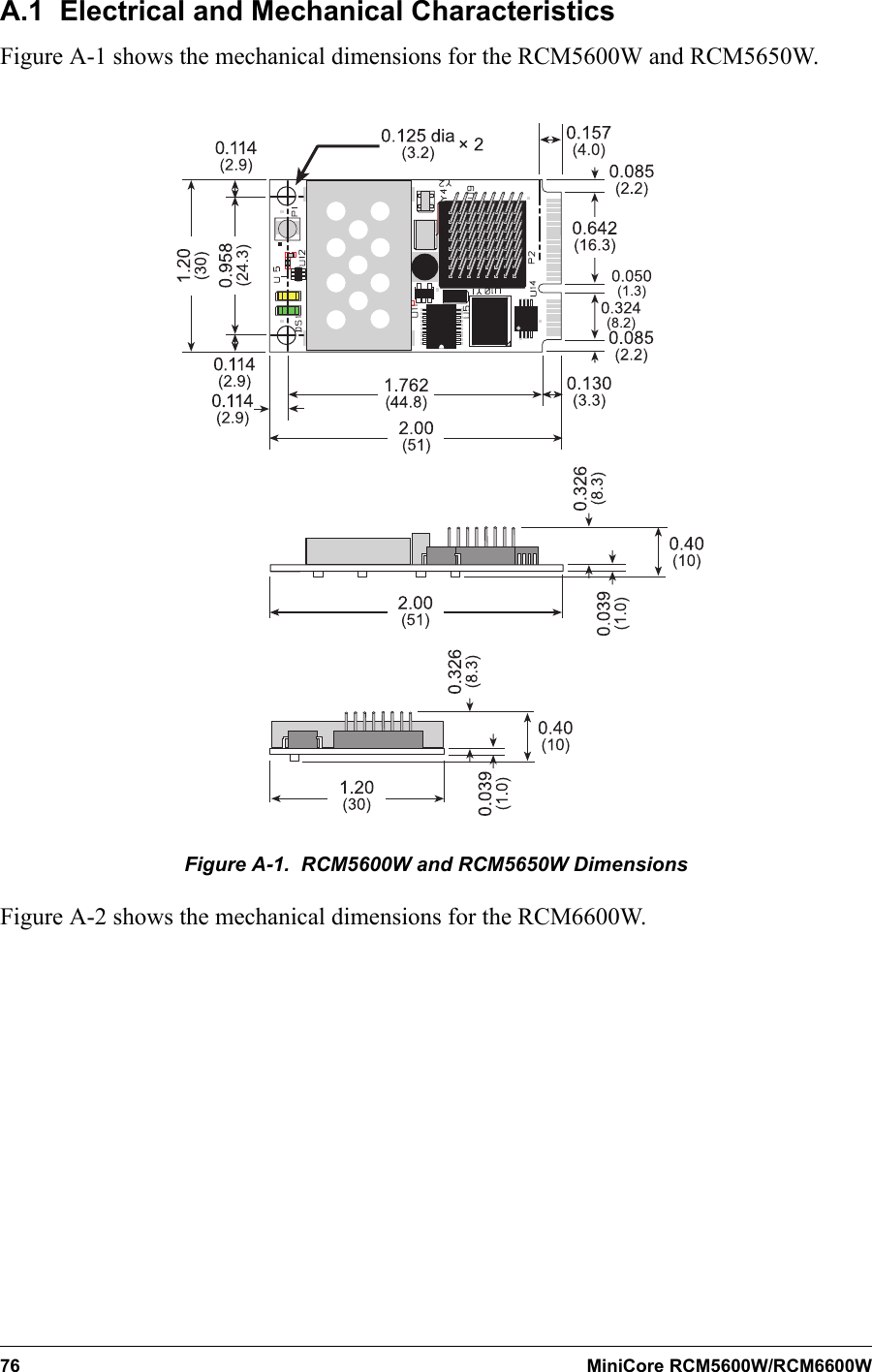
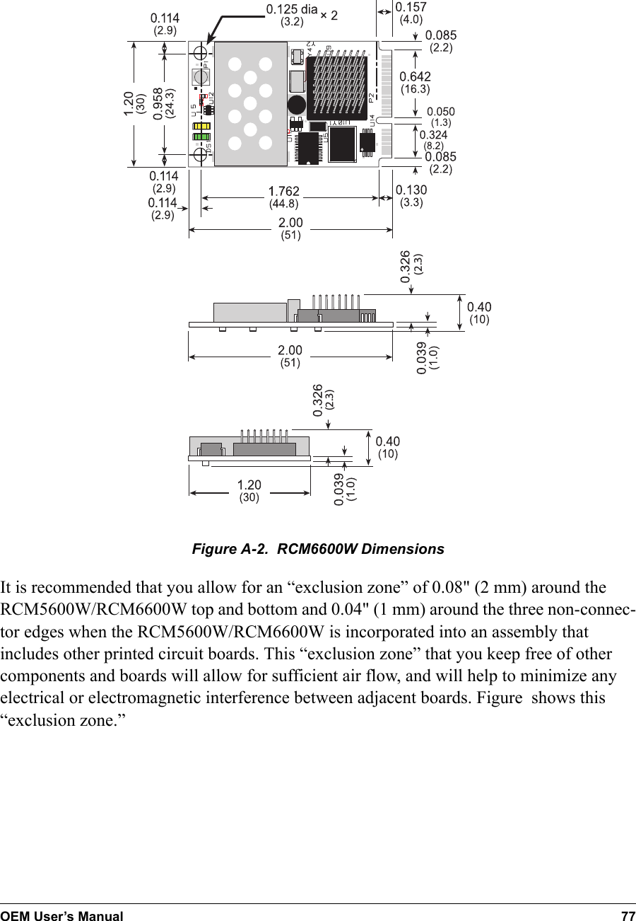
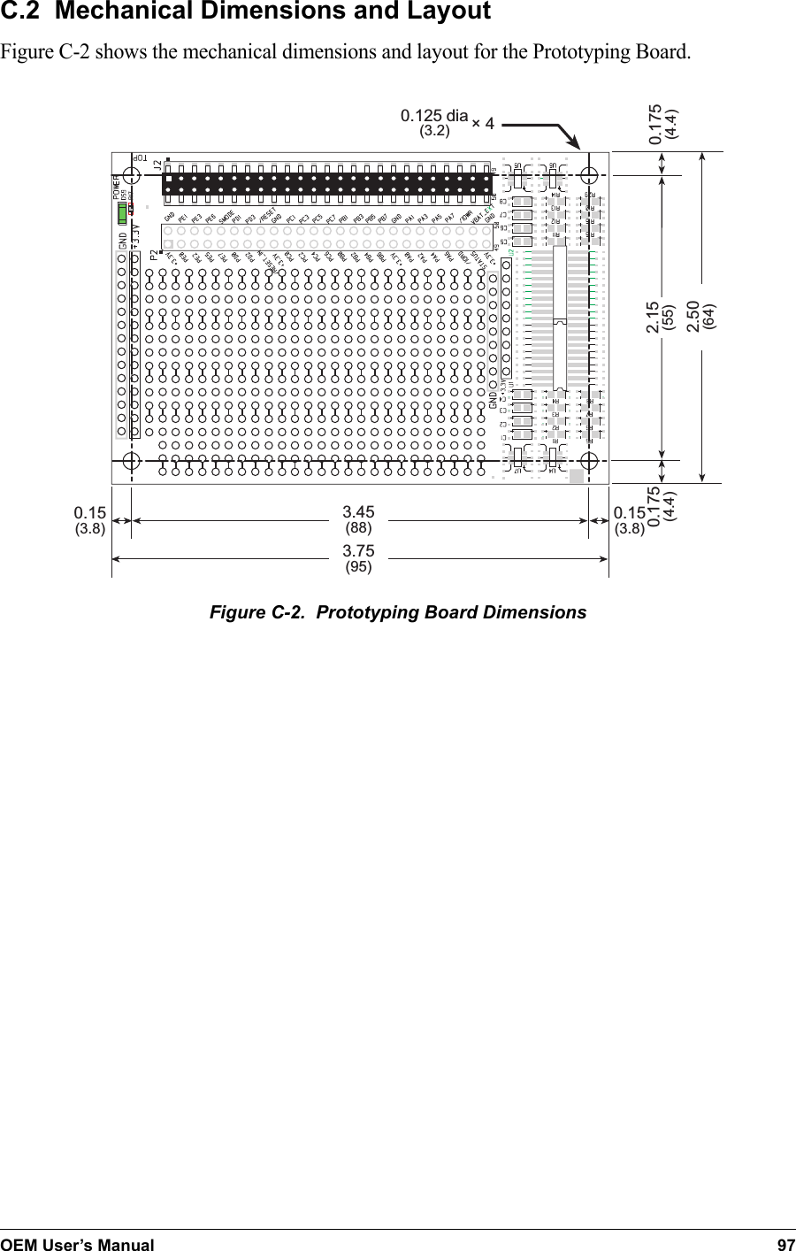
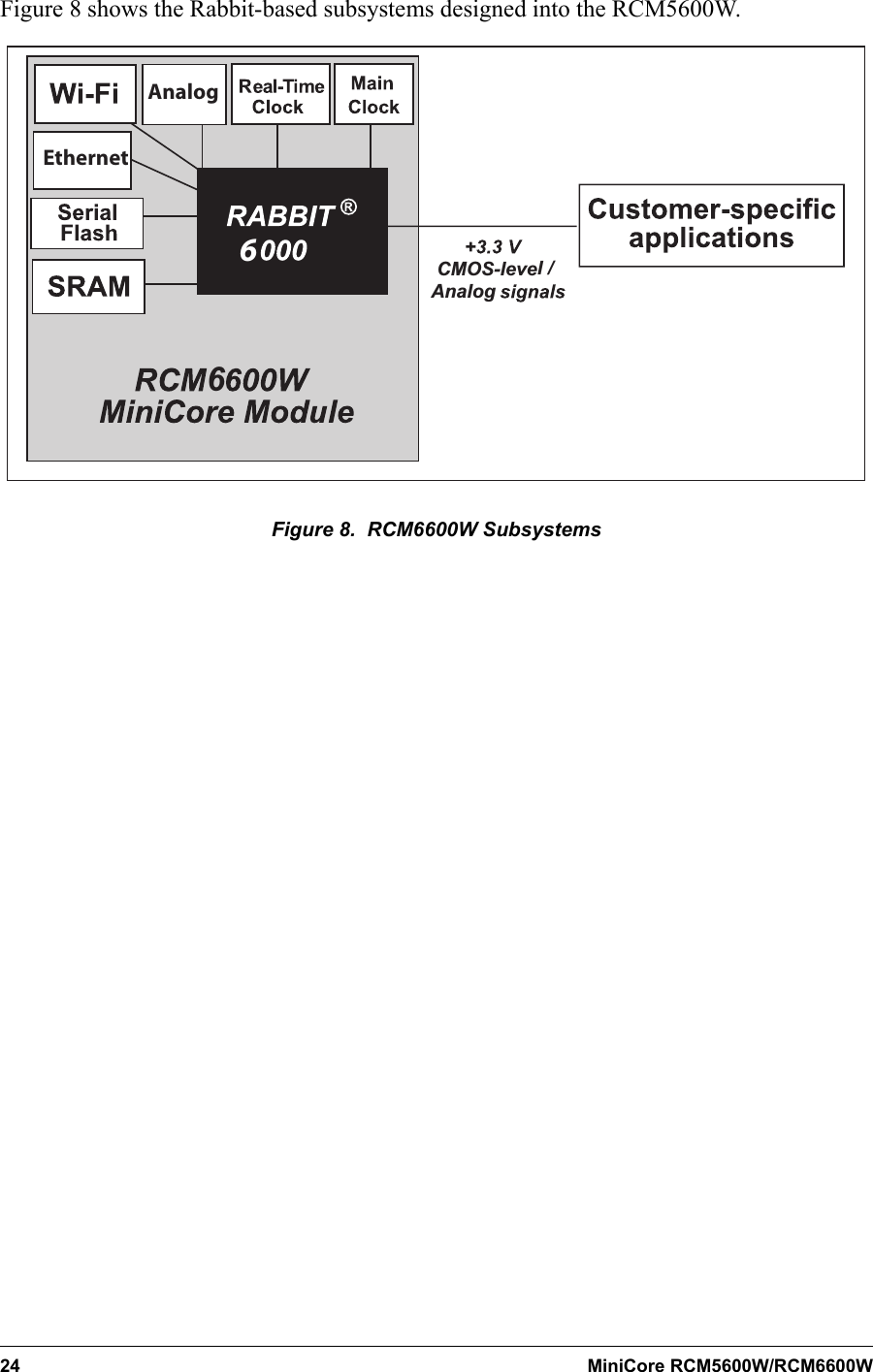
Digi R66 802.11b/g mini-PCI module User Manual RCW5600W
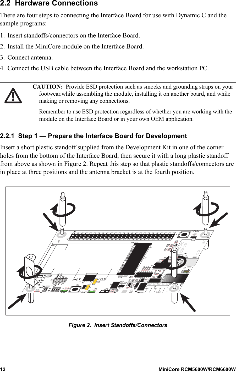
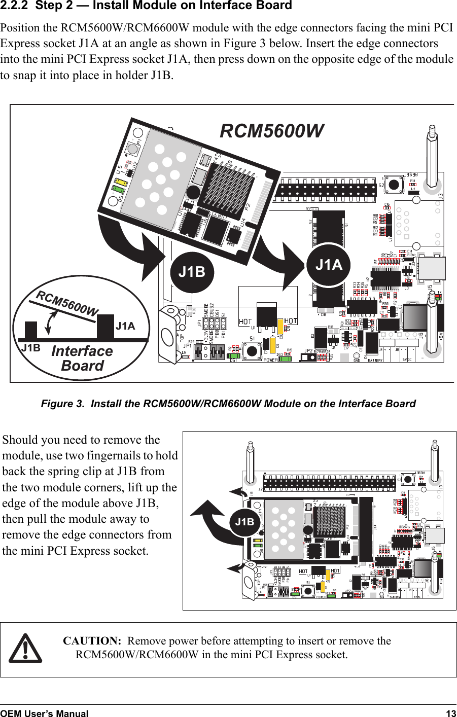
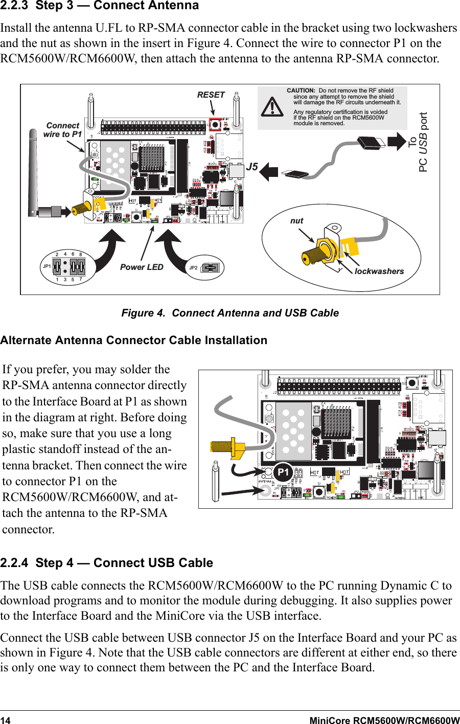
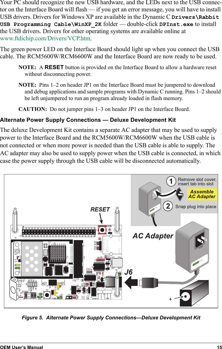
Digi International Inc 802.11b/g mini-PCI module RCW5600W
UserManual.wiki
>
Digi
>
R66 User Manual
Revised Manual
Navigation menu
Upload a User Manual
Namespaces
Wiki Guide
HTML
PDF
Info
Views
User Manual
Discussion / Help
Navigation
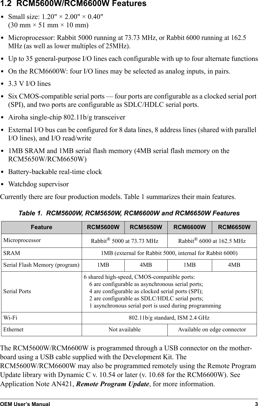
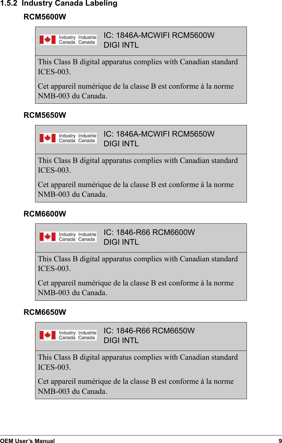
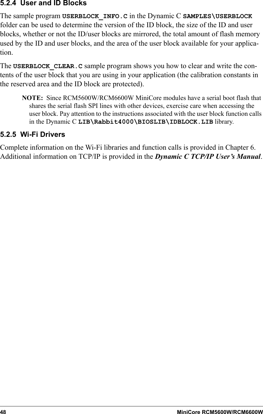
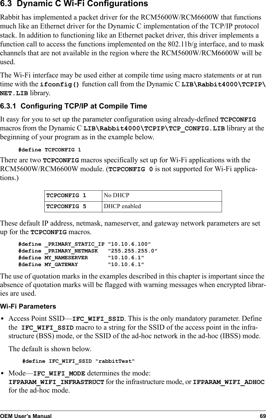
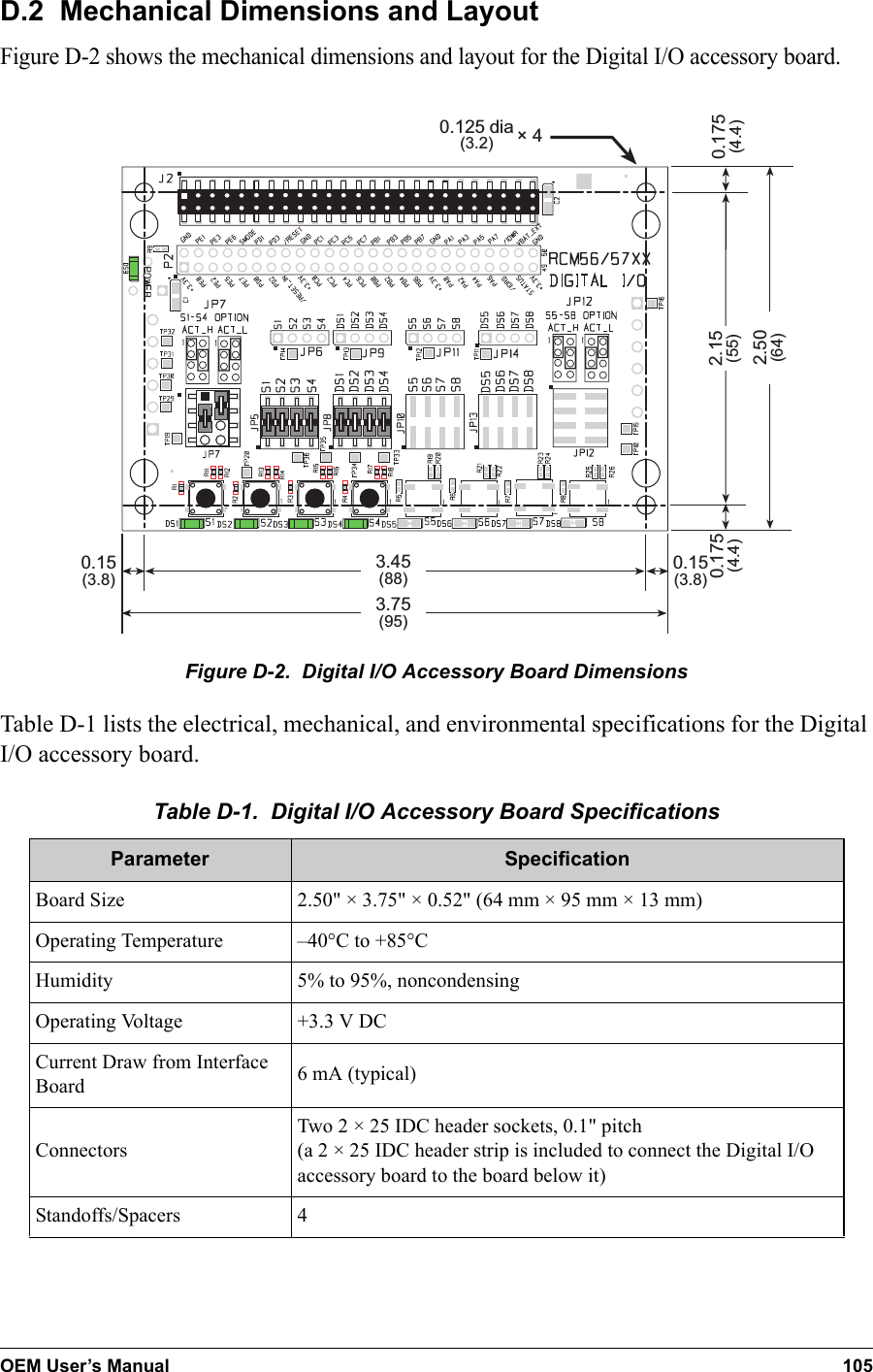
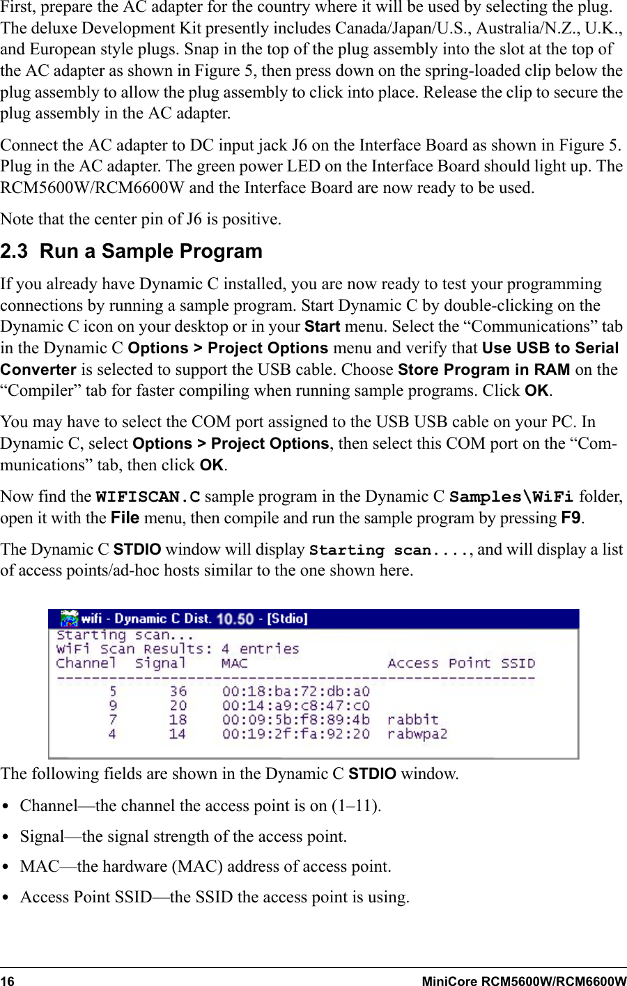
![10 MiniCore RCM5600W/RCM6600W1.5.3 EuropeThe marking shall include as a minimum:•the name of the manufacturer or his trademark;•the type designation;•equipment classification, (see below).Receiver Class Risk Assessment of Receiver Performance1Highly reliable SRD communication media, e.g., serving human life inherent systems (may result in a physical risk to a person).2Medium reliable SRD communication media, e.g., causing inconvenience to persons that cannot be overcome by other means.3Standard reliable SRD communication media,e.g., inconvenience to persons that can simply be overcome by other means.NOTE: Manufacturers are recommended to declare the classification of their devices in accordance with Table 2 and EN 300 440-2 [5] clause 4.2, as relevant. In particular, where an SRD that may have inherent safety of human life implications, manufacturers and users should pay particular attention to the potential for interference from other systems operating in the same or adjacent bands.Regulatory MarkingThe equipment shall be marked, where applicable, in accordance with CEPT/ERC Rec-ommendation 70-03 or Directive 1999/5/EC, whichever is applicable. Where this is not applicable, the equipment shall be marked in accordance with the National Regulatory requirements.The MiniCore module has been tested and found to comply with:•EN 300 328 v1.7.1•EN 301 489-1 v1.8.1•EN 301 489-17 v1.3.2 standards.1.5.4 JapanRCM5600W and RCM5650Wmodules are certified for use in Japan under Article 2-1-19. The Acceptance Number is 003WWA090869.](https://usermanual.wiki/Digi/R66/User-Guide-1673842-Page-18.png)
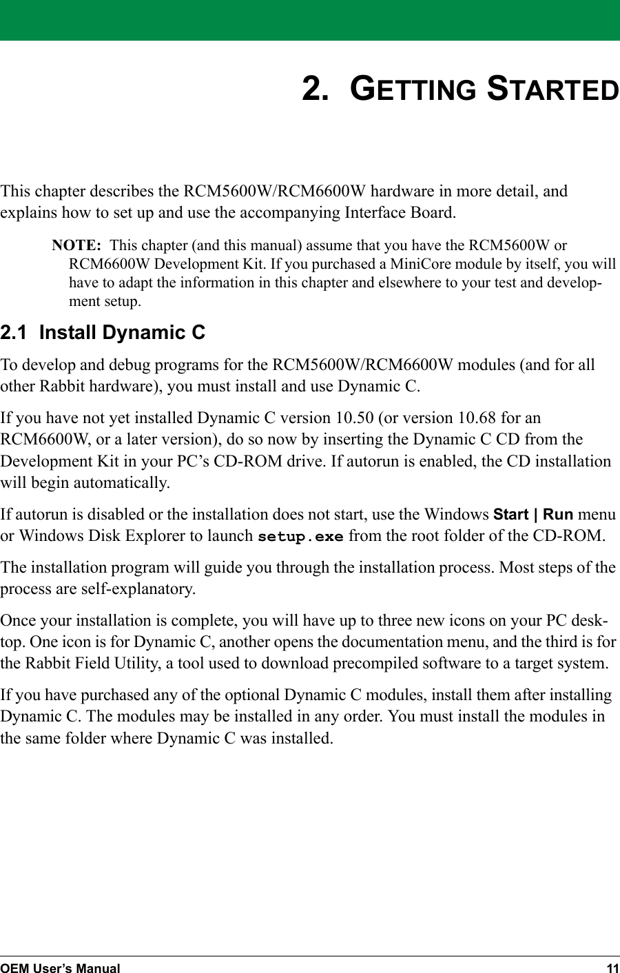
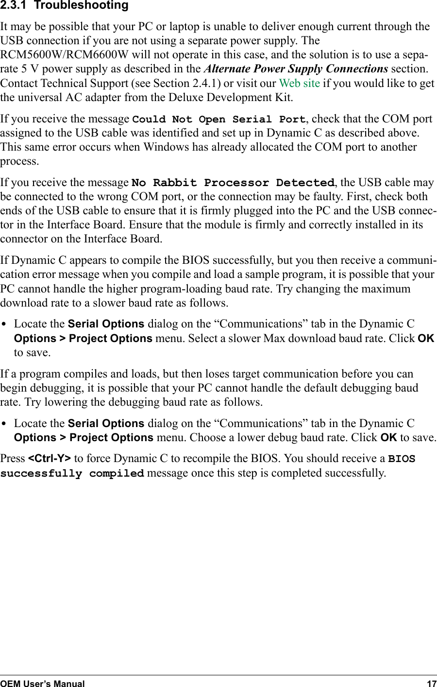
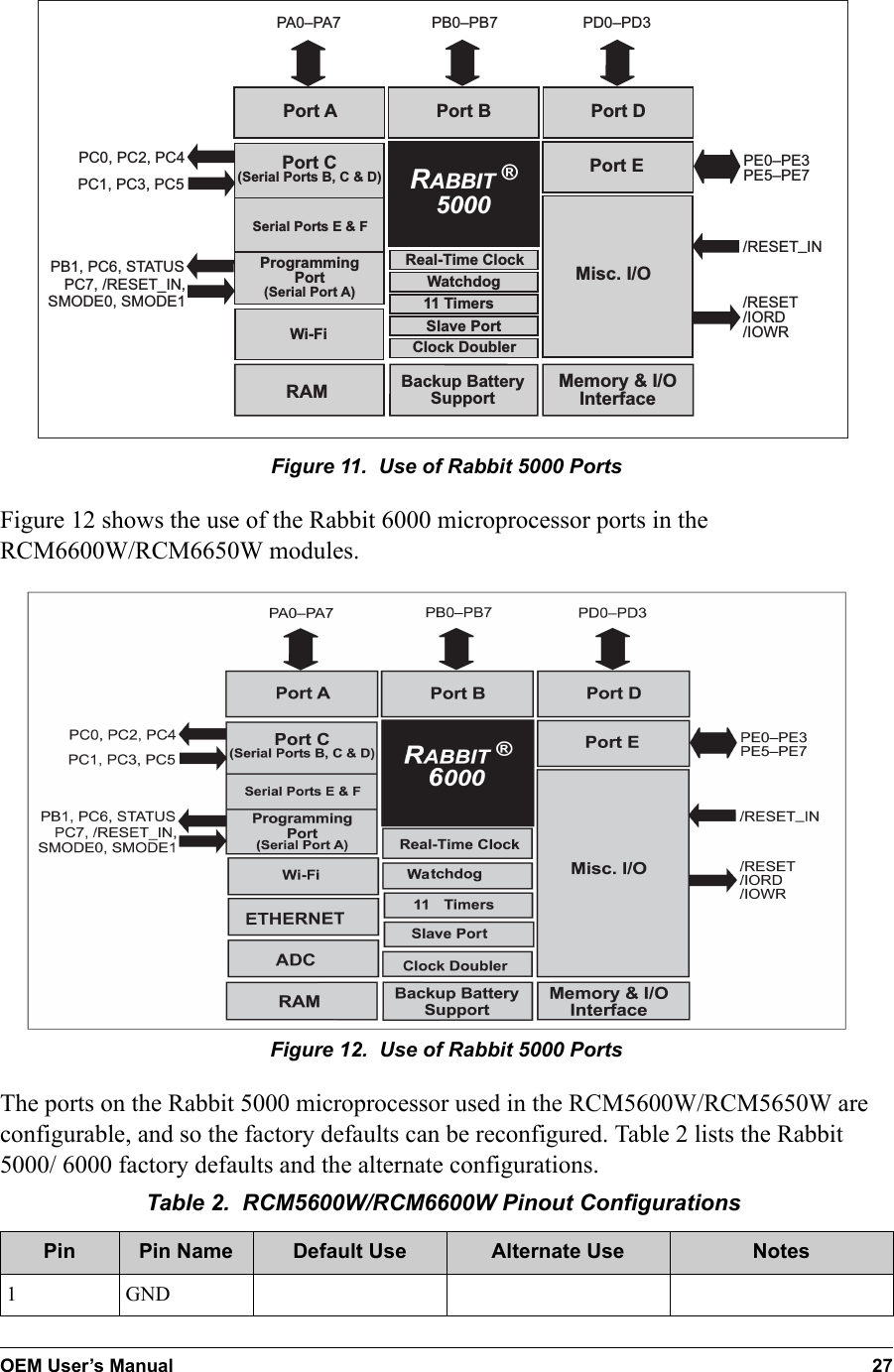
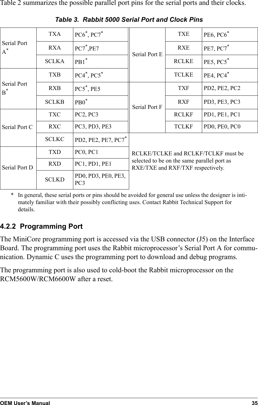
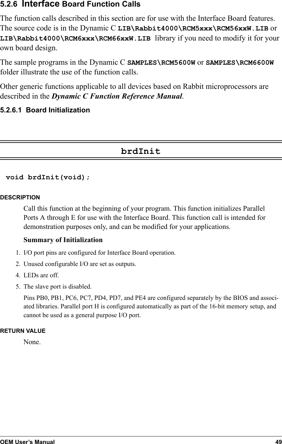
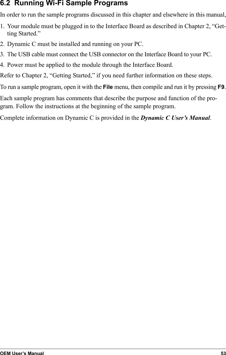
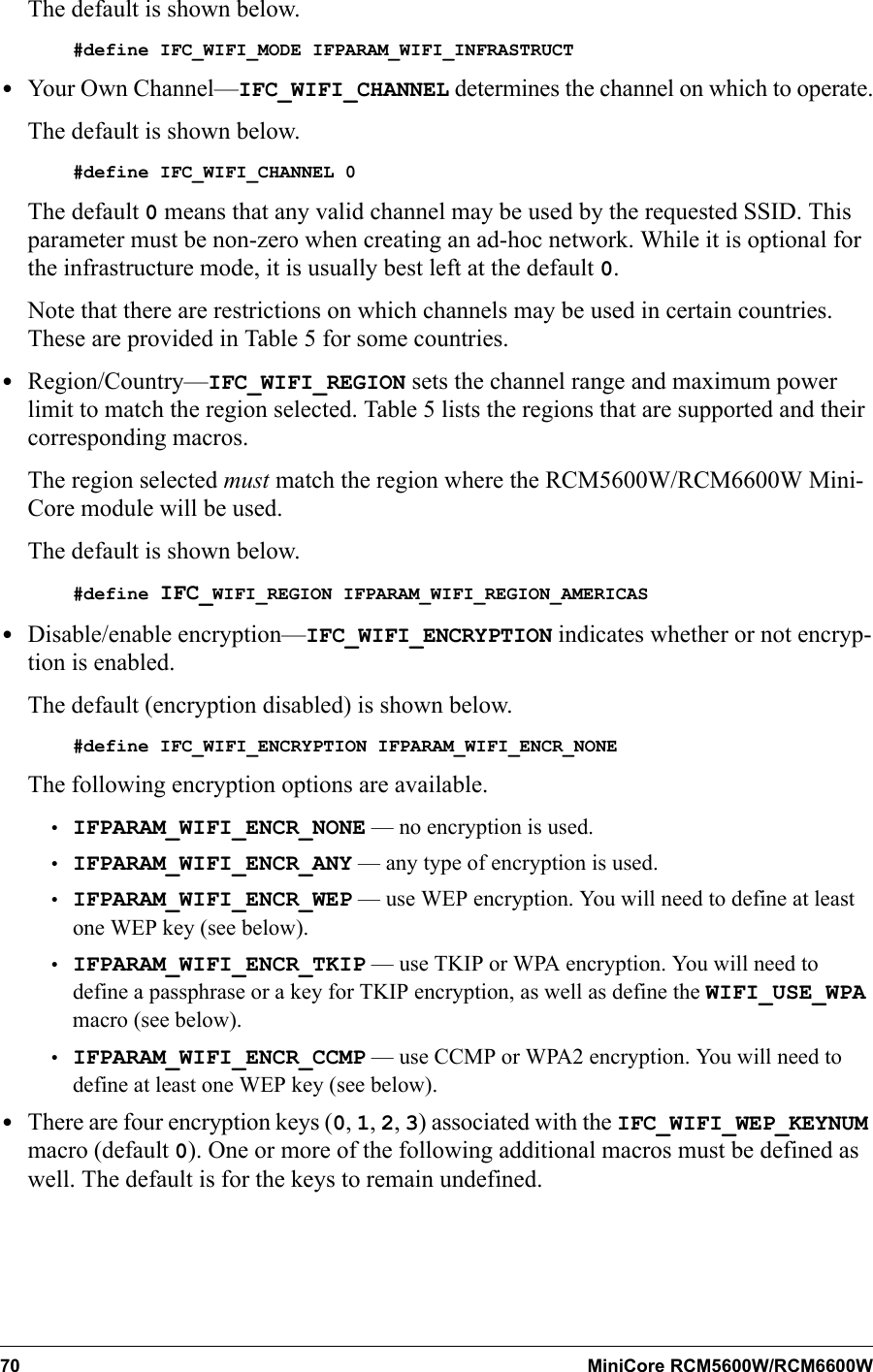
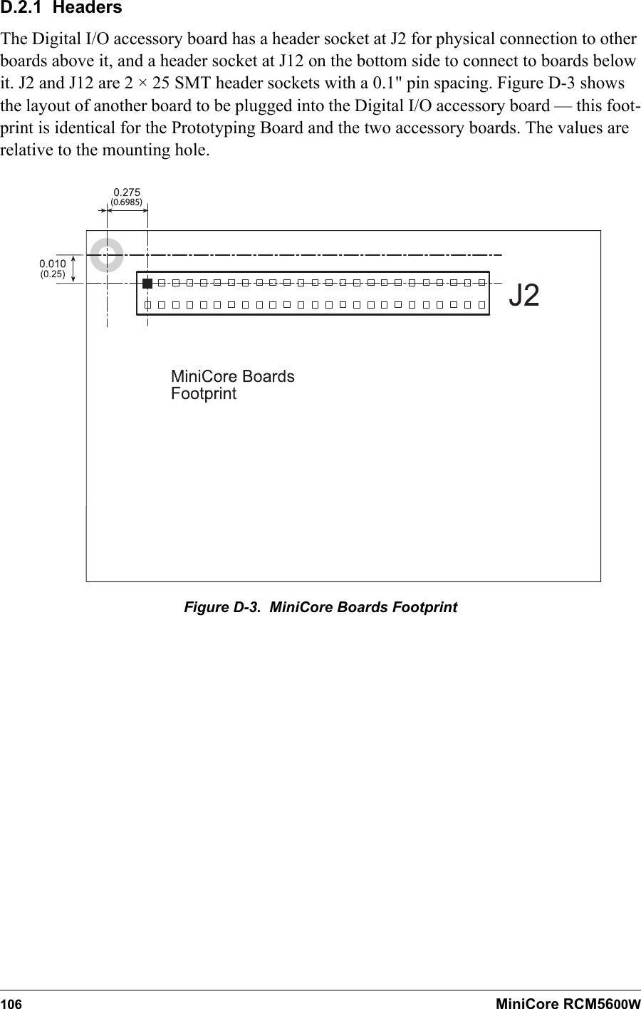
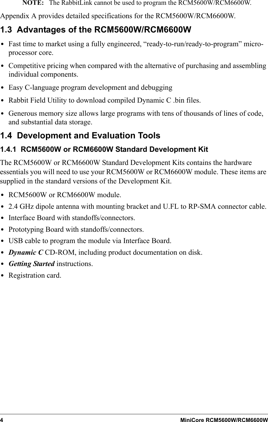
![OEM User’s Manual 3128 /RESET Reset output Reset inputReset output from Reset Generator or external reset input29 PB2 Input/Output/SWRExternal I/O Address IA030 PB3 Input/Output/SRDExternal I/O Address IA131 PB4 Input/OutputSA0External I/O Address IA232 PB5 Input/OutputSA1External I/O Address IA333 PB6 Input/Output/SCSExternal I/O Address IA434 PB7 Input/Output/ S L AVAT NExternal I/O Address IA535–42 PA[0:7] Input/OutputSlave port data bus(SD0–SD7)External I/O data bus(ID0–ID7)43 /IORD Output External I/O read strobe44 VBAT_EXT Battery input45 /IOWR Output External I/O write strobe46 PB1*Input/OutputSCLKAExternal I/O Address IA7Programming port SCLKA47 STATUS*Output Programming portTable 2. RCM5600W/RCM6600W Pinout Configurations (continued)Pin Pin Name Default Use Alternate Use Notes](https://usermanual.wiki/Digi/R66/User-Guide-1673842-Page-39.png)