Digi WMPX5F WMP100 User Manual ConnectPort X5 Family User s Guide
Digi International Inc WMP100 ConnectPort X5 Family User s Guide
UserManual.wiki
>
Digi
>
WMPX5F User Manual
User Manual
Navigation menu
Upload a User Manual
Namespaces
Wiki Guide
HTML
PDF
Info
Views
User Manual
Discussion / Help
Navigation


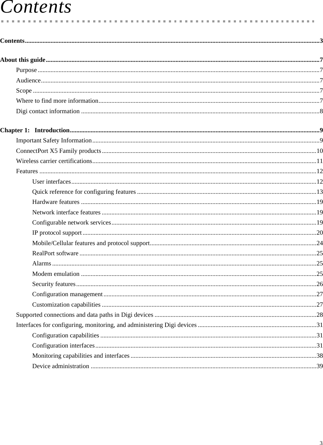
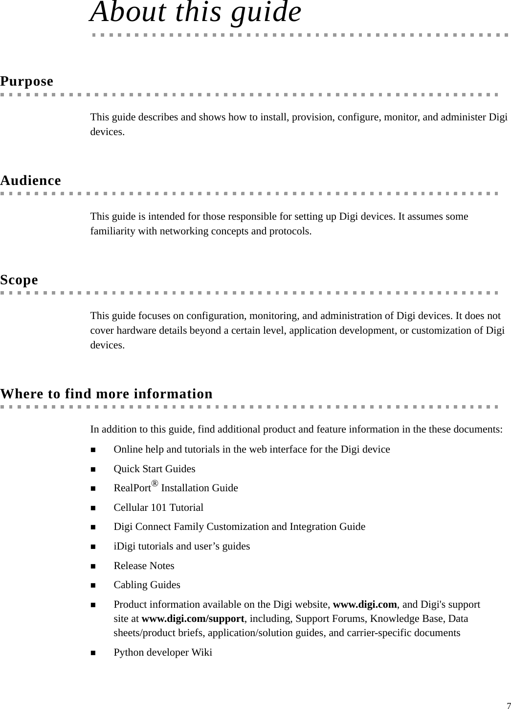

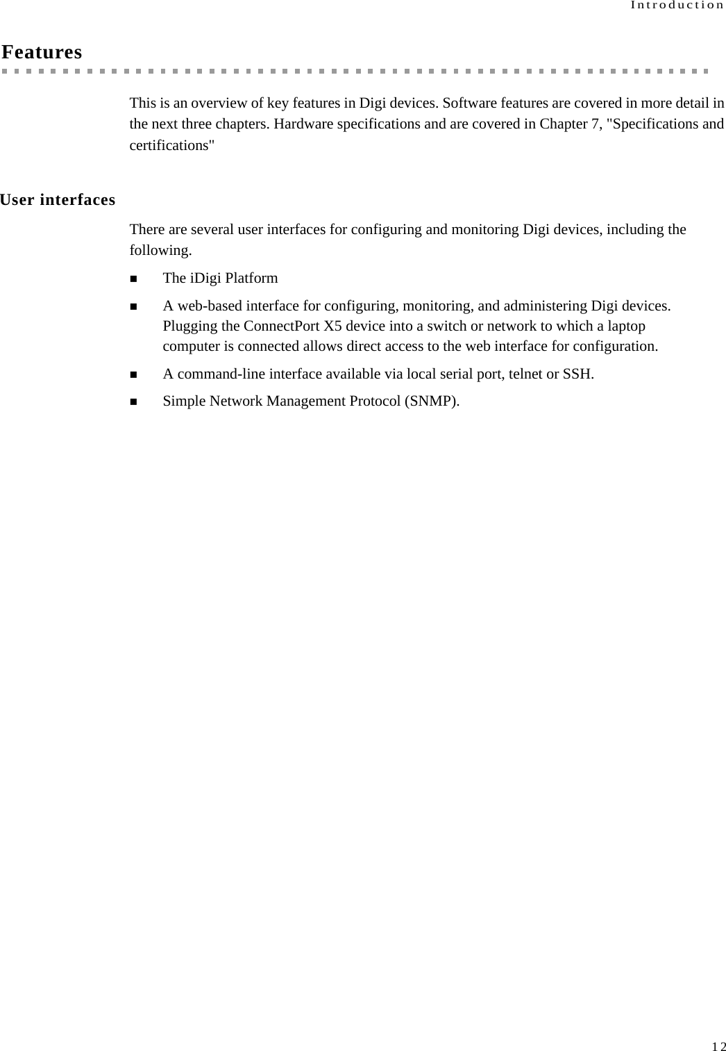
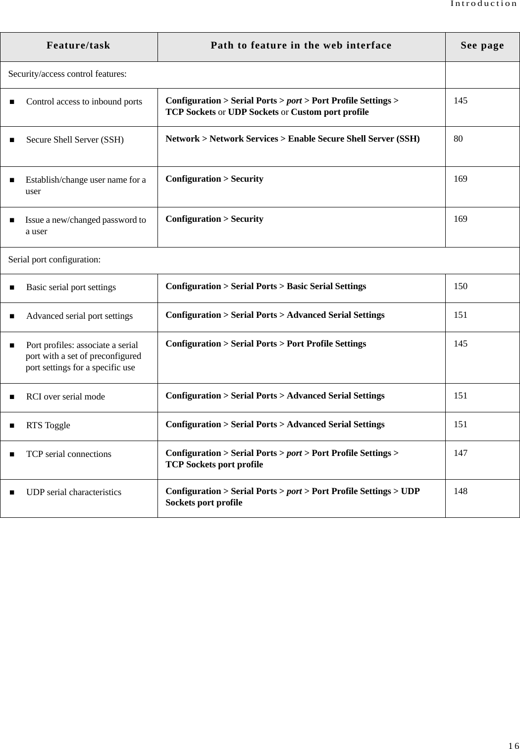
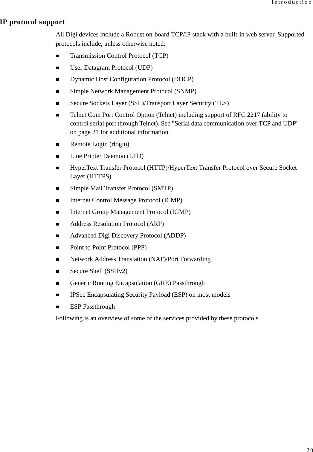
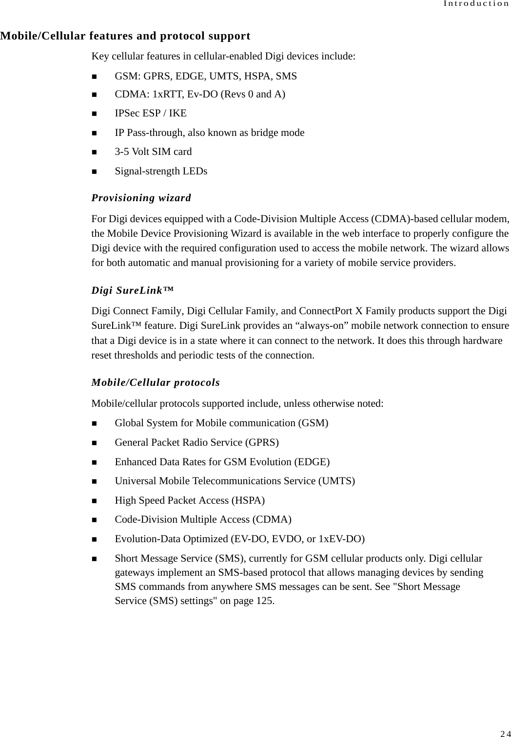
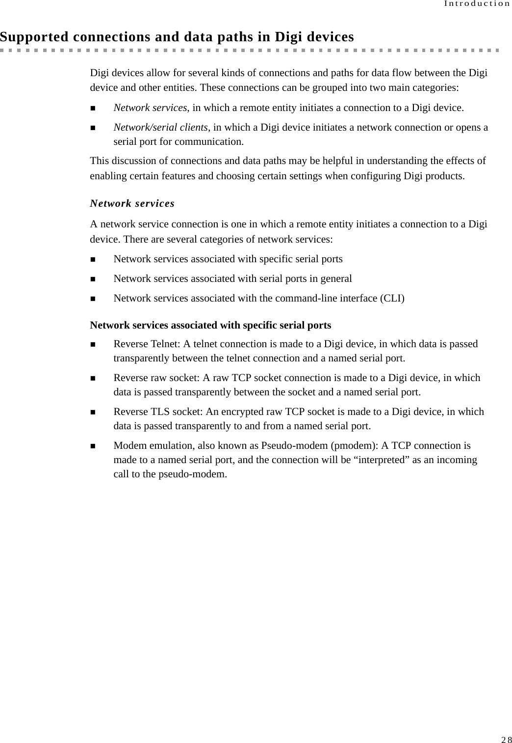
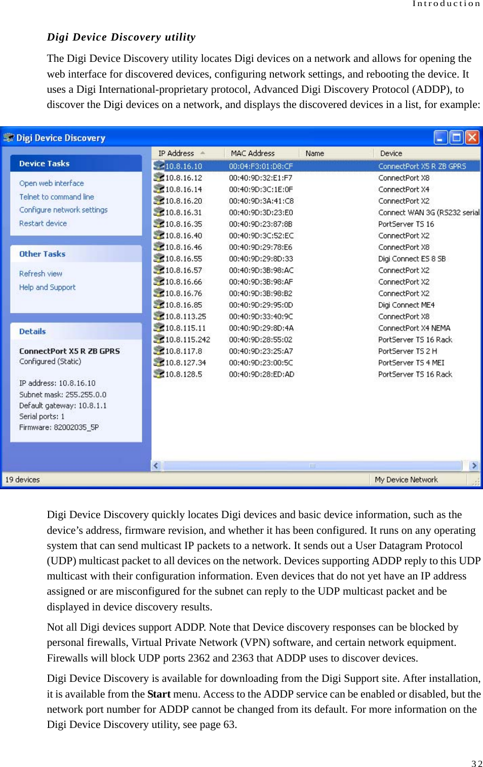
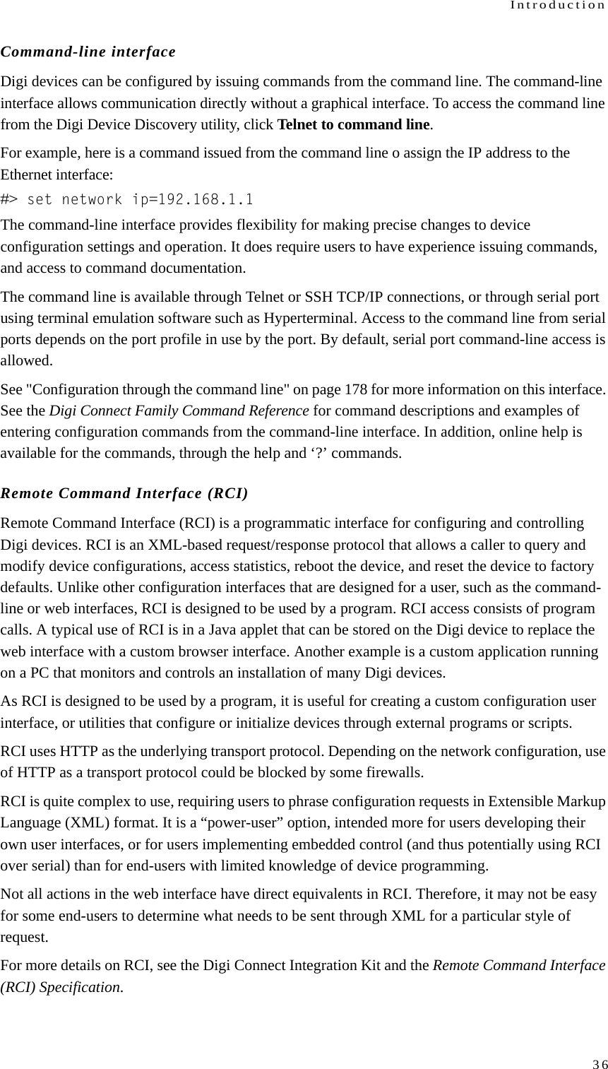
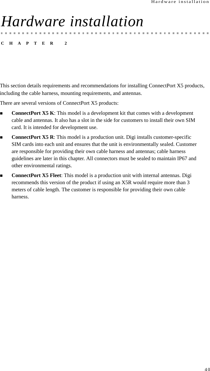

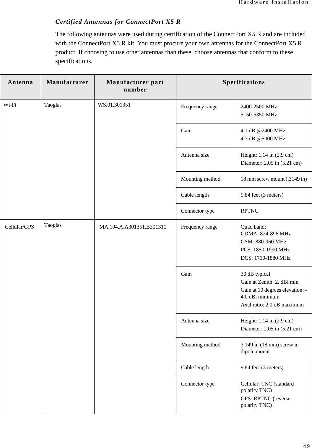

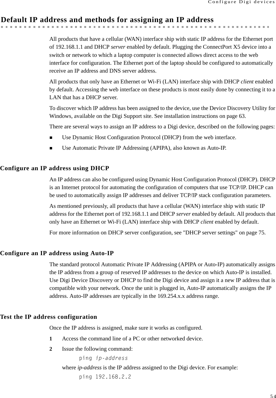
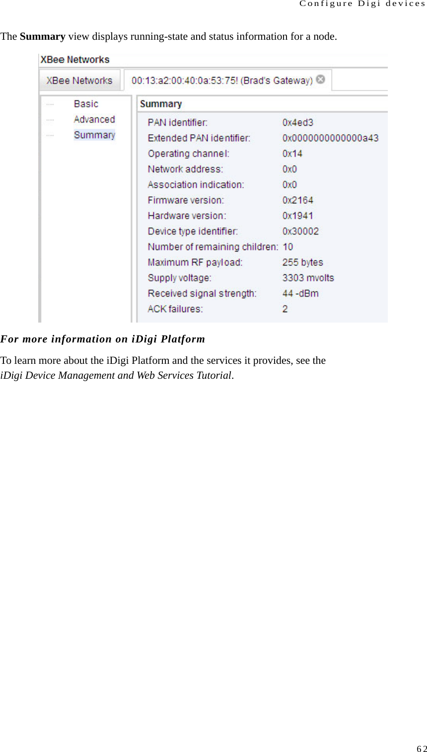
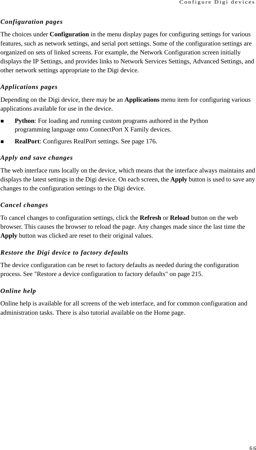
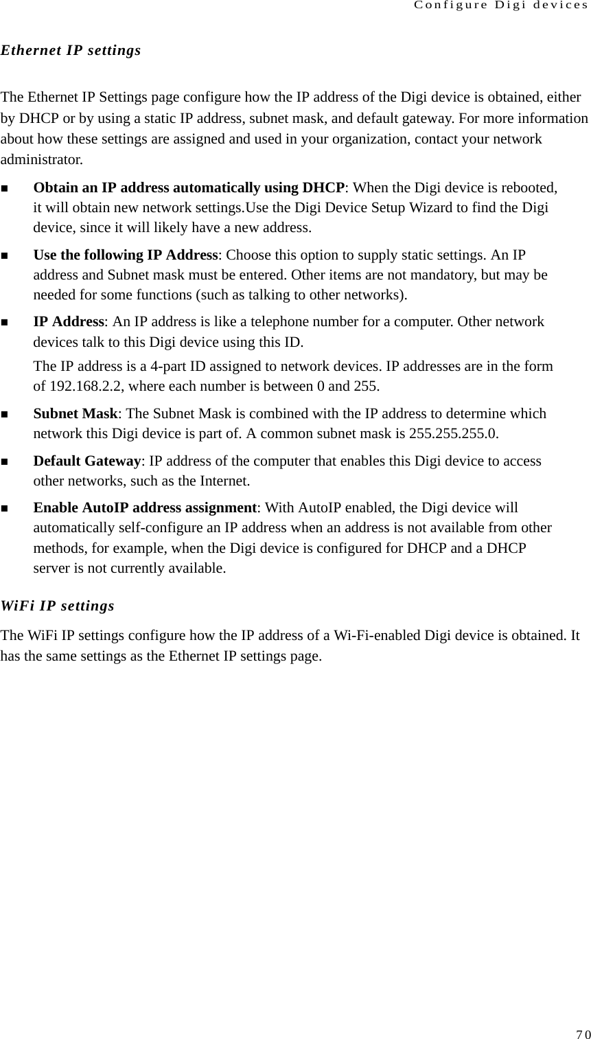
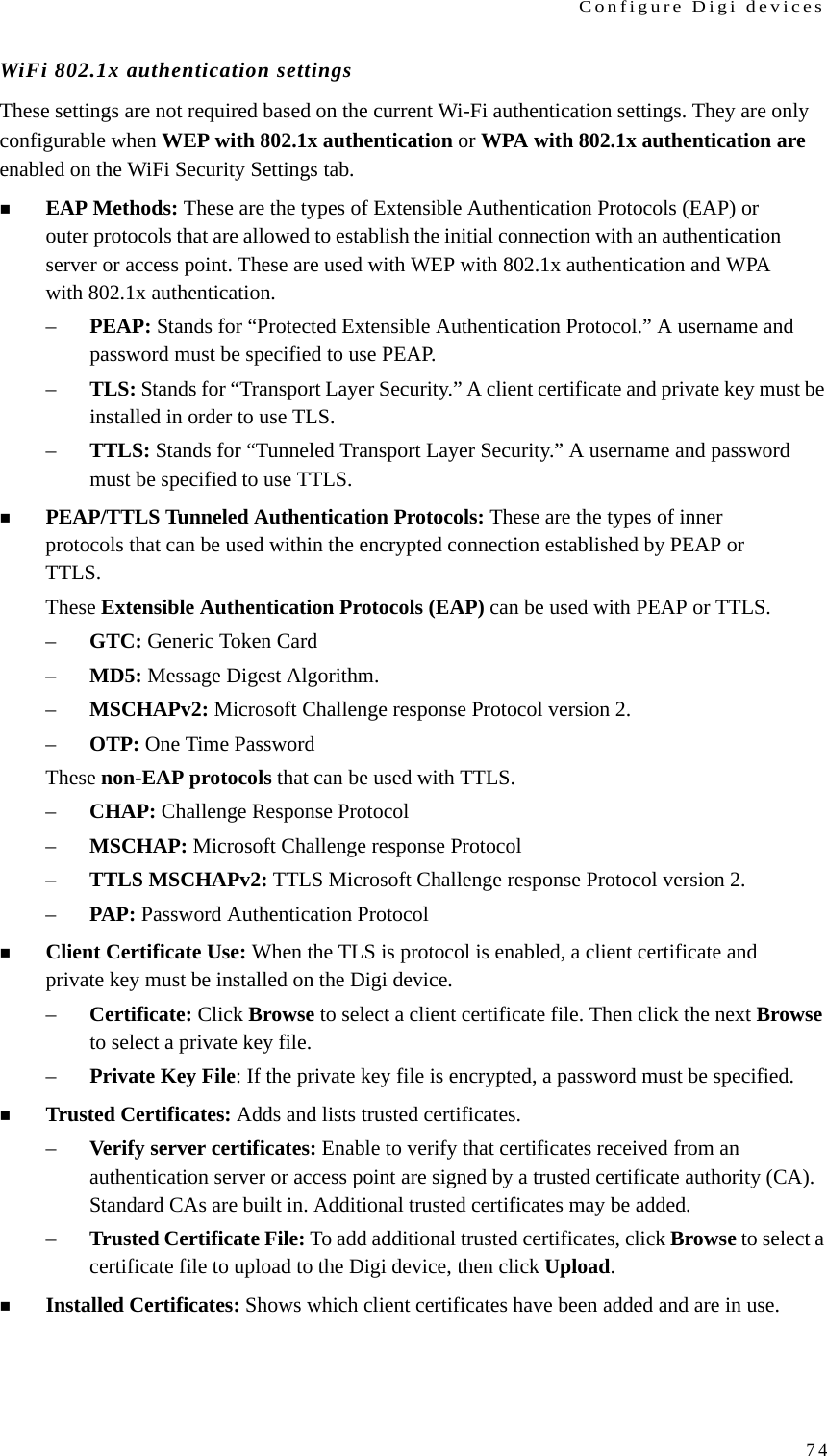
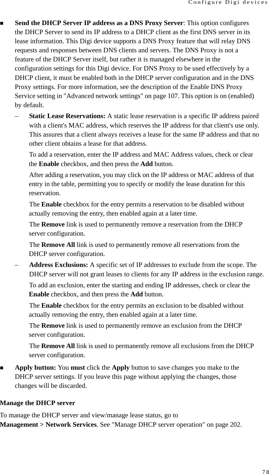
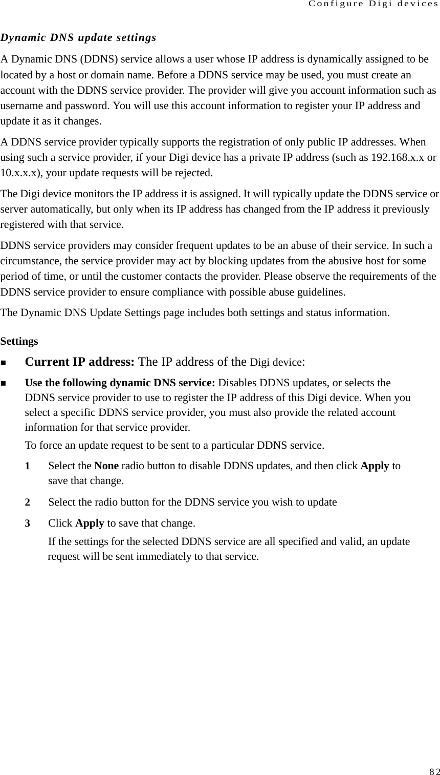
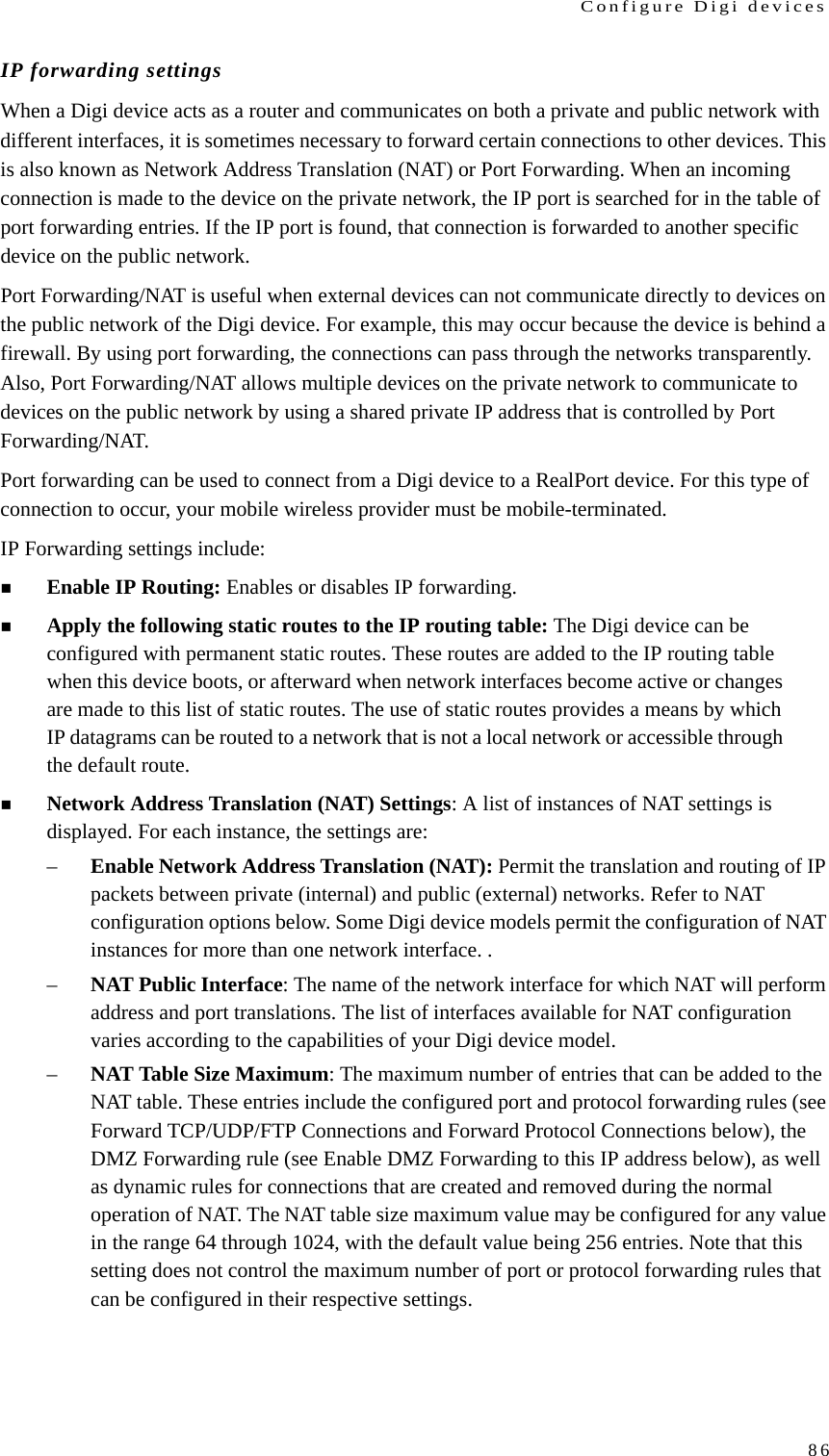
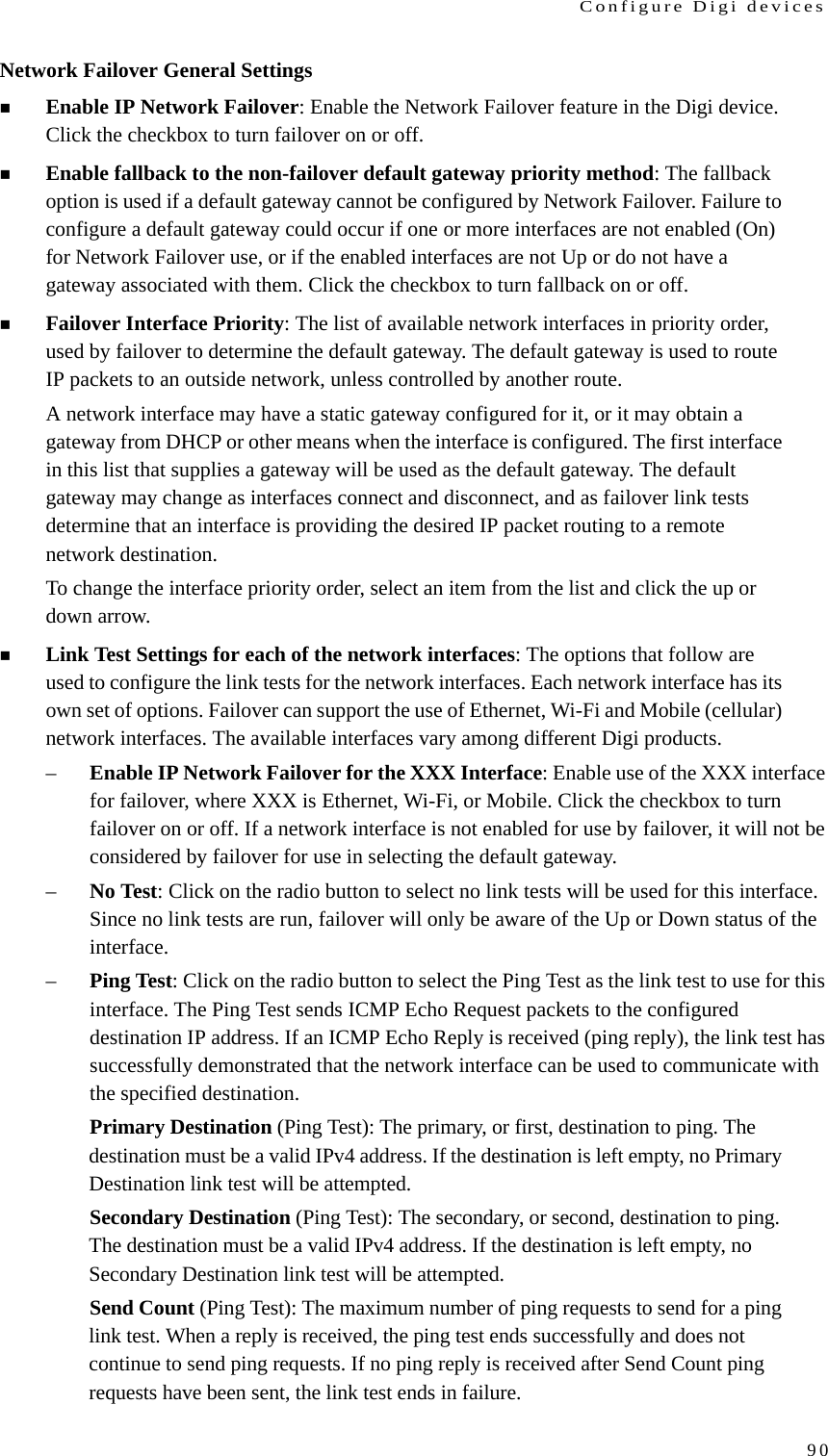
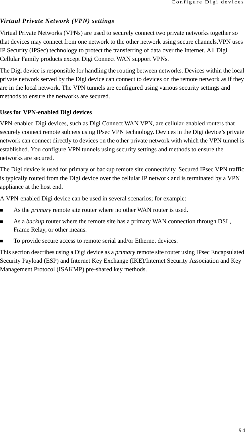

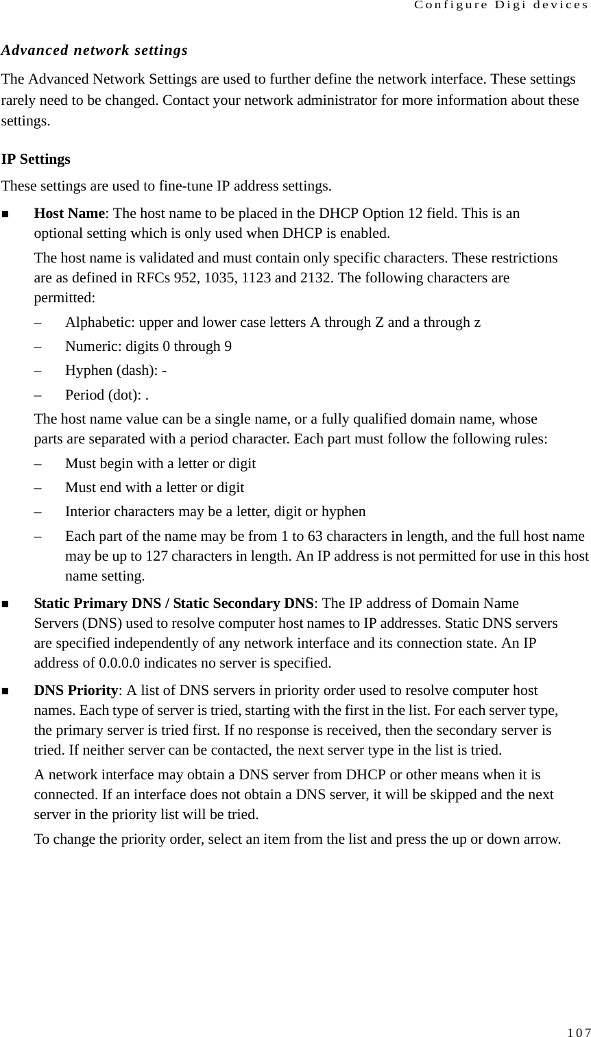
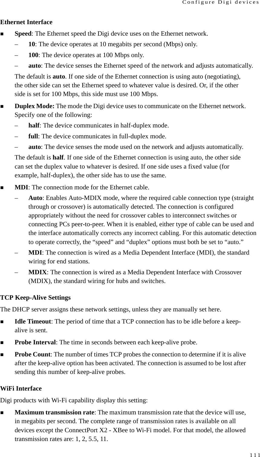
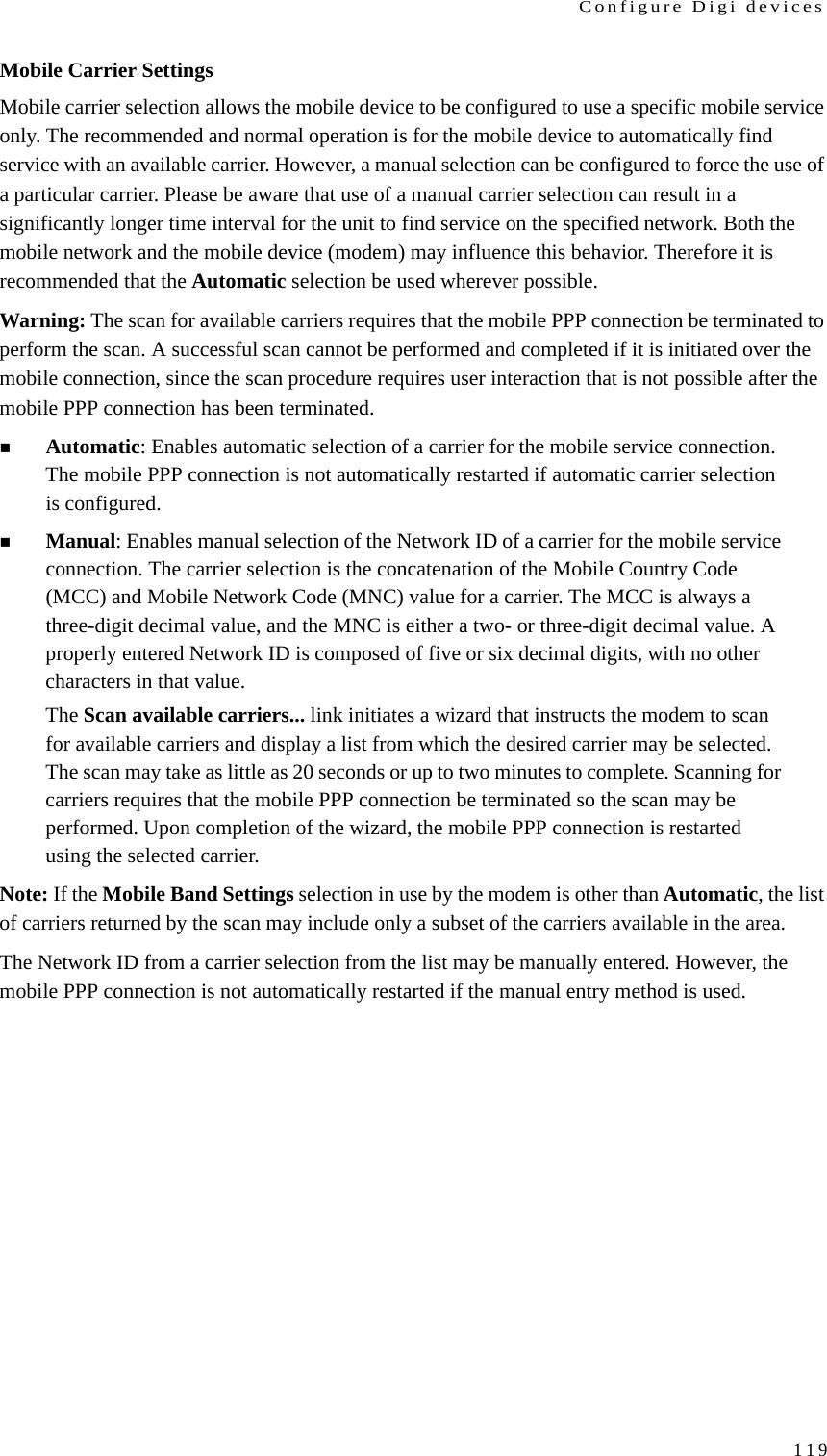
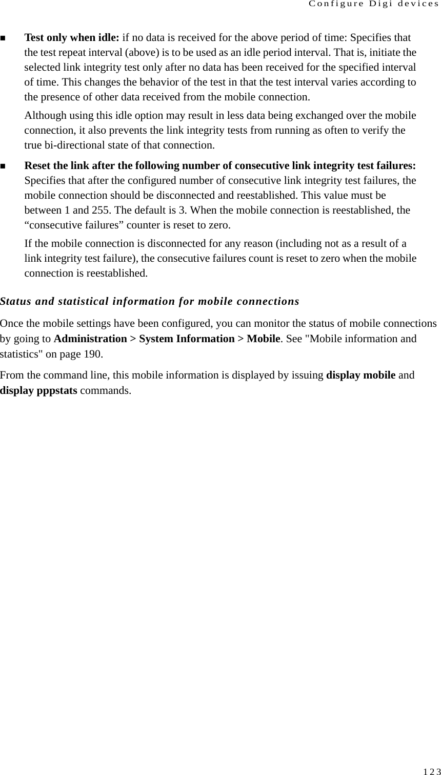
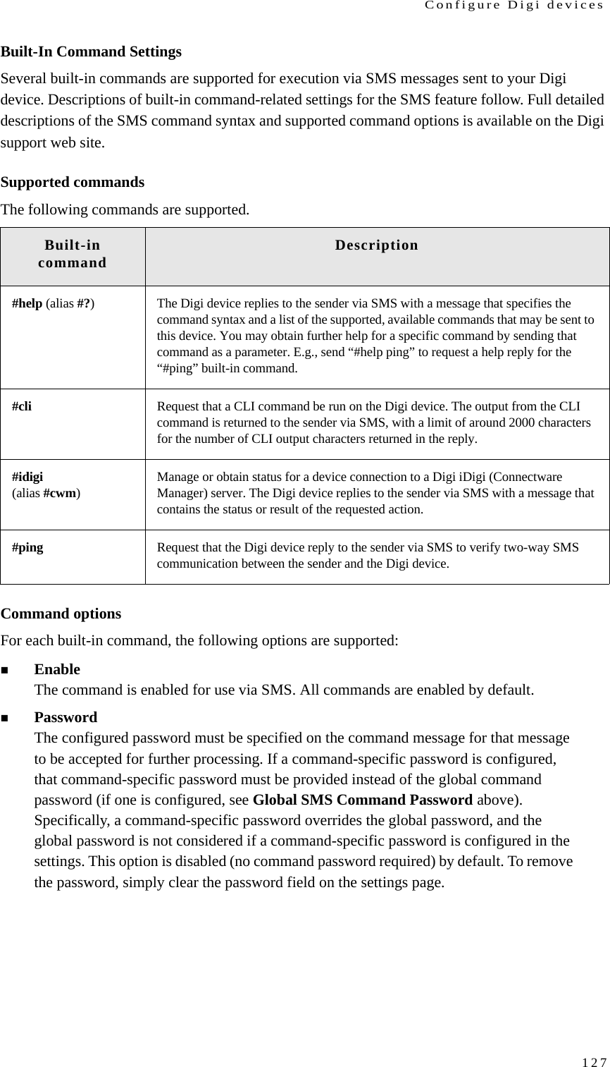
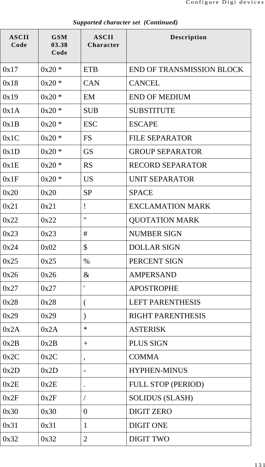
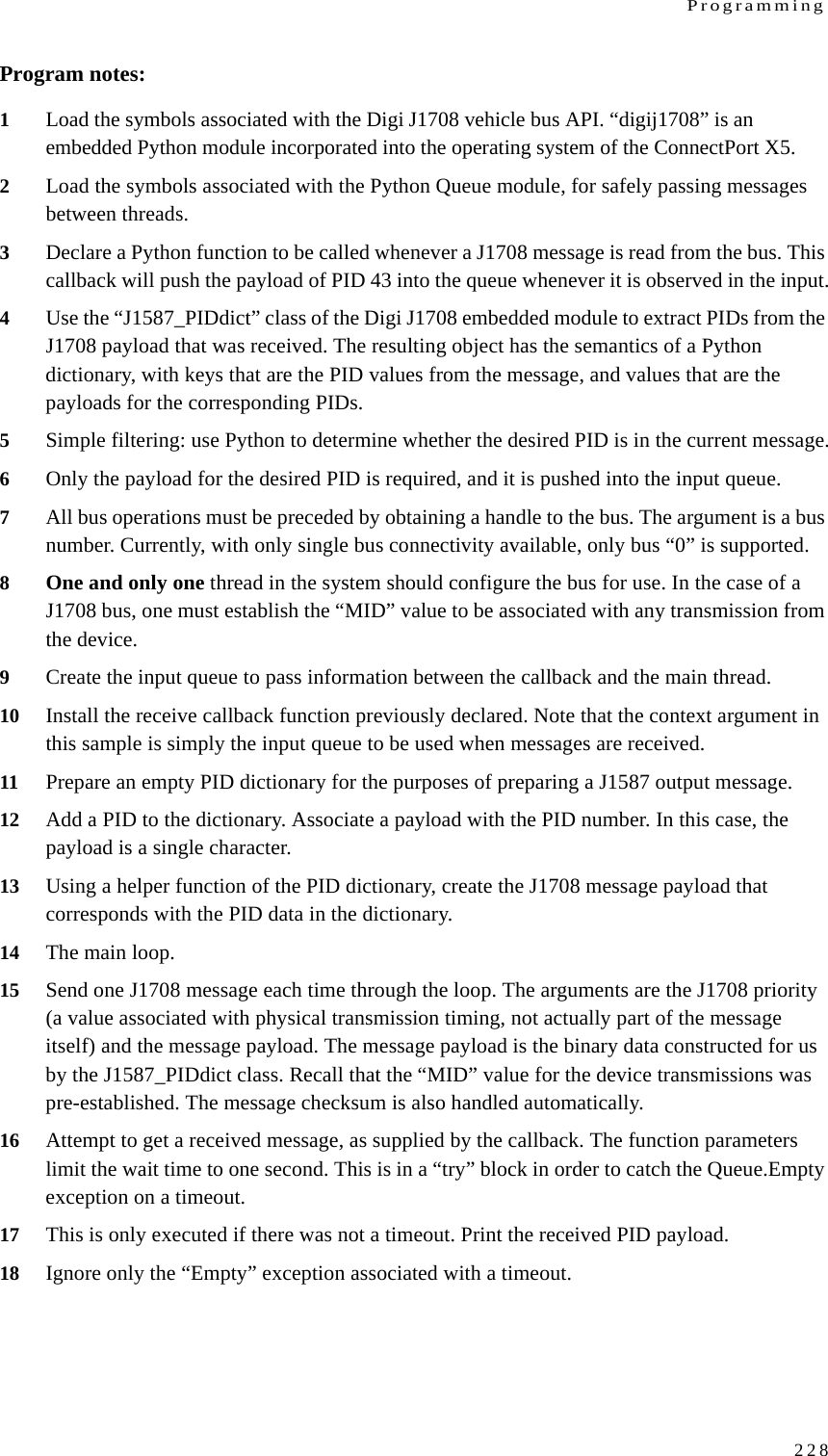
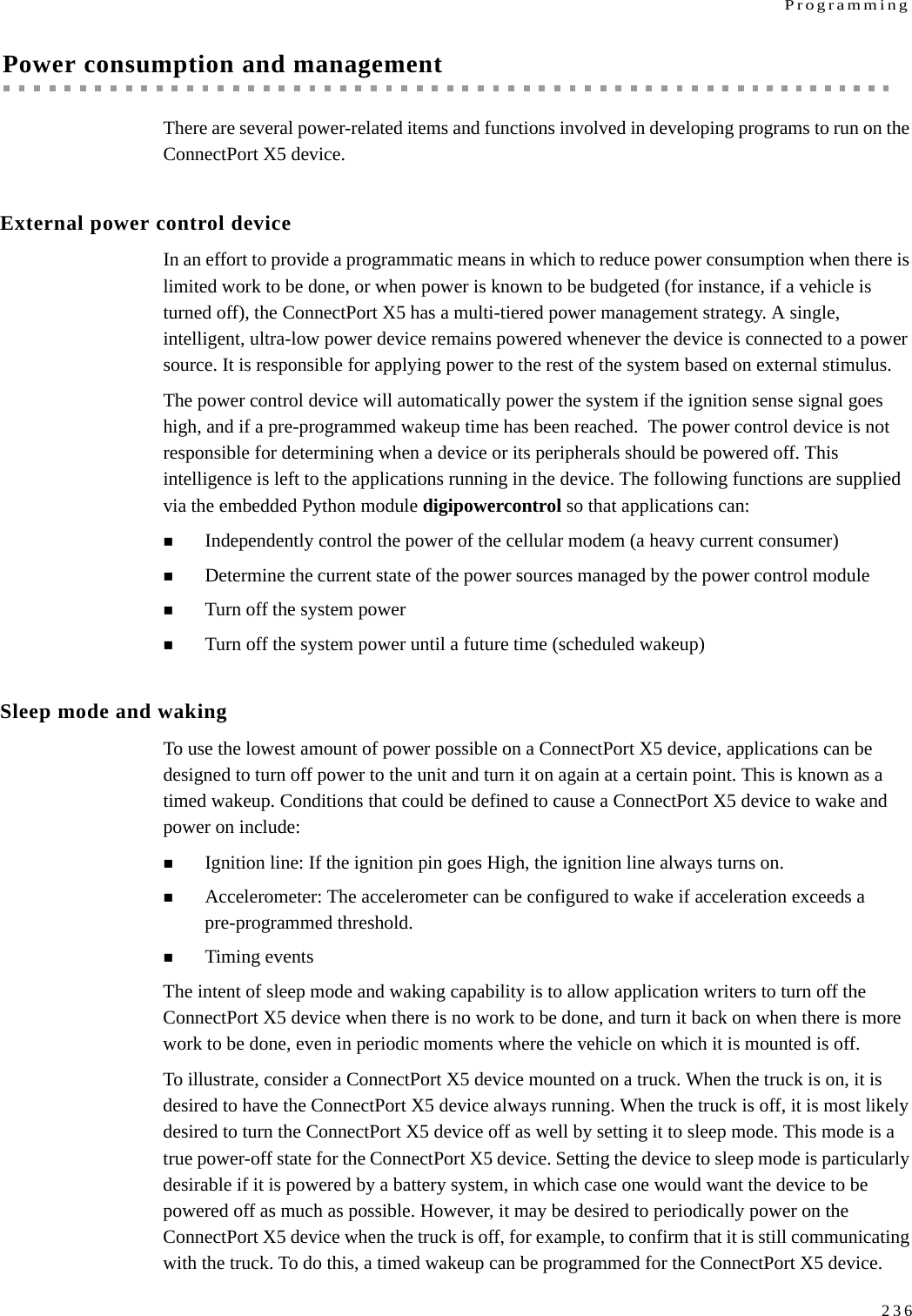
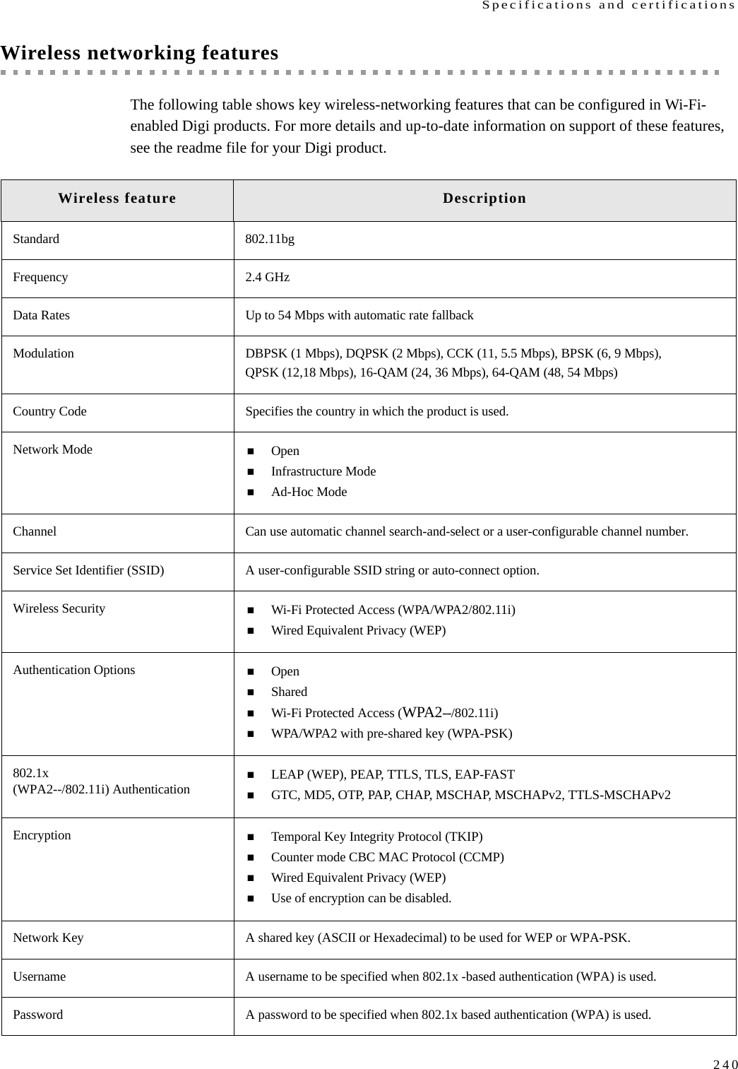
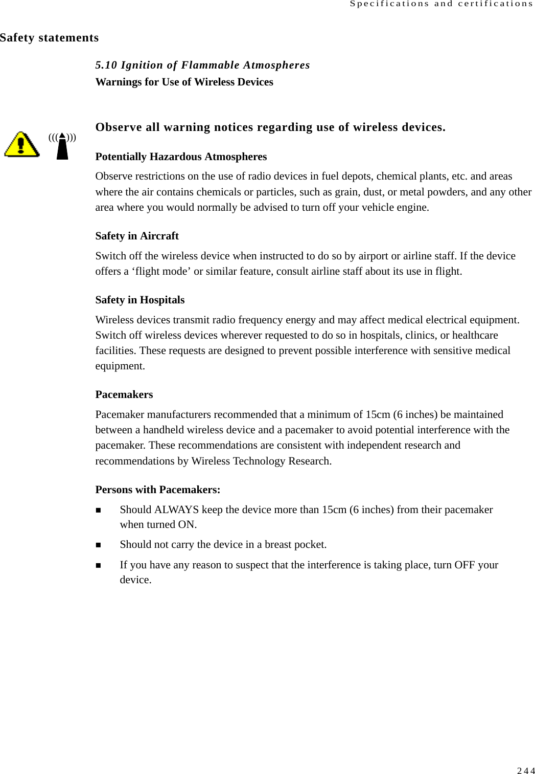
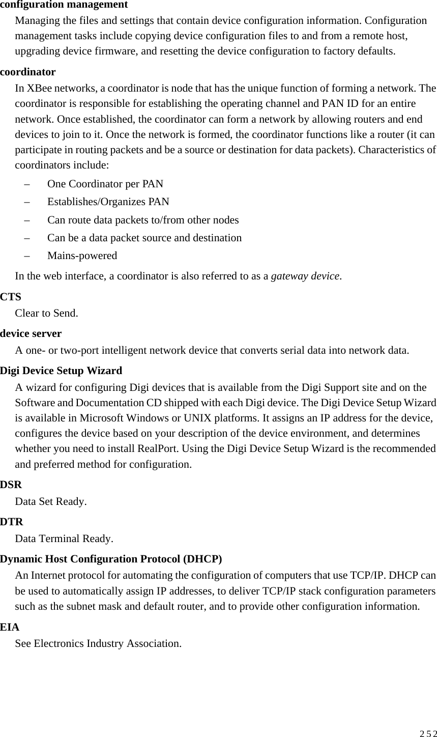
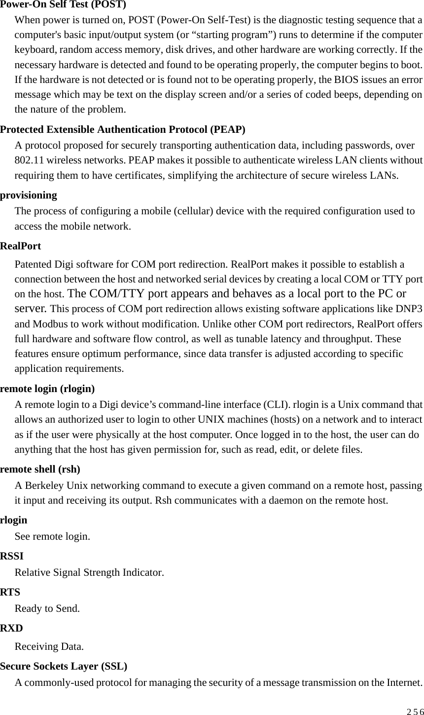
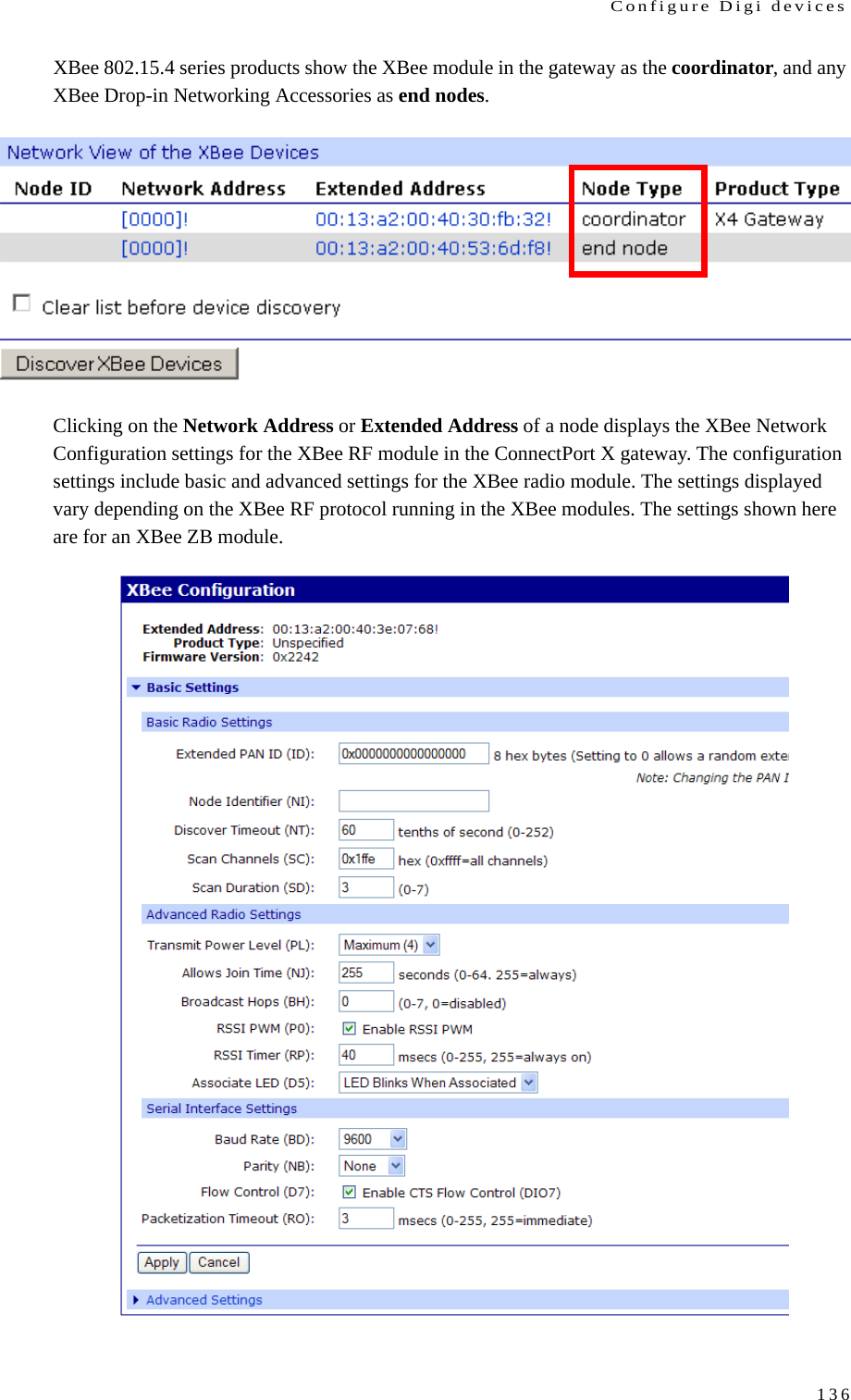
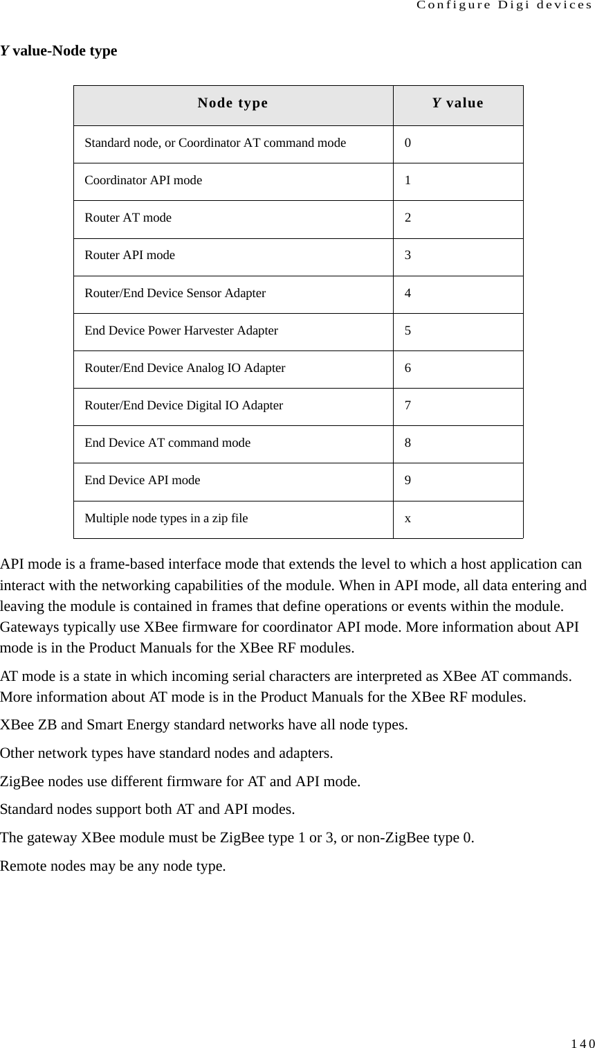
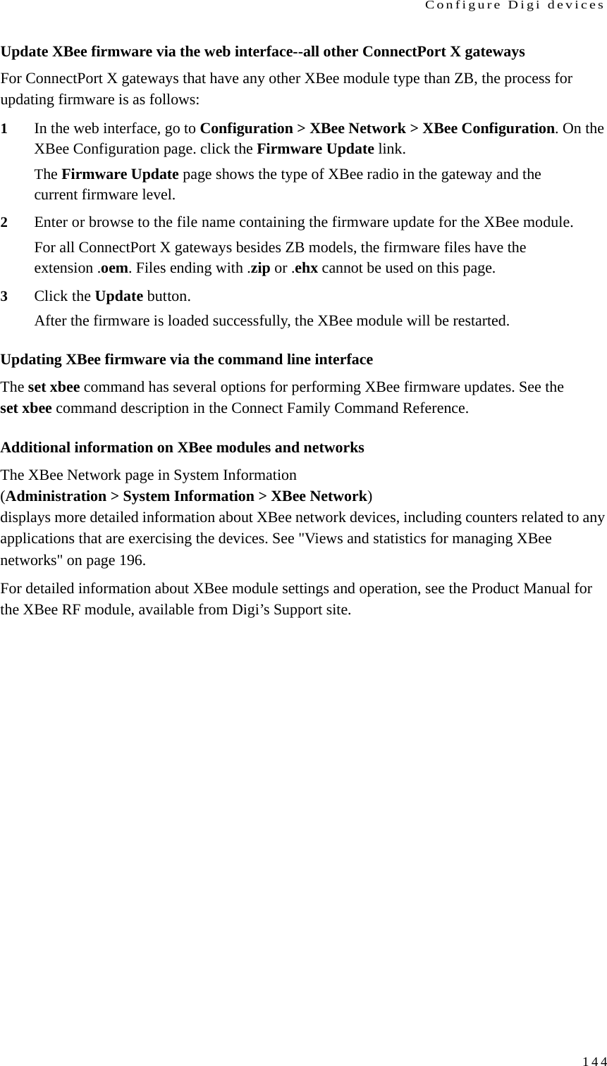
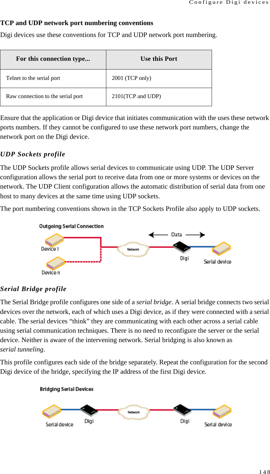
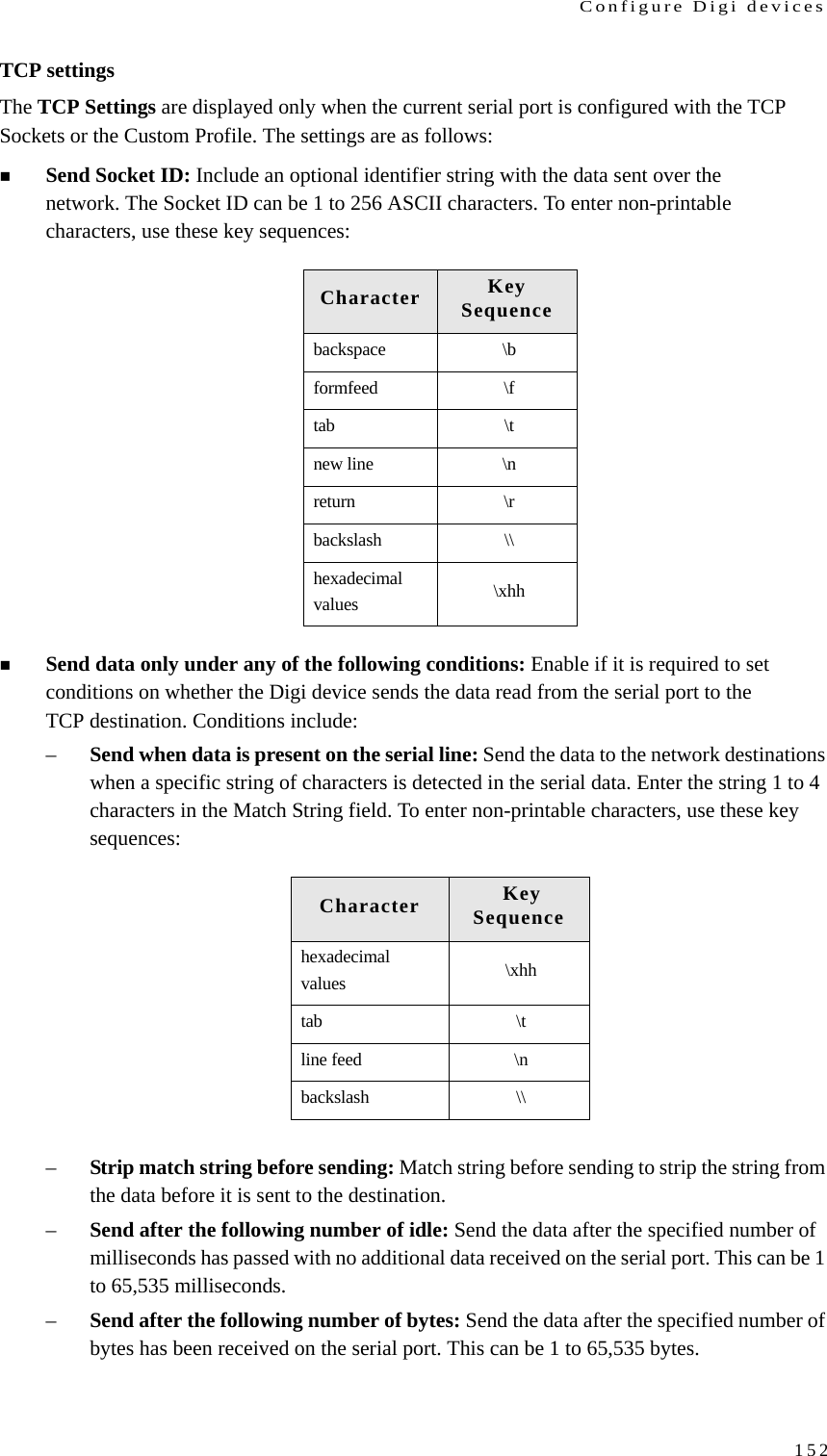
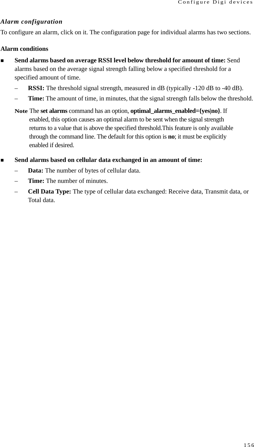
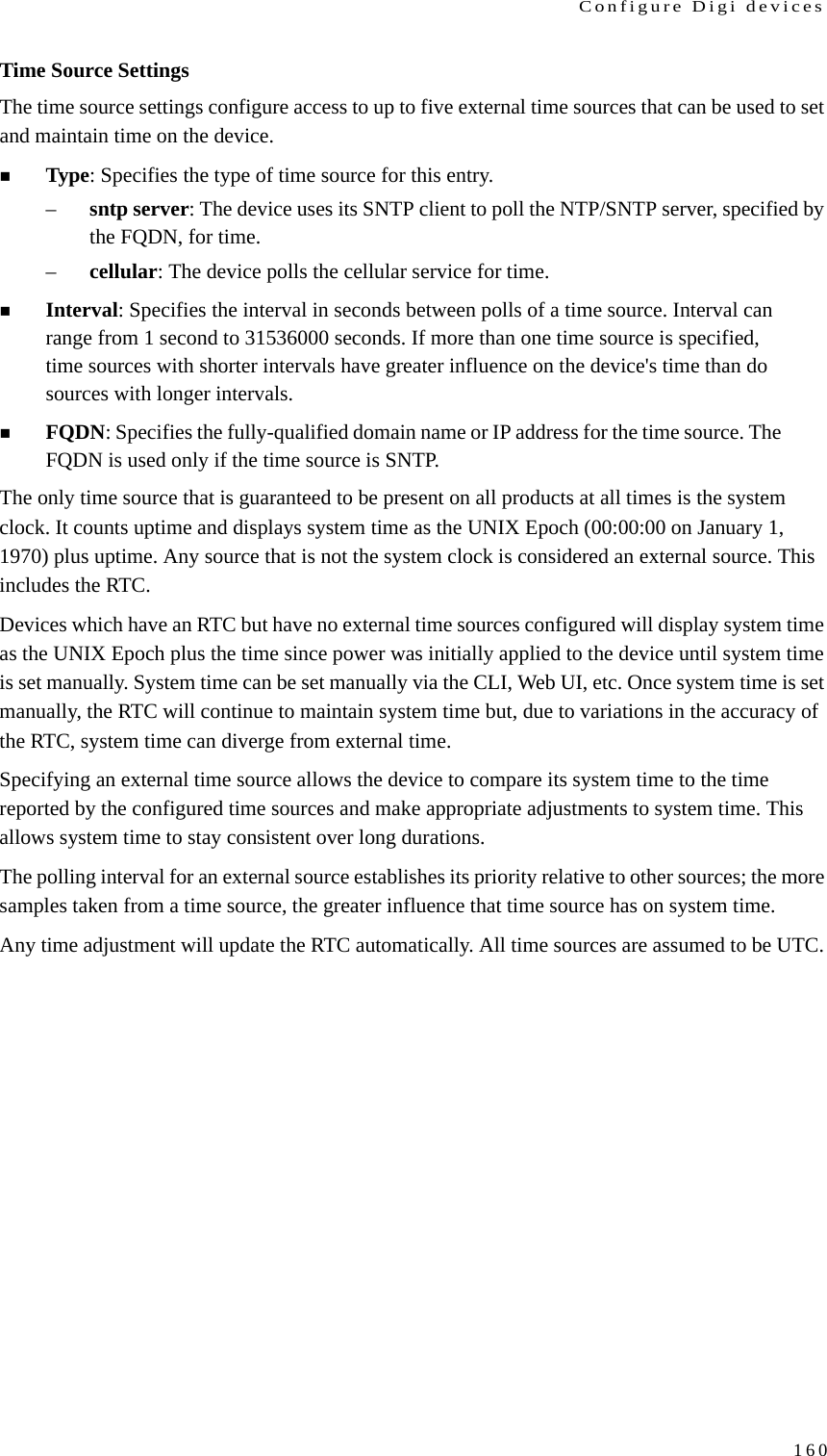
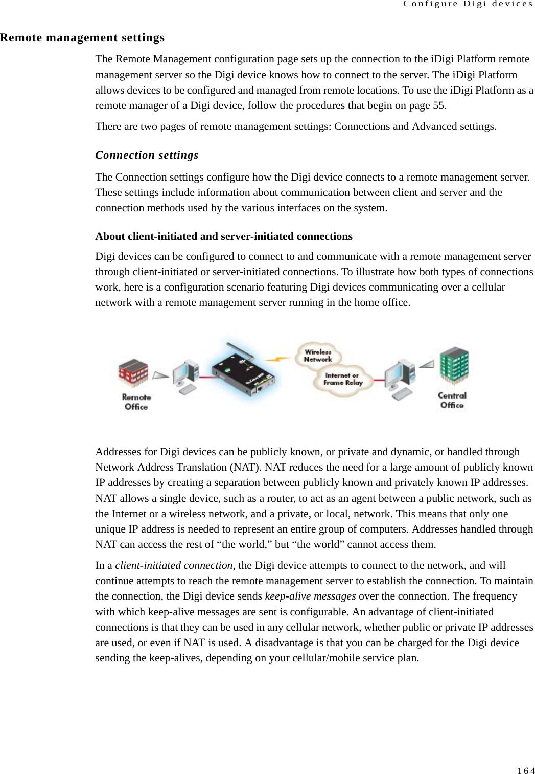
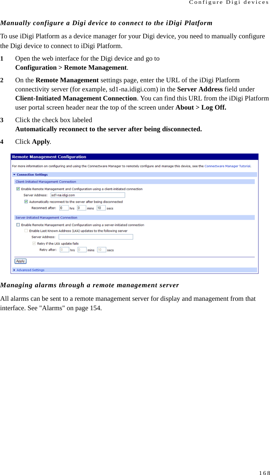
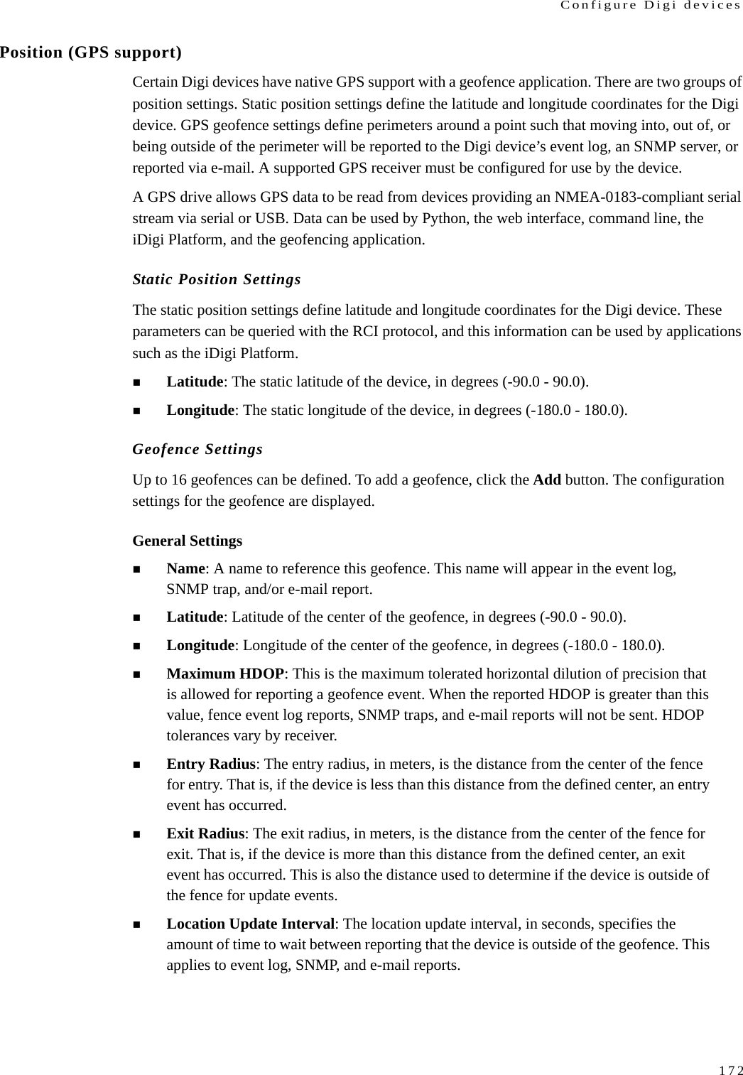
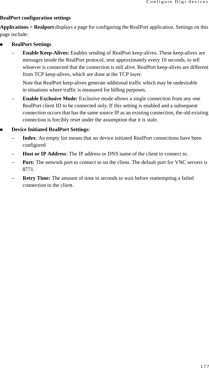
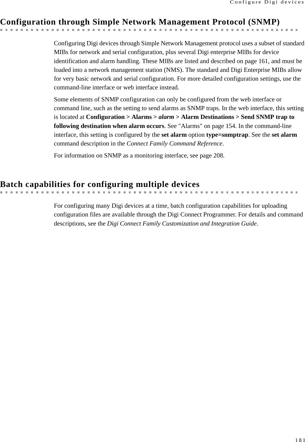
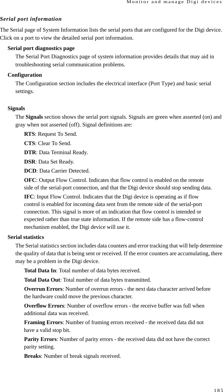
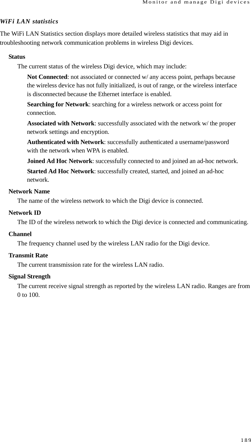
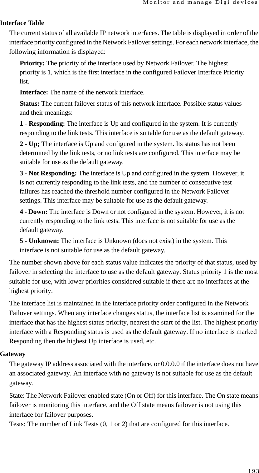
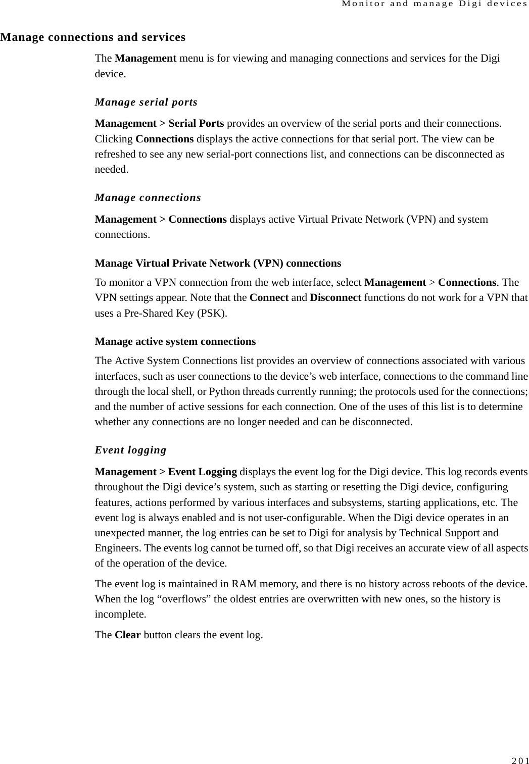
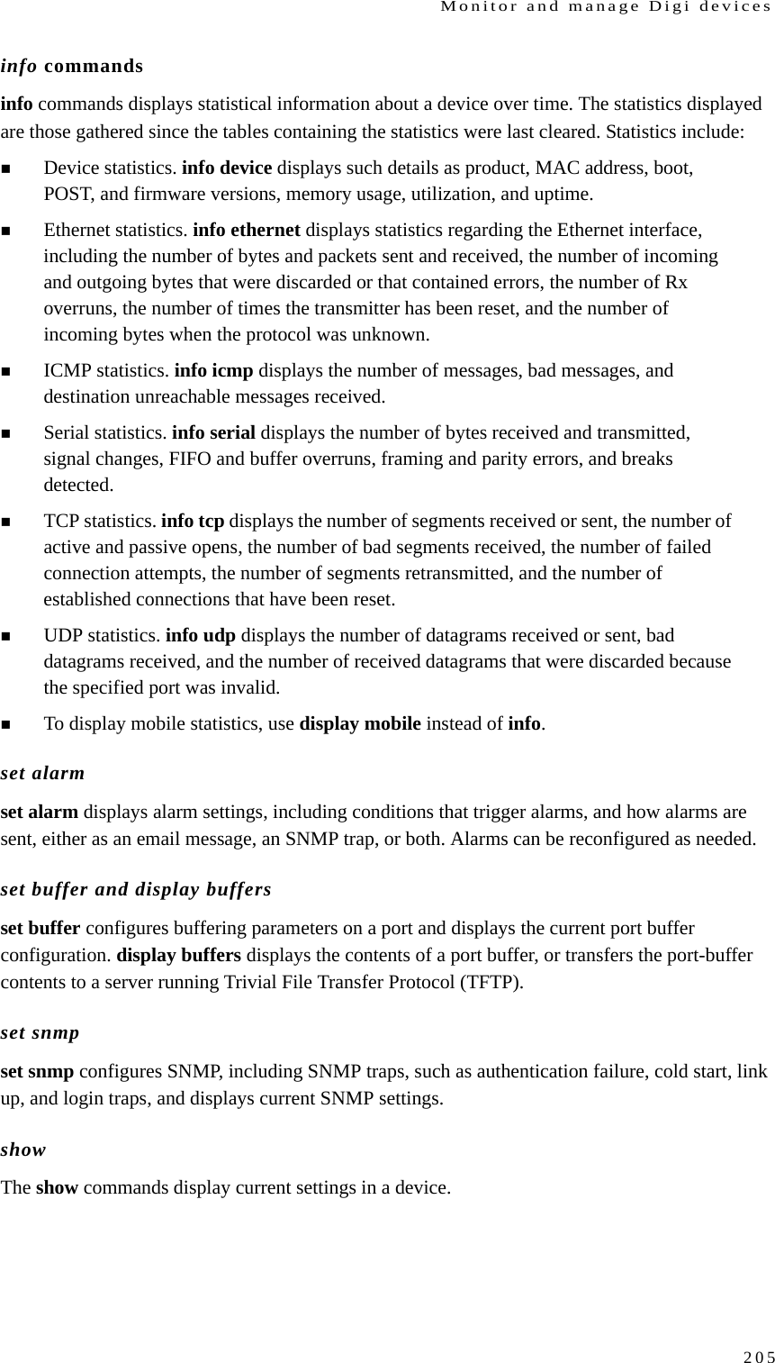
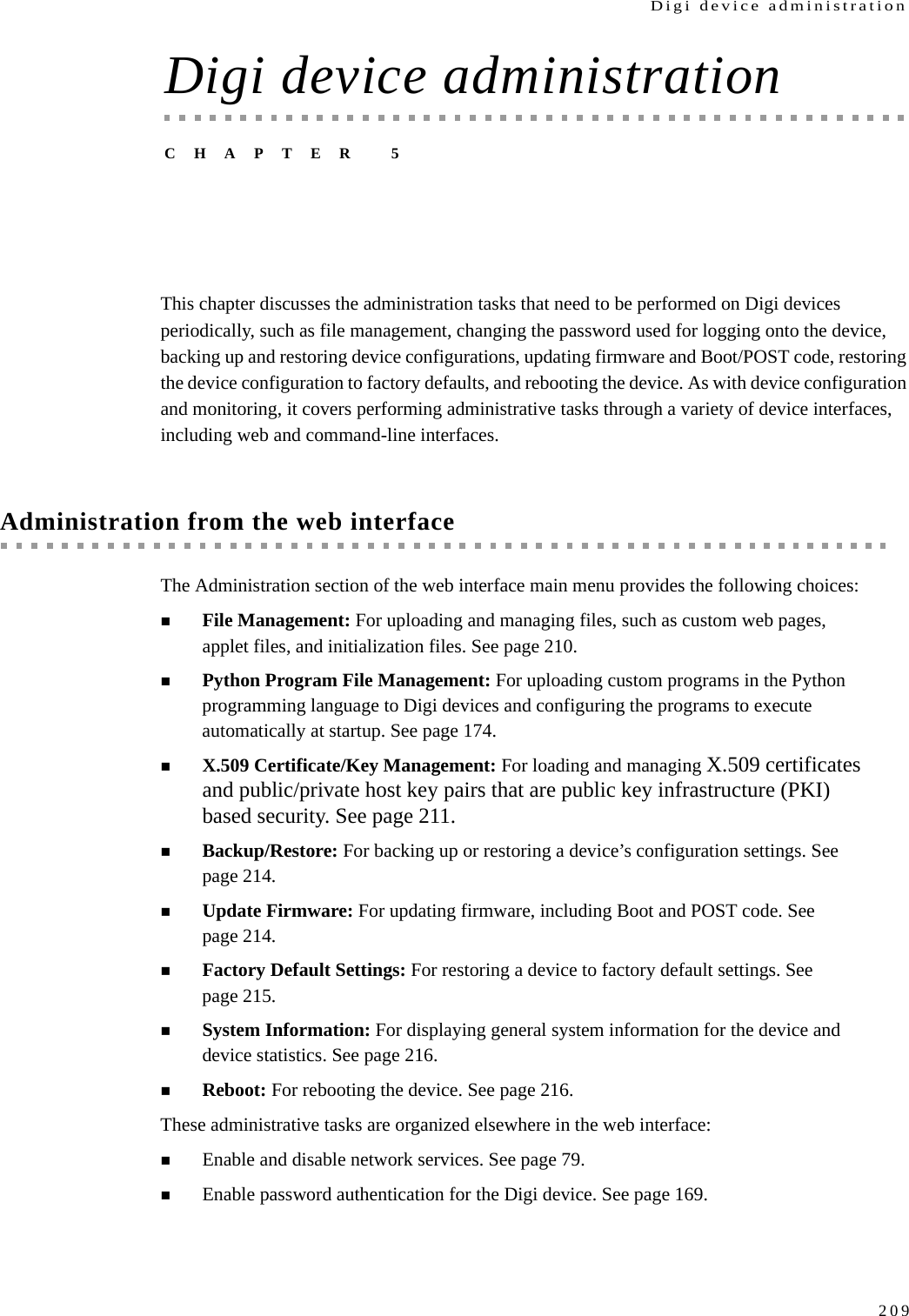
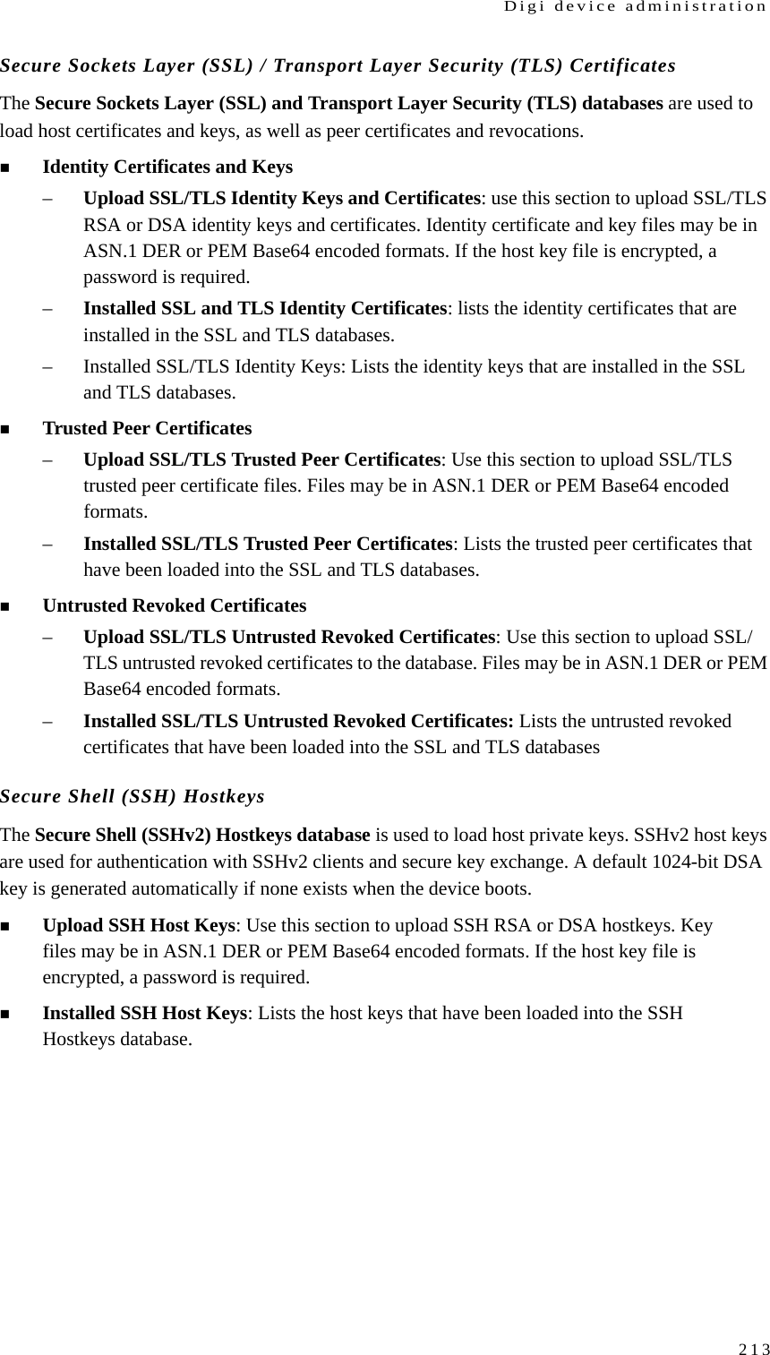
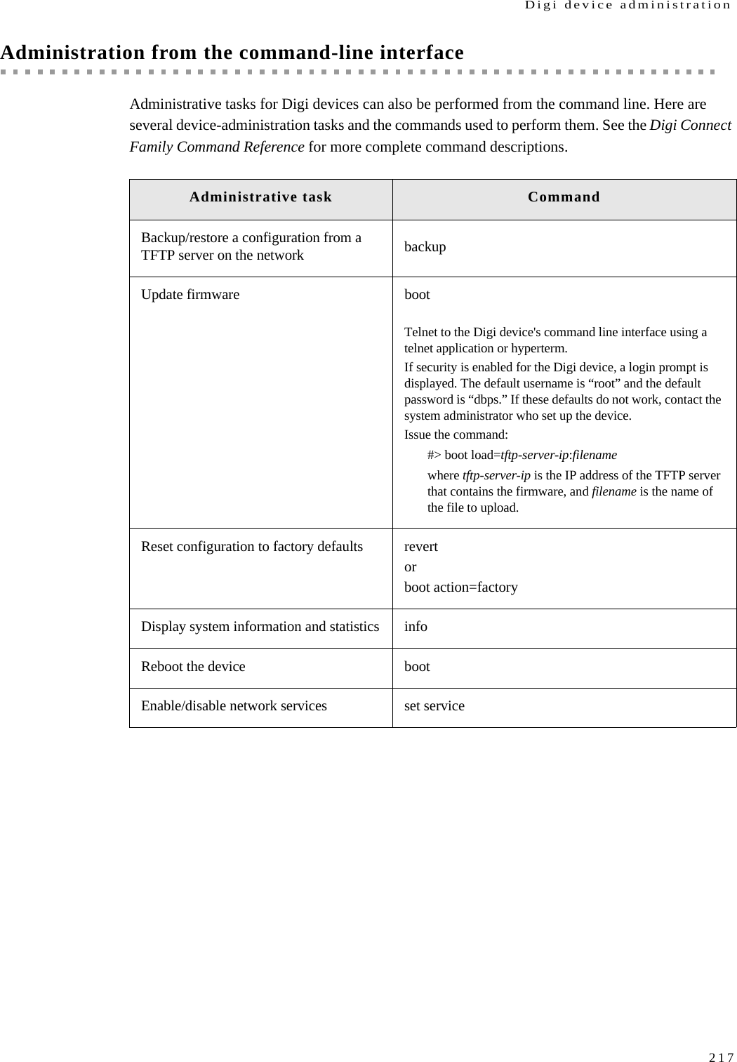
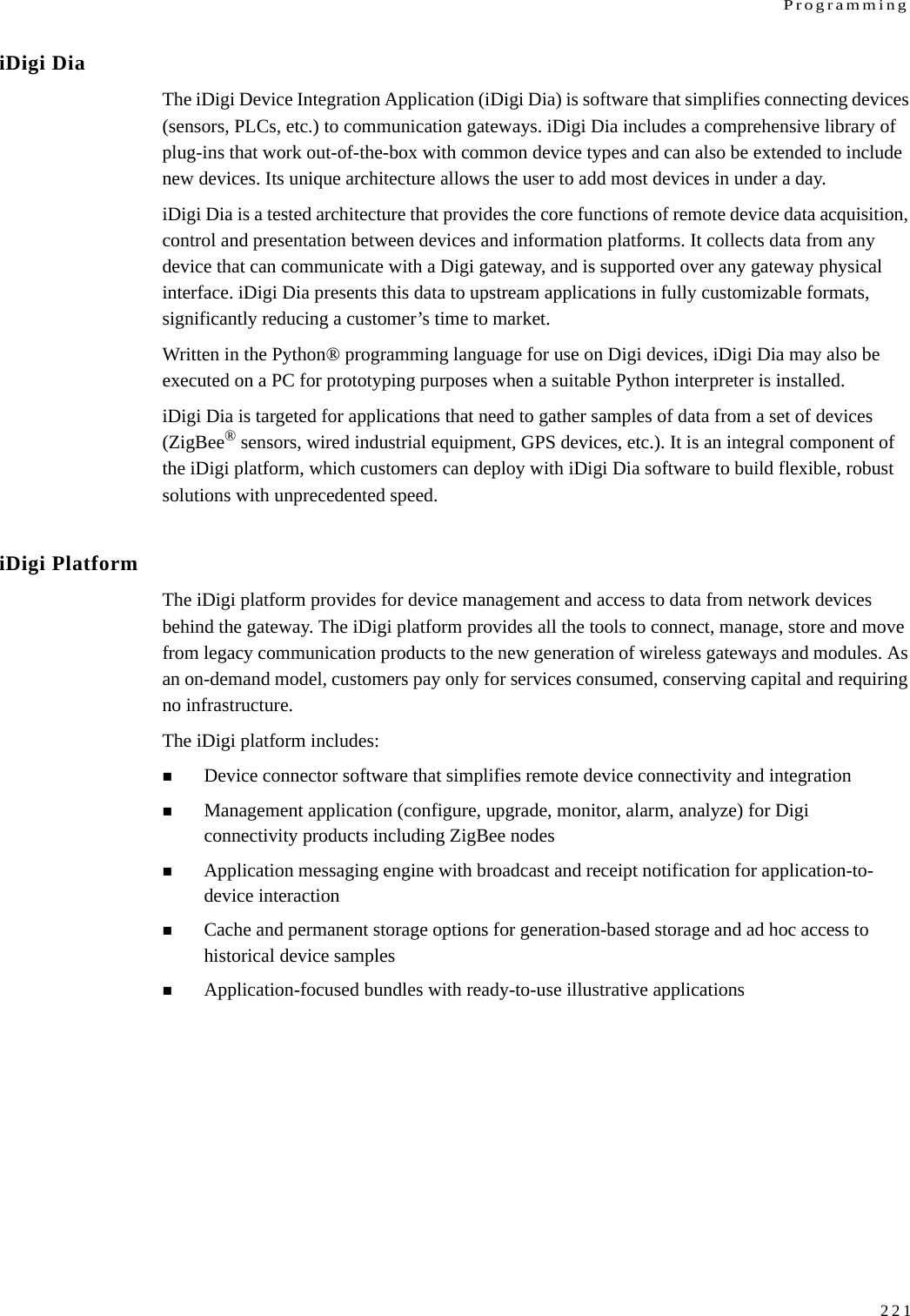
![Configure Digi devices133ASCIICode GSM 03.38CodeASCIICharacter Description0x4F 0x4F O LATIN CAPITAL LETTER O0x50 0x50 P LATIN CAPITAL LETTER P0x51 0x51 Q LATIN CAPITAL LETTER Q0x52 0x52 R LATIN CAPITAL LETTER R0x53 0x53 S LATIN CAPITAL LETTER S0x54 0x54 T LATIN CAPITAL LETTER T0x55 0x55 U LATIN CAPITAL LETTER U0x56 0x56 V LATIN CAPITAL LETTER V0x57 0x57 W LATIN CAPITAL LETTER W0x58 0x58 X LATIN CAPITAL LETTER X0x59 0x59 Y LATIN CAPITAL LETTER Y0x5A 0x5A Z LATIN CAPITAL LETTER Z0x5B 0x1B3C [ LEFT SQUARE BRACKET0x5C 0x1B2F \ REVERSE SOLIDUS (BACKSLASH)0x5D 0x1B3E ] RIGHT SQUARE BRACKET0x5E 0x1B14 ^ CIRCUMFLEX ACCENT0x5F 0x11 _ LOW LINE (UNDERSCORE)0x60 0x27 (1) ` GRAVE ACCENT0x61 0x61 a LATIN SMALL LETTER A0x62 0x62 b LATIN SMALL LETTER B0x63 0x63 c LATIN SMALL LETTER C0x64 0x64 d LATIN SMALL LETTER D0x65 0x65 e LATIN SMALL LETTER E0x66 0x66 f LATIN SMALL LETTER F0x67 0x67 g LATIN SMALL LETTER G0x68 0x68 h LATIN SMALL LETTER H0x69 0x69 i LATIN SMALL LETTER ISupported character set (Continued)](https://usermanual.wiki/Digi/WMPX5F/User-Guide-1291648-Page-133.png)
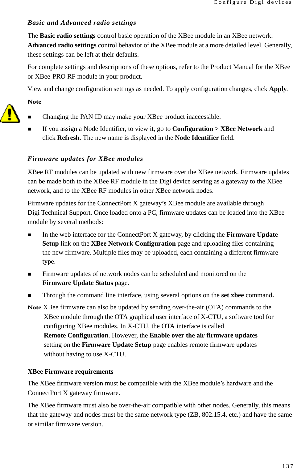
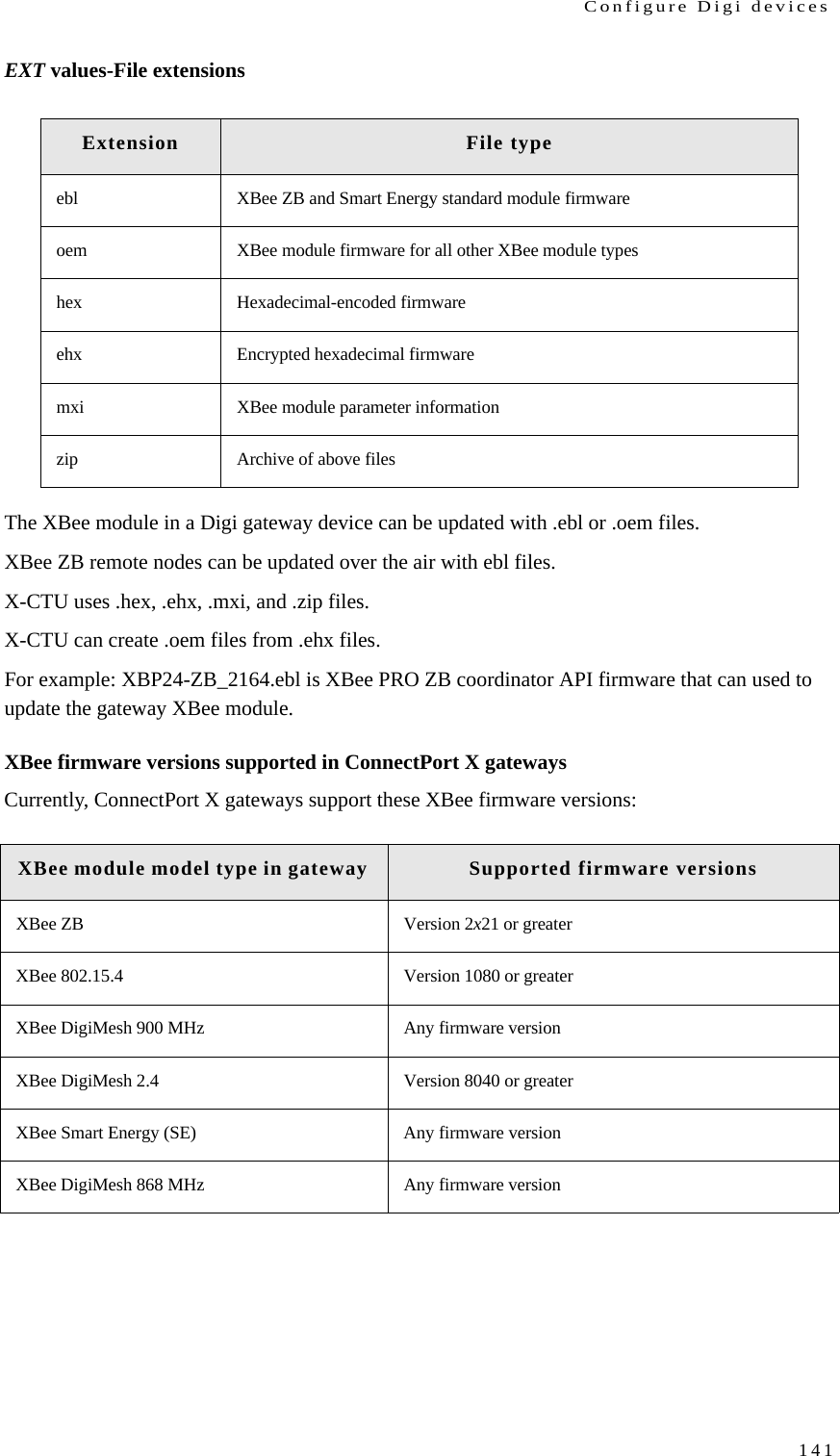
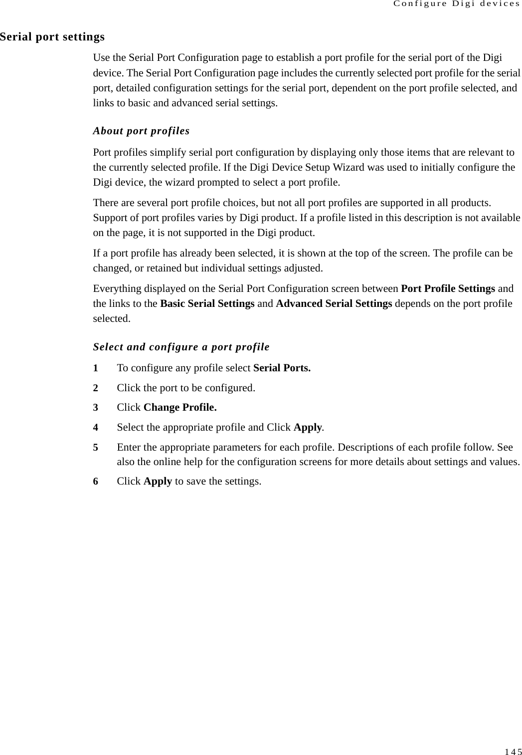
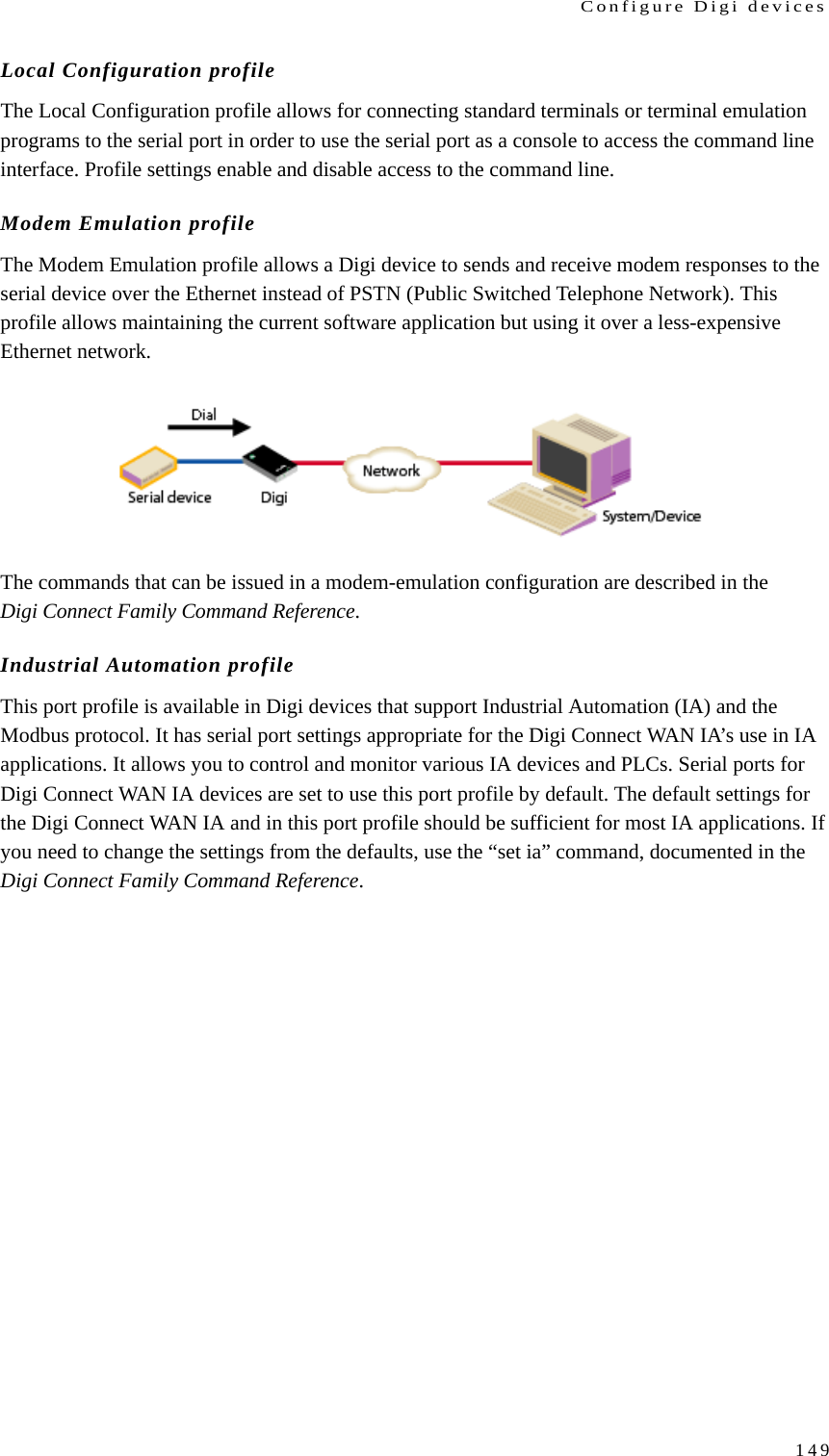
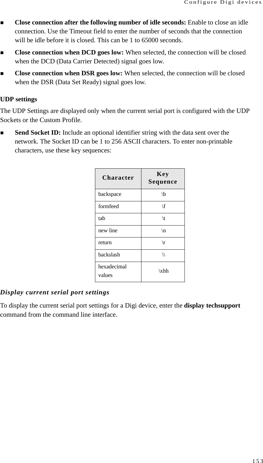
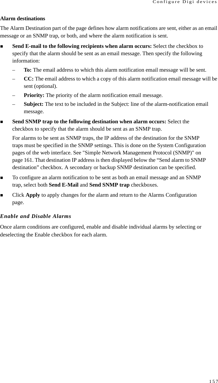
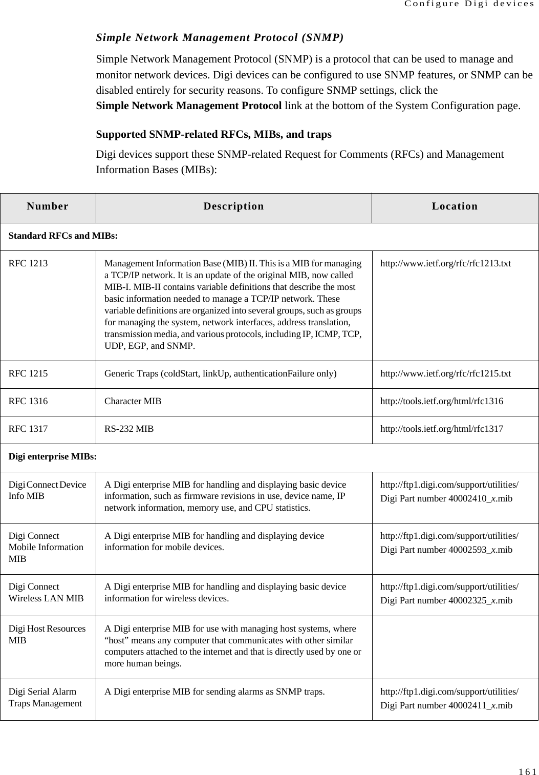
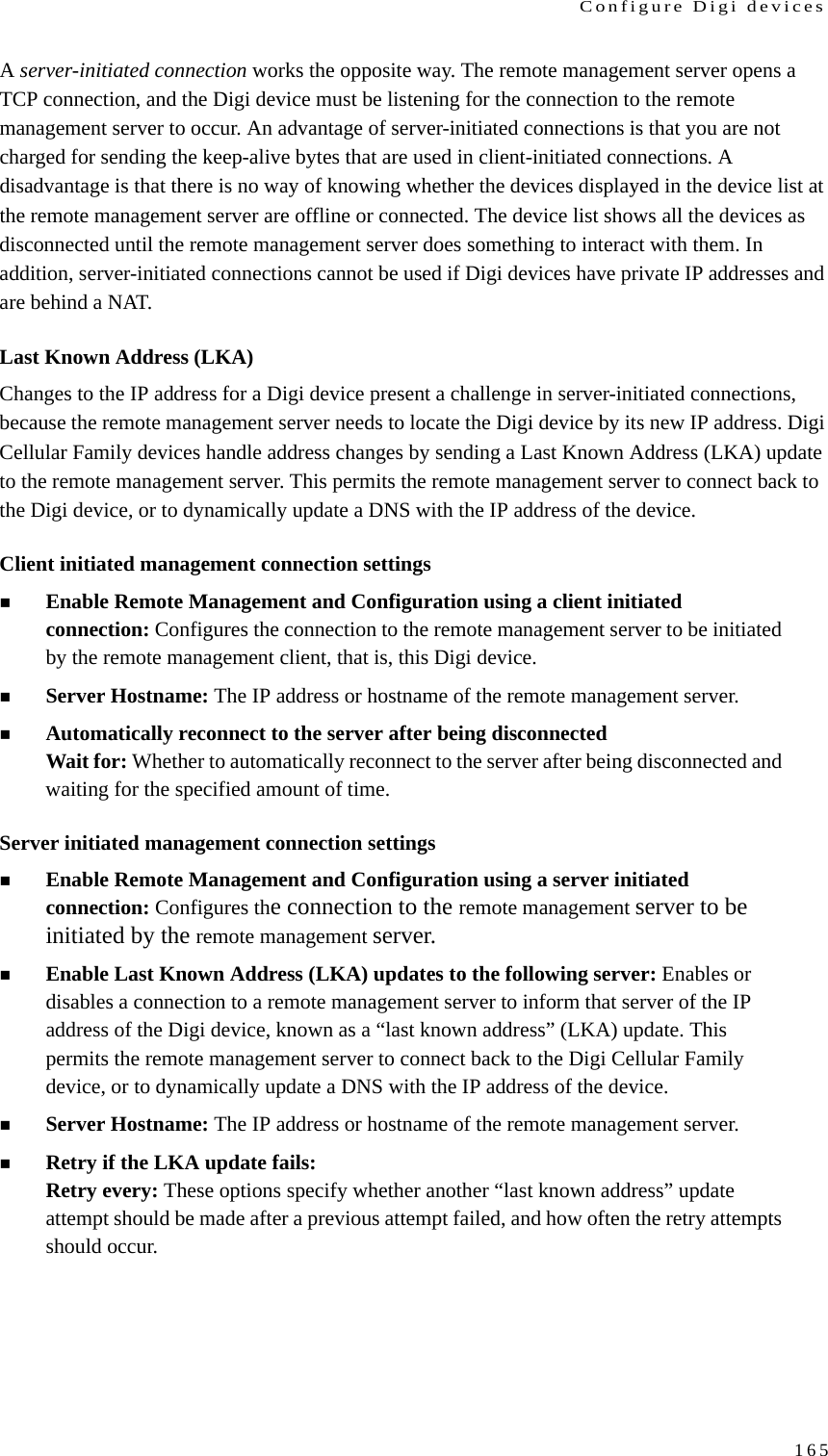
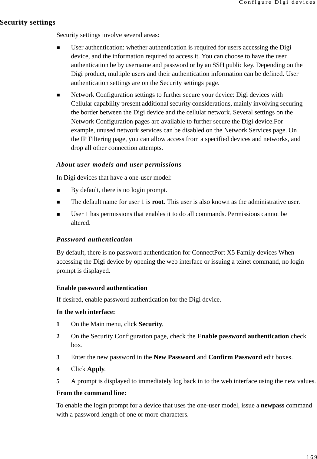
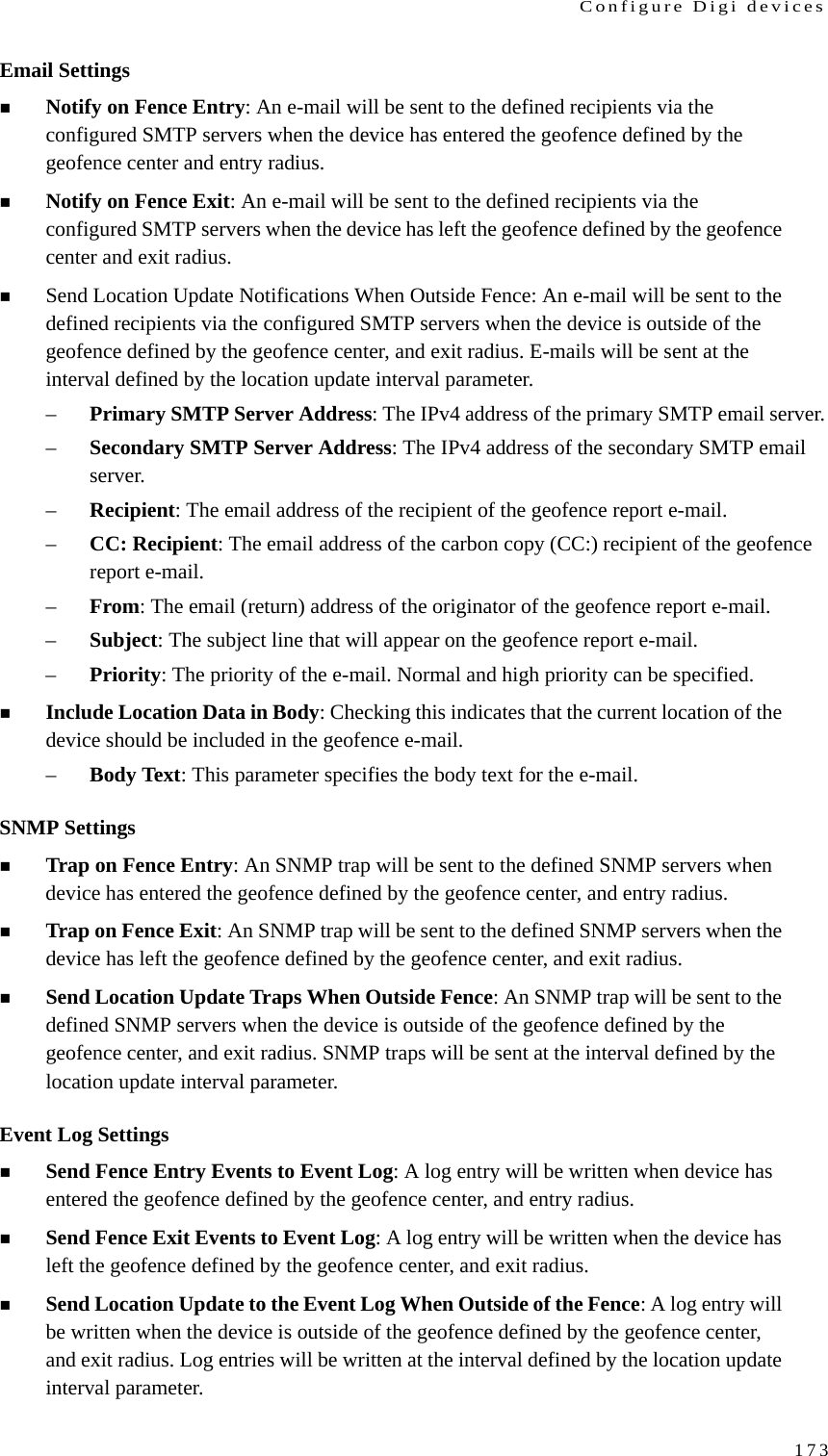
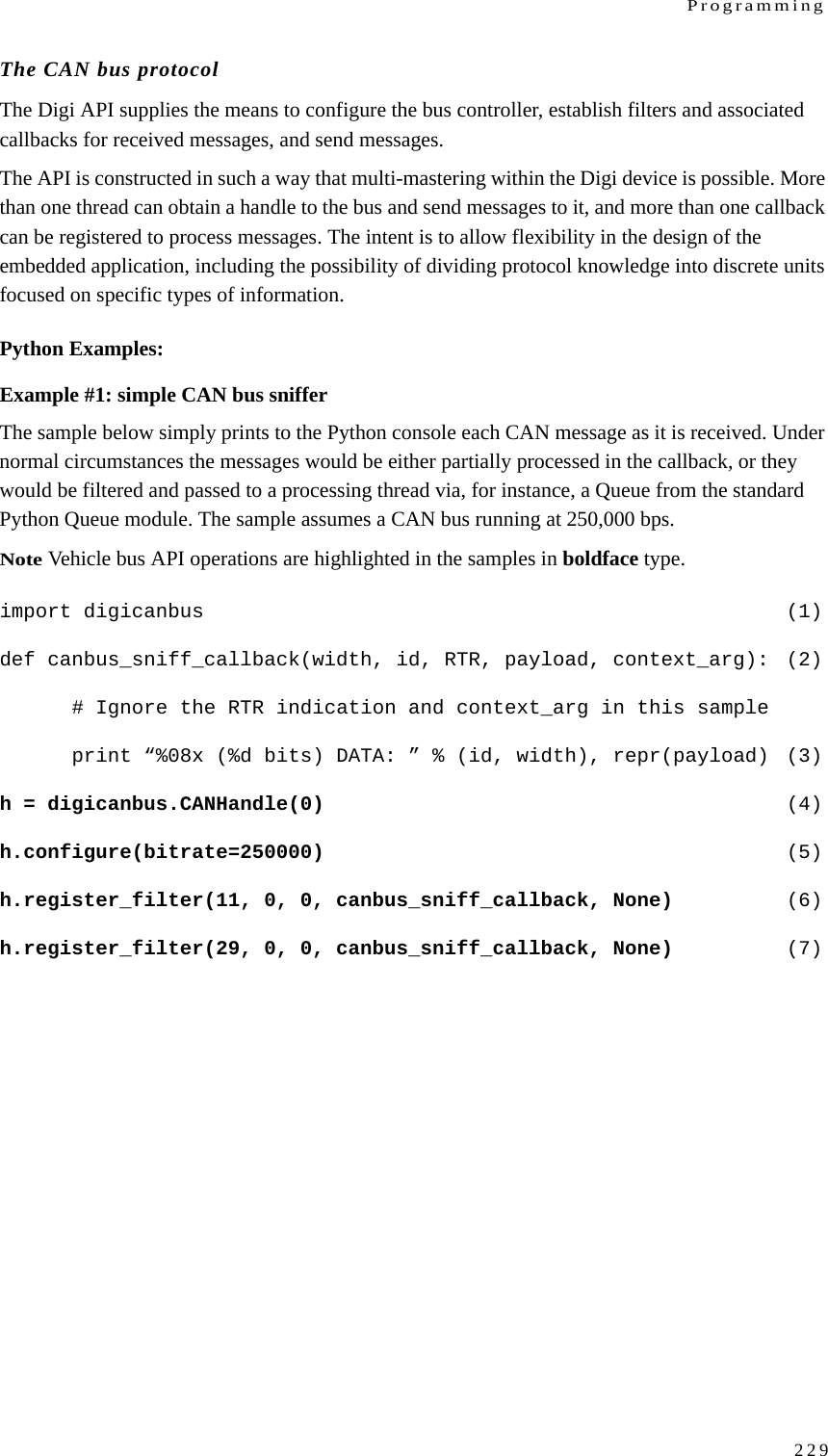
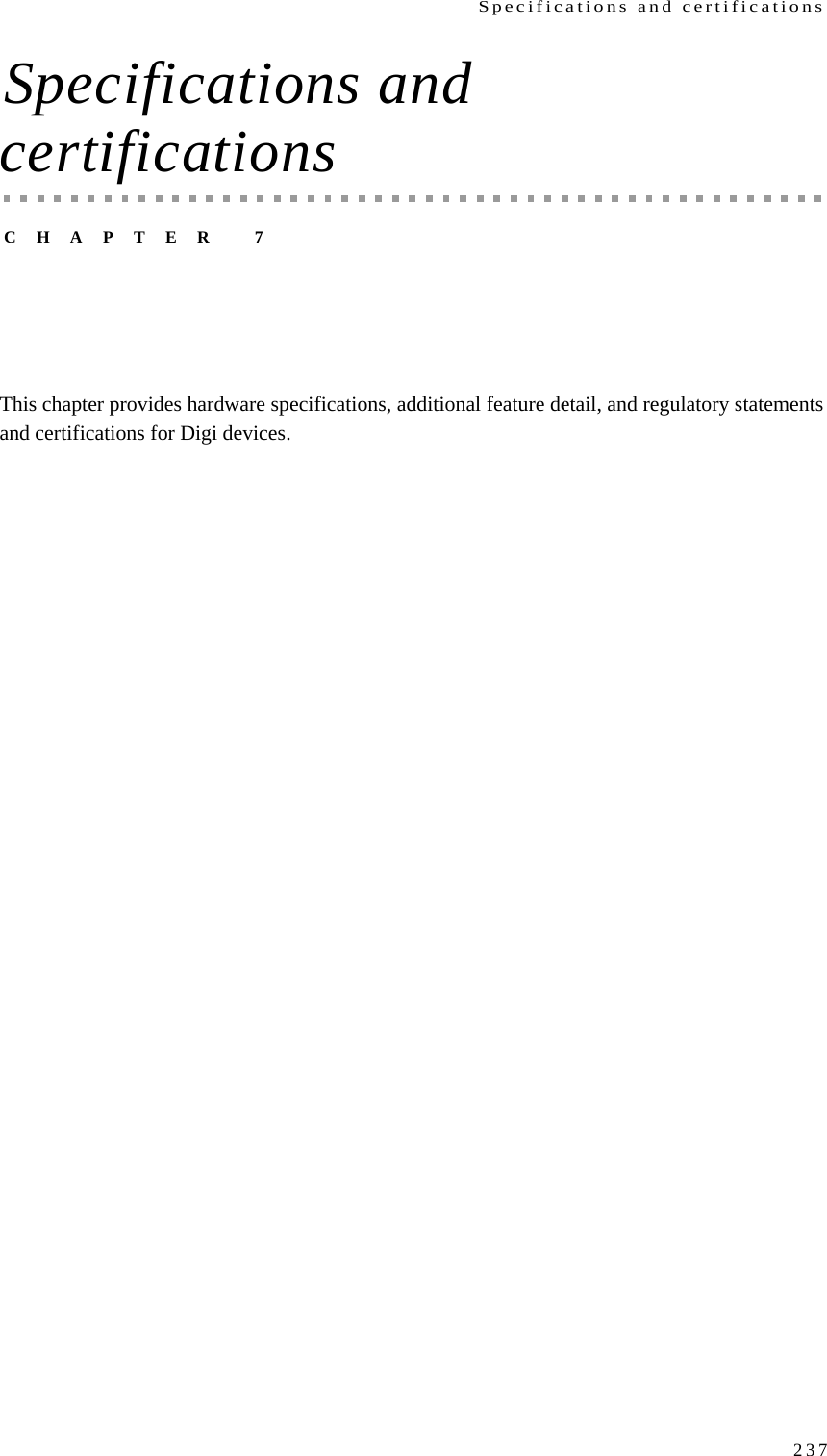
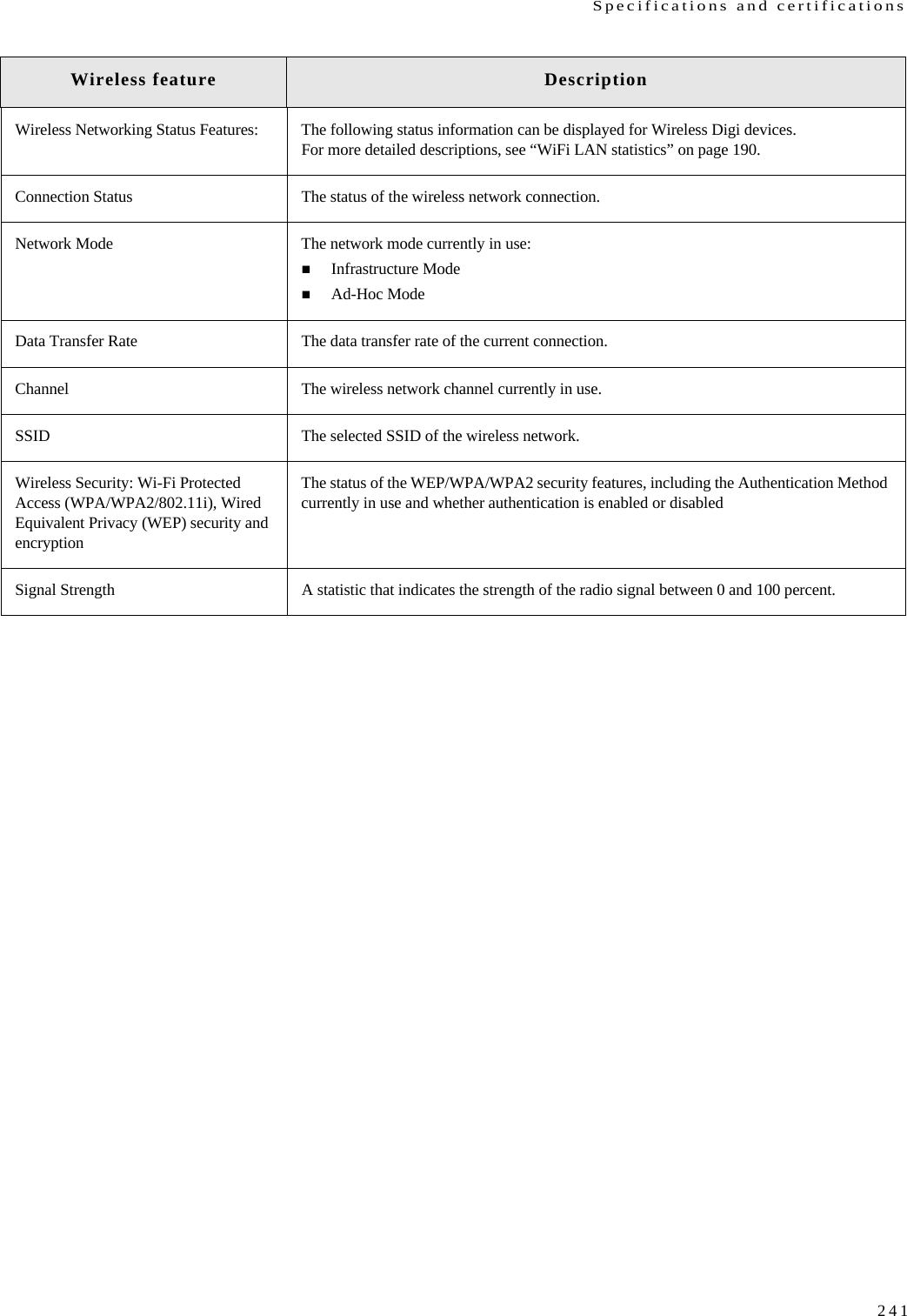
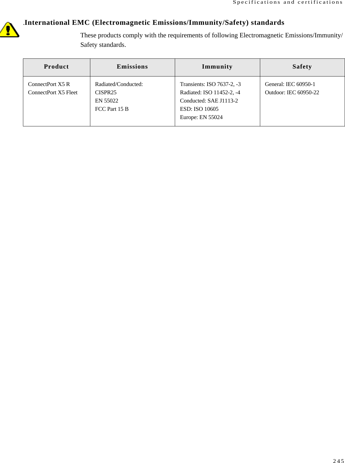
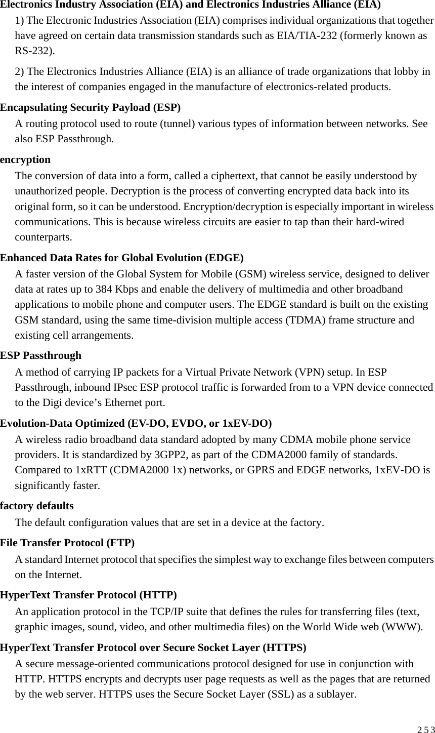
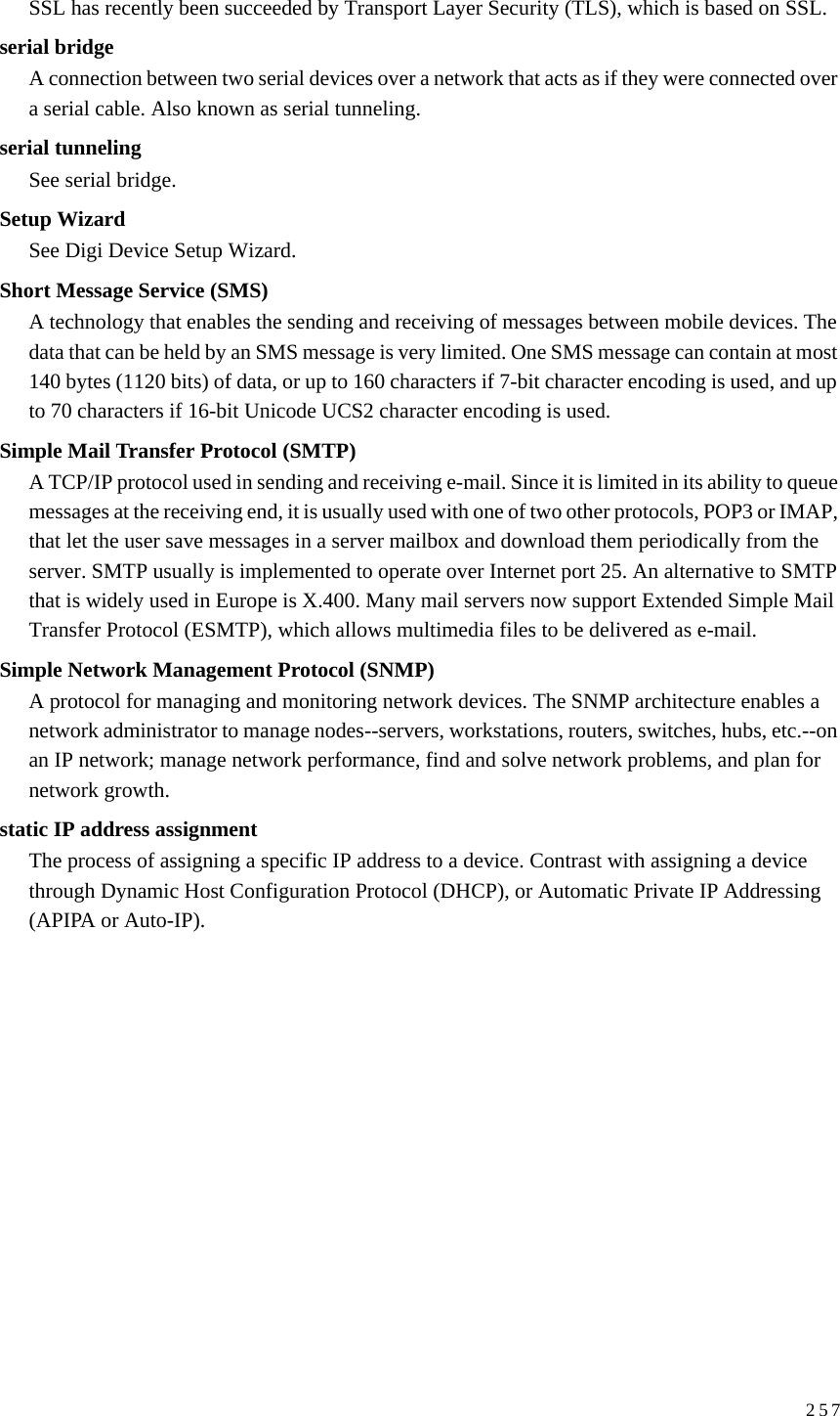
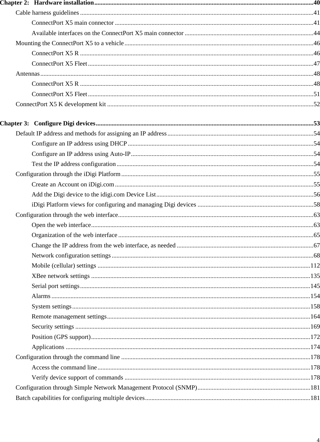
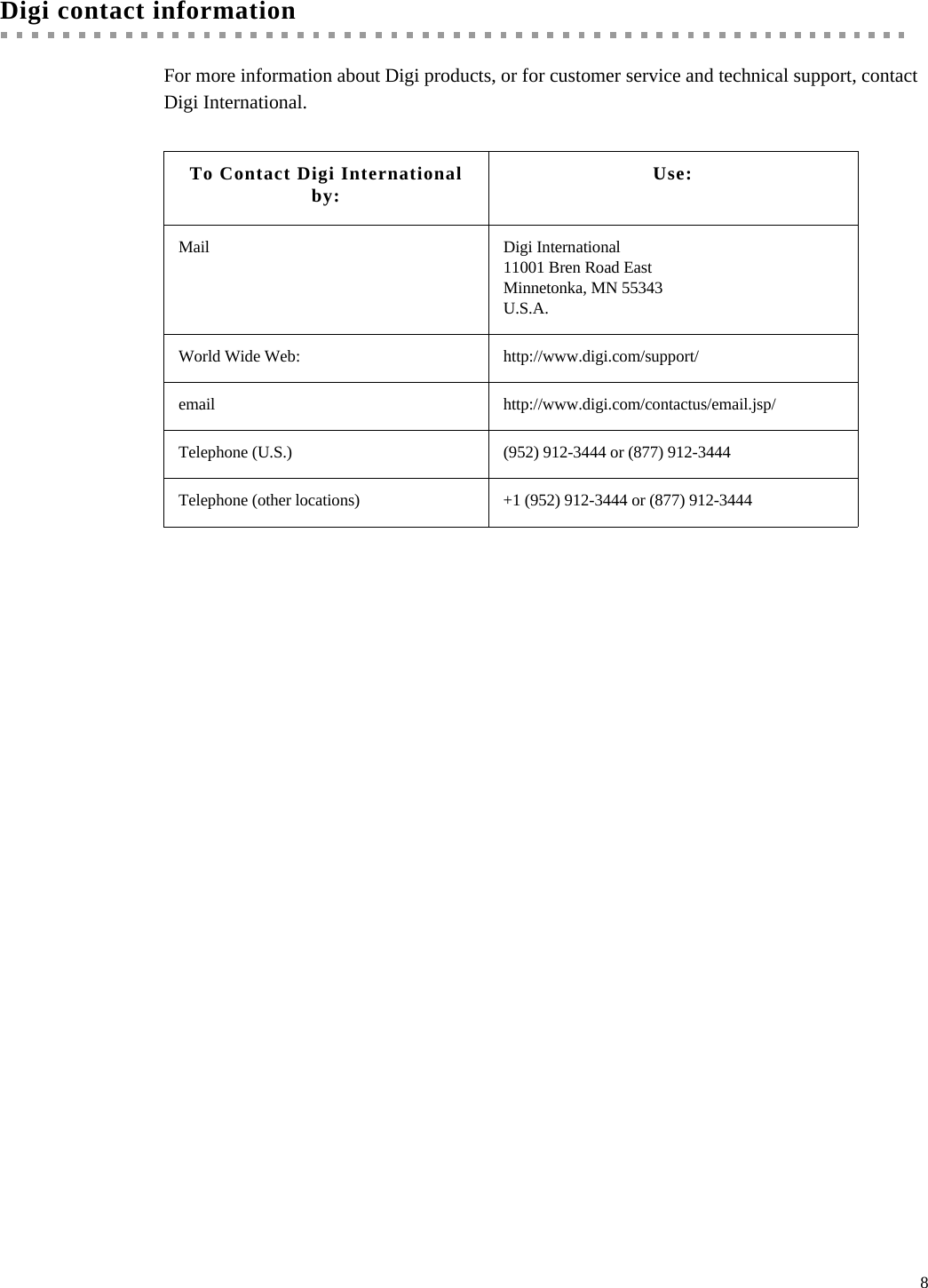
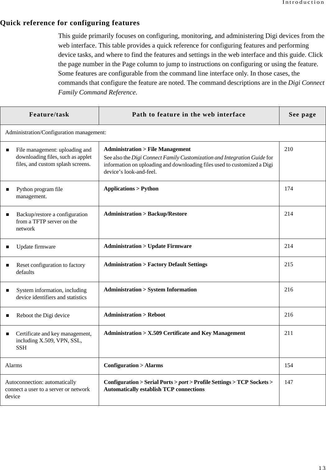
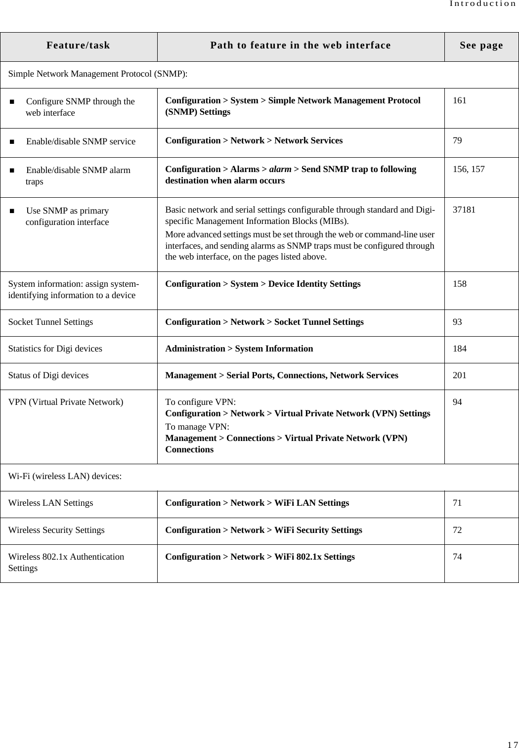
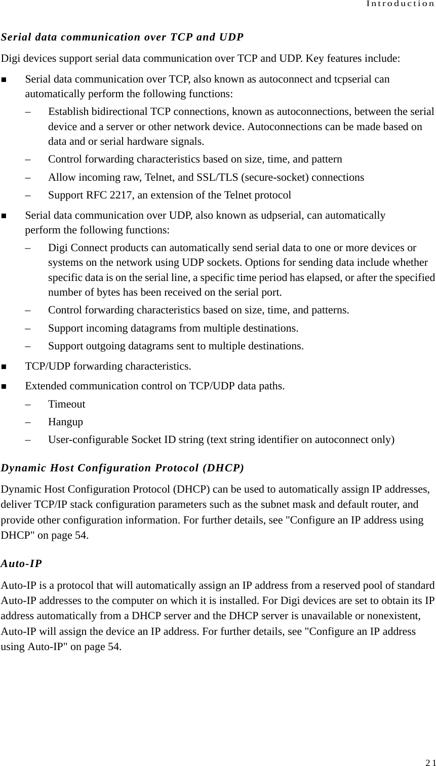
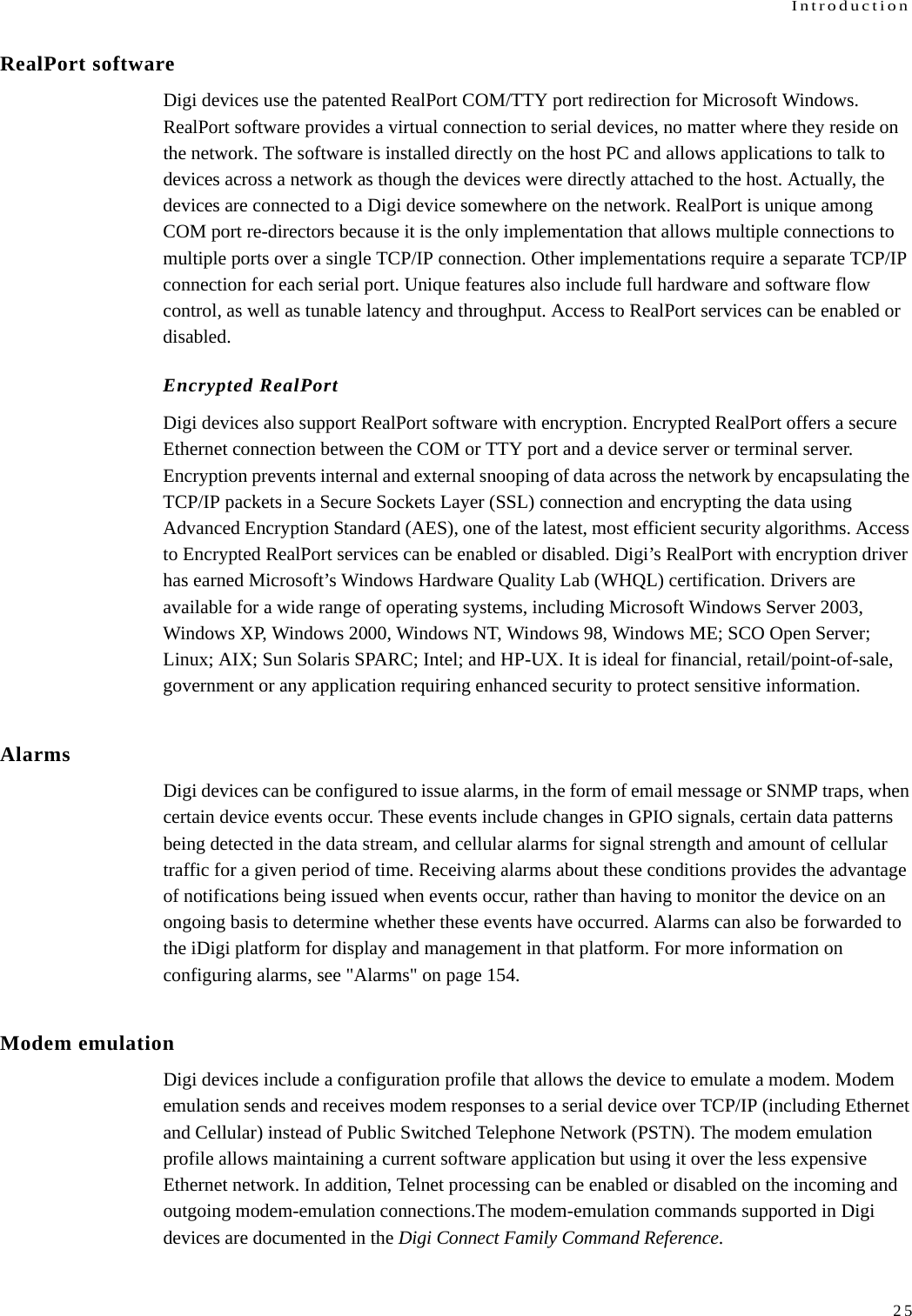
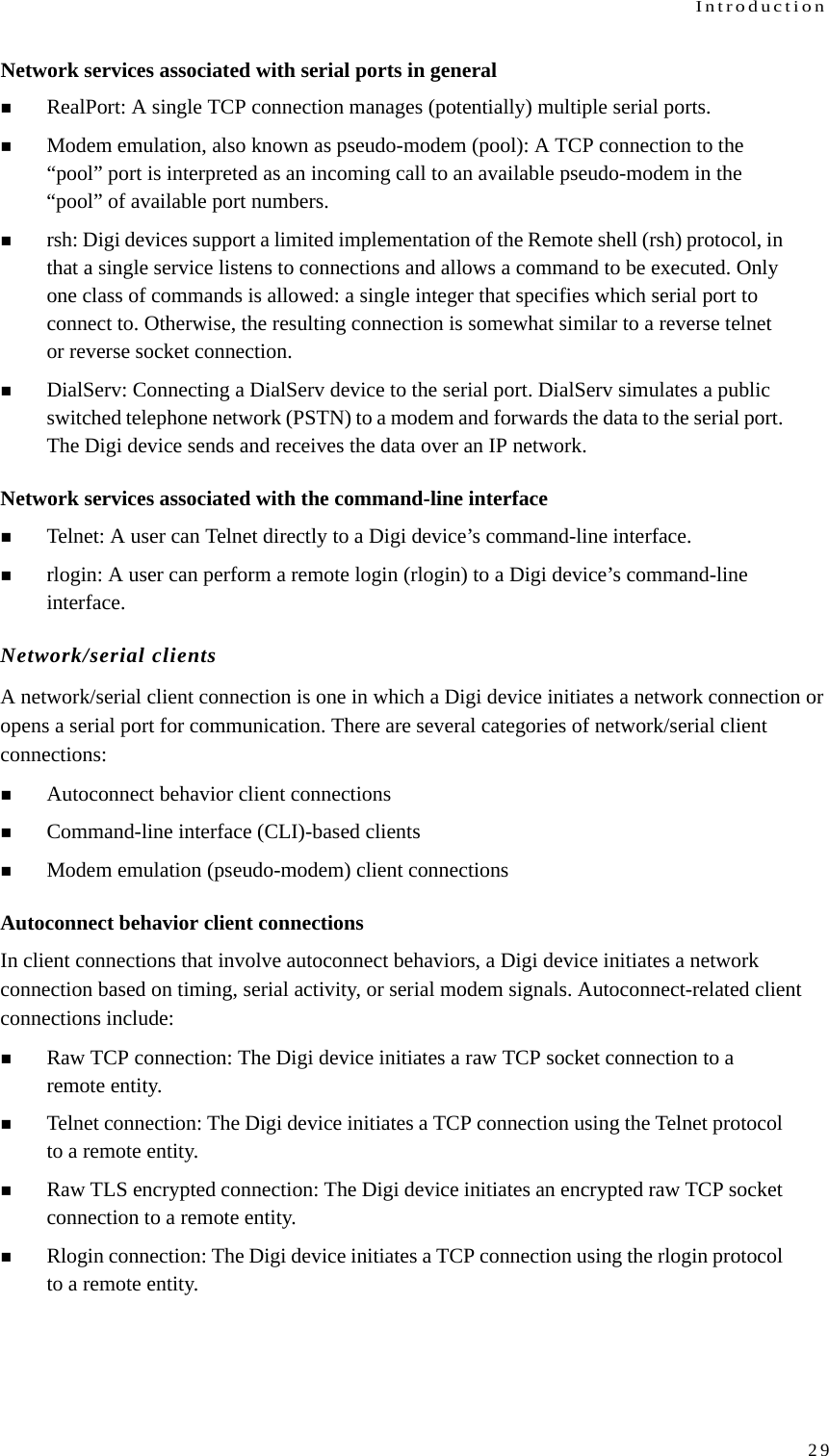
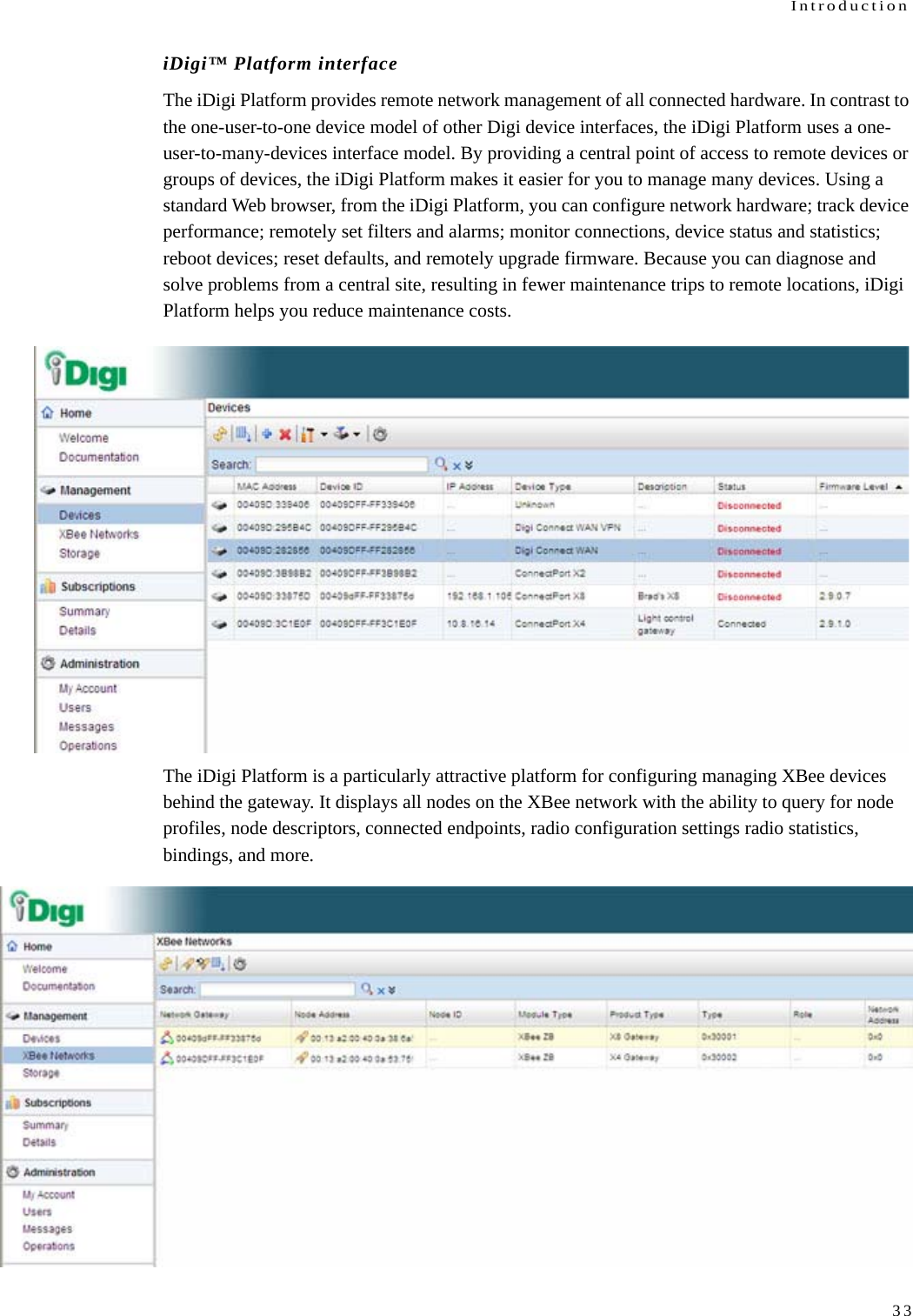
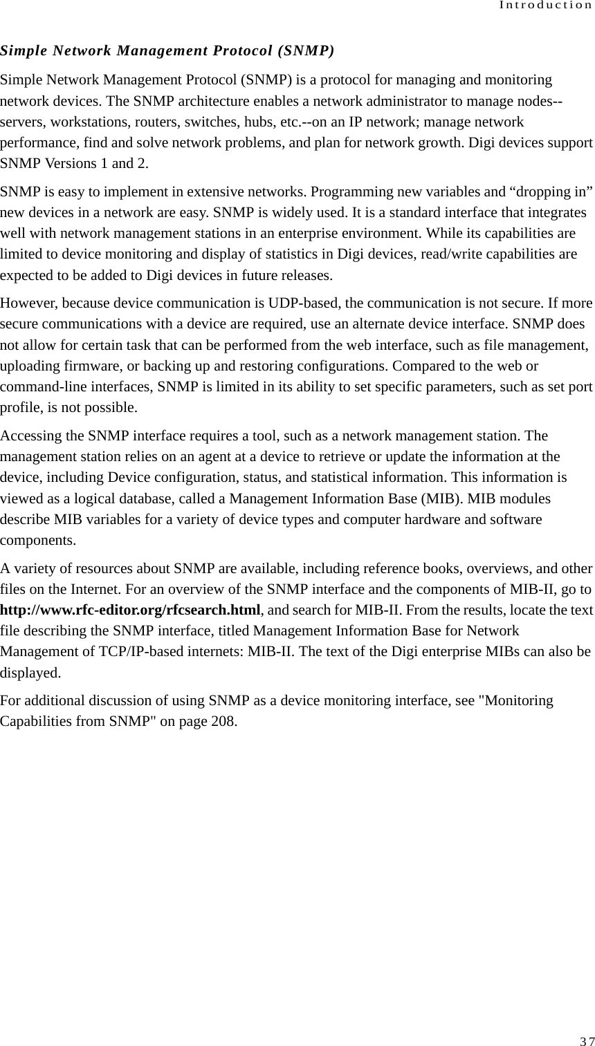
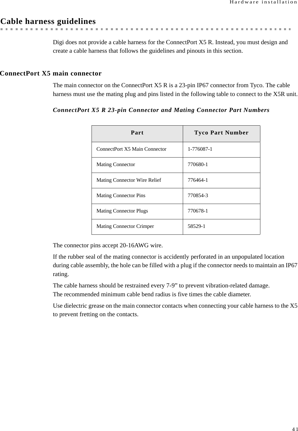
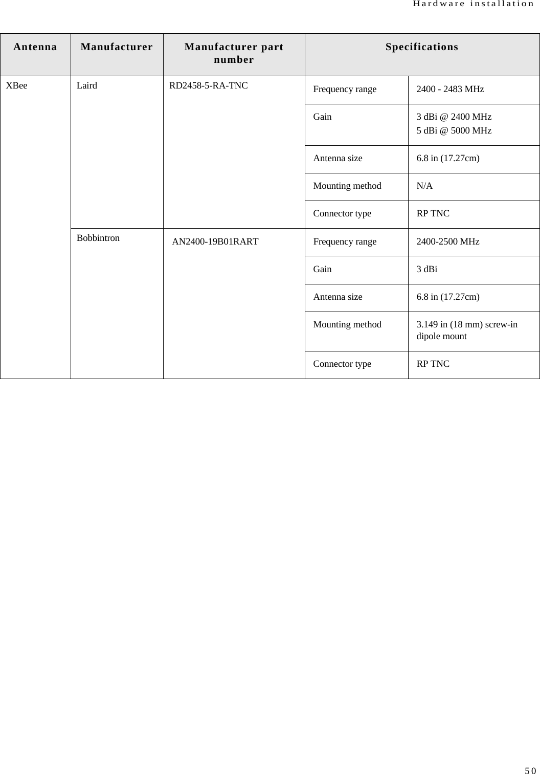
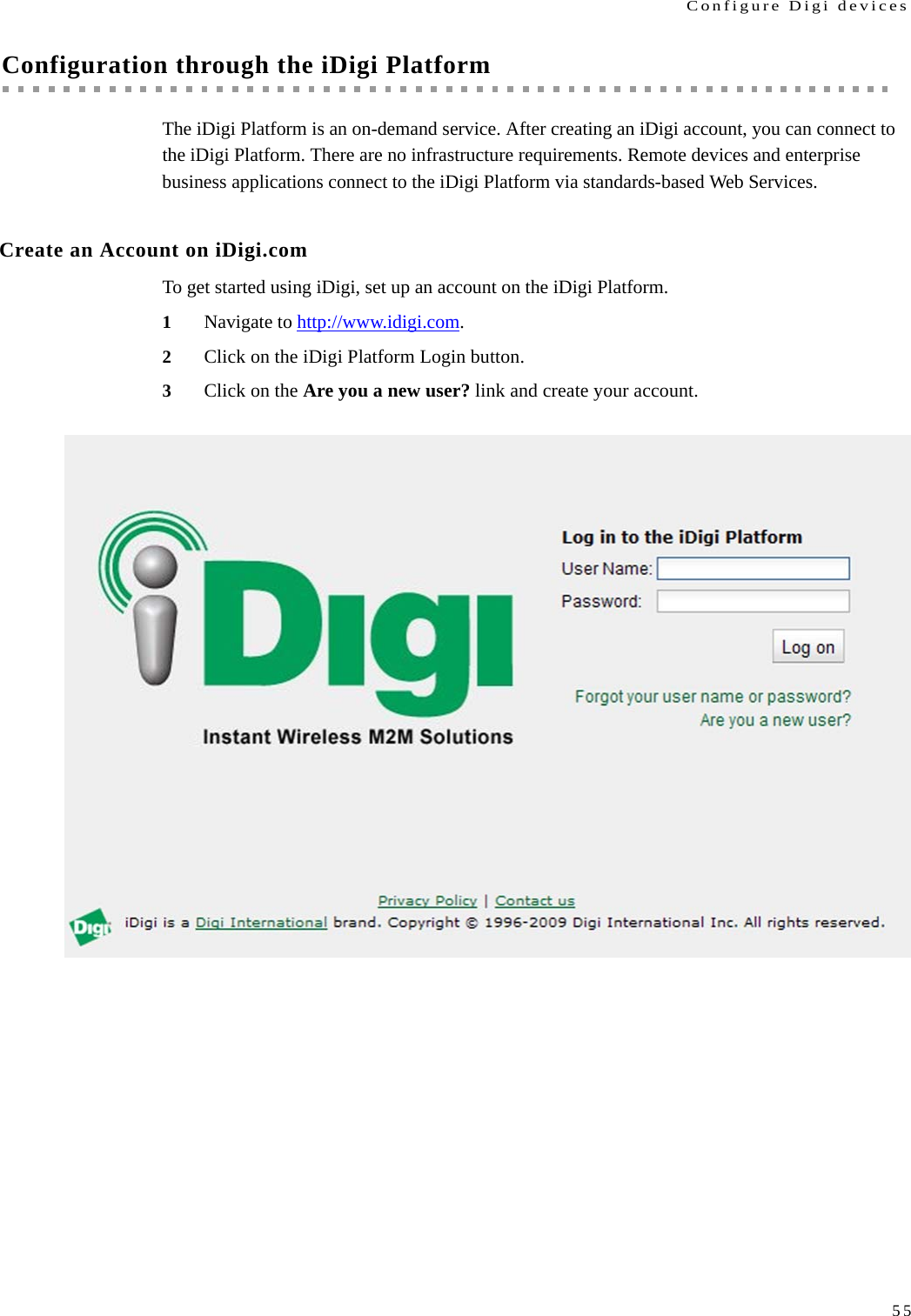
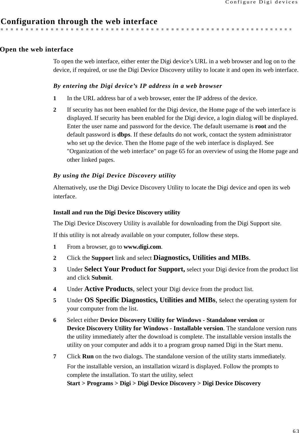
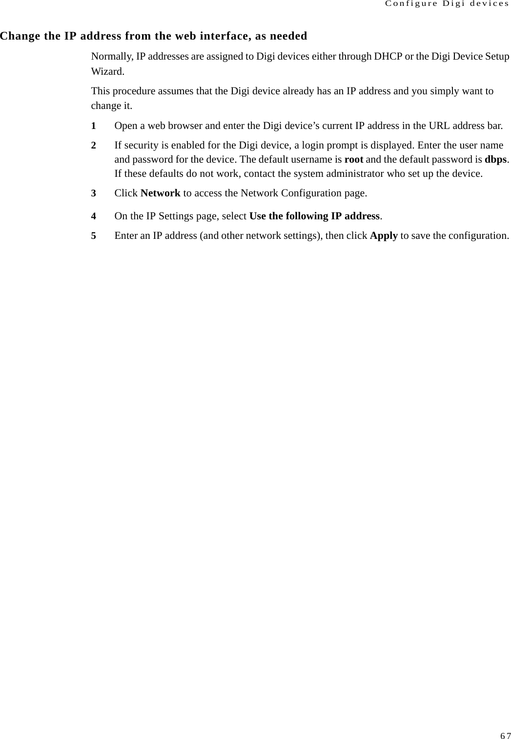
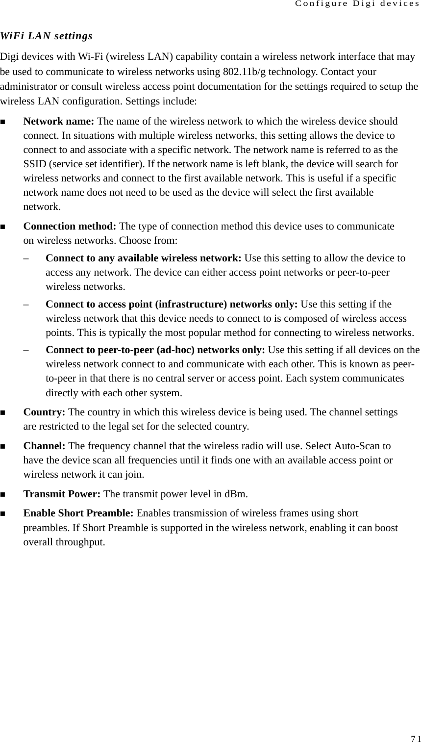
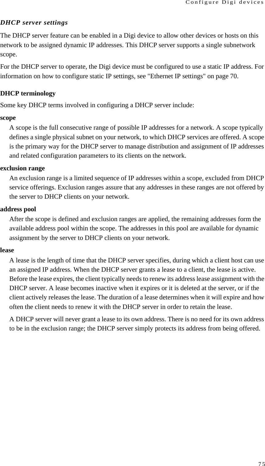
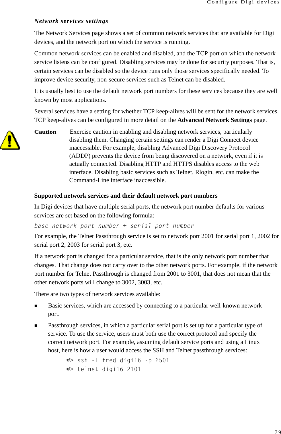
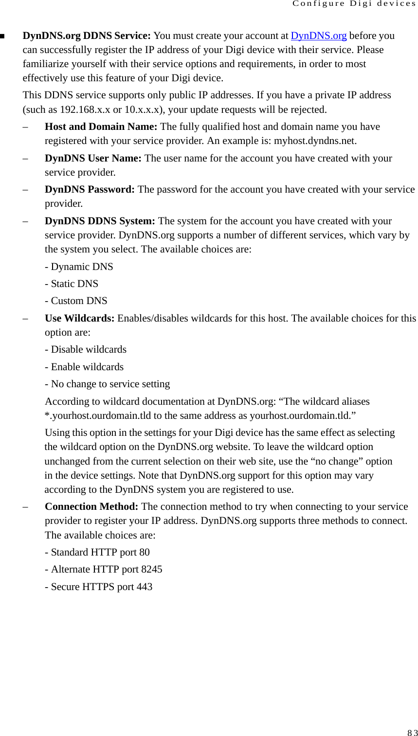
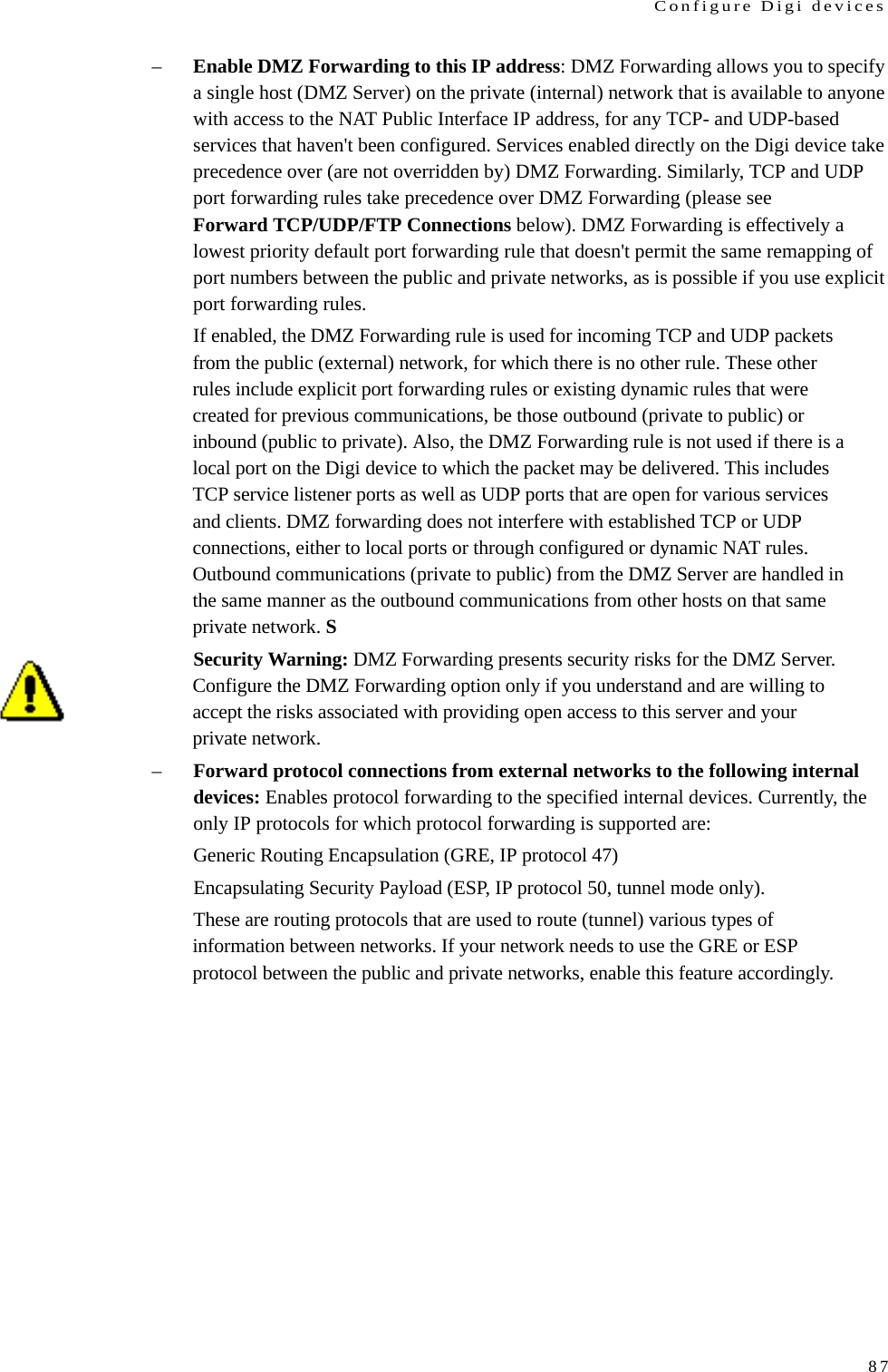
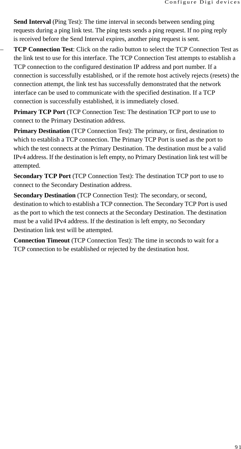
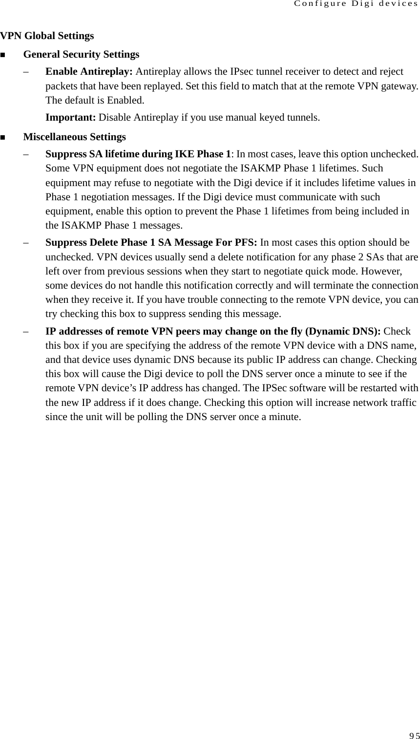
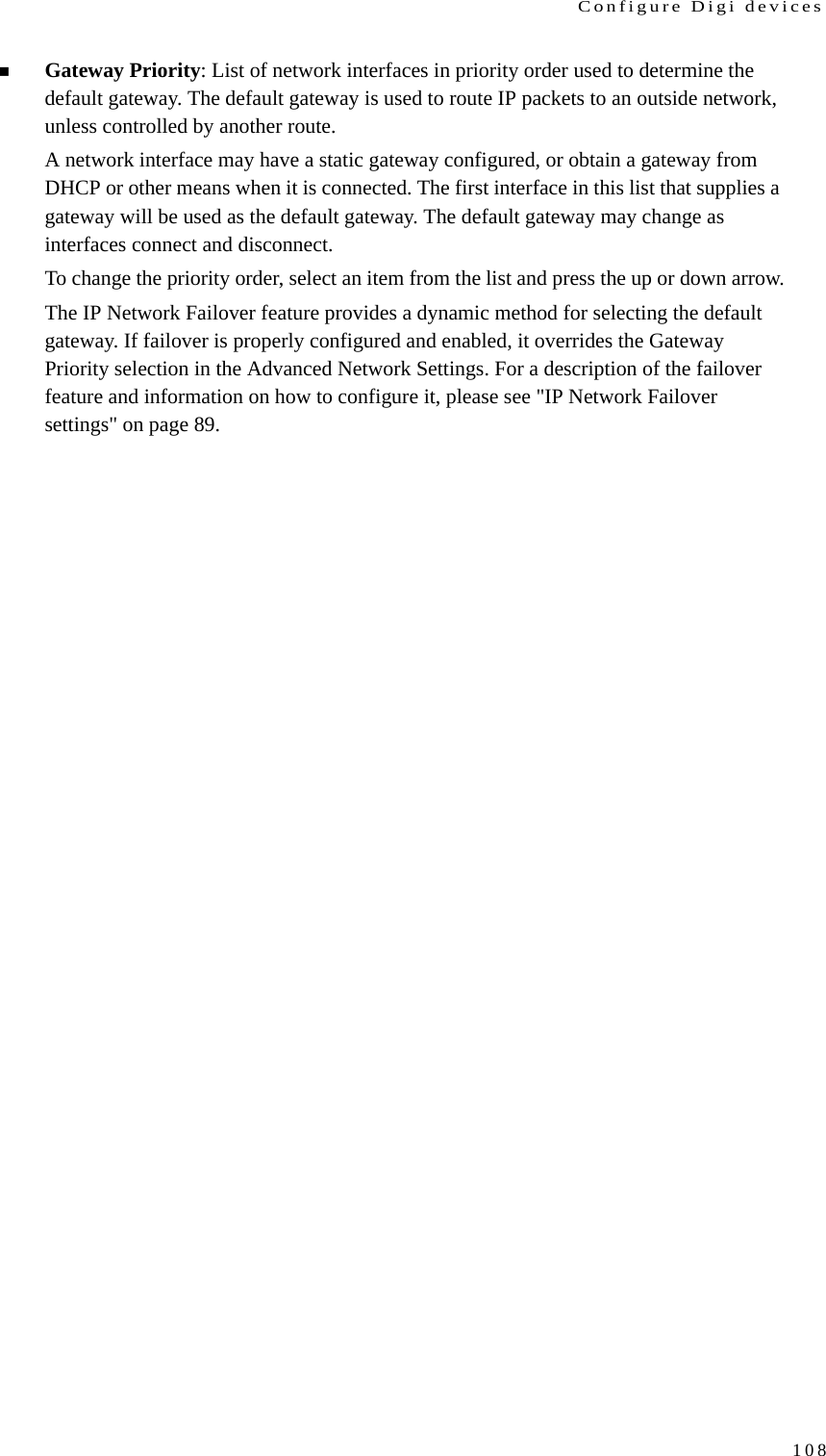
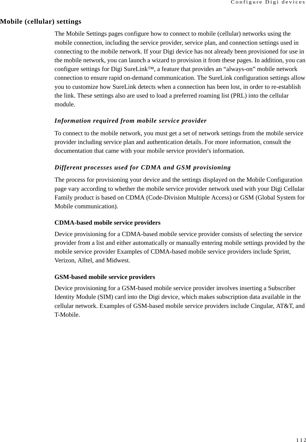
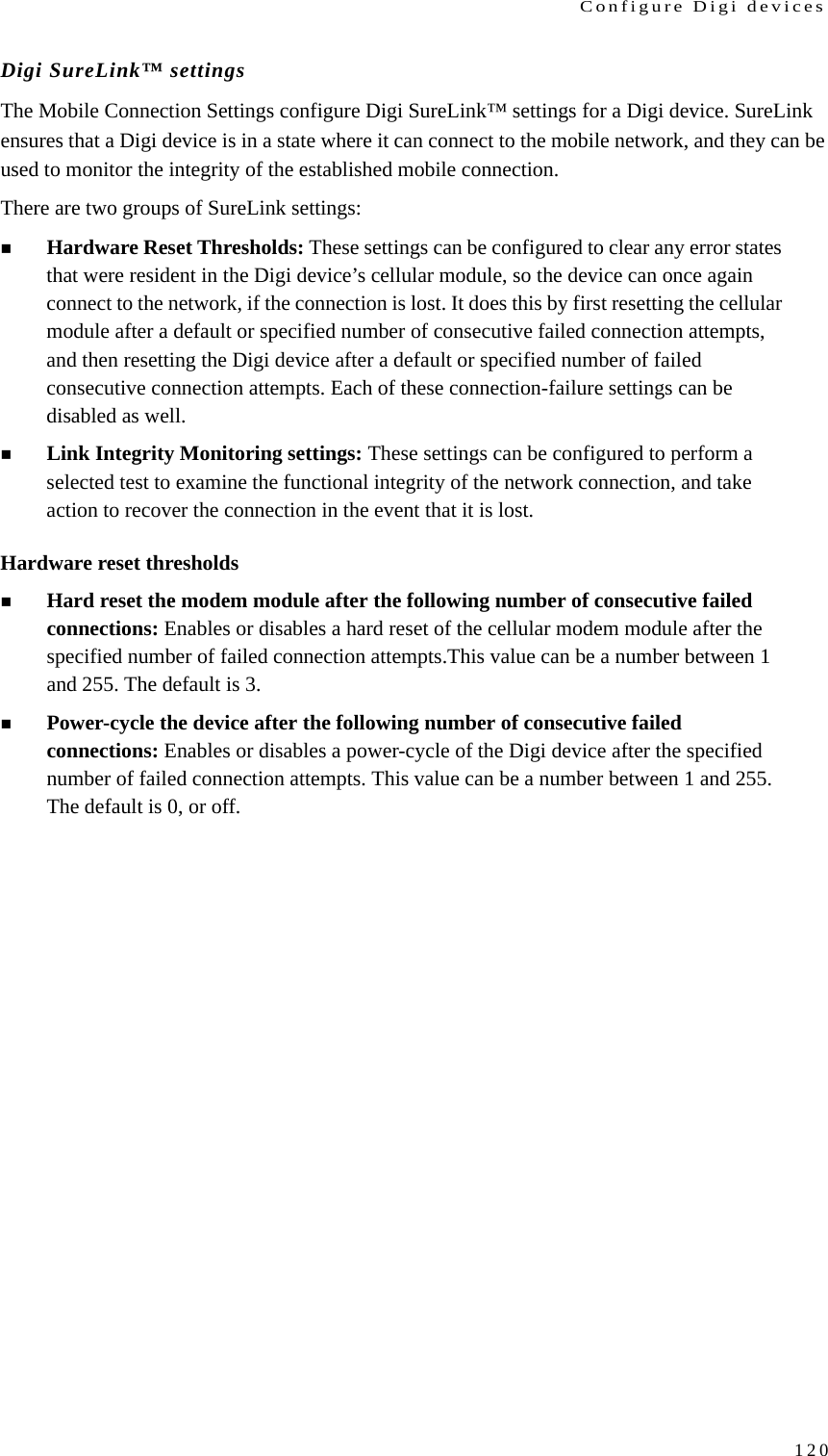
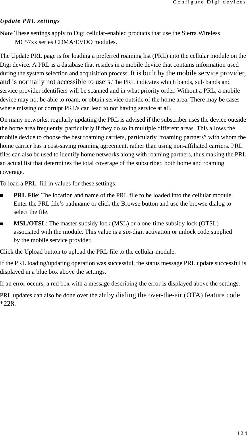
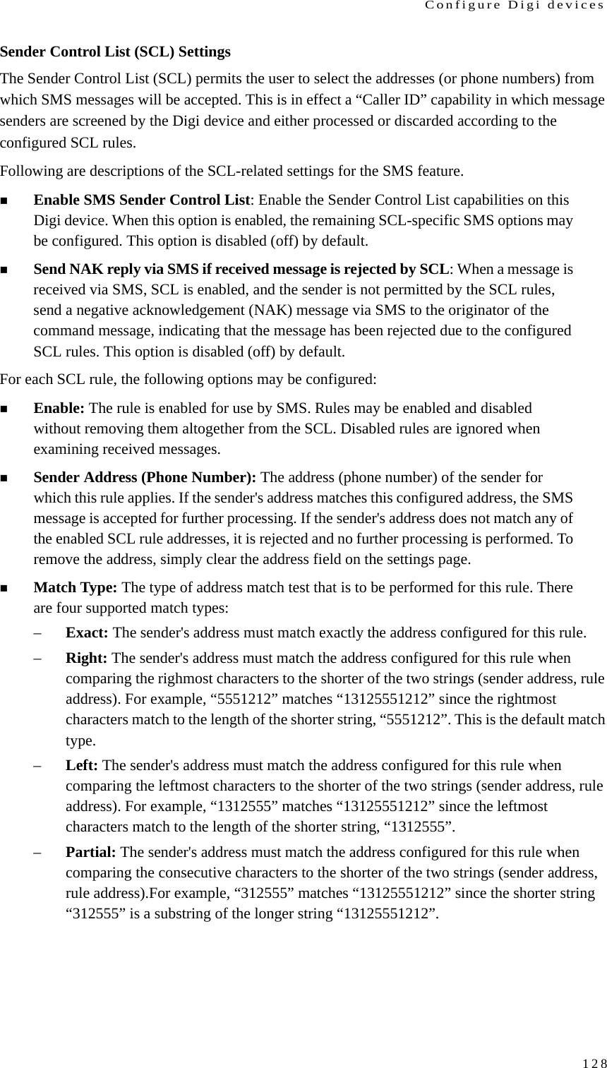
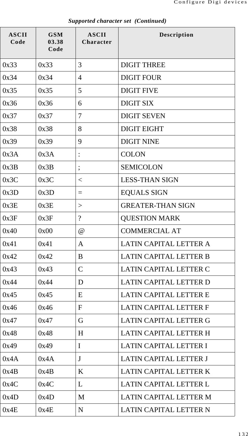
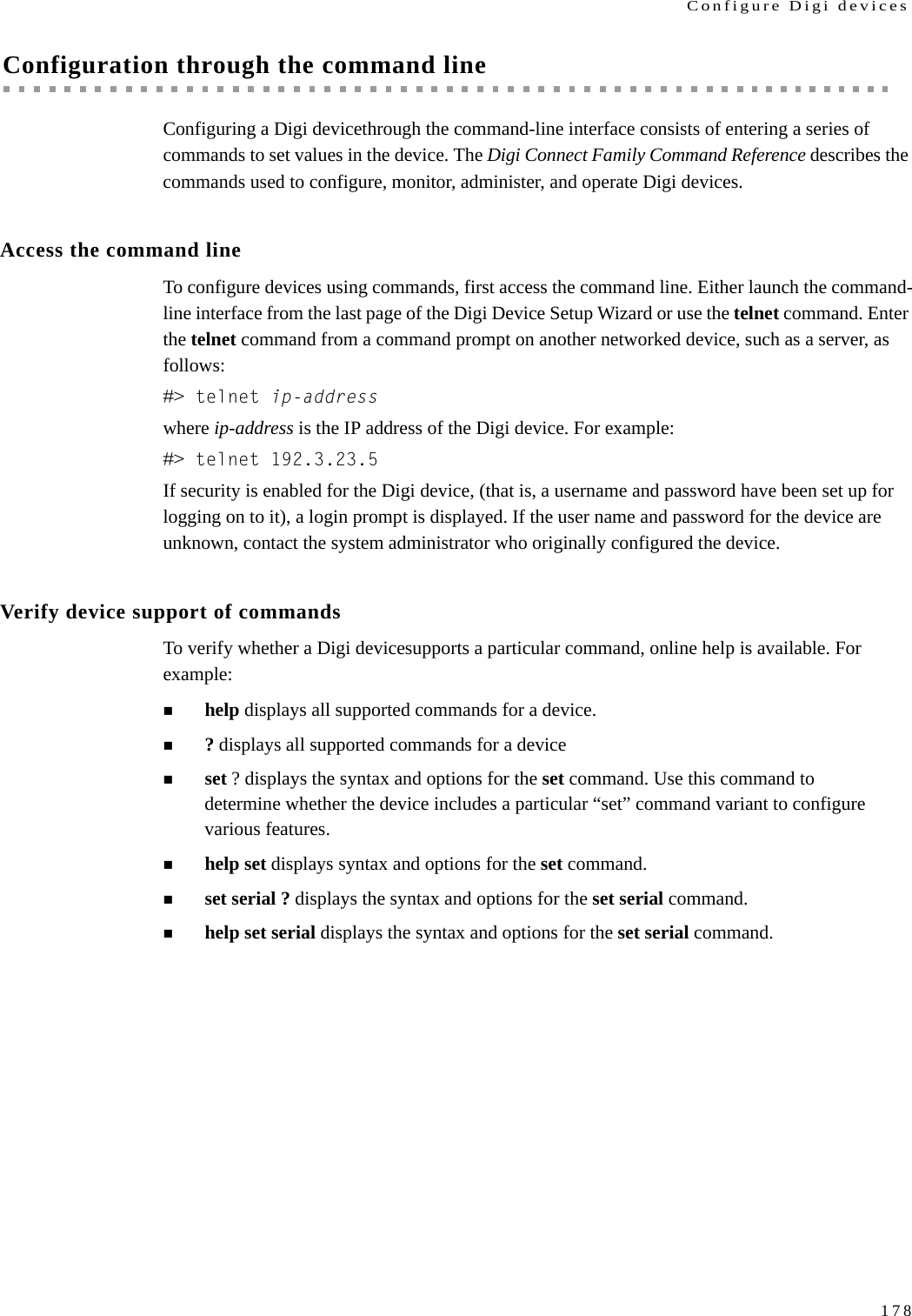
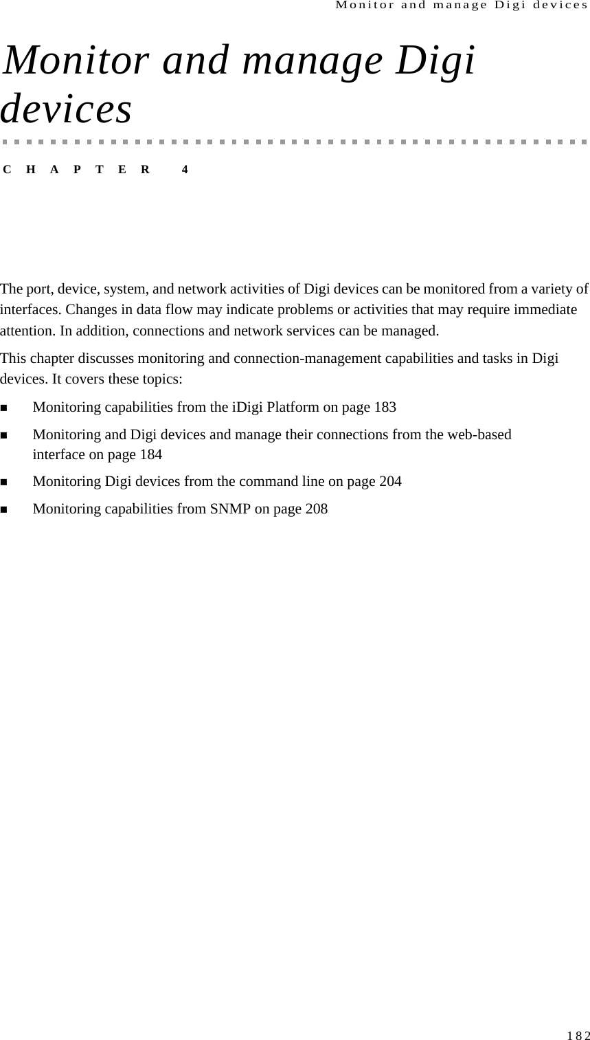
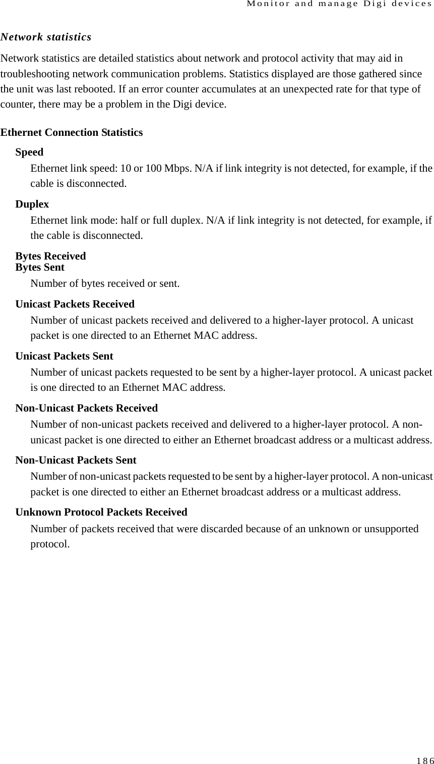
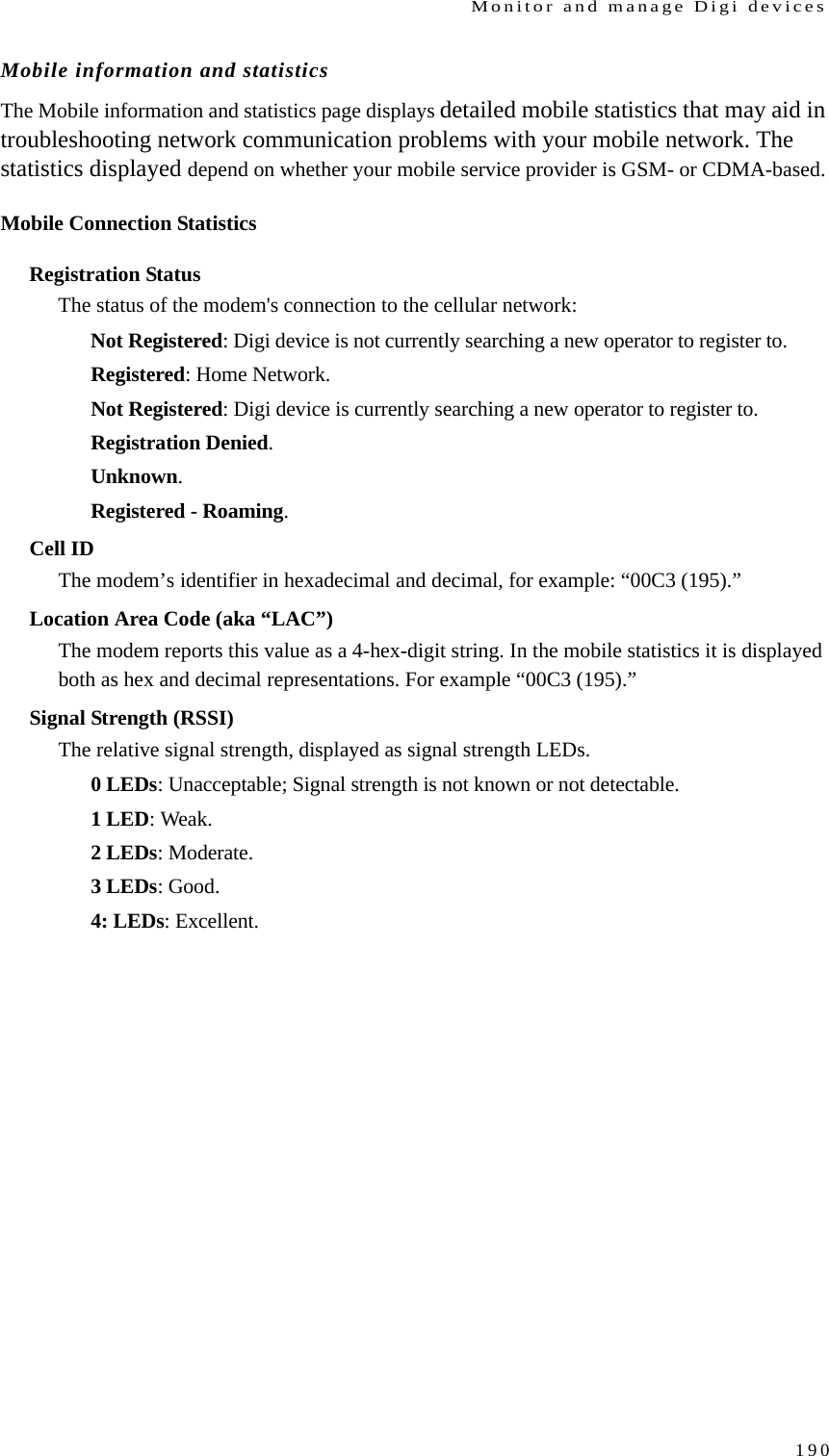
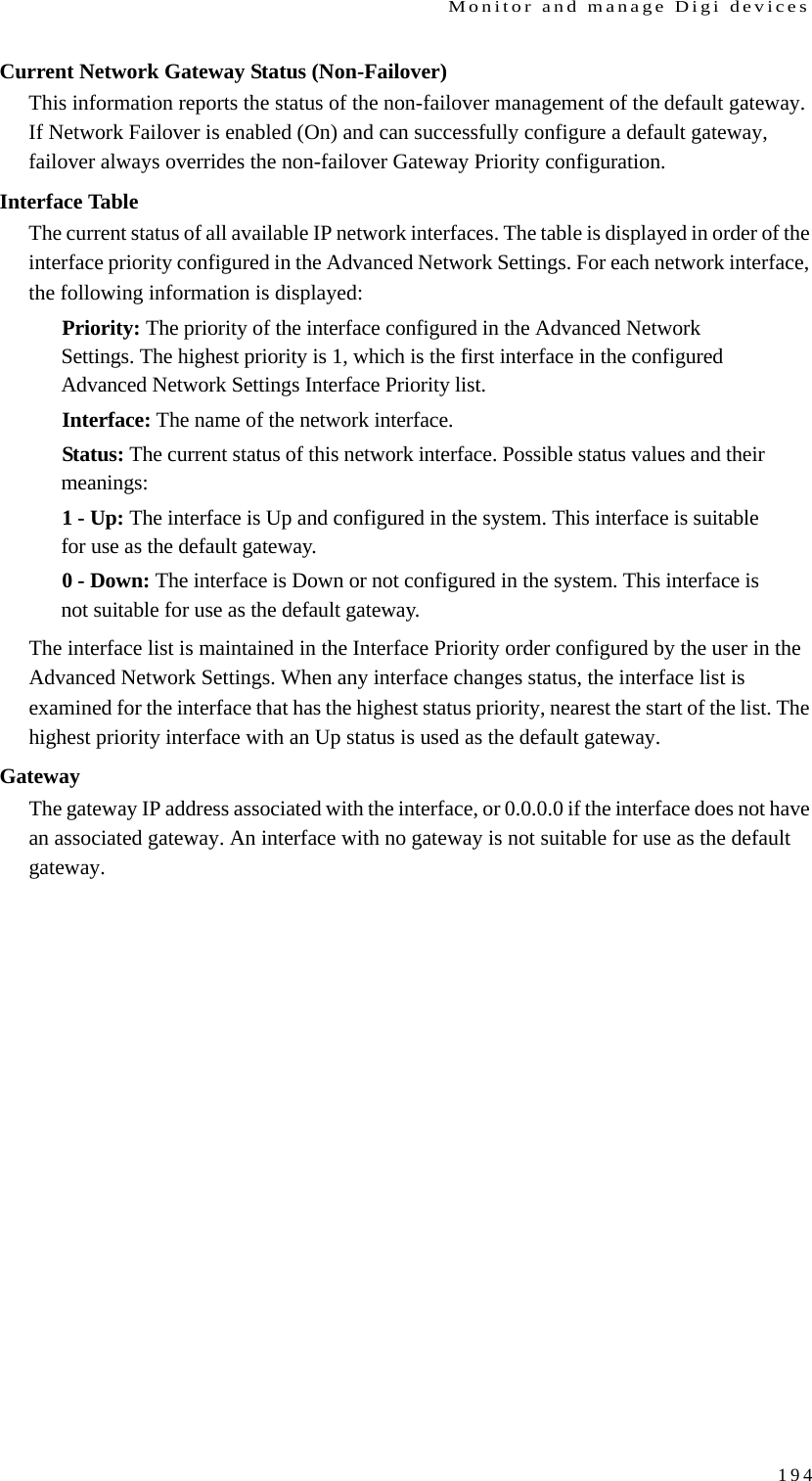
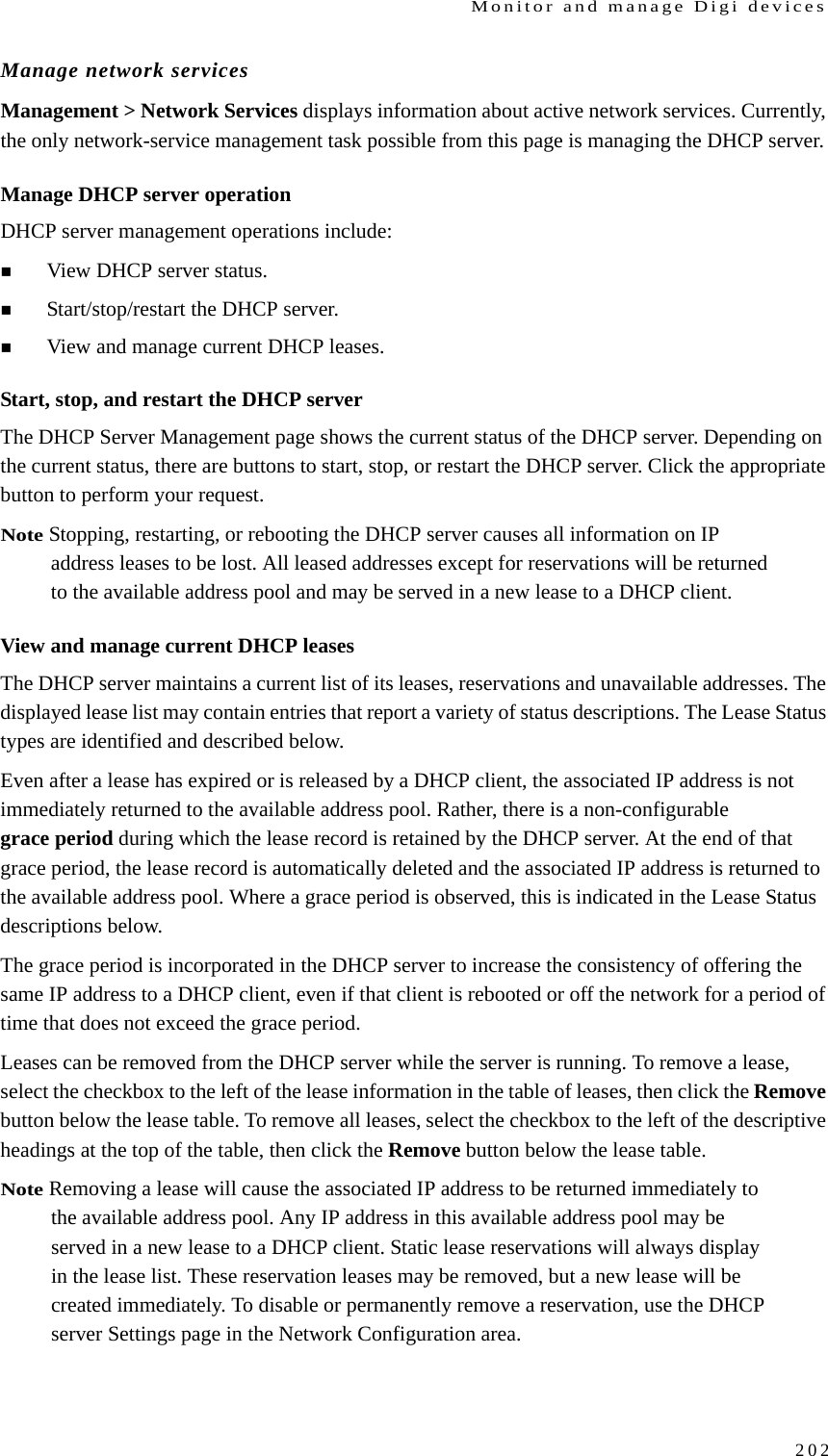
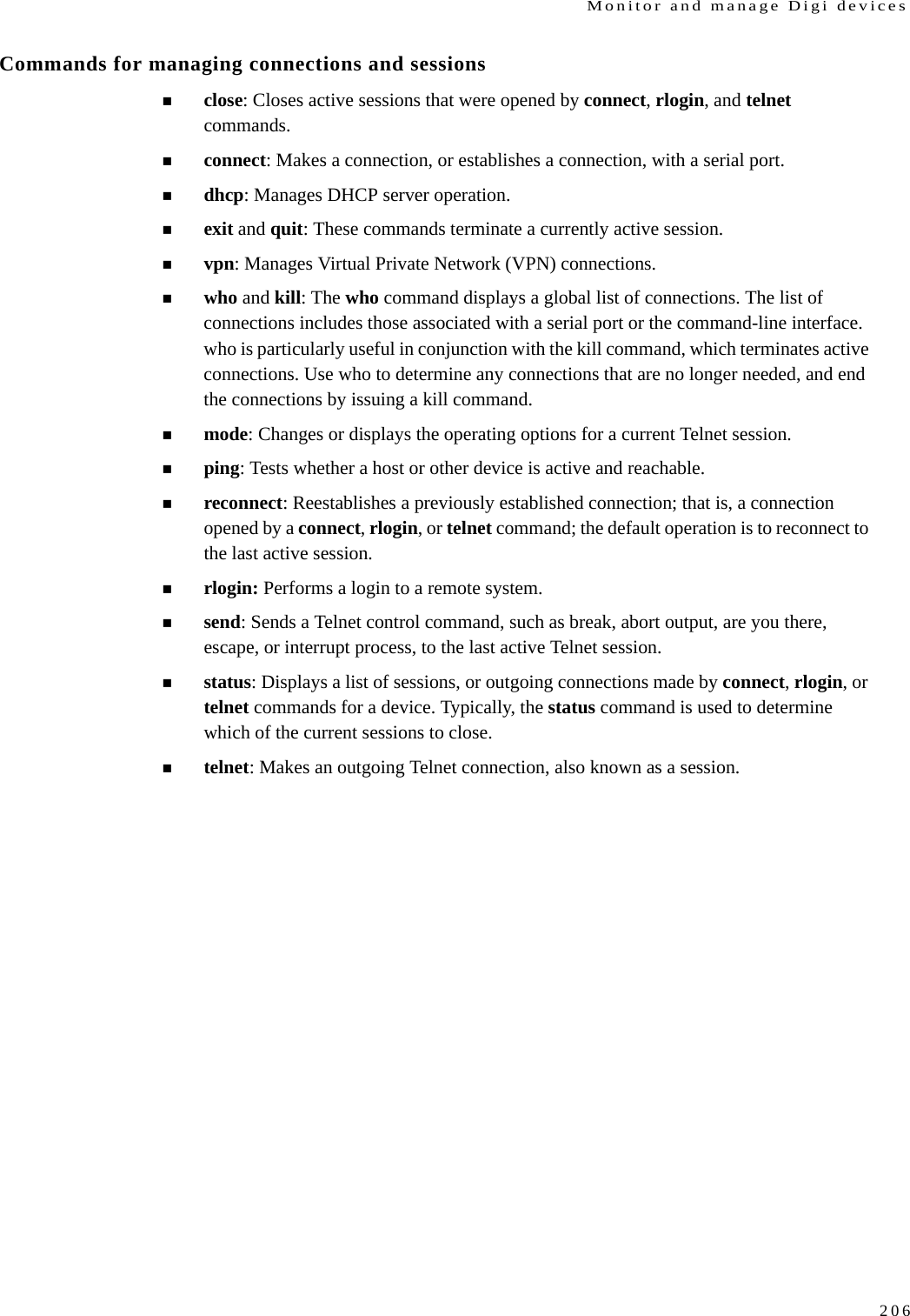
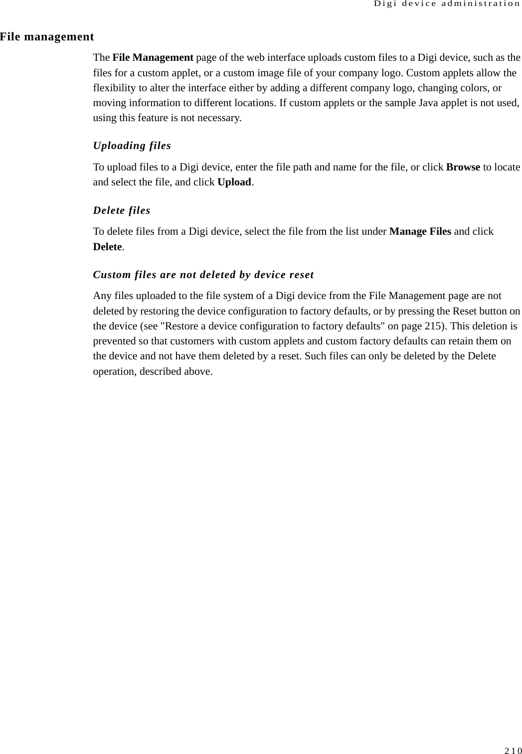
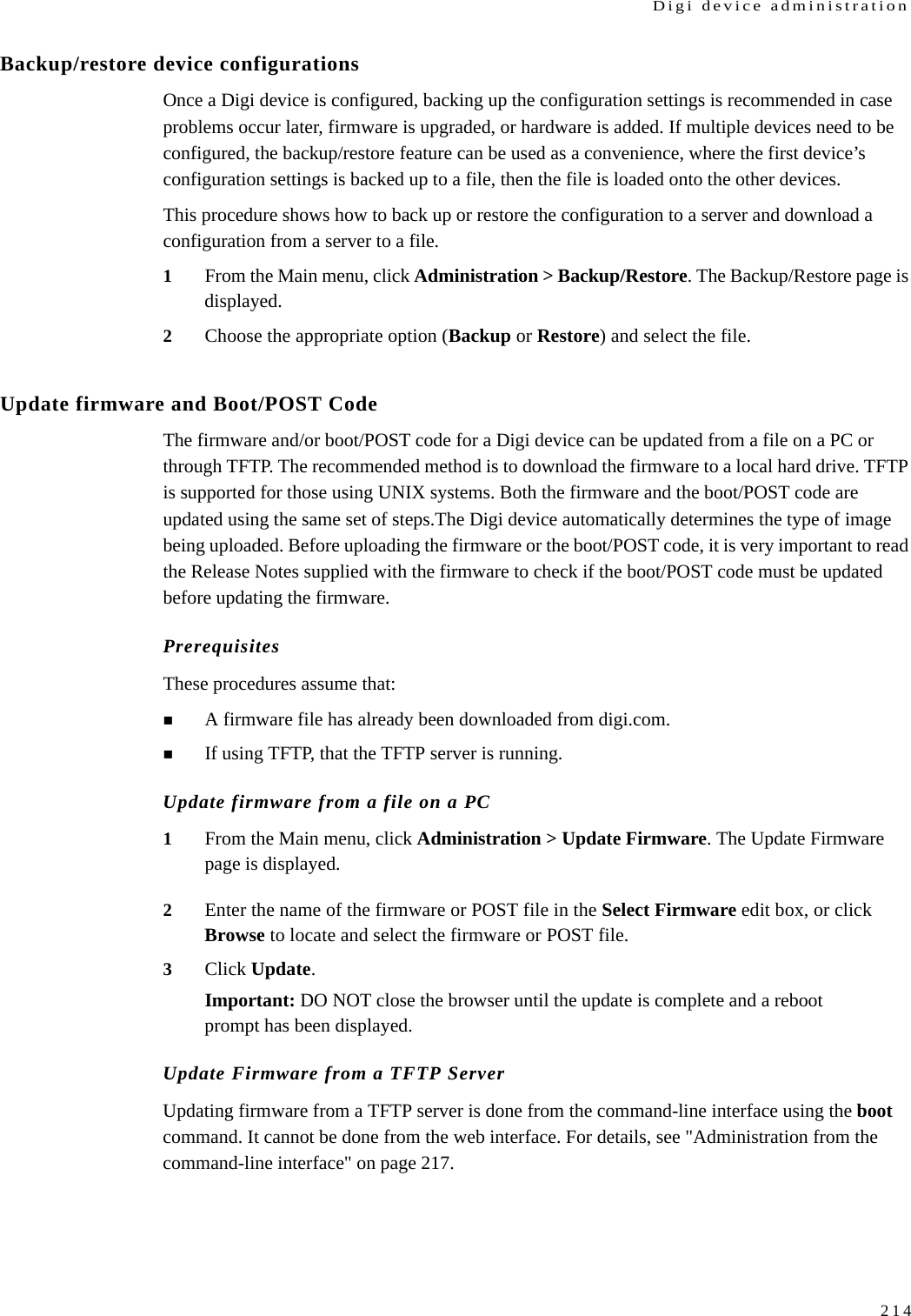
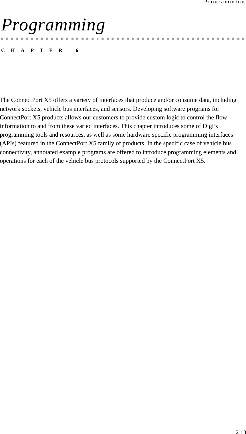
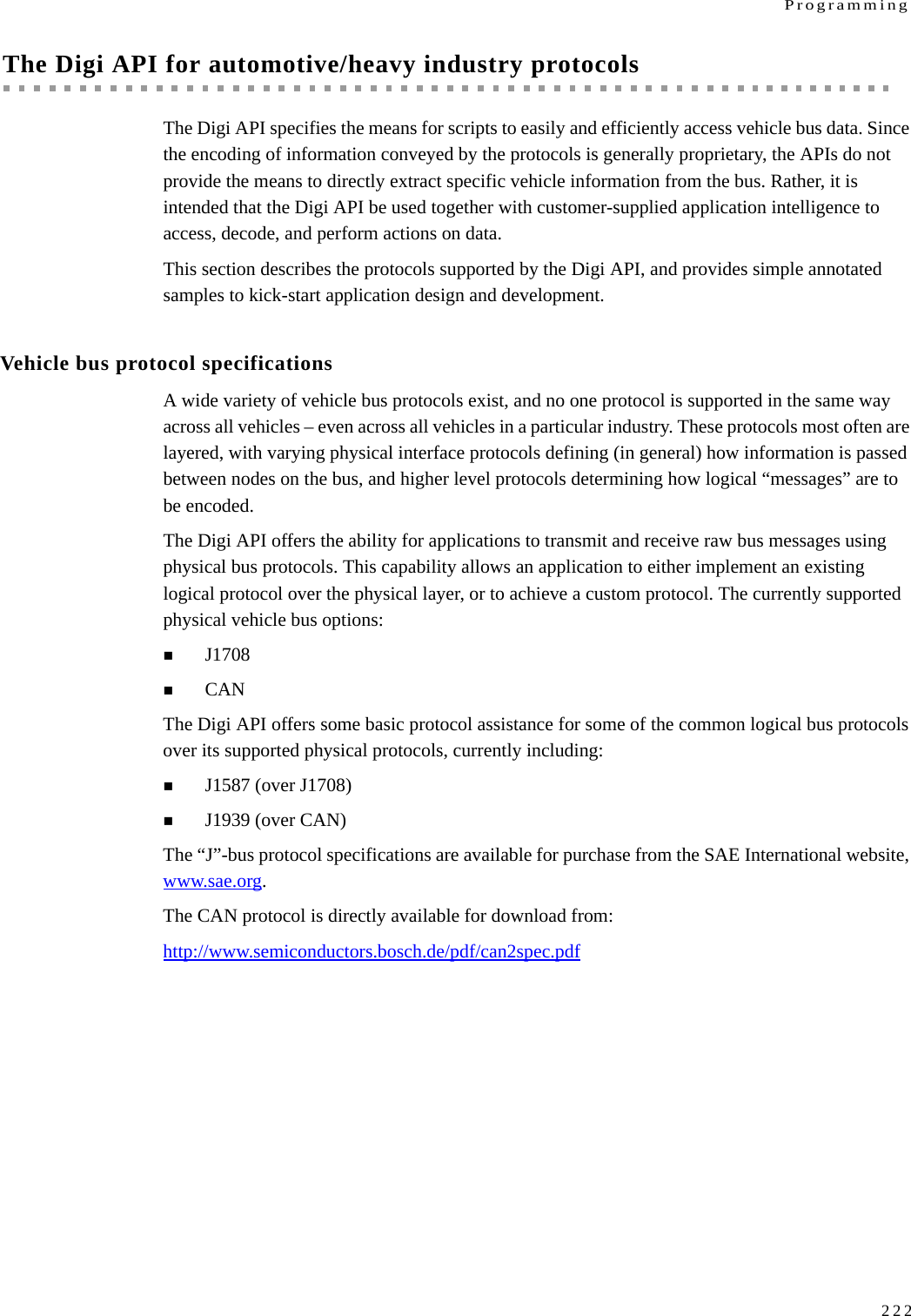
![Configure Digi devices175Digi Python Custom Development Environment pagePython functions can be used to obtain data from attached and integrated sensors on Digi products that have embedded XBee RF modules, such as the Drop-in Networking Accessories. The Digi Python Custom Development Environment page is an access point: for such information.http://www.digi.com/technology/drop-in-networking/python.jspPython Support Forum on digi.comFind answers to common questions and exchange ideas and examples with other members of the Digi Python development community at:http://www.digi.com/support/forum/forum.jspa?forumID=104Python configuration pagesSelecting Applications > Python from the main menu for a Python-enabled Digi device displays the Python Configuration pages. These pages are used to manage Python program files including uploading them to Digi devices and deleting them as needed, and configure Python programs to execute when the Digi device boots, also known as auto-start programs.Python filesThe Python Files page is for uploading and managing Python programs on a Digi device.Upload Files: Click Browse to select a file to upload to and click Upload. Manage Files: Select any files to remove from the Digi device and click Delete.Auto-start settingsThe Auto-start Settings page configures Python programs to execute when the Digi device boots. Up to four auto-start programs can be configured. Enable: When checked, the program specified in the Auto-start command line field will be run when the device boots. Auto-start command line: Specify the Python program filename to be executed and any arguments to pass to the program. The syntax is:filename [arg1 arg2...] Manually execute uploaded Python programsTo manually execute an uploaded Python program on a Digi device, access the command line of the device and enter the command:python filename [arg1 arg2...]View and manage executing Python programsTo view Python threads running on the Digi device, access the command line and enter the who command.](https://usermanual.wiki/Digi/WMPX5F/User-Guide-1291648-Page-175.png)
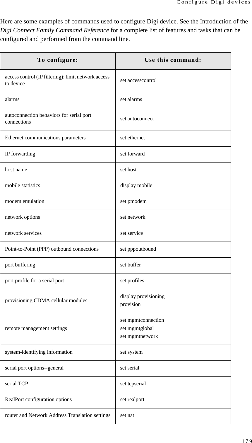
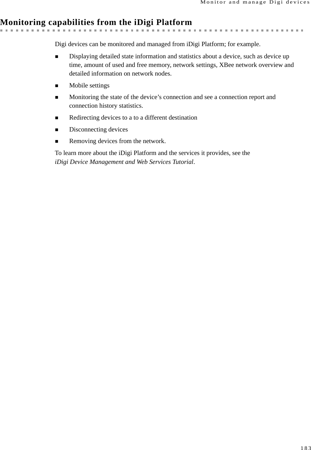
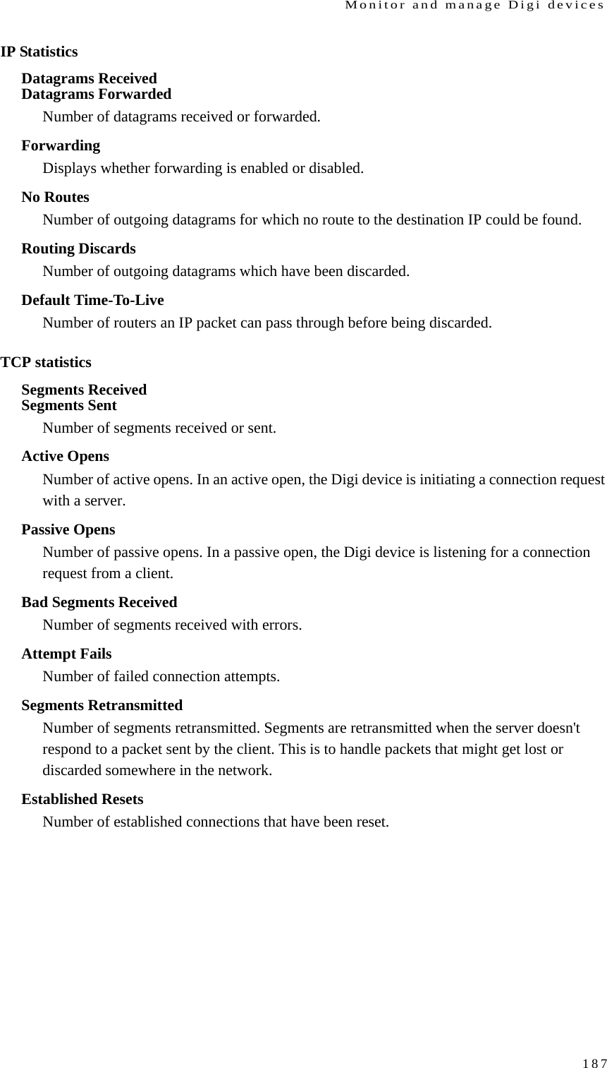
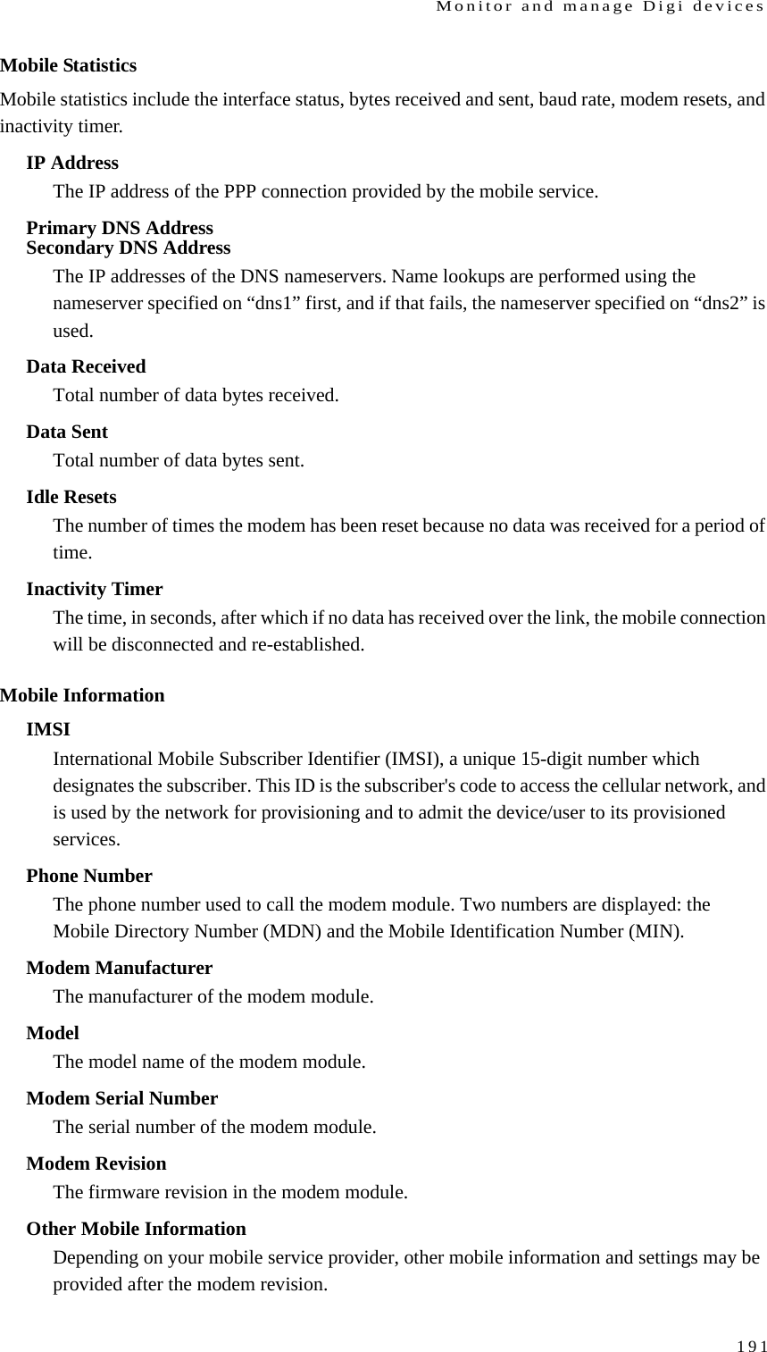
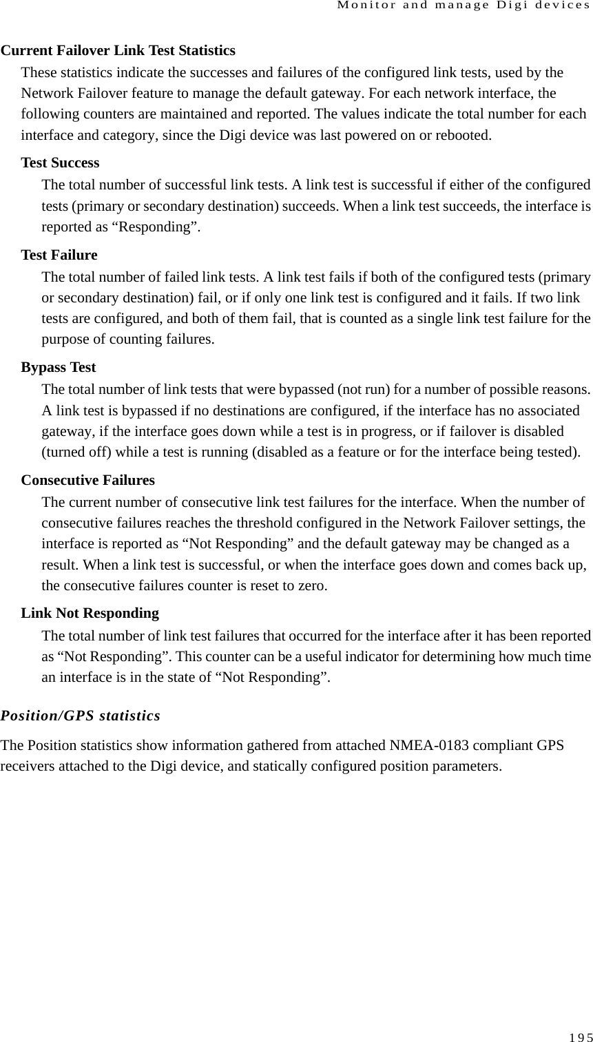
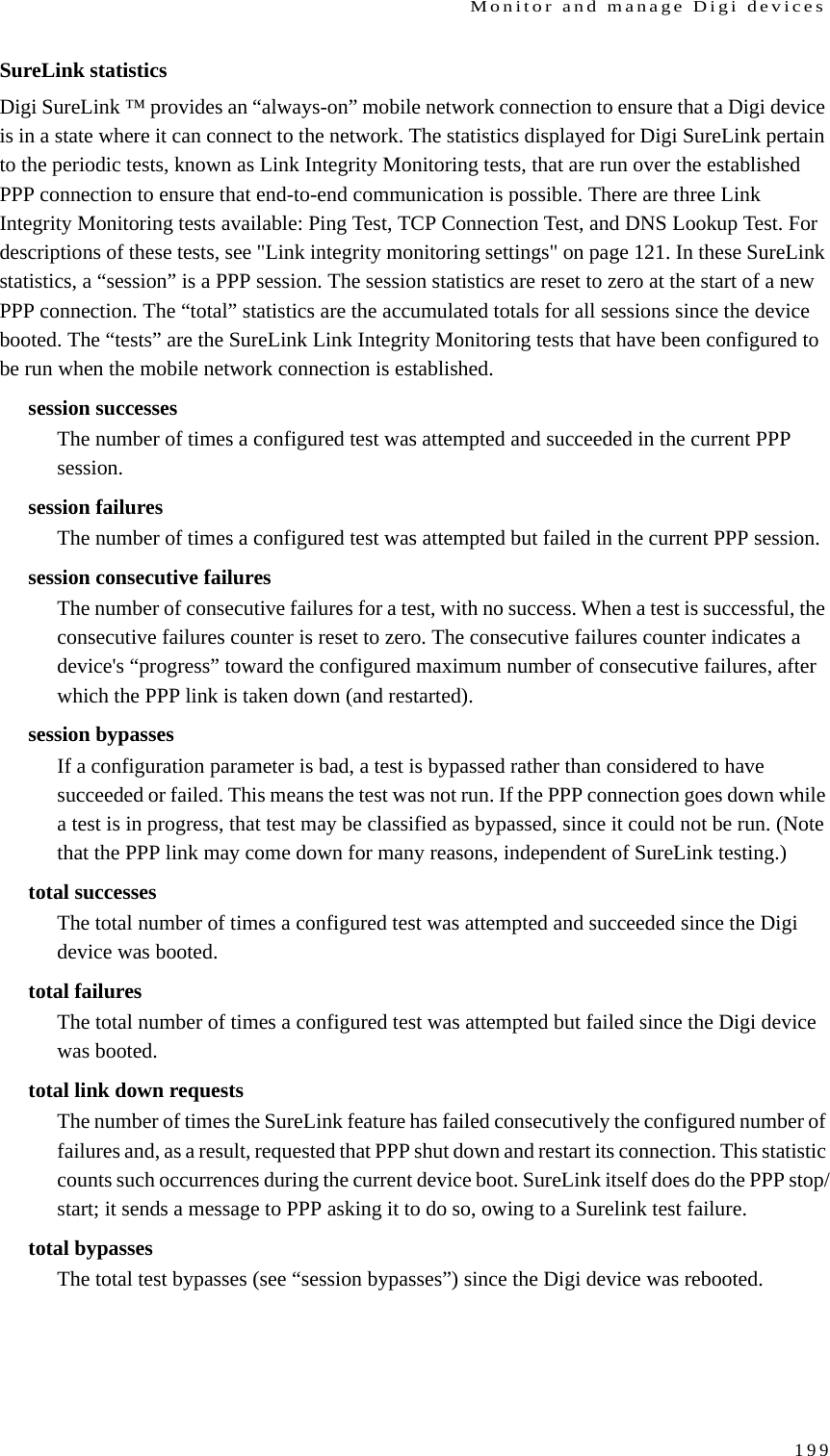
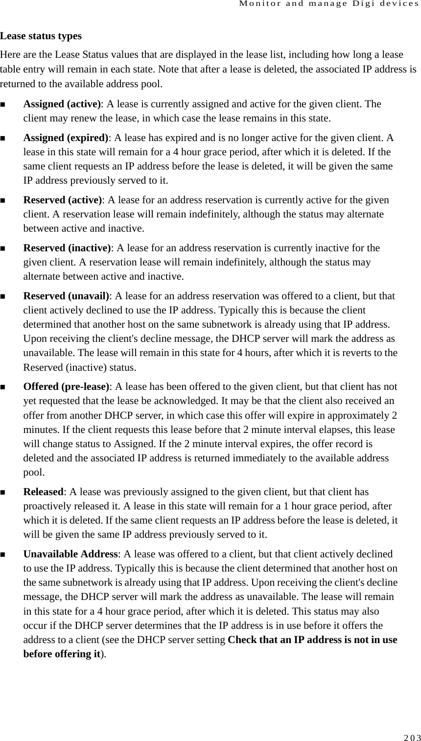
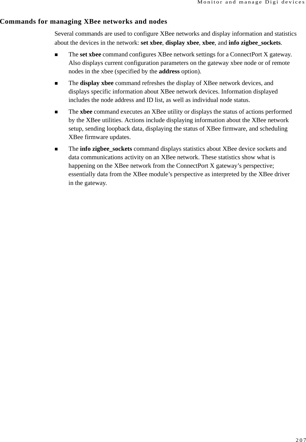
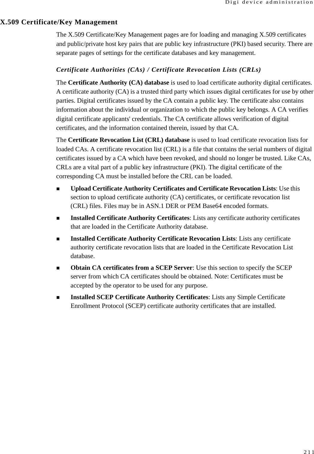
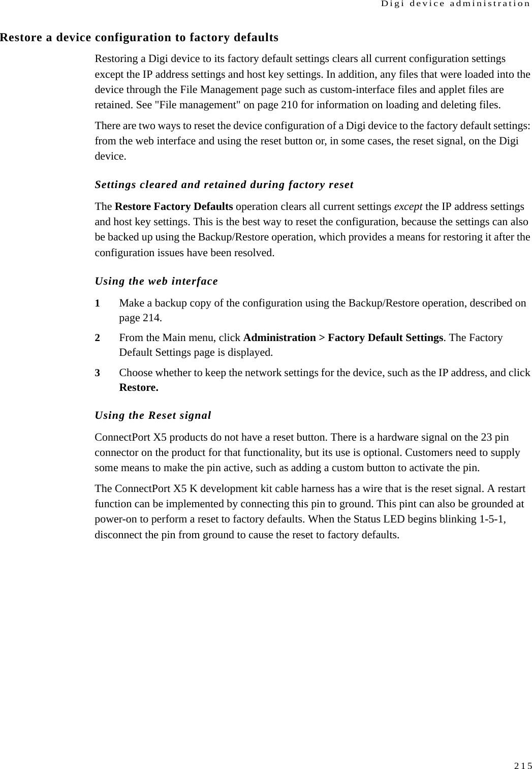
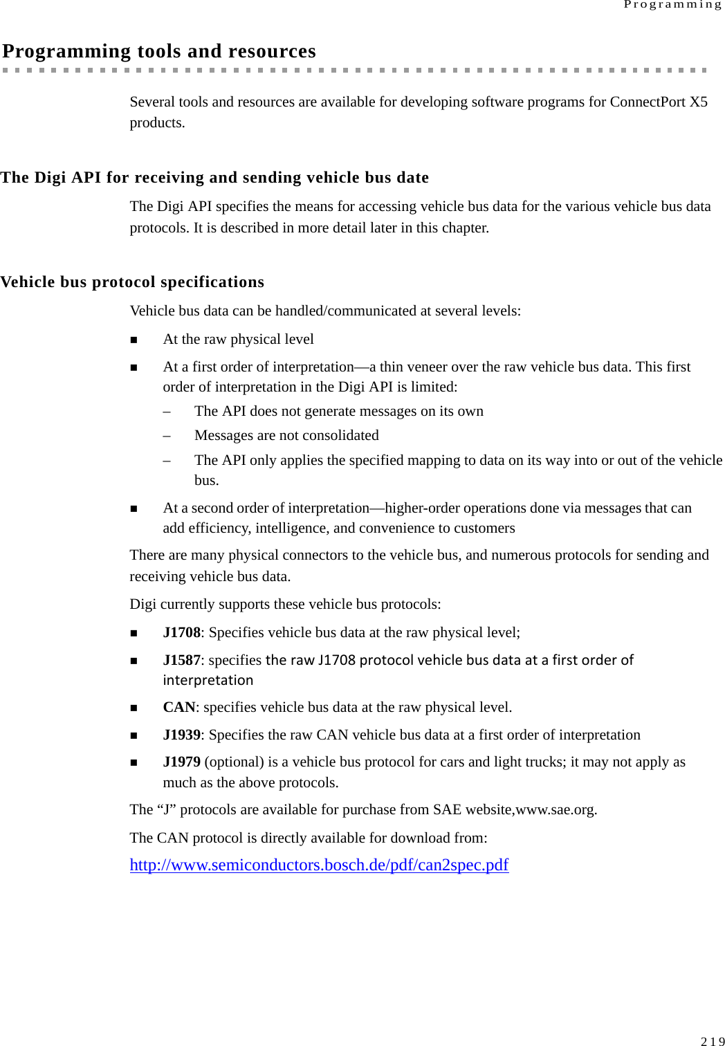
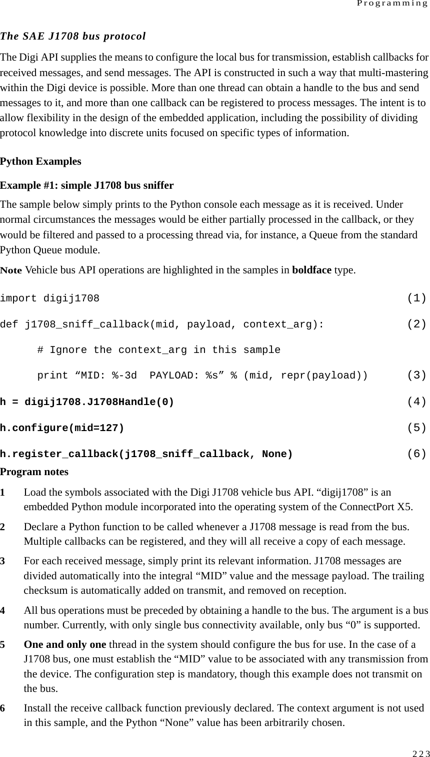
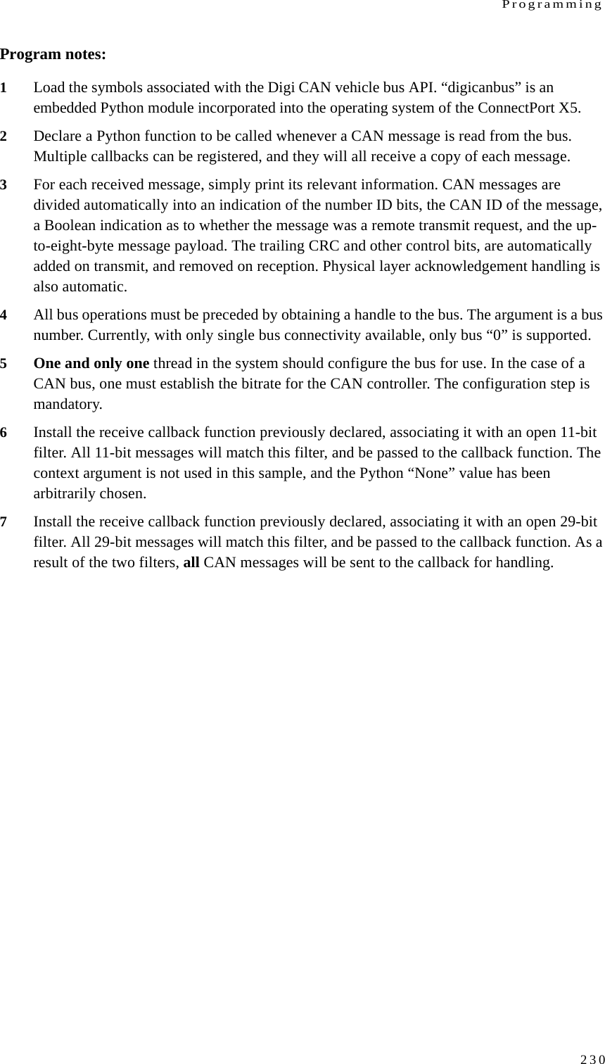
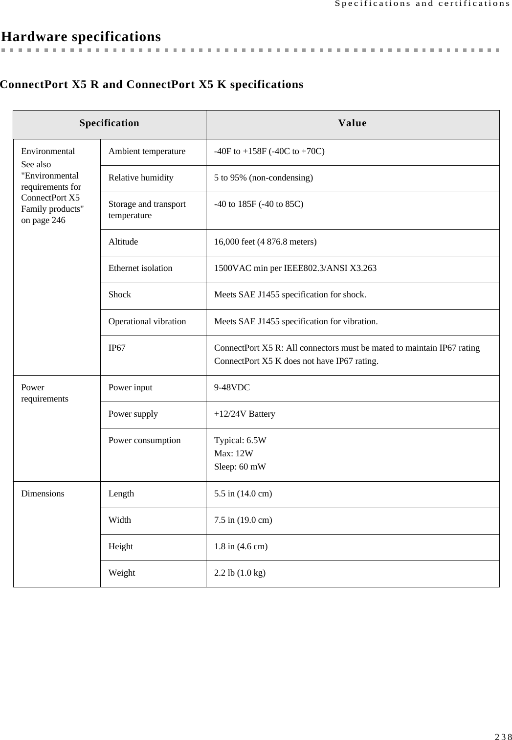
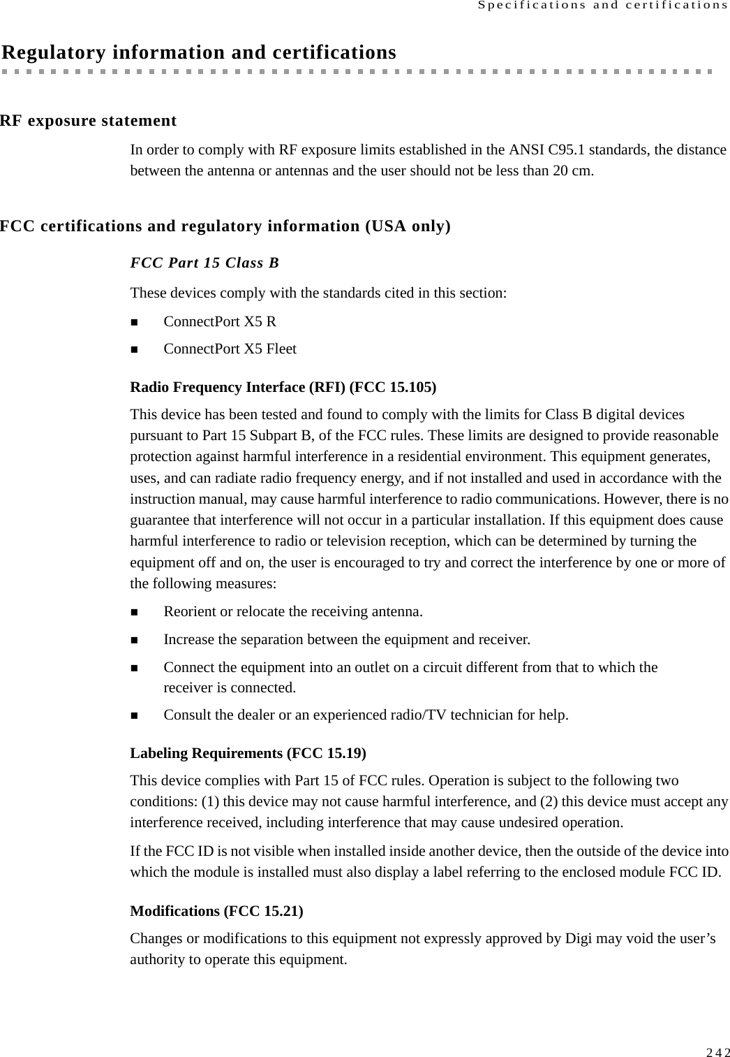
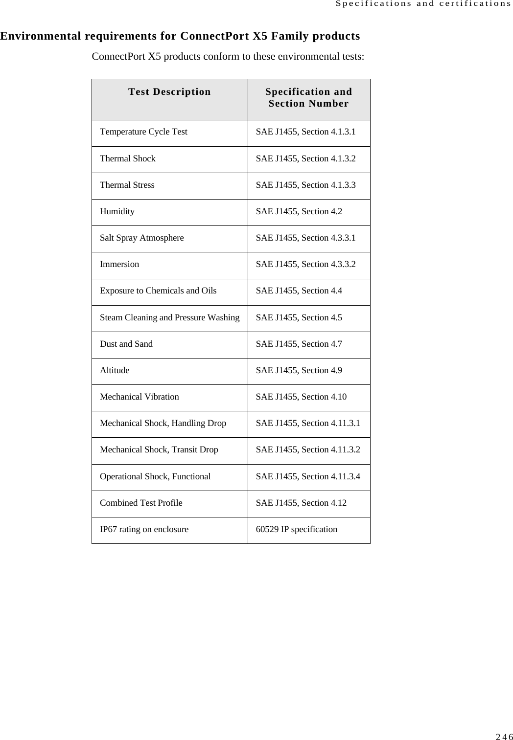
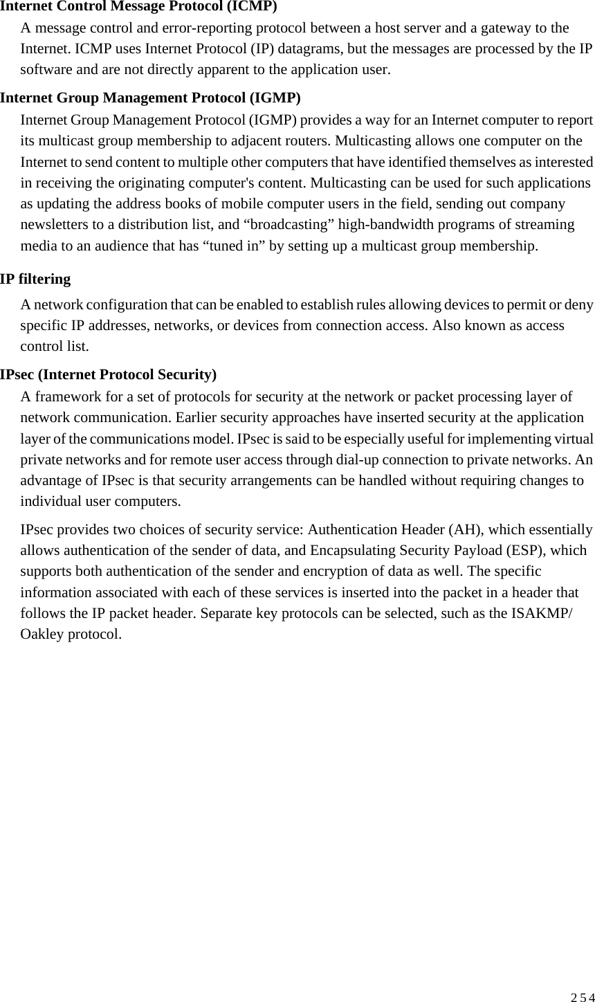
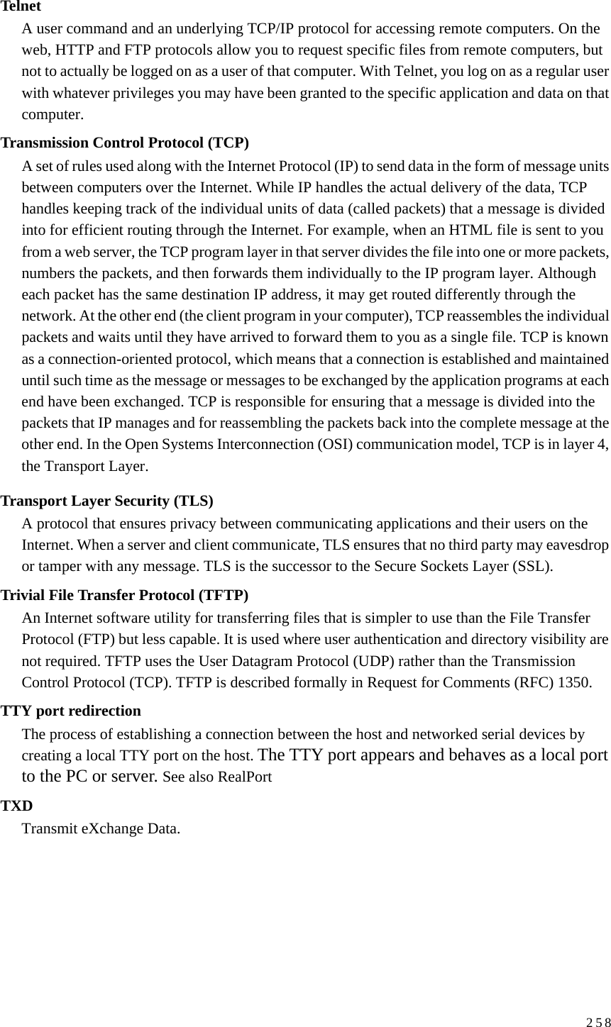
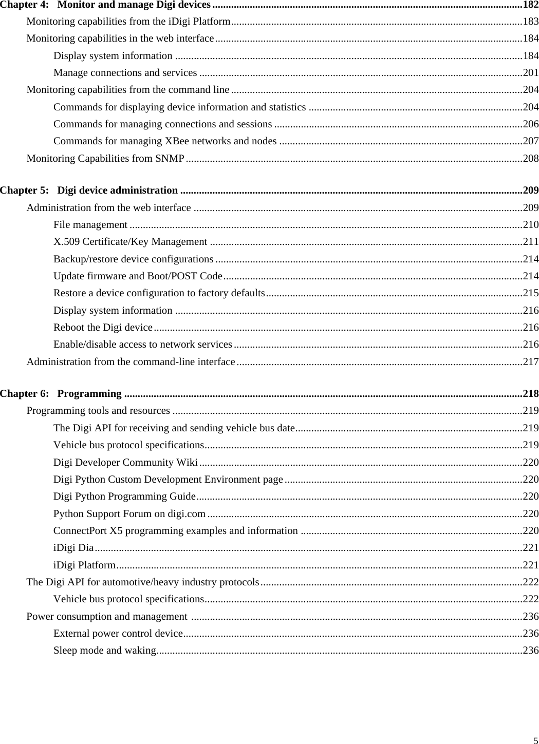
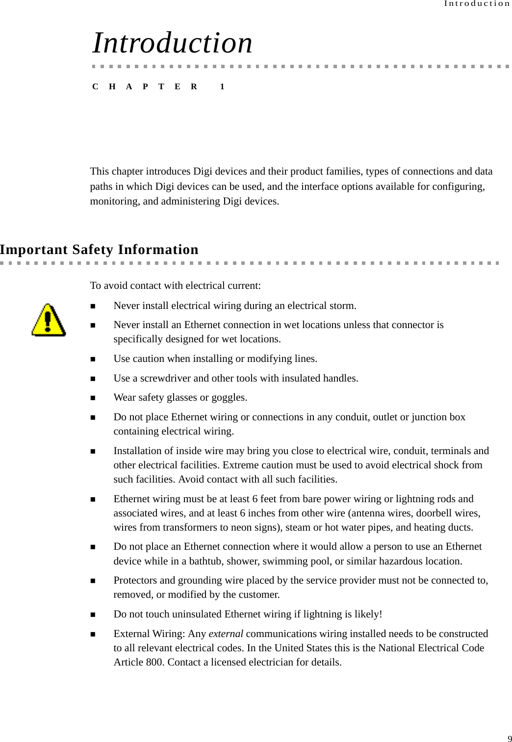
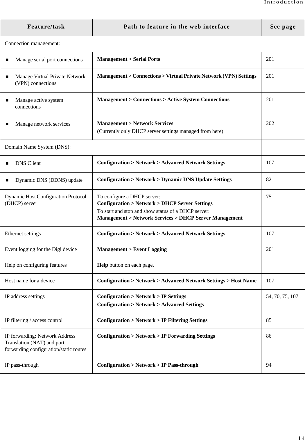
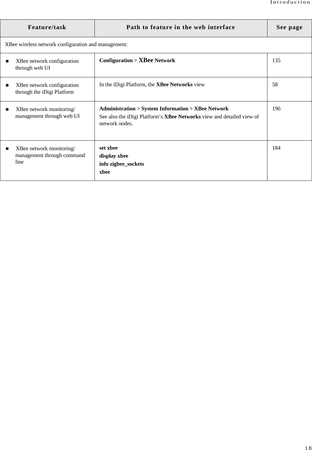
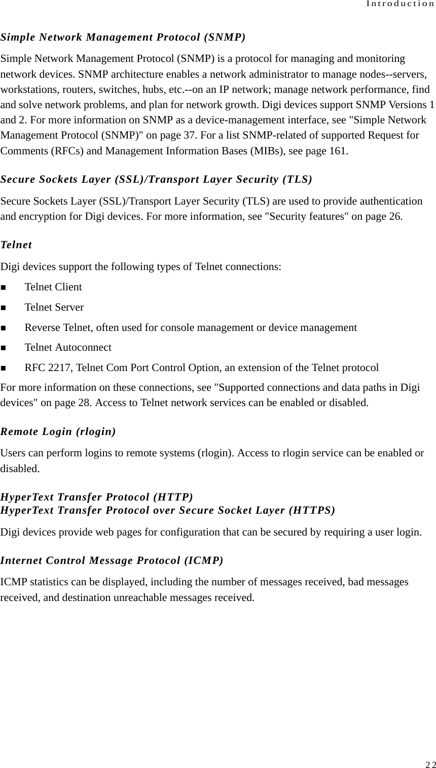
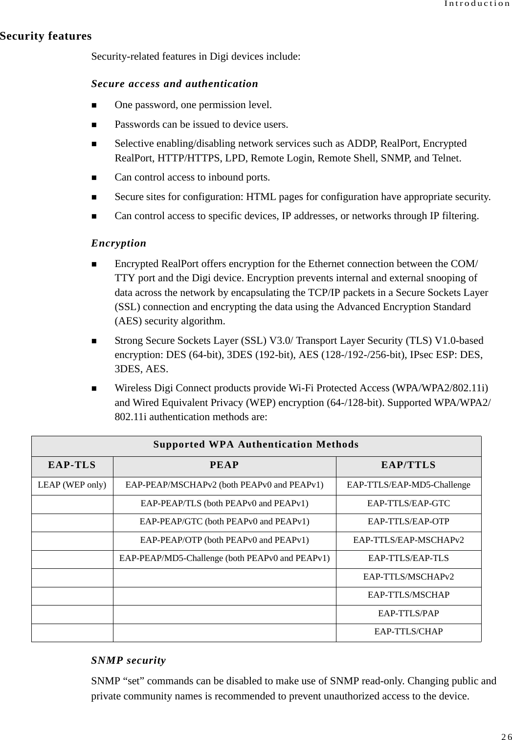
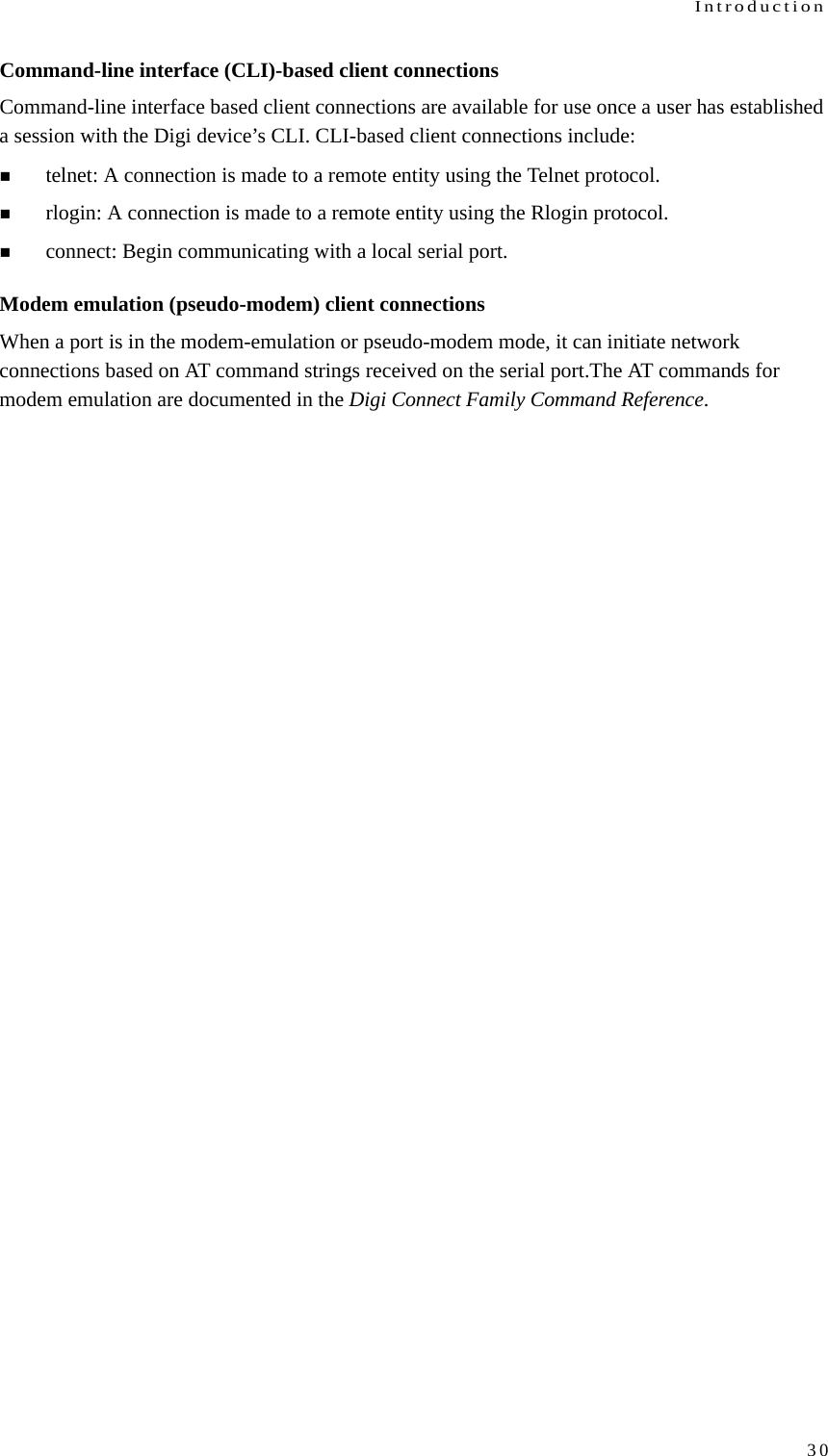
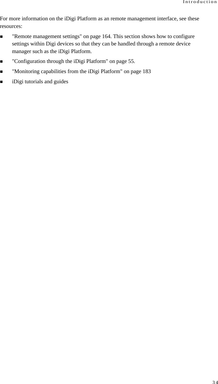
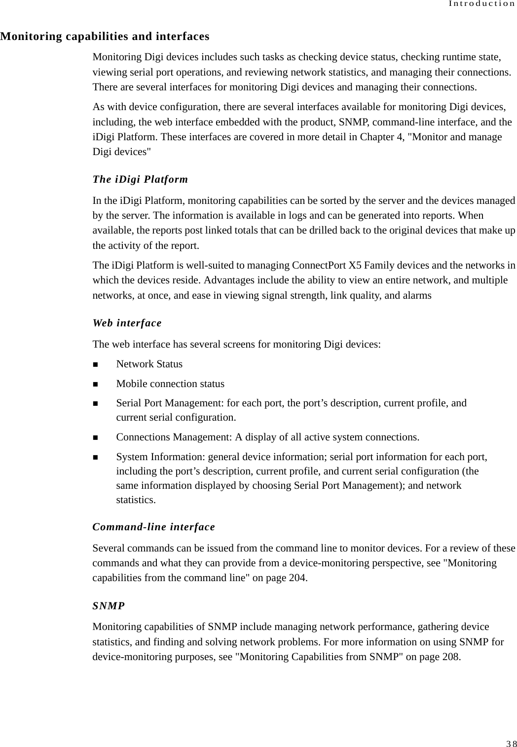
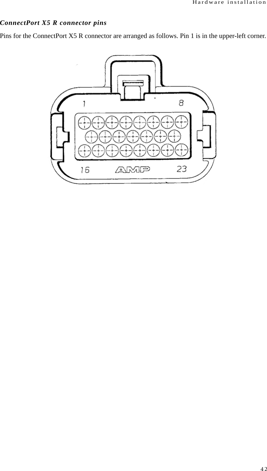
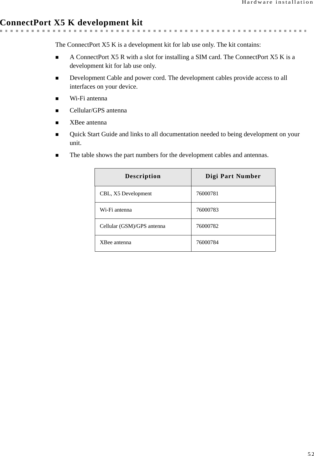
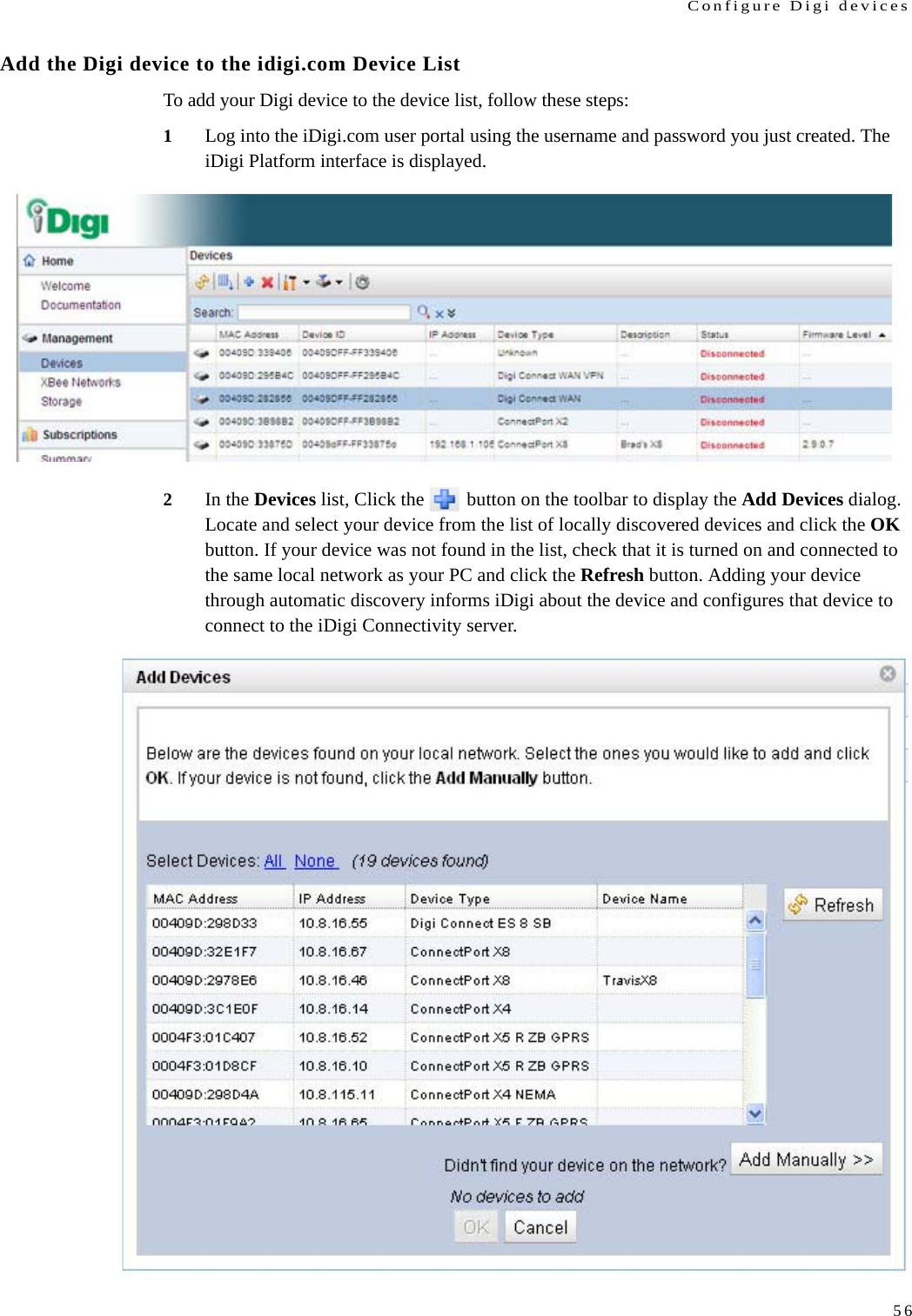
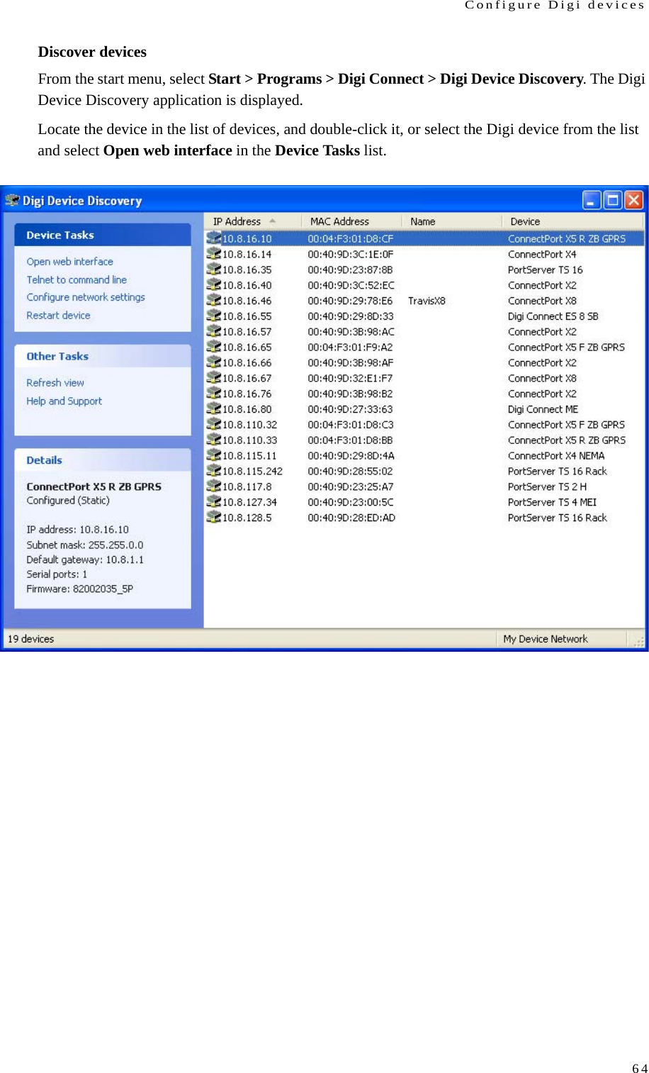
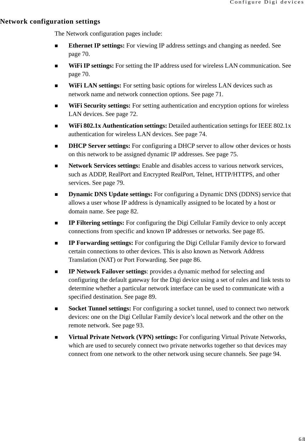
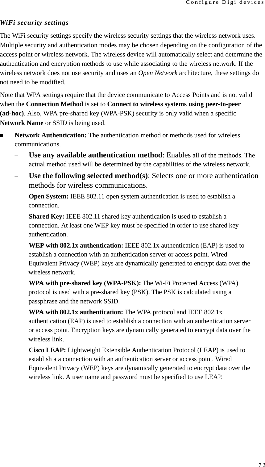
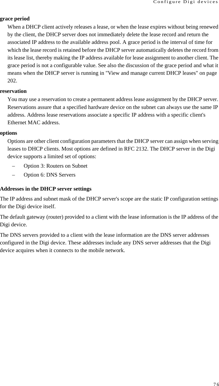
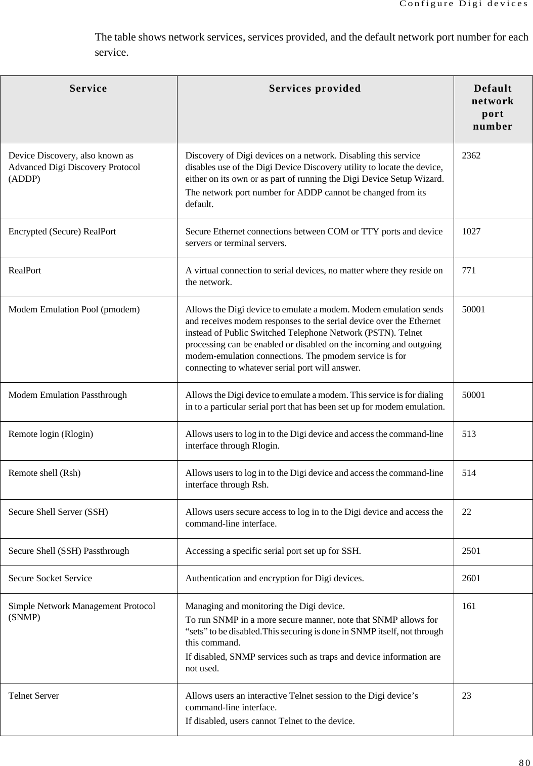
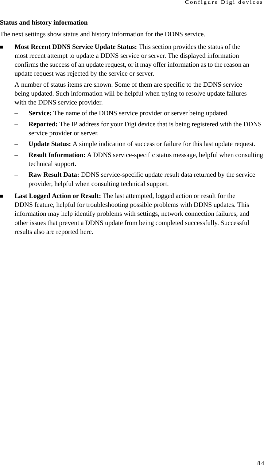
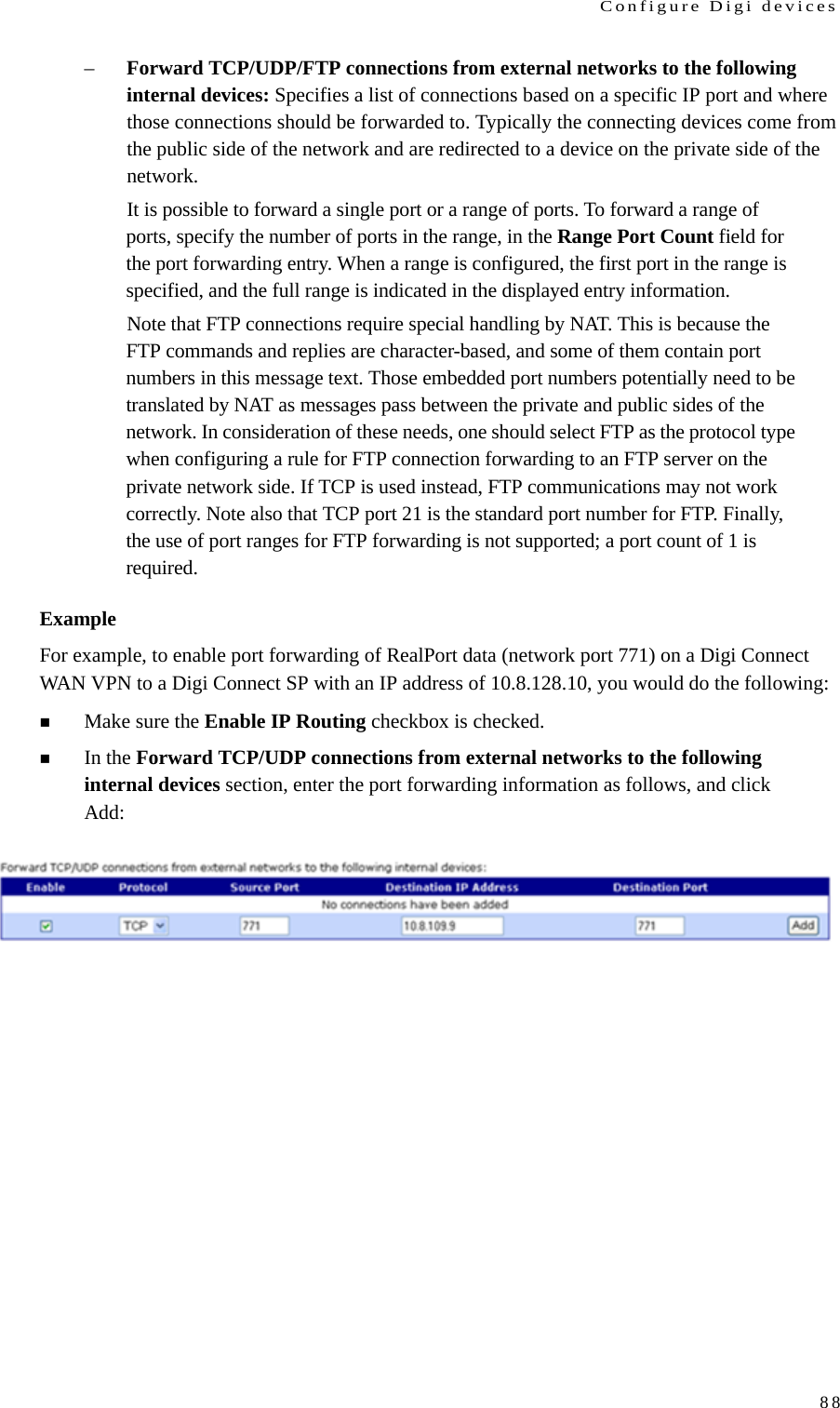
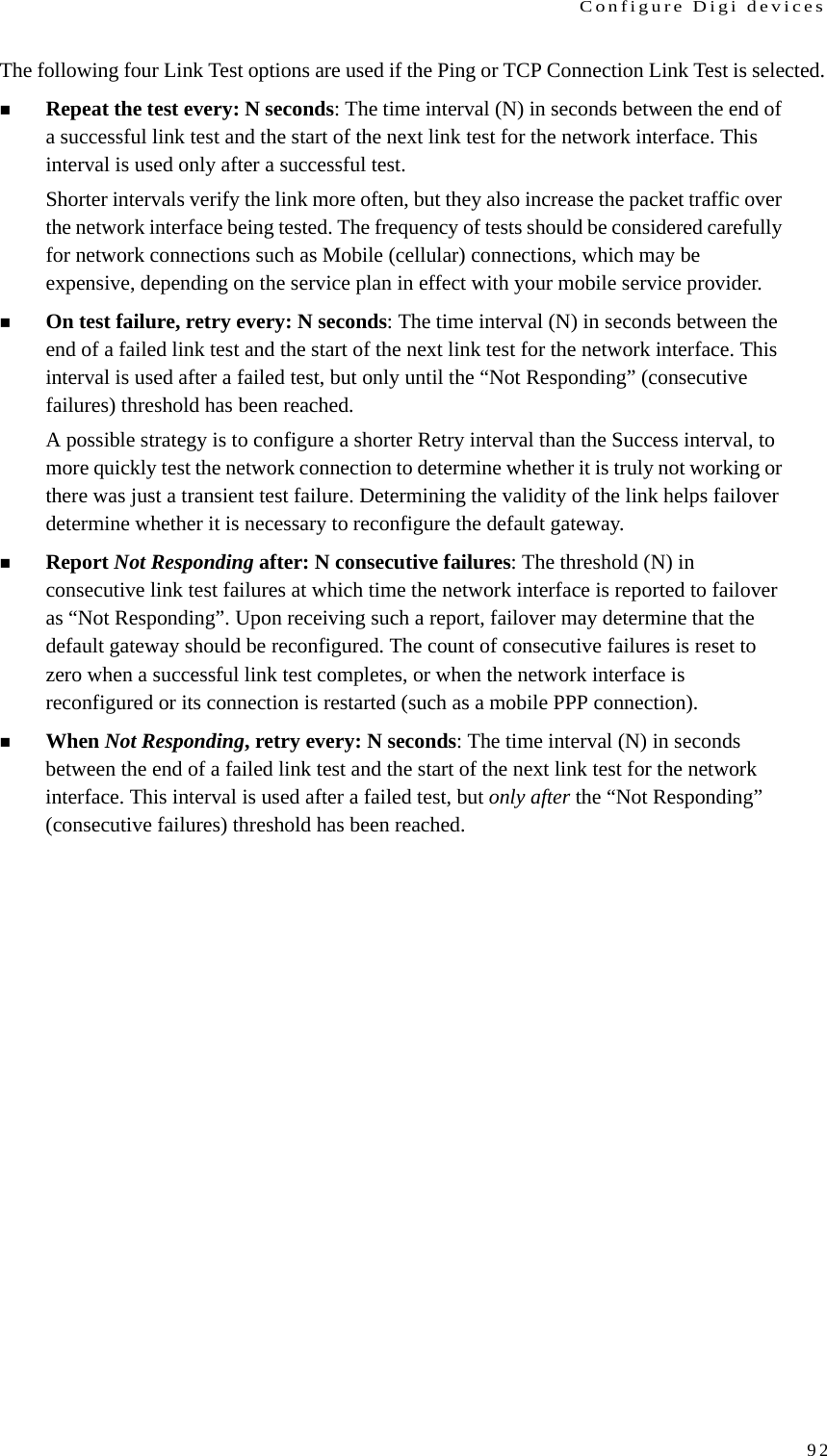
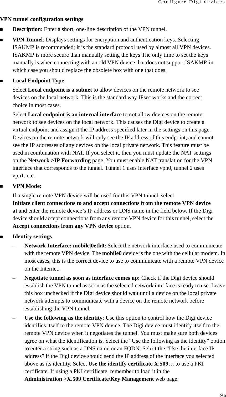
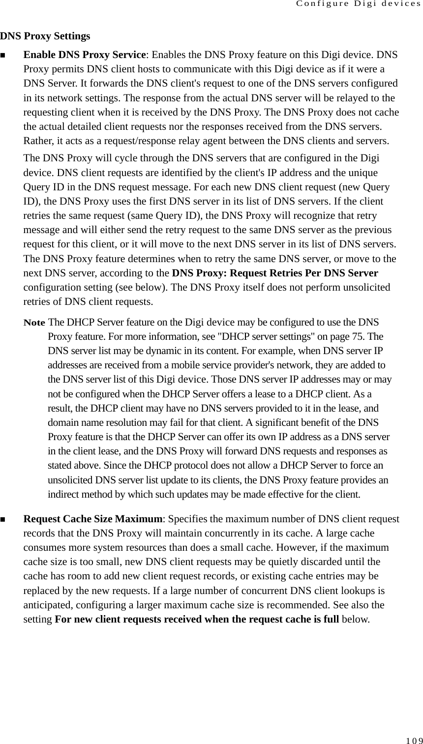
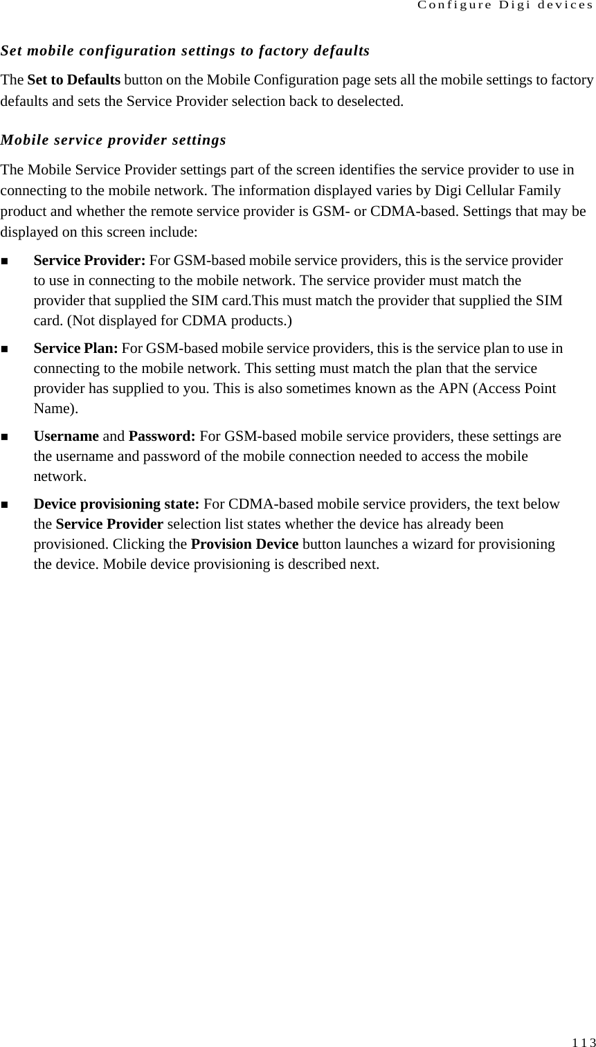
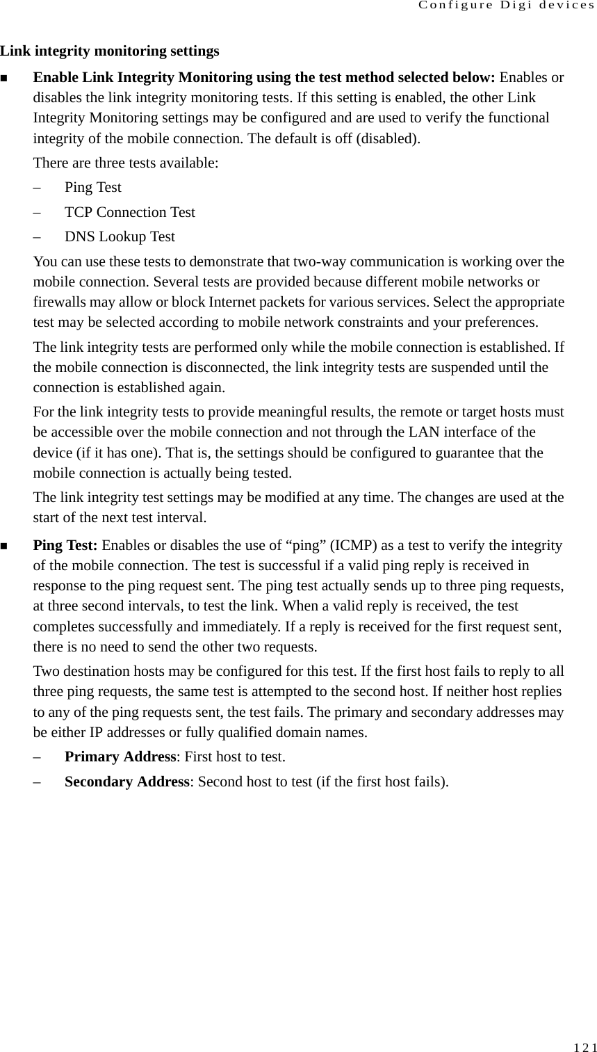
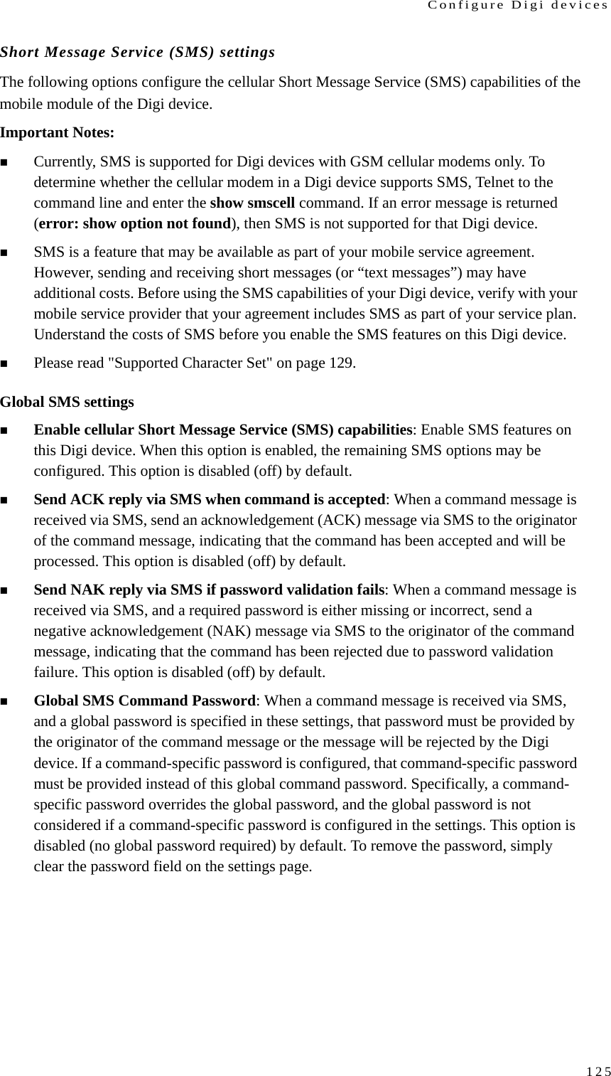
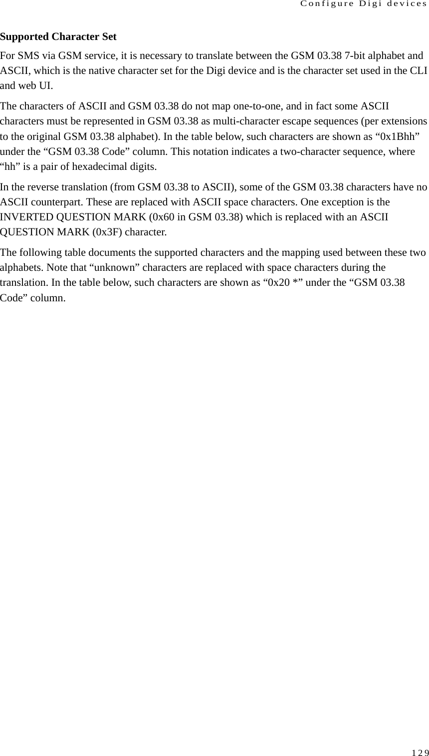
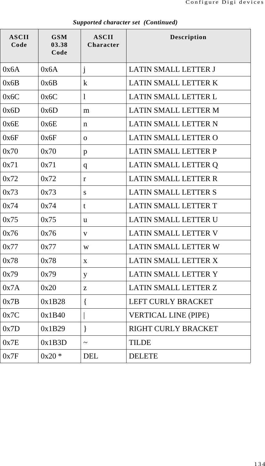
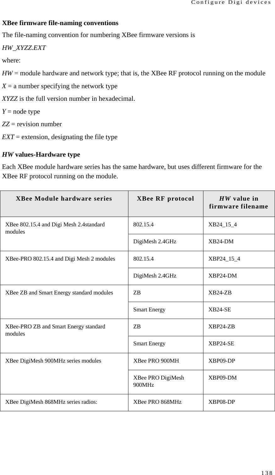
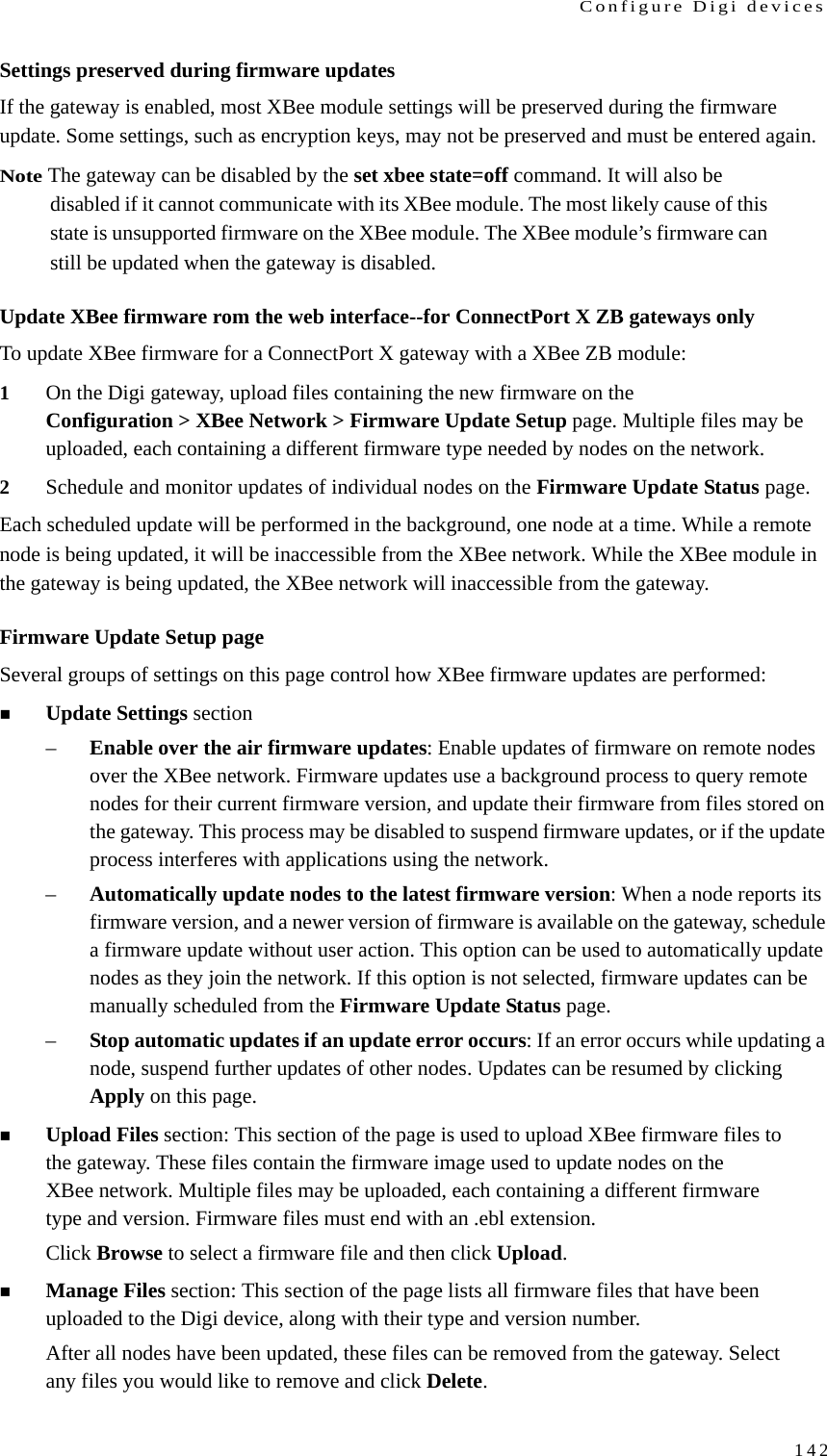
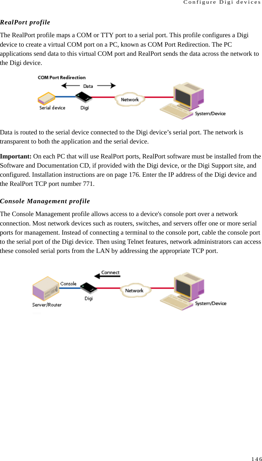
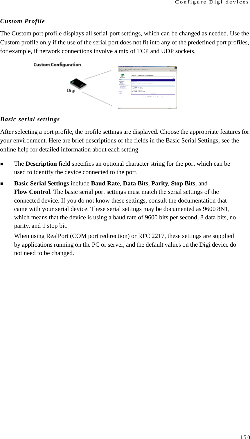
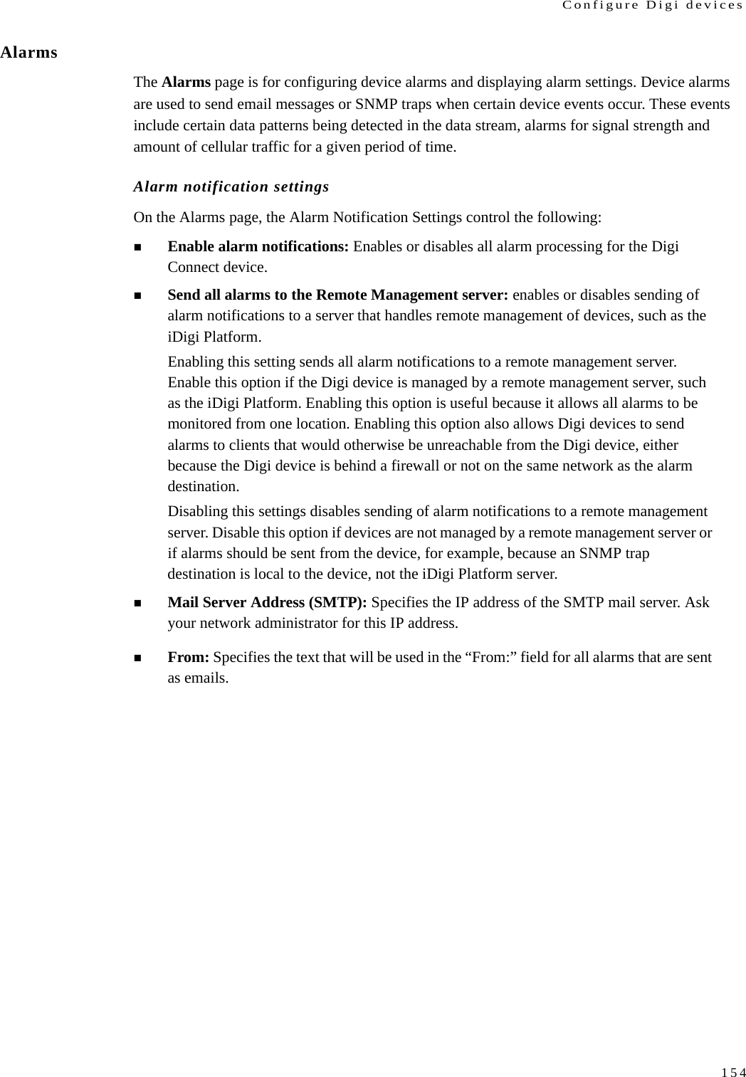
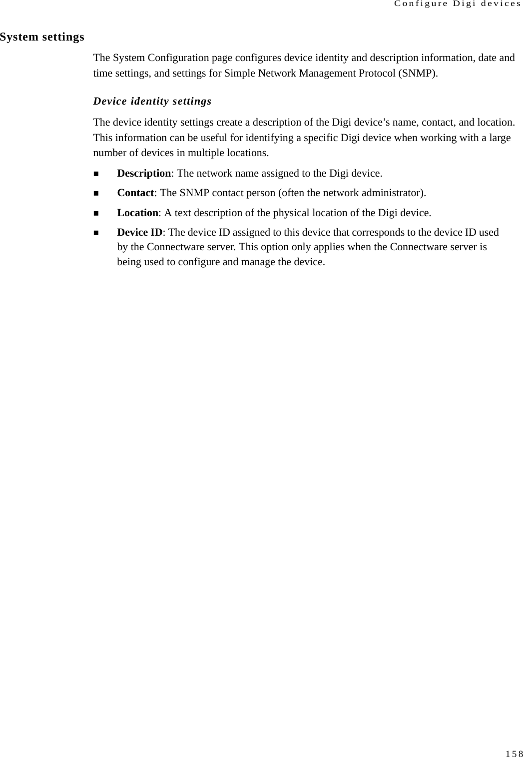
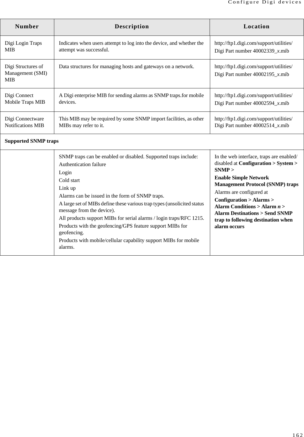
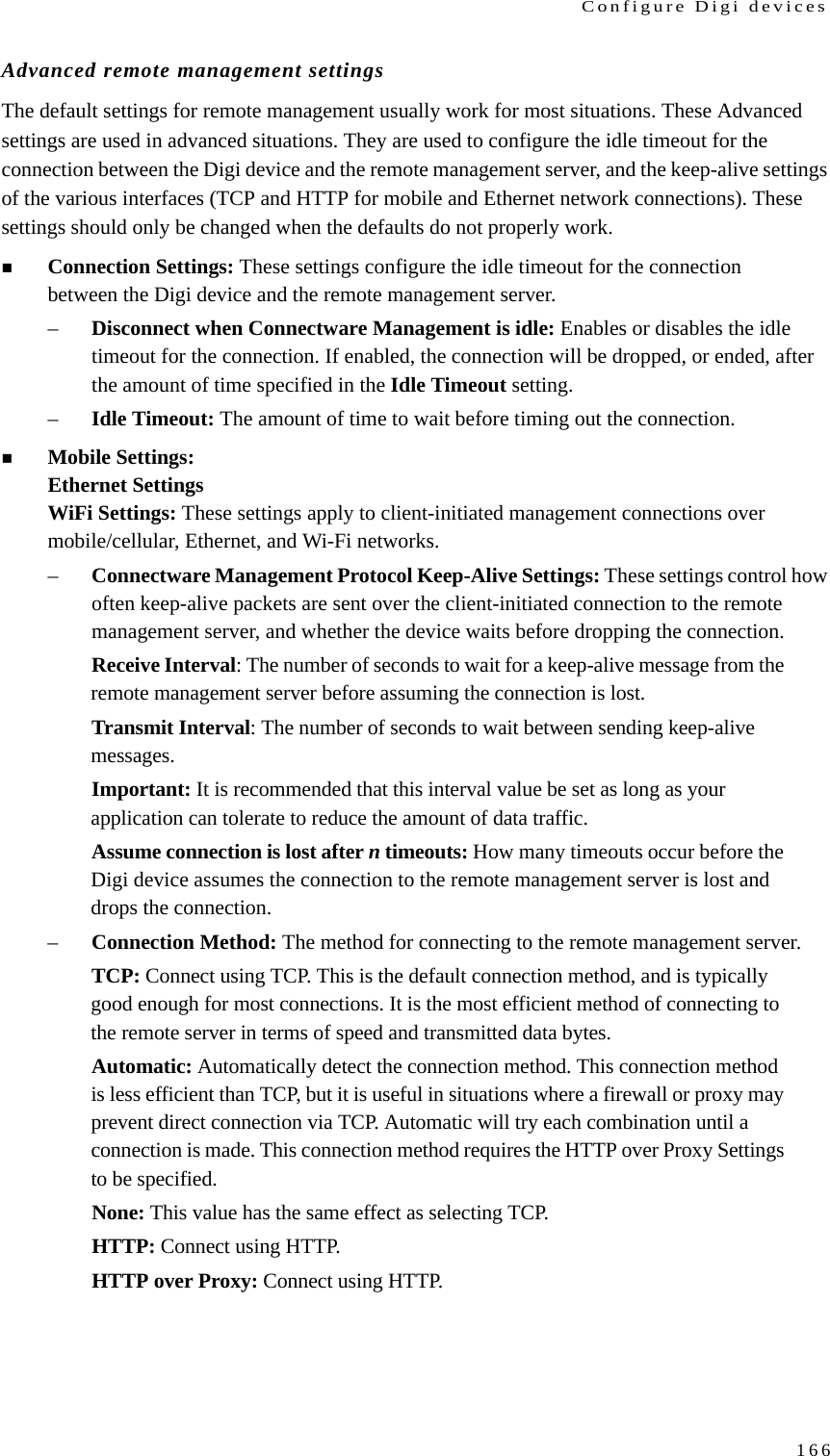
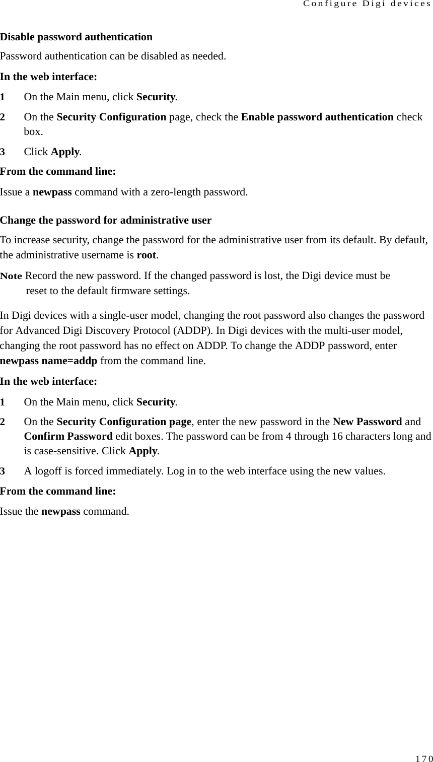
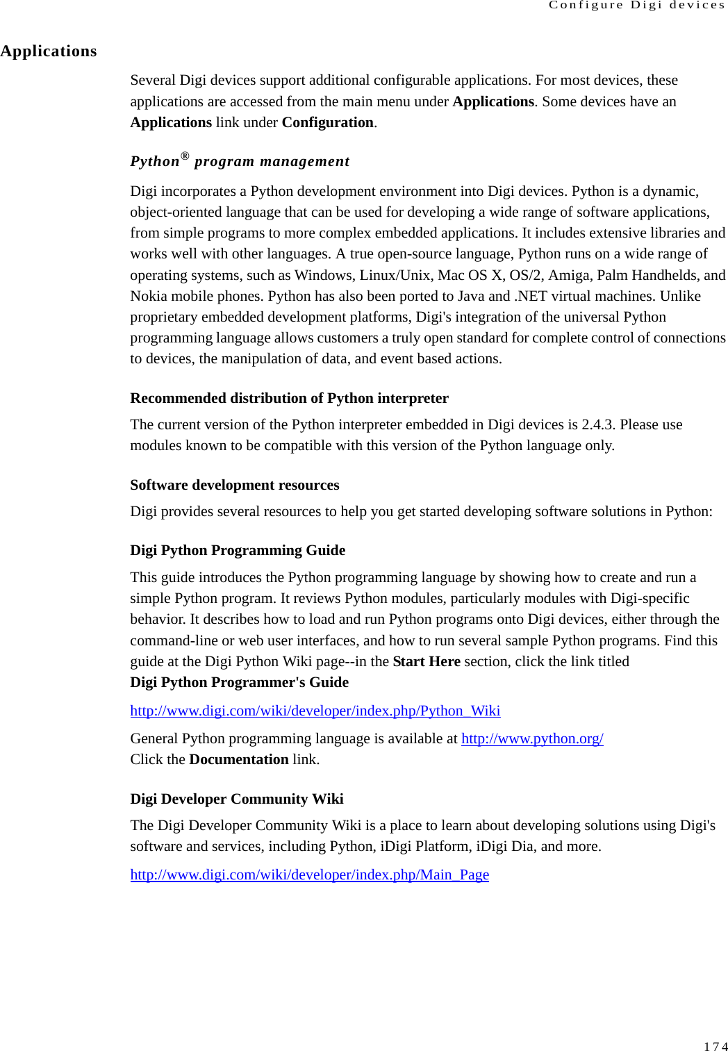
![Programming224Example #2: simple J1708 call and responseThe sample below is artificially constructed to demonstrate bus transmission, and to illustrate one method for organizing message reception. The sample is constructed supposing that an external device exists on the J1708 bus which will transmit a message with an “MID” value of 68 whenever it sees a message with the “MID” value of 127. A simple loop transmits a message with a “MID” of 127, then waits up to one second for a response before sending another. Counters are printed at each iteration of the loop.Note Vehicle bus API operations are highlighted in the samples in boldface type.import digij1708 (1)import Queue (2)def j1708_sniff(mid, payload, context_arg): (3)filter_list, input_queue = context_arg (4)if mid in filter_list: (5)input_queue.put(payload) (6)h = digij1708.J1708Handle(0) (7)h.configure(mid=127) (8)in_queue = Queue.Queue() (9)h.register_callback(j1708_sniff, ([68], in_queue)) (10)txcnt = 0rxcnt = 0while True: (11)h.send(5, ‘ABCDE’) (12)txcnt = txcnt + 1 (13)try:msg = in_queue.get(True, 1.0) (14)rxcnt = rxcnt + 1 (15)except Queue.Empty: pass (16)print “TxCnt: %-10d RxCnt: %-10d” % (txcnt, rxcnt) (17)](https://usermanual.wiki/Digi/WMPX5F/User-Guide-1291648-Page-224.png)
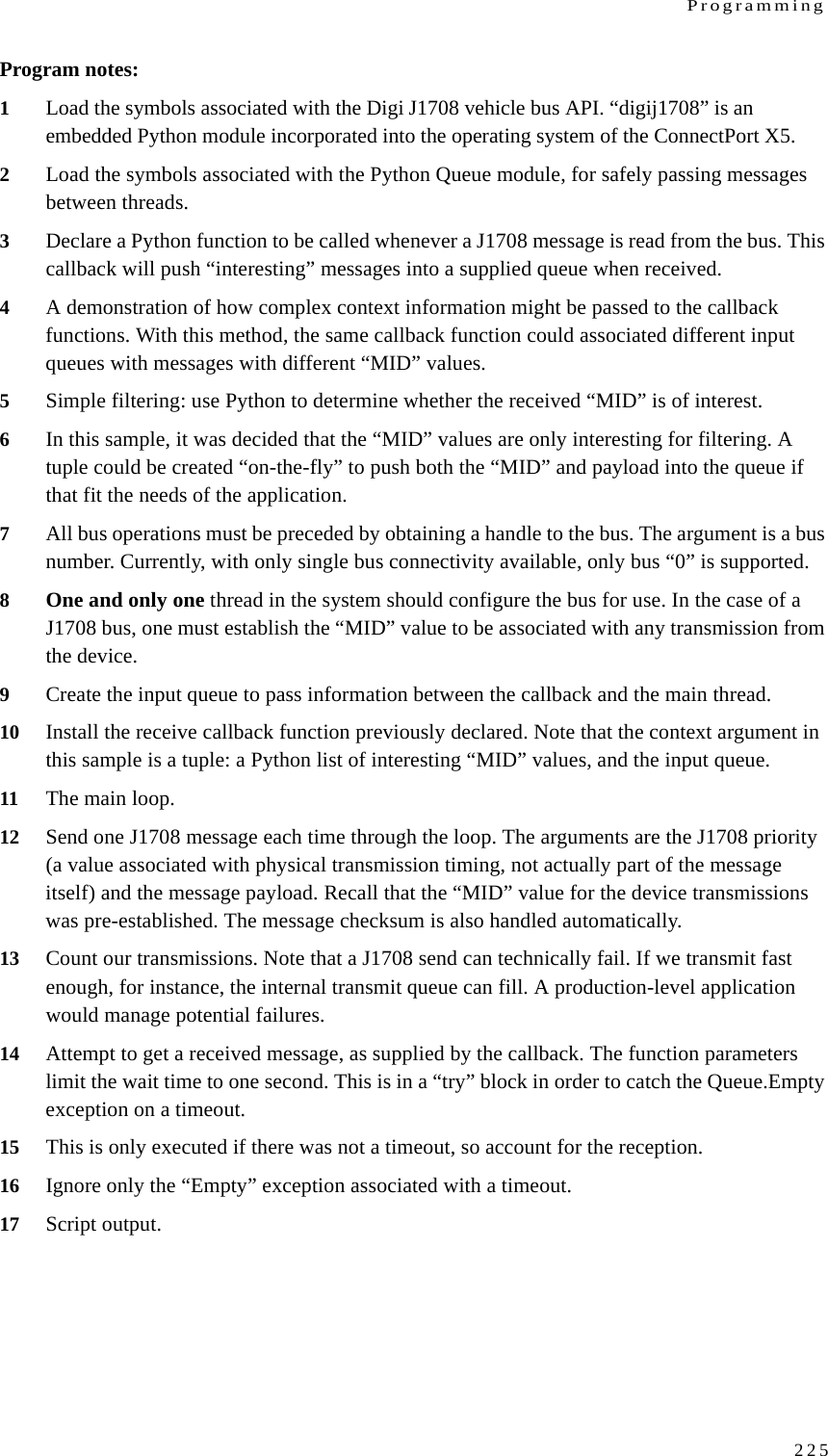
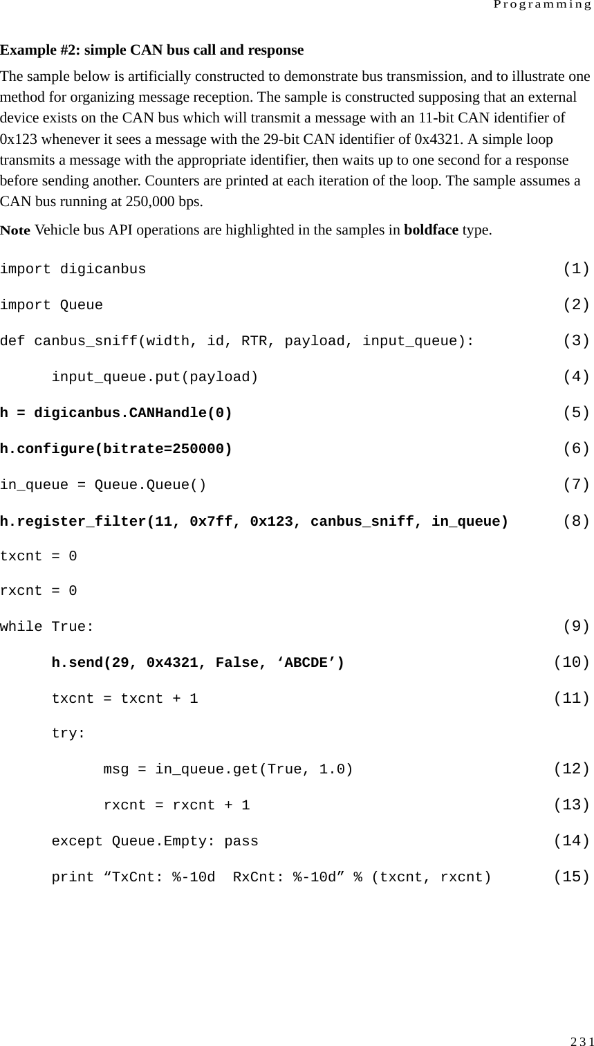
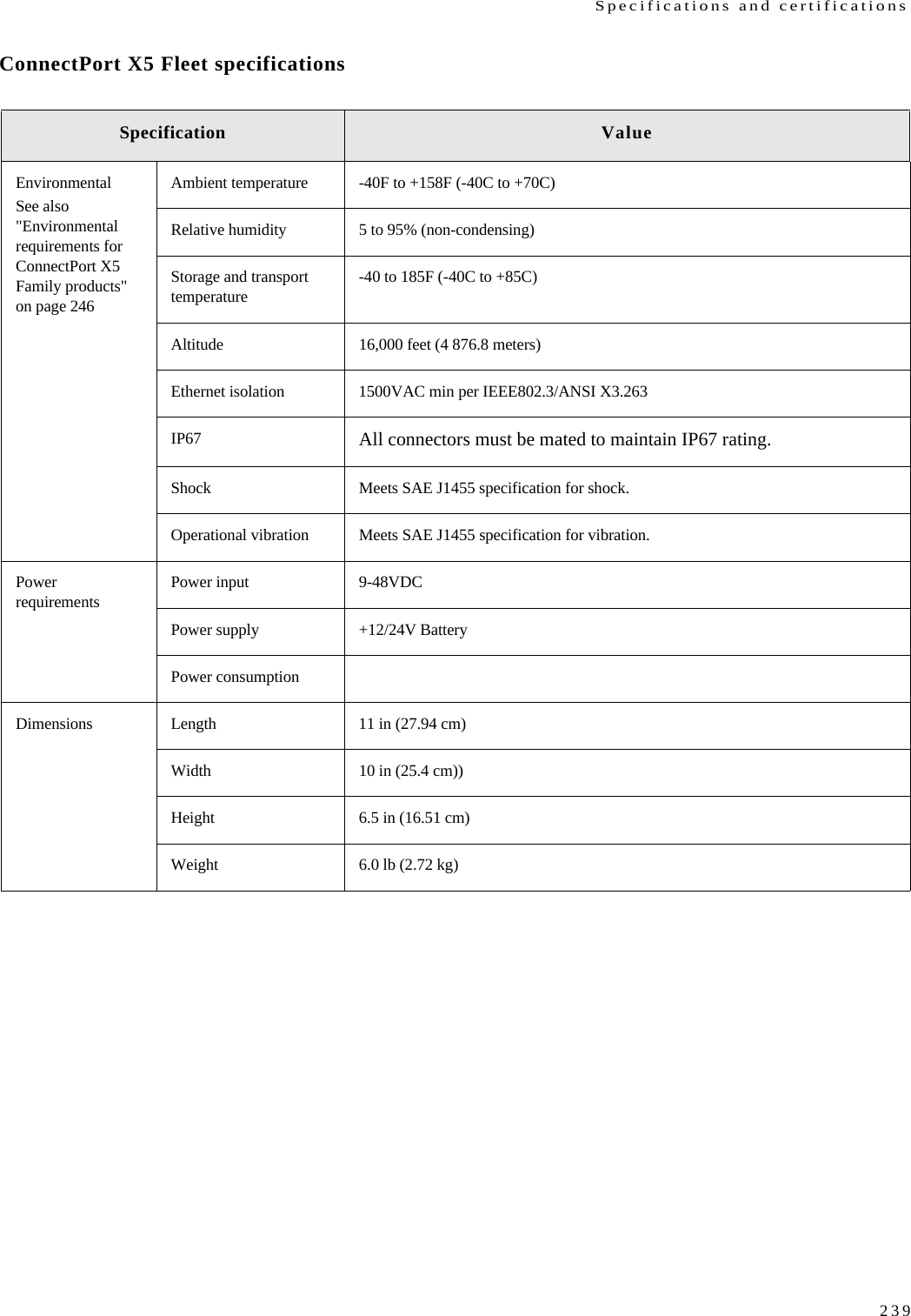
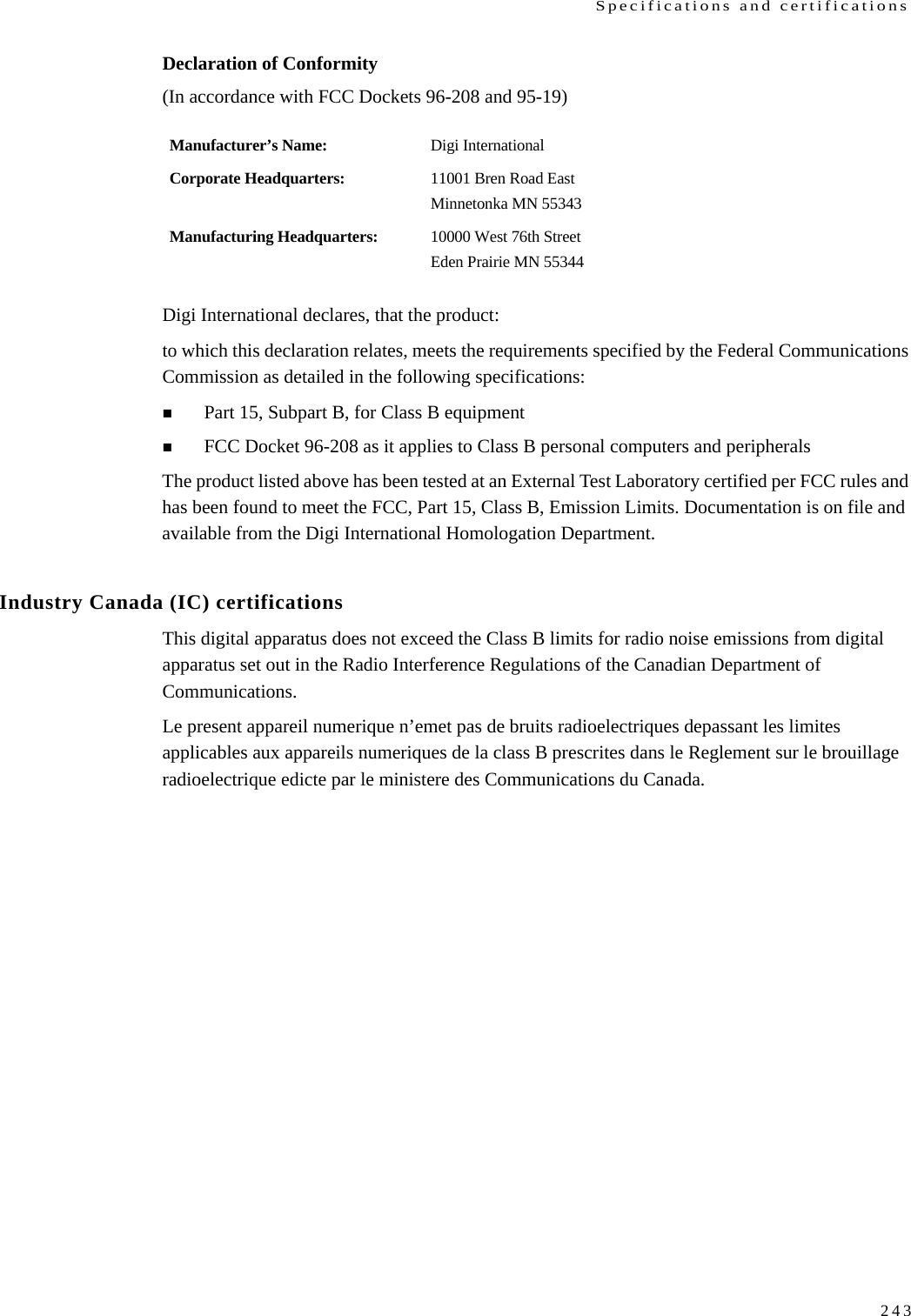
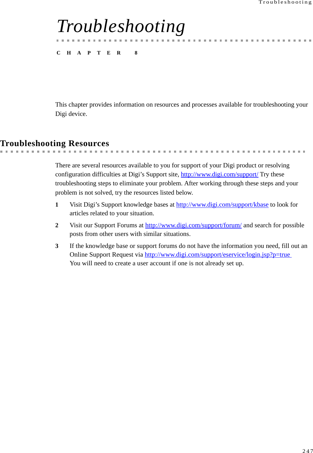
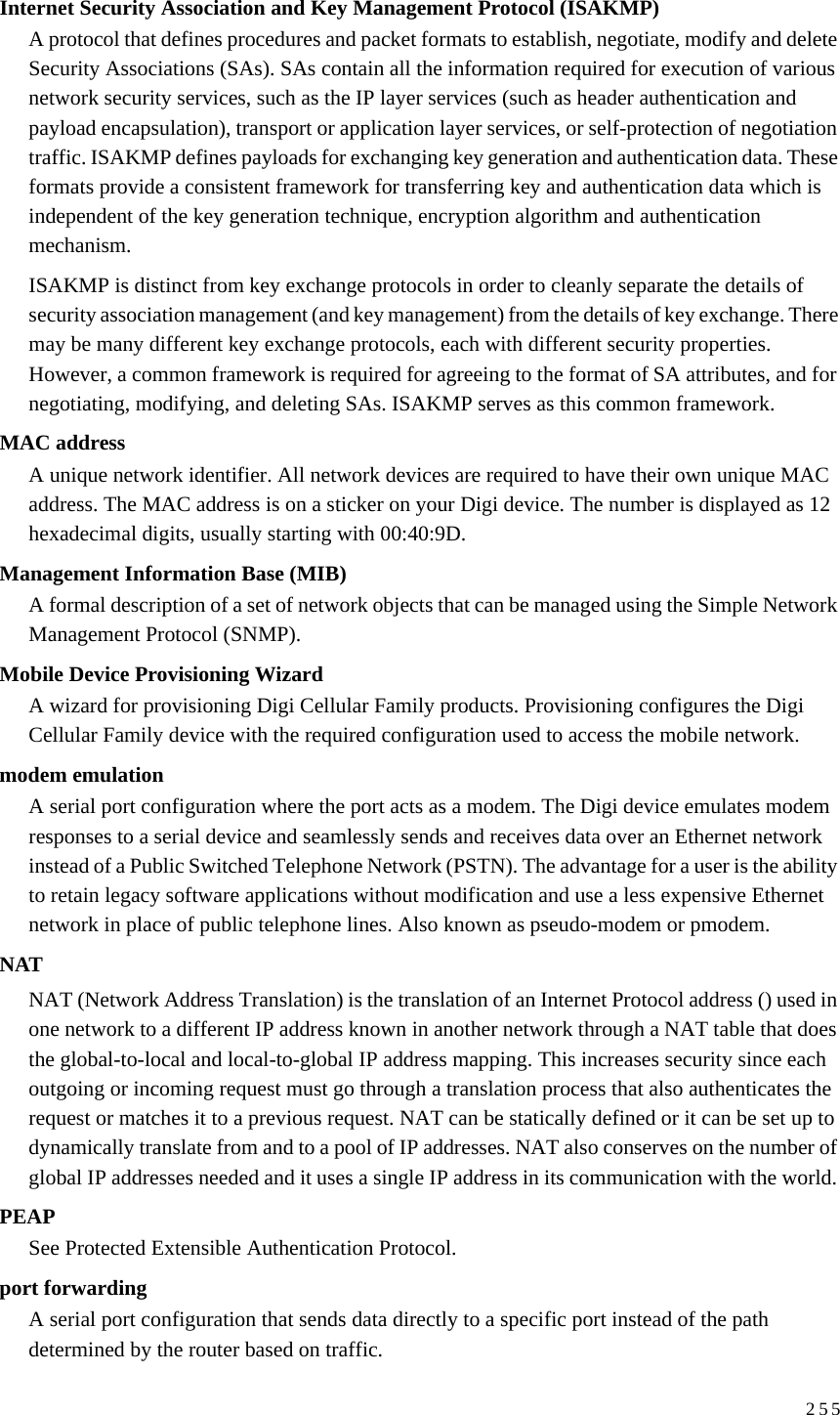
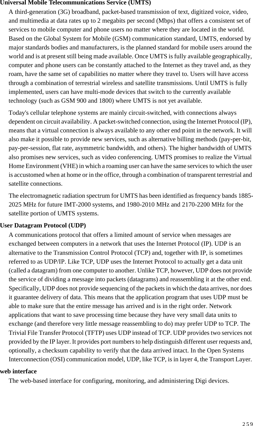
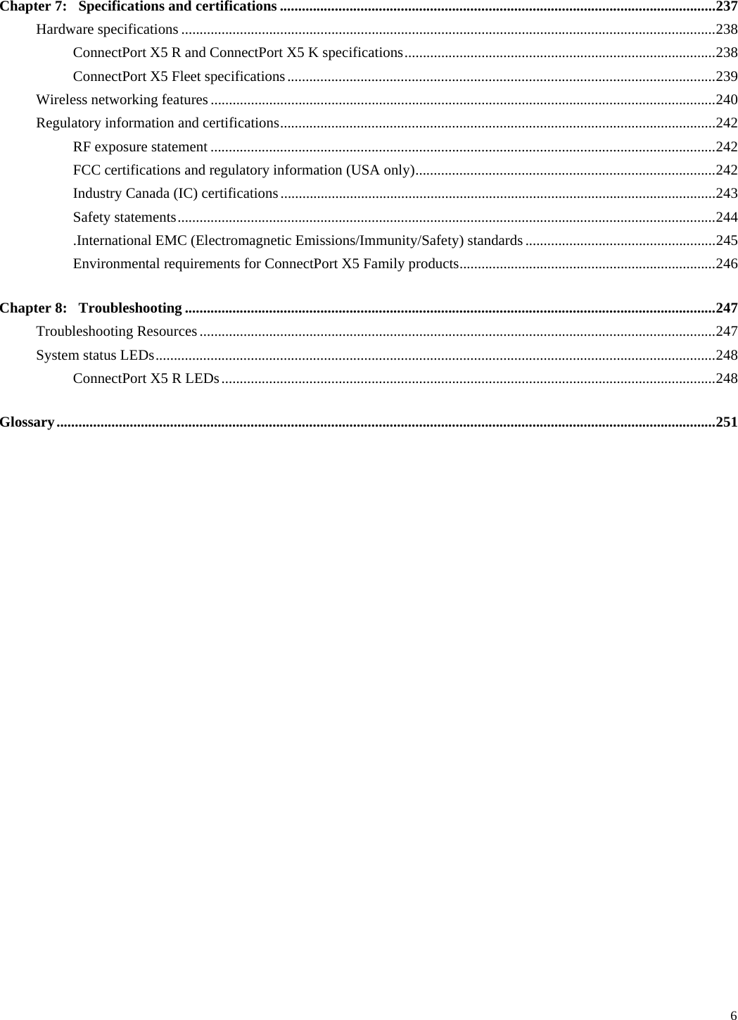
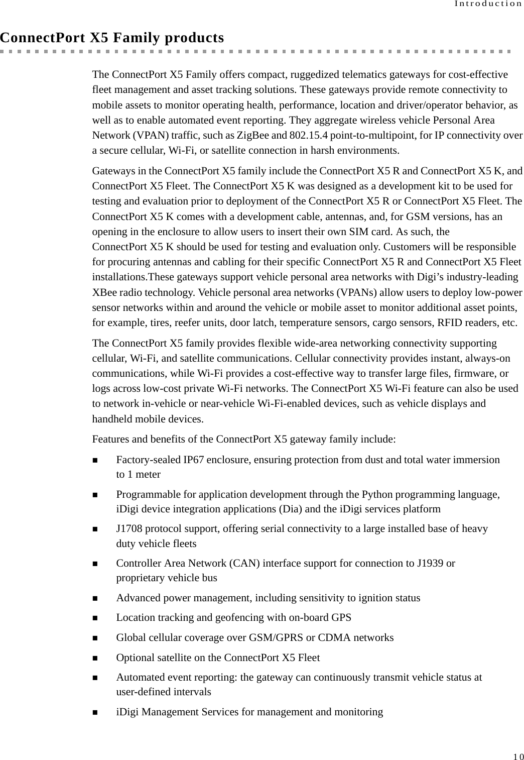
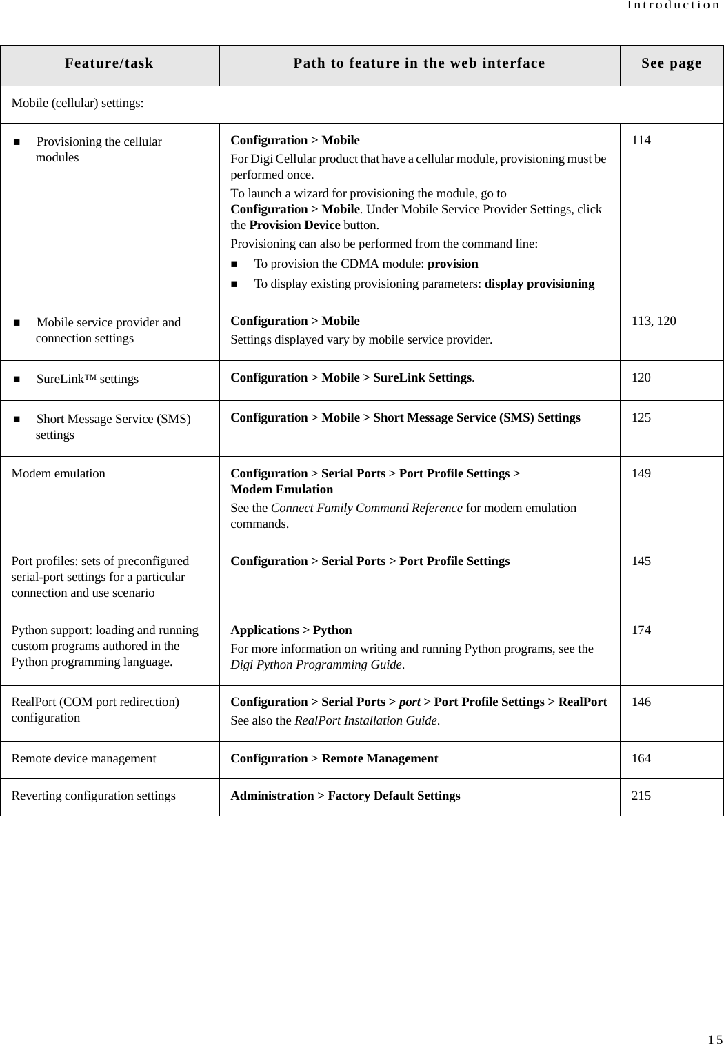
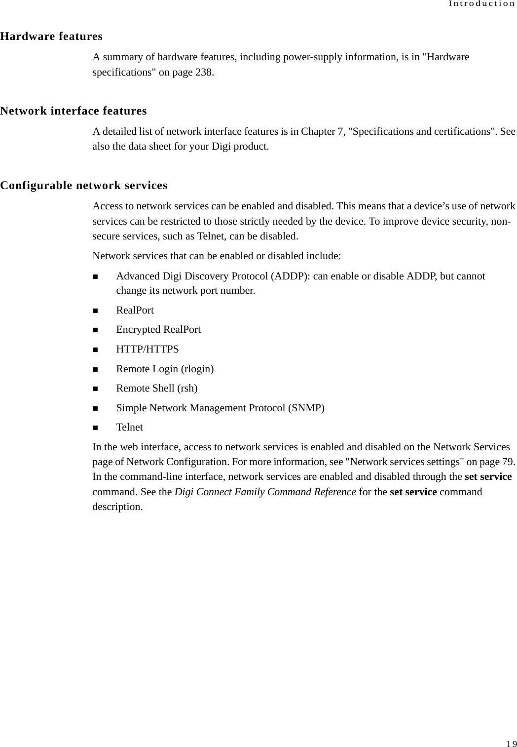
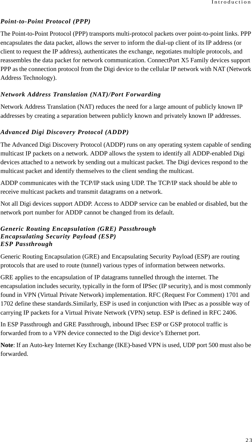
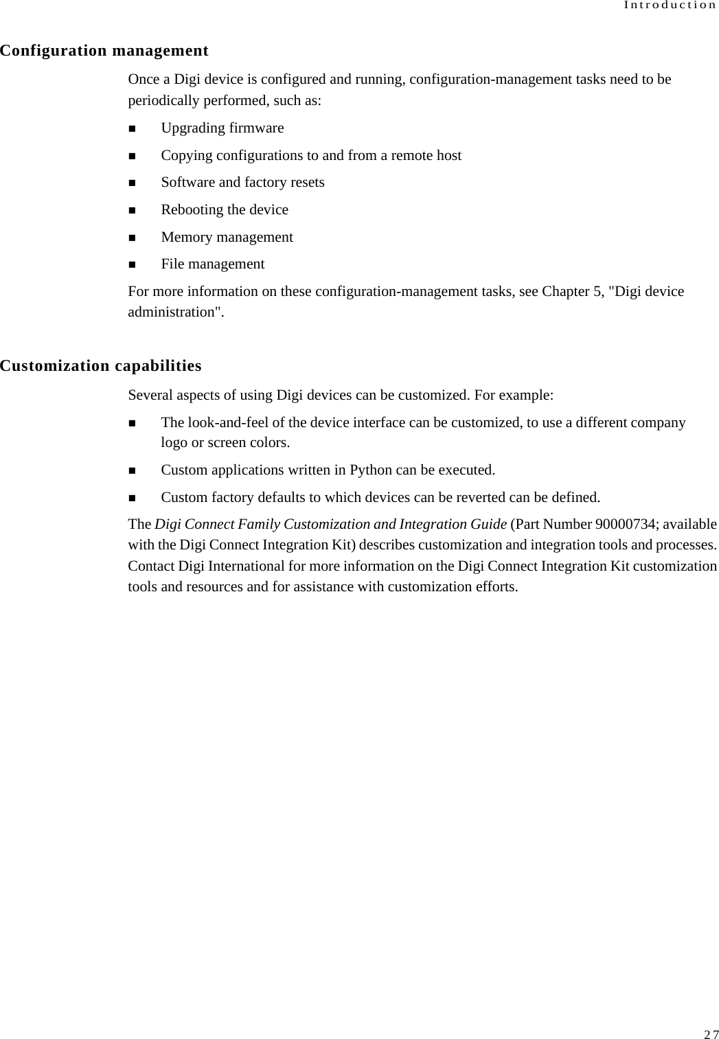
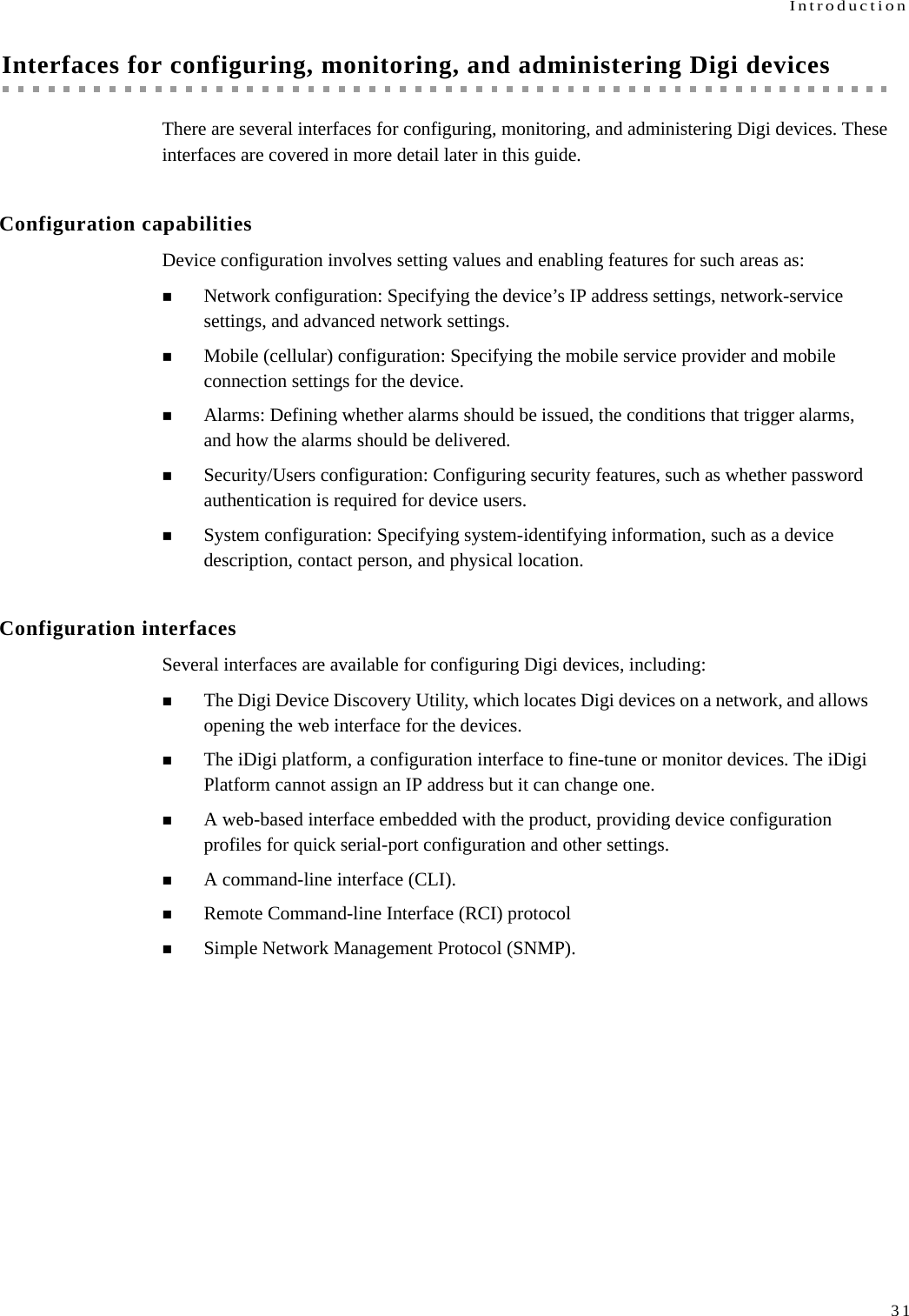
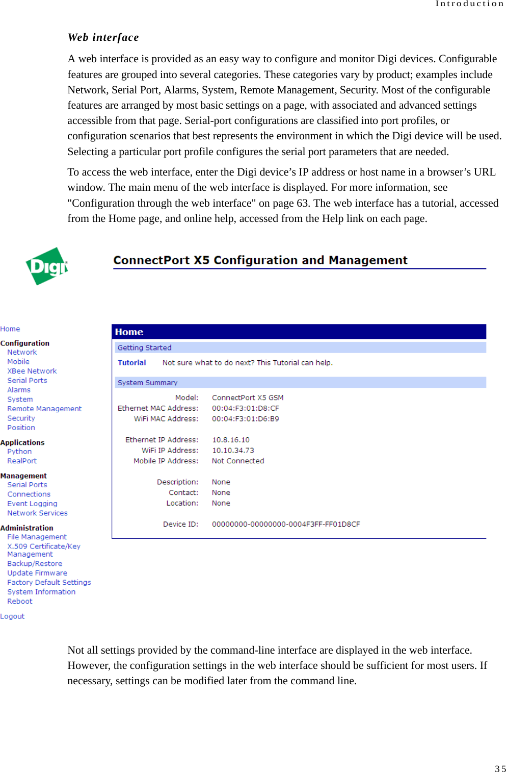
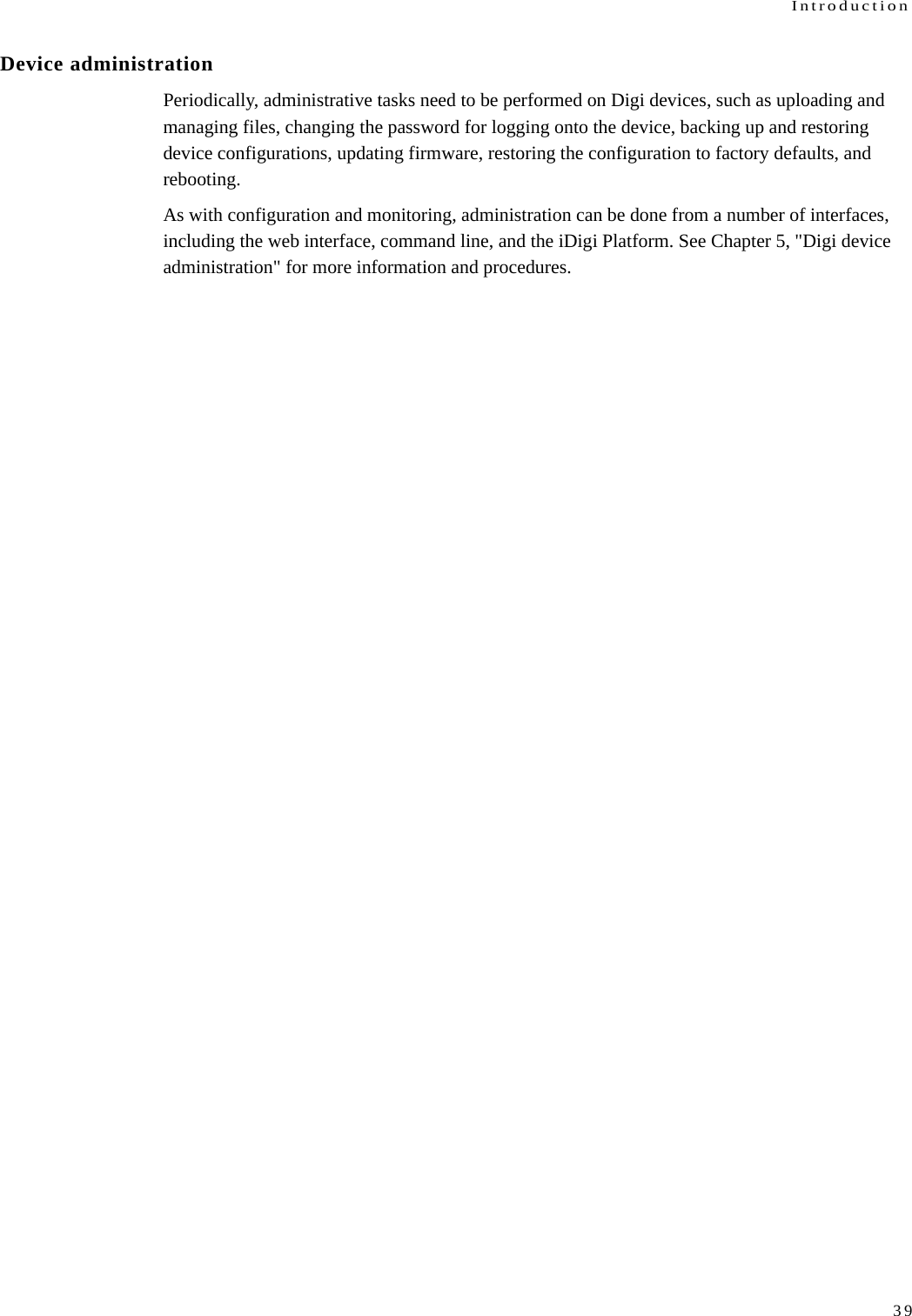
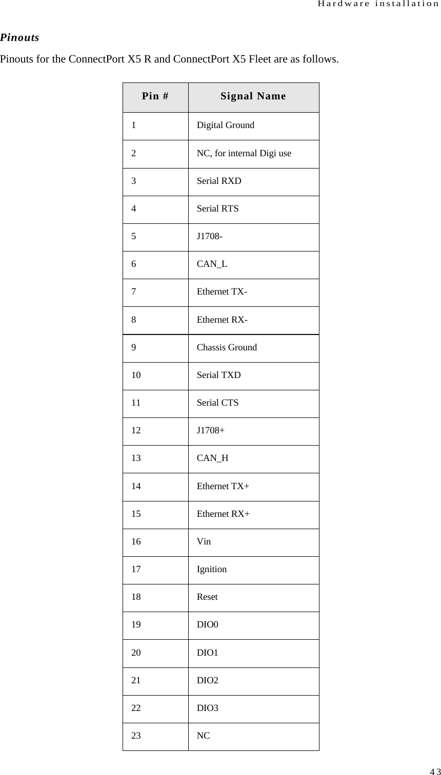
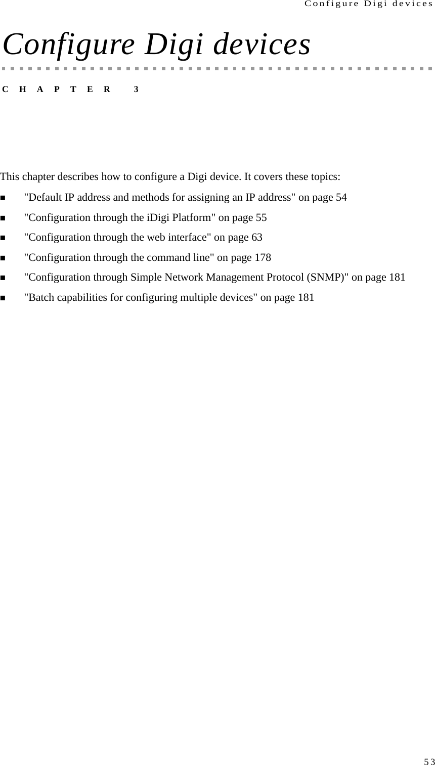
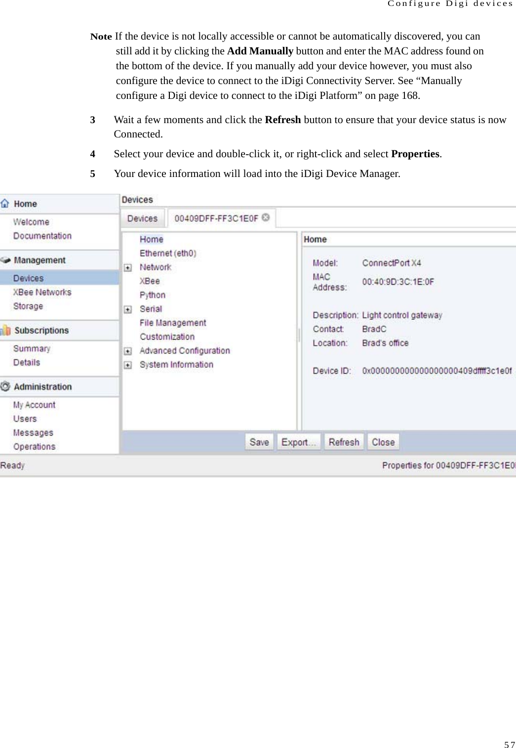
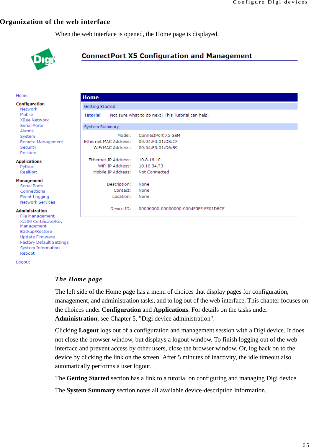
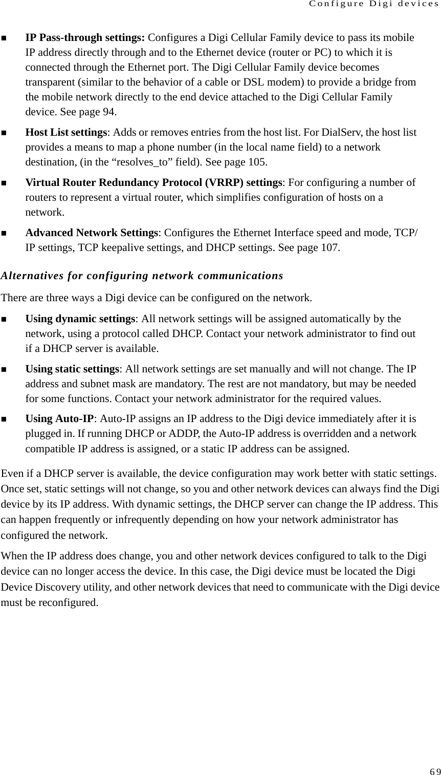
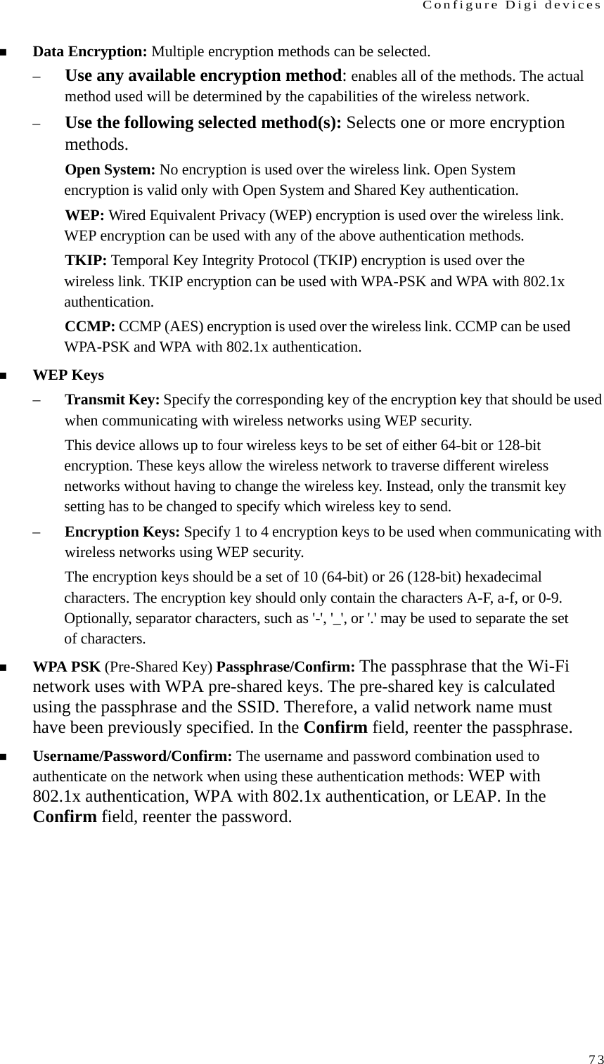
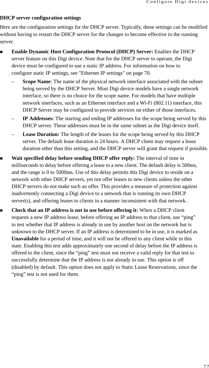
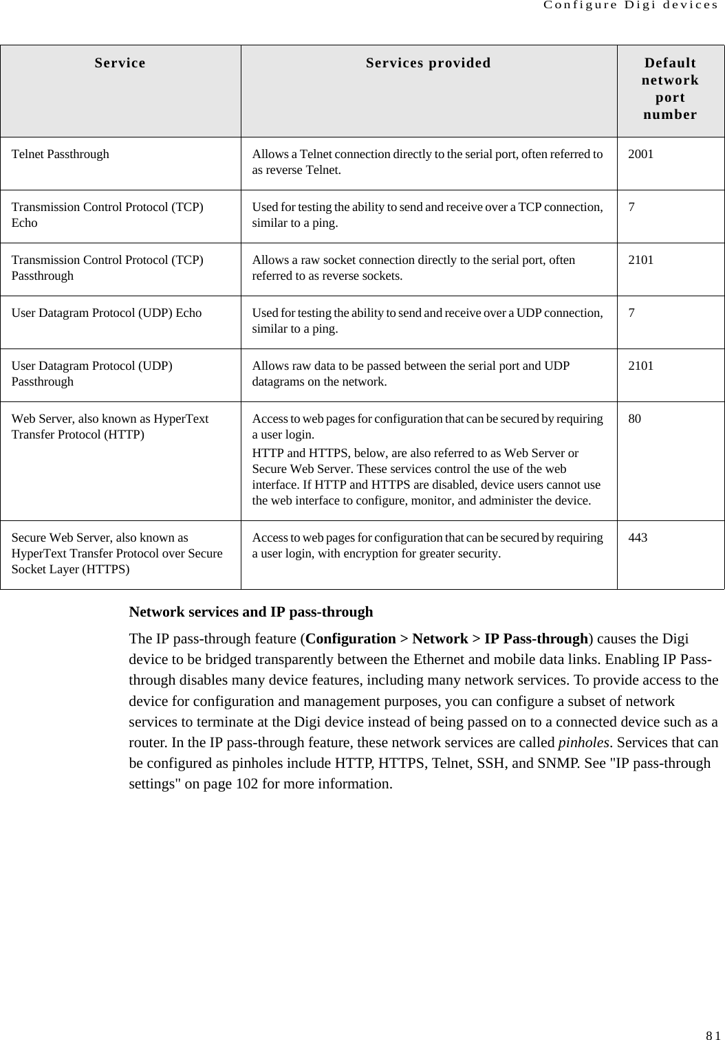
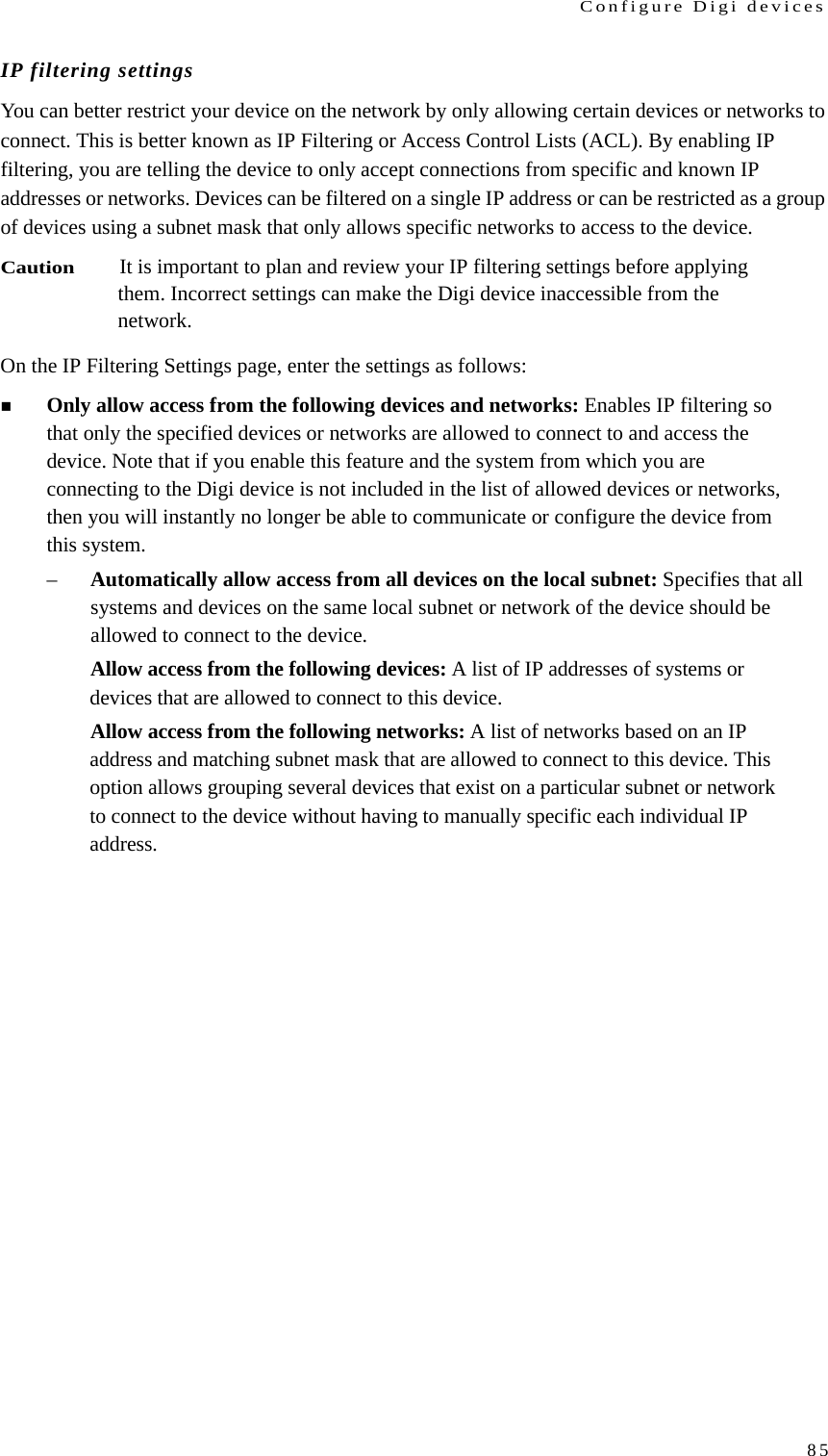
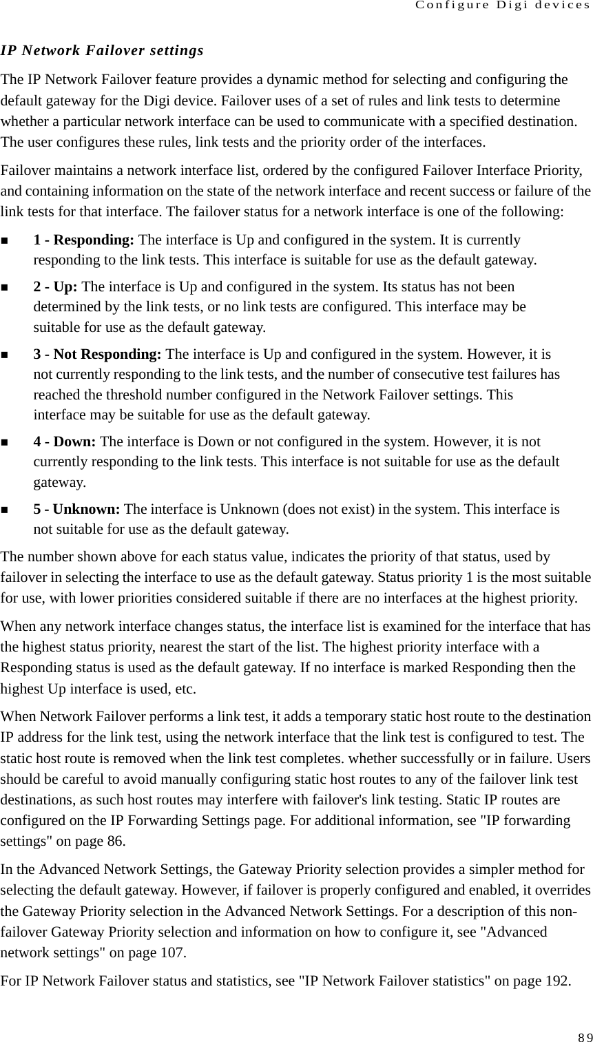
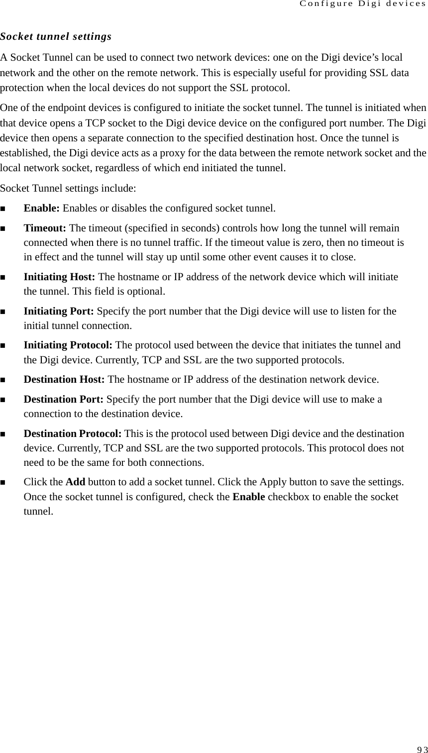
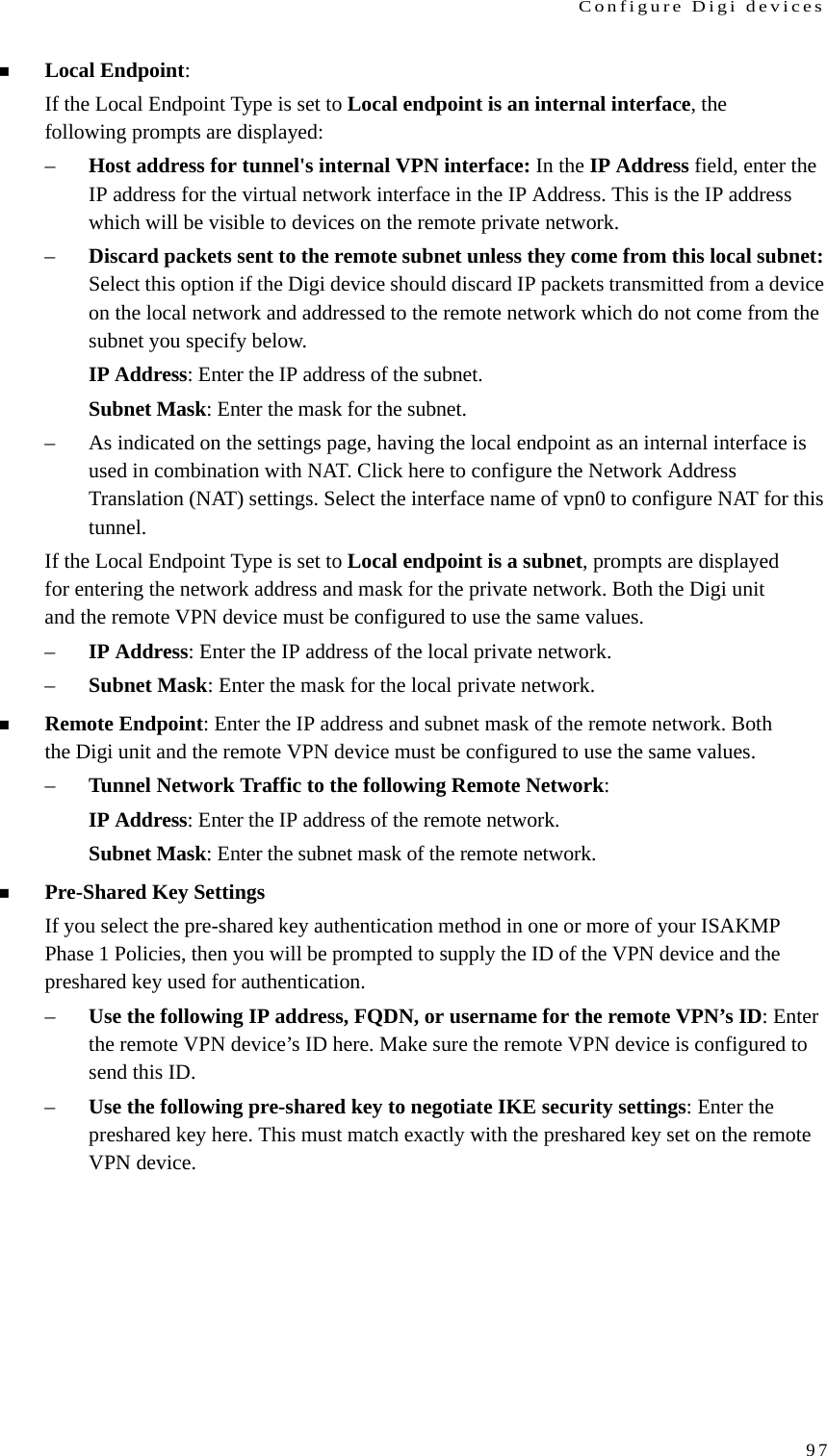
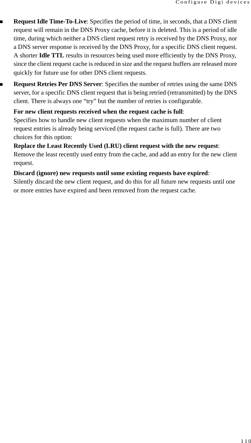
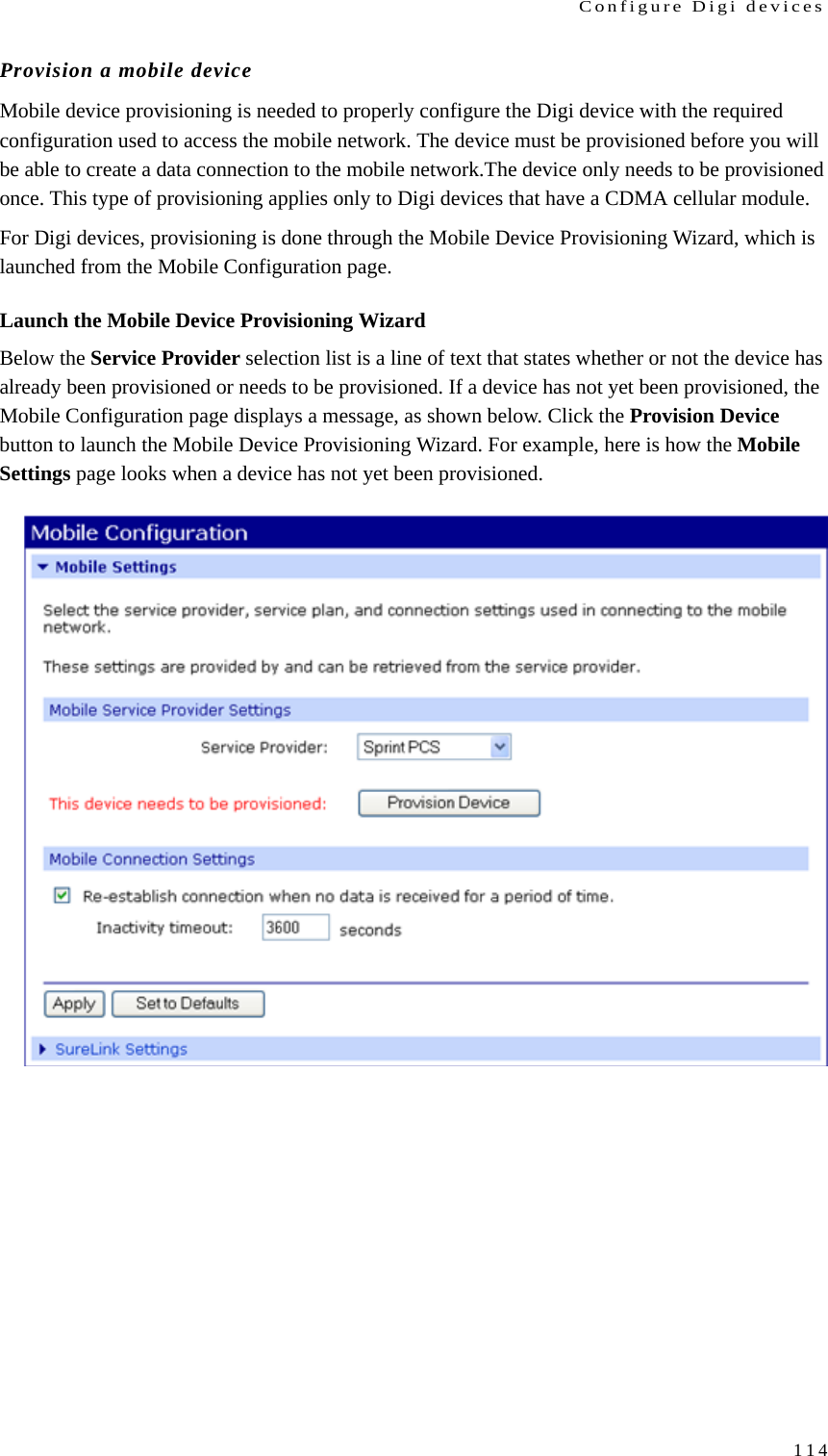
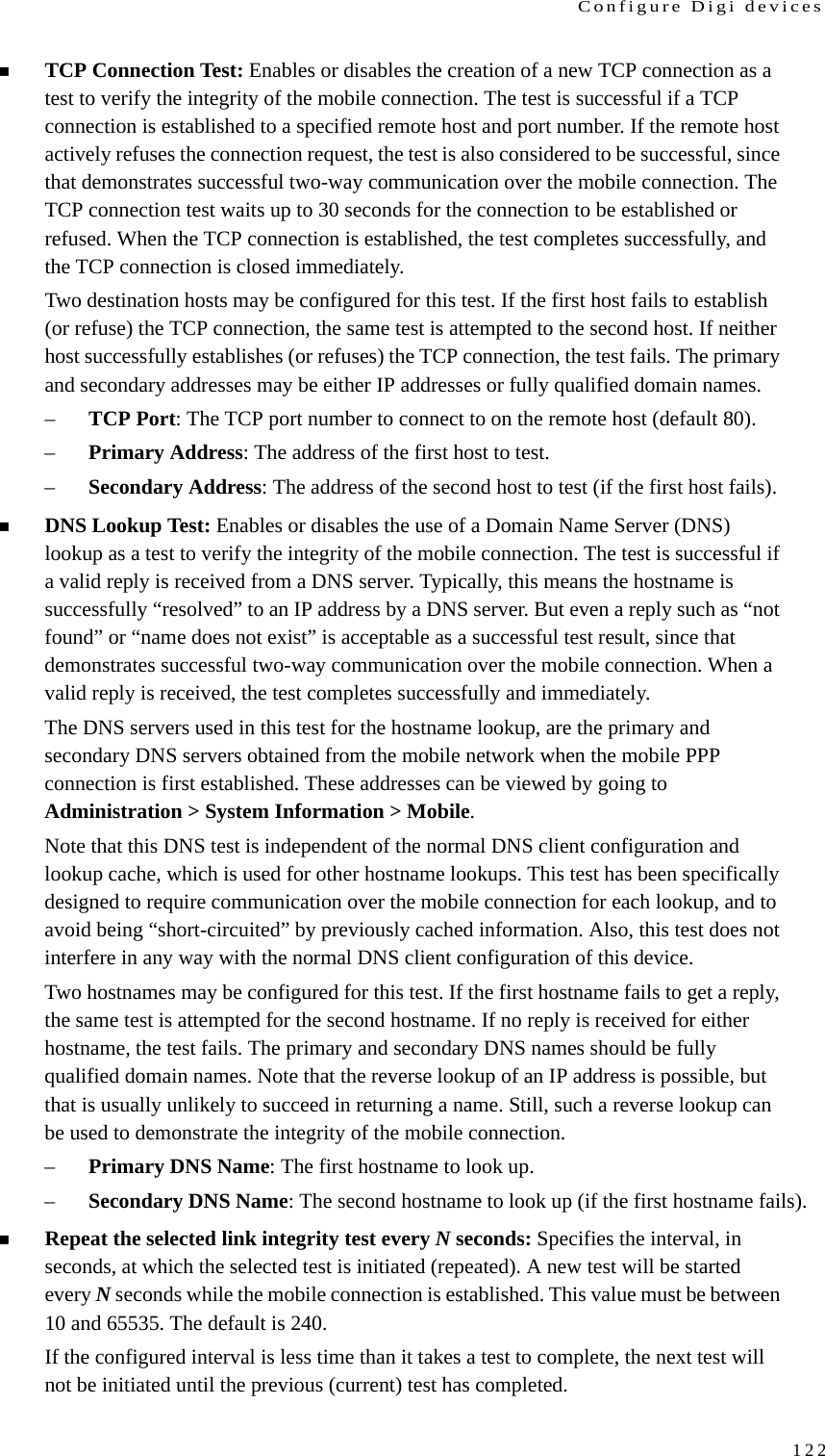
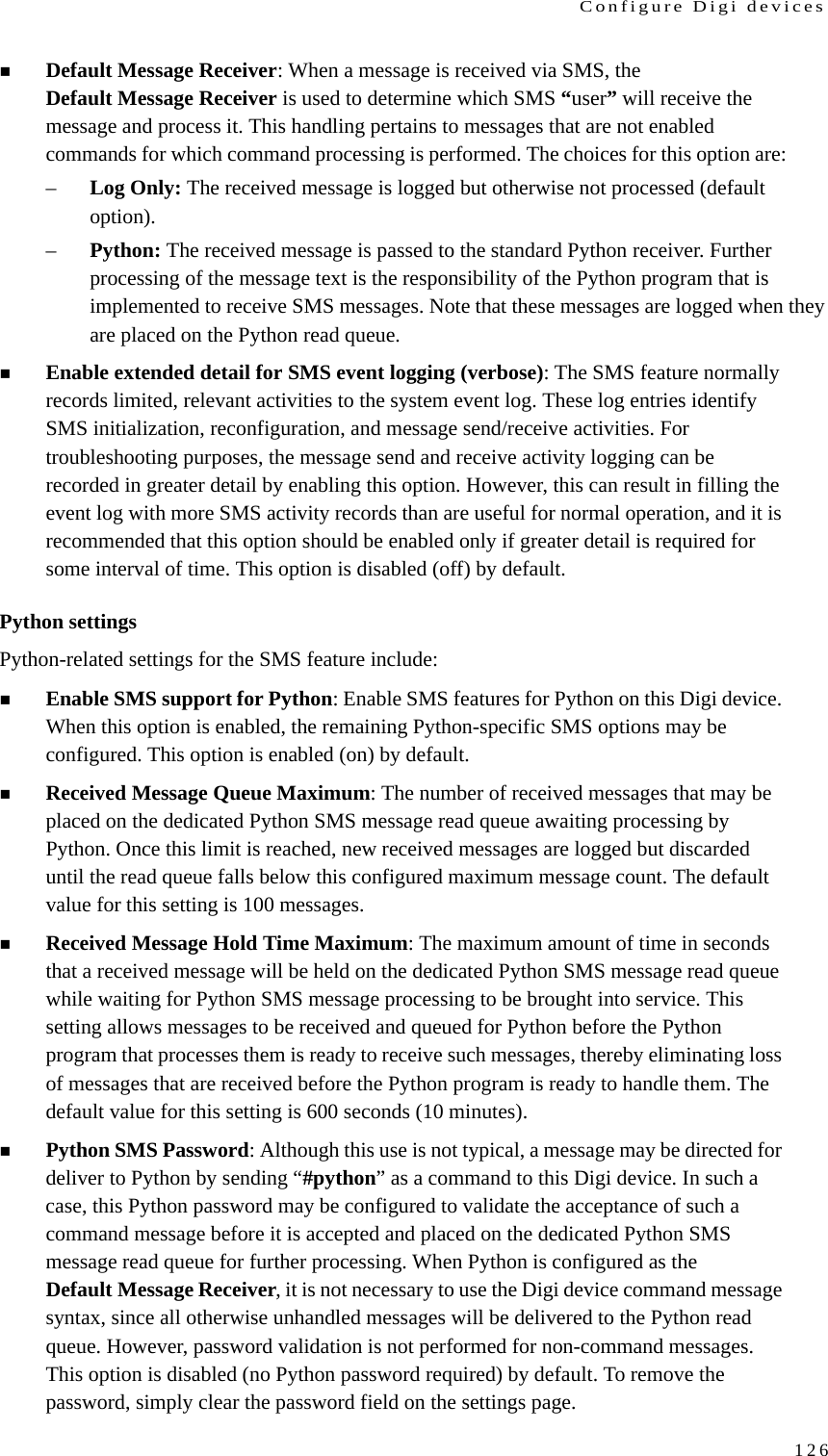
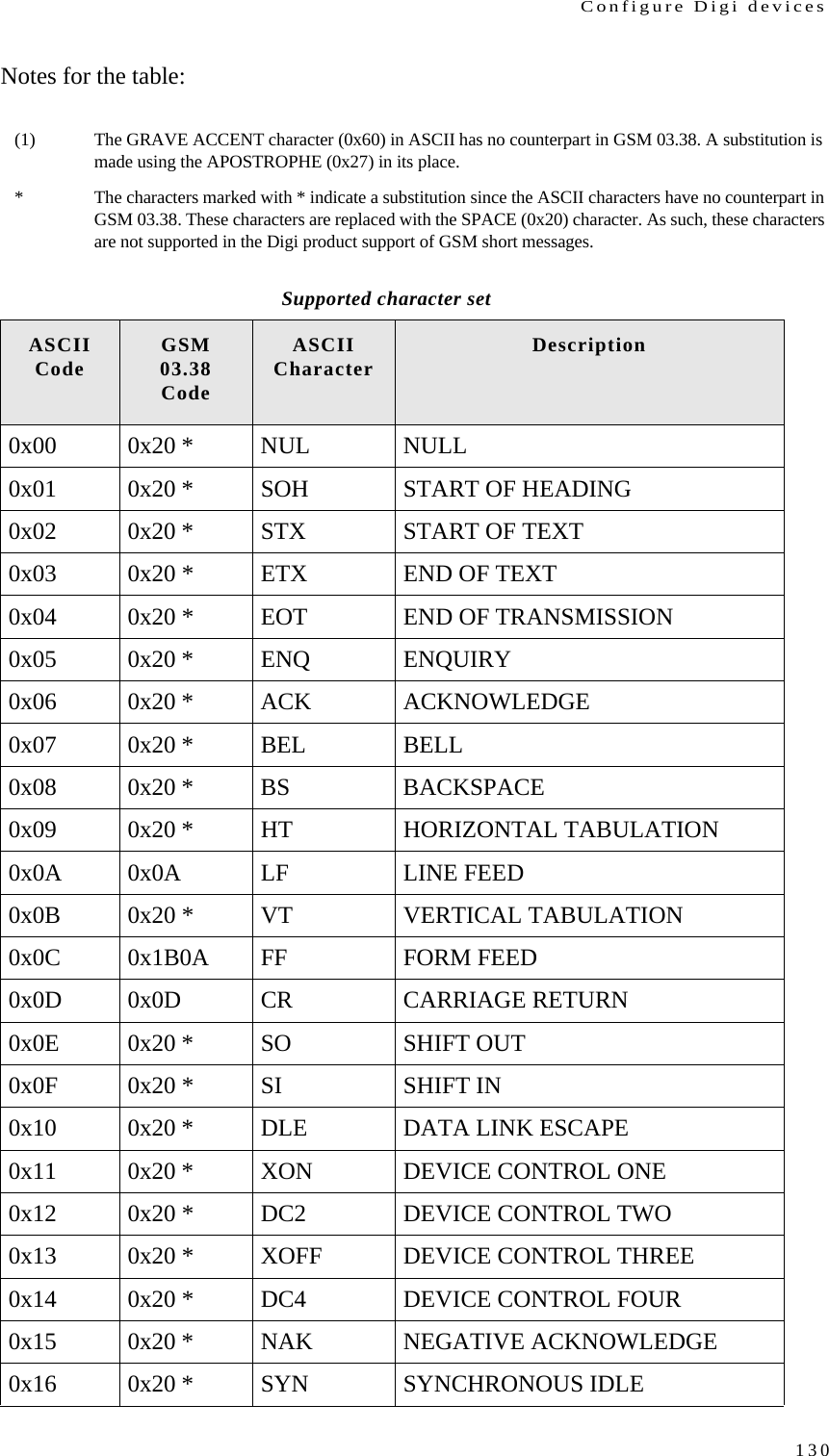
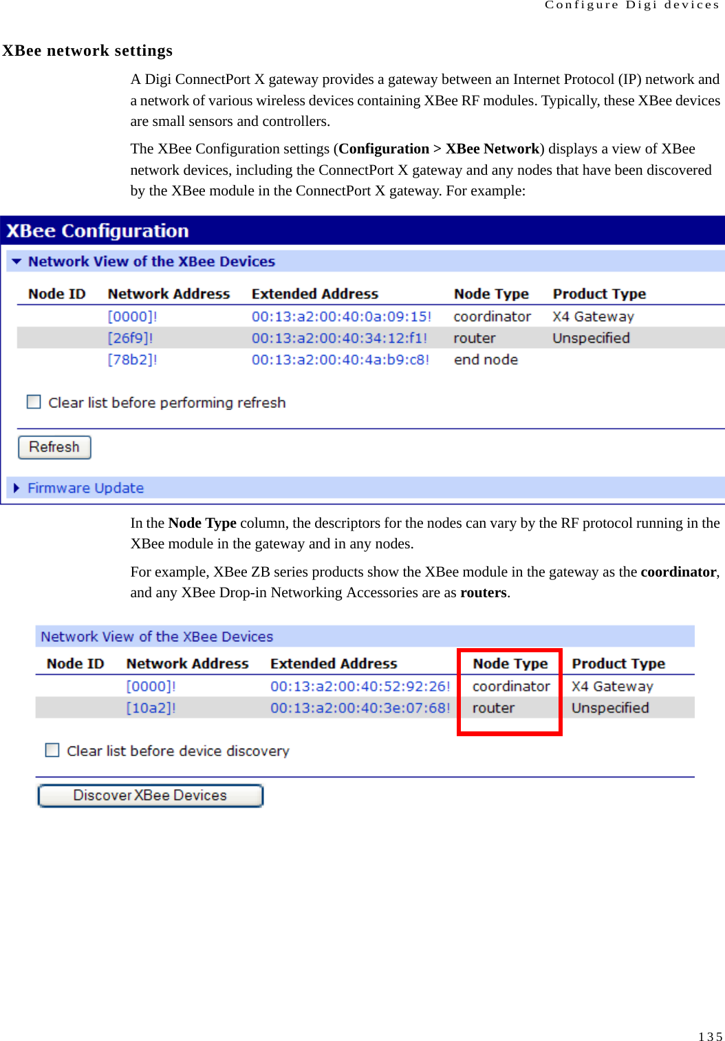
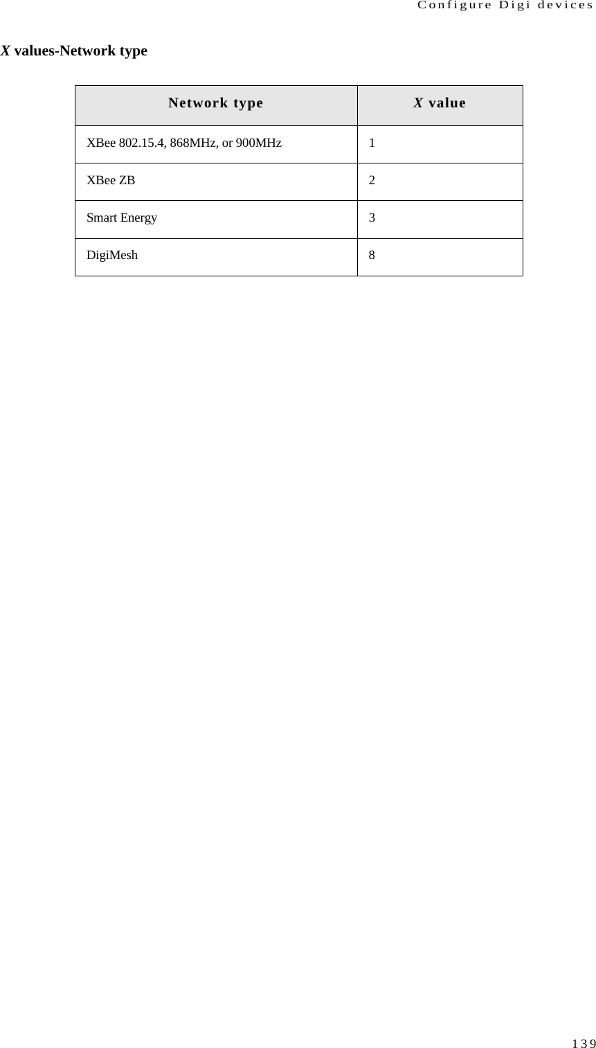
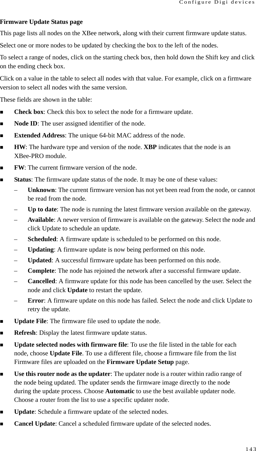
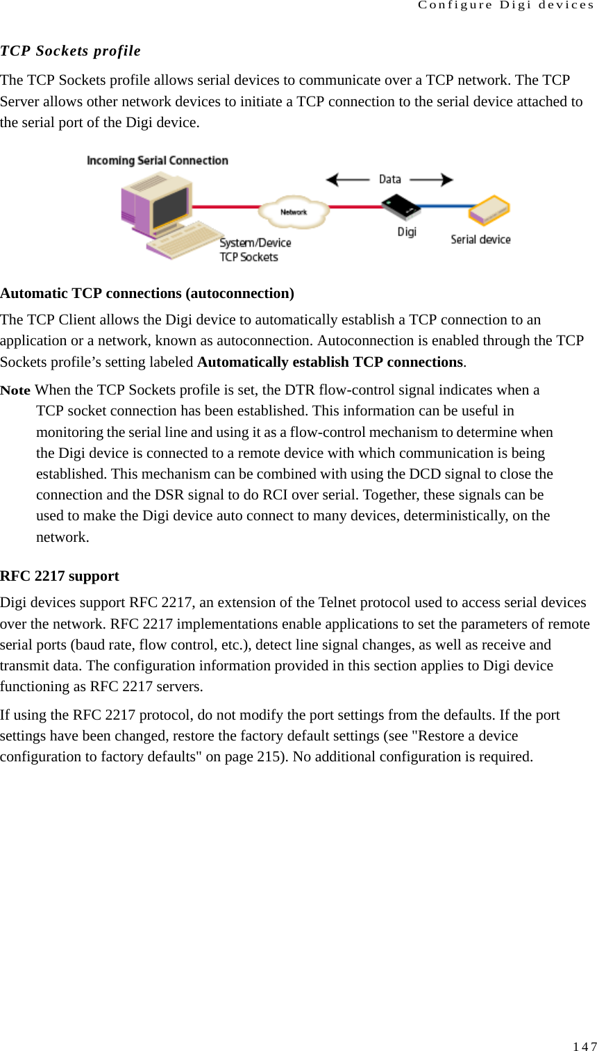
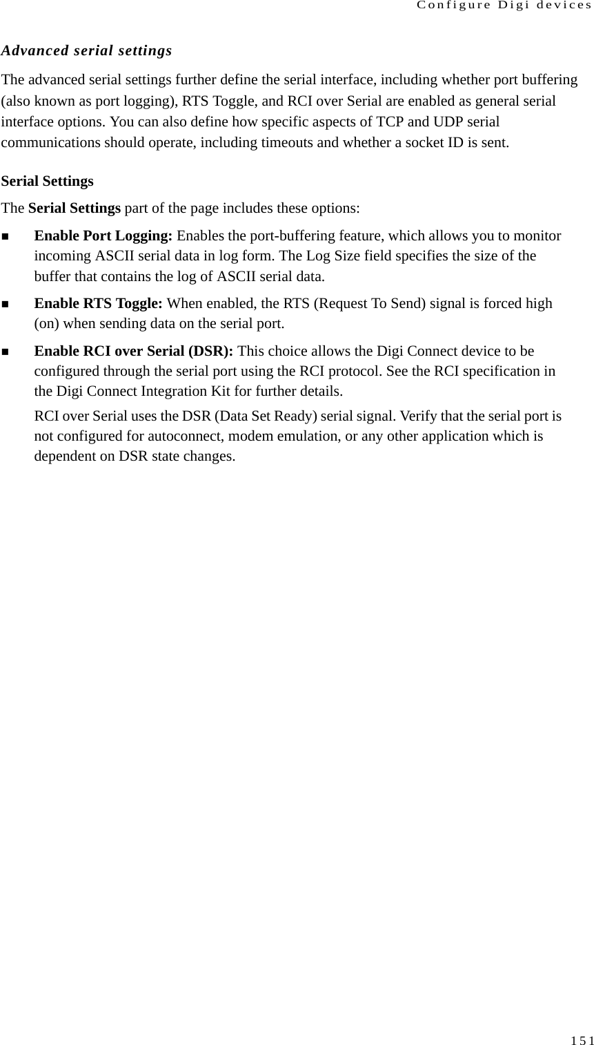
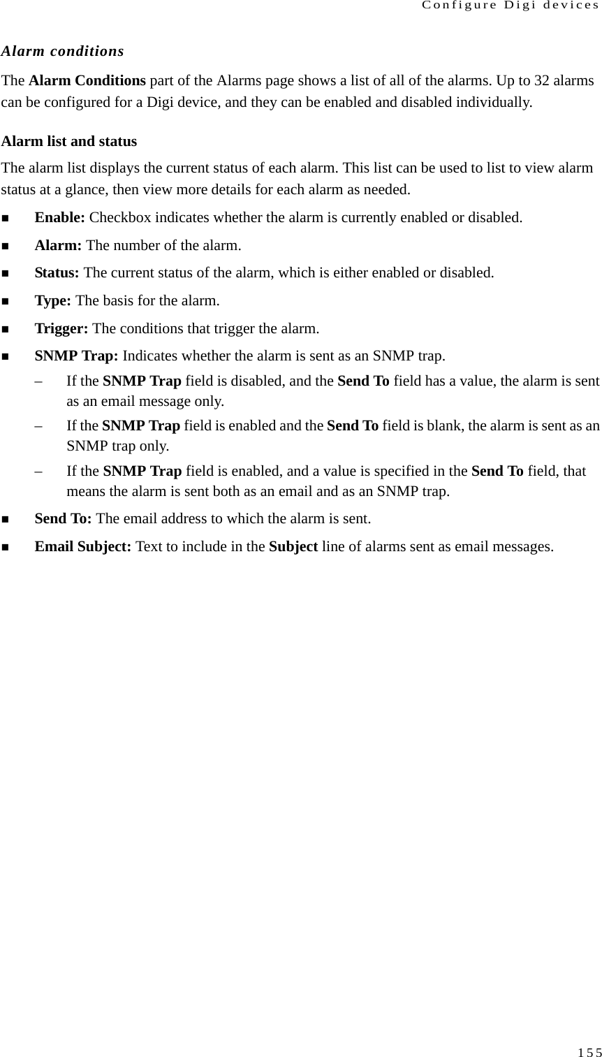
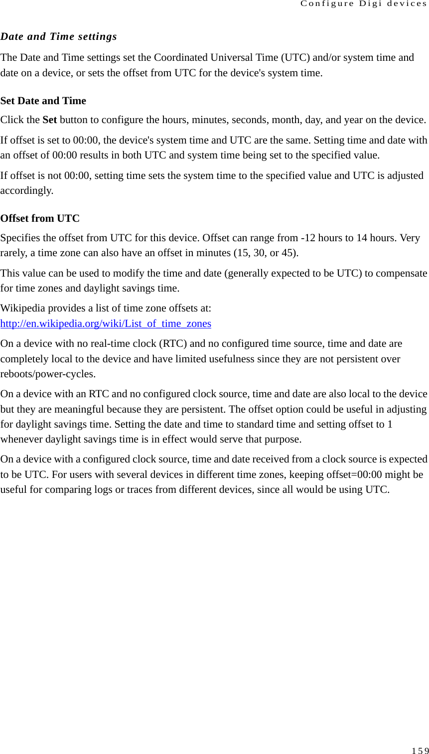
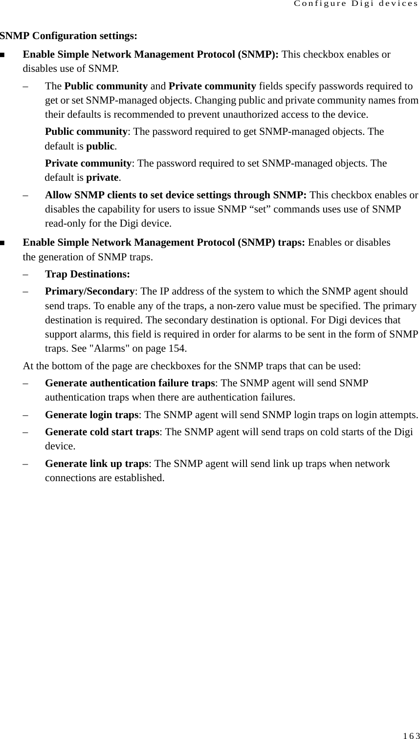
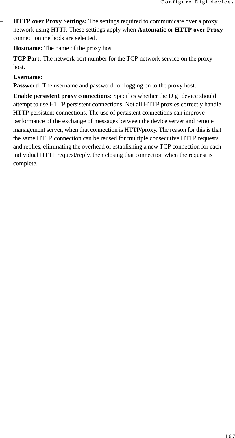
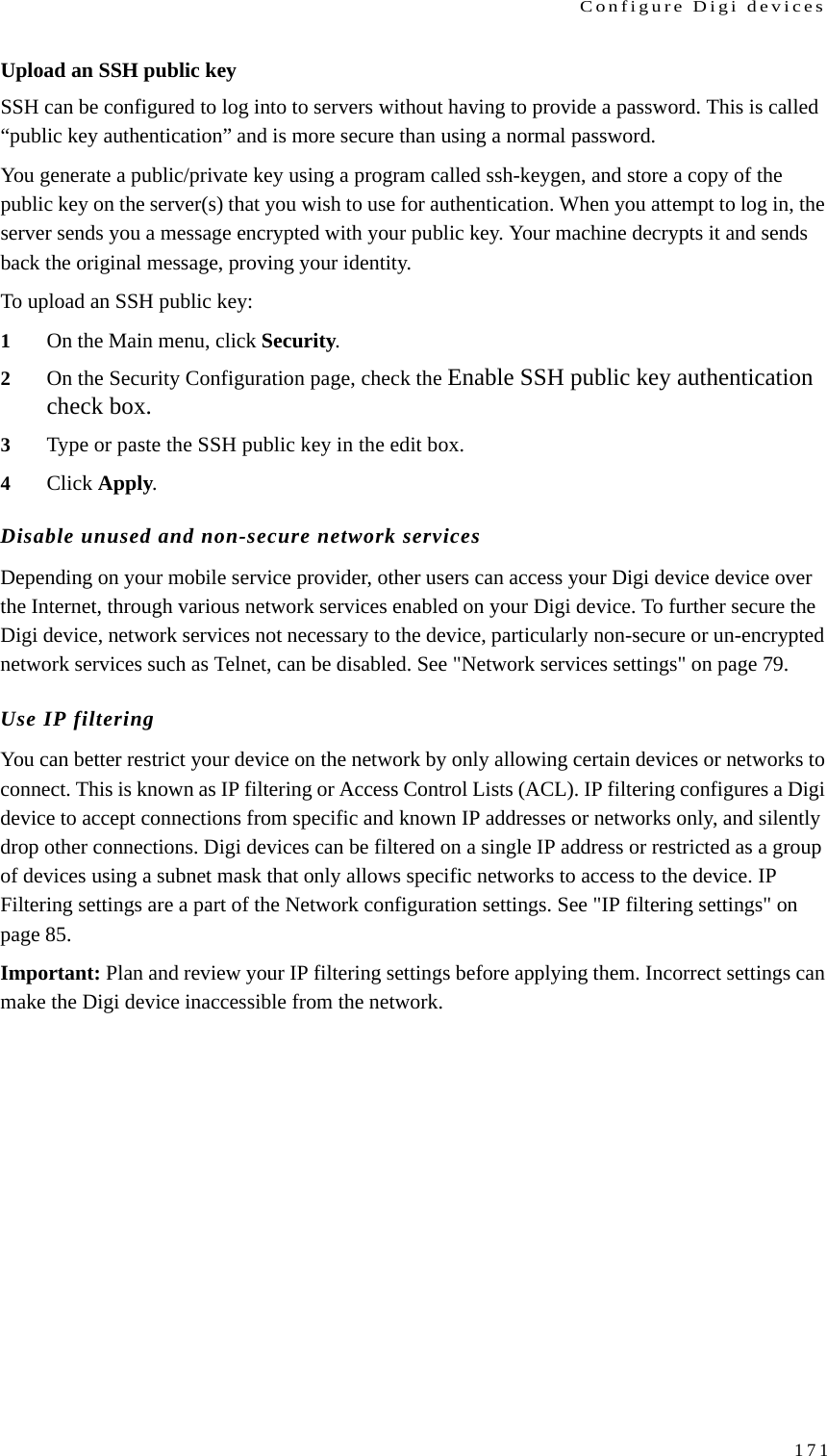
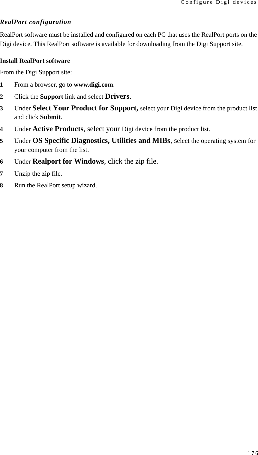
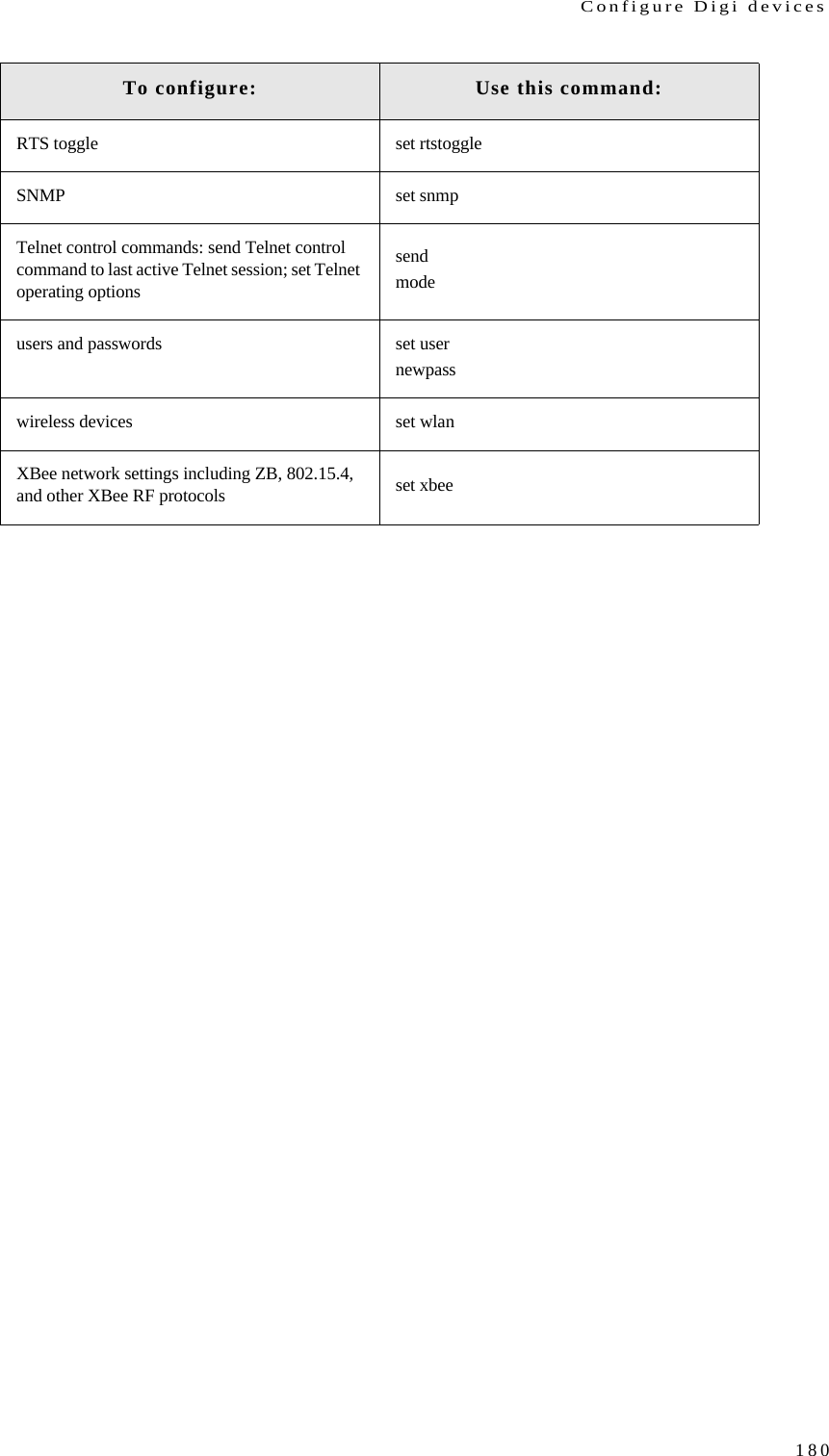
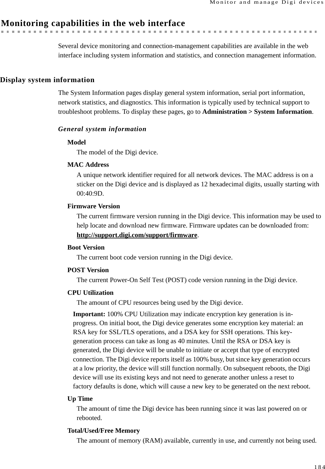
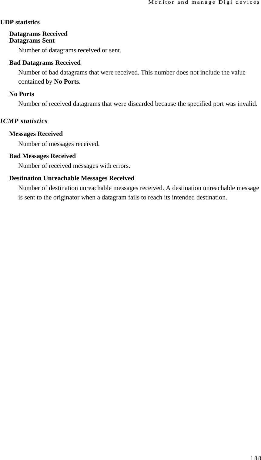
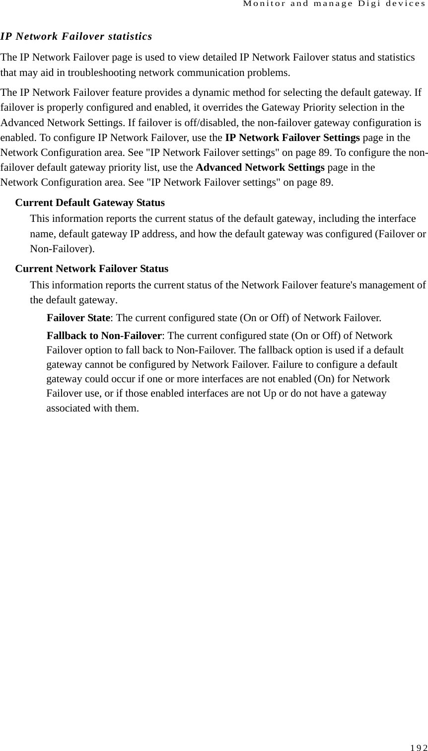
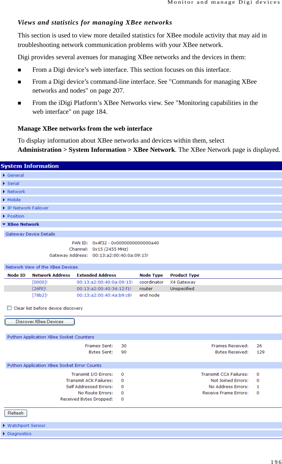
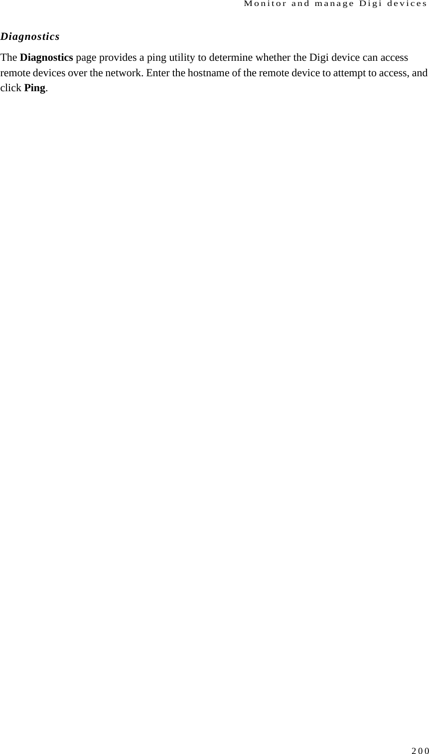
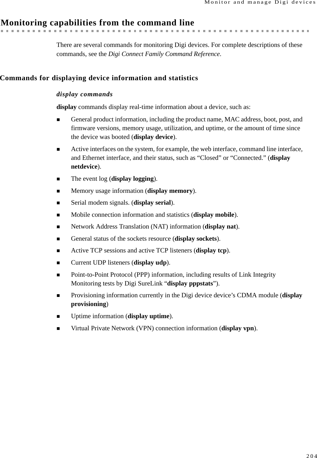
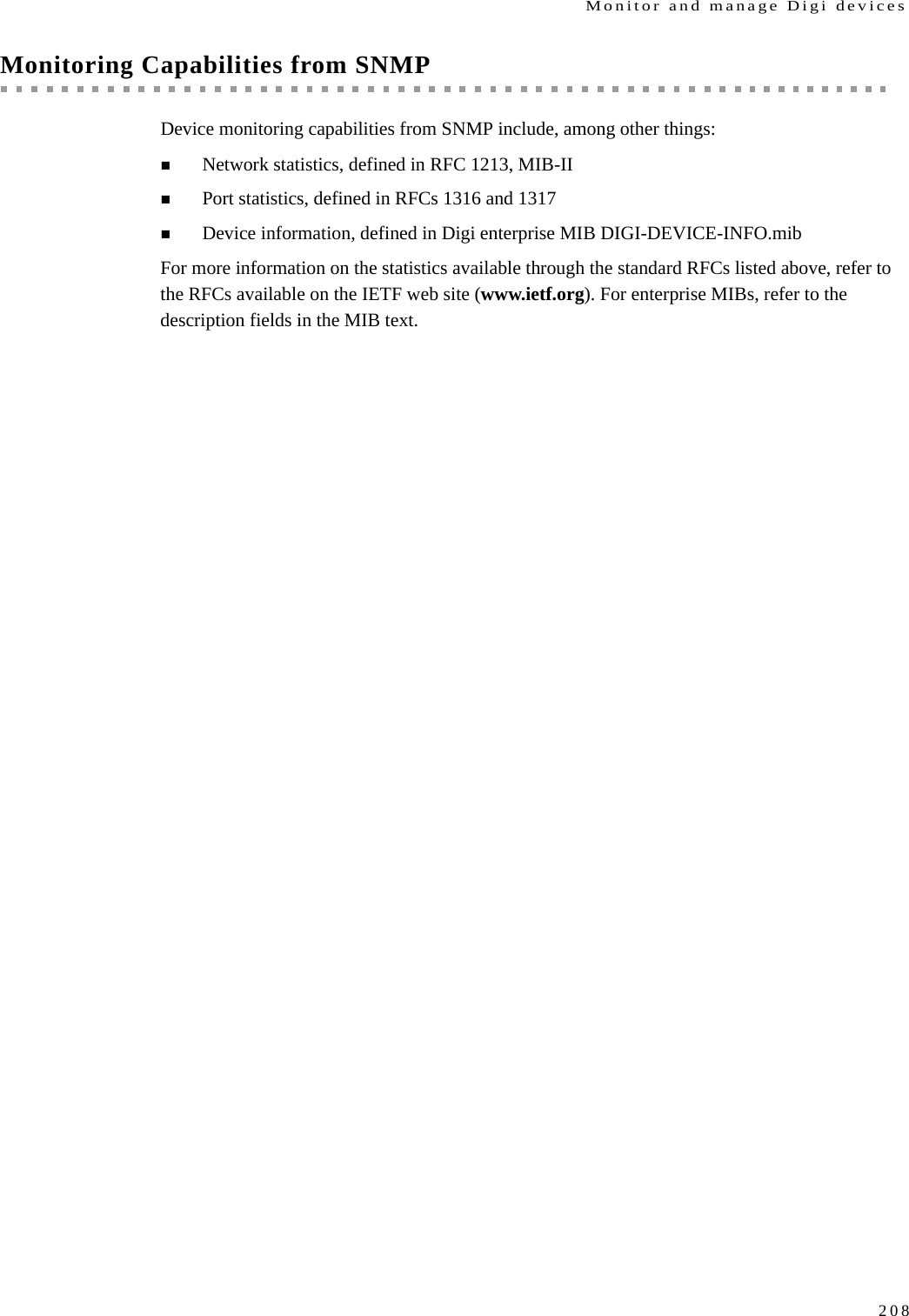
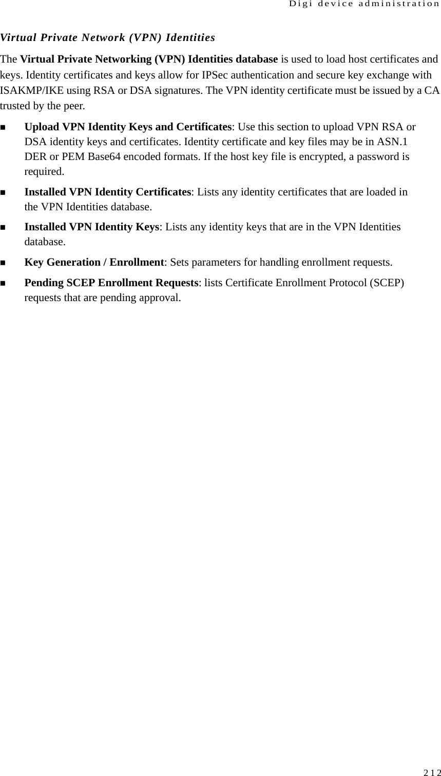
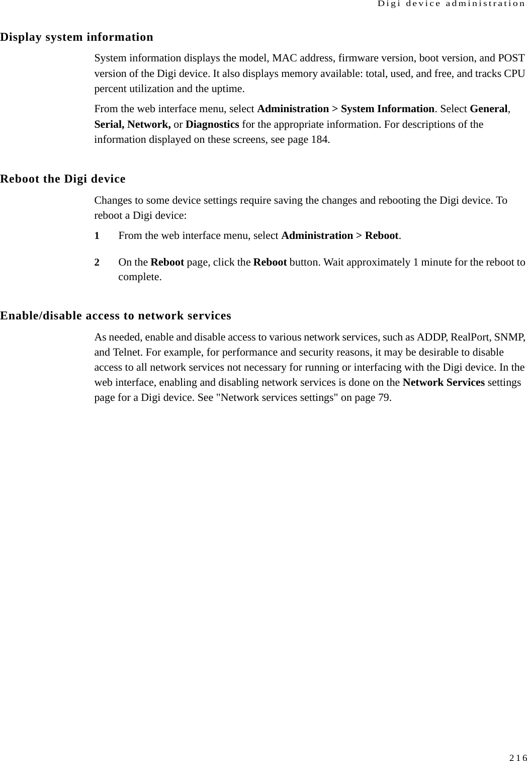
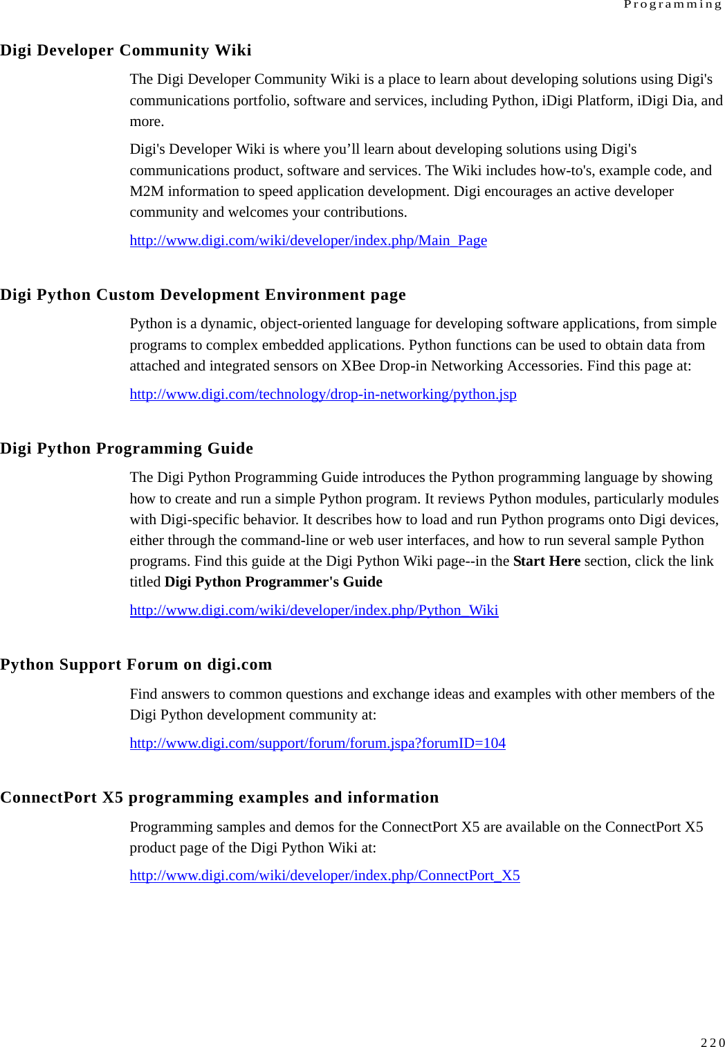
![Programming227Python Example: simple J1587 data call and responseThe sample below is artificially constructed to demonstrate bus transmission, and to illustrate one method for organizing message reception. The sample is constructed supposing that an external device exists on the J1708 bus that will provide an interesting value as payload for PID 43 if our device transmits a PID of 0 with a payload byte of 0x2B. A simple loop transmits the message, then waits up to one second for a response before sending another. Received data is printed. Note Vehicle bus API operations are highlighted in the samples in boldface type.import digij1708 (1)import Queue (2)def j1587_sniff(mid, payload, input_queue): (3)piddict = digij1708.J1587_PIDdict(payload) (4)if 43 in piddict: (5)input_queue.put(piddict[43]) (6)h = digij1708.J1708Handle(0) (7)h.configure(mid=127) (8)in_queue = Queue.Queue() (9)h.register_callback(j1587_sniff, in_queue) (10)piddict_out = digij1708.J1587_PIDdict() (11)piddict_out[0] = chr(43) (12)out_msg = piddict_out.J1708_payload() (13)while True: (14)h.send(5, out_msg) (15)try:msg = in_queue.get(True, 1.0) (16)print “Received: “, repr(msg) (17)except Queue.Empty: pass (18)](https://usermanual.wiki/Digi/WMPX5F/User-Guide-1291648-Page-227.png)