Digi XB900HP XBEE 900 HP User Manual low pwr 865 868
Digi International Inc XBEE 900 HP low pwr 865 868
UserManual.wiki
>
Digi
>
XB900HP User Manual
Manual
Navigation menu
Upload a User Manual
Namespaces
Wiki Guide
HTML
PDF
Info
Views
User Manual
Discussion / Help
Navigation

![XBee‐PRO®900HP/XBee‐PRO®XSCRFModules©2012DigiInternational,Inc. 2© 2012 Digi International, Inc. All rights reservedNopartofthecontentsofthismanualmaybetransmittedorreproducedinanyformorbyanymeanswithoutthewrittenpermissionofDigiInternational,Inc.XBee‐PRO®isaregisteredtrademarkofDigiInternational,Inc.Technical Support: Phone: (866) 765-9885 toll-free U.S.A. & Canada(801) 765-9885 Worldwide8:00 am - 5:00 pm [U.S. Mountain Time] Online Support: http://www.digi.com/support/eservice/login.jspEmail: rf-experts@digi.com](https://usermanual.wiki/Digi/XB900HP/User-Guide-1792196-Page-2.png)
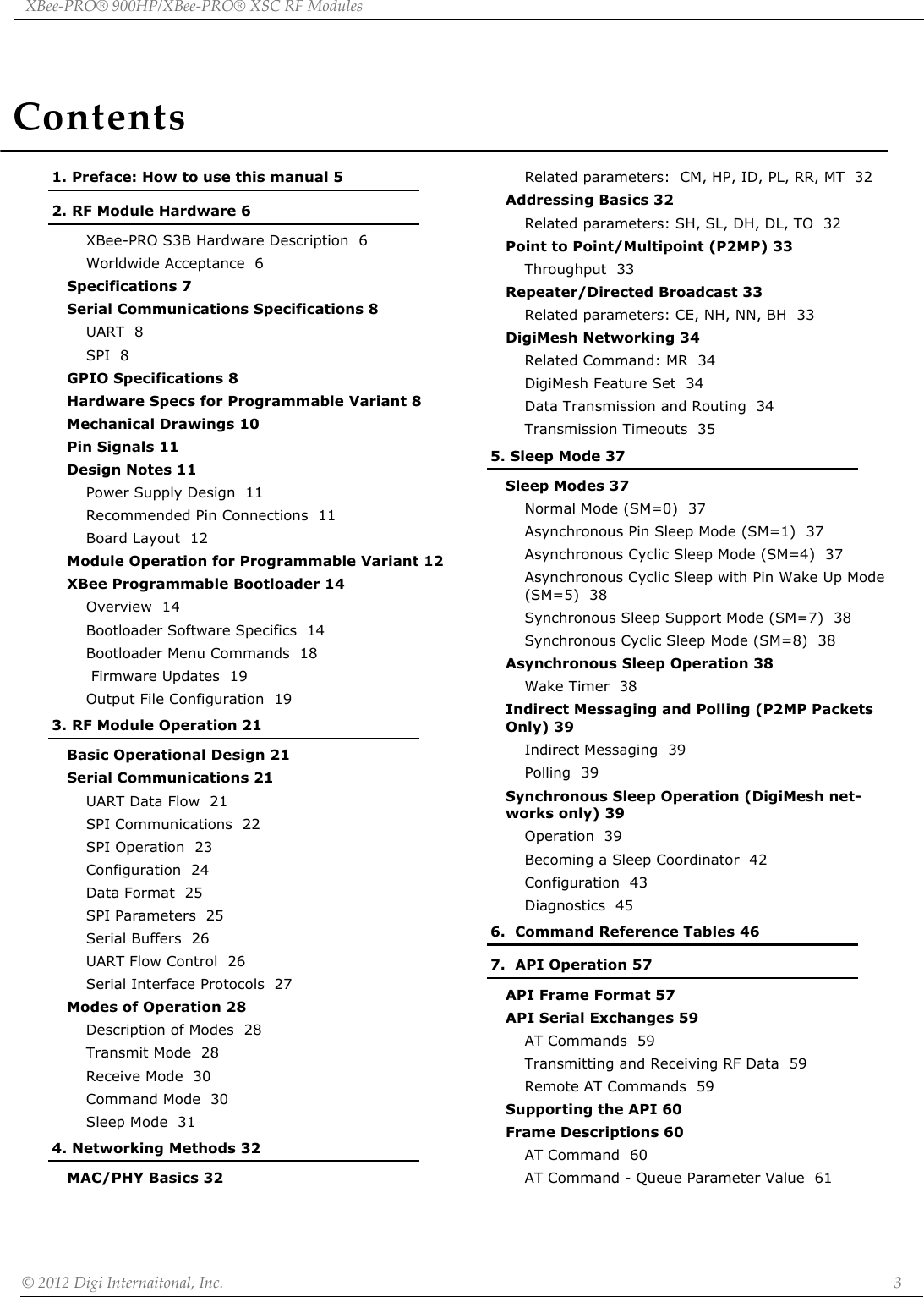

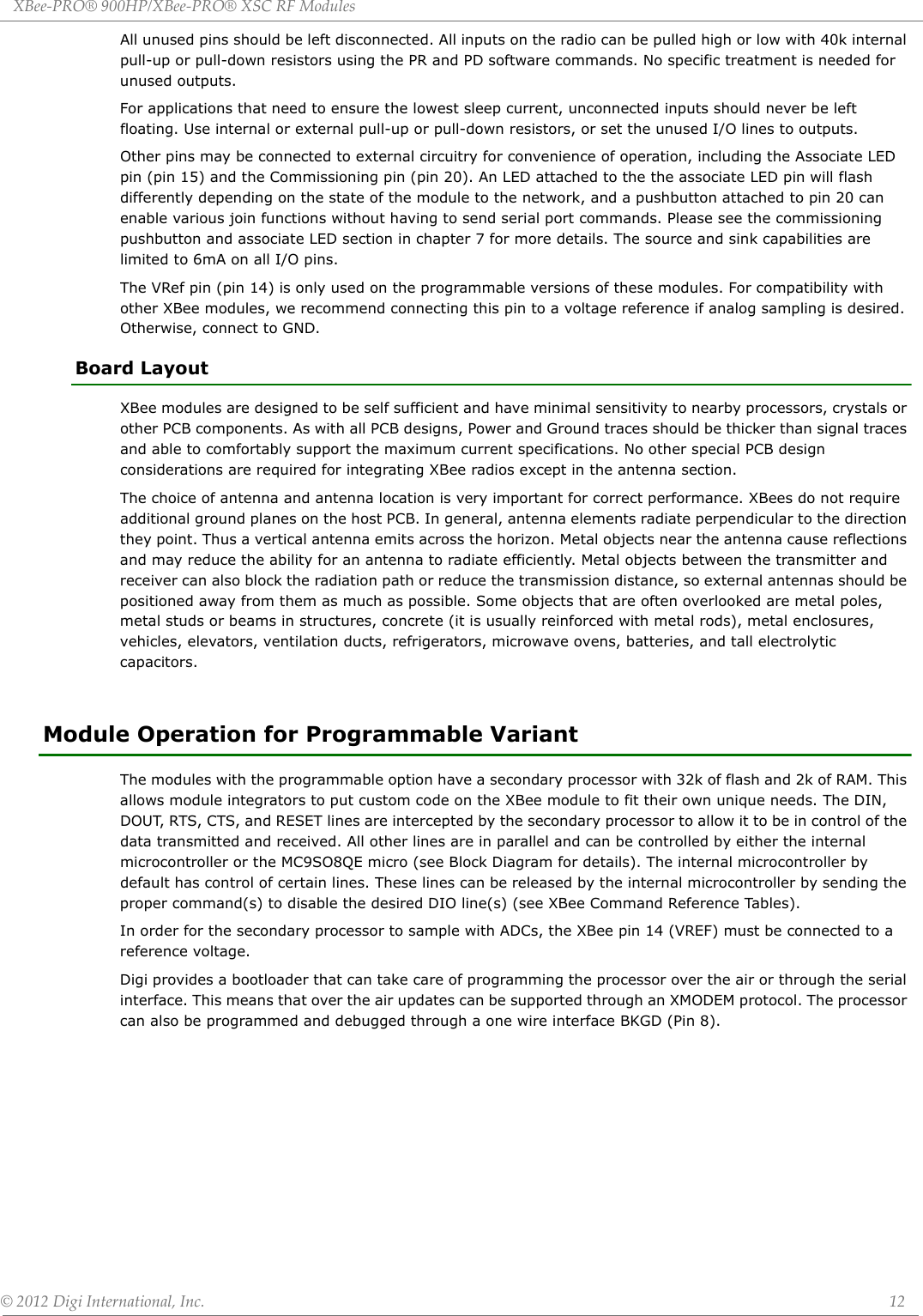
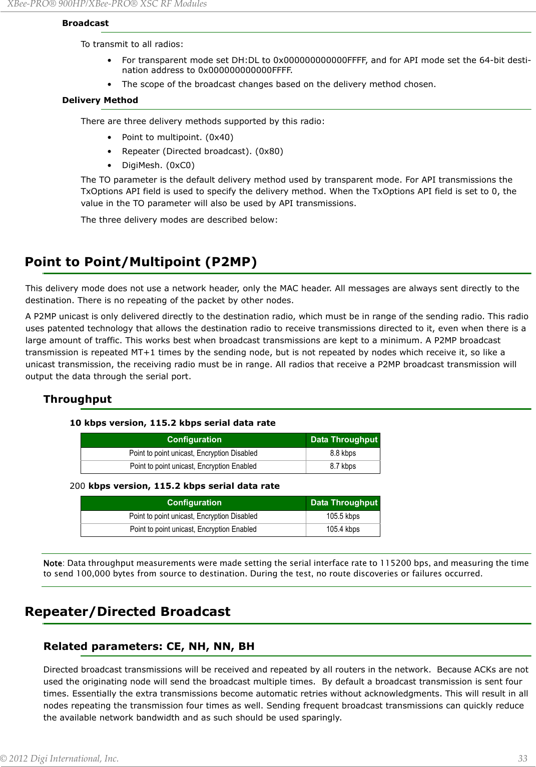
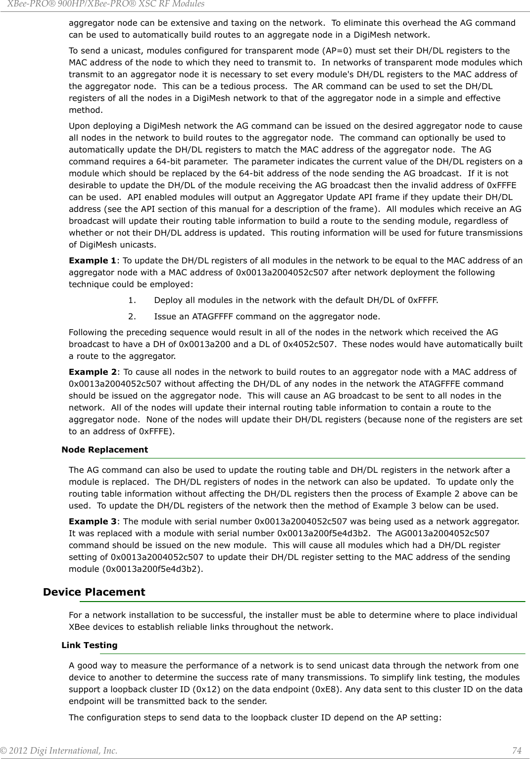
![XBee‐PRO®900HP/XBee‐PRO®XSCRFModules©2012DigiInternational,Inc. 17Application Interrupt Vector table and Linker Command FileSince the bootloader flash region is read-only, the interrupt vector table is redirected to the region 0xF1C0 to 0xF1FD so that application developers can use hardware interrupts. Note that in order for Application interrupts to function properly, the Application's linker command file (*.prm extension) must be modified appropriately to allow the linker to place the developers code in the correct place in memory. For example, the developer desires to use the serial communications port SCI1 receive interrupt. The developer would add the following line to the Codewarrior linker command file for the project:VECTOR ADDRESS 0x0000F1E0 vSci1RxThis will inform the linker that the interrupt function "vSci1Rx()" should be placed at address 0x0000F1E0. Next, the developer should add a file to their project "vector_table.c" that creates an array of function pointers to the ISR routines used by the application.extern void _Startup(void);/* _Startup located in Start08.c */extern void vSci1Rx(void);/* sci1 rx isr */ extern short iWriteToSci1(unsigned char *);void vDummyIsr(void);#pragma CONST_SEG VECTORSvoid (* const vector_table[])(void) = /* Relocated Interrupt vector table */{vDummyIsr,/* Int.no. 0 Vtpm3ovf (at F1C0)Unassigned */vDummyIsr, /* Int.no. 1 Vtpm3ch5 (at F1C2) Unassigned */vDummyIsr, /* Int.no. 2 Vtpm3ch4 (at F1C4) Unassigned */vDummyIsr, /* Int.no. 3 Vtpm3ch3 (at F1C6) Unassigned */vDummyIsr, /* Int.no. 4 Vtpm3ch2 (at F1C8) Unassigned */vDummyIsr, /* Int.no. 5 Vtpm3ch1 (at F1CA) Unassigned */vDummyIsr, /* Int.no. 6 Vtpm3ch0 (at F1CC) Unassigned */vDummyIsr, /* Int.no. 7 Vrtc (at F1CE) Unassigned */vDummyIsr, /* Int.no. 8 Vsci2tx (at F1D0) Unassigned */vDummyIsr, /* Int.no. 9 Vsci2rx (at F1D2) Unassigned */vDummyIsr, /* Int.no. 10 Vsci2err (at F1D4) Unassigned */vDummyIsr, /* Int.no. 11 Vacmpx (at F1D6) Unassigned */vDummyIsr, /* Int.no. 12 Vadc (at F1D8) Unassigned */vDummyIsr, /* Int.no. 13 Vkeyboard (at F1DA) Unassigned */vDummyIsr, /* Int.no. 14 Viic (at F1DC) Unassigned */vDummyIsr, /* Int.no. 15 Vsci1tx (at F1DE) Unassigned */vSci1Rx, /* Int.no. 16 Vsci1rx (at F1E0) SCI1RX */vDummyIsr, /* Int.no. 17 Vsci1err (at F1E2) Unassigned */vDummyIsr, /* Int.no. 18 Vspi (at F1E4) Unassigned */vDummyIsr, /* Int.no. 19 VReserved12 (at F1E6) Unassigned */vDummyIsr, /* Int.no. 20 Vtpm2ovf (at F1E8) Unassigned */vDummyIsr, /* Int.no. 21 Vtpm2ch2 (at F1EA) Unassigned */vDummyIsr, /* Int.no. 22 Vtpm2ch1 (at F1EC) Unassigned */vDummyIsr, /* Int.no. 23 Vtpm2ch0 (at F1EE) Unassigned */vDummyIsr, /* Int.no. 24 Vtpm1ovf (at F1F0) Unassigned */vDummyIsr, /* Int.no. 25 Vtpm1ch2 (at F1F2) Unassigned */vDummyIsr, /* Int.no. 26 Vtpm1ch1 (at F1F4) Unassigned */vDummyIsr, /* Int.no. 27 Vtpm1ch0 (at F1F6) Unassigned */](https://usermanual.wiki/Digi/XB900HP/User-Guide-1792196-Page-17.png)


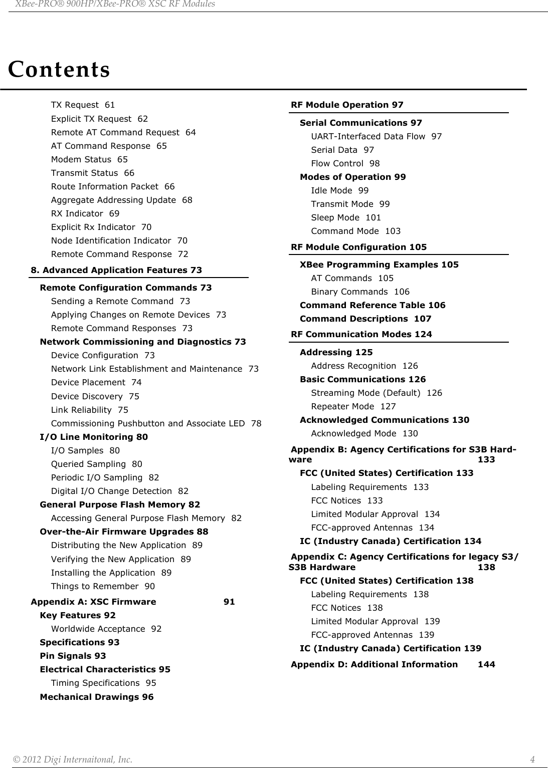
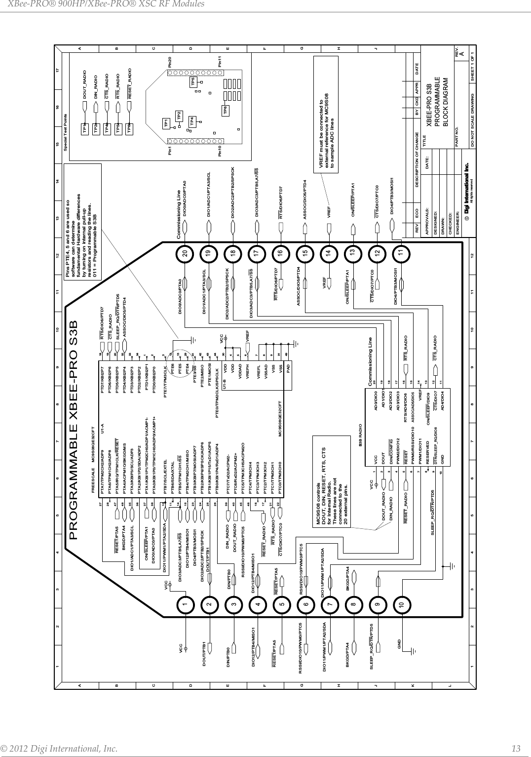
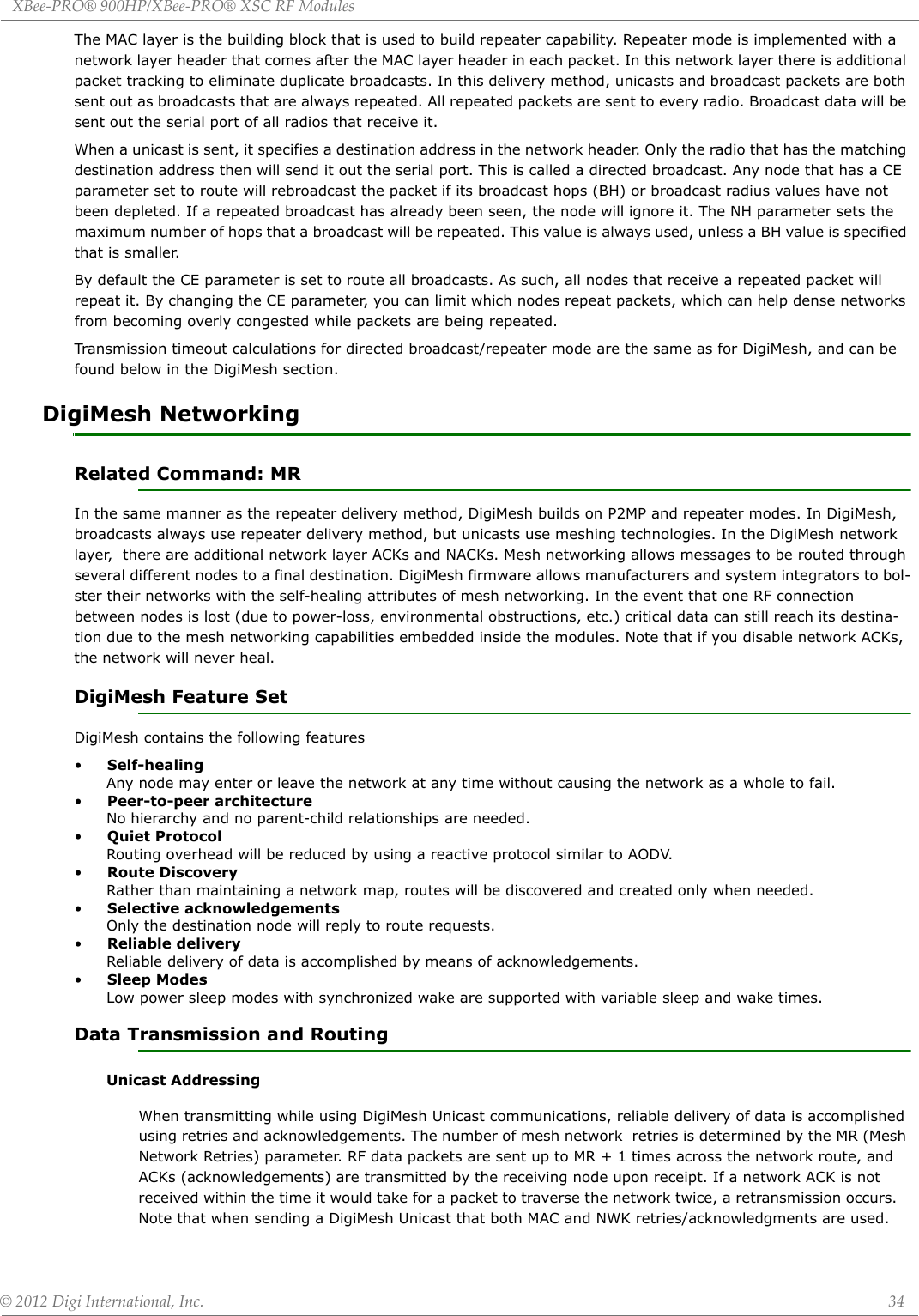
![XBee‐PRO®900HP/XBee‐PRO®XSCRFModules©2012DigiInternational,Inc. 30When DigiMesh data is transmitted from one node to another, a network-level acknowledgement is transmitted back across the established route to the source node. This acknowledgement packet indicates to the source node that the data packet was received by the destination node. If a network acknowledgement is not received, the source node will re-transmit the data. See Data Transmission and Routing in chapter 4 for more information. Receive ModeIf a valid RF packet is received, the data is transferred to the serial transmit buffer. This is the default mode for the XBee radio.Command ModeTo modify or read RF Module parameters, the module must first enter into Command Mode - a state in which incoming serial characters are interpreted as commands. The API Mode section in Chapter 7 describes an alternate means for configuring modules which is available with the SPI, as well as over the UART with code.AT Command ModeTo Enter AT Command Mode:Send the 3-character command sequence “+++” and observe guard times before and after the com-mand characters. [Refer to the “Default AT Command Mode Sequence” below.]Default AT Command Mode Sequence (for transition to Command Mode):•No characters sent for one second [GT (Guard Times) parameter = 0x3E8]•Input three plus characters (“+++”) within one second [CC (Command Sequence Character) parame-ter = 0x2B.]•No characters sent for one second [GT (Guard Times) parameter = 0x3E8]Once the AT command mode sequence has been issued, the module sends an "OK\r" out the UART pin. The "OK\r" characters can be delayed if the module has not finished transmitting received serial data.When command mode has been entered, the command mode timer is started (CT command), and the module is able to receive AT commands on the UART port. All of the parameter values in the sequence can be modified to reflect user preferences.NOTE: Failure to enter AT Command Mode is most commonly due to baud rate mismatch. By default, the BD (Baud Rate) parameter = 3 (9600 bps).To Send AT Commands:Send AT commands and parameters using the syntax shown below.SyntaxforsendingATCommandsTo read a parameter value stored in the RF module’s register, omit the parameter field.The preceding example would change the RF module Destination Address (Low) to “0x1F”. To store the new value to non-volatile (long term) memory, send the WR (Write) command. This allows modified parameter values to persist in the module’s registry after a reset. Otherwise, parameters are restored to previously saved values after the module is reset.Example: ATDL 1F<CR>“AT” PrexASCII CommandSpace(optional)Parameter(optional, HEX)Carriage Return](https://usermanual.wiki/Digi/XB900HP/User-Guide-1792196-Page-30.png)
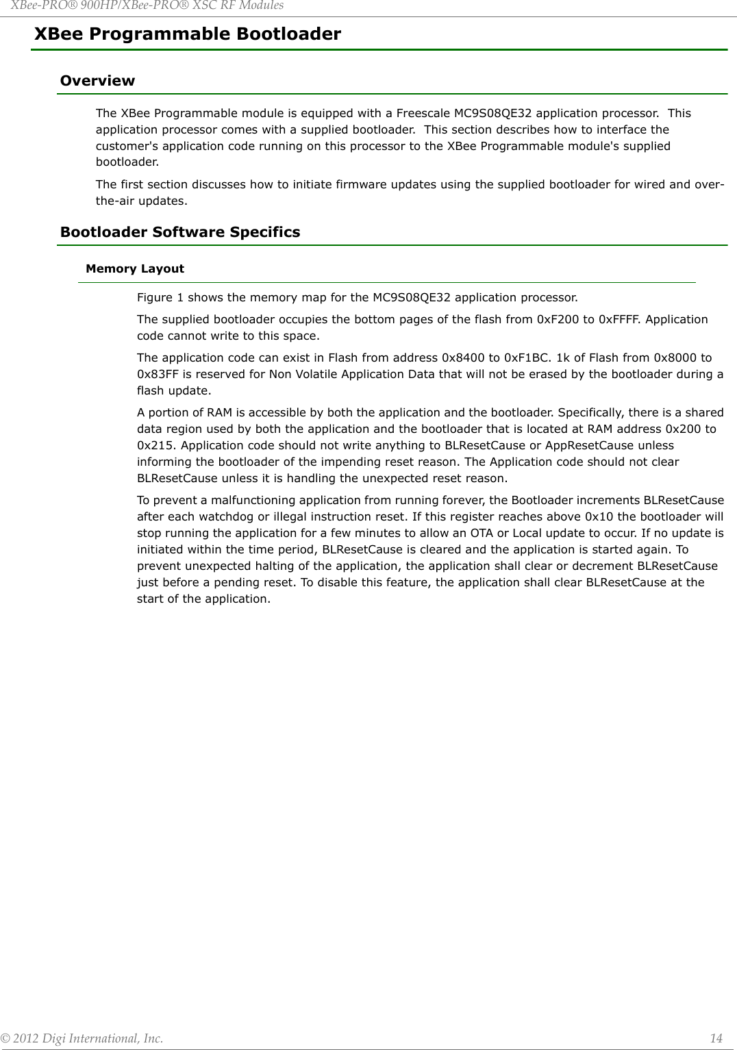
![XBee‐PRO®900HP/XBee‐PRO®XSCRFModules©2012DigiInternational,Inc. 31Command Response When a command is sent to the module, the module will parse and execute the command. Upon successful execution of a command, the module returns an “OK” message. If execution of a command results in an error, the module returns an “ERROR” message.Applying Command Changes Any changes made to the configuration command registers through AT commands will not take effect until the changes are applied. For example, sending the BD command to change the baud rate will not change the actual baud rate until changes are applied. Changes can be applied in one of the following ways:•The AC (Apply Changes) command is issued.•AT command mode is exited.To Exit AT Command Mode:1. Send the ATCN (Exit Command Mode) command (followed by a carriage return). [OR]2. If no valid AT Commands are received within the time specified by CT (Command Mode Timeout) Command, the RF module automatically returns to Idle Mode. For an example of programming the RF module using AT Commands and descriptions of each config-urable parameter, please see the Command Reference Table chapter.Sleep ModeSleep modes allow the RF module to enter states of low power consumption when not in use. XBee RF modules support both pin sleep (sleep mode entered on pin transition) and cyclic sleep (module sleeps for a fixed time). XBee sleep modes are discussed in detail in chapter 5.](https://usermanual.wiki/Digi/XB900HP/User-Guide-1792196-Page-31.png)
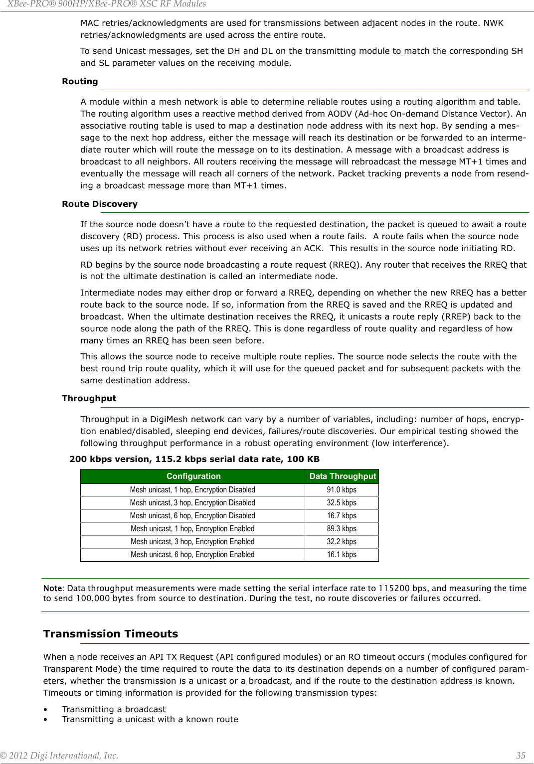

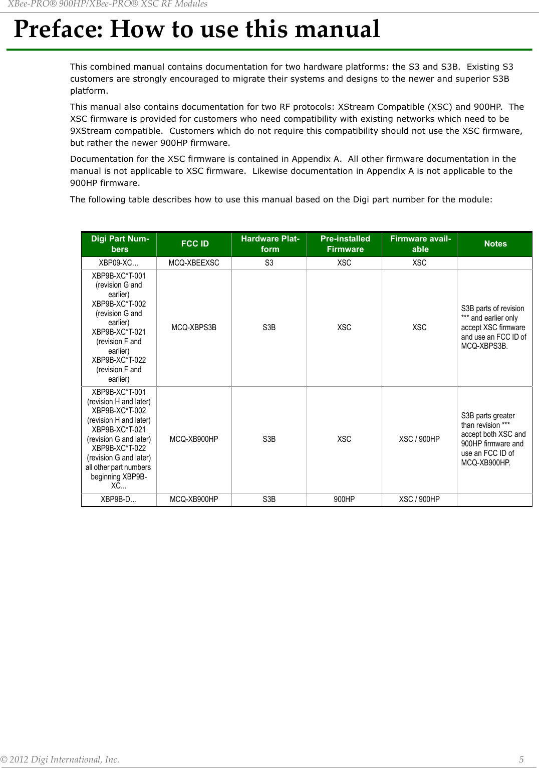
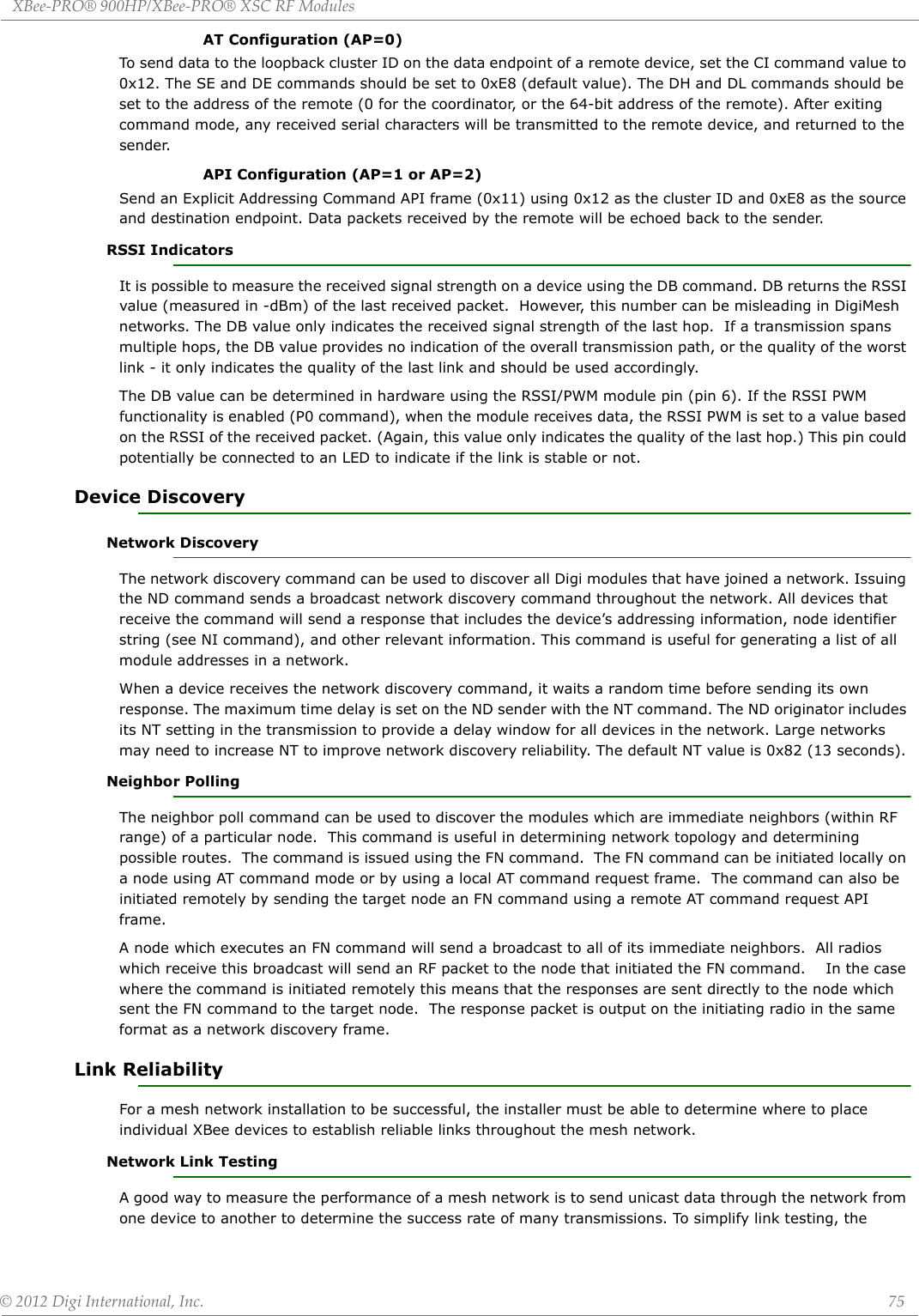
![XBee‐PRO®900HP/XBee‐PRO®XSCRFModules©2012DigiInternational,Inc. 47DiagnosticsIDNetwork ID. The user network identifier. Nodes must have the same network identifier to communicate. Changes to ID can be written to non-volatile memory using the WR command. Only modules with matching IDs can communicate with each other. When receiving a packet this is checked after the preamble ID. If using OEM network IDs, 0xFFFF will use the factory value.0-0x7FFF 0x7FFF MTBroadcast Multi-Transmit. The number of additional MAC-level broadcast transmissions. All broadcast packets are transmitted MT+1 times to ensure it is received. 0-5 3PL Power Level. Set/Read the power level at which the RF module transmits conducted power. Power level 4 is calibrated and the other power levels are approximate. .0 = +7 dBm1 = +15 dBm2 = +18 dBm3 = +21 dBm4 = +24 dBm 4RRUnicast Mac Retries. The maximum number of MAC level packet delivery attempts for unicasts. If RR is non-zero packets sent from the radio will request an acknowledgement, and can be resent up to RR times if no acknowledgements are received. 0-0xF 0x10EDEnergy Detect. Start an Energy Detect scan. This parameter is the time in milliseconds to scan all channels. The module will loop through all the channels until the time elapses. The maximal energy on each channel is returned, and each value is followed by a comma with the list ending with a carriage return. The values returned reflect the detected energy level in units of -dBm. 0-0xFF 0x10Table5‐03. DiagnosticsCommands‐MACStatisticsandTimeoutsATCommand Name and Description Parameter Range DefaultBCBytes Transmitted. The number of RF bytes transmitted. This count is incremented for every PHY level byte transmitted. The purpose of this count is to estimate battery life by tracking time doing transmissions. This number rolls over to zero from 0xFFFF. The counter can be reset to any 16-bit value by appending a hexadecimal parameter to the command.0-0xFFFF 0DBReceived Signal Strength. This command reports the received signal strength of the last received RF data packet. The DB command only indicates the signal strength of the last hop. It does not provide an accurate quality measurement for a multihop link. The DB command value is measured in -dBm. For example if DB returns 0x60, then the RSSI of the last packet received was -96dBm. 0-0xFF[read-only] 0ERReceived Error Count. This count is incremented whenever a packet is received which contained integrity errors of some sort. Once the number reaches 0xFFFF, further events will not be counted. The counter can be reset to any 16-bit value by appending a hexadecimal parameter to the command. 0-0xFFFF 0GDGood Packets Received. This count is incremented whenever a good frame with a valid MAC header is received on the RF interface. Once the number reaches 0xFFFF, further events will not be counted. The counter can be reset to any 16-bit value by appending a hexadecimal parameter to the command. 0-0xFFFF 0EAMAC ACK Timeouts. This count is incremented whenever a MAC ACK timeout occurs on a MAC level unicast. Once the number reaches 0xFFFF further events will not be counted. The counter can be reset to any 16-bit value by appending a hexadecimal parameter to the command.0-0xFFFF 0TRTransmission Errors. This count is incremented whenever a MAC transmission attempt exhausts all MAC retries without ever receiving a MAC acknowledgement message from the destination node. Once the number reaches 0xFFFF, further events will not be counted. The counter can be reset to any 16-bit value by appending a hexadecimal parameter to the command. 0-0xFFFF 0UAMAC Unicast Transmission Count. This count is incremented whenever a MAC unicast transmission occurs for which an ACK is requested. Once the number reaches 0xFFFF further events will not be counted. The counter can be reset to any 16-bit value by appending a hexadecimal parameter to the command.0-0xFFFF 0%H MAC Unicast One Hop Time. The MAC unicast one hop timeout in milliseconds. Changing MAC parameters can change this value. [read-only] 0xCF%8 MAC Broadcast One Hop Time. The MAC broadcast one hop timeout in milliseconds. Changing MAC parameters can change this value. [read-only] 0x1BEATCommand Name and Description Parameter Range Default](https://usermanual.wiki/Digi/XB900HP/User-Guide-1792196-Page-47.png)
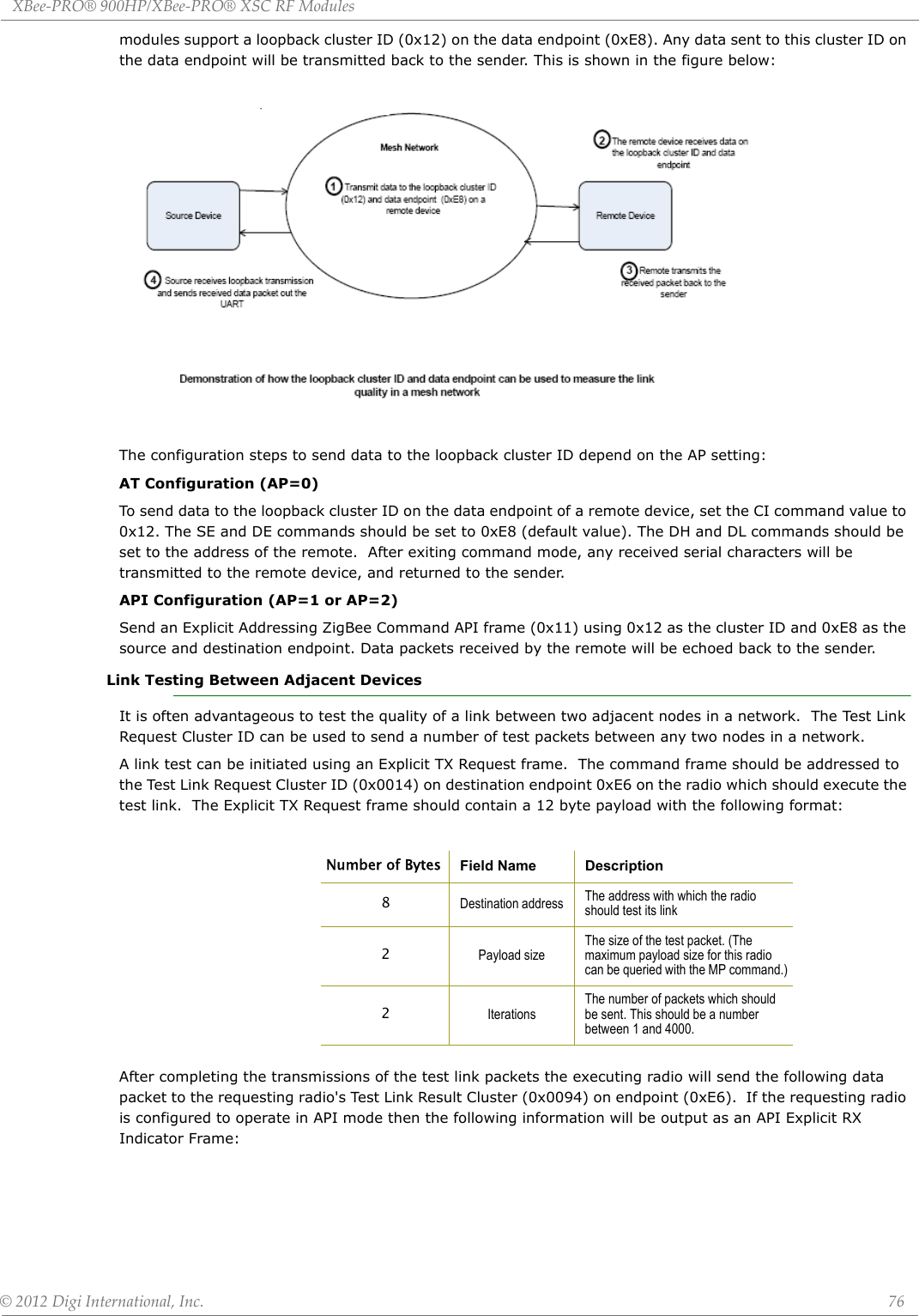
![XBee‐PRO®900HP/XBee‐PRO®XSCRFModules©2012DigiInternational,Inc. 48NetworkAddressingTable5‐04. NetworkCommands‐DigiMeshandRepeaterATCommand Name and Description Parameter Range DefaultCENode Messaging Options. The module's routing and messaging mode bit field. A routing module will repeat broadcasts. Indirect Messaging Coordinators will not transmit point-to-multipoint unicasts until they are requested by an Indirect Messaging Poller. Setting a radio as an Indirect Messaging Poller will cause it to regularly send polls to its Indirect Messaging Coordinator. Nodes can also be configured to route, or not route, multi-hop packets. Bit 0 - Indirect Messaging Coordinator enable All point-multipoint unicasts will be held until requested by a polling end device.Bit 1 - Disable routing on this node When set, this node will not propagate broadcasts or become an intermediate node in a DigiMesh route. This node will not function as a repeater.Bit 2 - Indirect Messaging Polling enable Periodically send requests for messages held by the node’s coordinator.Bit 0 and bit 2 cannot be set at the same time.0-6 0BHBroadcast Hops. The transmission hops for broadcast data transmissions. Set to 0 for maximum radius. If BH is set greater than NH then the value of NH is used.Supported in both variants.0-0x20 0NHNetwork Hops The maximum number of hops expected to be seen in a network route. This value doesn't limit the number of hops allowed, but it is used to calculate timeouts waiting for network acknowledgements. Supported in both variants.0-0x20 NN Network Delay Slots. Set or read the maximum random number of network delay slots before rebroadcasting a network packet. 0 to 0x05 3MRMesh Unicast Retries The maximum number of network packet delivery attempts. If MR is non-zero, packets sent will request a network acknowledgement, and can be resent up to MR+1 times if no acknowledgements are received. We recommend setting this value to 1. If this parameter is set to 0, then network ACKs are disabled. Routes can be found initially, but will never be repaired if a route fails.Supported in the 200k variant only.0 to 7 1Table5‐05. AddressingCommandsATCommand Name and Description Parameter Range DefaultSH Serial Number High. The upper 32 bits of the module’s unique IEEE 64-bit MAC address. 0-0xFFFFFFFF[read-only] FactorySL Serial Number Low. The lower 32 bits of the module’s unique IEEE 64-bit MAC address. 0-0xFFFFFFFF[read-only] FactoryDHDestination Address High. The upper 32 bits of the 64-bit destination address. When combined with DL, it defines the destination address used for transmission in transparent mode. 0-0xFFFFFFFF 0DLDestination Address Low. The lower 32 bits of the 64-bit destination address. When combined with DH, DL defines the destination address used for transmission in transparent mode. 0-0xFFFFFFFF 0x0000FFFFTOTransmit Options. This command defines transmission options for all packets originating from this radio. These options can be overridden on a packet-by-packet basis by using the TxOptions field of the API TxRequest frames.Bit Meaning Description6, 7 Delivery method b’00 - <invalid option>. b’01 - Point-Multipoint b’10 - Repeater mode (directed broadcast of packets) b’11 - DigiMesh (not available on 10k product)5 Reserved <set this bit to 0>4 Reserved <set this bit to 0>3 Trace Route Enable a Trace Route on all DigiMesh API packets2 NACK Enable a NACK messages on all DigiMesh API packets1 Disable RD Disable Route Discovery on all DigiMesh unicasts0 Disable ACK Disable acknowledgments on all unicastsExample #1: Setting TO to 0x80 would cause all transmissions to be sent using repeater mode.Example #2: Setting TO to 0xC1 would cause all transmissions to be sent using DigiMesh, with network acknowledgments disabled.Bits 6 & 7 cannot be set to DigiMesh on the 10k build.Bits 4 & 5 must be set to 0Bits 1, 2, & 3 cannot be set on the 10k build0x40(10k product)0xC0(200k product)](https://usermanual.wiki/Digi/XB900HP/User-Guide-1792196-Page-48.png)
![XBee‐PRO®900HP/XBee‐PRO®XSCRFModules©2012DigiInternational,Inc. 49Addressing Discovery/ConfigurationNINode Identifier. A string identifier for this module. The string accepts only printable ASCII data In AT Command Mode, the string can not start with a space. A carriage return or comma ends the command. Command will automatically end when maximum bytes for the string have been entered. This string is returned as part of the ATND (Network Discover) command. This identifier is also used with the ATDN (Destination Node) command. up to 20 byte ASCII string a space characterNTNode Discover Timeout. The amount of time a node will spend discovering other nodes when ND or DN is issued. This value is used to randomize the responses to alleviate network congestion.0x20 - 0x2EE0[x 100 msec] 0x82 (130d)NONode Discovery Options. The options value for the network discovery command. The options bitfield value can change the behavior of the ND (network discovery) command and/or change what optional values are returned in any received ND responses or API node identification frames. Options include: 0x01 = Append DD value (to ND responses or API node identification frames) 0x02 = Local device sends ND or FN response frame when ND is issued.0x04 = Append RSSI (of the last hop for DigiMesh networks) to ND or FN responses or API node identification frames.0-0x07 [bitfield] 0CI Cluster ID. The application layer cluster ID value. This value will be used as the cluster ID for all data transmissions. The default value 0x11 (Transparent data cluster ID) 0-0xFFFF 0x11DEDestination Endpoint. The application layer destination ID value. This value will be used as the destination endpoint for all data transmissions. The default value (0xE8) is the Digi data endpoint.0-0xFF 0xE8SESource Endpoint. The application layer source endpoint value. This value will be used as the source endpoint for all data transmissions. The default value 0xE8 (Data endpoint) is the Digi data endpoint0-0xFF 0xE8Table5‐06. AddressingDiscovery/ConfigurationCommandsATCommand Name and Description Parameter Range DefaultAGAggregator Support. The AG command sends a broadcast through the network that has the following effects on nodes which receive the broadcast: - The receiving node will establish a DigiMesh route back to the originating node, provided there is space in the routing table. - The DH and DL of the receiving node will be updated to the address of the originating node if the AG parameter matches the current DH/DL of the receiving node. - For API-enabled modules on which DH and DL are updated, an Aggregate Addressing Update frame will be sent out the serial port.Note that the AG command is only available on products that support DigiMesh.Any 64-bit number n/aDNDiscover Node. Resolves an NI (Node Identifier) string to a physical address (case sensitive). The following events occur after the destination node is discovered: <AT Firmware> 1. DL & DH are set to the extended (64-bit) address of the module with the matching NI (Node Identifier) string. 2. OK (or ERROR)\r is returned. 3. Command Mode is exited to allow immediate communication <API Firmware>0xFFFE and 64-bit extended addresses are returned in an API Command Response frame.If there is no response from a module within (NT * 100) milliseconds or a parameter is not specified (left blank), the command is terminated and an “ERROR” message is returned. In the case of an ERROR, Command Mode is not exited. 20 byte ascii string Table5‐05. AddressingCommandsATCommand Name and Description Parameter Range Default](https://usermanual.wiki/Digi/XB900HP/User-Guide-1792196-Page-49.png)
![XBee‐PRO®900HP/XBee‐PRO®XSCRFModules©2012DigiInternational,Inc. 51Serial InterfacingI/O SettingsTable5‐08. SerialInterfacingCommandsATCommand Name and Description Parameter Range DefaultBDBaud rate. The UART baud rate (speed for data transfer between radio modem and host). Values from 0-8 select preset standard rates. Values at 0x39 and above select the actual baud rate. Providing the host supports it. Baud rates can go as high as 7Mbps. The values from 0 to 8 are interpreted as follows: 0 - 1,200bps 3 - 9,600bps 6 - 57,600bps1 - 2,400bps 4 - 19,200bps 7 - 115,200bps2 - 4,800bps 5 - 38,400bps 8 - 230,400bps0 to 8, and 0x100 to 0x6ACFC0 0x03 (9600 bps) NBParity. Set or read parity settings for UART communications. The values from 0 to 2 are interpreted as follows: 0 No parity 1 Even parity 2 Odd parity0-2 0 (No parity) SBStop Bits. The number of stop bits for the UART.0 - One stop bit1 - Two stop bits0-1 0ROPacketization Timeout. The number of UART character times of inter-character silence required before packetization in transparent mode. Set (RO=0) to transmit characters as they arrive instead of buffering them into one RF packet.0 - 0xFF [x character times] 3FTFlow Control Threshhold. The UART flow control threshhold. De-assert CTS and/or send XOFF when FT bytes are in the UART receive buffer. Re-assert CTS when less than FT - 16 bytes are in the UART receive buffer. 0x11 - 0x16F 0x13FAPAPI mode. The UART API mode. The following settings are allowed: 0 Transparent mode, API mode is off. All UART input and output is raw data and packets are delineated using the RO and RB parameters. 1 API mode without escapes is on. All UART input and output data is packetized in the API format. 2 API mode is on with escaped sequences inserted to allow for control characters (XON, XOFF, escape, and the 0x7e delimiter to be passed as data.) 0- 2 0AOAPI Options. The API data frame output format for received frames. This parameter applies to both the UART and SPI interfaces.0 API RX Indicator (0x90) 1 API Explicit RX Indicator (0x91) 0, 1 0Table5‐09. I/OSettingsandCommandsATCommand Name and Description Parameter Range DefaultCBCommissioning Pushbutton. This command can be used to simulate commissioning button presses in software. The parameter value should be set to the number of button presses to be simulated. For example, sending the ATCB1 command will execute the action associated with 1 commissioning button press.0-4 n/aD0DIO0 / AD0 Configuration (Pin 20). 0 = Disabled1 = Commissioning button2 = ADC3 = Digital input4 = Digital output low 5 = Digital output high 0 - 5 1D1DIO1 / AD1 Configuration (Pin 19). 0 = Disabled1 = SPI Attention2 = ADC3 = Digital input4 = Digital output low 5 = Digital output high 6 = Uart Data Present Indicator0-6 0D2DIO2 / AD2 Configuration (Pin 18). 0 = Disabled1 = SPI Clock2 = ADC 3 = Digital input4 = Digital output low 5 = Digital output high 0-5 0](https://usermanual.wiki/Digi/XB900HP/User-Guide-1792196-Page-51.png)
![XBee‐PRO®900HP/XBee‐PRO®XSCRFModules©2012DigiInternational,Inc. 53I/O SamplingP2DIO12 Configuration (Pin 4). 0 = Disabled1 = SPI_MISO3 = Digital input4 = Digital output low 5 = Digital output high 0, 1, 3-5 0P3DIO13 / DOUT Configuration (Pin 2). 0 = Disabled1 = UART DOUT output0, 1 1P4DIO14 / DIN Configuration (Pin 3). 0 = Disabled1 = UART DIN output0, 1 1PDPull Direction. The resistor pull direction bit field for corresponding I/O lines that are set in the PR command.0 = pull down1 = pull up0-0x7FFF 0PRPull-up Resistor. The bit field that configures the internal pull-up resistor status for the I/O lines. "1" specifies the pull-up/down resistor is enabled. "0" specifies no pullup/down.Bits: 0 - DIO4 / AD4 / SPI_MOSI1 - DIO3 / AD3 / SPI_SSEL2 - DIO2 / AD2 / SPI_SCLK3 - DIO1 / AD1 / SPI_ATTN4 - DIO0 / AD05 - DIO6 / RTS 6 - SLEEP_REQUEST 7 - DIN / CONFIG 8 - DIO5 / AD5 / ASSOCIATE 9 - On/SLEEP10 - DIO12 / SPI_MISO11 - DIO10 / PWM0 / RSSI 12 - DIO11/ PWM1 13 - DIO7/CTS 14 - PWM0 / DOUT 0 - 0x7FFF 0x7FFFM0 PWM0 Duty Cycle. The duty cycle of the PWM0 line. The line should be configured as a PWM output using the P0 command. 0-0x3FF 0M1 PWM1 Duty Cycle. The duty cycle of the PWM1 line. The line should be configured as a PWM output using the P1 command. 0-0x3FF 0LTAssoc LED Blink Time. The Associate LED blink time. If the Associate LED functionality is enabled (D5 command), this value determines the on and off blink times for the LED. If LT=0, the default blink rate will be used (500ms sleep coordinator, 250ms otherwise). For all other LT values, LT is measured in 10ms0x14-0xFF [x 10 ms] 0RP RSSI PWM Timer. Time RSSI signal will be output after last transmission. When RP = 0xFF, output will always be on. 0 - 0xFF [x 100 ms] 0x28 (4 seconds)Table5‐010. I/OSamplingCommandsATCommand Name and Description Parameter Range DefaultAVAnalog Voltage Reference. The analog voltage reference that is used for A/D sampling.0 = 1.25 V reference1 = 2.5 V reference0, 1 0Table5‐09. I/OSettingsandCommandsATCommand Name and Description Parameter Range Default](https://usermanual.wiki/Digi/XB900HP/User-Guide-1792196-Page-53.png)
![XBee‐PRO®900HP/XBee‐PRO®XSCRFModules©2012DigiInternational,Inc. 55Sleep DiagnosticsAT Command OptionsSTWake Time. The wake period of the module. For asynchronous sleep modules, this command defines the amount of time that the module will stay awake after receiving RF or serial data.For synchronous sleep modules, this command defines the amount of time that the module will stay awake when operating in cyclic sleep mode. This value will be adjusted upwards automatically if it is too small to function properly based on other settings.0x45-0x36EE80 0x7D0 (2 seconds)WHWake Host. The wake host timer value. If the wake host timer is set to a non-zero value, this timer specifies a time (in millisecond units) that the device should allow after waking from sleep before sending data out the UART or transmitting an I/O sample. If serial characters are received, the WH timer is stopped immediately. When in synchronous sleep, the device will shorten its sleep period by the value specified by the WH command to ensure that it is prepared to communicate when the network wakes up. When in this this sleep mode, the device will always stay awake for the WH time plus the amount of time it takes to transmit a one-hop unicast to another node.0-0xFFFF (x 1ms) 0Table5‐011. Diagnostics‐SleepStatusTimingATCommand Name and Description Parameter Range DefaultSSSleep Status. The SS command can be used to query a number of Boolean values describing the status of the module.Bit 0: This bit will be true when the network is in its wake state.Bit 1: This bit will be true if the node is currently acting as a network sleep coordinator. Bit 2: This bit will be true if the node has ever received a valid sync message since the time it was powered on. Bit 3: This bit will be true if the node has received a sync message in the current wake cycle.Bit 4: This bit will be true if the user has altered the sleep settings on the module so that the node will nominate itself and send a sync message with the new settings at the beginning of the next wake cycle.Bit 5: This bit will be true if the user has requested that the node nominate itself as the sleep coordinator (using the commissioning button or the CB2 command).Bit 6 = This bit will be true if the node is currently in deployment mode.All other bits: Reserved - All non-documented bits can be any value and should be ignored.[read-only] 0x40OSOperational Sleep Period. The sleep period that the node is currently using. This number will oftentimes be different from the SP parameter if the node has synchronized with a sleeping router network.Units of 10mSec[read-only] 0x12COWOperational Wake Period. The wake time that the node is currently using. This number will oftentimes be different from the ST parameter if the node has synchronized with a sleeping router network.Units of 1 ms[read-only] 0xBB8MS Number of Missed Syncs. The number of wake cycles that have elapsed since the last sync message was received. Supported in the 80k firmware variant only. [read-only] 0SQMissed Sync Count. Count of the number of syncs that have been missed. This value can be reset by setting ATSQ to 0. When the value reaches 0xFFFF it will not be incremented anymore.0-0xFFFF 0Table5‐012. ATCommandOptionsATCommand Name and Description Parameter Range DefaultCCCommand Character. Set or read the character to be used between guard times of the AT Command Mode Sequence. The AT Command Mode Sequence causes the radio modem to enter Command Mode (from Idle Mode).0 - 0xFF 0x2BCN Exit Command Mode. Explicitly exit the module from AT Command Mode. n/a n/aCTCommand Mode Timeout. Set/Read the period of inactivity (no valid commands received) after which the RF module automatically exits AT Command Mode and returns to Idle Mode.2-0x1770 0x64 (100d)GTGuard Times. Set required period of silence before and after the Command Sequence Characters of the AT Command Mode Sequence (GT + CC + GT). The period of silence is used to prevent inadvertent entrance into AT Command Mode.0 to 0xFFFF 0x3E8(1000d)ATCommand Name and Description Parameter Range Default](https://usermanual.wiki/Digi/XB900HP/User-Guide-1792196-Page-55.png)
![XBee‐PRO®900HP/XBee‐PRO®XSCRFModules©2012DigiInternational,Inc. 56Firmware CommandsTable5‐013. FirmwareVersion/InformationATCommand Name and Description Parameter Range DefaultVL Version Long. Shows detailed version information including application build date and time. [read-only] n/aVR Firmware Version. Read firmware version of the module. 0 - 0xFFFFFFFF [read-only] Firmware-setHV Hardware Version. Read hardware version of the module. 0 - 0xFFFF [read-only] Factory-setHS Hardware Series. The module hardware series number. For example, if the module is version S8B, this will return 0x801. 0-0xFFFF Factory-setDD Device Type Identifier. Stores a device type value. This value can be used to differentiate multiple XBee-based products.0-0xFFFFFFFF [ read only ] 0xC0000NP Maximum RF Payload Bytes. This value returns the maximum number of RF payload bytes that can be sent in a unicast transmission based on the current configurations. 0-0xFFFF[read-only] 0x100CKConfiguration CRC. The CRC of the current settings. The purpose of this command is to allow the detection of an unexpected configuration change on a device. After a firmware update, this command may return a different value.](https://usermanual.wiki/Digi/XB900HP/User-Guide-1792196-Page-56.png)
![XBee‐PRO®900HP/XBee‐PRO®XSCRFModules©2012DigiInternational,Inc. 62Example: The example above shows how to send a transmission to a module where escaping is disabled (AP=1) with destination address 0x0013A200 40014011, payload "TxData0A". If escaping is enabled (AP=2), the frame should look like: 0x7E 0x00 0x16 0x10 0x01 0x00 0x7D 0x33 0xA2 0x00 0x40 0x0A 0x01 0x27 0xFF 0xFE 0x00 0x00 0x54 0x78 0x44 0x61 0x74 0x61 0x30 0x41 0x7D 0x33The checksum is calculated (on all non-escaped bytes) as [0xFF - (sum of all bytes from API frame type through data payload)]. Explicit TX Request Frame Type: 0x11Allows application layer fields (endpoint and cluster ID) to be specified for a data transmission. Similar to the TX Request, but also requires application layer addressing fields to be specified (endpoints, cluster ID, profile Frame Fields Offset Example DescriptionAPI PacketStart Delimiter 00x7ELength MSB 1 0x00 Number of bytes between the length and the checksumLSB 2 0x16Frame-specific Data Frame Type 30x10Frame ID 40x01Identifies this command for correlation to a later response frame (0x90) to this command. If set to 0, no response frame will be sent..64-bit DestinationAddressMSB 5 0x00 Set to the 64-bit address of the destination device. The following address is also supported:0x000000000000FFFF - Broadcast address60x1370xA280x0090x4010 0x0A11 0x01LSB 12 0x27 Reserved 13 0xFF Set to 0xFFFE. 14 0xFE Broadcast Radius 15 0x00Sets maximum number of hops a broadcast transmission can occur. If set to 0, the broadcast radius willbe set to the maximum hops value.Transmit Options 16 0x00If the Transmit Options Bitfield is 0, then the TO parameter will be used.Bitfield:bit 0: Disable ACKbit 1: Disable Route Discoverybit 2: Enable Unicast NACK messages.bit 3: Enable Unicast Trace Route messages.bits 6,7: b’01 - Point-Multipoint b’10 - Repeater mode (directed broadcast) b’11 - DigiMesh (not available on 10k product)All other bits must be set to 0.RF Data17 0x54Data that is sent to the destination device18 0x7819 0x4420 0x6121 0x7422 0x6123 0x3024 0x41Checksum 25 0x13 0xFF - the 8 bit sum of bytes from offset 3 to this byte.](https://usermanual.wiki/Digi/XB900HP/User-Guide-1792196-Page-62.png)

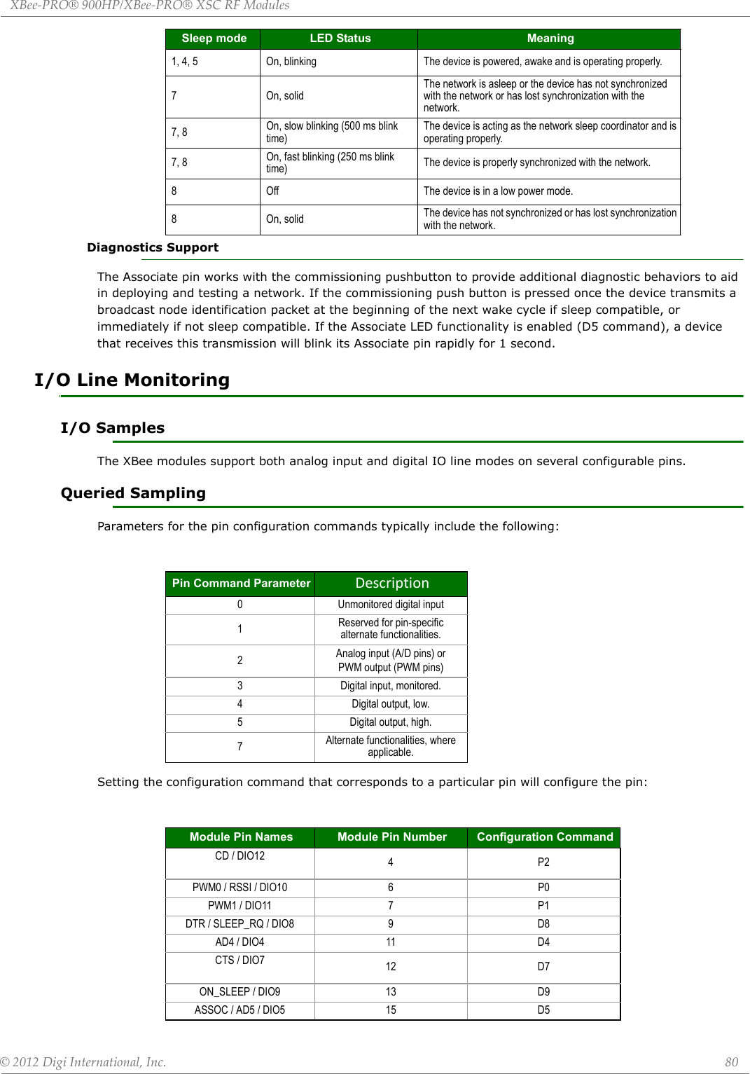
![XBee‐PRO®900HP/XBee‐PRO®XSCRFModules©2012DigiInternational,Inc. 81See the command table for more information. Pullup resistors for each digital input can be enabled using the PR command.If the IS command is issued from AT command mode then a carriage return delimited list will be returned containing the above-listed fields. If the command is issued via an API frame then the module will return an AT command response API frame with the IO data included in the command data portion of the packet.RTS / DIO6 16 D6AD3 / DIO3 17 D3AD2 / DIO2 18 D2AD1 / DIO1 19 D1AD0 / DIO0 / CommissioningButton 20 D01 Sample Sets Number of sample sets in the packet. (Always set to 1.)2 Digital Channel MaskIndicates which digital IO lines have sampling enabled. Each bit corresponds to one digital IO line on the module. • bit 0 = AD0/DIO0 • bit 1 = AD1/DIO1 • bit 2 = AD2/DIO2 • bit 3 = AD3/DIO3 • bit 4 = DIO4 • bit 5 = ASSOC/DIO5•bit 6 = RTS/DIO6•bit 7 = CTS/GPIO7• bit 8 = DTR / SLEEP_RQ / DIO8 • bit 9 = ON_SLEEP / DIO9 • bit 10 = RSSI/DIO10• bit 11 = PWM/DIO11• bit 12 = CD/DIO12For example, a digital channel mask of 0x002F means DIO0,1,2,3, and 5 are enabled as digital IO.1 Analog Channel MaskIndicates which lines have analog inputs enabled for sampling. Each bit in the analog channel mask corresponds to one analog input channel.•bit 0 = AD0/DIO0•bit 1 = AD1/DIO1•bit 2 = AD2/DIO2•bit 3 = AD3/DIO3•bit 4 = AD4/DIO4Variable Sampled Data SetIf any digital IO lines are enabled, the first two bytes of the data set indicate the state of all enabled digital IO. Only digital channels that are enabled in the Digital Channel Mask bytes have any meaning in the sample set. If no digital IO are enabled on the device, these 2 bytes will be omitted.Following the digital IO data (if any), each enabled analog channel will return 2 bytes. The data starts with AIN0 and continues sequentially for each enabled analog input channel up to AIN5. Example Sample AT Response0x01\r [1 sample set]0x0C0C\r [Digital Inputs: DIO 2, 3, 10, 11 enabled]0x03\r [Analog Inputs: A/D 0, 1 enabled]Module Pin Names Module Pin Number Configuration Command](https://usermanual.wiki/Digi/XB900HP/User-Guide-1792196-Page-81.png)
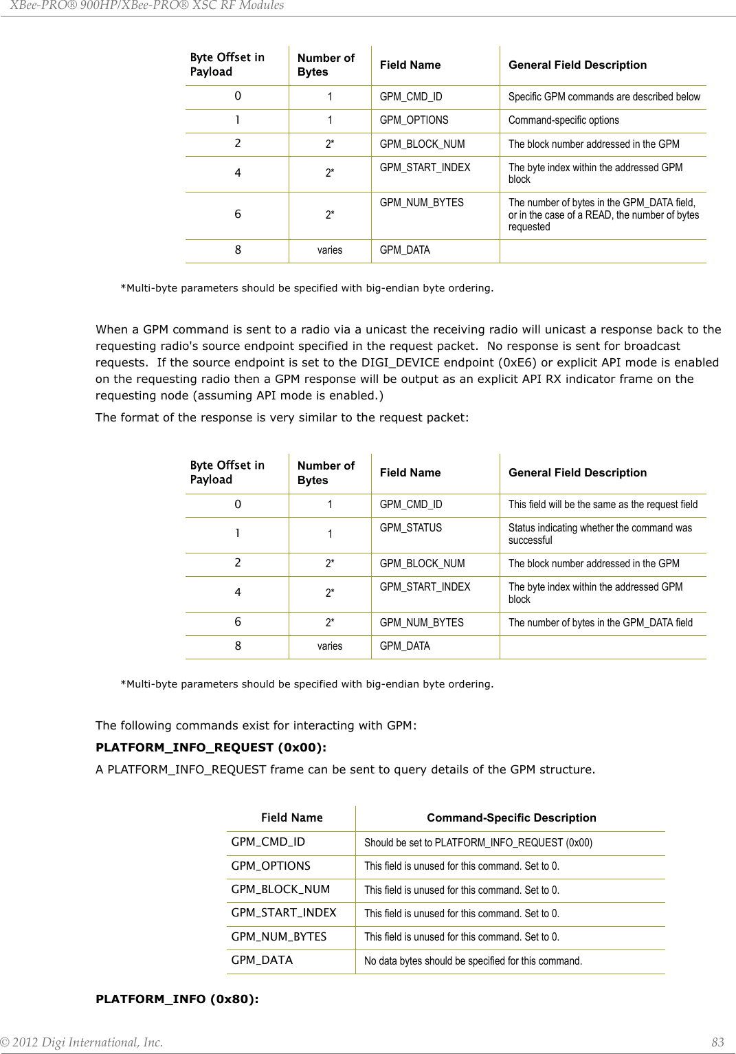
![XBee‐PRO®900HP/XBee‐PRO®XSCRFModules©2012DigiInternational,Inc. 82Periodic I/O SamplingPeriodic sampling allows an XBee-PRO module to take an I/O sample and transmit it to a remote device at a periodic rate. The periodic sample rate is set by the IR command. If IR is set to 0, periodic sampling is disabled. For all other values of IR, data will be sampled after IR milliseconds have elapsed and transmitted to a remote device. The DH and DL commands determine the destination address of the IO samples. Only devices with API mode enabled will send IO data samples out their serial interface. Devices not in API mode will discard received IO data samples. A module with sleep enabled will transmit periodic I/O samples at the IR rate until the ST time expires and the device can resume sleeping. See the sleep section for more information on sleep.Digital I/O Change DetectionModules can be configured to transmit a data sample immediately whenever a monitored digital I/O pin changes state. The IC command is a bitmask that can be used to set which digital I/O lines should be monitored for a state change. If one or more bits in IC is set, an I/O sample will be transmitted as soon as a state change is observed in one of the monitored digital I/O lines. The figure below shows how edge detection can work with periodic sampling.General Purpose Flash MemoryXBee-PRO 900HP modules provide 119 512-byte blocks of flash memory which can be read and written by the user application. This memory provides a non-volatile data storage area which can be used for a multitude of purposes. Some common uses of this data storage include: storing logged sensor data, buffering firmware upgrade data for a host microcontroller, or storing and retrieving data tables needed for calculations performed by a host microcontroller. The General Purpose Memory (GPM) is also used to store a firmware upgrade file for over-the-air firmware upgrades of the XBee module itself.Accessing General Purpose Flash MemoryThe GPM of a target node can be accessed locally or over-the-air by sending commands to the MEMORY_ACCESS cluster ID (0x23) on the DIGI_DEVICE endpoint (0xE6) of the target node using explicit API frames. (Explicit API frames are described in the API Operation section.To issue a GPM command the payload of an explicit API frame should be formatted in the following way:0x0408\r [Digital input states: DIO 3, 10 high, DIO 2, 11 low]0x03D0\r [Analog input ADIO 0= 0x3D0]0x0124\r [Analog input ADIO 1=0x120]Example Sample AT Response](https://usermanual.wiki/Digi/XB900HP/User-Guide-1792196-Page-82.png)

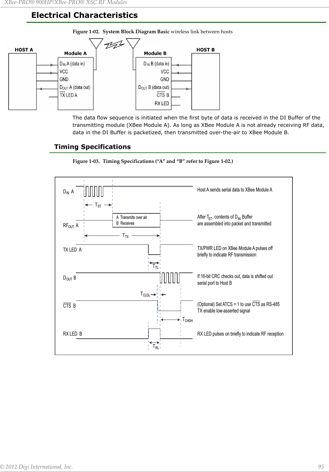
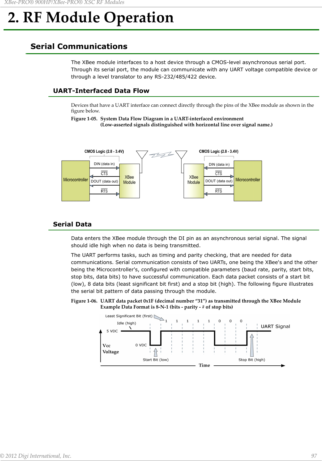
![XBee‐PRO®900HP/XBee‐PRO®XSCRFModules©2012DigiInternational,Inc. 98Flow ControlFigure1‐07. InternalDataFlowDiagram(Thefivemostcommonly‐usedpinsignalsshown.)DI (Data In) Buffer and Flow ControlWhen serial data enters the XBee module through the DI Pin, then the data is stored in the DI Buffer until it can be transmitted.When the RO parameter threshold is satisfied (refer to Transmit Mode and Command Descriptions sections for more information), the module attempts to initialize an RF connection. If the module is already receiving RF data, the serial data is stored in the module's DI Buffer. If the DI buffer becomes full, hardware or software flow control must be implemented in order to prevent overflow (loss of data between the host and XBee RF Module).How to eliminate the need for flow control:• Send messages that are smaller than the DI buffer size, which is generally around 1,000 bytes. • Interface at a lower baud rate (BD parameter) than the fixed RF data rate with the Retries functionality (RR parameter) disabled.Two cases in which the DI Buffer may become full and possibly overflow:• If the serial interface data rate is set higher than the RF data rate of the module, the module will receive data from the host faster than it can transmit the data over-the-air.• If the module is receiving a continuous stream of data, monitoring data on a network, or awaiting acknowledgments for Retries functionality, any serial data that arrives on the DI pin is placed in the DI Buffer. The data in the DI buffer will be transmitted over-the-air when the module no longer detects RF data in the network.Hardware Flow Control (CTS). When the DI buffer is 65 bytes away from being full; by default, the module de-asserts (high) CTS to signal to the host device to stop sending data [refer to FT (Flow Control Threshold) and CS (DO2 Configuration) Commands]. CTS is re-asserted after the DI Buffer has 34 bytes of memory available.Software Flow Control (XON). XON/XOFF software flow control can be enabled using the FL (Software Flow Control) command.DO (Data Out) Buffer and Flow ControlWhen RF data is received, the data enters the DO buffer and is then sent out the serial port to a host device. Once the DO Buffer reaches capacity, any additional incoming RF data is lost.Two cases in which the DO Buffer may become full and possibly overflow:• If the RF data rate is higher than the set interface data rate of the module, the module will receive data from the transmitting module faster than it can send the data to the host.• If the host does not allow the RF module to send data out of the DO buffer because of hard-ware or software flow control.Hardware Flow Control (RTS). If RTS is enabled for flow control (RT Parameter = 2), data will not be sent out the DO Buffer as long as RTS (pin 16) is de-asserted.Software Flow Control (XOFF). XON/XOFF software flow control can be enabled using the FL (Software Flow Control) Command. This option only works with ASCII data.](https://usermanual.wiki/Digi/XB900HP/User-Guide-1792196-Page-98.png)
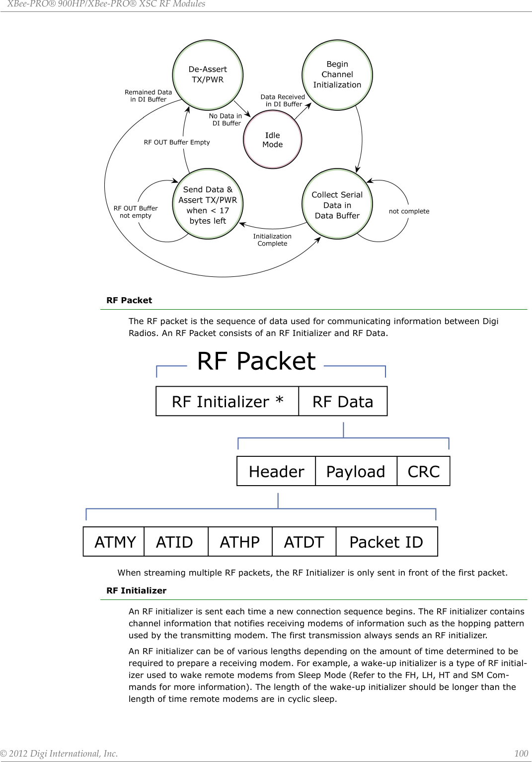
![XBee‐PRO®900HP/XBee‐PRO®XSCRFModules©2012DigiInternational,Inc. 99Modes of OperationXBee-PRO® 900HP/XBee-PRO® XSC RF Modules operate in five modes.Figure1‐08. ModesofOperationIdle ModeWhen not receiving or transmitting data, the RF module is in Idle Mode. The module shifts into the other modes of operation under the following conditions:• Transmit Mode (Serial data is received in the DI Buffer)• Receive Mode (Valid RF data is received through the antenna)• Sleep Mode (Sleep Mode condition is met)• Command Mode (Command Mode Sequence is issued)Transmit ModeWhen the first byte of serial data is received from the UART in the DI buffer, the modem attempts to shift to Transmit Mode and initiate an RF connection with other modems. After transmission is complete, the modem returns to Idle Mode.RF transmission begins after either of the following criteria is met:1. RB bytes have been received in the DI buffer and are pending for RF transmission [refer to RB (Packetization Threshold) command, p34].- The RB parameter may be set to any value between 1 and the RF packet size (PK), inclusive. When RB = 0, the packetization threshold is ignored.2. At least one character has been received in the DI buffer (pending for RF transmission) and RO time has been observed on the UART [refer to RO (Packetization Timeout) command].- The time out can be disabled by setting RO to zero. In this case, transmission will begin after RB bytes have been received in the DI buffer.Note: RF reception must complete before the modem is able to enter into Transmit Mode.After either RB or RO conditions are met, the modem then initializes a communications channel. [Channel initialization is the process of sending an RF initializer that synchronizes receiving modems with the transmitting modem. During channel initialization, incoming serial data accumulates in the DI buffer.]Serial data in the DI buffer is grouped into RF packets [refer to PK (RF Packet Size)]; converted to RF data; then transmitted over-the-air until the DI buffer is empty. RF data, which includes the payload data, follows the RF initializer. The payload includes up to the maximum packet size (PK Command) bytes. As the transmitting modem nears the end of the transmission, it inspects the DI buffer to see if more data exists to be transmitted. This could be the case if more than PK bytes were originally pending in the DI buffer or if more bytes arrived from the UART after the transmission began. If more data is pending, the transmitting modem assembles a subsequent packet for transmission.](https://usermanual.wiki/Digi/XB900HP/User-Guide-1792196-Page-99.png)
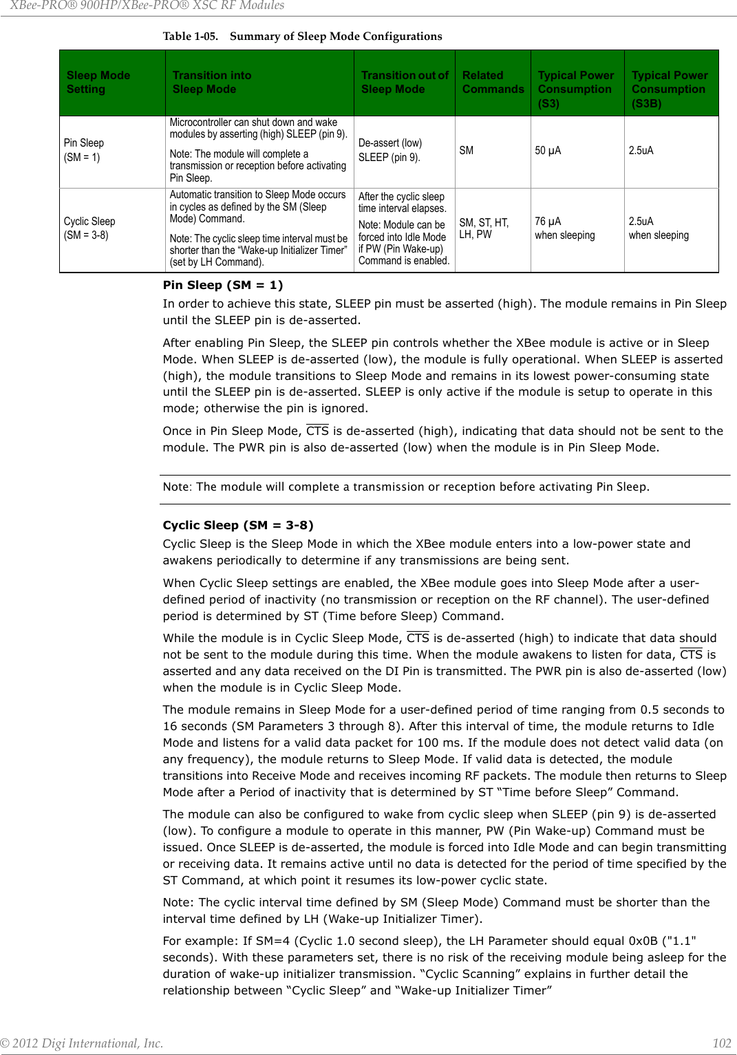
![XBee‐PRO®900HP/XBee‐PRO®XSCRFModules©2012DigiInternational,Inc. 101HeaderThe header contains network addressing information that filters incoming RF data. The receiv-ing modem checks for a matching Hopping Channel (HP parameter), Vendor Identification Num-ber (ID parameter) and Destination Address (DT parameter). Data that does not pass through all three network filter layers is discarded.CRC (Cyclic Redundancy Check)To verify data integrity and provide built-in error checking, a 16-bit CRC (Cyclic Redundancy Check) is computed for the transmitted data and attached to the end of each RF packet. On the receiving end, the receiving modem computes the CRC on all incoming RF data. Received data that has an invalid CRC is discarded. Receive ModeIf a module detects RF data while operating in Idle Mode, the module transitions into Receive Mode to start receiving RF packets. Figure1‐09. ReceptionofRFDataAfter a packet is received, the module checks the CRC (cyclic redundancy check) to ensure that the data was transmitted without error. If the CRC data bits on the incoming packet are invalid, the packet is discarded. If the CRC is valid, the packet proceeds to the DO Buffer.The module returns to Idle Mode after valid RF data is no longer detected or after an error is detected in the received RF data. If serial data is stored in the DI buffer while the module is in Receive Mode, the serial data will be transmitted after the module is finished receiving data and returns to Idle Mode.Sleep ModeSleep Modes enable the XBee module to operate at minimal power consumption when not in use. The following Sleep Mode options are available: •Pin Sleep •Cyclic Sleep For the module to transition into Sleep Mode, the module must have a non-zero SM (Sleep Mode) Parameter and one of the following must occur:• The module is idle (no data transmission or reception) for a user-defined period of time [Refer to the ST (Time before Sleep) Command].• SLEEP is asserted (only for Pin Sleep option).In Sleep Mode, the module will not transmit or receive data until the module first transitions to Idle Mode. All Sleep Modes are enabled and disabled using SM Command. Transitions into and out of Sleep Modes are triggered by various events as shown in the table below.](https://usermanual.wiki/Digi/XB900HP/User-Guide-1792196-Page-101.png)
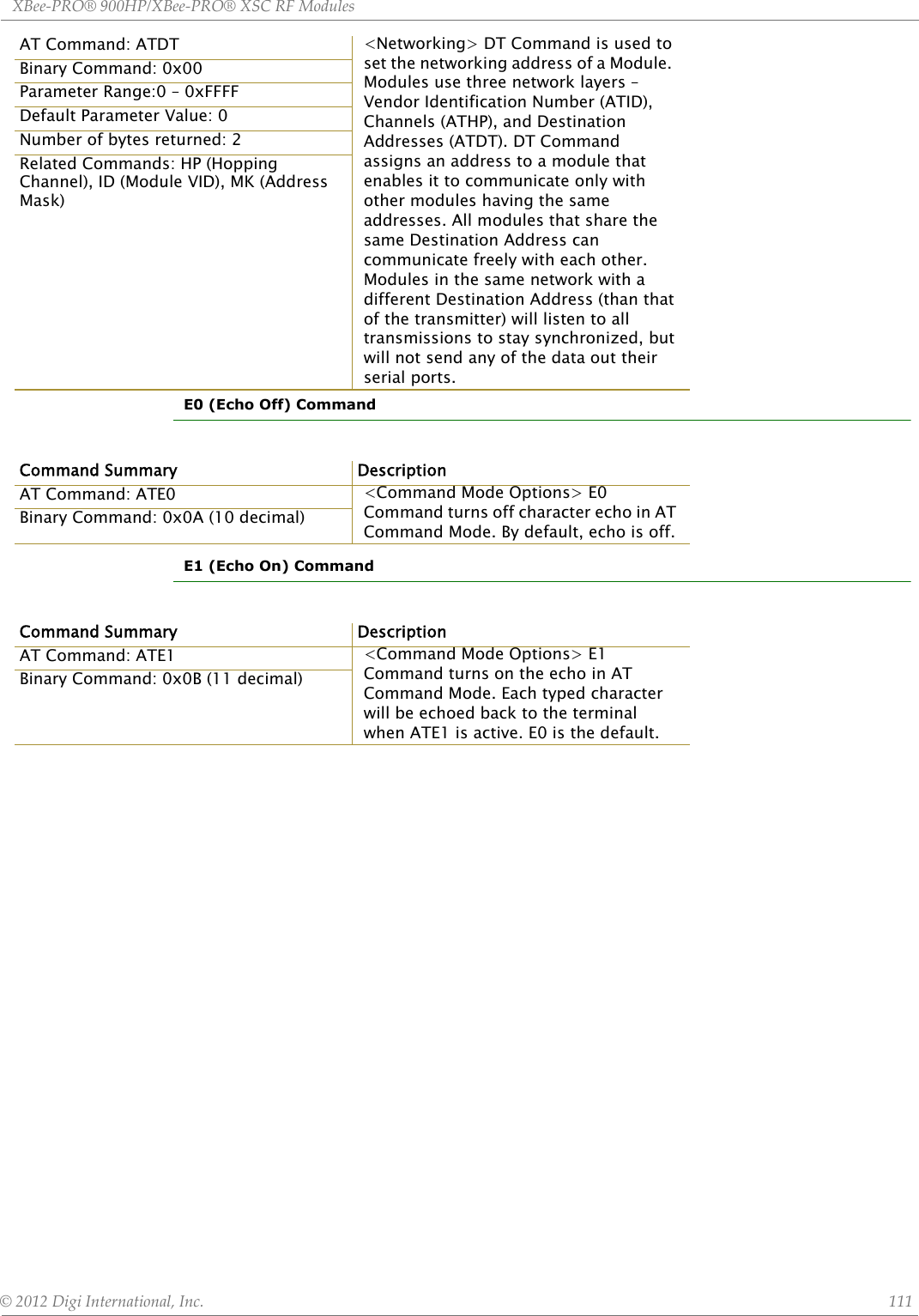
![XBee‐PRO®900HP/XBee‐PRO®XSCRFModules©2012DigiInternational,Inc. 103Cyclic Scanning. Each RF transmission consists of an RF Initializer and payload. The wake-up initializer contains initialization information and all receiving modules must wake during the wake-up initializer portion of data transmission in order to be synchronized with the transmitting module and receive the data.Figure1‐010.CorrectConfiguration(LH>SM)Lengthofthewake‐upinitializerexceedsthetimeintervalofCyclicSleep.Thereceiverisguaranteedtodetectthewake‐upinitializerandreceivetheaccompanyingpayloaddata.Figure1‐011.IncorrectConfiguration(LH<SM)Lengthofwake‐upinitializerisshorterthanthetimeintervalofCyclicSleep.Thisconfigurationisvulnerabletothereceiverwakingandmissingthewake‐upinitializer(andthereforealsotheaccompanyingpayloaddata).Command ModeTo modify or read module parameters, the module must first enter into Command Mode, the state in which received characters on the UART are interpreted as commands. Two command types are avail-able for programming the module:• AT Commands• Binary CommandsFor modified parameter values to persist in the module registry, changes must be saved to non-vola-tile memory using WR (Write) Command. Otherwise, parameters are restored to previously saved val-ues after the module is powered off and then on again.AT CommandsTo Enter AT Command Mode:• Send the 3-character command sequence “+++” and observe guard times before and after the command characters. [refer to ‘Default AT Command Mode Sequence’ below.] The ‘Termi-nal’ tab (or other serial communications software) of the X-CTU Software can be used to enter the sequence.[OR]• Assert (low) the CONFIG pin and either turn the power going to the module off and back on. (If using a Digi XBIB-R Interface Board, the same result can be achieved by holding the Data-In line low (also known as a break) while rebooting the module by pressing the reset button on the module assembly [module assembly = module mounted to an interface board]).](https://usermanual.wiki/Digi/XB900HP/User-Guide-1792196-Page-103.png)
![XBee‐PRO®900HP/XBee‐PRO®XSCRFModules©2012DigiInternational,Inc. 104Default AT Command Mode Sequence (for transition to Command Mode):• No characters sent for one second [refer to the BT (Guard Time Before) Command]• Input three plus characters (“+++”) within one second[refer to the CC (Command Sequence Character) Command.]• No characters sent for one second [refer to the AT (Guard Time After) Command.]To Send AT Commands:Send AT commands and parameters using the syntax shown below.Figure1‐12.SyntaxforsendingATCommandsTo read a parameter value stored in the module register, leave the parameter field blank.The preceding example would change the module’s Destination Address to “0x1F”. To store the new value to non-volatile (long term) memory, the Write (ATWR) command must subsequently be sent before powering off the module.System Response. When a command is sent to the module, the module will parse and execute the command. Upon successful execution of a command, the module returns an “OK” message. If execution of a command results in an error, the module returns an “ERROR” message.To Exit AT Command Mode:• If no valid AT Commands are received within the time specified by CT (Command Mode Time-out) Command, the module automatically returns to Idle Mode. [OR]• Send ATCN (Exit Command Mode) Command.For an example of programming the RF module using AT Commands and descriptions of each config-urable parameter, refer to the “RF Module Configuration” chapter.Binary CommandsSending and receiving parameter values using binary commands is the fastest way to change operating parameters of the module. Binary commands are used most often to sample signal strength (RS parameter) and/or error counts; or to change module addresses and channels for polling systems when a quick response is necessary. Since the sending and receiving of parameter values takes place through the same data path as 'live' data (received RF payload), follow the CTS pin as outlined in Figure 2-012 to distinguish between the two types of data (commands vs 'live' data).Common questions regarding the use of binary commands: • What are the implications of asserting CMD while live data is being sent or received? • After sending serial data, is there a minimum time delay before CMD can be asserted? • Is a time delay required after CMD is de-asserted before payload data can be sent? • How to discern between live data and data received in response to a command?CMD (pin 16) must be asserted in order to send binary commands to the module. The CMD pin can be asserted to recognize binary commands anytime during the transmission or reception of data. The status of the CMD signal is only checked at the end of the stop bit as the byte is shifted into the serial port. The application does not allow control over when data is received, except by waiting for dead time between bursts of communication.If the command is sent in the middle of a stream of payload data to be transmitted, the command will essentially be executed in the order it is received. If the radio is continuously receiving data, the radio will wait for a break in the received data before executing the command. The CTS signal will frame the response coming from the binary command request [Figure 1-013].](https://usermanual.wiki/Digi/XB900HP/User-Guide-1792196-Page-104.png)
![XBee‐PRO®900HP/XBee‐PRO®XSCRFModules©2012DigiInternational,Inc. 105A minimum time delay of 100 µs (after the stop bit of the command byte has been sent) must be observed before pin 5 can be de-asserted. The command executes after all parameters associated with the command have been sent. If all parameters are not received within 0.5 seconds, the module aborts the command and returns to Idle Mode.Note: Binary commands that return only one parameter byte must also be written with two parameter bytes, 0-padded, LSB first. Refer to “Programming Examples” section [p18] for a binary programming example.Commands can be queried for their current value by sending the command logically ORed (bit-wise) with the value 0x80 (hexadecimal) with CMD asserted. When the binary value is sent (with no parameters), the current value of the command parameter is sent back through the DO pin.Figure1‐013.BinaryCommandWritethenReadSignal#4isCMD(pin16)Signal#1istheDIN(pin3)signaltotheradioSignal#2istheDOUT(pin2)signalfromtheradioSignal#3isCTS(pin12)In this graph, a value was written to a register and then read out to verify it. While not in the middle of other received data, note that the CTS signal outlines the data response out of the module.IMPORTANT: For the XBee module to recognize a binary command, the RT (DI2 Configuration) param-eter must be set to one. If binary programming is not enabled RT = 0 or 2, the module will not recog-nize that the CMD pin is asserted and therefore will not recognize the data as binary commands.3.RFModuleConfigurationXBee Programming ExamplesFor information about entering and exiting AT and Binary Command Modes, refer to the Command Mode section.AT CommandsTo Send AT Commands (Using the ‘Terminal’ tab of the X-CTU Software)Example: Utilize the 'Terminal' tab of the X-CTU Software to change the module's DT (Destina-tion Address) parameter and save the new address to non-volatile memory. This example requires the installation of Digi’s X-CTU Software and a serial connection to a PC. Select the ‘Terminal’ tab of the X-CTU Software and enter the following command lines:Method 1 (One line per command)Note:Donotsendcom‐mandstothemoduleduringflashprogram‐ming(whenparametersarebeingwrittentothemoduleregistry).Waitforthe“OK”sys‐temresponsethatfol‐lowstheATWRcommandbeforeenter‐ingthenextcommandoruseflowcontrol.](https://usermanual.wiki/Digi/XB900HP/User-Guide-1792196-Page-105.png)
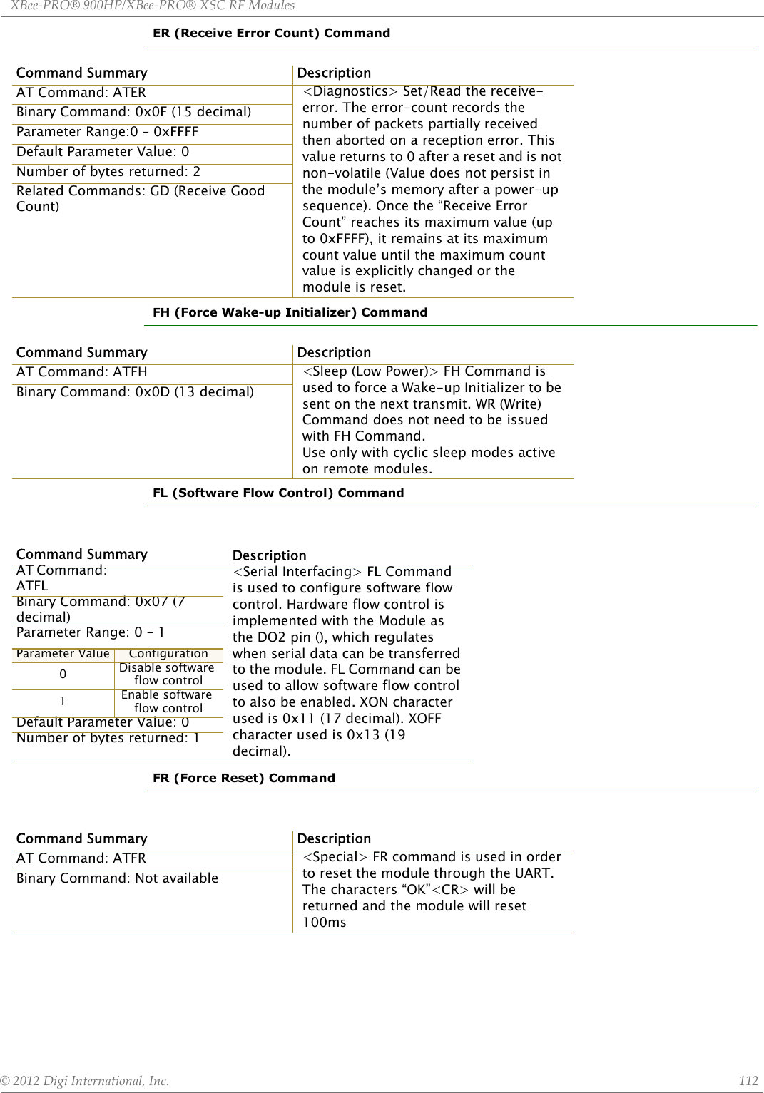
![XBee‐PRO®900HP/XBee‐PRO®XSCRFModules©2012DigiInternational,Inc. 106Note: When using X-CTU Software to program a module, PC com port settings must match the baud (interface data rate), parity & stop bits parameter settings of the module. Use the 'Com Port Setup' section of the “PC Settings” tab to configure PC com port settings to match those of the module.Binary CommandsTo Send Binary Commands Note: CTS is de-asserted high when commands are being executed. Hardware flow control must be disabled as CTS will hold off parameter bytes.Command Reference TableTable1‐06. ATCommands(TheRFModuleexpectsnumericalvaluesinhexadecimal.“d”denotesdecimalequivalent.)Send AT Command+++ATDT <Enter>ATDT1A0D <Enter>ATWR <Enter>ATCN <Enter>System ResponseOK <CR> (Enter into Command Mode){current value} <CR> (Read Destination Address)OK <CR> (Modify Destination Address)OK <CR> (Write to non-volatile memory)OK <CR> (Exit Command Mode)Method 2 (Multiple commands on one line)Send AT Command+++ATDT <Enter>ATDT1A0D,WR,CN <Enter>System ResponseOK <CR> (Enter into Command Mode){current value} <CR> (Read Destination Address)OK <CR> (Execute commands)Example: Use binary commands to change the XBee module's destination address to 0x1A0D and save the new address to non-volatile memory.1. RT Command must be set to “1” in AT Command Mode to enable binary programming.2. Assert CMD (Pin 16 is driven high). (Enter Binary Command Mode)3. Send Bytes (parameter bytes must be 2 bytes long):000D1A08(Send DT (Destination Address) Command)(Least significant byte of parameter bytes(Most significant byte of parameter bytes)(Send WR (Write) Command)4. De-assert CMD (Pin 16 is driven low)(Exit Binary Command Mode)AT CommandBinaryCommand AT Command Name Range Command Category # Bytes ReturnedFactoryDefault*AM 0x3A (58d) Auto-set MY - Networking & Security - -AT 0x05 (5d) Guard Time After 0x02 – 0xFFFF [x 100 msec] Command Mode Options 2 0x0A (10d)BD 0x15 (21d) Interface Data RateStandard baud rates: 0 – 6Non-standard baud rates:0x7D – 0xFFFFSerial Interfacing 2 0x03 9600bpsBT 0x04 (4d) Guard Time Before 2 – 0xFFFF [x 100 msec] Command Mode Options 2 0x0A (10d)CC 0x13 (19d) Command Sequence Character 0x20 – 0x7F Command Mode Options 1 0x2B (“+”)CD 0x28 (40d) DO3 Configuration 0 - 4 Serial Interfacing 1 0CN 0x09 (9d) Exit AT Command Mode - Command Mode Options - -CS 0x1F (31d) DO2 Configuration 0 – 4 Serial Interfacing 1 0CT 0x06 (6d) Command Mode Timeout 0x02 – 0xFFFF [x 100 msec] Command Mode Options 2 0xC8 (200d)DT 0x00 (0d) Destination Address 0 – 0xFFFF Networking 2 0E0 0x0A (10d) Echo Off - Command Mode Options - -E1 0x0B (11d) Echo On - Command Mode Options - -ER 0x0F (15d) Receive Error Count 0 – 0xFFFF Diagnostics 2 0](https://usermanual.wiki/Digi/XB900HP/User-Guide-1792196-Page-106.png)
![XBee‐PRO®900HP/XBee‐PRO®XSCRFModules©2012DigiInternational,Inc. 107NOTE:ATCommandsissuedwithoutaparametervalueareinterpretedasqueriesandwillreturnthecurrentlystoredparameter.*CommandsonlysupportedonS3Bhardware.Command Descriptions Commands in this section are listed alphabetically. Command categories are designated between the “< >” symbols that follow each command title. Modules expect numerical values in hexadecimal and those values are designated by a “0x” prefix.Modules operating within the same network should contain the same firmware platform to ensure the same AT Command parameters are supported.AM (Auto-set MY) CommandFH 0x0D (13d) Force Wake-up Initializer - Sleep (Low Power) - -FL 0x07 (7d) Software Flow Control 0 – 1 Serial Interfacing 1 0FR N/A Forces the module to Reset (Special)FT 0x24 (36d) Flow Control Threshold 0 – (DI buffer – 0x11) [bytes] Serial Interfacing 2 variesGD 0x10 (16d) Receive Good Count 0 – 0xFFFF Diagnostics 2 0HP 0x11 (17d) Hopping Channel 0 – 6 Networking 1 0HT 0x03 (3d) Time before Wake-up Initializer 0 – 0xFFFF [x 100 msec] Sleep (Low Power) 2 0xFFFFID 0x27 (39d) Module VID User set table: 0x10 - 0x7FFFRead-only: 0x8000 – 0xFFFF Networking 2 -LH 0x0C (12d) Wake-up Initializer Timer 0 – 0xFF [x 100 msec] Sleep (Low Power) 1 1MD 0x32 (50d) RF Mode 0 – 4 Networking & Security 1 0MK 0x12 (18d) Address Mask 0 – 0xFFFF Networking 2 0xFFFF *MY 0x2A (42d) Source Address 0 – 0xFFFF Networking & Security 2 0xFFFFNB 0x23 (35d) Parity 0 – 5 Serial Interfacing 1 0PC 0x1E (30d) Power-up Mode 0 – 1 Command Mode Options 1 0*PK 0x29 (41d) RF Packet Size 0 - 0x100 [bytes] Serial Interfacing 2 0x40 (64d)*PL 0x3c (60d) RF Power Level 0-4 (Special) 1 4PW 0x1D (29d) Pin Wake-up 0 – 1 Sleep (Low Power) 1 0*RB 0x20 (32d) Packetization Threshold 0 - 0x100 [bytes] Serial Interfacing 2 0x01RE 0x0E (14d) Restore Defaults - (Special) - -RN 0x19 (25d) Delay Slots 0 – 0xFF [slots] Networking 1 0RO 0x21 (33d) Packetization Timeout 0 – 0xFFFF [x 200 µsec] Serial Interfacing 2 0RP 0x22 (34d) RSSI PWM Timer 0 - 0x7F [x 100 msec] Diagnostics 1 0RR 0x18 (24d) Retries 0 – 0xFF Networking 1 0RS 0x1C (28d) RSSI 0x06 – 0x36 [read-only] Diagnostics 1 -RT 0x16 (22d) DI2 Configuration 0 - 2 Serial Interfacing 1 0*RZ 0x2C (44d) DI Buffer Size [read-only] Diagnostics - -SB 0x36 (54d) Stop Bits 0 - 1 Serial Interfacing 1 0SH 0x25 (37d) Serial Number High 0 – 0xFFFF [read-only] Diagnostics 2 -SL 0x26 (38d) Serial Number Low 0 – 0xFFFF [read-only] Diagnostics 2 -SM 0x01 (1d) Sleep Mode 0, 1, 3 - 8 Sleep (Low Power) 1 0ST 0x02 (2d) Time before Sleep 0x10 – 0xFFFF [x 100 msec] Sleep (Low Power) 2 0x64 (100d)SY 0x17 (23d) Time before Initialization 0 – 0xFF [x 100 msec] Networking 1 0 (disabled)TR 0x1B (27d) Transmit Error Count 0 – 0xFFFF Diagnostics 2 0TT 0x1A (26d) Streaming Limit 0 – 0xFFFF [0 = disabled] Networking 2 0xFFFFVR 0x14 (20d) Firmware Version 0 - 0xFFFF [read-only] Diagnostics 2 -WR 0x08 (8d) Write - (Special) - -Command Summary Description](https://usermanual.wiki/Digi/XB900HP/User-Guide-1792196-Page-107.png)
![XBee‐PRO®900HP/XBee‐PRO®XSCRFModules©2012DigiInternational,Inc. 108AT (Guard Time After) CommandBD (Interface Data Rate) CommandAT Command: ATAM <Networking & Security> AM Command is used to automatically set the MY (Source Address) parameter from the factory-set module serial number. The address is formed with bits 29, 28 and 13-0 of the serial number (in that order).Binary Command: 0x3A (58 decimal)This command is only supported on S3B modules.Command Summary DescriptionAT Command: ATAT <Command Mode Options> AT Command is used to set the time-of-silence that follows the command sequence character (CC Command). By default, AT Command Mode will activate after one second of silence. Refer to the AT Commands section to view the default AT Command Mode Sequence.Binary Command: 0x05 (5 decimal)Parameter Range:0x02 – 0xFFFF [x 100 milliseconds]Number of bytes returned: 2Default Parameter Value: 0x0A (10 decimal)Related Commands: BT (Guard Time Before), CC (Command Sequence Character)Command Summary DescriptionAT Command: ATBD <Serial Interfacing> BD Command allows the user to adjust the UART interface data rate and thus modify the rate at which serial data is sent to the module. The new baud rate does not take effect until the CN (Exit AT Command Mode) Command is issued. The RF data rate is not affected by the BD Command.Although most applications will only require one of the seven standard baud rates, non-standard baud rates are also supported.Note: If the serial data rate is set to exceed the fixed RF data rate of the module, flow control may need to be implemented as described in the Pin Signals and Flow Control sections of this manual.Non-standard Interface Data Rates: When parameter values outside the range of standard baud rates are sent, the closest interface data rate represented by the number is stored in the BD register. For example, a rate of 19200 bps can be set by sending the following command line “ATBD4B00”. NOTE: When using X-CTU Software, non-standard interface data rates can only be set and read using the X-CTU ‘Terminal’ tab. Non-standard rates are not accessible through the ‘Modem Configuration’ tab.When the BD command is sent with a non-standard interface data rate, the UART will adjust to accommodate the requested interface rate. In most cases, the clock resolution will cause the stored BD parameter to vary from the parameter that was sent (f h blbl )R di hBD d( dBinary Command: 0x15 (21 decimal)Parameter Range (Standard baud rates): 0 – 6(Non-standard baud rates): 0x7D – 0xFFFF (125d – 65535d)Parameter ValueBAUD (bps)Configuration0 12001 24002 48003 96004 192005 384006 57600Number of bytes returned: 2Default Parameter Value: Set to equal module’s factory-set RF data rate.](https://usermanual.wiki/Digi/XB900HP/User-Guide-1792196-Page-108.png)
![XBee‐PRO®900HP/XBee‐PRO®XSCRFModules©2012DigiInternational,Inc. 109Table1‐07. ParameterSentvs.ParameterStoredBT (Guard Time Before) CommandCC (Command Sequence Character) CommandCD (DO3 Configuration) CommandBD Parameter Sent (HEX) Interface Data Rate (bps) S3 BD Parameter Stored (HEX) S3B BD Parameter Stored (HEX)0 1200 0 04 19,200 4 46 57600 6 512C 300 12B 12BE100 57600 E883 E10DCommand Summary DescriptionAT Command: ATBT <Command Mode Options> BT Command is used to set the DI pin silence time that must precede the command sequence character (CC Command) of the AT Command Mode Sequence. Refer to the AT Commands section to view the default AT Command Mode Sequence.Binary Command: 0x04 (4 decimal)Parameter Range:2 – 0xFFFF [x 100 milliseconds]Default Parameter Value: 0x0A (10 decimal) Number of bytes returned: 2Related Commands: AT (Guard Time After), CC (Command Sequence Character)Command Summary DescriptionAT Command: ATCC <Command Mode Options> CC Command is used to set the ASCII character to be used between Guard Times of the AT Command Mode Sequence (BT+ CC + AT). The AT Command Mode Sequence activates AT Command Mode (from Idle Mode). Refer to the AT Commands section [p. 18] to view the default AT Command Mode Sequence.Binary Command: 0x13 (19 decimal)Parameter Range: 0x20 – 0x7FDefault Parameter Value: 0x2B (ASCII “+” sign) Number of bytes returned: 1Related Commands: AT (Guard Time After), BT (Guard Time Before)DescriptionAT Command: ATCDBinary Command: 0x28 (40 decimal) <Command Mode Options> CD Command is used to define the behavior of the DO3/RX LED line.Parameter Range: 0 – 3Parameter Value Configuration0RX LED1Default high2Default low3 (reserved)4Assert only when packet addressed to module is sentDefault Parameter Value: 0Number of bytes returned: 1](https://usermanual.wiki/Digi/XB900HP/User-Guide-1792196-Page-109.png)
![XBee‐PRO®900HP/XBee‐PRO®XSCRFModules©2012DigiInternational,Inc. 110CN (Exit AT Command Mode) CommandCS (DO2 Configuration) CommandCT (Command Mode Time out) CommandDT (Destination Address) CommandCommand Summary DescriptionAT Command: ATCN <Command Mode Options> CN Command is used to explicitly exit AT Command Mode.Binary Command: 0x09 (9 decimal)Command Summary DescriptionAT Command: ATCS <Serial Interfacing> CS Command is used to select the behavior of the DO2 pin signal. This output can provide RS-232 flow control, control the TX enable signal (for RS-485 or RS-422 operations), or set the default level for the I/O line passing function. By default, DO2 provides RS-232 CTS (Clear-to-Send) flow control.Binary Command: 0x1F (31 decimal)Parameter Range:0 – 4Parameter Value Configuration0RS-232 flow control1 RS-485 TX enable low2high3 RS-485 TX enable high4lowDefault Parameter Value: 0Number of bytes returned: 1Minimum Firmware Version Required: 4.27DCommand Summary DescriptionAT Command: ATCT <Command Mode Options> CT Command sets the amount of time before AT Command Mode terminates automatically. After a CT time of inactivity, the module exits AT Command Mode and returns to Idle Mode. AT Command Mode can also be exited manually using CN (Exit AT Command Mode) Command.Binary Command: 0x06 (6 decimal)Parameter Range:0x02 – 0xFFFF [x 100 milliseconds]Default Parameter Value: 0xC8 (200 decimal, 20 seconds)Number of bytes returned: 2Command Summary Description](https://usermanual.wiki/Digi/XB900HP/User-Guide-1792196-Page-110.png)
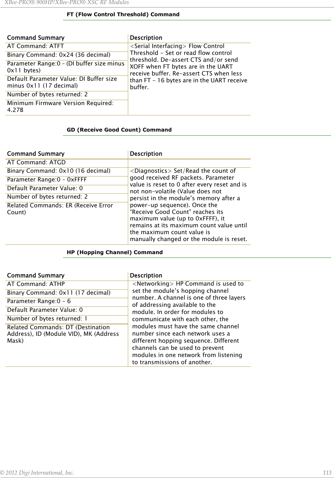
![XBee‐PRO®900HP/XBee‐PRO®XSCRFModules©2012DigiInternational,Inc. 114HT (Time before Wake-up Initializer) CommandID (Modem VID) CommandCommand Summary DescriptionAT Command: ATHT <Sleep (Low Power)> If any modules within range are running in a “Cyclic Sleep” setting, a wake-up initializer must be used by the transmitting module for sleeping modules to remain awake [refer to the LH (“Wake-up InitializerTimer”) Command]. When a receiving module in Cyclic Sleep wakes, it must detect the wake-up initializer in order to remain awake andreceive data. The value of HT Parameter tells the transmitter, “After a period of inactivity (no transmitting or receiving) lasting HT amount of time, send a long wake-up initializer”. HT Parameter should be set to match the inactivity time out [specified by ST (Time before Sleep) Command]used by the receiver(s). From the receiving module perspective, after HT time elapses and the inactivitytime out [ST Command] is met, the receiver goes into cyclic sleep. In cyclic sleep, the receiver wakes once per sleep interval to check for a wakeup initializer. When a wake-up initializer is detected, the module will stay awake to receive data. The wake-up initializer must be longer than thecyclic sleep interval to ensure that sleeping modules detect incoming data. When HT time elapses, the transmitter then knows that it needs to send a long Wake-up Initializer for all receivers to be able to remain awake andreceive the next transmission. Matching HT to the time specified by ST on the receiving module guarantees that all receivers will detect the next transmission.Binary Command: 0x03 (3 decimal)Parameter Range:0 – 0xFFFF [x 100 milliseconds]Default Parameter Value: 0xFFFF (means that long wake-up initializer will not be sent)Number of bytes returned: 2Related Commands: LH (Wake-up Initializer Timer), SM (Sleep Mode), ST (Time before Sleep)Command Summary DescriptionAT Command: ATID <Networking> Set/Read the “Vendor Identification Number”. Only modemswith matching IDs can communicate with each other. Modules with non-matchingVIDs will not receive unintended data transmission.Binary Command: 0x27 (39 decimal)Parameter Range (user-set table) 0x10 - 0x7FFFF (Factory-set and read-only) 0x8000 – 0xFFFFNumber of bytes returned: 2](https://usermanual.wiki/Digi/XB900HP/User-Guide-1792196-Page-114.png)
![XBee‐PRO®900HP/XBee‐PRO®XSCRFModules©2012DigiInternational,Inc. 115LH (Wake-up Initializer Timer) CommandMD (RF Mode) Command Command Summary DescriptionAT Command: ATLH <Sleep (Low Power)> LH Command adjusts the duration of time for which the RF initializer is sent.When receiving modules are put into Cyclic Sleep Mode, they power-down after a period of inactivity [specified by ST (Time before Sleep) Command] and will periodically awaken and listenfor transmitted data. In order for the receiving modules to remain awake, they must detect~35ms of the wake-up initializer. LH Command must be used whenever a receiver is operating in Cyclic Sleep Mode. This lengthensthe Wake-up Initializer to a specific amount of time (in tenths of a second). The Wake-up Initializer Time must be longer than the cyclic sleep time that is determined by SM (Sleep Mode)Command. If the wake-up initializer time were less than the Cyclic Sleep interval, the connection would be at risk of missing the wake-up initializer transmission. Refer to Figures 3.1 & 3.2 of the SM Command description to view diagrams of correct and incorrect configurations. The images help visualize the importance that the value of LH be greater than the value of SM.Binary Command: 0x0C (12 decimal)Parameter Range:0 – 0xFF [x 100 milliseconds]Default Parameter Value: 1Number of bytes returned: 1Related Commands: HT (Time before Wake-up Initializer), SM (Sleep Mode), ST (Time before Sleep)Command Summary DescriptionAT Command: ATMD <Networking & Security> The MDcommand is used to select/read the RFMode (Peer-to-peer orRepeater Modes) of the module.Repeater Mode enables longer range viaan intermediary module. When MD=3,the module will act as a “store andforward” repeater. Any packets notaddressed to this node will be repeated.A Repeater End Node (MD=4) handlesrepeated messages, but will not forwardthe data over-the-air. Refer to theRepeater Mode section [p. 40] for moreinformation.Binary Command: 0x32 (50 decimal)Parameter Range: 0, 3, 4Default Parameter Value: 0Number of bytes returned: 1Parameter Configuration0Peer-to-Peer(transparent operation)3Repeater & End Node4End Node](https://usermanual.wiki/Digi/XB900HP/User-Guide-1792196-Page-115.png)
![XBee‐PRO®900HP/XBee‐PRO®XSCRFModules©2012DigiInternational,Inc. 116MK (Address Mask) CommandMY (Source Address) CommandNB (Parity) CommandCommand Summary DescriptionAT Command: ATMK <Networking> MK Command is used to set/read the Address Mask.All data packets contain the Destination Address of the transmitting module.When an RF data packet is received, the transmitter’s Destination Address is logically “ANDed” (bitwise) with the Address Mask of the receiver. The resulting value must match the Destination Address or theAddress Mask of the receiver for the packet to be received and sent out themodule’s DO serial port. If the “ANDed” value does not match either theDestination Address or the Address Mask of the receiver, the packet is discarded. (All “0” values are treated as “irrelevant” values and are ignored.)Binary Command: 0x12 (18 decimal)Parameter Range:0 – 0xFFFFDefault Parameter Value: 0xFFFF (Destination address (DT parameter) of the transmitting module must exactly match the destination address of the receiving module.)Number of bytes returned: 2Related Commands: DT (Destination Address), HP (Hopping Channel), ID (Module VID)Command Summary DescriptionAT Command: ATMY <Networking & Security> Set/Read the source address of the module.Refer to the Addressing section [p. 38] of the RF Communication Modes chapter for more information.Binary Command: 0x2A (42 decimal)Parameter Range: 0 – 0xFFFFDefault Parameter Value: 0xFFFF (Disabled – the DT (Destination Address) parameter serves as both source and destination address.)Number of bytes returned: 2Related Commands: DT (Destination Address), HP (Hopping Channel), ID (Modem VID), MK (Address Mask), AM (Auto-set MY)This command is only supported on S3B modules.Command Summary DescriptionAT Command: ATNB <Serial Interfacing> Select/Read parity settings for UART communications.Binary Command: 0x23 (35 decimal)Parameter Range:0 – 4 (S3 Hardware)0-5 (S3B Hardware)Parameter Value Configuration08-bit (no parity or 7-bit (any parity)18-bit even28-bit odd38-bit mark48-bit space5 9-bit data (S3B Hardware)Default Parameter Value: 0Number of bytes returned: 1](https://usermanual.wiki/Digi/XB900HP/User-Guide-1792196-Page-116.png)
![XBee‐PRO®900HP/XBee‐PRO®XSCRFModules©2012DigiInternational,Inc. 117PC (Power-up to AT Mode) CommandPK (RF Packet Size) CommandPL (Module Power Level) CommandCommand Summary DescriptionAT Command: ATPC <Command Mode Options> PC Command allows the module to power-updirectly into AT Command Mode from reset or power-on. If PC Command isenabled with SM Parameter set to 1, DI3 (pin 9) can be used to enter themodule into AT Command Mode. When the DI3 pin is de-asserted (low),the module will wake-up in AT Command Mode. This behavior allows moduleDTR emulation.Binary Command: 0x1E (30 decimal)Parameter Range:0 – 1Parameter Value Configuration0 Power-up to Idle Mode1Power-up toAT Command ModeDefault Parameter Value: 0Number of bytes returned: 1Command Summary DescriptionAT Command: ATPK <Serial Interfacing> Set/Read the maximum size of the RF packets sent out a transmitting module. The maximum packet size can be used along with the RB and RO parameters to implicitly set the channel dwell time.Changes to this parameter may have a secondary effect on the RB (Packet Control Characters) parameter. RB must always be less than or equal to PK. If PK is changed to a value less than the current value of RB, RB is automatically lowered to be equal to PK.Binary Command: 0x29 (41 decimal) Parameter Range: 0 – 0x100 [Bytes]Default Parameter Value: 0x40 (64 decimal)Number of bytes returned: 2Related Commands: RB (Packetization Threshold), RO (Packetization Time out)This command is only supported on S3B modules.Command Summary DescriptionAT Command: ATPL <Special Commands> Set/Read the power level at which the RF module transmits conducted power. This command is only supported on S3B hardware. Power level 4 is calibrated and the other power levels are approximate.Binary Command: 0x3C (60 decimal)Parameter Range:0 – 4Parameter Value Configuration0 +7.0 dBm1 +15.0dBm2 +18.0dBm3 +21.0dBm4 +24.0 dBmDefault Parameter Value: 4Number of bytes returned: 1This command is only supported on S3B hardware](https://usermanual.wiki/Digi/XB900HP/User-Guide-1792196-Page-117.png)
)Default Parameter Value: 1Number of bytes returned: 2Related Commands: PK (RF Packet Size), RO (Packetization Time out)This command is only supported on S3B modules.Command Summary DescriptionAT Command: ATRE <Diagnostics> RE Command restores all configurable parameters to factorydefault settings. However, RE Command will not write the default values tonon-volatile (persistent) memory. Unless the WR (Write) Command isissued after the RE command, the default settings will not be saved in theevent of module reset or power-down.Binary Command: 0x0E (14 decimal)](https://usermanual.wiki/Digi/XB900HP/User-Guide-1792196-Page-118.png)
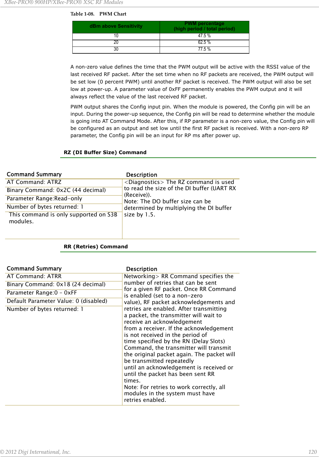
![XBee‐PRO®900HP/XBee‐PRO®XSCRFModules©2012DigiInternational,Inc. 119RN (Delay Slots) CommandRO (Packetization Time out) CommandRP (RSSI PWM Timer) CommandCommand Summary DescriptionAT Command: ATRN <Networking> RN Command is only applicable if retries have beenenabled [RR (Retries) Command], or if forced delays will be inserted intoa transmission [refer to TT (Streaming Limit) Command]. RN Command isused to adjust the time delay that the transmitter inserts before attemptingto resend a packet. If the transmitter fails to receive an acknowledgementafter sending a packet, it will insert a random number of delay slots(ranging from 0 to (RN minus 1)) before attempting to resend the packet.Each delay slot lasts for a period of 38ms.If two modules attempted to transmit at the same time, the random timedelay after packet failure would allow one of the two modules to transmitthe packet successfully, while the other would wait until the channelopens up to begin transmission.Binary Command: 0x19 (25 decimal)Parameter Range:0 – 0xFF [slots]Default Parameter Value: 0 (no delay slots inserted) Number of bytes returned: 1Command Summary DescriptionAT Command: ATRO <Serial Interfacing> RO Command is used to specify/read the time ofsilence (no bytes received) after which transmission begins. After a serialbyte is received and if no other byte is received before the RO time out,the transmission will start.Binary Command: 0x21 (33 decimal)Parameter Range:0 – 0xFFFF [x 200 µs]Default Parameter Value: 0 Number of bytes returned: 2Command Summary DescriptionAT Command: ATRP <Diagnostics> RP Command is used to enable a PWM (“Pulse Width Modulation”)output on the Config pin which is calibrated to show the level thereceived RF signal is above the sensitivity level of the module. The PWMpulses vary from zero to 95 percent. Zero percent means the received RFsignal is at or below the published sensitivity level of the module. The followingtable shows levels above sensitivity and PWM values.The total period of the PWM output is 8.32 ms. There are 40 steps in thePWM output and therefore the minimum step size is 0.208 ms.Binary Command: 0x22 (34 decimal)Parameter Range:0 - 0x7F[x 100 milliseconds]Default Parameter Value: 0 (disabled) Number of bytes returned: 1](https://usermanual.wiki/Digi/XB900HP/User-Guide-1792196-Page-119.png)
![XBee‐PRO®900HP/XBee‐PRO®XSCRFModules©2012DigiInternational,Inc. 121RS (RSSI) CommandRT (DI2 Configuration) CommandSB (Stop Bits) CommandSH (Serial Number High) CommandCommand Summary DescriptionAT Command: ATRS <Diagnostics> RS Command returns the signal level of the last packetreceived. This reading is useful for determining range characteristics of themodules under various conditions of noise and distance.Once the command is issued, the module will return a value between 0x6and 0x36 where 0x36 represents a very strong signal level and 0x4 indicatesa low signal level.Binary Command: 0x1C (28 decimal)Parameter Range: 0x06 – 0x36 [read-only]Number of bytes returned: 1Command Summary DescriptionAT Command: ATRT <Serial Interfacing> RT command is used to dictate the behavior of theDI2/RTS/CMD line. RT Command must be issued to enable RTS flow controlor binary programming.Binary Command: 0x16 (22 decimal)Parameter Range:0 – 2Parameter Value Configuration0 disabled1 Enable Binary Programming2Enable Flow ControlDefault Parameter Value: 0Number of bytes returned: 1Command Summary DescriptionAT Command: ATSB SB Command is used to set/read the number of stop bits in the data packets.Binary Command: 0x36 (54 decimal)Parameter Range:0 – 1Parameter Value Configuration01 stop bits12 stop bitsDefault Parameter Value: 0Number of bytes returned: 1Command Summary DescriptionAT Command: ATSH <Diagnostics> Read the serial number high word of the module.Binary Command: 0x25 (37 decimal)Parameter Range:0 – 0xFFFF [read-only]Number of bytes returned: 2Related Commands: SL (Serial Number Low)](https://usermanual.wiki/Digi/XB900HP/User-Guide-1792196-Page-121.png)
![XBee‐PRO®900HP/XBee‐PRO®XSCRFModules©2012DigiInternational,Inc. 122SL (Serial Number Low) CommandSM (Sleep Mode) CommandST (Time before Sleep) CommandCommand Summary DescriptionAT Command: ATSL <Diagnostics> Read the serial number low word of the module.Binary Command: 0x26 (38 decimal)Parameter Range:0 – 0xFFFF [read-only]Number of bytes returned: 2Related Commands: SH (Serial Number High)Command Summary DescriptionAT Command: ATSM <Sleep Mode (Low Power)> SM Command is used to adjust Sleep Mode settings. By default, Sleep Mode is disabled and the module remains continually active. SM Command allows the module to run in a lower-powerstate and be configured in one of eight settings. Cyclic Sleep settings wake the module after the amount of time designatedby SM Command. If the module detects a wake-up initializer during the time it is awake, it will synchronize with the transmitter and start receiving data after the wake-up initializer runs its duration. Otherwise, itreturns to Sleep Mode and continue to cycle in and out of inactivity until the Wake-up Initializer is detected. If a Cyclic Sleep setting is chosen, the ST, LH and HT parameters must also be set as described in the “SleepMode” section of this manual.Binary Command: 0x01Parameter Range:0,1 3-8Parameter Value Configuration0 Disabled1Pin Sleep3Cyclic 0.5 second sleep (Module wakes every 0.5 seconds)4 Cyclic 1.0 second sleep5 Cyclic 2.0 second sleep6 Cyclic 4.0 second sleep7 Cyclic 8.0 second sleep8 Cyclic 16.0 second sleepDefault Parameter Value: 0Number of bytes returned: 1Related Commands: For Pin Sleep – PC (Power-up Mode), PW (Pin Wake-up) For Serial Port Sleep – ST (Time before Sleep)For Cyclic Sleep – ST (Time before Sleep), LH (Wake-up Initializer Timer), HT (Time Before Wake-up Initializer), PW (Pin Wake-up)Command Summary DescriptionAT Command: ATST <Sleep Mode (Low Power)> ST Command sets the period of time (intenths of seconds) in which the module remains inactive before enteringinto Sleep Mode. For example, if the ST Parameter is set to 0x64 (100decimal), the module will enter into Sleep mode after 10 seconds of inactivity(no transmitting or receiving). This command can only be used ifCyclic Sleep or Serial Port Sleep Mode settings have been selected usingSM (Sleep Mode) Command.Binary Command: 0x02Parameter Range:0x10 – 0xFFFF [x 100 milliseconds]Default Parameter Value: 0x64 (100 decimal)Number of bytes returned: 2Related Commands: SM (Sleep Mode), LH (Wake-up Initializer Timer), HT (Time before Wake-up Initializer)](https://usermanual.wiki/Digi/XB900HP/User-Guide-1792196-Page-122.png)
![XBee‐PRO®900HP/XBee‐PRO®XSCRFModules©2012DigiInternational,Inc. 123SY (Time before Initialization) CommandTR (Transmit Error Count) CommandCommand Summary DescriptionAT Command: ATSY <Networking> SY Command keeps a communication channel open as long as module transmits or receives before the active connection expires. It can be used to reduce latency in a query/response sequence and should be set 100 ms longer than the delay between transmissions. This command allows multiple Modules to share a hopping channelfor a given amount of time after receiving data. By default, all packets include an RF initializer that contains channel information used to synchronize any listening receivers to the transmitter’s hopping pattern. Once a new module comes within range, it is able to instantly synchronize to thetransmitter and start receiving data. If no new modules are introduced into the system, the synchronization information becomes redundant once moduleshave become synchronized.SY Command allows the modules to remove this information from the RF Initializer after the initial synchronization. For example, changing the SY Parameter to 0x14 (20 decimal) allows all modules to remain in sync for 2seconds after the last data packet was received. Synchronization information is not re-sent unless transmission stops for more than 2 seconds. This command allows significant savings in packet transmission time.Warning: Not recommended for use in an interference-prone environment. Interference can break up the session and the communications channel will not be available again until SY time expires. With SY set to zero, the channel session is opened and closed with each transmission - resulting in a more robust link with more latency.Binary Command: 0x17 (23 decimal)Parameter Range:0 – 0xFF[x 100 milliseconds]Default Parameter Value: 0 (Disabled - channel initialization information is sent with each RF packet.)Number of bytes returned: 1Command Summary DescriptionAT Command: ATTR <Diagnostics> TR Command records the number of retransmit failures.This number is incremented each time a packet is not acknowledged withinthe number of retransmits specified by the RR (Retries) Command. Ittherefore counts the number of packets that were not successfully receivedand have been dropped.The TR Parameter is not non-volatile and will therefore be reset to zeroeach time the module is reset.Binary Command: 0x1B (27 decimal)Parameter Range:0 – 0xFFFFDefault Parameter Value: 0 Number of bytes returned: 2Related Commands: RR (Retries)](https://usermanual.wiki/Digi/XB900HP/User-Guide-1792196-Page-123.png)
![XBee‐PRO®900HP/XBee‐PRO®XSCRFModules©2012DigiInternational,Inc. 124TT (Streaming Limit) Command4.RFCommunicationModesNetwork configurations covered in this chapter are described in terms of the following:• Network Topology (Point-to-Point, Point-to-Multipoint or Peer-to-Peer)• RF Communication Type (Basic or Acknowledged)• RF Mode (Streaming, Repeater, Acknowledged or Multi-Streaming)The following table provides a summary of the network configurations supported.Table1‐09. SummaryofnetworkconfigurationssupportedbytheXStreamRFModuleCommand Summary DescriptionAT Command: ATTT <Networking> TT Command defines a limit on the number of bytes that canbe sent out before a random delay is issued. TT Command is used to simulatefull-duplex behavior.If a module is sending a continuous stream of RF data, a delay is insertedwhich stops its transmission and allows other modules time to transmit(once it sends number of bytes specified by TT Command). Inserted randomdelay lasts between 1 & ‘RN + 1’ delay slots, where each delay slotlasts 38 ms.Binary Command: 0x1A (26 decimal)Parameter Range:0 – 0xFFFF (0 = disabled)Default Parameter Value: 0xFFFF (65535 decimal)Number of bytes returned: 2Related Commands: RN (Delay Slots)Point-to PointDefinition An RF data link between two modulesSample Network Profile *(Broadcast Communications) Use default values for all modules.Sample Network Profile *(Acknowledged Communications)All Modules: ATAM [auto-set MY (Source Address) parameter] **ATDTFFFF [set Destination Address to 0xFFFF]Basic Communication RF Modes Streaming Mode [p. 39], Repeater Mode [p. 40]Acknowledged Communication RF Mode Acknowledge Mode [p. 43]Point-to -Multipoint](https://usermanual.wiki/Digi/XB900HP/User-Guide-1792196-Page-124.png)
![XBee‐PRO®900HP/XBee‐PRO®XSCRFModules©2012DigiInternational,Inc. 125*Assumedefaultvaluesforparametersnotlisted.Profilesdonotreflectaddressingimplementations.**AM (Auto-set MY) Command must be issued through a terminal program such as the one incorporated in the X-CTU ‘Terminal’ tab.AddressingEach RF packet contains addressing information that is used to filter incoming RF data. Receiving modules inspect the Hopping Channel (HP parameter), Vendor Identification Number (ID parameter) and Destination Address (DT parameter) contained in each RF packet. Data that does not pass through all three network security layers is discarded.Figure1‐014.FiltrationlayerscontainedintheRFpacketheaderDefinition RF Data links between one base and multiple remotes. Sample Network Profile *(Basic Communications)Base: ATMY 0 [set Source Address to 0x00]ATDT FFFF [set Destination Address to 0xFFFF] Remotes: ATAM [auto-set MY (Source Address) parameter] **ATDT 0 [set Destination Address to 0x00]Sample Network Profile *(Acknowledged Communications)Base: ATMY 0 [set Source Address to 0x00]ATDT FFFF [set Destination Address to 0xFFFF]ATRR 3 [set number of Retries to 3]Remotes: ATAM [auto-set MY (Source Address) parameter] **ATDT 0 [set Destination Address to 0x00]ATRR 3 [set number of Retries to 3]Basic Communication RF Modes Streaming Mode [p39], Repeater Mode [p.40]Acknowledged Communication RF Modes Acknowledged Mode [p43]Peer-to-PeerDefinitionModules remain synchronized without use of a master/server. Each module shares the roles of master and slave. MaxStream’s peer-to-peer architecture features fast synch times (35ms to synchronize modules) and fast cold start times (50ms before transmission).Sample Network Profile *(Basic Communications) Use default values for all modules.Sample Network Profile *(Acknowledged Communications)All Modules: ATAM [auto-set MY (Source Address) parameter] **ATDT FFFF [set Destination Address to 0xFFFF]ATRR 3 [set number of Retries to 3]Basic Communication RF Mode Streaming Mode [p.39]Acknowledged Communication RF Mode Acknowledged Mode [p.43]Point-to Point](https://usermanual.wiki/Digi/XB900HP/User-Guide-1792196-Page-125.png)
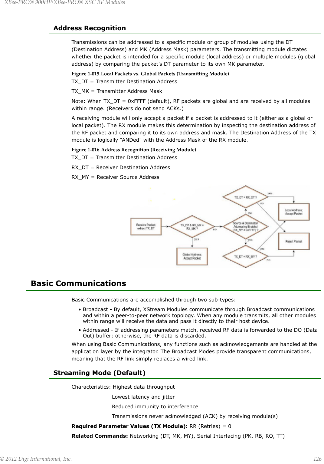
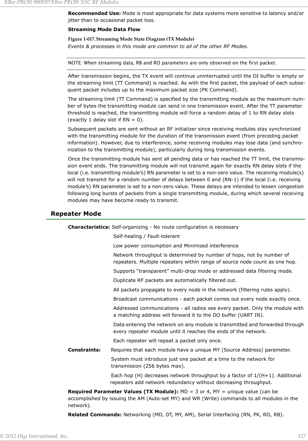
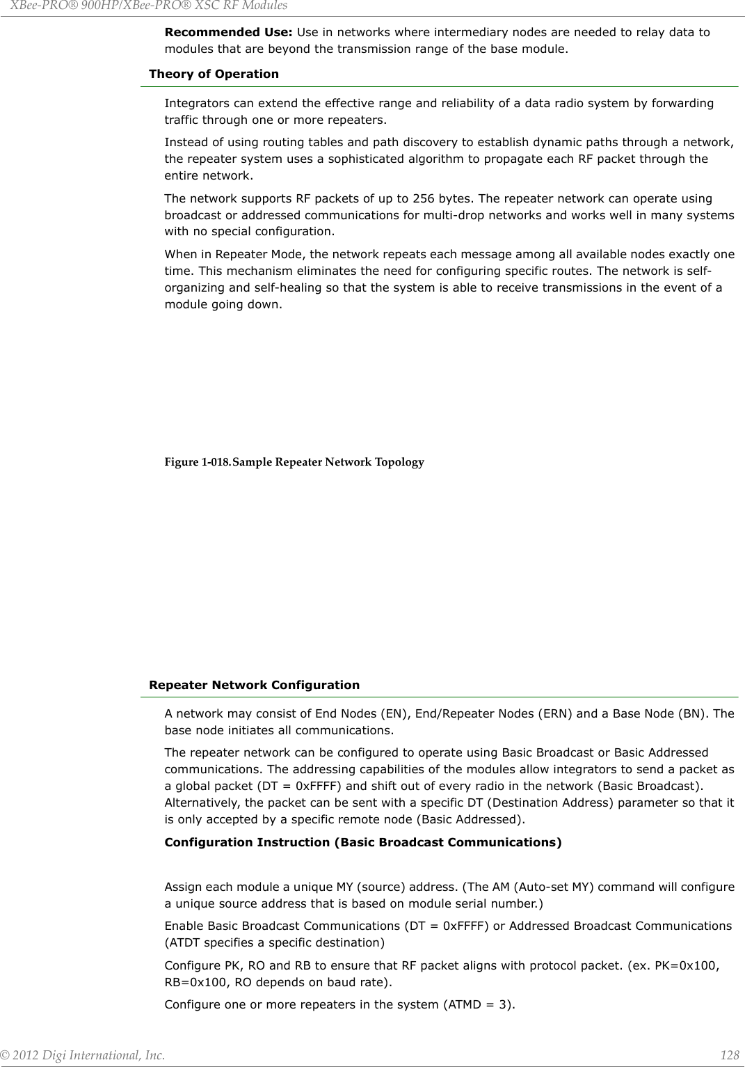
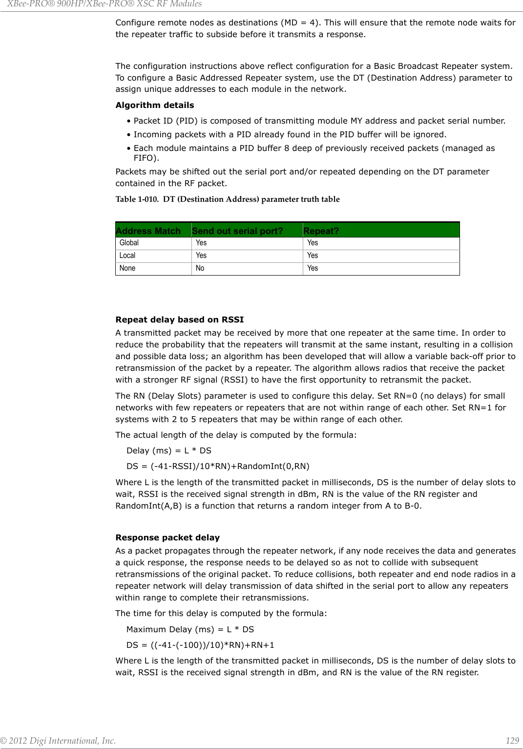
![XBee‐PRO®900HP/XBee‐PRO®XSCRFModules©2012DigiInternational,Inc. 130Use Case - Broadcast Repeater NetworkConsider modules R1 through R10 each communicating to a PLC using the ModBus protocol and spaced evenly in a line. All ten nodes are configured as ‘destinations & repeaters’ within the scope of Basic Broadcast Communications (MD=3, AM, DT=0xFFFF, PK=0x100, RO=0x03, RB=0x100, RN=1). The Base Host (BH) shifts payload that is destined for R10 to R1. R1 initializes RF communication and transmits payload to nodes R2 through R5 which are all within range of R1. Modules R2 through R5 receive the RF packet and retransmit the packet simultaneously. They also send the data out the serial ports, to the PLC's.Table1‐011. CommandsusedtoconfigurerepeaterfunctionsBandwidth ConsiderationsUsing broadcast repeaters in a network reduces the overall network data throughput as each repeater must buffer an entire packet before retransmitting it. For example: if the destination is within range of the transmitter and the packet is 32 bytes long, the transmission will take approximately 72ms on a 9600 baud XSC Module. If that same packet has to propagate through two repeaters, it will take 72ms to arrive at the first repeater, another 72 ms to get to the second and a final 72ms to get to the destination for a total of 216ms. Taking into account UART transfer times (~1ms/byte at 9600 baud), a server to send a 32 byte query and receive a 32 byte response is ~200ms, allowing for 5 polls per second. With the two repeaters in the path, the same query/response sequence would take about 500ms for 2 polls per second.To summarize, this system is sending and receiving 64 bytes 5 times per second for a throughput of 320 bytes per second with no repeaters and 128 bytes per second with 2 repeaters. Generally, the network throughput will decrease by a factor of 1/(R+1), with R representing the number of repeaters between the source and destination.Acknowledged CommunicationsAcknowledged ModeCharacteristics: Reliable delivery through positive acknowledgements for each packet Throughput, latency and jitter vary depending on the quality of the channel and the strength of the signal. Recommended Use: Acknowledge Mode configuration is appropriate when reliable delivery is required between modules. If messages are smaller than 256 bytes, use RB and RO commands to align RF packets with application packets. Required Parameter Values (TX Module): RR (Retries) >= 1 Related Commands: Networking (DT, MK, RR), Serial Interfacing (PK, RN, TT, RO, RB)Table1‐012. SampleNetworkProfileAT CommandBinary Command AT Command Name Range# Bytes ReturnedFactory DefaultAM 0x3A (58d) Auto-set MY - - -DT 0x00 (0d) Destination Address 0-0xFFFF 2 0MD 0x3C (60d) RF Mode 3-4 1 0MY 0x2A (42d) Source Address 0-0xFFFF 2 0xFFFFRN 0x19 (25d) Delay Slots 0-0xFF [slots] 1 0WR 0x08 (8d) Write - - -Module Parameter Settings (assume default values for parameter not listed)All ATRR A [set number of Retries to 0x0A]ATRN 5 [set number of Delay Slots to 5]](https://usermanual.wiki/Digi/XB900HP/User-Guide-1792196-Page-130.png)
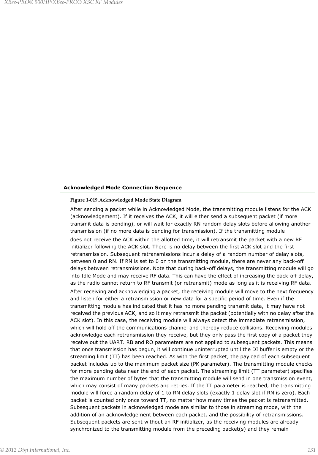

![XBee‐PRO®900HP/XBee‐PRO®XSCRFModules©2012DigiInternational,Inc. 133AppendixB:AgencyCertificationsforS3BHardwarePlease note that both Appendix B and Appendix C contain Agency Certification information. Please refer to the Preface for instructions on which appendix applies to your product.FCC (United States) CertificationThe XBee-PRO® 900HP/XBee-PRO® XSC RF Module complies with Part 15 of the FCC rules and regulations. Compliance with the labeling requirements, FCC notices and antenna usage guidelines is required.In order to operate under Digi’s FCC Certification, RF Modules/integrators must comply with the following regulations:Labeling RequirementsWARNING: The Original Equipment Manufacturer (OEM) must ensure that FCC labeling requirements are met. This includes a clearly visible label on the outside of the final product enclosure that displays the text shown in the figure below.FigureA‐01. RequiredFCCLabelforOEMproductscontainingtheXBee‐PRO®900HP/XBee‐PRO®XSCRFModule.XBEE PRO 900HPFCC NoticesIMPORTANT: The XBee-PRO® 900HP/XBee-PRO® XSC OEM RF Module has been certified by the FCC for use with other products without any further certification (as per FCC section 2.1091). Modifications not expressly approved by Digi could void the user's authority to operate the equipment.IMPORTANT: OEMs must test final product to comply with unintentional radiators (FCC section 15.107 & 15.109) before declaring compliance of their final product to Part 15 of the FCC Rules.IMPORTANT: The RF module has been certified for remote and base radio applications. If the module will be used for portable applications, the device must undergo SAR testing.This equipment has been tested and found to comply with the limits for a Class B digital device, pursuant to Part 15 of the FCC Rules. These limits are designed to provide reasonable protection against harmful interference in a residential installation. This equipment generates, uses and can radiate radio frequency energy and, if not installed and used in accordance with the instructions, may cause harmful interference to radio communications. However, there is no guarantee that interference will not occur in a particular installation. If this equipment does cause harmful interference to radio or television reception, which can be determined by turning the equipment off and on, the user is encouraged to try to correct the interference by one or more of the following measures: Re-orient or relocate the receiving antenna, Increase the separation between the equipment and receiver, Connect equipment and receiver to outlets on different circuits, or Consult the dealer or an experienced radio/TV technician for help.1. The system integrator must ensure that the text provided with this device [Figure A-01] is placed on the outside of the final product and within the final product operation manual.2. The XBee-PRO® 900HP/XBee-PRO® XSC RF Module may only be used with antennas that have been tested and approved for use with this module refer to Table A-1.Contains FCC ID: MCQ-XB900HPThe enclosed device complies with Part 15 of the FCC Rules. Operation is subject to the following two conditions: (i.) this device may not cause harmful interference and (ii.) this device must accept any inter-ference received, including interference that may cause undesired operation.](https://usermanual.wiki/Digi/XB900HP/User-Guide-1792196-Page-133.png)
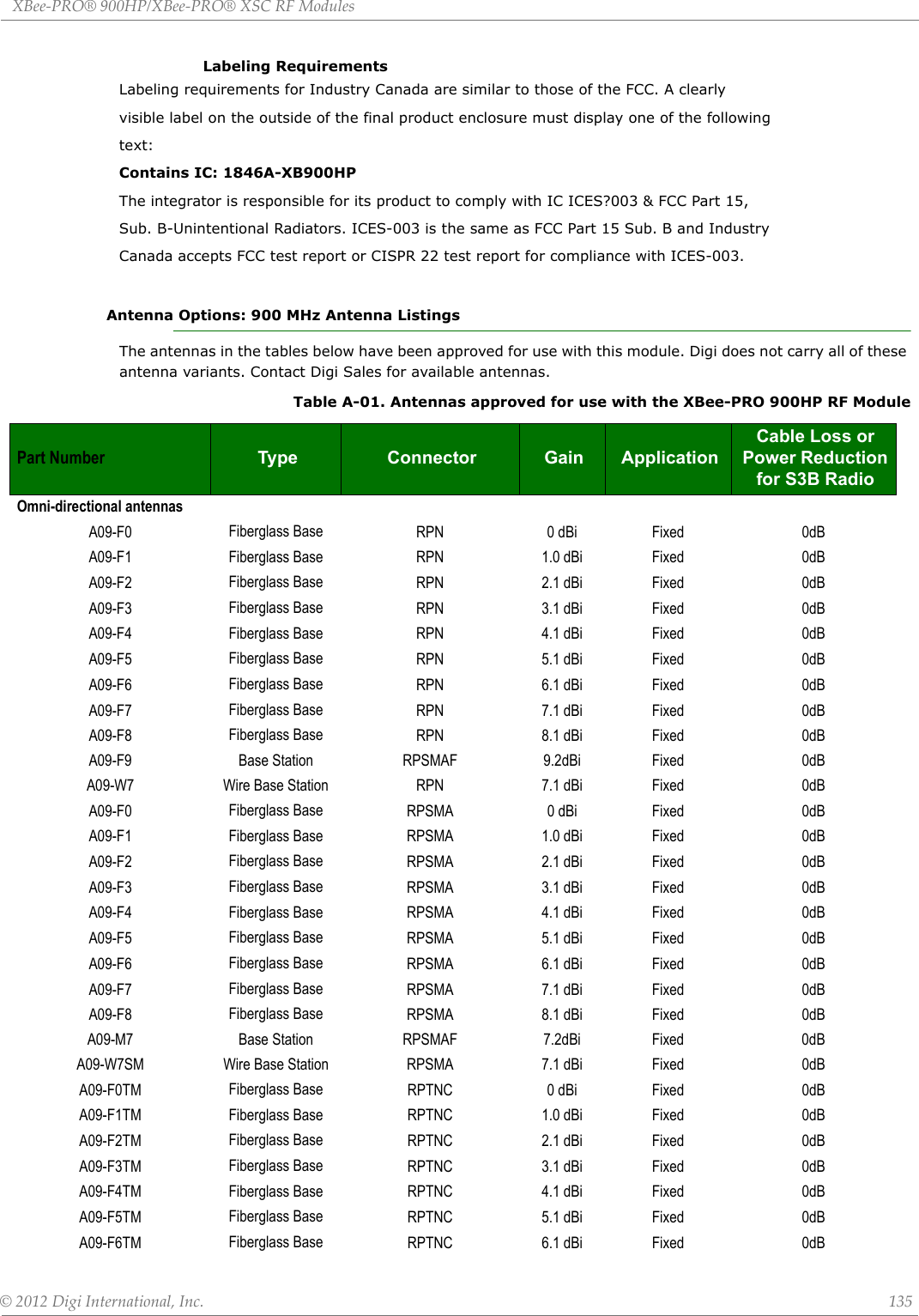
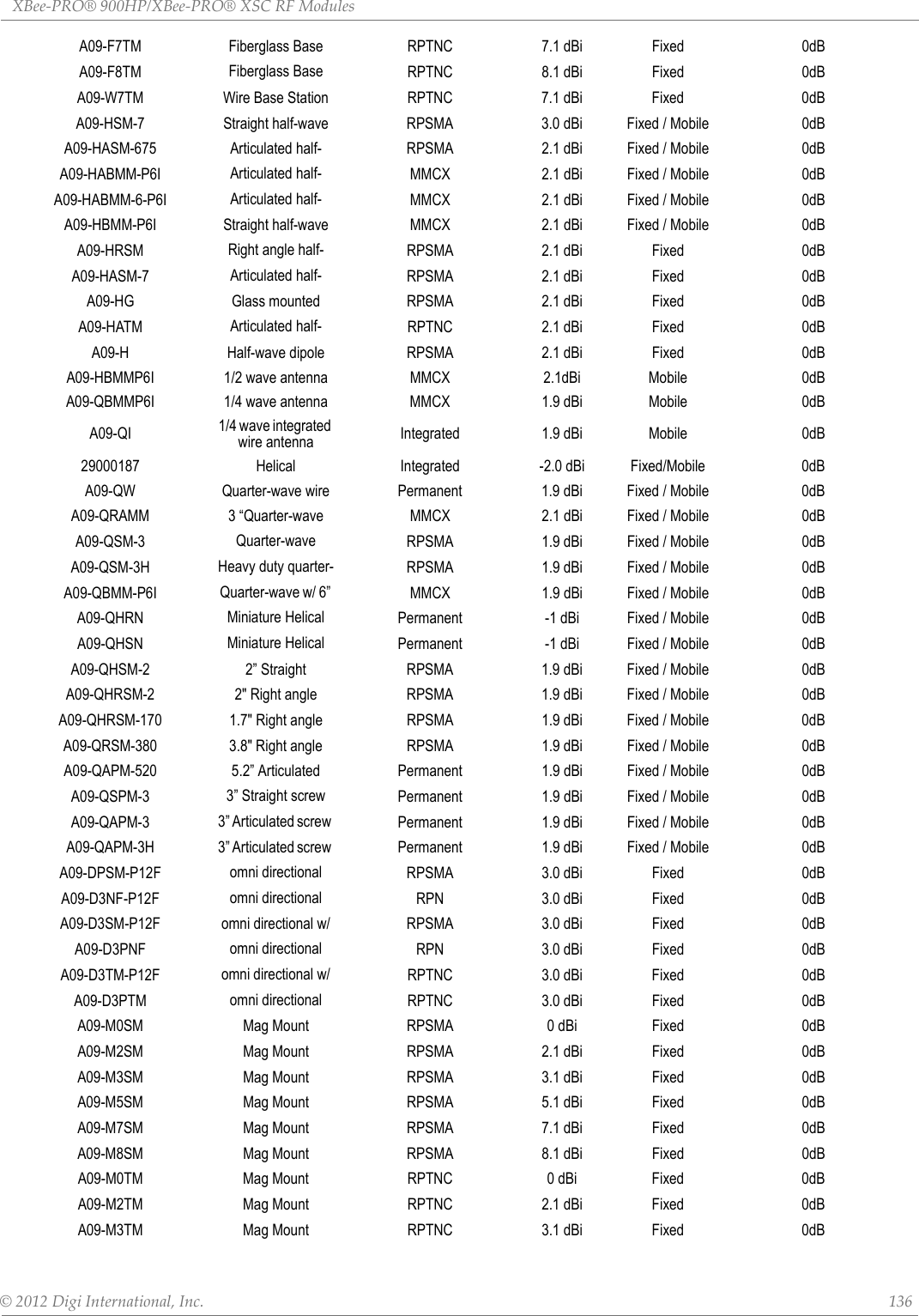
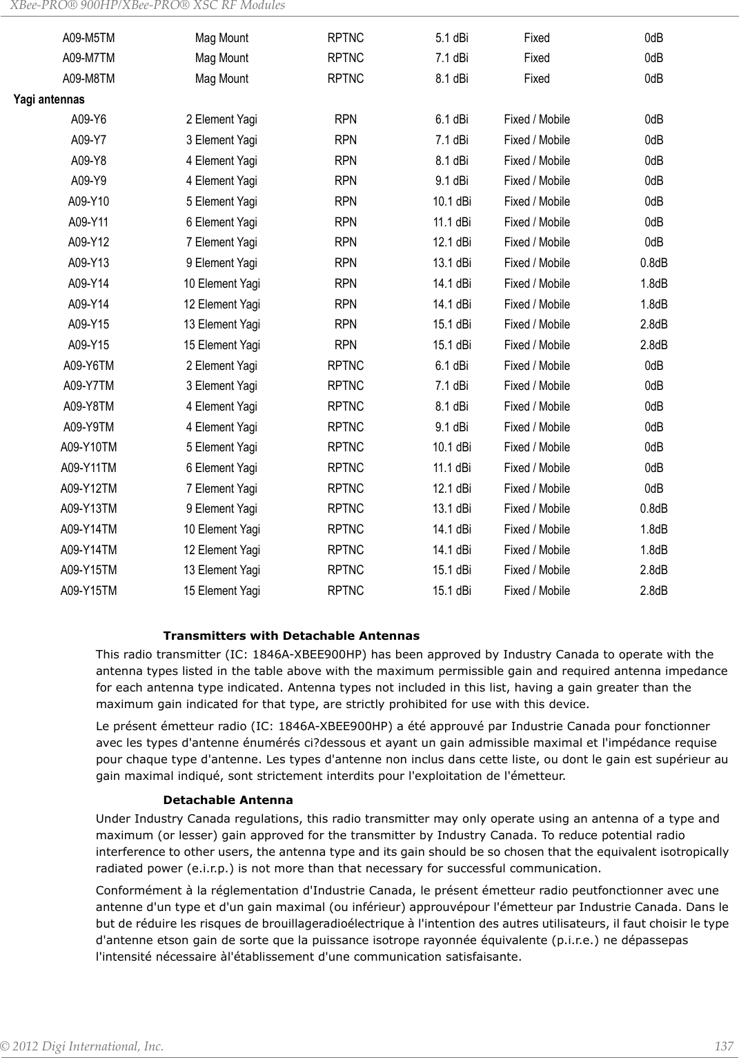
![XBee‐PRO®900HP/XBee‐PRO®XSCRFModules©2012DigiInternational,Inc. 138AppendixC::AgencyCertificationsforlega‐cyS3/S3BHardwarePlease note that both Appendix B and Appendix C contain Agency Certification information. Please refer to the Preface for instructions on which appendix applies to your product.FCC (United States) CertificationThe XBee-PRO® XSC RF Module complies with Part 15 of the FCC rules and regulations. Compliance with the labeling requirements, FCC notices and antenna usage guidelines is required.In order to operate under Digi’s FCC Certification, RF Modules/integrators must comply with the following regulations:Labeling RequirementsWARNING: The Original Equipment Manufacturer (OEM) must ensure that FCC labeling requirements are met. This includes a clearly visible label on the outside of the final product enclosure that displays the text shown in the figure below.FigureA‐01. RequiredFCCLabelforOEMproductscontainingtheXBee‐PRO®XSCRFModule.XBEE PRO S3ORXBEE PRO S3BFCC NoticesIMPORTANT: The XBee-PRO® XSC OEM RF Module has been certified by the FCC for use with other products without any further certification (as per FCC section 2.1091). Modifications not expressly approved by Digi could void the user's authority to operate the equipment.IMPORTANT: OEMs must test final product to comply with unintentional radiators (FCC section 15.107 & 15.109) before declaring compliance of their final product to Part 15 of the FCC Rules.IMPORTANT: The RF module has been certified for remote and base radio applications. If the module will be used for portable applications, the device must undergo SAR testing.This equipment has been tested and found to comply with the limits for a Class B digital device, pursuant to Part 15 of the FCC Rules. These limits are designed to provide reasonable protection against harmful interference in a residential installation. This equipment generates, uses and can radiate radio frequency energy and, if not installed and used in accordance with the instructions, 1. The system integrator must ensure that the text provided with this device [Figure A-01] is placed on the outside of the final product and within the final product operation manual.2. The XBee-PRO® XSC RF Module may only be used with antennas that have been tested and approved for use with this module refer to Table A-1.Contains FCC ID: MCQ-XBEEXSCThe enclosed device complies with Part 15 of the FCC Rules. Operation is subject to the following two conditions: (i.) this device may not cause harmful interference and (ii.) this device must accept any inter-ference received, including interference that may cause undesired operation.Contains FCC ID: MCQ-XBPS3BThe enclosed device complies with Part 15 of the FCC Rules. Operation is subject to the following two conditions: (i.) this device may not cause harmful interference and (ii.) this device must accept any inter-ference received, including interference that may cause undesired operation.](https://usermanual.wiki/Digi/XB900HP/User-Guide-1792196-Page-138.png)