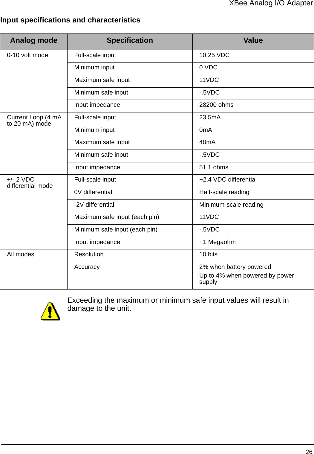
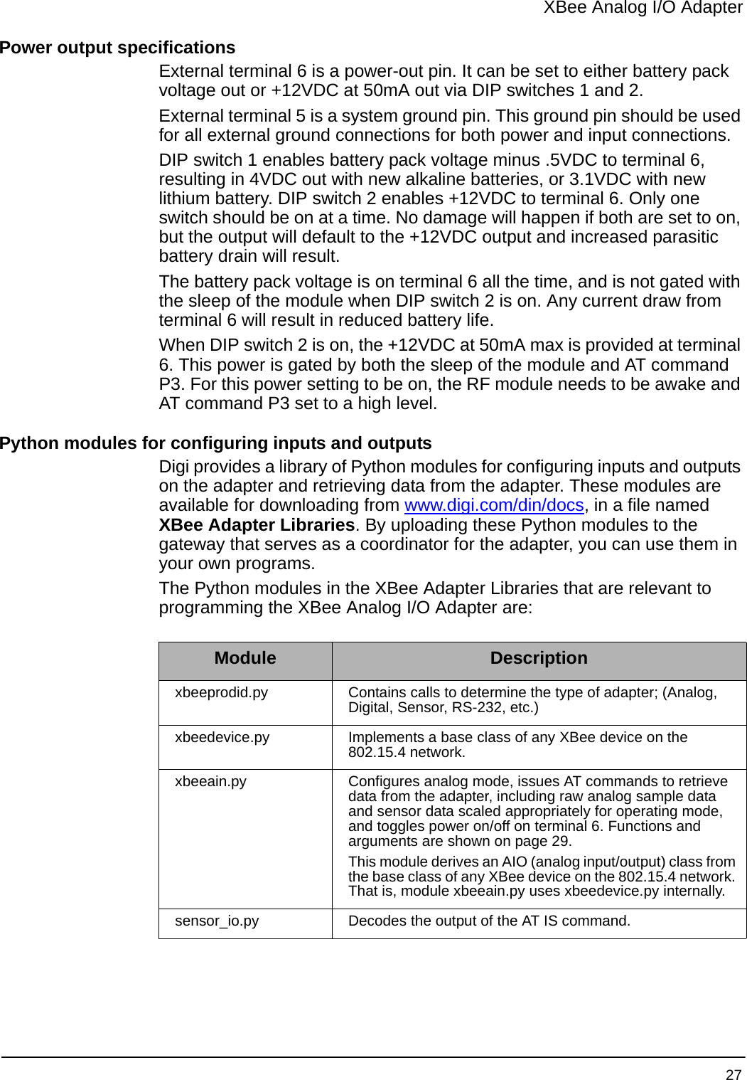
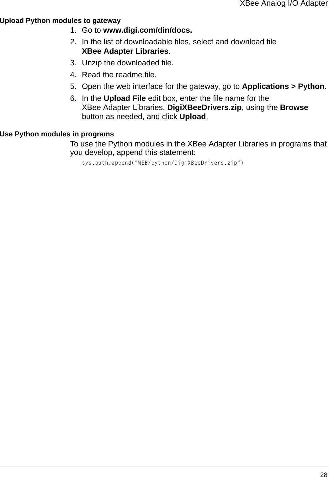
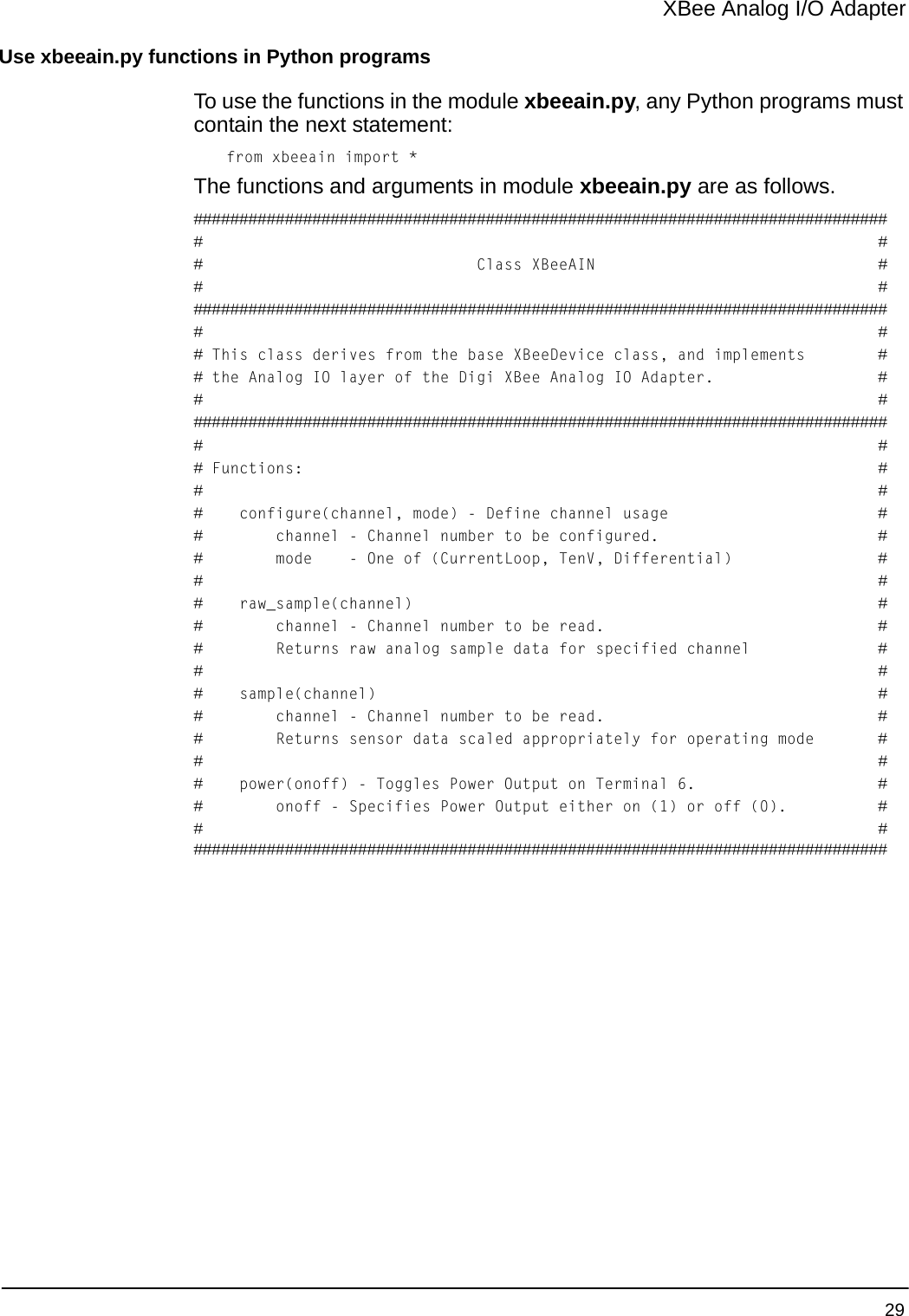
Digi XSTICK1 XStick 802.15.4 User Manual
Digi International Inc XStick 802.15.4
UserManual.wiki
>
Digi
>
XSTICK1 User Manual
>
User Manual
Contents
1.
User Manual
2.
User Manual addendum
User Manual
Navigation menu
Upload a User Manual
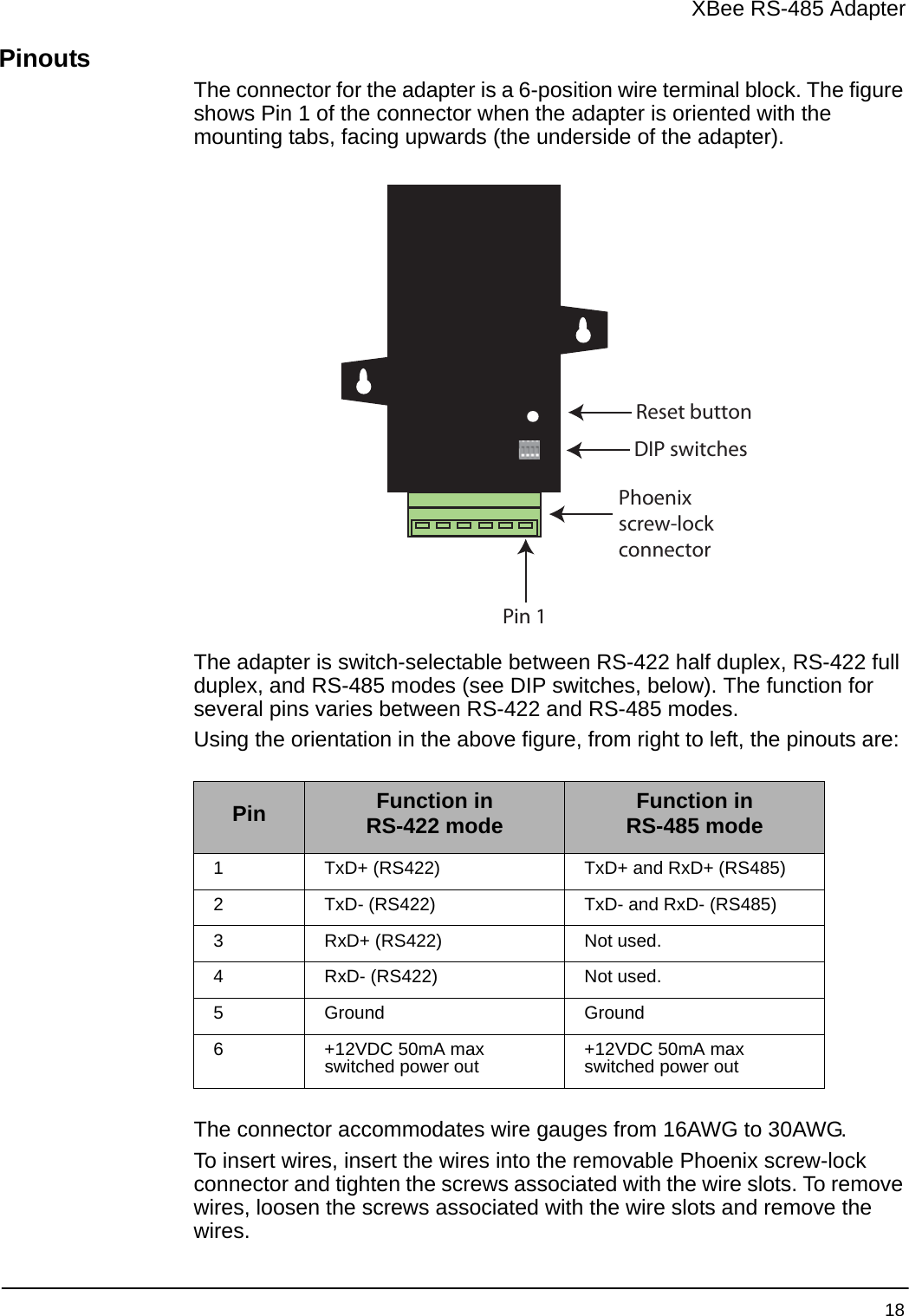
Namespaces
Wiki Guide
HTML
PDF
Info
Views
User Manual
Discussion / Help
Navigation

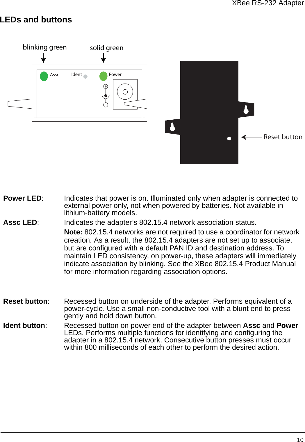
![XBee RS-232 Adapter 11Button press Network association ActionSingle Associated Cannot wake module, but will cause adapter to remain awake for 30 seconds if pressed during a sleep interval, then sends a Node Identification broadcast transmission. All devices that receive this transmission will blink their Associate LED rapidly for 1 second.Unassociated Blinks a numeric error code returned by the ATAI (Association Indication) command on the Assc LED. The AI code indicates the cause of the join failure. See the 802.15.4 XBee module’s Product Manual for descriptions of these codes.1 blink: Active scan timeout.2 blinks: Active scan found no PANs.3 blinks: Active scan found PAN, but the Coordinator Allow Association bit is not set.4 blinks: Active scan found PAN, but Coordinator and End Device are not configured to support beacons.5 blinks: Active scan found PAN, but Coordinator ID (PAN ID) value does not match the ID of the End Device.6 blinks: Active Scan found PAN, but Coordinator CH (Channel) value does not match the CH of the End Device.7 blinks: Energy scan timeout.8 blinks: Coordinator start request failed.9 blinks: Coordinator could not start due to invalid parameters.10 blinks: Coordinator Realignment is in progress.11 blinks: Association request not sent.12 blinks: Association request timed out - no reply was received.13 blinks: Association request had an invalid parameter.14 blinks: Association request channel access failure - Request was not transmitted - CCA failure.15 blinks: Remote Coordinator did not send an ACK after Association Request was sent.16 blinks: Remote Coordinator did not reply to the Association Request, but an ACK was received after sending the request.17 blinks: [reserved].18 blinks: Sync-Loss - Lost synchronization with a beaconing coordinator.19 blinks: Disassociated - No longer associated to coordinator.Two Associated Not supported.Four Associated/Unassociated Performs an ATRE command to reset the parameters in the XBee module.](https://usermanual.wiki/Digi/XSTICK1.User-Manual/User-Guide-983807-Page-11.png)
![XBee RS-232 PH Adapter 16Button press Network association ActionSingle Associated Cannot wake module, but will cause adapter to remain awake for 30 seconds if pressed during a sleep interval. Sends a Node Identification broadcast transmission. All devices that receive this transmission will blink their Associate LED rapidly for 1 second.Unassociated Blinks a numeric error code returned by the ATAI (Association Indication) command on the Assc LED. The AI code indicates the cause of the join failure. See the 802.15.4 XBee module’s Product Manual for descriptions of these codes.1 blink: Active scan timeout.2 blinks: Active scan found no PANs.3 blinks: Active scan found PAN, but the Coordinator Allow Association bit is not set.4 blinks: Active scan found PAN, but Coordinator and End Device are not configured to support beacons.5 blinks: Active scan found PAN, but Coordinator ID (PAN ID) value does not match the ID of the End Device.6 blinks: Active Scan found PAN, but Coordinator CH (Channel) value does not match the CH of the End Device.7 blinks: Energy scan timeout.8 blinks: Coordinator start request failed.9 blinks: Coordinator could not start due to invalid parameters.10 blinks: Coordinator Realignment is in progress.11 blinks: Association request not sent.12 blinks: Association request timed out - no reply was received.13 blinks: Association request had an invalid parameter.14 blinks: Association request channel access failure - Request was not transmitted - CCA failure.15 blinks: Remote Coordinator did not send an ACK after Association Request was sent.16 blinks: Remote Coordinator did not reply to the Association Request, but an ACK was received after sending the request.17 blinks: [reserved].18 blinks: Sync-Loss - Lost synchronization with a beaconing coordinator.19 blinks: Disassociated - No longer associated to coordinator.Two Associated Not supported.Four Associated/Unassociated Performs an ATRE command to reset the parameters in the XBee module.](https://usermanual.wiki/Digi/XSTICK1.User-Manual/User-Guide-983807-Page-16.png)
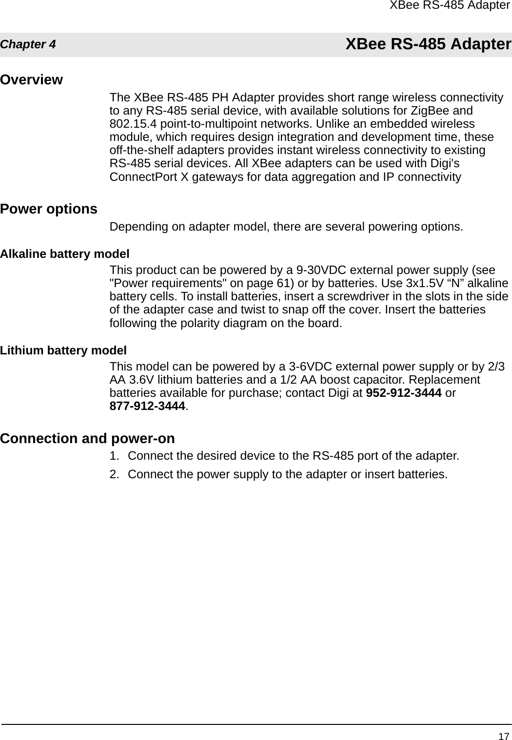

![XBee RS-485 Adapter 21Button press Network association ActionSingle Associated Cannot wake module, but will cause adapter to remain awake for 30 seconds if pressed during a sleep interval. Sends a Node Identification broadcast transmission. All devices that receive this transmission will blink their Associate LED rapidly for 1 second.Unassociated Blinks a numeric error code returned by the ATAI (Association Indication) command on the Assc LED. The AI code indicates the cause of the join failure. See the 802.15.4 XBee module’s Product Manual for descriptions of these codes.1 blink: Active scan timeout.2 blinks: Active scan found no PANs.3 blinks: Active scan found PAN, but the Coordinator Allow Association bit is not set.4 blinks: Active scan found PAN, but Coordinator and End Device are not configured to support beacons.5 blinks: Active scan found PAN, but Coordinator ID (PAN ID) value does not match the ID of the End Device.6 blinks: Active Scan found PAN, but Coordinator CH (Channel) value does not match the CH of the End Device.7 blinks: Energy scan timeout.8 blinks: Coordinator start request failed.9 blinks: Coordinator could not start due to invalid parameters.10 blinks: Coordinator Realignment is in progress.11 blinks: Association request not sent.12 blinks: Association request timed out - no reply was received.13 blinks: Association request had an invalid parameter.14 blinks: Association request channel access failure - Request was not transmitted - CCA failure.15 blinks: Remote Coordinator did not send an ACK after Association Request was sent.16 blinks: Remote Coordinator did not reply to the Association Request, but an ACK was received after sending the request.17 blinks: [reserved].18 blinks: Sync-Loss - Lost synchronization with a beaconing coordinator.19 blinks: Disassociated - No longer associated to coordinator.Two Associated Not supported.Four Associated/Unassociated Performs an ATRE command to reset the parameters in the XBee module.](https://usermanual.wiki/Digi/XSTICK1.User-Manual/User-Guide-983807-Page-21.png)

![XBee Analog I/O Adapter 34Button press Network association ActionSingle Associated Cannot wake module, but will cause adapter to remain awake for 30 seconds if pressed during a sleep interval. Sends a Node Identification broadcast transmission. All devices that receive this transmission will blink their Associate LED rapidly for 1 second.Unassociated Blinks a numeric error code returned by the ATAI (Association Indication) command on the Assc LED. The AI code indicates the cause of the join failure. See the 802.15.4 XBee module’s Product Manual for descriptions of these codes.1 blink: Active scan timeout.2 blinks: Active scan found no PANs.3 blinks: Active scan found PAN, but the Coordinator Allow Association bit is not set.4 blinks: Active scan found PAN, but Coordinator and End Device are not configured to support beacons.5 blinks: Active scan found PAN, but Coordinator ID (PAN ID) value does not match the ID of the End Device.6 blinks: Active Scan found PAN, but Coordinator CH (Channel) value does not match the CH of the End Device.7 blinks: Energy scan timeout.8 blinks: Coordinator start request failed.9 blinks: Coordinator could not start due to invalid parameters.10 blinks: Coordinator Realignment is in progress.11 blinks: Association request not sent.12 blinks: Association request timed out - no reply was received.13 blinks: Association request had an invalid parameter.14 blinks: Association request channel access failure - Request was not transmitted - CCA failure.15 blinks: Remote Coordinator did not send an ACK after Association Request was sent.16 blinks: Remote Coordinator did not reply to the Association Request, but an ACK was received after sending the request.17 blinks: [reserved].18 blinks: Sync-Loss - Lost synchronization with a beaconing coordinator.19 blinks: Disassociated - No longer associated to coordinator.Two Associated Not supported.Four Associated/Unassociated Performs an ATRE command to reset the parameters in the XBee module.](https://usermanual.wiki/Digi/XSTICK1.User-Manual/User-Guide-983807-Page-34.png)
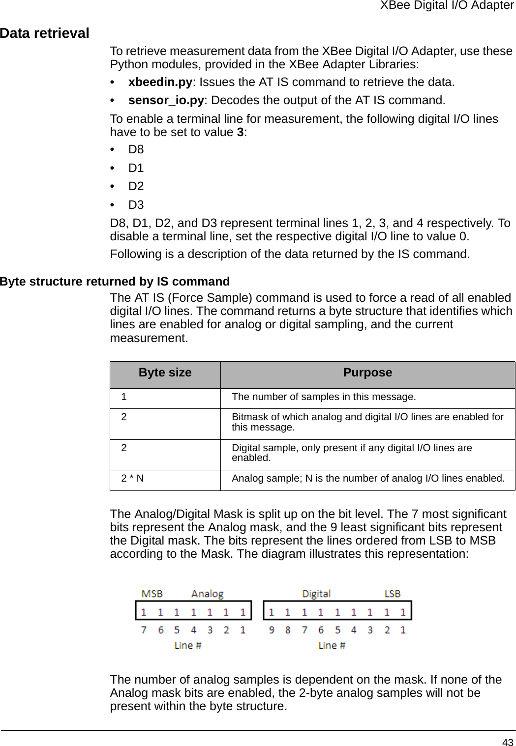
![XBee Digital I/O Adapter 46Button press Network association ActionSingle Associated Cannot wake module, but will cause adapter to remain awake for 30 seconds if pressed during a sleep interval. Sends a Node Identification broadcast transmission. All devices that receive this transmission will blink their Associate LED rapidly for 1 second.Unassociated Blinks a numeric error code returned by the ATAI (Association Indication) command on the Assc LED. The AI code indicates the cause of the join failure. See the 802.15.4 XBee module’s Product Manual for descriptions of these codes.1 blink: Active scan timeout.2 blinks: Active scan found no PANs.3 blinks: Active scan found PAN, but the Coordinator Allow Association bit is not set.4 blinks: Active scan found PAN, but Coordinator and End Device are not configured to support beacons.5 blinks: Active scan found PAN, but Coordinator ID (PAN ID) value does not match the ID of the End Device.6 blinks: Active Scan found PAN, but Coordinator CH (Channel) value does not match the CH of the End Device.7 blinks: Energy scan timeout.8 blinks: Coordinator start request failed.9 blinks: Coordinator could not start due to invalid parameters.10 blinks: Coordinator Realignment is in progress.11 blinks: Association request not sent.12 blinks: Association request timed out - no reply was received.13 blinks: Association request had an invalid parameter.14 blinks: Association request channel access failure - Request was not transmitted - CCA failure.15 blinks: Remote Coordinator did not send an ACK after Association Request was sent.16 blinks: Remote Coordinator did not reply to the Association Request, but an ACK was received after sending the request.17 blinks: [reserved].18 blinks: Sync-Loss - Lost synchronization with a beaconing coordinator.19 blinks: Disassociated - No longer associated to coordinator.Two Associated Not supported.Four Associated/Unassociated Performs an ATRE command to reset the parameters in the XBee module.](https://usermanual.wiki/Digi/XSTICK1.User-Manual/User-Guide-983807-Page-46.png)
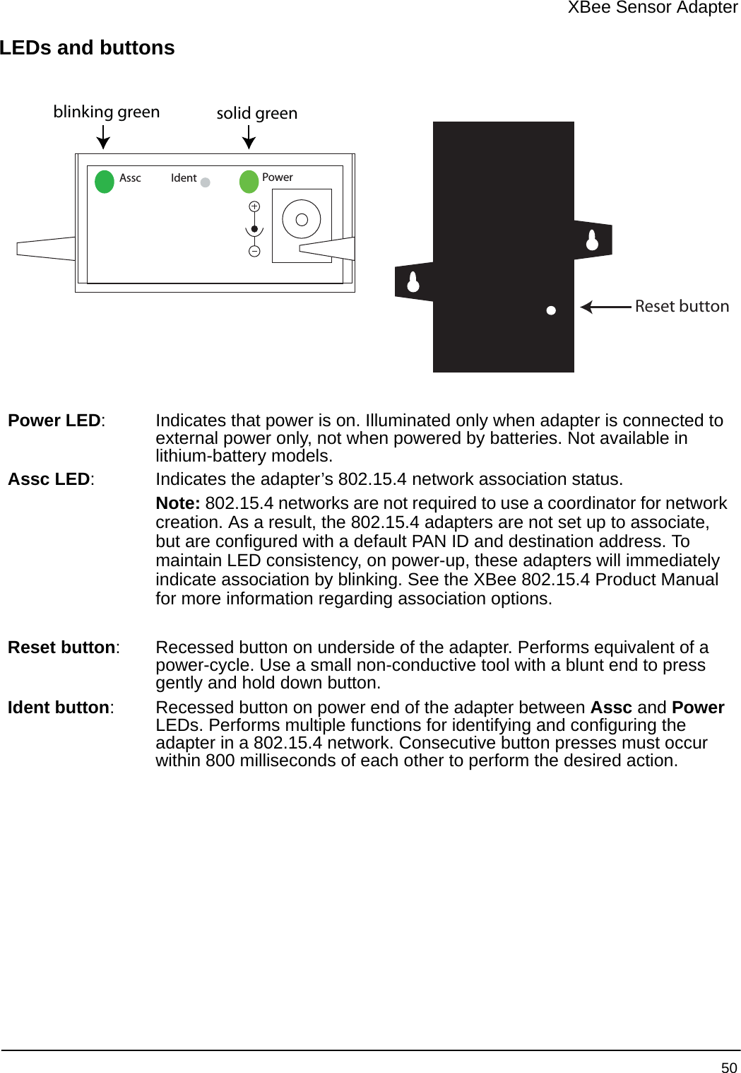
![XBee Sensor Adapter 51Button press Network association ActionSingle Associated Cannot wake module, but will cause adapter to remain awake for 30 seconds if pressed during a sleep interval. Sends a Node Identification broadcast transmission. All devices that receive this transmission will blink their Associate LED rapidly for 1 second.Unassociated Blinks a numeric error code returned by the ATAI (Association Indication) command on the Assc LED. The AI code indicates the cause of the join failure. See the 802.15.4 XBee module’s Product Manual for descriptions of these codes.1 blink: Active scan timeout.2 blinks: Active scan found no PANs.3 blinks: Active scan found PAN, but the Coordinator Allow Association bit is not set.4 blinks: Active scan found PAN, but Coordinator and End Device are not configured to support beacons.5 blinks: Active scan found PAN, but Coordinator ID (PAN ID) value does not match the ID of the End Device.6 blinks: Active Scan found PAN, but Coordinator CH (Channel) value does not match the CH of the End Device.7 blinks: Energy scan timeout.8 blinks: Coordinator start request failed.9 blinks: Coordinator could not start due to invalid parameters.10 blinks: Coordinator Realignment is in progress.11 blinks: Association request not sent.12 blinks: Association request timed out - no reply was received.13 blinks: Association request had an invalid parameter.14 blinks: Association request channel access failure - Request was not transmitted - CCA failure.15 blinks: Remote Coordinator did not send an ACK after Association Request was sent.16 blinks: Remote Coordinator did not reply to the Association Request, but an ACK was received after sending the request.17 blinks: [reserved].18 blinks: Sync-Loss - Lost synchronization with a beaconing coordinator.19 blinks: Disassociated - No longer associated to coordinator.Two Associated Not supported.Four Associated/Unassociated Performs an ATRE command to reset the parameters in the XBee module.](https://usermanual.wiki/Digi/XSTICK1.User-Manual/User-Guide-983807-Page-51.png)