Digi XSTICK2 XStick ZNet 2.5 User Manual XBee Adapters and Routers User s Guide
Digi International Inc XStick ZNet 2.5 XBee Adapters and Routers User s Guide
UserManual.wiki
>
Digi
>
XSTICK2 User Manual
>
User Manual
Contents
1.
User Manual
2.
User Manual Addendum
User Manual
Navigation menu
Upload a User Manual
Namespaces
Wiki Guide
HTML
PDF
Info
Views
User Manual
Discussion / Help
Navigation

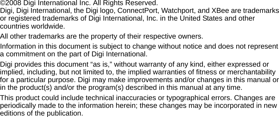

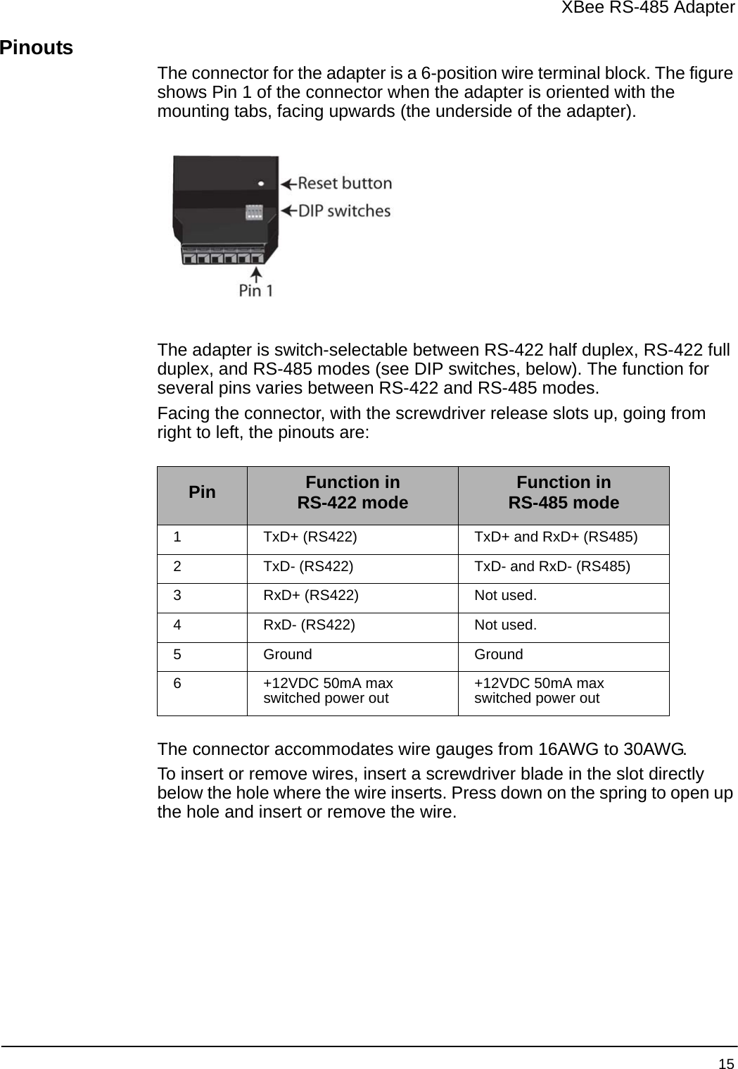
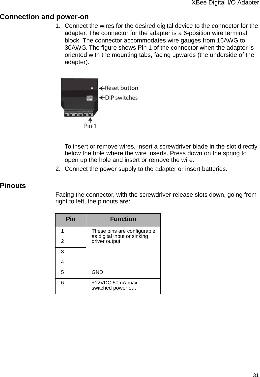
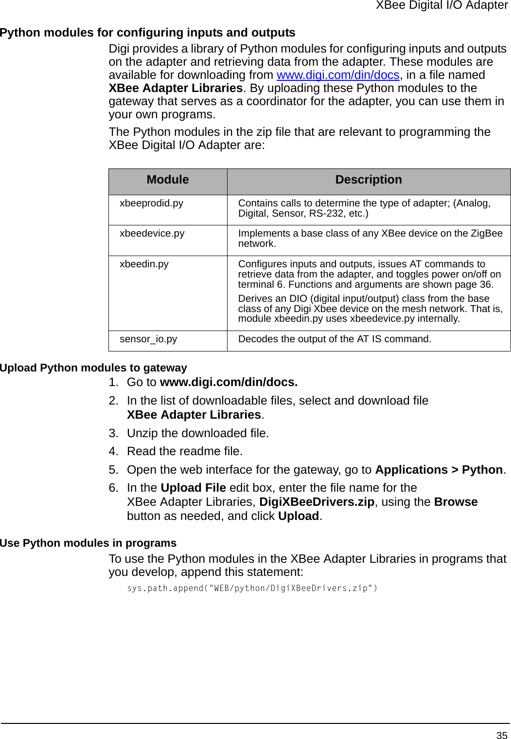


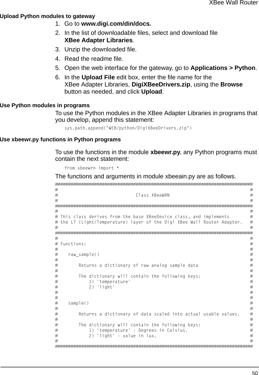
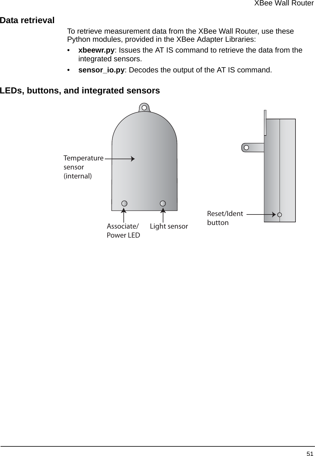
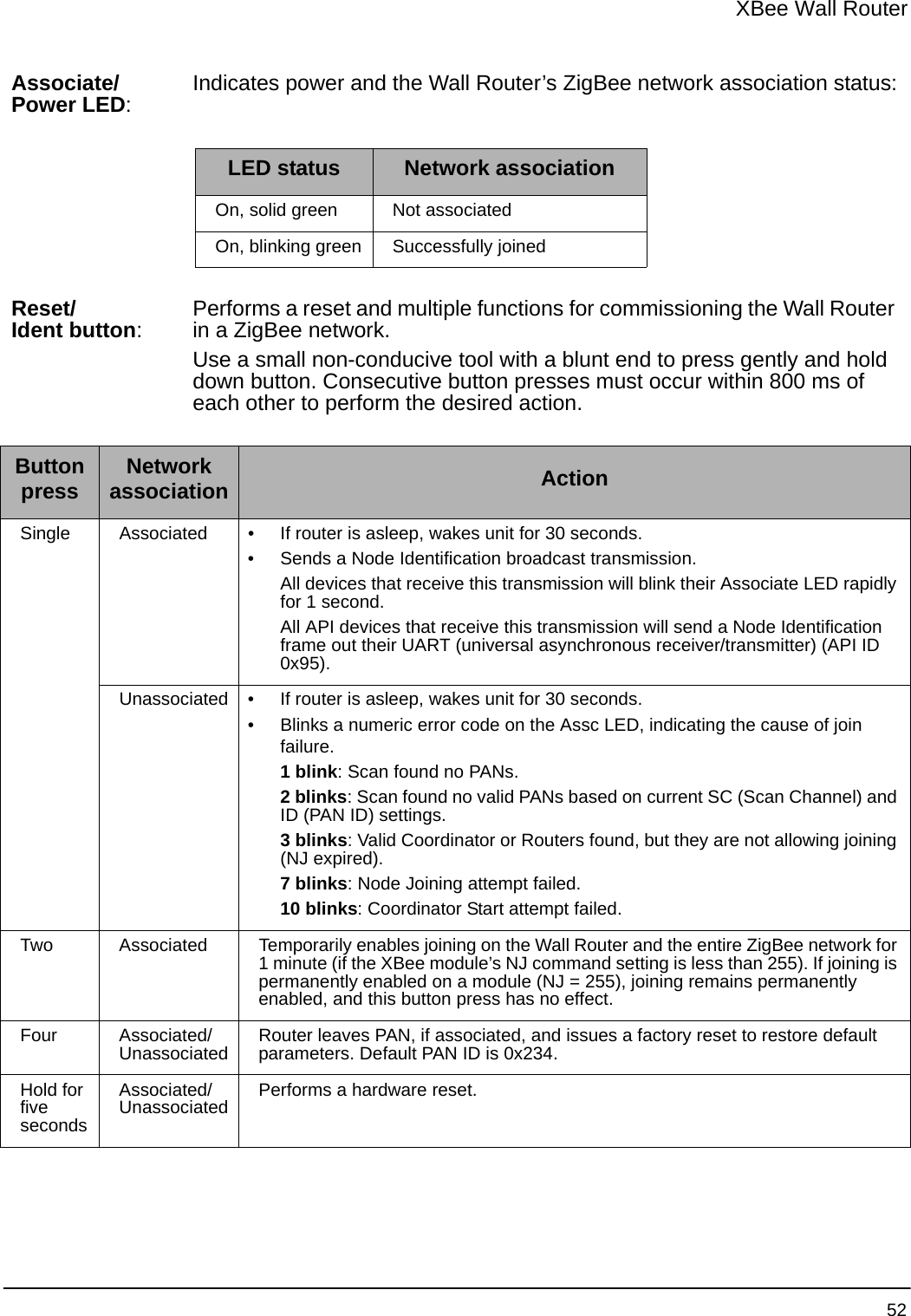

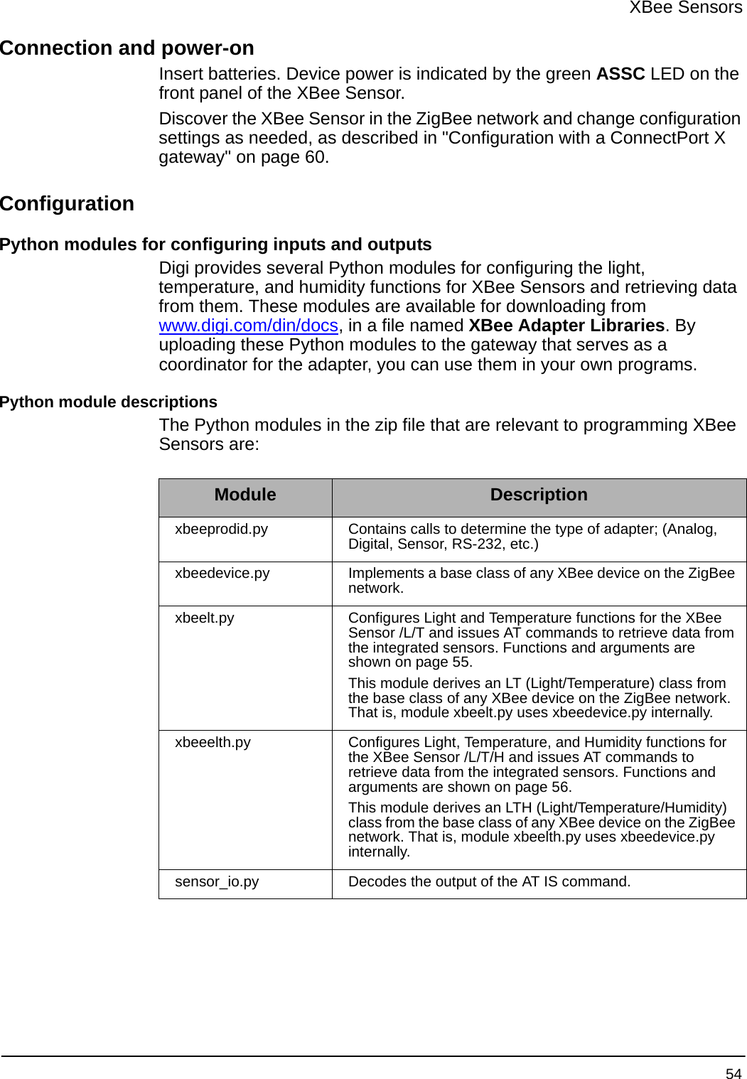
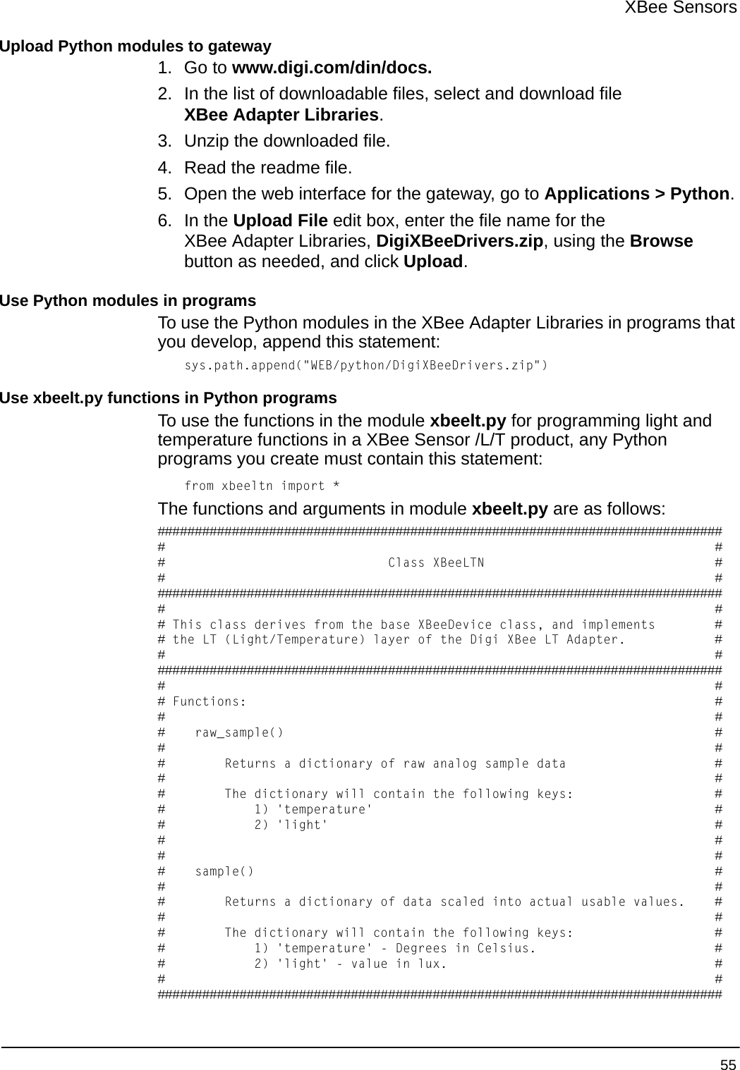
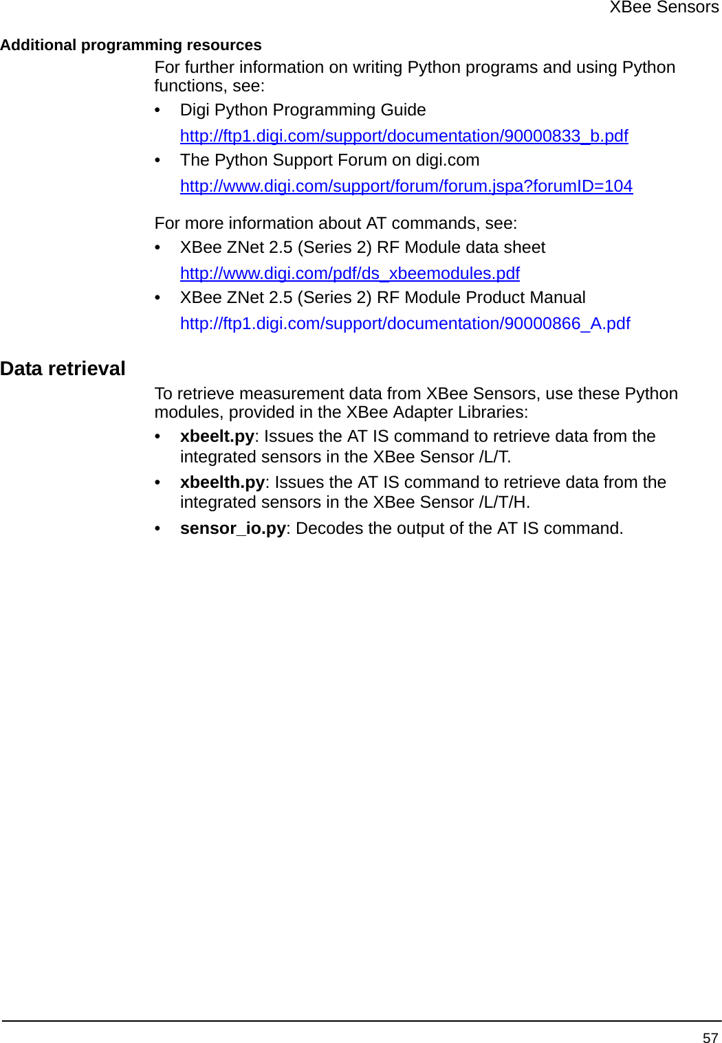
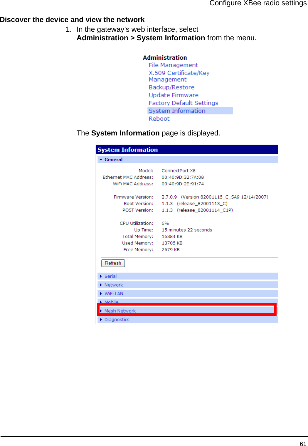
![XBee Sensors 56Use xbeelth.py functions in Python programsTo use the functions in the module xbeelth.py for programming light, temperature, and humidity functions in a XBee Sensor /L/T/H product, any Python programs you create must contain this statement:from xbeelth import *The functions and arguments in module xbeelth.py are as follows:############################################################################# ## Class XBeeLTHN ## ############################################################################## ## This class derives from the base XBeeDevice class, and implements ## the LTH (Light/Temperature/Humidity) layer of the Digi XBee LTH Adapter. ## ############################################################################## ## Functions: ## ## raw_sample() ## ## Returns a dictionary of raw analog sample data ## ## The dictionary will contain the following keys: ## 1) 'temperature' ## 2) 'light' ## 3) 'humidity' ## ## ## sample() ## ## Returns a dictionary of data scaled into actual usable values. ## ## The dictionary will contain the following keys: ## 1) 'temperature' - Degrees in Celsius. ## 2) 'light' - value in lux. ## 3) 'humidity' - value in %rh ## #############################################################################Sample programimport sysimport time# When running on the gateway, all of the modules our # application will use shall exist within this ZIP file:sys.path.append("WEB/python/DigiXBeeDrivers.zip")from xbeelth import *lth = XBeeLTHN("00:13:a2:00:40:3e:16:d2!")print lth.getname()reading = lth.sample()print "---------------------------------------------"print "Temperature (C):\t" + str("%.2f" % reading['temperature']) print "Temperature (F):\t" + str("%.2f" % (reading['temperature'] * (9.0 / 5.0) + 32.0)) print "Light (lx):\t\t" + str("%.2f" % reading['light']) print "Humidity (%RH):\t\t" + str("%.0f" % reading['humidity']) + '%'print "---------------------------------------------"](https://usermanual.wiki/Digi/XSTICK2.User-Manual/User-Guide-923503-Page-56.png)