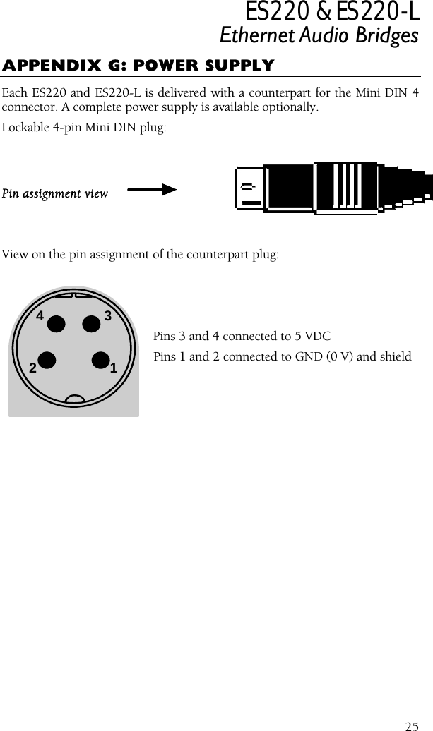
Digigram ES220 Ethernet Audio Distributor User Manual ES220 ES220 L
Digigram Ethernet Audio Distributor ES220 ES220 L
UserManual.wiki
>
Digigram
>
ES220 User Manual
>
Users Manual
Contents
1.
Users Manual Statement
2.
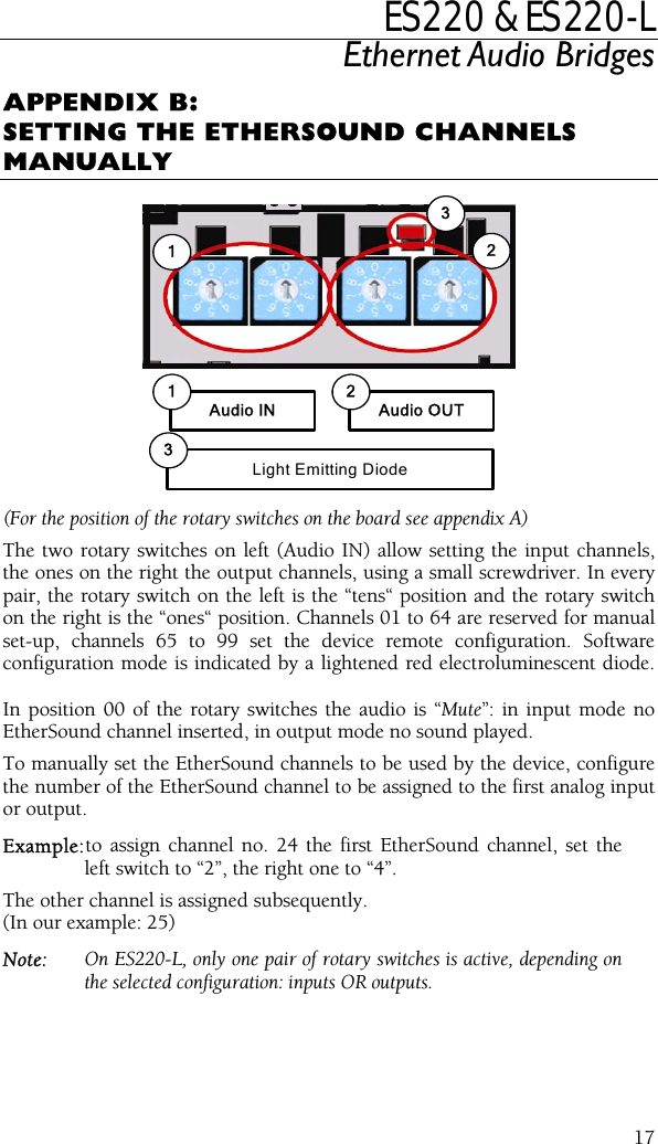
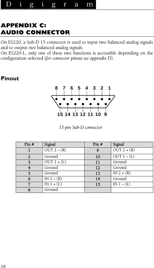
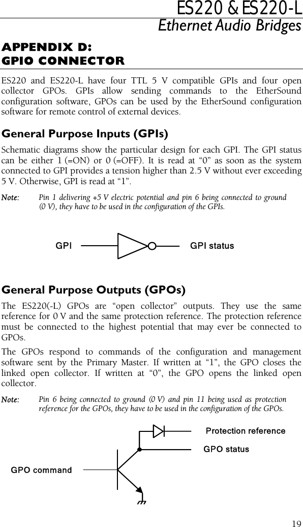
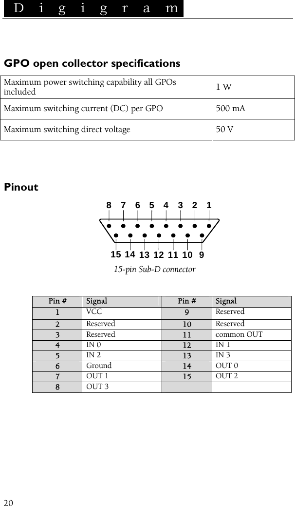
Users Manual
Users Manual
Navigation menu
Upload a User Manual
Namespaces
Wiki Guide
HTML
PDF
Info
Views
User Manual
Discussion / Help
Navigation