Digigram MULTIE PCI Express Audio Cards User Manual VX881 882HR 12 2006
Digigram PCI Express Audio Cards VX881 882HR 12 2006
Digigram >
Contents
- 1. Manual PCX881e PCX882e
- 2. Manual PCX1222e PCX1221e
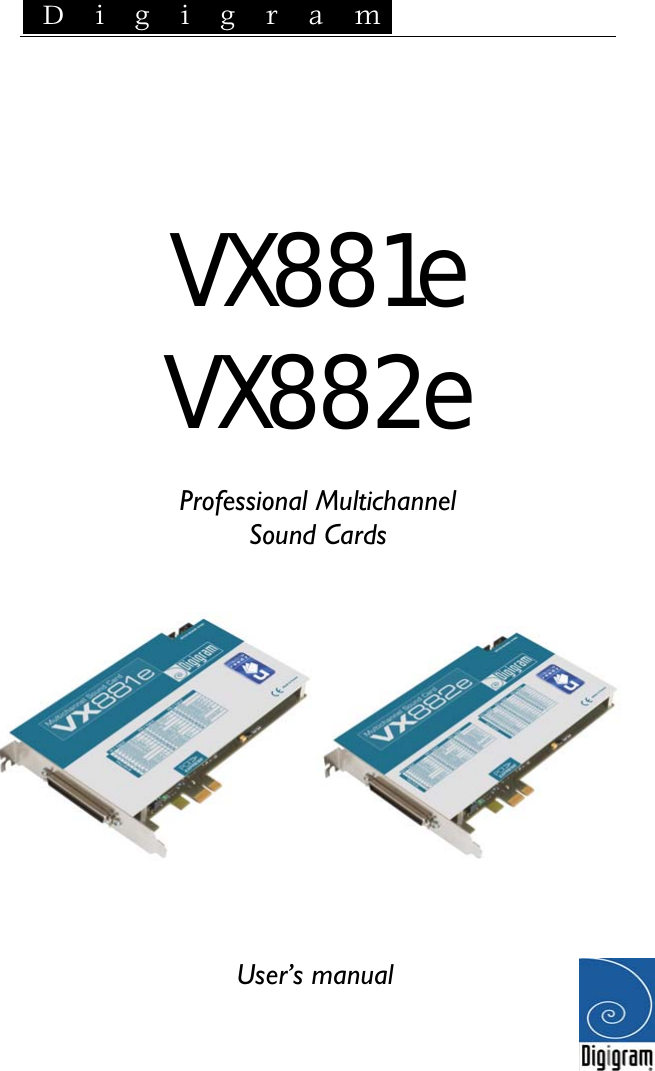
- 3. Manual VX881e VX882e
- 4. Manual VX1222e VX1221e
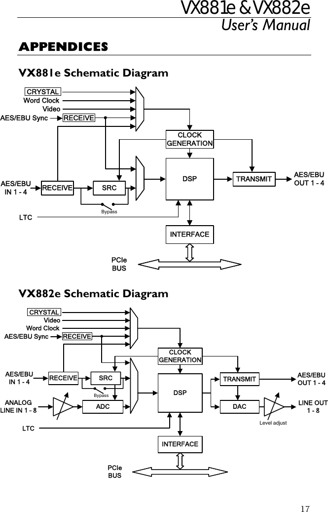
Manual VX881e VX882e