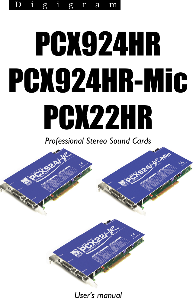
Digigram PCX924HR Audio Equipment User Manual Manual PCX

Digigram Audio Equipment Manual PCX

Contents

Manual PCX

 D i g i g r a m     PCX924HR PCX924HR-Mic PCX22HR Professional Stereo Sound Cards      User’s manual
 D i g i g r a m    2         For technical support, please contact your system supplier               Digigram S.A. Parc de Pré Milliet, 38330 Montbonnot - FRANCE Tel: +33 (0)4 76 52 55 01 • Fax: +33 (0) 4 76 52 53 07 • E-mail: info@digigram.com Digigram Inc. 2101 Wilson Boulevard, Suite 1004, Arlington, VA 22201-USA Tel: +1 703 875 9100 • Fax: +1 703 875 9161 • E-mail: input@digigram.com Digigram Asia Pte Ltd. 350 Orchard Road - #19-07 Shaw House Singapore, 238868-SINGAPORE Tel: +65 6291 2234 • Fax: +65 6291 3433• E-mail: info_asia@digigram.com
PCX924HR & PCX924HR-Mic, PCX22HR User’s Manual  3 Table of Contents INFORMATION FOR THE USER........................................................................5 IMPORTANT NOTICE..................................................................................................5 CONTENTS OF THIS PACKAGE........................................................................6 FEATURES...............................................................................................................................6 PCX924HR & PCX924HR-Mic Main hardware features.......................................... 6 PCX924HR-Mic Additional hardware features..............................................................7 PCX22HR - Main hardware features............................................................................... 7 PCX924HR, PCX924-Mic, and PCX22HR Main software features....................... 8 HARDWARE REQUIREMENTS............................................................................9 Minimum requirements......................................................................................................... 9 Software requirements .......................................................................................................... 9 Supported operating systems .............................................................................................. 9 HARDWARE INSTALLATION..............................................................................9 Installing the card ................................................................................................................... 9 Interrupt and memory address........................................................................................... 9 SOFTWARE INSTALLATION.................................................................................9 Installation under Windows 2000, XP, and Windows Server 2003......................10 Removing the driver under Windows 2000, XP, and Windows Server 2003 ....10 HOW TO CHECK THE INSTALLATION....................................................11 THE ‘DIGIGRAM HARDWARE SETTINGS’ (‘DHS’) CONTROL PANEL...................................................................................12 SPECIFICATIONS...........................................................................................................13 Configuration....................................................................................................................13 Inputs .................................................................................................................................13 Additional functionalities – PCX 924HR-Mic..........................................................14 Outputs..............................................................................................................................14 Connectors........................................................................................................................14 Audio specifications........................................................................................................15 Analog audio performance...........................................................................................15 Sample rate converter performance .........................................................................15 Analog mono microphone input features - PC924HR-Mic ................................. 16 AES42 microphone input features - PCX924HR-Mic..........................................16 Development environments .........................................................................................16
 D i g i g r a m    4 APPENDICES......................................................................................................................17 PCX924HR Schematic Diagram................................................................................17 PCX924HR-Mic Schematic Diagram........................................................................17 PCX22HR Schematic Diagram...................................................................................17 PCX924HR & PCX924-Mic layout...........................................................................18 PCX22HR layout  ...........................................................................................................18 PCX924HR - analog cable diagram:.........................................................................19 PCX924HR-Mic - analog cable diagram:.................................................................19 PCX924v2 Wiring Diagram – analog Cable...........................................................20 PCX924HR-Mic Wiring Diagram – analog Cable.................................................20 PCX924HR & PCX924HR-Mic - digital cable with GPIOs.................................21 PCX924HR & PCX924-Mic - digital cable without GPIOs.................................21 PCX924HR & PCX924HR-Mic wiring Diagram – digital cable with GPIOs.............................................................................................22 PCX924HR & PCX924HR-Mic wiring Diagram – digital cable without GPIOs.......................................................................................22 PCX22v2 : ANALOG CABLE diagram.......................................................................23 Wiring Diagram – Analog Cable - PCX22HR.........................................................23 PCX22HR - digital cable with GPIOs.........................................................................24 PCX22HR digital cable without GPIOs .....................................................................24 Wiring Diagram – Digital Cable with GPIOs (PCX22HR)...................................25 Wiring Diagram – digital cable without GPIOs (PCX22HR) ..............................25 PCX924HR cable pinout ..............................................................................................26 PCX924HR-Mic cable pinout......................................................................................26   Warning: Electrostatic discharge (ESD) can damage several components on the board. To avoid such damage in handling the board, take the following precautions: Bring the device and everything that contacts it to ground potential by providing a conductive surface and discharge paths. As a minimum, observe these precautions: • Disconnect all power and signal sources. • Place the device on a grounded conductive work surface. • Ground yourself via a grounding wrist strap or by holding a grounded object. • Ground any tool that will contact the device.   Copyright 2006 Digigram. All rights reserved. No portion of this manual may be reproduced without prior written consent from Digigram. The copyright protection claimed here includes photocopying, translation and/or reformatting of the information contained in this manual. While every effort has been made to ensure accuracy, Digigram is not responsible for errors and omissions, and reserves the right to make improvements or changes in the products and programs described without notice. Digigram and the Digigram logo, PCX924HR and PCX924HR-Mic are registered trademarks or trademarks of Digigram S.A.. All other trademarks are property of their respective holders.
PCX924HR & PCX924HR-Mic, PCX22HR User’s Manual  5INFORMATION FOR THE USER  This device complies with part 15 of FCC rules. Operation is subject to the following two conditions: (1) This device may not cause harmful interference, and (2) This device must accept any interference received, including interference that may cause undesired operation. This equipment has been tested and found to comply with the limits for a CLASS B digital device, pursuant to Part 15 of the FCC Rules. These limits are designed to provide reasonable protection against harmful interference in a residential installation. This equipment generates, uses, and can radiate radio frequency energy and, if not installed and used in accordance with the instructions contained in this data sheet, may cause harmful interference to radio and television communications. However, there is no guarantee that interference will not occur in a particular installation. If this equipment does cause harmful interference to radio or television reception, which can be determined by turning the equipment off and on, the user is encouraged to try to correct the interference by one or more of the following measures: * reorient or relocate the receiving antenna * increase the separation between the equipment and the receiver * connect the equipment into an outlet on a circuit different from that of the receiver * consult the dealer or an experienced audio television technician.  Note: Connecting this device to peripheral devices that do not comply with CLASS B  requirements or using an unshielded peripheral data cable could also result in  harmful interference to radio or television reception. The user is cautioned  that any changes or modifications not expressly approved by the party  responsible  for compliance could void the user’s authority to operate this equipment. To ensure that the use of this product does not contribute to interference, it is necessary to use shielded I/O cables.    IMPORTANT NOTICE  This card has been tested and found to comply with the following standards: • International: CISPR22 Class B. • Europe: EMC 89/336/CEE (1992) specifications. • United States: FCC Rules-Part 15-Class B (digital device).  In order to guarantee compliance with the above standards in an installation, the following must be done: • the provided cable must not be modified. • additional cables used must have their respective shield connected to each extremity.
 D i g i g r a m    6 CONTENTS OF THIS PACKAGE Thank you for purchasing a Digigram PCX924 or PCX22v2 card. The package consists of the following components: • a PCX924HR, PCX924HR-Mic, or PCX22HR sound card, • the User’s Manual at hand.  The cables (optional) are delivered separately.  FEATURES PCX924HR-Mic, PCX924HR,and PCX22HR are audio cards for PCI bus. They are ‘Universal PCI 64-bit/66 MHz’, which means they can be plugged in 32-bit/33 MHz 5 V keyed PCI slots as well as in 64-bit/66 MHz 3.3 V keyed PCI slots. The cards are also compatible with PCI-X interfaces. PCX924HR & PCX924HR-Mic Main hardware features • 2 balanced∗ analog mono line inputs, with software adjustable gain and a maximum Input level of +24 dBu • 2 servo-balanced∗∗ analog mono line outputs, with software adjustable gain and a maximum output level of +24 dBu • 1 digital AES/EBU∗∗∗ stereo input This input features a hardware sample rate converter (for details see chapter ‘Specifications’) The selection of the digital input for recording excludes the selection of the analog inputs. It is possible to use the signal on the digital input as reference clock. • 1 AES/EBU Sync input  • These two AES/EBU inputs allow:  - recording of a digital signal on the AES/EBU data input; this input is  also used as source of synchronization with a digital clock - recording of a digital signal on the AES/EBU data inputs, synchronized  on a digital clock connected to the AES/EBU synchronization input;                                                 ∗ can be used with unbalanced signals ∗∗ electronically servo-balanced outputs provide automatic level adjustment to accommodate either balanced or unbalanced lines ∗∗∗ can be used as S/PDIF interface as well
PCX924HR & PCX924HR-Mic, PCX22HR User’s Manual  7- the synchronization of analog recording and playback on an AES/EBU  clock connected to the AES/EBU Sync input. • 1 digital AES/EBU∗∗∗ stereo output  Always transmits the digital version of the analog outputs 1 and 2. • 1 LTC (Linear Time Code) input • 1 mini jack stereo headphone output  This output is in parallel of the analog outputs 1 and 2. • 2 General Purpose inputs and 2 outputs (GPIOs) • Inter-card synchronization connector PCX924HR-Mic Additional hardware features • 1 analog microphone input with - high-quality preamplifier  - switchable 48 V phantom power   - analog expander/compressor/limiter  This input is mixed with the two line inputs before A/D conversion. • The AES/EBU input is AES42 compatible (for details see chapter ‘Specifications’) Note: AES42 is an extension of the digital audio standard of interface AES3 providing for interfacing digital microphones. PCX22HR - Main hardware features • 2 servo-balanced∗ analog mono line outputs, with software adjustable gain and a maximum output level of +24 dBu • 1 digital AES/EBU ∗∗ stereo input, for synchronization on an external clock • 1 digital AES/EBU∗∗ stereo output (Always plays the digital version of the analog outputs 1 and 2) • 1 LTC (Linear Time Code) input • 1 mini jack stereo headphone output (This output is in parallel of the analog outputs 1 and 2) • 2 General Purpose inputs and 2 outputs (GPIOs)                                                   ∗ electronically servo-balanced outputs provide automatic level adjustment to accommodate either balanced or unbalanced lines ∗∗ can be used as S/PDIF interface as well
 D i g i g r a m    8 PCX924HR, PCX924-Mic, and PCX22HR Main software features  • Decoding and mixing of several PCM (8, 16 and 24 bits) and MPEG Audio streams (Layer 1, II & III, up to 48 kHz sampling frequency) • Real-time, simultaneous record and playback in PCM (8, 16 and 24 bits), Float IEEE754 conversion (with 24-bit fixed-point dynamic range), as well as in MPEG Audio Layer I, Layer II, and Layer IIIL • When using the np SDK, direct monitoring, level adjustment, panning, cross-fades, punch-in/punch-out, scrubbing, time-scaling, inter-board synchronization, synchronization on LTC (SMPTE) • Possibility to control the parameters of the inputs and outputs (gains, mutes, 48 V switch, analog compressor-limiter-expander parameters), from the provided ‘Digigram Hardware Settings’ application, or from any application that addresses these controls • 24-bit DSP effects in playback and recording: 3-band parametric equalizer plus Maximizer • Low latency DirectSound, Wave, and ASIO drivers  L MPEG Layer III play-only on DSP;   MPEG Layer III recording on the host computer is available through Digigram's PC Codec using the np SDK
PCX924HR & PCX924HR-Mic, PCX22HR User’s Manual  9HARDWARE REQUIREMENTS Minimum requirements • Pentium III 700 MHz (or equivalent) minimum • One free PCI (3.3 V or 5 V keyed) or PCI-X slot Software requirements SOFTWARE REQUIREMENTS To use your PCX924HR or PCX924HR-Mic, install the driver from the np Runtime HR package version 1.40 or higher. This package includes a WDM DirectSound driver. Microsoft DirectX 9 or a later version must also be installed. The card can also be used with applications based on Digigram‘s np SDK Supported operating systems PCX924HR and PCX924HR-Mic cards run under Windows 2000, Windows XP1, and Windows 2003 Server1, are compatible np SDK, and come along with low-latency DirectSound, Wave, and ASIO drivers.  HARDWARE INSTALLATION The card has to be installed in the computer prior to installing its driver. Installing the card Gently plug the card in a free PCI slot and press it down to position it firmly. Tighten the screw. Interrupt and memory address Hardware interrupt and addresses are automatically set up at start-up by the PCI PnP BIOS.  SOFTWARE INSTALLATION Please visit the Digigram web site at www.digigram.com for the most recent driver. In case you run a specific application developed or installed by a Digigram partner, it might require the use of a specific driver version. In this case, make sure that the updated driver has been approved by your supplier.                                                 1 3- bit version
 D i g i g r a m    10 Installation under Windows 2000, XP, and Windows Server 2003 If the driver has been downloaded from our web site, it has to be expanded prior to the driver’s installation as follows: double-click on the downloaded file (self-expanding). You can use the default destination location (Windows temporary folder) or select another directory. • Shut down your computer and insert your PCX card. • Restart your computer. • Click on Cancel if the “Found New Hardware” Wizard appears. • Double-click on the setup.exe icon to launch the driver installation. • A welcome message is displayed, click Next to continue. • The “License Agreement” window appears: read it, and click on Yes to approve it. Do the same for the “Read Me First” window. • Choose the destination folder where Setup will install the application files (..\pcxnp by default). Note that the driver files are installed in   ..\windows\system32\Drivers\Digigram\PCXHR Next. • In the “Select components” window make sure that the “Driver for the HR boards” has been selected. • Select the program folder where the program icons will be added (default: DIGIGRAM). Next. • Click on Next to start copying the files. • Click on Continue anyway in the “Hardware installation” window (Windows XP). • In the “Digigram drivers” window, select the number and the size of buffers required by your applications. Click on Ok. • Click on the Finish button to complete the driver installation. Removing the driver under Windows 2000, XP, and Windows Server 2003 • Open the Windows Control Panel and double-click on the Add/Remove Software icon.  • Select "Digigram HR Runtime …", and Change/Remove. • Select Remove in the “HR Runtime” window. • Follow the instructions to finish the driver removal.
PCX924HR & PCX924HR-Mic, PCX22HR User’s Manual  11How to check the installation Once the driver and the cards are installed according to the procedure described in this manual, you can verify that the card is properly installed and works fine as follows: • Menu <Start> <Settings> <Control panel>, <Sound and Multimedia>, tab “Audio”, Default device (Playback device, Recording device). The card’s channels can be selected. the card can be used with any DirectSound application (see pages hereafter). • The card is also visible via the np interface: Go to <Start> <Programs> <Digigram> and select <Digigram Control Center>. • In the “Digigram drivers” window, select the ‘General Information’ tab.  In the “Modules Information” window, you can see the HR Runtime modules that have been installed, and their versions. • In the “Digigram drivers” window, select the ‘Diagnostics’ tab. You should see here the icons of the cards you have installed.  If the card you have installed is listed: • Right click on the icon of the card. • Select Diagnostics, and Play Sine. This plays in loop a sine signal on the outputs of the card. You can also select Play file to play in loop a file of your choice (PCM or MPEG).  If the playback is correct, the card is correctly installed and works. • To stop the playback, right click on the card icon, and select Stop Activities.  The card is also visible via the DHS control panel (cf. dedicated chapter next page).  If the card is not displayed: • Make sure that during the HR runtime installation the “Driver for the HR boards” has been selected in the “Select components” window. • make sure that the card is correctly inserted in the PCI slot, and screwed on the PC chassis. • if necessary, uninstall HR runtime package as described in this manual, and re-install it.
 D i g i g r a m    12 The ‘Digigram Hardware Settings’ (‘DHS’) control panel  Digigram hardware settings (DHS) is an application allowing to configure the hardware resources of Digigram cards for all audio applications using them.  A resource being managed by the DHS application can not be modified by any other applications. To enable an audio application to modify a Digigram card resource, this resource must not be managed by the DHS. Note: As soon as a resource of a card is managed by the DHS, the clock selection of this chart must obligatorily be defined in the DHS.  The DHS allows to define: • Selection of the clock the card uses  • selection of the input source  • Analog and digital gain of an input  • Enable Sample Rate Converters of an input:  • Select the input monitored on an output  • Set the monitoring gains  • Set the analog and digital gains of an output  • Define the digital output format    For help on how to use this control panel, please refer to its on-line help.
PCX924HR & PCX924HR-Mic, PCX22HR User’s Manual  13SPECIFICATIONS Configuration  PCX924HR  PCX924HR-Mic PCX22HR Bus/Format  PCI 2.2, “Universal PCI 32-bit/66 MHz” master mode, “short-length” PCI format compatible, PCI-X compatible Digital Signal Processor  Motorola 56303 at 100 MHz RAM  512 kWords Size  175 mm x 99 mm x 20 mm Power requirements (+3.3V/+5V / +12V / –12V) 0,35 A / 0,2 A / 0,2 A / 0,08 A 0,4 A / 0,3 A∗ / 0,22 A / 0,1 A 0,30 A / 0,18 A / 0,18 A / 0,08 A Operating: temp / humidity (non-condensing) 0°C / +50°C • 5% / 90% Storage: temp / humidity (non-condensing) -5°C / +70°C • 0% / 95% Inputs  PCX924HR  PCX924HR-Mic PCX22HR Analog line inputs (mono)  2 balanced∗∗ Maximum input level/impedance  +24 dBu / >10 k( Digital inputs (stereo)  1 AES/EBU∗∗∗  with hardware sample rate coverter (SRC) - Other inputs  AES/EBU Sync (up to 200 kHz) Programmable input gain analog: from –94 dB to +16 dB ⊗ digital: from –110 dB to +18 dB Other inputs  2 GPI (dry contact), LTC AES11 synchronization  Yes                                                   ∗ enabling phantom power (48 V) may increase this value by 50% using the 10 V AES42 power to feed the microphone may increase this value by 150%  ∗∗ can be used with unbalanced signals ∗∗∗ can be used as S/PDIF interface as well ⊗ maximum sensitivity: 0 dBFs for –16 dBu input
 D i g i g r a m    14  Additional functionalities – PCX 924HR-Mic Microphone input 1 professional mono with - high-quality preamplifier  - switchable 48 V phantom power  - analog expander/compressor/limiter  This input is mixed with the two line inputs before A/D conversion. Digital input (stereo) The input AES/EBU IN∗ is AES42 compatible - supplying 10 V to feed a digital microphone - allowing remote microphone control.  Outputs  PCX924HR  PCX924HR-Mic PCX22HR Analog line outputs (mono)  2 servo-balanced∗∗ Maximum output level / impedance  +24 dBu / < 100Ω Digital outputs (stereo)  1 AES/EBU, up to 200 kHz Programmable output gain analog: from –24 dB to +24 dB digital: from –110 dB to +18 dB Other outputs  1 stereo headphone output (600 Ω) 2 GPO (relay, 0,5 A, 48 VCC)  Connectors  PCX924HR PCX924HR-MicPCX22HR Internal connector  inter-board synchronization  External connectors •  15-pin Sub-D for analog I/Os • 115-pin HD Sub-D for digital I/Os, Sync., and GPIO • 1 mini jack headphone stereo output (3,5 mm TRS female jack)                                                  ∗ can be used as S/PDIF interface as well ∗∗ electronically servo-balanced outputs provide automatic level adjustment to accommodate either balanced or unbalanced lines
PCX924HR & PCX924HR-Mic, PCX22HR User’s Manual  15Audio specifications  PCX924HR PCX924HR-MicPCX22HR Sampling frequencies available  Programmable from 8 to 192 kHz A/D and D/A converter resolution  24 bits Supported audio formats  PCM (8, 16, 24 bits), Float IEEE754, MPEG (Layer I, II, and III up to 48 kHz)  Analog audio performance Measurements done at Fs=48 kHz unless stated otherwise, with filter on the 22 Hz- 22 kHz range  PCX924HR PCX924HR-MicPCX22HR Frequency response (record + play) at 48 kHz: 20 Hz - 20 kHz: +0 /-0.3 dB at 96 kHz: 20 Hz - 40 kHz: +0 /-0.4 dB at 192 kHz: 20 Hz - 80 kHz: +0 /-1.1 dB Channel phase difference: 20/20kHz  <0.2°/2° Dynamic range (A-weighted) Analog In: >104 dB* Analog out: > 106 dB THD + noise 1 kHz at –2 dBfs Analog In: >-97 dB* Analog out: <-95 dB Crosstalk (Analog in or out)    1 kHz at 24 dBu: <–115 dB 15 kHz at 24 dBu: <-100 dB * PCX924HR & PCX924HR-Mic only Sample rate converter performance  PCX924HR  PCX924HR-Mic Maximum frequency  192 kHz Frequency ratio  from 1:8 to 7,5:1 THD + noise 1 kHz at –2 dBfs  <-130 dB
 D i g i g r a m    16 Analog mono microphone input features - PC924HR-Mic Power supply  switchable 48 V phantom power Programmable mic gain  0 to 66 dB in 0.5 dB steps Maximum input level/impedance +10 dBu / < 10kΩ Equivalent Input Noise,  A/D-D/A at 48kHz, G=60 dB <-125 dBu Programmable noise-gate threshold -52 dB, -42 dB, -32 dB Programmable compressor/limiter threshold from –26 dB to 0 dB Programmable compressor ratio 1, 1.2, 1.5, 1.8, 2, 2.5, 3, 3.5, 4, 4.5 Programmable compressor/limiter gain from 0 to 16 dB Limiter ratio 15:1 Compressor/limiter release time 150 ms Management of line and mic inputs Mixed together before A/D, with independent level and mute controls Programmable DSP effects on the output 3-band parametric equalizer plus Maximizer AES42 microphone input features - PCX924HR-Mic Power supply  10 V min / 250 mA max Remote control  Yes Supported synchronization Operational mode 1 (the microphone generates its own clock)  Development environments  PCX924HR PCX924HR-MicPCX22HR Digigram management  np SDK (HR Runtime, PCM and MPEG) Other management  Wave (PCM, MPEG), ASIO, and DirectSound (PCM) Supported operating systems  Windows 2000, XP1, and Windows 2003 Server1 Main on-board processing features (with np SDK) PCM play, rec, Float IEEE754, direct monitoring, MPEG, direct monitoring, real-time mixing, level adjustment, panning, cross-fade, punch-in/punch-out, scrubbing, time-scaling                                                 1 32-bit version
PCX924HR & PCX924HR-Mic, PCX22HR User’s Manual  17APPENDICES PCX924HR Schematic Diagram PCI BUS AES/EBU INDACLevel adjustTRANSMIT AES/EBU OUTCLOCKGENERATION DSPINTERFACERECEIVEADC ANALOGLINE IN1 – 2SRCBypassAES/EBUSYNC RECEIVELINE OUTHeadphonesOUTGPIO CONTROLGP OUTGP INCRYSTALLTC PCX924HR-Mic Schematic Diagram PCI BUS AES/EBU INAES42 compatibleDACLevel adjustTRANSMIT AES/EBU OUTCLOCKGENERATION DSPINTERFACERECEIVEADC ANALOGLINE IN1 – 2SRCLTCBypassAES/EBUSYNC RECEIVELINE OUTHeadphonesOUTGPIO CONTROLGP OUTGP INLevel setting48 VMICRO IN (mono) LIMITERCRYSTAL PCX22HR Schematic Diagram  PCI BUS    AES/EBU SYNC IN Level adjust  TRANSMIT AES/EBU OUT CLOCK GENERATIONDSPINTERFACEXTALGPIO CONTROLGP OUTGP INANALOG OUTDACLTC
 D i g i g r a m    18 PCX924HR & PCX924-Mic layout  PCX22HR layout   J 2 J 1J 3 PCX22HRJ 4  J1 : Headphone connector (3.5 mm TRS female jack) Contact  Signal Sleeve Ground Tip Left channel Ring Right channel  J2 : Analog cable J3 : Digital cable J4 : Inter-card synchronization connector
PCX924HR & PCX924HR-Mic, PCX22HR User’s Manual  19PCX924HR - analog cable diagram: Analog cable delivered by Digigram:   PCX924HR-Mic - analog cable diagram: Analog cable delivered by Digigram:
 D i g i g r a m    20  PCX924v2 Wiring Diagram – Analog Cable  J13female+-231Left INJ12female+-231Right IN J11male+-231Left OUTJ10male+-231Right OUTXLR19103136715J2Signal number PCX924HR-Mic Wiring Diagram – Analog Cable J14female+-231MicJ13female+-231Left INJ12female+-231Right IN J11male+-231Left OUTJ10male+-231Right OUTXLR19103136715125J2Signal number
PCX924HR & PCX924HR-Mic, PCX22HR User’s Manual  21PCX924HR & PCX924HR-Mic Digital cable with GPIOs Schematic diagram of the cable delivered by Digigram*:  PCX924HR & PCX924-Mic  digital cable without GPIOs Schematic diagram of the cable delivered by Digigram*:  * Your cable may look different if it is not a Digigram cable.
 D i g i g r a m    22 PCX924HR & PCX924HR-Mic Wiring Diagram – digital cable with GPIOs    PCX924HR & PCX924HR-Mic Wiring Diagram – digital cable without GPIOs
PCX924HR & PCX924HR-Mic, PCX22HR User’s Manual  23PCX22V2 : ANALOG CABLE DIAGRAM Analog cable delivered by Digigram:      WIRING DIAGRAM – ANALOG CABLE - PCX22HR  J11male+-231Left OUTJ10male+-231Right OUTXLR19103J2Signal number
 D i g i g r a m    24 PCX22HR - digital cable with GPIOs Schematic diagram of the cable delivered by Digigram*:  PCX22HR digital cable without GPIOs Schematic diagram of the cable delivered by Digigram*:  * Your cable may look different if it is not a Digigram cable.
PCX924HR & PCX924HR-Mic, PCX22HR User’s Manual  25Wiring Diagram – Digital Cable with GPIOs (PCX22HR)   Wiring Diagram – digital cable without GPIOs (PCX22HR)
 D i g i g r a m    26 PCX924HR cable pinout Pin #  ANALOG  DIGITAL 1  R OUT +  GPIO OUT 1A 2 GND  NC 3  L OUT -  NC 4  GND  AES/EBU IN - 5  NC  AES/EBU IN + 6  R IN -  GPI INPUT 2 7  L IN +  GND/GPIO INPUT COMMON 8  GND  GPI INPUT 1 9  R OUT -  GND 10  L OUT +  LTC IN 11  GND  GPIO OUT 1B 12  NC  GPIO OUT 2A 13  R IN +  GPIO OUT 2B 14  GND  AES/EBU OUT + 15  L IN -  AES/EBU OUT -  PCX924HR-Mic cable pinout Pin #  ANALOG  DIGITAL 1  R OUT +  GPIO OUT 1A 2  GND  AES/EBU IN - 3  L OUT -  AES/EBU IN + 4  GND  AES/EBU SYNC IN - 5  MIC IN –  AES/EBU SYNC IN + 6  R IN -  GPIO INPUT 2 7  L IN +  GND/GPI INPUT COMMON 8  GND  GPI INPUT 1 9  R OUT -  GND 10  L OUT +  LTC IN 11  GND  GPI OUT 1B 12  MIC IN +  GPI OUT 2A 13  R IN +  GPI OUT 2B 14  GND  AES/EBU OUT + 15  L IN -  AES/EBU OUT -

Navigation menu