Digigram X1222HR PCI Bus Audio Cards User Manual VX881 882HR 11 2004
Digigram PCI Bus Audio Cards VX881 882HR 11 2004
UserManual.wiki
>
Digigram
>
X1222HR User Manual
>
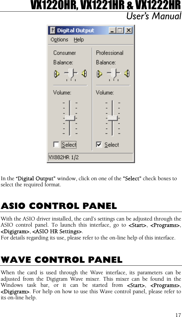
Manual VX
Contents
1.
Manual PCX
2.
Manual VX
Manual VX
Navigation menu
Upload a User Manual
Namespaces
Wiki Guide
HTML
PDF
Info
Views
User Manual
Discussion / Help
Navigation