Digigram X882HR PCI Bus Radio Cards User Manual Manual VX881HR
Digigram PCI Bus Radio Cards Manual VX881HR
Digigram >
Contents
- 1. Manual PCX881HR
- 2. Manual VX881HR
Manual VX881HR
D i g i g r a m
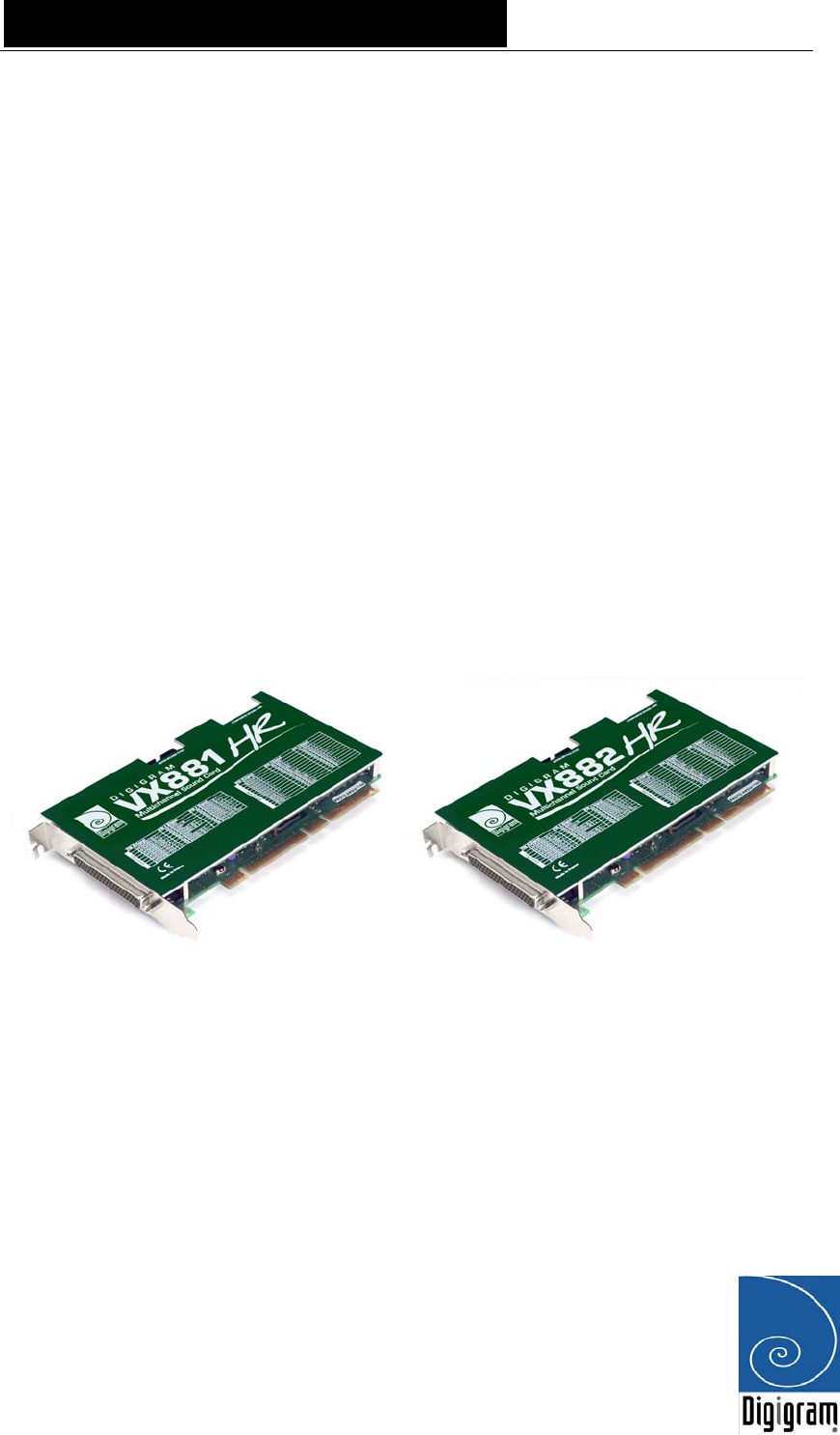
VX881HR
VX882HR
Professional Sound Cards
User’s manual

D i g i g r a m
2
For technical support,
please contact your system supplier.
Digigram S.A.
Parc de Pré Milliet, 38330 Montbonnot - FRANCE
Tel: +33 (0)4 76 52 55 01• Fax: +33 (0) 4 76 52 53 07• E-mail: info@digigram.com
Digigram Inc.
2101 Wilson Boulevard, Suite 1004, Arlington, VA 22201-USA
Tel: +1 703 875 9100 • Fax: +1 703 875 9161 • E-mail: input@digigram.com
Digigram Asia Pte Ltd.
350 Orchard Road - #19-07 Shaw House Singapore 238868-SINGAPORE
Tel: +65 6291 2234 • Fax: +65 6291 3433 • E-mail: info_asia@digigram.com

VX881HR
& VX882HR
User’s Manual
3
Table of Contents
INFORMATION FOR THE USER
....................................................................................................4
IMPORTANT NOTICE
...............................................................................................................................5
CONTENTS OF THIS PACKAGE
....................................................................................................5
FEATURES
.............................................................................................................................................................5
VX881HR main hardware features.............................................................................................................. 5
VX882HR main hardware features.............................................................................................................. 6
Main software features...................................................................................................................................... 6
HARDWARE REQUIREMENTS
........................................................................................................6
Minimum requirements ..................................................................................................................................... 6
SOFTWARE REQUIREMENTS
............................................................................................................6
Supported operating systems........................................................................................................................... 7
HARDWARE INSTALLATION
..........................................................................................................7
Installing the card ................................................................................................................................................ 7
Interrupt and memory address ....................................................................................................................... 7
SOFTWARE INSTALLATION
..............................................................................................................7
Installation under Windows 2000 and XP.................................................................................................. 7
Removing the driver under Windows 2000 and XP................................................................................ 8
HOW TO CHECK THE INSTALLATION
..................................................................................8
SPECIFICATIONS
................................................................................................................................10
CONFIGURATION ........................................................................................................................................... 10
INPUTS / OUTPUTS ....................................................................................................................................... 10
AUDIO SPECIFICATIONS.............................................................................................................................. 11
AUDIO Performance....................................................................................................................................... 11
DEVELOPMENT ENVIRONMENTS.......................................................................................................... 11
APPENDICES ............................................................................12
VX881HR – Pinout...........................................................................................................................................12
VX882HR – Pinout...........................................................................................................................................13

D i g i g r a m
4
INFORMATION FOR THE USER
This device complies with part 15 of FCC rules. Operation is subject to the following
two conditions: (1) This device may not cause harmful interference, and (2) This device
must accept any interference received, including interference that may cause undesired
operation.
This equipment has been tested and found to comply with the limits for a CLASS B
digital device, pursuant to Part 15 of the FCC Rules. These limits are designed to
provide reasonable protection against harmful interference in a residential installation.
This equipment generates, uses, and can radiate radio frequency energy and, if not
installed and used in accordance with the instructions contained in this data sheet, may
cause harmful interference to radio and television communications. However, there is
no guarantee that interference will not occur in a particular installation.
If this equipment does cause harmful interference to radio or television reception, which
can be determined by turning the equipment off and on, the user is encouraged to try to
correct the interference by one or more of the following measures:
* reorient or relocate the receiving antenna
* increase the separation between the equipment and the receiver
* connect the equipment into an outlet on a circuit different from that of the receiver
* consult the dealer or an experienced audio television technician.
Note: Connecting this device to peripheral devices that do not comply with CLASS B
requirements or using an unshielded peripheral data cable could also result in
harmful interference to radio or television reception. The user is cautioned that any
changes or modifications not expressly approved by the party responsible for
compliance could void the user’s authority to operate this equipment. To ensure
that the use of this product does not contribute to interference, it is necessary to use
shielded I/O cables.
Copyright 2004 Digigram. All rights reserved.
No portion of this manual may be reproduced without prior written consent from Digigram. The copyright protection
claimed here includes photocopying, translation and/or reformatting of the information contained in this manual.
While every effort has been made to ensure accuracy, Digigram is not responsible for errors and omissions, and
reserves the right to make improvements or changes in the products and programs described without notice.
Digigram VX881HR and VX882HR are registered trademarks or trademarks of Digigram S.A. Other trademarks are
property of their respective holders.

VX881HR
& VX882HR
User’s Manual
5
IMPORTANT NOTICE
This card has been tested and found to comply with the following standards:
• International: CISPR22 Class B.
• Europe: EMC 89/336/CEE (1992) specifications.
• United States: FCC Rules-Part 15-Class B (digital device).
In order to guarantee compliance with the above standards in an installation, the
following must be done:
• the provided cable must not be modified.
• additional cables used must have their respective shield connected to each
extremity.
CONTENTS OF THIS PACKAGE
Thank you for purchasing a Digigram PCX sound card.
The package consists of the following components:
* a VX881HR or VX882HR sound card,
* the User’s Manual at hand
The cables (optional) are delivered separately.
FEATURES
VX881HR and VX882HR are audio cards for PCI bus. They are ‘Universal PCI
64-bit/66 MHz’, which means they can be plugged in 32-bit/33 MHz 5 V PCI
slots, 3.3V keyed PCI slots as well as in 64-bit/66 MHz 3.3 V keyed PCI slots.
The cards are also compatible with PCI-X interfaces.
VX881HR main hardware features
• 4 stereo AES/EBU digital inputs, with hardware sample rate converters
• 4 stereo AES/EBU digital outputs
• 1 stereo AES/EBU digital sync input
• 1 standard Word Clock input
• 1 standard Word Clock output
• 1 video sync input
• 1 SMPTE/LTC (Linear Time Code) sync input

D i g i g r a m
6
VX882HR main hardware features
• All features of VX881HR plus…
• 8 balanced analog mono line inputs, with software programmable analog
and digital gain.
• 8 servo-balanced∗ analog mono line outputs, with software
programmable analog and digital gain.
• 192 kHz / 24-bit converters
• Analog inputs and outputs maximum levels: +24 dBu
Main software features
• Real-time, simultaneous record and playback in PCM (8, 16 and 24 bits)
as well as in MPEG Audio layer I, layer II and layer III.
• Decoding and mixing of several PCM and MPEG audio streams
• When using the np SDK, panning, cross fades, punch-in/punch-out,
scrubbing, time-stretching, pitch-shifting, format and frequency
conversions.
• Low latency DirectSound drivers
HARDWARE REQUIREMENTS
VX881HR and VX882HR have been developed for IBM and IBM-compatible
PC systems.
Minimum requirements
• Pentium III minimum (or equivalent)
• 128 MB RAM
• One free PCI or PCI-X slot
SOFTWARE REQUIREMENTS
To use your VX881HR or VX882HR, you have to install the driver from the
np Runtime HR package version 1.00 or higher. This package also includes a
WDM DirectSound driver so that the cards can be used with standard
multimedia applications. The Microsoft DirectX runtime version 9 or higher
must also be installed on your computer.
∗
electronically servo-balanced outputs provide automatic level adjustment to accommodate
either balanced or unbalanced lines

VX881HR
& VX882HR
User’s Manual
7
Supported operating systems
VX881HR, and VX882HR cards run under Windows 2000 and Windows XP.
HARDWARE INSTALLATION
The card has to be installed in the computer prior to installing its driver.
Installing the card
Gently plug the card into a free PCI slot and press it down to position it
firmly. Tighten the screw.
Interrupt and memory address
Hardware interrupt and addresses are automatically set up at start-up by the
PCI PnP BIOS.
SOFTWARE INSTALLATION
Please visit the Digigram web site at www.digigram.com for the most recent
driver.
In case you run a specific application developed or installed by a Digigram
Partner, it might require the use of a specific driver version. In this case, make
sure that the updated driver has been approved by your supplier.
Installation under Windows 2000 and XP
If the driver has been downloaded from our web site, it has to be expanded
prior to the driver’s installation as follows: double-click on the downloaded
file (self-expanding). You can use the default destination location (Windows
temporary folder) or select another directory.
• Shut down your computer and insert the PCX sound card.
• Restart your computer.
• Click on Cancel if the Found New Hardware Wizard appears.
• Double-click on the setup.exe icon to launch the driver installation.
• The welcome message is displayed, click next.
• The “License Agreement” window appears: read it, and click on
Yes to approve it. Do the same for the “Read Me First” window.

D i g i g r a m
8
• Choose the destination folder where Setup will install the
application files (\pcxnp by default). Please note that driver files are
installed in \windows\system32\Drivers\Digigram\PCXHR. Click on
Next
• Check the “Driver for the HR board” check-box option.
• Select the program folder where the program icons will be added
(default DIGIGRAM). Click on Next.
• Click on Next to start copying the files.
• Click on Continue anyway in the “Hardware installation” window
(Windows XP).
• In the “Digigram drivers” window, “PCX HR Settings” tab select
the number and the size of buffers required by your applications.
Click on Ok.
• Click on Finish to complete the driver installation.
Removing the driver under Windows 2000 and XP
• Open the Windows Control Panel and double-click on the
Add/Remove Software icon.
• Select 'Digigram HR Runtime…', and Change/Remove.
• Select Remove in the “HR Runtime” window.
• Follow the instructions to finish to remove the driver.
HOW TO CHECK THE INSTALLATION
Once the driver and the cards are installed according to the procedure
described in this manual, you can verify that the card is properly installed and
works fine as follows:
• Go to <Start> <Programs> <Digigram> and select
<Digigram Control Center>.
• In the “Digigram drivers” window, select the General Information
tab. In the “Modules Information” window, you can see the HR
Runtime modules that have been installed and their versions.
• In the “Digigram drivers” window, select the Diagnostics tab.
You should see here the icons of the cards you have installed.
If the card you have installed is listed:
• Right click on the icon of the card.

VX881HR
& VX882HR
User’s Manual
9
• Select Diagnostics, and Play sine. This plays in loop a sine wave
signal on the outputs of the card.
You can also select Play file to play in loop a file of your choice
(PCM, MPEG layer 1 or layer 2).
If the playback is correct, the card is correctly installed and works.
• To stop the playback, right click on the card icon, and select
Stop Activities.
If the card is not displayed:
• make sure you have installed the Driver for the HR board, from the
HR Runtime installation (check-box).
• make sure that the card is correctly inserted in the PCI slot, and
screwed on the PC chassis.
• if necessary, uninstall np Runtime package as described in this
manual, and re-install it.
D i g i g r a m
10
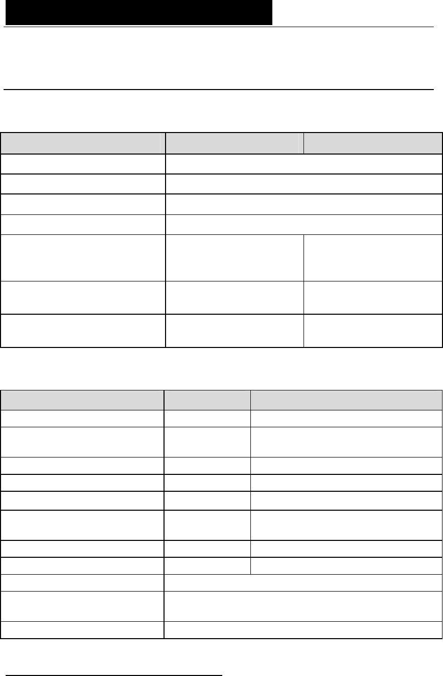
SPECIFICATIONS
CONFIGURATION
VX881HR VX882HR
Bus / format 64-bit/66 Mhz Universal PCI master mode
Digital Signal Processor Motorola 56321 at 240 MHz
RAM 512 kWords
Size 175mm x 99 mm
Power requirements
(+3.3 V /+5 V / +12 V / -12
V)
0 A /0.6 A /0.1A /0 A 0 A /0.7 A /0.5A /0.2 A
Operating: temp / humidity
(non-condensing) 0°C/+50°C • 5%/90% 0°C/+40°C • 5%/90%
Storage: temp / humidity
(non-condensing) -5°C/+70°C • 0%/95% -5°C/+70°C • 0%/95%
INPUTS / OUTPUTS
VX881HR VX882HR
Analog line inputs (mono) - 8 balanced*
Maximum input
level/impedance - +24 dBu / >100 kΩ
Programmable input gain digital digital and analog by steps of 0.5 dB
Digital inputs (stereo) 4 AES/EBU 4 AES/EBU
Analog line outputs (mono) - 8 servo-balanced∗∗
Maximum output
level/impedance - +24 dBu / low impedance
Programmable output gain digital digital and analog by steps of 1 dB
Digital outputs (stereo) 4 AES/EBU 4 AES/EBU
Additional outputs Word Clock
Additional inputs AES/EBU Sync (up to 192 kHz), Word clock (up to 96
kHz), LTC, Video
Connectors 62-pin SUB-D
∗ can be used with unbalanced signals
∗∗ electronically servo-balanced outputs provide automatic level adjustment to accommodate
either balanced or unbalanced lines
VX881HR
& VX882HR
User’s Manual
11
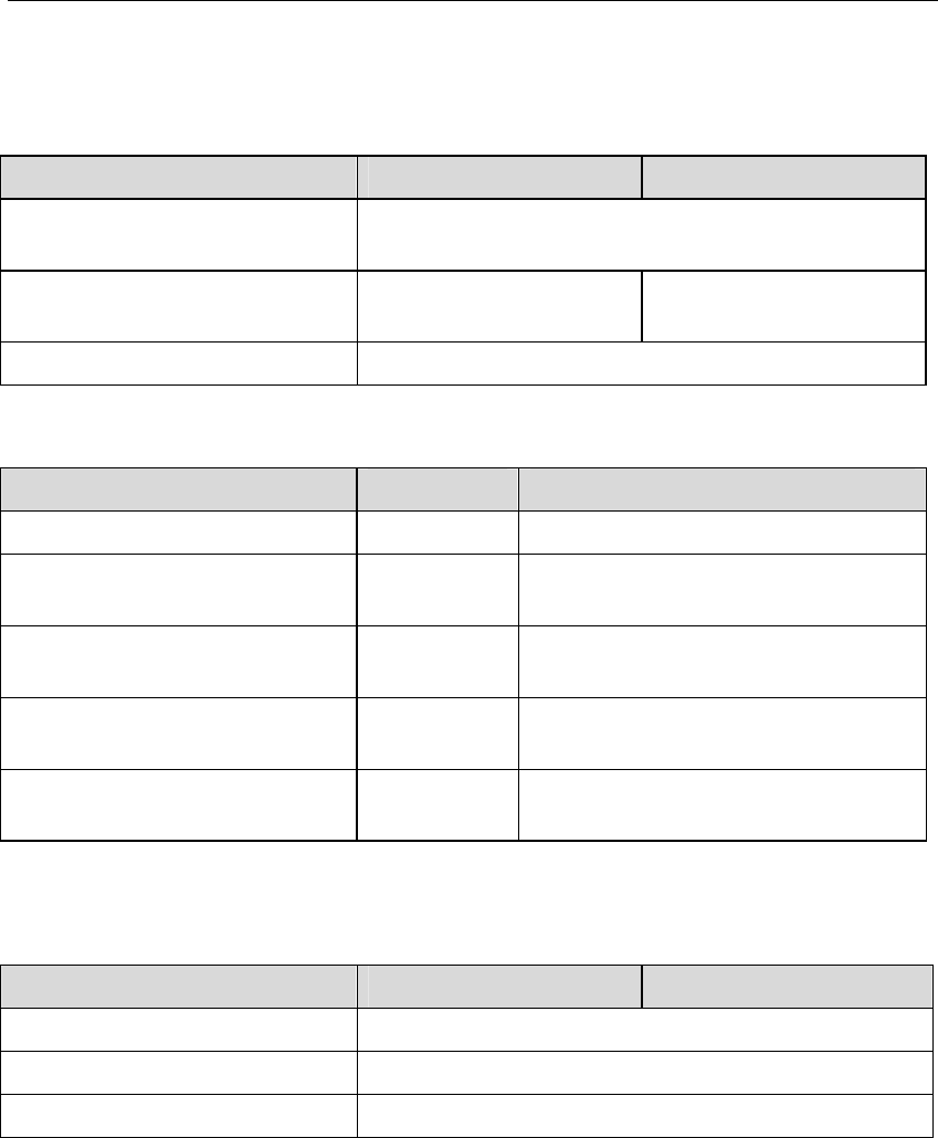
AUDIO SPECIFICATIONS
VX881HR VX882HR
Sampling frequencies
available Programmable from 8 to 192 kHz
A/D and D/A
converter resolution NA 24 bits
Supported audio formats MPEG, PCM (8, 16, 24 bits)
AUDIO PERFORMANCE
VX881HR VX882HR
Frequency response NA 20 Hz–20 kHz: ±0.2 dB
Channel phase difference:
20 Hz / 20 kHz NA <0.2°/2°
Dynamic range
(A-weighted) NA Analog In: >104 dB
Analog Out: >104 dB
THD + noise,
1 kHz at –1 dBfs NA Analog In: <–97 dB
Analog Out: <–94 dB
Crosstalk
(Analog Input or output) NA 1 kHz at 22 dBu: <–100 dB
15 kHz at 22 dBu: <–85 dB
Note: All measurements are done at Fs=48 kHz, in rec+play mode.
DEVELOPMENT ENVIRONMENTS
VX881HR VX882HR
Digigram Management np SDK (HR runtime)
Other management Wave, ASIO (PCM only), DirectSound (PCM only)
OS supported Windows 2000 and XP
D i g i g r a m
12
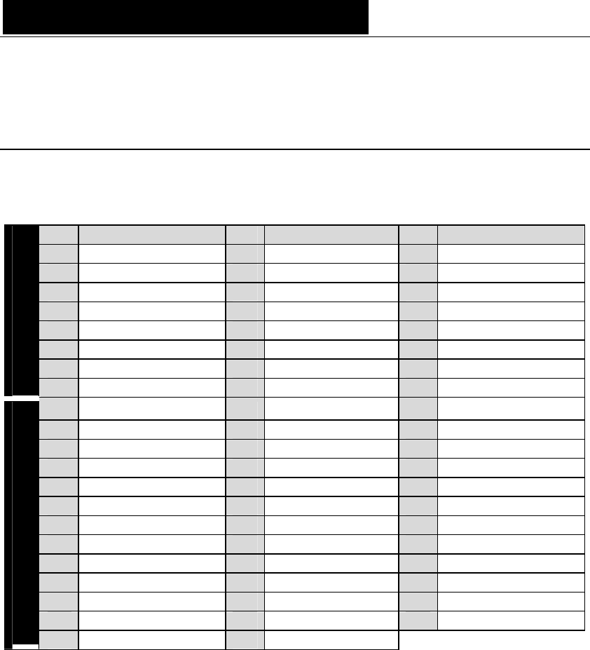
APPENDICES
VX881HR – Pinout
Pin Signal Pin Signal Pin Signal
1 AES/EBU 2 - 22 GND 43 AES/EBU IN 1 -
2 AES/EBU 2 + 23 Vidéo IN 44 AES/EBU IN 1 +
3 AES/EBU SYNC - 24 GND 45 AES/EBU OUT 3 -
4 AES/EBU SYNC + 25 AES/EBU IN 3 - 46 AES/EBU OUT 3 +
5 AES/EBU OUT 4 - 26 AES/EBU IN 3 + 47 AES/EBU OUT 1 -
6 AES/EBU OUT 4 + 27 GND 48 AES/EBU OUT 1 +
7 AES/EBU OUT 2 - 28 AES/EBU IN 4 - 49 Word Clock IN
Digital
8 AES/EBU OUT 2 + 29 AES/EBU IN 4 + 50 Word Clock OUT
9 LTC IN 30 GND 51 NC
10 NC 31 NC 52 NC
11 NC 32 NC 53 NC
12 NC 33 GND 54 NC
13 NC 34 NC 55 NC
14 NC 35 NC 56 NC
15 NC 36 GND 57 NC
16 NC 37 NC 58 NC
17 NC 38 NC 59 NC
18 NC 39 GND 60 NC
19 NC 40 NC 61 NC
20 NC 41 NC 62 NC
Analog
21 NC 42 GND
VX881HR
& VX882HR
User’s Manual
13
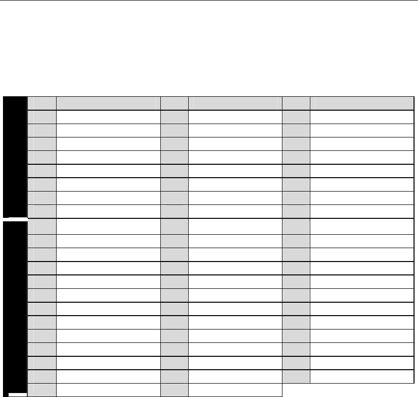
VX882HR – Pinout
Pin Signal Pin Signal Pin Signal
1 AES/EBU 2 - 22 GND 43 AES/EBU IN 1 -
2 AES/EBU 2 + 23 Vidéo IN 44 AES/EBU IN 1 +
3 AES/EBU SYNC - 24 GND 45 AES/EBU OUT 3 -
4 AES/EBU SYNC + 25 AES/EBU IN 3 - 46 AES/EBU OUT 3 +
5 AES/EBU OUT 4 - 26 AES/EBU IN 3 + 47 AES/EBU OUT 1 -
6 AES/EBU OUT 4 + 27 GND 48 AES/EBU OUT 1 +
7 AES/EBU OUT 2 - 28 AES/EBU IN 4 - 49 Word Clock IN
Digital
8 AES/EBU OUT 2 + 29 AES/EBU IN 4 + 50 Word Clock OUT
9 LTC IN 30 GND 51 OUT 7 -
10 OUT 8 - 31 IN 8 - 52 OUT 7+
11 OUT 8 + 32 IN 8 + 53 OUT 5 -
12 OUT 6 - 33 GND 54 OUT 5 +
13 OUT 6 + 34 IN 7 - 55 OUT 3 -
14 OUT 4 - 35 IN 7 + 56 OUT 3 +
15 OUT 4 + 36 GND 57 OUT 1 -
16 OUT 2 - 37 IN 6 - 58 OUT 1 +
17 OUT 2 + 38 IN 6 + 59 IN 3 -
18 IN 4 - 39 GND 60 IN 3 +
19 IN 4 + 40 IN 5 - 61 IN 1 -
20 IN 2 - 41 IN 5 + 62 IN 1 +
Analog
21 IN 2 + 42 GND