Digital Ally VULINK1 DIGITAL TRANSMISSION SYSTEM (2400-2483.5 MHz) User Manual DVM 250 250Plus Installation Guide
Digital Ally, Inc. DIGITAL TRANSMISSION SYSTEM (2400-2483.5 MHz) DVM 250 250Plus Installation Guide
User Manual
Copyright © 2014, Digital Ally, Inc. All Rights Reserved. This publication may not be reproduced, stored in a retrieval system, or
transmitted in whole or part in any form or by any means electronic, mechanical, recording, photocopying, or in any other manner
without the prior written approval of Digital Ally, Inc.
860-00198-00_WIP Rev A
March 2014
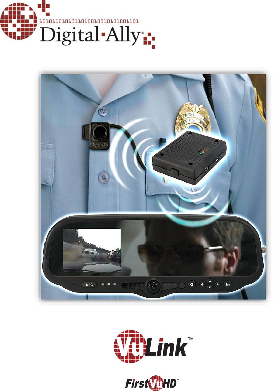
Wireless Link for and DVM systems
Operation and Installation Guide
VuLink Operation & Installation Guide 860-00198-00 REV A
i
Table of Contents
SECTION - 1: BEFORE YOU BEGIN............................................................................................................................ 1-1
OVERVIEW OF FEATURES ........................................................................................................................................................................ 1-1
INSTALLATION TOOLS NEEDED ............................................................................................................................................................. 1-1
CAUTIONS AND NOTES ............................................................................................................................................................................ 1-1
PARTS AND OPTIONAL ACCESSORIES LIST........................................................................................................................................... 1-2
SECTION - 2: VULINK CONFIGURATION ................................................................................................................ 2-1
USING VUVAULT TO CONFIGURE YOUR VULINK AND FIRSTVUHD ................................................................................................. 2-1
Configuring VuLink .................................................................................................................................................................... 2-2
Configuring your FirstVu HD .................................................................................................................................................. 2-3
Activating VuLink & FirstVu HD within VuVault ............................................................................................................. 2-4
USING THE CONFIGURATION MANAGER TO CONFIGURE YOUR VULINK AND FIRSTVUHD ......................................................... 2-4
Installing the Software ............................................................................................................................................................. 2-4
Configuring VuLink .................................................................................................................................................................... 2-5
Saving your VuLink Settings ................................................................................................................................................... 2-6
Configuring your FirstVu HD .................................................................................................................................................. 2-7
Saving your FirstVu HD Settings ........................................................................................................................................... 2-7
DVM-800, DVM-250, AND DVM-250PLUS DEVICE CONFIGURATION ...................................................................................... 2-8
SECTION - 3: INSTALLATION INSTRUCTIONS ...................................................................................................... 3-1
STEP 1: REMOVE BODY TRIM ............................................................................................................................................................... 3-1
STEP 2: POWER IGNITION, AND GROUND CONNECTIONS ................................................................................................................ 3-2
STEP 3: VULINK TRIGGER CONNECTIONS .......................................................................................................................................... 3-2
STEP 4: VULINK INSTALLATION ........................................................................................................................................................... 3-3
SECTION - 4: MODEL-SPECIFIC WIRING DIAGRAMS ......................................................................................... 4-1
DVM-100 / DVM-400 ........................................................................................................................................................................ 4-1
DVM-500PLUS / DVM-750 ............................................................................................................................................................... 4-2
DVM-800 / DVM-LIVE ....................................................................................................................................................................... 4-3
DV-440ULTRA ......................................................................................................................................................................................... 4-4
DVM-250PLUS OR DVM250 (WITH INTERFACE BOX) ................................................................................................................... 4-5
GENERIC INPUT SOURCE ......................................................................................................................................................................... 4-6
SECTION - 5: OPERATION ........................................................................................................................................... 5-1
POWER CONTROL ..................................................................................................................................................................................... 5-1
TESTING THE SYSTEM ............................................................................................................................................................................. 5-1
COVERT MODE .......................................................................................................................................................................................... 5-1
VULINK™ LED STATUS INDICATORS .................................................................................................................................................... 5-2
FIRSTVUHD™ LED STATUS INDICATORS ............................................................................................................................................ 5-2
SECTION - 6: SUPPORT ................................................................................................................................................ 6-1
SOFTWARE UPDATES ............................................................................................................................................................................... 6-1
PERFORMING A RESET ............................................................................................................................................................................ 6-1
TROUBLESHOOTING ................................................................................................................................................................................. 6-1
SECTION - 7: WARRANTY INFORMATION ............................................................................................................. 7-1
SECTION - 8: CONTACT INFORMATION .................................................................................................................. 8-1
SECTION - 9: REGULATORY ........................................................................................................................................ 9-1

VuLink Operation & Installation Guide 860-00198-00 REV A
Digital Ally, Inc. | Before you Begin
1-1
Section - 1: Before you Begin
Overview of Features
Automatically start recordings on your Firstvu HD using the same triggers as vehicle
video systems, regardless of whether the unit is mounted or worn
Simultaneously start recordings with your vehicle video system, whether started
manually on either system or automatically triggered
Eliminate distraction, need to continuously record or remember to press record
Link recordings from both systems into the same incident in VuVault™ management &
reporting software
Installation Tools Needed
Wire Strippers
Tools to remove vehicle trim
Wire Crimpers
Digital Volt Meter
Cautions and Notes
Please read and follow the instructions and precautions in this installation guide when installing
VuLink.
For assistance, a qualified installation technician or mechanic should be consulted.
Do not use excessive force when removing the mirror from the windshield. The mirror
mounting plate may become separated from the windshield and/or the windshield may
break if excessive force is used. If you are unfamiliar with rearview mirror removal seek
professional assistance.
To prevent electrical shorts or breakage in the wiring and cabling, do not allow wiring and
cabling to be pinched behind trim pieces, panels, or other physical objects.
Do not run wires or cables in areas where they may become damaged by heat from the
engine or the exhaust system.
Do not install any wiring in the deployment path of the air bag(s).
When installing the cables or making wire connections, it is recommended you leave a little
‘slack’ in the cable connections to allow for service loops and for movement of the mirror so
the connections do not get pulled or accidentally disconnected.
Where possible, avoid running cables parallel to other wiring and/or antenna coax that may
be installed in the vehicle.
We recommend at least 2 feet of distance between our cabling and that of other systems
which may carry a signal for transmit and/or receive
VuLink Operation & Installation Guide 860-00198-00 REV A
Digital Ally, Inc. | Before you Begin
1-2
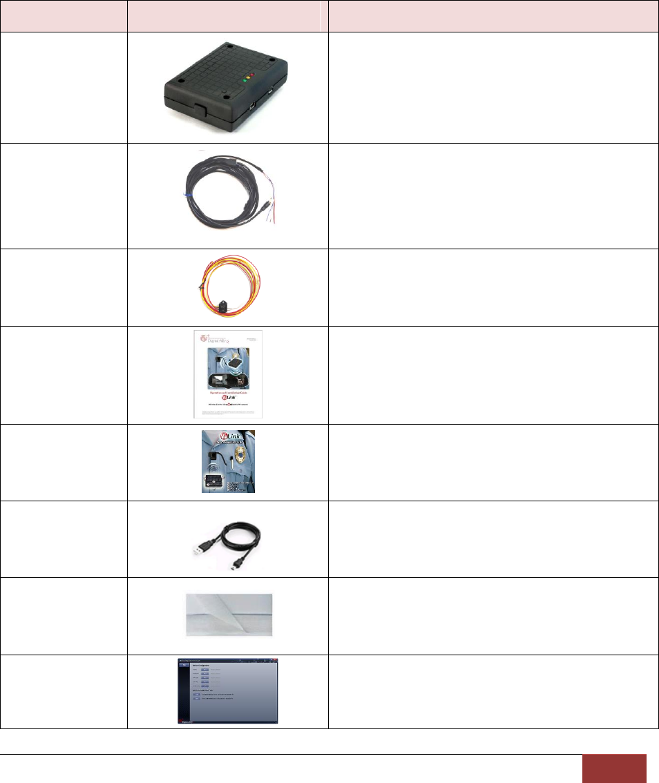
Parts and Optional Accessories List
VuLink Standard Package (pn#001-0950-00)
The diagram and table below outline the parts that are included with the VuLink Package.
Part Number
Image
Description
006-08257-00
Assembly, VuLink
008-01456-00
Cable, VuLink Base, 15ft
006-0050
Relay with harness, 12VDC
860-00198-00
VuLink Operation and Installation Guide
860-00199-00
VuLink Quick Reference Guide
008-0100
USB Cable
050-10148-10
Mounting Kit, Velcro qty 2 1"x1.5"
914-00001-00
Electronic Files (preloaded on VuLink device)
Mini Configuration Manager / Viewer
Operation Manuals
VuLink Operation & Installation Guide 860-00198-00 REV A
Digital Ally, Inc. | VuLink Configuration
2-1
Section - 2: VuLink Configuration
Using VuVault to Configure your VuLink and FirstVuHD
Prior to installation, VuLink must be configured either through the Mini Configuration Manager
Software installer supplied on the VuLink internal memory or by using Digital Ally’s optional
VuVault™ back-office software. If you have purchased VuVault™, follow the instructions on this
page to configure and activate your VuLink.
If you have NOT purchased VuVault, skip to page 2-4 to configure your device.
You must upgrade VuVault to version 4.4 (minimum) to configure and activate a VuLink
device. VideoManagerII and previous versions of VuVault will not work with VuLink.
VuVault is used to manage VuLink settings as well as activate your device for use within the
system.
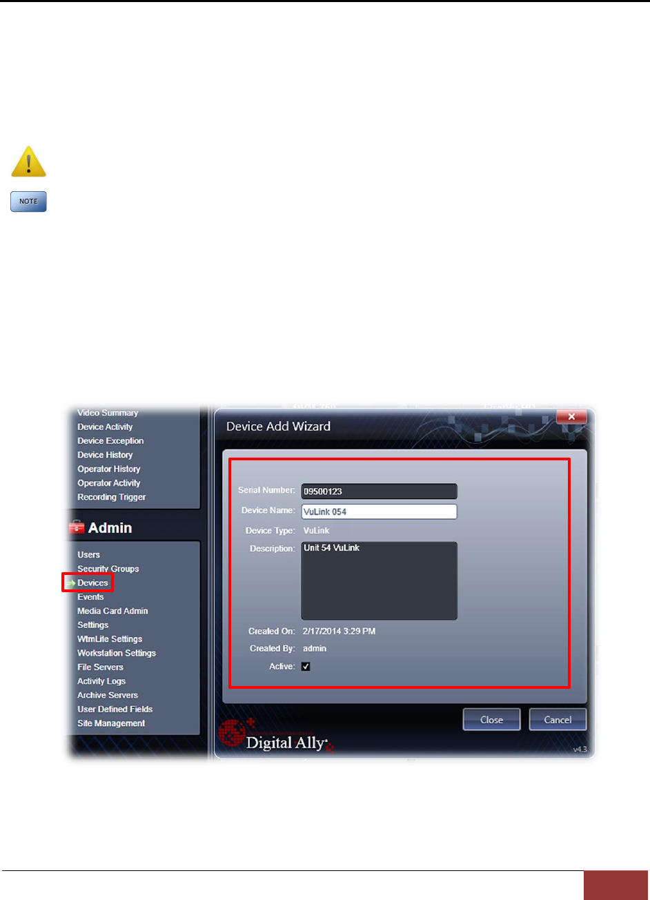
1. Before you can configure your device for use within VuVault, the serial numbers for
VuLink and associated FirstVuHD devices must be added into the system. Select
Admin>Devices>Add Device to add your devices into VuVault. Type in your device serial
numbers and assign a name within the system. When done, press Save (for more
information consult the VuVault User’s Guide “Adding Devices” section).
A configuration field will be available in the Admin>Settings tab within VuVault once a valid
VuLink serial number has been added into the system. These global settings will define how
your FirstVu HD’s will connect to VuLink.
VuLink Operation & Installation Guide 860-00198-00 REV A
Digital Ally, Inc. | VuLink Configuration
2-2
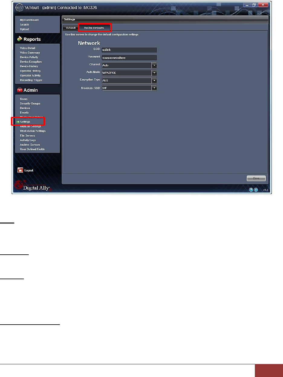
Configuring VuLink
VuLink acts as an 802.11n wireless access point which your FirstVu HD’s will use to
communicate with your in-car video system. After you have made your selections, press Save.
Network
SSID
The SSID is the wireless network name. This parameter specifies the VuLink SSID that
your FirstVu HD’s are authorized to connect to.
Password
This parameter specifies the password or security phrase required to connect to VuLink.
Channel
This parameter specifies the wireless channel that your FirstVu HD’s will use to connect
to the VuLink.
Settings: 1 to 11, Auto [default]
Authentication Mode
This parameter specifies the security authentication required by VuLink.
Settings: WPAPSK, WPA2PSK [default]
VuLink Operation & Installation Guide 860-00198-00 REV A
Digital Ally, Inc. | VuLink Configuration
2-3
Encryption Type
This parameter specifies the wireless encryption protocol required by VuLink. If selecting
WPA2PSK as the authentication mode, choose AES as the encryption type. If selecting
WPAPSK as the authentication mode, choose TKIP as the encryption type.
Settings: TKIP, AES [default]
Broadcast SSID
Choose whether or not to broadcast the SSID. Broadcasting allows computers with
wireless cards to find the network by browsing. Disabling the broadcast of the SSID
prevents browsing to find the network.
Settings: On, Off [default]
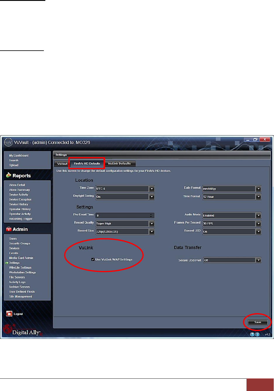
Configuring your FirstVu HD
Go to the FirstVu HD settings tab and check the “Use VuVault WAP settings” box as shown
below. When done, press Save.
VuLink Operation & Installation Guide 860-00198-00 REV A
Digital Ally, Inc. | VuLink Configuration
2-4
Activating VuLink & FirstVu HD within VuVault
After you have saved your desired configuration, proceed
to Admin>Media Card Admin to activate each device.
FirstVu HD Activation
1. Turn on your FirstVu HD & plug it into your
computer using the supplied USB cable.
2. Select FirstVu HD as the device type. Click
Refresh and the FirstVu HD will be displayed as a
removable drive.
3. Highlight the drive with your mouse.
4. Select Activate and unplug your FirstVu HD.
VuLink Activation
5. Plug in your VuLink into your computer using the supplied USB cable.
6. Select VuLink as the device type. Click Refresh and VuLink will be displayed as a
removable drive.
7. Highlight the drive with your mouse.
8. Select Activate.
9. All done! Proceed to Section 3 to install your VuLink.
Using the Configuration Manager to Configure your VuLink and FirstVuHD
VuLink must be configured prior to use. Configuration for VuLink is determined by the
configuration files that are downloaded to the device from the Mini Configuration Manager
supplied on the internal memory, or by using Digital Ally’s optional VuVault™ back-office
software.
If you have NOT purchased VuVault™, follow the instructions in this section to configure
and activate your device using the stand-alone Mini Configuration Manager software.
Installing the Software
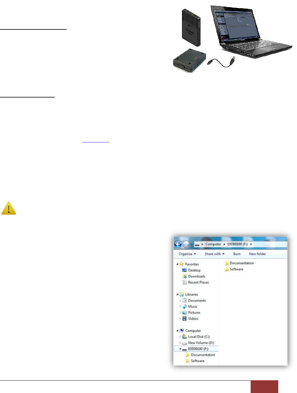
1. Your VuLink is preloaded with software and
documentation files located on its internal
memory. Plug VuLink into a computer using
the included USB cable to access these files.
2. The Documentation folder contains the
Operation Guide and Quick Start Guide. The
Software folder contains the Digital Ally Mini
Configuration Manager and Basic Viewer
software. If you purchased the optional
VuVault™ back office software, it will be
located separately on a DVD.
3. Open the Software folder and run the Digital
Ally Viewer installer. This will install all
necessary files to your computer.
VuLink Operation & Installation Guide 860-00198-00 REV A
Digital Ally, Inc. | VuLink Configuration
2-5
Configuring VuLink
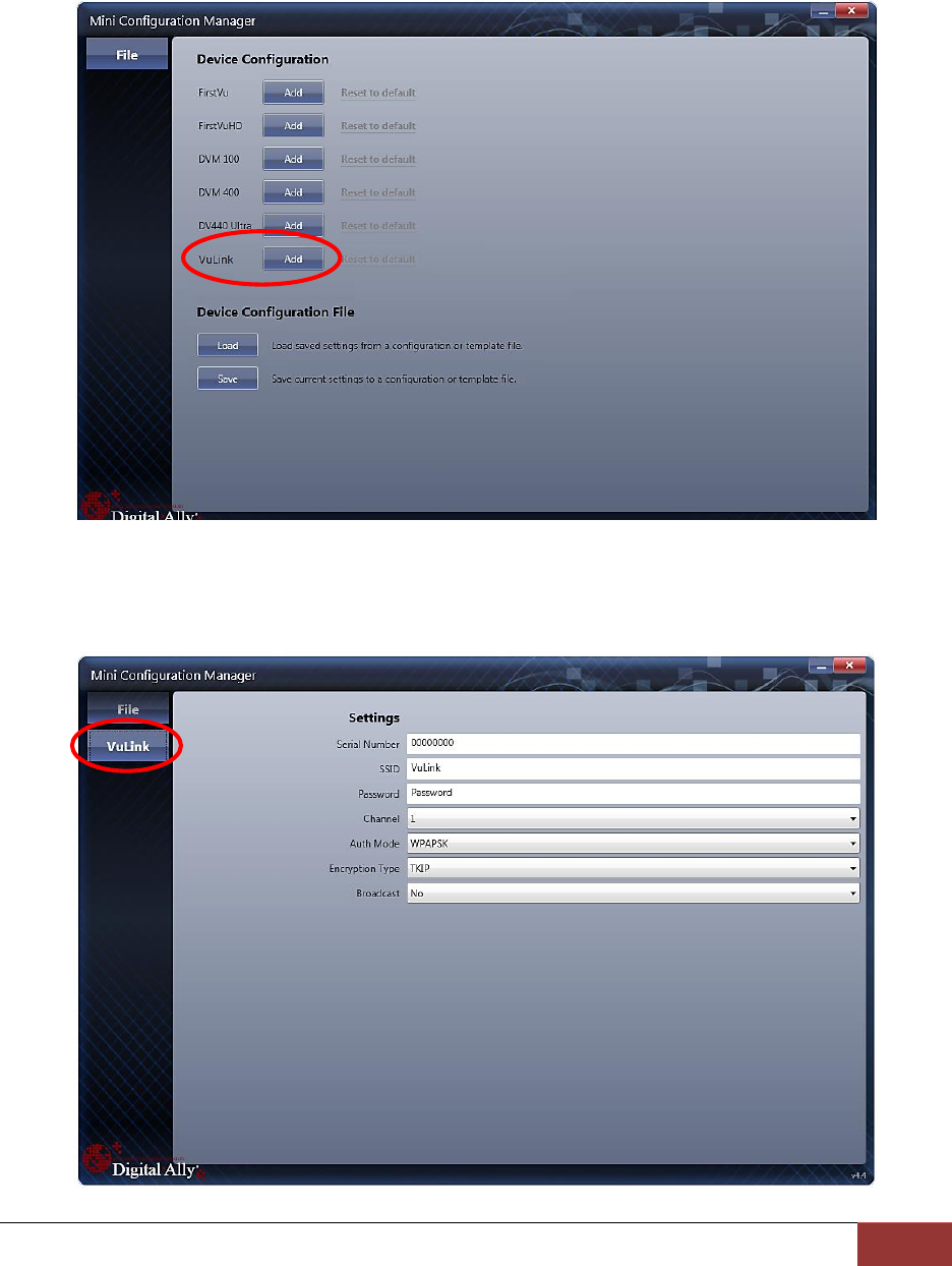
Press the Add button to display the list of available options for VuLink.
Select the Vulink tab. VuLink functions as an 802.11n wireless access point which your FirstVu
HD’s will use to communicate with your in-car video system. After you have made your
selections, return to the File tab to save your settings.
VuLink Operation & Installation Guide 860-00198-00 REV A
Digital Ally, Inc. | VuLink Configuration
2-6
Settings
Serial Number
This is the serial number printed on your VuLink device. Type in your serial number here.
(Example 09500061).
SSID
The SSID is the wireless network name. This parameter specifies the VuLink SSID that
your FirstVu HD’s are authorized to connect to.
Password
This parameter specifies the password or security phrase required to connect to VuLink.
Channel
This parameter specifies the wireless channel that your FirstVu HD’s will use to connect
to the VuLink.
Settings: 1 to 11, 1 [default]
Authentication Mode
This parameter specifies the security authentication required by VuLink.
Settings: WPAPSK, WPA2PSK [default]
Encryption Type
This parameter specifies the wireless encryption protocol required by VuLink. If selecting
WPA2PSK as the authentication mode, choose AES as the encryption type. If selecting
WPAPSK as the authentication mode, choose TKIP as the encryption type.
Settings: TKIP, AES [default]
Broadcast
Choose whether or not to broadcast the SSID. Broadcasting allows computers with
wireless cards to find the network by browsing. Disabling the broadcast of the SSID
prevents browsing to find the network.
Settings: On, Off [default]
Saving your VuLink Settings
1. Connect VuLink to your computer through the supplied USB cable.
Your computer will recognize it as a removable drive and the serial
number will be displayed.
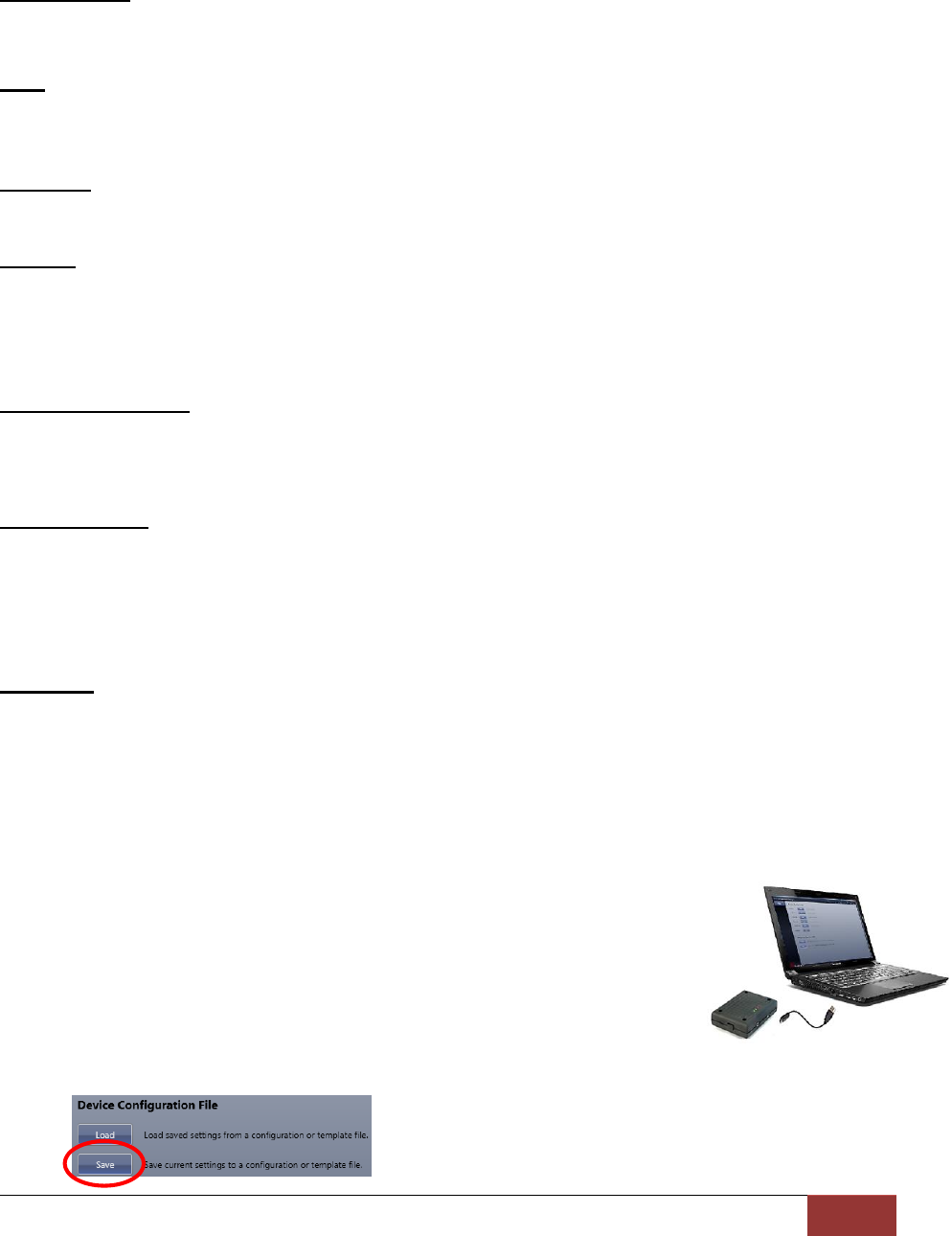
2. From the File Tab, Select Save. You’ll be prompted to select the
location of your Vulink device. You may also wish to back up the
configuration file to a location on your computer’s hard drive. The
configuration file named “deviceconfig” will be written to VuLink.
VuLink Operation & Installation Guide 860-00198-00 REV A
Digital Ally, Inc. | VuLink Configuration
2-7
3. All Done! VuLink is now ready to be installed in your vehicle. Proceed to Section 3.
Configuring your FirstVu HD
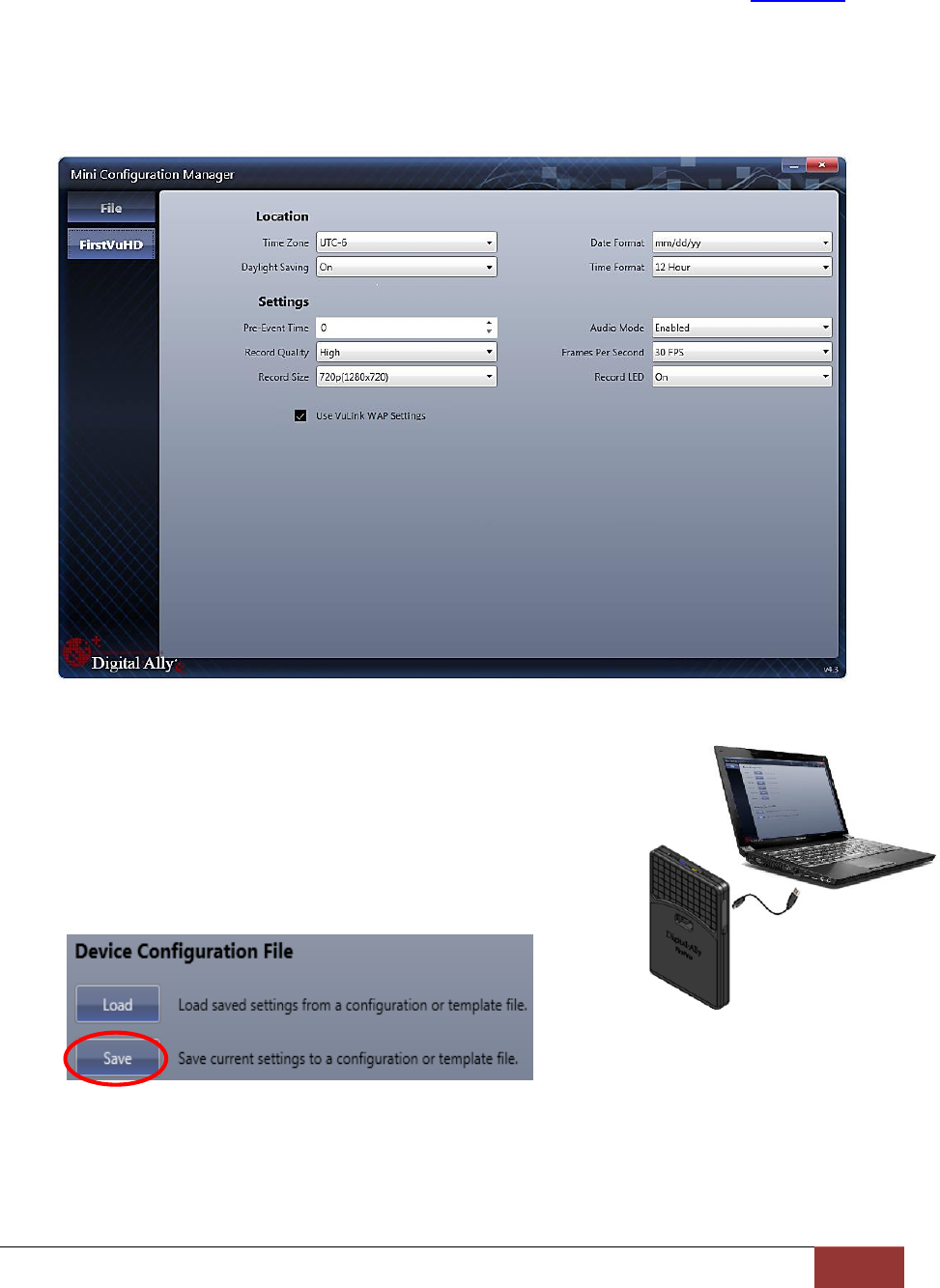
Go to the FirstVu HD tab and check the “Use VuLink WAP settings” box as shown below. When
done, return to the File tab to save your settings.
Saving your FirstVu HD Settings
1. Plug in your FirstVu into the computer using the supplied
USB cable.
2. From the File Tab, Select Save. You’ll be prompted to
select the location of your FirstVu HD device. You may also
wish to back up the configuration file to a location on your
computer’s hard drive.
3. The configuration file will be placed on your FirstVu HD. Reboot your FirstVu HD. The
FirstVu HD is now ready to be used with VuLink.
VuLink Operation & Installation Guide 860-00198-00 REV A
Digital Ally, Inc. | VuLink Configuration
2-8
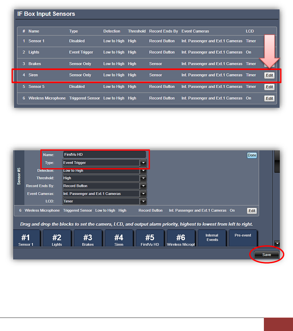
DVM-800, DVM-250, and DVM-250Plus Device Configuration
From your VuVault or Configuration Manager Settings tab, enable the desired sensor to be
used with VuLink. Using this configuration, the FirstVu HD will be enabled to trigger device
recordings and have a customized trigger name. This customized name will become a
searchable parameter if using VuVault.
1. Go to the IF Box Input Sensors tab. Select the Sensor 5 row and press Edit.
2. Select a name for the Sensor #5 VuLink trigger. Change Type to Event Trigger. When
done, press Save.
3. You will need to re-activate your DVM with the new device configuration. Consult your
device Operation Guide for instructions.
VuLink Operation & Installation Guide 860-00198-00 REV A
Digital Ally, Inc. | Installation Instructions
3-1
Section - 3: Installation Instructions
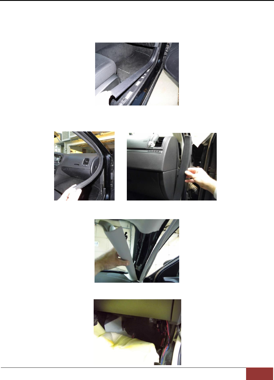
Step 1: Remove Body Trim
1. Remove front passenger side threshold
2. Pull the door seal away and remove any side trim pieces
3. Remove the passenger side front interior A-pillar cover
4. remove the passenger side kick panel & pull back the carpet to expose the vehicle
chassis
VuLink Operation & Installation Guide 860-00198-00 REV A
Digital Ally, Inc. | Installation Instructions
3-2
Step 2: Power Ignition, and Ground Connections
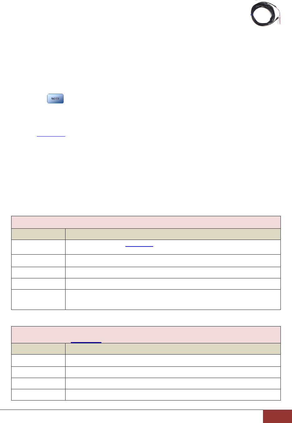
Remove 6 to 7 inches of the outer jacket at the bare end of the power cable.
The Red wire of the DVM power cable should be connected to the vehicle constant +12Vdc.
Connect the Blue wire to the ignition switch where +12vdc is only present when the vehicle
ignition key is in the ON position. The Black wire of this power cable connects directly to the
vehicle’s chassis. Secure all cables and in-line fuse housing using Velcro or standard tie wraps
as required.
It is required that this power wire be tied directly to vehicle power with no obstructions to
the vehicle battery such as a cutoff switch or charge guard system.
It is recommended that these connections are made directly to the engine
compartment battery wiring harness for best results.
Step 3: VuLink Trigger Connections
Consult the Section 4 diagrams for your specific video system or generic input trigger
connection. In some installations, you will use the supplied relay to connect to your desired
input trigger. When the trigger is active, the relay will be energized and VuLink will be triggered.
If the input trigger is not active, the relay will not be energized.
If a relay is required for your installation, located the light trigger input wire from the DVM and
connect it directly to the WHITE wire on the VuLink Base Cable using a butt splice connector.
Connect the light trigger from the light bar controller to the relay.
Make the connections as shown in the tables below:
VuLink Base Cable Connections
Wire Color
Connection
WHITE
Consult diagrams in Section 4. Do not connect directly to light bar controller
output.
BLACK
Chassis ground
RED
+12VDC Battery terminal
BLUE
+12VDC Switched ignition
BROWN
For DVM-800/DVM-LIVE/DVM-250, connect to BROWN wire of I/O box
harness. For all other installations connect to RED wire from included relay.
Relay Connections
Check Section 4 to verify if your installation requires a relay
Wire Color
Connection
WHITE
Connect to +12DVC when emergency lights are active.
WHITE
Chassis ground
RED
Connect to BROWN wire on VuLink Base Cable
YELLOW
Chassis ground
VuLink Operation & Installation Guide 860-00198-00 REV A
Digital Ally, Inc. | Installation Instructions
3-3
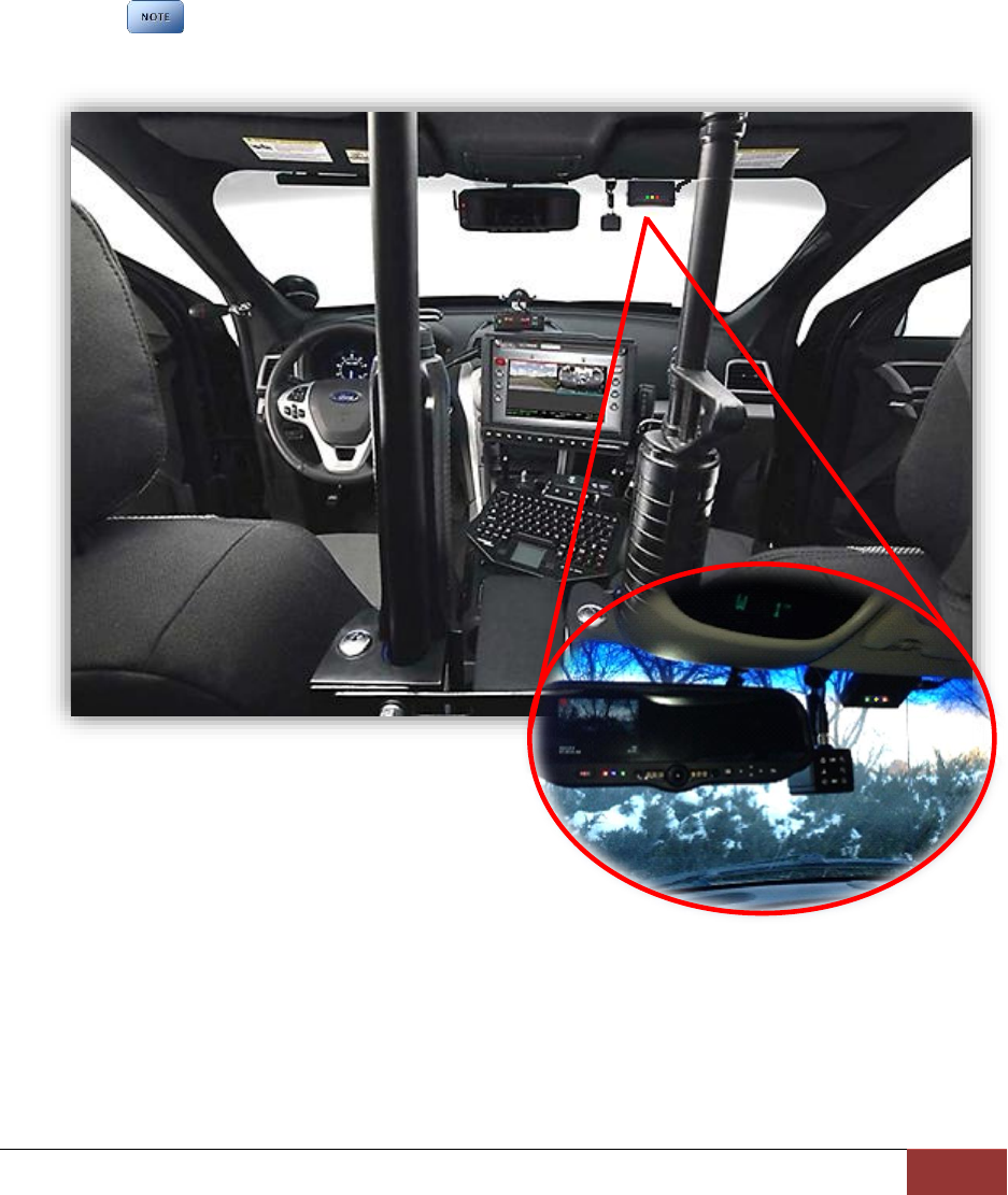
Step 4: VuLink Installation
Plug the base cable into the connector on the side of VuLink. Prep the windshield glass with
alcohol to remove any dirt or debris. Using the included double-sided tape, attach VuLink to
an unobstructed location on the windshield below the roofline. To avoid possible interference
from other vehicle equipment, do not mount VuLink near other vehicle antennas.
The GREEN power LED will be illuminated as long as it is receiving battery power,
regardless of the ignition switch position.
VuLink Operation & Installation Guide 860-00198-00 REV A
Digital Ally, Inc. | Model-Specific Wiring Diagrams
4-1
Section - 4: Model-Specific Wiring Diagrams
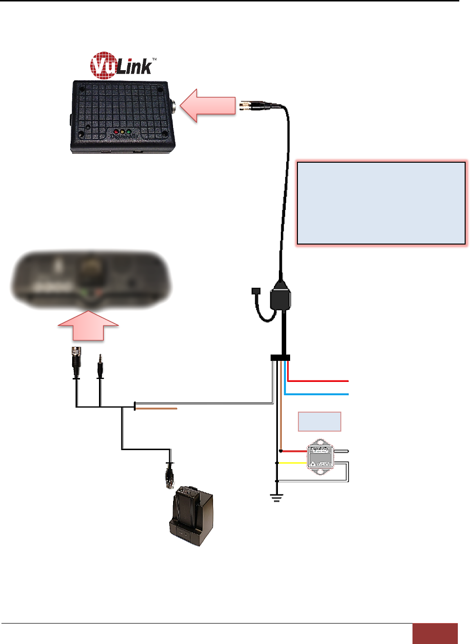
DVM-100 / DVM-400
DVM
VuLink Base Cable
008-01456-00
RED = +12VDC Battery
BLUE = +12VDC Ignition
BLACK = Chassis Ground
WHITE = Emergency Light Input
WHITE = Tie to ground
Relay
(see
belo
w)
DWM800
Sensor Cable
Connect WHITE wire from
VuLink Base Cable to WHITE
wire of DWM800 sensor cable
VuLink Relay Wiring
WHITE = connect to Emergency lights
WHITE = connect to chassis ground
YELLOW = connect to chassis ground
RED = connect to BROWN wire on
VuLink base cable
NC
VuLink Operation & Installation Guide 860-00198-00 REV A
Digital Ally, Inc. | Model-Specific Wiring Diagrams
4-2
DVM-500Plus / DVM-750
VuLink Relay Wiring
WHITE = connect to Emergency lights
WHITE = connect to chassis ground
YELLOW = connect to chassis ground
RED = connect to BROWN wire on
VuLink base cable
BLUE = +12VDC Switched Ignition
RED = +12VDC Battery
WHITE = Emergency Light Input
WHITE = Tie to ground
BLACK = Chassis Ground
Connect WHITE wire from
VuLink Base Cable to
ORANGE wire of I/O BOX
input sensor cable
Relay
(see
belo
w)
DVM
VuLink Base Cable
008-01456-00
I/O Box
DVM
NC
VuLink Operation & Installation Guide 860-00198-00 REV A
Digital Ally, Inc. | Model-Specific Wiring Diagrams
4-3
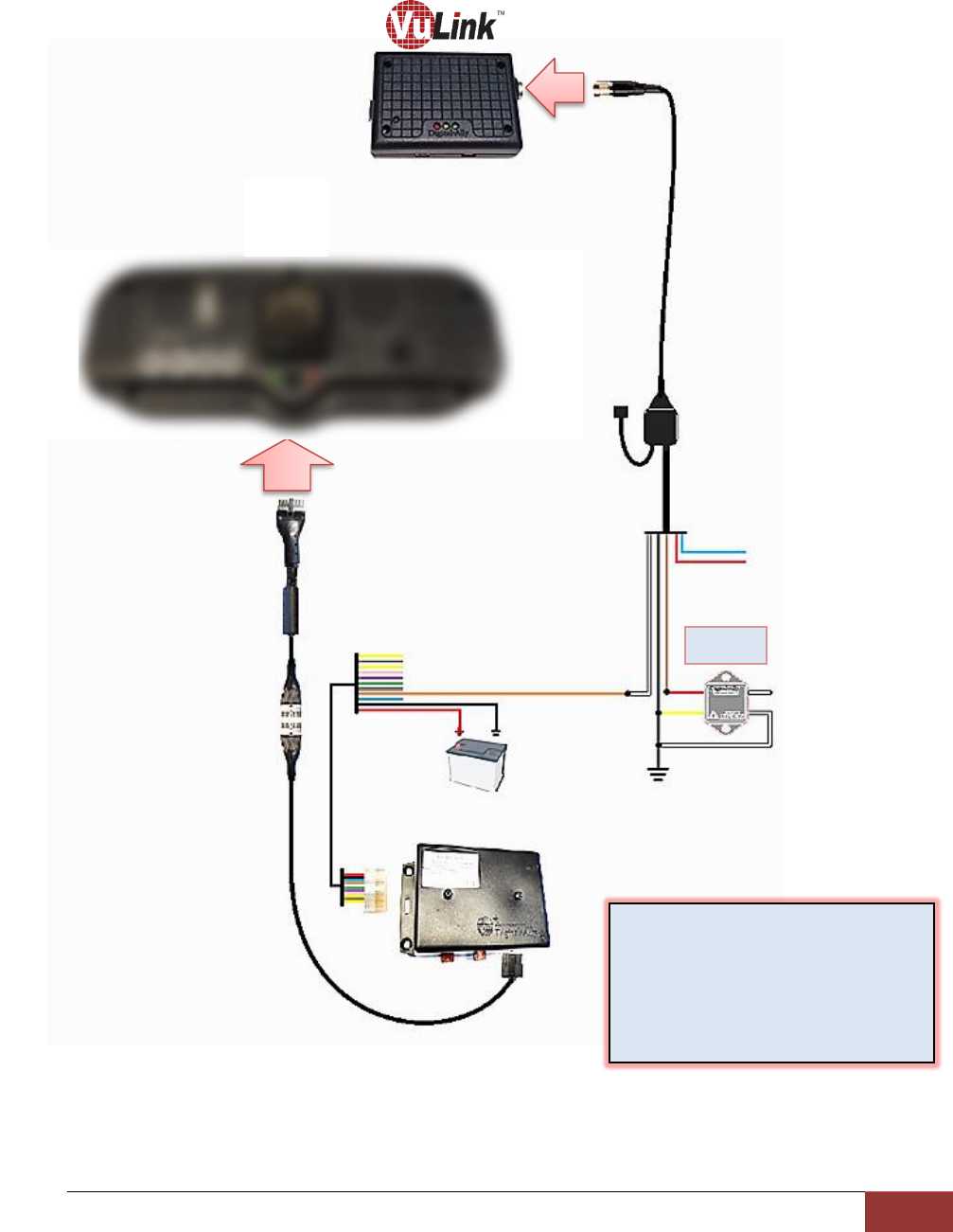
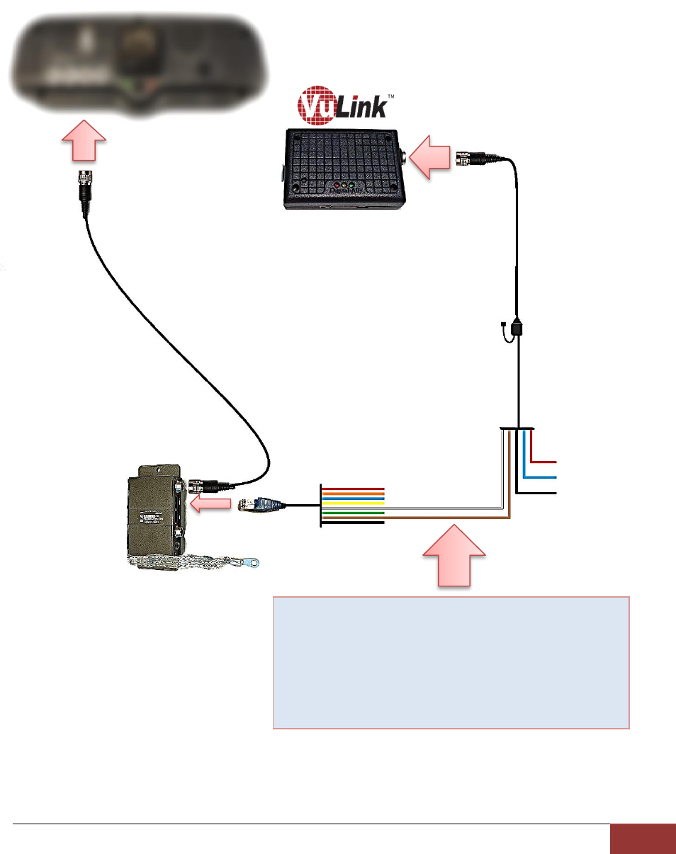
DVM-800 / DVM-LiVE
I/O Box
VuLink Base Cable
008-01456-00
RED = +12VDC Battery
BLACK = Chassis Ground
BLUE = +12VDC
Switched Ignition
Connect WHITE wire
from VuLink Base Cable
to WHITE wire of I/O
box sensor cable
(Sensor 5)
Connect BROWN
wire from VuLink
Base Cable to
BROWN wire of I/O
box sensor cable
DVM
NC
VuLink Operation & Installation Guide 860-00198-00 REV A
Digital Ally, Inc. | Model-Specific Wiring Diagrams
4-4
DV-440Ultra
BLUE = +12VDC Switched Ignition
RED = +12VDC Battery
WHITE = Emergency Light Input
WHITE = Tie to Ground
VuLink Base Cable
008-01456-00
Connect WHITE wire from
VuLink Base Cable to WHITE
wire of DWM800 sensor cable
VuLink Relay Wiring
WHITE = connect to Emergency lights
WHITE = connect to chassis ground
YELLOW = connect to chassis ground
RED = connect to BROWN wire on
VuLink base cable
Relay
DWM800
Sensor Cable
9 pin
NC
BLACK = Chassis Ground
VuLink Operation & Installation Guide 860-00198-00 REV A
Digital Ally, Inc. | Model-Specific Wiring Diagrams
4-5
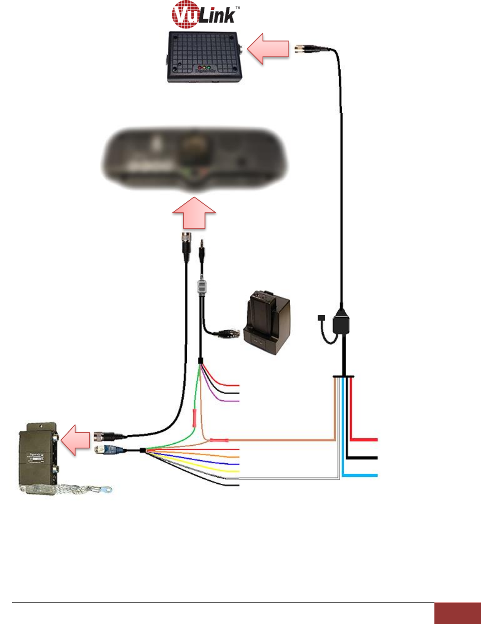
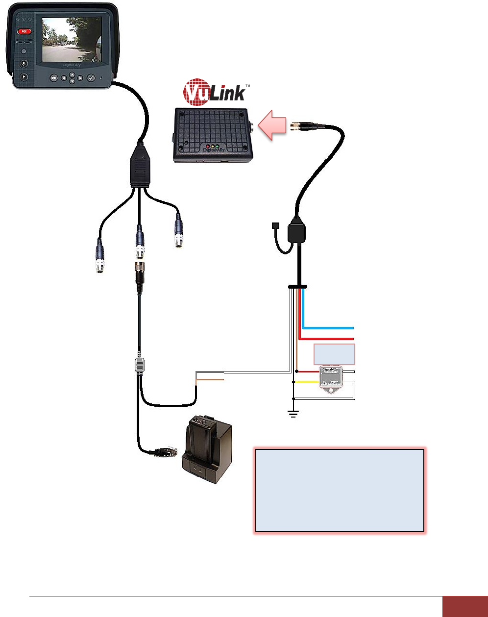
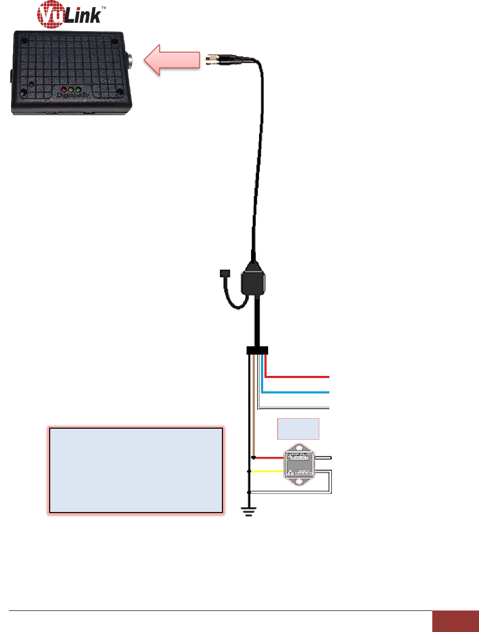
DVM-250Plus or DVM250 (with interface box)
RED = +12VDC Battery
BLUE = +12VDC Ignition
BLACK = Chassis Ground
VuLink Base Cable
008-01456-00
DVM
I/O Box
1. Connect WHITE wire from VuLink Base Cable to
WHITE wire of I/O box input sensor cable
(Sensor 5)
2. Connect BROWN wire from VuLink Base Cable
to BROWN wire of I/O box input sensor cable
(output alarm)
NC
VuLink Operation & Installation Guide 860-00198-00 REV A
Digital Ally, Inc. | Model-Specific Wiring Diagrams
4-6
Generic Input Source
RED = +12VDC Battery
BLUE = +12VDC Ignition
WHITE = +12VDC Auxiliary output
(enabled when VuLink is activated)
VuLink Relay Wiring
WHITE = connect to Input Trigger
WHITE = connect to chassis ground
YELLOW = connect to chassis ground
RED = connect to BROWN wire on
VuLink base cable
WHITE = +12VDC Generic Input Trigger
WHITE = Tie to Ground
VuLink Base Cable
008-01456-00
Relay
NC
BLACK = Chassis Ground
VuLink Operation & Installation Guide 860-00198-00 REV A
Digital Ally, Inc. | Operation
5-1
Section - 5: Operation
Power Control
Power to VuLink is controlled through your vehicle’s ignition. There are no manual controls for
powering the unit on and off. When ignition is cycled, the VuLink boot-up process will begin. The
red and green status indicators will flash in unison until boot up is complete. When ignition is
turned off, the VuLink will enter low power standby and will then power off. No LED’s will be
illuminated when ignition is off.
Testing the System
1. The Green status indicator will be illuminated whenever battery power is present,
regardless of the ignition switch position.
2. Turn on your vehicle’s ignition. The yellow and red status indicators will blink in unison
as the VuLink is booting up.
3. Once the boot-up process is complete, the Yellow status indicator will flash as VuLink
tried to establish a wireless connection with your configured FirstVuHD’s.
4. When a wireless link is established, the Yellow status indicator on VuLink will remain lit
as long as the FirstVu is within range. Typical range is 40ft.
5. The Yellow status indicator will also remain illuminated to the FirstVu HD. Typical range
is 40ft.
6. Power on your in-car video system (ICV).
7. Start an event recording by activating your emergency lights.
8. The Red status indicator on the VuLink will turn on to indicate the event is being
recorded. The Red status indicator on the FirstVuHD and ICV should also turn on
indicating that they are also recording.
Whenever VuLink is connected to a FirstVu HD and the system is actively
recording, all 3 status indicators will remain illuminated.
9. After 10 seconds, press the RECORD Stop button on your ICV to stop the event record.
All Red status indicators on the ICV, VuLink, and FirstVuHD will turn off.
10. Press the record button on your FirstVuHD to start a new recording. All Red status LED’s
on VuLink, FirstVuHD, and ICV will illuminate to indicate the system is recording.
11. Press the RECORD Stop button on your ICV to stop the event record. All Red status
LED’s on the DVM, VuLink, and FirstVuHD will turn off.
Covert Mode
Pressing the covert button on the left side of
VuLink will temporarily turn off all status LED’s
until the next power cycle.
VuLink Operation & Installation Guide 860-00198-00 REV A
Digital Ally, Inc. | Operation
5-2
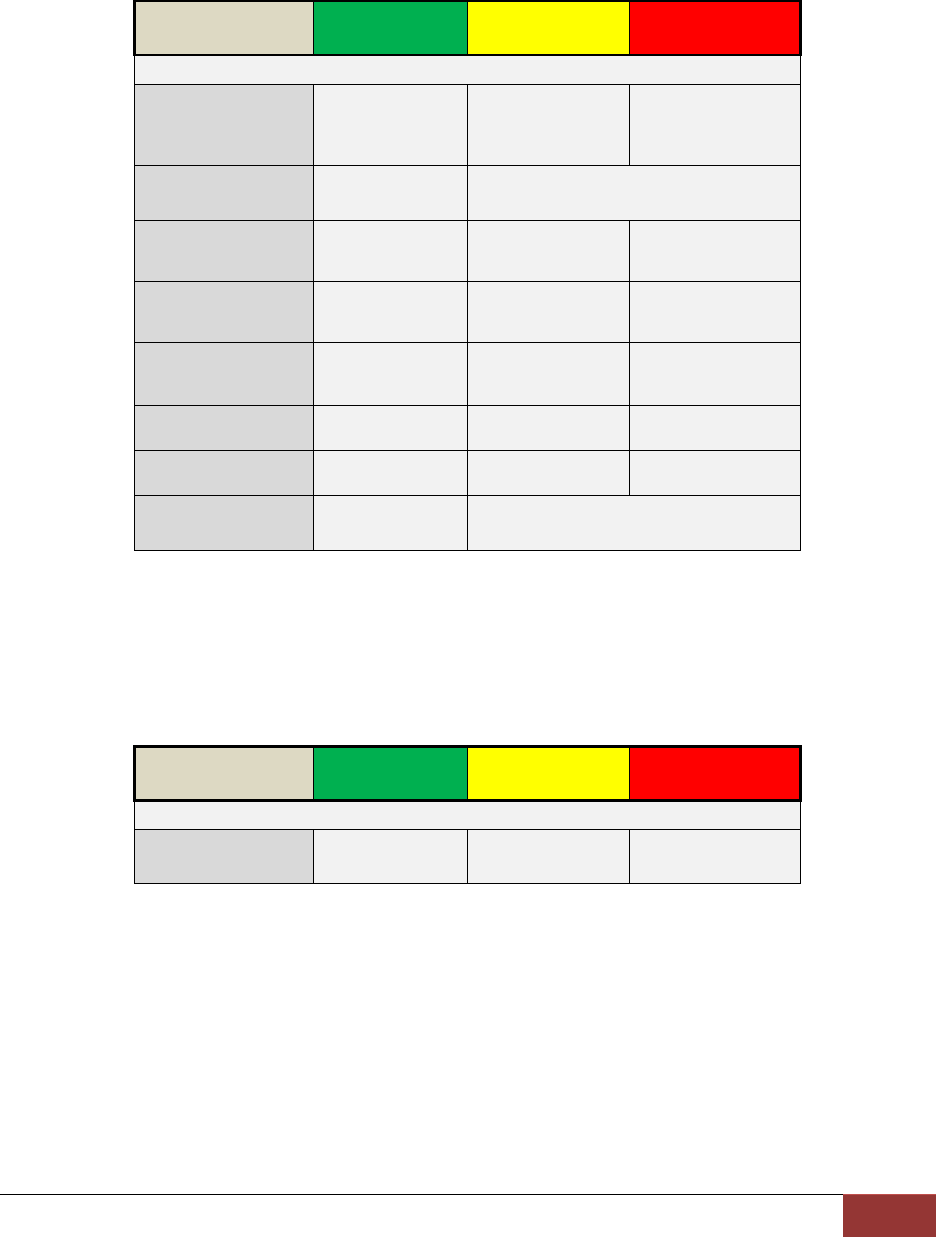
VuLink™ LED Status Indicators
GREEN
YELLOW
RED
Battery Power
present to
VuLink
ON
--
--
Power-on
Sequence
ON
Flash in unison
Searching for
Wireless Link
--
Flash
--
Wireless Link
Established
--
ON
--
Record in
Progress
--
--
ON
Covert Mode
OFF
OFF
OFF
Ignition Off
ON
OFF
OFF
Firmware
Upgrade
ON
Alternating flash
FirstVuHD™ LED Status Indicators
The FirstVuHD yellow status LED will be on whenever a wireless link is established with VuLink.
For a complete list of status indicators, consult the FirstVu HD Operation Guide.
GREEN
YELLOW
RED
Wireless Link
Established
--
ON
--
VuLink Operation & Installation Guide 860-00198-00 REV A
Digital Ally, Inc. | Support
6-1
Section - 6: Support
Software Updates
Log on to www.digitalallyinc.com/tech-support.php and Register for an Account to be an
Authorized User. By registering you will be able to download all the latest software updates
and be notified of future updates.
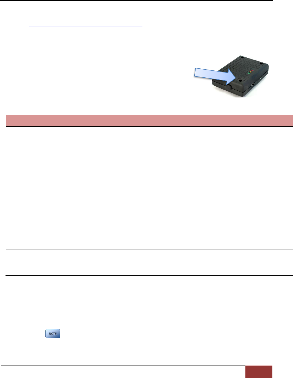
Performing a Reset
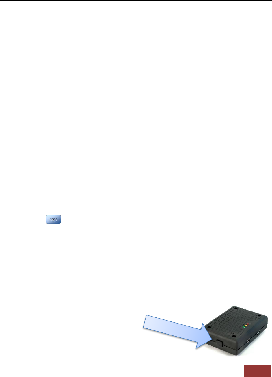
Using a small device such as a paper clip or eye-glass
screwdriver, press the recessed reset button that is
located as shown to the right. After a reset occurs,
VuLink will determine if a firmware file is present and
read the deviceconfig for changes.
Troubleshooting
Symptom
Resolution
Green Status indicator not lit
Verify the power cable connector is connected to VuLink.
Verify there are no breaks, pinches, or cuts in the wiring or cable harness.
Check the wiring and voltage levels to the red and black wires on the VuLink
cable harness. Should be constant 12vdc measured across these two wires.
Red/Blue status indicators
do not blink in unison when
ignition is applied
Verify the power cable connector is connected to VuLink.
Verify there are no breaks, pinches, or cuts in the wiring or cable harness.
Check the wiring and voltage levels to the red and black wires on
the VuLink cable harness. Should be constant 12vdc measured
across these two wires.
Yellow light is always
blinking / FirstVu HD will not
connect to VuLink
FirstVu HD is out of range.
FirstVu HD and/or VuLink not properly configured. Recheck device
configurations in Section 3.
Reset the system.
Contact technical support if problem persists.
Poor wireless range
Ensure Vulink is properly mounted to windshield and no other
vehicle antennas or obstructions are nearby.
FirstVu HD battery may be low. Replace FirstVu HD battery.
Product Repair
VuLink should be returned to Digital Ally for service. The warranty may be voided if the device
is opened by any unauthorized individual. Please contact Digital Ally to obtain a Return
Materials Authorization (RMA). It is helpful and will expedite the process if you have your unit’s
serial number available at the time of your call.
All In-Warranty and Out-of-Warranty service must be performed by
Digital Ally, Inc. There are no user serviceable parts inside of VuLink.

VuLink Operation & Installation Guide 860-00198-00 REV A
Digital Ally, Inc. | Warranty Information
7-1
Section - 7: Warranty Information
We warranty that our wireless link, Model VuLink™, will be free from defects in workmanship and
material for a period of 12 months from the date of purchase by the original purchaser. If any
defect is discovered through normal and proper use of the unit during this period, the defect will
be repaired or the unit will be replaced at our factory or at one of our authorized service centers
at no cost to the purchaser. The purchaser must return the defective unit to the factory or one of
our authorized service centers, freight prepaid. We will pay for shipping charges for the return of
the unit.
This warranty applies only to defects in a unit’s internal electronic components and circuitry,
and is void as to units that have been opened without prior authorization, have experienced
unauthorized repairs, or have had unauthorized modifications. This warranty does not cover the
following:
Normal wear and tear on the unit such as batteries, frayed cables or wires, broken
connectors, or scratched or broken cases.
Damage caused by operator abuse or neglect.
Damage caused by incorrect use of the unit, carelessness, unauthorized alterations
to the unit, improper storage of the unit or unauthorized service, installation or repairs
made to the unit.
Damage caused by fire, flood, lightning, vandalism, collision, acts of God, or
other events beyond the reasonable control of Digital Ally, Inc. or the purchaser.
Damage to external parts of the unit such as buttons, wires, and cables, etc.
Damage from use of the unit in hostile operating environments.
We reserve the right to charge for repairs to a unit during the warranty period made necessary
because of any of the foregoing causes at our standard rates for repair of units not under
warranty.
The purchaser assumes all risk of use from its purchase and use of the unit. Harmful personal
contact with a unit might occur in the event of violent maneuvers, collisions, or similar
circumstances, even if the unit was properly installed and used. We are not responsible for, and
we specifically disclaim any liability for injury caused by a unit in such circumstances.
THIS WARRANTY IS GIVEN IN LIEU OF ALL OTHER WARRANTIES. THERE ARE NO
WARRANTIES THAT EXTEND BEYOND THIS STATEMENT. ALL IMPLIED WARRANTIES ARE
DISCLAIMED, INCLUDING, WITHOUT LIMITATION, WARRANTIES OF MERCHANTABILITY, NON-
INFRINGEMENT, FITNESS FOR A PARTICULAR PURPOSE, AND WARRANTIES IMPLIED FROM A
COURSE OF DEALING, COURSE OF PERFORMANCE OR USAGE OF TRADE. THE PURCHASER’S
SOLE AND EXCLUSIVE REMEDY FOR A WARRANTY CLAIM WILL BE THE REPAIR OR
REPLACEMENT OF A UNIT.

VuLink Operation & Installation Guide 860-00198-00 REV A
Digital Ally, Inc. | Contact Information
8-1
Section - 8: Contact Information
9705 Loiret Blvd
Lenexa, KS 66219
Website:
www.digitalallyinc.com
Support E-Mail:
support@digitalallyinc.com
Sales E-Mail:
sales@digitalallyinc.com
Phone:
913-814-7774
Fax:
913-814-7775
Sales / Support Toll Free:
1-800-440-4947
* Specifications subject to change without notice.

VuLink Operation & Installation Guide 860-00198-00 REV A
Digital Ally, Inc. | Regulatory
9-1
Section - 9: Regulatory
This device complies with Part 15 of the FCC Rules. Operation is subject to the following two
conditions: (1) This device may not cause harmful interference, and (2) This device must accept
any interference received, including interference that may cause undesired operation.
This equipment has been tested and found to comply with the limits for a Class B digital device,
pursuant to part 15 of the FCC Rules. These limits are designed to provide reasonable
protection against harmful interference in a residential installation. This equipment generates
uses and can radiate radio frequency energy and, if not installed and used in accordance with
the instructions, may cause harmful interference to radio communications. However, there is
no guarantee that interference will not occur in a particular installation. If this equipment does
cause harmful interference to radio or television reception, which can be determined by turning
the equipment off and on, the user is encouraged to try to correct the interference by one or
more of the following measures:
Reorient or relocate the receiving antenna.
Increase the separation between the user equipment and VuLink.
Connect the user equipment into an outlet on a circuit different from that to which VuLink
is connected.
Contact Digital Ally technical support.
This device complies with Industry Canada licence-exempt RSS standard(s). Operation is
subject to the following two conditions: (1) this device may not cause interference, and (2) this
device must accept any interference, including interference that may cause undesired operation
of the device.
Le présent appareil est conforme aux CNR d'Industrie Canada applicables aux appareils radio
exempts de licence. L'exploitation est autorisée aux deux conditions suivantes : (1) l'appareil ne
doit pas produire de brouillage, et (2) l'utilisateur de l'appareil doit accepter tout brouillage
radioélectrique subi, même si le brouillage est susceptible d'en compromettre le
fonctionnement.
The CE Mark is a European marking of conformity indicating that a product complies with the
essential requirements of the applicable European laws or Directives with respect to safety,
health, environment, and consumer protection.
Changes or modifications not expressly approved by Digital Ally, Inc. could void the user’s
authority to operate the equipment.