Digital Barriers Services 1 The RDC2 Sensor Node is an Unattended Ground Sensor (UGS) User Manual User man
Digital Barriers Services Ltd The RDC2 Sensor Node is an Unattended Ground Sensor (UGS) User man
User man

Copyright 2018 Digital Barriers plc
USER GUIDE
RDC SETUP AND DEPLOYMENT
VERSION 2.0 – AUGUST 18
RDC from Digital Barriers is a revolutionary unattended ground sensor (UGS) system for intrusion detection and remote
asset protection. It combines an innovative rapid deployment design, exceptional power efficiency, accurate target
detection/classification and intelligent mesh-based two-way wireless networking.
This document provides detailed instructions for using and deploying RDC systems. The following Windows
applications are provided for use with RDC networks:
RDC Staging Tool – an application for creating RDC networks by setting the operating frequency and network
ID.
RDC Config – an application for setting the configuration parameters of each node in a network. It can be used
in a standalone mode or within EdgeVis Shield when used with EdgeVis equipment.
This user guide covers the UM, UM+ and RDC2 variants of RDC.
There are separate RDC Staging Tool and RDCConfig user guides. This document should be read in conjunction with
those documents.
RDC Sensor Nodes use Lithium Thionyl Chloride batteries. Handling instruction and precautions for safe use of these
batteries is provided in Annex C.
RDC
USER GUIDE – RDC SETUP AND DEPLOYMENT
ISSUED: 21 AUGUST 2018 PAGE 2
1. Operating Concept
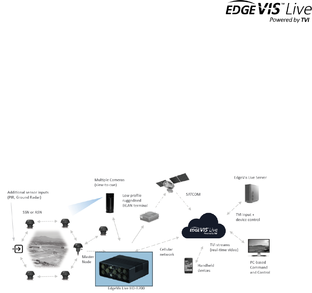
An RDC network comprises RDC Sensor Nodes (SN) and an RDC Master Node (MN). The SNs are passive devices that
are buried in the ground to provide intruder detection with classification (person, vehicle or digging). A person walking
or a vehicle moving creates seismic vibrations in the ground. The SNs detect the vibrations and process them to
determine whether the intrusion is a vehicle or person. RDC is also able to classify digging activity using a shovel or
pick axe. SNs report to the MN over a wireless communications link. The MN communicates this information to a user
terminal, such as a laptop or another device containing a modem such as a Digital Barriers encoder/communications
hub.
The RDC network is a self-forming, self-healing network. Nodes can act as relays for other nodes whilst simultaneously
performing a seismic sensing role. All communications are terminated at the Master Node which acts as the gateway
to other devices/monitors.
A typical deployment scenario is shown below:
USER GUIDE – RDC SETUP AND DEPLOYMENT
ISSUED: 21 AUGUST 2018 PAGE 3
2. RDC System Components
2.1 Sensor Node (SN)
A detection system consists of a number of deployed Sensor Nodes (SNs).
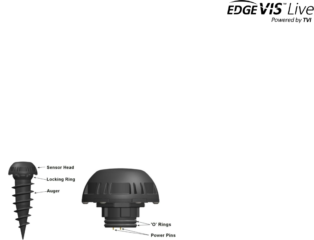
The SNs are in two parts, the sensor head and the auger. The sensor head contains the detection and wireless
communications electronics. The auger holds the battery and connects to the sensor head using a push fit connection.
The locking ring holds the sensor head and the auger tube together.
The radio antenna is housed within the sensor head.
Each sensor has a unique identification number (ID). This can be found on the brass plate on the underside of the sensor
head. There is also a brass label with the letters signifying the type of RDC node (UM, UM+ or RDC2). Feature differences
between UM, UM+ and RDC2 can be found in the RDC Config user guide.
2.2 Master Node (MN)
The Master Node is a gateway device with two-way communications to the Sensor Nodes. It manages the network
communications. Fusion, which is a powerful method for minimising false alarms, can be set and applied on the Master
Node. It also monitors the network for loss of communications to any node. See RDC Config user guide for details of
fusion and loss of comms.
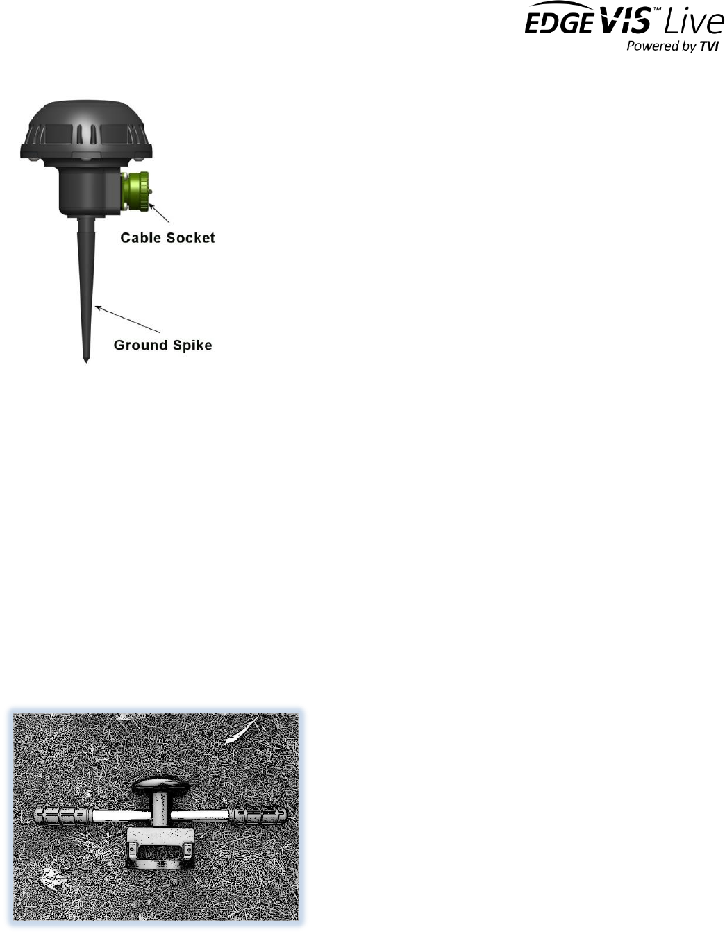
The MN has a connector mounted on the side. Power and communication is provided through this connector. The MN
has a M10 threaded hole in the bottom to allow it to be mounted to a bracket or fitted with the ground spike. The MN
must be oriented as shown in the picture below in order to align the internal antenna correctly for optimising the radio
communications.
USER GUIDE – RDC SETUP AND DEPLOYMENT
ISSUED: 21 AUGUST 2018 PAGE 4
2.3 Cables
The MN can be connected to a number of systems to which it can report intrusion events. The cable type always
supplied with RDC is the RDC Master Node USB Cable. The USB cable is used for connecting to the USB port of a
Windows PC/laptop/tablet. The host device provides USB power to the MN.
A Serial and Power Cable may be supplied for connecting the MN to a serial port of another device (e.g. Digital Barriers
M350 and C310 encoders). There is a separate connection for providing power such that the cable is ‘Y’-shaped.
Alternative cables are available for connection to other equipment such as the SD-R500 ‘Tri-Star’ and HD_R700 ‘Tri-
Star 2’.
2.4 Deployment tool
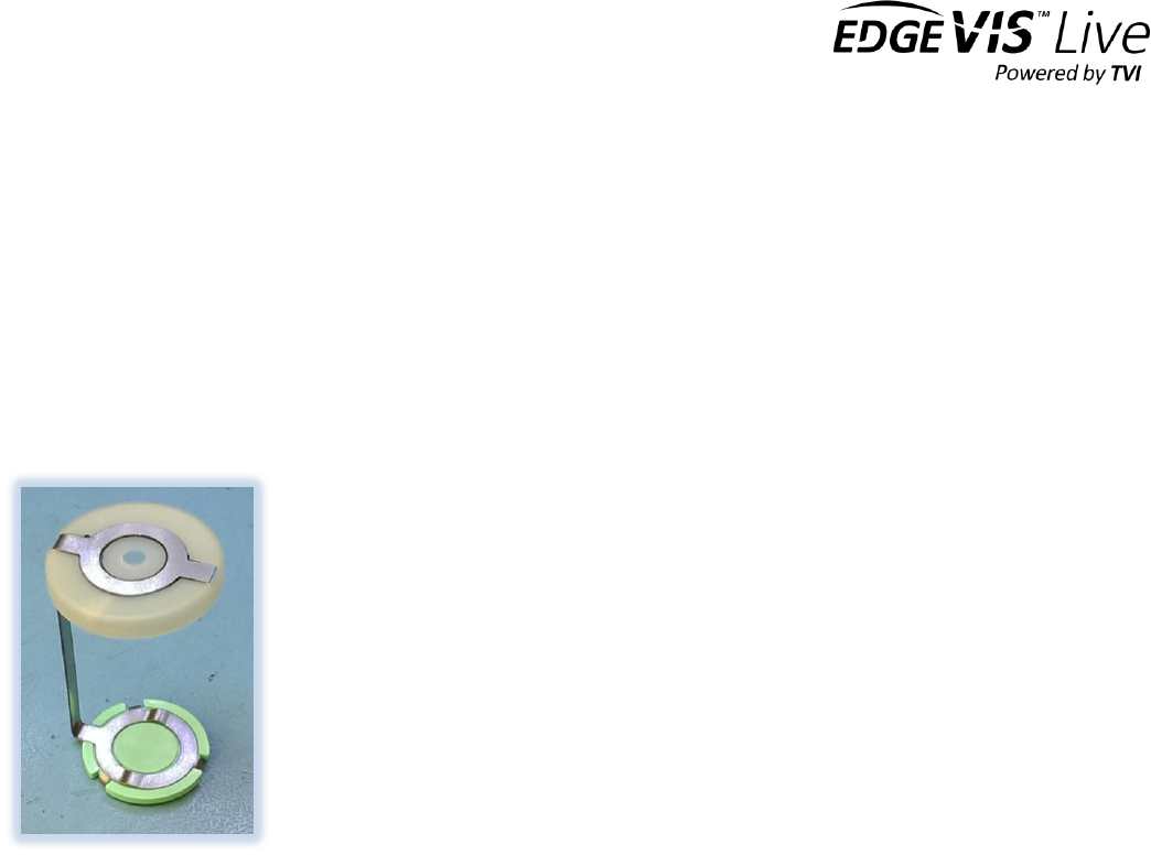
The deployment tool fits over the sensor head like a spanner. The palm rest on the top of the tool is designed to allow
the user to apply sufficient pressure to ensure that the node is deployed correctly. It is important to keep one hand
pressing down on the palm rest as this will help guide the node into the ground straight and help prevent the tool from
slipping off the node. The tool must be used correctly to prevent damage to the Sensor Nodes.
USER GUIDE – RDC SETUP AND DEPLOYMENT
ISSUED: 21 AUGUST 2018 PAGE 5
2.5 Other equipment required
Terminal: the RDC MN is designed to enable direct connection to a Windows PC, laptop or tablet running Digital
Barriers RDC Config or Staging Tool software via USB.
Master Node Power Supply: if using the Serial and Power Cable a 5-36V DC power supply is required for providing
power to the MN. If this is to be deployed outside it will need to be environmentally protected and employ a safety
isolating transformer if mains powered.
Batteries for Sensor Nodes: each SN is powered by a 3.6v Lithium Thionyl Chloride battery. Recommended batteries
are the Saft LS33600 and the Tadiran SL2780/S (TL-5930 in North America). A battery clip is provided for connecting
the negative terminal of the battery to the electronics enclosure.
Figure 1: Battery clip

USER GUIDE – RDC SETUP AND DEPLOYMENT
ISSUED: 21 AUGUST 2018 PAGE 6
3. Getting Started
3.1 Equipment check
Check that all the required kit is readily to hand. This should include:
A Master Node
At least one Sensor Node
A deployment tool
Batteries for each SN. Recommended batteries are the Saft LS33600
and the Tadiran SL2780/S (TL-5930 in the USA)
A battery clip for each SN
Windows PC/laptop/tablet suitably protected for use outdoors if required
RDC Master Node USB Cable
USB stick containing the RDC Staging Tool RDC Config and User Manuals
3.2 Care and handling
RDC contains a sensitive sensor in order to detect seismic vibrations. SNs should be carried with reasonable care and
not subject to excessive shock. Care must be taken not to damage or puncture the battery. Damaged batteries should
not be used. Care must also be taken not to allow the inside of the battery enclosure to become wet. Ensure that the
seals are clean and in good condition, and that the locking ring is secure but not overtightened.
3.3 Install software
Install the RDC Staging Tool and RDC Config software on the terminal. RDC Config will be installed as part of EdgeVis
Shield if provided, otherwise it can be installed standalone.
3.3 Create a Network
RDC systems will often be supplied pre-connected i.e. there is no need to set-up the network. However, if this is not
the case the RDC Staging Tool should be used. Connect the Master Node to the terminal using the Master Node USB
cable supplied. Run the Staging Tool from the Digital Barriers folder in the Start Menu. See RDC Staging Tool User
Guide for further instructions.
The Staging Tool can be used to add additional nodes to the network.
3.3 Configure Sensors
Usually some initial configuration of the Sensors will need to be undertaken prior to deployment. Use RDC Config to
set the desired configuration.
If there is no encoder/communications hub run RDC Config in standalone mode from the Digital Barriers folder in the
Start Menu. Connect the Master Node to the terminal using the Master Node USB cable supplied. Run RDC Config
from the Digital Barriers folder in the Start Menu. See RDC Config User Guide for further instructions.
If there is an encoder/communications hub the configuration can be done from RDC Config within EdgeVis Shield. In
this case the Master Node is connected to the encoder/communications hub via the cable supplied.
USER GUIDE – RDC SETUP AND DEPLOYMENT
ISSUED: 21 AUGUST 2018 PAGE 7
4. Deploying a Sensor
4.1 Installing the Battery
Check the auger tube to ensure it is dry and free from dirt/sand
When opening the unit to replace a battery ensure you are in a dry environment.
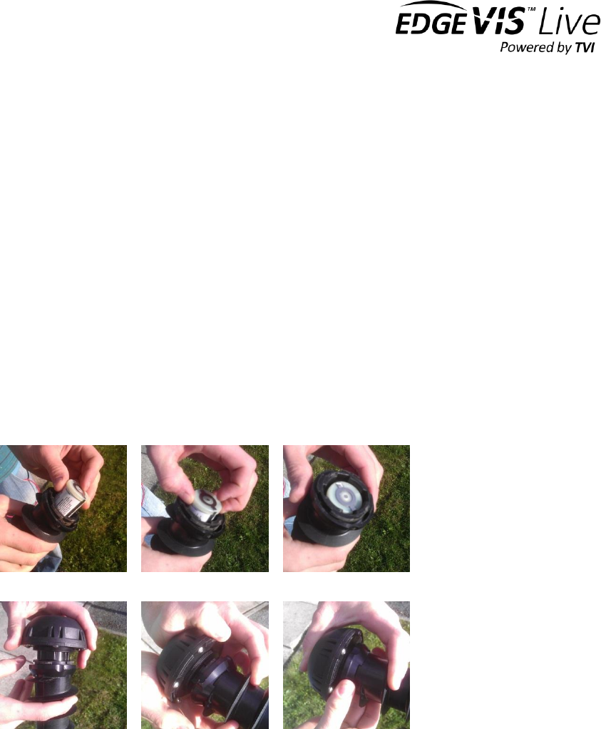
Place a battery into a clip and then into the auger tube. The positive end of the battery fits into the white cap.
Never force a battery clip and battery into the tube.
Align the node head with the cut-outs in the auger and push the two together.
Tighten the locking ring to seal the auger and the node head.
o Ensure the threads are clean before you attempt to tighten
o The locking ring is not intended to ‘pull’ the auger and the node head together. Push the auger and
the node head together then use the locking ring to hold them in place
o Fully tighten the locking ring and then back it off half a turn. This helps prevent binding and makes
the node easier to undo later.
After installing the battery but before deploying a node in the ground check that it can connect directly to the Master
Node. The RDC Staging Tool and RDC Config can both be used to check that the node has connected to the network.
See Staging Tool and RDC Config user guides for details.
4.2 Deployment
Correct deployment of RDC Sensor Nodes is critical for achieving the desired performance. Remote sites are most
suited for the application of ground sensors. Heavy industrial or urban locations are generally not suitable for ground
sensors due to the high levels of background noise. Digital Barriers can provide training and application advice if
required.
Annex A provides recommendations for deploying RDC networks for achieving optimum performance in different
environments.
USER GUIDE – RDC SETUP AND DEPLOYMENT
ISSUED: 21 AUGUST 2018 PAGE 8
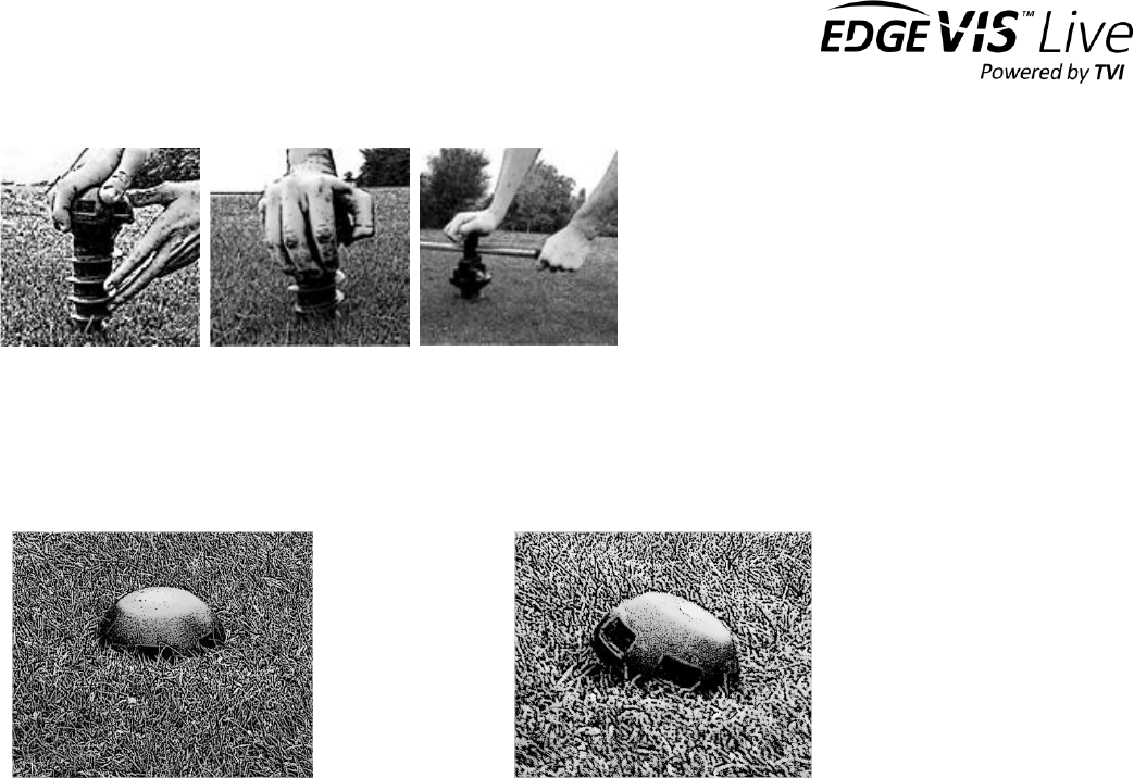
The SNs should be screwed into the ground so that the bottom edge of the sensor head is flush with the ground. The
SN should be deployed in an upright orientation. An angled node may have a reduced radio range due to the antenna
not being correctly aligned. Also, the node may be prone to false alarms in windy conditions.
CORRECT DEPLOYMENT
INCORRECT DEPLOYMENT
Place the SN in the desired location and start to screw it in by hand. It should be possible to screw the SN in a few turns
before using the deployment tool. If this is not possible it may be necessary to select another location to deploy it.
It is important to maintain downward pressure on the SN so that it does not dig out the soil around it. If the
SN starts to dig it can create a mound of soil that the node will sit on leaving it proud of the surface.
Do not over tighten the nodes especially in loose ground. As the node is tightened you will be able to feel the
ground resistance. If the node is over-tightened it will turn more easily as the soil or sand rotates with the
node. If this happens remove the node and reinsert it nearby.
If the node encounters an object in the ground during deployment such as a stone, it may need to be re-
inserted into another position. Hard objects in the ground can prevent the node from being fully screwed in.
The nodes can be deployed in most ground types but will perform better in certain situations. Soil or sand is
preferable to very stony ground where it is more difficult to completely insert and secure the node in the
ground. A secure deployment with the node fully deployed will perform better and more consistently than
one that has not been properly deployed.
It is advisable to place one knee on the ground to provide a more stable posture whilst deploying the SN.
This reduces the likelihood that:
The tool will slip off damaging the node
The user will be injured due to unsafe posture
The node will be deployed at an angle
USER GUIDE – RDC SETUP AND DEPLOYMENT
ISSUED: 21 AUGUST 2018 PAGE 9
5. Deploying a Network of Nodes
5.1 Radio communications
In a RDC network SNs can connect with the MN either directly or indirectly through other SNs in the system. It is a self-
healing and self-forming network. SNs automatically choose the shortest and most reliable route to the MN using
other SNs if required. All SNs need to have a reliable radio communications link with the MN at all times. A poor
communications link between the SN and the MN or any intermediate link between SN and MN may result in
detections being lost and reduced battery life. It is therefore recommended to use the RDC Deploy software to assist
with network deployment. In instances where there are insufficient routes to the MN SNs can be deployed as Repeater
Nodes
1
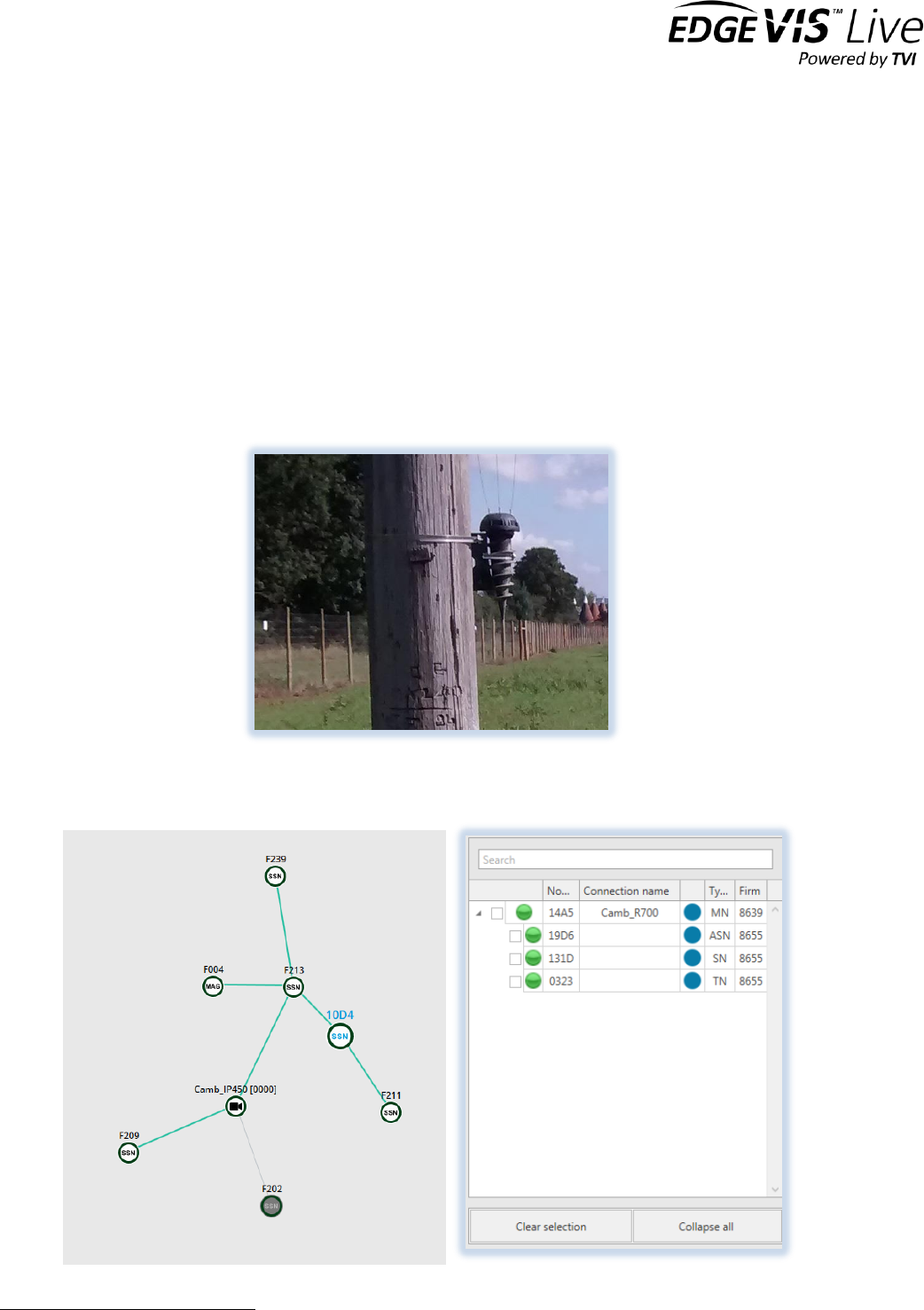
to improve the comms. A Node mount can be provided for mounting Sensor Nodes operating as Repeaters on
poles or walls. It is important that the Node is vertical, as shown, so that the internal antenna is correctly aligned.
Confirm that all the nodes are shown as connected within the Configuration window of RDC Config or visible and
shown as online within the network map of EdgeVis Shield.
1
A Repeater Node is SN with detection switched off

USER GUIDE – RDC SETUP AND DEPLOYMENT
ISSUED: 21 AUGUST 2018 PAGE 10
Note that the network does not respond instantly to changes in the position or number of nodes and takes some time
to finalize & settle on the best route to the MN.
An elevated node and/or line of sight between nodes will improve radio communications significantly. Objects or
vegetation between the nodes is likely to reduce the radio range.
Typically, the communications range between nodes deployed on the ground is 20-50metres. If the Master Node or a
Repeater Node is deployed 1-2m above the ground and with line of sight to a node on the ground the maximum
distance increases to typically 150-500metres. In this case Master-to-Repeater or Repeater-to-Repeater distances can
exceed 1km.
5.2 Detection Performance
The detection performance of the SNs can vary due to the following factors:
Nature of intrusion (e.g. type of vehicle, weight of person)
Type of ground
Vegetation
Moisture content of the soil
Background noise (e.g. wind, rain, distant machinery)
The detection performance can be greatly affected by the deployment. See Annex A for further guidance on
deployment.
The SN and MN may be camouflaged to avoid discovery. The sensor head can be covered by snow, vegetation, sand,
and earth. However, the radio signal may be affected reducing the possible range between the MN and SN and
between SNs. Wet materials will reduce the radio signal more than dry materials.
Burying the Sensor Node head 1-2 cms below the surface can be helpful for reducing false alarms in areas where there
may be wind-blown debris or sand. In hot, sunny climates it may be covered to reduce the effect of solar gain. This will
have some impact on radio range depending upon the topography and position of Master Nodes or Repeater Nodes.
5.3 Retrieval
The SN should be retrieved using the deployment tool to unscrew it until it has become loose. It is still important to
keep one hand pressing down on the palm rest as this will help prevent the tool from slipping off the node. It is
advisable to place one knee on the ground when retrieving a node to avoid undue strain.
If possible the Sensor Node should be washed and dried before opening it to remove the battery. This avoids mud
getting onto the lockring threads on the head of the Sensor Node. See next section for more details.
Once cleaned the SNs should be powered down by removing the auger and the battery.
5.4 Maximising Battery Life
Details of expected battery life can be found in Annex B. Note that nodes which are powered on but do not have a
network connection will have considerably reduced battery life ~1 month. Nodes which have temporary
disconnections from the network will have reduced battery life. Therefore, it is important that the Master Node and
any Repeater Nodes remain permanently powered. Also, Sensor Nodes must have a good connection to the network
otherwise disconnections will reduce battery life. The connection to the network can be checked using the Radio
Performance view in RDC Config. The proportion of missed alive messages should be as low as possible but in all cases
less than 3 or 4%.

USER GUIDE – RDC SETUP AND DEPLOYMENT
ISSUED: 21 AUGUST 2018 PAGE 11
5.5 Operation in the event of loss of network connectivity
5.5.1 RDC UM and UM+
If a RDC UM or UM+ node is unable to connect to a network because there is no Master Node or it is too far from other
working nodes that could act as repeaters the node searches for a network continuously. When this connection is lost,
the node radio receiver is switched ON continuously until the connection is resumed. When the receiver is
continuously ON, the overall power consumption of the node is significantly higher (>2.5 times than when connected).
This situation should be avoided where possible.
5.5.2 RDC2
One of the key features of RDC radio networking is its low power. In case of earlier versions (UM, UM+), a sensor node is
in low power networking mode as long as it is connected with the network but when this connection is lost, the node
radio receiver is switched ON continuously until connection is resumed. When the receiver is continuously ON, the
overall power consumption of the node is significantly higher (>2.5 times than when connected). This is acceptable if the
network downtime is very low but if the network is unavailable for longer durations (days) that could significantly reduce
the battery life of the node.
Under normal circumstances, the network is not expected to be unavailable but there are scenarios like maintenance,
power failure to the Master Node etc. when the network could be disrupted. There have been cases when complete
network deployment and commissioning took several days (due to logistics etc.) which impacted sensor battery life.
RDC2 nodes have much lower power consumption than RDC UM and UM+ nodes. Therefore, the radio receiver
continuously ON means much higher relative consumption (>6 times than when connected). RDC2 Sensor Nodes
incorporate a ‘network hunting strategy’ which significantly reduces power consumption when disconnected from a
network for significant periods of time.
RDC2 nodes are in a low power networking mode when they are connected with the network but when the network is
lost, they follow a back off network hunting strategy instead of switching ON the receiver continuously. This hunting
algorithm is optimised for the best combination of lower power consumption and quick re-connects times.
Aggressive Mode
For first 4 hours of network loss, the radio receiver is continuously ON. This is to handle scenarios where there is
temporary network loss, for example, due to moving obstacles or during deployment. The node is always looking for
network during this time and re-connection happens within a 5/40 seconds depending on network mode (Fast
Deployment/Extended Battery Life). Power consumption during this mode is approximately 6 times higher than when
operating in Extended Battery Life mode.

USER GUIDE – RDC SETUP AND DEPLOYMENT
ISSUED: 21 AUGUST 2018 PAGE 12
Reduced Power Mode
If a network is not found for a continuous period of 4 hours, then hunting switches into a reduced power mode. This
mode implements a 4 minute hunting cycle. Every 4 minutes, the radio receiver is switched ON continuously for 45
seconds and then switched OFF for the next 4 minutes. This means that the re-connect time could be up to 4 minutes.
This mode lasts for 8 hours and power consumption during this mode is approximately 2.5 times higher than when
connected in Extended Battery Life mode.
Lowest Power Mode
If a network is not found for a continuous period of 12 hours, then hunting switches into a very low power mode. This
mode implements a 12 minute cycle. Every 12 minutes, the radio receiver is switched ON continuously for 45 seconds
and then switched OFF for the next 12 minutes. This means that the re-connect time could be up to 12 minutes. This
mode lasts until a network is found. Power consumption during this time is approximately the same as when connected
in Extended Battery Life mode.
Note that the network hunting strategy is activated only if the node has joined the network at least once since power
cycle. On power up, the radio receiver is continuously ON until a network is found.
Important Note
The network hunting strategy only reduces power consumption in the event of long periods of disconnection. Many
short periods of disconnection should be avoided since during these periods the receiver is continuously ON (Aggressive
mode). This may occur in cases where a node has a poor connection to the network. It is important to ensure that nodes
have a good connection to a network by monitoring the radio performance in the network map (EdgeVis Shield) or Radio
Performance tab ( RDC Config). The missed message rate should be <3%.

USER GUIDE – RDC SETUP AND DEPLOYMENT
ISSUED: 21 AUGUST 2018 PAGE 13
6. Maintenance
6.1 Battery replacement
Batteries should be replaced between deployments or periodically. In EdgeVis Shield low battery alerts from the
Sensor Nodes can be reported by SMS, email and the EdgeVis Shield Client. This is configured using the EdgeVis Rule
Builder (see knowledgebase article – EdgeVis Alarm Management – Creating rules and alerts).
When opening the unit to replace a battery ensure you are in a dry environment between 5 and 40C.
Note that the Master Node and ASNs do not provide low battery alarms because the threshold at which alarms should
be generated is entirely dependent upon the power supply used.
6.2 Servicing
After each deployment the O-rings on the bottom of the SN head that seal the battery enclosure should be checked
and replaced if damaged. The threads of the locking ring and the SN head should be cleaned to prevent them
becoming blocked with dirt or sand. Water or water containing a mild detergent can be used to clean the RDC
components. Do not use chemicals. The Node should be thoroughly dried before re-assembly.

USER GUIDE – RDC SETUP AND DEPLOYMENT
ISSUED: 21 AUGUST 2018 PAGE 14
Annex A: Deployment Guidelines
A1 Introduction
The RDC system operates best if the Sensor Nodes are deployed well. A good deployment provides a number of
benefits:
Reduces false alarms caused by environmental conditions
Improves the likelihood of successful detections
Improves the consistency of detection performance
Improves the radio communications
Maximises battery life
Minimises the risk of theft or tampering by making it difficult to remove the nodes without the deployment
tool
It is necessary to consider both the radio communications and the detection performance.
Generally, the Master Node location is fixed according to access to power and/or communications. The Sensor Nodes
need to be located close to the expected points of intrusion. Once these locations have been identified it is then
necessary to ensure there is good communications between the Sensor Nodes and Master Node. This may involve the
deployment of Repeater Nodes.
A good rule of thumb for assessing whether there is likely to be good communication is to examine whether there is
line of sight between the Sensor Node and the Master Node. If they are within a few hundred metres of each other and
there is line of sight the communications will usually be good and there will be no need for a Repeater Node. However,
if there is no line of sight then a Repeater Node should be located where there is line of sight between the Master Node
and the Repeater Node and also line of sight from the Sensor Node to the Repeater Node. Sometimes multiple
Repeater Nodes will be required to cover the distance between the Master Node and the Repeater Node. Additional
Repeater Nodes can be added to provide redundancy in the communications.
With the Nodes deployed the radio communications performance should be checked as described in Section 5.4.
A2 Deployment location recommendations
Detection performance is dependent upon four factors:
The weight and characteristics of the movement of the person or vehicle to be detected
The ground type
The level of background noise which may be naturally occurring or man-made. Note that seismic noise that
can affect the sensor may not be audible to the human ear due to being below the ear’s frequency response.
The detection sensitivity set by the user
The performance of the system can be considerably enhanced by following these recommendations when deciding
where to deploy the Sensor Nodes and selecting sensitivity settings. Note that the relevance of each of these
recommendations will be dependent upon the nature of the threat to be detected and the area to be protected.
Reduce the detection sensitivity to the minimum necessary: when the nodes are deployed close to the road or path
taken by a vehicle or person reduce the sensitivity in order to minimise the probability of false alarms.
Deploy in open areas away from sources of seismic noise: the detection performance of the node is affected by the
level of background noise. Seismically quiet areas will have the most constant level of background noise and will
therefore provide the most consistent detection. Avoid deploying within 150m of busy roads and other sources of
noise such as pump stations. The background noise can be measured. It is displayed in the ‘Background’ tab of RDC
Config.

USER GUIDE – RDC SETUP AND DEPLOYMENT
ISSUED: 21 AUGUST 2018 PAGE 15
Be aware of hidden noise sources: when you are deploying the nodes try to reconnoitre the entire area of detection.
Sources of noise such as roads can affect the detection performance of the nodes even if you cannot see them from
the deployment position. Also, try to assess whether there may be sources of noise at times other than the time of
deployment. Maps of the vicinity showing infrastructure can help with this prior to reconnoitring the site. The
‘Background’ measurement can be used to identify sources of seismic noise.
Read the ground for obvious paths: a person or vehicle will generally follow the easiest available path. Consider the
environment in which the nodes are to be deployed and deploy the nodes close by any obvious transit routes. This is
especially important for slow moving vehicles on smooth roads.
Vehicle sensitivity settings: in all cases of vehicle detection the nodes should be placed as close as possible to the
path taken by the vehicle whilst taking into consideration factors such as the need for concealment. The road type and
likely vehicle speed and weight will affect the detection performance for a given sensitivity setting. The detection
sensitivity should be set to the minimum required for detection in order to minimise the risk of nuisance alarms. For
instance, a node placed close to a rough track along which heavy vehicles are to be detected could have a ‘low’
sensitivity setting. The vehicle detection should only be set to ‘Medium’ when ‘Low’ yields insufficient detection.
Use road surface imperfections to your advantage. Detection of a vehicle on a smooth road surface can be more
difficult to achieve as the vehicle generates a reduced seismic signature. Imperfections in the road surface will cause
the vehicle to be detected at a greater distance and more reliably so deploy close to these if possible.
Avoid areas with livestock: areas where livestock are roaming should be avoided as the animal movement may
reduce the consistency of detection and can result in nuisance alarms. Fusion can be very effective for minimising
nuisance alarms caused by animals. See RDC Config user guide for instructions for setting fusion.
Avoid animal runs: wild animals (e.g. goats, sheep) often follow well-trodden paths which can be identified. Try to
avoid these where possible. Fusion can be very effective for minimising nuisance alarms caused by animals. See RDC
Config user guide for instructions for setting fusion.
Minimise deployment in hedges or under tree canopies: deployment in hedges and under tree canopies should be
minimised for several reasons:
The noise generated by movement of the hedge or tree in wind can affect performance
Drips from the foliage can generate person false alarms
Animals tend to use hedges for cover and create noise whilst moving about in them
If deploying in hedges to conceal the nodes or under tree canopies use the ‘Woodland’ environment setting.
Be aware of flight paths: if a node is to be deployed near the flight path of aircraft taking off and landing the
detection sensitivity may need to be reduced to minimise nuisance alarms depending upon the aircraft distance and
noise. Consider placing the node as close as possible to the path, track or area to be monitored and setting sensitivity
low and as far as way as possible from the likely aircraft.
Be aware of the potential impact of close by man-made structures: structures such as drainage pipes or nearby
fences can reduce performance due to the noise they can generate. Fences can generate noise in windy conditions and
heavy rain. When deploying close to buildings be aware that there may be sources of noise (e.g. machinery) coming
from within the building that you cannot see. The ‘Background’ measurement can be used to identify sources of
seismic noise.
A3 Node deployment below ground level or camouflage
Sensor Nodes may be deployed just below ground level. This has several benefits:
Nodes are hidden
Nodes will be less affected by strong winds and heavy rain than nodes which are exposed to the environment.
This has the benefit of both minimising the risk of false alarms and reducing the background noise level in
these conditions which can reduce detection range.
Machines such as lawnmowers are unlikely to damage the nodes unless they are digging into the earth.
The main drawback of deploying below ground level is that the radio range will be reduced. The node should only be
deployed so that the top of the cap is between 0.5-2cms below ground. Placing a Repeater Node close by above
ground level will ensure there is good communications to the buried nodes(s).

USER GUIDE – RDC SETUP AND DEPLOYMENT
ISSUED: 21 AUGUST 2018 PAGE 16
Radio range between two nodes which are both placed at ground level will be highly dependent upon the local
topography and in many cases very short (few tens of metres). RDC Deploy can be used to determine maximum radio
range between pairs of nodes before deploying them.
Sensor Nodes and Master Nodes may be camouflaged. When the top of the Node is above the ground but
camouflaged the radio performance may be affected a little by the camouflage but less significantly than when
burying the node. Note that material stuck to the node cap to camouflage it should not be able to flap around in the
wind otherwise this can lead to false alarms.
In hot sunny climates burying the nodes or covering it can help to keep the nodes cool.

USER GUIDE – RDC SETUP AND DEPLOYMENT
ISSUED: 21 AUGUST 2018 PAGE 17
Annex B
Technical specifications
RDC System
Function: Detect and classify human and vehicle movement and digging activity
Key components: Sensor Node (SN), Master Node (MN)
Communications
Radio
Frequency of Operation: Europe: 865.3-868.0MHz
North America: 903.0-927.0MHz
Modulation: BPSK, Direct Sequence Spread Spectrum
Max output power: Europe: +5dBm (limited by regulations)
North America: +10dBm
Receiver Sensitivity: -110dBm (message error rate <1 in 103)
Network Topology: Multi-hop (mesh), configurable as single-hop (factory config)
Antenna: Internal
Master node serial communications
Standard: EIA/TIA-232
Connections: TXD, RXD and GND connections (no RTS/CTS handshaking)
Baud rate: 19.2kbps
Environmental
Operating temperature range: -20°C to +70°C
Storage temperature range: -40°C to +80°C
Ingress protection: IP67 (totally protected against dust, protected against
the effect of immersion up to 1 metre)
Vibration: DEF STAN 00-35: Part 3: Issue 3
Drop: 1.5m single occurrence, any face
Static load: 100kg
Impact: 3.25” ball bearing from 1.5m
Weight
Master Node: 410g include ground spike
Sensor Node: 550g (incl. battery pack)
Dimensions
Master Node: Max. length (excl. spike): 80mm
Max. diameter: 90mm
Sensor Node: Max. length: 240mm

USER GUIDE – RDC SETUP AND DEPLOYMENT
ISSUED: 21 AUGUST 2018 PAGE 18
Max. diameter: 90mm
Power
Sensor Node
Single 3.6V Lithium Thionyl Chloride (D-cell) battery pack
Recommended batteries:
Saft LS33600
Tadiran SL2780/S (TL-5930)
Sensor Node Typical Battery Life
Mode
UM
UM+
RDC2
Single hop2
175 days
200 days
560 days
Fast configuration (Detection
OFF*)
100 days
100days
200 days
Fast configuration (Detection
ON)
80 days
90 days
180 days
Extended battery life
(Detection OFF*)
165 days
165 days
450 days
Extended battery life
(Detection ON)
125 days
140 days
360 days
No connection to network
40 days
40 days
360 days**
*repeater node
** must be completely disconnected from network. A node with a poor connection to a network could have battery
life ranging from 40 days to 360 days.
Assumes nominal 19Ah battery (Tadiran SL2780). 19Ah is only available in ideal conditions (25C temperature and
constant current of 4mA). From experience of real world conditions we de-rate this to 15.5Ah.
Notes:
Battery life in very hot or very cold conditions will be reduced.
Sensor Nodes which have poor network connections may have considerably reduced battery life.
When there is no connection to a network a node will go into a sleep mode to minimise power consumption.
When a network is available the node may take up to 12 minutes to re-establish a connection.
Master Node
Input Voltage: Minimum: 5V
Maximum: 35V
2
Requires factory configuration. Users cannot switch between single hop and multi-hop and vice versa

USER GUIDE – RDC SETUP AND DEPLOYMENT
ISSUED: 21 AUGUST 2018 PAGE 19
Master Node Current Consumption:
Current(mA)
Voltage
(v)
Maximum
Average
Minimum
avg power
consumption
5
29.27
26.45
26.09
132.25
6
24.53
22.28
21.98
133.68
7
21.13
19.18
18.94
134.26
8
18.64
16.96
16.75
135.68
9
16.76
15.23
14.98
137.07
10
15.27
13.88
13.65
138.8
11
14.01
12.75
12.58
140.25
12
13.03
11.86
11.7
142.32
13
12.18
11.1
10.95
144.3
14
10.44
10.43
10.27
146.02
15
10.81
9.86
9.69
147.9
16
10.26
9.37
9.22
149.92
17
9.78
8.93
8.79
151.81
18
9.35
8.55
8.39
153.9
19
8.98
8.21
8.1
155.99
20
8.63
7.9
7.75
158
21
8.33
7.62
7.52
160.02
22
8.05
7.36
7.27
161.92
23
7.79
7.12
7.01
163.76
24
7.55
6.91
6.82
165.84
25
7.34
6.7
6.53
167.5
26
7.14
6.52
6.43
169.52
27
6.95
6.34
6.25
171.18
28
6.78
6.18
6.08
173.04
29
6.61
6.03
5.95
174.87
30
6.43
5.89
5.82
176.7

USER GUIDE – RDC SETUP AND DEPLOYMENT
ISSUED: 21 AUGUST 2018 PAGE 20
Annex C
Battery Safety
C1 First aid measures
A. Electrolyte Contact
Skin
Immediately flush with plenty of water for at least 15 minutes. If symptoms are present after flushing, get medical
attention.
Eyes
Immediately flush with plenty of water for at least 15 minutes and get medical attention.
Respiratory system
With large quantities and irritation of the respiratory tract, medical surveillance for 48 hours.
Immediately inhale Cortisone Spray, e.g. Pulmicort.
B. Lithium Metal Contact
Skin
Remove particles of lithium from skin as rapidly as possible. Immediately flush with plenty of water for at least 15
minutes and get medical attention.
Eyes
Immediately flush with plenty of water for at least 15 minutes and get immediate medical attention.
C2 Accidental release measures
When the battery housing is damaged, small amounts of electrolyte may leak. Seal battery in an air tight plastic bag,
adding some chalk (CaCO3) or lime (CaO) powder or Vermiculite. Electrolyte traces may be wiped off using paper
towel. Rinse with water afterwards.

USER GUIDE – RDC SETUP AND DEPLOYMENT
ISSUED: 21 AUGUST 2018 PAGE 21
CE COMPLIANCE STATEMENT
Digital Barriers Services Ltd declares that RDC2 complies with the essential requirements and other relevant
provisions of
RED Directive 2014/53/EU (Radio Equipment Directive)
In order to satisfy the essential requisite of the RED Directive 2014/53/EU, the radio is compliant with the following
standards:
Radio Spectrum standards: EN 300 220-1 v3.1.1 and EN 300 220-2 v3.2.1
EMC (Electromagnetic Compatibility) standards: EN 301 489-1 v1.9.2, and EN 301 489-17 v2.2.1
Product safety: EN61010-1:2010
The use of this product may be dangerous and has to be avoided in the following areas:
Where it can interfere with other electronic devices in environments such as hospitals, airports, aircraft, etc.
Where there is risk of explosion such as gasoline stations, oil refineries, etc.
It is responsibility of the user to enforce the country regulations and specific environment regulations.
A copy of the declaration of conformity is available on request by contacting:
Digital Barriers Services Ltd.
Belle House
Platform 1, Victoria Mainline Station
London
SW1V 1JT
FCC Compliance Statement
Digital Barriers Services Ltd declares that the RDC2 Sensor Node complies with part 15 of the FCC rules. Operation is
subject to the following two conditions:
1) This device may not cause harmful interference
2) This device must accept any interference received, including interference that may cause undesired operation
Any changes or modification not expressly approved by Digital Barriers could void the user's authority to operate the
device. Where shielded interface cables have been provided with the product or specified additional components or
accessories elsewhere defined to be used with the installation of the product, they must be used in order to ensure
compliance with FCC regulations.
FCC ID: 2ABOE1 (RDC2 Sensor Node)