Digital Control 2020 TT, TT5 User Manual 3 1400 00 D TensiTrak Manual
Digital Control Inc TT, TT5 3 1400 00 D TensiTrak Manual
User Manual
®
TensiTrak
® Pullback and
Pressure Monitoring System
Operator’s Manual
DIGITAL
CONTROL
INCORPORATED
DCI Headquarters
19625 62nd Ave. S., Suite B-103
Kent, Washington 98032 USA
Tel 425 251 0559 / 800 288 3610
Fax 253 395 2800
E-mail DCI@digital-control.com
www.digitrak.com
DCI Europe
Kurmainzer Strasse 56
D-97836 Bischbrunn
Germany
Tel +49(0) 9394 990 990
Fax +49(0) 9394 990 999
DCI.Europe@digital-control.com
DCI India
SCO # 259, Sector 44-C
Chandigarh (UT) 160 047
Punjab, India
Tel +91(0) 172 464 0444
Fax +91(0) 172 464 0999
DCI.India@digital-control.com
DCI China
USA Excalibre
2803 Bldg C, 70 Cao Bao Rd
Shanghai P.R.C. 200233
Tel +86(0) 21 6432 5186
Fax +86(0) 21 6432 5187
DCI.China@digital-control.com
DCI Australia
2/9 Frinton Street
Southport, Queensland 4215
Australia
Tel +61(0) 7 5531 4283
Fax +61(0) 7 5531 2617
DCI.Australia@digital-control.com

DIGITAL CONTROL INCORPORATED
2 Eclipse® TensiTrak® Operator’s Manual
3-1400-00-D
© 2004-2007 by Digital Control Incorporated. All rights reserved. January 2008 edition.
Trademarks
The DCI logo, CableLink®, DataLog®, DigiTrak®, Eclipse®, iGPS®, Intuitive®, look-ahead®, SST®, target-in-
the-box®, Target Steering®, and TensiTrak® are U.S. registered trademarks and DucTrak™, FasTrak™,
LT™, SuperCell™, and TeleLock™ are trademarks of Digital Control Incorporated.
Patents
The DigiTrak® Eclipse® TensiTrak® Pullback and Pressure Monitoring System is covered by one or more
of the following U.S. Patents: 5,337,002; 5,633,589; 5,698,981; 5,764,062; 5,878,824; 5,926,025;
5,933,008; 5,961,252; 5,990,682; 5,990,683; 6,002,258; 6,035,951; 6,232,780; 6,396,275; 6,454,023;
6,457,537; 6,496,008; 6,693,429; 6,768,307; 6,954,073; 6,993,981; 7,015,697; 7,049,820; 7,061,244;
7,154,273. Sale of a DigiTrak® Eclipse® Receiver does not convey a license under any patents covering
the DigiTrak® Eclipse® Transmitter or underground drill housing. Other patents pending.
Limited Warranty
All products manufactured and sold by Digital Control Incorporated (DCI) are subject to the terms of a
Limited Warranty. A copy of the Limited Warranty is included with this manual along with your DigiTrak®
Eclipse® TensiTrak® System; it can also be obtained by contacting DCI Customer Service, 800-288-3610
or 425-251-0559, or by connecting to DCI's web site, www.digitrak.com.
Important Notice
All statements, technical information, and recommendations related to the products of DCI are based on
information believed to be reliable, but the accuracy or completeness thereof is not warranted. Before
utilizing any DCI product, the user should determine the suitability of the product for its intended use. All
statements herein refer to DCI products as delivered by DCI and do not apply to any user customizations
not authorized by DCI nor to any third-party products. Nothing herein shall constitute any warranty by DCI
nor will anything herein be deemed to modify the terms of DCI’s existing Limited Warranty applicable to all
DCI products.
FCC Compliance Statement
This equipment has been tested and found to comply with the limits for a Class B digital device, pursuant
to Part 15 of the Rules of the Federal Communications Commission. These limits are designed to provide
reasonable protection against harmful interference in a horizontal directional drilling installation. This
equipment generates, uses, and can radiate radio frequency energy and, if not installed and used in
accordance with the instructions, may cause harmful interference to radio communications or inaccurate
readings on your DCI locating equipment. However, there is no guarantee that interference will not occur
in a particular installation. If this equipment does cause harmful interference to radio or television
reception, which can be determined by turning the equipment off and on, the user is encouraged to try to
correct the interference by one or more of the following measures:
¾ Reorient or relocate the DigiTrak® Eclipse® Receiver.
¾ Increase the separation between the problematic equipment and the DigiTrak® Eclipse® Receiver.
¾ Connect the equipment into an outlet on a different circuit.
¾ Consult the dealer for help.
Changes or modifications to the DCI equipment not expressly approved and carried out by DCI will void
the user’s Limited Warranty and the FCC’s authorization to operate the equipment.

DIGITAL CONTROL INCORPORATED
Eclipse® TensiTrak® Operator’s Manual 3
Table of Contents
SAFETY PRECAUTIONS AND WARNINGS................................................................................................ 5
INTRODUCTION........................................................................................................................................... 7
SYSTEM COMPONENTS............................................................................................................................. 9
Eclipse TensiTrak Unit............................................................................................................................ 9
Eclipse TensiTrak Receiver.................................................................................................................. 10
Eclipse TensiTrak Remote Display....................................................................................................... 10
Eclipse TensiTrak Software.................................................................................................................. 11
ACTiSYS Infrared Cable....................................................................................................................... 11
USB-to-Serial Adapter .......................................................................................................................... 11
QUICK START GUIDE................................................................................................................................ 13
Powering On TensiTrak Unit ................................................................................................................ 13
Setting up Receiver and Remote Display............................................................................................. 14
Calibrating TensiTrak Unit to Receiver................................................................................................. 15
Calibration and Verification Procedure ..........................................................................................15
Setting Up TensiTrak Downhole Assembly ..........................................................................................16
Start/Stop Saving Data ......................................................................................................................... 17
Start Saving Data (Optional – for Data to be Transferred to Computer) ....................................... 17
Monitoring Used Memory............................................................................................................... 18
Stop Saving Data ........................................................................................................................... 19
USING TENSITRAK MENUS ON RECEIVER............................................................................................ 21
SETTING UP TENSITRAK SYSTEM AND SAVING DATA ....................................................................... 23
Setting Up TensiTrak System............................................................................................................... 23
1. Power Up TensiTrak Unit.......................................................................................................... 24
2. Power Up Receiver & Confirm Tension and Mud Pressure Readings ..................................... 24
3. Power Up Remote Display & Confirm Tension, Mud Pressure Readings ................................25
4. Confirm or Change Job Number (Receiver) ............................................................................. 26
5. Calibrate Receiver to TensiTrak Unit ........................................................................................26
6. Monitor Used Memory and Battery Status of Receiver and TensiTrak Unit............................. 27
Saving Data (Receiver) ........................................................................................................................ 28
1. Start Receiver’s Data Saving Mode ..........................................................................................28
2. Track the TensiTrak Unit’s Depth and Position ........................................................................ 29
3. Stop Saving Data ...................................................................................................................... 30
Summary of Procedure for Setting Up System & Saving Data ............................................................ 31
Setting Up TensiTrak System ........................................................................................................ 31
Saving Data (Receiver) .................................................................................................................. 31
INSTALLING TENSITRAK SOFTWARE .................................................................................................... 33
Computer System Requirements ......................................................................................................... 33
Installing Software on Computer .......................................................................................................... 33
Eclipse TensiTrak Software ........................................................................................................... 33
Software for USB-to-Serial Adapter ............................................................................................... 33

DIGITAL CONTROL INCORPORATED
4 Eclipse® TensiTrak® Operator’s Manual
Table of Contents (Cont.)
USING TENSITRAK SOFTWARE .............................................................................................................. 35
Starting TensiTrak Program ................................................................................................................. 35
Menu Bar........................................................................................................................................ 36
Job Information Field...................................................................................................................... 37
DATA Field..................................................................................................................................... 38
Port Status Field and Open/Close Buttons .................................................................................... 38
PLOT Button .................................................................................................................................. 39
Pull Force Graph ............................................................................................................................ 39
Mud Pressure Graph...................................................................................................................... 40
Opening Project Files ........................................................................................................................... 41
Printing and Previewing Project Reports.............................................................................................. 42
Saving Project Files.............................................................................................................................. 43
E-mailing Project Files.......................................................................................................................... 44
TRANSFERRING DATA FROM RECEIVER TO COMPUTER ................................................................. 45
Transferring Data from Receiver to Computer .....................................................................................45
Transferring Hints ................................................................................................................................. 46
Deleting Data from Receiver After Transfer ......................................................................................... 48
EDITING DATA IN COMPUTER................................................................................................................. 49
Editing Run Information ........................................................................................................................ 49
Formatting Force and Pressure Graphs............................................................................................... 50
Adjusting Graphs to View Data Better ...........................................................................................50
LIMITED WARRANTY

DIGITAL CONTROL INCORPORATED
Eclipse® TensiTrak® Operator’s Manual 5
Safety Precautions
and Warnings
IMPORTANT NOTE: All operators must read and understand the following Safety Precautions and
Warnings and must review this manual (the DigiTrak® Eclipse® TensiTrak® Pullback and Pressure
Monitoring System Operator’s Manual), as well as the operator’s manual that came with your
DigiTrak Eclipse system (the DigiTrak® Eclipse® inGround Positioning System Operator’s Manual),
before using the TensiTrak system.
1 Serious injury and death can result if underground drilling equipment makes contact
with an underground utility such as a high-voltage electrical cable or a natural gas
line.
 Substantial property damage and liability can result if underground drilling equipment
makes contact with an underground utility such as a telephone, cable TV, fiber-optic,
water, or sewer line.
Work slowdowns and cost overruns can occur if drilling operators do not use the
drilling or locating equipment correctly to obtain proper performance.
¾ Directional drilling operators MUST at all times:
• Understand the safe and proper operation of drilling and locating equipment, including the
use of ground mats and proper grounding procedures.
• Ensure that all underground utilities have been located, exposed, and marked accurately
prior to drilling.
• Wear protective safety clothing such as dielectric boots, gloves, hard-hats, high-visibility
vests, and safety glasses.
• Locate and track the drill head accurately and correctly during drilling.
• Comply with state and local governmental regulations (e.g., OSHA).
• Follow all other safety procedures.
¾ The TensiTrak system is intended for use during the pullback of product only. Pushing on the
TensiTrak unit could cause damage to the unit.
¾ Before each installation, inspect the TensiTrak unit’s battery cap and mud pressure sensor for
damage or wear.
¾ The TensiTrak system should be tested prior to use to verify accuracy of readings.
0 The DigiTrak Eclipse equipment is not explosion-proof and should never be used
near flammable or explosive substances.

DIGITAL CONTROL INCORPORATED
6 Eclipse® TensiTrak® Operator’s Manual
Safety Precautions
and Warnings (Cont.)
¾ Interference can cause significant inaccuracies in the measurement of depth and the TensiTrak
unit’s range capability.
• Sources of interference include but are not limited to traffic signal loops, invisible dog fences,
cable TV, power lines, fiber-trace lines, metal structures, cathodic protection, transmission
towers, cellular phones, telephone lines, conductive earth, salt water, rebar, and radio
frequencies.
• Interference with the operation of the remote display may also occur from other sources
operating nearby on the same frequency, such as car rental agencies using their remote
check-in modules, other directional drilling locating equipment, etc.
¾ During pullback, if depths are being tracked, they will not be accurate unless:
• The Eclipse receiver has been properly calibrated and the calibration has been checked for
accuracy so that the receiver shows the correct depth.
• The TensiTrak unit has been located correctly and accurately and the receiver is directly
above and parallel to the transmitter in the tool underground.
• The receiver height-above-ground or ultrasonic distance has been set correctly.
¾ The TensiTrak unit is positioned behind the reamer, between the swivel and the product so that
the TensiTrak unit does not rotate.
¾ Exposure to extreme vibration could possibly damage the TensiTrak unit and/or the batteries and
possibly reset the recorded maximum pull force.
¾ Exposure to downhole fluid pressures above 127 psi (876 kPa) could possibly damage the
TensiTrak unit.
¾ The TensiTrak unit should never be shrouded with a metal pipe, if a shroud is required, it must
be a nonmetallic shroud.
¾ Avoid pressure washing directly into the mud pressure sensor.
¾ Do not weld on the TensiTrak unit.
¾ Carefully review this operator’s manual and be sure you always operate the Eclipse TensiTrak
system properly to obtain accurate pullback, pressure, and depth data. If you have any questions
about the operation of the TensiTrak system, please call DCI’s Customer Service Department at
425-251-0559 or 800-288-3610.
REMEMBER: If you are having difficulty on the job, call DCI (425-251-0559 or
800-288-3610) and we’ll do our best to assist you.
DIGITAL CONTROL INCORPORATED
Eclipse® TensiTrak® Operator’s Manual 7
Introduction
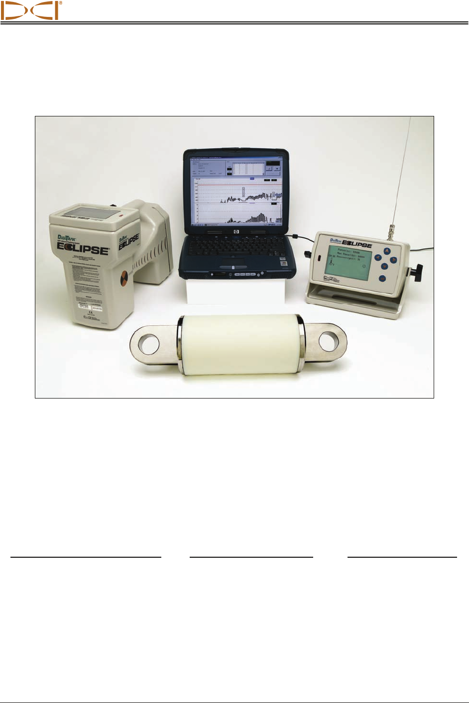
Eclipse TensiTrak System
The DigiTrak® Eclipse® TensiTrak® Pullback and Pressure Monitoring System allows you to monitor and
save live pullback data electronically. The TensiTrak unit is a self-contained wireless tool that measures
and transmits real-time data related to the pull forces on a product and downhole mud pressures during
horizontal directional drilling (HDD) installations. It is placed behind the reamer between a swivel and the
product. The data is monitored and saved using a walkover Eclipse TensiTrak receiver, which transmits
live data to the Eclipse TensiTrak remote display on the drill rig. The data is then transferred to a
computer for analysis, graphing, printing, saving, and e-mailing.
The following types of data can be monitored and saved with the Eclipse TensiTrak system:
Monitored and Saved on Receiver Monitored Only on Receiver Saved on TensiTrak Unit
● Real-time pull force ● TensiTrak temperature ● Maximum pull force
● Real-time downhole mud pressure ● TensiTrak battery status
● Maximum pull force ● TensiTrak depth and position
This operator’s manual begins by describing the primary components of the TensiTrak system, which
include the TensiTrak unit, the Eclipse receiver, the Eclipse remote display, the computer software, the
infrared (IR) cable that connects the receiver to the computer, and the special USB adapter, which is
required for newer computers and laptops without serial ports. Then it presents procedures for saving
pullback data; for installing and using the Eclipse TensiTrak software; for transferring the data from the

Introduction
8 Eclipse® TensiTrak® Operator’s Manual
receiver to the computer; and for viewing, editing, and e-mailing the data. A Quick Start Guide is provided
after the System Components section for users who already know how to operate the Eclipse locating
equipment.
Some terms and techniques used in this manual are considered basic to the Eclipse locating system. If
you have never used the Eclipse system, Digital Control Incorporated (DCI) strongly recommends that
you read the operator’s manual for the Eclipse locating system (DigiTrak® Eclipse® inGround Positioning
System Operator’s Manual) before you try using the TensiTrak system.
NOTE: You must know how to operate the Eclipse locating system prior to operating the
Eclipse TensiTrak system.
DCI also recommends that you read the instructions in this TensiTrak system operator’s manual and
familiarize yourself with the various menu screens on your Eclipse TensiTrak receiver before using the
system for a pullback. If you have questions, please call DCI’s Customer Service Department at 800-288-
3610 or 425-251-0559.
DIGITAL CONTROL INCORPORATED
Eclipse® TensiTrak® Operator’s Manual 9
System Components
The Eclipse TensiTrak system has six main components:
¾ Eclipse TensiTrak unit – A compact unit that contains a battery-powered transmitter with sensors
that continuously measure and transmit the pull force, maximum pull force, downhole mud pres-
sure, temperature, battery life, and depth/position signal. It also updates and saves the maximum
pull force.
¾ Eclipse TensiTrak receiver – An Eclipse receiver with TensiTrak capability.
¾ Eclipse TensiTrak remote display – An Eclipse remote upgraded to have the TensiTrak firmware.
¾ Eclipse TensiTrak software – Provided on CD along with this manual and sample data.
¾ ACTiSYS infrared cable – Connects serial (COM) port on a computer to the infrared (IR) port on
the Eclipse TensiTrak receiver for data transfer.
¾ USB-to-serial adapter – Converts serial connection to USB connection, which is required if your
computer does not have a serial port.
Eclipse TensiTrak Unit
The Eclipse TensiTrak unit contains sensors that continuously measure the pull force, the downhole mud
pressure, and the maximum pull force. The TensiTrak unit also contains a transmitter so it can send this
information to the receiver. It also sends battery life and temperature information. The TensiTrak unit’s
depth and position can be tracked by the receiver to a maximum depth of 60 ft (18.3 m).
The TensiTrak unit can be powered by either three C-cell alkaline batteries or by a DCI SuperCell Lithium
Battery. The difference between these two power options is battery life. The three C-cells will power the
TensiTrak unit for approximately 15 hours; the SuperCell battery will power it for approximately 40 hours.
The TensiTrak unit automatically begins transmitting the pull force, mud pressure, and maximum pull
force data once the power source is installed. It also automatically starts saving the maximum pull force
data internally.
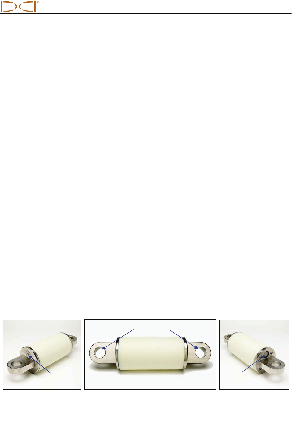
The TensiTrak unit’s dimensions are 5.5 in. (140 mm) in diameter by 19.5 in. (495 mm) in length. It is
installed behind a reamer or hole opener between the swivel and the product. The inner diameter of the
pulling eye is 1.77 in. (4.5 cm). If the diameter of the TensiTrak unit is smaller than that of the reamer and
product, you may want to shroud the TensiTrak unit; be sure that this is done with nonmetallic material.
Leading End View Side View Trailing End View
Eclipse TensiTrak Unit
Leading End Trailing End
Mud
Sensor
Battery
Cap
Pulling Eyes
System Components
10 Eclipse® TensiTrak® Operator’s Manual
Eclipse TensiTrak Receiver
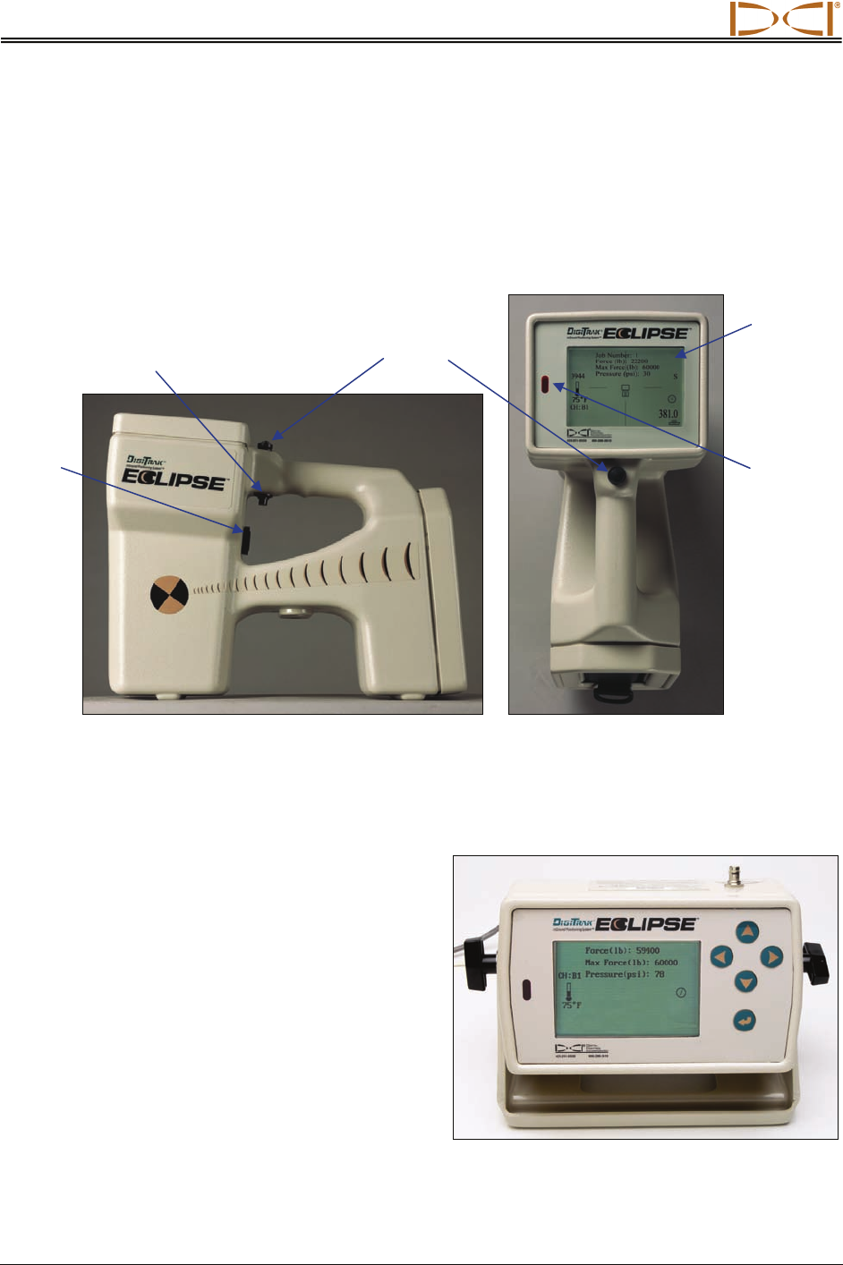
The Eclipse TensiTrak receiver monitors the pullback and mud pressure data in real time and sends the
data to the Eclipse TensiTrak remote display on the drill rig. The receiver will save approximately 30
hours worth of data or approximately five runs before transferring to a computer is required. The Eclipse
TensiTrak receiver can also be used to track the position and depth of the TensiTrak unit, and it will also
display the TensiTrak unit’s temperature and battery status.
Eclipse TensiTrak Receiver Side View (left) and Top View (right)
From this point forward in this manual, the Eclipse TensiTrak receiver will often be referred to as simply
the receiver. Any Eclipse receiver can be upgraded to have the TensiTrak capability.
Eclipse TensiTrak
Remote Display
The Eclipse TensiTrak remote display functions just
like your standard Eclipse remote display except that
it has upgraded firmware to display the pull force,
mud pressure, and maximum pull force.
Speake
r
Trigge
r
Switch
Toggle
Switch
Display
Screen
Infrared
Port
Eclipse TensiTrak Remote Display
System Components
Eclipse® TensiTrak® Operator’s Manual 11
Eclipse TensiTrak Software
The Eclipse TensiTrak software is provided
on a single CD-ROM, which also contains this
operator’s manual and sample data. The Tensi-
Trak software requires a computer with at least
the following system specifications:
¾ 600 MHz or greater processor
¾ Microsoft Windows 98, 2000, or XP
operating system
¾ Serial (COM) port or USB port
¾ Pointing device (mouse)
¾ Color printer for color graphs
Software installation instructions are given later
in this manual (see Installing TensiTrak Soft-
ware section).
ACTiSYS Infrared Cable
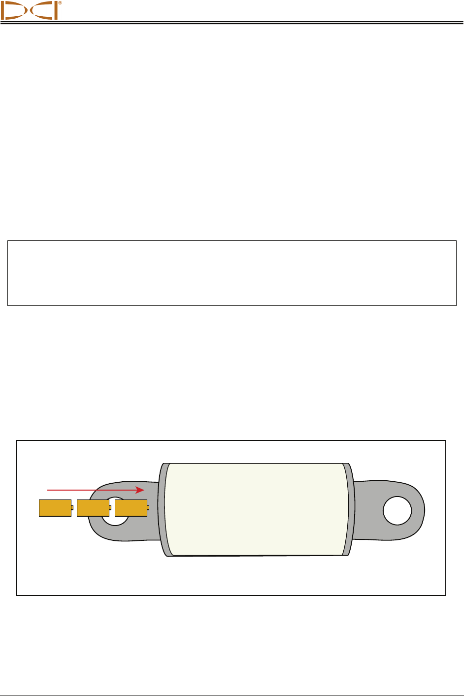
The ACTiSYS infrared (IR) cable has a serial
plug at one end and an IR reader at the other
end. To transfer data from the receiver to the
computer, the IR reader must be placed over
the receiver’s IR port, and the serial plug must
be connected to the computer. Then, using the
receiver’s menus and the Eclipse TensiTrak
software, the data is transferred to the com-
puter. If the computer does not have a serial
port, a serial-to-USB adapter must be used; it is
provided with the IR cable.
The ACTiSYS IR cable is provided by DCI with
the Eclipse TensiTrak system. For replace-
ments, please contact the manufacturer
ACTiSYS Corporation (www.ACTiSYS.com)
and reference ACTiSYS Part No. ACT-IR220L+.
Software is not required for IR use.
USB-to-Serial Adapter
The USB-to-serial adapter is required to con-
nect the ACTiSYS IR cable to the computer if
the computer does not have a serial port. The
adapter provided by DCI is a Port Authority
USB Serial DB9 Adapter. Replacements are
available from www.CablesToGo.com. This
adapter comes with software that must be in-
stalled on your computer.
ACTiSYS Infrared Cable
Serial Plug
IR Reade
r
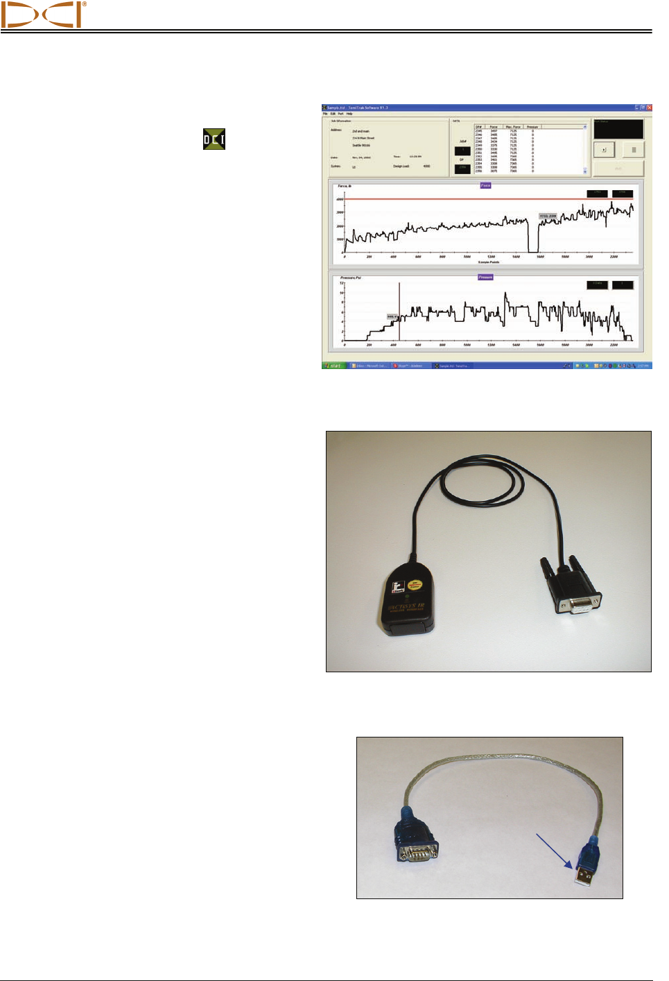
Eclipse TensiTrak Main Application Window
Port Authority USB Serial DB9 Adapter
Serial Plug
USB Plug

System Components
12 Eclipse® TensiTrak® Operator’s Manual
Notes
DIGITAL CONTROL INCORPORATED
Eclipse® TensiTrak® Operator’s Manual 13
Quick Start Guide
This TensiTrak system quick start guide is intended for use by someone who is already familiar with the
Eclipse locating equipment. Please review the DigiTrak Eclipse InGround Positioning System Operator’s
Manual if you are not familiar. This guide does not explain how to access the various menus or modes or
how to check depth or signal strength—it is assumed that you will already know how to do these things.
The key components needed for a quick start are the receiver, the remote display, the TensiTrak unit, at
least two fully charged NiCad battery packs, and either three new C-cell alkaline batteries or one new DCI
SuperCell Lithium Battery with a spacer.
The TensiTrak unit begins to measure and save data as soon as the power source is loaded into the
battery compartment.
NOTE: If you remove and replace the TensiTrak unit’s power source when it is under load, the pull
force measurements will not be accurate. The TensiTrak unit “zeroes” the pull force
measurement when the batteries are installed. If the batteries are installed under load, then
you will have incorrect readings. If this occurs, remove the batteries and reinstall them when
the TensiTrak unit is not under load.
Powering On TensiTrak Unit
It is important to inspect the TensiTrak unit’s mud pressure sensor and the O-ring on the battery cap
before each use. You must also ensure that the TensiTrak unit’s mud sensor end is on the trailing end.
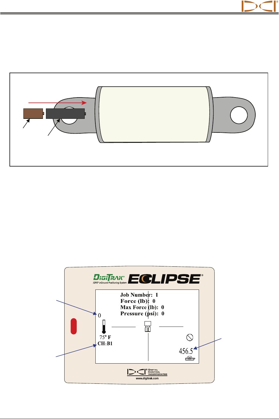
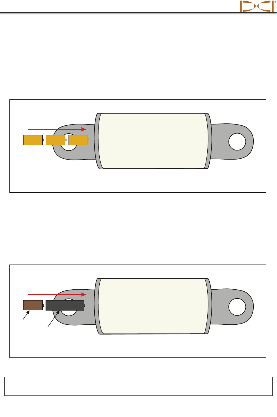
To power up the TensiTrak unit using three C-cell alkaline batteries, insert the batteries into the battery
compartment positive terminals first, as shown below.
Loading Three C-cell Alkaline Batteries in TensiTrak Unit
Leading End (with
Battery Compartment)
Trailing End (with
Mud Pressure Sensor)
Install 3 C-cell
Alkaline Batteries
Quick Start Guide
14 Eclipse® TensiTrak® Operator’s Manual
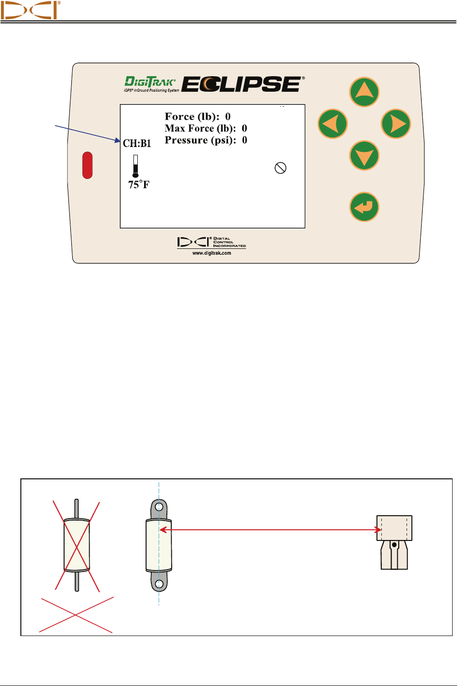
To power up the TensiTrak unit using the SuperCell lithium battery, insert it positive terminal first, followed
by a spacer or dummy battery (positive terminal first), as shown below. You must use a spacer or a
dummy battery behind the SuperCell battery to take up space and provide the necessary ground
connection. Do not use a C-cell battery as a spacer or dummy battery.
Loading SuperCell Lithium Battery and Spacer in TensiTrak Unit
Setting up Receiver and Remote Display
Power up the remote display and receiver, and select Tension mode on both. Verify that live data is
displayed on both; if not, verify that both are set to the same telemetry channel and option mode.
Verify that the Job Number shows as 1. If this is not the first job, then you will need to change the Job
Number. To do so, from the main menu screen select DataLog | Tension DataLog | Change Job
Number.
Verify that there are no data points.
Receiver Display Screen
Data Point
Number
Signal
Strength
Telemetry
Channel
Leading End (with
Battery Compartment)
Trailing End (with
Mud Pressure Sensor)
Install SuperCell
Battery and Spacer
Space
r
SuperCell Battery
Quick Start Guide
Eclipse® TensiTrak® Operator’s Manual 15
Remote Display Screen
Calibrating TensiTrak Unit to Receiver
It is only necessary to calibrate the receiver to the TensiTrak unit if you will be tracking its depth during
installation. Calibration should be completed in an interference-free environment. The calibration area
should be free of passive and active interference sources.
If you are only tracking the position (not depth) of the TensiTrak unit, then it is not necessary to calibrate.
Calibration and Verification Procedure
1. Using a tape measure, position the TensiTrak unit at a distance of 10 ft (3 m) from the receiver, as
shown in the figure below; measure from the centerline of the TensiTrak unit to the bottom inside
edge of the receiver (below the display window at the ground, not at the upper edge of the display,
which is wider). Be sure to position the TensiTrak unit with the pulling eyes “open to the sky” (facing
up and down) rather than with the pulling eyes on edge.
Calibration Setup
Centerline o
f
TensiTrak
Unit with Pulling Eyes
“Open to the Sky”
Eclipse
Receiver
10 ft (3 m)
Telemetry
Channel
NOT TensiTrak
Unit with Pulling
Eyes on Edge
Quick Start Guide
16 Eclipse® TensiTrak® Operator’s Manual
2. Select Tension from the receiver’s main menu screen to confirm that the TensiTrak unit is working—
you should see the following values: Pull Force = 0–100, Max Force = 0–200, and Pressure = 0.
Verify that the Job Number is correct; if not, change to the correct job number.
3. Exit Tension mode.
4. Select 1 Pt. Cal. from the Configure menu.
5. Follow the prompts to complete a high-frequency calibration. If the receiver asks to confirm “High
Freq” or “Low Freq”, the receiver is not properly calibrating to the TensiTrak unit’s signal. Power off
the receiver, and then power it back on again and repeat steps 4 and 5 again.
6. Go back to the main menu and select Tension to enter the Tension mode.
7. Check the depth at two different locations to ensure a good calibration.
Setting Up TensiTrak Downhole Assembly
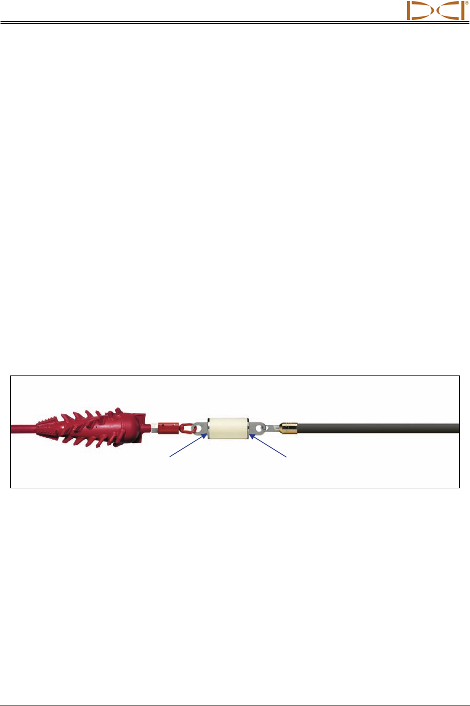
The TensiTrak downhole assembly consists of the following items in the order listed here: reamer, swivel,
TensiTrak unit, and the product, including the clevises required to connect the TensiTrak to the swivel
and the product. If the diameter of the product is larger than the diameter of the TensiTrak unit, DCI
recommends the use of a nonmetallic shroud to keep material from bridging between the reamer and the
product.
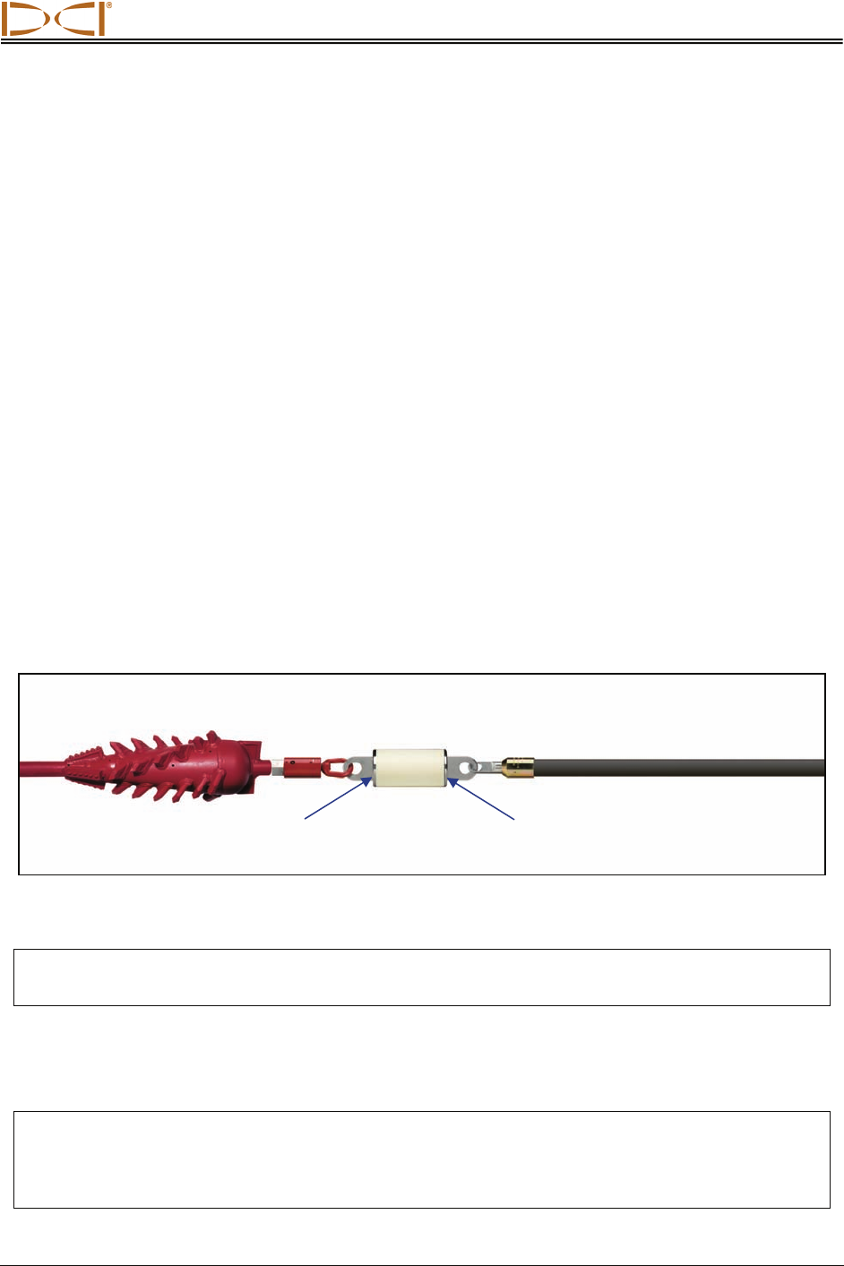
The TensiTrak unit is installed into the downhole assembly so that it is positioned behind the reamer,
between the swivel and the product as shown below
TensiTrak Downhole Assembly
It is critical that the TensiTrak unit’s mud pressure sensor end is positioned as the trailing end to ensure
that formation cuttings do not get packed around the sensor.
Note that if the TensiTrak unit’s batteries are installed when the TensiTrak unit is under load, you will not
get correct readings during the installation. You must remove and replace the three C-cell alkaline
batteries when the TensiTrak unit is not under load.
At this point, active monitoring is available on the receiver and the remote, but data is not being saved. To
start saving data on the receiver, see the next page.
Reame
r
Swivel Product
TensiTrak
Unit
Leading End with
Battery Compartment
Trailing End with
Mud Pressure Sensor
Quick Start Guide
Eclipse® TensiTrak® Operator’s Manual 17
Start/Stop Saving Data
Start Saving Data (Optional – for Data to be Transferred to Computer)
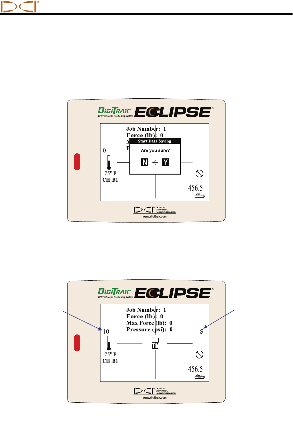
When you are ready to start the HDD installation, you will want to start the receiver’s saving mode. To do
so, from Tension mode, toggle up and answer Y for yes in the Start Data Saving dialog box.
Start Data Saving Dialog Box
The letter S for saving appears on the right side of the receiver’s screen and the data point will start
counting up (by one) every 3 seconds, which is the data collection interval. The receiver will beep to
confirm active data saving. You may want to document the data point to the corresponding site conditions
for comparison purposes after transferring the data to your computer.
Tension Mode Receiver Display Screen
“S” indicates
Saving Mode
Data Point
Number
Quick Start Guide
18 Eclipse® TensiTrak® Operator’s Manual
NOTE: If there is no live data being received from the TensiTrak unit or if the unit is out of range,
the data point counter and the beeper will stop.
SUGGESTION: Because the TensiTrak unit creates a time-based graph, it is recommended that
you document corresponding site conditions for data points. For example, you
might save information such as “data point 300 was 100 ft (30.5 m) into the
pullback.”
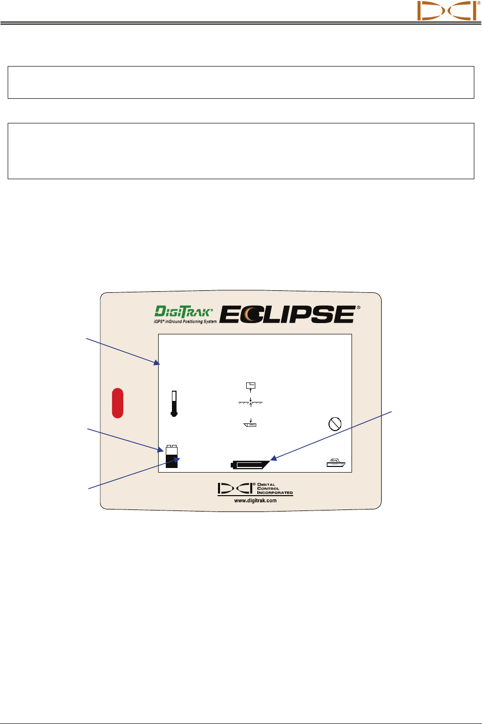
Monitoring Used Memory
The receiver can save approximately 30 hours of TensiTrak data or approximately five runs before the
memory is full. When the receiver is in Tension mode and it is actively saving data, it displays the amount
of used memory as a percentage. You can view the used memory by holding the trigger in.
456.5
CH
:
B1
75
o
F
Used Memory: 12.0
%
3944
S
-+
o‘ o’’
17’6’’
14.9
+–
Receiver Display Screen Showing Used Memory
Used
Memory
Receiver
Battery
Status
Receiver
Battery Voltage
Remaining
Transmitter
Battery Status
(Shown Full)
Quick Start Guide
Eclipse® TensiTrak® Operator’s Manual 19
Stop Saving Data
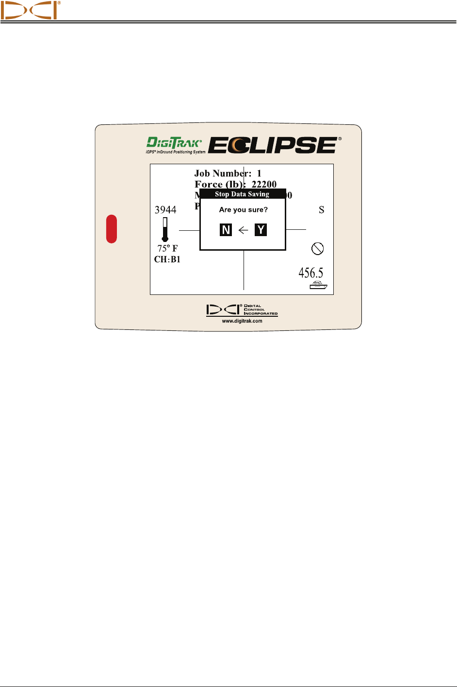
When the installation is completed or you want to temporarily stop saving data, push the toggle up and
answer Y for yes in the Stop Data Saving dialog box.
Stop Data Saving Dialog Box
If you want to resume saving, go to the Tension menu, toggle up, and answer Y for yes. You should
return to the last screen displayed before you stopped saving, unless you have changed the job number.

Quick Start Guide
20 Eclipse® TensiTrak® Operator’s Manual
Notes
DIGITAL CONTROL INCORPORATED
Eclipse® TensiTrak® Operator’s Manual 21
Using TensiTrak Menus
on Receiver
Your receiver has a set of TensiTrak menus for operating the TensiTrak system. To view the TensiTrak
menu options, select the DataLog option from the Eclipse main menu (where the menu options are
Locate, Power Off, Set US, Configure, High/Low Fre, Tension, and DataLog). Then select the
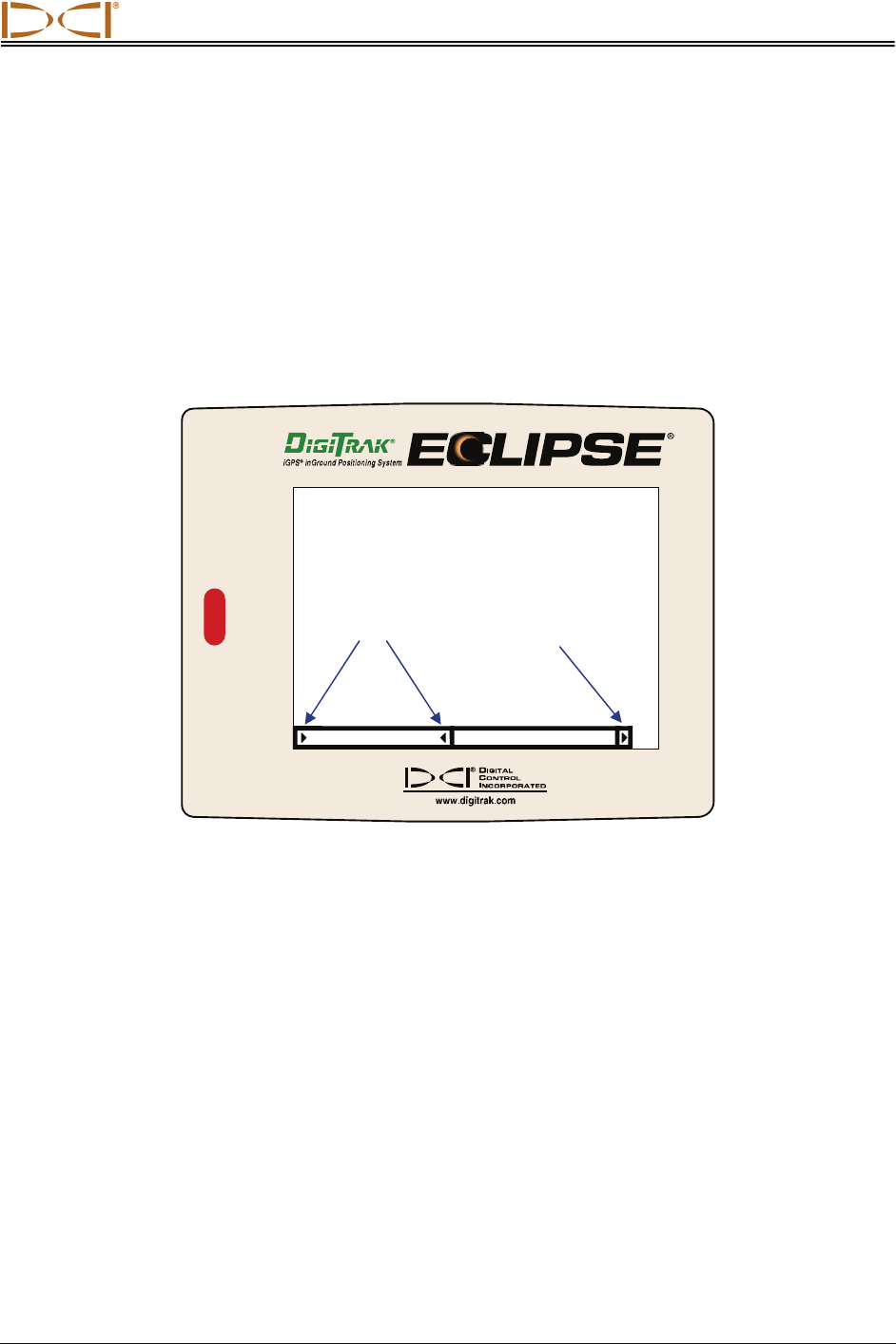
Tension DataLog option to advance to the TensiTrak main menu screen, which is shown below and
discussed further in this section.
TensiTrak Main Menu Screen
The TensiTrak main menu screen shows only the first two menu options. The Job Number option is
currently selected, as indicated by the selection arrows surrounding it. The scroll right arrow at the end of
the menu bar, just after the Send Tension Data option, indicates there are more options to the right. To
see the other options, toggle right. The other menu options are Delete Tension Data, List Saved Job
Number, and Exit.
Selection
Arrows Scroll Right
Arrow
Job Number Send Tension Data
Using Receiver Menus
22 Eclipse® TensiTrak® Operator’s Manual
DataLog
Send Tension Data Delete Tension Data Exit
Tension DataLog
Job Number
From Eclipse Main Menu
List Saved Job Number
Eclipse Receiver TensiTrak Menus
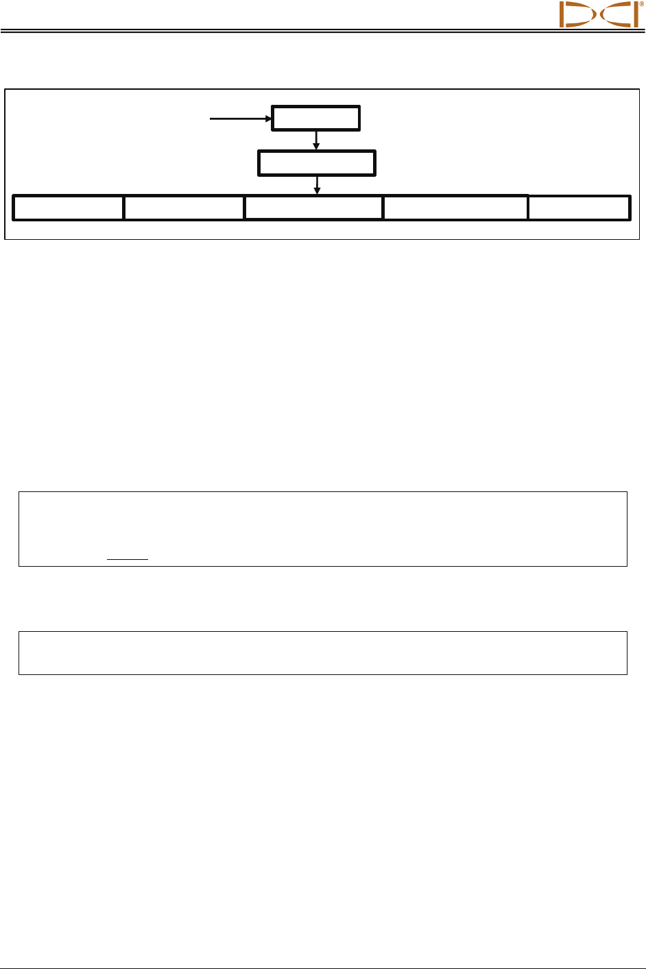
To use the TensiTrak menus, select a menu option using the toggle, then click the trigger. The available
menu options and their functions are found by selecting DataLog from the Eclipse main menu and then
selecting Tension DataLog.
¾ Job Number – Displays the last pullback job number used, and allows you to change the job
number. Used when assigning a job number to a new run.
¾ Send Tension Data – Sends the TensiTrak data to the computer via the receiver’s infrared port
(see Transferring Data from Receiver to Computer section for more information).
¾ Delete Tension Data – Deletes all data from all jobs saved in the receiver.
WARNING: The Delete Tension Data option will delete ALL data in the receiver. You cannot
clear specific jobs. Be sure you have transferred and saved the data on your com-
puter before you use this menu option. Once the data is deleted from the receiver, it
cannot be retrieved.
¾ List Saved Job Number – Lists all job numbers saved in the receiver. Used to determine the
next number to assign when starting a new job.
NOTE: It is strongly suggested that you transfer the TensiTrak data to the computer from the
receiver as soon as convenient to avoid the possibility of data loss.
¾ Exit – Returns you to the Eclipse main menu.
DIGITAL CONTROL INCORPORATED
Eclipse® TensiTrak® Operator’s Manual 23
Setting Up TensiTrak System
and Saving Data
Setting Up TensiTrak System
Before saving TensiTrak data on the Eclipse receiver, you must set up the system properly.
¾ You must confirm that the mud pressure sensor and battery cap on the TensiTrak unit are free of
damage and wear.
¾ You must power up the TensiTrak unit, the receiver, and the remote display.
¾ You must verify that the TensiTrak unit is sending data to the receiver and that the receiver is
transmitting this data to the remote display at the drill.
¾ If you plan to track the depth of the TensiTrak unit during installation, then you must calibrate the
receiver to the TensiTrak unit in an interference-free environment. You must verify your
calibration.
¾ You may need to change the job number on the receiver if this is not the first time the system is
being used.
¾ You must correctly connect the TensiTrak unit to the other components of the downhole
assembly.
¾ You must start the data saving mode to begin saving the TensiTrak data on the receiver.
TensiTrak Downhole Assembly
NOTE: It is extremely important to ensure that the TensiTrak unit is oriented correctly with the
direction of pull back. The mud pressure sensor must be on the trailing end.
Because the TensiTrak unit begins measuring and saving data once the batteries are installed, you may
prefer to power up the TensiTrak unit after it is positioned with the rest of the downhole assembly near the
pull-in area.
NOTE: If you remove and replace the TensiTrak unit’s batteries when it is under load, the pull
force measurements will not be accurate because the TensiTrak unit “zeroes” the pull
force measurement at battery installation. If this occurs you must remove and replace the
batteries when the TensiTrak unit is not under load.
Reame
r
Swivel Product
TensiTrak
Unit
Leading End with
Battery Compartment
Trailing End with
Mud Pressure Sensor
Recording Data
24 Eclipse® TensiTrak® Operator’s Manual
1. Power Up TensiTrak Unit
Using Three C-Cell Alkaline Batteries
1. Inspect and clean as necessary the mud pressure sensor area, battery cap, and O-ring for
damage and wear.
2. Install three C-cell alkaline batteries into the battery compartment with the positive terminals first,
and then tighten the battery cap until it seats completely.
Loading Three C-cell Alkaline Batteries in TensiTrak Unit
Using SuperCell Lithium Battery
1. Inspect and clean as necessary the mud pressure sensor area, battery cap, and O-ring for
damage and wear.
2. Install the SuperCell lithium battery into the battery compartment with the positive terminals first,
followed by a spacer or dummy battery (positive terminal first), and then tighten the battery cap
until it seats completely.
Loading SuperCell Lithium Battery and Spacer in TensiTrak Unit
NOTE: You must use a spacer or a dummy battery behind the SuperCell battery to take up space
and provide the necessary ground connection.
Leading End (with
Battery Compartment)
Trailing End (with
Mud Pressure Sensor)
Install 3 C-cell
Alkaline Batteries
Leading End (with
Battery Compartment)
Trailing End (with
Mud Pressure Sensor)
Install SuperCell
Battery and Spacer
Space
r
SuperCell Battery
Recording Data
Eclipse® TensiTrak® Operator’s Manual 25
2. Power Up Receiver & Confirm Tension and Mud Pressure Readings
1. Power up the receiver by placing a NiCad battery pack into the receiver’s battery compartment
and then clicking the trigger.
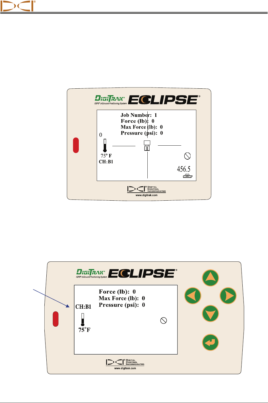
2. Select Tension from the Eclipse main menu screen.
3. Verify that you see the pull force, maximum pull force, and mud pressure listed on the screen.
4. Verify that you have the correct job number.
Receiver Display Screen
3. Power Up Remote Display & Confirm Tension, Mud Pressure Readings
1. Power up the remote display by placing a NiCad battery pack in the remote (or by plugging the
unit into a cigarette adapter) and then pressing the execute button.
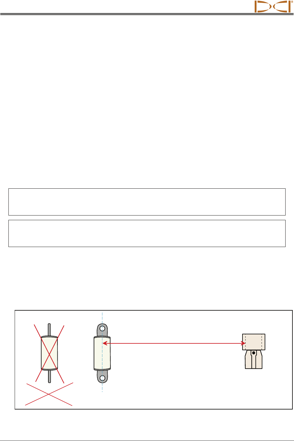
2. Select the Tension option from the remote’s main menu screen.
3. Verify that you see the pull force, maximum pull force, and mud pressure listed on the screen.
Remote Display Screen
Telemetry
Channel
Recording Data
26 Eclipse® TensiTrak® Operator’s Manual
4. Confirm or Change Job Number (Receiver)
You will need to use the Receiver’s Job Number command to assign a job number when you are starting
a new run. To change the job number:
1. From the Eclipse main menu, toggle right to select DataLog, then click the trigger.
2. Select Tension DataLog, then click the trigger.
3. Select Job Number, then click the trigger. The last job number that was used is displayed.
4. Push the toggle up to advance to the next run number, then click the trigger.
5. You will be asked if you are sure. Use the toggle to select Y for yes, then click the trigger.
6. The new job number will be shown on the screen.
5. Calibrate Receiver to TensiTrak Unit
If you are going to track the depth of the TensiTrak unit, then you must calibrate the receiver to the
TensiTrak unit. This should be done in an interference-free environment—that is, there should be no
passive or active interference sources within 10–15 ft (3–4.6 m) of the receiver and TensiTrak unit. When
you go into Tension mode you should see a stable signal strength in the bottom left corner of the screen.
NOTE: If depth readings are not needed, calibration is not required. Measurement of the pull
force and downhole mud pressure does not require calibration. The depth readings are
not saved.
NOTE: Calibrating the Eclipse receiver to the TensiTrak unit will erase the previously saved
calibration for the single-high (SH) mode. The Eclipse receiver will require calibration
when a different transmitter is used in SH mode.
Calibration and Verification Procedure
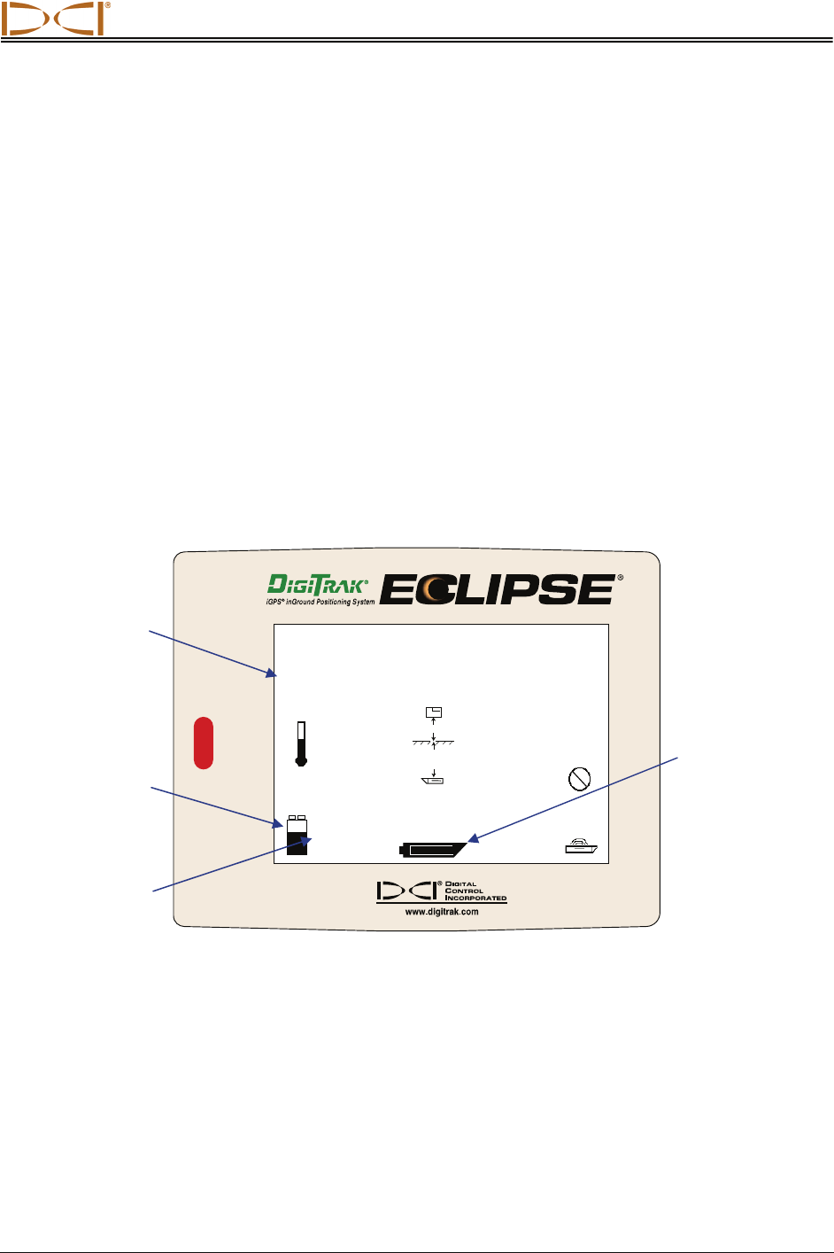
1. Using a tape measure, position the TensiTrak unit at a distance of 10 ft (3 m) from the receiver,
as shown in the figure below; measure from the centerline of the TensiTrak unit to the bottom
inside edge of the receiver (below the display window at the ground, not at the upper edge of the
display, which is wider). Be sure to position the TensiTrak unit with the pulling eyes “open to the
sky” (facing up and down) rather than with the pulling eyes on edge.
Calibration Setup
Centerline o
f
TensiTrak
Unit with Pulling Eyes
“Open to the Sky”
Eclipse
Receiver
10 ft (3 m)
NOT TensiTrak
Unit with Pulling
Eyes on Edge
Recording Data
Eclipse® TensiTrak® Operator’s Manual 27
2. Select Tension from the receiver’s main menu screen to confirm that the TensiTrak unit is
working—you should see the following values: Pull Force = 0–100, Max Force = 0–200, and
Pressure = 0. Verify that the Job Number is correct; if not, change to the correct job number.
3. Exit Tension mode.
4. Select 1 Pt. Cal. from the Configure menu.
5. Follow the prompts to complete a high-frequency calibration. If the receiver asks to confirm “High
Freq” or “Low Freq”, the receiver is not properly calibrating to the TensiTrak unit’s signal. Power
off the receiver, and then power it back on again and repeat steps 4 and 5 again.
6. Go back to the main menu and select Tension to enter the Tension mode.
7. Check the depth at two different locations to ensure a good calibration.
6. Monitor Used Memory and Battery Status of Receiver and
TensiTrak Unit
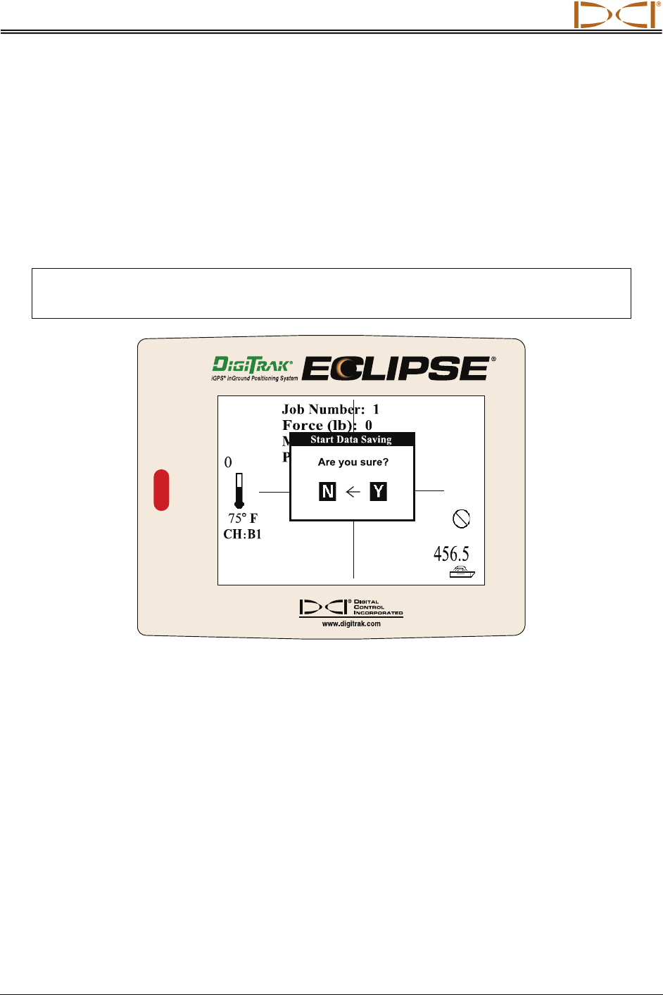
To confirm the battery status, hold in the trigger and view the receiver’s battery status icon and the
corresponding value for the amount of voltage remaining. You should change the battery when it shows
as half-full or with a remaining voltage of 14.5 or less. The TensiTrak unit’s battery status when using
three C-cell alkaline batteries displays in the bottom middle of the screen with the trigger held.
456.5
CH
:
B1
75
o
F
Used Memory: 12.0
%
3944
S
-+
o‘ o’’
17’6’’
14.9
+–
Battery Status Display Screen
If using the DCI SuperCell Lithium Battery, you will not see battery status. The SuperCell battery provides
approximately 40 hours of life in the TensiTrak unit, and you must monitor this yourself.
Used
Memory
Receiver
Battery
Status
Receiver
Battery Voltage
Remaining
Transmitter
Battery Status
(C-cell Only)
Shown Full
Recording Data
28 Eclipse® TensiTrak® Operator’s Manual
Saving Data (Receiver)
1. Start Receiver’s Data Saving Mode
When you are ready for the installation to begin, you will start the receiver’s saving mode. First, be sure
that the remote display is powered up.
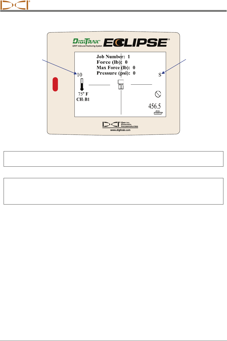
1. Select Tension from the main menu screen.
2. Toggle up and select Y for yes at the Start Data Saving dialog box.
NOTE: If it is not necessary to transfer the data to a computer, then you do not need to save
the data.
Start Data Saving Dialog Box
3. Verify that the letter S for saving appears on the right side of the screen. Also observe the
number above the thermometer; this is the data point. This number will increase by one every
3 seconds. The receiver will beep when this occurs to confirm active data saving. You may want
to document this number and the corresponding site conditions for comparison after transferring
the data to the computer.
Recording Data
Eclipse® TensiTrak® Operator’s Manual 29
Tension Mode Receiver Display Screen
NOTE: If there is no live data being received from the TensiTrak unit or if the unit is out of range,
the data point counter and the beeper will stop.
SUGGESTION: Because the TensiTrak unit creates a time-based graph, it is recommended that
you document corresponding site conditions for data points. For example, you
might save information such as “data point 300 was 100 ft (30.5 m) into the
pullback.”
2. Track the TensiTrak Unit’s Depth and Position
If you would like to track the TensiTrak unit’s position and depth, you can do so using the locate points
and locate line, as with other Eclipse transmitters. For complete information about the locating procedure,
see the Eclipse operator’s manual.
“S” indicates
Saving Mode
Data Point
Number
Recording Data
30 Eclipse® TensiTrak® Operator’s Manual
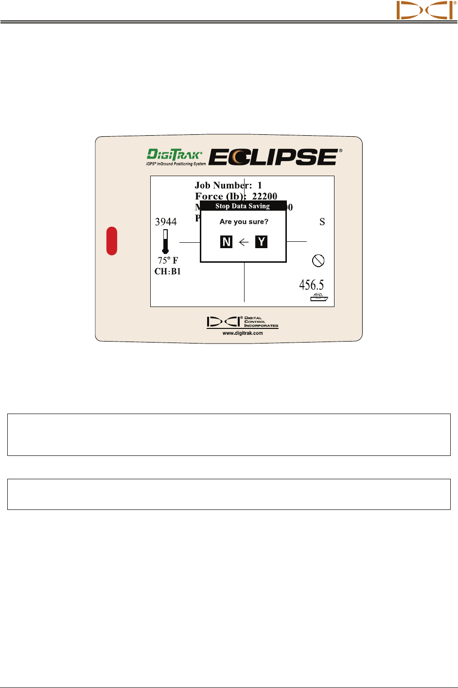
3. Stop Saving Data
After the installation is complete, you must tell the receiver to stop saving data. To do this:
1. Toggle up, and you will see the Stop Data Saving dialog box.
Stop Data Saving Dialog Box
2. Toggle right to select Y for yes.
3. Click the trigger
NOTE: The Eclipse receiver can be shut off and on and the battery changed without affecting the
presaved data. Once the receiver is restarted and returned to Tension saving mode, it will
append the data properly.
NOTE: It is strongly suggested that you transfer the TensiTrak data to the computer from the
receiver as soon as convenient to avoid the possibility of data loss.
Congratulations! You are now ready to save another job or to transfer this job to the computer. For
transferring instructions, see the Transferring Data to Computer section.

Recording Data
Eclipse® TensiTrak® Operator’s Manual 31
Summary of Procedure for Setting Up System & Saving Data
Setting Up TensiTrak System
1. Power Up TensiTrak Unit
2. Power Up Receiver and Confirm Tension and Mud Pressure Readings
3. Power Up Remote and Confirm Tension and Mud Pressure Readings
4. Confirm or Change Job Number (Receiver)
5. Calibrate Receiver to TensiTrak Unit
6. Monitor Used Memory and Battery Status of Receiver and TensiTrak Unit
Saving Data (Receiver)
1. Start Receiver’s Data Saving Mode
2. Track the TensiTrak Unit’s Depth and Position
3. Stop Saving Data

Recording Data
32 Eclipse® TensiTrak® Operator’s Manual
Notes

DIGITAL CONTROL INCORPORATED
Eclipse® TensiTrak® Operator’s Manual 33
Installing TensiTrak Software
Computer System Requirements
The Eclipse TensiTrak computer software is provided on a single CD-ROM, which also contains the
operator’s manual and sample data. The TensiTrak software requires a computer with at least the
following system specifications:
¾ 600 MHz or greater processor
¾ Microsoft Windows 98, 2000, or XP operating system
¾ Serial (COM) port or USB port
¾ Pointing device (mouse)
¾ Color printer for color graphs
Installing Software on Computer
NOTE: Files will automatically be placed under the C:\Program Files folder in a new folder named Digital
Control Incorporated (C:\Program Files\Digital Control Incorporated). You can change this default
storage location during installation.
Eclipse TensiTrak Software
1. Close any open applications.
2. Place the TensiTrak CD-ROM in the CD drive and follow the prompts. The software will install
automatically. You will be given an opportunity to change the default storage location during
installation.
3. Once the program is installed, you will see an Eclipse TensiTrak shortcut icon on your
desktop and under All Programs in your Start menu (in lower left corner of computer screen).
Before using the program, DCI recommends restarting your computer.
Software for USB-to-Serial Adapter
If you do not have a serial port on your computer, then you will need to use the USB-to-serial adapter
provided with the TensiTrak system. This adapter requires you to install software on your computer.
1. Close any open applications.
2. Place the CD-ROM provided with the USB-to-serial adapter in the CD drive, and follow the
prompts. The software will install automatically.

Installing Software
34 Eclipse® TensiTrak® Operator’s Manual
Notes
DIGITAL CONTROL INCORPORATED
Eclipse® TensiTrak® Operator’s Manual 35
Using TensiTrak Software
Starting TensiTrak Program
There are three ways to start the Eclipse TensiTrak program:
¾ Double-click on the Eclipse TensiTrak icon on the desktop.
¾ Use the Start button (in lower left corner of computer screen) and select Start | All Programs |
TensiTrak.
¾ From Windows Explorer, click on the Tensitrak.exe file in the C:\Program Files\Digital Control
Incorporated\TensiTrak folder, or the folder you have designated for the storage location.
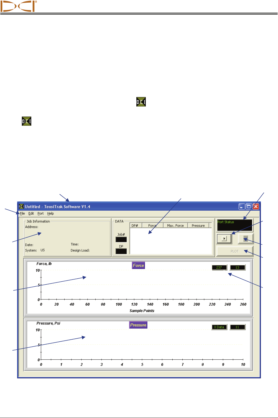
After you start up the program, you will see the main application window without data, as shown in the
figure below. This window serves as a blank form for a new project (it is also generated by using the File |
New command on the menu bar). The main features and information fields identified on the blank project
screen below are described after the figure.
TensiTrak Main Application Window
Menu
Bar
PLOT
Button
Port Close
Button
Port Open
Button
Port Status
Field
DATA Field
Title Ba
r
Mud
Pressure
Graph
Job Info
Field
Pull Force
Graph
Cursor
Coordinates
Using Software
36 Eclipse® TensiTrak® Operator’s Manual
Menu Bar
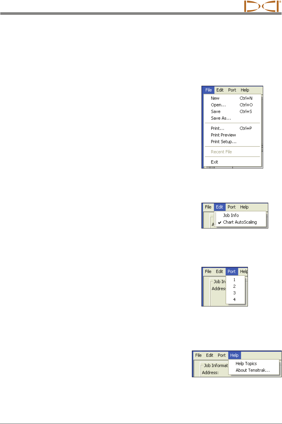
Under each menu on the menu bar (File, Edit, Port, and Help) are commands for running the Eclipse
TensiTrak program. Many of the commands are similar to those used in other Windows programs. This is
particularly true for the File and Help menu commands. The menu commands are summarized below.
File Menu Commands
¾ New – Creates a new blank project screen.
¾ Open – Opens an existing project.
¾ Save – Saves an opened project using the same file name.
¾ Save As – Saves an opened project to a specified file name
and folder.
¾ Print – Prints a project.
¾ Print Preview – Displays the project on the screen as it would
appear printed.
¾ Print Setup – Selects a printer and printer connection.
¾ Recent Files – Allows you to click on the filename of a recently
opened project to open the file immediately.
¾ Exit – Exits Eclipse TensiTrak program.
Edit Menu Commands
¾ Job Info – Allows entry or editing of data in the Job Information
field, which includes address, date, time, system, and design
load.
¾ Chart AutoScaling – Allows you to toggle the autoscaling
feature on and off. The autoscaling feature automatically determines adequate ranges for the X
and Y axes depending upon the data points uploaded.
Port Menu Commands
The Port menu has four options, which are listed as 1, 2, 3, and 4.
These numbers represent the COM ports available. The Port menu
is used to select a port for transferring data.
To determine the computer’s available ports, open your computer’s
Control Panel and click on the System icon to open the System
Properties dialog box. Click on the Hardware tab and then the Device Manager option at the top to
open the Device Manager dialog box. Click on “Ports” in the listing to view the available ports on your
system.
Help Menu Commands
¾ Help Topics – Opens Eclipse TensiTrak Help file.
¾ About TensiTrak – Provides software version number and
copyright information for Eclipse TensiTrak software.
Using Software
Eclipse® TensiTrak® Operator’s Manual 37
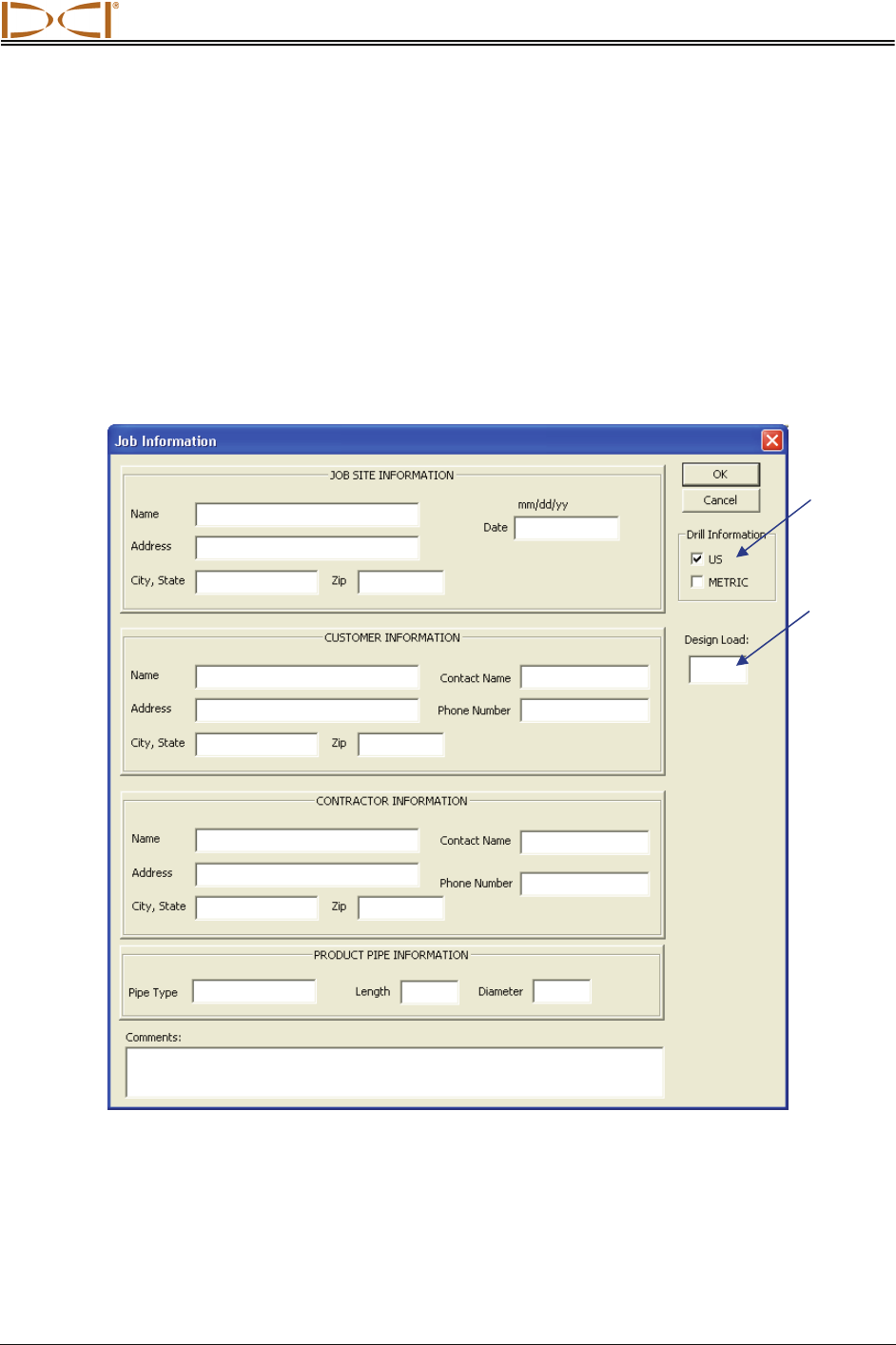
Job Information Field
The Job Information field displays some basic information
about the job, including location, date, time, system, and
design load. To enter or change the job information, select
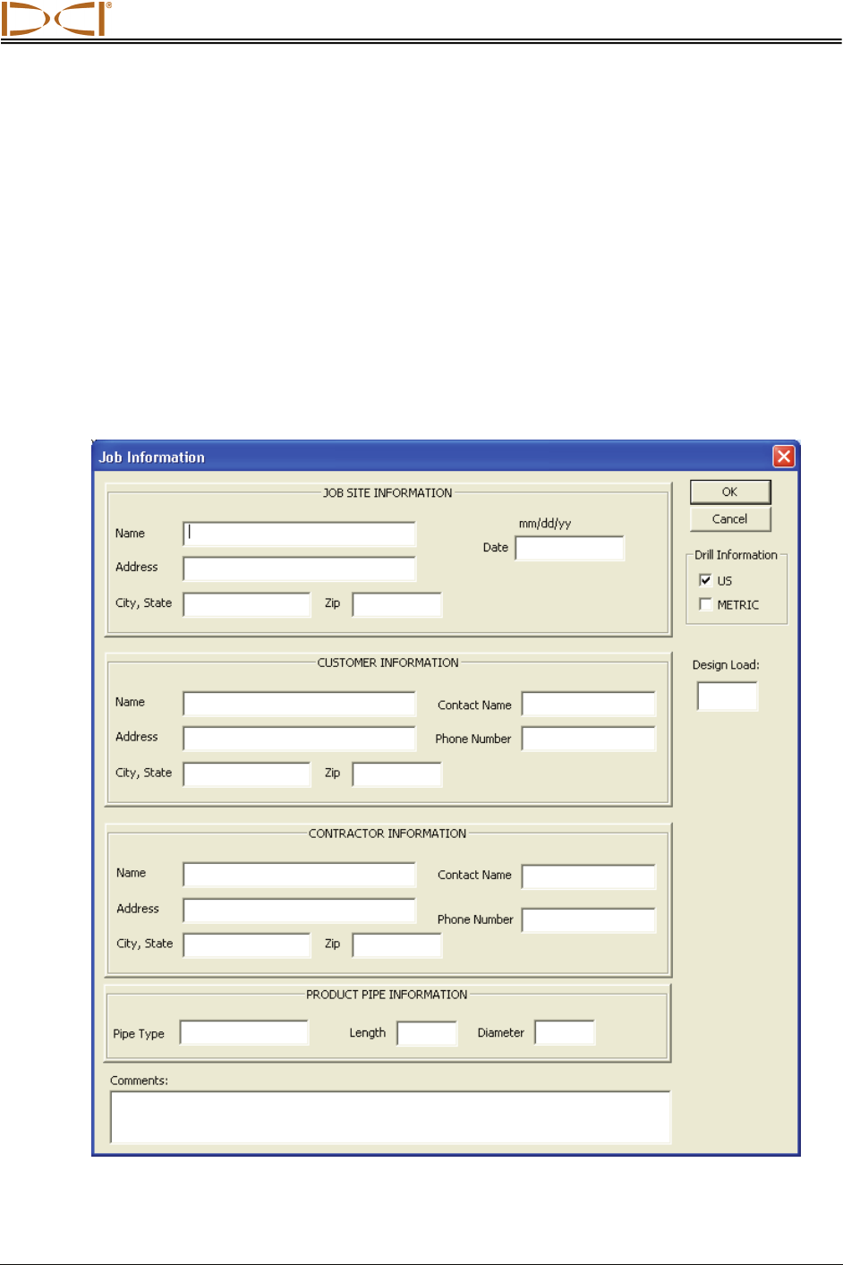
Job Info from the Edit menu. You will see the Job Informa-
tion dialog box (see “Editing Job Information” in the Editing
Data in Computer section). If you select METRIC in the
Drill Information field, the units of measure will change from
pounds (lbs) to kilo-Newtons (kN) and from pounds-per-
square-inch (psi) to kilo-Pascals (kPa).
Job Information Dialog Box
Design
Load
(Maximum
Force on
Product)
Drill
Information
Units
Using Software
38 Eclipse® TensiTrak® Operator’s Manual
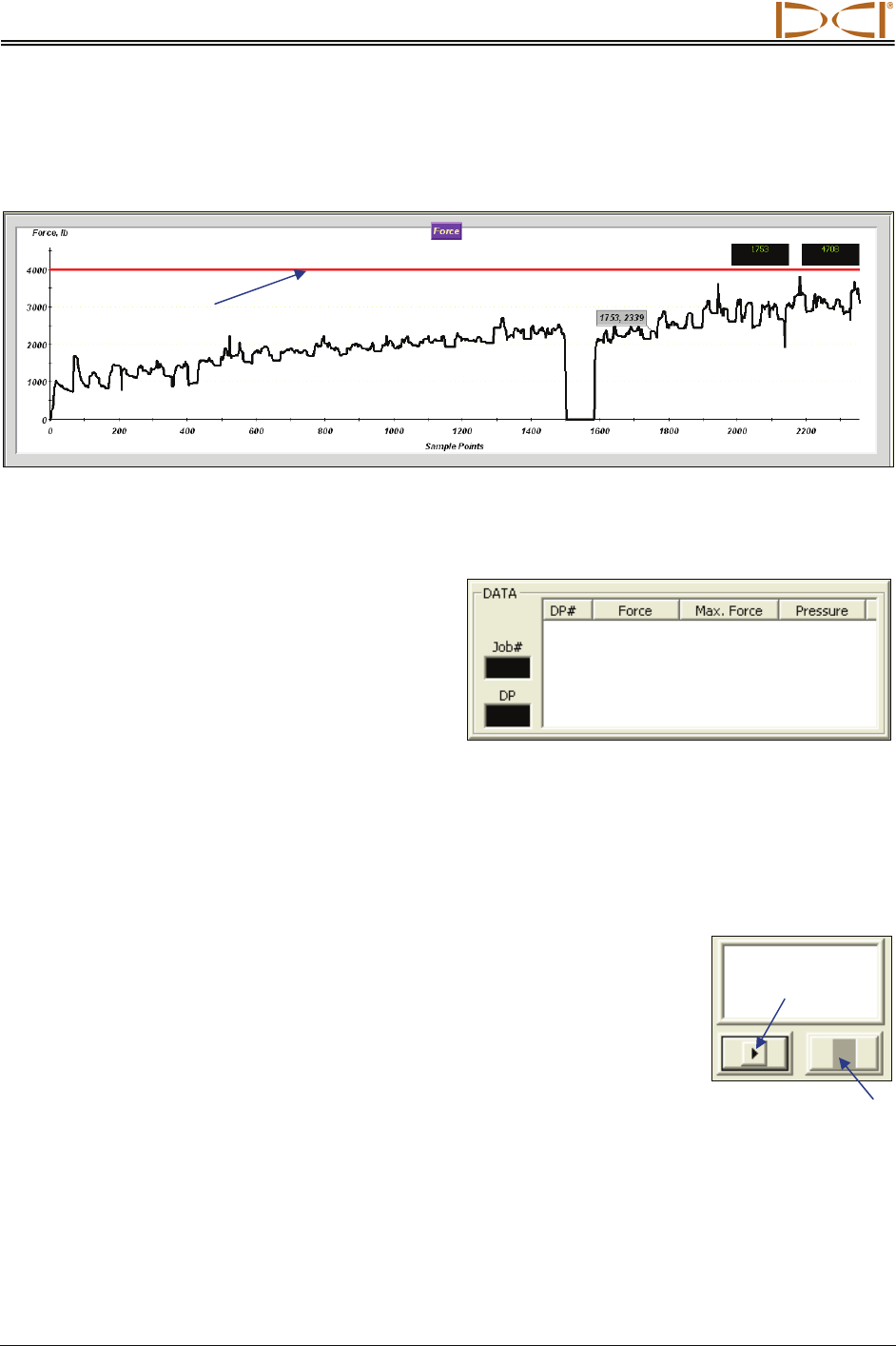
If you want to enter the maximum pull force of the product so that it displays as a horizontal red line on
the Force graph, then enter the value in the Design Load input box. A value of 4000 was entered as the
design load in the example shown below.
Pull Force Graph
DATA Field
The DATA field lists information about each data
point (DP) in the specified job (Job#). Each of the
data fields is described below.
¾ DP# – A sequential listing of each data
point.
¾ Force – The amount of pull force mea-
sured at the time of that data point.
¾ Max. Force – The maximum pull force measured at the time of that data point.
¾ Pressure – The mud pressure measured at the time of that data point.
Port Status Field and Open/Close Buttons
The input box in the top right corner of the software screen displays the port
status. Before transferring data, you must connect the receiver and computer
using the ACTiSYS IR cable, and the USB-to-serial cable if necessary, through
an available port. To choose a port, select the desired port number (1, 2, 3, 4)
from the Port menu (port 1 is generally used), then click on the Open button.
To disconnect from a port, click on the Close button.
If you cannot open a port after you have identified one using your computer’s system properties hardware
settings in the Control Panel (see “Port Menu Commands” earlier in this section), close the Eclipse
TensiTrak program and reopen it. Select the desired port, and click on the Open button. You may also
refer to “Transferring Hints” in the Transferring Data to Computer section of this manual. If this does not
solve the problem, then call DCI Customer Service, 800-288-3610 or 425-251-0559, for assistance.
Open
Close
Design Load
Using Software
Eclipse® TensiTrak® Operator’s Manual 39
PLOT Button
The PLOT button is used to replot the data in the Pull Force and Mud Pressure
graphs if you have added a value to the Design Load field after the data has
been transferred from the receiver to the computer.
Pull Force Graph
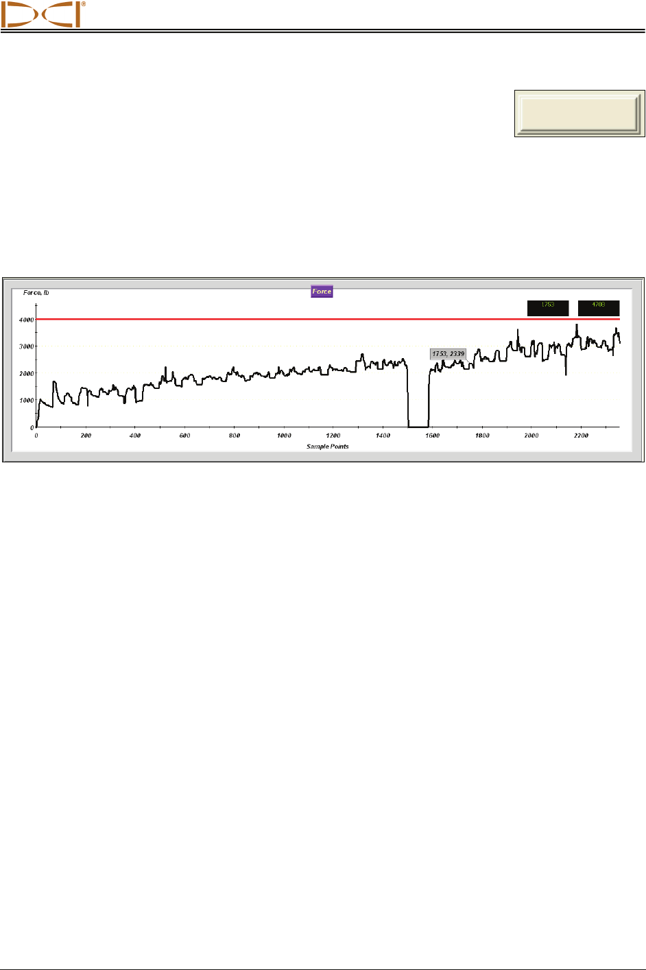
The Pull Force graph shows the amount of pull force (in pounds or kilo-Newtons) exerted on the
TensiTrak unit at each data collection interval (3 seconds) from the moment you began saving data on
the receiver. If you want to see whether the force exerted stayed below or went above a certain value
during the pullback process, you can apply a limit line on the graph to view the results.
¾ Force, lb – The Y-axis shows the value for the pull force.
¾ Sample Points – The X-axis shows the number of data points; a data point is saved every
3 seconds.
¾ Cursor Coordinates – The cursor coordinates show the pull force and data point numbers of the
mouse pointer as it is positioned on the graph.
PLOT
Using Software
40 Eclipse® TensiTrak® Operator’s Manual
Mud Pressure Graph
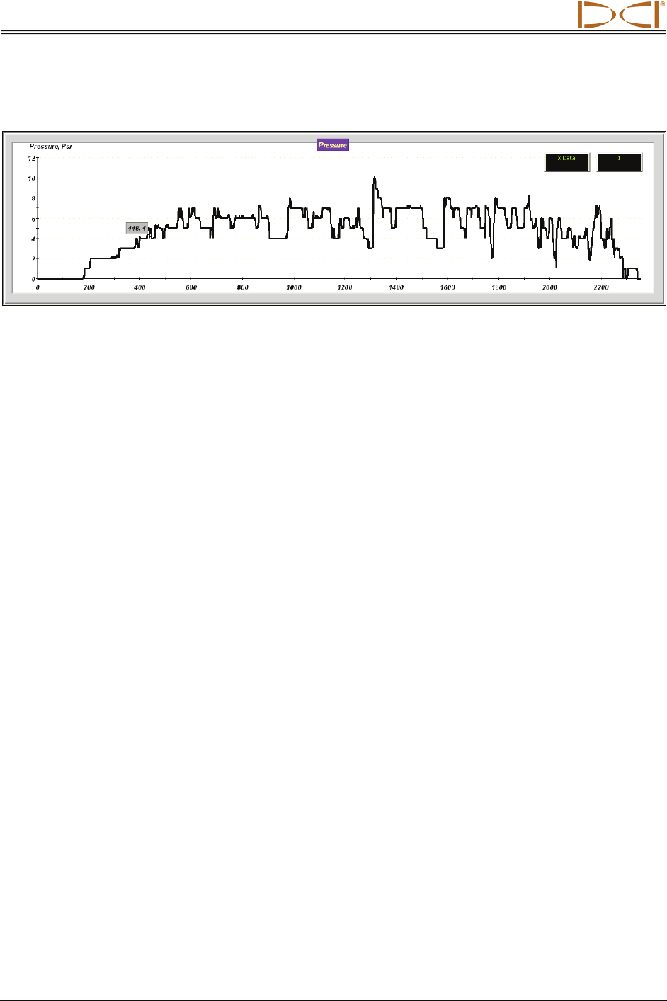
The Mud Pressure graph shows the downhole mud pressure (in pounds-per-square-inch or kilo-Pascals)
at each collection interval.
¾ Pressure, psi – The Y-axis shows the value of the mud pressure.
¾ Data Points – The X-axis shows the number of data points; a data point is saved every
3 seconds.
¾ Cursor Coordinates – The cursor coordinates show the pull force and data point numbers of the
mouse pointer as it is positioned on the graph.
Using Software
Eclipse® TensiTrak® Operator’s Manual 41
Opening Project Files
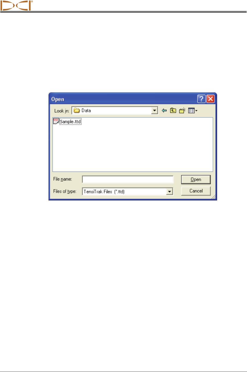
1. To open an existing drill project from within the TensiTrak program, select Open from the File
menu. You will see the Open dialog box and a list of available TensiTrak project files (with the file
extension “ttd”) in the folder that was last used. If this is the first time the program is being used,
however, the Open dialog box will show the Data folder under the Eclipse TensiTrak program file,
which is the default location for saving project files (C:\Program Files\Digital Control Incor-
porated\TensiTrak\Data).
Open Dialog Box
2. Select the desired Eclipse TensiTrak project file (in this example, Sample.ttd), or navigate to the
folder where you have saved your project files and select the desired file. Then click on the Open
button. You will see the main application window.
Using Software
42 Eclipse® TensiTrak® Operator’s Manual
Printing and Previewing Project Reports
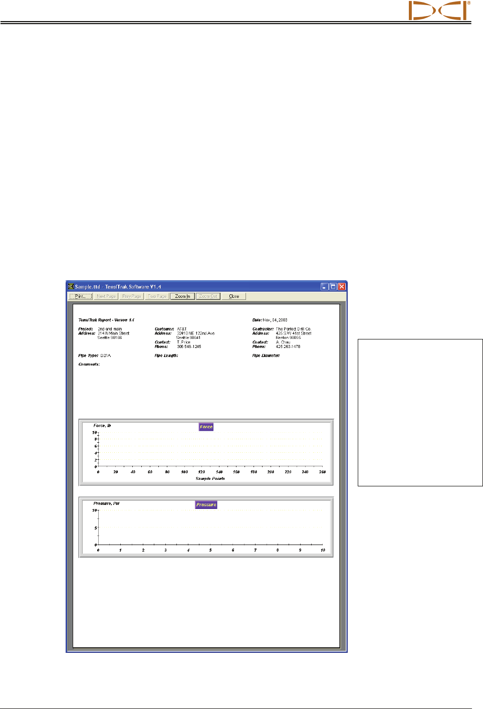
1. If you want to preview the printed pages before you send the file to print, select Print Preview
from the File menu.
2. To print the project data, select Print from the File menu. A Report Size dialog box should
appear. Input the range of data points that are pertinent and click OK. A Print dialog box should
appear next. Make any adjustments needed in the Print dialog box, then click OK. If you have the
Adobe Acrobat PDF writer software, you can select the Adobe PDF printer to print to a PDF file
(see your Adobe software documentation).
3. The project data will print on at least two pages. On the first page, the job information will appear
at the top, and the two graphs at the bottom. On the second page (and more if needed), the
pullback data will be listed as shown in the DATA field.
4. If the run is long, you may prefer to print the graphs in landscape mode so that it will print larger.
To do so, select Print Setup from the File menu and click on Landscape under Orientation. Then
you can print page 1 (the graphs) in the landscape orientation, or you can choose to print all
pages in the landscape orientation.
Print Preview
NOTE: Twenty (20) data
points will print per page
in portrait orientation. If
you have 10,000 data
points, then you will have
500 pages of data. Only
14 data points will print
per page in landscape
orientation. Thus, 10,000
data points would require
714 pages in landscape
orientation.
Using Software
Eclipse® TensiTrak® Operator’s Manual 43
Saving Project Files
1. To save an open project file, select Save from the File menu. The file will automatically be saved
under its current file name (shown on the left in the blue title bar at the top of the main application
window) and location. If the project has not yet been saved and named, then the file will automa-
tically save to the default file name Untitled.ttd.
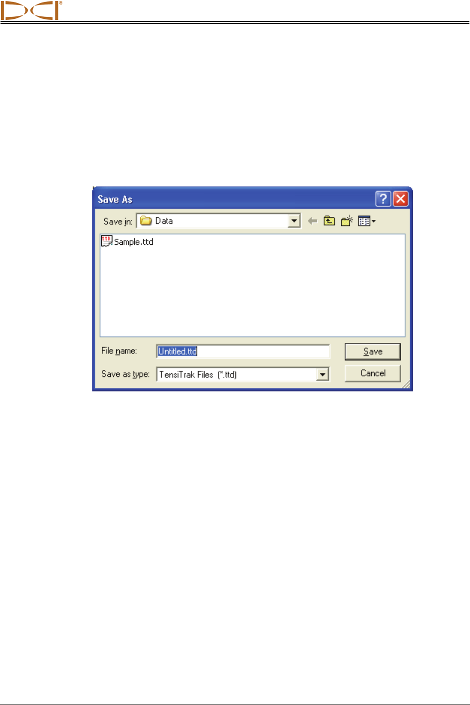
2. To save a file with a different file name or location, select Save As from the File menu. You will
see the Save As dialog box, which automatically opens to the folder where the current file is
saved.
Save As Dialog Box
3. Change the file name and location as desired, then click Save. The open file will now have the
new file name and/or location.
Using Software
44 Eclipse® TensiTrak® Operator’s Manual
E-mailing Project Files
You can send Eclipse TensiTrak files via e-mail. E-mailed files can be opened on any computer that has
the same version of the Eclipse TensiTrak software as used on the originating computer.
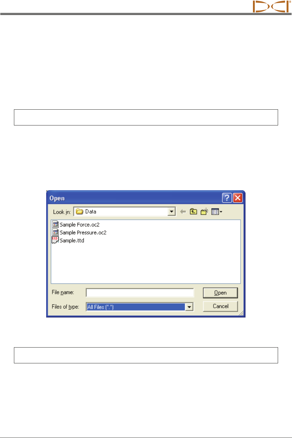
The Eclipse TensiTrak program generates three files for each drill run – one “*.ttd” project file and two
“*.oc2” files, one for the Force data and one for the Pressure data. All three files are required to be in the
same folder for the project data to display correctly.
NOTE: All project files (the *.ttd and two *.oc2 files) must be e-mailed and saved to the
same folder on the receiving computer so that the data will display correctly.
To e-mail files for a project, select the TensiTrak project “*.ttd” file and the two accompanying *.oc2 files
(for Force and Pressure) as attachments in your e-mailing application, and then send the e-mail. The
default location of the TensiTrak program data is C:\Program Files\Digital Control Incorporated\TensiTrak\
Data. You can see the different file types under the Data folder by setting the drop-down selection at the
bottom of the dialog box to “All Files (*.*)”, as shown below.
Open Dialog Box Showing “All Files”
NOTE: If you have made a PDF file of the project data, then you can select the PDF file for
e-mailing. The *.ttd and *.oc2 files are not required to view the PDF file.
DIGITAL CONTROL INCORPORATED
Eclipse® TensiTrak® Operator’s Manual 45
Transferring Data
from Receiver to Computer
Transferring Data from Receiver to Computer
DCI suggests that you transfer data to a computer following every TensiTrak job.
DCI recommends that you use an AC power source when transferring data from the receiver to the
computer. DCI does not recommend using an adapter with inverter. If AC power is not available, then use
the laptop’s battery pack. It is not advisable to transfer data inside an operating vehicle, due to noise
interference during the IR transfer.
To transfer data, you will need the receiver (containing the data to transfer), the ACTiSYS IR cable and
USB adapter, and a computer with the Eclipse TensiTrak software installed (see Installing TensiTrak
Software section).
To transfer data from the receiver to the computer:
1. Plug the ACTiSYS IR cable into the serial (COM) port on the computer, or use the USB-to-serial
adapter to connect the cable to a USB port.
2. Start up the computer and open the TensiTrak program (see “Starting TensiTrak Program” in
Using TensiTrak Software section).
3. Select a port (1, 2, 3, 4) from the Port menu, then click the Port Open button. The port will automa-
tically open, and you will see “Com1 Port opened” (for example) in the port status field.
4. Start up the receiver.
5. From the main menu screen push the toggle to the right a few times to
select the DataLog option, and click the trigger. Then select the
Tension DataLog option.
6. Hold the IR reader approximately 2 in. (5 cm) over the red IR port on the
left side of the receiver’s display window. The IR cable must remain
stationary above the IR port during the data transfer.
7. From the TensiTrak menu, select Send Tension Data, and click the trigger. Toggle up or down
accordingly to choose the desired Job Number, then click the trigger. The computer screen
should show the Job Number and the data point number counting up. The data transfer rate is
approximately 7 seconds per 1000 data points; thus, it will take more than one minute to transfer
10,000 data points. The data will appear on the computer screen when the transfer is successful.
8. Save the file.
NOTE: DCI recommends that you transfer data for each run at least twice, and save each with a
different name. For example, you could transfer and save the data the first time as
“Riverbore” and the second time as “Riverbore Rev 1”.
Click Trigger to
Start Receiver
Transferring Data
46 Eclipse® TensiTrak® Operator’s Manual
Transferring Hints
If the data does not transfer, try another port. To do so, click on the Port Close button to close the current
port. Then select a different port, click on the Port Open button, and try transferring again.
To verify the available ports on your computer, select Start | Control Panel | System to open the System
Properties dialog box. Another way to access the System Properties dialog box is to select Start | My
Computer and then double click on “View system information” listed under System Tasks on the left side
of the dialog box.
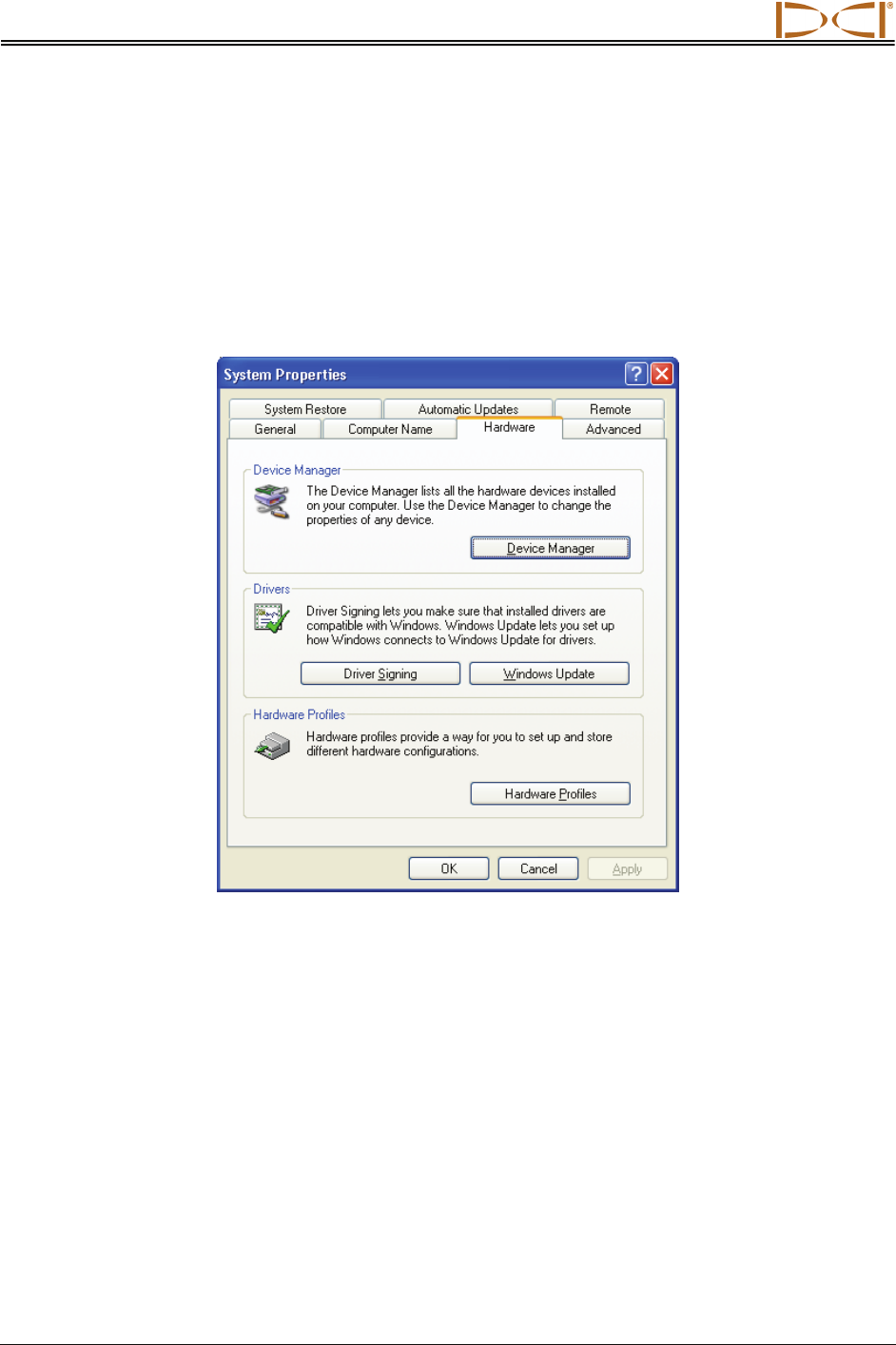
System Properties Dialog Box Showing Hardware Tab
In the System Properties dialog box, click on the Hardware tab, then the Device Manager button to open
the Device Manager dialog box, which shows all the hardware devices installed on your computer.
Double click on Ports to see the current port assignments. You should see “Prolific USB-to-Serial Comm
Port” with its designated COM port in parenthesis. If it shows this port is designated as COM5 or greater,
then you must change this to a COM port number of 1, 2, 3, or 4, because the Eclipse TensiTrak will only
communicate on ports 1, 2, 3, or 4.
If you must change the “USB-to-Serial Comm Port” setting, double click on it in the Device Manager
dialog box to bring up its Properties dialog box. Click on the Port Settings tab, then click on the Advanced
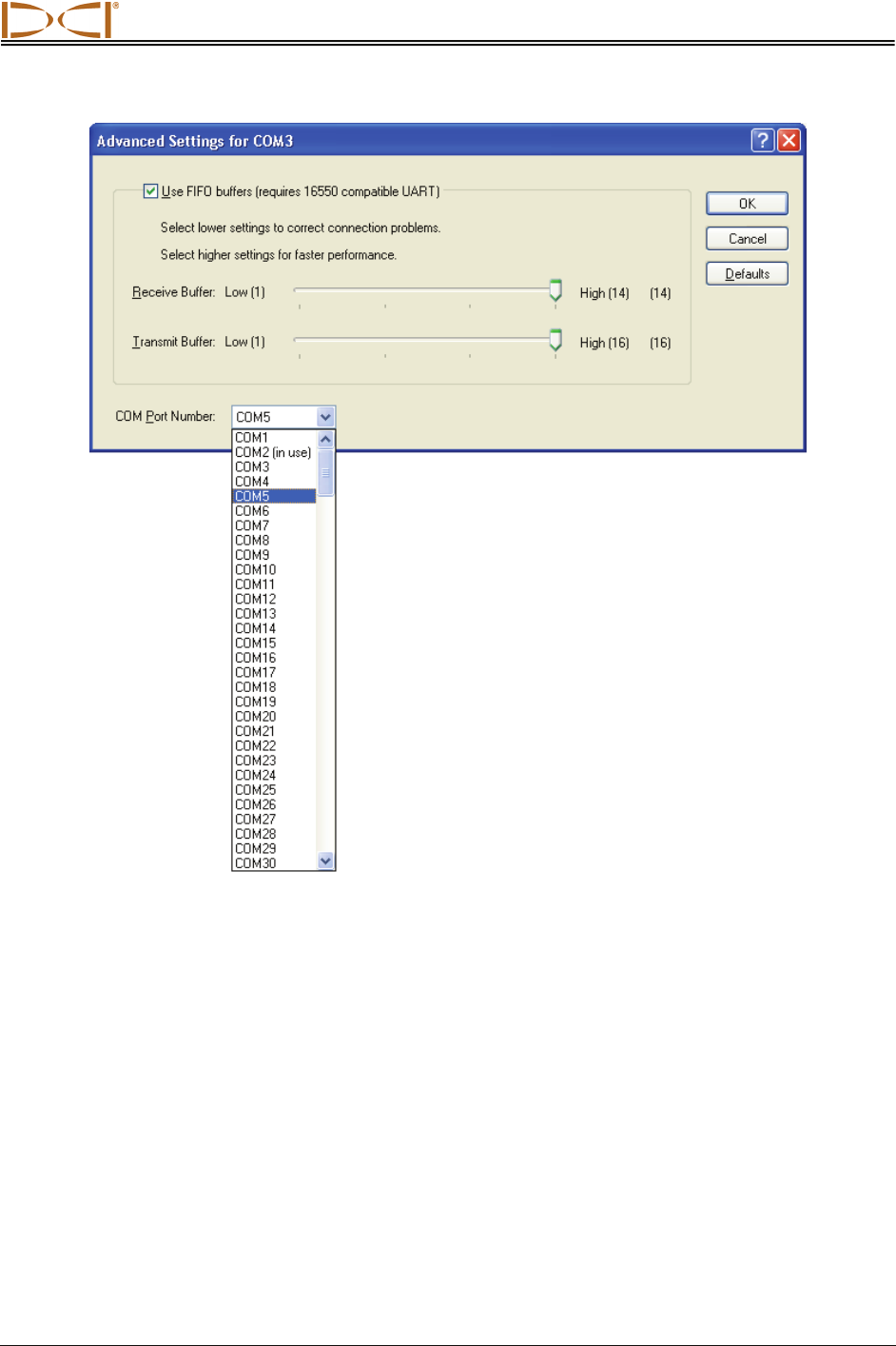
button to see the Advanced Settings dialog box for that port. Click on the drop-down arrow for the COM
Port Number in the lower portion of the dialog box as shown below.
Transferring Data
Eclipse® TensiTrak® Operator’s Manual 47
COM Port Advanced Settings Dialog Box
This shows all of the ports and which ones are in use. Click on COM port 1, 2, 3, or 4, whichever is
available, and then click OK and close out all of the dialog boxes.
If COM ports 1, 2, 3, and 4 are already in use, you may have to temporarily reassign one to free up a port
for the TensiTrak program’s USB-to-Serial Adapter.
Another remedy to try if the data does not transfer is to hold the IR cable 2 in. (5 cm) above the red IR
port on the receiver and/or at a slight angle. You may need to close and reopen the port or exit and then
reopen the Eclipse TensiTrak program.
You may need to disable the IR device. To do this, open the System Properties dialog box as discussed
in the second paragraph of this subsection. Then, click on the Hardware tab, then the Device Manager
button to open the Device Manager dialog box. If there is a listing under “Infrared devices”, then double
click on that to open the Infrared devices Properties box. At the bottom of this dialog box, click on the
Device usage drop-down arrow and select “Do not use this device (disable).”

Transferring Data
48 Eclipse® TensiTrak® Operator’s Manual
Deleting Data from Receiver After Transfer
After you have transferred the data for all of the runs saved in the receiver, you can delete the data from
the receiver to make room for more runs. You can save up to 30 hours of data or five runs (check the
receiver’s used memory) before you have to delete data from the receiver. Be sure you have transferred
and saved the data on your computer before you delete the data from the receiver. Once the data is
deleted from the receiver, it cannot be retrieved. You may want to transfer the same run a few times
(using different run information and file names each time), so that you have a backup version of the data.
NOTE: You cannot save more than five runs in the receiver at any one time. If you attempt to
save more than five runs before deleting data, you could lock-up the receiver and lose
all data it has saved. This may require the receiver to be returned to DCI for repair.
To delete all data from the receiver:
1. Select DataLog from the receiver’s main menu screen, and click the trigger. Then select the
Tension DataLog option, and click the trigger.
2. From the TensiTrak menu, select Delete Tension Data, and click the trigger.
3. You will see the Delete Tension Data dialog box. Push the toggle to the right to select Y for yes,
and click the trigger.
NOTE: When you delete data from the receiver, you will delete ALL data in the receiver. You
cannot delete specific runs. Be sure you have saved the data on your computer before
you delete the data from the receiver.
4. After the data has been deleted, click the trigger.
5. To return to the main menu screen, push the toggle down two times.
DIGITAL CONTROL INCORPORATED
Eclipse® TensiTrak® Operator’s Manual 49
Editing Data in Computer
You can edit the data in the computer after it has been transferred. Remember to transfer data for each
run at least twice, and save each set of data with a different name, to ensure that you have a backup
copy of the data.
Editing Run Information
1. Select Job Info from the Edit menu. You will see the Run Information dialog box shown below.
2. Edit the information as needed, then click OK.
Job Information Dialog Box
Editing Data
50 Eclipse® TensiTrak® Operator’s Manual
Formatting Force and Pressure Graphs
You can customize the look of your graphs by using the 2D Chart Control Properties dialog box. To
access this dialog box, place your mouse in either the force or pressure graph area and click the right
mouse button. The most useful tips for sizing the graphs are described below.
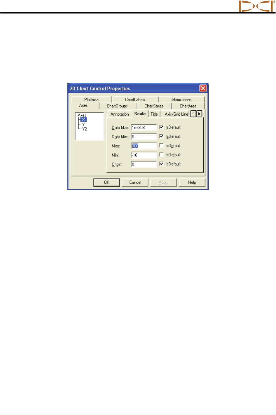
2D Chart Control Properties Dialog Box Showing X-Axis Scale Tab
Adjusting Graphs to View Data Better
1. In the 2D Chart Control Properties dialog box, click on the Axes tab.
2. To adjust the X-axis scale, click on the X in the Axes box in the top left area.
3. Click on the Scale tab.
4. Highlight the value in the Max box (as shown above in the 2D Chart Control Properties Dialog
Box graphic), and then type in a number for the data points; we recommend that you choose a
value just beyond the end of the bore.
5. Click on the Apply button, and you will see the scale for the X-axis adjust in the chosen graph.
Editing Data
Eclipse® TensiTrak® Operator’s Manual 51
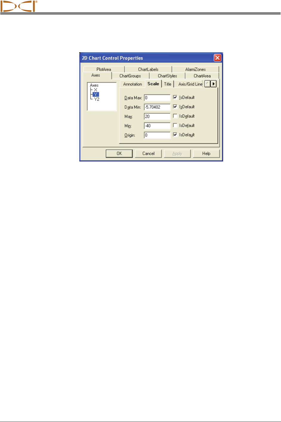
6. To adjust the Y-axis scale, click on the Y in the Axes box in the top left area.
2D Chart Control Properties Dialog Box Showing Y-Axis Scale Tab
7. Under the Scale tab, type in values for the Max and Min boxes. The Max box adjusts the amount
of white space above the X-axis; the Min box adjusts the amount of white space below the X-axis.
8. Click Apply or OK to adjust the graph.

Editing Data
52 Eclipse® TensiTrak® Operator’s Manual
Notes
3-1400-00-D

19625 62nd Ave. S., Suite B-103 y Kent, WA 98032 USA y (425) 251-0559 or (800) 288-3610 y FAX (253) 395-2800
www.digitrak.com (Web Site) DCI@digital-control.com (E-mail)
3-1400-00-D Page 1 of 2
DIGITAL
CONTROL
INCORPORATED
LIMITED WARRANTY
Digital Control Incorporated (“DCI”) warrants that when shipped from DCI each DCI product (“DCI Product”) will
conform to DCI’s current published specifications in existence at the time of shipment and will be free, for the
warranty period (“Warranty Period”) described below, from defects in materials and workmanship. The limited
warranty described herein (“Limited Warranty”) is not transferable, shall extend only to the first end-user (“User”)
purchasing the DCI Product from either DCI or a dealer expressly authorized by DCI to sell DCI Products
(“Authorized DCI Dealer”), and is subject to the following terms, conditions and limitations:
1. A Warranty Period of twelve (12) months shall apply to the following new DCI Products: receivers/locators,
remote displays, battery chargers and rechargeable batteries, and DataLog® modules and interfaces. A Warranty
Period of ninety (90) days shall apply to all other new DCI Products, including transmitters, accessories, and
software programs and modules. Unless otherwise stated by DCI, a Warranty Period of ninety (90) days shall
apply to: (a) a used DCI Product sold either by DCI or by an Authorized DCI Dealer who has been expressly
authorized by DCI to sell such used DCI Product; and (b) services provided by DCI, including testing, servicing,
and repairing an out-of-warranty DCI Product. The Warranty Period shall begin from the later of: (i) the date of
shipment of the DCI Product from DCI, or (ii) the date of shipment (or other delivery) of the DCI Product from an
Authorized DCI Dealer to User.
2. DCI's sole obligation under this Limited Warranty shall be limited to either repairing, replacing, or adjusting, at
DCI's option, a covered DCI Product that has been determined by DCI, after reasonable inspection, to be
defective during the foregoing Warranty Period. All warranty inspections, repairs and adjustments must be
performed either by DCI or by a warranty claim service authorized in writing by DCI. All warranty claims must
include proof of purchase, including proof of purchase date, identifying the DCI Product by serial number.
3. The Limited Warranty shall only be effective if: (i) within fourteen (14) days of receipt of the DCI
Product, User mails a fully-completed Product Registration Card to DCI; (ii) User makes a reasonable
inspection upon first receipt of the DCI Product and immediately notifies DCI of any apparent defect; and
(iii) User complies with all of the Warranty Claim Procedures described below.
WHAT IS NOT COVERED
This Limited Warranty excludes all damage, including damage to any DCI Product, due to: failure to follow DCI’s
user’s manual and other DCI instructions; abuse; misuse; neglect; accident; fire; flood; Acts of God; improper
applications; connection to incorrect line voltages and improper power sources; use of incorrect fuses;
overheating; contact with high voltages or injurious substances; or other events beyond the control of DCI. This
Limited Warranty does not apply to any equipment not manufactured or supplied by DCI nor, if applicable, to any
damage or loss resulting from use of any DCI Product outside the designated country of use. By accepting a DCI
Product and not returning it for a refund within thirty (30) days of purchase, User agrees to the terms of this
Limited Warranty, including without limitation the Limitation of Remedies and Liability described below, and
agrees to carefully evaluate the suitability of the DCI Product for User's intended use and to thoroughly read and
strictly follow all instructions supplied by DCI (including any updated DCI Product information which may be
obtained at the above DCI website). In no event shall this Limited Warranty cover any damage arising during
shipment of the DCI Product to or from DCI.
User agrees that the following will render the above Limited Warranty void: (i) alteration, removal or tampering
with any serial number, identification, instructional, or sealing labels on the DCI Product, or (ii) any unauthorized
disassembly, repair or modification of the DCI Product. In no event shall DCI be responsible for the cost of or any
damage resulting from any changes, modifications, or repairs to the DCI Product not expressly authorized in
writing by DCI, and DCI shall not be responsible for the loss of or damage to the DCI Product or any other
equipment while in the possession of any service agency not authorized by DCI.

3-1400-00-D Page 2 of 2
DCI reserves the right to make changes in design and improvements upon DCI Products from time to time, and
User understands that DCI shall have no obligation to upgrade any previously manufactured DCI Product to
include any such changes.
The foregoing Limited Warranty is DCI’s sole warranty and is made in place of all other warranties, express or
implied, including but not limited to the implied warranties of merchantability and fitness for a particular purpose
and any implied warranty arising from course of performance, course of dealing, or usage of trade. If DCI has
substantially complied with the warranty claim procedures described below, such procedures shall constitute
User’s sole and exclusive remedy for breach of the Limited Warranty.
LIMITATION OF REMEDIES AND LIABILITY
In no event shall DCI nor anyone else involved in the creation, production, or delivery of the DCI Product
be liable for any damages arising out of the use or inability to use the DCI Product, including but not
limited to indirect, special, incidental, or consequential damages or for any cover, loss of information,
profit, revenue or use based upon any claim by User for breach of warranty, breach of contract,
negligence, strict liability, or any other legal theory, even if DCI has been advised of the possibility of
such damages. In no event shall DCI’s liability exceed the amount User has paid for the DCI Product. To
the extent that any applicable law does not allow the exclusion or limitation of incidental, consequential
or similar damages, the foregoing limitations regarding such damages shall not apply.
This Limited Warranty gives you specific legal rights, and you may also have other rights which vary from state to
state. This Limited Warranty shall be governed by the laws of the State of Washington.
WARRANTY CLAIM PROCEDURES
1. If you are having problems with your DCI Product, you must first contact the Authorized DCI Dealer where it
was purchased. If you are unable to resolve the problem through your Authorized DCI Dealer, contact DCI’s
Customer Service Department in Kent, Washington, USA at the above telephone number between 6:00 a.m. and
6:00 p.m. Pacific Time and ask to speak with a customer service representative. (The above “800” number is
available for use only in the USA and Canada.) Prior to returning any DCI Product to DCI for service, you must
obtain a Return Merchandise Authorization (RMA) number. Failure to obtain a RMA may result in delays or return
to you of the DCI Product without repair.
2. After contacting a DCI customer service representative by telephone, the representative will attempt to assist
you in troubleshooting while you are using the DCI Product during actual field operations. Please have all related
equipment available together with a list of all DCI Product serial numbers. It is important that field troubleshooting
be conducted because many problems do not result from a defective DCI Product, but instead are due to either
operational errors or adverse conditions occurring in the User’s drilling environment.
3. If a DCI Product problem is confirmed as a result of field troubleshooting discussions with a DCI customer
service representative, the representative will issue a RMA number authorizing the return of the DCI Product and
will provide shipping directions. You will be responsible for all shipping costs, including any insurance. If, after
receiving the DCI Product and performing diagnostic testing, DCI determines the problem is covered by the
Limited Warranty, required repairs and/or adjustments will be made, and a properly functioning DCI Product will
be promptly shipped to you. If the problem is not covered by the Limited Warranty, you will be informed of the
reason and be provided an estimate of repair costs. If you authorize DCI to service or repair the DCI Product, the
work will be promptly performed and the DCI Product will be shipped to you. You will be billed for any costs for
testing, repairs and adjustments not covered by the Limited Warranty and for shipping costs. In most cases,
repairs are accomplished within 1 to 2 weeks.
4. DCI has a limited supply of loaner equipment available. If loaner equipment is required by you and is available,
DCI will attempt to ship loaner equipment to you by overnight delivery for your use while your equipment is being
serviced by DCI. DCI will make reasonable efforts to minimize your downtime on warranty claims, limited by
circumstances not within DCI’s control. If DCI provides you loaner equipment, your equipment must be received
by DCI no later than the second business day after your receipt of loaner equipment. You must return the loaner
equipment by overnight delivery for receipt by DCI no later than the second business day after your receipt of the
repaired DCI Product. Any failure to meet these deadlines will result in a rental charge for use of the loaner
equipment for each extra day the return of the loaner equipment to DCI is delayed.