Digital Control A050316 ECP, FC User Manual Operating Instructions
Digital Control Inc ECP, FC Operating Instructions
User Manual
MFCB
Multi-Function Cable Box
Operator’s Manual
D
IGITAL
CONTROL
INCORPORATED
DCI Headquarters
19625 62nd Ave. S., Suite B-103
Kent, Washington 98032 USA
Tel 425 251 0559 / 800 288 3610 Fax 253 395 2800
E-mail DCI@digital-control.com www.digitrak.com
DCI Europe
Kurmainzer Strasse 56
D-97836 Bischbrunn
Germany
Tel +49(0) 9394 990 990
Fax +49(0) 9394 990 999
DCI.Europe@digital-control.com
DCI India
DTJ 1023, 10th Floor
DLF Tower A, DA Dist. Cent.
Jasola, New Delhi 110044 India
Tel +91(0) 11 4507 0444
Fax +91(0) 11 4507 0440
DCI.India@digital-control.com
DCI China
No. 41, Lane 500, Xingle Road
Huacao Town, Minhang District
Shanghai P.R.C. 201107
Tel +86(0) 21 6432 5186
Fax +86(0) 21 6432 5187
DCI.China@digital-control.com
DCI Australia
2/9 Frinton Street
Southport, Queensland 4215
Australia
Tel +61(0) 7 5531 4283
Fax +61(0) 7 5531 2617
DCI.Australia@digital-control.com
DCI Russia
420059 Pavlyukhina Street
104, Kazan
Russia
Tel +7 843 277 52 22
Fax +7 843 277 52 07
DCI.Russia@digital-control.com

DIGITAL CONTROL INCORPORATED
2 DigiTrak® MFCB™ Operator’s Manual
3-3400-00-A1
© 2010 by Digital Control Incorporated. All rights reserved. March 2011 edition.
68BTrademarks
The DCI logo, CableLink®, DataLog®, DigiTrak®, Eclipse®, F2®, iGPS®, MFD®, SST®, target-in-the-box®,
Target Steering®, and TensiTrak® are U.S. registered trademarks and DucTrak™, F Series™, FSD™,
FasTrak™, LT™, LT2™, SE™, SuperCell™, and TeleLock™ are trademarks of Digital Control
Incorporated.
69BPatents
The DigiTrak® Locating Systems are covered by one or more of the following U.S. Patents: 5,337,002;
5,633,589; 5,990,682; 5,990,683; 6,002,258; 6,005,532; 6,008,651; 6,014,026; 6,035,951; 6,047,783;
6,057,687; 6,095,260; 6,160,401; 6,232,780; 6,250,402; 6,396,275; 6,496,008; 6,525,538; 6,593,745;
6,653,837; 6,693,429; 6,756,784; 6,768,307; 6,838,882; 6,924,645; 7,061,244; 7,080,698; 7,154,273;
7,159,672; 7,167,005; 7,176,690; 7,304,479; 7,309,990; 7,345,486. Sale of a DigiTrak® F2® receiver does
not convey a license under any patents covering the DigiTrak® transmitter or underground drill housing.
Other patents pending.
70BLimited Warranty
All products manufactured and sold by Digital Control Incorporated (DCI) are subject to the terms of a
Limited Warranty. A copy of the Limited Warranty is included with your DigiTrak® F2® Locating System; it
can also be obtained by contacting DCI Customer Service, 800-288-3610 or 425-251-0559, or by
connecting to DCI's website, www.digitrak.com.
71BImportant Notice
All statements, technical information, and recommendations related to the products of DCI are based on
information believed to be reliable, but the accuracy or completeness thereof is not warranted. Before
utilizing any DCI product, the user should determine the suitability of the product for its intended use. All
statements herein refer to DCI products as delivered by DCI and do not apply to any user customizations
not authorized by DCI nor to any third-party products. Nothing herein shall constitute any warranty by DCI
nor will anything herein be deemed to modify the terms of DCI’s existing Limited Warranty applicable to all
DCI products.
FCC Compliance Statement
This equipment complies with Part 15 of the Rules of the FCC. Operation is subject to the following two
conditions: (1) this equipment may not cause harmful interference, and (2) this equipment must accept
any interference received, including interference that may cause undesired operation. DCI is responsible
for FCC compliance in the United States: Digital Control Incorporated, 19625 62nd Ave. S., Suite B-103,
Kent, WA 98032; phone 425-251-0559 or 800-288-3610.
WARNING: Changes or modifications to any DCI equipment not expressly approved and carried out by
DCI could void the user’s authorization to operate the equipment.

DIGITAL CONTROL INCORPORATED
3 DigiTrak® MFCB™ Operator’s Manual
Table of Contents
TABLE OF CONTENTS ................................................................................................................................ 3
Dear Customer: ......................................................................................................................................... 6
SAFETY PRECAUTIONS AND WARNINGS .................................. ERROR! BOOKMARK NOT DEFINED.
MULTI-FUNCTION CABLE BOX .................................................... ERROR! BOOKMARK NOT DEFINED.
Power Setup .............................................................................................................................................. 8
Connecting the Cable Transmitter ....................................................................................................... 10
CABLE MODE ............................................................................................................................................. 13
Display Screens ....................................................................................................................................... 13
Standard Eclipse and F-Series Cable Transmitters ............................................................................ 13
Eclipse Steering Tool Transmitter (SST) ............................................................................................. 14
Target Steering .................................................................................................................................... 17
Roll Offset ................................................................................................................................................ 17
APPENDIX A: SYSTEM SPECIFICATIONS AND MAINTENANCE REQUIREMENTS ............................ 21
Power Requirements ............................................................................................................................... 21
Environmental Requirements .................................................................................................................. 21
CE Declaration of Conformity…………………………………………………………………………………20
LIMITED WARRANTY……………………………………………………………………………………………21
DIGITAL CONTROL INCORPORATED
4 DigiTrak® MFCB™ Operator’s Manual
Safety Precautions
and Warnings
Important Note: All operators must read and understand the following Safety Precautions and
Warnings and must review this Operator’s Manual before using the DigiTrak® F2® Locating System.
Serious injury and death can result if underground drilling equipment makes contact with
an underground utility such as a high-voltage electrical cable or a natural gas line.
Substantial property damage and liability can result if underground drilling equipment
makes contact with an underground utility such as a telephone, fiber-optic, water, or
sewer line.
Work slowdowns and cost overruns can occur if drilling operators do not use the drilling
or locating equipment correctly to obtain proper performance.
Directional drilling operators MUST at all times:
• Understand the safe and proper operation of drilling and locating equipment, including the use of
ground mats and proper grounding procedures.
• Ensure that all underground utilities have been located, exposed, and marked accurately prior to
drilling.
• Wear protective safety clothing such as dielectric boots, gloves, hard-hats, high-visibility vests
and safety glasses.
• Locate and track the transmitter in the drill head accurately and correctly during drilling.
• Comply with state and local governmental regulations (e.g., OSHA).
• Follow all other safety procedures.
The DigiTrak F2 system cannot be used to locate utilities.
Continued exposure to heat, due to frictional heating of the transmitter in the drill head from drilling in
sand, gravel, or rock without sufficient fluid flow around the transmitter, can cause inaccurate infor-
mation to be displayed and may permanently damage the transmitter. For more information see the
Transmitter section of this manual.
The DigiTrak F2 equipment is not explosion-proof and should never be used near
flammable or explosive substances.

DIGITAL CONTROL INCORPORATED
DigiTrak® MFCB™ Operator’s Manual 5
Safety Precautions
and Warnings (Continued)
The battery charger provided with the DigiTrak F2 system is designed with adequate safeguards to
protect you from shock and other hazards when used as specified within this document. If you use
the battery charger in a manner not specified by this document, the protection provided may be
impaired. Do not attempt to disassemble the battery charger. It contains no user-serviceable parts.
The battery charger is not to be installed into caravans, recreational vehicles, or similar vehicles
Remove the batteries from all components of the system during shipping and prolonged storage.
Prior to the start of each drilling run, test the DigiTrak F2 system with the transmitter inside the drill
head to confirm that it is operating properly and is providing accurate drill head location and heading
information (see the Receiver and Locating sections) and accurate transmitter depth, pitch, and roll
information.
During drilling, the depth will not be accurate unless:
• The receiver has been properly calibrated and the calibration has been checked for accuracy so
that the receiver shows the correct depth.
• The transmitter has been located correctly and accurately and the receiver is directly above the
transmitter in the drill head underground.
• The receiver is kept level and the height-above-ground has been set correctly.
Always test calibration after you have stopped drilling for any length of time.
Interference can cause inaccuracies in the measurement of depth and loss of the transmitter’s pitch,
roll, or heading. You should always perform an electrical interference check prior to drilling.
• Sources of interference include but are not limited to traffic signal loops, invisible dog fences,
cable TV, power lines, fiber-trace lines, metal structures, cathodic protection, telephone lines, cell
phones, transmission towers, conductive earth, salt water, rebar, radio frequencies, and other
unknown sources of interference.
• Interference with the operation of the remote display may also occur from other sources operating
nearby on the same frequency, such as car rental agencies using their remote check-in modules,
other directional drilling locating equipment, etc.
• Background noise must be minimal and signal strength must be at least 150 points above the
background noise during all locating operations.
Carefully review this manual to ensure you know how to operate the DigiTrak F2 system properly to
obtain accurate depth, pitch, roll, and locate points. If you have any questions about the operation of
the system, please call DCI’s Customer Service Department at any of the phone numbers provided
on the cover, and we will do our best to assist you.

DIGITAL CONTROL INCORPORATED
6 DigiTrak® MFCB™ Operator’s Manual
Dear Customer:
Thank you for choosing DigiTrak® Locating Systems. We are proud of the
equipment that we have been designing and building in Washington State since
1990. We believe in providing a unique, high-quality product and standing behind
it with superior customer service and training.
Please take the time to read this entire manual—especially the section on safety.
Also, please fill in the product warranty registration form under the Service &
Support section of our website or fill out a paper copy and mail or fax it to us at
253-395-2800. We will put you on the Digital Control mailing list and send you
product upgrade information and our FasTrak™ newsletter.
Feel free to contact us at any of our global offices listed on the front cover if you
have any problems or questions. Our Customer Service Department is available
24 hours a day, 7 days a week to provide assistance.
As the horizontal directional drilling industry grows, we’re keeping an eye on the
future to develop equipment that will make your job faster and easier. Stay
current by visiting our web site at www.digitrak.com or by giving us a call.
We welcome questions, comments, and ideas.
Digital Control Incorporated
Kent, Washington
2009
DIGITAL CONTROL INCORPORATED
7 DigiTrak® MFCB™ Operator’s Manual
Introduction
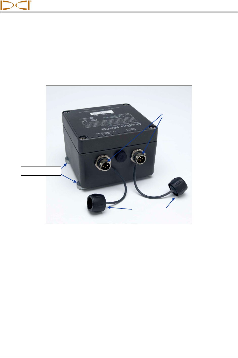
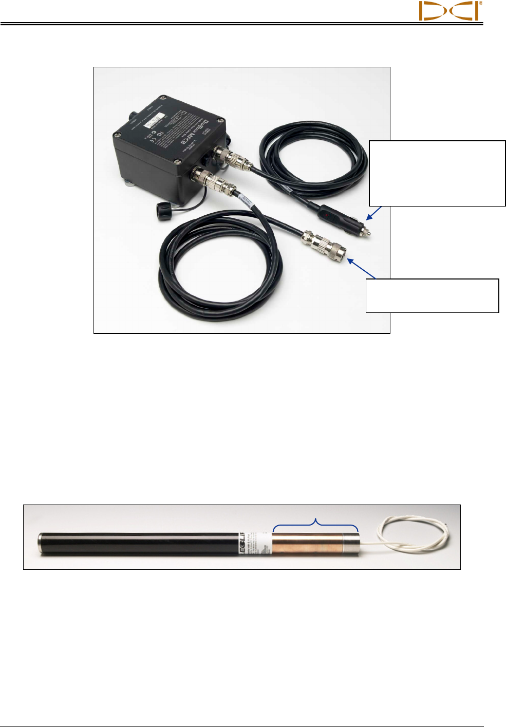
The DigiTrak Multi-Function Cable Box (MFCB) is used as an interface between a variety of DigiTrak
cable transmitters and remote displays. The cable box provides power to the cable transmitter and allows
steering information from the transmitter wire to be displayed on the remote.
DigiTrak Multi-Function Cable Interface Box (MFCB)
The cable box can be used with the following DigiTrak transmitters:
Eclipse cable transmitter (ECP)
F Series cable transmitter (FC)
Eclipse steering tool transmitter (SST)
The cable box can be used with the following DigiTrak remote displays:
Multi-Function Display (MFD), console mounted and freestanding
F Series Display (FSD)
This manual covers the power setup of the cable box and cable transmitters with the MFD and FSD
remote displays and using the cable mode of the MFD and FSD remotes.
Magnetic Base
Power Ports
Protective Caps

Power Setup
8 DigiTrak® MFCB™ Operator’s Manual
Notes
DIGITAL CONTROL INCORPORATED
9 DigiTrak® MFCB™ Operator’s Manual
Power Setup
The cable box has two identical power ports shown in the introduction. The ports can be used
interchangeably; one needs to be connected to the DC power source and the other to the remote
display’s DC power port. The power ports are keyed to match the power cable connectors. The power
cables are installed in the same way as the remote display’s standard DC power cable. See “Connecting
the DC Power Cable” in the Basic Instructions section of your MFD/FSD remote manual.
The cable box may be powered by the drill rig’s battery using the standard DC power cable provided with
your remote display. However, DCI recommends powering the cable-box directly with a standard 12-28 V
DC automotive battery.
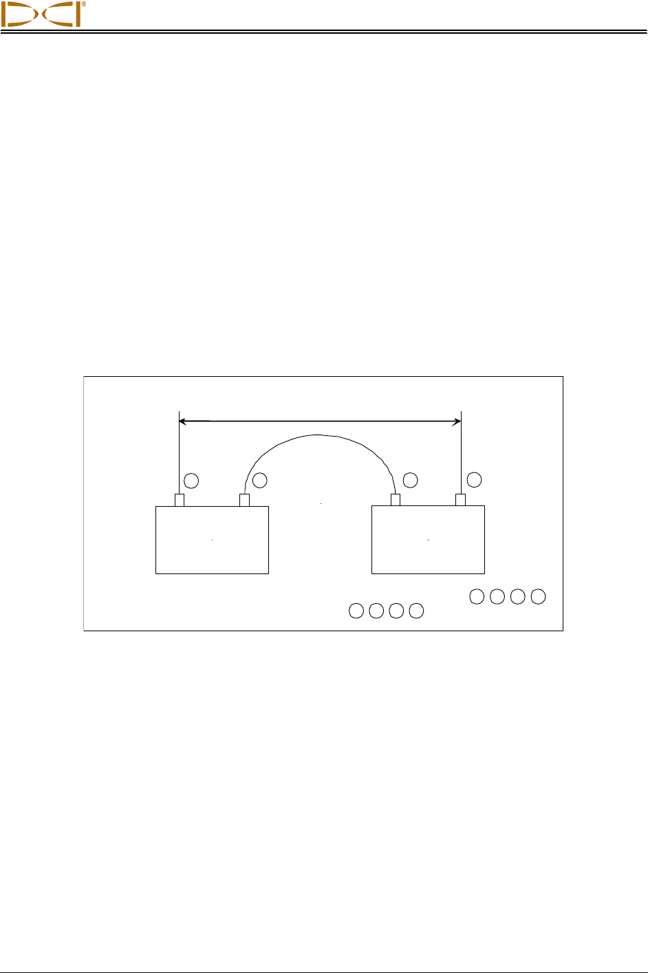
For bores shorter than 1000 ft (305 m), one 12-V battery will suffice. If the bore length increases beyond
1000 ft (305 m), an additional battery may be added in series (see diagram).
Connect batteries in the order shown by the numbers in circles: 1 , 2 , 3 , 4
Disconnect batteries in the opposite order: 4 , 3 , 2 , 1
12-Volt
Battery
–
+
12-Volt
Battery
–
+
–
+
12–28 Volts DC
4
3
2
1
Adding Batteries in Series
The cable that connects to the remote display is installed in the same way as the remote display’s
standard DC power cable.
Power Setup
10 DigiTrak® MFCB™ Operator’s Manual
Cable-Box Power Cables
When connecting to a free standing automotive battery, be sure the positive wire (white, shown red in the
Connecting the Cable System Components diagram below) is connected to the positive battery terminal
and that the negative wire (black) is connected to the negative battery terminal. See the “Connecting the
Cable System Components Diagram” under Connecting the Cable Transmitter.
Connecting to Cable Transmitter
For the cable transmitter to function, it must be grounded to the transmitter housing. The ground point on
the cable transmitter is the metal portion of the wire end.
Eclipse Cable Transmitter
When the cable transmitter is properly fitted into the housing, the ground connection will occur
automatically because the housing is grounded through the drill. When testing the cable transmitter
outside of the housing, you can make a ground connection by taking a piece of wire and touching the
negative terminal of the battery with one end and touching the other end of the wire to the transmitter’s
ground.
Connects to the Remote
Display’s DC Power Port
Connects to the DC Power
Source (or use the bare
wire cable to connect
directly to a freestanding
automotive battery)
Ground
Multi-Function Cable Box
DigiTrak® MFCB™ Operator’s Manual 11
Once the ground connection is achieved, the cable transmitter is powered through the DCI cable-box as
shown below.
Cable Transmitter Powered through Cable-Box
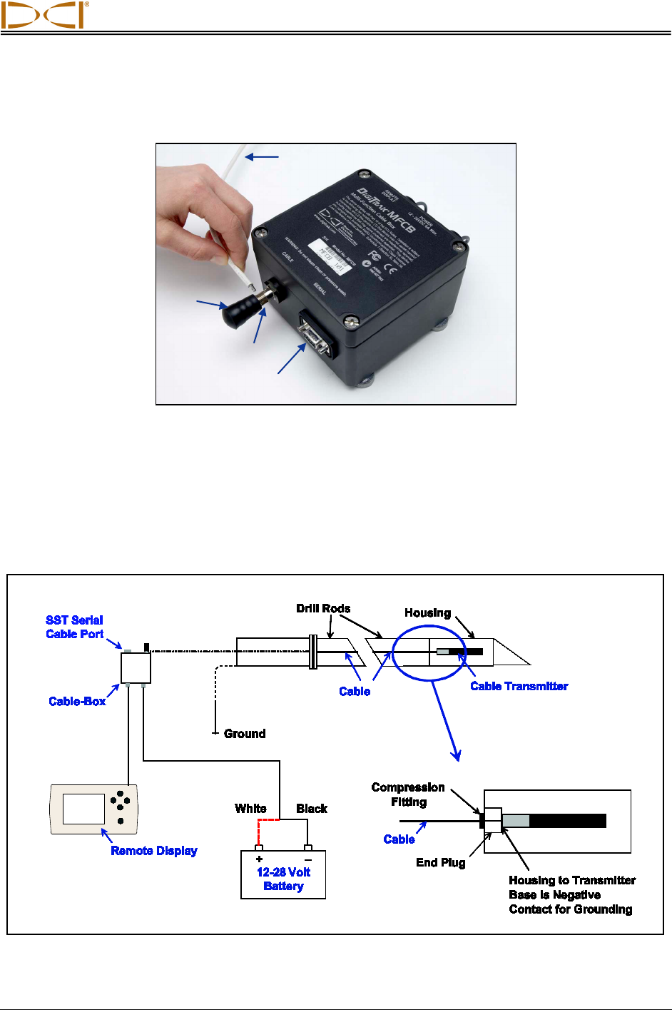
Install the cable from the transmitter by rotating the knob on the cable-box counterclockwise until the hole
in the power post is exposed. Insert the stripped portion of the cable into the hole and gently tighten the
knob by rotating it clockwise to secure. When a Steering Tool used, the computer connection is made
through the SST serial cable port.
The complete cable system setup is given in the following diagram.
Knob
Power Post
SST Serial
Cable Port
Cable to Transmitter

Power Setup
12 DigiTrak® MFCB™ Operator’s Manual
Connecting Cable System Components
The compression fitting shown in the diagram above is a non-DCI part required to seal the transmitter
from the drilling fluid. Drill or tooling manufacturers will have information on compression fittings.
DIGITAL CONTROL INCORPORATED
13 DigiTrak® MFCB™ Operator’s Manual
Cable Mode
Display Screens
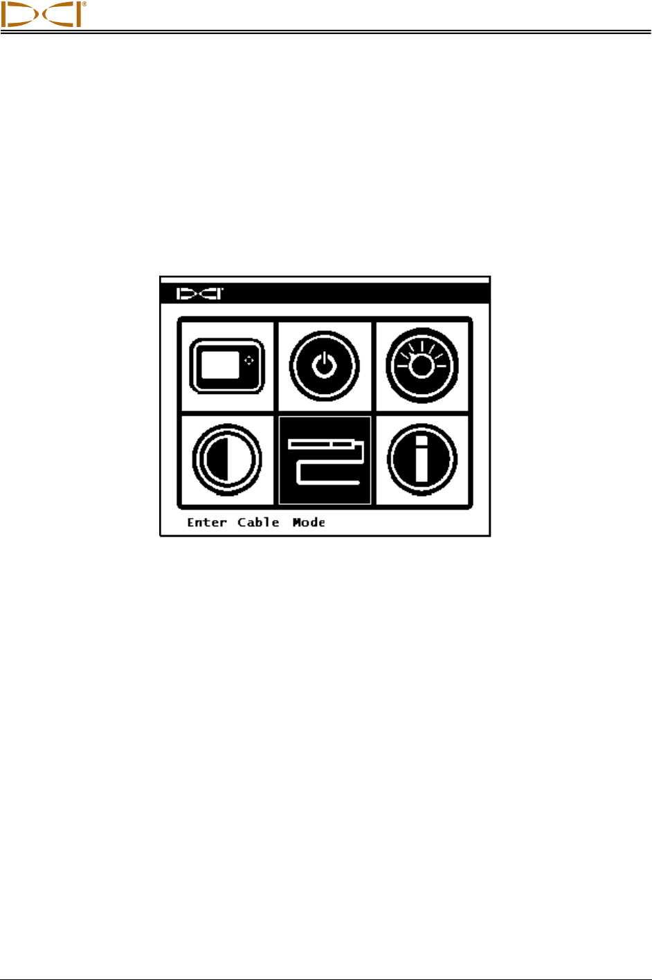
The standard Eclipse and F-Series Cable modes and the Eclipse SST mode display screens are viewed
by selecting the cable icon on the main menu of the MFD or FSD remote display. The cable system
components must be properly connected with power supplied before you can access this menu option.
Main Menu with Cable Mode Highlighted
The remote will automatically detect which cable system is being used and display the appropriate
screen.
Standard Eclipse and F-Series Cable Transmitters
When a Standard Eclipse or F-Series Cable Transmitter is used, the following screen will display.
Cable Mode
14 DigiTrak® MFCB™ Operator’s Manual
Eclipse and F-Series Cable Mode Main Display
The above screen shows no telemetry data being received as indicated by the empty update meter. The
roll and pitch are provided through the cable. For depth information to display, the appropriate DigiTrak
receiver must be used to locate the transmitter and take a depth reading. See the Operators Manual for
the system you are using.
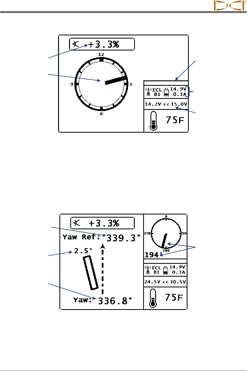
Eclipse Steering Tool Transmitter (SST)
A screen such as the following will display when an Eclipse Steering Tool Transmitter is used.
Eclipse SST Main Display (Off-Line)
When using the Eclipse SST System, it is necessary to first establish the reference yaw using the SST
transmitter, a non-magnetic housing, and the remote display. This procedure is sometimes referred to as
“shooting the probe.” Shoot the probe (determine the reference yaw) by carefully aligning the SST
transmitter (in the non-mag housing) onto the bore path and pointing in the direction of drilling. The
Input voltage range
(approximate) supplied
to the transmitter
Output voltage and
current (Amperage)
supplied by the
Cable-Box
Empty update meter
indicates no
telemetry reception
SST Roll Position and
Numeric Value
Reference Yaw
(programmed in the
Reference Yaw Menu
discussed below)
SST’s yaw deviation
(difference between
reference yaw and
actual yaw)
Actual SST Yaw
Transmitter Pitch
Transmitter Roll
Cable Mode
DigiTrak® MFCB™ Operator’s Manual 15
remote will display the transmitter’s heading or “yaw” at the bottom of the screen, shown above. The
reference yaw must be programmed to this value. Program the reference yaw in the Reference Yaw
Menu as described below.
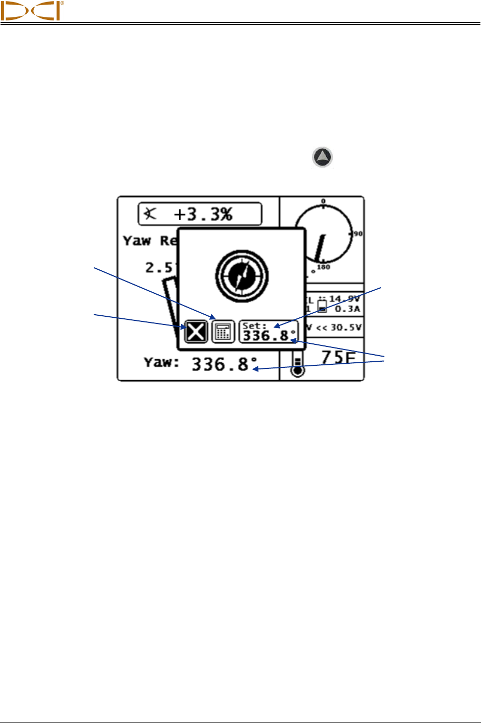
Reference Yaw Menu
From the Eclipse SST Main Display, press the up direction button, , on the MFD or FSD to access
the Reference Yaw Menu.
Reference Yaw Menu
There are three options in the reference yaw menu as described above. Use the direction buttons to
highlight the desired option and press the execute button to select it.
When the Set option has been selected, you will be returned to the SST Main Display with the new
reference yaw displayed.
When the Keypad has been selected, the following screen will display.
“Set” programs the
displayed (actual
SST yaw) value as
the reference yaw
Exit (highlighted)
exits the menu
with no change
Keypad allows the
reference yaw to be
entered manually
Actual SST Yaw
Cable Mode
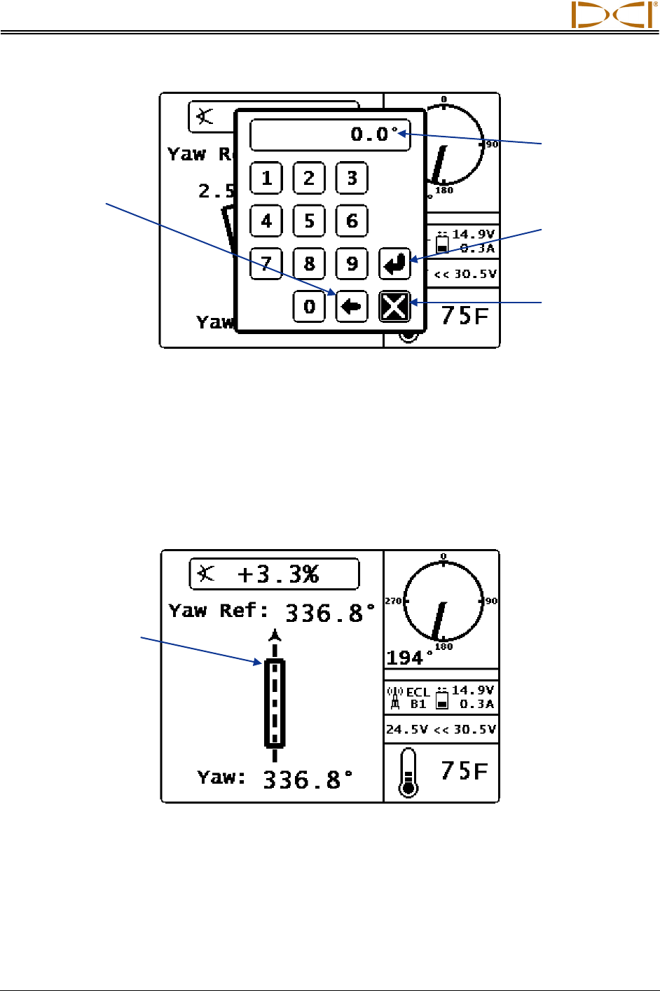
16 DigiTrak® MFCB™ Operator’s Manual
Reference Yaw Manual Entry Key Pad
Enter the reference yaw value in this screen by using the direction buttons to highlight a number and the
execute button to select it. Enter the value for reference yaw one digit at a time left to right; then select
the curved arrow to set it. For example if you want to set 76.5° as the reference yaw, select 7, then 6,
then 5, and then select the curved arrow. You will be returned to the Eclipse SST Main Display with the
new reference yaw displayed.
When the SST Transmitter’s yaw matches the reference yaw, the transmitter is considered to be “on-line”
and a screen such as the following will display.
Eclipse SST Main Display (On-Line)
The SST can also be used with an Eclipse receiver to take depth readings and for Target Steering. See
the Eclipse System operator’s manual and the SST System operator’s manual for more information.
“Exit” (highlighted)
exits the menu with no
change
Backspace deletes
the last number
entered
Numbers for the
reference yaw
display here as
they are entered
SST on Reference Line
Curved arrow
(Execute) sets the
reference yaw
Cable Mode
DigiTrak® MFCB™ Operator’s Manual 17
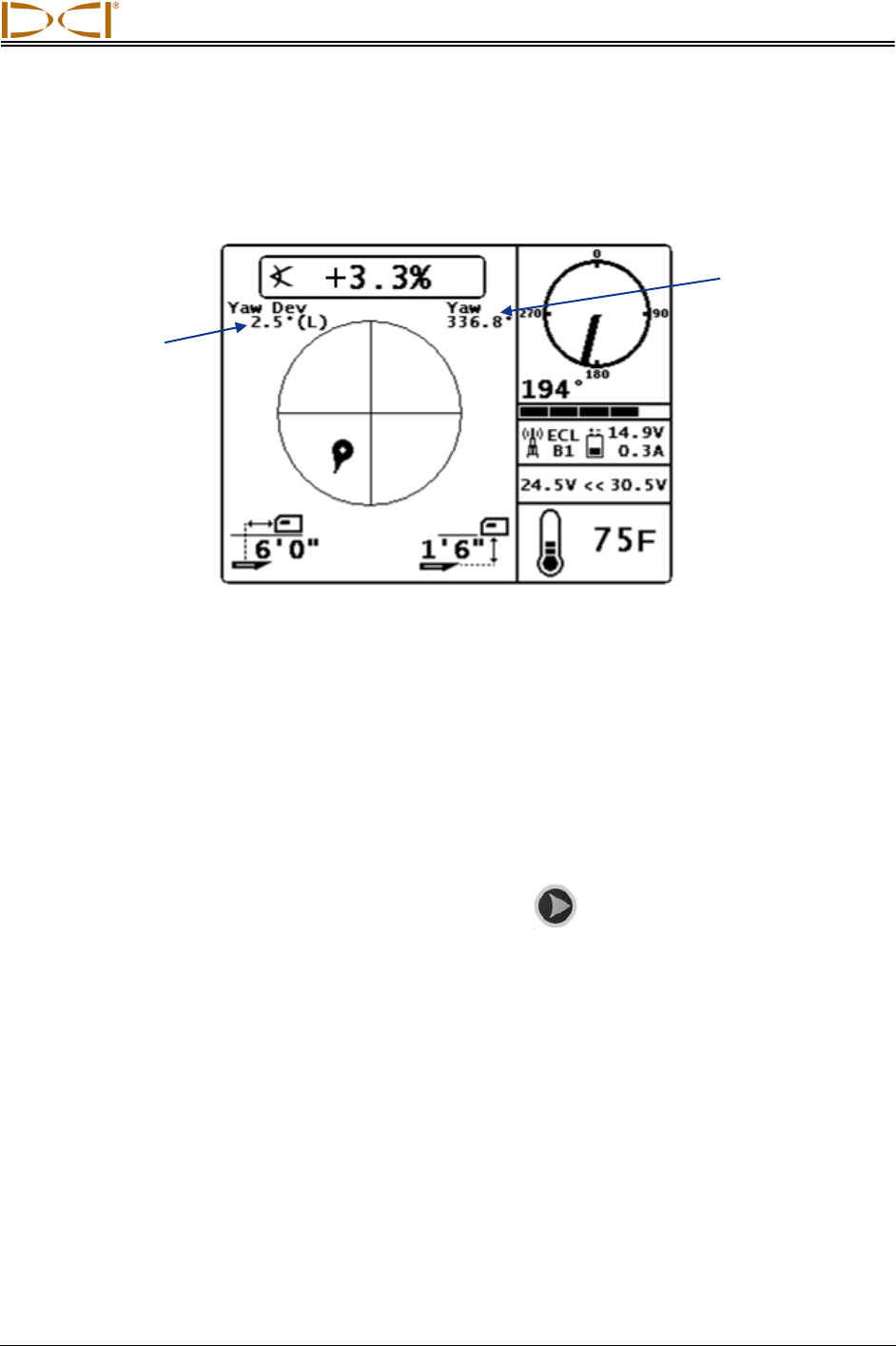
Target Steering
When a target depth has been programmed into the receiver and the remote is receiving telemetry data,
the following screen will display.
SST Target Steering Display
If a standard Eclipse Cable transmitter is used, the screen will display as above but without the yaw data
and the roll will display by clock position as opposed to the 360⁰ indicator shown here. See the Target
Steering Display in the Remote Mode section.
Roll Offset
The roll offset function is only available in cable-mode. It is used when the transmitter’s 12 o’clock slot
does not match the drill head’s 12 o’clock position.
To access the roll offset menu, push the right direction button, , from the Eclipse Cable or SST Main
Display. The Roll Offset Menu will appear.
SST’s Deviation from
Reference Yaw
Actual SST Yaw
Cable Mode
18 DigiTrak® MFCB™ Operator’s Manual
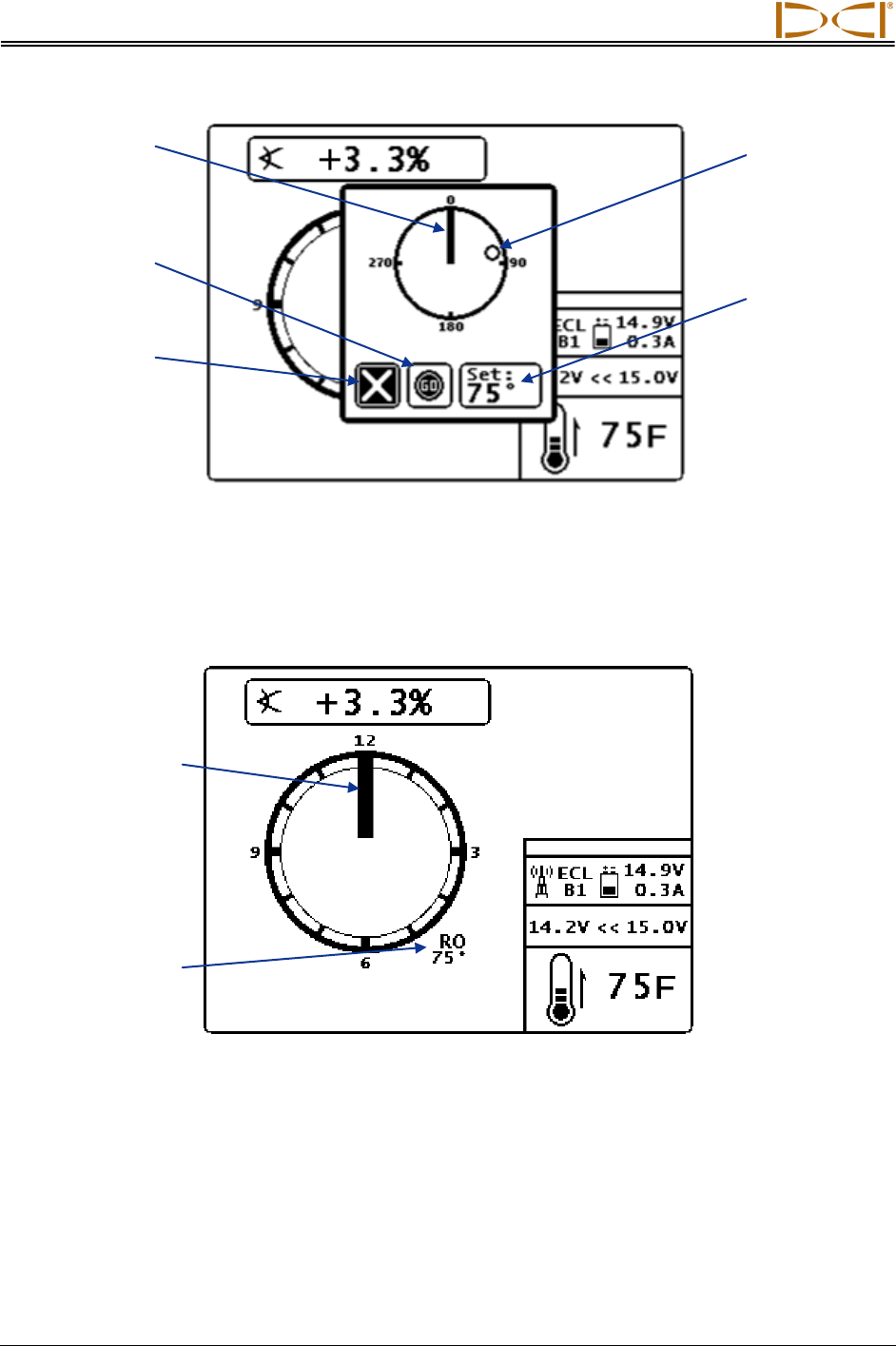
Roll Offset Menu (Enable)
There are three options in the roll offset menu as described above. Use the direction buttons to highlight
the desired option and the execute button to select it.
Once the roll offset is programmed, the following screen will display if using the Eclipse Cable transmitter.
Eclipse Cable Mode Screen with Roll Offset
The roll offset will remain active until you access the roll offset menu and disable it.
When roll offset is active and the Roll Offset Menu is accessed by pressing the right directional button,
the following screen will display.
Transmitter’s 12
o’clock position
“Set” programs the
displayed value as
the roll offset
Exit (highlighted)
exits the menu
with no change
“Go” activates roll
offset to the value
most recently set
Fixed mark
denoting drill
head’s 12 o’clock
position
Drill head’s 12 o’clock
Offset to transmitter’s
12 o’clock index slot
Cable Mode
DigiTrak® MFCB™ Operator’s Manual 19
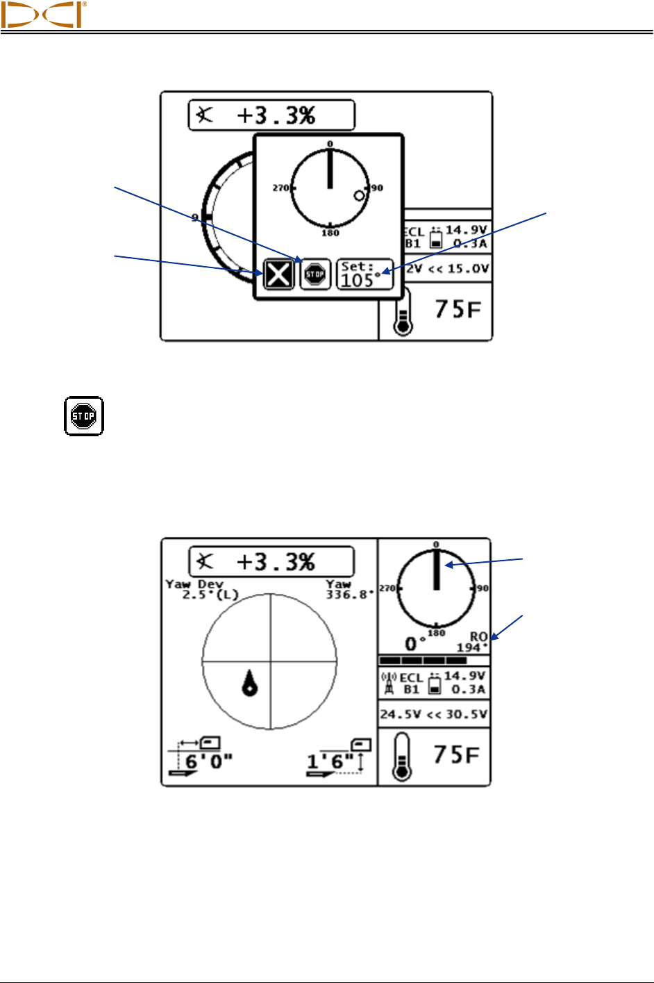
Roll Offset Menu (Disable or Set)
Selecting will disable roll offset and return you to the standard cable or SST mode display screen.
The value displayed for roll will be that of the transmitter. Selecting “Set” will program the roll offset to the
displayed value.
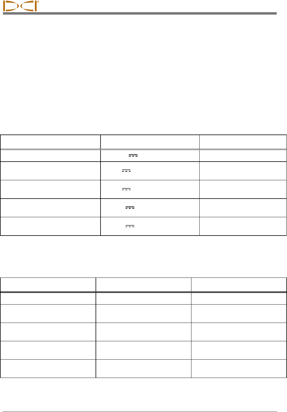
The clock moves to the upper right of the display when using an SST transmitter, Target Steering, or
receiving depth readings. The roll offset value will still display next to the clock as shown below.
SST Target Steering Display with Roll Offset
If a standard Eclipse Cable transmitter is used, the screen will display as above but without the yaw data
and the roll will display by clock position as opposed to the 360⁰ indicator shown here. The roll offset is
always displayed by degree.
“Set” programs the
displayed value as
the roll offset
Exit (highlighted)
exits the menu
with no change
“Stop” disables
the roll offset
Drill head’s 12 o’clock
Offset to transmitter’s
12 o’clock index slot

Cable Mode
20 DigiTrak® MFCB™ Operator’s Manual
Notes
DIGITAL CONTROL INCORPORATED
21 DigiTrak® MFCB™ Operator’s Manual
Appendix A:
System Specifications and
Maintenance Requirements
The power requirements and environmental requirements for the DigiTrak Multi-Function Cable Box and
remote displays are listed below.
Power Requirements
Device (Model Number) Operational Voltage Operational Current
DigiTrak Multi-Function Cable Box 12 - 28 V (nominal) 6 A max
DigiTrak MFD Remote Display
(MFD) 14.4 V (nominal) 220 mA max
DigiTrak F Series Remote Display
(FSD) 14.4 V (nominal) 220 mA max
DigiTrak Eclipse, F Series, and F5
Cable Transmitter (ECP, FC, F5C) 9 - 28 V (nominal) 6 A max
DigiTrak Eclipse and F5 Steering
Tool (SST and SST5) 9 - 28 V (nominal) 6 A max
Environmental Requirements
Device Relative Humidity Operating Temperature
DigiTrak Multi-Function Cable Box <90% -4° to 140°F (-20° to 60°C)
DigiTrak MFD Remote Display
(MFD)
<90% -4° to 140°F (-20° to 60°C)
DigiTrak F Series Remote Display
(FSD)
<90%
-4° to 140°F (-20° to 60°C)
DigiTrak Eclipse, F Series, and F5
Cable Transmitter (ECP, FC, F5C)
<100% -4° to 180°F (-20° to 82°C)
DigiTrak Eclipse and F5 Steering
Tool (SST and SST5)
<100%
-4° to 180°F (-20° to 82°C)

19625 62nd Ave. S., Suite B-103 Kent, WA 98032 USA (425) 251-0559 OR (800) 288-3610 FAX (253) 395-2800
www.digitrak.com (Web Site) DCI@digital-control.com (E-mail)
3-3400-00-A Page 1 of 2
DIGITAL
CONTROL
I
NCORPORATED
LIMITED WARRANTY
Digital Control Incorporated ("DCI") warrants that when shipped from DCI each DCI product (“DCI Product”) will
conform to DCI’s current published specifications in existence at the time of shipment and will be free, for the
warranty period (“Warranty Period”) described below, from defects in materials and workmanship. The limited
warranty described herein (“Limited Warranty”) is not transferable, shall extend only to the first end-user (“User”)
purchasing the DCI Product from either DCI or a dealer expressly authorized by DCI to sell DCI Products
(“Authorized DCI Dealer”), and is subject to the following terms, conditions and limitations:
1. A Warranty Period of twelve (12) months shall apply to the following new DCI Products: receivers/locators,
remote displays, battery chargers and rechargeable batteries, and DataLog® modules and interfaces. A Warranty
Period of ninety (90) days shall apply to all other new DCI Products, including transmitters, accessories, and
software programs and modules. Unless otherwise stated by DCI, a Warranty Period of ninety (90) days shall
apply to: (a) a used DCI Product sold either by DCI or by an Authorized DCI Dealer who has been expressly
authorized by DCI to sell such used DCI Product; and (b) services provided by DCI, including testing, servicing,
and repairing an out-of-warranty DCI Product. The Warranty Period shall begin from the later of: (i) the date of
shipment of the DCI Product from DCI, or (ii) the date of shipment (or other delivery) of the DCI Product from an
Authorized DCI Dealer to User.
2. DCI's sole obligation under this Limited Warranty shall be limited to either repairing, replacing, or adjusting, at
DCI's option, a covered DCI Product that has been determined by DCI, after reasonable inspection, to be
defective during the foregoing Warranty Period. All warranty inspections, repairs and adjustments must be
performed either by DCI or by a warranty claim service authorized in writing by DCI. All warranty claims must
include proof of purchase, including proof of purchase date, identifying the DCI Product by serial number.
3. The Limited Warranty shall only be effective if: (i) within fourteen (14) days of receipt of the DCI
Product, User mails a fully-completed Product Registration Card to DCI; (ii) User makes a reasonable
inspection upon first receipt of the DCI Product and immediately notifies DCI of any apparent defect; and
(iii) User complies with all of the Warranty Claim Procedures described below.
WHAT IS NOT COVERED
This Limited Warranty excludes all damage, including damage to any DCI Product, due to: failure to follow DCI’s
user’s manual and other DCI instructions; abuse; misuse; neglect; accident; fire; flood; Acts of God; improper
applications; connection to incorrect line voltages and improper power sources; use of incorrect fuses;
overheating; contact with high voltages or injurious substances; or other events beyond the control of DCI. This
Limited Warranty does not apply to any equipment not manufactured or supplied by DCI nor, if applicable, to any
damage or loss resulting from use of any DCI Product outside the designated country of use. By accepting a DCI
Product and not returning it for a refund within thirty (30) days of purchase, User agrees to the terms of this
Limited Warranty, including without limitation the Limitation of Remedies and Liability described below, and
agrees to carefully evaluate the suitability of the DCI Product for User's intended use and to thoroughly read and
strictly follow all instructions supplied by DCI (including any updated DCI Product information which may be
obtained at the above DCI website). In no event shall this Limited Warranty cover any damage arising during
shipment of the DCI Product to or from DCI.
User agrees that the following will render the above Limited Warranty void: (i) alteration, removal or tampering
with any serial number, identification, instructional, or sealing labels on the DCI Product, or (ii) any unauthorized
disassembly, repair or modification of the DCI Product. In no event shall DCI be responsible for the cost of or any
damage resulting from any changes, modifications, or repairs to the DCI Product not expressly authorized in
writing by DCI, and DCI shall not be responsible for the loss of or damage to the DCI Product or any other
equipment while in the possession of any service agency not authorized by DCI.

3-3400-00-A Page 2 of 2
DCI reserves the right to make changes in design and improvements upon DCI Products from time to time, and
User understands that DCI shall have no obligation to upgrade any previously manufactured DCI Product to
include any such changes.
THE FOREGOING LIMITED WARRANTY IS DCI’S SOLE WARRANTY AND IS MADE IN PLACE OF ALL
OTHER WARRANTIES, EXPRESS OR IMPLIED, INCLUDING BUT NOT LIMITED TO THE IMPLIED
WARRANTIES OF MERCHANTABILITY AND FITNESS FOR A PARTICULAR PURPOSE AND ANY IMPLIED
WARRANTY ARISING FROM COURSE OF PERFORMANCE, COURSE OF DEALING, OR USAGE OF
TRADE, ALL OF WHICH ARE HEREBY DISCLAIMED AND EXCLUDED. If DCI has substantially complied with
the warranty claim procedures described below, such procedures shall constitute User’s sole and exclusive
remedy for breach of the Limited Warranty.
LIMITATION OF REMEDIES AND LIABILITY
In no event shall DCI nor anyone else involved in the creation, production, or delivery of the DCI Product
be liable for any damages arising out of the use or inability to use the DCI Product, including but not
limited to indirect, special, incidental, or consequential damages or for any cover, loss of information,
profit, revenue or use based upon any claim by User for breach of warranty, breach of contract,
negligence, strict liability, or any other legal theory, even if DCI has been advised of the possibility of
such damages. In no event shall DCI’s liability exceed the amount User has paid for the DCI Product. To
the extent that any applicable law does not allow the exclusion or limitation of incidental, consequential
or similar damages, the foregoing limitations regarding such damages shall not apply.
This Limited Warranty gives you specific legal rights, and you may also have other rights which vary from state to
state. This Limited Warranty shall be governed by the laws of the State of Washington.
WARRANTY CLAIM PROCEDURES
1. If you are having problems with your DCI Product, you must first contact the Authorized DCI Dealer where it
was purchased. If you are unable to resolve the problem through your Authorized DCI Dealer, contact DCI’s
Customer Service Department in Kent, Washington, USA at the above telephone number between 6:00 a.m. and
6:00 p.m. Pacific Time and ask to speak with a customer service representative. (The above “800” number is
available for use only in the USA and Canada.) Prior to returning any DCI Product to DCI for service, you UmustU
obtain a Return Merchandise Authorization (RMA) number. Failure to obtain a RMA may result in delays or return
to you of the DCI Product without repair.
2. After contacting a DCI customer service representative by telephone, the representative will attempt to assist
you in troubleshooting while you are using the DCI Product during actual field operations. Please have all related
equipment available together with a list of all DCI Product serial numbers. It is important that field troubleshooting
be conducted because many problems do not result from a defective DCI Product, but instead are due to either
operational errors or adverse conditions occurring in the User’s drilling environment.
3. If a DCI Product problem is confirmed as a result of field troubleshooting discussions with a DCI customer
service representative, the representative will issue a RMA number authorizing the return of the DCI Product and
will provide shipping directions. You will be responsible for all shipping costs, including any insurance. If, after
receiving the DCI Product and performing diagnostic testing, DCI determines the problem is covered by the
Limited Warranty, required repairs and/or adjustments will be made, and a properly functioning DCI Product will
be promptly shipped to you. If the problem is not covered by the Limited Warranty, you will be informed of the
reason and be provided an estimate of repair costs. If you authorize DCI to service or repair the DCI Product, the
work will be promptly performed and the DCI Product will be shipped to you. You will be billed for any costs for
testing, repairs and adjustments not covered by the Limited Warranty and for shipping costs. In most cases,
repairs are accomplished within 1 to 2 weeks.
4. DCI has a limited supply of loaner equipment available. If loaner equipment is required by you and is available,
DCI will attempt to ship loaner equipment to you by overnight delivery for your use while your equipment is being
serviced by DCI. DCI will make reasonable efforts to minimize your downtime on warranty claims, limited by
circumstances not within DCI’s control. If DCI provides you loaner equipment, your equipment must be received
by DCI no later than the second business day after your receipt of loaner equipment. You must return the loaner
equipment by overnight delivery for receipt by DCI no later than the second business day after your receipt of the
repaired DCI Product. Any failure to meet these deadlines will result in a rental charge for use of the loaner
equipment for each extra day the return of the loaner equipment to DCI is delayed.