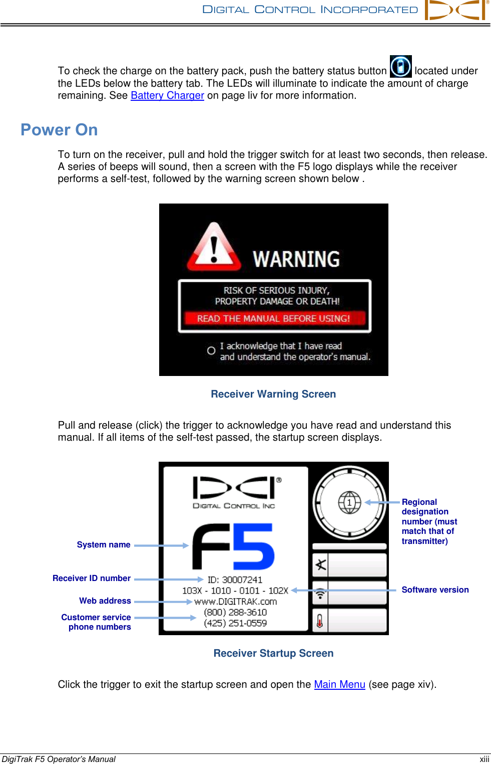
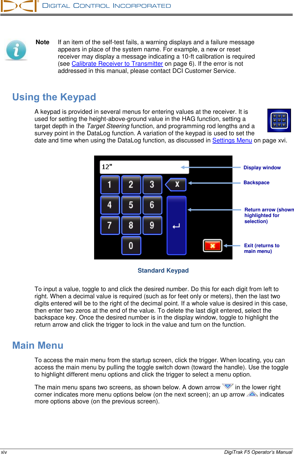
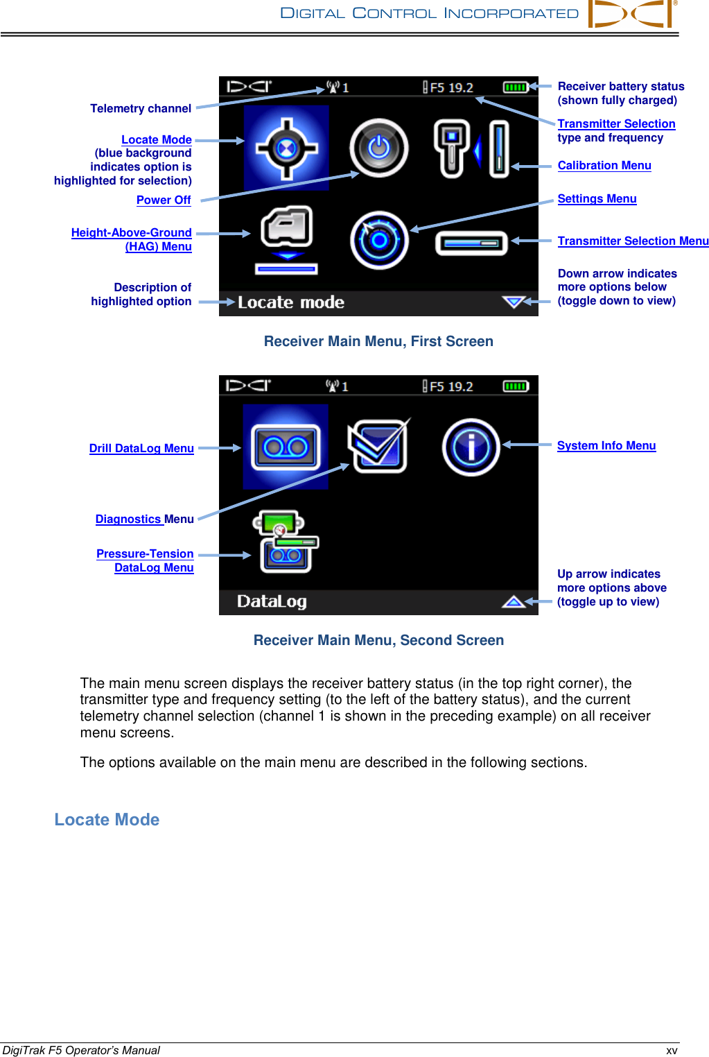
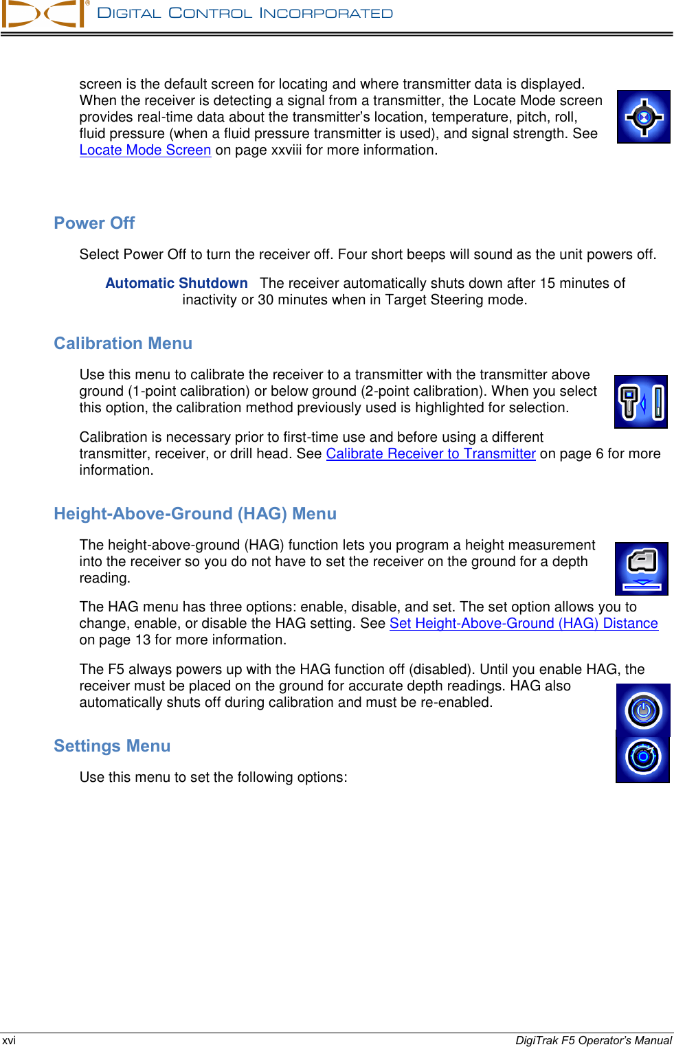
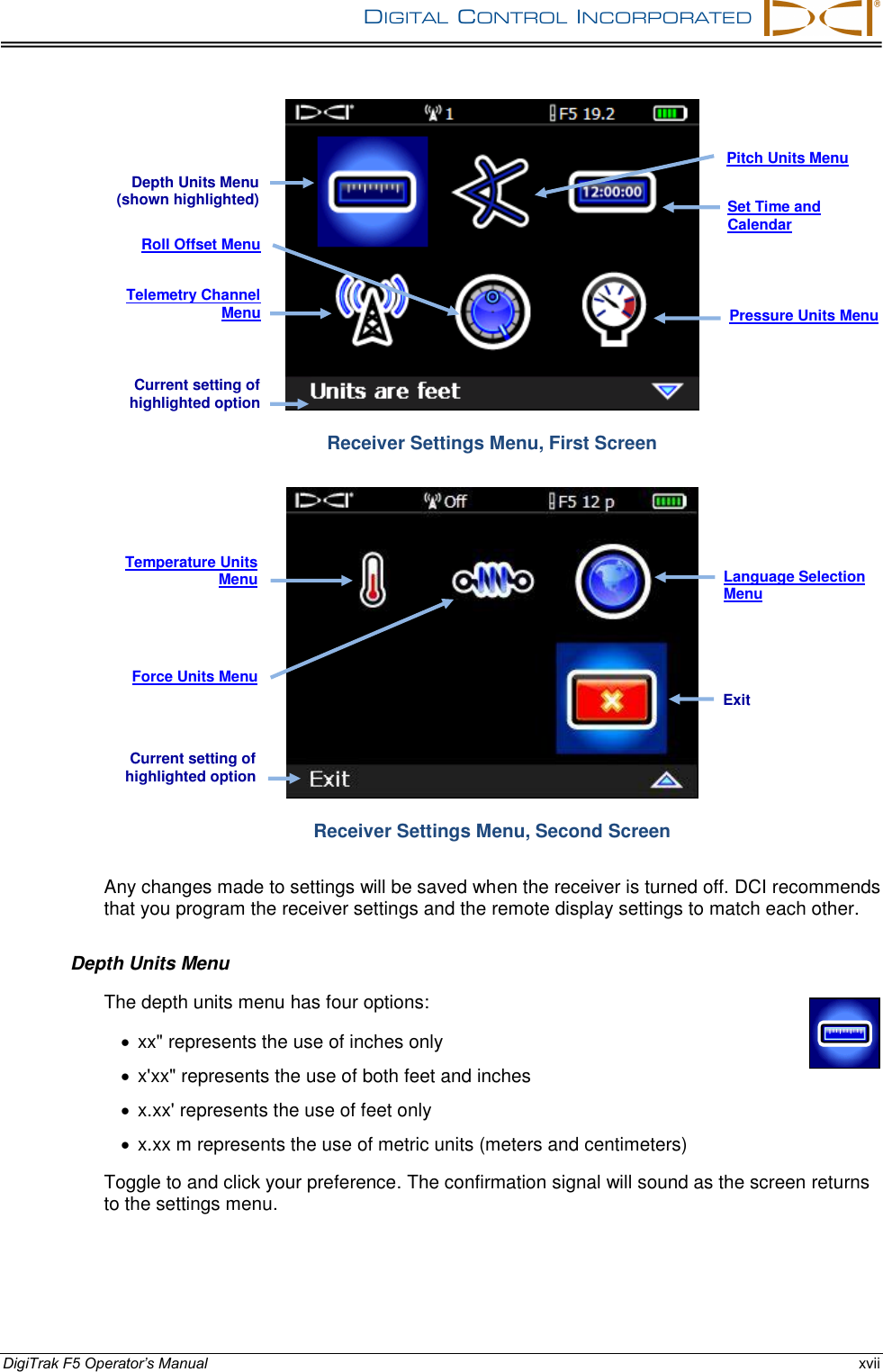
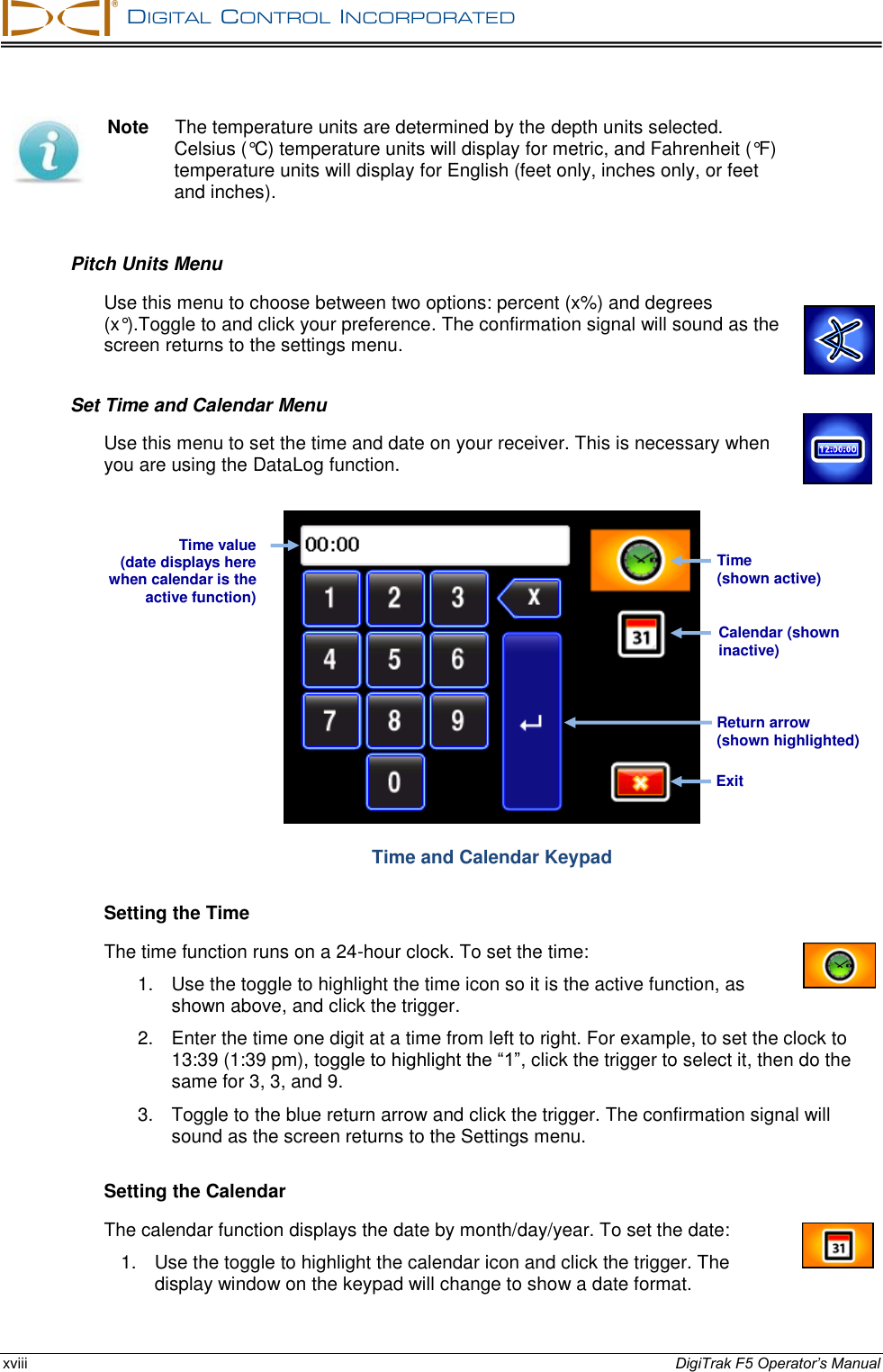
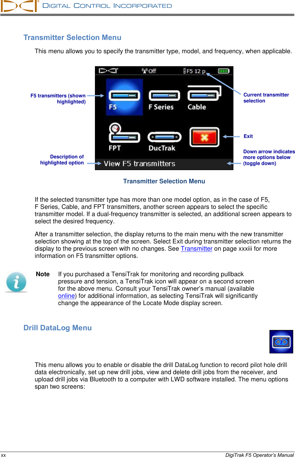
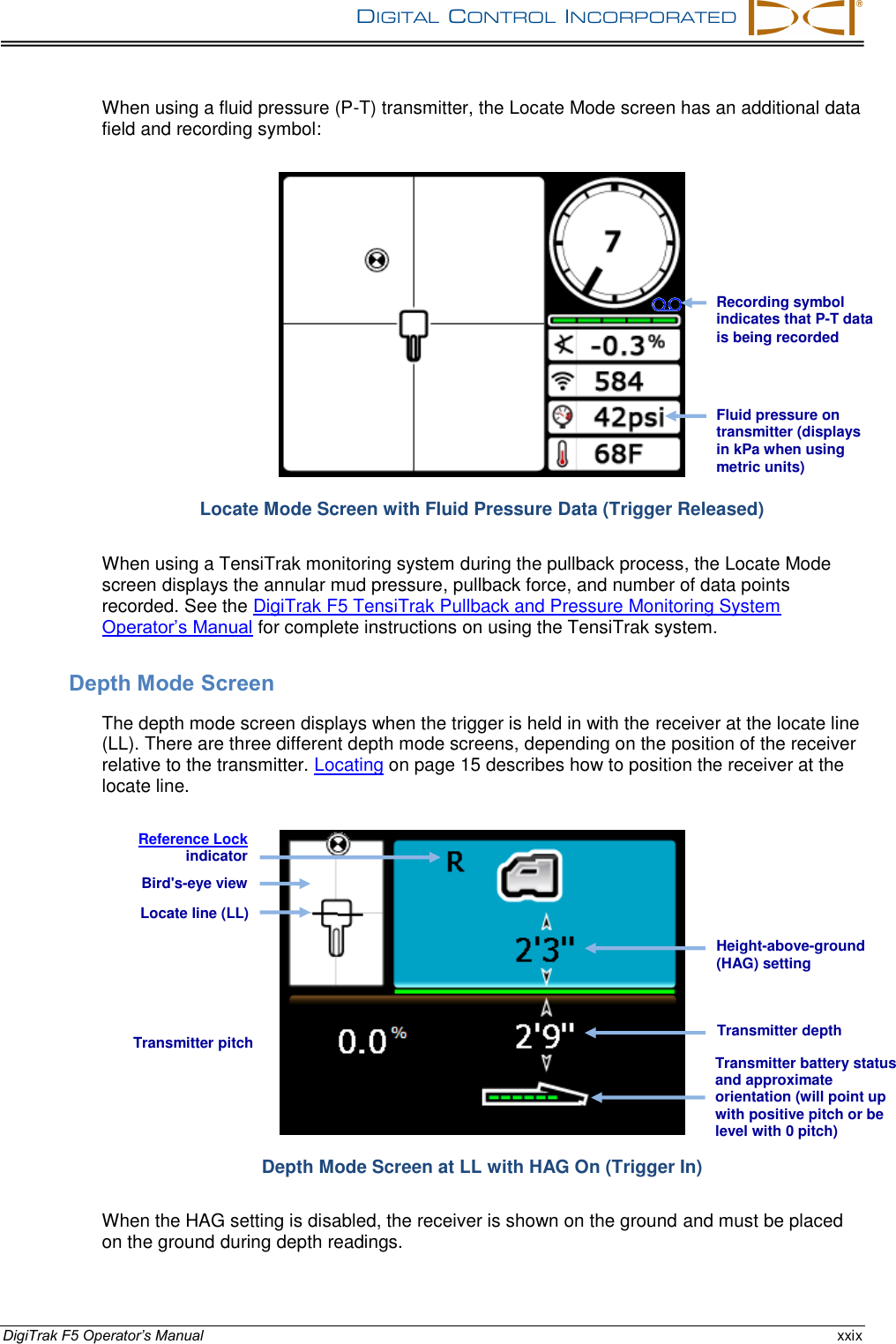
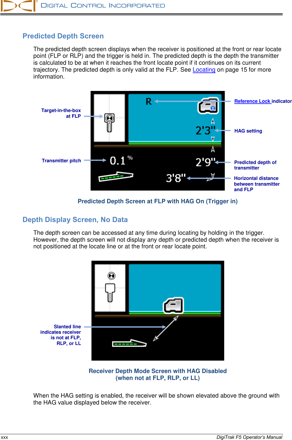
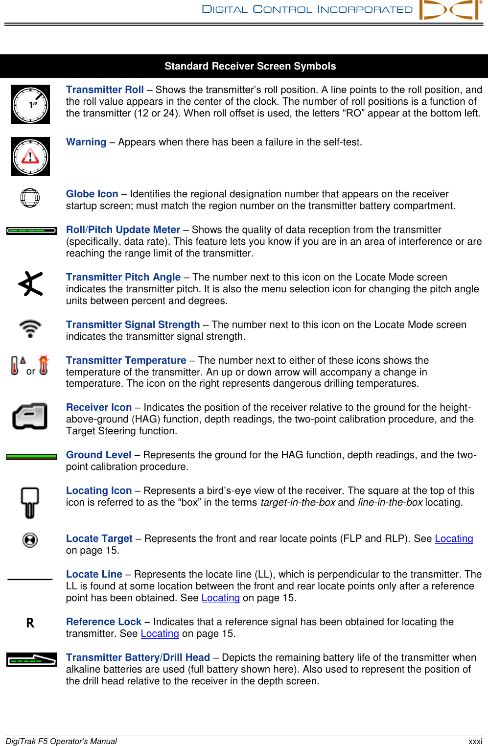
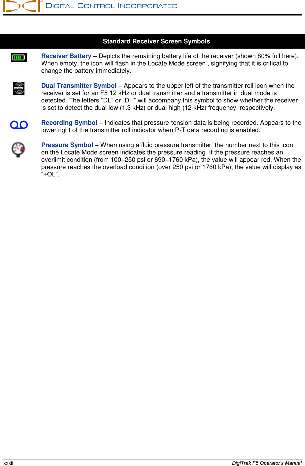
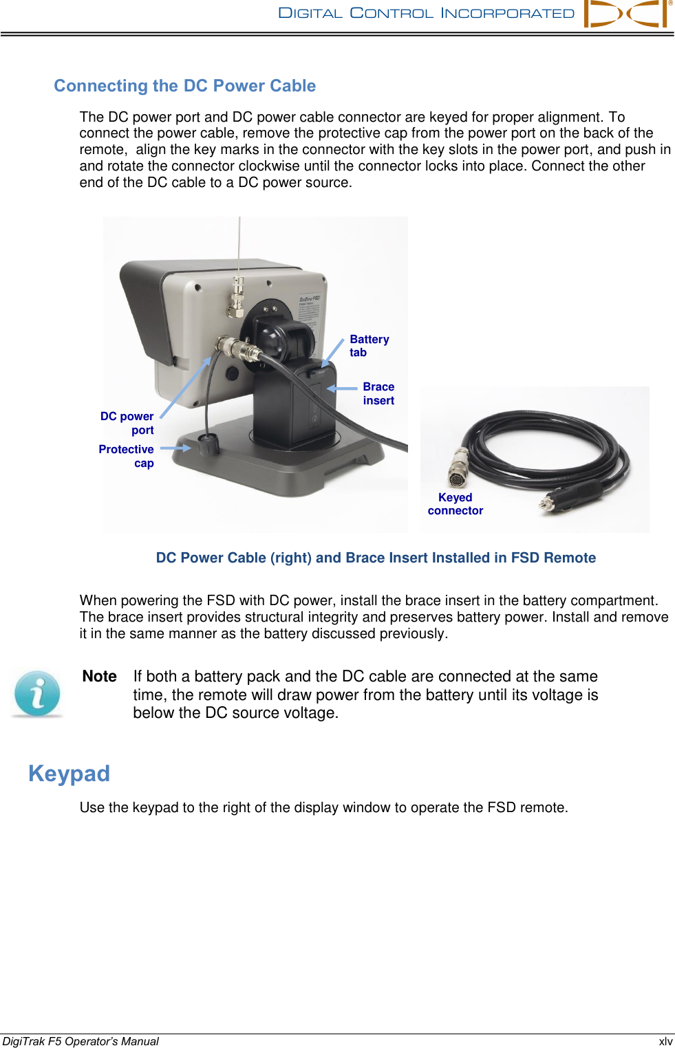
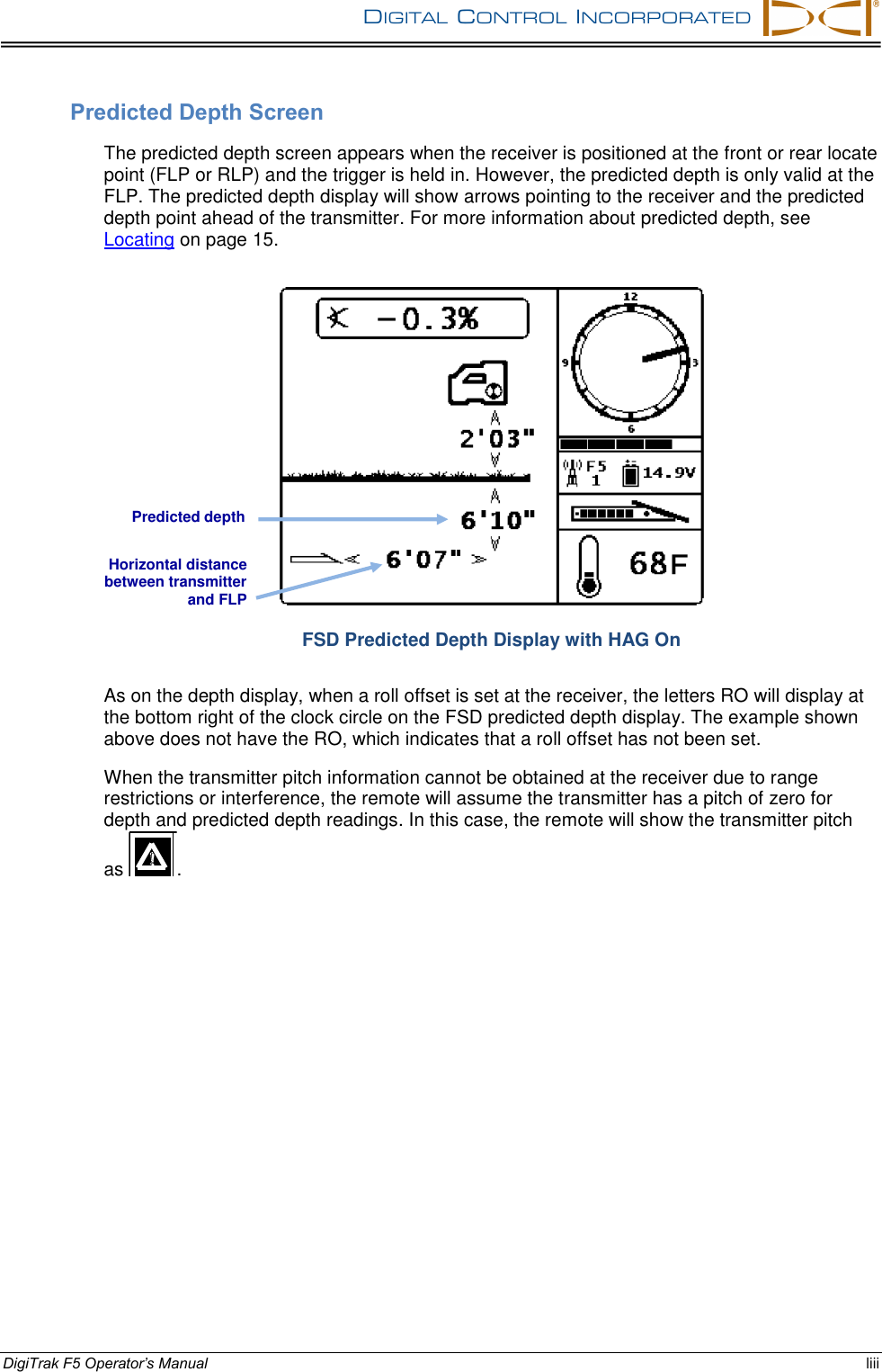
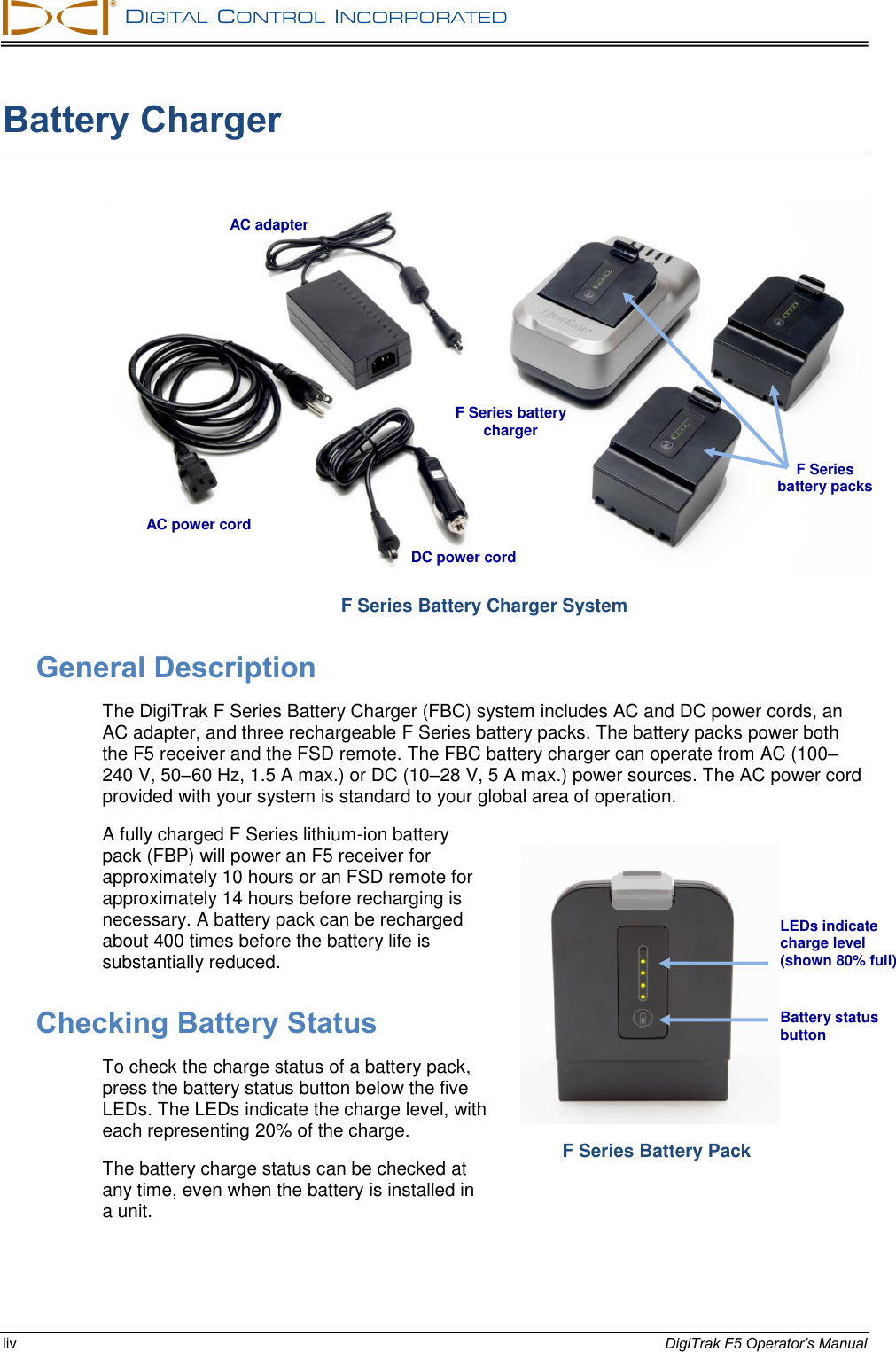
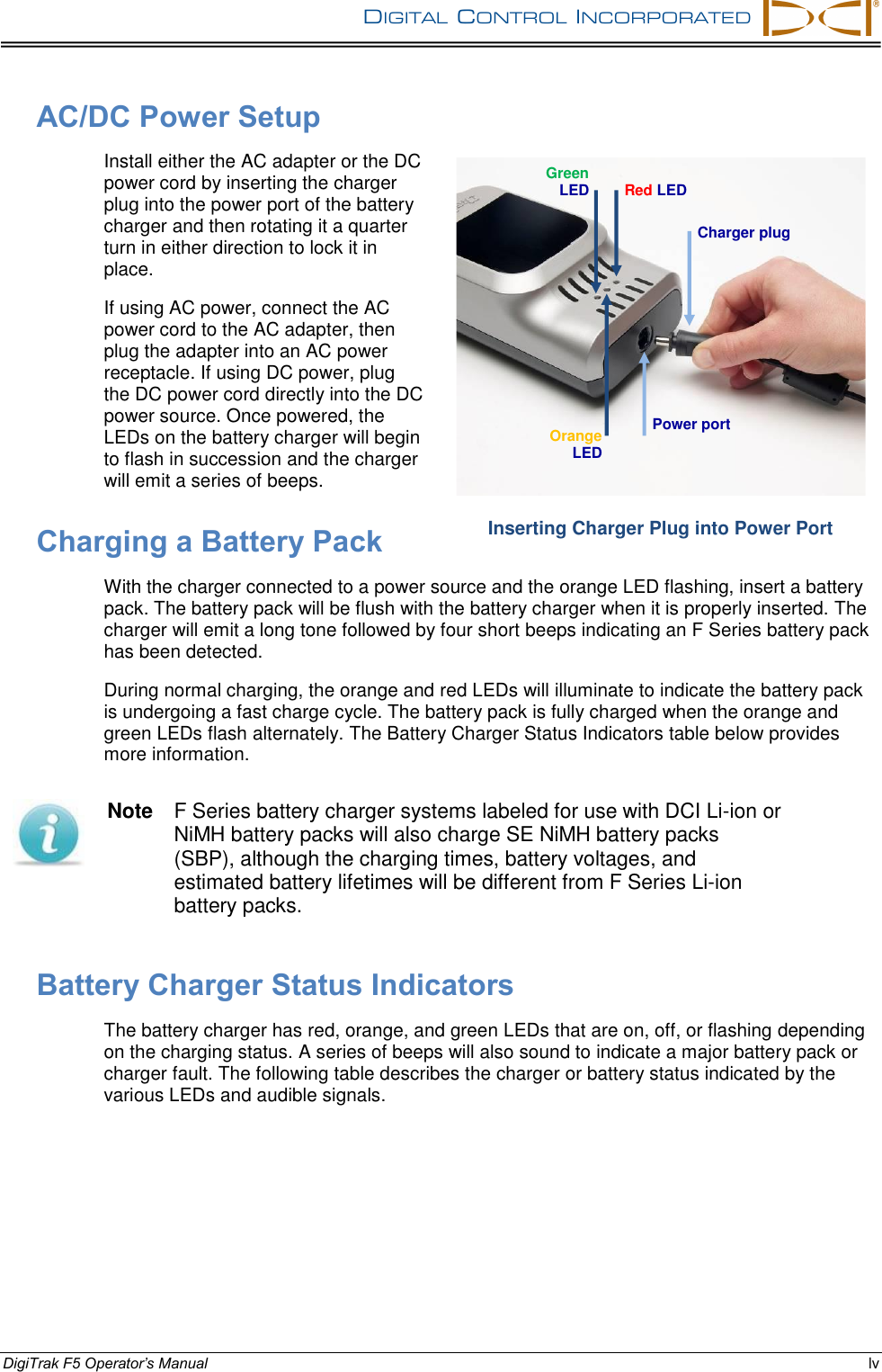
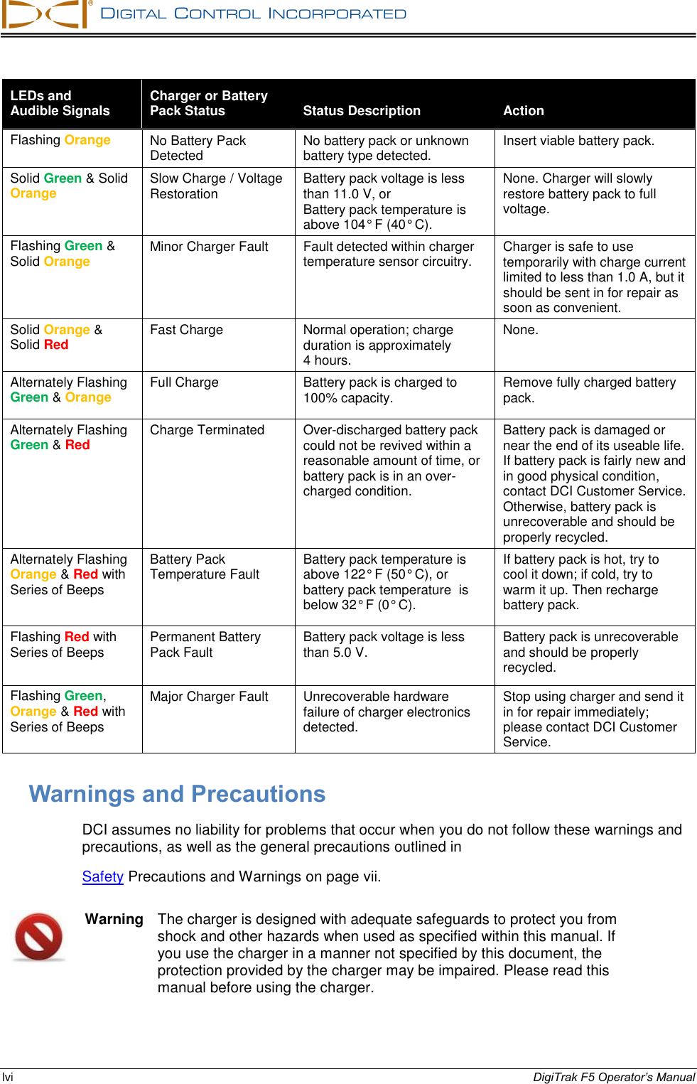
Digital Control B2DIG1 DR2 User Manual Operating Instructions
Digital Control Inc DR2 Operating Instructions
UserManual.wiki
>
Digital Control
>
B2DIG1 User Manual
User Manual
Navigation menu
Upload a User Manual
Namespaces
Wiki Guide
HTML
PDF
Info
Views
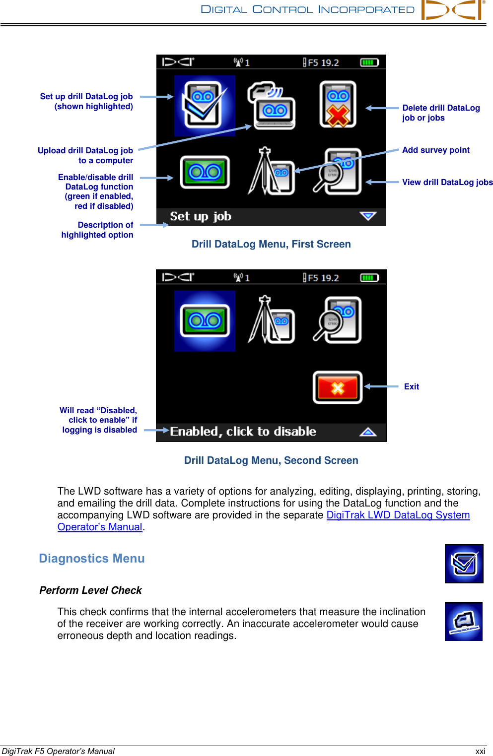
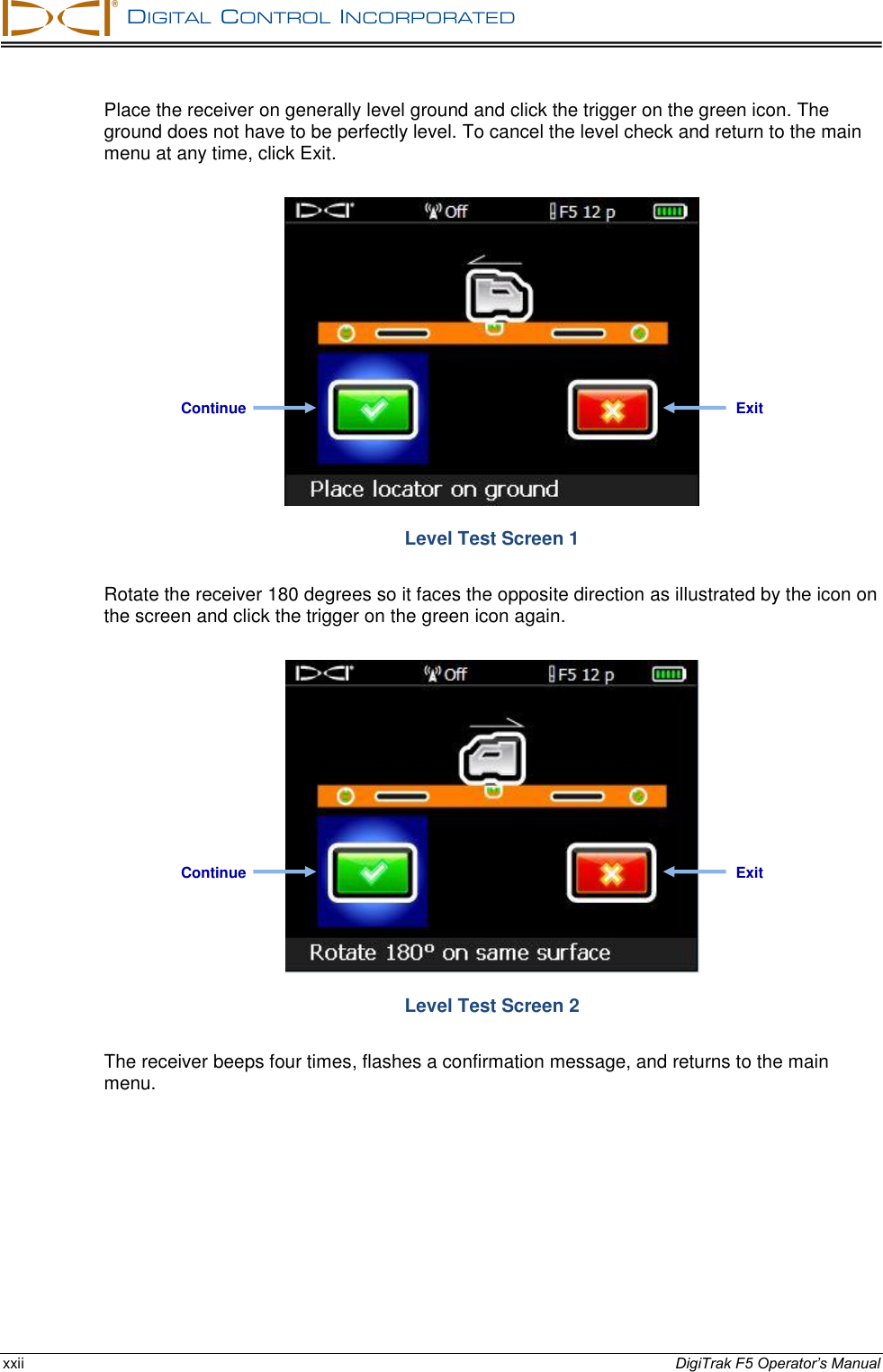
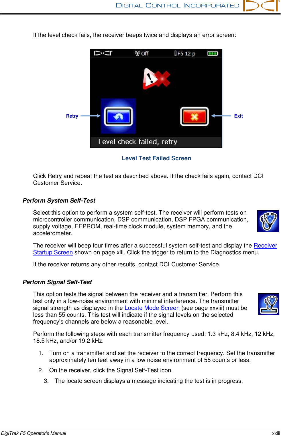
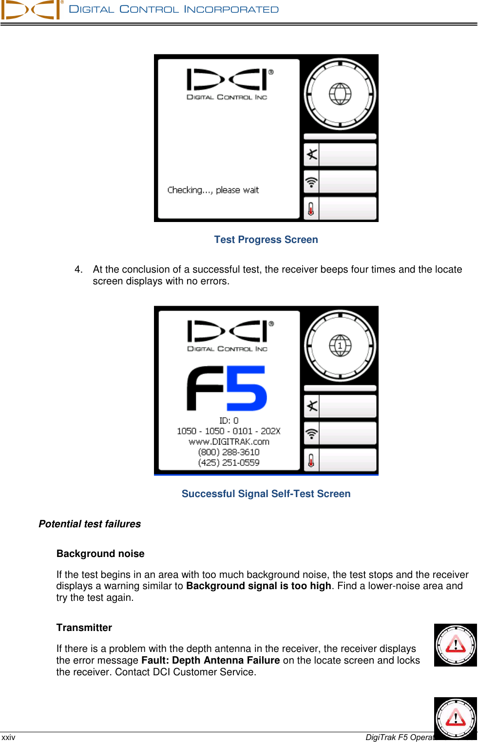
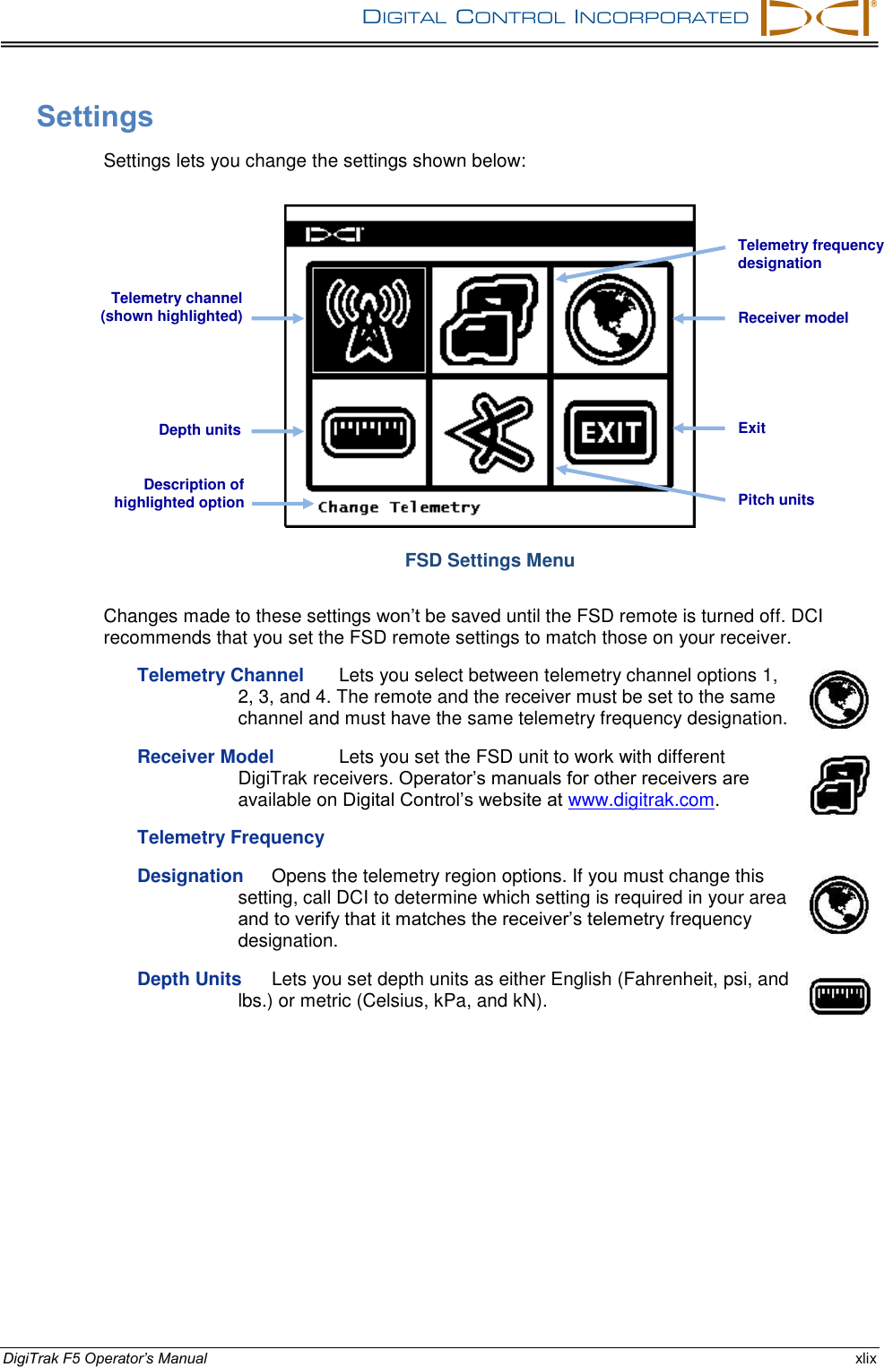
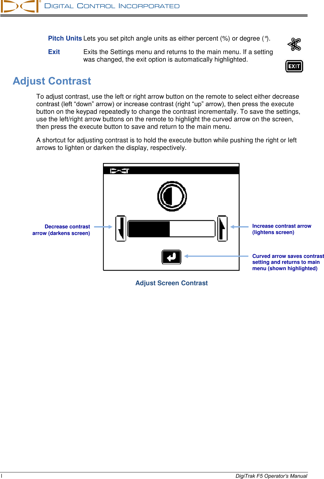
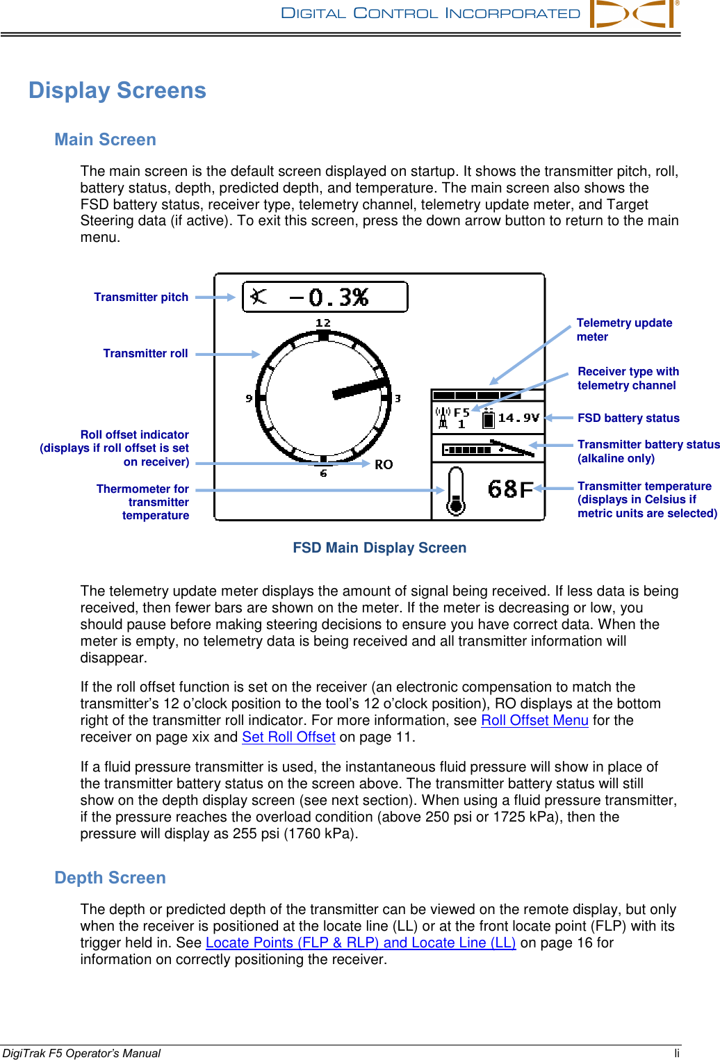
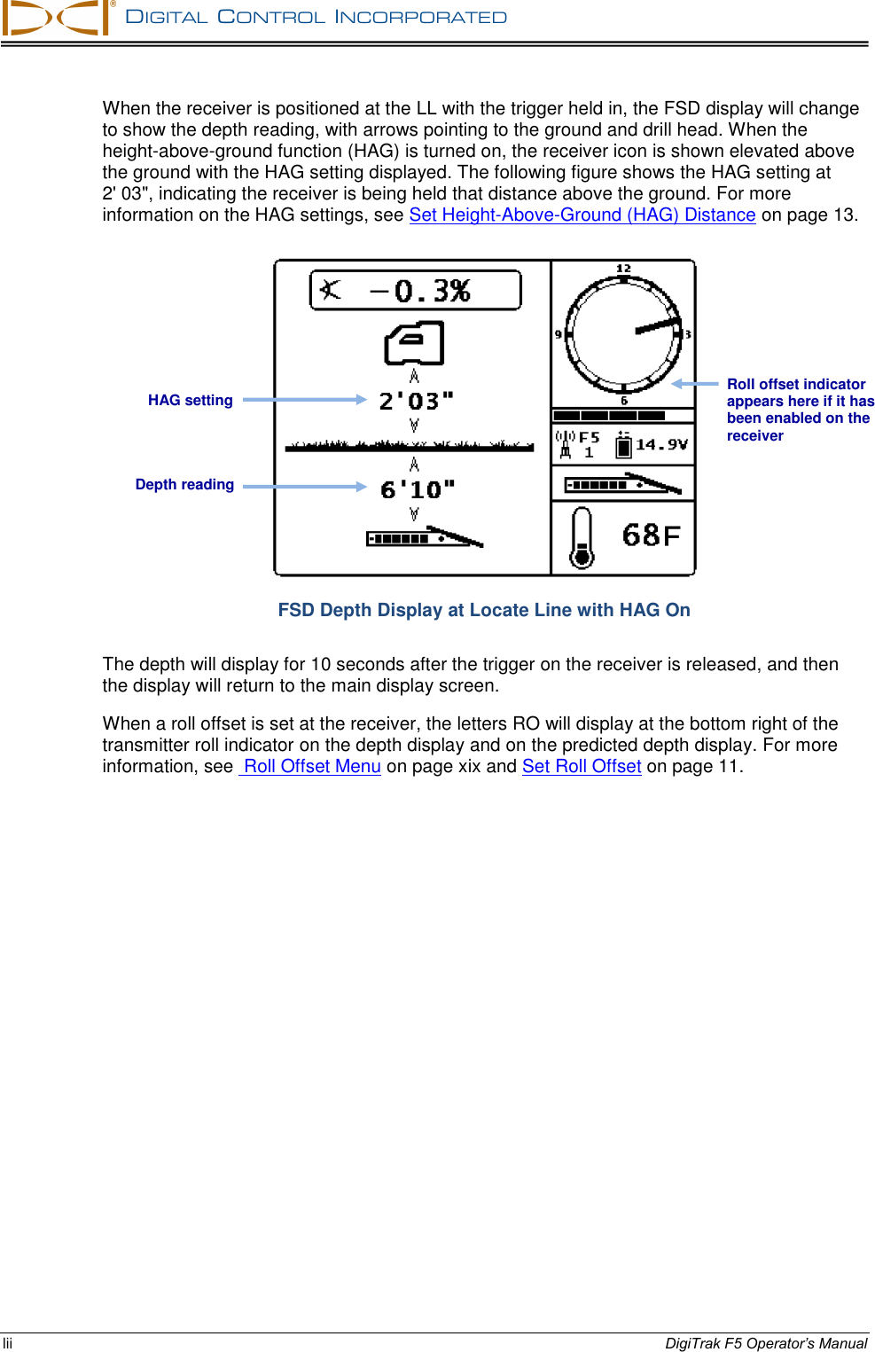
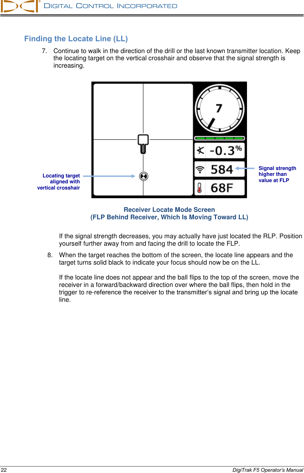
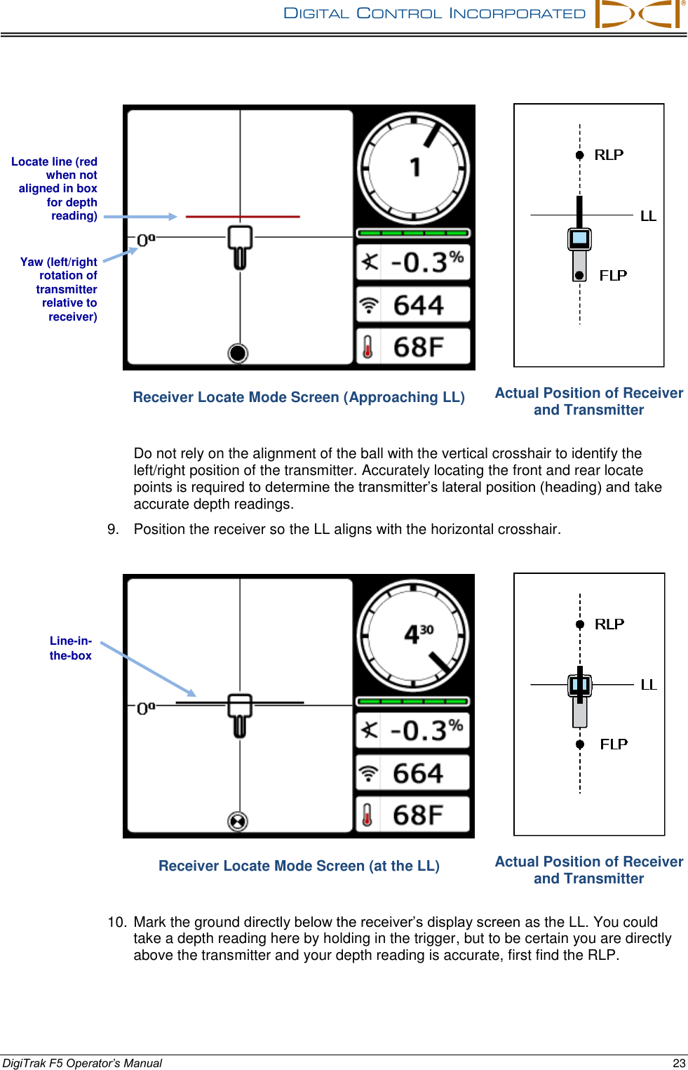
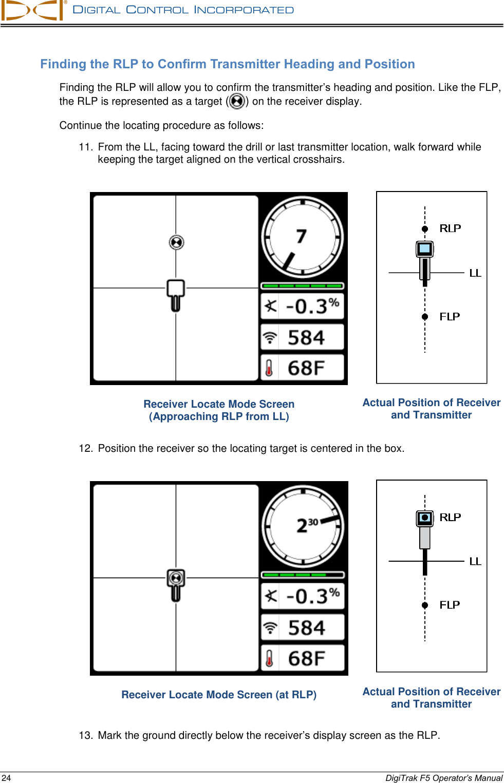
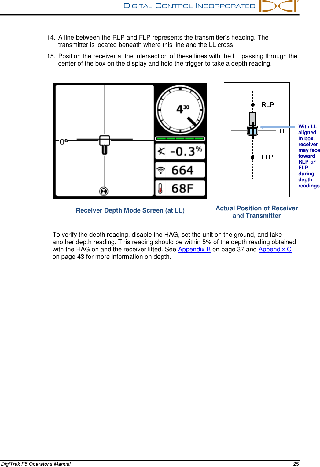
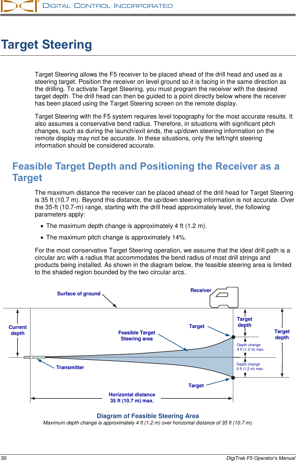
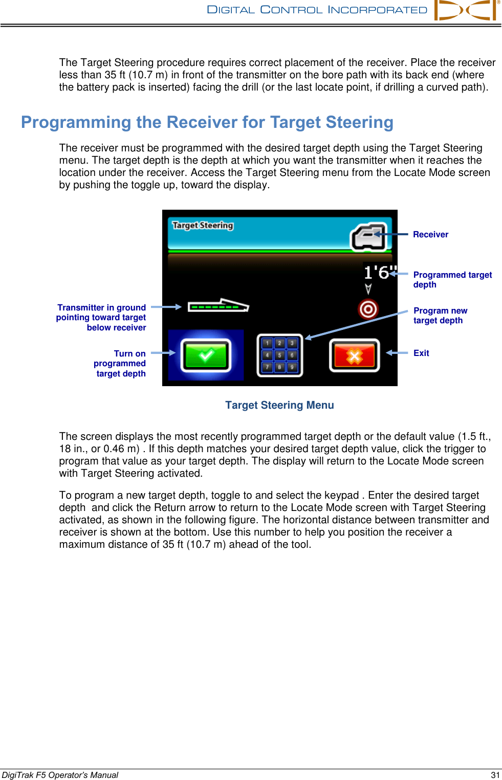
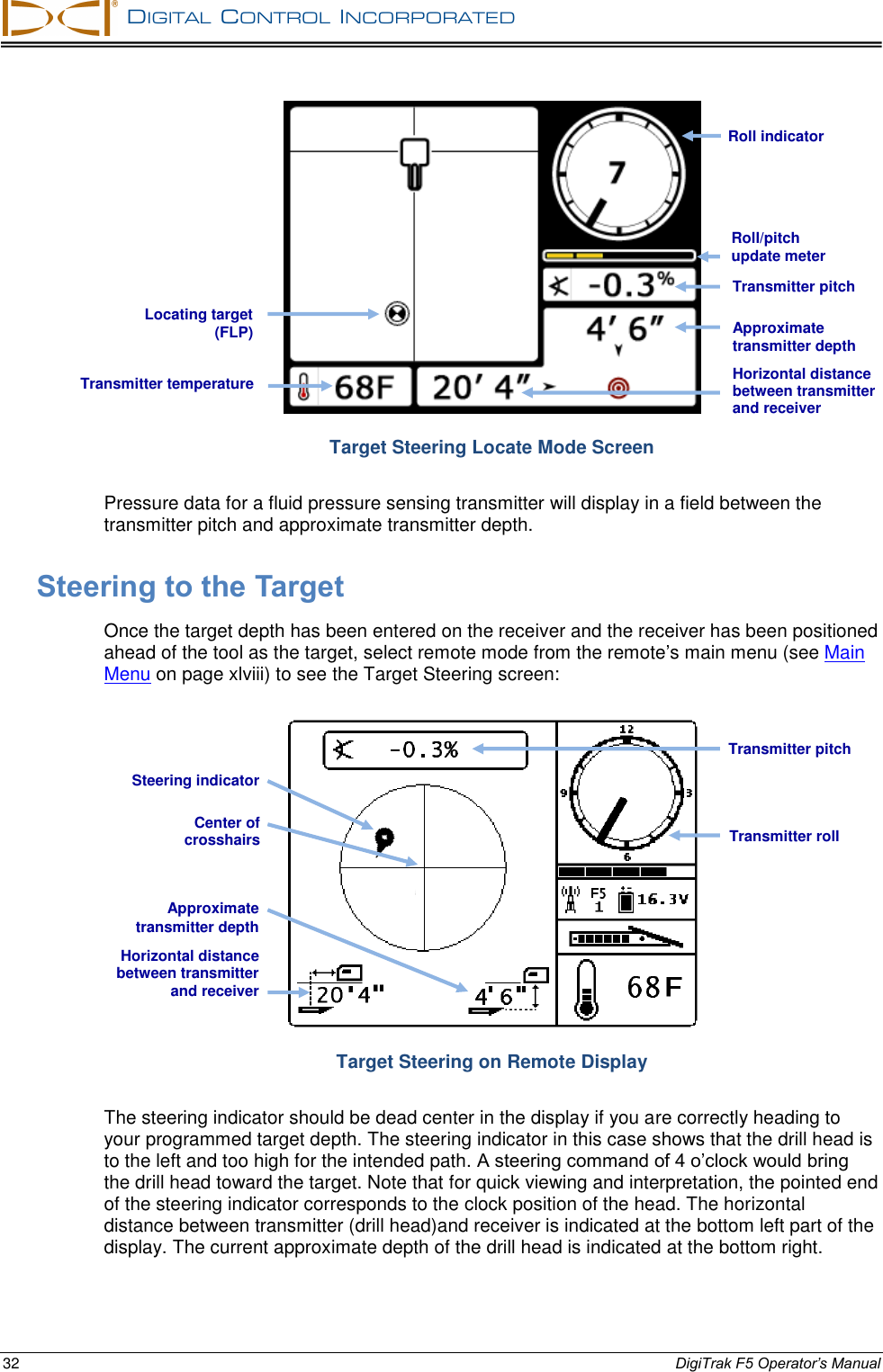
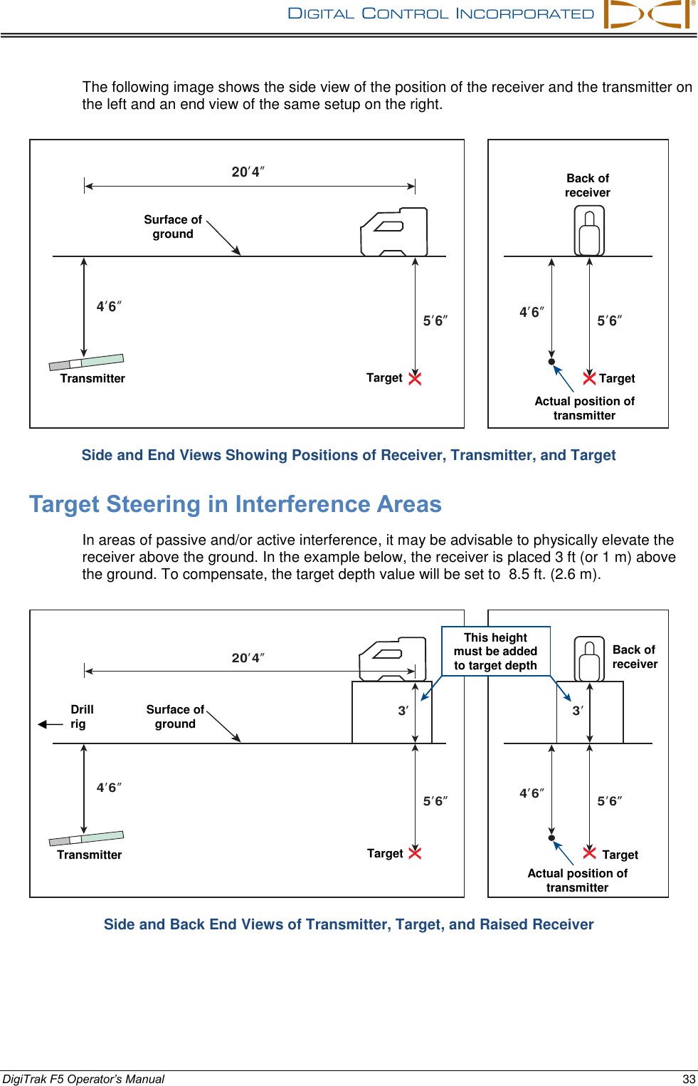
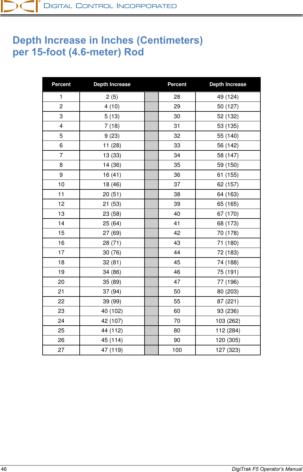
User Manual
Discussion / Help
Navigation