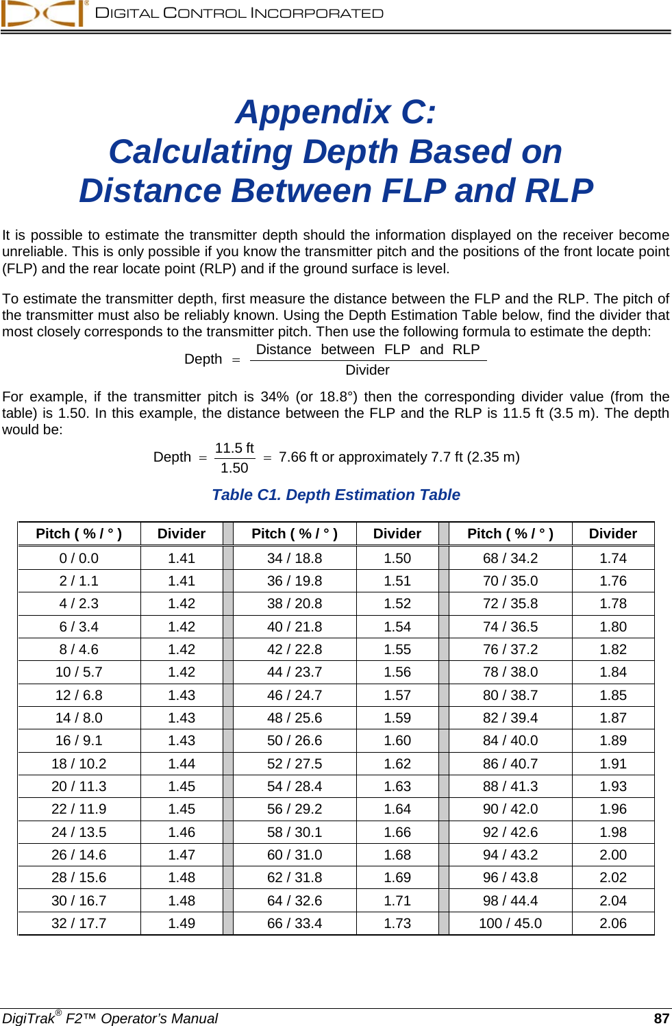
Digital Control F2R F2R User Manual Operating Instructions
Digital Control Inc F2R Operating Instructions
UserManual.wiki
>
Digital Control
>
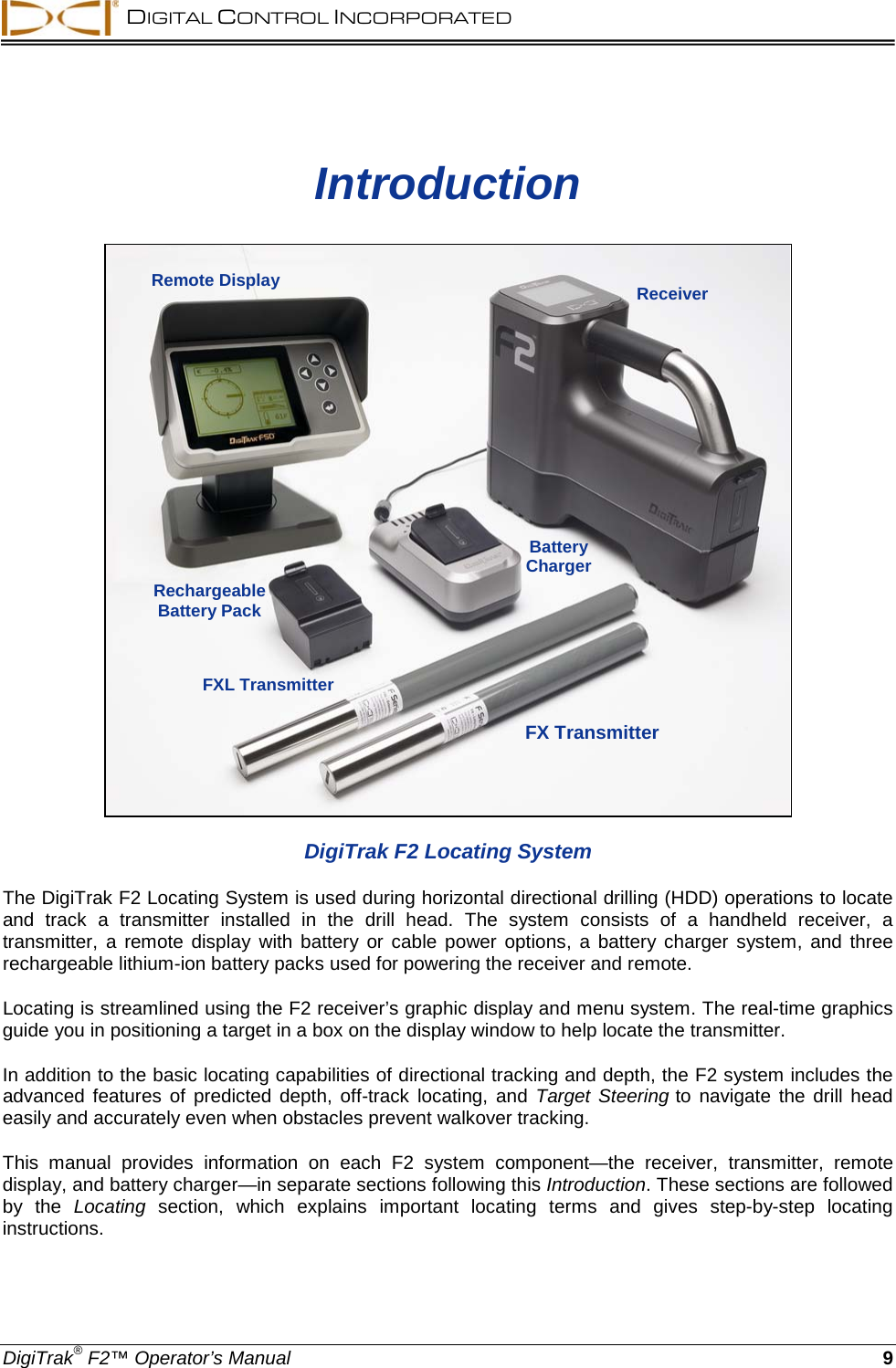
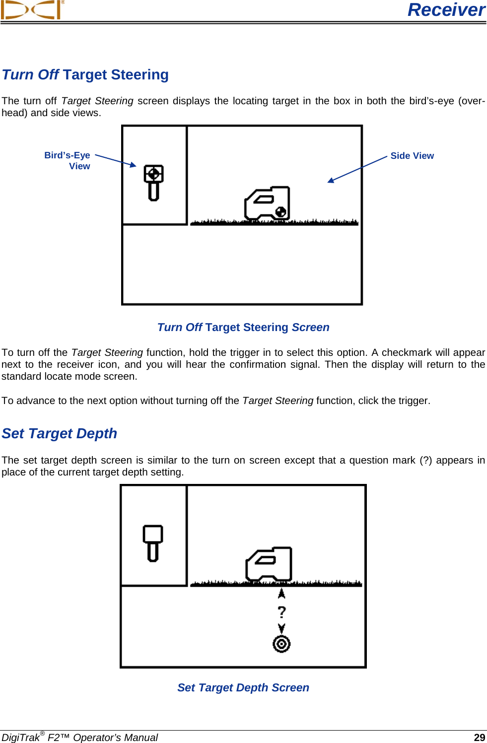
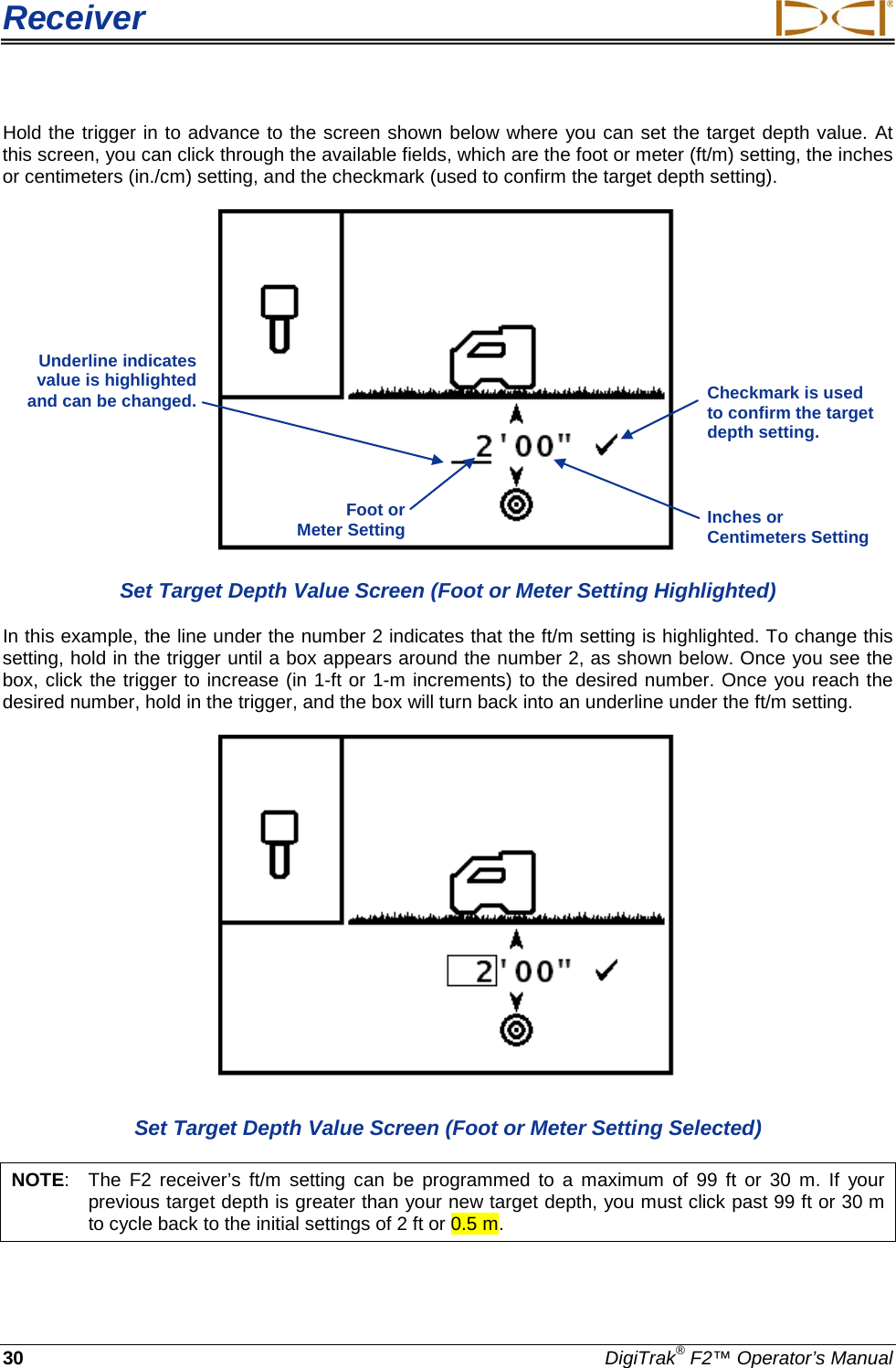
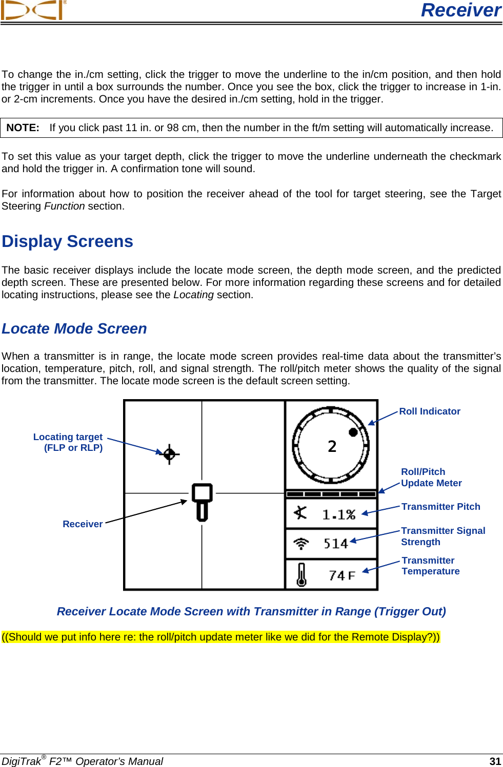
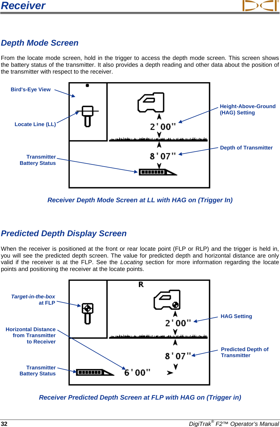
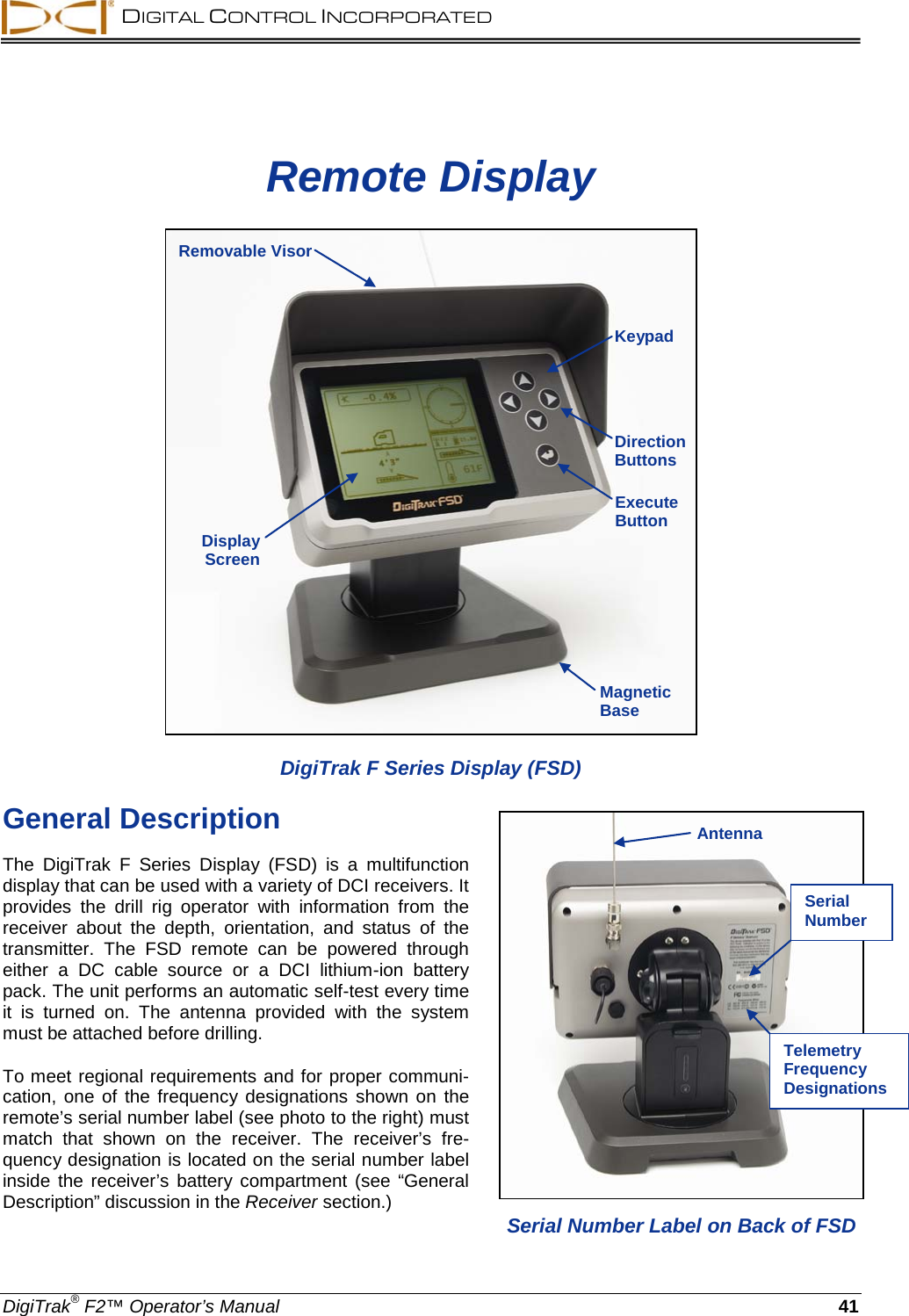
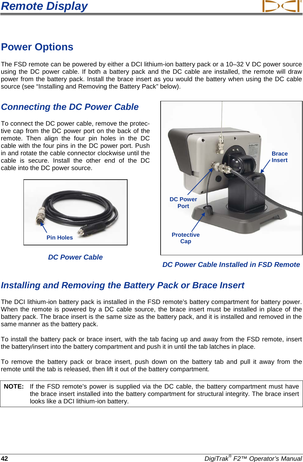
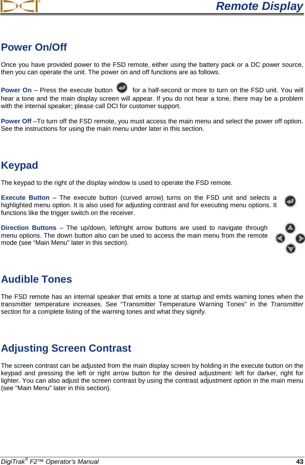
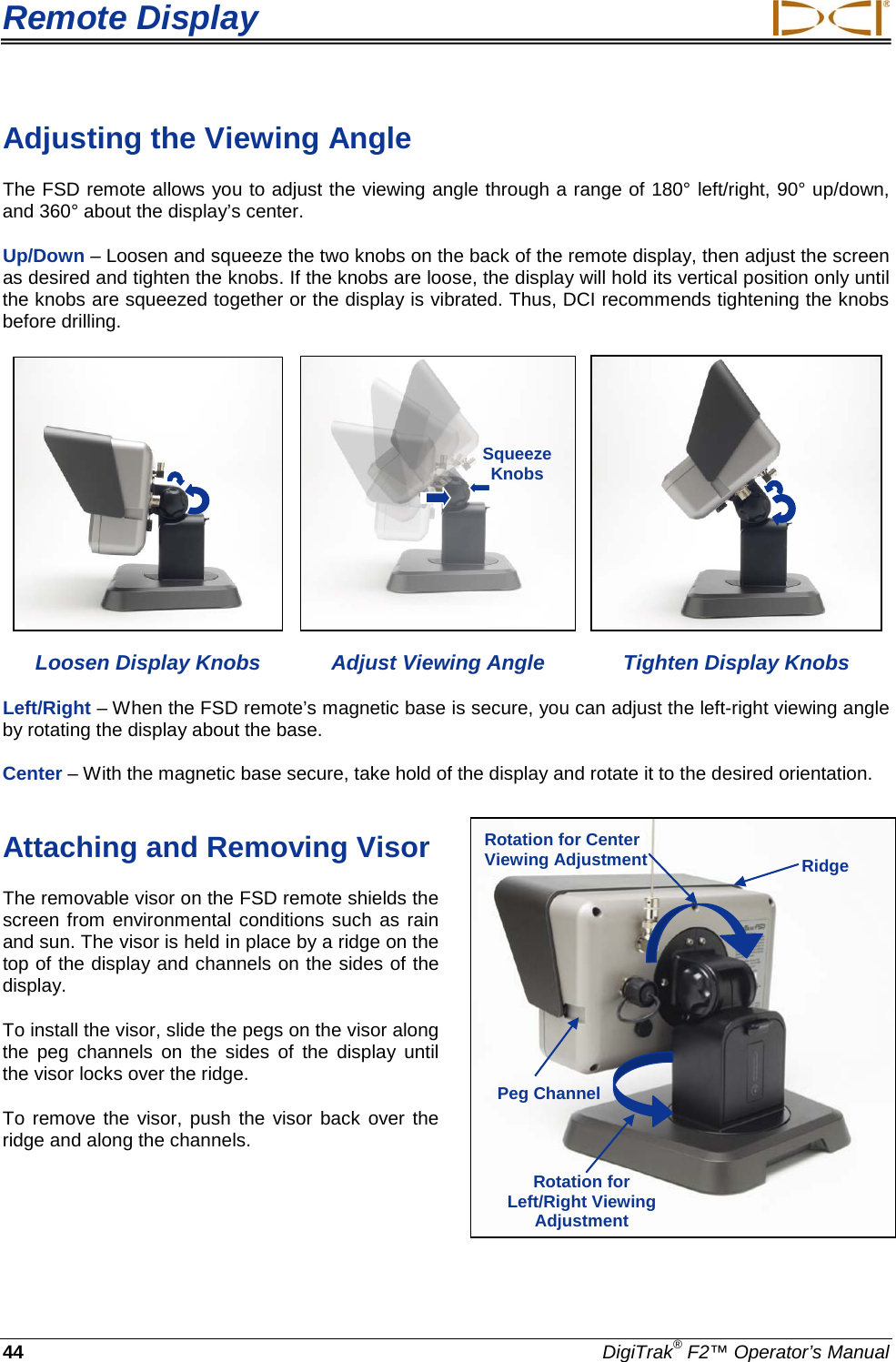
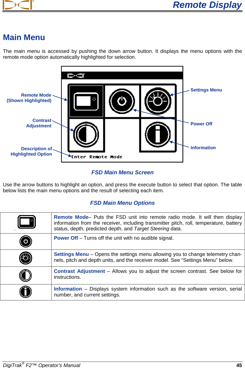
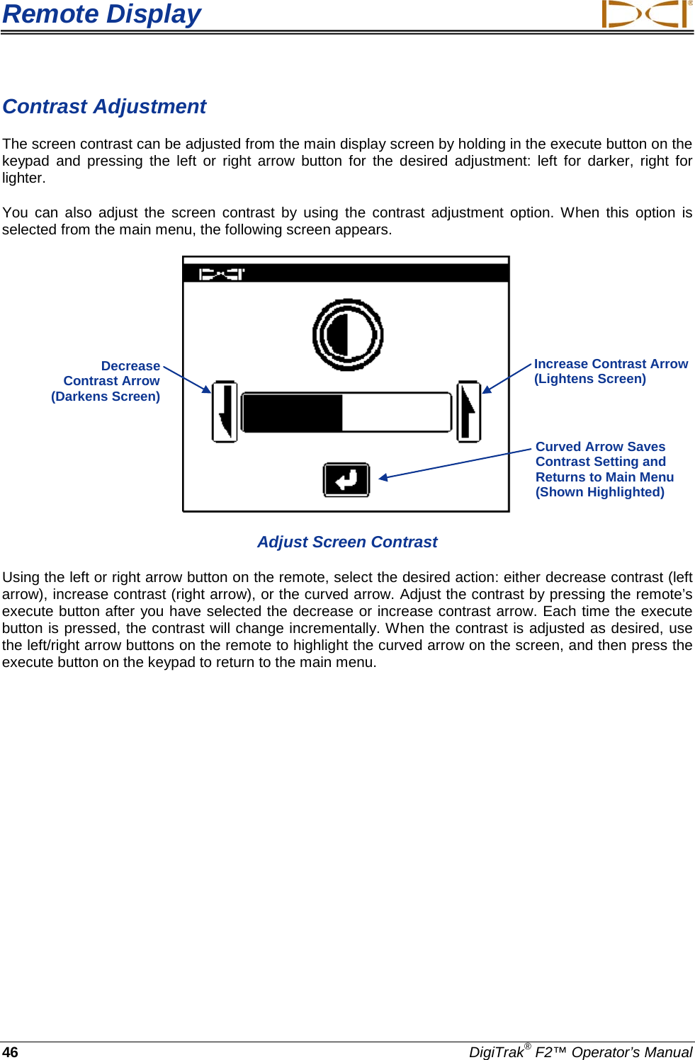
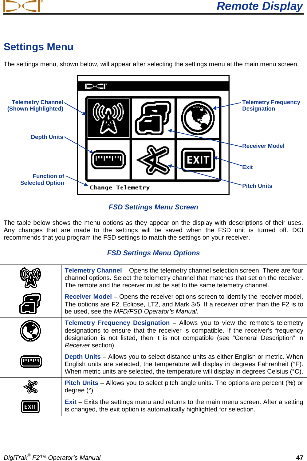
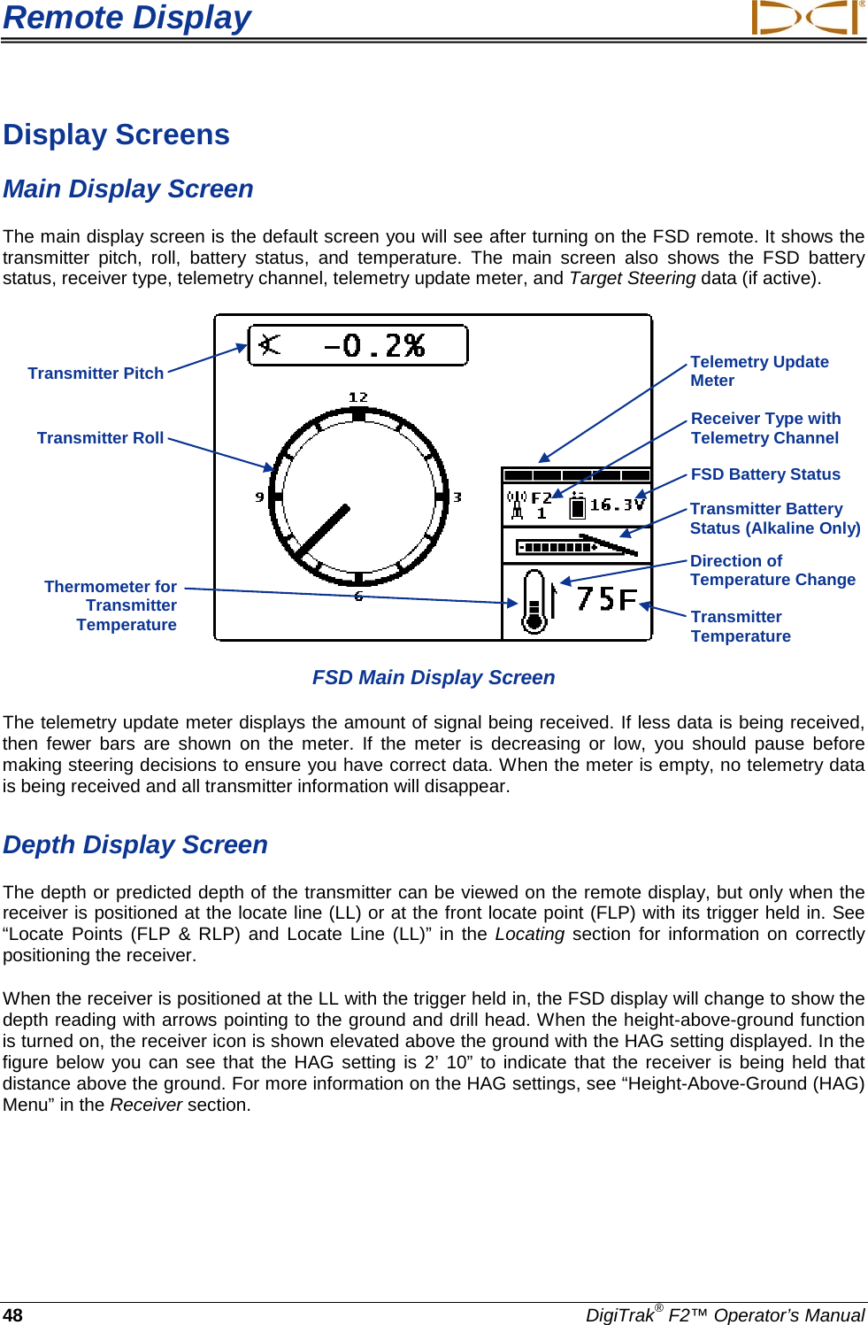
F2R User Manual
User Manual
Navigation menu
Upload a User Manual
Namespaces
Wiki Guide
HTML
PDF
Info
Views
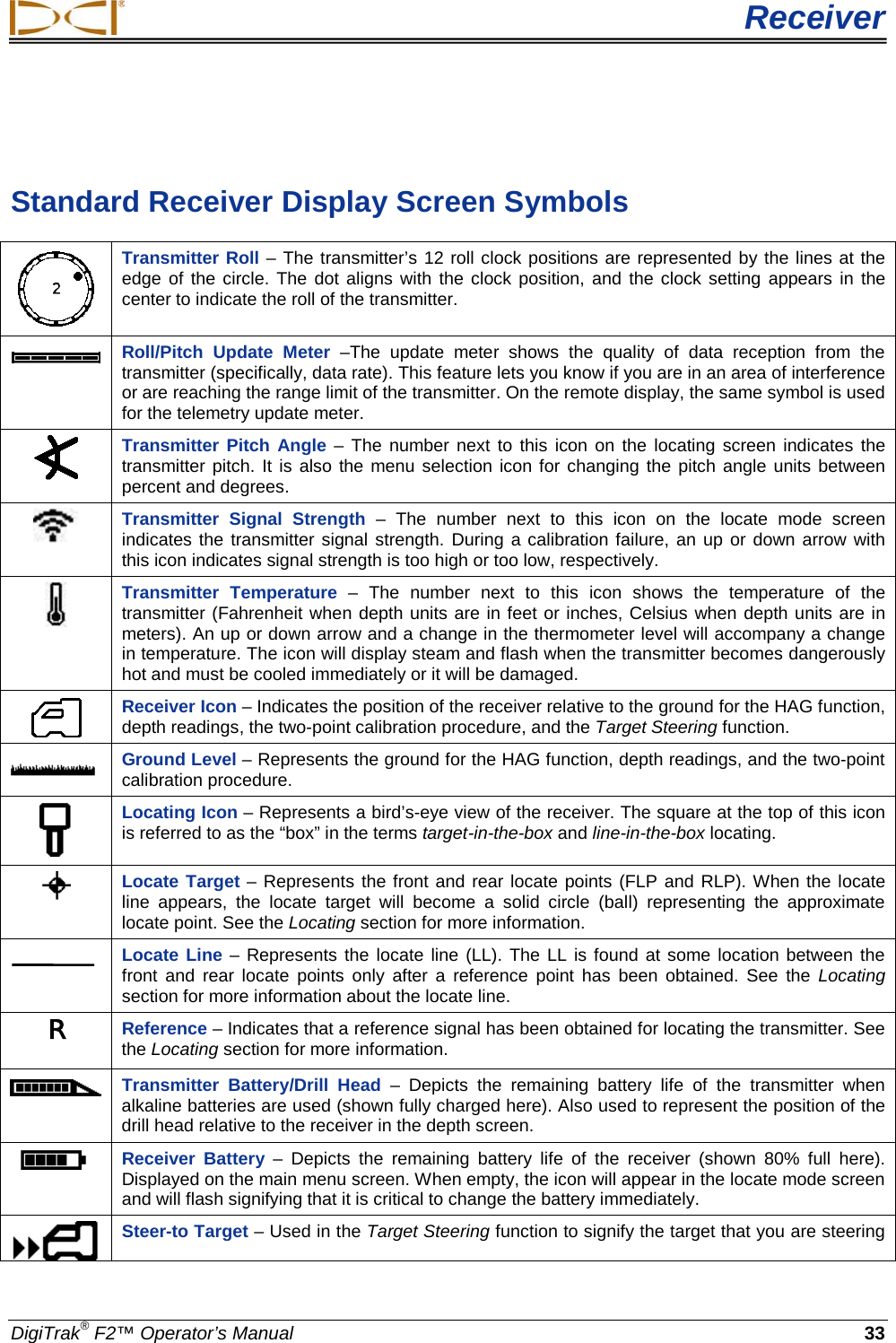
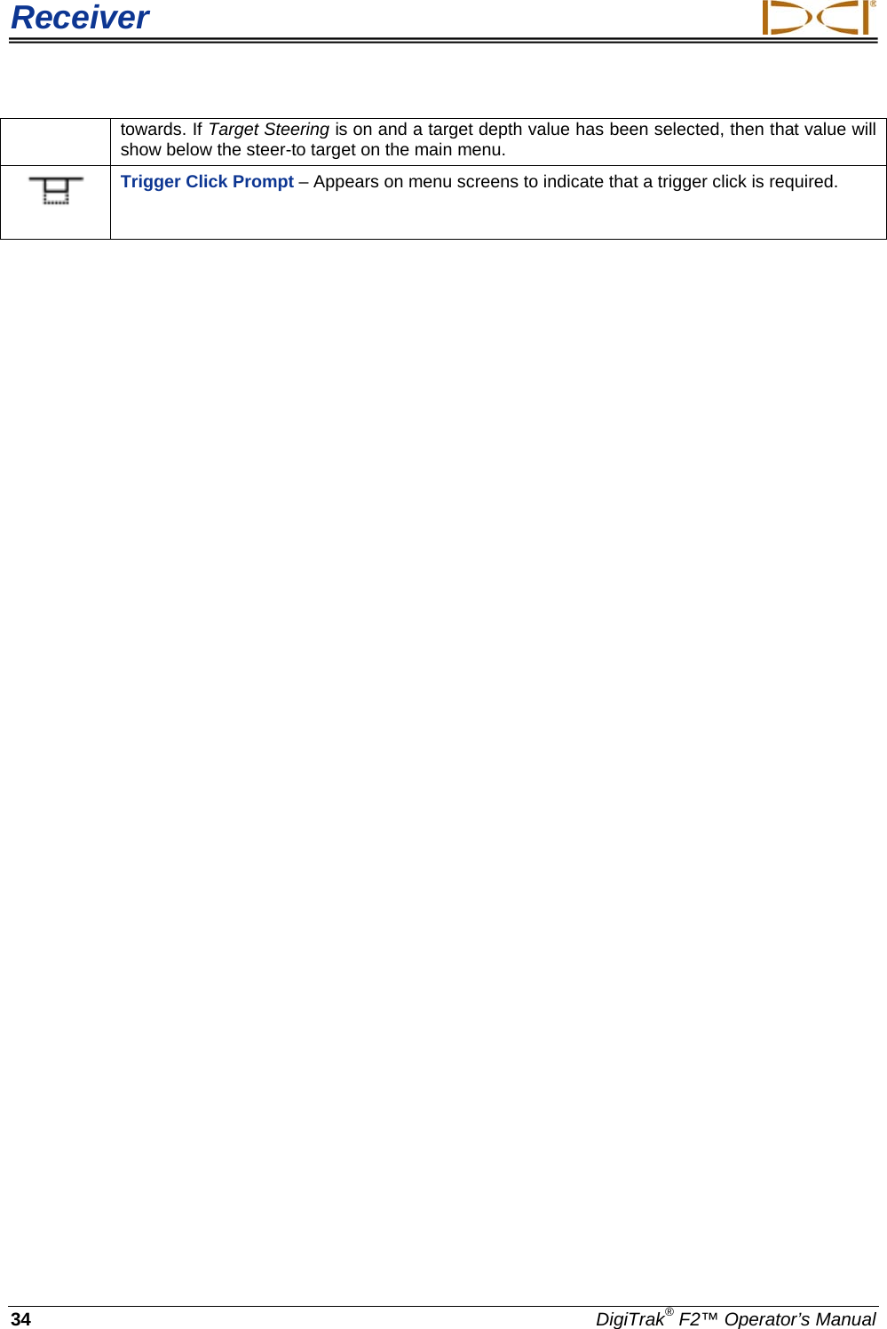
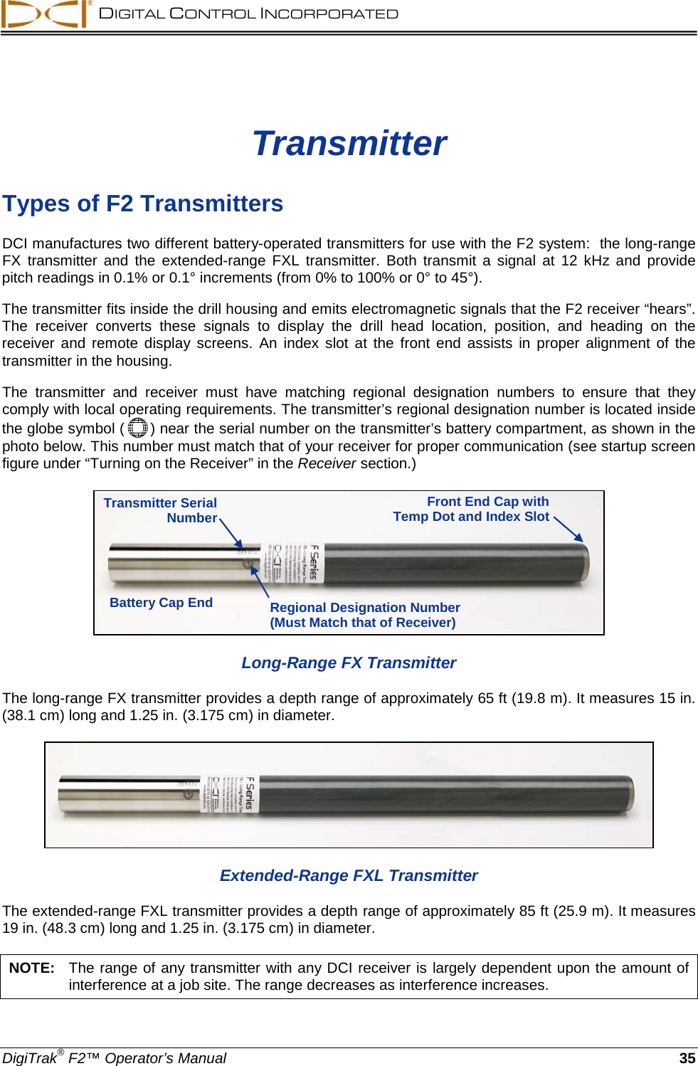
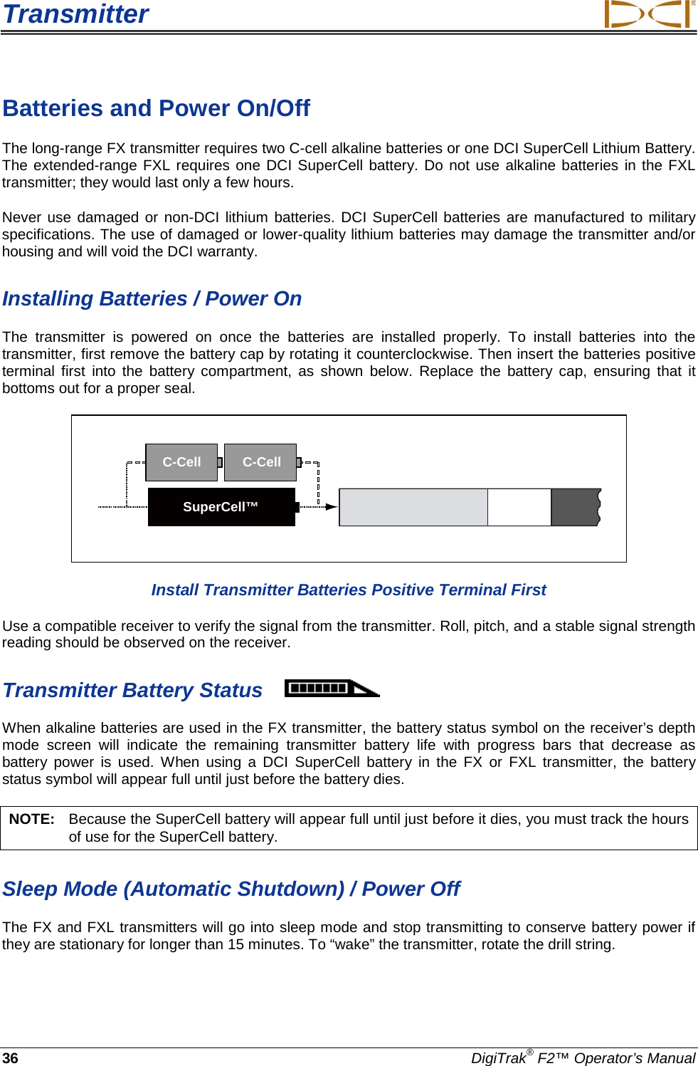
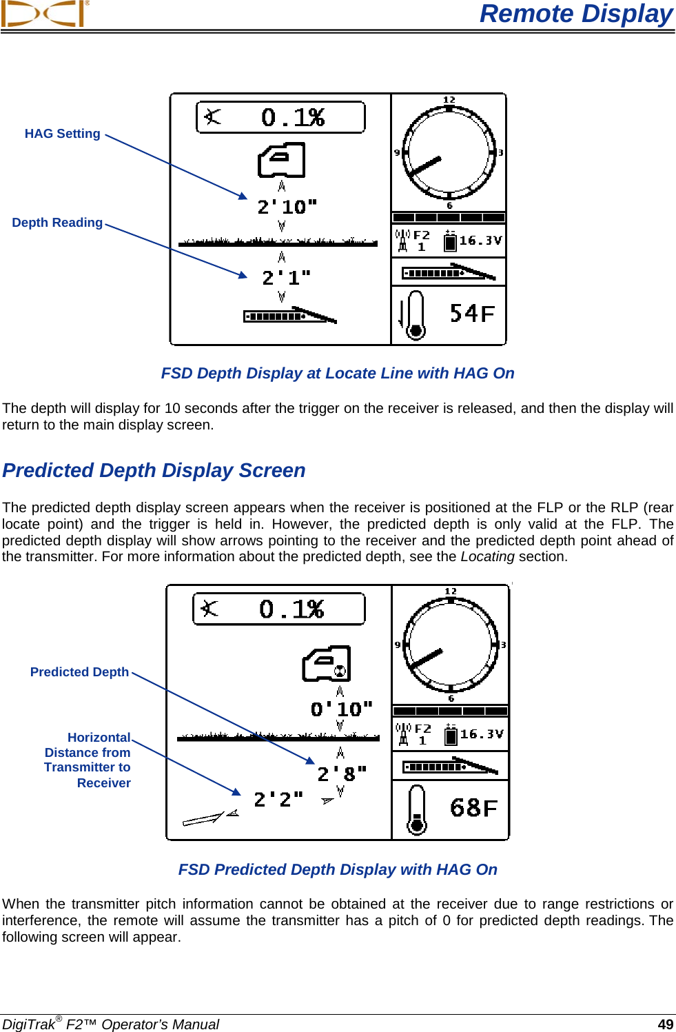
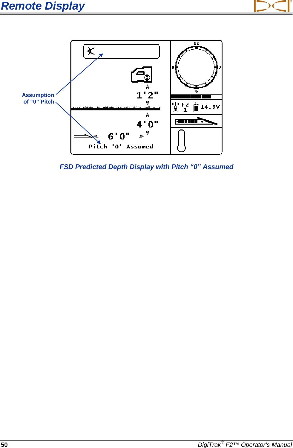
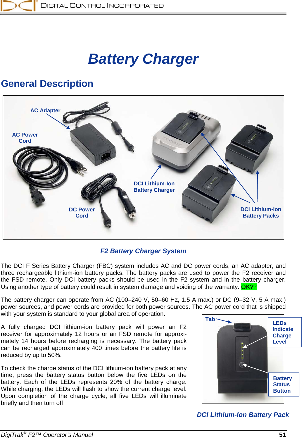
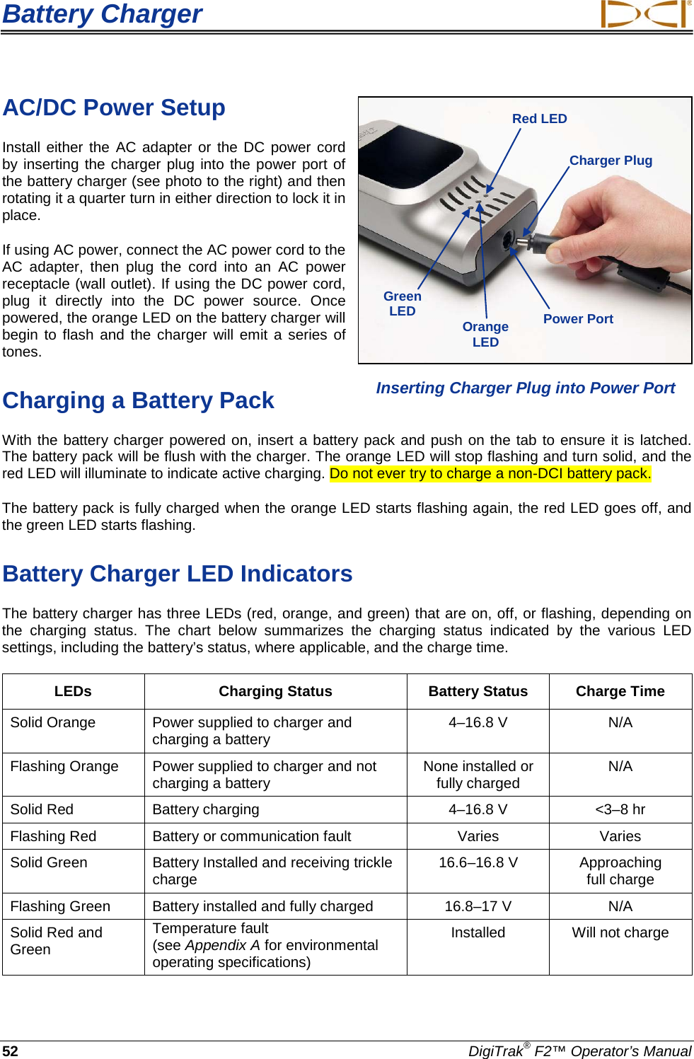
User Manual
Discussion / Help
Navigation