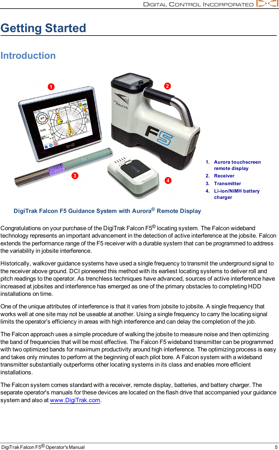
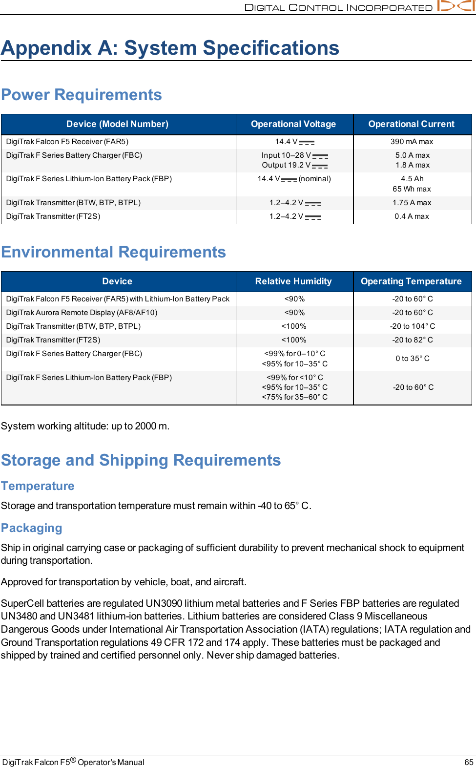
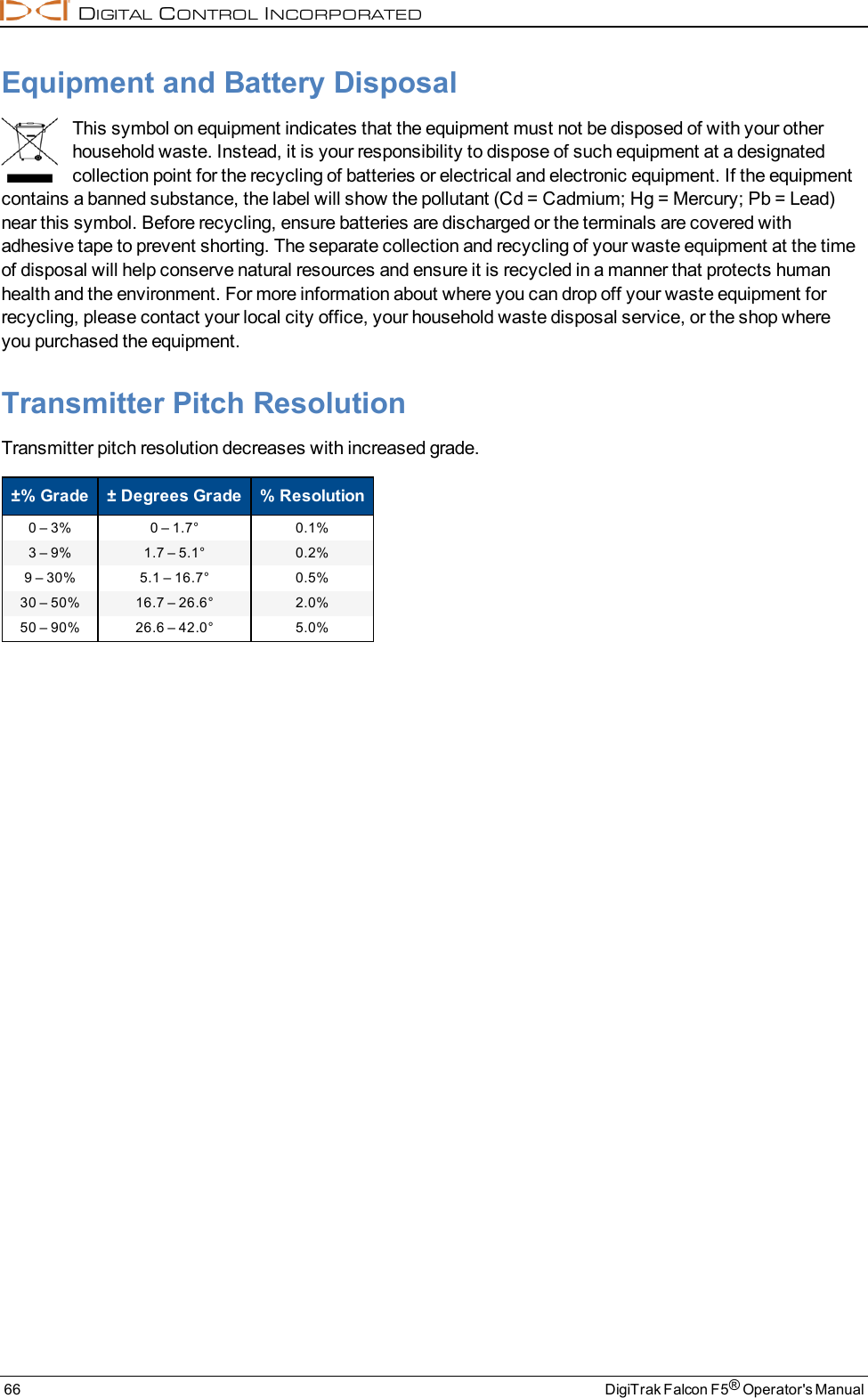
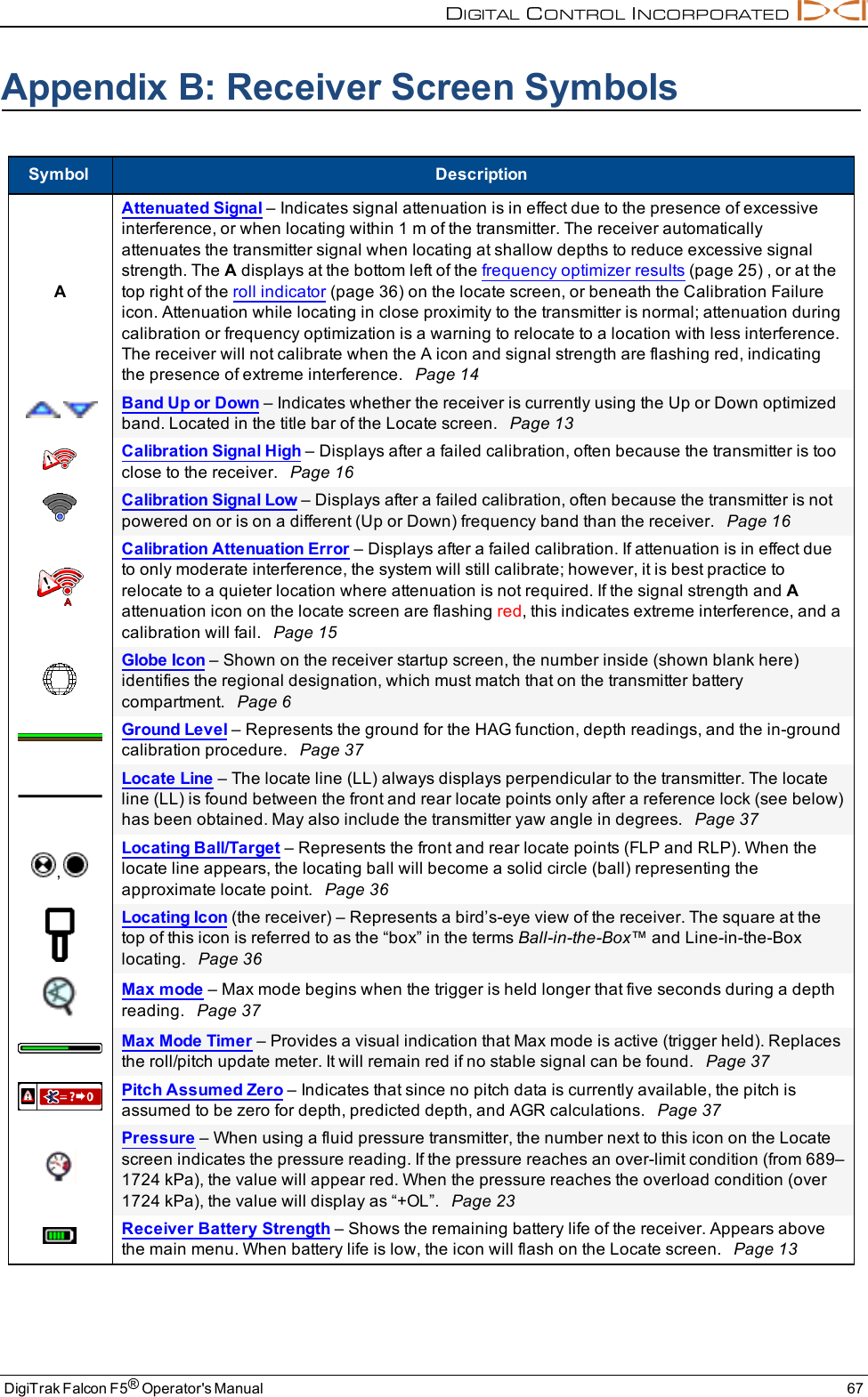
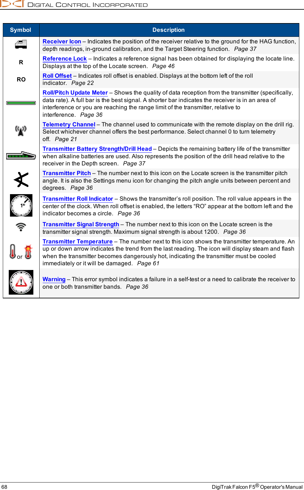
Digital Control P62019 BTS User Manual DigiTrak Falcon F5 Operator s Manual OM metric
Digital Control Inc BTS DigiTrak Falcon F5 Operator s Manual OM metric
UserManual.wiki
>
Digital Control
>
P62019 User Manual
user manual
Navigation menu
Upload a User Manual
Namespaces
Wiki Guide
HTML
PDF
Info
Views
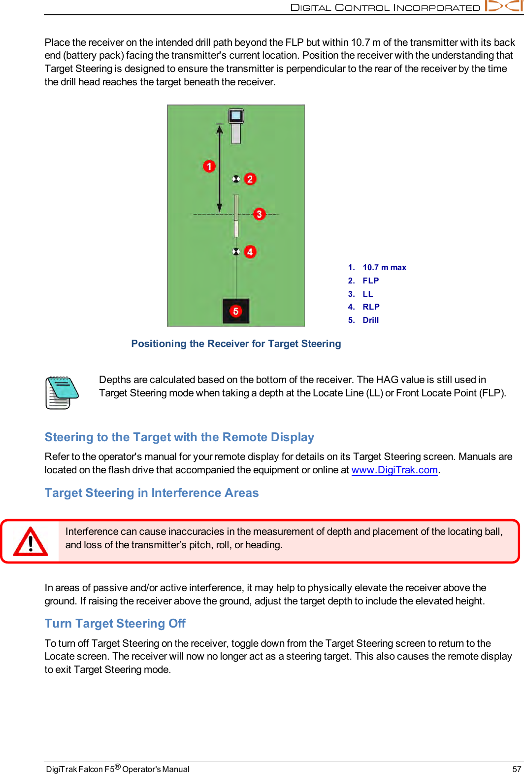
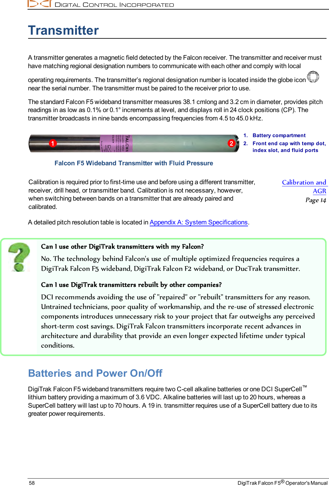
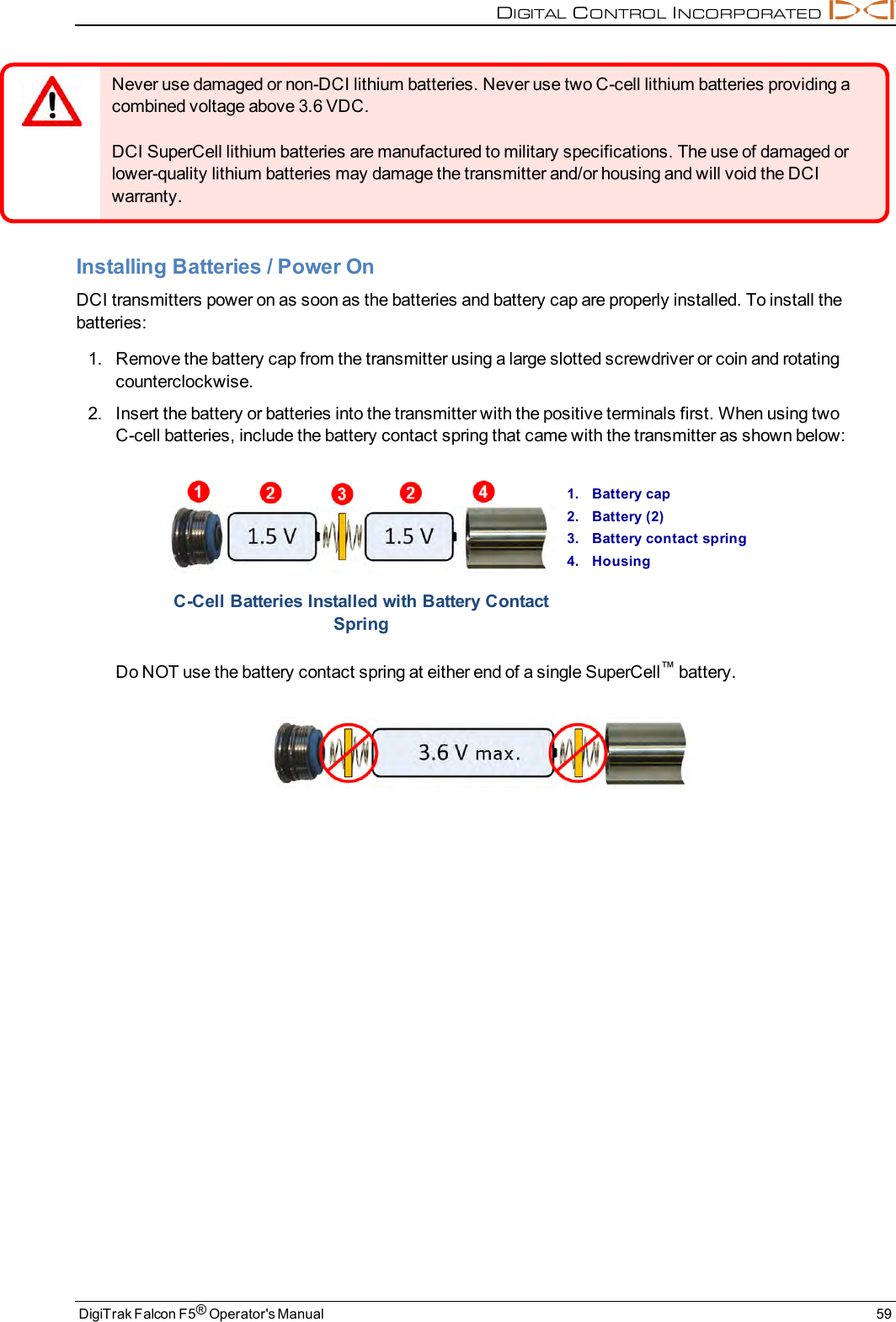
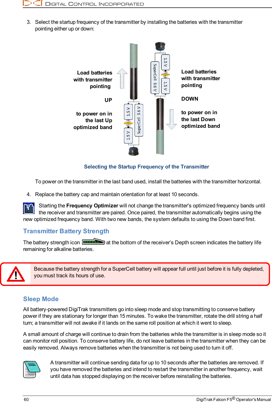
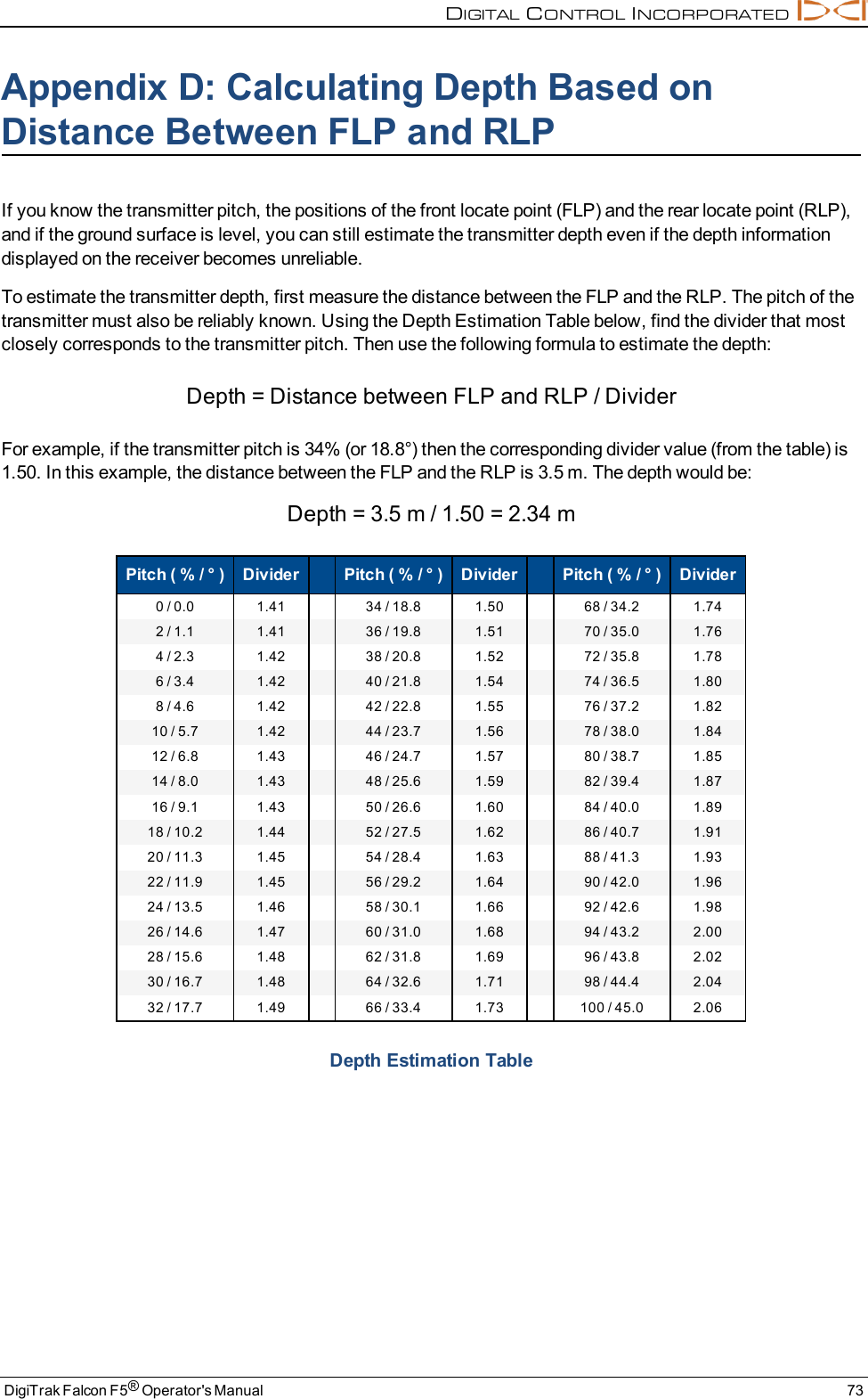
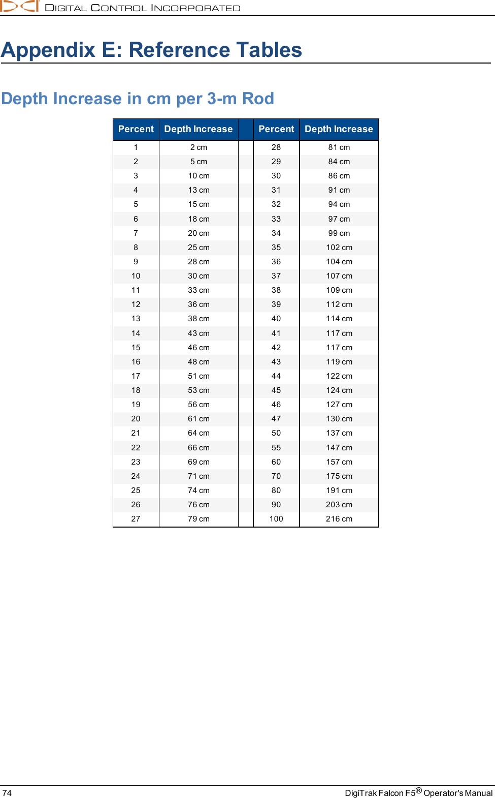
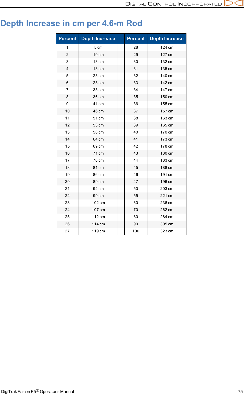
User Manual
Discussion / Help
Navigation