Digital Control Z22012 BTWL, BTPL User Manual DigiTrak Falcon F5 OM draft
Digital Control Inc BTWL, BTPL DigiTrak Falcon F5 OM draft
UserManual.wiki
>
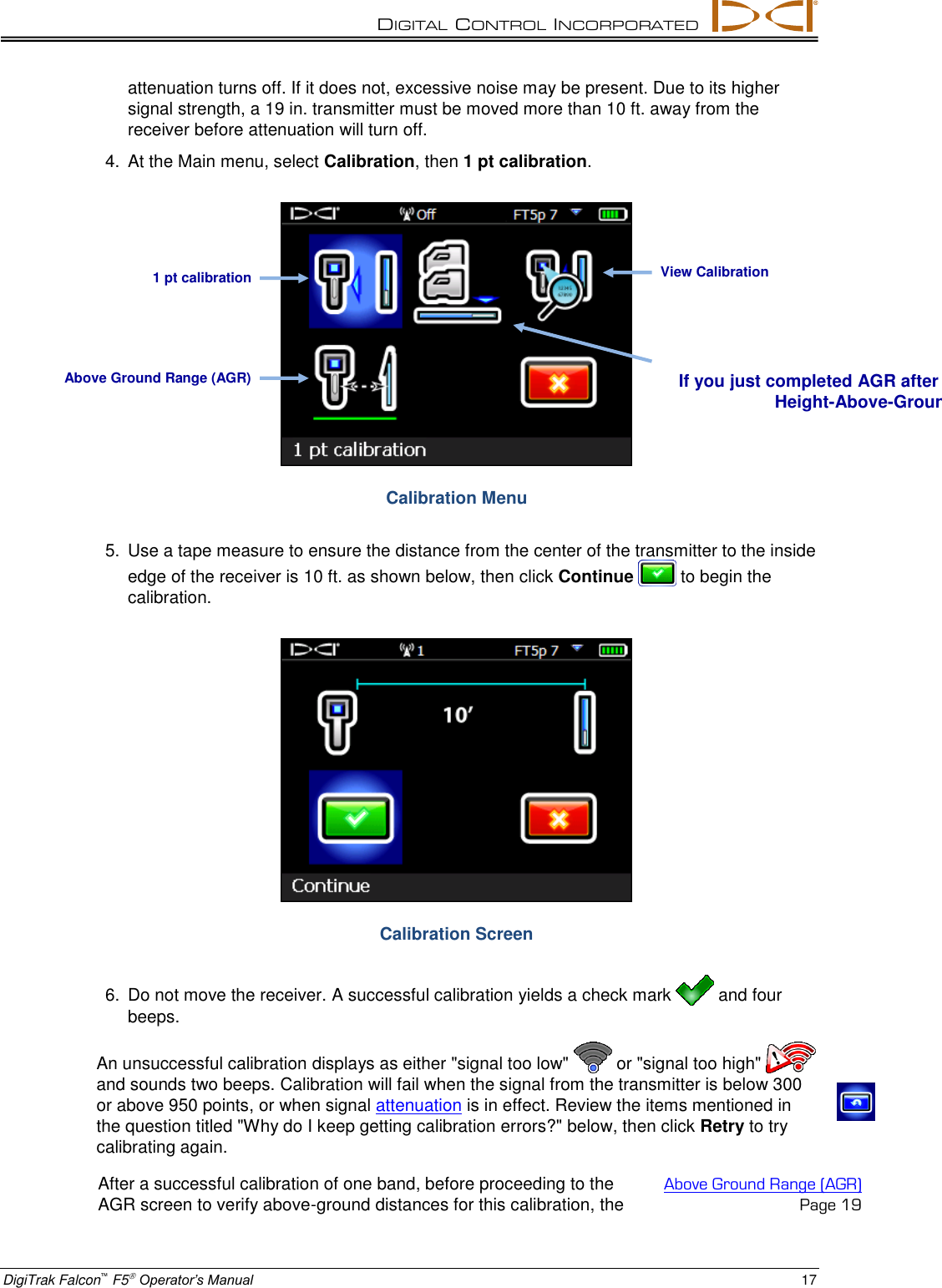
Digital Control
>
Z22012 User Manual
User Manual
Navigation menu
Upload a User Manual
Namespaces
Wiki Guide
HTML
PDF
Info
Views
User Manual
Discussion / Help
Navigation