Digital Monitoring 1100 SPREAD SPECTRUM TRANSMITTER User Manual MANUAL
Digital Monitoring Products Inc SPREAD SPECTRUM TRANSMITTER MANUAL
MANUAL
INSTALLATION SHEET
1100 Receiver
Description
The 1100 Receiver provides 500 wireless zones for DMP Command Processor™ panels. The receiver and housing
easily mount near the panel enclosure or in a remote location. Providing a wide reception range, a fast scan time
of available frequencies, and two-way communication with transmitters, the 1100 Receiver is a simple and robust
solution to problematic hardwired systems. The 1100 Receiver is compatible with all DMP 1100 series devices.
Compatibility
The 1100 Receiver is compatible with the following panels.
• XR500
• XRSuper6
• XR20
• XR40
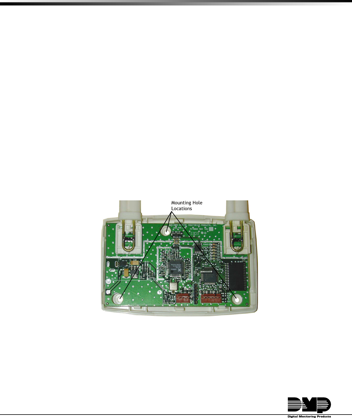
Installing the 1100 Receiver
Mounting in a Remote Location
Choose an optimum location to mount the receiver. Be sure to install the receiver no more than 1,000 feet from the
panel. Remove the cover from the plastic casing. Secure the casing back and printed circuit board (PCB) to the wall
in the desired location using the supplied screws. Snap the cover back on the unit.
FCC Note: The antenna(s) used for this transmitter must be installed to provide a separation distance
of at least 20 cm from all persons. It must not be co-located or operated in conjunction with any other
antenna or transmitter.
Figure 1: Receiver PCB and back case
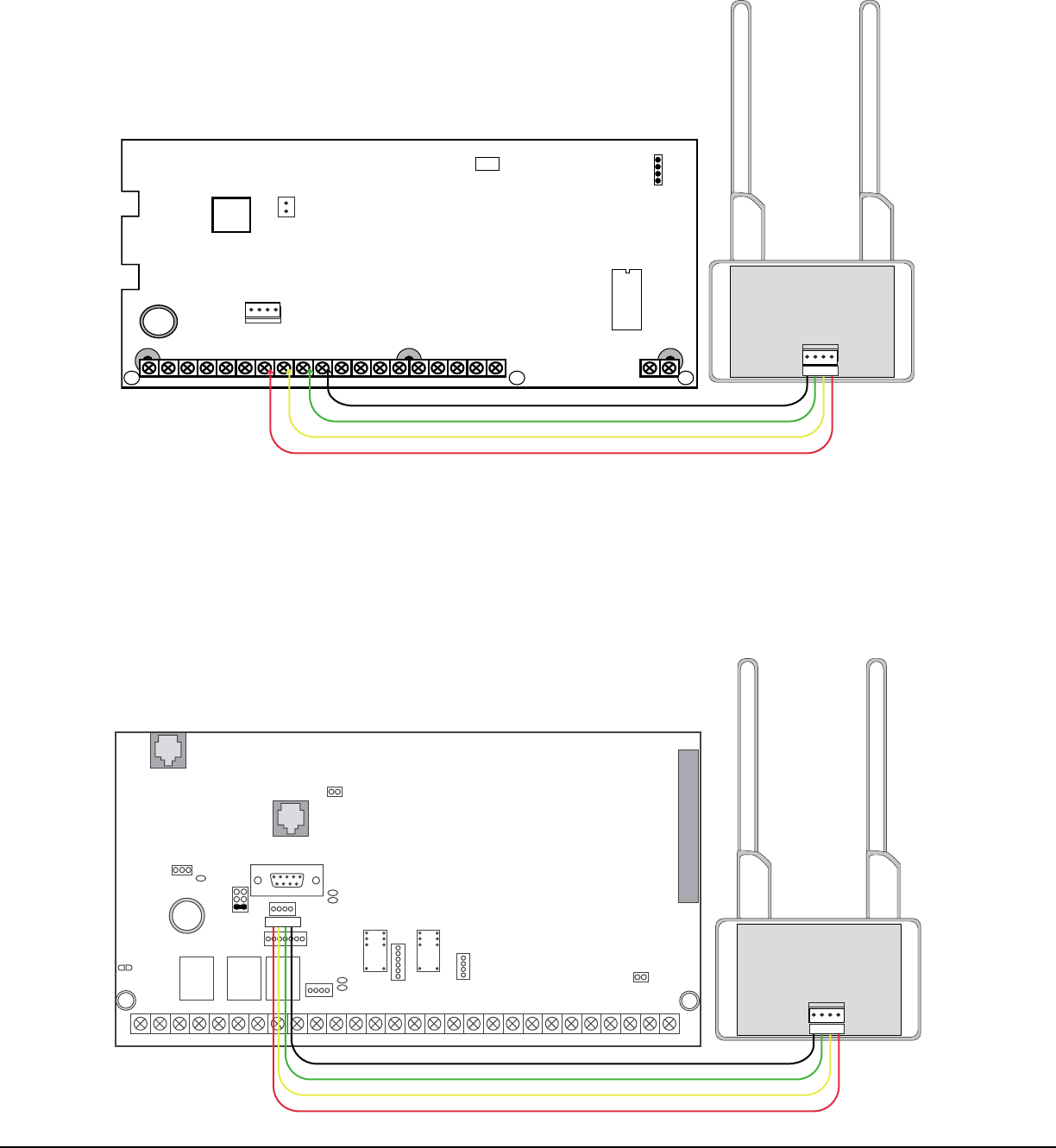
Wiring
The 1100 Receiver easily interfaces with the XRSuper6, XR20, or XR40 Command Processor™ panels using the keypad
bus. On the XR500 Command Processor™ panel set J23 for wirelss operation and connect the 4-wire harness to J22.
Digital Monitoring Products 1100 Receiver Installation Sheet
2
Keypad Bus Wiring
Connect the 4-wire harness from the 1100 Receiver to the keypad bus terminals 7, 8, 9, and 10. Connect the other
end of the 4-wire harness to J3 on the 1100 receiver PCB. Figure 2 shows a sample XRSuper6/XR20/XR40 panel
keypad bus terminal wired to the 1100 Receiver.
AC
1234567810 11 12 13 14 15 16 17 18 19
920 21
+B BELL GND SMK GND
RED YEL GRN BLK Z1 Z2 Z3 Z4 Z5 Z6+ Z6-
AC -B GND GND
J3
RED
PROG
J8 Programmer Header J8
Use DMP Model 330 Programming Harness
XRSuper6/
XR20/XR40
J16
Command
Processor Reset
J7 RJ Cable Monitor
Use DMP Model 306 Harness
J7
RJ SUP
J11
1
2
3
4
Output
Header
DMP 1100 Wireless Receiver
J3
Red
Black
Green
Yellow
Red
Figure 2: XRSuper6/XR20/XR40 keypad bus wiring
XR500 Panel Wireless Wiring
To enable XR500 Wireless operation install a jumper on the J23 6-pin header lower position next to the letter "X".
Reset the panel using J16 jumper to activate wireless operation. Use a standard 4-wire harness to connect to
Jumper J22 on the XR500 control panel. Connect the other end of the 4-wire harness to J3 on the 1100 Receiver
PCB. If the XR500 J23 is set for RS-232 or LX-Bus operation, selecting wireless operation disables the previously
selected option. RS-232 or LX-Bus operation must be transferred to an interface card connected to J6 Interface Card
Expansion Connector.
AC
1 2 3 4 5 6 7 8 10 11 12 13 14 15 16 17 18 199202122232425262728
+B BELL GND SMK GNDRED YEL GRN BLK Z1 Z2 Z3 Z4 Z5 Z6 Z7 Z8 Z9+ Z9– Z10+ Z10–AC –B GND GND GNDGND
K6 K7
Output 1 Output 2
J3
Phone Line
J10
J22
LX-Bus
Battery
Start
J23
J21
RS-232
Power
LED
J8
PROG
J4
Tamper
J16
Reset
Out1 Out2
Outputs 3-6
J11
3
4
5
6
J2
J1
Ethernet
J6
Interface
Card
Expansion
Connector
XR500/XR500N
Command Processor™
Panel
R
L
X
J12 56
40
DMP 1100 Wireless Receiver
J3
Red
Black
Green
Yellow
Red
Red
Figure 3: XR500 wireless wiring

1100 Receiver Installation Sheet Digital Monitoring Products
3
Programming the Panel
Before operating the 1100 Receiver, you must program the panel to recognize the 1100 Receiver. Enter panel
programming and press the COMMAND key to display Wireless Options. Program the 1100 Receiver and keyfobs in
this portion of panel programming.
WIRELESS OPTIONS
Wireless Options
Press the COMMAND key until Wireless Options displays. Press any top row Select Key
to enter Wireless Options programming.
RECEIVER ID:
Receiver IdentiÞ cation
Ensure the XR500 panel is set for wireless operation. Refer to XR500 Panel Wireless
Wiring on the previous page. The panel senses and automatically displays the receiver
identiÞ cation number. Press the COMMAND key to accept the Receiver ID and display
the check-in time prompt.
CHECKIN: 30
30 60 120 180
Check-in Time
The 1100 Receiver tells the 1101 Transmitter how long the transmitter waits before
checking in with the Receiver. Select the number of seconds the 1100 Receiver sends
to the transmitter to indicate the Check-in Time. Press any Select Key to change the
Check-in Time. Enter the number of seconds for the transmitter to wait. The default
is 30 seconds. Press the COMMAND key to accept the Check-in Time and display the
keyfobs programming prompt.
KEYFOB 1
Keyfob 1
Use the following prompts to program up to four keyfobs to use with this receiver.
Press any Select Key to enter Keyfob 1 Programming.
SERIAL NO:
Serial Number
Enter the keyfob serial number located on the casing back. Each keyfob has a unique
serial number. Do not lose the serial number. Do not use the same serial number
for more than one keyfob. Press the Back Arrow key to make corrections. Press the
COMMAND key to accept the serial number and display the Output Number option.
OUTPUT NO: 0
Output Number
The fourth button on the keyfob is programmed to trip an output. Enter the output
number that this keyfob trips when pressed. For example, the output number could
be the output that controls the garage door opener. Press the Back Arrow key to
make corrections. Press the COMMAND key to accept the output number and begin
programming the next keyfob. After programming all keyfobs, press the COMMAND key
to exit Wireless Options programming.
Note: These prompts repeat for Keyfob 2, Keyfob 3, and Keyfob 4. Repeat these
programming options for each keyfob used in the system.
Program transmitters in panel programming Zone Information.
XR500 Programming
After programming Wireless Options and all the keyfobs save the information. Press the COMMAND key until STOP
displays. Press any top row Select Key to run the Stop routine. When any panel programming is changed, the Stop
routine must run and "SAVING PROGRAM" must displays on the keypad in order to save the programming changes.

LT-0692 (11/03) © 2003 Digital Monitoring Products, Inc.
INTRUSION • FIRE • ACCESS • NETWORKS
2500 North Partnership Boulevard
800-641-4282
www.dmp.com
Made in the USA SpringÞ eld, Missouri 65803-8877
FCC Information
This device complies with Part 15 of the FCC Rules. Operation is subject to the following two conditions:
(1) This device may not cause harmful interference, and
(2) this device must accept any interference received, including interference that may cause undesired operation.
Changes or modiÞ cations made by the user and not expressly approved by the party responsible for compliance could
void the user’s authority to operate the equipment.
NOTE: This equipment has been tested and found to comply with the limits for a Class B digital device, pursuant
to part 15 of the FCC Rules. These limits are designed to provide reasonable protection against harmful
interference in a residential installation. This equipment generates, uses and can radiate radio frequency
energy and, if not installed and used in accordance with the instructions, may cause harmful interference
to radio communications. However, there is no guarantee that interference will not occur in a particular
installation. If this equipment does cause harmful interference to radio or television reception, which
can be determined by turning the equipment off and on, the user is encouraged to try to correct the
interference by one or more of the following measures:
- Reorient or relocate the receiving antenna.
- Increase the separation between the equipment and receiver.
- Connect the equipment into an outlet on a circuit different from that to which the receiver is connected.
- Consult the dealer or an experienced radio/TV technician for help.