Digital Monitoring PC0088 SPREAD SPECTRUM TRANSMITTER User Manual LT 0695 PIR 8 04 indd
Digital Monitoring Products Inc SPREAD SPECTRUM TRANSMITTER LT 0695 PIR 8 04 indd
USERS MANUAL
INSTALLATION SHEET
FIELD TEST VERSION 7/28/2004
1125 PIR Motion Detector
Description
The 1125 PIR (Passive Infrared) Motion Detector is a wireless, low current sensor for use with the 1100D Wireless
Receiver. Using mirrored optic technology the 1125 PIR is highly immune to multiple false alarm sources. In addition
to switch-selectable sensitivity and range adjustment, you can use masking to modify coverage patterns for various
applications.
Parts Included
• One PIR detector
• Three 3V lithium CR-123A batteries
• Two plastic masks
• One screw to secure the unit to the wall mounting bracket
• One wall-mounting bracket
• One sheet of adhesive masking labels
• One cardboard undercrawl window mask
For your convenience, two additional pre-printed serial number
labels are included. Verify the serial numbers on the labels match
the serial number located on the back of the device housing. Prior
to installing the device, record the serial number located on the
back of the device housing or place one of the pre-printed serial
number labels on the panel programming sheet. This number is
required during programming.
Selecting a Location
Mount the unit:
• On a rigid vibration-free surface
• 6 to 10 feet (1.8 to 3m) high, but at least 6 inches (15cm) from the ceiling
• So the expected intruder movement is across the detection pattern elds, see Figure 2
Do not locate the unit:
• On a surface exposed to moisture
• In any area containing excessive metallic surfaces
• Where it may be exposed to false alarm sources such as: direct sunlight, heat sources (heater, radiators, etc.)
in the eld of view or strong air drafts (fans, air conditioner, etc.)
• Where the ambient temperature is below 32° F (0°C) or above 131°F (55°C)
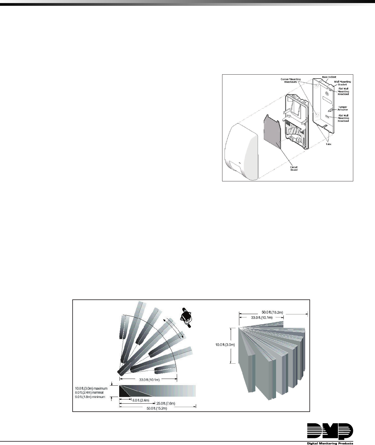
Figure 2: Detection Pattern
Figure 1: 1125 PIR Exploded View
Digital Monitoring Products 1125 PIR Installation Sheet
2
1125 PIR Installation Sheet Digital Monitoring Products
3
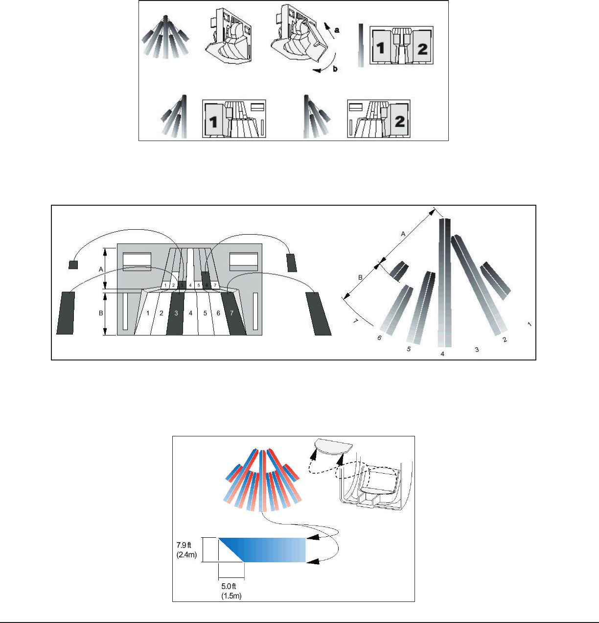
Selecting the Coverage Pattern
The unit coverage pattern can be modied to t specic applications by masking mirror curtains. Mask curtains to
avoid sources of false alarms, such as heaters, air conditioners, and windows. Open the unit by pushing the opening
tab up. If necessary, use one or more of the following methods to modify the coverage pattern.
Using the plastic masks
Use one or both of the plastic masks provided to mask off large coverage areas as shown in Figure 3.
Figure 3: Plastic Masks
Using the adhesive labels
Mask the appropriate mirror curtains with the provided adhesive labels. See the example shown in Figure 4. Do not
use sharp objects to remove unwanted labels. If necessary, carefully peel off the label.
Figure 4: Adhesive Labels
Using the cardboard masks
Use the cardboard undercrawl window mask as shown in Figure 5. The undercrawl mask allows objects to be placed
within 5 feet of, or directly below, the detector. When not using the mask as described here or in the Pet Alley
conguration, remove the mask completely.
Figure 5: Cardboard Masks

Digital Monitoring Products 1125 PIR Installation Sheet
2
1125 PIR Installation Sheet Digital Monitoring Products
3
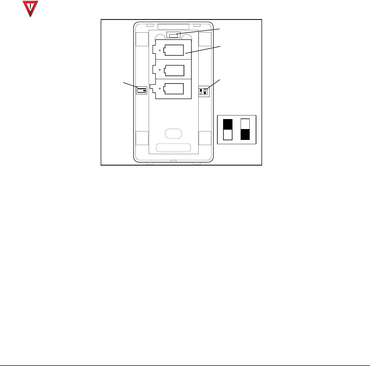
Setting the Sensitivity and Range Switches
Use the switches located on the unit back to set sensitivity and range, as shown in Figure 6. Use the following to
determine the appropriate switch settings for an application.
Mode
BI = Bi-curtain Mode (factory default) increases false alarm immunity in smaller areas and requires an intruder
to pass through two curtains to trigger an alarm. Do not use for single curtain applications or ranges under 5 feet
(1.5 m).
STD = Standard Mode is used for wide-angle or single-curtain applications. This requires the intruder to only pass
through one curtain to trigger an alarm.
Range
Program the switch for a range under 33 feet (10.1 m) or up to 50 feet (15.2 m). It is important to program the unit
correctly for optimum sensitivity. Walk test the unit regularly by walking across the elds of view and checking that
the LED lights and that an alarm is indicated at the control panel. See Walk Testing.
Note: The LED only lights if the unit is placed in Walk test Mode by the installer and the unit is enrolled in the
system.
Mounting the Unit
Caution: You must be free of static electricity before handling sensor circuit boards. Touch a grounded, bare
metal surface before touching circuit boards or wear a grounding strap.
Prior to permanently mounting the PIR unit, access the device address label and check that the PIR and control
panel communication is working. See the Walk Testing section.
FCC Considerations
The antenna used for this transmitter must be installed to provide a separation distance of at least 20 cm from all
persons. It must not be co-located or operated in conjunction with any other antenna or transmitter.
1. Separate the PIR unit from the mounting bracket. Refer to Figure 1 for details.
2. Insert a small at-head screwdriver between the tabs at the unit bottom and turn the screwdriver to push the
tabs apart.
3. Select the appropriate knockout mounting holes on the mounting bracket for either corner or at wall
mounting.
Note: Holes near the tamper actuator are not mounting knockouts.
4. Use screws and wall anchors, if necessary, to attach the mounting bracket to the wall. Do not over-tighten.
5. Snap the unit to the mounting bracket.
Digital Monitoring Products 1125 PIR Installation Sheet
4
1125 PIR Installation Sheet Digital Monitoring Products
5
Installing or Replacing Batteries
Note: You must remove all batteries to reset the low battery signal before installing new batteries. Always replace
all three batteries. Allow three minutes after installing the batteries for the sensor to become operational before
initiating a Walk Test.
Use only 3V lithium CR-123A batteries. Use the following steps to install the batteries:
1. Remove the unit from the wall mounting bracket. See Mounting the Unit.
2. Remove all batteries (if installed) before installing new batteries.
3. Observe polarity and insert the three lithium batteries into the battery holder where indicated in Figure 6.
Caution: Risk of re, explosion, and burns. Do not recharge, disassemble, heat above 212°F (100°C), or
incinerate. Properly dispose of unused batteries.
Tamper
Opening Tab
Battery
Compartment
Switches
Switch Settings
33'
(10.1m)
50'
(15.2m)
STD
BI
Figure 6: 1125 PIR Switches
Programming the PIR in the Panel
Refer to the panel programming guide as needed. Program the device as a zone in Zone Information during panel
programming. Typically select the Night or Exit zone type for the 1125 PIR. At the Serial Number: prompt, enter the
serial number recorded from the back of the device case. Continue to program the zone as directed in the panel
programming guide.
Note: When a receiver is installed or powered down and powered up or the panel is reset, the supervision timer
cycle restarts.
Note: You can re-use a device in another system after the serial number has been previously programmed. Remove
the device battery, press and hold the tamper switch for one second to clear the panel house code from the device
memory and set the device back to factory defaults.
Digital Monitoring Products 1125 PIR Installation Sheet
4
1125 PIR Installation Sheet Digital Monitoring Products
5
PIR Walk Testing
A Walk test Mode for testing the unit operation and coverage pattern is provided. Use the following instructions to
walk test the unit:
1. Ensure the 1125 PIR is programmed in the Command Processor™ panel.
2. Lift the unit from the bracket until the tamper switch opens to enable the Walk test Mode.
3. When the unit is remounted on the bracket, the unit remains in the Walk test Mode for 3-4 minutes. If
additional time is required, depressing and releasing the tamper switch resets the Walk test timer. Depending
on switch settings (see Selecting the Coverage Pattern), the Walk test Mode allows the unit to alarm whenever
one or two curtain areas are entered. The LED visible on the front cover lights to indicate an alarm.
4. Walk test the detection pattern and make any necessary adjustments.
5. Replace and walk test the unit to verify the unit is communicating with the control panel.
Note: After Walk test Mode times out (3 to 4 minutes), the unit returns to normal operating mode. In normal
operating mode, the PIR unit activates approximately once every three minutes, and the LED disables to reduce
battery drain.
Maintenance
When installed and used properly, the unit provides years of service with minimal maintenance. To ensure proper
operation, you should walk test the unit annually as described in Walk Testing. Clean the inside of the unit with a
soft bristled brush or compressed air. Clean the cover with a water dampened cloth as needed to keep it free of
dust and dirt. Always test the unit after cleaning.
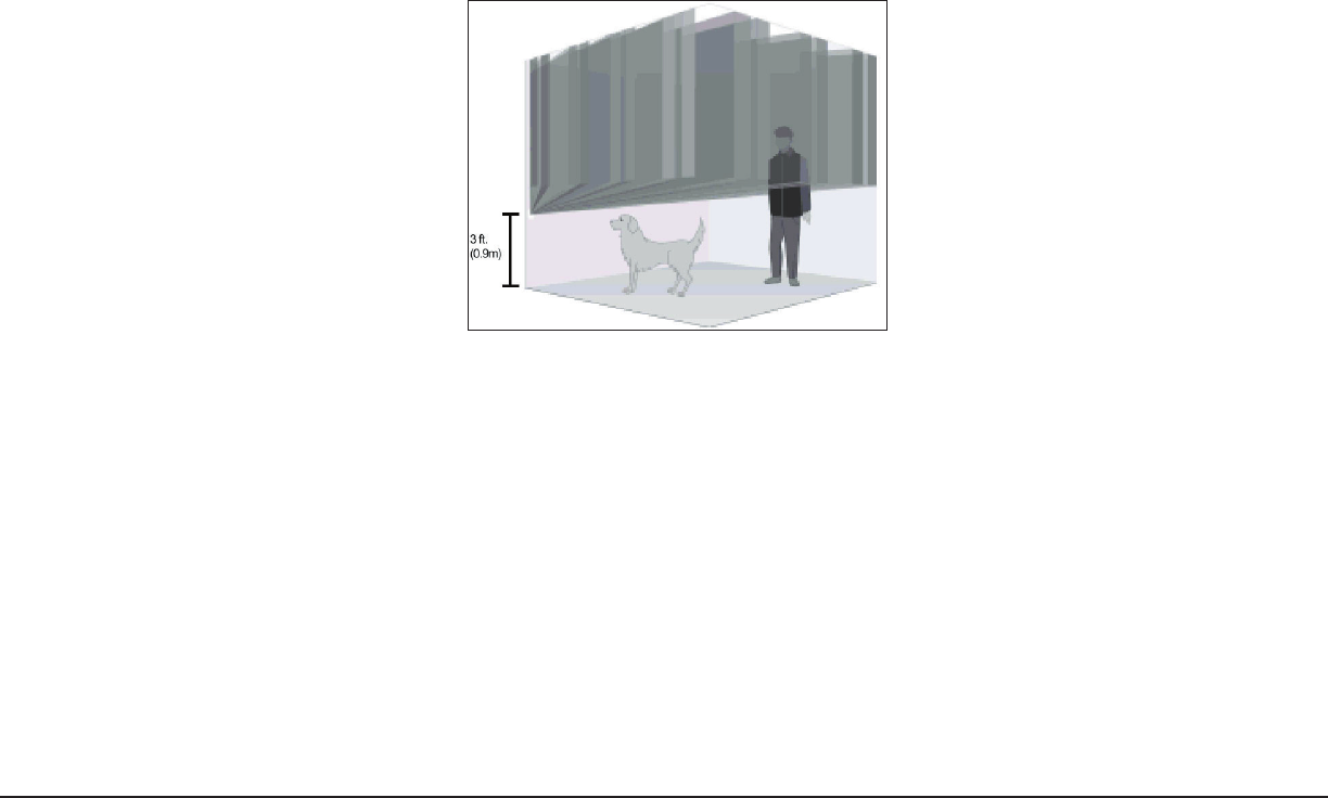
Pet Alley Application
To create a detection-free area close to the oor, mount the unit 3 feet (0.9 m) above the oor, upside down with
the detector window toward the ceiling. The undercrawl mask should be in place to reduce ceiling exposure.
Coverage distance is 25 feet in Bi-curtain Mode. As shown in Figure 7, pets are free to roam below the unit
mounting height without causing alarms. When not using the mask as described here or in the Using the cardboard
masks conguration, remove the mask completely.
Figure 7: Pet Alley

LT-0695 (5/04) © 2004 Digital Monitoring Products, Inc.
800-641-4282
www.dmp.com
Made in the USA
INTRUSION • FIRE • ACCESS • NETWORKS
2500 North Partnership Boulevard
Springfield, Missouri 65803-8877
Specications
Battery
Life 1 year (min)
Type 3.0V Lithium CR-123A
Transmit condition Alarm, tamper
Detection range 50 feet (15.2 m)
Mounting height 6 to 10 feet (1.8 to 3m)
Number of curtains 9
Operating temp. 32 to 131° F (0 to 55° C)
Relative humidity 10 to 93% non-condensing
Dimensions 5.1” H X 2.9” W X 2.2” D
Color White
Housing material Flame retardant ABS
Patent Information
Protected under pending U.S. and foreign patents.
FCC Information
This device complies with Part 15 of the FCC Rules. Operation is subject to the following two conditions:
(1) This device may not cause harmful interference, and
(2) this device must accept any interference received, including interference that may cause undesired operation.
Changes or modications made by the user and not expressly approved by the party responsible for compliance could
void the user’s authority to operate the equipment.
NOTE: This equipment has been tested and found to comply with the limits for a Class B digital device, pursuant
to part 15 of the FCC Rules. These limits are designed to provide reasonable protection against harmful
interference in a residential installation. This equipment generates, uses and can radiate radio frequency
energy and, if not installed and used in accordance with the instructions, may cause harmful interference
to radio communications. However, there is no guarantee that interference will not occur in a particular
installation. If this equipment does cause harmful interference to radio or television reception, which can be
determined by turning the equipment off and on, the user is encouraged to try to correct the interference by
one or more of the following measures:
- Reorient or relocate the receiving antenna.
- Increase the separation between the equipment and receiver.
- Connect the equipment into an outlet on a circuit different from that to which the receiver is connected.
- Consult the dealer or an experienced radio/TV technician for help.