Digital Monitoring PC0096 FHSS TRANSMITTER User Manual USERS MANUAL
Digital Monitoring Products Inc FHSS TRANSMITTER USERS MANUAL
USERS MANUAL
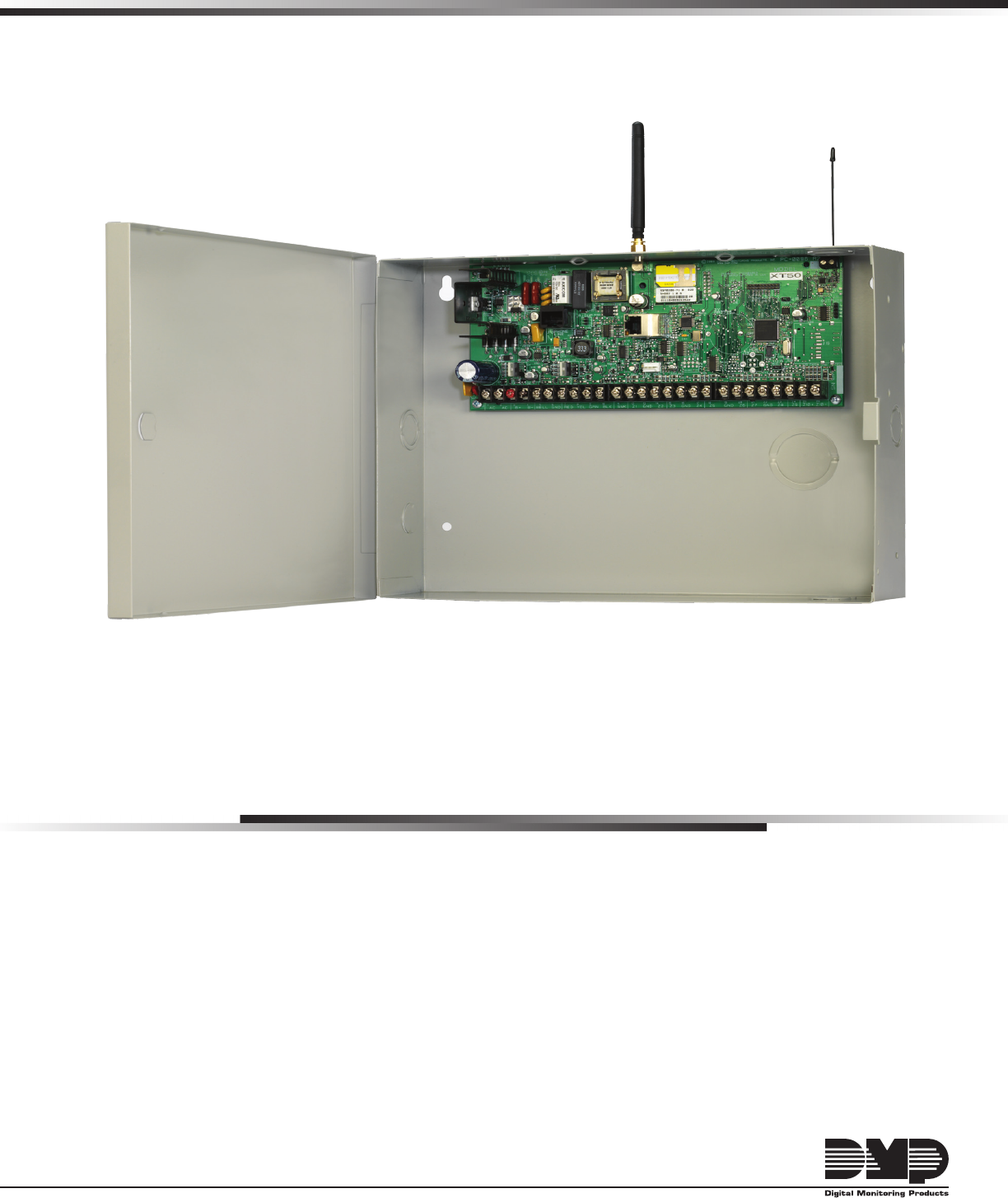
InstallatIon GuIde
Xt serIes™ Panels
MODEL XT30/XT50
XT SERIES™
INSTALLATION GUIDE
FCC NOTICE
This equipment has been tested and found to comply with the limits for a Class B digital device, pursuant
to part 15 of the FCC Rules. These limits are designed to provide reasonable protection against harmful
interference in a residential installation. This equipment generates, uses and can radiate radio frequency
energy and, if not installed and used in accordance with the instructions, may cause harmful interference
to radio communications. However, there is no guarantee that interference will not occur in a particular
installation. If this equipment does cause harmful interference to radio or television reception, which
can be determined by turning the equipment off and on, the user is encouraged to try to correct the
interference by one or more of the following measures:
Reorient or relocate the receiving antenna.•
Increase the separation between the equipment and receiver.•
Connect the equipment into an outlet on a circuit different from that to which the receiver is •
connected.
Consult the dealer or an experienced radio/TV technician for help.•
This device has been designed to operate with the antennas listed in the Accesory Devices section, and
having a maximum gain of 1.8 dB. Antennas not included in this list or having a gain greater than 1.8 dB are
strictly prohibited for use with this device. The required antenna impedance is 50 ohms.
If necessary, the installer should consult the dealer or an experienced radio/television technician
foradditionalsuggestions.Theinstallermayndthefollowingbooklet,preparedbytheFederal
Communications Commission, helpful:
“How to identify and Resolve Radio-TV Interference Problems.”
ThisbookletisavailablefromtheU.S.GovernmentPrintingOfce,WashingtonD.C.20402
StockNo.004-000-00345-4
©2008DigitalMonitoringProducts,Inc.
InformationfurnishedbyDMPisbelievedtobeaccurateandreliable.
This information is subject to change without notice.

XT30/XT50 Installation Guide Digital Monitoring Products
i
table of Contents
Panel Specications
1.1 Power Supply .........................................1
1.2 Communication .......................................1
1.3 Panel Zones ............................................1
1.4 Keypads/Expansion .................................1
1.5 Number of Zones ....................................1
1.6 Outputs ..................................................1
1.7 EnclosureSpecications ..........................1
Introduction
2.1 Description .............................................2
2.2 SystemCongurations .............................2
2.3 BeforeYouBegin ....................................2
2.4 About this Guide .....................................2
2.5 NRTL Compliance Instructions .................2
System Components
3.1 Description .............................................3
3.2 WiringDiagram .......................................3
3.3 LightningProtection ................................3
3.4 Accessory Devices ...................................3
3.4 Accessory Devices continued ...................4
3.5 XT30/XT50WiringDiagram .....................4
Installation
4.1 MountingtheEnclosure ...........................5
4.2 MountingKeypads ..................................5
4.3 InstallationSpecications ........................5
Primary Power Supply
5.1 AC terminals 1 and 2 ...............................6
5.2 Transformer Types ..................................6
Secondary Power Supply
6.1 Battery Terminals 3 and 4 ........................7
6.2 Earth Ground ..........................................7
6.3 Replacement Period ................................7
6.4 Discharge/Recharge ................................7
6.5 Battery Supervision .................................7
6.6 XT30/XT50 Power Requirements ..............7
6.7 XT30/XT50 Standby Battery Calculations ..8
Bell Output
7.1 Terminals 5 and 6 ...................................9
Keypad Data Bus
8.1 Description .............................................9
8.2 Terminal 7 - RED.....................................9
8.3 Terminal 8 - YELLOW ..............................9
8.4 Terminal 9 - GREEN.................................9
8.5 Terminal 10 - BLACK ...............................9
8.6 ProgrammingConnection ........................9
8.7 KeypadAddressing ..................................9
Smoke and Glassbreak Detector Output
9.1 Terminal 11 ............................................9
Burglary Zones
10.1 Description ...........................................10
10.2 Operational Parameters .........................10
10.3 Zone Response Time .............................10
10.4 KeyswitchArmingZone .........................10

Digital Monitoring Products XT30/XT50 Installation Guide
ii
table of Contents
Powered Zone for 2-Wire Smoke Detectors
11.1 Terminals 25 and 26 ..............................11
Annunciator Outputs
12.1 Description ...........................................12
12.2 HarnessWiring .....................................12
12.3 Model 860 Relay Module ........................12
Telephone RJ Connector
13.1 Description ...........................................13
13.2 FCCRegistration ...................................13
13.3 Notication ...........................................13
Ethernet Connector J1
14.1 Description ...........................................14
14.2 Ethernet LEDs ......................................14
Reset Jumpers J16
15.1 Description ...........................................14
Flash Load Jumper J18
16.1 Description ..........................................14
Cellular Connections
17.1 Cellular ...............................................15
On-Board 1100 Series Wireless Antenna Connections
18.1 Wireless Antenna .................................15
NRTL Listed Specications
19.1 Introduction .........................................16
19.2 Bypass Reports .....................................16
19.3 Current Draw ........................................16
Household Burglar-Alarm System Units ANSI/UL 1023
20.1 Bell Cutoff ............................................16
20.2 Entry Delay ..........................................16
20.3 Exit Delay .............................................16
20.4 Wireless External Contact ......................16
20.5 Wireless Supervision Time .....................16
20.6 Wireless Audible Annunciation ...............16
20.7 Panel location .......................................16
Digital Burglar Alarm Communicator System Units ANSI/UL 1635
21.1 Entry Delay ..........................................16
21.2 Exit Delay .............................................16
21.3 Test Frequency .....................................16
21.4 Automatic Bell Test ...............................16
21.5 Central Station ......................................16
Household Fire Warning System ANSI/UL 985 NFPA 72 Specications
22.1 BellOutputDenition ............................17
22.2 Household System ................................17
22.3 HouseholdFireWarning ........................17
22.4 Wireless External Contact ......................17
22.5 Wireless Supervision Time .....................17
22.6 WirelessFireVerication ........................17

XT30/XT50 Installation Guide Digital Monitoring Products
iii
table of Contents
California State Fire Marshal Specications
23.1 BellOutputDenition ............................17
False Alarm Reduction Programmable Options ANSI/SIA CP-01-2007
24.1 ShippingDefaultsandProgramming .......18
24.2 CallWaiting ..........................................19
24.3 Entry Delay ..........................................19
24.4 Local Bell .............................................19
24.5 Minimum Installation Requirements ........19
Troubleshooting
25.1 TroubleshootingSection ........................20
25.2 Common LCD Keypad Displays ...............20
Wiring Diagrams
26.1 MultipleIndicatingCircuitModules .........21
ListingsandApprovals .......................................22

XT30/XT50 Installation Guide Digital Monitoring Products
1
Panel sPeCIfICatIons
Panel Specications
1.1 Power Supply
TransformerInput: Plug-in—16.5VAC40VA,Model321
Wire-in—16.5VAC40VA,Model320
StandbyBattery: 12VDC7.7Ah(40VAtransformerchargesupto2batteries)
AuxiliaryOutput: 12VDCat500mA
BellOutput: 12VDCat1.5Amps
SmokeDetectorOutput: 12VDCat100mA
All circuits inherent power limited
Note:PleaseseeNRTL(NationalRecognizedTestingLaboratory)ListedSpecicationssectionforaNRTL
certicatedapplication.
1.2 Communication
Built-inSDLCDigitalDialercommunicationtoDMPModelSCS-1RReceivers
Built-innetworkcommunicationtoDMPModelSCS-1RReceivers
Built-incellularcommunicationtoDMPModelSCS-1RReceivers
Built-inCID(ContactID)dialercommunicationtonon-DMPreceivers
1.3 Panel Zones
Nine1kOhmEOLburglaryzones:zones1to9
One3.3kOhmEOLClassBpoweredrezonewithresetcapability:zone10
1.4 Keypads/Expansion
Youcanconnectuptovesupervisedkeypads.
• 32-characteralphanumerickeypads
Youcanconnectunsupervisedkeypads.
• 32-characteralphanumerickeypads
• SecurityCommand™, Thinline™, Aqualite™,ClearTouch™,andIconkeypads
Inaddition,thefollowingzoneexpanderscanbeadded:
• One,four,eightand16-zoneexpansionmodules
• Single-zonePIRandglassbreakdetectors
1.5 Number of Zones
Onboardzones1-10•
Fivekeypadbusaddresseswithzones11-14,21-24,31-34,41-44,and51-54(hardwiredorwireless)•
Zonenumbers31to34and41to44cansupport1100SeriesKeyFobsorDMPwirelessoutputmodules•
XT50has20additionalonboardwirelesszonesnumbered80-99•
1.6 Outputs
TheXT30/XT50panelsprovidefouropencollectoroutputsratedfor50mAeach.AModel300OutputHarness
is required. The open collector outputs provide the ground connection for a positive voltage source.
1.7 Enclosure Specications
TheXT30/XT50panelshipsstandardina340enclosurewithEOLresistors,batteryleads,user’sguide,and
programmingsheet.Allenclosuresareconstructedusing20-gaugecoldrolledsteel.
Enclosure
Model
Size Color
340 12.5”Wx9.5”Hx2.75”D Gray(G)
349 12.5”Wx11.25”Hx3.5”D Gray(G)

Digital Monitoring Products XT30/XT50 Installation Guide
2
IntroduCtIon
Introduction
2.1 Description
TheDMPXT30/XT50panelsare12VDCcombinationburglaryandresidentialrealarmpanelswithbattery
backup.TheXT30andXT50panelsprovidenineon-boardburglaryzonesandoneon-board12VDCClassB
poweredrezone.Therezonehasaresetcapabilitytoprovidefor2-wiresmokedetectors,relays,or
otherlatchingdevices.ThepanelscancommunicatetoDMPSCS-1RReceiversusingSDLCdigitaldialer,IP
Network,orCellularreportingformats.ContactIDreportingisalsoavailabletoCIDcompatiblereceivers.
TheXT30has10onboardzonesand5keypadbusaddressesfor20hardwiredorwirelesszonesforatotalof
30zones.TheXT50has10onboardzones,5keypadbusaddressesfor20hardwiredorwirelesszones,and20
additionalonboardwirelesszonesforatotalof50availablezones.
2.2 System Congurations
The panels can be programmed to operate as either an All/Perimeter system that provides one perimeter
areaandoneinteriorarea,orasaHome/Sleep/Awaysystemthatprovidesoneperimeter,oneinterior,and
one bedroom area. The bedroom area provides for any protection devices the user wants disarmed during
theirsleepinghoursandarmedintheAwaymode.Inaddition,theXT30/XT50canoperateasafourarea
system.
2.3 Before You Begin
Beforeinstallingthepanel,werecommendyoureadthroughtheentirecontentsofthisguide.Familiarize
yourselfwiththefeaturesofthepanelandthekeypointstorememberduringtheinstallation.Besureto
read and understand all of the caution statements printed in bold italics. In addition to this installation
guide,youshouldalsoreadthroughandfamiliarizeyourselfwiththeseotherproductdocuments:
• XT30/XT50ProgrammingGuide
• XT30/XT50User’sGuide
2.4 About this Guide
Theinformationcontainedinthisguideisorganizedintovesections:
• The Table of Contents at the front of this guide lists all of the headings and the page number where
the information can be found.
• TheIntroduction section gives you an overview of the various components that go into a
panelsystemanddiagramssometypicalsystemcongurations.
• TheInstallation sectionbeginswithmountinginstructionsfortheenclosureandtakesyouthroughthe
proper way to power up the panel prior to programming.
• TheWiring Diagram section provides common system drawings for the panels.
Caution notes
Throughoutthisguideyouwillseecautionnotescontaininginformationyouneedtoknowwheninstalling
thepanel.Thesecautionsareindicatedwithayieldsign.Wheneveryouseeacautionnote,makesureyou
completely read and understand its information. Failing to follow the caution note can cause damage to the
equipmentorimproperoperationofoneormorecomponentsinthesystem.Seetheexampleshownbelow.
Always ground the panel before applying power to any devices: The panel must be properly grounded
before connecting any devices or applying power to the panel. Proper grounding protects against
ElectrostaticDischarge(ESD)thatcandamagesystemcomponents.
Remove All Power From the Panel! Remove all AC and Battery power from the panel before installing or
connecting any modules, cards, or wires to the panel.
2.5 NRTL Compliance Instructions
ForapplicationsthatmustconformtoalocalauthoritiesinstallationstandardoraNRTL(NationalRecognized
TestingLaboratory)certicatedsystem,pleaseseetheNRTLListedSpecicationssectionneartheendofthis
guide for additional instructions.

XT30/XT50 Installation Guide Digital Monitoring Products
3
system ComPonents
System Components
3.1 Description
ThebasicXTSeriessystemismadeupofanalarmpanelwithbuiltincommunications,anenclosure,a16.5
VACtransformer,anda12VDCbattery.Youcanaddkeypadstothesystemandauxiliarydevicestothe
panel’sopencollectoroutputstoexpandthesystem.Combinedcurrentrequirementsofadditionalmodules
mayrequireanauxiliarypowersupply.RefertotheStandbyBatteryPowerCalculationsectioninthisguide
when calculating power requirements.
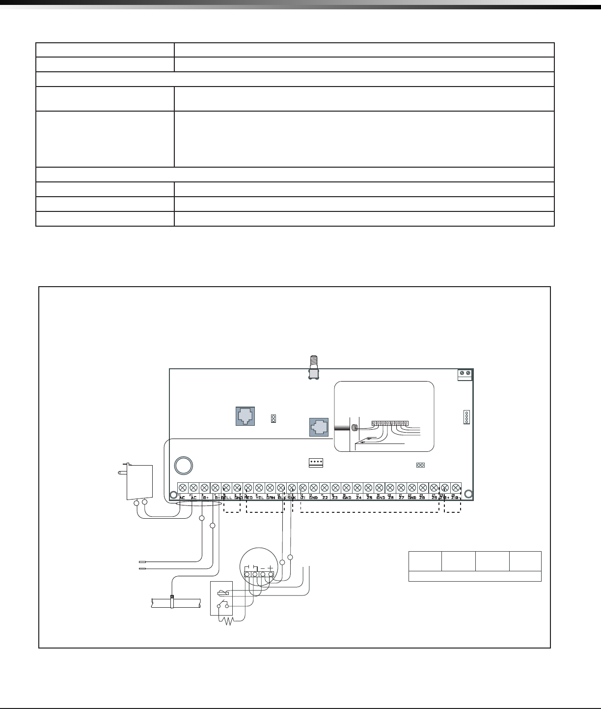
3.2 Wiring Diagram
The system wiring diagram in Figure 1 on the following page, shows some of the accessory devices you can
connect for use in various applications. A description of each module follows.
3.3 Lightning Protection
MetalOxideVaristorsandTransientVoltageSuppressorshelpprotectagainstvoltagesurgesoninputand
output circuits. This transient protection provides additional resistance to electrical surges such as lighting.
AdditionalsurgeprotectionisavailablebyinstallingtheDMP370or370RJLightningSuppressors.
3.4 Accessory Devices
Zone and Output Expansion Modules
710BusSplitter/Repeater Allowsyoutoincreasekeypadwiringdistanceto2500feet.
711SinglePointZoneExpander ProvidesoneClassBzoneforconnectingburglarydevicesandnon-poweredredevices.
714,714-8,714-16ZoneExpander
ProvidesClassBzonesforconnectingburglaryandnon-poweredredevices.
712-8ZoneExpander Provides8zonesforconnectingburglarydevices.
715,715-8,715-16Zone
Expander
Provides12VDCClassBpoweredzonesforconnectingsmokedetectors,glassbreak
detectors,andother2-or4-wiredevices.
860RelayOutputModule Providesthreeadditionalsocketsforexpansionofuptofourrelays.
Interface Card
734WiegandInterfaceCard Provides system codeless entry, and arming and disarming using access control readers.
DMP Two-Way Wireless Devices
1100D/1100DH/1100DIWireless
Receiver
Supportstransmittersinresidentialorcommercialwirelessoperationoffofthekeypadbus.
OnlyneededforXT30
1101UniversalTransmitter Provides both internal and external contacts that may be used at the same time to yield two
individualreportingzonesfromonewirelesstransmitter.
1102UniversalTransmitter Provides an external contact.
1114Four-ZoneExpander Providesfourwirelesszones
1116RelayOutput Provides one Form C relay
1117LEDAnnunciator Provides a visual system status indicator
1121PIRMotionDetector Provides motion detection with pet immunity.
1125PIRMotionDetector
Providesmultiplelenscongurations,dualcoverageareaselection,andsensitivityadjustments.
1129GlassbreakDetector Detects the shattering of framed glass mounted in an outside wall and provides full-pattern
coverage and false-alarm immunity.
1131RecessedContact
Provides concealed protection for doors, windows or other applications needing a discreet contact
.
1139BillTrap Providesasilentalarmoptionforretailandbankingcashdrawers.
1142BCTwo-buttonPanicBelt
Clip Transmitter
Provides portable two-button panic operation.
1142Two-buttonPanic
Transmitter
Provides permanently mounted under-the-counter two-button panic operation.
1145(Four-Button)
1146(Two-Button)
1147(One-Button)
KeyFobtransmittersdesignedtoclipontoakeyringorlanyard.
Digital Monitoring Products XT30/XT50 Installation Guide
4
system ComPonents
3.4 Accessory Devices continued
1161ResidentialSmokeDetector Residentialsmokedetectorwithsounder.
1162ResidentialSmokeDetector Residentialsmoke/heatdetectorwithsounderandxedrate-of-riseheatdetector
Keypads
ePAD™VirtualKeypads Allows users to control the security system from any computer in the world using the
Internet.
LCDkeypads Allowsyoutocontrolthepanelfromvariousremotelocations.Connectuptovekeypads.
Model690,790,693/793SecurityCommand™keypads,7060,7063,7070,7073,7160,7163,
7170,7173Thinline™keypads,7060A,7063A,7070A,7073AAqualite™keypads,7360,7363
Thinline Icon
Serieskeypads,or7760ClearTouch™keypadtothekeypadbususingterminals
7,8,9,and10.
Cellular Antennas
383RubberduckStubAntenna ProvidesSMARubberduckAntennaforcellularconnection.
384MagneticMountAntenna ProvidesSMAMagneticMountAntennaforcellularconnection.
385DualBandSmartdiscAntenna
ProvidesSMADualBandSmartdiscAntennaforcellularconnection.
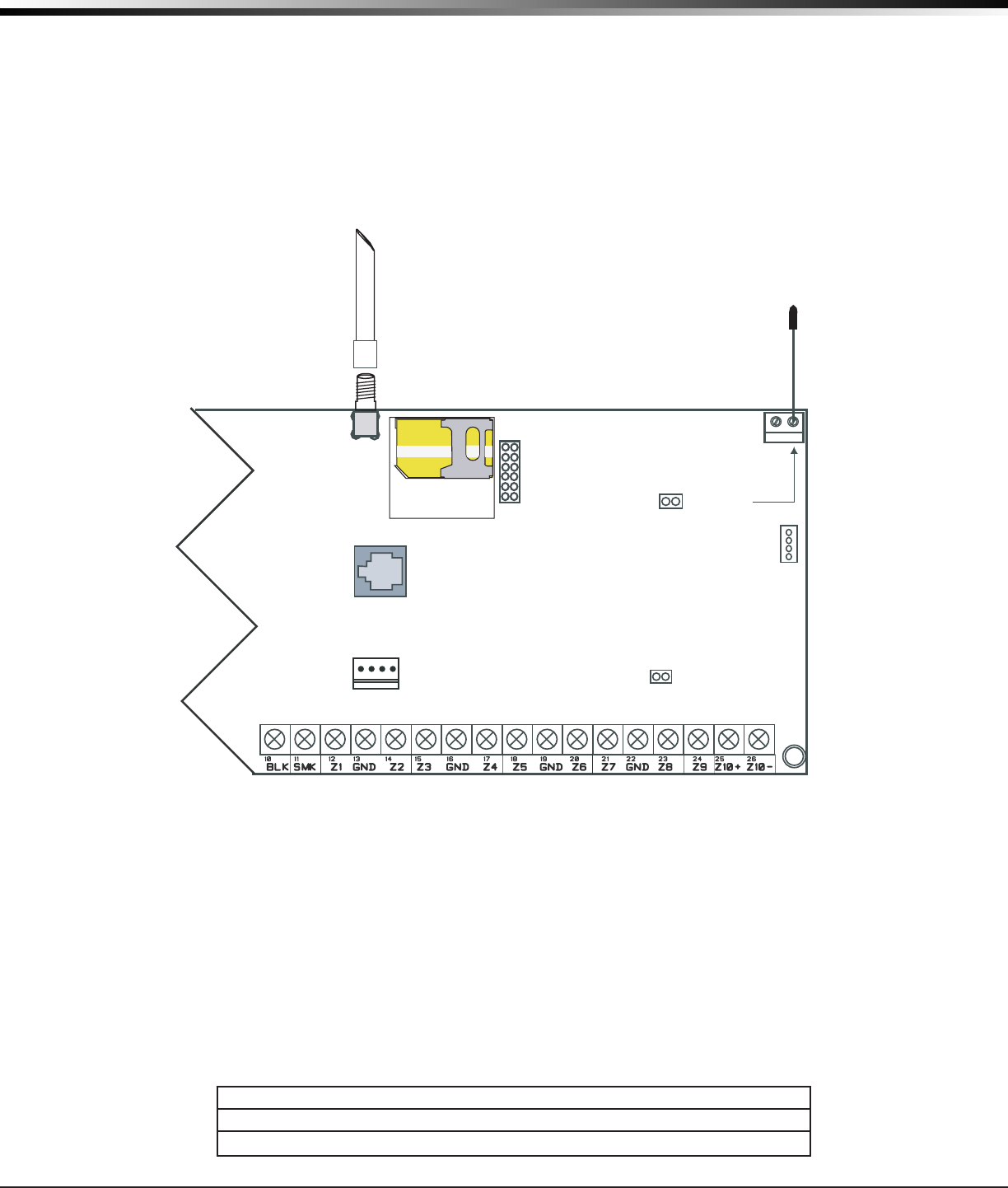
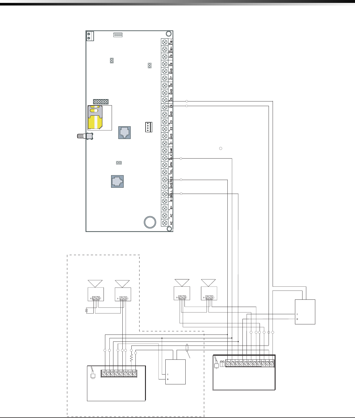
3.5 XT30/XT50 Wiring Diagram
16 to 18
gauge wire
Maximum AC
Wire distance ñ
16 gauge wire: 70 feet
18 gauge wire: 40 feet
RED
BLACK
Cold Water
Pipe Earth
Ground
s
s
s
s
USE MARKING
Commercial Burglary Control Unit (DACT)
Household Fire and Burglary Warning System
Control Unit.
NFPA 72
This equipment should be installed in accordance with Chapter 11
of the National Fire Alarm Code, ANSI/NFPA 72-2002, (National
Fire Protection Association, Batterymarch Park, Quincy, MA
02269). Printed information describing proper installation,
operation, testing, maintenance, evacuation planning, and repair
service is to be provided with this equipment. Warning: Ownerís
instruction notice, not to be removed by anyone except occupant.
HOUSEHOLD FIRE WIRING
Recognized limited energy cable must be
used for connection of all initiating,
indicating, and supplementary devices.
POWER LIMITED
All circuits on the Model XT30/XT50 comply
with the requirements for inherent power
limitation and are Class 2.
TYPES OF SERVICE
Suitable for DACT Central Station.
Suitable for Household Fire and
Household Burglary. Test weekly.
SIA CP-01-2007 minimum system is
XT30 or XT50, local Bell, and off premise
DACT communication to an
SCS-1R receiver plus ANSI/SIA CP-01-
2007 classified compatible DMP keypads
as indicated in the installation guide.
J3
Phone Line
Outputs
J11
1
2
3
4
J1
Ethernet
J16
Reset
J20
Wireless
Antenna
connection
J7 RJ
Supervision
J19 Celllular
Antenna
connection
XT30/XT50
Command Processorô Panel
RED
PROG
J8
Programmer Header J8
Use DMP Model 330 Harness
AC Wiring must be in conduit and exit out
the left side of the enclosure.
Wiring on terminals 5 through 26 must exit
right and maintain a 1/4" separation from
the AC and battery positive wiring.
Terminals 5-20 are Power Limited.
Listed Resistors
1.0k Ohm - DMP Model 311
3.3k Ohm - DMP Model 309
Plug into
120 VAC
60 Hz
outlet not
controlled
by switch.
Zone 10 compatibility
identifier: A
Maximum operating
range:
8.8 VDC - 14.2 VDC.
DMP Transformers
Model 321 ñ 16.5 VAC 40 VA
Class 2 plug-in.
Model 320 ñ 16.5 VAC 40 VA
Class 2 wire-in.
Verification
Zone
10
Control Unit
Delay
13.6 sec.
Smoke
Model
______
Detector
Delay
____sec.
Heat detectors, manual pull stations, or any other
shorting device. Unlimited number of units.
1K Ohm EOL
on each zone
3.3K Ohm EOLSwitched
Voltage
Output
Zone 10Keypad
Bus
Smoke Zones 1 to 9Bell
Secondary Power Supply
1.2 Amps maximum charging current. Use only
12 VDC rechargeable batteries. Replace every 3
to 5 years.
Minimum voltage on
Auxiliary output to
process Sensor trips
is 10.4 VDC.
For Wireless Devices, Control Unit delay is 0 (zero).
Bell ó 10.2 - 13.9 VDC
Total current: 1.5 Amps max.
w/ 40 VA
AUX (RED) ó Up to 500mA
auxiliary current at
10.2 -
13.9
VDC from Terminal 7
Smoke Output: ó 100mA at
10.2 - 13.9 VDC Terminal 11
Smoke
Detector
1k Ohm
s
s
To Keypad
or Zone
Expander
For NRTL listed applications the maximum current from a combination of
bell output, auxillary output, and smoke output is 1.6 amps.
Figure 1: System Wiring Diagram
XT30/XT50 Installation Guide Digital Monitoring Products
5
InstallatIon
Installation
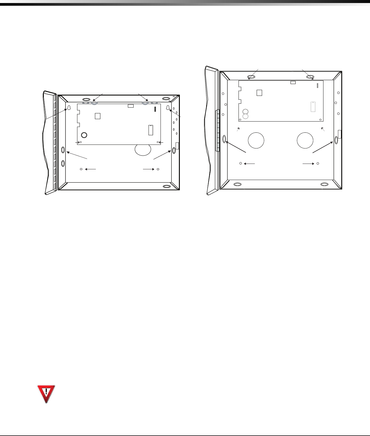
4.1 Mounting the Enclosure
The metal enclosure must be mounted in a secure, dry place to protect the panel from damage due to
tampering or the elements. It is not necessary to remove the PCB when installing the enclosure. The PCB
maybeinstalledinthestandard340smallenclosureorintheoptional349mediumenclosure.
Enclosure Mounting Holes
Dual 1/2" and 3/4" Conduit Knockout
Battery Shel
f
Enclosure Mounting Hole
s
J1111
XT30/XT50
Phone Jack
Connector
Command Processor
Reset
J16
J4
J11 1
2
3
4
Slide panel PCB into lower enclosure slots
Panel
PCB
screw
Panel
PCB
screw
Model 349 Enclosure
Slide panel PCB between formed metal supports
Dual 1/2" and 3/4" Conduit Knockouts
Battery Shelf
Enclosure Mounting Holes
Enclosure
Mounting
Hole
Enclosure
Mounting
Hole Phone Jack
Connector
J4
Command Processor
Reset
J16
J11
1
2
3
4
XT30/XT50
Panel
PCB
screw
Panel
PCB
screw
Model 340 Enclosure
Figure 2: Standard 340 Enclosure (left) or Optional 349 Enclosure (right)
4.2 Mounting Keypads
DMPkeypadshaveremovablecoversthatallowthebasetobemountedonawallorotheratsurfaceusing
the screw holes provided on each corner.
Formountingkeypadsonsolidwalls,orforapplicationswhereconduitisrequired,useaDMP695or696
keypadconduitbackbox.
4.3 Installation Specications
Severalfactorsdeterminetheperformancecharacteristicsofthekeypadbus:thelengthofwireused,the
numberofdevicesconnected,andthevoltageateachdevice.Whenplanningakeypadbusinstallation,
keepinmindthefollowingfourspecications:
1.DMPrecommendsusing18or22-gaugeunshielded wireforallkeypadcircuits.Do not use twisted pair
orshieldedwireforkeypadbusdatacircuits.
2.Onkeypadbuscircuits,tomaintainauxiliarypowerintegritywhenusing22-gaugewiredonotexceed
500feet.Whenusing18-gaugewiredonotexceed1,000feet.Toincreasethewirelengthortoadd
devices, install an additional power supply.
Note:Eachpanelallowsaspecicnumberofsupervisedkeypads.Addadditionalkeypadsinthe
unsupervisedmode.Refertothepanelinstallationguideforthespecicnumberofsupervisedkeypads
allowed.
3.Maximumdistanceforanyonebuscircuit(lengthofwire)is2,500feetregardlessofthewiregauge.
This distance can be in the form of one long wire run or multiple branches with all wiring totaling no
morethan2,500feet.Aswiredistancefromthepanelincreases,DCvoltageonthewiredecreases.
4.Maximumvoltagedropbetweenthepanel(orauxiliarypowersupply)andanydeviceis2.0VDC.Ifthe
voltage at any device is less than the required level, add an auxiliary power supply at the end of the
circuit.Whenvoltageistoolow,thedevicescannotoperateproperly.
Foradditionalinformationrefertothe710InstallationSheet(LT-0310)andortheLX-Bus/KeypadBusWiring
ApplicationNote(LT-2031).

Digital Monitoring Products XT30/XT50 Installation Guide
6
InstallatIon
Primary Power Supply
5.1 AC terminals 1 and 2
Connectthetransformerwirestoterminals1and2onthepanel.Usenomorethan70ft.of16gauge,or
40ft.of18gauge,wirebetweenthetransformerandthepanel.
Always ground the panel before applying power to any devices: The panel must be properly grounded
before connecting any devices or applying power to the panel. Proper grounding protects against
ElectrostaticDischarge(ESD)thatcandamagesystemcomponents.SeeEarthground,intheSecondary
PowerSupplysection.
5.2 Transformer Types
Thetransformerforthepanelis16.5VAC40VA,whichprovidesupto1.5Ampsofbelloutputcurrent,
500mAofauxiliarycurrent,and100mAofsmokedetectoroutput.YoucanuseeithertheModel320wire-in
or321plug-intransformerwiththepanel.Thetotalcurrentavailableislimitedbythetotalbatterystandby
requirements of the installation.
Thetransformermustbeconnectedtoa120VAC60Hzcommercialpoweroutletthatisnotcontrolledbya
wall switch. Never share the transformer output with any other equipment.
XT30/XT50 Installation Guide Digital Monitoring Products
7
InstallatIon
Secondary Power Supply
6.1 Battery Terminals 3 and 4
Connecttheblackbatteryleadtothenegativebatteryterminal.Thenegativeterminalconnectstothe
enclosuregroundinternallythroughtheXT30orXT50circuitboard.Connecttheredbatteryleadtothe
positivebatteryterminal.Observepolaritywhenconnectingthebattery.
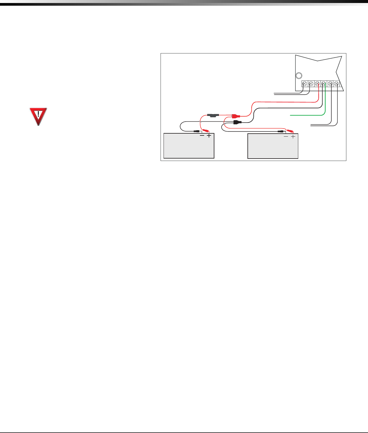
Add a second battery in parallel
usingtheDMPModel318DualBattery
Harness. DMP requires each battery
be separated by a PTC in the battery
harness wiring to protect each
battery from a reversal or short
within the circuit. See Figure 4.
Use sealed lead-acid batteries
only: Use12VDCsealedlead-acid
rechargeable battery. Batteries
suppliedbyDMPhavebeentested
toensureproperchargingwithDMP
products.
GEL CELL BATTERIES CANNOT BE
USED WITH THE XT30/XT50 PANEL.
6.2 Earth Ground
Terminal4ofthepanelmustbeconnectedtoearthgroundusing14gaugeorlargerwiretoprovideproper
transientsuppression.DMPrecommendsconnectingtoametalcoldwaterpipeorgroundrodonly.Donot
connect to electrical conduit or a telephone company ground.
6.3 Replacement Period
DMPrecommendsreplacingthebatteryevery3to5yearsundernormaluse.
6.4 Discharge/Recharge
Thepanelbatterychargingcircuitoatchargesat13.9VDCatamaximumcurrentof1.2Ampsusinga40VA
transformer. The total current available is reduced by the combined auxiliary current draw from terminals
7,11,and25.Thevariousbatteryvoltagelevelsarelistedbelow:
BatteryTrouble: Below 11.9VDC
BatteryRestored: Above 12.6VDC
6.5 Battery Supervision
The panel tests the battery once every hour when AC power is present. This test occurs 15 minutes past
eachhourandlastsforveseconds.Aloadisplacedonthebatteryandifitsvoltagefallsbelow11.9VDCa
low battery is detected. If AC power has failed, a low battery is detected any time the battery voltage falls
below11.9VDC.
If a low battery is detected with AC power present, the test is repeated every two minutes until the battery
chargesabove12.6VDC;thebatteryrestoredvoltage.Ifafaultybatteryisreplacedwithafullycharged
battery, the restored battery will not be detected until the next two-minute test is done.
6.6 XT30/XT50 Power Requirements
During AC power failure, the panel and all auxiliary devices connected draw their power from the battery.
Alldevicesmustbetakenintoconsiderationwhencalculatingthebatterystandbycapacity.Onthe
followingpageisalistofthepowerrequirementsofthepanel.AddtheadditionalcurrentdrawofDMP
keypads,smokedetectoroutput,andanyotherauxiliarydevicesusedinthesystemforthetotalcurrent
required. The total is then multiplied by the total number of standby hours required to arrive at the total
Ampere-hours required.
AC
1234
+BAC –B
318 Battery
Harness
Panel Red and
Black Battery Cables
Red
Black
Battery
Battery
Red
Black
56
BELL GND
To AC
14 AWG to
Earth Ground
XT30/XT50
Command Processor
Panel
PTC
To Bell
Circuit
Figure 4: Wiring Multiple Batteries

Digital Monitoring Products XT30/XT50 Installation Guide
8
InstallatIon
6.7 XT30/XT50 Standby Battery Calculations
Standby Battery Power Calculations Alarm Current
XT30 Panel
XT50 Panel
Built-in Network (additional current)
Built-in Cellular (additional current)
Active Zones 1-9
Active Zone 10
2-Wire Smoke Detectors
Panel Bell Output
x
x
x
x
x
x
125mA
145mA
145mA
17mA
1.6mA
4mA
0.1mA
______mA
______
______
______
______
______
______
Qty ______
Qty ______
Qty ______
1500mA
x
x
x
x
125mA
145mA
145mA
65mA
*2mA
30mA
0.1mA
Max.
______mA
______
______
______
______
______
______
______
263GDigitalCellularCommunicator x 17mA ______ Qty ______ x 65mA ______
1100D Wireless Receiver x 40mA ______ Qty ______ x 40mA ______
1100DHWirelessHighPowerReceiver x 160mA ______ Qty ______ 160mA ______
1100DI Wireless In-Line Receiver x 30mA ______ Qty ______ 30mA ______
690 Security Command Keypad x 77mA ______ Qty ______ x 84mA ______
693 Security Command Keypad x 92mA ______ Qty ______ x 120mA ______
790 Security Command Keypad
Active Zones (EOL Installed)
x 77mA
1.6mA
______
______
Qty ______
Qty ______
x
x
84mA
*2mA
______
______
793 Security Command Keypad
Active Zones (EOL Installed)
x 92mA
1.6mA
______
______
Qty ______
Qty ______
x
x
120mA
*2mA
______
______
7060/7160 Thinline/7060A Aqualite Keypad x 72mA ______ Qty ______ x 87mA ______
7063/7163 Thinline/7063A Aqualite Keypad x 85mA ______ Qty ______ x 100mA ______
7360 Thinline Icon Keypad
7363 Thinline Icon Keypad
7070/7170 Thinline/7070A Aqualite Keypad
Active Zones (EOL Installed)
x
x
x
60mA
73mA
72mA
1.6mA
______
______
______
______
Qty ______
Qty ______
Qty ______
Qty ______
x
x
x
x
67mA
80mA
87mA
*2mA
______
______
______
______
7073/7173 Thinline/7073A Aqualite Keypad
Active Zones (EOL Installed)
x 85mA
1.6mA
______
______
Qty ______
Qty ______
x
x
100mA
*2mA
______
______
734WiegandInterfaceModule
Active Zones (EOL Installed)
x
x
15mA
1.6mA
______
______
Qty ______
Qty ______
x
x
15mA
*2mA
______
______
738A Ademco Wireless Interface Module x 75mA ______ Qty ______ x 75mA ______
708 Bus Extender Module (one pair) x 20mA ______ Qty ______ x 20mA ______
710 Bus Splitter/Repeater Module x 30mA ______ Qty ______ x 30mA ______
714 Zone Expansion Modules
Active Zones (EOL Installed)
x
x
7mA
1.6mA
______
______
Qty ______
Qty ______
x
x
7mA
*2mA
______
______
712-8 Zone Expansion Module
Active Zones (EOL Installed)
x
x
17mA
1.6mA
______
______
Qty ______
Qty ______
x
x
17mA
*2mA
______
______
714-8, 714-16 Zone Expansion Module
Active Zones (EOL Installed)
x
x
20mA
1.6mA
______
______
Qty ______
Qty ______
x
x
20mA
*2mA
______
______
715 Zone Expansion Module
Active Zones (EOL Installed)
2-Wire Smokes
x
x
x
7mA
4mA
.1mA
______
______
______
Qty ______
Qty ______
Qty ______
x
x
x
7mA
*30mA
.1mA
______
______
______
715-8, 715-16 Zone Expansion Modules
Active Zones (EOL Installed)
2-Wire Smokes
x 20mA
4mA
.1mA
______
______
______
Qty ______ x 20mA
*30mA
.1mA
______
______
______
Aux. Powered Devices on Terminals 7 and 11
Other than Keypads and Modules
______mA ______mA
Total Standby
Total Standby______mA x number of Standby Hours
needed
Total Alarm
* Based on 10% of active zones in alarm condition.
______mA
______ =
______mA
+
Total
Total Alarm
________mA-hours
________mA-hours
________mA-hours
X .001
= ________Amp-hrs
______mA
Required

XT30/XT50 Installation Guide Digital Monitoring Products
9
InstallatIon
Bell Output
7.1 Terminals 5 and 6
Nominal12VDCissuppliedbyterminal5onthepaneltopoweralarmbellsorhorns.Theoutputisrated
foramaximumof1.5Ampswitha40VAtransformer.Thisoutputcanbesteady,pulsed,orTemporalCode3
dependingupontheBellActionspeciedinOutputOptionsprogramming.Terminal6isthegroundreference
forthebellcircuit.Ifusingahornorsiren,a1k0hm1/2Wresistershouldbeaddedacrossthebellcircuit
for supervision.
Keypad Data Bus
8.1 Description
Terminals7,8,9,and10ofthepanelaredesignatedasthekeypaddatabus.Inadditiontokeypads,
theXT30/XT50allowstheconnectionofanycombinationofzoneexpansionmodules,5845LXGlassbreak
Detectors,and6155LXPIRstothekeypadbusuptothemaximumofvedevices.
8.2 Terminal 7 - RED
Nominal12VDCissuppliedatterminal7topowerkeypadsandzoneexpanders.Thisisalsowherepower
foranyauxiliarydeviceissupplied.Thegroundreferenceforterminal7isterminal10.Themaximum
outputisratedat500mA.AllauxiliarydevicestotaledtogethermustnotexceedtheTerminal7maximum
current rating of 500mA.
8.3 Terminal 8 - YELLOW
Datareceivefromkeypadsandzoneexpanders.
8.4 Terminal 9 - GREEN
Datatransmittokeypadsandzoneexpanders.
8.5 Terminal 10 - BLACK
Terminal10isthegroundreferenceforLCDkeypads,zoneexpanders,andanyauxiliarydevicesbeing
poweredbyterminals7and11.
8.6 Programming Connection
Alocking4-pinheader(J8)isprovidedtoconnectakeypadwhenusingaDMPModel330ProgrammingCable.
Thisprovidesaquickandeasyconnectionforprogrammingthepanel.
8.7 Keypad Addressing
KeypadBusexpansionzonesarenumberedingroupsoffourcorrespondingtotheaddress.Example:address
1iszones11-14andaddress5iszones51-54.Thereareamaximumof20zonespossibleontheKeypadBus.
Allkeypadzonesterminatewitha1k0hmEOLresister.
Address XT30/XT50
Zone Number
1 11-14
2 21-24
3 31-34
4 41-44
5 51-54
8.8 OVC LED
TheOvercurrentLED(OVC)lightsRedwhenthedevicesconnectedtotheKeypadBusandLX-Bus(es)draw
morecurrentthanthepanelisratedfor.TheOVCislocatedaboveOutputs1and2onthepanelandturnsa
steadyRedwhenlit.WhentheOVCLEDlightsRed,theLX-Bus(es)andKeypadbusareshutdown.
Smoke and Glassbreak Detector Output
9.1 Terminal 11
Nominal12VDCat100mAmaximum(sharedbyterminal25)issuppliedatterminal11topower4-wire
smokedetectorsorotherauxiliarypowereddevices.Thisoutputcanbeturnedoffbytheuserfor5seconds
usingtheSensorResetoptionintheUserMenu.Terminal10isthegroundreferenceforterminal11.
Digital Monitoring Products XT30/XT50 Installation Guide
10
InstallatIon
Burglary Zones
10.1 Description
OnXT30/XT50panels,terminals12to24arethenineburglaryzones.Forprogrammingpurposes,thezone
numbersare1to9.Thezonecongurationsonterminals12to24aredescribedbelow.
Terminal Function Terminal Function
12 Zone1voltagesensing 19 Groundforzones5&6
13 Groundforzones1&2 20 Zone6voltagesensing
14 Zone2voltagesensing 21 Zone7voltagesensing
15 Zone3voltagesensing 22 Groundforzones7,8,&9
16 Groundforzones3&4 23 Zone8voltagesensing
17 Zone4voltagesensing 24 Zone9voltagesensing
18 Zone 5 voltage sensing
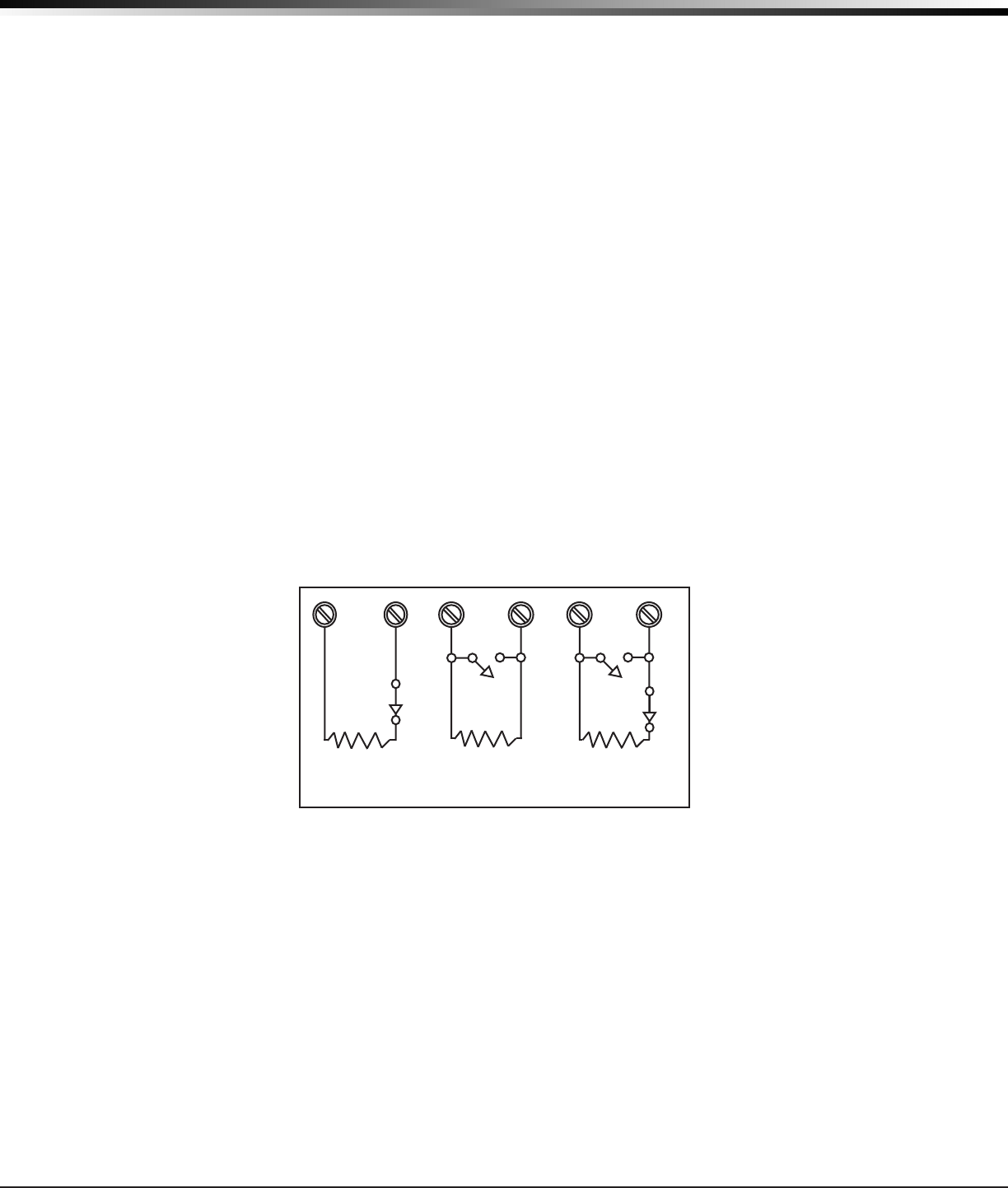
Thevoltagesensingterminalmeasuresthevoltageacrossthe1kOhmEnd-of-Lineresistorandthezone’s
groundterminal.Drycontactsensingdevicescanbeusedinseries(normally-closed)orinparallel
(normally-open)withanyoftheburglaryprotectionzones.
10.2 Operational Parameters
Eachburglaryprotectionzonedetectsthreeconditions:open,normal,andshort.
The parameters for each are listed below:
Condition Resistance on zone Voltage on zone terminal
Open over1300ohms over2.0VDC
Normal 600to1300ohms 1.2to2.0VDC
Short under600ohms under1.2VDC
1K Ohm
Normally
Closed
1K Ohm
Normally Open
1K Ohm
Combination Normally Open
and Normally Closed
Figure 5: Protection Zone Contact Wiring
10.3 Zone Response Time
Aconditionmustbepresentonazonefor500millisecondsbeforeitisdetectedbythepanel.Ensure
detectiondevicesusedontheprotectionzonesareratedforusewiththisdelay.
10.4 Keyswitch Arming Zone
YoucanuseamomentarykeyswitchonazoneprogrammedasanArmingtypeforuseinarmingand
disarming the system without a code.
XT30/XT50 Installation Guide Digital Monitoring Products
11
InstallatIon
Powered Zone for 2-Wire Smoke Detectors
11.1 Terminals 25 and 26
Aresettable2-wireClassBpoweredzoneisprovidedonterminals25(positive)and26(negative)ofthe
panel.Forprogrammingpurposes,thezonenumberis10ontheXT30/XT50.ThezoneusesaModel309,
3.3kOhmEOLresistor(providedwiththepanel)andhasanoperatingrangeof8.8to13.9VDC.
Thecompatibilityidentieris:A.
Caution:Sensorresetonzone10willdroppowertodevicesonthiszone,causingthepaneltosensean
openconditiononallzonetypesotherthanFire,FireVerify,andSupervisory.Whenevernon-Fireandnon-
Supervisoryzonetypesareusedonzone10,maketheappropriateadjustmentstothezone’sArmedAction
to prevent false alarms from occurring.
Manufacturer Model Detector
ID Base Base
ID
# of
Detectors
Zone
Expansion
Modules
Detection Systems DS250, DS250TH B MB2W, MB2WL A 10 715, 715-8,
715-16, 725
Detection Systems DS250HD B MB2W, MB2WL A 10 715, 715-8,
715-16
Detection Systems DS282, DS282TH B 10 715, 715-8,
715-16, 725
DMP/Hochiki SLK-835 HD-5 HSB-200,
HSB-200N HB-55 7 715, 715-8,
715-16
DMP/Hochiki SLR-835 HD-3 NS6-100 HB-55 7 715, 715-8,
715-16, 725
DMP/Hochiki SLR-835B HD-6 7 715, 715-8,
715-16, 725
Sentrol/ESL 429AT, 521B, 521BXT S09A 12 715, 715-8,
715-16

Digital Monitoring Products XT30/XT50 Installation Guide
12
InstallatIon
Annunciator Outputs
12.1 Description
Thefourannunciatoroutputscanbeprogrammedtoindicatetheactivityofthepanel’szonesorconditions
occurring on the system. Annunciator outputs do not provide a voltage but instead switch-to-ground voltage
from another source. The outputs can respond to any of the conditions listed below:
1) Activationbyzonecondition:Steady,Pulse,Momentary,orFollower 6) Ambushalarm
2) Manuallyfromthekeypad 7) ExitandEntrytimers
3) Communicationfailure 8) SystemReady
4) Armedareaannunciation 9) LatetoClose
5) FireAlarmorFireTrouble
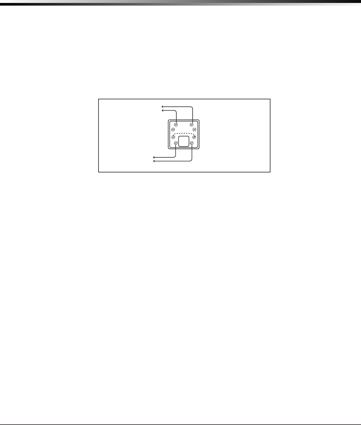
12.2 Harness Wiring
TheopencollectoroutputsareaccessiblebyinstallingtheDMP300Harnessonthe4-pinheaderlabeledJ11.
The output locations are shown below.
Output Color Wire Output Color Wire
1 Red 1 3 Green 3
2 Yellow 2 4 Black 4
12.3 Model 860 Relay Module
ConnectaModel860RelayModuletothepaneltoproviderelaysfortheannunciatoroutputsthatcanbe
used for electrical isolation between the alarm panel and other systems or for switching voltage to control
variousfunctions.Themoduleincludesonerelayandprovidesthreeadditionalsocketsforexpansionofup
tofourrelays.Powerissuppliedtotherelaycoilsfromthepanelkeypadbus.The860mountsinsidethe
panelenclosureusingthe3-holemountingconguration.Plasticstandoffsareprovidedwiththemodulefor
easeofinstallation.A4-wireharnessisalsoprovidedthatconnectstheModel860tothepanel.
Relay Contact Rating: 1Ampat30VDC
XT30/XT50 Installation Guide Digital Monitoring Products
13
InstallatIon
Telephone RJ Connector
13.1 Description
ConnectthepaneltothepublictelephonenetworkbyinstallingaDMP356RJCablebetweenthepanel’sJ3
connectorandtheRJ31XorRJ38Xphonejack.
AtwopinheaderlabeledRJSUP(J7)isprovidedtoallowmonitoringofthetelephonecableconnected
betweenthepanelandaRJ38Xjack(pins2and7jumpered).AttachaDMPModel306HarnessbetweenJ7
andanyavailablezone.TheJ7pinsareconnectedviathetelephonecabletotheRJ38Xjackpins2and7.
TheRJ38Xjackprovidesajumperbetweenpins2and7whichcompletesthecircuit.Programthezoneasa
Supervisorytype(SV).Whenthetelephonecableisremoved,thekeypaddisplayszonetroubleandproduces
a steady tone.
To Telephone
Line
RJ31X or RJ38X
Phone Block
8
7
6
54
3
2
1
Ring Tip
To Premise
Phone(s)
Ring1 Tip 1
Figure 7: Phone Jack Wiring
13.2 FCC Registration
The panel complies with FCC part 68 and is registered with the FCC.
Registrationnumber:CCKAL00BXT50
RingerEquivalence:0.0B
13.3 Notication
Registered terminal equipment must not be repaired by the user. In case of trouble, the device must be
immediatelyunpluggedfromthetelephonejack.Thefactorywarrantyprovidesforrepairs.Registered
terminalequipmentmaynotbeusedonpartylinesorinconnectionwithcointelephones.Noticationmust
be given to the telephone company with the following information:
a.Theparticularline(s)theserviceisconnectedto
b. The FCC registration number
c. The ringer equivalence
d.Themake,model,andserialnumberofthedevice
Digital Monitoring Products XT30/XT50 Installation Guide
14
InstallatIon
Ethernet Connector J1
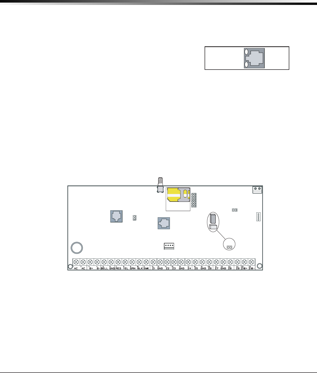
14.1 Description
TheEthernetConnector(J1)isavailableontheNetworkversionandconnectsdirectlytoanEthernet
networkusingastandardpatchcable.
14.2 Ethernet LEDs
ThetwoLEDs,locatedontheleftsideoftheJ1EthernetConnector,
indicatenetworkoperation.Thetop,LinkLEDisasteadygreenlight
whenanethernetcableisconnected.Thebottom,ActivityLED
ashesyellowtoindicatemessagesarebeingreceivedortransmitted.
Reset Jumpers J16
15.1 Description
The reset header is located just above the terminal strip on the right side of the circuit board and is used
toresettheXT30/XT50microprocessor.Toresetthepanelwhenrstinstallingthesystem,installthereset
jumper before applying power to the panel. After connecting the AC and battery, remove the reset jumper.
To reset the panel while the system is operational, for example, prior to reprogramming, install the reset
jumper without powering down the system. Remove the reset jumper after one or two seconds.
Afterresettingthepanel,beginprogrammingwithin30minutes.Ifyouwaitlongerthan30minutes,you
must reset the panel again.
XT30/XT50 Panel
J3
Phone Line
Outputs
J11
1
2
3
4
J1
Ethernet
J20
Wireless
Antenna
connection
J7 RJ
Supervision
J24 Celllular
header for
263G
connection
J19 Celllular
Antenna
connection
65555
Momentarily
place the Reset
jumper over both
of the J16 pins to
reset the panel.
J16
Reset
J18
Load
RED
Programming
J8
Figure 9: Panel Showing the Reset Jumper Wires
Flash Load Jumper J18
16.1 Description
ToupdatetheXT30/50panelwithanewsoftwareversion(rule),placejumpersontheReset(J16)and
Load(J18)headers.ConnectaDMP399CablefromtheJ8ProgrammingHeadertoalaptopPCcontaining
therule.Then,removethejumperfromtheReset(J16)headerwhileleavingtheLoad(J18)jumperin
place.
Afterthesoftwareversionisupdated,returnthejumpertoReset(J16),removetheLoad(J18)jumperand
the399cable.ThenremoveReset(J16)jumpertoresumenormalpaneloperation.
Figure 8: J1 Connector and LEDs
J1
Ethernet
Link LED
Activity LED
XT30/XT50 Installation Guide Digital Monitoring Products
15
InstallatIon
Cellular Connections
17.1 Cellular
TheXT30/XT50Cellularoptionisavailablebuilt-inatthefactoryorasanoptionaladd-onmodule,Model
263G.TheJ19SMAcellularantennaconnectorisprovidedforthebuilt-incellularversionandprotrudes
through the top of the enclosure.
Ifthepanelisnotpurchasedwithbuilt-incellular,thentheJ24headerisprovidedtoconnecta263GDigital
CellularCommunicatorasanadd-on.The263GDigitalCellularCommunicatorprovidesacellularantenna
connectionthatprotrudesthroughthetopoftheenclosuresimilartoJ19.
Figure 10: Cellular and 1100 Series Wireless Antenna Connections
On-Board 1100 Series Wireless Antenna Connections
18.1 Wireless Antenna
TheXT50WirelessAntennaterminalblockJ20islocatedatthetoprightcornerofthecircuitboard.The
antenna installs through a small opening in the top of the enclosure and is attached to the panel using the
right terminal. The left terminal is not used.
TheXT50built-inwirelessoperateswithDMP1100Seriestransmitters.Seesection3.4foralistofaccessory
devices.
18.2 LED Operation
TwoLEDsdisplayreceiveroperationandactivity.Refertothetablebelowasrequired.
Operation
GreenLED-Flashestoindicatedataisbeingtransmittedfromthereceiver.
YellowLED-Flashestoindicatedataisbeingreceivedfromatransmitter.
Outputs
J11
1
2
3
4
J1
Ethernet
J16
Reset
J20
1100 Series
Wireless
Antenna
connection
J24 Celllular
header for
263G
connection
J19 Celllular
Antenna
connector
65555
Built-in Cellular
Module Connect
antenna to
rightside
only
J18
Load
RED
Programming
J8
1100 Series
Antenna
(XT50)
Model 383
supplied
with panel

Digital Monitoring Products XT30/XT50 Installation Guide
16
ComPlIanCe
NRTL Listed Specications
19.1 Introduction
Theprogrammingandinstallationspecicationscontainedinthissectionmustbecompletedwheninstalling
theXT30/XT50inaccordancewithanyoftheANSI/ULburglarystandards.Additionalspecicationsmaybe
required by a particular standard.
19.2 Bypass Reports
ThebypassreportsmustbeprogrammedasYESforallNRTL(NationalRecognizedTestingLaboratory)Listed
burglary applications.
19.3 Current Draw
Thetotalcurrentdrawfromacombinationofauxiliary,smoke,andbelloutputterminalsmustnotexceed
1.6 Amps.
Household Burglar-Alarm System Units ANSI/UL 1023
20.1 Bell Cutoff
The bell cutoff time cannot be less than four minutes.
20.2 Entry Delay
Themaximumentrydelayusedmustnotbemorethan45seconds.
20.3 Exit Delay
The maximum exit delay used must not be more than 60 seconds.
20.4 Wireless External Contact
Whenused,theExternalContactof1101or1102mustbeprogrammedNormallyClosed.
20.5 Wireless Supervision Time
TheZoneInformationSupervisionTimecannotbesetto0(zero).
20.6 Wireless Audible Annunciation
TheWirelessAudibleoptionmustbeselectedasDAYforresidentialapplications.
20.7 Panel location
Mountpanelinsideprotectedareaorhavetamperswitchinstalledonenclosure.Zone1maybeprogrammed
for Alarm on Tamper.
Digital Burglar Alarm Communicator System Units ANSI/UL 1635
21.1 Entry Delay
The maximum entry delay used must not be more than 60 seconds.
21.2 Exit Delay
The maximum exit delay used must not be more than 60 seconds.
21.3 Test Frequency
TheTestFrequencyoptionmustbeprogrammedtosendareportonceevery24hours.
21.4 Automatic Bell Test
ThisoptionmustbeprogrammedasYES.
21.5 Central Station
DigitalDialerCentralStation(DACT)serviceforcommercialapplicationcanbeprovidedunderUL1635by
addingalistedlocalaudiblesignalapplianceandplacingtheXT30orXT50panelintotheModel350AAttack
ResistantEnclosure.

XT30/XT50 Installation Guide Digital Monitoring Products
17
ComPlIanCe
Household Fire Warning System ANSI/UL 985 NFPA 72 Specications
22.1 Bell Output Denition
ThebelloutputoftheModelXT30/XT50mustbeprogrammedtooperatesteadyonburglaryalarmsand
pulsedonrealarms.SeetheXT30/XT50ProgrammingGuide.
22.2 Household System
An alarm sounding device must be installed indoors so that it is clearly heard in all sleeping areas.
22.3 Household Fire Warning
Recognizedlimitedenergycablemustbeusedforconnectionofallinitiating,indicating,andsupplementary
devices.
22.4 Wireless External Contact
Whenused,theExternalContactof1101or1102mustbeprogrammedNormallyClosed.SeetheXT30/
XT50ProgrammingGuide.
22.5 Wireless Supervision Time
TheZoneInformationSupervisionTimemustbe3minutesforredevices.SeetheXT30/XT50Programming
Guide.
22.6 Wireless Fire Verication
Whenused,theModel1161and1162wirelesssmokedetectorsmustnotbeprogrammedasFireVerication
(FV)zonetype.SeetheXT30/XT50ProgrammingGuide.
California State Fire Marshal Specications
23.1 Bell Output Denition
ThebelloutputoftheModelXT30/XT50mustbeprogrammedtooperatesteadyonburglaryalarmsand
temporalonrealarms.

Digital Monitoring Products XT30/XT50 Installation Guide
18
ComPlIanCe
False Alarm Reduction Programmable Options ANSI/SIA CP-01-2007
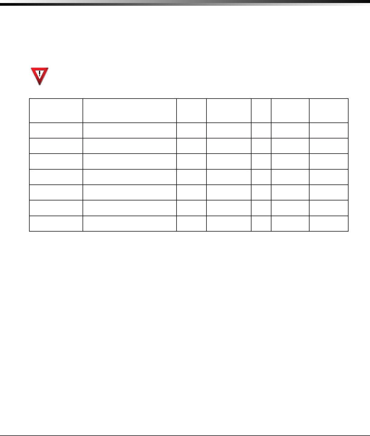
24.1 Shipping Defaults and Recommended Programming
SIA CP-01 FEATURE
PARAGRAPH # AND
DESCRIPTION
DMP PROGRAMMING
GUIDE LT-0981
SECTION #
REQUIREMENT RANGE SHIPPING
DEFAULT
RECOMMENDED
PROGRAMMING*
4.2.2.1ExitTime 8.6ExitDelay Required
(Programmable) 45sec.-250sec. 60
Seconds 60Seconds
4.2.2.2Progress
Annunciation
13.14Prewarn
Address Allowed
Individualkeypads
may be disabled per
zone
All
keypads
enabled
Allkeypadsenabled
4.2.2.3ExitTime
Restart 8.6ExitDelay RequiredOption For re-entry during
exit time Enabled Enabled
4.2.2.5AutoStayArm
onUnvacatedPremises
8.17Occupied
Premise - SeeInstall
Guide
RequiredOption
(exceptfor
remotearming)
OccupiedPremise
NO/YESoption Enabled
EnabledYes
for Residential
Applications
4.2.4.4ExitTimeand
Progress Annunciation/
Disable - for Remote
Arm
NotAvailableon
Remote Arming AllowedOption
Progress Annunciation
Always disabled for
Remote Arming
Not
Available
Remote Arming not
allowed for CP-01
installations.
4.2.3.1EntryDelay(s) 8.5EntryDelay Required
(Programmable) 30sec.–240Sec.** 30
Seconds Atleast30Seconds**
4.2.5.1AbortWindow–
forNon-FireZones 3.3TransmitDelay RequiredOption Disablebyzoneor
zonetype
Enabled
NTDY
EXZone
Enabled
4.2.5.1AbortWindow
Time–forNon-Fire
Zones
3.3TransmitDelay Required
(Programmable)
20sec.,30sec.,or
40sec.**
30
Seconds Atleast20Seconds**
4.2.5.1.2Abort
Annunciation 3.3TransmitDelay RequiredOption
Annunciate that
no alarm was
transmitted
Yes Yes
4.2.5.4.1Cancel
Annunciation
AlwaysEnabled-Not
Programmable RequiredOption
Annunciate that
a Cancel was
transmitted(S49)
Always
Enabled Yes
4.2.6.1&4.2.6.2
Duress Feature
UserCode+1=
AmbushCodeNot
Available
AllowedOption
No1+derivativeof
another user code/no
duplicates with other
user codes
Code+1
Always
Disabled
NotProgrammable
4.3.1CrossZoning 13.16CrossZone RequiredOption Yes/NoZone
Programming No
Enabledusingtwoor
more programmed
zones
4.3.1Programmable
Cross Zoning Time 8.7CrossZoneTime Allowed 4sec.-250sec. 0Seconds Perwalkpathin
protected premises
4.3.2SwingerShutdown NotAvailable—
AlwaysOn Required
Forallnon-re
zones,shutdown
after 1 trip
Always
On AlwaysOn
4.3.2SwingerShutdown
Disable 13.13SwingerBypass Allowed For non-police
responsezones Yes Enabled(allzones)
4.3.3FireAlarm
Verication 13.5ZoneType RequiredOption FV Type Zone No
Yes as required
(unlesssensorscan
selfverify)
4.5CallWaitingCancel 3.17FirstTelephone
Number RequiredOption Include*70Pin
TelephoneNumber Disabled Enabledifuserhas
call waiting
*ProgrammingatinstallationmaybesubordinatetootherNRTLrequirementsfortheintendedapplication.
**ForNRTLInstallations,combinedEntryDelayandTransmitDelayshouldnotexceed1minute.

XT30/XT50 Installation Guide Digital Monitoring Products
19
ComPlIanCe
False Alarm Reduction Programmable Options ANSI/SIA CP-01-2007
(continued)
24.2 Call Waiting
TheCallWaitingdefaultsettingisdisabled.TocanceltheCallWaitingfeature,program*(star)70P
(pause),thestandardtelephonecodeprexthatcancelscallwaiting,intothetelephonenumberstring.
CancelCallWaitingfortelephonelinesthathaveCallWaitingoperationalonthetelephoneline.Seethe
XT30/XT50ProgrammingGuide.
Caution: A call waiting cancel programmed on a non-call waiting telephone line, would prevent
communication to the central station.
24.3 Entry Delay
OnlyuseEntryDelay1.DonotuseEntryDelay2.SeetheXT30/XT50ProgrammingGuide.
24.4 Local Bell
Allnon-rezonessuchasNight,Day,Exit,Aux1andAux2mustbeprogrammedforlocalbellenabledwith
a bell cutoff time set to a minimum of 6 minutes to provide a cancel window of 5 minutes or greater. This
doesnotapplytomanuallyoperatedzonetypessuchasPanicandEmergency.
24.5 Minimum Installation Requirements
SIACP-01-2007minimumsysteminstallationrequirementsincludeanXT30orXT50,alocalBell,andoff
premiseDACTcommunicationtoanSCS-1Rreceiverplusoneofthefollowingcompatiblekeypads.
690,693,790,793SecurityCommand™keypads
7060,7063,7070,7073,7160,7163,7170,or7173Thinline™keypads
7060A,7063A,7070A,or7073AAqualite™keypads
7360or7363Thinline™Iconkeypads
7760ClearTouch™keypad

Digital Monitoring Products XT30/XT50 Installation Guide
20
troubleshootInG
Troubleshooting
25.1 Troubleshooting Section
ThissectionoftheInstallationGuideprovidestroubleshootinginformationforusewheninstallingor
servicinganXT30/XT50system.
Problem Possible Cause Possible Solutions
Keypad displays “SERVICE REQUIRED”
J16 Jumper is installed. Remove the J16 reset jumper.
Openorshortonthegreendatawireto
the keypad.
Check for broken or shorted wires between
the panel and the keypad.
Bad keypad or zone expander. Replace with a new or repaired keypad or
zone expander.
Keypad display is not functional.
When a key is pressed, only a short
beep is emitted.
Open or short on the yellow data wire to
the keypad.
Check for broken or shorted wires between
the panel and the keypad.
Bad keypad or zone expander. Replace with a new or repaired keypad or
zone expander.
Keypad beeps when keys are pressed,
but will not allow the user to arm or
disarm, or enter the User Menu.
Twoormorekeypadsareassignedtothe
same address.
Set each keypad on the system to a unique
address.
Wireless Green LED is off.
HouseCodeisnotprogrammed. ProgramHouseCodeinSystemOptions.
Panel is reset.
Panel is powered off. Turn power on.
PanelisrunningandWirelssGreen
LEDisnotashing.
Problem with wireless circuitry.
ProblemwithWirelssProgramming.
WirelessYellowLEDashesmultiple
times.
Transmitterishavingtrouble
communicatingwithreceiver. Retry
Non-DMPtransmittersareattemptingto
talk with receiver.
WirelessYellowLEDneverashes. Transmitterisnotgettingthroughto
receiver.
Re-programserialnumber.
Move transmitter closer.
Check for hardware problems
Power LED
Overcurrent LED
Keypad LED
25.2 Common LCD Keypad Displays
Listedbelowareseveralkeypadmessagesyoumayseeonthedisplay.FollowtheinstructionsinthePossible
Solutionscolumntocorrecttheproblem.
Message Meaning Possible Solutions
INVALID CODE Theusercodeyouhaveenteredisnotrecognized
by the system. Checktheusercodeandtryagain.
LATE TO CLOSE Thesystemwasnotarmedatitsscheduledclosing
time.
Users still on the premise should arm the system or
extend the schedule to a later time.
AC TROUBLE Thesystemisnotgettingproperpower. CheckthattheACconnectionsaregood.
BATTERY TROUBLE Thebatteryiseitherlowormissing. Checkthatthebatteryconnectionsaregoodand
thebatteryisstillgood.
SYSTEM TROUBLE or
SERVICE REQUIRED
There is a problem with one or more components in
the system.
Make sure the J16 jumper is removed from the
panel. Make sure there is not a short or open
conditiononthegreendatawiretothekeypad.
You may also need to check that all of the keypads
andexpansionmodulesonthebusaregood.
XT30/XT50 Installation Guide Digital Monitoring Products
21
WIrInG dIaGrams
Wiring Diagrams
26.1 Multiple Indicating Circuit Modules Installation
J3
Phone Line
Outputs
J11
1
2
3
4
J1
Ethernet
J16
Reset
J20
Wireless
Antenna
connection
J7 RJ
Supervision
J24 Celllular
header for
263G
connection
J19 Celllular
Antenna
connection
65555
J18
Load
RED
Programming
J8
S
AUXILIARY
POWER
SUPPLY
12 or 24 VDC
5 Amp Maximum
Power Supply
Trouble Contacts
N/C
NOTE: If an auxiliary supply is not used,
terminals 3 and 4 on the 866 Indicating
Circuit Module can be jumpered together
to supply bell power from the XT30 panel.
Each 866 Indicating Circuit Module
in alarm draws up to 35mA from its
terminal 3 alarm input.
The Auxiliary Power Supply and Indicating Circuit Module
trouble contact zone must be programmed as a Supervisory
Type zone and must be selected for display in the keypad
status list.
= Supervised Circuit
S
1
2
3
4
5
6
7
8
Auxiliary Power
Ground
Alarm Input
Bell Power + Input
Bell Power Ð Input
Bell A + Output -
Bell A Ð Output
Bell B + Output
Bell T rouble
Bell T rouble
Bell B Ð Output 9
10
11
UL Listed, Polarized
Indicating Devices.
Style Z
Notification Circuit Module
DMP Model 865
85mA at 12 VDC
AUXILIARY
POWER
SUPPLY
Power Supply
Trouble Contacts
N/C
12 or 24 VDC
5 Amp Maximum
S
S
1
2
3
4
5
6
7
8
Auxiliary Power
Ground
Alarm Input
Bell Power Input
Bell Output +
Bell Output -
Bell T rouble
Bell T rouble
UL Listed, Polarized
notification Devices.
10k Ω EOL Resistor
DMP Model 308
Notification Circuit Module
DMP Model 866
37mA at 12 VDC
1k Ω
Optional Module installation
Each 865 Notification Circuit Module
in alarm draws up to 85mA from its
terminal 3 alarm input.
S
S
S
S
S
S
S
S
S
S
Style W
S
S
SS
S

LT-09801.01©2008DigitalMonitoringProducts,Inc.
800-641-4282
www.dmp.com
MadeintheUSA
INTRUSION•FIRE•ACCESS•NETWORKS
2500NorthPartnershipBoulevard
Springfield,Missouri65803-8877
8165
Listings and Approvals
CaliforniaStateFireMarshal(CSFM)
ETL: ANSI/SIACP-01 FalseAlarmReduction
ANSI/UL1023 HouseholdBurglar
ANSI/UL985 HouseholdFireWarning
ANSI/UL1635 DigitalBurglar
FCCPart15ID:CCKPC0096
FCCPart68RegistrationIDCCKAL00BXT50
IndustryCanadaID:5251A-PC0096