Digital Monitoring PC0098 LOW POWER TRANSMITTER User Manual LT 0703 4 06 indd
Digital Monitoring Products Inc LOW POWER TRANSMITTER LT 0703 4 06 indd
USERS MANUAL
INSTALLATION GUIDE
1140 Series Keyfob Transmitters
Description
The 1140 Series offer a Four-Button, Two-Button, or One-Button Keyfob transmitter that is portable, water resistant,
and designed to be clipped to a keychain or lanyard. The 1140 Series keyfobs provide operation within a maximum
of 200 feet of the receiver location. The 1140 Series keyfob LED provides visual acknowledgement when a button
is pressed and responds to each separate operation with specic color-coded LED displays. The 1140 Series keyfobs
operate using the supplied 3.0V universal Lithium coin cell battery.
What is Included
The 1140 Series Keyfob includes the following items:
• One 1145 Four-Button Keyfob Transmitter OR
One 1146 Two-Button Keyfob Transmitter OR
One 1147 One-Button Keyfob Transmitter
• One 3V Lithium CR2032 coin cell battery
• Peel-off Button ID Labels
• LED operation pocket card
• Serial number label
Transmitter Serial Number
For your convenience, an additional pre-printed serial
number label is included. Prior to installing the device,
record the serial number or place the pre-printed serial
number label on the panel programming sheet. This number
is required during programming.
Programming the Keyfob in the Panel
Refer to the XRSuper6/XR20/XR40 Programming Guide
(LT-0305) as needed. Program and assign an address to the
1140 Series Keyfob in Wireless Devices during panel programming. As soon as the 1140 Series keyfob is programmed,
the default button operation is activated. See Figure 1. Should the default
button operation need to be changed, all buttons can be reprogrammed to
operate as needed.
Preparing the Keyfob for Use
Attach the keyfob transmitter to any keyring or lanyard. Select the peel-off
labels that display the programming for each button and place them onto the
corresponding keyfob buttons for quick reference. See Figure 2. For easier
label installation use a small at head screwdriver or X-acto knife to select the
label and apply it to the proper button location as shown in Figure 1. Button
labels can be changed if programming is changed.
LED Communication
When any button is pressed, the LED ashes Green one time for one-half second
to conrm the button press. When the top and bottom buttons are pressed at
the same time, the panel acknowledges with different LED displays to indicate
panel status. The table below describes the LED operation and what the
different color ashes mean.
LED Display What it Means
Green, Green Disarmed and ready to arm.
Green, Yellow Disarmed and trouble.
Red, Red All system armed.
Red, Yellow Armed (Perimeter/Home or Sleep).
Yellow, Yellow System trouble, no acknowledgement, or out of range.
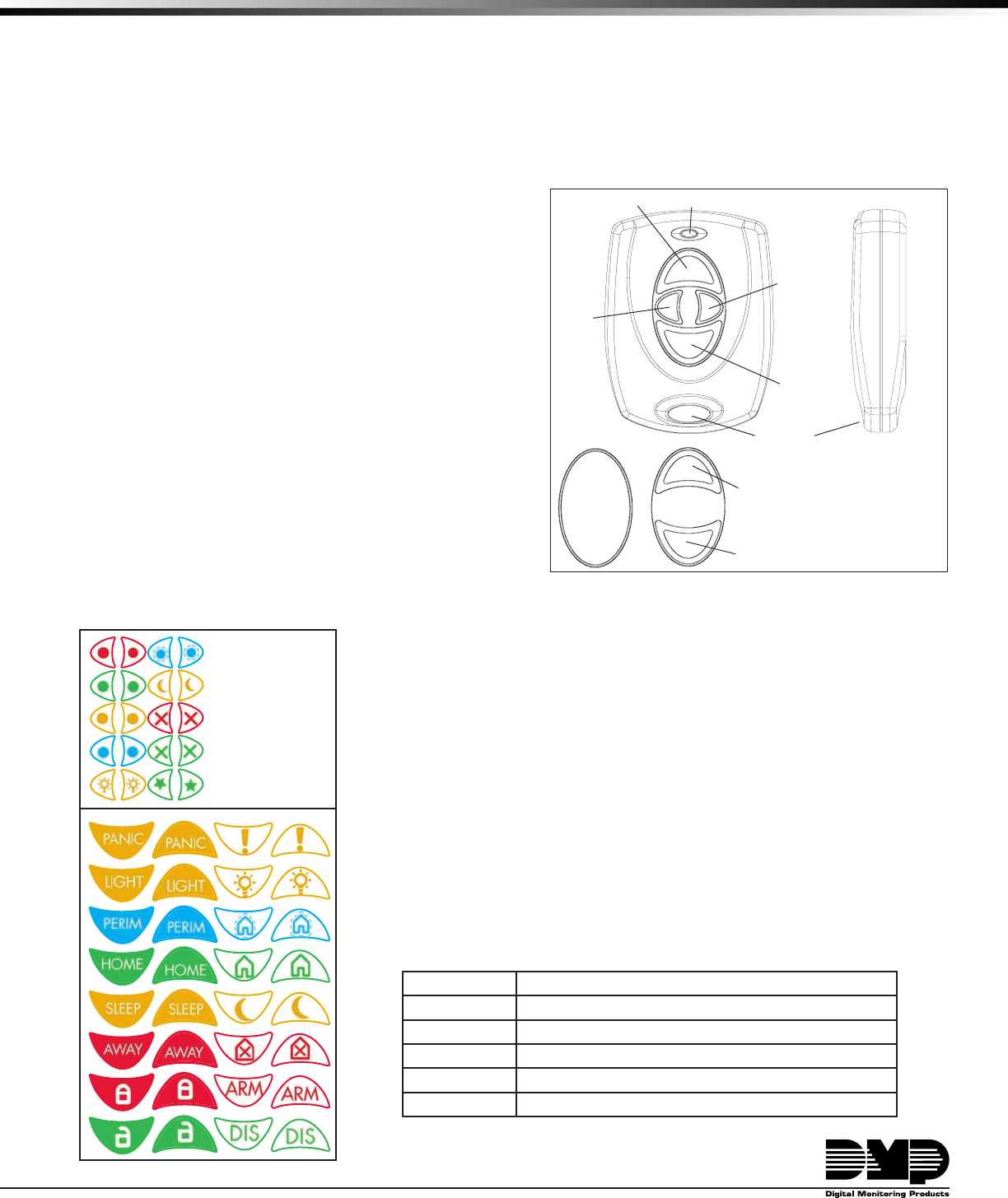
Figure 1: 1140 Series KeyfobTransmitters
Connect
Keyring or
Lanyard Here
LED
Front View
Side View
Arm
(Home)
Left
Button
Arm (Away)
Top Button
Panic
Right
Button
Disarm
Bottom Button
Keyfob
Front
Keyfob
Back
Slot Location
Button Callouts
Identify Default
Programming
1146
2-Button
Layout
1147
1-Button
Layout
Arm (Away)
Top Button
Disarm
Bottom Button
1145 4-Button Layout
Figure 2: Button Labels
Optional
Small or
Large
Labels are
available.
LT-0703 (4/06) © 2006 Digital Monitoring Products, Inc.
800-641-4282
www.dmp.com
Made in the USA
INTRUSION • FIRE • ACCESS • NETWORKS
2500 North Partnership Boulevard
Springfield, Missouri 65803-8877
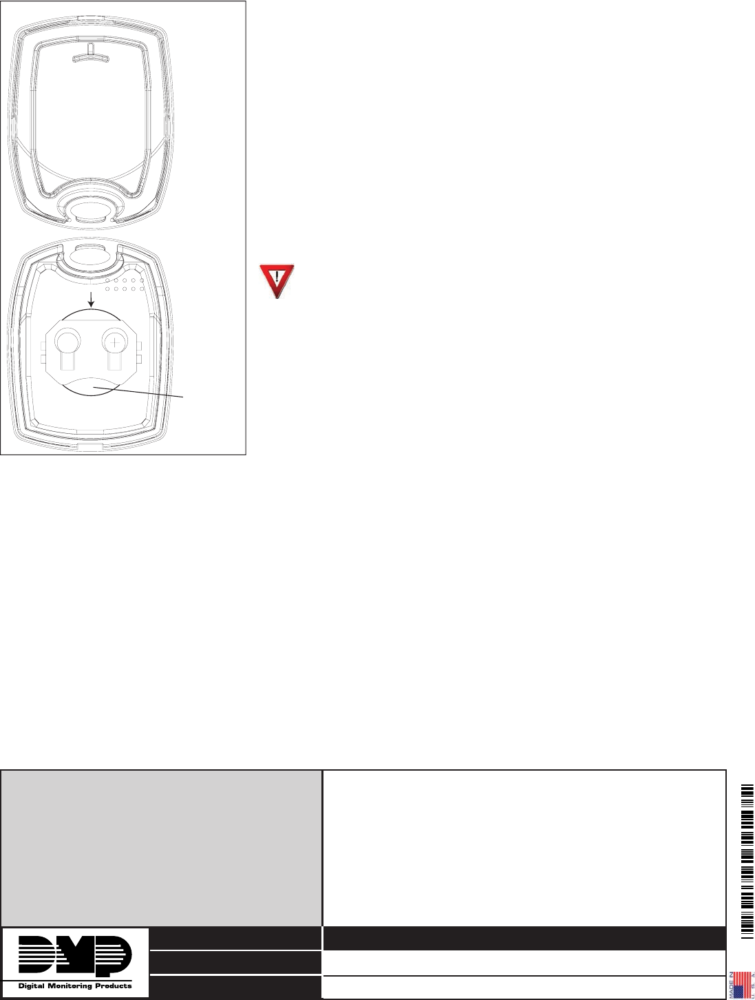
Installing or Replacing the Battery
Observe polarity when installing the battery. Use only 3.0V coin cell
batteries, DMP Model CR2032, or the equivalent battery from a local retail
outlet.
Note: When setting up a wireless system, it is recommended to program
zones or devices and connect the receiver before installing batteries in the
transmitters.
1. Insert a small at head screwdriver into the slot at the keyfob end
opposite the keyring and twist to separate the keyfob front and back
sections.
2. If replacing the battery, push and slide the old battery out of the
holder in the direction of the arrow to remove it. See Figure 3.
3. Slide the new 3.0V Lithium battery into the holder and push into place.
4. Snap the front and back sections back together.
Caution: Properly dispose of unused batteries. Do not recharge,
disassemble, heat above 212°F (100°C), or incinerate. Risk of re,
explosion, and burns.
Battery Life Expectancy
Typical battery life expectancy for DMP Model 1140 Series Keyfob is 2
years. DMP wireless equipment uses two-way communication to extend
battery life.
FCC Information
This device complies with Part 15 of the FCC Rules. Operation is subject
to the following two conditions: (1) This device may not cause harmful
interference, and (2) this device must accept any interference received,
including interference that may cause undesired operation.
Changes or modications made by the user and not expressly approved by the party responsible for compliance could
void the user’s authority to operate the equipment.
NOTE: This equipment has been tested and found to comply with the limits for a Class B digital device, pursuant
to part 15 of the FCC Rules. These limits are designed to provide reasonable protection against harmful
interference in a residential installation. This equipment generates, uses and can radiate radio frequency
energy and, if not installed and used in accordance with the instructions, may cause harmful interference
to radio communications. However, there is no guarantee that interference will not occur in a particular
installation. If this equipment does cause harmful interference to radio or television reception, which
can be determined by turning the equipment off and on, the user is encouraged to try to correct the
interference by one or more of the following measures:
- Reorient or relocate the receiving antenna.
- Increase the separation between the equipment and receiver.
- Connect the equipment into an outlet on a circuit different from that to which the receiver is connected.
- Consult the dealer or an experienced radio/TV technician for help.
Keyfob
Back
Battery
Inside Battery
Compartment
Keyfob Front
Slot
Push Battery
Edge to Slide
Battery Out
Figure 3: 1145 Battery Location
Specications
Battery
Life Expectancy 2 years
Type 3.0V Lithium CR2032
See Battery Life Expectancy for full details.
Dimensions 1.98” H x 1.98” W x 0.6” D
Color Black
Housing Material Flame retardant ABS
Patents
Patent(s) Pending
Listings and Approvals
FCC Part 15 Registration ID CCKPC0098