Digital Monitoring PC0111 LOW POWER SPREAD SPECTRUM TRANSMITTER User Manual USERS MANUAL
Digital Monitoring Products Inc LOW POWER SPREAD SPECTRUM TRANSMITTER USERS MANUAL
USERS MANUAL
INSTALLATION GUIDE
1100DI Wireless Receiver
Description
The 1100DI Wireless Receiver provides up to 16 wireless zones for XRSuper6 and XR20 Command Processor™ panels
and up to 32 wireless zones (28 zones using one keypad) for XR40 Command Processor™ panels. The 1100DI is
compatible with all DMP wireless devices. The 1100DI provides two-way, supervised communication using 900 MHz
frequency hopping-spread-spectrum technology. The receiver can be installed anywhere on the panel keypad bus.
What is Included
The 1100DI Wireless Receiver includes the following items:
• One Model 1100DI Wireless Receiver
• One 4-wire Harness
• Hardware pack
Compatibility
The 1100DI Wireless Receiver is compatible with any XRSuper6, XR20, or XR40 Command Processor™ panels using
rmware Version 300 or higher. In addition to rmware Version 300 or higher, XR20 Command Processor™ panels
need to be hardware Level L or higher released October 2000. No specic receiver programming is required. Once
installed, a panel programmed with wireless information will automatically recognize the wireless receiver.
Installing the 1100DI Wireless Receiver
The 1100DI Wireless Receiver can be mounted anywhere along the panel keypad bus. A location should be selected
that will be centrally located between the 1100 Series transmitters used in the installation. Install the receiver
away from large metal objects. Mounting the receiver on or near metal surfaces impairs performance. Do not used
shielded wire between the panel and receiver. When selecting the proper mounting location and operation, refer to
the LED Survey Operation section of the specic installation guide for the transmitter being installed.
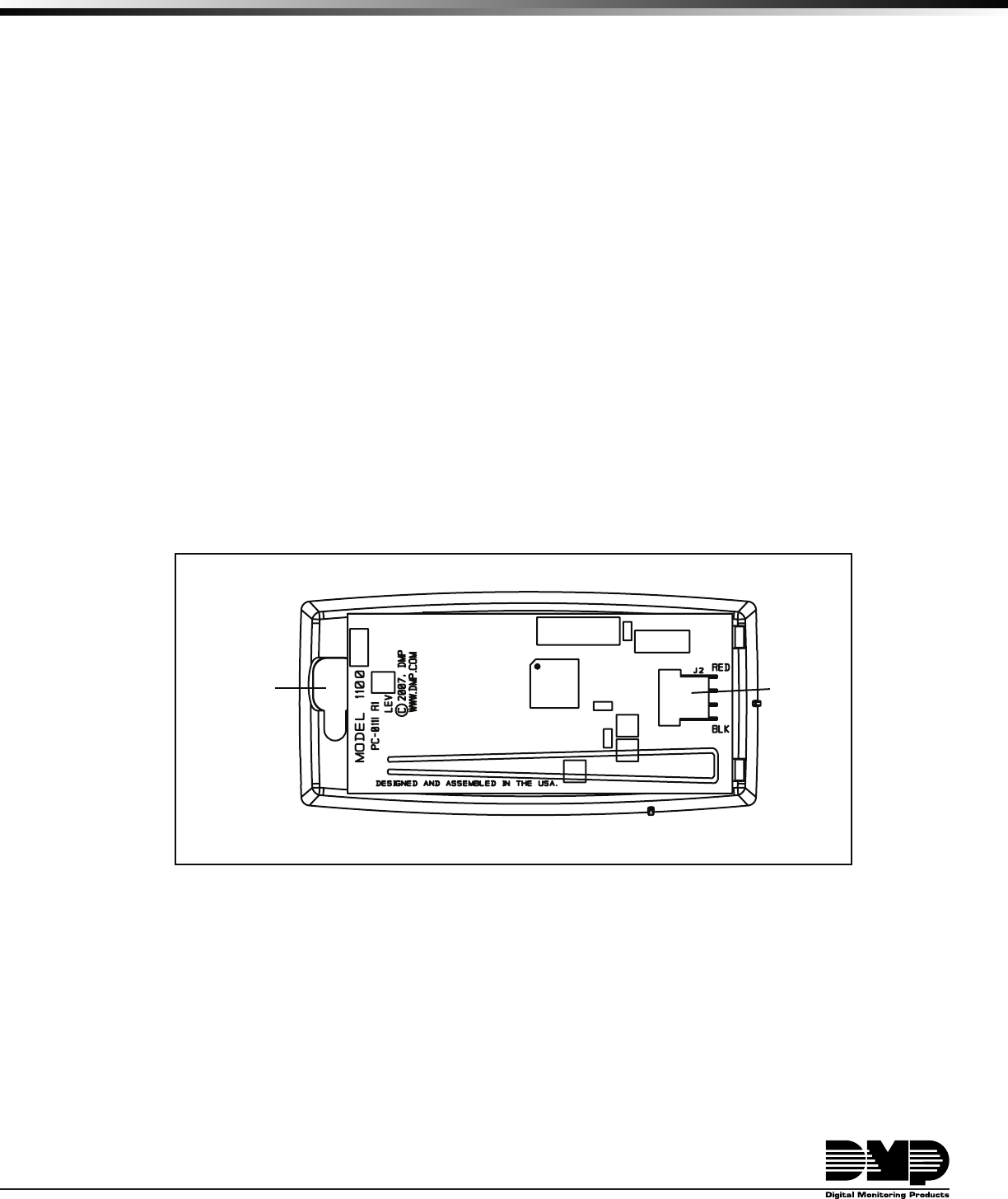
Figure 1: Receiver PCB
Installing the Receiver behind a Keypad
The following instructions cover installing the receiver inside the wall behind the keypad. If the installation requires
the receiver to be mounted, refer to Installing the Optional Mounting Bracket or Installing the Receiver without the
Mounting Bracket.
1. Remove the cover from the plastic housing by squeezing both sides toward each other.
2. Connect the receiver to the panel keypad bus using the supplied 4-wire harness. Route the wires through the
opening in the back of the housing.
3. Snap the cover back in place and suspend the receiver inside the wall behind the keypad. Do not install the
receiver inside of a gang box.
Keypad Bus
header
Wire
opening

Digital Monitoring Products 1100DI Wireless Receiver Installation Guide
2
1100DI Wireless Receiver Installation Guide Digital Monitoring Products
3
Installing the Optional Mounting Bracket
The following instructions cover installing the receiver using the included mounting bracket. If the installation
does not require the mounting bracket, refer to Installing the Receiver behind the Keypad or Installing the Receiver
without the Mounting Bracket.
1. Secure the mounting bracket using the supplied screws or double-sided tape.
2. Remove the cover from the plastic housing by squeezing both sides toward each other.
3. Connect the receiver to the panel keypad bus using the supplied 4-wire harness. Route the wires through the
opening in the back of the housing.
4. Snap the cover back in place.
5. Line up the receiver base with the mounting bracket snap connectors and press the housing into place.
Snap Connectors
Wall Mount
Screw Hole
Wall Mount
Screw Hole
Figure 2: Optional Mounting Bracket
Installing the Receiver without the Mounting Bracket
These instructions cover installing the receiver without the mounting bracket. If the installation requires the
mounting bracket, refer to Installing the Receiver behind the Keypad or Installing the Optional Mounting Bracket.
1. Remove the cover from the plastic housing by squeezing both sides toward each other.
2. Connect the receiver to the panel keypad bus using the supplied 4-wire harness. Route the wires through the
opening in the back of the housing.
3. Snap the cover back in place.
4. Secure the receiver housing to the wall in the desired location using the supplied double-sided tape.
Programming the Panel
Refer to the XRSuper6/XR20/XR40 Programming Guide (LT-0305) as needed. In System Options, program the House
Code (1-50). In Zone Information, program the wireless zones.
1100DI Receiver Operation
The 1100DI receiver automatically sends the panel house code to wireless transmitters when the unique transmitter
serial number is programmed into the panel. The house code identies the panel, receiver, and transmitters to each
other. The receiver only listens for transmissions using the specied house code and/or programmed transmitter
serial number.
Note: When setting up a wireless system, it is recommended to program zones and connect the receiver before
installing batteries in the transmitters.
Transmitters can be programmed for supervised or unsupervised operation. When programmed as supervised, the
transmitter must communicate with the receiver within the programmed number of minutes. If the transmitter fails
to communicate, the panel displays a missing condition.
Note: When a receiver is installed, powered up, or the panel is reset, the supervision time for transmitters is reset.
If the receiver has been powered down for more than one hour, wireless transmitters may take up to an additional
hour to send a supervision message unless tripped, tampered, or powered up. This operation extends battery life for
transmitters. A missing message may display on the keypad until the transmitter sends a supervision message.
When any wireless zone programming is changed in the panel, receiver zone programming is updated when exiting
panel programming. During the update, all wireless zones display as normal for approximately one minute,
regardless of the actual state of the wireless device(s).
Digital Monitoring Products 1100DI Wireless Receiver Installation Guide
2
1100DI Wireless Receiver Installation Guide Digital Monitoring Products
3
LED Operation
Two LEDs display receiver operation and activity. Refer to the table below as required.
Operation
Green LED - Flashes to indicate data is being sent to the panel.
Red LED - Steady to indicate memory upload. Off when upload is complete.
Zone Conguration
Refer to the XRSuper6/XR20/XR40 Programming Guide (LT-0305) for complete wireless programming information.
Note: When any wireless input zone for a particular address is programmed (Ex: 11-14 = Addr 1), the 1100DI responds
to the panel for this address. Other devices, such as keypads or hardwired zone expanders, cannot use this address.
Zones connected directly to the panel cannot be wireless.
Keypad Address Zone Numbers
XRSuper6 XR20 XR40
1 7-10 11-14 11-14
2 21-24 21-24 21-24
3 31-34 31-34 31-34
4 41-44 41-44 41-44
5 * * 51-54
6 N/A N/A 61-64
7 N/A N/A 71-74
8 N/A N/A 81-84
* Note: Address 5 can be used with unsupervised keypads.
This allows all 16 zones to be used by wireless transmitters.
Transmitter Survey LED Operation
DMP 1100 Series transmitters provide Two-way (transmit acknowledge) operation. This advanced data protocol
allows each transmitter to conrm that each of its messages (alarm, checkin, tamper, low battery) are received
and acknowledged by the 1100 Series receiver. The conrmation is indicated visually by use of an LED on each
transmitter. This Survey LED should be used during installation to test each transmitter for proper operation. A full
denition of the Survey LED follows.
The red LED on an 1100 Series transmitter turns on when the processor wakes up to send a message. Then after a
series of communication steps are completed (successful or not), the LED turns off when the processor goes back
to sleep. 99.9% of the time the processor is asleep in normal operation. The following list summarizes various
indications that can be observed on the LED and a denition for each. Note this is for a single message. Example,
pressing and holding the tamper switch.
Single 1/16 second ash
• Processor wakes up
• Transmitter receives immediate synchronization from receiver
• Transmitter transmits
• Transmitter receives immediate acknowledgement from receiver
• Processor goes to sleep
Single Pulse greater than 1/16 second but shorter than 8 seconds
• Processor wakes up
• Transmitter receives synchronization from receiver - possibly not immediate
• Transmitter transmits
• Transmitter receives acknowledgement from receiver - possibly not immediate
• Processor goes to sleep
Steady for 8 seconds
• Processor wakes up
• Transmitter never receives synchronization from receiver, or might receive synchronization
• Transmitter transmits if synchronization was received
• Transmitter never receives any further data from receiver
• Processor times out and goes to sleep

Digital Monitoring Products 1100DI Wireless Receiver Installation Guide
4
1100DI Wireless Receiver Installation Guide Digital Monitoring Products
5
Multiple short ashes
• Processor wakes up
• Transmitter receives synchronization from receiver
• Transmitter transmits
• Transmitter receives data from receiver, but not a valid acknowledgement
• Processor briey goes to sleep
• Entire sequence is repeated, each short ash indicates a cycle
Troubleshooting Using the Transmitter Survey LED
If a transmitter is unable to reliably communicate a message to the receiver, or is reported as missing, the Survey
LED can be used to help diagnose the issue. If the missing transmitter cannot be explained by obvious reasons such
as a damaged transmitter, failed battery, or changes in building construction; then the Survey LED should be used.
To use the Survey LED operation to help diagnose a eld issue, complete the following steps on an 1100 Series
transmitter. Repeat the following sequence 5 times and write down the LED operation for each tamper switch
action.
• Press and hold the tamper switch
• Observe the LED until is turns off for at least 5 seconds
• Release the tamper switch
• Observe the LED until is turns off for at least 5 seconds
You now have observed the LED 10 times. Based on the results you have recorded use the list below to assist in
troubleshooting.
LED turns on a single time for less than 1 second 8 to 10 times.
• System is working properly
LED turns on for more than 1 second 3 to 9 times.
• The transmitter or receiver needs to be relocated
LED turns on for more than 1 second all 10 times.
• The receiver is not turned on, or is not operating
• The transmitter is not programmed into the receiver
• The transmitter or receiver needs to be relocated
LED ashes multiple times with a single tamper press or release 3 to 10 times.
• The transmitter or receiver needs to be relocated
LED never turns on.
• The transmitter battery is dead
• The tamper switch is being pressed or released too quickly
• The tamper switch or other part of the transmitter is broken
LED stays on constantly and is dim
• The transmitter battery is almost dead
• The transmitter is broken
General Wireless Troubleshooting
If ALL wireless devices do not operate, refer to the following checklist:
• Verify equipment model numbers.
• Verify the House Code (1-50) is programmed in System Options.
• Verify the 4-wire connector from the receiver J3 is connected to the XRSuper6, XR20, or XR40 panel
terminals 7, 8, 9, and 10.
• Verify what zone numbers are assigned as wireless zones and check the address settings of other device(s)
connected to the keypad bus to ensure no duplicate addresses have been used.
• Verify the 1100DI LEDs are operating as listed in 1100DI LED Operation on the previous page.
• Verify transmitters have batteries correctly inserted.

Digital Monitoring Products 1100DI Wireless Receiver Installation Guide
4
1100DI Wireless Receiver Installation Guide Digital Monitoring Products
5
Transmitter Supervision Time
For NRTL Listed installations, program the transmitter supervision time in panel zone programming as listed in the
following table. Refer to the XRSuper6/XR20/XR40 Programming Guide (LT-0305) for complete wireless programming
information.
UL Listing Listed Accessories Supervision
Time
ANSI/UL 1023 Household Burglary Alarm System Units
Accessory
1101/1102/1103 Universal Transmitters
1125 PIR Motion Detector
1142 Two-Button Hold-Up Transmitter
60
60
60
ANSI/UL 636 Holdup Alarm Units and Systems Accessory 1142 Two-Button Hold-Up Transmitter 60
ANSI/UL 634 Connections and Switches for use with
Burglar Alarm Systems Accessory 1101/1102/1103 Universal Transmitters 60
ANSI/UL 639 Intrusion Detection Units Accessory 1125 PIR Motion Detector 60
ANSI/UL 365 Police Station Connected Burglar Accessory 1103 Universal Transmitter 60
ANSI/UL 609 Local Burglar Alarm Units and System
Accessory 1103 Universal Transmitter 60
ANSI/UL 1076 Proprietary Burglar Alarm Units Accessory 1103 Universal Transmitter 60
ANSI/UL 1610 Central Station Burglar Alarm Units
Accessory 1103 Universal Transmitter 60
ANSI/UL 985 Household Fire Warning system Accessory 1101/1102/1103 Universal Transmitter
1161/1162 Residential Smoke Detectors
3
3
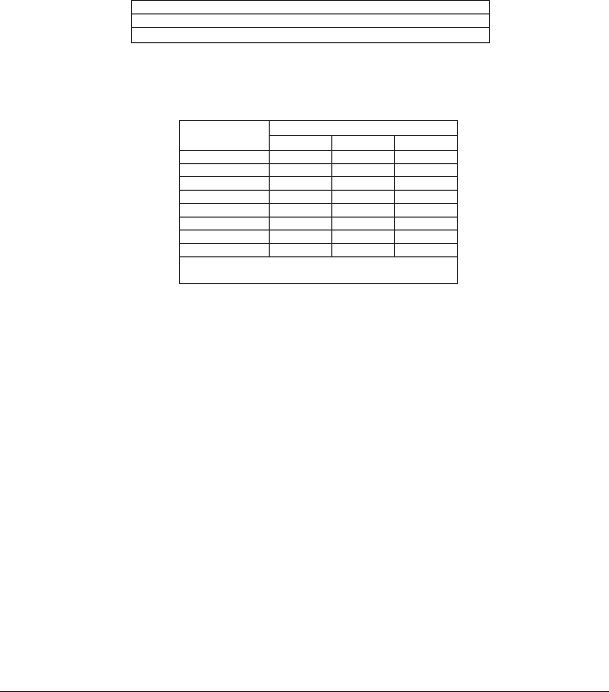
Receiver/Panel Software Version Table
The table below provides a list of the required panel and wireless receiver software versions needed to support each
transmitter. In each case the version must be the level indicated or higher.
Model Description 1100DI
Receiver
XRS6/XR20/XR40
Panel
1101 Universal Transmitter, Internal/External Contacts 100 300
1102 Universal Transmitter, External Contact 100 300
1114 Four Zone Expander 100 300
1116 Relay Output 104 304
1117 LED Annunciator 104 304
1118 Remote Indicator Light 104 304
1121 PIR Motion Detector 100 300
1125 PIR Motion Detector 100 300
1129 Glassbreak Detector 100 300
1139 Wireless Bill Trap 100 300
1142 Two-Button Hold-Up Transmitter 100 300
1145, 1146, 1147 Four, Two, or One-Button Key Fobs 100 302
1161, 1162 Residential Smoke Detector 100 300

LT-0692 © 2007 Digital Monitoring Products, Inc.
800-641-4282
www.dmp.com
Made in the USA
INTRUSION • FIRE • ACCESS • NETWORKS
2500 North Partnership Boulevard
Springfield, Missouri 65803-8877
7514
FCC Information
This device complies with Part 15 of the FCC Rules. Operation is subject to the following two conditions:
(1) This device may not cause harmful interference, and
(2) this device must accept any interference received, including interference that may cause undesired operation.
Changes or modications made by the user and not expressly approved by the party responsible for compliance could
void the user’s authority to operate the equipment.
Note: This equipment has been tested and found to comply with the limits for a Class B digital device, pursuant
to part 15 of the FCC Rules. These limits are designed to provide reasonable protection against harmful
interference in a residential installation. This equipment generates, uses and can radiate radio frequency
energy and, if not installed and used in accordance with the instructions, may cause harmful interference
to radio communications. However, there is no guarantee that interference will not occur in a particular
installation. If this equipment does cause harmful interference to radio or television reception, which can be
determined by turning the equipment off and on, the user is encouraged to try to correct the interference by
one or more of the following measures:
- Reorient or relocate the receiving antenna.
- Increase the separation between the equipment and receiver.
- Connect the equipment into an outlet on a circuit different from that to which the receiver is connected.
- Consult the dealer or an experienced radio/TV technician for help.
Note: The 1100 Series wireless system is a two-way supervised wireless design. It is compliant with FCC rules as
they pertain to 900 MHz Spread Spectrum devices. In rare instances it has been observed that certain 900 MHz
cordless telephones may occasionally experience a clicking sound on the telephone while in use. If this occurs, it
may be resolved by selecting a different channel on the cordless telephone, or replacing the cordless phone with a
different brand or model of 900 MHz telephone or other cordless telephone.
Specications
Operating Voltage 8.0 to 14 VDC
Current Draw xxmA
Frequency Range 903-927 MHz
Dimensions
Receiver Case 3.3” L x 1.6” W x 1.2” H
Color White
Housing Material Flame retardant ABS
Patents
U.S. Patent No. 7,239,236
Listings and Approvals
FCC Part 15 Registration ID CCKPC0111
IC Registration ID 5251A-PC0111