Digital Monitoring PC0124 LOW POWER TRANSCEIVER User Manual
Digital Monitoring Products Inc LOW POWER TRANSCEIVER Users Manual
Users Manual
InstallatIon GuIde
1105 Universal Transmitter
Description
The 1105 Series are two input transmitters that are typically used for door/window applications. The 1105 Series
provides an internal case tamper, internal magnetic reed switch and an on-board terminal block to allow for
external contact wiring. Both sets of contacts, internal and external, can be programmed to operate at the same
time allowing for two independent zones from one transmitter. The 1105-EOL provides one internal magnetic reed
switch, a wall tamper, and an on-board terminal block to allow for external contact wiring with an end-of-line
resistor. Refer to the panel programming guide for zone programming information.
Compatibility
All DMP 1100 Series Wireless Receivers and Panels
What is Included
The 1105 Universal Transmitter includes the following items:
• One1105TransmitterPCBmountedinatwo-parthousing
(base and cover)
• Magnetwithstandardhousingandbase
• One3VlithiumCR123ABattery
• Hardwarepack
• Zonenameandnumberlabel
• Serialnumberlabel
• OptionalCommercialmagnethousing
The 1105-EOL Universal Transmitter includes the following items:
• One1105Transmitterandallcomponentslistedabove
• OneModel312470KEOLResistor
Transmitter Serial Number
For your convenience, an additional pre-printed serial number
label is included. Prior to installing the device, record the serial
number or place the pre-printed serial number label on the panel
programming sheet. This number is required during programming.
As needed, use the zone name and number label to identify a
specictransmitter.
Programming the Transmitter in the Panel
RefertotheXR500SeriesProgrammingGuide(LT-0679),XR100
SeriesProgrammingGuide(LT-0896),ortheXT30/XT50Series
ProgrammingGuide(LT-0981)asneeded.Programthedeviceasa
zone in Zone Information during panel programming. At the Serial
Number:prompt,entertheeight-digitserialnumber.Continueto
program the zone as directed in the panel programming guide.
Note: When a receiver is installed, powered up, or the panel is reset, the supervision time for transmitters is reset.
If the receiver has been powered down for more than one hour, wireless transmitters may take up to an additional
hour to send a supervision message unless tripped, tampered, or powered up. This operation extends battery life for
transmitters. A missing message may display on the keypad until the transmitter sends a supervision message.
Selecting the Proper Location (LED Survey Operation)
The1105Transmitterprovidesabuilt-insurveycapabilitytoallowonepersontoconrmtransmittercommunication
withthereceiverwhilethecoverisremoved.The1105TransmitterPCBRedSurveyLEDturnsonwheneverdata
is sent to the receiver then immediately turns off when the receiver acknowledgement is received. Pressing the
tamperswitchisaconvenientwaytosenddatatothereceivertoconrmoperation.Whenthetamperswitch
is pressed or released, the LED blinks once to indicate proper operation. When the transmitter does not receive
an acknowledgement from the receiver the LED remains on for about 8 seconds to let you know communication is
notestablished.CommunicationisalsofaultywhentheLEDashesmultipletimesinquicksuccession.Relocate
the transmitter or receiver until the LED immediately turns off indicating the transmitter and receiver are
communicatingproperly.Propercommunicationbetweenthetransmitterandreceiverisveriedwhenforeach
press or release of the tamper switch, the LED blinks immediately on and immediately off.
RepeatthistesttoconrmveseparateconsecutiveLEDblinks.Anyindicationotherwise
means proper communication has not been established.
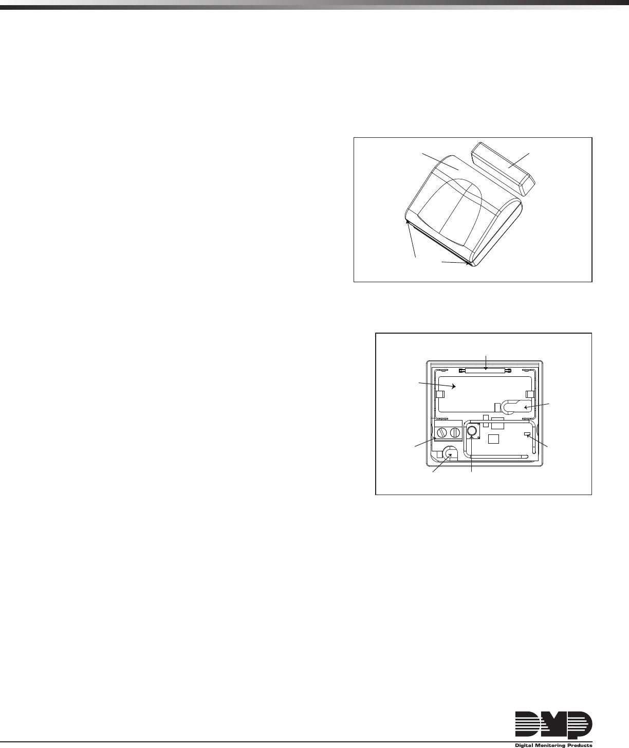
Figure 2: 1105 PCB Layout
Battery
Location
Internal Contact Magnetic
Reed Switch
External
Contact
Terminal
Block
Tamper
Switch
Mounting
Hole
Mounting
Hole
Red Survey
LED
Figure 1: Mounted Transmitter and Magnet
Standard Magnet Housing
1105 Universal Transmitter
Insert small screwdriver
and twist to remove cover
Digital Monitoring Products 1105 Installation Guide
2
Mounting the Transmitter and Magnet Assemblies
Forinternalcontactoperation,thetransmitterandmagnetassemblyshouldhavenomorethan1/2"spacebetween
the assembled housings after installation. When mounting on metal (ferrous) surfaces, this distance is slightly less.
For door installations, it is recommended the transmitter be mounted on the door frame and the magnet assembly
be mounted on the door.
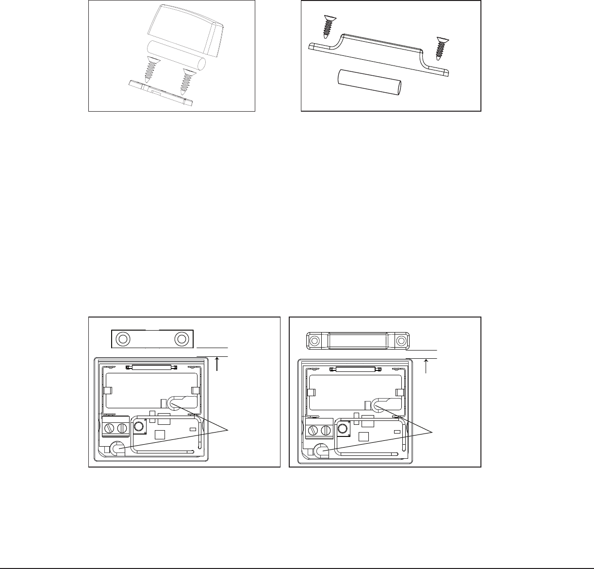
Magnet Assembly
Only one magnet assembly is required for internal reed switch operation. Depending on the installation
requirements,eithertheStandardMagnetAssembly(Figure3)ortheCommercialMagnetAssembly(Figure4)canbe
used.
Installing the Transmitter
The following instructions cover installing the transmitter and magnet assembly.
1. Remove the cover and battery if installed. See Figure 1.
2.Holdthetransmitterbaseinplacewiththereedswitchnearesttotheareawherethemagnetistobe
mounted.
3.Placetwosupplied#4atheadscrewsintothemountingholelocationsasshowninFigure5and6tosecure
the housing to the surface.
4.Whenusingthestandardmagnet,placethemagnetbaseonthesurfacenearesttotheinternalreedswitch
locationandusetheprovided#4atheadscrewstosecurethemagnetbaseinplace.Snapthemagnetinto
the standard housing, then snap the housing onto the base.
5.Whenusingthecommercialmagnet,snapthemagnetintothecommercialhousing,thenusingthesupplied#4
atheadscrews,mountthemagnetinthedesiredlocation.
6. Before replacing the cover, verify the internal tamper spring is on the tamper switch for normal operation.
Housing
Base
Magnet
Magnet
Housing
#4 Flat Head
Screws
Figure 3: Standard
Magnet Assembly
Minimum 1/8”
Mounting
distance
Wall Mount
Screw Holes
Standard Magnet Base
Figure 5: Transmitter and
Standard Magnet
Minimum 1/8”
Mounting
distance
Commercial Magnet
Wall Mount
Screw Holes
Figure 6: Optional
Commercial Magnet
Magnet
Housing
Magnet
#4 Flat Head
Screws
Figure 4: Commercial
Magnet Assembly
1105 Installation Guide Digital Monitoring Products
3
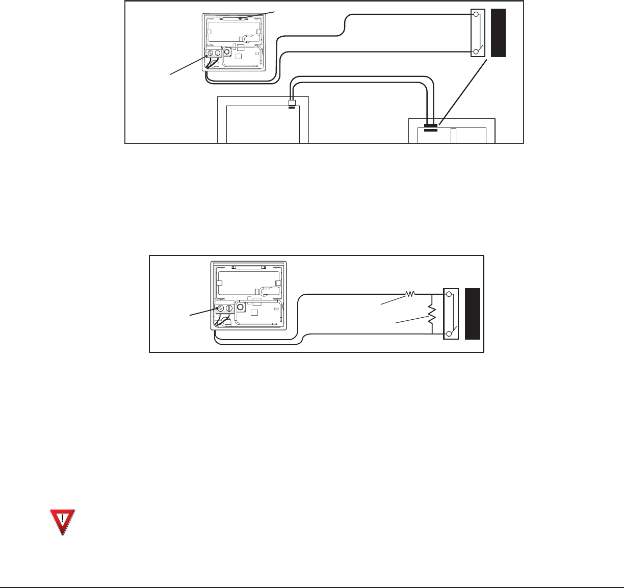
1105 External Contact Mounting
Whenconnectinganexternalcontacttotheterminalblock,DMPrecommendsusing18or22-gaugeunshieldedwire.
Do notusetwistedpairorshieldedwire.Connect the external contact as normally open (N/O) or normally closed
(N/C)withoutanyend-of-lineresistor.RefertotheContactoptionunderZoneInformationintheappropriate panel
programming guide.
Note: When using both the internal reed switch and external terminal block, you must use consecutive zone
numbers. Refer to the following examples:
• XR500 system—zones562and563orzones893and894
• XR100 system—zones523and524orzones593and594
• XT30/XT50 Series—zones31and32orzones34and41
Figure 7: External Contact Wiring
Magnet
1105 Universal
Transmitter
External
Contact
External Contact
Terminal Block
Internal Contact
Reed Switch
Internal Contact Magnet
External Contact
Program External
Contact as next
consecutive Zone
Program
Internal
Contact
as one Zone
Window
Door
1105-EOL Wiring and Connecting Contacts
Whenconnectinganexternalcontacttotheterminalblock,DMPrecommendsusing18or22-gaugeunshieldedwire.
Do notusetwistedpairorshieldedwire.Connectthecontactasnormallyopen(N/O)ornormallyclosed(N/C)withthe
470Kend-of-lineresistorasshowninFigure8.
Note: The Normally Open YES NO option in the panel wireless zone programming has no affect on the transmitter
operationwhenusingthe470Kend-of-lineresistor.
Installing or Replacing the Battery
Observepolaritywheninstallingthebattery.Useonly3.0Vlithiumbatteries,DMPModelCR123,ortheequivalent
batteryfromalocalretailoutlet.ForULinstallations,onlyuse#123batteriesmanufacturedbyEnergizerforthe
1105orCR123AbatteriesmanufacturedbyPanasonicforthe1105-EOL.
Note: When setting up a wireless system, it is recommended to program zones and connect the receiver before
installing batteries in the transmitters.
1. If installed, remove the transmitter housing cover as shown in Figure 1.
2.Ifreplacingthebattery,removetheoldbatteryanddisposeofitproperly.
3.Placethe3.0VlithiumbatteryintheholderasshowninFigure2andpressintoplace.
4.Alignthebackofthetransmittercovernexttothebatteryandsnapthecoverintoplace.
Caution:Riskofre,explosion,andburns.Donotrecharge,disassemble,heatabove212°F(100°C),or
incinerate. Properly dispose of unused batteries.
External Contact
Program Contact in
Panel Zone Programming
Contact
Terminal
Block
470K
470K
Series for N/C
Parallel for N/O
Figure 8: Contact Terminal Block Wiring
LT-10731.01©2009DigitalMonitoringProducts,Inc.
800-641-4282
www.dmp.com
Made in the USA
INTRUSION•FIRE•ACCESS•NETWORKS
2500NorthPartnershipBoulevard
Springfield,Missouri65803-8877
9425
Battery Life Expectancy
Typical battery life expectancy for DMP Model 1105 wireless transmitters is 5 years. DMP wireless equipment uses
two-way communication to extend battery life.
The following situations can reduce battery life expectancy:
• Ifareceiverisunpluggedornotinstalled.
Note: Transmitters continue to send supervision messages until a receiver returns an acknowledgement.
After an hour the transmitter only attempts a supervision message every 60 minutes.
• Frequenttransmissions,suchasadoorcontactwheremessagesaresenteverytimethedooropensorcloses.
• Wheninstalledinextremehotorcoldenvironments.
The following situation can extend battery life expectancy:
• Extendtransmittersupervisiontimeinpanelprogramming.
• Infrequenttransmissiontrips,suchasawindowthatrarelysendsmessages.
FCC Information
ThisdevicecomplieswithPart15oftheFCCRules.Operationissubjecttothefollowingtwoconditions:
(1) This device may not cause harmful interference, and
(2)thisdevicemustacceptanyinterferencereceived,includinginterferencethatmaycauseundesiredoperation.
Theantennausedforthistransmittermustbeinstalledtoprovideaseparationdistanceofatleast20cmfromall
persons.Itmustnotbeco-locatedoroperatedinconjunctionwithanyotherantennaortransmitter.
Changesormodicationsmadebytheuserandnotexpresslyapprovedbythepartyresponsibleforcompliancecould
void the user’s authority to operate the equipment.
NOTE: ThisequipmenthasbeentestedandfoundtocomplywiththelimitsforaClassBdigitaldevice,pursuant
topart15oftheFCCRules.Theselimitsaredesignedtoprovidereasonableprotectionagainstharmful
interference in a residential installation. This equipment generates, uses and can radiate radio frequency
energy and, if not installed and used in accordance with the instructions, may cause harmful interference
toradiocommunications.However,thereisnoguaranteethatinterferencewillnotoccurinaparticular
installation. If this equipment does cause harmful interference to radio or television reception, which
can be determined by turning the equipment off and on, the user is encouraged to try to correct the
interference by one or more of the following measures:
- Reorient or relocate the receiving antenna.
- Increase the separation between the equipment and receiver.
- Connecttheequipmentintoanoutletonacircuitdifferentfromthattowhichthereceiverisconnected.
- Consultthedealeroranexperiencedradio/TVtechnicianforhelp.
Specications
Battery
Life Expectancy 5 years (normal operation)
Type 3.0VlithiumCR123A
See Battery Life Expectancy for full details.
FrequencyRange: 903-927MHz
Dimensions
TransmitterCase
1.75”Lx1.6”Wx0.79”H
Standard
MagnetHousing
1.35”Lx0.375”Wx0.425”H
CommercialMagnetHousing
2.25”Lx0.375”Wx0.34”H
Color White
HousingMaterial FlameretardantABS
Patents
U.S.PatentNo.7,239,236
Listings and Approvals
FCCPart15RegistrationIDCCKPC0124
ICRegistrationID5251A-PC0124
Underwriters Laboratories (UL) Listed
ANSI/UL1023 HouseholdBurglarAlarmSystemUnits
ANSI/UL634 ConnectionsandSwitchesforusewith
Burglar Alarm Systems Accessory
ANSI/UL985 HouseholdFireWarningSystem
Accessory
Additional UL Listings for 1105-EOL only
ANSI/UL365 PoliceStationConnectedBurglar
ANSI/UL609 LocalBurglarAlarmUnitsandSystems
ANSI/UL1076 ProprietaryBurglarAlarmUnits
ANSI/UL1610 CentralStationBurglarAlarmUnits
ANSI/UL864 FireProtectiveSignalingSystems