Digital Monitoring PC0132 Digital Keypad User Manual
Digital Monitoring Products Inc Digital Keypad
UserManual.wiki
>
Digital Monitoring
>
PC0132 User Manual
User Manual
Navigation menu
Upload a User Manual
Namespaces
Wiki Guide
HTML
PDF
Info
Views
User Manual
Discussion / Help
Navigation
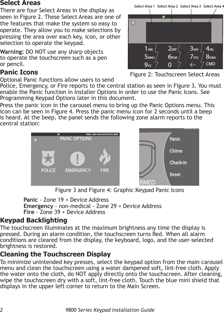
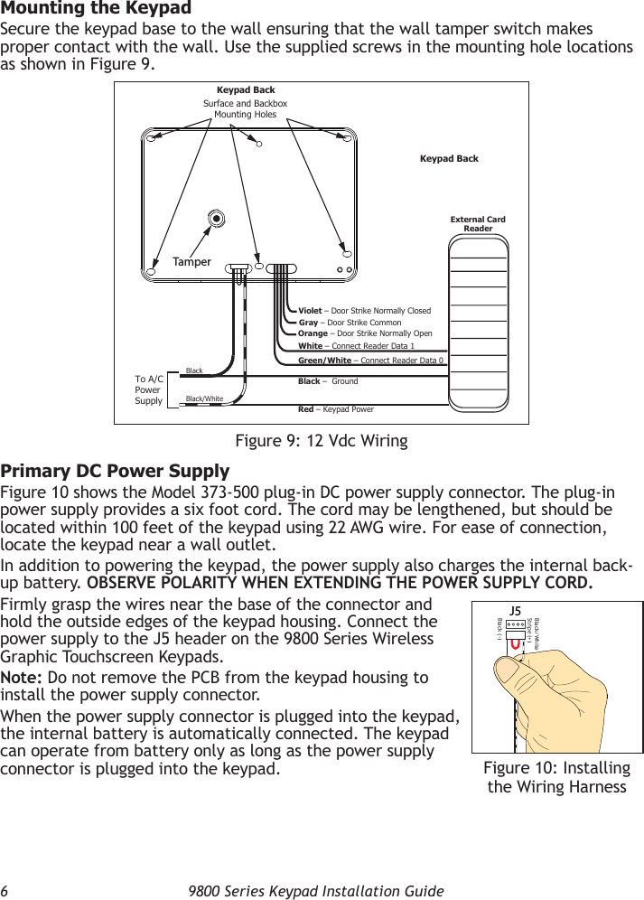
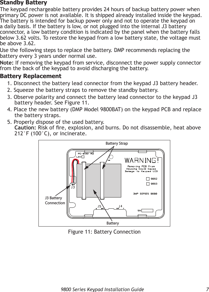
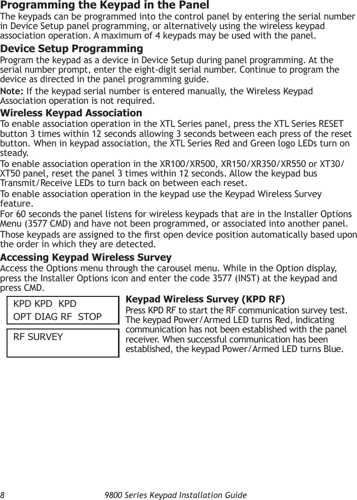
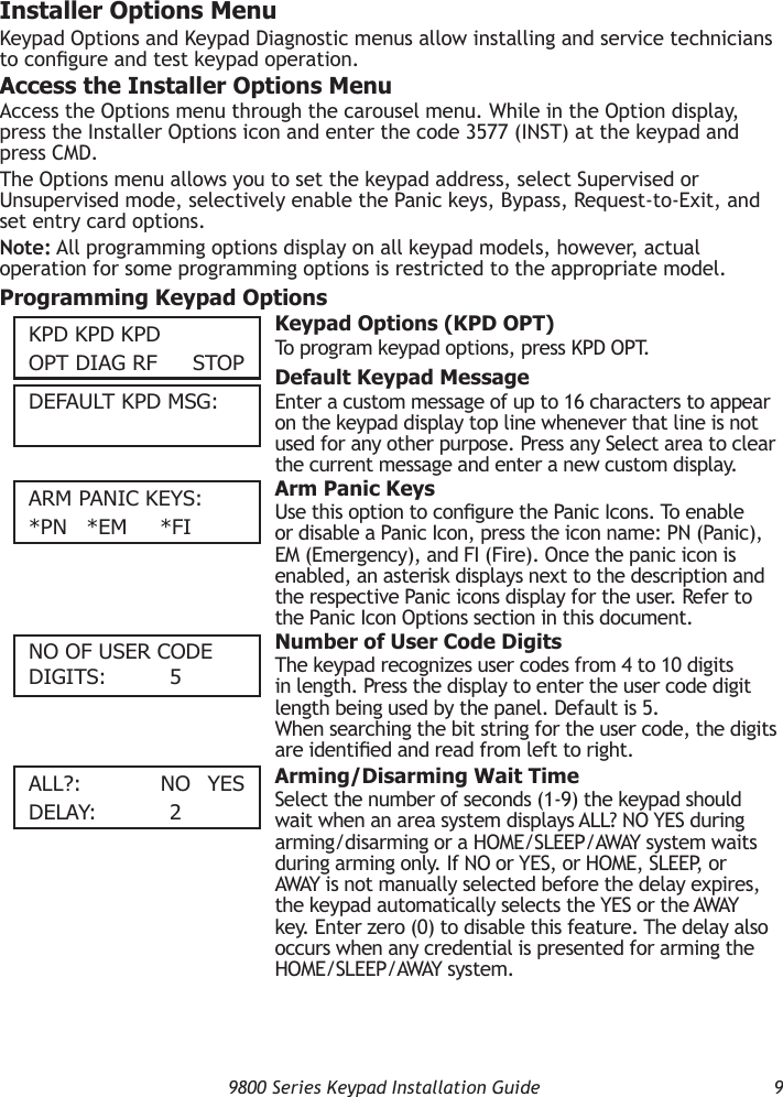
![9800 Series Keypad Installation Guide 11RequIRe SITecODe: nO yeS Require Site CodePress YES to use a site code, for non-DMP cards, and press CMD to view the site code entry display. Default is NO.In addition to User Code verication, door access is only granted when any one site code programmed at the SITE CODES entry option matches the site code received in the Wiegand string. You can program up to eight three-digit site codes.Note: A card with a site code greater than three digits cannot be used. Use only cards with three-digit site codes.SITe cODeS 1-4> > > > Site Codes 1-4Enter site codes 1-4 (left to right separated by > sign). Press the > sign to add, delete, or change the site code. Press CMD to save the entry. Site code range is 0-999.SITe cODeS 5-8> > > > Site Codes 5-8Enter site codes 5-8 (left to right separated by > sign). Press the > sign to add, delete, or change the site code. Press CMD to save the entry. Site code range is 0-999. No Communication With PanelThis option denes the relay action when communication with the panel has not occurred for ve seconds. Press any select area to display CHOOSE ACTION. The default is Relay Always Off.Choose the No Communication with Panel action that is required. Press OFF to choose [Default] (Relay Always Off) — The relay does not turn on when any Wiegand string is received. Off does not affect any REX operation. Press SITE to choose (Accept Site Code) — Door access is granted when the Wiegand site code string received matches any site code programmed at SITE CODE ENTRY. For details refer back to the REQUIRE SITE CODE option. Press ANY to choose (Any Wiegand Read) — Door access is granted when any Wiegand string is received. Press ON to choose (Relay Always On) — The relay is always on.Press the CMD key to display the next action. Press LAST to choose (Keep Last State) — The relay remains in the same state and does not change when communication is lost. After choosing the action, the NO COMM WITH PNL option and the newly dened action display. Press CMD to save the entry. Press the Back Arrow to return to REQUIRE SITE CODE:.nO cOmm WITH Pnl OFFcHOOSe AcTIOnOFF SITe Any OncHOOSe AcTIOnlAST](https://usermanual.wiki/Digital-Monitoring/PC0132/User-Guide-2347128-Page-13.png)