Digital Monitoring PC0133 LOW POWER TRANSCEIVER User Manual USERS MANUAL
Digital Monitoring Products Inc LOW POWER TRANSCEIVER USERS MANUAL
USERS MANUAL
InstallatIon GuIde
1107 Micro Window Transmitter
Description
The Model 1107 Micro Window Transmitter is a low prole 1100 Series transmitter for use on windows and powered by a 3V
coin cell battery. It contains a single reed switch which detects a magnet.
Compatibility
All DMP 1100 Series Wireless Receivers and Panels
What is Included
The 1107 Micro Window Transmitter includes the following items:
• One 1107 Transmitter PCB mounted in a two-part housing
• Magnet with standard or commercial housing and base
• One CR2430 3V Coin Cell Lithium Battery
• Hardware pack and serial number label
• Double-sided tape for transmitter and standard magnet housing
Transmitter Serial Number
For your convenience, an additional pre-printed serial number label is
included. Prior to installing the device, record the serial number or place
the pre-printed serial number label on the panel programming sheet. This
number is required during programming. As needed, use the zone name and number label to identify a specic transmitter.
Programming the Transmitter in the Panel
Program the device as a zone in Zone Information during panel programming. At the
Serial Number: prompt, enter the eight-digit serial number. Continue to program the
zone as directed in the panel programming guide.
Note: When a receiver is installed, powered up, or the panel is reset, the supervision
time for transmitters is reset. If the receiver has been powered down for more than
one hour, wireless transmitters may take up to an additional hour to send a supervision
message unless tripped, tampered, or powered up. This operation extends battery life
for transmitters. A missing message may display on the keypad until the transmitter sends a supervision message.
Selecting the Proper Location (LED Survey Operation)
The 1107 provides survey capability to allow one person to conrm transmitter communication with the receiver before
installation. The 1107 Red Survey LED turns on whenever data is sent to the receiver then immediately turns off when
the receiver acknowledgement is received. Using the contact magnet is a convenient way to send data to the receiver to
conrm operation. When the magnet is moved away or brought towards the contact, the LED blinks once to indicate proper
communication. When the transmitter does not receive an acknowledgement from the receiver the LED remains on for about
8 seconds to let you know communication is not established. Communication is also faulty when the LED ashes multiple
times in quick succession. Relocate the contact or receiver until the LED immediately turns off indicating the transmitter and
receiver are communicating properly. Proper communication between the transmitter and receiver is veried each time the
magnet is moved within 1/2 inch of the transmitter or pulled away from the transmitter. Refer to the 1100 Series Receiver
installation for full information about the survey LED.
Mounting the Transmitter and Magnet Assembly
The transmitter and magnet assembly should have no more than 1/2" space between the assembled housings after
installation. When mounting on metal (ferrous) surfaces, this distance is slightly less. It is recommended the transmitter be
mounted on the window frame and the magnet assembly be mounted on the window.
Magnet Assembly
Only one magnet assembly is required for internal
reed switch operation. Depending on the installation
requirements, either the Standard Magnet Assembly (Figure
3) or the Commercial Magnet Assembly (Figure 4) can be
used. Snap the supplied magnet into the desired housing
prior to mounting.
Installing the Transmitter and Magnet
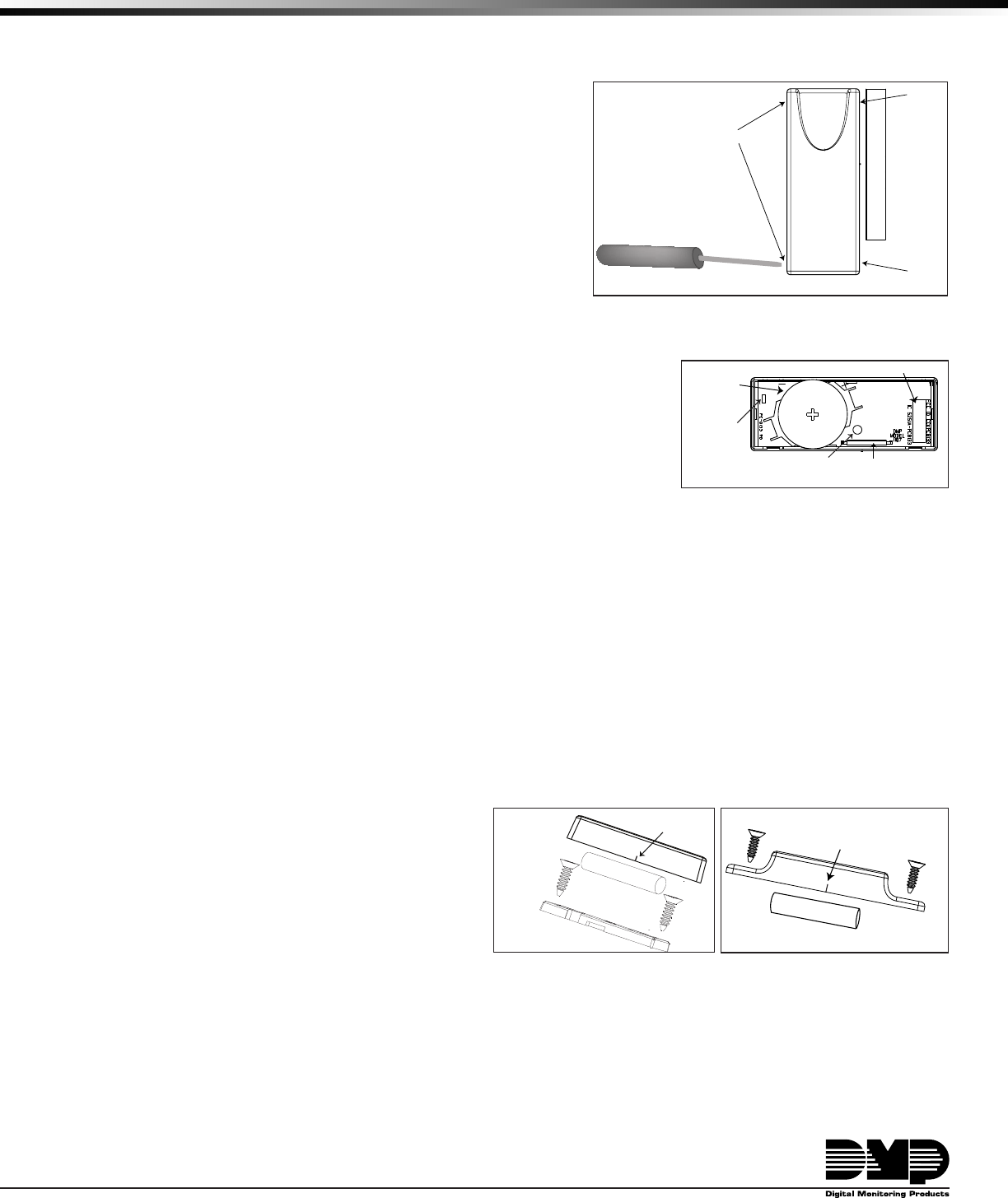
1. Remove the cover and battery if installed. See Fig. 1.
2. Hold the transmitter base in place with the reed
switch nearest to the area where the magnet is to be mounted.
Note: There is no need to remove the PCB from the housing during installation.
3. Use the supplied double-sided tape or place one supplied #4 at head screw into the mounting hole location to secure
the housing to the surface.
4.
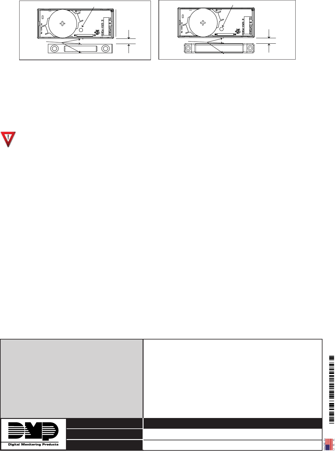
When using the standard magnet, place the magnet base on the surface nearest to the internal reed switch location
aligning the location notches in the transmitter and magnet base (see Figure 5), and use the provided #4 at head screws
to secure the magnet base in place. Snap the magnet into the standard housing, then snap the housing onto the base.
5. When using the commercial magnet, snap the magnet into the commercial housing, then using the
supplied #4 at head screws, mount the magnet using the alignment notches as a guide (see Figure 6).
Figure 2: 1107 PCB Layout
Optional Mounting
Hole
Battery
Location
Internal Contact
Magnetic Reed Switch
Red Survey
LED
C
R
2
4
3
0
Serial Number
Figure 1: Transmitter and Magnet
Standard
Magnet
Housing
1107 Transmitter
Insert small screwdriver
into notch and lift to
remove cover.
Do not twist.
Notch
Notch
Notch
Housing
Base
Magnet
Magnet
Housing
#4 Flat Head
Screws
Alignment
Notch
Figure 3: Standard
Magnet Assembly
Magnet
Housing
Magnet
#4 Flat Head
Screws
Alignment
Notch
Figure 4: Commercial
Magnet Assembly
LT-1156 © 2010 Digital Monitoring Products, Inc.
800-641-4282
www.dmp.com
Made in the USA
INTRUSION • FIRE • ACCESS • NETWORKS
2500 North Partnership Boulevard
Springfield, Missouri 65803-8877
10445
Installing or Replacing the Battery
Observe polarity when installing the battery, the positive (+) side up. Reversing the battery will damage the transmitter. Use
a 3V coin cell lithium battery, DMP Model CR2430, or the equivalent battery from a local retail outlet.
Note: When setting up a wireless system, it is recommended to program zones and connect the receiver before installing
batteries in the transmitters.
1. If installed, remove the transmitter housing cover as shown in Figure 1.
2. If replacing the battery, remove the old battery and dispose of it properly.
3. Place the 3V coin cell lithium battery in the holder positive side up as shown in Figure 2 and press into place.
4. Snap the cover into place, keeping the thinner scooped end of the cover opposite of the battery.
Caution: Risk of re, explosion, and burns. Do not recharge, disassemble, heat above 212°F (100°C), or
incinerate. Properly dispose of unused batteries.
Battery Life Expectancy
Typical battery life expectancy for DMP Model 1107 wireless transmitters is two years. DMP wireless equipment uses two-way
communication to extend battery life.
The following situations can reduce battery life expectancy:
• If a receiver is unplugged or not installed.
Note: Transmitters continue to send supervision messages until a receiver returns an acknowledgement.
After an hour the transmitter only attempts a supervision message every 60 minutes.
• Frequent transmissions, such as a door contact where messages are sent every time the door opens or closes.
• When installed in extreme hot or cold environments.
The following situation can extend battery life expectancy:
• Extend transmitter supervision time in panel programming.
• Infrequent transmission trips, such as a window that rarely sends messages.
FCC Information
This device complies with Part 15 of the FCC Rules. Operation is subject to the following two conditions:
(1) This device may not cause harmful interference, and
(2) this device must accept any interference received, including interference that may cause undesired operation.
The antenna used for this transmitter must be installed to provide a separation distance of at least 20 cm from all persons. It must not
be co-located or operated in conjunction with any other antenna or transmitter.
Changes or modications made by the user and not expressly approved by the party responsible for compliance could void the user’s
authority to operate the equipment.
NOTE: This equipment has been tested and found to comply with the limits for a Class B digital device, pursuant to part 15 of the FCC
Rules. These limits are designed to provide reasonable protection against harmful interference in a residential installation.
This equipment generates, uses and can radiate radio frequency energy and, if not installed and used in accordance with the
instructions, may cause harmful interference to radio communications. However, there is no guarantee that interference will
not occur in a particular installation. If this equipment does cause harmful interference to radio or television reception, which
can be determined by turning the equipment off and on, the user is encouraged to try to correct the interference by one or
more of the following measures:
- Reorient or relocate the receiving antenna.
- Increase the separation between the equipment and receiver.
- Connect the equipment into an outlet on a circuit different from that to which the receiver is connected.
- Consult the dealer or an experienced radio/TV technician for help.
Specications
Battery
Life Expectancy 2 years (normal operation)
Type 3V coin cell lithium CR2430
Frequency Range: 903-927 MHz
Dimensions
Transmitter
2 5/8” L x 1” W x 5/16” H
Standard Magnet 2 1/8” L x 3/8” W x 5/16” H
Commercial Magnet
2 1/8” L x 3/8” W x 5/16” H
Color White
Housing Material Flame retardant ABS
Accessories
1107-HSG-C/10 Chocolate Color Housing-10 pack
Patents
U. S. Patent No. 7,239,236
Listings and Approvals
FCC Part 15 Registration ID CCKPC0133
IC Registration ID 5251A-PC0133
Maximum 1/2”
Mounting
distance
Standard Magnet Base
Optional Mounting Hole
C
R
2
4
3
0
Alignment
Notches
Figure 5: Transmitter and Standard Magnet
Commercial Magnet
Maximum 1/2”
Mounting
distance
Optional Mounting Hole
C
R
2
4
3
0
Alignment
Notches
Figure 6: Optional Commercial Magnet