Digital Monitoring PC0137 LOW POWER TRANSCEIVER User Manual
Digital Monitoring Products Inc LOW POWER TRANSCEIVER Users Manual
Users Manual

INSTALLATION GUIDE
738Z Z-Wave Module
Description
The 738Z Z-Wave Module communicates with the panel on the keypad bus and communicates with Z-Wave
compatible components using special z-wave technology.
Z-Wave is a next-generation wireless ecosystem that lets all your home electronics talk to each other, and to you,
via remote control. It uses simple, reliable, low-power radio waves that easily travel through walls, oors and
cabinets.
Z-Wave unies all your home electronics into an integrated wireless network, with no complicated programming and
no new cables to run. Any Z-Wave enabled device can be effortlessly added to this network, and many non-Z-Wave
devices can be made compatible by simply plugging them into a Z-Wave accessory module. In seconds, your device
gets joined to the network and can communicate wirelessly with other Z-Wave modules and controllers.
This module is one component of a Z-Wave control system and is designed to work with all other Z-Wave enabled
devices in a home control network. The 738Z supports up to 32 compnenets, including Z-Wave locks, lights and
thermostats.
Compatibility
• XT30/XT50 Series and XTL panels using rmware version 109 or higher
What is Included
The 738Z Z-Wave Module includes the following items:
• One Model 738Z Z-Wave Module with housing
• Hardware pack
Installing the 738Z Z-Wave Module
Selecting a Location
A location should be selected that will be centrally located between the 1100 Series transmitters used in the
installation. Install the receiver away from large metal objects. Mounting the receiver on or near metal surfaces
impairs performance. Do not use shielded wire between the panel and receiver.
Installing the 738Z
The 738Z ships installed in a decorative, high-impact plastic housing that mounts directly to walls, backboards, or
other at surfaces. For easy installation, the 738Z housing back and both ends have wire entrances.
Mounting the 738Z to Walls
The bottom half of the plastic housing contains two screw holes for mounting on single-gang switch boxes.
Wireless Range
The 738Z complies with the Z-Wave standard of open-air, line of sight transmission distances of 65 feet. Actual
performance in a home depends on several things, including the number of walls between the 738Z and the
destination device, the type of construction, and the number of Z-Wave enabled devices installed in the control
networks.
Every Z-Wave enabled device acts as a repeater and multiple devices result in more possible transmission routes.
Reset Button
Once the 738Z Module is installed and programmed, the reset button near the top center of the module can be
pressed to perform a reset of the 738Z module if there are communication issues between Z-wave devices.
Note: The reset button should only be used if the 738Z module is unresponsive after installing and program is
complete.
If using the reset button, press and hold the button for more than 1 second to reset. After a reset, allow at
least 5 seconds before issuing any commands to the module. A reset will not erase any existing Z-Wave network
information. Any communication occurring between a panel and 738Z will not be received by the 738Z during the
restart.
Digital Monitoring Products 738Z Z-Wave Module Installation Guide
2
Programming the Panel
The 738Z Z-Wave module is programmed from the panel programming menu after the Device Setup menu. Refer
to the XT30/XT50 Series Programming Guide (LT-0981) or the XTL Programming Guide (LT-1108) for information on
programming the 738Z into the panel.
LED Operation
Two LEDs display receiver operation and activity. Refer to the table below as required.
Operation
PTX Green LED (Far left LED) - Flashes to indicate data is being sent to the panel.
ZTX Green LED (Middle LED) - Flashes to indicate data is being sent to the Z-Wave controller.
ZRX Yellow LED (Far right LED) - Flashes to indicate data is being received from the Z-Wave controller.
Device Compatibility
• Z-Wave Thermostat (DMP Model Z-TZEMT400BB3X)
• Z-Wave Light Control Module (DMP Model Z-45603)
• Z-Wave Light Control Module with Dimmer Switch (DMP Model Z-45602)
• Z-Wave Deadlock Door - Polished (DMP Model Z-99100-004)
• Z-Wave Deadlock Door - Satin (DMP Model Z-99100-005)
• Z-Wave Deadlock Door - Venetian (DMP Model Z-99100-006)
MyAccess™ LED Operation
The 738Z module can be controlled from a cell phone using MyAccess™ Text Messaging commands.
Action Text Command to send to panel
List loocks that are unlocked STATUS LOCKS
Lock a specic lock (enter name of lock) LOCK NAME
Unlock a specic lock (enter name of lock) UNLOCK NAME
List lights that are on STATUS LIGHTS
Turn on a specic light (enter name of light) TURN ON NAME
Set a specic dimmer to level xx (enter name of light
and dimmer level)
TURN ON NAME LEVEL
Turn off a specic light (enter name of light) TURN OFF NAME
List status of all thermostats (inclluding system
setting and temperature of room)
STATUS THERMOSTATS
Set the thermostat to Cool or Heat with this
temperature (enter name of thermostat and
temperature)
SET NAME COOL TEMP
SET NAME HEAT TEMP
Set the thermostat to Auto with heat and cool temps
(enter name of thermostat, auto and high and low
temperatures)
SET NAME AUTO HI LO
Set the thermostat to Auto with one temperature
(enter name of thermostat, auto and temperature)
SET NAME AUTO TEMP
Set the thermostat fan to Auto or On (enter name of
thermostat, fan and auto or on)
SET NAME FAN ON
SET NAME FAN AUTO
Set the thermostat to a specic temperature, but do
not change the current AUTO/COOL/HEAT setting
(enter name of thermostat and temperature)
SET NAME TEMP

738Z Z-Wave Module Installation Guide Digital Monitoring Products
3
Wiring Specications for Keypad Bus
Several factors determine the performance characteristics of the DMP Keypad bus: the length of wire used, the
number of devices connected, and the voltage at each device. When planning an installation, keep in mind the
following four specications:
1. DMP recommends using 18 or 22-gauge unshielded wire for all keypad circuits. Do not use twisted pair or
shielded wire for keypad bus data circuits. All 22-gauge wire must be connected to a power-limited circuit and
jacket wrapped.
2. On keypad bus circuits, to maintain auxiliary power integrity when using 22-gauge wire do not exceed 500 feet.
When using 18-gauge wire do not exceed 1,000 feet. To increase the wire length or to add devices, install an
additional power supply that is listed for Fire Protective Signaling, power limited, and regulated
(12 VDC nominal) with battery backup.
Note: Each panel allows a specic number of supervised keypads. Add additional keypads in the unsupervised
mode. Refer to the panel installation guide for the specic number of supervised keypads allowed.
3. Maximum distance for any one bus circuit (length of wire) is 2,500 feet regardless of the wire gauge. This
distance can be in the form of one long wire run or multiple branches with all wiring totaling no more than
2,500 feet. As wire distance from the panel increases, DC voltage on the wire decreases.
4. Maximum voltage drop between the panel (or auxiliary power supply) and any device is 2.0 VDC. If the voltage
at any device is less than the required level, add an auxiliary power supply to the circuit. When voltage is too
low, the devices cannot operate properly.
For additional information refer to the panel installation guide and Keypad Bus Wiring Application Note (LT-2031).
General Z-Wave Troubleshooting
If any Z-Wave devices do not operate, refer to the following checklist:
• Verify equipment model numbers.
• Verify the
FCC Information
This device complies with Part 15 of the FCC Rules. Operation is subject to the following two conditions:
(1) This device may not cause harmful interference, and
(2) this device must accept any interference received, including interference that may cause undesired operation.
Changes or modications made by the user and not expressly approved by the party responsible for compliance could void the
user’s authority to operate the equipment.
Note: This equipment has been tested and found to comply with the limits for a Class B digital device, pursuant to part 15 of
the FCC Rules. These limits are designed to provide reasonable protection against harmful interference in a residential
installation. This equipment generates, uses and can radiate radio frequency energy and, if not installed and used
in accordance with the instructions, may cause harmful interference to radio communications. However, there is no
guarantee that interference will not occur in a particular installation. If this equipment does cause harmful interference to
radio or television reception, which can be determined by turning the equipment off and on, the user is encouraged to try
to correct the interference by one or more of the following measures:
- Reorient or relocate the receiving antenna.
- Increase the separation between the equipment and receiver.
- Connect the equipment into an outlet on a circuit different from that to which the receiver is connected.
- Consult the dealer or an experienced radio/TV technician for help.
Note: The 738Z Module is a two-way supervised wireless design. It is compliant with FCC rules as they pertain to 900 MHz Spread
Spectrum devices. In rare instances it has been observed that certain 900 MHz cordless telephones may occasionally experience
a clicking sound on the telephone while in use. If this occurs, it may be resolved by selecting a different channel on the cordless
telephone, or replacing the cordless phone with a different brand or model of 900 MHz telephone or other cordless telephone.
To comply with RF exposure requirements, a minimum distance of 20cm must be maintained between the antenna and all persons.
Industry Canada Information
This device complies with Industry Canada licence-exempt RSS standard(s). Operation is subject to the following two
conditions: (1) this device may not cause interference, and (2) this device must accept any interference, including interference
that may cause undesired operation of the device.
LT-1209 © 2012 Digital Monitoring Products, Inc.
800-641-4282
www.dmp.com
Made in the USA
INTRUSION • FIRE • ACCESS • NETWORKS
2500 North Partnership Boulevard
Springfield, Missouri 65803-8877
12035
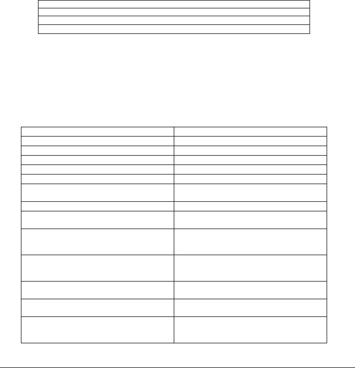
Specications
Operating Voltage 8.0 to 14 VDC
Current Draw 35mA
Frequency Range 908 MHz
Dimensions
Receiver Case 4.5” W x 2.75” H x 1.75” D
Color White
Housing Material Flame retardant ABS
Patents
U.S. Patent No. 7,239,236
Listings and Approvals
FCC Part 15 ID: CCKPC0137
Industry Canada: 5251A-PC0137