Digital Monitoring PC0137R2 Z-Wave Interface User Manual Installation Guide
Digital Monitoring Products Inc Z-Wave Interface Installation Guide
Installation Guide
738Zplus Z-WAVE INTERFACE MODULE
Installation Guide
DESCRIPTION
LT-1608 © 2017 Digital Monitoring Products, Inc.
17103
1SELECT THE LOCATION
Select a central location for the 738Zplus Z-Wave Interface
Module. Keep in mind that at least one Z-Wave Plus device
must be within 65 feet of the 738Zplus. Most Z-Wave Plus
devices act as repeaters for the signal to create longer and
multiple transmission routes (battery-powered Z-Wave Plus
devices do not repeat signals in order to extend battery life).
See Figure 2.
Note: Place the module away from large, metal objects
to avoid interference with the Z-Wave Plus signal.
2MOUNT THE 738Zplus
1. With the housing cover o, carefully remove the
738Zplus’s PCB from the housing.
2. Use the supplied screws to secure the 738Zplus
housing against a wall or flat surface. See Figure 3.
The 738Zplus Z-Wave Interface
Module allows DMP panels to
communicate with up to 232
Z-Wave or Z-Wave Plus devices,
such as light controls, light bulbs,
door locks, garage door openers,
and thermostats.
The 738Zplus is automatically
recognized by DMP panels, and no
additional programming is required.
Once the 738Zplus is connected to
a DMP panel, users can immediately
begin adding Z-Wave devices to
their system.
The 738Zplus connects to the
panel’s keypad bus and takes
control of the system’s Z-Wave Plus
devices using an integrated wireless
network. Devices can be remote
controlled from smartphones using
the DMP Virtual Keypad™ app,
or from any mobile device using
MyAccess™ text commands.
Compatibility
The 738Zplus module is compatible with:
• DMP XT30/XT50 Series panels,
Version 171 or higher
• All Z-Wave and Z-Wave Plus
devices
What is Included?
One model 738Zplus with housing
and a hardware pack
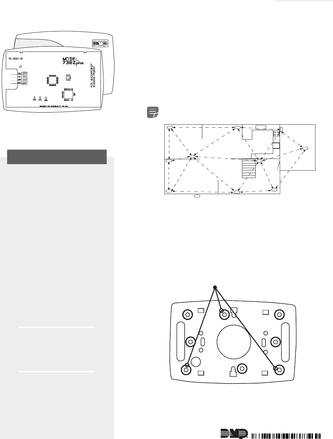
Figure 2: Example Z-Wave Plus Transmission Routes
= Z-Wave Plus Device
Oce Dining
Living Room
Foyer
Kitchen
Garage
Control
Panel with
738Zplus
Figure 3: 738Zplus Housing with Mounting Holes
Mounting Holes
Figure 1: 738Zplus Z-Wave
Interface Module
2 738ZPLUS INSTALLATION GUIDE | DIGITAL MONITORING PRODUCTS
4ADD DEVICES
After wiring the 738Zplus to the panel, use a DMP keypad to program Z-Wave Plus devices into
the panel through the User Menu Z-Wave Setup option. This allows users to add devices through
the User Menu or the Virtual Keypad App™ after installation. When possible, have the Z-Wave
device near the 738Zplus during setup and programming.
Note: When programming Z-Wave devices into a XT50 or XTLplus panel, you can add
multiple devices at once. If you add multiple devices at once, then you will name each
device after they have all been added.
1. Open the Keypad menu, press CMD until MENU? YES NO appears, and then press YES.
2. After accessing the User Menu, press CMD until ZWAVE SETUP? appears. Press any select
key/area.
3. Select ADD. The screen displays PROCESSING.
4. When prompted, press the button (or series of buttons if adding a thermostat) on the
device you are adding.
5. The keypad displays that the device has connected to your system through the 738Zplus.
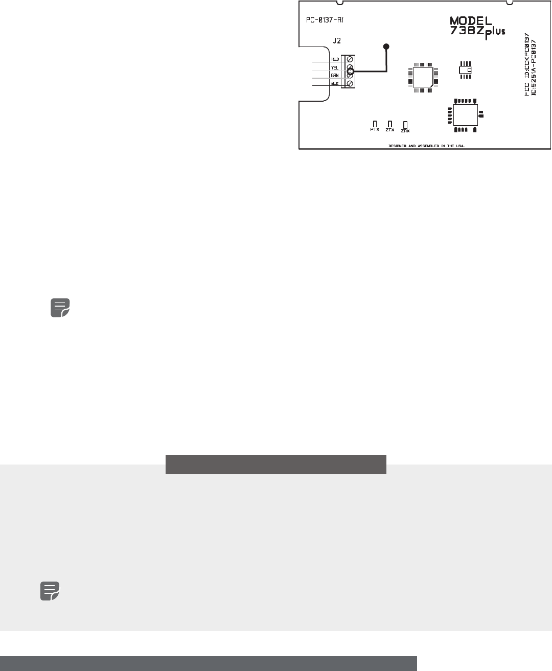
3WIRE THE 738Zplus
The 738Zplus has four wire connections to connect to the panel’s keypad bus. See Figure 4.
1. Connecting the wires to the 738Zplus
terminals.
a. Connect the wire that delivers power
to the module to the RED terminal.
b. Connect the wire that sends data
from the module to the YEL terminal.
c. Connect the wire that receives data
from the panel to the GRN terminal.
d. Connect the ground wire to the BLK
terminal.
2. Carefully place the 738Zplus PCB back
into the housing, and then snap the
housing cover into place.
3. At the panel, connect the wires to the
keypad bus corresponding terminals. Figure 4: 738Zplus Module PCB & Connections
Wiring to
Keypad Bus
ADDITIONAL INFORMATION
LED Operation
See Figure 4.
• PTX Green LED - If the light is blinking, then data is being sent to the panel.
• ZTX Green LED - If the light is blinking, then data is being sent to Z-Wave Plus devices.
• ZRX Yellow LED - If the light is blinking, then data is being received from Z-Wave Plus devices.
Z-Wave Certification
• The 738Zplus is a Z-Wave Security enabled device.
• The 738Zplus can be added to an existing network as a secondary controller by using the XFER (transfer) process and
selecting secondary from the primary controller.
Note: See the Z-Wave setup section of your control panel user guide for more information.
• The 738Zplus is compatible with Z-Wave Plus devices from all manufacturers.
• The 738Zplus can perform a factory default reset by initializing defaults in the panel programming menu.

738ZPLUS INSTALLATION GUIDE | DIGITAL MONITORING PRODUCTS 3
FCC INFORMATION
This device complies with Part 15 of the FCC Rules. Operation is subject to the following two conditions:
1. This device may not cause harmful interference, and
2. this device must accept any interference received, including interference that may cause undesired operation.
The antenna used for this transmitter must be installed to provide a separation distance of at least 20 cm (7.874 in.) from all persons. It
must not be located or operated in conjunction with any other antenna or transmitter.
Changes or modifications made by the user and not expressly approved by the party responsible for compliance could void the user’s
authority to operate the equipment.
Note: This equipment has been tested and found to comply with the limits for a Class B digital device, pursuant to part 15 of the
FCC Rules. These limits are designed to provide reasonable protection against harmful interference in a residential installation.
This equipment generates, uses and can radiate radio frequency energy and, if not installed and used in accordance with the
instructions, may cause harmful interference to radio communications. However, there is no guarantee that interference will not
occur in a particular installation. If this equipment does cause harmful interference to radio or television reception, which can be
determined by turning the equipment o and on, the user is encouraged to try to correct the interference by one or more of the
following measures:
• Reorient or relocate the receiving antenna.
• Increase the separation between the equipment and receiver.
• Connect the equipment into an outlet on a circuit dierent from that to which the receiver is connected.
• Consult the dealer or an experienced radio/TV technician for help.
Industry Canada Information
This device complies with Industry Canada Licence-exempt RSS standard(s). Operation is subject to the following two conditions:
1. This device may not cause interference, and
2. this device must accept any interference, including interference that may cause undesired operation of the device.
Le présent appareil est conforme aux CNR d’Industrie Canada applicables aux appareils radio exempts de licence. L’exploitation est
autorisée aux deux conditions suivantes : (1) l’appareil ne doit pas produire de brouillage, et (2) l’utilisateur de l’appareil doit accepter
tout brouillage radioélectrique subi, même si le brouillage est susceptible d’en compromettre le fonctionnement.
This system has been evaluated for RF Exposure per RSS-102 and is in compliance with the limits specified by Health Canada Safety
Code 6. The system must be installed at a minimum separation distance from the antenna to a general bystander of 7.87 inches (20 cm)
to maintain compliance with the General Population limits.
L’exposition aux radiofréquences de ce système a été évaluée selon la norme RSS-102 et est jugée conforme aux limites établies par le
Code de sécurité 6 de Santé Canada. Le système doit être installé à une distance minimale de 7.87 pouces (20 cm) séparant l’antenne
d’une personne présente en conformité avec les limites permises d’exposition du grand public.

Designed, engineered,
and manufactured in
Springfield, Missouri
INTRUSION • FIRE • ACCESS • NETWORKS
2500 North Partnership Boulevard
Springfield, Missouri 65803-8877
800-641-4282 | dmp.com
Specifications
Power Requirements
Operating Voltage 8.0 to 14VDC
Current Draw 35mA
Frequency Range 908 MHz
Dimensions 4.5”W x 2.75”H x 1.75”D
Color White
Housing Material Flame retardant ABS
Certifications
Z-Wave Certification: ZC08-14080002
FCC Part 15 ID: CCKPC0137
Industry Canada: 5251A-PC0137
Z-Wave Device Compatibility
Z-Wave GE Light Control Modules with and without dimmer
(ex. DMP Z-45602 and Z-45603)
Z-Wave Kwikset and Schlage Deadbolt and Lever Locks
(ex. DMP Z-99100)
Z-Wave Trane or 2-GIG Thermostats
(ex. DMP Z-TSEMT400BB3X or 2-GIG Z-STAT)
Z-Wave Portable Controllers
(ex. GE 45601)
Z-Wave Toggle Style Auxiliary Switch
(ex. DMP Z-45604)
Z-Wave In-Wall Dimmer Switch
(ex. DMP-Z45605)
Z-Wave In-Wall Toggle Style On/O Relay Switch
(ex. DMP Z-45606)
Z-Wave Garage Door Controller
(ex. DMP Z-GD00Z-4)