Digital Monitoring PC0152 LOW POWER WIRELESS TRANSCIEVER User Manual
Digital Monitoring Products Inc LOW POWER WIRELESS TRANSCIEVER
USER MANUAL
INSTALLATION SHEET
1127C PIR Motion Detector
Description
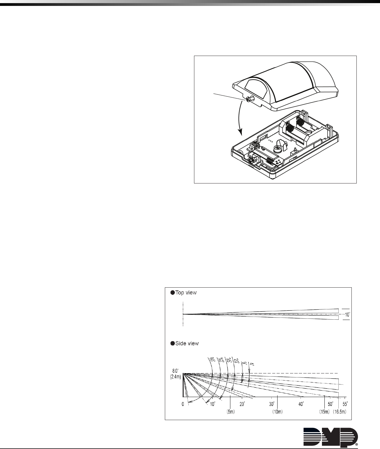
1127C is an 1100 Series Wireless Wall Mount Curtain PIR. The Detection area is a 50’ x 10’curtain using a fresnel lens.
The PIR includes a case tamper and functionality to allow sensor conguration from the control panel. DMP Exclusive
Features include Sensitivity Adjustment, Pulse Count, Walk Test, & Disarm Disable.
Features
• Remote conguration from panel
• Excellent R.F.I. and noise immunity
• Adjustable sensitivity from panel programming
• Pulse count selection allows multiple triggers
before an alarm is initiated
• Walk Test mode initiated from panel
• Disarm Disable operation to save battery life
• Installs up to 8’ wall height
Compatibility
• All DMP 1100 Series Wireless Receivers and panels
What is Included
The 1127C Series PIR Motion Detector includes the
following:
• One PIR detector with DMP wireless transmitter
• Two CR123 batteries
• Zone name and number label
• Serial number label
Installation
For your convenience, an additional pre‑printed serial number label is included. Prior to installing the device, record
the serial number or place the pre‑printed serial number label on the panel programming sheet. This number is
required during programming. As needed, use the zone name and number label to identify a specic transmitter.
Selecting the Best Location (LED Survey Operation)
The PIR transmitter provides a survey capability to allow one person to conrm transmitter communication with the
receiver while the cover is removed. The PIR transmitter PCB Red Survey LED turns on whenever the processor turns
on to send data to the receiver then immediately turns off when the receiver acknowledgement is received and the
processor shuts off. While in Walk Test mode, waving your hand in front of the PIR is a convenient way to send data
to the receiver to conrm operation. The PIR
circuit board LED lights to indicate motion
and the Survey LED briey lights to conrm
communication.
When the transmitter does not receive an
acknowledgement from the receiver, the
transmitter Survey LED remains on for about
8 seconds to let you know communication is
not established. Relocate the transmitter or
receiver until the Survey LED immediately
turns off indicating the transmitter and
receiver are communicating properly. If the
transmitter is not programmed into the panel,
the Survey LED does not operate properly.
Figure 1: Remove the Cover
Cover Lock Screw
Figure 2: Detection Pattern
Digital Monitoring Products 1127 PIR Installation Sheet
2
Mounting Location Considerations
Mount the unit:
• On a rigid vibration‑free surface
• So the expected intruder movement is across the detection pattern
Do not locate the unit:
• Facing areas that may change temperature rapidly
• In any area containing excessive metallic surfaces
• Where it may be exposed to false alarm sources such as: direct
sunlight, heat sources (heater, radiators, etc.) in the eld of view
or strong air drafts (fans, air conditioner, etc.)
Programming the PIR in the Panel
Program the device as a zone in Zone Information during panel
programming. At the Serial Number: prompt, enter the eight‑digit
serial number. Continue to program the zone as directed in the panel
programming guide.
Note: When a receiver is installed, powered up, or the panel is reset,
the supervision time for transmitters is reset. If the receiver has
been powered down for more than one hour, wireless transmitters
may take up to an additional hour to send a supervision message
unless tripped, tampered, or powered up. This operation extends battery life for transmitters. A missing
message may display on the keypad until the transmitter sends a supervision message.
The 1127C PIR programming offers some unique features:
• Disarm‑Disable operation to save battery life. Selecting YES for Disarm Disable in Zone Programming allows the
PIR to be disabled for Night and Exit type zones while the area is disarmed. Default is YES.
• Pulse count selection allows multiple triggers before an alarm is initiated. The pulse count is the number of
pulse inputs (trips) the PIR motion detector needs to sense before going into alarm. The pulse count in a high‑
security installation may be programed to 2, ensuring that the detector sends an alarm more quickly than a
pulse count of 4.
• Adjustable sensitivity from panel programming. Programming with a sensitivity of HIGH operates the PIR at
maximum sensitivity. A sensitivity of LOW operates the PIR at 75% of maximum sensitivity. Programming a LOW
sensitivity for installations in harsh environments may reduce false alarms.
• Walk Test mode initiated from panel. The Wireless PIR Walk Test is a 30‑minute test allowing the installer to
verify proper operation of PIR motion detectors in a system. Within one minute after the Wireless PIR Walk Test
is initiated, the LED’s on all 1127C PIR’s are enabled to ash when the sensors detect motion.
Testing
Walk Test
1. From the Walk Test menu of the panel, select the PIR Walk Test to place the PIR in walk test mode (enabling
the LED) for 30 minutes. After 30 minutes, the Walk Test automatically exits and the PIR returns to normal.
Any 1127C PIR Transmitters that have DISARM DISABLE set to YES are temporarily enabled when the Walk Test is
selected. Upon completion of Walk Test, the transmitter is disabled again.
2
. After entering the walk test mode, thoroughly test the installation to insure proper protection pattern of the
installed units. The walk test is a local test only and no results are sent to the Central Station.
Transmission Test
1. After programming the unit, close the cover to restore the tamper switch.
2. Verify that the keypad display indicates a signal received from the detector.
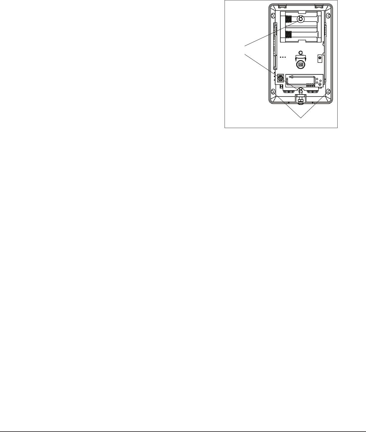
Wall Mount holes
Corner Mount holes
Figure 3: Mounting Holes
1127 PIR Installation Sheet Digital Monitoring Products
3
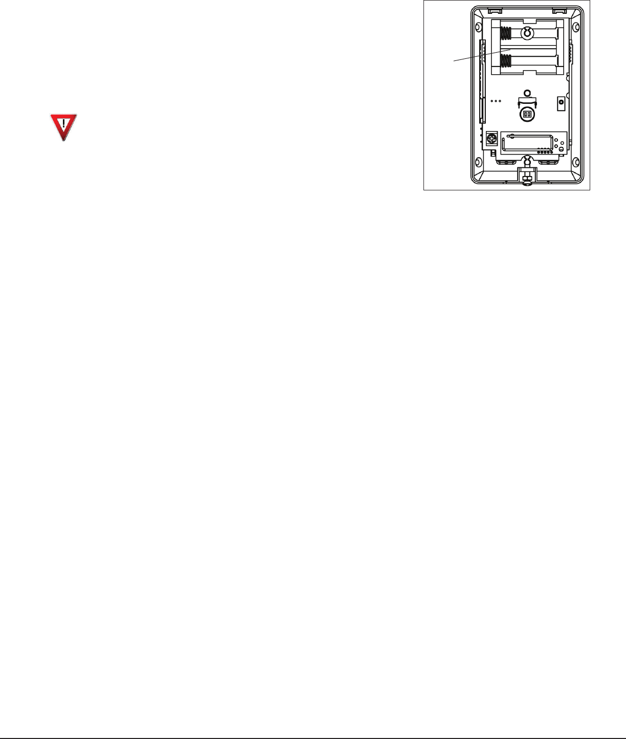
Installing or Replacing Batteries
Observe polarity when installing the battery. Use only 3.0V lithium batteries,
DMP Model CR123.
Note: When setting up a wireless system, it is recommended to program zones
and connect the receiver before installing batteries in the transmitters.
1. Remove the front cover. See Figure 1.
2. Remove the batteries (if installed) before installing new batteries.
Caution: Risk of re, explosion, and burns. Do not recharge, disassemble,
heat above 212°F (100°C), or incinerate. Properly dispose of unused
batteries.
3. Observe polarity and insert the batteries into the battery holder.
Note: If the battery reaches the factory preset low level, a Low Battery
signal is sent to the panel. The 1127C PIR remains operational for
approximately 30 days to allow adequate time to replace the battery.
Battery Life Expectancy
Typical battery life expectancy for a DMP Model 1127C Wireless PIR is ve
years, based on 300 trips per day. Battery life can be increased 40%, to seven
years, by programming the Disarm Disable feature to YES. DMP wireless equipment uses two‑way communication to
extend battery life.
The following situation can extend battery life expectancy:
•
Enabling the Disarm Disable feature in Zone Programming allows the PIR to be disabled while the area is disarmed.
This eliminates frequent motion from being detected in a high trafc area during the disarmed period.
• Extend transmitter supervision time in panel programming.
The following situations can reduce battery life expectancy:
• If a receiver is unplugged, or not installed.
Note: Transmitters continue to send supervision messages until a receiver returns an acknowledgement.
After an hour the transmitter only attempts a supervision message every 60 minutes.
• Programming the Disarm Disable feature as NO where frequent transmissions, in areas of high trafc, cause
messages to be sent every time movement is detected.
• When installed in extreme hot or cold environments.
Maintenance
When installed and used properly, the unit provides years of service with minimal maintenance. To ensure proper
operation, perform unit testing annually as described. Clean the cover and optional bracket with a water dampened
cloth as needed to keep it free of dust and dirt. Always test the unit after cleaning.
Battery
Compartment
Figure 4: Battery Compartment

LT-1062 1.03 © 2013 Digital Monitoring Products, Inc.
800-641-4282
www.dmp.com
INTRUSION • FIRE • ACCESS • NETWORKS
2500 North Partnership Boulevard
Springfield, Missouri 65803-8877
13195
Designed, Engineered
and Assembled in U.S.A.
FCC Information
This device complies with Part 15 of the FCC Rules. Operation is subject to the following two conditions:
(1) This device may not cause harmful interference, and
(2) this device must accept any interference received, including interference that may cause undesired operation.
Changes or modications made by the user and not expressly approved by the party responsible for compliance could
void theuser’s authority to operate the equipment.
NOTE: This equipment has been tested and found to comply with the limits for a Class B digital device, pursuant
to part 15 of the FCC Rules. These limits are designed to provide reasonable protection against harmful
interference in a residential installation. This equipment generates, uses and can radiate radio frequency
energy and, if not installed and used in accordance with the instructions, may cause harmful interference
to radio communications. However, there is no guarantee that interference will not occur in a particular
installation. If this equipment does cause harmful interference to radio or television reception, which can be
determined by turning the equipment off and on, the user is encouraged to try to correct the interference
by one or more of the following measures:
‑ Reorient or relocate the receiving antenna.
‑ Increase the separation between the equipment and receiver.
‑ Connect the equipment into an outlet on a circuit different from that to which the receiver is connected.
‑ Consult the dealer or an experienced radio/TV technician for help.
NOTE: The 1100 Series wireless system is a two‑way supervised wireless design. It is compliant with FCC rules
as they pertain to 900 MHz Spread Spectrum devices. In rare instances it has been observed that certain 900
MHz cordless telephones may occasionally experience a clicking sound on the telephone while in use. If
this occurs, it may be resolved by selecting a different channel on the cordless telephone, or replacing the
cordless phone with a different brand or model of 900 MHz telephone or other cordless telephone.
To comply with RF exposure requirements, a minimum distance of 20cm must be maintained between the
antenna and all persons.
This device complies with Industry Canada Licence‑exempt RSS standard(s). Operation is subject to the following
two conditions:
Industry Canada Information
(1) this device may not cause interference, and (2) this device must accept any interference, including interference
that may cause undesired operation of the device.
Le présent appareil est conforme aux CNR d’Industrie Canada applicables aux appareils radio exempts de licence.
L’exploitation est autorisée aux deux conditions suivantes : (1) l’appareil ne doit pas produire de brouillage, et (2)
l’utilisateur de l’appareil doit accepter tout brouillage radioélectrique subi, même si le brouillage est susceptible
d’en compromettre le fonctionnement.
Specications
Battery
Life Expectancy 5 to 7 years
Type 3.0V CR123
See Battery Life Expectancy for details.
Transmit condition Alarm, Low Battery
Mounting height 8 feet
Frequency Range 903‑927 MHz
Dimensions
2.7” W x 1.77” D x 4.33” H
Color White
Ordering Information
1127C‑W Curtain PIR
CR123 3.0V battery
Patents
U.S. Patent No. 7,239,236
Listings and Approvals
FCC Part 15: CCKPC0152
Industry Canada: 5251A‑PC0152
Underwriters Laboratories (UL) Listed
ANSI/UL 1023 Household Burglar Alarm System Units
Accessory
ANSI/UL 639 Intrusion Detection Unit Accessory