Digital Monitoring PC0191 Wireless alarm sounder User Manual Users manual
Digital Monitoring Products Inc Wireless alarm sounder Users manual
Users manual
INSTALLATION GUIDE
1101 Universal Transmitter
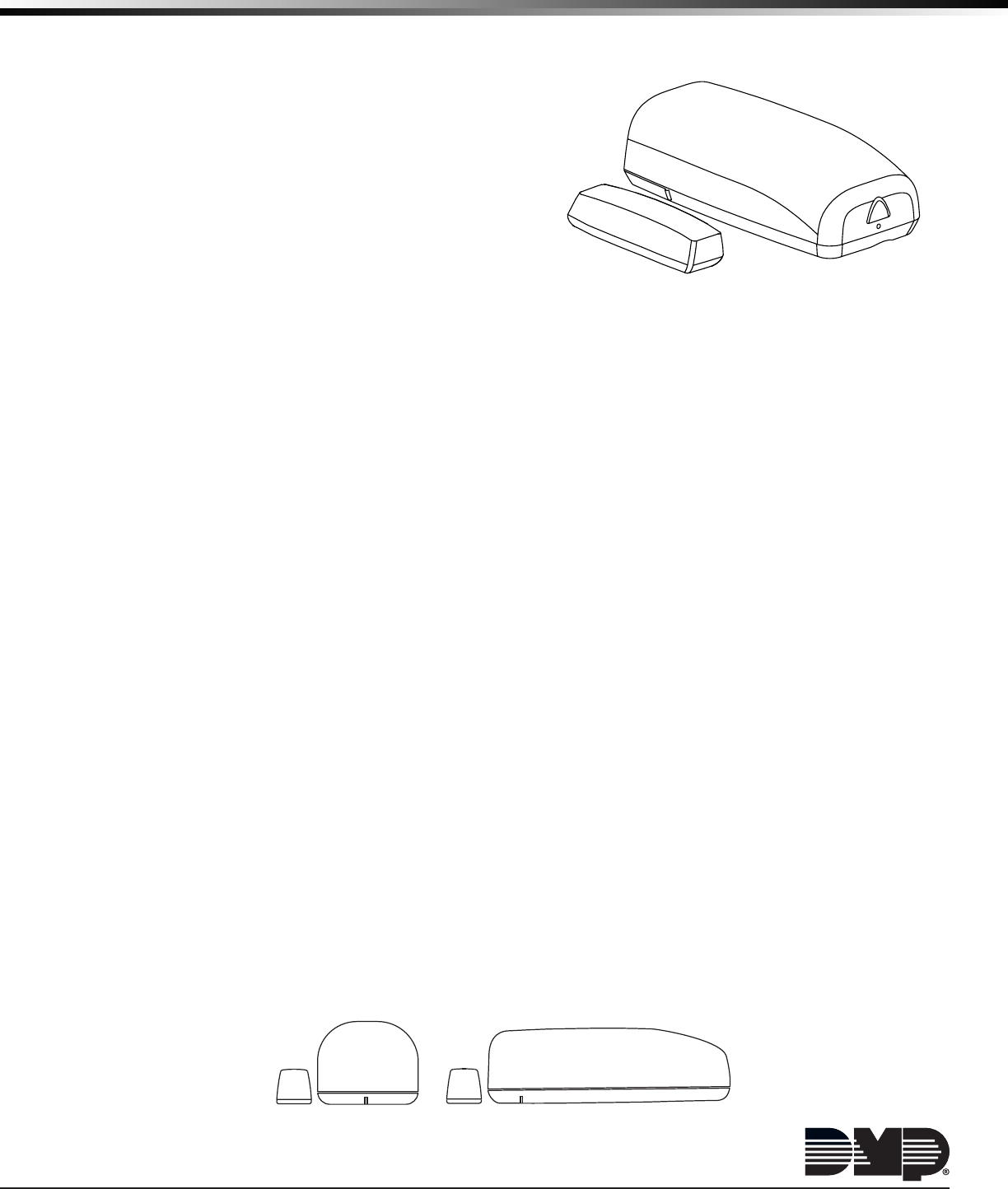
Description
The 1101 is a two-input transmitter that is typically used
for door and window applications. The 1101 provides two
internal magnetic reed switches and an on-board terminal
block to allow for external contact wiring. Both sets of
contacts, internal and external, can be programmed to
operate at the same time allowing for two independent
zones from one transmitter.
Using the on-board LED the 1101 Universal Transmitter
provides built-in survey capability to allow for single-person
installations, eliminating the requirement for an external
survey kit. For added security, an internal case tamper
switch is provided.
Compatibility
All DMP 1100 Series Wireless Receivers and Panels
Included Components
• One 1101 transmitter PCB mounted in a two-part housing (base and cover)
• One magnet housing and base
• One 3V lithium CR123A battery
• Hardware pack
Programming the Transmitter in the Panel
Program the device as a zone in Zone Information during panel programming. At the Serial Number: prompt, enter
the eight-digit serial number. Continue to program the zone as directed in the panel programming guide.
Note: When a receiver is installed, powered up, or the panel is reset, the supervision time for transmitters is reset.
If the receiver has been powered down for more than one hour, wireless transmitters may take up to an additional
hour to send a supervision message unless tripped, tampered, or powered up. This operation extends battery life for
transmitters. A missing message may display on the keypad until the transmitter sends a supervision message.
Selecting the Proper Location (LED Survey Operation)
The 1101 Transmitter provides a survey capability to allow one person to conrm transmitter communication
with the receiver while the cover is removed. The 1101 Transmitter PCB Red Survey LED turns on whenever data
is sent to the receiver then immediately turns off when the receiver acknowledgement is received. Pressing the
tamper switch is a convenient way to send data to the receiver to conrm operation. When the tamper switch is
pressed or released, the LED blinks once to indicate proper operation. When the transmitter does not receive an
acknowledgement from the receiver the LED remains on for about 8 seconds to let you know communication is
not established. Communication is also faulty when the LED ashes multiple times in quick succession. Relocate
the transmitter or receiver until the LED immediately turns off indicating the transmitter and receiver are
communicating properly. Proper communication between the transmitter and receiver is veried when for each press
or release of the tamper switch, the LED blinks immediately on and immediately off. Repeat this test to conrm ve
separate consecutive LED blinks. Any indication otherwise means proper communication has not been established.
Mounting the Transmitter and Magnet Assemblies
For internal contact operation, the transmitter and magnet assembly should have no more than a 5/8" space
between the assembled housings after installation. When mounting on metal surfaces, this distance is slightly less.
For door installations, it is recommended the transmitter be mounted on the door frame and the magnet assembly
be mounted on the door. See Figure 2 for transmitter and magnet placement options.
Figure 2. Transmitter and Magnet Placement Options
Side Mounting End Mounting
Figure 1: Transmitter and Magnet
Digital Monitoring Products 1101 Installation Guide
2
Magnet Assembly
Only one magnet assembly is required for internal reed switch operation. Depending on the installation
requirements, either the standard magnet assembly or the commercial magnet assembly can be used. See Figures 3
and 4. Snap the supplied magnet into the desired housing prior to mounting.
Installing the Transmitter
1. Remove the transmitter cover by pushing the button on the end of the cover and gently pulling upwards.
2. Remove the battery (if installed).
3. Hold the transmitter base in place with the reed switch near the area where you plan to mount the magnet.
4. Place one screw into the mounting hole location shown in Figure 5 and secure the housing to the surface.
5. Place the magnet housing base on the surface near one of the internal reed switch locations (see the magnet
alignment markers on the transmitter base) and use the provided screws to secure the magnet base in place.
See Figures 3 and 4.
6. Place the magnet and transmitter housing covers back on their bases.
Internal and External Contact Mounting
When connecting an external contact to
the terminal block, using 18 or 22 gauge
unshielded wire is recommended. Do not use
twisted pair or shielded wire. Connect the
external contact as normally open (N/O) or
normally closed (N/C) without any end-of-line
resistor. Refer to the Contact option under
Zone Information in the appropriate panel
programming guide.
When using both contacts, you must use
consecutive zone numbers. Refer to the
following examples:
• XR500, XR350/XR550 systems - zones
562 and 563 or zones 893 and 894
• XR100 and XR150 systems - zones 523
and 524 or zones 593 and 594
• XT30/XT50 Series - zones 31 and 32 or
zones 34 and 41
• XTLplus Series - zones 3 and 4
Note: For UL listed installations, program the external contact as Normally Closed (N/C).
Refer to the Contact option under Zone Information in the appropriate panel programming guide.
Figure 3: Standard
Magnet Assembly
Figure 4: Commercial
Magnet Assembly
Cover
Magnet
Screws
Mounting
Base
Cover
Screws
Magnet
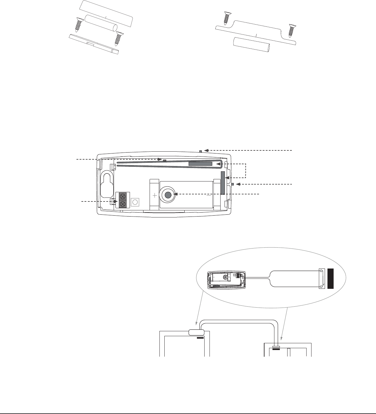
Figure 6: External Contact Wiring
Window - External Contact
Door - Internal Contact
Magnet with
External Contact
1101
Transmitter
Figure 5: Internal and External Contact Points
Red Survey
LED
External Contact
Terminal Block
Internal Contact
Magnetic Reed Switches
Battery Location
Mounting Hole
Magnet Alignment
Marker
Magnet Alignment
Marker
Magnet with 1101

1101 Installation Guide Digital Monitoring Products
3
Installing or Replacing the Battery
Observe polarity when installing the battery. Use only 3.0V lithium batteries, DMP Model CR123, or the equivalent
battery from a local retail outlet. For UL installations, only use #123 batteries manufactured by Energizer or CR123A
batteries manufactured by Panasonic or Tekcell.
Note: When setting up a wireless system, it is recommended to program zones and connect the receiver before
installing batteries in the transmitters.
1. If installed, remove the transmitter housing cover by pushing the button on the end and gently pulling upwards.
2. If replacing the battery, remove the old battery and dispose of it properly.
3. Place the 3.0V lithium battery in the holder shown in Figure 5 and press into place.
4. Snap the cover back into place.
Caution: Risk of re, explosion, and burns. Do not recharge, disassemble, heat above 212°F (100°C), or
incinerate. Properly dispose of used batteries.
Battery Life Expectancy
Typical battery life expectancy for DMP Model 1101 wireless transmitters is 5 years. DMP wireless equipment uses
two-way communication to extend battery life.
The following situations can reduce battery life expectancy:
• If a receiver is unplugged or not installed.
Note: Transmitters continue to send supervision messages until a receiver returns an acknowledgement.
After an hour the transmitter only attempts a supervision message every 60 minutes.
• Frequent transmissions, such as a door contact where messages are sent every time the door opens or closes.
• When installed in extreme hot or cold environments.
The following situation can extend battery life expectancy:
• Extend transmitter supervision time in panel programming.
• Infrequent transmission trips, such as a window that rarely sends messages.
1101
Transmitter

800-641-4282
INTRUSION • FIRE • ACCESS • NETWORKS
www.dmp.com 2500 North Partnership Boulevard
Designed, Engineered and
Assembled in U.S.A. Springeld, Missouri 65803-8877
LT-0694 1.04 © 2016 Digital Monitoring Products, Inc.
16335
FCC Information
This device complies with Part 15 of the FCC Rules. Operation is subject to the following two conditions:
(1) This device may not cause harmful interference, and
(2) this device must accept any interference received, including interference that may cause undesired operation.
The antenna used for this transmitter must be installed to provide a separation distance of at least 20 cm from all
persons. It must not be co-located or operated in conjunction with any other antenna or transmitter.
Changes or modications made by the user and not expressly approved by the party responsible for compliance could
void the user’s authority to operate the equipment.
NOTE: This equipment has been tested and found to comply with the limits for a Class B digital device, pursuant
to part 15 of the FCC Rules. These limits are designed to provide reasonable protection against harmful
interference in a residential installation. This equipment generates, uses and can radiate radio frequency
energy and, if not installed and used in accordance with the instructions, may cause harmful interference
to radio communications. However, there is no guarantee that interference will not occur in a particular
installation. If this equipment does cause harmful interference to radio or television reception, which can be
determined by turning the equipment off and on, the user is encouraged to try to correct the interference
by one or more of the following measures:
- Reorient or relocate the receiving antenna.
- Increase the separation between the equipment and receiver.
- Connect the equipment into an outlet on a circuit different from that to which the receiver is connected.
- Consult the dealer or an experienced radio/TV technician for help.
Industry Canada Information
This device complies with Industry Canada Licence-exempt RSS standard(s). Operation is subject to the following
two conditions: (1) this device may not cause interference, and (2) this device must accept any interference,
including interference that may cause undesired operation of the device.
Le présent appareil est conforme aux CNR d’Industrie Canada applicables aux appareils radio exempts de licence.
L’exploitation est autorisée aux deux conditions suivantes : (1) l’appareil ne doit pas produire de brouillage, et (2)
l’utilisateur de l’appareil doit accepter tout brouillage radioélectrique subi, même si le brouillage est susceptible
d’en compromettre le fonctionnement.
Specications
Battery
Life Expectancy 5 years (normal operation)
Type 3.0V lithium CR123A
See Battery Life Expectancy for full details.
Frequency Range: 905-924 MHz
Dimensions
Transmitter Case 3.3” L x 1.6” W x 0.9” H
Transmitter Base 3.3” L x 1.6” W x 0.1” H
Magnet Housing 1.5” L x 0.5” W x 0.7” H
Magnet Spacer 1.5” L x 0.5” W x 0.1” H
Color White
Housing Material Flame retardant ABS
Compatibility
All DMP 1100 Series Wireless Receivers and Panels
Patents
U. S. Patent No. 7,239,236
Certications
California State Fire Marshal (CSFM)
FCC Part 15 Registration ID CCKPC0191
Industry Canada Registration ID 5251A-PC0191
ANSI/UL 1023 Household Burglar Alarm System Units
Accessory Magnetically Activated Switch or Door
Contact Transmitter
ANSI/UL 634 Connections and Switches for use with
Burglar Alarm Systems Accessory