Displaydata 120-0112 Aura 29 Electronic Label User Manual Manual
ZBD Displays Ltd Aura 29 Electronic Label Manual
UserManual.wiki
>
Displaydata
>
120-0112 User Manual
>
Manual
Contents
1.
Manual
2.
User Manual
Manual
Navigation menu
Upload a User Manual
Namespaces
Wiki Guide
HTML
PDF
Info
Views
User Manual
Discussion / Help
Navigation
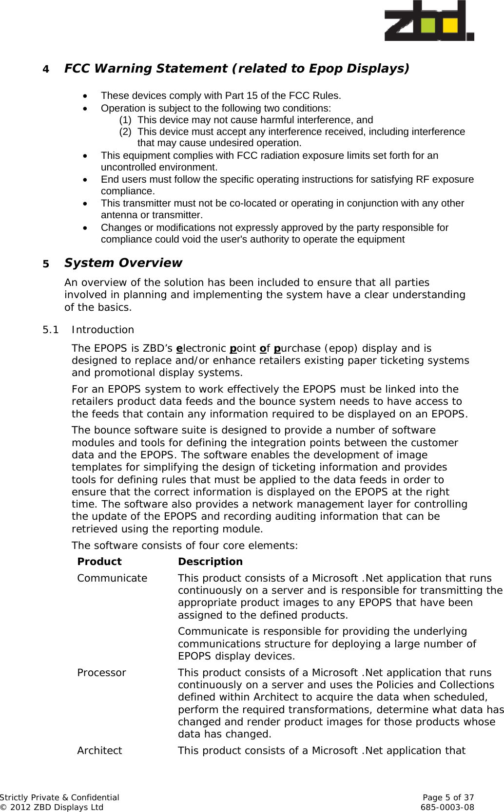
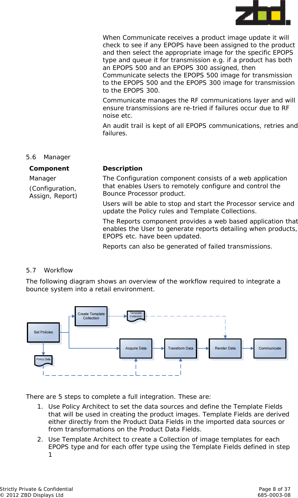
![Strictly Private & Confidential Page 9 of 37 © 2012 ZBD Displays Ltd 685-0003-08 Steps 1 & 2 often become an iterative process as the templates are developed. 3. Acquire the Data Values according to the transformation and policy rules defined in steps 1 & 2 4. Render the product images using the Data Values acquired in step 3 and the Template Collection defined in step 2. 5. Use Bounce Manager to view the updated statistics. 5.8 Step 1 – Defining the Template Fields Link Transformation[PromoPrice] = [Price] * 0.8[StockLevel] = If [Stock] > 100 Then “In Stock” Else If [Stock] = 0 Then “Out of Stock” Else “Low Stock”Product Data Fields Template FieldsSKUPricePromoPriceDescriptionBrandModelStockLevelTemplatePolicy RulesPrice DbSKUPriceDescriptionModel DbSKUBrandModelStock DbSKUStock‘Standard’ Template Fields are created using Policy Architect. Definition of the Template Fields begins by determining all the different data sources that will be used to create them and registering these with the Policy Architect application. A data source can take any form and may consist of a simple comma separated value file, an Excel spreadsheet, an XML file, a bitmap image directory, an Access database or more complex transactional databases such as Oracle or Microsoft SQL Server. Once the data sources have been registered the user then defines the data tables and the Product Data Fields that contain the relevant product information to be used in creating the product images. Each of the data source tables registered to Policy Architect needs to be linked to at least one other table to enable Policy Architect to determine how to retrieve the correct Data Values from each of the tables to make a consistent data set. Normally each of the data source tables would be linked via the product ID as this is a unique identifier that would usually be consistent across multiple data sets.](https://usermanual.wiki/Displaydata/120-0112.Manual/User-Guide-2210849-Page-9.png)
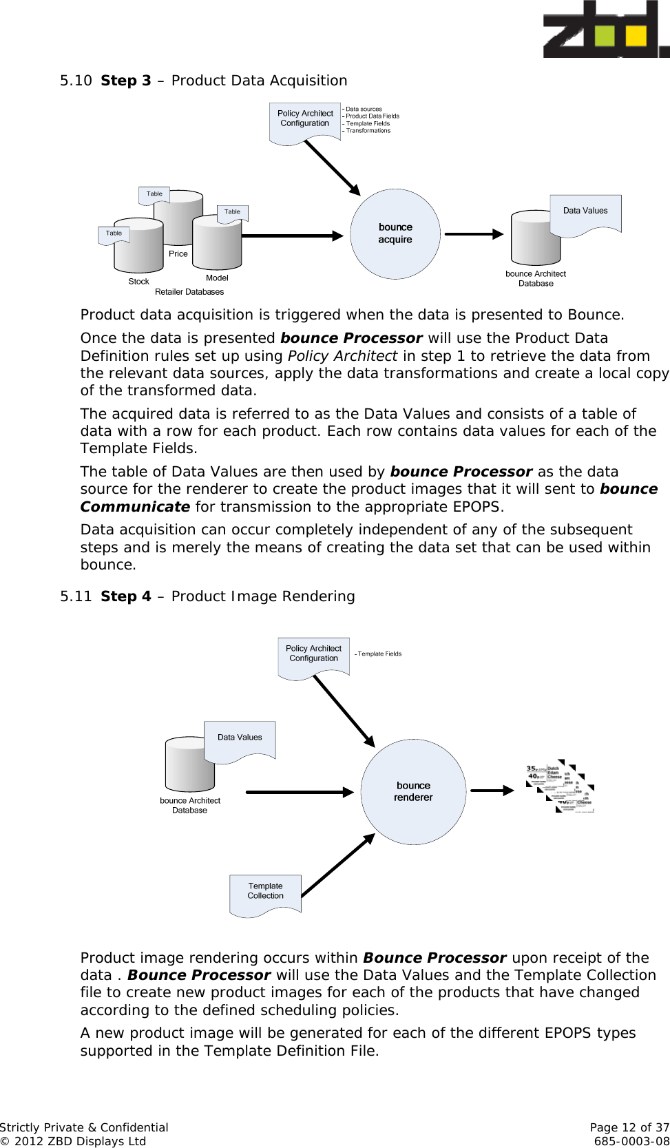
![Strictly Private & Confidential Page 10 of 37 © 2012 ZBD Displays Ltd 685-0003-08 Once the user has registered all the data sources and linked the tables they can then concentrate on determining what fields to be retrieved from them in order to define the Template Fields. Obvious fields such as [SKU], [Price], and [Description] etc. can normally be imported without the requirement to perform any transformations on the data as it is acquired. A special Template Field called [Template] must always be defined. This field contains the name of a Template Architect template that will be used by the Bounce Processor when creating the product image. Using Policy Architect the user is able to create new Template Fields by applying transformations to the Product Data Fields e.g. The user can create a new Template Field called [UnitPrice] that is calculated from the data sources by taking the [Price] and dividing it by the [UnitWeight]. Policy Architect is extremely powerful as it allows the user to combine the data source fields in many different ways to create new Template Fields for use by the Bounce Processor during rendering. Conditional fields can be created that enable the renderer to determine whether to show information on the display e.g. If the word “vegetarian” is found in the [SpecialConsiderations] data source field Policy Architect can create a Template Field called [Vegetarian] and set it to TRUE. Within Template Architect you could then create a template that would act on this Template Field and add the text “Suitable for vegetarians” or place a vegetarian icon on the display if this field is not NULL. In the example above the [Template] field has been set to ‘Standard’, but a transformation could be applied to one or more of the Product Data Fields to select different templates based on the data in the sources e.g. If [PromoPrice] is non-zero then set the [Template] Product Data Value to ‘Promotional’ else set to ‘Standard’. Once the user has created their initial set of Template Fields it is time to move on to the next step: Template Creation. 5.9 Step 2 – Template Creation](https://usermanual.wiki/Displaydata/120-0112.Manual/User-Guide-2210849-Page-10.png)
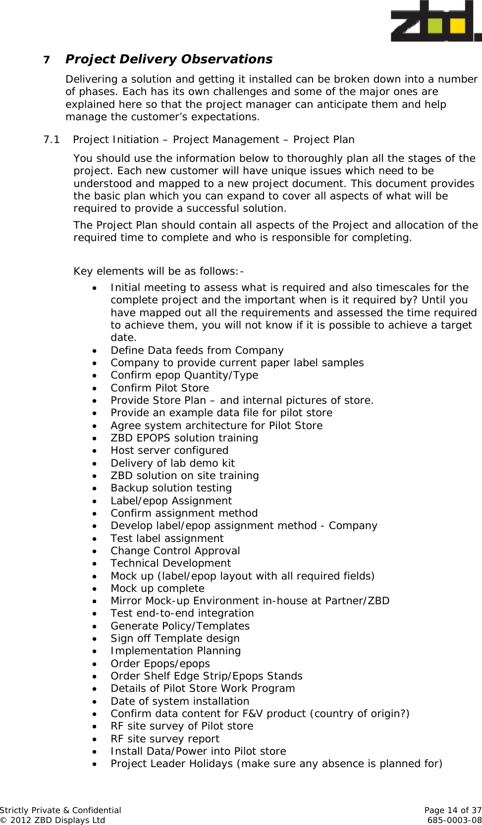
![Strictly Private & Confidential Page 11 of 37 © 2012 ZBD Displays Ltd 685-0003-08 Templates are created using a Template Architect. In this stage the user creates a Collection of image templates for each of the EPOPS types and for promotions or special offers etc. A template is a list of instructions for the Bounce Processor renderer detailing what Template Fields, background images and icons to place in an EPOPS image and what attributes, such as font style, to use when rendering the Data Values held by the Template Fields on to the image. Template Architect provides a graphical user interface for defining where and how the Template Fields should be rendered within the product image. Using the GUI the user can select a Template Field and define the area on the EPOPS display that the values contained in the Template Field should be rendered. A selection of field attributes is also available so that the user can apply different fonts, font styles, font sizes etc. The Template Field objects can be inverted to display white on black or the object can be set to auto fit within a bounding rectangle defined by the user. The user can apply conditions to Template Field objects based on the Data Value contained in the field. When a condition is applied the object will only be rendered on the EPOPS display if the condition evaluates True at the time of rendering the image. The user can place Template Fields into a group having its own bounding rectangle and apply group attributes e.g. the user may apply the [Description] and [Ingredients] Template Fields into a group and set the CentredVertical attribute. This would cause the renderer to combine the [Description] and [Ingredients] Data Values into a single object that it would then render around a vertical line central to the group bounding rectangle. Static text objects and basic line drawing objects can also be applied to a template. Users can also import their own background bitmap images into the template providing the ability for creating a consistent graphical look and feel of an EPOPS image. Graphics libraries are also provided for the user to map Template Fields to graphical images that will be rendered in place of the text contained in the field i.e. the user can associate a vegetarian graphic icon to the [Vegetarian] Template Field and the renderer would apply this icon to a specific location for every product where the Data Value is True. The user may end up iterating between this and the previous step during template creation as they may decide to create new Template Fields or make use of different data source fields in the template. Once the user has created a Collection of templates to accommodate the different EPOPS types they can then move on to define the scheduling rules that will be applied to the bounce system.](https://usermanual.wiki/Displaydata/120-0112.Manual/User-Guide-2210849-Page-11.png)
![Strictly Private & Confidential Page 13 of 37 © 2012 ZBD Displays Ltd 685-0003-08 5.12 Step 5 – Update EPOPS Bounce Communicate queues EPOPS image updates whenever the renderer generates a new product image in Step 4. 1. All newly rendered product images are delivered to Bounce Communicate as soon as they have been created and will commence to transmit the images to the epops Bounce Communicate keeps an audit log of all transaction requests. All updates and their status are logged for future retrieval using Report Manager. 5.13 Step 6 – Report Viewing The Report Manager component of Bounce provides a means for the user to view status and statistical information about the EPOPS system. All actions that are performed by Bounce are logged and reporter provides a means to view those actions in a number of different ways: The user can get a summary of the last 7 days transactions. The user can view what updates occurred to a particular product over a specified period of time. The user can view what updates occurred on a specific date or within a specified time frame. 6 External Documents - Caution References to external documents are made throughout and shown as [Document Class - Reference number (Title)] so for example 530-0027-xx (Batch Configuration Tool). There will also be a version number for each document (-xx). Please check that you have the most recent versions of each document before using it. These documents are likely to change on a regular basis so it is worth checking with ZBD support before beginning a major project that you have the latest versions.](https://usermanual.wiki/Displaydata/120-0112.Manual/User-Guide-2210849-Page-13.png)
![Strictly Private & Confidential Page 17 of 37 © 2012 ZBD Displays Ltd 685-0003-08 Check network access (Switch port available, cabling type) 7.6 Handover Once everything has been installed it is essential to check that all store operatives have received adequate training. Leaving this activity too late may impact any KPI measurements for the project. See section 8 It is possible that store layouts may change after the installation has been completed that could adversely affect the RF characteristics of the system, it is therefore important that the original installation details are retained by the implementation team to allow easier identification of the changes and to propose corrective actions. 8 Site Survey Doing a site survey is absolutely necessary to avoid running into problems when doing the actual installation. This needs to include looking at fixtures and fittings as well as the RF characteristics of the environment to site the communicator properly. 8.1 Site Survey basics Get as much detail about the site in advance. Site Layout plan (map) Site Name, full postal address Contact details of store managers Attendees Create a plan for the site survey before visiting the site 8.2 RF Range testing and positioning the communicator 8.2.1 RF Range Test tool The RF Range Test tool will be made available to partners – please ask for copies of this from ZBD Support [Document 530-0025] 8.2.2 RSSI scan A document explaining how to do an RSSI scan for conflicting RF noise will be made available to partners – please ask for copies of this from ZBD support [Document 530-0024] 8.2.3 Smaller format stores (approx. 5000 m2) If it’s not a particularly large store or contains less than 7,000 items then one communicator might be enough, unless the store is an unusual shape or has unusual RF characteristics. In all cases an RF range test should still be carried out. 8.2.4 Larger format stores Most shops will require a multiple communicator system and it is mandatory that a full RF survey is conducted to confirm the best placement of communicators to ensure full RF coverage throughout the store and of course this applies to multi-level stores. 8.2.5 Environmental considerations What departments and product types are going to be labelled? Proposed location and orientation of the Communicator(s)](https://usermanual.wiki/Displaydata/120-0112.Manual/User-Guide-2210849-Page-17.png)
![Strictly Private & Confidential Page 18 of 37 © 2012 ZBD Displays Ltd 685-0003-08 Ceiling Height, type [demountable, solid concrete, wood, asbestos etc] Fixture construction/height [steel, wood, 1.2Metres/1.8 Metres etc] Size/shape of coverage area [Rectangular, L shaped, 48M x 71M etc] Ceiling infrastructure [traywork/H&V etc] Features such as low ceilings, traywork carrying high power cables, wooden shelves and high metal shelves can have a negative effect on the RF range. Maybe some epops will need a few retries to receive price updates – moving the communicator around to find the optimum position is worth taking time over. To help troubleshoot any technical issues that arise later it’s mandatory to have a map of the store that details the products and departments in each section, this will assist in diagnosing any issues that the store may report post-installation. Department EPOPS50 EPOPS300 EPOPS500 Standard (0-40) Freezer Medicines 350 Y Mens Health 250 Y Nail & Accesories 500 Y Nails 150 Y Oils 200 Y Prepared Meals 400 Y Toys & Gifts 750 500 Y etc. Try to link EPOPS required to map locations 8.2.6 Note the position of the IT infrastructure Connectivity [Ethernet Category, RF etc] IP Addressing requirements [allocated IP addresses for Bounce devices] PC locations [inc new Bounce PC] Communications Cabinet Switch/Patch capacity for Bounce devices Make sure the customer’s IT team or contractor is aware if new power or network points need to be installed. Medicines Health Products Nails Oils Prepared Meals Toys](https://usermanual.wiki/Displaydata/120-0112.Manual/User-Guide-2210849-Page-18.png)
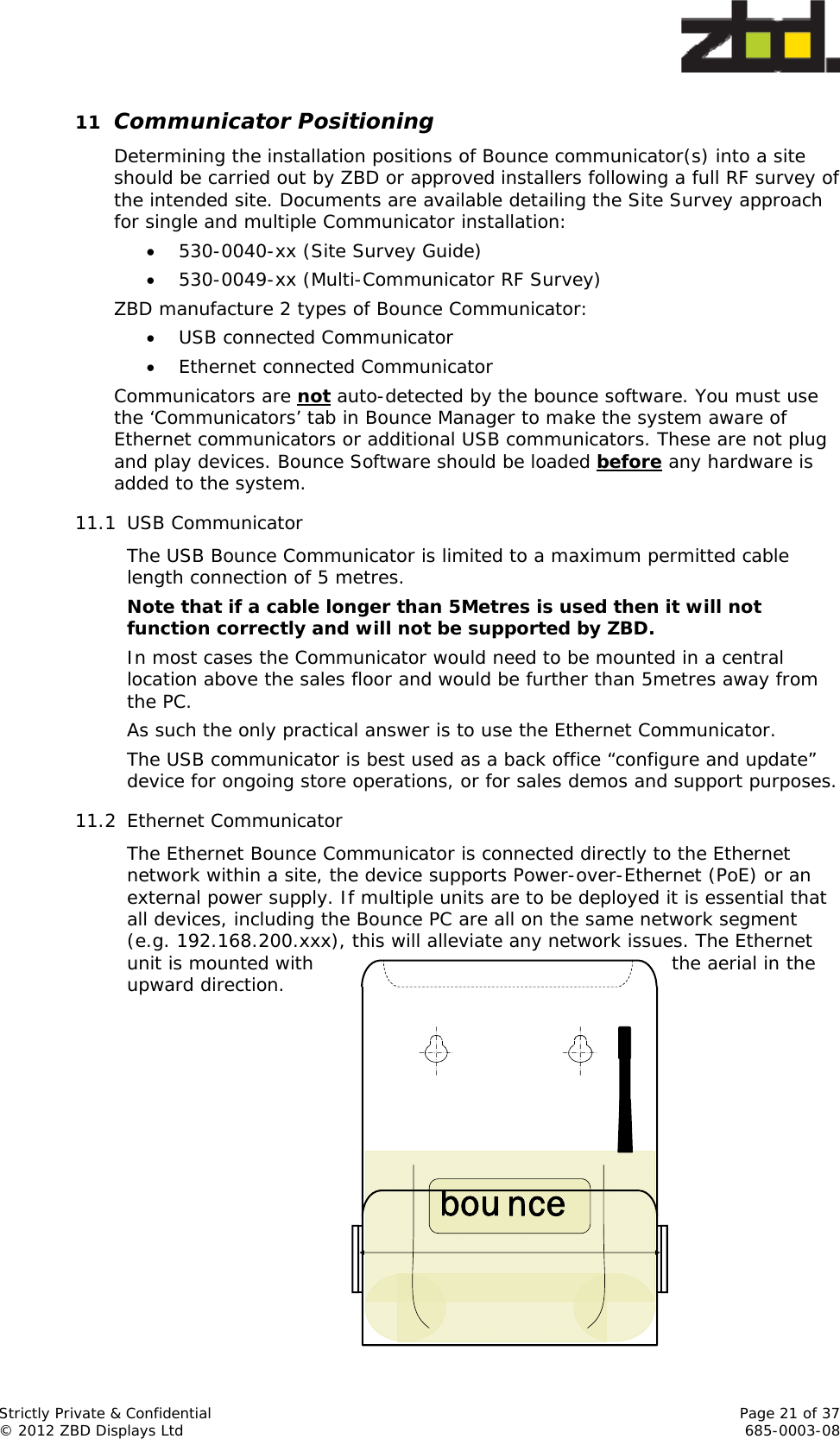
![Strictly Private & Confidential Page 22 of 37 © 2012 ZBD Displays Ltd 685-0003-08 Detail of Ethernet Communicator in bracket 11.3 Positioning The Bounce Communicator should ideally be located in a central position in the area that the epops will be located, ideally the position should be at height of at least 2.5 metres above the floor level and have no metal obstructions within 2 metres to the front, rear and sides. ZBD can provide an off-the-shelf bracket to mount the Communicator in a variety of positions, and also offer extension brackets if required. See diagram below You should make sure that the power can be cycled from the IT room so you do not need a ladder to physically disconnect the Ethernet communicator. This could be a physical mains switch if the Ethernet communicators are powered or the ability to remove the Ethernet PoE cables. The orientation of the Communicator should be as detailed in any Site Survey documentation produced as this could affect coverage in larger sized operations. Bounce Holder Bounce Wall Bracket 12 Software Requirements, Setup and Installation 12.1 Documentation available As part of the overall project management process, the setup of the system should be detailed in the Technical Specification. Due to the greater flexibility available our recommendation is that the solution runs based on the ‘Enterprise Interface’ [550-0009-xx] The Bounce Software suite is available on the ZBD FTP (ftp.zbd.co.uk) site and can be downloaded and installed onto a number of platforms. The Bounce System Software fully supports the following Windows host operating systems. Windows XP Professional (SP3 or higher) - (32bit) Windows Vista Business Edition (SP2 or higher) - (32bit) Windows 7 Professional Edition (SP1 or higher) - (32bit & 64bit) Windows Server 2003 R2 (SP1 or higher) – (32bit)](https://usermanual.wiki/Displaydata/120-0112.Manual/User-Guide-2210849-Page-22.png)
![Strictly Private & Confidential Page 23 of 37 © 2012 ZBD Displays Ltd 685-0003-08 Windows Server 2008 R2 (SP1 or higher) – (32bit & 64bit) Please remember that the USB communicator only has drivers available for the 32bit versions of these operating systems. We recommend for deployments, whether single or multiple communicators, that Ethernet communicators are used because they are easier to install and support. Installation guides have been produced for each platform and should be referenced prior to any live deployment: 530-0012-xx – Windows Vista & Windows 7 530-0013-xx – Windows Server 2008 Please read the Release Notes for the version of software you are going to be installing. This contains valuable information about a clean install and also upgrading from a prior version. Additional applications for running the USB communicator from a remote machine on the network and other ways to improve the system architecture are available. With a complete Technical Specification we can look at providing tools that may benefit the solution as a whole. Copies of these documents can be requested through ZBD Support support@zbdsolutions.com. If an installation is requested on a platform other than those listed, the request will be submitted to a ZBD Technical review where consideration will be given to the request and business opportunity. 12.2 Software Installation – Clean Install It is important to understand that a clean install is usually the quickest and easiest installation as there will not be any conflicts with any other application software loaded on a used PC system. Regardless of what PC is used the steps below must be followed. Run the Microsoft Update and download and install all hotfixes, patches and security updates that are available. Reboot the PC Run the Microsoft Update (expect to find more updates are now available that were not shown on the last update) and download and install all hotfixes, patches and security updates that are available. Re-run the Microsoft Update again and ensure no more updates are available. If this is a used PC, make a backup of the PC. Install Bounce v3.3 software components in the following order:- (Please note you may be requested to reboot the PC, and if so you must do this after each module has completed its installation process.) Bounce Communicate Bounce Processor Bounce Architect Bounce Manager [please see Appendix A ‘Bounce Manager installation’ for more details] Run Microsoft Update on the host OS. Reboot the PC. Run Microsoft Update again to ensure all patches are applied.](https://usermanual.wiki/Displaydata/120-0112.Manual/User-Guide-2210849-Page-23.png)
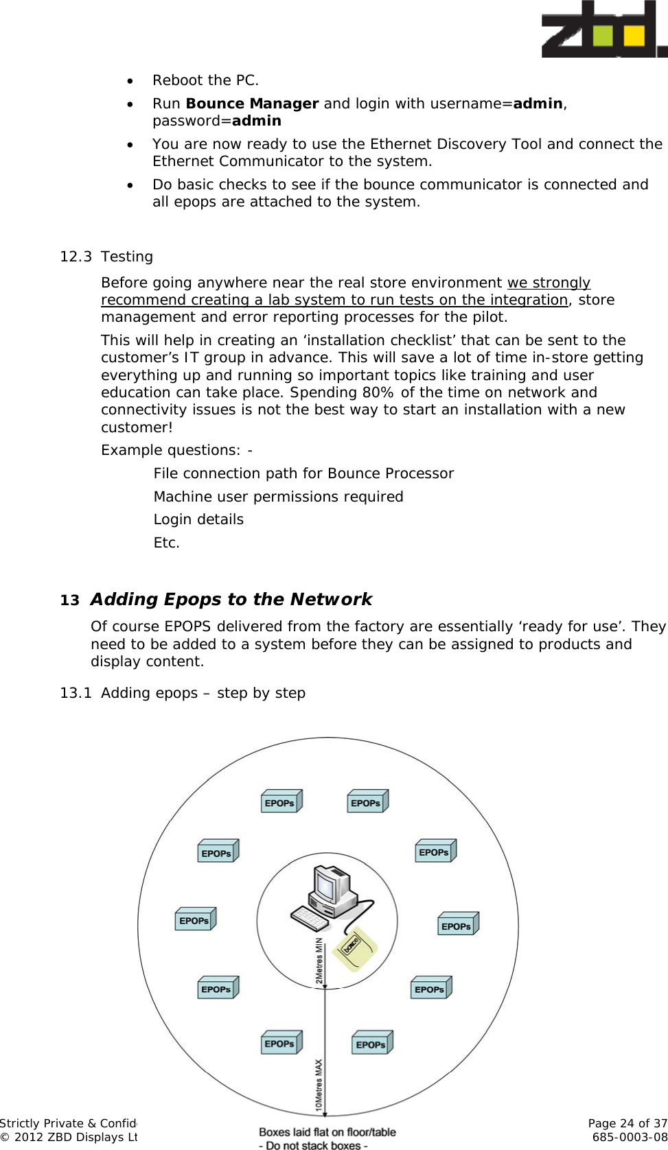
![Strictly Private & Confidential Page 25 of 37 © 2012 ZBD Displays Ltd 685-0003-08 The epops MUST be within 10m of the Bounce Communicator antenna to be configured 1. Adding epops to a network uses Channel 5 (in European territories) and Channel 60 in the USA. It is not possible to build two systems of epops for different stores using two machines in close proximity as there will be contention (conflict) for the same RF configuration channel. 2. Each box of EPOPS contains a number of 2D barcodes listing all the serial numbers of the EPOPS it contains. Record the label serial numbers using a 2D scanner into Notepad [or equivalent text editor] 3. Repeat for each box that you want to add in that session 4. Save the file and ensure all serial numbers are on separate lines and there are no gaps between lines or separator characters in the file. 5. Import this as a CSV file using Bounce Manager a. The process uses a list of epops in CSV format and configures each label, it then generates a list of successful and failed epops, any failures are automatically removed from the system making the installation clean. b. Failed epops should be re-run again – the Batch Configuration process results in a report which gives the option to rerun the configuration process again for any that have failed to configure. This should definitely be done. 6. Epops are then added by Bounce to the network automatically 7. Adding epops takes ~10 hours for circa 1,000 displays 8. The status progress can be viewed through the command line window or through the Batch Configuration Report in Bounce Manager. Once the process completes the total number of epops will be shown on the Bounce Manager Dashboard. 13.2 Offsite configuration If it is not practical to configure epops into a new installation (this could be due to construction delays, incomplete data cabling etc) then the configuration can be undertaken off-site. 1. Build a Bounce PC using the licence key for the installation 2. Configure the epops using Bounce Manager 3. Back up the database using Bounce Manager 4. Take the epops and the back up to the store and restore the database 5. After 15 minutes all of the epops should have resynchronised 6. Epops can be allocated to product in the normal way. 7. Delete the database from the off-site system and uninstall the software IMPORTANT NOTE: For sites that already have epops installed this process must NOT be used as it would generate duplicate RF addresses in the epops and could overwrite previous data changes in the live environment. If such a requirement is necessary contact support@zbdsolutions.com. 13.3 Synchronisation and Label Management In order for the system to function smoothly all epops should be kept in the store within range of the Bounce Communicator antenna. This is a ‘must do’](https://usermanual.wiki/Displaydata/120-0112.Manual/User-Guide-2210849-Page-25.png)
![Strictly Private & Confidential Page 29 of 37 © 2012 ZBD Displays Ltd 685-0003-08 16 Training and Procedures before handover 16.1 Training Staff training is a very important part of the success of any project. Since the staff are such a key part of any retail organisation their opinion and user experience carries great weight with any decision making process later in the sale. Staff training must incorporate the basic functionality such as: o Knowing how to access the Bounce Manager application o How to use the HHT application device o How to manually assign/un-assign epops to products o How to manually add/delete epops to the system o The correct handling and care of the epops [cleaning etc] o Use of the built-in scanner to read bar-codes effectively. o Ongoing training to ensure all operators can use scanners correctly. o How to attach/remove epops from fixtures and correct use of fittings (i.e. to optimize viewing angles etc.) o The correct thermal stabilization (thermal equilibrium) period if epops are moved from ambient temperature to “chiller” environments or vice versa. It is recommended that display image updates are not carried out during the 45min thermal stabilization period. If updates are carried out the image will be blackened or smudged and the correct time must elapse before a new image update is downloaded which will correct the smudged image. The staff should have access to User Guides that they can use to administer the labeling system; these documents should be the responsibility of the customer or agent to provide. We recommend getting hold of any ‘User Guides’ created by the customer to check that what they’ve created is correct and clear. 16.2 Procedures and handover Retailers usually have a pre-defined set of procedures and will know what their roles and responsibilities are in most situations. These scenarios need to be discussed and agreed with the project team before the system is handed over to them. Does the project team know how the store gets more EPOPS? What’s the procedure for reporting faults or issues? Unless these are dealt with before the store takes over responsibility for the system then the whole installation may fail. The handover process should confirm that the store management has accepted the system, and these processes have been agreed. o Staff training & supporting procedures documentation (eg: Quick Reference Guide) o Support contact information (who to call, how to escalate). o Typically in the form of an A4/A5 o Support Notice with information and contact numbers o Where to get spares displays, shelf-edging or other consumables?](https://usermanual.wiki/Displaydata/120-0112.Manual/User-Guide-2210849-Page-29.png)
![Strictly Private & Confidential Page 30 of 37 © 2012 ZBD Displays Ltd 685-0003-08 o Returns Management Process has been agreed and the store management knows what it is. So, the staff will know what to do if there’s a problem, where to get more epops from and they’ll have had training. 17 System Management The system is managed through the Bounce Manager application and provides status updates, reports and alerts. The Bounce Manager application guide is documented in 530-0058-xx (Bounce Manager User Guide). This document is very important and must be read before the system is made operational 18 Support Overview Issues that need ZBD assistance should be sent via our support email address (Salesforce portal) with all the necessary information to be able to reproduce the problem. support@zbdsolutions.com In most cases ZBD are likely to be responsible for third level support only. So partners will provide the first and second level support for most system installations whether they are trials, proof of concept or full roll-out. ZBD will deal with third level support issues once the partner has been able to reproduce the issue themselves in-house and is able to give ZBD the means to reproduce the issue in order to fix it. The different parts of the Bounce software suite all have logs available on the live system to help diagnose issues and solve problems. This support section focuses on the XML based ‘Enterprise Interface’ [550-0009-xx] since this is our preferred method of driving the system. This offers the greatest flexibility for interfacing to the system and controlling it without significant integration/coding work needing to be carried out. This support chapter has been split into three sections: - 1. Store level diagnostics Information and questions for store personnel to help them either solve the problem themselves or help in the diagnosis 2. Partner / Support level diagnostics Locations for support logs and some information on mid-level issues that can occur as well as how to fix them 3. Advanced Selected challenges and more detailed information 18.1 Store level diagnostics The main challenge with problems reported by store staff is lack of information that’s useful to actually solve the problem. These are usually vague statements like: - ‘Nothing seems to be working’](https://usermanual.wiki/Displaydata/120-0112.Manual/User-Guide-2210849-Page-30.png)
![Strictly Private & Confidential Page 31 of 37 © 2012 ZBD Displays Ltd 685-0003-08 ‘A label didn’t update’ ‘A price change didn’t happen’ Instead of trying to use this vague information as the basis for diagnosing the fault and fixing the problem it’s actually more time efficient to go through a set number of steps. 18.1.1 Is the RF network working? There are a couple of ways for staff to check whether the RF network is actually functioning properly 18.1.1.1 Is the green or orange light flashing on the communicator? This may not be visible to the staff, depending on where it is mounted in the store 18.1.1.2 Can you assign an EPOPS to a different product? Pick an EPOPS from the shop floor and try to assign it to something different (remember to assign it back afterwards!) Try a couple if the first attempt doesn’t work – remember, depending on the way the system is set up, that there may be a wait for this action to complete. 18.1.1.3 What is the general system status? There is an alert log in Bounce Manager and visible alerting in the Dashboard to warn the store staff whether there are significant problems anywhere with the system 18.1.2 What’s the status of the label? It’s important to find out from the staff what the label actually says: - ‘Successfully configured’* The label is on the network but has never been linked to a product ‘Unassigned’* The label is on the network and was linked to a product but is not linked to a product anymore ‘No image available’* The label is assigned/linked to a product but the problem could be that the product information isn’t available from the retailer’s host system [see section 13.2.1.2 later] ‘Product image bitmap’ The label has a product image with price/barcode etc. means that it’s currently linked to the product shown *It is possible in some environments that these default images have been replaced with specific customer images.](https://usermanual.wiki/Displaydata/120-0112.Manual/User-Guide-2210849-Page-31.png)
![Strictly Private & Confidential Page 32 of 37 © 2012 ZBD Displays Ltd 685-0003-08 18.1.2.1 Interrogate Bounce Manager about the label In order for store staff to interrogate the system about a specific EPOPS look at the Bounce Manager page and type/scan its serial number into EPOPS History 18.1.2.2 Force the label to update Using the HHT it may be possible to force the label to update or to use the retailer’s host system to send the product information to the label again. REMEMBER: The store back office system may be out of range of the communicator if it’s sitting out in the middle of the sales area. Holding a label and trying to send it updates when out of range of the communicator is obviously going to cause even more confusion! 18.1.2.3 Is the label update or assignment in the Update Queue? Apart from sitting and looking at a label and maybe missing changes on the screen it’s possible to check the bounce queue in Bounce Manager 18.2 Partner / Support Level Diagnostics We recommend that partners and support organisations should have remote access to the machines running the Bounce software in store. The main reason for this is that EPOPS are still quite ‘new’ technology and while we are confident the solution is robust the customer will be nervous about relying on something they may not understand. So it is very important for support organisations to be able to react quickly and answer questions that the customer might have. The only way to really achieve this is by having remote access to the machine in the store. 18.2.1 Enterprise Interface error logging The main advantage of using XML files and folders is that files (product updates, link requests and system commands) which aren’t processed are moved into their respective error folders. So it’s easy to see whether files have been processed or not. More detail on setting up the system this way is available in the Enterprise Interface [550-0009-] There is also a general ‘logging output file’ which can be activated in Policy Architect. Policy Architect > Edit > Logging Settings [The schema file for this is available from the ZBD technical team] All this information can be accessed by the retailer’s host system and used to send status information back to the organisation – rather than having to rely on store staff managing the system and trying to diagnose issues themselves.](https://usermanual.wiki/Displaydata/120-0112.Manual/User-Guide-2210849-Page-32.png)
![Strictly Private & Confidential Page 33 of 37 © 2012 ZBD Displays Ltd 685-0003-08 18.2.1.1 Incoming XML data doesn’t match the Schema If files are sent from the host system that don’t match the schema for the products, EPOPS or system commands then they won’t be processed and re-named as errors 18.2.1.2 XML files didn’t actually arrive to be processed There may be a classification of products or a switch higher up within the retailer’s host system that means products aren’t categorised or available as ‘electronic epops’ We’ve seen this where the request is made to the host system for the information for a particular product but he host has ignored this request because that particular product shouldn’t be merchandised (sold) using an electronic label. 18.2.2 Error logs There are quite a few logs available to diagnose system issues although it takes some experience to draw conclusions from them. 18.2.3 System Management Tools In the latest release (3.3) there are a number of command line tools which are designed to carry out batch processes, solve problems and diagnose possible faults across the network of epops in the store. 18.2.3.3 Bounce Processor Database Cleaning Tool The Bounce Processor Database Cleaning Tool is a command line application that is designed to remove unused data from the Bounce Processor SQL Server database instance and reclaim storage space. The tool requires no user interaction and can therefore be used from a scheduled task within Windows. [530-0034-xx] 18.2.3.4 SQL Database Cleanup Tool The SQL Database Cleanup Tool is a command line application that is designed to remove unused data from the Bounce SQL Server database instance and reclaim storage space. The tool requires no user interaction and can therefore be used from a scheduled task within Windows. [530-0032-xx] Both these cleanup tools should be scheduled to run in installations to ensure that SQL Express 2008 does not reach it’s 10GB data limit.](https://usermanual.wiki/Displaydata/120-0112.Manual/User-Guide-2210849-Page-33.png)
![Strictly Private & Confidential Page 34 of 37 © 2012 ZBD Displays Ltd 685-0003-08 18.2.3.5 Get Log Tool This tool copies and zips all the log files for the system and places the zip file in the same directory that the batch file was run from. The default location for this is: - C:\Program Files\ZBD Displays\Bounce\Tools\GetLogFiles This saves users hunting around locations for all the logs and brings them together into one place. It does not send the file anywhere however! When logging a support request it is good practice to include the zipped log files in the request. 18.2.3.6 SQLBounceXMLBackup and SQLBounceXMLRestore These tools create an XML based backup of the Bounce Comms database but only retain the information needed to recover a network of EPOPS with their product associations. Since the amount of information retained is less these files are not as big as standard SQL backups so they can be emailed and sent without the same network issues that a 300Mb file might have. 18.2.3.7 BackupDB Tool A standalone tool for backing up the bounce database 18.2.3.8 EPOPS Command Line Application (CLA) The CLA tool is a powerful command line application that should only be used when directed to by ZBD Support. Making improper changes to the system using this tool can have a detrimental effect on the system and in some cases loose communication to the EPOPS altogether. Please refer to the detailed notes in the documentation for this tool [530-0037-xx] 18.2.4 Other ZBD Software Tools These utilities are available to make batch tasks simpler and save time 18.2.4.1 Auto EPOPS Assign Allows you to assign a .csv file or EPOPS serial numbers to a .csv file of product ID’s automatically. The next EPOPS serial number in the list will be associated (linked) to the next product in the list. It’s also possible to use Auto EPOPS Assign to automatically link an EPOPS serial number list to products with the same ID as the EPOPS serial numbers. [530-0036-xx] 18.2.4.2 Delete EPOPS Allows mass deletion of a .csv list of EPOPS serial numbers from a system without having to find individual EPOPS in the Bounce GUI list [530-0035-xx]](https://usermanual.wiki/Displaydata/120-0112.Manual/User-Guide-2210849-Page-34.png)
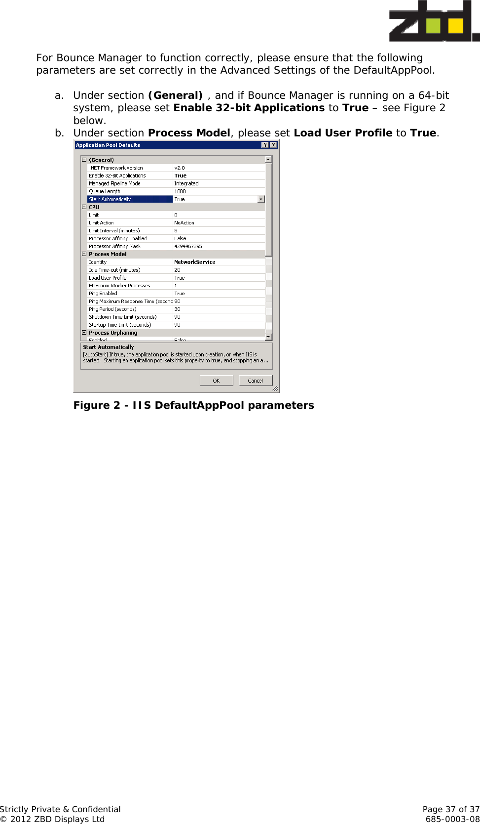
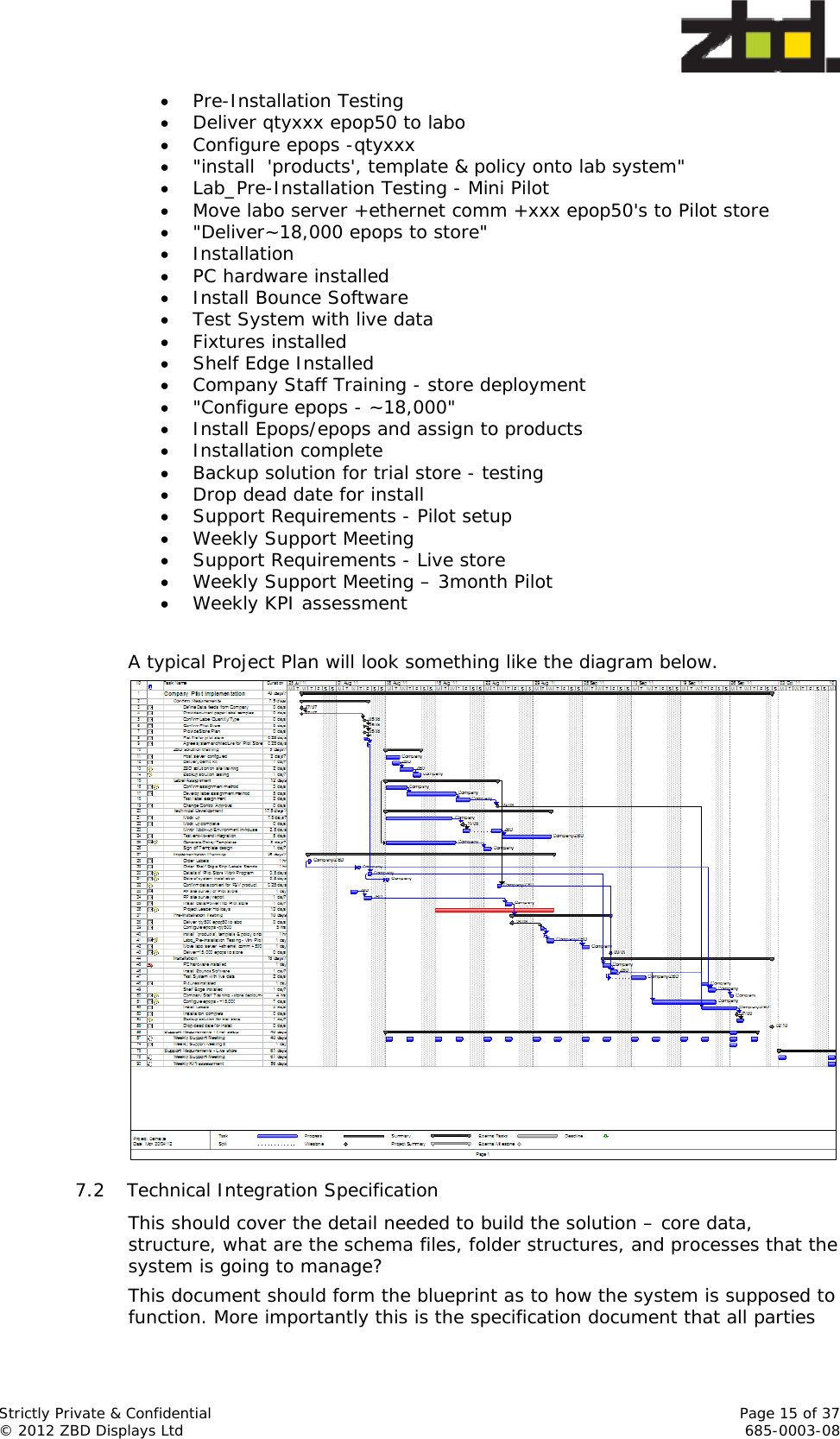
![Strictly Private & Confidential Page 36 of 37 © 2012 ZBD Displays Ltd 685-0003-08 20 Appendix A – Bounce Manager installation Bounce Manager can be installed in either of 2 modes: either in Standalone mode or in IIS mode. In Standalone mode, access to Bounce Manager is restricted to the PC on which it is installed. In IIS mode, Bounce Manager can be accessed from remote PCs. The installation and correct configuration of Microsoft Internet Information Services (IIS) is a pre-requisite in this case. Installation files: the Bounce Manager installation package contains 2 folders ‘Standalone’ and ‘IIS’. The ‘Standalone’ folder contains the Bounce Manager installation files (setup.exe and BounceManagerSetup.msi) which install Bounce Manager as a web service running on TCP/IP port 8000. If Bounce Manager is installed as ‘Standalone’ it will only be available on the PC on which it is installed via http://localhost:8000/. [N.B – please run the file setup.exe to install] If access to Bounce Manager is required from a remote PC, then the ‘IIS’ alternative needs to be installed. The ‘IIS’ folder contains the installation files (setup.exe and BounceManagerIISSetup.msi) which install Bounce Manager as a module or web application under Microsoft Internet Information Services (IIS). [N.B – please run the file setup.exe to install] Configuration steps: The ‘IIS’ option requires a number of configuration steps, as listed below: (1)Enable ‘IIS 6 Management Compatibility’ The location of this Windows module depends on your operating system – please refer to Windows documentation for more details. Under Windows 2008 Server R2 64-bit the ‘IIS 6 Management Compatibility’ module can be found under Web Server (IIS), ‘Add Role Services’ and select ‘IIS 6 Management Compatibility’. Under Windows 7 32-bit, the ‘IIS 6 Management Compatibility’ module can be found in “Control Panel > Programs & Features > Turn Windows features on or off”. Figure 1 - enable IIS 6 management compatibility (2) Bounce Manager runs under the DefaultAppPool under IIS.](https://usermanual.wiki/Displaydata/120-0112.Manual/User-Guide-2210849-Page-36.png)