Bendix/King Global Positioning System KLN 35A 006 08791 0000 2
User Manual: Bendix/King Global Positioning System KLN 35A
Open the PDF directly: View PDF ![]() .
.
Page Count: 179 [warning: Documents this large are best viewed by clicking the View PDF Link!]
- TITLE PAGE
- TABLE OF CONTENTS
- INTRODUCTION
- KLN 35A SNEAK PREVIEW
- HOW-TO INDEX
- SECTION 1
- SECTION 2
- SECTION 3
- 3. BASIC GPS OPERATION
- 3.1. COVERAGE AREA
- 3.2. TURN-ON AND SELF TEST
- 3.3. DISPLAY FORMAT
- 3.4. BASIC OPERATION OF PANEL CONTROLS
- 3.5. MESSAGE PAGE
- 3.6. INITIALIZATION AND TIME TO FIRST FIX
- 3.7. SELECTING AND SCANNING WAYPOINTS
- 3.8. “NEAREST” FUNCTIONS
- 3.9. DIRECT TO OPERATION
- 3.10. NAVIGATION PAGES
- 3.11. WAYPOINT PAGES
- 3.12. VIEWING AND SETTING THE DATE AND TIME
- 3.13. THE OTHER (OTH) PAGES
- 3.14. REMOTE MOUNTED ANNUNCIATORS
- 3.15. SPECIAL USE AIRSPACE ALERTING
- 3.16 SAMPLE TRIP
- 3. BASIC GPS OPERATION
- SECTION 4
- 4. ADVANCED GPS OPERATION
- 4.1. CREATING AND MODIFYING FLIGHT PLANS
- 4.1.1. CREATING A FLIGHT PLAN
- 4.1.2. VIEWING DISTANCE AND DESIRED TRACK BETWEEN STORED FLIGHT PLAN WAYPOINTS
- 4.1.3. ACTIVATING A NUMBERED FLIGHT PLAN
- 4.1.4. ADDING A WAYPOINT TO A FLIGHT PLAN
- 4.1.5. DELETING A WAYPOINT FROM A FLIGHT PLAN
- 4.1.6. DELETING FLIGHT PLANS
- 4.1.7. STORING FPL 0 AS A NUMBERED FLIGHT PLAN
- 4.2. OPERATING FROM THE ACTIVE FLIGHT PLAN
- 4.3. CALCULATOR PAGES
- 4.4. CREATING USER-DEFINED WAYPOINTS
- 4.5. NAVIGATION MODES
- 4.6. OPERATION OUTSIDE THE PRIMARY COVERAGE AREA
- 4.7. USING THE TAKE-HOME MODE
- 4.1. CREATING AND MODIFYING FLIGHT PLANS
- 4. ADVANCED GPS OPERATION
- APPENDIX A
- APPENDIX B - MESSAGE PAGE MESSAGES
- APPENDIX C - SCRATCHPAD MESSAGES
- APPENDIX D - ABBREVIATIONS
- APPENDIX E - LAT/LON CONVERSIONS
- APPENDIX F— GPS PRIMER
- INDEX
Pilot’s Guide
ORS 01
KLN 35A
Bendix/King®
Global Positioning System
A
WARNING
Information subject to the export control laws. This document, which includes
any attachments and exhibits hereto, contains information subject to
International Traffic in Arms Regulation (ITAR) or Export Administration
Regulation (EAR) of 1979, which may not be exported, released or disclosed
to foreign nationals inside or outside the U.S. without first obtaining an export
license. Violators of ITAR or EAR may be subject to a penalty of 10 years
imprisonment and a fine of $1,000,000 under 22 U.S.C. 2778 or Section
2410 of the Export Administration Act of 1979. Include this notice with any
reproduced portion of this document.
COPYRIGHT NOTICE
©1996 AlliedSignal, Inc.
Reproduction of this publication or any portion thereof by any means without
the express written permission of AlliedSignal Commercial Avionics Systems
is prohibited. For further information contact the Manager, Technical
Publications; AlliedSignal Commercial Avionics Systems; 400 North Rogers
Road; Olathe, Kansas 66062. Telephone: (913) 782-0400.
AlliedSignal, Inc.
Commercial Avionics Systems
400 North Rogers Road
Olathe, Kansas 66062-1294
FAX: 913-791-1302
TELEPHONE: 913-782-0400
006-08791-0000
Rev. 2 4/97 A
KLN 35A Pilot’s Guide
006-08791-0000
for KLN 35A
with
Operational Revision Status ORS 01
April 1997
Revision History and Instructions
Manual KLN 35A Pilots Guide
Revision 2, April 1997
Part Number 006-08791-0000
Typographical and spelling errors corrected on pages; 3-27, 3-41,
3-65 and 3-67. Illustration corrections on figures; 3-184 and 4-20.
Database Form Corrections. Added warning and copyright notices
on front cover. Added revision page R-1. Deleted EFF-1 through
EFF-6 pages.
R-1 Effective Date 4/97006-08791-0000 Rev 2

NOTE: A “whiskers” border is used around
data on some of the figures in this Pilot's Guide
to indicate that the data inside the border is
flashing.
åå.ånm ZBV
åååååå BIMINI
#>Leg N 25
VOR 1 W 79

KLN 35A Pilot’s Guide Table of Contents
TOC-1 Effective Date 5/95006-08791-0000 Rev 0
INTRODUCTION..............................................................................i
KLN 35A SNEAK PREVIEW .........................................................ii
HOW-TO INDEX ............................................................................iv
1. KLN 35A SYSTEM COMPONENTS .......................................1-1
2. DATA BASE ...........................................................................2-1
2.1. Data Basics .....................................................................2-1
2.2. Data Base Contents and Coverage Areas ......................2-1
2.3. ICAO Identifiers ...............................................................2-3
2.4. Updating the Data Base ..................................................2-4
2.5. User Defined Data Base ..................................................2-7
2.6. Data Base Update Service Options .................................2-7
3. BASIC GPS OPERATION ......................................................3-1
3.1. Coverage Area ................................................................3-1
3.2. Turn-on and Self Test ......................................................3-1
3.3. Display Format ................................................................3-7
3.4. Basic Operation of Panel Controls ................................3-10
3.4.1. Page Selection ......................................................3-10
3.4.2. Data Entry .............................................................3-12
3.4.3. The Duplicate Waypoint Page ..............................3-15
3.4.4. Cyclic Fields ..........................................................3-16
3.5. Message Page ..............................................................3-17
3.6. Initialization and Time to First Fix ..................................3-18
3.7. Selecting and Scanning Waypoints ...............................3-20
3.7.1. Selecting Waypoints by Identifier ..........................3-21
3.7.2. Selecting Waypoints by Scanning .........................3-22
3.7.4. Selecting Waypoints by Name or City ...................3-24
3.8. “Nearest” Functions ......................................................3-26
3.8.1. Viewing the Nearest Waypoints ............................3-27
3.8.1.1 Nearest Airport Criteria .................................3-28
3.8.1.2 Continuous Display of Nearest Airport ..........3-29
3.8.2. Viewing the Nearest Special Use Airspaces .........3-29
3.8.3. Viewing the Nearest Flight Service Station
Frequencies ..........................................................3-31
3.8.4. Viewing the Nearest Center Frequencies .............3-32
3.9. Direct to Operation ........................................................3-32
3.9.1. Initiating a Direct To ..............................................3-33
3.9.2. Canceling a Direct To ...........................................3-35

3.9.3. Waypoint Alerting for Direct To Operation ............3-35
3.10. Navigation Pages ........................................................3-36
3.10.1. The Navigation 1 (NAV 1) Page ..........................3-36
3.10.2. The Navigation 2 (NAV 2) Page ..........................3-39
3.10.3. The Navigation 3 (NAV 3) Page ..........................3-40
3.10.4. The Navigation 4 (NAV 4) Page ..........................3-40
3.11. Waypoint Pages ..........................................................3-45
3.11.1. Airport Pages ......................................................3-45
3.11.1.1. The Airport 1 (APT 1) Page ........................3-45
3.11.1.2. The Airport 2 (APT 2) Page ........................3-46
3.11.1.3. The Airport 3 (APT 3) Page ........................3-47
3.11.1.4. The Airport 4 (APT 4) Page ........................3-48
3.11.1.5. The Airport 5 (APT 5) Page ........................3-50
3.11.2. VOR Pages .........................................................3-51
3.11.2.1. The VOR 1 Page ........................................3-51
3.11.2.2. The VOR 2 Page ........................................3-51
3.11.3. NDB Pages .........................................................3-52
3.11.3.1. The NDB 1 Page .........................................3-52
3.11.3.2. The NDB 2 Page .........................................3-52
3.11.4. Supplemental Waypoint Pages ...........................3-53
3.11.4.1. The Supplemental 0 (SUP 0) Page .............3-53
3.11.4.2. The Supplemental 1 (SUP 1) Page ............3-53
3.11.4.3. The Supplemental 2 (SUP 2) Page ............3-54
3.11.4.4. The Supplemental 3 (SUP 3) Page .............3-54
3.12. Viewing and Setting the Date and Time ......................3-55
3.13. The Other (OTH) Pages ..............................................3-57
3.13.1. Determining the Status of the GPS Signals ........3-57
3.13.2. Viewing and Deleting User Waypoints and
Waypoint Remarks ..........................................3-59
3.13.2.1.The OTH 3 Page ..........................................3-60
3.13.2.2. The OTH 4 Page .........................................3-61
3.13.3. Viewing the KLN 35A Software Status and
Time of Operation ...........................................3-61
3.15. Special Use Airspace Alerting .....................................3-62
3.16 Sample Trip .................................................................3-65
3.16.1 Pre-departure ......................................................3-65
3.16.2 En route ..............................................................3-66
3.16.3 Terminal Area .....................................................3-67
Table of Contents
TOC-2
Effective Date 5/95 006-08791-0000 Rev 0

4. ADVANCED GPS OPERATION .............................................4-1
4.1. Creating and Modifying Flight Plans ................................4-1
4.1.1. Creating a Flight Plan .............................................4-1
4.1.2. Viewing Distance and Desired Track
Between Stored Flight Plan Waypoints ...................4-3
4.1.3. Activating a Numbered Flight Plan ..........................4-4
4.1.4. Adding a Waypoint to a Flight Plan .........................4-5
4.1.5. Deleting a Waypoint from a Flight Plan ...................4-6
4.1.6. Deleting Flight Plans ...............................................4-6
4.1.7. Storing FPL 0 as a Numbered Flight Plan ..............4-7
4.2. Operating from the Active Flight Plan ..............................4-8
4.2.1. General Procedures ................................................4-8
4.2.2. Turn Anticipation and Waypoint Alerting .................4-9
4.2.3. Viewing the Waypoint Pages for the Active
Flight Plan Waypoints ...........................................4-10
4.2.4. Combining Direct To and Flight Plan Operation ...4-11
4.2.5. Viewing Distance, ETE, ETA, or Desired Track
to Flight Plan Waypoints .......................................4-13
4.3. Calculator Pages ...........................................................4-14
4.3.1. The Calculator 1 (CAL 1) Page .............................4-14
4.3.2. The Calculator 2 (CAL 2) Page .............................4-16
4.3.3. The Calculator 3 (CAL 3) Page .............................4-18
4.3.4. The Calculator 4 (CAL 4) Page .............................4-19
4.3.5. The Calculator 5 (CAL 5) Page .............................4-20
4.3.6. The Calculator 6 (CAL 6) Page .............................4-20
4.4. Creating User-defined Waypoints ................................4-21
4.4.1. Creating a Waypoint at Your Present Position ......4-22
4.4.2. Creating a Waypoint at a Certain
Latitude/Longitude .................................................4-23
4.4.3. Creating a Waypoint Referenced from
Another Waypoint ..................................................4-24
4.5. Navigation Modes ..........................................................4-25
4.5.1. Selecting the Leg Mode or the OBS mode ...........4-26
4.5.2. The En route-Leg Mode ........................................4-26
4.5.3. The En route-OBS Mode ......................................4-27
4.5.4. Effects of Switching From En route-OBS
Mode to En route-Leg Mode .................................4-28
4.5.5. Activating a Waypoint While in the
En route-OBS Mode ..............................................4-28
KLN 35A Pilot’s Guide Table of Contents
TOC-3 Effective Date 3/96006-08791-0000 Rev 1

4.6. Operation Outside the Primary Coverage Area .............4-29
4.7. Using the Take-home Mode ..........................................4-30
APPENDIX A - NAVIGATION TERMS .......................................A-1
APPENDIX B - MESSAGE PAGE MESSAGES .........................B-1
APPENDIX C - SCRATCHPAD MESSAGES .............................C-1
APPENDIX D - ABBREVIATIONS ..............................................D-1
State Abbreviations ................................................................D-1
Canadian Province Abbreviations ..........................................D-2
Country Abbreviations ...........................................................D-2
ARTCC Abbreviations ............................................................D-8
Other Abbreviations Used on KLN 35A Pages ....................D-17
APPENDIX E - LAT/LON CONVERSIONS ................................E-1
APPENDIX F - GPS PRIMER .....................................................F-1
Table of Contents
TOC-4
Effective Date 5/95 006-08791-0000 Rev 0

KLN 35A Pilot’s Guide Introduction
iEffective Date 5/95006-08791-0000 Rev 0
INTRODUCTION
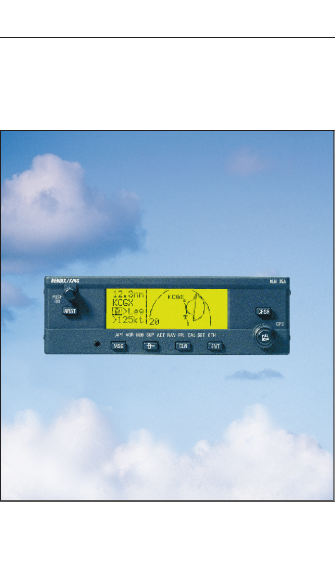
Thank you for choosing the Bendix/King KLN 35A GPS. If you’ve
never used GPS before, you’ll find it will change the way you fly. The
moving map graphics with special use airspace boundaries will give
you an extra feeling of security during all of your time in the air. All in
all, it will let you concentrate on the fun in flying, and isn’t that why
you learned to fly in the first place?
This Pilot's Guide should be of great help to you. It is written in plain,
simple English and it assumes you are not an experienced user of
GPS or other type of long range navigation equipment. If you are
experienced, so much the better. This Pilot's Guide also includes
hundreds of sample screen figures and other illustrations to make
your learning easier. It is designed so that you can start at the front
and progress in the order presented; however, you may want to skip
around and learn things in your own order. Also, on page iv, there is
an index of frequently used procedures which will help you find the
page that describes how to do exactly what you want to do. There
are also several appendices in the back of the manual that you may
find useful from time to time.
Be sure to keep this Pilot's Guide handy with you in the airplane. It is
designed to fit easily in the glove box, or in the seat pocket. The KLN
35A is very simple to operate, but the Pilot's Guide can sure be of
help to you.
One last thing. Don't get so involved in learning to use the KLN 35A
that you forget to fly the airplane. Be careful, and remember to keep
a close eye out for other aircraft.

Introduction
iiEffective Date 5/95 006-08791-0000 Rev 0
KLN 35A SNEAK PREVIEW
If you absolutely can't wait to use your KLN 35A until you've read this
Pilot's Guide, this section is for you. This page will teach you just
enough to get going and then learn by doing. This operational pre-
view assumes the KLN 35A has been properly installed, the unit was
previously operational in the same general geographical location, and
that no peripheral equipment interfaced with the KLN 35A (such as
external HSIs, CDIs, autopilots, moving map display, etc.) is to be
used at this time. If you are using this operational preview in flight, do
so only in good VFR conditions and only with an alternate means of
navigation (including pilotage) available to cross-check position.
1.Turn the unit on by pushing in the On/Off switch (the small knob
in upper left hand corner).
2.For a few seconds, the Turn On Page is displayed while the unit
runs a self-test. Afterwards, the Self-test Page is displayed. If
the KLN 35A is receiving an altitude from an encoding altimeter,
the present altitude will be displayed on line 3. The bottom line
should display Passand a flashing Ok?. Press the Fbutton
to approve the Self-test Page.
3.The Initialization Page will now be displayed. If the date and time
are incorrect by more than 10 minutes, refer to section 3.2 of this
Pilot's Guide. The right side of the screen should show the
identifier of the nearest airport to the initial position, along with a
radial and distance from that airport waypoint. Press Fwith
the cursor flashing over Ok?to approve the Initialization Page.
4.The VFR page will now be displayed to notify you that the GPS is
for VFR use only. Press Fto approve this page.
5.A Data Base Page is now displayed showing the date the data
base expires or the date it expired. Press Fto acknowledge
the information displayed on this page.

KLN 35A Pilot’s Guide Introduction
iii Effective Date 5/95006-08791-0000 Rev 0
6. The next page displayed will probably be a page showing the
VHF communication frequencies for the airport you are at. For
now, use the right outer knob to turn to the NAV page type
(watch the lower left corner of the screen and the small bar at the
bottom to know when you are there). Then use the right inner
knob to select the NAV 2 page if not already there. The NAV 2
page shows your present position relative to a nearby VOR.
Verify that this position is correct before proceeding.
7. Press the Dbutton. A page with the words DIRECT TO is now
displayed on the screen.
In step 8 you will enter the ICAO identifier of the airport. The
identifier will have a "K" prefix for a Continental U.S. airport, a "C"
prefix for a Canadian airport, or a "P" prefix (in some cases) for
an Alaskan airport if the identifier is all letters. For example, LAX
becomes KLAX. For these countries if the identifier contains any
numbers, there is no prefix. For example, TX04 is entered TX04.
For other areas of the world the airport identifier should be
entered identically to how it is charted.
8. Rotate the right inner knob until the first character of the airport
identifier is displayed. Turn the right outer knob one step clock-
wise to move the flashing segment to the second character
position. Rotate the right inner knob to select the second charac-
ter of the identifier. Use this procedure to enter the complete
airport identifier.
9. Press F. The display will change to a page showing the identi-
fier, name, city, and state/country of the airport just entered.
Confirm that the correct airport is displayed. Press Fa second
time to approve the airport data.
10. A Navigation page is now on the screen. It displays the distance,
groundspeed, bearing, and ETE to the destination airport. In
addition, it displays a course deviation indicator (CDI).
See--wasn't that easy?

Introduction
iv
Effective Date 5/95 006-08791-0000 Rev 0
HOW-TO INDEX
This index will help you quickly find important procedures at a glance.
The list is alphabetized by action words.
TO: SEE PAGE:
Activate a waypoint in OBS mode without changing the
selected course ................................................................................4-29
Activate one of the previously created numbered flight plans ..............4-4
Add a waypoint to a flight plan ..............................................................4-5
Calculate density altitude ....................................................................4-19
Calculate distance and time for a flight plan .......................................4-16
Calculate distance, bearing, and time from waypoint to waypoint......4-15
Calculate fuel requirements for a flight plan........................................4-18
Calculate fuel requirements from waypoint to waypoint .....................4-16
Calculate the pressure altitude............................................................4-18
Calculate true airspeed (TAS).............................................................4-20
Calculate winds aloft ...........................................................................4-21
Cancel Direct To operation .................................................................3-35
Change a cyclic field ...........................................................................3-16
Change navigation modes ..................................................................4-26
Change the default first waypoint character........................................3-14
Change the NAV 2 page present position reference waypoint...........3-39
Create a flight plan ................................................................................4-2
Create a user-defined waypoint at your present position ...................4-22
Create a user-defined waypoint using the radial/distance method.....4-24
Create a user-defined waypoint with latitude/longitude ......................4-23
Cycle between distance and desired track display on a
numbered flight plan page..................................................................4-4
Cycle between distance, ETE, ETA, and desired track on the
FPL 0 page.......................................................................................4-13
Delete a flight plan which is no longer required ....................................4-6
Delete a user-defined waypoint from the OTH 3 page .......................3-60
Delete a waypoint from a flight plan ......................................................4-6
Delete a waypoint remark from the OTH 4 page ................................3-61
Display the nearest airport continuously .............................................3-29

KLN 35A Pilot’s Guide Introduction
vEffective Date 5/95006-08791-0000 Rev 0
TO: SEE PAGE:
Enter a user-defined waypoint remark on the SUP 3 page ................3-54
Enter a waypoint identifier...................................................................3-13
Enter an airport remark on the APT 5 page........................................3-50
Enter the local magnetic variation manually on the SET 2 page........4-30
Fly Direct To a waypoint......................................................................3-33
Fly direct to a waypoint in the active flight plan (FPL 0) .....................4-12
Initialize the position from the SET 1 page .........................................3-19
Recenter the D-Bar by going direct to the active waypoint.................3-35
Select a VOR or NDB by navaid name...............................................3-24
Select a waypoint by identifier from a waypoint page.........................3-21
Select a waypoint by scanning with the cursor off ..............................3-22
Select a waypoint by scanning with the cursor on ..............................3-23
Select an airport by scanning the airport name ..................................3-25
Set the date on the SET 2 page..........................................................3-55
Set the time on the SET 2 page..........................................................3-56
Specify the nearest airport criteria ......................................................3-28
Store the active flight plan as a numbered flight plan ...........................4-7
Turn on and initialize the KLN 35A........................................................3-2
Update the KLN 35A data base ............................................................2-5
View a message ..................................................................................3-17
View the waypoints in the flight plan that are not the
active waypoint.................................................................................4-11

KLN 35A Pilot’s Guide Introduction
iEffective Date 5/95006-08791-0000 Rev 0
INTRODUCTION
Thank you for choosing the Bendix/King KLN 35A GPS. If you’ve
never used GPS before, you’ll find it will change the way you fly. The
moving map graphics with special use airspace boundaries will give
you an extra feeling of security during all of your time in the air. All in
all, it will let you concentrate on the fun in flying, and isn’t that why
you learned to fly in the first place?
This Pilot's Guide should be of great help to you. It is written in plain,
simple English and it assumes you are not an experienced user of
GPS or other type of long range navigation equipment. If you are
experienced, so much the better. This Pilot's Guide also includes
hundreds of sample screen figures and other illustrations to make
your learning easier. It is designed so that you can start at the front
and progress in the order presented; however, you may want to skip
around and learn things in your own order. Also, on page iv, there is
an index of frequently used procedures which will help you find the
page that describes how to do exactly what you want to do. There
are also several appendices in the back of the manual that you may
find useful from time to time.
Be sure to keep this Pilot's Guide handy with you in the airplane. It is
designed to fit easily in the glove box, or in the seat pocket. The KLN
35A is very simple to operate, but the Pilot's Guide can sure be of
help to you.
One last thing. Don't get so involved in learning to use the KLN 35A
that you forget to fly the airplane. Be careful, and remember to keep
a close eye out for other aircraft.

Introduction
iiEffective Date 5/95 006-08791-0000 Rev 0
KLN 35A SNEAK PREVIEW
If you absolutely can't wait to use your KLN 35A until you've read this
Pilot's Guide, this section is for you. This page will teach you just
enough to get going and then learn by doing. This operational pre-
view assumes the KLN 35A has been properly installed, the unit was
previously operational in the same general geographical location, and
that no peripheral equipment interfaced with the KLN 35A (such as
external HSIs, CDIs, autopilots, moving map display, etc.) is to be
used at this time. If you are using this operational preview in flight, do
so only in good VFR conditions and only with an alternate means of
navigation (including pilotage) available to cross-check position.
1.Turn the unit on by pushing in the On/Off switch (the small knob
in upper left hand corner).
2.For a few seconds, the Turn On Page is displayed while the unit
runs a self-test. Afterwards, the Self-test Page is displayed. If
the KLN 35A is receiving an altitude from an encoding altimeter,
the present altitude will be displayed on line 3. The bottom line
should display Passand a flashing Ok?. Press the Fbutton
to approve the Self-test Page.
3.The Initialization Page will now be displayed. If the date and time
are incorrect by more than 10 minutes, refer to section 3.2 of this
Pilot's Guide. The right side of the screen should show the
identifier of the nearest airport to the initial position, along with a
radial and distance from that airport waypoint. Press Fwith
the cursor flashing over Ok?to approve the Initialization Page.
4.The VFR page will now be displayed to notify you that the GPS is
for VFR use only. Press Fto approve this page.
5.A Data Base Page is now displayed showing the date the data
base expires or the date it expired. Press Fto acknowledge
the information displayed on this page.

KLN 35A Pilot’s Guide Introduction
iii Effective Date 5/95006-08791-0000 Rev 0
6. The next page displayed will probably be a page showing the
VHF communication frequencies for the airport you are at. For
now, use the right outer knob to turn to the NAV page type
(watch the lower left corner of the screen and the small bar at the
bottom to know when you are there). Then use the right inner
knob to select the NAV 2 page if not already there. The NAV 2
page shows your present position relative to a nearby VOR.
Verify that this position is correct before proceeding.
7. Press the Dbutton. A page with the words DIRECT TO is now
displayed on the screen.
In step 8 you will enter the ICAO identifier of the airport. The
identifier will have a "K" prefix for a Continental U.S. airport, a "C"
prefix for a Canadian airport, or a "P" prefix (in some cases) for
an Alaskan airport if the identifier is all letters. For example, LAX
becomes KLAX. For these countries if the identifier contains any
numbers, there is no prefix. For example, TX04 is entered TX04.
For other areas of the world the airport identifier should be
entered identically to how it is charted.
8. Rotate the right inner knob until the first character of the airport
identifier is displayed. Turn the right outer knob one step clock-
wise to move the flashing segment to the second character
position. Rotate the right inner knob to select the second charac-
ter of the identifier. Use this procedure to enter the complete
airport identifier.
9. Press F. The display will change to a page showing the identi-
fier, name, city, and state/country of the airport just entered.
Confirm that the correct airport is displayed. Press Fa second
time to approve the airport data.
10. A Navigation page is now on the screen. It displays the distance,
groundspeed, bearing, and ETE to the destination airport. In
addition, it displays a course deviation indicator (CDI).
See--wasn't that easy?

Introduction
iv
Effective Date 5/95 006-08791-0000 Rev 0
HOW-TO INDEX
This index will help you quickly find important procedures at a glance.
The list is alphabetized by action words.
TO: SEE PAGE:
Activate a waypoint in OBS mode without changing the
selected course ................................................................................4-29
Activate one of the previously created numbered flight plans ..............4-4
Add a waypoint to a flight plan ..............................................................4-5
Calculate density altitude ....................................................................4-19
Calculate distance and time for a flight plan .......................................4-16
Calculate distance, bearing, and time from waypoint to waypoint......4-15
Calculate fuel requirements for a flight plan........................................4-18
Calculate fuel requirements from waypoint to waypoint .....................4-16
Calculate the pressure altitude............................................................4-18
Calculate true airspeed (TAS).............................................................4-20
Calculate winds aloft ...........................................................................4-21
Cancel Direct To operation .................................................................3-35
Change a cyclic field ...........................................................................3-16
Change navigation modes ..................................................................4-26
Change the default first waypoint character........................................3-14
Change the NAV 2 page present position reference waypoint...........3-39
Create a flight plan ................................................................................4-2
Create a user-defined waypoint at your present position ...................4-22
Create a user-defined waypoint using the radial/distance method.....4-24
Create a user-defined waypoint with latitude/longitude ......................4-23
Cycle between distance and desired track display on a
numbered flight plan page..................................................................4-4
Cycle between distance, ETE, ETA, and desired track on the
FPL 0 page.......................................................................................4-13
Delete a flight plan which is no longer required ....................................4-6
Delete a user-defined waypoint from the OTH 3 page .......................3-60
Delete a waypoint from a flight plan ......................................................4-6
Delete a waypoint remark from the OTH 4 page ................................3-61
Display the nearest airport continuously .............................................3-29

KLN 35A Pilot’s Guide Introduction
vEffective Date 5/95006-08791-0000 Rev 0
TO: SEE PAGE:
Enter a user-defined waypoint remark on the SUP 3 page ................3-54
Enter a waypoint identifier...................................................................3-13
Enter an airport remark on the APT 5 page........................................3-50
Enter the local magnetic variation manually on the SET 2 page........4-30
Fly Direct To a waypoint......................................................................3-33
Fly direct to a waypoint in the active flight plan (FPL 0) .....................4-12
Initialize the position from the SET 1 page .........................................3-19
Recenter the D-Bar by going direct to the active waypoint.................3-35
Select a VOR or NDB by navaid name...............................................3-24
Select a waypoint by identifier from a waypoint page.........................3-21
Select a waypoint by scanning with the cursor off ..............................3-22
Select a waypoint by scanning with the cursor on ..............................3-23
Select an airport by scanning the airport name ..................................3-25
Set the date on the SET 2 page..........................................................3-55
Set the time on the SET 2 page..........................................................3-56
Specify the nearest airport criteria ......................................................3-28
Store the active flight plan as a numbered flight plan ...........................4-7
Turn on and initialize the KLN 35A........................................................3-2
Update the KLN 35A data base ............................................................2-5
View a message ..................................................................................3-17
View the waypoints in the flight plan that are not the
active waypoint.................................................................................4-11
System Components
Effective Date 5/95 006-08791-0000 Rev 0
System Components
Chapter 1
1-0
N
S
E
W
TO
FR
33
30
24
21
15
12
6
3
OBS
GS
N
A
V
ı
GS
ı
N
33
30
W
24
21
S
15
12
E
6
3
HDGNAV GS
AIRCRAFT
POWER
ALTITUDE
14V
GRAY
CODE
WPT ALERT
MESSAGE
MOVING MAP
DISPLAYS
ARTEX
ELS-10
ALT HDG NAV APR APGS
ALT HDG NAV APR BC AP
ENG
TEST
KC 193
YD
RN RC PC
BC
ı
DN
UP
KA 92 GPS ANTENNA
HSI CDI
AUTOPILOT
REMOTE ANNUNCIATORS
RS-232
OUTPUT
KLN 35A SYSTEM
REQUIRED
OPTIONAL
OR
KI 525A KI 206
89.6nm ∂∆ KOSH
105kt > ««««∑∏π««««
>Leg DTK343° TK344°
NAV 1 >345°To 0:51
APT VOR NDB SUP ACT NAV FPL CAL SET OTH GPS
KLN 35A
B
CRSR
MSG D CLR ENT
Pull
SCAN
Push
ON ∫
NRST

KLN 35A Pilot’s Guide System Components
1-1 Effective Date 5/95006-08791-0000 Rev 0
System Components
Chapter 1
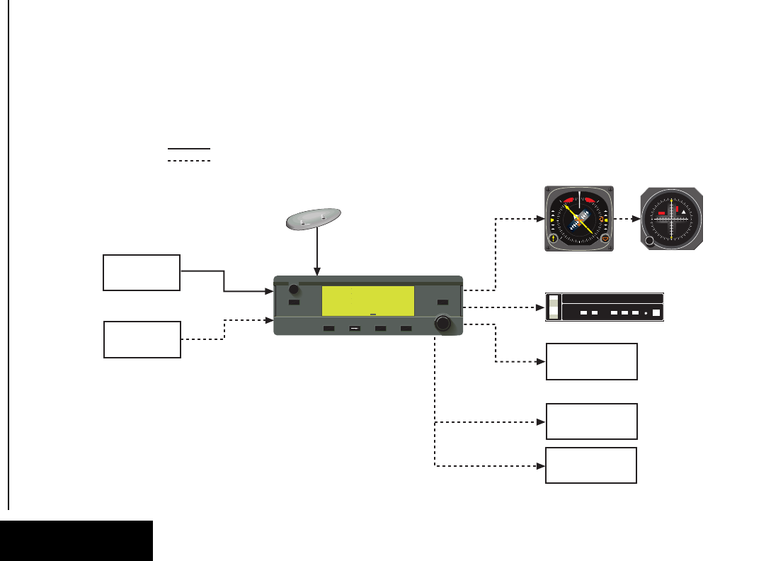
1. KLN 35A SYSTEM COMPONENTS
A basic KLN 35A system consists of a panel mounted KLN 35A GPS
and a KA 92 GPS antenna. An altitude input is required to obtain full
navigation and operational capabilities. Additional system compo-
nents may be added or interfaced to the KLN 35A which increase its
features and capabilities. Some of these optional components
include an external course deviation indicator (CDI) or horizontal situ-
ation indicator (HSI), ARTEX ELS-10 emergency locator transmitter
(ELT), autopilot, and external annunciators.
The KLN 35A panel mounted unit contains the GPS sensor, the navi-
gation computer, a liquid crystal display (LCD), and all controls
required to operate the unit.
A KA 92 GPS “patch” antenna is available for use with the KLN 35A.
It is designed to always be mounted on the top of the aircraft.
The KLN 35A has analog outputs to drive the left-right deviation bar
of most mechanical CDIs and HSIs. In addition, the NAV mode of
the Bendix/King KFC 150, KAP 150, KAP 150H, KAP 100, KFC 200,
KAP 200, KFC 250, KFC 275, KFC 300, and KFC 325 flight control
systems may be coupled to the KLN 35A. Many other autopilots may
also be coupled to the KLN 35A. Actual autopilot performance and
capability when coupled to the KLN 35A may vary significantly from
one autopilot model to another.
Altitude may be provided to the KLN 35A from an encoding altimeter
or blind encoder. Altitude is used as an aid in position determination
when not enough satellites are in view.
Some installations may require remote annunciators to be mounted
in the aircraft panel in order to indicate the status of certain KLN 35A
functions, namely waypoint alert and message.
Data Base
Effective Date 5/95 006-08791-0000 Rev 0
Data Base
Chapter 2
2-0
CANADA
USA
LATIN AM
PACIFIC
SOUTH PAC
SOUTH AM
EUROPE EAST EUR
MID EAST
AFRICA
SOUTH PAC
PACIFIC
75°
60°
45°
30°
15°
0°
15°
30°
45°
60°
75°
60°
45°
30°
15°
0°
15°
30°
45°
60°
165°150°135°120°105°90°75°60°45°30°15°0°15°30°45°60°75°90°105°120°135°150°165°180°
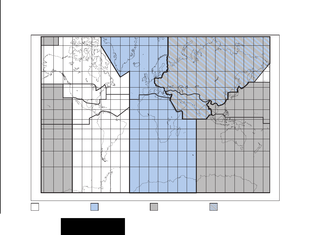
Pacific Data Base
coverage area Common to Pacific & Atlantic
Data Base coverage areas
Atlantic Data Base
coverage area
Americas Data Base
coverage area
Figure 2-1 KLN 35A Data Base Geographical Region

KLN 35A Pilot’s Guide Data Base
2-1 Effective Date 5/95006-08791-0000 Rev 0
Data Base
Chapter 2
2.DATA BASE
2.1. DATA BASICS
The data base provides two primary functions. First, it makes pilot
interface with the GPS sensor much easier. Rather than having to
manually look up and then enter the latitude and longitude for a spe-
cific waypoint, it allows you to merely enter a simple waypoint
identifier. The data base automatically looks up and displays the lati-
tude and longitude associated with the identifier. It should be obvious
that the data base saves a lot of tedious latitude/longitude entry and
also greatly reduces the potential for data input mistakes.
The second function of the data base is that it serves as a very con-
venient means to store and easily access aeronautical information.
Want to know the name of the airport, the nearest city, or the airport
altitude? Just unleash the power of the KLN 35A and display the
information right on the screen.
2.2. DATA BASE CONTENTS AND COVERAGE AREAS
There are three data base coverage areas available for the KLN 35A.
They are referred to as the “Americas” data base, the “Atlantic”data
base, and the “Pacific” data base.
The International Civil Aviation Organization (ICAO) and Aeronautical
Radio, Inc. (ARINC) break the world into the ten geographic regions
shown in figure 2-1. The KLN 35A Americas data base contains
aeronautical information for the group of ICAO regions consisting of
Canada, USA, Latin America, and South America. The KLN35A
Atlantic data base provides information for the ICAOregions of
Europe, Africa, East Europe, and Mid East. Likewise, the Pacific
data base provides information for East Europe, Mid East, Pacific and
South Pacific.
All three data bases contain complete information for all VORs and
NDBs in their respective coverage area. The data base also contains
public use and military airports which have any runway at least 1000
feet in length.

Data Base
2-2
Effective Date 5/95 006-08791-0000 Rev 0
Data Base
Chapter 2
The following is a listing of the KLN 35A data base contents:
AIRPORTS
Identifier
Name
City, State or Country
Use type (if military)
Latitude and Longitude
Elevation
Runway numbers, lengths, surfaces, and lighting
Communication frequencies
VORs
Identifier
Name
Frequency
Latitude and Longitude
Magnetic variation
NDBs
Identifier
Name
Frequency
Latitude and Longitude
(Note - Outer Compass Locators are not included in the data base)
250 USER DEFINED WAYPOINTS
Identifier
Latitude and Longitude
MISCELLANEOUS
Air Route Traffic Control Center (ARTCC and FIR) frequencies
Flight Service Stations (location of points of communication and
associated frequencies)
Special Use Airspace (SUA) boundaries (Prohibited, Restricted, Alert,
Class B, Class C, CTA, TMA, TRSA)

KLN 35A Pilot’s Guide Data Base
2-3 Effective Date 5/95006-08791-0000 Rev 0
Data Base
Chapter 2
2.3. ICAO IDENTIFIERS
Waypoints are stored in the KLN 35A data base almost exclusively
by their ICAO identifiers. ICAO (International Civil Aviation
Organization) is an internationally accepted reference for the data. In
almost all cases the proper ICAO identifiers may be taken directly
from Jeppesen Sanderson or government aeronautical charts.
Airport identifiers in the contiguous United States, Alaska, and
Canada are special cases in the ICAO system. Many airport identi-
fiers for these areas have four letters beginning with a prefix letter
that corresponds to the geographic area in which it is located. The
prefix letter for the contiguous U.S. is “K”. Thus, the identifier for
Dallas/Fort Worth International Airport is KDFW, not DFW (which
would be identical to the VOR identifier). Likewise, the identifier for
Orlando Executive Airport is KORL while the VOR identifier is ORL.
The prefix letter for Canada is “C” and for Alaska is “P”.
NOTE: There are several exceptions in Alaska. In many cases, air-
ports with three letter identifiers receive the prefix “P”, but there are
many that don’t. The most reliable method of determining an Alaska
airport identifier is to look it up from the airport name or city. See sec-
tion 3.7.4, “Selecting Waypoints by Name or City”.
Incidentally, you can program the KLN 35A to default to a certain
letter (such as “K”) when you are entering a waypoint identifier. See
section 3.4.2, “Data Entry” to learn about this handy feature.
Not all airport identifiers receive the prefix letter. Airport identifiers
which are combinations of letters and numbers do not apply to the
prefix rule. Examples of airport identifiers not using the prefix are
3C2, 7TX6, and M33.
So remember, if you are entering or looking for an airport
identifier that is all letters (no numbers) then it will begin with a
“K” prefix in the contiguous U.S., a “P” in Alaska (in some
cases), or a “C” in Canada. If there are numbers in the identifier
then a prefix is not used. For other areas of the world the airport
identifier stored in the KLN 35A data base is identical to how it is
charted.

Data Base
2-4Effective Date 5/95 006-08791-0000 Rev 0
Data Base
Chapter 2
2.4. UPDATING THE DATA BASE
The information stored in the data base would eventually become
obsolete if there wasn’t some means to update it. For example, new
airports open, navaids can move or change frequency,
communication frequencies can change, and on and on.
The data base is updated by means of a 3.5-inch diskette supplied by
AlliedSignal and an IBM-compatible personal computer. This method
does not have to involve removing the KLN 35A from the aircraft’s
instrument panel. A jack, usually mounted in the aircraft’s instrument
panel, provides a means of interfacing the KLN 35A with the comput-
er via an interface cable. The diskettes are not returned to
AlliedSignal.
Every 28 days, AlliedSignal receives new NavData™information
from Jeppesen Sanderson. This information is processed and down-
loaded onto diskettes. AlliedSignal makes the update service
available to you in a choice of several subscription or random update
programs. See section 2.6 for details on these programs.
NOTE: AlliedSignal sends the update so that it arrives prior to the
next effective date. The new update may be installed any time prior
to the effective date and the KLN 35A will use the previous data up to
the effective date and automatically begin using the new data on the
effective date.
In order to use the update program you must have access to a com-
puter having a disk drive capable of utilizing 3.5-inch 1.44 megabyte
high density diskettes. This computer also needs to have an avail-
able COM1 or COM2 serial port. If you wish to perform updates in
the cockpit, an optional PC Interface kit must be used. Included in
the kit is an interface cable that plugs into both the computer and into
the data loader jack. The data loader jack is included with the KLN
35A installation kit and is typically installed in the aircraft’s instrument
panel.
CAUTION: The data base must be updated only while the air-
craft is on the ground. The KLN 35A does not perform any
navigation function while the data base is being updated. Since
a data base update takes approximately 10 minutes it is a good
idea to turn off all electrical equipment on the aircraft except for
the KLN 35A to avoid running down the aircraft battery.

NOTE: The diskettes sent to you can only be used to update one
KLN 35A, although they can update that specific unit numerous
times. The first time the diskettes are used in an update operation, a
unique identification code from the KLN 35A being used is uploaded
to the diskettes. These diskettes may be used in this specific KLN
35A an unlimited number of times which could be required if you
switch back and forth between the Americas, Atlantic, and Pacific
data bases during one update cycle. These diskettes may not, how-
ever, be used to update other KLN 35As. This update protection
ensures that Jeppesen Sanderson is properly compensated for the
use of their NavData™.
To update the KLN 35A data base:
1. Plug the 9 pin female connector end of the interface cable into a
COM serial port of the computer. If the computer has COM 1
and COM 2 serial ports, either may be used. Some computers
use a 9 pin COM serial port connector while other computers use
a 25 pin connector. If the computer being used has a 9 pin con-
nector, the interface cable connector will plug directly into the
computer’s 9 pin connector. If the computer’s COM serial port
uses a 25 pin connector, use the 25 pin to 9 pin adapter included
in the PC interface kit to adapt the interface cable’s connector to
the computer’s connector.
2. If you are using the PC interface kit in the cockpit, plug the other
end of the interface cable (4 conductor male connector) into the
data loader jack that is mounted in the aircraft panel.
3. Insert the diskette into the computer’s disk drive. Turn on the
computer being used for the data base update. The program on
the disk will automatically “boot” (load) and the computer screen
will display “Ready” when the computer is ready to continue with
the data base update operation.
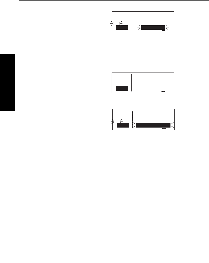
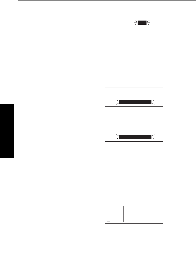
4. Turn on the KLN 35A. Press F
as required to approve the Self
Test, Initialization, VFR, and Data
Base pages. Use the right outer
knob to select the Setup (SET)
type pages and the right inner
knob to select the SET 3 page
(figure 2-2).
5. Press B. Update Pub DB? will
now be inverse video as in
figure 2-3.
KLN 35A Pilot’s Guide Data Base
2-5 Effective Date 5/95006-08791-0000 Rev 0
Data Base
Chapter 2
åå.ånm Update data
åååååå base on
>Leg ground only:
SET 3 Update pub DB?
APT VOR NDB SUP ACT NAV FPL CAL SET OTH
Figure 2-2
åå.ånm Update data
åååååå base on
#>Leg ground only:
CRSR Update pub DB?
APT VOR NDB SUP ACT NAV FPL CAL SET OTH
Figure 2-3
Data Base
2-6Effective Date 5/95 006-08791-0000 Rev 0
Data Base
Chapter 2
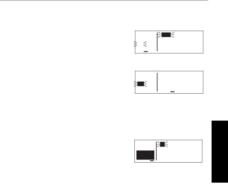
6.Press F. The estimated load
time in minutes is now displayed
(figure 2-4).
NOTE: In step 6, repeatedly pressing
E
will terminate the update process
and bring the display back to the origi-
nal SET 3 page shown in figure 2-2.
7.Press Fto acknowledge the estimated load time and begin
erasing the existing data base. The unit will now display Erasing
data base. After the data base
has been erased, the loading of
the new data automatically
begins. As the new data is being
loaded, the percentage of transfer
is displayed (figure 2-5).
8.The KLN 35A will indicate when
the data base update is complete
as shown in figure 2-6. You may
either turn the KLN 35A off at this
point or press Fto restart the
KLN 35A.
9.Remove the interface cable. Remove the disk from the com-
puter. Turn off the computer.
The chances are small of having difficulty updating the data base
but—
If you have a problem:
• First check that the interface cable is properly connected and that
the computer is turned on. If there is a problem with the
connection or the computer the KLN 35A will display Data
Loader Not Ready. When the problem is corrected this prompt
is removed and the update operation can continue from where it
left off.
• If an internal test fails after the data has been loaded, the KLN
35A will display Checksum Error, Data Base Invalid. Press
F to acknowledge. The KLN 35A will then display Data Base
Update Failed, Retry?Use the right outer knob to position the
cursor over the desired choice and press F.
APT VOR NDB SUP ACT NAV FPL CAL SET OTH
åå.ånm Programming
åååååå data base
>Leg 95% complete
CRSR
Figure 2-5
APT VOR NDB SUP ACT NAV FPL CAL SET OTH
åå.ånm Published data
åååååå base update
#>Leg complete
CRSR Acknowledge?
Figure 2-6
APT VOR NDB SUP ACT NAV FPL CAL SET OTH
åå.ånm Estimated load
åååååå time: 5 min
#>Leg
CRSR Approve?
Figure 2-4

KLN 35A Pilot’s Guide Data Base
2-7 Effective Date 5/95006-08791-0000 Rev 0
Data Base
Chapter 2
• There are other error messages that may be displayed. If you
have a problem that you can’t resolve, write down any error
messages to aid your AlliedSignal Service Center in identifying
the problem.
2.5. USER DEFINED DATA BASE
In addition to the published data base of airports, VORs, and NDBs
stored in the Jeppesen data base, you may create up to 250 other
user-defined waypoints. Section 4.4, “Creating User-defined
waypoints” describes this further.
The KLN 35A contains an internal lithium battery that is used to
“keep-alive” the user-defined data base as well as flight plans. This
battery has a typical life of three to five years.
It is highly
recommended that the battery be replaced every three years at an
authorized AlliedSignal Service Center.
2.6. DATA BASE UPDATE SERVICE OPTIONS
The following tear-out page can be used for ordering the Americas,
Atlantic, and Pacific data base update services from AlliedSignal.
The forms may be mailed or FAXed for your convenience.

Data Base
2-8
Effective Date 5/95 006-08791-0000 Rev 0
Data Base
Chapter 2
This page intentionally left blank

Name:
Company:
Address:
City:
State: Zip Code:
Country:
Telephone: ( )
FAX: ( )
Aircraft Make:
Aircraft Model:
Please set up the service under:
MasterCard/VISA
Method of Payment
Check/Money order enclosed
Wire Transfer:
Chase Manhattan Bank, NY
Acct #910-2-538734
Tax may apply in some states.
See pricing sheet.
Number
Expires
Signature
AlliedSignal CAS offers several update
service options to suit your requirements.
Please select the service desired, then
fill out and mail this order form. Credit
card orders may be faxed.
Note: Updates are current for 28 days
after effective date on diskette. If you
select any service other than the com-
plete 13-time service, your KLX 35A will
begin alerting you after 28 days that
your data base is out of date.
Send to:
AlliedSignal CAS
Data Base Update Service
Mail Drop #66
400 N. Rogers Road
Olathe KS 66062-1212
Telephone: (913) 768-3020
FAX: (913) 768-3904
Check One:
Complete Update Service.
Provides 13 updates–one every 28
days for one year.
Six-time Update Service. Provides
six updates–one every 56 days for
one year.
Four-time Update Service.
Provides four updates–one during
each quarter for one year.
Single Update. Provides one
update upon receipt of order.
Check Requested Data Base:
Americas Data Base
Atlantic International Data Base
Pacific International Data Base
Diskette Format Only
(Laptop Computer Required. See
section 2 of KLX 35A Pilot’s Guide
for details.)
KLX 35A Data Base Update Service Order Form
Consult Pricing Sheet (006-08794-0001) for Service Prices
A

BUSINESS REPLY MAIL
FIRST-CLASS MAIL PERMIT NO. 121 OLATHE, KANSAS
POSTAGE WILL BE PAID BY ADDRESSEE
Fold here
NO POSTAGE
NECESSARY
IF MAILED
IN THE
UNITED STATES
ALLIEDSIGNAL COMMERCIAL AVIONICS SYSTEMS
M D 66
400 NORTH ROGERS ROAD
OLATHE KS 66062-9987
Tape here
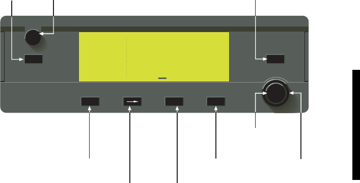
Basic GPS Operation
Chapter 3
89.6nm ∂∆ KOSH
105kt > ««««∑∏π««««
>Leg DTK343° TK344°
NAV 1 >345°To 0:51
APT VOR NDB SUP ACT NAV FPL CAL SET OTH GPS
KLN 35A
B
CRSR
MSG D CLR ENT
Pull
SCAN
Push
ON ∫
DIRECT-TO
BUTTON
MESSAGE
BUTTON
CLEAR
BUTTON
ENTER
BUTTON
RIGHT INNER
KNOB
RIGHT OUTER
KNOB
CURSOR
BUTTON
NEAREST
BUTTON ON/OFF
SWITCH
NRST
Figure 3-1 KLN 35A Controls

Basic GPS Operation
Effective Date 5/95 006-08791-0000 Rev 0
Basic GPS Operation
Chapter 3
3-0
KLN 35A Pilot’s Guide Basic GPS Operation
3-1 Effective Date 5/95006-08791-0000 Rev 0
Basic GPS Operation
Chapter 3
3.BASIC GPS OPERATION
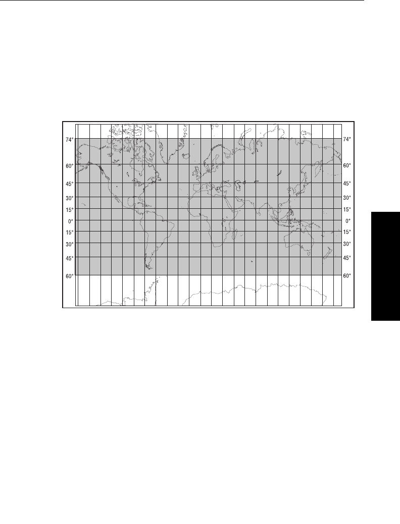
3.1. COVERAGE AREA
The KLN 35A was designed to provide worldwide navigation cover-
age from North 74°latitude to South 60°Latitude (figure 3-2).
Outside this area, magnetic variation must be manually entered as
discussed in section 4.6, “Operation Outside the Primary Coverage
Area”. See section 2.2 for the data base geographical regions.
3.2. TURN-ON AND SELF TEST
Well, it’s time to get down to business and actually use the KLN 35A!
Figure 3-1 can be folded out and used as a reference during the
following procedures. This is especially handy if you’re learning while
away from your GPS. The steps below take a lot of words to explain,
but before you know it, you will be “flying” through them.
NOTE: When power is applied to the KLN 35A it always “wakes up”
in the En route-Leg mode. Only the En route-Leg mode is described
in this chapter. In this mode the KLN 35A performs great circle
navigation (the shortest distance between two points located on the
earth’s surface). The course deviation output displayed on the unit’s
internal course deviation indicator (CDI) and provided to an external
horizontal situation indicator (HSI) or CDI is five nautical miles (full
scale sensitivity) left and right. The other mode is En route-OBS and
is described in section 4.5.3.
Figure 3-2 KLN 35A Navigation Coverage Area
To turn on and initialize the KLN 35A:
1.Turn on the KLN 35A by pushing in the power switch.
The Turn-On page (figure 3-3) will
be displayed for a few seconds.
During this time, the KLN 35A
performs an extensive internal
test. The operational revision
status (ORS) level number in the
upper right corner of the display
should match the ORS level
indicated on the cover of this
Pilot’s Guide .
When the internal test is com-
plete, the Turn-On page will
automatically be replaced by the
Self Test page (figure 3-4).
NOTE: If the KLN 35A is operating in
the Take-Home Mode, the Take-
Home Warning Page (figure 3-5) is
displayed first and must be
acknowledged by pressing
F
. See
section 4.7 for more information on
the Take-Home mode.
2.Verify that the data displayed on the Self Test page is the same
as is being displayed on the appropriate indicator (if any) in the
aircraft which is interfaced to the KLN 35A. If the KLN 35A is not
connected to any other equipment in the aircraft, you may skip to
step 3.
If the KLN 35A is interfaced with a NAV indicator such as an HSI
or a course deviation indicator (CDI), the deviation bar (D-bar)
should be indicating a half scale deviation to the right. The
TO/FROM indicator should be showing FROM.
If any of the above checks fail, do not use the associated
indicator with the KLN 35A.
3.If the KLN 35A has passed the internal self test, the bottom of the
Self Test page will display Passand all external annunciators
should be illuminated. If instead, Failis displayed, recycle power
to the KLN 35A. If the Self Test page still displays Fail, the
KLN 35A requires repair and should not be used for navigation.
Basic GPS Operation
3-2Effective Date 5/95 006-08791-0000 Rev 0
Basic GPS Operation
Chapter 3
APT VOR NDB SUP ACT NAV FPL CAL SET OTH
KLN 35A GPS ORS 01
Self-Test in Progress
©1995 AlliedSignal
Avionics, Inc.
Figure 3-3
APT VOR NDB SUP ACT NAV FPL CAL SET OTH
««««“‘”««««
Baro: 29.92"
Altitude 1138ft
ANNUN ON Pass Ok?
∫
Figure 3-4
APT VOR NDB SUP ACT NAV FPL CAL SET OTH
WARNING
System in Take-home
Mode: DO NOT USE FOR
NAVIGATION Ok?
Figure 3-5

KLN 35A Pilot’s Guide Basic GPS Operation
3-3 Effective Date 5/95006-08791-0000 Rev 0
Basic GPS Operation
Chapter 3
4. When you are ready to approve the Self-test page, press the F
button while the Ok? is flashing. If it happens not to be flashing,
press the Bbutton and use the right outer knob to move the
cursor there.
5. The next page displayed will be
the Initialization page (figure 3-6).
Verify that the date displayed in
the top left corner of the
Initialization page is correct. The
KLN 35A has an internal battery
powered calendar/clock, so the
date and time normally don’t require setting. The battery has a
life of approximately 3 years. In addition, the KLN 35A’s system
date and time are automatically updated very precisely when at
least one satellite is being received. However, if for some reason
the date or time are incorrect, it is necessary to enter the correct
date or time so that the KLN 35A can reach the navigation mode.
The date must be correct and the time must be correct within ten
minutes so that the KLN 35A will start looking for the correct
satellites.
If the date is incorrect, rotate the
right outer knob counterclockwise
until the cursor is over the entire
date field (figure 3-7). Rotate the
right inner knob until the correct
day of the month is displayed
(figure 3-8). Then, move the cur-
sor to the month field by rotating
the outer knob one click
clockwise and change the month
as necessary. Use the same
methods to select the correct
year (figure 3-9). When the date
is correct, press F.
6. Verify that the time displayed in
the upper right corner of the
Initialization page is correct to
within ten minutes of the actual
time. Remember, once the KLN 35A receives the first satellite, it
will automatically be very accurately updated by the satellite to
the correct time. However, you are responsible for assuring the
APT VOR NDB SUP ACT NAV FPL CAL SET OTH
20 DEC 95 1415 UTC
WPT: Ref KIXD
N 38°49.91' 330°Fr
W 94°53.38' Ok? 0.8nm
Figure 3-6
APT VOR NDB SUP ACT NAV FPL CAL SET OTH
20 DEC 95 1415 UTC
WPT: Ref KIXD
N 38°49.91' 330°Fr
W 94°53.38' Ok? 0.8nm
Figure 3-7
APT VOR NDB SUP ACT NAV FPL CAL SET OTH
07 --- -- 1415 UTC
WPT: Ref KIXD
N 38°49.91' 330°Fr
W 94°53.38' Ok? 0.8nm
Figure 3-8
APT VOR NDB SUP ACT NAV FPL CAL SET OTH
07 JAN 96 1415 UTC
WPT: Ref KIXD
N 38°49.91' 330°Fr
W 94°53.38' Ok? 0.8nm
Figure 3-9

desired time zone is selected on
the KLN 35A. If it is necessary to
reset the time, position the cursor
over the time zone field
(figure 3-10) and select the
desired time zone (figure 3-11).
The following are the time zones which the KLN 35A is capable
of displaying:
UTC Coordinated Universal Time (Zulu)
GST Greenland Standard Time (UTC - 3)
GDT Greenland Daylight Time (UTC - 2)
ATS Atlantic Standard Time (UTC - 4)
ATD Atlantic Daylight Time (UTC - 3)
EST Eastern Standard Time (UTC - 5)
EDT Eastern Daylight Time (UTC - 4)
CST Central Standard Time (UTC - 6)
CDT Central Daylight Time (UTC - 5)
MST Mountain Standard Time (UTC - 7)
MDT Mountain Daylight Time (UTC - 6)
PST Pacific Standard Time (UTC - 8)
PDT Pacific Daylight Time (UTC - 7)
AKS Alaska Standard Time (UTC - 9)
AKD Alaska Daylight Time (UTC - 8)
HAS Hawaii Standard Time (UTC - 10)
HAD Hawaii Daylight Time (UTC - 9)
SST Samoa Standard Time (UTC - 11)
SDT Samoa Daylight Time (UTC - 10)
LCL Local Time Zone (user-defined)
You will be able to change the time zone any time you desire on
several other pages, so don’t worry if you’re not sure which time
zone to choose. UTC—Coordinated Universal Time (also called
“Zulu”) is always a safe choice.
Basic GPS Operation
3-4
Effective Date 5/95 006-08791-0000 Rev 0
Basic GPS Operation
Chapter 3
APT VOR NDB SUP ACT NAV FPL CAL SET OTH
07 JAN 96 1415 UTC
WPT: Ref KIXD
N 38°49.91' 330°Fr
W 94°53.38' Ok? 0.8nm
Figure 3-10
APT VOR NDB SUP ACT NAV FPL CAL SET OTH
07 JAN 96 0615 EST
WPT: Ref KIXD
N 38°49.91' 330°Fr
W 94°53.38' Ok? 0.8nm
Figure 3-11
KLN 35A Pilot’s Guide Basic GPS Operation
3-5 Effective Date 5/95006-08791-0000 Rev 0
Basic GPS Operation
Chapter 3
The local time zone (LCL) is selected on the SET 2 page, and is
defined to be a certain time offset from Zulu (UTC).
Once you have selected the desired time zone, position the cur-
sor over the entire time field and select the correct hour with the
right inner knob (figure 3-12).
Since 24 hour time is used, be
sure to add 12 if the time is after
1:00 P.M. (2:30 P.M. becomes
1430). Now move the cursor to
the tens of minutes position and
select the desired value, and
repeat this process for the last
digit of the time field. When the
correct time has been entered
(figure 3-13), press Fto start
the clock running. Don’t worry
that you can’t update the
seconds. The KLN 35A system
time will automatically be correct-
ed very precisely once a satellite is received.
7. To aid the GPS receiver in acquiring your position, it is vital that it
have a reasonable idea of where you are, and the Initialization
page is where you have the chance to set this initial position.
Check to see if the displayed initial position is where you actually
are. This latitude/longitude is the last known position before the
power was shut down the last time. Unless the unit has been
moved since its last use, this position should be correct. On the
right side of the screen will be the identifier of the nearest airport
in the data base, with a radial and distance from that airport. If
you need to change the initial position to—let’s say—John F.
Kennedy International (KJFK), move the cursor to the WPT: field
and use the right inner knob to
select a K as the first character of
the identifier (figure 3-14). Move
the cursor to the right one char-
acter and select a J and then
right again to select an F. The
final K should be filled in by the
data base (figure 3-15). When
you press F, the latitude and
longitude fields will change to
APT VOR NDB SUP ACT NAV FPL CAL SET OTH
07 JAN 96 14-- EST
WPT: Ref KIXD
N 38°49.91' 330°Fr
W 94°53.38' Ok? 0.8nm
Figure 3-12
APT VOR NDB SUP ACT NAV FPL CAL SET OTH
07 JAN 96 1430 EST
WPT: Ref KIXD
N 38°49.91' 330°Fr
W 94°53.38' Ok? 0.8nm
Figure 3-13
APT VOR NDB SUP ACT NAV FPL CAL SET OTH
07 JAN 96 1430 EST
WPT: K Ref KIXD
N 38°49.91' 330°Fr
W 94°53.38' Ok? 0.8nm
Figure 3-14
APT VOR NDB SUP ACT NAV FPL CAL SET OTH
07 JAN 96 1430 EST
WPT: KJFK Ref KIXD
N 38°49.91' 330°Fr
W 94°53.38' Ok? 0.8nm
Figure 3-15
Basic GPS Operation
3-6
Effective Date 5/95 006-08791-0000 Rev 0
Basic GPS Operation
Chapter 3
those of KJFK (figure 3-16). If
necessary, the latitude and longi-
tude may be entered manually.
8. When all information on the
Initialization page is correct, move
the cursor to Ok? and press F
to move on.
9. The VFR page will be displayed to notify you that the GPS is for
VFR use only.
10. The Data Base page will now be displayed with the cursor over
Acknowledge?. Line 1 indicates whether an Americas, Atlantic,
or Pacific data base is being used. If the data base is current, line
3 will show the date when the
data base expires (figure 3-17).
If, on the other hand, the data
base is out of date, line 3 shows
the date that it expired
(figure 3-18). The KLN 35A will
still function with an out of date
data base; however, you must
exercise extreme caution and
always verify that the data base
information is correct before using
information from an out-of-date
data base. Press Fto acknowl-
edge the information on the Data Base page.
WARNING: The accuracy of the data base information is
assured only if the data base is current. Operators using an out-
of-date data base do so entirely at their own risk.
A waypoint page for the waypoint which was active when the KLN
35A was last turned off will be displayed on the screen. If the last
active waypoint was an airport, the APT 4 page showing the airport’s
communications frequencies will be
displayed (figure 3-19). We thought
you’d like that! Almost always, the
waypoint which was active when you
last turned the KLN 35A off is the air-
port where you landed. Therefore,
when you get ready to depart, the air-
port communication frequencies for that airport will automatically be
displayed for you!
APT VOR NDB SUP ACT NAV FPL CAL SET OTH
AMERICAS
Data Base Expires
12 OCT 1996
Acknowledge?
Figure 3-17
APT VOR NDB SUP ACT NAV FPL CAL SET OTH
ATLANTIC INTL
Data Base Expired
12 OCT 1996
Acknowledge?
Figure 3-18
APT VOR NDB SUP ACT NAV FPL CAL SET OTH
åå.ånm KORL
åååååå ATIS* 127.25
>Leg CLR * 128.45
APT+4 GRND* 121.40
Figure 3-19
APT VOR NDB SUP ACT NAV FPL CAL SET OTH
07 JAN 96 1430 EST
WPT: KJFK Ref KJFK
N 40°38.41' ---°Fr
W 73°46.67' Ok? 0.0nm
Figure 3-16

Next, you’ll probably want to check the NAV 2 page to see your pre-
sent position. Use the right outer knob to select the NAV page type
and then the right inner knob, if nec-
essary, to select the NAV 2 page. It
is quite likely that the present position
will be dashed at first (figure 3-20). It
takes the KLN 35A several minutes to
acquire the GPS satellites and to
make its initial calculation of your
position. When the KLN 35A reaches
a NAV ready status and is able to
navigate, the NAV 2 page will display
your present position relative to the
nearest VOR (figure 3-21). Verify
that the present position shown on
the NAV 2 page is correct.
NOTE: In order to reach a Nav ready status, the aircraft must be
away from obstructions blocking the GPS antenna’s view of required
satellites. If the KLN 35A fails to reach a Nav ready status within five
minutes refer to section 3.6, “Initialization And Time To First Fix”.
3.3. DISPLAY FORMAT
The KLN 35A uses a Liquid Crystal Display (LCD). In normal opera-
tion, the display screen is divided into two segments by a vertical line,
called the page divider. In some cases, such as the display of
system messages or the turn-on and self test sequence, the page
divider disappears and you have a “full-screen” page.
Aeronautical information (or
data
) is presented on the screen in the
form of “pages”. A page is a presentation of specific data in an
organized format. Various page “types” are used to display related
kinds of data. For example, one page type is NAV (navigation). NAV
pages show information such as distance, groundspeed, bearing,
course, and other data relating to navigation. Another page type is
APT (airport). APT pages contain information pertinent to a specific
airport such as name, city, State, elevation, and direction and dis-
tance relative to the aircraft’s present position.
The top left corner of the screen
always displays distance to the active
waypoint (figure 3-22). The identifier
of the active waypoint is usually dis-
played on the second line. This area
KLN 35A Pilot’s Guide Basic GPS Operation
3-7 Effective Date 5/95006-08791-0000 Rev 0
Basic GPS Operation
Chapter 3
APT VOR NDB SUP ACT NAV FPL CAL SET OTH
--.-nm >Present Posn
------
>Leg Ref: -----
NAV 2 ---°Fr ----nm
Figure 3-20
APT VOR NDB SUP ACT NAV FPL CAL SET OTH
0.9nm >Present Posn
KORL
>Leg Ref: ORL
NAV 2 030°Fr 0.4nm
Figure 3-21
APT VOR NDB SUP ACT NAV FPL CAL SET OTH
7.6nm DATE/TIME
KIXD 12 DEC 95
>Leg 1941:18 CST
SET 2 Central Std
Figure 3-22

of the display is very useful, since it lets you know where you’re going
and how far until you get there.
NOTE: In cases when the active
waypoint identifier is displayed on the
right side of the page divider, line 2
will display the current groundspeed
(figure 3-23)
NOTE: For purposes of this Pilot’s Guide, many of the screen illus-
trations do not show actual navigation data in this area as in figure
3-24. In these cases, the displayed data is not relevant to the discus-
sion of the KLN 35A operation.
In normal operation, the aeronautical
data is displayed on the right side of
the screen. The bottom line on the
left side of the page divider indicates
the page type that is being displayed
on the right side of the page divider.
In figure 3-24, the APT 1 (airport 1)
page is being displayed.
You might think of the page types as the chapters in a book and the
page numbers as the pages within a chapter. Just as a chapter in a
book may have from one to many pages, a KLN 35A page type may
have from two to 10 pages associated with it. There are, for
example, 10 flight plan pages (FPL 0, FPL 1, FPL 2, ..., FPL 9) in the
flight plan page type and five airport pages (APT 1, APT 2, APT 3,
APT 4, APT 5) in the airport page type.
Figure 3-25 shows an example of an
APT 4 page. Notice the “+” sign in
the page identification. Whenever a
“+” sign is part of a page identifier
there will be two or more pages, all
having the same page number, used
to present all of the required informa-
tion. That is, all of the information
associated with a particular page
number doesn’t fit on the page being
viewed. In this case the “+” sign indi-
cates that there are two or more APT
4 pages. Figure 3-26 shows the sec-
ond APT 4 page for KICT (Wichita Mid-Continent Airport).
Basic GPS Operation
3-8
Effective Date 5/95 006-08791-0000 Rev 0
Basic GPS Operation
Chapter 3
APT VOR NDB SUP ACT NAV FPL CAL SET OTH
åå.ånm KICT
åååååå ATIS 125.15
>Leg CLR 125.70
APT+4 GND 121.90
Figure 3-25
APT VOR NDB SUP ACT NAV FPL CAL SET OTH
åå.ånm KICT
åååååå TWR 118.20
>Leg UNIC 122.95
APT+4 CL C 126.70
Figure 3-26
APT VOR NDB SUP ACT NAV FPL CAL SET OTH
åå.ånm KISM
åååååå KISSIMMEE MUN
>Leg ORLANDO
APT 1 FL
Figure 3-24
APT VOR NDB SUP ACT NAV FPL CAL SET OTH
22.5nm ∂∆ KTOP
110kt > ««««∑∏π««««
>Leg DTK121° TK126°
NAV 1 >121°To 0:12
∫
Figure 3-23
KLN 35A Pilot’s Guide Basic GPS Operation
3-9 Effective Date 5/95006-08791-0000 Rev 0
Basic GPS Operation
Chapter 3
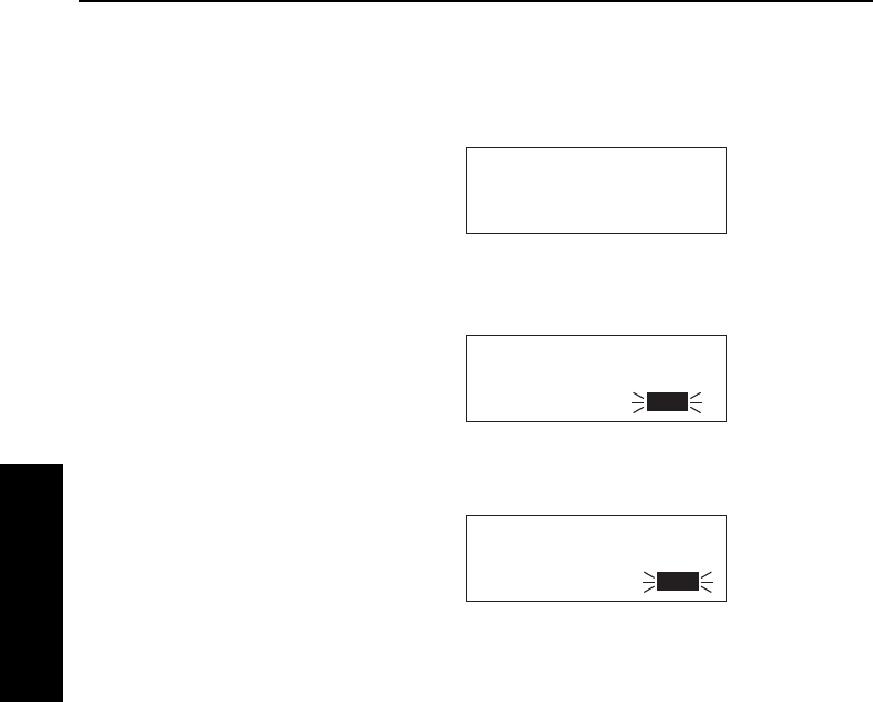
The third line of the left side has three purposes: (1) If the KLN 35A
is ready for you to approve something, such as a selected waypoint,
the “Ent” prompt will flash (figure 3-27), indicating you should press
the Fbutton to continue. (2) If the
KLN 35A has a new message for you
which must be viewed on a message
page, a large “M” will flash in the
same area (figure 3-28) telling you to
press the Cbutton and view the
new message. (3) Immediately to the
right of the “message/enter” display
area, the navigation mode (see sec-
tion 4.5 for details) is displayed. If the
KLN 35A is in the En route-Leg mode
(the normal mode of operation), “Leg”
will be displayed here.
The lower left corner of the display, where the page type and number
are usually displayed, can also display short operational messages to
the user called “scratchpad messages”. These messages are
displayed for approximately five
seconds, then this area returns to the
page type and number. Figure 3-29
shows an example of a scratchpad
message indicating a duplicate
identifier. A complete listing of
scratchpad messages is available in
Appendix C of this Pilot’s Guide.
APT VOR NDB SUP ACT NAV FPL CAL SET OTH
åå.ånm H 276
åååååå HOTEL
Dup N 55°49.90'
Ident W 55°45.70'
Figure 3-29
APT VOR NDB SUP ACT NAV FPL CAL SET OTH
åå.ånm ZBV 116.70
åååååå BIMINI
#>Leg N 25°42.10'
VOR 1 W 79°17.10'
Figure 3-27
APT VOR NDB SUP ACT NAV FPL CAL SET OTH
åå.ånm ZBV ∂∆ KSEA
åååååå > ««««∑∏∫««««
{>Leg 62.1nm 112kt
NAV 1 >262°To 0:33
Figure 3-28
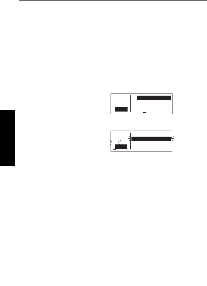
Basic GPS Operation
3-10
Basic GPS Operation
Chapter 3
Effective Date 3/96 006-08791-0000 Rev 1
3.4. BASIC OPERATION OF PANEL CONTROLS
The KLN 35A controls are very easy to use. Most of the page selec-
tion and data entry is done with the knobs on the right side of the
front panel and the cursor (B) button immediately above them. The
Gbutton is located on the left side , and there are four buttons
across the bottom: C(Message), D(Direct To), E(Clear), and
F(Enter). The operation of these buttons will be described on the
next few pages.
The cursor is an area of inverse video (light characters on a dark
background) on the screen. Many pages allow you to add, delete, or
change data on the screen by first pressing the Bbutton to turn the
cursor function on and bring the cursor on the screen. The right
knobs are then used to enter or
change data. When the cursor is on
the screen, the lower left corner of the
screen will show CRSR in inverse
video rather than the page name for
that particular page (figure 3-30). The
cursor is over Present Posn.
There are times when the cursor is
flashing. Figure 3-31 shows an
example of how “whiskers” are used
in this Pilot’s Guide to depict a flash-
ing cursor (over ATIS 125.15). In
addition, it shows an example of how
“whiskers” around normal text is used to depict normal (non-inverse)
characters flashing. The letters Ent are flashing but are not in
inverse video.
3.4.1. PAGE SELECTION
It is now time to learn to select a desired page.
NOTE: The cursor function is not used in selecting pages and the
B
button should not be pressed at this time. If CRSR is annunciat-
ed in the lower left corner of the display, press the
B
button to turn
the cursor function off.
APT VOR NDB SUP ACT NAV FPL CAL SET OTH
åå.ånm KICT
åååååå ATIS 125.15
#>Leg CLR 125.70
CRSR GND 121.90
Figure 3-31
APT VOR NDB SUP ACT NAV FPL CAL SET OTH
åå.ånm >Present Posn
åååååå
>Leg N 39°43.20'
CRSR W 86°17.21'
Figure 3-30

The right outer knob is rotated to select one of ten page types for the
display. These ten page types are the following:
Remember that the page type is displayed at the lower left corner of
the screen. The first three letters of the page type are always used
for annunciation on the screen, for example, CAL represents
Calculator page. The page type is also annunciated by means of a
bar on the display, which moves as you turn the right outer knob. All
the page types are listed across the front panel directly under the dis-
KLN 35A Pilot’s Guide Basic GPS Operation
3-11 Effective Date 5/95006-08791-0000 Rev 0
Basic GPS Operation
Chapter 3
Chapter Name/
Page # Range Page Type Page Functions
APT 1-5 Airport Directory of published
airports
VOR 1-2 VOR Directory of published
VOR stations
NDB 1-2 NDB Directory of published
non-directional beacons
(NDB)
SUP 0-3 Supplemental Wpt Directory of user-defined
waypoints
ACT * Active Waypoint Information about the
active waypoint
NAV 1-4 Navigation Navigation data
FPL 0-9 Flight Plan Active and stored flight
plans
CAL 1-6 Calculator Distance, bearing, time
and fuel calculator; air
data calculations based
on pilot-entered data
SET 1-8 Setup Setting initial position and
date/time, updating the
data base, and selecting
certain features
OTH 1-5 Other Status reports, and
deleting user wpts and
remarks
*Varies with the type of waypoints in the active flight plan.

Basic GPS Operation
3-12
Basic GPS Operation
Chapter 3
play, and the bar will always be over one of them. For example, let’s
say you were on an APT page
(figure 3-32) and you wanted to turn
to a SET page. You would look at the
list and see that the SET pages are
eight places to the right of the APT
pages. Therefore, turning the right
outer knob eight clicks clockwise will
get you to the SET pages
(figure 3-33). The annunciator bar
and the page labels work kind of like
a map to get you from one page type
to another. The page type selection
wraps around from Other (OTH) to
Airport (APT); that is, the knob has no mechanical stops.
Once you have selected the desired page type using the right outer
knob, you may select the page number by rotating the right inner
knob. Let’s use an example to make sure you understand. You are
presently viewing the APT 2 page and you wish to view the NAV 3
page. Rotating the right outer knob 5 (five) clicks clockwise will
display the NAV page that you last viewed—we’ll say the NAV 2
page. Turning the right inner knob one click clockwise or three clicks
counterclockwise will bring you to the NAV 3 page. Got it?
NOTE: In this Pilot’s Guide the right smaller knob is assumed to be
in the “in” position unless it specifically states that he knob should be
in the “out” position. Therefore, the words “rotate the right inner
knob” mean to turn the right inner knob while the knob is in the “in”
position.
3.4.2. DATA ENTRY
Now that you’ve learned how to select the desired page, you’re ready
to learn the means of entering data. It is necessary to enter data, for
example, in order to specify a waypoint of your choice to go Direct
To. The general procedure for entering a waypoint identifier is
described below and is shown in figures 3-34 through 3-42 for enter-
ing a waypoint (in this case, First Flight airport in North Carolina,
identifier KFFA) on the Calculator (CAL) 1 page.
Effective Date 3/96 006-08791-0000 Rev 1
APT VOR NDB SUP ACT NAV FPL CAL SET OTH
åå.ånm TURN
åååååå ANTICIPATION
>Leg ENABLED
SET 4
Figure 3-33
APT VOR NDB SUP ACT NAV FPL CAL SET OTH
åå.ånm KISM
åååååå KISSIMMEE MUN
>Leg ORLANDO
APT 1 FL
Figure 3-32
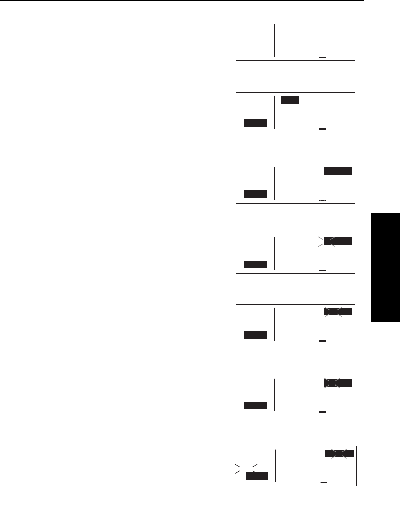
KLN 35A Pilot’s Guide Basic GPS Operation
3-13 Effective Date 5/95006-08791-0000 Rev 0
Basic GPS Operation
Chapter 3
To enter a waypoint identifier:
1. If the cursor is not on the screen
(figure 3-34), press B to turn on
the cursor function (figure 3-35).
2. If required, rotate the right outer
knob to position the cursor
(figure 3-36).
3. Rotate the right inner knob to
select the first character of the
waypoint identifier (figure 3-37).
4. Turn the right outer knob one
click clockwise to move the cur-
sor to the second character
position (figure 3-38).
5. Rotate the right inner knob to
select the second character
(figure 3-39).
6. Use the right outer and inner
knobs in this manner until the
complete waypoint identifier is
displayed (figure 3-40). Note that
you may not have to enter the
last characters of the identifier
because each time you enter a
character, the KLN 35A offers
you the first identifier in the data
base beginning with the charac-
ters you have entered.
APT VOR NDB SUP ACT NAV FPL CAL SET OTH
åå.ånm >Wpt Fr>KRDU
åååååå To>KSAV
>Leg 255nm Brg 209°
CRSR 121kt ETE 2:06
Figure 3-36
APT VOR NDB SUP ACT NAV FPL CAL SET OTH
åå.ånm >Wpt Fr>K
åååååå To>KSAV
>Leg 255nm Brg 209°
CRSR 121kt ETE 2:06
Figure 3-37
APT VOR NDB SUP ACT NAV FPL CAL SET OTH
åå.ånm >Wpt Fr>K
åååååå To>KSAV
>Leg 255nm Brg 209°
CRSR 121kt ETE 2:06
Figure 3-38
APT VOR NDB SUP ACT NAV FPL CAL SET OTH
åå.ånm >Wpt Fr>KF2
åååååå To>KSAV
>Leg 255nm Brg 209°
CRSR 121kt ETE 2:06
Figure 3-39
APT VOR NDB SUP ACT NAV FPL CAL SET OTH
åå.ånm >Wpt Fr>KFFA
åååååå To>KSAV
#>Leg 255nm Brg 209°
CRSR 121kt ETE 2:06
Figure 3-40
APT VOR NDB SUP ACT NAV FPL CAL SET OTH
åå.ånm >Wpt Fr>KRDU
åååååå To>KSAV
>Leg 255nm Brg 209°
CRSR 121kt ETE 2:06
Figure 3-35
APT VOR NDB SUP ACT NAV FPL CAL SET OTH
åå.ånm >Wpt Fr>KRDU
åååååå To>KSAV
>Leg 255nm Brg 209°
CAL 1 121kt ETE 2:06
Figure 3-34
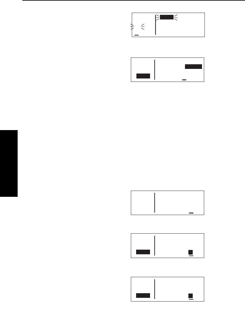
7.If Entis flashing on the left side of
the screen, then press F. This
will prompt the KLN 35A to dis-
play a waypoint page for the
waypoint identifier you just
entered (figure 3-41).
8.Verify the waypoint information
displayed, and then press F
again to approve the waypoint
page. The display will return to
the page previously displayed
(figure 3-42).
Often, you will find yourself entering airports that begin with the same
character over and over again. In section 2.3, you learned how the
KLN 35A uses ICAO identifiers, which means that many U.S. airport
identifiers begin with the letter K. Also, many airport identifiers in
Europe begin with the letter E or the letter L. Especially when flying
VFR, you will mostly want to enter airports as Direct To or Flight Plan
waypoints. The KLN 35A has a great feature that will save you turns
of the knob when you know that the first character will probably be a
K, E, L, or other letter that is commonly used in your part of the world.
You can set the default first waypoint identifier character on the SET
5 page.
To change the default first waypoint identifier character:
1.Select the SET 5 page (figure 3-
43) and turn on the cursor (B)
(figure 3-44).
2.Use the right inner knob to select
the desired character
(figure 3-45), such as a K in the
U.S., a C in Canada, a P in
Alaska, an E or an L in Europe,
etc.
Basic GPS Operation
3-14Effective Date 5/95 006-08791-0000 Rev 0
Basic GPS Operation
Chapter 3
APT VOR NDB SUP ACT NAV FPL CAL SET OTH
åå.ånm Default First
åååååå Character of
>Leg Wpt Identifier
SET 5 Entry: A
Figure 3-43
APT VOR NDB SUP ACT NAV FPL CAL SET OTH
åå.ånm Default First
åååååå Character of
>Leg Wpt Identifier
CRSR Entry: A
Figure 3-44
APT VOR NDB SUP ACT NAV FPL CAL SET OTH
åå.ånm Default First
åååååå Character of
>Leg Wpt Identifier
CRSR Entry: K
Figure 3-45
APT VOR NDB SUP ACT NAV FPL CAL SET OTH
åå.ånm >Wpt Fr>KFFA
åååååå To>KSAV
>Leg 361nm Brg 231°
CRSR 121kt ETE 2:59
Figure 3-42
APT VOR NDB SUP ACT NAV FPL CAL SET OTH
åå.ånm KFFA 10ft
åååååå FIRST FLIGHT
#>Leg KILL DEVIL HIL
APT 1 NC
Figure 3-41
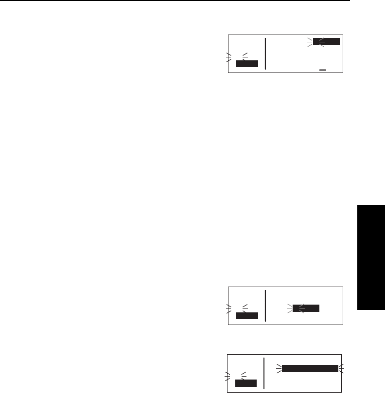
3. Turn off the cursor. To try it out, proceed to the SET 1 page
(initial position). Turn the cursor
(B) on (it will come on over the
waypoint field). Try turning the
right inner knob clockwise
(figure 3-46). There’s the
character you just selected on the
SET 5 page!
3.4.3. THE DUPLICATE WAYPOINT PAGE
There are some waypoints in the data base whose identifiers are not
unique. That is, more than one waypoint has the same identifier.
When a waypoint identifier has been entered which is not unique to a
single waypoint, a Duplicate Waypoint page appears on the screen.
The Duplicate Waypoint page is used to select which of the
waypoints having the same identifier is actually desired. The
waypoint identifier is displayed on the top left of the page. To the
right of the identifier is the number of waypoints in the data base
having the identifier. Below the identifier is a list of the waypoint
types (APT, VOR, NDB, USR) and the associated countries which
use the identifier.
To see an example of a Duplicate Waypoint page, try entering the
identifier “D” as a Direct To waypoint or a Flight Plan Waypoint:
1. Press D.
2. Select the letter “D” as the
waypoint identifier (figure 3-47).
Dis the full identifier of several
waypoints in the KLN 35A data
base.
3. Press F. The Duplicate
Waypoint page will be displayed
on the screen (figure 3-48). At
the time of this writing, there were
three waypoints in the Americas
data base having the identifier D. If there are more than four
waypoints having the same identifier, only the first three are ini-
tially shown. The list includes an NDB in Canada, an NDB in
Cuba, and an NDB in the U.S. The cursor will be over the first
waypoint listed. They are listed with the waypoint closest to the
aircraft’s present position displayed first and the waypoint furthest
from the aircraft displayed last. To view the rest of the choices,
KLN 35A Pilot’s Guide Basic GPS Operation
3-15 Effective Date 5/95006-08791-0000 Rev 0
Basic GPS Operation
Chapter 3
APT VOR NDB SUP ACT NAV FPL CAL SET OTH
åå.ånm DIRECT TO:
åååååå
#>Leg D
CRSR
Figure 3-47
APT VOR NDB SUP ACT NAV FPL CAL SET OTH
åå.ånm D Typ Area
åååååå 3 1 NDB CAN?
#>Leg 2 NDB CUB?
CRSR 3 NDB USA?
Figure 3-48
APT VOR NDB SUP ACT NAV FPL CAL SET OTH
åå.ånm INIT POS:K
åååååå N 39°36.91'
#>Leg W 78°45.71'
CRSR
Figure 3-46
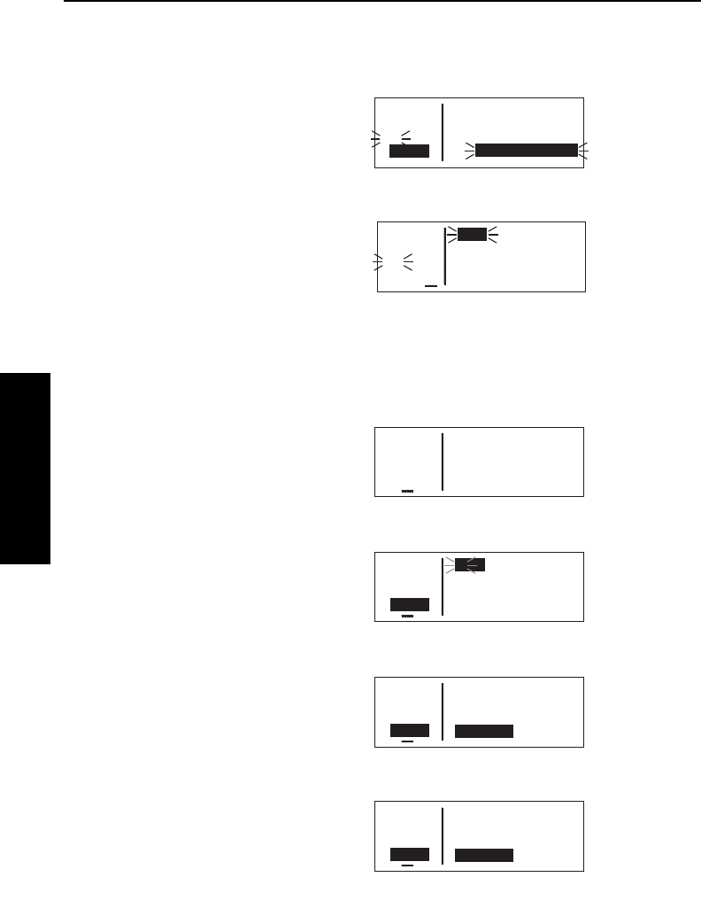
Basic GPS Operation
3-16
Effective Date 5/95 006-08791-0000 Rev 0
Basic GPS Operation
Chapter 3
rotate the right outer knob clockwise. Doing so will move the
flashing cursor over waypoints two, three and then will cause the
waypoint list to “scroll” so that the other waypoints in the list may
be seen.
4. To select the desired waypoint,
move the cursor over the
appropriate choice (figure 3-49).
5. Press Fand the display will
change to the waypoint page for
the selected waypoint
(figure 3-50).
6. Press Fagain to approve the
waypoint page.
3.4.4. CYCLIC FIELDS
On many of the KLN 35A pages, there are
cyclic fields
, which are
preceded by a carat (>). A cyclic field is one that you as the pilot can
select from two or more options. For
example, in figure 3-51, the field
>135°To (magnetic bearing to Austin
VOR) is a cyclic field. In this case,
the second option is the magnetic
radial from Austin VOR to present
position.
To change a cyclic field:
1. Turn on the cursor by pressing
the Bbutton (figure 3-52).
2. Using the right outer knob, move
the cursor over the cyclic field you
wish to change (figure 3-53).
3. Press the Ebutton to change
the cyclic field (figure 3-54).
Notice that repeated Epresses
“cycle” you through the choices.
In this case there are only two, so
Eworks like a toggle switch.
APT VOR NDB SUP ACT NAV FPL CAL SET OTH
åå.ånm AUS
åååååå Mag Var E 7°
>Leg
VOR 2 >135°To 13.3nm
Figure 3-51
APT VOR NDB SUP ACT NAV FPL CAL SET OTH
åå.ånm AUS
åååååå Mag Var E 7°
>Leg
CRSR >135°To 13.3nm
Figure 3-52
APT VOR NDB SUP ACT NAV FPL CAL SET OTH
åå.ånm AUS
åååååå Mag Var E 7°
>Leg
CRSR >135°To 12.8nm
Figure 3-53
APT VOR NDB SUP ACT NAV FPL CAL SET OTH
åå.ånm AUS
åååååå Mag Var E 7°
>Leg
CRSR >315°Fr 12.5nm
Figure 3-54
APT VOR NDB SUP ACT NAV FPL CAL SET OTH
åå.ånm D Typ Area
åååååå 3 1 NDB CAN?
#>Leg 2 NDB CUB?
CRSR 3 NDB USA?
Figure 3-49
APT VOR NDB SUP ACT NAV FPL CAL SET OTH
åå.ånm D 295
åååååå FIVE FINGER
#>Leg N 57°16.28'
NDB 1 W133°37.80'
Figure 3-50
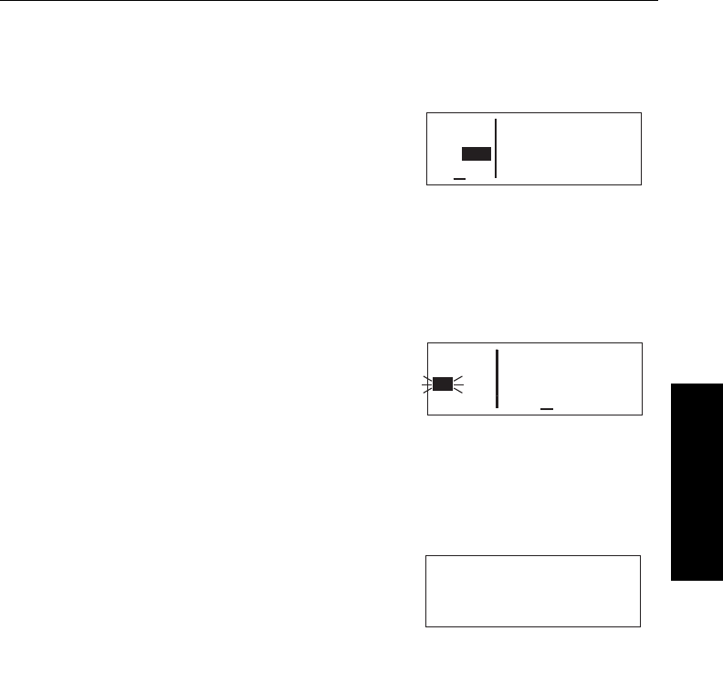
NOTE: The cyclic field which always appears on the left side of the
display is the navigation mode selector/annunciator. In most cases, it
will display >Leg indicating en route-leg mode (figure 3-54). The
other choice is the en route-OBS
mode, in which the magnetic selected
course is displayed here (figure 3-55).
You can move the cursor to this cyclic
field by turning the cursor all the way
counterclockwise. See section 4.5 for
more details on navigation modes.
3.5. MESSAGE PAGE
Whenever the KLN 35A wants to get your attention, the message
prompt (a large “M” on the left side of the screen begins flashing
(figure 3-56). If you have a remote
message annunciator in your aircraft,
it will also begin flashing at that time.
You should view the message at your
earliest opportunity because the unit
may be alerting you to some situation
of immediate concern to its condition
or to your flight. A description of each possible message is included
in Appendix B of this Pilot’s Guide.
To view a message:
1.Press the Cbutton. The MSG
page will appear and show the
new message (figure 3-57).
NOTE: Appendix B of this Pilot’s Guide contains a list of all the
Message page messages and their meanings. It is possible that
several messages are displayed at one time on the Message page.
The newest message appears first and the rest in reverse
chronological order.
2.After reading the message, press Cagain to return to the page
previously in view. If all of the messages cannot be displayed on
one Message page, repeated presses of Cwill show the other
messages before returning to normal operation. If a message
condition exists which requires a specific action by you, the
message prompt will remain on but will not flash.
KLN 35A Pilot’s Guide Basic GPS Operation
3-17 Effective Date 5/95006-08791-0000 Rev 0
Basic GPS Operation
Chapter 3
APT VOR NDB SUP ACT NAV FPL CAL SET OTH
*Data Base Outdated
All Data Must be
Confirmed Before Use
Figure 3-57
APT VOR NDB SUP ACT NAV FPL CAL SET OTH
åå.ånm Time CST 1537
åååååå Depart 1301
{>Leg ETA KSTJ 1557
NAV 3 Flight 2:36
Figure 3-56
APT VOR NDB SUP ACT NAV FPL CAL SET OTH
åå.ånm AUS
åååååå Mag Var E 7°
>142
VOR 2 >315°Fr 12.4nm
Figure 3-55

3.6. INITIALIZATION AND TIME TO FIRST FIX
Since the KLN 35A stores its position and other required parameters
in memory when power to the unit is removed, it is seldom necessary
to aid the unit in reaching a NAV ready condition. The time required
from power on until the KLN 35A determines its present position and
is therefore ready to navigate is called “time to first fix.” The time to
first fix is normally a few minutes or less. In order for the KLN 35A to
reach a NAV ready condition, it is necessary to meet the following
conditions:
1.The KLN 35A’s “almanac” data should be current. Almanac data
is orbital information for all the satellites and is used for initial
acquisition when the KLN 35A is first turned on. This data is
stored in the KLN 35A’s non-volatile memory and is considered
current for up to six months. Each satellite sends almanac data
for all satellites. Since the KLN 35A routinely updates the
almanac data during normal operation, the almanac data will
become out of date only if the KLN 35A hasn’t been used for the
previous six months or longer. Collecting new almanac data
takes place automatically if the data is more than six months old.
If the almanac data is out of date and needs to be collected, the
KLN 35A will take a few minutes to acquire your present position
(usually about six (6) minutes, but not more than 12 minutes).
The Self Test, Initialization, and Data Base pages should be
approved.
2.The aircraft must be located such that the GPS antenna has an
unobstructed view of the sky so that required satellite signals are
not being blocked. If possible, position the aircraft away from
hangars or other obstructions.
3.It is very helpful for the KLN 35A to have the correct time, date
and position to be able to determine which satellites should be in
view. This infomation is stored in the battery backed memory of
the KLN 35A so it is not normally required to update it. If the KLN
35A has the correct time, date and position, then the time to first
fix will usually be less than two (2) minutes. If this information is
not correct, then the KLN 35A will start to look for any satellites.
Eventually, the KLN 35A will find enough satellites to determine
the position of the aircraft. This process can take as long as 12
minutes. It is possible for you to update this information manually,
which will allow the KLN 35A to reach a NAV ready status much
faster. To set the time and date follow steps 5 and 6 in section
3.2, “Turn-On and Self-Test.” The initial position is usually set
during turn-on and self-test, but if for some reason it is necessary
Basic GPS Operation
3-18Effective Date 5/95 006-08791-0000 Rev 0
Basic GPS Operation
Chapter 3
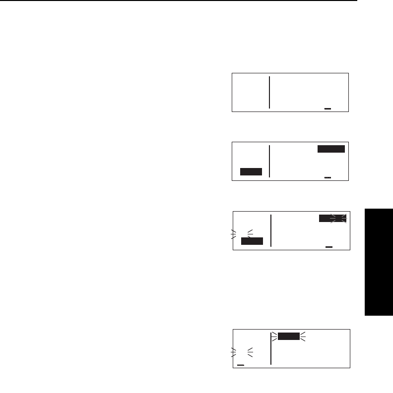
to update the position after the power-on sequence, then use the
following steps. Remember, if acquisition time is not important
then it is not necessary to update the time, date or position.
To initialize the position from the SET 1 page:
1. If the cursor is not on the screen
(figure 3-58), press the B
button to bring it on the page over
the INIT POS field (figure 3-59).
2. Using the right inner and outer
knobs, enter the identifier for the
airport where you are presently
located or the identifier of a
navaid or other airport which is
close to your present position
(figure 3-60). Any waypoint in the
data base which is within 60
miles is acceptable, but the clos-
er the better. Remember, if you
are entering an airport identifier
that is all letters (no numbers),
then it will begin with a “K” prefix
in the contiguous U.S., a “P” in
Alaska (in some cases; in others, the prefix is not added), or a
“C” in Canada. If there are numbers in the identifier then a prefix
is not used. Outside the contiguous U.S., Alaska, and Canada,
use the airport identifiers as they are charted.
3. Once you have entered the
complete identifier, press F.
The display will change to the
waypoint page for the waypoint
you entered (figure 3-61).
4. If this is the waypoint you intended to enter, press Fagain.
The display will change back to the SET 1 page.
NOTE: As an alternative, you can also enter the approximate latitude
and longitude of your present position directly on the SET 1 page
instead of entering a waypoint.
KLN 35A Pilot’s Guide Basic GPS Operation
3-19 Effective Date 5/95006-08791-0000 Rev 0
Basic GPS Operation
Chapter 3
APT VOR NDB SUP ACT NAV FPL CAL SET OTH
åå.ånm INIT POS:
åååååå N 51°12.00'
>Leg W115°51.11'
SET 1
Figure 3-58
APT VOR NDB SUP ACT NAV FPL CAL SET OTH
åå.ånm INIT POS:
åååååå N 51°12.00'
>Leg W115°51.11'
CRSR
Figure 3-59
APT VOR NDB SUP ACT NAV FPL CAL SET OTH
åå.ånm INIT POS:CYYC
åååååå N 51°12.00'
#>Leg W115°51.11'
CRSR
Figure 3-60
APT VOR NDB SUP ACT NAV FPL CAL SET OTH
åå.ånm CYYC 3560ft
åååååå CALGARY INTL
#>Leg CALGARY
APT 1 AB
Figure 3-61

Basic GPS Operation
3-20Effective Date 5/95 006-08791-0000 Rev 0
Basic GPS Operation
Chapter 3
5.With the right inner knob, position
the cursor over Ok?, if it is not
already there (figure 3-62).
6.Press Fto approve the initial position. The cursor will
automatically be removed from the screen.
NOTE: If the KLN 35A is in the Take-Home mode, you are allowed
to enter the groundspeed (kt) and heading (°) fields in order to simu-
late flight (figure 3-63). They are not
used for actual initialization in an
aircraft. However, entering a ground
speed will allow the KLN 35A to “fly”
along the active flight plan (or to a
direct to waypoint) starting from the
initialization waypoint. A heading may
be entered in the initial heading field while in the Take-Home mode if
the one offered is not desired. See section 4.7 for more details on
the Take-Home mode.
7.Select the NAV 2 page. When the KLN 35A reaches the NAV
ready status and is therefore able to navigate, the NAV 2 page
will display the present position. Verify that the latitude and
longitude or the waypoint, radial, and distance display of present
position are correct.
3.7. SELECTING AND SCANNING WAYPOINTS
There are four types of waypoints: airports, VORs, NDBs, and user
waypoints. Waypoints in the published data base fall into one of the
first three types. You can create up to 250 user waypoints to
supplement the waypoints in the database (see section 4.4 to create
a user waypoint).
There are three methods you may use to select a specific waypoint
for viewing. You may enter the waypoint’s identifier directly, you may
scan through the waypoint identifiers in alphabetical order, or you
may enter the waypoint’s name. If the waypoint is an airport, you
may also select it by entering the city where the airport is located.
APT VOR NDB SUP ACT NAV FPL CAL SET OTH
åå.ånm INIT POS:CYYC
åååååå N 51°06.83'
#>Leg W114°01.22'
CRSR Ok?
Figure 3-62
APT VOR NDB SUP ACT NAV FPL CAL SET OTH
åå.ånm INIT POS:
åååååå N 51°06.83'
>Leg W114°01.22'
SET 1 200kt 43°
Figure 3-63
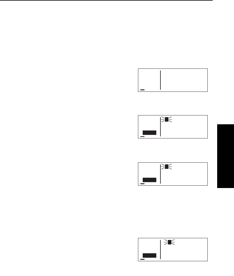
KLN 35A Pilot’s Guide Basic GPS Operation
3-21 Effective Date 5/95006-08791-0000 Rev 0
Basic GPS Operation
Chapter 3
3.7.1. SELECTING WAYPOINTS BY IDENTIFIER
The most direct way of selecting a specific waypoint is to simply enter
the waypoint’s identifier directly on the appropriate waypoint page
type (APT, for example). Let’s use Chicago O’Hare International
Airport whose identifier is KORD as an example.
To select a waypoint by identifier from a waypoint page:
1. Use the right outer and inner
knobs to select the Airport 1 (APT
1) page (figure 3-64). (Actually,
the airport identifier can be
entered on any of the three
Airport pages but we’ll use the
APT 1 since it displays the airport
name and city).
2. Turn on the cursor (B) and
make sure the right inner knob is
pushed in. The cursor will
appear over the first character of
the airport identifier (figure 3-65).
3. Turn the right inner knob to select
a “K” as the first character (figure
3-66). You may turn the knob
either clockwise or counterclock-
wise, and the letters and
numbers wrap around with a
blank character separating the “9”
and the “A”. Notice that as you turn through letters, the KLN 35A
automatically fills in the identifier of the first waypoint in alphanu-
meric order in the data base which matches what you’ve entered
so far (in this case, Hall Airport in Kaufman, Texas). Go ahead
and experiment a little bit.
4. Use the right outer knob to move
the cursor to the second
character and select an “O”
(figure 3-67).
APT VOR NDB SUP ACT NAV FPL CAL SET OTH
åå.ånm Y78 690ft
åååååå RAINBOW
>Leg MILWAUKEE
APT 1 WI
Figure 3-64
APT VOR NDB SUP ACT NAV FPL CAL SET OTH
åå.ånm Y78 690ft
åååååå RAINBOW
>Leg MILWAUKEE
CRSR WI
Figure 3-65
APT VOR NDB SUP ACT NAV FPL CAL SET OTH
åå.ånm K00 440ft
åååååå HALL
>Leg KAUFMAN
CRSR TX
Figure 3-66
APT VOR NDB SUP ACT NAV FPL CAL SET OTH
åå.ånm KOAJ 90ft
åååååå ELLIS
>Leg JACKSONVILLE
CRSR NC
Figure 3-67

Basic GPS Operation
3-22
Effective Date 5/95 006-08791-0000 Rev 0
Basic GPS Operation
Chapter 3
5. Use the same process to select
an “R” and then a “D”
(figure 3-68). You are now view-
ing the APT 1 page for KORD.
The KLN 35A feature of filling in characters of the identifier can be a
time saver! For a second example, let’s select Bloomington VOR
whose identifier is BMI.
More selecting a waypoint by identifier:
1. Make sure you have turned the
cursor off from the previous
example. With the right knobs,
select the VOR 1 page
(figure 3-69).
2. Turn the cursor (B) on.
3. Change the first character to a “B”
(figure 3-70).
4. Move the cursor to the second
character and select “M”
(figure 3-71). Eureka! When you
entered the “M”, the KLN 35A
searched its data base for the first
VOR identifier beginning with the
letters “BM” and found BMI.
Many times you will only have to
enter two or three characters of
the waypoint identifier and the KLN 35A will furnish the rest.
5. Turn off the cursor (B).
3.7.2. SELECTING WAYPOINTS BY SCANNING
You may also select waypoints by scanning through them. This may
be done with the cursor either on or off.
To select a waypoint by scanning with the cursor off:
1. Select the page type for the waypoint you are looking for (APT,
VOR, NDB, or SUP).
2. Pull the right inner knob to the “out” position.
APT VOR NDB SUP ACT NAV FPL CAL SET OTH
åå.ånm ABA 112.50
åååååå ARUBA
>Leg N 12°30.53'
VOR 1 W 69°56.47'
Figure 3-69
APT VOR NDB SUP ACT NAV FPL CAL SET OTH
åå.ånm BAE 116.40
åååååå BADGER
>Leg N 43°07.01'
CRSR W 88°17.06'
Figure 3-70
APT VOR NDB SUP ACT NAV FPL CAL SET OTH
åå.ånm BMI 108.20
åååååå BLOOMINGTON
>Leg N 40°28.85'
CRSR W 88°55.87'
Figure 3-71
APT VOR NDB SUP ACT NAV FPL CAL SET OTH
åå.ånm KORD 670ft
åååååå CHICAGO-O HARE
>Leg CHICAGO
CRSR IL
Figure 3-68
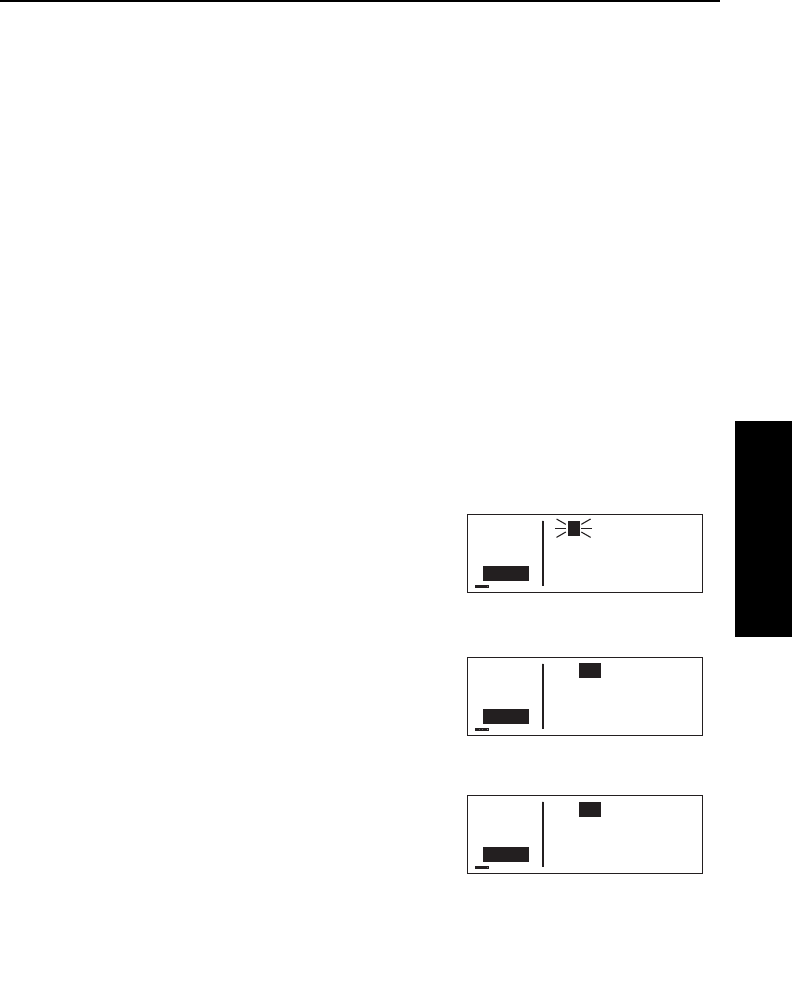
KLN 35A Pilot’s Guide Basic GPS Operation
3-23 Effective Date 5/95006-08791-0000 Rev 0
Basic GPS Operation
Chapter 3
3. Turn the right inner knob clockwise to scan through the
waypoints in alphabetical order, or counterclockwise to scan in
reverse alphabetical order. Remember that numbers are
considered lower in order than letters. Thus, the airport identifier
KA2 comes before KAAF.
NOTE: The faster you turn the knob while scanning, the larger the
step through the waypoints. This variable rate scanning allows you to
get from one end of the list to the other very quickly. When the knob
is turned slowly, you will go through the waypoints one at a time.
You may also want to scan waypoints with the cursor on. This is
especially useful if you remember the first part of the identifier, or if
you wanted to scan all airports that start with a KL, for example.
Let’s give it a try.
To select a waypoint by scanning with the cursor on:
1. Select the page type for the waypoint you are looking for (APT,
VOR, NDB, or SUP). In this case, we want the APT 1 page.
2. Turn on the cursor (B). It will appear over the first character of
the waypoint identifier. Select a Kwith the right inner knob.
3. Move the cursor one place to the
right and select an L
(figure 3-72).
4. Move the cursor one place to the
right and pull the right inner knob
out. The last two characters of
the waypoint identifier will be in
reverse video (figure 3-73).
5. Use the right inner knob to leaf
through all the data base airports
whose identifiers begin with KL.
You will see KL6, Little Bear
Lake Airport in Saskatchewan
(figure 3-74), and KLAS,
McCarran International in Las
Vegas, Nevada among others.
APT VOR NDB SUP ACT NAV FPL CAL SET OTH
åå.ånm KL3 850ft
åååååå WUNNUMMIN LAKE
>Leg WUNNUMMIN LAKE
CRSR ON
Figure 3-72
APT VOR NDB SUP ACT NAV FPL CAL SET OTH
åå.ånm KL3 850ft
åååååå WUNNUMMIN LAKE
>Leg WUNNUMMIN LAKE
CRSR ON
Figure 3-73
APT VOR NDB SUP ACT NAV FPL CAL SET OTH
åå.ånm KL6 2100ft
åååååå LITTLE BEAR LK
>Leg LITTLE BEAR LK
CRSR SK
Figure 3-74
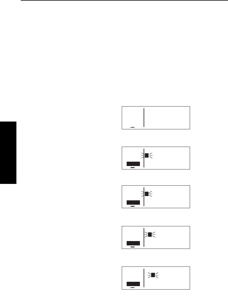
3.7.4. SELECTING WAYPOINTS BY NAME OR CITY
When you know the identifier of the desired waypoint you will use one
of the two methods just described to select it. However, what if you
know the name but you don’t know the identifier of your desired
waypoint? You’re in luck because the KLN 35A will allow you to
enter the first few characters of the name to help you find it in the
data base. We will use a couple of examples to illustrate how this is
done. For VORs and NDBs, you may use the navaid name. For air-
ports, you may use the airport name or the city name (where the
airport is located).
In this first example we want to view the information in the KLN 35A
data base for Napoleon VOR (located just east of Kansas City) but
we don’t remember the identifier for it.
To select a VOR or NDB by navaid
name:
1. With the cursor off, use the right
knobs to select the VOR 1 page
(figure 3-75). The VOR waypoint
in view is not important.
2. Press Band then make sure
the right inner knob is pushed to
the “in” position.
3. With the right outer knob, move
the cursor over the first character
in the VOR name which is being
displayed (figure 3-76).
4. Change this first character to an
“N” in this case (figure 3-77).
5. Move the cursor one space to the
right and select the second char-
acter, “A” (figure 3-78).
6. Select the third character, “P” (fig-
ure 3-79). Up pops Napoleon
and its identifier, ANX!
7. Turn off the cursor (B) so you
can view other pages.
Basic GPS Operation
3-24
Effective Date 5/95 006-08791-0000 Rev 0
Basic GPS Operation
Chapter 3
APT VOR NDB SUP ACT NAV FPL CAL SET OTH
åå.ånm CJS 116.70
åååååå JUAREZ CIUDAD
>Leg N 31°38.16'
CRSR W106°25.58'
Figure 3-76
APT VOR NDB SUP ACT NAV FPL CAL SET OTH
åå.ånm PNE 112.00
åååååå N PHILADELPHIA
>Leg N 40°04.92'
CRSR W 75°00.57'
Figure 3-77
APT VOR NDB SUP ACT NAV FPL CAL SET OTH
åå.ånm ABB 112.40
åååååå NABB
>Leg N 38°35.33'
CRSR W 85°38.16'
Figure 3-78
APT VOR NDB SUP ACT NAV FPL CAL SET OTH
åå.ånm ANX 114.00
åååååå NAPOLEON
>Leg N 39°05.73'
CRSR W 94°07.73'
Figure 3-79
APT VOR NDB SUP ACT NAV FPL CAL SET OTH
åå.ånm CJS 116.70
åååååå JUAREZ CIUDAD
>Leg N 31°38.16'
VOR 1 W106°25.58'
Figure 3-75

KLN 35A Pilot’s Guide Basic GPS Operation
3-25 Effective Date 5/95006-08791-0000 Rev 0
Basic GPS Operation
Chapter 3
We will now use another example to show how we may enter a few
characters and then scan through all the waypoints in the data base
beginning with those characters. Let’s use this method to find
La Guardia Airport in New York City.
To select an airport by scanning the airport name:
1. With the cursor off and the right inner knob in the “in” position,
select the APT (Airport) 1 page. The airport displayed at this
time is not important.
2. Turn on the cursor (B).
3. Move the cursor over the first
character in the airport name
(figure 3-80).
4. Change the first character to an
“L”.
5. Move the cursor one place to the
right, and select an “A”
(figure 3-81).
6. Now, move the cursor one place
to the right and pull the right inner
knob out. The rest of the airport
name field will appear in inverse
video (figure 3-82).
7. Turn the right inner knob clock-
wise, scanning through
La Crosse Municipal, La
Grande/Union airport, and
several others. Eventually, you
will arrive at “LA GUARDIA”
(figure 3-83). By turning the cur-
sor off, pushing the right inner
knob in and turning it, you can
leaf through the remainder of the
pages for La Guardia.
NOTE: This same method may be used with the name of the city
where the airport is located.
APT VOR NDB SUP ACT NAV FPL CAL SET OTH
åå.ånm MGGT 4950ft
åååååå LA AURORA INTL
>Leg GUATEMALA CITY
CRSR GTM
Figure 3-82
APT VOR NDB SUP ACT NAV FPL CAL SET OTH
åå.ånm KLGA 20ft
åååååå LA GUARDIA
>Leg NEW YORK
CRSR NY
Figure 3-83
APT VOR NDB SUP ACT NAV FPL CAL SET OTH
åå.ånm KPAE 610ft
åååååå SNOHOMISH CO
>Leg EVERETT
CRSR WA
Figure 3-80
APT VOR NDB SUP ACT NAV FPL CAL SET OTH
åå.ånm MGGT 4950ft
åååååå LA AURORA INTL
>Leg GUATEMALA CITY
CRSR GTM
Figure 3-81

Basic GPS Operation
3-26
Effective Date 5/95 006-08791-0000 Rev 0
Basic GPS Operation
Chapter 3
There are a few changes made to names in order to accommodate
the KLN 35A display and to make the names easier to find.
1. Names which are too long to fit on the display are abbreviated.
The first six characters are usually exactly correct, but the follow
ing are exceptions:
North, Northern, East, Eastern, etc.—uses N, E
Southeast, Northwest, etc.—uses SE, NW
Point—uses PT
Port—uses PT
Fort—uses FT
Saint—uses ST
General—Deleted, or uses GEN
Person’s name—uses initials for other than last name unless
very well known (Will Rogers World airport)
Delete “City of” (City of Colorado Springs Municipal)
Delete “Greater” (Greater Buffalo Int’l)
Delete “The” (The Hartsfield Atlanta Int’l)
2. Unless the first word is greater than eight characters, it is usually
not abbreviated.
3. Delete most punctuation such as periods and apostrophes.
4. Abbreviations for International are INTL, INT, and IN.
5. Abbreviations for Regional are REGL and REG.
3.8. “NEAREST” FUNCTIONS
At any time, you can have access to the nearest airports, waypoints,
Special Use Airspace (SUA), Flight Service Station (FSS) frequen-
cies, and Center frequencies to your position. Your ticket to do this is
the handy Gbutton.
When you first press the G button,
a page is displayed asking which
nearest function you would like to
select (figure 3-84).
APT VOR NDB SUP ACT NAV FPL CAL SET OTH
åå.ånm NEAREST
åååååå APT? VOR? NDB?
#>Leg SUP? SUA? FSS?
CRSR CTR?
Figure 3-84

KLN 35A Pilot’s Guide Basic GPS Operation
3-27 Effective Date 4/97006-08791-0000 Rev 2
Basic GPS Operation
Chapter 3
The choices are:
APT Airports
VOR VORs
NDB NDBs
SUP Supplemental (User-defined) waypoints
SUA Special Use Airspaces
FSS Flight Service Station Frequencies
CTR Center Frequencies
To select the desired nearest function, use the right outer knob to
move the cursor to the desired selection and press F. Notice that
the cursor is initially over the APT field, so you may press G then
press Fimmediately to access the nearest airports.
Selecting any of the waypoint types
(APT, VOR, NDB, or SUP) takes you
immediately to the waypoint page for
the first nearest waypoint of that type,
for example, the nearest airport (fig-
ure 3-85).
3.8.1. VIEWING THE NEAREST WAYPOINTS
There are actually two waypoint scan lists for airports, VORs, NDBs
and user-defined waypoints. These two lists are the “complete” list
and the “nearest” list. The complete list contains all of the waypoints
in the data base for a waypoint type (all the airports, for example).
The nearest list consists of the nine nearest waypoints (of that type)
to your present position. Therefore, if you are in the nearest airport
list, it will contain the nine nearest airports relative to your location.
The nearest list is positioned in front of the complete list. That is,
instead of using the G button, you may scan backwards (turn the
right inner knob counterclockwise while in the “pulled-out” position)
through the complete list to reach the nearest list. You will know
when you have reached the nearest list because the top middle por-
tion of the waypoint page will flash the relative position of the
waypoint to your position. “1” indicates nearest (figure 3-85) while “9”
indicates the ninth nearest
(figure 3-86). As you scan clockwise
with the right inner knob “1, 2, 3, ...,
9”, the next scan position is the
beginning of the complete list. The
APT VOR NDB SUP ACT NAV FPL CAL SET OTH
118.00 KPAO 1 1370ft
136.97 PALO ALTO-S CL
>Leg 2500ft HRD L
APT 1 >126°To 1.2nm
Figure 3-85
APT VOR NDB SUP ACT NAV FPL CAL SET OTH
118.00 KOAK 9 10ft
136.97 METRO OAKLAND
>Leg 10000ft HRD L
APT 1 >327°To 16.4nm
Figure 3-86

nearest list can only be reached by scanning backwards. It does not
wrap around after the last waypoint in the complete list.
Waypoint pages displayed in the nearest list do not contain a latitude
and longitude position as they do in the complete list. Instead, the
bearing and distance to the waypoint (or the radial and distance from
the waypoint) are displayed. In addition, nearest airport pages dis-
play the length, surface, and lighting of the longest runway. Once the
nearest waypoint is being displayed, the other waypoint pages (for
example, APT 2 and APT 3) for that airport are available for display
by making sure the right inner knob is pushed in and then turning it to
select the desired airport page.
3.8.1.1 Nearest Airport Criteria
The nine airports in the nearest list are the nine airports which meet
the criteria selected on the Setup 6 (SET 6) page. For example, you
probably wouldn’t want to take a turboprop into a 1500 foot grass
strip! The SET 6 page allows you to specify what criteria you want an
airport to meet before it is considered for the nearest airport list.
To specify the nearest airport criteria:
1. Select the SET 6 page and turn on the cursor (B).
2. Use the right inner knob to select
the minimum length runway
desired for the airport to qualify
for the nearest airport list (figure
3-87). Values between 1000 feet
and 5000 feet in 100 foot incre-
ments may be selected.
3. Rotate the right outer knob clockwise to move the cursor over the
runway surface criteria.
4. Turn the right inner knob to select either HRD or ANY. If ANY is
chosen, then both hard and soft surface runways meeting the
required runway length will be included in the nearest airport list.
If HRD is chosen, then only hard surface runways will be includ-
ed. Hard surface runways include concrete, asphalt, pavement,
tarmac, brick, bitumen, and sealed. Soft surface runways include
turf, gravel, clay, sand, dirt, ice, steel matting, shale, and snow.
For example, if the minimum runway criteria selected is 2200 feet in
length and HRD surface, then only airports having a hard surface
runway at least 2200 feet in length will be displayed in the nearest air-
port list.
Basic GPS Operation
3-28
Effective Date 5/95 006-08791-0000 Rev 0
Basic GPS Operation
Chapter 3
APT VOR NDB SUP ACT NAV FPL CAL SET OTH
åå.ånm NEAREST APT
åååååå CRITERIA
>Leg Length: 2200'
SET 6 Surface: HRD
Figure 3-87
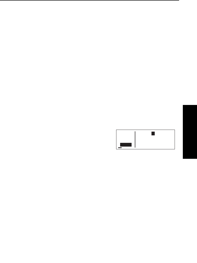
KLN 35A Pilot’s Guide Basic GPS Operation
3-29 Effective Date 5/95006-08791-0000 Rev 0
Basic GPS Operation
Chapter 3
3.8.1.2 Continuous Display of Nearest Airport
When the nearest airport page is initially displayed, “1” is displayed in
the upper right hand corner of the page to designate this airport as
the nearest airport. However, if you continue to fly along your flight
plan with this page selected, the same airport will be displayed and
its position in the nearest airport list will change from 1to 2, 3, 4... 9
until finally it won’t be in the nearest airport list at all. The reason for
this is that in the event of an actual emergency once you have
determined which airport you are heading for, you don’t want the
nearest airport list to update while you are maneuvering or looking up
data on the other airport pages for that airport.
There may be times, however, when you’re flying over “unfriendly”
terrain when you wish to always have the nearest airport displayed
on the screen.
To display the nearest airport continuously:
1. Display the nearest airport page by pressing Gfollowed by
pressing F.
2. Turn on the cursor (B).
3. Rotate the right outer knob
clockwise to position the cursor
over “1” (figure 3-88). As long as
the cursor is left in this position,
this page will update so that the
nearest airport is always shown
as the flight progresses.
3.8.2. VIEWING THE NEAREST SPECIAL USE AIRSPACES
The KLN 35A data base stores the locations of areas of special use
airspace (SUA). The types of SUA areas stored in the data base and
the abbreviations used to denote these areas are the following:
Class B Airspace CL B
Class C Airspace CL C
Control Area (used outside USA) CTA
Terminal Area (used outside USA) TMA
Alert Area ALRT
Danger Area DNGR
Prohibited Area PROH
Restricted Area REST
Terminal Radar Service Area TRSA
APT VOR NDB SUP ACT NAV FPL CAL SET OTH
åå.ånm KPAO 1 1370ft
åååååå PALO ALTO-S CL
>Leg 2500ft HRD L
CRSR >126°To 1.2nm
Figure 3-88

Basic GPS Operation
3-30Effective Date 5/95 006-08791-0000 Rev 0
Basic GPS Operation
Chapter 3
The nearest special use airspace feature is constantly keeping track
of the five nearest areas of SUA. Pressing the Gbutton and
selecting the SUAoption will display
the SUA 1 page (figure 3-89) for the
nearest SUA to your location, includ-
ing those which you are inside. Turn
to section 3.15 to learn more about
how an altitude input affects special
use airspace sensing and how the
KLN 35A determines if you are inside special use airspace or not.
The SUA 1 page displays the following information:
Line 1:The name of the special use airspace area.
Line 2:The SUA type (see the list of abbreviations above, this
particular SUA is Class B airspace), and the sequence number (1st
nearest, 2nd nearest, etc.).
Line 3:The altitude limits of the SUA.
Line 4:The proximity of the nearest point on the border of the SUA,
in the form of the absolute bearing, relative bearing, and distance to
the SUA border. The absolute bearing is the approximate heading
you would fly to most quickly get into the SUA. The relative bearing
arrow in the middle of this line points to the SUA border, telling you if
it is directly ahead of you (), straight off your left wing (), etc.
Finally, the distance to the SUA in nautical miles is displayed on the
right side of line 4.
If the aircraft is inside the SUA, line 4 will read A/C INSIDE SUA, if
you are above or below the SUA, as indicated by the encoding
altimeter, line 4 will tell you this (A/C ABOVESUAor A/C BELOW
SUA).
A single clockwise turn of the right
inner knob selects the SUA 2 page,
which displays either the controlling
ATC facility (figure 3-90), or if the spe-
cial use airspace is a Class B, Class
C, CTA, or TMA, the page will be dis-
played as in figure 3-91, instructing
you to press Eto see the APT 4
page (airport communications) for the
primary airport so that the correct
communications frequency may be
determined.
APT VOR NDB SUP ACT NAV FPL CAL SET OTH
åå.ånm KANSAS CITY
åååååå CL B 1
>Leg Below 8000ft
SUA 1 012° 9.3nm
Figure 3-89
APT VOR NDB SUP ACT NAV FPL CAL SET OTH
åå.ånm TRUMAN A
åååååå MOA 1
>Leg KC Center
SUA 2
Figure 3-90
APT VOR NDB SUP ACT NAV FPL CAL SET OTH
åå.ånm KANSAS CITY
åååååå CL B 1 INSIDE
>Leg Press CLR for
SUA 2 KMCI Freq Use
Figure 3-91

KLN 35A Pilot’s Guide Basic GPS Operation
3-31 Effective Date 5/95006-08791-0000 Rev 0
Basic GPS Operation
Chapter 3
To scan through the remainder of the nearest SUA areas, pull the
right inner knob to the “out” position and turn it clockwise to view the
SUA pages for the second nearest through fifth nearest SUAs.
NOTE: The KLN 35A displays the five nearest SUAs regardless of
your present altitude and the altitude limits of the SUA. For instance,
it will include SUAs specified as “Below 6000ft” even if you are cruis-
ing at 10,000 feet.
3.8.3. Viewing the Nearest Flight Service Station Frequencies
The KLN 35A stores in its data base the locations of Flight Service
Stations (FSS) and their remote communications sites. In addition,
the KLN 35A determines which two of these FSS points of communi-
cation are closest to your present location. What a convenience for
you! Next time you want to file a flight plan from the air or contact an
FSS for some other reason, you can easily use the KLN 35A to deter-
mine a suitable FSS and the appropriate frequency.
NOTE: In some areas of the world the KLN 35A provides the loca-
tion of the nearest point of communication with a facility providing
information (INF) or radio (RDO) services.
Pressing the Gbutton and selecting the FSS option will display two
of the nearest points of communication with Flight Service Stations.
There will normally be two FSS 1 pages, one for each of the two
points of contact. The name of the FSS is at the top of the page.
There can be from one to three frequencies included for a point of
contact (figure 3-92). Remember that
in the U.S. the frequency 122.00 MHz
is used for “Flight Watch” and the fre-
quency 123.60 MHz is used for
Aeronautical Advisory Service. As
you know, it is often possible to com-
municate with an FSS by transmitting
on 122.10 MHz and listening on the
VOR frequency. In cases like this,
the FSS 1 page displays the frequen-
cies to use for transmit and receive
and also the name of the VOR
through which you are communicat-
ing (figure 3-93).
APT VOR NDB SUP ACT NAV FPL CAL SET OTH
åå.ånm FT DODGE FSS
åååååå OMA VOR
>Leg Tx 122.10
FSS+1 Rec 116.30
Figure 3-93
APT VOR NDB SUP ACT NAV FPL CAL SET OTH
åå.ånm AUSTIN FSS
åååååå
>Leg 122.20
FSS+1 122.55
Figure 3-92
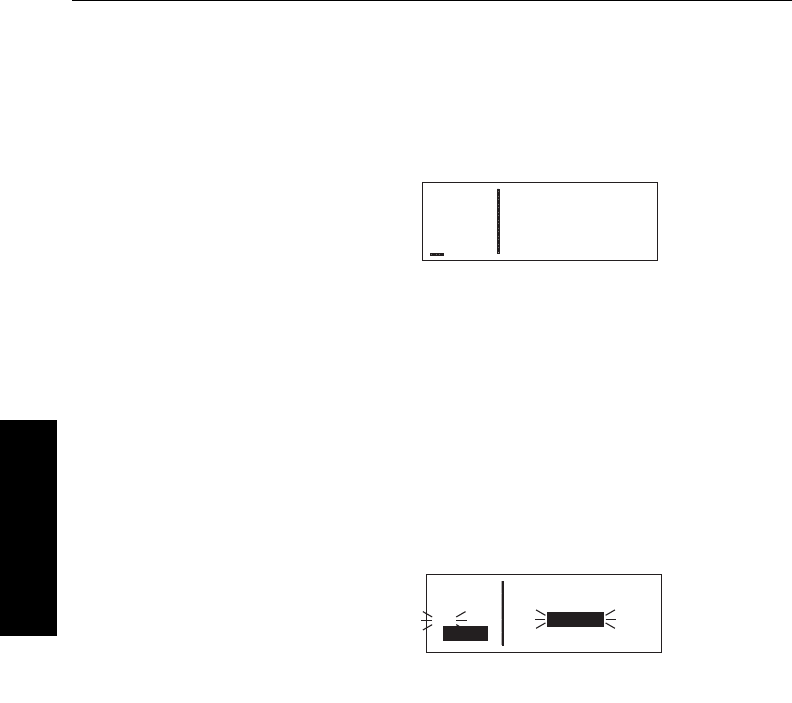
3.8.4. Viewing the Nearest Center Frequencies
The KLN 35A also stores in its data base the low altitude boundaries
of each of the ARTCC “Centers”. The KLN 35A determines the prop-
er Center to contact and the appropriate frequencies to use for the
aircraft’s present position. Pressing the Gbutton and selecting the
CTRoption will display this informa-
tion to you (figure 3-94). Next time
you wish to obtain VFR flight following
or communicate with Center for any
reason, you have a quick way to get a
frequency for establishing contact!
Appendix D contains a listing of
Center abbreviations used on the CTR page.
NOTE: Frequencies for Area Control Centers are displayed on the
CTR page for some areas of the world.
3.9. DIRECT TO OPERATION
The Dbutton is used to initiate Direct To operation (navigation from
your present position direct to your
destination). When Dis pressed,
the Direct To page will be displayed
with a flashing cursor over a waypoint
identifier (figure 3-95). The waypoint
identifier which appears on the Direct
To page is chosen by the KLN 35A
according to the following rules:
1. If the Flight Plan 0 (FPL 0) page is displayed on the screen and
the cursor is over one of the waypoint identifiers in FPL 0 when
D
is pressed, then that waypoint identifier will appear on the
DIR page. You will appreciate this feature when you learn to use
flight plans in section 4.2.
2. If the KLN 35A is displaying the NAV 4 page and the right inner
knob is in the “out” position, then the waypoint highlighted in the
lower right hand corner of the NAV 4 map display will be the
default waypoint. You will also find this feature useful when oper-
ating from the active flight plan.
OR . . .
Basic GPS Operation
3-32Effective Date 5/95 006-08791-0000 Rev 0
Basic GPS Operation
Chapter 3
APT VOR NDB SUP ACT NAV FPL CAL SET OTH
åå.ånm DIRECT TO:
åååååå
#>Leg KPWA
CRSR
Figure 3-95
APT VOR NDB SUP ACT NAV FPL CAL SET OTH
åå.ånm LOS ANGELES CTR
åååååå 118.55
>Leg 132.85
CTR
Figure 3-94

KLN 35A Pilot’s Guide Basic GPS Operation
3-33 Effective Date 5/95006-08791-0000 Rev 0
Basic GPS Operation
Chapter 3
3. If there is any waypoint page (APT, VOR, NDB, SUP, or ACT
page) in view when
D
is pressed, then the DIR page will
contain the identifier for the waypoint just viewed.
If none of the conditions above is occurring, then:
4. When
D
is pressed, the waypoint identifier for the current
active waypoint will be displayed on the DIR page.
If there is no active waypoint when Dis pressed, then:
5. The Direct To page displays blanks in the waypoint identifier
field. In order for there not to be an active waypoint, there is no
Direct To waypoint and there are no waypoints in Flight Plan 0.
3.9.1. INITIATING A DIRECT TO
Now that you know the ground rules, let’s go ahead and try some
practical examples. First, let’s say we wanted to fly directly to
Wexford County Airport in Cadillac, Michigan. Its ICAO identifier is
KCAD.
To fly Direct To a waypoint (procedure 1):
1.Press D. The Direct To page is
displayed (figure 3-96). The
cursor will already be on. A
waypoint identifier may or may
not be displayed, it doesn’t matter
at this point.
2.Rotate the right inner knob to
select the first character of the
desired waypoint’s identifier, in
this case, a “K” (figure 3-97).
Remember to enter the “K”, “C”,
or “P” prefix for certain airports in
North America, if required (see
section 2.3, “ICAO Identifiers”).
3.Turn the right outer knob one
click clockwise to move the flash-
ing portion of the cursor over the
second character position
(figure 3-98).
APT VOR NDB SUP ACT NAV FPL CAL SET OTH
åå.ånm DIRECT TO:
åååååå
#>Leg KDTW
CRSR
Figure 3-96
APT VOR NDB SUP ACT NAV FPL CAL SET OTH
åå.ånm DIRECT TO:
åååååå
#>Leg K
CRSR
Figure 3-97
APT VOR NDB SUP ACT NAV FPL CAL SET OTH
åå.ånm DIRECT TO:
åååååå
#>Leg K
CRSR
Figure 3-98
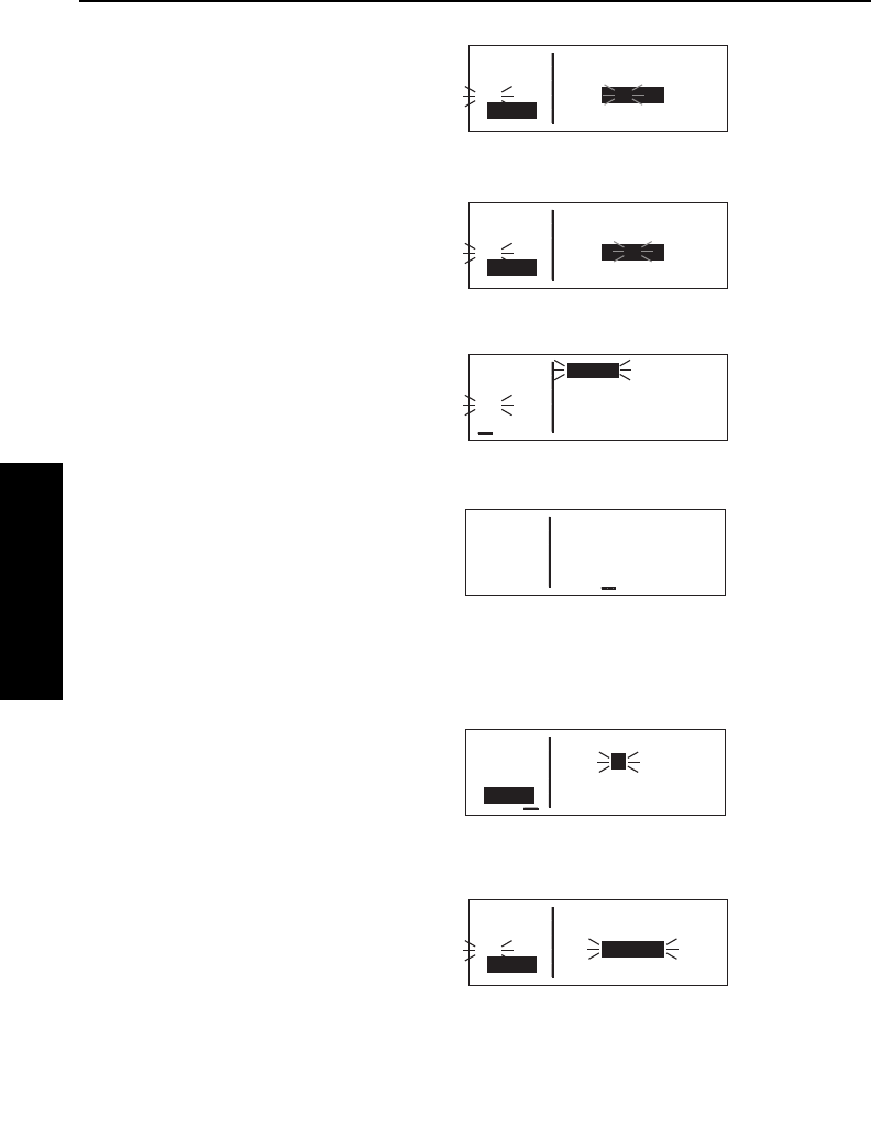
Basic GPS Operation
3-34Effective Date 5/95 006-08791-0000 Rev 0
Basic GPS Operation
Chapter 3
4.Rotate the right inner knob to
select the second character of the
identifier (figure 3-99).
5.Use right outer and inner knobs
as in the previous steps until the
desired identifier is completely
displayed (figure 3-100).
6.Press Fto display the waypoint
page for the selected waypoint
(figure 3-101).
7.Press Fagain to approve the
displayed waypoint page. The
screen will change to the NAV 1
page, and the selected waypoint
will now be the active Direct To
waypoint (figure 3-102).
To fly Direct To a waypoint (procedure 2):
1.Select the desired waypoint page
(APT, VOR, NDB, or SUP) on the
screen (figure 3-103) using one of
the three procedures explained in
section 3.9.
2.Press D. The Direct To page is
displayed and it contains the
desired waypoint identifier
(figure 3-104).
3.Press F. The display will revert to the NAV 1 page with the
selected waypoint as the Direct To waypoint.
APT VOR NDB SUP ACT NAV FPL CAL SET OTH
åå.ånm JJC 396
åååååå MOUNTAIN CITY
>Leg N 36°24.99'
CRSR W 81°49.46'
Figure 3-103
APT VOR NDB SUP ACT NAV FPL CAL SET OTH
åå.ånm DIRECT TO:
åååååå
#>Leg JJC
CRSR
Figure 3-104
APT VOR NDB SUP ACT NAV FPL CAL SET OTH
åå.ånm DIRECT TO:
åååååå
#>Leg KC2
CRSR
Figure 3-99
APT VOR NDB SUP ACT NAV FPL CAL SET OTH
åå.ånm DIRECT TO:
åååååå
#>Leg KCAD
CRSR
Figure 3-100
APT VOR NDB SUP ACT NAV FPL CAL SET OTH
åå.ånm KCAD 1310ft
åååååå WEXFORD CO
#>Leg CADILLAC
APT 1 MI
Figure 3-101
APT VOR NDB SUP ACT NAV FPL CAL SET OTH
76.8nm D∆ KCAD
121kt > ««««∑∏π««««
>Leg DTK167° TK168°
NAV 1 >167°To 0:41
∫
Figure 3-102
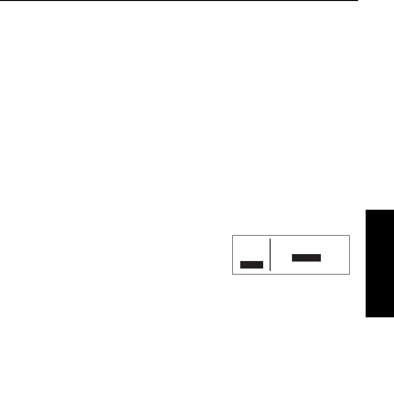
KLN 35A Pilot’s Guide Basic GPS Operation
3-35 Effective Date 5/95006-08791-0000 Rev 0
Basic GPS Operation
Chapter 3
If you get off course and wish to recenter the left/right deviation bar
(D-Bar) to proceed to the same waypoint, use the following
procedure:
To recenter the D-Bar by going direct to the active waypoint:
1.Select a non-waypoint page (NAV, FPL, CAL, SET, or OTH) on
the screen.
2.Press D. The Direct To page is displayed on the left, contain-
ing the active waypoint identifier.
3.Press F.
3.9.2. CANCELING A DIRECT TO
To cancel Direct To operation:
The primary reason for wanting to cancel Direct To operation is to
return to flight plan operation which is described later in section 4.2.4
“Combining Direct To and Flight Plan Operation”.
1.Press D.
2.Press Eto blank out the way-
point identifier field (figure 3-105).
3.Press F.
3.9.3. WAYPOINT ALERTING FOR DIRECT TO OPERATION
Approximately 36 seconds prior to reaching a Direct To waypoint, the
arrow preceding the waypoint identifier on the waypoint page for the
active waypoint will begin flashing. This arrow will also be flashing on
any NAV or FPL page displaying the active waypoint identifier. This
is called “waypoint alerting”. If an external waypoint alert annunciator
is mounted in the aircraft, this annunciator will begin flashing at the
same time.
APT VOR NDB SUP ACT NAV FPL CAL SET OTH
åå.ånm DIRECT TO:
åååååå
>Leg _____
CRSR
Figure 3-105

Basic GPS Operation
3-36Effective Date 5/95 006-08791-0000 Rev 0
Basic GPS Operation
Chapter 3
3.10. NAVIGATION PAGES
As you would expect, the NAV (navigation) pages contain information
relating specifically to the KLN 35A’s navigation capabilities. The
KLN 35A has four NAV pages. The procedure for selecting specific
pages, including the NAV pages, was described in section 3.4.1,
“Page Selection”.
3.10.1. THE NAVIGATION 1 (NAV 1) PAGE
The NAV 1 page is the primary
navigation display, and is shown in
figure 3-106. In normal flight, you will
probably want to view this page quite
often. A NAV 1 page displays the fol-
lowing information:
Line 1:The active navigation leg.
For Direct To operation this consists
of the Direct To symbol, ∂∂∆∆, followed
by the active Direct To waypoint iden-
tifier (figure 3-106). For the leg of a
flight plan this consists of the “from”
waypoint identifier and the active “to”
waypoint identifier (figure 3-107). An arrow ∆∆precedes the active
waypoint identifier.
Line 2:A cyclic field which can either be (1) a course deviation
indicator (CDI) that graphically displays left and right deviation from
desired track (figure 3-107), or (2)
The direction to fly to intercept the
desired track and the crosstrack
distance (figure 3-108). In either
case, the same information is
displayed. This is a cyclic field, so
you can change back and forth from
the two options by turning on the cursor (B) over the second line
and pressing the E button.
The CDI’s vertical bar operates like a navigation deviation needle on
a conventional CDI or HSI using VOR/Localizer navigation. An on-
course indication is displayed when the vertical deviation bar is
centered on the triangle in the middle of the CDI. In both modes (Leg
and OBS, see section 4.5), each dot represents one nautical mile
APT VOR NDB SUP ACT NAV FPL CAL SET OTH
66.1nm ∂∆ KAUG
132kt > ««««∑∏π««««
>Leg DTK048° TK046°
NAV 1 >047°To 0:30
∫
Figure 3-106
APT VOR NDB SUP ACT NAV FPL CAL SET OTH
åå.ånm KBGR ∆ KAUG
åååååå > ««««∑∏π««««
>Leg DTK237° TK233°
NAV 1 >234°To 0:22
∫
FIgure 3-107
APT VOR NDB SUP ACT NAV FPL CAL SET OTH
åå.ånm KBGR ∆ KAUG
åååååå >Fly L 0.4nm
>Leg DTK237° TK233°
NAV 1 >234°To 0:22
Figure 3-108
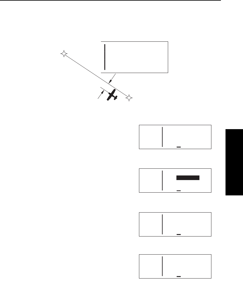
KLN 35A Pilot’s Guide Basic GPS Operation
3-37 Effective Date 5/95006-08791-0000 Rev 0
Basic GPS Operation
Chapter 3
deviation from the desired track. Therefore, the CDI shows course
deviation five nautical miles left and right of course. A vertical devia-
tion bar positioned two dots to the right of the center triangle indicates
the aircraft is two nautical miles to the left of course (figure 3-109).
The center triangle also serves as the CDI’s TO/FROM indicator and
operates in the same manner as a
conventional CDI TO/FROM indica-
tor; a triangle pointing up indicates
“to” the active waypoint while a
“down” triangle (figure 3-110)
indicates “from” the active waypoint.
The word FLAG is displayed over
the CDI when the KLN 35A is not
usable for navigation (figure 3-111).
The numerical crosstrack distance
display is especially handy when
more than five nautical miles off of
course (naturally, you yourself
would never deviate more than five
nm off course, but not everyone is
as good a pilot as you are!) If your
crosstrack distance was 13.1 nauti-
cal miles left of course, the graphic
CDI needle will be pegged on the
right side (which doesn’t tell you
much). But this presentation will
show you exactly how far off course
you are (figure 3-112). When the
KLN 35A is not usable for naviga-
tion, the crosstrack distance will be
APT VOR NDB SUP ACT NAV FPL CAL SET OTH
åå.ånm KBGR ∆ KAUG
åååååå > ««««“‘∫««««
>Leg DTK232° TK233°
NAV 1 >234°To 0:02
Figure 3-110
APT VOR NDB SUP ACT NAV FPL CAL SET OTH
--.-nm
------ > ««F«L A«G««
>Leg DTK---° TK---°
NAV 1 >---°To --:--
Figure 3-111
KBGR
KAUG
2 NM
KBGR ∆ KAUG
> ««««∑∏π∫«««
DTK232° TK233°
>234°To 0:02
Figure 3-109
APT VOR NDB SUP ACT NAV FPL CAL SET OTH
--.-nm
------ >Fly - --.-nm
>Leg DTK---° TK---°
NAV 1 >---°To --:--
Figure 3-113
APT VOR NDB SUP ACT NAV FPL CAL SET OTH
åå.ånm KBGR ∆ KAUG
åååååå >Fly R 13.1nm
>Leg DTK232° TK233°
NAV 1 >234°To 0:22
Figure 3-112

Basic GPS Operation
3-38Effective Date 5/95 006-08791-0000 Rev 0
Basic GPS Operation
Chapter 3
dashed out (figure 3-113).
Line 3:Magnetic desired track, and magnetic actual track (see
Appendix A for navigation terms). In normal on-course flight, it is
desirable to steer the aircraft to keep these two numbers equal.
Line 4:A cyclic field which can display either bearing to the active
waypoint (To) or radial from the active waypoint (Fr) relative to the
present position. By placing the cursor over this field and pressing
the Ebutton, you may toggle between the two options.
NOTE: Due to “great circle” courses and magnetic variation differ-
ences between present position and the active waypoint, the To
bearing and From radial may not be exactly 180° different from each
other when the system is in the Leg mode. This condition is most
likely to occur when long distances are involved, and/or you are
operating in very northerly or southerly latitudes. See figure 3-114 for
an example depicting a case like this. The aircraft is somewhere over
Georgia, and the active waypoint is KPHX. The bearing to steer is
269°, and radial is 72°. Generally, you will want to use bearing (not
radial) when long distances are involved.
Line 4 also displays the estimated time en route (ETE) from present
NN
KPHX
72°
269°
Figure 3-114
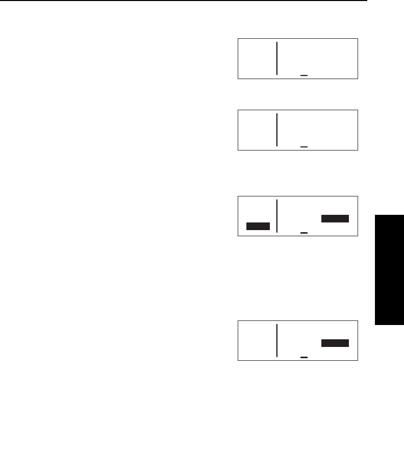
KLN 35A Pilot’s Guide Basic GPS Operation
3-39 Effective Date 5/95006-08791-0000 Rev 0
Basic GPS Operation
Chapter 3
position to active waypoint.
3.10.2. THE NAVIGATION 2 (NAV
2) PAGE
The NAV 2 pages in figures 3-115
and 3-116 display the aircraft’s
present position in one of two
formats. The first line is a cyclic field
which allows you to toggle between
formats. When the NAV 2 page is
first displayed, it defaults to present
position in terms of the radial and
distance from a nearby VOR. You
can change the reference waypoint from the nearby VOR to any
waypoint.
To change the NAV 2 page present
position reference waypoint:
1. With the NAV 2 page on the
radial and distance from a
reference waypoint format, turn
on the cursor (B) and move it to the Ref: field (figure 3-117).
2. Use the right inner and outer knobs to enter the waypoint you
wish to use as a reference.
3. Press F. The waypoint page
for the identifier just entered will
be displayed.
4. If this is the waypoint you intend-
ed, press Fagain. The display
will return to the NAV 2 page
(figure 3-118).
NOTE: If you change the reference waypoint, change to a page
other than the NAV 2 page, then turn back to the NAV 2 page, the
reference waypoint will revert back to a nearby VOR.
APT VOR NDB SUP ACT NAV FPL CAL SET OTH
åå.ånm >Present Posn
åååååå
>Leg Ref: KMKC
NAV 2 219°Fr 22.2nm
Figure 3-118
APT VOR NDB SUP ACT NAV FPL CAL SET OTH
åå.ånm >Present Posn
åååååå
>Leg N 38°53.74'
NAV 2 W 94°53.39'
Figure 3-115
APT VOR NDB SUP ACT NAV FPL CAL SET OTH
åå.ånm >Present Posn
åååååå
>Leg Ref: OJC
NAV 2 310°Fr 9.5nm
Figure 3-116
APT VOR NDB SUP ACT NAV FPL CAL SET OTH
åå.ånm >Present Posn
åååååå
>Leg Ref: OJC
CRSR 346°Fr 28.6nm
Figure 3-117

Basic GPS Operation
3-40
Effective Date 5/95 006-08791-0000 Rev 0
Basic GPS Operation
Chapter 3
By turning on the cursor (B) over the first line and pressing E,
you can change to the latitude and
longitude format.
3.10.3. THE NAVIGATION 3 (NAV
3) PAGE
The Navigation (NAV) 3 page shows
you several important times pertaining to your flight (figure 3-119).
Line 1: The current system time zone and time. The time zone may
be changed by turning the cursor (B) on over it and turning the
right inner knob. All times shown on the NAV 3 page are in terms of
the system time zone (except for the flight time, which is an elapsed
time).
Line 2: The time of departure. This is the time when a valid ground-
speed was first greater than 30 knots (typically during takeoff).
Line 3: Estimated time of arrival at your destination. If the active
waypoint is not part of the active flight plan, the active waypoint will
be the destination. Otherwise, the last waypoint in your active flight
plan will be the destination.
Line 4: The elapsed flight time, which will be the hours and minutes
since the departure time.
3.10.4. THE NAVIGATION 4 (NAV 4) PAGE
The NAV 4 page is a graphical moving map which offers excellent
“bird’s-eye-view” situational awareness to you as the pilot in com-
mand. This page can show you where you are and where you’re
headed relative to your active flight
plan or leg, your destination way-
point(s), the nearby airports and
VORs, and even the boundaries of
nearby special use airspace!
The NAV 4 page (figure 3-120) is a lit-
tle bit different than some of the other
KLN 35A pages. Instead of displaying the page type and number
(i.e. NAV 4) in the lower left corner of the screen, an additional piece
of navigation data is displayed here. We’re willing to bet you’ll know
APT VOR NDB SUP ACT NAV FPL CAL SET OTH
åå.ånm Time CDT 1605
åååååå Depart 1343
>Leg ETA KIXD 1710
NAV 3 Flight 2:22
Figure 3-119
25.8nm
SGJ
{>Leg
>117kt
APT VOR NDB SUP ACT NAV FPL CAL SET OTH
100 KJAX"
SGJ
OMN KCVN
%
%
%
%
Figure 3-120
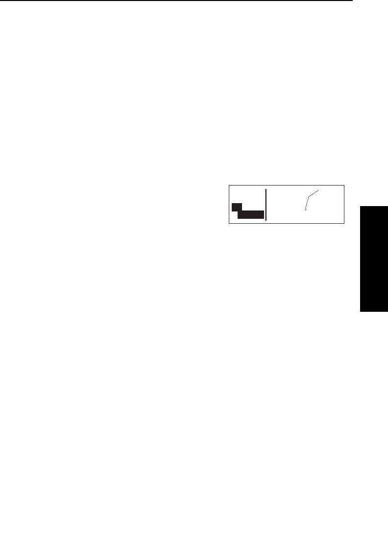
KLN 35A Pilot’s Guide Basic GPS Operation
3-41
Basic GPS Operation
Chapter 3
this is the NAV 4 page anyway, because of its unique graphics.
The left side of the screen displays the distance to go, active way-
point identifier, and mode annunciation (either Leg, or the OBS
selected course), just like it usually would, but the fourth line is a
cyclic field for which you may select:
Magnetic Desired Track (degrees) DTK123
Groundspeed (knots) 123kt
Estimated Time Enroute (hours:minutes) 1:23
Crosstrack Correction (nautical miles) 1.23→
NOTE: Magnetic desired track may only be selected when KLN 35A
is in the Leg navigation mode. When the KLN 35A is in the OBS
mode, the “desired track” is the same as the OBS selected course
displayed on line 3.
To change the data displayed in this
cyclic field, simply turn on the cursor
(B), rotate the right outer knob
counterclockwise to position the cur-
sor over this field (figure 3-121), and
press the Ebutton to choose the desired information.
Now we move on to the map display area on the right side of the
screen. In all KLN 35A installations there are three common map ori-
entation formats that may be selected on the NAV 4 page: a True
North up display, a desired track up display, or an actual track up dis-
play. When the North up display is selected, viewing the NAV 4 page
is like looking at a navigation chart with North at the top. When the
desired track up display is selected the NAV 4 page is like looking at
a chart that is turned so that your course line is always pointing up.
When the actual track up display is selected, viewing the NAV 4 page
is like looking at a chart that is turned so that the direction the aircraft
is tracking over the ground is pointing up. In a no-wind condition,
actual track is identical to the aircraft’s heading.
CAUTION: When using the actual track up format it is typical for
there to be a slight delay from the time a heading change is
made until the correct map orientation is displayed. Be careful
when using either the desired track up display or the actual
track up display to not think that a heading up display is being
used.
Effective Date 4/97006-08791-0000 Rev 2
25.8nm
SGJ
{>Leg
>117kt
APT VOR NDB SUP ACT NAV FPL CAL SET OTH
100 KJAX
"
SGJ
OMN KCVN
%
%
%
%
Figure 3-121
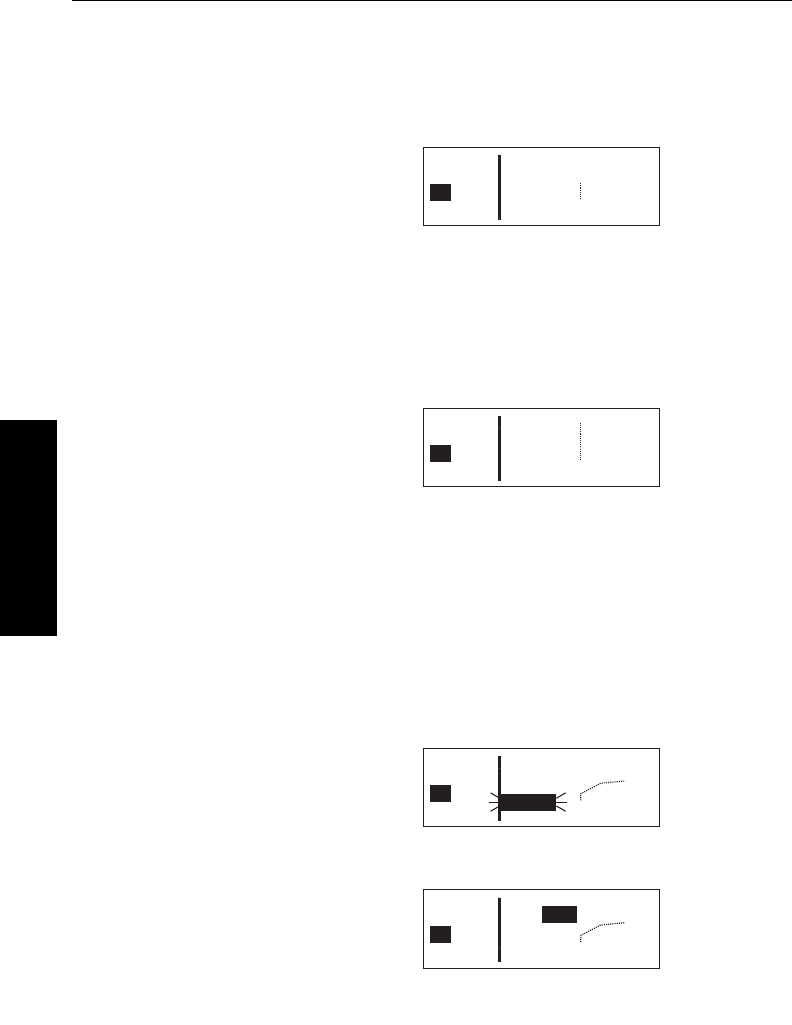
Basic GPS Operation
3-42Effective Date 5/95 006-08791-0000 Rev 0
Basic GPS Operation
Chapter 3
When you are navigating with a flight plan (see section 4.2), the NAV
4 page displays the waypoints of the active flight plan (FPL 0) with
their waypoint identifiers (figure 3-121). Course lines connect the
flight plan waypoints.
When operating Direct To a waypoint
which is not in the active flight plan,
the direct to waypoint is shown on the
map, and although the waypoints of
the active flight plan are still shown on
the screen, they are not connected by
course lines (figure 3-122).
In the lower left corner of the map display area is the map range
scale in nautical miles. The range scale indicates the distance from
the aircraft’s position to the top of the screen. You may select a
range scale of 1 NM to 500 NM with several choices in between by
turning on the cursor (B), and using
the right inner knob to select the
desired range scale. For example,
figure 3-123 illustrates the results of
changing the range scale of the map
in figure 3-122 from 60 nautical miles
to 30 nautical miles.
Additionally, there is a choice called AUTO, for automatic range scal-
ing. This choice is sandwiched between the 1 NM scale and the 500
NM scale, such that it is “below” 1 NM and “above” 500 NM. The
AUTO scale factor feature “zooms” the map in and out in a useful
way so that you don’t have to. Specifically, AUTO chooses the small-
est map scale that will display the active waypoint and, if there is one,
the waypoint after the active waypoint. Choosing the AUTO scale
factor means there is one less item for you to worry about.
Aside from changing the map range
scale, all other customization of the
map display is done from the menu.
Notice that when you turn on the cur-
sor (B), the Menu?field appears
above the range scale. Turn the right
outer knob one step counter-clock-
wise to move the cursor over the
Menu?field (figure 3-124) and press
F. The menu now “pops-up” on the
screen (figure 3-125).
17.6nm
SGJ
{>Leg
>117kt
APT VOR NDB SUP ACT NAV FPL CAL SET OTH
SUA:off
VOR:off
APT:off
112°KJAX "
KORL
OMN
%
%%%
ORL
GJ
Figure 3-125
24.2nm
2CB
{>Leg
>117kt
APT VOR NDB SUP ACT NAV FPL CAL SET OTH
30 KJAX"
SGJ
2CB
%
%
%
%
Figure 3-123
28.0nm
2CB
{>Leg
>117kt
APT VOR NDB SUP ACT NAV FPL CAL SET OTH
60 KJAX"
SGJ
2CB
%
%
%
%%
OMN
ORL
Figure 3-122
17.6nm
SGJ
{>Leg
>117kt
APT VOR NDB SUP ACT NAV FPL CAL SET OTH
Menu?
60 KJAX "
KORL
OMN
%
%%%
ORL
SGJ
Figure 3-124
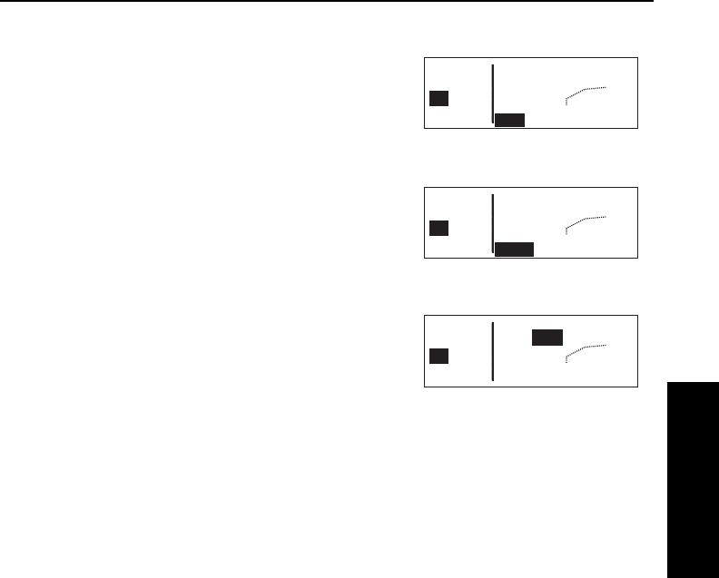
To select the desired NAV 4 orienta-
tion, you must first select the menu,
then use the right outer knob to posi-
tion the cursor over the map
orientation field (figure 3-126). Rotate
the right inner knob to display N↑for
North up, DTK↑for desired track up
(figure 3-127) or TK↑for actual track
up. If the cursor is located on a field
other than the map orientation field,
then the DTK↑or TK↑annunciation
is replaced with the actual value. The
123°displayed in figure 3-128 shows
how the actual track is displayed
when the cursor is not over the map
orientation field.
Actual track up display is usually pre-
ferred for use in flight. However, the
track up display is only usable when
the aircraft is moving 2 knots or more
so the North up display may be a good choice if you are stationary.
Notice that in both the North up format and the desired track up for-
mat, the aircraft’s position is depicted by a diamond. In the actual
track up format, the aircraft’s position is depicted by an aircraft sym-
bol.
You may choose to have nearby airports, VORs, and special use air-
space (SUA) displayed on the moving map! To do so, use the
pop-up menu by turning on the cursor and selecting Menu?.
When the menu is first displayed the cursor will be on the SUA selec-
tion field. Rotate the right inner knob to select onor off. When SUAs
are selected, the five nearest SUAs are displayed. However, they will
not be displayed on map range scales larger than 160 NM. Special
use airspace areas are displayed regardless of your altitude relative
to the airspace. The nearest SUA feature (section 3.8.2) and the
SUA alerting feature (section 3.15) will indicate the altitude limits of
the airspace to you. Section 3.15 will also help you understand more
about the KLN 35A special use airspace features as well as the types
of SUA that are included in the KLN 35A data base.
NOTE: Only the outer lateral boundaries are displayed for Class B,
Class C, CTA, and TMA airspace. The actual SUA may have differ-
ent lateral limits (i.e. smaller) depending on your present altitude.
KLN 35A Pilot’s Guide Basic GPS Operation
3-43 Effective Date 5/95006-08791-0000 Rev 0
Basic GPS Operation
Chapter 3
17.6nm
SGJ
{>Leg
>117kt
APT VOR NDB SUP ACT NAV FPL CAL SET OTH
SUA:off
VOR:off
APT:off
TK KJAX "
KORL
OMN
%
%%%
ORL
GJ
Figure 3-126
17.6nm
SGJ
{>Leg
>117kt
APT VOR NDB SUP ACT NAV FPL CAL SET OTH
SUA:off
VOR:off
APT:off
DTKKJAX "
KORL
OMN
%
%%%
ORL
GJ
Figure 3-127
17.6nm
SGJ
{>Leg
>117kt
APT VOR NDB SUP ACT NAV FPL CAL SET OTH
SUA:off
VOR:off
APT:off
123°KJAX "
KORL
OMN
%
%%%
ORL
GJ
Figure 3-128

Basic GPS Operation
3-44
Effective Date 5/95 006-08791-0000 Rev 0
Basic GPS Operation
Chapter 3
In the same manner, the nearest VORs and/or airports may be
selected by first using the right outer
knob to move the cursor over the
VOR or APT selection field and then
using the right inner knob to select on
or off. The example in figure 3-129
shows SUAs and airports having
been selected.
When the desired selections have
been made, press the Bbutton to
remove the menu from the screen
(figure 3-130). Notice that the nearest
airports are depicted with a small ##
symbol, while the VORs are shown as
a small box ($$).
One last item of interest on this page: you may change the active
waypoint to any of the flight plan waypoints without having to leave
the map display. This is done by pulling the right inner knob to the
“out” or “scan” position. This will cause the identifier for the active
waypoint to be displayed in the bottom right corner of the screen
(figure 3-131). The waypoint
displayed in this area will be the
default waypoint when Dis
pressed. By turning the right inner
knob it is possible to scan through the
waypoints of the active flight plan
(FPL 0). Turning the knob clockwise
will scan through the waypoints in sequence until the end of the flight
plan is reached. Turning the knob counter-clockwise will scan
through the active flight plan in reverse order until the beginning of
the flight plan is reached. Pushing the right inner knob back to the
“in” position will remove this text from the map display area.
The following hints will make using the NAV 4 page more enjoyable.
•It is easy to clutter the display with so much data that it is unus-
able. Select a range scale that allows an uncluttered
presentation of the chosen SUAs, VORs, and airports. Or,
select another combination of these from the menu.
Experiment and continue to make new selections for different
phases of your trip.
17.6nm
SGJ
{>Leg
>117kt
APT VOR NDB SUP ACT NAV FPL CAL SET OTH
SUA:on
VOR:off
APT:on
123°KJAX "
KORL
OMN
%
%%%
ORL
GJ
SGJ
Figure 3-131
17.6nm
SGJ
{>Leg
>117kt
APT VOR NDB SUP ACT NAV FPL CAL SET OTH
25 "KNIP
SGJ
%2CB
#
#
Figure 3-130
17.6nm
SGJ
{>Leg
>117kt
APT VOR NDB SUP ACT NAV FPL CAL SET OTH
SUA:on
VOR:off
APT:on
123°KJAX "
KORL
OMN
%
%%%
ORL
GJ
Figure 3-129

KLN 35A Pilot’s Guide Basic GPS Operation
3-45 Effective Date 5/95006-08791-0000 Rev 0
Basic GPS Operation
Chapter 3
•Press Eto instantly declutter the SUA, VOR, and airport
selections from the graphics display. Flight plan and Direct To
waypoints will still be displayed. Press Eagain to restore the
selections.
CAUTION: The NAV 4 page does not display weather, terrain, or
other data.
3.11. WAYPOINT PAGES
NOTE: Each of the waypoint page types includes a cyclic field which
displays present magnetic bearing to or magnetic radial from the
waypoint. Due to “great circle” courses and magnetic variation
differences between present position and the active waypoint, the To
bearing and From radial may not be exactly 180° different from each
other. This condition is most likely to occur when long distances are
involved, and/or you are operating in very northerly or southerly
latitudes. See section 3.10.1 and figure 3-114 for more details.
3.11.1. AIRPORT PAGES
3.11.1.1. The Airport 1 (APT 1) Page
See figure 3-132.
Line 1:The ICAO identifier (see
section 2.3) of the airport; an arrow
precedes the identifier if it is the
active waypoint. The airport elevation
above MSL in feet, which is rounded
to the nearest 10 feet.
Line 2:The name of the airport.
Line 3:The city where the airport is located.
Line 4:The State if the airport is
located in the U.S., the Province if
located in Canada, or the country if
outside the U.S. and Canada. A list-
ing of the abbreviations used for
States, Provinces, and countries is
contained in Appendix D. The right
side of line 4 will read MILITARYif it
is a military airport (Figure 3-133) or PRIVATEif it is a private-use
airport.
APT VOR NDB SUP ACT NAV FPL CAL SET OTH
åå.ånm KSZL 870ft
åååååå WHITEMAN AFB
>Leg KNOB NOSTER
APT 1 MO MILITARY
Figure 3-133
APT VOR NDB SUP ACT NAV FPL CAL SET OTH
åå.ånm KLIT 260ft
åååååå ADAMS
>Leg LITTLE ROCK
APT 1 AR
Figure 3-132
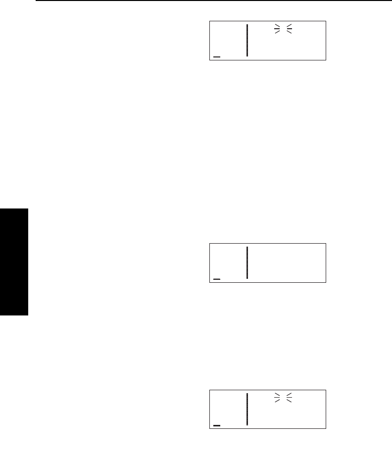
Basic GPS Operation
3-46Effective Date 5/95 006-08791-0000 Rev 0
Basic GPS Operation
Chapter 3
If the airport is being viewed as part of
the
nearest airports list
(see section
3.8.1, “Viewing the Nearest
Waypoints”), the APT 1 page format
will differ as follows (see figure 3-
134):
Line 1:After the airport identifier, the number designating the air-
port’s position in the nearest airport list is displayed. In figure 3-134,
KLIT is the third nearest airport.
Line 2:Same as a normal APT 1 page.
Line 3:The length, surface, and lighting of the longest runway.
Line 4:The magnetic bearing to or the magnetic radial from the
airport and the distance in nautical miles. Placing the cursor over the
radial/bearing field and pressing Etoggles between radial from and
bearing to the airport.
3.11.1.2. The Airport 2 (APT 2) Page
See figure 3-135.
Line 1:The ICAO identifier (see
section 2.3) of the airport; an arrow
precedes the identifier if it is the active
waypoint.
Lines 2-3:The latitude and longitude
of the airport reference point (the “official” location of the airport).
Line 4:The magnetic bearing to or the magnetic radial from the air-
port and the distance in nautical miles. Placing the cursor over the
radial/bearing field and pressing Etoggles between radial from and
bearing to the airport.
If the airport is being viewed as part of
the
nearest airports list
(see section
3.8.1, “Viewing the Nearest
Waypoints”), the APT 2 page format
will differ as follows (see
figure 3-136):
Line 1:After the airport identifier, the number designating the air-
APT VOR NDB SUP ACT NAV FPL CAL SET OTH
åå.ånm KLIT 3
åååååå LITTLE ROCK
>Leg AR
APT 2 >103°To 14.5nm
Figure 3-136
APT VOR NDB SUP ACT NAV FPL CAL SET OTH
åå.ånm KLIT 3 260ft
åååååå ADAMS
>Leg 7200ft HRD L
APT 1 >103°To 14.5nm
Figure 3-134
APT VOR NDB SUP ACT NAV FPL CAL SET OTH
åå.ånm KLIT
åååååå N 34°43.74'
>Leg W 92°13.47'
APT 2 >103°To 14.5nm
Figure 3-135

KLN 35A Pilot’s Guide Basic GPS Operation
3-47 Effective Date 5/95006-08791-0000 Rev 0
Basic GPS Operation
Chapter 3
port’s position in the nearest airport list is displayed.
Line 2:The city where the airport is located.
Line 3:The State if the airport is located in the US., the Province if
located in Canada, or the country if outside the US. and Canada. A
listing of the abbreviations used for States, Provinces, and countries
is contained in Appendix D. The right side of line 4 displays
MILITARYif it is a military airport or PRIVATEif it is a private-use
airport.
Line 4:The magnetic bearing to or the magnetic radial from the air-
port and the distance in nautical miles. Placing the cursor over the
radial/bearing field and pressing Etoggles between radial from and
bearing to the airport.
3.11.1.3. The Airport 3 (APT 3) Page
See figure 3-137.
The APT 3 page displays the runway
designation, length, surface, and
lighting for up to five runways in order
of length, beginning with the longest
runway. Since there are many times
when all of an airport’s runway infor-
mation does not fit on one page, additional APT 3 pages are used to
display the data. Remember that a “+” inserted between the page
type and the number (APT+3in this case) is used to indicate that
there is more than one Airport 3 page.
Line 1:The ICAO identifier (see section 2.3) of the airport; an arrow
precedes the identifier if it is the active waypoint. To the right is the
runway designation for the first runway on the page.
NOTE: In some parts of the world, runway numbers are based on
true runway heading rather than magnetic. These runways are
prevalent in northern Canada, where there is a large magnetic varia-
tion gradient. For these runways, a
¶¶
symbol separates the two
runway numbers (example
1144¶¶3322
).
Line 2:The runway length for the first runway listed on the page, the
runway surface type and the type of lighting (blank if none).
APT VOR NDB SUP ACT NAV FPL CAL SET OTH
åå.ånm KLIT 04R/22L
åååååå 7200' HRD L
>Leg 04L/22R
APT+3 7173' HRD L
Figure 3-137

Basic GPS Operation
3-48Effective Date 5/95 006-08791-0000 Rev 0
Basic GPS Operation
Chapter 3
Runway surface abbreviations:
HRD Hard surface
TRF Turf
GRV Gravel
CLY Clay
SND Sand
DRT Dirt
SNW Snow
ICE Ice
SHL Shale
MAT Steel mat
Runway lighting Abbreviations:
L Sunset to sunrise
LPC Pilot controlled lighting
LPT Part-time or on-request lighting
Lines 3-4:Runway information for the next shortest runway (if any),
in the same format as lines 1 and 2.
In the event that there is no runway information for an airport, the fol-
lowing message is displayed on the APT 3 page:
No Runway Data
3.11.1.4. THE AIRPORT 4 (APT 4) PAGE
See figure 3-138.
Line 1:The ICAO identifier (see
section 2.3) of the airport; an arrow
precedes the identifier if it is the active
waypoint.
Lines 2-4:The VHF communication frequencies associated with the
airport. The type and frequency is listed. The abbreviations are:
AAS aeronautical advisory service
AFIS aerodrome flight information service
ARVL arrival
APR approach
ATF aerodrome traffic frequency
AWOS automatic weather observing station
ATIS automatic terminal information service
CL B class B airspace (formerly terminal control area)(VFR frequency)
APT VOR NDB SUP ACT NAV FPL CAL SET OTH
åå.ånm KLIT
åååååå ATIS 125.60
>Leg PTX 118.95
APT+4 TWR * 121.90
Figure 3-138

CL C class C airspace (formerly airport radar service area) (VFR frequency)
CLR clearance delivery
CTA control area (VFR frequency used outside the U.S.)
CTAF common traffic advisory frequency
CTR center (when center is used for approach/departure control)
DEP departure
DIR director (approach control/radar)
GRND ground control
MCOM multicom
MF mandatory frequency
PCL pilot-controlled lighting
PTAX pre-taxi clearance
RAMP ramp/taxi control
RDR radar-only frequency
TMA terminal area (VFR frequency used outside the U.S.)
TWR control tower
UNIC unicom
Part-time operation, such as for a control tower, is indicated with an
asterisk (*) to the right of an airport frequency.
The frequencies associated with Class B or C airspace, CTA or TMA
are VFR frequencies. Airports which have one of these categories of
frequencies also have APR and DEP which are IFR frequencies.
Where required, APR, DEP, CL B, CL C, CTA, and TMA frequencies
are sectorized. That is, a frequency may be used only within a cer-
tain range of radials from a designated reference location. The
format for displaying the sectorization is to show the frequency first,
followed by the identifier of the associated reference point, followed
next by the associated altitude restrictions. For example, figure 3-
139 shows that the Orlando approach
control frequency 121.10 MHz is used
between the 311° radial and the 60°
radial from KMCO (Orlando
International Airport) for altitudes at
and below 5500 feet.
In a few cases, APR, DEP, CL B, CL C, CTA, and TMA frequencies
are sectorized such that the restrictions cannot be displayed on a sin-
gle page. When this occurs the following message is displayed on
the APT 4 page:
Text of Freq Use
Not Displayed
KLN 35A Pilot’s Guide Basic GPS Operation
3-49 Effective Date 5/95006-08791-0000 Rev 0
Basic GPS Operation
Chapter 3
APT VOR NDB SUP ACT NAV FPL CAL SET OTH
åå.ånm KORL
åååååå APR 121.10
>Leg KMCO 311°-060°
APT+4 Below 5500'
Figure 3-139
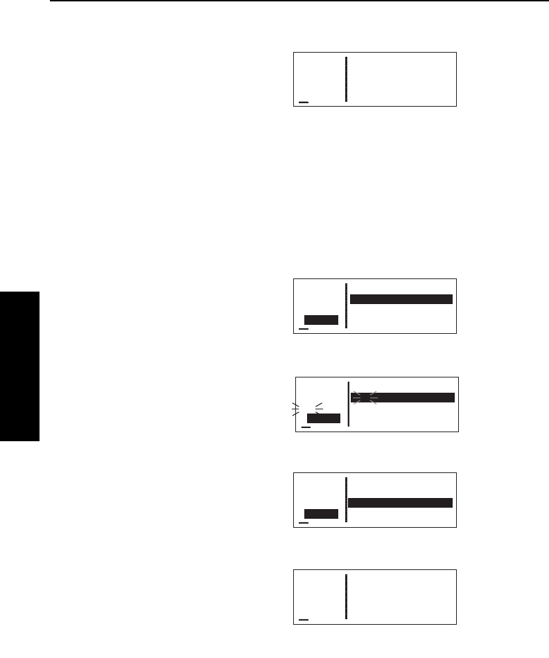
3.11.1.5. The Airport 5 (APT 5) Page
See figure 3-140.
Line 1:The ICAO identifier (see
section 2.3) of the airport; an arrow
precedes the identifier if it is the active
waypoint.
Lines 2-4:The pilot-entered remarks for the airport. Three lines of 14
characters each are available for the remarks. These remarks might
include information on lodging, dining, airport services, etc. Up to 100
waypoints may include remarks. Letters, numbers, hyphens, and
spaces may be used in the remark. If no remarks have been entered
for the airport, line 2 will display “[Remarks]”.
To enter an airport remark on the APT 5 page:
1.Turn on the cursor and move it
until the cursor fills line 2 of the
screen (figure 3-141).
2.With the right inner knob, select
the desired character, if any, and
move the cursor to the next char-
acter on the line (figure 3-142).
3.Repeat step 2 as necessary.
4.Press Fto approve each line of
remarks. The cursor will auto-
matically move to the next line
(see figure 3-143).
5.Turn the cursor off when you are
finished creating the remark
(figure 3-144).
The Other 4 (OTH 4) page is a list of
waypoints with associated remarks.
Sometimes these are deleted if there
are more than 100 waypoints with
remarks, or if the remarks are no longer relevant. If you wish to
delete a waypoint remark for an airport, see section 3.13.2.2.
Basic GPS Operation
3-50Effective Date 5/95 006-08791-0000 Rev 0
Basic GPS Operation
Chapter 3
APT VOR NDB SUP ACT NAV FPL CAL SET OTH
åå.ånm KLIT
åååååå G
#>Leg
CRSR
Figure 3-142
APT VOR NDB SUP ACT NAV FPL CAL SET OTH
åå.ånm KLIT
åååååå GREEN CAB CO
>Leg
CRSR
Figure 3-143
APT VOR NDB SUP ACT NAV FPL CAL SET OTH
åå.ånm KLIT
åååååå [Remarks]
>Leg
APT 5
Figure 3-140
APT VOR NDB SUP ACT NAV FPL CAL SET OTH
åå.ånm KLIT
åååååå [Remarks]
>Leg
CRSR
Figure 3-141
APT VOR NDB SUP ACT NAV FPL CAL SET OTH
åå.ånm KLIT
åååååå GREEN CAB CO
>Leg 555-9999
APT 5
Figure 3-144
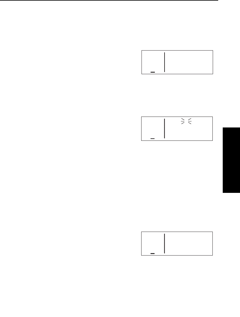
KLN 35A Pilot’s Guide Basic GPS Operation
3-51 Effective Date 5/95006-08791-0000 Rev 0
Basic GPS Operation
Chapter 3
3.11.2. VOR PAGES
Two pages of information may be displayed for each VOR in the KLN
35A. Sample VOR pages are shown in figures 3-145 through 3-147.
3.11.2.1. The VOR 1 Page
See figure 3-145.
Line 1:The VOR identifier, preceded
by an arrow if it is the active waypoint.
To the right of the identifier is the
frequency of the VOR in megahertz.
Line 2:The name of the VOR.
Lines 3-4:The latitude and longitude of the VOR
If the VOR is being viewed as part of
the
nearest VORs list
(see section
3.8.1), the VOR 1 page format will dif-
fer as follows (see figure 3-146):
Line 1:After the VOR identifier, the
number designating the VOR’s
position in the nearest VOR list is displayed. In figure 3-146, MEX is
the second nearest VOR.
Lines 3-4:In place of the latitude/longitude, line 3 is blank and line 4
displays the magnetic bearing to or the magnetic radial from the VOR
and the distance in nautical miles. Placing the cursor over the
radial/bearing field and pressing Etoggles between radial from and
bearing to station.
3.11.2.2. The VOR 2 Page
See figure 3-147.
Line 1:The VOR identifier, preceded
by an arrow if it is the active waypoint.
Line 2:The published magnetic sta-
tion declination of the VOR. Magnetic
station declination is another way to say the published magnetic vari-
ation for the VOR.
Line 4:The magnetic bearing to or the magnetic radial from the VOR
and the distance in nautical miles. Placing the cursor over the radi-
al/bearing field and pressing Etoggles between radial from and
bearing to station.
APT VOR NDB SUP ACT NAV FPL CAL SET OTH
åå.ånm MEX 2 117.00
åååååå MEXICO CITY
>Leg
VOR 1 >359°To 97.7nm
Figure 3-146
APT VOR NDB SUP ACT NAV FPL CAL SET OTH
åå.ånm MEX 117.00
åååååå MEXICO CITY
>Leg N 19°26.22'
VOR 1 W 99°04.17'
Figure 3-145
APT VOR NDB SUP ACT NAV FPL CAL SET OTH
åå.ånm MEX
åååååå Mag Var E 8°
>Leg
VOR 2 >359°To 97.7nm
Figure 3-147

Basic GPS Operation
3-52Effective Date 5/95 006-08791-0000 Rev 0
Basic GPS Operation
Chapter 3
3.11.3. NDB PAGES
Two pages of information may be displayed for each NDB in the KLN
35A. Sample NDB pages are shown in figures 3-148 through 3-150.
3.11.3.1. The NDB 1 Page
See figure 3-148.
Line 1:The NDB identifier, preceded
by an arrow if it is the active waypoint.
To the right of the identifier is the fre-
quency of the NDB in kilohertz.
Line 2:The name of the NDB.
Lines 3-4:The latitude and longitude
of the NDB
If the NDB is being viewed as part of
the
nearest NDBs list
(see section
3.8.1), the NDB 1 page format will dif-
fer as follows (see figure 3-149):
Line 1:After the NDB identifier, the number designating the NDB’s
position in the nearest NDB list is displayed. In figure 3-149, DFI is
the nearest NDB.
Lines 3-4:In place of the latitude/longitude, line 3 is blank and line 4
displays the magnetic bearing to or the magnetic radial from the NDB
and the distance in nautical miles. Placing the cursor over the
radial/bearing field and pressing Etoggles between radial from and
bearing to station.
3.11.3.2. The NDB 2 Page
See figure 3-150.
Line 1:The NDB identifier, preceded
by an arrow if it is the active waypoint.
Line 4:The magnetic bearing to or
the magnetic radial from the NDB and the distance in nautical miles.
Placing the cursor over the radial/bearing field and pressing Etog-
gles between radial from and bearing to station.
APT VOR NDB SUP ACT NAV FPL CAL SET OTH
åå.ånm DFI 1 246
åååååå DEFIANCE
>Leg
NDB 1 >021°To 2.3nm
Figure 3-149
APT VOR NDB SUP ACT NAV FPL CAL SET OTH
åå.ånm DFI
åååååå
>Leg
NDB 2 >021°To 2.3nm
Figure 3-150
APT VOR NDB SUP ACT NAV FPL CAL SET OTH
åå.ånm DFI 246
åååååå DEFIANCE
>Leg N 41°20.07'
NDB 1 W 84°25.62'
Figure 3-148

KLN 35A Pilot’s Guide Basic GPS Operation
3-53 Effective Date 5/95006-08791-0000 Rev 0
Basic GPS Operation
Chapter 3
3.11.4. SUPPLEMENTAL WAYPOINT PAGES
The Supplemental waypoint pages (SUP 0, SUP 1, SUP 2, and
SUP3) allow you to create “custom” waypoints for use in navigation.
A crop sprayer might want to create a waypoint on a field that is
sprayed regularly, for instance. Another candidate might be a small
airport which is not included in the KLN 35A data base. To learn how
to create a user-defined waypoint, see section 4.4.
3.11.4.1. The Supplemental 0 (SUP 0) Page
See figure 3-151.
NOTE: The SUP 0 page is only dis-
played for waypoint identifiers that do
not have a previously defined
position.
Line 1:The identifier for the as-yet-undefined waypoint.
Lines 2-4:Cursor fields for the three possible user-defined waypoint
creation methods. For information on creating user-defined way-
points, see section 4.4.
3.11.4.2. The Supplemental 1 (SUP 1) Page
See figure 3-152.
Line 1:The user-defined waypoint
identifier, preceded by an arrow if it is
the active waypoint. To the right of
the identifier are the letters “USR” to
signify that this is a user-defined
waypoint.
Lines 2-3:The latitude and longitude of the user-defined waypoint.
Line 4:The magnetic bearing to or the magnetic radial from the
user-defined waypoint and the distance in nautical miles. Placing the
cursor over the radial/bearing field and pressing Etoggles between
radial from and bearing to station.
APT VOR NDB SUP ACT NAV FPL CAL SET OTH
åå.ånm MYWPT USR
åååååå N 40°05.48'
>Leg W102°57.95'
SUP 1 >134°To 2.3nm
Figure 3-152
APT VOR NDB SUP ACT NAV FPL CAL SET OTH
åå.ånm MYWPT USR at:
åååååå User Pos L/L?
>Leg User Pos R/D?
SUP 0 Present Pos?
Figure 3-151
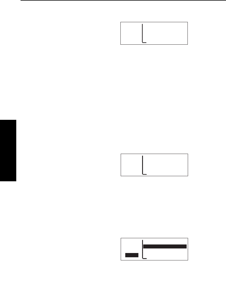
Basic GPS Operation
3-54
Effective Date 5/95 006-08791-0000 Rev 0
Basic GPS Operation
Chapter 3
3.11.4.3. The Supplemental 2 (SUP 2) Page
See figure 3-153.
Line 1: The user-defined waypoint
identifier, preceded by an arrow if it is
the active waypoint. To the right of
the identifier are the letters “USR” to
signify that this is a user-defined
waypoint.
Line 2: The identifier of the user-defined waypoint’s reference
waypoint. When this page is first viewed, the reference waypoint is
the nearest VOR to the user waypoint. The reference waypoint may
be changed by the pilot. However, once you leave this page and
come back, the reference waypoint reverts back to a nearby VOR.
Line 3: The magnetic radial from the reference waypoint to the user
waypoint.
Line 4: The distance in nautical miles from the reference waypoint to
the user waypoint.
3.11.4.4. The Supplemental 3 (SUP 3) Page
See figure 3-154.
Line 1: The identifier of the user-
defined waypoint; an arrow precedes
the identifier if it is the active
waypoint.
Lines 2-4: The pilot-entered remarks for the user waypoint. Three
lines of 14 characters each are available for the remarks. Up to 100
waypoints may include remarks. Letters, numbers, hyphens, and
spaces may be used in the remark. If no remarks have been entered
for the user-defined waypoint, line 2 will display [Remarks].
To enter a user-defined waypoint remark on the SUP 3 page:
1. Turn on the cursor and move it
until the cursor fills line 2 of the
screen (figure 3-155).
2. Select the desired character, if any, and move the cursor to the
APT VOR NDB SUP ACT NAV FPL CAL SET OTH
åå.ånm WPTX USR
åååååå GRASS STRIP
>Leg SOFT NORTH END
SUP 3
Figure 3-154
APT VOR NDB SUP ACT NAV FPL CAL SET OTH
åå.ånm WPTX USR
åååååå [Remarks]
>Leg
CRSR
Figure 3-155
APT VOR NDB SUP ACT NAV FPL CAL SET OTH
åå.ånm MYWPT USR
åååååå Ref: AKO
>Leg Rad: 101°
SUP 2 Dis: 10.6nm
Figure 3-153
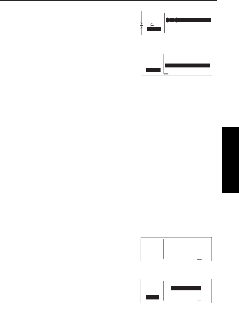
KLN 35A Pilot’s Guide Basic GPS Operation
3-55 Effective Date 5/95006-08791-0000 Rev 0
Basic GPS Operation
Chapter 3
next character on the line
(figure 3-156).
3. Repeat step 2 as necessary.
4. Press Fto approve each line
of remarks. The cursor will
automatically move to the next
line (see figure 3-157).
5. Turn the cursor off when you are
finished creating the remark.
The Other 4 (OTH 4) page is a list of
waypoints with associated remarks. Sometimes these are deleted if
there are more than 100 waypoints with remarks, or if the remarks
are no longer relevant. If you wish to delete a waypoint remark for a
user-defined waypoint, see section 3.13.2.2.
3.12. VIEWING AND SETTING THE DATE AND TIME
The KLN 35A system time and date should seldom, if ever, require
updating because they are automatically updated when at least one
satellite is received. In addition, the KLN 35A contains an internal
battery powered calendar/clock to keep system time and date when
the unit is not being used. You will normally check to make sure the
KLN 35A is set to the correct time and date shortly after you turn the
unit on while you verify the Self Test Page. You can, however, also
check the time and date on the Setup (SET) 2 page anytime you
desire. There are several pages as well as some internal functions of
the KLN 35A, such as magnetic variation and proper use of data
base information, that depend on having the proper time and date.
NOTE: You will not be able to update the time or date if the KLN 35A
is receiving a time and date from a satellite.
To set the date on the SET 2 page:
1. Select the SET 2 page
(figure 3-158).
2. Turn on the cursor. The cursor
will be over the entire date field
(figure 3-159).
3. Select the correct day of the
month with the right inner knob.
APT VOR NDB SUP ACT NAV FPL CAL SET OTH
åå.ånm WPTX USR
åååååå G
#>Leg
CRSR
Figure 3-156
APT VOR NDB SUP ACT NAV FPL CAL SET OTH
åå.ånm WPTX USR
åååååå GRASS STRIP
>Leg
CRSR
Figure 3-157
APT VOR NDB SUP ACT NAV FPL CAL SET OTH
åå.ånm DATE/TIME
åååååå 18 NOV 94
>Leg 1536:03 MST
SET 2 Mountain Std
Figure 3-158
APT VOR NDB SUP ACT NAV FPL CAL SET OTH
åå.ånm DATE/TIME
åååååå 18 NOV 94
>Leg 1536:10 MST
CRSR Mountain Std
Figure 3-159

Basic GPS Operation
3-56Effective Date 5/95 006-08791-0000 Rev 0
Basic GPS Operation
Chapter 3
4.Move the flashing part of the
cursor to the month field (middle
three dashes) with the right outer
knob, and select the proper
month (figure 3-160).
5.Move the flashing part of the
cursor to the tens digit of the year
field, and select the proper num-
ber (figure 3-161).
6.Repeat step 5 for the ones digit of
the year field.
7.Press Fto start the KLN 35A
using the newly entered date
(figure 3-162).
To set the time on the SET 2 page:
1.Select the SET 2 page if it is not already selected.
2.Turn on the cursor and move it to
the time zone field (figure 3-163).
3.Change the time zone with the
right inner knob, if desired
(figure 3-164). A listing of the
time zones and their abbrevia-
tions is contained in section 3.2,
“Turn-on and Self Test”.
4.Move the cursor to the time field.
The hours and minutes will
appear in inverse video.
5.Select the correct hour
(figure 3-165). Remember, the
KLN 35A uses 24 hour time. If it
is 1:00 P.M. or later, add 12 hours
(for example, 2:30 P.M. becomes
14:30).
APT VOR NDB SUP ACT NAV FPL CAL SET OTH
åå.ånm DATE/TIME
åååååå 08 DEC 94
>Leg 1536:30 MST
CRSR Mountain Std
Figure 3-163
APT VOR NDB SUP ACT NAV FPL CAL SET OTH
åå.ånm DATE/TIME
åååååå 08 DEC 94
>Leg 1536:31 MDT
CRSR Mountain Day
Figure 3-164
APT VOR NDB SUP ACT NAV FPL CAL SET OTH
åå.ånm DATE/TIME
åååååå 08 DEC 94
#>Leg 14__:42 MDT
CRSR Mountain Day
Figure 3-165
APT VOR NDB SUP ACT NAV FPL CAL SET OTH
åå.ånm DATE/TIME
åååååå 08 DEC __
#>Leg 1536:15 MST
CRSR Mountain Std
Figure 3-160
APT VOR NDB SUP ACT NAV FPL CAL SET OTH
åå.ånm DATE/TIME
åååååå 08 DEC 9_
#>Leg 1536:22 MST
CRSR Mountain Std
Figure 3-161
APT VOR NDB SUP ACT NAV FPL CAL SET OTH
åå.ånm DATE/TIME
åååååå 08 DEC 94
>Leg 1536:26 MST
CRSR Mountain Std
Figure 3-162

KLN 35A Pilot’s Guide Basic GPS Operation
3-57 Effective Date 5/95006-08791-0000 Rev 0
Basic GPS Operation
Chapter 3
6. Move the flashing part of the
cursor to the tens of minutes,
select the proper number
(figure 3-166), then move on to
the last digit and set it.
7. Press Fto start the clock
running (figure 3-167). Note that
the seconds will reset to zero
when you do this.
3.13. THE OTHER (OTH) PAGES
3.13.1. DETERMINING THE STATUS OF THE GPS SIGNALS
The Other (OTH) 1 and OTH 2 pages may be viewed at any time to
determine the status of the GPS receiver and the GPS satellites
being received. This includes which satellites are being tracked, the
satellites’ health, the signal-to-noise ratio for each of these satellites,
the elevation of each satellite above the horizon, and the estimated
position error.
The GPS receiver in the KLN 35A is capable of using signals from up
to eight satellites to determine its position. A valid position may be
determined using as few as four satellites alone or three satellites
with a valid altitude input. However, four satellites alone or three
satellites with an altitude input do not necessarily ensure that
navigation can take place. The satellites must be positioned relative
to your location such that sufficient “geometry” exists to determine an
accurate position. the satellite constellation geometry is continually
changing as each satellite, “rises”, travels across the sky, and
eventualy “sets” relative to your position. The GPS satellites are not
in geosynchronous orbits positioned over the same spot on earth at
all times like some television communication satellites with which you
may be familiar. Rather, the GPS satellites are in orbits that allow
them to circle the earth about two times each day.
APT VOR NDB SUP ACT NAV FPL CAL SET OTH
åå.ånm DATE/TIME
åååååå 08 DEC 94
#>Leg 143_:42 MDT
CRSR Mountain Day
Figure 3-166
APT VOR NDB SUP ACT NAV FPL CAL SET OTH
åå.ånm DATE/TIME
åååååå 08 DEC 94
>Leg 1430:00 MDT
CRSR Mountain Day
Figure 3-167

Basic GPS Operation
3-58
Effective Date 5/95 006-08791-0000 Rev 0
Basic GPS Operation
Chapter 3
A representative OTH 1 page is
shown in figure 3-168. The OTH 1
page displays the GPS receiver state
and the system’s estimate of the posi-
tion error expressed in nautical miles.
The GPS state is indicated on line 1.
The possibilities are:
INIT initialization
ACQ acquisition
TRAN transition
NAV navigation
NAV A navigation with altitude aiding
NAV D navigation with data collection
DEGRD navigation with position degradation
FAILR receiver failure
In the initialization state the GPS receiver is in the process of
initializing itself, collecting information such as the date, time, and last
present position. Next, the receiver collects data from its own
memory to determine which satellites should be visible. After
completing the initialization process the receiver begins the
acquisition process. During this time, the visible satellites are being
acquired and data is obtained from them.
The transition state indicates an adequate number of satellites for
navigation has been acquired and is being tracked but no position
data can yet be produced.
Normal navigation is indicated by a NAV, NAV A, or NAV D GPS
state. NAV A indicates that the altitude input is being used in the
position solution. NAV D indicates that besides calculation position,
the receiver is collecting and storing in its memory additional data
from the satellites (called ephemeris and almanac data).
Lines 3 and 4 of the OTH 1 page display the KLN 35A’s estimated
position error. The KLN 35A’s position error depends upon such
factors as the number of satellites being received, the strength of the
GPS signals, and the geometry of the satellites presently being used
for navigation.
APT VOR NDB SUP ACT NAV FPL CAL SET OTH
åå.ånm State NAV D
åååååå
>Leg Estimated Posn
OTH 1 Error 0.02nm
Figure 3-168

KLN 35A Pilot’s Guide Basic GPS Operation
3-59 Effective Date 5/95006-08791-0000 Rev 0
Basic GPS Operation
Chapter 3
Figures 3-169, 3-170 and 3-171 show
a representative example of a set of
OTH 2 pages. There will be three
OTH 2 pages if more than six
satellites are being received as in this
example. The following information is
displayed for each satellite on the
OTH 2 pages:
•The specific GPS satellites or
“space vehicles” (SV) being
received are displayed in the left
column. Each satellite has its
own identification number. A *
symbol to the right of the satellite
number indicates this particular
satellite is not presently being
used in the navigation position
solution.
•The satellite’s “health” (Hlt) is indicated to the right of the satellite
number. This health information is transmitted by the satellites.
•The signal-to-noise ratio (SNR in decibels) for each satellite is
displayed in the middle column and indicates the signal strength
for each satellite. The higher the SNR value the stronger the
signal. Values usable for navigation will be in the mid 30s to mid
50s; however, typical values are in the middle of this range.
•The elevation (Ele) above the horizon for each satellite is
provided in the right column and will range from 5° to 90°.
3.13.2. VIEWING AND DELETING USER WAYPOINTS AND
WAYPOINT REMARKS
The OTH 3 and OTH 4 pages list the user-defined waypoints and
waypoint remarks, respectively, which are currently stored in the KLN
35A’s memory.
APT VOR NDB SUP ACT NAV FPL CAL SET OTH
åå.ånm SV Hlt SNR Ele
åååååå 02 Good 41 43°
>Leg 11 Good 32 07°
OTH+2 16*Weak 31 76°
Figure 3-169
APT VOR NDB SUP ACT NAV FPL CAL SET OTH
åå.ånm SV Hlt SNR Ele
åååååå 18 Good 39 21°
>Leg 20 Good 47 88°
OTH+2 23*Good 34 09°
Figure 3-170
APT VOR NDB SUP ACT NAV FPL CAL SET OTH
åå.ånm SV Hlt SNR Ele
åååååå 25 Good 41 52°
>Leg
OTH+2
Figure 3-171
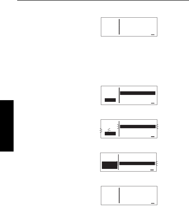
Basic GPS Operation
3-60
Effective Date 5/95 006-08791-0000 Rev 0
Basic GPS Operation
Chapter 3
3.13.2.1.The OTH 3 Page
An example of an OTH 3 page is
shown in figure 3-172. All currently
stored user-defined waypoints are
listed in alphanumeric order. If the
user-defined waypoint is the active
waypoint, an arrow (∆) follows the
identifier. If the waypoint is used in one or more flight plans, then the
number of the first flight plan in which it is used is displayed on the
right side. If there are more than three user waypoints in storage,
you can see the rest of the list by turning on the cursor (B) and
turning the right outer knob to scroll through the list.
To delete a user-defined waypoint from the OTH 3 page:
1. Turn on the cursor and position it
over the desired waypoint
(figure 3-173). If there are more
than three user-defined waypoint,
you will have to scroll the cursor
down the list.
2. Press E. The KLN 35A will ask
if you wish to delete that user-
waypoint (figure 3-174). If the
waypoint is active or used in a
flight plan, the deletion will not be
allowed and you will receive a
scratchpad message telling you
this (figure 3-175).
3. Press Fto approve the deletion
(figure 3-176).
APT VOR NDB SUP ACT NAV FPL CAL SET OTH
åå.ånm User Waypoints
åååååå LAKE
Used MYRWY 0
In Fpl WPTX 5
Figure 3-175
APT VOR NDB SUP ACT NAV FPL CAL SET OTH
åå.ånm User Waypoints
åååååå MYRWY 0
>Leg WPTX 5
OTH+3 ZIPPY
Figure 3-176
APT VOR NDB SUP ACT NAV FPL CAL SET OTH
åå.ånm User Waypoints
åååååå Del LAKE ?
#>Leg MYRWY 0
CRSR WPTX 5
Figure 3-174
APT VOR NDB SUP ACT NAV FPL CAL SET OTH
åå.ånm User Waypoints
åååååå LAKE
>Leg MYRWY 0
CRSR WPTX 5
Figure 3-173
APT VOR NDB SUP ACT NAV FPL CAL SET OTH
åå.ånm User Waypoints
åååååå LAKE
>Leg MYRWY 0
OTH+3 WPTX 5
Figure 3-172
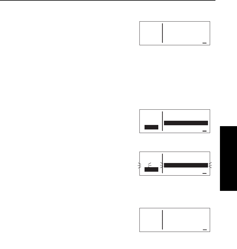
KLN 35A Pilot’s Guide Basic GPS Operation
3-61 Effective Date 5/95006-08791-0000 Rev 0
Basic GPS Operation
Chapter 3
3.13.2.2. The OTH 4 Page
An example of an OTH 4 page is
shown in figure 3-177. All waypoints
with remarks are listed in
alphanumeric order. Remarks can be
stored for airports (on the APT 5
page) or user-defined waypoints (on
the SUP 3 page). If the waypoint is an airport, then an “A” is dis-
played on the right side; likewise, a “U” represents a user-defined
waypoint. If there are more than three waypoints, you can see the
rest of the list by turning on the cursor (B) and turning the right
outer knob to scroll through the list.
To delete a waypoint remark from the OTH 4 page:
1. Turn on the cursor and position it
over the desired waypoint
(figure 3-178). If there are more
than three airports with remarks,
you will have to scroll the cursor
down the list.
2. Press E. The KLN 35A will ask
if you wish to delete that remark
(figure 3-179).
3. Press Fto approve the
deletion.
3.13.3. VIEWING THE KLN 35A SOFTWARE STATUS
The OTH 5 page (figure 3-180)
shows the software revision status of
the KLN 35A host computer (line 2),
the GPS receiver (line 3), and data
base (line 4).
APT VOR NDB SUP ACT NAV FPL CAL SET OTH
åå.ånm WPTS w/Remarks
åååååå FARM U
>Leg KISM A
OTH 4 K57 A
Figure 3-177
APT VOR NDB SUP ACT NAV FPL CAL SET OTH
åå.ånm Wpts w/Remarks
åååååå FARM U
>Leg KISM A
CRSR K57 A
Figure 3-178
APT VOR NDB SUP ACT NAV FPL CAL SET OTH
åå.ånm Wpts w/Remarks
åååååå FARM U
#>Leg Del KISM A?
CRSR K57 A
Figure 3-179
APT VOR NDB SUP ACT NAV FPL CAL SET OTH
åå.ånm SW REVISION
åååååå Host 03
>Leg Rcvr 02
OTH 5 DB 001
Figure 3-180

Basic GPS Operation
3-62Effective Date 5/95 006-08791-0000 Rev 0
Basic GPS Operation
Chapter 3
3.14. REMOTE MOUNTED ANNUNCIATORS
The KLN 35A has outputs capable of driving two
remote annunciator lights: waypoint alert and
message. Although these annunciators are optional,
it is desirable to have them mounted in the pilot’s
normal scan area so that these annunciators are
easily seen. A typical annunciator is shown in figure
3-181; however, actual annunciation abbreviations
and configurations may be different.
The remote waypoint alert annunciator is on whenever waypoint
alerting is occurring. See sections 3.9.3, “Waypoint Alerting for Direct
To Operation” and 4.2.2, “Turn Anticipation and Waypoint Alerting”.
The remote message annunciator is on whenever the message
prompt is on. See section 3.5.
3.15. SPECIAL USE AIRSPACE ALERTING
The KLN 35A data base contains the location of areas of special use
airspace (SUA). The types of SUA areas stored in the data base and
the abbreviations used to denote these areas are the following:
Class B CL B
Class C CL C
Control Area (used outside USA) CTA
Terminal Area (used outside USA) TMA
Alert Area ALRT
Danger Area DNGR
Prohibited Area PROH
Restricted Area REST
Terminal Radar Service Area TRSA
NOTE: The KLN 35A data base does not include Military Operations
areas (MOAs), Warning areas, Training areas or Caution areas.
The KLN 35A will normally alert you prior to entering one of these
areas with a message prompt. When
the Message page is viewed it will
display Airspace Alert and will also
display the name and type of the spe-
cial use airspace (figure 3-182). If the
special use airspace is a Class B,
Class C, CTA, or TMA, the message APT VOR NDB SUP ACT NAV FPL CAL SET OTH
*Airspace Alert
COLUMBUS FOUR MOA
1000 ft to 18000 ft
MEM Center
Figure 3-182
Figure 3-181
WPT
MSG
KLN 35A Pilot’s Guide Basic GPS Operation
3-63
Basic GPS Operation
Chapter 3
page will also instruct you to press
the Ebutton if you wish to see the
Airport 4 page (airport communica-
tions) for the primary airport so that
the correct communications frequen-
cy may be determined (figure 3-183).
NOTE: In addition to the message page messages that alert you to
special use airspace, the KLN 35A can also display the five nearest
areas of SUA. It will even give you the direction and distance to the
nearest edge of the SUA. See section 3.8.2 for more details.
The SUA alert feature is three dimensional. The SUA areas are
stored in the KLN 35A data base with regard to altitude when the
actual SUA altitude limitations are charted in terms of mean sea level
(MSL). Therefore, if you are flying either above or below an SUA
area you won’t be inconvenienced with nuisance alert messages.
However, if the actual lower limit of an SUA is charted in terms of an
altitude above ground level (AGL), then it is stored in the KLN 35A as
all altitude below the upper limit of the SUA. If the actual upper limit
of an SUA is charted in terms of AGL, it is stored in the KLN 35A as
“unlimited”.
Since the altitude input to the KLN 35A is pressure altitude from an
altitude encoder, you must manually
update the KLN 35A with an altimeter
setting (baro correction) in order to
receive accurate SUA alerting. You
may easily update the altimeter
setting by selecting the SET8 page
(figure 3-184) The right inner knob is
used to change the altimeter setting. When the setting is complete,
turn off the cursor.
CAUTION: Failure to keep the altimeter baro setting updated
will result in inaccurate special use airspace alerting. If this fea-
ture is used, it is a good idea to update the altimeter baro setting
on the SET 8 page each time you make a change to an aircraft’s
altimeter setting.
NOTE: If there is no altitude input to the KLN 35A, all altitudes will be
regarded as being within the boundary of the SUA area.
Effective Date 4/97006-08791-0000 Rev 2
APT VOR NDB SUP ACT NAV FPL CAL SET OTH
åå.ånm Baro: 29.95"
åååååå Ind Alt 8500'
>Leg Baro Unit: "
CRSR Inches
Figure 3-184
APT VOR NDB SUP ACT NAV FPL CAL SET OTH
*Airspace Alert
OMAHA CL C
Below 5000 ft
CLR for KOMA Freq
Figure 3-183
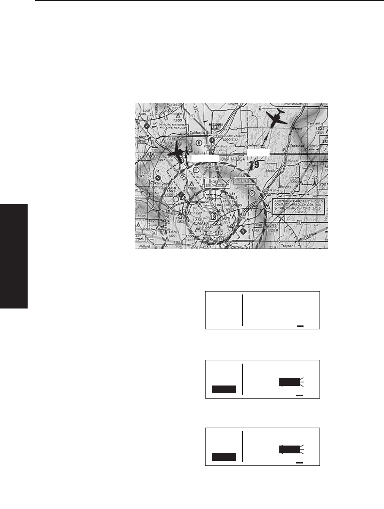
Basic GPS Operation
3-64
Effective Date 5/95 006-08791-0000 Rev 0
Basic GPS Operation
Chapter 3
Only the outer lateral boundaries are stored for Class B, Class C,
CTA, and TMA airspace. These SUA areas are stored as “cylinders”
of airspace so all altitudes below the upper limit of these areas are
considered to be in the SUA.
The message prompt for a special use airspace alert will occur when
the aircraft’s position is at a point such that a projection of the air-
craft’s existing track over the ground is approximately 10 minutes
from penetrating the
outer boundary of one
of these areas. It will
also occur if the aircraft
is within approximately
two nautical miles of
one of these areas
even if the aircraft’s
projected track over
the ground won’t actu-
ally penetrate the SUA
area (figure 3-185). If
one of the SUA areas
is penetrated, another
message will state:
Inside SUA.
The SUA alert feature may be disabled (or enabled) on the Setup 7
(SET 7) page, shown in figure 3-186.
Select the SET 7 page, turn on the
cursor (B). The right inner knob is
used to choose between SUA ALERT
ENABLED and SUA ALERT DIS-
ABLED.
If the SUA alert feature has been
enabled, the KLN 35A allows you to
select a vertical buffer on the SET 7
page in order to provide an additional
layer of protection from inadvertently
entering an SUA. To select a vertical
buffer, make sure the SUA alert fea-
ture has been enabled. Turn on the
cursor (B) (figure 3-187) and then
use the right inner knob to select the
buffer (figure 3-188). The buffer may
be selected in one hundred foot incre-
ments. After the desired selection
has been made, turn the B off.
APT VOR NDB SUP ACT NAV FPL CAL SET OTH
åå.ånm SUA ALERT
åååååå ENABLED
>Leg Buffer:±01000'
CRSR
Figure 3-188
APT VOR NDB SUP ACT NAV FPL CAL SET OTH
åå.ånm SUA ALERT
åååååå ENABLED
>Leg Buffer:±00500'
CRSR
Figure 3-187
APT VOR NDB SUP ACT NAV FPL CAL SET OTH
åå.ånm SUA ALERT
åååååå DISABLED
>Leg
SET 7
Figure 3-186
10 MIN
2 MILES
Figure 3-185

KLN 35A Pilot’s Guide Basic GPS Operation
3-65
Basic GPS Operation
Chapter 3
Effective Date 4/97006-08791-0000 Rev 2
The vertical buffer serves to “stretch” the SUA area in both directions
(up and down) by the selected buffer altitude. For example, let’s say
you have selected a buffer of 1,000 feet and the actual SUA area
exists from 5,000 feet MSL to 12,000 feet MSL. In this case you will
receive SUA alert messages if you fly at any altitude between 4,000
and 13,000 feet MSL.
CAUTION: It is the pilot’s responsibility to avoid those areas of
special use airspace where ATC clearance to penetrate is
required but has not been obtained. The KLN 35A’s special use
airspace alert is only a tool to assist the pilot and should never
be relied upon as the sole means of avoiding these areas.
3.16 SAMPLE TRIP
We’ve talked a lot about the features of the KLN 35A, and now it’s
time to put those features to work for us and try a sample trip! Our
trip will be from Adams field (KLIT) in Little Rock, Arkansas to Mueller
Municipal airport (KAUS) in Austin, Texas. The weather is perfect
and we decide to make trip VFR and fly direct to Austin.
3.16.1 PRE-DEPARTURE
1. Apply power to the KLN 35A by pushing the power switch to the
ON position.
2. Verify that the information on the Self Test and Initialization
pages is correct, including the time and date. Enter the altimeter
baro setting. Position the cursor over Ok? and press Fto
approve the Initialization page.
3. Read the Data Base page and acknowledge it by pressing F.
4. The APT 4 page for Adams field (KLIT), which shows the com-
munications frequencies, is now displayed on the screen since
KLIT was the active waypoint when you last removed power from
the KLN 35A. The first APT 4 page indicates that the ATIS fre-
quency is 125.65 MHz, the pre-taxi clearance delivery frequency
is 118.95 MHz, and the ground control frequency is 121.90 MHz.
After listening to ATIS, we contact clearance delivery for our
clearance out of the Little Rock Class C airspace. Next, we give
ground control a call and receive our taxi clearance.
5. By this time the KLN 35A has reached a NAV ready status. We
can verify this by turning to the NAV 2 page. It shows a valid
present position, in this case 3.8 nautical miles on the 320
degree radial from Little Rock (LIT) VOR.

Basic GPS Operation
3-66
Effective Date 5/95 006-08791-0000 Rev 0
Basic GPS Operation
Chapter 3
6. Press Dto bring up the Direct To page. Use the right inner
and outer knobs to enter the identifier of Mueller Municipal airport
(KAUS) by using the right inner knob to select the characters and
the right outer knob to move the flashing part of the cursor to the
desired cursor location.
7. Press F. The APT 1 page for Mueller Municipal is now dis-
played on the screen.
8. Press Fagain to approve the waypoint page. The NAV 1
page is now displayed. The NAV 1 page indicates it is 384
nautical miles to Austin and that the bearing is 225 degrees.
After take-off, the NAV 1 page will also display groundspeed and
estimated time en route.
3.16.2 EN ROUTE
1. We depart from runway 36 at Little Rock and are told to “maintain
runway heading.” After several radar vectors for traffic avoidance
we are finally cleared on course. The D-Bar indicates that the
radar vectors have taken us north of the original course and we
decide to proceed Direct To Austin from our present position. To
recenter the D-Bar, press D, and then press F.
2. After departure control has directed “squawk 1200, frequency
change approved,” you decide it would be a good idea to obtain
VFR flight following. To obtain the frequency for Center, press
the Gbutton, move the cursor to the CTR? selection, and
press F. The KLN 35A indicates that for our position, we
should be able to contact Memphis Center on 118.85 MHz.
3. We’ve only flown about 100 nautical miles, but we begin wonder-
ing where we would go if an engine suddenly started running
rough. We decide to use the KLN 35A to determine where the
nearest airports are from our present location. To view the near-
est airports press G, and then press F. The nearest airport is
Hope Municipal (M18) which is eight nautical miles from our posi-
tion on a bearing to the airport of 11 degrees. You now rotate the
right inner knob to view the other APT pages for Hope Municipal.
We learn, for example, that it is located in Hope, Arkansas, and
has two hard surface runways that are each 5500 feet in length.
By pulling the right inner knob to the “out” position, you may now
scan clockwise through the remaining eight airports in the
nearest airport list.
4. For the majority of the en route portion of the flight, you select the
NAV 4 page’s moving map display. Pressing the right B

KLN 35A Pilot’s Guide Basic GPS Operation
3-67
Basic GPS Operation
Chapter 3
button, you select the 30 nautical mile range scale using the right
inner knob. Moving the cursor to Menu? And pressing F
brings up the display menu on the screen. You then use the right
knobs to select APT:on and SUA:on so that nearby airports and
special use airspace (SUA) are shown on the moving map
display. While the menu is displayed, select the track up map
orientation (TK) as well, Pressing the Bbutton again
removes the menu from the screen.
5. Since it is a good idea to not rely on just one navigation source,
we suggest you cross check the KLN 35A position against other
equipment in the aircraft. The NAV 2 page indicates we are
presently located on the Texarkana (TXK) VOR 68 degree radial
at a distance of 19 nautical miles. By tuning our NAV receiver
and DME to TXK, we are able to confirm that this is the correct
position.
3.16.3 TERMINAL AREA
1. About 50 nautical miles from Austin’s Mueller airport we start
preparing for our arrival. Viewing the APT 4 page for KAUS you
determine that the ATIS frequency is 119.20 MHz and tower is
121.00 MHz.
2. A few minutes later, the message prompt begins flashing. When
you press C, the message page advises Airspace Alert -
Austin CL C - Below 4600 ft - CLR for KAUS Freq. The
Special Use Airspace Alert feature has determined that you are
within 10 minutes of penetrating the Austin Class C airspace.
When you press Eand view the APT 4 page for KAUS, you
see that the Class C airspace frequencies are sectorized. You
determine from the APT 4 page that the proper frequency to use
is 124.90 MHz since we are Northeast of Austin and 124.90 MHz
is the appropriate frequency to use from 3 degrees to 170
degrees. You turn to the NAV 4 page so that we can see the
outer boundary of the Austin Class C airspace relative to our
location and route.
3. After you call Austin approach control for clearance into the Class
C airspace, you view the rest of the APT pages for KAUS to
determine the field elevation and available runways.
4. After landing, the KLN 35A is turned off either by pulling the KLN
35A power knob out (to OFF), or with the avionics master switch
if one is installed.
Effective Date 4/97006-08791-0000 Rev 2

Basic GPS Operation
3-68
Effective Date 5/95 006-08791-0000 Rev 0
Basic GPS Operation
Chapter 3
This page intentionally left blank

KLN 35A Pilot’s Guide Advanced GPS Operation
4-1 Effective Date 3/96006-08791-0000 Rev 1
Advanced GPS Operation
Chapter 4
4. ADVANCED GPS OPERATION
4.1. CREATING AND MODIFYING FLIGHT PLANS
The following rules and considerations apply to KLN 35A flight plans:
•The KLN 35A is capable of storing in its memory nine flight plans
plus an active flight plan.
•Each of the flight plans may contain up to 20 waypoints. The
waypoints may consist of any combination of published
waypoints from the data base or user created waypoints.
•The flight plans are numbered 0 through 9 (FPL 0, FPL 1, FPL 2,
. . . , FPL 9).
•The active flight plan is always FPL 0. The standard procedure
is to create a flight plan in one of the flight plans numbered as
FPL 1, FPL 2, etc. When one of these numbered flight plans is
activated, it becomes FPL 0, the active flight plan. This Pilot’s
guide will refer to FPL 0 as the “active flight plan” and FPL 1
through FPL 9 as the “numbered flight plans.” If desired, a flight
plan can be created directly in the active flight plan. This avoids
creating the flight plan in a numbered flight plan and then having
to activate it. The disadvantage is that if a numbered flight plan
is subsequently made active, the one programmed directly into
FPL 0 will be lost.
•Modifications may be made to FPL 0 without affecting the way it
is stored as a numbered flight plan.
•Unless Direct To operation is being used, the active flight plan
(FPL 0) must contain at least two waypoints. Otherwise, the KLN
35A navigation system will be flagged.
4.1.1. CREATING A FLIGHT PLAN
A flight plan for a flight from Lakefront airport in New Orleans, LA. to
St. Petersburg/Clearwater, FL. International airport will be used as an
example of how to create a flight plan. The waypoints making up the
flight plan are: KNEW (Lakefront airport), GPT (Gulfport VOR), SJI
(Semmes VOR), CEW (Crestview VOR), MAI (Marianna VOR), TLH
(Tallahassee VOR), CTY (Cross City VOR), and KPIE
(St. Petersburg/Clearwater International airport).
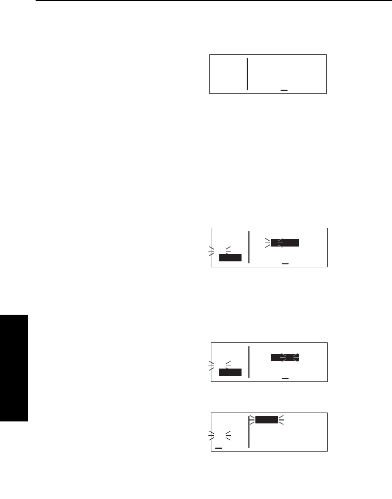
Advanced GPS Operation
4-2Effective Date 5/95 006-08791-0000 Rev 0
Advanced GPS Operation
Chapter 4
To create a flight plan:
1.Select the flight plan (FPL) pages with the right outer knob.
2.Select a flight plan page
(preferably other than FPL 0)
which does not contain a flight
plan (figure 4-1). If all of the flight
plan pages contain flight plans,
refer to section 4.1.6, “Deleting
Flight Plans”.
3.Turn on the cursor (B).
NOTE: The KLN 35A flight plan operation is designed so that the
first waypoint in the flight plan should always be the departure point.
Remember to enter the K, P, or Cprefix for certain airports in the
United States, Alaska (some, but not all cases), or Canada, respec-
tively. See section 2.3, “ICAO Identifiers”.
4.Use the right inner knob to select
the first character of the departure
waypoint identifier (figure 4-2). If
you have set the default first way-
point character to Kon the SET 5
page, you will just need one turn
clockwise (see section 3.4.2,
“Data Entry”)
5.Turn the right outer knob to move the flashing part of the cursor
over the second character, then select the desired character.
6.Use the above procedure to
select the entire identifier for the
first waypoint (figure 4-3).
7.Press F. A waypoint page for
the identifier just entered will be
displayed on the screen (figure
4-4). If a mistake was made and
the wrong waypoint identifier was
entered, press Eand begin
again. If no mistake was made
but the waypoint identifier just
entered isn’t in the data base, a
page allowing creation of a user defined waypoint will appear on
APT VOR NDB SUP ACT NAV FPL CAL SET OTH
åå.ånm Copy FPL 0?
åååååå 1: >Dis
>Leg
FPL 7
Figure 4-1
APT VOR NDB SUP ACT NAV FPL CAL SET OTH
åå.ånm Copy FPL 0?
åååååå 1:KNEW >Dis
#>Leg
CRSR
Figure 4-3
APT VOR NDB SUP ACT NAV FPL CAL SET OTH
åå.ånm Copy FPL 0?
åååååå 1:K >Dis
#>Leg
CRSR
Figure 4-2
APT VOR NDB SUP ACT NAV FPL CAL SET OTH
åå.ånm KNEW 10ft
åååååå LAKEFRONT
#>Leg NEW ORLEANS
APT 1 LA
Figure 4-4

KLN 35A Pilot’s Guide Advanced GPS Operation
4-3 Effective Date 5/95006-08791-0000 Rev 0
Advanced GPS Operation
Chapter 4
the screen. Refer to section 4.4 for instructions on how to create
a user-defined waypoint.
8.Press Fagain to approve the
waypoint page being displayed.
The cursor will move
automatically to the second way-
point position (figure 4-5).
9.Use the same procedure to enter
the rest of the waypoints in the
flight plan (figure 4-6). If the flight
plan consists of three or more
waypoints, the waypoints will
automatically scroll as necessary
to allow entry of the next way-
point.
10.When all of the waypoints have been entered in the flight plan,
the right outer knob may be rotated to move the cursor up and
down and manually “scroll” through the waypoints making up this
flight plan. This is useful if the flight plan contains four or more
waypoints since not all of the waypoints can be displayed at one
time. When the right outer knob is rotated counterclockwise, the
cursor may be positioned over Use?. If there are more than
three waypoints in the flight plan, the first two waypoints will then
be displayed followed by the last waypoint in the flight plan.
Rotate the right outer knob to move the cursor and manually
scroll to see the missing intermediate waypoints.
11.Turn off the cursor (B). Additional flight plans may now be
created in the same manner.
4.1.2. VIEWING DISTANCE AND DESIRED TRACK BETWEEN
STORED FLIGHT PLAN WAYPOINTS
The stored flight plan (FPL 1-9) pages have a field to the right of each
waypoint in the flight plan. This field may be used to display the
cumulative distance (Dis) to each waypoint or the magnetic desired
track (Dtk) from the previous waypoint.
If you have more than three waypoints in the stored flight plan, you
may wish to view flight data for waypoints which are not displayed on
the screen. If this is the case, turn on the cursor (B) and use the
right outer knob to scroll down the flight plan until the waypoint of
interest is on the screen.
APT VOR NDB SUP ACT NAV FPL CAL SET OTH
åå.ånm Use? Inverted?
åååååå 1:KNEW >Dis
>Leg 2:
CRSR
Figure 4-5
APT VOR NDB SUP ACT NAV FPL CAL SET OTH
åå.ånm Use? Inverted?
åååååå 6:TLH >Dis
#>Leg 7:CTY 394
CRSR 8:KPIE ----
Figure 4-6
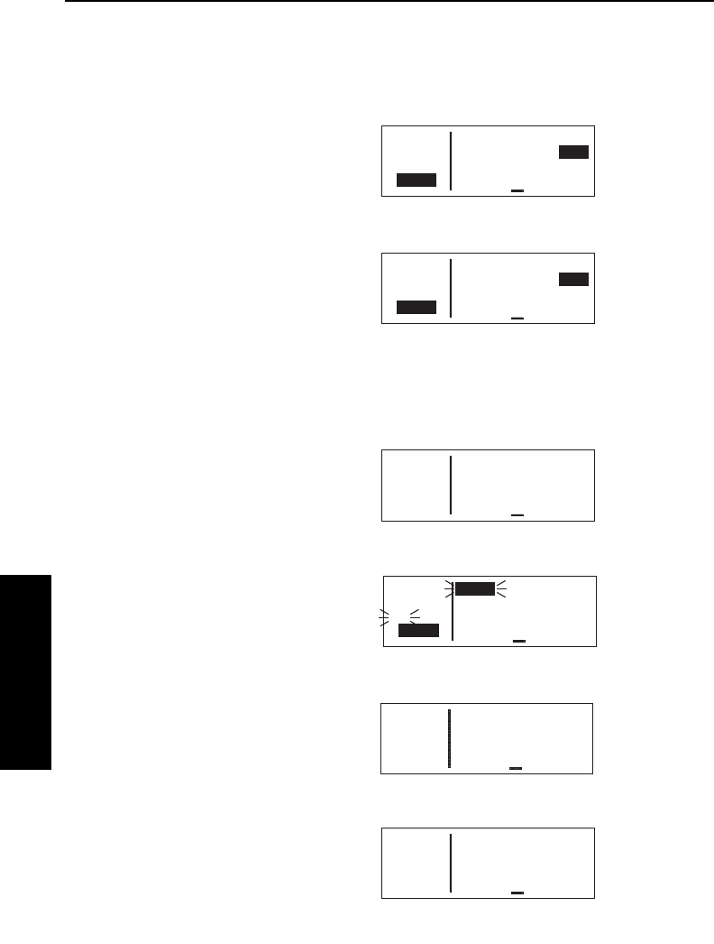
Advanced GPS Operation
4-4
Effective Date 5/95 006-08791-0000 Rev 0
Advanced GPS Operation
Chapter 4
This display will default to the distance presentation at power-on.
The area in the upper right hand corner of the screen is a cyclic field.
To cycle between distance and desired track display on a num-
bered flight plan page:
1. Turn on the cursor (B); it will
come up over the cyclic field,
which in this case is displaying
distance (Dis) in nautical miles
(figure 4-7).
2. Press E. The cyclic field will
change to magnetic desired track
(Dtk) (figure 4-8). An additional
Epress cycles back to Dis.
4.1.3. ACTIVATING A NUMBERED FLIGHT PLAN
To activate one of the previously created numbered flight plans:
1. Use the right outer and inner
knobs to select the desired flight
plan page (figure 4-9).
2. Press Bto turn on the cursor.
It will appear over Use?
(figure 4-10). If you haven’t left
the numbered flight plan since
creating this flight plan, rotate the
outer knob counterclockwise to
position the cursor over Use?
3. Press Fto activate the flight
plan in the order shown
(figure 4-11). To activate the
flight plan in inverse order (first
waypoint becomes last and last
waypoint becomes first), rotate
the outer knob one step clock-
wise to position the cursor over
Use? Inverted? before pressing
F(figure 4-12).
APT VOR NDB SUP ACT NAV FPL CAL SET OTH
åå.ånm Use? Inverted?
åååååå 1:KORL >Dis
#>Leg 2:KATL 344
CRSR 4:KIXD 977
Figure 4-10
APT VOR NDB SUP ACT NAV FPL CAL SET OTH
åå.ånm Use? Inverted?
åååååå 1:KORL >Dis
>Leg 2:KATL 344
FPL 4 4:KIXD 977
Figure 4-9
APT VOR NDB SUP ACT NAV FPL CAL SET OTH
åå.ånm Use? Inverted?
åååååå 1:KNEW >Dtk
>Leg 2:GPT 66°
CRSR 8:KPIE 169°
Figure 4-8
APT VOR NDB SUP ACT NAV FPL CAL SET OTH
åå.ånm Use? Inverted?
åååååå 1:KNEW >Dis
>Leg 2:GPT 54
CRSR 8:KPIE 497
Figure 4-7
APT VOR NDB SUP ACT NAV FPL CAL SET OTH
213nm ≤ 1:KIXD >Dis
KSTL ≥ 2:KSTL 213
>Leg 3:KATL 633
FPL 0 4:KORL 977
Figure 4-12
APT VOR NDB SUP ACT NAV FPL CAL SET OTH
344nm ≤ 1:KORL >Dis
KATL ≥ 2:KATL 344
>Leg 3:KSTL 764
FPL 0 4:KIXD 977
Figure 4-11
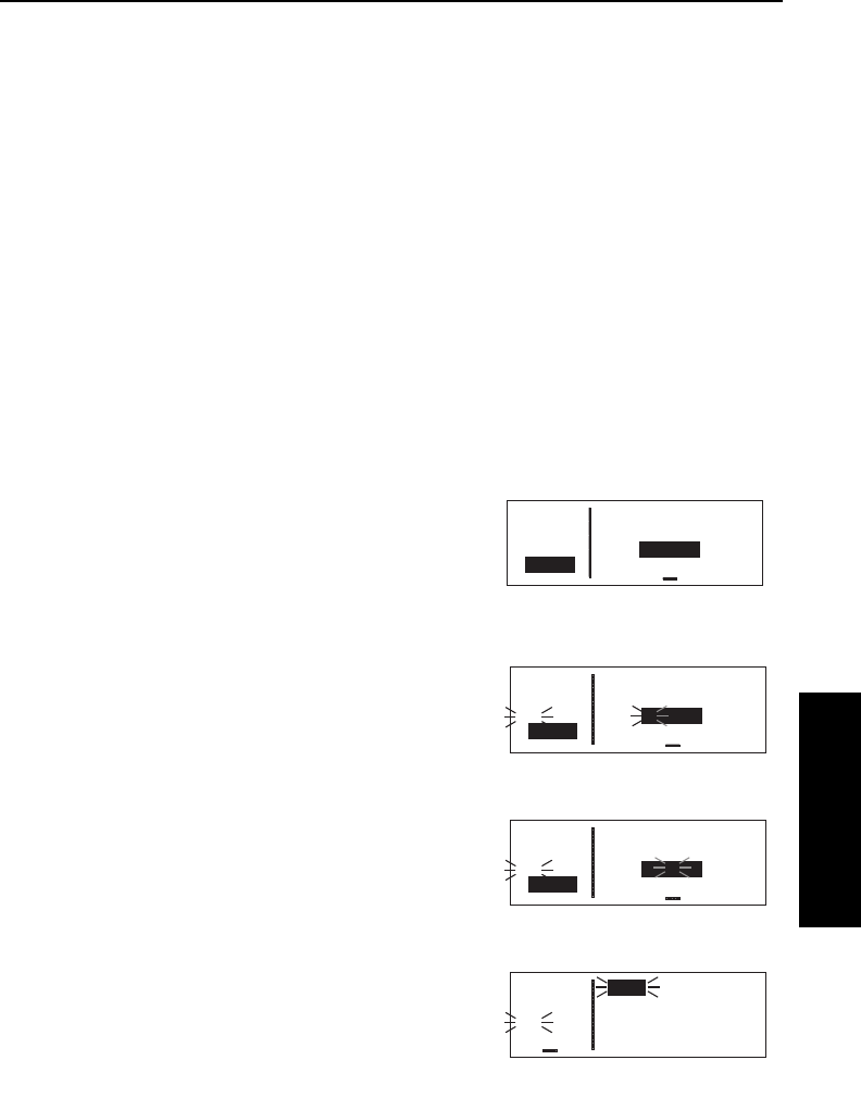
KLN 35A Pilot’s Guide Advanced GPS Operation
4-5 Effective Date 5/95006-08791-0000 Rev 0
Advanced GPS Operation
Chapter 4
4. The selected flight plan is now displayed as FPL 0, the active
flight plan. Any changes made to FPL 0 will not affect how this
flight plan is stored as the numbered flight plan.
4.1.4. ADDING A WAYPOINT TO A FLIGHT PLAN
A waypoint may be added to any flight plan containing fewer than 20
waypoints
To add a waypoint to a flight plan:
1. Turn on the cursor with the Bbutton.
2. With the outer knob, position the cursor over the waypoint identi-
fier which you desire to follow the waypoint being added.
Another way to think of this is to position the cursor over the
location in the flight plan you wish the new waypoint to be added.
For example, if SJI is presently the second waypoint in the flight
plan and you wish to insert GPT
in the number 2 position in front
of SJI, move the cursor over SJI
(figure 4-13).
3. Use the inner knob to enter the
first character of the waypoint
being inserted. As you begin to
turn the knob, the existing
waypoint in this position
automatically jumps down to the
next position. In this case, SJI
automatically moves to waypoint
3 and KPIE changes to waypoint
8 (figure 4-14).
4. Complete the waypoint entry
operation (figure 4-15).
5. Press Fto display the way-
point page on the right side for
the identifier just entered
(figure 4-16).
APT VOR NDB SUP ACT NAV FPL CAL SET OTH
åå.ånm Use? Inverted?
åååååå 1:KNEW >Dis
>Leg 2:SJI 96
CRSR 7:KPIE 497
Figure 4-13
APT VOR NDB SUP ACT NAV FPL CAL SET OTH
åå.ånm Use? Inverted?
åååååå 1:KNEW >Dis
#>Leg 2:G ----
CRSR 8:KPIE ----
Figure 4-14
APT VOR NDB SUP ACT NAV FPL CAL SET OTH
åå.ånm Use? Inverted?
åååååå 1:KNEW >Dis
#>Leg 2:GPT ----
CRSR 8:KPIE ----
Figure 4-15
APT VOR NDB SUP ACT NAV FPL CAL SET OTH
åå.ånm GPT 109.00
åååååå GULFPORT
#>Leg N 30°24.41'
VOR 1 W 89°04.61'
Figure 4-16
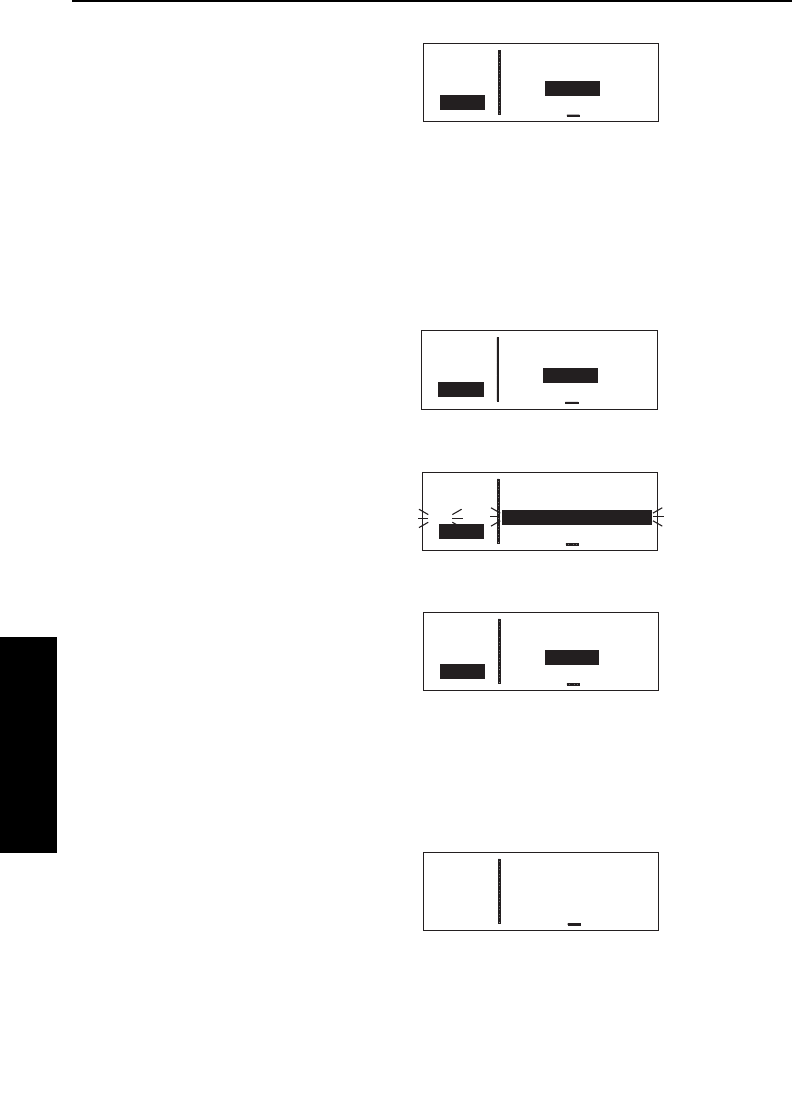
Advanced GPS Operation
4-6
Advanced GPS Operation
Chapter 4
Effective Date 4/97 006-08791-0000 Rev 2
6. Press Fagain to approve the
waypoint page (figure 4-17).
7. Turn off the cursor (B).
4.1.5. DELETING A WAYPOINT FROM A FLIGHT PLAN
To delete a waypoint from a flight plan:
1. Press Bto enable the cursor if it is not on already.
2. Move the cursor over the
waypoint you wish to delete
(figure 4-18).
3. Press E. The letters Del
(delete) will appear to the left of
the identifier and a question mark
will appear to the right of the
identifier (figure 4-19). If a mis-
take was made and you do not
wish to delete this waypoint,
press E.
4. Press Fand the waypoint will
be deleted from the flight plan.
The other waypoints in the flight
plan will be correctly repositioned
(figure 4-20).
5. Turn off the cursor (B).
4.1.6. DELETING FLIGHT PLANS
To delete a flight plan which is no longer required:
1. Display the flight plan (FPL 0,
FPL 1, . . ., or FPL 9) which is to
be cleared (figure 4-21).
2. Make sure that the cursor is
turned off, and use the B button
if it is not.
APT VOR NDB SUP ACT NAV FPL CAL SET OTH
åå.ånm Use? Inverted?
åååååå 3:SJI >Dis
>Leg 4:CEW 183
CRSR 8:KPIE 497
Figure 4-18
APT VOR NDB SUP ACT NAV FPL CAL SET OTH
åå.ånm Use? Inverted?
åååååå 3:SJI >Dis
#>Leg Del CEW 183
CRSR 8:KPIE 497
Figure 4-19
APT VOR NDB SUP ACT NAV FPL CAL SET OTH
åå.ånm Use? Inverted?
åååååå 1:KNEW >Dis
>Leg 2:GPT 54
FPL 7 7:KPIE 497
Figure 4-21
APT VOR NDB SUP ACT NAV FPL CAL SET OTH
åå.ånm Use? Inverted?
åååååå 2:GPT >Dis
>Leg 3:SJI 96
CRSR 8:KPIE 497
Figure 4-17
APT VOR NDB SUP ACT NAV FPL CAL SET OTH
åå.ånm Use? Inverted?
åååååå 3:SJI >Dis
>Leg 4:MAI 263
CRSR 7:KPIE 497
Figure 4-20
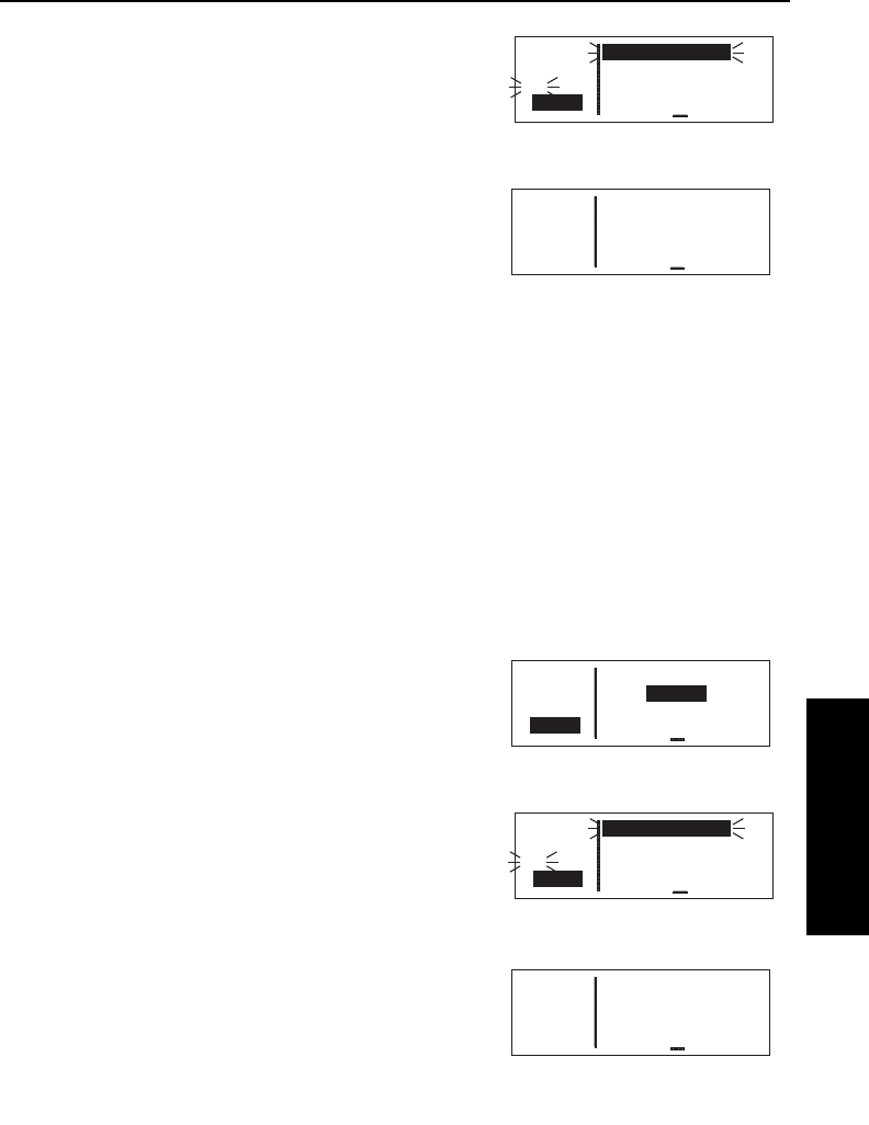
KLN 35A Pilot’s Guide Advanced GPS Operation
4-7 Effective Date 5/95006-08791-0000 Rev 0
Advanced GPS Operation
Chapter 4
3.Press E. The words Delete
FPL?will appear at the top of the
page (figure 4-22). If a mistake
was made and you do not wish to
clear this flight plan, press E
again.
4.Press Fto clear the flight plan
(figure 4-23).
4.1.7. STORING FPL 0 AS A NUMBERED FLIGHT PLAN
The active flight plan may be loaded into a numbered flight plan so
that it can be recalled for later use. This may be desirable, for
example, if the active flight plan was originally created on the FPL 0
page and not as a numbered flight plan.
To store the active flight plan as a numbered flight plan:
1.Select a numbered flight plan page which does not contain any
waypoints (figure 4-23). If none exist, use the procedure
described in section 4.1.6, “Deleting Flight Plans,” to clear a flight
plan which is no longer required.
2.Turn on the cursor (B). It will
appear over the blank first
waypoint position (figure 4-24).
3.Rotate the right outer knob coun-
terclockwise to position the
cursor over Copy FPL 0?
(figure 4-25).
4.Press Fto load the active flight
plan into this numbered flight plan
(figure 4-26).
APT VOR NDB SUP ACT NAV FPL CAL SET OTH
åå.ånm Delete FPL?
åååååå 1:KNEW >Dis
#>Leg 2:GPT 54
CRSR 7:KPIE 497
Figure 4-22
APT VOR NDB SUP ACT NAV FPL CAL SET OTH
åå.ånm Copy FPL 0?
åååååå 1: >Dis
>Leg
FPL 7
Figure 4-23
APT VOR NDB SUP ACT NAV FPL CAL SET OTH
åå.ånm Copy FPL 0?
åååååå 1: >Dis
>Leg
CRSR
Figure 4-24
APT VOR NDB SUP ACT NAV FPL CAL SET OTH
åå.ånm Copy FPL 0?
åååååå 1: >Dis
#>Leg
CRSR
Figure 4-25
APT VOR NDB SUP ACT NAV FPL CAL SET OTH
åå.ånm Use? Inverted?
åååååå 1:KORL >Dis
>Leg 2:KATL 344
FPL 7 4:KIXD 977
Figure 4-26

Advanced GPS Operation
4-8
Effective Date 5/95 006-08791-0000 Rev 0
Advanced GPS Operation
Chapter 4
4.2. OPERATING FROM THE ACTIVE FLIGHT PLAN
4.2.1. GENERAL PROCEDURES
Everything you have learned in this Pilot’s Guide thus far is
applicable to using the KLN 35A for flight plan operation. The
following rules and considerations apply for flight plan operation while
the KLN 35A is in the En route-Leg mode:
•Always verify that you are viewing the active flight plan page
(FPL 0) and not one of the other numbered flight plan pages.
•The active leg of the flight plan is designated with a symbol.
A leg is defined as the course line between a pair of waypoints (a
“from” waypoint and a “to” waypoint). The head of the arrow is
positioned to the left of and points to the active “to” waypoint. In
figure 4-27, SLC (Salt Lake City
VOR) is the “to” waypoint. The
tail of the symbol is positioned
to the left of the “from” waypoint.
KPVU (Provo Municipal) is the
“from” waypoint in figure 4-27.
The symbol is not displayed
unless the KLN 35A is actually receiving GPS signals suitable for
navigation.
(Note: If the unit is in the take-home mode, it has
been “tricked” into thinking it is receiving signals and therefore
the symbol can be displayed).
Also, the symbol will not be
displayed if Direct To navigation
is occurring and the Direct To
waypoint is not in FPL 0. If in
doubt as to whether or not Direct
To operation is occurring, view
the NAV 1 page. If the top line
shows the ∂∂∆∆symbol (figure
4-28) instead of a “from” waypoint
(figure 4-29), then Direct To navi-
gation is occurring. If it is desired
to cancel the Direct To operation
and operate from the active flight
plan, press D, E, and then
F.
≤
≥
≤
≥
≤
≥
≤
≥
≤
≥
APT VOR NDB SUP ACT NAV FPL CAL SET OTH
åå.ånm ≤ 1:KPVU >Dis
åååååå ≥ 2:SLC 40
>Leg 3:OGD 63
FPL 0 6:KPIH 168
Figure 4-27
APT VOR NDB SUP ACT NAV FPL CAL SET OTH
åå.ånm ∂∆ SLC
åååååå > ««««∑∏π««««
>Leg DTK335° TK337°
NAV 1 >338°To 0:14
∫
Figure 4-28
APT VOR NDB SUP ACT NAV FPL CAL SET OTH
åå.ånm KPVU ∆ SLC
åååååå > ««««∑∏π««««
>Leg DTK335° TK337°
NAV 1 >338°To 0:14
∫
Figure 4-29
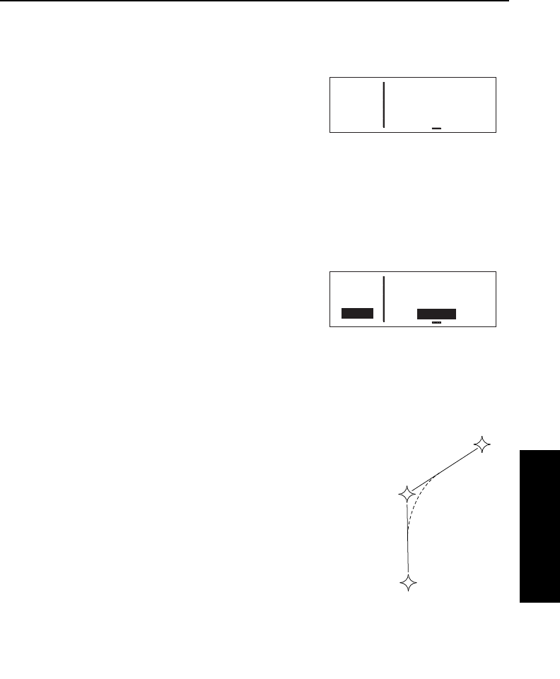
KLN 35A Pilot’s Guide Advanced GPS Operation
4-9 Effective Date 5/95006-08791-0000 Rev 0
Advanced GPS Operation
Chapter 4
•As flight plan waypoints are reached, the active leg symbol auto-
matically shifts to the next leg.
•If the flight plan contains more
waypoints than can be displayed
on the screen at one time, the
page will automatically scroll as
progress is made along the flight
plan so that the active leg is
always displayed (figure 4-30).
•The last waypoint in the flight plan is always displayed at the bot-
tom of the FPL 0 page, even if all of the waypoints in the flight
plan can’t be displayed on the page at one time. To view inter-
mediate waypoints, turn the cursor on and use the right outer
knob to manually scroll through all of the waypoints, as desired.
If scrolling is performed all the
way to the end of the flight plan, a
blank waypoint position will exist
so that a waypoint may be added
to the end of the flight plan
(figure 4-31).
4.2.2. TURN ANTICIPATION AND WAYPOINT ALERTING
Prior to reaching a waypoint in the active flight
plan, the KLN 35A will provide navigation along a
curved path segment to ensure a smooth transi-
tion between two adjacent legs in the flight plan.
That is, the CDI or HSI left/right deviation will be
referenced to the dashed line in figure 4-32. This
feature is called turn anticipation. The transition
course is based upon the aircraft’s actual
groundspeed and the amount of course angle
change between the two legs. The KLN 35A
automatically sequences to the next leg after
passing the midpoint in the transition segment.
Approximately 20 seconds prior to the beginning of turn anticipation,
the arrow preceding the active waypoint identifier will begin flashing
on the FPL 0 page and on any Navigation page or waypoint page dis-
APT VOR NDB SUP ACT NAV FPL CAL SET OTH
åå.ånm 2:SLC >Dis
åååååå ≤ 3:OGD
>Leg ≥ 4:MLD 59
FPL 0 6:KPIH 104
Figure 4-30
APT VOR NDB SUP ACT NAV FPL CAL SET OTH
åå.ånm ≥ 4:MLD >Dis
åååååå 5:PIH 94
>Leg 6:KPIH 97
CRSR 7:
Figure 4-31
WPT 1
WPT 2
WPT 3
Figure 4-32
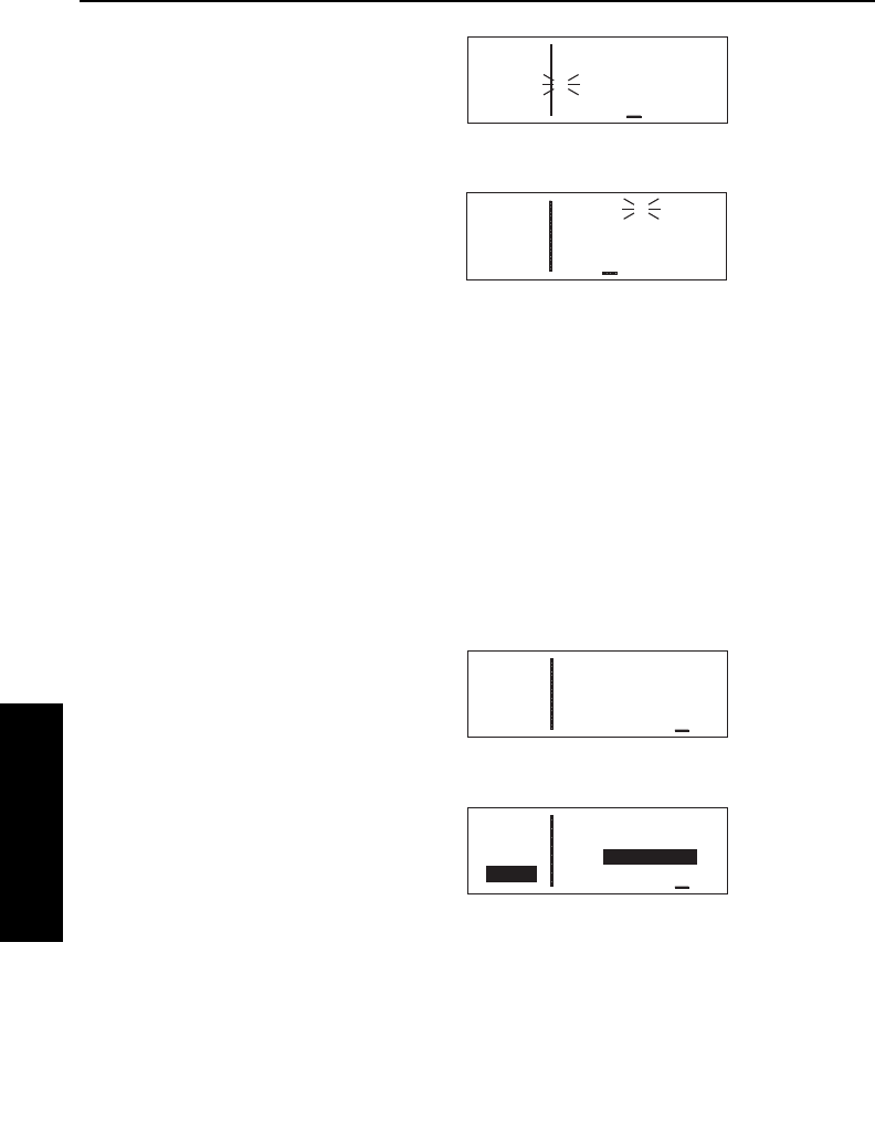
Advanced GPS Operation
4-10
Effective Date 5/95 006-08791-0000 Rev 0
Advanced GPS Operation
Chapter 4
playing the active waypoint identifier
(figures 4-33 and 4-34). This is called
“waypoint alerting”. If an external
waypoint alert annunciator is mount-
ed in the aircraft, this annunciator will
begin flashing at the same time.
To utilize the turn anticipation feature,
start the turn transition to the next leg
in the flight plan at the very beginning
of turn anticipation. This occurs when
the external waypoint alert annuncia-
tor stops flashing and goes on
steady. At this time, the KLN 35A will notify you with a message on
the Message page of the new desired track to select on your HSI or
CDI.
*Adj Nav Crs to 123°
A message will not be given if the change in desired track (course
change) is less than 5°.
The desired track (Dtk) displayed on the NAV 4 page also changes
to the value for the next leg at the beginning of turn anticipation. Turn
anticipation becomes inactive when transition to the next leg has
been made.
If desired, turn anticipation may be
disabled (or enabled) on the Setup
(SET) 4 page by pressing the B
button and then using the right inner
knob to switch back and forth
between ENABLED (figure 4-35) and
DISABLED (figure 4-36). If turn
anticipation is disabled, navigation is
provided all the way to the waypoint,
and waypoint alerting occurs
approximately 36 seconds prior to
actually reaching the waypoint.
4.2.3. VIEWING THE WAYPOINT PAGES FOR THE ACTIVE
FLIGHT PLAN WAYPOINTS
The waypoint pages for each of the waypoints in the active flight plan
may be easily displayed by selecting the Active (ACT) Waypoint page
type. When the ACT page type is first selected, the waypoint page
APT VOR NDB SUP ACT NAV FPL CAL SET OTH
åå.ånm TURN
åååååå ANTICIPATION
>Leg ENABLED
SET 4
Figure 4-35
APT VOR NDB SUP ACT NAV FPL CAL SET OTH
åå.ånm TURN
åååååå ANTICIPATION
>Leg DISABLED
CRSR
Figure 4-36
APT VOR NDB SUP ACT NAV FPL CAL SET OTH
åå.ånm 1:SLC >Dis
åååååå ≤ 2:OGD
>Leg ≥ 3:MLD 2
FPL 0 7:KPIH 47
Figure 4-33
APT VOR NDB SUP ACT NAV FPL CAL SET OTH
åå.ånm PIH ∆ KPIH
åååååå > ««««∑∏∫««««
>Leg DTK335° TK337°
NAV 1 >338°To 0:01
Figure 4-34

KLN 35A Pilot’s Guide Advanced GPS Operation
4-11 Effective Date 5/95006-08791-0000 Rev 0
Advanced GPS Operation
Chapter 4
for the active waypoint will be displayed (figure 4-37). The location of
the waypoint in the flight plan (way-
point 1, waypoint 2, etc.) is
annunciated with a number to the left
of the identifier. In addition, an arrow
to the left of the waypoint number
designates the active waypoint. If
there is a U to the far right of the iden-
tifier, it designates the waypoint as a
user-defined waypoint. If the way-
point is an airport, the field elevation
is displayed here. If the waypoint is a
VOR or an NDB, the navaid
frequency is displayed in this area
(figure 4-38).
To view the waypoints in the flight plan that are not the active
waypoint:
1. Pull the right inner knob to the
“out” position and turn it to view
each of the waypoints in the
order they are contained in the
flight plan (figure 4-39).
2. Once the desired waypoint is
found, the right inner knob may
be pushed back to the “in”
position and rotated to display
any of the other waypoint pages
(figure 4-40).
3. Pulling the knob back out will allow further scanning of the
waypoint pages in the active flight plan.
4.2.4. COMBINING DIRECT TO AND FLIGHT PLAN
OPERATION
It is very common when using flight plan operation to use the Direct
To function to proceed directly to a waypoint which exists in the
active flight plan. For example, after takeoff, it is common to receive
vectors in the terminal area and then be given a clearance direct to
the first point in the flight plan that was filed. The KLN 35A makes
this kind of operation very easy to accomplish. Whenever you do a
Direct To operation to a waypoint which is in the active flight plan
(FPL 0), the system will provide navigation to the waypoint and then
APT VOR NDB SUP ACT NAV FPL CAL SET OTH
åå.ånm ∆ 6 KPIH 4450'
åååååå POCATELLO REGL
>Leg POCATELLO
ACT 1 ID
Figure 4-37
APT VOR NDB SUP ACT NAV FPL CAL SET OTH
åå.ånm ∆ 5 PIH 112.60
åååååå POCATELLO
>Leg N 42°52.22'
ACT 1 W112°39.13'
Figure 4-38
APT VOR NDB SUP ACT NAV FPL CAL SET OTH
åå.ånm 1 KPVU 4490'
åååååå PROVO MUN
>Leg PROVO
ACT 1 UT
Figure 4-39
APT VOR NDB SUP ACT NAV FPL CAL SET OTH
åå.ånm 1 KPVU A
åååååå UNIC 123.05
>Leg UNIC 122.80
ACT+4 CTAF 122.80
Figure 4-40
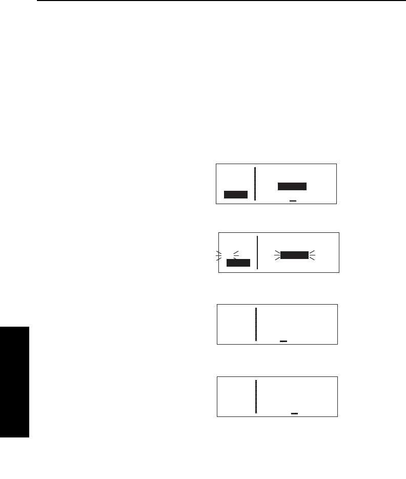
Advanced GPS Operation
4-12
Effective Date 5/95 006-08791-0000 Rev 0
Advanced GPS Operation
Chapter 4
automatically resume navigation along the flight plan when the Direct
To waypoint is reached. Waypoints which exist prior to the Direct To
waypoint in the active flight plan are bypassed. Of course, the active
flight plan will never be resumed if the Direct To operation is to a way-
point which is not in the active flight plan.
Any of the several methods previously described for initiating Direct
To operation may be used, although the one below is the easiest for
this application.
To fly direct to a waypoint in the active flight plan (FPL 0):
1. Select the FPL 0 page.
2. Turn on the cursor (B) and use
the left outer knob to position the
cursor over the desired waypoint
(figure 4-41).
3. Press D. The display will
change to the Direct To Page
(figure 4-42), with the identifier of
the selected waypoint.
4. Press Fto approve the Direct
To. The NAV 1 page will be
displayed (figure 4-43) reflecting
the new active waypoint.
5. If you now turn back to the FPL 0
page, you will see that the active
waypoint is now preceded by an
arrow only, instead of the
symbol (figure 4-44). This is
because there is no “from”
waypoint in the flight plan.
If it is desired to cancel the Direct To
operation prior to reaching the Direct
To waypoint in order to proceed along
the flight plan leg, press D, then
press E, then F.
≤
≥
APT VOR NDB SUP ACT NAV FPL CAL SET OTH
115nm 2:APE >Dis
DQN ∆ 3:DQN 115
>Leg 4:VHP 207
FPL 0 5:KIND 214
Figure 4-44
APT VOR NDB SUP ACT NAV FPL CAL SET OTH
115nm ∂∆ DQN
DQN > ««««∑∏π««««
>Leg DTK273° TK302°
NAV 1 >273°To 0:54
∫
Figure 4-43
APT VOR NDB SUP ACT NAV FPL CAL SET OTH
34.1nm DIRECT TO:
APE
#>Leg DQN
CRSR
Figure 4-42
APT VOR NDB SUP ACT NAV FPL CAL SET OTH
34.1nm ≤ 1:KZZV >Dis
APE ≥ 2:APE 34
>Leg 3:DQN 118
CRSR 5:KIND 217
Figure 4-41
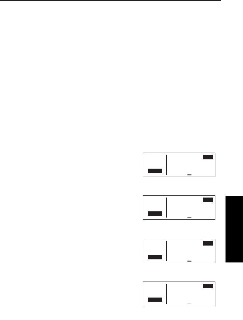
4.2.5. VIEWING DISTANCE, ETE, ETA, OR DESIRED TRACK
TO FLIGHT PLAN WAYPOINTS
The active flight plan (FPL 0) page has a data field to the right of
each waypoint in the flight plan. This field may be used to display the
cumulative distance (Dis) from the present position to each waypoint,
the estimated time en route (ETE), the estimated time of arrival (ETA,
for which the time zone abbreviation is displayed), or the magnetic
desired track (Dtk) between each waypoint.
If you have more than four waypoints in FPL 0, you may wish to view
flight data for waypoints which are not displayed on the screen. If this
is the case, turn on the cursor (B) and use the right outer knob to
scroll down the flight plan until the waypoint of interest is on the
screen.
This display will default to the distance presentation at power-on
(figure 4-139). The area in the upper right hand corner of the screen
is a cyclic field, which means that . . .
To cycle between distance, ETE, ETA, and desired track on the
FPL 0 page:
1. Turn on the cursor (B); it will
come up over the cyclic field,
which in this case is displaying
distance (Dis) in nautical miles
(figure 4-45).
2. Press E. Subsequent presses
of the Ebutton will cycle
through ETE in hours:minutes
(figure 4-46), ETA in terms of the
system time zone (figure 4-47),
magnetic Dtk (figure 4-48), then
back to Dis.
KLN 35A Pilot’s Guide Advanced GPS Operation
4-13 Effective Date 5/95006-08791-0000 Rev 0
Advanced GPS Operation
Chapter 4
APT VOR NDB SUP ACT NAV FPL CAL SET OTH
åå.ånm ≤ 1:KZZV >Dis
åååååå ≥ 2:APE 22
>Leg 3:DQN 106
CRSR 5:KIND 204
Figure 4-45
APT VOR NDB SUP ACT NAV FPL CAL SET OTH
åå.ånm ≤ 1:KZZV >ETE
åååååå ≥ 2:APE 0:08
>Leg 3:DQN 0:44
CRSR 5:KIND 1:27
Figure 4-46
APT VOR NDB SUP ACT NAV FPL CAL SET OTH
åå.ånm ≤ 1:KZZV >UTC
åååååå ≥ 2:APE 1535
>Leg 3:DQN 1612
CRSR 5:KIND 1654
Figure 4-47
APT VOR NDB SUP ACT NAV FPL CAL SET OTH
åå.ånm ≤ 1:KZZV >Dtk
åååååå ≥ 2:APE 291°
>Leg 3:DQN 265°
CRSR 5:KIND 147°
Figure 4-48
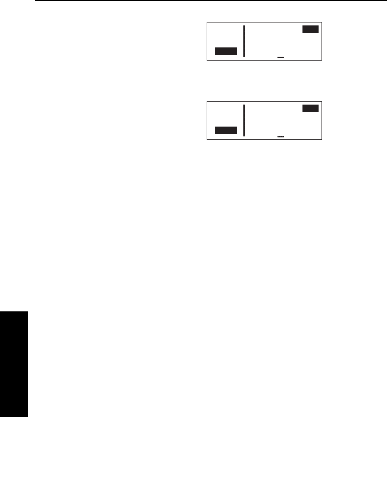
Advanced GPS Operation
4-14
Effective Date 5/95 006-08791-0000 Rev 0
Advanced GPS Operation
Chapter 4
NOTE: When the cursor is over the
cylic field and it is displaying the ETA
time zone, turning the right inner knob
changes the system time zone
(figure 4-49).
NOTE: When the KLN 35A is in OBS
mode, the FPL 0 page will present
OBS selected course (OBS) as an
option instead of magnetic desired
track (Dtk). The selected course will
be displayed to the right of the active
waypoint, and the OBS fields for all
other waypoints will be dashed (figure
4-50).
4.3. CALCULATOR PAGES
The Calculator (CAL) pages are used for trip planning. They are con-
venient both on the ground before you begin your flight, and in the
air. The CAL 1 page performs distance, bearing, and time calcula-
tions, and the CAL 2 page is for advisory fuel planning.
Data entered on any of the Calculator pages has no effect on naviga-
tion data provided on any Navigation (NAV) or Flight Plan (FPL)
pages. You may perform trip calculations without disturbing ongoing
navigation.
NOTE: The Calculator pages rely on pilot enterable inputs for
groundspeed, fuel flow, fuel reserve requirements, altitudes, and air-
speeds. These pages do not utilize inputs from fuel flow or air data
sensors.
4.3.1. THE CALCULATOR 1 (CAL 1) PAGE
The CAL 1 page allows you to do distance, bearing, and time calcula-
tions that you might otherwise need a chart, ruler, and pocket
calculator for. The KLN 35A will perform these calculations either
from waypoint to waypoint (for in-flight calculations, your present
position can be one of the waypoints), or for one of your flight plans
(active or stored).
APT VOR NDB SUP ACT NAV FPL CAL SET OTH
åå.ånm 1:KZZV >OBS
åååååå ∆ 2:APE 270°
>270 3:DQN ----
CRSR 5:KIND ----
Figure 4-50
APT VOR NDB SUP ACT NAV FPL CAL SET OTH
åå.ånm ≤ 1:KZZV >EST
åååååå ≥ 2:APE 1035
>Leg 3:DQN 1112
CRSR 5:KIND 1154
Figure 4-49
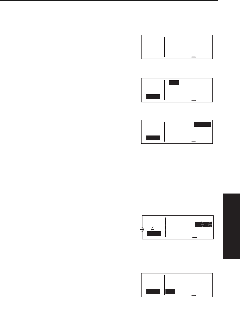
To calculate distance, bearing, and time from waypoint to
waypoint:
1.From the CAL 1 page
(figure 4-51), turn on the cursor
(B). It will appear over a cyclic
field that either displays Wpt
(waypoint to waypoint) or Fpl
(flight plan).
2.For this type of calculation, the
cyclic field should display Wpt.
Press Eto toggle if this is not
the case (figure 4-52).
3.Turn the right outer knob
clockwise to move the cursor to
the "from" waypoint in the upper
right corner of the screen
(figure 4-53).
4.Enter the desired identifier for the
"from" waypoint and press F.
You will be shown the waypoint
page for the waypoint you entered. Press Fagain to approve.
NOTE: On either of the two waypoint fields on this page, you can
select your present position. To do this, press Ewhile the cursor is
on the desired waypoint field. The results will only be displayed
when your KLN 35A is receiving a valid position, or if you happen to
be in the Take Home mode (see section 4.7).
5.With the cursor over the "to"
waypoint, enter the desired
identifier (figure 4-54) and press
Ftwice. The distance in
nautical miles and the bearing will
be displayed on line 3.
6.Use the right outer knob to move the cursor over the
groundspeed field on line 4.
7.Select your estimated
groundspeed for the trip. As you
change it, the estimated time en
route (ETE) calculation will be
updated (figure 4-55).
KLN 35A Pilot’s Guide Advanced GPS Operation
4-15 Effective Date 5/95006-08791-0000 Rev 0
Advanced GPS Operation
Chapter 4
APT VOR NDB SUP ACT NAV FPL CAL SET OTH
åå.ånm >Fpl: 0 KJFK
åååååå To KORD
>Leg 643nm
CAL 1 138kt ETE 4:40
Figure 4-51
APT VOR NDB SUP ACT NAV FPL CAL SET OTH
åå.ånm >Wpt Fr>KJFK
åååååå To>KSAV
>Leg 624nm Brg 217°
CRSR 138kt ETE 4:31
Figure 4-52
APT VOR NDB SUP ACT NAV FPL CAL SET OTH
åå.ånm >Wpt Fr>KJFK
åååååå To>KSAV
>Leg 624nm Brg 217°
CRSR 138kt ETE 4:31
Figure 4-53
APT VOR NDB SUP ACT NAV FPL CAL SET OTH
åå.ånm >Wpt Fr>KLGA
åååååå To>KCLE
>Leg 364nm Brg 279°
CRSR 122kt ETE 2:59
Figure 4-55
APT VOR NDB SUP ACT NAV FPL CAL SET OTH
åå.ånm >Wpt Fr>KLGA
åååååå To>KCLE
#>Leg 628nm Brg 217°
CRSR 138kt ETE 4:33
Figure 4-54
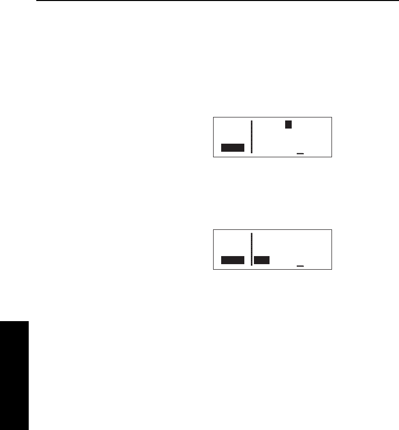
To calculate distance and time for a flight plan:
1. From the CAL 1 page, turn on the cursor (B). It will appear
over a cyclic field that either displays Wpt (waypoint to waypoint)
or Fpl (flight plan).
2. For this type of calculation, the cyclic field should display Fpl.
Press Eto toggle if this is not the case.
3. Turn the right outer knob
clockwise to place the cursor over
the flight plan number. As you
cycle through the flight plans, the
first and last waypoints of each
flight plan will be displayed, along
with the total distance in nautical
miles (figure 4-56).
4. Once you have selected the desired flight plan, move the cursor
to the groundspeed field on line 4.
5. Select your estimated ground-
speed for the trip. As you change
it, the estimated time en route
(ETE) calculation will be updated
(figure 4-57).
4.3.2. THE CALCULATOR 2 (CAL 2) PAGE
The CAL 2 page is for calculating fuel requirements for a trip. To use
these pages, you need to have a good idea what the typical fuel flow
rate for your aircraft is. This information can often be found for given
cruise power settings in a "performance" section of the Pilot’s
Operating Handbook for the aircraft. The units for fuel are not speci-
fied on this page, but the units of time are always hours. This means
that you can use gallons per hour, pounds per hour, kilograms per
hour, etc. Like with the CAL 1 page, the fuel calculations can be
done from waypoint to waypoint (including present position), or for
one of your flight plans.
To calculate fuel requirements from waypoint to waypoint:
1. From the CAL 2 page, turn on the cursor (B). It will appear
over a cyclic field that either displays Wpt (waypoint to waypoint)
or Fpl (flight plan).
Advanced GPS Operation
4-16
Effective Date 5/95 006-08791-0000 Rev 0
Advanced GPS Operation
Chapter 4
APT VOR NDB SUP ACT NAV FPL CAL SET OTH
åå.ånm >Fpl: 2 KDPA
åååååå To KSUS
>Leg 224nm
CRSR 152kt ETE 1:28
Figure 4-56
APT VOR NDB SUP ACT NAV FPL CAL SET OTH
åå.ånm >Fpl: 2 KDPA
åååååå To KSUS
>Leg 224nm
CRSR 127kt ETE 1:46
Figure 4-57
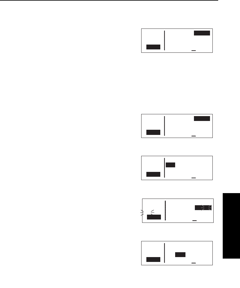
KLN 35A Pilot’s Guide Advanced GPS Operation
4-17 Effective Date 5/95006-08791-0000 Rev 0
Advanced GPS Operation
Chapter 4
2.For this type of calculation, the cyclic field should display Wpt.
Press Eto toggle if this is not the case.
3.Turn the right outer knob
clockwise to move the cursor to
the "from" waypoint in the upper
right corner of the screen
(figure 4-58).
4.Enter the desired identifier for the
"from" waypoint and press F. The waypoint page for the iden-
tifier you just entered will be displayed. If it is the correct one,
press Fagain.
NOTE: On either of the two waypoint fields on this page, you can
select your present position. To do this, press Ewhile the cursor is
on the desired waypoint field (figure
4-59). The results will only be dis-
played when your KLN 35A is
receiving a valid position, or if you
happen to be in the Take Home
mode (see section 4.7, "Using the
Take-home Mode").
5.Move the cursor to the
groundspeed field on line 2.
6.Select your estimated ground-
speed for the trip (figure 4-60).
7.With the cursor over the "to"
waypoint, enter the desired iden-
tifier (figure 4-61) and press F.
8.Move the cursor to the fuel flow
rate field and use the right inner
knob to select the desired value
(figure 4-62). Remember that
this can be in any units you
desire (as long as it's per hour),
but the same fuel units must
carry through the calculations.
APT VOR NDB SUP ACT NAV FPL CAL SET OTH
åå.ånm >Wpt Fr>KDPA
åååååå 127kt To>KSUS
>Leg FF:010 Res:005
CRSR Fuel Req 23
Figure 4-58
APT VOR NDB SUP ACT NAV FPL CAL SET OTH
åå.ånm >Wpt Fr>P.Pos
åååååå 127kt To>KSUS
>Leg FF:010 Res:005
CRSR Fuel Req 22
Figure 4-59
APT VOR NDB SUP ACT NAV FPL CAL SET OTH
åå.ånm >Wpt Fr>P.Pos
åååååå 105kt To>KSPI
#>Leg FF:010 Res:005
CRSR Fuel Req 26
Figure 4-61
APT VOR NDB SUP ACT NAV FPL CAL SET OTH
åå.ånm >Wpt Fr>P.Pos
åååååå 105kt To>KSUS
>Leg FF:010 Res:005
CRSR Fuel Req 26
Figure 4-60
APT VOR NDB SUP ACT NAV FPL CAL SET OTH
åå.ånm >Wpt Fr>P.Pos
åååååå 105kt To>KSPI
>Leg FF:007 Res:005
CRSR Fuel Req 14
Figure 4-62
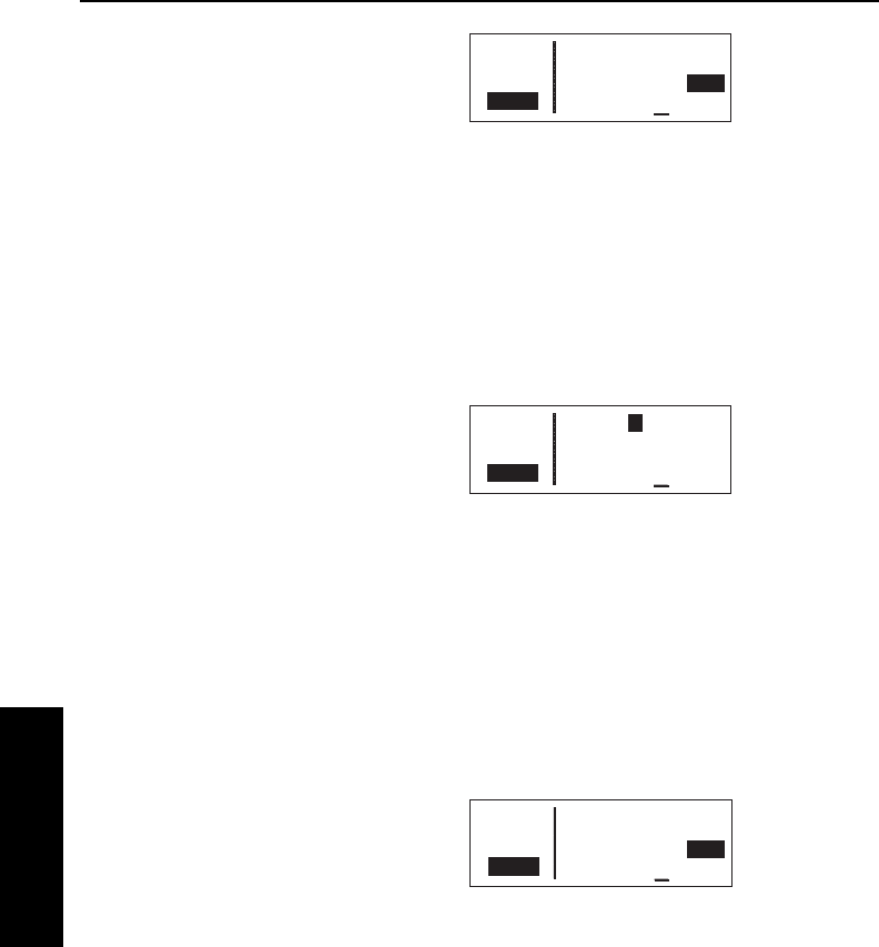
9. Move the cursor to the fuel
reserve requirement field and
enter the desired value. As you
do, watch the calculation of fuel
required on line 4 change (figure
4-63).
To calculate fuel requirements for a flight plan:
1. From the CAL 2 page, turn on the cursor (B). It will appear
over a cyclic field that either displays Wpt (waypoint to waypoint)
or Fpl (flight plan).
2. For this type of calculation, the cyclic field should display Fpl.
Press Eto toggle if this is not the case.
3. Turn the right outer knob
clockwise to place the cursor over
the flight plan number. As you
cycle through the flight plans, the
first and last waypoints of each
flight plan will be displayed
(figure 4-64).
4. Once you have selected the desired flight plan, move the cursor
to the groundspeed field on line 2.
5. Select your estimated groundspeed for the trip.
6. Move the cursor to the fuel flow rate field and use the right inner
knob to select the desired value. Remember that this can be in
any units you desire (as long as it's per hour), but the same fuel
units must carry through the calculations.
7. Move the cursor to the fuel
reserve requirement field and
enter the desired value. As you
do, watch the calculation of fuel
required on line 4 change
(figure 4-65).
4.3.3. THE CALCULATOR 3 (CAL 3) PAGE
The CAL 3 page is used to determine pressure altitude
To calculate the pressure altitude:
1. Turn on the cursor (B).
Advanced GPS Operation
4-18
Effective Date 5/95 006-08791-0000 Rev 0
Advanced GPS Operation
Chapter 4
APT VOR NDB SUP ACT NAV FPL CAL SET OTH
åå.ånm >Fpl: 4 KIXD
åååååå 105kt To KDAL
>Leg FF:007 Res:005
CRSR Fuel Req 32
Figure 4-64
APT VOR NDB SUP ACT NAV FPL CAL SET OTH
åå.ånm >Fpl: 4 KIXD
åååååå 121kt To KDAL
>Leg FF:009 Res:006
CRSR Fuel Req 36
Figure 4-65
APT VOR NDB SUP ACT NAV FPL CAL SET OTH
åå.ånm >Wpt Fr>P.Pos
åååååå 105kt To>KSPI
>Leg FF:007 Res:008
CRSR Fuel Req 17
Figure 4-63

KLN 35A Pilot’s Guide Advanced GPS Operation
4-19 Effective Date 5/95006-08791-0000 Rev 0
Advanced GPS Operation
Chapter 4
2.Enter the altitude indicated on the
aircraft’s altimeter (Ind:) to the
nearest hundred feet by using the
right inner knob to select the
desired value (figure 4-66).
3.Use the right outer knob to move
the cursor to the Baro:field, and
then use the right inner knob to
enter the current altimeter setting
(figure 4-67). The pressure alti-
tude (Prs) is now displayed.
NOTE: The altimeter baro set units may be changed between inch-
es, millibars and hectopascals on the SET 8 page (see section 3.15).
4.3.4. THE CALCULATOR 4 (CAL 4) PAGE
The CAL 4 page is used to determine density altitude
To calculate the density altitude:
1.Turn on the cursor (B).
2.The pressure altitude (Prs:) displayed will be either the last
entered pressure altitude on this page, or the last calculated
pressure altitude from the CAL 3 page. If you desire to change it,
enter the current pressure altitude to the nearest hundred feet by
using the right inner knob (figure 4-68).
3.Use the right outer knob to move
the cursor to the first Temp:field,
and then use the right inner and
outer knobs to enter the outside
air temperature (degrees Celsius)
(figure 4-69). The first digit of the
temperature is either “0” if the
temperature is above zero or “-” if
the temperature is below zero.
For maximum accuracy, the static
air temperature should be
entered. This is the temperature
of air without the effect of heating
due to the aircraft’s movement through the air. For the airspeeds
of most piston aircraft, the difference between static air tempera-
ture and the observed air temperature (or “total air temperature”)
is negligible. The density altitude (Den) is now displayed.
APT VOR NDB SUP ACT NAV FPL CAL SET OTH
åå.ånm PRESSURE ALT
åååååå Ind: 05000ft
>Leg Baro: 29.74"
CRSR Prs 05200ft
Figure 4-67
APT VOR NDB SUP ACT NAV FPL CAL SET OTH
åå.ånm PRESSURE ALT
åååååå Ind: 05000ft
>Leg Baro: 30.03"
CRSR Prs 04900ft
Figure 4-66
APT VOR NDB SUP ACT NAV FPL CAL SET OTH
åå.ånm DENSITY ALT
åååååå Prs: 05500ft
>Leg Temp: 010°C
CRSR Den 06200ft
Figure 4-68
APT VOR NDB SUP ACT NAV FPL CAL SET OTH
åå.ånm DENSITY ALT
åååååå Prs: 05500ft
>Leg Temp: 006°C
CRSR Den 05700ft
Figure 4-69
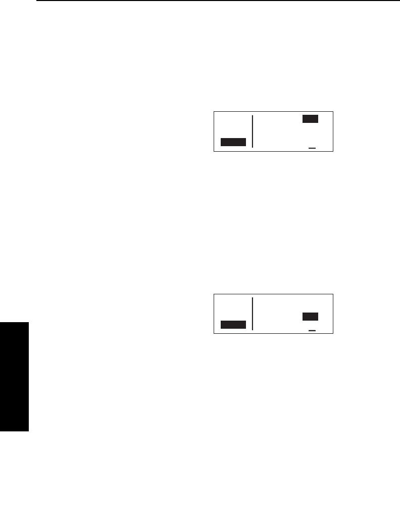
Advanced GPS Operation
4-20
Effective Date 5/95 006-08791-0000 Rev 0
Advanced GPS Operation
Chapter 4
4.3.5. THE CALCULATOR 5 (CAL 5) PAGE
The CAL 5 page is used to determine the true airspeed (TAS) of the
aircraft.
To calculate the true airspeed (TAS):
1 Turn on the cursor (B).
2. Enter the aircraft’s calibrated
airspeed by using the right inner
knob (figure 4-70). If the
calibrated airspeed isn’t known,
use the indicated airspeed. For
most aircraft the difference
between the calibrated airspeed
and the indicated airspeed is small at cruise airspeeds.
3. Use the right outer knob to move the cursor to the Prs: field, and
then use the right inner knob to enter the aircraft’s pressure
altitude. If the pressure altitude was previously calculated on the
CAL 3 page, or entered on the CAL 4 page, it will already be
displayed.
4. Move the cursor to the first Temp: position, and then enter the
outside air temperature (degrees C) by using the right inner and
outer knobs (figure 4-71). The
first digit of the temperature is
either “0” if the temperature is
above zero or “-” if the tempera-
ture is below zero. For maximum
accuracy, the total air tempera-
ture should be entered. This is
the temperature of air including the effect of heating due to the
aircraft’s movement through the air. The temperature read on a
standard outside air temperature gauge found on most piston air-
craft is “total air temperature”. Since the difference between
static air temperature and the observed air temperature (or “total
air temperature”) is usually negligible, any temperature entered
on the CAL 4 page is transferred to this page. The true airspeed
(TAS) is now displayed.
4.3.6. THE CALCULATOR 6 (CAL 6) PAGE
The CAL 6 page is used to determine the present wind direction and
speed. In addition, the headwind or tailwind component of the wind is
displayed.
APT VOR NDB SUP ACT NAV FPL CAL SET OTH
åå.ånm CAS: 130kt
åååååå Prs: 05500ft
>Leg Temp: 006°C
CRSR TAS 141kt
Figure 4-70
APT VOR NDB SUP ACT NAV FPL CAL SET OTH
åå.ånm CAS: 130kt
åååååå Prs: 05500ft
>Leg Temp: 013°C
CRSR TAS 143kt
Figure 4-71

KLN 35A Pilot’s Guide Advanced GPS Operation
4-21 Effective Date 5/95006-08791-0000 Rev 0
Advanced GPS Operation
Chapter 4
To calculate the winds aloft:
1. Turn on the cursor (B).
2. Enter the aircraft’s true airspeed
by using the right inner knob
(figure 4-72). If the CAL 5 page
was previously used to calculate
true airspeed, it will already be
displayed.
3. Use the right outer knob to move
the cursor to the Hdg: field, and
then use the right inner knob to
enter the aircraft’s heading (figure
4-73). The headwind or tailwind
and the wind direction and speed
are now displayed. The wind
direction is relative to true North.
NOTE: The wind calculations are only correct when you have
entered the correct aircraft heading and true airspeed. Make sure to
re-enter new values if you change airspeed or heading.
4.4. CREATING USER-DEFINED WAYPOINTS
You may create and store up to 250 user-defined (also known as
supplemental) waypoints. These waypoints will be very helpful to
you. One major application is private-use airstrips, which are not
included in the Jeppesen data base. They are also handy for points
which you fly over frequently, and wish to navigate to. For example,
a crop sprayer would want to store the locations of the fields he or
she dusts often.
There are three ways to create a user-defined waypoint. If you
happen to know the latitude and longitude of the point, that is one
option. The waypoint can also be defined as a radial and distance
from another waypoint. A third choice is just to store your present
position under the identifier you have chosen.
NOTE: Whenever you are in a waypoint entry situation, such as a
Direct To waypoint or flight plan, and you enter an identifier which is
not in the data base, the KLN 35A will automatically start the user-
defined waypoint creation process.
APT VOR NDB SUP ACT NAV FPL CAL SET OTH
åå.ånm TAS: 136kt
åååååå Hdg: 090°
>Leg Headwind 018kt
CRSR 110°True 020kt
Figure 4-72
APT VOR NDB SUP ACT NAV FPL CAL SET OTH
åå.ånm TAS: 136kt
åååååå Hdg: 025°
>Leg Headwind 002kt
CRSR 110°True 20kt
Figure 4-73
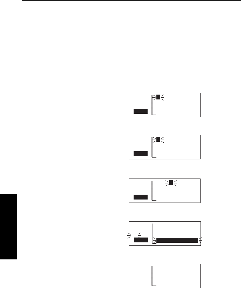
To delete a user-defined waypoint that is no longer needed, see
section 3.13.2, "Viewing and Deleting User Waypoints and Waypoint
Remarks".
4.4.1. CREATING A WAYPOINT AT YOUR PRESENT POSITION
Creating a waypoint at your present position is the simplest possible
way to create a user-defined waypoint. This is nice for
"remembering" a spot you are at. Let's suppose you're at a private
strip that you want to name "VALLY"
To create a user-defined waypoint at your present position:
1.From any supplemental waypoint
(SUP) page, turn on the cursor
(B). It will flash over the first
character in the waypoint
identifier field (figure 4-74).
2.Use the right inner knob to select
the first character of the identifier
(figure 4-75). Remember that
when the cursor is on, the right
inner knob changes the character
and the right outer knob moves
the cursor around.
3.Spell out the rest of the identifier
using the right inner and outer
knobs (figure 4-76).
4.Move the cursor down to the
fourth line, over Present Pos?
(figure 4-77).
5.Press F. The SUP 1 page for
your new waypoint will be
displayed with its latitude and
longitude (figure 4-78). The
cursor is turned off automatically.
Advanced GPS Operation
4-22Effective Date 5/95 006-08791-0000 Rev 0
Advanced GPS Operation
Chapter 4
APT VOR NDB SUP ACT NAV FPL CAL SET OTH
åå.ånm VALLY USR at:
åååååå User Pos L/L?
>Leg User Pos R/D?
CRSR Present Pos?
Figure 4-76
APT VOR NDB SUP ACT NAV FPL CAL SET OTH
åå.ånm VALLY USR at:
åååååå User Pos L/L?
#>Leg User Pos R/D?
CRSR Present Pos?
Figure 4-77
APT VOR NDB SUP ACT NAV FPL CAL SET OTH
åå.ånm VALLY USR
åååååå N 38°30.25'
>Leg W 95°18.54'
SUP 1 >111°TO 0.2nm
Figure 4-78
APT VOR NDB SUP ACT NAV FPL CAL SET OTH
åå.ånm V USR at:
åååååå User Pos L/L?
>Leg User Pos R/D?
CRSR Present Pos?
Figure 4-75
APT VOR NDB SUP ACT NAV FPL CAL SET OTH
åå.ånm FARM USR
åååååå N 38°49.74'
>Leg W 97°30.28'
CRSR >274°To 105nm
Figure 4-74
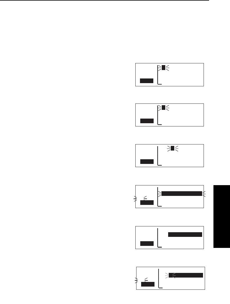
4.4.2. CREATING A WAYPOINT AT A CERTAIN
LATITUDE/LONGITUDE
It is also possible to create a user-defined waypoint by manually
entering a latitude and longitude. Let's say you wanted to create a
user waypoint over your farm at N 42°56.32', W 76°29.95'
To create a user-defined waypoint with latitude/longitude:
1. From any supplemental waypoint
(SUP) page, turn on the cursor
(B). It will flash over the first
character in the waypoint
identifier field (figure 4-79).
2. Use the right inner knob to select
the first character of the identifier
(figure 4-80). Remember that
when the cursor is on, the right
inner knob changes the character
and the right outer knob moves
the cursor around.
3. Spell out the rest of the identifier
using the right inner and outer
knobs (figure 4-81).
4. Move the cursor down to the
second line, over User Pos L/L?
(figure 4-82).
5. Press F. The display will
change to a format like
figure 4-83.
6. Use the right inner knob to select
N for north or S for south
(figure 4-84).
KLN 35A Pilot’s Guide Advanced GPS Operation
4-23 Effective Date 5/95006-08791-0000 Rev 0
Advanced GPS Operation
Chapter 4
APT VOR NDB SUP ACT NAV FPL CAL SET OTH
åå.ånm FARM USR at:
åååååå User Pos L/L?
#>Leg User Pos R/D?
CRSR Present Pos?
Figure 4-82
APT VOR NDB SUP ACT NAV FPL CAL SET OTH
åå.ånm FARM USR
åååååå _ __°__.__'
>Leg ____°__.__'
CRSR >---°To ----nm
Figure 4-83
APT VOR NDB SUP ACT NAV FPL CAL SET OTH
åå.ånm FARM USR
åååååå N __°__.__'
#>Leg ____°__.__'
CRSR >---°To ----nm
Figure 4-84
APT VOR NDB SUP ACT NAV FPL CAL SET OTH
åå.ånm LAKE USR
åååååå N 33°27.42'
>Leg W115°36.81'
CRSR >201°To 651nm
Figure 4-79
APT VOR NDB SUP ACT NAV FPL CAL SET OTH
åå.ånm F USR at:
åååååå User Pos L/L?
>Leg User Pos R/D?
CRSR Present Pos?
Figure 4-80
APT VOR NDB SUP ACT NAV FPL CAL SET OTH
åå.ånm FARM USR at:
åååååå User Pos L/L?
>Leg User Pos R/D?
CRSR Present Pos?
Figure 4-81
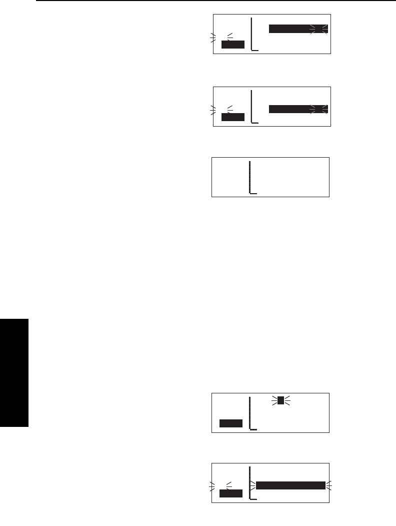
Advanced GPS Operation
4-24
Effective Date 5/95 006-08791-0000 Rev 0
Advanced GPS Operation
Chapter 4
7. Use the right outer knob to move
the cursor, and the right inner
knob to select the proper
numbers to complete the latitude
entry (figure 4-85).
8. Press F. The cursor will move
to the longitude field.
9. Enter the longitude in the same
manner as the latitude
(figure 4-86).
10. Press Fto approve this
position. The cursor will
automatically turn off
(figure 4-87).
4.4.3. CREATING A WAYPOINT REFERENCED FROM
ANOTHER WAYPOINT
The third method of creating a user-defined waypoint is as a radial
and distance from a known waypoint.
To create a user-defined waypoint using the radial/distance
method:
1. From any supplemental waypoint (SUP) page, turn on the cursor
(B). It will flash over the first character in the waypoint
identifier field.
2. Use the right inner knob to select the first character of the
identifier. Remember that when the cursor is on, the right inner
knob changes the character and the right outer knob moves the
cursor around.
3. Spell out the rest of the identifier
using the right inner and outer
knobs (figure 4-88).
4. Move the cursor down to the third
line, over User Pos R/D?
(figure 4-89).
APT VOR NDB SUP ACT NAV FPL CAL SET OTH
åå.ånm FCTRY USR at:
åååååå User Pos L/L?
>Leg User Pos R/D?
CRSR Present Pos?
Figure 4-88
APT VOR NDB SUP ACT NAV FPL CAL SET OTH
åå.ånm FCTRY USR at:
åååååå User Pos L/L?
#>Leg User Pos R/D?
CRSR Present Pos?
Figure 4-89
APT VOR NDB SUP ACT NAV FPL CAL SET OTH
åå.ånm FARM USR
åååååå N 42°56.32'
#>Leg W 76°29.95'
CRSR >---°To ----nm
Figure 4-86
APT VOR NDB SUP ACT NAV FPL CAL SET OTH
åå.ånm FARM USR
åååååå N 42°56.32'
>Leg W 76°29.95'
SUP 1 >035°To 6.7nm
Figure 4-87
APT VOR NDB SUP ACT NAV FPL CAL SET OTH
åå.ånm FARM USR
åååååå N 42°56.32'
#>Leg ____°__.__'
CRSR >---°To ----nm
Figure 4-85
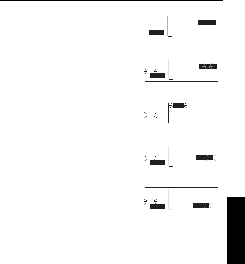
5. Press F. The display will
change to a format like
figure 4-90 with the cursor over
the reference waypoint field.
6. Use the right inner and outer
knobs to select the identifier of
the desired reference waypoint
(figure 4-91).
7. Press F. The waypoint page
for the waypoint you just entered
will be displayed (figure 4-92).
8. Press Fagain to approve the
waypoint. You will be returned to
the waypoint creation page.
9. Use the right inner and outer
knobs to select the desired radial.
Notice that you may enter the
angle down to the tenth of a
degree (figure 4-93).
10. Press Fto approve the radial.
The cursor will move to line 4.
11. Use the right inner and outer
knobs to select the desired dis-
tance from the reference
waypoint (figure 4-94).
12. Press Fto approve the dis-
tance. The cursor will
automatically be removed from
the screen.
4.5.NAVIGATION MODES
The KLN 35A has two modes of operation: En Route-Leg and En
Route-OBS. When the KLN 35A is turned on, it always "wakes up" in
the En route-Leg mode. The En Route-Leg mode is the normal
mode for en route flying. One can think of the OBS mode as similar
to VOR navigation, except it allows you to use any waypoint in the
same manner as VORs.
KLN 35A Pilot’s Guide Advanced GPS Operation
4-25 Effective Date 5/95006-08791-0000 Rev 0
Advanced GPS Operation
Chapter 4
APT VOR NDB SUP ACT NAV FPL CAL SET OTH
åå.ånm FCTRY USR
åååååå Ref: _____
>Leg Rad: ___._°
CRSR Dis: ___._nm
Figure 4-90
APT VOR NDB SUP ACT NAV FPL CAL SET OTH
åå.ånm FCTRY USR
åååååå Ref: OJC
#>Leg Rad: 313.3°
CRSR Dis: 003.7nm
Figure 4-94
APT VOR NDB SUP ACT NAV FPL CAL SET OTH
åå.ånm FCTRY USR
åååååå Ref: OJC
#>Leg Rad: ___._°
CRSR Dis: ___._nm
Figure 4-91
APT VOR NDB SUP ACT NAV FPL CAL SET OTH
åå.ånm OJC 113.00
åååååå JOHNSON CO
#>Leg N 38°50.44'
VOR 1 W 94°44.21'
Figure 4-92
APT VOR NDB SUP ACT NAV FPL CAL SET OTH
åå.ånm FCTRY USR
åååååå Ref: OJC
#>Leg Rad: 313.3°
CRSR Dis: ___._nm
Figure 4-93
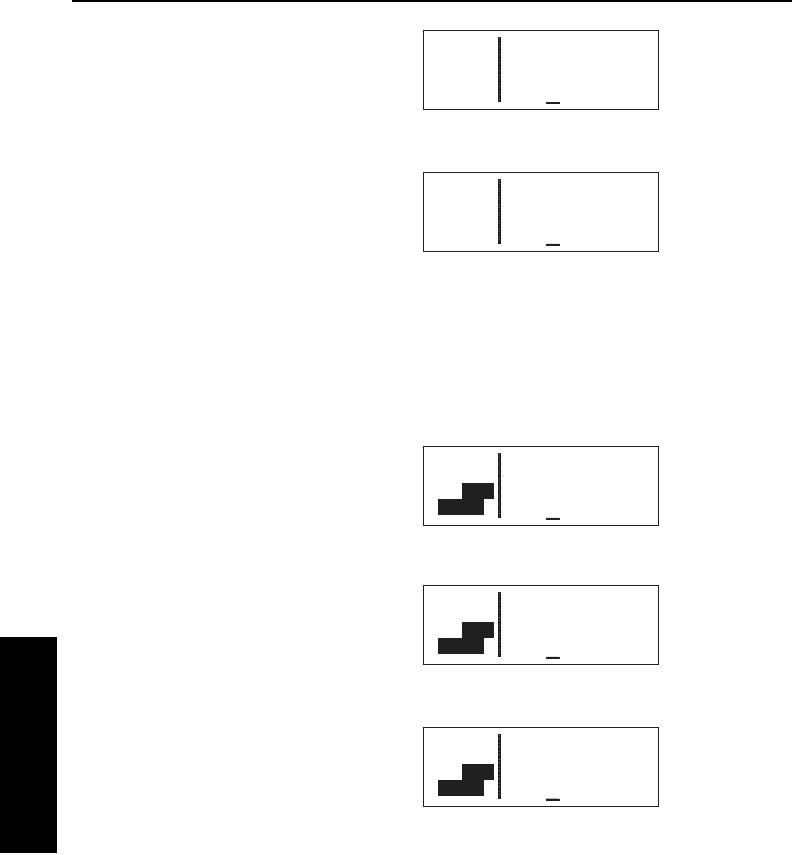
The mode is annunciated on the left
side of the screen, line 3. When in
the En Route-Leg mode, it displays
Leg (figure 4-95), and when in the
En Route-OBS mode, it displays the
selected magnetic course
(figure 4-96).
4.5.1. SELECTING THE LEG MODE OR THE OBS MODE
To change navigation modes:
1. From any page (except a message page), turn on the cursor
(B).
2. Turn the right inner knob counter
clockwise until the cursor is over
the navigation mode. In this
case, the current mode is Leg
(figure 4-97).
3. Press E. The mode will toggle
between Leg and OBS. In the
case of OBS mode, the selected
course angle will be displayed
(figure 4-98).
4. If you desire to change the
selected course while in OBS
mode, turn the right inner knob
while the cursor is over the mode
annunciation (figure 4-99).
5. Turn off the cursor (B).
4.5.2. THE EN ROUTE-LEG MODE
The following are the characteristics of the En route-Leg Mode:
1. The course deviation indicator (CDI) sensitivity is plus and minus
five nautical miles, full scale. This applies to the CDI on the
NAV 1 page as well as any external CDIs or HSIs interfaced to
Advanced GPS Operation
4-26
Effective Date 5/95 006-08791-0000 Rev 0
Advanced GPS Operation
Chapter 4
APT VOR NDB SUP ACT NAV FPL CAL SET OTH
åå.ånm ∆KICT
åååååå > ««««∑∏π«««∫
>309 TK343°
CRSR >345°To 0:50
Figure 4-99
APT VOR NDB SUP ACT NAV FPL CAL SET OTH
åå.ånm ∂∆KICT
åååååå > ««««∑∏π««««
>Leg DTK345° TK343°
CRSR >345°To 0:50
∫
Figure 4-97
APT VOR NDB SUP ACT NAV FPL CAL SET OTH
åå.ånm ∂∆ KICT
åååååå > ««««∑∏π««««
>345 TK343°
CRSR >345°To 0:50
∫
Figure 4-98
APT VOR NDB SUP ACT NAV FPL CAL SET OTH
åå.ånm ∂∆KICT
åååååå > ««««∑∏π««««
>Leg DTK345° TK343°
NAV 1 >345°To 0:50
∫
Figure 4-95
APT VOR NDB SUP ACT NAV FPL CAL SET OTH
åå.ånm ∂∆ KICT
åååååå > ««««∑∏π««««
>345 TK343°
NAV 1 >345°To 0:50
∫
Figure 4-96

the KLN 35A. If the CDI or HSI has five dots left and right of the
center position, then each dot represents one nautical mile of
deviation.
2.Navigation is provided along the great circle path between two
waypoints. As you probably know, great circle navigation is the
shortest distance between two points located on the earth's
surface. In the case of Direct To operation, the "from" waypoint
is not displayed but it is the point where Direct To operation was
initiated. The course to fly while in this mode is referred to as the
desired track (Dtk). The desired track is displayed on the NAV 1
page. To fly a great circle course between two points, the
desired track may be constantly changing. A good way to
illustrate this concept is with a world globe and a piece of string.
You can determine the great circle path between Denver,
Colorado and Manila, Philippines by stretching the string over the
globe between these two points. Notice that you would start the
flight with a northwesterly desired track, which gradually
becomes due westerly, and finally southwesterly by the time you
reach Manila. Of course, your trips with the KLN 35A will be
substantially shorter and the desired track will probably change
only a few degrees.
3.Automatic waypoint sequencing is provided during flight plan
operation. As you reach a waypoint in your flight plan, the next
leg of the flight plan automatically becomes active.
4.Turn anticipation may be utilized in flight plan operation as
described in section 4.2.2.
4.5.3. THE EN ROUTE-OBS MODE
The following are characteristics of the En Route-OBS mode.
1.(Same as item 1 for En Route-Leg mode) The course deviation
indicator (CDI) sensitivity is plus and minus five nautical miles,
full scale. This applies to the CDI on the NAV 1 page as well as
any external CDIs or HSIs interfaced to the KLN 35A. If the CDI
or HSI has five dots left and right of the center position, then
each dot represents one nautical mile of deviation.
2.The course is defined by the active waypoint and the selected
magnetic course. A course "to" or "from" the active waypoint
may be selected.
3.There is no automatic leg sequencing or turn anticipation.
KLN 35A Pilot’s Guide Advanced GPS Operation
4-27 Effective Date 5/95006-08791-0000 Rev 0
Advanced GPS Operation
Chapter 4

Advanced GPS Operation
4-28
Effective Date 5/95 006-08791-0000 Rev 0
Advanced GPS Operation
Chapter 4
4. When the active waypoint is a VOR, the published magnetic
variation for the VOR is utilized rather than the calculated
magnetic variation.
4.5.4. EFFECTS OF SWITCHING FROM EN ROUTE-OBS
MODE TO EN ROUTE-LEG MODE
The following mode transition occurs if the KLN 35A is in the En
Route-OBS mode with a TO indication and the mode is switched to
the En Route-Leg mode:
1. The waypoint that was active while in the OBS mode remains the
active waypoint when the En route-Leg mode is activated. The
system does not attempt to orient itself on a leg of the active
flight plan.
2. The selected course (Obs) that was active in the OBS mode
prior to switching to Leg mode becomes the desired track (Dtk) in
the Leg mode.
3. With the exception of #2 above, the characteristics of normal
Direct To operation apply.
4. If the active waypoint was part of the active flight plan (FPL 0),
the system will revert to normal flight plan operation once the
active waypoint is reached.
If, on the other hand, the KLN 35A is showing a FROM indication
when the mode is switched from En Route-OBS to En Route-Leg
mode, the system will immediately orient itself on the nearest leg of
the flight plan.
4.5.5. ACTIVATING A WAYPOINT WHILE IN THE EN ROUTE-
OBS MODE
While in the En route-OBS mode, you may activate another waypoint
by using the normal Direct To method or by using a second method.
This second method activates another waypoint without changing the
selected course (OBS). In other words, when the new waypoint is
activated, the D-Bar is not necessarily
recentered. In figure 4-100 the
KLN 35A is in the En Route-OBS
mode and the selected course is
149°. You have just crossed ARG
and desire to activate the next
waypoint in the flight plan, GQE,
without recentering the D-Bar.
APT VOR NDB SUP ACT NAV FPL CAL SET OTH
0.8nm ∆ARG
110kt > ««««“‘”««««
>149 TK148°
CRSR >329°To 0:00
∫
Figure 4-100

KLN 35A Pilot’s Guide Advanced GPS Operation
4-29 Effective Date 5/95006-08791-0000 Rev 0
Advanced GPS Operation
Chapter 4
To activate a waypoint in OBS mode without changing the
selected course:
1.Press D(figure 4-101). The
rules described in section 4.9,
"Direct To Operation", dictate
which waypoint identifier will be
initially displayed on the Direct To
page. Change the waypoint if
necessary.
2.Press Da second time. The
annunciation DIRECT TO
changes to ACTIVATE(figure 4-
102). Repeated presses of D
cause the annunciation to alter-
nate between DIRECT TOand
ACTIVATE. Make sure ACTIVATEis displayed.
3.If the desired waypoint is not the one that was suggested by the
KLN 35A, enter the desired identifier. Press F.
4.Press Fto approve the
waypoint page and activate the
waypoint (figure 4-103). The
selected course does not
change, therefore this method
does not center the D-Bar like a
Direct To operation does.
4.6.OPERATION OUTSIDE THE PRIMARY COVERAGE AREA
The KLN 35A's primary coverage area is from N 74°to S 60°as was
shown in figure 4-1. Navigation outside this area is automatically
referenced to true North unless a manual input of magnetic variation
is made on the SET 2 page. The same is true anytime the KLN 35A
is in the OBS mode and the active waypoint is outside the primary
coverage area. Under both of these conditions, the following
message will be displayed on the Message page:
*Magnetic Var Invalid
All Data Referenced
To True North
APT VOR NDB SUP ACT NAV FPL CAL SET OTH
åå.ånm ACTIVATE:
åååååå
#>149 GQE
CRSR
Figure 4-102
APT VOR NDB SUP ACT NAV FPL CAL SET OTH
50.1nm ∆GQE
109kt > ««««“‘∫««««
>149 TK147°
NAV 1 >148°To 0:28
Figure 4-103
APT VOR NDB SUP ACT NAV FPL CAL SET OTH
åå.ånm DIRECT TO:
åååååå
#>149 ARG
CRSR
Figure 4-101
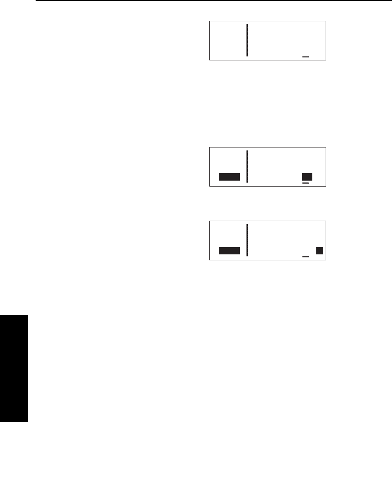
Advanced GPS Operation
4-30
Effective Date 5/95 006-08791-0000 Rev 0
Advanced GPS Operation
Chapter 4
When navigation is within the primary
coverage area, the SET 2 page does
not display magnetic variation (figure
4-104). However, under the condi-
tions stated above, a user magnetic
variation may be entered on line 4 of
the SET 2 page.
To enter the local magnetic variation manually on the SET 2
page:
1. Turn on the cursor (B).
2. Move the cursor over the
numerical field on line 4
(figure 4-105).
3. Use the right knobs to select the
magnetic variation, from 0 to 99
degrees.
4. Move the flashing part of the
cursor to the E/W (east/west) field
and select whether the magnetic
variation is easterly or westerly
(figure 4-106).
5. Press F to approve and turn the cursor (B) off.
4.7.USING THE TAKE-HOME MODE
It is very likely that the KLN 35A will become your "best friend" in the
cockpit, especially in VFR flight. As with any good friend, you may
need some time to get well-acquainted. This will allow you to utilize it
to the maximum extent. A great way to get to know the KLN 35A is
to use it outside the airplane, using what we call the "take-home
mode".
There are products available which allow you to use the KLN 35A at
your home, office, or hotel to have get-acquainted time in the take-
home mode, for instance the Commander 2000 from Lone Star
Aviation. It is also helpful to do flight planning and perform data base
updates outside the airplane, perhaps with a home personal
computer.
APT VOR NDB SUP ACT NAV FPL CAL SET OTH
åå.ånm DATE/TIME
åååååå 25 DEC 94
>Leg 1830:09 EST
CRSR Mag Var: 10°E
Figure 4-105
APT VOR NDB SUP ACT NAV FPL CAL SET OTH
åå.ånm DATE/TIME
åååååå 25 DEC 94
>Leg 1830:09 EST
CRSR Mag Var: 21°E
Figure 4-106
APT VOR NDB SUP ACT NAV FPL CAL SET OTH
åå.ånm DATE/TIME
åååååå 25 DEC 94
>Leg 1830:09 EST
SET 2 Eastern Std
Figure 4-104

For more information on the Commander 2000, or to place an order,
contact:
Lone Star Aviation Corp.
1306 Tatum Drive
Arlington, TX 76012
Phone: (817) 548-7768
FAX: (817) 261-8692
When the KLN 35A is in the take-home mode, it performs as if it is
receiving adequate satellite signals to determine its position. It
displays the latitude and longitude of its last known position or of
whatever position it is initialized to on the Setup 1 (SET 1) page (see
section 3.6, "Initialization and Time to First Fix"). In addition, a
ground speed and heading may be entered on the SET 1 page and
the KLN 35A will track a flight plan or a direct to waypoint just as if it
was actually functioning in an aircraft. Distances count down,
waypoints sequence, and the deviation bar follows the progress of
the simulated flight. Using the take-home mode is an excellent way
to learn the operation of the KLN 35A without worrying about the
engine running, other traffic, or even terrain (fortunately, these
phenomena are not simulated in the take-home mode!
KLN 35A Pilot’s Guide Advanced GPS Operation
4-31 Effective Date 5/95006-08791-0000 Rev 0
Advanced GPS Operation
Chapter 4

Advanced GPS Operation
4-32
Effective Date 5/95 006-08791-0000 Rev 0
Advanced GPS Operation
Chapter 4
This page intentionally left blank
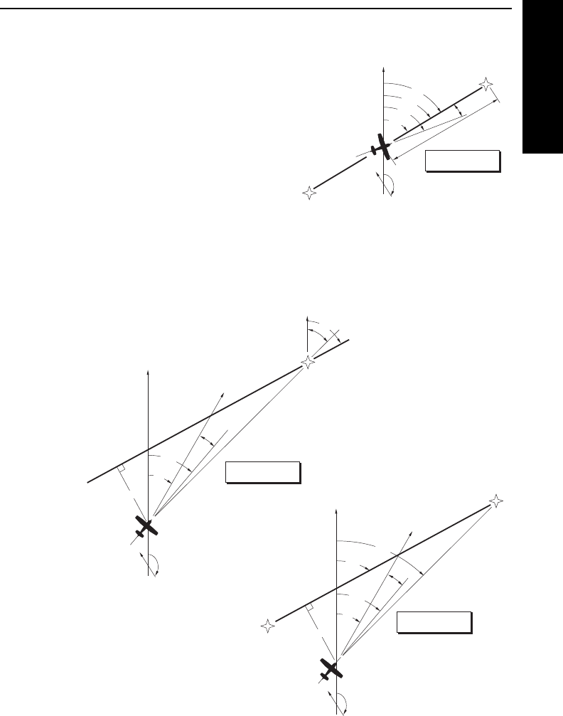
KLN 35A Pilot’s Guide Appendix
A-1 Effective Date 5/95006-08791-0000 Rev 0
Navigation Terms
Appendix A
APPENDIX A - NAVIGATION TERMS
BRG - Bearing to waypoint (degrees)
DA - Drift Angle (degrees)
DIS - Distance to waypoint (nm)
DTK - Desired Track (degrees)
OBS - Selected Course
GS - Groundspeed (nm/hr)
HDG - Heading (degrees)
POS - Present position
TK - Actual Track (degrees)
WPT - Waypoint
XTK - Cross Track Error Correction (nm)
displayed as “FLY L 2.3 nm”
ETE - Estimated Time Enroute (hrs:min)
ETA - Estimated Time of Arrival
WPT 1
WIND
POS
XTK
TK
HDG
DTK
BRG
GS
NORTH
WPT 2
DA
OFF TRACK
Enroute Leg Mode
DIS/ETE/ETA
WPT 1
WIND
POS
HDG DA
NORTH
WPT 2
DIS/ETE/ETA/GS
ON TRACK
Enroute-Leg Mode
BRG
TK
DTK
NORTH
BRG
OBS
OFF TRACK
Enroute-OBS Mode
WIND
POS
XTK
TK
HDG
GS
NORTH
ACTIVE WPT
DA
DIS/ETE/ETA

Appendix
A-2
Effective Date 5/95 006-08791-0000 Rev 0
Navigation Terms
Appendix A
This page intentionally left blank

APPENDIX B - MESSAGE PAGE MESSAGES
Adj Nav Crs to 234° — (Adjust navigation indicator course to 234°)
When this message appears, you should select the suggested
course on the HSI or CDI. When the KLN 35A is in the En Route-Leg
mode, this message occurs at the beginning of turn anticipation (prior
to reaching the active waypoint) if the upcoming course change is
greater than 5°. See section 4.2.2.
Airspace Alert
[name and type of special use airspace]
[altitude boundaries]
[responsible ATC facility] -- This message appears when the estimat-
ed time to enter a special use airspace (SUA) is approximately 10
minutes or when the distance from an area of special use airspace is
less than two nautical miles. See section 3.15.
All Wpt Remarks Used, Delete on OTH 4 Page — This message
will be displayed if you attempt to enter a waypoint remark and the
user database already contains 100 waypoint remarks.
Altitude Fail — This message will be displayed if the altitude input
becomes invalid during operation.
Battery Low: Service Required to Prevent User Data Loss —
This message will be displayed when the KLN 35A’s internal battery
is low and needs replacing at an authorized AlliedSignal service
center. The battery should be replaced within a week to prevent the
loss of all user-defined data including waypoints, airport remarks,
flight plans, etc. Typical battery life is approximately three to five
years.
Check Real Time Clock -- This message appears when a possible
fault is detected with the KLN 35A’s internal real time clock. This con-
dition does not require immediate service. Manually initialize the time
on the Initialization Page to minimize the time to first fix (see section
3.6).
Data Base Error: Publ Data Not Useable, Service Required —
This message appears if the data base fails an internal test when the
KLN 35A is turned on.
Data Base Outdated, All Data Must be Confirmed Before Use —
This message appears when the data base is out of date as a result
of a date and time entered on the SET 2 page or Self-Test page or as
a result of a pilot-entered date being overridden by a date from the
GPS receiver.
Appendix
B-1 Effective Date 5/95006-08791-0000 Rev 0
Message Page Messages
Appendix B
KLN 35A Pilot’s Guide

Appendix
B-2
Effective Date 5/95 006-08791-0000 Rev 0
Message Page Messages
Appendix B
Inside SUA
[name and type of special use airspace]
[altitude boundaries]
[responsible ATC facility] -- (Inside Special Use Airspace) This mes-
sage appears when the aircraft is inside special use airspace (SUA).
See section 3.15.
Magnetic Var Invalid All Data Referenced To True North — This
message appears when the magnetic variation is invalid due to -
operation outside of the data base magnetic variation area without
having a pilot-entered magnetic variation. See section 4.6.
No GPS Receiver Data — This message appears when the KLN
35A fails a specific internal test for the GPS receiver. This failure will
prevent the unit from providing any navigation capability.
OBS Waypoint > 200nm — (OBS mode waypoint greater than 200
nm away) This message is displayed when the KLN 35A is in the
OBS mode and the distance to the active waypoint is more than 200
nautical miles.
Other WPTs Deleted — (Other waypoints deleted) This message is
displayed whenever more than 10 waypoints used in a flight plan
(including the active waypoint) have been deleted.
Position of _______ has Changed -- This message appears when
either the latitude or the longitude of a waypoint used in a flight plan
or the active waypoint has changed by more than .33 minutes as a
result of updating the data base.
Positions of Other WPTs Have Changed -- This message appears
when the above message “ Position of _______ has Changed” would
be effective for more than ten waypoints..
RCVR HW Error: ____ -- (Receiver Hardware Error) This message
appears when the KLN 35A fails a specific internal test for the GPS
receiver. The blank will contain a numerical value which may provide
assistance to maintenance personnel.
Recycle Power to Use Valid Data Base Data -- This message
appears when the date entered on the Initialization page is before the
data base effective date and the date entered later on the SET 2
page is after the data base effective date, or vice versa. Turn the
KLN 35A off and back on so that the correct data base data is uti-
lized.

Appendix
B-3 Effective Date 5/95006-08791-0000 Rev 0
Message Page Messages
Appendix B
KLN 35A Pilot’s Guide
User Data Base Lost -- This message appears when the KLN 89(B)
determines that the internal memory backup battery is dead or that
some other internal failure has occurred which has caused user-
entered waypoints, flight plans, and waypoint remarks to be lost.
User Data Lost -- This message appears when the KLN 89 deter-
mines that the internal memory backup battery is dead or that some
other internal failure has occurred which has caused user data such
as page setups to be lost.
WPT _____ Deleted -- This message appears when a waypoint used
in a flight plan, or the active waypoint, no longer exists as a result of
updating the data base. The blank space is filled in with the waypoint
identifier. The waypoint is deleted from flight plans in which it was
used.

Appendix
B-4
Effective Date 5/95 006-08791-0000 Rev 0
Message Page Messages
Appendix B
This page intentionally left blank

KLN 35A Pilot’s Guide Appendix
C-1 Effective Date 5/95006-08791-0000 Rev 0
Scratchpad Messages
Appendix C
APPENDIX C - SCRATCHPAD MESSAGES
Scratchpad messages are temporarily displayed in reverse video in
the bottom left corner of the screen. The following are scratchpad
messages that may appear:
Active Wpt — (Active Waypoint) Appears when you attempt to
delete a user-defined waypoint on the OTH 3 page if the waypoint is
the active waypoint (the waypoint you are navigating to). Another
waypoint must be made the active waypoint before this waypoint can
be deleted from the user-defined waypoint list.
Dup Ident — (Duplicate Identifier) Appears when you select a
waypoint identifier on one of the waypoint type pages if there is more
than one waypoint of that waypoint type having the same identifier.
Invald Ent — (Invalid Entry) Appears when you attempt to enter data
which is not a valid entry. For example, trying to enter a date of 30
FEB 95.
No Act Wpt — (No Active Waypoint) Appears when you attempt to
activate the OBS mode if there is no active waypoint. To have an
active waypoint, a flight plan must be activated of a Direct To must be
initiated.
NoSuch Wpt — (No Such Waypoint) Appears when there is no
waypoint in the data base corresponding to the entered identifier on
the Supplemental Waypoint page.
Remrks Full — (Remarks Full) Appears when you attempt to create
a user-entered Airport or Supplemental Waypoint remark on the APT
5 or SUP 3 page if 100 user-entered remarks already exist. In order
to create additional airport remarks, some existing remarks must be
deleted on the OTH 4 page.
Used In Fpl — (Used in Flight Plan) Appears when you attempt to
delete a user-defined waypoint on the OTH 3 page if the waypoint is
used in a flight plan. Either this waypoint must be deleted from the
flight plan or the entire flight plan must be deleted before this
waypoint can be deleted from the user-defined waypoint list.
USR DB Full — (User Data Base Full) Appears when you attempt to
create a user-defined waypoint if the user data base already contains
250 waypoints. In order to create additional user-defined waypoints,
it will first be necessary to delete existing user-defined waypoints on
the OTH 3 page.

Appendix
C-2
Effective Date 5/95 006-08791-0000 Rev 0
Scratchpad Messages
Appendix C
This page intentionally left blank

APPENDIX D - ABBREVIATIONS
STATE ABBREVIATIONS
ABBREVIATION STATE
AK Alaska
AL Alabama
AR Arkansas
AZ Arizona
CA California
CO Colorado
CT Connecticut
DC District of Columbia
DE Delaware
FL Florida
GA Georgia
IA Iowa
ID Idaho
IL Illinois
IN Indiana
KS Kansas
KY Kentucky
LA Louisiana
MA Massachusetts
MD Maryland
ME Maine
MI Michigan
MN Minnesota
MO Missouri
MS Mississippi
MT Montana
NC North Carolina
ND North Dakota
NE Nebraska
NH New Hampshire
NJ New Jersey
NM New Mexico
NV Nevada
NY New York
OH Ohio
OK Oklahoma
KLN 35A Pilot’s Guide Appendix
D-1 Effective Date 5/95006-08791-0000 Rev 0
Abbreviations
Appendix D

STATE ABBREVIATIONS (Cont’d)
OR Oregon
PA Pennsylvania
RI Rhode Island
SC South Carolina
SD South Dakota
TN Tennessee
TX Texas
UT Utah
VA Virginia
VT Vermont
WA Washington
WI Wisconsin
WV West Virginia
WY Wyoming
CANADIAN PROVINCE ABBREVIATIONS
ABBREVIATION PROVINCE
AB Alberta
BC British Columbia
MB Manitoba
NB New Brunswick
NF Newfoundland
NS Nova Scotia
NW Northwest Territory
ON Ontario
PE Prince Edward Island
PQ Quebec
SK Saskatchewan
YK Yukon
COUNTRY ABBREVIATIONS
ABBREVIATION COUNTRY
AFG Afghanistan
AGO Angola
AIA Anguilla Isl.
ALB Albania
ANT Antarctica/Netherlands
Antilles/Aruba
Appendix
D-2
Effective Date 5/95 006-08791-0000 Rev 0
Abbreviations
Appendix D

COUNTRY ABBREVIATIONS (Cont’d)
ARE United Arab Emirates
ARG Argentina
ASM American/Western Samoa
ATG Antigua/Barbuda
AUS Australia
AUT Austria
BDI Burundi
BEL Belgium
BEN Benin
BFA Burkina Faso
BGD Bangladesh
BGR Bulgaria
BHR Bahrain
BHS Bahamas
BHU Bhutan
BLZ Belize
BMU Bermuda
BOL Bolivia
BRA Brazil
BRB Barbados
BRN Brunei
BWA Botswana
CAF Central African Republic
CHE Switzerland
CHL Chile/Easter Isl.
CHN China
CIV Ivory Coast
CMR Cameroon
CNR Canary Islands
COG Congo
COK Cook Islands
COL Colombia/San Andres
CRI Costa Rica
CSK Czechoslovakia
CUB Cuba
CYM Cayman Islands
CYP Cypress
DEU Germany
DJI Djibouti
DMA Dominica
KLN 35A Pilot’s Guide Appendix
D-3 Effective Date 5/95006-08791-0000 Rev 0
Abbreviations
Appendix D

COUNTRY ABBREVIATIONS (Cont’d)
DNK Denmark
DOM Dominican Republic
DZA Algeria
ECU Ecuador
EGY Egypt
ERI Eritrea
ESP Spain
ETH Ethiopia
FIN Finland
FJI Fiji/Tonga
FLK Falkland Islands
FRA France
GAB Gabon
GBR United Kingdom
GHA Ghana
GIB Gibraltar
GIN Guinea
GLP Guadeloupe/Martinique
GMB Gambia
GNB Guinea-Bissau
GNQ Equatorial Guinea
GPV Cape Verde
GRC Greece
GRD Grenada
GRL Greenland
GTM Guatemala
GUF French Guiana
GUY Guyana
HKG Hong Kong
HND Honduras
HTI Haiti
HUN Hungary
IDN Indonesia
IND India
IOT British Indian Ocean Territory
IRL Ireland
IRN Iran
IRQ Iraq
ISL Iceland
ISR Israel
Appendix
D-4
Effective Date 5/95 006-08791-0000 Rev 0
Abbreviations
Appendix D

COUNTRY ABBREVIATIONS (Cont’d)
ITA Italy
JAM Jamaica
JOR Jordan
JPN Japan/Okinawa
JTN Johnston Island
KEN Kenya
KHM Cambodia/Kampuchea
KIR Kiribati/Tuvalu/Phoenix I./Line I.
KNA St. Kitts/Nevis
KOR Korea
KWT Kuwait
LAO Laos
LBN Lebanon
LBR Liberia
LBY Libya/SPA Jamahiriya
LCA St. Lucia
LKA Sri Lanka
LSO Lesotho
LUX Luxembourg
MAC Macau
MAR Morocco
MDG Madagascar/Comoros/Mayotte I./Reunion
MDV Maldives
MEL Melilla
MEX Mexico
MHL Marshall Island
MID Midway Island
MLI Mali
MLT Malta
MNP Mariana Islands
MOZ Mozambique
MRT Mauritania
MSR Monserrat Isl.
MUS Mauritius
MWI Malawi
MYR Myanmar
MYS Malaysia
NCL New Caledonia
NER Niger
NGA Nigeria
KLN 35A Pilot’s Guide Appendix
D-5 Effective Date 5/95006-08791-0000 Rev 0
Abbreviations
Appendix D

COUNTRY ABBREVIATIONS (Cont’d)
NIC Nicaragua
NIU Niue Island
NLD Netherlands
NOR Norway
NPL Nepal
NRU Naura
NZL New Zealand
OMN Oman
PAC Oakland OTCA (PACIFIC)
PAK Pakistan
PAN Panama
PCI Caroline Island/Micronesia
PER Peru
PHL Philippines
PNG Papua New Guinea
POL Poland
PRI Puerto Rico
PRK Korea (Dem. Peoples Republic)
PRT Portugal/Azores/Madeira Isl.
PRY Paraguay
PYF French Polynesia/Society Isl./Tuamotu
QAT Qatar
ROM Romania
RWA Rwanda
SAU Saudi Arabia
SDN Sudan
SEN Senegal
SGP Singapore
SHN Ascension Island/St. Helena
SLB Solomon Islands
SLE Sierra Leone
SLV El Salvador
SOM Somalia
SPM St. Pierre/Miquelon
STP Sao Tome/Principe
SUR Suriname
SVK Slovakia
SWE Sweden
SWZ Swaziland
SYC Seychelles
Appendix
D-6
Effective Date 5/95 006-08791-0000 Rev 0
Abbreviations
Appendix D

KLN 35A Pilot’s Guide Appendix
D-7 Effective Date 5/95006-08791-0000 Rev 0
Abbreviations
Appendix D
COUNTRY ABBREVIATIONS (Cont’d)
SYR Syria
TCA Turks and Caicos Islands
TCD Chad
TGO Togo
THA Thailand
TTO Trinidad/Tobago (SP?)
TUN Tunisia
TUR Turkey
TWN Taiwan
TZA Tanzania
UGA Uganda
URY Uruguay
USA Baker Islands
VCT St. Vincent
VEN Venezuela
VGB Virgin Islands (U.K.)
VIR Virgin Islands (U.S.)
VNM Vietnam
VUT Vanautu
WAK Wake Island
WLF Wallis/Futuna Islands
XJ1 Kazakhstan/Kyrgyzstan
XJ2 Armenia/Georgia
XJ3 Ukraine/Moldova
XJ4 Estonia/Russia
XJ5 Belarus/Latvia/Lithuania/Russia
XJ6 Kazakhstan/Russia
XJ7 Kazakhstan/Tajikistan/Turkmenistan/
Uzbekistan
XJJ Azerbaijan
XJR Russia
YEM Yemen (Arab Republic)
YUG Yugoslavia
ZAF South Africa
ZAM Zambia
ZAR Zaire
ZWE Zimbabwe

Appendix
Effective Date 5/95 006-08791-0000 Rev 0
Abbreviations
Appendix D
ARTCC ABBREVIATIONS
ABBREVIATION ARTCC
ABQ ALBUQUERQUE
ACC ACCRA
ADD ADDIS ABABA
ADE ADELAIDE
ADN ADEN
AKM AKMOLA
AKT AKTYUBINSK
ALG ALGIERS
ALM ALMATY
AMD AMDERMA
AMM AMMAN
AMS AMSTERDAM
ANA ANADYR
ANC ANCHORAGE ARCTIC
ANC ANCHORAGE
ANC ANCHORAGE OCEANIC
ANK ANKARA
ANT ANTANANARIVO
ARK ARKHANGELSK
ASH ASHKHABAD
ASM ASMARA
AST ASTRAKHAN
ASU ASUNCION
ATF ANTOFAGASTA
ATH ATHENS
ATL ATLANTA
ATY ATYRAU
AUC AUCKLAND OCEANIC
AUC AUKLAND
BAG BAGHDAD
BAH BAHRAIN
BAK BAKU
BAL BALI
BAN BANGKOK
BAR BARCELONA
BAT BATAGAY
BEI BEIJING
BEL BELEM
BER BERMUDA
BIA BIAK
D-8

KLN 35A Pilot’s Guide Appendix
Effective Date 5/95006-08791-0000 Rev 0
Abbreviations
Appendix D
ARTCC ABBREVIATIONS (Cont’d)
BIS BISHKEK
BLA BLAGOVESHCHENSK
BLG BELGRADE
BLO BLOEMFONTEIN
BOD BODO
BOD BODO OCEANIC
BOG BOGOTA
BOM BOMBAY
BOR BORDEAUX
BOS BOSTON
BRA BEIRA
BRD BRINDISI
BRE BREMEN
BRI BRISBANE
BRL BERLIN
BRN BARNAUL
BRR BARRANQUILLA
BRS BRASILIA /UTA
BRT BEIRUT
BRU BRUSSELS
BRV BRATISLAVA
BRY BERYOZOVO
BRZ BRAZZAVILLE
BSK BRATSK
BST BREST
BUC BUCHAREST
BUD BUDAPEST
BUJ BUJUMBURA
CAI CAIRO
CAL CALCUTTA
CAM CAMPO GRANDE
CAM CENTRAL AMERICA
CAN CANARIES
CAP CAPE TOWN
CAS CASABLANCA
CHA CHAYBUKHA
CHE CHELYABINSK
CHI CHICAGO
CHO CHOKURDAKH
CHR CHERSKY
CHT CHITA

ARTCC ABBREVIATIONS (Cont’d)
CHU CHULMAN
CLE CLEVELAND
COC COCOS I
COL COLOMBO
COP COPENHAGEN
COR CORDOBA
CRT CURITIBA
CUR CURACAO
DAK DAKAR
DAK DAKAR OCEANIC
DAM DAMASCUS
DAR DARWIN
DEL DELHI
DEN DENVER
DES DAR-ES-SALAAM
DHA DHAKA
DIK DIKSON
DOR DORNOD
DSS DUSSELDORF
DUR DURBAN
DUS DUSHANBE
EDM EDMONTON
EMI EMIRATES
ENT ENTEBBE
EZE EZEIZA
FRA FRANKFURT
FW FT WORTH
GAB GABORONE
GAN GANDER DOMESTIC
GAN GANDER OCEANIC
GEN GENEVA
GEO GEORGETOWN
GUA GUANGZHOU
GUY GUAYAQUIL
HAN HANOI
HAR HARARE
HAV HAVANA
HK HONG KONG
HNR HONIARA
HOC HOCHIMINH
Appendix
D-10
Effective Date 5/95 006-08791-0000 Rev 0
Abbreviations
Appendix D

ARTCC ABBREVIATIONS (Cont’d)
HON HONOLULU CERAP
HOU HOUSTON
HOU HOUSTON OCEANIC
IND INDIANAPOLIS
IRK IRKUTSK
ISL ISLA DE PASCUA
IST ISTANBUL
JAK JAKARTA
JAX JACKSONVILLE
JED JEDDAH
JOH JOHANNESBURG
KAB KABUL
KAL KALININGRAD
KAM KAMENNYI MYS
KAN KANO
KAR KARACHI
KAT KATHMANDU
KAZ KAZAN
KC KANSAS CITY
KHA KHABAROVSK
KHR KHARKOV
KHT KHATANGA
KIE KIEV
KIG KIGALI
KIN KINGSTON
KIR KIRENSK
KIS KISANGANI
KK KOTA KINABALU
KL KUALA LUMPUR
KM KHANTY-MANSIYSK
KNS KINSHASA
KO KZYL-ORDA
KOL KOLPASHEVO
KOS KOSTANAY
KRA KRASNOVODSK
KRS KRASNOYARSK
KRV KIROV
KSH KISHINAU
KTM KHARTOUM
KUN KUNMING
KLN 35A Pilot’s Guide Appendix
D-11 Effective Date 5/95006-08791-0000 Rev 0
Abbreviations
Appendix D

ARTCC ABBREVIATIONS (Cont’d)
KUR KURGAN
LAH LAHORE
LAN LANZHOU
LAP LA PAZ
LAX LOS ANGELES
LIL LILONGWE
LIM LIMA
LIS LISBON
LJU LJUBLJANA
LON LONDON
LUA LUANDA
LUB LUBUMBASHI
LUS LUSAKA
LVO LVOV
MAD MADRID
MAG MAGADAN
MAI MAIQUETIA
MAL MALE
MAN MANILA
MAR MARSEILLE
MAU MAURITIUS
MAZ MAZATLAN
MAZ MAZATLAN OCEANIC
MDR MADRAS
MEL MELBOURNE
MEM MEMPHIS
MEN MENDOZA
MER MERIDA
MEX MEXICO
MGD MAGDAGACHI
MIA MIAMI
MIA MIAMI OCEANIC
MIL MILAN
MIN MINNEAPOLIS
MIR MIRNY
MLM MALMO
MLT MALTA
MNC MONCTON NORTHERN
MNC MONCTON SOUTHERN
MNS MANAUS
Appendix
D-12
Effective Date 5/95 006-08791-0000 Rev 0
Abbreviations
Appendix D

ARTCC ABBREVIATIONS (Cont’d)
MNT MONTERREY
MOG MOGADISHU
MON MONTREAL
MOS MOSCOW
MRM MURMANSK
MS MYS SHMIDTA
MSK MINSK
MTV MONTEVIDEO
MUN MUNICH
MUR MUREN
MUS MUSCAT
NAD NADI OCEANIC
NAH NAHA
NAI NAIROBI
NAS NASSAU
NDJ N'DJAMENA
NIC NICOSIA
NIK NIKOLAEVSK-NA-AMURE
NMY NIAMEY
NOR NORILSK
NOV NOVOSIBIRSK
NUK NUKUS
NY NEW YORK
NY NEW YORK OCEANIC
NZE NEW ZEALAND
OAK OAKLAND
OAK OAKLAND OCEANIC
ODE ODESSA
OKH OKHA
OMS OMSK
ORN ORENBURG
OSK OKHOTSK
OSL OSLO
PA PUNTA ARENAS
PAN PANAMA
PAP PORT-AU-PRINCE
PAR PARIS
PE PORT ELIZABETH
PEC PECHORA
PEM PERM
KLN 35A Pilot’s Guide Appendix
D-13 Effective Date 5/95006-08791-0000 Rev 0
Abbreviations
Appendix D

ARTCC ABBREVIATIONS (Cont’d)
PEN PENZA
PER PERTH
PET PETERSBURG
PEV PEVEK
PHN PHNOM PENH
PIA PIARCO
PM PORT MORESBY
PMT PUERTO MONTT
PRA PRAGUE
PRM PARAMARIBO /UTA
PTR PETROPAVLOVSK-KAM.
PV PORTO VELHO
PYO PYONGYANG
REC RECIFE
RES RESISTENCIA
REY REYKJAVIK
RIG RIGA
RIV RIVADAVIA
RMS REIMS
ROB ROBERTS
ROC ROCHAMBEAU
ROM ROME
ROS ROSTOV
ROV ROVANIEMI
SAI SAINSHAND
SAL SAL OCEANIC
SAM SAMARA
SAN SANTIAGO
SCO SCOTTISH
SDO SANTO DOMINGO
SEA SEATTLE
SEM SEMIPALATINSK
SEY SEYCHELLES
SHA SHANGHAI
SHE SHENYANG
SHN SHANNON
SHW SHANWICK OCEANIC
SIM SIMFEROPOL
SIN SINGAPORE
SJU SAN JUAN OCEANIC
Appendix
D-14
Effective Date 5/95 006-08791-0000 Rev 0
Abbreviations
Appendix D

ARTCC ABBREVIATIONS (Cont’d)
SKO SKOPJE
SLC SALT LAKE CITY
SLK SALEKHARD
SM SANTA MARIA OCEANIC
SMR SAMARKAND
SNA SANAA
SOF SOFIA
SON SONDRESTROM
STA STAVANGER
STO STOCKHOLM
SUK SUKHUMI
SUN SUNDSVALL
SUR SURGUT
SWI SWITZERLAND
SYD SYDNEY
SYK SYKTYVKAR
SYM SEYMCHAN
TAE TAEGU
TAH TAHITI OCEANIC
TAI TAIPEI
TAL TALLINN
TAM TAMPERE
TAS TASHKENT
TAZ TASHAUZ
TBI TBILISI
TEH TEHRAN
TEL TEL AVIV
TIK TIKSI
TIL TILICHIKI
TIR TIRANA
TOK TOKYO
TOR TORONTO
TRI TRIPOLI
TRO TRONDHEIM
TUN TUNIS
TUR TURUKHANSK
TYU TYUMEN
UFA UFA
UJU UJUNG PANDANG
ULA ULAANBAATAR
KLN 35A Pilot’s Guide Appendix
D-15 Effective Date 5/95006-08791-0000 Rev 0
Abbreviations
Appendix D

Appendix
D-16
Effective Date 5/95 006-08791-0000 Rev 0
Abbreviations
Appendix D
ARTCC ABBREVIATIONS (Cont’d)
UND UNDERHAAN
URA URALSK
URU URUMQI
VAN VANCOUVER
VAR VARNA
VEL VELIKIYE LUKI
VIE VIENNA
VIL VILNIUS
VLA VLADIVOSTOK
VLO VOLOGDA
VNT VIENTIANE
VOL VOLGOGRAD
VRK VORKUTA
WAR WARSAW
WAS WASHINGTON
WEL WELLINGTON
WIN WINNIPEG
WND WINDHOEK
WUH WUHAN
YAK YAKUTSK
YAN YANGON
YEK YEKATERINBURG
YEN YENISEYSK
YER YEREVAN
YS YUZHNO-SAKHALINSK
ZAG ZAGREB
ZHK ZHEZKAZGAN
ZUR ZURICH
ZYR ZYRYANKA

OTHER ABBREVIATIONS USED ON KLN 35A PAGES
AAirport waypoint
A/C Aircraft
ACQ Acquisition
ACT Active flight plan waypoints
ADJ Adjust
AKD Alaska Daylight Time
AKS Alaska Standard Time
ALRT Alert
ALT Altitude
APT Airport
ATD Atlantic Daylight Time
ATS Atlantic Standard Time
BARO Barometric
BRG Bearing
CAL Calculator
CAS Calibrated Airspeed
CDT Central Daylight Time
CHAR Character
CL B Class B Airspace
CL C Class C Airspace
CRS Course
CRSR Cursor
CST Central Standard Time
CTA Control Area
DB Data base
DEGRD Degraded navigation
DEN Density Altitude
DIS Distance
DNGR Danger Area
DTK Desired track
DUP Duplicate
E East
EDT Eastern Daylight Time
ELE Elevation
ENT Enter
EST Eastern Standard Time
ETA Estimated time of arrival
ETE Estimated time en route
FAILR Failure of receiver
FPL Flight plan
KLN 35A Pilot’s Guide Appendix
D-17 Effective Date 5/95006-08791-0000 Rev 0
Abbreviations
Appendix D

OTHER ABBREVIATIONS (Cont’d)
FR From
GDT Greenland Daylight Time
GS Groundspeed
GST Greenland Standard Time
HAD Hawaii Daylight Time
HAS Hawaii Standard Time
HDG Heading
HLT Health of space vehicle signal
IDENT Identifier
IND Indicated
INIT Initialization
KT Knots
L Left
MAG VAR Magnetic variation
MDT Mountain Daylight Time
MSG Message
MST Mountain Standard Time
N NDB waypoint
N North
NAV Navigation
NAV A Navigation with altitude aiding
NAV D Navigation with data collection
NM Nautical miles
OBS Omni bearing selection
ORS Operational Revision Status
OTH Other
P.POS Present position
PDT Pacific Daylight Time
POS Position
POSN Position
PRES Present
PROH Prohibited Area
PRS Pressure Altitude
PST Pacific Standard Time
PUB Published
PWR Power
RAD Radial
RCVR Receiver
REF Reference
REQ Required
Appendix
D-18
Effective Date 5/95 006-08791-0000 Rev 0
Abbreviations
Appendix D

KLN 35A Pilot’s Guide Appendix
D-19 Effective Date 5/95006-08791-0000 Rev 0
Abbreviations
Appendix D
OTHER ABBREVIATIONS (Cont’d)
RES Reserve fuel
REST Restricted Area
S South
S Supplemental waypoint
SDT Samoa Daylight Time
SET Setup
SNR Signal-to-noise ratio
SST Samoa Standard Time
SUA Special Use Airspace
SUP Supplemental
SV Space vehicle
SW Software
TAS True Airspeed
TEMP Temperature
TK Actual track
TMA Terminal Area
TOT Total
TRSA Terminal Radar Service Area
U User-defined waypoint
USR User-defined waypoint
UTC Coordinated Universal Time (Zulu)
V VOR waypoint
W West
WPT Waypoint
Z Zulu time

Appendix
D-20
Effective Date 5/95 006-08791-0000 Rev 0
Abbreviations
Appendix D
This page intentionally left blank

APPENDIX E - LAT/LON CONVERSIONS
The KLN 35A utilizes latitude and longitude expressed in degrees,
minutes, and hundredths of a minute. You may occasionally see a
document expressing latitude and longitude in degrees, minutes, and
seconds. This table may be used to convert seconds to hundredths
of a minute.
SECONDS (”) HUNDREDTHS OF A MINUTE (’)
00 .00
01 .02
02 .03
03 .05
04 .07
05 .08
06 .10
07 .12
08 .13
09 .15
10 .17
11 .18
12 .20
13 .22
14 .23
15 .25
16 .27
17 .28
18 .30
19 .32
20 .33
21 .35
22 .37
23 .38
24 .40
25 .42
26 .43
27 .45
28 .47
29 .48
30 .50
31 .52
32 .53
KLN 35A Pilot’s Guide Appendix
E-1 Effective Date 5/95006-08791-0000 Rev 0
Lat/Lon Conversions
Appendix E

LAT/LON CONVERSIONS (Cont’d)
SECONDS (”) HUNDREDTHS OF A MINUTE (’)
33 .55
34 .57
35 .58
36 .60
37 .62
38 .63
39 .65
40 .67
41 .68
42 .70
43 .72
44 .73
45 .75
46 .77
47 .78
48 .80
49 .82
50 .83
51 .85
52 .87
53 .88
54 .90
55 .92
56 .93
57 .95
58 .97
59 .98
For example:
35° 46’ 24” is the same as 35° 46.40’
32° 15’ 58” is the same as 32° 15.97’
Appendix
E-2
Effective Date 5/95 006-08791-0000 Rev 0
Lat/Lon Conversions
Appendix E

KLN 35A Pilot’s Guide Appendix
F-1 Effective Date 5/95006-08791-0000 Rev 0
GPS Primer
Appendix F
APPENDIX F— GPS PRIMER
BACKGROUND
The Global Positioning System (GPS) is a satellite-based navigation
system that was originally conceived and implemented by the United
States Department of Defense (DoD). The system is, however, avail-
able to all civilian users free of charge. GPS provides extremely
precise position, velocity, and time information.
The satellites are not geosynchronous, as is the case with many
weather and television satellites. That is, each satellite is not above a
fixed spot on the Earth all the time, but rather is continuously moving
across the sky. In fact, each satellite completely orbits the Earth two
times per day.
The Department of Defense imposes an intentional accuracy degra-
dation of the GPS system. This degradation is known as Selective
Availability (SA). When SA is active, only U.S. military users have
access to full GPS accuracy. For civilian users, position accuracy is
degraded to no worse than 100 meters. At the time of this writing,
Selective Availability is on (and therefore accuracy is degraded) near-
ly 100% of the time.
GPS POSITION DETERMINING CONCEPT
The technique used to determine position is fundamentally very sim-
ple. The complicated part is accounting for and correcting all the
possible errors in the position.
The GPS receiver is able to determine the time it takes a radio signal
to travel from the satellite to the GPS antenna. Since this radio signal
travels at the speed of light (approximately 186,000 statute miles per
second), the time delay can very easily be used to determine the
receiver’s distance from a given satellite. If measurements are taken
from four satellites (or three satellites and an input from an aircraft
altimeter), the receiver can identify its position very precisely.
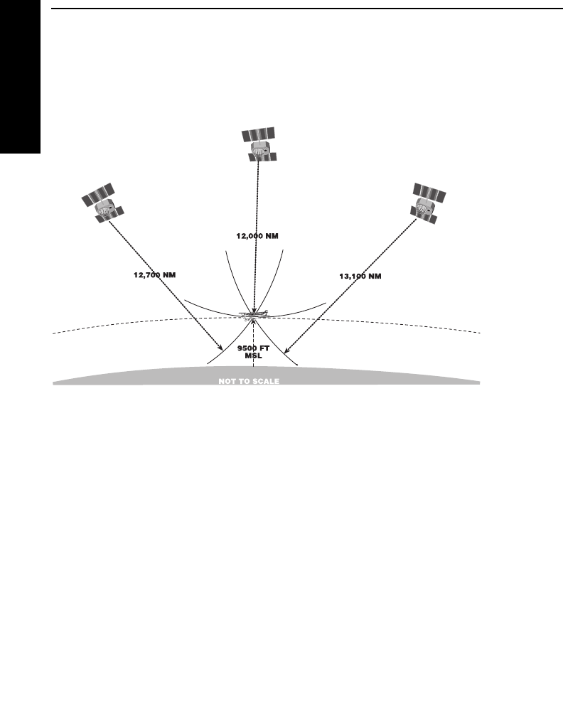
Appendix
F-2
Effective Date 5/95 006-08791-0000 Rev 0
GPS Primer
Appendix F
For example, the GPS receiver might determine that it is exactly
12,000 miles from satellite A, 12,700 miles from satellite B, and
13,100 miles from satellite C. At the same time, the aircraft’s encod-
ing altimeter might be indicating an altitude of 9,500 feet MSL. There
is only one point in space that satisfies these four measurements.
GPS DATA SIGNALS
Two of the primary types of signals that the GPS satellites broadcast
are almanac and ephemeris data. These signals enable the GPS
receiver to quickly lock on to the satellites in view. Otherwise, the
receiver would have to look for each of the 24 satellites to determine
which ones could be used.
Almanac data is very crude data which describes the approximate
orbital position of the satellites. Each of the 24 satellites transmits the
almanac data for all satellites, so a GPS receiver has only to listen to
one satellite in order to know which satellites are “visible” (in the sky)
at that particular time. Almanac data is good for about six months, so
when you turn the receiver off, then back on a month later, it will
know what satellites to look for.
Ephemeris data is very precise data which each satellite transmits to
tell the GPS receiver exactly where it is and what its orbital parame-
ters will be for about the next four hours. Each satellite transmits its
own unique ephemeris data.

KLN 35A Pilot’s Guide Appendix
F-3 Effective Date 5/95006-08791-0000 Rev 0
GPS Primer
Appendix F
GPS SYSTEM SEGMENTS
The GPS system is composed of three segments: the Space
Segment, the Control Segment, and the User Segment.
The Space Segment consists of the 24 NAVSTAR satellites which
orbit the earth at an altitude of 10,898 nautical miles. The satellite
orbits are very precisely planned so that the entire surface of the
earth may use the GPS system 24 hours a day, every day. There
are almost always more than six satellites in view from anywhere on
Earth.
The Control Segment consists of a network of ground-based monitor-
ing and control stations. The Master Control Station is located in
Colorado Springs, Colorado. All satellite data which is collected by
the other ground stations is assimilated and analyzed at Colorado
Springs. Based on these analyses, ephemeris updates (such as sys-
tem clock corrections) are sent (uplinked) to the satellites through
radio transmitters at the ground stations. These ground stations are
located at Kwajalein (west of Hawaii in the central Pacific Ocean),
Diego Garcia (in the Indian Ocean), and Ascension (in the south
Atlantic Ocean).
As an owner of a GPS system, you can now claim to be a certified
member of the GPS User Segment! GPS has many users and uses,
and more are being dreamed up all the time. Not only are aircraft
using GPS navigation, so are military systems and personnel,
boaters, hikers, and surveyors. Personal automobiles and transport
trucks use Intelligent Transportation Systems, or ITS, to find their
destinations, and track their movements. Some biologists attach
GPS receivers to animals to monitor their movement and migration
patterns. Geologists even use GPS to track the movement of glaci-
ers and to analyze plate tectonics (movements of the Earth’s crust).
What an exciting new technology as we move into the 21st Century!

GPS XPRESS™ CARD 8-CHANNEL RECEIVER
The KLN 35A uses an AlliedSignal GPS receiver known as the GPS
Xpress™ card. It was dubbed this way because it is identical in size
to an everyday credit card, and its faster acquisition time than
previous single-channel designs. The GPS receiver has eight paral-
lel channels, which means each channel can continuously track a
satellite, for continuous tracking of up to eight GPS satellites. The
parallel receiver design has several advantages:
•Excellent performance during high dynamic conditions (high
velocity and/or acceleration).
•Improved position acquisition time (also known as time-to-first-
fix) over single-channel designs.
• Improved position accuracy.
Appendix
F-4
Effective Date 5/95 006-08791-0000 Rev 0
GPS Primer
Appendix F

INDEX
A
Abbreviations
Airport names 3-26, 3-45
ARTCC/FIR D-8
Canadian Province D-2
Communication frequencies 3-48
Country D-2
GPS receiver state 3-3-58
Other abbreviations D-17
State D-1
Time zones 3-4
ACT (Active waypoint pages) 4-10
Activating
Numbered flight plan 4-4
Waypoint in the OBS mode 4-28
Actual track 3-38, 3-43, A-1
Adding waypoints to flight plan 4-2
Airport data
Bearing and distance 3-46
City, State (or country) 3-45
Communication frequencies 3-48
Identifier 2-4
Latitude/longitude 3-46
Military 3-45
Name 3-45
Nearest 3-27, 3-46
Remarks 3-50
Runway information 3-47
Airport waypoint pages 3-45
Airspeed 4-20, 4-21
Alerting
Special Use Airspace (SUA) 3-62
Waypoint 3-35, 4-9
Almanac 3-18, 3-58, F-2
Altitude
Density 4-19
Indicated 3-2, 4-18
Input 1-1, 3-63
Pressure 3-63, 4-18, 4-19, 4-20
Annunciators, remote 3-62
Antenna 1-1
APT 1 page 3-45
KLN 35A Pilot’s Guide Index
I-1 Effective Date 5/95006-08791-0000 Rev 0
Index

APT 2 page 3-46
APT 3 page 3-47
APT 4 page 3-48
APT 5 page 3-50
ARTCC (Center)
Abbreviations D-8
Frequencies 3-32
AUTO map scale 3-42
Autopilot 1-1
B
Baro set 3-2, 3-63
Battery 2-7
Bearing to waypoint 3-36, 3-38, 3-45
C
CAL 1 page 4-14
CAL 2 page 4-16
CAL 3 page 4-18
CAL 4 page 4-19
CAL 5 page 4-20
CAL 6 page 4-20
Canadian province abbreviations D-2
Cancel Direct To operation 3-35, 4-12
CDI
External 1-1
Internal 3-36
Characters
“>“ 3-16
“→” 3-36, 4-8
“*” 3-59
“+” 3-8
City of airport 3-45
Clear button 3-10, 3-16
Communication frequencies
Airports 3-49
Centers 3-32
Flight Service Stations 3-31
Computer data base, updating 2-5
Controls 3-0
Country abbreviations D-2
Coverage area
Data base 2-0
GPS 3-1, 4-29
Index
I-2
Effective Date 5/95 006-08791-0000 Rev 0
Index

Change first waypoint identifier character 3-14
Creating
Flight plans 4-1
User waypoint at known latitude/longitude 4-23
User waypoint at present position 4-22
User waypoint from another waypoint 4-24
Crosstrack distance 3-36, A-1
CRSR button 3-10
CTA 3-49
Cursor 3-10
Cyclic field (>) 3-16
D
Data base
Airports 3-45
Contents 2-1
Functions 2-1
Geographical regions 2-0
ICAO identifiers 2-3
NDBs 3-52
PC interface kit 2-4
Subscriptions and update options 2-8
Updating 2-4, 2-7
User waypoints 3-53
VORs 3-51
Data entry 3-12
Date and time 3-3, 3-55
Display format 3-7
Default first waypoint identifier character 3-14
Deleting
Airport and user waypoint remarks 3-61
Direct To operation 3-35, 4-12
Flight plans 4-7
User waypoints 3-60
Waypoints from flight plan 4-6
Departure time 3-40
Desired track (DTK) 3-38, 3-41, 4-4, 4-12, A-1
Direct To operation
Canceling Direct To 3-35, 4-12
NAV 1 page in Direct To 3-34, 3-36
Procedures 3-32
Recenter D-bar 3-35
Using with flight plan operation 4-11
Waypoint alerting 3-35
KLN 35A Pilot’s Guide Index
I-3 Effective Date 5/95006-08791-0000 Rev 0
Index

Disable turn anticipation 4-10
Distance 3-7, A-1
Duplicate waypoint page 3-15
E
Editing
Flight plans 4-5, 4-6
Emergency nearest airport 3-27
Enter (ENT) button and prompt 3-9, 3-10
Entering
Airport remarks 3-50
User waypoint remarks 3-54
Waypoint identifiers 3-13
Estimated position error (EPE) 3-58
Erase; See Delete
ETA (Estimated time of arrival) 3-40
ETE (Estimated time en route) 3-38, 3-41
F
Flight plans
Activating 4-4
Active flight plan 4-1, 4-8
Adding waypoints 4-2
Creating 4-1
Deleting 4-7
Deleting waypoints 4-6
Direct to operation in flight plans 4-11
Editing 4-5, 4-6
Flight plan 0 (active flight plan) 4-1, 4-8
Inverting 4-5
Operating from the active flight plan 4-8
Rules for use of 4-8
Storing active flight plan as a numbered flight plan 4-7
Viewing distance, ETE, ETA, and DTK of
flight plan waypoints 4-4, 4-12
Viewing waypoint pages for active flight plan 4-10
Flight time 3-40
FPL 0 page 4-8
FPL 1-9 pages 4-1
Frequencies for airport communications 3-48
FSS frequencies 3-31
Fuel planning 4-16
Index
I-4
Effective Date 5/95 006-08791-0000 Rev 0
Index

G
GPS
Coverage area 3-1
Panel controls 3-0
Receiver status 3-57, 3-58
Theory of operation F-1
Groundspeed 3-8
H
How-To Index iv
HSI 1-1
I
ICAO identifiers 2-3
Initial position 3-5, 3-19
Initialization 3-2, 3-18
Initialization page 3-3
Interfaces 1-1
Inverting flight plans 4-5
J
K
KA 92 antenna 1-1
L
Latitude/longitude conversion table E-1
Leg mode 4-35
Lighting, runway 3-48
Locator outer marker (LOM) 3-55
M
Magnetic variation 4-26
Map display 3-40
Message (MSG) button, prompt, and page 3-9, 3-10, 3-17
Modes, navigation
OBS 4-36
Leg 4-35
Selecting Leg or OBS mode 4-35
KLN 35A Pilot’s Guide Index
I-5 Effective Date 5/95006-08791-0000 Rev 0
Index

N
Name of navaid or airport 3-45, 3-51, 3-52
NAV 1 page 3-36
NAV 2 page 3-39
NAV 3 page 3-40
NAV 4 page 3-40
NAV/GPS switch/annunciator 3-62
Navigation map display 3-40
Navigation pages
Moving map (NAV 4 page) 3-40
Present position (NAV 2 page) 3-39
Primary navigation (NAV 1 page) 3-36
Times relating to navigation (NAV 3) 3-40
Navigation terminology A-1
NDB 1 page 3-52
NDB 2 page 3-52
NDB data
Bearing and distance 3-52
Frequency 3-52
Identifier 3-52
Latitude/longitude 3-52
Name 3-52
Nearest 3-27
Nearest
Centers 3-32
Flight Service Stations 3-31
Special Use Airspace 3-29
Waypoints 3-27
O
OBS mode 4-27
Operating from active flight plan 4-8
ORS (Operational Revision Status) Cover, 3-2
OTH 1 page 3-57
OTH 2 page 3-59
OTH 3 page 5-60
OTH 4 page 3-61
OTH 5 page 3-61
P
Page number on display 3-8
Page organization 3-9
Page selection 3-10
PC interface kit 2-4
Index
I-6
Effective Date 5/95 006-08791-0000 Rev 0
Index

PC requirements for updating data base 2-4
Plus sign (+) meaning 3-8
Prefixes for airport identifiers 2-3
Present position 3-7, 3-39
Q
R
Radial from a waypoint 3-38, 3-39
Receiver status 3-57, 3-59
Remarks
Airport page 3-50
User waypoint page 3-54
Runway information 3-47
S
Sample trip 3-65
Satellite status 3-59
Scanning waypoint names 3-23
Scratchpad messages 3-9
Screen organization 3-7
Selected course, See OBS mode
Selecting
Waypoints 3-21, 3-22, 3-23, 3-24
Self-test 3-2
SET 1 page 3-19
SET 2 page 3-55
SET 3 page 2-4
SET 4 page 4-10
SET 5 page 3-14
SET 6 page 3-28
SET 7 page 3-64
SET 8 page 3-63
Set date and time 3-3, 3-55
Simulator (Take-Home mode) 4-30
Sneak Preview of operation ii
SNR (Signal-to-noise ratio) 3-59
Software status 3-61
Special use airspace 3-29, 3-62
State abbreviations D-1
SUP 0 page 3-53
SUP 1 page 3-53
SUP 2 page 3-54
SUP 3 page 3-54
KLN 35A Pilot’s Guide Index
I-7 Effective Date 5/95006-08791-0000 Rev 0
Index

Surface, runway 3-48
System components 1-1, 1-2
T
Take-Home mode 4-30
Take-Home warning page 3-2
Time
Actual 3-3, 3-40, 3-55
Departure 3-40
ETA 3-40
ETE 3-38, 3-41
Flight 3-40
Setting 3-5, 3-55
Time to first fix 3-18
Time zones 3-4
TMA 3-49
To/From indicator 3-37
Track; See Actual Track
True airspeed 4-20, 4-21
Turn anticipation 4-9
Turn-on 3-1
Turn-on page 3-2
Trip planning 4-14, 4-16
U
Updating the data base 2-3
User waypoints 3-53, 3-60
UTC; See Time zones
V
VOR 1 page 3-51
VOR 2 page 3-51
VOR data
Bearing and distance 3-51
Frequency 3-51
Identifier 3-51
Latitude/longitude 3-51
Magnetic station declination 3-51
Map display of 3-44
Name 3-51
Nearest 3-27
Index
I-8
Effective Date 5/95 006-08791-0000 Rev 0
Index

W
Waypoint alerting 3-35, 4-10
Waypoint identifier entry 3-13
Waypoint identifiers 2-3
Waypoint pages
Active waypoint 4-10
Airport 3-45
NDB 3-52
Selecting waypoint pages 3-21, 3-22, 3-23, 3-24
User-defined waypoint/SUP 3-53
VOR 3-51
Waypoint scanning window 3-44
Waypoints
Adding to flight plan 4-2
Creating user waypoint 4-21
Deleting from flight plan 4-6
Deleting user waypoint 3-60
Duplicate 3-15
“From” and “To” waypoints 3-36, 4-8
Selecting and scanning 3-21, 3-22, 3-23, 3-24
Viewing user waypoints 3-60
Viewing waypoint in active flight plan (FPL 0) 4-10
Wind 4-20
X
Y
Z
KLN 35A Pilot’s Guide Index
I-9 Effective Date 5/95006-08791-0000 Rev 0
Index

Index
I-10
Effective Date 5/95 006-08791-0000 Rev 0
Index
This page intentionally left blank
