007 0813 060
User Manual: 007-0813-060
Open the PDF directly: View PDF ![]() .
.
Page Count: 264 [warning: Documents this large are best viewed by clicking the View PDF Link!]

FDDIXPress™ Administrator’s Guide
Document Number 007-0813-060

FDDIXPress™ Administrator’s Guide
Document Number 007-0813-060
CONTRIBUTORS
Written by Carlin Otto and Susan Thomas
Illustrated by Carlin Otto
Production by Kirsten Johnson
Engineering contributions by Paul Reilly, Vernon Schryver, Premkumar Thoppae,
and Jong Kim
Special acknowledgement to Wendy Ferguson, whose FDDI documentation
provided inspiration and a starting point.
St Peter’s Basilica image courtesy of ENEL SpA and InfoByte SpA. Disk Thrower
image courtesy of Xavier Berenguer, Animatica
© 1996, Silicon Graphics, Inc.— All Rights Reserved
The contents of this document may not be copied or duplicated in any form, in whole
or in part, without the prior written permission of Silicon Graphics, Inc.
RESTRICTED RIGHTS LEGEND
Use, duplication, or disclosure of the technical data contained in this document by
the Government is subject to restrictions as set forth in subdivision (c) (1) (ii) of the
Rights in Technical Data and Computer Software clause at DFARS 52.227-7013
and/or in similar or successor clauses in the FAR, or in the DOD or NASA FAR
Supplement. Unpublished rights reserved under the Copyright Laws of the United
States. Contractor/manufacturer is Silicon Graphics, Inc., 2011 N. Shoreline Blvd.,
Mountain View, CA 94043-1389.
Silicon Graphics, the Silicon Graphics logo, and IRIX are registered trademarks and
Onyx, CHALLENGE, Crimson, FDDIXPress, FDDIVisualyzer, Indigo, Indy, and
Indigo2 are trademarks of Silicon Graphics, Inc. ST is a registered trademark of AT&T.
UNIX is a registered trademark in the United States and other countries, licensed
exclusively through X/Open Company, Ltd.

iii
Table of Contents
List of Figures vii
List of Tables ix
Introduction xi
Audience xii
Typographical Conventions xii
Additional Reading xiii
IRIX Operating System Manuals xiii
Networking Manuals xiii
FDDI Station and Ring Management Manuals xiii
ANSI and ISO Documents for FDDI xiv
Product Support xv
1. Introducing FDDI 1
FDDI Features 1
FDDI Standard 2
Physical Layer Medium Dependent Protocol 5
Physical Layer Protocol 5
Media Access Control Protocol 5
Station Management Protocol 6
FDDI Ring 6
FDDI Devices 8
Dual Attach Station 9
Single Attach Station 10
Concentrators 10
Optical Bypass Switch 11

iv
Table of Contents
How FDDI Works 12
Operational Ring 12
Fixing a Broken Ring 12
Optical Bypass Switch 14
Transmitting and Receiving on the Ring 15
Multiprotocol Networking With FDDI 15
2. Configuring FDDIXPress Software 17
FDDIXPress Package 17
Installing FDDIXPress 17
Number Assignment to Interfaces 18
Overview 18
Number Assignment for CHALLENGE M 19
Number Assignment for CHALLENGE and Onyx 19
Number Assignment for Octane, Origin200, Origin 2000, and O2 21
Default Configurations 22
Quick and Easy Configuration Instructions 24
FDDI as the Primary Interface and Ethernet as Secondary 24
FDDI as the Secondary Interface and Ethernet as Primary 25
FDDI as the Only Network Interface 27
Complete and Complex Configuration Information 28
Prepare for Configuration 29
Network Connection Names and IP Addresses 31
Configure the Station’s Network Interfaces 33
Build Configuration Changes Into the System 40
Install the FDDI Board 41
Configure the Environment for User Friendliness and Safety
(Optional) 42
Verifying the FDDI Connection 47
3. Managing Your FDDI Station and Ring 51
Station Management Commands 51
Verifying the Connection to a Station 53
Listing the Stations on the Ring 54

Table of Contents
v
Displaying SMT Information for a Remote Station 55
Display the SMT Version 55
Display a Station’s Configuration Information 56
Recognizing Faults on the FDDI Ring 57
Monitoring a Station’s FDDI Status 60
Display Kernel and SMT Daemon Statistics 63
Display SMT Information (MIB) 65
Displaying and Configuring Network Interface Information 67
Display the Configuration 67
Change the Configuration 69
Verifying a Station’s PCM Functionality 71
Removing a Station From the FDDI Ring 72
Temporarily Disable Any Station’s FDDI Interface 73
Remove a Device Attached to a Concentrator 73
Removing a DAS That Has an Optical Bypass Switch 74
Remove a DAS Without an Optical Bypass Switch 76
Removing FDDIXPress 78
4. Troubleshooting 79
General Advice 79
Checking Physical Connections 80
Recognition of Board by Software 80
Check Cables and Connectors 83
Cable Lengths 86
Status Indicators and Symptoms 87
Link-Level Errors 87
Token Count Not Incrementing 87
Too Many Claims or Beacons 88
Ring Is Wrapped 88
High Rate of Packet Loss 90
Cannot Communicate With Other Stations 90
Current Neighbor’s Address Is Zero 93
Ring Is Not Wrapped and Token Count Increments But smtping
Does Not Work 93
System Does Not Load Miniroot or Boot From the Network 94

vi
Table of Contents
A. Error Messages 95
How Messages Are Listed 95
SMT Error Messages 97
xpi Driver Error Messages 149
ipg Driver Error Messages 157
rns Driver Error Messages 161
B. smtstat Reports 167
MAC Status Report 169
Port Status Report 174
Ring Management Status Report 181
Configuration Information Report 185
Neighbor Information Report 189
SMT Information Report 192
C. Configuring the SMT Daemon and the
FDDIXPress Driver 197
Configuring the SMT Daemon 197
Station Section 199
Board Sections 205
MAC Parameters 207
PHY Parameters 212
Configuring the FDDIXPress Driver 218
D. Man Pages 219
Index 241

vii
List of Figures
Figure 1-1 FDDI as Related to the OSI Model 3
Figure 1-2 FDDI Components of FDDIXPress and an FDDI Board 4
Figure 1-3 Simple Token Ring 7
Figure 1-4 A Basic FDDI Ring 8
Figure 1-5 Connection of DAS Ports to Primary and Secondary Rings 9
Figure 1-6 FDDI Ring With Concentrators 11
Figure 1-7 Wrapping the Ring 13
Figure 1-8 Connection of DAS Ports at Points Where Ring Is Wrapped 13
Figure 1-9 A Fragmented Ring 14
Figure 1-10 FDDI With an Ethernet Network 16
Figure 2-1 Displaying Available Interfaces With netstat -in 34
Figure 2-2 Screen Display for /usr/etc/netstat -ia Command 44
Figure 2-3 Displaying Broadcast Address 45
Figure 2-4 An Example of the hinv Display 48
Figure 3-1 smtping Display 53
Figure 3-2 smtring Display 54
Figure 3-3 Ring Created From smtring Display 55
Figure 3-4 smtinfo -c Display 56
Figure 3-5 Fault Isolation and Ring Wrap 58
Figure 3-6 Fragmented Ring 59
Figure 3-7 smtstat Display 60
Figure 3-8 smtstat -s Display: General Report Format 66
Figure 3-9 smtconfig Display 68
Figure 4-1 Cable-to-Cable Connections 84
Figure 4-2 Correct Cable Connections 84
Figure 4-3 Direction Indicators With Media Interface Connector 85
Figure A-1 Error Message Format in the /var/adm/SYSLOG File 96

viii
List of Figures
Figure A-2 Information Not Included in Alphabetized List of xpi Messages 150
Figure A-3 Information Not Included in Alphabetized List of rns Messages 161
Figure B-1 MAC Status Report 169
Figure B-2 Port Status Report (for a Dual Ring DAS) 174
Figure B-3 Ring Management Status Report 181
Figure B-4 Configuration Information Report 185
Figure B-5 Neighbor Information Report 189
Figure B-6 SMT Information Report 192
Figure C-1 Outline of smtd.conf File 198
Figure C-2 smtd.conf: Station Section 199
Figure C-3 Station ID 202
Figure C-4 smtd.conf: Board Sections 206
Figure C-5 smtd.conf: MAC Parameters 208
Figure C-6 smtd.conf: PHY Parameters 213
Figure Gl-1 Canonical Order 222
Figure Gl-2 FDDI Order 226
Figure Gl-3 FDDI Frame 227
Figure Gl-4 FDDI Token 238
Figure Gl-5 Tree Topology 239
Figure Gl-6 Wrap 240

ix
List of Tables
Table 1-1 FDDI versus Ethernet and Token Ring 1
Table 2-1 Number Assignment for FDDIXPress Network Interfaces 18
Table 2-2 Number Assignments for Network Interfaces on CHALLENGE
and Onyx Platforms 20
Table 2-3 Default Network Interface Configuration 22
Table 2-4 Default Network Interface Parameters 23
Table 3-1 FDDIXPress (SMT) Commands 52
Table 3-2 Information Displayed by smtinfo -c 57
Table 3-3 smtstat Report Fields 61
Table 3-4 smtstat -v Kernel Statistics 63
Table A-1 Reason Codes Used in Error Messages 120
Table B-1 smtstat Report Field 168
Table B-2 MAC Status, Left Column 170
Table B-3 MAC Status, Right Column 172
Table B-4 Port Status, Left Column 175
Table B-5 Port Status, Right Column 178
Table B-6 Port Status, Bottom Section 179
Table B-7 Ring Management Status, Left Column 182
Table B-8 Ring Management Status, Right Column 183
Table B-9 Ring Management Status, Bottom Section 184
Table B-10 Configuration Information, Top Section 186
Table B-11 Configuration Information, Bottom Left Column 187
Table B-12 Configuration Information, Bottom Right Column 188
Table B-13 Neighbor Information, Top Section 190
Table B-14 Neighbor Information, Bottom Section 191
Table B-15 SMT Information Status, Left Column 193
Table B-16 SMT Information Status, Right Column 195

x
List of Tables
Table C-1 smtd.conf: Station Parameter Defaults 200
Table C-2 smtd.conf: MAC Parameter Defaults 209
Table C-3 smtd.conf: PHY Parameter Defaults 214
Table C-4 CMT Capability Flags 218
Table D-1 FDDIXPress Man Pages 219
Table Gl-1 Maximum Networks and Hosts Possible for IP Addresses 230
Table Gl-2 Internet Address Ranges 230

xi
Introduction
FDDIXPress™ connects Silicon Graphics® computers to FDDI networks.
This FDDIXPress Administrator’s Guide is your guide to configuring, testing, and
monitoring your FDDI network connection. This guide has been written so you can
perform all the basic FDDI station and ring administration tasks, whether you are a
newcomer to IRIX™ and networking, or a seasoned IRIX network administrator.
This guide describes the administrative user interface to a Silicon Graphics’ computer’s
FDDI connection; the guide can be used with any Silicon Graphics’ FDDI board and
driver.
This guide tells you how to
•configure your FDDI station (Chapter 2)
•verify that the FDDI connection is working (Chapter 2)
•monitor and maintain your station’s FDDI connection (Chapter 3)
•monitor and maintain your FDDI ring (Chapter 3)
•resolve problems (Chapter 4 and Appendix A)
In addition, this guide contains a chapter describing how FDDI works and a glossary
defining FDDI terms.

xii
Introduction
Audience
This guide has been written for the person who keeps the FDDI network connection on
a station working. This person might be an experienced network administrator or a
novice. The format in this guide is task-oriented and assumes no prior knowledge of
FDDI or network administration. This guide provides all the information you need to
maintain a single FDDIXPress station’s connection to the FDDI ring.
Note: This guide is not an in-depth network administration guide; it does not provide
information for planning, managing, and maintaining an FDDI network. The product
FDDIVisualyzer™ is designed for this purpose.
Typographical Conventions
This guide uses the following typographical conventions:
Fixed-width type
Indicates system output, such as responses to commands that you see on
the screen. Code samples, onscreen text, error messages, and file
contents also appear in this font.
Bold fixed-width type
Indicates user input, including keyboard keys (printing and
nonprinting), and literals supplied by the user in examples.
italics Designates book titles, command and utility names, filenames, and
filename suffixes. Indicates generic, place-holding variable names and
variables to be supplied by the user.
[ ] Encloses optional command arguments.
... Denotes omitted material or indicates that the preceding optional items
may appear more than once in succession.

Introduction
xiii
Additional Reading
This section lists reference material for the IRIX operating system, networking, and
FDDI.
IRIX Operating System Manuals
The following documents are available from Silicon Graphics, Inc.:
•IRIX Admin guide set
a set of guides intended for administrators of the IRIX operating system and
accessible through the online viewer IRIS Insight
•IRIX Admin: Selected Reference Pages
an item in the optional IRIX Admin guide set
•IRIS Software Installation and Licensing
an item in the optional IRIX Admin guide set
Networking Manuals
The following documents are available from Silicon Graphics, Inc.:
•IRIX Admin: Networking and Mail
an item in the optional IRIX Admin guide set
•ONC3/NFS Administration Guide
•NIS Administration Guide
•NetVisualyzer User’s Guide
FDDI Station and Ring Management Manuals
The following document is available from Silicon Graphics, Inc.:
•FDDIVisualyzer User’s Guide

xiv
Introduction
ANSI and ISO Documents for FDDI
The following documents are available from the American National Standards Institute:
•PHY:
ANSI FDDI Physical Layer (PHY)
X3.148:1988; ISO 9314-1: 1989;
Information Processing Systems—Fiber Distributed Data Interface (FDDI)—Part 1:
Token Ring Physical Layer Protocol (PHY)
•MAC:
ANSI FDDI Media Access Control (MAC)
X3.139:1987; ISO 9314-2: 1989;
Information Processing Systems—Fiber Distributed Data Interface (FDDI)—Part 2:
Token Ring Media Access Control (MAC)
•PMD:
ANSI FDDI Physical Medium Dependent (PMD)
X3.166:1990; ISO 9314-3: 1990;
Information Processing Systems—Fiber Distributed Data Interface (FDDI)—Part 3:
Token Ring Physical Layer Medium Dependent (PMD)
•SMT:
ANSI FDDI Station Management (SMT)
X3T9.5/revision 6.2 dated 18 May 1990. (The SMT version listed here is a draft that, at
the time this document went to print, had not been approved as a standard. When
you order the ANSI SMT document, a newer revision may be available. The older
version is not available once it has been replaced by a new one.)
To order ANSI documents, contact
American National Standards Institute
11 West 42nd Street
New York, NY 10036
Telephone: (212) 642-4900
Fax: (212) 302-1286
Telex: 42 42 96 ANSI UI

Introduction
xv
Product Support
Silicon Graphics, Inc., provides a comprehensive product support and maintenance
program for its products. If you are in North America and would like support for your
Silicon Graphics supported products, contact the Technical Assistance Center at
1-800-800-4SGI. If you are outside North America, contact the Silicon Graphics
subsidiary or authorized distributor in your country.


1
Chapter 1
1. Introducing FDDI
This chapter introduces the basic concepts of the FDDI protocol. After reading this
chapter, you will know how FDDI works and be familiar with the most common FDDI
terms.
FDDI Features
Fiber Distributed Data Interface (FDDI) is a local area network (LAN) communications
protocol that is based on a basic token ring architecture. It is fast, reliable, and
manageable. It is emerging as the standard alternative to slower protocols like Ethernet
and 802.5 token ring. Table 1-1 compares FDDI with Ethernet (the built-in
communications medium offered on Silicon Graphics workstations and servers) and
token ring 802.5.
Table 1-1 FDDI versus Ethernet and Token Ring
Feature FDDI Ethernet Token Ring
802.5
Maximum physical
transmission speed
100 Mbps 10 Mbps 4 or 16 Mbps
Maximum packet size 4500 bytes 1518 bytes 4500 bytes for 4
18,000 for 16
Typical maximum length of
LAN cable
100 kilometers < 2.5 kilometers < 42 kilometers
(200 km wrapped)
Typical max. length between
nodes
2 kilometers 500 meters 300 meters
Maximum number of
nodes per LAN
500 1024 255

2
Chapter 1: Introducing FDDI
FDDI Standard
FDDI is an international standard. It has been approved and accepted by the two major
standards committees: American National Standards Institute (ANSI) and International
Standards Organization (ISO).
The FDDI components of FDDIXPress and the accompanying FDDI board conform to the
ANSI and ISO FDDI standards. The specific FDDI components (and the ANSI and ISO
standards on which they are based) are listed below:
•physical layer medium dependent sublayer (PMD)
ANSI X3.166-1990 and ISO 9314-3:1990
•physical layer protocol sublayer (PHY)
ANSI X3.148-1988 and ISO 9314-1:1989
•media access control sublayer (MAC)
ANSI X3.139-1987 and ISO 9314-2:1989
•station management module (SMT)
ANSI X3T9.5/84-49, Revision 6.2, May 18, 1990
Figure 1-1 shows how the FDDI components correspond to ISO’s seven-layer Open
Systems Interconnection (OSI) reference model.

FDDI Standard
3
Figure 1-1 FDDI as Related to the OSI Model
The OSI model defines a hierarchical structure for organizing the different functions
(services) of telecommunications systems. In theory, each layer is completely
independent, so changes to one layer have no effect on other layers. Standard interfaces
are defined for communication between the adjacent layers. As Figure 1-1 shows, the
FDDI standard occupies the two lowest layers—the entire physical layer and a portion
of the data link layer—just as Ethernet and token ring do.
The physical layer defines the electrical, mechanical, and logical characteristics for
transmitting bits across the physical medium. Examples of physical media include
twisted pair, coaxial, and fiber optic cable. Dual ring FDDI specifies fiber optic cable as
the physical medium.
The data link layer specifies the way a node (for example, the FDDIXPress board)
accesses the underlying physical medium and how it formats data for transmission.
FDDI specifies formatting data into frames, using a special set of symbols and following
Layer 7:
Layer 6:
Layer 5:
Layer 4:
Layer 3:
Layer 2:
Layer 1:
rcp, rlogin, ftp
network library routines
sockets
TCP, UDP
IP
Physical
Data Link
Network
Transport
Session
Presentation
Application
logical link control (LLC)
physical layer (PHY)*
physical medium dependent (PMD)*
media access control (MAC)* station
management
(SMT)*
END-to-END SERVICES
responsible for data transfer
APPLICATION SERVICES
responsible for information
Examples from the UNIX Environment
transfer
Legend: Items marked with an asterisk are FDDI components.

4
Chapter 1: Introducing FDDI
a special set of rules. The MAC sublayer within the data link layer specifies the physical
address (MAC address) used for uniquely identifying FDDI nodes.
Functionally, FDDI is similar to the 802.5 token ring and Ethernet standards, as
summarized below:
•Like Ethernet and 802.5 token ring, FDDI uses the interface to the logical link
control (LLC) sublayer of the data link layer, so switching from Ethernet to FDDI
does not affect the higher layers. Layer 3 and 4 software (for example,
TCP-UDP/IP) works over FDDI just as it does over Ethernet or token ring.
•Like Ethernet and 802.5 token ring, FDDI uses frames to deliver data between
stations.
•Like 802.5 token ring (but unlike Ethernet), FDDI prevents collisions on its physical
medium (cable) by passing a token; at any specific instant, only the station with the
token may transmit onto the ring.
The subsections that follow describe each of the FDDI components. Figure 1-2 illustrates
one possible configuration of these FDDI components.
Figure 1-2 FDDI Components of FDDIXPress and an FDDI Board
Primary Ring
Secondary
Ring
FDDI
SMT
CPU
PHY
MAC
PMD
Board
Board
PHY
PMD
code
Station’s address
Dual-attachment
see Figure 1-5 for
details of port and
ring attachments

FDDI Standard
5
Physical Layer Medium Dependent Protocol
The physical layer medium dependent protocol (PMD) defines the lowest FDDI protocol;
it occupies the lower sublayer of the physical layer. PMD specifies the requirements for
the cable (for example, fiber optic), the transmitter and receiver, the media interface
connectors (MIC), and the optional optical bypass switch. PMD functionality is
contained within a chip on the FDDI board.
Physical Layer Protocol
The physical layer protocol (PHY) defines the upper sublayer of the physical layer. It
establishes the connection between the PMD and MAC. In addition, the PHY provides
encoding and decoding of data and control symbols. The PHY synchronizes incoming
and outgoing code-bit clocks. This functionality is contained inside a chip on the FDDI
board.
Media Access Control Protocol
The media access control protocol (MAC) schedules and performs data transfer on the
FDDI cable. The MAC is the FDDI component that contains the FDDI connection’s
identity, commonly referred to as a MAC address.
When a MAC begins to receive a block of information (a frame) from the FDDI cable, it
checks the destination address field of the frame to see if the address is one of its own
addresses. If the address matches one of its own addresses, the MAC simultaneously
repeats the frame onto the physical medium and copies the frame into its local memory.
While repeating the frame, the MAC modifies the frame’s status to indicate that the
frame has been seen and received. The modified frame continues along the ring until it
reaches the original transmitting station, which interprets the modified frame as an
acknowledgment. This functionality is handled by a chip on the FDDI board.

6
Chapter 1: Introducing FDDI
Station Management Protocol
The station management protocol (SMT) monitors and controls all FDDI activity on its
station. SMT manages processes in the various FDDI layers (PMD, PHY, and MAC) at the
station level and ensures the correct operation of the station on the ring. (See “FDDI
Ring” for a description of the FDDI ring.) SMT’s responsibilities include overseeing
station insertion and removal from the ring, initializing the station to conform with the
current ring status, and identifying, isolating, and recovering from faults on the ring.
An FDDIXPress station’s SMT functionality is distributed. Some of it is contained within
a software module that includes the SMT daemon (smtd) and a special database file called
the management information base (MIB); some functionality is located within chips on
the FDDI board.
The MIB resides in the local memory on each FDDI station. This database maintains
statistical and operational information used to manage the ring.
Control within an FDDI ring is distributed among the SMT entities of all the stations on
that ring; control is not handled by a master station. SMT entities communicate with each
other to manage the administration of addressing, allocation of network bandwidth, and
configuration and control of the ring. Some of these SMT parameters are
site-configurable. For FDDIXPress, the SMT configuration file is /etc/fddi/smtd.conf.
For more information about the SMT daemon, see the smtd(1M) man page.
FDDI Ring
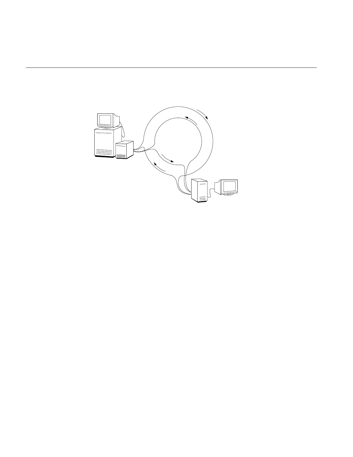
An FDDI ring is a length of cable laid out in a closed loop. Current standards require that
the ring cable be fiber optic cable. An optical signal (light) passes through the cable
(around the ring) and returns to its point of origin. Whenever a station is connected to
the ring, it is physically inserted into the ring so that the optical signal passes through the
station (illustrated in Figure 1-3). Stations on the ring are referred to as upstream or
downstream in relation to each other. The downstream neighbor station is the first
station to see a transmitting station’s transmission. In Figure 1-3, station A is station C’s
downstream neighbor and station B’s upstream neighbor.
FDDI Standard
7
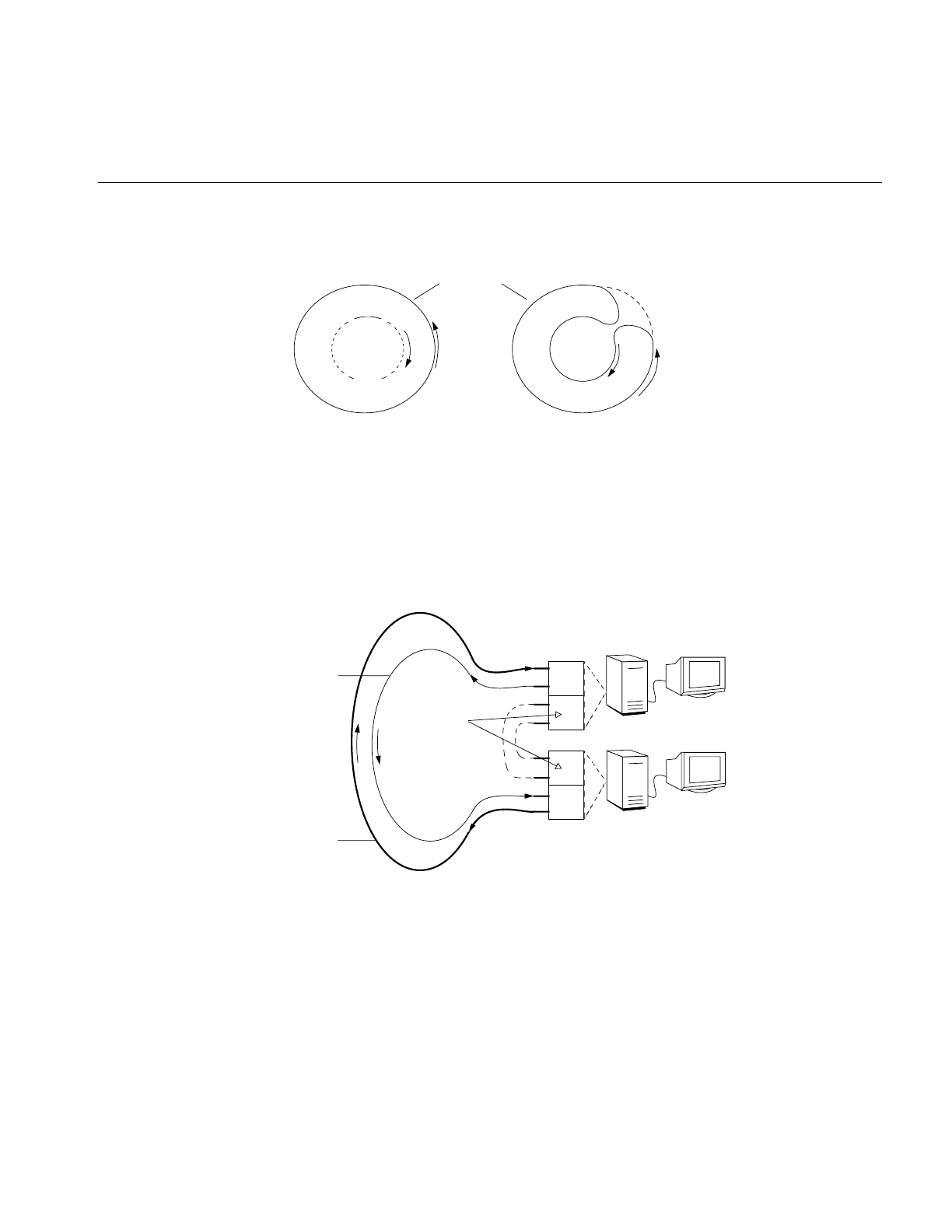
Figure 1-3 Simple Token Ring
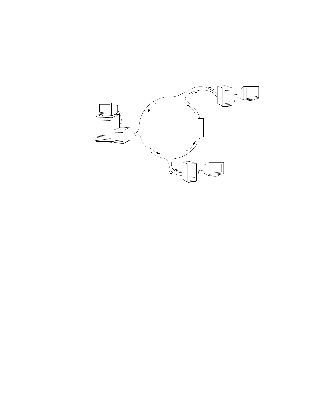
The FDDI dual ring (or trunk ring) has two separate loops (rings). One ring is called the
primary ring and the other is the secondary ring, as illustrated in Figure 1-4. Most sites
use the secondary ring as a backup ring. The light signal within each loop of a dual ring
travels in the opposite direction from the signal in the other ring; in FDDI jargon this is
referred to as counter-rotating. Because the signal travels in different directions,
upstream and downstream neighbors are opposite on each ring. In Figure 1-5, where
station 2 is station 1’s downstream neighbor on the primary ring, station 2 is the
upstream neighbor on the secondary ring.
Single Ring
Token
Station A
Station C
Station B
upstream from B
downstream from C
upstream from A
downstream from B
8
Chapter 1: Introducing FDDI
Figure 1-4 A Basic FDDI Ring
The cabling for FDDI is available in a number of forms. Multimode (62.5 micron) fiber
optic cable was the first transmission medium (cable) defined for FDDI. Recently, the use
of single-mode (50-micron) fiber optic cable was approved. Copper cable has also been
approved, for use only between concentrators and stations.
FDDI Devices
In addition to the FDDI components, the FDDI standard defines the types of devices that
can be connected to the ring. These devices include (but are not limited to) the following:
•stations
–DAS: dual attach station (usually attaches directly to FDDI dual ring)
–SAS: single attach station (attaches to the FDDI ring through a concentrator)
•concentrators
–DAC: dual attach concentrator (usually attaches directly to the FDDI dual ring)
–SAC: single attach concentrator (attaches to the FDDI ring through another
concentrator)
•optical bypass switch
DAS
Primary Ring
Secondary
Ring
DAS
FDDI Devices
9
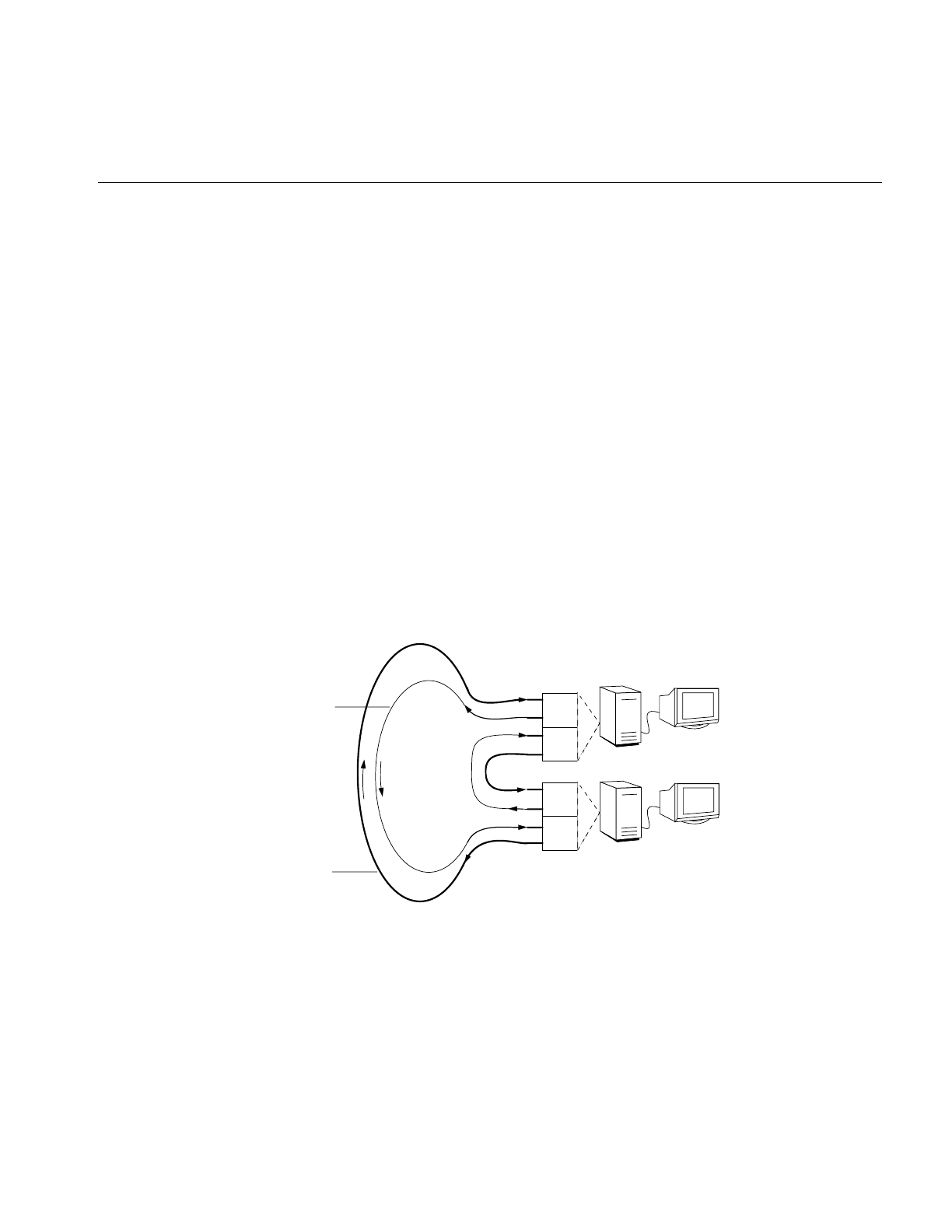
Dual Attach Station
A dual attach station (DAS) has two ports (A and B). A DAS can be connected to the dual
ring or to a concentrator.
When connected to the dual ring, each port connects to both the primary ring and the
secondary ring (as shown in Figure 1-5). This dual connection is known in FDDI jargon
as “connecting to the dual ring.” The station’s SMT ensures that the station can continue
to transmit and receive data even when the primary ring experiences a break. (A break
in the ring occurs when the signal cannot make a complete trip around the ring; this can
be caused by a station failing or by a faulty cable.)
When connected to a concentrator, the two ports can each be connected to one of the
concentrator’s M ports. A DAS station can behave as a single attach station (SAS) if
configured to do so, in which case only one of its ports is connected to the concentrator
and the other port is not used.
Note: As illustrated in Figure 1-5, for DAS connections to the dual ring, port A must
always be connected to port B of the downstream station, while port B connects to port
A of the upstream station.
Figure 1-5 Connection of DAS Ports to Primary and Secondary Rings
A
B
A
B
Station 1
Station 2
Primary
Secondary
Ring
Ring
DAS
DAS
Ports

10
Chapter 1: Introducing FDDI
Single Attach Station
A single attach station (SAS) has a single slave (S) port that attaches to the ring through
a master (M) port on a concentrator. The concentrator routes the signal from the
functioning ring through every SAS connected to that concentrator.
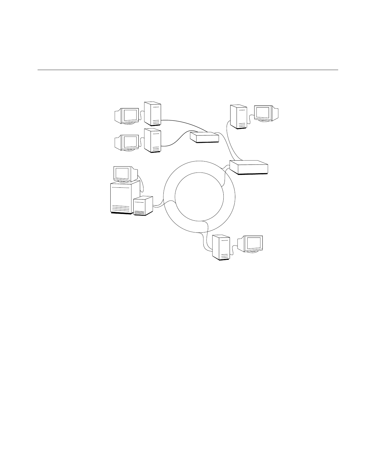
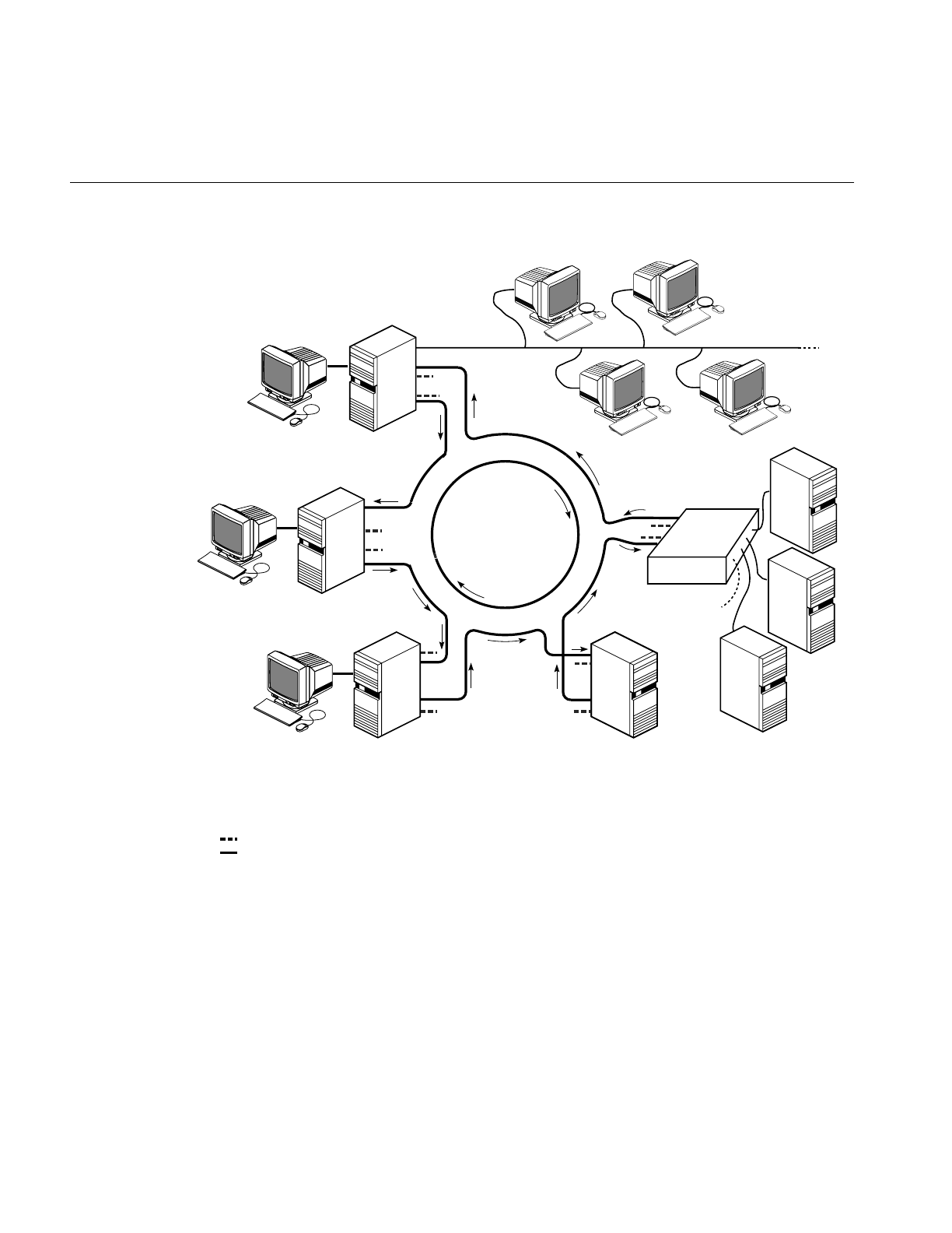
Concentrators
A concentrator allows many single-attachment FDDI devices to obtain their connection
to the FDDI ring through one device—the concentrator. Concentrators have one or more
master ports (M), each of which accepts a connection from one single-attachment device.
The FDDI standard defines two types of concentrators: dual-attachment and
single-attachment. A dual attach concentrator (DAC) has two ports (A and B), each of
which connects to both the primary and secondary rings, just like the DAS. A single
attach concentrator (SAC) connects to an FDDI ring through another concentrator, in the
same manner as an SAS. Figure 1-6 illustrates the use of concentrators on an FDDI ring.
FDDI Devices
11
Figure 1-6 FDDI Ring With Concentrators
Optical Bypass Switch
An optical bypass switch (OBS) is an optional device that can be attached between a dual
ring and a DAS or DAC. The OBS allows a dual-attachment device to become
dysfunctional without wrapping the ring.
DAS
Primary Ring
Secondary
Ring
DAS
SAS
DAC
SAS
SAS
SAC

12
Chapter 1: Introducing FDDI
How FDDI Works
The FDDI local area network consists of two or more stations or nodes connected serially
by fiber optic cables to form a closed loop, the ring. Each FDDI local area network has
two rings: a primary ring and a secondary ring. Figure 1-6 and Figure 1-10 show
common FDDI ring configurations. The secondary ring is usually configured as a backup
ring.
Operational Ring
An optical signal (light), encoded to represent data, is beamed into the cable by a
transmitting station. The signal travels through the cable and is read by each station on
the ring, until it returns to the original sender. As long as the signal can make a complete
trip around the loop, the ring is operational. When a break or fault occurs in the ring, the
signal cannot complete the loop. Situations that break the ring include, among other
things, a missing or damaged cable, a loose connection, and a dysfunctional station.
Fixing a Broken Ring
The optical signal travels in opposite directions in each ring. This design makes closure
of a broken primary ring feasible. When the SMT module within a station notices that the
primary ring is broken, it connects the secondary ring to the primary one to complete the
loop. This action bypasses (cuts out) the faulty section, as illustrated in Figure 1-7. In
FDDI jargon, fixing a broken primary ring in this manner is called “wrapping the ring.”
The original two rings are joined to form a single loop (ring). Notice that the ring must
wrap in two locations to complete the loop. In this condition, transmission proceeds
without interruption for all the stations on the functioning portion of the ring.
How FDDI Works
13
Figure 1-7 Wrapping the Ring
When a ring wraps, two stations change their internal optical signal paths. Instead of the
signal passing through both port A and port B (as illustrated in Figure 1-5), it is received
and transmitted through a single port (either A or B). Figure 1-8 illustrates the altered
optical signal paths. The two stations that make this change are located at the ends of the
functional portion of the primary ring.
Figure 1-8 Connection of DAS Ports at Points Where Ring Is Wrapped
break
Primary
Unused
Secondary
Ring
wrap
wrap
A
B
A
B
Station 1
Station X
Primary
Secondary
Ring
Ring
DAS
DAS
Ports
wrap wrap
One of these
may be
dysfunctional,
or there may be
a dysfunctional
station between
the two ports.
unused ports

14
Chapter 1: Introducing FDDI
If more than one fault occurs on the FDDI ring, the ring may become fragmented, as
shown in Figure 1-9. In this condition, communication continues among the stations
within each fragment, but communication is not possible with stations located on a
different fragment.
FDDI management tools such as smtstat and smtring (or the graphical product,
FDDIVisualyzer) can be used to identify problems with the ring.
Figure 1-9 A Fragmented Ring
Optical Bypass Switch
FDDI defines an optional device that allows a DAS to become dysfunctional without
wrapping the ring. This device is called an optical bypass switch (OBS). The optical
bypass switch is connected between a station’s two ports and the dual ring.
Without an optical bypass switch, when a DAS becomes dysfunctional, the signal going
around the ring cannot continue past the dysfunctional station; stations downstream
from this station do not receive any signal. The ring is broken, which causes an automatic
wrap.
When an optical bypass switch is present in this situation, it maintains an intact loop by
simply routing the signal through the switch, bypassing the dysfunctional station as if it
were not attached to the ring. The SMT modules of neighboring stations will notice that
they have acquired different neighbors, but they will continue to communicate without
the disruption caused by a wrapped ring.
break
break
fragment
fragment
wrap
wrap
wrap
wrap

How FDDI Works
15
Transmitting and Receiving on the Ring
A station on a ring gains access to transmit information onto that ring by capturing the
ring’s token. Only one token is allowed on each ring. Various controls are built into FDDI
to limit or specify the length of time the token can be held. Once a station captures the
token, it can transmit data onto the network. When the station finishes transmitting, or
its time expires, it places the token back onto the ring, thus allowing the next station the
opportunity to capture it. When a station does not have anything to transmit, it does not
capture the token.
Once a frame is transmitted onto the ring, it moves around the ring in the following
manner: Each station reads the frame and transmits it back onto the ring. If a station
makes a local copy of the frame, it indicates this action by altering various bits in the copy
that it retransmits onto the ring. As frames pass around the ring, the transmitting station
recognizes the return of its own data and determines if reception has been successful and
error free by checking the changed bits in the frame. Each station is responsible for
removing (stripping) all the data that it placed on the ring.
Multiprotocol Networking With FDDI
You can use FDDI as a standalone network, or you can incorporate it into an existing
internetwork. When incorporating FDDI with an existing network, it is standard practice
to use FDDI as the backbone and the slower networks (Ethernet or token ring) as
subnetworks. This involves using a router (for example, an FDDI-to-Ethernet router) that
is connected to both the non-FDDI network and the FDDI ring. The router allows
information (packets) to flow between the two networks even though they use different
protocols. Figure 1-10 shows FDDI with an Ethernet network; the ring illustrated has five
dual-attachment nodes, one of which is a concentrator. A Silicon Graphics workstation
or server that has two network interfaces automatically and by default performs as a
router.
16
Chapter 1: Introducing FDDI
Figure 1-10 FDDI With an Ethernet Network
A
B
A
B
A
B
DAS
DAS
DAS
A
B
DAS
AB
= not in use
= in use
DAC
Router/Gateway
Ethernet Network
SAS
SAS
SAS
DAS = dual−attachment station
SAS = single−attachment station
DAC = dual−attachment concentrator

17
Chapter 2
2. Configuring FDDIXPress Software
This chapter explains how to configure your new FDDI station. You can also use these
instructions to reconfigure an already functioning station.
The section “Quick and Easy Configuration Instructions” provides step-by-step
instructions for a basic, nonpersonalized configuration.
FDDIXPress Package
FDDIXPress is a software option to accompany your Silicon Graphics computer’s FDDI
board. FDDIXPress software includes a driver for the FDDI board, an FDDI SMT module
(including software to maintain its management information database [MIB]), and some
utilities (SMT commands).
Depending on the specific release, FDDIXPress software may be shipped with the FDDI
board or with your computer’s operating system; the FDDIXPress release notes and the
FDDI Board’s Installation Guide or Installation Instructions provide details.
Installing FDDIXPress
The step-by-step instructions for installing FDDIXPress software are located in your
FDDIXPress release notes. General instructions for installing Silicon Graphics software
are included in the IRIX Admin: Software Installation and Licensing and on the inst(1M)
man page.
After installing the software, follow the steps in either “Quick and Easy Configuration
Instructions” or “Complete and Complex Configuration Information” to configure the
new FDDI station.

18
Chapter 2: Configuring FDDIXPress Software
Number Assignment to Interfaces
This section describes how identification numbers (for example, xpi0,xpi3) are assigned
to the FDDIXPress network interfaces.
Overview
The number assignment for network interfaces varies, depending on the hardware
platform. Table 2-1 summarizes some of the implemented schemes.O
Table 2-1 Number Assignment for FDDIXPress Network Interfaces
Hardware Platform FDDIXPress
Interface Name Number Assignment Scheme
Crimson™ipg0 - ipg3 Network interface number matches a jumper
setting on each board. Jumper setting 0 has
network interface ipg0.
Indigo™xpi0 Always xpi0 for a single FDDI connection.
Indigo2™xpi0 Network interface number depends on the
order in which FDDIXPress boards are found
during startup. See “Number Assignment for
CHALLENGE M” for details.
Indy™xpi0 Always xpi0 for a single FDDI connection.
CHALLENGE™ M xpi0 Always xpi0 for a single FDDI connection.
CHALLENGE L and XL xpi0, xpi1, xpi# Network interface number depends on the
order in which FDDIXPress boards are found
during startup. See “Number Assignment for
CHALLENGE and Onyx” for details.
Onyx™xpi0, xpi1, xpi# Same scheme used for CHALLENGE L and XL.
Octane, Origin200, Origin
2000, and O2
rns0, rns1,
rns#
Network interface number is automatically
assigned at system startup. Numbering depends
on the interface numbers currently in the
ioconfig.conf file. See “Number Assignment for
Octane, Origin200, Origin 2000, and O2” on
page 21.

Number Assignment to Interfaces
19
Number Assignment for CHALLENGE M
During startup of a CHALLENGE M workstation, the operating system searches for
FDDIXPress boards starting at the topmost GIO Bus slot. The network interfaces are
subsequently assigned to the FDDI connections in the order they were located: the first
board is assigned xpi0 and the second is assigned xpi1.
Number Assignment for CHALLENGE and Onyx
During startup of a CHALLENGE L, CHALLENGE XL, or Onyx system, the operating
system searches for FDDIXPress mezzanine boards attached to system IO4 boards in the
order shown below. When it locates a board, it adds the board to its hardware inventory.
1. Main IO4 board, lower mezzanine position (adapter 5)
2. Main IO4 board, upper mezzanine position (adapter 6)
3. Second IO4 board, lower mezzanine position (adapter 5)
4. Second IO4 board, upper mezzanine position (adapter 6)
The order continues as established above. You can display the contents of the hardware
inventory with the hinv command, as shown below. The FDDIXPress boards are listed in
the order in which they were found.
% /sbin/hinv
...
description: slot #, adapter #, xpi#-xpi#
description: slot #, adapter #, xpi#-xpi#
...
The driver then uses the information summarized in Table 2-2 to assign network
interface numbers to the FDDIXPress mezzanine boards in the hardware inventory. For
each FDDIXPress mezzanine board, the operating system assigns two consecutive
numbers.
Note: Numbering for FDDIXPress boards installed in VME slots is controlled by jumpers
on the board.

20
Chapter 2: Configuring FDDIXPress Software
The network interface names and numbers cannot be changed or configured. The
naming/numbering scheme is embedded in the software.
The last two columns of Table 2-2 summarize how to match the labelling on the IO panel
plates to the network interfaces (that is, the connections at the daughter cards on the
FDDIXPress mezzanine boards). The bottom daughter card of each installed FDDIXPress
board is assigned the first number within the assigned pair of numbers (for example, xpi0
or xpi2); the top daughter card, is assigned the higher number of the pair (for example,
xpi1 or xpi3).
This method of assigning numbers has the following consequences that should be
considered when FDDIXPress boards are added, removed, or moved:
•When additional FDDIXPress boards are installed, the network interfaces on
FDDIXPress boards downstream from the new board become dysfunctional. For
example, if a second FDDIXPress board is added upstream from the first
FDDIXPress board, network interfaces xpi0 and xpi1 are assigned to the new board
during the next powerup and, unless the software has been reconfigured, the IP
network addresses do not match the cables that are attached to the ports.
To fix this, the cables attached to the panel plates for the original board must be
moved to the panel plates for the new board. Or, alternatively, the netif.options file
must be edited so that the lines for the interfaces on the original board reflect the
new numbers (for example, if#name=xpi0 is changed to if#name=xpi2, and
if#name=xpi1 is changed to if#name=xpi3).
Table 2-2 Number Assignments for Network Interfaces on CHALLENGE and
Onyx Platforms
Order In Which Boards Are
Found Network Interfaces
Serviced by
FDDIXPress Board
Mapping IO Panel Plate Labels to Network
Interfaces
Daughter Card Interface
First FDDIXPress board xpi0 and xpi1 bottom
top
xpi1
xpi0
Second FDDIXPress board xpi2 and xpi3 bottom
top
xpi3
xpi2
And so on

Number Assignment to Interfaces
21
•When FDDIXPress boards are removed, moved, or are not found by the operating
system during startup, the interfaces that used to be serviced by the missing board
are assigned to the next downstream FDDIXPress board, so all downstream
network interfaces become dysfunctional. For example, if the first FDDIXPress
board is not found during a powerup, its network interfaces (xpi0 and xpi1) are
assigned to the next board. This shifting of network interfaces affects all boards
downstream from the missing board. The networks physically attached to the ports
no longer match the assigned IP addresses.
To remedy this problem, the cables attached to the panel plates for each board can
be moved to the next downstream board. Or, alternatively, the netif.options file can
be edited so that the lines for the FDDIXPress interfaces reflect the new numbers
(for example, if#name=xpi2 is changed to if#name=xpi0, and if#name=xpi3 is
changed to if#name=xpi1).
Number Assignment for Octane, Origin200, Origin 2000, and O2
These workstations are PCI bus-based systems and their interface numbering scheme is
automatically determined at system startup by the ioconfig utility (see ioconfig(1M)).
At system startup, ioconfig inventories the FDDIXPress boards in the system and tries to
match them with the devices found in the /etc/ioconfig.conf file. If ioconfig detects a new
board, it assigns the next number available for that class (in this case, rns).
For example, upon initial startup after adding two FDDIXPress boards, the first board is
labeled rns0 and the second board is rns1. These numbers remain during subsequent
system reboots and even if the boards are moved. If a board is moved, it receives the next
available number (rns2, for example) unless you edit the /etc/ioconfig.conf file and remove
the initial entry.

22
Chapter 2: Configuring FDDIXPress Software
Default Configurations
If the only configuration task you perform is adding entries to the /etc/hosts file, the
system automatically configures all network interfaces with the default configuration
described in this section. The defaults for ordering and naming network connections is
summarized in Table 2-3. The default settings for operational parameters are
summarized in Table 2-4.
The default configuration for FDDI will not succeed if the /etc/hosts file does not contain
an entry with the station’s hostname paired with an FDDI network IP address. The name
in the /etc/hosts file must match the name displayed when the hostname command is
invoked from a shell window, as shown:
% /usr/bsd/hostname
If the line in the /etc/hosts file with the station’s hostname has an non-FDDI IP address (for
example, an IP address for an Ethernet network), the configuration process will
complete, but neither the FDDI nor Ethernet connection will function.
For this station to be a router/gateway, it must have two network interfaces. For
example, if the station is to perform as an Ethernet-to-FDDI router, it must have an
Ethernet interface in addition to the FDDI interface. A station with two network
interfaces, by default, functions as a router.
Table 2-3 Default Network Interface Configuration
Interface Default Configuration
primary interface
interface selected FDDI (for example, ipg0 or xpi0)
network connection name assigned Same as the hostname defined in the /etc/sys_id
file.
IP address The IP address in /etc/hosts file that is associated
with the station’s hostname.
secondary interface
interface selected Built-in Ethernet (for example, ec0 or et0)
network connection name assigned gate-hostname
IP address The IP address in /etc/hosts file that is associated
with the name “gate-hostname.”

Default Configurations
23
The network interfaces are configured with default operational parameter settings, as
summarized in Table 2-4.
If the configuration described in this section fits your needs, you do not need to perform
any of the configuration tasks. Skip to “Install the FDDI Board” on page 41. Otherwise,
follow the instructions in one or more of the sections in this chapter to change the
configuration to suite your needs.
Table 2-4 Default Network Interface Parameters
Parameter Default Description
netmask No subnet.
(That is, the bits in the standard
network portion of the Internet
address are set to 1; the bits in the
standard host portion of the
Internet address are set to 0. For
class B addresses, 0xFFFF0000. For
class C, 0xFFFFFF00.)
32-bit value used to create two or more
subnetworks from a single Internet address,
by increasing the number of bits used as the
network portion and decreasing the number
of bits used as the host portion. When
creating the mask, assign 1 to each network
bit and 0 to each host bit.
broadcast
address
For the Internet address family, the
host portion of the IP address is set
to 1s. (For class B addresses,
x.x.255.255. For class C addresses,
x.x.x.255.)
Address used by this interface for contacting
all stations on the local area network.
route
metric
0 Hop count value advertised by the routing
daemon (routed) to other routers. Higher
numbers make the route less desirable and
less likely to be selected as a route. Settings
range from 0 (most favorable) to 16 (least
favorable, infinite).
arp Address Resolution Protocol is
enabled and used by the interface.
Address Resolution Protocol (ARP)
translates IP addresses to link-layer
(hardware) addresses.
When this parameter is disabled, interface
does not use ARP.
debug Disabled. When debugging is enabled, a wider variety
of error messages are displayed when errors
occur.

24
Chapter 2: Configuring FDDIXPress Software
Quick and Easy Configuration Instructions
To configure your FDDI station quickly, follow the step-by-step instructions in the
appropriate example:
•“FDDI as the Primary Interface and Ethernet as Secondary” on page 24
•“FDDI as the Secondary Interface and Ethernet as Primary” on page 25
•“FDDI as the Only Network Interface” on page 27
FDDI as the Primary Interface and Ethernet as Secondary
The configuration described here contains no special items, just the most basic
functionality.
If your site uses an NIS service, the changes described in this section must also be made
to the database on the NIS server .
1. Open a shell window.
2. Log on as superuser:
% /sbin/su
Password: thepassword
3. Determine your station’s hostname:
# /usr/bsd/hostname
4. Open the /etc/hosts file:
# /usr/sbin/jot /etc/hosts
5. Find the line containing your station’s hostname.
If the file does not contain a line for your hostname, follow the instructions in
“Complete and Complex Configuration Information” on page 28,
6. Copy the line and place the copy immediately below the original.
7. Return to the original line and change the address (numbers on the left) to the IP
address for the FDDI network.

Quick and Easy Configuration Instructions
25
8. On the new line, change each instance of the hostname to gate-hostname.
For example, the lines for a station with a hostname of mickey, residing in a domain
of disney.com, would look like this:
x.x.x.x mickey.disney.com mickey #FDDI primary
x.x.x.x gate-mickey.disney.com gate-mickey #Ether secondary
Each x represents one, two, or three decimal digits.
9. Do not change the address on the new line. This is your original Ethernet IP address
and will continue to be used.
10. Save and close the file.
11. You are now ready to install the FDDI board. Follow the instructions in the board’s
installation guide or installation instructions.
If the board is already installed, type the following commands to build your
changes into the operating system:
# /etc/autoconfig
Automatically rebuild the operating system (y/n)? y
# /etc/reboot
FDDI as the Secondary Interface and Ethernet as Primary
The configuration described here contains no special items, just the most basic
functionality. This configuration makes it possible for a Silicon Graphics system to load
the miniroot over the primary Ethernet network (or boot from the network).
1. Open a shell window.
2. Log on as superuser:
% /sbin/su
Password: thepassword
#
3. Determine your station’s hostname:
# /usr/bsd/hostname
4. Open the /etc/hosts file:
# /usr/sbin/jot /etc/hosts

26
Chapter 2: Configuring FDDIXPress Software
5. Find the line containing your station’s hostname.
If the file does not contain a line for your hostname, follow the instructions in
“Complete and Complex Configuration Information” on page 28.
6. Copy the line and place the copy immediately below the original.
7. On this new line, change the IP address (all the numbers on the left) to the FDDI IP
address.
8. Also on the new line, change each instance of the hostname to fddi-hostname.
For example, the lines for a station with a hostname of mickey, residing in a domain
of disney.com, would look like this:
x.x.x.x mickey.disney.com mickey #Ether primary
x.x.x.x fddi-mickey.disney.com fddi-mickey #FDDI secondary
Each x represents one, two, or three decimal digits.
9. Save and close the file.
If your site uses an NIS service, the changes described above must also be made to
the database on the NIS server.
10. Determine the name of your primary Ethernet interface with the command shown
below. Some common examples include ec0,et0,enp0,ep0.
# /usr/etc/netstat -i
11. Determine the name of your FDDI interface. This information is in the FDDIXPress
release notes. Common names include xpi0 and ipg0.
12. Open the /etc/config/netif.options file:
# /usr/sbin/jot /etc/config/netif.options
13. Find this line:
: if1name=
Change it as shown below. Be sure to remove the colon and leading space.
if1name=Ethernetinterfacename

Quick and Easy Configuration Instructions
27
14. Find this line:
: if2name=
Change it as shown below. Be sure to remove the colon and leading space.
if2name=FDDIinterfacename
15. Find this line:
: if2addr=gate-$HOSTNAME
Change it as shown below. Be sure to remove the colon and leading space.
if2addr=fddi-$HOSTNAME
16. Save and close the file.
17. You are now ready to install the FDDI board. Follow the instructions in the board’s
installation guide or installation instructions.
If the board is already installed, type the following commands to build your
changes into the operating system:
# /etc/autoconfig
Automatically rebuild the operating system (y/n)? y
# /etc/reboot
FDDI as the Only Network Interface
The configuration described here contains no special items, just the most basic
functionality.
1. Open a shell window.
2. Log on as superuser:
% /sbin/su
Password: thepassword
#
3. Determine your station’s hostname:
# /usr/bsd/hostname

28
Chapter 2: Configuring FDDIXPress Software
4. Open the /etc/hosts file:
# /usr/sbin/jot /etc/hosts
5. Find the line containing your station’s hostname.
If the file does not contain a line for your hostname, follow the instructions in
“Complete and Complex Configuration Information” on page 28.
6. Change the address (numbers on the left) to the IP address for the FDDI network.
For example, the line for a station with a hostname of mickey, residing in a domain
of disney.com, would look like this:
x.x.x.x mickey.disney.com mickey #FDDI primary
Each x represents one to three decimal digits.
7. Save and close the file.
If your site uses an NIS service, the changes described above must also be made to
the database on the NIS server.
8. You are now ready to install the FDDI board. Follow the instructions in the board’s
installation guide or installation instructions.
If the board is already installed, type the following commands to build your
changes into the operating system:
# /etc/autoconfig
Automatically rebuild the operating system (y/n)? y
# /etc/reboot
Complete and Complex Configuration Information
This section describes configurations and configuration issues not covered by “Quick
and Easy Configuration Instructions.” The configuration instructions in this section are
more complex and complete. This section explains when and why you need to configure
an FDDI station, in addition to how to do it.
The following is an overview of the procedure for installing and configuring
FDDIXPress. For a new FDDI station, the tasks must be performed in the order listed.
Each task is divided into detailed steps and described in the referenced section.

Complete and Complex Configuration Information
29
1. Prepare for configuration, as described in “Prepare for Configuration” on page 29.
2. Perform the required configuration tasks:
■Ensure your station’s network connection names and IP addresses are in the
/etc/hosts file, as described in “Network Connection Names and IP Addresses”
on page 31.
■Verify and, if necessary, modify the /etc/config/netif.options file as described in
“Configure the Station’s Network Interfaces” on page 33.
■If necessary, create or modify the /etc/config/ifconfig-#.options file, as described in
“Changing Settings for the Operational Parameters” on page 38.
3. Perform the FDDI board installation, as described in “Install the FDDI Board” on
page 41.
4. Optionally, make your environment user friendly, as described in “Configure the
Environment for User Friendliness and Safety (Optional)” on page 42.
5. Check that the FDDI connection is functional, as described in “Verifying the FDDI
Connection” on page 47.
Prepare for Configuration
Before starting the installation, collect the necessary information and perform
housekeeping so the installation goes smoothly.
1. If your computer has not been networked before, follow the instructions in the
Personal System Administration Guide to set up your system as a networked
workstation. These tasks include assigning your system a hostname, a network
connection name, an IP address, as well as enabling TCP/IP.
2. If the FDDIXPress software has not been installed, do so now.
3. Determine the number of networks to which your station will be connected after
FDDIXPress is installed. For example, if your station is currently connected to an
Ethernet network, will the station continue to use the Ethernet connection in
addition to the FDDI connection?
4. If the station will have more than one network connection, decide which will be the
primary network. The primary network interface should be the one where all or
most of your station’s network services or clients reside.
Note: The network you select as primary experiences the heaviest usage. It is
recommended that FDDI be the primary network connection. However, for systems
that need to boot over the network, Ethernet must be primary.

30
Chapter 2: Configuring FDDIXPress Software
5. For each network connection, select a network connection name and IP address.
The network connection name of the primary network connection must be the same
as the system’s hostname. You can display your system’s hostname by using the
hostname command within a shell window:
% /usr/bsd/hostname
You can display the current IP address associated with the network connection
name hostname by typing one of the following commands in a shell window:
% /sbin/grep hostname /etc/hosts
% /usr/bin/ypmatch hostname hosts
The names you create for non-primary network interfaces can be anything you
want. To facilitate recognition, the names usually include both the hostname and an
indication of the protocol (for example, fddi-mars or fddi2-mars).
6. Determine if any of your station’s network interfaces require special configuration
for any of the following items: subnetwork mask (netmask), broadcast address,
route metric, or use of Address Resolution Protocol.
The default configuration settings for these operational parameters are listed in
Table 2-4, in “Default Configurations.” In most cases, the defaults are the desired
settings.
If any of these operational parameters needs special configuration, the network
administrator must create an /etc/config/ifconfig-#.options file, where the pound sign
(#) matches the network interface’s order in the netif.options file. Once these files are
created, you can proceed with the configuration.
7. For sites using an NIS server:
The network administrator needs to update the site’s hosts and ethers databases to
include the correct information about this station. The hosts database should be
updated to include all the station’s network connection names and IP addresses
before you restart the system after installing the board. The ethers database can be
updated only after the board has been installed.
8. You are ready to start configuring. Follow the instructions in “Network Connection
Names and IP Addresses.”

Complete and Complex Configuration Information
31
Network Connection Names and IP Addresses
Your FDDI station must have a network connection name1 and IP address for each FDDI
network interface. It may also need network connection names and IP addresses for
other network interfaces (for example, Ethernet).
This section provides instructions for entering your network connection names and IP
addresses into the local /etc/hosts file.
If your site uses an NIS service, the changes described in this section must also be made
to the NIS server’s database.
1. Open a shell window.
2. Log on as superuser:
% /sbin/su
Password: thepassword
#
3. Use your favorite editor (for example, jot or vi) to open the /etc/hosts file. For
example, the command line below opens the /etc/hosts file for editing:
# /usr/sbin/jot /etc/hosts
4. Locate the line containing the network connection name that you selected for your
FDDI connection. If you do not find an entry for this name, search for the FDDI IP
address. If you do not find either, skip to step 6. If you find the FDDI name or
address, continue.
Searching for all instances of the station’s hostname will usually identify all the
network connection names for the system. You can display the system’s hostname
with the /usr/bsd/hostname command.
5. Verify that the IP address and the name are correct for the FDDI connection. (Make
sure the IP address is not the Ethernet address.) If the name and address are correct,
skip to step 7, otherwise continue.
1The network connection name is a name entered in the /etc/hosts file. This name is paired with an IP
address. Each network interface must have one network connection name that is unique to the domain
and one globally unique IP address.

32
Chapter 2: Configuring FDDIXPress Software
6. If the line is not correct or is missing, edit the file so that there is a line containing the
IP address and network connection name for the FDDI network interface.
A typical format for an entry in /etc/hosts file is as shown:
IPaddress fullnetworkconnectionname aliases
For example, a portion of an /etc/hosts file might look like this, where the host goofy
has two entries and mickey has one:
198.45.91.1 mickey.mrktg.disney.com mickey
198.45.91.5 goofy.mrktg.disney.com goofy
198.45.65.1 fddi-goofy.engr.disney.com fddi-goofy
7. If your station will be using more than one network connection, for each one (in
addition to FDDI), verify that the name and IP address are the correct.
8. Save and close the file.
9. Decide if the following statements are true for your system, then choose the relevant
substep, below:
•In the /etc/hosts file, the FDDI IP address is assigned to the station’s hostname
•The Ethernet IP address to the entry gate
•FDDI is the primary network interface
•The station has no more than two network interfaces
■If all the statements are true, you do not need to perform any other
configuration tasks. If the FDDI board is not installed, install it now. Otherwise,
if the board is installed, use these commands to build your changes into the
operating system:
% /sbin/su
Password: thepassword
# /etc/autoconfig
Automatically rebuild the operating system (y/n)? y
# /etc/reboot
■If any of the statements are false, you need to configure the network interface(s).
Follow the instructions in the next section, “Configure the Station’s Network
Interfaces.”
For more information about the /etc/hosts file, see the hosts(4) man page and IRIX Admin:
Networking and Mail.

Complete and Complex Configuration Information
33
Configure the Station’s Network Interfaces
This section explains how to configure your station’s network interface (or interfaces). If
you do not perform any of the procedures in this section, the system configures the
station with the default settings described in “Default Configurations” on page 22.
This section contains the following subsections:
•“Making FDDI the Secondary Network Interface” on page 33
•“Changing the Ethernet’s Name” on page 37
•“Configuring Multiple FDDI Interfaces” on page 38
•“Changing Settings for the Operational Parameters” on page 38
•“Disabling Forwarding and Routing” on page 39
Making FDDI the Secondary Network Interface
To make FDDI the secondary network interface, edit the /etc/config/netif.options file as
explained in this procedure. This allows a Silicon Graphics workstation or server to boot
from the primary Ethernet network.
1. Determine the names of your system’s network interfaces.
■If you are installing the FDDI board for the first time, the FDDIXPress release
notes indicate the name of the FDDI network interface for your system (for
example, ipg# or xpi#).
■Other interface names can be displayed with the netstat command.
Open a shell window and use the /usr/etc/netstat -in command to list the
currently available network interfaces, as demonstrated in Figure 2-1. If an
FDDI connection is operating, its name is listed. The names you see may be
different than those shown in Figure 2-1.

34
Chapter 2: Configuring FDDIXPress Software
Figure 2-1 Displaying Available Interfaces With netstat -in
2. Open the /etc/config/netif.options file with your favorite editor.
3. Change the following lines
: if1name=
: if1addr=$HOSTNAME
: if2name=
: if2addr=gate-$HOSTNAME
to
if1name=name of interface you want to be primary
: if1addr=$HOSTNAME
if2name=FDDIinterfacename
if2addr=fddi-$HOSTNAME
Do not alter the line containing : if1addr
4. Remove the colons and leading spaces.
For example:
if1name=ec0
: if1addr=$HOSTNAME
if2name=xpi0
if2addr=fddi-$HOSTNAME
5. If you do not want to use the network connection name shown above
(fddi-hostname), you may replace the name with one of your own choice.
Make sure the name or name format you enter corresponds to an entry in the
/etc/hosts file.
6. If this is your final configuration change, go to the subsection “Build Configuration
Changes Into the System” to finish.
Name Mtu Network Address Ipkts
Ierrs Opkts Oerrs Coll
xpi0 4500 195.41.72 195.41.72.61 0
0 000
ec0 1500 195.41.75 195.41.75.61
2546732 5158 231251 0 10338
lo0 32880 127 127.0.0.1
7990697 0 7990697 0 0
an Ethernet interface
an FDDI interface

Complete and Complex Configuration Information
35
Example 2-1 FDDI as Primary Interface Configuration
A workstation named minnie has an FDDI interface, xpi0, and an Ethernet interface, ec0.
If the netif.options file is not altered, the default configuration is: xpi0 is assigned the IP
address corresponding to minnie, and ec0 is assigned the IP address for gate-minnie. If
there is no entry in /etc/hosts for gate-minnie, the secondary interface is not configured.
For example, minnie’s /etc/hosts file contains this information:
195.41.91.3 minnie.disney.com minnie
195.41.184.2 gate-minnie.disney.com gate-minnie
The unaltered /etc/config/netif.options file contains this information:
: if1name=
: if1addr=$HOSTNAME
: if2name=
: if2addr=gate-$HOSTNAME
This is the resulting configuration:
•minnie (195.41.91.3) is configured as the primary FDDI interface.
•gate-minnie (195.41.184.2) is configured as the secondary Ethernet interface.
Example 2-2 FDDI as Secondary Interface Configuration
To make the Ethernet (ec0) interface primary and the FDDI (xpi0) secondary for the
system described in Example 2-1, you need to change the lines in the netif.options file to
the following:
if1name=ec0
: if1addr=$HOSTNAME
if2name=xpi0
: if2addr=gate-$HOSTNAME
This is the result:
•minnie (195.41.91.3) is configured as the primary Ethernet interface.
•gate-minnie (195.41.184.2) is configured as the secondary FDDI interface.
Example 2-3 Changing the Secondary FDDI Interface Name
To change the FDDI secondary interface name to fddi-minnie for the system described in
Example 2-1 and Example 2-2, the /etc/hosts file and the /etc/config/netif.options file need to
be altered.

36
Chapter 2: Configuring FDDIXPress Software
The /etc/config/netif.options file must have the following entries:
if1name=ec0
: if1addr=$HOSTNAME
if2name=xpi0
if2addr=fddi-$HOSTNAME
The /etc/hosts file must have the following entries:
195.41.91.3 minnie.disney.com minnie
195.41.184.2 fddi-minnie.disney.com fddi-minnie
Explanation of Network Configuration Process
During system startup and anytime it is invoked specifically, the shell command file
/etc/init.d/network configures and initializes the network interfaces and software. Some of
the script’s procedures are accomplished by calling other utilities and reading
configuration files. Some of the tasks the /etc/init.d/network command file performs are:
•Determines the station’s hostname. This information is defined in the /etc/sys_id file.
•Determines the network hardware and interfaces available in the operating system.
This information can be viewed with the hinv command.
•Determines the ordering for the network interfaces. This information is defined in
the /etc/config/netif.options file. If the netif.options file has not been altered, the default
ordering is configured (explained in “Default Configurations” on page 22 and
defined within the network script).
•Determines the network connection name for each network interface. This
information is defined by the if#addr lines in the /etc/config/netif.options file. If the
netif.options file has not been altered, the default names (explained in “Default
Configurations” and defined in the network script) are used.
•Determines the IP address for each interface by looking up each network connection
name in the /etc/hosts file.
•Determines the settings for each network interface’s operational parameters. This
information is defined in the /etc/config/ifconfig-#.options. If an ifconfig-#.options file
does not exist for the interface, the default settings are assigned (described in
“Default Configurations”).

Complete and Complex Configuration Information
37
•Configures the number of network interfaces specified by the
if_ num variable in the network script.
•Starts (enables) each successfully configured interface.
The results of the network script’s configuration can be viewed with the /usr/etc/netstat -i
and /usr/etc/ifconfig commands.
Changing the Ethernet’s Name
Ethernet is automatically configured as the secondary network interface. It is assigned a
network connection name of gate-hostname. This section provides instructions for
changing the name used for the Ethernet network connection.
If a station does not have a second entry in the /etc/hosts file, the system does not
configure a second network interface.
To configure Ethernet with a different /etc/hosts entry (for example, ether-hostname),
follow these instructions:
1. Log on as superuser and open the /etc/config/netif.options file with your favorite
editor.
2. Change the following line:
: if2addr=gate-$HOSTNAME
to
if2addr=newname
or
if2addr=newname-$HOSTNAME
3. Save and close the file.
4. Use one of the following commands to verify that the name you have entered in the
netif.options file exists in the /etc/hosts file or hosts database. If the name does not
exist, follow the instructions in “Network Connection Names and IP Addresses” on
page 31 to modify the /etc/hosts file.
% /sbin/grep name /etc/hosts
% /usr/bin/ypmatch name hosts
name is either the new name or newname-hostname.
5. If this is your final configuration change, go to the subsection “Build Configuration
Changes Into the System” on page 40 to finish.

38
Chapter 2: Configuring FDDIXPress Software
Configuring Multiple FDDI Interfaces
There is no default configuration for FDDI network interfaces other than the first one. If
a system has two or more FDDI connections, you need to add a pair of lines to the
/etc/config/netif.options file for each additional FDDI network interface and possibly
change the if_num variable in the /etc/init.d/network file.
The following lines are an example of netif.options entries for a system with three FDDI
connections and one Ethernet. The lines for the first and second network interfaces have
not been edited, so the default configuration for a primary FDDI and secondary Ethernet
are automatically configured.
: if1name=
: if1addr=
: if2name=
: if2addr=
if3name=xpi1
if3addr=fddi2-goofy
if4name=xpi2
if4addr=fddi3-goofy
The network connection names (for example, fddi3-goofy) must exist in the /etc/hosts file.
The following is a single line in a network file that has been altered to configure twelve
network interfaces:
if_num=12
Changing Settings for the Operational Parameters
To change the default settings for operational parameters (summarized in Table 2-4),
create or edit the /etc/config/ifconfig-#.options file for the network interface. The pound sign
(#) in the filename must match the number in the netif.options file that was used to
configure the network connection. For example, for the netif.options line if3name=xpi0,
create or edit the file /etc/config-3.options.
The following is an example of the contents of an /etc/config/ifconfig-#.options file. This file
enables the IP address resolution protocol, sets a route metric, and specifies a subnetwork
mask for the associated network:
arp metric 9 netmask 0xFFFFFF80
Complete instructions for configuring operational parameters are provided in the device
configuration instructions in IRIX Admin: Networking and Mail.

Complete and Complex Configuration Information
39
Disabling Forwarding and Routing
By default, the routing daemon (routed) is started and IP forwarding (in the operating
system) is enabled whenever a system has two or more network interfaces. This default
configuration causes the system to advertise itself as a router to other systems on the
networks, maintain tables of routes it knows, and to transfer (that is, route, forward)
packets between its networks whenever it encounters packets that need to be routed in
order to be delivered.
If your station has two (or more) network interfaces and you do not want the system to
transfer or route packets between its networks or to advertise itself as a router, follow the
steps in the examples below for the configuration you want.
Example 2-4 Disable Forwarding and Route Advertising
This example disables the capability to forward data from one network to another and
advertisement of all routing information. (This configuration does not disable the
routing daemon’s maintenance of routing tables, only its advertisement of the routing
information.)
1. Edit the /etc/config/routed.options file so that it contains the characters -hq. This
prevents the system from advertising its network connections (routes) or its
presence (the host route) on any of the system’s networks.
2. Edit the /var/sysgen/master.d/bsd file so that the line containing
int ipforwarding = 1 is changed to int ipforwarding = 0. This prevents the
system from passing (transferring) any messages between its networks.
3. Go to the subsection “Build Configuration Changes Into the System” on page 40 to
finish.
Example 2-5 Disable Route Advertising
This example allows data to be forwarded from one network to another, but prevents the
system from advertising its network connections (thus preventing the system from
becoming known as a router).
1. Edit the /etc/config/routed.options file so that it contains the characters -hq. This
causes the system to refrain from all rout advertising; it does not advertise its
network connections (routes) and it does not advertise its own presence has a host
(host routes) on its connected networks.
2. Go to the subsection “Build Configuration Changes Into the System” on page 40 to
finish.

40
Chapter 2: Configuring FDDIXPress Software
Example 2-6 Disable Route Advertising Except For the Primary Interface
This example allows data to be forwarded from one network to another and prevents the
system from advertising its network connections (thus preventing the system from
becoming known as a router). However, it allows the system to advertise its own
presence as a host on the network attached as its primary network interface.
1. Edit the /etc/config/routed.options file so that it contains the characters -hmq. This
causes the system to advertise (on all its connected networks) its presence as a host
(the host route) on its primary network, but prevents the system from advertising
its network connections and other host routes.
2. Go to the subsection “Build Configuration Changes Into the System” on page 40 to
finish.
For more information, see the routed(1M) and chkconfig(1M) man pages and the
comments in the /var/sysgen/master.d/bsd file.
Build Configuration Changes Into the System
To build your network interface or driver configuration changes into the operating
system, follow the procedure that is appropriate:
•If the FDDI board has not been installed, do not rebuild the operating system now.
Instead, follow the instructions in the FDDI board’s installation guide or installation
instructions to install the board.
•If the FDDI board is installed, rebuild the operating system, and reboot to start
using the new operating system with these commands:
% /sbin/su
Password: thepassword
# /etc/autoconfig
Automatically rebuild the operating system (y/n)? y
# /etc/reboot

Complete and Complex Configuration Information
41
Install the FDDI Board
The FDDIXPress board should be installed after the FDDIXPress software has been
installed and configured. The instructions for installing an FDDI board are described in
the board’s installation guide or installation instructions.
The following is an overview of the procedure for installing the FDDIXPress product
(software and hardware). The steps must be performed in the order shown.
1. Install the FDDIXPress software.
2. Perform these required configuration tasks:
■Update your station’s name(s) and IP address(es) in the /etc/hosts file.
Instructions are provided in “Network Connection Names and IP Addresses”
on page 31.
■Configure the network interface(s). Instructions are provided in “Configure the
Station’s Network Interfaces” on page 33.
3. Install the FDDI board. Follow the instructions in the board’s installation guide or
installation instructions.
Installation of the board includes the following three steps. The FDDI connection
will not function if you do not finish your installation with these steps:
■Restart the system.
■Answer yes to the prompt Automatically rebuild the operating system
(y/n)?
■Reboot the system.
4. (Optional) When you finish installing the board, continue with “Configure the
Environment for User Friendliness and Safety (Optional)” to make your station’s
environment user friendly and safe.
5. Verify the FDDI connection. Instructions are provided in “Verifying the FDDI
Connection” on page 47.

42
Chapter 2: Configuring FDDIXPress Software
Configure the Environment for User Friendliness and Safety
(Optional)
This section describes how to make your environment user friendly and safe. All
procedures in this section are optional.
Four actions are recommended:
•Set the path variable to include the SMT commands.
•Create backup copies of important FDDIXPress files.
•For sites without an NIS service: Create an /etc/ethers file so that names can be used
with SMT commands instead of MAC addresses.
•For sites with an NIS service: Create local copies of the ethers and hosts databases.
Setting the Path to the SMT Commands (Optional)
To invoke the SMT commands from any directory, the system must know where the
commands reside. This section shows how to configure your environment so that the
SMT commands are always available, regardless of the directory you are currently
logged into.
If you do not configure the path, you must type the complete path to the directory where
the SMT commands reside each time you invoke an SMT command.
1. Find the path to the SMT commands by reading any of the SMT command man
pages. For example, enter the command:
% /usr/bin/man smtring
In the display that appears in your shell window, the text under the heading
SYNOPSIS indicates the path. Make note of the path; it is everything up to, but not
including, the command name. In the following display, /usr/etc/ is the path:
NAME
smtring - examines the state of FDDI ring
SYNOPSIS
/usr/etc/smtring [-adn] [-i interval] . . .

Complete and Complex Configuration Information
43
2. Open your .login file (or .cshrc file) with your favorite editor. For example, type a
command line like this:
% /usr/sbin/jot /usr/people/yourloginname/.login
3. Locate the line that sets the path variable. The line looks like this:
set path=(. ~/bin /usr/bsd /usr/sbin /usr/lib /etc)
4. At the end of the path variable’s last line, but before the closing parenthesis, add the
new path. For example, if you were editing the example .login (or .cshrc) file, it
should look like this example:
set path=(. ~/bin /usr/bsd /usr/sbin /usr/lib /etc /usr/etc)
Setting Up the ethers File (Optional)
The FDDIXPress SMT commands use MAC (physical) addresses to contact other FDDI
stations on the ring. If you want to use the commands with names, instead of MAC
addresses, your system must have access to an ethers database. (The ethers database
maps physical addresses—MAC and Ethernet addresses—to network connection
names.) Your station can obtain ethers database information from the site’s Network
Information Service (NIS) or from a local /etc/ethers file.
Note: If any of your station’s networks uses an NIS server, this procedure must be done
at the NIS server, not on the local station.
Edit the /etc/ethers file so it lists this station’s MAC address and those of all the other
stations on the FDDI ring:
1. Open a shell window and log on as superuser.
2. Use the /usr/etc/netstat -ia command to determine the MAC address of your station’s
FDDI board and the name of the FDDI interface. Be sure to find the MAC address
for the FDDI board (for example, the MAC address listed under xpi0 or ipg0), not
the Ethernet board (for example, ec0). In a default configuration, FDDI is the first
interface listed. The MAC address is the number displayed in hexadecimal format,
as shown in Figure 2-2.

44
Chapter 2: Configuring FDDIXPress Software
Figure 2-2 Screen Display for /usr/etc/netstat -ia Command
3. Open the /etc/ethers file with your favorite editor.
4. Add a line to the /etc/ethers file that specifies the FDDI board’s MAC address and the
station’s FDDI network connection name. In the /etc/ethers file, use the format
displayed with the /usr/etc/netstat command for the MAC address and network
connection name:
x:x:x:x:x:x networkconnectionname # comments
x:x:x:x:x:x is the 48-bit, hexadecimal MAC address of each network interface board.
Each x represents one byte and can be a hexadecimal numeral from 0 to ff. The
networkconnectionname corresponds to the name in the /etc/hosts file that is paired
with the FDDI IP address. Comments start after the # character and are optional.
5. In another shell window, determine the broadcast address for your network by
using the following command. The broadcast address is the sequence of digits
displayed in the location illustrated in Figure 2-3.
% /usr/etc/smtconfig networkinterfacename
Name Mtu Network Address Ipkts Ierrs Opkts Oerrs Coll
xpi0 4500 N1 mickey.disney 0 0 0 0 0
pmap-mcast
allhosts-mcast
0a:00:fc:04:a9:9
ec0 1500 N2 gate-mickey.disney 2546732 5158 231251 0 10338
pmap-mcast
allhosts-mcast
0a:00:f6:06:34:ff
lo0 32880 loopback localhost 7990697 0 7990697 0 0
allhosts-mcast
FDDI MAC address
FDDI network interface name
FDDI network
connection name

Complete and Complex Configuration Information
45
Figure 2-3 Displaying Broadcast Address
6. Using the broadcast address from step 5, make each station on the ring provide its
MAC address and network connection name:
% /usr/etc/ping -r -c 10 broadcastaddress
7. Display the gathered information:
% /usr/etc/arp -a
8. Copy all the displayed MAC addresses and host names into your /etc/ethers file. Be
sure to use the proper format as explained above and shown in Example 2-7.
Example 2-7 Sample ethers File
In this example, a station with a hostname of goofy, shows first a portion of an arp display,
and second a corresponding portion of the /etc/ethers file. goofy has two network
interfaces and has been configured with the default configurations. Note that the arp
display does not list goofy’s information.
The arp display:
mickey.disney.com (187.41.75.61) at a:0:69:6:34:ff
donald.disney.com (187.41.75.1) at a:0:69:2:4:45
minnie.disney.com (187.41.75.5) at a:0:69:2:15:ff
The /etc/ethers file:
a:0:69:da:5c:f goofy# local FDDI MAC addr
2:c:1f:1:e2:88 gate-goofy# local Ethernet addr
a:0:69:6:34:ff mickey# an FDDI remote station
a:0:69:2:4:45 donald# an FDDI remote station
a:0:69:2:15:ff minnie# an FDDI remote station
The above addresses can also be in this format:
0a:00:69:da:5c:0f goofy
02:0c:1f:01:e2:88 gate-goofy
xpi0: flags=863<UP,BROADCAST,NOTRAILERS,RUNNING,MULTICAST>
inet 223.41.75.4 netmask 0xffffff00 broadcast 223.41.75.255
Broadcast address

46
Chapter 2: Configuring FDDIXPress Software
For more information, see the ethers(4), ping(1M), and arp(1M) man pages. For more
information about the role of the /etc/ethers file, see IRIX Admin: Networking and Mail. For
information about NIS, see the NIS Administration Guide and man pages.
Some of the FDDIXPress tools and commands (such as smtping and smtstat) depend on
the /etc/ethers file (either local or on the NIS server) to know stations by their network
connection names instead of by their MAC addresses. The /etc/ethers file maps MAC
addresses to network connection names. You need to enter each FDDI station into the
ethers database. (The file /etc/ethers is the ethers database.) If you do not update this
database, FDDIXPress commands know stations only by their MAC addresses, in
hexadecimal numerical format and Ethernet order, as defined in the Glossary.
The stations listed by arp -a are stations that your station has communicated with in the
last few minutes. You can add entries to the arp display by invoking ping name or
ping IPaddress.
If your site uses a Network Information Service (NIS) server, you may want to keep local
(backup) copies of the ethers and hosts files for use when the NIS server is unavailable.
(The local copies are not used as long as NIS is available.) For example, an NIS server
could become unavailable when the FDDI ring wraps. If you decide to keep local backup
copies, remember to update them when changes are made.
Type the following command lines to make local copies of /etc/hosts and /etc/ethers files,
including the changes the network administrator has made to the database:
% /sbin/su
Password: thepassword
# /usr/bin/ypcat hosts > /etc/hosts
# /usr/bin/ypcat ethers > /etc/ethers
Do not perform this step until you are certain the network administrator has made all the
changes pertaining to your station.

Verifying the FDDI Connection
47
Backing Up SMT Files (Optional)
Files can become corrupted. It is a wise practice to keep backup copies of important files.
To create backup copies of two FDDIXPress files that the SMT module (daemon) uses
frequently, follow this procedure.
1. Go to the fddi directory:
% cd /etc/fddi
2. Become superuser:
% /sbin/su
Password: thepassword
#
3. Make backup copies of the smtd.conf and smtd.mib files:
# /sbin/cp smtd.conf smtd.conf.orig
# /sbin/cp smtd.mib smtd.mib.orig
Performing this step can save you from reinstalling the FDDIXPress software if either file
becomes corrupted or is deleted.
Verifying the FDDI Connection
To verify that the station’s FDDI connection is working, follow the steps in this section.
Many of these steps use the smtstat -s command to view key items from the SMT
information database. For details on how to use the smtstat command, see “Display SMT
Information (MIB)” on page 65. If any of the following tests fail, see Chapter 4 for
troubleshooting ideas.
1. Open a shell window.
2. Type the following command to verify that the FDDI board is recognized by the
system software:
% /sbin/hinv
The hinv display, shown in Figure 2-4, lists all the hardware known to the system.
An FDDI controller must display in the list. If an FDDI controller is not listed, refer
to “Recognition of Board by Software” on page 80.

48
Chapter 2: Configuring FDDIXPress Software
Figure 2-4 An Example of the hinv Display
3. List all network interfaces on the system. An FDDIXPress interface, such as ipg# or
xpi#, must be listed.
% /usr/etc/netstat -in
If the listing does not include an FDDI network interface, the FDDIXPress software
may not have been installed, may not be configured, or may not be built into the
operating system. Fix the problem before continuing.
4. Invoke the report display for the first FDDIXPress interface:
% /usr/etc/smtstat -I FDDIinterface -s
If an error message displays, look up the error message in Appendix A for
troubleshooting instructions.
5. Verify that the FDDI board sees the ring’s token.
■Type 1 to view the MAC (#1) report.
■Type zto reset the counters and start accumulating. The accumulating total
displays every second.
■Look at the “MAC state” field. It should display ACTIVE.
■Watch the “tokens” field for 15 seconds. The number should increment rapidly.
If the “tokens” field does not increment, refer to “Token Count Not
Incrementing” on page 87.
1 33 MHZ IP12 Processors
FPU: MIPS R2010A/R3010 VLSI Floating Point Chip Revision: 4.0
CPU: MIPS R2000A/R3000 Processor Chip Revision: 3.0
On-board serial ports: 2
Data cache size:32 Kbytes
Instruction cache size:32 Kbytes
Main memory size:16 Mbytes
I/O board, slot F: IO3
Integral Ethernet: ec0, version 1
XPI FDDI controller: xpi0, firmware version 1, DAS
Disk drive: unit 1 on SCSI controller 0
Integral SCSI controller 0: Version WD33C93A, revision 9
Iris Audio Processor, rev 3
Graphics board: LG1
FDDI board Network interface name

Verifying the FDDI Connection
49
6. Verify that the ports are working.
■Type 2 to view the Port (#2) report.
■For a dual ring DAS, the following fields should have the statuses shown:
Port B Port A
neighbor A B
PCM state ACTIVE ACTIVE
PC withhold NONE NONE
conn state ACTIVE ACTIVE
tx line state THRU THRU
rcv line state ILS ILS
AWRAP entry indicates that the ring is wrapped at this port. This may be due to
an illegal port connection or it may indicate a fault on the ring. If the WRAP is on
port B, the fault domain starts somewhere upstream from this station; if the
WRAP is on port A, the fault is downstream.
A WRAP entry on a DAS connected to a concentrator is functioning normally. If
the ring is wrapped, refer to “Ring Is Wrapped” on page 88.
■For an SAS, the following fields should have the statuses shown:
Port S
neighbor M
PCM state ACTIVE
PC withhold NONE
conn state ACTIVE
tx line state THRU
rcv line state ILS
AQLS or HLS entry on the transmit line state indicates the connection at this
station is faulty. This may be due to an illegal port connection or it may indicate
a faulty cable or connection. Follow the instructions in “Check Cables and
Connectors” on page 83 to correct the connection.
7. Verify that the optical signal is being received without errors.
■Continue viewing the Port (#2) report.
■Type rto view the totals accumulated since the last reboot.
■Look at the “Link errors: short-term” field. The number should be 9 or greater.
If the short-term link error value is less than 9, refer to “Link-Level Errors” on
page 87.

50
Chapter 2: Configuring FDDIXPress Software
8. Verify that there are no beacon or claim errors.
■Type 3 to view the Ring Mgt (#3) report.
■Type z.
■Monitor the “Claims received” and “Beacons received” areas for 1 minute. The
values should be close to zero for a ring functioning normally. If you observe an
increase of two or more beacons or claims, wait a few minutes and repeat your
observations two more times.
If you consistently see more than two additional claims or beacons during your
monitoring periods, refer to “Too Many Claims or Beacons” on page 88.
9. Verify upstream and downstream neighbors:
■Type 5 to view the Neighbors (#5) report.
■In the bottom section of the display, verify that a nonzero address is listed for
upstream and downstream neighbor stations. Ignore the “old” listings. If one or
both of the neighbors are listed with an address of zero, refer to “Current
Neighbor’s Address Is Zero” on page 93.
■Take note of the names or MAC addresses for the upstream and downstream
neighbors. You will use these in a subsequent step. If the screen display lists
MAC addresses only with no names, the /etc/ethers database has not been set up.
The /etc/ethers database is an optional configuration task explained in “Setting
Up the ethers File (Optional)” on page 43.
10. Type qto quit the report display.
11. Verify that this station can communicate with other stations on the ring.
■Type one of the following commands for each of the station’s neighbors:
%/usr/etc/smtping -c 10 fddinetworkconnectionname
or
%/usr/etc/smtping -c 10 MACaddress
Names and MAC addresses of other stations on your FDDI ring are listed in the
/etc/ethers file or ethers database.
■Verify that the message in the next-to-last line of the smtping display indicates
less than 10 percent packet loss. If smtping does not elicit a response from a
station, see “Cannot Communicate With Other Stations” on page 90 for
troubleshooting instructions.
If the ring is losing packets at a rate over 10 percent, see “High Rate of Packet
Loss” on page 90.

51
Chapter 3
3. Managing Your FDDI Station and Ring
This chapter describes how to manage your station’s connection to the FDDI ring.
Specifically, the following topics are covered:
•“Verifying the Connection to a Station” on page 53
•“Listing the Stations on the Ring” on page 54
•“Displaying SMT Information for a Remote Station” on page 55
•“Recognizing Faults on the FDDI Ring” on page 57
•“Monitoring a Station’s FDDI Status” on page 60
•“Displaying and Configuring Network Interface Information” on page 67
•“Verifying a Station’s PCM Functionality” on page 71
•“Removing a Station From the FDDI Ring” on page 72
If you are the FDDI ring’s network administrator, you need to devise a way to keep track
of the stations on your FDDI ring to ensure that they are operational and that the network
traffic is flowing freely. How do you determine whether a particular station is on the ring
or whether the ring has wrapped? How do you find out what, if anything, is wrong with
a station? This chapter provides some of the information you need to answer these
questions.
Station Management Commands
FDDIXPress provides station management (SMT) commands (listed in Table 3-1) for
managing and monitoring both the FDDI ring and the FDDI connections at each station.
You execute these commands from a shell window.
FDDIXPress includes a graphical tool for maintaining FDDI rings: FDDIVisualyzer. This
application displays a color-coded graphical representation of the FDDI ring, thus
allowing you to see the ring status and view all the station statuses. Unlike the SMT

52
Chapter 3: Managing Your FDDI Station and Ring
commands that work best for monitoring a single station, FDDIVisualyzer provides
complete ring status at a single glance.
You can use the SMT commands to verify that a station is reachable on the ring, to list all
the stations on the ring, to monitor the status of a particular station’s FDDI connection,
and so forth. Table 3-1 lists the SMT commands.
Something the SMT commands do not do for you is maintain a list of all the stations that
are supposed to be on the ring. In general, SMT information is always current, so only
the currently operating stations can be listed and contacted. However, at times, it is
convenient to have a list of all the stations that should be functioning on a particular ring.
This is a task the network administrator for the FDDI ring should do.
The SMT commands are specialized versions of the IRIX networking commands. For
example, a few of the SMT commands that are similar to the networking commands
include smtstat (like netstat), smtping (like ping), and smtconfig (like ifconfig). Be sure to use
the SMT commands for the FDDI connections; use the standard network commands for
the Ethernet connections. See Appendix D for the man pages for the SMT commands.
Table 3-1 FDDIXPress (SMT) Commands
Target Utility Description
Ring smtring Lists all the functioning stations on the ring.
Remote station or
local station
smtinfo Shows SMT information for one station on the ring.
smtping Verifies that a particular station on the ring can be reached.
Proves that the local station’s FDDI connection is
functional.
Local station (only) smtconfigConfigures or displays local station’s FDDI interface
parameters. Superuser access is required to (re)configure.
smtmaint Sets FDDI PCM line states for debugging local station’s
FDDI connection. Intended for use by FDDI experts only.
Superuser access required.
smtstat Shows SMT statistics and information for local station;
displays selected contents of MIB, organized into six
different reports.

Verifying the Connection to a Station
53
Verifying the Connection to a Station
To see if a station is on the FDDI ring:
% /usr/etc/smtping –I fddiinterface -c 2 host
host is a name in the /etc/ethers file or a MAC address, and fddiinterface is the network
interface (for example, ipg0,ipg1, and so on, or xpi0,xpi1, and so on).
This command sends a request for a response (analogous to an RSVP). The previous
request is sent twice (–c 2) to a host (either a MAC address or a name defined in
/etc/ethers) on the specified FDDI network connection. As the host receives each request,
it responds by sending some data. If host is not responding for any reason, smtping will
time out, and the screen display indicates the problem with the message ... 0 packets
received, 100% packet loss.
When a station is on the ring and responds, you see a display similar to Figure 3-1.
Figure 3-1 smtping Display
For additional information about smtping and its options, see smtping(1M).
SMTPING goofy -- 8 data bytes
68 bytes from 0a:00:1b:04:00:07: xid=0 time=10 ms
68 bytes from 0a:00:1b:04:00:07: xid=1 time=10 ms
---- goofy SMTPING Statistics ----
2 packets transmitted, 2 packets received, 0% packet loss
round-trip (ms) min/avg/max = 10/10/10

54
Chapter 3: Managing Your FDDI Station and Ring
Listing the Stations on the Ring
To list all the functioning stations on the FDDI ring, use the smtring command:
% /usr/etc/smtring
smtring broadcasts to all the stations and concentrators on the ring, waits 60 seconds to
collect all responses, and then lists the responding stations in logical order. The local
station is at the top of the list (unless a specific host has been specified in the command
line). Each line shows three items of information, described from left to right:
•the station ID for the station listed on the right (under the label MAC Address)
•the station’s upstream neighbor
•the station’s name (or, if the ethers database is not maintained, the MAC address in
canonical order)
Figure 3-2 shows an example of responses. In this example, the smtring command has
been invoked from a station named goofy whose MAC address is a:0:1b:4:0:7 and whose
upstream neighbor is mickey. From this listing you can construct a ring, as shown in
Figure 3-3.
Figure 3-2 smtring Display
In Figure 3-2, goofy’s station ID is the default one created by the FDDIXPress SMT
daemon from the MAC address.
Logical FDDI Ring Dump(4 nodes)
Station ID Upstream Nbr MAC Address
00:00:0a:00:1b:04:00:07 mickey.disney.com -> fddi-goofy.disney.com
00:00:0a:00:1b:d6:b5:10 fddi-goofy.disney.com -> donald.disney.com
00:00:0a:00:1b:04:1c:0f donald.disney.com -> gate-minnie.disney.com
00:00:0a:00:1b:05:62:c4 gate-minnie.disney.com -> mickey.disney.com

Displaying SMT Information for a Remote Station
55
Figure 3-3 Ring Created From smtring Display
You can use the –Ioption to smtring if you have more than one FDDI controller board
installed (for example, xpi0 and xpi1) and want to examine the state of the second board’s
ring. To do this, use:
% /usr/etc/smtring -I interfacename
Displaying SMT Information for a Remote Station
With the smtinfo command, you can see SMT information for a specified remote host,
including station configuration and operation information and supported SMT versions.
Display the SMT Version
To display the SMT version for a remote host (for example, 0a:00:1b:04:00:07 or goofy), use:
% /usr/etc/smtinfo host
host is a name in the /etc/ethers file or a MAC address.
The output looks like the following line and shows the host goofy is currently using SMT
version 2, and can communicate with stations using SMT versions 1 or 2.
goofy uses SMT version 2 (supported versions: 1-2)
Unused
secondary
ring
fddi-goofy
donald
gate-minnie
mickey

56
Chapter 3: Managing Your FDDI Station and Ring
Display a Station’s Configuration Information
To see station configuration information for a remote host (for example, 0a:00:1b:04:00:07
or goofy), use:
% /usr/etc/smtinfo -c host
host is a name in the /etc/ethers file or a MAC address.
An example of smtinfo -c output is shown in Figure 3-4 and the information is explained
in Table 3-2.
Figure 3-4 smtinfo -c Display
Msg Timestamp: 659039603.045009
Station Dscrpt: 1 MAC, 0 masters, 2 nonmaster STATION
Supported Vers: v1-v1, opvers=1
Station States: topology=ROOTSTA, dupa=0
Station Policy: conf=NONE, conn=REJECT(MM)
MAC3 Nbrs: una=0a:00:1b:05:62:c4, dna=0a:00:1b:d6:b5:10
Path Descriptors: port1: pc=B state=ACTIVE pc_nbr=A remotemac=0 conn_rid=2
port2: pc=A state=ACTIVE pc_nbr=B remotemac=1 conn_rid=3
mac3: addr=0a:00:1b:04:00:07 conn_rid=1

Recognizing Faults on the FDDI Ring
57
If the host has an additional FDDI board installed and you want to see configuration
information about that interface (for example, ipg1), use:
% /usr/etc/smtinfo -c -I interfacename host
For more information about smtinfo, see smtinfo(1).
Recognizing Faults on the FDDI Ring
The network administrator for an FDDI ring needs to monitor the ring and recognize
faults when they occur. One type of fault, for example, occurs when a station on the
network goes down. The SMT modules within the FDDI stations isolate the fault and
wrap to the secondary ring. If an optical bypass switch is installed on the dysfunctional
station, the switch causes the ring to bypass the station and no wraps occur. The network
continues to function. Figure 3-5 shows an example of wrapped ring when one station
goes down.
Table 3-2 Information Displayed by smtinfo -c
Item Description
Msg Timestamp This information is not useable.
Station Dscrpt Description of the station
Supported Vers SMT versions supported and currently used
Station States Station’s states.
dupa=0 indicates that there are no duplicate MAC addresses.
ROOTSTA indicates that the station is connected to a dual
ring, not a concentrator.
MAC3 Nbrs Upstream (una) and downstream (dna) neighbor addresses.
Path Descriptors Descriptions of the port or ports and the interface’s MAC
address in canonical order.
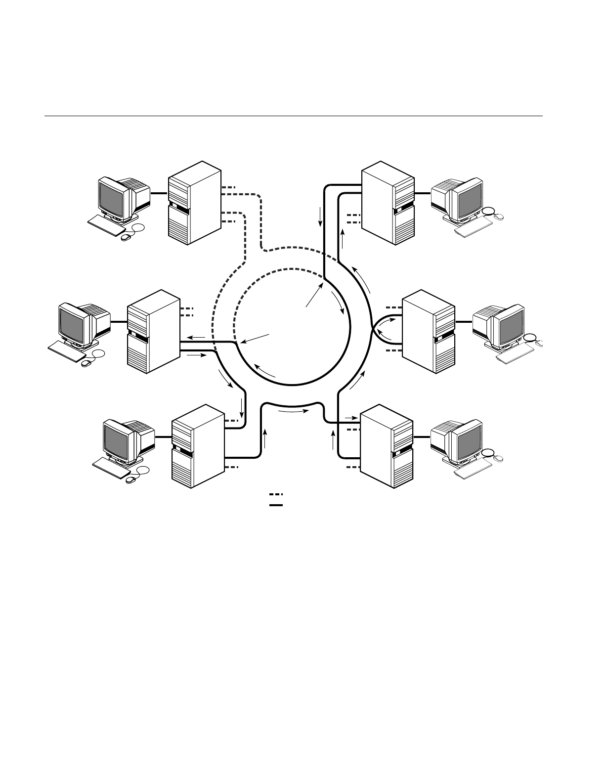
58
Chapter 3: Managing Your FDDI Station and Ring
Figure 3-5 Fault Isolation and Ring Wrap
As you can see in Figure 3-5, when one station experiences an error, only that station is
out of the loop. It is also possible for one port on one station to malfunction (as illustrated
by fault 1 in Figure 3-6), in which case the ring wraps, but no station is out of the loop.
Traffic on the network continues as usual. Notice that when a station fails (both ports are
off the ring), the wraps do not occur on the faulty port, but on its two neighbor ports.
A
B
A
B
A
B
DAS
DAS
DAS
wrap on port A
wrap on port B
A
B
DAS
A
B
DAS
A
B
DAS
fault
not in use
in use
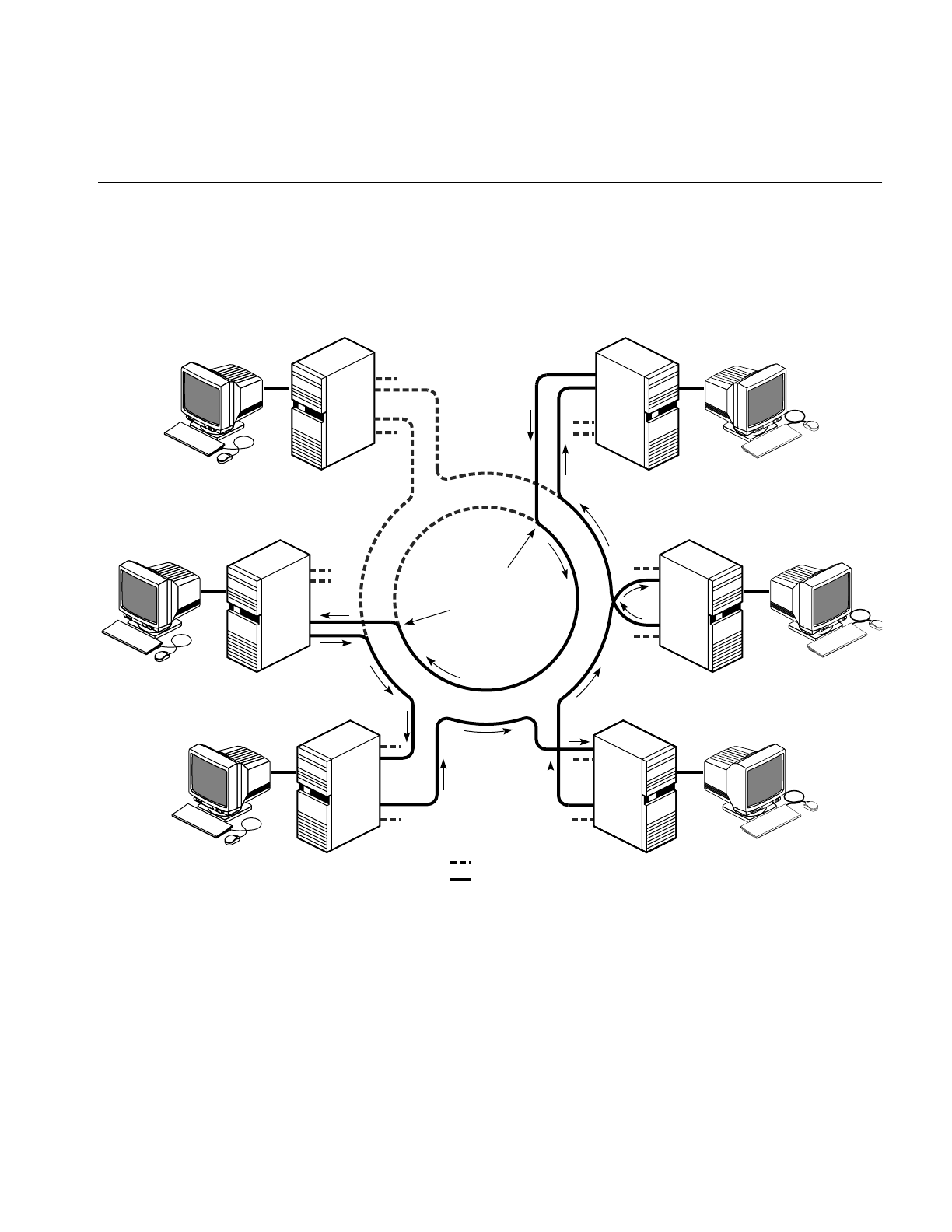
Recognizing Faults on the FDDI Ring
59
If two or more stations go down, the network may become fragmented into a number of
smaller loops, and users may not be able to access stations that have become isolated
onto a different loop. It is important to locate the faults and make the necessary repairs
as quickly as possible. Figure 3-6 shows a fragmented network with two stations down.
Figure 3-6 Fragmented Ring
A
B
A
B
A
B
DAS
DAS
DAS
wrap on port A
wrap on port B
A
B
DAS
A
B
DAS
A
B
DAS
fault
not in use
in use

60
Chapter 3: Managing Your FDDI Station and Ring
How do you know there is a fault on the ring? One way is to use smtping at each station
to verify that each one responds. Another way is to use smtring to create a complete list,
then verify that all known stations appear on the list. The easiest method is to use the
FDDIVisualyzer product, which graphically indicates faults on the ring. In all of these
instances, an up-to-date, complete list of all stations that are physically attached to the
ring is vital. The network administrator should maintain this list. In many cases, once a
station fails, it is not possible to communicate with it remotely over the ring. Its failure is
deduced from its absence or lack of response. To debug the faulty station, log on to that
station through a second network connection or at the station.
You can log on to any station and use smtstat to display status information about that
station’s FDDI interfaces. This command does not access a station remotely; rather, it
displays information about the local host, even when the host is not functioning on the
ring. A step-by-step verification process is described in “Verifying the FDDI
Connection” on page 47.
Monitoring a Station’s FDDI Status
You can display and monitor the status of a station’s FDDI connection by logging on to
the station and entering the following command:
% /usr/etc/smtstat
The smtstat report is shown in Figure 3-7 and a listing of its columns follows. Table 3-3
explains the entries for the columns in more detail.
Figure 3-7 smtstat Display
SM_DAS: Station ID=00-00-50-00-d8-20-00-e0 SMT Version 1 (1-1)
Name Address MAC port nbr PCM tls rls flags
ipg0 0a:00:1b:04:00:07 ACT B A ACTIVE THRU ILS <LS,RC,JOIN,THRU,RNGOP>
A B ACTIVE THRU ILS <LS,RC,JOIN,THRU>
SM_SAS: Station ID=00-00-50-00-d8-20-88-40 SMT Version 1 (1-1)
Name Address MAC port nbr PCM tls rls flags
xpi0 0a:00:1b:04:11:02 ACT S M ACTIVE THRU ILS <LS,RC,JOIN,THRU,RNGOP>
For a DAS
For an SAS

Monitoring a Station’s FDDI Status
61
In the DAS display, the first line contains the following information:
•the type of station (SM_DAS is a single MAC, dual-attachment station)
•the SMT station ID
•supported SMT versions
The second line contains column headings while subsequent lines display the
information:
•Name: names of FDDI interfaces (for example, ipg0,xpi0)
•Address: MAC address (in canonical order) associated with each interface
•MAC: status of the MAC (for example, ACT for active is normal)
•port: ports present for each MAC
•nbr: port on neighbor station to which each local port is connected (A-to-B, B-to-A,
and S-to-M are normal)
•PCM: status of each port’s physical connection management (PCM) where ACTIVE
is normal
•tls: transmit line state for each port (THRU is normal)
•rls: receive line state for each port (ILS is normal)
•flags: flags for each port (RNGOP,LS,RC,JOIN,THRU, and OBS are normal)
By monitoring SMT status, you can see the connection state, transmitting and receiving
line states, and the flags indicating the ring state. In the smtstat display shown in
Figure 3-7, the primary ring is operating (RNGOP), its transmit line is working (THRU), its
receive line is idle (ILS), and the secondary ring is functional (LS,RC,JOIN) but not
operating. If the ring were wrapped at this station, you would see a WRAP indication.
Table 3-3 smtstat Report Fields
Field Possible Entries Description
MAC MAC status
ACT active
CON connect
OFF MAC could not be read by software

62
Chapter 3: Managing Your FDDI Station and Ring
port local port connection type
Areceive on SAS, or receive for primary ring and transmit for
secondary ring on DAS
Btransmit on SAS, or transmit for primary ring and receive
for secondary ring on DAS
Mmaster
Sslave
? no connection
nbr same as port neighbor port connection type
PCM physical connection management state
ACTIVE active
CONNECT connected
JOINED joined
tls, rls transmit and receive line states
ALS active line state
ILS idle line state
QLS quiet line state
HLS halt line state
MLS master line state
THRU through connection (the ring is working at this station)
WRAP port is wrapped, which can mean that the ring is wrapped
at this station, or (for a DAS board attached to a
concentrator) that the port is wrapped to support an SAS
connection
flags special flags associated with station’s ports
LS line state desirable
Table 3-3 (continued) smtstat Report Fields
Field Possible Entries Description

Monitoring a Station’s FDDI Status
63
Display Kernel and SMT Daemon Statistics
By using the –v(verbose) option with smtstat, you can display additional statistics,
including the following:
•Physical connection management (PCM) status.
•A log showing line states for PHY0 (usually port B).
•Kernel statistics, described in Table 3-4. These statistics are reset to zero each time
the system is booted. Of the kernel statistics, only the following items normally
have steadily increasing values: frame_ct,A-bit,C-bit, and tok_ct.
RC ring connected; neighbor sending symbols
JOIN ring joined; neighbor handshaking finished.
RNGOP ring in operation
OBS optical bypass switch in use
CON-
Undesirable
undesirable SMT connection
CON-Illegal illegal SMT connection
WA withhold Port A as a back-up link
WAT withhold Port A in Tree mode
Table 3-4 smtstat -v Kernel Statistics
Field Description
Left column
frame_ct Frames seen
A-bit Address-recognized bits seen
rngop Times ring transitioned from nonoperational to operational
tkerr Duplicate tokens seen
Table 3-3 (continued) smtstat Report Fields
Field Possible Entries Description

64
Chapter 3: Managing Your FDDI Station and Ring
tvxexp Times valid-transmission-timer (TVX) expired
myclm Station’s own claims seen
mybec Station’s own beacons seen
eovf Elasticity buffer overflows experienced
tx_under Transmit FIFO underflows experienced
flsh Frames flushed
tot_junk Frames discarded
error Errors detected by MAC
rx_ovf Receive FIFO overflows experienced
Middle column
tok_ct Tokens seen
C-bit Frame-copied bits seen
rngbroke Times ring has become nonoperational.
clm Claims seen
trtexp Times token-rotation-timer (TRT) expired
loclm Claims seen that were lower than this station’s
otrbec Other stations’ beacons
noise Noise events from PMD and PHY
err_ct Frames seen with bad checksums (CRCs)
abort Frames aborted
junk_void Badly formatted void frames
shorterr Frames seen that were too short
buf_ovf Buffer overflows experienced
Right column
Table 3-4 (continued) smtstat -v Kernel Statistics
Field Description

Monitoring a Station’s FDDI Status
65
Using –vv (extra verbose) displays even more information, including SMT daemon
(smtd) statistics. The report displays
•additional station information
•physical connection management (PCM) status
•line state log for PHY0 (usually port B)
•MAC statistics and configuration information (referred to as a MAC dump)
•PHY1 (usually port A) configuration information
Display SMT Information (MIB)
To monitor continually the FDDI activity of a configured interface on the local system,
use:
% /usr/etc/smtstat –s -I fddiinterface
fddiinterface is the interface (for example, ipg0,ipg1,xpi0,xpi3).
E-bit Error-detected bits seen
multda Frames seen with station’s address and A bit already set
bec Beacons seen
tkiss Tokens issued
hiclm Claims seen that were higher than mine
dup_mac Times duplicate MAC addresses detected
xmtabt Transmission aborts experienced
lost_ct Badly formatted frames seen
miss Frames seen but unable to copy
junk_bec Badly formatted beacons seen
longerr Frames seen that were too long
Table 3-4 (continued) smtstat -v Kernel Statistics
Field Description

66
Chapter 3: Managing Your FDDI Station and Ring
The output of this command produces the following six smtstat reports.
•MAC status
•port status
•ring management status
•configuration information
•neighbor information
•miscellaneous SMT information
This output requires a shell window or a terminal at least 80 columns wide by 24 lines
high. When the window is too small, the display is not usable. Make your display area at
least this size before invoking the command.
The reports are viewed one at a time. The top of each report displays the report name,
date, and time. At the bottom of each report is a menu line listing all the available reports,
as shown in Figure 3-8.
Figure 3-8 smtstat -s Display: General Report Format
5: Neighbor Information -- Mar 24 15:46:19
1:MAC 2:Port 3:Ring Mgt 4:Config Mgt 5:Neighbors 6:SMT DZR:Mode
(all the Neighbor report information)
Menu Line

Displaying and Configuring Network Interface Information
67
The following user interface allows you to manipulate the reports:
•To display a different report, type the report’s number. The numbers are displayed
in the menu line on the bottom of the screen. For example, to view the SMT report,
type 6.
•To quit, type qor Ctrl+c.
•To refresh the screen, type Ctrl+l.
•To change the time interval for the report statistics display, press one of the these
keys:
rEach second, shows totals accumulated since last reboot.
dResets fields to zero every second, and each second shows totals
accumulated within that last second.
zResets fields to zero when zis pressed, and every second displays
the accumulating totals.
For a description of all the fields in each report, see Appendix B, “smtstat Reports.” For
a complete definition of each field, refer to the ANSI standard entitled ANSI FDDI Station
Management (SMT). For information about command usage, refer to the smtstat(1M) man
page.
Displaying and Configuring Network Interface Information
As network administrator, you may need to display or temporarily alter a station’s
network interface parameters. The command smtconfig allows you to do this.
Display the Configuration
To display the current configuration of the FDDI interface, follow these steps:
1. Use smtstat to determine the name of the FDDI network interface(s) on your station.
The FDDI interface name is listed under the column heading Name. Examples: ipg0,
xpi0.
2. Use smtconfig with the name of the interface discovered in the first step:
% /usr/etc/smtconfig interfacename

68
Chapter 3: Managing Your FDDI Station and Ring
Sample output from smtconfig is shown in Figure 3-9. A description of the fields follows,
starting with the first item on the left of the top line and moving right.
Figure 3-9 smtconfig Display
•First line:
–The interface name.
–Flags that are enabled, with the following meanings:
•Second line:
–The address family configured for this interface: inet is the default.
–The address assigned to this network interface: The default is the IP address
associated with the hostname in the /etc/hosts file.
–The network mask (netmask) used for the IP subnetwork: The default is a value
that, when applied, implements no mask.
–The address used for broadcasting to all stations on the ring: The default is an IP
address where the host portion is all ones.
UP The network interface is enabled and should be functioning. When UP is
displayed, RUNNING should also be displayed.
BROADCAST A broadcast address is set.
DEBUG Debugging is enabled.
NOTRAILERS The link layer encapsulation does not use trailers.
RUNNING The driver is running and should be functional. This flag and UP should
always appear together.
NOARP The Address Resolution Protocol is not enabled.
MULTICAST A multicast address is set.
CKSUM The driver is generating checksums for transmitted packets.
OBS An optical bypass switch is present.
xpi0: flags=863<UP,BROADCAST,NOTRAILERS,RUNNING,MULTICAST,OBS>
inet 187.51.80.4 netmask 0xffffff00 broadcast 187.51.80.255

Displaying and Configuring Network Interface Information
69
Change the Configuration
As superuser, you can enable and disable the FDDI interface or (re)configure the FDDI
interface parameters manually using the smtconfig(1M) command. Most of the time, it is
not necessary to set interface parameters manually using smtconfig because FDDI is
configured automatically with default settings (as described in Table 2-3) when the
system is started or rebooted.
Note: Changes made with smtconfig are not saved; at reboot they return to their default
settings (or the /etc/config/ifconfig-#.options and /etc/config/netif.options files). To change the
configuration so the changes survive rebooting, follow the instructions in Chapter 2 or in
IRIX Admin: Networking and Mail.
To change the configuration of a network interface, perform the following steps:
1. Become superuser:
% /sbin/su
Password: thepassword
#
2. Use smtstat to determine the name of the FDDI network interface(s) on your station.
The FDDI interface name is listed under the column heading Name. Examples of
FDDI interfaces include ipg0,ipg1,xpi0,xpi3.
3. Use smtconfigwith one of the following formats.
Superuser can use the smtconfig command to change the FDDI operational
parameters listed below, in much the same manner as ifconfig. For information
about the creation and purpose of these parameters, refer to IRIX Admin: Networking
and Mail.
•Enable or disable the interface:
# /usr/etc/smtconfig interfacename up
# /usr/etc/smtconfig interfacename down
•Set a network mask value for an IP subnetwork:
# /usr/etc/smtconfig interfacename netmask value_or_name
•Change the address used for broadcasting:
# /usr/etc/smtconfig interfacename broadcast address

70
Chapter 3: Managing Your FDDI Station and Ring
•Enable or disable driver debugging messages:
# /usr/etc/smtconfig interfacename debug
# /usr/etc/smtconfig interfacename -debug
•Enable or disable Address Resolution Protocol. ARP is enabled when there is no
flag about ARP:
# /usr/etc/smtconfig interfacename arp
# /usr/etc/smtconfig interfacename -arp
•Set the routing metric used by the route daemon (routed):
# /usr/etc/smtconfig interfacename metric digit
•Change the IP address for this interface:
# /usr/etc/smtconfig interfacename IPaddress
•Select a different interface to be the primary network interface for this station:
# /usr/etc/smtconfig interfacename primary
Examples
This section describes some scenarios in which the different smtconfig command options
can be used.
•Before performing computer maintenance work that will require rebooting a
station, disable the FDDI network interface, xpi0, with the command:
# /usr/etc/smtconfig xpi0 down
•On a router with an FDDI interface named ipg0, you want to decrease the number of
packets going through the station enroute to other networks. One way to do this is
by advertising the route as less favorable. Use this command:
# /usr/etc/smtconfig ipg0 metric 5
For information about creating netmasks, route metrics, broadcast addresses, and IP
addresses, or about altering network interface configurations, see “Changing Settings for
the Operational Parameters” in Chapter 2, the smtconfig(1M) man page, or IRIX Admin:
Networking and Mail.

Verifying a Station’s PCM Functionality
71
Verifying a Station’s PCM Functionality
The smtmaint command allows you, as superuser, to set the Physical Connection
Management (PCM) line state for each PHY on a station’s FDDI board. An SAS has one
PHY (PHY0); a DAS has two PHYs (in most cases, PHY0 for port B and PHY1 for port A).
Use smtmaint judiciously and only if you are an FDDI expert. Setting a line state can make
the ring nonfunctional.
You can set these six line states:
QLS PHY sends a continuous stream of Quiet symbols so the transceiver
emits no signal.
ILS PHY sends a continuous stream of Idle symbols; this is a normal
condition between transmissions.
HLS PHY sends a continuous stream of Halt symbols; this forces a break in
the ring.
MLS PHY sends a continuous stream of alternating Halt and Quiet symbols;
this is used to propagate a trace along the ring.
ALS PHY functions normally; it is Active and incorporated into the ring.
-t PHY enters PC_TRACE state (trace function) attempting to recover the
ring from a stuck beacon condition.
To change a line state, follow these steps:
1. Become superuser:
% /sbin/su
Password: thepassword
#
2. Use smtstat to discover the name of the FDDI network interface on your station. The
FDDI interface name is listed under the column heading Name. Examples of FDDI
interfaces include ipg0,ipg1,xpi0.
3. Use this command to change the line state:
# /usr/etc/smtmaint interfacename 0or1 linestate
0or1 identifies the PHY (port) and linestate is one of the line states listed above (for
example, ALS, -t, or ILS).

72
Chapter 3: Managing Your FDDI Station and Ring
Removing a Station From the FDDI Ring
When an FDDI station is removed from the ring, the SMT modules reconfigure the ring.
If the removal is done in a way that makes it impossible for the optical signal to complete
its loop around the ring, the ring wraps. Generally, it is best to avoid wrapped rings for
long periods. The procedures described in this section describe how to avoid or minimize
a wrapped ring when removing a station from the ring.
The situations listed below constitute taking an FDDI station off the ring; any of these has
the potential to cause the FDDI ring to wrap (sometimes for a very short period of time).
•Rebooting a system, which includes any of the following: invoking the reboot or init
commands, pressing the station’s reboot button, and crashing the station’s system.
A crash usually results in an automatic reboot.
•Hanging the station’s system (usually due to software failures).
•Shutting down the station’s system, which includes using any of the following
commands: shutdown,reboot,halt,init 0.
•Removing power from the station by pressing the power switch or disconnecting
the power cable.
•Disconnecting the station’s FDDI cables.
•Disabling the FDDI network interface, which includes invoking any of the
following commands with the down or stop option: smtconfig,ifconfig,
/etc/init.d/network.
•Removing an optical bypass switch from a station.
The procedure for safely removing a station from the ring differs, depending on three
factors:
•whether the removal is temporary or permanent
•whether the station is directly attached to the dual ring (DAS) or is attached to a
concentrator (SAS or dual-homed DAS)
•whether an optical bypass switch is present or not (applies only to a DAS attached
directly to the dual ring)

Removing a Station From the FDDI Ring
73
Temporarily Disable Any Station’s FDDI Interface
To temporarily disable any FDDI interface for a short period of time, use the smtconfig
command described in “Change the Configuration” on page 69.
If the station is a DAS, is not attached to a concentrator, and does not have an optical
bypass switch, the ring will wrap when the FDDI network interface is disabled.
However, this is usually not a problem for a short period of time.
Remove a Device Attached to a Concentrator
Four types of devices can be attached to concentrators: single-attachment stations and
concentrators (SAS and SAC) and dual-homed, dual-attachment devices (DAS and
DAC). It is simple to remove any of these from the ring. Because the concentrator
maintains the integrity of the ring, it is not important whether the station will be out of
the ring for a long or short period of time. You need only decide whether the removal is
temporary or permanent.
Temporarily Removing a Device
To temporarily remove a device attached to the ring through a concentrator, perform the
following steps:
1. Become superuser and shut down the system. As soon as you do this, the station is
out of the ring. The command lines below are one way of doing this:
%/sbin/su
Password: thepassword
#/etc/shutdown
2. You can now perform system maintenance or physically disconnect the station from
ring (actually, from the concentrator). The concentrator will maintain the integrity
of the ring. However, since the station’s identity as an FDDI station remains in the
system files, the station should be returned to the ring at some point. When
reinserted into the ring, the station does not have to be reconnected at the same
location.

74
Chapter 3: Managing Your FDDI Station and Ring
Permanently Removing a Device
To permanently remove a concentrator-attached device from the ring, do the following:
1. Become superuser and disable the FDDI interface using these commands:
% /sbin/su
Password: thepassword
# /usr/etc/smtconfig interfacename down
2. Edit the files described in “Complete and Complex Configuration Information” on
page 28 to remove or comment out the lines referring to this station. One or more of
the following files may need to be edited: /etc/hosts,/etc/ethers,/etc/config/netif.options.
3. Shut down the system using the shutdown or halt command.
4. Power off the station by pressing its power switch.
5. Disconnect the FDDI cable(s).
6. At this point, you can move the workstation or server. If you ever decide to reinsert
this station into this ring, you will need to reconfigure it.
Removing a DAS That Has an Optical Bypass Switch
Removing a DAS that has an optical bypass switch is simple. Because the optical bypass
switch maintains the integrity of the ring, it is not important whether the station is out of
the ring for a long or short period of time. You need only decide whether the removal is
temporary or permanent.
As long as you leave the optical bypass switch in place and move only the station, the
ring will not wrap.

Removing a Station From the FDDI Ring
75
Temporarily Removing a DAS
To temporarily take a DAS with an optical bypass switch out of its ring follow these steps.
1. Become superuser and shut down the system. For example:
% /sbin/su
Password: thepassword
# /etc/shutdown
2. Disconnect the optical bypass switch’s DC power cable from the FDDI board.
3. If you need to, power off the station by pressing the station’s power switch, and
disconnect the station’s FDDI cable(s). Do not disconnect the connections between
the ring and the optical bypass switch.
4. You can now perform system maintenance or physically disconnect the station from
ring. The optical bypass switch maintains the integrity of the ring. However, since
the station’s identity as an FDDI station remains in the system files, the station
should be returned to the ring at some point. When reinserted into the ring, the
station does not have to be reconnected at the same location.
Permanently Removing a DAS
To permanently remove a DAS with an optical bypass switch from the ring, perform the
steps below:
1. Become superuser and disable the FDDI interface with these commands:
% /sbin/su
Password: thepassword
# /usr/etc/smtconfig interfacename down
2. Edit the configuration files to remove or comment out the lines referring to this
station. One or more of the following files may need to be edited: /etc/hosts,
/etc/ethers,/etc/config/netif.options.
3. Shut down the system using the shutdown or halt command.
4. Power off the station by pressing its power switch.
5. Disconnect the optical bypass switch’s DC power cable from the FDDI board.
6. Disconnect the FDDI board’s cables from the optical bypass switch.
7. At this point, you can move the workstation or server. If you ever want to insert this
station into this ring, you need to reconfigure the station. Another station can be
attached to the optical bypass switch at any time.

76
Chapter 3: Managing Your FDDI Station and Ring
Remove a DAS Without an Optical Bypass Switch
Removing a DAS that does not have an optical bypass switch always disrupts the ring;
removal of a station causes the ring to wrap in configurations where the secondary ring
is a backup. There is no way to avoid this; hence, your primary concern is the length of
time the ring will be disrupted. After you remove the station, you need to do one of the
following as soon as possible to reestablish the integrity of the ring:
•Insert the same or another station at the location.
•Insert an optical bypass switch at the location.
•Patch the ring (for example, by inserting a barrel connector or section of fiber optic
cable at the location).
Temporarily Removing a DAS
To temporarily remove a DAS without an optical bypass switch from its ring, follow the
instructions below.
Note: This procedure causes the ring to wrap.
1. Become superuser and shut down the system. For example:
% /sbin/su
Password: thepassword
# /etc/shutdown
2. Power off the station by pressing the station’s power switch, and disconnect the
station’s FDDI cable(s).
3. As soon as possible, do something to reestablish the ring’s integrity. A list of
possible actions is provided at the beginning of this section.
4. You can now perform system maintenance or physically move the station. Since the
removed station’s identity as an FDDI station remains in the system files, the station
should be returned to the ring at some point. When reinserted into the ring, the
station does not have to be reconnected at the same location.

Removing a Station From the FDDI Ring
77
Permanently Removing a DAS
To permanently remove a DAS station without an optical bypass switch from the ring,
follow the instructions below.
Note: The ring will wrap as soon as you disable the FDDI interface.
1. Become superuser:
% /sbin/su
Password: thepassword
#
2. Edit the configuration files to remove or comment out the lines referring to this
station. One or more of the following files may need to be edited: /etc/hosts,
/etc/ethers,/etc/config/netif.options.
3. Disable the FDDI interface:
# /usr/etc/smtconfig interfacename down
4. Shut down the system using the shutdown or halt command.
5. Power off the station by pressing its power switch.
6. Disconnect the station’s FDDI cable(s).
7. As soon as possible, do something to reestablish the ring’s integrity. A list of
possible actions is provided in the beginning of this section.
8. At this point, you can move the workstation or server. If you want to reinsert this
station into this ring, you will need to reconfigure the station.
For more information, see the smtconfig(1M), halt(1M), and shutdown(1M) man pages
or ”Change the Configuration” in this chapter.

78
Chapter 3: Managing Your FDDI Station and Ring
Removing FDDIXPress
To permanently remove an FDDIXPress board and software from a station, follow the
steps below:
1. Use inst to remove the FDDIXPress software:
# /usr/sbin/inst
...
Inst> remove FDDIXPress
...
Inst> quit
2. Follow the set of instructions in “Removing a Station From the FDDI Ring” on
page 72 that is appropriate for your configuration.
3. Once the power is off, remove the board.
The board’s installation guide or installation instructions provides hardware details
that are useful for removing the board.
4. When the FDDI board has been removed, press the power switch to turn the system
on.
5. Answer the questions on the terminal to restart the system.
6. Answer yes to the prompt to rebuild the operating system. This step removes the
FDDI driver from the operating system (kernel).
Automatically reconfigure the operating system (y or n)? y
7. Reboot the system to start using the new operating system.

79
Chapter 4
4. Troubleshooting
This chapter describes what to do when your FDDI network connection has problems.
The chapter describes the following topics:
•“General Advice” on page 79
•“Checking Physical Connections” on page 80
•“Status Indicators and Symptoms” on page 87
General Advice
When you experience difficulty with the FDDI network connection at a particular
station, you can:
1. Check the physical connections at the station as detailed in “Checking Physical
Connections.”
2. Search or read the /var/adm/SYSLOG file and console window for error messages. If
you find any FDDI driver or SMT messages, read about them in Appendix A.
3. Use the SMT commands (or FDDIVisualyzer) to identify problematic status
indicators, and if you find any, read about them in “Status Indicators and
Symptoms” on page 87.
The following sections will help you with each of these suggested steps.

80
Chapter 4: Troubleshooting
Checking Physical Connections
Check each of the following, using the step-by-step instructions:
•“Recognition of Board by Software” on page 80
•“Check Cables and Connectors” on page 83
•“Cable Lengths” on page 86
Recognition of Board by Software
Complete inability to access the FDDI ring may indicate that the board and software are
not communicating. Follow the instructions below to figure out why.
1. In a shell window, type this command:
% /sbin/hinv
When a board is listed by hinv,, this does not mean that the board and driver are
functional; it means that the operating system was able to recognize the board. For
an explanation of the hinv screen display, see “Verifying the FDDI Connection” on
page 47 or the hinv(1M) man page.
2. If hinv displays an entry for the FDDI hardware, the operating system is recognizing
the board. The problem may be bad cable connections or improperly configured
software. First, follow one of the sets of instructions below, then (if necessary)
follow the instructions in “Check Cables and Connectors.”
If hinv does not display an entry for the FDDI hardware, the operating system did
not find the FDDI board the last time the station was booted. The problem may be
an incompatible operating system, or a loose or dysfunctional board. First, follow
the instructions below to verify the board, then follow the instructions in “FDDI
Connection Has Not Been Functional Since Last Boot” on page 81.
Verify the Board
Verify that the LEDs on the FDDI board indicate that the board is receiving power. If the
LEDs indicate that there is no power to the FDDI board or that the board is not
operational, follow the instructions in the board’s hardware manual to troubleshoot the
problem. It is possible that the board is not seated firmly into its connection to the system,
or that the board is dysfunctional.
If you reinstall the board, take extra precautions to seat the FDDI board firmly.

Checking Physical Connections
81
FDDI Connection Has Not Been Functional Since Last Boot
If the FDDI connection has not been working since the last time the station was booted
or if this is an initial installation of an FDDI product, one or more of the following could
be occurring:
•The operating system installed on the station is not compatible with the FDDI board
installed.
•The operating system has not been rebuilt to include the driver for the board.
•The network interface for the board has not been configured properly.
Follow the instructions below to determine the cause of the problem:
1. Verify that the installed IRIX operating system (oeo1) and FDDIXPress software are
the correct versions by doing the following:
■Determine the correct versions. The FDDIXPress release notes indicate the
correct IRIX and FDDIXPress versions for your FDDI board.
■Use the versions command (shown below) to display the installed release
identifications (versions). If the version is not correct, install the correct version.
Then invoke hinv.
% /usr/sbin/versions eoe1
eoe1 date Execution Only Environment 1, version
% /usr/sbin/versions FDDIXPress
FDDIXPress date FDDIXPress release Option
2. Use the netstat command, as shown below, to display the currently configured
network interfaces. If the FDDI interface is not displayed, continue to the next step.
If the interface is displayed, but the configuration is incorrect, follow the
instructions in “Configure the Station’s Network Interfaces” on page 33 to
reconfigure it.
% /usr/etc/netstat -ina
3. Verify the FDDI entries in the /etc/config/netif.options file. For example, the network
interface may be misspelled.
4. Use /etc/autoconfig to rebuild the operating system to include the FDDIXPress driver.
Then, reboot the system to start using the new operating system. Finally, invoke
netstat -ina again. If the FDDI interface is still missing, contact the Silicon Graphics
Technical Assistance Center.

82
Chapter 4: Troubleshooting
FDDI Connection Has Been Functional In the Recent Past
If new software (operating system, FDDIXPress, or another network communications
software) has been installed since the FDDI connection was last functional, the problem
is probably incompatible software. Verify that the software you last installed supports
the FDDI board installed in the station.
If the FDDI connection has been functional after the last new software was installed, the
problem is probably the board. The board may have become loosened from its
connection to the system or it may be dysfunctional.
Follow these steps to resolve the problem:
1. Verify that the LEDs on the FDDI board indicate that the board is receiving power. If
the LEDs indicate that there is no power to the FDDI board or that the board is
dysfunctional, follow the instructions in the board’s hardware manual to
troubleshoot the problem. Otherwise, continue.
2. Ensure that the system is using the operating system that was built most recently.
Use the /etc/autoconfig command to rebuild the operating system, then reboot to start
using it. During the reboot, begin step 3.
3. Watch the messages on the terminal during restart to verify that each network
interface is configured correctly. The messages should look similar to these
examples:
Configuring xpi0 as mickey
Configuring ec0 as gate-mickey
If the FDDI driver is not mentioned on the terminal during startup, there is a
problem with the software. Continue to step 4.
If a startup terminal message indicates that the hardware is missing, as in the
following example, start again at the beginning of “Recognition of Board by
Software” on page 80.
xpi0: missing

Checking Physical Connections
83
4. Use the netstat command to display the currently configured network interfaces. If
the interface is displayed, but the configuration is incorrect, follow the instructions
in section “Configure the Station’s Network Interfaces” on page 33 to reconfigure it.
% /usr/etc/netstat -in
The /etc/config/netif.options file may have an incorrect entry (for example, a
misspelled network interface); verify all file contents carefully.
If the FDDI interface does not display, it is possible the board or software is
dysfunctional. Contact the Silicon Graphics Technical Assistance Center.
Check Cables and Connectors
A wrap on an A or B port, a high level of link-layer errors, or a stagnant token count can
indicate a faulty cable, a loose or damaged connection, or a dirty cable end. The
problematic cable or connection can be found at or near the station where the error is
occurring.
Connections
At each cable connection, along the entire length of the ring where there is a problem,
verify two things:
•Each connection is tight. Many connectors must snap or click together to be tight.
(Remember to verify the connections at each station’s I/O panel.)
•Each connection is correct.
–For cable-to-cable connections, the labels on the two cable connections must
pair as a valid (V) connection, as summarized in Figure 4-1, where U indicates
that the connection is undesirable, invalid indicates that it is invalid, and V
indicates it is valid. Figure 4-2 illustrates valid connections for a typical ring.
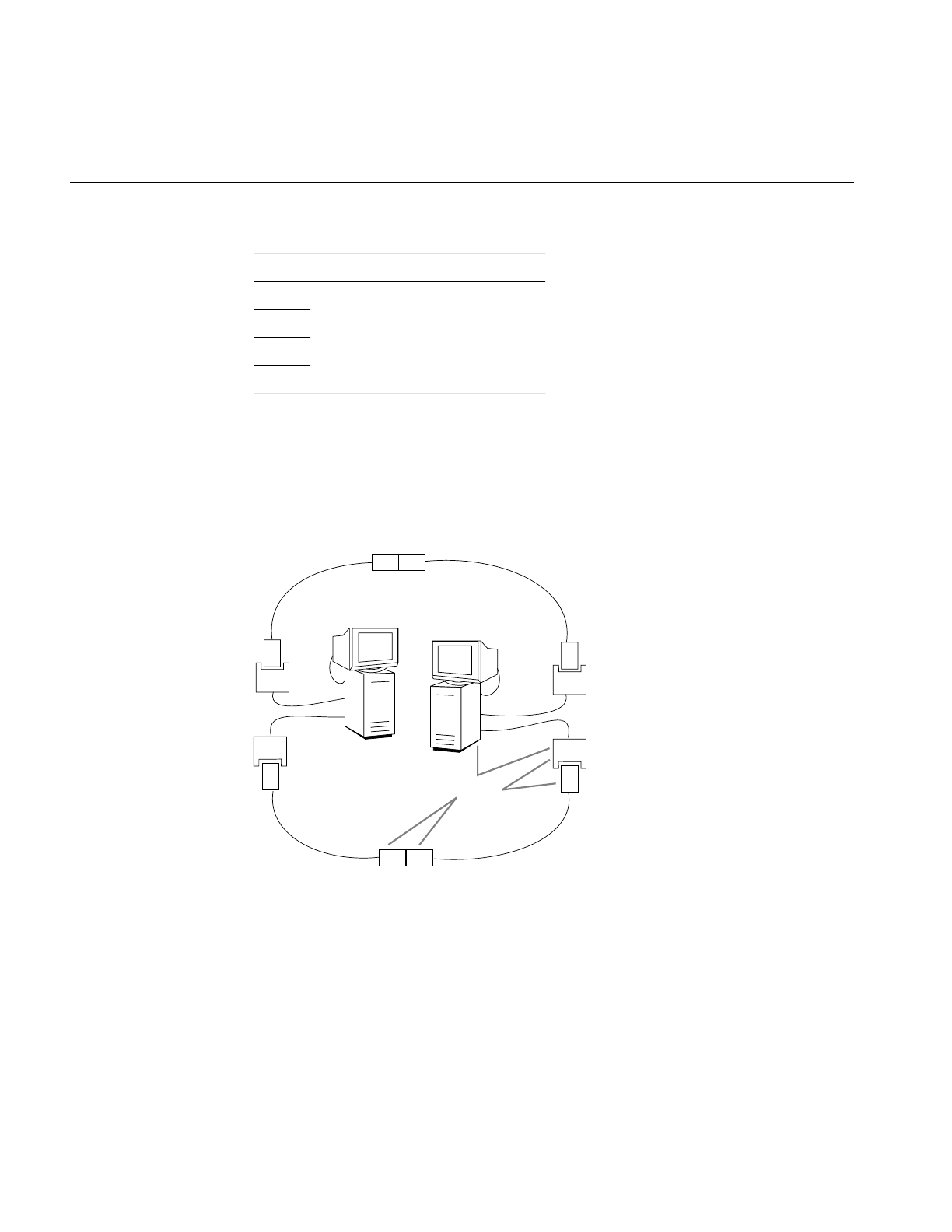
84
Chapter 4: Troubleshooting
Figure 4-1 Cable-to-Cable Connections
–For cable-to-station connections, the labels on the connectors must match (for
example, A-to-A or red-to-red, not B-to-A or red-to-blue). (Remember to verify
the connections at each station’s I/O panel. The cable’s label must match the
port where it is connected.)
Figure 4-2 Correct Cable Connections
ABS M
AUVU V
BVUU V
SUUV V
MV V V invalid
BA
A
A
B
B
AB
DAS
B
A
B
B
A
A
DAS
A
B
Cable-to-cable
Cable-to-
station
Verify

Checking Physical Connections
85
Dirty Fiber End
The ends of fiber optic cable can become dirty and interfere with the transmission of the
optical signal. Common pollutants are oil (from being touched by human fingers) and
dust (from being left uncapped).
Note: Do not touch the ends of fiber optic cable. Do not leave the fiber optic cable
uncapped when it is not connected. The cap prevents dust and other pollutants from
collecting on the exposed fiber optic material.
•Gently clean cable ends with 96% isopropyl alcohol and a non-lint producing soft
material, or an alcohol-wipe product.
Faulty Cable
Fiber optic cable can become damaged if excessively bent (or coiled), twisted, or sharply
struck. Replace suspect cables with functional cables.
When no replacement cable is available, use a small, powerful flashlight (as described in
the bulleted steps below) to verify that the light signal passes through the cable. This test
identifies broken or incorrectly built cables, but cannot identify borderline conditions.
1. Identify the direction that light travels within each optical fiber line of the suspect
cable. (FDDI MIC connectors and cable contain two optical fibers.)
Fiber optic material is designed somewhat like a funnel. Light travels in only one
direction: from the wide end to the narrow end. Some cable manufacturers label
each fiber with arrows. Some cables have connectors constructed so that the input
end of each fiber is indicated by the connector’s cover; the wider portion of the
cover (the funnel’s mouth) indicates the input end, as shown in Figure 4-3.
Figure 4-3 Direction Indicators With Media Interface Connector
Cable Output
Input
Connector with two fibers
Output
Input

86
Chapter 4: Troubleshooting
2. Shine the flashlight into one of the inputs. Verify that the light is visible and bright at
the output end of that line. If the light is not visible or is dim, the cable is faulty.
Replace it.
If the light is visible when shone in the opposite direction, the cable has been built
improperly. Replace it.
3. Repeat step 2 for the other input line.
Note: Special equipment is needed to accurately measure whether the optical signal is
full strength. The flashlight test cannot tell if the signal is partially obstructed.Visible
light at the other end of the cable does not guarantee that the cable is fully functional.
Cable Lengths
An increasing bit-error rate may indicate that power is being lost because the cable is too
long.
Cable Between Stations
A typical manufacturer’s maximum length of cable between DAS stations is 2 kilometers
(approximately 1.24 miles) for regular fiber optic cable, but can be much longer (for
example, 10 km) for newer low-loss fiber optic cable. Length is measured from the FDDI
connector on the I/O panel of one station to the FDDI connection on the I/O panel of a
neighbor station. This length is not the distance between the two stations; it is the length
of the cable lying between two stations. Coils of cable lying in the closets, floors, or
ceilings of buildings can quickly add up to this maximum, so beware.
Total Length of Ring Cable
A typical manufacturer’s maximum length of cable allowed for one ring is 100 kilometers
(approximately 62 miles). The total ring cable length is calculated by summing all the
between-station lengths (as described in the paragraph above).
Note: Special equipment is needed to measure the amount of power loss on a fiber optic
cable.

Status Indicators and Symptoms
87
Status Indicators and Symptoms
This section contains some common symptoms and smtstat status indicators
accompanied by descriptions of what they may indicate and what you can do to remedy
the problem.
Link-Level Errors
A high rate of link-layer errors can indicate a cable problem very close to or on the local
station. Follow the instructions for verifying and cleaning cable connections.
Token Count Not Incrementing
When the token count is not incrementing, the FDDI board is not seeing the light signals
on the ring (neither port is functioning or there may be a problem with the ring).
1. This symptom may indicate that the FDDI network interface has been turned off.
When this is the case, the Port Status report indicates that the MAC is OFF. Verify
that the FDDI cables are connected, then use smtconfig to stop and restart the FDDI
network interface.
If the problem persists, proceed to step 2.
2. Use the smtstat -s Port Status report to check the status of the receive line states.
■If the report shows HLS, the problem is probably one of the neighbor stations or
the ring. Verify that each neighbor station is functioning properly.
■If the report indicates QLS, the problem is probably local to this station. The
problem may be loose or damaged connectors, faulty cabling, or incorrectly
connected ports. Follow the instructions in “Checking Physical Connections”
on page 80 for all cabling between the station’s I/O panel and the ring.
Be especially careful to verify that the ends of the fiber optic cable at the I/O panel
have not been damaged.

88
Chapter 4: Troubleshooting
Too Many Claims or Beacons
When claims or beacons increment rapidly for more than a few seconds, a station on the
ring is malfunctioning or inserting itself. When the symptom persists for more than 5
minutes or is observed on three consecutive occasions (when you are certain no new
stations are being added), follow these steps to locate the dysfunctional station, then
remove it from the ring. This procedure can be very time consuming. A malfunctioning
station is sometimes difficult to locate.
1. Locate a patch for the ring. The following items can be used to patch a ring: an
optical bypass switch, a fiber optic barrel connector, or an extra length of your ring’s
fiber optic cabling with appropriate connectors.
2. Physically disconnect one station from the ring.
3. Insert the patch into the ring (to fill the gap where the station was).
4. Wait two or three minutes. During this time, the stations remaining on the ring
rearrange themselves.
5. Go to another station. Check if the problem has been remedied.
6. If the problem no longer manifests, you know that all the remaining stations are
functioning properly. Do not return the dysfunctional station to the ring until it has
been fixed.
If the problem still exists, go to step 7.
7. Reinsert the disconnected station. Repeat steps 2–6.
Ring Is Wrapped
When the ring is wrapped, follow these instructions:
1. At each dual ring DAS, use the smtstat -s Port Status report to verify that neither
port’s transmit line state is in WRAP.
The transmit lines for a two-port FDDI board that is connected to a concentrator
normally indicate WRAP. This is normal and not a problem.

Status Indicators and Symptoms
89
2. When you locate a WRAP, look at the Port Status report’s flags to verify that the WRAP
is not caused by an undesirable (CON_undesirable) or illegal connection
(C_illegal). If you identify a problematic connection, follow the instructions in
“Check Cables and Connectors” on page 83 to remedy the problem. Otherwise,
proceed to step 3.
3. When you locate two dual ring DASes, each with one of its ports in WRAP, you have
identified the boundaries of the functioning and nonfunctioning sections of the
ring. The fault can be found somewhere between the two stations: downstream
from the station whose port A is wrapped and upstream from the station whose
port B is wrapped.
4. Follow the instructions in “Checking Physical Connections” on page 80 for the
connectors and cables within the identified fault domain. If the problem persists,
proceed to step 5.
5. Starting with either of the boundary stations, perform these steps to determine
whether the fault is caused by the operating system or SMT module within one of
the stations located along the fault domain.
■Locate a patch for the ring. The following items can be used to patch a ring: an
optical bypass switch, a fiber optic barrel connector, or an extra length of your
ring’s fiber optic cabling with appropriate connectors.
■Disconnect the station from the ring.
■Patch the ring.
■Connect the station’s A connector (port) to its B connector (port) with a length
of fiber optic cable.
■Use the smtstat -s MAC Status report to verify that the station’s token count
increments rapidly. An incrementing token indicates that the station is
functioning properly.
■If the token increments rapidly, reconnect the station to the ring and repeat this
procedure on the next station within the fault domain.
■If you locate a dysfunctional station, do not reinsert it into the ring until it is
fixed.

90
Chapter 4: Troubleshooting
High Rate of Packet Loss
If the packet loss is 100%, go to “Cannot Communicate With Other Stations” on page 90.
Otherwise, perform these steps:
1. If the high packet loss is displayed by the ping command, not by smtping , check any
routers connected to the ring for overloading.
Use /usr/etc/netstat -ina (or FDDIVisualyzer) at each station to identify all the
stations on the ring that are routers. A router has two or more MAC addresses, two
or more network addresses, and the routing daemon (routed) is running and is not
configured with the -qand -h options. (The routing daemon is configured by the
/etc/config/routed and /etc/config/routed.options files.)
2. If the high packet loss is indicated by both ping and smtping, use smtstat -s (or
FDDIVisualyzer) to locate additional symptoms.
High packet loss when using the -f option or the -i option with a short interval does
not necessarily indicate a problem. It is normal for ping and smtping to place echo
request packets onto the send queue faster than they can be processed, resulting in a
perceived loss of packets. In these instances, the packets are lost within the initiating
host, not on the network.
Cannot Communicate With Other Stations
If smtping or ping do not elicit a response, identify the appropriate subsection below and
follow the instructions.
Neither ping Nor smtping Works
1. If neither smtping nor ping elicits responses from any station, the /etc/hosts and
/etc/config/netif.options files may not have been set up properly. For example, the files
may be configuring the FDDI network interface with the Ethernet IP address. Verify
that the IP (inet) addresses for all network interfaces are correct. To display the
currently configured IP addresses for FDDI and Ethernet network interfaces:
% /usr/etc/netstat -in
If the IP addresses are correct, proceed to step 2. If the addresses are not correct,
follow the instructions in Chapter 2 to reconfigure FDDIXPress.

Status Indicators and Symptoms
91
2. If the IP addresses are correct, the station may not be connected to any of its
networks. At each of the station’s neighbors, use smtstat -s to find a wrapped FDDI
ring. If both neighbors indicate a WRAP, follow the instructions in “Checking
Physical Connections” on page 80 to reconnect this station to the ring.
3. If the problem persists, identify other problems, as described in “Verifying the
FDDI Connection” on page 47.
ping Works But smtping Does Not
If smtping does not elicit a response from a particular station but ping does, any of the
following may be the problem:
•The MAC address for the station may be incorrect.
•The station may be off the FDDI ring.
•The ring may be wrapped so that the two stations are on different fragments.
In the last two cases, the ping response is arriving over another connection, not the FDDI
connection in question, and the success of the ping indicates that the station is reachable
through a router.
The smtping command uses physical (MAC) addresses, not IP addresses, so it can
communicate only with stations on the same physical medium (that is, local area
network). For example, a station with an IP address of 223.62.4.51 (where the network
portion is 223.62.4) cannot smtping a station residing on a network with the address
223.62.5; however, it can contact address 223.62.4.11 (assuming that no subnetworks have
been created). You can verify the IP address of the other station with one of these
command lines:
% /usr/bin/ypmatch name hosts
% /sbin/grep name /etc/hosts
1. Use ping with the -roption and the IP address (not the host name) to verify that the
station is being reached over the FDDI network (not through a router or another
network connection). Make sure that the network portion of the IP address matches
the FDDI network (not that of another network). If the station answers, continue. If
the station does not answer, follow the instructions in “Neither ping Nor smtping
Works” on page 90.
%/usr/etc/ping -r IPaddress

92
Chapter 4: Troubleshooting
2. Verify the MAC address for the station you are trying to contact. You can obtain a
station’s MAC address with smtstat at that station’s terminal. Then, use smtping
with the MAC address (not the hostname) and specify the FDDI interface. If the
station answers, the station’s MAC address in the /etc/ethers file may be incorrect. If
the problem persists, continue with step 3.
%/usr/etc/smtping -I fddiinterface ##:##:##:##:##:##
3. Use smtstat -s at each station on the ring to verify the ports that indicate a WRAP.
ping Does Not Work But smtping Does
If smtping works but ping does not, it is possible that the /etc/hosts file has not been set up
properly. For example, the station may have both an FDDI and an Ethernet cable
connected but the network connection names and IP addresses in the /etc/hosts or
/etc/config/netif.options files are mismatched.
1. Display the currently configured IP (inet) address for each network interface:
% /usr/etc/netstat -ina
Verify that the displayed addresses correctly match the connected networks. If
everything is correct, proceed to step 2. If any IP addresses is not correct, follow the
instructions in “Network Connection Names and IP Addresses” on page 31 to
reconfigure FDDIXPress.
2. Again invoke smtping using the MAC address for the station (not the hostname) and
specify the FDDI interface. If the station answers, continue. If the station does not
answer, follow the instructions in “Neither ping Nor smtping Works” on page 90.
%/usr/etc/smtping -I fddiinterface ##:##:##:##:##:##
3. Use ping with the -roption and the station’s IP address (not the hostname) to verify
that the station is being reached over the FDDI network in question (not through a
router or another network connection). Make sure that the network portion of the IP
address matches the network address (from the netstat display) for the fddiinterface
used in the smtping command above. If the station answers, all is well. If the station
does not answer, go to step 4.
%/usr/etc/ping -r IPaddress
4. Disable then re-enable the FDDI interface, then repeat steps 1-3:
%/usr/etc/smtconfig fddiinterface down
%/usr/etc/smtconfig fddiinterface up

Status Indicators and Symptoms
93
Current Neighbor’s Address Is Zero
When both current neighbor addresses are zero, the station is not seeing a signal from
any other station on the ring. This condition is normal if the station is the only station on
the ring. This condition is not normal and indicates a wrapped ring when the site’s
configuration is a multistation dual ring with one ring as a backup. The zero addresses
indicate that the station is located within a fault domain (a nonfunctional section of the
ring). Follow the instructions in “Ring Is Wrapped” on page 88.
When one of the current neighbor addresses is zero, the station is not seeing any signal
from that neighbor’s direction (which is either upstream or downstream). A dual ring
configuration with one ring as a backup wraps when this occurs. You can see this wrap
by using the smtstat -s reports at this station. Follow the instructions in “Ring Is
Wrapped” on page 88. The zero address indicates the direction you should start looking
for the fault. Be sure to start your search at the nonwrapped port on this station’s I/O
panel. The wrapped port is a functional port.
Ring Is Not Wrapped and Token Count Increments But smtping Does
Not Work
If the ring is not wrapped, smtping does not work with any station, and smtstat -s
indicates that the token count increments normally, there is probably something wrong
with the station’s software.
To resolve this problem, follow this procedure:
1. Verify that the problem is not caused by your station’s configuration.
■Use smtping with a valid MAC address. To determine all valid MAC addresses,
use smtring.
■If smtping works with the MAC addresses, but does not work with station
names, the ethers database (the /etc/ethers file, local or on an NIS server) is
incorrectly set up. Follow the instructions in “Setting Up the ethers File
(Optional)” on page 43 to set up an ethers database.
2. If smtping does not work with MAC addresses, use these commands to disable and
reenable the software and board:
% /sbin/su
Password: thepassword
# /usr/etc/smtconfig interfacename down up

94
Chapter 4: Troubleshooting
3. Verify the FDDI connection again.
4. If the problem is still present, reinstall your station’s software (following the
instructions in the release notes) and reconfigure it (following the instructions in
Chapter 2, “Configuring FDDIXPress Software” of this manual).
5. If the problem is still present, contact the Silicon Graphics Technical Assistance
Center.
System Does Not Load Miniroot or Boot From the Network
Silicon Graphics workstations and servers are capable of loading a small-sized version of
the operating system (the miniroot) and booting themselves over the network; however,
they are capable of doing this only over Ethernet local area networks (they cannot boot
over FDDI networks) that are configured as the primary network interface.
If your system is unable to load the miniroot (or boot over the network), verify that its
primary network interface is an Ethernet connection by following these instructions:
1. Restart the system from the System Maintenance menu. Do not rebuild the
operating system during this restart.
2. Log on and open a shell window.
3. Use these commands to display the ordering of the network interfaces:
%/usr/etc/netstat -i
<primary interface>
<secondary interface>
...
4. If the primary interface is an Ethernet (for example, ec0,et0,enp#), the Ethernet
network connection may be dysfunctional. See IRIX Admin: Networking and Mail for
information about Ethernet network connections.
If the primary interface is not an Ethernet, go to step 5.
5. Configure an Ethernet connection as the primary interface, following the
instructions in “FDDI as the Secondary Interface and Ethernet as Primary” on
page 25.
6. Reboot the system. When the system is up and running, it should be capable of
loading the miniroot over the network and booting from it.

95
Appendix A
A. Error Messages
This appendix contains an alphabetical list of all the error messages that can be displayed
by FDDIXPress drivers, SMT commands, and the SMT module. The error messages are
divided into three sections:
•“SMT Error Messages” on page 97
•“xpi Driver Error Messages” on page 149
•“ipg Driver Error Messages” on page 157
•“rns Driver Error Messages” on page 161
The error messages in this appendix are those that are unique to FDDIXPress. Standard
system error messages, even when caused by the FDDIXPress code, are not included.
How Messages Are Listed
With each error message is a discussion of the problems that may cause the message. The
list contains only messages that indicate an error or problem; it does not contain
informational messages that occur during normal operation.
Messages are alphabetized according to the following rules:
•Each message is alphabetized by the numerals (0–9) and letters (a–z) of the
message’s text. Numerals precede letters. Capitalization makes no difference.
(Figure A-1 illustrates the text of an error message.)

96
Appendix A: Error Messages
•Nonletters (for example, - or %) and blank spaces are shown in the text of the
message, but are ignored in alphabetization. For example, the message sm_open
appears between smnet and smp.
•When an error message includes an item that the software specifies differently for
each instance of the message (a variable), this item is displayed in italic font and
labeled with a generic name (for example, filename). The generic names are skipped
for alphabetization purposes. For example, the error message goofy not
responding is located among the “n” listings as hostname not responding.
Common generic names used in this listing include hostname,interfacename,phyID,
version#, userentry, systemmessage,digit,filename, and hexnumeral.
Note: If you cannot find an error message in the listing, identify potential fill-in
words, then look up the message without those words.
•The creator of each message is listed, in angled brackets, below the text of the
message: (<creator>).
FDDIXPress error messages created by the SMT daemon (smtd) and the SMT commands
are written into the file /var/adm/SYSLOG or displayed at the terminal; some messages
appear in both places. Within the SYSLOG file, each message is preceded by the date,
time, hostname, the name of the process that created the message, and its process ID
number, as illustrated in Figure A-1. Only the text of the error message is included in the
alphabetic list that follows.
Figure A-1 Error Message Format in the /var/adm/SYSLOG File
May 10 05:12:03 goofy smtd[58]: Unknown Frame, FC=2
Date and time Host Creator Text of error message

SMT Error Messages
97
SMT Error Messages
A<->A twist detected
<smtd>
A twist in the fiber was detected. The software was expecting an A-to-B
connection. Follow the instructions in the section “Checking Physical
Connections” in Chapter 4 to fix the cable or connection problem.
A general error occurred
<smtd>
The SMT daemon has encountered a problem with its MIB information.
This may indicate that the MIB file (/etc/fddi/smtd.mib) is corrupted. Make
a new copy from the backup, then use smtconfig to stop and restart the
network interface. This also can indicate that the requesting SMT
module has requested invalid MIB information.
ANNOUNCE: Illegal FC=hexnumeral
<smtd>
The SMT daemon was attempting to send an announce frame, but found
that the frame control (FC) value, which was created by another module
of the software, is not supported.
interfacename.#: arm failed
<smtd>
While attempting to configure and bring up the SMT daemon, the
software was unable to set a new interrupt level in the operating system
for the network interface indicated.
Bad access type (token): On line digit
<smtd>
An ACCESS entry in the MIB file (/etc/fddi/smtd.mib) contains a type of
access (token) not recognized by the software. The problem is on the line
of the file indicated. Make a new copy of the file from a backup copy,
then use smtconfig to stop and restart the network interface.
Bad CONF_SIF frame type(digit) received
<smtd>
An illegal Configuration SIF frame was received; the frame was not of a
known type (for example, REQUEST and RESPONSE).

98
Appendix A: Error Messages
Bad echo frame type(digit) received
<smtd>
An illegal ECF (ECHO) frame was received; the frame was not of a
known type (for example, REQUEST and RESPONSE).
Bad FC=hexnumeral recv
<smtd>
An FDDI frame was received with an illegal FC (frame control) value in
the header. The illegal two-symbol (2-byte) FC value is indicated in the
message as a hexadecimal number.
Bad format for OBJECT TYPE (token): On line digit
<smtd>
An object (token) in the MIB file (/etc/fddi/smtd.mib) was an unrecognized
type. The problem is on the line of the file indicated. Make a new copy
of the file from a backup copy, then use smtconfig to stop and restart the
network interface.
Bad format (token): On line digit
<smtd>
When reading the MIB file (/etc/fddi/smtd.mib), a formatting entry was
not found when expected. Instead, token was encountered. The problem
is on the line of the file indicated. Make a new copy of the file from a
backup copy, then use smtconfig to stop and restart the network interface.
bad header
<smtd>
This is a minor internal error not requiring any action on your part. An
invalid packet header was detected.
remotehost -- BAD type len=digits
<smtd>
The SMT software could not parse an entry in a frame received from the
station indicated (remotehost). The illegal entry was of the type and
length indicated. This indicates an incompatibility between the two
stations. You may want to report this problem to the Silicon Graphics
Technical Assistance Center.

SMT Error Messages
99
Bad object identifier: On line digit
<smtd>
When reading the MIB file (/etc/fddi/smtd.mib), an entry (object) on the
line of the file indicated could not be properly identified. Make a new
copy of the file from a backup copy, then use smtconfig to stop and restart
the network interface.
Bad operator: On line digit
<smtd>
An unrecognized entry was found in the MIB file (/etc/fddi/smtd.mib) on
the line indicated. Make a new copy of the file from a backup copy, then
use smtconfig to stop and restart the network interface.
Bad OP SIF frame type(digit) received
<smtd>
An illegal Operation SIF frame was received; the frame was not of a
known type (for example, REQUEST and RESPONSE).
BAD parameter type=hexnumeral len=digit
<smtd>
As the SMT daemon was processing a packet, it encountered an
unknown parameter of the type and length indicated. The invalid
parameter was skipped; the rest of the packet was processed.
bad parse of community
<smtd>
This is a minor internal error not requiring any intervention. An invalid
field was found in the header of a received packet.
Bad parse of object id: On line digit
<smtd>
A NULL object identifier was encountered unexpectedly in the MIB file
(/etc/fddi/smtd.mib) on the line of the file indicated. Make a new copy of
the file from a backup copy, then use smtconfig to stop and restart the
network interface.

100
Appendix A: Error Messages
Bad parse of object type: On line digit
<smtd>
A NULL object type was encountered unexpectedly in the MIB file
(/etc/fddi/smtd.mib). The problem is on the line of the file indicated. Make
a new copy of the file from a backup copy, then use smtconfig to stop and
restart the network interface.
bad parse of version
<smtd>
This is a minor internal error not requiring any intervention. An invalid
version was found in the header of a received packet.
bad phy/mac count
The number of PHYs and MACs defined in the file /etc/fddi/smtd.conf is
invalid. For example, four PHYs cannot be defined for one MAC. See
Appendix B for descriptions of valid entries for this file.
Bad status (token): On line digit
<smtd>
An unrecognized type of status (token) was encountered in the MIB file
(/etc/fddi/smtd.mib) on the line of the file indicated. Make a new copy of
the file from a backup copy, then use smtconfig to stop and restart the
network interface.
Bad syntax (token): On line digit
<smtd>
An entry (token) in the MIB file (/etc/fddi/smtd.mib) could not be parsed
(understood) and is probably improperly put together. The problem is
on the line of the file indicated. Make a new copy of the file from a
backup copy, then use smtconfig to stop and restart the network interface.
bad una
<smtring>
A received packet contained a missing or malformed upstream neighbor
address field. If the message occurs frequently, check the stations
upstream.

SMT Error Messages
101
bad una purged
<smtring>
A received packet contained a missing or malformed field and was
discarded. The problematic field contained the address of the upstream
neighbor (una). The frame has been discarded.
userentry: bad value
<smtconfig>
The netmask option of the smtconfig command failed. The entry is not a
legal IP address represented in standard format (decimal, dot notation).
See dotted decimal notation in the Glossary. A zero address (0.0.0.0) is not
legal.
B<->B twist detected
<smtd>
A twist in the fiber was detected. The software was expecting an A-to-B
connection. Follow the instructions in the section “Checking Physical
Connections” in Chapter 4 to fix the cable or connection problem.
bind
<smtinfo>, <smtd>, <smtping>, <smtd>
When attempting to set up a reception socket, the bind system or library
call failed. During a boot or restart of the network interface, this
condition is common and does not indicate a malfunction. However, if
the message occurs frequently during normal operation, it indicates a
problem with the operating system. For example, it may be overloaded.
bind port(interfacename)
<smtping>
When attempting to set up a transmission socket to the indicated
network interface, the bind system call failed. During a boot or restart of
the network interface, this condition is common and does not indicate a
malfunction. However, if the message occurs frequently during normal
operation, it indicates a problem with the operating system. For
example, it may be overloaded.

102
Appendix A: Error Messages
buildheader
<smtd>
This is a minor internal error not requiring any intervention. An error
was detected when attempting to create a packet header.
buildint
<smtd>
This is a minor internal error not requiring any intervention. An error
was detected when attempting to create an SMT packet.
buildstring
<smtd>
This is a minor internal error not requiring any intervention. An error
was detected when attempting to build an SMT packet.
build una failed
<smtring>
The SMT software was unable to build the upstream neighbor’s address
from the response frame received. This error probably indicates an
incompatibility between the two machines. This error is not serious;
however, you may want to report the problem to the Silicon Graphics
Technical Assistance Center.
Can't find variable name in this MIB
<smtd>
The SMT daemon has encountered a problem with the MIB. This
message probably indicates an incompatibility within the different
FDDIXPress software files and modules. For example, the SMT daemon
and the FDDI driver were started at different times. Use the smtconfig
command to stop then restart the FDDI network interface (which also
starts the SMT daemon).
This can also indicate that the MIB file (/etc/fddi/smtd.mib) is corrupted.
Make a new copy from the backup, then use smtconfig to stop and restart
the network interface. In rare circumstances, this can indicate that the
requesting SMT has requested invalid MIB information.

SMT Error Messages
103
Can't get response from daemon
<smtconfig>, <smtping>, <smtring>, <smtstat>
When attempting to start, the command could not contact the SMT
daemon (smtd), indicating that the SMT daemon probably is not
running. Use smtconfig to stop and restart the network interface (which
restarts the SMT daemon).
Can’t get smtd version
<smtinfo>, <smtping>, <smtring>, <smtstat>
The version of the SMT daemon cannot be determined. This may
indicate that the FDDI interface is disabled or that the SMT daemon was
stopped then restarted manually. Use smtconfig to stop and restart the
network interface.
can't open configurationfilename
<smtd>
While configuring itself, the SMT daemon was unable to open the file
/etc/fddi/smtd.conf. This may indicate that the file is missing. Verify its
presence in the /etc/fddi directory. If the file does exist, it may be
corrupted. Make a new copy of it from your backup copy.
conf: bad entry: fieldname
<smtd>
A problem was encountered during configuration of the SMT daemon
and FDDI network interface. The field name displayed in the message
was found in the file /etc/fddi/smtd.conf, but is not recognized by the
configuration software. See Appendix B for descriptions of proper
formatting for this file.
conf: bad format: linenumber
<smtd>
A problem was encountered during configuration of the SMT daemon
and FDDI network interface. An entry in the file /etc/fddi/smtd.conf is
formatted improperly or the file is missing a required entry at the line
indicated. See Appendix B for descriptions of proper formatting for this
file.

104
Appendix A: Error Messages
Examples of formatting errors include the following:
•forgetting to terminate each station section with ENDSTATION
•forgetting to terminate each MAC section with ENDMAC
•forgetting to terminate each PHY section with ENDPHY
•allowing an uncommented entry to contain less than three items:
the field’s name, an equal sign (=), and a value
conf: bad mac addr: badaddress
<smtd>
A problem was encountered during configuration of the SMT daemon
and FDDI network interface. The value entered for the MAC address
(addr) in the file /etc/fddi/smtd.conf is not a valid entry. See Appendix B
for descriptions of valid entries for this file.
conf: bad MAC entry: name not set
<smtd>
A problem was encountered during configuration of the SMT daemon
and FDDI network interface. The line containing the name of the
network interface was missing from one of the MAC sections in the file
/etc/fddi/smtd.conf. See Appendix B for descriptions of required entries
for this file.
conf: bad phy_ct=: illegalentry
<smtd>
A problem was encountered during configuration of the SMT daemon
and FDDI network interface. The number of PHYs specified (phy_ct
field) in the file /etc/fddi/smtd.conf is not a valid entry. See Appendix B for
descriptions of valid entries for this file.
conf: bad sid: stationID
<smtd>
A problem was encountered during configuration of the SMT daemon
and FDDI network interface. The value entered in the file
/etc/fddi/smtd.conf for StationID is not a valid entry. See Appendix B for
descriptions of valid entries for this file.

SMT Error Messages
105
conf: bad SRF address: address
<smtd>
A problem was encountered during configuration of the SMT daemon
and FDDI network interface. The value entered for the SRF multicast
address (sr_mid) in the file /etc/fddi/smtd.conf is not a valid entry. See
Appendix B for descriptions of valid entries for this file.
conf: bad station entry: text
<smtd>
A problem was encountered during configuration of the SMT daemon
and FDDI network interface. Some undefined problem has been
encountered within a station section in the file /etc/fddi/smtd.conf. The
text indicated in the message identifies the item in the file that could not
be processed. See Appendix B for descriptions of valid entries for this
file.
interfacename: config missing
<smtd>
While configuring itself with the file /usr/etc/smtd.conf, the SMT daemon
did not find a required configuration parameter for the MAC specified
in the message. See Appendix B for details about this configuration file.
conf: ignored 3rd phy for interfacename
<smtd>
During configuration of the SMT daemon and FDDI network interface,
a value for a nonexistent third PHY was detected in the file
/etc/fddi/smtd.conf. The entry has been ignored. Processing has
continued.
conf: primary missing for interfacename
<smtd>
During configuration of the SMT daemon and FDDI network interface,
a problem was encountered. The primary path for the MAC (network
interface) indicated was not found. This could indicate that the PHY
sections for that MAC and/or the phy_ct field have been set improperly
in the file /etc/fddi/smtd.conf. See Appendix B for descriptions of valid
entries for this file.

106
Appendix A: Error Messages
conf: secondary missing for interfacename
<smtd>
A problem was encountered during configuration of the SMT daemon
and FDDI network interface. The secondary path for the MAC (network
interface) indicated was not found. This could indicate that the PHY
sections for this MAC and/or the phy_ct field have been set improperly
in the file /etc/fddi/smtd.conf. See Appendix B for descriptions of valid
entries for this file.
conf: user data too long
<smtd>
A problem was encountered during configuration of the SMT daemon
and FDDI network interface. The value entered as user data
(user_data) in the file /etc/fddi/smtd.conf contains too many characters.
See Appendix B for descriptions of valid entries for this file.
couldn't bind remotesocket
<smtd>
Abind system call failed. This indicates a problem with the operating
system.
couldn't get fdditree
<smtd>
The SMT daemon could not read the MIB file (/etc/fddi/smtd.mib). This
could indicate that the file is missing. Verify its presence. This message
could also indicate that the file is corrupted. Make a new copy of it from
a backup, then use smtconfig to stop and restart the network interface.
couldn't get hostent
<smtd>
The gethostbyname system call failed for localhost. This could indicate
that the localhost information about the local station (the station
where smtd was invoked) is missing from the local /etc/hosts file. Verify
that the following line exists in the /etc/hosts file:
127.0.0.1 localhost localhost.x.x.x loghost
The alternate format is this:
127.1 localhost localhost.x.x.x loghost
x.x.x contains the station’s domain information.

SMT Error Messages
107
couldn't get hostname
<smtring>
When attempting to set up a reception socket, the gethostname system
call failed. This may indicate a problem with the operating system. For
example, it may be overloaded. This may indicate that the station
specified on the smtring command line was not found in the hosts
database (either the local /etc/hosts file or the NIS server).
couldn't get localport
<smtd>
The SMT daemon was unable to obtain a local communication port. This
indicates a problem with the operating system.
couldn't get remotesocket
<smtd>
Asocket system call failed. This indicates a problem with the operating
system.
couldn't get socket name
<smtd>
Agetsockname system call failed. This indicates a problem with the
operating system.
couldn't open remote SNMP session
<smtd>
The SMT daemon could not open a session with an SNMP module. This
may indicate that the SNMP daemon is not running. This may also
indicate that the file descriptor obtained for the port is invalid.
couldn't open SNMP session
<smtd>
The SMT daemon could not obtain a communication channel (session).
This indicates a problem with FDDIXPress software. Reboot the system.
If the problem persists, reinstall the software shipped with your FDDI
board.

108
Appendix A: Error Messages
Denied REQUEST: bad version digit
<smtd>
The SMT daemon was attempting to respond to an FDDI request frame;
however, it discovered that the received frame was encoded in an
unsupported version of the SMT protocol. Use the “SMT Information”
report of the smtstat -s command to discover the range of supported
versions on this station.
DUP!
<smtping>
The number of duplicate response frames was excessive. This indicates
a problem at the remote station, except when the smtping command has
been invoked with a broadcast address (ff:ff:ff:ff:ff:ff), in which case
duplicate frames are normal.
Encapsulation Routing
<smtconfig>
Asetsockopt system or library call failed. This indicates a problem with
the operating system. For example, it may be overloaded.
Error: interfacename PHYindex: actionname errormessage
<smtd>
The specified action (actionname) caused an error as detailed in the text
of errormessage for the interface and PHY indicated. This indicates
something wrong with the SMT software. Reboot the system. If the
problem continues, reinstall the software that was shipped with the
FDDI board. If the problem persists, call the Silicon Graphics Technical
Assistance Center.
Error building packet
The SNMP daemon could not build an SMT packet as requested (for
example, the size may be too large). The requested packet was not sent.
Error in config file: can't decode section delimiter: delimiter
<smtd>
While configuring itself, the SMT daemon could not parse (understand)
the section delimiter (as indicated in the message) in the file
/usr/etc/smtd.conf. See Appendix B for details about this configuration
file.

SMT Error Messages
109
Error in config file: too many stations defined: max=digit
<smtd>
While configuring itself, the SMT daemon found too many stations
defined in the file /usr/etc/smtd.conf. The maximum number of stations
allowed is defined in the message. See Appendix B for details about this
configuration file.
Error in config file: unknown section delimiter: delimiter
<smtd>
While configuring itself, the SMT daemon could not parse (understand)
the section delimiter (as indicated in the message) in the file
/usr/etc/smtd.conf. See Appendix B for details about this configuration
file.
Error: smt phyID: actionname errormessage
<smtd>
The specified action (actionname) caused an error as detailed in the text
of errormessage for the interface and PHY indicated. This indicates
something wrong with the SMT software. Reboot the system. If the
problem continues, reinstall the software that was shipped with the
FDDI board. If the problem persists, call the Silicon Graphics Technical
Assistance Center.
event 0xhexnumeral tlvget failed
<smtd>
It was not possible to parse and build the SMT event identified by the
hexadecimal numeral.
fatal path rid mismatch
<smtd>
The SMT daemon found an inconsistency in the MAC, PHY, and path
configurations (rid = resource identification, a software variable). Use
smtconfig to stop, then restart the network interface (and the SMT
daemon) so that it can rebuild its information. If the problem persists,
the MIB file may be corrupted; create a new /etc/fddi/smtd.mib file from a
backup copy, then use smtconfig to stop and restart the network interface.

110
Appendix A: Error Messages
frame too large: len = digits
<smtd>
An illegal FDDI frame was received. The frame had too many bits.
fs_reg: socket
<smtd>
Asocket system or library call failed. This may indicate a problem with
the operating system.
gethostbyname
<smtring>
The gethostbyname system or library call failed for one of the stations.
This could indicate that the station’s network connection name has not
been added to the hosts database (NIS service or local /etc/hosts file), or
that the station’s IP address is invalid. This error could indicate a
problem with the NIS server. For example, it may be overloaded or not
currently functional.
get localhost failed
<smtping>
When attempting to set up a reception socket, the gethostbyname system
call failed for localhost. This could indicate that localhost
information about the local station (the station where smtping was
invoked) is missing from the local /etc/hosts file. Verify that one of the
following lines exists in the /etc/hosts file:
127.0.0.1 localhost localhost.x.x.x loghost
The alternate format is as follows:
127.1 localhost localhost.x.x.x loghost
x.x.x contains the station’s domain information.
getsockname
<smtinfo>
Agetsockname system or library call failed. This indicates a problem with
the operating system. For example, it may be overloaded.

SMT Error Messages
111
getsockname failed(errornumber)
<smtping>, <smtring>
When attempting to set up a reception socket on the local host, the
getsockname system call failed. This indicates a problem with the
operating system. For example, it may be overloaded.
gettimeofday failed
<smtd>
The gettimeofday system or library call failed. This indicates a problem
with the operating system. For example, it may be overloaded.
init_mib: mibfile = NULL
<smtd>
An internal error was detected when the SMT daemon attempted to
initialize the MIB file (/etc/fddi/smtd.mib). This may indicate that the file
is corrupted or missing. Create a new MIB file using the command lines
below. If you do not have a backup copy (/etc/fddi/smtd.mib.orig) of the
MIB file, reinstall your FDDIXPress software.
% /sbin/su
# cd /etc/fddi
# /bin/cp smtd.mib.orig smtd.mib
# /usr/etc/smtconfig FDDIinterfacename down up
interfacename:phy info missing
<smtd>
While reading the file /usr/etc/smtd.conf to configure itself, the SMT
daemon did not find a required configuration parameter for the MAC
(network interface) and PHY indicated in the message. The phy variable
will be replaced by the word primary or secondary, where primary
usually identifies port B and secondary port A. See Appendix B for
details about this configuration file.
Invalid device name: interfacename
<smtinfo>, <smtping>, <smtring>, <smtstat>
The interface name specified for the SMT command using the -I option
was not recognized as an FDDI interface at that station. Verify (with the
netstat -ina command) that the interface name you specified exists on
that station and is correctly typed on the command line. You also can use
the hinv command to identify the station’s FDDI hardware and its
associated network interface.

112
Appendix A: Error Messages
invalid event 0xhexnumeral ignored
<smtd>
The SMT event identified by the hexadecimal numeral is not recognized,
so it has been ignored.
characters: invalid PCM line state
<smtmaint>
The characters indicated are not valid. They do not correspond to any
physical connection (PCM) line state recognizable by smtmaint. Valid
line states are limited to the values specified in “Verifying a Station’s
PCM Functionality” on page 71 and on the smtmaint man page.
digit: invalid PHY index
<smtmaint>
The decimal number indicated is not a valid entry. The number was
entered as the second parameter in the smtmaint command line,
corresponding to a PHY. The entry must be a decimal digit of 0 or 1.
characters is a reserved word: On line digit
<smtd>
The entry indicated by characters has been improperly used in the MIB
file (/etc/fddi/smtd.mib). The problem is on the line of the file indicated.
Make a new copy of the file from a backup copy, then use smtconfig to
stop and restart the network interface.
invalid response type: type
<smtinfo>
The responding SMT module sent information of an invalid type. The
type, which must be RESPONSE, is specified within one of the fields of
the response. This indicates that the responding station is either
dysfunctional or not behaving in conformance with the FDDI SMT
protocol.

SMT Error Messages
113
ioctl (requestparameter)
<smtconfig>
During configuration of the SMT daemon and network interface, an ioctl
system or library call failed for the indicated requestparameter. This may
indicate an invalid configuration parameter (user entry) on the smtconfig
command line. The configuration has failed; the parameter has not been
changed.
The following requestparameters indicate the invalid user entry:
SIOCGIFFLAGS network interface name
SIOCSIFADDR inet (IP or internet) address
SIOCSIFNETMASK netmask
SIOCSIFBRDADDR broadcast address
SIOCSIFHEAD make network interface primary
SIOCSIFDSTADDR destination address
set metric route metric
This error message may also indicate a problem with the operating
system. When the requestparameter is not listed above, this message
usually indicates a problem with the operating system.
interfacename,phyID: ioctl(requestparameter)
<smtd>
An ioctl system or library call with the requestparameter indicated failed.
The call was made for the network interface and PHY indicated. This
indicates a problem with the operating system.
interfacename, phyID: LEM_FAIL
<smtd>
This is a serious error condition. The SMT daemon has detected too
many link errors occurring at the network interface and PHY indicated.
When this message is displayed, the SMT daemon is not able to
reestablish the ring, so the indicated port is not functioning. The
problem lies between this station and the upstream neighbor. Follow the
instructions in sections “Checking Physical Connections” on page 80
and “Link-Level Errors” on page 87.

114
Appendix A: Error Messages
interfacename.digit: LER alarm = currentLER
<smtd>
The Link Error Alarm was activated for the network interface (MAC
address) and PHY (digit) specified in the message, indicating that the
link error rate (LER) exceeded the alarm threshold. Follow the
instructions in the section “Checking Physical Connections” in
Chapter 4 to fix the cable problem.
localhost
<smtinfo>
Agethostbyname system or library call failed when using the localhost
parameter. This could indicate that the localhost information about
the local station (the station where smtinfo was invoked) is missing from
the local /etc/hosts file. Verify that the one of the following lines exists in
the /etc/hosts file:
127.0.0.1 localhost localhost.x.x.x loghost
An alternate format is this:
127.1 localhost localhost.x.x.x loghost
x.x.x completes the address.
local port
<smtd>
Agetsockname system call failed. This indicates a problem with the
operating system.
mac dump for station failed
<smtinfo>, <smtping>, <smtring>
An attempt to obtain information from another station failed. This may
indicate the SMT daemon on the local machine has failed or the interface
is disabled. Use the smtconfig command to stop and restart the FDDI
network interface.
Malloc failed
<smtd>
Amalloc system or library call failed. This indicates a problem with the
operating system when attempting to allocate memory.

SMT Error Messages
115
map_open: mktemp failed
<smtd>
In attempting to update the MIB, a mktemp system or library call failed
to create a unique, temporary file. This may indicate that the operating
system is overloaded.
map_smt: BAD command action
<smtd>
The action (internal software command) specified when this routine was
called is not a valid one. Another error message will provide more detail
about the problem, including the name of the process that provided the
invalid command. This indicates a problem with the SMT software.
Reboot the system. If the problem continues, reinstall the software that
was shipped with the FDDI board. If the problem persists, call the
Silicon Graphics Technical Assistance Center.
map_smt: variable doesn't exist
<smtd>
The specified variable caused an error. This indicates a problem with the
SMT software. The MIB file may be corrupted. Make a new copy of
/etc/fddi/smtd.mib from your backup copy. Reboot the system. If the
problem continues, reinstall the software that was shipped with the
FDDI board. If the problem persists, call the Silicon Graphics Technical
Assistance Center.
map_smt: FDDI interface interfacename not found
<smtd>
The indicated FDDI network interface is not known to the system.
Another error message will provide more detail about the problem,
including the name of the process that provided the invalid name. (The
map_smt routine is an internal SMT routine called by many FDDIXPress
processes.)

116
Appendix A: Error Messages
map_smt: Invalid action: action
<smtd>
The specified action (internal software command) is not a valid one. This
indicates something wrong with the SMT software. Reboot the system.
If the problem continues, reinstall the software that was shipped with
the FDDI board. If the problem persists, call the Silicon Graphics
Technical Assistance Center.
Mib not initialized. Exiting
<smtd>
An operating system error was detected. The MIB file (/etc/fddi/smtd.mib)
could not be initialized. This may indicate that the file is corrupted or
missing. Create a new MIB file using the command line below. If you do
not have a backup copy (for example, /etc/fddi/smtd.mib.orig) of the MIB
file, reinstall your FDDIXPress software.
% /sbin/su
# cd /etc/fddi
# /bin/cp smtd.mib.orig smtd.mib
# /usr/etc/smtconfig FDDIinterface down up
Mib table is bad. Exiting
<smtd>
The MIB file (/etc/fddi/smtd.mib) could not be parsed. Make a new copy
of the file from a backup copy, then use smtconfig to stop and restart the
network interface.
Missing end of oid: On line digit
<smtd>
The end of an entry (object) in the MIB file (/etc/fddi/smtd.mib) was
missing. The problem was encountered on the line of the file indicated.
Make a new copy of the file from a backup copy, then use smtconfig to
stop and restart the network interface.

SMT Error Messages
117
newiphase for interfacename failed
<smtd>
The SMT daemon failed to configure and bring up (get running) the
software for the network interface indicated in the message. This
indicates that the network interface name is not known to the system.
Use the command below to verify that the driver has been built into the
operating system:
% /sbin/grep FDDIinterface /var/sysgen/master.c
FDDIinterface is ipg or xpi (without the final digit). If there are no entries
for the FDDI interface (for example, if_ipgintr), use the /etc/autoconfig
command to rebuild the operating system, then reboot to start using the
new operating system.
If the problem persists, reinstall the software that was shipped with the
installed FDDI board, rebuild the operating system, and reboot. If the
message continues to be displayed, contact the Silicon Graphics
Technical Assistance Center.
No end to oid: On line numeral
<smtd>
The final entry in a series of an entries for an object in the MIB file
(/etc/fddi/smtd.mib) was missing. The problem was encountered on the
line of the file indicated. Make a new copy of the file from a backup copy,
then use smtconfig to stop and restart the network interface.
No frame sent successfully during last # seconds
<smtd>
Asend system or library call has failed to complete successfully during
the indicated period of time. This indicates a problem with the operating
system.
No response from daemon: timed-out
<smtd>
The SMT daemon has halted or quit. This indicates a problem with the
FDDIXPress software files. Use smtconfig to stop and restart the FDDI
network interface. If the problem persists, reboot the system to restart
everything. If this does not solve the problem, reinstall the software
shipped with your FDDI board. If the message continues to display,
contact the Silicon Graphics Technical Assistance Center.

118
Appendix A: Error Messages
No SMT frames received for numeral seconds
<smtd>
The SMT daemon has not received any SMT protocol frames within the
number of seconds indicated, so the SMT daemon has reset the driver.
This message can indicate the ring is totally quiet, which would be
normal only when the station was the only one on the ring. It could
indicate the station has been isolated onto a ring fragment. Check if any
of this station’s ports are wrapped. This message might indicate a
problem with the board. Error messages created by the driver will help
you identify this condition.
Not a sequence: On line digit
<smtd>
When reading the MIB file (/etc/fddi/smtd.mib), an ASN.1 entry (object)
was encountered, on the line of the file indicated, that was not a
SEQUENCE type. Make a new copy of the file from a backup copy, then
use smtconfig to stop and restart the network interface.
No terminating parenthesis (token): On line digit
<smtd>
When reading the MIB file (/etc/fddi/smtd.mib), the SMT daemon found
that a required parenthesis was missing on the line of the file indicated.
Make a new copy of the file from a backup copy, then use smtconfig to
stop and restart the network interface.
nt_send: rc=digit
<smtd>
An attempt to send an NIF request frame failed. The reason for the
failure is indicated by the reason code (rc). See the rc entry in this
listing for the reasons associated with each code. The SMT daemon
software is not functioning correctly. Reboot the system. If this error
message continues to be displayed, reinstall the software. If the problem
still persists, contact the Silicon Graphics Technical Assistance Center.

SMT Error Messages
119
object identifier too long
<smtd>
An invalid entry was found in the MIB file /etc/fddi/smtd.mib. This may
indicate that the file is corrupted. Create a new MIB file and restart the
network interface using the command lines below. If you do not have a
backup copy (/etc/fddi/smtd.mib.orig) of the MIB file, reinstall your
FDDIXPress software.
% /bin/su
Password: thepassword
# cd /etc/fddi
# /bin/cp smtd.mib.orig smtd.mib
# /usr/etc/smtconfig FDDIinterface down up
-p pattern ???:
<smtping>
The smtping -p command specified characters that are not hexadecimal.
Use only hexadecimal characters: 0 to 9 and a to f.
digits% packet loss
<smtping>
The number of response ECHO packets received is less than the number
of request ECHO packets sent. The loss is expressed as a percentage: the
number of received packets divided by the number sent. Low
percentages of packet loss are not usually a problem. The number that
constitutes “low” is somewhat subjective. However, when the
percentage of lost packets is greater than ten (10%) and when this
symptom persists for over an hour, it is a good idea to investigate what
is causing the loss. Follow the instructions in “Status Indicators and
Symptoms” on page 87.
packet too short (number bytes)
<smtping>
As smtping attempted to display the response packet, it discovered that
the packet was shorter than the one it had sent. This may indicate that
the responding station is creating malformed packets.

120
Appendix A: Error Messages
patterns must be specified as hex digits
<smtping>
The pattern specified on the smtping -p command line contained
characters that are not valid hexadecimal characters. The following
characters are valid: 0, 1, 2, 3, 4, 5, 6, 7, 8, 9, a, A, b, B, c, C, d, D, e, E, f, F,
and blank spaces.
Premature end of file: On line digit
<smtd>
When reading the MIB file (/etc/fddi/smtd.mib), the SMT daemon found
that an end-of-file indicator was encountered unexpectedly on the line
of the file indicated. Make a new copy of the file from a backup copy,
then use smtconfig to stop and restart the network interface.
interfacename.#: primary PC_UNKNOWN
<smtd>
When attempting to configure and bring up a new network interface
and SMT daemon, the software could not locate a primary PHY for the
MAC. This can indicate a problem with the configuration file
(/etc/fddi/smtd.conf) or with the board. See Appendix B for details about
this configuration file. If the problem persists, contact the Silicon
Graphics Technical Assistance Center.
rc
The reason codes (rc) are listed in Table A-1 with their hexadecimal and
decimal (digit) representations.
Table A-1 Reason Codes Used in Error Messages
Reason Name Hex
Code
Decimal
Code
Description
RC_NOCLASS 0x1 1 Frame class not supported. Supported classes
are NIF, SIF, ECF, RAF, ESF, and PMF.
RC_NOVERS 0x2 2 Frame version not supported.
RC_SUCCESS 0x3 3 Success.
RC_BADSETCOUNT 0x4 4 Bad SETCOUNT.

SMT Error Messages
121
READ_MIB FAILED
<smtd>
An internal error was detected when attempting to initialize the MIB file
(/etc/fddi/smtd.mib). This may indicate that the file is corrupted or
missing. Create a new MIB file using the command lines below. If you
do not have a backup copy of the MIB file (/etc/fddi/smtd.mib.orig),
reinstall your FDDIXPress software.
% /sbin/su
# cd /etc/fddi
# /bin/cp smtd.mib.orig smtd.mib
# /usr/etc/smtconfig FDDInetworkinterface down up
Recv Frame error
<smtd>
An recv system or library call failed during reception of a request frame.
This indicates a problem with the operating system.
recvfrom
<smtd>
Arecvfrom system or library call failed. This indicates a problem with the
operating system.
RC_READONLY 0x5 5 Attempt to change read-only parameter.
RC_NOPARM 0x6 6 Requested parameter is not supported.
RC_NOMORE 0x7 7 No more room or parameter for add or
remove.
RC_RANGE 0x8 8 Out of range.
RC_AUTH 0x9 9 Authentication failed.
RC_PARSE 0xa 10 Parameter parsing failed.
RC_TOOLONG 0xb 11 Frame too long.
RC_INVALID 0xc 12 Unrecognized parameter.
Table A-1 (continued) Reason Codes Used in Error Messages
Reason Name Hex
Code
Decimal
Code
Description

122
Appendix A: Error Messages
REQUEST: Illegal FC=hexnumeral
<smtd>
The SMT daemon was attempting to send a request frame, but found
that the frame control (FC) value was for a class that does not allow
request frames (for example, RDF).
REQUEST: Unsupported FC=hexnumeral
<smtd>
The SMT daemon was attempting to send a request frame, but found
that the frame control (FC) value, which was created by another module
of the software, is not supported. For example, RDF requests were not
supported in early versions of FDDIXPress.
Reset interfacename
<smtd>
There is a problem with the FDDI board associated with the network
interface indicated. An automatic reset is in progress. If this message
appears infrequently, it does not indicate a problem. However, if it
occurs frequently, follow the instructions in the section “Checking
Physical Connections” on page 80. If the message continues to display
frequently, contact the Silicon Graphics Technical Assistance Center.
resp_map: sendto
<smtd>
The sendto system or library call failed. This may indicate a problem with
the operating system.
response from station1 instead of station2
<smtinfo>
The host specified in the smtinfo command line did not respond. Instead,
information was obtained from a different host. This may indicate that
there are duplicate or switched IP addresses in the hosts database. Verify
the IP addresses for station1 and station2 in the /etc/hosts file (either local
or on the NIS server).

SMT Error Messages
123
Response message would have been too large
<smtd>
The SMT daemon has encountered a problem. This probably indicates
that the MIB file (/etc/fddi/smtd.mib) is corrupted. Make a new copy from
the backup. This can indicate that the requesting SMT module has
requested invalid MIB information.
sanity check for interfacename board# failed
<smtd>
An invalid value was detected in the file /etc/fddi/smtd.conf. In most
cases, another error message will identify the specific problem. See
Appendix B for details about this configuration file.
sanity: unsupported MACtype=type
<SMT daemon>
The file /etc/fddi/smtd.conf has an entry in a type field (PHY section) that
is not supported by the network interface being configured by this entry.
The entry may be incorrect, or the network interface being configured
with this section of the file may not be the target (intended) interface.
The configuration file must be corrected before the station can function.
See Appendix B for details about this configuration file.
sanity: interfacename unsupported mac type = type
<SMT daemon>
The file /etc/fddi/smtd.conf has a StationType entry that is not supported
by the indicated network interface, which is being configured with this
entry. The entry may simply be incorrect, or the network interface being
configured with this section of the file may not be the intended one. See
Appendix B for details about this configuration file.
sanity: unsupported station type=type
<SMT daemon>
The file /etc/fddi/smtd.conf has an entry in the StationType field that is
not supported by the network interface configured with that station
entry. The entry may be incorrect, or the network interface being
configured with this section of the file may not be the target (intended)
interface. The configuration file must be corrected before the station can
function. See Appendix B for details about this configuration file.

124
Appendix A: Error Messages
interfacename.#: secondary PC_UNKNOWN
<smtd>
When attempting to configure and bring up a new network interface
and SMT daemon, the software could not locate a secondary PHY for the
MAC. This can indicate a problem with the configuration file
(/etc/fddi/smtd.conf) or with the board. See Appendix B for details about
this configuration file. If the problem persists, contact the Silicon
Graphics Technical Assistance Center.
select
<smtd>
The select system or library call failed. This indicates something wrong
with the operating system. For example, it may be overloaded.
select: systemmessage
<smtstat>
When attempting to read the status information files, the select system or
library call failed. The system error message will provide more details
about the reason for the failure.
send
<smtping>
Asend system call failed. This indicates a problem with the operating
system. For example, it may be overloaded.
sendto
<smtd>
Asendto system call failed. This indicates a problem with the operating
system. For example, it may be overloaded.
send_frame: # bytes not sent
<smtd>
Asend system or library call failed. This indicates a problem with the
operating system.

SMT Error Messages
125
Should be ACCESS (token): On line digit
<smtd>
An expected ACCESS entry was not found in the MIB file
(/etc/fddi/smtd.mib). Instead, the software encountered token. The
problem is on the line of the file indicated. Make a new copy of the file
from a backup copy, then use smtconfig to disable and reenable the
network interface.
Should be STATUS (token): On line digit
<smtd>
An expected STATUS entry was not found in the MIB file
(/etc/fddi/smtd.mib) on the line of the file indicated. Make a new copy of
the file from a backup copy, then use smtconfig to stop and restart the
network interface.
sm_conf: oport failed
<smtd>
During SMT startup, a system call to set up (open and bind) a raw socket
failed. An additional error message generated by sm_open provides
more detail about the reason for the failure.
sm_multi: SIOCADDMULTI
sm_multi: SIOCDELMULTI
<smtd>
When the SMT daemon was attempting to add or delete a multicast
address, an ioctl system or library call with the SIOCADDMULTI or
SIOCDELMULTI request parameter failed.
sm_open: bind port(portID,portname)
<smtd>
The bind system or library call failed to bind the socket (identification
number and name) indicated. This indicates a problem with the
operating system. For example, it may be overloaded.
sm_open: socket
<smtd>
The socket system or library call failed to open (obtain) a socket. This
indicates a problem with the operating system. For example, it may be
overloaded.

126
Appendix A: Error Messages
sm_open: setsockopt (portID)
<smtd>
The setsockopt system or library call failed to set the options for the socket
indicated by portID. This indicates a problem with the operating system.
For example, it may be overloaded.
sm_reset: ioctl(~IFF_UP)
sm_reset: ioctl(IFF_UP)
<smtd>
During an FDDI board reset, the SMT daemon’s attempt to contact the
network interface’s driver failed. Specifically, the ioctl call to the driver
with the ~IFF_UP or IFF_UP request parameter failed. If this message
occurs infrequently and if the network interface is functioning within a
few minutes of the message appearing, it does not indicate a problem. If
this message is displayed frequently or if the network interface does not
work, there is probably a problem with the driver.
Try manually restarting all the network interfaces on this station with
the command below:
% /bin/su
Password: thepassword
# /etc/init.d/network stop
# /etc/init.d/network start
Then check if the FDDI connection is working. If it is not working, halt
or shut down the system, turn the power off, wait a few minutes, turn
the power back on, and restart the system. If this same error message
occurs, or if the FDDI connection is not working, reinstall the
FDDIXPress software that was shipped with the installed FDDI board.
If the problem persists, contact the Silicon Graphics Technical Assistance
Center.
sm_reset: ioctl(SIOCGIFFLAGS)
<smtd>
During an FDDI board reset, the SMT daemon’s attempt to enable the
network interface driver and verify or save the network interface’s flag
settings, failed. In other words, the ioctl call with the SIOCGIFFLAGS
request parameter failed. Follow the instructions detailed under the
error message sm_reset: ioctl(IFF_UP).

SMT Error Messages
127
sm_reset: socket
<smtd>
While the SMT daemon was attempting to reset itself during an FDDI
board reset, a socket system or library call failed. This indicates a problem
with the operating system. For example, it may be overloaded. This
message does not indicate a problem unless it occurs frequently.
sm_set_macaddr: socket
<smtd>
While the SMT daemon was attempting to associate the network
interface with the FDDI board’s MAC address, a socket system call failed.
This indicates a problem with the operating system.
sm_set_macaddr: ioctl(SIOCSIFADDR)
<smtd>
While the SMT daemon was attempting to associate the FDDI board’s
MAC address with a network interface, an ioctl system call with the
SIOCSIFADDR request parameter failed. This indicates a problem with
the operating system.
smtconfig bind
<smtconfig>
A bind system or library call failed. This indicates a problem with the
operating system. For example, it may be overloaded.
smtconfig: bind
<smtd>
Abind system or library call failed. This indicates a problem with the
operating system. For example, it may be overloaded.
smtconfig: cannot turn on interfacename except as root
<smtconfig>
The effective user ID of the calling process (value returned by the geteuid
system call) does not include superuser (root) privileges. Only a
superuser can enable a network interface. Become superuser (su) and
try again.

128
Appendix A: Error Messages
smtconfig: can't exec smtd
<smtconfig>
An execl system or library call failed to make a new process for the SMT
daemon. This indicates a problem with the operating system.
smtconfig: Command not found.
<smtconfig>
The path to the directory containing the SMT command has not been
defined in the logged-on user’s environment PATH variable. See
“Configure the Environment for User Friendliness and Safety
(Optional)” on page 42 for details on how to solve this problem. You can
also type the full path to the command, as follows:
% /usr/etc/smtconfig interfacename
If this command line does not invoke the command, the FDDIXPress
software or the command is not installed. Reinstall the FDDIXPress
software.
smtconfig: interfacename failed to start: systemmessage
<smtconfig>
The software was unable to start the indicated network interface for the
reasons provided in the standard system message.
smtconfig: entry: no such interface
<smtconfig>
The indicated network interface that was entered on the smtconfig
command line is not known to the system. Follow the instructions below
to resolve the problem:
•Use /usr/etc/netstat -i to list the known, running interfaces.
If the interface you want is listed, try smtconfig again.
If the interface you want is not listed, this indicates that the FDDI
driver is not running. It may not be built into the operating system
or the board may not be recognized. Proceed to the next step.

SMT Error Messages
129
•Use the command /usr/sbin/versions FDDIXPress to verify that the
software is installed.
If versions does not find FDDIXPress, install the FDDIXPress
software, following the instructions in the FDDIXPress release
notes, and configure it, following the instructions in Chapter 2.
If FDDIXPress is listed, proceed to the next step.
•Type the /bin/hinv command to verify that the board is installed and
recognized.
If the FDDI controller is not listed, follow the instructions in the
section “Recognition of Board by Software” on page 80.
smtconfig: entry: permission denied
<smtconfig>
The requested smtconfig change (entry) requires that the user have
superuser (root) access privileges. Become superuser (enter su). Then
try again.
smtconfig: smtd failed: systemmessage\numeral
<smtconfig>
A process could not be created for starting the SMT daemon. This
indicates a problem with the operating system, as detailed in the
systemmessage.
smtconfig SIOC_XPI_EXEC
<smtconfig>
While loading new firmware into the FDDI board’s memory, an ioctl
system or library call with the SIOC_XPI_EXEC request parameter failed.
This probably indicates a mismatch between the hardware (FDDI board)
and software. Reinstall the software shipped with the installed board. If
the problem persists, contact the Silicon Graphics Technical Assistance
Center.
smtconfig SIOC_XPI_SIGNAL
<smtconfig>
While loading new firmware into the FDDI board’s memory, an ioctl
system or library call with the SIOC_XPI_SIGNAL request parameter
failed. This indicates a problem with the operating system, but not the
I/O system. The software was unable to load the newer firmware.

130
Appendix A: Error Messages
smtconfig SIOC_XPI_STO
<smtconfig>
The ioctl system or library call with the SIOC_XPI_STO request
parameter failed while the SMT daemon was attempting to load
firmware onto an FDDI board. This indicates an incompatibility
between the operating system and smtconfig. Use /usr/sbin/versions eoe1
to display the operating system’s version (release). Use
/usr/sbin/relnotes FDDIXPress to display the FDDIXPress release notes.
Verify that your operating system is the correct version, as indicated in
the release notes.
smtconfig SIOC_XPI_VERS
<smtconfig>
The ioctl system or library call with the SIOC_XPI_VERS request
parameter failed while the SMT daemon was attempting to verify the
firmware on an FDDI board. This probably indicates a mismatch
between the hardware (FDDI board) and software. Reinstall the
software shipped with the installed board. If the problem persists,
contact the Silicon Graphics Technical Assistance Center.
smtconfig socket
smtconfig: socket
<smtconfig>
Asocket system or library call failed. This indicates a problem with the
operating system. For example, it may be overloaded.
smtconfig: unrecognized interface: systemmessage
<smtconfig>
The network interface entered on the smtconfig command line is not
known to the system as an FDDI interface. Use /usr/etc/netstat -ina to list
the known interfaces or use /bin/hinv to identify the FDDI hardware and
its associated FDDI interface, then try again. If the network interface you
want to configure is not listed, verify that the board and software are
installed, then rebuild the operating system with /etc/autoconfig, and
reboot to start using the new operating system.

SMT Error Messages
131
smtconfig: WARNING: Writing interfacename EEPROM
Do not reset the machine
<smtconfig>
This is not an error message. It is included here because it is an extremely
important informational message. When this message is displayed, the
software is in the process of loading (writing) new firmware into one of
the FDDI board’s chips. Nothing is wrong; however, the computer must
not be interrupted until another smtconfig message has been displayed.
smtd: can't fork
<smtd>
The fork system or library call failed. This indicates something wrong
with the operating system. For example, it may be overloaded.
smtd dump
<smtping>
An attempt to obtain status from the remote SMT module failed. This
may indicate that the SMT daemon on the local system has failed. Use
the smtconfig command to stop and restart the network interface. If the
problem persists, contact the Silicon Graphics Technical Assistance
Center
smtd_fs: frame too large (len=digits)
<smtd>
An illegal FDDI frame was received; the frame had too many bits.
smtd_fs: frame too small (len=digits)
<smtd>
A received FDDI frame was illegally small.
smtdfs: digit of digit bytes written
<smtd>
Asendto system or library call successfully sent only some of the
requested data. The number of bytes sent and the number requested are
indicated. This may indicate a problem with the operating system.

132
Appendix A: Error Messages
SMT_DOWN
<smtconfig>
An attempt by smtconfig to disable the SMT daemon has failed. Use
/usr/etc/smtconfiginterfacename down to manually disable the interface. If
this fails, reinstall the software shipped with the board.
SMT_FS_NIF: unknown type(digit)
<smtd>
An illegal NIF frame was received; the frame was not of a known type
(that is, ANNOUNCE,REQUEST, or RESPONSE). Another FDDI station is
transmitting invalid NIF packets.
SMT_FS_RDF: bad length
<smtd>
An RDF response frame was received with an invalid length. Another
FDDI station is transmitting invalid RDF packets.
SMT_FS_RDF: req denied by stationID, rc=hexnumeral
<smtd>
A response RDF frame was received indicating that one of this station’s
request frames has been denied. The station denying the request is
indicated with the reason (rc) indicated. See the rc entry in this listing
for the reasons associated with each code.
smtinfo: can’t find MAC address for station
<smtinfo>
No MAC address was found for the station specified on the SMT
command line. (Verify that the name for the specified station has been
typed correctly on the command line.) This error message usually
indicates that the station has not been added to the ethers or hosts
databases.Verify that the station’s name appears in the local or NIS
server’s/etc/hosts and /etc/ethers files. If the name is missing from either
file, add it (as explained in “Setting Up the ethers File (Optional)” on
page 43). Or, if your network uses the NIS service, have your network
administrator add it to the network’s databases.

SMT Error Messages
133
If you maintain local (backup) copies, be sure to copy the NIS server’s
files to the local machine using the command lines below:
% /bin/su
Password: thepassword
# /usr/bin/ypcat ethers > /etc/ethers
# /usr/bin/ypcat hosts > /etc/hosts
smtinfo: Command not found.
<smtinfo>
The path to the directory containing the SMT command has not been
defined in the logged on user’s environment PATH variable. See
“Configure the Environment for User Friendliness and Safety
(Optional)” on page 42 for details on how to solve this problem. You can
also type the full path to the command:
% /usr/etc/smtinfo station
station can be the network connection name or the MAC address.
If this command line does not invoke the command, the FDDIXPress
software or the command is not installed. Reinstall the FDDIXPress
software.
smtinfo: invalid timeout: userinput
<smtinfo>
The user entered an invalid time-out value. The time-out parameter
entered on the smtinfo -t command line must be a value greater than
zero. Zero and negative values are not legal.
smtinfo: recv
<smtinfo>
Arecv system or library call failed. This indicates a problem with the
operating system. For example, it may be overloaded. This message
indicates a problem only if it occurs frequently.
smtinfo: recv socket
<smtinfo>
Asocket system or library call failed. This indicates a problem with the
operating system. For example, it may be overloaded. This message
indicates a problem only if it occurs frequently.

134
Appendix A: Error Messages
smtinfo register failed
<smtinfo>
An attempt to obtain information from another station failed. This may
indicate an overloaded network or individual station.
smtinfo: sendframe failed
<smtinfo>
Asendframe system or library call failed. This indicates a problem with
the operating system. For example, it may be overloaded. This is a
problem only if it occurs frequently.
smtinfo version version# doesn’t match daemon’s (version#)
<smtinfo>
The smtinfo code is a different version from the SMT daemon’s code.
SMT commands must be the same release as the SMT daemon. If the
SMT daemon’s version number has been altered in the /etc/fddi/smtd.conf
or /etc/fddi/smtd.mib file, the discrepancy could cause this problem. If you
are sure that this is the cause, edit the altered file’sversion setting back
to the original.
This message may indicate that different versions of smtd and the SMT
command have been installed. To remedy this problem, reinstall the
FDDIXPress software, use /etc/autoconfig to rebuild the operating system
with the new driver, then reboot the system.
smtmaint: Command not found
<smtmaint>
The path to the directory containing the SMT command has not been
defined in the logged on user’s environment PATH variable. See
“Configure the Environment for User Friendliness and Safety
(Optional)” on page 42 for details on how to solve this problem. You can
also type the full path to the command:
# /usr/etc/smtmaint # linestate
If this command does not invoke the command, the FDDIXPress
software or the command is not installed. Reinstall the FDDIXPress
software.

SMT Error Messages
135
SMT_MAINT: oport failed
<smtd>
When the SMT daemon was called by the smtmaint command, a system
call to setup (open and bind) a raw socket failed. An additional error
message generated by sm_open provides more detail about the reason for
the failure.
smtping: bad preload value
<smtping>
The value entered for the number of preloaded frames on the smtping -l
command line is not valid. The preloaded frames must be zero or greater
than zero. Negative values are not valid.
smtping: bad timing interval
<smtping>
The value entered for a timing interval on the smtping -i command line
is not valid. The timing interval must be greater than zero. Zero and
negative values are not valid.
smtping: can’t find MAC address for station
<smtping>
No MAC address was found for the station specified on the SMT
command line. (Verify that the name has been typed correctly on the
command line.) This error message usually indicates that the station has
not been added to the ethers or hosts databases.Verify that the station’s
network connection name appears in the local or NIS server’s/etc/hosts
and /etc/ethers files. If the name is missing from either file, add it (as
explained in Chapter 2). Or, if your network uses the NIS service, have
your network administrator add it to the network’s databases.
If you maintain local (backup) copies, be sure to copy the NIS server’s
files to the local machine using the command lines below:
% /bin/su
Password: thepassword
# /usr/bin/ypcat ethers > /etc/ethers
# /usr/bin/ypcat hosts > /etc/hosts

136
Appendix A: Error Messages
smtping: Command not found.
<smtping>
The path to the directory containing the SMT command has not been
defined in the logged on user’s environment PATH variable. See
“Configure the Environment for User Friendliness and Safety
(Optional)” on page 42 for details on how to solve this problem. You can
also type the full path to the command, as shown in the example below:
% /usr/etc/smtping station
station can be the network connection name or the MAC address.
If this command line does not invoke the command, the FDDIXPress
software or the command is not installed. Reinstall the FDDIXPress
software.
smtping: -d is meaningful only with -x
<smtping>
The smtping command has been invoked with an invalid -d option.
smtping: -f and -i incompatible options
<smtping>
The two smtping command line options -f and -i cannot be used together.
smtping: illegal packet size.
<smtping>
The value entered for setting packet size (in bytes) on the smtping -s
command line is not valid. Packet size must be greater than zero. Zero
and negative values are illegal.
smtping: packet size too large.
<smtping>
The value entered for setting packet size (in bytes) on the smtping -s
command line is not valid. The maximum packet size allowed may vary
from release to release, but is generally less than 4436 bytes.
smtping: recv
<smtping>
Arecv system call failed. This indicates a problem with the operating
system. For example, it may be overloaded. This message indicates a
problem only if it occurs frequently.

SMT Error Messages
137
smtping: recv socket
<smtping>
Arecvsock system call failed. This indicates a problem with the operating
system. For example, it may be overloaded. This message indicates a
problem only if it occurs frequently.
smtping register failed
<smtping>
An attempt to obtain information from (open the connection to) another
station failed. This may indicate an overloaded network or individual
station.
smtping: send socket
<smtping>
Asendsock system call failed. This indicates a problem with the
operating system. For example, it may be overloaded. This message
indicates a problem only if it occurs frequently.
smtping unregister failed
<smtping>
An attempt to obtain information from (close the connection to) another
station failed. This may indicate an overloaded network or individual
station.
smtping version %d doesn’t match daemon’s (version#)
<smtping>
The smtping code is a different version from the SMT daemon’s code.
SMT commands must be the same release as the SMT daemon. If the
SMT daemon’s version number has been altered in the /etc/fddi/smtd.conf
or /etc/fddi/smtd.mib file, the discrepancy could cause this problem. If you
are sure that this is the cause, edit the altered file’sversion setting back
to the original. This message may indicate that different versions of smtd
and the SMT command have been installed. To remedy this problem,
reinstall the FDDIXPress software and reboot the system (to rebuild the
operating system with the new driver).

138
Appendix A: Error Messages
smtring bind
<smtring>
The bind system or library call failed when the SMT daemon attempted
to set up a reception socket. This indicates a problem with the operating
system. For example, it may be overloaded. This message indicates a
problem only if it occurs frequently.
smtring: can’t find MAC address for station
<smtring>
No MAC address was found for the station specified on the SMT
command line. (Verify that the name has been typed correctly on the
command line.) This error message usually indicates that the station has
not been added to the ethers or hosts databases.Verify that the station’s
network connection name appears in the local or NIS server’s/etc/hosts
and /etc/ethers files. If the name is missing from either file, add it (as
explained in Chapter 2). Or, if your network uses the NIS service, have
your network administrator add it to the network’s databases.
If you maintain local (backup) copies, be sure to copy the NIS server’s
files to the local machine using these commands:
% /sbin/su
Password: thepassword
# /usr/bin/ypcat ethers > /etc/ethers
# /usr/bin/ypcat hosts > /etc/hosts
smtring: Command not found.
<smtring>
The path to the directory containing the SMT command has not been
defined in the logged on user’s environment PATH variable. See
“Configure the Environment for User Friendliness and Safety
(Optional)” in Chapter 2 for details on how to solve this problem. You
can also type the full path to the command, as shown in the example
below:
% /usr/etc/smtring
If this command does not invoke the command, the FDDIXPress
software or the command is not installed. Reinstall the FDDIXPress
software.

SMT Error Messages
139
smtring: invalid interval: interval
<smtring>
The interval specified on the smtring -i command line was not valid. The
value must be a decimal digit greater than zero.
smtring: invalid timeout: timeout
<smtring>
The time-out specified on the smtring -t command line was not valid.
The value must be a decimal digit greater than zero.
smtring: recv
<smtring>
Arecv system call failed. This indicates a problem with the operating
system. For example, it may be overloaded. This message indicates a
problem only if it occurs frequently.
smtring: recv socket
<smtring>
Asocket system or library call failed. This indicates a problem with the
operating system. For example, it may be overloaded. This message
indicates a problem only if it occurs frequently.
smtring register failed
<smtring>
An attempt to obtain information from (open the connection to) another
station failed. This may indicate an overloaded network or individual
station.
smtring unregister failed
<smtring>
An attempt to obtain information from (close the connection to) another
station failed. This may indicate an overloaded network or individual
station.
smtring version # doesn’t match daemon’s (version#)
<smtring>
The smtring code is a different version from the SMT daemon’s code.
SMT commands must be the same software release as the SMT daemon.
To remedy this problem, reinstall the FDDIXPress software.

140
Appendix A: Error Messages
smtring: xmit failed
<smtring>
The smtring command was unable to successfully transmit a frame to
one particular station (station is not indicated). The reason for this
failure will be indicated in a subsequent map_smt error message.
smtstat: Command not found.
<smtstat>
The path to the directory containing the SMT command has not been
defined in the logged on user’s environment PATH variable. See
“Configure the Environment for User Friendliness and Safety
(Optional)” on page 42 for details on how to solve this problem. You can
also type the full path to the command:
% /usr/etc/smtstat
If this command does not invoke the command, the FDDIXPress
software or the command is not installed. Reinstall the FDDIXPress
software.
smtstat: mac dump for interface failed
<smtstat>
While attempting to obtain status information, smtstat could not contact
the SMT daemon (smtd), which indicates that the daemon is not running
or that the interface is disabled. Use smtconfig to stop then restart the
network interface (including the SMT daemon).
smtstat: mac status for interface:# failed
<smtstat>
While attempting to obtain status information, smtstat could not contact
the SMT daemon (smtd), which indicates that the daemon probably is
not running. Use smtconfig to stop then restart the network interface
(including the SMT daemon).
smtstat: NN dump for interface failed
<smtstat>
While attempting to obtain status information, smtstat could not contact
the SMT daemon (smtd), which indicates that the daemon is not running
or the interface is disabled. Use smtconfig to stop then restart the network
interface (including the SMT daemon).

SMT Error Messages
141
SMT_STAT: oport failed
<smtd>
A call to set up (open and bind) a raw socket failed while the SMT
daemon was updating the MIB. An additional error message generated
by sm_open provides more detail about the reason for the failure.
smtstat: port status for interface:# failed
<smtstat>
While attempting to obtain status information, smtstat could not contact
the SMT daemon (smtd). This indicates that the daemon is not running
or the interface is disabled. Use smtconfig to stop then restart the network
interface (including the SMT daemon).
smtstat: select: standarderror
<smtstat>
The select system or library call failed. The text of the standard system
error indicates the problem.
smtstat: smt status for failed
<smtstat>
While attempting to obtain status information, smtstat could not contact
the SMT daemon (smtd), which indicates that the daemon probably is
not running. Use smtconfig to stop then restart the network interface
(including the SMT daemon).
smt status failed
<smtinfo>, <smtring>, <smtstat>
An attempt to obtain information from another station’s SMT module
failed. This may indicate an overloaded network or individual station.
Another error message, created by sm_map, will provide further details
about the reason for the failure.
smtstat version version# doesn't match daemon's (version#)
<smtstat>
The smtstat code is a different version from the SMT daemon’s code.
SMT commands must be from the same software release as the SMT
daemon. To remedy this problem, reinstall the FDDIXPress software.

142
Appendix A: Error Messages
SMT_TRACE: oport failed
<smtd>
A system call to set up (open and bind) a raw socket failed while the SMT
daemon was attempting to trace a stuck beacon condition. An additional
error message generated by sm_open provides more detail about the
reason for the failure.
SMT_TRAPPORT NUMBER not defined yet
<smtd>
The getservbyname system or library call failed to return a UDP port. This
can indicate that something is wrong with the network services database
file or the operating system.
SMT_UP
<smtconfig>
An attempt by smtconfig to restart the SMT daemon has failed. Use
/usr/etc/smtconfiginterfacename up to manually start the interface. If this
fails, reinstall the software shipped with the board.
SNMP PORT != filedescriptor
<smtd>
The UDP socket (port) for the SMT daemon has an incorrect file
descriptor. This indicates an operating system problem.
socket
<smtd>
The socket system or library call failed to open (obtain) a socket. This
indicates a problem with the operating system. For example, it may be
overloaded.
-- somebody’s printing up packets!
<smtping>
The number of response ECHO packets is greater than the number of
request packets sent, meaning that the responding station is creating
more than one response to each request or that two stations are
responding to each request.

SMT Error Messages
143
Someone is using my MAC address(macaddress)
<smtd>
The SMT daemon has detected another station using the same MAC
address as this station. This condition will cause serious confusion on
the ring. Remove this station from the ring. Do not return it until it has
a unique MAC address. This problem can be caused by defining the
MAC address in the SMT daemon configuration file (discussed in
Appendix B) instead of using the MAC address from the hardware.
SRF failed for interfacename
<smtd>
There was an unsuccessful attempt to send an announcement Status
Report Frame (SRF) for the network interface indicated in the message.
This may indicate a problem with the multicast address (sr_mid)
defined in the station section of the /etc/fddi/smtd.conf file. See
Appendix B for details about valid entries for this file.
Station info failed
<smtstat>
An attempt to obtain information from the station’s SMT module failed.
An error message created by sm_map will provide further details about
the reason for the failure.
sub-identifier not found: entry
<smtd>
A required entry was not found in the MIB file /etc/fddi/smtd.mib. This
may indicate that the file is corrupted. Create a new MIB file using the
following commands. If you do not have a backup copy
(/etc/fddi/smtd.mib.orig) of the MIB file, reinstall your FDDIXPress
software.
% /sbin/su
# cd /etc/fddi
# /bin/cp smtd.mib.orig smtd.mib
# /usr/etc/smtconfig FDDIinterface down up

144
Appendix A: Error Messages
sub-identifier too large: entry
<smtd>
An invalid entry was found in the MIB file /etc/fddi/smtd.mib. This may
indicate that the file is corrupted. Create a new MIB file using the
command lines above. If you do not have a backup copy
(/etc/fddi/smtd.mib.orig) of the MIB file, reinstall your FDDIXPress
software.
TERMINATE
<smtd>
This is a very serious error message. Troubleshooting activity should be
started as soon as possible. The SMT daemon has attempted and failed
to reset the FDDI board. The FDDI connection on this station is not
functioning at all.
•Try restarting all the network interfaces manually with the
commands below:
% /bin/su
Password: thepassword
# /etc/init.d/network stop
# /etc/init.d/network start
•Follow the instructions in Chapter 2 to verify the FDDI connection.
•If the error message reappears or if nothing in Chapter 2 remedies
the nonfunctional FDDI network connection, restart the system and
write down the messages displayed on the terminal during the
system’s restart. Then contact the Silicon Graphics Technical
Assistance Center.
The mib description doesn't seem to be consistent.
Some nodes can't be linked under the 'iso' tree.
these nodes are left: label ::= {parent subID} (nodetype)
<smtd>
Some inconsistencies were found while the SMT daemon was
attempting to parse (read and understand) the MIB file
(/etc/fddi/smtd.mib). Make a new copy of the file from a backup copy, then
use smtconfig to stop and restart the network interface.

SMT Error Messages
145
The value given has the wrong type or length
<smtd>
The SMT daemon has encountered a problem. This probably indicates
that the MIB file (/etc/fddi/smtd.mib) is corrupted. Make a new copy from
the backup, then use smtconfig to disable and reenable the network
interface. This can indicate that the requesting SMT module has
requested invalid MIB information.
This variable is read only
<smtd>
The SMT daemon has encountered a problem. This probably indicates
that the MIB file (/etc/fddi/smtd.mib) is corrupted. Make a new copy from
the backup, then use smtconfig to disable and reenable the network
interface. This can indicate that the requesting SMT module has
requested invalid MIB information.
Too large packet:
<smtd>
The SMT daemon received a frame with too many bits, so the frame was
not processed. This is a minor error and can be ignored unless it occurs
frequently, in which case you should report it to the Silicon Graphics
Technical Assistance Center.
interfacename,phyID: TRACE
<smtd>
This is a serious error condition. The SMT daemon has detected a stuck
beacon on the ring. The beacon was detected at the network interface
and PHY indicated. The entire ring is dysfunctional because at least one
station is malfunctioning. The best method for locating the
dysfunctional station is to remove each station, one at a time, from the
ring, and then follow these steps:
1. Remove one station from the ring and patch the ring.
2. At any functional station on the ring, use smtstat -s (Ring
Management report, status field) to monitor the ring status. The
field shows DIRECTED when the beacon is stuck and RINGOP when
the ring is functioning.

146
Appendix A: Error Messages
3. If smtstat indicates that the beacon is stuck, return the removed
station to the ring, remove a different station, patch the ring, and
monitor the ring status.
4. The stuck beacon condition disappears when you remove the
dysfunctional station.
5. Repeat steps 2 and 3 until you have identified the dysfunctional
station or until all the stations have been tested.
type=type, len=length: suppressed
<smtinfo>
An error message of the type and length indicated was suppressed so as
not to appear in the system log.
Unaligned parameter:
<smtd>
The SMT daemon encountered improperly aligned data in a received
frame. The frame was not processed. This message can indicate a minor
incompatibility between two stations on the ring.
Unexpected EOF: On line digit
<smtd>
An unexpected end of file (EOF) occurred on the line of the file indicated
when the SMT daemon was reading the MIB file (/etc/fddi/smtd.mib).
Make a new copy of the file from a backup copy, then use smtconfig to
stop and restart the FDDI network interface. If you do not have a backup
copy of the MIB file, reinstall your FDDIXPress software.
Unexpected FC =
<smtinfo>
The responding SMT module sent an SMT frame that was not marked
with the proper frame control label. Frame control information is
specified within one of the fields of the response. This may indicate that
the frame was malformed, or it may indicate the responding station is
misbehaving.

SMT Error Messages
147
Unexpected (token): On line digit
<smtd>
An unexpected entry (token) was encountered when the SMT daemon
was reading the MIB file (/etc/fddi/smtd.mib). The problem is on the line
of the file indicated. Make a new copy of the file from a backup copy.
Unknown Frame, FC=hexnumeral
<smtd>
An FDDI frame was received with an illegal frame control (FC) value in
the header; the received FC value is indicated in the message.
Unknown frame type: 0xhexnumeral
<smtd>
The SMT daemon was attempting to respond to an FDDI request frame;
however, it discovered that the received frame was an illegal type.
Usage:
usage:
<smtinfo>, <smtping>, <smtconfig>, <smtmaint>
The SMT command has been invoked without the correct number of
arguments or parameters. Correct usage for the command is described
in lines displayed after this one. Further detail about the command is
available by typing:
% /usr/bin/man commandname
station uses SMT version # (supported versions: #-#)
<smtinfo>
The SMT module on the remote station specified in the smtinfo
command line does not support the version of the SMT standard used
by the SMT module on this station. The remote SMT module supports
only those versions displayed in the message.

148
Appendix A: Error Messages
Variable has bad type
<smtd>
An invalid entry was found in the MIB file /etc/fddi/smtd.mib. This may
indicate that the file is corrupted. Create a new MIB file using the
following commands. If you do not have a backup copy
(/etc/fddi/smtd.mib.orig) of the MIB file, reinstall your FDDIXPress
software.
% /bin/su
# cd /etc/fddi
# /bin/cp smtd.mib.orig smtd.mib
# /usr/etc/smtconfig FDDinterface down up
version digit not supported.
<smtd>
The SMT daemon was attempting to respond to an FDDI request frame;
however, it discovered that the received frame indicated that it was
encoded in an unsupported version of the SMT protocol.
Warning: This entry is pretty silly: On line digit
<smtd>
When reading the MIB file (/etc/fddi/smtd.mib), the SMT daemon
encountered an entry (object) that was incomplete. The problem is on
the line of the file indicated. Make a new copy of the file from a backup
copy, then use smtconfig to disable and reenable the network interface.
wrong auth header type
<smtd>
This is a minor internal error not requiring any intervention. An
authentication error was detected: invalid packet header type.
wrong data byte # should be hexnumeral but was hexnumeral
<smtping>
When smtping was processing a response packet, it noticed that a data
byte (identified in the error message by its sequence within the packet)
was not what was expected. The responding station changed the value
to the value indicated in the error message.

xpi Driver Error Messages
149
Wrong Type (should be text)
<smtd>
An invalid entry was found in the MIB file /etc/fddi/smtd.mib. This may
indicate that the file is corrupted. Create a new MIB file using the
following commands. These command lines assume that you have
named your backup copy /etc/fddi/smtd.mib.orig. If you do not have a
backup copy of the MIB file, reinstall your FDDIXPress software.
% /bin/su
Password: thepassword
# cd /etc/fddi
# /bin/cp smtd.mib.orig smtd.mib
# /usr/etc/smtconfig FDDinterface down up
You are not superuser
<smtmaint>
The command was invoked when the user was not logged in as
superuser. Before using this command, become superuser.
% /bin/su
Password: thepassword
#
You must be superuser.
<smtd>
The logged-on user who invoked smtd does not have superuser
privileges. Use the /sbin/su command to log on as superuser.
xpi Driver Error Messages
The error messages described in this section are produced by the xpi driver included in
FDDIXPress 3.6. Other releases may have additional messages, not included here.
The XPI error messages indicate the FDDIXPress board’s location, as illustrated in
Figure A-2. The hardware location information is not included in the alphabetized
messages in this section.

150
Appendix A: Error Messages
Figure A-2 Information Not Included in Alphabetized List of xpi Messages
xpi#: bad firmware checksum
The firmware on the board has been corrupted; the driver calculated the
checksum for the firmware and the calculation did not match the
firmware’s known correct checksum. Use smtconfig to disable then
reenable the xpi# interface. If the problem persists, the board may need
to be replaced. If so, contact the Silicon Graphics Technical Assistance
Center.
xpi#: bad firmware version
See the message “firmware too old or new.”
xpi#: bad GIO ID hexnumeral
During probing, the first device on an FDDIXPress mezzanine board
responded to the driver with an invalid identification. The indicated
hexnumeral is not a valid identification for a GIO Bus device. This
indicates a problem with the board. Contact the Silicon Graphics
Technical Assistance Center.
xpi#: bad MAC address ##:##:##:##:##:##
The driver considers the board’s MAC address invalid. The invalid
value is displayed in canonical order and in hexadecimal format.
Because of this problem, the driver has disabled the xpi# interface.
Contact the Silicon Graphics Technical Assistance Center.
xpi#: bad MAC address checksum
The MAC address, stored within a chip on the board, has become
corrupted. Contact the Silicon Graphics Technical Assistance Center.
xpi3 slot 13 adapter 6: error message
Not included in alphabetized list

xpi Driver Error Messages
151
xpi#: bad probe
The driver’s attempt to probe an FDDIXPress mezzanine board failed to
retrieve any valid information about the board. This may indicate an
incompatibility between the software and the hardware. Use versions to
verify that the version of FDDIXPress that is currently installed is the
correct version for the installed board. Then, use autoconfig to rebuild the
operating system to include the FDDIXPress driver, and reboot the
system to start using the new driver. If the problem reoccurs, contact the
Silicon Graphics Technical Assistance Center.
xpi#: bad second GIO ID hexnumeral
During probing, the second FDDI device on an FDDIXPress mezzanine
board responded to the driver with an invalid identification. The
indicated hexnumeral is not a valid identification for a GIO Bus device.
This indicates a problem with the board. Contact the Silicon Graphics
Technical Assistance Center.
xpi#: board asleep at linenumber with curaddr not lstaddr
The board is not responding. This does not indicate a serious problem,
but should appear very infrequently. Each time this message occurs
during normal operation, the driver attempts to reset the board. If the
message appears only occasionally and the driver successfully resets the
board and it functions, you do not need to do anything. For an
FDDIXPress DAS board installed into an Indigo or Indy workstation,
use the SMT Information Report from the smtstat -s command to verify
that the board’s “station type” is being identified properly as DAS (not
SAS). If the board is listed as SAS, the daughter card on the FDDIXPress
board may be loose.
If the message occurs frequently or if the board does not function after
the message has been displayed, it is possible the board is defective.
Contact the Silicon Graphics Technical Assistance Center.

152
Appendix A: Error Messages
xpi#: cannot handle address family
While attempting to send a packet, the driver encountered an unknown
address family. The known address families are IP (inet family, which
includes TCP and UDP), SDL (supporting the data link provider
interface), unspecified (for example, an ARP packet), and raw. Any other
address will cause this error message to be displayed. The application
that made the transmission request should be altered to use destination
addresses for known address families. Nothing is wrong with the
FDDIXPress driver or board.
xpi#: ELM programming errors hexaddress
While checking the status of the FDDIXPress board, the system found a
problem with the ELM chip. Contact the Silicon Graphics Technical
Assistance Center.
xpi#: extra board
The driver found that too many FDDIXPress mezzanine boards are
installed. The extra board has not been initialized and is not operational.
Driver functionality is not affected by this extra board.
xpi#: extra board in slot #
The driver found that too many FDDIXPress boards are installed in this
system. The indicated board has not been initialized and is not
operational. Driver functionality is not affected by this extra board.
xpi#: failed to allocate interrupt
The driver was unable to program the DANG chip on the FDDIXPress
mezzanine board to handle interrupts. Contact the Silicon Graphics
Technical Assistance Center.
xpi#: failed to get MAC address
The driver could not read the MAC address from the board. It is possible
that the FDDIXPress board is not firmly seated into its option slot on the
CPU board. Follow the instructions to reinstall the board. If this error
message continues to be displayed, contact the Silicon Graphics
Technical Assistance Center.

xpi Driver Error Messages
153
xpi#: failed to reset
The driver attempted to reset the board, but the board did not respond.
Use smtconfig to disable then reenable the xpi# interface. If the message
appears again, halt or shut down the system, turn off the power, and
turn the power back on. If the message continues to be displayed, it is
possible that the board is not seated firmly into its connector on the CPU
board. Follow the instructions to reinstall the board; verify that the
FDDIXPress board is firmly seated in the option slot connector. If the
problem persists, contact the Silicon Graphics Technical Assistance
Center.
xpi#: failure
The driver has determined that the board is dead. Contact the Silicon
Graphics Technical Assistance Center.
xpi#:digit false interrupts
The driver has experienced the indicated number of unaccountable
(false) interrupts. The interrupt count has been reset and the driver is
continuing to function as usual. A single occurrence or infrequent
display of this message is not a problem. However, if the message is
displayed repeatedly, power cycle the system to reset the board. If this
does not resolve the problem, contact the Silicon Graphics Technical
Assistance Center.
xpi#: firmware too old or new
The driver is not compatible with the firmware on the board. This error
message is a problem only in the three situations:
•when the message is displayed every time the system is rebooted
•when the system fails to load (write) new firmware onto the board
immediately after it displays this message
You know the system is writing new firmware when it displays the
message Warning: Writing EEPROM. Do not reset the
system until finished. ............
Finished.

154
Appendix A: Error Messages
•when the message is followed by other error messages
If any of the above three conditions occur, use smtconfig to disable then
reenable the xpi# interface. If smtconfig cannot be invoked or if the
problem persists, reinstall the FDDIXPress software, invoke the
command /etc/autoconfig to rebuild the operating system, then reboot the
system. Upon rebuilding the operating system, be sure to answer y,
when prompted with Automatically reconfigure the operating
system (y or n)?
If this error message continues to be displayed, contact the Silicon
Graphics Technical Assistance Center.
xpi#: FSI internal error
While checking the status of the FDDIXPress board, the system found
and recovered from a problem with the FSI component. Contact the
Silicon Graphics Technical Assistance Center.
xpi#: impossible output checksum
While attempting to calculate the checksum for a transmit packet, the
driver encountered a protocol for which it does not perform
checksumming. There is no malfunction; the packet was transmitted.
xpi#: MAC programming error hexaddress
While checking the status of the FDDIXP board, the system found a
problem with the MAC chip. Contact the Silicon Graphics Technical
Assistance Center.
xpi#: missing
The operating system (kernel) has been configured with a driver for an
FDDIXPress board, but the board is not responding. The board may
have never been installed, it may have been removed, it may be loose
from its connection to the system, or it may be dysfunctional.
If the board has not yet been installed, follow the instructions to install it.

xpi Driver Error Messages
155
If the board has been removed, the driver should be removed from the
configured operating system (kernel). Use these commands to rebuild
the operating system:
% /sbin/su
Password: thepassword
# /etc/autoconfig
...
Automatically reconfigure the operating system (y or n)? y
...
# /etc/reboot
If the board is installed, it may be loose. Follow the installation
instructions to reinstall it. Take extra precautions to seat its connectors
firmly. If this error message continues to be displayed, contact the Silicon
Graphics Technical Assistance Center.
xpi#: missing first PHY card
The lower daughter card (for example, the hardware servicing xpi0 or
xpi2) on the FDDIXPress mezzanine board did not respond to probing.
Contact the Silicon Graphics Technical Assistance Center.
xpi#: missing from slot #
The board installed in the indicated slot did not respond to the driver’s
probe for information. The board may not be installed, it may not be
seated firmly into it connection to the backplane, or it may be
dysfunctional. Reinstall the board, taking extra care to seat it firmly. If
the problem persists, contact the Silicon Graphics Technical Assistance
Center.
xpi#: missing second PHY card
The upper daughter card (for example, the hardware servicing xpi1 or
xpi3) on the FDDIXPress mezzanine board did not respond to probing.
Contact the Silicon Graphics Technical Assistance Center.

156
Appendix A: Error Messages
xpi#: no memory
The driver was unable to allocate memory for use by an FDDIXPress
(xpi) interface. This does not indicate a problem with FDDIXPress. A
shared system resource is unavailable.
xpi#: no memory for frame filter
The driver was unable to allocate memory for use by an FDDIXPress
(xpi) interface. This does not indicate a problem with FDDIXPress. A
shared system resource is unavailable.
xpi#: no memory for slot #
The driver was unable to allocate memory for use by an FDDIXPress
(xpi) interface. This does not indicate a problem with FDDIXPress. A
shared system resource is unavailable.
xpi#: not an FDDI board in slot #
The board that the driver found in the slot indicated is not an
FDDIXPress board.
xpi#: present
When resetting the board, the driver found the board. This message is
displayed only when the showconfig flag is set during the boot. This
message does not indicate any problem.
xpi#: second probe failed
The driver’s attempt to probe the second FDDI device (for example, xpi1
or xpi3) on an FDDIXPress mezzanine board failed to retrieve any valid
information. This may indicate an incompatibility between the software
and the hardware. Use versions to verify that the version of FDDIXPress
that is currently installed is the correct version for the installed board.
Then, use autoconfig to rebuild the operating system to include the
FDDIXPress driver, and reboot the system to start using the new driver.
If the problem reoccurs, contact the Silicon Graphics Technical
Assistance Center.

ipg Driver Error Messages
157
ipg Driver Error Messages
The error messages described in this section are produced by the ipg driver included in
FDDIXPress 3.6. Other releases may have additional messages not found here.
ipg#: bad EDT entry
The Equipped Device Table (EDT) entry for the FDDIXPress board is
incorrect. This is caused by conflicting or duplicate lines in the file
/usr/sysgen/system. Remove all edits that you have made to this file. Then
reboot the system to rebuild the operating system (kernel) and reboot it
again to start using the new operating system.
ipg#: bad NVRAM contents
During startup, the driver attempted to read the contents of the board’s
non-volatile read-only memory (NVRAM) and found it corrupted. The
FDDIXPress board is dysfunctional. Contact the Silicon Graphics
Technical Assistance Center.
ipg#: board asleep at linenumber with curaddr
The board is not responding. This does not indicate a serious problem,
but should appear very infrequently. Each time this message occurs
during normal operation, the driver attempts to reset the board. If the
message appears only occasionally and the driver successfully resets the
board and it functions, you do not need to do anything. If the message
occurs frequently or if the board does not function after the message has
been displayed, it is possible the board is defective. Contact the Silicon
Graphics Technical Assistance Center.
ipg#: cannot handle address family
While attempting to send a packet, the driver encountered an unknown
address family. The known address families are IP (inet family, which
includes TCP and UDP);, SDL (supporting the data link provider
interface); unspecified (for example, an ARP packet); and raw. Any other
type of address will cause this error message to be displayed. The
application that made the transmission request should be altered to use
destination addresses for known address families. Nothing is wrong
with the FDDIXPress driver or board.

158
Appendix A: Error Messages
ipg#: download failed with hexnumeral hexnumeral
While the driver was attempting to start the board, it failed to
successfully write into the board’s memory. The board is dysfunctional.
Contact the Silicon Graphics Technical Assistance Center.
ipg#: duplicate EDT entry
The Equipped Device Table (EDT) entry for the FDDIXPress board is a
duplicate. This is caused by conflicting or duplicate lines in the file
/usr/sysgen/system. Remove all edits that you have made to this file. Then
use /etc/autoconfig to rebuild the operating system (kernel), and reboot
the system to start running the new operating system.
ipg#: failed to get NVRAM
During startup, the driver was unable to read the FDDIXPress board’s
memory. The board may be dysfunctional. Contact the Silicon Graphics
Technical Assistance Center.
ipg#: failed to reset
The driver attempted to reset the board, but the board did not respond.
Use smtconfig to disable then reenable the ipg# interface. If the message
appears again, halt or shut down the system, turn off the power, then
turn the power back on. If the message continues to display, it is possible
that the board is not seated firmly into its connection. Follow the
instructions to reinstall the board; verify that the FDDIXPress board is
firmly seated. If the problem persists, contact the Silicon Graphics
Technical Assistance Center.
ipg#: firmware failed to start: sig=hexnum flag=hexnum
When the driver attempted to start the firmware on the board, it failed
to start. The board is dysfunctional. Contact the Silicon Graphics
Technical Assistance Center.
ipg#:digit
During an attempt to communicate with the FDDIXPress board (for
synchronization or to process an incoming frame), the driver
determined that the board is dysfunctional. Contact the Silicon Graphics
Technical Assistance Center.

ipg Driver Error Messages
159
ipg#: missing
The operating system (kernel) has been configured with a driver for an
FDDIXPress board, but the board is not responding. The board may
have never been installed, it may have been removed, it may be loose
from its connection to the system, or it may be dysfunctional.
If the board has not yet been installed, follow the instructions to install it.
If the board has been removed, the driver should be removed from the
configured operating system (kernel). Use these commands to rebuild
the operating system:
% su
Password: thepassword
# /etc/autoconfig
...
Automatically reconfigure the operating system (y or n)? y
...
# /etc/reboot
If the board is installed, it may be loose. Follow the instructions to
reinstall it. Take extra precautions to seat its connectors firmly. If this
error message continues to be displayed, contact the Silicon Graphics
Technical Assistance Center.
ipg#: no interrupt vector
When preparing to reset the FDDIXPress board, the driver did not
obtain a necessary piece of information (how to contact the board). The
failure was due to a problem with the system or the software (not with
the FDDIXPress board). The FDDIXPress software may not be complete
or correct; the operating system may have a problem. Reinstall the
software that is appropriate for the installed FDDIXPress board. If this
does not remedy the problem, contact the Silicon Graphics Technical
Assistance Center.

160
Appendix A: Error Messages
ipg#: PIO map failed
When preparing to reset the board, the driver could not obtain necessary
information about the board. The failure was due to a problem with the
system or the software (not with the FDDIXPress board). The
FDDIXPress software may not be complete or correct; the operating
system may have a problem. Reinstall the software that is appropriate
for the installed FDDIXPress board. If this does not remedy the problem,
contact the Silicon Graphics Technical Assistance Center.
ipg#: present
When resetting the board, the driver found the board. This message is
displayed only when the showconfig flag is set during the boot. This
message does not indicate any problem.
ipg#: stray interrupt
The driver received a message (an interrupt) from the board when it was
not expecting one. This occurs when the board and driver are not
synchronized with each other. This message does not indicate a problem
if the FDDI network interface subsequently becomes functional. If the
message appears with each restart of the network interface and if the
FDDI network interface does not become functional, the board is
probably dysfunctional. In this situation, contact the Silicon Graphics
Technical Assistance Center.
ipg#: unlikely NVRAM MAC address
During startup, the driver read the MAC address from the board’s
non-volatile read-only memory (NVRAM) and encountered an address
that it believes is incorrect. The NVRAM data is probably corrupted.
This is cause for concern, since an incorrect MAC address can cause
serious problems for a local area network. Contact the Silicon Graphics
Technical Assistance Center.

rns Driver Error Messages
161
rns Driver Error Messages
The error messages described in this section are produced by the rns driver included in
FDDIXPress 6.3. Other releases may have additional messages, not included here.
The rns error messages indicate the location of the FDDIXPress board, as illustrated in
Figure A-3. The bus# identifies the PCI bus where the FDDI card is connected and the
dev# is the PCI device number of the card on the bus.
Figure A-3 Information Not Included in Alphabetized List of rns Messages
The hardware location information is not included in the alphabetized messages in this
section.
rns#: bad IFDDI status 0x%x
The FDDIXPress driver has encountered an internal problem. Please
contact the Silicon Graphics Technical Assistance Center.
rns#: bad unit number #
There is a problem in the IRIX software. Please contact the Silicon
Graphics Technical Assistance Center.
rns#: CAMEL NP error
The FDDIXPress driver has encountered an internal problem. Please
contact the Silicon Graphics Technical Assistance Center.
rns#: cannot handle address family x
There is a problem in the IRIX software. Please contact the Silicon
Graphics Technical Assistance Center.
rns0 bus0 dev3: error message
Not included in alphabetized list

162
Appendix A: Error Messages
rns#: Can't alloc something
The driver was unable to allocate memory for use by the rns# interface.
This does not indicate a problem with the FDDIXPress driver. A shared
system resource is not available.
rns#: Can't get MAC address
The driver could not read the MAC address from the card. It is possible
that the FDDIXPress card is not firmly seated into its option slot. Follow
the instructions to reinstall the card. If this error message continues to
display, contact the Silicon Graphics Technical Assistance Center.
rns#: Can't handle address family
While attempting to send a packet, the driver encountered an unknown
address family. The known address families are IP (inet family, which
includes TCP and UDP); SDL (supporting the data link provider
interface); unspecified (for example, an ARP packet); and raw. Any other
address causes this error message to display. The application that made
the transmission request should be altered to use destination addresses
for known address families. Nothing is wrong with the FDDIXPress
driver or card.
rns#: Can't initialize card
The driver attempted to reset the card, but the card did not respond. Use
smtconfig to disable then reenable the rns# interface. If the message
appears again, halt or shut down the system, turn off the power, and
turn the power back on.
If the message continues to display, it is possible that the board is not
seated firmly into its option slot. Follow the instructions to reinstall the
card. If this error message continues to display, contact the Silicon
Graphics Technical Assistance Center.
rns#: Can't install isr
There is a problem in the IRIX software. Please contact the Silicon
Graphics Technical Assistance Center.
rns#: Corrupted read descriptor ring
The FDDIXPress driver has encountered an internal problem. Please
contact the Silicon Graphics Technical Assistance Center.

rns Driver Error Messages
163
rns#: Corrupted write descriptor ring
The FDDIXPress driver has encountered an internal problem. Please
contact the Silicon Graphics Technical Assistance Center.
rns#: Extra card
The driver found too many FDDIXPress cards installed in this system.
The indicated card has not been initialized and is not operational. Driver
functionality is not affected by this extra card.
rns#: FSI host error
The FDDIXPress driver has encountered an internal problem. Please
contact the Silicon Graphics Technical Assistance Center.
rns#: FSI internal error
While checking the status of the FDDIXPress card, the system found and
recovered from a problem with the FSI component. Contact the Silicon
Graphics Technical Assistance Center.
rns#: FSI port error
The FDDIXPress driver has encountered an internal problem. Please
contact the Silicon Graphics Technical Assistance Center.
rns#: FSI ring error
The FDDIXPress driver has encountered an internal problem. Please
contact the Silicon Graphics Technical Assistance Center.
rns#: hwgraph_char_device_add
There is a problem in the IRIX software. Please contact the Silicon
Graphics Technical Assistance Center.
rns#: IFDDI CMR asleep
The FDDIXPress driver has encountered an internal problem. Please
contact the Silicon Graphics Technical Assistance Center.
rns#: IFDDI CMR broken
The FDDIXPress driver has encountered an internal problem. Please
contact the Silicon Graphics Technical Assistance Center.

164
Appendix A: Error Messages
rns#: IFDDI FCR fetch asleep
The FDDIXPress driver has encountered an internal problem. Please
contact the Silicon Graphics Technical Assistance Center.
rns#: IFDDI FCR stor asleep
The FDDIXPress driver has encountered an internal problem. Please
contact the Silicon Graphics Technical Assistance Center.
rns#: MAC programming error
The FDDIXPress driver has encountered an internal problem. Please
contact the Silicon Graphics Technical Assistance Center.
rns#: MAC address xx:xx:xx:xx:xx:xx
The system has been started with "showconfig=1" command.
rns#: no memory
There is a problem in the IRIX software. Please contact the Silicon
Graphics Technical Assistance Center.
rns#: no memory for driver
There is a problem in the IRIX software. Please contact the Silicon
Graphics Technical Assistance Center.
rns#: no memory for frame filter
There is a problem in the IRIX software. Please contact the Silicon
Graphics Technical Assistance Center.
rns#: port error type #
The FDDIXPress driver has encountered an internal problem. Please
contact the Silicon Graphics Technical Assistance Center.
rns#: rings not 4GB aligned at 0x%x
There is a problem in the IRIX software. Please contact the Silicon
Graphics Technical Assistance Center.

rns Driver Error Messages
165
rns#: stray interrupt
The FDDIXPress driver has encountered an internal problem. Please
contact the Silicon Graphics Technical Assistance Center.
rns#: wrong vhdl
There is a problem in the IRIX software. Please contact the Silicon
Graphics Technical Assistance Center.


167
Appendix B
B. smtstat Reports
This appendix explains the individual reports that /usr/etc/smtstat -s displays on the
screen.
For information on the usage of smtstat, see the smtstat(1M) man page.
The smtstat -s command generates the following reports containing SMT information.
Each report is explained in a separate section of this appendix:
•“MAC Status Report” on page 169
•“Port Status Report” on page 174
•“Ring Management Status Report” on page 181
•“Configuration Information Report” on page 185
•“Neighbor Information Report” on page 189
•“SMT Information Report” on page 192
In each section, all the fields contained in the report are described. For each field, the
following information is described:
•Field name as displayed in the report. Fields that correspond to variables in the
SMT management information base (MIB) use the MIB variable name.
•Possible entries or range of values for that field.
•Definition of the field and flags. Some items include the official ANSI name (in
parentheses) for the item. For example, (fddiMAC72). More information can be
obtained by reading the section on MIB structure in the ANSI SMT document.

168
Appendix B: smtstat Reports
The example in Table B-1 defines a field labeled PC withhold from an unnamed report.
ANSI FDDI documents are the source for much of the text in this appendix. See
“Additional Reading” on page xiii for information about obtaining these documents.
The following user interface allows you to manipulate the reports:
•To display a different report, type the report’s number. For example, to view the
SMT report, type 6.
•To quit, press q or Ctrl+C.
•To refresh the screen, press Ctrl+L.
•To change the time interval for which report statistics are displayed, press one of the
following keys:
rEach second, shows totals accumulated since last reboot.
dResets fields to zero every second, and each second shows totals
accumulated within that last second.
zResets fields to zero when z is pressed, and every second displays
the accumulating totals.
Table B-1 smtstat Report Field
Field Possible
Entries Description
PC withhold The reason for withholding a port connection.
(fddiPORT63)
NONE Normal entry. No connection has been withheld.
MM Connection was withheld due to illegal port connection:
Port M to Port M.
OTHER Connection was withheld for a nonspecified reason.

MAC Status Report
169
MAC Status Report
The MAC Status report monitors the number of packets transmitted and received and the
number of frames and tokens. These numbers are continuously updated on the screen.
You can also see the number of address bits (A bits) and copied bits (C bits). These
numbers should be almost equal; if they are not, a MAC may have recognized an A bit
but was unable to copy it. Figure B-1 shows an example of a MAC Status report.
Figure B-1 MAC Status Report
1: MAC Status for goofy -- Oct 29 10:54:23 D: Delta/second
ipg0 ipg0
MAC state ACTIVE Transmit Errors:
packets xmit 889106 underflow 7
packets rcvd 981925 abort 3
frames 10842285 Receive Errors:
A bit 142890 E bit rcvd 554
C bit 142861 set E bit 11
void frames 65835 bad CRC,len 554
total junk 55738 missed 0
tokens issued 954853 others’ miss 29
tokens 2474866620 no host bufs 1
ring latency 34usec lost 0
ring load 74% flushed 3552
token latency 0.052 aborted 0
t_neg 159.990 small gap 0
t_max 165.002 too short 0
t_min 4.000 too long 0
t_req 165.000 poss dup addr 0
tvx 4.019 FIFO overflow 0
stray tokens 0
1:MAC 2:Port 3:Ring Mgt 4:Config Mgt 5:Neighbors 6:SMT DZR:Mode

170
Appendix B: smtstat Reports
The information on the MAC Status report screen is organized into two columns: the left
and the right. Table B-2 explains the left column fields, and Table B-3 describes the right
column fields.
Table B-2 MAC Status, Left Column
Field Possible
Entries Description
MAC state The state of the MAC.
ACTIVE Normal state—transmitting and receiving frames normally.
OFF Hardware off. Normal for initial state. Abnormal once
system is configured, rebooted, and SMT daemon is
running.
CLAIM In process of sending claim tokens during ring recovery.
BEACON In process of sending beacons after ring recovery failed.
packets xmit 0-n The count of the frames transmitted by this MAC.
(fddiMAC73)
packets rcvd 0-n The count of the frames successfully received into this
station’s buffers by this MAC.
(fddiMAC72)
frames 0-n The number of valid frames that have been seen by this
MAC, including those received by this station. This number
also includes packets (not addressed to this station and so
not received by it) that have passed this MAC on the ring.
(fddiMAC71)
A bit 0-n The count of frames received into this station’s buffers with
the “destination address matched” bit set by a previous
station. This bit is set in the frame as it passes a station
whose individual address matches the destination address
in the frame.
C bit 0-n The count of frames received into this station’s buffers with
the “frame copied” bit set by a previous station. This bit is
set in the frame as it passes a station that copies the frame
into the station’s buffers.

MAC Status Report
171
void frames 0-n The count of discarded frames with the void frame control
value transferred into this station’s buffers and then
discarded. These happen most often when the hardware is
in “promiscuous” mode for monitoring by NetLook.
Another source is corruption of frames by noise not
detected by the frame check sequence (FCS). Such
infrequent problems are detected and fixed by higher layer
protocols. (NetLook is described in the NetVisualyzer User’s
Guide.)
total junk 0-n This count includes frames received into a station buffer but
discarded because they were void frames, “aborted” (that
is, truncated before a proper ending), or “flushed” (that is,
the station was too busy to realize that a frame was not
meant for it before copying the first part of the frame into a
buffer).
tokens issued 0-n The number of tokens sent by this station. The station issues
a token after every burst of packets it sends (after grabbing
the circulating token) and after winning the claim process
when restoring the ring.
tokens 0-n The total number of times this station has seen a token on
this MAC. This count is valuable for determining network
load. (fddiMAC74)
token latency 0-n The current token rotation time (TRT) in milliseconds.
ring latency 0-n usec The minimum token rotation time in microseconds.
ring load 0-n% The load on the ring, expressed as a percentage.
t_neg 0-n Negotiated target token rotation time (TTRT) in
milliseconds obtained during the claim process.
(fddiMAC52)
t_max 0-n Maximum TTRT (in milliseconds) supported by this
station. (fddiMAC53)
t_min 0-n Minimum TTRT (in milliseconds) supported by this station.
(fddiMAC5)
Table B-2 (continued) MAC Status, Left Column
Field Possible
Entries Description

172
Appendix B: smtstat Reports
t_req 0-n This station’s bid for the TTRT in milliseconds.
(fddiMAC51)
tvx 0-n The valid transmission timer (TVX) used for ring recovery.
If a valid frame or token is not received within the specified
time (in milliseconds), the claim process is started.
(fddiMAC54)
Table B-3 MAC Status, Right Column
Field Possible
Entries Description
Transmit Errors:
underflow 0-n The hardware output first-in, first-out buffer underflowed
during frame transmission. A large number of these
problems indicate a hardware problem.
abort 0-n The line state changed during transmission or the station
received a MAC frame (that is, claim or beacon) while the
station was transmitting a frame, indicating that the ring is
recovering itself.
Receive Errors:
E bit rcvd 0-n The number of frames copied into the station’s buffers with
the frame status error bit already set by a previous station.
set E bit 0-n The count of frames with bad CRC or length that caused this
station to set the E bit on a frame passing by this station,
including those frames copied into the station’s buffers.
bad CRC, len 0-n The count of frames with bad CRC or length copied into
station buffers.
missed 0-n Frames this station should have received, but for some
reason the station was too busy to copy the frames into a
buffer.
Table B-2 (continued) MAC Status, Left Column
Field Possible
Entries Description

MAC Status Report
173
others’ miss 0-n The count of frames missed by other stations. (This is equal
to A bit count minus C bit count.)
no host bufs 0-n This generally counts frames that were received into one set
of buffers but discarded because of a lack of buffers at the
next stage.
lost 0-n Count of frames dropped by the FORMAC due to, for
example, invalid symbols from the PHY. (fddiMAC82)
flushed 0-n Count of flushed frames (that is, the system was too busy to
realize that a frame was not meant for it before copying the
first part of the frame into a buffer).
aborted 0-n Count of aborted frames (that is, frames truncated before a
proper ending).
small gap 0-n Number of times when too small a gap between frames
occurred.
too short 0-n Count of frames less than the minimum size.
too long 0-n Count of frames more than the maximum size.
poss dup
addr
0-n Count of frames addressed to this MAC that have the A bit
set. Frames directly addressed to this station that already
have the A bit set indicate that some other station has the
same MAC address as this station. This may count frames
with multicast addresses, and so is not a reliable indication
of a duplicate address.
FIFO
overflow
0-n Hardware input first-in, first-out buffer overflow count.
stray
tokens
0-n Count of tokens received while in “Transmit Data” or “Issue
Token” states (that is, unexpected tokens). This may indicate
a dysfunctional token ring controller somewhere on the ring.
Table B-3 (continued) MAC Status, Right Column
Field Possible
Entries Description

174
Appendix B: smtstat Reports
Port Status Report
The Port Status report shows the state of the ports (A and B, or S), including various types
of errors, such as a wrap. Highlighted ratio or alarm fields indicate a problem with the
port. Figure B-2 is an example of port status information for a DAS.
The Port Status report screen information is organized as two main columns (left and
right) and a bottom section. Each column has two subcolumns that list entries for each
port (B and A, or S). Table B-4 explains the fields for the left column, Table B-5 describes
the right column fields, and Table B-6 describes the bottom section fields.
Figure B-2 Port Status Report (for a Dual Ring DAS)
2: Port Status -- Oct 7 18:26:28 D: Delta/second
Port B Port A Port B Port A
neighbor A B noise 0 0
PCM state ACTIVE ACTIVE elasticity ovf 0 0
PC withhold NONE NONE Not copied err:
conn state ACTIVE ACTIVE threshold 0.023% 0.023%
tx line state THRU THRU ratio 0.000% 0.000%
rcv line state ILS ILS Link errors: 0 0
LCT failures 0 0 estimate 16 16
connects 0 0 alarm 8 8
Frame errors: cutoff 7 7
threshold 0.023% 0.023% long-term 16 16
ratio 0.000% 0.000%
B flags <LS,RC,JOIN,THRU,RNGOP>
A flags <LS,RC,JOIN,THRU>
# signal bits 10 10
B r_val <Port_A,CONN,SHORT_LCT>
B t_val <Port_B,CONN,SHORT_LCT>
A r_val <Port_B,CONN,SHORT_LCT>
A t_val <Port_A,CONN,SHORT_LCT>
1:MAC 2:Port 3:Ring Mgt 4:Config Mgt 5:Neighbors 6:SMT DZR:Mode

Port Status Report
175
Table B-4 Port Status, Left Column
Field Possible Entries Description
neighbor A, B, M, ? The type of the port connector (PC) at the other end of the
physical connection. This should be watched to detect
twisted cables. Port B’s neighbor type should be A, and
vice versa for a DAS, dual-ring. (fddiPORT13)
PCM state Current state of the physical connection management
(PCM) state machine. (fddiPORT62)
OFF Initial state.
BREAK Start of connection.
TRACE Localizing stuck beacon condition.
CONNECT Synchronizing the connection for signaling.
NEXT Signaling state.
SIGNAL Sending/receiving signal bits.
JOIN Initial state for active connection establishment.
VERIFY Verifying state for connection establishment.
ACTIVE Normal entry. Connection established and port is
incorporated into ring.
MAINT Maintenance state.
BYPASS Optical bypass switch active or just passing frames or
tokens.
PC withhold The reason for withholding a connection. (fddiPORT63)
NONE Normal entry.
MM When an M port is connected to another M port, the
connection is withheld.
OTHER

176
Appendix B: smtstat Reports
conn state Gives a higher-level view of the connect state of the port
combining the PCM state and PC withhold values.
(fddiPORT61)
DISABLED
CONNECTING Attempting to connect.
STANDBY
ACTIVE Normal entry for functioning port.
tx line state Current transmitted line state. THRU is normal.
QLS Quiet: absence of activity on the medium.
HLS Halt: forced logical break in activity.
ILS Idle: normal condition between transmissions.
MLS Master.
ALS Active.
ULS Unknown (invalid).
NLS Noise.
LSU Cannot determine current state.
REP Repeat, act as a bypass.
SIG Ready to do CMT signaling.
THRU Normal entry. PHY is connected to the ring.
WRAP Ring is wrapped on this port. For a station with two ports
where one or both ports are connected to a concentrator,
this is normal.
LCT Performing link confidence test.
LCTOFF Link confidence test disabled.
BREAK Break state entered.
Table B-4 (continued) Port Status, Left Column
Field Possible Entries Description

Port Status Report
177
rcv line state Current line state received by this port. ILS is the normal
value.
QLS Quiet: used as part of physical connection establishment
process. May also indicate absence of a physical
connection.
HLS Halt.
ILS Idle: establish and maintain clock synchronization.
MLS Master.
ALS Active: indicates reception of a MAC frame.
ULS Unknown: invalid value.
NLS Noise: indicates noisy physical link.
LSU Cannot determine current state.
LCT failures 0-n Count of total failures of the link confidence test (LCT).
The LCT is used to test a link to determine if the link
quality is adequate for ring operation.
connects 0-n Count of times since the link was last functional that port
has been through the break state without joining.
Frame errors: Frame errors occur when a frame is lost or is received
with errors.
threshold 0.023% The threshold for frame errors. When the ratio exceeds
this value, the ratio field becomes highlighted.
(fddiMAC95)
ratio 0-n% Ration of current frame errors to total received frames;
highlighted when ratio exceeds threshold. (fddiMAC96)
Table B-4 (continued) Port Status, Left Column
Field Possible Entries Description

178
Appendix B: smtstat Reports
Table B-5 Port Status, Right Column
Field Possible Entries Description
noise 0-n Count of times when the line state is bad for a while.
The SMT daemon tests the link on which such a “noise
event” occurs.
elasticity ovf 0-n Count of elasticity buffer overflows.
Not copied
errors:
0-n Not copied errors occur when a bit is seen (that is, the
A bit is set) but not copied (that is, the C bit is not set)
on a received frame.
threshold 0.023% The threshold for not copied errors. When the ratio
exceeds this value, the ratio field becomes
highlighted. (fddiMAC103)
ratio 0-n% Current ratio of not copied errors to total received
frames; highlighted when ratio exceeds threshold.
(fddiMAC105)
Link errors: Link error values are average link error rates (LER)
that range from a high rate of 4 (indicating 10e–4 or
one error in every 104 bits) to a low of 16 (indicating
10e–16 or one error in every 1016 bits). This attribute is
reported as the absolute value of the base 10 logarithm
of the LER estimate value. The LER estimate is
expressed as LEM CT/(T*125*10e6). Since T (time
duration) is not specified in the SMT standard, the
time duration during which the LER is computed is
implementation-specific.
estimate 16
(meaning less than
one error in every
1016 bits)
This is the official error rate value advertised in SMT
frames for other stations. It is for the link on the
indicated port. (fddiPORT51)
alarm 8
(meaning less than
one error in every 108
bits)
The link error rate at which a link connection
generates an alarm. This field becomes highlighted
when the alarm condition is met. (fddiPORT59)

Port Status Report
179
cutoff 7
(meaning less than
one error in every 107
bits)
The link error rate at which the connection is broken.
The SMT daemon shuts down and tests the link when
the link error rate becomes more frequent than this
level. (fddiPORT58)
long-term 4-16 Long-term link error rate estimate based on all errors
seen since the last time the link was reset (that is, the
PCM state was BS, for break state). A 4 indicates a
high error rate while a 16 indicates a low rate.
Table B-6 Port Status, Bottom Section
Field Possible Entries Description
A, B, and S flags: PCM operational flags (from section 9.4.3.1 of ANSI
SMT document).
BS Break state: PCM not leaving break state at appropriate
time.
LS A line state has been received since entering current
state.
RC Receive code.
TC Transmit code.
TD Transmit delay.
JOIN The port is ready to be incorporated in the token path.
HOLD If dual attach, don’t wrap when a fault occurs on a
single ring.
THRU The PHY is connected to the ring.
DISABLED Stay in “maint” state.
WA Withhold Port A as a backup link.
WAT Withhold Port A in Tree mode.
Table B-5 (continued) Port Status, Right Column
Field Possible Entries Description

180
Appendix B: smtstat Reports
LEMFAIL Recently suffered LER cutoff.
NE Noise Event timer expired, indicating that a “noise
event” or burst of many 4-bit symbols was corrupted.
The link is shut down and retested when a noise event
occurs.
RNGOP Ring is operational.
OBS Optical bypass switch present.
CON_
Undesirable
Undesirable physical connection such as
A-to-A or B-to-B.
C_Illegal Illegal connection attempted (for example, M-to-M
connection).
TR_REQ Trace request.
DRAG Indicates one of the following conditions: taking too
long with the link turned off after receiving a TRACE
request, or too many consecutive failed attempts to
complete PC signaling, including the link confidence
test.
# signal bits The number of PCM signal bits received or transmitted
in the most recent effort to complete PC signaling. If the
most recent PC signaling was successful, then 10 bits
will have been sent and received.
(Section 9.6.3 of ANSI SMT document)
A and B r_val: Received (set) PCM signal bits.
A, B, M, S Type of port.
CONN Current connection is compatible.
CON_
Undesirable
Current connection is undesirable.
short There is no recent history of excessive link errors.
medium,long A rejection occurred, due to link errors.
Many rejections occurred.
Table B-6 (continued) Port Status, Bottom Section
Field Possible Entries Description

Ring Management Status Report
181
Ring Management Status Report
The Ring Management Status report shows the status of the ring for an FDDI network
interface. An actively growing number of received claims or beacons indicates a problem
with the ring, except when a station is being added to the ring. Figure B-3 shows an
example of the Ring Management Status report.
Figure B-3 Ring Management Status Report
extended The port is being withheld from any connection due to
an undesirable connection.
MAC available
for LCT
A and B t_val: Same as for
r_val.
Transmitted (set) PCM signal bits.
Table B-6 (continued) Port Status, Bottom Section
Field Possible Entries Description
3: RMT Status for fddi-sol -- Oct 29 10:55:33 D: Delta/second
xpi0 xpi0
ring ok ON Claims received:
ring up cnt 262 mine 0
TRT expires 0 lower 39
TVX expires 143 higher 529
dup MAC cnt 0 Beacons received:
mine 0
started 02/24 16:09:26 from others 0
promisc drop 0
Claim state 164
Beacon state 0
RMT state RINGOP
RMT flags:
xpi0 <JOIN,MAC_AVAIL,RE>
1:MAC 2:Port 3:Ring Mgt 4:Config Mgt 5:Neighbors 6:SMT DZR:Mode

182
Appendix B: smtstat Reports
The Ring Management Status report screen information is organized as two columns (left
and right) and a bottom section. Table B-7 explains the fields for the left column,
Table B-8 describes the right column fields, and Table B-9 describes the bottom section
fields.
Table B-7 Ring Management Status, Left Column
Field Possible
Entries Description
ring ok ON Indicates if the ring is in the operational state. This field
displays ON while tokens and other frames are circulating.
ring up cnt 0-n Count of times the ring has entered the operational state from
the nonoperational state; number of times the token has been
lost. (fddiMAC86)
TRT expires 0-n Count of times that the token rotation timer (TRT) expired,
indicating that the token was lost which forces ring recovery.
See the t_neg and t_req values on MAC Status report.
TVX expires 0-n Count of times that the valid transmission timer (TVX)
expired. It can expire when there are no valid frames seen on
the ring. It means that the ring must be recovered. See the
tvx value on MAC Status report. (fddiMAC83)
dup MAC cnt 0-n Number of indications of possible duplicate MAC address.
started date time The date (month/day) and time (hour:minute:second) when
the SMT module started functioning.

Ring Management Status Report
183
Table B-8 Ring Management Status, Right Column
Field Possible
Entries Description
Claims received: MAC claim frames containing “requested token rotation
timer” (RTRT). Claim frames are used during ring recovery.
mine 0-n Count of station’s own claims.
lower 0-n Count of frames with lower values than this station’s. The
value is either a lower RTRT value, or if the timer value
matches this station’s, a lower address value.
higher 0-n Count of frames with higher values than this station’s. The
value is either a higher RTRT value, or if the timer value
matches this station’s, a higher address value.
Beacons received: MAC beacon frames are used when there is a serious ring
failure, indicating that the claim process failed.
mine 0-n Count of station’s own beacons.
from others 0-n Count of other stations’ beacons.
promisc drop 0-n Count of beacons received but not copied to host memory
(that is, dropped). This can happen when the station is
promiscuously receiving (copying into buffers) all frames in
order to “snoop” on the fiber while using NetLook.
Claim state 0-n Number of times this station has entered the claim state,
when it will transmit MAC claim frames to recover the ring.
Beacon state 0-n Number of times this station has entered the beacon state,
when it will transmit MAC beacon frames to recover the
ring.

184
Appendix B: smtstat Reports
Table B-9 Ring Management Status, Bottom Section
Field Possible Entries Description
RMT state Current state of the Ring Management state machine.
(fddiMAC111)
ISOLATED Initial state.
NONOP Ring recovery in progress; ring not operational.
RINGOP Ring is operational.
DETECT Ring not operational for a while.
NONOP_DUP Ring is not operational; this MAC address is likely a
duplicate.
RINGOP_DUP Ring operational; however, this MAC address is likely
a duplicate.
DIRECTED Stuck beacon (beaconing more than 7 seconds).
TRACE Trace in progress.
RMT flags:
network interface name
(Section 10.3.1 of ANSI SMT document)
JOIN The port has been incorporated in the token path.
MAC_AVAIL The MAC is available for transmitting and receiving.
JM Jamming has been initialized.
NO The ring has not been operational for an extended
period.
BN The MAC is in the beacon state.
CLM The MAC is in the claim state.
RE Recovery enabled.

Configuration Information Report
185
Configuration Information Report
The Configuration Information report shows the types of connection paths available and
the current paths that pass through the station (the PRiMary and SECondary paths). A
CE (Connection Entity) value of INSERT_X indicates that both the primary and secondary
paths are used and the ring is wrapped. The report also shows whether an optical bypass
switch (OBS) is installed; in this case, an OBS is present. Figure B-4 shows an example of
configuration information.
Figure B-4 Configuration Information Report
The Configuration Information report screen information is organized as a top section
(with two columns), a bottom left column, and a bottom right column. Table B-10
explains the fields for the top section, Table B-11 describes the bottom left column fields,
and Table B-12 describes the bottom right column fields.
4: Configuration Information -- Oct 7 18:26:16 D: Delta/second
xpi0 xpi0
path avail PRM,SEC,ISO DNA port A
path requested PRM,SEC msloop status UNKNOWN
cur path SEC root DNA port ?
root concent FALSE root cur path UNKNOWN
Port B Port A Port B Port A
undes. conn OFF OFF PCM target CMT CMT
remote MAC OFF ON maint line st QLS QLS
CE state INSERT_S INSERT_P TB max 50 50
path request SEC PRM break state OFF OFF
MAC placemt 3 3 optical bypass present present
path avail PRM,SEC PRM,SEC OB insert max 25 25
loop time 0 0 inserted yes yes
fotx MULTI MULTI insert policy ok ok
llc priority 0 0 debug level 2 2
B conn policy LCT,PLACEMENT
A conn policy LCT,PLACEMENT
1:MAC 2:Port 3:Ring Mgt 4:Config Mgt 5:Neighbors 6:SMT DZR:Mode

186
Appendix B: smtstat Reports
Table B-10 Configuration Information, Top Section
Field Possible Entries Description
path avail Indicates the paths available.
(fddiPATHClass.PATH11)
PRM Primary.
SEC Secondary.
ISO Isolated.
LOC Local.
path requested same as above Indicates the path requested.
(fddiPATHClass.PATH11)
cur path same as above Indicates the association of the MAC with a
station path.
(fddiMAC23)
root concent FALSE, TRUE TRUE indicates a root concentrator MAC.
(fddiMAC28)
DNA port A, B, M Downstream neighbor port connection type.
(fddiMAC33)
msloop status UNKNOWN Master-slave loop status.
(fddiMAC121)
root DNA port ?, A, B, M If a root MAC, indicates downstream neighbor
port type (? means unknown).
(fddiMAC122)
root cur path UNKNOWN If a root MAC, indicates the current path.
(fddiMAC123)

Configuration Information Report
187
Table B-11 Configuration Information, Bottom Left Column
Field Possible Entries Description
undes. conn OFF
ON
Set to ON when an undesirable connection attempt has
been made. Indicates that a fiber cable is plugged into
the wrong socket. (fddiPORT81)
remote MAC OFF
ON
When set to ON, indicates that the remote partner intends
to place a MAC in the output token path of this port.
(fddiPORT15)
CE state
ISOLATED
INSERT_P
INSERT_S
INSERT_X
Local
Current connection entity’s (CE) state. (fddiPORT16)
Not inserting.
Inserting on primary.
Inserting on secondary.
Connected to a concentrator.
Connected to a local path.
path request same as
path avail
Indicates the desired path for the port. (fddiPORT17)
MAC placemt 0-n Indicates MAC whose transmit path exits the station
through this port. Values start at “total phy count + 1” if
there is MAC. (fddiPORT18)
path avail same as
previous
path avail
Indicates the paths available for the M and S ports.
(fddiPORT19)
loop time 0-n Time (in msec) for the optional MAC local loop to
prevent deadlock. (fddiPORT21)
fotx SINGLE
MULTI
The fiber optic transmitter (cable) class: single-mode or
multi-mode. (fddiPORT22)
llc priority 0-n Link-level control priority.
B and A, or S
conn policy
The port connection policies on this node. (fddiPORT14)
LCT Link confidence test is performed.

188
Appendix B: smtstat Reports
LOOP MAC local loop is made active before connection.
PLACEMENT MAC exists.
Table B-12 Configuration Information, Bottom Right Column
Field Possible Entries Description
PCM target CMT Indicates whether CMT is turned on or off.
maint line st QLS Specifies the symbol stream to be transmitted when
the PCM is in the maintenance state. See
smtmaint(1) reference page. (fddiPORT31)
TB max 0-n msec Break time before the Break State flag is set.
(fddiPORT32)
break state ON, OFF When ON, indicates that the PCM state machine is
not leaving the break state in an expected time
interval and that a problem is suspected.
(fddiPORT33)
optical bypass none, present Indicates if an optical bypass switch is present.
(fddiATTACHMENT12)
OB insert max 0-n Maximum optical bypass switch insertion/
deinsertion time for this station.
(fddiATTACHMENT13)
inserted yes, no Indicates whether the attachment is currently
inserted in the node. (fddiATTACHMENT14)
insert policy ok Indicates that it is all right to insert the port.
(fddiATTACHMENT15)
debug level 0-6 Current level of debugging/error message logging
by the FDDI kernel.
Table B-11 (continued) Configuration Information, Bottom Left Column
Field Possible Entries Description

Neighbor Information Report
189
Neighbor Information Report
The Neighbor Information report shows information about a station’s upstream and
downstream neighbors. It shows whether or not the upstream neighbor address (UNA)
and downstream neighbor address (DNA) are valid and if addresses are duplicated. In
this case, no duplicate addresses are seen. The report also lists the addresses in FDDI
order and canonical order. Figure B-5 shows an example of neighbor information for a
station called fddi-sol.
Figure B-5 Neighbor Information Report
The Neighbor Information report screen information is organized as a top section (with
two columns) and a bottom section. Table B-13 explains the fields for the top section, and
Table B-14 describes the bottom section fields.
5: Neighbors of fddi-sol -- Oct 7 18:26:55 D:Delta/second
ipg0 ipg0
state NT0 dup addr seen no
xid 0xfa2 Upstr is dup no
UNA valid yes next NIF 16:21:36
DNA valid yes Upstr seen 16:21:05
dup addr test PASS Dnstr seen 16:21:06
ipg0 FDDI Order Canonical Order Host name
Local 50-96-20-10-00-40 0a:69:04:08:00:02 fddi-sol
Upstream 50-96-20-10-00-10 0a:69:04:08:00:08 fddi-luna
Old 00-00-00-00-00-00 00:00:00:00:00:00
Downstream 50-96-20-10-00-b0 0a:69:04:08:00:0d mars
Old 50-96-20-10-00-c8 0a:69:04:08:00:13 terra
1:MAC 2:Port 3:Ring Mgt 4:Config Mgt 5:Neighbors 6:SMT DZR:Mode

190
Appendix B: smtstat Reports
Table B-13 Neighbor Information, Top Section
Field Possible Entries Description
state Neighbor notification (NN) transmitter state.
NT0 Wait.
NT1 Send.
xid 0-n (in hex) Current NN transaction ID.
UNA valid yes, no Upstream neighbor address displayed in neighbor
ID list (in bottom section) is valid.
DNA valid yes, no Downstream neighbor address displayed in
neighbor ID list (in bottom section) is valid.
dup addr test Current status of duplicate address detection.
(fddiMAC29)
NONE Test not performed.
PASS No duplicate address detected.
FAIL Duplicate address detected.
dup addr seen yes, no This MAC has the same address as another MAC on
the ring. (fddiMAC112)
Upstr is dup yes, no Upstream neighbor has reported a duplicate
address condition. (fddiMAC113)
next NIF time The time (hour, minute, second) when the next
Neighbor Information Frame will be sent.
Upstr seen time
in 24-hour format
The time (hour, minute, second) when Neighbor
Information Frame (NIF) from upstream neighbor
was last seen.
Dnstr seen time
in 24-hour format
The time (hour, minute, second) when Neighbor
Information Frame (NIF) from downstream
neighbor was last seen.

Neighbor Information Report
191
Table B-14 Neighbor Information, Bottom Section
Field Possible Entries Description
network interface name ipg#, xpi#, rns# Identifies the network interface for
which information is being displayed.
Local Information about this station.
Upstream Information about the current
neighbor immediately upstream.
Old Information about the previous
upstream neighbor.
Downstream Information about the current
neighbor immediately downstream.
Old Information about the previous
downstream neighbor.
FDDI Order MAC address in FDDI order.
00-00-00-00-00-00 No station at this location. For
Upstream and Downstream, this
indicates a wrap. For Old, this is the
default when there has not been a
change in neighbors.
nonzero hex addr MAC address of a station.
Canonical Order
MAC address in canonical order.
00:00:00:00:00:00 Same description as for FDDI order.
nonzero hex addr MAC address of a station.
Host name Network connection name from
/etc/ethers file. If ethers file is not
available, MAC address is displayed
instead of name.

192
Appendix B: smtstat Reports
SMT Information Report
The SMT Information report displays miscellaneous SMT information not covered in the
other reports. It shows the configuration management (CFM) state; if the ring is
wrapped, the CFM state field will show WRAP_AB. Figure B-6 displays an example of
SMT information.
Figure B-6 SMT Information Report
The SMT Information report screen information is divided into left and right columns.
Table B-15 explains the fields for the left column, and Table B-16 describes the right
column fields.
6: SMT Information -- Oct 7 18:27:09 D: Delta/second
Station ID 00-00-50-96-20-10-00-40 MAC count 1
cur version 1 nonmaster ct 2
low version 1 master ct 0
high version 1 path avail PRM,SEC
station type SM_DAS config cap WRAPAB
XID 0xfa4 config policy NONE
ECM state IN conn policy REJECT(MM)
CFM state THRU_B report limit 5
hold state DISABLED t_notify 30
rem disconn OFF status report OFF
topology ROOTSTA,DO_SRF
Manufacturer data
OUI 0a:69:04
data Silicon Graphics ipg0
User data SGI FDDI Station Manager v3.6
1:MAC 2:Port 3:Ring Mgt 4:Config Mgt 5:Neighbors 6:SMT DZR:Mode

SMT Information Report
193
Table B-15 SMT Information Status, Left Column
Field Possible
Entries Description
Station ID 64-bit
hex address
Used to uniquely identify an FDDI station. Bottom 48 bits
are station’s MAC address in FDDI order. (fddiSMT11)
cur version 0-n The version of SMT that is used. (fddiSMT13)
low version 0-n hex The lowest version of SMT that this station supports.
(fddiSMT15)
high version 0-n hex The highest version of SMT that this station supports.
(fddiSMT14)
station type Identifies the station type.
SAS Single-attachment station.
SAC Single-attachment concentrator.
SM_DAS Single-MAC, dual-attachment station.
DM_DAS Dual-MAC, dual-attachment station.
XID 0-n hex Current transaction ID.
ECM state Current entity coordination management (ECM) state.
ECM controls the optical bypass switch. (fddiSMT41)
IN Switch is not in bypassed state.
OUT Switch is in bypassed state.
TRACE Indicates stuck beacon condition.
LEAVE Allows time to break connections.
INSERT Allows time for switching.
PATHTEST Testing state.
CHECK State to confirm both switches have switched.
CFM state Current configuration management (CFM) state. CFM
performs the interconnection of PHYs and MACs to
configure the ports and MACs within a node. (fddiSMT42)

194
Appendix B: smtstat Reports
ISOLATED No connections to PHYs.
WRAP_A Frames can be transmitted on MAC attached to port A.
WRAP_B Frames can be transmitted on MAC attached to port B.
WRAP_AB Displayed for dual-homed DAS only.
THRU_A This MAC is operating on secondary ring.
THRU_B This MAC is operating on primary ring.
THRU_AB Displayed for dual MAC only when it is attached to a
concentrator. Both ports are being used.
hold state ENABLED
DISABLED
Current state of the hold function. (fddiSMT43)
rem disconn ON
OFF
Indicates if the station was remotely disconnected from
the network. (fddiSMT44)
topology Flags indicating station topology conditions. (Section
7.3.1.3 of ANSI SMT document)
WRAPPED Ring is wrapped at this station. For a station with two
ports where one or both ports are connected to a
concentrator, this is normal.
AA_TWIST A-to-A connection detected.
BB_TWIST B-to-B connection detected.
ROOTSTA Station is on dual ring and not on tree.
DO_SRF Status Report Frames (SRF) reporting is enabled.
Table B-15 (continued) SMT Information Status, Left Column
Field Possible
Entries Description

SMT Information Report
195
Table B-16 SMT Information Status, Right Column
Field Possible Entries Description
MAC count 0-n Number of MACs in this station. (fddiSMT21)
nonmaster ct 0-n Number of nonmaster ports (A, B, or S ports) in this
station. (fddiSMT22)
master ct 0-n Number of master ports in this node. Nonzero only for
concentrators. (fddiSMT23)
path avail Indicates the path types available in the station.
(fddiSMT24)
config cap Configuration capabilities of the node. (fddiSMT25)
HOLDAVAIL Supports optional hold function.
WRAPAB Wrap state is forced (for example, for attachment to a
concentrator).
config policy Current configuration policies. (fddiSMT26)
conn policy Current types of connections that are rejected.
(fddiSMT27)
REJECT(MM) Reject master-master connections.
report limit 0-n Limit on the number of Status Report Frames (SRFs) to
be queued for transmission after the supported
condition becomes inactive or after any supported
event has been detected. (fddiSMT28)
t_notify 0-n seconds Interval between transmissions of Neighborhood
Information Frames (NIFs) by the Neighbor
Notification protocol. (fddiSMT29)
status report ON, OFF Indicates whether the node implements the Status
Reporting Protocol. (fddiSMT30)
Manufacturer data: Manufacturer-defined information. (fddiSMT16)

196
Appendix B: smtstat Reports
OUI 24-bit value
in hex
format
Organization unique identification number in
canonical format. This value matches the most
significant 3 bytes (24 bits) of the MAC address.
data string Text.
User data User-defined data. (fddiSMT17)
Table B-16 (continued) SMT Information Status, Right Column
Field Possible Entries Description

197
Appendix C
C. Configuring the SMT Daemon and the
FDDIXPress Driver
This appendix contains instructions for configuring the SMT daemon and the
FDDIXPress driver with site-specific (nondefault) settings.
Configuring the SMT Daemon
The SMT daemon can be configured for three kinds of parameters: SMT station, MAC,
and PHY parameters.
Note: Only FDDI experts should change the SMT daemon configuration. Many of these
parameters can have disastrous effects on the FDDI ring. It is relatively easy to make the
entire FDDI ring dysfunctional if these parameters are set incorrectly.
The SMT daemon configuration file is /etc/fddi/smtd.conf. The file is organized into two
types of sections, as illustrated in Figure C-1 and described below:
•The station section (labeled SMT_STATION ) has one area (labeled station #) for
each instance of an FDDI network interface on the station, up to four.
•The numerous FDDI board sections are each labeled with an FDDI interface name
(for example, xpi , rns, or ipg). There is one board section for each type of FDDI
board supported by Silicon Graphics. Each type-of-board section has four subareas:
one subarea for each instance (network interface) of that type (for example, ipg0,
ipg1,ipg2,ipg3). Each subarea can contain parameters for one MAC and, for each
MAC, one or more PHYs.

198
Appendix C: Configuring the SMT Daemon and the FDDIXPress Driver
Figure C-1 Outline of smtd.conf File
Station Section:
station 1
station 2
station 3
station 4
FDDI interface A:
interfaceA0
MAC
PHY
PHY
interfaceA1
MAC
PHY
PHY
interfaceA2
MAC
PHY
PHY
interfaceA3
MAC
PHY
PHY
MAC
FDDI interface B:
interfaceB0
MAC
PHY
PHY
etcetera
Station Section
One Type-of-Board Section
Another Type-of-Board Section
One specific,
A second specific,
network interface
of this type
of this type
network interface

Configuring the SMT Daemon
199
Station Section
The SMT_STATION section of the smtd.conf looks like Figure C-2. Before any alteration
has been made to this file, the station parameters are listed only under the first instance
(station 0), and they are marked with a pound sign (commented out) indicating that
they are not currently used for configuration. When the file looks like this, each FDDI
network interface is configured with default station settings, as summarized in
Table C-1.
Figure C-2 smtd.conf: Station Section
###############################################################
# SMT_STATION
#
# station 0
STATION:
#
# All station fields are optional.
#
#StationId = 00-00-01-01-01-01-01-01 # force station id to be
#StationType = 2 # 0=SAS, 1=SAC, 2=SM_DAS, 3=DM_DAS
#srf_on = 1 # SRF reporting, 0=disable, 1=enable
#trace_on = 1 # RMT on/off flag, 0=disable, 1=enable
#reportlimit = 1 # max number of messages transmitted
#pathavail = 3 # 0=unknown, 1=primary, 2=secondary, 3=local
#conf_cap = 2 # 1=holdavail, 2=wrap_ab, 3=both
#conf_policy = 0 # 0=configurationhold
#conn_policy = 32768 # reject MM
#t_notify = 30 # sec for holding reset
#pmf_on = 0 # PMF, 0=disable, 1=enable
#vers_op = 1 # SMT operational version
#sr_mid = 01:80:c2:00:01:10 # SRF multicast address
#user_data = descriptive string # an informative label
ENDSTATION
# station 1
STATION:
ENDSTATION
# station 2
STATION:
ENDSTATION
# station 3
STATION:
ENDSTATION
Area for station 0
first FDDI interface configured
Area for station 1

200
Appendix C: Configuring the SMT Daemon and the FDDIXPress Driver
Once the file has been altered to contain uncommented parameters, the SMT daemon is
configured to use those settings with the network interface that corresponds to that
station section. The manner in which the smtd.conf sections (station 0,station 1, and
so on) are matched to network interfaces is detailed below:
•The network configuration script (/etc/init.d/network) uses the settings located under
station 0 to configure the first FDDI network interface it sets up.
You can discover the order in which a station’s network interfaces are configured
with the command /usr/etc/netstat -i.
•The script uses the settings under station 1 for the next FDDI network interface it
configures, and so on, up to the fourth.
The default settings for station parameters are summarized in Table C-1.
Explanations for changing the settings are listed immediately after the table. Whenever
a parameter matches a parameter in one of the FDDI standards, the official FDDI name
is shown in parentheses (fddiname).
Table C-1 smtd.conf: Station Parameter Defaults
Parameter Default Setting Description
StationId 00-00-MAC address
(in canonical order)
Forces SMT StationID to be this value.
StationType read from hardware Station type:
0=SAS, 1=SAC, 2=SM_DAS, 3=DM_DAS
srf_on 1 Status report protocol (SRF) on/off:
1=on/enable
trace_on 1 Trace function on/off:
1=on/enable
reportlimit 5 Maximum number of status report frames
transmitted during a reset.
pathavail 3 SMT paths available:
3=local
conf_cap 2 Configuration capabilities:
2=wrap_ab
conf_policy 0 Configuration policy:
0=configurationhold

Configuring the SMT Daemon
201
Instructions for Changing a Station Parameter
To change one or more of the station parameters, follow these steps:
1. Open the /etc/fddi/smtd.conf file with your favorite editor.
2. Locate the line containing the parameter you want to alter.
3. If you are configuring a second, third, or fourth FDDI interface, copy the entire line
into the area associated with the network interface you want to configure.
4. Uncomment the line by removing the leftmost pound sign (#). Do not remove the
other pound sign (in the center portion of the line) that marks the parameter’s
description.
5. Alter the setting of the parameter.
6. Save the file.
7. Stop, then restart the network interface, with the commands below:
% su
Password: thepassword
# smtconfig interfacename down
# smtconfig interfacename up
conn_policy 32768 SMT connection policy:
32768=bit15=reject MM
t_notify 30 Seconds for holding reset.
pmf_on 0 Parameter management protocol (PMF) on/off:
0=disable
vers_op varies SMT operational version.
sr_mid 01:80:c2:00:01:10 Status report protocol (SRF) multicast address.
user_data none Text entry available for customer to use.
Table C-1 (continued) smtd.conf: Station Parameter Defaults
Parameter Default Setting Description

202
Appendix C: Configuring the SMT Daemon and the FDDIXPress Driver
Station Parameter Descriptions
StationId
(fddiSMTStationId)
An 8-byte identification number displayed in canonical order. The least significant six
bytes must be a universally administered address (that is, the MAC address). The most
significant two bytes can be assigned at each site. FDDIXPress (by default) uses the MAC
address of the first MAC (MAC0) for the lower six bytes and zeros for the upper two, as
illustrated in Figure C-3. The entry is in hexadecimal characters where bytes are
separated by colons (for example, 00:01:0a:00:d9:04:00:07).
Figure C-3 Station ID
StationType
Identifies the type of device associated with this interface:
0=single-attachment station (SAS)
1=single-attachment concentrator (SAC)
2=single-MAC, dual-attachment station, (SM_DAS)
3=dual-MAC, dual-attachment station (DM_DAS)
srf_on
(fddiSMTStatRptPolicy)
A switch to turn Status Report Frame protocol (SRF) on and off. SRF is used by a station
to periodically announce its status (for example, a change in configuration, initiation of
a trace event, detection of an illegal connection). This functionality is useful to other
SMTs for maintaining the ring.
0=disable
1=enable
trace_on
A switch to turn Trace capabilities on and off. The trace function is one of the basic FDDI
methods for recovering a disfunctional ring.
00:00:0a:00:d9:04:00:07
Site-use MAC address

Configuring the SMT Daemon
203
0=disable
1=enable
reportlimit
The maximum number of status report frames (SRFs) that can be sent during a board
reset. The entry is a decimal digit equal to or greater than 0.
pathavail
(fddiSMTPathsAvailable)
This setting defines the path (or paths) available to the SMT on this station for
communicating with other SMTs. Each path consists of a communication route: one
media connection, one PHY, and one MAC. The primary and secondary paths usually,
but not necessarily, correspond to connections to the primary and secondary rings. The
local path is a route by which the SMT can access other SMTs without using the main
trunk ring. Each increase in the pathavail setting adds an additional path; for example,
when the setting is 3, primary and secondary paths are available as well as an alternate,
local path.
Settings 0-2 are dynamically overidable, but 3 is not. When the entry is 0, 1, or 2, the
actual connection to the ring overides the file setting, and the SMT daemon is allowed to
use whatever paths are identified. For example, if the entry in the smtd.conf file is 0 but
two paths are found, the SMT daemon will have both a primary and secondary path
available. The 3 (local) setting cannot be overidden. For example, if the setting is 2, the
local path will not be made available, even if the path actually exists.
0=isolated
1=primary
2=secondary
3=local
conf_cap
(fddiSMTConfigCapabilities)
The configuration capabilities for this MAC. These items apply only to dual-attachment
devices; the settings are ignored for single-attachment devices.
1=holdavail (prevents wrapping when a fault occurs)
2=wrap_ab (a dual-homed connection)
3=both
conf_policy
(fddiSMTConfigPolicy)

204
Appendix C: Configuring the SMT Daemon and the FDDIXPress Driver
The configuration policy for this MAC. For this configuration to be set up, the selected
items must be supported (as set in the conf_cap parameter).
0=configuration hold
conn_policy
(fddiSMTConnectionPolicy)
The connection policy for the MAC. The selections are controlled by a 16-bit register in
which each bit controls one policy. One or more of the bits can be set. The entry in the
configuration file must be a decimal numeral representing the value of the 16-bit binary
sequence with all the desired bits set to one. For example, if you want to set bits 0 and 1
(binary 0000 0000 0000 0011), assign a 3 to conn_policy. Below are the meanings for each
bit when it is set to one:
bit 0: reject AA
bit 1: reject AB
bit 2: reject AS
bit 3: reject AM
bit 4: reject BA
bit 5: reject BB
bit 6: reject BS
bit 7: reject BM
bit 8: reject SA
bit 9: reject SB
bit 10: reject SS
bit 11: reject SM
bit 12: reject MA
bit 13: reject MB
bit 14: reject MS
bit 15: reject MM
Note: The most significant bit (bit 15) must always be set.

Configuring the SMT Daemon
205
pmf_on
Switch to turn Parameter Management protocol (PMF) on and off. PMF makes it possible
for SMTs to ask for and receive MIB information about other stations on the ring. The
protocol also allows SMTs to alter some of the information in other stations’ MIBs.
0=disable
1=enable
vers_op
(fddiSMTOpVersionId)
The SMT version to which this SMT daemon conforms. This entry should not be altered.
sr_mid
Address used for Status Report Frame protocol (SRF) multicast group communication.
The default entry is the address specified in the SMT standard and should not be altered.
user_data
(fddiSMTUserData)
User data that, if defined, is included in the SMT Info field of each SMT frame’s header.
The entry can be up to 32 characters (blank spaces are allowed and are counted as
characters); quotation marks are not required.
Board Sections
The board sections of the smtd.conf file are labeled with the name of the network interface
(for example, ipg , rns, or xpi) for that type of board. There is one section for each type of
FDDI board supported by Silicon Graphics. Figure C-4 illustrates two type-of-board
sections; however, there is no limit to these kinds of sections.
Each type-of-board section contains four specific network interface areas. The file must
contain one network interface area for each MAC of that type installed into the station
(for example, xpi0,xpi1,xpi2,xpi3). One MAC parameter and one or more PHY
parameters can be placed into each of the specific interface areas.

206
Appendix C: Configuring the SMT Daemon and the FDDIXPress Driver
Figure C-4 smtd.conf: Board Sections
#
#interfacenameA - description of this interface.
#
MAC:
#
#Fields which must be present
#
name = interfacenameA0
{the MAC and PHY information is located here}
ENDMAC
MAC:
name = interfacenameA1
ENDMAC
MAC:
name = interfacenameA2
ENDMAC
MAC:
name = interfacenameA3
ENDMAC
#
#interfacenameB - description of this interface.
#
MAC:
name = interfacenameB0
ENDMAC
MAC:
name = interfacenameB1
ENDMAC
MAC:
name = interfacenameB2
ENDMAC
MAC:
name = interfacenameB3
ENDMAC
Area for a specific
interface
Area for one type of board/interface
(four interfaces of this type are possible)
Area for a second
interface
Another type of board/interface

Configuring the SMT Daemon
207
MAC Parameters
The MAC section of the smtd.conf file looks like Figure C-5. Each MAC section configures
one MAC.
Unlike the other sections of this file, the MAC area contains a required line. This line,
identified by arrows in Figure C-5, must never be missing and must contain a valid FDDI
network interface name.
Before any alteration has occurred, the MAC parameters are listed only once, under the
first specific-interface area of the first type-of-board section. All but one of the parameters
are marked with a pound sign (commented out), indicating that they are not currently
used for configuration. The single, uncommented line (name=interfacename) must never
be removed or commented out; this line is required. When the file looks like this, the SMT
daemon is configured with default settings, as summarized in Table C-2.
When a board has more than one MAC, there can be one MAC section for each MAC. In
these configurations, each MAC section must have a unique entry for
name=interfacename.
Explanations for changing the MAC settings are listed immediately after the table.
Whenever a parameter matches a parameter in one of the FDDI standards, the official
FDDI name is shown in parentheses (fddiname).

208
Appendix C: Configuring the SMT Daemon and the FDDIXPress Driver
Figure C-5 smtd.conf: MAC Parameters
#
#interfacenameA - description of this interface.
#
MAC:
#
# Fields which MUST be present.
#
name = interfacenameA0 # interface name
#
# MAC fields which are optional.
#
#addr = 08:00:69:04:00:df
#maxflops = 1 # max number of poison pill
#fsc = 0 # MAC repeats A/C indicators(bridge only)
#bridge = 0 # transparent bridge(bridge only)
#treq = 165 # MAC claim bid value
#tmax = 165 # 4,125,000 symbol time = 165msec
#tvx = 4 #
#tmax_lobound = 165 #
#tvx_lobound = 4 #
#fr_threshold = 15 # frame err threshold
#fnc_threshold = 15 # frame notcpd threshold
{the PHY information is located here}
ENDMAC
MAC:
name = interfacenameA1
ENDMAC
MAC:
name = interfacenameA2
ENDMAC
Area for MAC parameters
of first MAC for one interface
This line
must not
be changed.
These lines
must not
be removed;
interface name
must be correct.

Configuring the SMT Daemon
209
Instructions for Changing a MAC Parameter
If you wish to change one or more of the MAC parameters, follow these steps:
1. With your favorite editor, open the /etc/fddi/smtd.conf file.
2. Locate the line containing the MAC parameter you want to alter.
3. Locate the area labeled with the network interface you wish to configure. Be sure to
locate the correct type-of-board section (interfacename) as well as the correct
specific-interface area (interfacename0,interfacename1, and so on).
The netstat -ina command displays all network interfaces on the station.
Table C-2 smtd.conf: MAC Parameter Defaults
Parameter Default Setting Description
addr read from hardware MAC address in canonical order
maxflops 1 Maximum number of times the board can be reset
fsc 0 Frame Status Capabilities: (set only on bridges):
0=MAC repeats Abit/Cbit indicators.
bridge 0 Bridge type (set only for bridges):
0=transparent bridge
treq 165 MAC claim bid value:
165 msec=lowest priority
tmax 165 Maximum bid supported:
165 msec=4,125,000 symbol time
tvx 4 Valid transmission timer:
4 msec
tmax_lobound 165 Lowest supported value for tmax.
tvx_lobound 4 Lowest supported value for tvx.
fr_threshold 15 Frame error threshold:
15 = one error in 1015 is allowed.
fnc_threshold 15 Frames not copied threshold:
15 = one error in 1015 is allowed.

210
Appendix C: Configuring the SMT Daemon and the FDDIXPress Driver
4. Copy the entire line into the area.
5. Uncomment the line by removing the leftmost pound sign (#). Do not remove the
other pound sign (in the center portion of the line) that marks the parameter’s
description.
6. Alter the setting of the parameter.
7. Save the file.
8. Disable, then enable the network interface, with the commands below:
% su
Password: thepassword
# smtconfig interfacename down
. . .
# smtconfig interfacename up
MAC Parameter Descriptions
addr
(fddiMACSMTAddress)
The 6-byte MAC address in canonical order. This entry should not be changed because
duplicate MAC addresses will cause the ring to malfunction seriously. The entry is in
hexadecimal characters with bytes separated by colons.
maxflops
The maximum number of times the board will be allowed to reset. Once this maximum
has been reached, the SMT daemon removes the station from the ring. The entry is a
decimal numeral greater than zero.
fsc
(fddiMACFrameStatusCapabilities)
Frame Status Capabilities determines how the station, functioning as a bridge, handles
the A and C bits within frames. This parameter should be set only for a station
performing as a bridge.
0=MAC only repeats A-bit and C-bit indicators
1=MAC set Abit on all frames; sets Cbit when forwarding
2=MAC inverts A and C bits
bridge
(fddiMACBridgeFunction)

Configuring the SMT Daemon
211
Indicates how the bridge will function. This parameter should be set only for a station
performing as a bridge.
0=transparent bridge, 802.1b
1=source routing bridge, 802.5
treq
(fddiMACTReq)
Defines the priority (target token rotation time: TTRT) used in the MAC’s claim bids.
Only one or two stations on a ring should have this value altered to a higher priority (for
example, to 8).
0= highest priority
165=lowest priority
tmax
(fddiMACTMax)
Maximum token rotation time (TRT) in milliseconds supported by this station. The entry
is a decimal digit greater than or equal to 165.
tvx
(fddiMACTvxValue)
Valid transmission timer in milliseconds. The entry sets the amount of time the station
will wait before it initiates a claim process. The time is measured from reception of the
last valid frame or token. The entry is a decimal number greater than 2.35.
tmax_lobound
(fddiPATHClassT-MAXLowerBound)
Lowest supported value for tmax parameter (above). For FDDIXPress, this entry should
be the same as that for tmax.
tvx_lobound
(fddiPATHClassTVXLowerBound)
Lowest supported value for tvx parameter (above). For FDDIXPress, this entry should
be the same as the entry for tvx.
fr_threshold
(fddiMACFrameErrorThreshold)

212
Appendix C: Configuring the SMT Daemon and the FDDIXPress Driver
Frame error threshold. The entry is the number of frames with errors allowed in every
65,536 frames processed. When the threshold is reached, SMT removes the station from
the ring. The entry is a decimal number between 0 and 65536 inclusive, in which no
commas are included.
fnc_threshold
(fddiMACNotCopiedThreshold)
Frames not copied threshold. The entry is the number of uncopied frames allowed in
every 65,536 frames seen. When the threshold is reached, SMT removes the station from
the ring. The entry is a decimal number between 0 and 65536 inclusive, in which no
commas are included.
PHY Parameters
The PHY section of the smtd.conf file looks like Figure C-6. Before any alteration has
occurred, the PHY parameters are listed only once, under the first specific-interface area
of the first type-of-board section. All the parameters are marked with a pound sign
(commented out), indicating that they are not currently used for configuration. When the
file looks like this, the SMT daemon is configured with default settings, as summarized
in Table C-3.
If a MAC has two PHYs, there can be two PHY sections (PHY0 and PHY1) for one MAC.
Explanations for changing the PHY settings are listed immediately after the table.
Whenever a parameter matches a parameter in one of the FDDI standards, the official
FDDI name is shown in parentheses (fddiname).

Configuring the SMT Daemon
213
Figure C-6 smtd.conf: PHY Parameters
#
#interfacename - description of this interface.
#
MAC:
name = interfacename0
{the MAC information is located here}
# All PHY fields are optional.
# PHY - 0
#PHY:
#type = 2 # 0=SAS, 1=SAC, 2=SM_DAS, 3=DM_DAS
#pctype = 1 # 0=A, 1=B, 2=S, 3=M, 4=UNKNOWN
#ler_cutoff = 7 # Link error rate cutoff
#ler_alarm = 8 # LER alarm
#tb_max = 50 # 50 msec
#debug = 2 # default = set
#ip_pri = 0 # LLC priority
#pcm_tgt = 2 # PCM_CMT
#imax = 25; # 25 msec default
#ipolicy = 1; # attachment insert policy
#fotx = 0; # Fiber-Optic class 0-multi mode
#conn_policy = 5 # LCT|PLACEMENT
#ENDPHY
# PHY - 1
#PHY:
#ENDPHY
ENDMAC
MAC:
name = interfacename1
ENDMAC
Area for PHY parameters
for one MAC
A second PHY
for the same MAC

214
Appendix C: Configuring the SMT Daemon and the FDDIXPress Driver
Table C-3 smtd.conf: PHY Parameter Defaults
Parameter Default Setting Description
type read from hardware Type of device:
0=SAS, 1=SAC, 2=SM_DAS, 3=DM_DAS.
pctype read from hardware Port type:
0=A, 1=B, 2=S, 3=M, 4=unknown.
ler_cutoff 7 Link error rate cutoff:
7 = one error in 107 is allowed.
ler_alarm 8 LER alarm:
8=alarm occurs after errors exceed one in 108.
tb_max 50 Break State timer in msec.
debug 2 2 = highest debug level.
ip_pri 0 LLC priority.
pcm_tgt 2 PCM_CMT is enabled.
imax 25 Maximum time, in msec, for an Optical bypass
switch to insert into ring.
ipolicy 1 Optical bypass switch insertion policy:
1=don’t insert.
fotx 0 Fiber-optic class:
0=multi mode.
conn_policy 5 PHY connection policy:
5=LCT and PLACEMENT (also referred to as
CF_MAC).

Configuring the SMT Daemon
215
Instructions for Changing a PHY Parameter
To change one or more of the PHY parameters, follow these steps:
1. Open the /etc/fddi/smtd.conf file with your favorite editor.
2. Locate the line containing the PHY parameter you want to alter.
3. Locate the area labeled with the network interface you want to configure. Be sure to
locate the correct type-of-board section (interfacename) as well as the correct
specific-interface area (interfacename0,interfacename1, and so on).
The netstat -ina command displays all network interfaces on the station.
4. Locate the correct PHY area (for example, PHY0 or PHY1) within the MAC area.
5. Copy the entire line into the area.
6. Uncomment the line by removing the leftmost pound sign (#). Do not remove the
other pound sign (in the center portion of the line) that marks the parameter’s
description.
7. Alter the setting of the parameter.
8. Save the file.
9. Disable, then enable the network interface, with the commands below:
% su
Password: thepassword
# smtconfig interfacename down
. . .
# smtconfig interfacename up

216
Appendix C: Configuring the SMT Daemon and the FDDIXPress Driver
PHY Parameter Descriptions
type
Type of device.
0=SAS
1=SAC
2=SM_DAS
3=DM_DAS
pctype
(fddiPORTMy-Type)
The entry defines the type of port (PC_TYPE) for this PHY.
0=A
1=B
2=S
3=M
4=unknown
ler_cutoff
(fddiPORTLer-Cutoff)
Link error rate cutoff. Expressed as the cutoff’s exponent. For example, 7 means that one
error in 107 is allowed before the PHY is removed from ring. The entry is a decimal digit
ranging from 4 to 15 inclusive.
ler_alarm
(fddiPORTLer-Alarm)
Link error alarm. Expressed as the exponent of the threshold. For example, 8 means that
the alarm occurs after the number of errors exceeds one in 108. The entry is a decimal
digit ranging from 4 to 15 inclusive.
tb_max
(fddiPORTTB-Max)
Break state timer for optical bypass switches, set in milliseconds. This entry defines the
amount of time that an optical bypass switch will be allowed to continue in a break state
before the SMT daemon indicates that the switch is stuck in the break state (sets the
BS_Flag) . The entry is a decimal number greater than 30.
debug

Configuring the SMT Daemon
217
Sets the debugging level, which determines the kinds of error messages displayed by the
SMT daemon.
0=low debug level
2=high debug level
ip_pri
Sets the LLC priority. IRIX does not currently support this functionality. The only valid
setting is 0.
pcm_tgt
Defines the behavior of the physical connection management (PCM). The only valid
setting is 2, which enables PCM.
imax
(fddiATTACHMENTI-MaxExpiration)
Maximum time, in milliseconds, for an optical bypass switch to insert into ring. The entry
is a decimal number ranging from 0 to 25 inclusive.
ipolicy
(fddiATTACHMENTInsertPolicy)
Sets the insertion policy for the optical bypass switch.
0=insert
1=don’t insert
fotx
(fddiPORTFotxClass)
Fiber optic transmitter class. See fiber optic cable in the Glossary.
0=multimode
1=single mode
conn_policy
(fddiPORTConnectionPolicies)

218
Appendix C: Configuring the SMT Daemon and the FDDIXPress Driver
Sets the connection policies (CMT capability flags) supported by this PHY. The entry is a
decimal numeral from 0 to 6 inclusive.
Configuring the FDDIXPress Driver
FDDIXPress drivers usually have a few configurable parameters (for example, the size
for the maximum transmission unit, MTU). The specific items vary from driver to driver,
so they are explained fully within the driver’s configuration file.
Driver configuration files reside in the /var/sysgen/master.d directory. Examples of
configuration files include if_xpi for the xpi driver and if_ipg for the ipg driver.
After making changes to a configuration file, the operating system (kernel) must be
rebuilt to include a driver with the new parameter settings, then the system must be
rebooted. The instructions in “Build Configuration Changes Into the System” on page 40
describe this procedure.
Table C-4 CMT Capability Flags
Flag Description
0=none No policy.
1=LCT Link confidence testing enabled.
2=loop MAC local loop enabled.
3=LCT and loop Link confidence and MAC local loop enabled.
4=placement MAC is connected to a port (not floating) and is available for link
confidence and loop; also referred to as CF_MAC.
5=LCT and placement
6=Loop and placement

219
Appendix D
D. Man Pages
This appendix describes the FDDIXPress man pages. Table D-1 lists and summarizes the
functions.
The man command can be used to display complete information about each command.
For example, to read about smtconfig, use this command:
% man smtconfig
Table D-1 FDDIXPress Man Pages
Man Page Function
fddi(7) General information about FDDI controllers.
smtconfig(1M) Configure or display FDDI network interface parameters.
smtd(1M) The FDDI Station Management protocol (SMT) daemon.
smtinfo(1) Collect and display SMT information from any station on the ring.
smtmaint(1M) Set FDDI line state (requires superuser privileges).
smtping(1M) Send FDDI ECHO_REQUEST frames to an FDDI station on the ring.
smtring(1M) Display a list of stations currently connected to the ring.
smtstat(1) Show local station’s SMT status. Can display six different reports.


221
Glossary
American National Standards Institute (ANSI)
The United States standardization body. ANSI produces documents that describe
standards for information systems and input/output interfaces such as FDDI. ANSI is a
member of the International Standards Organization (ISO).
ANSI
See American National Standards Institute.
attenuation
The weakening or diminishing of signal strength that can result in a loss of data.
bandwidth
The range of frequencies that can be used for transmitting information on a channel,
equal to the difference in hertz (Hz) between the highest and the lowest frequencies
available on that channel. Bandwidth indicates the transmission capacity of a channel;
the larger the bandwidth, the greater the amount of information that can pass through a
circuit.
beacon process
A fault isolation process that is initiated after a ring fault occurs and the claim process
fails. Stations within the ring send beacon frames to isolate the fault.
bypass
The ability of a node to isolate itself optically from the ring while maintaining the
integrity of the rest of the ring.
canonical order
In the computer world, the term bit order is analogous to the order for reading a flow of
letters in text. Canonical order is somewhat like reading across the page from left to right,
but reading each word from right to left. So, the characters TIME WAR would be read as
“emit raw.” To compare this to a very different ordering, see FDDI order.

222
Glossary
In more technical terms, canonical order is a method for representing the 48-bit (6-byte)
sequences used for addresses in FDDI. This method considers the first bit transmitted
within each byte to be the least significant bit, as illustrated in Figure Gl-1. For example,
the sequence <1 followed by 0, 0, 0> is represented as 1 in decimal (not as 8). This is the
ordering traditionally used for Ethernet addresses and is bit-swapped within each byte
with respect to FDDI ordering. For the bytes themselves, the first transmitted byte is
considered to be the most significant byte.
Figure Gl-1 Canonical Order
The SMT commands represent each byte of a canonically ordered FDDI address as a
hexadecimal value (two hexadecimal characters) separated by a colon (:), for example,
08:00:69:a4:0c:d0. See also FDDI order.
CDDI
See copper distributed data interface.
CEM
See configuration element management.
CFM
See configuration management.
Written in hexadecimal:
First byte
Most significant bit
100000010 0000110
First bit transmitted and received
Second byte
for FDDI order Most significant bit
for canonical order
FDDI order =
Canonical order = 8 0 - 0 E
0 1 : 7 0
First
byte Second
byte
Last bit transmitted and received for this byte

Glossary
223
cladding
The low refractive index material that surrounds the core of an optical cable.
claim process
A process in which stations bid for the right to initialize the ring.
CMT
See connection management.
CON
See concentrator.
configuration element management (CEM)
The portion of connection management (CMT) that manages the configuration of a port
and, if present, its MAC. There is one instance of this functionality for each port on a
station or concentrator.
concentrator (CON)
An FDDI node that has additional ports beyond those required for its own attachment to
an FDDI network. These additional ports (type M) are for attaching other FDDI nodes
(including other concentrators) in a tree topology.
configuration management (CFM)
The portion of the station management that manages the configuration of the station’s
MAC and PHY entities.
connection management (CMT)
The portion of the FDDI SMT that manages the operation of the physical layer. CMT
functionality is divided into three areas: physical connection management (PCM),
configuration element management (CEM), and entity coordination management
(ECM). CMT performs the following:
•monitors the primary and secondary ring
•isolates and wraps around noisy or quiet links
•prevents stations from entering the ring in an illegal topology
•verifies when a faulty link has been fixed and unwraps the ring

224
Glossary
connector plug
A device used to terminate an optical signal transmission cable. The connector plug is the
male half of an optical signal transmissions cable connection. Plugs connect to
receptacles. See also media interface connector, straight tip connector.
connector receptacle
A device used to terminate an optical signal transmission cable. The connector receptacle
is the female half of an optical signal transmissions cable connection. Receptacles connect
to plugs. See also media interface connector, straight tip connector.
copper distributed data interface
An FDDI-like protocol that uses copper cabling (either shielded or unshielded twisted
pair) instead of fiber optic cabling for attaching nodes to concentrators.
core
The central transmission area of a fiber. The core always has a refractive index higher
than that of the cladding. The core acts as a wave guide and confines the signal.
counter-rotating
An arrangement in which the light signal within each loop of a dual ring travels in
opposite directions.
DA
See destination address.
DAS
See dual-attachment station.
decibel (dB)
A standard unit that uses a logarithmic scale for expressing transmission gain or loss and
relative power levels.
destination address (DA)
The address of the station to receive the data. Consists of 4 (16-bit address) or 12 (48-bit
address) symbols. A physical connection to the ring that performs the conversion from
optical to electrical signals, symbol detection and decoding, and error detection and line
state detection.

Glossary
225
dotted decimal notation
A way of representing a 32-bit (4-byte) Internet address in ASCII. Each byte of the
address is represented as a decimal number (ranging in value from 0 to 255). Bytes are
separated by a dot (.). For example, 126.52.4.89. See also Internet address.
downstream
The direction of an optical signal’s flow within the ring.
dual-attachment station (DAS)
An FDDI station that offers two connections (attachments) to the FDDI ring. The two
connections can connect to the primary and secondary rings, or the two can be attached
to a concentrator for a dual-homed configuration.
dual-fiber cable
A type of optical fiber cable that has two single-fiber cables enclosed in a jacket of
extruded PVC, with a ripcord for pulling back the jacket to access the fibers.
dual-homed
A DAS configuration in which both ports are connected as S-type ports to a concentrator.
Port A is connected to one M-type port and B is connected to a different M-type port on
the same or a different concentrator. This configuration provides a backup interface if one
port should fail. Synonym: tree connection with redundancy.
dual ring
An FDDI ring configuration with two separate loops (rings) of fiber optic cable. It is
common for one loop to be the main (primary) ring and the other to be used as a backup.
In this configuration, the ring can wrap to reestablish communication when there are
problems with the primary ring. It is also possible to configure both rings as main (data
carrying) networks.
ECM
See entity coordination management.
entity coordination management (ECM)
The portion of CMT that manages the media interface to the FDDI network, which
includes coordinating the activity of all of the PHYs associated with that physical
attachment and controlling the optional optical bypass function within the station. There
is only one instance of this functionality on a station or concentrator.

226
Glossary
Ethernet order
See canonical order.
FDDI
See fiber distributed data interface.
FDDI order
In the computer world, the term bit order is analogous to the order for reading the flow
of letters across a page of text. FDDI order is somewhat like reading from left to right, as
English speakers normally do. Thus, the characters TIME WAR would be read as “time
war.” To compare FDDI order to a very different ordering, see canonical order.
In more technical terminology, FDDI order is a method for representing the 48-bit
(6-byte) sequences used for addresses in FDDI. This method considers the first
transmitted bit within a byte to be the most significant bit, as illustrated in Figure Gl-2. For
example, the sequence <1 followed by 0, 0, 0> is represented as 8 decimal. This is FDDI’s
native ordering and is bit-swapped within each byte with respect to canonical (or
Ethernet) order. For the bytes themselves, the first transmitted byte is considered to be
the most significant byte (the same as for canonical order).
Figure Gl-2 FDDI Order
The SMT commands represent each byte of an FDDI address in FDDI order as a
hexadecimal value (two hexadecimal characters) separated by a dash (-), for example,
10-00-96-25-30-0b. See also canonical order.
Written in hexadecimal:
First byte
Most significant bit
100000010 0000110
First bit transmitted and received
Second byte
for FDDI order Most significant bit
for canonical order
FDDI order =
Canonical order = 8 0 - 0 E
0 1 : 7 0
First
byte Second
byte
Last bit transmitted and received for this byte

Glossary
227
fiber distributed data interface (FDDI)
A fiber distributed data interface that is a 100 Mbps standard for fiber optic
communications made up of two counter-rotating rings of message traffic.
fiber optic cable
A type of communications cable constructed of material (for example, glass) that allows
an optical signal (light) to travel through it. Fiber optic cable currently is available in two
types: multimode and single-mode.
The inside diameter, or pipe, of multimode fiber optic cable is big enough so that light
“bounces off the walls” in a number of ways as it proceeds down the fiber. Each of the
possible paths is referred to as a mode that takes a slightly different time to travel down
the pipe. The existence of the multiple modes causes intersymbol interference.
Single-mode fiber optic cable is narrower than multimode, so the transmitted signal
bounces less. Only one mode (straight down the center) maintains its power and is low
loss. The other modes quickly dissipate as light moves down the fiber.
The larger, multimode fiber optic cable (typically 62.5 micron internal diameter) is easier
to launch a signal into. The interference, rather than the loss of power or spectral purity,
limits the distance for a given bit rate, so multimode fibers are most often driven with
inexpensive light-emitting diodes (LEDs).
The smaller, single-mode fiber (typically 50 micron internal diameter) is harder to couple
power into. However, since there is only one mode, the light can travel much farther
without successive bits interfering with each other—or, equivalently, a higher bit rate can
be supported at a given distance. To achieve its higher potential, single-mode fiber is
usually (but not always) driven with expensive semiconductor lasers rather than LEDs.
fiber optics
A technology whereby signals are transmitted over an optical waveguide medium
through the use of light-generating transmitters and light-detecting receivers.
frame
A protocol data unit (PDU) transmitted between cooperating MAC entities on a ring. See
also protocol data unit. The nine fields of the FDDI frame and the number of symbols
used by each field are illustrated in Figure Gl-3: I = idle; SD = starting delimiter; FC =
frame control; DA = destination MAC address; SA = source MAC address; data = user
data; FCS = frame check sequence; ED = ending delimiter; FS = frame status.
Figure Gl-3 FDDI Frame
SDIFCDASA FCS EDdata FS
16 2 4 or 12 4 or 122 8 1 1 Number of symbols

228
Glossary
frame class
Identifies the general function of the frame. SMT defines eight frame classes, listed
below:
frame type
Defines the specific purpose of the frame. SMT frame types are Announcement, Request,
and Response. Announcement communicates information; Request asks the targeted
(destination) SMT to provide an answer; Response is the answer to a Request frame. Each
SMT frame class supports one, two, or three frame types.
frequency
The number of cycles completed by a signal in 1 second, expressed in hertz (Hz). For
example, 5000 cycles per second is expressed as 5000 Hz (or 5 kHz).
gateway
A computer that, in addition to doing all the tasks that a router performs, supports
conversion (translation) from one network’s protocols to the other’s. For example, an
FDDI/Ethernet gateway converts 4500-byte FDDI packets into 1500-byte Ethernet
packets whenever packets originate on the FDDI ring and require routing (forwarding)
to a destination on the Ethernet network. See also router.
hostname
The user-friendly name assigned to a system. The hostname is specified in the /etc/sys_id
file. A system’s hostname can be displayed with the hostname command.
NIF neighbor information frames
SIF status information frames
ECF echo frames
RAF resource allocation frames
RDF request denied frames
SRF status report frames
PMF parameter management frames
ESF extended service frames

Glossary
229
IEEE order
See canonical order.
interchannel isolation
The ability to prevent undesired optical energy from appearing in one signal path as a
result of coupling from another signal path, thus eliminating crosstalk.
International Standards Organization (ISO)
The international standardization body; ANSI represents the United States as a member
of ISO.
Internet address
Also called IP address. A globally unique 4-byte (32-bit) number used by the Internet
Protocol (IP or TCP/IP) software to identify computers (or more accurately, computers’
network connections). As the well-quoted dictum says: “In the IP world, hosts do not
have addresses, network interfaces do.” One computer (host) can have one or more IP
addresses; each physical network connection for a host must have at least one unique IP
address.
Internet addresses come in a number of classes; the major classes are A, B, and C. All IP
addresses have three parts: class identifier, network identifier, and host identifier. The
number of bits used to represent each part depends on the address’ class, as described
below:
•Class A addresses use one bit (bit 0) for class identification, 7 bits for network
identification, and 24 bits for host identification.
•Class B addresses use 2 bits (bits 0 and 1) for class identification, 14 bits for network,
and 16 for host.
•Class C addresses use three bits (bits 0 to 2) for class identification, 21 for network,
and 8 for host.
The class plus network identification parts are commonly referred to as the “network
address,” while the class, network, and host identification parts are referred to as the
“host address.” For example, the network address for a device with an IP (or host)
address of 206.2.71.198 is “net 206.2.71.” IP addresses are usually represented in ASCII
digits 0 to 9 in dotted decimal notation (for example, 126.13.69.237). Table Gl-1 shows the
maximum world-wide number of networks that are possible for IP addresses. Table Gl-1
also shows how many hosts can share any single network address.

230
Glossary
Table Gl-2 summarizes the ranges of valid addresses within these three classes.
To ensure global uniqueness, network addresses (or blocks of them) are assigned, by the
Network Information Center, to requesting organizations. The network administrator for
each organization allocates the individual addresses (host addresses within the assigned
blocks) to specific devices. Local network administrators are responsible for ensuring
that two devices at the same site do not use the same address. See also dotted decimal
notation.
Table Gl-1 Maximum Networks and Hosts Possible for IP Addresses
Class Maximum Number of
Networks Possible World Wide Maximum Number of Hosts Possible for
Each Network Address
A 127 16,777,213
B 16,383 65,533
C 2,097,151 253
Table Gl-2 Internet Address Ranges
Class Bit Usage Within Address
(each X represents one byte) Smallest
Non-Broadcast Valid
Address
Largest Valid
Non-Broadcast
Address
A 1.0.0.1 126.255.255.254
(127.x.x.x is reserved)
B 128.0.0.1 191.255.255.254
C 192.0.0.1 223.255.255.254
X. X.X.X
classid + netid hostid
X.X. X.X
classid + netid hostid
X.X.X X
classid + netid hostid

Glossary
231
IP address
See Internet address.
ISO
See International Standards Organization.
JK
The nondata symbol pair that identifies the start of a frame. See also symbol.
least significant
The item in a sequence that, by its placement within the sequence, makes the least
difference in the value. For example, in the decimal number 209, nine is the least
significant digit because it represents ones while the other digits represent larger values
(tens and hundreds). See also most significant.
line state
One of several characteristic patterns of bits or symbols transmitted on an FDDI fiber. See
also symbol.
LLC
See logical link control.
load
The amount of traffic on the ring.
logical ring
The set of MACs (for example, FDDI stations) serially connected, thus forming a single
ring. An unwrapped, fault-free FDDI ring provides two logical rings.
logical link control (LLC)
Local area network protocols in the lower layers of the OSI model. See also Open Systems
Interconnection.
MAC
See media access control.

232
Glossary
management information base (MIB)
A database of FDDI station and ring information. Each Station Management (SMT)
module manages its own MIB; however, in order to manage the ring, SMTs share much
of the MIB information with each other. Each MIB object (item of information) has a set
of attributes, including read and write permissions. FDDIXPress provides the
/usr/etc/smtstat command to display MIB information.
media access control (MAC)
Local area network protocol functions corresponding to the OSI data link layer (layer 2).
MACs provide the following:
•on transmission, assemble data into a frame with address and error-detection fields
•on reception, disassemble frame, perform address recognition and error detection
•manage data link layer communication
media interface connector (MIC)
A type of connector that provides an interface (connection) between FDDI cables. Each
MIC contains two fiber optic fiber lines: one for transmit and one for receive.
MIB
See management information base.
MIC
See media interface connector.
MIC receptacle
The fixed or stationary half of an optical signal transmissions cable connection attached
to FDDI. Receptacles mate with plugs. See also connector receptacle.
most significant
The item in a sequence that, by its placement within the sequence, makes the most
difference in the value. For example, in the decimal number 209, two is the most
significant digit because it represents hundreds while the other digits represent smaller
values (tens and ones). See also least significant.

Glossary
233
neighbor
A term that refers to the two functioning stations on either side of an FDDI station. A
neighbor station is the immediate next station on a logical ring when viewed from the
station in question. A neighbor can be either upstream or downstream. See also upstream,
downstream, logical ring.
neighborhood information frame (NIF)
The neighborhood information frame is used by a station for periodic announcement of
its address and basic station description.
network address
A unique, nonphysical address that identifies a local area network. The format for this
address varies depending on the address family (for example, OSI, Internet). For the
Internet (IP or inet) family, the network address is an IP address in which that portion
commonly referred to as the netid is followed by a hostid portion of zero. For example, a
Class A address of 125.0.0.0 (dotted decimal notation), a Class B address of 191.252.0.0
(dotted decimal notation), and a Class C address of 203.27.190.0 are all network
addresses.
Note: In some environments, the definition and usage of the term network address is quite
different from this definition.
The OSI family’s equivalent to the IP address is the NSAP address as defined in ISO8348,
not the SNPA.
network connection name
A user-friendly name associated with a specific network interface. Network connection
names are specified in the /etc/hosts file. The network connection name for the primary
network interface is the system’s hostname. (See hostname.) By convention, a system’s
other network connection names include the system’s hostname. For example, a host by
the name of mickey with two network connections might have its FDDI interface
associated with the network connection name mickey, while its Ethernet interface is
associated with the name gate-mickey.
Network Information Center
The central authority that assigns blocks of Internet Protocol (IP) addresses to worldwide
public and private organizations. The current address for this organization is
Government Systems, Inc., Attn: Network Information Center, 14200 Park Meadow
Drive, Suite 200, Chantilly, VA 22021 (at telephone 1-800-365-3642). See also Internet
address.

234
Glossary
NIF
See neighborhood information frame.
node
A generic term referring to an active device (station or concentrator) on an FDDI ring.
Each node has one (and only one) SMT module managing it. A node can have zero or
multiple MACs, PHYs, and PMDs.
octet
A data unit composed of eight ordered bits; octet is a synonym for byte. A pair of data
symbols is represented in one octet.
Open Systems Interconnection (OSI)
The OSI model is a standard for computer communications protocols and the
implementation of these protocols. The model is a product of International Standards
Organization (ISO) and specifies a seven-layer architecture.
optical bypass switch (OBS)
A device that can be connected between a dual-attachment station and the dual ring. If
the station fails, is powered off, or is physically removed, the OBS prevents the ring from
wrapping by directing the signal back onto the ring, thus bypassing the station. The
station’s two neighbors will notice that their upstream or downstream neighbor has
changed, but the signal continues to loop around the ring, so no wrap occurs.
OSI
See Open Systems Interconnection.
path test
A self-test performed by an FDDI node’s own CMT to verify that its connection to the
ring is performing correctly. The path test is one part of the trace function.
The path test includes the following items:
•verification that the MAC can resolve the beacon and claim process
•loopback verification of the PHY’s functionality
•verification of accessibility of all data paths at the node
•confirmation of the parameters given to the MAC

Glossary
235
PCM
See physical connection management.
PDU
See protocol data unit.
PHY
See physical layer protocol.
physical connection management (PCM)
The portion of connection management (CMT) that manages a physical connection
between the PHY being managed and another PHY, likely an adjacent (neighbor) station
on the ring.
physical layer protocol (PHY)
The layer that performs the clock recovery and serial-to-parallel (receive) or
parallel-to-serial (transmit) conversion of data between the transmission medium and
the MAC entity.
physical layer medium dependent protocol (PMD)
The medium that specifies the optical-to-electrical conversion mechanism to conform to
FDDI.
PMD
See physical layer medium dependent.
port
The physical location where a computer’s signals pass through to a peripheral device or
a communications network medium (cable). In FDDI, there are four types of ports: A, B,
S, and M. Ports A and B are both used for a dual-attachment configuration; port S is used
for a single-attachment configuration; M ports are found only on concentrators. Each
port has both an incoming (reception) line and an outgoing (transmission) line; however,
in some configurations, only one line is in use.
primary ring
The main transmission ring within a dual ring. See also DAS, ring, secondary ring.

236
Glossary
protocol data unit (PDU)
The unit of data transfer between communicating peer layer entities. It may contain
control information, address information, data, or any combination of the three. The
FDDI PHY PDUs are code groups such as frames and tokens. See also frame.
receive
The action of a station accepting a token, frame, or other symbol sequence from the
incoming medium.
receiver
An electronic circuit that converts an optical signal to an electric logic signal.
repeat
The action of a station in receiving a token or frame from the adjacent upstream station
and simultaneously sending it to the adjacent downstream station.
ring
Two or more stations that pass information sequentially through a physical medium
(cable). Each station examines all information on the physical medium, copies
information sent to it, and returns the information to the cable where the originating
station can read it.
ring management (RMT)
The portion of connection management that monitors the MAC. It provides a trace
mechanism to handle beaconing and also detects duplicate addresses on the ring.
RMT
See ring management.
router
A computer that routes (forwards) packets between two or more networks and is capable
of discovering (or maintaining) routes to distant network destinations. In the simplest
situation, a router with two network connections moves from network 1 to network 2 all
of the packets that have been transmitted on network 1, but are destined for a host on
network 2, and vice versa. In cases in which the destination host is located on a network
to which the router is not physically attached, the router sends the packet to the next
router along the route; and that router passes the packet to another router, until the
packet can be delivered directly to the specified destination host. In OSI terminology, a
router is an Intermediate System supporting network layer forwarding.

Glossary
237
SA
See source address.
secondary ring
The backup ring used when a fault occurs on the primary ring. See also primary ring.
SIF
See status information frame.
single-attachment station (SAS)
A station that offers a single connection (attachment) to the FDDI network.
SMT
See station management.
source address (SA)
The address of the station that sends a frame. The address consists of 4 symbols (16-bit
address) or 12 symbols (48-bit address).
station
An addressable node on an FDDI network capable of transmitting, repeating, and
receiving information. A station has exactly one SMT, at least one MAC, at least one PHY,
and at least one PMD.
station management (SMT)
One of the FDDI standards. The entity within a station that monitors station activity,
exercises overall control of station activity, and manages the FDDI ring. The SMT module
controls and manages the station’s processes at the various FDDI layers. It also works
cooperatively with other SMT modules to manage the ring. SMT provides services such
as fault isolation and recovery for the ring, maintenance of the local station’s MIB, control
over station insertion and removal from the ring, and configuration management.
station ID
An 8-byte (64-bit), site-configurable number used by SMT modules to identify and
reference FDDI stations. This number is used only for reporting status information. The
FDDIXPress SMT daemon, by default, creates the station ID from the station’s MAC
address. The six bytes of the MAC address (in canonical order) occupy the lower six bytes
of the station ID and the upper two bytes are set to zero.

238
Glossary
status information frame (SIF)
Status information frames are used to request and provide, in response, a station’s
configuration and operating information.
straight-tip (ST®)connector
An optical fiber connector used to join single fibers together.
symbol
The smallest signaling element used by the data link layer. The FDDI symbol set consists
of 16 data symbols and 8 control symbols. Each symbol corresponds to a specific
sequence of 5 bits transmitted by the physical layer on the optic cable that is seen by
software as a 4-bit sequence. (The 4-bit to 5-bit conversion, and vice-versa, is done by
hardware.)
target token rotation time (TTRT)
The amount of time a station bids in the claim process. The station whose claim indicates
that it has the lowest TTRT wins the claim process. This TTRT value is then used by all
stations on the network for setting TTRT.
token
A packet that is the explicit indication of the right to transmit on a shared medium. On a
token ring, the token circulates sequentially through the stations on the ring. At any time,
it may be held by zero or one station. The format for the FDDI token is illustrated in
Figure Gl-4. The FDDI token has four fields: I = idle; SD = starting delimiter; FC = frame
control; ED = ending delimiter. The illustration indicates the number of symbols used for
each field.
Figure Gl-4 FDDI Token
token ring
A set of stations serially connected by a transmission medium (cable) to form a closed
loop.
SDIFCED
16 2 2 Number of symbols2

Glossary
239
token rotation time (TRT)
The maximum time that a token needs to make a complete circuit around the ring.
trace
An RMT function that attempts to provide ring recovery when there is a stuck
(continuous) beacon condition on the ring. The trace causes all stations and concentrators
upstream from the tracing SMT to leave the ring and perform a Path Test. When the stuck
device is isolated, the ring is wrapped so as to exclude the stuck device.
transmit
The action of a station generating a frame, token, or control sequence and placing it on
the medium to the next station.
transmitter (optical)
An opto-electronic circuit that converts an electrical logic signal to an optical signal.
tree
A physical topology consisting of a hierarchy of master-slave connections between a
concentrator and other FDDI nodes (including subordinate concentrators) as illustrated
by the dotted enclosure in Figure Gl-5.
Figure Gl-5 Tree Topology
TRT
See token rotation time.
SAS SAC
SAS SAS
SASSAS
DAC
Tree
Dual
MMMM
MM
ring

240
Glossary
trunk
A physical loop topology, either open or closed, employing two optical fiber signal paths,
one in each direction (that is, counter-rotating), forming a sequence of peer connections
between FDDI nodes. When the trunk forms a closed loop, it is sometimes called a trunk
ring.
TTRT
See target token rotation time.
upstream
Opposite from the direction of the optical signal’s flow within a ring.
wrap
A condition in which the primary ring loops to (is connected to) the secondary ring.
Wraps occur when there is a fault on the primary ring, as illustrated in Figure Gl-6. The
fault or break in the primary ring prevents the optical signal from completing the loop
around the ring, thus stopping all communication. Wrapping reestablishes the loop and
allows communication to continue. When a ring is wrapped, one or more ports have
been left out of the ring.
Figure Gl-6 Wrap
break
Primary
Backup
Secondary
Ring
wrap
wrap

241
Index
A
Address Resolution Protocol, 23, 30
American National Standards Institute. See ANSI.
ANSI, 2
ANSI documents, xiv
ARP, 23, 30
arp command, 45, 46
B
backup copies of SMT files, 47
beacon errors, 50, 88
booting over network, 25, 29, 33, 94
broadcast address
how to configure, 23, 30
how to display, 44
C
cable
copper, 8
fiber optic, 3, 5, 6
multimode, 8
single-mode, 8
cable connections
checking, 83
cable problems, 85
cable-to-cable connections, 83
cable-to-station connections, 84
checking
cable connections, 83
FDDI connection to ring, 47, 53
claim errors, 50, 88
command descriptions, 52
concentrator, 8, 10, 11
configuration information report, 55, 185
configuration of
driver, 218
FDDIXPress, 28-47
network interfaces, 28-47
routing functions, 39-40
SMT, 197-218
configuration requirements, 22
configuration tasks
for NIS, 30
network administrator, 30
optional, 29
required, 29
connections
cable-to-cable, 83
station-to-cable, 84
undesirable, 83
valid, 83
customer support, xv

242
Index
D
DAC, 8, 10
daemon statistics, 63
DAS, 8, 9, 13
data link layer, 3, 4
default configuration
of network interfaces, 22-23
summary, 22, 23
diskless, 94
documentation, xiii-xiv
downstream, 6
driver configuration, 218
driver error messages
ipg, 157-160
rns, 161-165
xpi, 150-156
dual attach concentrator. See DAC.
dual attach station. See DAS.
dysfunctional FDDI board, 83
E
error message alphabetization rules, 95
error message format, 96
error message log file, 79, 96
error messages, 97-165
/etc/config/ifconfig-#.options files. See files.
/etc/config/netif.options file. See files.
/etc/ethers file. See files.
/etc/fddi/smtd.conf file. See files.
/etc/hosts file. See files.
Ethernet, 1, 3, 4
ethers database, 30, 43
F
fault
on the FDDI ring, 57
FDDI
cable, 6, 8
compared to 802.5 token ring, 1
compared to Ethernet, 1
description, 1-??
documents, xiii, xiv
features, 1
frames, 15
how it works, 12-16
how to manage, 51
OSI relationship, 3
physical address. See MAC address.
ring, 6, 7, 8, 9, 12
the standard, 2
with Ethernet, 15, 16
within OSI layers, 2, 3
wrapped ring. See wrapped ring.
FDDI components
illustration of, 4
list of, 2
FDDI connection
verifying it works, 47
FDDI devices
concentrators, 10
description, 8-11
optical bypass switches, 11
stations, 9
fddi man page, 219
Fiber Distributed Data Interface. See FDDI.
fiber optic cable
damaged, 85
description of. See cable.
flashlight test, 85
fiber optic care, 85
fiber optic problems, 85

243
Index
files
driver configuration file, 218
error message file, 79, 96
/etc/config/ifconfig-#.options,30
/etc/config/netif.options,26, 34, 35, 38
/etc/config/routed,90
/etc/config/routed.options,39, 40, 90
/etc/ethers,43, 45, 93
/etc/fddi/smtd.conf,6, 197
/etc/hosts,22, 24, 25, 28, 31, 32
/etc/init.d/network,36, 38
log messages, 96
SMT configuration file, 197
/var/adm/SYSLOG,79, 96
/var/sysgen/master.d/bsd,39
/var/sysgen/master.d/if_ipg,218
/var/sysgen/master.d/if_xpi,218
forwarding packets, 39
fragmented ring, 14, 59
frames, 15
H
hinv command, 47, 80
hosts database, 30
how to
configure driver, 218
configure FDDI as secondary, 33
configure MTU, 218
configure routing, 39-40
configure SMT daemon, 197-218
display broadcast address, 44, 45
display hostname, 22, 30
display IP address, 68
display MAC address, 43, 44
display MIB information, 65
display network connection name, 43
display network interface name, 43, 44, 68
display network interface status, 65
display SMT information, 66
list stations on ring, 54
monitor status, 60
see a wrap on a port, 174
verify FDDI connection, 47
verify operating system includes driver, 117
I
ifconfig-#.options files. See files.
installation
of FDDI board, 41
of software, 17
overview of, 28
International Standards Organization. See ISO.
IP address
displaying, 68
ISO, 2
See also OSI.
ISO documents, xiv
K
kernel statistics, 63
L
link-level errors, 83, 87, 174
LLC, 4
log file, 96
Logical Link Control. See LLC.

244
Index
M
MAC
description, 2, 5
documentation, xiv
status report, 169
MAC address, 4
format for, 44
how to display, 43, 45
Management Information Base. See MIB.
managing FDDI connection, 51
media access control. See MAC.
media interface connector. See MIC.
MIB, 6, 47
MIC, 5, 83, 85
miniroot, 25, 33, 94
monitor FDDI status, 60
MTU configuration, 218
N
neighbor address problems, 93
neighbor information report, 189
netif.options file. See files.
netmask, 23, 30
netstat, 43
network administrator responsibilities, 51, 52, 57, 60
network connection name, 31, 43
networking
documentation, xiii
FDDI with other networks, 15, 16
network interface
configuring (complex), 28-47
configuring (easy), 24-28
configuring (temporary), 69-70
configuring FDDI as secondary, 25, 33
displaying configuration of, 67
displaying name of, 43, 68
more than one, 37, 38
number assignment, 18-21
status, 65
temporary changes, 67
network script. See files.
NIS, 24, 26, 28, 30, 31, 43, 46
O
OBS. See optical bypass switch.
Open Systems Interconnect. See OSI.
operational parameters, 38
optical bypass switch, 5, 8, 11, 14, 57, 63, 88, 89
optical signal, 6, 13, 49
OSI
data link layer, 3, 4
FDDI relationship, 3
physical layer, 2, 3, 5
reference model, 2, 3
seven-layer model, 2, 3
P
packet loss, 90
patching the ring, 88, 89
PHY
description, 2, 5
documentation, xiv
physical layer, 2, 3, 5
physical layer medium dependent. See PMD.
physical layer protocol. See PHY.
ping command, 45
ping command problems, 90
PMD
description, 2, 5
documentation, xiv

245
Index
port
A, 9
B, 9
description, 9
M, 10
master, 10
S, 10
slave, 10
status report, 174
port connections, 83, 84
ports, 9, 10
primary ring, 9, 12
problems, 79
product support, xv
R
required configuration tasks, 29
ring
description of, 6, 7, 9, 12
fault, 57
fragmented, 59
listing stations on, 54
patching, 88, 89
primary, 9, 12
secondary, 9, 12
verifying a station, 53
wrapped, 12, 13, 49, 62, 88
ring fragmented, 14
ring management
status, 181
status report, 181
routed,39
routed.options file. See files.
route metric, 23, 30
router
configuration of, 22
description of, 15
disabling, 39
routing, 39
configuration of, 39-40
S
SAC, 8, 10
SAS, 8, 9, 10
secondary ring, 9, 12
Silicon Graphics customer support, xv
single attach concentrator. See SAC.
single attach station. See SAS.
SMT
configuration, 6
documentation, xiv
information report, 192
module, 6
standard, 2
station information, 55
station version, 55
status report, 66
status reports. See SMT status reports.
SMT commands, 51
smtconfig command, 67
smtconfig man page, 219
smtd,6, 96
SMT daemon, 6
configuration file, 197
configuring, 197
smtd.conf file. See files.
SMT error messages, 97-149

246
Index
smtinfo command, 55
smtinfo man page, 219
smtmaint man page, 219
smtping command, 50, 53
smtping command problems, 90
smtping man page, 219
smtring command, 54
smtring man page, 219
smtstat command, 60, 63, 65
smtstat man page, 219
smtstat reports, 167-196
SMT status reports
commands to control display of, 168
Configuration Information (#4), 185
description of, 167-196
how to use, 66, 67, 168
MAC (#1), 48, 169
Neighbor Information (#5), 189
Port (#2), 49, 174
Ring Management (#3), 50, 181
SMT Information (#6), 192
SMT utilities, 51
station
SMT information, 55
SMT version, 55
verifying FDDI connection, 47
station management
commands, 51
station management protocol. See SMT.
statistics
daemon, 63
kernel, 63
status
monitoring, 60
network interface, 65
See also SMT status reports.
subnetwork mask, 23, 30
SYSLOG file, 79, 96
T
technical assistance center, xv
token
description of, 15
verifying, 48
token count problems, 83, 87
token problems, 169
token ring, 1, 3, 4
troubleshooting, 79
U
undesirable connections, 83
upstream, 6
/usr/etc/netstat command, 43
utilities
station management, 51
V
valid MIC connections, 83
/var/adm/SYSLOG file. See files.
verifying
beacon, 50
claim, 50
FDDI connection, 47-50, 53
optical signal, 49
presence of FDDI board, 47
presence of token, 48
W
wrap, 12, 13
wrapped ring, 12, 13, 14, 49, 57, 59, 60, 62, 83, 88, 174

Tell Us About This Manual
As a user of Silicon Graphics products, you can help us to better understand your needs
and to improve the quality of our documentation.
Any information that you provide will be useful. Here is a list of suggested topics:
•General impression of the document
•Omission of material that you expected to find
•Technical errors
•Relevance of the material to the job you had to do
•Quality of the printing and binding
Please send the title and part number of the document with your comments. The part
number for this document is 007-0813-060.
Thank you!
Three Ways to Reach Us
•To send your comments by electronic mail, use either of these addresses:
–On the Internet: techpubs@sgi.com
–For UUCP mail (through any backbone site): [your_site]!sgi!techpubs
•To fax your comments (or annotated copies of manual pages), use this
fax number: 650-965-0964
•To send your comments by traditional mail, use this address:
Technical Publications
Silicon Graphics, Inc.
2011 North Shoreline Boulevard, M/S 535
Mountain View, California 94043-1389

