RPPG_front 007 2499
User Manual: 007-2499-007
Open the PDF directly: View PDF ![]() .
.
Page Count: 182 [warning: Documents this large are best viewed by clicking the View PDF Link!]

REACT™ Real-Time
Programmer’s Guide
Document Number 007-2499-007

REACT™ Real-Time Programmer’s Guide
Document Number 007-2499-007
CONTRIBUTORS
Written by David Cortesi and Susan Thomas
Updated by Julie Boney
Illustrated by Gloria Ackley and Susan Thomas
Production by Chrystie Danzer
Engineering contributions by Rich Altmaier, Joe Caradonna, Jeffrey Heller, Ralph
Humphries, Bruce Johnson, Luis Stevens, and Don Hankins
© Copyright 1998, 2000 Silicon Graphics, Inc.— All Rights Reserved
The contents of this document may not be copied or duplicated in any form, in whole
or in part, without the prior written permission of Silicon Graphics, Inc.
RESTRICTED RIGHTS LEGEND
Use, duplication, or disclosure of the technical data contained in this document by
the Government is subject to restrictions as set forth in subdivision (c) (1) (ii) of the
Rights in Technical Data and Computer Software clause at DFARS 52.227-7013
and/or in similar or successor clauses in the FAR, or in the DOD or NASA FAR
Supplement. Unpublished rights reserved under the Copyright Laws of the United
States. Contractor/manufacturer is Silicon Graphics, Inc., 2011 N. Shoreline Blvd.,
Mountain View, CA 94043-1389.
Silicon Graphics, the Silicon Graphics logo, CHALLENGE, Indy, IRIX, and Onyx are
registered trademarks and IRIS Insight, Onyx 2, Origin 200, Origin 2000, Origin 3000,
Performer, POWER CHALLENGE, POWER Channel, POWERpath, and REACT/Pro
are trademarks of Silicon Graphics, Inc. R8000 and R10000 are registered trademarks
of MIPS Technologies, Inc. AT&T and SVR4 are registered trademarks of AT&T.
Tundra Universe is a trademark of Tundra Semiconductor Corporation. UNIX is a
registered trademark in the United States and other countries, licensed exclusively
through X/Open Company, Ltd.

iii
Contents
List of Examples xi
List of Figures xiii
List of Tables xv
About This Guide xvii
Who This Guide Is For xvii
What the Book Contains xviii
Other Useful Books and Sites xix
Reader Comments xx
1. Real-Time Programs 1
Defining Real-Time Programs 1
Examples of Real-Time Applications 2
Simulators 2
Requirements on Simulators 3
Frame Rate 3
Transport Delay 3
Aircraft Simulators 3
Ground Vehicle Simulators 4
Plant Control Simulators 4
Virtual Reality Simulators 4
Hardware-in-the-Loop Simulators 5
Data Collection Systems 5
Requirements on Data Collection Systems 5
Real-Time Programming Languages 6

iv
Contents
2. How IRIX and REACT/Pro Support Real-Time Programs 7
Kernel Facilities for Real-Time Programs 8
Kernel Optimizations 8
Special Scheduling Disciplines 8
POSIX Real-Time Policies 8
Gang Scheduling 9
Locking Virtual Memory 9
Mapping Processes and CPUs 9
Controlling Interrupt Distribution 10
REACT/Pro Frame Scheduler 11
Synchronization and Communication 11
Shared Memory Segments 12
Semaphores 12
Locks 13
Mutual Exclusion Primitives 14
Signals 14
Signal Latency 15
Signal Families 15
Timers and Clocks 16
Hardware Cycle Counter 16
Interchassis Communication 17
Socket Programming 17
Message-Passing Interface (MPI) 17
Reflective Shared Memory 18
External Interrupts 18

Contents
v
3. Controlling CPU Workload 19
Using Priorities and Scheduling Queues 19
Scheduling Concepts 20
Tick Interrupts 20
Time Slices 20
Understanding the Real-Time Priority Band 21
Understanding Affinity Scheduling 24
Using Gang Scheduling 25
Changing the Time Slice Duration 26
Minimizing Overhead Work 27
Assigning the Clock Processor 27
Unavoidable Timer Interrupts 28
Isolating a CPU From Sprayed Interrupts 28
Redirecting Interrupts 28
Understanding the Vertical Sync Interrupt 30
Restricting a CPU From Scheduled Work 30
Assigning Work to a Restricted CPU 33
Isolating a CPU From TLB Interrupts 34
Isolating a CPU When Performer Is Used 35
Making a CPU Nonpreemptive 35
Minimizing Interrupt Response Time 37
Maximum Response Time Guarantee 37
Components of Interrupt Response Time 37
Hardware Latency 38
Software Latency 39
Kernel Critical Sections 39
Device Service Time 40
Dispatch User Thread 40
Mode Switch 40
Minimal Interrupt Response Time 41

vi
Contents
4. Using the Frame Scheduler 43
Frame Scheduler Concepts 44
Frame Scheduler Basics 44
Thread Programming Models 44
Frame Scheduling 45
The FRS Controller Thread 47
The Frame Scheduler API 48
Interrupt Information Templates 48
Library Interface for C Programs 50
System Call Interface for Fortran and Ada 52
Thread Execution 53
Scheduling Within a Minor Frame 54
Scheduler Flags frs_run and frs_yield 55
Detecting Overrun and Underrun 55
Estimating Available Time 56
Synchronizing Multiple Schedulers 56
Starting a Single Scheduler 57
Starting Multiple Schedulers 57
Pausing Frame Schedulers 58
Managing Activity Threads 58
Selecting a Time Base 59
On-Chip Timer Interrupt 60
High-Resolution Timer 60
Vertical Sync Interrupt 60
External Interrupts 61
Device Driver Interrupt 61
Software Interrupt 62
User-Level Interrupts 62

Contents
vii
Using the Scheduling Disciplines 63
Real-Time Discipline 63
Background Discipline 64
Underrunable Discipline 64
Overrunnable Discipline 64
Continuable Discipline 65
Using Multiple Consecutive Minor Frames 65
Designing an Application for the Frame Scheduler 66
Preparing the System 67
Implementing a Single Frame Scheduler 68
Implementing Synchronized Schedulers 69
Synchronized Scheduler Concepts 69
Implementing a Master Controller Thread 70
Implementing Slave Controller Threads 71
Handling Frame Scheduler Exceptions 72
Exception Types 72
Exception Handling Policies 72
Injecting a Repeat Frame 73
Extending the Current Frame 73
Dealing With Multiple Exceptions 73
Setting Exception Policies 73
Querying Counts of Exceptions 75
Using Signals Under the Frame Scheduler 76
Signal Delivery and Latency 76
Handling Signals in the FRS Controller 77
Handling Signals in an Activity Thread 78
Setting Frame Scheduler Signals 78
Sequence Error 79
Using Timers with the Frame Scheduler 80

viii
Contents
FRS Kernel-Level Device Driver Interface 80
Device Driver Overview 81
Registering the Initialization and Termination Functions 81
Frame Scheduler Initialization Function 82
Frame Scheduler Termination Function 84
Generating Interrupts 85
5. Optimizing Disk I/O for a Real-Time Program 87
Memory-Mapped I/O 87
Asynchronous I/O 88
Conventional Synchronous I/O 88
Asynchronous I/O Basics 88
Guaranteed-Rate I/O (GRIO) 89
6. Managing Device Interactions 91
Device Drivers 91
How Devices Are Defined 91
How Devices Are Used 92
Device Driver Entry Points 92
Taking Control of Devices 93
SCSI Devices 94
SCSI Adapter Support 94
System Disk Device Driver 94
System Tape Device Driver 95
Generic SCSI Device Driver 95
CD-ROM and DAT Audio Libraries 96
The PCI Bus 97

Contents
ix
The VME Bus 98
CHALLENGE an Onyx Hardware Nomenclature 98
VME Bus Attachments 99
VME Address Space Mapping 100
PIO Address Space Mapping 101
DMA Mapping 102
Program Access to the VME Bus 102
PIO Access 102
User-Level Interrupt Handling 103
DMA Access to Master Devices 103
DMA Engine Access to Slave Devices 104
Serial Ports 108
External Interrupts 109
7. Managing User-Level Interrupts 111
Overview of ULI 112
The ULI Handler 112
Restrictions on the ULI Handler 113
Planning for Concurrency 114
Debugging With Interrupts 114
Declaring Global Variables 114
Using Multiple Devices 115
Setting Up 115
Opening the Device Special File 116
Locking the Program Address Space 116
Registering the Interrupt Handler 117
Registering an External Interrupt Handler 118
Registering a VME Interrupt Handler 118
Registering a PCI Interrupt Handler 119
Interacting With the Handler 119
Achieving Mutual Exclusion 120
Sample Programs 120

x
Contents
A. Sample Programs 131
Basic Example 132
Real-Time Application Specification 132
Frame Scheduler Design 132
Example of Scheduling Separate Programs 133
Examples of Multiple Synchronized Schedulers 134
Example of Device Driver 136
Examples of a 60 Hz Frame Rate 136
Example of Managing Lightweight Processes 137
The simple_pt Pthreads Program 137
Glossary 147
Index 155

xi
List of Examples
Example 3-1 Initiating Gang Scheduling 26
Example 3-2 Setting the Time-Slice Length 26
Example 3-3 Setting the Clock CPU 27
Example 3-4 Number of Processors Available and Total 32
Example 3-5 Restricting a CPU 32
Example 3-6 Assigning the Calling Process to a CPU 33
Example 3-7 Making a CPU nonpreemptive 36
Example 4-1 Skeleton of an Activity Thread 53
Example 4-2 Alternate Skeleton of Activity Thread 54
Example 4-3 Function to Set INJECTFRAME Exception Policy 74
Example 4-4 Function to Set STRETCH Exception Policy 74
Example 4-5 Function to Return a Sum of Exception Counts (pthread Model) 75
Example 4-6 Function to Set Frame Scheduler Signals 79
Example 4-7 Minimal Activity Process as a Timer 80
Example 4-8 Exporting Device Driver Entry Points 82
Example 4-9 Device Driver Initialization Function 83
Example 4-10 Device Driver Termination Function 84
Example 4-11 Generating an Interrupt From a Device Driver 85
Example 6-1 Memory Mapping With pciba 97
Example 7-1 Hypothetical PCI ULI Program 121
Example 7-2 Hypothetical External Interrupt ULI Program 126


xiii
List of Figures
Figure 3-1 Real-Time Priority Band 22
Figure 3-2 Components of Interrupt Response Time 38
Figure 4-1 Major and Minor Frames 46
Figure 6-1 Multiprocessor CHALLENGE Data Path Components 99
Figure 7-1 ULI Functional Overview 111
Figure 7-2 ULI Handler Functions 114


xv
List of Tables
Table 2-1 Signal Handling Interfaces 15
Table 3-1 schedctl() Real-Time Priority Range Remapping 23
Table 4-1 Frame Scheduler Operations 50
Table 4-2 Frame Scheduler schedctl() Support 52
Table 4-3 Signal Numbers Passed in frs_signal_info_t 78
Table 6-1 Multiprocessor CHALLENGE VME Cages and Slots 99
Table 6-2 POWER Channel-2 and VME bus Configurations 100
Table 6-3 VME Bus PIO Bandwidth 103
Table 6-4 VME Bus Bandwidth, VME Master Controlling DMA 104
Table 6-5 VME Bus Bandwidth, DMA Engine, D32 Transfer (CHALLENGE/Onyx
Systems) 106
Table 6-6 VME Bus Bandwidth, DMA Engine, D32 Transfer (Origin/Onyx 2
Systems) 106
Table A-1 Summary of Frame Scheduler Example Programs 131


About This Guide
xvii
About This Guide
A real-time program is one that must maintain a fixed timing relationship to external
hardware. In order to respond to the hardware quickly and reliably, a real-time program
must have special support from the system software and hardware.
This guide describes the real-time facilities of IRIX, called REACT, as well as the optional
REACT/Pro extensions.
This guide is designed to be read online, using IRIS InSight. You are encouraged to read
it in non-linear order using all the navigation tools that Insight provides. In the online
book, the name of a reference page (“man page”) is red in color (for example, mpin(2) and
sproc(2)). You can click on these names to cause the reference page to open automatically
in a separate terminal window.
Who This Guide Is For
This guide is written for real-time programmers. You, a real-time programmer, are
assumed to be
•an expert in the use of your programming language, which must be either C, Ada,
or FORTRAN to use the features described here
•knowledgeable about the hardware interfaces used by your real-time program
•familiar with system-programming concepts such as interrupts, device drivers,
multiprogramming, and semaphores
You are not assumed to be an expert in UNIX system programming, although you do
need to be familiar with UNIX as an environment for developing software.

xviii
About This Guide
What the Book Contains
Here is a summary of what you will find in the following chapters.
Chapter 1, “Real-Time Programs,”describes the important classes of real-time programs,
emphasizing the different kinds of performance requirements they have.
Chapter 2, “How IRIX and REACT/Pro Support Real-Time Programs,” gives an
overview of the real-time features of IRIX. From these survey topics you can jump to the
detailed topics that interest you most.
Chapter 3, “Controlling CPU Workload,” describes how you can isolate a CPU and
dedicate almost all of its cycles to your program’s use.
Chapter 4, “Using the Frame Scheduler,” describes the REACT/Pro Frame Scheduler,
which gives you a simple, direct way to structure your real-time program as a group of
cooperating processes, efficiently scheduled on one or more isolated CPUs.
Chapter 5, “Optimizing Disk I/O for a Real-Time Program,”describes how to set up disk
I/O to meet real-time constraints, including the use of asynchronous I/O and
guaranteed-rate I/O.
Chapter 6, “Managing Device Interactions,” summarizes the software interfaces to
external hardware, including user-level programming of external interrupts and VME
and SCSI devices.
Chapter 7, “Managing User-Level Interrupts,” describes the user-level interrupt (ULI)
facility to perform programmed I/O (PIO) from user space. You can use PIO to initiate a
device action that leads to a device interrupt, and you can intercept and handle the
interrupt in your program.
Appendix A, “Sample Programs,”provides the location of the sample programs that are
distributed with the REACT/Pro Frame Scheduler and describes them in detail.

About This Guide
xix
Other Useful Books and Sites
The following books contain more information that can be useful to a real-time
programmer.
•For a survey of all IRIX facilities and manuals, see Programming on Silicon Graphics
Systems: An Overview; part number 007-2476-nnn.
•The IRIXview User’s Guide, part number 007-2824-nnn, tells how to use a graphical
performance analysis tool that can be of great help in debugging and tuning a
real-time application on a multiprocessor system.
•Topics in IRIX Programming, part number 007-2478-nnn, covers several programming
facilities only touched on in this book.
•MIPS Compiling and Performance Tuning Guide, 007-2479-nnn covers compiler use.
•The IRIX Device Driver Programmer’s Guide, part number 007-0911-nnn, gives details
on all types of device control, including programmed I/O (PIO) and direct memory
access (DMA) from the user process, as well as discussing the design and
construction of device drivers and other kernel-level modules.
•Administration of a multiprocessor is covered in a family of six books, including
–IRIX Admin: System Configuration and Operation (007-2859-nnn)
–IRIX Admin: Disks and Filesystems (007-2825-nnn)
–IRIX Admin: Peripheral Devices (007-2861-nnn)
•For details of the architecture of the CPU, processor cache, processor bus, and
virtual memory, see the MIPS R4000 Microprocessor User’s Manual, 2nd Ed. by Joseph
Heinrich. This and other chip-specific documents are available for downloading
from the MIPS home page, http://www.mips.com.
•For programming inter-computer connections using sockets, IRIX Network
Programming Guide, part number 007-0810-nnn.
•For coding functions in assembly language, MIPSpro Assembly Language
Programmer’s Guide, part number 007-2418-nnn.

xx
About This Guide
•For information about the physical description of the XIO-VME option for Origin
and Onyx 2 systems, refer to the Origin 2000 and Onyx 2 VME Option Owner’s Guide.
•For information about the SGI Origin 3000 series and Onyx 3000 series, see the
following site:
http:/www.sgi.com/origin/3000
In addition, Silicon Graphics offers training courses in Real-Time Programming and in
Parallel Programming.
Reader Comments
If you have comments about the technical accuracy, content, or organization of this
document, please tell us. Be sure to include the title and document number of the manual
with your comments. (Online, the document number is located in the front matter of the
manual. In printed manuals, the document number can be found on the back cover.)
You can contact us in any of the following ways:
•Send e-mail to the following address:
techpubs@sgi.com
•Use the Feedback option on the Technical Publications Library World Wide Web
page:
http://techpubs.sgi.com
•Contact your customer service representative and ask that an incident be filed in the
SGI incident tracking system.
•Send mail to the following address:
Technical Publications
SGI
600 Amphitheatre Pkwy., M/S 535
Mountain View, California 94043-1351
•Send a fax to the attention of “Technical Publications” at +1 650 932 0801.
We value your comments and will respond to them promptly.

1
Chapter 1
1. Real-Time Programs
This chapter surveys the categories of real-time programs, and indicates which types can
best be supported by REACT and REACT/Pro. As an experienced programmer of
real-time applications, you might want to read the chapter to verify that this book uses
terminology that you know; or you might want to proceed directly to Chapter 2, “How
IRIX and REACT/Pro Support Real-Time Programs.”
Defining Real-Time Programs
A real-time program is any program that must maintain a fixed, absolute timing
relationship with an external hardware device.
Normal-time programs do not require a fixed timing relationship to external devices. A
normal-time program is a correct program when it produces the correct output, no
matter how long that takes. You can specify performance goals for a normal-time
program, such as “respond in at most 2 seconds to 90% of all transactions,” but if the
program does not meet the goals, it is merely slow, not incorrect.
A real-time program is one that is incorrect and unusable if it fails to meet its
performance requirements, and so falls out of step with the external device.

2
Chapter 1: Real-Time Programs
Examples of Real-Time Applications
Some examples of real-time applications include simulators, data collection systems, and
process control systems. This section describes each type briefly. Simulators and data
collection systems are described in more detail in following sections.
•A simulator maintains an internal model of the world. It receives control inputs,
updates the model to reflect them, and displays the changed model. It must process
inputs in real time in order to maintain an accurate simulation, and it must generate
output in real time to keep up with the display hardware.
Silicon Graphics systems are well suited to programming many kinds of simulators.
•A data collection system receives input from reporting devices, for example,
telemetry receivers, and stores the data. It may be required to process, reduce,
analyze or compress the data before storing it. It must react in real time to avoid
losing data.
Silicon Graphics systems are suited to many data collection tasks.
•A process control system monitors the state of an industrial process and constantly
adjusts it for efficient, safe operation. It must react in real time to avoid waste,
damage, or hazardous operating conditions.
Silicon Graphics systems are suited for many process control applications.
Simulators
All simulators have the same four components,
•An internal model of the world, or part of it; for example, a model of a vehicle
traveling through a model geography, or a model of the physical state of a nuclear
power plant.
•External devices to display the state of the model; for example, one or more video
displays, audio speakers, or a simulated instrument panel.
•External devices to supply control inputs; for example, a steering wheel, a joystick,
or simulated knobs and dials.
•An operator (or hardware under test) that “closes the loop”by moving the controls
in response to what is shown on the display.

Simulators
3
Requirements on Simulators
The real-time requirements on a simulator vary depending on the nature of these four
components. Two key performance requirements on a simulator are frame rate and
transport delay.
Frame Rate
A crucial measure of simulator performance is the rate at which it updates the display.
This rate is called the frame rate, whether or not the simulator displays its model on a
video screen.
Frame rate is given in cycles per second (abbreviated Hz). Typical frame rates run from
15 Hz to 60 Hz, although rates higher and lower than these are used in special situations.
The inverse of frame rate is frame interval. For example, a frame rate of 60 Hz implies a
frame interval of 1/60 second, or 16.67 milliseconds. To maintain a frame rate of 60 Hz,
a simulator must update its model and prepare a new display in less than 16.67 ms.
The REACT/Pro Frame Scheduler (FRS) helps you organize a multiprocess application
to achieve a specified frame rate. (See Chapter 4, “Using the Frame Scheduler.”)
Transport Delay
Transport delay is the term for the number of frames that elapses before a control motion
is reflected in the display. When the transport delay is too long, the operator perceives
the simulation as sluggish or unrealistic. If a visual display lags behind control inputs, a
human operator can become physically ill.
Aircraft Simulators
Simulators for real or hypothetical aircraft or spacecraft typically require frame rates of
30 Hz to 120 Hz and transport delays of 1 or 2 frames. There can be several analogue
control inputs or and possibly many digital control inputs (simulated switches and
circuit breakers, for example). There are often multiple video display outputs (one each
for the left, forward and right “windows”), and possibly special hardware to shake or tilt
the “cockpit.” The display in the “windows” must have a convincing level of detail.
Silicon Graphics systems with REACT/Pro are well suited to building aircraft
simulators.

4
Chapter 1: Real-Time Programs
Ground Vehicle Simulators
Simulators for automobiles, tanks, and heavy equipment have been built with Silicon
Graphics systems. Frame rates and transport delays are similar to those for aircraft
simulators. However, there is a smaller world of simulated “geography” to maintain in
the model. Also, the viewpoint of the display changes more slowly, and through smaller
angles, than the viewpoint from an aircraft simulator. These factors can make it
somewhat simpler for a ground vehicle simulator to update its display.
Plant Control Simulators
A simulator can be used to train the operators of an industrial plant such as a nuclear or
conventional power generation plant. Power-plant simulators have been built using
Silicon Graphics systems.
The frame rate of a plant control simulator can be as low as 1 or 2 Hz. However, the
number of control inputs (knobs, dials, valves, and so on) can be very large. Special
hardware may be required to attach the control inputs and multiplex them onto the VME
or PCI bus. Also, the number of display outputs (simulated gauges, charts, warning
lights, and so on) can be very large and may also require custom hardware to interface
them to the computer.
Virtual Reality Simulators
A virtual reality simulator aims to give its operator a sense of presence in a
computer-generated world. (So does a vehicle simulator. One difference is that a vehicle
simulator strives for an exact model of the laws of physics, which a virtual reality
simulator typically does not need to do.)
Usually the operator can see only the simulated display, and has no other visual
referents. Because of this, the frame rate must be high enough to give smooth,
nonflickering animation, and any perceptible transport delay can cause nausea and
disorientation. However, the virtual world is not required (or expected) to look like the
real world, so the simulator may be able to do less work to prepare the display.
Silicon Graphics systems, with their excellent graphic and audio capabilities, are well
suited to building virtual reality applications.

Data Collection Systems
5
Hardware-in-the-Loop Simulators
The operator of a simulator need not be a person. In a hardware-in-the-loop (HITL)
simulator, the role of operator is played by another computer, such as an aircraft
autopilot or the control and guidance computer of a missile. The inputs to the computer
under test are the simulator’s display output. The output signals of the computer under
test are the simulator’s control inputs.
Depending on the hardware being exercised, the simulator may have to maintain a very
high frame rate, up to several thousand hertz. Silicon Graphics systems are excellent
choices for HITL simulators.
Data Collection Systems
A data collection system has the following major parts:
1. Sources of data, for example telemetry. Often the source or sources are interfaced to
the VME bus, but the PCI bus, serial ports, SCSI devices, and other device types are
also used.
2. A repository for the data. This can be a raw device such as a tape, or it can be a disk
file or even a database system.
3. Rules for processing. The data collection system might be asked only to buffer the
data and copy it to disk. Or it might be expected to compress the data, smooth it,
sample it, or filter it for noise.
4. Optionally, a display. The data collection system may be required to display the
status of the system or to display a summary or sample of the data. The display is
typically not required to maintain a particular frame rate, however.
Requirements on Data Collection Systems
The first requirement on a data collection system is imposed by the peak data rate of the
combined data sources. The system must be able to receive data at this peak rate without
an overrun; that is, without losing data because it could not read the data as fast as it
arrived.

6
Chapter 1: Real-Time Programs
The second requirement is that the system must be able to process and write the data to
the repository at the average data rate of the combined sources. Writing can proceed at the
average rate as long as there is enough memory to buffer short bursts at the peak rate.
You might specify a desired frame rate for updating the display of the data. However,
there is usually no real-time requirement on display rate for a data collection system.
That is, the system is correct as long as it receives and stores all data, even if the display
is updated slowly.
Real-Time Programming Languages
The majority of real-time programs are written in C, which is the most common language
for system programming on UNIX. All of the examples in this book are in C syntax.
The second most common real-time language is Ada, which is used for many
defense-related projects. Silicon Graphics sells Ada 95, an implementation of the
language. Ada 95 programs can call any function that is available toaCprogram, so all
the facilities described in this book are available, although the calling syntax may vary
slightly. Ada offers additional features that are useful in real-time programming; for
example, it includes a partial implementation of POSIX threads, which is used to
implement Ada tasking.
Some real-time programs are written in FORTRAN. A program in FORTRAN can access
any IRIX system function, that is, any facility that is specified in section 2 of the reference
pages. For example, all the facilities of the REACT/Pro Frame Scheduler are accessible
through the IRIX system function schedctl(), and hence can be accessed from a
FORTRAN program (see “The Frame Scheduler API” on page 48).
A FORTRAN program cannot directly call C library functions, so any facility that is
documented in volume 3 of the reference pages is not directly available in FORTRAN.
Thus the mmap() function, a system function, is available, but the usinit() library
function, which is basic to SGI semaphores and locks, is not available. However, it is
possible to link subroutines in C to FORTRAN programs, so you can write interface
subroutines to encapsulate C library functions and make them available to a FORTRAN
program.

7
Chapter 2
2. How IRIX and REACT/Pro Support Real-Time
Programs
This chapter provides an overview of the real-time support for programs in IRIX and
REACT/Pro.
Some of the features mentioned here are discussed in more detail in the following
chapters of this guide. For details on other features, you are referred to reference pages
or to other manuals. The main topics surveyed are:
•“Kernel Facilities for Real-Time Programs,” including special scheduling
disciplines, isolated CPUs, and locked memory pages
•“REACT/Pro Frame Scheduler,” which takes care of the details of scheduling
multiple threads on multiple CPUs at guaranteed rates
•“Synchronization and Communication,” reviewing the ways that a concurrent,
multi-threaded program can coordinate its work
•“Timers and Clocks,”reviewing your options for time-stamping and interval timing
•“Interchassis Communication,” reviewing two ways of connecting multiple chassis

8
Chapter 2: How IRIX and REACT/Pro Support Real-Time Programs
Kernel Facilities for Real-Time Programs
The IRIX kernel has a number of features that are valuable when you are designing your
real-time program.
Kernel Optimizations
The IRIX kernel has been optimized for performance in a multiprocessor environment.
Some of the optimizations are as follows:
•Instruction paths to system calls and traps are optimized, including some hand
coding, to maximize cache utilization.
•In the real-time dispatch class (described further in “Using Priorities and
Scheduling Queues” on page 19), the run queue is kept in priority-sorted order for
fast dispatching.
•Floating point registers are saved only if the next process needs them, and restored
only if saved.
•The kernel tries to redispatch a process on the same CPU where it most recently ran,
looking for some of its data remaining in cache (see “Understanding Affinity
Scheduling” on page 24).
Special Scheduling Disciplines
The default IRIX scheduling algorithm is designed to ensure fairness among time-shared
users. Called an “earnings-based”scheduler, the kernel credits each process group with
a certain number of microseconds on each dispatch cycle. The process with the fattest
“bank account” is dispatched first. If a process exhausts its “bank account” it is
preempted.
POSIX Real-Time Policies
While the earnings-based scheduler is effective at scheduling timeshare applications, it
is not suitable for real-time. For deterministic scheduling, IRIX provides the POSIX
real-time policies: first-in-first-out and round robin. These policies share a real-time
priority band consisting of 256 priorities. Processes scheduled using the POSIX real-time
policies are not subject to “earnings” controls. For more information about scheduling,
see “Understanding the Real-Time Priority Band” on page 21 and the realtime(5)
reference page.

Kernel Facilities for Real-Time Programs
9
Gang Scheduling
When your program is structured as a share process group (using sproc()), you can
request that all the processes of the group be scheduled as a “gang.”The kernel runs all
the members of the gang concurrently, provided there are enough CPUs available to do
so. This helps to ensure that, when members of the process group coordinate through the
use of locks, a lock is usually be released in a timely manner. Without gang scheduling,
the process that holds a lock may not be scheduled in the same interval as another
process that is waiting on that lock.
For more information, see “Using Gang Scheduling” on page 25.
Locking Virtual Memory
IRIX allows a process to lock all or part of its virtual memory into physical memory, so
that it cannot be paged out and a page fault cannot occur while it is running.
Memory linking prevents unpredictable delays caused by paging. Of course the locked
memory is not available for the address spaces of other processes. The system must have
enough physical memory to hold the locked address space and space for a minimum of
other activities.
The system calls used to lock memory, such as mlock() and mlockall(), are discussed in
detail in Topics in IRIX Programming (see “Other Useful Books and Sites” on page xix).
Mapping Processes and CPUs
Normally IRIX tries to keep all CPUs busy, dispatching the next ready process to the next
available CPU. (This simple picture is complicated by the needs of affinity scheduling,
and gang scheduling). Since the number of ready processes changes all the time,
dispatching is a random process. A normal process cannot predict how often or when it
will next be able to run. For normal programs this does not matter, as long as each process
continues to run at a satisfactory average rate.

10
Chapter 2: How IRIX and REACT/Pro Support Real-Time Programs
Real-time processes cannot tolerate this unpredictability. To reduce it, you can dedicate
one or more CPUs to real-time work. There are two steps:
•Restrict one or more CPUs from normal scheduling, so that they can run only the
processes that are specifically assigned to them.
•Assign one or more processes to run on the restricted CPUs.
A process on a dedicated CPU runs when it needs to run, delayed only by interrupt
service and by kernel scheduling cycles (if scheduling is enabled on that CPU). For
details, see “Assigning Work to a Restricted CPU” on page 33. The REACT/Pro Frame
Scheduler takes care of both steps automatically; see “REACT/Pro Frame Scheduler”on
page 11.
Controlling Interrupt Distribution
In normal operations, CPUs receive frequent interrupts:
•I/O interrupts from devices attached to, or near, that CPU.
•A scheduling clock causes an interrupt to every CPU every time-slice interval of 10
milliseconds.
•Whenever interval timers expire (“Timers and Clocks”on page 16), a CPU handling
timers receives timer interrupts.
•When the map of virtual to physical memory changes, a TLB interrupt is broadcast
to all CPUs.
These interrupts can make the execution time of a process unpredictable. However, you
can designate one or more CPUs for real-time use, and keep interrupts of these kinds
away from those CPUs. The system calls for interrupt control are discussed further in
“Minimizing Overhead Work”on page 27. The REACT/Pro Frame Scheduler also takes
care of interrupt isolation.

REACT/Pro Frame Scheduler
11
REACT/Pro Frame Scheduler
Many real-time programs must sustain a fixed frame rate. In such programs, the central
design problem is that the program must complete certain activities during every frame
interval.
The REACT/Pro Frame Scheduler (FRS) is a process execution manager that schedules
activities on one or more CPUs in a predefined, cyclic order. The scheduling interval is
determined by a repetitive time base, usually a hardware interrupt.
The Frame Scheduler makes it easy to organize a real-time program as a set of
independent, cooperating threads. The Frame Scheduler manages the housekeeping
details of reserving and isolating CPUs. You concentrate on designing the activities and
implementing them as threads in a clean, structured way. It is relatively easy to change
the number of activities, or their sequence, or the number of CPUs, even late in the
project. For detailed information about the Frame Scheduler, see Chapter 4, “Using the
Frame Scheduler.”
Synchronization and Communication
In a program organized as multiple, cooperating processes, the processes need to share
data and coordinate their actions in well-defined ways. IRIX with REACT provides the
following mechanisms, which are surveyed in the topics that follow:
•Shared memory allows a single segment of memory to appear in the address spaces
of multiple processes.
•Semaphores are used to coordinate access from multiple processes to resources that
they share.
•Locks provide a low-overhead, high-speed method of mutual exclusion.
•Barriers make it easy for multiple processes to synchronize the start of a common
activity.
•Signals provide asynchronous notification of special events or errors. IRIX supports
signal semantics from all major UNIX heritages, but POSIX-standard signals are
recommended for real-time programs.

12
Chapter 2: How IRIX and REACT/Pro Support Real-Time Programs
Shared Memory Segments
IRIX allows you to map a segment of memory into the address spaces of two or more
processes at once. The block of shared memory can be read concurrently, and possibly
written, by all the processes that share it. IRIX supports the POSIX and the SVR4 models
of shared memory, as well as a system of shared arenas unique to IRIX. These facilities
are covered in detail in Topics in IRIX Programming (see “Other Useful Books and Sites”
on page xix).
Semaphores
A semaphore is a flexible synchronization mechanism used to signal an event, limit
concurrent access to a resource, or enforce mutual exclusion of critical code regions.
IRIX implements industry standard POSIX and SVR4 semaphores, as well as its own
arena-based version. All three versions are discussed in Topics in IRIX Programming (see
“Other Useful Books and Sites”on page xix). While the interfaces and semantics of each
type are slightly different, the way they are used is fundamentally the same.
Semaphores have two primary operations that allow threads to atomically increment or
decrement the value of a semaphore. With POSIX semaphores, these operations are
sem_post() and sem_wait(), respectively (see sem_post(3) and sem_wait(3) for
additional information).
When a thread decrements a semaphore and causes its value to becomes less than zero,
the thread blocks; otherwise, the thread continues without blocking. A thread blocked on
a semaphore typically remains blocked until another thread increments the semaphore.
The wakeup order depends on the version of semaphore being used:
POSIX Thread with the highest priority waiting for the longest amount of time
(priority-based)
Arena Process waiting the longest amount of time (FIFO-based)
SVR4 Process waiting the longest amount of time (FIFO-based)
Tip: Silicon Graphics recommends using the POSIX semaphores for the synchronization
of real-time threads, because they queue blocked threads in priority order and
outperform the other semaphore versions with low to no contention.

Synchronization and Communication
13
Following are examples of using semaphores.
•To implement a lock using POSIX semaphores, an application initializes a
semaphore to 1, and uses sem_wait() to acquire the semaphore and sem_post() to
release it.
•To use semaphores for event notification, an application initializes the semaphore to
0. Threads waiting for the event to occur call sem_wait(), while threads signaling
the event use sem_post().
Locks
A lock is a mutually exclusive synchronization object that represents a shared resource.
A process that wants to use the resource sets a lock and later releases the lock when it is
finished using the resource.
As discussed in “Semaphores”on page 12, a lock is functionally the same as a semaphore
that has a count of 1. The set-lock operation acquires a lock for exclusive use of a resource.
On a multiprocessor system, one important difference between a lock and semaphore is
when a resource is not immediately available, a semaphore always blocks the process,
while a lock causes a process to spin until the resource becomes available.
A lock, on a multiprocessor system, is set by “spinning.”The program enters a tight loop
using the test-and-set machine instruction to test the lock’s value and to set it as soon as
the lock is clear. In practice the lock is often already available, and the first execution of
test-and-set acquires the lock. In this case, setting the lock takes a trivial amount of time.
When the lock is already set, the process spins on the test a certain number of times. If
the process that holds the lock is executing concurrently in another CPU, and if it releases
the lock during this time, the spinning process acquires the lock instantly. There is zero
latency between release and acquisition, and no overhead from entering the kernel for a
system call.
If the process has not acquired the lock after a certain number of spins, it defers to other
processes by calling sginap(). When the lock is released, the process resumes execution.
For more information on locks, refer to Topics in IRIX Programming (see “Other Useful
Books and Sites”on page xix), and to the usnewlock(3), ussetlock(3), and usunsetlock(3)
reference pages.

14
Chapter 2: How IRIX and REACT/Pro Support Real-Time Programs
Mutual Exclusion Primitives
IRIX supports library functions that perform atomic (uninterruptible) sample-and-set
operations on words of memory. For example, test_and_set() copies the value of a word
and stores a new value into the word in a single operation; while test_then_add()
samples a word and then replaces it with the sum of the sampled value and a new value.
These primitive operations can be used as the basis of mutual-exclusion protocols using
words of shared memory. For details, see the test_and_set(3p) reference page.
The test_and_set() and related functions are based on the MIPS R4000 instructions Load
Linked and Store Conditional. Load Linked retrieves a word from memory and tags the
processor data cache “line” from which it comes. The following Store Conditional tests
the cache line. If any other processor or device has modified that cache line since the Load
Linked was executed, the store is not done. The implementation of test_then_add() is
comparable to the following assembly-language loop:
1:
ll retreg, offset(targreg)
add tmpreg, retreg, valreg
sc tmpreg, offset(targreg)
beq tmpreg, 0, b1
The loop continues trying to load, augment, and store the target word until it succeeds.
Then it returns the value retrieved. For more details on the R4000 machine language, see
one of the books listed in “Other Useful Books and Sites” on page xix.
The Load Linked and Store Conditional instructions operate only on memory locations
that can be cached. Uncached pages (for example, pages implemented as reflective
shared memory, see “Reflective Shared Memory” on page 18) cannot be set by the
test_and_set() function.
Signals
A signal is a notification of an event, sent asynchronously to a process. Some signals
originate from the kernel: for example, the SIGFPE signal that notifies of an arithmetic
overflow; or SIGALRM that notifies of the expiration of a timer interval (for the complete
list, see the signal(5) reference page). The Frame Scheduler issues signals to notify your
program of errors or termination. Other signals can originate within your own program.

Synchronization and Communication
15
Signal Latency
The time that elapses from the moment a signal is generated until your signal handler
begins to execute is known as signal latency. Signal latency can be long (as real-time
programs measure time) and signal latency has a high variability. (Some of the factors are
discussed under “Signal Delivery and Latency”on page 76.) In general, use signals only
to deliver infrequent messages of high priority. Do not use the exchange of signals as the
basis for scheduling in a real-time program.
Note: Signals are delivered at particular times when using the Frame Scheduler. See
“Using Signals Under the Frame Scheduler” on page 76.
Signal Families
In order to receive a signal, a process must establish a signal handler, a function that is
entered when the signal arrives.
There are three UNIX traditions for signals, and IRIX supports all three. They differ in the
library calls used, in the range of signals allowed, and in the details of signal delivery (see
Table 2-1). Real-time programs should use the POSIX interface for signals.
Table 2-1 Signal Handling Interfaces
Function SVR4-compatible
Calls BSD 4.2 Calls POSIX Calls
set and query
signal handler
sigset(2)
signal(2)
sigvec(3)
signal(3)
sigaction(2)
sigsetops(3)
sigaltstack(2)
send a signal sigsend(2)
kill(2)
kill(3)
killpg(3)
sigqueue(2)
temporarily block
specified signals
sighold(2)
sigrelse(2)
sigblock(3)
sigsetmask(3)
sigprocmask(2)
query pending
signals
sigpending(2)
wait for a signal sigpause(2) sigpause(3) sigsuspend(2)
sigwait(2)
sigwaitinfo(2)
sigtimedwait(2)

16
Chapter 2: How IRIX and REACT/Pro Support Real-Time Programs
The POSIX interface supports the following 64 signal types:
1-31 Same as BSD
32 Reserved by IRIX kernel
33-48 Reserved by the POSIX standard for system use
49-64 Reserved by POSIX for real-time programming
Signals with smaller numbers have priority for delivery. The low-numbered
BSD-compatible signals, which include all kernel-produced signals, are delivered ahead
of real-time signals; and signal 49 takes precedence over signal 64. (The BSD-compatible
interface supports only signals 1-31. This set includes two user-defined signals.)
IRIX supports POSIX signal handling as specified in IEEE 1003.1b-1993. This includes
FIFO queueing new signals when a signal type is held, up to a system maximum of
queued signals. (The maximum can be adjusted using systune; see the systune(1)
reference page.)
For more information on the POSIX interface to signal handling, refer to Topics in IRIX
Programming and to the signal(5), sigaction(2), and sigqueue(2) reference pages.
Timers and Clocks
A real-time program sometimes needs a source of timer interrupts, and some need a way
to create a high-precision timestamp. Both of these are provided by IRIX. IRIX supports
the POSIX clock and timer facilities as specified in IEEE 1003.1b-1993, as well as the BSD
itimer facility. The timer facilities are covered in Topics in IRIX Programming.
Hardware Cycle Counter
The hardware cycle counter is a high-precision hardware counter that is updated
continuously. The precision of the cycle counter depends on the system in use, but in
most, it is a 64-bit counter.
You sample the cycle counter by calling the POSIX function clock_gettime() specifying
the CLOCK_SGI_CYCLE clock type.

Interchassis Communication
17
The frequency with which the cycle counter is incremented also depends on the
hardware system. You can obtain the resolution of the clock by calling the POSIX
function clock_getres().
Note: The cycle counter is synchronyzed only to the CPU crystal and is not intended as
a perfect time standard. If you use it to measure intervals between events, be aware that
it can drift by as much as 100 microseconds per second, depending on the hardware
system in use.
Interchassis Communication
Silicon Graphics systems support three methods for connecting multiple computers:
•Standard network interfaces let you send packets or streams of data over a local
network or the Internet.
•Reflective shared memory (provided by third-party manufacturers) lets you share
segments of memory between computers, so that programs running on different
chassis can access the same variables.
•External interrupts let one CHALLENGE/Onyx/Origin system signal another.
Socket Programming
One standard, portable way to connect processes in different computers is to use the
BSD-compatible socket I/O interface. You can use sockets to communicate within the
same machine, between machines on a local area network, or between machines on
different continents.
For more information about socket programming, refer to one of the networking books
listed in “Other Useful Books and Sites” on page xix.
Message-Passing Interface (MPI)
The Message-Passing Interface (MPI) is a standard architecture and programming
interface for designing distributed applications. Silicon Graphics, Inc., supports MPI in
the POWER CHALLENGE Array product. For the MPI standard, see
http://www.mcs.anl.gov/mpi/index.html.

18
Chapter 2: How IRIX and REACT/Pro Support Real-Time Programs
The performance of both sockets and MPI depends on the speed of the underlying
network. The network that connects nodes (systems) in an Array product has a very high
bandwidth.
Reflective Shared Memory
Reflective shared memory consists of hardware that makes a segment of memory appear
to be accessible from two or more computer chassis. Actually the CHALLENGE/Onyx
implementation consists of VME bus devices in each computer, connected by a very
high-speed, point-to-point network.
The VME bus address space of the memory card is mapped into process address space.
Firmware on the card handles communication across the network, so as to keep the
memory contents of all connected cards consistent. Reflective shared memory is slower
than real main memory but faster than socket I/O. Its performance is essentially that of
programmed I/O to the VME bus, which is discussed under “PIO Access” on page 102.
Reflective shared memory systems are available for Silicon Graphics equipment from
several third-party vendors. The details of the software interface differ with each vendor.
However, in most cases you use mmap() to map the shared segment into your process’s
address space (see Topics in IRIX Programming as well as the usrvme(7) reference page).
External Interrupts
The Origin/CHALLENGE/Onyx systems support external interrupt lines for both
incoming and outgoing external interrupts. Software support for these lines is described
in the IRIX Device Driver Programmer’s Guide and the ei(7) reference page. You can use the
external interrupt as the time base for the Frame Scheduler. In that case, the Frame
Scheduler manages the external interrupts for you. (See “Selecting a Time Base” on
page 59.)

19
Chapter 3
3. Controlling CPU Workload
This chapter describes how to use IRIX kernel features to make the execution of a
real-time program predictable. Each of these features works in some way to dedicate
hardware to your program’s use, or to reduce the influence of unplanned interrupts on
it. The main topics covered are:
•“Using Priorities and Scheduling Queues” describes scheduling concepts, setting
real-time priorities, and affinity and gang scheduling.
•“Minimizing Overhead Work”on page 27 discusses how to remove all unnecessary
interrupts and overhead work from the CPUs that you want to use for real-time
programs.
•“Minimizing Interrupt Response Time” on page 37 discusses the components of
interrupt response time and how to minimize them.
Using Priorities and Scheduling Queues
The default IRIX scheduling algorithm is designed for a conventional time-sharing
system, where the best results are obtained by favoring I/O-bound processes and
discouraging CPU-bound processes. However, IRIX supports a variety of scheduling
disciplines that are optimized for parallel processes. You can take advantage of these in
different ways to suit the needs of different programs.
Note: You can use the methods discussed here to make a real-time program more
predictable. However, to reliably achieve a high frame rate, you should plan to use the
REACT/Pro Frame Scheduler described in Chapter 4.

20
Chapter 3: Controlling CPU Workload
Scheduling Concepts
In order to understand the differences between scheduling methods you need to know
some basic concepts.
Tick Interrupts
In normal operation, the kernel pauses to make scheduling decisions every 10
milliseconds in every CPU. The duration of this interval, which is called the “tick”
because it is the metronomic beat of the scheduler, is defined in sys/param.h. Every CPU
is normally interrupted by a timer every tick interval. (However, the CPUs in a
multiprocessor are not necessarily synchronized. Different CPUs may take tick interrupts
at a different times.)
During the tick interrupt the kernel updates accounting values, does other housekeeping
work, and chooses which process to run next—usually the interrupted process, unless a
process of superior priority has become ready to run. The tick interrupt is the mechanism
that makes IRIX scheduling “preemptive”; that is, it is the mechanism that allows a
high-priority process to take a CPU away from a lower-priority process.
Before the kernel returns to the chosen process, it checks for pending signals, and may
divert the process into a signal handler.
You can stop the tick interrupt in selected CPUs in order to keep these interruptions from
interfering with real-time programs—see “Making a CPU Nonpreemptive” on page 35.
Time Slices
Each process has a guaranteed time slice, which is the amount of time it is normally
allowed to execute without being preempted. By default the time slice is 10 ticks, or 100
ms, on a multiprocessor system and 2 ticks, or 20 ms, on a uniprocessor system. A typical
process is usually blocked for I/O before it reaches the end of its time slice.
At the end of a time slice, the kernel chooses which process to run next on the same CPU
based on process priorities. When runnable processes have the same priority, the kernel
runs them in turn.

Using Priorities and Scheduling Queues
21
Understanding the Real-Time Priority Band
A real-time thread can select one of a range of 256 priorities (0-255) in the real-time
priority band, using POSIX interfaces sched_setparam() or sched_setscheduler(). The
higher the numeric value of the priority, the more important the thread. The range of
priorities is shown in Figure 3-1.
It is important to consider the needs of the application and how it should interact with
the rest of the system before selecting a real-time priority. In making this decision,
consider the priorities of the system threads.
IRIX manages system threads to handle kernel tasks, such as paging and interrupts.
System daemon threads execute between priority range 90 and 109, inclusive. System
device driver interrupt threads execute between priority range 200 and 239, inclusive.
An application can set the priorities of its threads above those of the system threads, but
this can adversely affect the behavior of the system. For example, if the disk interrupt
thread is blocked by a higher priority user thread, disk data access is delayed until the
user thread completes.
Setting the priorities of application threads within or above the system thread range
requires an advanced understanding of IRIX system threads and their priorities. The
priorities of the IRIX system threads are found in /var/sysgen/mtune/kernel. If necessary,
you can change these defaults using systune, although this is not recommended for most
users (see the systune(1M) reference page for details).
Many soft real-time applications simply need to execute ahead of time-share
applications, so priority range 0 through 89 is best suited. Since time-share applications
are not priority scheduled, a thread running at the lowest real-time priority (0) still
executes ahead of all time-share applications. At times, however, the operating system
briefly promotes time-share threads into the real-time band to handle time-outs and
avoid priority inversion. In these special cases, the promoted thread’s real-time priority
is never boosted higher than 1.

22
Chapter 3: Controlling CPU Workload
Figure 3-1 Real-Time Priority Band
Note: Applications cannot depend on system services if they are running ahead of
system threads, without observing system responsiveness timing guidelines.
Interactive real-time applications (such as digital media) need low latency response
times from the operating system, but changing interrupt thread behavior is undesirable.
In this case, priority range 110 through and including 199 is the best choice, allowing
execution ahead of system daemons but behind interrupt threads. Applications in this
range are typically cooperating with a device driver, in which case the correct priority for
the application is the priority of the device driver interrupt thread minus 50. If the
application is multi-threaded, and multiple priorities are warranted, then priorities of
threads should be no greater than the priority of the device driver interrupt thread minus
50. Note that threads running at a higher priority than system daemon threads should
never run for more than a few milliseconds at a time, in order to preserve system
responsiveness.
255
Reserved for System Use 254
240
239
200
199
110
109
90
89
0
Hard Real-Time
System Device Driver Interrupt Threads
255
254
240
239
200
199
110
109
90
0
89
System Daemon Threads
Soft Real-Time
Interactive Real-Time

Using Priorities and Scheduling Queues
23
Hard real-time applications can use priorities 240 through 254 for the most deterministic
behavior and the lowest latencies. However, if threads running at this priority range ever
reach the state where they consume 100% of the system’s processor cycles, the system
becomes completely unresponsive. Threads running at a higher priority than the
interrupt threads should never run for more that a few hundred microseconds at a time,
to preserve system responsiveness.
Priority 255, the highest real-time priority, should not be used by applications. This
priority is reserved for system use to handle timers for urgent real-time applications and
kernel debugger interrupts. Applications running at this priority risk hanging the
system.
The proprietary IRIX interface for selecting a real-time priority, schedctl(), is supported
for binary compatibility, but is not the interface of choice. The nondegrading real-time
priority range of schedctl() is remapped onto the POSIX real-time priority band as
priorities 90 through 118, as shown in Table 3-1.
Table 3-1 schedctl() Real-Time Priority Range Remapping
schedctl() POSIX
39 90
38 110
37 111
36 112
35 113
34 114
33 115
32 116
31 117
30 118

24
Chapter 3: Controlling CPU Workload
Notice the large gap between the first two priorities; it preserves the scheduling
semantics of schedctl() threads and system daemons.
Real-time users are encouraged to use tools such as par and irixview to observe the actual
priorities and dynamic behaviors of all threads on a running system (see the par(1) and
irixview(1) reference pages for details).
Understanding Affinity Scheduling
Affinity scheduling is a special scheduling discipline used in multiprocessor systems.
You do not have to take action to benefitfromaffinity scheduling, but you should know
that it is done.
As a process executes, it causes more and more of its data and instruction text to be
loaded into the processor cache. This creates an “affinity” between the process and the
CPU. No other process can use that CPU as effectively, and the process cannot execute as
fast on any other CPU.
The IRIX kernel notes the CPU on which a process last ran, and notes the amount of the
affinity between them. Affinity is measured on an arbitrary scale.
When the process gives up the CPU—either because its time slice is up or because it is
blocked—one of three things can happen to the CPU:
•The CPU runs the same process again immediately.
•The CPU spins idle, waiting for work.
•The CPU runs a different process.
The first two actions do not reduce the process’s affinity. But when the CPU runs a
different process, that process begins to build up an affinity while simultaneously
reducing the affinity of the earlier process.

Using Priorities and Scheduling Queues
25
As long as a process has any affinity for a CPU, it is dispatched only on that CPU if
possible. When its affinity has declined to zero, the process can be dispatched on any
available CPU. The result of the affinity scheduling policy is that:
•I/O-bound processes, which execute for short periods and build up little affinity,
are quickly dispatched whenever they become ready.
•CPU-bound processes, which build up a strong affinity, are not dispatched as
quickly because they have to wait for “their” CPU to be free. However, they do not
suffer the serious delays of repeatedly “warming up” a cache.
Using Gang Scheduling
You can design a real-time program as a family of cooperating, lightweight processes,
created with sproc(), sharing an address space. These processes typically coordinate their
actions using locks or semaphores (“Synchronization and Communication”on page 11).
When process A attempts to seize a lock that is held by process B, one of two things can
happen, depending on whether or not process is B is running concurrently in another
CPU.
•If process B is not currently active, process A spends a short time in a “spin loop”
and then is suspended. The kernel selects a new process to run. Time passes.
Eventually process B runs and releases the lock. More time passes. Finally process A
runs and now can seize the lock.
•When process B is concurrently active on another CPU, it typically releases the lock
while process A is still in the spin loop. The delay to process A is negligible, and the
overhead of multiple passes into the kernel and out again is avoided.
In a system with many processes, the first scenario is common even when processes A,
B, and their siblings have real-time priorities. Clearly it is better if processes A and B are
always dispatched concurrently.
Gang scheduling achieves this. Any process in a share group can initiate gang
scheduling. Then all the processes that share that address space are scheduled as a unit,
using the priority of the highest-priority process in the gang. IRIX tries to ensure that all
the members of the share group are dispatched when any one of them is dispatched.

26
Chapter 3: Controlling CPU Workload
You initiate gang scheduling with a call to schedctl(), as sketched in Example 3-1.
Example 3-1 Initiating Gang Scheduling
if (-1 == schedctl(SCHEDMODE,SGS_GANG))
{
if (EPERM == errno)
fprintf(stderr,"You forget to suid again\n");
else
perror("schedctl");
}
You can turn gang scheduling off again with another call, passing SGS_FREE in place of
SGS_GANG.
Changing the Time Slice Duration
You can change the length of the time slice for all processes from its default (100 ms,
multiprocessor systems/20 ms, uniprocessor systems) using the systune command (see
the systune(1) reference page). The kernel variable is slice_size; its value is the number of
tick intervals that make up a slice. There is probably no good reason to make a global
change of the time-slice length.
You can change the length of the time slice for one particular process using the schedctl()
function (see the schedctl(2) reference page), as shown in Example 3-2.
Example 3-2 Setting the Time-Slice Length
#include <sys/schedctl.h>
int setMyTimeSliceInTicks(const int ticks)
{
int ret = schedctl(SLICE,0,ticks)
if (-1 == ret)
{ perror("schedctl(SLICE)"); }
return ret;
}
You can lengthen the time slice for the parent of a process group that is gang-scheduled
(see “Using Gang Scheduling” on page 25). This keeps members of the gang executing
concurrently longer.

Minimizing Overhead Work
27
Minimizing Overhead Work
A certain amount of CPU time must be spent on general housekeeping. Since this work
is done by the kernel and triggered by interrupts, it can interfere with the operation of a
real-time process. However, you can remove almost all such work from designated
CPUs, leaving them free for real-time work.
First decide how many CPUs are required to run your real-time application (regardless
of whether it is to be scheduled normally, or as a gang, or by the Frame Scheduler). Then
apply the following steps to isolate and restrict those CPUs. The steps are independent
of each other. Each needs to be done to completely free a CPU.
•“Assigning the Clock Processor” on page 27
•“Isolating a CPU From Sprayed Interrupts” on page 28
•“Redirecting Interrupts” on page 28
•“Restricting a CPU From Scheduled Work” on page 30
•“Isolating a CPU From TLB Interrupts” on page 34
•“Making a CPU Nonpreemptive” on page 35
Assigning the Clock Processor
Every CPU that uses normal IRIX scheduling takes a “tick”interrupt that is the basis of
process scheduling. However, one CPU does additional housekeeping work for the
whole system, on each of its tick interrupts. You can specify which CPU has these
additional duties using the privileged mpadmin command (see the mpadmin(1) reference
page). For example, to make CPU 0 the clock CPU (a common choice), use
mpadmin -c 0
The equivalent operation from within a program uses sysmp() as shown in Example 3-3
(see also the sysmp(2) reference page).
Example 3-3 Setting the Clock CPU
#include <sys/sysmp.h>
int setClockTo(int cpu)
{
int ret = sysmp(MP_CLOCK,cpu);
if (-1 == ret) perror("sysmp(MP_CLOCK)");
return ret;
}

28
Chapter 3: Controlling CPU Workload
Unavoidable Timer Interrupts
In machines based on the R4x00 CPU, even when the clock and fast timer duties are
removed from a CPU, that CPU still gets an unwanted interrupt as a 5-microsecond
“blip”every 80 seconds. Systems based on the R8000 and R10000 CPUs are not affected,
and processes running under the Frame Scheduler are not affected even by this small
interrupt.
Isolating a CPU From Sprayed Interrupts
By default, the Origin, Onyx 2, CHALLENGE, and Onyx systems direct I/O interrupts
from the bus to CPUs in rotation (called spraying interrupts). You do not want a real-time
process interrupted at unpredictable times to handle I/O. The system administrator can
isolate one or more CPUs from sprayed interrupts by placing the NOINTR directive in
the configuration file /var/sysgen/system/irix.sm. The syntax is
NOINTR cpu# [cpu#]...
Before the NOINTR directive takes effect, the kernel must be rebuilt using the command
/etc/autoconfig -vf, and rebooted.
Redirecting Interrupts
To minimize latency of real-time interrupts, it is often necessary to direct them to specific
real-time processors. This process is called interrupt redirection.
A device interrupt can be redirected to a specific processor using the DEVICE_ADMIN
directive in the /usr/sysgen/system/irix.sm file.
The DEVICE_ADMIN and the NOINTR directives are typically used together to
guarantee that the target processor only handles the redirected interrupts.
For example, adding the following lines to the irix.sm system configuration file ensures
that CPU 1 handles only PCI interrupt 4:
NOINTR 1
DEVICE_ADMIN: /hw/module/1/slot/io1/baseio/pci/4 INTR_TARGET=/hw/cpunum/1
On the Origin 3000 series, if a DEVICE_ADMIN directive is used to redirect an interrupt,
the hardware limitations might not allow the the interrupt to be redirected to the
requested CPU. If this occurs, you will see the following message on the console and in
the system log (hwgraph path and CPU number as appropriate for each case):

Minimizing Overhead Work
29
WARNING:Override explicit interrupt targetting:
/hw/module/001c10/Ibrick/xtalk/15/pci/4/ei(0x2f8),unable to target CPU 4
For a threaded interrupt handler, the directive will still ensure that the interrupt handler
thread is given control on the specified CPU.
If the interrupt handler is non-threaded and interrupt redirection is requested to ensure
the handler runs on a particular CPU, choice of the interrupt CPU is critical. A device on
a particular PCI bus can interrupt CPUs only on one Processor Interface (PI), either PI-0
or PI-1. (A device can still interrupt CPUs on any node, but it can interrupt only those on
one PI.) At boot time, it is determined which CPUs are interruptible from which PCI bus.
Once determined, the set of interruptible CPUs for a particular PCI bus should not
change from boot to boot, unless a system configuration change is made, such as
disabling the CPU and reconfiguring the I/O.
If you receive the previously mentioned warning message, indicating that an interrupt
redirect failed, you can perform the following procedure to determine to which CPUs an
interrupt can be directed, and then change the DEVICE_ADMIN directive accordingly.
From the message, you know that CPU 4 is on a PI that cannot receive interrupts from
the device in question. As shown in the following example, output from an ls command
indicates which PI the CPU is on. In this case, it is PI-0, as indicated by the 0 in the path.
o3000%ls -l /hw/cpumun/4
lrw------- ... 4 -> /hw/module/001c13/node/cpubus/0/a
You now know that the PCI bus that this device is on can interrupt CPUs only on PI-1.
Using this knowledge and output from the ls command, you can choose an interruptible
CPU. As shown from the output from the ls command in the following example,
changing the DEVICE_ADMIN directive to use CPU 2, 3, 6, or 7 will allow you to work
around this hardware limitation.
o3000%ls -l /hw/cpunum
total
lrw------- ... 0 -> /hw/module/001c10/node/cpubus/0/a
lrw------- ... 1 -> /hw/module/001c10/node/cpubus/0/b
lrw------- ... 2 -> /hw/module/001c10/node/cpubus/1/a
lrw------- ... 3 -> /hw/module/001c10/node/cpubus/1/b
lrw------- ... 4 -> /hw/module/001c13/node/cpubus/0/a

30
Chapter 3: Controlling CPU Workload
lrw------- ... 5 -> /hw/module/001c13/node/cpubus/0/b
lrw------- ... 6 -> /hw/module/001c13/node/cpubus/1/a
lrw------- ... 7 -> /hw/module/001c13/node/cpubus/1/b
Note: The actual DEVICE_ADMIN directive varies depending on the system’s hardware
configuration.
Before the directives take effect, the kernel must be rebuilt using the command
/etc/autoconfig -vf, and rebooted.
Understanding the Vertical Sync Interrupt
In systems with dedicated graphics hardware, the graphics hardware generates a variety
of hardware interrupts. The most frequent of these is the vertical sync interrupt, which
marks the end of a video frame. The vertical sync interrupt can be used by the Frame
Scheduler as a time base (see “Vertical Sync Interrupt”on page 60). Certain GL and Open
GL functions are internally synchronized to the vertical sync interrupt (for an example,
refer to the gsync(3g) reference page).
All the interrupts produced by dedicated graphics hardware are at an inferior priority
compared to other hardware. All graphics interrupts including the vertical sync interrupt
are directed to CPU 0. They are not “sprayed”in rotation, and they cannot be directed to
a different CPU.
Restricting a CPU From Scheduled Work
For best performance of a real-time process or for minimum interrupt response time, you
need to use one or more CPUs without competition from other scheduled processes. You
can exert three levels of increasing control: restricted,isolated, and nonpreemptive.
In general, the IRIX scheduling algorithms run a process that is ready to run on any CPU.
This is modified by considerations of
•affinity—CPUs are made to execute the processes that have developed affinity to
them
•processor group assignments—the pset command can force a specified group of
CPUs to service only a given scheduling queue

Minimizing Overhead Work
31
You can restrict one or more CPUs from running any scheduled processes at all. The only
processes that can use a restricted CPU are processes that you assign to those CPUs.
Note: Restricting a CPU overrides any group assignment made with pset. A restricted
CPU remains part of a group, but does not perform any work you assign to the group
using pset.

32
Chapter 3: Controlling CPU Workload
You can find out the number of CPUs that exist, and the number that are still unrestricted,
using the sysmp() function as in Example 3-4.
Example 3-4 Number of Processors Available and Total
#include <sys/sysmp.h>
int CPUsInSystem = sysmp(MP_NPROCS);
int CPUsNotRestricted = sysmp(MP_NAPROCS);
To restrict one or more CPUs, you can use mpadmin. For example, to restrict CPUs 4 and
5, you can use
mpadmin -r 4
mpadmin -r 5
The equivalent operation from within a program uses sysmp() as in Example 3-5 (see
also the sysmp(2) reference page).
Example 3-5 Restricting a CPU
#include <sys/sysmp.h>
int restrictCpuN(int cpu)
{
int ret = sysmp(MP_RESTRICT,cpu);
if (-1 == ret) perror("sysmp(MP_RESTRICT)");
return ret;
}
You remove the restriction, allowing the CPU to execute any scheduled process, with
mpadmin -u or with sysmp(MP_EMPOWER).
Note: The following points are important to remember:
•The CPU assigned to handle the scheduling clock (“Assigning the Clock Processor”
on page 27) must not be restricted.
•The REACT/Pro Frame Scheduler automatically restricts and isolates any CPU it
uses. See Chapter 4.

Minimizing Overhead Work
33
Assigning Work to a Restricted CPU
After restricting a CPU, you can assign processes to it using the command runon (see the
runon(1) reference page). For example, to run a program on CPU 3, you could use
runon 3 ~rt/bin/rtapp
The equivalent operation from within a program uses sysmp() as in Example 3-6 (see
also the sysmp(2) reference page).
Example 3-6 Assigning the Calling Process to a CPU
#include <sys/sysmp.h>
int runMeOn(int cpu)
{
int ret = sysmp(MP_MUSTRUN,cpu);
if (-1 == ret) perror("sysmp(MP_MUSTRUN)");
return ret;
}
You remove the assignment, allowing the process to execute on any available CPU, with
sysmp(MP_RUNANYWHERE). There is no command equivalent.
The assignment to a specified CPU is inherited by processes created by the assigned
process. Thus if you assign a real-time program with runon, all the processes it creates run
on that same CPU. More often you want to run multiple processes concurrently on
multiple CPUs. There are three approaches you can take:
1. Use the REACT/Pro Frame Scheduler, letting it restrict CPUs for you.
2. Let the parent process be scheduled normally using a nondegrading real-time
priority. After creating child processes with sproc(), use
schedctl(SCHEDMODE,SGS_GANG) to cause the share group to be
gang-scheduled. Assign a processor group to service the gang-scheduled process
queue.
The CPUs that service the gang queue cannot be restricted. However, if yours is the
only gang-scheduled program, those CPUs are effectively dedicated to your
program.
3. Let the parent process be scheduled normally. Let it restrict as many CPUs as it has
child processes. Have each child process invoke sysmp(MP_MUSTRUN,cpu) when
it starts, each specifying a different restricted CPU.

34
Chapter 3: Controlling CPU Workload
Isolating a CPU From TLB Interrupts
When the kernel changes the address space in a way that could invalidate TLB entries
held by other CPUs, it broadcasts an interrupt to all CPUs, telling them to update their
translation lookaside buffers (TLBs).
You can isolate the CPU so that it does not receive broadcast TLB interrupts. When you
isolate a CPU, you also restrict it from scheduling processes. Thus isolation is a superset
of restriction, and the comments in the preceding topic, “Restricting a CPU From
Scheduled Work” on page 30, also apply to isolation.
The isolate command is mpadmin -I; the function is sysmp(MP_ISOLATE, cpu#). After
isolation, the CPU synchronizes its TLB and instruction cache only when a system call is
executed. This removes one source of unpredictable delays from a real-time program and
helps minimize the latency of interrupt handling.
Note: The REACT/Pro Frame Scheduler automatically restricts and isolates any CPU it
uses.
When an isolated CPU executes only processes whose address space mappings are fixed,
it receives no broadcast interrupts from other CPUs. Actions by processes in other CPUs
that change the address space of a process running in an isolated CPU can still cause
interrupts at the isolated CPU. Among the actions that change the address space are:
•Causing a page fault. When the kernel needs to allocate a page frame in order to
read a page from swap, and no page frames are free, it invalidates some unlocked
page. This can render TLB and cache entries in other CPUs invalid. However, as
long as an isolated CPU executes only processes whose address spaces are locked in
memory, such events cannot affect it.
•Extending a shared address space with brk(). Allocate all heap space needed before
isolating the CPU.
•Using mmap(),munmap(),mprotect(),shmget(), or shmctl() to add, change or
remove memory segments from the address space; or extending the size of a
mapped file segment when MAP_AUTOGROW was specified and MAP_LOCAL
was not. All memory segments should be established before the CPU is isolated.
•Starting a new process with sproc(), thus creating a new stack segment in the shared
address space. Create all processes before isolating the CPU; or use sprocsp()
instead, supplying the stack from space allocated previously.

Minimizing Overhead Work
35
•Accessing a new DSO using dlopen() or by reference to a delayed-load external
symbol (see the dlopen(3) and DSO(5) reference pages). This adds a new memory
segment to the address space but the addition is not reflected in the TLB of an
isolated CPU.
•Calling cacheflush() (see the cacheflush(2) reference page).
•Using DMA to read or write the contents of a large (many-page) buffer. For speed,
the kernel temporarily maps the buffer pages into the kernel address space, and
unmaps them when the I/O completes. However, these changes affect only kernel
code. An isolated CPU processes a pending TLB flush when the user process enters
the kernel for an interrupt or service function.
Isolating a CPU When Performer Is Used
The Performer graphics library supplies utility functions to isolate CPUs and to assign
Performer processes to the CPUs. You can read the code of these functions in the file
/usr/src/Performer/src/lib/libpfutil/lockcpu.c. They use CPUs starting with CPU number 1
and counting upward. The functions can restrict as many as 1+2×pipes CPUs, where pipes
is the number of graphical pipes in use (see the pfuFreeCPUs(3pf) reference page for
details). The functions assume these CPUs are available for use.
If your real-time application uses Performer for graphics—which is the recommended
approach for high-performance simulators—you should use the libpfutil functions with
care. You may need to replace them with functions of your own. Your functions can take
into account the CPUs you reserve for other time-critical processes. If you already restrict
one or more CPUs, you can use a Performer utility function to assign Performer processes
to those CPUs.
Making a CPU Nonpreemptive
After a CPU has been isolated, you can turn off the dispatching “tick”for that CPU (see
“Tick Interrupts” on page 20). This eliminates the last source of overhead interrupts for
that CPU. It also ends preemptive process scheduling for that CPU. This means that the
process now running continues to run until
•it gives up control voluntarily by blocking on a semaphore or lock, requesting I/O,
or calling sginap()
•it calls a system function and, when the kernel is ready to return from the system
function, a process of higher priority is ready to run

36
Chapter 3: Controlling CPU Workload
Some effects of this change within the specified CPU include the following:
•IRIX no longer ages degrading priorities. Priority ageing is done on clock tick
interrupts.
•IRIX no longer preempts a low-priority process when a high-priority process
becomes runnable, except when the low-priority process calls a system function.
•Signals (other than SIGALARM) can only be delivered after I/O interrupts or on
return from system calls. This can extend the latency of signal delivery.
Normally an isolated CPU runs only a few, related, time-critical processes that have
equal priorities, and that coordinate their use of the CPU through semaphores or locks.
When this is the case, the loss of preemptive scheduling is outweighed by the benefitof
removing the overhead and unpredictability of interrupts.
To make a CPU nonpreemptive you can use mpadmin. For example, to isolate CPU 3 and
make it nonpreemptive, you can use
mpadmin -I 3
mpadmin -D 3
The equivalent operation from within a program uses sysmp() as shown in Example 3-7
(see the sysmp(2) reference page).
Example 3-7 Making a CPU nonpreemptive
#include <sys/sysmp.h>
int stopTimeSlicingOn(int cpu)
{
int ret = sysmp(MP_NONPREEMPTIVE,cpu);
if (-1 == ret) perror("sysmp(MP_NONPREEMPTIVE)");
return ret;
}
You reverse the operation with sysmp(MP_PREEMPTIVE) or with mpadmin -C.

Minimizing Interrupt Response Time
37
Minimizing Interrupt Response Time
Interrupt response time is the time that passes between the instant when a hardware
device raises an interrupt signal, and the instant when—interrupt service completed—
the system returns control to a user process. IRIX guarantees a maximum interrupt
response time on certain systems, but you have to configure the system properly to realize
the guaranteed time.
Maximum Response Time Guarantee
In CHALLENGE/Onyx and POWER-CHALLENGE systems, interrupt response time is
guaranteed not to exceed 200 microseconds in a properly configured system. The
guarantee for Origin 2000 and Onyx 2 series and Origin 3000 and Onyx 3 series is the
same (these systems generally achieve shorter response times in practice).
This guarantee is important to a real-time program because it puts an upper bound on
the overhead of servicing interrupts from real-time devices. You should have some idea
of the number of interrupts that will arrive per second. Multiplying this by 200
microseconds yields a conservative estimate of the amount of time in any one second
devoted to interrupt handling in the CPU that receives the interrupts. The remaining
time is available to your real-time application in that CPU.
Components of Interrupt Response Time
The total interrupt response time includes these sequential parts:
The parts are diagrammed in Figure 3-2 and discussed in the following topics.
Hardware latency The time required to make a CPU respond to an
interrupt signal.
Software latency The time required to dispatch an interrupt
thread.
Device service time The time the device driver spends processing the
interrupt and dispatching a user thread.
Mode switch The time it takes for a thread to switch from
kernel mode to user mode.

38
Chapter 3: Controlling CPU Workload
Figure 3-2 Components of Interrupt Response Time
Hardware Latency
When an I/O device requests an interrupt, it activates a line in the VME or PCI bus
interface. The bus adapter chip places an interrupt request on the system internal bus,
and a CPU accepts the interrupt request.
The time taken for these events is the hardware latency, or interrupt propagation delay.
In the CHALLENGE/Onyx, the typical propagation delay is 2 microseconds. The
worst-case delay can be much greater. The worst-case hardware latency can be
significantly reduced by not placing high-bandwidth DMA devices such as graphics or
HIPPI interfaces on the same hardware unit (POWERChannel-2 in the CHALLENGE,
module and hub chip in the Origin) used by the interrupting devices.
Enter
User
Code
Exit
Device
Driver
Enter
Device
Driver
Device
Raises
Interrupt
Hardware
Latency Software
Latency Mode
Switch
Device
Service
Enter
Interrupt
Dispatch
Kernel
Critical
Section
Dispatch
Interrupt
Thread
Interrupt
Service
Routine
Dispatch
User
Thread

Minimizing Interrupt Response Time
39
Software Latency
The primary function of interrupt dispatch is to determine which device triggered the
interrupt and dispatch the corresponding interrupt thread. Interrupt threads are
responsible for calling the device driver and executing its interrupt service routine.
While interrupt dispatch is executing, all interrupts for that processor are masked until
it completes. Any pending interrupts are dispatched before interrupt threads execute.
Thus, the handling of an interrupt could be delayed by one or more devices.
In order to achieve 200-microsecond response time, you must ensure that the time-critical
devices supply the only interrupts directed to that CPU (see “Redirecting Interrupts”on
page 28).
Kernel Critical Sections
Most of the IRIX kernel code is noncritical and executed with interrupts enabled.
However, certain sections of kernel code depend on exclusive access to shared resources.
Spin locks are used to control access to these critical sections. Once in a critical section,
the interrupt level is raised in that CPU. New interrupts are not serviced until the critical
section is complete.
Although most kernel critical sections are short, there is no guarantee on the length of a
critical section. In order to achieve 200 microsecond response time, your real-time
program must avoid executing system calls on the CPU where interrupts are handled.
The way to ensure this is to restrict that CPU from running normal processes (see
“Restricting a CPU From Scheduled Work”on page 30) and isolate it from TLB interrupts
(see “Isolating a CPU From TLB Interrupts”on page 34)—or to use the Frame Scheduler.
You may need to dedicate a CPU to handling interrupts. However, if the
interrupt-handling CPU has power well above that required to service interrupts—and
if your real-time process can tolerate interruptions for interrupt service—you can use the
isolated CPU to execute real-time processes. If you do this, the processes that use the CPU
must avoid system calls that do I/O or allocate resources, for example fork(),brk(), or
mmap(). The processes must also avoid generating external interrupts with long pulse
widths (see “External Interrupts” on page 109).
In general, processes in a CPU that services time-critical interrupts should avoid all
system calls except those for interprocess communication and for memory allocation
within an arena of fixed size.

Device Service Time
The time spent servicing an interrupt should be negligible. The interrupt handler should
do very little processing, only wake up a sleeping user process and possibly start another
device operation. Time-consuming operations such as allocating buffers or locking down
buffer pages should be done in the request entry points for read(),write(), or ioctl().
When this is the case, device service time is minimal.
Device drivers supplied by SGI indeed spend negligible time in interrupt service. Device
drivers from third parties are an unknown quantity. Hence the 200-microsecond
guarantee is not in force when third-party device drivers are used on the same CPU at a
superior priority to the time-critical interrupts.
Dispatch User Thread
Typically, the result of the interrupt is to make a sleeping thread runnable. The runnable
thread is entered in one of the scheduler queues. (This work may be done while still
within the interrupt handler, as part of a device driver library routine such as wakeup().)
Mode Switch
A number of instructions are required to exit kernel mode and resume execution of the
user thread. Among other things, this is the time the kernel looks for software signals
addressed to this process, and redirects control to the signal handler. If a signal handler
is to be entered, the kernel might have to extend the size of the stack segment. (This
cannot happen if the stack was extended before it was locked.)

Minimizing Interrupt Response Time
41
Minimal Interrupt Response Time
To summarize, you can ensure interrupt response time of less than 200 microseconds for
one specified device interrupt provided you configure the system as follows:
•The interrupt is directed to a specific CPU, not “sprayed”; and is the
highest-priority interrupt received by that CPU.
•The interrupt is handled by an SGI-supplied device driver, or by a device driver
from another source that promises negligible processing time.
•That CPU does not receive any other “sprayed” interrupts.
•That CPU is restricted from executing general UNIX processes, isolated from TLB
interrupts, and made nonpreemptive—or is managed by the Frame Scheduler.
•Any process you assign to that CPU avoids system calls other than interprocess
communication and allocation within an arena.
When these things are done, interrupts are serviced in minimal time.
Tip: If interrupt service time is a critical factor in your design, consider the possibility of
using VME programmed I/O to poll for data, instead of using interrupts. It takes at most
4 microseconds to poll a VME bus address (see “PIO Access” on page 102). A polling
process can be dispatched one or more times per frame by the Frame Scheduler with low
overhead.


43
Chapter 4
4. Using the Frame Scheduler
The REACT/Pro Frame Scheduler (FRS) makes it easy to structure a real-time program
as a family of independent, cooperating activities, running on multiple CPUs, scheduled
in sequence at the frame rate of the application.
This chapter contains details on the operation and use of the Frame Scheduler, under
these main headings:
•“Frame Scheduler Concepts” on page 44 details the operation and methods of the
Frame Scheduler.
•“Selecting a Time Base” on page 59 covers the important choice of which source of
interrupts should define a frame interval.
•“Using the Scheduling Disciplines” on page 63 explains the options for scheduling
activities of different kinds.
•“Designing an Application for the Frame Scheduler” on page 66 presents an
overview of the steps in the design process.
•“Preparing the System”on page 67 reviews the system administration steps needed
to prepare the CPUs that the Frame Scheduler will use.
•“Implementing a Single Frame Scheduler” on page 68 outlines the structure of an
application that uses one CPU.
•“Implementing Synchronized Schedulers” on page 69 outlines the structure of an
application that needs the power of multiple CPUs.
•“Handling Frame Scheduler Exceptions” on page 72 describes how overrun and
underrun exceptions are dealt with.
•“Using Signals Under the Frame Scheduler”on page 76 discusses the issue of signal
latency and the signals the Frame Scheduler generates.
•“Using Timers with the Frame Scheduler”on page 80 covers the use of itimers with
the Frame Scheduler.
•“FRS Kernel-Level Device Driver Interface” on page 80 documents the way that a
kernel-level device driver can generate time-base interrupts for a Frame Scheduler.

44
Chapter 4: Using the Frame Scheduler
Frame Scheduler Concepts
One Frame Scheduler dispatches selected threads at a real-time rate on one CPU. You can
also create multiple, synchronized Frame Schedulers that dispatch concurrent threads on
multiple CPUs.
Frame Scheduler Basics
When a Frame Scheduler takes over scheduling and dispatching threads on one CPU, it
isolates the CPU (see “Isolating a CPU From TLB Interrupts”on page 34), and completely
supersedes the operation of the normal IRIX scheduler on that CPU. Only threads
queued to the Frame Scheduler can use the CPU. IRIX thread dispatching priorities are
not relevant on that CPU.
The execution of normal processes, daemons, and pending timeouts are all migrated to
other CPUs—typically to CPU 0, which cannot be owned by a Frame Scheduler. All
interrupt handling is usually directed away from a Frame Scheduler CPU as well (see
“Preparing the System” on page 67). However, a Frame Scheduler CPU can be used to
handle interrupts, although doing so runs a risk of causing overruns.
Thread Programming Models
The Frame Scheduler in REACT/Pro version 3.2 supports two thread programming
models: sprocs and pthreads. Both threading models allow multiprogramming, but
sprocs are proprietary to Silicon Graphics, while pthreads are standardized by the IEEE
POSIX 1003.1c specification.
In this guide, a thread is defined as an independent flow of execution that consists of a set
of registers (including a program counter and a stack).
A traditional IRIX process has a single active thread that starts once the program is
executed and runs until the program terminates. A multithreaded process may have
several threads active at one time. Hence, a process can be viewed as a receptacle that
contains the threads of execution and the resources they share (that is, data segments, text
segments, file descriptors, synchronizers, and so forth).

Frame Scheduler Concepts
45
Frame Scheduling
Instead of scheduling threads according to priorities, the Frame Scheduler dispatches
them according to a strict, cyclic rotation governed by a repetitive time base. The time
base determines the fundamental frame rate. (See “Selecting a Time Base” on page 59.)
Some examples of the time base are
•a specific clocked interval in microseconds
•the Vsync (vertical retrace) interrupt from the graphics subsystem
•an external interrupt (see “External Interrupts” on page 61)
•a device interrupt from a specially modified device driver
•a system call (normally used for debugging)
The interrupts from the time base define minor frames. Together, a fixed number of minor
frames make up a major frame. The length of a major frame defines the application’strue
frame rate. The minor frames allow you to divide a major frame into sub-frames. Major
and minor frames are shown in Figure 4-1.
In the simplest case, you have a single frame rate, such as 60 Hz, and every activity your
program does must be done once per frame. In this case, the major and minor frame rates
are the same.
In other cases, you have some activities that must be done in every minor frame, but you
also have activities that are done less often: in every other minor frame or in every third
one. In these cases, you define the major frame so that its rate is the rate of the
least-frequent activity. The major frame contains as many minor frames as necessary to
schedule activities at their relative rates.
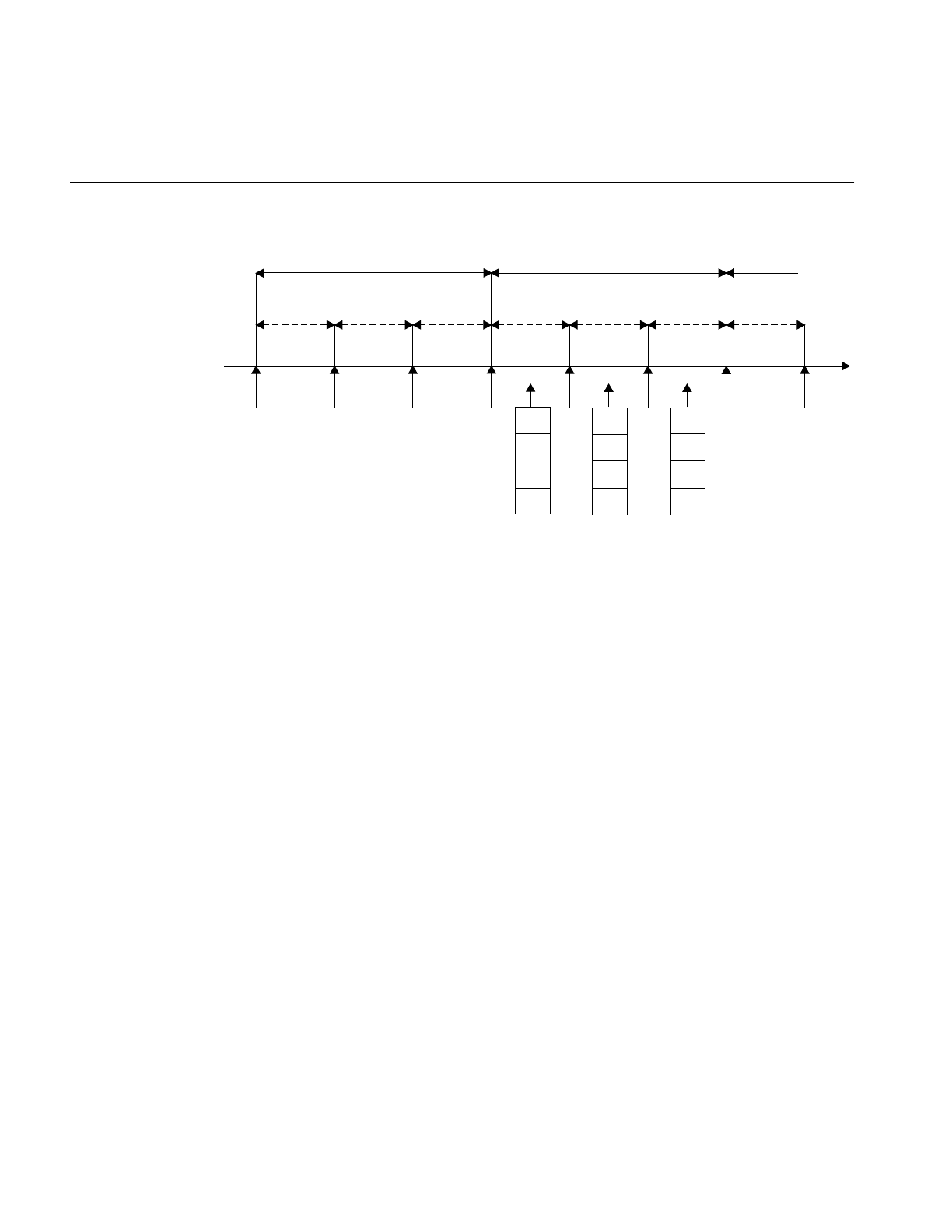
46
Chapter 4: Using the Frame Scheduler
Figure 4-1 Major and Minor Frames
As pictured in Figure 4-1, the Frame Scheduler maintains a queue of threads for each
minor frame. Queue each activity thread of your program to a specific minor frame.
Determine the order of cyclic execution within a minor frame by the order in which you
queue threads. You can:
•Queue multiple threads in one minor frame. They are run in the queued sequence
within the frame. All must complete their work within the minor frame interval.
•Queue the same thread to run in more than one minor frame. Say that thread double
is to run twice as often as thread solo. You queue double to Q0 and Q2 in Figure 4-1,
and queue solo to Q1.
•Queue a thread that takes more than a minor frame to complete its work. If thread
sloth needs more than one minor interval, you queue it to Q0, Q1, and Q2 in
Figure 4-1, such that it can continue working in all three minor frames until it
completes.
•Queue a background thread that is allowed to run only when all others have
completed, to use up any remaining time within a minor frame.
Q0 Q1 Q2
TIME
Major frame
Minor-0 Minor-1 Minor-2 Minor-0 Minor-1 Minor-2
Major frame
Real-time event interrupts
Thread queues

Frame Scheduler Concepts
47
All these options are controlled by scheduling disciplines you specify for each thread as
you queue it (see “Using the Scheduling Disciplines” on page 63).
Typically a frame scheduler is driven by a single interrupt source and contains minor
frames having the same duration, but a variable frame scheduler may be used to
implement an FRS having multiple interrupt sources and/or minor frames of variable
duration (see the frs_create_vmaster() function).
The relationship between threads and a Frame Scheduler depends upon the thread
model in use.
•The pthread programming model requires that all threads scheduled by the Frame
Scheduler and controlling the Frame Scheduler be system scope threads. These
threads must also reside in the same process.
•The sproc() and fork() programming models do not require that the participating
threads reside in the same process.
See “Implementing a Single Frame Scheduler” on page 68 for details.
The FRS Controller Thread
The thread that creates a Frame Scheduler is called the FRS controller thread. It is
privileged in these respects:
•Its identifier is used to identify its Frame Scheduler in various functions. If you are
using POSIX threads, the FRS controller thread uses a pthread ID; if you are using
sproc(), the FRS controller process uses a PID.
•It can receive signals when errors are detected by the Frame Scheduler (see “Using
Signals Under the Frame Scheduler” on page 76).
•It cannot itself be queued to the Frame Scheduler. It continues to be dispatched by
IRIX, and executes on a CPU other than the one the Frame Scheduler uses.

48
Chapter 4: Using the Frame Scheduler
The Frame Scheduler API
An overview of the Frame Scheduler API can be found in the frs(3) reference page, which
provides a complete listing of all the FRS functions. Separate reference pages for each of
the FRS functions provide the details of the Frame Scheduler API. The API elements are
declared in /usr/include/sys/frs.h. The following are some important types that are
declared in /usr/include/sys/frs.h:
Additionally the pthreads interface adds the following types, as declared in
/usr/include/sys/pthread.h:
Interrupt Information Templates
Variable frame schedulers may drive each minor frame with a different interrupt source,
as well as define a different duration for each minor frame. These two characteristics may
be used together or separately, and are defined using an interrupt information template.
An interrupt information template consists of an array of frs_intr_info_t data structures,
where each element in the array represents a minor frame. For example, the first element
in the array represents the interrupt information for the first minor frame, and so on for
n minor frames.
typedef frs_fsched_info_t A structure containing information about one scheduler,
including its CPU number, interrupt source and time base,
and number of minor frames. Used when creating a Frame
Scheduler.
typedef frs_t A structure that identifies a Frame Scheduler.
typedef frs_queue_info_t A structure containing information about one activity
thread: the Frame Scheduler and minor frame it uses and
its scheduling discipline. Used when enqueuing a thread.
typedef frs_recv_info_t A structure containing error recovery options.
typedef frs_intr_info_t A structure that frs_create_vmaster() uses for defining
interrupt information templates (see below).
typedef pthread_t An integer identifying the pthread ID.
typedef pthread_attr_t A structure containing information about the attributes of
the FRS controller thread.

Frame Scheduler Concepts
49
The frs_intr_info_t data structure contains two fields for defining the interrupt source and
its qualifier: intr_source and intr_qualifier.
The following example demonstrates how to define an interrupt information template
for a frame scheduler having minor frames of different duration. Assume the application
requires four minor frames, where each minor frame is triggered by the synchronized
clock timer, and the duration of each minor frame is as follows: 100 ms, 150 ms, 200 ms,
and 250 ms. The interrupt information template may be defined as:
frs_intr_info_t intr_info[4];
intr_info[0].intr_source = FRS_INTRSOURCE_CCTIMER;
intr_info[0].intr_qualifier = 100000;
intr_info[1].intr_source = FRS_INTRSOURCE_CCTIMER;
intr_info[1].intr_qualifier = 150000;
intr_info[2].intr_source = FRS_INTRSOURCE_CCTIMER;
intr_info[2].intr_qualifier = 200000;
intr_info[3].intr_source = FRS_INTRSOURCE_CCTIMER;
intr_info[3].intr_qualifier = 250000;
The following example demonstrates how to define an interrupt information template
for a frame scheduler using multiple interrupt sources. Assume the application requires
two minor frames, where the first minor frame is triggered by the vertical retrace
interrupt and the second minor frame is triggered by the CPU timer. Also assume the
vertical retrace interrupt is running at 60 Hz (every 16.6 ms). The following interrupt
information template defines the CPU timer interrupt of the second frame to fire 8.3 ms
after the vertical retrace interrupt:
frs_intr_info_t intr_info[2];
intr_info[0].intr_source = FRS_INTRSOURCE_VSYNC;
intr_info[0].intr_qualifier = 0;
intr_info[1].intr_source = FRS_INTRSOURCE_CPUTIMER;
intr_info[1].intr_qualifier = 8300;
Note that 8.3 ms was chosen in the example because it is known that the timer interrupt
will fire before the next major frame’svsync interrupt. If 20 ms were chosen for the timer
instead, then a sequence error would occur (see section “Sequence Error” on page 79)
and an error signal would be sent to the controller thread.
Detailed programming examples are available, demonstrating use of variable frame
schedulers, which can be found in the /usr/share/src/react/examples directory. For more
information, see the frs_create_vmaster(3) reference page.

50
Chapter 4: Using the Frame Scheduler
Library Interface for C Programs
The API library functions in /usr/lib/libfrs.a are summarized in Table 4-1 for convenient
reference.
Table 4-1 Frame Scheduler Operations
Operation Used For Frame Scheduler API
Create a Frame
Scheduler
Process setup frs_t* frs_create(int cpu, int intr_source, int intr_qualifier, int
n_minors, pid_t sync_master_pid, int num_slaves);
Process or
pthread setup
frs_t* frs_create_master(int cpu, int intr_source, int
intr_qualifier, int n_minors, int num_slaves);
Process or
pthread setup
frs_t* frs_create_slave(int cpu, frs_t* sync_master_frs);
Process or
pthread setup
frs_t* frs_create_vmaster(int cpu, int n_minors, int
n_slaves, frs_intr_info_t *intr_info);
Queue to an FRS
minor frame
Process setup int frs_enqueue(frs_t* frs, pid_t pid, int minor_frame,
unsigned int discipline);
Pthread setup int frs_pthread_enqueue(frs_t* frs, pthread_t pthread, int
minor_frame, unsigned int discipline);
Insert into a queue,
possibly changing
discipline
Process setup int frs_pinsert(frs_t* frs, int minor_frame, pid_t target_pid,
int discipline, pid_t base_pid);
Pthread setup int frs_pthread_insert(frs_t* frs, int minor_index,
pthread_t target_pthread, int discipline, pthread_t
base_pthread);
Set error recovery
options
Process setup int frs_setattr(frs_t* frs, int minor_frame, pid_t pid,
frs_attr_t attribute, void* param);
Pthread setup int frs_pthread_setattr(frs_t* frs, int minor_frame,
pthread_t pthread, frs_attr_t attribute, void* param);
Join an FRS (activity
is ready to start)
Process or
pthread
execution
int frs_join(frs_t* frs);

Frame Scheduler Concepts
51
Start scheduling (all
activities queued)
Process or
pthread
execution
int frs_start(frs_t* frs);
Yield control after
completing activity
Process or
pthread
execution
int frs_yield(frs_t* frs);
Pause scheduling at
end of minor frame
Process or
pthread
execution
int frs_stop(frs_t* frs);
Resume scheduling
at next time-base
interrupt
Process or
pthread
execution
int frs_resume(frs_t* frs);
Trigger a user-level
FRS interrupt
Process or
pthread
execution
int frs_userintr(frs_t* frs);
Interrogate a minor
frame queue
Process or
pthread query
int frs_getqueuelen(frs_t* frs, int minor_index);
Process query int frs_readqueue(frs_t* frs, int minor_frame, pid_t
*pidlist);
Pthread query int frs_pthread_readqueue(frs_t* frs, int minor_frame,
pthread_t *pthreadlist);
Retrieve error
recovery options
Process query int frs_getattr(frs_t* frs, int minor_frame, pid_t pid,
frs_attr_t attribute, void* param);
Pthread query int frs_pthread_getattr(frs_t* frs, int minor_frame,
pthread_t pthread, frs_attr_t attribute, void* param);
Destroy FRS and
send SIGKILL to its
FRS controller
Process or
pthread
teardown
int frs_destroy(frs_t* frs);
Remove a process or
thread from a queue
Process
teardown
int frs_premove(frs_t* frs, int minor_frame, pid_t
remove_pid);
Pthread
teardown
int frs_pthread_remove(frs_t* frs, int minor_frame,
pthread_t remove_pthread);
Table 4-1 (continued) Frame Scheduler Operations
Operation Used For Frame Scheduler API

52
Chapter 4: Using the Frame Scheduler
System Call Interface for Fortran and Ada
Each Frame Scheduler function is available in two ways: as a system call to schedctl(),or
as one or more library calls to functions in the frs library, /usr/lib/libfrs.a. The system call
is accessible from FORTRAN and Ada programs because both languages have bindings
for schedctl() (see the schedctl(2) reference page). The correspondence between the
library functions and schedctl() calls is shown in Table 4-2.
Note: The pthread functions for the Frame Scheduler are not supported for FORTRAN
applications.
Table 4-2 Frame Scheduler schedctl() Support
Library Function Schedctl Syntax
frs_create() int schedctl(MPTS_FRS_CREATE, frs_info_t* frs_info);
frs_enqueue() int schedctl(MPTS_FRS_ENQUEUE, frs_queue_info_t* frs_queue_info);
frs_join() int schedctl(MPTS_FRS_JOIN, pid_t frs_master);
frs_start() int schedctl(MPTS_FRS_START, pid_t frs_master);
frs_yield() int schedctl(MPTS_FRS_YIELD);
frs_stop() int schedctl(MPTS_FRS_STOP, pid_t frs_master);
frs_resume() int schedctl(MPTS_FRS_RESUME, pid_t frs_master);
frs_destroy() int schedctl(MPTS_FRS_DESTROY, pid_t frs_master);
frs_getqueuelen() int schedctl(MPTS_FRS_GETQUEUELEN, frs_queue_info_t*
frs_queue_info);
frs_readqueue() int schedctl(MPTS_FRS_READQUEUE, frs_queue_info_t* frs_queue_info,
pid_t* pidlist);
frs_premove() int schedctl(MPTS_FRS_PREMOVE, frs_queue_info_t* frs_queue_info);
frs_pinsert() int schedctl(MPTS_FRS_PINSERT, frs_queue_info_t* frs_queue_info,
pid_t *base_pid);
frs_getattr() int schedctl(MPTS_FRS_GETATTR, frs_attr_info_t* frs_attr_info);
frs_setattr() int schedctl(MPTS_FRS_SETATTR, frs_attr_info_t* frs_attr_info);

Frame Scheduler Concepts
53
Thread Execution
An activity thread that is queued to a Frame Scheduler has the basic structure shown in
Example 4-1.
Example 4-1 Skeleton of an Activity Thread
/* Initialize data structures etc. */
frs_join(scheduler-handle)
do
{
/* Perform the activity. */
frs_yield();
} while(1);
_exit();
When the thread is ready to start real-time execution, it calls frs_join(). This call blocks
until all queued threads are ready and scheduling begins (see “Starting Multiple
Schedulers”on page 57). When frs_join() returns, the thread is running in its first minor
frame. For more information about frs_join(), see frs_join(3).
The thread then performs whatever activity is needed to complete the minor frame and
calls frs_yield(). This gives up control of the CPU until the next minor frame where the
thread is queued and executes. For more information about frs_yield(), see frs_yield(3).
An activity thread is never preempted within a minor frame. As long as it yields before
the end of the frame, it can do its assigned work without interruption from other threads
(it can be interrupted by hardware interrupts, if any hardware interrupts are allowed in
that CPU). The Frame Scheduler preempts the thread at the end of the minor frame.
Tip: Because an activity thread cannot be preempted, it can often use global data without
locks or semaphores. When the thread that modifies a global variable is queued in a
different minor frame than the threads that read the variable, there can be no access
conflicts between them.
Conflicts are still possible between two threads that are queued to the same minor frame
in different, synchronized Frame Schedulers. However, such threads are guaranteed to
be running concurrently. This means they can use spin-locks (see “Locks” on page 13)
with high efficiency.

54
Chapter 4: Using the Frame Scheduler
Tip: When a very short minor frame interval is used, it is possible for a thread to have
an overrun error in its first frame due to cache misses. A simple variation on the basic
structure shown in Example 4-1 is to spend the first minor frame touching a set of
important data structures in order to “warm up” the cache. This is sketched in
Example 4-2.
Example 4-2 Alternate Skeleton of Activity Thread
/* Initialize data structures etc. */
frs_join(scheduler-handle); /* Much time could pass here. */
/* First frame: merely touch important data structures. */
do
{
frs_yield();
/* Second and later frames: perform the activity. */
} while(1);
_exit();
When an activity thread is scheduled on more than one minor frame in a major frame, it
can be designed to do nothing except warm the cache in the entire first major frame. To
do this, the activity thread function has to know how many minor frames it is scheduled
on, and calls frs_yield() that many times in order to pass the first major frame.
Scheduling Within a Minor Frame
Threads in a minor frame queue are dispatched in the order they appear on the queue
(priority is irrelevant). Queue ordering can be modified by:
•appending a thread at the end of the queue with frs_pthread_enqueue() or
frs_enqueue()
•inserting a thread after a specific target thread via frs_pthread_insert() or
frs_pinsert()
•deleting a thread in the queue with frs_pthread_remove() or frs_premove()
See the reference pages frs_enqueue(3), frs_pinsert(3), frs_premove(3), and “Managing
Activity Threads” on page 58.

Frame Scheduler Concepts
55
Scheduler Flags frs_run and frs_yield
The Frame Scheduler keeps two status flags per queued thread, named frs_run and
frs_yield. If a thread is ready to run when its turn comes, it is dispatched and its frs_run
flag is set to indicate that this thread has run at least once within this minor frame.
When a thread yields, its frs_yield flag is set to indicate that the thread has released the
processor. It is not activated again within this minor frame.
If a thread is not ready (usually because it is blocked waiting for I/O, a semaphore, or a
lock), it is skipped. Upon reaching the end of the queue, the scheduler goes back to the
beginning, in a round-robin fashion, searching for threads that have not yielded and may
have become ready to run. If no ready threads are found, the Frame Scheduler goes into
idle mode until a thread becomes available or until an interrupt marks the end of the
frame.
Detecting Overrun and Underrun
When a time base interrupt occurs to indicate the end of the minor frame, the Frame
Scheduler checks the flags for each thread. If the frs_run flag has not been set, that thread
never ran and therefore is a candidate for an underrun exception. If the frs_run flag is set
but the frs_yield flag is not, the thread is a candidate for an overrun exception.
Whether these exceptions are declared depends on the scheduling discipline assigned to
the thread. Scheduling disciplines are explained under “Using the Scheduling
Disciplines” on page 63).
At the end of a minor frame, the Frame Scheduler resets all frs_run flags, except for those
of threads that use the Continuable discipline in that minor frame. For those threads, the
residual frs_yield flags keeps the threads that have yielded from being dispatched in the
next minor frame.
Underrun and overrun exceptions are typically communicated via IRIX signals. The
rules for sending these signals are covered under “Using Signals Under the Frame
Scheduler” on page 76.

56
Chapter 4: Using the Frame Scheduler
Estimating Available Time
It is up to the application to make sure that all the threads queued to any minor frame
can actually complete their work in one minor-frame interval. If there is too much work
for the available CPU cycles, overrun errors will occur.
Estimation is simplified by the fact that only the queued threads can execute on a CPU
controlled by the Frame Scheduler. You need to estimate the maximum time each thread
can consume between one call to frs_yield() and the next.
Frame Scheduler threads do compete for CPU cycles with I/O interrupts on the same
CPU. If you direct I/O interrupts away from the CPU (see “Isolating a CPU From
Sprayed Interrupts”on page 28 and “Redirecting Interrupts”on page 28), then the only
competition for CPU cycles (other than a very few essential TLB interrupts) is the
overhead of the Frame Scheduler itself, and it has been carefully optimized for least
overhead.
Alternatively, you may assign specific I/O interrupts to a CPU used by the Frame
Scheduler. In that case, you must estimate the time that interrupt service will consume
(see “Maximum Response Time Guarantee” on page 37) and allow for it.
Synchronizing Multiple Schedulers
When the activities of one frame cannot be completed by one CPU, you need to recruit
additional CPUs and execute some activities concurrently. However, it is important that
each of the CPUs have the same time base, so that each starts and ends frames at the same
time.
You can create one master Frame Scheduler, which owns the time base and one CPU, and
as many synchronized (slave) Frame Schedulers as you need, each managing an
additional CPU. The slave schedulers take their time base from the master, so that all start
minor frames at the same instant.
Each FRS requires its own controller thread. Therefore, to create multiple, synchronized
Frame Schedulers, you must create a controller thread for the master and each slave FRS.
Each Frame Scheduler has its own queues of threads. A given thread can be queued to
only one CPU. (However, you can create multiple threads based on the same code, and
queue each to a different CPU.) All synchronized Frame Schedulers use the same number
of minor frames per major frame, which is taken from the definition of the master FRS.

Frame Scheduler Concepts
57
Starting a Single Scheduler
A single Frame Scheduler is created when the FRS controller thread calls
frs_create_master() or frs_create(). The FRS controller calls frs_pthread_enqueue() or
frs_enqueue() one or more times to notify the new Frame Scheduler of the threads to
schedule in each of the minor frames. The FRS controller calls frs_start() when it has
queued all the threads. Each scheduled thread must call frs_join() after it has initialized
and is ready to be scheduled.
Each activity thread must be queued to at least one minor frame before it can join the FRS
via frs_join(). Once all activity threads have joined and the FRS is started by the
controller thread, the first minor frame begins executing. For more information about
these functions, see the frs_enqueue(3), frs_join(3), and frs_start(3) reference pages.
Starting Multiple Schedulers
A Frame Scheduler cannot start dispatching activities until
•the FRS controller has queued all the activity threads to their minor frames.
•all the queued threads have done their own initial setup and have joined.
When multiple Frame Schedulers are used, none can start until all are ready.
Each FRS controller notifies its Frame Scheduler that it has queued all activities by calling
frs_start(). Each activity thread signals its Frame Scheduler that it is ready to begin
real-time processing by calling frs_join().
A Frame Scheduler is ready when it has received one or more frs_pthread_enqueue() or
frs_enqueue() calls, a matching number of frs_join() calls, and an frs_start() call for each
Frame Scheduler. Each slave Frame Scheduler notifies the master Frame Scheduler when
it is ready. When all the schedulers are ready, the master Frame Scheduler gives the
downbeat, and the first minor frame begins.

58
Chapter 4: Using the Frame Scheduler
Pausing Frame Schedulers
Any Frame Scheduler can be made to pause and restart. Any thread (typically but not
necessarily the FRS controller) can call frs_stop(), specifying a particular Frame
Scheduler. That scheduler continues dispatching threads from the current minor frame
until all have yielded. Then it goes into an idle loop until a call to frs_resume() tells it to
start. It resumes on the next time-base interrupt, with the next minor frame in succession.
For more information, see the frs_stop(3) and frs_resume(3) reference pages.
Note: If there is a thread running Background discipline in the current minor frame, it
continues to execute until it yields or is blocked on a system service.
Since a Frame Scheduler does not stop until the end of a minor frame, you can stop and
restart a group of synchronized schedulers by calling frs_stop() for each one before the
end of a minor frame. There is no way to restart all of a group of schedulers with the
certainty that they start up on the same time-base interrupt.
Managing Activity Threads
The FRS control thread identifies the initial set of activity threads by calling
frs_pthread_enqueue() or frs_enqueue() prior to starting the Frame Scheduler. All the
queued threads must call frs_join() before scheduling can begin. However, the FRS
controller can change the set of activity threads dynamically while the Frame Scheduler
is working, using the following functions:
frs_getqueuelen() Get the number of threads currently in the queue for a
specified minor frame.
frs_pthread_readqueue()
or frs_readqueue()
Return the ID values of all queued threads for a specified
minor frame as a vector of integers.
frs_pthread_remove() or
frs_premove()
Remove a thread (specified by its ID) from a minor frame
queue.
frs_pthread_insert() or
frs_pinsert()
Insert a thread (specified by its ID and discipline) into a
given position in a minor frame queue.

Selecting a Time Base
59
Using these functions, the FRS controller can change the queueing discipline (overrun,
underrun, continuable) of a thread by removing it and inserting it with a new discipline.
The FRS controller can suspend a thread by removing it from its queue; or can restart a
thread by putting it back in its queue.
Note: When an activity thread is removed from the last or only queue it was in, it is
returned to the normal IRIX scheduler and can begin to execute on another CPU. When
an activity thread is removed from a queue, a signal may be sent to the removed thread
(see “Handling Signals in an Activity Thread”on page 78). If a signal is sent to it, it begins
executing in its specified or default signal handler; otherwise, it simply begins executing
following frs_yield(). Once returned to the IRIX scheduler, a call to an FRS function such
as frs_yield() returns an error (this also can be used to indicate the resumption of normal
scheduling).
The FRS controller can also queue new threads that have not been scheduled before. The
Frame Scheduler does not reject an frs_pthread_insert() or frs_pinsert() call for a thread
that has not yet joined the scheduler. However, a thread must call frs_join() before it can
be scheduled. For more information, see the frs_pinsert(3) reference page.
If an queued thread should be terminated for any reason, the Frame Scheduler removes
the thread from all queues in which it appears.
Selecting a Time Base
Your program specifies an interrupt source for the time base when it creates the master
(or only) Frame Scheduler. The master Frame Scheduler initializes the necessary
hardware resources and redirects the interrupt to the appropriate CPU and handler.
The Frame Scheduler time base is fundamental because it determines the duration of a
minor frame, and hence the frame rate of the program. This section explains the different
time bases that are available.
When you use multiple, synchronized Frame Schedulers, the master Frame Scheduler
distributes the time-base interrupt to each synchronized CPU. This ensures that
minor-frame boundaries are synchronized across all the Frame Schedulers.

60
Chapter 4: Using the Frame Scheduler
On-Chip Timer Interrupt
Each processor chip contains a free-running timer that is used by IRIX for normal process
scheduling. This timer is not synchronized between processors, so it cannot be used to
drive multiple synchronized schedulers. The on-chip timer can be used as a time base
when only one CPU is used.
To use the on-chip timer, specify FRS_INTRSOURCE_CPUTIMER as the interrupt
source, and the minor frame interval in microseconds, to frs_create_master() or
frs_create().
High-Resolution Timer
The high-resolution timer and clock is a timer that is synchronous across all processors,
and is ideal to drive synchronous schedulers. On Origin, Onyx 2, CHALLENGE, and
Onyx systems, this timer is based on the high-resolution counter discussed under
“Hardware Cycle Counter” on page 16.
To use this timer, specify FRS_INTRSOURCE_CCTIMER, and specify the minor frame
interval in microseconds to frs_create_master() or frs_create().
The IRIX kernel uses this timer for managing timer events. When your program creates
the master Frame Scheduler, the Frame Scheduler migrates all timeout events to CPU 0,
leaving the timer on the scheduled CPU free.
The high-resolution timers in all CPUs are synchronized automatically.
Vertical Sync Interrupt
An interrupt is generated for every vertical retrace by the graphics subsystem (see
“Understanding the Vertical Sync Interrupt”on page 30). The frame rate is either 50 Hz
or 60 Hz, depending on the installed hardware. This interrupt is especially appropriate
for a visual simulator, since it defines a frame rate that matches the graphics subsystem
frame rate.
To use the vertical sync interrupt, specify FRS_INTRSOURCE_VSYNC to
frs_create_master() or frs_create(). An error is returned if this system is not configured
with a graphics subsystem.
When multiple synchronized schedulers are used, the master Frame Scheduler
distributes the vertical sync interrupt.

Selecting a Time Base
61
External Interrupts
An external interrupt is generated via a signal applied to the external interrupt socket on
systems supporting such a hardware feature, such as Origin, CHALLENGE, and Onyx
systems (see “External Interrupts”on page 109). To use external interrupts as a time base:
1. Redirect the external interrupt to the master FRS CPU using the appropriate device
administration directive in /var/sysgen/system/irix.sm.
2. For the directives take effect, rebuild the kernel using the command
/etc/autoconfig -vf, and reboot.
3. Specify FRS_INTRSOURCE_EXTINTR to frs_create_master() or frs_create().
For example, in irix.sm, a directive similar to the following causes PCI interrupt 4 of the
first I/O slot to be handled by CPU 1. (The actual directive depends on the hardware
configuration of the target platform.)
DEVICE_ADMIN: /hw/module/1/slot/io1/baseio/pci/4 INTR_TARGET=/hw/cpunum/1
When multiple synchronized schedulers are used, the master Frame Scheduler receives
the interrupt and allocates it simultaneously to the synchronized schedulers.
Device Driver Interrupt
A user-written, kernel-level device driver can supply the time-base interrupt (see “FRS
Kernel-Level Device Driver Interface” on page 80). The Frame Scheduler registers the
driver and assigns it a unique registration number, then allocates an interrupt group. The
device driver must direct interrupts to it.
To use a device driver as a time base, specify FRS_INTRSOURCE_DRIVER and the
device driver’s registration number to frs_create_master() or frs_create(). See
“Implementing a Single Frame Scheduler” on page 68.

62
Chapter 4: Using the Frame Scheduler
Software Interrupt
A programmed, software-generated interrupt can be used as the time base. Any user
process can send this interrupt to the master Frame Scheduler by calling frs_userintr().
Note: Software interrupts are primarily intended for application debugging. It is not
feasible for a user process to generate the low-latency and determinism for interrupts
required by a real-time application.
To use software interrupts as a time base, specify FRS_INTRSOURCE_USER to
frs_create_master() or frs_create().
Caution: The use of software interrupts has a potential for causing a system deadlock if
the interrupt-generating process contends for a resource that is also used by a
frame-scheduled activity thread. If any activity thread calls IRIX system functions, the
only way to be absolutely sure of avoiding deadlock is for the interrupt-generating
process to avoid using any IRIX system functions. Note that C library functions such as
printf() invoke system functions, and can lead to deadlocks in this case.
User-Level Interrupts
The user level interrupt (ULI) facility allows a hardware interrupt to be handled by a user
process, enabling device drivers to reside at the user-level; see the uli(3) reference page
for details. To use ULI to drive the frame scheduler, specify FRS_INTRSOURCE_ULI as
the interrupt source to the frs_create_master() or frs_create_vmaster() functions.
The ULI capability is supported only for Origin and Onyx 2 platforms. The PCI or VME
interrupt must be routed to the master Frame Scheduled processor in order for the frame
scheduler to recognize it.
Note: The frame scheduler is invoked after the user-level portion of the interrupt handler
has completed servicing the interrupt.

Using the Scheduling Disciplines
63
Using the Scheduling Disciplines
When an FRS controller thread queues an activity thread to a minor frame (using
frs_pthread_enqueue() or frs_enqueue()), it must specify a scheduling discipline that tells
the Frame Scheduler how the thread is expected to use its time within that minor frame.
Real-Time Discipline
In the simplest case, an activity thread starts during the minor frame in which it is
queued, and completes its work and yields within the same minor frame.
If the thread is not ready to run (for example, blocked on I/O) during the entire minor
frame, an underrun exception is said to occur. If the thread fails to complete its work and
yield within the minor frame interval, an overrun exception is said to occur.
The Frame Scheduler calls this strict discipline the Real-time scheduling discipline.
This model could describe a simple kind of simulator in which certain activities—poll the
inputs; calculate the new status; update the display—must be repeated in that order
during every frame. In this scenario, each activity must start and must finish in every
frame. If one fails to start, or fails to finish, the real-time program is broken in some way
and must take some action.
However, realistic designs need the flexibility to have threads that
•need not start every frame; for instance, threads that sleep on a semaphore until
there is work for them to do
•may run longer than one minor frame
•should run only when time is available, and whose rate of progress is not critical
The other disciplines are used, in combination with Real-time and with each other, to
allow these variations.

64
Chapter 4: Using the Frame Scheduler
Background Discipline
The Background discipline is mutually exclusive with the other disciplines. The Frame
Scheduler dispatches a Background thread only when all other threads queued to that
minor frame have run and have yielded. Since the Background thread cannot be sure it
will run and cannot predict how much time it will have, the concepts of underrun and
overrun do not apply to it.
Note: A thread with the Background discipline must be queued to its frame following
all non-Background threads. Do not queue a real-time thread after a Background thread.
Underrunable Discipline
You specify Underrunable discipline with Real-time discipline to prevent detection of
underrun exceptions. You specify Underrunable in two cases:
•When a thread needs to run only when an event has occurred, such as a lock being
released or a semaphore being posted.
•When a thread may need more than one minor frame (see “Using Multiple
Consecutive Minor Frames” on page 65).
When you specify Real-time+Underrunable, the thread is not required to start in that
minor frame. However, if it starts, it is required to yield before the end of the frame or an
overrun exception is raised.
Overrunnable Discipline
You specify Overrunnable discipline with Real-time discipline to prevent detection of
overrun exceptions. You specify it in two cases:
•When it truly does not matter if the thread fails to complete its work within the
minor frame—for example, a calculation of a game strategy which, if it fails to
finish, merely makes the computer a less dangerous opponent.
•When a thread may need more than one minor frame (see “Using Multiple
Consecutive Minor Frames” on page 65).
When you specify Overrunnable+Real-time, the thread is not required to call frs_yield()
before the end of the frame. Even so, the thread is preempted at the end of the frame. It
does not have a chance to run again until the next minor frame in which it is queued. At
that time it resumes where it was preempted, with no indication that it was preempted.

Using the Scheduling Disciplines
65
Continuable Discipline
You specify Continuable discipline with Real-time discipline to prevent the Frame
Scheduler from clearing the flags at the end of this minor frame (see “Scheduling Within
a Minor Frame” on page 54).
The result is that, if the thread yields in this frame, it need not run or yield in the
following frame. The residual frs_yield flag value, carried forward to the next frame,
applies. You specify Continuable discipline with other disciplines in order to let a thread
execute just once in a block of consecutive minor frames.
Using Multiple Consecutive Minor Frames
There are cases when a thread sometimes or always requires more than one minor frame
to complete its work. Possibly the work is lengthy, or possibly the thread could be
delayed by a system call or a lock or semaphore wait.
You must decide the absolute maximum time the thread could consume between starting
up and calling frs_yield(). If this is unpredictable, or if it is predictably longer than the
major frame, the thread cannot be scheduled by the Frame Scheduler. Hence, it should
probably run on another CPU under the IRIX real-time scheduler.
However, when the worst-case time is bounded and is less than the major frame, you can
queue the thread to enough consecutive minor frames to allow it to finish. A combination
of disciplines is used in these frames to ensure that the thread starts when it should,
finishes when it must, and does not cause an error if it finishes early.
The discipline settings for each frame should be:
First frame Real-time + Overrunnable + Continuable—the thread must start in this
frame (not Underrunable) but is not required to yield (Overrunnable). If
it yields, it is not restarted in the following minor frame (Continuable).
Intermediate Real-time+Underrunable+Overrunnable+Continuable—the thread
need not start (it might already have yielded, or might be blocked) but
is not required to yield. If it does yield (or if it had yielded in a preceding
minor frame), it is not restarted in the following minor frame
(Continuable).

66
Chapter 4: Using the Frame Scheduler
Final frame Real-time+Underrunable—the thread need not start (it might already
have yielded) but if it starts, it must yield in this frame (not
Overrunnable). The thread can start a new run in the next minor frame
to which it is queued (not Continuable).
A thread can be queued for one or more of these multiframe sequences in one major
frame. For example, suppose that the minor frame rate is 60 Hz, and a major frame
contains 60 minor frames (1 Hz). You have a thread that should run at a rate of 5 Hz and
can use up to 3/60 second at each dispatch. You can queue the thread to 5 sequences of
3 consecutive frames each. It could start in frames 0, 12, 24, 36, and 48. Frames 1, 13, 25,
37 and 49 could be intermediate frames, and 2, 14, 26, 38 and 50 could be final frames.
Designing an Application for the Frame Scheduler
When using the Frame Scheduler, consider the following guidelines when designing
your real-time application.
1. Determine the programming model for implementing the activities in your
program, choosing among POSIX threads, IRIX sproc(), or SVR4 fork() calls. (You
cannot mix pthreads and other disciplines within your program.)
2. Partition the program into activities, where each activity is an independent piece of
work that can be done without interruption.
For example, in a simple vehicle simulator, activities might include “poll the
joystick,” “update the positions of moving objects,” “cull the set of visible objects,”
and so forth.
3. Decide the relationships among the activities:
•Some must be done once per minor frame, others less frequently.
•Some must be done before or after others.
•Some may be conditional. For example, an activity could poll a semaphore and
do nothing unless an event had completed.
4. Estimate the worst-case time required to execute each activity. Some activities may
need more than one minor frame interval (the Frame Scheduler allows for this).
5. Schedule the activities: If all are executed sequentially, will they complete in one
major frame? If not, choose activities that can execute concurrently on two or more
CPUs, and estimate again. You may have to change the design in order to get
greater concurrency.

Preparing the System
67
When the design is complete, implement each activity as an independent thread that
communicates with the others using shared memory, semaphores, and locks (see
“Synchronization and Communication” on page 11).
The Frame Scheduler is created, stopped, and resumed by a controller thread. The
controller thread can also interrogate and receive signals from the Frame Scheduler (see
“Signals” on page 14).
A Frame Scheduler seizes its assigned CPU, isolates it, and controls the scheduling on it.
It waits for all queued threads to initialize themselves and “join”the scheduler. The FRS
begins dispatching the threads in the specified sequence during each frame interval.
Errors are monitored (such as a thread that fails to complete its work within its frame)
and a specified action is taken when an error occurs. Typically the error action is to send
a signal to the controller thread.
Preparing the System
Before a real-time program executes, you must set up the system in the following ways.
1. Choose the CPU or CPUs that the real-time program will use. CPU 0 (at least) must
be reserved for IRIX system functions.
2. Decide which CPUs will handle I/O interrupts. By default, IRIX distributes I/O
interrupts across all available processors as a means of balancing the load (referred
to as spraying interrupts). CPUs that are used for real-time programs should be
removed from the distribution set (see “Redirecting Interrupts” on page 28).
3. If using an external interrupt as a time base, make sure it is redirected to the CPU of
the master FRS (see “External Interrupts” on page 61).
4. Make sure that none of the real-time CPUs is managing the clock (see “Assigning
the Clock Processor” on page 27). Normally the responsibility of handling 10ms
scheduler interrupts is given to CPU 0.
Each Frame Scheduler takes care of restricting and isolating its CPU, so that the CPU is
used only for threads scheduled by the Frame Scheduler.

68
Chapter 4: Using the Frame Scheduler
Implementing a Single Frame Scheduler
When the activities of your real-time program can be handled within a major frame
interval by a single CPU, your program needs to create only one Frame Scheduler.
Examples for implementing a single FRS can be found in the simple and simple_pt
programs, described in Appendix A.
Typically your program has a top-level process (called the controller thread) to handle
startup and termination, and one or more activity threads that are dispatched by the
Frame Scheduler. The activity threads are typically lightweight threads (pthreads or
sprocs), but that is not a requirement—they can also be created with fork(); they need not
be children of the controller thread. (See, for instance, “Example of Scheduling Separate
Programs” on page 133.).
In general, these are the steps for setting up a single Frame Scheduler:
1. Initialize global resources such as memory-mapped segments, memory arenas, files,
asynchronous I/O, semaphores, locks, and other resources.
2. Lock the shared address space segments. (When fork() is used, each child process
must lock its own address space.)
3. If using pthreads, create a controller thread; otherwise, the initial thread of
execution may be used as the controller thread.
•Create a system scope attribute structure using pthread_attr_init() and
pthread_attr_setscope(). See the pthread_attr_init(3P) and
pthread_attr_setscope(3P) references pages for details.
•Create a system scope controller thread using pthread_create() and the attribute
structure you just set up. See pthread_create(3P) for details.
•Exit the initial thread, since it cannot execute any FRS operations.
4. Create the Frame Scheduler using frs_create_master(),frs_create_vmaster(), or
frs_create() (see the frs_create(3) reference page for details).
5. Create the activity threads using one of the following interfaces (depending on the
thread model being used):
•pthread_create()
•sproc()
•fork()

Implementing Synchronized Schedulers
69
6. Queue the activity threads on the target minor frame queues, using
frs_pthread_enqueue() or frs_enqueue().
7. Optionally, initialize the Frame Scheduler signal handler to catch frame overrun,
underrun, and activity dequeue events (see “Setting Frame Scheduler Signals” on
page 78 and “Setting Exception Policies” on page 73). The handlers are set at this
time, after creation of the activity threads, so that the activity threads do not inherit
them.
8. Use frs_start() (Table 4-1) to enable scheduling.
9. Have the activity threads call frs_join(). The Frame Scheduler begins scheduling
processes as soon as all the activity threads have called frs_join().
10. Wait for error signals from the Frame Scheduler and for the termination of child
processes.
11. Use frs_destroy() to terminate the Frame Scheduler.
12. Tidy up the global resources, as required.
Implementing Synchronized Schedulers
When the real-time application requires the power of multiple CPUs, you must add one
more level to the program design for a single CPU. The program creates multiple Frame
Schedulers, one master and one or more synchronized slaves.
Synchronized Scheduler Concepts
The first Frame Scheduler provides the time base for the others. It is called the master
scheduler. The other schedulers take their time base interrupts from the master, and so
are called slaves. The combination is called a sync group.
No single thread may create more than one Frame Scheduler. This is because every Frame
Scheduler must have a unique FRS controller thread to which it can send signals. As a
result, the program has three types of threads:
•a master controller thread that sets up global data and creates the master Frame
Scheduler
•one slave controller thread for each slave Frame Scheduler
•activity threads

70
Chapter 4: Using the Frame Scheduler
The master Frame Scheduler must be created before any slave Frame Schedulers can be
created. Slave Frame Schedulers must be specified to have the same time base and the
same number of minor frames as the master.
Slave Frame Schedulers can be stopped and restarted independently. However, when
any scheduler, master or slave, is destroyed, all are immediately destroyed.
Implementing a Master Controller Thread
A variety of program designs are possible but the simplest is possibly the set of steps
described in the following paragraphs.
The master controller thread performs these steps:
1. Initializes global resource. One global resource is the thread ID of the master
controller thread.
2. Creates the master Frame Scheduler using either the frs_create_master() or
frs_create_vmaster() call, and stores its handle in a global location.
3. Creates one slave controller thread for each synchronized CPU to be used.
4. Creates the activity threads that will be scheduled by the master Frame Scheduler
and queues them to their assigned minor frames.
5. Sets up signal handlers for signals from the Frame Scheduler (see “Using Signals
Under the Frame Scheduler” on page 76).
6. Uses frs_start() (Table 4-1) to tell the master Frame Scheduler that its activity
threads are all queued and ready to commence scheduling.
The master Frame Scheduler starts scheduling threads as soon as all threads have
called frs_join() for their respective schedulers.
7. Waits for error signals.
8. Uses frs_destroy() to terminate the master Frame Scheduler.
9. Tidies up global resources as required.

Implementing Synchronized Schedulers
71
Implementing Slave Controller Threads
Each slave controller thread performs these steps:
1. Creates a synchronized Frame Scheduler using frs_create_slave(), specifying
information about the master Frame Scheduler stored by the master controller
thread. The master FRS must exist. A slave FRS must specify the same time base and
number of minor frames as the master FRS.
2. Changes the Frame Scheduler signals or exception policy, if desired (see “Setting
Frame Scheduler Signals” on page 78 and “Setting Exception Policies” on page 73).
3. Creates the activity threads that are scheduled by this slave Frame Scheduler, and
queues them to their assigned minor frames.
4. Sets up signal handlers for signals from the slave Frame Scheduler.
5. Use frs_start() to tell the slave Frame Scheduler that all activity threads have been
queued.
The slave Frame Scheduler notifies the master when all threads have called
frs_join(). When the master Frame Scheduler starts broadcasting interrupts,
scheduling begins.
6. Waits for error signals.
7. Uses frs_destroy() to terminate the slave Frame Scheduler.
For an example of this kind of program structure, refer to “Examples of Multiple
Synchronized Schedulers” on page 134.
Tip: In this design sketch, the knowledge of which activity threads to create, and on
which frames to queue them, is distributed throughout the code of multiple threads,
where it might be hard to maintain. However, it is possible to centralize the plan of
schedulers, activities, and frames in one or more arrays that are statically initialized. This
improves the maintainability of a complex program.

72
Chapter 4: Using the Frame Scheduler
Handling Frame Scheduler Exceptions
The FRS control thread for a scheduler controls the handling of the Overrun and
Underrun exceptions. It can specify how these exceptions should be handled, and what
signals the Frame Scheduler should send. These policies have to be set before the
scheduler is started. While the scheduler is running, the FRS controller can query the
number of exceptions that have occurred.
Exception Types
The Overrun exception indicates that a thread failed to yield in a minor frame where it
was expected to yield, and was preempted at the end of the frame. An Overrun exception
indicates that an unknown amount of work that should have been done was not done,
and will not be done until the next frame in which the overrunning thread is queued.
The Underrun exception indicates that a thread that should have started in a minor frame
did not start. Possibly the thread has terminated. More likely it was blocked in some kind
of wait because of an unexpected delay in I/O, or a deadlock on a lock or semaphore.
Exception Handling Policies
The FRS control thread can establish one of four policies for handling overrun and
underrun exceptions. When it detects an exception, the Frame Scheduler can:
•Send a signal to the FRS controller
•Inject an additional minor frame
•Extend the frame by a specified number of microseconds
•Steal a specified number of microseconds from the following frame
The default action is to send a signal (the specific signals are listed under “Setting Frame
Scheduler Signals”on page 78). The scheduler continues to run. The FRS control thread
can then take action, for example, terminating the Frame Scheduler.

Handling Frame Scheduler Exceptions
73
Injecting a Repeat Frame
The policy of injecting an additional minor frame can be used with any time base. The
Frame Scheduler inserts another complete minor frame, essentially repeating the minor
frame in which the exception occurred. In the case of an overrun, the activity threads that
did not finish have another frame’s worth of time to complete. In the case of an underrun,
there is that much more time for the waiting thread to wake up. Because exactly one
frame is inserted, all other threads remain synchronized to the time base.
Extending the Current Frame
The policies of extending the frame, either with more time or by stealing time from the
next frame, are allowed only when the time base is an on-chip or high-resolution timer
(see “Selecting a Time Base” on page 59).
When adding time, the current frame is made longer by a fixed amount of time. Since the
minor frame becomes a variable length, it is possible for the Frame Scheduler to drop out
of synch with an external device.
When stealing time from the following frame, the Frame Scheduler returns to the original
time base at the end of the following minor frame—provided that the threads queued to
that following frame can finish their work in a reduced amount of time. If they do not,
the Frame Scheduler steals time from the next frame still.
Dealing With Multiple Exceptions
You decide how many consecutive exceptions are allowed within a single minor frame.
After injecting, stretching, or stealing time that many times, the Frame Scheduler stops
trying to recover, and sends a signal instead.
The count of exceptions is reset when a minor frame completes with no remaining
exceptions.
Setting Exception Policies
The frs_pthread_setattr() or frs_setattr() function is used to change exception policies.
This function must be called before the Frame Scheduler is started. After scheduling has
begun, an attempt to change the policies or signals is rejected.

74
Chapter 4: Using the Frame Scheduler
In order to allow for future enhancements, frs_pthread_setattr() or frs_setattr() accepts
arguments for minor frame number and thread ID; however it currently allows setting
exception policies only for all policies and all minor frames. The most significant
argument to it is the frs_recv_info structure, declared with these fields.
typedef struct frs_recv_info {
mfbe_rmode_t rmode; /* Basic recovery mode */
mfbe_tmode_t tmode; /* Time expansion mode */
uint maxcerr; /* Max consecutive errors */
uint xtime; /* Recovery extension time */
} frs_recv_info_t;
The recovery modes and other constants are declared in /usr/include/sys/frs.h. The
function in Example 4-3 sets the policy of injecting a repeat frame. The caller specifies
only the Frame Scheduler and the number of consecutive exceptions allowed.
Example 4-3 Function to Set INJECTFRAME Exception Policy
int
setInjectFrameMode(frs_t *frs, int consecErrs)
{
frs_recv_info_t work;
bzero((void*)&work,sizeof(work));
work.rmode = MFBERM_INJECTFRAME;
work.maxcerr = consecErrs;
return frs_setattr(frs,0,0,FRS_ATTR_RECOVERY,(void*)&work);
}
The function in Example 4-4 sets the policy of stretching the current frame (a function to
set the policy of stealing time from the next frame is nearly identical). The caller specifies
the Frame Scheduler, the number of consecutive exceptions, and the stretch time in
microseconds.
Example 4-4 Function to Set STRETCH Exception Policy
int
setStretchFrameMode(frs_t *frs,int consecErrs,uint microSecs)
{
frs_recv_info_t work;
bzero((void*)&work,sizeof(work));
work.rmode = MFBERM_EXTENDFRAME_STRETCH;
work.tmode = EFT_FIXED; /* only choice available */
work.maxcerr = consecErrs;
work.xtime = microSecs;
return frs_setattr(frs,0,0,FRS_ATTR_RECOVERY,(void*)&work);
}

Handling Frame Scheduler Exceptions
75
Querying Counts of Exceptions
When you set a policy that permits exceptions, the FRS controller thread can query for
counts of exceptions. This is done with a call to frs_pthread_getattr() or frs_getattr(),
passing the handle to the Frame Scheduler, the number of the minor frame, and the
thread ID of the thread within that frame.
The values returned in a structure of type frs_overrun_info_t are the counts of overrun and
underrun exceptions incurred by that thread in that minor frame. In order to find the
count of all overruns in a given minor frame, you must sum the counts for all threads
queued to that frame. If a thread is queued to more than one minor frame, separate
counts are kept for it in each frame.
The function in Example 4-5 takes a Frame Scheduler handle and a minor frame number.
It gets the list of thread IDs queued to that minor frame, and returns the sum of all
exceptions for all of them.
Example 4-5 Function to Return a Sum of Exception Counts (pthread Model)
#define THE_MOST_TIDS 250
int
totalExcepts(frs_t * theFRS, int theMinor)
{
int numTids = frs_getqueuelen(theFRS, theMinor);
int j, sum;
pthread_t allTids[THE_MOST_TIDS];
if ( (numTids <= 0) || (numTids > THE_MOST_TIDS) )
return 0; /* invalid minor #, or no threads queued? */
if (frs_pthread_readqueue(theFRS, theMinor, allTids) == -1)
return 0; /* unexpected problem with reading IDs */
for (sum = j = 0; j<numTids; ++j)
{
frs_overrun_info_t work;
frs_pthread_getattr(theFRS /* the scheduler */
theMinor, /* the minor frame */
allTids[j], /* the threads */
FRS_ATTR_OVERRUNS, /* want counts */
&work); /* put them here */
sum += (work.overruns + work.underruns);
}
return sum;
}

76
Chapter 4: Using the Frame Scheduler
Tip: The FRS read queue functions return the number of threads present on the queue at
the time of the read. Applications can use this returned value to eliminate calls to
frs_getqueuelen().
Using Signals Under the Frame Scheduler
The Frame Scheduler itself sends signals to the threads using it. And threads can
communicate by sending signals to each other. In brief, an FRS sends signals to indicate
that
•The FRS has been terminated
•Overrun or underrun have been detected
•A thread has been dequeued
The rest of this topic details how to specify the signal numbers and how to handle the
signals.
Signal Delivery and Latency
When a process is scheduled by the IRIX kernel, it receives a pending signal the next time
the process exits from the kernel domain. For most signals, this could occur
•when the process is dispatched after a wait or preemption
•upon return from some system call
•upon return from the kernel’s usual 10-millisecond tick interrupt
(SIGALRM is delivered as soon as the kernel is ready to return to user processing after
the timer interrupt, in order to preserve timer accuracy.) Thus, for a process that is ready
to run, in a CPU that has not been made nonpreemptive, normal signal latency is at most
10 milliseconds, and SIGALARM latency is less. However, when the receiving process is
not ready to run, or when there are competing processes with higher priorities, the
delivery of a signal is delayed until the next time the receiving process is scheduled.

Using Signals Under the Frame Scheduler
77
When the CPU is nonpreemptive (see “Making a CPU Nonpreemptive” on page 35),
there are no clock tick interrupts, so signals can only be delivered following a system call.
Signal latency can be greater when running under the Frame Scheduler. Like the normal
IRIX scheduler, the Frame Scheduler delivers pending signals to a process when it next
returns to the process from the kernel domain. This can occur
•when the process is dispatched at the start of a minor frame where it is queued
•upon return from some system call
The upper bound on signal latency in this case is the interval between the minor frames
to which that process is queued. If the process is scheduled only once in a major frame,
it might not receive a signal until a full major frame interval after the signal is sent.
Handling Signals in the FRS Controller
When a Frame Scheduler detects an Overrun or Underrun exception that it cannot
recover from, and when it is ready to terminate, it sends a signal to the FRS controller.
Tip: Child processes inherit signal handlers from the parent, so a parent should not set
up handlers prior to sproc() or fork() unless they are meant to be inherited.
The FRS controller for a synchronized Frame Scheduler should have handlers for
Underrun and Overrun signals. The handler could report the error and issue
frs_destroy() to shut down its scheduler. An FRS controller for a synchronized scheduler
should use the default action for SIGHUP (Exit) so that completion of the frs_destroy()
quietly terminates the FRS controller.
The FRS controller for the master (or only) Frame Scheduler should catch Underrun and
Overrun exceptions, report them, and shut down its scheduler.
When an FRS is terminated with frs_destroy(), it sends SIGKILL to its FRS controller.
This cannot be changed; and SIGKILL cannot be handled. Hence frs_destroy() is
equivalent to termination for the FRS controller.

78
Chapter 4: Using the Frame Scheduler
Handling Signals in an Activity Thread
A Frame Scheduler can send a signal to an activity thread when the thread is removed
from any queue using frs_pthread_remove() or frs_premove() (see “Managing Activity
Threads”on page 58). The scheduler can also send a signal to an activity thread when it
is removed from the last or only minor frame to which it was queued (at which time a
thread is returned to normal IRIX scheduling).
In order to have these signals sent, the FRS controller must set nonzero signal numbers
for them, as discussed in the following topic, “Setting Frame Scheduler Signals.”
Setting Frame Scheduler Signals
The Frame Scheduler sends signals to the FRS controller.
Note: In earlier versions of REACT/Pro, the Frame Scheduler sent these signals to all
processes queued to that Frame Scheduler as well as the FRS controller. That is no longer
the case. You can remove signal handlers for these signals from activity processes, if they
exist.
The signal numbers used for most events can be modified. signal numbers can be queried
using frs_pthread_getattr(FRS_ATTR_SIGNALS) or frs_getattr(FRS_ATTR_SIGNALS)
and changed using frs_pthread_setattr(FRS_ATTR_SIGNALS) or
frs_setattr(FRS_ATTR_SIGNALS), in each case passing an frs_signal_info structure. This
structure contains room for four signal numbers, as shown in Table 4-3.
Table 4-3 Signal Numbers Passed in frs_signal_info_t
Field Name Signal Purpose Default Signal Number
sig_underrun Notify FRS controller of Underrun. SIGUSR1
sig_overrun Notify FRS controller of Overrun. SIGUSR2
sig_dequeue Notify an activity thread that it has been
dequeued with frs_pthread_remove() or
frs_premove().
0 (do not send)
sig_unframesched Notify an activity thread that it has been
removed from the last or only queue in
which it was queued.
SIGRTMIN

Using Signals Under the Frame Scheduler
79
Signal numbers must be changed before the Frame Scheduler is started. All the numbers
must be specified to frs_pthread_setattr() or frs_setattr(), so the proper way to set any
number is to first file the frs_signal_info_t using frs_pthread_getattr() or frs_getattr(). The
function in Example 4-6 sets the signal numbers for Overrun and Underrun from its
arguments.
Example 4-6 Function to Set Frame Scheduler Signals
int
setUnderOverSignals(frs_t *frs, int underSig, int overSig)
{
int error;
frs_signal_info_t work;
error = frs_pthread_getattr(frs,0,0,FRS_ATTR_SIGNALS,(void*)&work);
if (!error)
{
work.sig_underrun = underSig;
work.sig_overrun = overSig;
error = frs_pthread_setattr(frs,0,0,FRS_ATTR_SIGNALS,(void*)&work);
}
return error;
}
Sequence Error
When frs_create_vmaster() is used to create a frame scheduler triggered by multiple
interrupt sources, a sequence error signal is dispatched to the controller thread if the
interrupts come in out of order. For example, if the first and second minor frame
interrupt sources are different, and the second minor frame’s interrupt source is
triggered before the first minor frame’s interrupt source, then a sequence error has
occurred.
This type of error condition is indicative of unrealistic time constraints defined by the
interrupt information template.
The signal code that represents the occurrence of a sequence error is SIGRTMIN+1. This
signal cannot be reset or disabled using the frs_setattr() interface.

80
Chapter 4: Using the Frame Scheduler
Using Timers with the Frame Scheduler
In general, interval timers and the Frame Scheduler do not mix. The expiration of an
interval is marked by a signal. However, signal delivery to an activity thread can be
delayed (see “Signal Delivery and Latency” on page 76), so timer latency is
unpredictable.
The FRS controller, because it is scheduled by IRIX, not the Frame Scheduler, can use
interval timers.
Example 4-7 Minimal Activity Process as a Timer
frs_join(scheduler-handle)
do {
usvsema(frs-controller-wait-semaphore);
frs_yield();
} while(1);
_exit();
FRS Kernel-Level Device Driver Interface
The Frame Scheduler provides a device driver interface to allow any device with a
kernel-level device driver to generate the time-base interrupt. As many as eight different
device drivers can support the Frame Scheduler in any one system. The Frame Scheduler
distinguishes device drivers by an ID number in the range 0 through 7 that is coded into
each driver.
Note: The structure of an IRIX kernel-level device driver is discussed in the IRIX Device
Driver Programming Guide (see “Other Useful Books and Sites” on page xix). The
generation of time-base signals can be added as a minor enhancement to a existing device
driver.
In order to interact with the Frame Scheduler, a driver provides two routines, one for
initialization and one for termination, which it exports during driver initialization. After
a master Frame Scheduler has initialized a device driver, the driver calls a Frame
Scheduler entry point to signal the occurrence of each interrupt.

FRS Kernel-Level Device Driver Interface
81
Device Driver Overview
The following sequence of actions occurs when a device driver is used as a source of
time-base interrupts for the Frame Scheduler.
1. During its initialization in the pfxstart() or pfxinit() entry point, the driver calls a
kernel function to specify its unique driver identifier between 0 and 7, and to
register its pfx_frs_func_set() and pfx_frs_func_clear() functions. After this has been
done, the Frame Scheduler is aware of the existence of this driver and allows
programs to request it as the source of interrupts.
2. Later, a real-time program creates a master Frame Scheduler and specifies this
driver by its number as the source of interrupts (see “Device Driver Interrupt” on
page 61). The Frame Scheduler calls the pfx_frs_func_set() registered by this
particular driver. This tells the driver that time signals are needed.
3. The device driver calls frs_handle_driverintr() each time its interrupt handling
routine is entered. This informs the Frame Scheduler that an interrupt has been
received.
4. When the Frame Scheduler is being terminated, it invokes pfx_frs_func_clear() for
the driver it is using. This tells the driver that time signals are no longer needed, and
to cease calling frs_handle_driverintr() until it is once again initialized by a Frame
Scheduler.
Device driver names, device driver structure, configuration files, and related topics are
covered in the IRIX Device Driver Programming Guide.
Registering the Initialization and Termination Functions
A device driver must register two interface functions to make them known to the Frame
Scheduler. This call, which occurs during the device driver’s own initialization, also
makes the driver known as a source of time-base interrupts:
frs_driver_export( int frs_driver_id,
void (*frs_func_set)(intrgroup_t*),
void (*frs_func_clear)(void));

82
Chapter 4: Using the Frame Scheduler
The parameter frs_driver_id is the driver’s identification number. A real-time program
specifies the same number to frs_create_master() or frs_create() to select this driver as
the source of interrupts. The identifier is an integer between 0 and 7. Different drivers in
the same system must use different identifiers. A typical call resembles the code in
Example 4-8.
Example 4-8 Exporting Device Driver Entry Points
/*
** Function called by the example driver to export
** its Frame Scheduler interface functions.
*/
frs_driver_export(3, example_frs_func_set, example_frs_func_clear);
Frame Scheduler Initialization Function
The device driver must provide a function with the following prototype:
void pfx_frs_func_set ( intrgroup_t* intrgroup ) ;
A skeleton of an initialization function for a CHALLENGE/Onyx system running under
IRIX 6.2 is shown in Example 4-9. The function is called by a new master Frame
Scheduler—one that is created with an interrupt source parameter of
FRS_INTRSOURCE_DRIVER and an interrupt qualifier specifying this device driver’s
number (see “Device Driver Interrupt”on page 61). A device driver is used by only one
Frame Scheduler at a time.
The argument intrgroup is passed by the Frame Scheduler to identify the interrupt group
it has allocated. A VME device driver must set the hardware devices it manages so that
interrupts are directed to this interrupt group. The actual group identifier may be
obtained using the macro:
intrgroup_get_groupid(intrgroup)
The effective destination may be obtained using the following macro:
EVINTR_GROUPDEST(intrgroup_get_groupid(intrgroup))

FRS Kernel-Level Device Driver Interface
83
Example 4-9 Device Driver Initialization Function
/*
** Frame Scheduler initialization function
** for the External Interrupts Driver
*/
int FRS_is_active = 0;
int FRS_vme_install = 0;
void
example_frs_func_set(intrgroup_t* intrgroup)
{
int s;
ASSERT(intrgroup != 0);
/*
** Step 1 (VME only):
** In a VME device driver, set up the hardware to send
** the interrupt to the appropriate destination.
** This is done with vme_frs_install() which takes:
** * (int) the VME adapter number
** * (int) the VME IPL level
** * the intrgroup as passed to this function.
*/
FRS_vme_install = vme_frs_install(
my_edt.e_adap, /* edt struct from example_edtinit */
((vme_intrs_t *)my_edt.e_bus_info)->v_brl,
intrgroup);
/*
** Step 2: any hardware initialization required.
*/
/*
** Step 3: note that we are now in use.
*/
FRS_is_active = 1;
}
Only VME device drivers on the CHALLENGE/Onyx need to call vme_frs_install() —
do not call it on the Origin 2000. As suggested by the code in Example 4-9, the arguments
to vme_frs_install() can be taken from data supplied at boot time to the device driver’s
pfxedtinit() function:
•the adapter number is in the edt.e_adap field
•the configured interrupt priority level is in the vme_intrs.v_brl addressed by the
edt.e_bus_info field
The pfxedtinit() entry point is documented in the IRIX Device Driver Programming Guide.

84
Chapter 4: Using the Frame Scheduler
Tip: The vme_frs_install() function is a dynamic version of the VECTOR configuration
statement. You are not required to use the IPL value from the configuration file.
Frame Scheduler Termination Function
The device driver must provide a function with the following prototype:
void prfx_frs_func_clear ( void ) ;
A skeleton for this function is shown in Example 4-10. The Frame Scheduler that
initialized a device driver calls this function when the Frame Scheduler is terminating.
The Frame Scheduler deallocates the interrupt group to which interrupts were directed.
The device driver should clean up data structures and make sure that the device is in a
safe state. A VME device driver must call vme_frs_uninstall().
Example 4-10 Device Driver Termination Function
/*
** Frame Scheduler termination function
*/
void
example_frs_func_clear(void)
{
/*
** Step 1: any hardware steps to quiesce the device.
*/
/*
** Step 2 (VME only):
** Break the link between interrupts and the interrupt
** group by calling vme_frs_uninstall() passing:
** * (int) the VME adapter number
** * (int) the VME IPL level
** * the value returned by vme_frs_install()
*/
vme_frs_uninstall(
my_edt.e_adap, /* edt struct from example_edtinit */
((vme_intrs_t *)my_edt.e_bus_info)->v_brl,
FRS_vme_install);
/*
** Step 3: note we are no longer in use.
*/
FRS_is_active = 0;
}

FRS Kernel-Level Device Driver Interface
85
Generating Interrupts
A driver has to call the Frame Scheduler interrupt handler from within the driver’s
interrupt handler using code similar to that shown in Example 4-11. It delivers the
interrupt to the Frame Scheduler on that CPU. The function to be invoked is
void frs_handle_driverintr(void);
Example 4-11 Generating an Interrupt From a Device Driver
void example_intr()
{
/*
** Step 1: anything required by the hardware
*/
/*
** Step 2: if connected to the Frame Scheduler, send
** an interrupt to it. Flag FRS_is_active is set in
** Example 4-9 and cleared in Example 4-10.
*/
if (FRS_is_active) frs_handle_driverintr();
/*
** Step 3: any additional processing needed.
*/
return;
}
It is possible for an interrupt handler to be entered at a time when the Frame Scheduler
for its processor is not active; that is, after frs_destroy() has been called and before the
driver termination function has been entered. The frs_handle_driverintr() function
checks for this and does nothing when nothing is required.
The call to frs_handle_driverintr() must be executed on a CPU controlled by the FRS that
is using the driver. The only way to ensure this is to ensure that the hardware interrupt
used by this driver is directed to that CPU. In IRIX 6.4 and later, you direct a hardware
interrupt to a particular CPU by placing a DEVICE_ADMIN directive in the file
/var/sysgen/system/irix.sm. See comments in that file for the syntax.


87
Chapter 5
5. Optimizing Disk I/O for a Real-Time Program
A real-time program sometimes needs to perform disk I/O under tight time constraints
and without affecting the timing of other activities such as data collection. This chapter
covers techniques that IRIX supports that can help you meet these performance goals,
including these topics:
•“Memory-Mapped I/O” on page 87 points out the uses of mapping a file into
memory.
•“Asynchronous I/O”on page 88 describes the use of the asynchronous I/O feature
of IRIX version 5.3 and later.
•“Guaranteed-Rate I/O (GRIO)”on page 89 describes the use of the guaranteed-rate
feature of XFS.
Memory-Mapped I/O
When an input file has a fixed size, the simplest as well as the fastest access method is to
map the file into memory (for details on mapping files and other objects into memory, see
the book Topics in IRIX Programming).Afile that represents a data base of some kind—for
example a file of scenery elements, or a file containing a precalculated table of operating
parameters for simulated hardware—is best mapped into memory and accessed as a
memory array. A mapped file of reasonable size can be locked into memory so that access
to it is always fast.
You can also perform output on a memory-mapped file simply by storing into the
memory image. When the mapped segment is also locked in memory, you control when
the actual write takes place. Output happens only when the program calls msync() or
changes the mapping of the file. At that time the modified pages are written. (See the
msync(2) reference page.) The time-consuming call to msync() can be made from an
asynchronous process.

88
Chapter 5: Optimizing Disk I/O for a Real-Time Program
Asynchronous I/O
You can use asynchronous I/O to isolate the real-time processes in your program from
the unpredictable delays caused by I/O. Asynchronous I/O is implemented in IRIX to
conform with the POSIX real-time specification 1003.1c. The details of asynchronous I/O
are covered at more length in the manual Topics in IRIX Programming (see “Other Useful
Books and Sites” on page xix).
Conventional Synchronous I/O
Conventional I/O in UNIX is synchronous; that is, the process that requests the I/O is
blocked until the I/O has completed. The effects are different for input and for output.
For disk files, the process that calls write() is normally delayed only as long as it takes to
copy the output data to a buffer in kernel address space. The device driver schedules the
device write and returns. The actual disk output is asynchronous. As a result, most
output requests are blocked for only a short time. However, since a number of disk writes
could be pending, the true state of a file on disk is unknown until the file is closed.
In order to make sure that all data has been written to disk successfully, a process can call
fsync() for a conventional file or msync() for a memory-mapped file (see the fsync(2) and
msync(2) reference pages). The process that calls these functions is blocked until all
buffered data has been written.
Devices other than disks may block the calling process until the output is complete. It is
the device driver logic that determines whether a call to write() blocks the caller, and for
how long. Device drivers for VME devices are often supplied by third parties.
Asynchronous I/O Basics
A real-time process needs to read or write a device, but it cannot tolerate an
unpredictable delay. One obvious solution can be summarized as “call read() or write()
from a different process, and run that process in a different CPU.”This is the essence of
asynchronous I/O. You could implement an asynchronous I/O scheme of your own
design, and you may wish to do so in order to integrate the I/O closely with your own
design of processes and data structures. However, a standard solution is available.

Guaranteed-Rate I/O (GRIO)
89
IRIX (since version 5.3) supports asynchronous I/O library calls conforming to POSIX
document 1003.1b-1993. You use relatively simple calls to initiate input or output. The
library package handles the details of
•initiating several lightweight processes to perform I/O
•allocating a shared memory arena and the locks, semaphores, and/or queues used
to coordinate between the I/O processes
•queueing multiple input or output requests to each of multiple file descriptors
•reporting results back to your processes, either on request, through signals, or
through callback functions
Guaranteed-Rate I/O (GRIO)
Under specific conditions, your program can demand a guaranteed rate of data transfer.
You can use this feature, for example, to ensure input of picture data for real-time video
display, or to ensure disk output of high-speed telemetry data capture.
The details of guaranteed-rate I/O (GRIO) are covered at length in two other manuals:
•For an overview of concepts, and for instructions on how to set up and configure a
volume for GRIO use, see IRIX Administration: Disks and File Systems.
•For an overview of the programming use of GRIO, see Topics In IRIX Programming.
Both manuals are listed under “Other Useful Books and Sites” on page xix.


91
Chapter 6
6. Managing Device Interactions
A real-time program is defined by its close relationship to external hardware. This
chapter reviews the ways that IRIX gives you to access and control external devices.
Device Drivers
Note: This section contains an overview for readers who are not familiar with the details
of the UNIX I/O system. All these points are covered in much greater detail in the IRIX
Device Driver Programmer’s Guide (see “Other Useful Books and Sites” on page xix).
It is a basic concept in UNIX that all I/O is done by reading or writing files. All I/O
devices—disks, tapes, printers, terminals, and VME cards—are represented as files in the
file system. Conventionally, every physical device is represented by an entry in the /dev
file system hierarchy. The purpose of each device special file is to associate a device name
with a a device driver, a module of code that is loaded into the kernel either at boot time
or dynamically, and is responsible for operating that device at the kernel’s request.
How Devices Are Defined
In IRIX 6.4 and later, the /dev filesystem still exists to support programs and shell scripts
that depend on conventional names such as /dev/tty. However, the true representation of
all devices is built in a different file system rooted at /hw (for hardware). You can explore
the /hw filesystem using standard commands such as file,ls, and cd. You will find that the
conventional names in /dev are implemented as links to device special files in /hw. The
creation and use of /hw, and the definition of devices in it, is described in detail in the IRIX
Device Driver Programmer’s Guide.

92
Chapter 6: Managing Device Interactions
How Devices Are Used
To use a device, a process opens the device special file by passing the file pathname to
open() (see the open(2) reference page). For example, a generic SCSI device might be
opened by a statement such as this.
int scsi_fd = open("/dev/scsi/sc0d11l0",O_RDWR);
The returned integer is the file descriptor, a number that indexes an array of control blocks
maintained by IRIX in the address space of each process. With a file descriptor, the
process can call other system functions that give access to the device. Each of these
system calls is implemented in the kernel by transferring control to an entry point in the
device driver.
Device Driver Entry Points
Each device driver supports one or more of the following operations:
open Notifies the driver that a process wants to use the device.
close Notifies the driver that a process is finished with the device.
interrupt Entered by the kernel upon a hardware interrupt, notes an event
reported by a device, such as the completion of a device action, and
possibly initiates another action.
read Entered from the function read(), transfers data from the device to a
buffer in the address space of the calling process.
write Entered from the function write(), transfers data from the calling
process’s address space to the device.
control Entered from the function ioctl(), performs some kind of control
function specific to the type of device in use.
Not every driver supports every entry point. For example, the generic SCSI driver (see
“Generic SCSI Device Driver” on page 95) supports only the open, close, and control
entries.

Device Drivers
93
Device drivers in general are documented with the device special files they support, in
volume 7 of the reference pages. For a sample, review:
•dsk(7m), documenting the standard IRIX SCSI disk device driver
•smfd(7m), documenting the diskette and optical diskette driver
•tps(7m), documenting the SCSI tape drive device driver
•plp(7), documenting the parallel line printer device driver
•klog(7), documenting a “device” driver that is not a device at all, but a special
interface to the kernel
If you review a sample of entries in volume 7, as well as other reference pages that are
called out in the topics in this chapter, you will understand the wide variety of functions
performed by device drivers.
Taking Control of Devices
When your program needs direct control of a device, you have the following choices:
•If it is a device for which IRIX or the device manufacturer distributes a device
driver, find the device driver reference page in volume 7 to learn the device driver’s
support for read(),write(),mmap(), and ioctl(). Use these functions to control the
device.
•If it is a PCI device without Bus Master capability, you can control it directly from
your program using programmed I/O (see the pciba(7M) reference page). This
option is discussed in the IRIX Device Driver Programmer’s Guide.
•If it is a VME device without Bus Master capability, you can control it directly from
your program using programmed I/O or user-initiated DMA. Both options are
discussed under “The VME Bus” on page 98.
•If it is a PCI or VME device with Bus Master (on-board DMA) capability, you should
receive an IRIX device driver from the OEM. Consult IRIX Admin: System
Configuration and Operation to install the device and its driver. Read the OEM
reference page to learn the device driver’s support for read(),write(), and ioctl().
•If it is a SCSI device that does not have built-in IRIX support, you can control it from
your own program using the generic SCSI device driver. See “Generic SCSI Device
Driver” on page 95.

94
Chapter 6: Managing Device Interactions
In the remaining case, you have a device with no driver. In this case you must create a
device driver. This process is documented in the IRIX Device Driver Programmer’s Guide,
which contains extensive information and sample code (see “Other Useful Books and
Sites” on page xix).
SCSI Devices
The SCSI interface is the principal way of attaching disk, cartridge tape, CD-ROM, and
digital audio tape (DAT) devices to the system. It can be used for other kinds of devices,
such as scanners and printers.
IRIX contains device drivers for supported disk and tape devices. Other SCSI devices are
controlled through a generic device driver that must be extended with programming for
a specific device.
SCSI Adapter Support
The detailed, board-level programming of the host SCSI adapters is done by an
IRIX-supplied host adapter driver. The services of this driver are available to the SCSI
device drivers that manage the logical devices. If you write a SCSI driver, it controls the
device indirectly, by calling a host adapter driver.
The host adapter drivers handle the low-level communication over the SCSI interface,
such as programming the SCSI interface chip or board, negotiating synchronous or wide
mode, and handling disconnect/reconnect. SCSI device drivers call on host adapter
drivers using indirect calls through a table of adapter functions. The use of host adapter
drivers is documented in the IRIX Device Driver Programmer’s Guide.
System Disk Device Driver
The naming conventions for disk and tape device files are documented in the intro(7)
reference page. In general, devices in /dev/[r]dsk are disk drives, and devices in /dev/[r]mt
are tape drives.
Disk devices in /dev/[r]dsk are operated by the SCSI disk controller, which is documented
in the dsk(7) reference page. It is possible for a program to open a disk device and read,
write, or memory-map it, but this is almost never done. Instead, programs open, read,
write, or map files; and the EFS or XFS file system interacts with the device driver.

SCSI Devices
95
System Tape Device Driver
Tape devices in /dev/[r]mt are operated by the magnetic tape device driver, which is
documented in the tps(7) reference page. Users normally control tapes using such
commands as tar,dd, and mt (see the tar(1), dd(1M) and mt(1) reference pages), but it is
also common for programs to open a tape device and then use read(),write(), and ioctl()
to interact with the device driver.
Since the tape device driver supports the read/write interface, you can schedule tape I/O
through the asynchronous I/O interface (see “Asynchronous I/O Basics”on page 88). Be
careful to ensure that asynchronous operations to a tape are executed in the proper
sequence.
Generic SCSI Device Driver
Generally, non-disk, non-tape SCSI devices are installed in the /dev/scsi directory. These
devices so named are controlled by the generic SCSI device driver, which is documented
in the ds(7m) reference page.
Unlike most kernel-level device drivers, the generic SCSI driver does not support
interrupts, and does not support the read() and write() functions. Instead, it supports a
wide variety of ioctl() functions that you can use to issue SCSI commands to a device. In
order to invoke these operations you prepare a dsreq structure describing the operation
and pass it to the device driver. Operations can include input and output as well as
control and diagnostic commands.
The programming interface supported by the generic SCSI driver is quite primitive. A
library of higher-level functions makes it easier to use. This library is documented in the
dslib(3x) reference page. It is also described in detail in the IRIX Device Driver
Programmer’s Guide. The most important functions in it are listed below:
•dsopen(), which takes a device pathname, opens it for exclusive access, and returns
adsreq structure to be used with other functions.
•fillg0cmd(),fillg1cmd(), and filldsreq(), which simplify the task of preparing the
many fields of a dsreq structure for a particular command.
•doscsireq(), which calls the device driver and checks status afterward.

96
Chapter 6: Managing Device Interactions
The dsreq structure for some operations specifies a buffer in memory for data transfer.
The generic SCSI driver handles the task of locking the buffer into memory (if necessary)
and managing a DMA transfer of data.
When the ioctl() function is called (through doscsireq() or directly), it does not return
until the SCSI command is complete. You should only request a SCSI operation from a
process that can tolerate being blocked.
Built upon the basic dslib functions are several functions that execute specific SCSI
commands, for example, read08() performs a read. However, there are few SCSI
commands that are recognized by all devices. Even the read operation has many
variations, and the read08() function as supplied is unlikely to work without
modification. The dslib library functions are not complete. Instead, you must alter them
and extend them with functions tailored to a specific device.
For more on dslib, see the IRIX Device Driver Programmer’s Guide.
CD-ROM and DAT Audio Libraries
A library of functions that enable you to read audio data from an audio CD in the
CD-ROM drive is distributed with IRIX. This library was built upon the generic SCSI
functions supplied in dslib. The CD audio library is documented in the CDintro(3dm)
reference page (installed with the dmedia_dev package).
A library of functions that enable you to read and write audio data from a digital audio
tape is distributed with IRIX. This library was built upon the functions of the magnetic
tape device driver. The DAT audio library is documented in the DTintro(3dm) reference
page (installed with the dmedia_dev package).

The PCI Bus
97
The PCI Bus
Beginning in IRIX 6.5, the PCI Bus Access driver (pciba) can be used on all Silicon
Graphics platforms that support PCI for user-level access to the PCI bus and the devices
that reside on it. The pciba interface provides a mechanism to access the PCI bus address
spaces, handle PCI interrupts, and obtain PCI addresses for DMA from user programs.
It provides a convenient mechanism for writing user-level PCI device drivers.
The pciba driver is a loadable device driver that is not loaded in the kernel by default.
For information on loading the pciba driver see the pciba(7M) reference page.
The pciba driver provides support for open(),close(), ioctl(), and mmap() functions. It
does not support the read() and write() driver functions. Using pciba, memory-mapped
I/O is performed to PCI address space without the overhead of a system call. PCI bus
transactions are transparent to the user. Access to PCI devices is performed by knowing
the location of the PCI bus in the hardware graph structure and the slot number where
the PCI card resides. Specific information about using the pciba driver can be found in
the pciba(7M) reference page.
Example 6-1 shows how to use pciba to map into the memory space of a PCI card on an
Origin 2000 or Onyx 2 system. The code performs an open to the address space found in
base register 2 of a PCI device that resides in slot 1 of a PCI shoebox (pci_xio). Then it
memory maps 1 MB of memory into the process address space. Lastly, it writes zeros to
the first byte of the memory area.
Example 6-1 Memory Mapping With pciba
#define PCI40_PATH "/hw/module/1/slot/io2/pci_xio/pci/1/base/2"
#define PCI40_SIZE (1024*1024)
fd = open(PCI40_PATH, O_RDWR);
if (fd < 0 ) {
perror("open");
exit (1);
}
pci40_addr = (volatile uchar_t *) mmap(0, PCI40_SIZE,
PROT_READ|PROT_WRITE,MAP_SHARED, fd, 0);
if (pci40_addr == (uchar_t *) MAP_FAILED) {
perror("mmap");
exit (1);
}
pci40_addr= 0x00;
More information about pciba and user access to the PCI bus on Silicon Graphics systems
can be found in the IRIX Device Driver Programming Guide.

98
Chapter 6: Managing Device Interactions
The VME Bus
Each CHALLENGE, Onyx, POWER CHALLENGE, and POWER Onyx system includes
full support for the VME interface, including all features of Revision C.2 of the VME
specification, and the A64 and D64 modes as defined in Revision D. Each Origin 2000,
Origin 200, and Onyx 2 system supports VME as an optional interface.VME devices can
access system memory addresses, and devices on the system bus can access addresses in
the VME address space.
The naming of VME devices in /dev/vme and /hw/vme for Origin 2000 systems, and other
administrative issues are covered in the usrvme(7) reference page and the IRIX Device
Driver Programming Guide.
For information about the physical description of the XIO-VME option for Origin and
Onyx 2 systems, refer to the Origin 2000 and Onyx 2 VME Option Owner’s Guide.
CHALLENGE an Onyx Hardware Nomenclature
A number of special terms are used to describe the multiprocessor CHALLENGE
support for VME. The terms are described in the following list. Their relationship is
shown graphically in Figure 6-1.
POWERpath-2 Bus The primary system bus, connecting all CPUs and I/O channels
to main memory.
POWER Channel-2 The circuit card that interfaces one or more I/O devices to the
POWERpath-2 bus.
F-HIO card Adapter card used for cabling a VME card cage to the
POWER Channel
VMECC VME control chip, the circuit that interfaces the VME bus to the
POWER Channel.
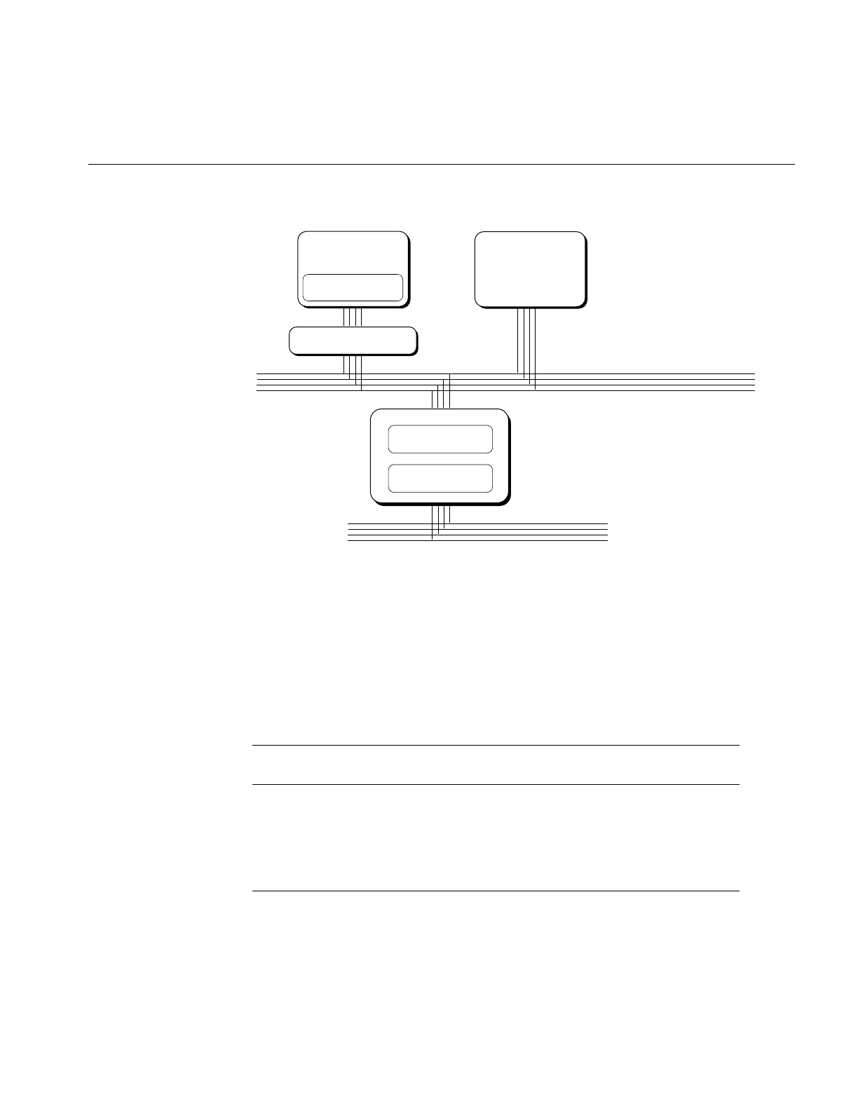
The VME Bus
99
Figure 6-1 Multiprocessor CHALLENGE Data Path Components
VME Bus Attachments
All multiprocessor CHALLENGE systems contain a 9U VME bus in the main card cage.
Systems configured for rack-mount can optionally include an auxiliary 9U VME card
cage, which can be configured as 1, 2, or 4 VME busses. The possible configurations of
VME cards are shown in Table 6-1.
Table 6-1 Multiprocessor CHALLENGE VME Cages and Slots
Model Main Cage
Slots Aux Cage Slots
(1 bus) Aux Cage Slots
(2 busses) Aux Cage Slots
(4 busses)
CHALLENGE L 5 n.a. n.a. n.a.
Onyx Deskside 3 n.a. n.a. n.a.
CHALLENGE XL 5 20 10 and 9 5, 4, 4, and 4
Onyx Rack 4 20 10 and 9 5, 4, 4, and 4
CPU
Second level cache
Main Memory
POWERpath−2 (system) Bus
First level cache
VMECC
F−HIO Card
VME Bus

100
Chapter 6: Managing Device Interactions
Each VME bus after the first requires an F cable connection from an F-HIO card on a
POWER Channel-2 board, as well as a Remote VCAM board in the auxiliary VME cage.
Up to three VME busses (two in the auxiliary cage) can be supported by the first POWER
Channel-2 board in a system. A second POWER Channel-2 board must be added to
support four or more VME busses. The relationship among VME busses, F-HIO cards,
and POWER Channel-2 boards is detailed in Table 6-2.
F-HIO short cards, which are used only on the first POWER Channel-2 board, supply
only one cable output. Regular F-HIO cards, used on the second POWER Channel-2
board, supply two. This explains why, although two POWER Channel-2 boards are
needed with four or more VME busses, the F-HIO slots on the first POWER Channel-2
board remain unused.
VME Address Space Mapping
A device on the VME bus has access to an address space in which it can read or write.
Depending on the device, it uses 16, 32, or 64 bits to define a bus address. The resulting
numbers are called the A16, A32, and A64 address spaces.
Table 6-2 POWER Channel-2 and VME bus Configurations
Number of
VME Busses PC-2 #1
FHIO slot #1 PC-2 #1
FHIO slot #2 PC-2 #2
FHIO slot #1 PPC-2 #2
FHIO slot #2
1 unused unused n.a. n.a.
2 F-HIO short unused n.a. n.a.
3 (1 PC-2) F-HIO short F-HIO short n.a. n.a.
3 (2 PC-2) unused unused F-HIO unused
4 unused unused F-HIO F-HIO
5 unused unused F-HIO F-HIO

The VME Bus
101
There is no direct relationship between an address in the VME address space and the set
of real addresses in the system main memory. An address in the VME address space must
be translated twice:
•The VME interface hardware establishes a translation from VME addresses into
addresses in real memory.
•The IRIX kernel assigns real memory space for this use, and establishes the
translation from real memory to virtual memory in the address space of a process or
the address space of the kernel.
Address space mapping is done differently for programmed I/O, in which slave VME
devices respond to memory accesses by the program, and for DMA, in which master
VME devices read and write directly to main memory.
Note: VME addressing issues are discussed in greater detail from the standpoint of the
device driver, in the IRIX Device Driver Programmer’s Guide.
PIO Address Space Mapping
To allow programmed I/O, the mmap() system function establishes a correspondence
between a segment of a process’s address space and a segment of the VME address space.
The kernel and the VME device driver program registers in the VME bus interface chip
and recognizes fetches and stores to specific main memory real addresses and translates
them into reads and writes on the VME bus. The devices on the VME bus must react to
these reads and writes as slaves; DMA is not supported by this mechanism.
For CHALLENGE and Onyx systems, one VME bus interface chip can map as many as
12 different segments of memory. Each segment can be as long as 8 MB. The segments can
be used singly or in any combination. Thus one VME bus interface chip can support 12
unique mappings of at most 8 MB, or a single mapping of 96 MB, or combinations
between.
For systems supporting the XIO-VME option, which uses a Tundra Universe VME
interface chip, user-level PIO mapping is allocated as follows:
•all A16 and A24 address space is mapped
•seven additional mappings for a maximum of 512 MB in A32 address space

102
Chapter 6: Managing Device Interactions
DMA Mapping
DMA mapping is based on the use of page tables stored in system main memory. This
allows DMA devices to access the virtual addresses in the address spaces of user
processes. The real pages of a DMA buffer can be scattered in main memory, but this is
not visible to the DMA device. DMA transfers that span multiple, scattered pages can be
performed in a single operation.
The kernel functions that establish the DMA address mapping are available only to
device drivers. For information on these, refer to the IRIX Device Driver Programmer’s
Guide.
Program Access to the VME Bus
Your program accesses the devices on the VME bus in one of two ways, through
programmed I/O (PIO) or through DMA. Normally, VME cards with Bus Master
capabilities always use DMA, while VME cards with slave capabilities are accessed using
PIO.
The VME bus interface also contains a unique hardware feature, the DMA Engine, which
can be used to move data directly between memory and a slave VME device.
PIO Access
Perform PIO to VME devices by mapping the devices into memory using the mmap()
function (The use of PIO is covered in greater detail in the IRIX Device Driver
Programmer’s Guide. Memory mapping of I/O devices and other objects is covered in the
book Topics in IRIX Programming.)
Each PIO read requires two transfers over the VME bus interface: one to send the address
to be read, and one to retrieve the data. The latency of a single PIO input is approximately
4 microseconds on the CHALLENGE/Onyx systems and 2.6 microseconds on the
Origin/Onyx 2 systems. PIO write is somewhat faster, since the address and data are sent
in one operation. Typical PIO performance is summarized in Table 6-3.

The VME Bus
103
When a system has multiple VME buses, you can program concurrent PIO operations
from different CPUs to different buses, effectively multiplying the bandwidth by the
number of buses. It does not improve performance to program concurrent PIO to a single
VME bus.
Tip: When transferring more than 32 bytes of data, you can obtain higher rates using the
DMA Engine. See “DMA Engine Access to Slave Devices” on page 104.
User-Level Interrupt Handling
If a VME device that you control with PIO can generate interrupts, you can arrange to
trap the interrupts in your own program. In this way, you can program the device for
some lengthy operation using PIO output to its registers, and then wait until the device
returns an interrupt to say the operation is complete.
The programming details on user-level interrupts are covered in Chapter 7, “Managing
User-Level Interrupts.”
DMA Access to Master Devices
VME bus cards with Bus Master capabilities transfer data using DMA. These transfers
are controlled and executed by the circuitry on the VME card. The DMA transfers are
directed by the address mapping described under “DMA Mapping” on page 102.
Table 6-3 VME Bus PIO Bandwidth
Data Unit Size Reads for
Origin/Onyx 2
Systems
Reads for
CHALLENGE/
Onyx Systems
Writes for
Origin/Onyx 2
Systems
Writes for
CHALLENGE/
Onyx Systems
D8 0.35 MB/second 0.2 MB/second 1.5 MB/second 0.75 MB/second
D16 0.7 MB/second 0.5 MB/second 3.0 MB/second 1.5 MB/second
D32 1.4 MB/second 1 MB/second 6 MB/second 3 MB/second

104
Chapter 6: Managing Device Interactions
DMA transfers from a Bus Master are always initiated by a kernel-level device driver. In
order to exchange data with a VME Bus Master, you open the device and use read() and
write() calls. The device driver sets up the address mapping and initiates the DMA
transfers. The calling process is typically blocked until the transfer is complete and the
device driver returns.
The typical performance of a single DMA transfer is summarized in Table 6-4. Many
factors can affect the performance of DMA, including the characteristics of the device.
DMA Engine Access to Slave Devices
A DMA engine is included as part of, and is unique to each Silicon Graphics VME bus
interface. It performs efficient, block-mode, DMA transfers between system memory and
VME bus slave cards—cards that are normally capable of only PIO transfers.
The DMA engine greatly increases the rate of data transfer compared to PIO, provided
that you transfer at least 32 contiguous bytes at a time. The DMA engine can perform D8,
D16, D32, D32 Block, and D64 Block data transfers in the A16, A24, and A32 bus address
spaces.
Table 6-4 VME Bus Bandwidth, VME Master Controlling DMA
Data Transfer
Size Reads for
Origin/Onyx 2
Systems
Reads for
CHALLENGE/
Onyx Systems
Writes for
Origin/Onyx 2
Systems
Writes for
CHALLENGE/
Onyx Systems
D8 N/A 0.4 MB/sec N/A 0.6 MB/sec
D16 N/A 0.8 MB/sec N/A 1.3 MB/sec
D32 N/A 1.6 MB/sec N/A 2.6 MB/sec
D32 BLOCK 20 MB/sec (256
byte block)
22 MB/sec (256
byte block)
24 MB/sec (256
byte block)
24 MB/sec (256
byte block)
D64 BLOCK 40 MB/sec (2048
byte block)
55 MB/sec (2048
byte block)
48 MB/sec (2048
byte block)
58 MB/sec (2048
byte block)

The VME Bus
105
All DMA engine transfers are initiated by a special device driver. However, you do not
access this driver through open/read/write system functions. Instead, you program it
through a library of functions. The functions are documented in the udmalib(3x) (for
CHALLENGE/Onyx systems) and the vme_dma_engine(3x) (for Origin/Onyx 2
systems) reference pages. For CHALLENGE/Onyx systems, the functions are used in the
following sequence:
1. Call dma_open() to initialize action to a particular VME card.
2. Call dma_allocbuf() to allocate storage to use for DMA buffers.
3. Call dma_mkparms() to create a descriptor for an operation, including the buffer,
the length, and the direction of transfer.
4. Call dma_start() to execute a transfer. This function does not return until the
transfer is complete.
Note: The Origin/Onyx 2 library also supports these functions, but they are not the
preferred interface.
For the Origin and Onyx 2 XIO-VME interface, the VME DMA engine library is used in
the following sequence:
1. Call vme_dma_engine_handle_alloc() to allocate a handle for the DMA engine by
the given pathname.
2. Call vme_dma_engine_buffer_alloc() to allocate the host memory buffer according
to the address and byte_count pair.
3. Call vme_dma_engine_transfer_alloc() to allocate a transfer entity by the given
parameters. Some parameters must be specified, such as the buffer handle, the VME
bus address, the number of bytes that are being transferred, the VME bus address
space type, and the direction of the transfer. There are two advisory parameters: the
throttle size and the release mode.
4. Call vme_dma_engine_schedule() to schedule a transfer for the actual DMA action.
This call provides a way to schedule multiple transfers for one-time DMA action.
5. Call vme_dma_engine_commit() to ask the library to commit all scheduled
transfers. Two commitment modes are available: synchronous and asynchronous.
•In synchronous mode, the library returns when the DMA is finished and an
advisory parameter specifies the wait method: spin-waiting or sleep-waiting.
•In asynchronous mode, the library returns instantly. Call
vme_dma_engine_rendezvous() to wait until all scheduled transfers are
complete. Here also are the spin-waiting or sleep-waiting options for waiting.
For more details of user DMA, see the IRIX Device Driver Programmer’s Guide.

106
Chapter 6: Managing Device Interactions
The typical performance of the DMA engine for D32 transfers is summarized in Table 6-5
and Table 6-6. Performance with D64 Block transfers is somewhat less than twice the rate
shown in Table 6-5 and Table 6-6. Transfers for larger sizes are faster because the setup
time is amortized over a greater number of bytes.
Table 6-5 VME Bus Bandwidth, DMA Engine, D32 Transfer (CHALLENGE/Onyx Systems)
Transfer Size Reads Writes Block Reads Block Writes
32 2.8 MB/sec 2.6 MB/sec 2.7 MB/sec 2.7 MB/sec
64 3.8 MB/sec 3.8 MB/sec 4.0 MB/sec 3.9 MB/sec
128 5.0 MB/sec 5.3 MB/sec 5.6 MB/sec 5.8 MB/sec
256 6.0 MB/sec 6.7 MB/sec 6.4 MB/sec 7.3 MB/sec
512 6.4 MB/sec 7.7 MB/sec 7.0 MB/sec 8.0 MB/sec
1024 6.8 MB/sec 8.0 MB/sec 7.5 MB/sec 8.8 MB/sec
2048 7.0 MB/sec 8.4 MB/sec 7.8 MB/sec 9.2 MB/sec
4096 7.1 MB/sec 8.7 MB/sec 7.9 MB/sec 9.4 MB/sec
Table 6-6 VME Bus Bandwidth, DMA Engine, D32 Transfer (Origin/Onyx 2 Systems)
Transfer Size Reads Writes Block Reads Block Writes
32 1.2 MB/sec 1.1 MB/sec 1.2 MB/sec 1.2 MB/sec
64 2.0 MB/sec 1.9 MB/sec 2.0 MB/sec 2.0 MB/sec
128 3.3 MB/sec 3.5 MB/sec 3.3 MB/sec 3.9 MB/sec
256 5.1 MB/sec 5.6 MB/sec 5.2 MB/sec 6.3 MB/sec
512 6.9 MB/sec 8.2 MB/sec 7.3 MB/sec 9.0 MB/sec
1024 8.0 MB/sec 10.5 MB/sec 8.8 MB/sec 12.0 MB/sec
2048 9.2 MB/sec 12.2 MB/sec 9.8 MB/sec 14.0 MB/sec
4096 9.6 MB/sec 12.6 MB/sec 11.3 MB/sec 15.1 MB/sec

The VME Bus
107
Some of the factors that affect the performance of user DMA include
•The response time of the VME board to bus read and write requests
•The size of the data block transferred (as shown in Table 6-5)
•Overhead and delays in setting up each transfer
The numbers in Table 6-5 were achieved by a program that called dma_start() in a tight
loop, in other words, with minimal overhead.
The dma_start() and vme_dma_engine_commit() functions operate in user space; they
are not kernel-level device driver calls. This has two important effects. First, overhead is
reduced, since there are no mode switches between user and kernel, as there are for
read() and write(). This is important since the DMA engine is often used for frequent,
small inputs and outputs.
Second, dma_start() does not block the calling process, in the sense of suspending it and
possibly allowing another process to use the CPU. However, it waits in a test loop,
polling the hardware until the operation is complete. As you can infer from Table 6-5,
typical transfer times range from 50 to 250 microseconds. You can calculate the
approximate duration of a call to dma_start() based on the amount of data and the
operational mode.
The vme_dma_engine_commit() call can be used either synchronously (as described for
the dma_start() library call) or asynchronously. If the call is made asynchronously, the
transfer completes (in parallel) while the process continues to execute. Because of this,
the user process must coordinate with DMA completion using the
vme_dma_engine_rendezvous() call.
You can use the udmalib functions to access a VME Bus Master device, if the device can
respond in slave mode. However, this may be less efficient than using the Master device’s
own DMA circuitry.
While you can initiate only one DMA engine transfer per bus, it is possible to program a
DMA engine transfer from each bus in the system, concurrently.

108
Chapter 6: Managing Device Interactions
Serial Ports
IRIX 6.5 adds support for the user mode serial library, or usio, which provides access to
the system serial ports on Origin, O2, and OCTANE systems, without the overhead of
system calls. On these systems, the device /dev/ttyus* is mapped into the user process’s
address space and is accessed directly by the library routines. The user mode library
provides read, write, and error detection routines. In addition to the library routines, ioctl
support is provided to perform functions that are not time critical, such as port
configuration. The read() and write() system calls are not supported for this device type,
as these functions are implemented in the user library. For complete information about
usio, see the usio(7) reference page.
On the Origin, O2, and OCTANE systems, support for a character-based interface on the
serial ports is also provided as a low-cost alternative for applications needing bulk data
transfer with no character interpretation, via the serial ports. For more information, see
the cserialio(7) reference page.
Systems that do not support usio or cserialio must rely on the serial device drivers and
STREAMS modules for an input device that interfaces through a serial port for real-time
programs. This is not a recommended practice for several reasons: the serial device
drivers and the STREAMS modules that process serial input are not optimized for
deterministic, real-time performance; and at high data rates, serial devices generate
many interrupts.
When there is no alternative, a real-time program will typically open one of the files
named /dev/tty*. The names, and some hardware details, for these devices are
documented in the serial(7) reference page. Information specific to two serial adapter
boards is in the duart(7) reference page and the cdsio(7) reference page.
When a process opens a serial device, a line discipline STREAMS module is pushed on
the stream by default. If the real-time device is not a terminal and doesn’t support the
usual line controls, this module can be removed. Use the I_POP ioctl (see the streamio(7)
reference page) until no modules are left on the stream. This minimizes the overhead of
serial input, at the cost of receiving completely raw, unprocessed input.
An important feature of current device drivers for serial ports is that they try to minimize
the overhead of handling the many interrupts that result from high character data rates.
The serial I/O boards interrupt at least every 4 bytes received, and in some cases on every
character (at least 480 interrupts a second, and possibly 1920, at 19,200 bps). Rather than
sending each input byte up the stream as it arrives, the drivers buffer a few characters
and send multiple characters up the stream.

External Interrupts
109
When the line discipline module is present on the stream, this behavior is controlled by
the termio settings, as described in the termio(7) reference page for non-canonical input.
However, a real-time program will probably not use the line-discipline module. The
hardware device drivers support the SIOC_ITIMER ioctl that is mentioned in the
serial(7) reference page, for the same purpose.
The SIOC_ITIMER function specifies the number of clock ticks (see “Tick Interrupts”on
page 20) over which it should accumulate input characters before sending a batch of
characters up the input stream. A value of 0 requests that each character be sent as it
arrives (do this only for devices with very low data rates, or when it is absolutely
necessary to know the arrival time of each input byte). A value of 5 tells the driver to
collect input for 5 ticks (50 milliseconds, or as many as 24 bytes at 19,200 bps) before
passing the data along.
External Interrupts
The Origin, CHALLENGE, Onyx, and Onyx 2 systems include support for generating
and receiving external interrupt signals. The electrical interface to the external interrupt
lines is documented in the ei(7) reference page.
Your program controls and receives external interrupts by interacting with the external
interrupt device driver. This driver is associated with the special device file /dev/ei, and is
documented in the ei(7) reference page.
For programming details of the external interrupt lines, see the IRIX Device Driver
Programmer’s Guide. You can also trap external interrupts with a user-level interrupt
handler (see “User-Level Interrupt Handling” on page 103); this is also covered in the
IRIX Device Driver Programmer’s Guide.


111
Chapter 7
7. Managing User-Level Interrupts
The user-level interrupt (ULI) facility allows a hardware interrupt to be handled by a
user process. The ULI facility is intended to simplify and streamline the response to
external events. ULIs can be written to respond to interrupts initiated from the VME bus,
the PCI bus, or external interrupt ports. ULIs are essentially Interrupt Service Routines
(ISRs) that reside in the address space of a user process. As shown in Figure 7-1, when an
interrupt is received that has been registered to a ULI, it calls the user function from the
interrupt level. For function prototypes and other details, see the uli(3) reference page.
Figure 7-1 ULI Functional Overview
Note: The uli(3) reference page and the libuli library are installed as part of the
REACT/Pro package. The features described in this chapter are supported in
REACT/Pro version 3.2, which must be installed in order to use them.
Interrupt level
User level
Kernel
ISR
ULI
function
User
process
Interrupt
The kernel ISR
calls the function
residing in
user process space

112
Chapter 7: Managing User-Level Interrupts
Overview of ULI
In the past, PIO could be only synchronous: the program wrote to a device register, then
polled the device until the operation was complete. With ULI, the program can manage
a device that causes interrupts on the VME or PCI bus. You set up a handler function
within your program. The handler is called whenever the device causes an interrupt.
In IRIX 6.2, user-level interrupts were introduced for VME bus devices and for external
interrupts on the CHALLENGE and Onyx systems. In IRIX 6.5, user-level interrupts are
also supported for PCI devices, and for external interrupts on Origin 2000, Origin 200,
and Onyx 2 systems.
When using ULI with a VME or PCI device, you use PIO to initiate device actions and to
transfer data to and from device registers. When using ULI to trap external interrupts,
you enable the interrupts with ioctl() calls to the external interrupt handler. All these
points are covered in much greater detail in the IRIX Device Driver Programmer’s Guide
(see “Other Useful Books and Sites” on page xix).
The ULI Handler
The ULI handler is a function within your program. It is entered asynchronously from
the IRIX kernel’s interrupt-handling code. The kernel transfers from the kernel address
space into the user process address space, and makes the call in user (not privileged
kernel) execution mode. Despite this more complicated linkage, you can think of the ULI
handler as a subroutine of the kernel’s interrupt handler. As such, the performance of the
ULI handler has a direct bearing on the system’s interrupt response time.
Like the kernel’s interrupt handler, the ULI handler can be entered at almost any time,
regardless of what code is being executed by the CPU—a process of your program or a
process of another program, executing in user space or in a system function. In fact, the
ULI handler can be entered from one CPU while the your program executes concurrently
in another CPU. Your normal code and your ULI function can execute in true
concurrency, accessing the same global variables.

Overview of ULI
113
Restrictions on the ULI Handler
Because the ULI handler is called in a special context of the kernel’s interrupt handler, it
is severely restricted in the system facilities it can use. The list of features the ULI handler
may not use includes the following:
•Any use of floating-point calculations. The kernel does not take time to save
floating-point registers during an interrupt trap. The floating-point coprocessor is
turned off, and an attempt to use it in the ULI handler causes a SIGILL (illegal
instruction) exception.
•Any use of IRIX system functions. Because most of the IRIX kernel runs with
interrupts enabled, the ULI handler could be entered while a system function was
already in progress. System functions do not support reentrant calls. In addition,
many system functions can sleep, which an interrupt handler may not do.
Note: Elsewhere in this book you will read that interrupt handlers in IRIX 6.5 run as
“threads” and can sleep. While true, this privilege has not yet been extended to
user-level interrupt handlers, which are still required never to sleep.
•Any storage reference that causes a page fault. The kernel cannot suspend the ULI
handler for page I/O. Reference to an unmapped page causes a SIGSEGV (memory
fault) exception.
•Any calls to C library functions that might violate the preceding restrictions.
There are very few library functions that you can be sure use no floating point, make no
system calls, and do not cause a page fault. Unfortunately, library functions such as
sprintf(), often used in debugging, must be avoided.
In essence, the ULI handler should do only these things, as shown in Figure 7-2:
•Store data in program variables in locked pages, to record the interrupt event.
For example, a ring buffer is a data structure that is suitable for concurrent access.
•Program the device as required to clear the interrupt or acknowledge it.
The ULI handler has access to the whole program address space, including any
mapped-in devices, so it can perform PIO loads and stores.
•Post a semaphore to wake up the main process.
This must be done using a ULI function.

114
Chapter 7: Managing User-Level Interrupts
Figure 7-2 ULI Handler Functions
Planning for Concurrency
Since the ULI handler can interrupt the program at any point, or run concurrently with
it, the program must be prepared for concurrent execution. There are two areas to
consider: global variables, and library routines.
Debugging With Interrupts
The asynchronous, possibly concurrent entry to the ULI handler can confuse a
debugging monitor such as dbx. Some strategies for dealing with this are covered in the
uli(3) reference page.
Declaring Global Variables
When variables can be modified by both the main process and the ULI handler, you must
take special care to avoid race conditions.
An important step is to specify -D_SGI_REENTRANT_FUNCTIONS to the compiler, so
as to get the reentrant versions of the C library functions. This ensures that, if the main
process and the ULI handler both enter the C library, there is no collision over global
variables.
Interrupt level
User level
Kernel
ISR
ULI
function
User
process
Interrupt
Process wakeup
SprocA SprocB
Memory access
Shared
memory/
Mapped
memory

Setting Up
115
You can declare the global variables that are shared with the ULI handler with the
keyword “volatile,” so that the compiler generates code to load the variables from
memory on each reference. However, the compiler never holds global values in registers
over a function call, and you almost always have a function call (such as
ULI_block_intr()) preceding a test of a shared global variable.
Using Multiple Devices
The ULI feature allows a program to open more than one interrupting device. You
register a handler for each device. However, the program can only wait for a specific
interrupt to occur; that is, the ULI_sleep() function specifies the handle of one particular
ULI handler. This does not mean that the main program must sleep until that particular
interrupt handler is entered, however. Any ULI handler can waken the main program, as
discussed under “Interacting With the Handler” on page 119.
Setting Up
A program initializes for ULI in the following major steps:
1. Open the device special file for the device.
2. For a PCI or VME device, map the device addresses into process memory (see the
IRIX Device Driver Programmer’s Guide (see “Other Useful Books and Sites” on
page xix).
3. Lock the program address space in memory.
4. Initialize any data structures used by the interrupt handler.
5. Register the interrupt handler.
6. Interact with the device and the interrupt handler.
Any time after the handler has been registered, an interrupt can occur, causing entry to
the ULI handler.

116
Chapter 7: Managing User-Level Interrupts
Opening the Device Special File
Devices are represented by device special files (see the IRIX Device Driver Programmer’s
Guide (see “Other Useful Books and Sites” on page xix)). In order to gain access to a
device, you open the device special file that represents it. The device special files that can
generate user-level interrupts include:
•The external interrupt line on a CHALLENGE/ Onyx or Origin 200 system, or the
base module’s external interrupt in an Origin 2000 or Onyx 2 system is /dev/ei. Other
external interrupt source devices in an Origin 2000 or Onyx 2 system are mentioned
in the IRIX Device Driver Programmer’s Guide.
•The files that represent PCI bus address spaces are summarized in the pciba(7)
reference page and the IRIX Device Driver Programmer’s Guide.
•The files that represent VME control units are summarized in the IRIX Device Driver
Programmer’s Guide.
The program should open the device and verify that the device exists and is active before
proceeding.
Locking the Program Address Space
The ULI handler must not reference a page of program text or data that is not present in
memory. You prevent this by locking the pages of the program address space in memory.
The simplest way to do this is to call the mlockall() system function:
if (mlockall(MCL_CURRENT|MCL_FUTURE)<0) perror (“mlockall”);
The mlockall() function has two possible difficulties. One is that the calling process must
have either superuser privilege or CAP_MEMORY_MGT capability (see the
mlockall(3C) reference page). This may not pose a problem if the program needs
superuser privilege in any case, for example, to open a device special file. The second
difficulty is that mlockall() locks all text and data pages. In a very large program, this
may be so much memory that system performance is harmed.
The mlock() or mpin() functions can be used by unprivileged programs to lock a limited
number of pages. The limit is set by the tunable system parameter maxlkmem. (Check its
value—typically 2000—in /var/sysgen/mtune/kernel. See the systune(1) reference page for
instructions on changing a tunable parameter.)

Setting Up
117
In order to use mlock() or mpin(), you must specify the exact address ranges to be locked.
Provided that the ULI handler refers only to global data and its own code, it is relatively
simple to derive address ranges that encompass the needed pages. If the ULI handler
calls any library functions, the library DSO needs to be locked as well. The smaller and
simpler the code of the ULI handler, the easier it is to use mlock() or mpin().
Registering the Interrupt Handler
When the program is ready to start operations, it registers its ULI handler. The ULI
handler is a function that matches the prototype
void function_name(void *arg);
The registration function takes arguments with the following purposes:
•The file descriptor of the device special file.
•The address of the handler function.
•An argument value to be passed to the handler on each interrupt. This is typically a
pointer to a work area that is unique to the interrupting device (supposing the
program is using more than one device).
•A count of semaphores to be allocated for use with this interrupt.
•An optional address, and the size, of memory to be used as stack space when calling
the handler.
•Additional arguments for VME and PCI devices.
You can ask the ULI support to allocate a stack space by passing a null pointer for the
stack argument. When the ULI handler is as simple a function as it normally is, the
default stack size of 1024 bytes is ample.
The semaphores are allocated and maintained by the ULI support. They are used to
coordinate between the program process and the interrupt handler, as discussed under
“Interacting With the Handler”on page 119. You should specify one semaphore for each
independent process that can wait for interrupts from this handler. Normally one
semaphore is sufficient.
The value returned by the registration function is a handle that is used to identify this
interrupt in other functions. Once registered, the ULI handler remains registered until
the program terminates (there is no function for un-registration).

118
Chapter 7: Managing User-Level Interrupts
Registering an External Interrupt Handler
The ULI_register_ei() function takes the arguments described in the preceding topic.
Once it has successfully registered your handler, all external interrupts are directed to
that handler.
It is important to realize that, so long as a ULI handler is registered, none of the other
interrupt-reporting features supported by the external interrupt device driver operate
any more (see the IRIX Device Driver Programmer’s Guide and the ei(7) reference page).
These restrictions include the facts that:
•The per-process external interrupt queues are not updated.
•Signals requested by ioctl(EIIOCSETSIG) are not sent.
•Calls to ioctl(EIIOCRECV)sleep until they are interrupted by a timeout, a signal, or
because the program using ULI terminated and an interrupt arrived.
•Calls to the library function eicbusywait_f() do not terminate.
Clearly you should not use ULI for external interrupts when there are other programs
running that also use them.
Registering a VME Interrupt Handler
The ULI_register_vme() function takes two additional arguments:
•the interrupt level that the device uses.
•a word that contains, or receives, an interrupt vector number (sometimes referred to
as the status or ID).
The interrupt level used by a device is normally set by hardware and documented in the
VECTOR line that defines the device (see the IRIX Device Driver Programmer’s Guide).
Some VME devices have a fixed interrupt vector number; others are programmable. You
pass a fixed vector number to the function. If the number is programmable, you pass 0,
and the function allocates a number. You must then use PIO to program the vector
number into the device.

Setting Up
119
Registering a PCI Interrupt Handler
The ULI_register_pci() function takes one argument in addition to those already
described: the number of the interrupt line(s) to attach to. Lines is a bitmask with bits 0,
1, 2, and 3 corresponding to lines A, B, C, and D, respectively.
Interacting With the Handler
The program process and the ULI handler synchronize their actions using two functions.
When the program cannot proceed without an interrupt, it calls ULI_sleep(), specifying
•the handle of the interrupt for which to wait
•the number of the semaphore to use for waiting
Typically only one process ever calls ULI_sleep() and it specifies waiting on semaphore
0. However, it is possible to have two or more processes that wait. For example, if the
device can produce two distinct kinds of interrupts—normal and high-priority,
perhaps—you could set up an independent process for each interrupt type. One would
sleep on semaphore 0, the other on semaphore 1.
When an ULI handler is entered, it wakes up a program process by calling
ULI_wakeup(), specifying the semaphore number to be posted. The handler must know
which semaphore to post, based on the values it can read from the device or from
program variables.
The ULI_sleep() call can terminate early, for example if a signal is sent to the process. The
process that calls ULI_sleep() must test to find the reason the call returned—it is not
necessarily because of an interrupt.
The ULI_wakeup() function can be called from normal code as well as from a ULI
handler function. It could be used within any type of asynchronous callback function to
wake up the program process.

120
Chapter 7: Managing User-Level Interrupts
The ULI_wakeup() call also specifies the handle of the interrupt. When you have
multiple interrupting devices, you have the following design choices:
•You can have one child process waiting on the handler for each device. In this case,
each ULI handler specifies its own handle to ULI_wakeup().
•You can have a single process that waits on any interrupt. In this case, the main
program specifies the handle of one particular interrupt to ULI_sleep(), and every
ULI handler specifies that same handle to ULI_wakeup().
Achieving Mutual Exclusion
The program can gain exclusive use of global variables with a call to ULI_block_intr().
This function does not block receipt of the hardware interrupt, but does block the call to
the ULI handler. Until the program process calls ULI_unblock_intr(), it can test and
update global variables without danger of a race condition. This period of time should
be as short as possible, because it extends the interrupt latency time. If more than one
hardware interrupt occurs while the ULI handler is blocked, it is called for only the
last-received interrupt.
There are other techniques for safe handling of shared global variables besides blocking
interrupts. One important, and little-known, set of tools is the test_and_set() group of
functions documented in the test_and_set(3) reference page. These instructions use the
Load Linked and Store Conditional instructions of the MIPS instruction set to safely
update global variables in various ways.
Sample Programs
This section contains two programs to show how user-level interrupts are used.
•The program listed in Example 7-1 is a hypothetical example of how user-level
interrupts can be used to handle interrupts from the PCI bus in an Onyx 2/Origin
2000 system
•The program listed in Example 7-2 is a hypothetical example of how user-level
interrupts can be used to handle external interrupts in a CHALLENGE and Onyx
system.

Sample Programs
121
Example 7-1 Hypothetical PCI ULI Program
/*
* pci40_uli.c - PCI User Level Interrupt (ULI) test using the
* Greenspring PCI40 IP carrier card to generate
* interrupts.
*
* This version for Onyx 2/Origin 2000 systems (Origin 200 systems
* will have a different hwgraph path.)
*
* link with -luli
*
* Make sure that the latest 6.5 REACT/pro, PCI and kernel
* roll-up patches are installed.
*
*/
#include <sys/types.h>
#include <sys/mman.h>
#include <sys/fcntl.h>
#include <sys/prctl.h>
#include <unistd.h>
#include <stdio.h>
#include <sys/syssgi.h>
#include <sys/sysmp.h>
#include <sched.h>
#include <sys/uli.h>
#define INTRPATH "/hw/module/1/slot/io2/pci_xio/pci/2/intr"
#define PCI40_PATH "/hw/module/1/slot/io2/pci_xio/pci/2/base/2"
#define PLX_PATH "/hw/module/1/slot/io2/pci_xio/pci/2/base/0"
#define PCI40_SIZE (1024*1024)
#define PLX_SIZE 128
#define PCI_INTA 0x01
#define NUM_INTS 1000000
#define BAD_RESPONSE 30
#define PROC 0
extern int errno;
int intr;
static void *ULIid;
volatile uchar_t *pci40_addr;
/* definitions for timer */
typedef unsigned long long iotimer_t;
__psunsigned_t phys_addr, raddr;
unsigned int cycleval;
volatile iotimer_t begin_time, end_time, *timer_addr;
int timer_fd, poffmask;
float usec_time;
int bad_responses = 0;

122
Chapter 7: Managing User-Level Interrupts
float longest_response = 0.0;
float average_response = 0.0;
static void
intrfunc(void *arg)
{
end_time = *timer_addr;
/* Set the global flag indicating to the main thread that an
* interrupt has occurred, and wake it up
*/
intr++;
/*
* clear the interrupt on the mothercard by clearing CNTRL0
* adding 1 to offset for big endian access
*/
*(unsigned char *)(pci40_addr+0x501) = 0x00;
}
main(int argc, char *argv[])
{
int fd;
int pci_fd;
int plx_fd;
int cpu;
int multi_cpus = 0;
volatile uint_t *plx_addr;
volatile uint_t x;
float fres;
double total = 0;
struct sched_param sparams;
struct timespec wait_time;
/*
* do the appropriate real-time things
*/
sparams.sched_priority = sched_get_priority_max(SCHED_FIFO);
if (sched_setscheduler(0, SCHED_FIFO, &sparams) < 0) {
perror("psched: ERROR - sched_setscheduler");
exit(1);
}
if (mlockall( MCL_CURRENT | MCL_FUTURE )){
perror ("mlockall");
}
/*
* be sure there are multiple cpus present before
* attempting to run on an isolated cpu - once
* verified, isolate and make non-preemptive
* the cpu, then force the process to execute there
*

Sample Programs
123
*/
cpu = sysmp(MP_NPROCS) - 1;
if (cpu>0) {
multi_cpus = 1;
if (sysmp(MP_ISOLATE,cpu)) {
perror("sysmp-MP_ISOLATE");
exit(1);
}
if (sysmp(MP_NONPREEMPTIVE,cpu)) {
perror("sysmp-MP_NONPREEMPTIVE");
exit(1);
}
if (sysmp(MP_MUSTRUN,cpu)) {
perror("sysmp-MP_MUSTRUN");
exit(1);
}
}
/*
* memory map the hardware cycle-counter
*/
poffmask = getpagesize() - 1;
phys_addr = syssgi(SGI_QUERY_CYCLECNTR, &cycleval);
raddr = phys_addr & ~poffmask;
timer_fd = open("/dev/mmem", O_RDONLY);
timer_addr = (volatile iotimer_t *)mmap(0, poffmask, PROT_READ,
MAP_PRIVATE, timer_fd, (off_t)raddr);
timer_addr = (iotimer_t *)((__psunsigned_t)timer_addr +
(phys_addr & poffmask));
fres = ((float)cycleval)/1000000.0;
/*
* open the PCI user interrupt device/vertex
*/
fd = open(INTRPATH, O_RDWR);
if (fd < 0 ) {
perror(INTRPATH);
exit (1);
}
/*
* open the PLX register space on the PCI40 card
*/
plx_fd = open(PLX_PATH, O_RDWR);
if (plx_fd < 0 ) {
perror(PLX_PATH);
exit (1);
}
/*

124
Chapter 7: Managing User-Level Interrupts
* open the PCI40 memory space for device registers
*/
pci_fd = open(PCI40_PATH, O_RDWR);
if (pci_fd < 0 ) {
perror(PCI40_PATH);
exit (1);
}
/*
* map in the PLX register space on the PCI40 card
*/
plx_addr = (volatile uint_t *) mmap(0, PLX_SIZE, PROT_READ|PROT_WRITE,
MAP_SHARED, plx_fd, 0);
if (plx_addr == (uint_t *) MAP_FAILED) {
perror("mmap plx_addr");
exit (1);
}
/*
* set up the PLX register to pass through the interrupt
*/
x = *(volatile uint_t *)(plx_addr + 0x1a);
*(volatile uint_t *)(plx_addr + 0x1a) = x | 0x00030f00;
/*
* map in the PCI40 memory space for device registers
*/
pci40_addr = (volatile uchar_t *) mmap(0, PCI40_SIZE, PROT_READ|PROT_WRITE,
MAP_SHARED, pci_fd, 0);
if (pci40_addr == (uchar_t *) MAP_FAILED) {
perror("mmap");
exit (1);
}
/*
* clear the interrupt on the mothercard by clearing CNTRL0
* adding 1 to offset for big endian access
*/
*(unsigned char *)(pci40_addr+0x501) = 0x00;
/*
* Register the pci interrupt as a ULI source.
*/
ULIid = (int *)ULI_register_pci(fd, /* the pci interrupt device */
intrfunc, /* the handler function pointer */
0, /* the argument to the handler */
0, /* the # of semaphores needed */
0, /* the stack to use */
0, /* the stack size to use */
PCI_INTA);/* PCI interrrupt line */

Sample Programs
125
if (ULIid == 0) {
perror("register uli");
exit(1);
}
printf ("Registered successfully for PCI INTA - Sending interrupts\n");
/*
* Ask for 200 usec wait time - resolution on Origin is
* really only ~1.5 ms instead
*/
wait_time.tv_sec = 0;
wait_time.tv_nsec = 200000;
while(intr < NUM_INTS) {
/*
* then, enable the interrupt on the PCI carrier
* card - adding 1 to offset for big endian access
*/
begin_time = *timer_addr;
*(unsigned char *)(pci40_addr+0x501) = 0xc0;
nanosleep(&wait_time,NULL);
usec_time = (end_time-begin_time)*fres;
if (usec_time > BAD_RESPONSE) {
bad_responses++;
}
if ((usec_time > longest_response) && (intr > 5))
longest_response = usec_time;
total += usec_time;
average_response = total/(float)intr;
if (!(intr % 1000)&&(intr>0)) {
printf(" Average ULI Response (%d interrupts):\t %4.2f usecs\n",
intr,average_response);
printf(" Number of Interrupts > %d usecs:\t\t %d \n",
BAD_RESPONSE,bad_responses);
}
}
printf(" Average ULI Response (%d interrupts):\t %4.2f usecs \n",
intr,average_response);
printf(" Number of Interrupts > %d usecs:\t\t %d \n",
BAD_RESPONSE,bad_responses);
printf(" Longest ULI Response:\t\t\t\t\t %4.2f \n", longest_response);
if (multi_cpus) {
sysmp( MP_PREEMPTIVE, cpu );
sysmp( MP_UNISOLATE, cpu );
}
}

126
Chapter 7: Managing User-Level Interrupts
Example 7-2 Hypothetical External Interrupt ULI Program
/* This program demonstrates use of the External Interrupt source
* to drive a User Level Interrupt.
*
* The program requires the presence of an external interrupt cable looped
* back between output number 0 and one of the inputs on the machine on
* which the program is run.
*/
#include <sys/ei.h>
#include <sys/uli.h>
#include <sys/lock.h>
#include <unistd.h>
#include <stdlib.h>
#include <stdio.h>
#include <fcntl.h>
/* The external interrupt device file is used to access the EI hardware */
#define EIDEV "/dev/ei"
static int eifd;
/* The user level interrupt id. This is returned by the ULI registration
* routine and is used thereafter to refer to that instance of ULI
*/
static void *ULIid;
/* Variables which are shared between the main process thread and the ULI
* thread may have to be declared as volatile in some situations. For
* example, if this program were modified to wait for an interrupt with
* an empty while() statement, e.g.
* while(!intr);
* the value of intr would be loaded on the first pass and if intr is
* false, the while loop will continue forever since only the register
* value, which never changes, is being examined. Declaring the variable
* intr as volatile causes it to be reloaded from memory on each iteration.
* In this code however, the volatile declaration is not necessary since
* the while() loop contains a function call, e.g.
* while(!intr)
* ULI_sleep(ULIid, 0);
* The function call forces the variable intr to be reloaded from memory
* since the compiler cannot determine if the function modified the value
* of intr. Thus the volatile declaration is not necessary in this case.
* When in doubt, declare your globals as volatile.
*/
static int intr;
/* This is the actual interrupt service routine. It runs
* asynchronously with respect to the remainder of this program, possibly
* simultaneously, on an MP machine. This function must obey the ULI mode

Sample Programs
127
* restrictions, meaning that it may not use floating point or make
* any system calls. (Try doing so and see what happens.)
*/
static void
intrfunc(void *arg)
{
/* Set the global flag indicating to the main thread that an
* interrupt has occurred, and wake it up
*/
intr = 1;
ULI_wakeup(ULIid, 0);
}
/* This function creates a new process and from it, generates a
* periodic external interrupt.
*/
static void
signaler(void)
{
int pid;
if ((pid = fork()) < 0) {
perror("fork");
exit(1);
}
if (pid == 0) {
while(1) {
if (ioctl(eifd, EIIOCSTROBE, 1) < 0) {
perror("EIIOCSTROBE");
exit(1);
}
sleep(1);
}
}
}
/* The main routine sets everything up, then sleeps waiting for the
* interrupt to wake it up.
*/
int
main()
{
/* open the external interrupt device */
if ((eifd = open(EIDEV, O_RDONLY)) < 0) {
perror(EIDEV);
exit(1);
}
/* Set the target cpu to which the external interrupt will be

128
Chapter 7: Managing User-Level Interrupts
* directed. This is the cpu on which the ULI handler function above
* will be called. Note that this is entirely optional, but if
* you do set the interrupt cpu, it must be done before the
* registration call below. Once a ULI is registered, it is illegal
* to modify the target cpu for the external interrupt.
*/
if (ioctl(eifd, EIIOCSETINTRCPU, 1) < 0) {
perror("EIIOCSETINTRCPU");
exit(1);
}
/* Lock the process image into memory. Any text or data accessed
* by the ULI handler function must be pinned into memory since
* the ULI handler cannot sleep waiting for paging from secondary
* storage. This must be done before the first time the ULI handler
* is called. In the case of this program, that means before the
* first EIIOCSTROBE is done to generate the interrupt, but in
* general it is a good idea to do this before ULI registration
* since with some devices an interrupt may occur at any time
* once registration is complete
*/
if (plock(PROCLOCK) < 0) {
perror("plock");
exit(1);
}
/* Register the external interrupt as a ULI source. */
ULIid = ULI_register_ei( eifd, /* the external interrupt device */
intrfunc, /* the handler function pointer */
0, /* the argument to the handler */
1, /* the number of semaphores needed */
NULL, /* the stack to use (supply one) */
0); /* the stack size to use (default) */
if (ULIid == 0) {
perror("register ei");
exit(1);
}
/* Enable the external interrupt. */
if (ioctl(eifd, EIIOCENABLE) < 0) {
perror("EIIOCENABLE");
exit(1);
}
/* Start creating incoming interrupts. */
signaler();
/* Wait for the incoming interrupts and report them. Continue
* until the program is terminated by ^C or kill.
*/

Sample Programs
129
while (1) {
intr = 0;
while(!intr) {
if (ULI_sleep(ULIid, 0) < 0) {
perror("ULI_sleep");
exit(1);
}
printf("sleeper woke up\n");
}
}


131
Appendix A
A. Sample Programs
A number of example programs are distributed with the REACT/Pro Frame Scheduler.
This section describes them. Only one is reproduced here (see “The simple_pt Pthreads
Program” on page 137; the others are found on disk).
The source for the example programs distributed with the Frame Scheduler are found in
the directory /usr/share/src/react/examples and the executables are in /usr/react/bin. They are
summarized in Table A-1 and are discussed in more detail in the topics that follow.
Table A-1 Summary of Frame Scheduler Example Programs
Directory Features of Example
simple
simple_pt
r4k_intr
simple shows two processes and simple_pt shows two threads scheduled on a single
CPU 0 at a frame rate slow enough to permit use of printf() for debugging. The
examples differ in the time base used; and the r4k_intr code uses a barrier for
synchronization.
Like simple, but the scheduled processes are independent programs.
0"multi
multi_pt
ext_intr
user_intr
vsync_intr
Three synchronous Frame Schedulers running lightweight processes (or pthreads in
multi_pt) on three processors. These examples are much alike, differing mainly in the
source of the time base interrupt.
complete
stop_resume
Like multi in starting three Frame Schedulers. Information about the activity
processes is stored in arrays for convenient maintenance. The stop_resume code
demonstrates frs_stop() and frs_resume() calls.
driver
dintr
driver contains a pseudo-device driver that demonstrates the Frame Scheduler
device driver interface. dintr contains a program based on simple that uses the
example driver as a time base.
sixtyhz
memlock
One process scheduled at a 60 Hz frame rate. The activity process in the memlock
example locks its address space into memory before it joins the scheduler.
upreuse Complex example that demonstrates the creation of a pool of reusable processes, and
how they can be dispatched as activity processes on a Frame Scheduler.

132
Appendix A: Sample Programs
Basic Example
The example in /usr/react/src/examples/simple shows how to create a simple application
using the Frame Scheduler API. The code in /usr/react/src/examples/r4kintr is similar.
Real-Time Application Specification
The application consists of two processes that have to periodically execute a specific
sequence of code. The period for the first process, process A, is 600 milliseconds. The
period for the other process, process B, is 2400 ms.
Note: Such long periods are unrealistic for real-time applications. However, they allow
the use of printf() calls within the “real-time” loops in this sample program.
Frame Scheduler Design
The two periods and their ratio determine the selection of the minor frame period—
600 ms—and the number of minor frames per major frame—4, for a total of 2400 ms.
The discipline for process A is strict real-time (FRS_DISC_RT). Underrun and overrun
errors should cause signals.
Process B should run only once in 2400 ms, so it operates as Continuable over as many
as 4 minor frames. For the first 3 frames, its discipline is Overrunnable and Continuable.
For the last frame it is strict real-time. The Overrunnable discipline allows process B to
run without yielding past the end of each minor frame. The Continuable discipline
ensures that once process B does yield, it is not resumed until the fourth minor frame has
passed. The combination allows process B to extend its execution to the allowable period
of 2400 ms, and the strict real-time discipline at the end makes certain that it yields by the
end of the major frame.
There is a single Frame Scheduler so a single processor is used by both processes. Process
A runs within a minor frame until yielding or until the expiration of the minor frame
period. In the latter case the frame scheduler generates an overrun error signaling that
process A is misbehaving.
When process A yields, the frame scheduler immediately activates process B. It runs until
yielding, or until the end of the minor frame at which point it is preempted. This is not
an error since process B is Overrunable.

133
Starting the next minor frame, the Frame Scheduler allows process A to execute again.
After it yields, process B is allowed to resume running, if it has not yet yielded. Again in
the third and fourth minor frame, A is started, followed by B if it has not yet yielded. At
the interrupt that signals the end of the fourth frame (and the end of the major frame),
process B must have yielded, or an overrun error is signalled.
Example of Scheduling Separate Programs
The code in directory /usr/react/src/examples/mprogs does the same work as example simple
(see “Basic Example” on page 132). However, the activity processes A and B are
physically loaded as separate commands. The main program establishes the single
Frame Scheduler. The activity processes are started as separate programs. They
communicate with the main program using SVR4-compatible interprocess
communication messages (see the intro(2) and msgget(2) reference pages).
There are three separate executables in the mprogs example. The master program, in
master.c, is a command that has the following syntax:
master [-p cpu-number] [-s slave-count]
The cpu-number specifies which processor to use for the one Frame Scheduler this
program creates. The default is processor 1. The slave-count tells the master how many
subordinate programs will be enqueued to the Frame Scheduler. The default is two
programs.
The problems that need to be solved in this example are as follows:
•The FRS master program must enqueue the activity processes. However, since they
are started as separate programs, the master has no direct way of knowing their
process IDs, which are needed for frs_enqueue().
•The activity processes need to specify upon which minor frames they should be
enqueued, and with what discipline.
•The master needs to enqueue the activities in the proper order on their minor
frames, so they will be dispatched in the proper sequence. Therefore the master has
to distinguish the subordinates in some way; it cannot treat them as
interchangeable.
•The activity processes must join the Frame Scheduler, so they need the handle of the
Frame Scheduler to use as an argument to frs_join(). However, this information is
in the master’s address space.
•If an error occurs when enqueueing, the master needs to tell the activity processes
so they can terminate in an orderly way.

134
Appendix A: Sample Programs
There are many ways in which these objectives could be met (for example, the three
programs could share a shared-memory arena). In this example, the master and
subordinates communicate using a simple protocol of messages exchanged using
msgget() and msgput() (see the msgget(2) and msgput(2) reference pages). The sequence
of operations is as follows:
1. The master program creates a Frame Scheduler.
2. The master sends a message inviting the most important subordinate to reply. (All
the message queue handling is in module ipc.c, which is linked by all three
programs.)
3. The subordinate compiled from the file processA.c replies to this message, sending
its process ID and requesting the FRS handle.
4. The subordinate process A sends a series of messages, one for each minor queue on
which it should enqueue. The master enqueues it as requested.
5. The subordinate process A sends a “ready” message.
6. The master sends a message inviting the next most important process to reply.
7. The program compiled from processB.c will reply to this request, and steps 3-6 are
repeated for as many slaves as the slave-count parameter to the master program.
(Only two slaves are provided. However, you can easily create more using processB.c
as a pattern.)
8. The master issues frs_start(), and waits for the termination signal.
9. The subordinates independently issue frs_join() and the real-time dispatching
begins.
Examples of Multiple Synchronized Schedulers
The example in /usr/react/src/examples/multi demonstrates the creation of three
synchronized Frame Schedulers. The three use the cycle counter to establish a minor
frame interval of 50 ms. All three Frame Schedulers use 20 minor frames per major frame,
for a major frame rate of 1 Hz.

135
The following processes are scheduled in this example:
•Processes A and D require a frequency of 20 Hz
•Process B requires a frequency of 10 Hz and can consume up to 100 ms of execution
time each time
•Process C requires a frequency of 5 Hz and can consume up to 200 ms of execution
time each time
•Process E requires a frequency of 4 Hz and can consume up to 250 ms of execution
time each time
•Process F requires a frequency of 2 Hz and can consume up to 500 ms of execution
time each time
•Processes K1, K2 and K3 are background processes that should run as often as
possible, when time is available.
The processes are assigned to processors as follows:
•Scheduler 1 runs processes A (20 Hz) and K1 (background).
•Scheduler 2 runs processes B (10 Hz), C (5 Hz), and K2 (background).
•Scheduler 3 runs processes D (20Hz), E (4 Hz), F (2 Hz), and K3.
In order to simplify the coding of the example, all real-time processes use the same
function body, process_skeleton(), which is parameterized with the process name, the
address of the Frame Scheduler it is to join, and the address of the “real-time”action it is
to execute. In the sample code, all real-time actions are empty function bodies (feel free
to load them down with code).
The examples in /usr/react/src/examples/ext_intr,user_intr, and vsync_intr are all similar to
multi, differing mainly in the time base used. The examples in complete and stop_resume
are similar in operation, but more evolved and complex in the way they manage
subprocesses.
Tip: It is helpful to use the xdiff program when comparing these similar programs—see
the xdiff(1) reference page.

136
Appendix A: Sample Programs
Example of Device Driver
The code in /usr/react/src/examples/driver contains a skeletal test-bed for a kernel-level
device driver that interacts with the Frame Scheduler. Most of the driver functions
consist of minimal or empty stubs. However, the ioctl() entry point to the driver (see the
ioctl(2) reference page) simulates a hardware interrupt and calls the Frame Scheduler
entry point, frs_handle_driverintr() (see “Generating Interrupts” on page 85). This
allows you to test the driver. Calling its ioctl() entry is equivalent to using frs_usrintr()
(see “The Frame Scheduler API” on page 48).
The code in /usr/react/src/examples/dintr contains a variant of the simple example that uses
a device driver as the time base. The program dintr/sendintr.c opens the driver, calls ioctl()
to send one time-base interrupt, and closes the driver. (It could easily be extended to send
a specified number of interrupts, or to send an interrupt each time the return key is
pressed.)
Examples of a 60 Hz Frame Rate
The example in directory /usr/react/src/examples/sixtyhz demonstrates the ability to
schedule a process at a frame rate of 60 Hz, a common rate in visual simulators. A single
Frame Scheduler is created. It uses the cycle counter with an interval of 16,666
microseconds (16.66 ms, approximately 60 Hz). There is one minor frame per major
frame.
One real-time process is enqueued to the Frame Scheduler. By changing the compiler
constant LOGLOOPS you can change the amount of work it attempts to do in each frame.
This example also contains the code to query and to change the signal numbers used by
the Frame Scheduler.
The example in /usr/react/src/examples/memlock is similar to the sixtyhz example, but the
activity process uses plock() to lock its address space. Also, it executes one major frame’s
worth of frs_yield() calls immediately after return from frs_join(). The purpose of this is
to “warm up” the processor cache with copies of the process code and data. (An actual
application process could access its major data structures prior to this yield in order to
speed up the caching process.)

137
Example of Managing Lightweight Processes
The code in /usr/react/src/examples/upreuse implements a simulated real-time application
based on a pool of reusable processes. A reusable process is created with sproc() and
described by a pdesc_t structure. Code in pqueue.c builds and maintains a pool of
processes. Code in pdesc.c provides functions to get and release a process, and to dispatch
one to execute a specific function.
The code in test_hello.c creates a pool of processes and dispatches each one in turn to
display a message. The code in test_singlefrs.c creates a pool of processes and causes them
to join a Frame Scheduler.
The simple_pt Pthreads Program
This section is a variation of the simple program, implemented using the pthreads
programming model.
#include <math.h>
#include <stdio.h>
#include <signal.h>
#include <semaphore.h>
#include <pthread.h>
#include <sys/schedctl.h>
#include <sys/sysmp.h>
#include <sys/frs.h>
/*
* frs_abort: If a pthread calls exit, then all pthreads within the process
* will be terminated and the FRS will be destroyed.
*
* For some failure conditions, this is the desired behavior.
*/
#define frs_abort(x) exit(x)
sem_t sem_threads_enqueued;
pthread_attr_t pthread_attributes;
int cpu_number = 1;
/*
* Some fixed real-time loop parameters
*/
#define NLOOPS_A 20
#define NLOOPS_B 15
#define LOGLOOPS_A 150
#define LOGLOOPS_B 30000

138
Appendix A: Sample Programs
void Thread_Master(void);
void Thread_A(frs_t* frs);
void Thread_B(frs_t* frs);
void setup_signals(void);
/*
* NOTE: The initial thread of a pthread application (i.e., the thread
* executing main) cannot be an FRS controller or an FRS scheduled
* activity thread. This is because all FRS controller and activity
* threads must be system scope threads. The initial thread, however,
* is process scope (see pthread_attr_setscope(3P)).
*
* In this example, the initial thread simply performs some set-up
* tasks, launches the system scope Master Controller thread, and
* exits.
*/
main(int argc, char** argv)
{
pthread_t pthread_id_master;
int ret;
/*
* Usage: simple [cpu_number]
*/
if (argc == 2)
cpu_number = atoi(argv[1]);
/*
* Initialize semaphore
*/
if (sem_init(&sem_threads_enqueued, 1, 0)) {
perror("Main: sem_init failed");
frs_abort(1);
}
/*
* Initialize signals to catch FRS termination
* underrun, and overrun error signals
*/
setup_signals();
/*
* Initialize system scope thread attributes
*/
if (ret = pthread_attr_init(&pthread_attributes)) {
fprintf(stderr,
"Main: pthread_attr_init failed (%d)\n", ret);
frs_abort(1);
}

139
ret = pthread_attr_setscope(&pthread_attributes, PTHREAD_SCOPE_SYSTEM);
if (ret) {
fprintf(stderr,
"Main: pthread_attr_setscope failed (%d)\n", ret);
frs_abort(1);
}
/*
* Launch Master Controller Thread
*/
ret = pthread_create(&pthread_id_master,
&pthread_attributes,
(void *(*)(void *)) Thread_Master,
NULL);
if (ret) {
fprintf(stderr,
"Main: pthread_create Thread Master failed (%d)\n", ret);
frs_abort(1);
}
/*
* Once the Master Controller is launched, there is no need for
* us to hang around. So we might as well free-up our stack by
* exiting via pthread_exit().
*
* NOTE: Exiting via exit() would be fatal, terminating the
* entire process.
*/
pthread_exit(0);
}
void
Thread_Master(void)
{
frs_t* frs;
pthread_t pthread_id_a;
pthread_t pthread_id_b;
int minor;
int disc;
int ret;
/*
* Create the Frame Scheduler object:
*
* cpu = cpu_number,
* interrupt source = CCTIMER
* number of minors = 4
* slave mask = 0, no slaves

140
Appendix A: Sample Programs
* period = 600 [ms] == 600000 [microseconds]
*/
frs = frs_create_master(cpu_number,
FRS_INTRSOURCE_CCTIMER,
600000,
4,
0);
if (frs == NULL) {
perror("Master: frs_create_master failed");
pthread_exit(0);
}
/*
* Thread A will be enqueued on all minor frame queues
* with a strict RT discipline
*/
ret = pthread_create(&pthread_id_a,
&pthread_attributes,
(void *(*)(void *)) Thread_A,
(void*) frs);
if (ret) {
fprintf(stderr,
"Master: pthread_create Thread A failed (%d)\n", ret);
pthread_exit(0);
}
for (minor = 0; minor < 4; minor++) {
ret = frs_pthread_enqueue(frs,
pthread_id_a,
minor,
FRS_DISC_RT);
if (ret) {
perror("Master: frs_pthread_enqueue Thread A failed");
pthread_exit(0);
}
}
/*
* Thread B will be enqueued on all minor frames, but the
* disciplines will differ. We need continuability for the first
* 3 frames, and absolute real-time for the last frame.
*/
ret = pthread_create(&pthread_id_b,
&pthread_attributes,
(void *(*)(void *)) Thread_B,
(void*) frs);
if (ret) {
fprintf(stderr,

141
"Master: pthread_create Thread B failed (%d)\n", ret);
pthread_exit(0);
}
disc = FRS_DISC_RT | FRS_DISC_UNDERRUNNABLE |
FRS_DISC_OVERRUNNABLE | FRS_DISC_CONT;
for (minor = 0; minor < 3; minor++) {
ret = frs_pthread_enqueue(frs,
pthread_id_b,
minor,
disc);
if (ret) {
perror("Master: frs_pthread_enqueue ThreadB failed");
pthread_exit(0);
}
}
ret = frs_pthread_enqueue(frs,
pthread_id_b,
3,
FRS_DISC_RT | FRS_DISC_UNDERRUNNABLE);
if (ret) {
perror("Master: frs_pthread_enqueue ThreadB failed");
pthread_exit(0);
}
/*
* Give all FRS threads the go-ahead to join
*/
if (sem_post(&sem_threads_enqueued)) {
perror("Master: sem_post failed");
pthread_exit(0);
}
if (sem_post(&sem_threads_enqueued)) {
perror("Master: sem_post failed");
pthread_exit(0);
}
/*
* Now we are ready to start the frame scheduler
*/
printf("Running Frame Scheduler on Processor [%d]\n", cpu_number);
if (frs_start(frs) < 0) {
perror("Master: frs_start failed");
pthread_exit(0);
}
/*
* Wait for FRS scheduled threads to complete

142
Appendix A: Sample Programs
*/
if (ret = pthread_join(pthread_id_a, 0)) {
fprintf(stderr,
"Master: pthread_join thread A (%d)\n", ret);
pthread_exit(0);
}
if (ret = pthread_join(pthread_id_b, 0)) {
fprintf(stderr,
"Master: pthread_join thread B (%d)\n", ret);
pthread_exit(0);
}
/*
* Clean-up before exiting
*/
(void) pthread_attr_destroy(&pthread_attributes);
(void) sem_destroy(&sem_threads_enqueued);
pthread_exit(0);
}
void
Thread_A(frs_t* frs)
{
int counter;
double res;
int i;
int previous_minor;
pthread_t pthread_id = pthread_self();
/*
* Join to the frame scheduler once given the go-ahead
*/
if (sem_wait(&sem_threads_enqueued)) {
perror("ThreadA: sem_wait failed");
frs_abort(1);
}
if (frs_join(frs) < 0) {
perror("ThreadA: frs_join failed");
frs_abort(1);
}
fprintf(stderr, "ThreadA (%x): Joined Frame Scheduler on cpu %d\n",
pthread_id, frs->frs_info.cpu);
counter = NLOOPS_A;
res = 2;
/*

143
* This is the real-time loop. The first iteration
* is done right after returning from the join
*/
do {
for (i = 0; i < LOGLOOPS_A; i++) {
res = res * log(res) - res * sqrt(res);
}
/*
* After we are done with our computations, we
* yield the cpu. The yield call will not return until
* it's our turn to execute again.
*/
if ((previous_minor = frs_yield()) < 0) {
perror("ThreadA: frs_yield failed");
frs_abort(1);
}
fprintf(stderr,
"ThreadA (%x): Return from Yield; previous_minor: %d\n",
pthread_id, previous_minor);
} while (counter--);
fprintf(stderr, "ThreadA (%x): Exiting\n", pthread_id);
pthread_exit(0);
}
void
Thread_B(frs_t* frs)
{
int counter;
double res;
int i;
int previous_minor;
pthread_t pthread_id = pthread_self();
/*
* Join to the frame scheduler once given the go-ahead
*/
if (sem_wait(&sem_threads_enqueued)) {
perror("ThreadB: sem_wait failed");
frs_abort(1);
}
if (frs_join(frs) < 0) {
perror("ThreadB: frs_join failed");
frs_abort(1);
}

144
Appendix A: Sample Programs
fprintf(stderr, "ThreadB (%x): Joined Frame Scheduler on cpu %d\n",
pthread_id, frs->frs_info.cpu);
counter = NLOOPS_B;
res = 2;
/*
* This is the real-time loop. The first iteration
* is done right after returning from the join
*/
do {
for (i = 0; i < LOGLOOPS_B; i++) {
res = res * log(res) - res * sqrt(res);
}
/*
* After we are done with our computations, we
* yield the cpu. THe yield call will not return until
* it's our turn to execute again.
*/
if ((previous_minor = frs_yield()) < 0) {
perror("ThreadB: frs_yield failed");
frs_abort(1);
}
fprintf(stderr,
"ThreadB (%x): Return from Yield; previous_minor: %d\n",
pthread_id, previous_minor);
} while (counter--);
fprintf(stderr, "ThreadB (%x): Exiting\n", pthread_id);
pthread_exit(0);
}
/*
* Error Signal handlers
*/
void
underrun_error()
{
if ((int)signal(SIGUSR1, underrun_error) == -1) {
perror("[underrun_error]: Error while resetting signal");
frs_abort(1);
}
fprintf(stderr, "[underrun_error], thread %x\n", pthread_self());
frs_abort(2);
}
void
overrun_error()

145
{
if ((int)signal(SIGUSR2, overrun_error) == -1) {
perror("[overrun_error]: Error while resetting signal");
frs_abort(1);
}
fprintf(stderr, "[overrun_error], thread %d\n", pthread_self());
frs_abort(2);
}
void
setup_signals()
{
if ((int)signal(SIGUSR1, underrun_error) == -1) {
perror("[setup_signals]: Error setting underrun_error signal");
frs_abort(1);
}
if ((int)signal(SIGUSR2, overrun_error) == -1) {
perror("[setup_signals]: Error setting overrun_error signal");
frs_abort(1);
}
}


147
Glossary
activity
When using the Frame Scheduler, the basic design unit: a piece of work that can be done
by one thread or process without interruption. You partition the real-time program into
activities, and use the Frame Scheduler to invoke them in sequence within each frame
interval.
address space
The set of memory addresses that a process may legally access. The potential address
space in IRIX is either 232 (IRIX 5.3) or 264 (IRIX 6.0 and later); however only addresses that
have been mapped by the kernel are legally accessible.
affinity scheduling
The IRIX kernel attempts to run a process on the same CPU where it most recently ran,
in the hope that some of the process’s data will still remain in the cache of that CPU. The
process is said to have “cache affinity” for that CPU. (“Affinity” means “a natural
relationship or attraction.”)
arena
A segment of memory used as a pool for allocation of objects of a particular type. Usually
the shared memory segment allocated by usinit().
asynchronous I/O
I/O performed in a separate process, so that the process requesting the I/O is not blocked
waiting for the I/O to complete.
average data rate
The rate at which data arrives at a data collection system, averaged over a given period
of time (seconds or minutes, depending on the application). The system must be able to
write data at the average rate, and it must have enough memory to buffer bursts at the
peak data rate.

148
Glossary
backing store
The disk location that contains the contents of a memory page. The contents of the page
are retrieved from the backing store when the page is needed in memory. The backing
store for executable code is the program or library file. The backing store for modifiable
pages is the swap disk. The backing store for a memory-mapped file is the file itself.
barrier
A memory object that represents a point of rendezvous or synchronization between
multiple processes. The processes come to the barrier asynchronously, and block there
until all have arrived. When all have arrived, all resume execution together.
context switch time
The time required for IRIX to set aside the context, or execution state, of one process and
to enter the context of another; for example, the time to leave a process and enter a device
driver, or to leave a device driver and resume execution of an interrupted process.
deadline scheduling
A process scheduling discipline supported by IRIX version 5.3. A process may require
that it receive a specified amount of execution time over a specified interval, for instance
70ms in every 100ms. IRIX adjusts the process’s priority up and down as required to
ensure that it gets the required execution time.
deadlock
A situation in which two (or more) processes are blocked because each is waiting for a
resource held by the other.
device driver
Code that operates a specific hardware device and handles interrupts from that device.
Refer to the IRIX Device Driver Programmer’s Guide, part number 007-0911-nnn.
device numbers
Each I/O device is represented by a name in the /dev file system hierarchy. When these
“special device files”are created (see the makedev(1) and install(1) reference pages) they
are given major and minor device numbers. The major number is the index of a device
driver in the kernel. The minor number is specific to the device, and encodes such
information as its unit number, density, VME bus address space, or similar
hardware-dependent information.

Glossary
149
device service time
The amount of time spent executing the code of a device driver in servicing one interrupt.
One of the three main components of interrupt response time.
device special file
The symbolic name of a device that appears as a filename in the /dev directory hierarchy.
The file entry contains the device numbers that associate the name with a device driver.
direct memory access (DMA)
Independent hardware that transfers data between memory and an I/O device without
program involvement. CHALLENGE/Onyx systems have a DMA engine for the VME
bus.
file descriptor
A number returned by open() and other system functions to represent the state of an
open file. The number is used with system calls such as read() to access the opened file
or device.
frame rate
The frequency with which a simulator updates its display, in cycles per second (Hz).
Typical frame rates range from 15 to 60 Hz.
frame interval
The inverse of frame rate, that is, the amount of time that a program has to prepare the
next display frame. A frame rate of 60 Hz equals a frame time of 16.67 milliseconds.
frs controller
The thread or process that creates a Frame Scheduler. Its thread or process ID is used to
identify the Frame Scheduler internally, so a thread or process can only be identified with
one scheduler.
gang scheduling
A process scheduling discipline supported by IRIX. The processes of a share group can
request to be scheduled as a gang; that is, IRIX attempts to schedule all of them
concurrently when it schedules any of them—provided there are enough CPUs. When
processes coordinate using locks, gang scheduling helps to ensure that one does not
spend its whole time slice spinning on a lock held by another that is not running.

150
Glossary
guaranteed rate
A rate of data transfer, in bytes per second, that definitely is available through a
particular file descriptor.
hard guarantee
A type of guaranteed rate that is met even if data integrity has to be sacrificed to meet it.
heap
The segment of the address space devoted to static data and dynamically-allocated objects.
Created by calls to the system function brk().
interrupt
A hardware signal from an I/O device that causes the computer to divert execution to a
device driver.
interrupt latency
The amount of time that elapses between the arrival of an interrupt signal and the entry
to the device driver that handles the interrupt.
interrupt response time
The total time from the arrival of an interrupt until the user process is executing again.
Its three main components are interrupt latency,device service time, and context switch time.
locality of reference
The degree to which a program keeps memory references confined to a small number of
locations over any short span of time. The better the locality of reference, the more likely
a program will execute entirely from fast cache memory. The more scattered are a
program’s memory references, the higher is the chance that it will access main memory
or, worse, load a page from swap.
locks
Memory objects that represent the exclusive right to use a shared resource. A process that
wants to use the resource requests the lock that (by agreement) stands for that resource.
The process releases the lock when it is finished using the resource. See semaphore.
major frame
The basic frame rate of a program running under the Frame Scheduler.

Glossary
151
minor frame
The scheduling unit of the Frame Scheduler, the period of time in which any scheduled
thread or process must do its work.
overrun
When incoming data arrives faster than a data collection system can accept it, so that data
is lost, an overrun has occurred.
overrun exception
When a thread or process scheduled by the Frame Scheduler should have yielded before
the end of the minor frame and did not, an overrun exception is signalled.
pages
The units of real memory managed by the kernel. Memory is always allocated in page
units on page-boundary addresses. Virtual memory is read and written from the swap
device in page units.
page fault
The hardware event that results when a process attempts to access a page of virtual
memory that is not present in physical memory.
peak data rate
The instantaneous maximum rate of input to a data collection system. The system must
be able to accept data at this rate to avoid overrun. See average data rate.
process
The entity that executes instructions in a UNIX system. A process has access to an address
space containing its instructions and data. The state of a process includes its set of
machine register values, as well as many process attributes.
process attributes
Variable information about the state of a process. Every process has a number of
attributes, including such things as its process ID, user and group IDs, working directory,
open file handles, scheduler class, environment variables, and so on. See the fork(2)
reference page for a list.
process group
See share group.

152
Glossary
processor sets
Groups of one or more CPUs designated using the pset command.
programmed I/O (PIO)
Transfer of data between memory and an I/O device in byte or word units, using
program instructions for each unit. Under IRIX, I/O to memory-mapped VME devices is
done with PIO. See DMA.
race condition
Any situation in which two or more processes update a shared resource in an
uncoordinated way. For example, if one process sets a word of shared memory to 1, and
the other sets it to 2, the final result depends on the “race”between the two to see which
can update memory last. Race conditions are prevented by use of semaphores or locks.
resident set size
The aggregate size of the valid (that is, memory-resident) pages in the address space of a
process. Reported by ps under the heading RSS. See virtual size and the ps(1) reference
page.
scheduling discipline
The rules under which an activity thread or process is dispatched by a Frame Scheduler,
including whether or not the thread or process is allowed to cause overrun or underrun
exceptions.
segment
Any contiguous range of memory addresses. Segments as allocated by IRIX always start
on a page boundary and contain an integral number of pages.
semaphore
A memory object that represents the availability of a shared resource. A process that
needs the resource executes a “p” operation on the semaphore to reserve the resource,
blocking if necessary until the resource is free. The resource is released by a “v”operation
on the semaphore. See locks.
share group
A group of two or more processes created with sproc(), including the original parent
process. Processes in a share group share a common address space and can be scheduled
as a gang (see gang scheduling). Also called a process group.

Glossary
153
signal latency
The time that elapses from the moment when a signal is generated until the
signal-handling function begins to execute. Signal latency is longer, and much less
predictable, than interrupt latency.
soft guarantee
A type of guaranteed rate that XFS may fail to meet in order to retry device errors.
spraying interrupts
In order to equalize workload across all CPUs, the CHALLENGE/Onyx systems direct
each I/O interrupt to a different CPU chosen in rotation. In order to protect a real-time
program from unpredictable interrupts, you can isolate specified CPUs from sprayed
interrupts, or you can assign interrupts to specific CPUs.
striped volume
A logical disk volume comprising multiple disk drives, in which segments of data that
are logically in sequence (“stripes”) are physically located on each drive in turn. As many
processes as there are drives in the volume can read concurrently at the maximum rate.
translation lookaside buffer (TLB)
An on-chip cache of recently-used virtual-memory page addresses, with their
physical-memory translations. The CPU uses the TLB to translate virtual addresses to
physical ones at high speed. When the IRIX kernel alters the in-memory page translation
tables, it broadcasts an interrupt to all CPUs, telling them to purge their TLBs. You can
isolate a CPU from these unpredictable interrupts, under certain conditions.
transport delay
The time it takes for a simulator to reflect a control input in its output display. Too long
a transport delay makes the simulation inaccurate or unpleasant to use.
underrun exception
When a thread or process scheduled by the Frame Scheduler should have started in a
given minor frame but did not (owing to being blocked), an underrun exception is
signaled. See overrun exception.
VERSA-Model Eurocard (VME) bus
A hardware interface and device protocol for attaching I/O devices to a computer. The
VME bus is an ANSI standard. Many third-party manufacturers make VME-compatible
devices. The Silicon Graphics CHALLENGE/Onyx and Crimson computer lines support
the VME bus.

154
Glossary
video on demand (VOD)
In general, producing video data at video frame rates. Specific to guaranteed rate, a disk
organization that places data across the drives of a striped volume so that multiple
processes can achieve the same guaranteed rate while reading sequentially.
virtual size
The aggregate size of all the pages that are defined in the address space of a process. The
virtual size of a process is reported by ps under the heading SZ. The sum of all virtual
sizes cannot exceed the size of the swap space. See resident set size and the ps(1) reference
page.
virtual address space
The set of numbers that a process can validly use as memory addresses.

155
Index
A
address space
functions that change, 34
locking in memory, 116
of VME bus devices, 100
affinity scheduling, 24
affinity value, 24
aircraft simulator, 3
asynchronous I/O, 88
POSIX 1003.1b-1993, 89
average data rate, 6
B
brk()
modifies address space, 34
bus
assign interrupt to CPU, 28
C
cache
affinity scheduling, 24
warming up in first frame, 54
cacheflush(), 35
CD-ROM audio library, 96
CPU
assign interrupt to, 28
assign process to, 33
CPU 0 not used by Frame Scheduler, 44
isolating from sprayed interrupts, 28
isolating from TLB interrupts, 34
making nonpreemptive, 35
restricting to assigned processes, 9, 30
cycle counter, 16
as Frame Scheduler time base, 60
drift rate of, 17
precision of, 16
D
data collection system, 2, 5
average data rate, 6
peak data rate, 5
requirements on, 5
DAT audio library, 96
/dev/ei, 109
device
opening, 92
device driver
as Frame Scheduler time base, 80-85
entry points to, 92
for VME bus master, 104
generic SCSI, 95
reference pages, 93
tape, 95
device service time, 37, 40
device special file
for user-level interrupt, 116

156
Index
dispatch cycle time, 37
dlopen(), 35
DMA engine for VME bus, 104
performance, 106
DMA mapping, 102
DMA to VME bus master devices, 103
dslib, 95
DSO, 35
dynamic shared object. See DSO
E
/etc/autoconfig command, 30
external interrupt, 18, 109
user-level handler, 118
with Frame Scheduler, 61
F
file descriptor
of a device, 92
frame interval, 3
frame rate, 3
of plant control simulator, 4
of virtual reality simulator, 4
Frame Scheduler, 11, 43-85
advantages, 11
and cycle counter, 60
and external interrupt, 61
and the on-chip timer, 60
and vertical sync, 60
background discipline, 64
continuable discipline, 65
CPU 0 not used by, 44
design process, 66
device driver initialization, 82
device driver interface, 80-85
device driver interrupt, 85
device driver termination, 84
device driver use, 81
example code, 131-145
exception handling, 72-74
frs_run flag, 55
frs_yield flag, 55
FRS controller, 47, 56
interface to, 48-53
interval timers not used with, 80
major frame, 45
minor frame, 45
multiple synchronized, 56
overrun exception, 63, 72
overrunnable discipline, 64
pausing, 58
process outline for multiple, 69
process outline for single, 68
real-time discipline, 63
scheduling disciplines, 63-66
scheduling rules of, 54
signals produced by, 77, 78
software interrupt to, 62
starting up, 57
thread structure, 53
time base selection, 45, 59
underrunable discipline, 64
underrun exception, 63, 72
using consecutive minor frames, 65
warming up cache, 54
frs_create(), 68
frs_create_master(), 70, 82
frs_create_slave(), 71
frs_destroy(), 69, 70, 71
frs_driver_export(), 81
frs_enqueue(), 69
frs_getattr(), 75
frs_handle_driverintr(), 85
frs_join(), 53, 57, 70, 71

157
Index
frs_premove(), 78
frs_pthread_enqueue(), 54, 63, 69, 70, 71
frs_pthread_getattr(), 75
frs_pthread_remove(), 78
frs_pthread_setattr(), 73
example code, 74
frs_resume(), 58
frs_setattr(), 73
frs_start(), 57, 69, 70, 71
frs_stop(), 58
frs_userintr(), 62
frs_yield, 53
frs_yield()
with overrunable discipline, 64
FRS controller, 47, 56
receives signals, 78
G
gang scheduling, 9, 25
GRIO. See guaranteed-rate I/O
ground vehicle simulator, 4
guaranteed-rate I/O, 89
H
hardware latency, 37, 38
hardware simulator, 5
I
interchassis communication, 17-18
interrupt
assign to CPU, 28
controlling distribution of, 10
external. See external interrupt
group. See interrupt group
isolating CPU from, 28
propogation delay, 38
response time. See interrupt response time
spraying, 28
TLB, 34
vertical sync, 30, 60
See also user-level interrupt (ULI)
interrupt group, 59
Frame Scheduler passes to device driver, 82
interrupt response time, 37-41
200 microsecond guarantee, 37
components, 37
device service time, 40
hardware latency, 38
kernel service not guaranteed, 39
restrictions on processes, 39
software latency, 39
interrupts
unavoidable from timer, 28
interval timer
not used with Frame Scheduler, 80
ioctl()
and device driver, 92
IPL statement, 28
IRIS InSight, xvii
IRIX functions
ioctl(), 118
mlock(), 116
mlockall(), 116
mpin(), 116
test_and_set(), 120
ULI_block_intr(), 120
ULI_register_ei(), 118
ULI_register_pci(), 119
ULI_register_vme(), 118
ULI_sleep(), 115, 119
ULI_wakeup(), 119

158
Index
irix.sm configuration file, 28
K
kernel
affinity scheduling, 24
critical section, 39
gang scheduling, 25
interrupt response time, 39
originates signals, 14
real-time features, 8-10
scheduling, 20
tick, 20
time slice, 20
L
latency
hardware, 37, 38
software, 37, 39
libc reentrant version, 114
lock, 13
defined, 13
effect of gang scheduling, 25
set by spinning, 13
locking memory, 116
locking virtual memory, 9
M
major frame, 45
MAP_AUTOGROW flag, 34
MAP_LOCAL flag, 34
memory
shared. See shared memory
memory mapping
for I/O, 87
minor frame, 45, 54
mmap(), 34
mpadmin command
assign clock processor, 27
make CPU nonpreemptive, 36
restrict CPU, 32
unrestrict CPU, 32
mprotect(), 34
multiprocessor architecture
affinity scheduling, 24
and Frame Scheduler, 56
munmap(), 34
mutual exclusion primitive, 14
N
NOINTR statement, 28
O
open()
of a device, 92
operator
affected by transport delay, 3
in virtual reality simulator, 4
of simulator, 2
overrun in data collection system, 5
overrun in Frame Scheduler, 63
P
page fault
causes TLB interrupt, 34
prevent by locking memory, 9
PCI bus, 97
user-level interrupt handler for, 119
peak data rate, 5

159
Index
PIO access to VME devices, 102
PIO address mapping, 101
plant control simulator, 4
power plant simulator, 4
priority, 21-24
process
assign to CPU, 33
mapping to CPU, 9
time slice, 20
process control, 2
process group, 9
and gang scheduling, 25
propagation delay. See hardware latency
pset command
and restricted CPU, 31
pthread_attr_init(), 68
pthread_attr_setscope(), 68
R
REACT, xvii
REACT/Pro, xvii
read()
and device driver, 92
real-time application
data collection, 2, 5
frame rate, 3
process control, 2
simulator, 2, 2-5
types of, 1-6
real-time priority band, 21
real-time program
and Frame Scheduler, 11
defined, 1
disk I/O by, 87
reentrant C library, 114
reflective shared memory, 18
response time. See interrupt response time
restricting a CPU, 30
runon command, 33
S
schedctl(), 26, 33
example code, 26
with Frame Scheduler, 52
scheduling, 20-26
affinity type, 24
gang type, 9, 25
scheduling discipline
See also Frame Scheduler scheduling disciplines
SCSI interface, 94-96
generic device driver, 95
semaphore, 12-13
defined, 12
sginap(), 13
shared memory, 12
reflective, 18
shmctl(), 34
shmget(), 34
signal, 14-16
delivery priority, 16
latency, 76
signal numbers, 16
SIGUSR1, 78
SIGUSR2, 78
with Frame Scheduler, 76
signal handler
when setting up Frame Scheduler, 70, 71
SIGRTMIN on dequeue, 78
SIGUSR1
on underrun, 78
SIGUSR2
on overrun, 78
simulator, 2, 2-5

160
Index
aircraft, 3
control inputs to, 2, 4
frame rate of, 3, 4
ground vehicle, 4
hardware, 5
operator of, 2
plant control, 4
state display, 2
virtual reality, 4
world model in, 2
sockets, 17
software latency, 37, 39
spin lock, 13
sproc()
CPU assignment inherited, 33
modifies address space, 34
sprocsp(), 34
synchronization and communication, 11-16
sysmp(), 33
assign process to CPU, 33
example code, 27, 32, 33, 36
isolate TLB interrupts, 34
make CPU nonpreemptive, 36
number of CPUs, 32
restrict CPU, 32
run process on any CPU, 33
sys/param.h, 20
T
tape device, 95
telemetry, 2
test_and_set, 14
thread
FRS controller, 47
tick, 20
disabling, 35
time base for Frame Scheduler, 59
timer interrupts unavoidable, 28
time slice, 20
TLB update interrupt, 34
transport delay, 3
U
udmalib, 104-107
underrun, in Frame Scheduler, 63
user-level interrupt (ULI), 111-129
and debugging, 114
external interrupt with, 118
initializing, 115
interrupt handler function, 112-115
PCI interrupt with, 119
registration, 117
restrictions on handler, 113
ULI_block_intr() function, 120
ULI_register_ei() function, 118
ULI_register_pci() function, 119
ULI_register_vme() function, 118
ULI_sleep() function, 115, 119
ULI_wakeup() function, 119
VME interrupt with, 118
V
vertical sync interrupt, 30, 60
virtual memory
locking, 9
virtual reality simulator, 4
VME bus, 98-107
address space mapping, 100
configuration, 99
DMA mapping, 102
DMA to master devices, 103
performance, 103, 104, 106
PIO access, 102

161
Index
PIO address mapping, 101
udmalib, 104
user-level interrupt handler for, 118
volatile keyword, 115
W
write()
and device driver, 92

