007 2825 001
User Manual: 007-2825-001
Open the PDF directly: View PDF ![]() .
.
Page Count: 253 [warning: Documents this large are best viewed by clicking the View PDF Link!]

IRIX™ Admin: Disks and Filesystems
Document Number 007-2825-001

IRIX™ Admin: Disks and Filesystems
Document Number 007-2825-001
CONTRIBUTORS
Written by Susan Ellis
Illustrated by Dany Galgani
Production by Gloria Ackley
Cover design and illustration by Rob Aguilar, Rikk Carey, Dean Hodgkinson,
Erik Lindholm, and Kay Maitz
© Copyright 1996, Silicon Graphics, Inc.— All Rights Reserved
The contents of this document may not be copied or duplicated in any form, in whole
or in part, without the prior written permission of Silicon Graphics, Inc.
RESTRICTED RIGHTS LEGEND
Use, duplication, or disclosure of the technical data contained in this document by
the Government is subject to restrictions as set forth in subdivision (c) (1) (ii) of the
Rights in Technical Data and Computer Software clause at DFARS 52.227-7013
and/or in similar or successor clauses in the FAR, or in the DOD or NASA FAR
Supplement. Unpublished rights reserved under the Copyright Laws of the United
States. Contractor/manufacturer is Silicon Graphics, Inc., 2011 N. Shoreline Blvd.,
Mountain View, CA 94043-1389.
Silicon Graphics, the Silicon Graphics logo, and IRIS are registered trademarks, and
IRIX, XFS, Extent File System, Indy, CHALLENGE, IRIS InSight, and REACT are
trademarks of Silicon Graphics, Inc. UNIX is a registered trademark in the United
States and other countries, licensed exclusively through X/Open Company, Ltd.
Network License System and NetLS is trademarks of Apollo Computer, Inc., a
subsidiary of Hewlett-Packard Company. NFS is a registered trademark of Sun
Microsystems. NetWorker is a registered trademark of Legato Systems, Inc.
EXABTYE is a trademark of EXABTYE Corporation.

iii
Contents
List of Examples xi
List of Figures xiii
List of Tables xv
IRIX Admin Manual Set xvii
About This Guide xix
What This Guide Contains xix
Conventions Used in This Guide xxi
How to Use This Guide xxii
Product Support xxiii
Additional Resources xxiii
1. Disk Concepts 1
Disk Drives Supported by IRIX 1
Physical Disk Structure 3
Disk Partitions 4
System Disks, Option Disks, and Partition Layouts 6
Partition Types 11
Volume Headers 12
Device Files 14
Block and Character Devices 15
Device Permissions and Owner 16
Major and Minor Devices 16
Device Names 16

iv
Contents
2. Performing Disk Administration Procedures 19
Listing the Disks on a System With hinv 20
Formatting and Initializing a Disk With fx 21
Adding Files to the Volume Header With dvhtool 22
Removing Files in the Volume Header With dvhtool 24
Displaying a Disk’s Partitions With prtvtoc 25
Repartitioning a Disk With xdkm 27
Repartitioning a Disk With fx 27
Before Repartitioning 27
Invoking fx From the Command Monitor 28
Invoking fx From IRIX 30
Creating Standard Partition Layouts 31
Creating Custom Partition Layouts 32
After Repartitioning 36
Creating Device Files With MAKEDEV 36
Creating Device Files With mknod 37
Creating Mnemonic Names for Device Files With ln 38
Creating a System Disk From the PROM Monitor 38
Creating a New System Disk From IRIX 44
Creating a New System Disk by Cloning 48
Adding a New Option Disk 50
Adding a Disk on an Integral SCSI Controller 51
Adding a Disk on a Non-Integral SCSI Controller or a VME Controller 52
3. Filesystem Concepts 53
IRIX Directory Organization 54
General Filesystem Concepts 56
Inodes 58
Types of Files 59
Hard Links and Symbolic Links 59
Filesystem Names 61
EFS Filesystems 61

Contents
v
XFS Filesystems 63
Network File Systems (NFS) 64
Cache File Systems (CacheFS) 65
/proc Filesystem 65
Filesystem Creation 66
Filesystem Mounting and Unmounting 66
Filesystem Checking 68
Filesystem Reorganization 69
Filesystem Administration From the Miniroot 69
How to Add Filesystem Space 70
Mount a Filesystem as a Subdirectory 70
“Steal” Space From Another Filesystem 70
Grow a Filesystem Onto Another Disk 71
Disk Quotas 71
Filesystem Corruption 72
4. Creating and Growing Filesystems 75
Planning for XFS Filesystems 75
Prerequisite Software 75
Choosing the Filesystem Block Size and Extent Size 76
Choosing the Log Type and Size 77
Checking for Adequate Free Disk Space 78
Disk Repartitioning 80
Dump and Restore Requirements 81
Making an XFS Filesystem 82
Making an EFS Filesystem 84
Making a Filesystem From inst 85
Growing an XFS Filesystem Onto Another Disk 86
Growing an EFS Filesystem Onto Another Disk 87
Converting Filesystems on the System Disk From EFS to XFS 89
Converting a Filesystem on an Option Disk From EFS to XFS 96

vi
Contents
5. Maintaining Filesystems 99
Routine Filesystem Administration Tasks 99
Mounting and Unmounting Filesystems 100
Manually Mounting Filesystems 100
Mounting Filesystems Automatically With the /etc/fstab File 101
Mounting a Remote Filesystem Automatically 103
Unmounting Filesystems 103
Managing Disk Space 104
Monitoring Free Space and Free Inodes 105
Monitoring Key Files and Directories 106
Cleaning Out Temporary Directories 107
Locating Unused Files 108
Identifying Accounts That Use Large Amounts of Disk Space 110
Running Out of Space in the Root Filesystem 112
Imposing Disk Quotas 113
Monitoring Disk Quotas 114
Copying XFS Filesystems With xfs_copy 114
Checking EFS Filesystem Consistency With fsck 115
Checking Unmounted Filesystems 115
Checking Mounted Filesystems 116
Checking XFS Filesystem Consistency With xfs_check 117
6. Logical Volume Concepts 119
Introduction to Logical Volumes 120

Contents
vii
XLV Logical Volumes 122
Composition of Logical Volumes 123
Volumes 125
Subvolumes 126
Plexes 127
Volume Elements 130
XLV Logical Volume Names 133
XLV Daemons 133
XLV Error Policy 134
XLV Logical Volume Planning 134
Don’t Use XLV When ... 134
Decide Which Subvolumes to Use 134
Choose Subvolume Sizes 135
To Plex or Not to Plex? 135
To Stripe or Not to Stripe? 136
Concatenate Disk Partitions or Not? 136
Real-Time Subvolumes 137
Files on the Real-Time Subvolume and Commands 137
File Creation on the Real-Time Subvolume 137
Guaranteed-Rate I/O and the Real-Time Subvolume 138
lv Logical Volumes 138
7. Creating and Administering XLV Logical Volumes 141
Verifying That Plexing Is Supported 141
Creating Volume Objects With xlv_make 142
Example 1: A Simple Logical Volume 142
Example 2: A Striped, Plexed Logical Volume 145
Example 3: A Plexed Logical Volume for an XFS Filesystem With an External Log
146
Displaying Logical Volume Objects 148
Adding a Volume Element to a Plex (Growing a Logical Volume) 149
Adding a Plex to a Logical Volume 150

viii
Contents
Detaching a Plex From a Logical Volume 153
Deleting an XLV Object 154
Removing and Mounting a Plex 155
Creating Plexed Logical Volumes for Root 158
Booting the System Off an Alternate Plex 160
CHALLENGE L, CHALLENGE XL, and CHALLENGE DM 160
All Other Models 160
Configuring the System for More Than Ten XLV Logical Volumes 162
Converting lv Logical Volumes to XLV Logical Volumes 163
Creating a Record of XLV Logical Volume Configurations 164
8. Creating and Administering lv Logical Volumes 167
Creating Entries in the /etc/lvtab File 168
Creating New Logical Volume With mklv 169
Checking Logical Volumes With lvck 170
Creating a Logical Volume and a Filesystem on Newly Added Disks 171
Increasing the Size of a Logical Volume 173
Shrinking a Logical Volume 174
9. System Administration for Guaranteed-Rate I/O 175
Guaranteed-Rate I/O Overview 176
GRIO Guarantee Types 178
Hard and Soft Guarantees 179
Per-File and Per-Filesystem Guarantees 179
Private and Shared Guarantees 179
Rotor and Non-Rotor Guarantees 180
An Example Comparing Rotor and Non-Rotor Guarantees 180
Real-Time Scheduling, Deadline Scheduling, and Nonscheduled Reservations 181
GRIO System Components 182
Hardware Configuration Requirements for GRIO 183
Configuring a System for GRIO 185

Contents
ix
Additional Procedures for GRIO 188
Disabling Disk Error Recovery 188
Restarting the ggd Daemon 191
Modifying /etc/grio_config 191
Running ggd as a Real-time Process 192
GRIO File Formats 192
/etc/grio_config File Format 193
/etc/grio_disks File Format 196
/etc/config/ggd.options File Format 198
A. Repairing EFS Filesystem ProblemsWith fsck 199
Initialization Phase 200
General Errors 201
Phase 1 Check Blocks and Sizes 201
Phase 1 Error Messages 201
Phase 1 Responses 204
Phase 1B Rescan for More Bad Dups 204
Phase 2 Check Pathnames 205
Phase 2 Error Messages 205
Phase 2 Responses 207
Phase 3 Check Connectivity 207
Phase 3 Error Messages 208
Phase 3 Responses 209
Phase 4 Check Reference Counts 209
Phase 4 Error Messages 210
Phase 4 Responses 212
Phase 5 Check Free List 213
Phase 5 Error Messages 213
Phase 5 Responses 214
Phase 6 Salvage Free List 214
Cleanup Phase 214
Cleanup Phase Messages 215
Index 217


xi
List of Examples
Example 4-1 mkfs Command for an XFS Filesystem With an Internal Log 83
Example 4-2 mkfs Command for an XFS Filesystem With an External Log 83
Example 4-3 mkfs Command for an XFS Filesystem With a Real-Time Subvolume 83
Example 9-1 Configuration File for a Volume Used for GRIO 187


xiii
List of Figures
Figure 1-1 Controllers and Disk Drives 2
Figure 1-2 Physical Disk Structure 3
Figure 1-3 Disk Partitions 5
Figure 1-4 Partition Layout of System Disks With Separate Root and Usr 7
Figure 1-5 Partition Layout of System Disks With Separate Root and Usr and an
XFS Log Partition 8
Figure 1-6 Partition Layout of System Disks With Combined Root and Usr 9
Figure 1-7 Partition Layout of Option Disks 9
Figure 1-8 Partition Layouts of Options Disks With XLV Log Subvolumes 10
Figure 3-1 The IRIX Filesystem 57
Figure 3-2 Mounting a Filesystem 67
Figure 6-1 Writing Data to a Non-Striped Logical Volume 120
Figure 6-2 Writing Data to a Logical Volume 121
Figure 6-3 Logical Volume Example 124
Figure 6-4 Volume Composition 125
Figure 6-5 Subvolume Composition 126
Figure 6-6 Plexed Subvolume Example 128
Figure 6-7 Plex Composition 129
Figure 6-8 Single-Partition Volume Element Composition 130
Figure 6-9 Striped Volume Element Composition 131
Figure 6-10 Multipartition Volume Element Composition 132


xv
List of Tables
Table 1-1 Standard Partition Numbers, Names, and Functions 6
Table 1-2 Partition Types and Uses 11
Table 1-3 Processor Types and sash Versions 13
Table 1-4 Device Name Construction 16
Table 2-1 sash and fx Versions 28
Table 3-1 Standard Directories and Their Contents 54
Table 3-2 Types of Files 59
Table 4-1 dump Arguments for Filesystem Backup 92
Table 5-1 Forms of the umount Command 103
Table 5-2 Files and Directories That Tend to Grow 106
Table 9-1 Disk Drive Parameters for GRIO 184
Table 9-2 Disk Drives Whose Parameters Can Be Changed 184
Table 9-3 Examples of Values of Variables Used in Constructing an XLV
Logical Volume Used for GRIO 186
Table 9-4 Disks in /etc/grio_disks by Default 196
Table 9-5 Optimal I/O Sizes and the Number of Requests per Second
Supported 196
Table A-1 Meaning of fsck Phase 1 Responses 204
Table A-2 Meaning of Phase 2 fsck Responses 207
Table A-3 Meaning of fsck Phase 3 Responses 209
Table A-4 Meaning of fsck Phase 4 Responses 212
Table A-5 Meanings of Phase 5 fsck Responses 214

xvii
IRIX Admin Manual Set
This guide is part of the IRIX Admin manual set, which is intended for administrators:
those who are responsible for servers, multiple systems, and file structures outside the
user’s home directory and immediate working directories. If you find yourself in the
position of maintaining systems for others or if you require more information about
IRIX™ than is in the end-user manuals, these guides are for you.

xviii
IRIX Admin Manual Set
The IRIX Admin guides are available through the IRIS InSight™ online viewing system.
The set comprises these volumes:
•IRIX Admin: Software Installation and Licensing—Explains how to install and license
software that runs under IRIX, the Silicon Graphics® implementation of the UNIX®
operating system. Contains instructions for performing miniroot and live
installations using the inst command. Identifies the licensing products that control
access to restricted applications running under IRIX and refers readers to licensing
product documentation.
•IRIX Admin: System Configuration and Operation—Lists good general system
administration practices and describes system administration tasks, including
configuring the operating system; managing user accounts, user processes, and disk
resources; interacting with the system while in the PROM monitor; and tuning
system performance.
•IRIX Admin: Disks and Filesystems (this guide)—Explains disk, filesystem, and
logical volume concepts. Provides system administration procedures for SCSI disks,
XFS™ and EFS filesystems, XLV and lv logical volumes, and guaranteed-rate I/O.
•IRIX Admin: Networking and Mail—Describes how to plan, set up, use, and maintain
the networking and mail systems, including discussions of sendmail, UUCP, SLIP,
and PPP.
•IRIX Admin: Backup, Security, and Accounting—Describes how to back up and restore
files, how to protect your system’s and network’s security, and how to track system
usage on a per-user basis.
•IRIX Admin: Peripheral Devices—Describes how to set up and maintain the software
for peripheral devices such as terminals, modems, printers, and CD-ROM and tape
drives. Also includes specifications for the associated cables for these devices.
•IRIX Admin: Selected Reference Pages (not available in InSight)—Provides concise
reference page (manual page) information on the use of commands that may be
needed while the system is down. Generally, each reference page covers one
command, although some reference pages cover several closely related commands.
Reference pages are available online through the man(1) command.

xix
About This Guide
IRIX Admin: Disks and Filesystems is one guide in the IRIX Admin series of IRIX system
administration guides. It discusses important concepts and administration procedures
for disks, filesystems, logical volumes, and guaranteed-rate I/O. These procedures apply
to all Silicon Graphics systems running the IRIX 6.2 release or later.
This guide replaces the disks and filesystems material in the now-obsolete IRIX Advanced
Site and Server Administration Guide. It also incorporates all of the material in the guide
Getting Started With XFS Filesystems except for the material on backup and restore, which
is now included in the guide IRIX Admin: Backup, Security, and Accounting.
What This Guide Contains
The types of disks, filesystems, and logical volumes covered in this guide are:
•SCSI disks. Systems that run IRIX 6.2 or later use only SCSI disks.
•The Extent File System™ (EFS). The EFS filesystem, a filesystem developed by
Silicon Graphics, has been the filesystem used by IRIX for many years.
•The XFS filesystem. The XFS filesystem, a high-performance alternative to EFS
developed by Silicon Graphics, was first released for IRIX 5.3.
•lv logical volumes. The lv logical volume system provides basic logical volumes and
has been available in IRIX for many years. Support for lv logical volumes will be
dropped in a future IRIX release.
•XLV logical volumes. The XLV logical volume system, a high-performance logical
volume system with many advanced features was developed by Silicon Graphics
and released first for IRIX 5.3.

xx
About This Guide
This guide is organized into chapters that provide reference information (the “concepts”
chapters) and chapters that give procedures for performing disk and filesystem
administration tasks. An appendix provides in-depth information about the command
fsck. These chapters and appendix are:
•Chapter 1, “Disk Concepts,” provides information about the structure of disks, disk
partitioning, and disk partition device files.
•Chapter 2, “Performing Disk Administration Procedures,” describes disk
administration tasks such as listing disks, initializing disks, modifying volume
headers, repartitioning disks, creating device files, and adding new disks to
systems.
•Chapter 3, “Filesystem Concepts,” provides information about the IRIX filesystem
layout, general filesystem concepts, details of the EFS and XFS filesystem types, and
discussions of creating, mounting, checking, and growing filesystems.
•Chapter 4, “Creating and Growing Filesystems,” describes filesystem
administration procedures such as making filesystems, mounting them, growing
them, and converting from EFS to XFS.
•Chapter 5, “Maintaining Filesystems,” describes filesystem administration
procedures that need to be performed routinely or on an as-needed basis, such as
checking filesystems and managing disk usage when the amount of free disk space
is low.
•Chapter 6, “Logical Volume Concepts,” describes the general concepts of logical
volumes and the specifics of lv and XLV logical volumes.
•Chapter 7, “Creating and Administering XLV Logical Volumes,” provides
administration procedures for creating and administering XLV logical volumes and
converting lv logical volumes to XLV.
•Chapter 8, “Creating and Administering lv Logical Volumes,” provides
administration procedures for creating and administering lv logical volumes.
•Chapter 9, “System Administration for Guaranteed-Rate I/O,” provides
information about guaranteed-rate I/O and the administration procedures required
to support its use by applications.
•Appendix A, “Repairing EFS Filesystem ProblemsWith fsck,” provides detailed
information about using fsck.

About This Guide
xxi
Conventions Used in This Guide
These type conventions and symbols are used in this guide:
Bold Function names, literal command-line arguments (options/flags),
commands entered at the prompts of interactive commands
Italics Command names, filenames, new terms, the names of inst subsystems,
manual/book titles, variable command-line arguments, and variables to
be supplied by the user in examples, code, and syntax statements
Fixed-width type
Examples of command output that is displayed in windows on your
monitor
Bold fixed-width type
Commands and text that you are to type literally in response to shell and
command prompts
ALL CAPS Environment variables
#IRIX shell prompt for the superuser (root)
%IRIX shell prompt for users other than superuser
>> Command Monitor prompt
<Enter> When you see <Enter>, press the Enter key on the keyboard; do not type
in the letters
When a procedure provided in this guide can also be performed using the Disk Manager
on the System Toolchest or additional information on a topic is provided in the Personal
System Administration Guide, a Tip describes the information you can find in the Personal
System Administration Guide. For example:
Tip: You can use the Disk Manager in the System Toolchest to get information about the
disks on a system. For instructions, see the section “Checking Disk Setup Information”
in Chapter 6 of the Personal System Administration Guide.
When a procedure could result in the loss of files if not performed correctly or should be
performed only by knowledgeable users, the procedure is preceded by a Caution. For
example:
Caution: The procedure in this section can result in the loss of data if it is not performed
properly. It is recommended only for experienced IRIX system administrators.

xxii
About This Guide
Some features described in this guide are available only when software option products
are purchased. These features and their option products are identified in Notes. For
example:
Note: The plexing feature of XLV, which enables the use of the optional plexes, is
available only when you purchase the Disk Plexing Option software option.
How to Use This Guide
IRIX Admin: Disks and Filesystems is written for system administrators and other
knowledgeable IRIX users who need to perform administration tasks on their disks,
filesystems, and logical volumes. It provides command line procedures for performing
administration tasks; these tasks are most relevant to administering servers and
workstations with many disks. Simple disk and filesystem administration using the
graphical user interface provided by the Disk Manager is described in the Personal System
Administration Guide.
This guide can be used by any user with a basic knowledge of IRIX to learn about and
perform basic disk and filesystem administration procedures. However, some
procedures in this guide can result in loss of files on the system if the procedures are not
performed correctly. They should be attempted only by people who are:
•familiar with IRIX filesystem administration procedures
•experienced in disk repartitioning using fx
•comfortable performing administration tasks from the shell in the miniroot
environment provided by inst
•familiar with filesystem backup concepts and procedures, particularly using dump
A Caution paragraph appears at the beginning of each procedure that should be
performed only by knowledgeable administrators. To learn more about system
administration, see the guide IRIX Admin: System Configuration and Operation.

About This Guide
xxiii
The features described in this guide are included in IRIX system software releases
beginning with the IRIX 6.2 release. However, to use several features, you must obtain
Network License System™ (NetLS™) licenses by purchasing separate software options.
The features that require NetLS licenses are:
•The plexing feature of the XLV Volume Manager, which provides mirroring of disks
up to four copies. This feature is provided by the Disk Plexing Option software
option.
•Guaranteed-rate I/O. Guaranteed-rate I/O (GRIO) is a feature of IRIX that enables
an application to request a fixed I/O rate and, if granted, be assured of receiving
that rate. By default, the system allows four Guaranteed-rate I/O streams. To obtain
up to 40 streams, you must purchase the High Performance Guaranteed-Rate I/O—
5-40 Streams software option. An unlimited number of streams is provided by the
High Performance Guaranteed-Rate I/O—Unlimited Streams software option.
Product Support
Silicon Graphics offers comprehensive product support and maintenance programs for
its products. For information about using support services for IRIX and the other
products described in this guide, refer to the Release Notes for IRIX,eoe,grio, and plexing.
Additional Resources
For more information about disk management on IRIX, see these sources:
•The Personal System Administration Guide provides basic information on system
administration of Silicon Graphics systems. Although it has not yet been updated to
include information on XFS and XLV, it provides basic information on many system
administration tasks.
•Online reference pages (man pages) on various disk information and management
commands are included in the standard system software and can be viewed online
using the man and xman commands or the “Man Pages” item on the Help menu of
the System Toolchest.
•The guide IRIX Admin: Selected Reference Pages provides printed reference pages for
many of the commands used in the procedures in this guide. It is not available in
IRIS InSight.

xxiv
About This Guide
For more information on developing applications that access XFS filesystems, see these
sources:
•Online reference pages for system calls and library routines relevant to XFS and
GRIO are provided in the IRIS Developer’s Option (IDO) software product.
•The REACT/Pro Programmer’s Guide provides information about developing
applications that use GRIO.
For instructions for loading the miniroot, see the guide IRIX Admin: Software Installation
and Licensing.
For information on acquiring and installing NetLS licenses that enable the Disk Plexing
and High Performance Guaranteed-Rate I/O software options, see the guide IRIX
Admin: Software Installation and Licensing.
For additional information on changes in recent software releases of the software
documented in this guide, see the Release Notes for these products:
•IRIX
•eoe
•plexing
•grio
•nfs
•dev

1
Chapter 1
1.Disk Concepts
This chapter provides background information about disks to help you successfully set
up the disks and disk device files on your system.
The major sections in this chapter are;
•“Disk Drives Supported by IRIX” on page 1
•“Physical Disk Structure” on page 3
•“Disk Partitions” on page 4
•“System Disks, Option Disks, and Partition Layouts” on page 6
•“Partition Types” on page 11
•“Volume Headers” on page 12
•“Device Files” on page 14
If you are installing a disk drive, see the installation instructions furnished with the
hardware. Disk administration procedures are described in Chapter 2, “Performing Disk
Administration Procedures.” For information on filesystems, begin with Chapter 3,
“Filesystem Concepts.”
Disk Drives Supported by IRIX
The systems running IRIX 6.2 support SCSI hard disk drives on SCSI or VME (Jaguar)
controllers. Figure 1-1 shows how disk drives and other peripheral devices are connected
to controllers in systems.
2
Chapter 1: Disk Concepts
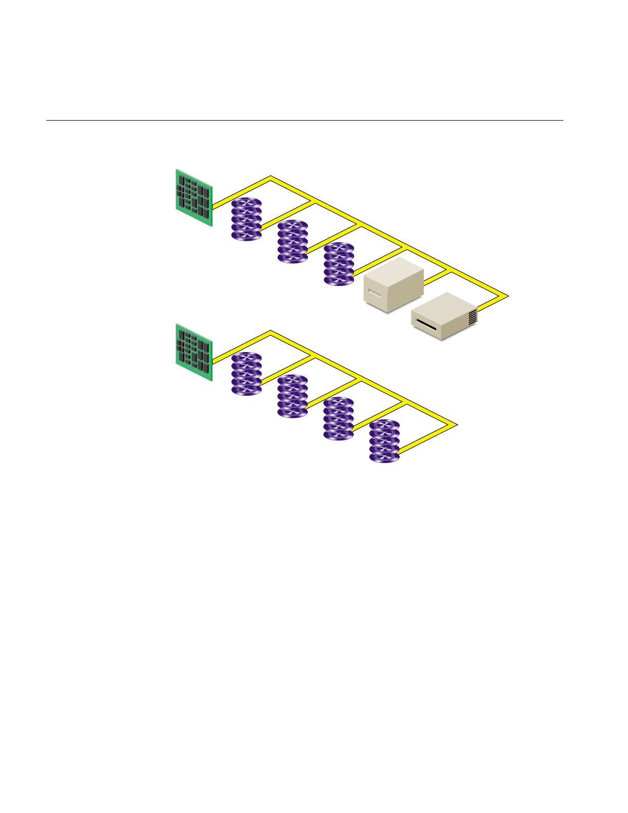
Figure 1-1 Controllers and Disk Drives
Each disk drive is managed by a controller. Each type of controller can support a fixed
number of drives. Your workstation can support a fixed number of controllers. (For the
number and type of controllers supported by your model of workstation, see your
hardware owner’s guide.) SCSI controllers support up to seven disks per controller or up
to 15 disks per controller (depending upon the SCSI controller type), and VME
controllers support up to 14 disks per controller.
Each disk is assigned a drive address (called the unit number in output from the hinv
command and also known as a SCSI ID). This address is set by a switch, a dial, or jumpers
on the disk, or by the physical location of the disk. See the hardware owner’s guide for
the system for information on setting the drive address of a disk.
Controller 0
(integral SCSI)
Unit 1
Unit 2
Unit 3
Unit 4
Controller 1
(SCSI) Unit 1
Unit 2
Unit 3
Unit 4
Unit 5
Physical Disk Structure
3
Some SCSI devices, such as RAIDs (an array of disks with built-in redundancy), have an
additional identifying number called a logical unit number or lun. It is used to address
disks within the device.
Physical Disk Structure
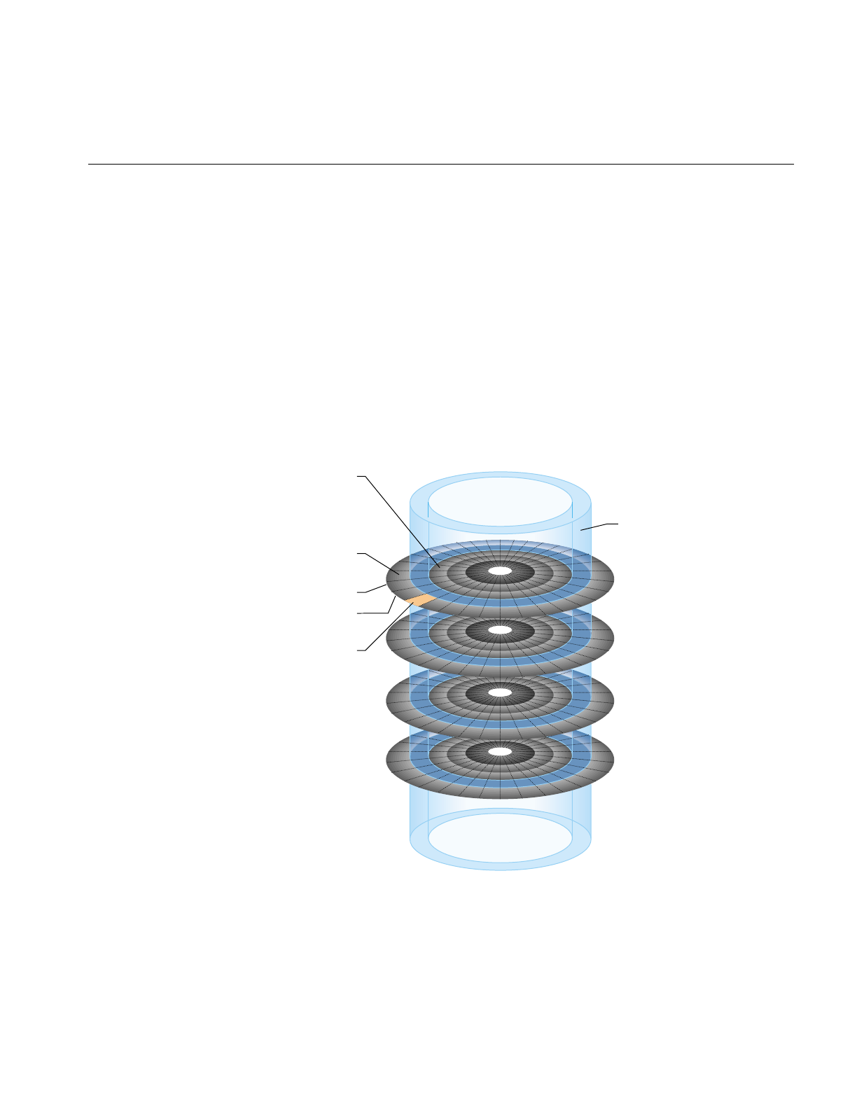
Figure 1-2 shows the physical structure of a disk. A disk is composed of circular plates
called platters. Each platter has an upper and lower oxide-coated surface. Recording heads,
at least one per surface, are mounted on arms that can be moved to various radial
distances from the center of the platters. The heads float very close to the surfaces of the
platters, never actually touching them, and read and record data as the platters spin
around.
Figure 1-2 Physical Disk Structure
Track
(complete ring at
a radial distance
from the center on
a single surface)
Surface
(entire upper side)
Disk block
(512 byte portion
of a track)
Platter
Surface
(entire lower side)
Cylinder
(tracks on all
surfaces at the
same radial
distance from
the center,
"concentric
rings")

4
Chapter 1: Disk Concepts
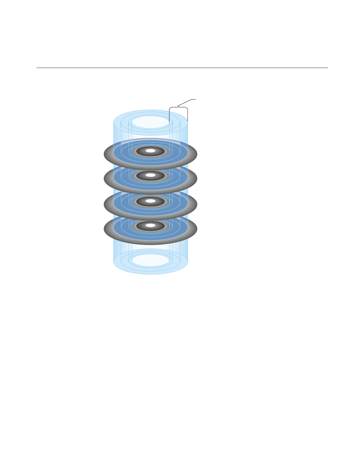
When the recording heads are at a particular position, the portions of the disk that can be
read or written are called a cylinder. As shown in Figure 1-2, a cylinder is made up of rings
on the upper and lower surfaces of all of the platters. The ring on one surface is called a
track. Each track is divided into disk blocks (sometimes called sectors, these physical blocks
on a disk are different from filesystem blocks). On SCSI disks, the number of disk blocks
per cylinder may vary; outer cylinders may have more disk blocks than inner cylinders.
Formatting a disk divides the disk into tracks and disk blocks that can be addressed by
the disk controller, writes timing marks, and identifies bad areas on the disk (called bad
blocks). SCSI disk drives are shipped preformatted. They do not require formatting at any
time. Bad block handling is performed automatically by SCSI disks. Bad blocks are areas
of a disk that cannot reliably store data. Bad block handling maps bad blocks to substitute
blocks that are in a reserved area of disk that is inaccessible by normal IRIX commands.
Disk Partitions
Disks are divided into logical units called partitions. An example of a partitioned disk is
shown in Figure 1-3. Partitions divide the disk into fixed-size portions which can be used
by IRIX or by users for different purposes. Partition sizes are measured in 512-byte disk
blocks. On SCSI disks, partitions merely need to be integral numbers of disk blocks. They
can be an integral number of cylinders or a fractional number of cylinders.
Disk Partitions
5
Figure 1-3 Disk Partitions
Each disk block can belong to any number of partitions, including no partition (in which
case the disk space of the cylinder is unused or wasted). This means that partitions can
overlap. For example, a disk can be divided into several non-overlapping partitions and
have an additional partition defined that is the entire disk.
Partition
(contiguous cylinders
or portions of cylinders)

6
Chapter 1: Disk Concepts
Each partition on a disk has a number from 0 through 15. By convention, some of these
partition numbers have a particular function and a name. These numbers, names, and
functions are listed in Table 1-1.
System Disks, Option Disks, and Partition Layouts
System disks contain the IRIX operating system. Specifically, they must contain a volume
header that includes sash (see the section “Volume Headers” in this chapter), the Root
filesystem, a swap partition, and possibly a Usr filesystem. Each workstation or server
has one system disk; IRIX is booted from this disk when the system is brought up. On
workstations, the system disk is on controller number 0 and drive address 1 by default.
On some servers, the default controller and drive address for the system disk is controller
1 and drive address 1. The location of the system disk is reported by the nvram command;
it is the value of OSLoadPartition.
All other disks on the system other than the system disk are known as option disks.
Table 1-1 Standard Partition Numbers, Names, and Functions
Partition Number Name Function
0 root Root partition, used for the Root filesystem on system disks.
1 swap Swap partition, used by IRIX for temporary storage when there
is less physical memory than all of its processes need.
6 usr Usr partition, used on system disks when separate Root and
Usr filesystems are used.
7 (none) The entire disk except the volume header and xfslog partition
(if present).
8 volhdr Volume header (see the section “Volume Headers” in this
chapter)
9 (none) Reserved partition (historically, this partition was the bad block
partition on non-SCSI drives).
10 volume The entire disk, including the volume header.
15 xfslog A small partition used for an XFS log (see the section “Partition
Types” in this chapter).
System Disks, Option Disks, and Partition Layouts
7
Disks are shipped from Silicon Graphics with one of several “standard” partition
layouts. You can list the partitions of a disk with the prtvtoc command (see the section
“Displaying a Disk’s Partitions With prtvtoc” in Chapter 2). The standard partition
layouts are described and illustrated below.
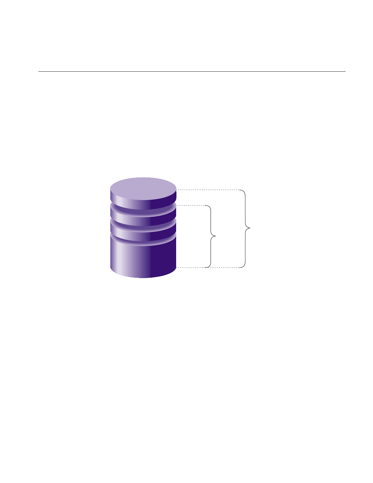
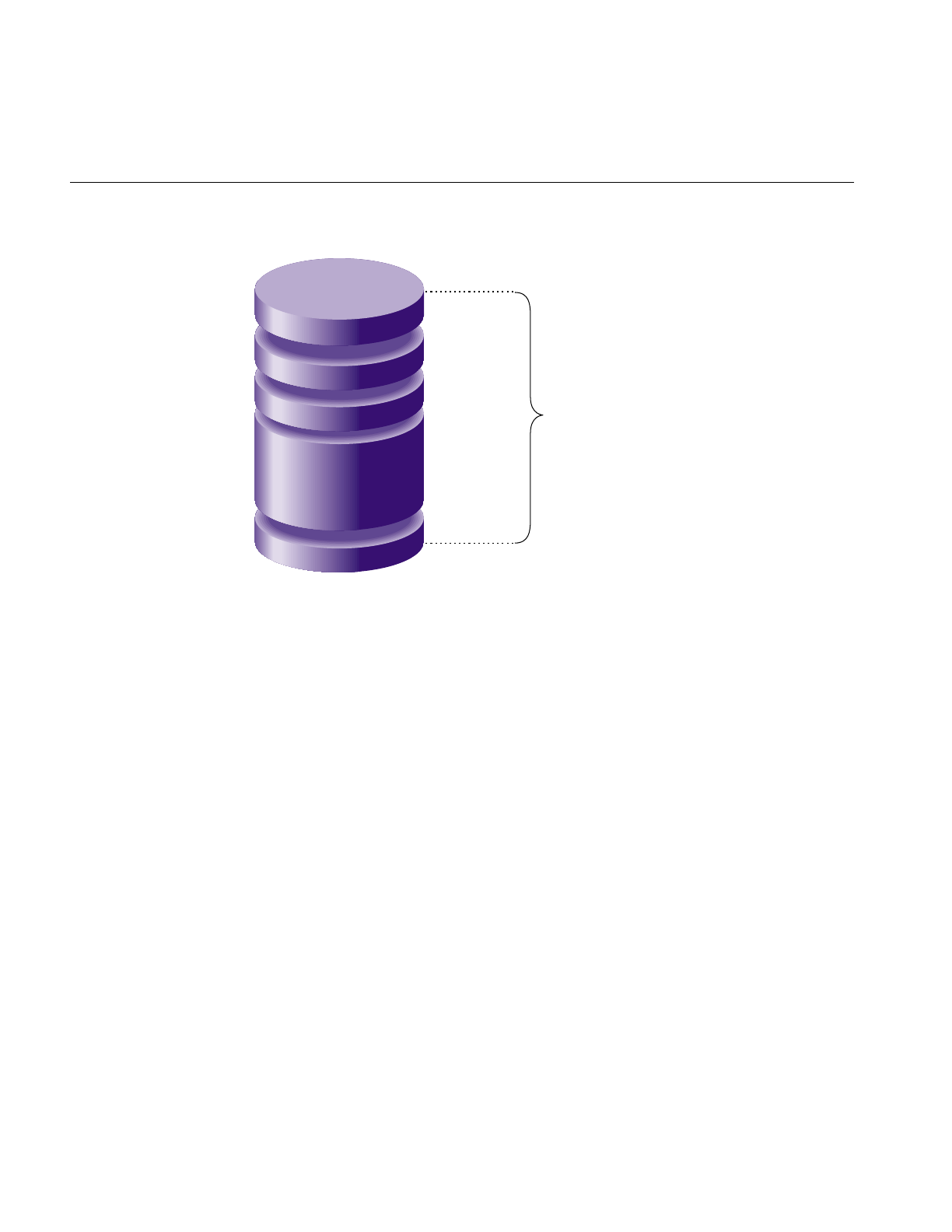
Figure 1-4 and Figure 1-5 show the two common layouts of a system disk with separate
partitions for the Root and Usr filesystems. The layout in Figure 1-4 is used for EFS
filesystems and for XFS filesystems when the XFS log doesn’t have its own partition (it is
an internal XFS log). Figure 1-5 shows the partition layout when an XFS log partition is
included (an external log).
Figure 1-4 Partition Layout of System Disks With Separate Root and Usr
Partition 8 (volhdr)
Partition 0
(root)
Partition 1
(swap) Partition 7
Partition 6
(usr)
Partition 10
(volume)
8
Chapter 1: Disk Concepts
Figure 1-5 Partition Layout of System Disks With Separate Root and Usr and an XFS Log
Partition
Separate root and usr partitions were standard on older systems and are still used on
servers. In the original UNIX design, only the Root filesystem needed to be mounted to
boot UNIX. This is not true for IRIX anymore—both filesystems must be mounted, so
there is no longer the concept of the Root filesystem being a minimal subset of operating
system software.
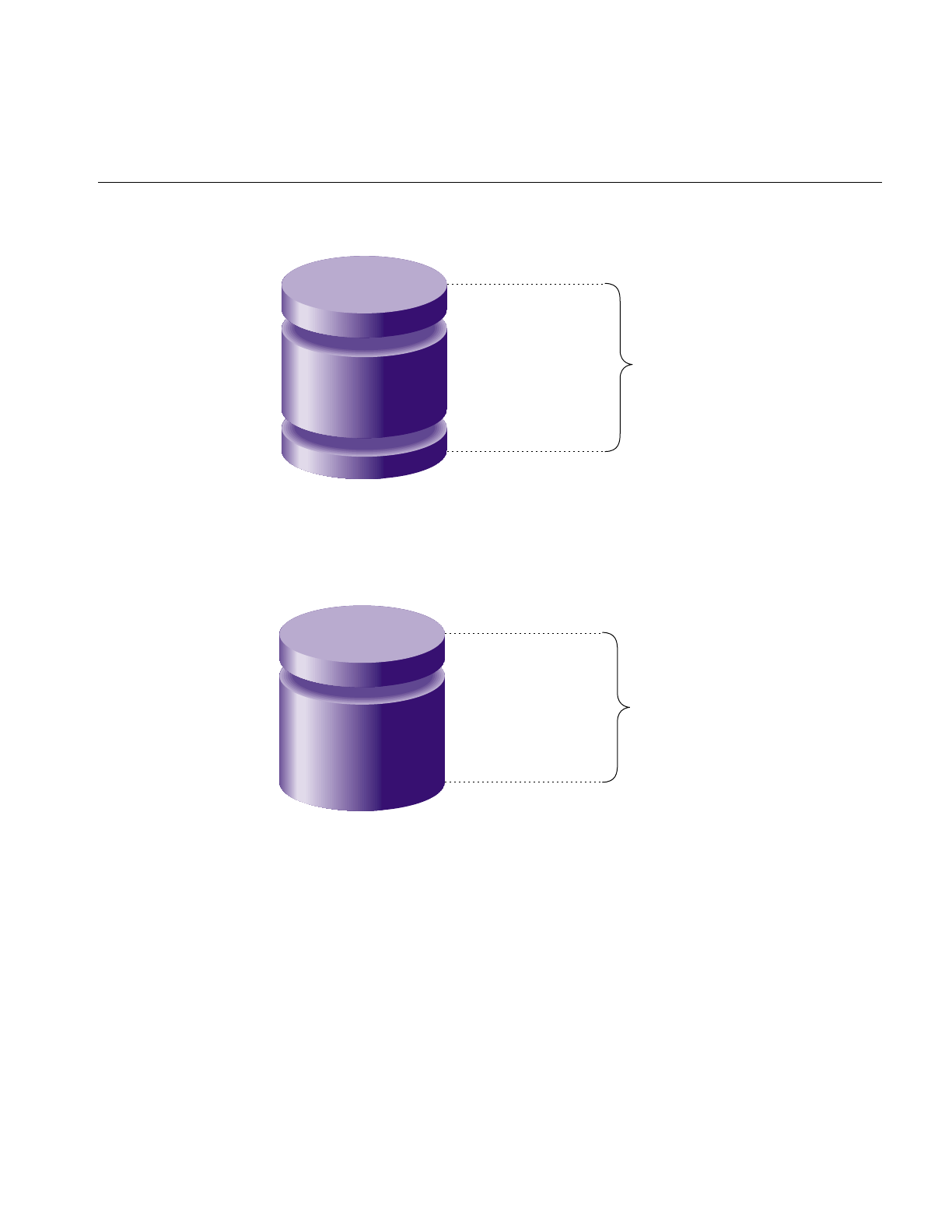
Figure 1-6 shows the layout of a system disk with a single partition for a combined Root
and Usr filesystem and a swap partition. This arrangement is standard on most newer
systems and applies to both EFS and XFS filesystems. However, restrictions on making
the root partition part of a logical volume may make separate root and usr partitions a
better choice than a single combined partition (see Chapter 6, “Logical Volume
Concepts,” for information about logical volume restrictions).
Partition 8
(volhdr)
Partition 0
(root)
Partition 1
(swap)
Partition 6
(usr)
Partition 10
(volume)
Partition 15
(xfslog)
System Disks, Option Disks, and Partition Layouts
9
Figure 1-6 Partition Layout of System Disks With Combined Root and Usr
Figure 1-7 shows the standard layout of an option disk that doesn’t have an XFS log
partition. It has a single partition for data.
Figure 1-7 Partition Layout of Option Disks
Partition 8 (volhdr)
Partition 0 (root)
Partition 1 (swap)
Partition 10
(volume)
Partition 8 (volhdr)
Partition 7
Partition 10
(volume)
10
Chapter 1: Disk Concepts
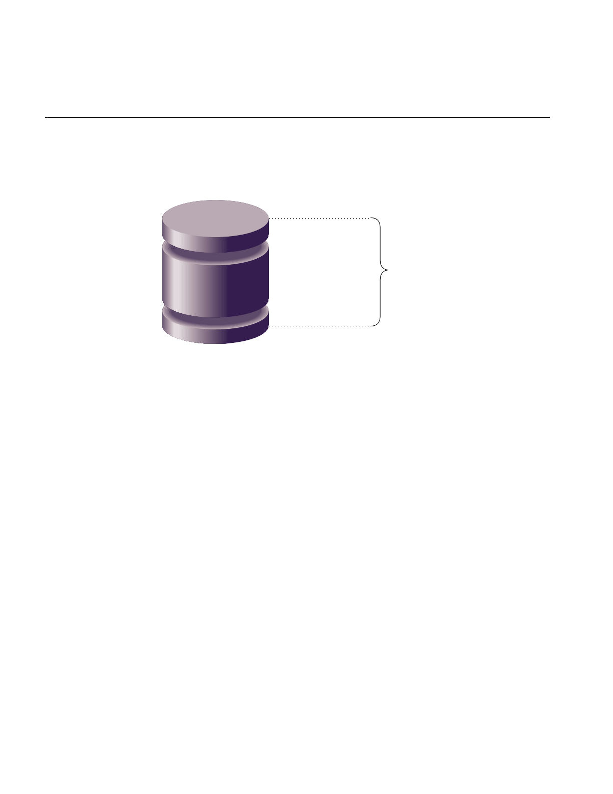
Figure 1-8 shows the layout of an option disk with two partitions, one for data and one
for an XFS log.
Figure 1-8 Partition Layouts of Options Disks With XLV Log Subvolumes
The default partition layouts are generic in nature and should be evaluated by the system
administrator. After your system has been in operation for a few months, you may decide
that a different arrangement would better serve your users’ needs. Some points to
consider in choosing partition layouts are:
•A single file can’t be larger than its filesystem.
•When disks are partitioned into several filesystems, a runaway process writing a file
fills just a partition rather than the entire disk.
•A large root partition ensures that future, and most likely larger, IRIX system
software releases can be installed without running out of disk space in the Root
filesystem.
The fx command is used for changing disk partitions (called repartitioning a disk). It
knows about standard partition layouts or can be used to create custom partition layouts.
Additional information about using fx to repartition disks is provided in the section
“Repartitioning a Disk With fx” in Chapter 2.
Once disks have been partitioned, these partitions may be used as filesystems, as parts
of a logical volume, or as raw disk space. Filesystems are described in Chapter 3,
“Filesystem Concepts.” Logical volumes are described in Chapter 6, “Logical Volume
Concepts.”
Partition 8 (volhdr)
Partition 7
Partition 15 (xfslog)
Partition 10
(volume)

Partition Types
11
Partition Types
Each partition has a type that is displayed by fx and prtvtoc. Table 1-2 lists the partition
types, their uses, and the partition numbers that can be assigned to those types. (Partition
9 isn’t listed in this table; remember that it is reserved.) Partition types, except for xlv, are
assigned by fx. The type xlv is automatically assigned by several XLV logical volume
commands.
Table 1-2 Partition Types and Uses
Partition Type Partition Use Partitions That Can Be This Type
efs EFS filesystem 0, 6, 7 (standard partitions);
2, 3, 4, 5, 11, 12, 13, 14, 15 (custom partitions)
xfs XFS filesystem 0, 6, 7 (standard partitions);
2, 3, 4, 5, 11, 12, 13, 14, 15 (custom partitions)
xfslog External log for an XFS
filesystem (part of an XLV log
subvolume)
15 (standard partition);
0, 2, 3, 4, 5, 6, 7, 11, 12, 13, 14 (custom
partitions)
raw Swap space 1
volhdr Volume header 8
volume Entire volume, including the
volume header
10
xlv Part of an XLV data or
real-time subvolume
0, 1, 2, 3, 4, 5, 6, 7, 11, 12, 13, 14, 15 (partitions
are changed to type xlv by XLV commands)
lvol Part of an lv logical volume 0, 2, 3, 4, 5, 6, 7, 11, 12, 13, 14, 15 (partitions are
changed to type lvol by mklv)

12
Chapter 1: Disk Concepts
The partitions listed as standard partitions in Table 1-2 are created when you use the fx
repartition commands rootdrive,usrrootdrive, and optiondrive. Prompts ask you
whether you want partition type efs or xfs, and, if you specify xfs for usrrootdrive or
optiondrive, if you want an xfslog partition. To use an xfslog partition (an external XFS
log), you must configure the xfslog partition as an XLV log subvolume. (See Chapter 7,
“Creating and Administering XLV Logical Volumes,” for more information about XLV.)
If you do not use an xfslog partition, the XFS log is stored in an xfs partition (and called
an internal log).
To assign a partition type to a partition number listed as a custom partition in Table 1-2,
you must use the expert mode of fx (fx –x) to create the partition and assign the type. (See
the fx(1M) reference page for more information about the expert mode of fx.)
Volume Headers
A partition called the volume header is stored on the partition that begins at disk block 0.
(For proper system operation, the volume header must begin at disk block 0). It contains
a minimal filesystem with a few files that contain information about the device
parameters, the partition layout, the version number of the most recently used version of
fx, and logical volume information. It also may contain some standalone programs.
The files and standalone programs that may be in a volume header are:
sgilabel This file contains fx version number information. It is important not to
delete this file from the volume header.
symmon symmon is a standalone program used to debug the kernel. See the
symmon(1M) reference page for more information.
xlvlab*, lvlab* Logical volume information is stored in files called logical volume labels
in the volume header. lv logical volume information is stored in files
whose names begin with lvlab and XLV logical volume information is
stored in files whose names begin with xlvlab. This information is used
by the system to assemble logical volumes when the system is booted.
Logical volume labels are created automatically when logical volumes
are created.
ide ide (integrated diagnostics environment) is a diagnostics program for
low-end systems only. ide is executed when you choose the third item,
“Run Diagnostics,” on the System Maintenance Menu. Newer systems
execute ide from the /stand directory if it isn’t in the volume header.

Volume Headers
13
fx fx is the standalone version of the IRIX fx command. It is a disk utility
used primarily for repartitioning disks. Older systems sometimes
included a copy of the command fx in the volume header. There is no
longer any need for fx in the volume header.
sash On system disks, a copy of the standalone program sash (the standalone
shell) must be in the volume header; it is required to boot a system. sash
is a processor-specific program. Therefore, if you ever need to copy it
from the /stand directory of another system or from the /stand directory
of a software distribution CD, you must copy the correct version. If you
copy from another system, both systems must have the same processor
type. If you copy it from a software distribution CD, use the hinv
command to identify the processor type of your system and Table 1-3 to
identify the version of sash needed for that system.
The fx command can be used to display and modify the device parameters and the
partition layout. See the fx(1M) reference page and the section “Repartitioning a Disk
With fx” in Chapter 2. Using fx has the side effect of creating the file sgilabel in the volume
header.
The command prtvtoc is also used to display partition layout information. See the section
“Displaying a Disk’s Partitions With prtvtoc” in Chapter 2 for instructions.
The dvhtool command can be used to add and delete standalone programs from the
volume header. dvhtool can also be used to delete logical volume labels from the volume
header. See the sections “Adding Files to the Volume Header With dvhtool,” and
“Removing Files in the Volume Header With dvhtool” in Chapter 2 for more
information.
Table 1-3 Processor Types and sash Versions
Processor Type sash Version
IP17 sashIP17
IP19, IP20, IP22 sashARCS
IP21, IP26 sash64

14
Chapter 1: Disk Concepts
The volume header is consulted (and therefore any mistakes made creating or modifying
the volume header become apparent) only at these times:
•during the boot up process
•when creating or growing filesystems
•when creating or growing logical volumes
•when adding swap areas
Device Files
IRIX programs communicate with hardware devices through two types of files, called
special files. The two types are character device files (also called raw device files) and block
device files.
Device files are in the /dev directory of the Root filesystem. Since every entry in a
directory is a file (see Table 3-2), conceptually a disk device is treated as if it were a file.
In practice, there are differences between regular files and device files, so the latter are
referred to as special files.
Device files are created automatically when system software is installed and, if necessary,
at system boot up by the command MAKEDEV. The device files created by MAKEDEV
are based on the hardware configuration of the system; however, not all possible device
files are created. Disk device files are created only for partitions 0, 1, 6, 7, 15, vh, and vol
(vh stands for volume header and is partition 8, vol is the entire volume and is the same
as partition 10). You can run MAKEDEV manually if you added a supported device, or,
to create a specific device file, you can use the mknod command. For more information
about MAKEDEV, see the section “Creating Device Files With MAKEDEV” in Chapter 2.
For more information about mknod, see the section “Creating Device Files With mknod”
in Chapter 2.
The following examples of output are the results of the ls -l command invoked on a user’s
regular file and on the /dev directory. They show the difference in structure between
regular and device files. This is a regular file:
-rw-r----- 1 ralph raccoons 1050 Apr 23 08:14 scheme.notes
Regular files are indicated by a dash (–) in the first column. The remainder of the output
is explained in the guide IRIX Admin: System Configuration and Operation.

Device Files
15
These are device files:
brw------- 2 root sys 128,16 Apr 15 10:59 /dev/dsk/dks0d1s1
brw------- 2 root sys 128,16 Apr 15 10:59 /dev/root
brw------- 2 root sys 128,22 Apr 12 13:51 /dev/dsk/dks0d1s6
brw------- 2 root sys 128,22 Apr 12 13:51 /dev/usr
crw------- 2 root sys 128,16 Apr 15 10:58 /dev/rdsk/dks0d1s0
crw------- 2 root sys 128,16 Apr 15 10:58 /dev/rroot
crw------- 2 root sys 128,22 Apr 12 13:51 /dev/rdsk/dks0d1s6
crw------- 2 root sys 128,22 Apr 12 13:51 /dev/rusr
The device file listing has some similar information to the listing of the regular file, but
also contains additional information. The device files shown have the following
characteristics:
•The first column of the listing contains a b or a c to indicate the type of device: block
or character.
•In the field of a long listing where a regular file shows the byte count of the file, a
device file displays two numerals called the major and minor device numbers.
•The filenames are device names, which are constructed based on hardware type and
configuration.
The following sections explain each of these characteristics of device files.
Block and Character Devices
Block device files (also called block devices) and character device files (also called
character devices or raw devices) differ in the way in which they are accessed.
Block devices access data in blocks which come from a system buffer cache. Only blocks
of data of a certain size are read from a block device.
Character devices access data on a character by character basis. Programs such as
terminal and pseudo-terminal device drivers that want to do their own input and output
buffering use character devices. Some types of hardware, such as disks and tapes, can
have both character and block device files. The difference is that the character interface
for disks bypasses the buffer cache.
The section “Device Names” in this chapter explains the naming conventions for block
and character device files.

16
Chapter 1: Disk Concepts
Device Permissions and Owner
The files are owned by root with group sys, and no other user or group has permission to
use them. This means that only processes with the root ID can read from and write to the
device files. Tape devices, floppy drives, and tty terminals are some common exceptions
to this rule.
Major and Minor Devices
Major and minor device numbers appear where the character count appears in the listing
of a normal file.
The major device number refers to a specific device driver. The minor device number
specifies a particular physical unit and possibly characteristics of the unit. For disks, the
minor number identifies the drive address and the partition. The major and minor device
numbers are displayed by the ls -l command.
There are devices that have identical major and minor numbers, but they are designated
in one entry as a block device (a b in the first column) and in another entry as a character
device (a c in the first column). Notice that such pairs of files have different filenames or
are in different directories (for example, /dev/dsk/dks0d1s0 and /dev/rdsk/dks0d1s0).
Device Names
Device names for disks are filenames that are constructed so that they indicate the type
of hardware (disk), type of device access (block or character), type of device, controller
number, drive address, and partition number. For example, the block device name for the
root partition of a SCSI system disk is /dev/dsk/dks0d1s0. Table 1-4 lists each component of
this filename, describes its meaning, and lists other possible values.
Table 1-4 Device Name Construction
Device Name
Component Purpose Possible Values
dev device files directory dev
dsk subdirectory for hard
disk files (think “disk”
to remember it)
dsk (block device files)
rdsk (character device files; the r stands for “raw,”
another name for the character device)

Device Files
17
dks disk device type dks (SCSI device)
fd (floppy disk)
jag (VME SCSI device, also known as Jaguar disk)
raid (SCSI RAID device)
0 controller number for SCSI: 0–n, where n is system dependent
for VME SCSI (Jaguar): 0–5
for SCSI RAID: 0–14
d1 drive address for SCSI: d1–d7 or d1–d15 (depending upon controller
type)
for VME SCSI (Jaguar): d0–d13
for SCSI RAID: dn where n is in the range 0–147 and
doesn’t end in 8 or 9
s0 partition number (slice
number)
s0 (root, for the Root filesystem)
s1 (swap)
s2
s3
s4
s5
s6 (usr, for the Usr filesystem)
s7 (entire usable portion of disk, excludes the volume
header)
s8, vh (volume header)
s9 (non-SCSI bad block list)
s10, vol (entire disk)
s11
s12
s13
s14
s15 (XFS log)
Table 1-4 (continued) Device Name Construction
Device Name
Component Purpose Possible Values

18
Chapter 1: Disk Concepts
Some examples of device names and their meanings are:
/dev/dsk/dks0d1s0
The block device file for partition (slice) 0 of the SCSI disk on controller
0 at drive address 1.
/dev/dsk/jag5d13s7
The block device file for partition 7 (the entire disk except volume
header) of the Jaguar disk on controller 5 at drive address 13.
/dev/rdsk/dks0d2vh
The character (raw) device for the volume header (partition 8) of the
SCSI disk on controller 0 at drive address 2.

19
Chapter 2
2.Performing Disk Administration Procedures
This chapter describes administration procedures for disks and their device files.
The major sections in this chapter are:
•“Listing the Disks on a System With hinv” on page 20
•“Formatting and Initializing a Disk With fx” on page 21
•“Adding Files to the Volume Header With dvhtool” on page 22
•“Removing Files in the Volume Header With dvhtool” on page 24
•“Displaying a Disk’s Partitions With prtvtoc” on page 25
•“Repartitioning a Disk With xdkm” on page 27
•“Repartitioning a Disk With fx” on page 27
•“Creating Device Files With MAKEDEV” on page 36
•“Creating Device Files With mknod” on page 37
•“Creating Mnemonic Names for Device Files With ln” on page 38
•“Creating a System Disk From the PROM Monitor” on page 38
•“Creating a New System Disk From IRIX” on page 44
•“Creating a New System Disk by Cloning” on page 48
•“Adding a New Option Disk” on page 50
Administration procedures for filesystems and logical volumes are described in later
chapters of this guide.

20
Chapter 2: Performing Disk Administration Procedures
Listing the Disks on a System With hinv
You can list the disks connected to a system by giving this hinv command from IRIX:
hinv -c disk
The output lists the disk controllers and disks present on a system, for example:
Integral SCSI controller 0: Version WD33C93B, revision D
Disk drive: unit 2 on SCSI controller 0
Disk drive: unit 1 on SCSI controller 0
This output shows a single integral SCSI controller whose number is 0 and two disk
drives. These disks are at drive addresses 1 and 2. In hinv output, drive addresses are
called units. They are also sometimes called unit numbers. Each disk is uniquely
identified by the combination of its controller number and drive address.
If you are in the PROM Monitor, you can also give the hinv command from the Command
Monitor:
>> hinv
Output for SCSI disks looks like this:
SCSI Disk: scsi(0)disk(1)
SCSI Disk: scsi(0)disk(2)
In this output, the controller number is the “scsi” number and the drive address is the
“disk” number. The type of controller isn’t listed. As a rule of thumb, workstations have
integral controllers and servers may have integral SCSI controllers or non-integral
controllers that are SCSI or VME. On some Challenge systems, the output of hinv in the
PROM monitor shows only disks on the boot IOP (I/O processor).
The controller number and drive addresses of disks are specified, using a variety of
syntax, as arguments to the IRIX disk and filesystem commands, such as fx,prtvtoc,
dvhtool, and mkfs. For example, for a disk on controller 0 at drive address 1:
•To specify the disk on an fx command line, the command line is:
fx "dksc(0,1)"

Formatting and Initializing a Disk With fx
21
•To specify the disk (actually, its volume header) on a prtvtoc command line, either of
these two commands can be used:
prtvtoc /dev/rdsk/dks0d1vh
prtvtoc dks0d1vh
•To specify the disk 1 (actually, its volume header) on a dvhtool command line, the
command is:
dvhtool /dev/rdsk/dks0d1vh
•To specify partition 7 of the second disk above on a mkfs command line for an EFS
filesystem, the command is:
mkfs -t efs /dev/rdsk/dks0d1s7
Tip: You can use the Disk Manager in the System Toolchest to get information about the
disks on a system. For instructions, see the section “Checking Disk Setup Information”
in Chapter 6 of the Personal System Administration Guide.
Formatting and Initializing a Disk With fx
When you format a disk, you write timing marks and divide the disk into tracks and
sectors that can be addressed by the disk controller. SCSI disks are shipped
pre-formatted; formatting a SCSI disk is rarely required. Formatting is done by fx; see the
fx(1M) reference page for details.
Caution: Formatting a disk results in the loss of all data on the disk. It is recommended
only for experienced IRIX system administrators.
Formatting a disk destroys information about bad areas on the disk (called bad blocks).
Identifying and handling bad blocks is also done by fx; see the fx(1M) reference page for
details.
Caution: Using fx for bad block handling usually results in the loss of all data on the
block. It is recommended only for experienced IRIX system administrators.
Initializing a disk consists of creating a volume header for a disk. Disks supplied by
Silicon Graphics are shipped with a volume header, and initialization isn’t necessary.
Disks from third-party vendors or disks whose volume headers have been destroyed
must be initialized to create a volume header. Initializing disks is done by fx. No explicit
commands are necessary; fx automatically notices if no volume header is present and

22
Chapter 2: Performing Disk Administration Procedures
creates one. (See the section “Repartitioning a Disk With fx” in this chapter for
information on invoking fx.) When fx creates a volume header, a prompt asks if you want
to write the volume header; reply yes.
Tip: You can use the Disk Information window of the Disk Manager in the System
Toolchest to perform disk initialization and other tasks. For more information, see the
section “Formatting, Verifying, and Remaking Filesystems on a Fixed Disk” in Chapter 6
of the Personal System Administration Guide.
Adding Files to the Volume Header With dvhtool
As explained in the section “Volume Headers” in Chapter 1, the volume header of
system disks must contain a copy of the program sash. The procedure in this section
explains how to put sash or other programs into a volume header. Before performing this
procedure, review the discussion of dvhtool in the section “Volume Headers” in
Chapter 1.
When you add programs to the volume header of a disk, there are two sources for those
programs. One is the /stand directory of the system and the other is the /stand directory
on an IRIX software release CD. The /stand directory on a CD (usually /CDROM/stand
after the CD is mounted) contains copies of sash,fx, and ide that are processor-specific.
As superuser, perform this procedure to add programs to a volume header:
1. Invoke dvhtool with the raw device name of the volume header of the disk as an
argument, for example:
#dvhtool /dev/rdsk/dks0d2vh
(See the section “Device Names” in Chapter 1 for information on constructing the
device name.)
2. Display the volume directory portion of the volume header by using the vd (volume
directory) and l (list) commands:
Command? (read, vd, pt, dp, write, bootfile, or quit): vd
(d FILE, a UNIX_FILE FILE, c UNIX_FILE FILE, g FILE UNIX_FILE or l)?
l
Current contents:
File name Length Block #
sgilabel 512 2
sash 159232 3

Adding Files to the Volume Header With dvhtool
23
3. For each program that you want to copy to the volume header, use the a (add)
command. For example, to copy sash from the /stand directory to sash in the volume
header, use this command:
(d FILE, a UNIX_FILE FILE, c UNIX_FILE FILE, g FILE UNIX_FILE or l)?
a /stand/sash sash
As another example, to copy sash from a CD to an IP20 or IP22 system (an Indy™),
use this command:
(d FILE, a UNIX_FILE FILE, c UNIX_FILE FILE, g FILE UNIX_FILE or l)?
a /CDROM/stand/sashARCS sash
CDs contain multiple processor-specific versions of sash; Table 1-3 lists the version
of sash for each processor type.
4. Confirm your changes by listing the contents of the volume with the l (list)
command:
(d FILE, a UNIX_FILE FILE, c UNIX_FILE FILE, g FILE UNIX_FILE or l)?
l
Current contents:
File name Length Block #
sgilabel 512 2
sash 159232 3
5. Make the changes permanent by writing the changes to the volume header using
the quit command to exit this “submenu” and the write command:
(d FILE, a UNIX_FILE FILE, c UNIX_FILE FILE, g FILE UNIX_FILE or l)?
quit
Command? (read, vd, pt, dp, write, bootfile, or quit): write
6. Quit dvhtool by giving the quit command:
Command? (read, vd, pt, dp, write, bootfile, or quit): quit

24
Chapter 2: Performing Disk Administration Procedures
Removing Files in the Volume Header With dvhtool
Caution: The procedure in this section can result in the loss of data if it is not performed
properly. It is recommended only for experienced IRIX system administrators.
The procedure below can be used to remove logical volume labels (for example xlvlab)
and files (for example sash) from the volume header of a disk. Before performing this
procedure, review the discussion of dvhtool in the section “Volume Headers” in
Chapter 1.
1. Using hinv, determine the controller and drive addresses of the disk that has the
volume header you want to change. In this procedure, the example commands and
output assume that the disk is on controller 0, drive address 2. Substitute the
controller and drive addresses of your disk.
2. As superuser, invoke dvhtool with the raw device name of the volume header of the
disk, for example:
#dvhtool /dev/rdsk/dks0d2vh
(See the section “Device Names” in Chapter 1 for information on constructing the
device name.)
3. Display the volume directory portion of the volume header by answering two
prompts:
Command? (read, vd, pt, dp, write, bootfile, or quit): vd
(d FILE, a UNIX_FILE FILE, c UNIX_FILE FILE, g FILE UNIX_FILE or l)?
l
Current contents:
File name Length Block #
sgilabel 512 2
xlvlab 10752 3
lvlab2 512 26
4. Use the d command to delete the file you want to delete, for example xlvlab:
(d FILE, a UNIX_FILE FILE, c UNIX_FILE FILE, g FILE UNIX_FILE or l)?
d xlvlab
5. To delete additional files, continue to use the d command, for example:
(d FILE, a UNIX_FILE FILE, c UNIX_FILE FILE, g FILE UNIX_FILE or l)?
d lvlab2

Displaying a Disk’s Partitions With prtvtoc
25
6. List the volume directory again to confirm that the files are gone:
(d FILE, a UNIX_FILE FILE, c UNIX_FILE FILE, g FILE UNIX_FILE or l)?
l
Current contents:
File name Length Block #
sgilabel 512 2
7. Exit this “menu” and write the changes to the volume header:
(d FILE, a UNIX_FILE FILE, c UNIX_FILE FILE, g FILE UNIX_FILE or l)?
q
Command? (read, vd, pt, dp, write, bootfile, or quit): write
8. Quit dvhtool:
Command? (read, vd, pt, dp, write, bootfile, or quit): quit
Displaying a Disk’s Partitions With prtvtoc
Use the prtvtoc command to get information about the size and partitions of a disk. Only
the superuser can use this command. The command is:
prtvtoc device
device is optional; when it is omitted, prtvtoc displays information for the system disk.
device is the raw device name (see the section “Device Names” in Chapter 1) of the disk
volume header. The /dev/rdsk portion of the device name can be omitted if desired. For
example, for a SCSI disk that is drive address 1 on controller 0, device is dks0d1vh. (See
the section “Device Names” in Chapter 1 for more information on device names.)
An example of the output of prtvtoc is:
Printing label for root disk
* /dev/rdsk/dks0d1vh (bootfile “/unix”)
* 512 bytes/sector
* 85 sectors/track
* 9 tracks/cylinder
* 3 spare blocks/cylinder
* 2726 cylinders
* 4 cylinders occupied by header
* 2722 accessible cylinders

26
Chapter 2: Performing Disk Administration Procedures
*
* No space unallocated to partitions
Partition Type Fs Start: sec (cyl) Size: sec (cyl) Mount Directory
0 efs yes 3048 ( 4) 51054 ( 67) /
1 raw 54102 ( 71) 81534 ( 107)
6 efs yes 135636 ( 178) 1941576 (2548) /usr
8 volhdr 0 ( 0) 3048 ( 4)
10 volume 0 ( 0) 2077212 (2726)
The first section of the output shows the device parameters that can be used to figure out
the capacity of the disk (remember that 1 kilobyte = 1024 bytes and 1 megabyte = 1048576
bytes):
512 bytes/block * 85 blocks/track * 9 tracks/cylinder * 2722 cylinders
= 1,066,152,960 bytes
= 1,041,165 kilobytes
= 1,016 megabytes
The partition table at the end of the output lists the partitions, their type (name or
filesystem type), whether they contain a filesystem, their location on the disk (start and
size in blocks and cylinders), and mount directory for filesystems. The partitions in this
output are shown graphically in Figure 1-4.
Another example of the output of prtvtoc, showing fractional numbers of cylinders per
partition, is:
#prtvtoc /dev/rdsk/dks0d2vh
* /dev/rdsk/dks0d2vh (bootfile “/unix”)
* 512 bytes/sector
* 115 sectors/track
* 20 tracks/cylinder
* 20 spare blocks/cylinder
* 3865 cylinders
* 2 cylinders occupied by header
* 3863 accessible cylinders
*
* No space unallocated to partitions
Partition Type Fs Start: sec (cyl) Size: sec (cyl) Mount
Directory
0 xfs yes 4560 ( 2) 8684310 (3808.9) /usr/people
1 raw 8688870 (3810.9) 125000 ( 54.8)
8 volhdr 0 ( 0) 4560 ( 2)
10 volume 0 ( 0) 8813870 (3865.7)

Repartitioning a Disk With xdkm
27
Repartitioning a Disk With xdkm
Disks can be repartitioned using the graphical user interface of the xdkm command.
Information about xdkm is available from its online help.
Repartitioning a Disk With fx
Caution: The procedure in this section can result in the loss of data if it is not performed
properly. It is recommended only for experienced IRIX system administrators.
Repartitioning disks is done from the command line by the fx command. There are two
versions of this program, a standalone version and an IRIX version. The standalone
version is invoked from the Command Monitor, which enables you to repartition the
system disk. Option disks can be repartitioned using the IRIX version. Two of the
following subsections describe how to invoke each version of fx:
•“Invoking fx From the Command Monitor”
•“Invoking fx From IRIX”
The standard partition layouts described in the section “System Disks, Option Disks, and
Partition Layouts” in Chapter 1 are “built into”fx. You can partition a disk using one of
the standard layouts or you can create custom partition layouts. Two subsections
describe how to create standard and custom partition layouts:
•“Creating Standard Partition Layouts”
•“Creating Custom Partition Layouts”
The final subsection, “After Repartitioning,” describes how to proceed after the
repartitioning is complete.
To repartition a disk, start with the first subsection, “Before Repartitioning.” Then choose
one of the sections on invoking fx, choose one of the sections on creating partitions, and
finish up with the section “After Repartitioning.”
Before Repartitioning
Caution: Repartitioning a disk makes the data on the disk inaccessible (you must
repartition back to the original partitions to get to it).

28
Chapter 2: Performing Disk Administration Procedures
Before repartitioning a disk, if there is any valuable data on the disk to be repartitioned,
make a backup of the files on the disk. If the disk is a system disk and you plan to copy
the files from the backup to the disk after repartitioning, you must use either the System
Manager or the Backup command. Only backups made with Backup or the System
Manager will be available to the system from the System Recovery menu of the System
Maintenance Menu. The System Manager is the preferred method of the two and is
described completely in the Personal System Administration Guide. Other commands
require a full system installation to operate correctly.
Invoking fx From the Command Monitor
The procedure in this section describes how to invoke the standalone version of fx from
the Command Monitor. It is only necessary for the system disk. You can use the IRIX
version of fx for other disks (see the next section “Invoking fx From IRIX”).
1. Shut the system down into the System Maintenance Menu.
2. Bring up the Command Monitor by choosing the fifth item on the System
Maintenance Menu.
3. Identify the copy of fx that you will boot. Some possible locations are: fx in the /stand
directory of the system disk or fx on an IRIX software distribution CD in a CD-ROM
drive on the local system or on a remote system.
A single copy of fx is in the /stand directory, but IRIX software distribution CDs
contain several processor-specific versions of fx. Booting fx from a CD on a local
CD-ROM drive requires a processor-specific copy of sash on the CD, too.
Table 2-1 shows the versions of sash and fx to use when you are using them from a
source that provides several processor-specific versions.
4. Boot fx from the Command Monitor. The command to boot fx depends upon the
location of the copy of you are booting.
Table 2-1 sash and fx Versions
Processor Type sash Version fx Version
IP17 sashIP17 fx.IP17
IP19, IP20, IP22 sashARCS fx.ARCS
IP21, IP26 sash64 fx.64

Repartitioning a Disk With fx
29
•This command boots fx from the /stand directory on the system disk:
>> boot stand/fx --x
•This command boots fx from an IRIX software release CD in a local CD-ROM
drive, where the CPU type of the system is IP19, IP20, or IP22 and the CD-ROM
drive is at drive address 4 on controller 0:
>> boot -f dksc(0,4,8)sashARCS dksc(0,4,7)stand/fx.ARCS --x
•This command boots fx from an IRIX software release CD in a CD-ROM drive
mounted at /CDROM on a remote system named dist, where the CPU type of
the local system is IP21 or IP26:
>> boot -f bootp()dist:/CDROM/stand/fx.64 --x
5. fx prompts you for each part of the disk name. The default answer is in parentheses
and matches the system disk. The prompts are:
fx: "device-name" = (dksc)
fx: ctlr# = (0)
fx: drive# = (1)
fx: lun# = (0)
The default device name is dksc, which indicates a SCSI disk on a SCSI controller.
(See the fx(1M) reference page for other device names.) The next prompt asks you to
specify the disk controller number and the next one the drive address (unit) of the
disk. The final prompt asks for the lun (logical unit) number. The logical unit
number is typically used by only a few SCSI devices such as RAIDs (an array of
disks with built-in redundancy) to address disks within the device. For regular
disks, use logical unit number 0.
For each prompt, press the <Enter> key for the default value or enter another value,
followed by <Enter>.
Once you have answered the prompts, fx performs a disk controller test and you see
the fx main menu:
---- please choose one (? for help. .. to quit this menu)----
[exi]t [d]ebug/ [l]abel/
[b]adblock/ [exe]rcise/ [r]epartition/
fx>
The exit option quits fx, while the other commands take you to submenus. (The
slash [/] character after a menu option indicates that choosing that option leads to a
submenu.) For complete information on all fx options, see the fx(1M) reference
page.

30
Chapter 2: Performing Disk Administration Procedures
Invoking fx From IRIX
The procedure in this section describes how to invoke fx from IRIX.
1. Make sure that the disk drive to be partitioned is not in use. That is, make sure that
no filesystems are mounted and no programs are accessing the drive.
2. As superuser, give the fx command:
#fx "controller_type(controller,address,logical_unit)"
The variables are:
controller_type The controller type. It is dksc for SCSI controllers. For other
controller types, see the fx(1M) reference page.
controller The controller number for the disk.
address The drive address of the disk.
logical_unit The logical unit number for the device. It is used by only a few SCSI
devices such as RAIDs (an array of disks with built-in redundancy)
to address disks within the device. The logical_unit is normally 0.
If you give the q
command without arguments, you are prompted for these values.
fx first performs a controller test, then displays this menu:
---- please choose one (? for help. .. to quit this menu)----
[exi]t [d]ebug/ [l]abel/
[b]adblock/ [exe]rcise/ [r]epartition/
fx>
The exit option quits fx, while the other commands take you to submenus. (The
slash [/] character after a menu option indicates that choosing that option leads to a
submenu.) For complete information on all fx options, see the fx(1M) reference
page.

Repartitioning a Disk With fx
31
Creating Standard Partition Layouts
This section shows the procedure for repartitioning a disk so that it has one of the
standard partition layouts. The example used in this section is to change a disk from
separate root and usr partitions to a combined root and usr partition.
1. From the fx main menu, choose the repartition option:
---- please choose one (? for help. .. to quit this menu)----
[exi]t [d]ebug/ [l]abel/
[b]adblock/ [exe]rcise/ [r]epartition/
fx> repartition
----- partitions-----
part type cyls blocks Megabytes (base+size)
0: efs 4 + 67 3024 + 50652 1 + 25
1: raw 71 + 108 53676 + 81648 26 + 40
6: efs 179 + 2547 135324 + 1925532 66 + 940
8: volhdr 0 + 4 0 + 3024 0 + 1
10: volume 0 + 2726 0 + 2060856 0 + 1006
capacity is 2061108 blocks
----- please choose one (? for help, .. to quit this menu)-----
[ro]otdrive [o]ptiondrive [e]xpert
[u]srrootdrive [re]size
You see the partition layout for the disk that you specified when fx was started,
followed by the repartition menu. The rootdrive,usrrootdrive, and optiondrive
options are used for standard partition layouts, the resize option is used for custom
partition layouts, and the expert option, which appears only if the fx is invoked
with the -x option. The expert option enables custom partitioning functions. These
functions can severely damage the disk when performed incorrectly, so they are
unavailable unless explicitly requested with -x.
2. To create a combined root and usr partition, choose the rootdrive option.
fx/repartition> rootdrive
3. A prompt appears that asks about the partition type. The possible types are shown
in Table 2-1. For this example, choose efs:
fx/repartition/rootdrive: type of data partition = (xfs) efs

32
Chapter 2: Performing Disk Administration Procedures
4. A warning appears; answer yes to the prompt after the warning:
Warning: you will need to re-install all software and restore user data
from backups after changing the partition layout. Changing partitions
will cause all data on the drive to be lost. Be sure you have the drive
backed up if it contains any user data. Continue? yes
----- partitions-----
part type cyls blocks Megabytes (base+size)
0: efs 4 + 2614 3024 + 1976184 1 + 965
1: raw 2618 + 108 1979208 + 81648 966 + 40
8: volhdr 0 + 4 0 + 3024 0 + 1
10: volume 0 + 2726 0 + 2060856 0 + 1006
capacity is 2061108 blocks
----- please choose one (? for help, .. to quit this menu)-----
[ro]otdrive [u]srrootdrive [o]ptiondrive [re]size
The partition layout after repartitioning is displayed and the repartition submenu
appears again.
5. To return to the fx main menu, enter .. at the prompt:
fx/repartition> ..
----- please choose one (? for help, .. to quit this menu)-----
[exi]t [d]ebug/ [l]abel/
[b]adblock/ [exe]rcise/ [r]epartition/
fx>
Creating Custom Partition Layouts
The following procedure describes how to repartition a disk so that it has a custom
partition layout. As an example, this procedure repartitions a 380 MB SCSI drive to
increase the size of the root partition.

Repartitioning a Disk With fx
33
1. At the fx main menu, choose the repartition command:
---- please choose one (? for help. .. to quit this menu)----
[exi]t [d]ebug/ [l]abel/
[b]adblock/ [exe]rcise/ [r]epartition/
fx> repartition
----- partitions-----
part type cyls blocks Megabytes (base+size)
0: efs 7 + 80 2835 + 32400 1 + 16
1: rawdata 87 + 202 35235 + 81810 17 + 40
6: efs 289 + 1269 117045 + 513945 57 + 251
7: efs 7 + 1551 2835 + 628155 1 + 307
8: volhdr 0 + 7 0 + 2835 0 + 1
10: entire 0 + 1550 0 + 630990 0 + 308
capacity is 631017 blocks
----- please choose one (? for help, .. to quit this menu)-----
[ro]otdrive [u]srrootdrive [o]ptiondrive [re]size
You see the partition layout for the disk that you specified when fx was started,
followed by the repartition menu. Look at the size column for partitions 0, 1, and 6.
In this example, you have 32400 + 81810 + 513945 = 628155 blocks to use. Look at
the start block numbers, and notice that partition 7 overlaps 0, 1, and 6. Partition 0 is
the Root filesystem, and is mounted on the system’s root directory (/). Partition 1 is
your system’s swap space. Partition 6 is the Usr filesystem, and it is mounted on the
/usr directory. In this example, you will take space from the Usr filesystem and
expand the Root filesystem.
2. Choose the resize option to change the size of partitions on the disk and answer y to
the warning message:
fx/repartition> resize
Warning: you will need to re-install all software and restore user data
from backups after changing the partition layout. Changing partitions
will cause all data on the drive to be lost. Be sure you have the drive
backed up if it contains any user data. Continue? y
After changing the partition, the other partitions will
be adjusted around it to fit the change. The result will be
displayed and you will be asked whether it is OK, before the
change is committed to disk. Only the standard partitions may
be changed with this function. Type ? at prompts for a list
of possible choices

34
Chapter 2: Performing Disk Administration Procedures
3. The prompt after the warning message offers the swap space partition as the default
partition to change, but in this example designate the root partition to be resized, so
enter root at the prompt:
fx/repartition/resize: partition to change = (swap) root
current: type efs base: 7 cyls, 2835 blks, 1 Mb
len: 80 cyls, 32400 blks, 16 Mb
4. The next prompt asks for the partitioning method (partition size units) with
megabytes as the default. Other options are to use percentages of total disk space,
numbers of disk blocks, or numbers of disk cylinders. Megabytes and percentages
are the easiest methods to use to partition your disk. Press <Enter> to use
megabytes as the method of repartitioning:
fx/repartition/resize: partitioning method = (megabytes (2^20 bytes)) <Enter>
5. The next prompt asks for the size of the root partition in megabytes. The default is
the current size of the partition. For this example, increase the size to 20 MB:
fx/repartition/resize: size in megabytes (max 307) = (16) 20
----- partitions-----
part type cyls blocks Megabytes (base+size)
0: efs 7 + 101 2835 + 40960 1 + 20
1: rawdata 108 + 180 43795 + 73250 21 + 36
6: efs 289 + 1269 117045 + 513945 57 + 251
8: volhdr 0 + 7 0 + 2835 0 + 1
10: entire 0 + 1558 0 + 630990 0 + 308
The new partition map is displayed. Note that the 4 megabytes that you added to
your root partition were taken from the swap partition. Ultimately, you want those
megabytes to come from the usr partition, but for the moment, accept the new
partition layout.
6. To accept the new partition layout, enter yes at the prompt:
Use the new partition layout? (no) yes
The new partition table is printed again, along with the total disk capacity. Then
you are returned to the repartition menu.
7. Select resize again to transfer space from the usr partition to the swap area:
fx/repartition> resize
You see the same warning message again.

Repartitioning a Disk With fx
35
8. At the partition to change prompt, press <Enter> to change the size of the swap
partition:
fx/repartition/resize: partition to change = (swap) <Enter>
current: type raw base: 108 cyls, 43795 blks, 21 Mb
len: 180 cyls, 73250 blks, 36 Mb
9. Press <Enter> again to use megabytes as the method of repartition:
fx/repartition/resize: partitioning method = (megabytes (2^20 bytes)) <Enter>
10. The next prompt requests the new size of the swap partition. Since you added 4
megabytes to expand the Root filesystem from 16 to 20 megabytes, enter 40 and
press <Enter> at this prompt to expand the swap space to its original size. (If your
system is chronically short of swap space, you can take this opportunity to add
some space by entering a higher number.)
fx/repartition/resize: size in megabytes (max 307) = (36) 40
----- partitions-----
part type cyls blocks Megabytes (base+size)
0: efs 7 + 101 2835 + 40960 1 + 20
1: rawdata 108 + 202 43795 + 81920 21 + 40
6: efs 310 + 1247 125715 + 505275 61 + 247
8: volhdr 0 + 7 0 + 2835 0 + 1
10: entire 0 + 1558 0 + 630990 0 + 308
You see the new partition table. Note that the partition table now reflects that 4
megabytes have been taken from partition 6 (usr) and placed in the swap partition.
11. At the prompt, enter yes to accept the new partition layout:
Use the new partition layout? (no) yes
The new partition table and the repartition submenu are displayed again.
12. Enter .. at the prompt to move back to the fx main menu:
fx/repartition> ..
----- please choose one (? for help, .. to quit this menu)-----
[exi]t [d]ebug/ [l]abel/
[b]adblock/ [exe]rcise/ [r]epartition/
fx>

36
Chapter 2: Performing Disk Administration Procedures
After Repartitioning
1. From the fx main menu, enter exit to quit fx.
fx> exit
2. If you repartitioned the system disk, you must now install software on it in one of
two ways:
•Bring up the miniroot (choose “Install System Software” from the System
Maintenance Menu), use the mkfs command on the Administrative Commands
Menu to make filesystems on the disk partitions, and install an IRIX release and
optional software.
•Choose “System Recovery” from the System Maintenance Menu and use the
Backup or System Manager backup tape you created earlier to return the
original files to the disk.
3. If you repartitioned an option disk, use the mkfs command to create new filesystems
on the disk partitions.
4. Restore user files from backup tapes as necessary.
Creating Device Files With MAKEDEV
If you need to create device files for a non-SCSI disk or a SCSI disk that is not on an
integral SCSI controller, use the MAKEDEV command. The MAKEDEV command with
no arguments creates a standard set of device files in the current directory, so normally it
is executed from the /dev directory. As superuser, give these commands:
#cd /dev
#./MAKEDEV
By giving command line arguments, you can create some nonstandard devices with
MAKEDEV. See the MAKEDEV(1M) reference page for information about creating
nonstandard devices using MAKEDEV. Another way to create nonstandard devices with
MAKEDEV is to edit the MAKEDEV script, in /dev/MAKEDEV, or its auxiliary scripts, in
/dev/MAKEDEV.d, add devices, and run MAKEDEV as shown above.

Creating Device Files With mknod
37
Creating Device Files With mknod
You may need to create specific device files that are not created by MAKEDEV; for
example, a device file for a partition that is not created by default. You can edit
/dev/MAKEDEV or files in /dev/MAKEDEV.d as described in the section “Creating Device
Files With MAKEDEV” in this chapter or use the mknod command to create a specific
device special file in /dev.
The three forms of the mknod command are:
mknod name bmajor minor
mknod name cmajor minor
mknod name p
The arguments of mknod are:
name Specifies the name of the special file.
bSpecifies a block device.
cSpecifies a character device.
major major specifies a device type that corresponds to an appropriate entry in
the block or character device switch tables.
minor The minor number indicates a unit of the device. It distinguishes
peripheral devices from each other.
pSpecifies the special file as a first-in, first-out (FIFO) device. This is also
known as a named pipe. Named pipes have nothing to do with disks; the
use of this option is not described in this guide.
As an example, create a character (raw) device file for partition 3 of a SCSI disk that is on
controller 0 at drive address 2 (partition 3 has been created by custom partitioning of the
disk with fx). The value of name would be /dev/rdsk/dks0d2s3:
/dev/ All device files are in this directory.
rdsk/ The directory for character (raw) device files for disks.
dks It is a SCSI disk.
0d2s3 Controller 0, drive address 2, partition 3.

38
Chapter 2: Performing Disk Administration Procedures
To determine the values of major and minor, start by listing the contents of the device file
directory for this disk:
#ls -l /dev/rdsk/dks0d2*
crw------- 1 root sys 128, 32 Nov 30 06:49 dks0d2s0
crw------- 1 root sys 128, 33 Nov 30 06:49 dks0d2s1
crw------- 1 root sys 128, 38 Nov 30 06:49 dks0d2s6
crw------- 1 root sys 128, 39 Nov 30 06:49 dks0d2s7
crw------- 1 root sys 128, 40 Nov 30 06:49 dks0d2vh
crw------- 1 root sys 128, 42 Nov 30 06:49 dks0d2vol
The major device number for this disk is 128. Looking at the minor numbers, you can see
that they are assigned based on the partition number. Partition 3 should be minor
number 35.
The command to make a device file for the character device for this partition is:
#mknod /dev/rdsk/dks0d2s2 c 128 35
Creating Mnemonic Names for Device Files With ln
Device file names, for example /dev/dsk/dks0d1s0 and /dev/rdsk/dks0d2s7, can be difficult to
remember and type. Mnemonic device files can solve this problem. They are filenames in
the /dev directory that are symbolic links to the real device files. By default, IRIX has
several of these mnemonic device file names. For example, /dev/root is a mnemonic device
file name for /dev/dsk/dks0d1s0 (or whatever partition contains the Root filesystem) and
/dev/rswap is a mnemonic device file name for /dev/rdsk/dks0d1s1 (or whatever partition is
the swap partition). You can create additional mnemonic device file names using the ln
command:
#ln device_file mnemonic_name
For more information on the ln command, see the ln(1) reference page.
Creating a System Disk From the PROM Monitor
This section describes how to install a system disk on a system that does not currently
have a working system disk. It is used in these situations:
•The new disk has no formatting or partitioning information on it at all or the
partitioning is incorrect.

Creating a System Disk From the PROM Monitor
39
•It is an option disk that you must turn into a system disk.
If the system already has a working disk, you can use the procedure in the section
“Creating a New System Disk From IRIX” in this chapter instead.
To turn a disk into a system disk, you must have an IRIX system software release CD
available and a CD-ROM drive attached to the system or available on the network. If you
are using a CD-ROM drive attached to a system on the network, that system must be set
up as an installation server. See the IRIX Admin: Software Installation and Licensing guide
for instructions.
These instructions assume that the system disk is installed on controller 0 at drive
address 1. This is the standard location for workstations; the controller number is
system-specific on servers. Follow these steps:
1. Bring the system up into the System Maintenance Menu.
2. Bring up the Command Monitor by choosing the fifth item on the System
Maintenance Menu.
3. Give the hinv command and use the CPU type and Table 2-1 to determine the
version of standalone fx that you need to invoke. For example, a system with an
IP19 processor is an ARCS processor, so the version of standalone fx needed is
stand/fx.ARCS.
4. Determine the controller and drive address of the device that contains the copy of fx
that you plan to use (a CD-ROM drive attached to the system or a CD-ROM drive
on a workstation on the network). For example, for a local CD-ROM drive, if hinv
reports that the CD-ROM drive on the system is scsi(0), cdrom(4), the controller is 0
and the drive address is 4. The remainder of this example uses that device, although
your device may be different or may be located on a different workstation.
5. If you are installing over a network connection, get the IP address of the
workstation with the CD-ROM drive.
6. Insert the CD containing the IRIX system software release into the CD-ROM drive.
7. Give a Command Monitor command to boot fx. For this example the command is:
>> boot -f dksc(0,4,8)sashARCS dksc(0,4,7)stand/fx.ARCS --x
72912+9440+3024+331696+23768d+3644+5808 entry: 0x89f9a950
112784+28720+19296+2817088+59600d+7076+10944 entry: 0x89cd74d0
SGI Version 5.3 ARCS Oct 18, 1994

40
Chapter 2: Performing Disk Administration Procedures
See Appendix A of the guide IRIX Admin: Software Installation and Licensing for a
complete listing of appropriate commands to boot fx from CD-ROM on this or
another workstation.
8. Respond to the prompts by pressing the <Enter> key. These responses select the
system disk:
fx: “device-name” = (dksc)
fx: ctlr# = (0) <Enter>
fx: drive# = (1) <Enter>
...opening dksc(0,1,)
...controller test...OK
Scsi drive type == SGI SEAGATE ST31200N8640
----- please choose one (? for help, .. to quit this menu)-----
[exi]t [d]ebug/ [l]abel/ [a]uto
[b]adblock/ [exe]rcise/ [r]epartition/ [f]ormat
9. Display the partitioning of the disk by giving the repartition command:
fx> repartition
----- partitions-----
part type cyls blocks Megabytes (base+size)
7: efs 4 + 2722 3048 + 2074164 1 + 1013
8: volhdr 0 + 4 0 + 3048 0 + 1
10: volume 0 + 2726 0 + 2077212 0 + 1014
capacity is 2077833 blocks
Check the partition layout to see if the disk needs repartitioning. See the section
“System Disks, Option Disks, and Partition Layouts” in Chapter 1 for information
about standard partition layouts.
10. If the disk doesn’t need repartitioning, skip to step 13.
11. Choose a disk partition layout. You can choose a standard system disk partition
layout (described in the section “System Disks, Option Disks, and Partition
Layouts” in Chapter 1) or a custom partition layout.
12. If you choose a standard system disk partition layout, follow the directions in the
section “Creating Standard Partition Layouts” in this chapter. If you choose a
custom partition layout, follow the instructions in the section “Creating Custom
Partition Layouts” in this chapter.

Creating a System Disk From the PROM Monitor
41
13. In preparation for a future step, check the contents of the volume header by giving
this command:
----- please choose one (? for help, .. to quit this menu)-----
[ro]otdrive [o]ptiondrive [e]xpert
[u]srrootdrive [re]size
fx/repartition> label/show/directory
0: sgilabel block 3 size 512 2: sash block 1914 size 159232
1: ide block 4 size 977920
Verify that the volume header contains sash, a required file (it is listed as item 2 in
this example).
14. Quit fx and the Command Monitor so that you return to the System Maintenance
Menu:
----- please choose one (? for help, .. to quit this menu)-----
[para]meters [part]itions [b]ootinfo [a]ll
[g]eometry [s]giinfo [d]irectory
fx/label/show> ../../exit
>> exit
15. Choose the second option, “Install System Software,” from the System Maintenance
Menu.
Because there is no filesystem on the root partition, error messages may appear. One
example is the following message:
Mounting file systems:
/dev/dsk/dks0d1s0: Invalid argument
No valid file system found on: /dev/dsk/dks0d1s0
This is your system disk: without it we have nothing
on which to install software.
Another possible message indicates a problem, but does mount the root partition
and bring up inst:
Mounting file systems:
mount: /root/dev/usr on /root/usr: No such file or directory
mount: giving up on:
/root/usr
Unable to mount all local efs, xfs file systems under /root
Copy of above errors left in /root/etc/fscklogs/miniroot

42
Chapter 2: Performing Disk Administration Procedures
/dev/miniroot on /
/dev/dsk/dks0d1s0 on /root
Invoking software installation.
16. If the system offers to make a filesystem, answer yes to the prompts:
Make new file system on /dev/dsk/dks0d1s0 [yes/no/sh/help]: yes
About to remake (mkfs) file system on: /dev/dsk/dks0d1s0
This will destroy all data on disk partition: /dev/dsk/dks0d1s0.
Are you sure? [y/n] (n): yes
Do you want an EFS or an XFS filesystem? [efs/xfs]: xfs
Block size of filesystem 512 or 4096 bytes? 4096
Doing: mkfs -b size=512 /dev/dsk/dks0d1s0
meta-data=/dev/rdsk/dks0d1s0 isize=256 agcount=8, agsize=248166 blks
data = bsize=4096 blocks=248165
log =internal log bsize=512 blocks=1000
realtime =none bsize=4096 blocks=0, rtextents=0
Mounting file systems:
NOTICE: Start mounting filesystem: /root
NOTICE: Ending clean XFS mount for filesystem: /root
/dev/miniroot on /
/dev/dsk/dks0d1s0 on /root
17. If the system offers to put you into a shell, go into the shell and manually make the
Root and, if appropriate, the Usr filesystem. For example:
Please manually correct your configuration and try again.
Press Enter to invoke C Shell csh: <Enter>
#mkfs /dev/dsk/dks0d1s0
meta-data=/dev/dsk/dks0d1s0 isize=256 agcount=8, agsize=31021 blks
data = bsize=4096 blocks=248165
log =internal log bsize=4096 blocks=1000
realtime =none bsize=4096 blocks=0, rtextents=0
#exit

Creating a System Disk From the PROM Monitor
43
18. If the inst main menu comes up and you did not make a Root filesystem in step 16 or
step 17, make the Root and, if used, the Usr filesystems, and mount them. For
example:
Inst> admin
...
Admin> mkfs /dev/dsk/dks0d1s0
Make new file system on /dev/dsk/dks0d1s0 [yes/no/sh/help]: yes
About to remake (mkfs) file system on: /dev/dsk/dks0d1s0
This will destroy all data on disk partition: /dev/dsk/dks0d1s0.
Are you sure? [y/n] (n): yes
Do you want an EFS or an XFS filesystem? [efs/xfs]: xfs
Block size of filesystem 512 or 4096 bytes? 4096
Doing: mkfs -b size=512 /dev/dsk/dks0d1s0
meta-data=/dev/rdsk/dks0d1s0 isize=256 agcount=8, agsize=248166 blks
data = bsize=4096 blocks=248165
log =internal log bsize=512 blocks=1000
realtime =none bsize=4096 blocks=0, rtextents=0
Mounting file systems:
NOTICE: Start mounting filesystem: /root
NOTICE: Ending clean XFS mount for filesystem: /root
/dev/miniroot on /
/dev/dsk/dks0d1s0 on /root
Re-initializing installation history database
Reading installation history .. 100% Done.
Checking dependencies .. 100% Done.
Admin> return
19. Install IRIX software from the CD as usual.
20. Install option software and patches from other CDs, if desired.
21. If you don’t need to modify the volume header to add sash (see step 13), you have
finished creating the new system disk. You don’t need to do the remaining steps in
this procedure.

44
Chapter 2: Performing Disk Administration Procedures
22. In preparation for adding programs to the volume header of the disk, start a shell:
Inst> sh
23. Follow the instructions in the procedure in the section “Adding Files to the Volume
Header With dvhtool” in this chapter to add sash, if necessary, to the volume header
of the system disk. Remember that the /stand directory is mounted at /root/stand.
24. Exit from the shell:
#exit
25. Quit inst and bring the system up as usual.
Inst> quit
Creating a New System Disk From IRIX
This procedure describes how to turn an option disk into a system disk. The option disk
doesn’t need to have a filesystem or be mounted prior to starting the procedure.
Caution: The procedure in this section destroys all data on the option disk. If the option
disk contains files that you want to save, back up all files on the option disk to tape or
another disk before beginning this procedure.
You can use this procedure when you want to change to a larger system disk, for example
from a 1 GB disk to a 2 GB disk, or when you want to create a system disk that you can
move to another system. With this procedure, you create a “fresh” disk by installing
software from an IRIX system software CD. (To create an exact copy of a system disk, use
the section “Creating a New System Disk by Cloning” in this chapter instead.) Note that
if you plan to create a system disk for another system, the systems must be identical
because of hardware dependencies in IRIX.
You must perform this procedure as superuser. The procedure requires several system
reboots, so other users shouldn’t be using the system.
1. Using hinv, determine the controller and drive addresses of the disk to be turned
into a system disk. In this procedure, the example commands and output assume
that the disk is on controller 0 and drive address 2. Substitute your controller and
drive address throughout these instructions.
2. To repartition the disk so that it can be used as a system disk, begin by invoking fx:
#fx
fx version 5.3, Dec 19, 1994

Creating a New System Disk From IRIX
45
3. Answer the prompts with the correct controller number and drive address for the
disk you are converting and 0 for the lun number, for example:
fx: “device-name” = (dksc) <Enter>
fx: ctlr# = (0) <Enter>
fx: drive# = (1) 2
fx: lun# = (0) <Enter>
...opening dksc(0,2,0)
...controller test...OK
Scsi drive type == SGI SEAGATE ST31200N8640
----- please choose one (? for help, .. to quit this menu)-----
[exi]t [d]ebug/ [l]abel/
[b]adblock/ [exe]rcise/ [r]epartition/
4. Choose the repartition command:
fx> repartition
----- partitions-----
part type cyls blocks Megabytes (base+size)
7: efs 4 + 2722 3024 + 2057832 1 + 1005
8: volhdr 0 + 4 0 + 3024 0 + 1
10: volume 0 + 2726 0 + 2060856 0 + 1006
capacity is 2061108 blocks
5. Choose rootdrive or usrrootdrive, depending upon whether you want a combined
root and usr partition or separate root and usr partitions. (See the section “System
Disks, Option Disks, and Partition Layouts” in Chapter 1 for advantages and
disadvantages of each.) In this example, a combined root and usr disk, configured
for XFS, is chosen:
----- please choose one (? for help, .. to quit this menu)-----
[ro]otdrive [u]srrootdrive [o]ptiondrive [re]size
fx/repartition> rootdrive
fx/repartition/rootdrive: type of data partition = (xfs) <Enter>
----- partitions-----
part type cyls blocks Megabytes (base+size)
0: xfs 4 + 2614 3024 + 1976184 1 + 965
1: raw 2618 + 108 1979208 + 81648 966 + 40
8: volhdr 0 + 4 0 + 3024 0 + 1
10: volume 0 + 2726 0 + 2060856 0 + 1006

46
Chapter 2: Performing Disk Administration Procedures
capacity is 2061108 blocks
6. Quit fx:
----- please choose one (? for help, .. to quit this menu)-----
[ro]otdrive [u]srrootdrive [o]ptiondrive [re]size
fx/repartition> ../exit
7. Use the procedure in the section “Adding Files to the Volume Header With dvhtool”
in this chapter to examine the contents of the volume header of the disk to be
converted and to add sash to its volume header if it isn’t there already.
8. Make a Root filesystem on the root partition of the disk you are converting. If the
disk has a separate Usr partition, make a filesystem on that partition, too. For
example, to make an XFS filesystem with 4 KB block size and a 1000 block internal
log (the default values), give this command:
#mkfs /dev/dsk/dks0d2s0
As another example, to make an EFS filesystem, give this command:
#mkfs -t efs /dev/rdsk/dks0d2s0
For additional instructions on making an XFS filesystem, see the sections “Planning
for XFS Filesystems” and “Making an XFS Filesystem” in Chapter 4. For additional
instructions on making an EFS filesystem, see the section “Making an EFS
Filesystem” in Chapter 4. There is no need to mount the filesystems after making
them.
9. Insert a CD containing the IRIX release you plan to install into either your system’s
CD-ROM drive or a CD-ROM drive on a remote system.
10. Shut down the system and bring up the miniroot from the CD. For instructions, see
the guide IRIX Admin: Software Installation and Licensing.
11. Switch to the Administrative Commands Menu, unmount the root and usr (if used)
partitions from the old system disk, and mount the root and usr (if used) partitions
of the new disk in their place. For example, if the old system disk has root and usr
partitions and the new system disk has only a root partition, the commands are:
Inst> admin
Admin> umount /root
Admin> umount /root/usr
Admin> mount /dev/dsk/dks0d2s0 /root
Admin> return

Creating a New System Disk From IRIX
47
12. Confirm that the root and usr (if used) partitions of the new system disk are
mounted as /root and /root/usr (if used). This example shows the output for the
example in step 11:
Inst> sh df
Filesystem Type blocks use avail %use Mounted
on
/dev/miniroot xfs 49000 32812 16188 67 /
/dev/dsk/dks0d1s0 xfs 1984325 251 1984074 0 /root
Caution: If the wrong partitions are mounted, inst installs system software onto the
wrong partitions, which destroys the data on those partitions.
13. Install system software from this CD and options and patches from other CDs as
usual. Instructions are in the guide IRIX Admin: Software Installation and
Licensing.
14. Quit inst and bring the system back to IRIX (the system boots the old system disk).
15. To test the new system disk before replacing the old system disk or moving the disk
to a different system, begin by shutting down the system to the PROM Monitor.
16. Bring up the Command Monitor by choosing the fifth item on the System
Maintenance Menu.
17. Boot the system in single user mode from the new system disk by giving the
commands below. It uses controller 0 and drive address 2; substitute the values for
the new system disk in the first and second positions of each of the three triples of
numbers in this example.
>> setenv initstate=s
>> boot -f dksc(0,2,8)sash dksc(0,2,0)unix root=dks0d2s0
18. Run MAKEDEV and autoconfig:
#cd /dev
#./MAKEDEV
#/etc/autoconfig -f
19. Restart the system in multiuser mode by choosing Restart System from the System
menu of the Toolchest or with the reboot command.
The new system disk is ready to replace the system disk on this system or another system
with the same hardware configuration.

48
Chapter 2: Performing Disk Administration Procedures
Creating a New System Disk by Cloning
This procedure describes how to turn an option disk into an exact copy of a system disk.
Use this procedure when you want to set up two or more systems with identical system
disks. The systems must have identical processor and graphics types.
Caution: The procedure in this section destroys all data on the option disk. If the option
disk contains files that you want to save, back up all files on the option disk to tape or
another disk before beginning this procedure.
You must perform this procedure as superuser. To ensure that the system disk that you
create is identical to the original system disk, the system should be in single user mode.
1. List the disk partitioning of the system disk, for example:
#prtvtoc /dev/rdsk/dks0d1vh
...
Partition Type Fs Start: sec (cyl) Size: sec (cyl) Mount Directory
0 efs yes 3048 ( 4) 51054 ( 67) /
1 raw 54102 ( 71) 81534 ( 107)
6 efs yes 135636 ( 178) 1941576 (2548) /usr
8 volhdr 0 ( 0) 3048 ( 4)
10 volume 0 ( 0) 2077212 (2726)
2. List the disk partitioning of the option disk that is to be the clone, for example:
#prtvtoc /dev/rdsk/dks0d2vh
...
Partition Type Fs Start: sec (cyl) Size: sec (cyl) Mount Directory
0 efs 3024 ( 4) 50652 ( 67)
1 raw 53676 ( 71) 81648 ( 108)
6 efs 135324 ( 179) 1925532 (2547)
8 volhdr 0 ( 0) 3024 ( 4)
10 volume 0 ( 0) 2060856 (2726)
3. Compare the disk partitioning of the two disks. They must have the same layout for
the root and (if used) the usr partition. If they are not the same, repartition the
option disk to match the system disk using the procedure in the section
“Repartitioning a Disk With fx” in this chapter.
4. Use the procedure in the section “Adding Files to the Volume Header With dvhtool”
in this chapter to check the contents of the volume header of the option disk and
add programs, if necessary, by copying them from the system disk.

Creating a New System Disk by Cloning
49
5. Make a new filesystem on the root partition of the option disk. For example, to make
an XFS filesystem with a 4 KB block size and a 1000 block internal log (the default
values), give this command:
#mkfs /dev/dsk/dks0d2s0
As another example, to make an EFS filesystem, give this command:
#mkfs -t efs /dev/rdsk/dks0d2s0
For additional instructions on making an XFS filesystem, see the sections “Making
an XFS Filesystem” and “Making an EFS Filesystem” in Chapter 4. For additional
instructions on making an EFS filesystem, see the section “Making an EFS
Filesystem” in Chapter 4. There is no need to mount the filesystems after making
them.
6. If there is a separate usr partition, make a new filesystem on the usr partition of the
option disk.
7. Create a temporary mount point for the option disk filesystems, for example:
#mkdir /clone
8. Mount the Root filesystem of the option disk and change directories to the mount
point, for example:
#mount /dev/dsk/dks0d2s0 /clone
#cd /clone
9. Use dump (for EFS filesystems) or xfsdump (for XFS filesystems) to copy the Root
filesystem on the system disk to the Root filesystem of the option disk. The dump
command is:
#dump 0f - / | restore xf -
The xfsdump command is:
#xfsdump -l 0 - / | xfsrestore - .
10. If the disks do not have a usr partition, skip to step 13.
11. In preparation for copying the Usr filesystem, mount the Usr filesystem instead of
the Root filesystem:
#cd ..
#umount /clone
#mount /dev/dsk/dks0d2s6 /clone
#cd /clone

50
Chapter 2: Performing Disk Administration Procedures
12. Use dump (for EFS filesystems) or xfsdump (for XFS filesystems) to copy the Usr
filesystem on the system disk to the Usr filesystem of the option disk. The dump
command is:
#dump 0f - /usr | restore xf -
The xfsdump command is:
#xfsdump -l 0 - /usr | xfsrestore - .
13. Unmount the filesystem mounted at the temporary mount point and remove the
mount point, for example:
#cd ..
#umount /clone
#rmdir /clone
The option disk is now an exact copy of the system disk. It can be moved to a
system with the same hardware configuration.
Adding a New Option Disk
Adding a new option disk to a system involves the general steps below. Each step
contains one or more references to the manual or section in this guide that contains
specific instructions for the step.
1. Install the hardware. See the Owner’s Guide for the system for information.
2. Initialize the volume header, if necessary. See the section “Formatting and
Initializing a Disk With fx” in this chapter.
3. Partition the new disk, if necessary. It should be partitioned as an option disk. See
the section “Repartitioning a Disk With fx” in this chapter for instructions.
4. In preparation for the next step, identify the type of controller that the new disk is
attached to (integral SCSI controller, non-integral SCSI controller, or non-integral
VME controller). See the section “Listing the Disks on a System With hinv” in this
chapter for instructions.
5. Create device files, if necessary, in the /dev directory on the system disk and make
one or more filesystems on the disk. For disks on integral SCSI controllers, use the
procedure in the next subsection, “Adding a Disk on an Integral SCSI Controller.”
For a disk on a non-integral SCSI or VME controller, use the procedure in the
subsection called “Adding a Disk on a Non-Integral SCSI Controller or a VME
Controller” instead.

Adding a New Option Disk
51
Tip: You can use the Disk Manager in the System Toolchest to add a new option disk. For
instructions, see the section “Setting Up a New Disk” in Chapter 6 of the Personal System
Administration Guide. The section “Taking Advantage of a Second Disk” in that chapter
provides ideas for making effective use of an option disk.
Adding a Disk on an Integral SCSI Controller
To add an option disk on an integral SCSI controller to a system, perform these steps:
1. Complete the steps in the section “Adding a New Option Disk” above.
2. Use the Add_disk command to perform the remaining steps to configure the disk:
#Add_disk controller_number drive_address lun_number
If you are adding a second disk on controller 0 to your system, you do not have to
specify the disk, controller number, or logical unit number; adding disk 2 on
controller 0 is the default. If you are adding a third (or greater) disk, or if you are
adding a disk on a controller other than controller 0, you must specify the disk and
controller. If the disk device has a logical unit number different from zero, it must be
specified.
Add_disk checks for valid filesystems on the disk, and if any filesystems are present,
you are warned and asked for permission before the existing filesystems are
destroyed and a new filesystem is made.
The Add_disk command performs these tasks:
•Creates the character and raw device files for the new disk
•Creates a filesystem on the disk
•Creates the mount directory
•Mounts the filesystem
•Adds the mount order to the /etc/fstab file

52
Chapter 2: Performing Disk Administration Procedures
Adding a Disk on a Non-Integral SCSI Controller or a VME Controller
To add an option disk on a non-integral SCSI controller to a system or to add an option
disk on a VME bus SCSI controller to a system, perform these steps:
1. Complete the steps in the section “Adding a New Option Disk” above.
2. Create the device files, if necessary. See the sections “Creating Device Files With
MAKEDEV” and “Creating Device Files With mknod” in this chapter.
3. Make a filesystem. Use the instructions in one of these sections in Chapter 4:
“Making an XFS Filesystem” or “Making an EFS Filesystem.”

53
Chapter 3
3.Filesystem Concepts
This chapter explains some important concepts about hard disk filesystems, the structure
by which files and directories are organized in the IRIX system. The chapter describes the
primary types of IRIX filesystems, the older Extent File System (EFS) and the newer XFS
filesystem, and other disk filesystems. It explains concepts that are important to
filesystem administration such as IRIX directory organization, filesystem features,
filesystem types, creating filesystems, mounting and unmounting filesystems, and
checking filesystems for consistency.
The major sections in this chapter are:
•“IRIX Directory Organization” on page 54
•“General Filesystem Concepts” on page 56
•“EFS Filesystems” on page 61
•“XFS Filesystems” on page 63
•“Network File Systems (NFS)” on page 64
•“Cache File Systems (CacheFS)” on page 65
•“/proc Filesystem” on page 65
•“Filesystem Creation” on page 66
•“Filesystem Mounting and Unmounting” on page 66
•“Filesystem Checking” on page 68
•“Filesystem Reorganization” on page 69
•“Filesystem Administration From the Miniroot” on page 69
•“How to Add Filesystem Space” on page 70
•“Disk Quotas” on page 71
•“Filesystem Corruption” on page 72

54
Chapter 3: Filesystem Concepts
Even if you are familiar with the basic concepts of UNIX filesystems, you should read
through the following sections. The IRIX EFS and XFS filesystems are slightly different
internally from other UNIX filesystems and have slightly different administration
commands and procedures.
Filesystem administration procedures are described in Chapter 4, “Creating and
Growing Filesystems,” and Chapter 5, “Maintaining Filesystems.”
For information about floppy and CD-ROM filesystems, see the guide IRIX Admin:
Peripheral Devices.
IRIX Directory Organization
Every IRIX system disk contains some standard directories. These directories contain
operating system files organized by function. This organization is not entirely logical; it
has evolved over time and has its roots in several versions of UNIX. Table 3-1 lists the
standard directories that most systems have. It also lists alternate names for those
directories in some cases. The alternate names are usually an older pathname for the
directory and are provided (as symbolic links) to ease the transition from old pathnames
to new pathnames as the IRIX directory organization evolves.
Table 3-1 Standard Directories and Their Contents
Directory Alternate Name Contents
/ The root directory, contains the IRIX kernel (/unix)
/dev Device files for terminals, disks, tape drives,
CD-ROM drives, and so on
/etc Critical system configuration files and
maintenance commands
/etc/config /var/config,
/usr/var/config
System configuration files
/lib Critical compiler binaries and libraries
/lib32 Critical compiler binaries and libraries
/lib64 Critical compiler binaries and libraries for 64-bit
systems (IP19, IP21, and IP26)

IRIX Directory Organization
55
/lost+found Holding area for files recovered by the fsck
command
/proc /debug Process (debug) filesystem
/sbin Commands needed for minimal system
operability
/stand Standalone utilities (fx,ide,sash)
/tmp Temporary files
/tmp_mnt Mount point for automounted filesystems
/usr On some systems, a filesystem mount point
/usr/bin /bin Commands
/usr/bsd Commands
/usr/demos Demo programs
/usr/etc Critical system configuration files and
maintenance commands
/usr/include C header files
/usr/lib Libraries and support files
/usr/lib32 Libraries and support files
/usr/lib64 Libraries and support files for 64-bit systems (IP19,
IP21, and IP26)
/usr/local Non-Silicon Graphics system commands and files
/usr/lost+found Holding area for files recovered by the fsck
command
/usr/people Home directories
/usr/relnotes Release Notes
/usr/sbin Commands
/usr/share Shared data files for various applications
Table 3-1 (continued) Standard Directories and Their Contents
Directory Alternate Name Contents

56
Chapter 3: Filesystem Concepts
General Filesystem Concepts
A filesystem is a data structure that organizes files and directories on a disk partition so
that they can be easily retrieved. Only one filesystem can reside on a disk partition.
A file is a one-dimensional array of bytes with no other structure implied. Information
about each file is stored in structures called inodes (inodes are described in the next
section “Inodes”). Files cannot span filesystems.
A directory is a container that stores files and other directories. It is merely another type
of file that the user is permitted to use, but not allowed to write; the operating system
itself retains the responsibility for writing directories. Directories cannot span
filesystems. The combination of directories and files make up a filesystem.
/usr/share/Insight InSight books
/usr/share/catman Reference pages (man pages)
/usr/var Present if / and /usr are separate filesystems
/var System files likely to be customized or
machine-specific
/var/X11 X11 configuration files
/var/adm /usr/adm System log files
/var/inst Software installation history
/var/mail /usr/mail Incoming mail
/var/nodelock NetLS nodelock license file
/var/preserve /usr/preserve Temporary editor files
/var/spool /usr/spool Printer support files
/var/tmp /usr/tmp Temporary files
/var/yp NIS commands
Table 3-1 (continued) Standard Directories and Their Contents
Directory Alternate Name Contents
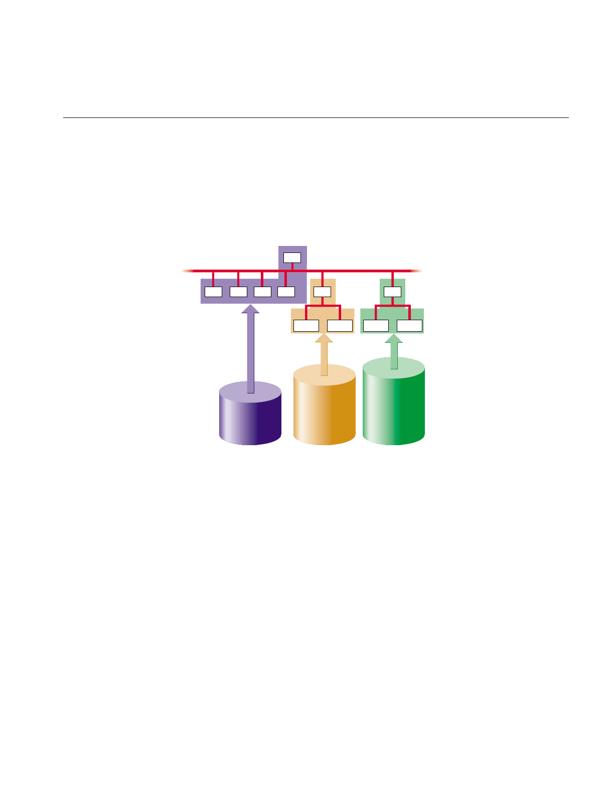
General Filesystem Concepts
57
The starting point of any filesystem is an unnamed directory that serves as the root for
that particular filesystem. In the IRIX operating system there is always one filesystem
that is itself referred to by that name, the Root filesystem. Traditionally, the root directory
of the Root filesystem is represented by a single slash (/). Filesystems are attached to the
directory hierarchy by the mount command. The result is the IRIX directory structure
shown in Figure 3-1.
Figure 3-1 The IRIX Filesystem
You can join two or more disk partitions to create a logical volume. The logical volume can
be treated as if it were a single disk partition, so a filesystem can reside on a logical
volume and hence is the only way for a single filesystem to span more than one disk.
Logical volumes are covered beginning in Chapter 6, “Logical Volume Concepts.”
The following subsections describe key components of filesystems.
/
/bin /etc /usr /var /d2
/proj1 /proj2
Partition
0
Partition
7
Partition
7
/d3
/proj3 /proj4
Disk 1 Disk 2 Disk 3

58
Chapter 3: Filesystem Concepts
Inodes
Information about each file is stored in a structure called an inode. The word inode is an
abbreviation of the term index node. An inode is a data structure that stores all
information about a file except its name, which is stored in the directory. Each inode has
an identifying inode number, which is unique across the filesystem that includes the file.
An inode contains this information:
•the type of the file (see the next section, “Types of Files,” for more information)
•the access mode of the file; the mode defines the access permissions read,write, and
execute and may also contain security labels and access control lists
•the number of hard links to the file (see the section “Hard Links and Symbolic
Links” for more information)
•who owns the file (the owner’s user-ID number) and the group to which the file
belongs (the group-ID number)
•the size of the file in bytes
•the date and time the file was last accessed, and last modified
•information for finding the file’s data within the disk partition or logical volume
•the pathname of symbolic links (when they fit and on XFS filesystems only)
You can use the ls command with various options to display the information stored in
inodes. For example, the command ls -l displays all but the last two items in the list above
in the order listed (the date shown is the last modified time).
Inodes do not contain the name of the file or its directory.

General Filesystem Concepts
59
Types of Files
Filesystems can contain the types of files listed Table 3-2. The type of a file is indicated by
the first character in the line of ls -l output for the file.
Hard Links and Symbolic Links
As discussed in the section “Inodes” in this chapter, information about each file, except
for the name and directory of the file, is stored in an inode for the file. The name of the
file is stored in the file’s directory and a link to the file is created by associating the
filename with an inode number. This type of link is called a hard link. Although every file
is a hard link, the term is usually used only when two or more filenames are associated
with the same inode number. Because inode numbers are unique only within a
filesystem, hard links cannot be created across filesystem boundaries.
Table 3-2 Types of Files
Type of File Character Description
Regular files –Regular files are one-dimensional arrays of bytes.
Directories d Directories are containers for files and other directories.
Symbolic links l Symbolic links are files that contain the name of another
file or a directory.
Character devices c Character devices enable communication between
hardware and IRIX; data is accessed on a character by
character basis.
Block devices b Block devices enable communication between hardware
and IRIX; data is accessed in blocks from a system buffer
cache.
Named pipes (also
known as FIFOs)
p Named pipes allow communication between two
unrelated processes running on the same host. They are
created with the mknod command (see the section
“Creating Device Files With mknod” in Chapter 2 for
more information on mknod).
UNIX domain sockets s UNIX domain sockets are connections between
processes that allow them to communicate, possibly
over a network.

60
Chapter 3: Filesystem Concepts
The second and later hard links to a file are created with the ln command, without the -s
option. For example, say the current directory contains a file called origfile. To create a
hard link called linkfile to the file origfile, give this command:
%ln origfile linkfile
The output of ls -l for origfile and linkfile shows identical sizes and last modification times:
%ls -l origfile linkfile
-rw-rw-r-- 2 joyce user 4 Apr 5 11:15 origfile
-rw-rw-r-- 2 joyce user 4 Apr 5 11:15 linkfile
Because origfile and linkfile are simply two names for the same file, changes in the contents
of the file are visible when using either filename. Removing one of the links has no effect
on the other. The file is not removed until there are no links to it (the number of links to
the file, the link count, is stored in the file’s inode).
Another type of link is the symbolic link. This type of link is actually a file (see Table 3-2).
The file contains a text string, which is the pathname of another file or directory. Because
a symbolic link is a file, it has its own owners and permissions. The file or directory it
points to can be in another filesystem. If the file or directory that a symbolic link points
to is removed, it is no longer available and the symbolic link becomes useless until the
target is recreated (it is called a dangling symbolic link).
Symbolic links are created with the ln command with the -s option. For example, to create
a symbolic link called linkdir to the directory origdir, give this command:
%ln -s origdir linkdir
The output of ls -ld for the symbolic link is shown below. Notice that the permissions and
other information don’t match. The listing for linkdir shows that it is a symbolic link to
origdir.
%ls -ld linkdir origdir
drwxrwxrwt 13 sys sys 2048 Apr 5 11:37 origdir
lrwxrwxr-x 1 joyce user 8 Apr 5 11:52 linkdir -> origdir
When you use “..” in pathnames that involve symbolic links, be aware that ” ..” refers to
the parent directory of the true file or directory, not the parent of the directory that
contains the symbolic link.
For more information about hard and symbolic links, see the ln(1) reference page and
experiment with creating and removing hard and symbolic links.

EFS Filesystems
61
Filesystem Names
Filesystems don’t have names per se; they are identified by their location on a disk or
their position in the directory structure in these ways:
•by the block and character device file names of the disk partition or logical volume
that contains the filesystem (see the section “Block and Character Devices” in
Chapter 1)
•by a mnemonic name for the disk partition or logical volume that contains the
filesystem (see the section “Creating Mnemonic Names for Device Files With ln” in
Chapter 2)
•by the mount point for the filesystem (see the section “Filesystem Mounting and
Unmounting” in this chapter)
The filesystem identifier from the list above that you use with commands that administer
filesystems (such as mkfs,mount,umount, and fsck) depends upon the command. See the
reference page for the command you want to use or examples in this guide to determine
which filesystem name to use.
EFS Filesystems
The EFS filesystem is the original IRIX filesystem. It contains an enhancement to the
standard UNIX filesystem called extents (defined below), and thus is called the Extent
File System (EFS). The maximum size of an EFS filesystem is about 8 GB. It uses a
filesystem block size of 512 bytes and allows a maximum file size of 2 GB minus 1 byte.
Advanced features of EFS are that it keeps multiple inode tables in close proximity to
data blocks rather than a single inode table, and it uses a bitmap to keep track of free
blocks instead of a list of free blocks.
Inodes are created when an EFS filesystem is created, not when files are created. When a
file is created, an inode is allocated to that file. Thus, the maximum number of files in a
filesystem is limited by the number of inodes in that filesystem. By default, the number
of inodes created is a function of the size of the partition or logical volume. Typically one
inode is created for every 4K bytes in the partition or logical volume. You can specify the
number of inodes with the -n option to the filesystem creation command, mkfs. Inodes
use disk space, so there is a tradeoff between the number of inodes and the amount of
disk space available for files.

62
Chapter 3: Filesystem Concepts
The first block of an EFS filesystem is not used. Information about the filesystem is stored
in the second block of the filesystem (block 1), called the superblock. This information
includes:
•the size of the filesystem, in both physical and logical blocks
•the read-only flag; if set, the filesystem is read only
•the superblock-modified flag; if set, the superblock has been modified
•the date and time of the last update
•the total number of index nodes (inodes) allocated
•the total number of inodes free
•the total number of free blocks
•the starting block number of the free block bitmap
After the superblock bitmap is a series of cylinder groups. A cylinder group is a group of
1 to 32 contiguous disk cylinders. Each cylinder group contains both inodes and data
blocks. Each contiguous group of data blocks that make up a file is called an extent. There
are 12 extent addresses in an inode. Extents are of variable length, anywhere from 1 to
148 contiguous blocks.
An inode contains addresses for 12 extents, which can hold a combined 1536 blocks, or
786,432 bytes. If a file is large enough that it cannot fit in the 12 extents, each extent is then
loaded with the address of up to 148 indirect extents. The indirect extents then contain the
actual data that makes up the file. Because EFS uses indirect extents, you can create files
up to 2 GB, assuming you have that much disk space available in your filesystem.
The last block of the filesystem is a duplicate of the filesystem superblock. This is a safety
precaution that provides a backup of the critical information stored in the superblock.
EFS filesystems can become fragmented over time. Fragmented filesystems have small
contiguous blocks of free space and files with poor layouts of the file extents. The fsr
command reorganizes filesystems to improve file extent layout and compact the
filesystem free space. By default, fsr is run once a week automatically from crontab.

XFS Filesystems
63
XFS Filesystems
XFS is a new IRIX filesystem designed for use on most Silicon Graphics systems—from
desktop systems to supercomputer systems. Its major features include
•full 64-bit file capabilities (files larger than 2 GB)
•rapid and reliable recovery after system crashes because of the use of journaling
technology
•efficient support of large, sparse files (files with “holes”)
•integrated, full-function volume manager, the XLV Volume Manager
•extremely high I/O performance that scales well on multiprocessing systems
•guaranteed-rate I/O for multimedia and data acquisition uses
•compatibility with existing applications and with NFS®
•user-specified filesystem block sizes ranging from 512 bytes up to 64 KB
•small directories and symbolic links of 156 characters or less take no space
At least 32 MB of memory is recommended for systems with XFS filesystems.
XFS supports files and filesystems of 240-1 or 1,099,511,627,775 bytes (one terabyte) on
32-bit systems (IP17, IP20, and IP22). Files up to 263-1 bytes and filesystems of unlimited
size are supported on 64-bit systems (IP19, IP21, and IP26). You can use the filesystem
interfaces supplied with the IRIS Development Option (IDO) software option to write
32-bit programs that can track 64-bit position and file size. Many programs work without
modification because sequential reads succeed even on files larger than 2 GB. NFS allows
you to export 64-bit XFS filesystems to other systems.
XFS uses database journaling technology to provide high reliability and rapid recovery.
Recovery after a system crash is completed within a few seconds, without the use of a
filesystem checker such as the fsck command. Recovery time is independent of filesystem
size.
XFS is designed to be a very high performance filesystem. Under certain conditions,
throughput exceeds 100 MB per second. Its performance scales to complement the
CHALLENGE™ MP architecture. While traditional filesystems suffer from reduced
performance as they grow in size, with XFS there is no performance penalty.

64
Chapter 3: Filesystem Concepts
You can create filesystems with block sizes ranging from 512 bytes to 64 KB. For real-time
data, the maximum extent size is 1 GB. Filesystem extents, which provide contiguous
data within a file, are configurable at file creation time using the fcntl() system call and
are multiples of the filesystem block size. Inodes are created as needed by XFS
filesystems. You can specify the size of inodes with the -i option to the filesystem creation
command, mkfs. You can also specify the maximum percentage of the space in a
filesystem that can be occupied by inodes with the mkfs -i maxpct= option.
Most filesystem commands, such as du,dvhtool,ls,mount,prtvtoc, and umount, work with
XFS filesystems as well as EFS filesystems with no user-visible changes. A few
commands, such as df, fx, and mkfs have additional features for XFS. The filesystem
commands clri,fsck, findblk, and ncheck are not used with XFS filesystems.
For backup and restore, the standard IRIX commands Backup, bru, cpio,Restore, and tar
and the optional software product NetWorker® for IRIX can be used for files less than 2
GB in size. To dump XFS filesystems, the new command xfsdump must be used instead
of dump. Restoring from these dumps is done using xfsrestore. See Table 3-1 and Table 3-2
in Chapter 3, “Dumping and Restoring XFS Filesystems,” for more information about the
relationships between xfsdump,xfsrestore,dump, and restore on XFS and EFS filesystems.
Network File Systems (NFS)
NFS filesystems are available if you are using the optional NFS software. NFS filesystems
are filesystems that are exported from one host and mounted on other hosts across a
network.
On the hosts where the filesystems reside, they are treated just like any other EFS or XFS
filesystem. The only special feature of these filesystems is that they are exported for
mounting from other workstations. Exporting NFS filesystems is done with the exportfs
command. On other hosts, these filesystems are mounted with the mount command or by
using the automount facility of NFS.
Tip: The sections “Using Disk Space on Other Systems” and “Making Your Disk Space
Available to Other Systems” in Chapter 6 of the Personal System Administration Guide
provide instructions for mounting and exporting NFS filesystems.
NFS filesystems are described in detail in the ONC3/NFS Administrator’s
Guide, which is included with the NFS software option.

Cache File Systems (CacheFS)
65
Cache File Systems (CacheFS)
The Cache File System (CacheFS) is a new filesystem type that provides client-side
caching for NFS and other filesystem types. Using CacheFS on NFS clients with local disk
space can significantly increase the number of clients a server can support and reduce the
data access time for clients using read-only file systems.
The cfsadmin command is used for managing CacheFS filesystems. A special version of
the fsck command, fsck_cachefs is used to check the integrity of a cache directory. It is
automatically invoked when a CacheFS filesystem is mounted. When mounting and
unmounting CacheFS filesystems, the -t cachefs option must be used. For more
information on these commands, see the cfsadmin(1M), fsck_cachefs(1M), and
mount(1M) reference pages.
CacheFS filesystems are available if you are using the optional NFS software. They are
described in detail in the ONC3/NFS Administrator’s Guide, which is included with the
NFS software option.
/proc Filesystem
The /proc filesystem, also known as the debug filesystem, provides an interface to
running IRIX processes for use by monitoring programs, such as ps and top, and
debuggers, such as dbx. The debug filesystem is usually mounted on /proc with a link to
/debug. To reduce confusion, /proc is not displayed when you list free space with the df
command.
The “files” of the debug filesystem are of the form /proc/nnnnn and /proc/pinfo/nnnnn,
where nnnnn is a decimal number corresponding to a process ID. These files do not
consume disk space; they are merely handles for debugging processes. /proc files cannot
be removed.
See the proc(4) reference page for more information on the debug filesystem.

66
Chapter 3: Filesystem Concepts
Filesystem Creation
To turn a disk partition or logical volume into a filesystem, the mkfs command must be
used. It takes a disk partition or logical volume and divides it up into areas for data
blocks, inodes, and free lists, and writes out the appropriate inode tables, superblocks,
and block maps. It creates the filesystem’s root directory and, for EFS filesystems only, a
lost+found directory.
An example mkfs command for making an EFS filesystem is:
mkfs -t efs /dev/rdsk/dks0d2s7
You can use the -n option to mkfs to specify the number of inodes created.
An example mkfs command for making an XFS filesystem with a 1 MB internal log
section is:
mkfs -l size=1m /dev/rdsk/dks0d2s7
An example mkfs command for making an XFS filesystem on a logical volume with log
and data subvolumes is:
mkfs /dev/rdsk/xlv/a
After using mkfs to create an EFS filesystem, run the fsck command to verify that the disk
is consistent.
For more instructions on making filesystems see Chapter 4, “Creating and Growing
Filesystems,” and the mkfs(1M), mkfs_efs(1M), and mkfs_xfs(1M) reference pages.
Filesystem Mounting and Unmounting
Filesystems must be mounted to be used. Figure 3-2 illustrates this process. When a
filesystem is mounted, the name of the device file for the filesystem (/dev/rdsk/dks0d2s7 in
Figure 3-2) and the name of a directory (/proj in Figure 3-2) are given. This directory, /proj,
is called a mount point and forms the connection between the filesystem containing the
mount point and the filesystem to be mounted. Mounting a filesystem tells the kernel
that the mount point is to be considered equivalent to the top level directory of the
filesystem when pathnames are resolved. In Figure 3-2, the files a,b, and c in the
/dev/rdsk/dks0d2s7 filesystem become /proj/a,/proj/b, and /proj/c as shown in the bottom of
the figure.
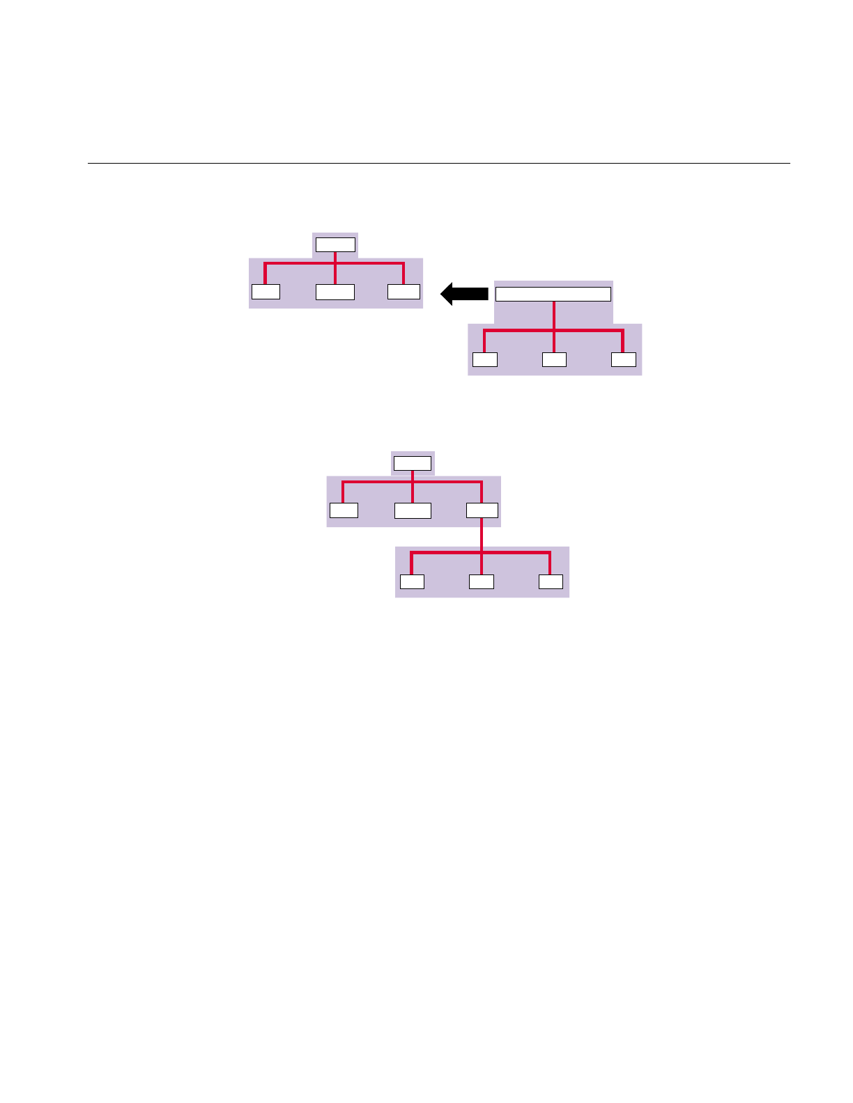
Filesystem Mounting and Unmounting
67
Figure 3-2 Mounting a Filesystem
When you mount a filesystem, the original contents of the mount point directory are
hidden and unavailable until the filesystem is unmounted. However, the mount point
directory owner and permissions are not hidden. Restricted permissions can restrict
access to the mounted filesystem.
Unlike other filesystems, the Root filesystem (/) is mounted as soon as the kernel is
running and cannot be unmounted because it is required for system operation. The Usr
filesystem, if it is a separate filesystem from the Root filesystem, must also be mounted
for the system to operate properly. System administration that requires unmounting the
Root and Usr filesystem can be done in the miniroot. See the section “Filesystem
Administration From the Miniroot” in this chapter for more information.
/(root)
/disk2
/usr /proj /dev/rdsk/dks0d2s7
/b
/a /c
/(root)
/disk2
/usr /proj
/b
/a /c

68
Chapter 3: Filesystem Concepts
You can mount filesystems several ways:
•manually with the mount command (discussed in the section “Manually Mounting
Filesystems” in Chapter 5)
•automatically when the system is booted, using information in the file /etc/fstab
(discussed in the section “Mounting Filesystems Automatically With the /etc/fstab
File” in Chapter 5)
•automatically when the filesystem is accessed (called automounting, this applies to
NFS (remote) filesystems only; see the section “Mounting a Remote Filesystem
Automatically” in Chapter 5)
You can unmount filesystems in these ways:
•shut the system down (filesystems are unmounted automatically)
•manually unmount filesystems with the umount command (see the section
“Unmounting Filesystems” in Chapter 5)
The mount and umount commands are described in detail in the section “Mounting and
Unmounting Filesystems” in Chapter 5.
Filesystem Checking
The fsck command checks EFS filesystem consistency and data integrity. Filesystems are
usually checked automatically when the system is booted. Except for the Root filesystem,
filesystems must be unmounted while being checked. You might want to invoke fsck
manually at these times:
•before making a backup
•after doing a restore
•after doing disk maintenance
•before installing software
•before manually mounting a dirty filesystem
•when fsck runs automatically and has many errors

Filesystem Reorganization
69
Several procedures for invoking fsck manually are described in the section “Checking
EFS Filesystem Consistency With fsck” in Chapter 5. A detailed explanation of the checks
performed by fsck and the options it presents when it finds problems are provided in
Appendix A, “Repairing EFS Filesystem ProblemsWith fsck.”
The xfs_check command checks XFS filesystem consistency. It is normally used only when
a filesystem consistency problem is suspected. See the xfs_check(1M) reference page for
more information.
The fsck_cachefs command checks CacheFS filesystem consistency. It is automatically run
when CacheFS filesystems are mounted. See the fsck_cachefs(1M) reference page and the
ONC3/NFS Administrator’s Guide for more information.
Filesystem Reorganization
EFS filesystems can become fragmented over time. When a filesystem is fragmented,
blocks of free space are small and files have many extents (see the section “EFS
Filesystems” in this chapter for information about extents). The fsr command reorganizes
filesystems so that the layout of the extents is improved and free disk space is coalesced.
This improves overall performance. By default, fsr is run automatically once a week from
crontab. See the fsr(1M) reference page for additional information.
Filesystem Administration From the Miniroot
When filesystem modifications or other administrative tasks require that the Root
filesystem not be mounted or not be in use, the miniroot environment provided by the
software installation tools included on IRIX system software release CDs can be used.
When using the miniroot, a limited version of IRIX is installed in the swap partition in a
filesystem mounted at /. The system runs this version of IRIX rather than the standard
IRIX in the Root and Usr filesystems. The Root and Usr filesystems are available and
mounted at /root and /root/usr. Thus the pathnames of all files in the Root and Usr
filesystems have the prefix/root.

70
Chapter 3: Filesystem Concepts
How to Add Filesystem Space
You can add filesystem space in three ways:
•Add a new disk, create a filesystem on it, and mount it as a subdirectory on an
existing filesystem.
•Change the size of the existing filesystems by removing space from one partition
and adding it to another partition on the same disk.
•Add another disk and grow an existing filesystem onto that disk with the growfs or
xfs_growfs command.
These three methods of adding filesystem space are discussed in the following
subsections.
Mount a Filesystem as a Subdirectory
To mount a filesystem as a subdirectory, you simply add a new disk with a separate
filesystem and create a new mount point for it within your filesystem. This is generally
considered the safest way to add space. For example, if your Usr filesystem is short of
space, add a new disk and mount the new filesystem on a directory called /usr/work. A
drawback of this approach is that it does not allow hard links to be created between the
original filesystem and the new filesystem.
See Chapter 2, “Performing Disk Administration Procedures,” for full information on
partitioning a disk and making filesystems on it.
“Steal” Space From Another Filesystem
To move disk space from one filesystem on a disk to another filesystem on the same disk,
you must back up your existing data on both filesystems, run the fx command to
repartition the disk, then remake both filesystems with the mkfs command. This method
has serious drawbacks. It is a great deal of work and has certain risks. For example, to
increase the size of a filesystem, you must remove space from other filesystems. You must
be sure that when you are finished changing the size of your filesystems, your old data
still fits on all the new, smaller filesystems. Also, resizing your filesystems may at best be
a stop-gap measure until you can acquire additional disk space.

Disk Quotas
71
Repartitioning is documented in “Repartitioning a Disk With fx” in Chapter 2. For
additional solutions when the filesystem is the Root filesystem, see “Running Out of
Space in the Root Filesystem” in Chapter 5.
Grow a Filesystem Onto Another Disk
Growing an existing filesystem onto an additional disk or disk partition is another way
to increase the available space in that filesystem. The original disk partition and the new
disk partition become either an lv logical volume or an XLV logical volume (your choice).
The growfs command (EFS filesystems) or xfs_growfs command (XFS filesystems)
preserves the existing data on the hard disk and adds space from the new disk partition
to the filesystem. This process is simpler than completely remaking your filesystems. The
one drawback to growing a filesystem across disks is that if one disk fails, you may not
recover data from the other disk, even if the other disk still works. If your Usr filesystem
is a logical volume, you will be unable to boot the system into multiuser mode. For this
reason, it is preferable, if possible, to mount an additional disk and filesystem as a
directory on the Root or Usr or filesystems (on / or /usr).
For instructions on growing a filesystem onto an additional disk, see the section
“Growing an EFS Filesystem Onto Another Disk” or “Growing an XFS Filesystem Onto
Another Disk” in Chapter 4.
Disk Quotas
If your system is constantly short of disk space and you cannot increase the amount of
available space, you may be forced to implement disk quotas. Quotas allow a limit to be
set on the amount of space a user can occupy, and there may be a limit on the number of
files (inodes) each user can own. IRIX provides the quotas system to automate this process
on EFS filesystems (the quotas system cannot be used on XFS filesystems). You can use
this system to implement specific disk usage quotas for each user on your system. You
may also choose to implement hard or soft limits. Hard limits are enforced by the system,
soft limits merely remind the user to trim disk usage.

72
Chapter 3: Filesystem Concepts
With soft limits, whenever a user logs in with a usage greater than the assigned soft limit,
that user is warned (by the login command). When the user exceeds the soft limit, the
timer is enabled. Any time the quota drops below the soft limits, the timer is disabled. If
the timer is enabled longer than a time period set by the administrators, the particular
limit that has been exceeded is treated as if the hard limit has been reached, and no more
resources are allocated to the user. The only way to reset this condition is to reduce usage
below the quota. Only root may set the time limits and this is done on a per-filesystem
basis.
Several options are available with the quotas subsystem. You can impose limits on some
users and not others, some filesystems and not others, and on total disk usage per user,
total number of files, or size of files. The system is completely configurable. You can also
keep track of disk usage through the process accounting system provided under IRIX.
The importance of managing disk quotas carefully cannot be over emphasized. It is
strongly recommended that if disk quotas are imposed, they should be soft quotas, and
every attempt should be made to otherwise rectify the situation before removing
someone’s files. Before using the quotas subsystem to enforce disk usage, carefully read
the material on disk quotas in the section “Disk Quotas” in this chapter.
The quotas system is described completely in the quotas(4) reference page. The procedure
for imposing disk quotas is described in the section “Imposing Disk Quotas” in
Chapter 5.
Filesystem Corruption
Most often, a filesystem is corrupted because the system experienced a panic or didn’t
shut down cleanly. This can be caused by system software failure, hardware failure, or
human error (for example, pulling the plug). Another possible source of filesystem
corruption is overlapping partitions.
There is no foolproof way to predict hardware failure. The best way to avoid hardware
failures is to conscientiously follow recommended diagnostic and maintenance
procedures.

Filesystem Corruption
73
Human error is probably the greatest single cause of filesystem corruption. To avoid
problems, follow these rules closely:
•Always shut down the system properly. Do not simply turn off power to the system.
Use a standard system shutdown tool, such as the shutdown command.
•Never remove a filesystem physically (pull out a hard disk) without first turning off
power.
•Never physically write-protect a mounted filesystem, unless it is mounted
read-only.
The best way to insure against data loss is to make regular, careful backups. See the guide
IRIX Admin: Backup, Security, and Accounting for complete information on system
backups.


75
Chapter 4
4.Creating and Growing Filesystems
This chapter describes the procedures you must perform to create or grow (increase the
size of) XFS and EFS filesystems or to convert from an EFS filesystem to an XFS
filesystem.
The major sections in this chapter are:
•“Planning for XFS Filesystems” on page 75
•“Making an XFS Filesystem” on page 82
•“Making an EFS Filesystem” on page 84
•“Making a Filesystem From inst” on page 85
•“Growing an XFS Filesystem Onto Another Disk” on page 86
•“Growing an EFS Filesystem Onto Another Disk” on page 87
•“Converting Filesystems on the System Disk From EFS to XFS” on page 89
•“Converting a Filesystem on an Option Disk From EFS to XFS” on page 96
Planning for XFS Filesystems
The following subsections discuss preparation for and choices you must make when
creating an XFS filesystem. Each time you plan to make an XFS filesystem or convert a
filesystem from EFS to XFS, review each section and make any necessary preparations.
Prerequisite Software
The subsystem eoe.sw.xfs is required to use XFS filesystems.
If you are converting the Root and Usr filesystems to XFS, you must have software
distribution CDs or access to a remote distribution directory for IRIX Release 6.2 or later.

76
Chapter 4: Creating and Growing Filesystems
Choosing the Filesystem Block Size and Extent Size
XFS allows you to choose the logical block size for each filesystem. (Physical disk blocks
remain 512 bytes. EFS has a fixed block size of 512 bytes.) If you use a real-time
subvolume on an XLV logical volume, you must also choose the extent size. The extent
size is the amount of space that is allocated to a file every time more space needs to be
allocated to it.
For XFS filesystems on disk partitions and logical volumes and for the data subvolume
of filesystems on XLV volumes, the block size guidelines are:
•The minimum block size is 512 bytes. Small block sizes increase allocation overhead
which decreases filesystem performance, but in general, the recommended block
size for filesystems under 100 MB and for filesystems with many small files is 512
bytes.
•The default block size is 4096 bytes (4K). This is the recommended block size for
filesystems over 100 MB.
•The maximum block size is 65536 bytes (64K). Because large block sizes can waste
space and lead to fragmentation, in general block sizes shouldn’t be larger than 4096
bytes (4K).
•For the Root filesystem on systems with separate Root and Usr filesystems, the
recommended block size is 512 bytes.
•For news servers, the recommended block size for the news filesystems is 2048
bytes.
Block sizes are specified in bytes in decimal (default), octal (prefixed by 0), or
hexadecimal (prefixed by 0x or 0X). If the number has the suffix “k,” it is multiplied by
1024. If the number has the suffix “m,” it is multiplied by 1048576 (1024 * 1024).
For real-time subvolumes of XLV logical volumes, the block size is the same as the block
size of the data subvolume. The guidelines for the extent size are:
•The extent size must be a multiple of the block size of the data subvolume.
•The minimum extent size is 4 KB.
•The maximum extent size is 1 GB.
•The default extent size is 64 KB.
•The extent size should be matched to the application and the stripe unit of the
volume elements used in the real-time subvolume.

Planning for XFS Filesystems
77
Choosing the Log Type and Size
Each XFS filesystem has a log that contains filesystem journaling records. This log
requires dedicated disk space. This disk space doesn’t show up in listings from the df
command, nor can you access it with a filename.
The location of the disk space depends on the type of log you choose. The two types of
logs are:
External When an XFS filesystem is created on an XLV logical volume and log
records are put into a log subvolume, the log is called an external log. The
log subvolume is one or more disk partitions dedicated to the log
exclusively.
Internal When an XFS filesystem is created on a disk partition or XLV logical
volume, or when it is created on an XLV logical volume that doesn’t
have a log subvolume, log records are put into a dedicated portion of the
disk partition (or data subvolume) that contains user files. This type of
log is called an internal log.
The guidelines for choosing the log type are:
•If you want the log and the data subvolume to be on different partitions or to use
different subvolume configurations for them, use an external log.
•If you want the log subvolume to be striped independently from the data subvolume
(see the section “Volume Elements” in Chapter 6 for an explanation of striping), you
must use an external log.
•If you are making the XFS filesystem on a disk partition (rather than on an XLV
logical volume), you must use an internal log.
•If you are making the XFS filesystem on an XLV logical volume that has no log
subvolume, you must use an internal log.
•If you are making the XFS filesystem on an XLV logical volume that has a log
subvolume, you must use an external log.
For more information about XLV and log subvolumes, see the section “XLV Logical
Volumes” in Chapter 6.

78
Chapter 4: Creating and Growing Filesystems
The amount of disk space needed for the log is a function of how the filesystem is used.
The amount of disk space required for log records is proportional to the transaction rate
and the size of transactions on the filesystem, not the size of the filesystem. Larger block
sizes result in larger transactions. Transactions from directory updates (for example, the
mkdir and rmdir commands and the create() and unlink() system calls) cause more log
data to be generated.
You must choose the amount of disk space to dedicate to the log (called the log size). The
minimum log size is 512 blocks. The typical log size is 1000 blocks. For filesystems with
very high transaction activity, a larger log size of 2000 blocks is recommended.
For external logs, the size of the log is the same as the size of the log subvolume. The log
subvolume is one or more disk partitions. You may find that you need to repartition a
disk to create a properly sized log subvolume (see the section “Disk Repartitioning” in
this chapter). For external logs, the size of the log is set when you create the log
subvolume with the xlv_make command.
For internal logs, the size of the log is specified when you create the filesystem with the
mkfs command.
The log size is specified in bytes as described in the section “Choosing the Filesystem
Block Size and Extent Size” in this chapter or as a multiple of the filesystem block size by
using the suffix “b.”
Checking for Adequate Free Disk Space
XFS filesystems may require more disk space than EFS filesystems for the same files. This
extra disk space is required to accommodate the XFS log and as a result of block sizes
larger than EFS’s 512 bytes. However, XFS represents free space more compactly, on
average, and the inodes are allocated dynamically by XFS, which can result in less disk
space usage.

Planning for XFS Filesystems
79
This procedure can be used to get a rough idea of the amount of free disk space that will
remain after a filesystem is converted to XFS:
1. Get the size in kilobytes of the filesystem to be converted and round the result to the
next megabyte. For example,
df -k
Filesystem Type kbytes use avail %use Mounted on
/dev/root efs 969857 663306 306551 68% /
This filesystem is 969857 KB, which rounds up to 970 MB.
2. If you plan to use an internal log (see the section “Choosing the Log Type and Size”
in this chapter), give this command to get an estimate of the disk space required for
the files in the filesystem after conversion:
%xfs_estimate -i logsize -b blocksize mountpoint
logsize is the size of the log. blocksize is the block size you chose for user files in the
section “Choosing the Filesystem Block Size and Extent Size” in this chapter.
mountpoint is the directory that is the mount point for the filesystem. For example,
%xfs_estimate -i 1m -b 4096 /
/ will take about 747 megabytes
The output of this command tells you how much disk space the files in the
filesystem (with a blocksize of 4096 bytes) and an internal log of size logsize will take
after conversion to XFS.
3. If you plan to use an external log, give this command to get an estimate of the disk
space required for the files in the filesystem after conversion:
%xfs_estimate -e 0 -b blocksize mountpoint
blocksize is the block size you chose for user files in the section “Choosing the
Filesystem Block Size and Extent Size” in this chapter. mountpoint is the directory
that is the mount point for the filesystem. For example,
%xfs_estimate -e 0 -b 4096 /
/ will take about 746 megabytes
with the external log using 0 blocks or about 1 megabytes
The first line of output from xfs_estimate tells you how much disk space the files in
the filesystem will take after conversion to XFS. In addition to this, you will need
disk space on a different disk partition for the external log. You should ignore the
second line of output.

80
Chapter 4: Creating and Growing Filesystems
4. Compare the size of the filesystem from step 1 with the size of the files from step 2
or step 3. For example,
970 MB - 747 MB = 223 MB free disk space
747 MB / 970 MB = 77% full
Use this information to decide if there will be an adequate amount of free disk space
if this filesystem is converted to XFS.
If the amount of free disk space after conversion is not adequate, some options to
consider are:
•Implement the usual solutions for inadequate disk space: remove unnecessary files,
archive files to tape, move files to another filesystem, add another disk, and so on.
•Repartition the disk to increase size of the disk partition for the filesystem.
•If there isn’t sufficient disk space in the Root filesystem and you have separate Root
and Usr filesystems, switch to combined Root and Usr filesystems on a single disk
partition.
•If the filesystem is on an lv logical volume or an XLV logical volume, increase the
size of the volume.
•Create an XLV logical volume with a log subvolume elsewhere, so that all of the
disk space can be used for user files.
Disk Repartitioning
Many system administrators may find that they want or need to repartition disks when
they switch to XFS filesystems and/or XLV logical volumes. Some of the reasons to
consider repartitioning are:
•If the system disk has separate partitions for Root and Usr filesystems, the Root
filesystem may be running out of space. Repartitioning is a way to increase the
space in Root (at the expense of the size of Usr) or to solve the problem by
combining Root and Usr into a single partition.
•System administration is a little easier on systems with combined Root and Usr
filesystems.
•If you plan to use XLV logical volumes, you may want to put the XFS log into a
small subvolume. This requires disk repartitioning to create a small partition for the
log subvolume.

Planning for XFS Filesystems
81
•If you plan to use XLV logical volumes, you may want to repartition to create disk
partitions of equal size that can be striped or plexed.
Disk partitions are discussed in Chapter 1, “Disk Concepts,” and using fx to repartition
disks is explained in the section “Repartitioning a Disk With fx” in Chapter 2.
Dump and Restore Requirements
The filesystem conversion procedures in the sections “Converting Filesystems on the
System Disk From EFS to XFS” and “Converting a Filesystem on an Option Disk From
EFS to XFS” in this chapter require that you dump the filesystems you plan to convert to
tape or to another disk with sufficient free disk space to contain the dump image.
Dumping to disk is substantially faster than dumping to tape.
When you convert a system disk, you must use the dump and restore commands. When
you convert a filesystem on an option disk, you can use any backup and restore
commands.
If you dump to a tape drive, follow these guidelines:
•Have sufficient tapes available for dumping the filesystems to be converted.
•If you are converting filesystems on a system disk, the tape drive must be local.
•If you are converting filesystems on option disks, the tape drive can be local or
remote.
The requirements for dumping to a different filesystem are:
•The filesystem being converted must have 2 GB or less in use (the maximum size of
the dump image file on an EFS filesystem) unless it is being dumped to an XFS
filesystem.
•The filesystem that will contain the dump must have sufficient disk space available
to hold the filesystems to be converted.
•If you are converting filesystems on a system disk, the filesystem where you place
the dump must be local to the system.
•If you are converting filesystems on option disks, the filesystem you dump to can be
local or remote.

82
Chapter 4: Creating and Growing Filesystems
Making an XFS Filesystem
This section explains how to create an XFS filesystem on an empty disk partition or XLV
logical volume. (For information about creating XLV logical volumes, see Chapter 7,
“Creating and Administering XLV Logical Volumes.”)
Tip: You can make an XFS filesystem on a disk partition or a logical volume using the
graphical user interface of the xfsm command. For information, see its online help.
Caution: When you create a filesystem, all files already on the disk partition or logical
volume are destroyed.
1. Review the subsections within the section “Planning for XFS Filesystems” in this
chapter to verify that you are ready to begin this procedure.
2. Identify the device name of the partition or logical volume where you plan to create
the filesystem. This is the value of partition in the examples below. For example, if
you plan to use partition 7 (the entire disk) of a SCSI option disk on controller 0 and
drive address 2, partition is /dev/dsk/dks0d2s7. For more information on determining
partition, see Table 1-4, the section “Introduction to Logical Volumes” in Chapter 6,
and the dks(7M) reference page.
3. If the disk partition is already mounted, unmount it:
#umount partition
Any data that is on the disk partition is destroyed (to convert the data rather than
destroy it, use the procedure in the section “Converting a Filesystem on an Option
Disk From EFS to XFS” in this chapter instead).
4. If you are making a filesystem on a disk partition or on an XLV logical volume that
doesn’t have a log subvolume, use this mkfs command to create the new XFS
filesystem:
#mkfs -b size=blocksize -l size=logsize partition
blocksize is the filesystem block size (see the section “Choosing the Filesystem Block
Size and Extent Size” in this chapter) and logsize is the size of the area dedicated to
log records (see the section “Choosing the Log Type and Size” in this chapter). The
default values are 4 KB blocks and a 1000 block log.
Example 4-1 shows the command line used to create an XFS filesystem and the
system output. The filesystem has a 10 MB internal log and a block size of 1K bytes
and is on the partition /dev/dsk/dks0d2s7.

Making an XFS Filesystem
83
Example 4-1 mkfs Command for an XFS Filesystem With an Internal
Log
#mkfs -b size=1k -l size=10m /dev/dsk/dks0d2s7
meta-data=/dev/dsk/dks0d2s7 isize=256 agcount=8, agsize=128615 blks
data = bsize=1024 blocks=1028916
log =internal log bsize=1024 blocks=10240
realtime =none bsize=65536 blocks=0, rtextents=0
5. If you are making a filesystem on an XLV logical volume that has a log subvolume
(for an external log), use this mkfs command to make the new XFS filesystem:
#mkfs -b size=blocksize volume
blocksize is the block size for filesystem (see the section “Choosing the Filesystem
Block Size and Extent Size” in this chapter), and volume is the device name for the
volume.
Example 4-2 shows the command line used to create an XFS filesystem on a logical
volume /dev/dsk/xlv/a with a block size of 1K bytes and the system output.
Example 4-2 mkfs Command for an XFS Filesystem With an External
Log
#mkfs -b size=1k /dev/dsk/xlv/a
meta-data=/dev/dsk/xlv/a isize=256 agcount=8, agsize=245530 blks
data = bsize=1024 blocks=1964240
log =volume log bsize=1024 blocks=25326
realtime =none bsize=65536 blocks=0, rtextents=0
Example 4-3 shows the command line used to create an XFS filesystem on a logical
volume /dev/dsk/xlv/xlv_data1 that includes a log, data, and real-time subvolumes
and the system output. The default block size of 4096 bytes is used and the real-time
extent size is set to 128K bytes.
Example 4-3 mkfs Command for an XFS Filesystem With a Real-Time Subvolume
#mkfs_xfs -r extsize=128k /dev/rdsk/xlv/xlv_data1
meta-data=/dev/rdsk/xlv/xlv_data1 isize=256 agcount=8, agsize=4300 blks
data = bsize=4096 blocks=34400
log =volume log bsize=4096 blocks=34400
realtime =volume rt bsize=131072 blocks=2560, rtextents=80
6. To use the filesystem, you must mount it. For example:
#mkdir mountdir
#mount partition mountdir

84
Chapter 4: Creating and Growing Filesystems
For more information about mounting filesystems, see the section “Manually
Mounting Filesystems” in Chapter 5.
7. To configure the system so that the new filesystem is automatically mounted when
the system is booted, add this line to the file /etc/fstab:
partition mountdir xfs rw,raw=rawpartition 0 0
where rawpartition is the raw version of partition. For example, if partition is
/dev/dsk/dks0d2s7,rawpartition is /dev/rdsk/dks0d2s7.
For more information about automatically mounting filesystems, see the section
“Mounting Filesystems Automatically With the /etc/fstab File” in Chapter 5.
Making an EFS Filesystem
The procedure in this section explains how to make a filesystem on a disk partition or on
a logical volume and mount it. (See From or Chapter 8, “Creating and Administering lv
Logical Volumes,” for information on creating logical volumes.) This procedure assumes
that the disk or logical volume is empty. If it contains valuable data, the data must be
backed up because it is destroyed during this procedure.
Tip: You can make an EFS filesystem on a disk partition using the Disk Manager in the
System Toolchest. For information, see the section “Formatting, Verifying, and Remaking
Filesystems on a Fixed Disk” in Chapter 6 of the Personal System Administration Guide.
Caution: When you create a filesystem, all files already on the disk partition or logical
volume are destroyed.
1. Identify the device name of the partition or logical volume where you plan to create
the filesystem. This is the value of partition in the examples below. For example, if
you plan to use partition 7 (the entire disk) of a SCSI option disk on controller 0 and
drive address 2, partition is /dev/dsk/dks0d2s7. For more information on determining
partition, see Table 1-4, the section “Introduction to Logical Volumes” in Chapter 6,
and the dks(7M) reference page.
2. If the disk partition is already mounted, unmount it:
#umount partition
Any data that is on the disk partition is destroyed (to convert the data rather than
destroy it, use the procedure in the section “Converting a Filesystem on an Option
Disk From EFS to XFS” in this chapter instead).

Making a Filesystem From inst
85
3. Create a new filesystem with the mkfs command, for example,
#mkfs -t efs /dev/rdsk/dks0d2s7
The argument to mkfs is the block or character device for the disk partition or logical
volume. You can use either the block device or the character device.
In the above example, mkfs uses default values for the filesystem parameters. If you
want to use parameters other than the default, you can specify these on the mkfs
command line. See the mkfs_efs(1M) reference page for information about using
command line parameters and proto files.
4. To use the filesystem, you must mount it. For example,
#mkdir /rsrch
#mount /dev/dsk/dks0d2s7 /rsrch
For more information about mounting filesystems, see the section “Manually
Mounting Filesystems” in Chapter 5.
5. To configure the system so that this filesystem is automatically mounted when the
system is booted up, add an entry in the file /etc/fstab for the new filesystem. For
example,
/dev/dsk/dks0d2s7 /rsrch efs rw,raw=/dev/rdsk/dks0d2s7 0 0
For more information about automatically mounting filesystems, see the section
“Mounting Filesystems Automatically With the /etc/fstab File” in Chapter 5.
Making a Filesystem From inst
Caution: When you create a filesystem, all files already on the disk partition or logical
volume are destroyed.
mkfs can be used from within the inst command to make filesystems. To make the Root
or Usr filesystem on a system disk, you must use inst from the miniroot. There are two
ways to use mkfs:
•The mkfs command on the Administrative Command Menu. The mkfs command
uses default values for the mkfs command options. It chooses an EFS filesystem or
an XFS filesystem based on the answer to a prompt. With no argument, the mkfs
command makes the Root filesystem and, if a usr partition is present, a Usr
filesystem. Other filesystems can be made by giving a device file argument to mkfs.

86
Chapter 4: Creating and Growing Filesystems
•From a shell. Giving the mkfs command from a shell (give the command sh, not
shroot) enables you to specify the mkfs command line, including options.
For more information about making filesystems from inst, see the guide IRIX Admin:
Software Installation and Licensing.
Growing an XFS Filesystem Onto Another Disk
When growing an XFS filesystem onto another disk, there are two possibilities:
•The XFS filesystem is on a disk partition.
•The XFS filesystem is on an XLV logical volume.
If the XFS filesystem is on an XLV logical volume, the additional disk can be added to the
logical volume as an additional volume element. Instructions for doing this are in the
section “Adding a Volume Element to a Plex (Growing a Logical Volume)” in Chapter 7.
The following steps show how to grow a fictional /disk2 XFS filesystem onto an XLV
logical volume created out of the /disk2 disk partition and a new disk. The procedure
assumes that the new disk is installed on the system and partitioned.
Caution: All files on the additional disk are destroyed by this procedure.
1. Make a backup of the filesystem you are going to extend.
2. Unmount the /disk2 filesystem:
#umount /disk2
3. Use xlv_make to create an XLV logical volume out of the /disk2 partition and the new
disk. The /disk2 partition must be the first volume element in the data subvolume.
For example:
#xlv_make
xlv_make> vol xlv0
xlv0
xlv_make> data
xlv0.data
xlv_make> plex
xlv0.data.0
xlv_make> ve dks0d2s7
xlv0.data.0.0
xlv_make> ve dks0d3s7

Growing an EFS Filesystem Onto Another Disk
87
xlv0.data.0.1
xlv_make> end
Object specification completed
xlv_make> exit
Newly created objects will be written to disk.
Is this what you want?(yes) yes
Invoking xlv_assemble
4. Mount the /disk2 filesystem:
#mount /dev/dsk/xlv/xlv0 /disk2
5. Grow the filesystem into the logical volume with the xfs_growfs command:
#xfs_growfs /disk2
6. Change the entry for /disk2 in the file /etc/fstab to mount the logical volume rather
than the disk partition:
/dev/dsk/xlv/xlv0 /disk2 xfs rw,raw=/dev/rdsk/xlv/xlv0 0 0
Growing an EFS Filesystem Onto Another Disk
The following steps show how to grow a fictional /work EFS filesystem onto an lv logical
volume created out of the /work disk partition and a new disk. The procedure assumes
that the new disk is installed on the system and partitioned.
Caution: All files on the new disk are destroyed by this procedure.
1. Make a backup of the filesystem you are going to extend.
2. Place an entry in the file /etc/lvtab for the logical volume. The entry should look
something like this:
lv0:Project Volume:devs=/dev/dsk/dks0d2s7,/dev/dsk/dks0d3s7
An /etc/lvtab entry is made up of several colon-separated fields. In the above
example:
lv0 The device name of the logical volume. It must be lv followed by a
single digit.
Project Volume The volume label. This field is optional, but may be useful for
commands to verify the volume associated with the device.

88
Chapter 4: Creating and Growing Filesystems
devs=/dev/dsk/dks0d2s7,/dev/dsk/dks0d3s7
The disk partitions that make up the logical volume. The first
partition must be the existing partition.
This example shows a logical volume composed of two disk partitions, but it could
be made up of several partitions. The only limit is the maximum size of a filesystem,
8 GB. For more information on /etc/lvtab entries, see the section “Creating Entries in
the /etc/lvtab File” in Chapter 8. When using a logical volume to extend an existing
filesystem, the logical volume cannot be striped.
3. Change the entry for /work in the file /etc/fstab to read:
/dev/dsk/lv0 /work efs rw,raw=/dev/rdsk/lv0 0 0
4. Unmount the /work filesystem:
#umount /work
5. Run the mklv command with the device name of the logical volume as an argument
to create the logical volume:
#mklv -f lv0
6. Run lvck to check the new logical volume:
#lvck /dev/rdsk/lv0
7. Grow the filesystem into the logical volume with the growfs command:
#growfs /dev/rdsk/lv0
8. Run fsck on the expanded filesystem:
#fsck /dev/rdsk/lv0
9. Mount the logical volume:
#mount /work
You can repeat this expansion process indefinitely. You can always add a new disk, add
its name to the lvtab entry, and then rerun mklv and growfs to further expand the
filesystem.

Converting Filesystems on the System Disk From EFS to XFS
89
Converting Filesystems on the System Disk From EFS to XFS
Caution: The procedure in this section can result in the loss of data if it is not performed
properly. It is recommendedonly for experienced IRIX system administrators.
This section explains the procedure for converting filesystems on the system disk from
EFS to XFS. Some systems have two filesystems on the system disk, the Root filesystem
(mounted at /) and the Usr filesystem (mounted at /usr). Other systems have a single,
combined Root and Usr filesystem mounted at /. This procedure covers both cases but
assumes that neither lv nor XLV logical volumes are in use on the system disk. The basic
procedure for converting a system disk is:
1. Load the miniroot.
2. Do a complete dump of filesystems on the system disk.
3. Repartition the system disk if necessary.
4. Create one or two new, empty XFS filesystems.
5. Restore the files from the filesystem dumps.
6. Reboot the system.
During this procedure, you can repartition the system disk if needed. For example, you
can convert from separate Root and Usr filesystems to a single, combined filesystem, or
you can resize partitions to make the root partition larger and the usr partition smaller.
See the section “Disk Repartitioning” in this chapter for more information.
The early steps of this procedure ask you to identify the values of various variables,
which are used later in the procedure. You may find it helpful to make a list of the
variables and values for later reference. Be sure to perform only the steps that apply to
your situation. Perform all steps as superuser.
Caution: It is very important to follow this procedure as documented without giving
additional inst or shell commands. Unfortunately, deviations from this procedure, even
changing to a different directory or going from the inst shell to an inst menu when not
directed to, can have very severe consequences from which recovery is difficult.

90
Chapter 4: Creating and Growing Filesystems
1. Review the subsections within the section “Planning for XFS Filesystems” in this
chapter to verify that you are ready to begin this procedure.
2. Verify that your backups are up to date. Because this procedure temporarily
removes all files from your system disk, it is important that you have a complete set
of backups that have been prepared using your normal backup procedures. You will
make a complete dump of the system disk starting at step 11, but you should have
your usual backups in addition to the backup made during this procedure.
3. Use prtvtoc to get the device name of the root disk partition, rootpartition. For
example:
#prtvtoc
Printing label for root disk
* /dev/rdsk/dks0d1s0 (bootfile "/unix")
...
The bootfile line contains the raw device name of the root disk partition, which is
/dev/rdsk/dks0d1s0 in this example. rootpartition is the block device name, which is
/dev/dsk/dks0d1s0 in this example.
4. If the system disk has separate Root and Usr filesystems, use the output of prtvtoc in
the previous step to figure out the device name of the usr partition. This is the value
of the variable usrpartition, which is used later in this procedure. Look for the line
that shows a mount directory of /usr:
Partition Type Fs Start: sec (cyl) Size: sec (cyl) Mount Directory
...
6 efs yes 116725 ( 203) 727950 (1266) /usr
The usr partition number is shown in the first column of this line; it is 6 in this
example. To determine the value of usrpartition, replace the final digit in rootpartition
with the usr partition number. For this example, usrpartition is /dev/dsk/dks0d1s6.
5. If you are using a tape drive as the backup device, use hinv to get the controller and
unit numbers (tapecntlr and tapeunit) of the tape drive. For example:
#hinv -c tape
Tape drive: unit 2 on SCSI controller 0: DAT
In this example, tapecntlr is 0 and tapeunit is 2.

Converting Filesystems on the System Disk From EFS to XFS
91
6. If you are using a disk drive as your backup device, use df to get the device name
(backupdevice) and mount point (backupfs) of the partition that contains the
filesystem where you plan to put the backup. For example:
#df
Filesystem Type blocks use avail %use Mounted on
/dev/root efs 1992630 538378 1454252 27% /
/dev/dsk/dks0d3s7 efs 3826812 1559740 2267072 41% /disk3
/dev/dsk/dks0d2s7 efs 2004550 23 2004527 0% /disk2
The filesystem mounted at /disk2 has plenty of disk space for a backup of the system
disk (/ uses 538,378 blocks, and /disk2 has 2,004,527 blocks available). The
backupdevice for /disk2 is /dev/dsk/dks0d2s7 and the backupfs is /disk2.
7. Create a temporary copy of /etc/fstab called /etc/fstab.xfs and edit it with your favorite
editor. For example:
#cp /etc/fstab /etc/fstab.xfs
#vi /etc/fstab.xfs
Make these changes in /etc/fstab.xfs:
•Replace efs with xfs in the line for the Root filesystem, /, if there is a line for
the Root filesystem.
•If there is no line for the Root filesystem, add this line:
/dev/root / xfs rw,raw=/dev/rroot 0 0
•If Root and Usr are separate filesystems and will remain so, replace efs with
xfs in the line for the Usr filesystem.
•If Root and Usr have been separate filesystems, but the disk will be
repartitioned during the conversion procedure so that they are combined,
remove the line for the Usr filesystem.
8. Shut down your workstation using the shutdown command or the “System
Shutdown” item on the System toolchest. Answer prompts as appropriate to get to
the five-item System Maintenance Menu.
9. Bring up the miniroot from system software CDs or a software distribution
directory.
10. Switch to the shell prompt in inst:
Inst> sh

92
Chapter 4: Creating and Growing Filesystems
11. Create a full backup of the Root filesystem by giving this command:
#/root/sbin/dump 0uCf tapesize dumpdevice rootpartition
tapesize is the tape capacity (it’s used for backup to disks, too) and dumpdevice is the
appropriate device name for the tape drive or the name of the file that will contain
the dump image. Table 4-1 gives the values of tapesize and dumpdevice for different
tape drives and disk. <tapecntlr> and <tapeunit> in Table 4-1 are tapecntlr and
tapeunit from step 5 in this section.
12. If Usr is a separate filesystem, insert a new tape (if you are using tape), and create a
full backup of the Usr filesystem by giving this command:
#/root/sbin/dump 0uCf tapesize dumpdevice usrpartition
tapesize is the tape capacity (it’s used for backup to disks, too) and dumpdevice is the
appropriate device name for the tape drive or the name of the file that will contain
the dump image. Table 4-1 gives the values of tapesize and dumpdevice for different
tape drives and disk.
13. Exit out of the shell:
#exit
...
Inst>
14. If you do not need to repartition the system disk, skip to step 18.
Table 4-1 dump Arguments for Filesystem Backup
Backup Device tapesize dumpdevice
Disk 2m Use /root/backupfs/root.dump for the Root filesystem and
/root/backupfs/usr.dump for the Usr filesystem
DAT tape 2m /dev/rmt/tps<tapecntlr>d<tapeunit>nsv
DLT tape 10m /dev/rmt/tps<tapecntlr>d<tapeunit>nsv
EXABYTE™ 8mm
model 8200 tape
2m /dev/rmt/tps<tapecntlr>d<tapeunit>nsv
EXABYTE 8mm
model 8500 tape
4m /dev/rmt/tps<tapecntlr>d<tapeunit>nsv
QIC cartridge tape 150k /dev/rmt/tps<tapecntlr>d<tapeunit>ns

Converting Filesystems on the System Disk From EFS to XFS
93
15. To repartition the system disk, use the standalone version of fx. This version of fx is
invoked from the Command Monitor, so you must bring up the Command Monitor.
To do this, quit out of inst, reboot the system, shut down the system, then request
the Command Monitor. An example of this procedure is:
Inst> quit
...
Ready to restart the system. Restart? { (y)es, (n)o, (sh)ell, (h)elp }: yes
...
login: root
#halt
...
System Maintenance Menu
...
Option? 5
Command Monitor. Type "exit" to return to the menu.
>>
On systems with a graphical System Maintenance Menu, choose the last option,
Enter Command Monitor, instead of choosing option 5.
16. Boot fx and repartition the system disk so that it meets your needs. The example
below shows how to use fx to switch from separate root and usr partitions to a
single root partition.
>> boot stand/fx
84032+11488+3024+331696+26176d+4088+6240 entry: 0x89f97610
114208+29264+19536+2817088+60880d+7192+11056 entry: 0x89cd31c0
Currently in safe read-only mode.
Do you require extended mode with all options available? (no) <Enter>
SGI Version 5.3 ARCS Dec 14, 1994
fx: "device-name" = (dksc) <Enter>
fx: ctlr# = (0) <Enter>
fx: drive# = (1) <Enter>
...opening dksc(0,1,0)
...controller test...OK
Scsi drive type == SGI SEAGATE ST31200N8640
----- please choose one (? for help, .. to quit this menu)-----
[exi]t [d]ebug/ [l]abel/ [a]uto
[b]adblock/ [exe]rcise/ [r]epartition/ [f]ormat
fx> repartition/rootdrive
fx/repartition/rootdrive: type of data partition = (xfs) <Enter>
Warning: you will need to re-install all software and restore user data
from backups after changing the partition layout. Changing partitions

94
Chapter 4: Creating and Growing Filesystems
will cause all data on the drive to be lost. Be sure you have the drive
backed up if it contains any user data. Continue? yes
----- please choose one (? for help, .. to quit this menu)-----
[exi]t [d]ebug/ [l]abel/ [a]uto
[b]adblock/ [exe]rcise/ [r]epartition/ [f]ormat
fx> exit
17. Load the miniroot again, using the same procedure you used in step 9.
18. Make an XFS filesystem for Root:
Inst> admin mkfs /dev/dsk/dks0d1s0
Unmounting device “/dev/dsk/dks0d1s0” from directory “/root”.
Make new file system on /dev/dsk/dks0d1s0 [yes/no/sh/help]: yes
About to remake (mkfs) file system on: /dev/dsk/dks0d1s0
This will destroy all data on disk partition: /dev/dsk/dks0d1s0.
Are you sure? [y/n] (n): y
Do you want an EFS or an XFS filesystem? [efs/xfs]: xfs
Block size of filesystem 512 or 4096 bytes? 4096
Doing: mkfs -b size=4096 /dev/dsk/dks0d1s0
meta-data=/dev/rdsk/dks0d1s0 isize=256 agcount=8, agsize=31021 blks
data = bsize=4096 blocks=248165
log =internal log bsize=4096 blocks=1000
realtime =none bsize=4096 blocks=0, rtextents=0
Mounting file systems:
NOTICE: Start mounting filesystem: /root
NOTICE: Ending clean XFS mount for filesystem: /root
/dev/miniroot on /
/dev/dsk/dks0d1s0 on /root
Re-initializing installation history database
Reading installation history .. 100% Done.
Checking dependencies .. 100% Done.

Converting Filesystems on the System Disk From EFS to XFS
95
19. Switch to the shell prompt in inst:
Inst> sh
20. If you made the backup on disk, create a mount point for the filesystem that
contains the backup and mount it:
#mkdir /backupfs
# mount backupdevice /backupfs
21. If you made the backup on tape, restore all files on the Root filesystem from the
backup you made in step 11 by putting the correct tape in the tape drive and giving
these commands:
#cd /root
#mt -t /dev/rmt/tpstapecntlrdtapeunit rewind
#restore rf dumpdevice
You may need to be patient while the restore is taking place; it normally doesn’t
generate any output and it can take a while.
22. If you made the backup on disk, restore all files on the Root filesystem from the
backup you made in step 11 by giving these commands:
#cd /root
#restore rf /backupfs/root.dump
23. If you made a backup of the Usr filesystem in step 12 on tape, restore all files in the
backup by putting the correct tape in the tape drive and giving these commands:
#cd /root/usr
#mt -t /dev/rmt/tpstapecntlrdtapeunit rewind
#restore rf dumpdevice
24. If you made a backup of the Usr filesystem in step 12 on disk, restore all files in the
backup by giving these commands:
#cd /root/usr
#restore rf /backupfs/usr.dump
25. Move the new version of /etc/fstab that you created in step 7 into place (the first
command, which is optional, saves the old version of /etc/fstab):
#mv /root/etc/fstab /root/etc/fstab.old
#mv /root/etc/fstab.xfs /root/etc/fstab

96
Chapter 4: Creating and Growing Filesystems
26. Exit from the shell and inst and restart the system:
#exit
#
Calculating sizes .. 100% Done.
Inst> quit
...
Ready to restart the system. Restart? { (y)es, (n)o, (sh)ell, (h)elp }: yes
Preparing to restart system ...
The system is being restarted.
Converting a Filesystem on an Option Disk From EFS to XFS
Caution: The procedure in this section can result in the loss of data if it is not performed
properly. It is recommended only for experienced IRIX system administrators.
This section explains how to convert an EFS filesystem on an option disk (a disk other
than the system disk) to XFS. It assumes that neither lv nor XLV logical volumes are used.
You must be superuser to perform this procedure.
1. Review the subsections within the section “Planning for XFS Filesystems” in this
chapter to verify that you are ready to begin this procedure.
2. Verify that your backups are up to date. Because this procedure temporarily
removes all files from the filesystem you convert, it is important that you have a
complete set of backups that have been prepared using your normal backup
procedures. You will make a complete backup of the system disk in step 4, but you
should have your usual backups in addition to the backup made during this
procedure.
3. Identify the device name of the partition, which is the variable partition, where you
plan to create the filesystem. For example, if you plan to use partition 7 (the entire
disk) of an option disk on controller 0 and drive address 2, partition is
/dev/dsk/dks0d2s7. For more information on determining partition (also known as a
special file), see the dks(7M) reference page.

Converting a Filesystem on an Option Disk From EFS to XFS
97
4. Back up all files on the disk partition to tape or disk because they will be destroyed
by the conversion process. You can use any backup command (Backup,bru,cpio,tar,
and so on) and back up to a local or remote tape drive or a local or remote disk. For
example, the command for dump for local tape is:
#dump 0uCf tapesize dumpdevice partition
tapesize is the tape capacity (it’s used for backup to disks, too) and dumpdevice is the
device name for the tape drive. Table 4-1 gives the values of tapesize and dumpdevice
for different local tape drives and disk. You can get the values of tapecntlr and
tapeunit used in the table from the output of the command hinv –c tape.
5. Unmount the partition:
#umount partition
6. Use the mkfs command to create the new XFS filesystem:
#mkfs -b size=blocksize -l size=logsize partition
blocksize is the filesystem block size (see the section “Choosing the Filesystem Block
Size and Extent Size” in this chapter) and logsize is the size of the area dedicated to
log records (see the section “Choosing the Log Type and Size” in this chapter).
Example 4-1 shows an example of this command line and its output.
7. Mount the new filesystem with this command:
#mount partition mountdir
8. In the file /etc/fstab, in the entry for partition, replace efs with xfs. For example:
partition mountdir xfs rw,raw=rawpartition 0 0
rawpartition is the raw version of partition.
9. Restore the files to the filesystem from the backup you made in step 4. For example,
if you gave the dump command in step 4, the commands to restore the files from
tape are:
#cd mountdir
#mt -t device rewind
#restore rf dumpdevice
The value of device is the same as dumpdevice without nsv or other letters at the end.
You may need to be patient while the restore is taking place; it doesn’t generate any
output and it can take a while.


99
Chapter 5
5.Maintaining Filesystems
This chapter describes administration procedures for maintaining XFS and EFS
filesystems that may need to be performed on a routine or as-needed basis. It is extremely
important to maintain filesystems properly, in addition to backing up the data they
contain. Failure to do so might result in loss of valuable system and user information.
The major sections in this chapter are:
•“Routine Filesystem Administration Tasks” on page 99
•“Mounting and Unmounting Filesystems” on page 100
•“Managing Disk Space” on page 104
•“Copying XFS Filesystems With xfs_copy” on page 114
•“Checking EFS Filesystem Consistency With fsck” on page 115
•“Checking XFS Filesystem Consistency With xfs_check” on page 117
Routine Filesystem Administration Tasks
To administer filesystems, you need to do the following:
•Monitor the amount of free space and free inodes available.
•If a filesystem is chronically short of free space, take steps to alleviate the problem,
such as removing old files and imposing disk usage quotas.
•Periodically check EFS filesystems for data integrity using fsck. (XFS filesystems are
checked with xfs_check only when a problem is suspected.)
•Back up filesystems.

100
Chapter 5: Maintaining Filesystems
Many routine administration jobs can be performed by shell scripts. Here are a few ideas:
•Use a shell script to investigate free blocks and free inodes, and report on
filesystems whose free space dips below a given threshold.
•Use a shell script to automatically “clean up” files that grow (such as log files).
•Use a shell script to highlight cases of excessive disk use.
All of these scripts can be run automatically by the cron command and the output sent to
you using electronic mail. Typically, these scripts use some combination of the find,du,
Mail, and shell commands.
The process accounting system performs many similar functions. If the process
accounting system does not meet your needs, examine the scripts in /usr/lib/acct, such as
ckpacct and remove, for ideas about how to build your own administration scripts.
Mounting and Unmounting Filesystems
As explained in the section “Filesystem Mounting and Unmounting” in Chapter 3, to be
accessed by IRIX, filesystems must be mounted. The subsections below explain the use
of the mount and umount commands and the file /etc/fstab to mount and unmount
filesystems.
Tip: You can mount and unmount XFS filesystems using the graphical user interface of
the xfsm command. For information, see its online help.
Manually Mounting Filesystems
The mount command is used to manually mount filesystems. The basic forms of the
mount command are:
mount device_file mount_point_directory
mount host:directory mount_point_directory
device_file is a block device file. host:directory is the hostname and pathname of a remote
directory that has been exported on the remote host by using the exportfs command on
the remote host (it requires NFS). mount_point_directory is the mount point directory. The
mount point must already exist (you can create it with the mkdir command).

Mounting and Unmounting Filesystems
101
If you omit either the device_file or the mount_point_directory from the mount command
line, mount checks the file /etc/fstab to find the missing argument (see the section
“Mounting Filesystems Automatically With the /etc/fstab File” for more information
about /etc/fstab).
For example, to mount a filesystem manually, use this command:
mount /dev/dsk/dks0d1s6 /usr
Another example, which uses a mnemonic device file name, is:
mount /dev/usr /usr
An example of a mount command for a filesystem that is listed in /etc/fstab is:
mount /d2
Other useful mount commands are:
mount -a Mount all filesystems listed in /etc/fstab.
mount -h host Mount all filesystems listed in /etc/fstab that are remote-mounted from
the system named host.
See the mount(1M) reference page for more information about the mount command.
Mounting Filesystems Automatically With the /etc/fstab File
The /etc/fstab file contains information about every filesystem and swap partition that is
to be mounted automatically when the system is booted into multi-user mode. In
addition, the /etc/fstab file is used by the mount command when only the device block file
or the mount point is given to the mount command. Filesystems that are not mounted
with the mount command, such as the /proc filesystem, are not listed in /etc/fstab.
The procedure in this section explains how to add an entry for a filesystem to /etc/fstab.
For each filesystem that is to be mounted every time the system is booted, a line similar
to this appears in the file /etc/fstab:
/dev/dsk/dks0d2s7 /test efs rw,raw=/dev/rdsk/dks0d2s7 0 0

102
Chapter 5: Maintaining Filesystems
The fields in this line are defined as follows:
/dev/dsk/dks0d2s7
The block device file of the partition where the filesystem is located.
/test The name of the directory where the filesystem will be mounted (the
mount point).
efs The type of filesystem. In this case, the filesystem is an EFS filesystem.
rw, raw= These are some of many options available when mounting a filesystem
(see the fstab(4) reference page for a complete list). In this instance, the
filesystem is to be mounted read-write, so that root and other users can
write to it. The raw= option gives the filesystem’s raw device filename.
It should be the last option in the options list.
0 0 These two numbers represent the frequency of dump cycles and the fsck
pass priority. These two numbers must be added after the last option in
the options list (raw =). The fstab(4) reference page contains additional
information.
If you have already mounted the filesystem as described in the section “Manually
Mounting Filesystems,” you can use the mount command to determine the appropriate
/etc/fstab entry. For example:
mount -p
This command displays all currently mounted filesystems, including the new filesystem
in /etc/fstab format. Copy the line that describes the new filesystem to /etc/fstab.
The mount command reads /etc/fstab sequentially; therefore, filesystems that are mounted
beneath other filesystems must follow their parent partitions in /etc/fstab in order for their
mount points to exist.
The swap partition on the system disk (partition 1) is not listed in /etc/fstab. However,
additional swap partitions added to the system are listed. For swap partitions, the mount
point field is not used. See the guide IRIX Admin: System Configuration and Operation and
the swap(1M) reference page for more information.
See the fstab(4) reference page for more information about /etc/fstab
entries.

Mounting and Unmounting Filesystems
103
Mounting a Remote Filesystem Automatically
If you have the optional NFS software, you can automatically mount any remote
filesystem whenever it is accessed (for example, by changing directories to the filesystem
with cd). The remote filesystem must be exported with the exportfs command.
For complete information about setting up automounting, including all the available
options, see the automount(1M) and exportfs(1M) reference pages. These commands are
discussed more completely in the ONC3/NFS Administrator’s Guide.
Unmounting Filesystems
Filesystems are automatically unmounted when the system is shut down. To manually
unmount filesystems, use the umount command. The three basic forms of the command
are shown in Table 5-1. Local filesystems can be unmounted with either of the first two
forms shown in the table; they are equivalent. Similarly, the first and third forms are
equivalent for remote filesystems.
For example, to unmount a local or remote filesystem mounted at /d2, give this
command:
umount /d2
Table 5-1 Forms of the umount Command
Command Comments
umount mount_point_directory mount_point_directory is a directory pathname that is the
mount point for the filesystem. This form can be used for
local or remote filesystems.
umount device_file device_file is a block device file name. This form is only for
local filesystems.
umount host:directory host:directory is a remote directory. This form is only for
remote filesystems.
umount -a Attempt to unmount all the filesystems currently mounted
(listed in /etc/mtab) except / and /usr. This command is not
the complement of the mount -a command, which mounts
all filesystems listed in /etc/fstab.

104
Chapter 5: Maintaining Filesystems
To unmount the filesystem on the partition /dev/dsk/dks0d1s7, give this command:
umount /dev/dsk/dks0d1s7
To unmount the remote-mounted (NFS) filesystem depot:/usr/spool/news, give this
command:
umount depot:/usr/spool/news
To be unmounted, a filesystem must not be in use. If it is in use and you try to unmount
it, you get a “Resource busy” message. These messages and their solutions are explained
in the umount(1M) reference page.
Managing Disk Space
At some point, you are likely to find yourself short on disk space. In addition to using
disk space intentionally for new files, you and other users may be creating and retaining
files that you do not need. Some possible sources of these files are:
•People tend to forget about files they no longer use. Outdated files often stay on the
system much longer than necessary.
•Some files, particularly log files such as /var/adm/SYSLOG, grow as a result of
normal system operations. Normally, cron rotates this file once per week so that it
does not grow excessively large. (See /var/spool/cron/crontabs/root.) However, you
should check this file periodically to make sure it is being rotated properly, or when
the amount of free disk space has grown small.
•The lost+found directory at the root of EFS filesystems may be full. If you log in as
root, you can check this directory and determine if the files there can be removed.
•Some directories, notably /tmp,/usr/tmp, and /var/tmp, accumulate files. These are
often copies of files being manipulated by text editors and other programs.
Sometimes these temporary files are not removed by the programs that created
them.
•The directories /usr/tmp,/var/tmp, and /var/spool/uucppublic are public directories;
people often use them to store temporary copies of files they are transferring to and
from other systems and sites. Unlike /tmp, they are not cleaned out when the system
is rebooted. The site administrator should be even more conscientious about
monitoring disk use in these directories.
•Users move old files to the dumpster without realizing that such files are not fully
deleted from the system.

Managing Disk Space
105
•vmcore and unix files in /var/adm/crash are accumulating without being removed.
•Binary core dumps, core files, from crashed application programs are not being
removed.
Tip: The section “Freeing Up Disk Space” in Chapter 6 of the Personal System
Administration Guide provides additional ideas for identifying unnecessary files.
The following subsections describe various techniques for monitoring disk space usage,
locating unneeded files, and limiting disk usage by individual users.
Monitoring Free Space and Free Inodes
You can quickly check the amount of free space and free inodes with the df command. For
example,
%df
Filesystem Type blocks use avail %use Mounted on
/dev/root efs 1939714 1326891 612823 68% /
The avail column shows the amount of free space in blocks.
To determine the number of free inodes, use this command:
%df -i
Filesystem Type blocks use avail %use iuse ifree %iuse Mounted
/dev/root efs 1939714 1326891 612823 68% 14491 195031 7% /
You see a listing similar to the first df listing, except that it also lists the number of inodes
in use, the number of inodes that are free (available), and the percentage of inodes in use.
For XFS filesystems, the number of free inodes is the maximum number that could be
allocated if needed. XFS allocates inodes as needed. On XFS filesystems inode usage is
very high only on very full filesystems.
On EFS filesystems, when a filesystem is more than about 90-95% full, system
performance may degrade, depending on the size of the disk. (The number of free disk
blocks on a 97% full large disk is larger than the number of free disk blocks on a 97% full
small disk.) You should monitor the amount of available space and take steps to keep an
adequate amount available. XFS filesystem performance doesn’t degrade when XFS
filesystems are very full.

106
Chapter 5: Maintaining Filesystems
Tip: The section “Monitoring Disk Space and Setting a Warning Level” in Chapter 6 of
the Personal System Administration Guide describes how to use the Disk Manager in the
System Toolchest to tell the system to issue warnings when disks reach capacities that
you specify.
Monitoring Key Files and Directories
Almost any system that is used daily has several key files and directories that grow
through normal use. Some examples are shown in Table 5-2.
The frequency with which you should check growing files depends on how active your
system is and how critical the disk space problem is. A good technique for keeping them
down to a reasonable size uses a combination of the tail and mv commands:
#tail -50 /var/adm/sulog > /var/tmp/sulog
#mv /var/tmp/sulog /var/adm/sulog
Table 5-2 Files and Directories That Tend to Grow
File Use
/etc/wtmp history of system logins
/tmp directory for temporary files (Root filesystem)
/var/adm/avail/availlog log file for the availabilility monitor (see the availmon(5) reference
page)
/var/adm/avail/notifylog log file for the availabilility monitor (see the availmon(5) reference
page)
/var/adm/sulog history of su commands
/var/cron/log history of actions of cron
/var/spool/lp/log history of actions of lp
/var/spool/uucp directory for uucp log files
/var/tmp directory for temporary files

Managing Disk Space
107
This sequence puts the last 50 lines of /var/adm/sulog into a temporary file, then moves the
temporary file to /var/adm/sulog. This reduces the file to the 50 most recent entries. It is
often useful to have these commands performed automatically every week using cron.
For more information on using cron to automate your regular tasks, see the cron(1M)
reference page.
Cleaning Out Temporary Directories
The directory /tmp and all of its subdirectories are automatically cleaned out every time
the system is rebooted. You can control whether or not this happens with the chkconfig
option nocleantmp. By default, nocleantmp is off, and thus /tmp is cleaned.
The directory /var/tmp is not automatically cleaned out when the system is rebooted. This
is a fairly standard practice on IRIX systems. If you wish, you can configure IRIX to
automatically clean out /var/tmp whenever the system is rebooted. Changing this
standard policy is a fairly extreme measure, and many people expect that files left in
/var/tmp are not removed when the system is rebooted. Do not make this change without
warning users well in advance.
If you must change the policy, this is how to do it:
1. Notify everyone who uses the system that you are changing the standard policy
regarding /var/tmp, and that all files left in /var/tmp will be removed when the
system is rebooted. Send electronic mail and post a message in the /etc/motd file.
Give the users at least one week’s notice, longer if possible.
2. Copy the file /etc/init.d/rmtmpfiles to a new file in the same directory, for example,
/etc/init.d/rmtmpfiles2:
#cd /etc/init.d
#cp rmtmpfiles rmptmpfiles2
3. Open rmtmpfiles2 for editing, for example:
#vi rmtmpfiles2
4. Find a block of commands in the file that looks something like this:
# make /var/tmp exist
if [ ! -d /var/tmp ]
then
rm -f /var/tmp # remove the directory
mkdir /var/tmp
fi

108
Chapter 5: Maintaining Filesystems
5. Before the fi statement add the following lines:
else
# clean out /var/tmp
rm -f /var/tmp/*
The complete block of commands should look something like this:
# make /var/tmp exist
if [ ! -d /var/tmp ]
then
rm -f /var/tmp # remove the directory
mkdir /var/tmp
else
# clean out /var/tmp
rm -f /var/tmp/*
fi
6. Save the file and exit the editor.
7. Create a link to the new file in the directory /etc/rc2.d, following the naming
conventions described in /etc/init.d/README. For example:
#cd ../rc2.d
#ln -s ../init.d/rmtmpfiles S59rmtmpfiles2
Locating Unused Files
Part of the job of cleaning up filesystems is locating and removing files that have not been
used recently. The find command can locate files that have not been accessed recently.
The find command searches for files, starting at a directory named on the command line.
It looks for files that match whatever criteria you wish, for example all regular files, all
files that end in .trash, or any file older than a particular date. When it finds a file that
matches the criteria, it performs whatever task you specify, such as removing the file,
printing the name of the file, changing the file’s permissions, and so forth.

Managing Disk Space
109
For example:
#find /usr -local -type f -mtime +60 -print > /usr/tmp/deadfiles &
In the above example:
/usr specifies the pathname where find is to start.
-local restricts the search to files on the local system.
-type f tells find to look only for regular files and to ignore special files,
directories, and pipes.
-mtime +60 says you are interested only in files that have not been modified in 60
days.
-print means that when a file is found that matches the -type and -mtime
expressions, you want the pathname to be printed.
> /usr/tmp/deadfiles &
directs the output to the temporary file /usr/tmp/deadfiles and runs in the
background. Redirecting the results of the search in a file is a good idea
if you expect a large amount of output.
As another example, you can use the find command to find files over 7 days old in the
temporary directories and remove them. Use the following commands:
#find /var/tmp -local -atime 7 -exec rm {} \;
#find /tmp -local -atime 7 -exec rm {} \;
This example shows how to use find to locate and remove all core files over a week old:
#find / -local -name core -atime +7 -exec rm {} \;
See the cron(1M) reference page for information on using the cron command to automate
the process of locating and possibly removing.

110
Chapter 5: Maintaining Filesystems
Identifying Accounts That Use Large Amounts of Disk Space
Four commands are useful for tracking down accounts that use large amounts of space:
du,find,quot, and diskusg.
du displays disk use, in blocks, for files and directories. For example:
#du /usr/share/catman/u_man
5 /usr/share/catman/u_man/cat1/audio
266 /usr/share/catman/u_man/cat1/Xm
1956 /usr/share/catman/u_man/cat1/X11
72 /usr/share/catman/u_man/cat1/Inventor
413 /usr/share/catman/u_man/cat1/dmedia
752 /usr/share/catman/u_man/cat1/explorer
12714 /usr/share/catman/u_man/cat1
1 /usr/share/catman/u_man/cat3/audio
63 /usr/share/catman/u_man/cat3
12 /usr/share/catman/u_man/cat6/video
1077 /usr/share/catman/u_man/cat6
92 /usr/share/catman/u_man/cat2
425 /usr/share/catman/u_man/cat4
170 /usr/share/catman/u_man/cat5
13 /usr/share/catman/u_man/cat1m
14557 /usr/share/catman/u_man
This displays the block count for all directories in the directory /usr/share/catman/u_man.
By default the du command displays disk use in 512-byte blocks. To display disk use in
1024-byte blocks, use the -k option. For example:
#du -k /usr/people/ralph
The -s option produces a summary of the disk use in a particular directory. For example:
#du -s /usr/people/alice
For a complete description of du and its options, see the du(1M) reference page.
Use find to locate specific files that exceed a given size limit. For example:
#find /usr -local -size +10000 -print
This example produces a display of the pathnames of all files (and directories) in the Usr
filesystem that are larger than 10,000 512-byte blocks.

Managing Disk Space
111
The quot command reports the amount of disk usage per user on an EFS filesystem. It is
part of the disk quotas subsystem, although you need not use quotas to use this
command. You can use the output of this command to inform your users of their disk
space usage. An example of the command is:
#/usr/etc/quot /
/dev/root (/):
371179 root
265712 ellis
12606 aevans
7927 demos
5526 bin
2744 lp
682 uucp
379 guest
207 adm
7 sys
The diskusg command is part of the process accounting subsystem and serves the same
purpose as quot.diskusg, though, is typically used as part of general system accounting
and can be used on both EFS and XFS filesystems. This command generates disk usage
information on a per-user basis. For example,
#/usr/lib/acct/diskusg /dev/root
0 root 736795
2 bin 11035
3 uucp 1342
4 sys 9
5 adm 1011
9 lp 5418
126 ellis 528263
993 demos 15737
998 guest 740
5315 aevans 24836
diskusg prints one line for each user identified in the /etc/passwd file. Each line contains
the user’s UID number and login name, and the total number of 512-byte blocks of disk
space currently being used by the account.
The output of diskusg is normally the input to acctdisk (see the acct(1M) reference page),
which generates total disk accounting records that can be merged with other accounting
records. For more information on the accounting subsystem, consult the guide IRIX
Admin: Backup, Security, and Accounting and the acct(4) reference page.

112
Chapter 5: Maintaining Filesystems
Running Out of Space in the Root Filesystem
For systems that have separate Root and Usr filesystems, running out of disk space on
the Root filesystem can occur for several reasons:
•New software options that place files in the Root filesystem have been installed.
•A new IRIX release that requires more disk space in the Root filesystem has been
installed.
•Files created while filesystems were unmounted have been unintentionally placed
in the Root filesystem instead of their intended filesystem. For example, say that the
Usr filesystem is unmounted and the file /usr/tempfile is created. When the Usr
filesystem is mounted at /usr, the file /usr/tempfile isn’t accessible, but it is still using
disk space.
•Applications that create files in /tmp are creating many files or very large files that
fill up the Root filesystem.
Several possible courses of action when the Root filesystem is too full are listed below.
You may want to pursue several of them.
•Check for hidden files. Unmount filesystems other than the Root filesystem (you
may find this easiest to do from the miniroot) and list the contents of each of the
mount point directories.
•Check the /lost+found directory. You may find that large files have accumulated
there.
•Increase the size of the Root filesystem by combining the Root and Usr filesystems
or by making the Root filesystem larger by taking disk space from the Usr
filesystem.
•Identify applications that are creating files in /tmp and cause the most problems, and
configure them to use /usr/tmp instead of /tmp for temporary files. Most applications
recognize the TMPDIR environment variable, which specifies the directory to use
instead of the default. For example, with csh:
%setenv TMPDIR /usr/tmp
With sh:
%TMPDIR=/usr/tmp ; export TMPDIR
•Make /tmp a mounted filesystem. (See the section “Mount a Filesystem as a
Subdirectory” in Chapter 3.) You can “carve” a /tmp filesystem out of other
filesystems if need be.

Managing Disk Space
113
Imposing Disk Quotas
The use of disk quotas to limit users’ use of disk space is discussed in the section “Disk
Quotas” in Chapter 3. They can be used only on EFS filesystems. To impose soft disk
quotas, follow these steps:
1. To enable the quotas subsystem, give the commands:
#chkconfig quotas on
#chkconfig quotacheck on
2. Create a file named quotas in the root directory of each filesystem that is to have a
disk quota. This file should be zero length and should be writable only by root. To
create the quotas file, give this command as root in the root directory of each of these
filesystems:
#touch quotas
3. Establish the quota amounts for individual users. The edquota command can be used
to set the limits desired upon each user. For example, to set soft limits of 100 MB and
100 inodes on the user ID sedgwick, give the following command:
#edquota sedgwick
The screen clears, and you are placed in the vi editor to edit the user’s disk quota.
You see:
fs / kbytes(soft=0, hard=0) inodes(soft=0, hard=0)
The filesystem appears first, in this case the Root filesystem (/). The numeric values
for disk space are in kilobytes, not megabytes, so to specify 100 megabytes, you
must multiply the number by 1024. The number of inodes should be entered
directly.
4. Edit the line to appear as follows:
fs / kbytes(soft=102400, hard=0) inodes(soft=100, hard=0)
5. Save the file and quit the editor when you have entered the correct values. If you
leave the value at 0, no limit is imposed. Since you are setting only soft limits in this
example, the hard values have not been set.
6. Use the -p option of edquota to assign the same quota to multiple users. Unless
explicitly given a quota, users have no limits set on the amount of disk they can use
or the number of files they can create.

114
Chapter 5: Maintaining Filesystems
7. Issue the quotaon command to put the quotas into effect. For quotas to be accurate,
this command should be issued on a local filesystem immediately after the
filesystem has been mounted. The quotaon command enables quotas for a particular
filesystem, or with the -a option, enables quotas for all filesystems indicated in
/etc/fstab as using quotas. See the fstab(4) reference page for complete details on the
/etc/fstab file.
Quotas will be automatically enabled at boot time in the future. The script
/etc/init.d/quotas handles enabling of quotas and uses the chkconfig command to check the
quotas configuration flag to decide whether or not to enable quotas. If you need to turn
quotas off, use the quotaoff command.
Monitoring Disk Quotas
Periodically, check the records retained in the quota file for consistency with the actual
number of blocks and files allocated to the user. Use the quotacheck command to verify
compliance. It is not necessary to unmount the filesystem or disable the quota system to
run this command, though on active filesystems, slightly inaccurate results may be seen.
This command is run automatically at boot time by the /etc/init.d/quotas script if the
quotacheck flag has been turned on with chkconfig.quotacheck can take a considerable
amount of time to execute, so it is convenient to have it done at boot time.
Copying XFS Filesystems With xfs_copy
The xfs_copy command can be used to copy an XFS filesystem with an internal log (XFS
filesystems with external logs or real-time subvolumes cannot be copied with xfs_copy).
One or more copies can be created on disk partitions, logical volumes, or files. Each copy
has a unique filesystem identifier, which enables them to be run as separate filesystems
on the same system. (Programs that do block-by-block copying, such as dd, do not create
unique filesystem identifiers.) Multiple copies are created in parallel. For more
information, see the xfs_copy(1M) reference page.
An example of the xfs_copy command is:
#xfs_copy /dev/dsk/dks0d3s7 /dev/dsk/dks5d2s7
... 10% ... 20% ... 30% ... 40% ... 50% ... 60% ... 70% ...
80% ... 90% ... 100%
Done.
All copies completed.

Checking EFS Filesystem Consistency With fsck
115
Checking EFS Filesystem Consistency With fsck
Before checking an EFS filesystem other than the Root filesystem for consistency, the
filesystem should be unmounted. (The Root filesystem can be checked while mounted.)
Unmounting can be achieved by explicitly unmounting the filesystem, or by shutting the
system down and bringing it up in single-user mode. (See the section “Unmounting
Filesystems” in this chapter for information on unmounting filesystems and the
single(1M) reference page for information on shutting the system down and bringing it
up in single-user mode.) Checking unmounted filesystems is described in the section
“Checking Unmounted Filesystems” below.
If you cannot shut down the system and cannot unmount the filesystem, but you need to
perform the check immediately, you can run fsck in “no-write” mode. The fsck command
checks the filesystem, but makes no changes and does not repair inconsistencies. The
procedure is explained in the section “Checking Mounted Filesystems” below.
You may find it convenient to check multiple filesystems at once. This is also known as
parallel checking. The fsck -m flag is used for parallel checking. For more information
about this and other fsck options see the fsck(1M) reference page.
Checking Unmounted Filesystems
To check a single, unmounted filesystem, give this command as root:
#fsck filesystem
filesystem is the device file name of the filesystem’s disk partition or logical volume, for
example /dev/usr,/dev/dsk/dks0d2s7, or /dev/dsk/lv2; see the sections “Filesystem Names”
in Chapter 3 and “Introduction to Logical Volumes” in Chapter 6 for more information.

116
Chapter 5: Maintaining Filesystems
As fsck runs, it proceeds through a series of steps, or phases. You may see an error-free
check:
fsck: Checking /dev/usr
** Phase 1 - Check Blocks and Sizes
** Phase 2 - Check Pathnames
** Phase 3 - Check Connectivity
** Phase 4 - Check Reference Counts
** Phase 5 - Check Free List
7280 files 491832 blocks 38930 free
If there are no errors, you are finished checking the filesystem.
If errors are detected in the filesystem, fsck displays an error message. Appendix A,
“Repairing EFS Filesystem ProblemsWith fsck,” explains how to proceed.
Checking Mounted Filesystems
If you cannot shut down the system and cannot unmount the filesystem, but you need to
perform the check immediately, you can run fsck in “no-write” mode. The fsck command
checks the filesystem, but makes no changes and does not repair inconsistencies.
For example, the following command invokes fsck in no-write mode:
#fsck -n /dev/usr
If any inconsistencies are found, they are not repaired. You must run fsck again without
the -n flag to repair any problems. The benefit of this procedure is that you should be able
to gauge the severity of the problems with your filesystem. The disadvantage of this
procedure is that fsck may complain about inconsistencies that don’t really exist (because
the filesystem is active).

Checking XFS Filesystem Consistency With xfs_check
117
Checking XFS Filesystem Consistency With xfs_check
The filesystem consistency checking command for XFS filesystems is xfs_check. (fsck is
used only for EFS filesystems.) Unlike fsck,xfs_check is not invoked automatically on
system startup; xfs_check should be used only if you suspect a filesystem consistency
problem. Before running xfs_check, the filesystem to be checked should be unmounted.
The command line for xfs_check is:
#xfs_check device
device is the device file for a disk partition or logical volume that contains an XFS
filesystem, for example /dev/dsk/xlv/xlv0.
Unlike fsck,xfs_check does not repair any reported filesystem consistency problems; it
only reports them. If xfs_check reports a filesystem consistency problem:
•If possible, contact the Silicon Graphics Technical Assistance Center for assistance
(see the Release Notes for this product for more information).
•To attempt to recover from the problem, follow this procedure:
1. Mount the filesystem using mount –r (read-only).
2. Make a filesystem backup with xfsdump.
3. Use mkfs to a make new filesystem on the same disk partition or XLV logical
volume.
4. Restore the files from the backup.


119
Chapter 6
6.Logical Volume Concepts
This chapter explains the concepts of logical volumes. The use of logical volumes allows
one filesystem to spread across multiple disk partitions.
Two types of logical volumes, lv and XLV, are supported by IRIX, included in standard
system software, and described in this chapter. Support for lv logical volumes will be
removed from IRIX following IRIX Release 6.2. The procedure for converting from lv
logical volumes to XLV logical volumes is described in the section “Converting lv Logical
Volumes to XLV Logical Volumes” in Chapter 7.
The major sections in this chapter are:
•“Introduction to Logical Volumes” on page 120
•“XLV Logical Volumes” on page 122
•“lv Logical Volumes” on page 138
Administration procedures for XLV logical volumes are described in Chapter 7,
“Creating and Administering XLV Logical Volumes,” and administration procedures for
lv logical volumes are described in Chapter 8, “Creating and Administering lv Logical
Volumes.”
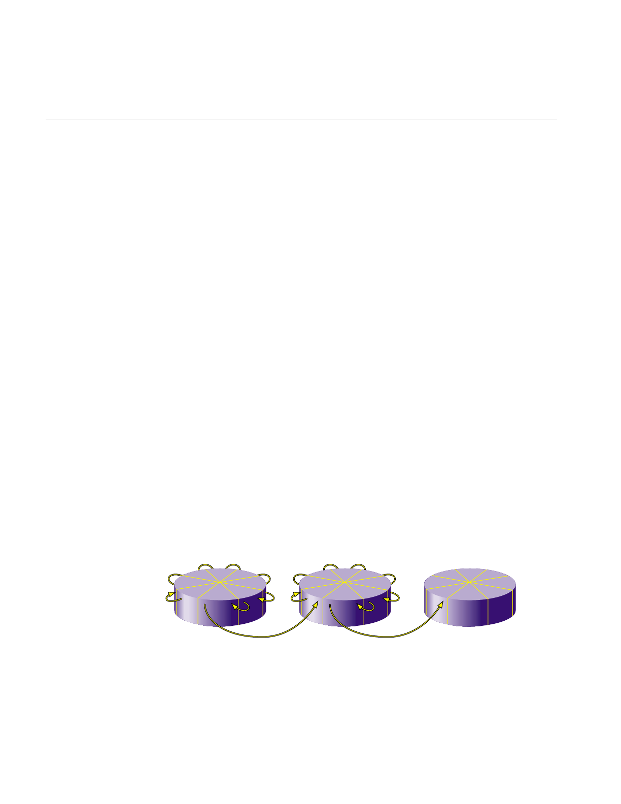
120
Chapter 6: Logical Volume Concepts
Introduction to Logical Volumes
The use of logical volumes enables the creation of filesystems, raw devices, or block
devices that span more than one disk partition. Logical volumes behave like regular disk
partitions; they appear as block and character devices in the /dev directory and can be
used as arguments anywhere a disk device can be specified.
lv logical volume device files have the names /dev/dsk/lv<n> and /dev/rdsk/lv<n>, where
<n> is a one or two digit integer. XLV logical volume device files have the names
/dev/dsk/xlv/<volname> and /dev/rdsk/xlv/<volname>, where <volname> is an alphanumeric
string that does not contain periods (dots, “.”).
Filesystems can be created, mounted, and used in the normal way on logical volumes, or
logical volumes can be used as block or raw devices. Logical volumes provide services
such as disk plexing (also known as mirroring) and striping transparently to the
applications that access the volumes. Key reasons to create a logical volume are:
•To allow a filesystem or disk device to be larger than the size of a physical disk.
•To increase disk I/O performance.
The drawback to logical volumes is that all disks used in a logical volume must function
correctly at all times. If you have a logical volume set up over three disks and one disk
goes bad, the information on the other two disks is unavailable and must be restored
from backups. However, by using the Disk Plexing Option optional software, you can
create multiple copies, called plexes, of the contents of XLV logical volumes, which
ensures that all of the information in an XLV logical volume is available even when a disk
goes bad.
A logical volume can include partitions from several physical disk drives. By default,
data is written to the first disk partition, then to the second disk partition, and so on.
Figure 6-1 shows the order in which data is written to partitions in a non-striped logical
volume.
Figure 6-1 Writing Data to a Non-Striped Logical Volume
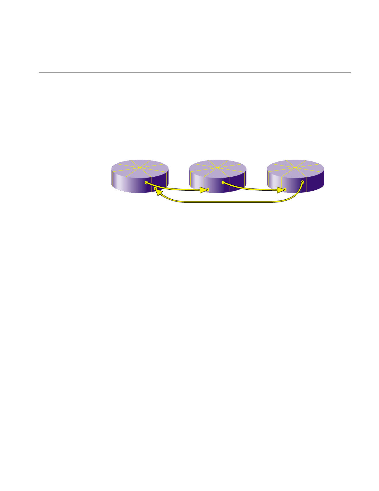
Introduction to Logical Volumes
121
Also, on striped logical volumes, the volume must have equal-sized partitions on several
disks. When logical volumes are striped, an amount of data, called the stripe unit, is
written to the first disk, the next stripe unit amount of data is written to the second disk,
and so on. When each of the disks have been written to, the next stripe unit of data is
written to the first disk, the next stripe unit amount of data is written to the second disk,
and so on to complete the “stripe.” Figure 6-2 shows the order in which data is written
to a striped logical volume.
Figure 6-2 Writing Data to a Logical Volume
Because each stripe unit in a stripe can be read and written simultaneously, I/O
performance is improved. To obtain the best performance benefits of striping,try to
connect the disks you are striping across on different controllers. In this arrangement,
there are independent data paths between each disk and the system. However, a small
performance improvement can be obtained using SCSI disks striped on the same
controller.
There are two basic scenarios for creating logical volumes. In the first scenario, you start
with empty disks and perform these basic steps:
1. Create disk partitions as necessary (see “Repartitioning a Disk With fx” in
Chapter 2).
2. Create the logical volume.
•For XLV logical volumes, see the sections “Creating Volume Objects With
xlv_make” and “Example 3: A Plexed Logical Volume for an XFS Filesystem
With an External Log” in Chapter 7.
•For lv logical volumes, see the sections “Creating Entries in the /etc/lvtab File”
and “Creating New Logical Volume With mklv” in Chapter 8.

122
Chapter 6: Logical Volume Concepts
3. Make a filesystem on the logical volume (see “Making an EFS Filesystem” or
“Making an XFS Filesystem” in Chapter 4).
In the second scenario for creating logical volumes, you have a filesystem on a disk
partition. You’d like to increase the size of the filesystem (“grow” the filesystem) by
creating a logical volume that includes the existing disk partition and a new disk
partition. This procedure is explained in the sections “Growing an XFS Filesystem Onto
Another Disk” (for XLV logical volumes) and “Growing an EFS Filesystem Onto Another
Disk” in Chapter 4 (for lv logical volumes).
The next two sections in this chapter describe the features of lv and XLV logical volumes.
XLV Logical Volumes
The XLV Volume Manager provides these advantages when XLV logical volumes are
used as raw devices and when EFS or XFS filesystems are created on them:
•support for very large logical volumes—up to one terabyte on 32-bit systems and
unlimited on 64-bit systems.
•support for disk striping for higher I/O performance
•plexing (mirroring) for higher system and data reliability
•online volume reconfigurations, such as increasing the size of a volume, for less
system downtime
However, using XLV logical volumes is not recommended on systems with a single disk.
With XFS filesystems, XLV provides these additional advantages:
•filesystem journal records on a separate partition, which can be on a separate disk,
for maximum performance
•access to real-time data

XLV Logical Volumes
123
When XFS filesystems are used on XLV volumes, each logical volume can contain up to
three subvolumes: data (required), log, and real-time. The data subvolume normally
contains user files and filesystem metadata (inodes, indirect blocks, directories, and free
space blocks). The log subvolume is used for filesystem journal records. It is called an
external log. If there is no log subvolume, journal records are placed in the data
subvolume (an internal log). Data with special I/O bandwidth requirements, such as
video, can be placed on the optional real-time subvolume.
XLV increases system reliability and availability by enabling you to add or remove a copy
of the data in the volume (a plex), increase the size of (grow) a volume, and replace failed
elements of a plexed volume without taking the volume out of service.
Converting from lv logical volumes to XLV logical volumes is easy. Using the commands
lv_to_xlv and xlv_make, you can convert lv logical volumes to XLV without having to
dump and restore your data.
EFS or XFS filesystems can be made on XLV logical volumes.
Composition of Logical Volumes
Logical volumes are composed of a hierarchy of logical storage objects: volumes are
composed of subvolumes, subvolumes are composed of plexes, and plexes are composed
of volume elements. Volume elements are composed of disk partitions. This hierarchy of
storage units is shown in Figure 6-3, an example of a relatively complex logical volume.
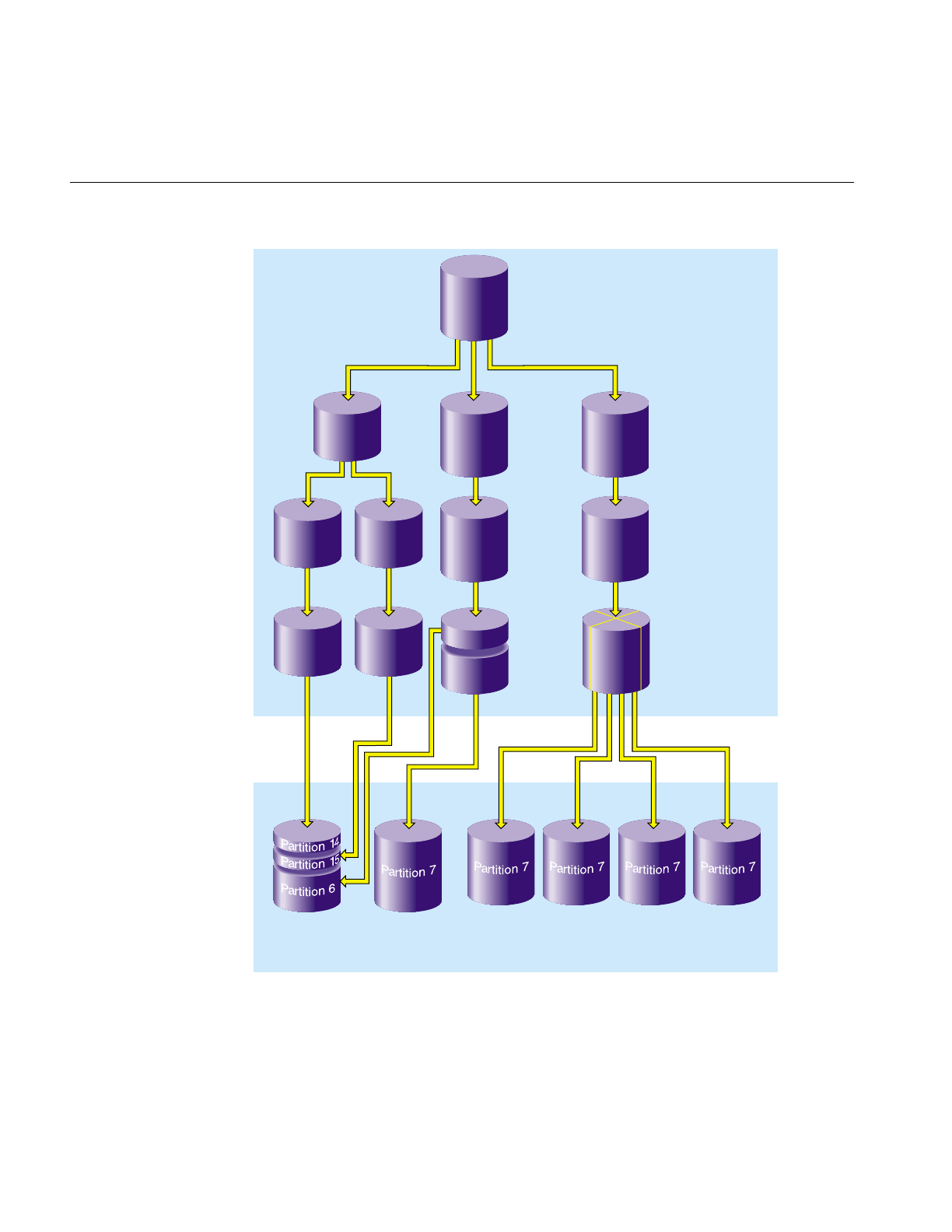
124
Chapter 6: Logical Volume Concepts
Figure 6-3 Logical Volume Example
Disk 1 Disk 2 Disk 3 Disk 4 Disk 5 Disk 6
Physical
Logical
Logical
volume
Log
subvolume Data
subvolume Real-time
subvolume
PlexPlex
PlexPlex
Volume
element Volume
element Volume
element
Striped
volume
element
Volume
element
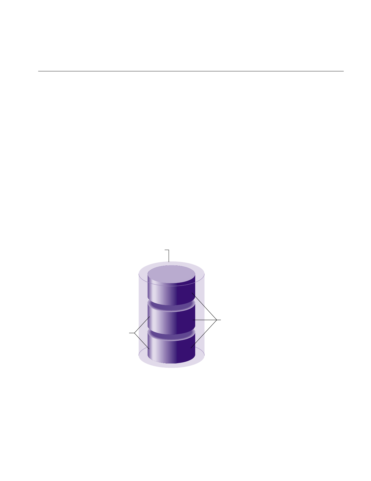
XLV Logical Volumes
125
Figure 6-3 illustrates the relationships between volumes, subvolumes, plexes, and
volume elements. In this example, six physical disk drives contain eight disk partitions.
The logical volume has a log subvolume, a data subvolume, and a real-time subvolume.
The log subvolume has two plexes (copies of the data) for higher reliability, and the data
and real-time subvolumes are not plexed (meaning that they each consist of a single
plex). The log plexes each consist of a volume element which is a disk partition on disk
1. The plex of the data subvolume consists of two volume elements, a partition that is the
remainder of disk 1 and a partition that is all of disk 2. The plex used for the real-time
subvolume is striped for increased performance. The striped volume element is
constructed from four disk partitions, each of which is an entire disk.
The subsections below describe these logical storage objects in more detail.
Volumes
Volumes are composed of subvolumes. For EFS filesystems, a volume consists of just one
subvolume. For XFS filesystems, a volume consists of a data subvolume, an optional log
subvolume, and an optional real-time subvolume. The breakdown of a volume into
subvolumes is shown in Figure 6-4.
Figure 6-4 Volume Composition
Real-time
Data
Log Subvolumes
Volume
Optional
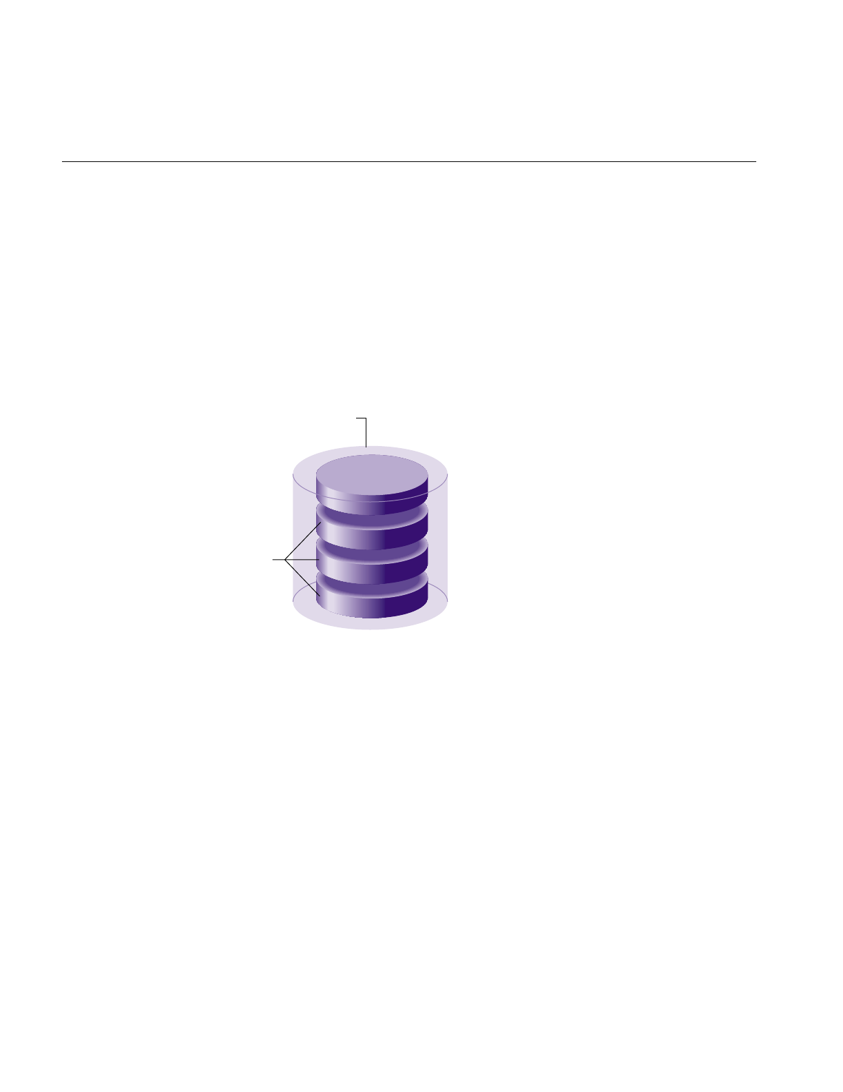
126
Chapter 6: Logical Volume Concepts
Each volume can be used as a single filesystem or as a raw partition. Volume information
used by the system during system startup is stored in logical volume labels in the volume
header of each disk used by the volume (see the section “Volume Headers” in Chapter 1).
At system startup, volumes won’t come up if any of their subvolumes cannot be brought
online. You can create volumes, delete them, and move them to another system.
Subvolumes
As explained in the section “Volumes,” each logical volume is composed of one to three
subvolumes, as shown in Figure 6-5. A subvolume is made up of one to four plexes.
Figure 6-5 Subvolume Composition
Note: The plexing feature of XLV, which enables the use of the optional plexes, is
available only when you purchase the Disk Plexing Option software option. See the
plexing Release Notes for information on purchasing this software option and obtaining
the required NetLS license. This NetLS license is installed in a nonstandard location,
/etc/nodelock.
Each subvolume is a distinct address space and a distinct type. The types of subvolumes
are:
Data subvolume
The data subvolume is required in all logical volumes. It is the only
subvolume present in EFS filesystems.
Plex
Plex
Plex
Plex
Subvolume
Optional

XLV Logical Volumes
127
Log subvolume The log subvolume contains XFS journaling information. It is a log of
filesystem transactions and is used to expedite system recovery after a
crash. Log information is sometimes put in the data subvolume rather
than in a log subvolume (see the section “Choosing the Log Type and
Size” in Chapter 4 and the mkfs_xfs(1M) reference page and its
discussion of the -l option for more information).
Real-time subvolume
Real-time subvolumes are generally used for data applications such as
video, where guaranteed response time is more important than data
integrity. The section “Real-Time Subvolumes” in this chapter and
Chapter 9, “System Administration for Guaranteed-Rate I/O,” explain
how applications access data on real-time subvolumes.
Subvolumes enforce separation among data types. For example, user data cannot
overwrite filesystem log data. Subvolumes also enable filesystem data and user data to
be configured to meet goals for performance and reliability. For example, performance
can be improved by putting subvolumes on different disk drives.
Each subvolume can be organized independently. For example, the log subvolume can
be plexed for fault tolerance and the real-time subvolume can be striped across a large
number of disks to give maximum throughput for video playback.
Volume elements that are part of a real-time subvolume should not be on the same disk
as volume elements used for data or log subvolumes. This is a recommendation for all
files on real-time subvolumes and required for files used for guaranteed-rate I/O with
hard guarantees. (See “Hardware Configuration Requirements for GRIO” in Chapter 9
for more information.)
Once a subvolume is created, it cannot be detached from its volume or deleted without
deleting its volume. Subvolumes are automatically deleted when their volumes are
deleted.
Plexes
A subvolume can contain from one to four plexes (also known as mirrors). Each plex is an
exact replica of all or a portion of the subvolume’s data. By creating a subvolume with
multiple plexes, system reliability is increased because there are redundant copies of the
data.
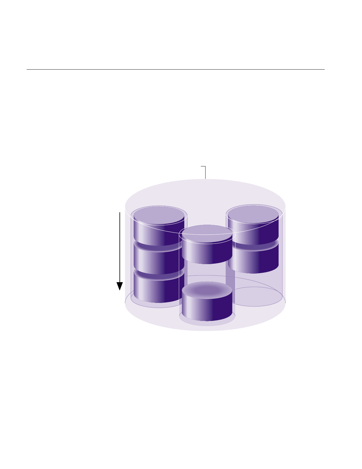
128
Chapter 6: Logical Volume Concepts
If there is just one plex in a subvolume, that plex spans the entire address space of the
subvolume. However, when there are multiple plexes, individual plexes can have holes
in their address spaces as long as the union of all plexes spans the entire address space.
Figure 6-6 shows an example of this. The subvolume contains three plexes. If complete,
each plex would be composed of three volume elements. However, two of the plexes are
missing a volume element. This is allowed because there is at least one volume element
with each address range. In fact, if Plex 1 in the figure were detached (removed from the
subvolume), the subvolume would still be functional because there is still at least one
volume element with each address range.
Figure 6-6 Plexed Subvolume Example
Data is written to all plexes. When an additional plex is added to a subvolume, the entire
plex is copied (this is called a plex revive) automatically by the system. See the
xlv_assemble(1M) and xlv_plexd(1M) reference pages for more information.
Subvolume
Volume
element
Volume
element
Volume
element
Volume
element
Volume
element
Volume
element
Volume
element
Plex 1
Plex 2
Plex 3
Increasing
addresses
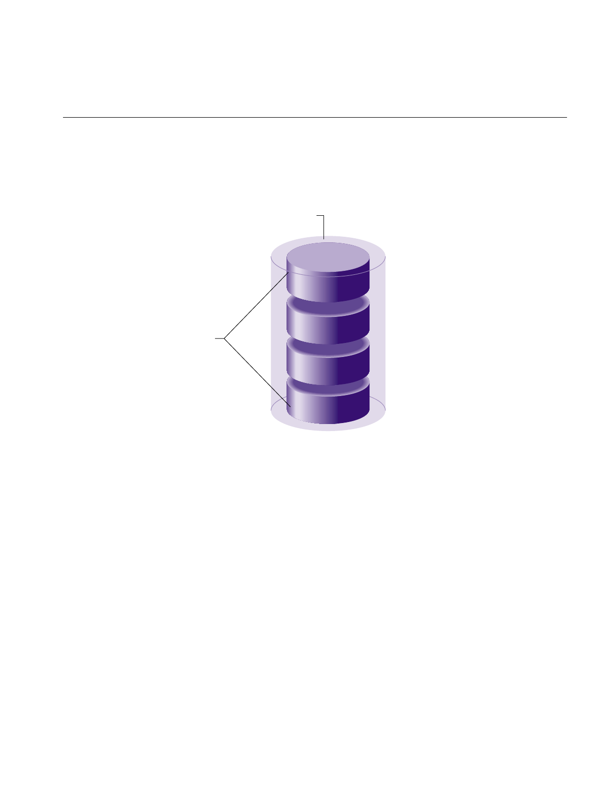
XLV Logical Volumes
129
A plex is composed of one or more volume elements, as shown in Figure 6-7, up to a
maximum of 128 volume elements. Each volume element represents a range of addresses
within the subvolume.
Figure 6-7 Plex Composition
When a plex is composed of two or more volume elements, it is said to have concatenated
volume elements. With concatenation, data written sequentially to the plex is also
written sequentially to the volume elements; the first volume element is filled, then the
second, and so on. Concatenation is useful for creating a filesystem that is larger than the
size of a single disk.
You can add plexes to subvolumes, detach them from subvolumes that have multiple
plexes (and possibly attach them elsewhere), and delete them from subvolumes that
have multiple plexes.
Note: To have multiple plexes, you must purchase the Disk Plexing Option software
option and obtain and install a NetLS license. See the plexing Release Notes for
information on purchasing this software option and obtaining the required NetLS
license. This NetLS license is installed in a nonstandard location, /etc/nodelock.
Plex
Volume
element
Volume
element
Volume
element
Volume
element
Up to 128
volume
elements

130
Chapter 6: Logical Volume Concepts
Volume Elements
Volume elements are the lowest level in the hierarchy of logical storage objects: volumes
are composed of subvolumes, subvolumes are composed of plexes, and plexes are
composed of volume elements. Volume elements are composed of physical storage
elements—disk partitions. They provide a way to link one or more disk partitions with
or without striping (at least two disk partitions are required for striping).
The simplest type of volume element is a single disk partition. The two other types of
volume elements, striped volume elements and multipartition volume elements, are
composed of several disk partitions. Figure 6-8 shows a single partition volume element.
Figure 6-8 Single-Partition Volume Element Composition
Figure 6-9 shows a striped volume element. Striped volume elements consist of two or
more disk partitions, organized so that an amount of data called the stripe unit is written
to each disk partition before writing the next stripe unit-worth of data to the next
partition.
Disk
partition
Volume element
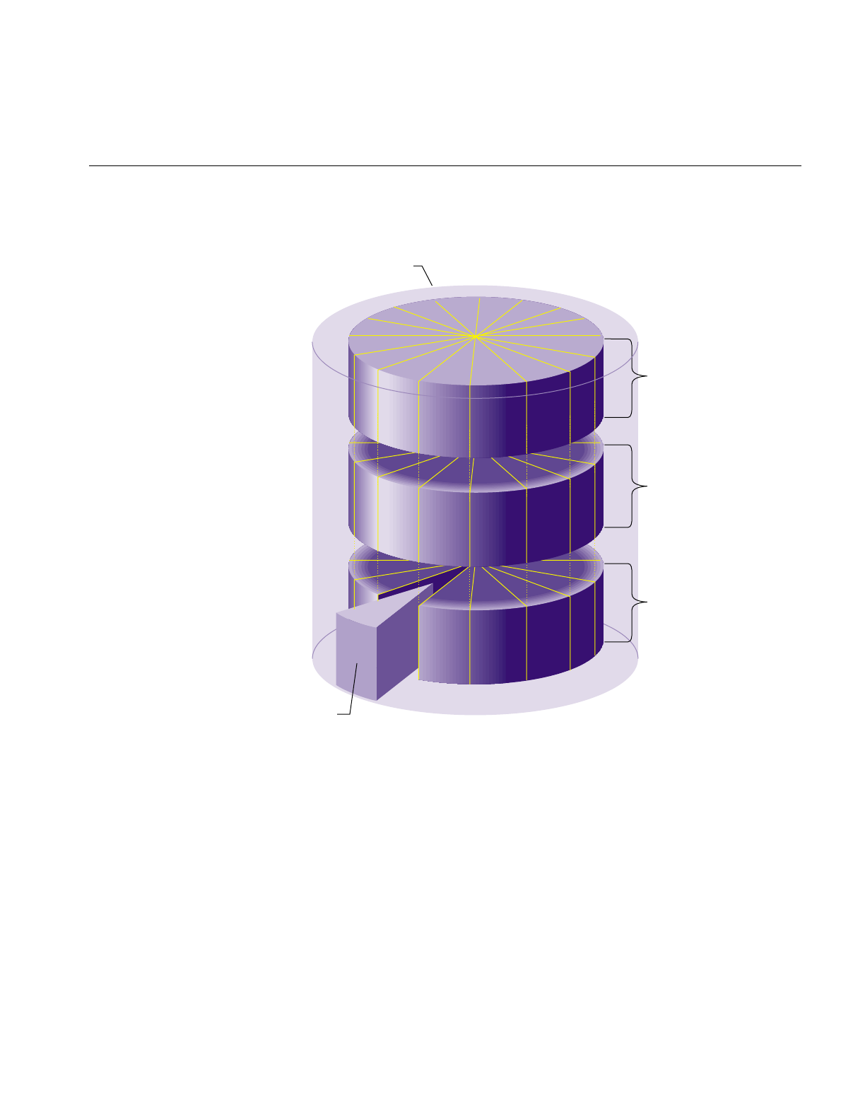
XLV Logical Volumes
131
Figure 6-9 Striped Volume Element Composition
Striping can be used to alternate sections of data among multiple disks. This provides a
performance advantage by allowing parallel I/O activity. As a rule of thumb, the stripe
unit size is a function of the I/O size of the application that uses the striped volume and
the number of partitions in the stripe. The stripe unit size should be the application I/O
size divided by the number of partitions. The default stripe unit is the device track size,
which is generally a good value to use. Stripe unit sizes of less than 32K bytes aren’t
recommended.
Disk partition
Disk partition
Disk partition
Stripe
Volume element
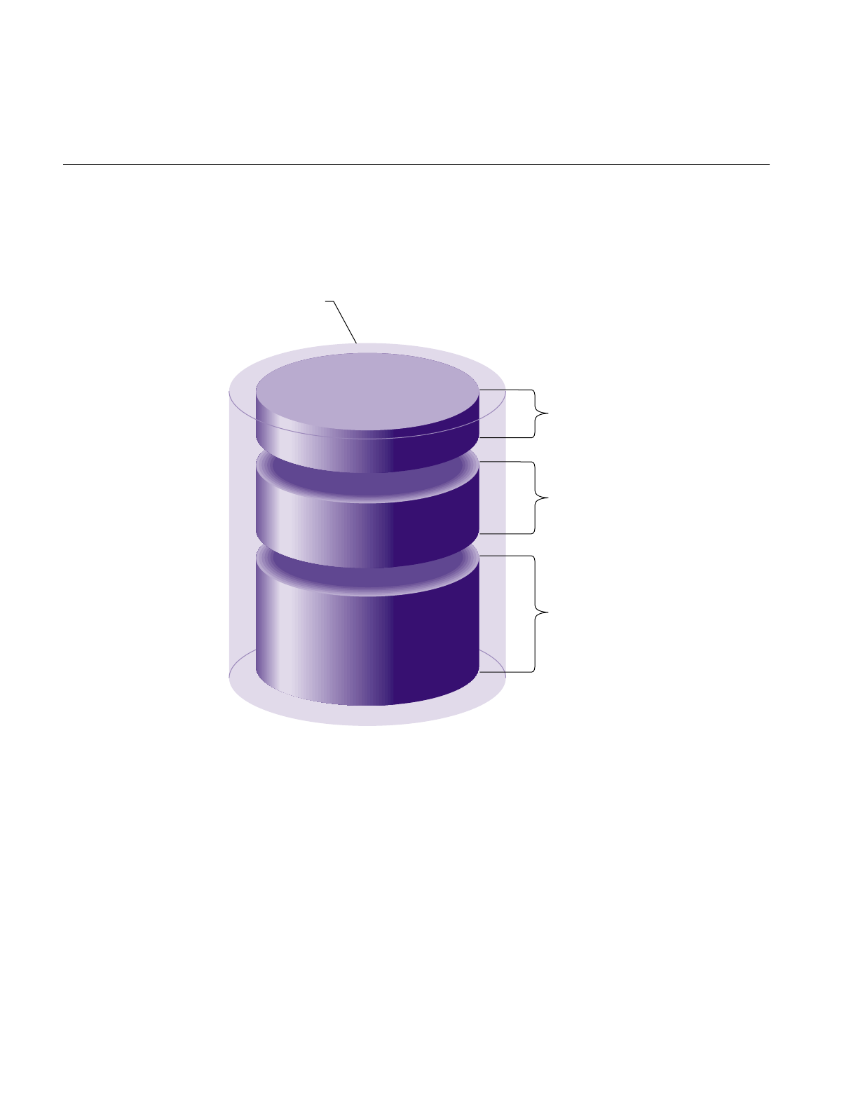
132
Chapter 6: Logical Volume Concepts
Figure 6-10 shows a multipartition volume element in which the volume element is
composed of more than one disk partition. In this configuration, the disk partitions are
addressed sequentially.
Figure 6-10 Multipartition Volume Element Composition
Any mixture of the three types of volume elements (single partition, striped, and
multipartition) can be included in a plex.
Disk partition
Disk partition
Disk partition
Volume element

XLV Logical Volumes
133
XLV Logical Volume Names
Volumes appear as block and character devices in the /dev directory. The device names
for logical volumes are /dev/dsk/xlv/<volume_name> and /dev/rdsk/xlv/<volume_name>,
where <volume_name> is a volume name specified when the volume is created using the
xlv_make command.
When a volume is created on one system and moved (by moving the disks) to another
system, the new volume name is the same as the original volume name with the
hostname of the original system prepended. For example, if a volume called xlv0 is
moved from a system called engrlab1 to a system called engrlab2, the device name of the
volume on the new system is /dev/dsk/xlv/engrlab1.xlv0 (the old system name engrlab1 has
been prepended to the volume name xlv0).
XLV Daemons
The XLV daemons are:
xlv_labd xlv_labd updates logical volume labels. It is started automatically at
system startup if it is installed and there are active XLV logical volumes.
xlvd xlvd handles I/O to plexes and performs plex error recovery. It is created
automatically during system startup if plexing software is installed and
there are active XLV logical volumes.
xlv_plexd xlv_plexd is responsible for making all plexes within a subvolume have
the same data. It is started automatically at system startup if there are
active XLV logical volumes.
XLV does not require an explicit configuration file, nor is it turned on and off with the
chkconfig command. XLV is able to assemble logical volumes based solely upon
information written in the logical volume labels. During initialization, the system
performs a hardware inventory, reads all the logical volume labels, and automatically
assembles the available disks into previously defined volumes.
If some disks are missing, XLV checks to see if there are enough volume elements among
the available plexes to map the entire address space. If the whole address space is
available, XLV brings the volume online even if some of the plexes are incomplete.

134
Chapter 6: Logical Volume Concepts
XLV Error Policy
For read failures on log and data subvolumes, XLV rereads from a different plex (when
available) and attempts to fix the failed plex by rewriting the results. XLV does not retry
on failures for real-time data.
For write errors on log and data subvolumes, XLV assumes that these write errors are
hard errors (the disk driver and controllers handle soft errors). If the volume element
with a hard error is plexed, XLV marks the volume element offline and ignores the
volume element from then on. If the volume element is not plexed, the volume element
remains associated with the volume and an error is returned.
XLV doesn’t handle write errors on real-time subvolumes. Incorrect data is returned
without error messages on subsequent reads.
XLV Logical Volume Planning
The following subsections discuss topics to consider when planning a logical volume.
Don’t Use XLV When ...
There are some situations where logical volumes cannot be used or are not
recommended:
•Raw swap devices cannot be logical volumes. (However, swap space can be added
as a regular file in a filesystem and that filesystem could be on a logical volume. See
the guide IRIX Admin: System Configuration and Operation for more information.)
•Logical volumes aren’t recommended on systems with a single disk.
•Striped or concatenated volumes cannot be used for the Root filesystem.
Decide Which Subvolumes to Use
The basic guidelines for choosing which subvolumes to use with EFS filesystems are:
•Only data subvolumes can be used.
•The maximum size of an EFS filesystem is 8 GB, so the data subvolume shouldn’t be
bigger than that or the space is wasted.

XLV Logical Volumes
135
The basic guidelines for choosing which subvolumes to use with XFS filesystems are:
•Data subvolumes are required.
•Log subvolumes are optional. If they are not used, log information is put into an
internal log in the data subvolume (by giving the -l internal option to mkfs).
•Real-time subvolumes are optional.
When you want a large raw partition with no filesystem on it, only the data subvolume
is used.
Choose Subvolume Sizes
The basic guidelines for choosing subvolume sizes are:
•The maximum size of a subvolume is one terabyte on 32-bit systems (IP17, IP20, and
IP22). It is unlimited on 64-bit systems (IP19, IP21, and IP26).
•Choosing the size of the log (and therefore the size of the log subvolume) is
discussed in the section “Choosing the Log Type and Size” in Chapter 4. Note that if
you do not intend to repartition a disk to create an optimal-size log partition, your
choice of an available disk partition may determine the size of the log.
To Plex or Not to Plex?
The basic guidelines for plexing are:
•Use plexing when high reliability and high availability of data are required.
•The Root filesystem can be plexed; each plex must be a single partition volume
element.
•Dual-hosted logical volumes (logical volume on disks that are connected to two
systems) cannot be plexed.
•RAID disks should not be plexed.
•Plexes can have “holes” in them, portions of the address range not contained by a
volume element, as long as at least one of the plexes in the subvolume has a volume
element with the address range of the hole.
•The volume elements in each plex of a subvolume must be identical in size with
their counterparts in other plexes (volume elements with the same address range).
The structure within a volume element (single partition, striped, or multipartition)
does not have to match the structure within its counterparts.

136
Chapter 6: Logical Volume Concepts
•To make volume elements identical in size, use the fx command in expert mode (fx
-x). At the first fx menu, give the command repartition/expert -b. This enables you
to repartition in units of blocks, which will ensure that the volume element is the
exact size you want it.
To Stripe or Not to Stripe?
The basic guidelines for striping are:
•The Root filesystem cannot be striped.
•Applications using a striped filesystem should be using direct I/O (see the open(2)
reference page).
•Striped disks lead to performance improvement only when the applications that use
them make large data transfers that access all of disks in the stripe in the filesystem.
•Striped volume elements should be made of disk partitions that are exactly the
same size. When the disk partitions are different sizes, the smallest size is used.
Additional space in the larger partitions is wasted.
•For best performance, each disk involved in a striped volume element should be on
a separate controller. For some disk types, performance improvement is seen with
up to four disks per controller. For other disk types, no additional performance
improvement is seen with three or more disk.
•A log subvolume can be striped only if it is an external log. Striping a log does not
result in a performance improvement.
Concatenate Disk Partitions or Not?
The basic guidelines for the concatenation of disk partitions are:
•The Root filesystem cannot have concatenated disk partitions.
•It is better to concatenate single-partition volume elements into a plex rather than
create a single multipartition volume element. This is not for performance reasons,
but for reliability. When one disk partition goes bad in a multipartition volume
element, the whole volume element is taken offline.

XLV Logical Volumes
137
Real-Time Subvolumes
Files created on the real-time subvolume of an XLV logical volume are known as
real-time files. The next three sections describe the special characteristics of these files.
Files on the Real-Time Subvolume and Commands
Real-time files have some special characteristics that cause standard IRIX commands to
operate in ways that you might not expect. In particular:
•You cannot create real-time files using any standard commands. Only specially
written programs can create real-time files. The next section, “File Creation on the
Real-Time Subvolume,” explains how.
•Real-time files are displayed by ls, just as any other file. However, there is no way to
tell from the ls output whether a particular file is on a data subvolume or is a
real-time file on a real-time subvolume. Only a specially written program can
determine the type of a file. The F_FSGETXATTR fcntl() system call can determine
if a file is a real-time or a standard data file. If the file is a real-time file, the fsx_xflags
field of the fsxattr structure has the XFS_XFLAG_REALTIME bit set.
•The df command displays the disk space in the data subvolume by default. When
the -r option is given, the real-time subvolume’s disk space and usage is added. df
can report that there is free disk space in the filesystem when the real-time
subvolume is full, and df –r can report that there is free disk space when the data
subvolume is full.
File Creation on the Real-Time Subvolume
To create a real-time file, use the F_FSSETXATTR fcntl() system call with the
XFS_XFLAG_REALTIME bit set in the fsx_xflags field of the fsxattr structure. This must
be done after the file has first been created/opened for writing, but before any data has
been written to the file. Once data has been written to a file, the file cannot be changed
from a standard data file to a real-time file, nor can files created as real-time files be
changed to standard data files.
Real-time files can only be read or written using direct I/O. Therefore, read() and write()
system call operations to a real-time file must meet the requirements specified by the
F_DIOINFO fcntl() system call. See the open(2) reference page for a discussion of the
O_DIRECT option to the open() system call.

138
Chapter 6: Logical Volume Concepts
Guaranteed-Rate I/O and the Real-Time Subvolume
The real-time subvolume is used by applications for files that require fixed I/O rates.
This feature, called guaranteed-rate I/O, is described in Chapter 9, “System
Administration for Guaranteed-Rate I/O.”
lv Logical Volumes
lv logical volumes are created and administered by means of a file defining the volumes,
/etc/lvtab, and the commands mklv,lvinit,lvinfo, and lvck. There are two components to
creating a logical volume from a set of disk partitions:
•Create an entry for the logical volume in the file /etc/lvtab./etc/lvtab is explained in
the section “Creating Entries in the /etc/lvtab File” in Chapter 8.
•Run the command mklv.mklv writes logical volume information to the volume
headers for the disks in the logical volume, creates device files in /dev for the logical
volume, and initializes the logical volume device. Using mklv is described in the
section “Creating New Logical Volume With mklv” in Chapter 8.
The root partition cannot be part of a logical volume, since the commands required for
logical volume initialization must reside on it. Also, swap space cannot be configured as
a logical volume.
Striping of lv logical volumes imposes some minor restrictions:
•If you want to stripe, all the drives (or to be exact, the partitions used for striping)
must be exactly the same size (in disk blocks).
•If you later want to add more disk partitions to the volume, you must add them in
units of the striping. That is, if you want to add disks to a three-way striped volume,
you must add them three at a time.
Once a logical volume is created, it can be used as if it were a single disk partition. For
example, you can create a filesystem on the logical volume and mount the filesystem. The
command lvinfo prints information about active logical volumes. See the lvinfo(1M)
reference page for more information.

lv Logical Volumes
139
The lvck command checks the consistency of logical volumes by examining the logical
volume labels of devices constituting the volumes. It looks for:
•disks connected in the wrong place
•inconsistencies between the logical volume labels of a logical volume
•internal inconsistencies in /etc/lvtab entries
•inconsistencies between the logical volume labels of a logical volume and its entry
in /etc/lvtab
The -d option of lvck can be used to create a new /etc/lvtab file after disks are moved or
renumbered. See the lvck(1M) reference page for details.
lvck has some repair capabilities. If it determines that the only inconsistency in a logical
volume is that a minority of devices have missing or corrupt logical volume labels, it is
able to restore a consistent logical volume by rewriting good labels. lvck queries the user
before attempting any repairs on a volume.
Examples of the lvck command line are given in the section “Checking Logical Volumes
With lvck” in Chapter 8.


141
Chapter 7
7.Creating and Administering XLV Logical Volumes
This chapter describes the procedures for creating and administering XLV logical
volumes using command-line utilities. A graphical user interface for performing many
of these procedures is available from the xlvm command. See its online help for more
information about xlvm.
The major sections in this chapter are:
•“Verifying That Plexing Is Supported” on page 141
•“Creating Volume Objects With xlv_make” on page 142
•“Displaying Logical Volume Objects” on page 148
•“Adding a Volume Element to a Plex (Growing a Logical Volume)” on page 149
•“Adding a Plex to a Logical Volume” on page 150
•“Detaching a Plex From a Logical Volume” on page 153
•“Deleting an XLV Object” on page 154
•“Removing and Mounting a Plex” on page 155
•“Creating Plexed Logical Volumes for Root” on page 158
•“Booting the System Off an Alternate Plex” on page 160
•“Configuring the System for More Than Ten XLV Logical Volumes” on page 162
•“Converting lv Logical Volumes to XLV Logical Volumes” on page 163
Verifying That Plexing Is Supported
As discussed in Chapter 7, “Creating and Administering XLV Logical Volumes,” the
plexing feature of XLV, which enables the use of multiple plexes, is available only when
you purchase the Disk Plexing Option software option. It requires a NetLS license which
must be installed in a nonstandard location, /etc/nodelock.

142
Chapter 7: Creating and Administering XLV Logical Volumes
You can use the xlv_mgr command to verify that the plexing software and a valid license
are installed. Follow these steps:
1. Invoke xlv_mgr:
#xlv_mgr
2. Give the show config command:
xlv_mgr> show config
Allocated subvol locks: 30 locks in use: 6
Plexing license: present
Plexing support: present
Maximum subvol block number: 0x7fffffffffffffff
The third line of output, “Plexing support is present,” indicates that plexing
software is installed with a valid license.
3. Quit out of xlv_mgr:
xlv_mgr> quit
Creating Volume Objects With xlv_make
The xlv_make command creates volumes, subvolumes, plexes, and volume elements
from unused disk partitions. It writes the logical volume labels in the disk volume
headers only; data on the disk partitions is untouched.
After you create a volume, you must make a filesystem on it if necessary and mount the
filesystem so that you can use the logical volume.
Caution: When you create a logical volume and make a filesystem, all data already on
the disk partitions is destroyed.
xlv_make can be run interactively or it can take commands from an input file. The
remainder of this section gives two examples of using xlv_make; the first one is interactive
and the second is noninteractive.
Example 1: A Simple Logical Volume
This example shows a simple logical volume composed of a data subvolume created
from two entire option disks. The disks are on controller 0, drive addresses 2 and 3. An
XFS filesystem is created and mounted at /vol1.

Creating Volume Objects With xlv_make
143
1. Unmount the disks that will be used in the volume if they are mounted. For
example:
#df
Filesystem Type blocks use avail %use Mounted on
/dev/root efs 1939714 430115 1509599 22% /
/dev/dsk/dks0d2s7 efs 2004550 22 2004528 0% /d2
/dev/dsk/dks0d3s7 efs 3826812 22 3826790 0% /d3
#umount /d2
#umount /d3
2. Start xlv_make:
#xlv_make
xlv_make>
3. Start creating the volume by specifying its name, for example xlv0:
xlv_make> vol xlv0
xlv0
4. Begin creating the data subvolume:
xlv_make> data
xlv0.data
xlv_make echoes the name of each object (volume, subvolume, plex, or volume
element) you create.
5. Continue to move down through the hierarchy of the volume by specifying the plex:
xlv_make> plex
xlv0.data.0
6. Specify the volume elements (disk partitions) to be included in the volume, for
example /dev/dsk/dks0d2s7 and /dev/dsk/dks0d3s7:
xlv_make> ve dks0d2s7
xlv0.data.0.0
xlv_make> ve dks0d3s7
xlv0.data.0.1
You can specify the last portion of the disk partition pathname (as shown) or the full
pathname. xlv_make accepts disk partitions that are of types “xlv,” “xfs,” and “efs.”
You can use other partition types, for example “lvol,” by giving the -force option,
for example, ve –force dks0d2s7.xlv_make automatically changes the partition type to
“xlv.”

144
Chapter 7: Creating and Administering XLV Logical Volumes
7. Tell xlv_make that you are finished specifying the objects:
xlv_make> end
Object specification completed
8. Review the objects that you’ve specified:
xlv_make> show
Completed Objects
(1) VOL xlv0
VE xlv0.data.0.0 [empty]
start=0, end=2004549, (cat)grp_size=1
/dev/dsk/dks0d2s7 (2004550 blks)
VE xlv0.data.0.1 [empty]
start=2004550, end=5831361, (cat)grp_size=1
/dev/dsk/dks0d3s7 (3826812 blks)
9. Write the volume information to the logical volume labels by exiting xlv_make:
xlv_make> exit
Newly created objects will be written to disk.
Is this what you want?(yes) yes
Invoking xlv_assemble
10. Make an XFS filesystem using mkfs, for example:
#mkfs /dev/dsk/xlv/xlv0
meta-data=/dev/dsk/xlv/xlv0 isize=256 agcount=8, agsize=16094 blks
data = bsize=4096 blocks=2482901
log =internal log bsize=4096 blocks=1000
realtime =none bsize=4096 blocks=0, rtextents=0
need correct command line
11. Mount the filesystem, for example:
#mkdir /vol1
#mount /dev/dsk/xlv/xlv0 /vol1
12. To have the logical volume mounted automatically at system startup, add an entry
for the volume to /etc/fstab, for example:
/dev/dsk/xlv/xlv0 /vol1 xfs rw,raw=/dev/rdsk/xlv/xlv0 0 0

Creating Volume Objects With xlv_make
145
Example 2: A Striped, Plexed Logical Volume
This example shows the noninteractive creation of a logical volume from four
equal-sized option disks (controller 0, units 2 through 5). Two plexes will be created with
the data striped across the two disks in each plex. The stripe unit will be 128 KB. An XFS
filesystem is created and mounted at /vol1.
1. As in the previous example, unmount filesystems on the disks to be used, if
necessary.
2. Create a file, called xlv0.specs for example, that contains input for xlv_make. For this
example and a volume named xlv0, the file contains:
vol xlv0
data
plex
ve -stripe -stripe_unit 256 dks0d2s7 dks0d3s7
plex
ve -stripe -stripe_unit 256 dks0d4s7 dks0d5s7
end
show
exit
This script specifies the volume hierarchically: volume, subvolume (data), first plex
with a striped volume element, then second plex with a striped volume element.
The ve commands have a stripe unit argument of 256. This argument is the number
of 512-byte disk blocks (sectors), so 128K/512 = 256. The end command signifies
that the specification is complete and the (optional) show command causes the
specification to be displayed. The logical volume label is created by the exit
command.
3. Run xlv_make to create the volume. For example:
#xlv_make xlv0.specs
4. Make an XFS filesystem with an internal 10 MB log and 1 KB block size:
#mkfs -b size=1k -l size=10m /dev/dsk/xlv/xlv0
5. Mount the filesystem, for example:
#mkdir /vol1
#mount /dev/dsk/xlv/xlv0 /vol1
6. To have the logical volume mounted automatically at system startup, add an entry
for the volume to /etc/fstab, for example:
/dev/dsk/xlv/xlv0 /vol1 xfs rw,raw=/dev/rdsk/xlv/xlv0 0 0

146
Chapter 7: Creating and Administering XLV Logical Volumes
Example 3: A Plexed Logical Volume for an XFS Filesystem With an
External Log
The following example shows how you can create an XLV logical volume that has a log
subvolume that is plexed and a data subvolume that is concatenated and plexed. The
volume will be used to hold an XFS filesystem with an external log.
This example uses four disks on controller 1 at drive addresses 2 through 5. The disks at
drive addresses 2 and 3 are partitioned as option drives with xfslog partitions. The disks
at drive addresses 4 and 5 are partitioned as option drives without xfslog partitions.
1. Invoke xlv_make and begin to create the volume, called xfs-mp5, by creating the log
subvolume with two plexes:
#xlv_make
xlv_make> vol xfs-mp5
xfs-mp5
xlv_make> log
xfs-mp5.log
xlv_make> plex
xfs-mp5.log.0
xlv_make> ve dks1d2s15
xfs-mp5.log.0.0
xlv_make> plex
xfs-mp5.log.1
xlv_make> ve dks1d3s15
xfs-mp5.log.1.0
2. Create the data subvolume with two plexes, each of which has two volume
elements:
xlv_make> data
xfs-mp5.data
xlv_make> plex
xfs-mp5.data.0
xlv_make> ve dks1d2s7
xfs-mp5.data.0.0
xlv_make> ve dks1d4s7
xfs-mp5.data.0.1
xlv_make> plex
xfs-mp5.data.1
xlv_make> ve dks1d3s7
xfs-mp5.data.1.0
xlv_make> ve dks1d5s7
xfs-mp5.data.1.1

Creating Volume Objects With xlv_make
147
3. Indicate that you have completed the volume, display it, and exit xlv_make:
xlv_make> end
Object specification completed
xlv_make> show
Completed Objects
(1) VOL xfs-mp5
VE xfs-mp5.log.0.0 [empty]
start=0, end=8255, (cat)grp_size=1
/dev/dsk/dks1d2s15 (8256 blks)
VE xfs-mp5.log.1.0 [empty]
start=0, end=8255, (cat)grp_size=1
/dev/dsk/dks1d3s15 (8256 blks)
VE xfs-mp5.data.0.0 [empty]
start=0, end=3920223, (cat)grp_size=1
/dev/dsk/dks1d2s7 (3920224 blks)
VE xfs-mp5.data.0.1 [empty]
start=3920224, end=7848703, (cat)grp_size=1
/dev/dsk/dks1d4s7 (3928480 blks)
VE xfs-mp5.data.1.0 [empty]
start=0, end=3920223, (cat)grp_size=1
/dev/dsk/dks1d3s7 (3920224 blks)
VE xfs-mp5.data.1.1 [empty]
start=3920224, end=7848703, (cat)grp_size=1
/dev/dsk/dks1d5s7 (3928480 blks)
xlv_make> exit
Newly created objects will be written to disk.
Is this what you want?(yes) y
Invoking xlv_assemble
4. Make an XFS filesystem by running mkfs. Note how mkfs automatically uses an
external log when one is present.
#mkfs /dev/dsk/xlv/xfs-mp5
meta-data=/dev/dsk/xlv/xfs-mp5 isize=256 agcount=8, agsize=122636 blks
data = bsize=4096 blocks=981088
log =volume log bsize=4096 blocks=1032
realtime =none bsize=65536 blocks=0, rtextents=0

148
Chapter 7: Creating and Administering XLV Logical Volumes
5. Mount the filesystem, for example:
#mkdir /v1
#mount /dev/dsk/xlv/xfs-mp5 /v1
6. To have the logical volume mounted automatically at system startup, add an entry
for the volume to /etc/fstab, for example:
/dev/dsk/xlv/xfs-mp5 /v1 xfs rw,raw=/dev/rdsk/xlv/xfs-mp5 0 0
Displaying Logical Volume Objects
To get a list of the top level XLV objects on a system (volumes, unattached plexes, and
unattached volume elements), invoke xlv_mgr and give the command show all, for
example:
#xlv_mgr
xlv_mgr> show all
Volume Element: SPARE_VE
Volume: BIG_VOLUME (complete)
In this example, there are two top level objects, a volume element named SPARE_VE and
a logical volume named BIG_VOLUME. The volume element is a top level object because
it is not part of (attached to) any plex. Volume elements can be attached to a plex at a later
time.
To display the complete hierarchy of a top level object, give the xlv_mgr command show
object with the name of the object, for example:
xlv_mgr> show object BIG_VOLUME
VOL BIG_VOLUME (complete)
VE BIG_VOLUME.log.0.0 [active]
start=0, end=8255, (cat)grp_size=1
/dev/dsk/dks1d2s15 (8256 blks)
VE BIG_VOLUME.log.1.0 [active]
start=0, end=8255, (cat)grp_size=1
/dev/dsk/dks1d3s15 (8256 blks)
VE BIG_VOLUME.log.2.0 [active]
start=0, end=8255, (cat)grp_size=1
/dev/dsk/dks1d4s15 (8256 blks)
VE BIG_VOLUME.data.0.0 [active]
start=0, end=3920223, (cat)grp_size=1
/dev/dsk/dks1d2s7 (3920224 blks)

Adding a Volume Element to a Plex (Growing a Logical Volume)
149
VE BIG_VOLUME.data.1.0 [active]
start=0, end=3920223, (cat)grp_size=1
/dev/dsk/dks1d3s7 (3920224 blks)
VE BIG_VOLUME.data.2.0 [active]
start=0, end=3920223, (cat)grp_size=1
/dev/dsk/dks1d4s7 (3920224 blks)
This output shows that BIG_VOLUME contains log and data subvolumes. Each
subvolume has three plexes that have one volume element each.
Adding a Volume Element to a Plex (Growing a Logical Volume)
Growing a logical volume (increasing its size) can be done by adding one or more
volume elements to the end of one or more of its plexes. (If you don’t add volume
elements to all plexes, data stored in the added volume elements won’t be replicated in
all plexes.)
The procedure below assumes that you are starting with a logical volume. If you are
starting with a filesystem on a single disk partition that you want to turn into a logical
volume and grow onto an additional disk partition, use the procedure in the section
“Growing an XFS Filesystem Onto Another Disk” in Chapter 4 or the section “Growing
an EFS Filesystem Onto Another Disk” in Chapter 4 instead.
1. If any of the volume elements you plan to add to the volume don’t exist yet, create
them with xlv_make. For example, follow this procedure to create a volume element
out of a new disk, /dev/dsk/dks0d4s7:
#xlv_make
xlv_make> ve spare_ve dks0d4s7
new_ve
xlv_make> end
Object specification completed
xlv_make> exit
Newly created objects will be written to disk.
Is this what you want?(yes) yes
Invoking xlv_assemble
The ve command creates a volume element name, spare_ve. The name is required
because the volume element is not part of a larger hierarchy; it is the top level object
in this case.

150
Chapter 7: Creating and Administering XLV Logical Volumes
2. Use the attach command of the xlv_mgr command to add each volume element. For
example, to add the volume element from step 1 to plex 0 of the data subvolume of
the volume xlv0, use this procedure:
#xlv_mgr
xlv_mgr> attach ve spare_ve xlv0.data.0
3. Quit out of xlv_mgr:
xlv_mgr> quit
4. If you are growing an XFS filesystem, mount the filesystem if it isn’t already
mounted:
#mount volume mountpoint
volume is the device name of the logical volume, for example /dev/dsk/xlv/xlv0, and
mountpoint is the mount point directory for the logical volume.
5. If you are growing an XFS filesystem, use xfs_growfs to grow the filesystem:
#xfs_growfs -d mountpoint
mountpoint is the mount point directory for the logical volume.
6. If you are growing an EFS filesystem, unmount the filesystem if it is mounted, and
use growfs to grow the filesystem:
#umount mountpoint
#growfs volume
mountpoint is the mount point directory for the filesystem. volume is the device name
of the logical volume, for example /dev/dsk/xlv/xlv0.
Adding a Plex to a Logical Volume
If you have purchased the Disk Plexing Option software option and have installed a
NetLS license for it (remember that its NetLS license is installed in a nonstandard
location, /etc/nodelock), you can add a plex to an existing subvolume for improved
reliability in case of disk failures. The procedure to add a plex to a subvolume is
described below. To add more than one plex to a subvolume or to add a plex to each of
the subvolumes in a volume, repeat the procedure as necessary.

Adding a Plex to a Logical Volume
151
1. If the plex that you want to add to the subvolume doesn’t exist yet, create it with
xlv_make. For example, to create a plex called plex1 to add to the data subvolume of
a volume called root_vol, give these commands:
#xlv_make
xlv_make> plex plex1
plex1
xlv_make> ve /dev/dsk/dks0d3s7
plex1.0
xlv_make> end
Object specification completed
xlv_make> exit
Newly created objects will be written to disk.
Is this what you want?(yes) yes
Invoking xlv_assemble
2. Use the xlv_mgr command to add the plex to the volume. For example, to add the
standalone plex plex1 to root_vol, use this procedure:
#xlv_mgr
xlv_mgr> attach plex plex1 root_vol.data
xlv_mgr automatically initiates a plex revive operation to copy the contents of the
original plex, root_vol.data.0, to the newly added plex.
3. You can confirm that root_vol now has two plexes by displaying the object
hierarchy:
xlv_mgr> show object root_vol
VOL root_vol (complete)
VE root_vol.data.0.0 [active]
start=0, end=988091, (cat)grp_size=1
/dev/dsk/dks0d2s7 (988092 blks)
VE root_vol.data.1.0 [empty]
start=0, end=988091, (cat)grp_size=1
/dev/dsk/dks0d3s7 (988092 blks)
The newly added plex, root_vol.data.1, is initially in the “empty” state. This is
because it is newly created.
4. Exit xlv_mgr:
xlv_mgr> quit

152
Chapter 7: Creating and Administering XLV Logical Volumes
The plex revive completes and the new plex switches to “active” state automatically, but
if you want to check its progress and verify that the plex has become active, follow this
procedure:
1. List the XLV daemons running, for example:
#ps -ef | grep xlv
root 27 1 0 10:49:27 ? 0:00 /sbin/xlv_plexd -m 4
root 35 1 0 10:49:28 ? 0:00 /sbin/xlv_labd
root 31 1 0 10:49:27 ? 0:00 xlvd
root 407 27 1 11:01:01 ? 0:00 xlv_plexd -v 2 -n root_vol.data
-d 50331648 -b 128 -w 0 0 1992629
root 410 397 2 11:01:11 pts/0 0:00 grep xlv
One instance of the xlv_plexd daemon is currently reviving root_vol.data. This
daemon exits when the plex has been fully revived.
2. Later, check the XLV daemons again, for example:
#ps -ef | grep xlv
root 27 1 0 10:49:27 ? 0:00 /sbin/xlv_plexd -m 4
root 35 1 0 10:49:28 ? 0:00 /sbin/xlv_labd
root 31 1 0 10:49:27 ? 0:03 xlvd
root 459 397 2 11:21:10 pts/0 0:00 grep xlv
The instance of xlv_plexd that was reviving root_vol.data is no longer running; it has
completed the plex revive.
3. Check the state of the plex using xlv_mgr:
#xlv_mgr
xlv_mgr> show object root_vol
VOL root_vol (complete)
VE root_vol.data.0.0 [active]
start=0, end=988091, (cat)grp_size=1
/dev/dsk/dks0d2s7 (988092 blks)
VE root_vol.data.1.0 [active]
start=0, end=988091, (cat)grp_size=1
/dev/dsk/dks0d2s0 (988092 blks)
xlv_mgr> quit
Both plexes are now in the “active” state.

Detaching a Plex From a Logical Volume
153
Detaching a Plex From a Logical Volume
Detaching a plex from a volume, perhaps because you want to swap disk drives, can be
done while the volume is active. However, the entire address range of the subvolume
must still be covered by active volume elements in the remaining plex or plexes. xlv_mgr
does not allow you to detach the only active plex in a volume if the other plexes are not
yet active. The procedure to detach a plex is:
1. Start xlv_mgr and display the volume that has the plex that you plan to detach, for
example, root_vol:
#xlv_mgr
xlv_mgr> show object root
VOL root (complete)
VE root.data.0.0 [active]
start=0, end=1843199, (cat)grp_size=1
/dev/dsk/dks1d3s0 (1843200 blks)
VE root.data.1.0 [active]
start=0, end=1843199, (cat)grp_size=1
/dev/dsk/dks1d4s0 (1843200 blks)
2. Detach plex 1 and give it the name plex1 by giving these commands:
xlv_mgr> detach plex root.1 rplex1
3. To examine the volume and the detached plex, give these commands:
xlv_mgr> show -long all
PLEX rplex1
VE rplex1.0 [stale]
start=0, end=1843199, (cat)grp_size=1
/dev/dsk/dks1d4s0 (1843200 blks)
VOL root (complete)
VE root.data.0.0 [active]
start=0, end=1843199, (cat)grp_size=1
/dev/dsk/dks1d3s0 (1843200 blks)
4. Exit xlv_mgr:
xlv_mgr> quit

154
Chapter 7: Creating and Administering XLV Logical Volumes
Deleting an XLV Object
Caution: The procedure in this section can result in the loss of data if it is not performed
properly. It is recommended only for experienced IRIX system administrators.
You can delete a volume or any other XLV object by using the xlv_mgr command. The
procedure is:
1. If you are deleting a volume, you must unmount it first. For example:
#umount /vol1
2. Start xlv_mgr and list each object on the system:
#xlv_mgr
xlv_mgr> show -long all
VOL root_vol (complete)
VE root_vol.data.0.0 [active]
start=0, end=988091, (cat)grp_size=1
/dev/dsk/dks0d2s0 (988092 blks)
VE root_vol.data.1.0 [active]
start=0, end=988091, (cat)grp_size=1
/dev/dsk/dks0d2s7 (988092 blks)
This example shows one high-level object, a volume with two plexes in a data
subvolume (root_vol.data.0 and root_vol.data.1). Each plex has one volume
element.
3. If the element you want to delete is not a high-level object, you must first detach it
from its high-level object. For example, to delete one of the plexes in the example, it
must first be detached:
xlv_mgr> detach plex root_vol.data.1 plex_to_be_deleted
Detached objects must be given a name, in this case plex_to_be_deleted.
4. Delete the object, in this example the plex plex_to_be_deleted:
xlv_mgr> delete object plex_to_be_deleted
5. Confirm that the object is gone:
xlv_mgr> show -long all
VOL root_vol (complete)
VE root_vol.data.0.0 [active]
start=0, end=988091, (cat)grp_size=1
/dev/dsk/dks0d2s0 (988092 blks)

Removing and Mounting a Plex
155
6. Exit xlv_mgr:
xlv_mgr> quit
Removing and Mounting a Plex
Caution: The procedure in this section can result in the loss of data if it is not performed
properly. It is recommended only for experienced IRIX system administrators.
You can get a snapshot of a filesystem by removing a plex from a plexed volume and
mounting that plex separately. Since you can only mount volumes, you must convert the
plex into a volume. The following procedure shows you how to remove the plex from its
original volume and make it into a separate volume:
1. Verify that the volume is currently not being revived. If there is a revive in progress,
you should wait until the revive is done because the data among the plexes is not
identical until after the plex revive is done.
#ps -ef | grep xlv_plexd
root 35 1 0 Dec 13 ? 0:00 /sbin/xlv_plexd -m 4
The output shows that just one copy of xlv_plexd, the master process, is running. If
more than one copy is running, a plex revive is in progress.
2. Unmount the filesystem mounted on the logical volume, /projvol5 in this example:
#umount /projvol5
Unmounting the filesystem puts it into a clean state.
3. Start xlv_mgr and display the logical volume, xfs-mp5 in this example:
#xlv_mgr
xlv_mgr> show object xfs-mp5
VOL xfs-mp5 (complete)
VE xfs-mp5.log.0.0 [active]
start=0, end=8255, (cat)grp_size=1
/dev/dsk/dks1d2s15 (8256 blks)
VE xfs-mp5.log.1.0 [active]
start=0, end=8255, (cat)grp_size=1
/dev/dsk/dks1d3s15 (8256 blks)
VE xfs-mp5.data.0.0 [active]
start=0, end=3920223, (cat)grp_size=1
/dev/dsk/dks1d2s7 (3920224 blks)

156
Chapter 7: Creating and Administering XLV Logical Volumes
VE xfs-mp5.data.0.1 [active]
start=3920224, end=7848703, (cat)grp_size=1
/dev/dsk/dks1d4s7 (3928480 blks)
VE xfs-mp5.data.1.0 [active]
start=0, end=3920223, (cat)grp_size=1
/dev/dsk/dks1d3s7 (3920224 blks)
VE xfs-mp5.data.1.1 [active]
start=3920224, end=7848703, (cat)grp_size=1
/dev/dsk/dks1d5s7 (3928480 blks)
4. Detach the second plex from the log subvolume and call it log_copy:
xlv_mgr> detach plex xfs-mp5.log.1 log_copy
One of the plexes from the log subvolume must be detached because the volume
that will be created with one of the data plexes must have a log subvolume to go
with it.
5. Detach the second plex from the data subvolume and call it data_copy:
xlv_mgr> detach plex xfs-mp5.data.1 data_copy
6. Display all of the high-level objects to verify that there are now one volume and two
plexes:
xlv_mgr> show all
Volume: xfs-mp5 (complete)
Plex: log_copy
Plex: data_copy
7. Give the delete command for each of the detached plexes:
xlv_mgr> delete object log_copy
Object log_copy deleted.
xlv_mgr> delete object data_copy
Object data_copy deleted.
The delete command changes the logical volume information in the volume
headers, but doesn’t touch the data in the partitions.
8. Exit xlv_mgr:
xlv_mgr> quit

Removing and Mounting a Plex
157
9. Make the partitions from the detached plexes into a volume:
#xlv_make
xlv_make> vol copy
copy
xlv_make> log
copy.log
xlv_make> ve dks1d3s15
copy.log.0.0
xlv_make> data
copy.data
xlv_make> ve dks1d3s7
copy.data.0.0
xlv_make> ve dks1d5s7
copy.data.0.1
xlv_make> end
Object specification completed
xlv_make> exit
Newly created objects will be written to disk.
Is this what you want?(yes) yes
Invoking xlv_assemble
10. Mount the new volume. The filesystem is still intact, so mkfs isn’t used (using mkfs
would erase the data).
#mkdir /copy
#mount /dev/dsk/xlv/copy /copy
11. Remount the original filesystem:
#mount /dev/dsk/xlv/xfs-mp5 /projvol5
12. Use the ls command to confirm that the files on the original volume also appear on
the new volume that you created from the removed plex.
#ls /copy
autoconfig chroot config cron.d
chkconfig clri cron fstab
#ls /projvol5
autoconfig chroot config cron.d
chkconfig clri cron fstab

158
Chapter 7: Creating and Administering XLV Logical Volumes
Creating Plexed Logical Volumes for Root
Caution: The procedure in this section can result in the loss of data if it is not performed
properly. It is recommended only for experienced IRIX system administrators.
You can put your Root filesystem on a plexed volume for greater reliability. A plexed
Root volume allows your system to continue running even if one of the root disks fails.
If there is a separate Usr filesystem on the system disk, it should be plexed, too. Because
the swap partition may be unavailable if the root disk fails, a spare swap partition should
available on a different disk. Administering the plexes of the Root and, if present, Usr
volumes and the swap partitions is easiest if each disk used in the volumes is identical
and is partitioned identically.
The Root volume can contain only a data subvolume. Each plex of the data subvolume
can contain only a single volume element. The volume element must contain a single
disk partition.
The Root filesystem can be either an EFS filesystem or an XFS filesystem with an internal
log.
Use the following procedure to create a plexed Root volume. It assumes that you are
starting with a working system (not a system with an empty system disk).
1. Make the root partition into an XLV volume. In this example, the XLV volume is
called xlv_root:
#xlv_make
xlv_make> vol xlv_root
xlv_root
xlv_make> data
xlv_root.data
xlv_make> ve -force /dev/dsk/dks0d1s0
xlv_root.data.0.0
xlv_make> end
Object specification completed
xlv_make> exit
Newly created objects will be written to disk.
Is this what you want?(yes) yes
Invoking xlv_assemble

Creating Plexed Logical Volumes for Root
159
The result is an XLV volume named xlv_root that contains the root partition. Since
XLV preserves the data in partitions, the contents of the root partition are preserved.
The -force option to the ve command was used because a mounted partition was
included in the volume.
2. Reboot the system so that the system switches from running off the root partition at
/dev/dsk/dks0d1s0 to running off the logical volume /dev/dsk/xlv/xlv_root:
#reboot
3. You can confirm that the Root volume is being used by comparing the major and
minor device numbers of /dev/root and /dev/dsk/xlv/xlv_root:
#ls -l /dev/root /dev/dsk/xlv/xlv_root
brw------- 2 root sys 192, 0 Oct 31 17:58 /dev/root
brw------- 2 root sys 192, 0 Dec 12 17:58 /dev/dsk/xlv/xlv_root
4. Create the second plex, for example out of /dev/dsk/dks0d2s0, and call the plex
root_plex1:
#xlv_make
xlv_make> plex root_plex1
root_plex1
xlv_make> ve /dev/dsk/dks0d2s0
root_plex1.0
xlv_make> end
Object specification completed
xlv_make> exit
Newly created objects will be written to disk.
Is this what you want?(yes) yes
Invoking xlv_assemble
5. Add sash to the volume header of the disk used for the second plex. It enables
booting off of the alternate plex if the primary plex fails.
#dvhtool -v get sash /tmp/sash /dev/rdsk/dks0d1vh
#dvhtool -v add /tmp/sash sash /dev/rdsk/dks0d2vh
6. Attach the second plex to the volume using xlv_mgr and quit out of xlv_mgr:
#xlv_mgr
xlv_mgr> attach plex root_plex1 xlv_root.data
xlv_mgr> quit
When the shell prompt returns, the system automatically begins a plex revive so
that the two plexes contain the same data.
7. Add procedure for creating Boot volume.

160
Chapter 7: Creating and Administering XLV Logical Volumes
Booting the System Off an Alternate Plex
Once you have plexed the Root volumes, you can boot off a secondary plex if the primary
plex becomes unavailable. Because the boot PROM does not understand logical volumes,
you must manually reconfigure the system to boot the system from the disk that contains
the alternate plex. The procedure for booting the system off a secondary plex depends on
the model of workstation or server. The first subsection below, “CHALLENGE L,
CHALLENGE XL, and CHALLENGE DM” is for those systems. For all other
workstations and servers you must follow the procedure in the second subsection, “All
Other Models.”
CHALLENGE L, CHALLENGE XL, and CHALLENGE DM
With Challenge L, XL, and DM systems, it is possible to change the drive addresses of
disks using a dial or switch. If the system disk and the alternate disk are both internal
disks on the same channel and are partitioned identically, you can swap the drive
addresses of the two disks. (If the system doesn’t meet these requirements, use the
procedure in the section “All Other Models” instead.) By exchanging the drive addresses
for the system disk and the alternate disk, the system automatically boots off the
alternate disk, which has become the new system disk. Follow this procedure:
1. Shut down the system. For example, use this command:
#shutdown
2. Power off the system.
3. By manipulating the switches or dials on the system disk and the alternate disk,
change each disk’s drive address to the other’s drive address.
4. Power up the system.
All Other Models
The following procedure describes how to boot the system off the alternate Root plex and
can be used on all system. In the example used in this procedure, the system is
reconfigured to boot off the partition /dev/dsk/dks0d2s0 and use partition /dev/dsk/dks0d2s1
as swap as an example. Substitute the correct partitions for your system.

Booting the System Off an Alternate Plex
161
1. On the System Maintenance Menu, choose Enter Command Monitor:
...
5) Enter Command Monitor
Option? 5
Command Monitor. Type “exit” to return to the menu.
2. Display the PROM environment variables:
>> printenv
SystemPartition=dksc(0,1,8)
OSLoadPartition=dksc(0,1,0)
root=dks0d1s0
...
The swap PROM environment variable (which is set below) is not displayed
because it is not saved in NVRAM.
3. Reset the SystemPartition, OSLoadPartition, and root environment variables to have
the values of the disk partition that contains the alternate plex and the swap
environment variable to have the value of the alternate swap partition:
>> setenv SystemPartition dksc(0,2,8)
>> setenv OSLoadPartition dksc(0,2,0)
>> setenv root dks0d2s0
>> setenv swap /dev/dsk/dks0d2s1
4. Exit the Command Monitor and restart the system:
>> exit
...
Option? 1
Starting up the system...
...

162
Chapter 7: Creating and Administering XLV Logical Volumes
5. Change /dev/rswap and /dev/swap so that they are linked to the new swap partition:
#cd /dev
#ls -l dsk/dks0d1s1 dsk/dks0d2s1
brw-r----- 1 root sys 128, 17 Sep 19 10:18 dsk/dks0d1s1
brw-r----- 2 root sys 128, 33 Sep 19 10:18 dsk/dks0d2s1
#ls -l *swap
crw------- 2 root sys 128, 17 Nov 18 1994 rswap
brw-r----- 2 root sys 128, 17 Sep 19 10:18 swap
#rm rswap swap
#mknod rswap c 128 33
#mknod swap b 128 33
6. Reboot the system to verify that it is configured correctly:
#reboot
Configuring the System for More Than Ten XLV Logical Volumes
By default, a system can have up to ten XLV logical volumes. To increase the number of
XLV logical volumes supported, you modify the file /var/sysgen/master.d/xlv. The
procedure is:
1. Using any editor, open the file /var/sysgen/master.d/xlv, for example:
#vi /var/sysgen/master.d/xlv
2. Find this line in the file:
#define XLV_MAXVOLS 10
3. Change the 10 in this line to a higher number of your choice, for example:
#define XLV_MAXVOLS 20
4. Write the file and quit the editor.
5. Generate a new kernel:
#/etc/autoconfig
6. Reboot the system to make the change take effect:
#reboot

Converting lv Logical Volumes to XLV Logical Volumes
163
Converting lv Logical Volumes to XLV Logical Volumes
This section explains the procedure for converting lv logical volumes to XLV logical
volumes. The files on the logical volumes are not modified or dumped during the
conversion. You must be superuser to perform this procedure.
1. Choose new names for the logical volumes, if desired. XLV, unlike lv, only requires
names to be valid filenames (except periods, “.”, are not allowed in XLV names), so
you can choose more meaningful names. For example, you can make the volume
names the same as the mount points you use. If you mount logical volumes at /a,/b,
and /c, you can name the XLV volumes a, b, and c.
2. Unmount all lv logical volumes that you plan to convert to XLV logical volumes. For
example:
#umount /a
3. Create an input script for xlv_make by using lv_to_xlv:
#lv_to_xlv -o scriptfile
scriptfile is the name of a temporary file that lv_to_xlv creates, for example
/usr/tmp/xlv.script. It contains a series of xlv_make commands that can be used to
create XLV volumes that are equivalent to the lv logical volumes listed in /etc/lvtab.
4. If you want to change the volume names, edit scriptfile and replace the names on the
lines that begin with vol with the new names. For example, change:
vol lv0
to:
vol a
The volume name can be any name that is a valid filename.
5. By default, all lv logical volumes on the system are converted to XLV. If you do not
want all lv logical volumes converted to XLV, edit scriptfile and remove the xlv_make
commands for the volumes that you do not want to change. See the section
“Creating Volume Objects With xlv_make” in this chapter and the xlv_make(1M)
reference page for more information.
6. Create the XLV volumes by running xlv_make with scriptfile as input:
#xlv_make scriptfile

164
Chapter 7: Creating and Administering XLV Logical Volumes
7. If you converted all lv logical volumes to XLV, remove /etc/lvtab:
#rm /etc/lvtab
8. If you converted just some of the lv logical volumes to XLV, open /etc/lvtab for
editting to begin removing the entries for the logical volumes you converted.
#vi /etc/lvtab
9. Edit /etc/fstab so that it automatically mounts the XLV logical volumes at startup.
These changes to /etc/fstab are required for each XLV logical volume:
•In the first field, insert the subdirectory xlv after /dev/dsk.
•If you changed the name of the volume, for example from lv0 to a, make the
change in the first field.
•Insert the subdirectory xlv into the raw device name.
•If you changed the name of the volume, for example from lv0 to a, make the
change in the raw device.
For example, if an original line is:
/dev/dsk/lv0 /a efs rw,raw=/dev/rdsk/lv0 0 0
the changed line, including the name change, is:
/dev/dsk/xlv/a /a efs rw,raw=/dev/rdsk/xlv/a 0 0
10. Mount the XLV logical volume, for example:
#mount /a
Creating a Record of XLV Logical Volume Configurations
Information about XLV objects, volumes, subvolumes, plexes, and volume elements, is
stored in logical volume labels in the volume header of each disk that contains an XLV
object (see the section “Volume Headers” in Chapter 1 for more information). If a logical
volume label is removed, the system is unable to assemble the logical volume that
includes that logical volume label, although the data in the object described in the logical
volume label is still present. You can re-create the logical volume label with xlv_make, but
only if you remember the exact configuration of the affected logical volume. The xlv_mgr
command can be used to create a script that records the exact configuration of each
logical volume on the system. This script can be given to xlv_make as input at a later time
if it is ever necessary to re-create any of the XLV logical volumes on the system.

Creating a Record of XLV Logical Volume Configurations
165
To create a record of the exact configuration of each XLV logical volume on the system,
follow this procedure:
1. Start the script command, which begins capturing text on the screen, and put the
captured text in the file /var/config/XLV.configuration:
#script /var/config/XLV.configuration
Script started, file is XLV.configuration
2. Start xlv_mgr:
#xlv_mgr
3. Give the script -write command to xlv_mgr with the name of a file that will contain
the configuration information, for example /var/config/XLV.configuration:
xlv_mgr> script -write /var/config/XLV.configuration
4. Exit xlv_mgr:
xlv_mgr> quit
5. Check the contents of the file that contains the configuration:
#cat /var/config/XLV.confguration
#
# Create Volume proj_vol
#
vol proj_vol
data
plex
ve -force -start 0 /dev/dsk/dks1d3s11 /dev/dsk/dks1d3s12
plex
ve -force -start 0 /dev/dsk/dks1d6s2 /dev/dsk/dks1d6s3
end
exit


167
Chapter 8
8.Creating and Administering lv Logical Volumes
This chapter describes the procedures for creating and administering lv logical volumes.
Support for lv logical volumes will be removed from IRIX following IRIX Release 6.2. The
procedure for converting from lv logical volumes to XLV logical volumes is described in
the section “Converting lv Logical Volumes to XLV Logical Volumes” in Chapter 7.
The major sections in this chapter are:
•“Creating Entries in the /etc/lvtab File” on page 168
•“Creating New Logical Volume With mklv” on page 169
•“Checking Logical Volumes With lvck” on page 170
•“Creating a Logical Volume and a Filesystem on Newly Added Disks” on page 171
•“Increasing the Size of a Logical Volume” on page 173
•“Shrinking a Logical Volume” on page 174

168
Chapter 8: Creating and Administering lv Logical Volumes
Creating Entries in the /etc/lvtab File
The file /etc/lvtab contains a table of logical volumes. It is read by the commands that
create, install, and check the consistency of logical volumes. You can modify it with a text
editor to add new logical volumes or to change existing ones.
The entries in /etc/lvtab have this form (it is shown wrapped here, but it is a single line
with no blank spaces):
volume_device_name:[volume_name][:stripes=stripe_number[:step=stripe_unit]]:devs=
device_pathnames
The volume_device_name is of the form lvn, where n is a one or two digit integer. The
logical volume is accessed through the device special files /dev/dsk/lv<n> and
/dev/rdsk/lv<n>.
The volume_name is an arbitrary identifying name for the logical volume. This name is
included in the logical volume labels on each of the partitions making up the logical
volume. It is then used by commands to verify that the logical volume on the disks is
actually the volume expected by /etc/lvtab. Any name of up to 80 characters can be used;
you should probably choose something that other users can identify. You can leave this
field blank, but this is not recommended.
The stripes option creates a logical volume that is striped across its constituent devices
(see Figure 6-1 for an illustration of how the data is written to the devices). The number
of device_pathnames must be a multiple of stripe_number.stripe_number specifies the
number of disks the volume is striped across. For example, suppose you have a logical
volume with 6 constituent devices and a stripe_number of 3. The logical volume is set up
to stripe across the first three devices until they are filled, then to stripe across the second
three.
The step option further specifies the stripe unit (the granularity with which the storage
is distributed across the components of a striped volume). stripe_unit is measured in disk
blocks. The default stripe unit is the device track size, which is generally a good value to
use.
The device_pathnames are listed following any options. They are the block device
filenames of the devices constituting the logical volume. device_pathnames must be
separated by commas. The partitions named must be legal for use as normal data storage,
and not dedicated partitions, such as swap.

Creating New Logical Volume With mklv
169
Creating New Logical Volume With mklv
The mklv command creates logical volumes by writing logical volume labels for the
devices that will make up the volume. The basic mklv command is:
#mklv volume_device_name
mklv reads the entry in /etc/lvtab identified by volume_device_name (volume_device_name is
the first field in the /etc/lvtab file) and creates the logical volume described. It labels the
devices appropriately by writing logical volume labels in the volume headers of the disks
used in the logical volume, then initializes the logical volume device for use. It is not
necessary to run the lvinit command after running mklv.
Normally, mklv checks all the named devices to see if they are already part of a logical
volume or contain a filesystem. The option -f forces mklv to skip those checks.
Various errors can arise when trying to create a logical volume. For example, one of the
specified disks might be missing, the new lvtab entry might have a typographical error,
or the partitions of a striped volume might not be exactly the same size.
If the partitions aren’t exactly the same size, for example because the default partitioning
for drives of similar sizes but from different manufacturers is slightly different, you will
see an error message similar to this from mklv:
lv0:proj:stripes=2:devs= \
/dev/dsk/dks0d2s7, \
/dev/dsk/dks1d0s7 <INCORRECT PARTITION SIZE>
In this case, you need to adjust the partition sizes; see the section “Repartitioning a Disk
With fx” in Chapter 2 for instructions.
The mklv(1M) reference page describes the possible error messages and their meanings.

170
Chapter 8: Creating and Administering lv Logical Volumes
Checking Logical Volumes With lvck
As described in the section “lv Logical Volumes” in Chapter 6, the lvck command is used
to check the consistency of logical volumes.
To check every logical volume for which there is an entry in /etc/lvtab, give this command:
#lvck
To check only one entry in /etc/lvtab, give the name of a logical volume device (the first
field in the /etc/lvtab entry), for example:
#lvck lv0
The -d option of lvck facilitates re-creation of an lvtab for the system, if necessary. You
might use this option if, for example, /etc/lvtab became corrupted or if you somehow lost
track of which disks were connected during a system reconfiguration. With the -d flag,
lvck ignores /etc/lvtab and searches through all disks connected to the system in order to
locate all logical volumes present. It prints a description of each logical volume found in
a form resembling an lvtab entry. For example:
#lvck -d
# The following logical volumes are present and correct:
# Volume id: IRIX: Mon Jun 5 16:58:15 1995
lv?:Zebra Project:devs=/dev/dsk/dks0d2s0, \
/dev/dsk/dks0d3s0
...
lvck can print out any logical volume label that exists for a block device file. The output
resembles an lvtab entry. This mode of lvck is purely informational; no checks are made
of any other devices mentioned in the logical volume label. To print the label, invoke lvck
with the block device file, for example:
#lvck /dev/dsk/dks0d2s7
# Volume id: IRIX: Thu Oct 5 16:29:33 1995
lv?:Project Data:devs=/dev/dsk/dks0d2s7, \
/dev/dsk/dks0d3s7
Possible errors and the messages from lvck are described in the lvck(1M) reference page.

Creating a Logical Volume and a Filesystem on Newly Added Disks
171
Creating a Logical Volume and a Filesystem on Newly Added Disks
Suppose that new disks are added to your system in order to provide additional storage.
Instead of simply creating a filesystem on each disk, you could create a logical volume
consisting of these new disks and make a filesystem on the logical volume. (To extend an
existing filesystem onto a logical volume created out of an existing disk and the new
disks, see the sections “Growing an EFS Filesystem Onto Another Disk” and “Growing
an XFS Filesystem Onto Another Disk” in Chapter 4.)
Caution: All files on the new disks are destroyed by this procedure. If the new disks
contain files that you want to save, back up all files to tape or another disk before
beginning this procedure.
Follow this procedure to create a logical volume and a filesystem on new disks that have
been initialized and partitioned:
1. Decide which partitions of these new disks you want to use for the new filesystem.
(Normally, when adding a new filesystem like this, you want to use the entire disks,
that is, partition 7 of each disk.)
2. Decide if you want to make a striped volume. (See the section “To Stripe or Not to
Stripe?” in Chapter 6 for information about the benefits and restrictions of striped
volumes.)
3. Add an entry to /etc/lvtab containing the device special pathnames of the new disks
that are to be part of the new volume. (See the section “Creating Entries in the
/etc/lvtab File” in this chapter for details of the syntax of lvtab entries.) For
example:
lv0:Zebra Project:stripes=2:devs=/dev/dsk/dks0d2s7,/dev/dsk/dks1d1s7
In this example, the logical volume named Zebra Project consists of two partitions
from two separate disks on different controllers. Storage is striped across the two
disks. (Note that it is not normally necessary to specify the step parameter. The
default stripe unit value is used automatically.)

172
Chapter 8: Creating and Administering lv Logical Volumes
4. Give the command lvck to check other logical volumes, if any, and the syntax of the
new entry in /etc/lvtab:
#lvck
The <NO LABEL PRESENT> message you see is normal for the devices in the new
logical volume.
5. Give the command mklv to place the logical volume labels on the new disks to
identify them as parts of a logical volume:
#mklv lv0
The device names /dev/dsk/lv0 and /dev/rdsk/lv0 are created. They can now be
accessed exactly like any regular disk partition.
6. To create the new filesystem, run mkfs on /dev/rdsk/lv0 as you would run it on a
regular disk, for example:
#mkfs /dev/rdsk/lv0
7. You can mount /dev/dsk/lv0 exactly as you would mount a filesystem on a regular
disk:
#mkdir /zebra
#mount /dev/dsk/lv0 /zebra
8. You may want to add an entry to /etc/fstab to mount this filesystem automatically, for
example:
/dev/dsk/lv0 /zebra efs rw,raw=/dev/rdsk/lv0 0 0
9. Give the command lvinfo to verify that the new logical volume is active:
#lvinfo lv0

Increasing the Size of a Logical Volume
173
Increasing the Size of a Logical Volume
Caution: The procedure in this section can result in the loss of data if it is not performed
properly. It is recommended only for experienced IRIX system administrators.
An existing logical volume can be extended to include one or more additional disk
partitions. Remember that if the original logical volume is striped, you must add a
number of disk partitions that is a multiple of the stripes parameter.
Caution: All files on the disk partition added to the logical volume are destroyed. If the
disk partition contains files that you want to save, back up all files on the partition to tape
or another disk before beginning this procedure.
Follow this procedure to increase the size of a logical volume, for example lv0:
1. Unmount the logical volume you plan to extend:
#umount /dev/dsk/lv0
2. Add the block device files for the new disk partition(s) to the end of the /etc/lvtab
entry for the logical volume. For example, say the original entry is:
lv0:Zebra Project:stripes=2:devs=/dev/dsk/dks0d2s7,/dev/dsk/dks1d1s7
Add more device_pathnames for the new disk partitions to the end of the entry
(although the line shown wrapped here, it is one line in the file):
lv0:Zebra Project:stripes=2:devs=/dev/dsk/dks0d2s7,/dev/dsk/dks1d1s7,
/dev/dsk/dks0d3s7, /dev/dsk/dks1d2s7
3. Give the command lvck to check other logical volumes, if any, and the syntax of the
changed entry in /etc/lvtab:
#lvck
The <NO LABEL PRESENT> message you see is normal for the devices in the new
logical volume.
4. Give the command mklv with the -f option to update the logical volume labels:
#mklv -f lv0
5. If there is a filesystem on the logical volume, extend it with the growfs command:
#growfs /dev/dsk/lv0
6. Remount the logical volume:
#mount /dev/dsk/lv0

174
Chapter 8: Creating and Administering lv Logical Volumes
Shrinking a Logical Volume
Caution: The procedure in this section can result in the loss of data if it is not performed
properly. It is recommended only for experienced IRIX system administrators.
Follow this procedure to remove one or more partitions from a logical volume:
1. Back up all files on the logical volume to tape or another filesystem. The entire
logical volume is erased during this procedure.
2. Make a list that contains the controller, drive address, and partition number of each
partition in the logical volume by looking at the /etc/lvtab entry for the volume.
3. For each controller and drive address pair in your list, follow the procedure in the
section “Removing Files in the Volume Header With dvhtool” in Chapter 2 to
remove one or more logical volume labels. These logical volume labels (files) are
called lvlab<n>, where <n> is a partition number of a partition on this disk that is
included in the logical volume you are removing.
4. Modify the /etc/lvtab entry for this logical volume so that it includes only the disk
partitions that you want to include in the “shrunk” logical volume.
5. Give the mklv command to re-create the logical volume labels for the shrunk logical
volume:
#mklv volume_device_name
volume_device_name is the first entry in the /etc/lvtab entry for this logical volume.
6. Make a filesystem on the logical volume by using the instructions in either the
section “Making an XFS Filesystem” or the section “Making an EFS Filesystem” in
Chapter 4.
7. Restore the files from the original logical volume to the shrunk logical volume. Be
aware that the files from the original logical volume may no longer fit on the
shrunken logical volume.

175
Chapter 9
9.System Administration for Guaranteed-Rate I/O
Guaranteed-rate I/O, or GRIO for short, is a mechanism that enables a user application
to reserve part of a system’s I/O resources for its exclusive use. For example, it can be
used to enable “real-time” retrieval and storage of data streams. GRIO manages the
system resources among competing applications, so the actions of new processes do not
affect the performance of existing ones. GRIO can read and write only files on a real-time
subvolume of an XFS filesystem. To use GRIO, the subsystem eoe.sw.xfsrt must be
installed.
This chapter explains important guaranteed-rate I/O concepts, describes how to
configure a system for GRIO, and provides instructions for creating an XLV logical
volume for use with applications that use GRIO.
The major sections in this chapter are:
•“Guaranteed-Rate I/O Overview” on page 176
•“GRIO Guarantee Types” on page 178
•“GRIO System Components” on page 182
•“Hardware Configuration Requirements for GRIO” on page 183
•“Configuring a System for GRIO” on page 185
•“Additional Procedures for GRIO” on page 188
•“GRIO File Formats” on page 192
Note: By default, IRIX supports four GRIO streams (concurrent uses of GRIO). To
increase the number of streams to 40, you can purchase the High Performance
Guaranteed-Rate I/O—5-40 Streams software option. For even more streams, you can
purchase the High Performance Guaranteed-Rate I/O—Unlimited Streams software
option. See the grio Release Notes for information on purchasing these software options
and obtaining the required NetLS licenses. NetLS licenses for GRIO are installed in the
standard location, /var/nodelock.

176
Chapter 9: System Administration for Guaranteed-Rate I/O
Guaranteed-Rate I/O Overview
The guaranteed-rate I/O system (GRIO) allows applications to reserve specific I/O
bandwidth to and from the filesystem. Applications request guarantees by providing a
file descriptor, data rate, duration, and start time. The filesystem calculates the
performance available and, if the request is granted, guarantees that the requested level
of performance can be met for a given time. This frees programmers from having to
predict system I/O performance and is critical for media delivery systems such as
video-on-demand.
The GRIO mechanism is designed for use in an environment where many different
processes attempt to access scarce I/O resources simultaneously. GRIO provides a way
for applications to determine that resources are already fully utilized and attempts to
make further use would have a negative performance impact.
If the system is running a single application that needs access to all the system resources,
the GRIO mechanism does not need to be used. Since there is no competition, the
application gains nothing by reserving the resources before accessing them.
Guarantees can be hard or soft, a way of expressing the tradeoff between reliability and
performance. Hard guarantees deliver the requested performance, but with some
possibility of error in the data (due to the requirements for turning off disk drive
self-diagnostics and error-correction firmware). Soft guarantees allow the disk drive to
retry operations in the event of an error, but this can possibly result in missing the rate
guarantee. Hard guarantees place greater restrictions on the system hardware
configuration.
Applications negotiate with the system to make a GRIO reservation, an agreement by the
system to provide a portion of the bandwidth of a system resource for a period of time.
The system resources supported by GRIO are files residing within real-time subvolumes
of XFS filesystems. A reservation can by transferred to any process and to any file on the
filesystem specified in the request.
A GRIO reservation associates a data rate with a filesystem. A data rate is defined as the
number of bytes per a fixed period of time (called the time quantum). The application
receives data from or transmits data to the filesystem starting at a specific time and
continuing for a specific period. For example, a reservation could be for 1.2 MB every 1.29
seconds, for the next three hours, to or from the filesystem on /dev/dsk/xlv/video1. In this
example, 1.29 seconds is the time quantum of the reservation.

Guaranteed-Rate I/O Overview
177
The application issues a reservation request to the system, which either accepts or rejects
the request. If the reservation is accepted, the application then associates the reservation
with a particular file. It can begin accessing the file at the reserved time, and it can expect
that it will receive the reserved number of bytes per time quantum throughout the time
of the reservation. If the system rejects the reservation, it returns the maximum amount
of bandwidth that can be reserved for the resource at the specified time. The application
can determine if the available bandwidth is sufficient for its needs and issue another
reservation request for the lower bandwidth, or it can schedule the reservation for a
different time. The GRIO reservation continues until it expires or an explicit
grio_unreserve_bw() or grio_remove_request() library call is made (for more
information, see the grio_unremove_bandwidth(3X) and grio_remove_request(3X)
reference pages). A GRIO reservation is also removed on the last close of a file currently
associated with a reservation.
If a process has a rate guarantee on a file, any reference by that process to that file uses
the rate guarantee, even if a different file descriptor is used. However, any other process
that accesses the same file does so without a guarantee or must obtain its own guarantee.
This is true even when the second process has inherited the file descriptor from the
process that obtained the guarantee.
Sharing file descriptors between processes in a process group is supported for files used
for GRIO, but the processes do not share the guarantee. If a process inherits an open file
descriptor from a parent process and wants to have a rate guarantee on the file, the
process must obtain another rate guarantee and associate it with the file descriptor.
Sharing file descriptors between processes inhibits the automatic removal of GRIO
reservations on the last close of a file associated with a rate reservation.
Four sizes are important to GRIO:
Optimal I/O size
Optimal I/O size is the size of the I/O operations that the system
actually issues to the disks. All the disks in the real-time subvolume of
an XLV volume must have the same optimal I/O size. Optional I/O
sizes of disks in real-time subvolumes of different XLV volumes can
differ. For more information see the sections “/etc/grio_config File
Format” and “/etc/grio_disks File Format” in this chapter.

178
Chapter 9: System Administration for Guaranteed-Rate I/O
XLV volume stripe unit size
The XLV volume stripe unit size is the amount of data written to a single
disk in the stripe. The XLV volume stripe unit size must be an even
multiple of the optimal I/O size for the disks in that subvolume. See the
section “Introduction to Logical Volumes” in Chapter 6 for more
information.
Reservation size (also known as the rate)
The reservation size is the amount of I/O that an application issues in a
single time quantum.
Application I/O size
The application I/O size is the size of the individual I/O requests that
an application issues. An application I/O size that equals the
reservation size is recommended, but not required(need to verify). The
reservation size must be an even multiple of the application I/O size,
and the application I/O size must be an even multiple of the optimal
I/O size.
The application is responsible for making sure that all I/O requests are issued within a
given time quantum, so that the system can provide the guaranteed data rate.
GRIO Guarantee Types
In addition to specifying the amount and duration of the reservation, the application
must specify the type of guarantee desired. There are five different classes of options that
need to be determined when obtaining a rate guarantee:
•The rate guarantee can be hard or soft.
•The rate guarantee can be made on a per-file or per-filesystem basis.
•The rate guarantee can be private or shared.
•The rate guarantee can be a fixed rotor, slip rotor, or non-rotor type.
•The rate guarantee can have deadline or real-time scheduling, or it can be
nonscheduled.
If the user does not specify any options, the rate guarantee has these options by default:
hard, shared, non-rotor options, and deadline scheduling. The per-file or per-filesystem
guarantee is determined by the libgrio calls to make the reservation: either the
grio_reserve_file() or grio_reserve_file_system() library calls.

GRIO Guarantee Types
179
Hard and Soft Guarantees
Ahard guarantee means that the system does everything possible to make sure the
application receives the amount of data that has been reserved during each time
quantum. It also indicates that the hardware configuration of the system does not
interfere with the rate guarantees.
Hard guarantees are possible only when the disks that are used for the real-time
subvolume meet the requirements listed in the section “Hardware Configuration
Requirements for GRIO” in this chapter.
Because of the disk configuration requirements for hard guarantees (see the section
“Hardware Configuration Requirements for GRIO” in this chapter), incorrect data may
be returned to the application without an error notification, but the I/O requests return
within the guaranteed time. If an application requests a hard guarantee and some part of
the system configuration makes the granting of a hard guarantee impossible, the
reservation is rejected. The application can then issue a reservation request for a soft
guarantee.
Asoft guarantee means that the system tries to achieve the desired rate, but there may be
circumstances beyond its control that prevent the I/O from taking place in a timely
manner. For example, if a non-real-time disk is on the same SCSI controller as real-time
disks and there is a disk data error on the non-real-time disk, the driver retries the request
to recover the data. This could cause the rate guarantee on the real-time disks to be
missed due to SCSI bus contention.
Per-File and Per-Filesystem Guarantees
Aper-file guarantee indicates that the given rate guarantee can be used only on one
specific file. When a per-filesystem guarantee is obtained, the guarantee can be transferred
to any file on the given filesystem.
Private and Shared Guarantees
Aprivate guarantee can be used only by the process that obtained the guarantee; it cannot
be transferred to another process. A shared guarantee can be transferred from one process
to another. Shared guarantees are only transferable; they cannot be used by both
processes at the same time.

180
Chapter 9: System Administration for Guaranteed-Rate I/O
Rotor and Non-Rotor Guarantees
The rotor type of guaranteed (either fixed or slip) is also known as a VOD (video on
demand) guarantee. It allows more streams to be supported per disk drive, but requires
that the application provide careful control of when and where I/O requests are issued.
Rotor guarantees are supported only when using a striped real-time subvolume. When
an application accesses a file, the accesses are time multiplexed among the drives in the
stripe. An application can only access a single disk during any one time quantum, and
consecutive accesses are assumed to be sequential. Therefore, the stripe unit must be set
to the number of kilobytes of data that the application needs to access per time quantum.
(The stripe unit is set using the xlv_make command when volume elements are created.)
If the application tries to access data on a different disk when it has a slip rotor guarantee,
the system attempts to change the process’s rotor slot so that it can access the desired
disk. If the application has a fixed rotor guarantee it is suspended until the appropriate
time quantum for accessing the given disk.
An application with a fixed rotor reservation that does not access a file sequentially, but
rather skips around in the file, has a performance impact. For example, if the real-time
subvolume is created on a four-way stripe, it could take as long as four (the size of the
volume stripe) times the time quantum for the first I/O request after a seek to complete.
Non-rotor guarantees do not have such restrictions. Applications with non-rotor
guarantees normally access the file in entire stripe size units, but can access smaller or
larger units without penalty as long as they are within the bounds of the rate guarantee.
The accesses to the file do not have to be sequential, but must be on stripe boundaries. If
an application tries to access the file more quickly than the guarantee allows, the actions
of the system are determined by the type of scheduling guarantee.
An Example Comparing Rotor and Non-Rotor Guarantees
Assume the system has eight disks, each supporting twenty-three 64 KB operations per
second. For non-rotor GRIO, if an application needs 512 KB of data each second, the eight
disks would be arranged in a eight-way stripe. The stripe unit would be 64 KB. Each
application read/write operation would be 512 KB and cause concurrent read/write
operations on each disk in the stripe. The application could access any part of the file at
any time, provided that the read/write operation always started at a stripe boundary.
This would provide 23 process streams with 512 KB of data each second.

GRIO Guarantee Types
181
With a non-rotor guarantee, the eight drives would be given an optimal I/O size of
512 KB. Each drive can support seven such operations each second. The higher rate
(7 x 512 KB versus 23 x 64 KB) is achievable because the larger transfer size does less
seeking. Again the drives would be arranged in an eight-way stripe but with a stripe unit
of 512 KB. Each drive can support seven 512K streams per second for a total of 8 * 7 = 56
streams. Each of the 56 streams is given a time period (also known as a time “bucket”).
There are eight different time periods with seven different processes in each period.
Therefore, 8 * 7 = 56 processes are accessing data in a given time unit. At any given
second, the processes in a single time period are allowed to access only a single disk.
Using a rotor guarantee more than doubles the number of streams that can be supported
with the same number of disks. The tradeoff is that the time tolerances are very stringent.
Each stream is required to issue the read/write operations within one time quantum. If
the process issues the call too late and real-time scheduling is used, the request blocks
until the next time period for that process on the disk. In this example, this could mean
a delay of up to eight seconds. In order to receive the rate guarantee, the application must
access the file sequentially. The time periods move sequentially down the stripe allowing
each process to access the next 512 KB of the file.
Real-Time Scheduling, Deadline Scheduling, and Nonscheduled
Reservations
Three types of reservation scheduling are possible: real-time scheduling, deadline
scheduling, and non-scheduled reservations.
Real-time scheduling means that an application receives a fixed amount of data in a fixed
length of time. The data can be returned at any time during the time quantum. This type
of reservation is used by applications that do only a small amount of buffering. If the
application requests more data than its rate guarantee, the system suspends the
application until it falls within the guaranteed bandwidth.
Deadline scheduling means that an application receives a minimum amount of data in a
fixed length of time. Such guarantees are used by applications that have a large amount
of buffer space. The application requests I/O at a rate at least as fast as the rate guarantee
and is suspended only when it is exceeding its rate guarantee and there is no additional
device bandwidth available.

182
Chapter 9: System Administration for Guaranteed-Rate I/O
Nonscheduled reservations means that the guarantee received by the application is only
a reservation of system bandwidth. The system does not enforce the reservation limits
and therefore cannot guarantee the I/O rate of any of the guarantees on the system.
Nonscheduled reservations should be used with extreme care.
GRIO System Components
Several components make up the GRIO mechanism: a system daemon, support
commands, configuration files, and an application library.
The system daemon is ggd. It is started from the script /etc/rc2.d/S94grio when the system
is started. It is always started; unlike some other daemons, it is not turned on and off with
the chkconfig command. A lock file is created in the /tmp directory to prevent two copies
of the daemon from running simultaneously. Requests for rate guarantees are made to
the ggd daemon. The daemon reads the GRIO configuration files /etc/grio_config and
/etc/grio_disks.
/etc/grio_config describes the various I/O hardware paths on the system, starting with the
system bus and ending with the individual peripherals such as disk and tape drives. It
also describes the bandwidth capabilities of each component. The format of this file is
described in the section “/etc/grio_config File Format” in this chapter. If you want a soft
rate guarantee, you must edit this file. See step 10 in the section “Configuring a System
for GRIO” in this chapter for more information.
/etc/grio_disks describes the performance characteristics for the types of disk drives that
are supported on the system, including how many I/O operations of each size (64K,
128K, 256K, or 512K bytes) can be executed by each piece of hardware in one second. You
can edit the file to add support for new drive types. The format of this file is described in
the section “/etc/grio_disks File Format” in this chapter.
The cfg command is used to automatically generate an /etc/grio_config configuration file
for a system’s configuration. It scans the hardware in the system, the XLV volumes, and
the information in the /etc/grio_disks file so that it can generate a performance tree, which
is put into /etc/grio_config, for use by the ggd daemon. This performance tree is based on
an optimal I/O size specified as an option to the cfg command. A checksum is included
at the end of /etc/grio_config by cfg. When the ggd daemon reads the configuration
information, it validates the checksum. You can also edit /etc/grio_config to tune the
performance characteristics to fit a given application and tell ggd to ignore the checksum.
See the section “Modifying /etc/grio_config” in this chapter for more information.

Hardware Configuration Requirements for GRIO
183
The /usr/lib/libgrio.so libraries contain a collection of routines that enable an application
to establish a GRIO session. The library routines are the only way in which an application
program can communicate with the ggd daemon. The library also includes a library
routine that applications can use to check the amount of bandwidth available on a
filesystem. This enables them to quickly get an idea of whether or not a particular
reservation might be granted—more quickly than actually making the request.
Hardware Configuration Requirements for GRIO
Guaranteed-rate I/O requires the hardware to be configured so that it follows these
guidelines:
•Put only real-time subvolume volume elements on a single disk (not log or data
subvolume volume elements). This configuration is recommended for soft
guarantees and required for hard guarantees.
•The drive firmware in each disk used in the real-time subvolume must have the
predictive failure analysis and thermal recalibration features disabled. All disk
drives have been shipped from Silicon Graphics this way since March 1994.
•When possible, disks used in the real-time subvolume of an XLV volume should
have the RC (read continuous) bit enabled. (The RC bit is a disk drive parameter
that is discussed in more detail later in this section.) This allows the disks to
perform faster, but at the penalty of occasionally returning incorrect data (without
giving an error).
•Disks used in the data and log subvolumes of the XLV logical volume must have
their retry mechanisms enabled. The data and log subvolumes contain information
critical to the filesystem and cannot afford an occasional disk error.
For GRIO with hard guarantees, these additional hardware configuration requirements
must be met:
•Each disk used for hard guarantees must be on a controller whose disks are used
exclusively for real-time subvolumes. These controllers cannot have any devices
other than disks on their buses. Any other devices could prevent the disk from
accessing the SCSI bus in a timely manner and cause the rate to be missed.

184
Chapter 9: System Administration for Guaranteed-Rate I/O
•For hard guarantees, the disk drive retry and error correction mechanisms must be
disabled for all disks that are part of the real-time subvolume. (Disk drive retry and
error correction mechanisms are controlled by drive parameters that are discussed
in more detail below.) When the drive does error recovery, its performance degrades
and there can be lengthy delays in completing I/O requests. However, when the
drive error recovery mechanisms are disabled, occasionally invalid data is returned
to the user without an error indication. Because of this, the integrity of data stored
on an XLV real-time subvolume is not guaranteed when drive error recovery
mechanisms are disabled.
As described in this section, in some situations, disk drive parameters must be altered on
some disks used for GRIO. Table 9-1 shows the disk drive parameters that may need to
be changed.
Setting disk drive parameters can be performed on approved disk drive types only. You
can use the fx command to find out the type of a disk drive. fx reports the disk drive type
after the controller test on a line that begins with the words “Scsi drive type.” The
approved disk drives types whose parameters can be set for real-time operation are
shown in Table 9-2.
The procedure for enabling the RC bit and disabling the disk drive retry and error
correction mechanisms is described in the section “Disabling Disk Error Recovery” in
this chapter.
Table 9-1 Disk Drive Parameters for GRIO
Parameter New Setting
Auto bad block reallocation (read) Disabled
Auto bad block reallocation (write) Disabled
Delay for error recovery (disabling this parameter
enables the read continuous (RC) bit)
Disabled
Table 9-2 Disk Drives Whose Parameters Can Be Changed
Disk Drive Types Approved for Changing Disk Parameters
SGI 0664N1D 6s61
SGI 0664N1D 4I4I

Configuring a System for GRIO
185
Configuring a System for GRIO
Caution: The procedure in this section can result in the loss of data if it is not performed
properly. It is recommended only for experienced IRIX system administrators.
This section describes how to configure a system for GRIO: create an XLV logical volume
with a real-time subvolume, make a filesystem on the volume and mount it, and
configure and restart the ggd daemon.
1. Choose disk partitions for the XLV logical volume and confirm the hardware
configuration as described in the section “Hardware Configuration Requirements
for GRIO” in this chapter. This includes modifying the disk drive parameters as
described in the section “Disabling Disk Error Recovery” in this chapter.
2. Determine the values of variables used while constructing the XLV logical volume:
vol_name The name of the volume with a real-time subvolume.
rate The rate at which applications using this volume access the data. rate
is the number of bytes per time quantum per stream (the rate)
divided by 1K. This information may be available in published
information about the applications or from the developers of the
applications.
num_disks The number of disks included in the real-time subvolume of the
volume.
stripe_unit When the real-time disks are striped (required for Video on Demand
and recommended otherwise), this is the amount of data written to
one disk before writing to the next. It is expressed in 512-byte
sectors.
For non-rotor guarantees:
stripe_unit = rate * 1K / (num_disks * 512)
For rotor guarantees:
stripe_unit = rate * 1K / 512
extent_size The filesystem extent size.
For non-rotor guarantees:
extent_size = rate * 1K

186
Chapter 9: System Administration for Guaranteed-Rate I/O
For rotor guarantees:
extent_size = rate * 1K * num_disks
opt_IO_size The optimal I/O size. It is expressed in kilobytes. By default, the
possible values for opt_IO_size are 64 (64K bytes), 128 (128K bytes),
256 (256K bytes), and 512 (512K bytes). Other values can be added
by editing the /etc/grio_disks file (see the section “/etc/grio_disks
File Format” in this chapter for more information).
For non-rotor guarantees, opt_IO_size must be an even factor of
stripe_unit, but not less than 64.
For rotor guarantees opt_IO_size must be an even factor of rate.
Setting opt_IO_size equal to rate is recommended.
Table 9-3 gives examples for the values of these variables.
3. Create an xlv_make script file that creates the XLV logical volume. (See the section
“Creating Volume Objects With xlv_make” in Chapter 7 for more information.)
Example 9-1 shows an example script file for a volume.
Table 9-3 Examples of Values of Variables Used in Constructing an XLV Logical Volume
Used for GRIO
Variable Type of Guarantee Comment Example
Value
vol_name any This name matches the last component of
the device name for the volume,
/dev/dsk/xlv/vol_name
xlv_grio
rate any For this example, assume 512 KB per
second per stream
512
num_disks any For this example, assume 4 disks 4
stripe_unit non-rotor 512*1K/(4*512) 256
rotor 512*1K/512 1024
extent_size non-rotor 512 * 1K 512k
rotor 512 * 1K * 4 2048k
opt_IO_size non-rotor 128/1 = 128 or 128/2 = 64 are possible 64
rotor Same as rate 512

Configuring a System for GRIO
187
Example 9-1 Configuration File for a Volume Used for GRIO
# Configuration file for logical volume vol_name. In this
# example, data and log subvolumes are partitions 0 and 1 of
# the disk at unit 1 of controller 1. The real-time
# subvolume is partition 0 of the disks at units 1-4 of
# controller 2.
#
vol vol_name
data
plex
ve dks1d1s0
log
plex
ve dks1d1s1
rt
plex
ve -stripe -stripe_unit stripe_unit dks2d1s0 dks2d2s0 dks2d3s0 dks2d4s0
show
end
exit
4. Run xlv_make to create the volume:
#xlv_make script_file
script_file is the xlv_make script file you created in step 3.
5. Create the filesystem by giving this command:
#mkfs -r extsize=extent_size /dev/dsk/xlv/vol_name
6. To mount the filesystem immediately, give these commands:
#mkdir mountdir
#mount /dev/dsk/xlv/vol_name mountdir
mountdir is the full pathname of the directory that is the mount point for the
filesystem.
7. To configure the system so that the new filesystem is automatically mounted when
the system is booted, add this line to /etc/fstab:
/dev/dsk/xlv/vol_name mountdir xfs rw,raw=/dev/rdsk/xlv/vol_name 0 0
8. If the file /etc/grio_config exists, and you see OPTSZ=65536 for each device and
OPTSZ=524288(check this) for disks in the real-time subvolume, skip to step 10.

188
Chapter 9: System Administration for Guaranteed-Rate I/O
9. Create the file /etc/grio_config with this command:
#cfg -d opt_IO_size
10. If you want soft rate guarantees, edit /etc/grio_config and remove this string:
RT=1
from the lines for disks where software retry is required (see the section
“/etc/grio_config File Format” in this chapter for more information).
11. Restart the ggd daemon:
#/etc/init.d/grio stop
#/etc/init.d/grio start
Now the user application can be started. Files created on the real-time subvolume
volume can be accessed using guaranteed-rate I/O.
Additional Procedures for GRIO
The following subsections describe additional special-purpose procedures for
configuring disks and GRIO system components.
Disabling Disk Error Recovery
As described in the section “Hardware Configuration Requirements for GRIO” in this
chapter, disks in XLV logical volumes used by GRIO applications may have to have their
parameters modified.
Caution: Setting disk drive parameters must be performed correctly on approved disk
drive types only. Performing the procedure incorrectly, or performing it on an
unapproved type of disk drive could severely damage the disk drive. Setting disk drive
parameters should be performed only by experienced system administrators.
The procedure for setting disk drive parameters is shown below. In this example all of
the parameters shown in Table 9-1 are changed for a disk on controller 131 at drive
address 1.
1. Start fx in expert mode:
#fx -x
fx version 6.2, Oct 10, 1995

Additional Procedures for GRIO
189
2. Specify the disk whose parameters you want to change by answering the prompts:
fx: "device-name" = (dksc) <Enter>
fx: ctlr# = (0) 131
fx: drive# = (1) 1
fx: lun# = (0)
...opening dksc(131,1,0)
...controller test...OK
3. Confirm that the disk drive is one of the approved types listed in Table 9-2 by
comparing the next line of output to the table.
Scsi drive type == SGI 0664N1D 6s61
----- please choose one (? for help, .. to quit this menu)-----
[exi]t [d]ebug/ [l]abel/
[b]adblock/ [exe]rcise/ [r]epartition/
4. Show the current settings of the disk drive parameters (this command uses the
shortcut of separating commands on a series of hierarchical menus with slashes):
fx > label/show/parameters
----- current drive parameters-----
Error correction enabled Enable data transfer on error
Don't report recovered errors Do delay for error recovery
Don't transfer bad blocks Error retry attempts 10
Do auto bad block reallocation (read)
Do auto bad block reallocation (write)
Drive readahead enabled Drive buffered writes disabled
Drive disable prefetch 65535 Drive minimum prefetch 0
Drive maximum prefetch 65535 Drive prefetch ceiling 65535
Number of cache segments 4
Read buffer ratio 0/256 Write buffer ratio 0/256
Command Tag Queueing disabled
----- please choose one (? for help, .. to quit this menu)-----
[exi]t [d]ebug/ [l]abel/
[b]adblock/ [exe]rcise/ [r]epartition/
The parameters in Table 9-1 correspond to “Do auto bad block reallocation (read),”
“Do auto bad block reallocation (write),” and “Do delay for error recovery,” in that
order. Each of them is currently enabled.

190
Chapter 9: System Administration for Guaranteed-Rate I/O
5. Give the command to start setting disk drive parameters and press <Enter> until
you reach a parameter that you want to change:
fx> label/set/parameters
fx/label/set/parameters: Error correction = (enabled) <Enter>
fx/label/set/parameters: Data transfer on error = (enabled) <Enter>
fx/label/set/parameters: Report recovered errors = (disabled) <Enter>
6. To change the delay for error recovery parameter to disabled, enter “disable” the
prompt:
fx/label/set/parameters: Delay for error recovery = (enabled) disable
7. Press <Enter> through other parameters that don’t need changing:
fx/label/set/parameters: Err retry count = (10) <Enter>
fx/label/set/parameters: Transfer of bad data blocks = (disabled) <Enter>
8. To change the auto bad block reallocation parameters, enter “disable” at their
prompts:
fx/label/set/parameters: Auto bad block reallocation (write) = (enabled) disable
fx/label/set/parameters: Auto bad block reallocation (read) = (enabled) disable
9. Press <Enter> through the rest of the parameters:
fx/label/set/parameters: Read ahead caching = (enabled) <Enter>
fx/label/set/parameters: Write buffering = (disabled) <Enter>
fx/label/set/parameters: Drive disable prefetch = (65535) <Enter>
fx/label/set/parameters: Drive minimum prefetch = (0) <Enter>
fx/label/set/parameters: Drive maximum prefetch = (65535) <Enter>
fx/label/set/parameters: Drive prefetch ceiling = (65535) <Enter>
fx/label/set/parameters: Number of cache segments = (4) <Enter>
fx/label/set/parameters: Enable CTQ = (disabled) <Enter>
fx/label/set/parameters: Read buffer ratio = (0/256) <Enter>
fx/label/set/parameters: Write buffer ratio = (0/256) <Enter>
10. Confirm that you want to make the changes to the disk drive parameters by
entering “yes” to this question and start exiting fx:
* * * * * W A R N I N G * * * * *
about to modify drive parameters on disk dksc(131,1,0)! ok? yes
----- please choose one (? for help, .. to quit this menu)-----
[exi]t [d]ebug/ [l]abel/ [a]uto
[b]adblock/ [exe]rcise/ [r]epartition/ [f]ormat
fx> exit

Additional Procedures for GRIO
191
11. Confirm again that you want to make the changes to the disk drive parameters by
pressing <Enter> in response to this question:
label info has changed for disk dksc(131,1,0). write out changes? (yes) <Enter>
Restarting the ggd Daemon
After any of the files /etc/grio_disks,/etc/grio_config, or /etc/config/ggd.options are modified,
ggd must be restarted to make the changes take effect. Give these commands to restart
ggd:
#/etc/init.d/grio stop
#/etc/init.d/grio start
When ggd is restarted, current rate guarantees are lost.
Modifying /etc/grio_config
You can edit /etc/grio_config to tune the performance characteristics to fit a given
application. Follow this procedure to make the changes:
1. Using the information in the section “/etc/grio_config File Format” in this chapter,
edit /etc/grio_config as desired.
2. Create or modify the file /etc/config/ggd.options and add -d. This option tells ggd to
ignore the file checksum in /etc/grio_config; the checksum is no longer correct
because of the editing in step 1. See the section “/etc/config/ggd.options File
Format” in this chapter for more information.
3. Restart the ggd daemon. See the section “Restarting the ggd Daemon” in this
chapter for directions.

192
Chapter 9: System Administration for Guaranteed-Rate I/O
Running ggd as a Real-time Process
Running ggd as a real-time process dedicates one or more CPUs to performing GRIO
requests exclusively. Follow this procedure on a multiprocessor system to run ggd as a
real-time process:
1. Create or modify the file /etc/config/ggd.options and add -c cpunum to the file. cpunum
is the number of a processor to be dedicated to GRIO. This causes the CPU to be
marked isolated, restricted to running selected processes, and nonpreemptive.
Processes using GRIO should mark their processes as real-time and runable only on
CPU cpunum. The sysmp(2) reference page explains how to do this.
2. Restart the ggd daemon. See the section “Restarting the ggd Daemon” in this
chapter for directions.
3. After ggd has been restarted, you can confirm that the CPU has been marked by
giving this command (cpunum is 3 in this example):
#mpadmin -s
processors: 0 1 2 3 4 5 6 7
unrestricted: 0 1 2 5 6 7
isolated: 3
restricted: 3
preemptive: 0 1 2 4 5 6 7
clock: 0
fast clock: 0
4. To mark an additional CPU for real-time processes after ggd has been restarted, give
these commands:
#mpadmin -rcpunum2
#mpadmin -Icpunum2
#mpadmin -Ccpunum2
GRIO File Formats
The following subsections contain reference information about the contents of the three
GRIO configuration files, /etc/grio_config,/etc/grio_disks, and /etc/config/ggd.options.

GRIO File Formats
193
/etc/grio_config File Format
The /etc/grio_config file describes the configuration of the system I/O devices. The cfg
command generates /etc/grio_config, based on an optimal I/O size specified on the
command cfg line. cfg scans the hardware in the system, the XLV volumes, and the
information in the /etc/grio_disks to create /etc/grio_config. You can also edit /etc/grio_config
to tune the performance characteristics to fit a given application. Changes to
/etc/grio_config do not take effect until the ggd daemon is restarted (see the section
“Restarting the ggd Daemon” in this chapter).
The information in /etc/grio_config is used by the ggd daemon to construct a tree that
describes the relationships between the components of the I/O system and their
bandwidths. In order to grant a rate guarantee on a disk device, the ggd daemon checks
that each component in the I/O path from the system bus to the disk device has sufficient
available bandwidth.
There are two basic types of records in /etc/grio_config: component records and
relationship records. Each record occupies a single line in the file. Component records
describe the I/O attributes for a single component in the I/O subsystem. CPU and
memory components are described in the file, as well, but do not currently affect the
granting or refusal of a rate guarantee.
The format of component records is:
componentname=parameter=value parameter=value ... (descriptive text)
componentname is a text string that identifies a single piece of hardware present in the
system. Some componentnames are:
SYSTEM The machine itself. There is always one SYSTEM component.
CPUnA CPU board in slot n. It is attached to SYSTEM.
MEMnA memory board in slot n. It is attached to SYSTEM.
IOBnAn I/O board with n as its internal location identifier. It is attached to
SYSTEM.
IOAnm An I/O adaptor. It is attached to IOBn at location m.
CTRnSCSI controller number n. It is attached to an I/O adapter.
DSKnUmDisk device m attached to SCSI controller n.

194
Chapter 9: System Administration for Guaranteed-Rate I/O
parameter can be one of the following:
OPTSZ The optimal I/O size of the component
NUM The number of OPTSZ I/O requests supported by the component each
second
SLOT The backplane slot number where the component is located, if
applicable (not used on all systems)
VER The CPU type of system (for example, IP22, IP19, and so on; not used on
all systems)
NUMCPUS The number of CPUs attached to the component (valid only for CPU
components; not used on all systems)
MHZ The MHz value of the CPU (valid only for CPU components; not used
on all systems)
CTLRNUM The SCSI controller number of the component
UNIT The drive address of the component
RT Set to 1 if the disk is in a real-time subvolume (remove this parameter for
soft guarantees)
RPOS Determines the disk’s position in the striped subvolume
The value is the integer or text string value assigned to the parameter. The string enclosed
in parentheses at the end of the line describes the component.
Some examples of component records taken from /etc/grio_config on an Indy system are
shown below. Each record is a single line, even if it is shown on multiple lines here.
•SYSTEM= OPTSZ=65536 NUM=5000 (IP22)
The componentname SYSTEM refers to the system bus. It supports five thousand 64
KB operations per second.
•CPU= OPTSZ=65536 NUM=5000 SLOT= 0 VER=IP22 NUMCPUS=1 MHZ=100
This describes a 100 MHz CPU board in slot 0. It supports five thousand 64 KB
operations per second.
•CTR0= OPTSZ=65536 NUM=100 CTLRNUM=0 (WD33C93B,D)
This describes SCSI controller 0. It supports one hundred 64 KB operations per
second.

GRIO File Formats
195
•DSK0U0= OPTSZ=65536 NUM=23 CTLRNUM=0 UNIT=1 (SGI SEAGATE
ST31200N9278)
This describes a SCSI disk attached to SCSI controller 0 at drive address 1. It
supports twenty-three 64 KB operations per second.
Relationship records describe the relationships between the components in the I/O
system. The format of relationship records is:
component:attached_component1 attached_component2 ...
These records indicate that if a guarantee is requested on attached_component1, the ggd
daemon must determine if component also has the necessary bandwidth available. This is
performed recursively until the SYSTEM component is reached.
Some examples of relationship records taken from /etc/grio_config on an Indy system are:
•SYSTEM: CPU
This describes the CPU board as being attached to the system bus.
•CTR0: DSK0U1
This describes the SCSI disk at drive address 1 being attached to SCSI controller 0.

196
Chapter 9: System Administration for Guaranteed-Rate I/O
/etc/grio_disks File Format
The file /etc/grio_disks contains information that describes I/O bandwidth parameters of
the various types of disk drives that can be used on the system.
By default, /etc/grio_disks contains the parameters for disks supported by Silicon
Graphics for optimal I/O sizes of 64K, 128K, 256K, and 512K. Table 9-4 lists these disks.
Table 9-5 shows the optimal I/O sizes and the number of optimal I/O size requests each
of the disks listed in Table 9-4 can handle in one second.
Table 9-4 Disks in /etc/grio_disks by Default
Disk ID String
"SGI IBM DFHSS2E 1111"
"SGI SEAGATE ST31200N8640"
"SGI SEAGATE ST31200N9278"
"SGI 066N1D 4I4I"
"SGI 0064N1D 4I4I"
"SGI 0664N1D 4I4I"
"SGI 0664N1D 6S61"
"SGI 0664N1D 6s61"
"SGI 0664N1H 6s61"
"IBM OEM 0663E15 eSfS"
"IMPRIMIS94601-15 1250"
"SEAGATE ST4767 2590"
Table 9-5 Optimal I/O Sizes and the Number of Requests per Second Supported
Optimal I/O Size Number of Requests per Second
65536 23
131072 16

GRIO File Formats
197
To add other disks or to specify a different optimal I/O size, you must add information
to the /etc/grio_disks file. If you modify /etc/grio_disks, you must rerun the cfg command to
re-create /etc/grio_config and then restart the ggd daemon for the changes to take effect
(see the section “Restarting the ggd Daemon” in this chapter).
The records in /etc/grio_disks are in these two forms:
ADD "disk id string"optimal_iosize number_optio_per_second
SETSIZE device optal_iosize
If the first field is the keyword ADD, the next field is a 28-character string that is the drive
manufacturer’s disk ID string. The next field is an integer denoting the optimal I/O size
of the device in bytes. The last field is an integer denoting the number of optimal I/O size
requests that the disk can satisfy in one second.
Some examples of these records are:
ADD “SGI SEAGATE ST31200N9278” 64K 23
ADD “SGI 0064N1D 4I4I” 50K 25
If the first field is the keyword SETSIZE, the next field is the pathname of a disk device.
The third field is an integer denoting the optimal I/O size to be used on the device.
Normally, the optimal I/O size of a disk device is determined by its stripe unit size. If the
disk is not striped or you do not want to use the stripe unit size for the optimal I/O size,
you can use the SETSIZE command to tell the cfg command how to construct the lines for
the GRIO disk in the /etc/grio_config file.
An example of a SETSIZE record is:
SETSIZE /dev/rdsk/dks136d1s0 50K
262144 9
524288 5
Table 9-5 (continued) Optimal I/O Sizes and the Number of Requests per Second Supported
Optimal I/O Size Number of Requests per Second

198
Chapter 9: System Administration for Guaranteed-Rate I/O
/etc/config/ggd.options File Format
/etc/config/ggd.options contains command-line options for the ggd daemon. Options you
might include in this file are:
-d Do not use the checksum at the end of /etc/grio_config. This is option is
required when /etc/grio_config has been modified to tune performance
for an application.
-c cpunum Dedicate CPU cpunum to performing GRIO requests exclusively.
If you change this file, you must restart ggd to have your changes take effect. See the
section “Restarting the ggd Daemon” in this chapter for more information.

199
Appendix A
A.Repairing EFS Filesystem ProblemsWith fsck
The fsck command checks EFS filesystem consistency and sometimes repairs problems
that are found. It is not used on XFS filesystems. This appendix describes the messages
that are produced by each phase of fsck, what they mean, and what you should do about
each one.
The sections in this appendix are:
•“Initialization Phase” on page 200
•“General Errors” on page 201
•“Phase 1 Check Blocks and Sizes” on page 201
•“Phase 2 Check Pathnames” on page 205
•“Phase 3 Check Connectivity” on page 207
•“Phase 4 Check Reference Counts” on page 209
•“Phase 5 Check Free List” on page 213
•“Phase 6 Salvage Free List” on page 214
•“Cleanup Phase” on page 214
The following abbreviations are used in fsck error messages:
BLK block number
DUP duplicate block number
DIR directory name
MTIME time file was last modified
UNREF unreferenced

200
Appendix A: Repairing EFS Filesystem ProblemsWith fsck
The following sections use these single-letter abbreviations:
Bblock number
Ffile (or directory) name
Iinode number
Mfile mode
Ouser ID of a file’s owner
Sfile size
Ttime file was last modified
Xlink count, or number of BAD, DUP, or MISSING blocks, or number of
files (depending on context)
Ycorrected link count number, or number of blocks in filesystem
(depending on context)
Znumber of free blocks
In actual fsck output, these abbreviations are replaced by the appropriate numbers.
Initialization Phase
The command line syntax is checked. Before the filesystem check can be performed, fsck
sets up some tables and opens some files. The fsck command terminates if there are
initialization errors.

General Errors
201
General Errors
Two error messages may appear in any phase. Although fsck prompts for you to continue
checking the filesystem, it is generally best to regard these errors as fatal. Stop the
command and investigate what may have caused the problem.
CAN NOT READ: BLK B (CONTINUE?)
The request to read a specified block number B in the filesystem failed.
This error indicates a serious problem, probably a hardware failure or an
error that causes fsck to try to read a block that is not in the filesystem.
Press n to stop fsck. Shut down the system to the System Maintenance
Menu and run hardware diagnostics on the disk drive and controller.
CAN NOT WRITE: BLK B (CONTINUE?)
The request for writing a specified block number B in the filesystem
failed. The disk may be write-protected or there may be a hardware
problem. Press n to stop fsck. Check to make sure the disk is not set to
“read only.” (Some, though not all, disks have this feature.) If the disk is
not write-protected, shut down the system to the System Maintenance
Menu and run hardware diagnostics on the disk drive and controller.
Phase 1 Check Blocks and Sizes
This phase checks the inode list. It reports error conditions resulting from:
•checking inode types
•setting up the zero-link-count table
•examining inode block numbers for bad or duplicate blocks
•checking inode size
•checking inode format
Phase 1 Error Messages
Phase 1 has three types of error messages: information messages, messages with a
CONTINUE? prompt, and messages with a CLEAR? prompt. The responses that you
give to phase 1 prompts affect fsck functions. The possible responses are discussed in the
next section, “Phase 1 Responses.” Typically, the right answer is yes, except as noted.

202
Appendix A: Repairing EFS Filesystem ProblemsWith fsck
UNKNOWN FILE TYPE I=I (CLEAR?)
The mode word of the inode I suggests that the inode is not a pipe,
special character inode, regular inode, directory inode, symbolic link, or
socket.
LINK COUNT TABLE OVERFLOW (CONTINUE?)
There is no more room in an internal table for fsck containing allocated
inodes with a link count of zero.
B BAD I=IInode I contains block number B with a number lower than the number
of the first data block in the filesystem or greater than the number of the
last block in the filesystem. This error condition may invoke the
EXCESSIVE BAD BLKS error condition in Phase 1 if inode I has too
many block numbers outside the filesystem range. This error condition
invokes the BAD/DUP error condition in Phase 2 and Phase 4.
EXCESSIVE BAD BLOCKS I=I (CONTINUE?)
There is more than a tolerable number (usually 50) of blocks with a
number lower than the number of the first data block in the filesystem
or greater than the number of the last block in the filesystem associated
with inode I.
B DUP I=IInode I contains block number B, which is already claimed by another
inode. This error condition may invoke the EXCESSIVE DUP BLKS error
condition in Phase 1 if inode I has too many block numbers claimed by
other inodes. This error condition invokes Phase 1B and the BAD/DUP
error condition in Phase 2 and Phase 4. Typically, you should answer no
the first time this error appears and yes the second time if you know the
files claimed by the other inode.
EXCESSIVE DUP BLKS I=I (CONTINUE?)
There is more than a tolerable number (usually 50) of blocks claimed by
other inodes.
DUP TABLE OVERFLOW (CONTINUE?)
There is no more room in an internal table in fsck containing duplicate
block numbers.
PARTIALLY ALLOCATED INODE I=I (CLEAR?)
Inode I is neither allocated nor unallocated.
RIDICULOUS NUMBER OF EXTENTS (n) (max allowed n)
The number of extents is larger than the maximum the system can set
and is therefore ridiculous.

Phase 1 Check Blocks and Sizes
203
ILLEGAL NUMBER OF INDIRECT EXTENTS (n)
The number of extents or pointers to extents (indirect extents) exceeds
the number of slots in the inode for describing extents.
BAD MAGIC IN EXTENT
The pointer to an extent contains a “magic number.” If this number is
invalid, the pointer to the extent is probably corrupt.
EXTENT OUT OF ORDER
An extent’s idea of where it is in the file is inconsistent with the extent
pointer in relation to other extent pointers.
ZERO LENGTH EXTENT
An extent is zero length.
ZERO SIZE DIRECTORY
It is erroneous for a directory inode to claim a size of zero. The
corresponding inode is cleared.
DIRECTORY SIZE ERROR
A directory’s size must be an integer number of blocks. The size is
recomputed based on its extents.
DIRECTORY EXTENTS CORRUPTED
If the computation of size (above) fails, fsck prints this message and asks
to clear the inode.
NUMBER OF EXTENTS TOO LARGE
The number of extents or pointers to extents (indirect extents) exceeds
the number of slots in the inode for describing extents.
POSSIBLE DIRECTORY SIZE ERROR
The number of blocks in the directory computed from extent pointer
lengths is inconsistent with the number computed from the inode size
field.
POSSIBLE FILE SIZE ERROR
The number of blocks in the file computed from extent pointer lengths
is inconsistent with the number computed from the inode size field. fsck
gives the option of clearing the inode in this case.

204
Appendix A: Repairing EFS Filesystem ProblemsWith fsck
Phase 1 Responses
Table A-1 explains the significance of responses to Phase 1 prompts:
Phase 1B Rescan for More Bad Dups
When a duplicate block is found in the filesystem, the filesystem is rescanned to find the
inode that previously claimed that block. When the duplicate block is found, the
following information message is printed:
B DUP I=IInode I contains block number B, which is already claimed by another
inode. This error condition invokes the BAD/DUP error condition in
Phase 2. Inodes with overlapping blocks may be determined by
examining this error condition and the DUP error condition in Phase 1.
Table A-1 Meaning of fsck Phase 1 Responses
Prompt Response Meaning
CONTINUE? n Terminate the command.
CONTINUE? y Continue with the command. This error condition means that
a complete check of the filesystem is not possible. A second run
of fsck should be made to recheck this filesystem.
CLEAR? n Ignore the error condition. A “no” response is appropriate only
if the user intends to take other measures to fix the problem.
CLEAR? y Deallocate inode I by zeroing its contents. This may invoke the
UNALLOCATED error condition in Phase 2 for each directory
entry pointing to this inode.

Phase 2 Check Pathnames
205
Phase 2 Check Pathnames
This phase traverses the pathname tree, starting at the root directory. fsck examines each
inode that is being used by a file in a directory of the filesystem being checked.
Referenced files are marked in order to detect unreferenced files later on. The command
also accumulates a count of all links, which it checks against the link counts found in
Phase 4.
Phase 2 reports error conditions resulting from the following:
•root inode mode and status incorrect
•directory inode pointers out of range
•directory entries pointing to bad inodes
fsck examines the root directory inode first, since this directory is where the search for all
pathnames must start.
If the root directory inode is corrupted, or if its type is not directory, fsck prints error
messages. Generally, if a severe problem exists with the root directory it is impossible to
salvage the filesystem. fsck allows attempts to continue under some circumstances.
Phase 2 Error Messages
Possible error messages caused by problems with the root directory inode are shown
below. The possible responses are discussed in the next section, “Phase 2 Responses.”
ROOT INODE UNALLOCATED. TERMINATING
The root inode points to incorrect information. There is no way to fix this
problem, so the command stops.
If this problem occurs on the Root filesystem, you must reinstall IRIX. If
it occurs on another filesystem, you must recreate the filesystem using
mkfs and recover files and data from backups.
ROOT INODE NOT A DIRECTORY. FIX?
The root directory inode does not seem to describe a directory. This error
is usually fatal. The typical answer is yes.

206
Appendix A: Repairing EFS Filesystem ProblemsWith fsck
DUPS/BAD IN ROOT INODE. CONTINUE?
Something is wrong with the block addressing information of the root
directory. The typical answer is yes.
Other Phase 2 messages have a REMOVE? prompt. These messages are:
I OUT OF RANGE I=I NAME=F (REMOVE?)
A directory entry F has an inode number I that is greater than the end of
the inode list. The typical answer is yes.
UNALLOCATED I=I OWNER=O MODE=M SIZE=S MTIME=T NAME=F(REMOVE?)
A directory entry F has an inode I that is not marked as allocated. The
owner O, mode M, size S, modify time T, and filename F are printed. If
the filesystem is not mounted and the -n option is not specified, and if
the inode that the entry points to is size 0, the entry is removed
automatically.
DUP/BAD I=I OWNER=O MODE=M SIZE=S MTIME=T DIR=F (REMOVE?)
Phase 1 or Phase 1B found duplicate blocks or bad blocks associated
with directory entry F, directory inode I. The owner O, mode M, size S,
modify time T, and directory name F are printed. Typically, you should
answer no the first time this error appears and yes the second time if you
know the files claimed by the other inode.
DUP/BAD I=I OWNER=O MODE=M SIZE=S MTIME=T FILE=F (REMOVE?)
Phase 1 or Phase 1B found duplicate blocks or bad blocks associated
with file entry F, inode I. The owner O, mode M, size S, modify time T,
and filename F are printed. Typically, you should answer no the first
time this error appears and yes the second time if you know the files
claimed by the other inode.

Phase 3 Check Connectivity
207
Phase 2 Responses
Table A-2 describes the significance of responses to Phase 2 prompts:
Phase 3 Check Connectivity
Phase 3 of fsck locates any unreferenced directories detected in Phase 2 and attempts to
reconnect them. It reports error conditions resulting from:
•unreferenced directories
•missing or full lost+found directories
Table A-2 Meaning of Phase 2 fsck Responses
Prompt Response Meaning
FIX? n fsck terminates.
FIX? y fsck treats the contents of the inode as a directory, even though
the inode mode indicates otherwise. If the directory is actually
intact, and only the inode mode is incorrectly set, this may
recover the directory.
CONTINUE? n fsck terminates.
CONTINUE? y fsck attempts to continue with the check. If some of the root
directory is still readable, pieces of the files system may be
salvaged.
REMOVE? n Ignore the error condition. A “no” response is appropriate only
if the user intends to take other action to fix the problem.
REMOVE? y Remove a bad directory entry.

208
Appendix A: Repairing EFS Filesystem ProblemsWith fsck
Phase 3 Error Messages
Phase 3 has two types of error messages: information messages and messages with a
RECONNECT? prompt. The possible responses are discussed in the next section, “Phase
3 Responses.”
UNREF DIR I=I OWNER=O MODE=M SIZE=S MTIME=T (RECONNECT?)
The directory inode I was not connected to a directory entry when the
filesystem was traversed. The owner O, mode M, size S, and modify
time T of directory inode I are printed. The fsck command forces the
reconnection of a nonempty directory. The typical answer is yes.
SORRY. NO lost+found DIRECTORY
No lost+found directory is in the root directory of the filesystem; fsck
ignores the request to link a directory in lost+found. The unreferenced file
is removed.
Use fsck -l to recover and remake the lost+found directory as soon as
possible.
SORRY. NO SPACE IN lost+found DIRECTORY
There is no space to add another entry to the lost+found directory in the
root directory of the filesystem; fsck ignores the request to link a
directory in lost+found. The unreferenced file is removed.
Use fsck -l to recover and clean out the lost+found directory as soon as
possible.
DIR I=I1 CONNECTED. PARENT WAS I=I2
This is an advisory message indicating that a directory inode I1 was
successfully connected to the lost+found directory. The parent inode I2 of
the directory inode I1 is replaced by the inode number of the lost+found
directory.

Phase 4 Check Reference Counts
209
Phase 3 Responses
Table A-3 explains the significance of responses to Phase 3 prompts:
Phase 4 Check Reference Counts
This phase checks the link count information seen in Phases 2 and 3 and locates any
unreferenced regular files. It reports error conditions resulting from:
•unreferenced files
•a missing or full lost+found directory
•incorrect link counts for files, directories, or special files
•unreferenced files and directories
•bad and duplicate blocks in files and directories
•incorrect counts of total free inodes
Table A-3 Meaning of fsck Phase 3 Responses
Prompt Response Meaning
RECONNECT? n Ignore the error condition. This invokes the UNREF error
condition in Phase 4. A “no” response is appropriate only if the
user intends to take other action to fix the problem.
RECONNECT? y Reconnect directory inode I to the filesystem in the directory
for lost files (lost+found). This may invoke a lost+found error
condition if there are problems connecting directory inode I to
lost+found. If the link was successful, this invokes a
CONNECTED information message.

210
Appendix A: Repairing EFS Filesystem ProblemsWith fsck
Phase 4 Error Messages
Phase 4 has five types of error messages:
•information messages
•messages with a RECONNECT? prompt
•messages with a CLEAR? prompt
•messages with an ADJUST? prompt
•messages with a FIX? prompt
The possible responses are discussed in the next section, “Phase 4 Responses.” The
typical answer is yes, except as noted.
UNREF FILE I=I OWNER=O MODE=M SIZE=S MTIME=T (RECONNECT?)
Inode I was not connected to a directory entry when the filesystem was
traversed. The owner O, mode M, size S, and modify time T of inode I
are printed. If the -n option is omitted and the filesystem is not mounted,
empty files are cleared automatically. Nonempty files are not cleared.
SORRY. NO lost+found DIRECTORY
There is no lost+found directory in the root directory of the filesystem;
fsck ignores the request to link a file in lost+found.
Use fsck -l to recover and create the lost+found directory as soon as
possible.
SORRY. NO SPACE IN lost+found DIRECTORY
There is no space to add another entry to the lost+found directory in the
root directory of the filesystem; fsck ignores the request to link a file in
lost+found.
Use fsck -l to recover and clean out the lost+found directory as soon as
possible.
(CLEAR) The inode mentioned in the immediately previous UNREF error
condition cannot be reconnected, so it is cleared.
LINK COUNT FILE I=I OWNER=O MODE=M SIZE=S MTIME=T COUNT=X SHOULD BE Y
(ADJUST?)
The link count for inode I, which is a file, is X but should be Y. The owner
O, mode M, size S, and modify time T are printed.

Phase 4 Check Reference Counts
211
LINK COUNT DIR I=I OWNER=O MODE=M SIZE=S MTIME=T COUNT=X SHOULD BE Y
(ADJUST?)
The link count for inode I, which is a directory, is X but should be Y. The
owner O, mode M, size S, and modify time T of directory inode I are
printed.
LINK COUNT F I=I OWNER=O MODE=M SIZE=S MTIME=T COUNT=X SHOULD BE Y
(ADJUST?)
The link count for F inode I is X but should be Y. The filename F, owner
O, mode M, size S, and modify time T are printed.
UNREF FILE I=I OWNER=O MODE=M SIZE=S MTIME=T (CLEAR?)
Inode I, which is a file, was not connected to a directory entry when the
filesystem was traversed. The owner O, mode M, size S, and modify
time T of inode I are printed. If the -n option is omitted and the
filesystem is not mounted, empty files are cleared automatically.
Nonempty directories are not cleared. Typically, you should answer no
the first time this error appears and yes the second time if you know the
files claimed by the other inode.
UNREF DIR I=I OWNER=O MODE=M SIZE=S MTIME=T (CLEAR?)
Inode I, which is a directory, was not connected to a directory entry
when the filesystem was traversed. The owner O, mode M, size S, and
modify time T of inode I are printed. If the -n option is omitted and the
filesystem is not mounted, empty directories are cleared automatically.
Nonempty directories are not cleared. Typically, you should answer no
the first time this error appears and yes the second time if you know the
files claimed by the other inode.
BAD/DUP FILE I=I OWNER=O MODE=M SIZE=S MTIME=T (CLEAR?)
Phase 1 or Phase 1B found duplicate blocks or bad blocks associated
with file inode I. The owner O, mode M, size S, and modify time T of
inode I are printed. Typically, you should answer no the first time this
error appears and yes the second time if you know the files claimed by
the other inode.

212
Appendix A: Repairing EFS Filesystem ProblemsWith fsck
BAD/DUP DIR I=I OWNER=O MODE=M SIZE=S MTIME=T (CLEAR?)
Phase 1 or Phase 1B found duplicate blocks or bad blocks associated
with directory inode I. The owner O, mode M, size S, and modify time T
of inode I are printed. Typically, you should answer no the first time this
error appears and yes the second time if you know the files claimed by
the other inode.
FREE INODE COUNT WRONG IN SUPERBLK (FIX?)
The actual count of the free inodes does not match the count in the
superblock of the filesystem.
Phase 4 Responses
Table A-4 describes the significance of responses to Phase 4 prompts:
Table A-4 Meaning of fsck Phase 4 Responses
Prompt Response Meaning
RECONNECT? n Ignore this error condition. This invokes a CLEAR error
condition later in Phase 4.
RECONNECT? y Reconnect inode I to filesystem in the directory for lost files
(lost+found). This can cause a lost+found error condition in this
phase if there are problems connecting inode I to lost+found.
CLEAR? n Ignore the error condition. A “no” response is appropriate only
if the user intends to take other action to fix the problem.
CLEAR? y Deallocate the inode by zeroing its contents.
ADJUST? n Ignore the error condition. A”no” response is appropriate only
if the user intends to take other action to fix the problem.
ADJUST? y Replace link count of file inode I with the link counted
computed in Phase 2.
FIX? n Ignore the error condition. A “no” response is appropriate only
if the user intends to take other action to fix the problem.
FIX? y Fix the problem.

Phase 5 Check Free List
213
Phase 5 Check Free List
Phase 5 checks the free-block list. It reports error conditions resulting from:
•bad blocks in the free-block list
•bad free-block count
•duplicate blocks in the free-block list
•unused blocks from the filesystem not in the free-block list
•total free-block count incorrect
Phase 5 Error Messages
Phase 5 has four types of error messages:
•information messages
•messages that have a CONTINUE? prompt
•messages that have a FIX? prompt
•messages that have a SALVAGE? prompt
The possible responses are discussed in the next section, “Phase 5 Responses.” The
typical answer is yes.
FREE BLK COUNT WRONG IN SUPERBLOCK (FIX?)
The actual count of free blocks does not match the count in the
superblock of the filesystem.
BAD FREE LIST (SALVAGE?)
This message is always preceded by one or more of the Phase 5
information messages.

214
Appendix A: Repairing EFS Filesystem ProblemsWith fsck
Phase 5 Responses
Table A-5 describes the significance of responses to Phase 5 prompts:
Phase 6 Salvage Free List
This phase reconstructs the free-block bitmap. There are no error messages that can be
generated in this phase and no responses are required.
Cleanup Phase
Once a filesystem has been checked, a few cleanup functions are performed. The cleanup
phase displays advisory messages about the filesystem and status of the filesystem.
Table A-5 Meanings of Phase 5 fsck Responses
Prompt Response Meaning
CONTINUE? n Terminate the command.
CONTINUE? y Ignore the rest of the free-block list and continue execution of
fsck. This error condition always invokes a BAD BLKS IN FREE
LIST error condition later in Phase 5.
FIX? n Ignore the error condition. A “no” response is appropriate only
if the user intends to take other action to fix the problem.
FIX? y Replace count in superblock by actual count.
SALVAGE? n Ignore the error condition. A “no” response is appropriate only
if the user intends to take other action to fix the problem.
SALVAGE? y Replace actual free-block bitmap with a new free-block bitmap.

Cleanup Phase
215
Cleanup Phase Messages
X files Y blocks Z free
This is an advisory message indicating that the filesystem checked
contained X files using Y blocks leaving Z blocks free in the filesystem.
SUPERBLOCK MARKED DIRTY
A field in the superblock is queried by system commands to decide if fsck
must be run before mounting a filesystem. If this field is not “clean,” fsck
reports and asks if it should be cleaned.
PRIMARY SUPERBLOCK WAS INVALID
If the primary superblock is too corrupt to use, and fsck can locate a
secondary superblock, it asks to replace the primary superblock with the
backup.
SECONDARY SUPERBLOCK MISSING
If there is no secondary superblock, and fsck finds space for one (after the
last cylinder group), it asks to create a secondary superblock.
CHECKSUM WRONG IN SUPERBLOCK
An incorrect checksum makes a filesystem unmountable.
***** FILE SYSTEM WAS MODIFIED *****
This is an advisory message indicating that the current filesystem was
modified by fsck.
***** REMOUNTING ROOT... *****
This is an advisory message indicating that fsck made changes to a
mounted Root filesystem. The automatic remount ensures that in-core
data structures and the filesystem are consistent.


217
Index
B
backup and restore
commands, 64
during conversion to XFS, 81, 92, 97
bad block handling, 4
block device files
as a type of file, 59
description, 14-18
block sizes
and mkfs,82, 97
guidelines, 76
range of sizes, 64, 76
syntax, 76
C
CacheFs filesystems, 65
cfg command
description, 182
using, 188
cfsadmin command, 65
character device files
as a type of file, 59
description, 14-18
chkconfig command
nocleantmp option, 107
quotacheck option, 113, 114
quotas option, 113, 114
cloning system disks, 48-50
compatibility
32-bit programs and XFS, 63
dump/restore and filesystem type, 64
NFS, 63
component records, 193
concatenation
definition, 129
guidelines, 136
not allowed on Root filesystems, 134
controllers
identifying controller number, 20
number of disk drives, 2
supported, 2
conventions, typographical, xxi
corruption of filesystems, 72
CPUs
and versions of fx,28
and versions of sash,13, 28
restrict to running GRIO processes, 192, 198
cylinder groups, 62
cylinders, 4
D
daemons
GRIO, 182, 191
XLV, 133
deadline scheduling, 181
/debug filesystem, 65
/dev/dsk/xlv directory, 133

218
Index
device files
creating mnemonic names, 38
creating special files, 37
creating with MAKEDEV,36
creating with mknod,37
description, 14-18
for lv logical volumes, 168
ls listings, 15
lv device file names, 120
major and minor device numbers, 16
names, 16-18
permissions and owner, 16
See also block device files, character device files.
using as command arguments, 20
XLV device file names, 120, 133
device names
disk for dump file, 91
identifying with prtvtoc,90
mnemonic, 38
tape drive, 90
df command and XLV, 137
direct I/O, 137
directories
as a type of file, 59
cleaning temporary, 107
definition, 56
hidden, 67
standard IRIX, 54
temporary, 112
/tmp and /var/tmp,107
directory organization, 54
disk blocks
bad block handling, 4
definition, 4
disk drives
adding a new disk as a filesystem, 70
approved types for GRIO, 184
device parameters, 13
growing a filesystem onto new, 71
identifying controller number and drive address,
20
non-SCSI disks, xix
parameters for GRIO, 184, 188
physical structure, 3
supported types, 1
disk partitions
and external log size, 135
and volume elements, 130
block and character devices, 120
considerations in choosing partition layouts, 10
creating custom layouts, 32
creating standard layouts, 31
definition, 4
device names, 90
displaying with prtvtoc,25
making an XFS filesystem, 82
on older systems, 8
overlapping, 5
partition numbers, names, and functions, 6
planning, 80
repartitioning, 80
repartitioning during conversion, 93
repartitioning with fx,27
sizes for striped volume elements, 136
standard partition layouts, 7
types, 11
Disk Plexing Option, 126
disk quotas
description, 71
edquota command, 113
imposing, 113
monitoring, 114
quotacheck command, 114
quotaoff command, 114
quotaon command, 114
quot command, 111
disk space
estimating with xfs_estimate,78
files that grow, 106

219
Index
for logs, 78
getting more, 80
growing a logical volume, 149
identifying large users, 110
increasing for XFS, 78
monitoring free inodes, 105
monitoring free space, 105
unused files, 104
drive addresses
identifying, 20
setting, 2
du command, 110
dump command
commands used during conversion to XFS, 92, 97
requirements for conversion to XFS, 81
when to use, 64
dvhtool command
adding files to the volume header, 22
and volume element sizes, 136
description, 13
examining a volume header, 22
removing files in the volume header, 24
E
edquota command, 113
EFS filesystems
adding space, 70
and XLV logical volumes, 123
changing size, 70
checking for consistency, 68, 115
corruption, 72
description, 61
fragmentation, 62
history, xix
inodes, 58, 61
maximum file size, 61
maximum filesystem size, 61
mounting, 66, 100-103
names, 61
reorganizing, 69
unmounting, 68, 103
XLV subvolumes, 134
efs partition type, 11
error recovery
and XLV, 134
disabling for GRIO, 188-191
/etc/config/ggd.options file, 182, 198
/etc/fstab file
entries for filesystems, 84, 101
entries for system disk, 91
entries for XLV logical volumes, 144, 164, 187
/etc/grio_config file, 182, 188, 191, 193, 198
/etc/grio_disks file, 182, 196
/etc/init.d/grio file, 191
/etc/init.d/quotas file, 114
/etc/init.d/rmtmpfiles file, 107
/etc/lvtab file
description, 164
syntax, 168
/etc/nodelock file, 141
/etc/rc2.d/S94grio file, 182
exportfs command, 64
extents
EFS filesystem, 62
indirect, 62
XFS filesystem, 64
extent size, 76, 185, 187
external logs
and log subvolumes, 123
creating with mkfs, example, 83
definition, 7, 77
disk partitions for, 11
example, 146
See also logs.
size, 78

220
Index
F
fcntl system call, 64, 137
files
and hard links, 59
and symbolic links, 59
definition, 56
files that grow, 106
information in inodes, 58
locating unused, 108
possible unused files, 104
types, 59
filesystems
adding space, 70
checking for consistency, 68, 115-117
corruption, 72, 117
creating, 66
definition, 56
mounting, 66, 100-103
names, 61
NFS, 64
/proc,65
remote, 103
routine administration tasks, 99
See also EFS filesystems, XFS filesystems.
unmounting, 68, 103
/ filesystem. See Root filesystem.
font conventions, xxi
formatting disks, 4, 21
fragmentation, 62, 69
fsck_cachefs command, 69
fsck command
description, 68
using, 115, 199-215
fsr command, 62, 69
fx command
and device parameters, 13
and partition types, 12
in volume header, 13
IRIX version, 30
repartitioning disks, 27-36
repartitioning example, 39, 44
standalone version, 28
standard vs. custom partitions, 12
using expert mode to assign partition types, 12
using the standalone version, 93
versions for different processors, 28
G
Getting Started With XFS Filesystems,xix
ggd daemon
description, 182
restarting, 188, 191
GRIO
component records, 193
configuring the ggd daemon, 191
creating an XLV logical volume for, 185
deadline scheduling, 181
default guarantee options, 178
description, 175, 176
disabling disk error recovery, 188-191
features, 176
file descriptors, 177
file formats, 192-198
guarantee types, 178-182
hard guarantees, 179, 183
hardware configuration requirements, 183
lock file, 182
non-scheduled reservations, 182
overview, 176
per-file guarantees, 179
per-filesystem guarantees, 179
private guarantees, 179
rate, 176
real-time scheduling, 181
relationship records, 195
reservations, 176
shared guarantees, 179

221
Index
sizes to choose, 177
soft guarantees, 179
streams, 175
system components, 182
growfs command
extending a filesystem onto a logical volume, 87
using after increasing the size of a logical volume,
173
guaranteed-rate I/O. See GRIO.
H
hard errors, 134
hard guarantees, 179, 183
hard links, 59
hardware requirements, 63, 183
heads, recording, definition, 3
hidden directories, 67
I
ide diagnostics program, 12
initializing a disk, 21
inodes
checking by fsck,201
description, 58
in EFS filesystems, 61
monitoring free inodes, 105
XFS filesystems, 64
internal logs
and the data subvolume, 123
and xfslog partitions, 12
creating with mkfs, example, 82
definition, 7, 77
See also logs.
size, 78
IRIS Volume Manager, 123
IRIX administration documentation, xvii-xviii, xxiii
IRIX Advanced Site and Server Administration Guide,
xix
IRIX directory organization, 54
J
journaling information, 63, 127
L
links, 59
ln command
creating hard links, 60
creating mnemonic names, 38
creating symbolic links, 60
logical volume labels
and logical volume assembly, 133
and lv volume names, 168
checks made by lvck,139
creating with mklv,169
daemon that updates them, 133
definition, 12
information used at system startup, 126
printing with lvck,170
removing with dvhtool,24
updating with mklv –f,173
written by xlv_make,142
logical volumes
adding plexes, 150
advantages, 120
choosing which subvolumes, 134
coming up at system startup, 126, 133
creating, examples, 142-145
creating, overview, 121
definition of volume, 125
deleting objects, 154
description, 120

222
Index
detaching plexes, 153
device names, 133
disadvantages, 120
disk labels, 119
displaying objects, 148
example (figure), 123
growing, 149
hierarchy of objects, 123
increasing size, 149
lv.See lv logical volumes.
moving to a new system, 126, 133
naming, 133
read and write errors, 134
removing labels in volume headers, 24
See also lv logical volumes, XLV logical volumes.
sizes, 135
striping, definition and illustration, 121
used as raw devices, 120, 126
volume composition, 125
XLV. See XLV logical volumes.
logs
choosing size, 78
choosing type, 77
creating external with fx,12
description, 77
example of external, 146
external, definition, 77
external, specifying size, 78
internal, definition, 77
internal, specifying size, 78
internal log, when used, 135
size syntax, 78
lost+found directories, 55, 66
lv_to_xlv command, 163
lvck command
description, 139
using, 170
lvinfo command, 138
lvlab logical volume labels. See logical volume labels.
lv logical volumes, 123
checking with lvck,170
converting to XLV, 163
creating on new disks, 171
creating out of old and new disks, 87
creating with mklv,169
description, 138
device names, 168
/etc/lvtab file, 168
history, xix
increasing the size, 173
restrictions in using, 138
See also logical volume labels, logical volumes.
shrinking, 174
volume names, 168
lvol partition type, 11
M
major device numbers, 16
MAKEDEV command, 14, 36
manual pages, xxiii
metadata, filesystem, 123
miniroot, using for filesystem administration, 69
minor device numbers, 16
mkfs command
command line syntax, 82, 83, 97
example commands, 66
example output, 83
for GRIO, 187
mklv command
using to create a logical volume for an existing
filesystem, 87
using to create new logical volumes, 169
using to extend logical volumes, 173
mknod command, 14, 37
mnemonic device file names, 38
mount command, 100-102

223
Index
mounting filesystems
CacheFS filesystems, 65
description, 66
illustration, 57, 66
methods, 68
mount point, 66
mpadmin command, 192
N
named pipes, 59
NetLS licenses
Disk Plexing Option, xxiii, 126
High Performance Guaranteed-Rate I/O, xxiii, 175
NFS compatibility, 63
NFS filesystems, 64, 103
non-scheduled reservations, 182
O
obsolete manuals, xix
optimal I/O size, 186, 194, 196
option disks
adding a new, 50-52
definition, 6
possible partition layouts, 9
turning into a system disk, 44
P
partitions. See disk partitions.
per-file guarantees, 179
per-filesystem guarantees, 179
platters, definition, 3
plexes
adding to volumes, 150
booting off alternate Root, 160
checking for required software, 141
definition, 127
deleting, 154
detaching, 153
Disk Plexing Option, xxiii, 126
displaying, 148
example of creating, 145, 146
for Root filesystem, 158
holes in address space, 128, 135
monitoring plex revives, 152
mounting, 155
plex composition, 129
read and write errors, 134
removing, 155
See also logical volumes.
volume element sizes, 135
when to use, 135
plex revives, 128, 152
prerequisite hardware, 63, 183
private guarantees, 179
/proc filesystems, 65
prtvtoc command
and root disk partition device name, 90
description, 13
displaying disk partitions, 25
Q
quotacheck command, 114
quotaoff command, 114
quotaon command, 114
quotas file, 113
quotas subsystem, 71
quot command, 111

224
Index
R
raw device files. See character device files.
raw partition type, 11
read continuous (RC) bit, 183
real-time files, 137
real-time process, 192
real-time scheduling, 181
real-time subvolumes
and utilities, 137
creating files, 137
GRIO files, 176
hardware requirements, 183
only real-time on disk, 127
reference pages, xxiii
relationship records, 195
remote filesystems, 103
repartitioning
definition, 10
example, 39, 44
See also disk partitions.
reserved partition, 6
restore command
and XFS filesystems, 64
commands used during conversion to XFS, 95, 97
retry mechanisms, 183
Root filesystem
and fsck,68
and the miniroot, 69
booting off an alternate plex, 160
combining with Usr, 80
converting to XFS, 89
definition, 57
dumping, 92
mounting and unmounting restrictions, 67
on plexed logical volume, 158
restoring all files, 95
restrictions, 136
running out of space, 112
standard directories, 54
root partition, 6
and striping, 136
and XLV, 134
combining with usr partition, 93
converting to XFS, 89-96
device name, 90
/root prefix for files, 69
S
sash standalone program, 13
scripting XLV configurations, 165
SCSI address. See drive addresses.
sgilabel
creating with fx,13
description, 12
shared guarantees, 179
soft guarantees, 179
special files. See device files.
striped volume elements. See volume elements.
stripe unit
definition, 130
specifying for lv logical volumes, 168
striping disks
description and illustration, 121
restrictions, 138
subvolumes
composition, 126
data subvolume definition, 126
displaying, 148
log subvolume definition, 127
real time subvolume definition, 127
See also logical volumes.
subvolume types, 126

225
Index
super-blocks, 62, 212-215
surfaces, definition, 3
swap partition, 6, 102
symbolic links
as a type of file, 59, 60
dangling, 60
definition, 60
for older pathnames, 54
symmon standalone program, 12
system administration documentation, xvii-xviii,
xxiii
system disks
creating by cloning, 48-50
creating from IRIX, 44-47
creating from the PROM Monitor, 38-44
definition, 6
possible partition layouts, 7
required disk partitions, 6
T
temporary directories
cleaning, 107
setting TMPDIR, 112
tracks, definition, 4
U
umount command, 103
unit number. See drive addresses.
UNIX domain sockets, 59
unmounting filesystems
methods, 68
umount command, 103
Usr filesystem
combining with Root filesystem, 80
converting to XFS, 89
dumping, 92
required for system operation, 67
restoring all files, 95
standard directories, 55
/usr/lib/libgrio.so,183
usr partition, 6
combining with root partition, 93
device name, 90
V
volhdr partition, 6
volhdr partition type, 11
volume elements
changing size with dvhtool,136
definition, 130
deleting, 154
displaying, 148
multipartition volume elements, 132, 136
single partition volume elements, definition, 130
striped, definition, 130
striped, example of creating, 145
striping, when to use, 136
volume header
adding files, 22
examining with dvhtool,22
removing files, 24
volume headers
description, 12
when used, 14
volume partition, 6
volume partition type, 11
volumes. See logical volumes.

226
Index
X
xdkm command, 27
xfs_check command
description, 69
how to use, 117
reporting and repairing problems, 117
xfs_copy command, 114
xfs_estimate command, 78
xfs_growfs command
description, 71
example, 150
extending a filesystem onto a logical volume, 86
xfsdump command, 64
XFS filesystems
adding space, 70
and standard commands, 64
block sizes, 64, 76
changing size, 70
checking for consistency, 69, 117
commands, 64
converting an option disk, 96
converting a system disk, 89-96
copying with xfs_check,114
corruption, 72, 117
creating, 66
description, 63
extents, 64
features, 63
filesystem on a new disk partition, 82
history, xix
inodes, 58
journaling information, 127
logs. See logs.
making filesystems, 82-84
maximum file size, 63
maximum filesystem size, 63
mounting, 66, 100-103
names, 61
on system disk, 89
preparing to make filesystems, 75-81
restore compatibility, 64
unmounting, 68, 103
xfslog partition, 6
xfslog partition type, 11
xfsm command
creating an XFS filesystem, 82
mounting and unmounting filesystems, 100
xfs partition type, 11
xfsrestore command, 64
xlv_labd daemon, 133
xlv_make command
and disk partition types, 143
GRIO example, 186
using to create a logical volume for an existing
filesystem, 86
using to create volume objects, 142-145
xlv_mgr command
adding a plex, 150
checking that plexing software is installed, 142
deleting volume objects, 154
detaching a plex, 153
displaying objects, 148
growing a volume, 149
xlv_plexd daemon, 133, 155
xlvd daemon, 133
xlvlab logical volume labels. See logical volume
labels.
XLV logical volumes
configuring system for more than ten, 162
converting lv logical volumes, 163
creating out of old and new disks, 86
creating spare objects, 149
daemons, 133
don’t use XLV when ..., 134

227
Index
error policy, 134
history, xix
names, 120
no configuration file, 133
overview, 122-134
planning logical volumes, 134-136
recording configuration, 164
See also logical volumes.
with EFS, 122
xlvm command, 141
xlv partition type, 11

Tell Us About This Manual
As a user of Silicon Graphics products, you can help us to better understand your needs
and to improve the quality of our documentation.
Any information that you provide will be useful. Here is a list of suggested topics:
•General impression of the document
•Omission of material that you expected to find
•Technical errors
•Relevance of the material to the job you had to do
•Quality of the printing and binding
Please send the title and part number of the document with your comments. The part
number for this document is 007-2825-001.
Thank you!
Three Ways to Reach Us
•To send your comments by electronic mail, use either of these addresses:
–On the Internet: techpubs@sgi.com
–For UUCP mail (through any backbone site): [your_site]!sgi!techpubs
•To fax your comments (or annotated copies of manual pages), use this
fax number: 650-932-0801
•To send your comments by traditional mail, use this address:
Technical Publications
Silicon Graphics, Inc.
2011 North Shoreline Boulevard, M/S 535
Mountain View, California 94043-1389

