007 2860 002
User Manual: 007-2860-002
Open the PDF directly: View PDF ![]() .
.
Page Count: 293 [warning: Documents this large are best viewed by clicking the View PDF Link!]

IRIX™ Admin: Networking and Mail
Document Number 007-2860-002

IRIX™ Admin: Networking and Mail
Document Number 007-2860-002
CONTRIBUTORS
Written by Arthur Evans and Jeffrey B. Zurschmeide, with updates by Pam Sogard
Edited by Christina Cary
Document Production by Cindy Stief
Engineering contributions by Scott Henry, Carlin Otto, Kam Kashani, Andrew
Cherenson, Chris Wagner, Dave Higgen, Jeff Doughty, Paul Mielke, Robert
Stephens, Joe Yetter, Jack Weldon, Gretchen Helms, and Vernon Schryver.
Cover design and illustration by Rob Aguilar, Rikk Carey, Dean Hodgkinson,
Erik Lindholm, and Kay Maitz
© Copyright 1996 Silicon Graphics, Inc.— All Rights Reserved
This document contains proprietary and confidential information of Silicon
Graphics, Inc. The contents of this document may not be disclosed to third parties,
copied, or duplicated in any form, in whole or in part, without the prior written
permission of Silicon Graphics, Inc.
RESTRICTED RIGHTS LEGEND
Use, duplication, or disclosure of the technical data contained in this document by
the Government is subject to restrictions as set forth in subdivision (c) (1) (ii) of the
Rights in Technical Data and Computer Software clause at DFARS 52.227-7013
and/or in similar or successor clauses in the FAR, or in the DOD or NASA FAR
Supplement. Unpublished rights reserved under the Copyright Laws of the United
States. Contractor/manufacturer is Silicon Graphics, Inc., 2011 N. Shoreline Blvd.,
Mountain View, CA 94039-7311.
Silicon Graphics and IRIS are registered trademarks and 4DDN, 4DLT,
CHALLENGE, FDDI Visualyzer, IRIS InSight, IRIS NetWorker, IRIS IRIX,
NetVisualyzer, Onyx and are trademarks of Silicon Graphics, Inc. DSI is a trademark
of Digicom Systems, Inc. Ethernet is a registered trademark of Xerox Corporation.
Hayes is a registered trademark of Hayes Microcomputer Products, Inc. IBM 3270 is
a trademark of International Business Machines, Inc. Intel is a registered trademark
of Intel Corporation. Macintosh is a registered trademark of Apple Computer
Corporation. MS-DOS is a registered trademark of Microsoft Corporation. Sun and
RPC are registered trademarks and NFS is a trademark of Sun Microsystems, Inc.
Tektronix is a trademark of Tektronix, Inc. Telebit is a registered trademark of Telebit
Corporation. UNIX is a registered trademark of UNIX System Laboratories. U. S.
Robotics is a registered trademark of U. S. Robotics, Inc. X Window System is a
trademark of X Consortium, Inc. ZyXEL is a trademark of ZyXEL.

iii
Contents
List of Figures xiii
List of Tables xv
IRIX Admin Manual Set xvii
About This Guide xix
What This Guide Contains xix
Conventions Used in This Guide xx
Additional Resources xxi
1. Understanding Silicon Graphics’ Networking Products 1
Networking Hardware 1
Networking Hardware Options 3
Controller Interface Names 3
Networking Software 4
Optional Networking Products 5
2. Planning a Network 7
Planning the Physical Network 7
Repeaters, Bridges, Routers, and Gateways 8
Performance Planning 9
Wide Area Networks 10
Internet Protocol Addresses 13
Format of Internet Protocol (IP) addresses 13
Obtaining a Network Number 15
Domain Names 17
Obtaining a Domain Name 17
Subdomains 17

iv
Contents
The Internet 18
Before Connecting to the Internet 18
Contacting Your Local Network Information Center 19
Online Information Sources 22
Name-to-Address Mapping 24
The /etc/hosts database 24
Domain Name System 25
Network Information Service (NIS) 25
Planning to Subnet Local Networks 25
Allocating IP Addresses 27
Planning for Network Security 28
Using Common Network Applications 28
Electronic Mail 29
Network File System (NFS) 29
3. Setting Up a Network 31
Configuring an IRIS System for a Network 31
Attaching Your Station to an Ethernet Network 32
Checking the Network Software Configuration 34
Modifying the Hosts Database 35
Naming Your Station 37
Testing Your Network Connectivity 37
Setting Up a Router 38
Configuring a Router With Two Interfaces 38
Configuring a Router With More Than Two Interfaces 39
Configuring Routing Behavior 40
Turning On Multicast Routing 41
Understanding Where Multicast Packets Are Forwarded 42
Setting Up Tunnels to Support Multicast Packets 43
Updating /etc/rpc for NIS Users 44
Subnetting a Network 45
Setting the Netmask 45
Rebooting the Station 46

v
Modifying the Network Interface Configuration 46
Modifying the Interface Name 47
Modifying the Interface Address 48
Assigning IP Aliases 49
Changing Network Parameters 51
Modifying the ifconfig-#.options File 52
Dynamic Host Configuration With Proclaim 53
Configuring the DHCP Server 54
Configuring the DHCP Relay Agent 54
The Proclaim Client 55
Limitations and Restrictions 55
Creating a Local Network Script 56
Turning On Remote Access Logging 56
Setting Up Network-Wide Services 56
How to Set Up a Proper Anonymous FTP Account 57
Setting Up an InSight File Server 60
Troubleshooting Your Ethernet Connection 64
Cable Problems 64
Late Collisions 65
Packet Size 66
Unable to Contact Server System 66
Checking Additional Network Interfaces 67
4. Managing a Network 69
Network Startup and Shutdown 69
Network Initialization Process 70
Network Shutdown Process 71
Network Management Tools 71
Interpreting Network Statistics 74
Testing Network Connectivity With ping 74
Measuring Network Throughput With ttcp 75
Collecting Network Statistics With netstat 76

vi
Contents
Network Tuning Tips 77
Setting MTU Sizes 77
Setting Packet Forwarding 77
Setting Window Sizes 78
HTTP Considerations 78
Troubleshooting Poor Network Performance 78
Hardware Problems 79
Network Configuration 79
Network Daemons 80
Packet Size 80
Kernel Configuration 80
5. SLIP and PPP 83
Overview 84
Installing the Software 85
Selecting a Modem 86
IP Addresses for SLIP and PPP Clients 86
Configuring a System for Dial-Out 87
Configuration Files for Dial-Out 87
Sample SLIP Configuration for Dial-Out 90
Sample PPP Configuration for Dial-Out 91
Configuring a System for Dial-In 92
Configuring SLIP for Dial-In 92
Configuring PPP for Dial-In 94
SLIP and PPP Routing and Address Allocation 94
Proxy-ARP Routing for SLIP Connections 95
SLIP/PPP Subnet 97
Connecting Two Networks With SLIP or PPP 97
Using Dynamic Address Allocation With PPP 97
Configuring a Bidirectional Link 98
Starting SLIP or PPP at Boot Time 98
Demand Dialing 99
NFS Over SLIP or PPP 99
File Transfer Over SLIP or PPP 100

vii
Troubleshooting SLIP and PPP Links 100
6. BIND Name Server 103
The Domain Name Service 103
BIND Servers and Clients 105
Master Servers 106
Slave and Forwarding Servers 107
Caching-Only Server 107
Clients 108
The BIND Configuration Files 108
BIND’s Boot File 109
BIND’s named.hosts File 111
BIND’s named.rev File 111
BIND’s localhost.rev File 112
BIND’s root.cache File 112
BIND’s /etc/config/named.options File 112
Configuring Hostname Resolution With /etc/resolv.conf 112
Setting Up a BIND Configuration 114
Configuring the Primary Server 115
Configuring the Secondary Server 119
Configuring a Caching-Only Server 120
Configuring the Forwarding Server 121
Configuring a Slave Server 122
Configuring the Client 123
Managing the BIND Environment 123
Adding a New Station 124
Deleting a Station 124
Adding Another Domain 124
Management Scripts 124
Debugging named 125
SYSLOG Messages 126
The nslookup Command 127

viii
Contents
7. UUCP 129
Choosing TCP/IP or UUCP 130
Hardware Requirements for UUCP 131
UUCP Commands 131
UUCP User Programs 131
UUCP Administrative Programs 132
UUCP Daemons 133
Supporting Databases 134
The Devices File 135
The Dialers File 139
The Systems File 142
The Dialcodes File 145
The Permissions File 146
The Poll File 153
The Sysfiles File 154
Other UUCP Files 154
UUCP Administrative Files 155
Setting Up UUCP 157
Determining the Remote and Local Stations 157
Making the Physical Connection 158
Configuring the Local Station 158
Configuring the Remote Station 162
Setting Up UUCP on a TCP/IP Connection 165
Testing the UUCP Connection 166
UUCP Error Messages 169
ASSERT Error Messages 169
STATUS Error Messages 171
8. IRIX sendmail 175
The Mail System 176
An Overview of sendmail 177
System Organization 178

ix
How sendmail Works 179
The sendmail Daemon 180
sendmail Scripts 180
sendmail Related Files and Directories 181
sendmail Commands 184
Aliases Database 185
Building the Aliases Database 185
Testing the Aliases Database 186
Alias Database Problems 187
List Owners 187
sendmail Network Configurations 188
Mail Domains 188
Mail Forwarders 189
Mail Relays 189
User-Configurable Macros and Classes 190
Domain Name Macro and Class (D) 190
Forwarder Station Name Macro and Class (F) 191
Relay Station Name Macro (R) 191
Top-Level Domain Macro (T) 192
Killed Stations Class (K) 192
Pathalias Database Macro (P) 192
sendmail Planning Checklist 192
Configuring sendmail 193
Customizing the sendmail.cf File 194
Modifying the Aliases Database 202
Starting the sendmail Daemon 204
Managing sendmail 205
sendmail Command-Line Flags 205
Debugging Flags 207
Using a Different Configuration File 207
The Mail Queue 208
The .forward File 209
sendmail Questions, Problems, and Troubleshooting 210

x
Contents
Notes to Current sendmail Users 211
MX Record Support 212
Multi-Token Class Match 212
A. BIND Standard Resource Record Format 215
Standard Resource Record Format 215
$INCLUDE 217
$ORIGIN 217
SOA—Start of Authority 217
NS—Name Server 218
A—Address 219
HINFO—Host Information 219
WKS—Well-Known Services 219
CNAME—Canonical Name 220
PTR – Domain Name Pointer 220
MB—Mailbox 220
MR—Mail Rename Name 221
MINFO—Mail Information 221
MG—Mail Group Member 221
MX—Mail Exchanger 221
RP—Responsible Person 222
TXT—Text 223
B. IRIX sendmail Reference 225
sendmail Command-Line Flags 225
Changing the Values of Configuration Options 225
Delivery Mode 226
Queue Mode 226
Daemon Mode 226
Verify Mode 227
Test Mode 227
Debugging Flags 227
Using a Different Configuration File 228

xi
Tuning 228
Timeouts and Intervals 229
Forking During Queue Runs 230
Queue Priorities 230
Load Limiting 231
Log Level 232
The Configuration File 233
The Syntax 233
The Semantics 239
Relevant Issues 246
Flags, Options, and Files 251
Command-Line Flags 252
Configuration Options 253
Mailer Flags 256
Support Files 258
Debugging Flags 259
Index 263


xiii
List of Figures
Figure 1-1 Ethernet Network Attachment 2
Figure 1-2 Serial Line Network 3
Figure 2-1 Heterogeneous Network With Wide-Area Connections 11
Figure 2-2 The Format of Internet Protocol (IP) Addresses 14
Figure 2-3 Subnetted Class B Address 27
Figure 3-1 A Network With Multicast Routers 42
Figure 3-2 A Tunnel Between Networks A and C 43
Figure 6-1 Partial View of Domain Name Space 104
Figure 6-2 Example BIND Configuration 115
Figure 8-1 Layers of TCP/IP Mail Software 177
Figure 8-2 sendmail System Structure 179
Figure 8-3 Example sendmail Configuration Environment 194
Figure B-1 Semantics of Rewriting Rule Sets 245


xv
List of Tables
Table 1-1 Standard Networking Software 4
Table 1-2 Optional Networking Products 5
Table 2-1 Network Device Characteristics 9
Table 2-2 Network Information Centers 20
Table 3-1 Variables for the netif.options File 47
Table 6-1 BIND Server Configurations 106
Table 6-2 named Database Files 109
Table 7-1 Comparison of TCP/IP and UUCP 130
Table 7-2 UUCP Escape Sequences 140
Table 7-3 Three-Wire Null-Modem Pinning Configuration 158
Table 7-4 Assert Error Messages 169
Table 7-5 STATUS Error Messages 172
Table 8-1 Sample aliases File Entries 202

xvii
IRIX Admin Manual Set
This guide is part of the IRIX Admin manual set, which is intended for administrators:
those who are responsible for servers, multiple systems, and file structures outside the
user’s home directory and immediate working directories. If you find yourself in the
position of maintaining systems for others or if you require more information about
IRIX™ than is in the end-user manuals, these guides are for you. The IRIX Admin guides
are available through the IRIS InSight™ online viewing system. The set comprises these
volumes:

xviii
IRIX Admin Manual Set
• IRIX Admin: Software Installation and Licensing—Explains how to install and
license software that runs under IRIX, the Silicon Graphics® implementation of the
UNIX® operating system. Contains instructions for performing miniroot and live
installations using Inst, the command line interface to the IRIX installation utility.
Identifies the licensing products that control access to restricted applications
running under IRIX and refers readers to licensing product documentation.
• IRIX Admin: System Configuration and Operation—Lists good general system
administration practices and describes system administration tasks, including
configuring the operating system; managing user accounts, user processes, and disk
resources; interacting with the system while in the PROM monitor; and tuning
system performance.
• IRIX Admin: Disks and Filesystems—Explains disk, filesystem, and logical volume
concepts. Provides system administration procedures for SCSI disks, XFS™ and EFS
filesystems, XLV logical volumes, and guaranteed-rate I/O.
• IRIX Admin: Networking and Mail—Describes how to plan, set up, use, and
maintain the networking and mail systems, including discussions of sendmail,
UUCP, SLIP, and PPP.
• IRIX Admin: Backup, Security, and Accounting—Describes how to back up and
restore files, how to protect your system’s and network’s security, and how to track
system usage on a per-user basis.
• IRIX Admin: Peripheral Devices—Describes how to set up and maintain the
software for peripheral devices such as terminals, modems, printers, and CD-ROM
and tape drives.
•IRIX Admin: Selected Reference Pages (not available in InSight)—Provides concise
reference page (manual page) information on the use of commands that may be
needed while the system is down. Generally, each reference page covers one
command, although some reference pages cover several closely related commands.
Reference pages are available online through the man command.

xix
About This Guide
This guide explains how to set up and maintain a network of IRIS® workstations and
servers. It includes information on TCP/IP networking, including SLIP and PPP, UUCP
networking, and configuring the sendmail mail transfer agent.
The standard network communications software that runs on Silicon Graphics®
workstations is derived from the networking software in the 4.3BSD UNIX® releases
from the University of California at Berkeley and the Sun® Microsystems RPC®(remote
procedure call) system. The IRIX operating system implements the Internet Protocol
suite and UNIX domain sockets using the 4.3BSD UNIX socket mechanism. The system
also supports access to the underlying network media by means of raw sockets.
What This Guide Contains
IRIX Admin: Networking and Mail contains the following chapters:
• Chapter 1, “Understanding Silicon Graphics’ Networking Products,” discusses
Silicon Graphics standard hardware and software networking products and
describes the standard software configuration (files, daemon, processes).
• Chapter 2, “Planning a Network,” provides insight into planning a network. It
includes internet addressing, the hosts database file, when to use certain
applications, how to subnet a network, security issues, and heterogeneous network
considerations.
• Chapter 3, “Setting Up a Network,” describes, through example, the process of
configuring a network (homogeneous and heterogeneous), how to set up a router,
and basic troubleshooting advice.
• Chapter 4, “Managing a Network,” describes the various tools available for
managing a network, including backup strategies, performance issues, and fault
isolation.
• Chapter 5, “SLIP and PPP,” describes the features and functions of SLIP and details
how to connect two stations using SLIP.

xx
About This Guide
• Chapter 6, “BIND Name Server,” provides an overview of the Berkeley Internet
Name Domain (BIND) server, also known as named. It also provides an example
setup procedure and general information on managing and troubleshooting BIND.
• Chapter 7, “UUCP,” compares TCP/IP and UUCP and describes the features and
functions of the UUCP networking utilities.
It also provides a setup example and information about common UUCP error
messages.
• Chapter 8, “IRIX sendmail,” provides an overview of the mail system, the sendmail
program, and the alias database. It contains a planning checklist and a setup
example for various sendmail configurations.
• Appendix A, “BIND Standard Resource Record Format,” provides detailed
information about all standard resource record formats used in BIND configuration
files.
• Appendix B, “IRIX sendmail Reference,” provides a concise reference to sendmail as
it is implemented under IRIX.
Conventions Used in This Guide
These type conventions and symbols are used in this guide:
Bold Keywords and literal command-line arguments (options/flags)
Helvetica Bold Hardware labels
Italics executable names, filenames, glossary entries (online, these show up as
underlined), IRIX commands, manual/book titles, new terms, tools,
utilities, variable command-line arguments, and variables to be
supplied by the user in examples, code, and syntax statements
Fixed-width type
Error messages, prompts, and onscreen text
Bold fixed-width type
User input, including keyboard keys (printing and nonprinting); literals
supplied by the user in examples, code, and syntax statements (see also
<>)
ALL CAPS Environment variables
“” (Double quotation marks) Onscreen menu items and references in text
to document section titles

About This Guide
xxi
() (Parentheses) Following IRIX commands—surround reference page
(man page) section number
[] (Brackets) Surrounding optional syntax statement arguments
<> (Angle brackets) Surrounding nonprinting keyboard keys, for example,
<Esc>,<Ctrl-D>
#IRIX shell prompt for the superuser (root)
%IRIX shell prompt for users other than superuser
Additional Resources
Internet Request For Comment documents are available from the Internet Network
Information Center (InterNIC) at the following address:
Network Solutions
Attn: InterNIC Registration Services
505 Huntmar Park Drive
Herndon, VA 22070
Phone: 1-800-444-4345 or 1-703-742-4777
Internet Request For Comment documents are also available by anonymous ftp from
various sites, such as ftp.ds.internic.net.
Braden, R. “Requirements for Internet Hosts.” Internet Request For Comment 1112 (1989).
Costales, B., sendmail. (Sebastopol, CA: O’Reilly & Associates, Inc., 1993).
Deering, S. “Host Extensions for IP Multicasting.” Internet Request For Comment 1112
(1989).
Everhart, C., Mamakos, L., Ullmann, R., Mockapetris, P. “New DNS RR Definitions.”
Internet Request For Comment 1183 (1990)
Hunt, C., TCP/IP Network Administration. (Sebastopol, CA: O’Reilly & Associates, Inc.,
1992).
Lottor, M. “Domain Administrator’s Guide.” Internet Request For Comment 1033 (1987).

xxii
About This Guide
Lottor, M. “TCP Port Service Multiplexer (TCPMUX).” Internet Request For Comment 1078
(1988).
Mockapetris, P. “DNS Encoding of Network Names and Other Types.” Internet Request
For Comment 1101 (1989).
Mockapetris, P. “Domain Names – Concept and Facilities.” Internet Request For Comment
1034 (1987).
Mockapetris, P. “Domain Names – Implementation and Specification.” Internet Request
For Comment 1035 (1987).
Mogul, J., Postel, J. “Internet Standard Subnetting Procedure.” Internet Request for
Comment 950 (1985).
Partridge, C. “Mail Routing and The Domain System.” Internet Request For Comment 974
(1986).
Stahl, M. “Domain Administrator’s Guide.” Internet Request For Comment 1032 (1987).

1
Chapter 1
1. Understanding Silicon Graphics’ Networking Products
This chapter provides information about the standard hardware and software
networking products provided with Silicon Graphics systems. It explains the physical
connection of an IRIX system to an Ethernet and serial network and describes network
hardware options and interface names for network devices. This chapter describes the
standard networking files, directories, and daemons, and provides an overview of the
network startup and shutdown processes. It also supplies a brief description of Silicon
Graphics’ optional networking products.
Topics covered in the remaining chapters of this guide require an understanding of the
fundamentals of network theory and operation. If you need information on networking
fundamentals, refer to the bibliography in the introduction to this guide for additional
reading. Topics in this chapter include:
• An overview of networking hardware. See “Networking Hardware” on page 1.
• An overview of networking software. See “Networking Software” on page 4.
• A list of optional networking software products. See “Optional Networking
Products” on page 5.
Networking Hardware
The networking hardware that comes standard on every Silicon Graphics system is an
Ethernet controller and two serial ports. (Some hardware products may have more ports
than this, including an ISDN port.) The Ethernet controller may be an entire board or an
integrated chip. Controllers interface between the networking software and the network
medium.
2
Chapter 1: Understanding Silicon Graphics’ Networking Products
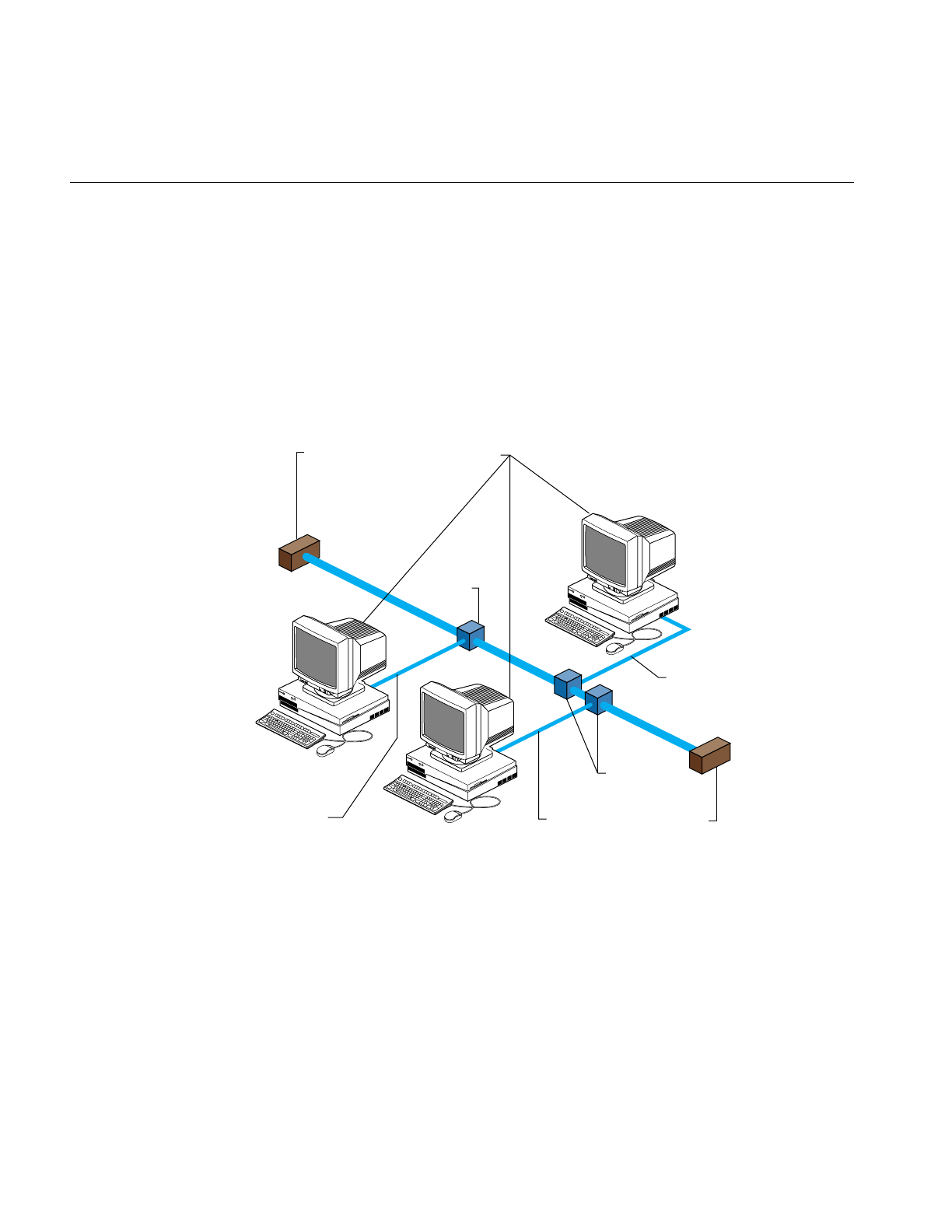
To connect your Ethernet controller to a network, you must have this hardware:
• an Attachment Unit Interface (AUI) cable, also referred to as a dropline or even
simply as a cable
• a transceiver
• access to an active Ethernet cable
Figure 1-1 shows how systems (termed “stations” on the network) might be connected to
an Ethernet network.
Figure 1-1 Ethernet Network Attachment
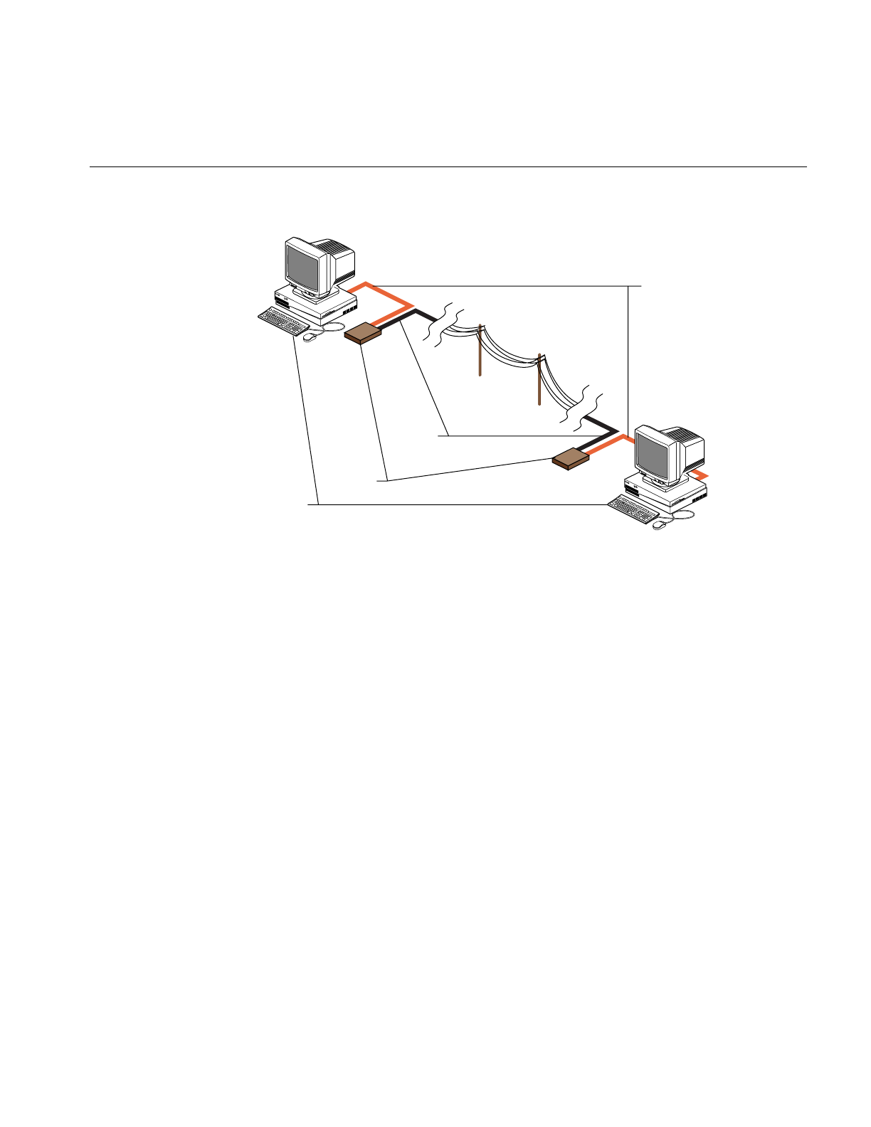
The serial ports on an IRIS system allow it to connect to serial networks. Serial-line
networks are systems connected by serial lines and modems. You do not need special
hardware installed in your computer to connect to a serial network.
Figure 1-2 shows systems connected to a serial network using modems.
Systems
Transceivers
Transceiver
Terminator
Terminator
AUI cable
AUI cable
AUI cable
Networking Hardware
3
Figure 1-2 Serial Line Network
Networking Hardware Options
In addition to Ethernet and serial-line hardware, other types of controllers can be
installed in Silicon Graphics systems as options. Some optional hardware products are
user installable, while others require installation by a System Support Engineer certified
by Silicon Graphics.
Optional networking products available from Silicon Graphics provide support for other
types of networks, including FDDI, token ring, X.25, and SNA. See your sales
representative for information on the networking options available for your system.
Controller Interface Names
The network controller is the physical board or chip. The interface is software’s
interpreter and handler of the controller. The interface name is the name most evident to
the user. For example, network management tools refer to the interface name when
providing information about the physical controller.
Modems
Systems
Telephone
lines
Serial lines

4
Chapter 1: Understanding Silicon Graphics’ Networking Products
To configure a controller, each network controller on a system must have a valid interface
name. A single system may have multiple controllers; each controller must have a unique
interface name. Several different types of controllers are available. Each type has its own
special interface name. Most network software supports a maximum of four network
interfaces by default.
You can get a list of the interfaces installed on a system using the hinv command:
%hinv -c network
Integral ISDN: Basic Rate Interface unit 0, revision 1.0
Integral Ethernet: ec0, version 1
The interface name for the Ethernet controller in this example is “ec0.”
Networking Software
The standard networking software shipped with all IRIS systems adheres to the Internet
Model standards and protocols. It is derived from the networking software in the 4.3BSD
UNIX®release from the University of California at Berkeley and the RPC® (remote
procedure call) system from Sun Microsystems. The IRIX operating system implements
the Internet Protocol suite and UNIX domain sockets using the 4.3BSD UNIX socket
mechanism. The system also supports access to the underlying network media by means
of raw sockets.
All standard networking software is supplied on the Execution Only Environment media
(eoe and netls_eoe). See Table 1-1 for a list of standard networking software for IRIS
systems. See Table 1-2 for a list of the optional networking products for IRIS systems.
Table 1-1 Standard Networking Software
Standard Networking Software Description
TCP/IP Transmission Control Protocol/Internet
Protocol support
UUCP UNIX to UNIX Copy Programs
sendmail Electronic mail support
SLIP Serial Line Internet Protocol
PPP Point to Point Protocol

Optional Networking Products
5
Optional Networking Products
Silicon Graphics supplies a variety of optional networking software to provide
interconnectivity between various vendors and mediums. Table 1-2 lists some of these
products. See your sales representative for detailed product information.
BIND Berkeley Internet Name Domain
NETLS Network License Server
NCS Network Computing System (supports
NETLS only)
RPC Remote Procedure Call support
Table 1-2 Optional Networking Products
Optional Networking Software Product Description
NFS™Includes software for Network File System (NFS); Network
Information System (NIS, formerly YP); and diskless system
support.
4DDN™Enables IRIS systems to function as a Phase IV DECnet end
node.
4DLT™Provides DECnet terminal service. (LAT)
Network License Server
Developers Option Consists of the License Server Lock (LSLOCK) and the
Network License Server (LSSERVER). The LSLOCK allows
software developers to license software products, and
LSSERVER is used to administer products licensed with
LSLOCK.
NetVisualyzer™Offers a set of graphical traffic monitoring, diagnostic,
planning, and performance analysis tools that provide
network information and statistics in a visually intuitive
form.
FDDI Visualyzer™Provides a graphical interface to the FDDI environment.
Table 1-1 (continued) Standard Networking Software
Standard Networking Software Description

6
Chapter 1: Understanding Silicon Graphics’ Networking Products
IRIS NetWorker™Application that automatically backs up systems over the
network. Keeps online indices of all backed up files.
4D TCP 3270 Enables IRIS systems to emulate an IBM® 3270™ type
terminal and open multiple sessions on an IBM mainframe.
IRIS 5080 Emulator Provides IBM 5080™ and 3270 terminal emulation. Delivers
direct access to models, applications, and data residing on
an IBM mainframe using the IRIS system.
4D Coax Connectivity The 4D CUT 3270 and 4D DFT 3270 coax products provide
your system with a cost-effective way to emulate an IBM
3270 type terminal.
4D SNA Connectivity Allows access to the IBM SNA environment. Provides access
to mainframe applications, utilizes multiple windows and
file transfer programs.
Table 1-2 (continued) Optional Networking Products
Optional Networking Software Product Description

7
Chapter 2
2. Planning a Network
This chapter contains common-sense approaches to planning the physical and logical
aspects of your network environment. The information contained in this chapter should
be read before you set up a new network or integrate into an existing network.
This chapter contains the following sections:
• “Planning the Physical Network” on page 7
• “Internet Protocol Addresses” on page 13
• “Domain Names” on page 17
• “The Internet” on page 18
• “Name-to-Address Mapping” on page 24
• “Planning to Subnet Local Networks” on page 25
• “Allocating IP Addresses” on page 27
• “Planning for Network Security” on page 28
• “Using Common Network Applications” on page 28
Planning the Physical Network
Planning the physical network requires that you first answer the question, “What
network media and topology configuration would best suit the needs of my users?” A
review of the MAC (Medium Access Control) level and application-level performance
information about the products you are considering will help you determine the
appropriate choice of media for your environment. In your review, consider the size
(number of stations) of your network. Your network size will influence the media type
and topology you choose for your network. If your network requires different types of
media, determine whether you have the correct equipment for integrating the various
media types.

8
Chapter 2: Planning a Network
The subsections that follow will help you answer this list of planning questions:
• What will my physical network look like?
• Do I have a map of my network?
• Will I need a repeater, bridge, router, or gateway?
• Will this network configuration meet my users’ needs?
• Where are my performance bottlenecks? Can I reduce or avoid them?
Repeaters, Bridges, Routers, and Gateways
Your choice of media and the number of stations, networks, and protocols in your
network may require the use of a repeater, bridge, router, or gateway. This section
suggests the type of device required for certain network functions.
repeater A device that regenerates and amplifies electrical signals. Its purpose is
to extend the physical length of a network.
bridge A device that decodes MAC-layer frames transmitted between different
hardware and media. Its purpose is to resolve network media
differences; it allows a network to be composed of various media types
(Ethernet, fiber, serial, and so on). It can also be used to segment similar
media types.
router A device that decodes and passes network-layer packets between
different networks. Its purpose is to provide the physical and logical
route from one network to another.
gateway A device that translates protocols from one station to another. Its
purpose is to allow stations with different networking protocols to
communicate successfully.
Note: The terms router and gateway are sometimes used interchangeably. Be sure you
know the function of the device you are considering, as the term may be technically
inaccurate.

Planning the Physical Network
9
Note that each device may not be limited to a single function. For example, a gateway
may also perform router functions if it is configured as a router. Table 2-1 summarizes the
characteristics of each network device.
Performance Planning
You can circumvent some performance bottlenecks with appropriate planning. These
bottlenecks might occur as a result of your choice of media, topology, number of network
devices, controller boards, or network design.
Choice of mediaBe sure the capacity of the medium you have selected is adequate for the
network size and data transmission type (large or small volumes of data,
sporadic or steady traffic). For example, Ethernet has a range of
capacities depending on the specific type of Ethernet cable used
(10base5, 10base2, or 10baseT). Media type is also a factor in data
degradation. For example, 10baseT is unshielded twisted pair and is
more sensitive to environmental conditions than 10base5. This should
be a consideration if you are planning a network for a manufacturing
environment that produces a high degree of electrostatic discharge.
Table 2-1 Network Device Characteristics
Device
Name Media Protocol LAN Purpose
repeater same same same extends physical
length of the network
bridge different/same different/same same/different bridge network
media differences
router same/different same different provides physical and
logical route between
networks
gateway same/different different same/different communication
between stations with
different networking
protocols

10
Chapter 2: Planning a Network
Number of devices
Network devices can cause degradation to the network performance.
Use repeaters only when necessary. Each additional devices introduces
additional resistance onto the network.
Choice of controller
Choose the most efficient controller for your media. For example, Silicon
Graphics supplies a standard Ethernet controller. An optional Efast™
card handles more of the protocol processing in hardware and frees the
station’s CPU for other processing.
Design of network
Think about the design of your network before you begin setting it up.
If possible, put departments that interact heavily on the same network
to decrease router traffic. Use dedicated routers to handle heavy traffic
between networks.
Wide Area Networks
In addition to the many options available for constructing local area networks, there are
several different ways of connecting local area networks into wide area networks. These
systems can be used to tie together local area networks at different locations, to allow
users working at scattered locations to access a network, and to connect your network to
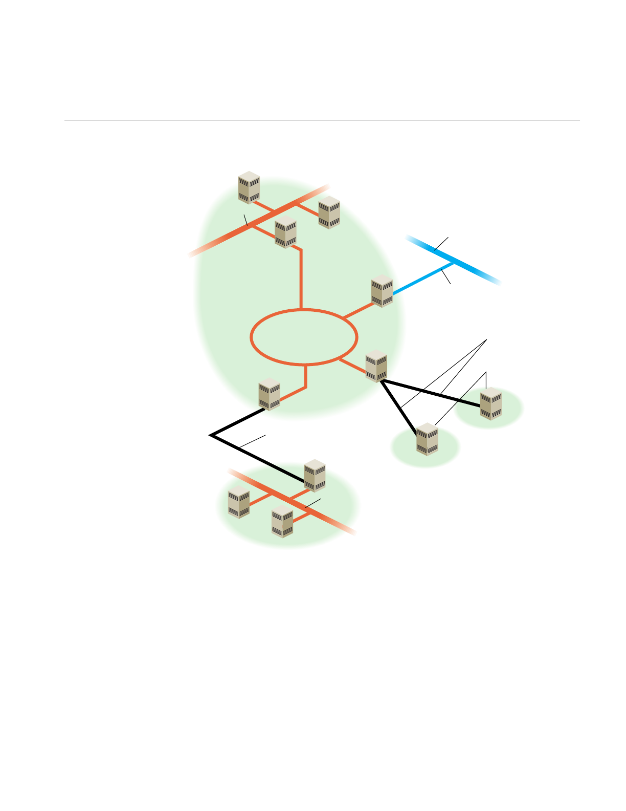
the outside world. Figure 2-1 shows how different kinds of wide-area connections might
fit into a large heterogeneous network.
Two of the available systems, Serial Line Internet Protocol (SLIP) and Point-to-Point
Protocol (PPP), provide a way of transferring Internet Protocol (IP) packets over a serial
telephone line; this means that SLIP and PPP users can access network resources much
as it they were on the local area network. PPP can also be used with Integrated Services
Digital Network (ISDN). ISDN uses a high-speed digital telephone line to achieve higher
throughput than a modem connection.
Another system, UNIX to UNIX Copy Program (UUCP) is an older system, primarily
designed for transferring information (such as network news and electronic mail) in
batch mode over serial lines.
Higher-performance network connections can be made using specialized hardware.
These connections are usually over dedicated lines, leased from a telephone company, or
over the telephone company’s packet-switched network.
Planning the Physical Network
11
Figure 2-1 Heterogeneous Network With Wide-Area Connections
Serial Line Internet Protocol (SLIP)
SLIP provides simultaneous operation of multiple processes on a serial cable or
telephone line. It allows network users the freedom to use TCP/IP based applications
over a serial cable or modem connection.
Leased
line
Ethernet
Ethernet
Internet
Main office network
Field office network
FDDI ring
Standalone
systems
SLIP or
PPP lines
SLIP or
PPP line

12
Chapter 2: Planning a Network
You might consider setting up a SLIP network when cost and distance are large factors
in your network planning.
Point to Point Protocol (PPP)
The Point to Point Protocol is similar in nature to SLIP. PPP provides a network
connection as if your system were connected to the remote host by a LAN connection.
Multiple processes and TCP/IP based applications are supported.
UNIX to UNIX Copy Program (UUCP)
UUCP, also called the Basic Networking Utilities, is a set of utilities that lets stations
using a version of the UNIX operating system (such as IRIX) communicate with each
other over serial lines. The utilities provided range from those used to copy files between
computers to those used for remote login and command execution.
You may consider setting up UUCP for long-haul communications using modems and
telephone lines. It is usually used to distribute electronic mail and network news.
Integrated Services Digital Network (ISDN)
ISDN is a system that connects systems using high-speed digital telephone lines. ISDN
can achieve throughput up to 128 Kb per second, several times faster than normal
modem connections. However, ISDN service can be expensive, and is not available in all
areas. See the ISDN User’s Guide for more information on ISDN.
High Performance Wide Area Networks
If you need higher performance than you can get using SLIP or PPP over a modem link
or ISDN, there are several choices available to you. The choices include Frame Relay
networking and leased line service, from 56K (56 Kb per second) to T1 (1.5 Mb per
second) and T3 (up to 45 Mb per second). If you require this kind of service, you’ll have
to shop around, comparing the prices and services offered by local Internet service
providers.

Internet Protocol Addresses
13
Internet Protocol Addresses
Each system on your network needs a unique Internet Protocol (IP) address for each of
its network interfaces. The Internet Network Information Center (InterNIC) is
responsible for assigning the network portion of an Internet address for each site. For
example, if Company A applies for an Internet address, the InterNIC provides the
network portion of the Internet address for the entire Company A site. A centralized
organization within Company A is responsible for assigning and managing the station
ID portion of the Internet address.
Internet addresses are maintained on each station or in a centralized network database
such as NIS or BIND. See “Name-to-Address Mapping” on page 24 for a comparison of
the different database types. Each station that wishes to communicate must have a valid
Internet address registered in the appropriate database. The standard hosts
name-address database on IRIX stations is the /etc/hosts file.
The subsections that follow will help you answer this list of planning questions:
• How do I obtain a valid Internet address for my site?
• How do I obtain a domain name assigned for my site?
• Do I understand the purpose of the /etc/hosts file?
• Do I have valid Internet addresses ready for all required stations?
Format of Internet Protocol (IP) addresses
An IP address is a 32-bit number that network software uses to identify a system on a
network. For the sake of human readability, these addresses are usually represented as
four one-byte integers, separated by dots (for example, 150.166.248.17). Every system on
an IP network must have its own unique IP address for the network to function properly.
Systems with more than one network interface must have a unique IP address for each
interface.
Note: Unlike a system’s Ethernet address, a system’s IP address is determined by the
network and network system administrators.

14
Chapter 2: Planning a Network
Conceptually, each 32-bit IP address is a pair of numbers where one number represents
the network and the other the system itself. There are four classes of addresses in use (A
through D). The class of address is determined by the first bits of the address:
• Class A addresses begin with 0 and have 7 bits for the network number and 24 bits
for the host number.
• Class B addresses begin with 10 and have 14 bits for the network number and 16
bits for the host number.
• Class C addresses begin with 110 and have 21 bits for the network number and 8
bits for the host number.
• Class D addresses begin with 1110 and are special “multicast” addresses for use
within a network site.
In all cases, host numbers 0 and 255 are reserved, and may not be used for actual systems.
Figure 2-2 shows the format of the different classes of Internet addresses.
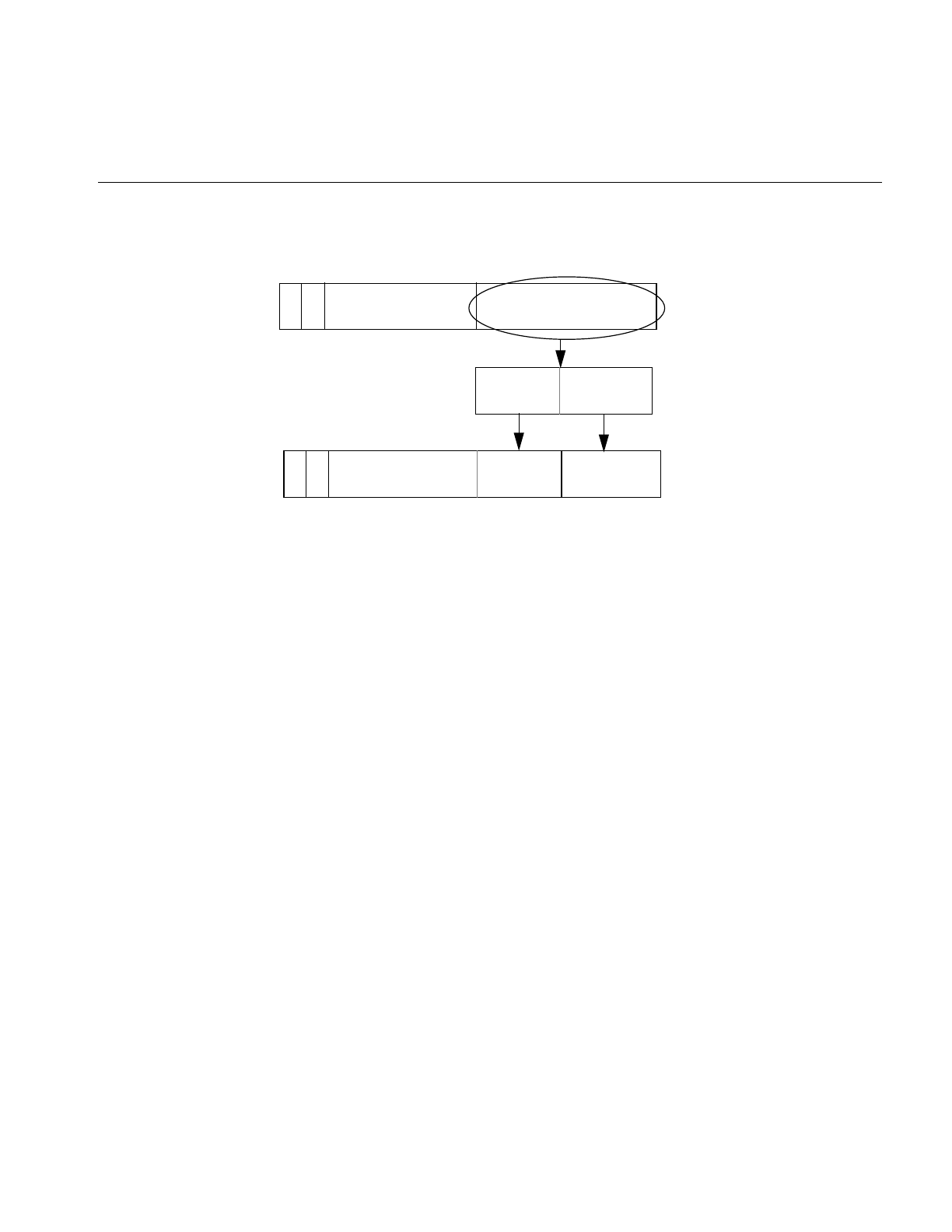
Figure 2-2 The Format of Internet Protocol (IP) Addresses
0 network host
bit numbers 0 1 7 8 31
CLASS A (128 networks with 16,777,214 systems each):
10 network host
bit numbers 0 15 16 31
110 network host
bit numbers 0 3 23 24 31
1110
bit numbers 0 431
2
21
3
multicast address
CLASS B (16,384 networks with 65,534 systems each):
CLASS C (2,097,152 networks with 254 systems each):
CLASS D (multicast group address within a network site):

Internet Protocol Addresses
15
To simplify Internet addressing, dotted decimal notation is used to break the 32-bit
number into four decimal numbers separated by dots.
For example, the IP address 128.74.41.123 in binary is:
10000000| 01001010| 00101001| 01111011
or
128 | 74 | 41 | 123
Class A, B and C IP addresses in dot notation conform to the following specifications:
Class A -- 001.hhh.hhh.hhh through 126.hhh.hhh.hhh
Class B -- 128.001.hhh.hhh through 191.254.hhh.hhh
Class C -- 192.000.001.hhh through 223.255.254.hhh
Note: hhh is the local system and the leading numbers are the network.
Networks are usually identified by network numbers—IP addresses in which the host
portion is not specified. For example, 150.166 represents a Class B network, and 192.26.80
represents a Class C network.
If your network will be connected to the Internet, then you must obtain a unique network
number, as described in “Obtaining a Network Number” on page 15. All the systems on
your network must have IP addresses allocated from your network.
If you are adding a machine to an existing network, its IP address must be allocated from
that network.
Obtaining a Network Number
You should obtain an Internet network number before you begin setting up your
network.The allocation of network numbers is managed by a set of organizations called
Network Information Centers (NICs). If your network is going to be isolated, and will
never be attached to the Internet, you can theoretically use any addresses you like.
However, if your network is ever going to be attached to the Internet, you should obtain
a valid network number. Before you request the network number, you should determine
the current needs of your organization (how many systems do you currently have that
should be on the network?) and expected growth over the next five years.

16
Chapter 2: Planning a Network
There are several ways to obtain a network number. In many cases the best option, if you
are connecting to the Internet through an Internet service provider, is to have the service
provider assign you a portion of the address space they have been allocated by the local
NIC.
The InterNIC recommends that you request a network number from your network
service provider. If they cannot supply one, contact your provider’s provider. As a last
resort, contact your Network Information Center. See “Contacting Your Local Network
Information Center” on page 19.
NIC Required Information
To request an Internet network address, you will typically need to supply the following
information to the local NIC:
• Your administrative point of contact (POC). The administrative POC is the person
responsible for answering administrative and policy questions about the network.
You need to know his/her name, title, mailing address, and phone number.
• Your technical point of contact (POC). The technical POC is responsible for the
technical support of the network. You need to know his/her name, title, mailing
address, and phone number.
• Organization name and postal address.
• Your network name (up to 12 characters).
• Your network’s geographic location and organization name.
• The name and location of the network document plan.
• Gateway information (connectivity, hardware, software, address).
• The approximate size of your network (number of hosts and subnets), initially and
within one year.
• Type of network (research, educational, government non-defense, commercial).
If you already have one or more network numbers assigned to your organization, the
NIC ,may require you to provide information on how these are being used, as evidence
that you really need a new network number.
If you request 16 or more Class C network numbers, the InterNIC requires you to provide
information on network topology, and if you request 256 or more Class C network
numbers or a Class B network number, the InterNIC requires you to provide a diagram
of the proposed network.

Domain Names
17
Domain Names
If you’re planning on putting your site on the Internet or exchanging e-mail with sites on
the Internet, you should register a domain name with your local NIC. A domain name
uniquely identifies your organization. For example, Silicon Graphics has the domain
name “sgi.com.”
The Internet uses Domain Name Service (DNS) to map domain names to IP addresses.
Therefore, even if you don’t use DNS internally, you must provide DNS name servers on
the Internet in order to connect your network to the Internet. You should have at least
two name servers, a primary and a secondary server. For robustness, the secondary
server should not be connected to the Internet through the same gateway as the primary
server. Since many organizations are not big enough to have multiple gateways to the
Internet, a common solution is to make a reciprocal arrangement with another
organization to provide secondary name service for each other.
If you are connecting to the Internet through an Internet service provider, they may be
able to provide name service for your organization, or help you locate someone to
provide secondary name service if you are able to provide a primary name server.
Obtaining a Domain Name
As with network numbers, the registration of domain names is administered by the
Network Information Centers. In some cases, there is a fee associated with holding a
domain name. For example, the InterNIC currently charges a fee of $100 for the first two
years, and $50 a year thereafter for domains under its jurisdiction.
You can register your domain name through your local NIC. See “Contacting Your Local
Network Information Center” on page 19 for contact information. When you register a
domain, you should also register a reverse domain, also known as an IN-ADDR domain.
The reverse domain provides a mapping from IP addresses to domain names.
In many cases, Internet service providers will register your domain for you, for a fee.
Subdomains
Once you have a domain name registered, you’re free to establish subdomains of your
own. This is particularly useful for large organizations that use the Domain Name

18
Chapter 2: Planning a Network
Service (DNS). The use of subdomains with DNS allows some administrative chores to
be decentralized.
For example, suppose “salad.com” has branch offices in Gilroy and Paris. These could be
established as subdomains, “gilroy.salad.com,” and “paris.salad.com.”
The Internet
Chances are, you will want to connect your system or network to the Internet. Wherever
you may be, there is likely an Internet gateway available within your local calling range.
The following sections offer some information that should help you get set up and
running. Obviously, each situation is somewhat different, and your local service provider
will have variations in service and equipment. Some research and experimentation is
usually required before everything works smoothly.
Before Connecting to the Internet
Before you sign up for an internet connection, consider what level of service you need.
For example, if you are an individual looking for basic e-mail, news, and file transfer
capabilities, it probably wouldn't make sense to install a dedicated network cable in your
home for economic reasons. A better choice for single-user access might be to subscribe
to a network provider who establishes an account for you on their system (one that is
currently connected to Internet). Typically, access to their system is through a modem
connection.
If you are trying to establish a connection to the Internet for a corporation, you will likely
need the bandwidth of a leased line, and all the required hardware that goes with it. You
will have to take into consideration the many administrative issues of running a site.
These issues include, but are not limited to
• cost analyses/budget
• establishing a domain
• applying for IP addresses
• establishing site policy
• establishing site security
• administration of network services (such as Domain Name Services, NIS, e-mail,
and so on)

The Internet
19
There are providers of network connectivity that can provide varying levels of service.
You must investigate the providers, and decide who provides the level of service you
need, at the appropriate cost.
If you choose an individual account on a provider's machine, the service provider deals
with most, if not all, of the administrative tasks, and you simply enjoy access to the
Internet.
If you would like a broader range of services, most providers will set you up with a
dedicated modem and phone line for your exclusive use, or they can provide a
network-only service (using SLIP, PPP, or UUCP), either through modems or other
network connections.
Connecting your network to the Internet requires a number of steps, including arranging
name servers, obtaining a network number, and registering a domain name for your
organization. Many Internet service providers are willing to provide these services for a
fee.
If you are trying to set up internet access for a company, or corporation, you should
research the issues listed above. Based on the information you obtain, formulate a plan
for your site based on the needs and expectations of your organization. One of the best
sources of information is the Internet itself. You should first obtain an individual account
from a local provider. With the individual account, you can gain access to a large amount
of information pertaining to establishing a site on the Internet.
Contacting Your Local Network Information Center
Before you connect your site to the Internet, you’ll need to contact your local Network
Information Center. The assignment of network numbers and domain names is
coordinated by the Network Information Centers. There are three main regional
Network Information Centers, as shown in Table 2-2.

20
Chapter 2: Planning a Network
Procedures for obtaining IP addresses and registering domain names vary, so contact
your local NIC for information.
Internet Network Information Center
The Internet Network Information Center (InterNIC) was formerly the sole Network
Information Center. It serves as the primary NIC for most of North and South America,
as well as for other regions that do not yet have NICs of their own. InterNIC maintains a
large archive of informational documents, which can be accessed using WWW, FTP, or
by e-mail to an automated-response mail server. Registration authority for some
countries (including Canada and Brazil) is delegated to national NICs. Contact
information for the national NICs may be obtained through InterNIC.
Network Solutions
Attn: InterNIC Registration Services
505 Huntmar Park Drive
Herndon, VA 22070
Phone: 1-800-444-4345 or 1-703-742-4777
E-mail: question@internic.net (general inquiries)
E-mail: hostmaster@internic.net (registration services)
WWW: http://www.internic.net/
FTP: ftp.ds.internic.net (complete RFCs, and so on)
FTP: rs.internic.net (registration information)
E-mail server: mailserv@rs.internic.net (send message with subject line “HELP”)
Table 2-2 Network Information Centers
Region Organization
Asia/Pacific Asia Pacific Network Information Center (APNIC)
Europe Réseaux IP Européens Network Coordination Centre (RIPE NCC)
Americas Internet Network Information Center (InterNIC)
other areas InterNIC

The Internet
21
Réseaux IP Européens
Réseaux IP Européens (RIPE) maintains an NIC that provides registration services for
European sites. It also maintains a store of informational documents, including the
InterNIC’s FYI documents, and instructions on how to register a host or network in one
of the European domains.
RIPE Network Coordination Centre
Kruislaan 409
NL-1098 SJ Amsterdam
The Netherlands
Phone: +31 20 592 5065
Fax: +31 20 592 5090
E-mail: ncc@ripe.net
WWW: http://www.ripe.net/
FTP: ftp.ripe.net
Asia Pacific Network Information Center
The Asia Pacific Network Information Center (APNIC) coordinates network information
for the Asia and Pacific region. Registration authority for some countries is delegated to
national NICs. Contact information for the national NICs may be obtained through
APNIC.
Asia Pacific Network Information Center
c/o United Nations University
53-70 Jingumae 5-chome
Shibuya-ku, Tokyo 150
Japan
Phone: +81-3-5467-7014
Fax: +81-3-5276-6239
E-mail: info@apnic.net
WWW: http://www.apnic.net/
FTP: archive.apnic.net

22
Chapter 2: Planning a Network
Online Information Sources
With an individual account or other access to the Internet, you can get the information
you need to provide access to your own site.
Usually, the provider of an individual account will also provide new-user
documentation that describes the basics of using the Internet. You can use the World
Wide Web (WWW) and the File Transfer Protocol (FTP) to access a wealth of information
on many subjects, including Internet connectivity. If you don’t know how to use FTP, see
“Retrieving Files With Anonymous FTP” on page 23 for a short tutorial. How you access
the Web depends on what Web browser you’re using. Most Web browsers have online
help available.
Network Information Centers
Your local NIC maintains archives of useful information on connecting to the Internet. In
addition to information about requesting network numbers and registering domain
names, they may have lists of local service providers. Most NICs make this information
available by WWW and FTP. See “Contacting Your Local Network Information Center”
on page 19 for WWW and FTP addresses for the major NICs.
The InterNIC has produced a series of information bulletins called FYIs. Especially
notable is FYI 16, entitled Connecting to the Internet -—What Connecting Institutions Should
Anticipate. While this is aimed primarily at U.S. educational institutions, it remains one
of the better pieces of documentation on establishing a site on the Internet. The FYI
documents are available by WWW and FTP from the InterNIC and from RIPE.
The Internet Society
The Internet Society is a non-governmental international organization for global
cooperation and coordination of the Internet. They also provide useful online
information—in particular, information on finding an Internet service provider, and a list
of network service providers around the world. This information is available by WWW.
A subset is available by anonymous FTP.
WWW: http://www.isoc.org/
FTP: ftp.isoc.org

The Internet
23
Retrieving Files With Anonymous FTP
Anonymous FTP is a conventional way of allowing you to sign onto a computer on the
Internet in order to obtain copies of files that are made available to the public. Some sites
offer anonymous FTP accounts to distribute software and various kinds of information.
If you have never used ftp, here is a brief summary on how to use the ftp command. To
connect to a remote host, specify the hostname on the command line:
ftp ftp.ds.internic.net
When ftp connects with the remote system, it prompts you for a login name. Use the
login name “anonymous”:
Connected to ftp.ds.internic.net.
Name (ftp.ds.internic.net:guest): anonymous
331 Guest login ok, send ident as password.
Password:
Many systems allow any password and request that the password you choose is your
user ID. If this fails, the generic password is usually “guest.”
230 Guest login ok, access restrictions apply.
Remote system type is UNIX.
Using binary mode to transfer files.
ftp>
Once connected and logged in, you can use ftp’s cd and ls commands to look at the files
available on the remote system. To obtain a file from the remote system, use the get
command. The get command copies one file from the remote system to your local system.
To obtain multiple files from the remote system, use the mget command.
ftp> cd fyi
250 CWD command successful.
ftp> get fyi6.txt
local: fyi6.txt remote: fyi6.txt
200 PORT command successful.
150 Opening BINARY mode data connection for fyi6.txt (3459 bytes).
226 Transfer complete.
3459 bytes received in 0.46 seconds (7.34 Kbytes/s)
ftp>

24
Chapter 2: Planning a Network
Name-to-Address Mapping
Because IP addresses are difficult to remember, they are usually associated with names.
In the case of a machine with a single IP address, this name usually consists of the
machine’s hostname and domain name. For example, a machine called “fruit” in the
domain “salad.com” would usually be referred to as “fruit.salad.com”. For clarity, this
type of name will be referred to in this section as a network connection name.
Because network connection names usually correspond to the machine’s hostname, these
network connection names are commonly referred to as “hostnames,” but this can be
misleading. The actual hostname is defined in the /etc/sys_id file. By default, this
hostname is used as the network connection name for the machine’s primary network
interface, but this behavior is configurable. A machine with multiple network interfaces
has multiple network connection names associated with it. By convention, each of these
connection names contains the hostname—for example, if the host “fruit” acts as a
gateway between two networks in the “salad.com” domain, it might use these names:
fruit.salad.com
gate-fruit.salad.com
The process of mapping network connection names to IP addresses is commonly called
hostname resolution. There are several different systems for hostname resolution.
Machines can use a local database (the /etc/hosts database), or they can obtain information
from servers on the network, using either the Network Information Service (NIS) or the
Domain Name System (DNS). The following sections describe the advantages and
drawbacks of the different systems:
• “The /etc/hosts database” on page 24
• “Domain Name System” on page 25
• “Network Information Service (NIS)” on page 25
The /etc/hosts database
The /etc/hosts database is an ASCII file that you can modify with any text editor. The file
contains lines of text that specify IP addresses and network connection names.
For a small network of stations under the same administrative control, maintaining a
consistent /etc/hosts database is straightforward. Establish a master copy on one station
and make additions or deletions from its file. Then use rcp(1C) or rdist(1C) to copy the file
to the other stations in the network.

Planning to Subnet Local Networks
25
Maintaining consistent versions of /etc/hosts on every station in a large network is
troublesome. NIS and the BIND name server both make maintenance easier by providing
a centralized version of the host database.
Domain Name System
The Internet uses the Domain Name System (DNS) to map names to IP addresses. The
most common implementation of a DNS name server is called Berkeley Internet Name
Domain (BIND). If your network interfaces with the Internet, you must have at least two
DNS name servers, a primary and a secondary server. Your Internet service provider may
be able to take care of this requirement for you.
BIND is best suited for large networks, or networks connected directly or indirectly to
the Internet. BIND provides access to a much larger set of stations than is provided in the
/etc/hosts database. A drawback of BIND is its complicated setup. BIND is described in
more detail in Chapter 6, “BIND Name Server”
Network Information Service (NIS)
NIS is a network-based information service and an administrative tool. It allows
centralized database administration and a distributed lookup service. NIS supports
multiple databases based on regular text files. For example, NIS databases can be
generated from the hosts,passwd,group, and aliases files on the NIS master.
NIS is best suited for a moderate-sized network (one containing approximately 1000
stations, or a small collection of interconnected networks). NIS is part of the NFS optional
software and is detailed in the NIS Administration Guide.
Planning to Subnet Local Networks
Subnetting allows you to divide a single network into a set of subnetworks. Subnetworks
are useful for many reasons. For example, if you have a satellite office that connects to
your main network, it should have its own network number or subnet. If you have a
large number of systems to be connected by Ethernet, you may have to use subnets to
overcome physical limitations on the number of hosts and length of network cable that
can be supported on a single Ethernet network.

26
Chapter 2: Planning a Network
Subnetting should be considered when the class limits are unrealistic for your network.
For example, a Class B network gives you approximately 64,000 stations per network.
This far exceeds the maximum number of stations allowed on most networks. Subnetting
allows the local organization to designate some of the host ID bits to form a subnet.
Subnetting generates a realistic number of stations per network. All changes are made at
the local site by the site administration group and are transparent to off-site stations.
Planning is required for subnetting a network (see “Subnetting a Network” on page 45
for subnetting procedure). Primarily, you must determine how to partition the host part
of the 32-bit Internet address. To define local subnetworks, use bits from the host number
sequence to extend the network portion of the Internet address. This reinterpretation of
IP addresses is done only for local networks. It is not visible to off-site stations.You
should have at least a rough idea of the physical layout of the network before you plan
your subnets. For example, you might want to have a subnet for each floor of your
building. If you have a branch office that’s connected to your main network, you might
want to set aside one or more subnets for it. In some cases, you may want to set aside a
subnet for SLIP and PPP clients (see “SLIP and PPP Routing and Address Allocation” on
page 94).
Sites with a Class A network number have 24 bits of host part with which to work; sites
with a Class B network number, 16 bits; and sites with a Class C network number, 8 bits.
For example, if your site has a Class B network number, each station on the network has
an Internet address that contains 16 bits for the network number and 16 bits for the host
number. To define 254 local subnetworks, each possessing at most 254 stations, you can
use 8 bits from the host portion of the address. Construct new network numbers by
concatenating the original 16-bit network number with the extra 8 bits containing the
local subnetwork number.
Figure 2-3 shows what happens to the bit assignments in a Class B Internet address that
is subnetted.
Allocating IP Addresses
27
Figure 2-3 Subnetted Class B Address
For example, the Class B Internet address for an entire site as seen from other sites might
be 128.50. If subnetting is enabled within the site, the site might be composed of several
subnets with network IDs like 128.50.20, 128.50.21, 128.50.22, and so on. A station that
resides on the subnet 128.50.21 might have the Internet address 128.50.21.5.
Note: The numbers 0 and 1 are reserved for broadcast addresses. Do not use subnetwork
numbers with all 0s or all 1s.
Allocating IP Addresses
Once you have obtained a network number, decided which system to use for hostname
resolution, and decided whether you’re going to subnet the network, you’re ready to
allocate IP addresses for individual systems. For most systems, this is as simple as
assigning an unused IP address from the correct net or subnet. If you use the syntax of
the /etc/hosts file, this will look something like this:
150.26.80.1 green.salad.com green
150.26.80.2 tossed.salad.com tossed
150.26.80.3 jello.salad.com jello
Note: Host numbers 0 and 255 are reserved, and shouldn’t be used.
Standard Class B
10
01 8 16 24 31 bits
host IDnetid
subnetwork host ID
(14 bits) (16 bits)
(8 bits) (8 bits)
(14 bits)
Subnetted Class B
1 0 netid host ID
(8 bits)
subnetwork
(8 bits)

28
Chapter 2: Planning a Network
Systems with more than one network interface may be connected to more than one
subnet, and require one address for each connected interface. Each interface should be
assigned an address from the subnet that the interface is connected to. For example, if
fruit.salad.com acts as a gateway between the 150.26.80 net and the 150.26.42 net, it might
have the following entries:
150.26.80.19 fruit.salad.com fruit
150.26.42.1 gate-fruit.salad.com gate-fruit
Even if you’re planning on using NIS or BIND for hostname resolution, you will
probably want to put together an /etc/hosts file. If you install this on your systems as you
attach them to the network, you’ll be able to communicate while you get NIS or BIND up
and running.
You should also establish some policy for allocating IP addresses for new systems once
the network is in place. If your organization is large, you might want to delegate this
authority to separate organizational units. For example, the branch office with its own
subnet should allocate IP addresses as needed from its subnet. If your organization is
divided up into subdomains, you might want to assign authority over certain subnets to
subdomain administrators.
Planning for Network Security
Securing a network is difficult. If you can discourage potential intruders and quickly
isolate or pinpoint successful intruders, you can consider your network secure. You
should establish a plan for keeping your network secure before you connect your
network to the Internet. For information on network security, see Chapter 5, “Network
Security,” in IRIX Admin: Backup, Security, and Accounting.
Using Common Network Applications
This guide is written specifically to support the standard network hardware and
software—Internet protocols over Ethernet. However, when discussing networking in
general, it is difficult to ignore network applications that are not standard, but are
common to most network environments. This section presents a brief overview of some
of the common network applications that you should consider when planning your
network.

Using Common Network Applications
29
Electronic Mail
Electronic mail is a group of programs (sendmail) used to send and receive messages to
and from users on the same local station or between remote stations. Mail can be sent
using UUCP or TCP/IP protocols. IRIX supports both System V (/bin/mail) and 4.3BSD
(/usr/sbin/Mail) mail programs, as well as MediaMail, which provides a graphical interface
for electronic mail.
Network File System (NFS)
NFS is a network program that can access a remote station’s filesystem and attach it and
its data to the local station’s filesystem. On the local station, the remote filesystem is
accessed as if it were local.
NFS should be considered in a network when you want to share files between stations.
With NFS, software or data used by a group is put on an NFS server. Authorized NFS
clients access the data over the network when needed. This approach ensures consistent
information, frees up disk space on client stations, and simplifies the backup procedure.
NFS is an optional software product and is described in the ONC3/NFS Administrator's
Guide.


31
Chapter 3
3. Setting Up a Network
This chapter contains the following sections:
• “Configuring an IRIS System for a Network” on page 31
• “Setting Up a Router” on page 38
• “Subnetting a Network” on page 45
• “Modifying the Network Interface Configuration” on page 46
• “Changing Network Parameters” on page 51
• “Dynamic Host Configuration With Proclaim” on page 53
• “Creating a Local Network Script” on page 56
• “Turning On Remote Access Logging” on page 56
• “Setting Up Network-Wide Services” on page 56
• “Troubleshooting Your Ethernet Connection” on page 64
Configuring an IRIS System for a Network
The procedure in this section explains how to configure an IRIS station, with one
interface, for an Ethernet network using its local /etc/hosts file (without BIND or NIS).
Configuring the station takes six steps:
1. Bring the station down
2. Attach the station to the network
3. Check the station’s network configuration
4. Modify the /etc/hosts database
5. Name the station
6. Test the connection
Each of these steps is explained in the sections that follow.

32
Chapter 3: Setting Up a Network
Attaching Your Station to an Ethernet Network
Attach your station to the network by connecting one end of the Attachment Unit
Interface (AUI) cable to the Ethernet I/O port and the other end to the network
transceiver or Medium Access Unit (MAU).
If your transceiver model has status lights, make sure that the power light on the
transceiver comes on when you attach the AUI cable to your workstation and the
transceiver. This light indicates that the Ethernet card or the integral Ethernet controller
is alive. Your station must be powered on to activate the power light on the transceiver.
You may also see another light, which indicates that your link to the network is activated.
If the power light on the transceiver is lit or if your transceiver or MAU has no lights,
bring your station back up into multiuser mode now.
Checking Your Ethernet Connection
You can use the ping command to check your Ethernet connection. This command tests
whether you can connect with another system on the Ethernet network. Perform the
following steps:
1. Obtain the hostname of at least one reliable station on the local area network to
which your system is connected. If possible, get the fully qualified hostname and
the IP address. (For example, a hostname might be hancock, and the fully qualified
hostname might be hancock.corp.gen.com, while the IP address might be 128.70.3.56.)
It is important that the station you select has a reliable Ethernet connection and that
it is up and running.
2. Once you have obtained a hostname and IP address, give the command
ping -r hostname
You should see a series of records indicating the returned packets from the remote
host. For example (using our example system):
PING hancock (128.70.3.56): 56 data bytes
64 bytes from 128.70.3.56: icmp_seq=0 ttl=255 time=2 ms
64 bytes from 128.70.3.56: icmp_seq=1 ttl=255 time=2 ms
64 bytes from 128.70.3.56: icmp_seq=2 ttl=255 time=2 ms
64 bytes from 128.70.3.56: icmp_seq=3 ttl=255 time=2 ms
64 bytes from 128.70.3.56: icmp_seq=4 ttl=255 time=2 ms

Configuring an IRIS System for a Network
33
3. Press <Ctrl>-C or your Delete key to stop the ping command. You see the tallied
results of the ping command. For example:
----hancock PING Statistics----
5 packets transmitted, 5 packets received, 0% packet loss
round-trip min/avg/max = 2/2/2 ms
4. If your network connection is working, you should see results comparable to those
above. Your ping results should show 0% packet loss and an equal number of
packets transmitted and received. If some packets are being lost, the first thing you
should check is the tightness and quality of the cable connections. Loose cables are
frequently the cause of lost packets. The round-trip time factors are a function of the
size and general load of your network, and not necessarily an indication of a
problem with your Ethernet connection.
If your ping command is not successful, there are several things you should check.
Perform these steps:
1. Try to ping the station by its IP address. For example, using our sample host
hancock, use the command
ping -r 128.70.3.56
2. Try to ping a different station on your local network.
3. Check the network configuration on your system with the netstat -in command. You
should see information similar to this:
Name Mtu Network Address Ipkts Ierrs Opkts Oerrs
ec0 1500 128.70.3 128.70.3.9 18 0 18 0
The ec0 entry indicates your primary Ethernet connection. The Ipkts and Opkts
fields indicate the number of inbound and outbound packets the network interface
has processed. The Ierrs and Oerrs fields indicate the number of errors in input
and output, respectively.
For the purposes of this troubleshooting session, though, check that the portion of
the IP address shown under the Network heading match the IP address of the
hostname that you attempted to ping. If the network addresses are not the same, the
station is on a different network and the ping likely failed for that reason. Find a
system to ping that is on your immediate local network.
4. Check the /var/adm/SYSLOG file for Ethernet error messages.
5. Check to ensure that other stations are operating normally on the local network.

34
Chapter 3: Setting Up a Network
6. Check to ensure that the correct software (eoe.sw.tcp) package has been installed on
your system.
7. Check the physical connections to the Ethernet cables and transceivers for tightness
and connection. A good indicator is the status light display on your transceiver (if
your transceiver has these lights). If your Ethernet hardware is loose or
disconnected, the /var/adm/SYSLOG file and your system console should both show
messages such as
ec0: no carrier: check Ethernet cable
8. If all connections are tight and you still receive errors, replace the pieces of the
Ethernet connection outside your system (the cable and transceiver). Different
transceivers require different wire connections, and sometimes the wrong cables are
used.
9. If you receive a message indicating that another host has the same IP address, find
out which host has the same address, and determine which host has set their
address incorrectly. (It is more likely that the same address was accidentally
assigned to a second system, or that the new system being tested incorrectly set the
address.)
Checking the Network Software Configuration
When the station comes up, verify the station’s software configuration. Log into the
station as root.
Issue the chkconfig(1M) command to check that your station’s standard networking
software is correctly configured:
/etc/chkconfig
You see information similar to this:
named off
network on
rwhod off
timed on
timeslave off
gated off
mrouted off
rtnetd off
snmpd on
routed on

Configuring an IRIS System for a Network
35
Note: Your output will vary from the output above depending upon installed software
and configuration flag settings.
If you are familiar with the network-related daemons, you can customize your
configuration flags to suit your network needs. If you are not familiar with the
network-related daemons, set your network-related flags as shown above. In particular,
make sure that the network variable is configured on.
Modifying the Hosts Database
Before you modify the hosts database, you should have a list of station names and valid
Internet addresses of all stations in your network, as discussed in “Allocating IP
Addresses” on page 27. If the network has routers (stations with multiple network
interfaces), there must be a valid Internet address and name for each interface. See
“Internet Protocol Addresses” on page 13 for a description of IP addresses.
Thehosts file is the hostname database. It contains information regarding known stations,
from the perspective of the local station. This example assumes that you are not using
NIS or BIND. If you are using NIS, refer to the NIS Administration Guide for more
information. If you are using BIND, refer to Chapter 6, “BIND Name Server,” for more
information.
The /etc/hosts database is an ASCII file that you can modify with any text editor. The file
contains lines of text that specify a station’s address, its “official” name, and any aliases.
The “official” name should be the fully qualified domain name. The address and name(s)
are separated by blanks, tabs, or both. Comments begin with a pound sign (#) and
continue to the end of the line.
An /etc/hosts database is shown in this sample /etc/hosts file:
# This is a comment
127.0.0.1 localhost
119.0.3.20 tuna.salad.com tuna # tuna is an alias
119.0.3.21 chicken.salad.com salad
119.0.3.22 walrus.salad.com walrus
Each IRIS system must have a copy of /etc/hoststhat contains entries for localhost and all
of its network interfaces. As shipped, the /etc/hosts database contains two entries. The
first entry is a name you can use to test the local network software:
127.0.0.1 localhost

36
Chapter 3: Setting Up a Network
When you reference localhost, the message is looped back internally; it is never
transmitted across the network.
Caution: Many important programs depend on the localhost entry—do NOT remove or
modify it. If the master copy of /etc/hosts is not maintained on an IRIS station or if you are
using BIND or NIS, make sure that the host database contains the localhost entry.
To enable the IRIS system to access the network, add an entry containing the newly
assigned IP address and the name in /etc/sys_id. The entry must contain the sys_id name,
either as the official hostname or as an alias.
Using the example /etc/hosts file above, the /etc/sys_id file for the host walrus should
contain either “walrus” or “walrus.salad.com”.
If you change the IRIS system’s name in /etc/sys_id, make sure to update the entry in
/etc/hosts; otherwise the network software will not initialize properly. If the following
message appears during station startup, then the /etc/hosts and /etc/sys_id files are
inconsistent and must be fixed:
*** Can't find hostname's Internet address in /etc/hosts
If your IRIS system is a gateway, each network interface must be assigned an Internet
address and have an entry in /etc/hosts, as described in “Setting Up a Router” on page 38.
It is important that each station have a consistent version of the host database. The proper
method for maintaining the consistency depends on the size of your network and
whether the network is connected to the Internet. You can use the rcp or rdist programs
by means of a cron job to ensure that the hosts files stay in sync.
Edit the /etc/hosts file and add the hostnames and Internet addresses for all stations on
your network. Each station on the network must have all station names in the local
/etc/hosts file. If you have a large /etc/hosts file, the easiest way to install it on a new system
is to set up a minimal hosts file with entries for the new system and for another system
that has an authoritative copy of the hosts file. This allows you to get the new system on
the net and copy the more complete hosts file from the other system (using rcp or ftp).
Another option is to transfer the hosts file on tape or disk.

Configuring an IRIS System for a Network
37
Naming Your Station
Once you have determined your station’s name, edit the /etc/sys_id file to give your
station its new identity.
1. Remove the default station name (IRIS) and replace it with the new station name
(setup1 for this example). You can use this command:
echo setup1 > /etc/sys_id
2. For the change to take affect, reboot your station with this command:
reboot
When your station comes back up, it should have the new station name as the login
prompt.
Testing Your Network Connectivity
Two network management tools, rupandping, provide quick information about network
connectivity. rup indicates if there is a physical problem with the network, such as your
station being unable to contact the other stations. Since rup uses broadcasts as a default,
it does not go through routers. If your station can see the other stations on the network,
use ping to test communication abilities. ping uses the Internet Control Message Protocol
(ICMP), which requests an echo from the designated station. It lets you know if you can
transmit and receive packets to and from specific stations.
1. Issue the rup command to determine if your station can contact the other stations on
the network:
/usr/bin/rup
You should get output on each of the stations on your network. The other stations
on your network must be up for your station to get a user-friendly response. If the
other stations are powered on and attached to the network but not up in user mode,
the information comes back in hexadecimal.
2. Issue the ping command to see if your station can communicate with the other
stations on the network:
/usr/etc/ping station_name

38
Chapter 3: Setting Up a Network
Let the output run a few seconds, then use <Ctrl-C> to break it. Pay particular
attention to the ping statistics. ping gives you the number of packets transmitted,
number of packets received, percentage packet loss, and round trip time (minimum,
maximum, and average). These are all good indicators as to the general condition of
your network. Obviously, you want 0% packet loss and a fast round-trip time.
Setting Up a Router
A router is a station with multiple network connections that forwards packets between
networks. This section provides the configuration procedure for a router with two
interfaces and a router with more than two interfaces. A station can have multiple
interfaces and not act as a router. The procedure for turning forwarding off on a station
with multiple interfaces is also provided in this section.
Configuring a Router With Two Interfaces
The /etc/init.d/network script is designed to automatically detect and configure a router
with two interfaces if the default naming scheme for the interfaces is used. By default, the
Internet addresses of the primary and secondary interfaces are derived from the
/etc/sys_id file. The primary interface uses the name in the sys_id file. The secondary
interface prefixes gate- to the name specified in the sys_id file.
To set up a router with two interfaces using the default naming scheme, follow this
procedure:
1. Log in as root.
2. Assign valid Internet names and addresses to both interfaces in the /etc/hosts file. For
example, the /etc/hosts file entries for the primary and secondary interfaces on the
station biway might look like this:
128.70.75.2 biway
128.70.80.3 gate-biway
3. Ensure that the router has the appropriate name in its /etc/sys_id file. Following this
example, the /etc/sys_id file should look like this:
biway

Setting Up a Router
39
4. Reconfigure the kernel and reboot the station to initialize your changes and
interfaces. Some systems prompt you for permission, as in the following example.
Others simply return a shell prompt. In either case, enter the reboot command when
the kernel has been reconfigured:
/etc/autoconfig
Automatically reconfigure the operating system? (y/n)y
reboot
Note: If you do not want to use the standard router naming scheme, you must modify
the/etc/config/netif.options file. “Modifying the Network Interface Configuration” on page
46 details the procedure for changing an interface name.
Configuring a Router With More Than Two Interfaces
If the router contains more than two interfaces, you must modify the
/etc/config/netif.options file in addition to the /etc/hosts and /etc/sys_id files. In the
netif.options file, you must define the interface type (enp1, ipg0, and so on). By default,
the names for the third and fourth interfaces are gate2-$HOSTNAME and
gate3-$HOSTNAME, where $HOSTNAME is the value returned when you issue the
hostname command. If you want to modify the interface names, see “Modifying the
Network Interface Configuration” on page 46 for the detailed procedure.
To set up a router with more than two interfaces and using the default naming scheme,
follow this procedure:
1. Log in as root.
2. Assign valid Internet names and addresses to all interfaces in the /etc/hosts file. For
example, the /etc/hosts file entries for the router freeway, with four interfaces, would
look like this:
128.70.30.1 freeway
128.70.32.4 gate-freeway
128.70.41.5 gate2-freeway
128.70.59.6 gate3-freeway
3. Ensure that the router has the appropriate name in its /etc/sys_id file. Following this
example, the /etc/sys_id file should look like this:
freeway

40
Chapter 3: Setting Up a Network
4. Modify the netif.options file to define your interface types. For this example, the third
and fourth interfaces are FDDI (ipg*). Change the if3name and if4name variables
from
if3name=
if4name=
to
if3name=ipg0
if4name=ipg1
5. Save your changes to the netif.options file.
6. Reconfigure the kernel and reboot the station to initialize your changes and
interfaces. Some systems prompt you for permission, as in the following example.
Others simply return a shell prompt. In either case, enter the reboot command when
the kernel has been reconfigured:
/etc/autoconfig
Automatically reconfigure the operating system? (y/n)y
reboot
Configuring Routing Behavior
By default, when a station has two or more network interfaces, it automatically forwards
(routes) packets between the two interfaces. If you do not want the station to serve as a
router on its network, disable its route advertising.
1. Modify the /etc/config/routed.options file so the router will not supply routing
information about general network routes (-q) or local interface routes (-h). Enter:
echo -qh > /etc/config/routed.options
2. Using the /etc/init.d/network script, turn the network off momentarily, then start it
again. Enter:
/etc/init.d/network stop
/etc/init.d/network start
3. When the network comes up, verify that it is not forwarding packets with the netstat
tool. Enter:
netstat -s -p ip |grep forward

Setting Up a Router
41
To change forwarding dynamics, create or edit the /etc/config/routed.options file to contain
the desired options. Some of the behaviors that can be altered by means of the
/etc/config/routed.options file are listed below:
• Suppress or force publicizing of routing information
• Enable tracing of all received packets
• Filter packets destined for specific networks
See the routed(1M) online reference page for more details.
Turning On Multicast Routing
Multicast routing is a delivery method in which a message is sent to a designated group
of receivers by the shortest delivery path (see Figure 3-1). Silicon Graphics systems
implement the Distance-Vector Multicast Routing Protocol (DVMRP, originally specified
by RFC-1075) with the mrouted process.
Note: As of IRIX 6.3, multicast routing can be used in combination with Network
Information Service (NIS) to reduce the number of NIS servers needed throughout the
network. For details, see the information on multicast-YP in the portmap(1M) and
ypserv(1M) reference pages.
To turn on multicast routing, do the following:
1. Identify the routers on each network that need to support multicasting. Make sure
that the routers you select are running IRIX Version 5.2 or later.
2. If you haven’t already done so, install on each router the eoe.sw.ipgate subsystem
from your IRIX distribution source. Run autoconfig(1M) if necessary.
3. As root, enter the command
chkconfig mrouted on
4. Restart the system with the reboot command.
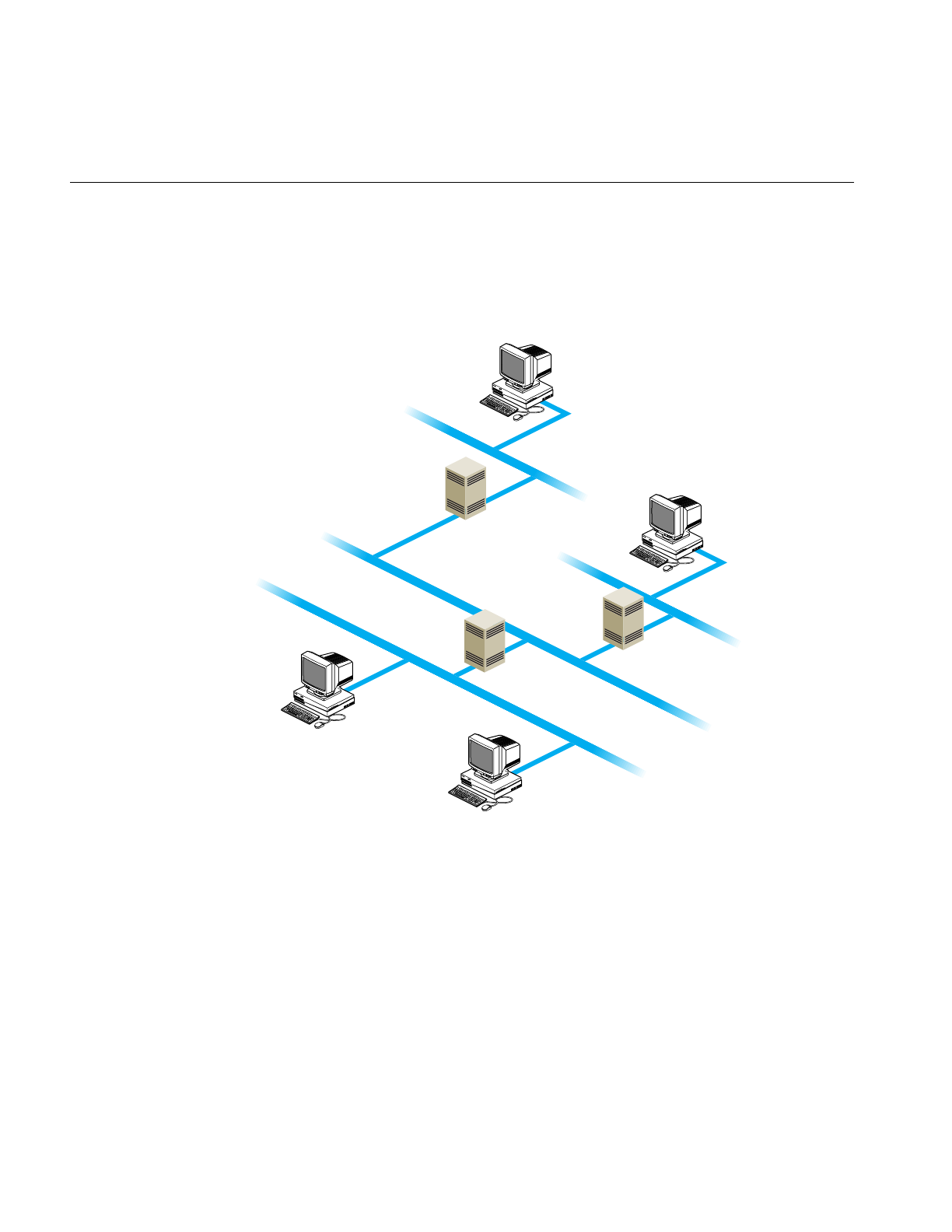
42
Chapter 3: Setting Up a Network
Understanding Where Multicast Packets Are Forwarded
Figure 3-1 shows an example network with three routers.
Figure 3-1 A Network With Multicast Routers
• If people on networks A, C, and D are listening for packets, as shown in the figure,
all four networks receive the multicast packets.
• If people on networks A and C are listening for packets, networks A, B, and C
receive the multicast packets.
• If three or more people on network A are listening for packets, networks A and B
receive the multicast packets. The multicast routing protocol prevents packets from
being sent to “leafs” of the network, such as networks C and D; however, it doesn’t
prevent packets from being sent to interior networks, such as network B.
Host
Host
Host
Host
Router 1
Router 2
Router 3
Net A
Net B
Net C
Net D
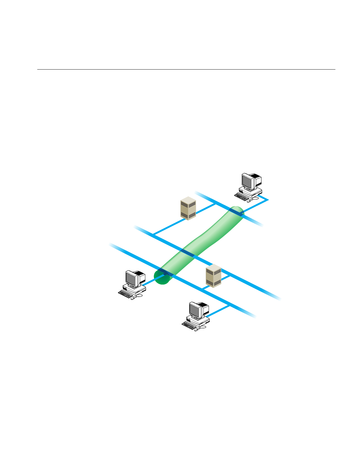
Setting Up a Router
43
Setting Up Tunnels to Support Multicast Packets
If your routers do not support multicast routing, you can support multicast packets by
creating tunnels between the networks. Any Silicon Graphics workstation running IRIX
Version 5.2 or later can be configured as the endpoint of a tunnel. With tunneling, the
multicast packets are encapsulated inside unicast packets, and then are sent to the other
end of the tunnel. They are converted back into multicast packets when they are received.
Figure 3-2 shows an example of a setup with a tunnel between networks A and C.
Figure 3-2 A Tunnel Between Networks A and C
Host
Host
Host
Router 1
Router 2
Net A
Net B
Net C

44
Chapter 3: Setting Up a Network
To create the tunnel, edit the file /etc/mrouted.conf. Step-by-step instructions follow:
1. Select the systems on each network that you will use for the sending and receiving
end of the tunnel.
Choose a system that is running IRIX Version 5.2 or later, is fast, and is not used
extensively. The audio and video data may be intermittent if the system you select is
slow or overloaded.
2. If you haven’t already done so, install the eoe.sw.ipgate subsystem from your IRIX
distribution source.
3. As root, edit the file /etc/mrouted.conf on the sending and receiving end of the tunnel.
Note that these endpoints can be separated by many routers; you can use any
machine on the network that is running IRIX Version 5.2 or later.
Add the following line for each network to which you want to establish a tunnel.
tunnel
<local IP address> <remote IP address>
In the above example, the system on network D would have the following entry:
tunnel 128.70.58.1 128.65.170.2
The system on network A would have the following entry:
tunnel 128.65.170.2 128.70.58.1
4. You can specify other optional settings for the tunnel. For details, see the
mrouted(1M) reference page.
5. Restart the system.
Note: One copy of the multicast packets is sent for each tunnel entry in mrouted.conf. This
results in extra network traffic. For example, suppose you have a workstation with one
network interface and you set up tunnels to workstations on three other networks. The
packets are replicated three times.
Updating /etc/rpc for NIS Users
The IRIX copy of the /etc/rpc file contains additions that are essential for using certain
multicast utilities if you’re running the Network Information Service (NIS). If the NIS
master is not running IRIX Version 5.2 or later, or is not a Silicon Graphics workstation,
verify that the /etc/rpc file on the NIS master includes these additions:
sgi_iphone 391010
sgi_videod 391011

Subnetting a Network
45
Subnetting a Network
Implementing the subnet address scheme is a very simple procedure. The following
steps are necessary to implement subnetting:
1. Set the netmask.
2. Reboot the station.
Note: If you have not done so already, read Chapter 2, “Planning a Network.” It contains
information about partitioning Internet addresses for subnetting.
Setting the Netmask
The netmask option of the ifconfig command is used to interpret and define the network
portion (subnets included) of the Internet address. A network mask defines the portion of
the Internet address that is to be considered the network part. This mask normally
contains the bits corresponding to the standard network part as well as the portion of the
host part that has been assigned to subnetworks. If no network mask is specified when
the address is set, it will be set according to the class of the network.
To configure a station’s primary interface to recognize a subnetted Class B address that
is using 8 bits of the host ID for defining the subnets, create or modify the
/etc/config/ifconfig-1.options file and insert the following line:
netmask 0xffffff00
This netmask value indicates that for the primary interface, the upper 24 bits of the
Internet address represent the network portion of the address, and the remaining 8 bits
represent the host ID. The nonsubnetted netmask for a Class B address (in hexadecimal)
would be 0xffff0000. The netmask value can be set using hexadecimal, dot-notation
Internet address, or pseudo-network name formats. This entry must be made on all
stations on the subnet.
Note: For stations with multiple interfaces, the network mask should be set for each
interface in the appropriate ifconfig-*.options file.

46
Chapter 3: Setting Up a Network
Rebooting the Station
When the netmask value is set, the station must be reconfigured and rebooted to
incorporate the new network address into the stations routing tables. Always reboot
routers before regular stations, because they provide routing information to other
stations and networks.
Reconfigure the kernel and reboot the station to initialize your changes and interfaces.
Some systems prompt for permission before reconfiguring the kernel, while others
simply return a shell prompt. In either case, enter the reboot command explicitly:
/etc/autoconfig
Automatically reconfigure the operating system? (y/n)y
reboot
Modifying the Network Interface Configuration
You do not always need to modify (configure) a station’s network interface; in most
situations, the default configuration suits the site’s needs. Modifying the network
interface configuration requires that you modify the /etc/config/netif.options file. You
modify this file if
• the station has more than two interfaces
• you don’t like or use the default naming conventions
• the default order is incorrect
There are two configurable variables in the netif.options file: interface name and interface
address. The interface name variable designates the order (first, second, third, or fourth)
and type of interface involved. The interface address variable assigns a valid Internet
address to each interface. There must be a valid Internet address for each interface in the
/etc/hosts file. Table 3-1 summarizes the interface name and interface address variables.

Modifying the Network Interface Configuration
47
You can modify either or both variables. Instructions for modifying both variables are
provided below.
Modifying the Interface Name
When a station has more than two network interfaces, you must modify the name entries
in the /etc/config/netif.options file to assign the interface order. Default order is assigned
only to the first two interfaces. Additionally, if you want to change the order (first,
second, and so on) or interface type assigned to a network interface, you must modify
the /etc/config/netif.options file. This example makes the first FDDI interface secondary.
1. Using the netstat command, verify the network interface’s name:
/usr/etc/netstat -ina
2. Using vi or any editor, open the netif.options file for editing:
vi /etc/config/netif.options
Table 3-1 Variables for the netif.options File
Variable Name Variable Examples
Interface Name ifxname=
where:
x = 1, 2, 3, or 4
name=ec0, et0, enp0,
enp1, fxp1, ipg0, ipg1, etc.
if1name=enp0
if2name=ipg0
if3name=enp1
if4name=enp2
Interface Address ifxaddress=
where:
x = 1, 2, 3, or 4
address=$HOSTNAME,
station name, or Internet
address
if1address=$HOSTNAME
if2address=fddi-$HOSTNAME
if3address=gate-goofy
if4address=128.70.28.2

48
Chapter 3: Setting Up a Network
3. Locate and modify the appropriate interface name variable. For this example, search
for the secondary interface name variable (if2name) and change it from the default
configuration to a configuration that supports the first FDDI interface as secondary:
Change from this:
: if2name =
to this:
if2name=ipg0
Caution: Note that all default variables (primary and secondary) start with a leading
colon (:). You must remove it and enter the interface type to change the default
interface name.
4. Save and exit the file.
If you have no other changes, autoconfigure and reboot the station. Otherwise, repeat
this procedure for each interface name change.
Note: When you alter the order of one network interface, the other interfaces in the
station remain in their default relative ordering. For example, on a three-interface station
(a=first, b=second, and c=third), if you were to make the default second the first (b=first),
the remaining interfaces would be configured a=second and c=third.
Modifying the Interface Address
To change the default interface address, modify the /etc/config/netif.options file. All
interface names require valid Internet addresses as found in the /etc/hosts file. The
$HOSTNAME variable pulls the station name from the /etc/sys_id file. This example
changes the second, third, and fourth interface addresses as follows:
• second interface address: fddi-$HOSTNAME
• third interface address: gate-goofy
• fourth interface address: 128.70.28.26

Modifying the Network Interface Configuration
49
Follow these instructions to modify your network interface address according to the
above example:
1. Verify or assign a valid entry for each interface in the /etc/hosts file. Write down the
name and address for each interface.
2. Using vi or any editor, open the netif.options file for editing:
vi /etc/config/netif.options
3. Locate and modify the appropriate interface address variable. For this example, we
want to modify the second, third, and fourth interface address variables. Find and
modify each variable as follows:
Change from this:
: if2addr=gate-$HOSTNAME
if3addr=gate2-$HOSTNAME
if4addr=gate3-$HOSTNAME
to this:
if2addr=fddi-$HOSTNAME
if3addr=gate-goofy
if4addr=128.70.28.26
Caution: Note that all default variables (primary and secondary) start with a leading
colon (:). You must remove it and enter the interface address to change the default
interface address.
4. Save and exit the file.
Repeat this procedure for each interface address change. If you have no other changes,
reconfigure and reboot the station.
Assigning IP Aliases
You can assign multiple IP addresses to a single network interface using the IP aliasing
feature of the ifconfig command (see ifconfig(1M)). This feature is useful if you find it
necessary to use the same network interface for connections to several networks; it is also
useful for maintaining an obsolete address for a host until users learn its new address. IP
aliasing is supported on all network interface types.

50
Chapter 3: Setting Up a Network
When IP aliasing is implemented on a host, the address that the /etc/host file assigns to
the hostname in /etc/sys_id is considered the primary address for the interface, and
alternative names assigned by the ifconfig command are considered IP aliases. When you
display network information (see “Collecting Network Statistics With netstat” in
Chapter 4), the primary address of an interface is listed first, followed by its aliases.
To assign an IP alias, use this form of the ifconfig command:
#ifconfig interface alias address [netmask mask_num] [broadcast address]
Note: Be sure to read the information in “IP Alias Guidelines” (below) before assigning
IP aliases.
You can specify a hostname from /etc/hosts instead of an IP address as the value of alias.
For example, either command below assigns an IP alias to the ec0 interface. The interface
in this example uses a netmask and broadcast address, but these fields are optional:
# ifconfig ec0 alias 128.70.40.93 netmask 0xffffff00 broadcast 128.70.40.255
# ifconfig ec0 alias plum netmask 0xffffff00 broadcast 128.70.40.255
IP Alias Guidelines
In theory, the number of IP aliases assigned to a given network interface is limitless;
however, the recommended maximum number is 1000. In addition, the primary address
of an interface and all its IP aliases should share a common subnet address. For example,
if the primary address of an interface on a class B network is 128.70.12.23, its IP aliases
should be addresses such as 128.70.12.19, 128.70.12.53, and so on.
Creating an IPaliases File
You can save IP alias settings in the /etc/config/ipaliases.options file so they are
automatically assigned during the network initialization process. The ipaliases.options file
is read by the network script if the /etc/config/ipaliases file contains the value on. Use the
procedure below to create an ipaliases.options file and assign IP aliases automatically
during network initialization:
1. Edit ipaliases.options using your favorite editor:
#vi /etc/config/ipaliases.options

Changing Network Parameters
51
Your entries should look similar to the example below. In this example,
broadcasting is performed on the Ethernet but not the FDDI network:
ec0 128.64.56.51 netmask 0xffffff00 broadcast 128.64.56.255
ec0 128.64.56.12 netmask 0xffffff00 broadcast 128.64.56.255
ipg0 190.111.79.16 netmask 0xffffff00
ipg0 190.111.79.10 netmask 0xffffff00
2. Create an ipaliases file and set IP aliasing on in the file:
#chkconfig -f ipaliases on
3. Stop and restart the network to put your changes into effect:
/etc/init.d/network stop
/etc/init.d/network start
IP Aliasing and Routing
Each IP alias is maintained in the IRIX routing table as a host route between the primary
address and the alias. By default, IRIX assumes that a host containing multiple network
interfaces is a router. These multi-homed hosts perform packet forwarding and advertise
routing information on the networks to which they are attached. However, if you
implement IP aliasing on a host with a single network interface (to connect a local
network and the Internet, for example), route advertising is not enabled. In this case, it is
necessary to force route advertising to make the network location of the local hosts
known.
To force route advertising, enter the -s option in the routed.options file on the IP-aliased
host.
Changing Network Parameters
Network parameters are those settings that determine how an interface processes or
supplies certain network information. Modifying network parameters requires that you
create and modify the appropriate /etc/config/ifconfig-#.options file (where “#” can be 1, 2,
3, or 4, based on the interface name).
The default parameter settings are known to function well and suit most site needs.
Changing the settings can cause a network to become dysfunctional. It is recommended
that these parameters be changed only by experienced or trained network managers.

52
Chapter 3: Setting Up a Network
Modifying the ifconfig-#.options File
There are four nondefault network parameters that can be set in the ifconfig-#.options file:
• netmask
• broadcast address
• Address Resolution Protocol (ARP)
• route metric
These steps show how to set the nondefault network parameters:
1. Using the netstat command, determine the order assigned to the network interface
at configuration time:
/usr/etc/netstat -i
2. Using vi or any editor, open or create the file /etc/config/ifconfig-#.options, where the
pound sign (#) represents the network interface’s name. For example, to configure a
primary interface, open or create the file /etc/config/ifconfig-1.options.
3. To change the network mask value for a network interface, enter a line with the
word netmask followed by a space and either the 32-bit hexadecimal value, Internet
address dot-notation, or the pseudo-network name:
netmask 0xffffff00
See “Turning On Multicast Routing” on page 41 for more details regarding
netmasks.
4. To change the broadcast address for a network interface, enter a line with the word
broadcast followed by a space and the dotted decimal IP broadcast address:
broadcast 189.170.6.0
To enable or disable the Address Resolution Protocol (ARP), enter a line with arp (to
enable) or -arp (to disable):
arp
The ARP tables are used by some of the network management tools (netstat,ifconfig,
and so on) and provide the administrator with invaluable network information.

Dynamic Host Configuration With Proclaim
53
5. To change the routing metric count for a network interface, enter a line with the
word metric followed by a space and the count:
metric 7
The default metric count, also called hops, is 0. The routed daemon monitors the
number of hops required to route data from one network to another. If you want to
reduce network traffic on a particular route, increase the metric count on the
appropriate router.
The interface configuration file for the secondary interface might look like the following:
cat /etc/config/ifconfig-2.options
netmask 255.255.255.0
broadcast 129.78.50.0
-arp
metric 4
The interface configuration file above indicates that the Class B network is subnetted
using 8 bits of the host ID for the subnet. It uses 0 as the broadcast address instead of the
default 1. ARP has been disabled and the metric (hop) count has been set to 4 to
discourage router traffic.
Dynamic Host Configuration With Proclaim
This section describes the IRIX proclaim facility, which is based on the dynamic host
configuration protocol (DHCP) described in RFC 1541. Proclaim and DHCP allow you to
allocate hostnames and network addresses automatically.
DHCP permits site administrators to set up one or more server systems that dynamically
distribute network IP addresses and site configuration parameters to new or requesting
client systems. In this way, a site with only a few available addresses can serve a large
number of hosts that connect to the network only occasionally, or a large site can manage
the permanent assignment of addresses with a minimum of administrative attention.
The proclaim facility consists of a daemon that runs on a master server, optional relay
daemons for servers on subnets, GUI configuration programs, and a client application
that communicates with the DHCP servers. All these programs are bundled with the
IRIX operating system.

54
Chapter 3: Setting Up a Network
The sections below provide information about configuring proclaim servers and clients.
If you are not comfortable with the basic concepts of networking, IP addresses, and
netmasks, please read Chapter 1, “Internet Protocol Addresses” in Chapter 2, and
“Setting the Netmask” in this chapter before continuing with this section.
Configuring the DHCP Server
The dhcp_bootp program is a server that communicates with DHCP and proclaim clients
to provide host configuration information, including an IP address at minimum. If your
site uses DNS to maintain the hosts map, you need some external mechanism (such as a
script) to update the DNS map from the DHCP server. If your site uses NIS to maintain
the hosts and ethers maps, dhcp_bootp must be run on the same machine as the NIS
master server.
The DHCP server generally uses configuration parameters based upon the subnet
number of the originating client request. The configuration files are all placed in the
directory/var/dhcp/config and are named in the form config.<netnumber>. For example, the
configuration file for clients on the 128.78.61 network should be named config.128.78.61.0.
If the subnet configuration file does not exist, then the config.Default file applies instead.
If the default configuration file is missing or unreadable, clients are configured to match
the DHCP server itself.
To configure the DHCP server, you can run the ProclaimServerMgr graphical interface, as
described by the ProclaimServerMgr(1M) reference page. If you prefer, you can configure
server options using your favorite text editor, altering the keywords documented on the
dhcp_bootp(1M) reference page.
Configuring the DHCP Relay Agent
Thedhcp_relayprogram is a subnet agent that communicates with the main DHCP server
to provide DHCP and proclaim clients with host configuration information. If your site
uses DNS to maintain the hosts map, you need some external mechanism (such as a
script) to update the DNS map from the DHCP server. If your site uses NIS to maintain
the hosts and ethers maps, your site’s main DHCP server must be on the same machine
as the NIS master. In any case, you should run dhcp_relay on all subnets besides the one
with the main DHCP server.

Dynamic Host Configuration With Proclaim
55
The DHCP relay agent reads the configuration file /var/dhcp/config/dhcp_relay.servers to
determine the location of the main DHCP server. This configuration file should contain
the IP address and hostname of the DHCP server, on two separate lines.
To configure the relay agent, you can run the ProclaimRelayMgr graphical interface, as
described by the ProclaimRelayMgr(1M) reference page. If you prefer, you can configure
relay agent options using your favorite text editor, following the steps documented on
the dhcp_relay(1M) reference page.
The Proclaim Client
The proclaim client communicates with a DHCP server to obtain host configuration
parameters, including an IP address and IP address lease at minimum. You can use
proclaim to set up and configure new systems automatically, and also to move systems
from one network to another without administrative intervention. The proclaim client can
also verify configurations at reboot time.
For more information about setting up proclaim on client systems, see the proclaim(1M)
reference page.
Limitations and Restrictions
The following restrictions and limitations are present in this release:
• The DHCP server must be the NIS master if your site uses NIS for hostname, IP
address, or network hardware address validation and mapping. Note that NIS is an
optional software product, and not all systems and networks use it.
• If your site uses DNS to maintain the hosts map, you need an external mechanism
(manual or automated) to update the DNS map from DHCP. This limitation should
be lifted in the next release.
• The server cannot respond simultaneously to both DHCP and bootp clients requests,
although it can act as the bootp server for normal bootp requests.

56
Chapter 3: Setting Up a Network
Creating a Local Network Script
To start and terminate locally developed network daemons, or to publish ARP entries
and set routes, create the separate shell script /etc/init.d/network.local.Make symbolic links
in/etc/rc0.dand/etc/rc2.dto this file to have it called during station startup and shutdown:
ln -s /etc/init.d/network.local /etc/rc0.d/K39network
ln -s /etc/init.d/network.local /etc/rc2.d/S31network
See/etc/init.d/network for the basic format of the script. Also refer to network(1M),rc2(1M),
and rc0(1M) for more information.
Turning On Remote Access Logging
Several network daemons have an option that lets you log remote accesses to the station
log file /var/adm/SYSLOG by using syslogd. Sites connected to the Internet should use this
feature. To enable logging for ftpd,tftpd, and rshd, edit /etc/inetd.conf and add “-l” after the
right-most instance of ftpd and tftpd. Add “-L” after the right-most instance of rshd. For
additional ftp logging, add “-ll” to the ftpd entry. Signal inetd to reread its file after you
have added your changes:
/etc/killall -HUP inetd
Remote logins by means of rlogin,telnet, and the 4DDN sethost programs can be logged
by login. Edit /etc/default/login and add the keywords “SYSLOG=ALL” or
“SYSLOG=FAIL” to it. For example, this command in the login file logs successful and
failed local and remote login attempts to syslogd:
syslog=all
See the login(1) reference page for details.
Setting Up Network-Wide Services
In addition to the required software that you must set up on each system on the network,
you may want to designate certain systems to provide network-wide services. For
example, you can set up a system as an InSight server, so that users can access a complete
set of InSight books without installing them all on their local disks. The following
sections discuss setting up an anonymous ftp server, and setting up an InSight server.

Setting Up Network-Wide Services
57
How to Set Up a Proper Anonymous FTP Account
An anonymous FTP account is a way for you to make information on your system
available to anybody, while still restricting access to your system. An anonymous FTP
account lets anybody log in to your system as user “anonymous,” or “ftp.” Any such
login causes the system to chroot to the FTP home directory (~ftp). This effectively limits
the anonymous FTP user from accessing any part of your directory structure that is not
a subdirectory of ~ftp (see chroot(1M)).
The following procedure is designed to help you set up a network-accessible anonymous
FTP account. As usual, understanding the various steps and continually monitoring how
the account is used are necessary to protect your system security.
1. Create the anonymous FTP user entry in /etc/passwd. The user name should be “ftp.”
Put an asterisk (*) in the password field, and assign user and group IDs, a home
directory, and a login shell. The following is an example of a typical entry in
/etc/passwd for an anonymous FTP account:
ftp:*:997:999:anonymous FTP account:/usr/people/ftp:/dev/null
The login shell /dev/null is recommended but not required, and the home directory
can be anywhere, with reservations as explained in the next step.
2. Create an anonymous FTP directory. This may be wherever you like but, especially
if you are going to allow writes to it, it should probably be on a separate partition
from / or usr. That way, if the partition fills up, it will not disable basic system
operations.
In this example procedure, /usr/people/ftp is the name of the anonymous FTP
directory. First, make the directory:
#mkdir /usr/people/ftp
and then, if it is a separate disk or disk partition, you can mount the device on it (see
mount(1M)). The anonymous FTP home directory you make must be the same one
you specify in the /etc/passwd file.
3. Set global read and access permission for the anonymous FTP directory, and change
the owner to “ftp” and the group to “other”:
#chmod 555 /usr/people/ftp
#chown ftp.other /usr/people/ftp

58
Chapter 3: Setting Up a Network
4. Change directory to the ftp home directory and create the subdirectories used for
FTP access:
#cd /usr/people/ftp
#mkdir bin etc pub private
In addition to the standard bin,etc, and pub directories, you may wish to make a
private directory for private transmissions, as explained below.
5. For the bin and etc directories, set the owner to “root,” group to “sys,” and global
read and access permissions:
#chmod 555 bin etc
#chown root.sys bin etc
6. For the pub directory, set the owner to “ftp,” the group to “other,” and global read,
write, and access permission:
#chown ftp.other pub
#chmod 777 pub
Caution: By allowing write permission, you make it possible for anonymous FTP
users to fill the disk partition.
7. If you created a private directory, set the permissions to allow anybody to write to it
but not to read its contents:
#chown ftp.guest private
#chmod 333 private
Anybody logging in can now place or retrieve files in the private directory, but they
must be told the name of the file beforehand, because they cannot list the directory
contents.
Caution: By allowing write permission, you make it possible for anonymous FTP
users to fill the disk partition.
8. Copy the ls command from /bin to ~ftp/bin:
#cp bin/ls bin

Setting Up Network-Wide Services
59
9. Copy /etc/passwd and /etc/group to ~ftp/etc and edit the files to an acceptable
minimum:
#cp /etc/passwd etc
#cp /etc/group etc
A good choice for the contents of passwd might be
root:*:0:0:super-user:/:/dev/null
bin:*:2:2:system tools owner:/bin:/dev/null
sys:*:4:0:system activity owner:/usr/adm:/dev/null
ftp:*:997:999:anonymous FTP account:/usr/people/ftp:/dev/null
A good choice for the contents of group might be
other::995:
guest:*:998:
ftp:*:999:
10. Set restrictive permissions on ~ftp/etc/passwd and ~ftp/etc/group:
#chmod 444 etc/*
11. Add appropriate device and library files for anonymous FTP as follows:
#mkdir dev
#/sbin/mknod /usr/people/ftp/dev/zero c 37 0
#mkdir lib
#cp /lib/libc.so.1 lib
#cp /lib/rld lib
12. Add the following entry to the file /etc/aliases to cause mail sent to the user ftp to go
to the postmaster:
ftp: postmaster
Run the command newaliases to make this take effect. (This assumes you have an
alias of postmaster in /etc/aliases. See aliases(4) and newaliases(1M).)
13. Enable FTP logging as described in “Limiting inetd Services” in Chapter 5 in IRIX
Admin: Backup, Security, and Accounting . Note that if you use one -l argument
with ftpd, you record only successful and unsuccessful FTP login attempts. If you
use two “l”s, you also record actions on files and directories performed during ftp
login sessions, and three “l”s cause the report to include the number of bytes
transferred in get and put operations.

60
Chapter 3: Setting Up a Network
For example, the following entry in /etc/inetd.conf means all logging information but
the byte count is sent to /var/adm/SYSLOG:
ftp stream tcp nowait root /usr/etc/ftpd ftpd -ll
14. Once you have edited /etc/inetd.conf, restart inetd with the following command:
#/etc/killall -HUP inetd
Note: Although the FTP logging records in /var/adm/SYSLOG now show any
passwords entered by users logging in, no password checking is done for
anonymous FTP. The convention is for anonymous users to enter their e-mail
addresses for passwords, but they could just as easily enter another user’s address
or anything at all.
If you place any text in the file /etc/issue, it is displayed when a user connects to your
system, before the login prompt is displayed. You might want to include information
here about the kind of services your FTP site offers, and whom to contact in case of
problems. In addition, any text in the file ~/ftp/README is displayed after the
anonymous FTP user logs in.
Refer to crontab(1), syslogd(1M), and the file /var/spool/cron/crontabs/root for information
on changing the frequency or nature of system log file maintenance—you may, for
example, want to increase the length of time you keep log files. To help you keep track of
the demands made on your public FTP server, see Chapter 6 of IRIX Admin: Backup,
Security, and Accounting for information on auditing system resource usage, and
Chapter 7 of IRIX Admin: Backup, Security, and Accounting for general system
accounting information.
Setting Up an InSight File Server
The files and directories that make up the InSight system of online documentation take
up a great deal of space. In your network, there is no reason for each system to maintain
a separate copy of the InSight documents as long as all systems are at substantially the
same software revision level. If the InSight software revision level is the same across
several systems, you can designate one system to serve the others with the InSight files,
thus freeing up disk space on the client systems.
Be sure to choose a server system that is not called upon to carry a heavy workload, and
take your network performance into account before you begin. If your users use InSight
a great deal and your network is already burdened, you may find that your users will not
appreciate the decreased response time from both InSight and your network in general.

Setting Up Network-Wide Services
61
Also, if a person is to use the InSight server as his or her workstation, that person must
be prepared to accept a certain (possibly substantial) amount of disk, CPU, and network
overhead as a result.
There are two convenient ways to set up an InSight server. These will be detailed in the
following subsections. Both methods require that you have the NFS software option
installed. If you do not understand the terms and concepts behind NFS, you should read
the ONC3/NFS Administrator’s Guide and the NIS Administration Guide before
undertaking these projects. The second method described here also requires a dedicated
CD-ROM drive to hold the InSight distribution media.
A Conventional InSight Server/Client System
To install the IRIS InSight Viewer and Document Library on a remote server and retrieve
the information from a local client system, follow the steps below.
On the server system:
1. Log in as root (superuser).
2. Bring up inst(1M) and install the complete IRIS InSight product image (from your
CD-ROM drive or distribution directory) with the commands
Inst> install insight insight_gloss *.books.*
Inst> go
The total size of the viewer and document library is a little less than 23 megabytes.
3. Export the /usr/share/Insight/library/SGI_bookshelves directory using the System
Manager or the exportfs command:
exportfs -i /usr/share/Insight/library/SGI_bookshelves
If the server does not have a graphical display, a warning is generated during the
exit. This warning relates to updating the X server's font directory and can be
ignored.
On the client system:
1. Log in as root (superuser).
2. Give the command
versions remove *.books.*
to remove the books on your bookshelves.

62
Chapter 3: Setting Up a Network
3. Run the inst command on your client system and give the following commands to
install the insight.sw.client subsystem (you may want to install the insight.man.man
and the insight.man.relnotes subsystems as well):
Inst> keep insight insight_gloss
Inst> install insight.sw.client
Inst> go
4. Mount the SGI_bookshelves directory from your server on your client system. In the
example below, the name of the server machine is capra.
mkdir /usr/share/Insight/library/SGI_bookshelves
mount capra:/usr/share/Insight/library/SGI_bookshelves
/usr/share/Insight/library/SGI_bookshelves
Note that when you enter the mount command on your client system, the entire
command line goes on a single line. The command is broken across two lines in this
example due to formatting limitations.
Note: If you have remote-mounted your InSight books, the Silicon Graphics desktophelp
system will not operate correctly while the books are mounted. To view the desktophelp,
unmount the books temporarily.
A CD-ROM InSight Server/Client System
With this method, you need not use up your disk space for the InSight files if you have a
CD-ROM drive you can dedicate to InSight. You simply leave the CD with the InSight
distribution in the drive and link the mounted distribution to the directory where InSight
would have installed the files. The drawback of this system is that you must dedicate a
CD-ROM drive to the purpose, but this method can be used with NFS to provide server
access to your entire network.
Note: If you have a version of the IRIS InSight Document Library installed on your client
disk but you want to mount the books from the CD-ROM, you must remove all the files
in /usr/share/Insight/library before creating the symbolic link described in step 2. Use the
versions remove command to cleanly remove the books, then check the directory to be sure
all files have been removed.
If you wish to use the IRIS InSight Viewer and Document Library from the CD-ROM and
access the information from a local or remote system, follow the steps below.

Setting Up Network-Wide Services
63
On the server system with the CD-ROM drive:
1. Log in as root (superuser).
2. Insert the IRIS InSight CD into the CD-ROM drive. If the drive is not mounted, use
the System Manager or the mount(1M) command to mount the drive. The most
common mount point is /CDROM. If the drive is mounted correctly, you should be
able to change directories to /CDROM and see all the files in the IRIS InSight CD. To
see the files, use the command
cd /CDROM/insight
3. As root, create a symbolic link from /usr/Insight/library/SGI_bookshelves to the CD
insight directory. You may need to create the directory /usr/Insight/library if it doesn't
exist. Use the commands:
mkdir -p /usr/share/Insight/library
ln -s /CDROM/insight/SGI_bookshelves /usr/share/Insight/library
Note that when you enter the link command on your client system, the entire
command line goes on a single line. The command is broken across two lines in this
example due to formatting limitations.
At this point, the InSight bookshelves are mounted on your server and available for
use on that system. To allow users on other systems on your network to use the
bookshelves, proceed to step 4.
4. If you want to share the bookshelves with other users on your network, export the
/CDROM directory using the System Manager or the exportfs command:
exportfs -i /CDROM
On each client system, perform the following steps:
1. Log in as root (superuser).
2. Run the inst command and give the following commands to install the
insight.sw.client subsystem (you may want to install the insight.man.man and the
insight.man.relnotes subsystems as well). You can get the installation software from
the CD in the /CDROM/dist directory on the server.
Inst> keep *
Inst> install insight.sw.client
Inst> go

64
Chapter 3: Setting Up a Network
3. Mount the bookshelves from the server. In the example below, the name of the
server machine is capra. Use the following command:
mount capra:/CDROM/insight/SGI_bookshelves
/usr/share/Insight/library/SGI_bookshelves
Note: When you enter the mount command on your client system, type the entire
command on a single line. The command in the previous example is broken across
two lines due to formatting limitations.
Using Remote InSight
After the software has been installed, you should force your shell to remake its list of
available programs and commands with the command
rehash
You can now invoke the IRIS InSight Viewer. The command to invoke the viewer is iiv
(an acronym for IRIS InSight Viewer):
iiv
Troubleshooting Your Ethernet Connection
This section addresses some of the common Ethernet-related problems. See also
“Troubleshooting System Configuration Using System Error Messages” in IRIX Admin:
System Configuration and Operation.
Cable Problems
Unplugged or loose cables are the most common problem that causes Ethernet-related
error messages. For example:
unix: <
ethernet_device
>: no carrier: check Ethernet cable
This message means that the carrier was not detected when attempting to transmit. One
recommendation is
• Check to see if the Ethernet cable is unplugged from the back of the machine. For
detailed instructions on connecting the cable, see your owner’s guide. You do not
need to shut down the system to connect or disconnect the cable. If you re-connected
the cable, test the network connection.

Troubleshooting Your Ethernet Connection
65
After determining that the transceiver cable is plugged into the back of the machine and
also into the transceiver box, look for other possible reasons for failure.
• Check the machine’s transceiver.
• Check the transceiver cable, and try swapping it out with one that is working on
another machine.
• Check for a problem with a 10baseT hub.
• If you try all the troubleshooting techniques and you still cannot access the
network, contact your service provider; the network itself may be temporarily out
of order.
For more information on this error, see the reference page for ethernet(7).
Late Collisions
Another problem related to cabling is that of late collisions. These result in errors like the
following:
unix: <
ethernet_device
>: no carrier: check Ethernet cable
The controller tried to transmit a packet but received a late collision signal from another
machine. This usually indicates a problem in the Ethernet cable layout. The most
frequent causes of this problem are excessively long cables and loose cable connections.
To isolate the problem, first look for violations of the Ethernet cable limits. For 10BASE5
cable (thicknet) the maximum segment length is 500m; for 10BASE2 cable (thinnet) the
maximum segment length is 200m. The length of a transceiver cable (the cable that goes
between a machine’s Ethernet port and its transceiver) should not exceed 50meters. If all
cables are within the specified limits and all connectors are firmly seated, this error could
indicate a hardware problem in an Ethernet controller or transceiver. Some
recommendations are:
• Check other machines on the network for bad Ethernet controllers.
• Check other machines on the network for bad transceivers. I f you suspect a bad
transceiver, you can try swapping in a different one that works on another system.
• Check to see if removing a certain machine from the network makes the problem
change or disappear.

66
Chapter 3: Setting Up a Network
Packet Size
A bad Ethernet controller somewhere on the network can cause problems by sending
packets that are too large or too small, causing errors like this:
unix: <
ethernet_device
>: packet too small (length = <packet size>)
unix: <
ethernet_device
>: packet too large (length = <packet size>)
The Ethernet controller received a packet that was smaller than the minimum packet size
or larger than the maximum packet size allowed by Ethernet. This problem is caused by
another machine with a bad Ethernet controller or transceiver. Some recommendations
are
• Check other machines on the network for bad Ethernet controllers.
• Check other machines on the network for bad transceivers. I f you suspect a bad
transceiver, you can try swapping in a different one that works on another system.
• Check to see if removing a certain machine from the network makes the problem
change or disappear.
For more information on this error, see the reference page for ethernet(7).
Unable to Contact Server System
When your system cannot contact a network system, an error message similar to this is
displayed:
portmapper not responding: giving up
This problem occurs in one of these situations:
• The system is not running.
Physically go to the system or call the system’s Primary User or Administrator to
check to see if the system is powered up and running.
• The network is not running.
To check, try to access another system on the network.

Troubleshooting Your Ethernet Connection
67
• The network administrator changed some information about the system or about
the system’s logical location on the network.
Check whether this is the case, and get the appropriate information to fix the
problem.
• The system has too many users or systems using its resources. It cannot provide
services to you at this time.
Contact the system’s Primary User or Administrator to check on this.
Checking Additional Network Interfaces
If your system has more than one network interface (additional interfaces are usually
fiber-optic [FDDI] links or SLIP connections or other Ethernet boards) you can easily
perform the above checks on each network interface.
To check your other network interfaces, give the netstat -in command. You see output
similar to the following:
Name Mtu Network Address Ipkts Ierrs Opkts Oerrs Coll
ec0 1500 128.70.0 128.70.0.9 15 0 15 0 24
ec1 1500 128.70.2 128.70.2.5 15 0 15 0 24
sl0 1006 (pt-to-pt) 128.70.0.9 0 0 0 0 0
lo0 8304 loopback localhost 8101 0 8101 0 0
The second Ethernet connection is to the network 128.70.2, a different LAN from the first
Ethernet connection. The address of the local station on the second LAN is 128.70.2.5. To
check that connection, use the ping command to test the connection to another station on
that network.
There is also a SLIP link running in this example. The SLIP link extends the same LAN
as ec0 to another system in a different location. To test this link, find the hostname or IP
address of the station at the other end of the SLIP link and use the ping command to test
connectivity.
The lo0 interface is the loopback network interface on the local host.


69
Chapter 4
4. Managing a Network
This chapter provides information on how to manage a network after installation.
Management includes maintenance, monitoring, and problem isolation. This chapter
provides brief descriptions of the various network management tools, help in
interpreting network statistics, a discussion of the factors that can affect network
performance, and some of the network kernel configuration options. The following
topics are covered:
• “Network Startup and Shutdown” on page 69.
• “Network Management Tools” on page 71
• “Interpreting Network Statistics” on page 74
• “Troubleshooting Poor Network Performance” on page 78
Network Startup and Shutdown
The main network script is /etc/init.d/network. Other scripts for other network
applications (UUCP, mail, and so on) also reside in this directory, but are covered in their
appropriate chapter in this guide. A brief description of the network script is provided.
The network master script is called during system startup and shutdown. It defines the
system name and host ID, ensures that the system has a valid Internet address, starts
networking daemons, and initializes the network interfaces. Site-dependent
configuration commands to start and stop local daemons, add static routes, and publish
ARP entries should be put in a separate shell script called /etc/init.d/network.local. Make
symbolic links from /etc/rc0.d and /etc/rc2.d to /etc/init.d/network.local so the network.local
file is called at system startup and shutdown (see “Creating a Local Network Script” on
page 56 for setup procedure).

70
Chapter 4: Managing a Network
Thenetwork master script is linked to /etc/rc0.d/K40network,which is invoked from /etc/rc0
during shutdown, and to /etc/rc2.d/S30network, which is invoked from /etc/rc2 during
startup. The script understands two arguments: startandstop. It can be run manually for
testing and troubleshooting network-related problems without having to reboot the
system.
Network Initialization Process
During system initialization, the shell script /etc/init.d/network is called. These are the
actions performed by the script at startup:
1. Checks hostname and Internet address to determine if system should be configured
as standalone or networked. Checks sys_id and hosts files. If the network
configuration flag is off, the system is configured for standalone operation.
2. Determines names and addresses or primary and router interfaces for typical
configurations.
3. Obtains any site-dependent information for interfaces from the netif.options file.
4. If system is not diskless, the shell script flushes all old routes.
5. Configures all interfaces, including loopback, using the ifconfig command.
6. If configured for IP packet filtering, the shell script starts the IP packet filtering
daemon (/usr/etc/ipfilterd). The ipfilterd daemon must be started before gateway
interface initialization.
7. Initializes gateway interface.
8. Initializes additional interfaces specified in the netif.options file.
9. If specified, initializes the Hypernet interface according to the ifconfig-hy.options file.
10. Initializes the loopback interface.
11. Using the chkconfig command, determines daemon configuration and reads relevant
daemon configuration files (*.options).
12. Sets default route for all IP multicast packets to the primary interface.
13. If NIS software is configured, defines and sets NIS domain name.
14. If NIS software is configured, starts appropriate NIS daemons.
15. If NFS software is configured, starts appropriate NFS daemons and mounts any
NFS filesystems listed in the /etc/fstab.
16. If configured on with chkconfig, it starts standard daemons (inetd,timed,timeslave,
rarpd,rwhod,snmpd, and so on).

Network Management Tools
71
Network Shutdown Process
During system shutdown, /etc/init.d/network stops the daemons and disables the network
devices. These are the actions the script performs at system shutdown:
1. Kills all network services that may be associated with a shell (rlogind, rexecd, rshd,
ftpd, telnetd, and so on).
2. Kills some network daemons immediately (inetd, bootp, tftpd, snmpd, and so on).
3. If NFS is running, unmounts remote filesystems.
4. Kills all remote daemons.
5. If NFS is running, unexports exported filesystems. See the ONC3/NFS
Administrator’s Guide and the NIS Administration Guide for complete information
about the optional NFS software.
6. Kills daemons that must be kept alive until the last minute (portmap, slip, ipfilterd).
7. Gracefully takes the system off the FDDI ring, if it is on the ring.
8. Stops the ypbind process of NIS.
Network Management Tools
This section describes a number of standard and some optional networking tools at your
disposal for day-to-day management of your network. Except as noted, the standard
networking tools reside in the /usr/etc directory. See the online reference pages for
additional information.
ifconfig(1M) Configures the network interface devices. ifconfig is performed at boot
time by the master network configuration script /etc/init.d/network.
Interface configuration includes enabling and disabling the interface
and any interface options that should be set when the interface is
configured. Options include support for the Address Resolution
Protocol (ARP), routing metrics, netmask, broadcast addresses, and so
on. The ifconfig tool used with the station’s interface name displays the
current interface configuration.

72
Chapter 4: Managing a Network
netstat(1) Displays various network-related data structures that are useful for
monitoring and troubleshooting a network. It has many options to show
information about all or specific interfaces (-i or -I), routing tables (-r
and -M), socket information (-a or -A), queue information (-iq),
network memory (-m), and protocols (-p).
arp(1M) Displays and manipulates arp table entries located in cache. arp options
include-a for all entries, -d to delete an entry, -s to publish an entry and
act as a server for this entry, and -f to pull information from a specified
file instead of /dev/kmem. arp. This is a good tool for troubleshooting
physical address resolution on a network. arp does not display the local
station’s Ethernet address. To get a local station’s Ethernet address, use
the netstat command with the -ia options.
rpcinfo(1M) Provides information about Remote Procedure Call (RPC) based
programs on local and remote stations. This is an excellent tool for
isolating network problems related to the RPC service. The information
provided by rpcinfo includes a list of rpc-based applications (portmapper,
NIS, rstatd, and so on), and the program number, version number,
protocol (TCP/UDP), and associated port number. If you are running an
RPC-based network application and cannot get a response from the
remote station, use the rpcinfo tool to ensure that the remote station
supports the desired application.
ping(1M) Tests and measures general network performance. It is based on the
Internet Control Message Protocol (ICMP) and sends an
ECHO_REQUEST soliciting an ECHO_RESPONSE, thereby creating a
two-way stream. It provides general information about packet loss and
round-trip time. ping increases network load; this factor should be
considered when testing a network with ping.
spray(1M) Sends a one-way stream of packets to a station using remote procedure
calls. It reports information about the transfer rate and the number of
packets received by the remote station. It provides very limited
information about general network performance.
rtquery(1M) Sends a request to a designated station for information on the station’s
network routing tables (routed or gated). This tool is especially useful for
troubleshooting routing problems.
traceroute(1M) Tracks packets as they journey through the network. This tool is very
useful for isolating network and router faults in a large heterogeneous
network. It displays the names and addresses of all the intermediary

Network Management Tools
73
routers that support the Internet Protocol “time-to-live” (TTL) field. It
also displays the amount of time the packet spends traveling to the
router, on the router, and leaving the router. traceroute increases network
load; this factor should be considered when testing a network with
traceroute.
route(1M) Manipulates the network routing tables. Typically, the routing tables are
handled automatically by the routed or gated daemon. However, route
can be used to create, maintain, and delete static routing tables, to flush
routing tables, and to show metric information about routes. To have
static routes incorporated at startup, modify the file /etc/gateways and
/etc/config/routed.options.
rup(1C) Displays status information, including uptime and load average, about
remote stations using Sun RPC broadcasts. If no specific station is
specified, it uses broadcasting and returns information about stations on
the local network; broadcasting does not go through routers. This tool is
useful for isolating physical problems with a station or the network.
ttcp(1) Used to test Transmission Control Protocol (TCP) and User Datagram
Protocol (UDP) performance. This tool provides a more realistic
measurement of performance than the standard tests (spray,rup,ping). It
allows measurements to be taken at both the local and remote end of the
transmission.
These network management tools are available as options for use on any Silicon
Graphics system:
NetVisualyzer A passive network management product. It offers a set of graphical
traffic monitoring, diagnostics, planning, and performance analysis
tools that provide network information and statistics for Ethernet or
FDDI networks in a visually intuitive form. NetVisualyzer comprises six
tools: NetLook, NetGraph, NetCPA, Analyzer, RouteQuery, and
TraceRoute. NetVisualyzer allows you to view and monitor your
network, collect network statistics and generate reports based on those
statistics, and decode heterogeneous packets layer by layer.
SPECTRUM A UNIX based network management tool for large-scale, multi-LAN,
multi-vendor networks. It provides you with graphical, real-time views
of your network. These views represent network location layouts,

74
Chapter 4: Managing a Network
network topology maps, and device front panels. The information
provided by these views allows you to intelligently manage, monitor,
and configure your network.
IRIS NetWorker™
An automatic backup and recovery service for networked stations that
performs backups of client systems to a centralized server. Backup
schedules are specified by the network administrator. Stations in the
network may be heterogeneous.
Interpreting Network Statistics
The network management tools provide the network administrator with valuable
information about the network. However, the presentation of these statistics can be
overwhelming. This section illustrates how to use three of the most common
management tools and how to interpret the network statistics generated by these tools.
Testing Network Connectivity With ping
Theping tool tests and measures general network performance. It tells you when there is
a problem with your network. The most important piece of information provided by ping
is the percentage packet loss. Ideally, you want to see 0% packet loss; however, anything
under .01% is acceptable. This low packet-loss threshold is required because many
network applications transmit large packets. If 0.1% of a packet is lost, the entire packet
must be retransmitted. This can cause a network to be saturated by retransmissions.
The following example uses ping in its simplest form, but the information obtained is
very useful. The ping tool is testing and measuring traffic between the local station and
the station testcase. See the ping(1M) reference page for more details about the many ping
options.

Interpreting Network Statistics
75
/usr/etc/ping testcase
PING testcase (192.55.43.4): 56 data bytes
64 bytes from 192.55.43.4: icmp_seq=0 ttl=249 time=160.314 ms
64 bytes from 192.55.43.4: icmp_seq=1 ttl=249 time=47.057 ms
64 bytes from 192.55.43.4: icmp_seq=2 ttl=249 time=28.129 ms
64 bytes from 192.55.43.4: icmp_seq=3 ttl=249 time=48.596 ms
64 bytes from 192.55.43.4: icmp_seq=4 ttl=249 time=131.894 ms
----testcase PING Statistics----
5 packets transmitted, 5 packets received, 0% packet loss
round-trip min/avg/max = 28.129/83.198/160.314 ms
The percentage packet loss is highlighted in bold. Again, 0% packet loss is the goal.
Anything over 0.1% should be investigated further.
Measuring Network Throughput With ttcp
The ttcp tool measures network throughput. It provides a realistic measurement of
network performance between two stations because it allows measurements to be taken
at both the local and remote ends of the transmission. As with all network management
tools, the statistics must be interpreted with the network configuration and applications
in mind. For example, the statistics generated from a ttcp probe between two stations
with routers in between results in lower throughput than if the stations were located on
the same network. On the same note, users running applications that transmit large data
structures see slower throughput than users running applications that transmit smaller
data structures.
In any case, on a relatively quiet network, you should expect to see throughput in the
700 KBps or greater range. Throughput of 500 KBps or less is questionable, and 400 KBps
or less may indicate a definite network problem.
The following example illustrates the statistics you might see if you ran a simple ttcp test
between the stations sheridan and longstreet (two workstations) on a clean network. See
the ttcp(1) reference page for details about the many ttcp options.
On sheridan, give the command
ttcp -r -s

76
Chapter 4: Managing a Network
You see the following output:
ttcp-r: buflen=8192, nbuf=2048, align=16384/0, port=5001 tcp
ttcp-r: socket ttcp-r: accept from 192.102.108.4
ttcp-r: 16777216 bytes in 19.99 real seconds = 819.64 KB/sec +++
ttcp-r: 10288 I/O calls, msec/call = 1.99, calls/sec = 514.67
ttcp-r: 0.1user 3.4sys 0:19real 17%
On longstreet, enter the command
ttcp -t -s sheridan
You see the following output:
ttcp-t: buflen=8192, nbuf=2048, align=16384/0, port=5001 tcp ->
sheridan
ttcp-t: socket
ttcp-t: connect
ttcp-t: 16777216 bytes in 19.98 real seconds = 820.02 KB/sec +++
ttcp-t: 2048 I/O calls, msec/call = 9.99, calls/sec = 102.50
ttcp-t: 0.0user 2.3sys 0:19real 12%
The throughput statistics are highlighted in bold and are in units of KBps. The
throughput on the station sheridan is 819.64 KBps and the throughput on the station
longstreet is 820.02 KBps. Both throughput values indicate good network performance
between the stations.
Collecting Network Statistics With
netstat
The netstat tool displays various network-related data structures that are useful for
monitoring and troubleshooting a network. Detailed statistics about network collisions
can be captured with the netstat tool. Collision rates above 5% could indicate a problem
with the network. The problem could be physical (bad tap, transceiver, loose terminator,
and so on) or there might be too much traffic on the network.
This example illustrates the statistics you might see on a station using netstat. See the
netstat(1) reference page for details about the many netstat options:
netstat -i
Name Mtu Network Address Ipkts Ierrs Opkts Oerrs Coll
enp0 1500 central thumper 498690 937 1066135 3 4858
lo0 32880 loopback localhost 1678915 0 1678915 0 0
The collision rate is approximately 0.45%, well within the acceptable range.

Network Tuning Tips
77
If the network interface is assigned IP aliases, the output from netstat -i looks similar to
this:
netstat -i
Name Mtu Network Address Ipkts Ierrs Opkts Oerrs Coll
enp0 1500 central thumper 498690 937 1066135 3 4858
enp0 1500 bldg-2 hopper 584280 163 137245 0 40717
lo0 32880 loopback localhost 1678915 0 1678915 0 0
Network Tuning Tips
In general, IRIX TCP/IP services are factory-tuned for optimum performance under
routine network operating conditions and no tuning is required after a network setup.
Kernel TCP/IP tuning parameters are controlled with the systune command or from the
file /var/sysgen/master.d/bsd.
Caution: It is not advisable to change the factory-shipped settings in this file unless you
receive explicit instructions in product documentation or you are highly experienced in
network administration.
Setting MTU Sizes
IRIX 6.2 and later versions implement MTU Discovery, a feature that allows a host to
calculate maximum transmission unit (MTU) sizes using a table of commonly used MTU
sizes. MTU Discovery is specified by the tcp_mtudisc variable in /var/sysgen/master.d/bsd.
When tcp_mtudisc is on and a router requests packet fragmentation without providing
MTU size information, the calculated segment size is used to fragment the packet instead
of the default maximum segment size (specified by tcp_mssdflt). The MTU Discovery flag
is on (set to 1) by default.
Setting Packet Forwarding
By default, IRIX hosts that contain more than one network interface are assumed to be
routers, so IP packet forwarding is enabled at system startup. In addition, the
factory-shipped configuration enables ICMP redirection, which causes the router to
forward messages that are destined for a particular host to an alternative router instead.
Two tunable kernel parameter, ipforwarding and icmp_dropredirects, turn packet
forwarding and ICMP redirection on and off.

78
Chapter 4: Managing a Network
On firewall systems, ipforwarding and icmp_dropredirects must be turned off to prevent
packets from breaching the security boundary. See the product documentation for your
firewall application for specific instructions on setting IP forwarding characteristics. Also
see the systune(1M) reference page for more information.
Setting Window Sizes
Send and receive window sizes are specified by the variables tcp_sendspace and
tcp_recvspace in /var/sysgen/master.d/bsd. By default, both variables are set to 60 KB. For
wide area network traffic, reducing window sizes to a value in the range of 4 to 8 KB can
result in better response times in interactive sessions. Large amounts of bulk transfer
traffic from systems using TCP windows larger than 4 to 8 KB can overflow the buffers
of slow- or moderate-speed routers on wide area network. Overflowing WAN router
buffers reduces the speed of the bulk transfers, and interactive traffic usually must wait
behind such large bursts in a route queue.
Note: Using small window sizes on high-speed WAN links (such as T3) severely reduces
TCP speed.
On a local Ethernet network, reducing the window size often increases performance.
However, it degrades performance on an FDDI network.
HTTP Considerations
In some cases, variables in /var/sysgen/master.d/bsd need adjusting for HyperText
Transport Protocol (HTTP) servers. These variables frequently include changes to the
number of connections and connection time-outs. See the product documentation for
your HTTP application for specific tuning instructions.
Troubleshooting Poor Network Performance
A variety of factors can affect network performance, including hardware problems,
network configuration, network applications, and packet size.

Troubleshooting Poor Network Performance
79
Hardware Problems
Hardware problems can cause a network to be slow or inoperable. These problems are
usually in the form of packet loss or corruption. Both of these problems can cause
increased network traffic to the point of unmanageable congestion. Items to check at the
physical level are:
Controller boardEven if the network media bandwidth is capable of handling the
network traffic load, the individual station may not be able to handle the
traffic. This is evidenced by a high degree of traffic on the network
interface for no apparent reason. This traffic can be seen using the
gr_osview tool (see the gr_osview(1) online reference page for options to
see network traffic statistics). If traffic is unusually heavy on the
interface, then there may be a problem with the controller, or the
controller may be too slow to handle the volume of traffic. You may need
a high-speed controller like the Efast card.
Transmitter and controller
Ensure that the Signal Quality Error (SQE), also called heartbeat, is
disabled on both the transmitter and controller. SQE can cause
unnecessary network traffic between the local station and the
transceiver. See the installation guides for your network controller and
transceiver for instructions on disabling SQE. By default, all Silicon
Graphics network controller boards are shipped with SQE disabled.
Physical problems with the media
Cables, taps, and other hardware will periodically break or malfunction.
A time domain reflectometer (TDR) is essential for troubleshooting
Ethernet cable problems. A good analyzer is also strongly recommended
to assist in isolating network physical problems. Silicon Graphics’
NetVisualyzer product supplies a visual network analyzer ideal for
locating physical problems with the media.
Network Configuration
The network configuration or topology can also adversely affect network performance.
Check for the following conditions:
• Check network configuration to ensure that it is within the official guidelines for the
media and topology. Pay special attention to the number and location of repeaters
and bridges.

80
Chapter 4: Managing a Network
• Consider work group affiliations when determining which network is best suited
for a particular station. Planning a network based on work group affiliations can
reduce the amount of intranetwork traffic. Put stations on the same network if they
routinely share resources (NFS filesystems, NIS domain, electronic mail, financial
databases).
• If connecting large subnets, use a dedicated router (station that performs routing
function only) as the primary router. Ensure that there are at least two ways in and
out of a network, because one of the routers will eventually fail. The router should
also use appropriate filters to filter out unnecessary traffic.
Network Daemons
Some network daemons (rwhod,rtnetd, and so on) can have an undesirable effect on the
network or network interface. For example, if a workstation is a multi-processor or is
running real-time processes, the rtnetd daemon may be running on the station. This
daemon is responsible for preempting incoming network packets to provide better
response time for real-time processes. This is perfectly acceptable if the user is aware of
the trade-offs between network processing and real-time processing. Some network
daemons should be evaluated individually.
Do not load rtnetd software on routers or other network intensive stations (mail servers,
NIS and DNS servers, and so on).
Packet Size
The maximum transfer unit (MTU) for data on the Ethernet is 1500 bytes. Network
performance and efficiency increase with packet size up to the MTU for the medium.
Packets that are larger than the media’s MTU must be broken into smaller packets
(fragmented) to fit within the medium’s MTU. IRIX versions 6.2 and higher use MTU
Discovery to perform fragmentation (see “Setting MTU Sizes” on page 77 for details).
Kernel Configuration
You can change several parameters to customize network behavior for local
configurations. The parameters listed below are in the /var/sysgen/master.d/bsd
configuration file.For details on reconfiguring the kernel after changing this file, see IRIX
Admin: System Configuration and Operation.

Troubleshooting Poor Network Performance
81
Kernel Tunable Options
There are four kernel parameters which directly affect the network performance:
tcp_sendspace,tcp_recvspace,udp_sendspace, and udp_recvgrams.
These parameters determine the default amount of buffer space used by TCP
(SOCK_STREAM) and UDP (SOCK_DGRAM) sockets. The tcp_sendspace and
tcp_recvspace parameters define the initial buffer space allocated to a socket. The
udp_sendspace parameter defines the default maximum size of UDP datagrams that can
be sent. The udp_recvgrams parameter determines the number of maximally sized UDP
datagrams that can be buffered in a UDP socket. The total receive buffer size in bytes for
each UDP socket is the product of udp_sendspace and udp_recvgrams. A program can
increase or decrease the send buffer and receive buffer sizes for a socket with the
SO_SNDBUF and SO_RCVBUF options to the setsockopt(2) system call. Many older TCP
implementations have problems with large TCP sendspace/recvspace values. This should
be decreased from 60 to 24 in environments where older stations have problems
communicating.
For 4.2BSD compatibility, the IRIX system limits its initial TCP sequence numbers to
positive numbers.
PC Connectivity
Many industry-standard personal computers with TCP/IP implementations experience
difficulty connecting to Silicon Graphics workstations and servers. This is because of the
increased size of the tcp_sendspace and tcp_recvspace variables in the IRIX file
/var/sysgen/master.d/bsd.
To allow your personal computers to connect successfully, change the values of the above
variables from the default (60 * 1024) to (24 * 1024) and reconfigure the kernel with the
lboot command. For more information on reconfiguring these values, see IRIX Admin:
System Configuration and Operation.


83
Chapter 5
5. SLIP and PPP
This chapter introduces the Silicon Graphics implementation of the Serial Line Internet
Protocol (SLIP) and Point-to-Point Protocol (PPP). SLIP and PPP are protocols for
TCP/IP networking over a serial line. SLIP and PPP can be used for connecting remote
systems to a local area network, or for connecting two networks together.
The Silicon Graphics implementation provides both RFC 1144 data compression and its
own proprietary data compression, which compresses header framing, checksum, and
TCP/IP information to three bytes. SLIP is part of the eoe software subsystem, and is
installed via the eoe.sw.slip package. Use the versions(1M) command to check to see if you
have SLIP installed on your system.
PPP offers substantially the same features as SLIP, but it is more flexible and robust. For
this reason, PPP is usually preferred over SLIP (you must use SLIP if the system to which
you are connecting supports SLIP and not PPP, however). In addition to its use in dial-up
connections over telephone lines and modems, PPP is also used in ISDN connections;
however, this guide assumes that you are using PPP over a conventional serial line
connection.
Note: If you are connecting a remote host with ISDN, you might prefer to use the
configuration instructions in the ISDN User’s Guide instead of using the procedures in
this chapter (also see the isdn(1M) reference page). You should use the information in this
chapter for an understanding of PPP operation and maintenance, however.
PPP is part of the eoe software subsystem, and is installed via the eoe.sw.ppp package. Use
the versions command to check to see if you have PPP installed on your system.
The following sections are included in this chapter:
• “Overview” on page 84
• “Installing the Software” on page 85
• “Selecting a Modem” on page 86
• “IP Addresses for SLIP and PPP Clients” on page 86

84
Chapter 5: SLIP and PPP
• “Configuring a System for Dial-Out” on page 87
• “Configuring a System for Dial-In” on page 92
• “SLIP and PPP Routing and Address Allocation” on page 94
• “Configuring a Bidirectional Link” on page 98
• “Starting SLIP or PPP at Boot Time” on page 98
• “Demand Dialing” on page 99
• “NFS Over SLIP or PPP” on page 99
• “File Transfer Over SLIP or PPP” on page 100
• “Troubleshooting SLIP and PPP Links” on page 100
Overview
Usually, a SLIP or PPP connection serves one of the following purposes:
• To connect a single remote system to a network. Here the systems have a
client-server relationship, with the single system being the client, and the system
directly connected to the network being the server. The server handles all of the
routing.
• To connect two networks together. In this case, the two systems usually act as peers.
A given SLIP or PPP link can be set up so that one system always initiates the connection
(by dialing the other system), or it can be set up so that either system can initiate the
connection. In the case of a client-server connection, the client usually initiates the
connection by dialing the server. However, the connection can be bi-directional as well.
In the case of a connection between two networks, you can either choose one system to
initiate connection, or allow either system to initiate the connection as needed.
Setting up an individual system as a SLIP or PPP client requires the following steps:
1. Install the software.
2. Select and install the appropriate hardware (modem and cable).
3. Select an IP address.
4. Configure the software for dial-out.
5. Configure routing behavior.

Installing the Software
85
Setting up a system as a SLIP or PPP server requires the following steps:
1. Install the software.
2. Select and install the appropriate hardware (modem and cable).
3. Configure the software for dial-in (set up configuration information for each client).
4. Configure routing behavior.
Connecting two networks using SLIP or PPP requires the following steps:
1. Install the software on both systems.
2. Select and install the appropriate hardware (modem and cable) on both systems.
3. Configure the software for dial-out access on one or both systems.
4. Configure the software for dial-in access on one or both systems.
5. Configure routing behavior.
Installing the Software
Make sure you have the appropriate software installed: to use SLIP, you must have the
eoe.sw.slip and eoe.sw.uucp subsystems installed. To use PPP, you must have the eoe.sw.ppp
andeoe.sw.uucp subsystems installed. You should also install the corresponding reference
pages (eoe.man subsystems). To verify whether these packages are installed, use the
versions command. For example, to check whether you have PPP installed, you could use
the following command:
% versions eoe.\*.{ppp,uucp}
If PPP and UUCP are installed, versions should produce output something like this:
I = Installed, R = Removed
Name Date Description
I eoe 09/24/96 IRIX Execution Environment, 6.3
I eoe.man 09/24/96 IRIX Execution Environment Man Pages
I eoe.man.ppp 09/24/96 Point-to-Point Protocol Man Pages
I eoe.man.uucp 09/24/96 UNIX-to-UNIX Copy Man Pages
I eoe.sw 09/24/96 IRIX Execution Environment Software
I eoe.sw.ppp 09/24/96 Point-to-Point Protocol Software
I eoe.sw.uucp 09/24/96 UUCP Utilities

86
Chapter 5: SLIP and PPP
For instructions on installing software, see IRIX Admin: Software Installation and
Licensing. After installing the SLIP or PPP software, you must reboot your system to
reconfigure the kernel.
Selecting a Modem
A modem capable of at least 9600 bits per second (bps, sometimes referred to as “baud”)
is required for use with SLIP or PPP. However, at this speed, your link will be quite slow.
A good modem choice is any modem that supports the V.32bis or V.34 standards and a
speed of 14,400 bps or greater. A half-duplex modem can be used but is less desirable for
interactive tasks.
Silicon Graphics does not manufacture these modems and cannot be responsible for
changes to the modems. Silicon Graphics cannot guarantee modem compatibility or the
quality of the telephone line used with SLIP or PPP.
(Removed PEP references)
If you are using a high-speed modem, be sure it supports hardware flow control using
RTS/CTS. With such a modem, use the ttyf* device name.
Note: Silicon Graphics supports DSI™, Intel®, Telebit®, ZyXEL™, U.S. Robotics®,
Hayes®, and most Hayes compatible modems. While many others work, configuring
them may be much more complicated and their operation is not guaranteed.
For instructions on installing modems and configuring modems, see “Installing a
Modem” in IRIX Admin: Peripheral Devices.
IP Addresses for SLIP and PPP Clients
Each SLIP or PPP client needs an IP address and hostname for its SLIP or PPP interface.
If it is also connected to one or more local area networks, it will also require an address
and hostname for each of its other network interfaces. If you have had an address and
hostname assigned to you by your system administrator or network service provider,
you can use this information to configure your system.
Some network service providers use dynamic addressing, where each client is given a
dynamically allocated IP address when it connects. IRIX PPP has support for dynamic

Configuring a System for Dial-Out
87
addressing. IRIX SLIP does not support dynamic addressing. See “Using Dynamic
Address Allocation With PPP” on page 97 for more information about dynamic
addressing.
If you are setting up a SLIP or PPP server on your LAN, or are connecting two networks
over a serial link, you should see “SLIP and PPP Routing and Address Allocation” on
page 94 for planning information.
Configuring a System for Dial-Out
Configuring SLIP or PPP for dial-out requires approximately the same steps:
1. Add a line to the /etc/uucp/Systems file describing the connection.
2. Add a line for the modem in the /etc/uucp/Devices file.
3. If your modem is not already listed in the /etc/uucp/Dialers file, add an entry for it.
4. Verify that the modem line is correctly configured in the /etc/inittab file.
PPP requires one additional step, setting up the /etc/ppp.conf file.
Configuration Files for Dial-Out
This section describes the various configuration files for SLIP and PPP:
•/etc/uucp/Systems
•/etc/uucp/Devices
•/etc/uucp/Dialers
•/etc/uucp/inittab
•/etc/ppp.conf
/etc/uucp/Systems
The /etc/uucp/Systems file contains the information your system needs to dial up another
system. The remote station’s node name and telephone number, as well as the local
modem’s speed and a password, are all kept here and are used to log in to the remote
station. The format for a line representing a SLIP or PPP connection in the systems file is
system Any type speed phone login-script

88
Chapter 5: SLIP and PPP
system specifies the name of the remote system. type gives the name of an entry in the
Devices file, specifying a line and modem type. speed specifies the speed of the connection
between the system and the modem. phone specifies the phone number for the remote
system. The login-script tells SLIP or PPP how to log into the remote system.
In this example, the local station “wenders” uses this line in its /etc/uucp/Systems file to
call station lynch. The connection is made at 38,400 bps. The password is “hopper.” SLIP
logs in to the remote station by responding with “slip-wenders” to the login prompt, and
“hopper” to the password prompt.
lynch Any ACUSLIP 38400 5551212 "" \r\c ogin:--ogin: slip-wenders \
asswd: hopper SLIP
The information must be in one continuous line. The last string, “SLIP,” forces the local
station to wait for the remote station to announce that it is starting the SLIP protocol.
The third field in the systems file (in this case, “ACUSLIP”) specifies the modem line to
be used to call the remote station. There must be at least one entry matching this field in
the /etc/uucp/Devices file.
For more information on the /etc/uucp/Systems file, see “The Systems File” on page 142.
/etc/uucp/Devices
The file /etc/uucp/Devices is used to configure the desired device, modem speed, and
dialer program for SLIP on your IRIS station. The correct format for a line appropriate for
SLIP in /etc/uucp/Devices is:
type device null speed 212 x dialer
The first field, type, can be any string you like, but it should correspond with the type
specified in the Systems file. If you have multiple modems that can be used
interchangeably, they should all have the same type name—the system automatically
selects one of these modems when making a call. The type name ACUSLIP is commonly
used to designate a modem for use with SLIP or PPP.
device can be any flow-control device associated with a port not currently in use. speed
should be the speed of the connection between your system and the modem. dialer can
be any dial program listed in /etc/uucp/Dialers.

Configuring a System for Dial-Out
89
If you want to configure more than one modem speed, use a different port, or use a
modem that supports a different command set, create a new line in the devices file that
reflects the change.
For example, the following line configures SLIP to use a TelebitTM T2500 modem at
38,400 bps on the serial port 2 hardware flow control device:
ACUSLIP ttyf2 null 38400 212 x t25slip
For more information on the /etc/uucp/Devices file, see “The Devices File” on page 135.
/etc/uucp/Dialers
The /etc/uucp/Dialers file contains entries for various types of modems. The dialer field in
the Devices file should refer to one of these entries.
It should not be necessary to add an entry to the dialers file, unless you are installing a
type of modem not supported by IRIX. If you need to add or modify an entry in the
dialers file, see “The Dialers File” on page 139.
/etc/inittab
The port you specified in /etc/uucp/Devices must be configured for dial-out or
dial-in/dial-out use in the /etc/inittab file. If you set up your modem for dial-out or
dial-in/dial-out use as directed in “Installing a Modem” in IRIX Admin: Peripheral
Devices, the /etc/inittab file should already be set up correctly.
For example, if you want to use ttyf2 for dial-out SLIP, the line for ttyf2 in /etc/inittab
should read
t2:23:off:/etc/getty ttyf2 co_38400 # port 2
This line turns off the getty program on port number 2.
If the link can be initiated by either station, you must turn on uugetty. For example, to
configure a symmetric link using Telebit T2500 modems, change the line to
t2:23:respawn:/usr/lib/uucp/uugetty -Nt 60 -it25in,conn ttyf2 dx_38400
Changes made to /etc/inittab are acted upon when init reexamines the /etc/inittab file. To
make init reexamine /etc/inittab immediately, use this command:
/etc/telinit q

90
Chapter 5: SLIP and PPP
For more information, see inittab(4).
/etc/ppp.conf
The /etc/ppp.conf file is used to specify options for PPP connections. Each entry in the file
consists of a host name and a set of options. For example:
salad out remotehost=dial-in.salad.com
localhost=caesar.salad.com
quiet add_route
This example specifies a connection between the local host caesar.salad.com and a remote
machine called dial-in.salad.com. The out keyword specifies that this is an outgoing
connection. The quiet keyword specifies a demand-dialed connection (see “Demand
Dialing” on page 99). The add-route keyword tells PPP to set up a default route through
dial-in.salad.com.
For a complete list of options for the ppp.conf file, see the ppp(1M) reference page.
Sample SLIP Configuration for Dial-Out
This section shows a sample SLIP configuration for dial-out. This example sets up a
connection between tuna.salad.com and dial-in.salad.com, a server on the salad.com
corporate network.
/etc/uucp/Systems
salad Any ACUSLIP 38400 5551212 "" \r\c ogin:--ogin: slip-tuna \
asswd: celery SLIP
/etc/uucp/Devices
ACUSLIP ttyf2 null 38400 212 x t25slip
/etc/inittab
t2:23:off:/etc/getty ttyf2 co_38400 # port 2
To start SLIP using the configuration in this example, enter the following command:
%/usr/etc/slip -o -p comp -r salad

Configuring a System for Dial-Out
91
Sample PPP Configuration for Dial-Out
The main configuration file for PPP is /etc/ppp.conf. This file is described in detail in the
ppp(1M) reference page. Here is an example of a ppp.conf file:
salad out remotehost=dial-in.salad.com
localhost=caesar.salad.com
quiet add_route
This entry describes an outgoing connection from a standalone system to a remote host
named “dial-in.salad.com,” which acts as a gateway to the spice.com network. The entry
specifies demand-dialed (quiet) mode. Stand-alone clients should usually include the
add_route keyword to set up a default route through the PPP server. The entry salad
should match an entry in the /etc/uucp/Systems file, such as the following:
salad Any ACUSLIP 38400 555-1212 "" @\r\c ogin--ogin: ppp-caesar \
ssword: mypasswd PPP
IRIX PPP sends out the message “starting PPP” before starting the protocol; therefore, the
chat script shown above waits to receive the string “PPP” to ensure that the login has
succeeded. If you are connecting to a non IRIX system, you may need to remove the
“PPP” string from this example.
There must be at least one ACUSLIP entry in the /etc/uucp/Devices file:
ACUSLIP ttyf2 null 38400 212 x t25slip
This entry specifies that ttyf2 is connected to a Telebit 2500 modem.
You should also have your /etc/inittab file set up to expect the modem port speed you are
using (in this case, 38400 bps) and to have getty or uugetty turned off. Specific details on
editing the /etc/inittab file and restarting telinit are found in IRIX Admin: Peripheral
Devices. The following entry works with the above listed file entries for PPP:
t2:23:off:/etc/uucp/uugetty ttyd2 dx_38400 # ppp modem
You may use dial-out PPP with the above-listed entry, but for dial-in PPP, you must
configure uugetty to answer the line, as described in IRIX Admin: Peripheral Devices.
It is important to note that the above-listed entries are simply examples of one
configuration that works for one example site. The same entries may not yield
satisfactory results in every case, due to other differences in site configuration and
modem manufacturer and model. For example, the PPP site you are dialing into may
require different settings in the /etc/ppp.conf file, and the entry in the Devices file assumes

92
Chapter 5: SLIP and PPP
a specific brand and model of modem. Also, the example assumes you have configured
the modem as described in “Installing a Modem” in IRIX Admin: Peripheral Devices.
When you have configured the files, you must issue the ppp command as root. The
following command works for the above-listed example file entries:
ppp -r salad
For complete information on the ppp command and its options, see the ppp(1M)
reference page.
Configuring a System for Dial-In
To configure any system for dial-in, you must have at least one port set up for dial-in use
(or combination dial-in/dial-out use). Each system that can dial in requires an entry in
the /etc/passwd file. In addition, SLIP connections may require an entry in the
/usr/etc/remoteslip file, and PPP connections may require an entry in /etc/ppp.conf.
Configuring SLIP for Dial-In
SLIP requires an entry in /etc/passwd in order to log in. The user ID and group ID must
both be zero (0). Instead of the shell specified at the end of a normal entry in /etc/passwd,
SLIP uses the file /usr/etc/remoteslip. To allow tuna.salad.com to log in as “slip-tuna,”
dial-in.salad.com should have this line in /etc/passwd:
slip-tuna:3RsB768WRAN2.:0:0:slip for tuna:/:/usr/etc/remoteslip
An entry like this one is necessary for each station that calls in by using SLIP. For
maximum system security, the home directory for SLIP accounts should only be writable
by the superuser. Using open directories such as /tmp opens your system up to a variety
of threats.
Note: The encrypted password in the example does not represent a real password. You
must use the passwd command to set the password for the SLIP login. See the passwd(1)
reference page for information on using passwd.

Configuring a System for Dial-In
93
/usr/etc/remoteslip
In the /etc/passwd entry for slip-tuna, the login shell is specified as the file
/usr/etc/remoteslip. This file is used to invoke SLIP on a remote station. In
/usr/etc/remoteslip, the slip command can specify the remote station’s name and any other
options appropriate to that connection.
/usr/etc/remoteslip is a Bourne shell script. You can add to the case statement as you would
to any Bourne shell script case statement. The sh(1) reference page contains detailed
information about shell script programming. Each SLIP connection should have an entry
in the following format:
slip-nodename )
exec /usr/etc/slip options
;;
nodename is the name of the remote station. Options for slip are detailed in the slip(1M)
reference page.
The /usr/etc/remoteslip file might contain this entry on the station dial-in.salad.com:
# Edit the case statement as required.
case $USER in
slip-tuna)
exec /usr/etc/slip -p comp -i -r tuna
;;
*)
exec /usr/etc/slip -i -r $USER
;;
esac
The connection between dial-in.salad.com and tuna uses the Silicon Graphics
proprietary header prediction and compression for faster data transfer because the -p
comp option is specified. To use RFC 1144 compression, use -p cslip instead. The option
tells SLIP that the session is input from another station. The slip option, -r tuna, specifies
the remote station’s name. Note that this example also supplies a default case. If all of
your SLIP clients use the same parameters, you can just modify the default case, instead
of adding entries for each client.

94
Chapter 5: SLIP and PPP
Configuring PPP for Dial-In
Like SLIP, PPP requires an entry in /etc/passwd in order to log in. The user ID and group
ID must both be zero (0). Instead of the shell specified at the end of a normal entry in
/etc/passwd, PPP uses the command /usr/etc/ppp. To allow the system caesar.salad.com to
log in as “ppp-caesar,” dial-in.salad.com should have this line in /etc/passwd:
ppp-caesar:3RsB768WRAN2.:0:0:PPP for caesar:/:/usr/etc/ppp
An entry like this one is necessary for each station that calls in by using PPP. For
maximum system security, the home directory for PPP accounts should be writable only
by the superuser. Using open directories such as /tmp exposes your system to a variety of
threats.
Note: The encrypted password in the example does not represent a real password. You
must use passwd to set the password for the PPP login. See the passwd(1) reference page
for information on using passwd.
If the default parameters are acceptable, you don’t even need an entry in /etc/ppp.conf for
a client. You may want to add a minimal entry, such as this:
ppp-caesar in remotehost=caesar.salad.com
Note: You should never use the add-route keyword by itself on a server system.
SLIP and PPP Routing and Address Allocation
There are three basic ways to deal with routing over a SLIP or PPP link, depending on
the circumstances.
• If you have a few standalone clients connecting to a server with SLIP on your main
network, you probably want to assign client addresses from the server’s network,
and use proxy-ARP routing (PPP handles ARP table entries automatically).
• If you have a lot of standalone clients connecting to your server, you’re better off
setting aside a subnet for SLIP and PPP client addresses. In this case, the server
appears to the main network as a gateway to the SLIP/PPP “net.”
• If you’re connecting two networks together using SLIP or PPP, each network should
have its own network number, and the systems that form the endpoints of the link
should both run routed.

SLIP and PPP Routing and Address Allocation
95
In all cases, the server should run the routing daemon, routed, unless you have a very
small network and use static routing. For more information, see the routed(1M) and
route(1M) reference pages. You can turn routed on using the chkconfig command:
#chkconfig routed on
Standalone clients should not run routed.
Proxy-ARP Routing for SLIP Connections
If you have a small number of standalone hosts connecting to a SLIP server, you can use
Proxy-ARP routing (proxy-ARP routing is not required for PPP connections, since PPP
automatically installs ARP table entries if they are needed). In this system, each of the
standalone hosts is assigned an Internet address from the server’s network. Each client
sets up a default route through the server, and the server advertises each of the client’s
addresses using the Address Resolution Protocol (ARP).
To set up a default route through the server, you can use the route command after a SLIP
connection is established. Add this command to the script that you use to start SLIP:
route add net default server-address 1
For each SLIP client, the server should issue an arp command:
arp -s client-hostname server--ethernet-address pub
Note that the server’s Ethernet address is not the same as its IP address. To determine the
server’s Ethernet address, run the arp command from another system on the same
Ethernet:
% arp dial-in.salad.com
dial-in.salad.com (192.70.79.7) at 8:0:69:9:4f:ef
The string of hexadecimal numbers separated by colons (8:0:69:9:4f:ef) is the server’s
Ethernet address.
The server can be set up to run the arp commands at boot time by placing the commands
in a local network script. The following example shows a local network script that sets
up ARP entries for a set of clients:
#!/bin/sh
#
# starting up local networking stuff

96
Chapter 5: SLIP and PPP
#
IS_ON=/etc/chkconfig
CONF=/etc/config
SERV_ADDR=8:0:69:9:4f:ef
if $IS_ON verbose ; then
ECHO=echo
VERBOSE=-v
else # For a quiet startup and shutdown
ECHO=:
VERBOSE=
fi
case "$1" in
'start')
# setup proxy ARP for the dialin hosts
# if this host has more than one interface,
# you will need to hard-code the Ethernet MAC address
# instead of letting it be determined at run time.
# note that 4DDN (among others) may change the MAC address from
default!
# and some AppleTalk packages change the output of `netstat
-ian`!
arp -s client1 $SERV_ADDR pub
arp -s client2 $SERV_ADDR pub
arp -s client3 $SERV_ADDR pub
;;
'stop')
# be nice and delete the ARP entries
arp -d client1
arp -d client2
arp -d client3
;;
*)
echo "usage: $0 {start|stop}"
;;
esac
exit 0
#

SLIP and PPP Routing and Address Allocation
97
Assume the preceding file was named /etc/init.d/network.local, and you want it to run just
after networking started, then you would use the following commands to create the
startup and shutdown links:
ln -s /etc/init.d/network.local /etc/rc2.d/S31netlocal
ln -s /etc/init.d/network.local /etc/rc0.d/K39netlocal
SLIP/PPP Subnet
If you have a lot of standalone clients, it would be cumbersome to issue arp commands
for all of them. A better strategy is to allocate client addresses from a special subnet set
aside for SLIP and PPP clients. The server acts as a gateway to this net. The server must
run routed, and it should use the -F option to reduce unnecessary network traffic. For
example, if the SLIP/PPP subnet was 128.70.80, the string “-F 128.70.80” should be added
to the /etc/config/routed.options file.
The clients should set up default routes through the server, just as with proxy-ARP
routing. In addition, if clients are to communicate with one another, they must have their
Ethernet interfaces turned off:
%chkconfig network off
If clients have their Ethernet interfaces enabled, they will try to reach other clients on the
same “net” through Ethernet, rather than through the server.
Connecting Two Networks With SLIP or PPP
Connecting two networks using SLIP or PPP is probably the simplest case from a routing
standpoint. Each network should have its own network number, and the addresses of the
server and client should be allocated from their respective networks. Both client and
server should run routed.
Routers on the main network may need to be configured to recognize and route to the
new network.
Using Dynamic Address Allocation With PPP
If you are connecting to a service provider who uses PPP with dynamic address
allocation, use the keywords localhost=0,0 and add_route in the /etc/ppp.conf file, to
allow the remote system to assign an IP address, and set up a default route through the
remote system.

98
Chapter 5: SLIP and PPP
Configuring a Bidirectional Link
A simple SLIP or PPP link, in which one station must always initiate the connection, can
be changed to allow either station to initiate the connection.
The first step is to establish a link in one direction. Once you’ve gotten that link working
correctly, set up the link in the reverse direction. You should be able to use the same
ppp.conf entry for both dial-in and dial-out.
Starting SLIP or PPP at Boot Time
To have a SLIP or PPP connection between networks start automatically, create a local
network script, /etc/init.d/network.local, for that purpose. The script resides on the station
where you want to initiate the link and should be linked to appropriate files in the
/etc/rc2.d and /etc/rc0.d directories. For example, to automatically start the demand-dialed
PPP link described in “Sample PPP Configuration for Dial-Out” on page 91, you would
create a local network script on caesar.salad.com. The script should start PPP when called
with the argument start, and terminate it when called with the argument stop.
#!/bin/sh
# ppp boot startup script
case $1 in
start)
/etc/killall ppp
if /etc/chkconfig ppp && test -x /usr/etc/ppp -a -s /etc/ppp.conf
then
/usr/etc/ppp -r salad &
fi
;;
stop)
/etc/killall -TERM ppp
;;
*)
echo “usage: $0 {start|stop}”
;;
esac
This script should be linked to the appropriate filenames in the /etc/rc2.d and /etc/rc0.d
directories:
ln -s /etc/init.d/network.local /etc/rc2.d/S31netlocal
ln -s /etc/init.d/network.local /etc/rc0.d/K39netlocal

Demand Dialing
99
Demand Dialing
If you have a SLIP or PPP link that is used irregularly but frequently, it is likely to be
economical for you to make that link a demand-dialing link. With demand dialing, the
system makes the telephone connection as needed, when there is network traffic to be
transmitted, and it drops the connection when there is no traffic. By default, much of the
non-essential network traffic does not cause a link to be established. For example, the
traffic generated by the time daemon (timed) would not cause a call to be placed, but a
request for file transfer would cause the connection to be made.
To use demand-dialing, add the -q option to your slip command on system that initiates
the connection. Demand-dialing mode is also known as “quiet” mode. For complete
information on this and other options, see the slip(1M) reference page.
PPP can be configured to use demand dialing by adding the “quiet” keyword to the
ppp.conf file.
When using demand-dialing, it makes sense to start SLIP or PPP automatically at boot
time, as described in “Starting SLIP or PPP at Boot Time” on page 98.
Note that the link is initiated only when there is traffic on the initiating end of the link.
NFS Over SLIP or PPP
You can run NFS over a SLIP or PPP link. NFS will be very slow because of the amount
of information transferred in NFS transactions. You may be able to improve performance
with these measures:
• Use NFS with modems faster than 9600 bps.
• Use one of the SLIP header prediction and compression options.
For more information regarding the SLIP compression options, comp and cslip,see
the slip(1M) reference page.
• Adjust the NFS options rsize,wsize,timeo, and retrans when mounting NFS file
systems.
To improve performance, read and write smaller blocks and specify longer
timeouts. See the fstab(4) reference page for more information on NFS filesystem
options.

100
Chapter 5: SLIP and PPP
File Transfer Over SLIP or PPP
File transfer over a serial link may be slow if other demanding utilities share the link. For
faster file transfer, try using uucp. Using uucp is effective if you do not want to share the
line with other utilities.
Troubleshooting SLIP and PPP Links
If your SLIP or PPP link seems to be connecting, but you can’t reach systems on the
remote network, you might have a routing problem. Try to reach the remote system with
ping:
%ping -c 10 dial-in.salad.com
If the connection is working, you should see output something like this:
PING dial-in.salad.com (128.70.79.52): 56 data bytes
64 bytes from 128.70.79.52: icmp_seq=0 ttl=255 time=2 ms
64 bytes from 128.70.79.52: icmp_seq=1 ttl=255 time=1 ms
64 bytes from 128.70.79.52: icmp_seq=2 ttl=255 time=1 ms
64 bytes from 128.70.79.52: icmp_seq=3 ttl=255 time=1 ms
64 bytes from 128.70.79.52: icmp_seq=4 ttl=255 time=1 ms
64 bytes from 128.70.79.52: icmp_seq=5 ttl=255 time=1 ms
64 bytes from 128.70.79.52: icmp_seq=6 ttl=255 time=1 ms
64 bytes from 128.70.79.52: icmp_seq=7 ttl=255 time=1 ms
64 bytes from 128.70.79.52: icmp_seq=8 ttl=255 time=2 ms
64 bytes from 128.70.79.52: icmp_seq=9 ttl=255 time=1 ms
----dial-in.salad.com PING Statistics----
10 packets transmitted, 10 packets received, 0% packet loss
If the connection is not working, you should see output like this:
PING dial-in.salad.com (128.70.79.52): 56 data bytes
----dial-in.salad.com PING Statistics----
10 packets transmitted, 0 packets received, 100% packet loss
If you can contact the remote host, but not other systems on the network, you probably
have a routing problem. Check that your routing is set up as described in “SLIP and PPP
Routing and Address Allocation” on page 94.

Troubleshooting SLIP and PPP Links
101
If you aren’t getting any connection at all, test the line with another utility. If you are
familiar with uucp, you may want to establish a uucp link between the stations as a means
of testing the connection. Most users will find cu an easier way to debug the link.
Note: cu requires a direct entry in the /etc/uucp/Devices file. Refer to “The Devices File” on
page 135 for more details.
When debugging a SLIP connection, check each station separately. First check the port
and modem on the local station by using a cu command like this:
cu -d -s speed -l port
For example, to test the port and modem installed on the station tuna.salad.com, you
would use this cu command:
cu -d -s 38400 -l ttyf2
(It may be necessary to turn off the (uu)getty first by changing respawn to off on the line
for the port in the file /etc/inittab.)
The modem should respond. Many modems respond by printing AT. If the modem does
not respond as expected, review the SLIP configuration procedure for the local station
and review the modem configuration and documentation. If the modem does respond as
expected, disconnect from cu by typing a tilde followed by a dot:
~.
Connect the stations you want to link as you would for the SLIP link. On the local station,
use cu to call the remote station through the port and connection you have already
verified with cu.
Check the connection to the remote station with a cu command like this:
cu -d -sspeed telno
For example, to test the connection between tuna and dial-in.salad.com, you would call
dial-in from tuna with this cu command:
cu -d -s38400 5552002
You should see the local station tell the modem to call the remote station. Eventually, you
should see the login prompt. Type the send strings from the /etc/uucp/Systems file in
response to the expect strings.


103
Chapter 6
6. BIND Name Server
The Berkeley Internet Name Domain (BIND) server implements the Internet Domain
Name Service (DNS) for the IRIX operating system. A name server is a network service
that enables clients to name resources or objects in the network and share this
information with other network objects. In effect, a name server is a distributed database
system for objects in a computer network. All IRIX network programs can use BIND to
store and retrieve station names and addresses. You can use BIND to replace the original
host table lookup of information in the /etc/hosts file.
BIND has two parts: the name server program, named, and a set of C library “resolver”
routines that access the server. named is a daemon that runs in the background and
responds to UDP and TCP queries on a well-known network port. The library routines
reside in the standard C library, libc.a. The host-address lookup routines gethostbyname,
gethostbyaddr, and sethostent use the resolver routines to query the name server. The
resolver library routines described in resolver include routines that build query packets
and exchange them with the name server.
The following topics are covered in detail in this chapter:
• “The Domain Name Service” on page 103
• “BIND Servers and Clients” on page 105
• “The BIND Configuration Files” on page 108
• “Setting Up a BIND Configuration” on page 114
• “Managing the BIND Environment” on page 123
• “Debugging named” on page 125
The Domain Name Service
Host-table lookup routines, such as those using the /etc/hosts file, require that the master
file for the entire network be maintained at a central location by a few people. This
approach works well for small networks where there are only a few stations and there is

104
Chapter 6: BIND Name Server
cooperation among the different organizations responsible for them. However, this
approach does not work well for large networks where stations cross organizational
boundaries.
The Domain Name Service eliminates the need for a single, centralized clearinghouse for
all names. The authority for this information can be delegated to the organizations on the
network that are responsible for it.
The Domain Name Service is organized as a hierarchical name space, like the IRIX file
system. Figure 6-1 shows a small section of this hierarchy. Each subtree in the hierarchy
is called a domain, and is given a label. At the top of the hierarchy is the root domain,
which is labelled with the null label (“ ”). The name of the domain is the concatenation
of all the domain labels from the root to the current domain. The labels are listed from
right to left and are separated by dots. (For example, the name for the domain labelled
“fruit” in Figure 6-1 would be “fruit.salad.com”.) A label must be unique only within its
domain.
Figure 6-1 Partial View of Domain Name Space
IN-ADDR SALAD
EDU COM
ARPA
STANFORD BERKELEY
= domains/subdomains = hosts
"" (root domain)
FRUIT
ORANGE LEMON
MONET

BIND Servers and Clients
105
Immediately below the root domain is a set of top-level domains. These top-level
domains are relatively static, and are administered by the Network Information Center.
These are the current top-level domains registered with the Network Information Center:
arpa a temporary domain for stations, also used as the top-level domain for
address-to-name mapping
com companies and businesses
edu universities and other educational institutions
gov government agencies
mil military organizations
net various network-type organizations and network management-related
organizations, such as information centers and operations centers
org technical support groups, professional societies, or similar organizations
There are also many national domains, such as DE for Germany and FR for France.
The whole space is partitioned into several non-overlapping areas of authority called
zones. Information in each zone is handled by the zone’s “authoritative” or “master”
name server(s). Each zone starts at a domain and extends down to the leaf domains, or
to domains where other zones start. Zones usually represent administrative boundaries.
An example of a domain name for a station at the University of California, Berkeley is
monet.berkeley.edu.
The top-level domain for educational organizations is edu. Berkeley is a subdomain of
edu, and monet is the name of the station.
BIND Servers and Clients
BIND is based on a server-client relationship. There are several different classes of
servers, with varying degrees of authority. This section discusses the interaction between
various types of servers, and between servers and clients. This information is
summarized in Table 6-1.

106
Chapter 6: BIND Name Server
Table 6-1 summarizes the general characteristics for various BIND server configurations.
All server configurations must run the named server daemon. The named daemon is
started automatically during station startup if the configuration flag named is “on.” See
the chkconfig(1M) reference page for more details.
The client accesses data from the name servers specified in its resolv.conf file. It does not
run the domain server, named.
Master Servers
A master server for a domain is the authority for that domain. This server maintains all
the data corresponding to its domain. Each domain should have at least two master
servers: a primary master, and a secondary master to provide backup service if the
primary is unavailable or overloaded. A server can be a master for multiple domains,
serving as primary for some domains and secondary for others.
A primary master server is a server that loads its data from a file on disk. This server can
also delegate authority to other servers in its domain. A secondary master server is a
server that is delegated authority and receives its data for a domain from a primary
master server. At boot time, the secondary server requests all the data for the given
Table 6-1 BIND Server Configurations
Primary
Server Secondary
Server Caching-only
Server Forwarder
Server Slave Server
Authoritative
server for the
domain
"Delegated"
authority
from
primary
server
Non-
authoritative Non-
authoritative Non-
authoritative
Loads data
from local file Loads data
from
primary
server
Answers
queries or
forwards
queries to
authoritative
servers
Answers
recursive
requests or
interacts
with other
name servers
before
answering
requests
Accesses data
from
specified list
of servers
(forwarders)

BIND Servers and Clients
107
domain from the primary master server. This server then periodically checks with the
primary server to see if it needs to update its data.
Root servers are the master servers for the root and top-level Internet domains. They are
listed in the root.cache file described in “BIND’s root.cache File” on page 112.
Slave and Forwarding Servers
A slave server always forwards queries it cannot satisfy locally to a fixed list of
forwarding servers, instead of interacting with the master name server for the root and
other domains. There may be one or more forwarding servers, and they are tried in turn
until the list is exhausted.
A slave-and-forwarder configuration is useful when you do not want all the servers at a
given site to interact with the rest of the Internet servers. The stations might be
administratively prohibited from having Internet access. To give the stations the
appearance of access to the Internet domain system, the stations could be slave servers
to the forwarding server on the gateway station. The gateway server would forward the
queries and interact with other name servers on the Internet to resolve each query before
returning the answer. A benefit of using the forwarding feature is that the central station
develops a more complete cache of information, which all the stations can take
advantage of. The use of slave mode and forwarding is discussed further in “Setting Up
a BIND Configuration” on page 114.
There are two main reasons to use forwarders. First, if your station does not have full
network access, it cannot send IP packets to the rest of the network. Therefore, it must
rely on a forwarder with access to the network. Second, the forwarder can see all queries
as they pass through the server and, therefore, builds up a more complete cache of data
than the cache in a typical station name server. In effect, the forwarder becomes a
meta-cache from which stations can benefit, thereby reducing the total number of queries
from that site to the rest of the network.
Caching-Only Server
A caching-only server is not authoritative for any domain. It services queries and asks
other servers, who have the authority, for needed information. The results of queries are
cached, to reduce traffic to the authoritative server. Query responses include a time-to-live
field, which indicates how long they should be cached for.

108
Chapter 6: BIND Name Server
Clients
A BIND client accesses the name servers that run on other stations in the network. The
named server does not run on the client station.
The BIND Configuration Files
This section discusses the various BIND configuration files. Examples of these files are
provided in “Setting Up a BIND Configuration” on page 114.
In IRIX, the named database files are stored in the /var/named directory. A README file
contains a short summary of the setup procedure and a list of official names for BIND
clients and servers. Typically, servers are also clients. BIND clients require the
/etc/resolv.conf file.
The /var/named/Examples subdirectory contains sample named database files. The files in
the Examples directory should be used and changed to reflect your setup. These files use
the record format described in Appendix A, “BIND Standard Resource Record Format.”
The database files needed to set up your BIND environment are:
•named.boot
•root.cache
•named.hosts
•named.rev
•localhost.rev
Note: If your network has more than one domain, incorporate the domain name as part
of the named.hosts,named.rev, and localhosts.rev filenames when you create your versions
of these files.
The number and configuration of the database files depend on the server type.

The BIND Configuration Files
109
Table 6-2 summarizes which database files are required for each type of server.
BIND’s Boot File
The boot file is first read when named starts up. It tells the server what type of server it is,
which zones it has authority over, and where to get its initial data. The default name of
this file is /etc/named.boot. The template for this file is called
/var/named/Examples/named.boot.master (for primary server) and named.boot.slave (for
secondary server).
To use a different file, create or modify the /etc/config/named.options file with this entry:
-b
other-bootfile-name
The recognized boot file structures are described in the subsections that follow.
Directory
The directory line specifies the directory in which the name server should run, allowing
the other filenames in the boot file to use relative pathnames.
directory /var/named
This entry is required. It makes sure named is in the proper directory when you try to
include files by relative pathnames with $INCLUDE. It also allows named to run in a
location that is reasonable for dumping core, if necessary.
Table 6-2 named Database Files
Filename Primary
Server Secondary
Server Caching-Only
Server Forwarder
Server Slave Server
named.boot required required required required required
localhosts.rev required required required required required
named.hosts required N/A N/A N/A N/A
named.rev required N/A N/A N/A N/A
root.cache required required required required required

110
Chapter 6: BIND Name Server
Primary Master
The line in the boot file that designates a primary server for a zone looks like this:
primary Berkeley.EDU named.hosts
The first field specifies that the server is a primary one for the zone stated in the second
field. The third field is the name of the file from which the data is read.
Secondary Master
The line for a secondary server is similar to that for the primary, except that it lists
addresses of other servers (usually primary servers) from which the zone data is
obtained. For example:
secondary Berkeley.EDU 128.32.0.10 128.32.0.4 ucbhosts.bak
The first field specifies that the server is a secondary master server for the zone stated in
the second field. The two network addresses specify the name servers that are primary
for the zone. The secondary server gets its data across the network from the listed
servers. It tries each server in the order listed until it successfully receives the data from
a listed server.
If a file name is present after the list of primary servers, data for the zone is saved in that
file. When the server first starts, it loads the data from the backup file if possible, and
consults a primary server to check that the zone information is still up to date.
Caching-Only Server
All servers should have a line like this one in the boot file to prime the name server’s
cache:
cache . root.cache
All listed cache files are read when named starts up. Valid values are reinstated in the
cache, and the root name server information in the cache files is always used to handle
initial queries.
The name server needs to know the servers that are the authoritative name servers for
the root domain of the network. The root.cache file primes the server’s cache with the
addresses of these higher authorities. This file uses the Standard Resource Record format
(or Master File format) described in detail in Appendix F.

The BIND Configuration Files
111
You do not need a special line to designate that a server is a caching server. What denotes
a caching-only server is the absence of authority lines, such as secondary or primary, in the
boot file.
Forwarders
Any server can make use of forwarders.For example,a server capable of processing
recursive queries may try resolving queries on behalf of other stations. The forwarders
command specifies forwarders by Internet address as follows:
forwarders 128.32.0.10 128.32.0.4
Slave Mode
You can use slave mode if, because of limited network access, use of forwarders is the
only way to resolve queries. You can also use slave mode if you wish to prevent the name
server from using forwarders other than those listed. Slave mode is activated by the
following command in the boot file:
slave
If you use slave, you must specify forwarders. In slave mode, the server forwards each
query to each of the forwarders until an answer is found or the list of forwarders is
exhausted.
BIND’s named.hosts File
This file contains the host-address database for your domain. It is required for primary
servers.
BIND’s named.rev File
This file specifies the IN-ADDR.ARPA domain, which is used to translate IP addresses
into names. Because Internet addresses do not fall within domain boundaries, this
special domain was formed to allow inverse mapping. The IN-ADDR.ARPA domain for
a station has four labels preceding it. These labels correspond to the four octets of an
Internet address in reverse order. All four octets must be specified, even if an octet is zero.

112
Chapter 6: BIND Name Server
For example, the Internet address 128.32.130.12 is located in the domain
12.130.32.128.IN-ADDR.ARPA. This reversal of the address allows for the natural
grouping of stations in a network.
An IN-ADDR.ARPA domain can also represent a network. For example, if the ARPANET
is network 10, there is a domain called 10.IN-ADDR.ARPA.
BIND’s localhost.rev File
This file specifies the IN-ADDR.ARPA domain of the local loopback interface’s network
address, 127.0.0.1. The address is better known as the localhost address. Many important
network programs depend on the information in this domain. This file is required on all
servers.
BIND’s root.cache File
This file, by default, contains the initial cache data for root domain servers. It is required,
in one form or another, on all servers.
BIND’s /etc/config/named.options File
This file is optional. It is used during station startup and by the named.restart script.
Specify command-line arguments for named in this file. See the named(1M) reference
page for details on the options.
Configuring Hostname Resolution With /etc/resolv.conf
The only configuration file required by BIND clients is the /etc/resolv.conf file.This file is
read the first time gethostbyname or gethostbyaddr is called. The resolv.conf file has several
functions:
• It defines the default domain or the default domain search list.
• It specifies the ordering of host resolution services used by gethostbyname and
gethostbyaddr.
• It lists Internet addresses of name servers.

The BIND Configuration Files
113
The first two items apply to both client and server stations. The last item is required only
by client stations. The file’s format is described in detail in the resolver(4) reference page.
To set up a station as a client of remote servers, add nameserver entries for the Internet
addresses of the name servers to /etc/resolv.conf. For example:
nameserver 128.32.130.12
You can specify up to three nameserverentries. It is usually not necessary to create this file
if you have a local server running. An entry for the local server should use an Internet
address of 0 (meaning “this station”).
On client and server stations, the name in /etc/sys_id should be set to the fully qualified
domain name. For example:
monet.Berkeley.EDU
However, if you choose not to use fully qualified domain names, add a line with the
keyword domain and the station’s domain to the resolv.conf file. For example:
domain berkeley.edu
The gethostbyname and gethostbyaddr library routines are normally configured to access
station information in this order:
1. NIS
2. BIND
3. Local /etc/hosts file
You can change this behavior with the hostresorder keyword in /etc/resolv.conf. See the
resolver(4) reference page for details.
To enable the system manager to copy files from another station when it is in single-user
mode, the /etc/hosts file should contain entries for important stations in addition to the
entries for the local station’s network interface(s) and localhost. See the hosts(4) reference
page for more information about the format.

114
Chapter 6: BIND Name Server
Setting Up a BIND Configuration
This section provides an example of how a BIND environment might be organized and
describes the procedure for configuring the various servers and client stations. The
example assumes you are connected to the Internet. When setting up your own
environment, replace the variables in the example with your own BIND environment
variables. The example is based on these variables:
• the domain is fruit.com, network address 128.70.10,and the network is attached to
the Internet
• primary server is apples.fruit.com, internet address 128.70.10.1
• aecondary server is oranges.fruit.com, internet address 128.70.10.2
• dorwarding server is banana.fruit.com, internet address 128.70.10.3
• caching-only server is guava.fruit.com, internet address 128.70.10.4
• slave servers are pineapple1.fruit.com and pineapple2.fruit.com, Internet addresses
128.70.10.8 and 128.70.10.9
• clients are plum1.fruit.com, plum2.fruit.com, and plum3.fruit.com, Internet addresses
128.70.10.5, 128.70.10.6, and 128.70.10.7
Figure 6-2 illustrates the example BIND environment described above. Station names in
the figure are shortened for illustrative purposes only.
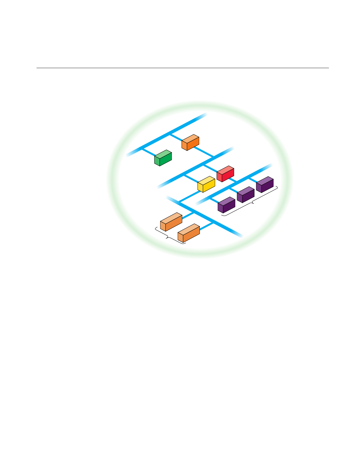
Setting Up a BIND Configuration
115
Figure 6-2 Example BIND Configuration
Configuring the Primary Server
Use this procedure to configure a primary server:
1. Log in as root.
2. Move to the named example directory:
cd /var/named/Examples
3. Copy the template files to the /var/named directory:
cp named.boot.master root.cache named.hosts \
named.rev localhost.rev /var/named
f
r
u
i
t
.
c
o
m
apples oranges
plum1 plum2 plum3
guava
banana
pineapple1
pineapple2
Primary
server
Secondary
server
Caching
server
Forwarder
server
Slave
servers
Client
servers

116
Chapter 6: BIND Name Server
4. Move named.boot.master to the default filename:
cd ..
mv named.boot.master named.boot
5. Modify named.boot with your editor of choice to resemble the following:
;
; Boot file for apple.fruit.com, primary for fruit.com
;
directory /var/named
;type domain source host/file backup file
cache . root.cache
primary fruit.com fruit.named.hosts
6. Modify the named.hosts file, here called fruit.named.hosts, to resemble the following:
; Authoritative data for fruit.com
;
@ IN SOA apples.fruit.com. named-mgr.apples.fruit.com.
(1994021501 ; Serial
10800 ; Refresh 3 hours
3600 ; Retry 1 hour
3600000 ; Expire 1000 hours
86400 ) ; Minimum 24 hours
; authoritative name servers for fruit.com
IN NS apples.fruit.com.
IN NS oranges.fruit.com.
; address records for all hosts on the net
IN A 128.70.10.1
apples IN A 128.70.10.1
oranges IN A 128.70.10.2
banana IN A 128.70.10.3
guava IN A 128.70.10.4
plum1 IN A 128.70.10.5
plum2 IN A 128.70.10.6
plum3 IN A 128.70.10.7
pineapple1 IN A 128.70.10.8
pineapple2 IN A 128.70.10.9
localhost IN A 127.0.0.1
; canonical or alias name for localhost
loghost IN CNAME localhost

Setting Up a BIND Configuration
117
7. Modify the localhost.rev file to resemble the following:
;localhost.rev -- PTR record for 127.1
;
@ IN SOA apples.fruit.com. named-mgr.apples.fruit.com.
(1994021501 ;Serial
10800 ;Refresh 3 hours
3600 ;Retry 1 hour
3600000 ;Expire 1000 hours
86400 ) ;Minimum 24 hours
; authoritative name servers for fruit.com
IN NS apples.fruit.com.
IN NS oranges.fruit.com.
0 IN PTR loopback.fruit.com.
1 IN PTR localhost.
8. Modify the named.rev file (fruitnamed.rev) to resemble the following:
;
; @(#)named.rev 1.1 (Berkeley) 86/02/05
;
@ IN SOA apples.fruit.com. named-mgr.apples.fruit.com.
(1994021501 ; Serial
10800 ; Refresh 3 hours
3600 ; Retry 1 hour
3600000 ; Expire 1000 hours
86400 ); Minimum 24 hours
;authoritative name servers for fruit.com
IN NS apples.fruit.com.
IN NS oranges.fruit.com.
;named.rev addresses, by default, are the last two numbers
;of the internet addresses in reverse order, if Class B
;address. If Class C address, then it’s the last number.
1 IN PTR apples.fruit.com.
2 IN PTR oranges.fruit.com.
3 IN PTR banana.fruit.com.
4 IN PTR guava.fruit.com.
5 IN PTR plum1.fruit.com.
6 IN PTR plum2.fruit.com.
7 IN PTR plum3.fruit.com.
8 IN PTR pineapple1.fruit.com.
9 IN PTR pineapple2.fruit.com.

118
Chapter 6: BIND Name Server
9. Use the default root.cache file if the primary server is attached to the Internet. If
practical, you should obtain the most up-to-date list from rs.internic.net using
anonymous FTP. The list is kept in the file domain/named.root.
; This file holds the information on root name servers needed to
; initialize cache of Internet domain name servers
; (e.g. reference this file in the “cache . <file>”
; configuration file of BIND domain name servers).
;
; This file is made available by InterNIC registration services
; under anonymous FTP as
; file /domain/named.root
; on server FTP.RS.INTERNIC.NET
; -OR- under Gopher at RS.INTERNIC.NET
; under menu InterNIC Registration Services (NSI)
; submenu InterNIC Registration Archives
; file named.root
;
; last update: Sep 1, 1995
; related version of root zone: 1995090100
;
;
; formerly NS.INTERNIC.NET
;
. 3600000 IN NS A.ROOT-SERVERS.NET.
A.ROOT-SERVERS.NET. 3600000 A 198.41.0.4
;
; formerly NS1.ISI.EDU
;
. 3600000 NS B.ROOT-SERVERS.NET.
B.ROOT-SERVERS.NET. 3600000 A 128.9.0.107
;
; formerly C.PSI.NET
;
. 3600000 NS C.ROOT-SERVERS.NET.
C.ROOT-SERVERS.NET. 3600000 A 192.33.4.12
;
; formerly TERP.UMD.EDU
;
. 3600000 NS D.ROOT-SERVERS.NET.
D.ROOT-SERVERS.NET. 3600000 A 128.8.10.90
;
; formerly NS.NASA.GOV
;
. 3600000 NS E.ROOT-SERVERS.NET.

Setting Up a BIND Configuration
119
E.ROOT-SERVERS.NET. 3600000 A 192.203.230.10
;
; formerly NS.ISC.ORG
;
. 3600000 NS F.ROOT-SERVERS.NET.
F.ROOT-SERVERS.NET. 3600000 A 39.13.229.241
;
; formerly NS.NIC.DDN.MIL
;
. 3600000 NS G.ROOT-SERVERS.NET.
G.ROOT-SERVERS.NET. 3600000 A 192.112.36.4
;
; formerly AOS.ARL.ARMY.MIL
;
. 3600000 NS H.ROOT-SERVERS.NET.
H.ROOT-SERVERS.NET. 3600000 A 128.63.2.53
;
; formerly NIC.NORDU.NET
;
. 3600000 NS I.ROOT-SERVERS.NET.
I.ROOT-SERVERS.NET. 3600000 A 192.36.148.17
; End of File
10. Enable named and reboot the station with the following commands:
chkconfig named on
reboot
Configuring the Secondary Server
Use this procedure to configure a secondary server:
1. Log in as root.
2. Move to the named example directory:
cd /var/named/Examples
3. Copy the template files to the /var/named directory:
cp named.boot.slave root.cache localhost.rev /var/named
4. Move named.boot.slave to the default filename:
cd ..
mv named.boot.slave named.boot

120
Chapter 6: BIND Name Server
5. Modify named.boot to look like the following:
more named.boot
;
; Boot file for orange.fruit.com, secondary for fruit.com
;
directory /var/named
; type domain source host/file backup file
cache . root.cache
secondary fruit.com 128.70.10.1 fruithosts.bak
6. Use the same localhost.rev file you installed on your primary server.
7. Use the same root.cache file you installed on your primary server.
8. Enable named and reboot the station with the following commands:
chkconfig named on
reboot
Configuring a Caching-Only Server
Use this procedure to set up a caching-only server:
1. Log in as root.
2. Move to the named example directory:
cd /var/named/Examples
3. Copy the template files to the /var/named directory:
cp named.boot.master root.cache /var/named
4. Move named.boot.master to the default filename:
cd ..
mv named.boot.master named.boot

Setting Up a BIND Configuration
121
5. Modify named.boot to look like the following:
more named.boot
;
;Boot file for guava.fruit.com,caching-only server for
;fruit.com
;Note that there should be one primary entry for each SOA
;record.
;
;
directory /var/named
;type domain source host/file backup file
cache . root.cache
6. Use the same localhost.rev file you installed on your primary server.
7. Use the same root.cache file you installed on your primary server.
8. Enable named and reboot the station with the following commands:
chkconfig named on
reboot
Configuring the Forwarding Server
Use this procedure to set up a forwarding server:
1. Log in as root.
2. Move to the named example directory:
cd /var/named/Examples
3. Copy the template files to the /var/named directory:
cp named.boot.master root.cache localhost.rev /var/named
4. Move named.boot.master to the default filename:
cd ..
mv named.boot.master named.boot

122
Chapter 6: BIND Name Server
5. Modify named.boot to look like the following:
more named.boot
;
;Boot file for banana.fruit.com, forwarder server
;for fruit.com
;Note that there should be one primary entry for each
;SOA record.
;
;
directory /var/named
;type domain source host/file backup file
cache . root.cache
forwarders 128.70.10.1 128.70.10.2
6. Use the same localhost.rev file you installed on your primary server.
7. Use the same root.cache file you installed on your primary server.
8. Enable named and reboot the station with the following commands:
chkconfig named on
reboot
Configuring a Slave Server
1. Log in as root.
2. Move to the named example directory:
cd /var/named/Examples
3. Copy the template files to the /var/named directory:
cp named.boot.slave root.cache localhost.rev /var/named
4. Move named.boot.master to the default filename:
cd ..
mv named.boot.slave named.boot

Managing the BIND Environment
123
5. Modify named.boot to look like the following:
;
;Boot file for pineapple1.fruit.com, slave server for
;fruit.com
;
directory /var/named
;type domain source host/file backup file
cache . root.cache
forwarders 128.70.10.3
slave
6. Use the same localhost.rev file you installed on your primary server.
7. Use the same root.cache file you installed on your primary server.
8. Enable named and reboot the station with the following commands:
chkconfig named on
reboot
Configuring the Client
Use this procedure to set up a BIND client:
1. Log in as root.
2. Create or modify the resolv.conf file to include the default domain name, the host
resolution order, and the list of name servers. It should look something like this:
domain fruit.com
nameserver 128.70.10.4
nameserver 128.70.10.2
nameserver 128.70.10.1
hostresorder bind local
3. Rebooting the client is suggested, but not required.
Managing the BIND Environment
This section describes the steps involved in maintaining the databases. It details how to
add and delete a station from the domain and how to add a new subdomain. It also
discusses some of the scripts that manage the BIND database.

124
Chapter 6: BIND Name Server
Adding a New Station
To add a new station to your zone files:
1. Edit the appropriate zone file for the station’s domain.
2. Add an A record for each address of the station.
3. Add CNAME, HINFO, WKS, RP, and MX records (optional).
4. Add the reverse IN-ADDR entry for each station address in the appropriate zone
files for each network the station is on.
Deleting a Station
To delete a station from the zone files:
1. Remove all the station’s resource records from the zone file of the station’s domain.
2. Remove all the station’s PTR records from the IN-ADDR zone files for each network
the station was on.
Adding Another Domain
To add a new subdomain to your domain:
1. Set up the other domain server, the new zone file, or both.
2. For each server of the new domain, add an NS record to the zone file of the parent
domain.
3. Add any necessary glue address records. See Appendix A, “BIND Standard
Resource Record Format” for details about glue records.
Management Scripts
You can use two shell scripts to manage named:/usr/sbin/named.reload and
/usr/sbin/named.restart.

Debugging named
125
named Reload Script
This shell script sends the HUP signal to named, which causes it to read named.boot and
reload the database. All previously cached data is lost. Use this script when named is
running and you want the internal database for named to reflect any changes you have
made.
named Restart Script
This shell script terminates the running namedand starts a new one. Use this script when
you have made changes to the named.boot file, or whenever you need to place the server
in a known state.
Debugging named
When named is running incorrectly, first check /var/adm/SYSLOG for any messages. For
additional information, send named one of the following signals, using killall(1M) and
defining SIG as INT, ABRT, USR1, or USR2:
/etc/killall -SIG named
INT Dumps the current database and cache to /var/tmp/named_dump.db. This
dumping should indicate whether the database was loaded correctly.
ABRT Dumps statistics data into /var/tmp/named.stats. Statistics data is
appended to the file.
USR1 Turns on debugging. Each subsequent USR1 increases the debug level.
There are 10 debug levels, and each prints more detailed information. A
debug level of 5 is useful for debugging lookup requests. The output
goes to /var/tmp/named.run.
USR2 Turns off debugging completely.

126
Chapter 6: BIND Name Server
SYSLOG Messages
Using syslog(3B), named logs certain errors to /var/adm/SYSLOG. This section lists
important error messages and their meanings.
•dname has CNAME and other illegal data
An alias has more than just a CNAME record. For example, since only “monet”
should have the A record, the following is wrong:
ucbmonet IN CNAME monet
ucbmonet IN A 128.32.0.1
•Attempted to query myself on ipaddr as name server for dname
The station is listed incorrectly as a forwarder in the named.boot file.
•zoneref: Masters for secondary zone dname unreachable
This station is a secondary server for dname. The primary server returned an invalid
data response or, because of a network problem, the station was not able to contact
the primary server to obtain the current state of the zone information.
•Lame delegation to dname1 received from ipaddr(purported server for
dname2) on query on name [dname3]
The message indicates that the remote server at the specified address is supposed to
be authoritative for the dname2 domain but has returned an indication that implies
it is not. The remote server or the server for its parent domain is misconfigured. This
error message can be disabled if named is started with the -L lamedel option.
•MAXQUERIES exceeded, possible data loop in resolving dname
The name server has tried to query too many other servers for the specified record.
This might happen if each of two remote servers reply that the other has the desired
information for dname.
•Malformed response from ipaddr
The remote DNS server at the specified address returned a malformed packet. This
message typically indicates an error in the remote server.
•Bogus root NS dname1 received from ipaddr on query on name[dname2] --
rejected
The name server at the specified address improperly returned NS records for the
root domain. The records have been ignored. You can disable this error message if
named is started with -L rootns.

Debugging named
127
•Root NS dname1 received from ipaddr on query on name [dname2]
The name server at the specified address returned NS records for the root domain.
You can disable this informational message if named is started with the -L rootns
option.
The nslookup Command
The nslookup command is a useful debugging tool for querying local and remote name
servers.nslookup operates in either interactive or non-interactive mode. Interactive mode
allows the user to query the name server for information about various stations and
domains or print a list of stations in the domain. Non-interactive mode is used to print
just the name and requested information for a station or domain. The following example
of nslookup output gets the address record for the station monet.berkeley.edu:
Default Server: ucbvax.berkeley.edu
Address: 128.32.133.1
> monet
Server: ucbvax.berkeley.edu
Address: 128.32.133.1
Name: monet.berkeley.edu
Address: 128.32.130.6
To exit, press <Ctrl-D> or enter exit. The help command summarizes available
commands. The complete set of commands is described on the nslookup(1C) reference
page.


129
Chapter 7
7. UUCP
UUCP stands for “UNIX to UNIX Copy Program,” and is a set of utilities that lets
computers using versions of the UNIX operating system (such as IRIX) communicate
with each other and with remote terminals. These utilities range from those used to copy
files between computers (uucpanduuto), to those used for simple encoding and decoding
(uuencode and uudecode), to those used for remote login and command execution (cu and
uux).
The following topics are covered in this chapter:
• “Choosing TCP/IP or UUCP” on page 130
• “Hardware Requirements for UUCP” on page 131
• “UUCP Commands” on page 131
• “UUCP Daemons” on page 133
• “Supporting Databases” on page 134
• “UUCP Administrative Files” on page 155
• “Setting Up UUCP” on page 157
• “UUCP Error Messages” on page 169
The UUCP system is contained in the eoe subsystem of your IRIX distribution, in the
package called eoe.sw.uucp. Use the versions command to determine if you have this
subsystem installed.
UUCP connections using telephone lines and modems are used to distribute electronic
mail and “net news” among thousands of computers in the USENET network.
As an administrator, you need to be familiar with the administrative tools, logs, and
database files used by UUCP. This chapter provides details about the UUCP files,
directories, daemons, and commands.

130
Chapter 7: UUCP
Choosing TCP/IP or UUCP
This section compares UUCP and the TCP/IP protocol suite for various purposes. You
can use them together, each for the tasks for which it is best suited. Both UUCP and
TCP/IP software are standard features of the IRIX operating system. To use the TCP/IP
software, you must have one of these communications mechanisms:
• a connection to an Ethernet network
• the optional FDDI hardware and software
• the Serial Line Internet Protocol (SLIP) software
To use UUCP, you must be connected to a serial network or to any TCP/IP network.
TCP/IP provides reliable interactive and batch services. UUCP is a batch-mode service;
when you issue a uucp command, it is placed in a queue with other commands. The
system checks the queue at regular intervals and executes the commands that it finds.
After your command is carried out, UUCP reports the results of the command. The time
it takes to carry out a command on a remote station varies on different stations. Table 7-1
shows a comparison of features of TCP/IP and UUCP.
Table 7-1 Comparison of TCP/IP and UUCP
TCP/IP Features UUCP Features
runs on Ethernet and FDDI, and over
serial lines runs over serial lines or over TCP/IP links
transfers files interactively transfers files in batch mode
executes commands on remote stations
interactively executes commands on remote stations in
batch mode
sends mail interactively or in batch mode sends mail in batch mode
starts a shell on a remote station starts a shell on a remote station
provides remote login facilities with
rlogin/telnet provides remote login facilities with cu
transfers data to any station running
TCP/IP transfers data to any station running
UUCP

Hardware Requirements for UUCP
131
Hardware Requirements for UUCP
Before your computer can communicate with other computers through UUCP, you must
set up the hardware to complete the communications link. The cables and other
hardware you will need depend on how you want to connect the computers: direct links,
telephone lines, or local area networks.
Note: Refer to IRIX Admin: Peripheral Devices and the Personal System Administration
Guide for information on setting up modems and other hardware.
Direct links You can create a direct link to another computer by running cables
between serial ports on the two computers. Direct links are useful if two
computers communicate regularly and are physically close—within 50
feet of each other. You can use a limited-distance modem to increase this
distance somewhat. Transfer rates of up to 38,400 bits per second (bps)
are possible when computers are directly linked. Such direct links are
now rarely used because local area networks provide faster,
easier-to-use connections.
Telephone lines Using a modem capable of dialing telephone numbers, your computer
can communicate with other computers over standard phone lines. The
modem dials the telephone number requested by the networking
utilities. The computer it is trying to contact must have a modem capable
of answering incoming calls.
UUCP Commands
UUCP programs can be divided into two categories: user programs and administrative
programs. The subsections that follow describe the programs in each category.
UUCP User Programs
The UUCP user programs are in /usr/bin. No special permission is needed to use these
programs; they are all described in the reference pages.
cu Connects your computer to a remote computer so you can log in to that
computer, allowing you to transfer some files or execute commands on
either computer without dropping the initial link.

132
Chapter 7: UUCP
uucp Lets you copy a file from one computer to another. This program creates
work files and data files, queues the job for transfer, and calls the uucico
daemon, which in turn attempts to contact the remote computer.
uuto Copies files from one computer to a public spool directory on another
computer (/var/spool/uucppublic/receive). Unlike uucp, which lets you
copy a file to any accessible directory on the remote computer, uuto
places the file in an appropriate spool directory and sends mail to the
remote user who requested that it be picked up with uupick.
uupick Retrieves the files placed under /var/spool/uucppublic/receive when files
are transferred to a computer that is using uuto.
uux Creates the work, data, and execute files needed to execute commands
on a remote computer. The work file contains the same information as
work files created by uucp and uuto. The execute files contain the
command string to be executed on the remote computer and a list of the
data files. The data files are those files required for the command’s
execution.
uustat Displays the status of requested transfers (uucp,uuto, or uux). This
program also provides a way to control queued transfers.
UUCP Administrative Programs
Most of the administrative programs are in /usr/lib/uucp, though the UUCP database files
reside in /etc/uucp. The only exception is uulog, which is in /usr/bin. These commands are
described in their respective reference pages.
You should use the uucp login ID when you administer UUCP because it owns the basic
networking and spooled data files. The home directory of the uucp login ID is
/usr/lib/uucp. The other UUCP login ID is nuucp, used by remote computers that do not
have their own login IDs to access your computer. A computer that logs in with nuucp
receives uucico as its shell.
The following programs are the administrative utilities of UUCP:
uulog Displays the contents of a specified computer’s log files. A log file is
created for each remote computer with which your computer
communicates. The log files contain records of each use of uucp,uuto,
and uux.

UUCP Daemons
133
uucleanup Cleans up the spool directory. This command is normally executed from
a shell script called uudemon.cleanup, which is started by cron.
Uutry Tests call-processing capabilities and does a moderate amount of
debugging. This command invokes the uucico daemon, in debug mode,
to establish a communications link between your computer and the
remote computer that you specify.
uucheck Checks for the presence of UUCP directories, programs, and support
files. This program can also check certain parts of the Permissions file for
obvious syntactic errors.
genperm Generates the Permissions file for stations that assign each remote station
its own login ID.
The following programs are used for initializing different types of modems. The use of
these programs is described in IRIX Admin: Peripheral Devices, Chapter 1, “Terminals
and Modems.”
fix-dsi This program initializes DSI modems
fix-hayes This program initializes Hayes modems.
fix-intel This program initializes Intel modems.
fix-telebit This program initializes Telebit modems.
fix-usr This program initializes U. S. Robotics modems.
fix-zyxel This program initializes Telebit modems.
UUCP Daemons
There are several daemons in UUCP. These daemons handle file transfers and command
executions. They can also be run manually from the shell.
uucico Selects the device used for the link, establishes the link to the remote
computer, performs the required login sequence and permission checks,
transfers data and execute files, logs results, and notifies the user by mail
of transfer completions. It also starts uuxqt to execute any requested
commands. When the local uucico daemon calls a remote computer, it
“talks” to the uucico daemon on the remote computer during the session.

134
Chapter 7: UUCP
The uucico daemon is executed by the uucp,uuto, and uux programs,
after all the required files have been created, to contact the remote
computer. It is also executed by the uusched and Uutry programs.
uuxqt Executes remote execution requests. This daemon searches the spool
directory for execute files (always named X.file) that have been sent from
a remote computer. When an X.file file is found, uuxqt opens it to get the
list of data files that are required for the execution. It then checks to see
if the required data files are available and accessible. If the files are
present and can be accessed, uuxqt checks the Permissions file to verify
that it has permission to execute the requested command. The uuxqt
daemon is executed by the uudemon.hour shell script, which is started by
cron.
uusched Schedules the queued work in the spool directory. Before starting the
uucico daemon, uusched randomizes the order in which remote
computers are called. uusched is executed by a shell script called
uudemon.hour, which is started by cron.
uugetty This program is very similar to the getty program except that it permits
a line (port) to be used in both directions. uugetty is assigned to a port in
the /etc/inittab file if you want a port to be bi-directional. uugetty is
described on the uugetty(1M) reference page.
Supporting Databases
The UUCP support files are in the /etc/uucp directory.
Devices Contains information concerning the location and line speed of the
automatic call units (modems) and direct links.
Dialers Contains character strings required to negotiate with automatic call
units (ACUs) or modems in establishing connections to remote
computers.
Systems Contains information needed by the uucico daemon and the cu program
to establish a link to a remote computer. This file contains information
such as the name of the remote computer, the name of the connecting
device associated with the remote computer, when the computer can be
reached, the telephone number, the login ID, and the password.
Dialcodes Contains dial-code abbreviations that can be used in the phone number
field of Systems file entries.

Supporting Databases
135
Permissions Defines the level of access that is granted to remote users using uucp or
uux when they attempt to transfer files or remotely execute commands
on your computer.
Poll Defines computers that are to be polled by your station and when they
are polled.
Sysfiles Assigns different or multiple files to be used by uucico and cu, such as
Systems,Devices, and Dialers files.
The subsections that follow provide details on the structure of these files so you can edit
them.
There are several other files that can be considered part of the supporting database; these
files are not directly related to the process of establishing a link and transferring files. The
files, Maxuuxqts,Maxuuscheds, and remote.unknown, are described briefly in “Other
UUCP Files” on page 154.
The Devices File
The Devices file (/etc/uucp/Devices) contains information for all the devices that can be
used to establish a link to a remote computer, such as automatic call units, direct links,
and network connections.
Note: This file works interdependently with the Dialers,Systems, and Dialcodes files.
Before you make changes in any of these files, you should be familiar with them all. A
change to an entry in one file may require a change to a related entry in another file.
Each entry in the Devices file has the following format:
Type Line Line2 Class Dialer-Token-Pairs
Entries for use with modems should always have the form
Name device null speed 212 x dialer
Entries for use over TCP/IP network connections have the form
TCP - - Any TCP uucp
Devices file fields are defined in the following sections.

136
Chapter 7: UUCP
The Type Field
The keyword used in the Type field is matched against the third field of Systems file
entries. The Type field can contain one of these keywords: Direct, ACU, or a station name.
Direct This keyword indicates a direct link to another computer or a switch (for
cu connections only).
ACU This keyword indicates that the link to a remote computer is made
through an automatic call unit (automatic-dial modem).
Sys-Name This value indicates a direct link to a particular computer. (Sys-Name is
replaced by the name of the computer.) This naming scheme is used to
convey the fact that the line associated with this Devices entry is for a
particular computer in the Systems file.
You can designate a protocol to use for a device within this field. See the “Protocols”
section at the end of the description of this file.
The Line Field
This field contains the device name of the line (port) associated with the Devices entry. For
instance, if the automatic dial modem for a particular entry is attached to the /dev/ttyf5
line, the name entered in this field is ttyf5.
You should always use the ttyf devices when working with modems. These devices
support hardware flow control, which is used by all modems that support V.32 or V.32bis.
The Line2 Field
If the keyword ACU is used in the Type field and the ACU is an 801-type dialer, the Line2
field contains the device name of the 801 dialer. (801-type ACUs do not contain a modem.
Therefore, a separate modem is required and must be connected to a different line,
defined in the Line field.) The need for a separate modem line means that one line would
be allocated to the modem and another to the dialer. Since non-801 dialers do not
normally use this configuration, they ignore the Line2 field, but it must still contain a
hyphen (-) or the word null as a place holder. A place holder is necessary for most
modems.

Supporting Databases
137
The Class Field
The keyword used in the Class field of the Devices file is matched against the fourth field
of Systems file entries:
Devices: ACU ttyf5 null D9600 212 x telebit
Systems: eagle Any ACU D9600 14155551212 login:nuucp password:Oakgrass
Some devices can be used at any speed, so the keyword ‘‘Any’’ can be used in the Class
field. If Any is used, the line will match any speed requested in a Systems file entry. If this
field is Any and the Systems file Class field is Any, the speed defaults to 9600 bps. If the
keyword ACU or Direct is used in the Type field, the Class field might contain only the
speed of the device. However, the speed can also be preceded by a letter (for example,
C9600,D9600) to differentiate between classes of dialers (Centrex or Dimension PBX).
Including the dialer class is necessary in larger offices that have more than one type of
telephone network: One network may be dedicated to serving only internal
communications while another handles external. In such a case, it becomes necessary to
distinguish which line(s) should be used for internal and which for external.
The Dialer-Token-Pairs Field
This field contains pairs of dialers and tokens. The Dialer portion may be the name of an
automatic-dial modem, or ‘‘Direct’’ for a direct-link device. You can have any number of
Dialer-Token-Pair (DTP) fields. The Token portion may be supplied immediately
following the Dialer portion; if not present, the Token portion will be taken from a related
entry in the Systems file.
This field has the format:
dialer token dialer token
The last pair may or may not be present, depending on the associated device (dialer). In
most cases, the last pair contains only a Dialer portion and the Token portion is retrieved
from the Phone field of the Systems file entry. A valid entry in the Dialer portion may be
defined in the Dialers file.
The DTP field can be structured in different ways, depending on the device associated
with the entry.
If an automatic-dial modem is connected directly to a port on your computer, the DTP
field of the associated Devices file entry will have only one pair. This pair is normally the
name of the modem. This name is used to match the particular Devices file entry with an

138
Chapter 7: UUCP
entry in the Dialers file. Therefore, the Dialer field must match the first field of a Dialers
file entry:
Devices: ACU ttyf2 null 9600 212 x telebit
Dialers: telebit =&-% "" \r\p\r\c $ <K\T%%\r>\c ONLINE!
Notice that only the Dialer portion (telebit) is present in the DTP field of the Devices file
entry. This means that the token to be passed on to the dialer (in this case the phone
number) is taken from the Phone field of a Systems file entry. (\T is implied)
If a direct link is established to a particular computer, the DTP field of the associated
entry contains the keyword Direct. This is true for both types of direct-link entries, Direct
and System-Name.
If an automatic-dial modem is connected to a switch, your computer must first access the
switch; the switch then makes the connection to the modem. This type of entry requires
two Dialer-Token-Pairs. The Dialer portion of each pair (fifth and seventh fields of entry)
is used to match entries in the Dialers file:
Devices: ACU ttyf2 null 9600 212 x t2500 telebit T25
Dialers: telebit "" "" \pr\ps\c est:\007 \E\D\e \007
Dialers: T25 =&-% "" \r\p\r\c $ <K\T%%\r>\c ONLINE!
In the first pair, t2500 is the Dialer and telebit is the token that is passed to the Develcon
switch to tell it which device (telebit modem) to connect to your computer. This token is
unique for each modem switch since each switch may be set up differently. Once the
telebit modem has been connected, the second pair is accessed, where T25 is the dialer
and the token (the telephone number) is retrieved from the Systems file. (See the
discussion of the Systems file’s Phone field in “The Systems File” on page 142.)
Two escape characters can appear in a DTP field:
\T Indicates that the Phone (Token) field should be translated by means of
the Dialcodes file.
\D Indicates that the Phone (Token) field should not be translated by means
of the Dialcodes file. If no escape character is specified at the end of a
Devices entry, the \D is assumed (default).

Supporting Databases
139
Device Protocols
You can define the protocol to use with each device. In most cases it is not needed since
you can use the default or define the protocol with the particular station you are calling.
(See the discussion of the Systems file, specifically the Type field.) If you do specify the
protocol, you must do it in the form Type, Protocol. Available protocols are
gThis protocol is slower and more reliable than e. It is good for
transmission over noisy telephone lines. This is the default protocol.
eThis protocol is faster than g, but it assumes error-free transmission,
such as over a TCP/IP network connection.
tThis protocol, like e, is for use in an error-free environment, such as a
TCP/IP network connection. The t protocol is used by systems running
BSD UNIX operating systems.
The Dialers File
TheDialers file (/etc/uucp/Dialers) specifies the initial conversation that must take place on
a line before it can be made available for transferring data. This conversation is usually a
sequence of ASCII strings that is transmitted and expected, and it is often used to dial a
phone number with an ASCII dialer (such as an automatic-dial modem).
As shown in the preceding section, the fifth field in a Devices file entry is an index into
the Dialers file or a special dialer type. An attempt is made to match the fifth field in the
Devices file with the first field of each Dialers file entry. In addition, each odd-numbered
Devices field, starting with the seventh position, is used as an index into the Dialers file.
If the match succeeds, the Dialers entry is interpreted to perform the dialer negotiations.
Each entry in the Dialers file has the following format:
dialer substitutions expect-send ...
The Dialer field matches the fifth and additional odd-numbered fields in the Devices file.
The substitutions field is a translate string: The first of each pair of characters is mapped
to the second character in the pair. This technique is usually used to translate the equal
sign (=) and the hyphen (-) characters into whatever the dialer requires for “wait for dial
tone” and “pause.”
The expect-send fields are character strings.

140
Chapter 7: UUCP
The following list describes some of the escape characters used in the Dialers file.
Table 7-2 lists escape sequences used by UUCP.
Table 7-2 UUCP Escape Sequences
Escape sequence Meaning
\N Send or expect a null character (ASCII NUL).
\b Send or expect a backspace character.
\c If at the end of a string, suppress the newline that is normally sent. Ignored
otherwise.
\d Delay two seconds before sending or reading more characters.
\p Pause for approximately 1/4 to 1/2 second.
\E Start echo checking. (From this point on, whenever a character is
transmitted, login processing will wait for the character to be received before
proceeding.)
\e Turn off echo checking.
\n Send a newline character.
\r Send or expect a carriage return.
\s Send or expect a space character.
\t Send or expect a tab character.
\\ Send or expect a backslash (\) character.
EOT Send or expect EOT newline twice.
BREAK Send or expect a break character.
\K Same as BREAK.
\ddd Send or expect the character represented by the octal digits ddd.

Supporting Databases
141
Here is a sample line from the Dialers file:
penril =W-P "" \d > Q\c : \d- > s\p9\c )-W\p\r\ds\p9\c-) y\c :
\E\TP > 9\c OK
The penril entry in the Dialers file is executed as follows. First, the phone number
argument is translated, replacing any equal sign with a W (wait for dial tone) and
replacing any hyphen with a P (pause).
The handshake given by the remainder of the line works as follows:
" " Wait for nothing; in other words, proceed to the next step.
\d Delay for two seconds.
> Wait for a “greater than” sign (>).
Q\c Send a Q with no terminating new line.
: Wait for a colon (:).
\d- Delay for two seconds.
> Wait for a “greater than” sign (>).
s\p9\c Send an s, pause for 1/2 second, send a 9, send no terminating new line.
)-W\p\r\ds\p9\c-)
Wait for a closing parenthesis [)]; if it is not received, process the string
between the hyphens as follows: Send a W, pause, send a carriage return,
delay, send an s, pause, send a 9 without a new line, and then wait for
the closing parenthesis.
y\c Send a y without a new line.
: Wait for a colon (:)
\E\TP Enable echo checking. (From this point on, whenever a character is
transmitted, handshake processing waits for the character to be received
before proceeding.) Then send the phone number. The \T instructs the
program to take the phone number passed as an argument, apply the
Dialcodes translation and the modem function translation specified by
field two of this entry, then send a P.
9\c Send a 9 without a new line.
OK Wait for the string OK.

142
Chapter 7: UUCP
The Systems File
The Systems file (/etc/uucp/Systems) contains the information needed by the uucico
daemon to establish a communications link to a remote computer. Each entry in the file
represents a computer that can call or be called by your computer. In addition, UUCP
software by default is configured to prevent any computer that does not appear in this
file from logging in to your computer. (Refer to “Other UUCP Files” on page 154 for a
description of the remote.unknown file.) More than one entry may be present for a
particular computer. The additional entries represent alternative communications paths
that are tried in sequential order.
Using the Sysfiles file, you can define several files to be used as Systems files. See “The
Sysfiles File” on page 154 for details.
Each entry in the Systems file has the following format:
System-name Time Type Class Phone Login
These fields are defined in the following sections.
The System-name Field
This field contains the node name of the remote computer.
The Time Field
This field is a string that indicates the day-of-week and time-of-day when the remote
computer can be called. The format of the Time field is
day[time][;retry]
The day portion is a list of one or more day specifiers. These specifiers are listed below.
Su, Mo, Tu, We, Th, Fr, Sa
These abreviations stand for individual days of the week: Sunday,
Monday, Tuesday, Wednesday, Thursday, Friday, Saturday.
Wk Specifies any weekday, Monday through Friday.
Any Specifies any day.

Supporting Databases
143
Never Specifies that this station never initiates calls to the remote computer.If
the Time field is Never, your computer will never initiate a call to the
remote computer. The call must be initiated by the remote computer. In
other words, your computer is in a passive mode with respect to the
remote computer. (For more information on permissions, see “The
Permissions File” on page 146.)
Here is an example of a Time field:
Wk1700-0800,Sa,Su
This example allows calls from 5:00 p.m. to 8:00 a.m., Monday through Friday, and any
time Saturday and Sunday. The example would be an effective way to call only when
phone rates are low, if immediate transfer is not critical.
The time portion should be a range of times such as 0800–1230. If no time portion is
specified, any time of day is assumed to be allowed for the call. A time range that spans
0000 is permitted. For example, 0800-0600 means all times are allowed other than at
times between 6 a.m. and 8 a.m.
An optional subfield, retry, is available to specify the minimum time (in minutes) before
a retry, following a failed attempt. The default wait is 5 minutes after the first failure, 10
after the second, and so on until a delay of about 24 hours. If the retry subfield is present,
that wait is used after every failure. The subfield separator is a semicolon (;). For
example, “Any;9” is interpreted as “call any time, but wait at least 9 minutes before
retrying after a failure occurs.”
The Type Field
This field contains the device type that should be used to establish the communications
link to the remote computer. The keyword used in this field is matched against the first
field of Devices file entries:
Systems: eagle Any ACU,g D1200 3251 login:nuucp password: Oakgrass
Devices: ACU ttym2 - D1200 penril
You can define the protocol used to contact the station by adding it on to the Type field.
The example just given shows how to attach the protocol g to the device type ACU. For
direct connects, use the name of the station to which you are connecting. See “Device
Protocols” on page 139.

144
Chapter 7: UUCP
The Class Field
This field is used to indicate the transfer speed of the device used to establish the
communications link. It may contain a letter and speed (for example, C1200,D1200) to
differentiate between classes of dialers. (See the discussion of the Class field in “The
Devices File” on page 135.) Some devices can be used at any speed, so the keyword Any
may be used. This field must match the Class field in the associated Devices file entry as
shown here:
Systems: eagle Any ACU D1200 NY3251 login:nuucp password:Oakgrass
Devices: ACU ttym2 - D1200 penril
If information is not required for this field, use a hyphen as a place holder for the field.
The Phone Field
This field is used to provide the phone number (token) of the remote computer for
automatic dialers. The phone number is made up of an optional alphabetic abbreviation
and a numeric part. If an abbreviation is used, it must be one that is listed in theDialcodes
file. For example:
Systems: eagle Any ACU D1200 NY3251 login:nuucp password: Oakgrass
Dialcodes: NY 9=1212555
In this string, an equal sign (=) tells the ACU to wait for a secondary dial tone before
dialing the remaining digits. A hyphen (-) in the string instructs the ACU to pause four
seconds before dialing the next digit.
If your computer is connected to a modem switch, you may access other computers that
are connected to that switch. The Systems file entries for these computers does not have
a phone number in the Phone field. Instead, this field contains the token that must be
passed on to the switch so it will know which computer your computer wishes to
communicate with. This token is usually just the station name. The associated Devices file
entry should have a \D at the end of the entry to ensure that this field is not translated
by means of the Dialcodes file.
The Login Field
This field contains login information given as a series of fields and subfields of the
format:
expect send

Supporting Databases
145
The send string is sent when the expect string is received. The expect field may be made
up of subfields of the form:
expect[-send-expect]...
The send field is sent if the prior expect is not successfully read and the expect following
the send is the next expected string. For example, with “login--login,” UUCP expects the
string “login.” If UUCP receives that string, it goes on to the next field. If it does not
receive the string, it sends nothing, followed by a new line, then looks for “login” again.
If no characters are initially expected from the remote computer, the characters " " (null
string) should be used in the first expect field. Note that all send fields are sent followed
by a newline unless the send string is terminated with a \c.
Here is an example of a Systems file entry that uses an expect-send string:
owl Any ACU 1200 NY6013 "" \r login:-BREAK-login: uucpx word: xyzzy
This example means causes UUCP to send a carriage return and wait for the string
“login:” If it doesn’t receive the string, it sends a break character and waits for “login:”
again. When it does receive the string “login,” it sends the login name uucpx; waits to
receive the string “word:” (the last part of “Password:”); and sends the password xyzzy.
Several escape sequences cause specific actions when they are a part of a string sent
during the login sequence. These are the same escape sequences used in the Dialers file,
listed in Table 7-2.
The Dialcodes File
The Dialcodes file (/etc/uucp/Dialcodes) contains the dial-code abbreviations that can be
used in the Phone field of the Systems file. Each entry has the following format:
abb dial-seq
abb is the abbreviation used in the Systems file Phone field and dial-seq is the dial sequence
that is passed to the dialer when that Systems file entry is accessed.
For example, the following entry would work with a Phone field in the Systems file such
as jt7867:
jt 9=555-
When the entry containing jt7867 was encountered, the sequence 9=555-7867 would
be sent to the dialer if the token in the dialer-token-pair was \T.

146
Chapter 7: UUCP
The Permissions File
The Permissions file (/etc/uucp/Permissions) specifies the permissions that remote
computers have with respect to login, file access, and command execution. There are
options that restrict the remote computer’s ability to request files and its ability to receive
files queued by the local site. Another option specifies the commands that a remote site
can execute on the local computer.
The program /etc/uucp/genperm is recommended for creating a sample or default
Permissions file from the Systems file.
How Permissions File Entries Are Structured
Each entry is a logical line with physical lines terminated by a backslash (\) to indicate
continuation. (Note that such continuations are not possible in most other UUCP files.)
Entries are made up of options delimited by white space. Each option is a name/value
pair in the following format:
name
=
value
Note that no white space is allowed within an option assignment.
Comment lines begin with a number sign (#) and occupy the entire line up to a newline
character. Blank lines are ignored (even within multi-line entries).
There are two types of Permissions file entries:
LOGNAME Specifies the permissions that take effect when a remote computer logs
in to (calls) your computer.
MACHINE Specifies the permissions that take effect when your computer logs in to
(calls) a remote computer.
LOGNAME entries begin with a LOGNAME option and MACHINE entries begin with
a MACHINE option.
Permissions File Considerations
Keep these rules in mind when using the Permissions file to restrict the level of access
granted to remote computers:
• Any login ID used by a remote computer to log in for UUCP communications must
appear in one and only one LOGNAME entry.

Supporting Databases
147
• Any site that is called whose name does not appear in a MACHINE entry will have
the following default permissions/restrictions:
– Local send and receive requests will be executed.
– The remote computer will be able to send files to your computer’s
/var/spool/uucppublic directory.
– The command sent by the remote computer for execution on your computer
must be one of the default commands, usually rmail.
Permissions File Options
This section describes each option, specifies how it is used, and lists its default value.
REQUEST When a remote computer calls your computer and requests to receive a
file, this request can be granted or denied. The REQUEST option
specifies whether the remote computer can request to set up file
transfers from your computer.
The string that follows specifies that the remote computer can request
to transfer files from your computer:
REQUEST=yes
The following string specifies that the remote computer cannot request
to receive files from your computer:
REQUEST=no
This is the default value. It will be used if the REQUEST option is not
specified. The REQUEST option can appear in either a LOGNAME
(remote calls you) entry or a MACHINE (you call remote) entry.
A note on security: When a remote computer calls you, you cannot
verify its identity unless you have a unique login and password for that
computer.
SENDFILES When a remote computer calls your computer and completes its work,
it may attempt to take work your computer has queued for it. The
SENDFILES option specifies whether your computer can send the work
queued for the remote computer.
The string shown here specifies that your computer may send the work
that is queued for the remote computer as long as it logged in as one of
the names in the LOGNAME option:
SENDFILES=yes

148
Chapter 7: UUCP
This string is mandatory if your computer is in a “passive mode” with
respect to the remote computer.
The string that follows specifies that files queued in your computer will
be sent only when your computer calls the remote computer:
SENDFILES=call
The call value is the default for the SENDFILE option. This option is
significant only in LOGNAME entries, because MACHINE entries
apply when calls are made to remote computers. If the option is used
with a MACHINE entry, it will be ignored.
READ and WRITE
These options specify the various parts of the filesystem that uucico can
read from or write to. The READ and WRITE options can be used with
either MACHINE or LOGNAME entries.
The default for both the READ and WRITE options is the uucppublic
directory, as shown in the following strings:
READ=/var/spool/uucppublic
WRITE=/var/spool/uucppublic
These strings specify permission to access any file that can be accessed
by a local user with “other” permissions:
READ=/ WRITE=/
Because this suggestion may compromise security, use it only if
required.
The value of these entries is a colon-separated list of pathnames. The
READ option is for requesting files, and the WRITE option for
depositing files. One of the values must be the prefix of any full
pathname of a file coming in or going out. To grant permission to
deposit files in /usr/news as well as in the public directory, the following
values would be used with the WRITE option:
WRITE=/var/spool/uucppublic:/usr/news
Note that if you use the READ and WRITE options, you must specify
all pathnames because the pathnames are not added to the default list.
For instance, if the /usr/news pathname were the only one specified in a
WRITE option, permission to deposit files in the public directory would
be denied.

Supporting Databases
149
You should be careful which directories you make accessible for
reading and writing by remote stations. For example, you probably
wouldn’t want remote computers to be able to write over your
/etc/passwd file, so /etc shouldn’t be open to writes.
NOREAD and NOWRITE
The NOREAD and NOWRITE options specify exceptions to the READ
and WRITE options or defaults. The strings shown here would permit
one remote computer to read any file except those in the /etc directory
(and its subdirectories—remember, these are prefixes) and to write only
to the default /var/spool/uucppublic directory:
READ=/ NOR EAD=/etc WRITE=/var/spool/uucppublic
NOWRITE works in the same manner as the NOREAD option.
NOREAD and NOWRITE can be used in both LOGNAME and
MACHINE entries.
CALLBACK The CALLBACK option is used in LOGNAME entries to specify that no
transaction will take place until the calling station is called back. You
would use CALLBACK for two reasons: From a security standpoint, if
you call back a station you can be sure it is the station it says it is. If you
are doing long data transmissions, you can choose the station that will
be billed for the longer call.
The string that follows specifies that your computer must call the
remote computer back before any file transfers will take place:
CALLBACK=yes
The default for the CALLBACK option is
CALLBACK=no
The CALLBACK option is very rarely used. Note that if two sites have
this option set for each other, a conversation cannot be started.
COMMANDS The COMMANDS option can be hazardous to the security of your
station. Use it with extreme care.
The uux program generates remote execution requests and queues
them to be transferred to the remote computer. Files and a command
are sent to the target computer for remote execution.

150
Chapter 7: UUCP
The COMMANDS option can be used in MACHINE entries to specify
the commands that a remote computer can execute on your computer.
Note that COMMANDS is not used in a LOGNAME entry;
COMMANDS in MACHINE entries defines command permissions,
whether you call the remote station or it calls you.
This string indicates the default commands that a remote computer can
execute on your computer:
COMMANDS=rmail
If a command string is used in a MACHINE entry, the default
commands are overridden. For instance, in the following example, the
entry overrides the COMMANDS default so that the computers eagle,
owl, and hawk can now execute rmail and rnews on your computer:
MACHINE=eagle:owl:hawk REQUEST=yes
COMMANDS=rmail:/usr/bin/rnews
READ=/ WRITE=/
In addition to the names as specified above, there can be full pathnames
of commands. For example, this line specifies that command rmail use
the default path:
COMMANDS=rmail:/usr/bin/rnews:/usr/local/lp
The default paths for your computer are /bin /usr/sbin,/usr/bsd, and
/usr/bin. When the remote computer specifies rnews or /usr/bin/rnews for
the command to be executed, /usr/bin/rnews is executed, regardless of
the default path. Likewise, /usr/local/lp is the lp command that is
executed.
Note: Including the ALL value in the list means that any command from
the remote computer(s) specified in the entry is executed. If you use this
value, you give the remote computer full access to your computer. Be
careful. This value allows far more access than normal users have.
This string illustrates the greater access:
COMMANDS=/usr/bin/rnews:ALL:/usr/local/lp
Two points about this string should be noted. The ALL value can
appear anywhere in the string, and the pathnames specified for rnews
and lp will be used (instead of the default) if the requested command
does not contain the full pathnames for rnews or lp.

Supporting Databases
151
The VALIDATE option should be used with the COMMANDS option
whenever potentially dangerous commands like cat and uucp are
specified with the COMMANDS option. Any command that reads or
writes files is potentially dangerous to local security when executed by
the UUCP remote execution daemon (uuxqt).
VALIDATE The VALIDATE option is used in conjunction with the COMMANDS
option when specifying commands that are potentially dangerous to
your computer’s security. It is used to provide a certain degree of
verification of the caller’s identity. The use of the VALIDATE option
requires that privileged computers have a unique login and password
for UUCP transactions. An important aspect of this validation is that the
login and password associated with this entry be protected. If an
outsider gets that information, that particular VALIDATE option can no
longer be considered secure. (VALIDATE is merely an added level of
security on top of the COMMANDS option, though it is a more secure
way to open command access than ALL.)
Give careful consideration to providing a remote system with a
privileged login and password for UUCP transactions. Giving another
system these privileges is like giving anyone on that computer a normal
login and password on your computer. Therefore, if you cannot trust
everyone at the remote site, do not provide that system with a
privileged login and password.
LOGNAME The LOGNAME option ensures that remote stations attempting to log in
to your computer have login privileges. The following LOGNAME
entry specifies that if one of the remote computers that claims to be eagle,
owl, or hawk logs in to your computer, it must have used the login
uucpfriend:
LOGNAME=uucpfriend VALIDATE=eagle:owl:hawk
As can be seen, if an outsider gets the uucpfriend login and password,
marauding is trivial.
But what does this have to do with the COMMANDS option, which
appears only in MACHINE entries? It links the MACHINE entry (and
COMMANDS option) with a LOGNAME entry associated with a
privileged login. This link is needed because the execution daemon is
not running while the remote computer is logged in. In fact, it is an
asynchronous process with no knowledge of what computer sent the
execution request. Therefore, the real question is, how does your
computer know where the execution files came from?

152
Chapter 7: UUCP
Each remote computer has its own “spool” directory on your computer.
These spool directories have write permission given only to the UUCP
programs. The execution files from the remote computer are put in its
spool directory after being transferred to your computer. When the
uuxqt daemon runs, it can use the spool directory name to find the
MACHINE entry in the Permissions file and get the COMMANDS list
or, if the computer name does not appear in the Permissions file, the
default list is used.
The following example shows the relationship between the MACHINE
and LOGNAME entries:
MACHINE=eagle:owl:hawk REQUEST=yes \
COMMANDS=rmail:/usr/bin/rnews \
READ=/ WRITE=/
LOGNAME=uucpz VALIDATE=eagle:owl:hawk \
REQUEST=yes SENDFILES=yes \
READ=/ WRITE=/
The value in the COMMANDS option means that remote mail and
/usr/bin/rnews can be executed by remote users.
In the first entry, you must make the assumption that when you want to
call one of the computers listed, you are really calling either eagle,owl,
or hawk. Therefore, any files put into one of the eagle,owl, or hawk spool
directories is put there by one of those computers. If a remote computer
logs in and says that it is one of these three computers, its execution
files will also be put in the privileged spool directory. You therefore
have to validate that the computer has the privileged login uucpz.
MACHINE Entry for “Other” Systems
You may want to specify different option values for computers your
computer calls that are not mentioned in specific MACHINE entries.
This situation may occur when there are many computers calling in, and
the command set changes from time to time. The name “OTHER” for the
computer name is used for this entry:
MACHINE=OTHER \
COMMANDS=rmail:rnews:/usr/bin/Photo:/usr/bin/xp
All other options available for the MACHINE entry may also be set for
the computers that are not mentioned in other MACHINE entries.

Supporting Databases
153
Combining MACHINE and LOGNAME Entries
It is possible to combine MACHINE and LOGNAME entries into a
single entry where the common options are the same. For example, the
two entries that follow share the same REQUEST, READ, and WRITE
options:
MACHINE=eagle:owl:hawk REQUEST=yes \
READ=/ WRITE=/
LOGNAME=uucpz REQUEST=yes SENDFILES=yes \
READ=/ WRITE=/
These two entries can be merged:
MACHINE=eagle:owl:hawk REQUEST=yes \
LOGNAME=uucpz SENDFILES=yes \
READ=/ WRITE=/
MYNAME The MYNAME option is used to override the name of the local
computer, when the local computer identifies itself to the remote
computer. This facility is useful when a computer is replaced or
renamed, and its neighbors need to process old traffic to the old name.
The Poll File
The Poll file (/etc/uucp/Poll) contains information for polling remote computers. Each
entry in the Poll file contains the name of a remote computer to call, followed by a <Tab>
character (a space won’t work), and finally the hours at which the computer should be
called. The format of entries in the Poll file is
sys-name hour ...
For example, the following entry provides polling of computer eagle every four hours:
eagle 0 4 8 12 16 20
The uudemon.poll script does not actually perform the poll. It merely sets up a polling
work file (always named C.file) in the spool directory that will be seen by the scheduler,
which is started by uudemon.hour.

154
Chapter 7: UUCP
The Sysfiles File
The /etc/uucp/Sysfiles file lets you assign different files to be used by uucp and cu as
Systems,Devices, and Dialers files. Here are some cases where this optional file may be
useful:
• You may want to use different Systems files so requests for login services can be
made to phone numbers different from those used for requests for uucp services.
• You may want to use Dialers files that have different handshaking for cu and uucp.
• You may want to have multiple Systems,Dialers, and Devices files. The Systems file in
particular may become large, making it more convenient to split it into several
smaller files.
The format of the Sysfiles file is:
service=
w
systems=
x:x
dialers=
y:y
devices=
z:z
The w parameter is replaced by uucico,cu, or both separated by a colon; x is one or more
files to be used as the Systems file, with each filename separated by a colon and read in
the order presented; y is one or more files to be used as the Dialers file; and z is one or
more files to be used as the Devices file. Each file is assumed to be relative to the /etc/uucp
directory, unless a full path is given. A backslash-carriage return (\<Return>) can be
used to continue an entry to the next line.
Here is an example using a local Systems file in addition to the usual Systems file:
service=uucico:cu systems=Systems:Local_Systems
If this line is in /etc/uucp/Sysfiles, then both uucico and cu will first look in
/etc/uucp/Systems. If the station they’re trying to call doesn’t have an entry in that file, or
if the entries in the file fail, then they’ll look in /etc/uucp/Local_Systems.
When different Systems files are defined for uucico and cu services, your station will store
two different lists of stations. You can print the uucico list by using the uuname command,
or the cu list by using the uuname -c command.
Other UUCP Files
Three files, in addition to those described in the preceding subsections, have an impact
on the use of basic networking facilities. In most cases, the default values are fine and no
changes are needed. If you want to change the default values, however, use any standard
IRIX text editor (ed,vi, or jot).

UUCP Administrative Files
155
Maxuuxqts This file defines the maximum number of uuxqt programs that can run
at once. The default number is two.
Maxuuscheds This file defines the maximum number of uusched programs that can run
at once. The default number is two.
unknown This file is a program that executes when a station that is not in any of
the Systems files starts a conversation. The program logs the
conversation attempt and refuses the connection. If you change the
permissions of this file so it cannot execute (chmod 000 unknown), your
station will accept any conversation requests.
UUCP Administrative Files
The UUCP administrative files are created in spool directories to lock devices, hold
temporary data, or keep information about remote transfers or executions.
TM (temporary data file)
These data files are created by UUCP processes under the spool
directory (for example, /var/spool/uucp/X) when a file is received from
another computer. The directory X has the same name as the remote
computer that is sending the file. The names of the temporary data files
have the following format:
TM
.pid.ddd
pid is a process-ID and ddd is a sequential, three-digit number starting at
0.
When the entire file is received, the TM.pid.ddd file is moved to the
pathname specified in the C.sysnxxxx file (discussed later in this
section) that caused the transmission. If processing is abnormally
terminated, the TM.pid.ddd file may remain in the X directory. These
files should be automatically removed by uucleanup.
LCK (lock file) Lock files are created in the /var/spool/locks directory for each device in
use. Lock files prevent duplicate conversations and multiple attempts to
use the same calling device. The names of lock files have this format:
LCK..
str

156
Chapter 7: UUCP
str is either a device or computer name. These files may remain in the
spool directory if the communications link is unexpectedly dropped
(usually because of a computer crash). Lock files are ignored (removed)
after the parent process is no longer active. Each lock file contains the
process ID of the process that created the lock.
C. (work file) Work files are created in a spool directory when work (file transfers or
remote command executions) has been queued for a remote computer.
The names of work files have the following format:
C.sysnxxxx
sys is the name of the remote computer, n is the ASCII character
representing the grade (priority) of the work, and xxxx is the four-digit
job sequence number assigned by UUCP. Work files contain the
following information:
• full pathname of the file to be sent or requested
• full pathname of the destination or user or filename
• user login name
• list of options
• name of associated data file in the spool directory. If the uucp -c or
uuto -p option was specified, a dummy name (D.0) is used
• mode bits of the source file
• login name of the remote user to be notified upon completion of the
transfer
D. (data file) Data files are created when the command line specifies that the source
file should be copied to the spool directory. The names of data files have
the following format:
D.systmxxxxyyy
systm is the first five characters in the name of the remote computer and
xxxx is a four-digit job sequence number assigned by UUCP. The
four-digit job sequence number may be followed by a subsequence
number, yyy, used when several D. files are created for a work (C.) file.
X. (execute file) Execute files are created in the spool directory prior to remote command
executions. The names of execute files have the following format:
X.sysnxxxx

Setting Up UUCP
157
sys is the name of the remote computer, n is the character representing
the grade (priority) of the work, and xxxx is a four-digit sequence
number assigned by UUCP. Execute files contain the following
information:
• requester’s login and computer name
• name of file(s) required for execution
• input to be used as the standard input to the command string
• filename for a file to receive standard output from the command
execution, together with the hostname of the computer on which
the file resides
• command string
• option lines for return status requests
Setting Up UUCP
Setting up UUCP involves five steps:
1. Determine the remote and local stations.
2. Make the physical connection
3. Configure the local (calling) station
4. Configure the remote (called) station
5. Test the UUCP connection
Determining the Remote and Local Stations
Typically, the local station is the station that initiates the UUCP connection. The remote
station is the station that responds to UUCP connection requests. However, with the
arrival of uugetty (a program that allows bi-directional line usage), the distinction
between the local and remote station is usually only the station name.
For our example, japan is the local station and us is the remote station.

158
Chapter 7: UUCP
Making the Physical Connection
UUCP supports physical connections for TCP/IP local area network connections, direct
links, or telephone lines. This example assumes a direct link. The procedure for running
UUCP over telephone line or local area networks is similar, requiring minor adjustments
to the various configuration files.
A direct link constitutes a connection between two Data Terminal Equipment (DTE)
devices. The devices must be fooled into thinking they are communicating with a Data
Communication Equipment (DCE) device. The way to get around this is with a null
modem.
The minimum pinning configuration shown in Table 7-3.
Attach the null modem cable to serial port two (ttyf2) on the local and remote
workstations.
Note: For more information on cables and modems, see IRIX Admin: Peripheral Devices,
Chapter 1, “Terminals and Modems.”
Configuring the Local Station
The remote station name in our example is us, and the local station name is japan. There
are two steps in configuring the local station:
1. Update standard system files.
2. Modify the UUCP configuration files.
Table 7-3 Three-Wire Null-Modem Pinning Configuration
IRIS A IRIS B
2 Transmit Data 3 Receive Data
3 Receive Data 2 Transmit Data
7 Signal Ground 7 Signal Ground

Setting Up UUCP
159
Updating Standard System Files
The three system files that you need to be concerned with are
•/etc/passwd
•/etc/group
•/etc/inittab
/etc/passwd
To ensure proper security and access, you need to ensure that the user entries for uucp
andnuucp are both present and correct. The uucp entry in the passwd file is for ownership
purposes, and the nuucp entry is for remote UUCP access. Ensure that your password file
has both entries and that they are the same as the following example. If the uucp and
nuucp entries don’t match the following, edit those accounts so they do match.
uucp:*:3:5:UUCP Owner:/usr/lib/uucp:/bin/csh
nuucp::10:10:Remote UUCP
User:/var/spool/uucppublic:/usr/lib/uucp/uucico
In the above example, the passwd entry for nuucp is split across two lines due to
formatting constraints. In the actual file, the entry appears on a single line.
On a newly installed station, neither uucp nor nuucp has a password. It is a good idea to
put a “*” in the password field for uucp, since no one should log in as uucp. You need to
assign nuucp a valid password that matches the password you assign for nuucp in the
Systems file. (See “The Systems File” on page 142. For example, assign nuucp the
password “secret.”)
New password: secret
Re-enter new password: secret
/etc/group
Check this file to ensure that there are valid groups for both uucp and nuucp. Compare
your uucp and nuucp group entries with the following. If there is a discrepancy, correct
it now.
uucp::5:uucp
nuucp::10:nuucp

160
Chapter 7: UUCP
/etc/inittab
This sample entry is for the local station. It allows calls to be initiated on port two, but
does not allow incoming calls on the port. Edit your /etc/inittab entry for “t2” as follows:
t2:23:off:/usr/lib/uucp/uugetty -Nt 60 ttyf2 co_9600 # port 2
For complete information on the uugetty command, see the uugetty(1M) reference page.
As usual, any time you make a change to the /etc/inittab, you must tell init to read the file
again with the telinit q command. Issue the following command:
/etc/telinit q
Modifying the UUCP Configuration Files
The UUCP configuration files to be modified are:
•/etc/uucp/Systems
•/etc/uucp/Devices
•/etc/uucp/Dialers
•/etc/uucp/Permissions
/etc/uucp/Systems
The Systems file contains information describing the station(s) that the local station
knows about. Add the following line to the bottom of the file:
us Any systemx 9600 unused ogin:--ogin: nuucp ssword: \ secret
Note: TheSystems file is read only, so if you are using vi you must force this change to be
written out by exiting vi with the :wq! option.
The first field specifies the name of the station that can call (the remote station). The
second field indicates that the specified station can call at any time. The third field tells
uucp the name of the device to use (systemx). The third field must match one of the first
field entries found in /etc/uucp/Devices. The forth field specifies the transfer speed (9600).
The fifth field is normally used for a phone number, but unused for direct links. The rest
of the line handles the login sequence; it is the chat script negotiated between the local
station and the remote station. This chat script is very important for a successful uucp
connection.

Setting Up UUCP
161
/etc/uucp/Devices
The Devices file contains information about the physical connection between the two
stations. Remove the pound sign from the systemx device entry so it looks like the
following:
# ---A direct connection to a system
systemx ttyf2 - Any direct
Note: If you have another direct connection to a station on another port, copy the systemx
device entry and modify the port number accordingly.
The first field in the Devices file links the device to the Systems file (third field entry). The
second field tells uucp which port to access. The third field is used with an Automatic Call
Unit (ACU). Direct links use a dash in the third field. The fourth field specifies the line
speed. The “Any” entry allows the speed to be determined by the /etc/inittab file for that
particular device. The fifth field contains the dialer name. It must be a valid entry in the
/etc/uucp/Dialers file.
/etc/uucp/Dialers
This file contains the chat script for the uucp device. Because this is a direct connection,
the chat script is picked up from the Systems file. However, there still has to be a valid
dialers entry for the direct connection. Verify that the Dialers file has an entry for the
“direct” dialer. Enter the following command:
grep direct /etc/uucp/Dialers
The system responds with
direct
# The following entry is for use with direct connections
uudirect "" "" \r\d in:--in:

162
Chapter 7: UUCP
/etc/uucp/Permissions
ThePermissions file controls remote uucp access with regard to remote users and stations.
See “The Permissions File” on page 146 for descriptions of all options. For this example,
edit the Permissions file to look like the following:
#dent"@(#)uucp:Permissions2.2"
# This entry for public login.
# It provides the default permissions.
# See the Basic Networking Utilities Guide for more information.
LOGNAME=nuucp MACHINE=us READ=/var/spool/uucp/uucppublic \
WRITE=/var/spool/uucppublic REQUEST=yes SENDFILES=yes \
COMMANDS=rmail
Note: This entry must be interpreted as a single line, even if it expands more than one
physical line.
This entry specifies that the user, nuucp, is allowed to log in from the remote station (us).
Thenuucp user on us may read any files that reside in /var/spool/uucp/uucppublic directory
and write to the general public directory /var/spool/uucppublic. The users on us may make
requests. Users on japan can send files.
Configuring the Remote Station
The remote station name in our example is japan. The local station name in our example
is us. There are two steps in configuring the remote station:
1. Update standard system files.
2. Modify the UUCP configuration files.
Updating Standard System Files
The three system files that you need to be concerned with are
•/etc/passwd
•/etc/group
•/etc/inittab

Setting Up UUCP
163
/etc/passwd
To ensure proper security and access, you need to ensure that the user entries for uucp
andnuucp are both present and correct. The uucp entry in the passwd file is for ownership
purposes and the nuucp entry is for remote UUCP access. Ensure that your password file
has both entries and that they are the same as the following example. If the uucp and
nuucp entries don’t match the following, edit them so they do match.
uucp:*:3:5:UUCP Owner:/usr/lib/uucp:/bin/csh
nuucp::10:10:Remote UUCP User:/var/spool/uucppublic:/usr/lib/uucp/uucico
On a newly installed station, neither uucp nor nuucp has a password. It is a good idea to
put an asterisk (*) in the password field for uucp, since no one should log in as uucp. You
need to assign nuucp a valid password that matches the password you assign for nuucp
in the Systems file. (See “The Systems File” on page 142.) Assign nuucp the password
“secret” with the command:
passwd nuucp
New password: secret
Re-enter new password: secret
/etc/group
Check this file to ensure that there are valid groups for both uucp and nuucp. Compare
your uucp and nuucp group entries with the following example. If there is a discrepancy,
correct it now.
uucp::5:uucp
nuucp::10:nuucp
/etc/inittab
This sample entry is for the remote station. It allows calls to be received on serial port 2,
but does not allow outgoing calls on the port. Edit your /etc/inittab entry for “t2” as
follows:
t2:23:respawn:/usr/lib/uucp/uugetty -Nt 60 ttyf2 co_9600#pt 2
For complete information on the uugetty command, see the uugetty(1M) reference page.
As usual, any time you make a change to the /etc/inittab, you must use the telinit q
command to tell init to read the file again. Issue the following command:
/etc/telinit q

164
Chapter 7: UUCP
Modifying the UUCP Configuration Files
The UUCP configuration files to be modified are
•/etc/uucp/Systems
•/etc/uucp/Permissions
/etc/uucp/Systems
The Systems file contains information describing the station(s) that the remote station
knows about. Add this line to the bottom of the Systems file:
japan Never
Note: The permission of the Systems file is read-only. If you edit this file, you may have
to use a forced write in order to save your changes. Consult the jot or vi reference page
for more information.
The first field specifies the name of a station that can call the local station. The second
field indicates the times this station can make the call. The value Never in this field
indicates that this station that this station may receive calls, but never initiate them.
/etc/uucp/Permissions
ThePermissions file controls remote uucp access with regard to remote users and stations.
See “The Permissions File” on page 146 for descriptions on all options. For this example,
edit the Permissions file to look like the following:
#ident"@(#)uucp:Permissions2.2"
# This entry for public login.
# It provides the default permissions.
# See the Basic Networking Utilities Guide for more
information.
LOGNAME=nuucp MACHINE=japan READ=/var/spool/uucp/uucppublic\
WRITE=/var/spool/uucppublic REQUEST=yes SENDFILES=yes \
COMMANDS=rmail
Note: This entry must be interpreted as a single line, even if it expands to more than one
physical line.
This entry specifies that the user, nuucp, is allowed to log in from the local station (japan).
The nuucp user on japan may read any files that reside in /var/spool/uucp/uucppublic
directory and write to the general public directory /var/spool/uucppublic. The users on
japan may request files. The users on us can send files.

Setting Up UUCP
165
Setting Up UUCP on a TCP/IP Connection
In many cases, you may decide to use the UUCP tools over conventional TCP/IP
network connections. There are entries in the Devices file provided for this, but you must
make some changes in the /usr/etc/inetd.conf and /etc/uucp/Systems files. Follow these
steps:
1. Edit the /usr/etc/inetd.conf file on the remote host and find this line:
#uucp stream tcp nowait root /usr/lib/uucp/uucpd uucpd
Remove the leading hashmark (#) to uncomment the line, and use these commands
to make the change take effect:
/etc/init.d/network stop
/etc/init.d/network start
This change tells the remote system to run the uucpd daemon when a request comes
in for UUCP transfer.
2. Add a line similar to the following to your local /etc/uucp/Systems file:
remotehost
Any TCP Any
The name remotehost should be replaced with the name of the remote host you will
be calling.
3. Run the /etc/uucp/genperm command as root on the local host to generate the UUCP
Permissions file.
4. Enter the following command to check that everything is set up correctly:
/usr/lib/uucp/uucheck -v

166
Chapter 7: UUCP
There is a great deal of output. You should see output similar to the following for
the specific entry you made:
When we call system(s): (
remotehost
)
We DO allow them to request files.
They can send files to
/var/spool/uucppublic (DEFAULT)
They can request files from
/var/spool/uucppublic
/usr/lib/mail
/usr/people/ftp
Myname for the conversation will be
MyName
.
PUBDIR for the conversation will be /var/spool/uucppublic.
Machine(s): (
remotehost
)
CAN execute the following commands:
command (rmail), fullname (/bin/rmail)
command (rnews), fullname (/usr/bin/rnews)
command (cunbatch), fullname (/usr/lib/news/cunbatch)
The cu command does not work for UUCP over a TCP connection. Use the
/usr/lib/uucp/Uutry command instead. Uutry is documented completely in the Uutry(1M)
reference page and in “Testing With Uutry” on page 168.
Testing the UUCP Connection
There are two basic tools for testing a UUCP connection:
• the cu program
• the Uutry program
Testing With cu
Thecu program is used to test the basic functionality of the UUCP connection. When you
use cu directly, you are performing the login process as if you were the uucp programs.
The cu command is also used for direct modem connections for terminal emulation. The
-d option to cu is used for diagnostics and causes traces of information to be printed out
to the standard output (your shell window). You should always use this mode when
testing a UUCP connection.

Setting Up UUCP
167
The following command tests the physical connection to the remote station, UUCP
configuration files, operating system files, and the uucico daemon on the remote station.
Note: The default permissions on devices (/dev/ttyf2) are set to 622. For cu to access your
device, you need to change the permissions to 666.
1. The cu command must be run from the local (calling) station. Execute the cu
command from the local station (japan) as follows:
/usr/bin/cu -d us
You get output similar to the following:
conn(
us
)
Device Type
us
wanted
mlock ttyf2 succeeded
filelock: ok
fixline(5, 9600)
processdev: calling setdevcfg(cu,
us
)
gdial(direct) called
getto ret 5
device status for fd=5
F_GETFL=2,iflag=‘12045’,oflag=‘0’,cflag=‘6275’,lflag=‘0’,line=‘1’
cc[0]=‘177’,[1]=‘34’,[2]=‘10’,[3]=‘25’,[4]=‘1’,[5]=‘0’,[6]=‘0’,[7]=‘
0’,
call _mode(1)
Connected
_receive started
transmit started
2. When the system pauses, press <Return>.
3. When you see the login prompt, log in as nuucp and supply the password for nuucp.
(In this case, the password is secret):
Break your connection with a tilde(~) dot(.) and a carriage return
(<CR>).
us
login: nuucp
Password: secret
IRIX Release 6.2 IP22
us
Copyright (c) 1987-1996 Silicon Graphics, Inc. All Rights Reserved.
Last login: Thu Aug 8 09:14:29 MDT 1996 on ttyf2
here=
japan
~[
us
].
call tilda(.)

168
Chapter 7: UUCP
Testing With Uutry
Uutry is the program that tests the copy-in/copy-out program (uucico). uucico must be
functioning properly before you can actually transfer data. Issue the Uutry command
from the local station (japan) to the remote station (us):
/usr/lib/uucp/Uutry us
You should see output similar to the following:
/usr/lib/uucp/uucico -r1 -s
us
-x5 >/tmp/
us
2>&1&
tmp=/tmp/
us
mchFind called (
us
)
conn(
us
)
Device Type
us
wanted
mlock ttyf2 succeeded
processdev: calling setdevcfg(uucico,
us
)
gdial(direct) called
getto ret 5
expect: (ogin:)
Note: The system may pause here for several minutes.
sendthem (^M)
expect: (ogin:)
^M^M^J^M^J^J
us
login:got it
sendthem (nuucp^M)
expect: (ssword:)
nuucp^M^JPassword:got it
sendthem (secret^M)
Login Successful: System=
us
msg-ROK
Rmtname
us
, Role MASTER, Ifn - 5, Loginuser - root
rmesg - ’P’ got Pg
wmesg ’U’g
Proto started g
*** TOP *** - role=1, setline - X
wmesg ’H’
rmesg - ’H’ got HY
PROCESS: msg - HY
HUP:
wmesg ’H’Y
cntrl - 0
send OO 0,exit code 0
Conversation Complete: Status SUCCEEDED

UUCP Error Messages
169
When you see “Status SUCCEEDED,” Uutry has successfully tested uucico. Press
<Ctrl-C> to break out of Uutry.
UUCP Error Messages
This section describes common error messages associated with the UUCP environment.
UUCP error messages can be divided into two categories: ASSERT Error Messages and
STATUS Error Messages.
ASSERT Error Messages
When a process is aborted, the station records ASSERT error messages in
/var/spool/uucp/.Admin/errors. These messages include the filename, the sccsid, the line
number, and the text listed in Table 7-4. In most cases, these errors are the result of file
system problems.
Table 7-4 Assert Error Messages
Error Message Description/Action
CAN’T OPEN An open() or fopen() failed.
CAN’T WRITE A write(),fwrite(),fprint(), or other call
failed.
CAN’T READ A read(),fgets(), or other call failed.
CAN’T CREATE A create() call failed.
CAN’T ALLOCATE A dynamic allocation failed.
CAN’T LOCK An attempt to make an LCK (lock) file
failed. In some cases, this is a fatal error.
CAN’T STAT A stat() call failed.
CAN’T CHMOD A chmod() call failed.
CAN’T LINK A link() call failed.
CAN’T CHDIR A chdir() call failed.
CAN’T UNLINK An unlink() call failed.

170
Chapter 7: UUCP
WRONG ROLE This is an internal logic problem.
CAN’T MOVE TO CORRUPT DIR An attempt to move some bad C. or X.
files to the /var/spool/uucp/.Corrupt
directory failed. The directory is probably
missing or has wrong modes or owner.
CAN’T CLOSE A close() or fclose() call failed.
FILE EXISTS The creation of a C. or D. file was
attempted, but the file already exists. This
situation occurs when there is a problem
with the sequence-file access. This usually
indicates a software error.
NO UUCP SERVER A TCP/IP call was attempted, but there is
no server for UUCP.
BAD UID The uid cannot be found in the /etc/passwd
file. The filesystem is in trouble, or the
/etc/passwd file is inconsistent.
BAD LOGIN_UID The uid cannot be found in the /etc/passwd
file. The filesystem is in trouble, or the
/etc/passwd file is inconsistent.
ULIMIT TOO SMALL The ulimit for the current user process is
too small. File transfers may fail, so
transfer will not be attempted.
BAD LINE There is a bad line in the Devices file; there
are not enough arguments on one or more
lines.
FSTAT FAILED IN EWRDATA There is something wrong with the
Ethernet media.
SYSLST OVERFLOW An internal table in gename.c overflowed.
A big or strange request was attempted.
TOO MANY SAVED C FILES An internal table in gename.c overflowed.
A big or strange request was attempted.
Table 7-4 (continued) Assert Error Messages
Error Message Description/Action

UUCP Error Messages
171
STATUS Error Messages
Status error messages are stored in the /var/spool/uucp/.Status directory. This directory
contains a separate file for each remote station that your station attempts to communicate
with. These files contain status information on the attempted communication, indicating
whether it was successful or not. Table 7-5 lists the most common error messages that can
appear in these files.
RETURN FROM FIXLINE IOCTL An ioctl, which should never fail, failed.
There is likely a system driver problem.
PERMISSIONS file: BAD OPTION There is a bad line or option in the
Permissions file. Fix it immediately.
BAD SPEED A bad line-speed appears in the Devices or
Systems file (Class field).
PKCGET READ The remote station probably hung up. No
action is required.
PKXSTART The remote station aborted in a
nonrecoverable way. This message can
generally be ignored.
SYSTAT OPENFAIL There is a problem with the modes of
/var/spool/uucp/.Status, or there is a file
with bad modes in the directory.
TOO MANY LOCKS There is an internal problem.
XMV ERROR There is a problem with some file or
directory. The problem is likely caused by
the spool directory, since the modes of the
destinations should have been checked
before this process was attempted.
CAN’T FORK An attempt to fork and execute failed. The
current job should not be lost, but will be
attempted later (uuxqt). No action need be
taken.
Table 7-4 (continued) Assert Error Messages
Error Message Description/Action

172
Chapter 7: UUCP
Table 7-5 STATUS Error Messages
Error Message Description/Action
OK System status is normal
NO DEVICES AVAILABLE There is currently no device available for
the call. Make sure that there is a valid
device in the Devices file for the particular
station. Check the Systems file for the
device to be used to call the station.
WRONG TIME TO CALL A call was placed to the station at a time
other than that specified in the Systems
file.
TALKING Self-explanatory.
LOGIN FAILED The login for the given station failed. The
problem could be a wrong login and
password, wrong number, a very slow
station, or failure in getting through the
Dialer-Token-Pairs script.
CONVERSATION FAILED The conversation failed after successful
startup. This situation usually means that
one side went down, the program
aborted, or the line (link) was dropped.
DIAL FAILED The remote station never answered. The
problem could be a bad dialer or the
wrong phone number.
BAD LOGIN/MACHINE
COMBINATION The station called you with a login or
station name that does not agree with the
Permissions file. This could be an attempt
to breach system security.
DEVICE LOCKED The calling device to be used is currently
locked and in use by another process.
ASSERT ERROR An ASSERT error occurred. Check the
/var/spool/uucp/.Admin/errors file for the
error message and refer to “Other UUCP
Files” on page 154.

UUCP Error Messages
173
SYSTEM NOT IN Systems The station is not in the Systems file.
CAN’T ACCESS DEVICE Typically, this message means that the
permissions on the device file (/dev/tty*)
are not set correctly. Some programs set
these permissions, and if terminated
abnormally, do not reset them to correct
states. Also, check the appropriate entries
in the Systems and Devices files.
DEVICE FAILED The attempt to open the device failed.
WRONG MACHINE NAME The called station is reporting a name
different from the one expected.
CALLBACK REQUIRED The called station requires that it call your
computer back to start a connection.
REMOTE HAS A LCK FILE FOR ME The remote site has a LCK file for your
computer. The remote station could be
trying to call your computer. If they have
an older version of UUCP, the process that
was talking to your station may have
failed earlier, leaving the LCK file. If the
remote site has the new version of UUCP
and they are not communicating with
your computer, then the process that has a
LCK file is hung.
REMOTE DOES NOT KNOW ME The remote computer does not have the
node name of your computer in its
Systems file.
REMOTE REJECT AFTER LOGIN The ID used by your computer to log in
does not agree with what the remote
computer was expecting.
REMOTE REJECT, UNKNOWN
MESSAGE The remote computer rejected the
communication with your computer for
an unknown reason. The remote
computer may not be running a standard
version of UUCP.
Table 7-5 (continued) STATUS Error Messages
Error Message Description/Action

STARTUP FAILED Login succeeded, but initial handshake
failed.
CALLER SCRIPT FAILED The problem indicated by this message is
usually the same as that indicated by
DIAL FAILED. However, if it occurs
often, suspect the caller script in the
Dialers file. Use uutry to check the caller
script.
Table 7-5 (continued) STATUS Error Messages
Error Message Description/Action

175
Chapter 8
8. IRIX sendmail
This chapter describes IRIX sendmail, a facility for routing mail across an internetwork.
This chapter is for system administrators who set up and maintain the mail system on a
station or network. It provides the information necessary for a straightforward
implementation of sendmail. The following topics are covered:
• “The Mail System” on page 176
• “An Overview of sendmail” on page 177
• “How sendmail Works” on page 179
• “Aliases Database” on page 185
• “sendmail Network Configurations” on page 188
• “User-Configurable Macros and Classes” on page 190
• “sendmail Planning Checklist” on page 192
• “Configuring sendmail” on page 193
• “Managing sendmail” on page 205
• “sendmail Questions, Problems, and Troubleshooting” on page 210
• “Notes to Current sendmail Users” on page 211
For sites already using sendmail, refer directly to “Notes to Current sendmail Users” on
page 211.
For additional reference material on IRIX sendmail, see Appendix B, “IRIX sendmail
Reference.”

176
Chapter 8: IRIX sendmail
The Mail System
The mail system is a group of programs that you can use to send messages to and receive
messages from other users on the network. You can send mail through either UUCP or
TCP/IP. The IRIX operating system uses MediaMail, System V /bin/mail, 4.3BSD
/usr/sbin/Mail, and sendmail for its mail implementation.
The process of delivering mail involves four elements:
User Interface The user interface creates new messages and reads, removes, and
archives received messages. MediaMail, System V /bin/mail, and 4.3BSD
/usr/sbin/Mail are the user interfaces provided with IRIX. Reference
pages are available to fully describe the features of these interfaces, and
MediaMail has an extensive online help system.
Mail Routing A mail router examines each message and routes it through the network
to the appropriate station. The sendmail program not only routes
messages, but also formats them appropriately for their recipient
stations.
Mail Transfer A mail transfer program transmits messages from one station to another.
sendmail implements the Simple Mail Transfer Protocol (SMTP) over
TCP/IP. For TCP/IP mail, sendmail acts as an integrated routing and
transfer program. In all cases, mail transfer has a counterpart: mail
reception. In most cases, a single program provides both functions.
UUCP is a mail transfer program that uses its own protocols and runs
over serial lines.
Mail Delivery A mail delivery program deposits mail into a data file for later perusal
by a user or another program. The /bin/mail -d program delivers local
mail.
After you compose a message by using MediaMail, /bin/mail, or /usr/sbin/Mail, the
message is sent to sendmail, which attempts to determine the destination of the message.
sendmail either calls /bin/mail (for mail to a user on the local station) or passes the message
to the appropriate mail transfer program (for mail to a user on a remote station).
Whensendmail receives a message from another station, it analyzes the recipient address;
then, it either calls /bin/mail to complete the delivery if the local station is acting as a relay,
or passes the message to the mail transfer program. For TCP/IP SMTP, sendmail also
performs the mail transfer.

An Overview of sendmail
177
When you send a mail message on a network that uses TCP/IP, several layers of network
software are involved. Figure 8-1 shows the layers of TCP/IP mail network software.
Figure 8-1 Layers of TCP/IP Mail Software
An Overview of sendmail
The Transmission Control Protocol (TCP) layer supports SMTP, which sendmail uses to
transfer mail to other TCP/IP stations. sendmail is responsible for calling local delivery
programs, mail routing, and TCP/IP mail transfer; it may also call other mail transfer
programs. For example, sendmail uses the UUCP transmission program to handle
messages sent to UUCP stations.
sendmail’s implementation features aliasing, forwarding, automatic routing to network
gateways, and flexible configuration.
In a simple network, each node has an address, and resources can be identified with a
host-resource pair. For example, a mail system can refer to users with a host–user-name
pair. Station names and numbers must be administered by a central authority, but user
names can be assigned locally to each station.
In an internetwork, multiple networks with different characteristics and management
must communicate. In particular, the syntax and semantics of resource identification
change. You can handle certain simple cases by using improvised techniques, such as
providing network names that appear local to stations on other networks. However, the
general case is extremely complex. For example, some networks require point-to-point
routing, which simplifies the database update problem, because only adjacent stations
are entered into the system tables; others use end-to-end addressing. Some networks use
a left-associative syntax; others use a right-associative syntax, causing ambiguity in
mixed addresses.
SMTP/sendmail
TCP
IP
network

178
Chapter 8: IRIX sendmail
Internetwork standards seek to eliminate these problems. Initially, these standards
proposed expanding the address pairs to address triples, consisting of network,station,
resource. Network numbers must be universally agreed upon; stations can be assigned
locally on each network. The user-level presentation was quickly expanded to address
domains, composed of a local resource identification and a hierarchical domain
specification with a common static root, as defined in RFC 1034. The domain technique
separates the issue of physical versus logical addressing. For example, an address of the
form “jane@iris1.company.com” describes only the logical organization of the address
space.
sendmail bridges the gap between the world of totally isolated networks that know
nothing of each other and the clean, tightly coupled world of unique network numbers.
sendmail can accept old arbitrary address syntaxes, resolving ambiguities by using
heuristics specified by the network administrator, as well as domain-based addressing.
sendmail helps guide the conversion of message formats between disparate networks. In
short, sendmail is designed to assist a graceful transition to consistent internetwork
addressing schemes.
System Organization
The design goals for sendmail included the following:
1. Message delivery should be reliable, guaranteeing that every message is correctly
delivered or at least brought to the attention of a human for correct disposal; no
message should ever be completely lost.
2. Existing software should be used to do actual message delivery whenever possible.
3. sendmail should be easy to expand to fairly complex environments.
4. Configuration should not be compiled into the code.
5. sendmail should let various groups maintain their own mailing lists, and let
individuals specify their own forwarding, without modifying the station’s alias file.
6. Each user should be able to specify the mailer to execute to process mail being
delivered. This feature allows users with specialized mailers that use a different
format to build their environments without changing the system, and facilitates
specialized functions (such as returning an “I am on vacation” message).
7. To minimize network traffic, addresses should be batched to a single station where
possible, without assistance from the user.
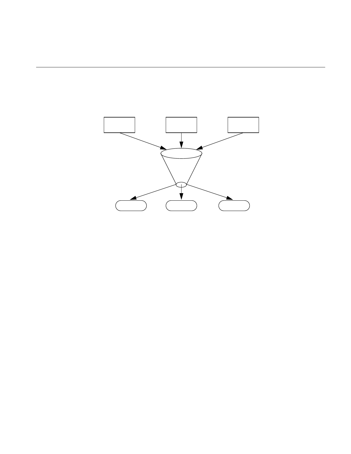
How sendmail Works
179
Figure 8-2 illustrates the sendmail system structure that is based on the original design
goals for sendmail.
Figure 8-2 sendmail System Structure
sendmail neither interfaces with the user nor does actual mail delivery. Rather, it collects
a message generated by a user agent program such as Berkeley Mail, edits the message
as required by the destination network, and calls appropriate mailers to do mail delivery
or queueing for network transmission. The exception is mail sent to a file; in this case,
sendmail delivers the mail directly.
This discipline allows the insertion of new mailers at minimum cost.
Because some of the senders may be network servers and some of the mailers may be
network clients, sendmail can be used as an internetwork mail gateway.
How sendmail Works
Understanding the sendmail programs requires understanding a variety of components.
Some of these components are daemons, scripts, files, and commands. This section
describes the various sendmail components.
user user user
mailer1 mailer2 mailer3
sendmail
agent1 agent2 agent3

180
Chapter 8: IRIX sendmail
The sendmail Daemon
Forsendmail to process incoming mail, a daemon must be running. The sendmail daemon
is the sendmail program with specific flags. (Appendix B describes the sendmail
command-line flags in detail.) The daemon is automatically started by the /etc/init.d/mail
script at station startup. The default command for the sendmail daemon is
/usr/lib/sendmail -bd -q15m
The -bd flag causes sendmail to run in daemon mode. The -q15m flag causes sendmail to
fork a subdaemon for queue processing every fifteen minutes. The -bd and -q flags can
be combined in one call.
sendmail Scripts
There are two scripts provided with your system that perform common functions in
sendmail. Use these scripts whenever possible, as they have been tested and are known to
perform the task correctly.
/etc/init.d/mail
Under rare circumstances, a user may need to stop or start the sendmail daemon
manually. For example, to implement changes to the configuration file, you must stop all
running sendmail processes, “refreeze” the configuration file, and restart the sendmail
daemon before the new configuration will take effect. To simplify the task of starting and
stopping sendmail, IRIX provides a shell script called /etc/init.d/mail.
This script takes a single argument, either start or stop, which starts or stops the sendmail
daemon respectively. You must be superuser (root) to use this script. For example, to stop
sendmail, use the following command:
/etc/init.d/mail stop
When /etc/init.d/mail is called with the start argument, it verifies the existence and
permissions of various sendmail related files and directories (see “sendmail Related Files
and Directories” on page 181). If a required component such as the /var/spool/mqueue
directory is missing, the script creates it. For more complex components, such as
/etc/aliases, the script exits with a message.
When the /etc/init.d/mail script is called with the stop argument, it kills all running
sendmail processes with a SIGTERM signal.

How sendmail Works
181
Note: Station start-up includes an automatic call to the /etc/init.d/mailscript with the start
argument. If station start-up runs in verbose mode (that is, /etc/chkconfig verbose on), the
following message displays, verifying that sendmail has been started:
Mailer daemons: sendmail
For more information, examine the /etc/init.d/mail script.
/usr/etc/configmail
The /usr/etc/configmail script provides an interface between command line input and the
sendmail.cf file. For more information, see “sendmail Related Files and Directories.” It
pipes the macro and class definitions into the sendmail.params file. This script simplifies
the sendmail configuration process.
The configmail script allows the user to interact with several sendmail parameters. These
parameters are equivalent to sendmail.cf macros and classes. You can verify the current
parameter settings, set specific parameters, issue a quick setup command, and get some
basic online help. configmail stores your changes in the sendmail.params file, which is read
by sendmail at startup time.
sendmail Related Files and Directories
The sendmail configuration files and directories are
• /etc/sendmail.cf
• /etc/sendmail.fc
• /etc/sendmail.hf
• /etc/sendmail.st
• /etc/aliases
• /var/spool/mqueue
• /var/mail

182
Chapter 8: IRIX sendmail
/etc/sendmail.cf
At the heart of the sendmail program is the sendmailconfiguration file /etc/sendmail.cf. The
sendmail.cf file is an ASCII file that contains most of the configuration information and is
read at run time.This file encodes options, header declarations, mailer declarations,
trusted user declarations, message precedences, address-rewriting rules, macro
definitions, and class definitions.
As the mail administrator and in order for you to successfully set up sendmail, you must
know which sendmail.cf macros and variables to change. The sendmail.cf file takes
advantage of sendmail’s ability to read macro and class definitions from pipes, thereby
simplifying and automating the sendmail configuration process. This file takes command
line input from the sendmail.params file and the /usr/etc/configmail script and incorporates
the input into the appropriate macros and classes.
/etc/sendmail.fc
The sendmail.fc file is a frozen configuration file. A frozen configuration file is an image
of the data space that belongs to sendmail when the configuration file is read. The
sendmail.fc file is not present by default. You can create the sendmail.fc file using the touch
command. After the sendmail.fc file is created, it is used in place of /etc/sendmail.cf. This
process improves start-up speed.
Note: All modifications to sendmail macros and classes should be made to sendmail.cf.
However, if the /etc/sendmail.fc file exists, changes to it are not honored until you rebuild
/etc/sendmail.fc. The mail script /etc/init.d/mail automatically rebuilds the frozen
configuration file if the sendmail.cf file exists. Always use the mail script because it
automatically rebuilds the sendmail.fc file. If you need to rebuild the frozen configuration
file manually, the command is
/usr/lib/sendmail -bz
/etc/sendmail.hf
Thesendmail.hf file is the Simple Mail Transfer Protocol (SMTP) help file. It contains some
brief information about the various SMTP commands.

How sendmail Works
183
/etc/sendmail.st
The sendmail.st file collects statistics related to sendmail. By default, the file is not present.
You can create the file using the touch command. If the file is present, sendmail
automatically updates the file with relevant sendmail statistics.
/etc/aliases
The aliases file contains the text form of the alias database used by the sendmail program.
The alias database contains aliases for local mail recipients. For example, the following
alias delivers mail addressed to jd on the local station to johndoe@company.com:
jd:johndoe@company.com
When sendmail starts up, it automatically processes the aliases file into the files
/etc/aliases.dir and /etc/aliases.pag. The aliases.dir and aliases.pag are DBM versions of the
aliases database. The DBM format improves sendmail performance.
Note: The newaliases program must be run after modifying the alias database file. See
“Building the Aliases Database” on page 185 for more information about building the
alias database.
/var/spool/mqueue
The mail queue, /var/spool/mqueue, is the directory where the mail queue and temporary
files reside. The messages are stored in various queue files that exist under the
/var/spool/mqueue directory. Queue files take these forms:
• qf*—control (queue) files for messages
• df*—data files
• tf*—temporary files
• nf*—a file used when a unique ID is created
• xf*—transcript file of the current session
Normally, a sendmail subdaemon processes the messages in this queue periodically,
attempting to deliver each message. (The /etc/init.d/mail script starts the sendmaildaemon
so that it forks a subdaemon every 15 minutes to process the mail queue.) Each time
sendmail processes the queue, it reads and sorts the queue, then attempts to run all jobs
in order.

184
Chapter 8: IRIX sendmail
/var/mail
/var/mail is the directory that houses all incoming mail. Each user on a local station
receives his or her mail in a file in the directory /var/mail. For example, the user guest
receives mail in the file /var/mail/guest.
sendmail Commands
These section describes some of the related sendmail programs and commands. The
programs and commands discussed in this section are
• sendmail
• newaliases
• mailq
sendmail
sendmail is the program that implements sendmail’s routing and transfer service. As a
program, it has many flags that can be set on the command line to tailor the sendmail
environment. Appendix B, “IRIX sendmail Reference,” provides complete descriptions
of the various command line flags and options.
/usr/bsd/newaliases
newaliases is the program used to rebuild the DBM version of the aliases database. This
program must be run any time the text version of the aliases file is modified. If newaliases
is not run after making changes to the aliases file, the changes are not incorporated into
the DBM alias database and are not seen by the sendmail program. See “Aliases Database”
on page 185 for more details about the alias database.
/usr/bin/mailq
The mailq command prints a current listing of the mail queue.

Aliases Database
185
Aliases Database
The aliases database is an ndbm database that contains mail aliases that are used by the
sendmail program. The text form of the database is maintained in the file /etc/aliases. The
aliases are of this form:
name:name1 [, name2, ...]
For example, the following command delivers mail addressed to jd to
johndoe@company.com:
jd:johndoe@company.com
Note: Only the local part of an address can be aliased. For example, the following
command is wrong and does not have the desired effect:
jd@big.university.edu:jd@company.com
sendmail consults the alias database only after deciding that the message (as originally
addressed) should be delivered locally, and after it has rewritten the address to contain
only the local part.
An alias continuation line must start with a space or a tab. Blank lines and lines
beginning with the number sign (#) are treated as comments.
If you are running NIS, sendmail can use the contents of the NIS alias database with the
local aliases database by adding the following special alias to the /etc/aliases file:
+:+
This special alias tells sendmail to consult the NIS alias database if the alias cannot be
found in the local alias database. When the same alias is specified in both the local and
NIS aliases file, the local alias supersedes the NIS alias.
Building the Aliases Database
At startup, sendmailautomatically uses the ndbm library to process the /etc/aliases file into
the files /etc/aliases.dir and /etc/aliases.pag. Using these files to resolve aliases improves
performance.

186
Chapter 8: IRIX sendmail
To rebuild the DBM version of the database without restarting sendmail, execute this
command:
newaliases
Executing this command is equivalent to giving sendmail the -bi flag:
/usr/lib/sendmail -bi
When building the DBM version of the database, sendmail checks the left-hand side of
each entry to make sure that it is a local address. sendmailissues a warning for each entry
in /etc/aliases with a non-local left-hand side. Such entries are not entered into the DBM
version of the database.
If the NIS alias database is used with the local usr/lib/aliases database, the special “+:+”
alias is entered into the DBM version of the database. If sendmail cannot find an alias in
the DBM version of the database, it looks for the special “+:+” alias. If it finds the special
alias, sendmail then queries the NIS alias database. This query permits you to change the
global NIS alias database without having to rebuild the local alias database. However,
the left-hand sides of the NIS alias are notchecked by sendmailto ensure that they contain
only local addresses.
If the configuration or the command line specifies the D option, sendmail automatically
tries to rebuild the alias database when it is out of date.
sendmail rebuilds the alias database if either of the following conditions exists:
• The DBM version of the database is mode 666.
•sendmail is running setuid to root.
Note: Auto-rebuild can be dangerous on heavily loaded stations with large alias files. If
it takes more than five minutes to rebuild the database, there is a chance that several
processes will start the rebuild process simultaneously.
Testing the Aliases Database
You can test the alias database with the -bv flag of the sendmail program. See “sendmail
Command-Line Flags” on page 205 for more details.

Aliases Database
187
Alias Database Problems
Problems can occur with the alias database, especially if a sendmail process accesses the
DBM version before it is completely rebuilt. Two circumstances can cause this problem:
• One process accesses the database while another process is rebuilding it.
• The process rebuilding the database dies because it has been killed, or a station
crash has occurred before completing the rebuild.
sendmail has two techniques for trying to relieve these problems. First, to avoid the
problem of a partially rebuilt database, sendmail ignores interrupts while rebuilding the
database. Second, at the end of the rebuild it adds an alias of the following form (which
is not normally legal):
@: @
Before sendmail accesses the database, it ensures that this entry exists. For this action to
occur, the configuration file must contain the -a option.
If the @:@ entry does not exist, sendmail waits for it to appear. After the specified waiting
period elapses, sendmail itself forces a rebuild. For this action to occur, the configuration
file must include the Doption. If the D option is not specified, a warning message is
generated and sendmail continues.
Another alias problem can arise for stations incorporating the NIS alias database in
/etc/aliases through the use of the +:+ alias. If the NIS alias server goes down or is
otherwise nonresponsive to NIS queries, sendmail will not see the aliases normally
obtained from the NIS server. This situation may result in mail being returned, marked
User unknown.
List Owners
If an error occurs when mail is sent to a certain address (x, for example), sendmail looks
for an alias of the following form to receive the errors:
owner-x
This scheme is typically useful for a mailing list where a user mailing to the list has no
control over the maintenance of the list itself; in this case the list maintainer would be the
owner of the list. For example, the following would cause jd@1company.com to get the

188
Chapter 8: IRIX sendmail
error that occurs when someone sends mail to unix-hackers,and sendmail finds the phony
user nosuchuser on the list.
unix-hackers: jd@company1.com, ed@big.university.edu,nosuchuser,
jane@company2.com
owner-unix-hackers: jd@company1.com
sendmail Network Configurations
This section explains the functions of domains, forwarders, and relays in a mail network.
It also explains how each of these components is designated in the /usr/etc/configmail
script and in the sendmail.cf file. It is important to understand these designations, since
you will be expected to enter this information in the working copy of these files for your
station.
Mail Domains
Within the sendmail environment, a domain is an administratively-defined area of control
with logical rather than physical boundaries.
You can configure three general types of domains:
• root: top-level domain of the local domain space. For example, horses.com is the top
level domain for the domain pintos.horses.com.
• direct: the domain(s) a station can send mail to directly (no forwarders or relays
involved).
• local: the domain to which a station belongs.
The following parameters designate domains in the /usr/etc/configmail script and the
/etc/sendmail.cf file:
•configmail parameters: rootdomain, directdomain, and localdomain
•sendmail.cf macros and classes:
– root domain: T macro
– direct domain: D class
– local domain: D macro

sendmail Network Configurations
189
Mail Forwarders
A forwarder station is a station that acts as a mail gateway into another network.
Typically, stations on either side of a gateway cannot connect directly to each other,
making the forwarder station a physical (not just administrative) necessity.
Forwarder stations are not necessarily “smarter” about mail routing than other stations
in the network, but they are “better connected.” Forwarder stations deliver mail to “all
points beyond” some point in the domain name space.
The designation of the forwarder station is primarily determined by the physical
topology of the network; the default sendmail.cffile can designate only a single forwarder,
and the name of that station must be hard-coded in the configuration file.
The following parameters designate a mail forwarder in the /usr/etc/configmail script and
the /etc/sendmail.cf file:
•configmail parameter: forwarder
•sendmail.cf macro and class: F
Mail Relays
A relay station is a station that acts as a collection point for mail destined for a specified
domain or group of domains. In the absence of MX records and mail exchangers, relay
stations provide a mechanism whereby mail can be concentrated onto centralized
locations prior to actual delivery. For more information about MX records and mail
exchangers, see Appendix B, “IRIX sendmail Reference.”
Relay stations are not necessarily “better connected” than other stations in the network,
but they are “smarter” about mail routing. They deliver mail to “all points within” some
point in the domain name space.
For example, a company with a domain company.com has configured sendmail to treat
alpha.company.com as the forwarder station and omega.company.com as the relay station.
sendmail assumes that alpha.company.com is ultimately responsible for all mail to domains
other than company.com and that station omega.company.com is ultimately responsible for
all mail to the company.com domain itself. Note that there is nothing to prevent the relay
and forwarder functions from residing on the same station.The designation of a relay
station is primarily determined by administrative decision. sendmail can recognize a
number of relay stations.

190
Chapter 8: IRIX sendmail
The relay station name is a special name used to identify relay stations in the network.
This special name is defined by means of the Rmacro and is typically the name “relay.”
A relay station is so designated by being aliased to the name “relay.” The default
sendmail.cffile probes for a station named or aliased to the special relay station name and
delivers mail to any such station in preference to the actual destination station. Mail is
also sent to relay stations whenever the local station cannot determine the proper
routing.
The following parameters designate a mail relay in the /usr/etc/configmail script and the
/etc/sendmail.cf file:
•configmail parameter: relayname
•sendmail.cf macro: R
User-Configurable Macros and Classes
The sendmail.cf file defines your mail network by assigning each element in the network
amacro or class value. The default values in your distribution sendmail.cf file will not work
without some modification.
Instead of modifying your sendmail.cf file directly, you can use the /usr/etc/configmail
script. It takes your input, saves it in sendmail.params, and configures the appropriate
macros and classes according to your sendmail environment.
Domain Name Macro and Class (D)
TheD macro defines the local domain name. Be sure that the macro contains the name of
the domain in which this station resides. If domains are not used, you can leave this
macro empty or comment it out.
• The D class explicitly lists all domains for which this station should send mail
directly by means of the local area network mailer.
• Mail for domains listed in the D class is sent directly to the destination station, if
possible. No attempt is made to send the mail by means of a relay station.
• Mail for domains not listed in the D class is sent by means of a relay station
associated with the destination station, if possible, rather than directly to the
recipient station.

User-Configurable Macros and Classes
191
• If this station is a relay for a particular domain, you must enter that domain name in
the Dclass. It is recommended that you always enter the domain name, regardless
of whether the station is a relay or not.
Forwarder Station Name Macro and Class (F)
The F macro defines the station name or alias of the station to which this station forwards
mail for unknown stations or domains.
• The F class contains all known names for the station defined in the F
macro.
• Mail is sent to the forwarder as a last resort only if one of these conditions exists:
– This station cannot make the destination station name canonical or determine
an appropriate relay or mail exchanger for the mail.
– The appropriate station, relay, or exchanger for the mail exists outside the
top-level domain. (See the description of the T macro later in this section.)
• If either condition for sending mail to this forwarder station exists, this station puts
messages to unknown stations or domains “on the wire” and hopes for the best.
• If no such station exists in your environment, leave the F macro and class empty. If
this station is the forwarder station, put this station’s name in the F macro. Put all
known names for the station in the Fclass.
Relay Station Name Macro (R)
The R macro defines the station name (or an alias) used by all stations that act as relay
stations. Relay stations are forwarders to known internal domains and are defined by the
use of this relay station name as their station name or alias. This macro comes
preconfigured as “relay,” a name that is strongly suggested.
• Do not leave this macro blank, even if your network has no relay stations
configured.
• Mail relay stations provide an alternative to an MX scheme, and can also be useful
as an emergency backup to the use of MX records for internal mail routing.

192
Chapter 8: IRIX sendmail
Top-Level Domain Macro (T)
The T macro defines the name of the top level of the local domain space. For example, if
this station resides in a subdomain named bar.foo.com under the foo.com domain, and if all
stations under the foo.com domain or any subdomain under the foo.com domain are
considered to be internal stations, the T macro containsfoo.com.
The top-level domain is used with the forwarder station (F) macro and class described
earlier in this section. All mail sent to stations outside the top level domain is sent by
means of the forwarder station.
Killed Stations Class (K)
The K class is a list of all known “killed” or “dead” stations in the local domain. This is
defined only on mail forwarders, to detect mail to stations that no longer exist. Any mail
directed to a “dead” station is automatically sent to the mail forwarder.
Pathalias Database Macro (P)
The P macro defines the location of the pathalias database that is used by sendmail for
UUCP mail routing.
sendmail Planning Checklist
Here is a list of items to consider before configuring your sendmail environment.
• What is the layout of your sendmail network (domains, forwarders, relays)?
• If you are using the /usr/etc/configmail script, do you have the values for the
parameters you need to modify?
• If you are manually modifying the /etc/sendmail.cf file, do you have the values for
the macros and classes you need to modify?
• Are you setting up any custom sendmail aliases? If you are, have aliases ready for
the aliases database file.

Configuring sendmail
193
• Are the /etc/hosts and /etc/passwd files up to date? The files should include the special
relay station name for the mail forwarder, station aliases, user accounts for mail
users, and so on. If you use domain names, the /etc/hosts file should use the
following format:
ip_address fully_qualified_domain_name alias1
,
alias2
,
...
A common problem with sendmail is that administrators place the aliases before the
fully qualified domain name in the /etc/hosts file.
Note: It is recommended that you do not make the first hostname entry a fully
qualified domain name when setting up an isolated or solitaire configuration.
• If you are using the Network Information Service (NIS) or BIND, are the
sendmail-related files configured correctly (aliases, hosts, passwd)?
Configuring sendmail
This section provides examples for configuring a fictitious sendmail environment. The
environment includes:
• a stand-alone station where users can send mail locally (solitaire)
• a simple isolated sendmail network with one domain
• a hierarchical sendmail network with relays and one domain (eng.fictitious.com)
• a hierarchical sendmail network with relays and multiple domains (corp.fictitious.com
and fin.fictitious.com)
• a complex hierarchical sendmail network with forwarders, relays, and multiple
domains (corp.fictitious.com and eng.fictitious.com)
• a UUCP sendmail connection (uk.com)
Note: In the following examples, an empty macro or class has no values assigned to it.
The macro or class is left blank.
Figure 8-3 illustrates the fictitious sendmail environment used in the following examples
for configuring sendmail.
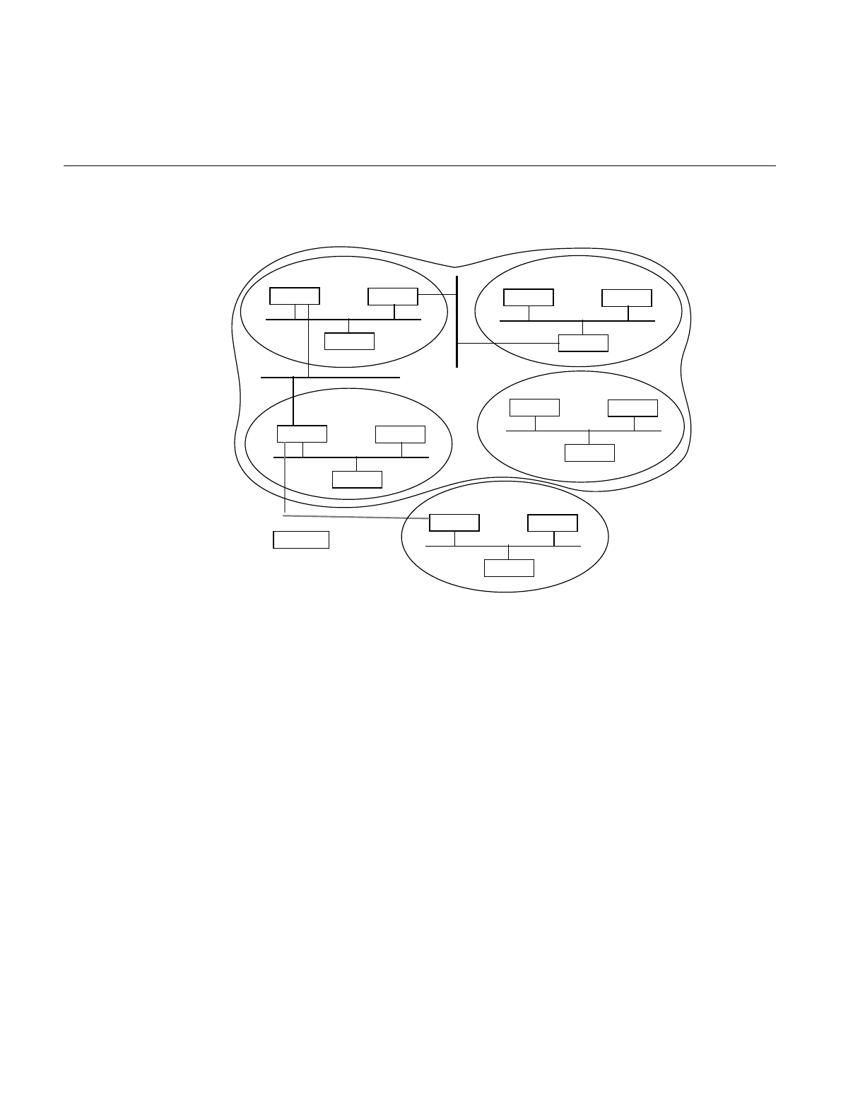
194
Chapter 8: IRIX sendmail
Figure 8-3 Example sendmail Configuration Environment
Customizing the sendmail.cf File
The configuration file describes mailers, tells sendmail how to parse addresses and
rewrite message headers, and sets various sendmail options. The standard configuration
file shipped with IRIX supports a wide variety of mail configurations and does not work
“out of the box.”
All examples are based on the default sendmail.cf configuration file as it is shipped with
IRIX. Note that sendmail macros and classes are both case-sensitive. See
“User-Configurable Macros and Classes” on page 190.
solitaire
fin1 fin2
fin3
fin.corp.fictitious.com
corp1 corp2
corp3
corp.fictitious.com
engr1 engr2
engr3
engr.fictitious.com
lab1 lab2
lab3
uk1 uk2
uk3
uk.com
fictitious.com
Simple Isolated Network

Configuring sendmail
195
Standalone Station (Solitaire)
In the example configuration in Figure 8-3, there is a single, isolated station named
solitaire. Mail is sent only from one user on the station to another user on the same station.
No mail is sent to any other station, and no mail is received from any other station.
Using the configmail script, set up mail like this:
/usr/etc/configmail set directdomains NULL
/usr/etc/configmail set localdomain NULL
/usr/etc/configmail set forwarder NULL
/usr/etc/configmail set rootdomain NULL
If you are configuring the sendmail.cf file by hand, make the required adjustments to the
following macros and classes:
The D macro and class:
Make sure that both the D macro and class are empty.
The F macro and class:
Make sure that both the F macro and class are empty.
The T macro: Make sure that the T macro is empty.
With a text editor, create a file named /usr/etc/resolv.conf and add the line:
hostresorder local bind
For more information about the resolv.conf file, see the resolv.conf(4) reference page.
Note: If this is the only station you are configuring for sendmail, proceed to “Modifying
the Aliases Database” on page 202.
Simple Isolated Network
An isolated network is the simplest network mail environment: a number of stations
reside on a private network and send mail to each other on a peer-to-peer basis. All
stations exist in the same domain; no subdomains exist. There is no connection or
gateway between this private network and the outside world. No station in the network
has greater responsibility for mail delivery than any other station. No relay or forwarder
stations exist. The stations in the example network are named lab1, lab2, and lab3.
Each station in the network uses the same configuration and can be set up as in the
“Standalone Station (Solitaire),” described above, or, as an alternative, you can use

196
Chapter 8: IRIX sendmail
configmail to perform an automatic setup. For the automatic setup procedure, refer to the
section "Automatically Configuring sendmail" in the Personal System Administration
Guide.
Hierarchical (Relay) Network With a Single Domain
In this example, all stations do not bear the same responsibility for mail delivery. One or
more stations are designated as mail relay stations, where mail is concentrated for further
processing or queueing before delivery.
This scheme has particular advantages if some stations frequently are powered off or are
otherwise unable to communicate. In such a situation, one or more relay stations are
more reliable; they are never or infrequently out of communication with the network and
are designated as mail concentration points. When mail is sent to a station that is down,
the mail travels to the relay station, where it is queued for later delivery, rather than being
queued on the originating station. When the destination station returns to operation, it is
more likely that the relay station will be up than the originating station. Therefore, the
mail will be delivered to the destination station in a timely manner.
This hierarchical scheme also offers administrative advantages. For example, if a single
station goes down for an extended period of time, or is simply failing to accept mail, the
situation is easier to detect when there is a central mail queue. An administrator can
check the mail queue on the relay station to see which stations are not accepting mail. If
there were no relay station, mail to the down station would be queued on stations
throughout the network, and the problem could be harder to spot.
All stations exist under the engr.fictitious.com domain. The stations in the network are
named engr1, engr2, and engr3. The mail relay station is engr1. The other stations in the
network are expected to send mail through engr1 rather than delivering it directly.
Each of the non-relay stations runs the same sendmail.cfconfiguration file. The sendmail.cf
file on relay station engr1 has a slightly different D class definition.
For example, using the configmail script, configure mail on the relay station engr1:
/usr/etc/configmail set directdomains engr.fictitious.com
/usr/etc/configmail set localdomain engr.fictitious.com
/usr/etc/configmail set forwarder NULL
/usr/etc/configmail set rootdomain engr.fictitious.com

Configuring sendmail
197
Using the configmail script, set up mail on the remaining stations in the engr.fictitious.com
domain. Note that the directdomains parameter is set to NULL on all stations except the
relay station engr1.
/usr/etc/configmail set directdomains NULL
/usr/etc/configmail set localdomain engr.fictitious.com
/usr/etc/configmail set forwarder NULL
/usr/etc/configmail set rootdomain engr.fictitious.com
If you are configuring the sendmail.cf file by hand, make the required adjustments to the
following macros and classes:
The D macro and class
On all stations, change the D macro to contain the engr.fictitious.com
domain name.
On the relay station engr1, make sure that the Dclass contains the
engr.fictitious.com domain name so that engr1 sends mail directly to all
stations in the engr.fictitious.com domain.
On the remaining stations, make sure that the Dclass is empty so that
they do not send mail directly to other stations. (They are to send the
mail to engr1.)
The F macro and class
Make sure that the F macro and class are empty.
The T macro On all stations, change the T macro to contain the engr.fictitious.com
domain name.
For engr1 to be recognized as the mail relay station, the special relay station name “relay”
(as defined by the R macro) must be one of the station aliases that belongs to engr1.
Include the station name “relay” in the entry for engr1 in /etc/hosts or the DNS or NIS
equivalent.
When you have completed this exercise, proceed to “Modifying the Aliases Database” on
page 202.
Hierarchical (Relay) Network With Multiple Domains
In this example, the hierarchical model is extended to multiple subdomains. This type of
environment is a logical extension of the preceding one and is probably the easiest model
to expand as the number of stations on the network increases. The environment requires
that domain names be used for proper mail addressing.

198
Chapter 8: IRIX sendmail
The entire local domain is named corp.fictitious.com. There is one subdomain under the
corp.fictitious.com domain: fin.corp.fictitious.com. The stations in the corp.fictitious.com
domain are corp1, corp2, and corp3. The stations in the fin.corp.fictitious.com domain are
fin1, fin2, and fin3. corp3 is the relay for the corp.fictitious.com domain; fin3 is the relay for
the fin.corp.fictitious.com domain.
The stations in each of the two domains (corp.fictitious.com and fin.corp.fictitious.com) are
configured much like those described in the preceding subsections.
Using the configmail script, set up mail on the relay station corp3:
/usr/etc/configmail set directdomains corp.fictitious.com
/usr/etc/configmail set localdomain corp.fictitious.com
/usr/etc/configmail set forwarder NULL
/usr/etc/configmail set rootdomain corp.fictitious.com
Using the configmail script, set up mail on the relay station fin3:
/usr/etc/configmail set directdomains fin.corp.fictitious.com
/usr/etc/configmail set localdomain fin.corp.fictitious.com
/usr/etc/configmail set forwarder NULL
/usr/etc/configmail set rootdomain corp.fictitious.com
Using the configmail script, set up mail on the remaining non-relay stations in the
corp.fictitious.com domain. Note that the directdomains parameter is set to NULL on
non-relay stations.
/usr/etc/configmail set directdomains NULL
/usr/etc/configmail set localdomain corp.fictitious.com
/usr/etc/configmail set forwarder NULL
/usr/etc/configmail set rootdomain corp.fictitious.com
Using the configmail script, set up mail on the remaining non-relay stations in the
fin.corp.fictitious.com domain. Note that the directdomains parameter is set to NULL on
non-relay stations.
/usr/etc/configmail set directdomains NULL
/usr/etc/configmail set localdomain fin.corp.fictitious.com
/usr/etc/configmail set forwarder NULL
/usr/etc/configmail set rootdomain corp.fictitious.com

Configuring sendmail
199
If you are configuring the sendmail.cf file by hand, make the required adjustments to the
following macros and classes:
The D macro For all stations in the corp.fictitious.com domain, change the D macro to
contain the corp.fictitious.com domain name.
For all stations in the fin.corp.fictitious.com domain, change the D macro
to contain the fin.corp.fictitious.com domain name.
The D class: On the relay station corp3, make sure that the D class contains the
corp.fictitious.comdomain name so that corp3 will send mail directly to all
stations in the corp.fictitious.com domain.
On the relay station fin3, make sure that the Dclass contains the
fin.corp.fictitious.com domain name so that fin3 will send mail directly to
all stations in the fin.corp.fictitious.com domain.
On the remaining stations in the network, make sure that the D class is
empty so that they do not send mail directly to other stations.
The F macro and class:
Make sure that the F macro and class are empty.
The T macro: On each of the stations, change the T macro to contain the
corp.fictitious.com domain name.
For the relay stations corp3 and fin3 to be recognized as such, the special relay station
name “relay” (as defined by the Rmacro) must be an alias for each of them. There can be
only one relay alias in the /etc/hosts file. Here is how to set up each alias:
• For corp3, the alias relay.corp.fictitious.com (and optionally “relay”) should be
included in its entry in /etc/hosts or the DNS or NIS equivalent.
• For fin3, the alias relay.fin.corp.fictitious.com should be included in its entry in
/etc/hosts or the DNS or NIS equivalent.
When you have completed this procedure, proceed to “Modifying the Aliases Database”
on page 202.
Complex (Forwarder) Hierarchical (Relay) Network With Domains
This section explains how to configure a station to act as the forwarder station; a
forwarder station can be added to any of the scenarios described in the preceding
subsections. Please see “sendmail Network Configurations” on page 188 for an
explanation of the forwarder station concept as used by IRIX sendmail.

200
Chapter 8: IRIX sendmail
This discussion applies to mail environments of all types. Whatever the form of your
internal mail environment, whenever you want to use a mail gateway station between
your internal mail network and the external world, a forwarder station is required. The
sendmail configuration for using this forwarder station is exactly the same for all stations
on the internal side of the gateway.
The internal mail environment consists of the domain corp.fictitious.com and any or all
domains under corp.fictitious.com (fin.corp.fictitious.com). All stations within the
corp.fictitious.com domain are capable of communicating with each other. For example,
there is no physical restriction to prevent station fin1.fin.corp.fictitious.com from sending
mail to corp1.corp.fictitious.com.
Station corp2.corp.fictitious.com can connect to all stations within the corp.fictitious.com
domain and can also connect to stations in other domains, such as engr.fictitious.com.
Station corp2.corp.fictitious.com is therefore the forwarder station to all domains beyond
thecorp.fictitious.comdomain. In this example, station corp2.corp.fictitious.com is aliased to
corp2 for ease of addressing in the internal mail environment.
In addition to the changes to sendmail.cfrequired for the internal mail environment, make
the following changes to the sendmail.cf file on all stations within the corp.fictitious.com
domain. Using the configmail script, change the appropriate parameter:
/usr/etc/configmail set forwarder corp2.corp.fictitious.com corp2
If configuring the sendmail.cf file by hand, make the required adjustments to the
following macros and classes:
The F macro: Make sure that the F macro contains the station name
corp2.corp.fictitious.com.
The F class: Make sure that the Fclass contains the two names corp2 and
corp2.corp.fictitious.com, by which the forwarder station is known.
When you have completed the procedure, proceed to “Modifying the Aliases Database”
on page 202.
UUCP Mail
The default sendmail.cf file shipped with IRIX includes support for sending mail through
UUCP. This section discusses these capabilities and explains how to integrate UUCP mail
into the local mail environment. UUCP support can be added to any of the scenarios
described in the preceding subsections.

Configuring sendmail
201
Thesendmail.cf file directs sendmailto read the /etc/uucp/Systems file on startup. All UUCP
station names are read from this file, and stations marked “domain-machine” are noted.
If a UUCP pathalias database is maintained on the station, the location of the database is
set with the Pmacro.
If the /etc/uucp/Systems file indicates that there are stations connected to the local station
through UUCP, sendmail sends mail received on the local station, and addressed to one
of the stations described in the /etc/uucp/Systemsfile, on to the proper place. If the P macro
is set and points to a valid UUCP pathalias database, sendmail will attempt to find a
UUCP path to a station for which it cannot find an address or MX record. If the database
returns a good UUCP path to the destination station, sendmail attempts to send the mail
to the left-most station on the path.
Depending upon the network environment, UUCP mail may range from the only form
of network mail to one part of a much larger network mail environment. The following
sections describe a common technique for adding UUCP to an existing local area mail
network.
Sample Environment
The local domain is named uk.com. Station uk1.uk.com is the forwarder station, as
described in “Complex (Forwarder) Hierarchical (Relay) Network With Domains” on
page 199 in “Customizing the sendmail.cf File” on page 194.
To avoid forwarder loops, the default sendmail.cf file permits only one forwarder station
to be configured. Therefore, station uk1.uk.com is also the UUCP forwarder station.
Changes to sendmail.cf
No changes to sendmail.cf are necessary beyond those required to configure station
uk1.uk.com as the forwarder station. (See “Complex (Forwarder) Hierarchical (Relay)
Network With Domains” on page 199.) If station uk1.uk.com maintains a pathalias
database, the Pmacro should be set to the pathname of the pathalias database.
Other Changes
The /etc/uucp/Systems file must also be configured before sendmail will see any of the
UUCP-connected stations. For more information see Chapter 7, “UUCP.”
When you have completed this procedure, look ahead to “Modifying the Aliases
Database” on page 202.

202
Chapter 8: IRIX sendmail
Modifying the Aliases Database
After modifying a station’s sendmail.cf file (see “Customizing the sendmail.cf File” on
page 194), the alias database file should also be modified to reflect your sendmail
environment. If you don’t have any “private” company aliases, you still need to modify
the aliases file to provide it with a valid postmaster alias.
Creating the Aliases File
Continuing with the fictitious example used in “Customizing the sendmail.cf File” on
page 194, assume that the administrator for the domain corp.fictitious.com has derived a
list of aliases for the corp.fictitious.com domain. The list of aliases is shown in Table 8-1.
Table 8-1 Sample aliases File Entries
Alias Name Member Station Name
finance john fin1
finance paul fin2
finance mary fin3
corp sharon corp1
corp pam corp2
corp peter corp3
all finance and corp N/A
postmaster mailmgr corp1

Configuring sendmail
203
The /etc/aliases file entries based on the list of aliases generated by the administrator
would look like this:
#############################################################
# Aliases in this file will NOT be expanded in the header
# from Mail, but WILL be visible over networks or from
# /bin/mail.
# >>>>>>>>> The program "newaliases" must be run after
# >> NOTE >> this file is updated for any changes to
# >>>>>>>>>> show through to sendmail.
#############################################################
start of common aliases--do not remove this line
# Add the following alias to enable Yellow Page aliases. If
# enabled, the YP database defines anything not defined in
# this file.
#+:+
# Alias for mailer daemon
MAILER-DAEMON:postmaster
# send mail likely to be lost to the mail server
rootcsh:postmaster
rootsh:postmaster
.
.
.
games:postmaster
# Following alias is required by RFC 822
# You should change ’root’ in the first line below to
# the administrator of this machine, and un-comment the
# following line.
postmaster:root
root:mailmgr@corp1
# aliases to handle mail to msgs and news
nobody: /dev/null
# end of common aliases--do not remove this line
# corp.fictitious.com aliases
finance:john@fin1,paul@fin2,mary@fin3
corp:sharon@corp1,pam@corp2,peter@corp3
all:finance,corp

204
Chapter 8: IRIX sendmail
Updating the aliases Database
After you modify the /etc/aliases text database file, run the newaliases program to
incorporate the text changes into the DBM files, /etc/aliases.dir and /etc/aliases.pag.
Update the aliases database:
/usr/bsd/newaliases
If there is nothing wrong with your aliases database, newaliases lists the number of aliases
and then return your prompt. If you see any other message, most likely there is a problem
with your aliases file. See “Debugging Flags” on page 207 for hints on troubleshooting
the alias file.
Starting the sendmail Daemon
After customizing the sendmail.cf files and modifying the aliases database, you are ready
to start sendmail.
By default, IRIX automatically starts sendmail at station start-up by using the shell script
/etc/init.d/mail. However, if you are configuring and testing sendmail and don’t want to
reboot the station, you can run the /etc/init.d/mail script manually. You should always use
themail script to stop and start sendmail. It processes and checks sendmail related files and
programs and in the correct order.
Start the sendmail daemon:
/etc/init.d/mail start
If you need to stop sendmail, enter the following command:
/etc/init.d/mail stop

Managing sendmail
205
Managing sendmail
This section describes some of the tasks related to managing the sendmail environment.
sendmail Command-Line Flags
You can include one or more flags on the command line to tailor a sendmail session. This
section describes some of the more frequently used flags. For a complete description of
command-line flags, see Appendix B, “IRIX sendmail Reference.”
Changing the Values of Configuration Options
The -o flag overrides an option in the configuration file. The override is for the current
session only. In the following example, the T (timeout) option becomes two minutes for
this session only:
/usr/lib/sendmail -oT2m
For a complete discussion of configuration options, see Appendix B, “IRIX sendmail
Reference.”
Delivery Mode
One configuration option frequently overridden on the command line is the d option,
which specifies the sendmail delivery mode. The delivery mode determines how quickly
mail is delivered:
ideliver interactively (synchronously)
bdeliver in background (asynchronously)
qqueue only (don’t deliver)
There are trade-offs. Mode ipasses the maximum amount of information to the sender,
but is rarely necessary.
Mode q puts the minimum load on your station, but if you use it, delivery may be
delayed for up to the queue interval.

206
Chapter 8: IRIX sendmail
Mode b is probably a good compromise. However, in this mode, sendmail may initiate a
large number of processes if you have a mailer that takes a long time to deliver a
message.
Queue Mode
The -q flag causes sendmail to process the mail queue at regular intervals. The syntax is
as follows, where time defines the interval between instances of queue processing:
-q [time]
Time is expressed in number of minutes: 15m sets the interval to 15 minutes. If time is
omitted, sendmail processes the queue once and returns. The -q flag is often used in
conjunction with daemon mode, described in the next subsection.
Daemon Mode
To process incoming mail over sockets, a daemon must be running. The -bd flag causes
sendmail to run in daemon mode. The -bd and -q flags can be combined in one call, as in
the following example:
/usr/lib/sendmail -bd -q30m
This command causes sendmail to run in daemon mode and to fork a subdaemon for
queue processing every half hour.
The script for starting sendmail that is provided with IRIX includes the following
command line:
/usr/lib/sendmail -bd -q15m
Verify Mode
Using the -bv flag directs sendmailto validate addresses, aliases, and mailing lists. In this
mode, sendmail performs verification only. It does not try to collect or deliver a message.
sendmail expands all aliases, suppresses duplicates, and displays the expanded list of
names. For each name, sendmail indicates if it knows how to deliver a message to that
destination.

Managing sendmail
207
Test Mode
The-btflag places sendmailin test mode so that it describes how the current configuration
rewrites addresses. Test mode is extremely useful for debugging modifications to the
/etc/sendmail.cfconfiguration file. For more information, see Appendix B, “IRIX sendmail
Reference.”
Debugging Flags
Several debugging flags are built into sendmail. Each flag includes a number and a level.
The number identifies the debugging flag. The level, which defaults to 1, dictates how
much information is printed. A low level causes minimal information to print; a high
level causes more comprehensive information to print. By convention, levels greater than
9 are not recommended, since so much information prints that it is of limited value.
Debugging flags use the following syntax:
-d debug-list
• Set flag 13 to level 1.
-d13
• Set flag 13 to level 3.
-d13.3
• Set flags 5 though 18 to level 1.
-d5-18
• Set flags 5 through 18 to level 4.
-d5-18.4
Many debugging flags are of little use to the average sendmail user. Some are occasionally
useful for helping to track down obscure problems. Appendix B, “IRIX sendmail
Reference,” includes a complete list of debugging flags.
Using a Different Configuration File
The -C flag directs sendmail to use an alternate configuration file. For example, the
following line directs sendmail to use the test.cf file instead of the default /etc/sendmail.cf
file:
/usr/lib/sendmail -Ctest.cf

208
Chapter 8: IRIX sendmail
If the -C flag appears without a filename, sendmail uses the file sendmail.cf in the current
directory. Thus, the -C flag directs sendmail to ignore any /etc/sendmail.fc (“frozen”) file
that may be present.
The Mail Queue
This section discusses how to print and force the mail queue.
Listing the Queue
You can list the contents of the queue by using the mailq command or by specifying the
-bp flag to sendmail. The list includes a listing of the queue IDs, the size of each message,
the date the message entered the queue, and the sender and recipients.
Forcing the Queue
The -q flag (with no value) forces sendmail to process the queue. It is sometimes useful to
use the -v flag (verbose) also when running the queue manually, as follows:
/usr/lib/sendmail -q -v
In verbose mode, sendmail displays the SMTP chatter with other stations as well as
messages indicating any delivery errors and final message disposition.
Because of the locking algorithm, it is impossible for one job to freeze the queue.
However, an uncooperative recipient station or a program recipient that never returns
can consume many station resources. Unfortunately, there is no way to resolve this
situation without violating the SMTP protocol used by sendmail.
In some cases, if a major station goes down for a couple of days, a prohibitively large
queue may be created. As a result, sendmail spends an inordinate amount of time sorting
the queue. You can remedy this situation by moving the queue to a temporary location
and creating a new queue. The old queue can be run later when the offending station
returns to service.

Managing sendmail
209
Use the following commands to move the entire queue directory. The mail queue should
be owned by root and belong to the mail group.
cd /var/spool
mv mqueue omqueue
mkdir mqueue
chmod 755 mqueue
Then kill the existing sendmaildaemon (because it will still be processing in the old queue
directory) and create a new daemon:
/etc/init.d/mail stop
/etc/init.d/mail start
To run the old mail queue, use the following command:
/usr/lib/sendmail -oQ/var/spool/omqueue -q
The -oQ flag specifies an alternate queue directory, and the -q flag causes sendmail to run
every job in the queue once and then return. Use the -v (verbose) flag to watch what is
going on. It may be necessary to run the old mail queue a number of times before all of
the messages can be delivered.
When the queue is finally emptied, the directory can be removed:
rmdir /var/spool/omqueue
The .forward File
As an alternative to the alias database, users can put a file with the name .forward in their
home directories. If the .forward file exists, in a user’s home directory sendmail redirects
mail for that user to the list of recipients in the file. The recipients are separated by
commas or new lines. For example, if the home directory for user jane has a .forward file
with the following contents, any mail arriving for jane is redirected to the specified
accounts:
zippy@state.edu
bongo@widgets.com

210
Chapter 8: IRIX sendmail
The .forward file also allows the user to redirect mail to files or programs. A .forward file
with the following contents redirects any incoming messages to jd@company.com,
appends a copy of the message to the file /var/tmp/mail.log, and pipes a copy of the
message to stdin of the /usr/bin/mymailer program:
jd@company.com
/var/tmp/mail.log
| /usr/bin/mymailer
In general, file-type recipients must be writable by everyone. However, if sendmail is
running as root and the file has setuid or setgid bits set, then the message will be written
to the file.
Users can redirect mail to themselves in addition to sending it to other recipients. This
feature is particularly useful if the users want to continue to receive mail in their own
mailboxes while passing copies of each incoming message to some alternative
destination. For example, say that the home directory for user johncontains a .forwardfile
with the following contents:
\john, |/usr/sbin/vacation
sendmail behaves as follows:
•It sends each incoming message to john’s regular mailbox; the backslash (\)
preceding the name indicates that no further aliasing is to occur.
•It pipes a copy of each message to stdin of the /usr/sbin/vacation program. (The
vertical bar [|] is the standard UNIX pipe symbol.)
sendmail Questions, Problems, and Troubleshooting
1. What are MX records?
MX records are resource records in the BIND database. Each record contains the
name of a target station, a preference level, and the name of an exchanger station
that handles mail for the target station. (The exchanger station may be the target
station itself.)
The BIND database can contain several MX records for each target station; the
record with the lowest preference level is tried first.
MX records provide a way to direct mail to alternative stations. Using MX records
lets you eliminate static routes from your sendmail configuration file. For more
details about setting up MX records, see Appendix B, “IRIX sendmail Reference.”

Notes to Current sendmail Users
211
2. sendmail doesn’t seem to see my changes to sendmail.cf.
Remember to save your changes to the configuration file by issuing the following
commands:
/etc/init.d/mail stop
/etc/init.d/mail start
The stopping and starting of the daemon forces sendmail to reconfigure the file.
Otherwise, sendmail runs using the old, “frozen” version of the configuration file,
thus ignoring your changes. For more information on “frozen” configuration files,
see Appendix B, “IRIX sendmail Reference.”
3. Can I put comments in macro definitions?
Do not include comments on macro or class definition lines in the sendmail.cffile. For
example,
DDfoo.com # my domain name
would define the D macro as:
"foo.com # my domain name"
Likewise,
CD foo.com bar.com # my local domains
would define the Dclass as containing “foo.com,” “bar.com,” “#,” “my,” “local,”
and “domains.”
4. Where can I find information to help me troubleshoot my sendmail installation?
See Appendix B, “IRIX sendmail Reference.”
Notes to Current sendmail Users
In general, the current version of sendmailshould be backward-compatible with previous
versions. Most users should be able to replace their existing sendmail with the new IRIX
4.0 sendmail and run as before without any changes. However, there are certain
differences between this and previous versions of sendmail that may cause compatibility
problems. These differences are described in the subsections that follow.

212
Chapter 8: IRIX sendmail
MX Record Support
For each destination station contacted by means of an IPC-type mailer (P=[IPC] in the
mailer definition line), sendmailqueries the DNS database for MX records associated with
the destination station. If the MX query succeeds, mail will be routed through the
appropriate exchanger station found among the returned MX records as described in
RFC 974 and required by RFC 1123.
The result is that this version of sendmail and previous versions may use different
methods to route mail to stations for which MX records are available. See Appendix B,
“IRIX sendmail Reference,” for information regarding mailer definitions.
With the advent of MX records, you may want to edit your sendmail.cf file to remove
previously required static routes.
Multi-Token Class Match
Some sendmail.cf implementations inadvertently rely on the inability of sendmail to do
multi-token class-matching. One such implementation is the standard sendmail.cf file
distributed with IRIX Releases 3.2 and 3.3. If your sendmail.cf file is based upon one of
those standard sendmail.cf files, you should read this section. If your sendmail.cf file is not
based on one of those standard files, this section may serve as an example if you
encounter odd behavior with class-matching while running the new sendmail.
The standard IRIX Release 3.2 and 3.3 sendmail.cf files define an Sclass that is scanned in
from the /etc/hosts file. This class is used to detect single-token station names that appear
in the local /etc/hosts file. With the advent of multi-token class-matching, the S class no
longer operates as intended.
The problem is that station names appearing in the /etc/hosts file are scanned into the S
class whether they are single- or multi-token station names (that is, whether or not they
contain dots). The S class still worked as intended with previous versions of sendmail,
because if an attempt was made to match a multi-token station name in the class, the
match would always fail. With the new sendmail, that same match will (incorrectly)
succeed. This problem is observed when rules such as this one began matching qualified
station names such as foo.bar.sgi.com:
# Assume that unqualified names are local.
R$*<@$=S>$* $1<@$2.$D>$3

Notes to Current sendmail Users
213
The result was that stations such as foo.bar.sgi.com that appeared on the LHS of the rewrite
rule shown here were being rewritten to foo.bar.sgi.com.bar.sgi.com, which is obviously
wrong.
The problem was not the use of the S class, but rather the practice of scanning
multi-token station names from the /etc/hosts file into the class in the first place.
An examination of the sendmail.cf file shows that the S class is being scanned in by the
following scan sets:
# Directly-connected SMTP hosts
FS/etc/hosts %*[.0-99] %[-_.a-zzA-ZZ0-99]
FS/etc/hosts %*[.0-99] %*[-._a-zzA-ZZ0-99] %[-_.a-zzA-Z0-99]
These scan sets read in the two left-most station names from /etc/hosts regardless of
whether they contain dots. To correct the situation, modify the scan sets to read in only
the station names from /etc/hosts in their single-token, unqualified form, as follows:
# Directly-connected SMTP hosts
FS/etc/hosts %*[.0-99] %[-_a-zzA-ZZ0-99]
FS/etc/hosts %*[.0-99] %*[-._a-zzA-ZZ0-99] %[-_a-zzA-ZZ0-99]
Note the removal of the dots from the right-most patterns.
Depending on your use of class-matching, this incompatibility may not affect you. If you
suspect there might be a problem, you should examine your use of classes and your class
definitions. If you are currently using a sendmail.cf file supplied by Silicon Graphics, you
should examine the Sclass scan sets and make the corrections indicated here. If you use
the default sendmail.cf as supplied in this release, you should be free from any such
problems.


215
Appendix A
A. BIND Standard Resource Record Format
The Berkeley Internet Name Domain (BIND) server uses a specific record format for the
name server data files. This appendix details BIND’s standard resource record format by
resource record type.
Standard Resource Record Format
The records in the name server data files are called resource records. The Standard
Resource Record (RR) Format is specified in RFC 1035. The standard format of resource
records is:
{name} {ttl} addr-class Record Type Record-specific data
• The first field is the name of the domain record. It must always start in column 1.
For some RRs the name may be left blank, in which case it becomes the name of the
previous RR.
• The second field is an optional time-to-live field, which specifies how long this data
will be stored in the database. When this field is blank, the default time-to-live value
is specified in the Start of Authority (SOA) resource record (described later in this
section).
• The third field is the address class. Currently only the IN class (for Internet hosts
and addresses) is recognized.
• The fourth field identifies the type of resource record.
• Subsequent fields depend on the type of RR.
Case is preserved in names and data fields when they are loaded into the name server.
Comparisons and lookups in the name server database are not case sensitive.
If you specify TTLs for resource records, it is important that you set them to appropriate
values. The TTL is the amount of time (in seconds) that a resolver will use the data from
your server before it asks your server again. If you set the value too low, your server will

216
Appendix A: BIND Standard Resource Record Format
become loaded down with repeat requests. If you set it too high, information you change
will not be distributed in a reasonable amount of time.
Most host information does not change much over time. A good way to set up your TTLs
is to set them at a high value, and lower the value if you know a change is coming soon.
You might set most TTLs between a day (86400) and a week (604800). When you know
some data is changing soon, set the TTL for that RR to a low value, between an hour
(3600) and a day, until the change takes place. Then reset it to its previous value. All
resource records with the same name, class, and type should have the same TTL value.
The following characters have special meanings in resource records:
(blank) A blank or tab character in the name field denotes the current domain.
@ A free-standing “at” sign (@) in the name field denotes the current
origin.
. A free-standing period in the name field represents the root domain
name.
\x The backslash designates that the special meaning of the character x
does not apply. The x represents any character other than a digit (0–9).
For example, use \.to place a dot character in a label.
\DDD Each D is a digit; the complete string is the octet corresponding to the
decimal number described by DDD. The octet is assumed to be text and
is not checked for special meaning.
( ) Parentheses enclose group data that crosses a line. In effect, newlines are
not recognized within parentheses. This notation is useful with SOA and
WKS records.
; A semicolon precedes a comment; the remainder of the line is ignored.
* An asterisk is a wildcard character.
Usually a resource record has the current origin appended to the name if the name is not
terminated by a period (.). This scheme is useful for appending the current domain name
to the data, such as workstation names, but can cause problems if you do not want the
name to be appended. If the name is not in the domain for which you are creating the
data file, end the name with a period. However, do not append the period to Internet
addresses.

Standard Resource Record Format
217
$INCLUDE
An include line has $INCLUDE starting in column 1 and is followed by a filename. This
feature helps you use multiple files for different types of data. For example:
$INCLUDE /usr/etc/named.d/mailboxes
This line is a request to load the file /usr/etc/named.d/mailboxes. The $INCLUDE command
does not cause data to be loaded into a different zone or tree. It allows data for a given
zone to be organized in separate files. For example, you might keep mailbox data
separate from host data by using this mechanism.
$ORIGIN
$ORIGIN changes the origin in a data file. The line starts in column 1 and is followed by
a domain origin. This feature is useful for putting more than one domain in a data file.
$ORIGIN Berkeley.EDU.
SOA—Start of Authority
name {ttl} addr-class SOA Source Person-in-charge
@ IN SOA ucbvax.Berkeley.EDU kjd.ucbvax.Berkeley.EDU.
(
1994021501;Serial
10800 ;Refresh
3600 ;Retry
3600000 ;Expire
86400 ;Minimum
)
The Start of Authority record, SOA,designates the start of a zone. There should be only
one SOA record per zone.
The name is the name of the zone. It can be a complete domain name like
“Berkeley.EDU.” or a name relative to the current $ORIGIN. The “at” sign (@) indicates
the current zone name, taken from the “primary” line in the named.boot file or from a
previous $ORIGIN line.
Source is the name of the host on which the master data file resides, typically the primary
master server.

218
Appendix A: BIND Standard Resource Record Format
Person-in-charge is the mailing address for the person responsible for the name server. The
mailing address is encoded in the form of a domain name where the “at” sign (@)
separating the user name from the hostname is replaced with a period. In the example
above, kjd.ucbvax.berkeley.edu is the encoded form of kjd@ucbvax.berkeley.edu.
Serial is the version number of this data file, and should be incremented whenever data
are changed. Do not use floating point numbers (numbers with a decimal point, such as
1.1). A useful convention is to encode the current date in the serial number. For example,
25 April 1994 edit #1 is encoded as:
1994042501
Increment the edit number if you modify the file more than once on a given day.
Refresh indicates how often, in seconds, a secondary name server is to check with the
primary name server to see if an update is needed.
Retry indicates how long, in seconds, a secondary server is to retry after a failure to check
for a refresh.
Expire is the maximum number of seconds that a secondary name server has to use the
data before they expire for lack of getting a refresh.
Minimum is the default number of seconds to be used for the time-to-live field on
resource records with no explicit time-to-live value.
NS—Name Server
{name} {ttl} addr-class NS Name server’s_name
IN NS ucbarpa.Berkeley.EDU.
The Name Server record, NS, lists the name of a machine that provides domain service
for a particular domain. The name associated with the RR is the domain name, and the
data portion is the name of a host that provides the service. Workstations providing name
service need not be located in the named domain. There should be one NS record for each
master server (primary or secondary) for the domain. If you use more than
approximately 10 to 15 NS records for a zone, you may exceed DNS datagram size limits.
NS records for a domain must exist in both the zone that delegates the domain and in the
domain itself. If the name server host for a particular domain is itself inside the domain,
then a glue record is needed. A glue record is an Address (A) record that specifies the

Standard Resource Record Format
219
address of the server. Glue records are needed only in the server delegating the domain,
not in the domain itself. For example, if the name server for domain SRI.COM is
KL.SRI.COM, then the NS and glue A records on the delegating server look like this:
SRI.COM. IN NS KL.SRI.COM.
KL.SRI.COM. IN A 10.1.0.2
The administrators of the delegating and delegated domains should ensure that the NS
and glue A records are consistent and remain so.
A—Address
{name} {ttl} addr-class A address
ucbvax IN A 128.32.133.1
IN A 128.32.130.12
The Address record, A, lists the address for a given workstation The name field is the
workstation name, and the address is the network address. There should be one A record
for each address of the workstation.
HINFO—Host Information
{name} {ttl} addr-class HINFO Hardware OS
IN HINFO SGI-IRIS-INDY IRIX
The Host Information resource record, HINFO,is for host-specific data. This record lists
the hardware and operating system running at the listed host. Only a single space
separates the hardware information and the operating-system information. To include a
space in the workstation name, you must place quotation marks around the name. There
should be one HINFO record for each host. See the file /usr/etc/named.d/README for the
current list of names for IRIS4D Series workstations and servers. To learn the names for
other types of hardware and operating systems, refer to the most current “Assigned
Numbers” RFC (RFC 1340 as of this writing).
WKS—Well-Known Services
{name} {ttl} addr-class WKS address protocol services list
IN WKS 192.12.6.16 UDP (who route
timed domain)
IN WKS 192.12.63.16 TCP (echo telnet
chargen ftp

220
Appendix A: BIND Standard Resource Record Format
smtp time
domain bootp
finger sunrpc)
The Well-Known Services record, WKS, describes well-known services supported by a
particular protocol at a specified address. The list of services and port numbers comes
from the list of services specified in /etc/services. There should be only one WKS record
per protocol per address.
CNAME—Canonical Name
aliases {ttl} addr-class CNAME Canonical name
ucbmonet IN CNAME monet
The Canonical Name resource record, CNAME,specifies an alias for the official, or
canonical, hostname. This record should be the only one associated with the alias name.
All other resource records should be associated with the canonical name, not with the
alias. Any resource records that include a domain name as their value (such as NS or MX)
should list the canonical name, not the alias.
Aliases are also useful when a host changes its name. In that case, it is usually a good idea
to have a CNAME record so that people still using the old name get to the right place.
PTR – Domain Name Pointer
name {ttl} addr-class PTR real name
6.130 IN PTR monet.Berkeley.EDU.
A Domain Name Pointer record, PTR,allows special names to point to some other
location in the domain. The example of a PTR record given here is used to set up reverse
pointers for the special IN-ADDR.ARPA domain. PTR names should be unique to the
zone. Note the period (.) appended to the real name to prevent named from appending
the current domain name.
MB—Mailbox
name {ttl} addr-class MB Machine
ben IN MB franklin.Berkeley.EDU.

Standard Resource Record Format
221
The Mailbox record, MB, lists the workstation where a user receives mail. The name field
is the user’s login. The machine field lists the workstation to which mail is to be
delivered. Mailbox names should be unique to the zone.
MR—Mail Rename Name
name {ttl} addr-class MR corresponding_MB
Postmaster IN MR ben
The Mail Rename Name record, MR, lists aliases for a user. The name field lists the alias
for the name listed in the last field, which should have a corresponding MB record.
MINFO—Mail Information
name {ttl} addr-class MINFO requests maintainer
BIND IN MINFO BIND-REQUEST kjd.Berkeley.EDU
The Mail Information record, MINFO, creates a mail group for a mailing list. This
resource record is usually associated with a Mail Group (MG) record, but can be used
with a Mailbox (MB) record. The name is the name of the mailbox. The requests field is
where mail (such as requests to be added to a mail group) should be sent. The maintainer
is a mailbox that should receive error messages. This arrangement is appropriate for
mailing lists when errors in members’ names should be reported to someone other than
the sender.
MG—Mail Group Member
{mail group name} {ttl} addr-class MG member name
IN MG Bloom
The Mail Group record, MG, lists members of a mail group. Here is an example for
setting up a mailing list:
Bind IN MINFO Bind-Request kjd.Berkeley.EDU.
IN MG Ralph.Berkeley.EDU.
IN MG Zhou.Berkeley.EDU.
MX—Mail Exchanger
preference mail

222
Appendix A: BIND Standard Resource Record Format
name {ttl} addr-class MX value exchanger
Munnari.OZ.AU. IN MX 10 Seismo.CSS.GOV.
*.IL. IN MX 10 CUNYVM.CUNY.EDU.
The Mail Exchanger record, MX, specifies a workstation that can deliver mail to a
workstation not directly connected to the network. In the first example given here,
Seismo.CSS.GOV. is a mail gateway that can deliver mail to Munnari.OZ.AU. Other
systems on the network cannot deliver mail directly to Munnari. The two systems,
Seismo and Munnari, can have a private connection or use a different transport medium.
The preference value is the order that a mailer should follow when there is more then one
way to deliver mail to a single workstation. See RFC 974 for more detailed information.
You can use a wildcard name containing an asterisk (*) for mail routing with an MX
record. Servers on the network can state that any mail to a given domain is to be routed
through a relay. In the second example given here, all mail to hosts in the domain IL is
routed through CUNYVM.CUNY.EDU. This routing is done by means of a wildcard MX
resource record, which states that *.IL has an MX of CUNYVM.CUNY.EDU.
RP—Responsible Person
owner {ttl} addr RP mbox_domain_name TXT_domain_name
franklin IN RP franklin.berkeley.edu admin.berkeley.edu.
The Responsible Person record, RP,identifies the name or group name of the responsible
person for a host. Often it is desirable to be able to identify the responsible entity for a
particular host. Otherwise, when that host is down or malfunctioning, it is difficult to
contact someone who can resolve the problem or repair the host.
The mbox domain name field is a domain name that specifies the mailbox for the
responsible person. Its format in master files uses the DNS convention for mailbox
encoding, identical to that used for the Person-in-charge mailbox field in the SOA record.
In the example given here, the mbox domain name shows the encoding for
ben@franklin.berkeley.edu. You can specify the root domain name (just “.”) to indicate
that no mailbox is available.
The last field is a domain name for which TXT RRs exist. You can perform a subsequent
query to retrieve the associated TXT resource records at the TXT domain name.
Retrieving the TXT records provides a level of indirection so that the entity can be
referred to from multiple places in the DNS. You can specify the root domain name (just
“.”) for the TXT domain name to indicate that no associated TXT RR exists. In the

Standard Resource Record Format
223
example, “sysadmins.berkeley.edu.” is the name of a TXT record that could contain some
text with names and phone numbers.
The format of the RP record is class insensitive. Multiple RP records at a single name may
be present in the database. They should have identical TTLs.
The RP record is experimental; not all DNS servers implement or recognize it.
TXT—Text
text-name {ttl} addr-class TXT text-data
location IN TXT "Berkeley, CA"
The Text record, TXT, is used to hold descriptive text. The semantics of the text depend
on the domain where it is found.


225
Appendix B
B. IRIX sendmail Reference
This appendix provides reference material on sendmail. It is divided into the following
sections:
• “sendmail Command-Line Flags” on page 225
• “Tuning” on page 228
• “The Configuration File” on page 233
• “Flags, Options, and Files” on page 251
sendmail Command-Line Flags
You can include one or more flags on the command line to tailor a sendmail session. This
section describes some of the more frequently used flags. For a complete description of
command-line flags, see “Flags, Options, and Files” on page 251.
Changing the Values of Configuration Options
The -o flag overrides an option in the configuration file. The override is for the current
session only. In the following example, the T (timeout) option becomes two minutes for
this session only:
/usr/lib/sendmail -oT2m
For a complete discussion of configuration options, see “Flags, Options, and Files” on
page 251.

226
Appendix B: IRIX sendmail Reference
Delivery Mode
One configuration option frequently overridden on the command line is the d option,
which specifies the sendmail delivery mode. The delivery mode determines how quickly
mail is delivered:
ideliver interactively (synchronously)
bdeliver in background (asynchronously)
qqueue only (don’t deliver)
There are trade-offs. Mode i passes the maximum amount of information to the sender,
but is rarely necessary.
Mode q puts the minimum load on your system, but if you use it, delivery may be
delayed for up to the queue interval.
Mode b is probably a good compromise. However, in this mode, sendmail may initiate a
large number of processes if you have a mailer that takes a long time to deliver a
message.
Queue Mode
The -q flag causes sendmail to process the mail queue at regular intervals. The syntax is
as follows, where time defines the interval between instances of queue processing:
-q [time]
Time is expressed in number of minutes: 15m sets the interval to 15 minutes. If time is
omitted, sendmail processes the queue once and returns. The -q flag is often used in
conjunction with daemon mode, described in the next subsection.
See “Timeouts and Intervals” on page 229 for a discussion of time-interval specifications
and formats.
Daemon Mode
To process incoming mail over sockets, a daemon must be running. The -bd flag causes
sendmail to run in daemon mode. The -bd and -q flags can be combined in one call, as in
the following example:

sendmail Command-Line Flags
227
/usr/lib/sendmail -bd -q30m
This command causes sendmail to run in daemon mode and to fork a subdaemon for
queue processing every half hour.
The script for starting sendmail that is provided with IRIX includes the following
command line:
/usr/lib/sendmail -bd -q15m
Verify Mode
Using the -bv flag directs sendmail to validate addresses, aliases, and mailing lists. In this
mode, sendmail performs verification only. It does not try to collect or deliver a message.
sendmail expands all aliases, suppresses duplicates, and displays the expanded list of
names. For each name, sendmail indicates if it knows how to deliver a message to that
destination.
Test Mode
The-bt flag places sendmail in test mode so that it describes how the current configuration
rewrites addresses. Test mode is extremely useful for debugging modifications to the
/usr/lib/sendmail.cf configuration file. For more information, see “Test Mode” on page 247.
Debugging Flags
Several debugging flags are built into sendmail. Each flag includes a number and a level.
The number identifies the debugging flag. The level, which defaults to 1, dictates how
much information prints. A low level causes minimal information to print; a high level
causes more comprehensive information to print. In general, levels greater than 9 cause
so much information to print that it is of limited value. Debugging flags use the following
syntax:
-d debug-list
A debug list includes the flag number and the flag level, as shown in the following
examples.
• Set flag 13 to level 1.

228
Appendix B: IRIX sendmail Reference
-d13
• Set flag 13 to level 3.
-d13.3
• Set flags 5 though 18 to level 1.
-d5-18
• Set flags 5 through 18 to level 4.
-d5-18.4
Many debugging flags are of little use to the average sendmail user. Some are occasionally
useful for helping to track down obscure problems. “Flags, Options, and Files” on page
251 includes a complete list of debugging flags.
Using a Different Configuration File
The -C flag directs sendmail to use an alternate configuration file. For example, the
following line directs sendmail to use the test.cf file instead of the default
/usr/lib/sendmail.cf file:
/usr/lib/sendmail -Ctest.cf
If the -C flag appears without a filename, sendmail uses the file sendmail.cf in the current
directory. Thus, the -C flag directs sendmail to ignore any /usr/lib/sendmail.fc (“frozen”) file
that may be present.
Tuning
A number of configuration parameters are available for fine-tuning sendmail to the
requirements of a specific site. Options in the configuration file set these parameters. For
example, the string “T3d” sets the T (timeout) option to “3d” (three days).
Most options have default values that are appropriate for many sites. However, sites
having very high mail loads may need to tune these parameters to fit the mail load. In
particular, sites with a large volume of small messages that are delivered to multiple
recipients may need to adjust the parameters for queue priorities.

Tuning
229
The rest of this section describes the configuration parameters for the following tuning
areas:
• timeouts and intervals
• forking during queue runs
• queue priorities
• load limiting
• delivery mode
• log level
Timeouts and Intervals
Time intervals use the following abbreviations:
s seconds
m minutes
h hours
d days
w weeks
For example, “10m” represents 10 minutes, and “2h30m”represents two hours and 30
minutes.
Queue Interval
The argument to the -q flag specifies how often to process the mail queue. When the
sendmail daemon is started with the /etc/init.d/mail script, the queue interval is set to 15
minutes.
If sendmail runs in delivery mode b, messages are written to the queue only when they
cannot be delivered (for example, when a recipient host is down). Therefore, the need to
process the queue is limited and the queue interval value may be set quite high. The
value is relevant only when a host that was down comes back up.
If sendmail runs in delivery mode q, the queue interval should be set to a low value, as it
defines the longest time that a message sits in the local queue before being processed.

230
Appendix B: IRIX sendmail Reference
Read Timeouts
sendmail can time out when reading the standard input or when reading from a remote
SMTP server. Technically, a timeout is not acceptable within the published protocols.
However, setting the read timeout option to a high value (such as an hour) reduces the
chance that a large number of idle daemons will pile up on a system. The read timeout
option is r.
Message Timeouts
sendmail causes a queued message to time out after a specified time period. This feature
ensures that the sender knows the message cannot be delivered. This default message
timeout value is one week (seven days). The value is set with the T option.
The queue records the time of submission, rather than the time remaining until timeout.
This approach enables sendmail to flush messages that have been hanging for a short
period by running the queue with a short message timeout. The following example
illustrates how to process the queue and flush any message that is one day old:
/usr/lib/sendmail -oT1d -q
Forking During Queue Runs
Setting the Y option causes sendmail to fork before each individual message when
processing the queue. This technique prevents sendmail from consuming large amounts
of memory, and may be useful in memory-poor environments. However, if the Y option
is not set, sendmail keeps track of hosts that are down during a queue run, which can
improve performance dramatically.
Queue Priorities
sendmail assigns a priority to every message when it is first instantiated. sendmail uses the
priority and the message creation time (in seconds since January 1, 1970) to order the
queue. The message with the lowest priority number is processed first. The algorithm
that derives a message’s priority uses the following information:
message size (in bytes)
Small messages receive lower priorities than large messages, increasing
the efficiency of the queue.

Tuning
231
message class If the user includes a “Precedence:” field and value in a message,
sendmail uses the value to select the message class from the configuration
file. (Typical values might be “first-class” or “bulk.”)
class work factor
This factor is set in the configuration file with the z option; its default
value is 1800.
number of recipients
The number of recipients affects the load a message presents to the
system. A message with a single recipient has a lower priority than one
with a long recipient list.
recipient work factor
This factor is set in the configuration file with the y option; its default
value is 1000.
The priority algorithm is as follows:
priority=message_size-(message_class * z)+(num_recipients * y)
After assigning message priorities, sendmail orders the queue by using the following
formula:
ordering = priority + creation_time
A message’s priority can change each time an attempt is made to deliver it. The “work
time factor” (set with the Z option) is a value that increments the priority, on the
assumption that a message that has failed many times will tend to fail in the future.
Load Limiting
sendmail can queue (and not attempt to deliver) mail if the system load average exceeds
a specified maximum. The x option defines this maximum limit. When the load average
exceeds the maximum, sendmail tests each message’s priority by using the following
algorithm, where q is the value associated with the q option, and x is the value associated
with the x option:
q/ (load_average -
x
+1)

232
Appendix B: IRIX sendmail Reference
In IRIX sendmail, the algorithm is modified slightly. The number of child processes forked
by the sendmail daemon is added to the load average. Thus, a host with a load average of
1 but with 6 forked sendmail processes has an effective load average of 7.
After the final load average is calculated, sendmail compares it to the message priority for
each message. If the priority is greater, sendmail sets the delivery mode to q (queue only).
The default value for the q option is 10000; each point of load average is worth 10000
priority points. The X option defines the load average at which sendmail refuses to accept
network connections. Locally generated mail (including incoming UUCP mail) is still
accepted.
Log Level
sendmail provides a comprehensive error- and event-logging capability. The L (log level)
option in the configuration file determines the level of detail written to the log. The
default value for the log level is 1; valid levels are as follows:
0 no logging
1 major problems only
2 message collections and failed deliveries
3 successful deliveries
4 messages being deferred (because a host is down, for example)
5 normal message queue-ups
6 unusual but benign incidents, such as trying to process a locked queue
file
9 log internal queue ID to external message ID mappings; useful for
tracing a message as it travels among several hosts
12 several messages of interest when debugging
16 verbose information regarding the queue

The Configuration File
233
The Configuration File
This section begins with an overview of the configuration file, describes its semantics in
detail, and includes hints on writing a customized version. Admittedly, the file’s syntax
is not easy to read or write. A more important design criterion is that the syntax be easy
to parse, because it must be parsed each time sendmail starts up.
The Syntax
The configuration file is a series of lines, each of which begins with a character that
defines the semantics for the rest of the line. A line beginning with a space or a tab is a
continuation line (although the semantics are not well defined in many places). A blank
line or a line beginning with the number symbol (#) is a comment.
Rewriting Rules—The S and R Commands
The rewriting rules are the core of address parsing. These rules form an ordered
production system. During parsing, sendmail scans the set of rewriting rules, looking for
a match on the left-hand side (ls) of the rule. When a rule matches, the address is replaced
by the right-hand side (rhs) of the rule.
The rewriting rules are grouped into sets of one or more rules. Each set has an integer
identifier called a rule set number. Each rule set acts like a subroutine: When the set is
called, each rule is scanned in sequence until all rules have been scanned or until the rule
set returns to the caller.
Some rule sets are used internally and have specific semantics. Others do not have
specifically assigned semantics and can be referenced by mailer definitions or by other
rule sets.
Each rule set begins with an S command, with the syntax
Sn
where n is the rule set identifier, an integer between 0 and 99. If the same rule set
identifier is used more than once in a configuration file, the last definition is the one used.
Each line within the rule set begins with an R command and defines a rewrite rule. R
commands have the syntax
Rlhs rhs [comments]

234
Appendix B: IRIX sendmail Reference
where the following conditions exist:
• The fields are separated by at least one tab character; embedded spaces with a field
are acceptable.
• Any input matching the lhs pattern is rewritten according to the rhs pattern.
• Comments, if any, are ignored.
Define Macro—The D Command
The D command names a macro and defines its content. A macro name is a single ASCII
character. sendmail defines several internal macros of its own. To avoid conflicts, use
uppercase letters for all user-defined macros. Lowercase letters and special characters are
reserved for system use. (A list of sendmail’s internally defined macros appears under the
topic “Special Macros and Conditionals” on page 239.)
The Define Macro command takes one of the following forms:
DxValue
Dx|shell_command [arguments]
where x is the name of the macro. The first form defines the macro to contain Value. The
second form defines the macro as the first line seen on stdout of the specified shell
command. The vertical bar must immediately follow the macro identifier; no white space
is permitted. The remainder of the line is interpreted as arguments to the shell command.
Macros can be interpolated in most places by means of the escape sequence $x.
Caution: sendmail does not honor comments on macro definition lines. For example, the
following line defines the D macro as “foo.com # my domain name”:
DDfoo.com # my domain name
Define Classes—The C and F Commands
The C command defines classes of words to match on the left-hand side of rewriting
rules, where a “word” is a sequence of characters. A class name is a single uppercase
letter. A class might define a site’s local names and be used to eliminate attempts to send
to oneself. Classes can be defined either directly in the configuration file or by being read
in from a pipe or other file. The sequence cannot contain characters used as “operators”
in addresses. (Operators are defined with the $o macro.)

The Configuration File
235
The C command takes one of the following forms:
CX word1 [word2 ...]
CX $x [$y ...]
where X is the class name. The first form defines the class to match any of the named
words. The second form reads the elements of the class from the expansion of the listed
macros. The macros to be expanded must be leftmost in each token. Only one macro can
be expanded per token. Any remainder in a token following a macro expansion is added
as a separate token.
TheF command defines a file from which to read the elements of a class, and takes either
of the following forms:
FX file [format]
FX|shell_command [arguments]
The first form reads the elements of the class from the named file. If an optional format
argument is present, it is passed as the control string to an sscanf() call and applied to
each input line read from the named file, thus:
sscanf(const char *line, const char *format, char *new-element);
There must be no white space to the left of the filename.
The second form reads the elements of the class from stdout of the specified shell
command. The entire contents of the line are taken to be a shell command followed by its
arguments.
It is permissible to split class definitions across multiple lines. For example, these two
forms are equivalent:
CHmonet picasso
and
CHmonet
CHpicasso
It is also permissible to define a class using both C and F commands. For example, the
following commands define class H containing monet, picasso, the expansion of the $w
macro, and all strings from the file /var/tmp/foofile appearing before the first number
symbol (#) on each line:

236
Appendix B: IRIX sendmail Reference
CHmonet picasso $w
FH/var/tmp/foofile %[^#]
Caution: sendmail does not honor comments that are not respected on class definition
lines. For example, the following command defines the D class as containing “foo.com,”
“bar.com,” “#,” “my,” “local,” and “domains”:
CD foo.com bar.com # my local domains
Define Mailer—The M Command
The M command defines programs and interfaces to mailers. The format is as follows:
Mname,{field=value}*
where name is the name of the mailer (used internally only) and the field=value pairs
define attributes of the mailer. The asterisk (*) indicates that the preceding bracketed
structure may be repeated 0 or more times. That is, there may be multiple field=value
pairs. The following list defines valid field names:
Path The pathname of the mailer.
Flags Special flags for this mailer; see “Flags, Options, and Files” on page 251
for a list of special flags.
Sender A rewriting set for sender addresses.
Recipient A rewriting set for recipient addresses.
Argv An argument vector to pass to this mailer.
Eol The end-of-line string for this mailer.
Maxsize The maximum message length to this mailer.
Only the first character of the field name is checked.
Define Header–The H Command
The H command defines the format of header lines that sendmail inserts into a message.
The command format is as follows:
H[?mflags?]hname: htemplate
Continuation lines for an H command line appear in the outgoing message. sendmail
macro-expands the htemplate before inserting it into the message. If mflags (which must

The Configuration File
237
be surrounded by question marks) appear in the command line, at least one of the
specified flags must also appear in the mailer definition or the header will not appear in
the message. However, if a header appears in the input message, the header also appears
in the output, regardless of these flags.
Some headers have special semantics, which are described in “The Semantics” on page
239.
Set Option—The O Command
Several sendmail options can be set by a command line in the configuration file. Each
option is identified by a single character.
The format of the O command line is as follows:
Oo value
The command sets option o to value. Depending on the option, value is a string; an
integer; a Boolean (with legal values “t,” “T,” “f,” or “F” and a default of TRUE); or a time
interval.
The K command is a new command available in IRIX sendmail. This command defines
(K)eyed databases that are accessible by means of the lookup operators. See “Define
Keyed Files—The K Command” on page 238 for a complete description of the K
command.
Define Trusted Users—The T Command
Trusted users are permitted to override the sender address by using the -f flag. Typically,
trusted users are limited to root,uucp, and network. On some systems it may be
convenient to include other users. For example, there may be a separate uucp login for
each host. Note, though, that the concept of trusted users in sendmail bears no relation to
Trusted IRIX/B, or to the concept of trusted (secure) operating systems in general.
The format of the T command is as follows:
Tuser1 user2
.
..
A configuration file can contain multiple T lines.

238
Appendix B: IRIX sendmail Reference
Define Precedence—The P Command
TheP command defines values for the Precedence field. The format of the command line
is as follows:
Pname
=
num
When sendmail matches the value in a message’s Precedence field with the name in a P
command line, sendmail sets the message’s class to num. A higher number indicates a
higher precedence. Negative numbers indicate that error messages will not be returned
to the sender. The default precedence is zero. For example, a list of precedences might be
Pfirst-class=0
Pspecial-delivery=100
Pjunk=-100
Define Keyed Files—The K Command
The K command defines a symbolic name for accessing a database. The format of the
command line is as follows:
Kname type file
The name value is the name used to specify the database in a lookup command. The type
defines the type of database file, which can be one of the following:
dbm Support for the ndbm(3) library.
nis Support for NIS (YP) maps. NIS+ is not supported in this version.
host Support for DNS lookups (for hostname lookups only).
dequote A “pseudo-map” (that is, one that does not have any external data) that
allows a configuration file to break apart a quoted string in the address.
This is primarily useful for DECnet addresses, which often have quoted
addresses that need to be unwrapped on gateways.
The file value specifies the filename of the database to be searched. For example, the
command:
Ksmpassword nis passwd.byname
defines smpassword as a special NIS map for the database file passwd.byname.

The Configuration File
239
The key lookup command uses the syntax:
$(map key$)
Continuing with the example,
$(smpassword susant$)
looks up the username susant in the smpassword map. If it finds a match, it replaces the
input with the search results, in this case, the password string for susant.
The Semantics
This section describes the semantics of the configuration file, including special macros,
conditionals, special classes, and the “error” mailer.
Special Macros and Conditionals
Macros are interpolated by means of the construct $x, where x is the name of the macro
to be interpolated. Special macros are named with lowercase letters; they either have
special semantics or pass information into or out of sendmail. Some special characters are
also reserved, and are used to provide conditionals and other functions.
The following syntax specifies a conditional:
$?
x
text1 $| text2 $.
This example interpolates text1 if the macro $x is set, and text2 otherwise.
The “else” ($|) clause can be omitted.
The following macros must be defined if information is to be transmitted into sendmail:
e SMTP entry message, which prints out when STMP starts up
j “official” domain name for this site; must be the first word of the $e
macro
l format of the UNIX “From” line; usually a constant
n name of the daemon (for error messages); usually a constant

240
Appendix B: IRIX sendmail Reference
o set of token operators in addresses
q default format of sender address
The $o macro consists of a list of characters that are treated as tokens themselves and
serve to separate tokens during parsing. For example, if @ were in the $o macro, then the
input string “a@b” would scan as three tokens: a, @, and b.
Here are several examples of these macro definitions:
De$j Sendmail $v/$Z ready at $b
Dj$w
DlFrom $g $d
DnMAILER-DAEMON
Do.:%@!^=/[]
Dq$g$?x ($x)$.
An acceptable alternative format for the $q macro is "$?x$x $.<$g>" . This syntax
corresponds to the following two formats:
jd@company.com (John Doe)
John Doe <jd@company.com>
Some macros are defined by sendmail for interpolation into arguments passed to mailers
or for other contexts. These macros are:
a origination date in RFC 822 format
b current date in RFC 822 format
c hop count
d date in UNIX (ctime) format
f sender (“From”) address
g sender address relative to the recipient
h recipient host
i queue ID
p PID for sendmail
r protocol used

The Configuration File
241
s sender’s hostname
t a numeric representation of the current time
u recipient user
v version number of sendmail
w hostname of this site
x full name of the sender
z home directory of the recipient
Macros $a, $b, and $d specify three dates that can be used. The $a and $b macros are in
RFC 822 format. $a is the time extracted from the “Date:” line of the message; $b is the
current date and time (used for postmarks). If no “Date:” line appears in the incoming
message, $a is also set to the current time. The $d macro is equivalent to the $a macro in
UNIX format (as described on the ctime(3C) reference page).
The $c macro is set to the “hop count,” the number of times this message has been
processed. It can be determined by the -h flag on the command line or by counting the
time stamps in the message.
The $f macro is the ID of the sender as originally determined; when a message is sent to
a specific host, the $g macro is set to the address of the sender relative tothe recipient. For
example, if jd sends to buddy@USomewhere.edu from the machine company.com, the $f
macro will be jd and the $g macro will be jd@company.com.
When a message is sent, the $h, $u, and $z macros are set to the host, user, and home
directory (if local) of the recipient. The first two are set from the $@ and $: part of the
rewriting rules, respectively. The $i macro is set to the queue ID on this host; when
included in the time-stamp line, it can be extremely useful for tracking messages.
The $p and $t macros are used to create unique strings (for example, for the Message-Id
field). The $r and $s macros are set to the protocol used to communicate with sendmail
and the name of the sending host; these macros are not supported in the current version.
The $v macro is set to be the version number of sendmail, which normally appears in time
stamps and is extremely useful for debugging. The $w macro is set to the name of this
host, if it can be determined.
The $x macro is set to the full name of the sender, derived from one of these sources (in
this order):

242
Appendix B: IRIX sendmail Reference
• a flag to sendmail
• the value of the “Full-name:” line in the header if it exists
• the comment field of a “From:” line
• for messages originating locally, the value from the /etc/passwd file
Special Classes
The w class is the set of all names this host is known by, and can be used to match local
hostnames.
The Left-Hand Side
The left-hand side of a rewriting rule contains a pattern. Words are simply matched
directly. A dollar sign introduces the following meta-syntax:
$* Match zero or more tokens.
$+ Match one or more tokens.
$- Match exactly one token.
$=x Match any token in class x.
$~x Match any token not in class x.
If a match occurs, it is assigned to the symbol $n for replacement on the right-hand side,
where n is the index in the lhs. For example, if the lhs
$-@$+
is applied to the input
jd@company.com
the rule will match, and the values passed to the rhs will be
$1 jd
$2 company.com

The Configuration File
243
The Right-Hand Side
When the left-hand side of a rewriting rule matches, the input is deleted and replaced by
the right-hand side. Right-hand-side tokens are inserted exactly as they appear unless
they begin with a dollar sign. The meta-syntax is:
$nSubstitute indefinite token n from lhs; substitute the corresponding
value from a $+, $-, $*, $=, or $~ match on the lhs; can be used anywhere.
$[hostname$] Canonicalizehostname; a hostname enclosed between $[ and $] is looked
up by the gethostbyname() routines and replaced by the canonical
name. For example, $[frodo$] might become frodo.fantasy.com and
$[[192.48.153.1]$] would become sgi.com. If gethostbyname() encounters
an error, hostname will be returned unchanged.
$[name$:default$]This is an extended version of the preceding construct, and provides a
way to determine whether the canonicalization was successful. Using
this syntax, the default is returned if the canonicalization step fails. For
example, $[frodo$:FAIL$] becomes FAIL if gethostbyname() fails to
canonicalize frodo.
$(x key$@arg$:default$)
Look up key in DBM or NIS database x. This is the database lookup
syntax; x corresponds to a database previously declared using the K
command (described in “Define Keyed Files—The K Command” on
page 238) and key is the string that should be searched for in the
database. The arg and default arguments are optional. The default is
returned if the key was not found in the database. If neither the default
nor a matching key is found, the whole expression expands to the value
of key. However, if a result is found, it is used as the format string of a
sprintf() expression, with the arg as extra argument. Thus, database
values with “%s” strings embedded in them can be useful when
rewriting expressions. These values could typically be used with the
pathalias program to expand routes without leaving sendmail.
${x query$:default$}
Look up query in DNS database x. This is the DNS database lookup
syntax. The various values of x are internally defined and correspond to
various DNS databases. The default argument is optional and will be
returned if query cannot be found in the specified database.

244
Appendix B: IRIX sendmail Reference
The values for x are listed below.
When domain search rules are requested, sendmail sets the
RES_DNSRCH flag when calling the resolver. See the resolver(4)
reference page for further information.
$>nCall rule set n; causes the remainder of the line to be substituted as usual
and then passed as the argument to rule set n. The final value of rule set
n becomes the substitution for this construct.
Multiple calls can be embedded on the rhs. For example, $>32$>33$1
would make the substitution for $1 and pass the result to rule set 33.
The result from rule set 33 would then be passed as the input to rule set
32. Finally, the entire construct would be replaced with the result from
rule set 32.
Only embedded rule set calls in the form outlined above are supported.
Rule sets calls cannot be arbitrarily placed within the rhs.
$#mailer$@host$:user
Resolve to mailer; the $# syntax should be used only in rule set 0. The
syntax causes evaluation of the rule set to terminate immediately and
signals sendmail that the address has completely resolved. This process
specifies the {mailer,host,user} triple necessary to direct the mailer. If the
mailer is local, the host part may be omitted. The mailer and host must
be a single word, but the user may be a multi-part value.
An entire rhs may also be prefixed by a $@ or a $: to control evaluation.
The $@ prefix causes the rule set to return with the remainder of the rhs as the value. The
$: prefix causes the rule to terminate immediately, but the rule set to continue; this can be
used to avoid continued application of a rule. The prefix is stripped before continuing.
@ Return MX record for query.
. As above, but use domain search rules.
: Return MR record for query.
? Return MB record for query.
c Expand query to its canonical name following MX records.
C As above, but use domain search rules.
h Like ${c but for A records.
H As above, but use domain search rules.
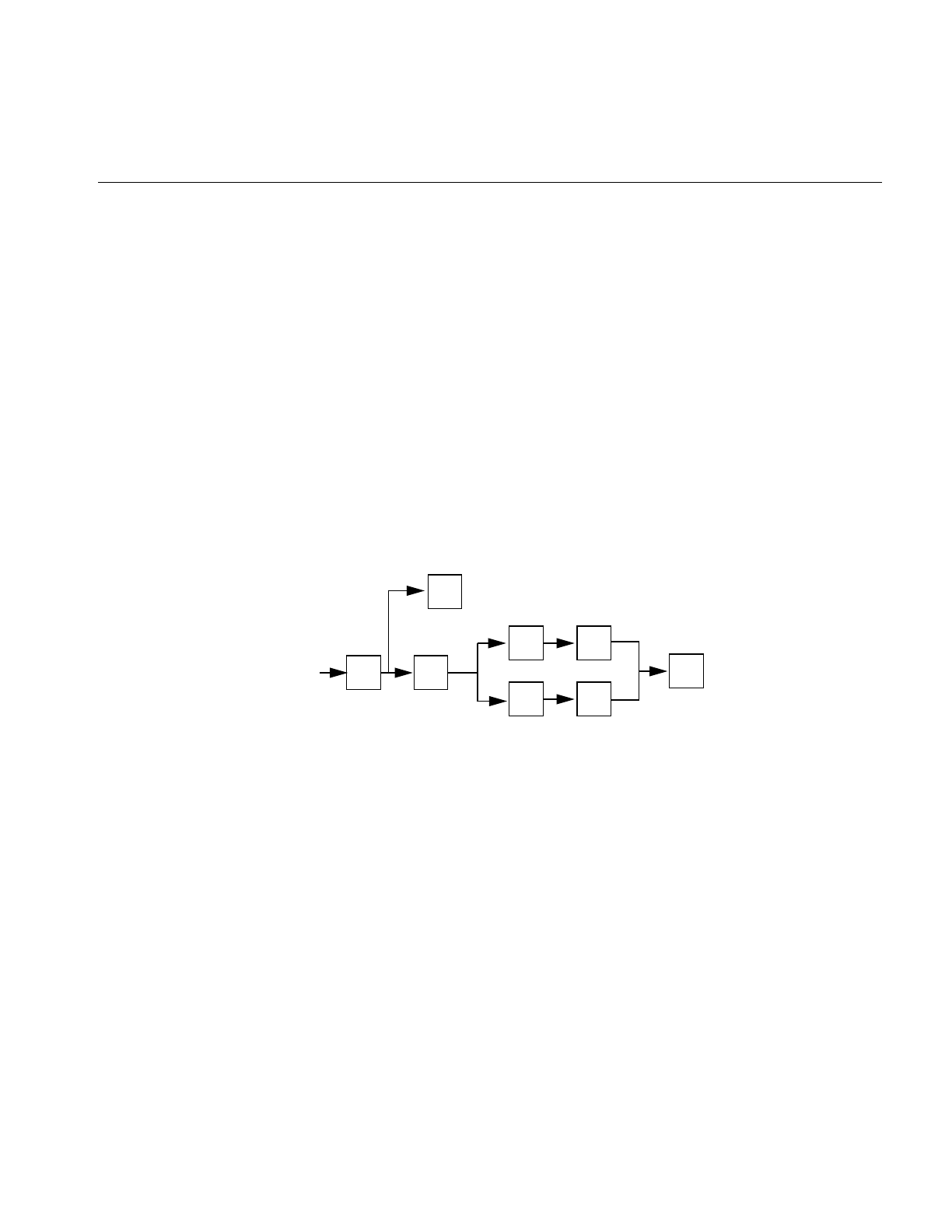
The Configuration File
245
The $@ and $: prefixes may precede a $> specification. For example,
R$+ $:$>7$1
matches anything, passes that to rule set 7, and continues; the $: is necessary to avoid an
infinite loop.
Substitution occurs in the order described: Parameters from the lhs are substituted, host
names are canonicalized, “subroutines” are called, and finally $#, $@, and $: are
processed.
Semantics of Rewriting Rule Sets
There are five rewriting rule sets that have specific semantics. Figure B-1 shows the
relationship among these rule sets.
Figure B-1 Semantics of Rewriting Rule Sets
Rule set 3 should turn the address into canonical form. This form should have the
following basic syntax:
local-part@host-domain-spec
If no “at” (@) sign is specified, then the host-domain-spec can be appended from the
sender address (if the C flag is set in the mailer definition corresponding to the sending
mailer). sendmail applies rule set 3 before doing anything with any address.
addr 3D 4msg
resolved address
0
R2
S1

246
Appendix B: IRIX sendmail Reference
Next, rule set 0 is applied to an address that actually specifies recipients. The address
must resolve to a {mailer, host, user} triple. The mailer must be defined in the mailer
definitions from the configuration file. The host is defined into the $h macro for use in
the argv expansion of the specified mailer.
Rule sets 1 and 2 are applied to all sender and recipient addresses, respectively. They are
applied before any specification in the mailer definition. They must never resolve.
Rule set 4 is applied to all addresses in the message. It is typically used to translate from
internal to external form.
The “error” Mailer
The mailer with the special name “error” can be used to generate a user error. The
(optional) host field is a numeric exit status to be returned, and the user field is a message
to be printed. For example, the following entry on the rhs of a rule causes the specified
error to be generated if the lhs match:
$#error$:Host unknown in this domain
This mailer is functional only in rule set 0.
Relevant Issues
This section discusses testing and debugging the rewrite rules and building mailer
definitions.
Testing and Debugging the Rewrite Rules
As part of building or modifying a configuration file, you should test the new file.
sendmail provides a number of built-in tools to assist in this task. The subsections that
follow discuss tools and techniques for debugging the rewrite rules.
Using Alternative Configuration Files
Using the -C command-line flag causes sendmail to read an alternate configuration file.
This feature is helpful during debugging because it permits modifications and testing on
a separate copy of the configuration file from the one currently in use. This precaution
eliminates the chance that a buggy configuration file will be used by an instance of
sendmail that is trying to deliver real mail. This flag also provides a convenient way to test

The Configuration File
247
any number of configuration files without fussy and potentially confusing renames. See
“Using a Different Configuration File” on page 228 and “Command-Line Flags” on page
252 for more information.
Test Mode
Invoking sendmail with the -bt flag causes it to run in “test mode.” For example, the
following command invokes sendmail in test mode and causes it to read configuration file
test.cf:
/usr/lib/sendmail -bt -Ctest.cf
In this mode, sendmail processes lines of the form
rwsets address
where rwsets is the list of rewriting sets to use and address is an address to which you
apply the sets. In test mode, sendmail shows the steps it takes as it proceeds, finally
showing the final address.
A comma-separated list of rule sets causes sequential application of rules to an input. For
example, the following command first applies rule set 3 to the value monet@giverny. Rule
set 1 is applied to the output of rule set 3, followed similarly by rule sets 21 and 4:
3,1,21,4 monet@giverny
Note: Some versions of sendmail, including those provided with all versions of IRIX prior
to IRIX 4.0, automatically apply rule set 3 to input before applying the requested rule set
sequence. Versions of sendmail in IRIX 4.0 and later do not apply rule set 3; rule set 3 must
be specifically requested.
The input and output of each rule set is displayed. For example, input of
3,0 foo@bar
might result in output that looks like this:
rewrite: ruleset 3 input: foo @ bar
rewrite: ruleset 3 returns: foo < @ bar >
rewrite: ruleset 0 input: foo < @ bar >
rewrite: ruleset 30 input: foo < @ bar . com >
rewrite: ruleset 30 returns: foo < @ bar . com >
rewrite: ruleset 0 returns:
$# forgn $@ bar . com $: foo < @ bar . com >

248
Appendix B: IRIX sendmail Reference
This output indicates that, given the address foo@bar, rule set 0 will select the forgn
mailer and direct it to connect to host bar.com, which will be told to send the mail on to
foo@bar.com. Furthermore, rule set 0 “called” rule set 30 at one point while processing
the address.
The -d21 Debugging Flag
The -d21 debugging flag causes sendmail to display detailed information about the
rewrite process. This flag is most useful when used with the test mode described in the
preceding subsection. The most useful setting of this flag is -d21.12, which shows all
rewrite steps. Higher levels of the -d21 flag are rarely needed and create enormous
amounts of output.
The Debugging Rewrite Rule
The standard /usr/lib/sendmail.cf file supplied with IRIX includes a special “debugging”
rewrite rule. This rule is defined as follows:
# insert this handy debugging line wherever you have problems
#R$* $:$>99$1
Note that rule set 99 is an empty rule set that does nothing. Placing one or more
(uncommented) copies of this rule anywhere within a rule set forces sendmail to display
an intermediate rewrite result without using the -d21 flag. The following test mode
output illustrates the use of the debugging rewrite rule:
rewrite: ruleset 3 input: foo @ bar
rewrite: ruleset 3 returns: foo < @ bar >
rewrite: ruleset 0 input: foo < @ bar >
rewrite: ruleset 99 input: foo < @ bar . com >
rewrite: ruleset 99 returns: foo < @ bar . com >
rewrite: ruleset 99 input: foo < @ barcom >
rewrite: ruleset 99 returns: foo < @ barcom >
rewrite: ruleset 0 returns:
$# ether $@ barcom $: foo < @ barcom >
Note that somewhere between the first and second appearance of the debugging rewrite
rule in rule set 0, the host name was mangled from bar.com to barcom.

The Configuration File
249
Building Mailer Definitions
To add an outgoing mailer to a mail system, you must define the characteristics of the
mailer. Each mailer must have an internal name. This name can be arbitrary, except that
the names “local” and “prog” must be defined.
The pathname of the mailer must be given in the P field. If this mailer is accessed by
means of an IPC connection (socket), use the string “[IPC]” instead.
The F field defines the mailer flags. Specify an f or r flag to pass the name of the sender
as an -f or -r flag respectively. These flags are passed only if they were passed to sendmail,
so that mailers that give errors under some circumstances can be placated. If the mailer
is not picky, just specify “-f $g” in the argv template. If the mailer must be called as root,
use the S flag; this flag will not reset the user ID before calling the mailer. (sendmail must
be running setuid to root for this technique to work.)
If this mailer is local (that is, it will perform final delivery rather than another network
hop), use the l flag. Quote characters (backslashes and quotation marks) can be stripped
from addresses if the s flag is specified; if it is not, they are passed through. If the mailer
is capable of sending to more than one user on the same host in a single transaction, use
the m flag. If this flag is on, the argv template containing $u will be repeated for each
unique user on a given host. The e flag marks the mailer as being expensive, causing
sendmail to defer connection until a queue run. (For this technique to be effective, you
must use the c configuration option.)
An unusual case is the C flag: it applies to the mailer the message is received from, rather
than the mailer being sent to. If this flag is set, the domain specification of the sender (that
is, the @host.domain part) is saved and is appended to any addresses in the message that
do not already contain a domain specification. For example, if the C flag is defined in the
mailer corresponding to jd@company.com, a message of the form
From: jd@company.com
To: buddy@USomewhere.edu, jane
will be modified to
From: jd@company.com
To: buddy@USomewhere.edu, jane@company.com
Other flags are described in “Mailer Flags” on page 256.

250
Appendix B: IRIX sendmail Reference
The S and R fields in the mailer description are per-mailer rewriting sets to be applied to
sender and recipient addresses, respectively. These sets are applied after the sending
domain is appended and the general rewriting sets (1 and 2) are applied, but before the
output rewrite (rule set 4) is applied. A typical usage is to append the current domain to
addresses that do not already have a domain.
For example, depending on the domain it is being shipped into, a header of the form
“From: jd” might be changed to “From: jd@company.com” or “From: company!jd.”
These sets can also be used to do special-purpose output rewriting with rule set 4.
TheE field defines the string to use as an end-of-line indication. A string containing only
a newline is the default. The usual backslash escapes (\r, \n, \f, \b) can be used.
Finally, an argv template is given as the E field. It can have embedded spaces. If there is
no argv with a $u macro in it, sendmail will speak SMTP to the mailer. If the pathname
for this mailer is “[IPC],” the argv should be
IPC $h [ port ]
where port is the port number to connect to. This number is optional.
For example, the following specification specifies a mailer to do local delivery and a
mailer for Ethernet delivery:
Mlocal, P=/bin/mail, F=EDFMlsmhu, S=10, R=20, A=mail -s -d $u
Mether, P=[IPC], F=mDFMhuXC, S=11, R=21, M=1000000, E=\r\n, \
A=IPC $h
The first mailer is called “local” and is located in the file /bin/mail. It has the following
characteristics:
• It escapes lines beginning with “From” in the message with a “>” sign.
• It expects “Date:”, “From:”, and “Message-Id:” header lines.
• It does local delivery.
• It strips quotation marks from addresses.
• It sends to multiple users at once.
• It expects uppercase to be preserved in both host and user names.

Flags, Options, and Files
251
Rule set 10 is to be applied to sender addresses in the message and rule set 20 is to be
applied to recipient addresses. The argv to send to a message is the word mail, the word
-s, the word -d, and words containing the name of the receiving user.
The second mailer is called “ether” and is connected with an IPC connection. It has the
following characteristics:
• It handles multiple users at the same time.
• It expects “Date:”, “From:”, and “Message-Id:” header lines.
• It expects uppercase to be preserved in both host and user names.
• It uses the hidden-dot algorithm of RFC 821.
• It rewrites addresses so that any domain from the sender address is appended to
any receiver name without a domain.
Sender addresses are processed by rule set 11; recipient addresses, by rule set 21. There
is a 1,000,000-byte limit on messages passed through this mailer. The EOL string for this
mailer is "\r\n" and the argument passed to the mailer is the name of the recipient host.
Flags, Options, and Files
This section contains information on the following topics:
• command-line flags
• configuration options
• mailer flags
• summary of support files
• debugging flags

252
Appendix B: IRIX sendmail Reference
Command-Line Flags
Flags must precede addresses. The flags are:
-bxSet operation mode to x. Operation modes are:
-Cfile Use a different configuration file. sendmail runs as the invoking user
(rather than root) when this flag is specified.
-dflag[-flag][.level]
Set debugging flag (or range of flags) to the specified level. (The default
is 1.) See “Debugging Flags” on page 259.
-Fname Set the full name of the sender to name.
-fname Set the name of the “From” person (the sender of the mail). This flag is
ignored unless the user appears in the list of “trusted” users, or name is
the same as the user’s name.
-hcnt Set the “hop count” to cnt. The hop count is incremented every time the
mail is processed. When it reaches a limit, the mail is returned with an
error message, the victim of an aliasing loop.
-n Don’t do aliasing.
a Run in ARPANET mode.
The special processing for the ARPANET includes reading the
“From:” and “Sender:” lines from the header to find the
sender, printing ARPANET-style messages (preceded by
three-digit reply codes for compatibility with the FTP
protocol) and ending lines of error messages with <CRLF>.
d Run as a daemon.
i Initialize the alias database.
m Deliver mail in the usual way (default).
p Print the mail queue.
s Speak SMTP on input side.
t Run in test mode.
v Just verify addresses, don’t collect or deliver.
z Freeze the configuration file.

Flags, Options, and Files
253
-ox value Set configuration option x to the specified value. These options are
described in section “Configuration Options” on page 253.
-q[time] Process the queued mail. If the time is given, sendmail will run through
the queue at the specified interval to deliver queued mail; otherwise, it
runs only once. See “Queue Mode” on page 226.
-r name An alternative and obsolete form of -f.
-t Read the header for “To:”, “Cc:”, and “Bcc:” lines, and send the message
to everyone listed in those lists. The “Bcc:” line is deleted before
sending. Any addresses in the argument vector are deleted from the
send list.
-v Go into verbose mode: Alias expansions are announced, and so on.
Configuration Options
You can set the following options by using the -o flag on the command line or the O line
in the configuration file. Many of these options cannot be specified unless the invoking
user is trusted.
Afile Use the named file as the alias file. If no file is specified, use alias in the
current directory.
aNIf set, wait up to N minutes for an “@:@” entry to exist in the alias
database before starting up. If the entry does not appear in N minutes,
rebuild the database (if the D option is also set) or issue a warning.
BcSet the blank substitution character to c. Unquoted spaces in addresses
are replaced by this character.
c If an outgoing mailer is marked as being expensive, don’t connect
immediately. This option requires queueing.
dxDeliver in mode x. Legal modes are:
i Deliver interactively (synchronously).
b Deliver in background (asynchronously).
q Just queue the message (deliver during queue run).
DRebuild the alias database if necessary and possible. If this
option is not set, sendmail will not rebuild the alias database
until you explicitly request it to do so (by using sendmail -bi).

254
Appendix B: IRIX sendmail Reference
exHandle errors by using mode x. The values for x are:
Fmode Set the UNIX file mode to use when creating queue files and “frozen
configuration” files.
f Save UNIX style “From” lines at the front of headers. Normally these
lines are assumed to be redundant and are discarded.
gnSet the default group ID for running mailers to n.
Hfile Specify the help file for SMTP.
I Insist that the BIND name server be running to resolve hostnames and
MX records. Treat ECONNREFUSED errors from the resolver as
temporary failures. In general, you should set this option only if you are
running the name server. Set this option if the /etc/hosts file does not
include all known hosts or if you are using the MX (mail forwarding)
feature of the BIND name server. The name server is still consulted even
if this option is not set, but sendmail resorts to reading /etc/hosts if the
name server is not available.
i Do not interpret dots on a line by themselves as a message terminator.
Ktimeout Define the maximum amount of time a cached connection is permitted
to idle without activity. The timeout is given as a tagged number, with “s”
for seconds, “m” minutes, “h” hours, “d” days, and “w” weeks. For
example, “K1h30m” and “K90m” both set the timeout to one hour thirty
minutes.
LnSet the log level to n.
Mx value Set the macro x to value.This option can be used only from the command
line.
m Send to “me” (the sender) even if the sender is in an alias expansion.
p Print error messages (default).
q Print no messages; just give exit status.
m Mail back errors.
w Write back errors (mail the errors if user not logged in).
e Mail back errors and always give zero exit status.

Flags, Options, and Files
255
Nnetname Set the name of the home (local) network. If the name of a connecting
host (determined by a call to gethostbyaddr()) is unqualified (contains
no dots), a single dot and netname will be appended to sendmail’s idea of
the name of the connecting host.
Later, the argument of the SMTP “HELO” command from the
connecting host will be checked against the name of the connecting
host as determined above. If they do not match, “Received:” lines are
augmented by the connecting hostname that sendmail has generated so
that messages can be traced accurately.
n Validate the right-hand side when building the alias database.
o Assume that the headers may be in an old format, in which spaces
delimit names. This option actually turns on an adaptive algorithm: If
any recipient address contains a comma, parenthesis, or angle bracket, it
will be assumed that commas already exist. If this flag is not on, only
commas delimit names. Headers are always written with commas
between the names.
Paddr Add “postmaster” address addr to the “Cc:” list of all error messages.
Qdir Use dir as the queue directory.
qfactor Use factor as the multiplier in the function to decide when to queue
messages rather than attempting to send them. This value is divided by
the difference between the current load average and the load average
limit (x option) to determine the maximum message priority that will be
sent. This value defaults to 10000.
rtime Cause a timeout on reads after time interval.
Sfile Log statistics in the named file.
s Be super-safe when running; that is, always instantiate the queue file,
even if attempting immediate delivery. sendmail always instantiates the
queue file before returning control to the client under any circumstances.
Ttime Set the queue timeout to time. After this interval, messages that have not
been successfully sent are returned to the sender.
unSet the default user ID for mailers to n. Mailers without the S flag in the
mailer definition run as this user.
v Run in verbose mode.

256
Appendix B: IRIX sendmail Reference
xLA Use LA as the system load average limit when deciding whether to
queue messages rather than attempting to send them.
XLA When the system load average exceeds LA, refuse incoming SMTP
connections.
yfactor This factor is multiplied by the number of recipients and added to the
priority. Therefore, this value penalizes messages with large numbers of
recipients.
Y Deliver each job that is run from the queue in a separate process. Use
this option if you are short of memory, since the default tends to
consume considerable amounts of memory while the queue is being
processed.
zfactor This factor is multiplied by the message class (determined by the
Precedence field in the user header and the precedence declaration lines
in the configuration file) and subtracted from the priority. Therefore,
messages with a higher class are favored.
Zfactor This factor is added to the priority every time a message is processed.
Therefore, this value penalizes messages that are processed frequently.
Mailer Flags
The following flags can be set in the F field of a mailer definition in the sendmail.cf file:
B Don’t wait for SMTP responses.
C If mail is received from a mailer with this flag set, any addresses in the
header that do not have an “at” sign (@) after being rewritten by rule set
3 have the “@domain” clause from the sender appended. This flag
allows mail with headers of the form
From: usera@hosta
To: userb@hostb, userc
to be rewritten automatically as
From: usera@hosta
To: userb@hostb, userc@hosta
D This mailer expects a “Date:” header line.
E Escape any lines beginning with “From” in the message with a “>” sign.

Flags, Options, and Files
257
e This mailer is expensive to connect to; usually, avoid connecting. Any
necessary connection occurs during a queue run.
F The mailer expects a “From:” header line.
f The mailer expects a -ffrom flag, but only if this is a network forwarding
operation. (That is, the mailer will give an error if the executing user
does not have special permissions.)
h Uppercase should be preserved in hostnames for this mailer.
I This mailer can use certain special SMTP features when transferring
mail to another system running sendmail. This option is not required; if
it is omitted, the transmission still operates successfully, although
perhaps not as efficiently as possible.
L Limit the line lengths as specified in RFC 821.
l This mailer is local; final delivery will be performed.
M This mailer expects a “Message-Id:” header line.
m This mailer can send to multiple users on the same host in one
transaction. When a $u macro occurs in the argv part of the mailer
definition, that field will be repeated as necessary for all qualifying
users.
n Do not insert a UNIX style “From” line on the front of the message.
P This mailer expects a “Return-Path:” line.
p Use the return path in the SMTP “MAIL FROM:” command rather than
just the return address; although this usage is required in RFC 821, many
hosts do not process return paths properly.
r Same as f, but sends an -r flag.
S Don’t reset the user ID before calling the mailer. Used in a secure
environment where sendmail runs as root, this option could avoid forged
addresses. This flag is suppressed if given from an “unsafe”
environment (such as a user’s mail.cf file).
s Strip quotation characters from the address before calling the mailer.
U This mailer wants UNIX style “From” lines with the UUCP-style
“remote from <host>” on the end.
u Preserve uppercase characters in user names for this mailer.

258
Appendix B: IRIX sendmail Reference
V Make all addresses UUCP !-relative to recipient or sender nodes.
Addresses of the form recipient_host!foo!bar are rewritten as foo!bar.
Addresses of the form mumble!grumble are rewritten as
sender_host!mumble!grumble.
X This mailer expects to use the hidden-dot algorithm as specified in RFC
821; basically, any line beginning with a dot has an extra dot prepended
(to be stripped at the other end). This action ensures that a line
containing a dot will not terminate the message prematurely.
x This mailer expects a “Full-Name:” header line.
Support Files
This section provides a summary of the support files that sendmail creates or generates.
/usr/lib/sendmail The sendmail program.
/usr/lib/sendmail.cf
The configuration file in textual form.
/usr/bsd/newaliases
A link to /usr/lib/sendmail; causes the alias database to be rebuilt.
Running this program is equivalent to giving sendmail the -bi flag.
/usr/lib/sendmail.fc
The configuration file represented as a memory image (the “frozen
configuration”).
/usr/lib/sendmail.hf
The SMTP help file.
/usr/lib/sendmail.st
A statistics file; need not be present.
/usr/lib/sendmail.killed
A text file that contains the names of all known “dead” hosts (hosts that
no longer exist or cannot receive mail for some reason).
/usr/lib/aliases The text version of the alias file.
/usr/lib/aliases.{pag,dir}
The alias file in ndbm format.

Flags, Options, and Files
259
/var/spool/mqueueThe directory in which the mail queue and temporary files reside.
/var/spool/mqueue/qf*
Control (queue) files for messages.
/var/spool/mqueue/df*
Data files.
/var/spool/mqueue/tf*
Temporary versions of the qf files, used during queue-file rebuild.
/var/spool/mqueue/nf*
A file used when a unique ID is created.
/var/spool/mqueue/xf*
A transcript of the current session.
/usr/bin/mailq Prints a listing of the mail queue; using this file is equivalent to using the
-bp flag to sendmail.
/etc/init.d/mail Shell script for starting and stopping the sendmail daemon.
/bin/mail Program that sendmail uses as the “local” mailer.
Debugging Flags
The following list includes all known debugging flags. Flags that are especially useful
are marked with an asterisk (*).
0.1* Force daemon to run in foreground.
0.4* Show known names for local host.
0.15 Print configuration file.
0.44 Have printav() print addresses of elements.
1.1* Show mail “From” address for locally generated mail.
2.1* Print exit status and envelope flags.
5.4 Print arguments to tick() calls.
5.5 Print arguments to setevent() and clrevent() calls.
5.6 Print event queue on tick() call.
6.1 Indicate call to savemail() or returntosender() error processing.

260
Appendix B: IRIX sendmail Reference
6.5 Trace states in savemail() state machine.
7.1* Print information on envelope assigned to queue file.
7.2* Print selected queue-file name.
7.20* Print intermediate queue-file name selections.
8.1* Print various information about resolver calls.
9.1* Show results from gethostbyaddr() call.
10.1* Print message delivery information.
11.1 Indicate call to openmailer().
12.1* Display remotename() input and output.
13.1 sendall()—print addresses being sent to
13.3 sendall()—print each address in loop looking for failure.
13.4 sendall()—print who gets the error.
14.2 Indicate commaize() calls.
15.1 Indicate port or socket number used by getrequests().
15.2 Indicate when getrequests() forks or returns.
15.15 Set DEBUG socket option in getrequests().
16.1* Indicate host, address, and socket being connected to in
makeconnection().
16.14 Set DEBUG socket option in makeconnection().
18.1* Show SMTP chatter.
18.100 Suspend sendmail after reading each SMTP reply.
20.1* Display parseaddr() input and output.
21.2* Show rewrite rule-set subroutine calls/returns and input/output, and
display run-time macro expansions.
21.3* Indicate rewrite subroutine call from inside rewrite rule.
21.4* Display rewrite results.
21.10* Indicate rule failures.
21.12* Indicate rule matches and display address-rewrite steps.

Flags, Options, and Files
261
21.15* Show rewrite substitutions.
21.35 Display elements in pattern and subject.
22.36 Display prescan() processing.
22.45 Display more prescan() processing.
22.101 Display even more prescan() processing.
25.1* Show “To” list designations.
26.1* Show recipient designations/duplicate suppression.
26.6* Show recipient password-match processing.
27.1* Print alias and forward transformations and errors.
27.3 Print detailed aliaslookup() information.
30.1 Indicate end of headers when collecting a message.
30.2 Print arguments to eatfrom() calls.
30.3 Indicate when adding an “Apparently-To” header to the message.
31.6 Indicate call to chompheader() and header to be processed.
32.1 Display collected header.
33.1 Display crackaddr() input/output.
35.9* Display macro definitions.
35.24 Display macro expansions.
36.5 Show symbol table processing.
36.9 Show symbol table hash function result.
37.1* Display options as set.
37.2* Show rewrite class loading.
40.1* Indicate queueing of messages and display queue contents.
40.4* Display queue control file contents.
40.5* Display information about message-controlling user.
41.2 Indicate orderq() failure to open control file.
45.1 Indicate setsender() calls.

262
Appendix B: IRIX sendmail Reference
50.1 Indicate dropenvelope() calls.
51.4 Don’t remove transcript files (qxAAXXXXX files).
52.1 Indicate call to disconnect(); print I/O file descriptors.
52.5 Don’t perform disconnect.
60.1* Print information about alias database accesses.
61.1* Print information about MX record lookups.

263
client-server configurations, 105
database files, 108
database management, 123
debugging, 125
deleting stations, 124
/etc/config/named.options file, 112
forwarding servers, 107
forwarding server setup, 121
localhost.rev file, 112
management scripts, 125
master servers, 106
named.rev file, 111
organization of, 104
primary master server, 110
primary server setup, 115, 123
root.cache file, 112
secondary master server, 110
secondary server setup, 119
server configurations, 106
setup example, 114
slave mode, 111
slave servers, 107
SYSLOG messages, 126
BIND database and MX records, 210
BIND host lookup routines, 103
boot file, BIND, 109
bridge, definition of, 8
C
caching-only server, BIND, 120
A
adding stations (with BIND), 124
administration, system
documentation, xvii-xviii
aliases (mail), creating, 202
aliases database
building, 185
format of, 185
modifying, 202
rebuilding, 184, 186
testing, 186
troubleshooting, 187
updating, 204
aliases file, 183
arp command, 72
ASSERT error messages (UUCP), 169
B
BIND
adding domains, 124
adding new stations, 124
and caching-only servers, 107
and forwarders, 111
and network planning, 25
and nslookup,127
and the /etc/hosts file, 25, 36
boot file, 109
caching-only servers, 110
caching-only server setup, 120
Index

264
Index
caching-only servers, 108, 110
chkconfig command, 51, 70
client setup, BIND, 123
configmail script, 181
configuring
network controllers, 4
network routers, 38
connecting to the Ethernet, 32
controller boards, and network troubleshooting, 79
controller interface names, 3
controllers (network), configuring, 4
cu command (UUCP), 131
D
database files, BIND, 108
database management, BIND, 123
DBM database, 184, 186
deleting staions (with BIND), 124
Devices database (UUCP), 134, 135
DHCP
client configuration, 55
network configuration, 53
relay-agent configuration, 55
server configuration, 54
Dialcodes database (UUCP), 134, 145
Dialers database (UUCP), 134, 135, 139
domain name macros and classes (sendmail.cf file),
190
domains
definition of, 104
top level, 105
domains (BIND), adding, 124
domain space, definition of, 104
E
editing the /etc/hosts file, 36
electronic mail and network planning, 29
/etc/chkconfi file, 34
/etc/config/ifconfig.options file, 51
/etc/config/ipaliases file, 50
/etc/config/named.options file, 112
/etc/config/netif.options file, 46, 47
/etc/fstab file, 70
/etc/hosts file, 70
alternatives to, 24
editing, 36
host names in, 24, 35
router entries, 38
/etc/init.d/mail script, 180
/etc/init.d/network initialization script, 70
/etc/init.d/network.local script, 56
/etc/init.d/network script, 38, 56, 71
/etc/sys_id file, 36, 70
Ethernet, testing, 64-67
Ethernet connections to an IRIS system, 32
F
forwarders and BIND, 111
forwarding, controlling on routers, 40
forwarding server, BIND, 121
.forward mail file, 209
G
gateway, definition of, 8
genperm command (UUCP), 133

265
Index
H
hardware options (network), 3
hardware requirements (network), 1
hosts database
modifying, 35
router entries in, 38
hosts database alternatives, 24
I
ifconfig command, 50, 71
ifconfig-hy.options file, 70
ifconfig.options file, 51
inetd daemon, 70
initializing the network, 70
InSight, using NFS, 60
InSight servers, 60
Internet addresses
and BIND, 13
and NIS, 13
and subnetworks, 26
classes of, 26
obtaining, 15
planning, 13
Internet Control Message Protocol (ICMP), 37
interpreting network statistics, 74
IPaliases.options file, 50
IP aliasing, 49
ipfiltered daemon, 70
IRIS Networker, 74
IRIX administration
documentation, xvii-xviii
K
kernel parameters and networking, 80
L
localhost entry in /etc/hosts file, 36
localhost.rev file, 112
local station (UUCP), configuring, 158
local stations (UUCP)
identifying, 157
logging remote access, 56
M
mail domains, 188
mail forwarders, 189
mailq command, 184
mail queue, 208
mail relays, 189
mail system components, 176
Maxuuscheds file (UUCP), 155
Maxuuxqts file (UUCP), 155
modem connections, 2
modifying the hosts database, 35
mqueue directory, 183
MTU Discovery, 77
multi-homed hosts, 51
MX records, 210, 212
N
named.boot file, 109, 125
named daemon, 125
named.host file, 111

266
Index
named.hosts file, 111
named.rev file, 111
named server, definition of, 103
naming stations, 37
netif.options file, 46, 47, 70
netmask, setting, 45
netmask option, 45
netstat command, 72, 76
NetVisualyzer, 73
network address masks, 45
network applications planning, 28
network configurations, sendmail,188
network connections, testing, 37
network controllers, choosing, 10
network daemons, 34
network equipment, planning, 8
Network File System (NFS), 99
network hardware options, 3
network hardware requirements, 1
Network Information Center (NIC), 15, 105
networking, preparing an IRIS system for, 31
network initialization, 70
network interfaces
modifying, 46
modifying addresses of, 48
modifying names of, 47
network management tools, 71
network master script, 69
network parameters
changing, 51
network performance factors, 78
network planning
BIND, 25
device number, 10
electronic mail, 29
Internet addresses, 13
media selection, 9
network applications, 28
NFS, 29
NIS, 25
PPP, 12
security, 28
size considerations, 7
SLIP, 11
subnetworks, 25
traffic, 10
UUCP, 12
network script, 69
network scripts, creating, 56
network shutdown, 69, 71
Network SLIP connections (NSLIP), 97
network software, IRIS standard distribution, 4
network software checkout, 34
network software options, 5
network statistics, interpreting, 74
network troubleshooting
configurations, 79
hardware, 79
media, 79
packet size, 80
servers, 80
newaliases program, 184
NFS
and network planning, 29
NIS
and network planning, 25
and the /etc/hosts file, 25, 36
nslookup command, 127
P
PC TCP/IP connections to an IRIX network, 81
performance factors (network), 78

267
Index
Permissions database (UUCP), 135, 146
ping command, 37, 72, 74
planning
for network traffic, 10
Internet addresses, 13
network controllers, 10
network devices, 10
network equipment, 8
network performance, 9
network size, 7
Point to Point Protocol (PPP), 83
dynamic addressing, 97
modem requirements, 86
routing, 94
Poll database (UUCP), 153
PPP
and network planning, 12
PPP (Point to Point Protocol), 83
preparing for networking, 31
primary address, 50
primary master server, BIND, 110
primary server, BIND, 115
proclaim
client configuration, 55
description, 53
network configuration, 53
relay-agent configuration, 55
server configuration, 54
Q
queue, mail, 208
R
rarpd daemon, 70
rebooting networked stations, 46
remote access logging, 56
remote stations (UUCP)
identifying, 157
remote stations (UUCP), configuring, 162
removing stations (with BIND), 124
repeater, definition of, 8
resolv.conf file, 106
resolver routines, purpose of, 103
root.cache file, 112
route command, 73
router
configuring, 38
controlling forwarding on, 40
dual interfaces on, 38
multiple interfaces on, 39
router, definition of, 8
rpcinfo command, 72
rtquery command, 72
rup command, 37, 73
rwhod daemon, 70
S
secondary master server, BIND, 110
secondary server, BIND, 119
security
and network planning, 28
selecting network media, 9
sendmail
files and directories, 181
sendmail
and multi-token class matching, 212
command-line flags, 205
design features, 178
functions of, 179
general description, 177
network configurations, 188

268
Index
planning list, 192
software components, 179
sendmail.cf.auto file, 182
sendmail.cf file
configurable elements, 190
customizing examples, 194
customizing for complex relay networks, 199
customizing for relay networks, 196
customizing for standalone stations, 195
forwarder name macros and class, 191
general description, 182
killed stations class, 192
pathalias database macro, 192
relay name macro, 191
top-level domain macro, 192
sendmail command
configuration file flag, 207
daemon mode, 206
debugging flags, 207
delivery mode, 205
queue mode, 206
test mode, 207
verify mode, 206
sendmail commands, 184
sendmail daemon, 180, 183, 204
sendmail.fc file, 182
sendmail.hf file, 182
sendmail management, 205
sendmail script, 180
sendmail scripts, 180
sendmail.st file, 183
Serial Line Interface Protocol (SLIP)
and bidirectional links, 98
and data compression, 83
and file transfers, 100
and NFS, 99
debugging, 100
modem requirements, 86
modems for, 86
modems settings for, 86
purpose of, 99
Serial Line Internet Protocol (SLIP)
and network planning, 11
routing, 94
serial line networks, 2
setting network masks, 45
setup
kernel, 80
shutting down the network, 69, 71
Signal Quality Error, 79
slave mode, BIND, 111
snmpd daemon, 70
SPECTRUM, 73
spray command, 72
standalone mode, 70
standard distribution network software, 4
starting the network, 69
station naming, 37
subnetworks
and network masks, 45
and troubleshooting, 80
Internet addresses for, 26
planning, 25
Sysfiles database (UUCP), 154
system administration
documentation, xvii-xviii
Systems database (UUCP), 134, 142
T
TCP/IP connectivity to personal computers, 81
TCP/IP tuning, 77
testing connectivity, 37
timed daemon, 70
timeslave daemon, 70

269
Index
traceroute command, 73
transmitters, and network troubleshooting, 79
troubleshooting network hardware, 79
ttcp command, 73, 75
tunable parameters and networking, 80
tuning TCP/IP, 77
U
UNIX to UNIX Copy Program, see UUCP
unknown file (UUCP), 155
/usr/bin/mailq command, 184
/usr/bin/rup command, 73
/usr/bsd/newaliases program, 184
/usr/etc/arp command, 72
/usr/etc/configmail script, 181
/usr/etc/ifconfig command, 71
/usr/etc/named.d/named.boot file, 109
/usr/etc/named.reload script, 125
/usr/etc/named.restart script, 125
/usr/etc/netstat command, 72
/usr/etc/ping command, 72
/usr/etc/resolv.conf,112
/usr/etc/route command, 73
/usr/etc/rpcinfo command, 72
/usr/etc/rtquery command, 72
/usr/etc/spray command, 72
/usr/etc/traceroute command, 73
/usr/etc/ttcp command, 73
/usr/lib/aliases database, 185
/usr/lib/aliases file, 183
/usr/lib/sendmail.cf.auto file, 182
/usr/lib/sendmail.cf file, 182
/usr/lib/sendmail.fc file, 182
/usr/lib/sendmail.hf file, 182
/usr/lib/sendmail program, 184
/usr/lib/sendmail.st file, 183
/usr/mail directory, 184
/usr/spool/mqueue directory, 183
uucheck command (UUCP), 133
uucico daemon (UUCP), 133, 134
uucleanup command (UUCP), 133
UUCP
administrative commands, 132
administrative files for, 155
and direct links, 131
and modem setup, 131
and network planning, 12
and TCP/IP, 130, 165
and telephone lines, 131
configuring local stations, 158
configuring remote stations, 162
daemons, 133
definition of, 129
error messages for, 169
hardware requirements, 131
identifying local stations, 157
identifying remote stations, 157
mail, 201
physical connections for, 158
setting up, 157
supporting databases, 134
testing connections for, 166
user commands, 131
uucp command (UUCP), 132
uugetty program (UUCP), 134
uulog command (UUCP), 132
uupick command (UUCP), 132
uustat command (UUCP), 132
uuto command (UUCP), 132
Uutry command (UUCP), 133
uux command (UUCP), 132
uuxqt daemon (UUCP), 134

270
Index
V
/var/sysgen/master.d/bsd file, 80
Y
y, 81
Z
zones, definition of, 105

Tell Us About This Manual
As a user of Silicon Graphics products, you can help us to better understand your needs
and to improve the quality of our documentation.
Any information that you provide will be useful. Here is a list of suggested topics:
• General impression of the document
• Omission of material that you expected to find
• Technical errors
• Relevance of the material to the job you had to do
• Quality of the printing and binding
Please send the title and part number of the document with your comments. The part
number for this document is 007-2860-002.
Thank you!
Three Ways to Reach Us
• To send your comments by electronic mail, use either of these addresses:
– On the Internet: techpubs@sgi.com
– For UUCP mail (through any backbone site): [your_site]!sgi!techpubs
•Tofax your comments (or annotated copies of manual pages), use this
fax number: 415-965-0964
• To send your comments by traditional mail, use this address:
Technical Publications
Silicon Graphics, Inc.
2011 North Shoreline Boulevard, M/S 535
Mountain View, California 94043-1389
