007 3620 002
User Manual: 007-3620-002
Open the PDF directly: View PDF ![]() .
.
Page Count: 180 [warning: Documents this large are best viewed by clicking the View PDF Link!]

Video Server Toolkit
Developer’s Guide
Document Number 007-3620-002

Video Server Toolkit Developer’s Guide
Document Number 007-3620-002
CONTRIBUTORS
Written by George Eckel and Susan Patick
Illustrated by Dany Galgani
Production by Heather Hermstad
Engineering contributions by Kader Fazlul, Ron Jacoby, Ruben Kleiman, Prince
Kohli, Kurt Merriweather, Mike Moskowitz, Hilmi Ortadeveci, Naveen Patil, Jim
Preston, Rick Reed, Manuel Ruiz, Aman Singla, Brad Thayer, Parkson Wong, and
David R L Worthington.
St. Peter’s Basilica image courtesy of ENEL SpA and InfoByte SpA. Disk Thrower
image courtesy of Xavier Berenguer, Animatica.
© 1998-1999, Silicon Graphics, Inc.— All Rights Reserved
The contents of this document may not be copied or duplicated in any form, in whole
or in part, without the prior written permission of Silicon Graphics, Inc.
RESTRICTED RIGHTS LEGEND
Use, duplication, or disclosure of the technical data contained in this document by
the Government is subject to restrictions as set forth in subdivision (c) (1) (ii) of the
Rights in Technical Data and Computer Software clause at DFARS 52.227-7013
and/or in similar or successor clauses in the FAR, or in the DOD or NASA FAR
Supplement. Unpublished rights reserved under the Copyright Laws of the United
States. Contractor/manufacturer is Silicon Graphics, Inc., 2011 N. Shoreline Blvd.,
Mountain View, CA 94043-1389.
Silicon Graphics, IRIS, and IRIX are registered trademarks and the Silicon Graphics
logo, Extent File System (EFS), GIGAchannel, IRIS FailSafe, O2, Onyx2, Origin,
Origin200, Origin2000, StudioCentral, and XFS are trademarks of Silicon Graphics,
Inc. UNIX is a registered trademark in the United States and other countries, licensed
exclusively through X/Open, Ltd.

iii
Contents
List of Figures ix
List of Tables xi
About This Guide xiii
What This Document Contains xiii
Who Should Read This Document xiv
Related Documentation xiv
Conventions Used in This Document xv
1. New Features in Version 1.1 1
Format Support 1
422 Deck Control Support 1
Automated Playout and Edit Control Support 1
Miscellaneous Support 2
2. Overview of Video Server Toolkit 3
Functional Overview 3
Software Overview 6
Clip Cache 8
Core Software 8
Archive Interface Module 9
Control Interface Module 9
Storage Device Interface Module 10
Format Interface Module 10
Media Device Interface Module 10
Logical Playback and Record Units 12

iv
Contents
Hardware Overview 14
Video Server Toolkit Server 16
Disk Storage 17
External Devices 17
Internal Devices 18
Video Device Control 18
3. Using the Video Server Toolkit GUIs 19
Playing and Recording Clips 20
Starting the Video Server Toolkit Media Control Panel 20
Determining Available Ports 23
About the Media Control Panel 26
Playing or Recording an Existing Clip 33
Creating a New Clip 35
Changing Cue Points and Edit Points 36
Controlling a Video Deck 37
Monitoring the Status of Video Server Toolkit (mcstat) 44
Starting the Unit Status Monitor from the Command Line 44
4. Adding and Removing Clips 47
Overview of Adding Clips Procedure 47
VST Media Formats and Types 48
Media Types 48
Media Format 49
Adding Clips 50
Adding Clips to VST 50
Clip Alignment 52
Notifying VST 54
Removing Clips 54
Exporting VST Clips 55

Contents
v
5. Using Clip Manager 57
Starting the Clip Manager 57
Clip Manager Menus 59
Obtaining Information About a Clip 61
Renaming a Clip 62
Deleting a Clip 63
Setting the Protections for a Clip 64
6. Archiving Clips 67
Overview of the Archival System 68
Meta Data 68
Archive and VST Configuration 69
About StudioCentral 70
Using VST With the StudioCentral 2.0 Archive System 71
Archiving Tasks 71
Locating a Clip in the StudioCentral 2.0 Archive System 73
Bringing In a New Clip From the Archive System 74
Updating a Clip 75
Using the Put Clip to Archive Window 76
7. FailSafe Operations 77
Hardware Configuration 77
Shared Resources 78
Server Failures 79
Troubleshooting IRIS FailSafe 79
Monitoring 81

vi
Contents
8. Completing Common Tasks Using MVCP Commands 83
Manual Access to Video Server Toolkit 84
Creating and Deleting a Unit 85
Deleting a Unit 85
Multiple Connections to a Unit 85
Loading and Unloading a Clip 86
Finding the Name of a Clip 86
Setting Edit Points 86
Cueing Decks to Play or Record 87
Optional Arguments 87
Sequencing Commands 87
Playing a Prerecorded Clip 88
Playing Clips Back to Back 89
Setting Configuration Values 90
Listing Configuration Settings 91
Listing Video and Deck Control Ports 92
Identifying the Audio Ports to Use 92
Configuring Audio Recording 92
Configuring Video Recording 93
Recording a Clip 93
Editing Clips 94
Editing Clips 94
Editing Frames 95
Displaying Your Logo 96
Monitoring the System 96
Status 96
Monitoring 97
Statistics 98
Error Reporting 99

Contents
vii
A. Multiport Video Computer Protocol (MVCP) Command Summary 101
Protocol Format 101
Unit Management 102
Establishing an Interactive MVCP Connection 103
Rules for Using MVCP Commands 103
Command Sets 104
Displaying MVCP Commands 104
Command Triggers 105
Time-of-day triggering 105
Response Codes 106
Response Text 107
OK Response 108
Using P2 Commands with MVCP Commands 109
Global Commands 110
Access Control 112
Ports 113
Units 114
Archive Management 117
Clip Management 121
System Controls 128
Statistics 128
Miscellaneous 130
Unit Commands 131
Unit Command Modes 134
Command Sequencing 135
Unit Commands 137
Index 159


ix
List of Figures
Figure 2-1 Functional Overview 4
Figure 2-2 Video Server Toolkit Media Control Panel 5
Figure 2-3 Video Server Toolkit Software Components 7
Figure 2-4 One Logical Unit With One Control Connection 12
Figure 2-5 One Logical Unit With Two Control Connections 13
Figure 2-6 Two Logical Units With One Control Connection 14
Figure 2-7 Video Server Toolkit Hardware Components 15
Figure 3-1 Video Server Toolkit Media Control Panel 23
Figure 3-2 Video Server Toolkit Media Control Panel With a Clip Loaded 26
Figure 3-3 Loading a Clip Into the Logical VTR 33
Figure 3-4 Create Clip Window 35
Figure 3-5 Deck Control Window 38
Figure 3-6 Unit Status Monitor 45
Figure 5-1 Clip Manager Window 59
Figure 5-2 The Clip Information Window 61
Figure 5-3 Rename Clip Window 62
Figure 5-4 Delete Clip Window 63
Figure 5-5 Set Protections Window 64
Figure 6-1 Archive System 67
Figure 6-2 Archive Configuration 70
Figure 6-3 Find Clip in Archive Window 73
Figure 6-4 Get Clip from Archive Window: Getting a New Clip 74
Figure 6-5 Get Clip from Archive Window: Updating an Existing Clip 75
Figure 6-6 Put Clip to Archive Window 76
Figure 7-1 VST IRIS FailSafe Configuration 78


xi
List of Tables
Table 3-1 VST Media Control Panel Options 21
Table 3-2 Log Severity Levels 22
Table 5-1 Log Severity Levels 58
Table 6-1 Archive-Related MVCP Commands 72
Table 7-1 Primary and Secondary Server States 79
Table A-1 Global MVCP Commands 110
Table A-2 MVCP Unit Commands 131


xiii
About This Guide
The Video Server Toolkit (VST) is Silicon Graphics’ broadcast-quality video playback,
edit, and record engine that unifies Silicon Graphics Origin servers and digital media
components. VST allows application developers to create powerful, high-performance
solutions for broadcast playout. This tool enables (supported) automation systems and
developer applications to trigger video for playout though (supported) video output
devices on a Silicon Graphics workstation or server.
The Video Server Toolkit Developer’s Guide describes how to use VST to play and record
digital media and to store the data in, and retrieve it from, a StudioCentral 2.0 archive
system.
Also described in this document are the graphical user interfaces (GUIs), which are used
to manually control VST, and MVCP (Multi-Unit Video Computer Protocol), which is
one command line, control protocol supported by VST.
Note: Video Server Toolkit is the new name for what used to be called VCP-Recorder.
What This Document Contains
The following material is covered in this document:
• Chapter 1, “New Features in Version 1.1,” provides a streamlined description of the
new features in VST, version 1.1.
• Chapter 2, “Overview of Video Server Toolkit,” contains an overview of the
product.
• Chapter 3, “Using the Video Server Toolkit GUIs,” describes how to use the VST
graphical user interface (GUI) to play and record clips and to determine status
information.
• Chapter 4, “Adding and Removing Clips,” describes how to add and remove audio
and video media clips from VST.

xiv
About This Guide
• Chapter 5, “Using Clip Manager,” describes how to use the VST GUI to manage
clips.
• Chapter 6, “Archiving Clips,” describes how to use VST with an archive system.
• Chapter 7, “FailSafe Operations,” describes how to use redundant servers to
provide a high-availability system.
• Chapter 8, “Completing Common Tasks Using MVCP Commands,” explains how
to complete common tasks you routinely perform using MVCP commands.
• Appendix A, “Multiport Video Computer Protocol (MVCP) Command Summary,”
describes the Silicon Graphics Multiple-Unit Video Computer Protocol.
The glossary provides definitions of key words used in this document.
HTML versions of the VST books are installed at URL:
• http://hostname.domain/VCPRecorder/DevelopersGuide
• http://hostname.domain/VCPRecorder/InstallationGuide
Who Should Read This Document
This document is written for Video Server Toolkit application developers and system
integrators, and others who are interested in obtaining an overview of the product. It is
assumed that the reader is already familiar with broadcast industry concepts.
Related Documentation
Refer to the man pages for specific command help. The man page titles are:
• vtrstart(1)— for startup
• vtrstop(1)— for shutdown
• vtrstat(1)— for status
• vtrclip(1)— for clip management
• mcpanel(1)— for media control panel
• mcclips(1)— for clip manager

About This Guide
xv
• mcstat(1)— for status display
• mccompstats(1)— for compression monitor
• vcp-recorder-controls(5)— for VST controls
• mvcp(5)— Multiport Video Computer Protocol
• vvtr(1)— for VST server
• vtrd(1)— for VST daemon
• vtrvfutil(1)— for VST vframe clip utility
You can list the man pages by entering the following command:
% versions long vcp_recorder_eoe | grep man
Refer to the following documents for related information:
•Video Server Toolkit Installation and Administration Guide (part number 007-3622-nnn)
for information about installing and maintaining a Video Server Toolkit system
Refer to the following documents for supplementary information:
•IRIX Admin: Software Installation and Licensing (part number 007-1364-nnn) for
information about installing software that runs under IRIX, the Silicon Graphics
implementation of the UNIX operating system
•IRIX Admin: System Configuration and Operation (part number 007-2859-nnn) for
information about IRIX system administration tasks
•IRIX Admin: Disks and Filesystems (part number 007-2825-nnn) for information about
general filesystem concepts and system administration procedures for SCSI disks,
XFS and EFS filesystems, logical volumes, and guaranteed rate I/O
Conventions Used in This Document
The following type and symbol conventions are used in this document:
Italics Used for filenames, pathnames, directory names, emphasis, document
titles, variable names, glossary terms, and command-line programs
Bold Used for keywords
Fixed-width Used for code examples and command syntax

xvi
About This Guide
Bold fixed-width
Used for user input, including nonprinting keyboard keys
Square brackets ([])
Surround syntax statement arguments that are optional
Square bullets (■)
Indicate substeps within a multistep process
Ellipsis (...) Indicate that the preceding is repeated
Right angle brackets (>)
Indicate a path through menus to a menu option. For example,
“File > Open” means “Under the File menu, choose the Open option.”
Right angle brackets also indicate the play button in the graphical user
interface.

1
Chapter 1
1. New Features in Version 1.1
This chapter provides a description of the new features in Video Server Toolkit (VST),
version 1.1. These features are discussed in greater length throughout the book.
Format Support
• DVCPRO—a video compression format created by Panasonic
• O2 support for MPEG
• DVB-ASI
422 Deck Control Support
• Sony BVW-75 Betacam SP tape deck
• Sony Digital Betacam DVW-500
• Panasonic AJ-D780 4X Transfer deck
• Panasonic AJD950W DVCPRO tape deck
Automated Playout and Edit Control Support
• Odetics Control System
• Sony P2 remote 9-pin and RS 422
• Buf VTC-4000
• NewsMaker StarDrive
• Panasonic AJ-A850 multi-VTR edit controller.
• Accom Axial edit controller’s autoedit feature

2
Chapter 1: New Features in Version 1.1
Miscellaneous Support
• IRIX 6.3 and IRIX 6.4
• Numerous new MVCP commands
• Archiving media using StudioCentral 2.0

3
Chapter 2
2. Overview of Video Server Toolkit
This chapter contains an overview of Video Server Toolkit (VST), which is a software
product used by application developers and systems integrators to enable a Silicon
Graphics Origin server or O2 workstation to be used as a video server. VST provides
real-time, frame-accurate recording and playback of broadcast-quality digital media
data.
Note: The term Origin in this document refers to Origin200, Origin2000, and Onyx2
servers. Where there is a distinction, the pertinent product name is used.
The following topics are discussed in this chapter:
• “Functional Overview” on page 3
• “Software Overview” on page 6
• “Hardware Overview” on page 14
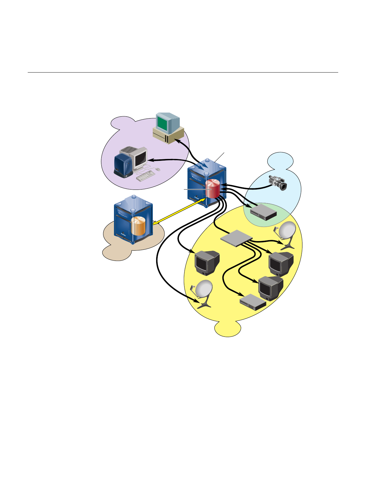
Functional Overview
Digital media data is brought into VST by recording it from a live feed or a videotape
deck, retrieving it from a StudioCentral 2.0 archive system, or copying it from a file. The
data can then be played out to a broadcast system, a video port, or a videotape deck; sent
to an MPEG-2 decoder for playout; or transferred to a StudioCentral 2.0 archive system
for storage and distribution.
VST can be automatically controlled by an application or through the use of a broadcast
system automation controller, which can control video servers using serial control
protocols, such as the Louth VDCP or Odetics VDR protocols, or an edit controller that
can control a VTR using the Sony RS-422 VTR protocol.
VST can also be manually controlled by using the VST graphical user interface or can be
controlled by an application using the Multiple-Unit Video Computer Protocol (MVCP).
4
Chapter 2: Overview of Video Server Toolkit
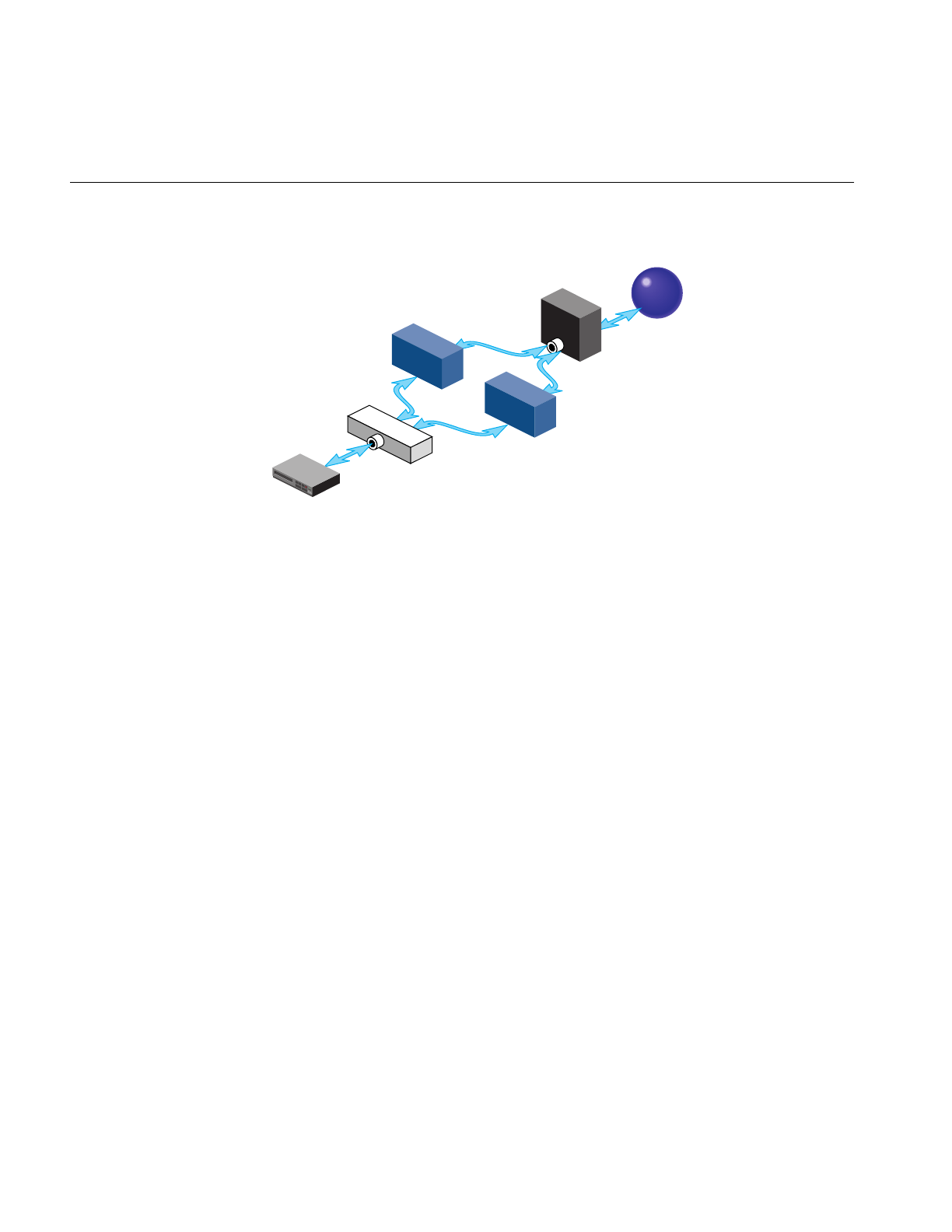
This functionality is shown in Figure 2-1.
Figure 2-1 Functional Overview
Automation
controller VCP-Recorder
server
Digital
media
Control
devices
Recording
devices
Playback
devices
Archive
system
Storage/
distribution
Live feed
Video deck
Broadcast
system
Vela
MPEG-2
decoder
Silicon Graphics
SiliconGraphics
Workstation
Functional Overview
5
The graphical user interface (GUI), which is used to control VST, was designed as both a
demonstration of the capability of VST and a beginning point from which broader
graphical applications can be developed. The GUI consists of screens that are used to
record and play digital data, determine status information, and manage digital media
data stored in VST.
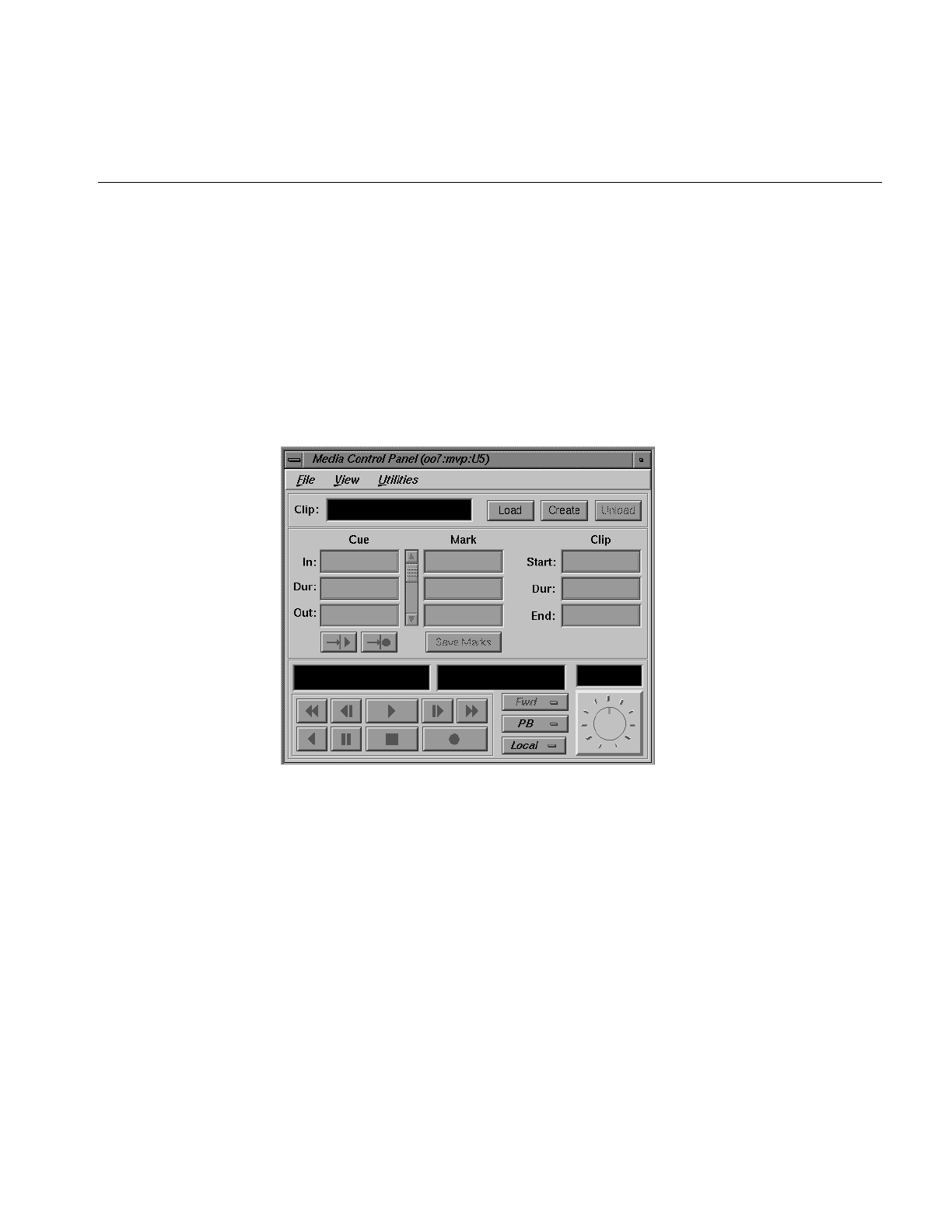
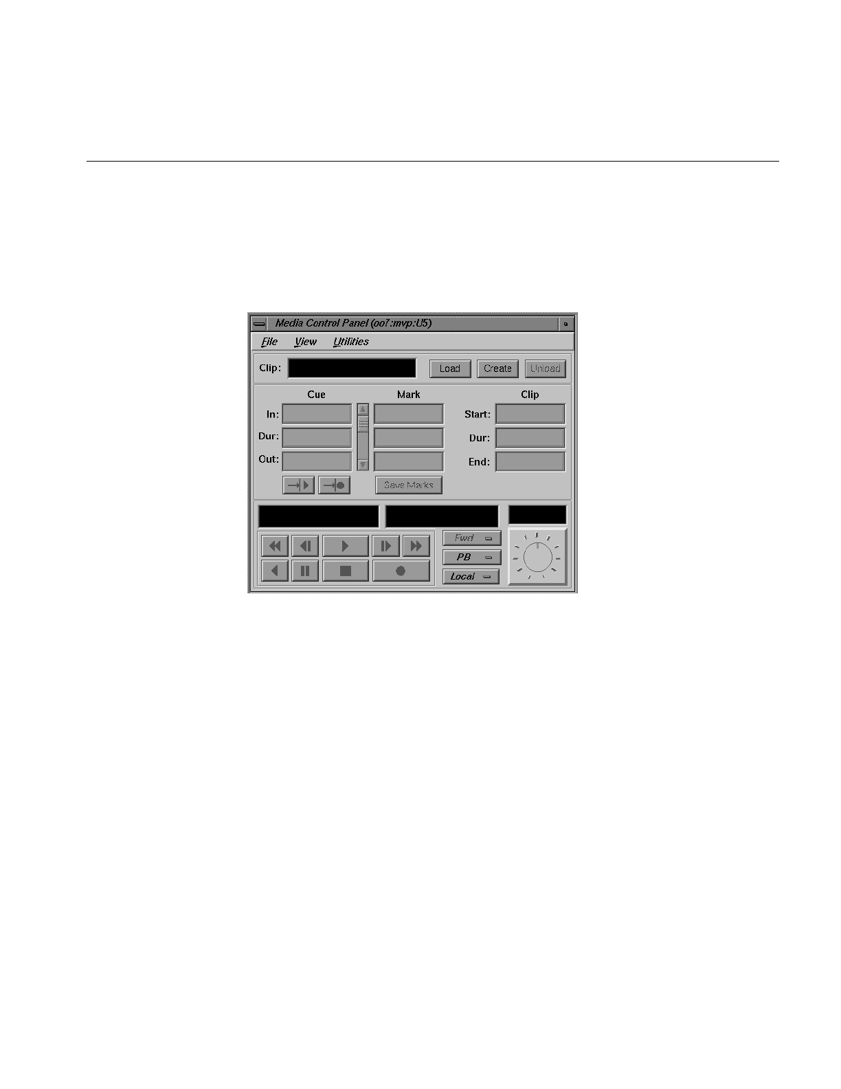
The GUI screen that is used to record and play digital media data is the VST Media
Control Panel (mcpanel), which is shown in Figure 2-2. The control panel is similar in
function to a standard videotape player or recorder. For example, there are buttons in the
control panel to cue the video, play it, stop the playback, and so on.
Figure 2-2 Video Server Toolkit Media Control Panel
The graphical user interface is described in Chapter 3, “Using the Video Server Toolkit
GUIs.” The MVCP protocol, which was used to implement the VST GUI, is described in
Appendix A.

6
Chapter 2: Overview of Video Server Toolkit
Software Overview
The VST software provides scalability and maximum flexibility, while enabling
real-time, frame-accurate control of digital media. The software includes the following:
• Core software, which provides the basic VST functionality for playback and
recording of digital data.
• Control interface modules, which provide device-dependent code. For example,
there is a control interface module that contains the code that is specific to a Louth
automation controller.
• Media device interface modules, which contain format-dependent code that
provides access to the ports over which media is played and recorded. For example,
there is a media device interface module that contains the code that supports the
Vela Research SCSI-attached MPEG-2 decoder.
• Format interface modules, which provide handlers for accessing specific digital
media storage formats. For example, there are format interface modules for the VST
variable-frame format, the MPEG-2 stream-based format, and the DVCPRO Data
Interchange Format (DIF).
Figure 2-3 shows the primary software components in VST.

Software Overview
7
Figure 2-3 Video Server Toolkit Software Components
The remainder of this section discusses the software components shown in Figure 2-3.
Silicon Graphics
SiliconGraphics
Louth VD
C
P
(
R
S
-
4
2
2
)
Automation
controller
Control
interface
modules
Archive
interface
modules
VCP-Recorder
GUI Application
program
Archive
system
Media
device
interface
modules
Logical
units
Format
interface
modules
Storage
device
interface
modules
Clip cache
VCP-Recorder
core software
Media ports
Playback/recording
devices
MVCP (TCP/IP)
ATS (TCP/IP)
MVCP (TCP/IP)

8
Chapter 2: Overview of Video Server Toolkit
Clip Cache
Digital media data that Video Server Toolkit (VST) processes for playout and recording
is stored in one or more clip caches. Each unit of data that is stored in a clip cache (for
example, a movie) is called a clip.
Clips can be added to the cache by:
• Using VST to record the clip
• Generating the clips elsewhere and adding them to the cache
• Transferring clips from a StudioCentral 2.0 archive system
Clips can be transferred from the clip cache into a StudioCentral 2.0 archive system for
storage.
Core Software
The core software provides the basic VST functionality for playback and recording of
digital data. It utilizes the IRIX operating system as well as portions of the Silicon
Graphics Digital Media Libraries.
The core software provides the following basic functionality:
• Archive management, which oversees the transferring of assets into and out of a
StudioCentral 2.0 archive system
• Clip cache management, which maintains persistent information about the media
that is either stored in the clip cache or is in the process of being transferred into or
out of it
• Controller management, which links one or more external control protocol modules
(for example, Louth) to the internal VST processing logic
• Configuration management, which automatically configures the VST software
according to the hardware capabilities of the system on which it runs
VST provides a core library that supports external interface modules, dynamic shared
objects (DSOs) that contain the code specific to a given external entity. When VST is
started, the VST software loads and initializes all external interface modules it locates so
that the modules can be used.

Software Overview
9
Archive Interface Module
VST has an archive interface that enables VST to retrieve clips from, and store them in an
archive asset repository. VST transfers the media to and from an archive system using the
Asset Transfer Service (or ATS), communicating with ATS using the FTP-like ATS
protocol.
Archive interface modules contain the code that is specific to a StudioCentral 2.0 archive
system. These modules provide the support that is needed to locate a given clip in the
StudioCentral 2.0 archive system and bring it into VST, and to store a clip from VST in
the StudioCentral 2.0 archive system.
Control Interface Module
Control interface modules allow various automation controllers and digital media
applications to control the use of VST. These modules translate to and from external
control protocols.
The following control interface modules are provided:
• The Louth Video Disk Communications Protocol defined by Louth Automation.
This control protocol provides control of VST over RS-232, RS-422, or TCP/IP. The
VST’s Louth interface module supports back-to-back play and record (subject to
restrictions imposed by the video I/O port capabilities) and archive management.
• The Sony RS-422 VTR (also called, 9-pin or P2) protocol. VST supports this protocol
through a full-featured VTR deck-emulation mode that includes frame-accurate
insert editing and variable-speed shuttle.
• Multiple-Unit Video Computer Protocol (MVCP) defined by Silicon Graphics. This
control protocol provides full-featured control of VST through TCP/IP. This control
interface module supports archive management, multiple-unit control, and event
monitoring, and provides access to advanced features of Silicon Graphics devices.
• The Odetics protocol is a Video Disk Control Protocol similar in purpose to the
Louth VDCP. Unlike Louth, it is built upon the foundation of the Legacy Sony
RS422 VTR Control Protocol, with which it shares many commands and features.
Odetics adds to the Sony protocol commands specific to Video Disk Recorders, such
as back-to-back playout and recording and clip management operations.

10
Chapter 2: Overview of Video Server Toolkit
Storage Device Interface Module
Storage device interface modules provide access to the storage systems on which the clip
cache resides. Currently, there is a storage device interface module for the IRIX XFS
filesystem.
Format Interface Module
Format interface modules provide handlers for accessing specific digital media storage
formats. VST currently provides format interface modules that support the following:
• VST variable-frame format (uncompressed, Rice 2:1 lossless compression, and
motion JPEG)
• MPEG2 stream-based format (transport and program streams)
• DVCPRO Data Interchange Format (DIF)
• DVB-ASI (Digital Video Broadcast Asynchronous Serial Interface) protocol
Note: vtrmpegutil is a utility that parses MPEG2 Program and Transport streams. It
provides syntax reporting for Transport streams, semantic analysis of PID mapping and
multiplexed bitrate. For more information, see the vtrmpegutil man page.
Media Device Interface Module
Media device interface modules provide access to the ports over which the media is
played and recorded (that is, the media ports). Each type of I/O port typically has its own
media device interface module.
VST has media device interface modules for the following:
• Silicon Graphics Video Library. This media device interface module supports the
Digital Video Option (DIVO) on Origin servers and the video port on O2
workstations.
– DIVO enables broadcast-quality video and embedded audio, and is used for the
recording and playback of uncompressed and Rice compression formats.
– DVC/DIVO is the DVCPRO version of the DIVO card. It performs all the
functions of the DIVO card and DVCPRO.

Software Overview
11
– DVB-ASI (Digital Video Broadcast Asynchronous Serial Interface) protocol
– The O2 video port is used for playback and recording of the motion JPEG
format, and is suitable for a test or development environment.
Note: The O2 video port is usually referred to as mvp (multiport video
processor) or O2Video.
• Vela Research four-port analog decoders. This media device interface module
enables the playback of MPEG-2 format data on Origin servers and O2
workstations.
• V-LAN transmitters. This media device interface module enables frame-accurate
capture from, and lay-down to, videotape decks.
• Diaquest. Direct Sony 422 control of videotape decks; used in the same way as
V-LAN.
DVB-ASI Format
The Viewgraphics MediaPump is a PCI-based, DVB-compliant adaptor board. It
multiplexes MPEG 2 transport streams and transmits them over coaxial cables using the
DVB-ASI (Digital Video Broadcast Asynchronous Serial Interface) protocol.
For more information, see the Video Server Toolkit Installation and Administration Guide.
DVCPRO Format
The DVCPRO compression algorithm compresses four video frames into one frame. This
compression format is useful for transporting video data across networks, such as
between video decks. DVCPRO-compressed frames in 1 times mode can be displayed
normally. The following section describes how to display DVCPRO-compressed frames
in 4 times mode
Displaying 4 Times Mode DVCPRO-Compressed Frames
The Serial Digital Transport Interface (SDTI) is a video networking protocol that allows
arbitrary data to be packeted and transmitted over the SMPTE-259M Serial Digital
Interface (SDI). VST supports playback and recording of DVCPRO (DIF) over SDTI at 1
times and 4 times normal speed. When recording SDTI/DVCPRO using DIVO-DVC, the
incoming signal can be looped to the output (EE mode) in either 1x or 4x mode.
12
Chapter 2: Overview of Video Server Toolkit
Logical Playback and Record Units
Logical units enable media ports to play and record clips. Each VST unit can be thought
of as a logical videotape recorder (VTR) transport that is capable of loading, cueing,
playing, and recording clips using a specific media port.
Logical units are created automatically by VST when the VST GUI or an automation
controller is used. When the MVCP protocol is used, a command requests that a unit be
created or that a unit created by another control connection be used.
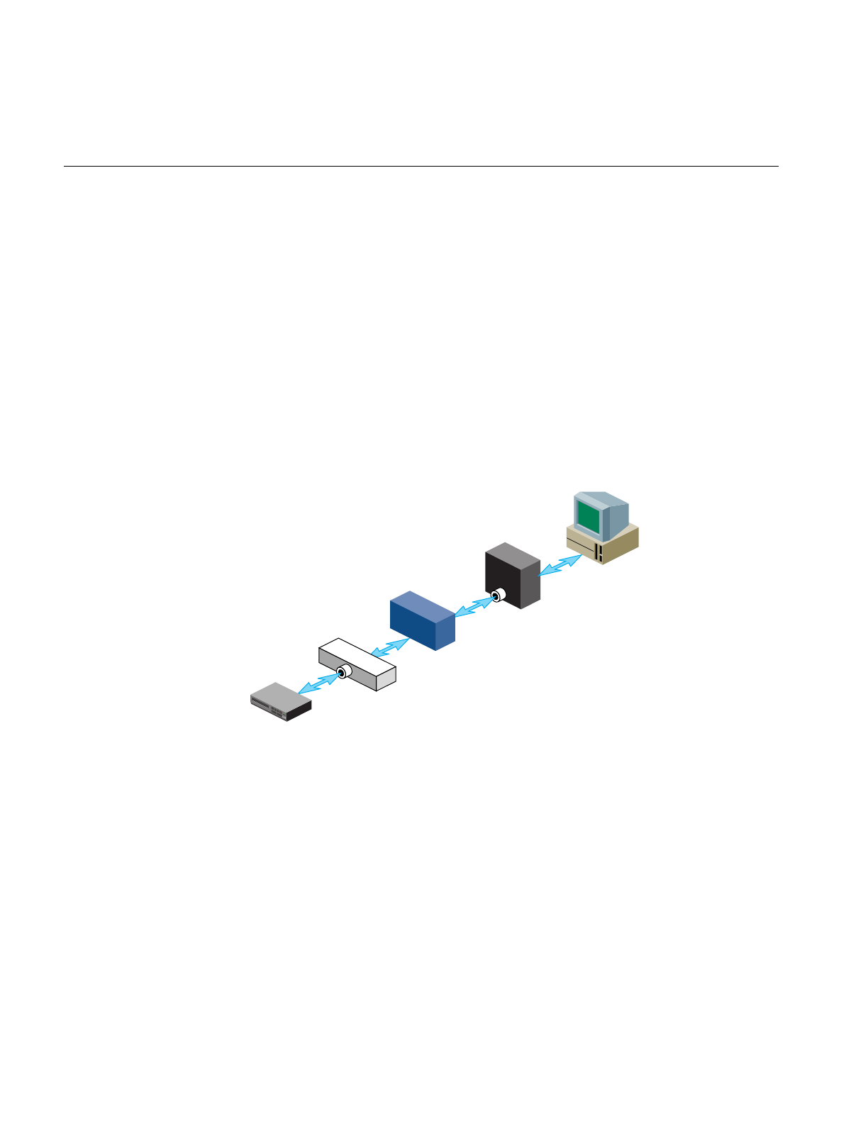
There is normally a one-to-one relationship between a control connection to VST and a
VST logical unit, and between a logical unit and a media port. This is shown in
Figure 2-4.
Figure 2-4 One Logical Unit With One Control Connection
Control
port
Logical
unit
Automation
controller
Media port
Playback/recording
device
Software Overview
13
A single unit can also be controlled by multiple control ports. For example, two tightly
integrated applications might control a single unit, where each application would have
its own control port. This is shown in Figure 2-5.
Figure 2-5 One Logical Unit With Two Control Connections
Caution: Exercise extreme care when the control of a unit is shared between two
controller connections. Interfering with a unit owned by a Sony, Odetics, or Louth
automation controller leads to unpredictable behavior in VST.
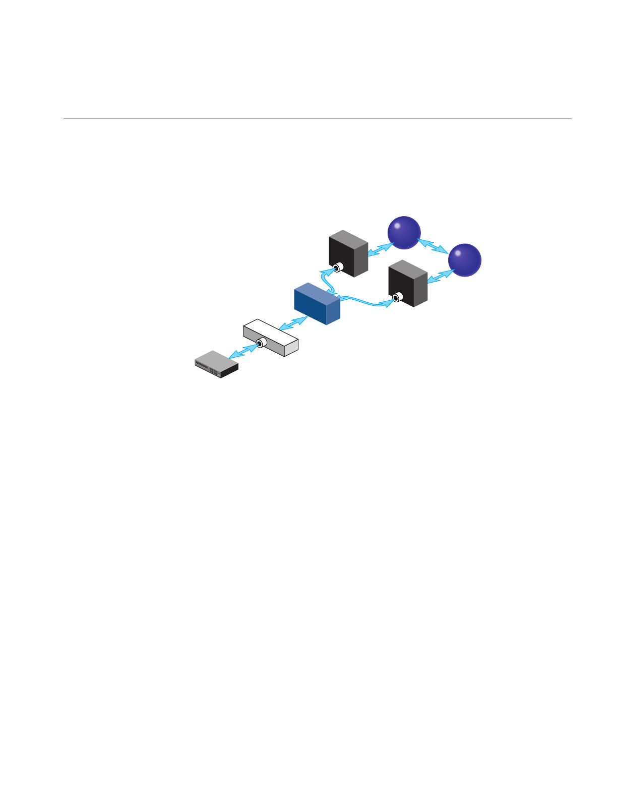
A media port can be controlled by multiple logical units. For example, an application
with one control connection and two units could be cueing one clip while playing out
another, enabling back-to-back playout of clips when allowed by the media format. This
example is shown in Figure 2-6.
Control
port Control
port
Logical
unit
Media port
Playback/recording
device
Application
Application
14
Chapter 2: Overview of Video Server Toolkit
Figure 2-6 Two Logical Units With One Control Connection
If a media port supports multiple logical units, the sharing is subject to the
device-sharing characteristics of that port.
Hardware Overview
A VST hardware configuration consists of the following components:
VST Server O2, O200 with GIGAchannel, O2000
Storage Internal ultraSCSIs or external CIPRICO 7000 RAIDS
Internal DevicesMVP (video card for O2), DIVO (video card for O200 and O2000),
DIVO-DVC (video card for Panasonic setups using DVC Pro), RAD
(audio card), ENET/ESER (ethernet cards), PCI fiberchannel, PCI
DVB-ASI, ATM.
External DevicesControllers: Sony controllers, Panasonic AJ-A850, Louth ADC, Odetics.
Decks: connected using VLAN
Media recorders/playback units: Vela, decoders
Control
port
Logical
unit Logical
unit
Media port
Playback/recording
device
Application
Hardware Overview
15
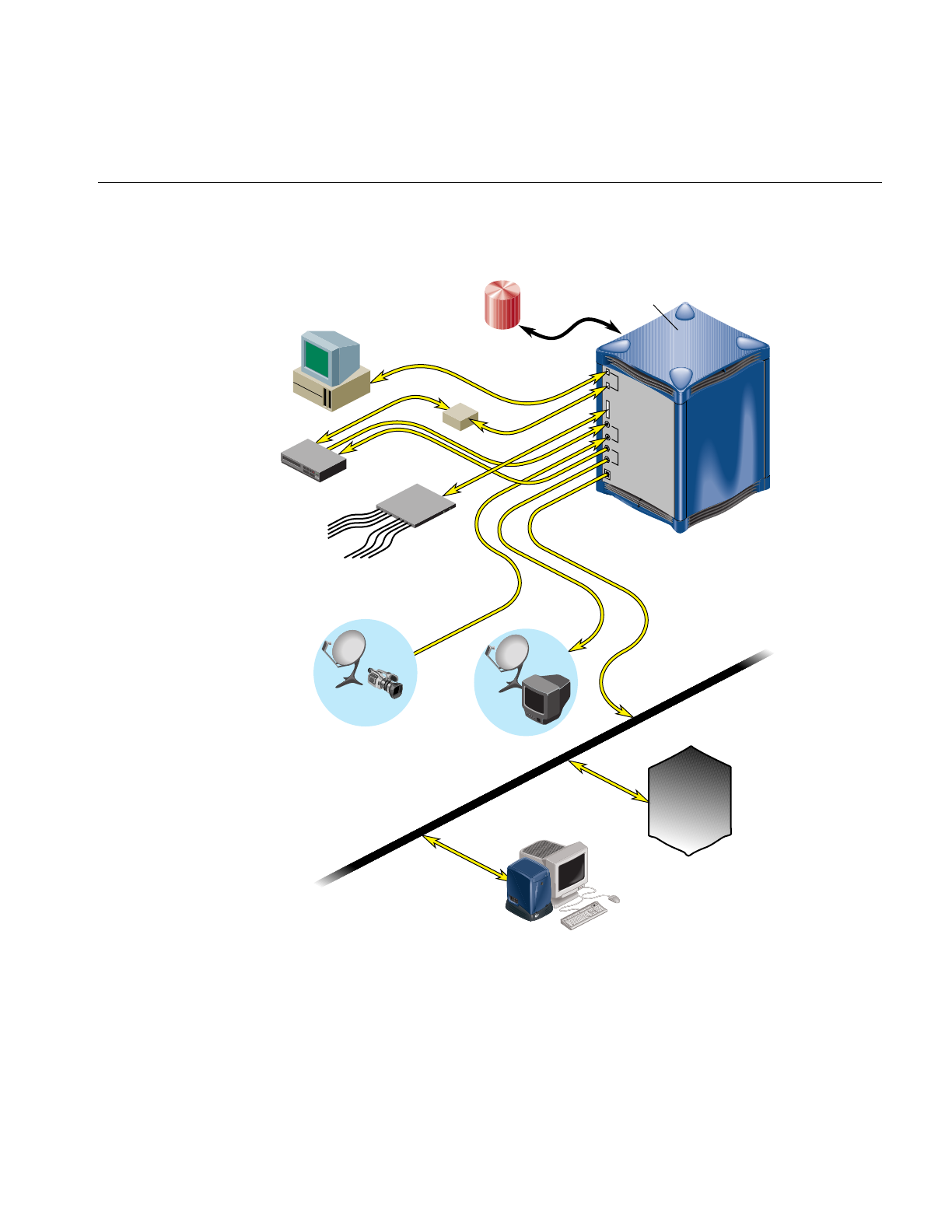
A typical hardware configuration is shown in Figure 2-7.
Figure 2-7 Video Server Toolkit Hardware Components
Disk
storage
VCP-Recorder
server
Workstation
MediaHub
server
Video deck
Serial ports
SCSI port
Video in
Video out
Ethernet port
Automation
controller
Vela MPEG-2
decoder
4 video
outputs
4 stereo
outputs
Live feed Broadcast
system
TCP/IP
RS-422
Network
Silicon Graphics
SiliconGraphics
VLAN

16
Chapter 2: Overview of Video Server Toolkit
Video Server Toolkit Server
The Video Server Toolkit (VST) server can be an Origin200 or Origin2000 Scalable
Symmetric Multi-Processing (S2MP) server, or an O2 workstation.
Origin Servers
The Origin servers provide massive processing, storage, and throughput capabilities to
satisfy even the largest production requirements. They are built from a scalable node
architecture, enabling small configurations that can be incrementally upgraded to the
larger configurations. Each Origin server can be configured as a single module or as
multiple modules with a single system image.
The Origin servers provide:
• Playback and recording of uncompressed and Rice compression video data with the
Digital Video Option (DIVO) card.
• DVCPRO, Data Interchange Format (DIF), a compression algorithm that
compresses four video frames into one frame. This compression format is useful for
transporting video data across networks, such as between video decks.
• Playback of MPEG-2 (system and transport streams) data with the Vela Research
SCSI-attached decoder.
• GIGAchannel expansion box for the O200, which allows the addition of up to five
DIVO boards.
• DVB-ASI is a PCI-based, DVB-compliant adaptor board. It multiplexes MPEG 2
transport streams and transmits them over coaxial cables using the DVB-ASI
(Digital Video Broadcast Asynchronous Serial Interface) protocol.
O2 Workstations
The O2 workstation provides a low-cost, entry-level video server platform that supports
some but not all of the features supported by the Origin platform.
The O2 workstation provides:
• Playback and recording of M-JPEG video
• Playback of MPEG-2 (system and transport streams) data with the Vela Research
SCSI-attached decoder

Hardware Overview
17
Disk Storage
The VST disk storage holds the XFS real-time filesystems that contain the movies, trailers,
commercials, and other digital media data stored in the clip cache. The descriptive
information about VST clips, for example, clip names, duration, edit points, and so on, are
also stored on these filesystems.
The VST storage system supports the use of scalable storage to enable the total disk space
to range from only a few gigabytes to hundreds of terabytes or more. The type of disk
storage that is used depends upon several factors, including the number and size of
stored clips, the use of RAID, and the required availability (uptime) of the system.
Three different types of disk storage are available:
• Normal XFS filesystems residing on a single disk drive. This type of disk storage
does not provide redundancy.
• Standard disk storage, sometimes called RAID-0, in which several disk drives are
striped into XLV logical volumes. This type of disk storage does not provide
redundancy but it does provide higher bandwidth than XFS on a single disk drive.
• RAID storage, such as RAID-3 and RAID-5, which provides high-availability,
redundant digital storage.
External Devices
VST supports the use of the following external devices:
• Vela Research 4-port MPEG-2 decoders, used for the playback of MPEG-2 format
data. Vela decoders are connected to the VST server through a SCSI connection.
• V-LAN transmitters, used to control a videotape deck for frame-accurate capture
and lay-down. A V-LAN transmitter is connected to a VST server through an RS-422
serial port connection.
• Broadcast system automation controllers that use, among others, the Odetics and
Louth Video Disk Communications Protocol, defined by Louth Automation.
Automation controllers are connected to the VST server through an RS-422 serial
connection or a TCP/IP Ethernet connection.

18
Chapter 2: Overview of Video Server Toolkit
• DVB-ASI, from Viewgraphics, is a PCI-based, DVB-compliant adaptor board. It
multiplexes MPEG 2 transport streams and transmits them over coaxial cables
using the DVB-ASI (Digital Video Broadcast Asynchronous Serial Interface)
protocol. For more information, see Chapter 8, “Installing the DVB-ASI Adapter
Board,” in the Video Server Toolkit Installation and Administration Guide.
• Edit controllers, including Panasonic AJ-A850, Buf VTC4000/RM4000, and the edit
control portion of the Sony DVW 500 digital Betacam deck.
For more information about installing these devices for use with VST, see the Video Server
Toolkit Installation and Administration Guide.
For a complete list of external devices that interface with VST, see the release notes.
Internal Devices
Video Server Toolkit supports the use of the following internal devices:
• DIVO, a CCIR 601 format digital video board that provides two sets of incoming
and outgoing video/audio signals and lossless 2:1 compression using the Rice
format. DIVO enables you to choose square or rectangular pixels, and compatibility
with PAL and NTSC.
• DIVO plus DVCPRO,. which compress four video frames into one frame using
cosine compression.
• MVP, which provides standard, uncompressed, analog or CCIR 601 audio/video
using RCA jacks, S-Video jacks, stereo input and output audio, the choice of using
square or rectangular pixels, and compatibility with PAL and NTSC.
Video Device Control
V-LAN transmitters provide the means by which VST can control remote video devices,
such as video decks.
VST can also control remote video devices directly using Sony 422 deck-control software
provided by DiaQuest.

19
Chapter 3
3. Using the Video Server Toolkit GUIs
The Video Server Toolkit (VST) graphical user interfaces (GUIs) were designed as both a
demonstration of the VST capability and a beginning point from which broader
graphical applications can be developed. The GUIs consists of the following:
• Media Control Panel (mcpanel), which enables clips to be played and recorded
• Deck Control Panel, which enables a video deck to be controlled
• Unit Status Monitor (mcstat), which displays the status of VST ports
• Clip Manager (mcclips), which is used to manage clips, including getting them
from, and writing them to a StudioCentral 2.0 archive system
The following topics are discussed in this chapter:
• “Playing and Recording Clips” on page 20
• “Monitoring the Status of Video Server Toolkit (mcstat)” on page 44
To add a clip to VST, see Chapter 4, “Adding and Removing Clips.”

20
Chapter 3: Using the Video Server Toolkit GUIs
Playing and Recording Clips
This section describes how to use the VST Media Control Panel and how to control a
video deck. The following topics are discussed:
• “Starting the Video Server Toolkit Media Control Panel” on page 20
• “Determining Available Ports” on page 23
• “About the Media Control Panel” on page 26
• “Playing or Recording an Existing Clip” on page 33
• “Creating a New Clip” on page 35
• “Changing Cue Points and Edit Points” on page 36
• “Controlling a Video Deck” on page 37
See the Video Server Toolkit Installation and Administration Guide for information about how
to copy digital media data from a file into the VST clip cache.
Starting the Video Server Toolkit Media Control Panel
To establish a control connection to VST and start the Media Control Panel, enter the
following, either from the workstation on the VST server or from a workstation on which
the VST tools software1 has been installed:
%/usr/vtr/bin/mcpanel hostname videoPort|unit
For more complete control of mcpanel, use it with the following set of flags:
%/usr/vtr/bin/mcpanel [-h hostname][-p videoPort|unit][-D deckCtlPort]
[-c clipname][-r][-C "inpoint outpoint"] [-P][-v loglevel]
1To run the Media Control Panel from a remote workstation, the vcp_recorder_eoe.sw32.tools subsystem
must be installed on a workstation that has IRIX 6.2 or later. See the Video Server Toolkit Installation and
Administration Guide for more information.

Playing and Recording Clips
21
Table 3-1 describes each of the options available when starting the VST Media Control
Panel.
Table 3-1 VST Media Control Panel Options
Option Description
-c Identifies the name of a clip to be loaded when the Media Control Panel starts. If this
option is not specified, no clip is initially loaded.
-D Specifies the video deck control port (deckCtlPort) to be used for V-LAN
communication to an external video storage device, such as a digital videotape
recorder (VTR). The deck is controlled by the Deck Control Panel.
If this option is not specified, deck control is not available.
-h Identifies the host on which VST runs. This enables the Media Control Panel to be
run from a remote workstation.
If this option is not specified, the local host is assumed.
-p Identifies the VST host video port or unit to which the control connection is made.
videoPort is the VST host video port to which the control connection is made. If you
specify a port, VST creates a new logical unit that is used by this control connection.
unit is the VST logical unit to which the connection is made. If you specify a unit, it
must have already been created by another control connection. The control
connection being made shares the unit with the control connection that created the
unit. (Units are named with a capital “U” followed by a number, for example, U4.)
If this option is not specified, the first video port on the VST is used.
-r Specifies that if an mcpanel already exists for the video port, the existing mcpanel
should be raised on the desktop instead of creating a new one.
-C Specifies that the loaded clip should be cued with the specified in- and out-points.
If “*” is specified for either inpoint or outpoint, the default edit in-point or out-point
is used.
-P Specifies that the clip whose name is clipname should start playing when the Media
Control Panel starts.
-v Sets the logging verbosity level to loglevel. The default is 0, meaning all log messages
up to and including Info priority are written to STDOUT. (The mcpanel program
writes its log messages to STDOUT.)
The values for loglevel are defined in Table 3-2.

22
Chapter 3: Using the Video Server Toolkit GUIs
Table 3-2 shows the log severity levels and codes, which are listed in decreasing order of
severity
Priority levels Info and Notice result from user-caused errors. Priority levels Warning
through Emergency result from system problems.
Table 3-2 Log Severity Levels
Priority Log
Level Description
Emergency -6 Panic condition.
Alert -5 Condition that should be corrected immediately, such as a corrupted
system file.
Critical -4 Critical condition that has system-wide impact, such as a hard device
error; immediate action required.
Error -3 Problem that needs correcting but does not require immediate action.
Warning -2 Possible problem but could be a transient problem that corrects itself.
Notice -1 Condition that might require attention, but is not an error condition.
Info 0 Informational message.
Debugnn Informational message that normally is of use to engineers for
debugging; may be Debug1, Debug2, or Debug3, with Debug3
producing the most debugging information.
Playing and Recording Clips
23
The VST Media Control Panel, shown in Figure 3-1, is displayed in its own window. This
control panel represents a unit, or logical VTR, that is used to play and record clips. The
buttons in the Media Control Panel are similar in function to those of a standard
videotape player/recorder. For example, there are buttons to load a clip, play it, and
pause.
Figure 3-1 Video Server Toolkit Media Control Panel
See “About the Media Control Panel” on page 26 for a detailed description of the Media
Control Panel.
Determining Available Ports
To determine which video and deck control ports are available on a VST server, use the
/usr/vtr/bin/vtrstat command as follows:
%/usr/vtr/bin/vtrstat -ports
# Port Type Description
----------------------------------------------------------
0 mvp Video SGI O2Video (Multiport Video Processor)
See the vtrstat(1) man page for more information.

24
Chapter 3: Using the Video Server Toolkit GUIs
Using Telnet to Determine Available Ports
To determine which video and deck control ports are available on a VST server, establish
a telnet connection to the VST server and then use the MVCP PLS (List Ports) command.
(See “Establishing an Interactive MVCP Connection” on page 103 for details.) The
following example shows the type of information returned by PLS for an O2 server. This
example identifies “mvp” as the video port (VID) on the server:
PLS
201 OK
mvp BOTH "SGI O2 (MACE) Video Processor" VID
The following example shows the PLS command output for an Origin server. This output
identifies “vlan_1” as the deck control port (DECK) and “DIVO_n,” where n is 0-7, as the
video ports (VID):
PLS
201 OK
vlan_1 BOTH "VLAN Deck Control" DECK
DIVO_0 BOTH "SGI XT-DIVO Digital Video Option" VID
DIVO_1 BOTH "SGI XT-DIVO Digital Video Option" VID
DIVO_2 BOTH "SGI XT-DIVO Digital Video Option" VID
DIVO_3 BOTH "SGI XT-DIVO Digital Video Option" VID
DIVO_4 BOTH "SGI XT-DIVO Digital Video Option" VID
DIVO_5 BOTH "SGI XT-DIVO Digital Video Option" VID
DIVO_6 BOTH "SGI XT-DIVO Digital Video Option" VID
DIVO_7 BOTH "SGI XT-DIVO Digital Video Option" VID
See “PLS” on page 113 for more information.
Determining Units in Use
To determine which units are in use on a VST server, use the /usr/vtr/bin/vtrstat command
as follows:
%/usr/vtr/bin/vtrstat -units
Unit Owner Port Clip Function Location
----------------------------------------------------------
U3 mvcp/oo7 mvp * IDLE *
See the vtrstat(1) man page for more information.

Playing and Recording Clips
25
Using Telnet to Determine Units in Use
To determine which units are in use on a VST server, establish a telnet connection to the
VST server and then use the MVCP ULS (List Units) command. The following example
shows the information returned by the ULS command:
ULS
201 OK
U1 mvcp/originserver mvp BOTH * DONE IDLE * 0 *
U2 mvcp/originserver mvp BOTH * DONE IDLE * 0 *
This example indicates that there are two units (U1 and U2) on the server, both using the
mvcp port on the host named originserver. The units were opened for input and output
(BOTH) and they are currently idle.
See “ULS” on page 115 for more information.
The following are examples of starting the Media Control Panel:
• When the Media Control Panel is started by entering the following command, a
control connection is made to the DIVO_1 video port on the “origin_server” host
using a newly added unit. Messages with a severity level of Info and above are
written on STDOUT:
%/usr/vtr/bin/mcpanel -h origin_server -p DIVO_1
• When the Media Control Panel is started by entering the following command, a
control connection is made to the U9 unit, which must already exist. Messages with
a severity level of Debug2 and above are written on STDOUT:
%/usr/vtr/bin/mcpanel -v 2 -h origin_server -p U9
• When the Media Control Panel is started by entering the following command, a
control connection is made to the mvp video port on the “o2server” host. Messages
with a severity level of Info and above are written on STDOUT:
%/usr/vtr/bin/mcpanel -h o2server -p mvp
26
Chapter 3: Using the Video Server Toolkit GUIs
About the Media Control Panel
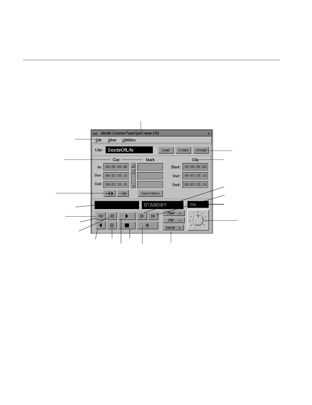
Figure 3-2 shows the appearance of the Media Control Panel after a clip has been loaded.
The header of the control panel identifies the host, control port, and unit to which the
control panel is connected.
Figure 3-2 Video Server Toolkit Media Control Panel With a Clip Loaded
VTR control buttons
Current frame and function
Option pulldown menus
Cue and edit points
Function buttons
Shuttle dial
Status/shuttle speed
Cueing buttons
Clip in-point/out-point
(Host: Port: Unit)
Menu bar
Jog backward
Pause Stop
Jog forward
Record
for playing and recording
Play backward
Play
Fast rewind
Fast forward

Playing and Recording Clips
27
The menu bar gives you access to the following:
• The File pulldown menu, which lets you load or unload an existing clip, create a
new clip, or close the Media Control Panel. Most of the functions available in this
pulldown menu are available through buttons in the Media Control Panel.
• The View pulldown menu, which lets you access the Deck Control window. The
Deck Control window, shown in Figure 3-5, is used to control a video deck attached
to the VST host. See “About the Deck Control Window” on page 39 for more
information.
• The Utilities pulldown menu, which lets you access the following:
– IRIX audio panel
– IRIX video panel
– VST Unit Status Monitor (mcstat), described in “Monitoring the Status of Video
Server Toolkit (mcstat)” on page 44
– VST Clip Manager (mcclips), described in Chapter 5, “Using Clip Manager”
The following describes each of the displays and buttons in the Media Control Panel:
• The Clip field contains the name of the clip, if one is loaded. The display is blank if a
clip is not loaded.
• The Load,Create, and Unload function buttons let you load an existing clip, create a
new one and record into it, and unload a clip, respectively.
• The cue points are used to move around within a clip and to control the portion of
the clip that is played. An in-point (In), the duration (Dur), and an out-point (Out)
are specified using the following format:
hh:mm:ss:ff
where hh is the hours, mm is the minutes, ss is the seconds, and ff is the frame
number. In drop-frame mode, the final colon is replaced by a period:
hh:mm:ss.ff
For example, if a clip with a cue in-point of 00:00:30.00 is cued for playing, it is cued
at thirty seconds.
See “Changing Cue Points and Edit Points” on page 36 for information about how
to change the cue points.

28
Chapter 3: Using the Video Server Toolkit GUIs
• The edit points (under “Mark” in the Media Control Panel) are persistent values
stored with a clip. They are used to initialize the cue points when the clip is loaded.
An in-point (In), the duration (Dur), and an out-point (Out) are specified using the
following format:
hh:mm:ss:ff
where hh is the hours, mm is the minutes, ss is the seconds, and ff is the frame
number. In drop-frame mode, the final colon is replaced by a period:
hh:mm:ss.ff
Note: Edit points may also be referred to as “edit marks.”
If a clip has edit points associated with it, those values are used to initialize the
clip’s cue points when the clip is loaded.
See “Changing Cue Points and Edit Points” on page 36 for information about how
to change the edit points.
• To the right of the cue and edit points are the start, the duration (Dur), and end of
the clip. Each is specified in the following format:
hh:mm:ss:ff
where hh is the hours, mm is the minutes, ss is the seconds, and ff is the frame
number. In drop-frame mode, the final colon is replaced by a period, as in:
hh:mm:ss.ff
If a clip does not have edit points associated with it, these start, duration, and end
values are used to initialize the cue points when the clip is loaded.
Note: You cannot change the values of the start, end, or duration of the clip itself.
However, you can select any of the values and copy it to the cue points or edit points.
• The cue buttons cue the clip for playout (—>|>) or recording (—>|•). The location
at which the clip is cued depends on how the clip is cued and the play direction, as
discussed in the descriptions of the VTR control buttons and the Media Control
Panel’s Option pulldown menus. (The play direction is determined by the setting of
the topmost Option pulldown menu.)
Note: A clip must be cued before it can be played or recorded. This can be
accomplished explicitly by clicking a cue button or implicitly by clicking the play or
record button without first clicking a cue button. If you click a cue button and then
click play or record, the clip starts playing or recording immediately. If you click play
or record without first clicking a cue button, the Media Control Panel first cues the
clip and then starts the requested function. In the latter case, there is a brief delay
before the requested play or record function begins.

Playing and Recording Clips
29
• The current frame display is initialized to the cue in-point or cue out-point each
time the clip is cued. The actual cue point depends on how the clip is cued and the
clip’s play direction, as discussed in the descriptions of the VTR control buttons and
the play direction. (The play direction is determined by the setting of the topmost
Option pulldown menu.) As the clip is played or recorded, the display changes to
indicate the current frame number.
• The function display shows the current function. When a clip is first loaded, the
word “STANDBY” is displayed.
• When a clip is being played or recorded, the status/shuttle speed display shows the
speed. If the clip is not being played or recorded, the status is displayed. The status
may be one of the following:
– WAIT, when the function is waiting to execute or waiting for another unit to
finish (for example, a Louth automation controller that is playing a clip). The
word BUSY blinks on and off.
– RUN, when the function is in progress.
– DONE, when the function completed without an error. The word DONE and
the function display are grayed-out.
– ERROR, when an error has occurred. The word ERROR blinks on and off, and
appears in red.

30
Chapter 3: Using the Video Server Toolkit GUIs
• The VTR control buttons control the playout and recording of clips. The following
describes these buttons, which correspond to standard VTR buttons:
– Fast-reverse (<<) plays the clip in reverse at a fast speed.
– Jog backward (<|) jogs the clip backward by one frame. Each time you click the
jog backward button, the clip jogs back one frame.
If the clip is playing when you click this button, the clip jogs backward one
frame and then pauses. You have to click either the play button or the pause
button to resume play.
– Forward play (>) plays the clip in the forward direction. If the clip is not cued, it
is cued before it begins playout.
– Jog forward (|>) jogs the clip forward by one frame. Each time you click the jog
forward button, the clip advances one frame.
If the clip is playing when you click this button, the clip jogs forward one frame
and then pauses. You have to click either the play button or the pause button to
resume play.
– Fast-forward (>>) plays the clip forward at a fast speed.
– Reverse play (<) plays the clip in reverse. If the clip is not cued, it is cued before
it begins playout.
– Pause (||) temporarily stops the clip from playing or recording. You have to
click the play, record, or pause button to resume.
– Stop (■) stops the clip and de-cues it. After the clip has been stopped, you must
re-cue it before playing it again.
– Record (•) begins recording. If the clip is not cued, it is cued for recording
before it begins.

Playing and Recording Clips
31
• The top Option pulldown menu lets you specify the play direction, which
determines the direction in which the clip is played and whether it plays once or
plays until it is stopped. The following options are available through this menu:
–Fwd, for forward play (default)
–F Lp, for forward loop play
–Bwd, for backward play
–B Lp, for backward loop play
–F/Bwd, for alternating forward and backward play
–F/B Lp, for alternating forward and backward loop play
–B/Fwd, for alternating backward and forward play
–B/F Lp, for alternating backward and forward loop play
– FCue, for forward play without cue (in and out) points set
– BCue, for backward play without cue (in and out) points set
If the direction is one of the forward directions (Fwd,F Lp,F/Bwd, or F/B Lp), the clip
is cued at its in-point. If the direction is one of the backward directions (Bwd,B Lp,
B/Fwd, or B/F Lp), the clip is cued at its out-point.
The forward direction means that the clip plays from its in-point to its out-point.
The backward direction means that the clip plays from its out-point to its in-point.
For alternating directions, the clip plays once in each direction. In loop mode, the
clip continues to play in the given direction until you click the stop button. If you do
not choose loop mode, the clip plays once in the indicated direction and then stops.
Note: When you change the option in this menu, the change takes effect the next
time you cue the clip. For example, assume that the Fwd option is in effect when you
start playing a clip. If you choose the F Lp option after the playing starts, the play
stops when the out-point is reached. The next time you play the clip, the clip plays
in forward loop mode.
To play forward or backward without using cue points, you first use FCue and
BCue, respectively, to cue the clips. When clips limits are disabled using the
controls, vtr.media.clip.limit.start and vtr.media.clip.limit.end, you can play forward or
backward without limitation.

32
Chapter 3: Using the Video Server Toolkit GUIs
• The middle Option pulldown menu lets you choose the following options:
–PB, the clip’s audio and video are output when a clip is playing; nothing is
output at other times (default).
–PB/EE, the clip’s audio and video are output when a clip is playing; the input
signal is output at other times.
Note: The EE (end-to-end) option emulates a video deck feature and is relevant
only when you have an active input source.
–PB/Im, the clip’s audio and video are output when a clip is playing; SMPTE 75%
colors bars and 1 kHz tone are output at other times.
–PB/B, the clip’s audio and video are output when a clip is playing; a black
screen is output at other times.
–EE, the output always displays the input signal instead of the signal from VST,
even when a clip is playing. (When a clip is playing, the output displays the
input signal.)
–Image, the output always displays SMPTE 75% colors bars and plays a 1 kHz
tone.
–Black, the output always displays a black screen.
–Hold, the output always displays the last image.
• The Local/Rem Option pulldown menu lets you put the unit in remote mode. The
following options are available through this menu:
–Local, which puts the unit in local mode and enables the VTR control buttons
(local).
–Rem, which puts the unit in remote mode and disables the VTR control buttons.
This mode prevents you from accidentally operating a Media Control Panel
while the unit is being controlled remotely, for example, by an automation
controller.
• The shuttle dial lets you control the speed of a clip that is playing. To use the shuttle
dial, begin playing the clip and then use the mouse to point to the black notch on
the dial. Press the left mouse button and keep it pressed while you turn the dial
clockwise to increase the speed or counterclockwise to decrease it.
Note: The straight up position of the dial is zero, or pause.
Playing and Recording Clips
33
In general, buttons that are enabled and can be used appear darker than those that are
disabled. For example, when you load an existing clip, the cue for playout button
(—>|>) is darker than the cue for recording button (—>|•). This indicates that the cue
for playout button is enabled and the cue for recording button is not.
Playing or Recording an Existing Clip
To play or record an existing clip, follow these steps:
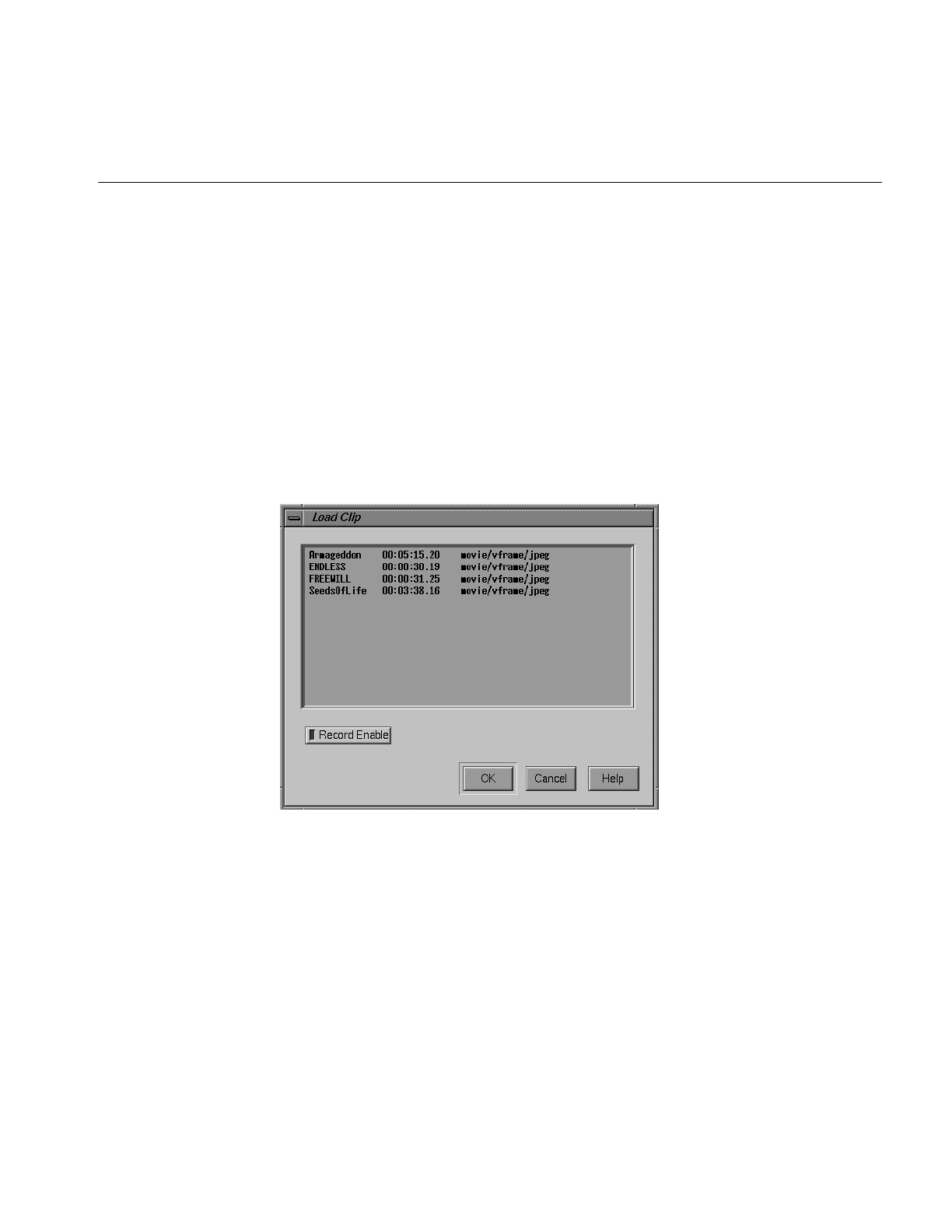
1. If the clip is not loaded, load the clip:
■Click the Load button in the Media Control Panel. A window that lists the clips
in the VST cache appears, as shown in Figure 3-3.
Figure 3-3 Loading a Clip Into the Logical VTR

34
Chapter 3: Using the Video Server Toolkit GUIs
The Load Clip window lists the name, duration, and format of each clip that is
stored in /usr/vtr/clips, which is the VST clip cache. For example, the SeedsOfLife
clip has a duration of 00:03:38.16 and its format is movie/vframe/jpeg. (If the
duration contains an asterisk [*], it means that no material has been recorded in
the clip.)
Note: If a clip is stored in a directory within /usr/vtr/clips, that directory name
precedes the clip name. For example, if the clip name appears as ADS/COMM1,
the clip is stored in /usr/vtr/clips/ADS/COMM1.
■Select the clip that you want to load. (You select the clip by pointing to it with
the mouse cursor and pressing the left mouse button.)
■If you want to record over this clip, click Record Enable. (When recording is
enabled, the yellow LED is lit in the Record Enable button.) Click Record Enable a
second time if you want to disable this option.
■Click the OK button. The window closes and the selected clip appears in the
Media Control Panel. The cue for playout button (—>|>) is enabled. If the clip
can be recorded over, the cue for recording button (—>|•) is also enabled.
2. Change the cue points, as needed. (See “Changing Cue Points and Edit Points” on
page 36 for information.)
3. Click the cue for playout button (-->|>) or the cue for recording button (—>|•).
Note: If you cue the clip first, the clip starts playing or recording as soon as you click
the play or record button. If you do not cue the clip beforehand, the Media Control
Panel automatically cues the clip and then starts playing or recording it. In the latter
case, there is a delay before the requested function begins.
4. Click the play button (>) to start the playout or the record button (•) to start
recording.
5. To stop playing or recording, click the stop button (■).
Note: If you want to replay or re-record the clip after it stops, the clip must be
re-cued. If you click the play or record button without first clicking the cue button,
the Media Control Panel automatically cues the clip before it starts playing or
recording.
Playing and Recording Clips
35
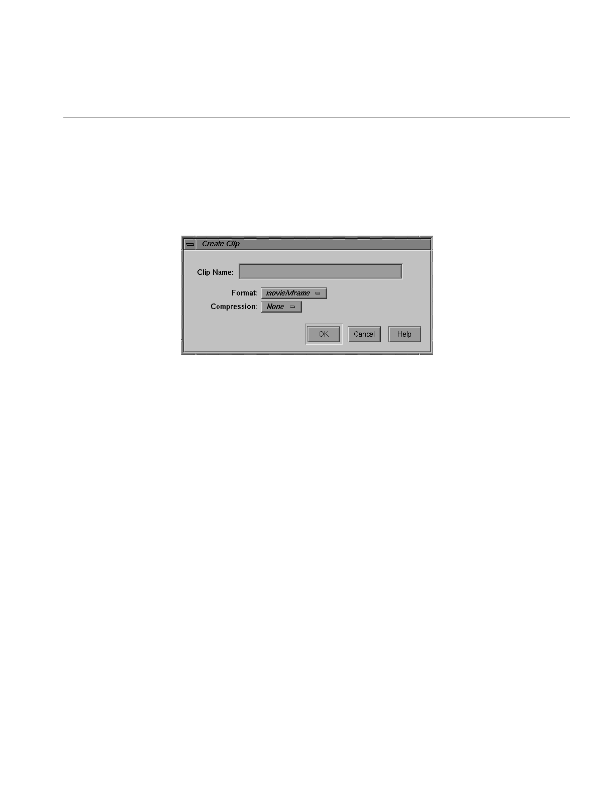
Creating a New Clip
To create a new clip and record its content, follow these steps:
1. Click the Create button in the Media Control Panel. The Create Clip window, shown
in Figure 3-4, appears.
Figure 3-4 Create Clip Window
2. Enter the name of the clip in the Clip Name field.
3. Choose the compression type of the clip from the Compression Option pulldown
menu. You can choose from the following compression types:
• Rice (Rice compression)—only on Origin servers with the Digital Video Option.
• None (uncompressed)—only on Origin servers with the Digital Video Option.
• JPEG (M-JPEG)—only on O2 workstations.
• DVCPRO
4. Choose the format of the movie from the Format Option pulldown menu.
Note: You can create clips through the VST graphical user interface using one of the
following options:
• movie/vframe, the VST variable-frame movie format
• movie/dif/dvcpro
5. Click the Type pulldown menu and select one of the following:
• Direct—to create a clip of media assets.
• Segmented—to create a list of pointers to one or more media assets.

36
Chapter 3: Using the Video Server Toolkit GUIs
6. Click the OK button. The window closes and the clip appears in the Media Control
Panel. Both the cue for recording button (—>|•) and the cue for playout button
(-->|>) are enabled.
7. Click the cue for recording button (—>|•).
8. To start recording, click the record button (•).
9. To stop recording, click the stop button (■).
For more information about controlling the video deck, see “Controlling a Video Deck”
on page 37.
Changing Cue Points and Edit Points
You can change the cue points and edit points of a clip in the Media Control Panel in three
ways:
• Select and type a new value. For example, if you want to change a value from
00:00:00.01 to 00:00:00.05, select the “1” and type “5.”
• Click inside a field and use the scroll bar. The Media Control Panel automatically
adjusts the other entries, accordingly, when you use the scroll bar. For example, to
increase the cue in-point, click any place within the cue in-point field and then click
the scroll bar to move it down. As the cue in-point increases, the duration decreases
by the same amount.
• Select values with the left mouse button and then copy them using the middle
mouse button.
If you press the Enter key after changing one of the values, the Media Control Panel
verifies the new value. If the new value is valid, the Media Control Panel adjusts the
other values to correspond to the new one, if necessary. If the new value is invalid, the
Media Control Panel displays an error message in a dialog box.
If you do not press the Enter key after changing one of the values, the Media Control
Panel does not check the validity of the new value. When you perform a function that
uses the new values (for example, cueing the clip), the Media Control Panel then
performs validity checking and displays an error message if a value is invalid.
Note: Changes that you make to the cue points take effect the next time the clip is cued.
They have no affect on a clip that is already cued or is playing.

Playing and Recording Clips
37
Any changes you make to the edit points or cue points are temporary. The changes cease
to exist after the clip is unloaded unless you do one of the following:
• To make changes to the edit points permanent (that is, stored persistently with the
clip), click the Save Marks button after you make the changes.
• To make changes to the cue points permanent, copy them to the edit points and then
click the Save Marks button. The next time the clip is loaded, the newly saved edit
points are copied to the cue points.
Note: Only the last set of edit points are saved. That is, when you save the edit points,
they replace the edit points that are currently stored with the clip.
Controlling a Video Deck
This section describes how to use the Deck Control window to control a video deck that
is attached to the VST host. (For information on attaching a video deck to a VST server,
see the Video Server Toolkit Installation and Administration Guide.)
Note: To use the Deck Control window, you must specify a deck control port in addition
to a video port when starting the Media Control Panel. (See “Starting the Video Server
Toolkit Media Control Panel” on page 20 for details.)
The following topics are discussed in this section:
• “Accessing the Deck Control Window” on page 38
• “About the Deck Control Window” on page 39
• “Recording From the Deck to a Clip” on page 42
• “Recording From a Clip to the Deck” on page 43
38
Chapter 3: Using the Video Server Toolkit GUIs
Accessing the Deck Control Window
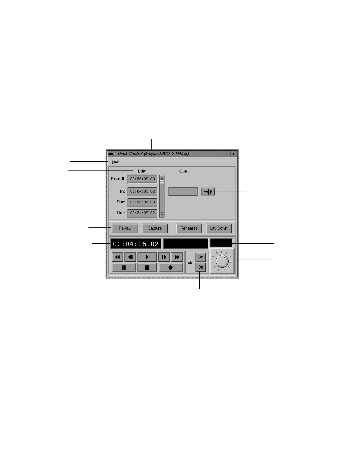
To access the Deck Control window, choose View > Deck Control Panel from the menu
bar of the Media Control Panel. The Deck Control window, shown in Figure 3-5, appears
in a separate window.
Figure 3-5 Deck Control Window
This window is the same regardless of whether you are using V-LAN transmitters or VST
software to control the remote video decks.
(Host: Port: Units)
Function buttons
Shuttle dial
Edit status
Deck control buttons
Edit point
Cue point and cue button
End-to-end
Menu bar
Current frame and function

Playing and Recording Clips
39
About the Deck Control Window
The File pulldown menu in the menu bar of the Deck Control window gives you access
to the following options:
• Close, to close the Deck Control window
• Exit, to close both the Deck Control window and the Media Control Panel from
which it was launched.
The following describes each of the displays and buttons in the Deck Control window:
• The edit points let you set the amount of time to preroll, the in-point, the duration,
and the out-point. Each of these can be specified in the following format:
hh:mm:ss:ff
where hh is the hours, mm is the minutes, ss is the seconds, and ff is the frame
number. In drop-frame mode, the final colon is replaced by a period:
hh:mm:ss.ff
See “Changing Cue Points and Edit Points” on page 36 for information about how
to change the edit points.
• The cue point is the location at which you want to position the deck. The cue point
can be specified in the following format:
hh:mm:ss:ff
where hh is the hours, mm is the minutes, ss is the seconds, and ff is the frame
number. In drop-frame mode, the final colon is replaced by a period:
hh:mm:ss.ff
• The cue button (—>|>) tells VST to search the deck to the cue point and park it
there.

40
Chapter 3: Using the Video Server Toolkit GUIs
• You can use the following deck control function buttons:
–Review, to review the specified edit. The deck plays the selected portion of the
tape, but VST does not record it.
–Capture, to perform a frame-accurate recording from the selected portion of a
loaded and cued source tape to the VST clip currently loaded. For more
information about recording, see “Recording From the Deck to a Clip” on
page 42.
–Rehearse, to review the specified edit. VST plays the selected portion of the clip,
but the deck does not record it.
–Lay Down, to perform a frame-accurate recording from the selected portion of
the clip on the VST video server to the source VTR. For more information, see
“Recording From a Clip to the Deck” on page 43.
• The current frame display is initialized to the cue in-point each time the clip is cued.
As the clip is played or recorded, the display changes to indicate the current frame
number.
• The function display shows the current function.
• The edit status display shows the status when performing an automated edit (that
is, a capture, review, lay-down, or rehearse). The status may be one of the following:
– CUE, when searching for the cue point
– SYNC, when doing a preroll
– LOCK, when the deck transport is locked
– EDIT, when the edit is in progress
– DONE, when the edit is complete

Playing and Recording Clips
41
• The deck control buttons, which control playout and recording, correspond to
standard VTR buttons. The following describes these buttons:
– Fast-reverse (<<) moves the deck in reverse at a fast speed.
– Jog backward (<|) jogs the deck backward by one frame. Each time you click
the jog backward button, the deck jogs back one frame.
If the deck is playing when you click this button, the deck jogs backward one
frame and then pauses. You have to click either the play button or the pause
button to resume play.
– Forward play (>) moves the deck in the forward direction. If the deck is not
cued, it is cued before it begins playout.
– Jog forward (|>) jogs the deck forward by one frame. Each time you click the
jog forward button, the deck advances one frame.
If the deck is playing when you click this button, the deck jogs forward one
frame and then pauses. You have to click either the play button or the pause
button to resume play.
– Fast-forward (>>) plays the deck forward at a fast speed.
– Pause (||) temporarily stops the deck from playing or recording. You have to
click the play, record, or pause button to resume.
– Stop (■) stops the deck and de-cues it. After the deck has been stopped, you
must re-cue it to play it again.
– Record (•) begins recording.
• The EE On and Off buttons turn the deck’s end-to-end mode on and off,
respectively. If you click the On button, the output displays the input signal instead
of the signal from the deck. If you click the Off button, the output displays the signal
from the deck.
• The shuttle dial lets you control the speed of the deck. To use the shuttle dial, use
the mouse to point to the black notch on the dial. Press the left mouse button and
keep it pressed while you turn the dial clockwise to increase the speed or
counterclockwise to decrease it.
Note: The straight up position of the dial is zero, or pause.

42
Chapter 3: Using the Video Server Toolkit GUIs
Recording From the Deck to a Clip
Before using VST to capture video from a deck you must:
• Connect the output of the deck to the input of the video card on the VST server.
• Connect the audio output of the deck to an audio transformer and connect the
audio transformer to the audio inputs of the VST server.
The audio transformer must convert the audio signal from the deck’s 600-ohm, balanced
output to the high impedance, unbalanced audio input of the VST server.
To record from the deck to a clip, follow these steps:
1. Use the Media Control Panel to do the following:
■Create a new clip. (See “Creating a New Clip” on page 35 for information about
how to create a new clip.)
■Change the cue in-point, if needed.
Note: The cue in-point in the Media Control Panel is the point in the clip to
which you want the material captured.
■If the Deck Control window is not displayed, choose
View > Deck Control Panel in the menu bar of the Media Control Panel.
2. Use the Deck Control window to do the following:
■Review the clip’s edit points and change them if needed.
Note: The edit points in the Deck Control window identify the portion of the
tape that you wish to capture and the duration of the capture.
■To see what would be recorded without actually recording into the clip, click
the Review button.
■To record the clip from the deck, click the Capture button.

Playing and Recording Clips
43
Recording From a Clip to the Deck
Before using VST to lay back video to a deck you must:
• Connect the input of the deck to the output of the video card on the VST server.
• Connect the audio input of the deck to an audio transformer and connect the audio
transformer to the audio outputs of the VST server.
The audio transformer must convert the audio signal from the high impedance,
unbalanced audio output of the VST server to the deck’s 600-ohm, balanced input.
To record from a clip to the deck, follow these steps:
1. Use the Media Control Panel to do the following:
■Load the clip from which you want to record.
■Change the cue in-point, if needed.
Note: The cue in-point in the Media Control Panel is the point in the clip from
which you want to record.
■If the Deck Control window is not displayed, choose
View > Deck Control Panel in the menu bar of the Media Control Panel.
2. Use the Deck Control window to do the following:
■Review the edit points and change them if needed.
Note: The edit points in the Deck Control window identify the portion of the
tape to which you want to record and the duration of the recording.
■To see what would be recorded without actually recording onto the tape, click
the Rehearse button.
■To record from the clip to the deck, click the Lay Down button.

44
Chapter 3: Using the Video Server Toolkit GUIs
Monitoring the Status of Video Server Toolkit (mcstat)
There are two ways to start the Unit Status Monitor. The quickest way is to choose
Utilities > Status Monitor from the Media Control Panel menu bar.
Starting the Unit Status Monitor from the Command Line
To monitor the status of VST, enter the following, either from the workstation on the VST
server or from a workstation on which the VST tools software1 has been installed:
%/usr/vtr/bin/mcstat [-v loglevel][hostname]
where
•loglevel sets the severity level of the messages that are written on STDOUT.
Note: The mcstat program writes its log messages to the window from which it is
invoked.
If this option is omitted, all messages with a severity level of Info and above are
written on STDOUT. If this option is present, loglevel, which can be a positive or
negative number, identifies the minimum level of the messages that are written to
the log. (See Table 3-2 on page 22 for the definition of the log severity levels.)
•hostname is the name of the host on which VST is running. If this parameter is
omitted, it is assumed that VST is running on the same host as the one from which
the program is invoked.
1To run the Unit Status Monitor from a remote workstation, the vcp_recorder_eoe.sw32.tools subsystem
must be installed on a workstation that has IRIX 6.2 or later. See the Video Server Toolkit Installation and
Administration Guide for more information.
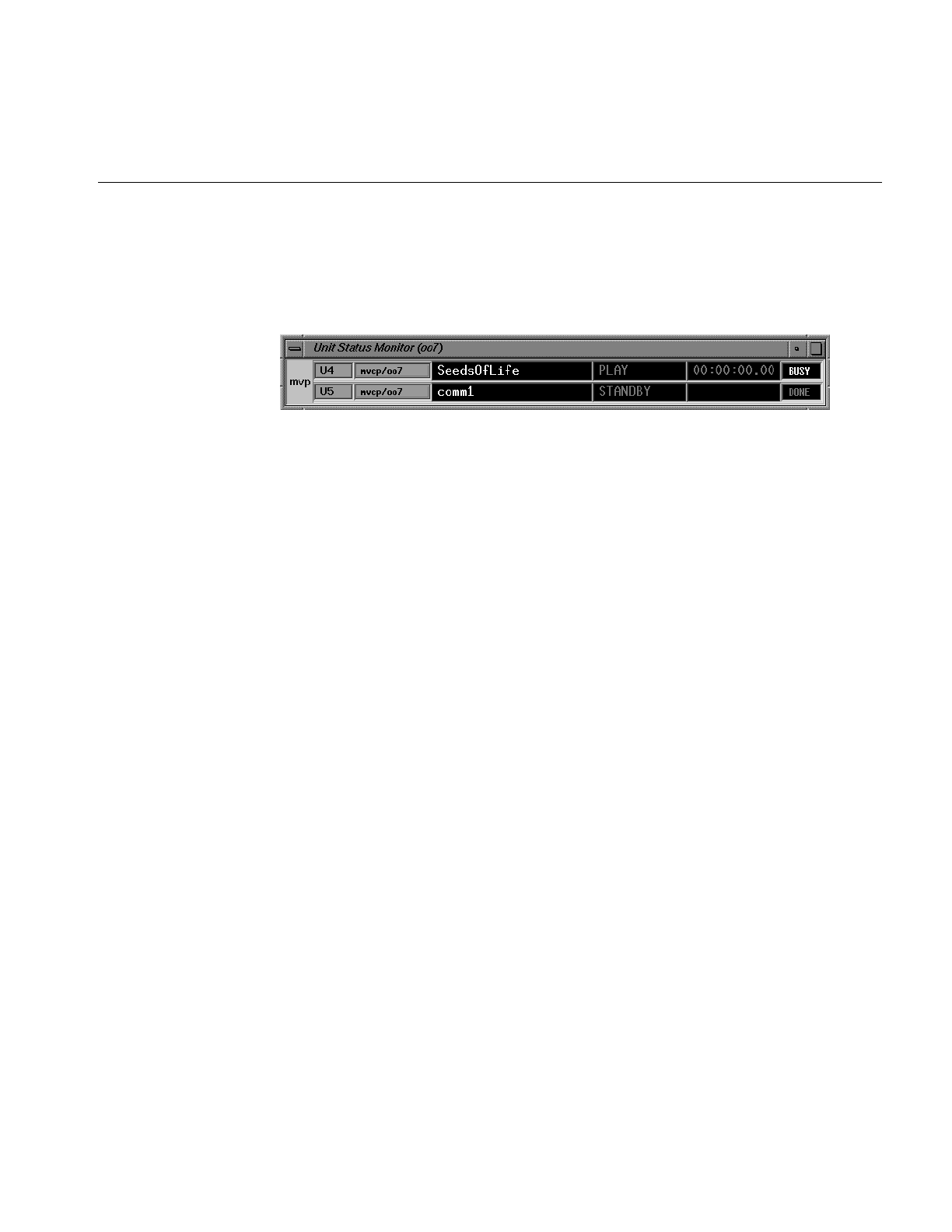
Monitoring the Status of Video Server Toolkit (mcstat)
45
The Video Server Toolkit Unit Status Monitor appears in a separate window, which is
shown in Figure 3-6. This monitor identifies each port,unit, type of connection and host,
clip name (if one is loaded), current function and frame, and the status of unit. (See
“About the Media Control Panel” on page 26 for more information.)
Figure 3-6 Unit Status Monitor
See “About the Media Control Panel” on page 26 and “About the Deck Control Window”
on page 39 for a description of the status information that is displayed by the Unit Status
Monitor.


47
Chapter 4
4. Adding and Removing Clips
Clips are segments of audio and video. Managing clips involves adding and removing
them from Video Server Toolkit (VST).
Managing clips is discussed in the following sections:
• “VST Media Formats and Types” on page 48
• “Adding Clips” on page 50
• “Removing Clips” on page 54
• “Exporting VST Clips” on page 55
Overview of Adding Clips Procedure
This section provides a procedural overview of the tasks involved in adding clips to
VST’s cache.
The following sections explain the steps in the following procedure in greater detail.
To add clips to the cache, use the following procedure.
1. Copy media to the VST machine.
If you are not using a real-time filesystem, use FTP put or get commands.
If you are using a real-time filesystem (recommended), you can either use the vtrutil
tool included with VST, or a modified form of FTP, vtrftpd, installable from the VST
image. You use the familiar FTP command, get, with vtrftpd to add files to VST.
For more information, see “Adding Clips” on page 50.

48
Chapter 4: Adding and Removing Clips
2. Align the clips.
If you used FTP or vtrftpd to add clips to VST, you must align them. For more
information, see “Clip Alignment” on page 52.
Clips added to VST using the vtrutil tool are already aligned.
3. Register the clip with VST.
Clips are registered automatically upon startup of VST.
If you want notify VST more quickly, or if you have added clips to the system in a
different way from those listed in step 1, use one of the following options:
• Install the fsmon daemon from the VST image. It periodically updates the list of
clips in the cache.
At times, however, fsmon cannot auto detect a clip because of an unrecognized
file extension. In that case, you must use one of the following options to notify
VST.
• Use the mvcp command, CADD.
• Use the vtrclip tool.
For more information see, “Notifying VST” on page 54.
VST Media Formats and Types
VST can use two different formats and two types of media.
Media Types
VST also accepts two types of media:
• Intraframe
In intraframe media, the video data for each frame is self-contained and does not
depend on the data from neighboring frames. This frame format has a fixed size.
Examples of intraframe media include JPEG, Rice, and uncompressed video.

VST Media Formats and Types
49
• Interframe
In interframe media, the compression techniques used for some video frames may
require data from neighboring frames in order to decompress the video frame. An
example of interframe media is MPEG1 and MPEG2.
Media Format
VST uses different formats for storing digital media in its clip cache filesystem(s):
• Intraframe media
– vframe format—for Rice and JPEG
– frame—for DIF and uncompressed
• Interframe media
– stream format - for MPEG2
vframe Format
The vframe (short for variable-size frame) format is specific to VST. The video and audio
data for each frame is stored contiguously in the media file. A separate index file contains
header information that describes the encoding parameters of the video and audio data,
and a frame map that stores the offsets of the video and audio data for each frame within
the media file.
The vframe format is used for recording and playback of intraframe media, including
uncompressed video as well as Rice-coded and JPEG-compressed video.
Thevtrvfutil command-line utility provides various analysis and update functions for the
vframe format. See the vtrvfutil man page for further information.
Frame Format
DIF is the 4:1 video compression frame format used by Panasonic’s DVCPRO.

50
Chapter 4: Adding and Removing Clips
Stream Format
The stream format consists of a media file, which is simply the native media bitstream,
and an index file, which maps random access cueing points to the appropriate offset in
the bitstream.
The stream format is used for playback of MPEG2 media.
The vtrmpegutil command line utility provides various analogies and update functions
for MPEG2 stream format assets. See the vtrmpegutil man page for more information.
Adding Clips
Adding clips has been partially automated. For all clip formats:
1. Transfer the clip into the filesystem, /usr/vtr/clips.
2. For Rice-formatted clips, transfer the index file for the clip into /usr/vtr/index.
3. Tell VST it is there.
VST detects the clips when the clip is first loaded and every time VST starts. The clips are
then listed in mcclips.
Adding Clips to VST
There are two types of files systems:
• Non-real-time
• Real-time
To guarantee real-time I/O rates, you must use a real-time filesystem.
Non-Real-Time Filesystems
Transferring files to a non-real-time filesystem is as easy as using ftp,cp, or rcplocally. You
can also use ftpd from a remote site.

Adding Clips
51
Real-Time Filesystems
To transfer clips to a real-time filesystem, use the customized version of ftpd (server)
called vtrftpd. It is in subsystem vcp_recorder_eoe.sw.ftpd. Only this version of FTP can
write to real-time filesystems locally.
The feature enhancement in vtrftpd is used when you:
• Use FTP (client) on a system connected to VST server.
• Use FTP (client) proxy on the VST server.
Both of these methods set up a TCP/IP connection with the vtrftpd server running on the
VST system.
To write to the filesystem, use of the following methods:
• On the remote archive server, use FTP’s put command to copy a clip to the clip cache
of VST from a remote host.
• On the machine running VST, use a proxy (secondary control) connection, vtrftpd, as
follows to copy a clip from the remote archive system to the local clip cache of VST:
ftp source-system
ftp> cd source-directory
ftp> proxy open localhost
ftp> proxy get filename /usr/vtr/clips/filename
ftp> cd index
ftp> proxy get indexname /usr/vtr/index/indexname
ftp> proxy bye
ftp> bye
localhost is the VST machine.
vtrftpd is not used when you only use ftp (client) on the VST server because the ftpd
server on another system would not be the enhanced version. To copy a clip from the
archive server to VST on the machine running VST, login to the archive system, run ftp,
and use the put command.

52
Chapter 4: Adding and Removing Clips
Clip Alignment
In single-disk systems, media files are aligned only with the filesystem’s block size so
that only one I/O operation is needed to access the data.
In multi-disk, RAID, striped systems, the media files must also be aligned with the
stripes.
When VST is used to record media, it automatically places the media data in the correct,
aligned locations on the disk.
When media data is transferred to VST, it often must be aligned with the disk’s blocks
and stripes. Whether or not media data must be aligned on your disks depends on the
media type of the media file:
• Intraframe media data requires alignment.
• Interframe media data does not require alignment.
The media data (video and audio for each frame) for an intraframe media clip must be
aligned on natural filesystem and disk drive boundaries to enable efficient read and
write access to the clip.
Degree of Alignment
Frame-oriented media data in an intraframe clip is aligned along two boundaries:
• Minor alignment boundary
• Major alignment boundary
A single element of a frame (a video field or audio chunk) never crosses a minor or major
alignment boundary. VST will not do a read or write operation to the clip media file
which crosses a major alignment boundary.
Minor Alignment
The minor alignment matches the greater of the filesystem block size, or the system
memory page size. On O2 workstations, the minor alignment is usually 4 KB, unless a
larger filesystem block size was used to construct an XFS filesystem. On Origin, the
minor alignment is usually 16 KB, unless a larger filesystem block size was used.

Adding Clips
53
Major Alignment
The major alignment matches the stripe size of the disk volume that holds the clip cache
filesystem.
If the clip cache resides on a single disk, no major alignment is required.
If the clip cache resides on a single RAID subsystem, major alignment is required for
efficient I/O access to the media data. Either make a real-time filesystem on the RAID
and set the real-time extent size of the XFS filesystem to the desired I/O operation size,
or add a configuration line to /usr/vtr/config/vtrfsinfo.conf. For example:
#/dev/root 2m
Note: vtrfsinfo.conf is not created by VST so you first must create the file.
If the clip cache resides on a striped XLV volume, the major alignment matches the stripe
size of the XLV volume.
Realigning a vframe Clip
A vframe clip is automatically aligned if you use vtrvfutil to copy the clip, as follows:
% vtrvfutil OriginalClipName NewClipName
vtrufutil automatically stores the media files in /usr/vtr/clips/.
To copy a vframe clip from outside the clip cache, use the following syntax:
% vtrvfutil -i file=MediaFile,index=IndexFile - NewClipName
vtrvfutil can also be used to realign a clip in-place, as follows:
% vtrvfutil -c realign ClipName
See the vtrufutil man page for a complete list of the options.

54
Chapter 4: Adding and Removing Clips
Notifying VST
If you place a clip in the clip filesystem, the first time you attempt to access the clip
through VST, it attempts to auto-detect the clip’s format and add it to the VST clip list.
However, until you attempt to access the clip, it will not be visible in a list of clips you
obtain from VST. To see the clip immediately, use the following command:
# vtrclip add clipName
Note: There might be a delay because adding clips always has a lower priority then
playout/record.
You can also use the following mvcp command to notify VST of an added clip.
CADD clipName
However, if you install the vcp_recorder_eoe.sw_fsmon subsystem, the VST filesystem
Monitor will monitor the clip filesystem for clips that are added or deleted and
automatically update the internal VST clip list. Sometimes, FSmon cannot autodetect
clips added to VST when the clips require the use of an index file, for example, for MPEG
and Rice-encoded clips. In this case, you must use the vtrclip add command to add the
index file and notify VST.
Removing Clips
There are two ways of removing clips from VST.
• VST Clip Manager (mcclips)
For more information about using the VST Control panel to remove a clip, see the
VST Developer’s Guide.
• Command line
You can completely remove a clip from VST using the following command:
# vtrclip rm clipName
clipName is the name of the clip file.

Exporting VST Clips
55
Exporting VST Clips
vtrvfutil makes the clip readable by Silicon Graphics digital media tools, such as dminfo,
dmconvert, and mediaplayer, or third-party tools that use the Silicon Graphics Movie
Library.
You can use the vtrvfutil command to add Quicktime formatting information to a clip:
# vtrvfutil -c makeqt clipName
clipName is the name of the clip file.
Note: Clip files are not necessarily usable by other tools.


57
Chapter 5
5. Using Clip Manager
This chapter describes how to use the Clip Manager graphical user interface (GUI) to
manage Video Server Toolkit (VST) clips. Clip Manager is a sample GUI application that
you can customize.
The following topics are discussed:
• “Starting the Clip Manager” on page 57
• “Clip Manager Menus” on page 59
• “Obtaining Information About a Clip” on page 61
• “Renaming a Clip” on page 62
• “Deleting a Clip” on page 63
• “Setting the Protections for a Clip” on page 64
For more information about archiving clips, see Chapter 6, “Archiving Clips.”
Starting the Clip Manager
To start the Clip Manager, enter the following, either from the workstation on the VST
server or from a workstation on which the VST tools software1 has been installed:
%/usr/vtr/bin/mcclips [-v loglevel][hostname]
where
•loglevel sets the severity level of the messages that are written on STDOUT.
1To run the Clip Manager from a remote workstation, the vcp_recorder_eoe.sw32.tools subsystem must
be installed on a workstation that has IRIX 6.2 or later. See the Video Server Toolkit Installation and
Administration Guide for more information.

58
Chapter 5: Using Clip Manager
Table 5-1 shows the log severity levels and codes, which are listed in decreasing
order of severity
Note: The mcclips program writes its log messages to the window from which it is
invoked.
If the -v option is omitted, all messages with a severity level of Info and above are
written to the log. If this option is present, loglevel, which can be a positive or
negative number, identifies the minimum level of the messages that are written to
the log.
•hostname is the name of the host on which VST is running. If this parameter is
omitted, it is assumed that VST is running on the same host as the one from which
the program is invoked.
Table 5-1 Log Severity Levels
Priority Log
Level Description
Emergency -6 Panic condition
Alert -5 Condition that should be corrected immediately, such as a corrupted
system file
Critical -4 Critical condition that has system-wide impact, such as a hard
device error; immediate action required
Error -3 Problem that needs correcting but does not require immediate
action
Warning -2 Possible problem but could be a transient problem that corrects itself
Notice -1 Condition that might require attention, but is not an error condition
Info 0 Informational message
Debugnn Informational message that normally is of use to engineers for
debugging; may be Debug1, Debug2, or Debug3, with Debug3
producing the most debugging information
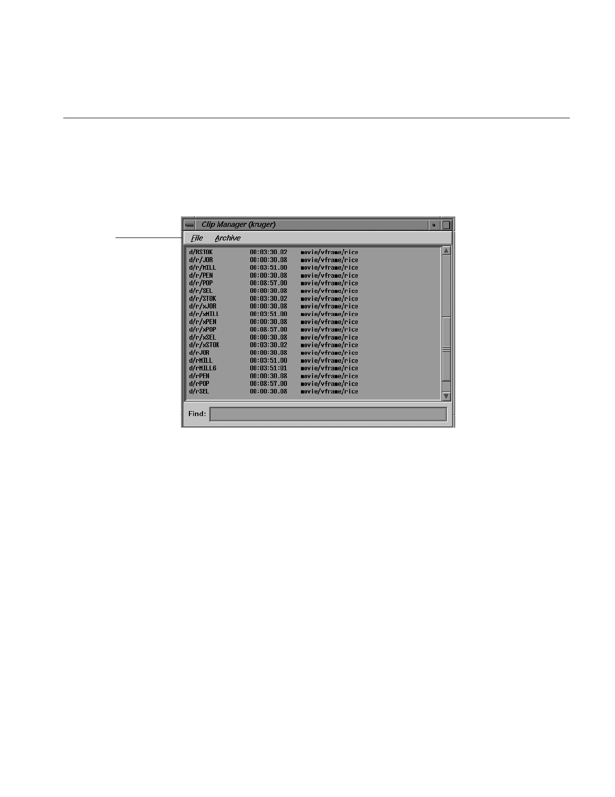
Clip Manager Menus
59
The VST Clip Manager is displayed in a separate window, which is shown in Figure 5-1.
The window shows the clips that are in VST. For each clip, it shows the name, the
duration, and the format. (If the duration contains an “*” it means that no material has
been recorded in the clip.)
Figure 5-1 Clip Manager Window
Note: You can also start the Clip Manager by choosing Utilities > Clip Manager in the
VST Media Control Panel menu bar.
Clip Manager Menus
The File pulldown menu in the menu bar of the Clip Manager window provides the
following options:
• Info, to obtain information about a clip
• Rename, to rename a clip
• Delete, to delete a clip
• Protect, to set the protection levels for a clip
Menu bar

60
Chapter 5: Using Clip Manager
• Close, to close the Clip Manager window
• Exit, to close the Clip Manager window and exit the program
• Load, to load a clip into a unit controlled by Sony protocols
Except for the Close and Exit options, you must select a clip before requesting one of the
options. You can select the clip by pointing to it with the mouse cursor and pressing the
left mouse button.
You can also use the Find field to select a clip by entering any number of characters that
match the values in either the name, the duration, or the format. For example, if you enter
“xxx” in the Find field, the Clip Manager highlights the first clip it finds that contains
“xxx.” If you add “y” to the Find field, it searches for a clip that contains “xxxy,” starting
with the current clip.
Regardless of the method for selecting a clip, the selected clip becomes highlighted.
Note: You can access the clip-related functions in the File pulldown menu by selecting a
clip and then pressing the right mouse button. You can also access the Info option by
double-clicking the clip in the Clip Manager window.
The Archive pulldown menu in the menu bar provides the following options:
• Find, to get information about a clip in the StudioCentral 2.0 archive system
• Get New, to bring a new clip from the StudioCentral 2.0 archive system into VST
• Get, update an existing clip from the StudioCentral 2.0 archive system
• Put, to write a clip to the StudioCentral 2.0 archive system
Note: You can access the functions in this option menu by pressing the right mouse
button and then selecting the Archive option in the pop up menu.

Obtaining Information About a Clip
61
Obtaining Information About a Clip
To obtain information about a clip, follow these steps:
1. Select the clip in the Clip Manager window.
2. Choose File > Info from the menu bar. The clip information window, as shown in
Figure 5-2, appears.
Figure 5-2 The Clip Information Window
This window shows the in- and out-points of the clip, the edit points, the size of the
clip, and the protection. An asterisk (*) indicates that the value is not set. For
example, Figure 5-2 indicates that the edit points are not set.
The remaining sections in this chapter describe in detail the use of the buttons in
this window.
3. To refresh the information in this window, click the Refresh button.

62
Chapter 5: Using Clip Manager
Renaming a Clip
To rename a clip, follow these steps:
1. Do one of the following:
■Select the clip in the Clip Manager window and then choose File > Rename
from the menu bar.
■If the clip information window for the clip is displayed, click the Rename...
button in the information window.
The Rename Clip window, as shown in Figure 5-3, appears.
Figure 5-3 Rename Clip Window
2. Enter the new name of the clip.
3. Click the Rename button.

Deleting a Clip
63
Deleting a Clip
To delete a clip, follow these steps:
1. Do one of the following:
■Select the clip in the Clip Manager window and then choose File > Delete from
the menu bar.
■If the clip information window for the clip is displayed, click the Delete button
in the information window.
The Delete Clip window, as shown in Figure 5-4, appears.
Figure 5-4 Delete Clip Window
2. Click the Delete button to delete the clip.
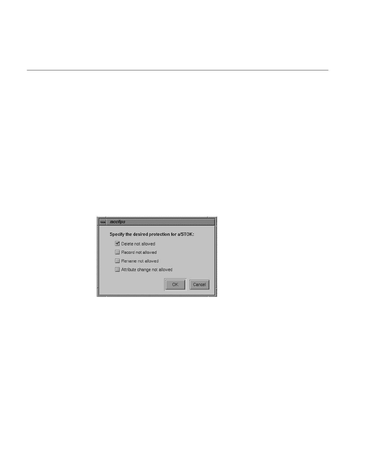
64
Chapter 5: Using Clip Manager
Setting the Protections for a Clip
By default, a clip can be deleted, recorded into, and renamed, and its edit point attributes
can be changed. Therefore, if you want a clip to be protected from any of these changes,
you must set the protections for that clip. This would be especially useful when multiple
applications and/or automation controllers are using the VST.
To set the protections for a clip, follow these steps:
1. Do one of the following:
• Select the clip in the Clip Manager window and then choose File > Protect from
the menu bar.
• If the clip information window for the clip is displayed, click the Protect...
button in the information window.
The Set Protections window, as shown in Figure 5-5, appears.
Figure 5-5 Set Protections Window
This window identifies the protections that can be set. Each protection is preceded
by a check box. If there’s a red check in the check box, the corresponding protection
is selected. If there is no red check, the corresponding protection is not selected.
Note: The default is that a clip has no protections set. Therefore, you must set
protections if you want the clip to have any.

Setting the Protections for a Clip
65
2. Click the appropriate check boxes to indicate the protections that you want for this
clip.
Note: Each check box acts like a toggle switch. Click the check box once to select that
protection. Click the check box a second time to deselect it.
3. Click the OK button to have the protections take effect.

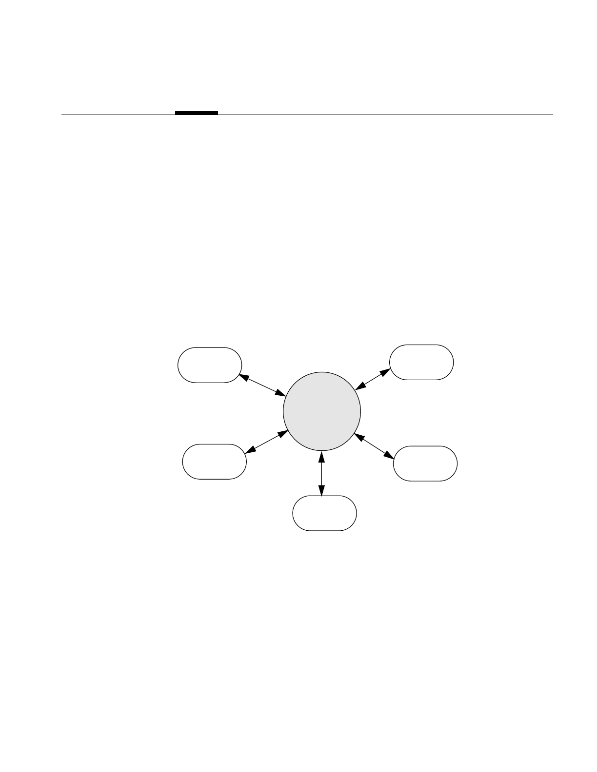
67
Chapter 6
6. Archiving Clips
Asset management involves archiving, retrieving, deleting, and obtaining media clips
and the associated meta data that describes them. Because the Video Server Toolkit (VST)
cache is limited in size, saving media files out to and retrieving files from an archival
server is a common practice.
An archive system is a storehouse for information. It often serves multiple applications,
such as asset creation, broadcasting, and compositing applications, as shown in
Figure 6-1. VST is designed to work with one or more archive systems of the same type.
Figure 6-1 Archive System
Archive
Application 1
Application 2
Application 3
Application 4
VST

68
Chapter 6: Archiving Clips
VST works in conjunction with StudioCentral 2.0 (SC 2.0) to archive media and
associated meta data. VST provides a set of asset management commands to interact
with the archive.
For a more complete set of asset management tools, use the tools provided by the archive
system. For more information about StudioCentral asset management tools, see the
StudioCentral documentation.
This following sections describe the configuration of the archive system and the asset
management tools you use with VST to interact with that system:
• “Overview of the Archival System” on page 68
• “About StudioCentral” on page 70
• “Using VST With the StudioCentral 2.0 Archive System” on page 71
Overview of the Archival System
VST archives:
• Media clips
• Meta data, which contains descriptive information about the media clips
Meta Data
Meta data contains information descriptive of the media clips associated with them.
Information about the media clips includes such things as:
• Name
• Format
• Size
• Start time
• Duration
You use asset management tools to store and retrieve meta data. You might like to know,
for example, the run time of a specific media file, or you might like to list the names of
the media clips in the archive.

Overview of the Archival System
69
Archive and VST Configuration
The elements in the archive system are:
• VST server
• Archive system
• Content server
All of these services can run on the same machine, however, it is recommended to keep
the archive on separate, networked machines.
Chain of Communication
The chain of communication when retrieving clips from the archive:
1. VST asks an archive system to access a media asset.
2. The archive system contacts the correct content server.
3. If the content server is different from the machine running VST, the media is copied
to the machine running VST.
If the content server is running on the machine running VST, a link to the requested
media is created.
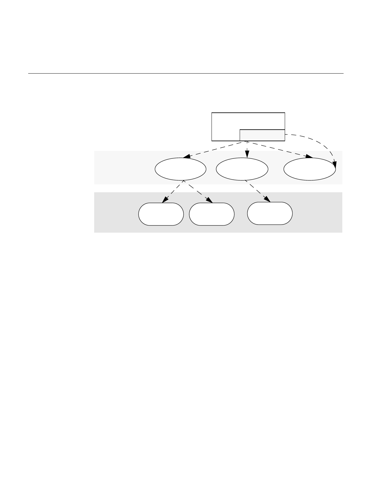
70
Chapter 6: Archiving Clips
Figure 6-2 shows this communication path.
Figure 6-2 Archive Configuration
Figure 6-2 shows that VST can work with multiple archives. The servers that contain
media content are usually not on the same system as the one running VST; but not
necessarily, as shown by Archive Server 3.
About StudioCentral
VST can work with many archives. The archive system developed by Silicon Graphics
and supported by VST is StudioCentral, version 2.0 or later.
StudioCentral Digital Asset Management System (StudioCentral) is a library of C++
foundation classes that enables you to build multimedia-based applications with digital
asset management capabilities.
For more information about StudioCentral, see the StudioCentral Developer’s Guide (part
number 007-3246-nnn).
VST
Archive system Archive machine 1 Archive machine 2 Archive machine 3
Content server 1 Content server 2
Content servers
Content server 3
Content server 4
ATS service

Using VST With the StudioCentral 2.0 Archive System
71
Using VST With the StudioCentral 2.0 Archive System
Before VST can successfully perform any archiving operation, the following guidelines
must be met:
• The Informix or Oracle database server should be installed.
• The proper StudioCentral 2.0 images should be installed.
• All the CAS datamodels should be installed.
• The Informix or Oracle database server should be up and running.
Ideally the database server should automatically start up at boot time.
• StudioCentral should be properly configured.
• At least one StudioCentral content server should be up and running.
Ideally the content server should automatically start up at boot time.
•inetd should be configured to accept connection on behalf of the StudioCentral ATS
service.
Archiving Tasks
When VST is configured to use a StudioCentral 2.0 archive system, you can use the VST
GUI (mcclips) to:
• Locate clips. See “Locating a Clip in the StudioCentral 2.0 Archive System” on
page 73
• Bring a clip into VST from the archive. See “Bringing In a New Clip From the
Archive System” on page 74
• Update a VST clip by getting its content from the StudioCentral 2.0 archive system.
See “Updating a Clip” on page 75
• Store a VST clip in the archive. See “Using the Put Clip to Archive Window” on
page 76

72
Chapter 6: Archiving Clips
The remainder of this section shows how to use the VST GUI, mcpanel, to accomplish
these tasks. However, you can also use the MVCP commands, explained in Table 6-1, to
perform these tasks and others.
To learn more about using MVCP commands, see Appendix A.
Note: Only version 2.0 (or greater) of StudioCentral works with VST. Archival tasks
require this application to be running.
Table 6-1 Archive-Related MVCP Commands
Command Description
AFND Locate a clip by name in an available StudioCentral 2.0 archive system.
AFNG Locate a pending or in-progress get-from-archive command for a clip.
AGET Retrieve a clip from a StudioCentral 2.0 archive system.
ALSG List the get-from-archive operations that are waiting or being processed.
ALSP List the put-to-archive operations that are waiting or being processed.
APUT Saves a clip to the archive system.

Using VST With the StudioCentral 2.0 Archive System
73
Locating a Clip in the StudioCentral 2.0 Archive System
To display a list of media assets on StudioCentral, you must log into StudioCentral and
use its tools.
To locate a clip in a StudioCentral 2.0 archive system, follow these steps:
1. Choose Archive > Find from the menu bar in mcpanel or from mcclips. The Find
Clip in Archive window, as shown in Figure 6-3, appears.
Figure 6-3 Find Clip in Archive Window
2. Enter the clip’s name, which corresponds to the value of the archived asset’s ClipId
attribute.
3. Click the Find button.
To determine whether the clip was found, see if it appears in the VST log.
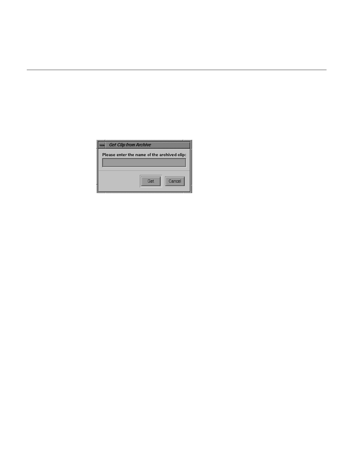
74
Chapter 6: Archiving Clips
Bringing In a New Clip From the Archive System
To bring in a new clip from the archive system, follow these steps:
1. Choose Archive > Get New from the menu bar. The Get Clip from Archive window,
as shown in Figure 6-4, appears.
Figure 6-4 Get Clip from Archive Window: Getting a New Clip
2. Enter the clip’s name, which is the value of the archived asset’s ClipId attribute.
3. Click the Get button.
A Get command can fail when there is no port available on the archive system that
supports the required format.
Note: If the clip exists in more than one archive system, the clip is brought in from the
first archive system in which it is found. The clip can be brought in from a specified
archive system using the MVCP command AGET.
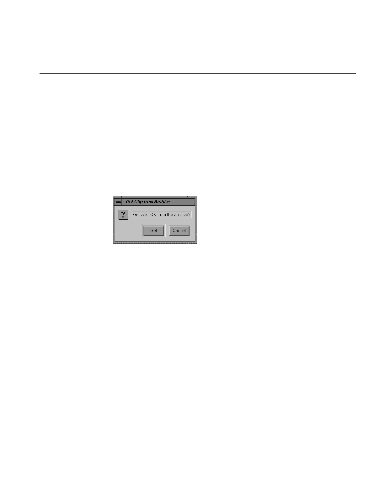
Using VST With the StudioCentral 2.0 Archive System
75
Updating a Clip
To update a clip by bringing in new content from an attached StudioCentral 2.0 archive
system, follow these steps:
1. Do one of the following:
• Select the clip in the Clip Manager window and then choose the Archive > Get
option from the menu bar.
• If the clip information window for the clip is displayed, click the Get Archive
button in the information window.
The Get Clip from Archive window, as shown in Figure 6-5, appears.
Figure 6-5 Get Clip from Archive Window: Updating an Existing Clip
2. Click the Get button to update the clip from the archive.
Note: The clip is updated from the first StudioCentral 2.0 archive system in which the
clip is found. That is, if the clip exists in more than one StudioCentral 2.0 archive system,
it is updated from the first one. The clip can be updated from an archive system other
than the first one by using the MVCP command AGET and specifying the desired archive
system.

76
Chapter 6: Archiving Clips
Using the Put Clip to Archive Window
To write a clip to a the StudioCentral 2.0 archive system, follow these steps:
1. Do one of the following:
• Select the clip in the Clip Manager window and then choose Archive > Put from
the menu bar.
• If the clip information window for the clip is displayed, click the Put Archive
button in the information window.
The Put Clip to Archive window, as shown in Figure 6-6, appears.
Figure 6-6 Put Clip to Archive Window
2. Click the Put button to write the clip to the StudioCentral 2.0 archive system.
For more information about the StudioCentral 2.0 archive system, see the Video
Server Toolkit Installation and Administration Guide.
Note: The clip is written to the first StudioCentral 2.0 archive system. That is, if there is
more than one StudioCentral 2.0 archive system, the clip is written to the first one. The
clip can be put into an StudioCentral 2.0 archive system other than the first one by using
the MVCP command APUT.
Checking Success of Storing Clip
Hardware, network, and StudioCentral failures can contribute to failures in storing clips
in an archive. The failure. however, may not be reported. You might, for example, be able
to AFND a clip on the archive because there is a “ghost” of the clip there, but not AGET
it because the clip is really not there. If you find that you cannot AGET a clip, you know
you need to use the Put Clip to Archive Window (or APUT) again to store the clip.

77
Chapter 7
7. FailSafe Operations
The IRIS FailSafe software uses redundant servers to provide a high-availability system.
The servers run Video Server Toolkit (VST) and communicate using a special serial
connection as well as a private ethernet; they may share clips and index filesystems.
When FailSafe detects a failure on the primary server, IRIS FailSafe transfers the
filesystems and processing functions to the secondary server.
To use FailSafe, make sure the subsystems, vcp_recorder_eoe.sw.fsmon and
vcp_recorder_eoe.sw.failsafe, are installed.
IRIS FailSafe is discussed in detail in the IRIS FailSafe Administrator’s Guide and the IRIS
FailSafe Programmer’s Guide.
Hardware Configuration
IRIS FailSafe is a software product that enables a pair of servers to be used in a redundant
configuration. The servers are configured with the VST software and share the VST
filesystems. The dual-server IRIS FailSafe configuration shown in Figure 7-1 provides
redundancy. If the primary server fails for any reason, the secondary server mounts any
shared filesystems with the clips and their index files. Then, using the local VST, the
second server is ready to play the clips.
In an IRIS FailSafe configuration, the operating system on each server is configured for
the VST. The disks on each server store the operating system and the shared RAIDs store
the clips and index filesystems. The RAID is shared by physically attaching it to an
Emulex LH5000 Digital Fibre hub and by connecting the servers to two other ports in this
hub. The two servers along with the shared RAID(s) form an IRIS FailSafe cluster.
The servers also share a public IP alias or a name users can use to connect to the servers.
If a server fails, the backup server takes over the shared RAIDs as well as this IP alias,
which users still use to connect to the servers. To the user, a failover looks the same as a
server that crashed and got rebooted very quickly.
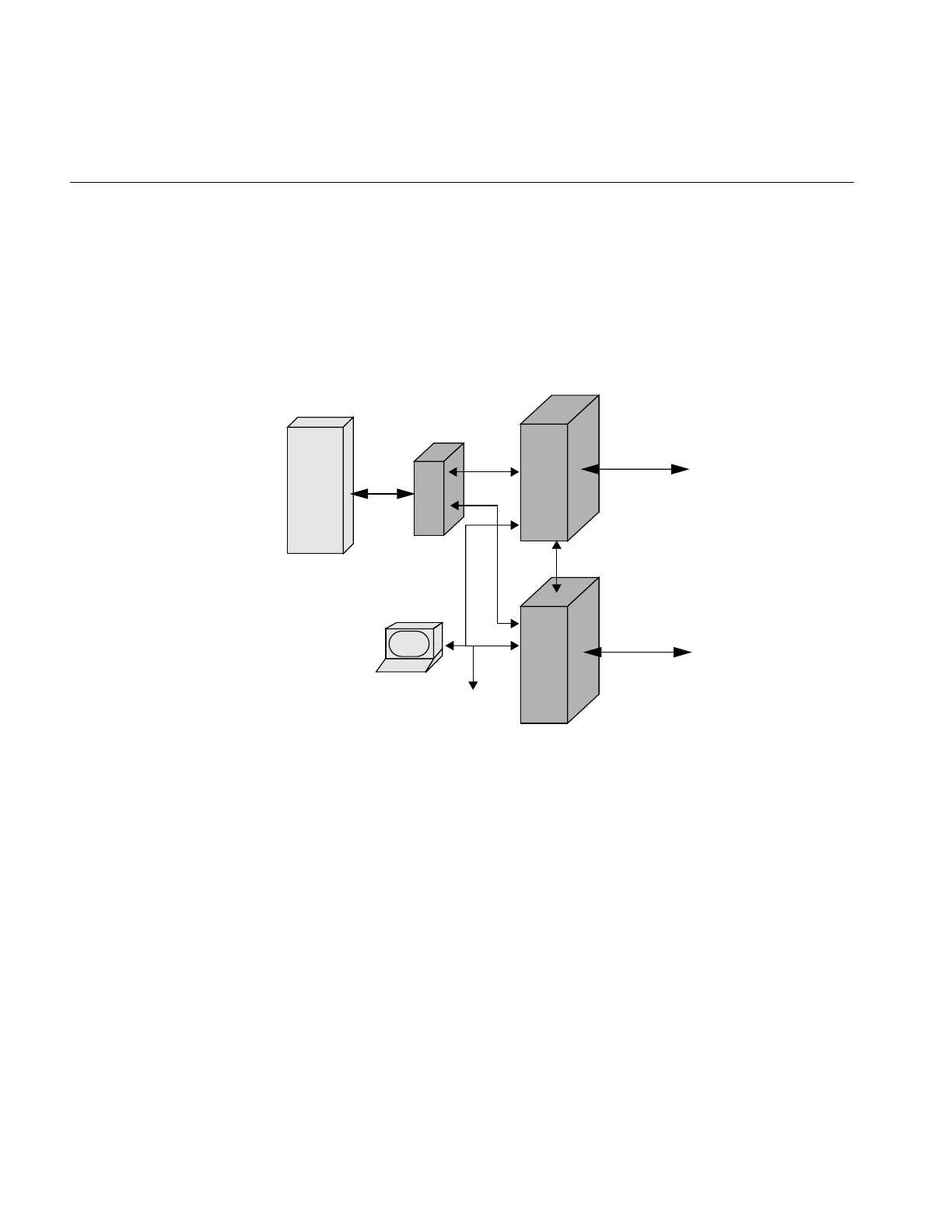
78
Chapter 7: FailSafe Operations
The servers use a special serial connection to communicate. When the backup server
detects a problem with the active server, IRIS FailSafe unmounts the filesystems from the
active server and automounts them on the secondary server. VST on the secondary server
detects this action and adds the clips to its tables so that it is ready to play them.
Figure 7-1 VST IRIS FailSafe Configuration
Shared Resources
The primary and secondary servers can share up to four Ciprico 7000 RAID systems
using an Emulex LH5000 digital Fibre Hub, as shown in Figure 7-1. They also share an
IP alias which always points to the currently-active server.
System Admin
O2
Workstation
Disk
Video
Servers
Octane 200
Storage
Network
Video streams
IRIS FailSafe Monitoring
RAID
Video streams
Hub

Troubleshooting IRIS FailSafe
79
Server Failures
Failures occur if one of the following events are detected on the currently-active server:
• Power failure
• Public network card failure
• Operating system crash
• Unmounting of shared filesystems
When a failure is detected, the secondary server attempts to reboot the primary server
using the serial cable. The secondary server also takes over the shared services, the
shared RAIDS, and the IP alias. VST detects the newly-mounted filesystem using fsmon
and loads the clips.
Troubleshooting IRIS FailSafe
In an IRIS FailSafe configuration, the primary and secondary servers use the states
shown in Table 7-1.
Table 7-1 Primary and Secondary Server States
Event Primary Server Status /
VST Status Secondary Server Status
/ VST Status Owner of
Shared
Services
Normal operation Normal
Running Normal
Running Primary
Power off primary server Cannot be determined
Not running Degraded
Running Secondary
Power on primary server Controlled-failback
Running Degraded
Running Secondary
ha_admin -rf (after power off on
primary server, ha_admin
executes on primary server)
Normal
Running Normal
Running Primary
Power off secondary server
(before execution of ha_admin
-rf)
Degraded
Running Cannot be determined
Not running Primary

80
Chapter 7: FailSafe Operations
Power on secondary server Degraded
Running Controlled-failback
Running Primary
ha_admin -rf (after power off on
secondary server, ha_admin
executes on secondary server)
Normal
Running Normal
Running Primary
Unmount shared filesystem
(Primary) Standby
Running Degraded
Running Secondary
Unmount shared filesystem
(Secondary) Standby
Running Degraded
Running Neither
ha_admin -rf (after unmounting,
ha_admin executes on primary
server)
Normal
Running Normal
Running Primary
Disconnect serial connection Normal
running Normal
Running Primary
ha_admin -m start backup Normal
Running Normal
Running Primary
ha_admin -fs primary (executed
on secondary server) Standby
Running Degraded
Running Secondary
ha_admin -rf primary after
ha_admin -fs primary
completed executing
Normal
Running Normal
Running Primary
Table 7-1 (continued) Primary and Secondary Server States
Event Primary Server Status /
VST Status Secondary Server Status
/ VST Status Owner of
Shared
Services

Troubleshooting IRIS FailSafe
81
Monitoring
The server availability status can be checked using the ha_admin -a command.
The status of the shared filesystem can be checked with the df command from either
server.
The status of the proper aliasing of the servers and the network can be checked using the
netstat -i command.
Use the IRIS FailSafe command-line interface to manage the Video Server Toolkit IRIS
FailSafe system. For details, see the IRIS FailSafe Administrator’s Guide.


83
Chapter 8
8. Completing Common Tasks
Using MVCP Commands
This chapter is a grab bag of common tasks you routinely perform using MVCP
commands. Each task is discussed in a tutorial fashion to introduce you to the way
MVCP works. Once you master the basic tasks presented in this chapter, you can proceed
to the other features offered by MVCP commands.
The tasks presented in this chapter are not sequential, but modular. There is a flow to the
MVCP commands as presented; however, one command does not necessarily build on
the one presented previous to it.
After completing a number of these tasks you will gain a feeling for the MVCP
commands. Appendix A describes all of the MVCP commands.
Note: For a quick reference summary of MVCP commands, see the mvcp man page.
This chapter discusses the following tasks:
• “Manual Access to Video Server Toolkit” on page 84
• “Creating and Deleting a Unit” on page 85
• “Loading and Unloading a Clip” on page 86
• “Finding the Name of a Clip” on page 86
• “Setting Edit Points” on page 86
• “Cueing Decks to Play or Record” on page 87
• “Sequencing Commands” on page 87
• “Playing a Prerecorded Clip” on page 88
• “Playing Clips Back to Back” on page 89
• “Setting Configuration Values” on page 90
• “Listing Configuration Settings” on page 91

84
Chapter 8: Completing Common Tasks Using MVCP Commands
• “Listing Video and Deck Control Ports” on page 92
• “Identifying the Audio Ports to Use” on page 92
• “Configuring Audio Recording” on page 92
• “Configuring Video Recording” on page 93
• “Recording a Clip” on page 93
• “Editing Clips” on page 94
• “Displaying Your Logo” on page 96
• “Monitoring the System” on page 96
• “Unit Errors” on page 100
Manual Access to Video Server Toolkit
Video Server Toolkit (VST) applications routinely open a TCP/IP connection to a host
running VST on the MVCP port, normally 5250. The application sends MVCP commands
to control VST.
The port value is set in the file /usr/vtr/config/control-in.conf. For example, to set the port
to 5250, use the following line in the file:
mvcp tcp 5250
If you do not specify a port number in control-in.conf, the default port number is used,
110, which is the login daemon.
You can, however, manually control VST by opening a telnet connection to a host
running VST and then issuing MVCP commands to control it. For example:
152% telnet sphere 5250
Trying 130.62.156.178...
Connected to sphere.mti.sgi.com.
Escape character is ‘^]’.
100 VTR Ready

Creating and Deleting a Unit
85
Creating and Deleting a Unit
A unit is a virtual VTR. It can play and record video and audio just like a VTR.
Units can be created using the following command:
UADD DIVO_0 * SHAR
The UADD command returns the name of the unit, unitName, for example:
UADD DIVO_0 * SHAR
202 OK
U1
U1, in this case, controls the DIVO_0 video board, which includes both an input video
port and an output video port.
For an explanation of the UADD options, see “UADD *owner* *port* *mode*
*port-physical-name*” on page 116. For more information about deleting a unit, see
“UCLS [ *unit-name* ]” on page 144.
Deleting a Unit
Units can be deleted using the following command:
UCLS unitName
Multiple Connections to a Unit
Once a unit has been created, it can be controlled by a number of MVCP connections by
opening it:
UOPN unitName
When multiple MVCP connections are made to one unit, the unit is not deleted until all
of the connections have deleted it.
Warning: Opening a unit owned by a Sony, Louth, or Odetics port using MVCP
commands (for example, UOPN) causes unpredictable behavior.

86
Chapter 8: Completing Common Tasks Using MVCP Commands
Loading and Unloading a Clip
To load and unload a clip into a unit, use the following commands, respectively:
LOAD unitName clipName OUT
UNLD unitName
unitName is the name of the unit on which the clip is loaded.
The OUT option means that the clip, clipName, can only be played, not recorded onto.
Other valid values include IN, which means the clip will be recorded onto, and BOTH,
which means the clip can be played or recorded onto.
If multiple units have loaded the same clip, the clip is not unloaded until all the units
have unloaded it.
Finding the Name of a Clip
If you do not know the name of a clip, you can list all of the clips by issuing the clip list
command:
CLS
Setting Edit Points
The IN and OUT edit points specify where the source video is to begin and end playing,
and where the beginning and ending recording points are on the record deck, usually
VST.
When a clip is played, by default the edit IN point is used as the starting point for PLAY.
To set edit points, use the CEDP command:
CEDP clipName inPoint outPoint

Cueing Decks to Play or Record
87
Cueing Decks to Play or Record
You can play and record on units without cueing them. There is, however, a good chance
that the beginning of the playing or recording will not be clean: the frame count might be
off by several frames or the audio might be garbled.
You can avoid these problems by cueing the units for playing or recording.
To cue a clip for playback, enter:
CUE unitName
To ca clip for recording, enter:
CUER unitName
Optional Arguments
The following optional CUE and CUER arguments specify the segment of media to play,
the direction of play, and how many times the segment is played:
CUE <in-point> <out-point> <direction> <number-of-passes>
Sequencing Commands
You can sequence more than one command to execute on a unit by using the
append-sequential specification:
/APP /SEQ command unitName
This command specifies that the command, command, is appended to the current list of
commands queued for the unit, unitName, and the command will be executed after the
previous command in the list completes. The alternative is to preempt the previous
command on the list using the flag, IMM.

88
Chapter 8: Completing Common Tasks Using MVCP Commands
You can also:
• Prepend a command in the list of commands by using /PRE instead of /APP.
• Delete the command list and replace it with a command using /FLS instead of
/APP.
For more information about command sequencing, see “Command Sequencing” on
page 135.
Playing a Prerecorded Clip
To play a clip, use the following procedure:
1. Open a TCP/IP connection to a host machine running VST.
If successful, VST responds:
100 VTR Ready
2. Create a unit, which is a virtual videotape deck:
UADD DIVO_0 * SHAR
For an explanation of the UADD options, see “UADD *owner* *port* *mode*
*port-physical-name*” on page 116.
3. Load the clip:
LOAD unitName clipName OUT
unitName is the name of the unit on which the clip is loaded.
The OUT option means that the clip, clipName, can only be played, not recorded
onto.
4. Cue the clip for playback:
CUE unitName
5. Play the clip:
PLAY unitName speed
speed is the speed of the playback, for example, 1000 is normal play, -1000 is normal
reverse play.

Playing Clips Back to Back
89
You can also play the clip in other modes, such as:
•FF—fast forward.
•JOG—advance or reverse one frame at a time.
•SHTL—is a variable speed fast forward or fast reverse.
For more information about the arguments for each of these commands, see “Unit
Commands” on page 131.
Playing Clips Back to Back
Playing one clip after another requires creating two units. While one unit is playing, the
other is cued to play. When the second unit starts playing, at the conclusion of the first
unit’s clip, the first unit is then cued to play. This procedure continues to repeat itself until
all the clips are played.
Make sure the following control is set:
vtr.media.vela.seamless_playback true
The following example demonstrates how to play two clips back to back.
1. Open a TCP/IP connection to a host machine running VST.
If successful, VST responds:
100 VTR Ready
2. Create two units, which are virtual videotape decks:
UADD DIVO_0 * SHAR
UADD DIVO_0 * SHAR
For an explanation of the UADD options, see “UADD *media-port-name*
*storage-port-name* *port-sharing-mode* [ *owner-info* ]” on page 114.
3. Load a clip in each unit:
LOAD unitName1 clipName1 OUT
LOAD unitName2 clipName2 OUT
unitName is the name of the unit on which the clip, clipname, is loaded.
The OUT option means that the clips can only be played, not recorded onto.

90
Chapter 8: Completing Common Tasks Using MVCP Commands
4. Cue and start the first unit playing:
/APP /SEQ CUE unitName1
/APP /SEQ PLAY unitName1
5. Append the PLAY command to the second unit to make the second unit wait for the
first unit to stop playing:
/APP /SEQ UUWT unitName2 unitName1 SYNR
For more information about command sequencing, see “Command Sequencing” on
page 135.
6. Cue and start the second unit playing:
/APP /SEQ CUE unitName2
/APP /SEQ PLAY unitName2 speed
speed is the speed of the playback; for example, 1000 is normal play, -1000 is normal
reverse play.
7. After the first unit has completed its playback, a new clip can be loaded and steps 5
and 6 are repeated for the first unit:
UWAT unitName1 SYNC
LOAD unitName1 clipName3 OUT
/APP /SEQ UUWT unitName1 unitName2 SYNR
/APP /SEQ CUE unitName1
/APP /SEQ PLAY unitName1
Setting Configuration Values
Configuration variables are called controls. The SET command specifies the control
values.
There are two sets of controls:
• Storage—for reading digital data off a disk or writing the data to a disk.
• Media—for communicating with the video port.

Listing Configuration Settings
91
To set the configuration variables for a specific unit, you have to select the set of controls
you want to set, STOR or MED. For example:
SET unitName MED vtr.media.video.input.compression.type DVCPRO
This command sets the video compression type to DVCPRO.
For more information about the SET command, see “SET *unit-name* *dev-type*
*control1-name* *control1-value* ...” on page 143.
Listing Configuration Settings
Configuration variables are called controls. The GET command lists them.
There are two sets of controls:
• Storage—for reading digital data off a disk or writing the data to a disk.
• Media—for communicating with the video port.
To list the configuration settings set for a specific unit, you have to select the set of
controls you are interested in, STOR or MED. For example:
GET unitName MED vtr.media.video.output.*
This command lists all of the video output controls for the specified unit.
To list all of the storage controls, use the asterisk (*) wildcard:
GET unitName STOR *
For more information about the GET command, see “GET *unit-name* *dev-type*
*control-name-pattern* ...” on page 140.

92
Chapter 8: Completing Common Tasks Using MVCP Commands
Listing Video and Deck Control Ports
To display the configuration of video and deck control ports, use the port list command:
PLS
Identifying the Audio Ports to Use
To identify which audio port to use, use the SET command for a unit:
SET <unit> MED vtr.media.audio.input.port RAD1.AESIn
SET <unit> MED vtr.media.audio.output.port RAD1.AESOut
Alternately, you can configure a unit in /usr/vtr/config/device-defaults/*. For example, in
DIVO_1 you would enter:
vtr.media.audio.input.port RAD1.AESIn
vtr.media.audio.output.port RAD1.AESOut
Configuring Audio Recording
To record audio using VST, you must set the following controls:
• Bits in audio sampling, 24 by default—vtr.media.audio.input.sample.width
• Sampling rate, 48,000 by default—vtr.media.audio.input.rate
• Audio port used—vtr.media.audio.input.port
The audio port can either be VideoIn, if the audio is embedded in the video signal, or the
name of an audio port, for example, AnalogIn or AESIn.
For information about setting control values, see “Setting Configuration Values” on
page 90.

Configuring Video Recording
93
Configuring Video Recording
To record video using VST, you must set the compression type using
vtr.media.video.input.compression.type.
Valid values include JPEG, for O2, or, for machines using DIVO boards:
• none—for uncompressed.
• rice—for lossless entropy-coding.
• DVCPRO— for high-quality DCT-based compression
For information about setting control values, see “Setting Configuration Values” on
page 90.
Recording a Clip
To record a clip, use the following procedure:
1. Open a TCP/IP connection to a host machine running VST.
If successful, VST responds:
100 VTR Ready
2. Create a unit, which is a virtual videotape deck:
UADD DIVO_0 * SHAR
For an explanation of the UADD options, see “UADD *media-port-name*
*storage-port-name* *port-sharing-mode* [ *owner-info* ]” on page 114.
3. Configure VST for audio and video recording, as described in “Configuring Audio
Recording” on page 92 and “Configuring Video Recording” on page 93.
4. Load the clip:
LOAD unitName clipName BOTH CRTE
unitName is the name of the unit on which the clip is loaded.
The BOTH option means that the clip, clipName, can be played or recorded onto.
The CRTE option means that the clip should be created if it does not exist.

94
Chapter 8: Completing Common Tasks Using MVCP Commands
5. Cue the clip for recording:
CUER unitName
6. Record onto the clip:
REC unitName
Editing Clips
You can edit clips on two levels of granularity:
• Clip
• Frame
Editing Clips
The following MVCP commands provide basic editing functionality for a clip already
loaded in a unit:
• CEDP—sets in and out edit points.
CEDIT InPoint OutPoint
• EDIT—cues a unit for recording and then begins recording.
EDIT unitName [ editInPoint [ editOutPoint ]]
• CUE—cues a deck for playing.
CUE unitName
• CUER—cues a deck for recording.
CUER unitName
• CRM—removes a clip.
CRM clipName
• CCP—copies a clip.
CCP clipName newClipName

Editing Clips
95
• CMV—renames a clip.
CMV clipName newClipName
• CLN—creates a new name for a clip and links it to another clip.
CLN clipName newClipName
When using CLN, changing one clip also changes the renamed clip because of their link.
For more information about setting in and out editing points, see “Setting Edit Points”
on page 86.
Editing Frames
The following MVCP commands manipulate the frames within a clip that is already
loaded in a unit:
• FRM—remove a frame. In film, the equivalent is cutting out frames of film and
splicing the two parts of the film back together.
FRM unitName inFrame outFrame
• FCLR—changes (clears) a frame to black but does not remove it.
FCLR unitName inFrame outFrame
• FNEW—inserts a black frame into the clip.
FNEW unitName inFrame outFrame
• FOVR—moves frames from one part of a clip and overwrites frames in another part
of the clip.
FOVR unitName sourceIn sourceOut destIn
• FINS—moves frames from one part of a clip and inserts them in another part of the
clip.
FINS unitName sourceIn sourceOut destIn
Note: Frame editing is not supported on all clip formats. Currently, only vframe clips can
be frame-edited.

96
Chapter 8: Completing Common Tasks Using MVCP Commands
Displaying Your Logo
You can use the MVCP SET command with the following controls to display your
company logo, or any image, when the video port is not playing a clip:
vtr.media.output.idle_mode image
vtr.media.video.output.image.type user
vtr.media.video.output.image.name <name of image>
Image files go in /usr/vtr/data/images.
Monitoring the System
VST provides the following ways to monitor the system:
• Status of units
• Continuous monitoring of a unit
• Listing statistics
• Error reporting
The following sections explain each of these reports in further detail:
• “Status” on page 96
• “Monitoring” on page 97
• “Statistics” on page 98
• “Error Reporting” on page 99
Status
You can display the status of one unit or all units using the following commands,
respectively:
USTA unitName
ULS

Monitoring the System
97
The values for the status are:
• WAIT—initial state
• RUN—running state
• DONE—completed state
• ERR—error state
Monitoring
For continuous monitoring of a unit, you use the MON command:
MON [unitName] [/ eventType]
If you omit a unit name, all of the units are monitored.
You can receive notification when one of the following events occurs on a unit:
• UADD—unit added
• URM—unit removed
• UCHG—unit state changed
• UCTL—unit control changed
• UERR—unit error
• CADD—clip added
• CRM—clip removed
You can add one or more of these event types to the MON command after the slash (/)
that separates the unit names from the event types.
If event types are not specified, notification of UCHG, URM, and UCTL events are
returned. If a unit name is not specified, notification of each UADD event is returned.
MON prevents an MVCP connection from processing any further commands. To stop
monitoring, you must close the MVCP connection.
For more information about the MON command, see “MON [ *unit-name* ... ] [ /
*event-type* ... ]” on page 116.

98
Chapter 8: Completing Common Tasks Using MVCP Commands
Statistics
You can return statistics values for one or all components in a system using the list
statistics command:
STLS [componentName [statisticsType]]
componentName is the name of the component you want statistics about. If omitted,
statistics for all components are returned.
statisticsType is the type of statistics you want returned. If omitted, all statistics for the
specified component are returned.
If successful, the STLS command returns a line of the following form:
componentName statisticsType statisticsValue...
Statistics on Statistics
You can return statistical values about a component’s or all component’s statistics using
the following command:
STST [componentName [statisticsType]]
For example, the following command calculates all the statistics for components that
contain “DIVO” in their names:
STST *DIVO*
If the command is successful, a single line is returned in the following format:
values samples min max sum mean stddev
where
•values is the number of statistical values matching the pattern.
•samples is the total number of samples collected.
•min is the minimum value.
•max is the maximum value.
•sum is the sum of the values.

Monitoring the System
99
•mean is the mean of the values.
•stddev is the standard deviation of the values.
For more information about STST, see “STST [*component-pattern* [*statistic-pattern*]]”
on page 129.
Error Reporting
VST includes three types of errors:
• MVCP command syntax errors
• Controller errors
• Unit Errors
MVCP Command Syntax Errors
All MVCP commands return error responses for syntax violations, for example, entering
a letter instead of a number.
Controller Errors
All controller and non-unit errors, such as errors in renaming or deleting a clip, return a
generic notification that something failed. To receive more specific information about the
most recent global error that occurred for a specific controller, use the ERR command:
ERR
This command returns an error code and a short description.

100
Chapter 8: Completing Common Tasks Using MVCP Commands
Unit Errors
Unit errors are errors in the execution of unit commands, such as PLAY, REC, and FF.
When looking at the status of a unit, you might find it in the error state, as described in
“Status” on page 96. In that case, you might like to get more information about the error.
To return unit errors, use the UERR command:
UERR unitName
This command returns an error code and a short description.

101
Appendix A
A. Multiport Video Computer Protocol (MVCP)
Command Summary
The base Video Server Toolkit (VST) software includes a protocol processor, which
provides full-featured control of VST via a textual TCP/IP-based protocol called the
Multiport Video Computer Protocol, or MVCP.
This appendix describes the MVCP commands.
Protocol Format
MVCP is a simple request/response protocol which is implemented over a TCP
byte-stream connection (i.e., a stream socket). The protocol is similar in nature to the FTP
control protocol in that requests consist of two- to four-character commands with a
varying number of space- delimited arguments terminated by a
carriage-return/line-feed.
Responses consist of a textually-represented numeric result code with an associated
informational message terminated by a CR/LF. Success is indicated with a response code
of the form 2xx. Unless otherwise stated, a command will return the result code 200 if the
command is successful.
Unlike FTP, certain MVCP responses may also include a single response line or multiple
response lines terminated by a single blank (CR/LF- only) line. The successful result
code is 202 if a single response line is returned and 201 if a response list (one or more lines
terminated by a blank line) is returned.
All MVCP command arguments and responses are space-delimited. Command or
response arguments which contain spaces are surrounded by double quotation marks. In
some cases, response arguments that do not contain spaces may be double-quoted, so the
application should always be prepared to handle them.

102
Appendix A: Multiport Video Computer Protocol (MVCP) Command Summary
Note: Future enhancements to MVCP may result in additional arguments being added
to commands or responses. When new arguments are added to a command, omission of
the new arguments will result in the behavior associated with the original command;
hence, existing applications will continue to work in a compatible manner.
An application should not depend on the exact number of arguments on a response line
returned by an MVCP command as additional arguments may be added as future
enhancements to the protocol. An application should expect and process those
arguments which it understands but should be prepared to ignore additional arguments
which it does not expect and understand.
Unit Management
A single MVCP connection can control multiple VST units (each unit is a logical VTR
transport capable of loading, cueing, and playing a clip). MVCP commands which
pertain to a specific unit include the unit name as the first argument of the request while
global commands, commands which do not pertain to a specific unit, do not include a
unit name.
For example:
CINF clip1 (global: retrieve clip information)
LOAD U1 CLIP3.DIF OUT (unit: load clip into unit U1)
When the unit name is omitted or specified as '*' with a unit command, the unit most
recently created is used. The unit name can be omitted only if the unit command has no
required arguments.
Units can either be created (using the UADD command) or opened (using the UOPN
command). When a unit is opened, it must have previously been created by another
controller (which could be another MVCP control connection or another external control
processor such as a station automation system or on-line editor). Of course, due care
must be exercised when sharing control of a unit between two controllers. Interfering
with a unit owned by one of the VST external protocol processors (e.g., Sony, Louth,
Odetics) will lead to unpredictable behavior.

Unit Management
103
Establishing an Interactive MVCP Connection
To establish an interactive MVCP connection, use telnet to establish a control connection
to the MVCP port on the VST host.
The following example establishes an interactive connection to the MVCP port (which is
usually port 5250) on the VST host “originserver.” The MVCP PLS (List Ports) command
is run and then the BYE command is used to terminate the control connection:
%telnet originserver 5250
Trying 133.144.166.34...
Connected to originserver.abc.com.
Escape character is '^]'.
100 VTR Ready
PLS
201 OK
vlan_1 BOTH "VLAN Deck Control" DECK
DIVO_0 BOTH "SGI XT-DIVO Digital Video Option" VID
DIVO_1 BOTH "SGI XT-DIVO Digital Video Option" VID
...
BYE
200 Goodbye
Connection closed by foreign host.
%
Rules for Using MVCP Commands
The following rules apply to the use of the MVCP commands:
• The commands are case-sensitive and must be entered exactly as shown in this
chapter.
• All MVCP command arguments are space-delimited. Command arguments that
contain spaces should be surrounded by double quotation marks.
• Each command must end with a carriage return and line feed.
• The command set is divided into two subsets. One subset contains the global
commands, which do not pertain to a specific unit. The other subset contains the
unit commands, which pertain to a specific unit. (See “Global Commands” on
page 110 and “Unit Commands” on page 131 for detailed information about these
command subsets.)

104
Appendix A: Multiport Video Computer Protocol (MVCP) Command Summary
• MVCP commands that pertain to a specific unit contain the unit name as the first
argument of the request. Global commands do not include a unit name. For
example, the following is a global command that requests information about the clip
named “NA40125D.” This command does not have a unit name:
CINF NA40125D (get clip information)
The following is a unit command that loads the clip named “NA40125D” for output
into the unit identified by “U1”:
LOAD U1 NA40125D OUT (load clip into unit U1)
• MVCP responds to each command with a response header line, which is terminated
with a carriage return and line feed. All MVCP responses are space-delimited.
Response arguments that contain spaces are surrounded by double quotation
marks. (See “Response Codes” on page 106 for information.)
Note: Future enhancements to MVCP may result in additional arguments being added
to commands or responses. The additional arguments will be added in such a way that
the commands or responses will be backward-compatible with the existing commands
or responses, so that existing applications will continue to work correctly.
Command Sets
The protocol command set is divided into two subsets. One subset includes the global
commands, those commands which do not pertain to a specific unit. The other subset
includes the unit commands.
In general, global commands affect the global state of VST and thus all control
connections (through MVCP or other protocols). However, certain commands affect only
the connection on which the commands are executed.
Displaying MVCP Commands
One way to learn MVCP commands is to see how they are used in the applications
included in VST, such as mcstat, mcpanel, and mcclips. To display in the console window
the MVCP commands as they are sent to VST and the MVCP responses as they are
received from VST, start the applications with the -v3 option:
# mcpanel -v3

Command Triggers
105
Command Triggers
More precise control of command execution can be accomplished by specifying the time
at which a given command should begin execution. This feature is supported only for
certain commands such as PLAY, REC, and STOP.
Note: On video devices, command timing is ignored when the unit is not in play or
record mode.
Time-of-day triggering
To specify a command time, at the beginning of the command line, include an at-sign (@)
followed by the desired time-of-day. Several formats for specifying time are understood:
The timecode form, HH:MM:SS:FF may be used to specify the time relative to midnight
local time calculated using current frame rate (which defaults to 29.97 and can be set with
FRAT). For instance, 14:14:00:00 specifies that the command should start at exactly
2:14pm local time.
Optionally, the timecode may also include a date by prepending the timecode with
yyyymmddT (for example, 19980828T12:34:00:02).
The ISO 8601 date/time form, yyyymmddThhmmss.ssssssZ, may be used to specify the
command time.
Finally, the time-of-day form, SEC.USEC, may be used to specify the time using a more
traditional UNIX timebase. SEC is the number of seconds since the standard Epoch, Jan
1, 1970. USEC is microseconds.
Example:
LOAD U1 a/COMM OUT
/SEQA CUE U1
/SEQA @17:31:00:02 PLAY U1
Note: f the system is receiving house timecode, command timing will be based on the
incoming time; otherwise, the system time will be used.

106
Appendix A: Multiport Video Computer Protocol (MVCP) Command Summary
Response Codes
The MVCP processor responds to all commands with a single response header line. Some
commands also return either a single response data line or multiple response data lines.
When multiple data lines are returned, they are terminated by a single blank line.
The response header line has the following format:
xxx message_text
where
•xxx is a three-digit decimal response code.
•message_text is a textual message describing the response.
This response header line may be followed by one or more data lines, depending on the
response code.
Each of the following is an example of a response header line:
200 OK
410 Invalid clip time
500 Server error
The following is an example of a response header line that is followed by two data lines:
In this example, a blank line follows the second data line.
ULS
201 OK
U1 mvcp/originserver mvp BOTH * DONE IDLE * 0 *
U2 mvcp/originserver mvp BOTH * DONE IDLE * 0 *
Caution: Additional fields may be added as future enhancements to response lines. The
additional fields will be added in such a way that the responses will be
backward-compatible so that existing applications will continue to work correctly.
The response codes are divided into the following categories:
• 2xx, successful command execution
• 4xx, command format or setup errors
• 5xx, command execution errors
Some error codes have more than one error message. The message depends on the error.

Response Codes
107
Response Text
200 OK Success with no additional data
201 OK Success with N data lines followed by a blank line
202 OK Success with one data line
400 Command invalid
401 Port name missing
402 Unit name missing
403 Clip not found
403 Unit not found
403 Unit not open
404 Access mode missing or invalid
405 Clip name missing
405 New clip name missing
406 Command not supported
407 Load mode missing or invalid
410 Invalid clip time
411 Event function missing or invalid
412 Clock time missing or invalid
413 Numeric argument missing or invalid
414 Invalid direction
415 <not used>
416 Insertion id missing or invalid
417 Event insertion failed
418 Invalid play speed
418 Invalid speed/count
419 Invalid number of passes
420 Must specify start time
421 Bad create flag
422 Invalid command sync
423 Invalid protection
424 Missing or invalid sort order
425 Missing or invalid time
426 Clip monitor not active
427 Invalid parameter format
428 Node type missing or invalid
429 Invalid event type
432 Too many units specified
433 Invalid timestamp format
434 Frame-rate missing
434 Unable to add clip
435 Filename missing

108
Appendix A: Multiport Video Computer Protocol (MVCP) Command Summary
436 f1f2 has to be in CAP
436 Still-frame mode invalid
436 Frame interleave mode invalid
437 Cannot specify both in and out as relative
438 Unit already open
439 Sync modifier not supported for this command
440 Invalid frame-rate
448 Too many arguments
457 User name missing
458 Password missing
460 Must provide USERname first
500 General error (message varies)
501 Unable to copy clip
501 Unable to find clip in archive
501 Unable to find pending get-from-archive request
501 Unable to issue delete-from--archive request
501 Unable to issue get-from-archive request
501 Unable to issue put-to-archive request
501 Unable to link clip
501 Unable to rename clip
510 General error (message varies)
510 Invalid clip time
511 General error (message varies)
540 Invalid frame-rate
548 Too many arguments
OK Response
After issuing a command, the system may respond, “OK.” This response means that the
command has been parsed, not that it has been executed. For example, if you:
LOAD Unit clipName
without a mode or CRTE argument, and clip does not exist, the command returns an
“OK,” even though a CRTE is required.

Response Codes
109
Whether or not the command will succeed depends on things such as:
• What type of media port is being controlled.
• Whether or what type of clip is loaded.
• What state the unit is in.
• What state the hardware is in.
It is impossible for MVCP to know anything beyond the syntactic validity of a unit
command.
One way of getting a response when the command has been executed is to issue the
command with /SYNC. For example, if you:
/SYNC LOAD Unit clipName
an error message is returned immediately.
Using P2 Commands with MVCP Commands
You cannot mix MVCP and P2 commands. You must either control a port using only
MVCP commands (LOAD/CUER/REC), or the P2 protocol (AUTOEDIT or
CUE/PLAY/EDIT_ON/EDIT_OFF).
There is one exception: you can use the following MVCP command to load a new clip
onto a port being controlled through P2:
SSET <control-port> vtr.control.clip.name <clip-name>
where control-port can be vtr_1, vtr_2, etc.

110
Appendix A: Multiport Video Computer Protocol (MVCP) Command Summary
Global Commands
Global commands affect the entire system, as opposed to unit commands described in
“Unit Commands” on page 131 that only effect specified units.
There are many different kinds of global commands:
• “Access Control” on page 112
• “Ports” on page 113
• “Units” on page 114
• “Archive Management” on page 117
• “Clip Management” on page 121
• “System Controls” on page 128
• “Statistics” on page 128
• “Miscellaneous” on page 130
Table A-1 identifies the global MVCP commands that are documented in this section.
Table A-1 Global MVCP Commands
Command Function
AFND Locate a clip in an available a StudioCentral 2.0 archive system
AFNG Locate a pending or in-progress get-from-archive command for a clip
AGET Retrieve a clip from a StudioCentral 2.0 archive system
ALSG List the get-from-archive operations that are waiting or being processed
ALSP List the put-to-archive operations that are waiting or being processed
APUT Store a clip to a StudioCentral 2.0 archive system
ARM Delete a clip from a StudioCentral 2.0 archive system
ARMG Cancel all pending or in-progress get-from-archive operations
BYE Terminate the current control connection
CADD Add a clip that has been inserted into the clip cache through an external means

Global Commands
111
CCHP Add specified protections to, or remove them from, a clip
CCP Create a new clip by copying it from an existing clip
CCST Get the current status of the VST Clip Cache
CEDP Set the edit points for a clip
CGP Get clip protections
CIMG Copy an image to a file
CINF Get information about a clip
CLN Create a new clip that shares the clip media content of another clip
CLS Get a list of all the clips in the VST clip cache
CLSA List the clips that have been added to the clip cache since the last time the CLSA
command was issued or since the CMON command that created this clip monitor
was executed
CLSR List the clips that have been removed from the clip cache since the last time the
CLSR command was issued or since the CMON command that created this clip
monitor was executed
CMIN Get the number of clips that have been added to, or removed from, the clip cache
CMON Initiate monitoring of the clip cache
CMV Rename a clip
CRM Delete a clip from the clip cache
CRMA Delete all clips currently residing in the clip cache
ERR Get the code and description of the last global error that occurred for a controller
FRAT Set the frame rate used in translating timecodes for command timing
GTOD Get the current system time
MON Place control connections into event monitoring mode
PASS Sets the password for access control
PLS Get the list of supported media ports
Table A-1 (continued) Global MVCP Commands
Command Function

112
Appendix A: Multiport Video Computer Protocol (MVCP) Command Summary
Access Control
This section lists those global commands that deal with system access.
USER *username*
The USER command sets the *username* for access control purposes. If MVCP access is
restricted by the mvcp.allow or mvcp.deny files, the USER and PASS commands must be
issued before access to any other MVCP commands is granted.
The USER command applies only to the current MVCP connection.
PASS *password*
The PASS command sets the *password* for access control purposes and must follow the
corresponding USER command.
The PASS command applies only to the current MVCP connection.
SGET Retrieves the values of system controls for the subsystem(s)
SORD Set the sort order that's used when lists are returned
SSET Sets system controls for the subsystem
STLS List statistics
STOD Set the system time
STST Calculate various statistics
STZ Reset statistics
UADD Create a new unit
ULS Get a list of the existing VST units
USER Sets the user for access control
Table A-1 (continued) Global MVCP Commands
Command Function

Global Commands
113
Ports
This section lists those global commands that deal with ports.
PLS
The PLS (List Ports) command returns the list of supported media ports. If successful, the
response code is 201 and one response line for each port is returned. The format of each
line is:
*name* *mode* "*description*" *type* *port-physical-name*
Where:
• *name* is the name of the port.
• *mode* is the port's input/output mode (IN, OUT, or BOTH).
• *description* is a description of the port.
• *type* is the type of the port, one of NET (network), VID (video), DECK (deck
control), or DISK (disk storage).
• *port-physical-name* is the physical name of the media port.
For example:
PLS
201 OK
vlan_1 BOTH "VLAN Deck Control" DECK
DIVO_0 BOTH "SGI XT-DIVO Digital Video Option" VID
DIVO_1 BOTH "SGI XT-DIVO Digital Video Option" VID
DIVO_2 BOTH "SGI XT-DIVO Digital Video Option" VID
DIVO_3 BOTH "SGI XT-DIVO Digital Video Option" VID
DIVO_4 BOTH "SGI XT-DIVO Digital Video Option" VID
DIVO_5 BOTH "SGI XT-DIVO Digital Video Option" VID
DIVO_6 BOTH "SGI XT-DIVO Digital Video Option" VID
DIVO_7 BOTH "SGI XT-DIVO Digital Video Option" VID

114
Appendix A: Multiport Video Computer Protocol (MVCP) Command Summary
Units
This section lists those global commands that affect all units in the system.
UADD *media-port-name* *storage-port-name* *port-sharing-mode* [ *owner-info* ]
The UADD (Add Unit) command creates a new unit. The name of the media port
accessed by the unit is specified by *media-port-name*. The storage port accessed by the
unit is specified by *storage-port- name* (use '*' to specify the default storage system).
Certain media ports must be opened without a storage port (e.g., deck-control ports).
Specify 'null' for the storage port to create a unit which does not have a storage port.
The *port-sharing-mode* specifies how access is shared between multiple units accessing
the same media port and takes one of the following values: EXCL, SHAR, or CONC.
Exclusive access (EXCL) means only one unit may exist which uses the media port at any
given time. If a unit already exists for that port, the UADD will fail.
Shared access (SHAR) means multiple units may be created which all access the same
port; however, only one unit may actually use the hardware at any given time. Shared
access is only available on media ports which support it (in their interface module).
Concurrent access (CONC) means multiple units may use the media port at the same
time. This mode is used most commonly on multiplexed networking ports (such as
ATM).
The *owner-info* is optional and sets the owner info for the new unit. The owner info is
included in certain status commands such as UINF, UGIN, and ULS.
If the unit is successfully created, the response code is 202 and a single response line is
returned containing the name of the newly created unit.
Note: An application must not make any assumptions about the name of the unit
including the format of the name. Unit naming is subject to change in future releases.

Global Commands
115
ULS
The ULS (List Units) command returns a list of the existing VST units. A snapshot of the
state of each unit is included.
If the ULS command is successful, the response code is 201 and one response line for each
unit is returned followed by a blank line. The format of each unit state is:
*name* *owner* *port* *mode* *clip* *status* *function* *location*
*speed* *frame-rate* *command-id*
Where:
• *name* is the name of the unit.
• *owner* is the name of the controller that created the unit.
• *port* is the name of the unit's media port.
• *mode* is the mode of the media port (IN, OUT, or BOTH).
• *clip* is the name of the loaded clip ("*" if no clip is loaded).
• *status* is the status of the current function (BUSY is the initial state, RUN is the
running state, DONE is the completed state, ERR is the error state).
• *function* is the current function: IDLE, LOAD, UNLD (Unload), CUE, CUER (Cue
for record), PLAY, STEP, SHTL (Shuttle), REC (Record) , PAUS (Pause), STON
(StandbyOn), STOP, FF (Fast Forward), REW (Rewind), REVU (Review), EDIT
(Edit), RHRS (Rehearse).
• *location* is the current clip location in the format hours:minutes:seconds:frames. In
drop-frame mode, the final colon (:) is replaced by a period (.).
• *speed* is the current playback speed (1000 = normal 1x speed).
• *frame-rate* is the frame-rate (in frames/sec) of the current clip. 525-line timing is
specified in its approximate form, 29.97.
• *command-id* is the id of the command currently being processed by the unit.
For example:
ULS
201 OK
U1 mvcp/originserver mvp BOTH * DONE IDLE * 0 *
U2 mvcp/originserver mvp BOTH * DONE IDLE * 0 *

116
Appendix A: Multiport Video Computer Protocol (MVCP) Command Summary
MON [ *unit-name* ... ] [ / *event-type* ... ]
The MON (Monitor) command places the current control connection into event
monitoring mode. In this mode, a single response line is returned whenever a monitored
event occurs. If one or more units are specified, unit events for only the specified units
are returned; otherwise, unit events for all units are returned.
A list of one or more event types may be specified (preceded by a single forward slash).
The event types are UADD (unit added), URM (unit removed), UCHG (unit state
change), ULOC (unit location change), UCTL (unit control change), UERR (unit error),
CADD (clip added), CRM (clip removed). Only the specified types of events are
returned.
If no event-type list is specified, UCHG, URM, UERR, and UCTL events are returned,
and if no units are specified, UADD events are also returned.
Event monitoring is terminated by closing the control connection.
The format of the event response line is one of the following:
UADD *owner* *port* *mode* *port-physical-name*
• *owner* is the name of the controller that created the unit.
• *port* is the name of the unit's media port.
• *mode* is the mode of the media port (IN, OUT, or BOTH).
• *port-physical-name* is the physical name of the media port controlled by the unit.
CADD *clip* *format* *size* *resident-size* *start* *end* *in* *out* *frame-rate*
• *clip* is the name of the clip.
• *format* is the format of the clip.
• *size* is the size of the clip content in bytes.
• *resident-size* is the size of the content that is currently resident on the clip cache
disk system.
• *start* is the timecode of the first frame of the clip.
• *end* is the timecode of the frame after the last frame of the clip.
• *in* is the current mark-in point of the clip.

Global Commands
117
• *out* is the current mark-out point of the clip.
• *frame-rate* is the frame-rate (in frames/sec) of the current clip.
• 525-line timing is specified in its approximate form, 29.97.
UOPN *unit-name*
The UOPN (Unit Open) command opens an existing unit and makes it controllable by
this MVCP connection.
If the unit is opened successfully, the response code is 202 and a single response line is
returned containing the name of the opened unit.
Warning: Opening a unit owned by a Sony, Louth, or Odetics port using MVCP
commands (for example, UOPN) causes unpredictable behavior.
Archive Management
This section lists those global commands that deal with archiving clips.
AFND *clip*
The AFND (Find Clip in Archive) command attempts to locate the clip specified by *clip*
in an available archive system. If successful, the response code is 201, and a response line
is returned for each archive system in which the clip is found. The response format is:
*archive-type* *archive-host*
Where:
• *archive-type* is the type of archive system.
• *archive-host* is the specific host name of the archive system containing the
specified clip.
For example:
AFND NA1001
201 OK
mediahub mhhost

118
Appendix A: Multiport Video Computer Protocol (MVCP) Command Summary
AFNG *clip*
The AFNG (Find Archive Get) command attempts to locate a pending or in-progress
archive get command for the clip specified by *clip*. If found, the response code is 202,
and a single response line is returned in the following format:
*clip* *atype* *ahost* *requester* *requested* *started* *eta*
Where:
• *clip* is the name of the clip.
• *atype* is the type of archive system.
• *ahost* is the specific host name of the archive system.
• *requester* is the name of the controller requesting the clip.
• *requested* is the time the retrieval was requested.
• *started* is the time the retrieval was started.
• *eta* is the time the retrieval is expected to complete.
AGET *clip* [*archive-clip-name* *archive-host*]
The AGET (Get from Archive) command enqueues a get-from-archive operation to
retrieve the clip specified by *clip* from an attached archive system. If
*archive-clip-name* is not specified or the default *archive-clip-name*, '*', is specified,
*clip* will be used.
If *archive-host* is specified, VST attempts to retrieve the clip from only that specific
archive. Otherwise, the clip is retrieved from the first archive in which it can be located.
If a get-from-archive operation is already pending for the clip, AGET does not add a new
one.
AGET always returns immediately with response code 200.
Archive operations are processed in-order by the VST Archive Manager which can
process a configurable number of concurrent operations for each attached archive
system.

Global Commands
119
If the clip cannot be successfully retrieved from the archive, the failure will be logged in
the VST status log. In addition, a clip monitor or event monitor will see the failing clip as
having been removed from the clip cache.
ALSG The ALSG (List Archive Gets) command lists the get-from-archive operations that
are waiting or being processed. The response code is 201, and a single response line is
returned for each archive request in the following format:
*clip* *atype* *ahost* *requester* *requested* *started* *eta*
Where:
• *clip* is the name of the clip.
• *atype* is the type of archive system.
• *ahost* is the specific host name of the archive system.
• *requester* is the name of the controller requesting the clip.
• *requested* is the time the archive operation was requested.
• *started* is the time the archive operation was started.
• *eta* is the time the archive operation is expected to complete.
ALSP
The ALSP (List Archive Puts) command lists the put-to-archive operations that are
waiting or being processed. The response code is 201, and a single response line is
returned for each archive request in the following format:
*clip* *atype* *ahost* *requester* *requested* *started* *eta*
Where:
• *clip* is the name of the clip.
• *atype* is the type of archive system.
• *ahost* is the specific host name of the archive system.
• *requester* is the name of the controller requesting the clip.
• *requested* is the time the archive operation was requested.
• *started* is the time the archive operation was started.
• *eta* is the time the archive operation is expected to complete.

120
Appendix A: Multiport Video Computer Protocol (MVCP) Command Summary
APUT *clip* [*archive-clip-name* [*archive-host*]]
The APUT (Put to Archive) command enqueues a put-to-archive operation to store the
clip specified by *clip* to an attached archive system. If *archive-clip-name* is not
specified or the default *archive-clip-name*, '*', is specified, *clip* will be used.
If *archive-host* is specified, the clip is stored into that specific archive. Otherwise, the
clip is stored into the default archive.
If a put-to-archive operation is already pending for the clip, APUT does not add a new
one.
If the specified clip does not exist, APUT returns an appropriate error response code.
Otherwise, APUT immediately returns response code 200.
Archive operations are processed in-order by the VST Archive Manager which can
process a configurable number of concurrent operations for each attached archive
system.
If the clip cannot be successfully stored into the archive, the failure will be logged in the
VST status log.
ARM *archive-clip-name* [*archive-host*]
The ARM (Delete from Archive) command enqueues a delete-from-archive operation to
delete the clip specified by *archive-clip-name* from an attached archive system. If a
delete-from-archive operation is already pending for the clip, ARM does not add a new
one.
ARM always immediately returns response code 200.
Archive operations are processed in-order by the VST Archive Manager which can
process a configurable number of concurrent operations for each attached archive
system.

Global Commands
121
ARMG
The ARMG (Cancel Archive Gets) cancels all pending or in-progress get-from-archive
operations.
ARMG always immediately returns response code 200.
Clip Management
This section lists those global commands that deal with clip management.
CADD *clip* [ *format* ]
The CADD (Add Clip) command adds a new clip that has been inserted into the clip
cache through an external means. The name of the new clip is specified by *clip*. The
format of the clip is specified by *format*. If *format* is not specified, the clip file's
*clip.format* attribute will be used, if it exists, or VST will attempt to automatically detect
the format of the clip.
The clip media file must be placed in the appropriate location in the clip cache before
issuing the CADD command. If the clip format requires an index, the index file must also
be placed in the appropriate index directory before issuing the command.
Note: CADD is no longer required to make a clip available to other VST commands (such
as loading it into a unit). VST will automatically attempt to locate and add a clip
whenever a controller references the clip.
However, CADD may be used to add a clip to VST's internal clip tables such that it will
appear in the clip listing returned by CLS. CADD will also generate the appropriate
clip-add event messages for controllers that are monitoring the clip cache.

122
Appendix A: Multiport Video Computer Protocol (MVCP) Command Summary
CCHP *clip* {{*+*|*-*}*protection-type* ...}
The CCHP (Change Clip Protection) command adds to and/or removes from the clip
specified by *clip* the protections specified by the *protection-type* arguments.
The types of protection include ATTR (Attribute Protect), MV (Rename Protect), REC
(Record Protect), and RM (Delete Protect). For example, the command "CCHP NA1001
+RM -ATTR" sets the protection on NA1001 such that the clip cannot be deleted but can
have its attributes (such as its edit points) changed.
If successful, the response code is 200.
CCP *clip* *new-clip*
The CCP (Copy Clip) command creates an new clip named *new-clip* by copying the
clip specified by *clip*. After the copy is created, there is no association between the new
clip and the original clip.
If successful, the response code is 200.
Note: CCP does not realign a clip as it is being copied. For clip formats which require
clip alignment that is compatible with the file system on which it is stored (such as the
VST VFrame format), if CCP is used to copy a clip between two different file systems, the
file systems must have identical major and minor alignments.
CCST
The CCST (Clip Cache Status) command returns the current status of the VST Clip Cache.
The response code is 202 and a single response line is returned in the following format:
*num-clips* *bytes-used* *bytes-avail* *bytes-avail-contiguous*
Where:
• *num-clips* is the number of clips resident in the clip cache.
• *bytes-used* is the number of bytes used on the storage systems which hold the clip
cache.

Global Commands
123
• *bytes-avail* is the number of free bytes available on the storage systems which
holds the clip cache.
• *bytes-avail-contiguous* is the number of free bytes available on the storage system
which has the greatest amount of free space.
CEDP *clip* *mark-in* *mark-out*
The CEDP (Set Clip Edit Points) command sets the edit points for the clip specified by
*clip*. The *mark-in* and *mark-out* arguments are specified in HH:MM:SS:FF format.
The new edit points will not be seen by any unit until the clip is loaded (or reloaded). If
the clip is already loaded into a unit, the original edit points will apply.
Specifying '*' for *mark-in* or *mark-out* removes the respective edit point.
If the command is successful, the response code is 200.
CGP *clip*
The CGP (Get Clip Protection) command returns the current protection of the clip
specified by *clip*.
If successful, the response code is 202, and a single response line is returned which
contains a list of the protections currently enabled for the clip. The protections are ATTR
(Attribute Protect), MV (Rename Protect), REC (Record Protect), and RM (Delete
Protect).
CIMG *clip* *timecode* *interleave* *filename* [*format*]
The CIMG (Create Clip Image) command extracts the image data associated with the
frame specified by *timecode* of the clip specified by *clip* and writes the image to the
file specified by *filename*.
*interleave* specifies how to construct the image from the two fields of the frame: F1 (odd
field only), F2 (even field only), F1F2 (both fields interleave), F1F1 (odd field
line-doubled), F2F2 (even field line-doubled).
*format* specifies the image format to use. Possible values are "rice", "rgb", "yuv", "jpeg",
and "tiff" (or others as supported by the Image Format Library). If *format* is not
specified, the format is inferred from the filename extension (".rice", ".rgb", ".yuv", ".jpg",
".tiff").

124
Appendix A: Multiport Video Computer Protocol (MVCP) Command Summary
For example:
CIMG bigclip 00:01:00:02 F1F2 x.jpg jpeg
200 OK
CINF *clip*
The CINF (Clip Info) command returns the attributes of the clip specified by *clip*. If the
clip currently exists in the clip cache, the response code is 202 and a single response line
is returned in the following format:
• *clip* *format* *size* *resident-size* *start* *end* *in* *out* *frame-rate*
• *clip* is the name of the clip.
• *format* is the format of the clip.
• *size* is the size of the clip content in bytes.
• *resident-size* is the size of the content that is currently resident on the clip cache
disk system.
• *start* is the timecode of the first frame of the clip.
• *end* is the timecode of the frame after the last frame of the clip.
• *in* is the current mark-in point of the clip.
• *out* is the current mark-out point of the clip.
• *frame-rate* is the frame-rate (in frames/sec) of the clip. 525-line timing is specified
in its approximate form, 29.97.
CLN *clip* *new-clip*
The CLN (Link Clip) command creates a new clip named *new-clip* which shares the
clip media content of the clip named by *clip*. The clip attributes (such as edit points) of
the new clip may be set independently of the original clip.
If the original clip is deleted, the new clip still retains the content of the original clip until
the new clip is also deleted.
This command is useful for creating clips which refer to segments of other clips.
If successful, the response code is 200.

Global Commands
125
CLS The CLS (List Clips) command returns a list of all the clips in the VCP- Recorder clip
cache. The response code is 201 and one response line is returned for each clip in the
cache. The format of the response line is:
• *clip* *format* *size* *resident-size* *start* *end* *in* *out* *frame-rate*
• *clip* is the name of the clip.
• *format* is the format of the clip.
• *size* is the size of the clip content in bytes.
• *resident-size* is the size of the content that is currently resident on the clip cache
disk system.
• *start* is the timecode of the first frame of the clip.
• *end* is the timecode of the frame after the last frame of the clip.
• *in* is the current mark-in point of the clip.
• *out* is the current mark-out point of the clip.
• *frame-rate* is the frame-rate (in frames/sec) of the clip. 525-line timing is specified
in its approximate form, 29.97.
CLSA
The CLSA (List Added Clips> command lists the clips that have been added to the clip
cache since the last time the CLSA command was issued (or since the CMON command
which created this clip monitor was executed).
Before the CLSA command may be issued by a controller, the CMON (Clip Monitor)
command must be issued to initiate monitoring of the clip cache for this controller.
If successful, the response code is 201 and one response line is returned for each newly
added clip which contains the clip's name. A blank line terminates the list of clips.

126
Appendix A: Multiport Video Computer Protocol (MVCP) Command Summary
CLSR
The CLSR (List Removed Clips> command lists the clips that have been removed from
the clip cache since the last time the CLSR command was issued (or since the CMON
command which created this clip monitor was executed).
Before the CLSR command may be issued by a controller, the CMON (Clip Monitor)
command must be issued to initiate monitoring of the clip cache for this controller.
If successful, the response code is 201 and one response line is returned for each removed
clip which contains the clip's name. A blank line terminates the list of clips.
CMIN
The CMIN (Clip Monitor Info) command returns the number of clips that have been
added to and/or removed from the clip cache and will be returned by the CLSA and
CLSR commands respectively.
The response code is 200, and a single response line is returned in the following format:
*num-clips-added* *num-clips-removed*
Where:
• *num-clips-added* is the number of clips that have been added.
• *num-clips-removed* is the number of clips that have been removed.
CMON
The CMON (Clip Monitor> command initiates monitoring of the clip cache. The CLSA
and CLSR commands are used to retrieve, respectively, the clips that have been added to
or removed from the clip cache.
If the CMON command is issued for a second or subsequent time, the current list of
added and removed clips is discarded and monitoring is initialized again.
The response code is 200.

Global Commands
127
CMV *clip* *new-clip*
The CMV (Move Clip) command renames the clip specified by *clip* to a new name
specified by *new-clip*.
If successful, the response code is 200.
Note: CMV cannot be used to move clips between file systems; use CCP instead.
CRM *clip*
The CRM (Delete Clip) command deletes the clip specified by *clip*. If any units
currently have the clip loaded, actual deletion of the clip will be deferred until all units
have unloaded the clip.
If the command is successful, the response code is 200.
CRMA
The CRMA (Delete All Clips) command deletes all clips currently residing in the clip
cache. Clips which are currently being retrieved from an archive system may or may not
be deleted depending on the progress of the retrieval.
If the command is successful, the response code is 200.

128
Appendix A: Multiport Video Computer Protocol (MVCP) Command Summary
System Controls
This section lists those global commands that deal with system controls.
SGET *subsystem-pattern* *control-name-pattern*
The SGET (System Get Control) command retrieves the values of system controls for the
subsystem(s) specified by *subsystem-pattern*. The possible values for
*control-name-pattern* are subsystem-dependent and are described elsewhere. If the
subsystem or control patterns contains wildcards, the values of all controls that match
the specified patterns will be returned.
If successful, response code is 201, and one response line is returned for each matching
control in the following format:
*subsystem-name* *control-name* "*control-value*"
SSET *subsystem-name* *control1-name* *control1-value* ...
The SSET (System Set Control) command sets system controls for the subsystem
specified by *subsystem-name*. For each control, a name and a value must be provided.
At least one control name/value pair must be specified. If the control value contains any
spaces or tabs, the value must be enclosed in double quotes.
The possible values for *control-name* and *control-value* are subsystem-dependent
and are described elsewhere.
Statistics
This section lists those global commands that deal with statistics gathering.
STLS [ *component-pattern* [ *statistic-pattern* ]]
The STLS (List Statistics) command lists the component name, statistic name, and current
value of each statistical value matching the specified patterns.
If the command is successful, the response code is 201, and a response line is returned for
each matching statistical value in the following format:
*component-name* *statistic-name* *value* ...

Global Commands
129
Where:
• *component name* is the name of the instance of the component that is generating
the statistic.
• *statistic name* is the name of the statistical value.
• *value* is the current value of the integer or floating-point statistic. The value of
certain types of statistics (e.g., histogram) may include more than one number.
STST [*component-pattern* [*statistic-pattern*]]
The STST (Statistics Statistics) command calculates various statistics over all of the
statistical values matching the specified patterns.
If the command is successful, the response code is 202, and a single response line is
returned in the following format:
*values* *samples* *min* *max* *sum* *mean* *stddev*
Where:
• *values* is the number of statistical values matching the pattern.
• *samples* is the total number of samples collected.
• *min* is the minimum value.
• *max* is the maximum value.
• *sum* is the sum of the values.
• *mean* is the mean of the values.
• *stddev* is the standard deviation of the values.
STZ [*component-pattern* [*statistic-pattern*]]
The STZ (Statistics Reset) command resets the values of all the statistics matching the
specified patterns.

130
Appendix A: Multiport Video Computer Protocol (MVCP) Command Summary
Miscellaneous
This section lists all global commands not coverecd in the previous sections
BYE
The BYE command terminates the current control connection.
ERR
The ERR command returns the code and description for the last global error that
occurred for this controller. Errors that occur on units are retrieved using the UERR
command. This command returns errors for all Clip Management commands and other
commands which do not pertain to a specific unit.
The response code is 202, and a single response line is returned in the following format:
*code* "*description*"
Where:
• *code* is the error code.
• *description* is the error description.
FRAT *frame-rate*
The <FRAT> (Frame Rate) command sets the frame rate used in translating timecodes for
command timing. The *frame-rate* is specified as frames per second. Supported values
are 24, 25, 29.97, and 30.
The FRAT command applies only to the current MVCP connection.
GTOD
The GTOD (Get Time-of-Day) command returns the current VST system time. The
response code is 202, and a single response line is returned with three forms of the
current time (time code, ISO 8601, and Unadjusted System Time):
*hh:mm:ss:ff* *yyyymmddThhmmss.ssssssZ* *UST*

Unit Commands
131
For example:
GTOD
202 OK
14:24:01.11 19980105T222400.890307Z 94038459071434
SORD *order-type*
The SORD (Set Sort Order) command sets the type of ordering used when lists are
returned. The possible values of *order-type* are NAME, which sorts lists by clip name,
and TIME, which sorts lists by creation time.
STOD *time*
The STOD (Set Time-of_Day) command sets the VST system time as specified by *time*
which is specified either as a time code (hh:mm:ss:ff) or in the ISO 8601-compatible
format (yyyymmddThhmmss.ssssssZ).
Unit Commands
The unit commands all have as their first argument the name of unit to which the
command is to be applied.
Table A-2 identifies the MVCP unit commands that are described in this section. .
Table A-2 MVCP Unit Commands
Command Function
CUE Cue for playback the clip currently loaded in a unit
CUER Cue for recording the clip currently loaded in a unit
EDIT Cue for recording and then begin recording
FCLR Erase the audio and video from specified frames in a clip
FF Fast forward the unit
FINS Move frames within a clip
FNEW Insert blank frames within a clip

132
Appendix A: Multiport Video Computer Protocol (MVCP) Command Summary
FOVR Overwrite frames within a clip
FRM Remove frames from within a clip
GET Get the values of controls
GOTO Jump a unit’s transport to a specified location
JOG Move a unit forward or reverse by the number of frames
LIMS Modify the edit limits being used by the current playback or record function
LOAD Load a clip into a unit
PAUS Pause a unit
PLAY Begin playback on a unit
REC Begin recording on a unit or resume normal recording after a PAUS command
REVU Do the equivalent of a cue for playback and then begin playing
REW Fast reverse the unit
RHRS Cue for playback and then begin playing, with the media port switched to
end-to-end mode for playback
RSUM Resume playback or recording
SET Set controls for the unit
SHTL Shuttle a unit at a specified speed
STON Sets the speed of the unit specified.
STON Halts playback but does not decue the unit.
STOP Stop playback or recording on a unit
UCLS Close an opened or created unit
UERR Get the code and description of the last error that occurred on a unit
UFLS Flush the command queue for a unit
UGIN Get the owner and port information for a unit
Table A-2 (continued) MVCP Unit Commands
Command Function

Unit Commands
133
Before you can use these unit commands, you must either create the unit or open it,
according to the following:
• When you want to use a unit that does not already exist, you create the unit using
the global UADD command.
When you create the unit, you identify the media port and you specify the port
access mode, which determines how access is shared among multiple units that
access the same media port. You can specify exclusive access, shared access, or
concurrent access of the media port.
When you create the unit it is automatically opened.
• When you want to share a unit that has already been created, you open the unit
using the global UOPN command.
When you open a unit, it must have previously been created by another control
port. Units can be shared with either another MVCP control connection or with
another external control processor, such as a station automation system.
Caution: Extreme care must be exercised when sharing control of a unit between
two controllers. Interfering with a unit owned by one of the automation protocol
processors (for example, a Louth controller) leads to unpredictable behavior.
UINF Get the owner and port information for a unit
UINT Interrupt the command currently being processed by a unit
ULOC Return the current transport location
UNLD Unload the clip currently loaded in a unit
UOPN Open an existing unit and make it controllable
USTA Get the status of a unit
USYN Set the default synchronization mode for a unit specified
UUWT Synchronize command execution between two units
UWAT Wait for the completion of the last command that was issued to a unit
Table A-2 (continued) MVCP Unit Commands
Command Function

134
Appendix A: Multiport Video Computer Protocol (MVCP) Command Summary
Unit Command Modes
The VST units execute asynchronously with the control processors that are controlling
them. How the MVCP control processor interacts with the units it controls and the client
application that is issuing the MVCP commands is determined by the command
synchronization processing. By default, when a command is issued to a unit, the unit's
command queue is immediately flushed of any commands which are waiting to be
executed by the unit, and the command preempts the previous command that was issued
to the unit, even if that command has not completed executing. Also by default, the
MVCP control processor returns a response to the client as soon as the command has
been queued for the unit, so the OK response to a command means only that the
command was successfully queued, not that the command completed successfully or has
even started executing.
Synchronization Mode
The synchronization mode determines when the MVCP control processor returns a
command response to the MVCP client. The available synchronization modes are: ASYN
(async), SYNI (sync-init), SYNR (sync-run), and SYNC (sync-complete). Async (ASYN)
mode is as has been described: the control processor responds as soon as the command
is queued.
Sync-init (SYNI) mode delays the response until the unit has reached the initialization
state on the command. This does not mean that the unit has begun to process the
command, and in fact it may have to wait for a shared resource (such as the media port)
to become available before it can continue.
Sync-run (SYNR) mode delays the response until the unit has reached the "running" state
on the command. This means that the unit is actively processing the command. For
instance, the running state for a PLAY command means that video is actually being
played.
Sync-complete (SYNC) mode delays the response until the unit has reached the
"complete" state on the command. This means that the unit will do no further processing
for this command. If the command is CUE, the complete state is reached when the unit
has been fully cued and is ready to being playback. If the command is PLAY, the complete
state is reached when playback has finished.
If no error occurs in the unit before the desired sync state has been reached, the response
code is 200 (or 201, or 202, as appropriate). If an error occurs before the unit reaches the
desired state, a 5XX error response code will be returned.

Unit Commands
135
The default command synchronization mode for a unit may be changed using the USYN
command. Or, the default may be overridden on a individual command basis by
prepending a forward slash (/) and the sync mode to the unit command. For example,
the command "PLAY U5" uses the default sync mode, while the command "/SYNC PLAY
U5" specifies that the command response should not be sent until the PLAY command
has completed executing.
Command Sequencing
Command sequencing refers to the way in which consecutive commands are issued to
and processed by the target unit. There are two variables which determine how a
command is issued and processed: the preemption mode and the queuing mode.
Preemption
The preemption mode determines whether a command will preempt the previous
command or wait for the previous command to reach a certain status before being
executed by the unit. Preemption is controlled by both the "previous" command and the
"next" command.
The "previous" command may be issued with a qualifier that defers execution the "next"
command until the "previous" command has reached a certain status. The "next"
command may be issued with a qualifier that defers its execution until the "previous"
command has reached a certain status.
The preemption modes available for the "previous" command are NNO (no deferral),
NINI (defer next until Init), NRUN (defer next until Running), NCMP (defer next until
Complete).
The preemption modes available for the "next" command are PNO (no deferral), PINI
(defer until previous Init), NRUN (defer until previous Running), NCMP (defer until
previous Complete). POVR may also be used to override the defer-next preemption
mode of the "previous" command.
Note: The IMM and SEQ qualifiers have been superceded by the new preemption
qualifiers, but are still supported for compatibility. IMM corresponds to PNO and SEQ
corresponds to PCMP.

136
Appendix A: Multiport Video Computer Protocol (MVCP) Command Summary
Queuing
The queuing mode determines whether a command is placed at the beginning of the unit
command queue (making it the next command to be executed), placed at the end of the
command queue (making it the last command), or whether the command queue is
flushed before adding the new command. The available queuing modes are prepend
(PRE), append (APP), and flush (FLSH).
The default command sequencing is flush/no-defer-next/no-defer- previous, meaning
that when an MVCP command is issued, the unit command queue is flushed and the
command preempts whatever command is currently being executed by the unit.
The default command sequencing mode for a unit may be changed using the USYN
command. Or, the default may be overridden on a individual command basis by
prepending a forward slash (/) and the sequencing mode to the unit command. For
example, the command "PLAY U5" uses the default sequencing mode, while the
command "/APP PLAY U5" specifies that the command should be appended to the unit's
command queue.
The default preemption and queuing modes are overridden individually. For example,
"/APP /PCMP PLAY U5" places the PLAY command at the end of the command queue
and the command does not begin executing until the previous command has completed.
Three common sequencing combinations can be abbreviated:
• /SEQA is equivalent to /APP /PCMP.
• /IMMP is equivalent to /PRE /PNO.
• /IMMF is equivalent to /FLSH /PNO.

Unit Commands
137
Unit Commands
This section lists the commands that affect specific units.
CUE [ *unit-name* [ *in* [ *out* [ *direction* [ *passes* ]]]]]
The CUE (Cue For Play) command cues for playback the clip currently loaded in the unit
specified by *unit-name*. If *in* is specified, the clip is cued at the specified frame. If *in*
is missing or specified as '*', the mark-in point stored with the clip is used, or if mark-in
is not set, the first recorded frame of the clip is used.
If *out* is specified, the clip is cued with the specified out point, meaning playback will
terminate at the specified frame. If *out* is missing or specified as '*', the mark-out point
stored with the clip is used, or if mark-out is not set, no out point is used.
If *out* is specified, *in* must be specified.
If either *in* or *out* is specified, the other may be specified as a duration by adding a '+'
prefix character. For example "1:00:01:00 1:00:06:00", "1:00:01:00 +5:00", and "+5:00
1:00:06:00" all refer to the same edit range.
The optional *direction* argument specifies the playback direction: FWD is forward,
BWD is backward, F/B is forward followed by backward, B/F is backward followed by
forward. The default direction is forward (FWD).
The optional *passes* argument specifies how many passes through the clip are made.
The default is 1 pass. Specify passes as 0 to repeat indefinitely (use the STOP command
to stop).
If *passes* is specified as -1, the unit is cued in free-range mode (only on media devices
that support free-range cueing). In free-range mode, the *in* point is used only as the
initial location but does not define the lower limit of playback. The lower limit is defined
by the vtr.media.clip.limit.start control, if set, or the start of the clip if the clip limit control
is not set.
In free-range mode, the upper limit of playback is defined by the specified out-point. If
the out-point is not set, the upper limit is defined by the vtr.media.clip.limit.end control,
if set, or the end of the clip if the clip limit control is not set.

138
Appendix A: Multiport Video Computer Protocol (MVCP) Command Summary
CUER [ *unit-name* [ *in* [ *out* ]]]
The CUER (Cue For Record) command cues for recording the clip currently loaded in the
unit specified by *unit-name*. If *in* is specified, the clip is cued at the specified frame.
If *in* is missing or specified as '*', the unit cues to the mark-in point stored with the clip
or if mark-in is not set.
If *out* is specified, the clip is cued with that out-point, meaning recording will terminate
at the specified frame. If *out* is missing or specified as '*', recording will continue until
the unit is stopped. if *out* is specified, *in* must be specified.
If either *in* or *out* is specified, the other may be specified as a duration by adding a '+'
prefix character. For example "1:00:01:00 1:00:06:00", "1:00:01:00 +5:00", and "+5:00
1:00:06:00" all refer to the same edit range.
EDIT [ *unit-name* [ *in* [ *out* ]]]
The EDIT (Edit) command performs an auto-edit for the edit range *in* *out*. The unit
prerolls for the duration specified by the setting of the vtr.edit.preroll control and
postrolls for the duration specified by the vtr.edit.postroll control.
FCLR *unit-name* *in* *out*
The FCLR (Clear Frames) command clears (erases) the frames of the clip loaded into the
unit specified by *unit-name* from the frame specified by *in* (inclusive) to the frame
specified by *out* (exclusive). The video and audio associated with the cleared frames is
removed, but the frames themselves remain. This contrasts with FRM which removes the
frames, closing the hole in the clip. The clip must be loaded for input (IN) or
input/output (BOTH).
FF [ *unit-name* ]
The FF (Fast Forward) command fast forwards the unit specified by *unit-name*. The fast
forward speed is device-dependent.

Unit Commands
139
FINS *unit-name* *source-in* *source-out* *dest-in*
The FINS (Insert Frames) command moves the frames in the range *source-in* to
*source-out* of the clip loaded into the unit specified by *unit-name*, inserting them at
the point specified by the timecode *dest-in*. The frames are removed from the original
location, and the duration of the clip remains the same. The clip must be loaded for input
(IN) or input/output (BOTH).
FNEW *unit-name* *in* *out*
The FNEW (Insert New Frames) command inserts blank frames into the clip loaded into
the unit specified by *unit-name* between the frame specified by *in* (inclusive) and
*out* (exclusive). FNEW opens a hole in the clip, and the duration of the clip will
increase. The clip must be loaded for input (IN) or input/output (BOTH).
FOVR *unit-name* *source-in* *source-out* *dest-in*
The FOVR (Overwrite Frames) command moves the frames in the range *source-in* to
*source-out* of the clip loaded into the unit specified by *unit-name*, overwriting the
frames starting at the timecode specified by *dest-in*. The frames are removed from the
original location. The duration of the clip will decrease, though if the source and target
overlap, the duration will decrease by a fewer number of frames than are represented by
the source range. The clip must be loaded for input (IN) or input/output (BOTH).
FRM *unit-name* *in* *out*
The FRM (Remove Frames) command removes the frames of the clip loaded into the unit
specified by *unit-name* from the frame specified by *in* (inclusive) to the frame
specified by *out* (exclusive). This command removes the frames altogether, moving the
frames after the removed frames down in the timeline to close the hole. This contrasts
with FCLR which simply erases the video and audio associated with the frames but does
not remove the frames themselves.
The clip must be loaded for input (IN) or input/output (BOTH).

140
Appendix A: Multiport Video Computer Protocol (MVCP) Command Summary
GET *unit-name* *dev-type* *control-name-pattern* ...
The GET (Get Control) command retrieves the values of device controls for the unit
specified by *unit-name*. The *dev-type* specifies whether the controls are queried in the
media (MED) or storage (STOR) device assigned to the unit.
The possible values for *control-name-pattern* are device- dependent and are described
elsewhere. If the pattern contains wildcards, the values of all controls that match the
specified pattern will be returned.
If successful, response code is 201, and one response line is returned for each matching
control in the following format:
*control-name* "*control-value*"
The following example gets the values of the device controls that begin with
“vtr.media.clip” for unit U1:
GET U1 MED vtr.media.clip*
201 OK
vtr.media.clip.limit.end "*"
vtr.media.clip.preset.start "01:00:00:00"
vtr.media.clip.limit.start "*"
vtr.media.clip.format "movie/vframe"
GOTO *unit-name* *timecode*
The GOTO (Goto) command jumps the unit transport specified by *unit-name* to the
location specified by *timecode*. The unit transport continues the function that is was
executing starting at the target of the Goto command.
STEP [ *unit-name* [ *frames* ]]
The STEP (Step) command steps the unit specified by *unit-name* by the number of
frames specified by *frames* (1 frame, if not specified). Positive numbers step forward.
Negative numbers step backward. If the distance specified by *frames* takes the unit
past the current edit limits, the unit will stop (or pause, if the unit is configured to pause
instead).
Some media ports require that the unit already be in a playback state when STEP is
issued.

Unit Commands
141
LIMS *unit-name* *in* [*out* [*direction* [*passes*]]]
The LIMS (Set Edit Limits) command modifies the edit limits being used by the current
playback or record function. Which edit parameters may be changed is
device-dependent. In general, only the out-point may be changed as a way to stop
playback or recording at a specific point even if the unit was cued without a out-point.
LOAD *unit-name* *clip* [*load-mode*]
The LOAD (Load Clip) command loads the clip specified by *clip* into the unit specified
by *unit-name*. The *load-mode* indicates whether the clip is being loaded for input
(IN), output (OUT), or both input and output (BOTH). The default is output (OUT).
If successful, the response code is 202 and a single response line is returned in the
following format:
• *format* *size* *resident-size* *start* *end* *in* *out* *frame- rate*
• *format* is the format of the clip.
• *size* is the size of the clip content in bytes.
• *resident-size* is the size of the content that is currently resident on the clip cache
disk system.
• *start* is the timecode of the first frame of the clip.
• *end* is the timecode of the frame after the last frame of the clip.
• *in* is the current mark-in point of the clip.
• *out* is the current mark-out point of the clip.
• *frame-rate* is the frame-rate (in frames/sec) of the clip. 525- line timing is specified
in its approximate form, 29.97.
PAUS [ *unit-name* ]
The PAUS (Pause) command pauses the unit specified by *unit- name*. The unit must be
in a playback or record state. The RSUM, PLAY, STEP, SHTL, FF, or REW commands are
used to resume playback. The RSUM or REC commands are used to resume recording.
If the unit is playing, the video output will be a still frame at the paused clip location.

142
Appendix A: Multiport Video Computer Protocol (MVCP) Command Summary
PLAY [ *unit-name* [ *speed* ]]
The PLAY command begins (or resumes) playback on the unit specified by *unit-name*.
If *speed* is not specified, normal playback speed, 1000, is used. Some media ports may
support other playback speeds.
Some media ports must be explicitly cued before starting playback. For those devices,
PLAY cannot be used to resume playback after a STOP command is issued. The unit must
be re- cued.
REC *unit-name*
The REC (Record) command begins recording on the unit specified by *unit-name*. REC
can also be used to resume normal recording after a PAUS command. Some media ports
must be explicitly cued before starting recording. For those devices, REC cannot be used
to resume recording after a STOP command is issued. The unit must be re- cued.
REVU *unit-name* *in* *out*
The REVU (Review) command performs a edit review for the edit range *in* to *out*. The
unit prerolls for the duration specified by the setting of the vtr.edit.preroll control and
postrolls for the duration specified by the vtr.edit.postroll control.
REW *unit-name*
The REW (Rewind) command rewinds the unit specified by *unit- name*. The rewind
speed is device-dependent and may be settable with a control.
RHRS *unit-name* *in* *out*
The RHRS (Rehearse) command performs an auto-edit for the edit range *in* *out*, but
during the actual edit range switches the output to E-to-E mode rather than recording.
The unit prerolls for the duration specified by the setting of the vtr.edit.preroll control
and postrolls for the duration specified by the vtr.edit.postroll control.
RSUM [ *unit-name* ]
The RSUM (Resume) command resumes the playback or recording function that was
paused by a PAUS command on the unit specified by *unit-name*.

Unit Commands
143
SET *unit-name* *dev-type* *control1-name* *control1-value* ...
The SET (Set Control) command sets device controls for the unit specified by
*unit-name*. The *dev-type* specifies whether the controls are to be set in the media
(MED) or storage (STOR) device assigned to the unit.
For each control, a name and a value must be provided. At least one control name/value
pair must be specified. If the control value contains any spaces or tabs, the value must be
enclosed in double quotes.
The possible values for *control-name* and *control-value* are device-dependent and are
described elsewhere.
The following example sets the value of a storage control for unit U1 so that frames are
automatically cleared from the clip after being played:
SET U1 STOR vtr.storage.fs.clear_after_play true
200 OK
SHTL *unit-name* *speed*
The SHTL (Shuttle) command shuttles the unit specified by *unit- name* at the speed
specified by *speed*. A speed of 1000 is normal 1x speed. The speed scale is linear, so a
speed of 100 is 1/10th normal speed and a speed of 10000 is 10x speed.
Positive speeds play forward. Negative speeds play backward.
The actual shuttle speeds available are device-dependent.
SSPD *unit-name* *speed*
The SSPD (Set Speed) command sets the speed of the unit specified by *unit-name* to the
speed specified by *speed*. SSPD is used to change speeds without changing the current
unit transport function (either PLAY or SHTL).

144
Appendix A: Multiport Video Computer Protocol (MVCP) Command Summary
STON [ *unit-name* ]
The STON (Standby On) command halts playback but does not stop the unit. This
releases the output port for use by another unit, but allows the unit to resume playback
quickly when a new playback command arrives.
STON is supported by only some media ports.
STOP [ *unit-name* ]
The STOP (Stop) command stops playback or recording.
For some media ports, playback or recording cannot be resumed until the unit is re-cued
with a CUE or CUER command, respectively.
UCLS [ *unit-name* ]
The UCLS (Unit Close) command closes an opened or created unit. This controller's
access will be terminated, and if no other controllers have the unit open, the unit will be
deleted.
If the command is successful, response code 200 is returned.
UERR *unit* *error-code* "*error-message*"
• *unit* is the name of the unit.
• *error-code* is the code of the error.
• *error-message* is the textual error message.

Unit Commands
145
UERR [ *unit-name* ]
The UERR (Unit Error) command returns the code and description for the last error that
occurred on the specified unit.
If the command is successful, the response code 202 is returned followed by a data line:
*code* "*description*"
Where:
• *code* is the error code of the last error.
• *description* is a textual description of the error.
UFLS [ *unit-name* ]
The UFLS (Flush Unit) command flushes the command queue for the unit specified by
*unit-name*.
UGIN *unit-name*
The UGIN (Get Unit Info) command returns the owner and port information for the unit
specified by *unit-name*. The specified unit does not need to be opened by the current
control connection (the UINF returns the identical information for an opened unit).
If the unit exists, the response code is 202 and a single response line is returned with this
format:
*owner* *port-name* *port-mode* *port-physical-name*
Where:
• *owner* is the name of the controller that created the unit.
• *port-name* is the name of the media port controlled by the unit.
• *port-mode* is the input/output mode supported by the unit. The possible values
are IN, OUT, and BOTH.
*port-physical-name* is the physical name of the media port controlled by the unit.

146
Appendix A: Multiport Video Computer Protocol (MVCP) Command Summary
UINF [ *unit-name* ]
The UINF (Get Unit Info) command returns the owner and port information for the unit
specified by *unit-name*. The unit must be opened (or created) by the current controller.
The response code is 202 and single response line is returned in the following format:
*owner* *port-name* *port-mode* *port-physical-name*
Where:
• *owner* is the name of the controller that created the unit.
• *port-name* is the name of the media port controlled by the unit.
• *port-mode* is the input/output mode supported by the unit. The possible values
are IN, OUT, and BOTH.
• *port-physical-name* is the physical name of the media port controlled by the unit.
UINT [ *unit-name* ]
The UINT (Unit Interrupt) command interrupts the command currently being processed
by the unit specified by *unit-name*. The command will be terminated with error EINTR.
ULOC *unit* *location*
• *unit* is the name of the unit.
• *location* is the current clip location in the format hours:minutes:seconds:frames. In
drop-frame mode, the final colon (:) is replaced by a period (.).
• UCTL *unit* *control-name* "*control-value*"
• *unit* is the name of the unit.
• *control-name* is the name of the control.
*control-value* is the new value of the control.

Unit Commands
147
ULOC [ *unit-name* ]
The ULOC (Unit Location) command returns the current transport location for the unit
specified by *unit-name*. The response code is 202 and a single response line is returned
in the following format:
*clip-loc* *vitc* *ltc* *UTC-time* *UST-time*
Where:
• *clip-loc* is the clip location, which roughly corresponds to a CTL (control track)
timecode.
• *vitc* is the VITC (vertical interval timecode) of the frame.
• *ltc* is the LTC (longitudinal timecode) of the frame.
• *UTC-time* is the UTC time when the unit was at the specified location. This time
can be used to account for application or network latency in time reporting. This
time is reported in the ISO 8601-compatible format: yyyymmddThhmmss.ssssssZ.
• *UST-time* is the UST (unadjusted system time) time when the unit was at the
specified location. This time can be used to account for application or network
latency in time reporting.
UNLD [ *unit-name* ]
The UNLD (Unload Clip) command unloads the clip currently loaded in the unit
specified by *unit-name*. If successful, the response code is 200.
URM *unit*
• *unit* is the name of the unit.
• UCHG *unit* *clip* *status* *function* *location* *speed* *frame- rate*
*command-id*
• *unit* is the name of the unit.
• *clip* is the name of the loaded clip ("*" if no clip is loaded).
• *status* is the status of the current function (BUSY is the initial state, RUN is the
running state, DONE is the completed state, ERR is the error state).

148
Appendix A: Multiport Video Computer Protocol (MVCP) Command Summary
• *function* is the current function: IDLE, LOAD, UNLD (Unload), CUE, CUER (Cue
for record), PLAY, STEP, SHTL (Shuttle), REC (Record) , PAUS (Pause), STON
(StandbyOn), STOP, FF (Fast Forward), REW (Rewind), REVU (Review), EDIT
(Edit), RHRS (Rehearse).
• *location* is the current clip location in the format hours:minutes:seconds:frames. In
drop-frame mode, the final colon (:) is replaced by a period (.).
• *speed* is the current playback speed (1000 = normal 1x speed).
• *frame-rate* is the frame-rate (in frames/sec) of the current clip. 525-line timing is
specified in its approximate form, 29.97.
• *command-id* is the id of the command currently being processed by the unit.
USTA [ *unit-name* ]
The USTA (Unit Status) command returns the status of the unit specified by *unit-name*.
The unit my be opened (or created) by the current controller.
If successful, the response code is 202, and a single response line is returned in the
following format:
• *clip* *status* *function* *location* *speed* *frame-rate* *command-id*
• *clip* is the name of the loaded clip ("*" if no clip is loaded).
• *status* is the status of the current function (BUSY is the initial state, RUN is the
running state, DONE is the completed state, ERR is the error state).
• *function* is the current function: IDLE, LOAD, UNLD (Unload), CUE, CUER (Cue
for record), PLAY, STEP, SHTL (Shuttle), REC (Record) , PAUS (Pause), STON
(StandbyOn), STOP, FF (Fast Forward), REW (Rewind), REVU (Review), EDIT
(Edit), RHRS (Rehearse).
• *location* is the current clip location in the format hours:minutes:seconds:frames. In
drop-frame mode, the final colon (:) is replaced by a period (.).
• *speed* is the current playback speed (1000 = normal 1x speed).
• *frame-rate* is the frame-rate (in frames/sec) of the current clip. 525-line timing is
specified in its approximate form, 29.97.
• *command-id* is the id of the command currently being processed by the unit.

Unit Commands
149
USYN [ *unit-name* ]
The USYN (Set Unit Synchronization) command sets the default command
synchronization mode for the unit specified by *unit- name*. The mode is set as specified
by the sync-mode qualifiers which precede the command name. See the section UNIT
COMMAND SYNCHRONIZATION below for more information.
Once the USYN command has been used to set the default sync mode, all unit commands
which do not specify a sync mode will use this default.
UUWT *unit-name* *wait-unit-name* *sync-mode* [ *wait-id* ]
The UUWT (Unit-Unit Wait) command provides a mechanism for synchronizing
command execution between two units. The unit specified by *unit-name* waits until the
unit specified by *wait-unit-name* reaches the execution status specified by *sync-mode*
for the command specified by *wait-id*.
For the possible values of *sync-mode*, see the section UNIT COMMAND
SYNCHRONIZATION below. Both units must be opened by the current control
connection.
If *wait-id* is not specified, the unit waits for the command at the end of the target unit's
command queue when the UUWT starts execution in the unit (not when the UUWT is
issued to the unit).
The target command id can be obtained by using the /CID qualifier on the target unit
command.
UWAT [ *unit-name* [ *sync-mode* ]]
The UWAT (Unit Wait) command waits for the last command issued to the unit specified
by *unit-name* according to the synchronization mode specified by *sync-mode* or the
default sync mode if the *sync-mode* argument is not provided.
For the possible values of *sync-mode*, see the section UNIT COMMAND
SYNCHRONIZATION below.


151
Glossary
9-Pin
The Sony protocol for communicating with video devices. 9-Pin is the same as RS-422.
ADAT
The Alesis ADAT Optical I/O interface is an 8-channel, 24-bit digital audio interface. It
is important to distinguish between the ADAT Optical format, a 24-bit digital audio I/O
protocol, and the ADAT tape decks themselves. Silicon Graphics workstations support
the ADAT Optical interface, in addition to AES digital I/O, either built in or via a
low-cost option card.
AES
(Audio Engineering Society) AES Stereo Digital Audio Input/Output. This connection
provides a stream of digital audio data that complies with the AES Digital Audio format.
archive system
A repository for storing and distributing digital media data. A StudioCentral 2.0 archive
system is one that a Video Server Toolkit has been configured to use. Video Server Toolkit
can store clips in, and retrieve them from, a StudioCentral 2.0 archive system only.
asset
Unit of storage in a StudioCentral 2.0 archive system. Each asset consists of descriptive
information such as the title and duration; digital media data, if the asset has content; and
an index, if required by the content format. For example, each movie, commercial, trailer,
thumbnail, and so on, stored in a StudioCentral 2.0 archive system is an asset. Assets may
consist of only descriptive information if those assets are used to group other assets.
automation controller
Computers that control broadcast devices. Automation controllers provide features such
as playing and recording clips according to a predefined schedule, providing statistics
about actual events, previewing schedules, controlling broadcast equipment, and so on.

152
Glossary
ATS
MediaHub Asset Transfer Service. The Asset Transfer Service daemon (atsd) can be used
to access the meta data and media contents of the Groups and Atoms contained in a
MediaHub server without using the full DAS or StudioCentral API’s.
Automation Systems
Broadcast Automation Systems (such as the Louth ADC- series) are used extensively by
broadcast studios to control multiple video devices. Scheduling of video playback and
recording, in conjunction with pre-assigned switcher effects can all be scheduled through
a single interface.
CCIR 601
A digital coding standard for television that is applicable to both the NTSC as well as
PAL/SECAM technologies. The standard describes the encoding parameters for the 4:2:2
member of the family (where 4:2:2 is the ratio in which the luminance and chrominance
sampling frequencies are related). One CCIR 601 video stream (no alpha) is about 22
MB/sec.
clip
The unit of storage in Video Server Toolkit. Each clip consists of descriptive information
such as the title and duration; digital media data, if the clip has content; and an index, if
required by the content format.
clip cache
XFS filesystems in which Video Server Toolkit stores clips. The clip cache can reside on a
normal XFS filesystem that can be shared with other uses, or a real-time filesystem
created on a set of striped disks or RAID units.
cue point
Timecodes that are used to move around within a clip and to control the portion of the
clip that is played. An in-point, the duration, and an out-point are each specified using
the hh:mm:ss:ff format, where hh is the hours, mm is the minutes, ss is the seconds, and ff
is the frame number. In drop-frame mode, the final colon is replaced by a period
(hh:mm:ss.ff).
For example, if a clip with a cue in-point of 00:00:30.00 is cued for playing in the forward
direction, it is cued at 30 seconds.
DAS
MediaHub Digital Asset Store.

Glossary
153
DiaQuest
Deck control software made by DiaQuest.
DIF
The compression format used by DVCPRO. A DIF file, for example, is a file containing a
clip compressed by DVCPRO.
DIVO
Digital Video Option, available on Origin servers. DIVO provides digital video ports
through which digital media data is played and recorded by Video Server Toolkit.
DIVO_DVC
A DIVO board altered to work specifically with DVCPRO products.
DMBuffer:
Digital Media data transport subsystem. DMBuffers are used for sharing and exchanging
time-sensitive visual data between compression devices and algorithms, video
input/output, graphics rendering and texturing, and the host processor(s).
DSO
Dynamic shared object. An object that one program can share with another.
DVCPRO
A digital video compression format provided by Panasonic. The format provides 4:1
video compression.
edit point
Persistent timecode values that are stored with a clip. Edit points are used to
automatically initialize the cue points when the clip is loaded. An in-point, the duration,
and an out-point can each be specified using the hh:mm:ss:ffformat, where hh is the hours,
mm is the minutes, ss is the seconds, and ff is the frame number. In drop-frame mode, the
final colon is replaced by a period (hh:mm:ss.ff).
For example, if a clip has an edit in-point of 00:00:30.00, its cue in-point is initialized to
30 seconds when the clip is loaded.
Edit points may also be called “edit marks.”

154
Glossary
Fibre Channel
The Fibre Channel Standard defines a high-speed data transfer interface that can be used
to connect workstations, mainframes, supercomputers, storage devices and displays.
The standard addresses the need for very fast transfers of large volumes of information.
Typical high-end Fibre Channel devices carry up to 1 Gb/s data rates.
GRIO
Guaranteed Rate I/O. GRIO is included in IRIX and is used by Video Server Toolkit to
guarantee disk bandwidth for recording and playback while allowing non-priority
access to the clip cache for other operations.
Horita
A company that makes, among other components, time code readers. Its identifier in
configuration files is hsip.
hsip
See Horita.
Little Red
A time code reader made by Miranda. Its identifier in configuration files is littlered.
Lossless Coding
A two-to-one compression format that does not reduce picture quality. It is a DIVO-601
internal format. See also, Rice.
Louth
The Louth Video Disk Communications Protocol, defined by Louth Automation,
provides full-featured control of the Video Server Toolkit using RS-232, RS-422, and
TCP/IP.
mcpanel
VTR emulation application for Video Server Toolkit.
MediaBase
An application used for browsing/streaming MPEG-1, MPEG-2 (and lower bit rate
formats) over intranets, streaming Server on Silicon Graphics workstations, and
browsing clients on all platforms. It is compatible as browsing application for MediaHub
and StudioCentral.

Glossary
155
MediaHub
Archive component of the VCP. MediaHub is built upon StudioCentral and allows assets
to be shared between Video Server Toolkit and other VCP software.
media port
Refers to any port through which digital media or control data is passed. That is, the term
refers to either a video or a deck control port. See also, port.
M-JPEG
Motion-JPEG (Joint Photographic Experts Group). Video Compression technology based
upon DCT.
MMGR
MediaHub Migration Manager. The Migration Manager is an Orbix service that
performs Hub-to-Hub transfers and Hub deletes of DAS assets.
MPEG-2
Broadcast satellite industry standard format for compressed video (1 to 15 MB/sec at
4:2:0). 4:2:2 (Studio Profile) format is from 8 to 40 MB/sec.
MVCP
Multiple-Unit Video Computer Protocol. A protocol defined by Silicon Graphics that
provides full-featured control of Video Server Toolkit through TCP/IP.
MVP
Multi-port Video Processor for the Silicon Graphics O2 system. The MVP driver supports
the O2 video input and output as well as the screen capture devices. It was designed and
written to the device-dependent specification of the Video Library (VL) replacement for
O2 workstation, DVL (Direct Video Library, that is, no video daemon).
Odetics
The Odetics protocol is a video disk control protocol similar in purpose to the Louth
board, which gives Video Server Toolkit control over Odetics devices.
P2
P2 is the Panasonic name for the Sony protocol.

156
Glossary
port
A point at which an external device connects to Video Server Toolkit. Video Server
Toolkit defines the following types of ports:
• Video ports, used by video input and output devices. DIVO video ports are named
DIVO_n (for example, DIVO_2), the O2 workstation video port is named mvp, and
Vela decoder ports are named vela_n (for example, vela_2).
• Deck control ports, which are used by V-LAN transmitters. Deck control ports are
named vlan_”n” (for example, vlan_0).
The term media port refers to either a video or a deck control port.
pre-roll
During recording, both source and recording machines can be rewound, generally three
frames, so that the beginning of the recording starts when both machines are running at
the correct speed. As a result, edits are more frame-accurate.
Rice
A lossless bit reduction (compression) encoding scheme that is supported on the Silicon
Graphics DIVO video option.
RS-422
Is the Sony protocol for communicating with video devices.
SMPTE 259M
A broadcast digital video signal standard. All high end digital video formats as well as
many peripheral devices have adopted this standard. 259M is a universal standard
permitting long cable runs regardless of the size of the facility.
Sony
A media company that uses it’s protocol, a standard by default, to control media
machines, such as VTRs.
StudioCentral
Is a software development environment for building applications and tools for digital
asset management solutions. StudioCentral provides the foundation for the acquisition,
creation, production, and distribution of digital assets.

Glossary
157
unit
A software mechanism that functions like a logical video tape recorder transport and is
capable of loading, cueing, playing, and recording digital clips. The unit manages a
media port, which may be shared with another unit.
A unit may also called a logical unit.
Video Server Toolkit
Video Server Toolkit is an element of the Origin Video Computing Platform from Silicon
Graphics. Video Server Toolkit is the clip serving platform element of VCP. The core
Video Server Toolkit software provides management of a simple database of clips (the
Clip Cache), a control API for managing and operating the Video Server Toolkit, and a
core library which supports various External Interface Modules.
VDCP
Video Disk Control Protocol. RS-422 based protocol used by the Louth Automation ADC
series.VDCP is the basis for control protocols for other manufacturers (such as Alamar),
as well. Video Server Toolkit can parse VDCP through serial ports or TCP/IP sockets.
Vela Research
Manufacturers of MPEG-2 Hardware & Software. Their Quad-SCSI decoder is supported
by Video Server Toolkit on the Silicon Graphics platform.
StreamCaster
A multi-channel digital broadcast play out application that runs on Silicon Graphics
servers. It is designed to play out more than 100 channels of stored MPEG-2 compressed
digital video, audio, and data over ATM.
VFRAME
Variable-frame optimized audio/video file format. As the name implies, it is frame-,
rather than stream-oriented, and has an separate index file associated with each media
file. This is the format used by Video Server Toolkit for all 601 (including lossless coded)
streams played out via DIVO-601, as well as M-JPEG on the O2 workstation.
Video Computing Platform
A software platform enabling developers to construct high-performance, scalable video
and audio applications on Silicon Graphics systems.

158
Glossary
VLAN
Video Local Area Network. A VLAN network allows a computer application to control
and synchronize all connected VTRs, switchers, DATs, mixers and DVEs.
VTR
A videotape recorder, which is a device that records and plays videotapes.
VVTR
Video Server Toolkit server. The Video Server Toolkit server is the main executable of the
Video Server Toolkit platform software.

159
A
adaptor board, 11, 16, 18
align media, 52
alignment, 52
archive interface modules, 9
archive systems, 3, 9, 68-76
updating clips, 75
audio, configuring, 92
audio port, 92
automation controllers, 9
B
back to back playing, 89
C
clip
add and remove, 47
removing, 54
transfering, 50
clip, editing, 94
clip, find a name, 86
clip, load and unload, 86
clip, recording, 93
clip cache, 8, 10, 17
Clip Manager, 27, 57-76
clips, 8
creating, 35
deleting, 63
managing, 57-76
obtaining information, 61
playing, 33
recording, 33, 35
renaming, 62
setting protections, 64
updating, 75
command, sequences, 87
commands, MVCP, 101
configuration, listing settings, 91
configuration, setting, 90
control interface modules, 6, 9
controller, errors, 99
cue buttons, 28, 34
cue decks, 87
cue points, 27, 36
D
Deck Control Panel, 37-43
devices, supported, 18
DIF, 49
DIVO, 16
DIVO_n, 156
DVB, 11, 16, 18
DVB-ASI, 10, 16
Index

160
Index
DVC, 10
DVC/DIVO, 10
DVCPRO, 6, 10
E
edit, 94
editing, frames, 95
edit marks, 28, 36
edit point, 86
end-to-end mode, 32, 41
error, controller, 99
error, MVCP, 99
error, unit, 100
error reporting, 99
exporting media data, 55
F
FailSafe, 77
troubleshooting, 79
features, new, 1
File System Monitor, 54
format interface modules, 6, 10
formats, digital media, 10
frame, editing, 95
FSmon, 54
fsmon, 54
G
GIGAchannel, 16
graphical user interface, 19-45, 57-65, 71-76
H
hardware overview, 14
high-availability, 77
I
image, displaying, emergency graphic, 96
interframe, 49
intraframe, 48, 49
J
JPEG, 49
JPEG, motion, 11, 35
L
logo, displaying, 96
Louth, 154
Louth automation controllers, 6, 9, 13, 17
M
major alignment, 53
mcclips, 19, 54
mcpanel, 19
mcstat, 19, 44
Media Control Panel, 20-43
buttons, 30
local mode, 32
remote mode, 32
starting, 20
media device interface modules, 6, 10
MediaPump, 11

161
Index
minor alignment, 52
monitor the system, 96
MPEG, 6, 11
MPEG, tool, 10
MPEG 2, 11, 16, 18
MPEG2, 10, 49
multi-disk, 52
multiplex, 11, 16, 18
Multiport Video Computer Protocol, 101
MVCP commands, 101
global commands, 110-115
response codes, 106
unit commands, 131-??
MVCP commands, displaying, 104
MVCP protocol, 9, 12
N
name, of clip, 86
non-real time file system, 50
O
O200, 16
P
PASS, 111
play, a clip, 88
play, back to back clips, 89
playing clips
controlling speed, 32
direction, 31
port 5250, 84
ports
media, 10, 12
video, 21
protocol, DVB-ASI, 10, 11, 16, 18
Q
Quicktime, 55
R
RAID, 52
realigning, 53
recording a clip, 93
recording video, 93
redundant servers, 77
Rice, 49
Rice-coded, 49
Rice compression, 10
S
SDTI, 11
sequence commands, 87
Serial Digital Transport Interface, 11
server, failures, 79
servers, redundant, 77
shuttle dial, 32
software
overview, 6
statistics, 98
statistics, analysis, 98
status, 29
status, of units, 96
storage device interface modules, 10

162
Index
stream format, 50
streams, 11, 16, 18
StudioCentral, 3
T
telnet, 84
troubleshooting
FailSafe, 79
U
Unit, create and delete, 85
unit, errors, 100
unit, monitoring, 97
unit, status, 96
units, 12, 21
creating, 133
opening, 133
Unit Status Monitor, 27, 44, 44-45
USER, 112
V
VCP-Recorder, access manually, 84
VCP-Recorder Clip Manager, 54
Vela decoders, 6, 11, 16, 17
vframe format, 49
video, configuring recording, 93
video decks, 17
controlling, 37-43
Video Server Toolkit, xiii
Viewgraphics, 11, 18
VST, xiii
vtrclip, 54
vtrmpegutil, 10


Tell Us About This Manual
As a user of Silicon Graphics products, you can help us to better understand your needs
and to improve the quality of our documentation.
Any information that you provide will be useful. Here is a list of suggested topics:
• General impression of the document
• Omission of material that you expected to find
• Technical errors
• Relevance of the material to the job you had to do
• Quality of the printing and binding
Please send the title and part number of the document with your comments. The part
number for this document is 007-3620-002.
Thank you!
Three Ways to Reach Us
• To send your comments by electronic mail, use either of these addresses:
– On the Internet: techpubs@sgi.com
– For UUCP mail (through any backbone site): [your_site]!sgi!techpubs
•Tofax your comments (or annotated copies of manual pages), use this
fax number: 650-932-0801
• To send your comments by traditional mail, use this address:
Technical Publications
Silicon Graphics, Inc.
2011 North Shoreline Boulevard, M/S 535
Mountain View, California 94043-1389
