SGI Management Center System Administrators Guide 007 5642 005
User Manual: 007-5642-005
Open the PDF directly: View PDF ![]() .
.
Page Count: 284 [warning: Documents this large are best viewed by clicking the View PDF Link!]
- SGI Management Center (SMC) System Administrator’s Guide
- Table of Contents
- Preface
- Product Definition
- Audience
- Revision History
- Related Documentation
- To access the IPMI guide, contact your local sales representative. The following paragraphs describe the general access method for SGI customer documentation.
- SUSE Linux documentation is available at: http://www.novell.com/documentation/suse.html RHEL documentation is available at: https://www.redhat.com/docs/manuals/enterprise/
- Annotations
- Product Support
- Reader Comments
- Chapter 1 Getting Started
- System Requirements
- Setting the Host Name
- Set Up an SGI Management Center Master Host
- Server Installation
- By default, the SGI Management Center password is root. For information on how to change this password, see Editing User Accounts on page 66. When you provision a host, SGI Management Center sets up a root account for your hosts.
- If the management network is something other than 10.0.0.0 following an installation or upgrade, you need to log in as root and update it in SGI Management Center preferences. See Preferences on page 23.
- Client Installation
- Advanced Scale-Out Configuration
- Prerequisites
- Configuration
- Provisioning
- The separate provisioning of each block of 4096 compute nodes does not imply that you cannot boot all nodes simultaneously. It o...
- If the SGI Management Center GUIs are open and you make changes to the primary host VCS entries, you will need to refresh the service node GUIs to see the modifications. You can do this by toggling between the Working Images and Versioned Images tabs.
- Instrumentation
- Server Installation
- Licensing
- Importing Existing Hosts
- Starting and Stopping the SGI Management Center Server
- Verifying SGI Management Center Services Are Running
- Chapter 2 Introduction to SGI Management Center
- Overview
- Using the Management Center Interface
- Customizing the Interface
- Chapter 3 Preferences and Settings
- Preferences
- General
- Configure Network and Email Settings
- Platform Management
- Applications
- Provisioning Settings
- Provisioning
- You can overwrite these settings from the Advanced Provisioning dialog. See Advanced Provisioning Options on page 145.
- If you change your multicast base address, you must verify that the multicast default route includes the new base address. See Configure Multicast Routes on page 39 for information on configuring multicast routes.
- After changing multicast settings, you must restart your server.
- You should be aware of the following: 1. The directory you select must belong to its own partition (for example, if you are down...
- Versioning
- Provisioning
- Configuring IPMI
- Configure the IPMI BMC
- Configure the ipmitool_options.profile
- Configure the Payload and Kernel
- Configure the Master Host and Management Center
- The SDR cache is created in $MGR_HOME/ipmi/sdrcache.dat on each host. If the $MGR_HOME/ipmi directory or the sdrcache.dat file cannot be created, monitoring will fail.
- This user is not required for monitoring temperature and fans but is required for power control and beaconing. This user cannot log into Management Center.
- Users must belong to Power as their primary group to appear in this list. See Groups on page 67.
- Configuring DHCP
- Configure TFTP
- Chapter 4 Cluster Configuration
- Clustered Environments
- Setting Up Your Cluster
- Adding Hosts
- Configure Platform Management
- Edit a Host
- Find a Host
- Delete a Host
- Import Hosts
- Host Power Controls
- Console
- Partitions
- Regions
- Racks
- Chapter 5 User Administration
- Default User Administration Settings
- Groups
- Roles
- Chapter 6 Imaging, Version Control, and Provisioning
- Overview
- Payload Management
- Configuring a Payload Source
- Creating a Payload
- Please consult SGI before upgrading your Linux distribution or kernel. Upgrading to a distribution or kernel not approved for us...
- If Management Center is unable to detect payload attributes, the Distribution Unknown dialog appears. From this dialog, select the distribution type that most closely resembles your distribution and Management Center will attempt to create your payload.
- When you select a “core” category to include in a payload, Management Center automatically selects packages that are essential i...
- Creating a Copy of an Existing Payload
- Importing a Payload from an Existing Host
- On RHEL, temporarily disable SE Linux while importing the payload. If you do not require SE Linux, you may want to leave it disa...
- * In the imported kernel, check the list of kernel modules that is generated and the list of kernel boot parameters that are gen...
- If you include a symlink when creating a payload, excluding the target produces a dangling symbolic link. This link may cause an exception and abort payload creation when Management Center attempts to repair missing directories.
- Importing Kernel Parameters from a Running Host
- Adding a Package to an Existing Payload
- If the browse button does not launch a dialog, a DNS name resolution error may exist. The DNS server name must be specified in t...
- Before adding the package, Management Center performs a package dependency check. See Payload Package Dependency Checks on page 87 for information about dependency errors.
- Remove a Payload Package
- Payload File Configuration
- Payload Authentication Management
- Payload Local User and Group Account Management
- Add and Update Payload Files or Directories
- Edit a Payload File with the Text Editor
- Delete Payload Files
- Delete a Payload
- Install Management Center into the Payload
- Installation on a Running Altix UV SSI or Cluster Compute Node
- Kernel Management
- Create a Kernel
- To Create a Kernel Using an Existing Binary
- For information on building a new kernel from source, see To Build a New Kernel from Source on page 104.
- Make sure you select a kernel binary that begins with vmlinuz and not vmlinux. This will result in provisioning problems later on.
- To make configuration changes to the kernel, see Edit a Kernel on page 107.
- To Create a Kernel from a Payload
- To Create a Copy of an Existing Kernel
- To Build a New Kernel from Source
- Please consult SGI before upgrading your Linux distribution or kernel. Upgrading to a distribution or kernel not approved for us...
- It is highly recommended the you use, or at least base your configuration on one of the vendor’s standard kernel configurations.
- To make configuration changes to the kernel, see Edit a Kernel on page 107.
- To Create a Kernel Using an Existing Binary
- Edit a Kernel
- Delete a Kernel
- Create a Kernel
- Image Management
- Please consult SGI before upgrading your Linux distribution or kernel. Upgrading to a distribution or kernel not approved for us...
- Create an Image
- Delete an Image
- Managing Partitions
- To Create a Partition for an Image
- After partitioning the hard disk(s) on a host for the first time, you can make a partition on the disk exempt from being overwri...
- Management Center generates the file, boot.profile, each time you save an image. For a description of the information contained in this file, see boot.profile on page 112.
- To Create a Partition for an Image
- RAID Partitions
- Edit a Partition
- Delete a Partition
- User-Defined File Systems
- Diskless Hosts
- Potentially large directories like /home should never be stored in RAM. Rather, they should be shared through a global storage solution.
- When using diskless hosts, the file system is stored in memory. Changes made to the host’s file system will be lost when the host reboots. If changes are required, make them in the payload first.
- To Configure a Diskless Host
- Although diskless hosts may use either tmpfs or nfs partitions, they must use only one type. If you are converting or editing a diskless host, change all partitions to the same type.
- Because Management Center writes and manages the fstab on the hosts, any changes made on the hosts are overwritten during provisioning.
- Management Center generates the file, boot.profile, each time you save an image. See boot.profile on page 112 for a description of the information contained in this file.
- RAM Disk
- Plug-ins for the Boot Process
- All plug-ins must be added inside the RAM Disk under /plugins/<filename>. The provisioning plug-in scripts run each time the nod...
- To Add a Plug-in
- You must add all necessary utilities for your plug-in script to the RAM Disk. For example, if you use a Perl script as a plug-in...
- All scripts must be installed in the /plugins/ directory. However, you can overwrite other utilities.
- Management Center generates the file, boot.profile, each time you save an image. See boot.profile on page 112 for a description of the information contained in this file.
- Version Control System (VCS)
- Version Control
- Version Branching
- Version Control Check-in
- Version Control Check-out
- To Check Out a Payload, Kernel, or Image
- When you check out a payload, kernel, or image, Management Center creates a working copy of the item. If you check out the root of a payload, kernel, or image, Management Center selects the tip revision.
- Every time a user creates a payload (or checks a payload out of VCS), Management Center stores a working copy of the payload in ...
- To Check Out a Payload, Kernel, or Image
- VCS Management
- VCS Host Compare
- Provisioning
- Chapter 7 Instrumentation and Events
- Instrumentation
- When monitoring the Management Center Master Host, the name of the Master Host must match the name assigned in $MGR_HOME/@genesis.profile.
- States
- Event Log
- Menu Controls
- Overview Tab
- Thumbnail Tab
- List Tab
- CPU Tab
- Memory Tab
- Disk Tab
- Network Tab
- Kernel Tab
- Load Tab
- Environmental Tab
- Environmental List Tab
- GPU Tab
- Power Tab
- Failure Analysis
- Management Center Monitoring and Event Subsystem
- By default, Management Center creates a backup of the $MGR_HOME/etc directory during installation and copies it to $MGR_HOME/etc.bak.<date>.<timestamp>
- Monitors
- Custom Monitors
- The name must be unique for each monitor.
- Test scripts carefully! Running an invalid script may cause undesired results with Management Center.
- When monitoring the Management Center Master Host, the name of the Master Host must match the name assigned in $MGR_HOME/@genesis.profile.
- To Add a Custom Monitor
- You must configure new metrics as part of this process. See Custom Metrics Example on page 180 for a continuation of this example.
- The script MUST exist on the hosts that will run this monitor. Therefore, you must either copy this script to each host ($MGR_HOME/bin) or configure the payload to include the script and provision the hosts with the new payload.
- When applying listeners to a host, the image used to provision the host must use a payload that contains Management Center. See Install Management Center into the Payload on page 99.
- When you add a monitor and click Apply as Default, Management Center saves the monitor as one of the default monitors-all future...
- Metrics
- Event Listeners
- To Enable or Disable a Listener
- To Add a Listener
- If you write a custom monitor and want to use one or more of the metrics from that monitor, you must edit the CustomMetrics.prof...
- The message is user-configurable and contains the content of the log message or e-mail message. Several variables are available in the message: {0} = Threshold {1} = Metric Name {2} = Metric Value at the time the listener was triggered {3} = Hostname
- When you add a listener and click Apply as Default, Management Center saves the listener as one of the default listeners-all fut...
- PBS Configuration
- To Edit a Listener
- To Delete a Listener
- To Import Listeners
- Loggers
- Chapter 8 Upgrading SGI Management Center
- General Tasks
- Upgrading from a Previous Version of SGI Management Center
- Upgrading from SGI ISLE Cluster Manager 2.x
- Chapter 9 Using the Discover Interface
- Software Requirements
- The Graphical Interface
- The Command-Line Interface
- Chapter 10 Troubleshooting
- Debug Logs
- Support Information Tool
- Startup Daemon Fails on the Master Host
- Nodes in Provisioning or Unknown State after Provisioning
- Temperatures and Fan Speeds Not Registering
- Inordinately High CPU Usage on Head Node
- Insufficient Number of Provisioning Channels
- Kernel Modules Not Loading on Compute Nodes
- Command-line Boot Parameters Not Honored
- Payload Check-in Error
- Invalid or Expired License Message
- Resource Usage Too High on Head Node
- Altix UV Provisioning Stops While Loading Kernel
- Chapter 11 Command-Line Interface
- Command-Line Syntax and Conventions
- CLI Commands
- conman
- cwhost
- cwpower
- cwprovision
- cwuser
- dbix
- dbx
- imgr
- kmgr
- pdcp
- Description
- Parameters
- Target Host List Options
- If you do not specify any of the following options, the WCOLL environment variable must point to a file that contains a list of hosts, one per line.
- No spaces are allowed in comma-delimited lists.
- Gender or -g classifications are not currently supported in this version of pdsh.
- The destination is always the last file in the list.
- Target Host List Options
- Example 1
- Example 2
- Example 3
- Example 4
- Example 5
- pdsh
- pmgr
- powerman
- vcs
- Appendix
- Pre-configured Metrics
- Glossary
- Index

SGI Management Center (SMC)
System Administrator’s Guide
007-5642-005
COPYRIGHT
© 2010, 2011 SGI. All rights reserved; provided portions may be copyright in third parties, as indicated elsewhere
herein. No permission is granted to copy, distribute, or create derivative works from the contents of this electronic
documentation in any manner, in whole or in part, without the prior written permission of SGI.
LIMITED RIGHTS LEGEND
The software described in this document is “commercial computer software” provided with restricted rights (except
as to included open/free source) as specified in the FAR 52.227-19 and/or the DFAR 227.7202, or successive
sections. Use beyond license provisions is a violation of worldwide intellectual property laws, treaties and
conventions. This document is provided with limited rights as defined in 52.227-14.
The electronic (software) version of this document was developed at private expense; if acquired under an agreement
with the USA government or any contractor thereto, it is acquired as “commercial computer software” subject to the
provisions of its applicable license agreement, as specified in (a) 48 CFR 12.212 of the FAR; or, if acquired for
Department of Defense units, (b) 48 CFR 227-7202 of the DoD FAR Supplement; or sections succeeding thereto.
Contractor/manufacturer is Silicon Graphics, 46600 Landing Parkway, Fremont, CA 94538.
TRADEMARKS AND ATTRIBUTIONS
Silicon Graphics, SGI, the SGI logo, SGI Prism, and Altix are trademarks or registered trademarks of Silicon
Graphics International Corp. or its subsidiaries in the United States and/or other countries worldwide.
AMD and AMD Opteron are trademarks or registered trademarks of Advanced Micro Devices, Inc. Intel, Pentium,
and Xeon are trademarks or registered trademarks of Intel Corporation or its subsidiaries in the United States and
other countries. Java is a registered trademark of Sun Microsystems, Inc. Linux is a registered trademark of Linus
Torvalds, used with permission by SGI. NVIDIA is a registered trademark of NVIDIA Corporation in the United
States and/or other countries. PBS Professional is a trademark of Altair Grid Technologies, a subsidiary of Altair
Engineering, Inc. Red Hat and all Red Hat-based trademarks are trademarks or registered trademarks of Red Hat,
Inc. in the United States and other countries. SUSE LINUX and the SUSE logo are registered trademarks of Novell,
Inc. UNIX is a registered trademark in the United States and other countries, licensed exclusively through X/Open
Company, Ltd. Windows, Windows Server, and Windows Vista are trademarks or registered trademarks of Microsoft
Corporation in the United States and/or other countries.
All other trademarks mentioned herein are the property of their respective owners.

007-5642-005 i
Preface .......................................................................................................................................................vii
Product Definition ................................................................................................................................vii
Audience ..............................................................................................................................................vii
Revision History ...................................................................................................................................vii
Related Documentation .......................................................................................................................viii
Annotations ...........................................................................................................................................ix
Product Support ...................................................................................................................................... x
Reader Comments .................................................................................................................................. x
Chapter 1
Getting Started ............................................................................................................................................ 1
System Requirements ............................................................................................................................. 1
Minimum Hardware Requirements .......................................................................................................1
Operating System Requirements ...........................................................................................................2
Software Requirements.........................................................................................................................3
Setting the Host Name ........................................................................................................................... 4
Set Up an SGI Management Center Master Host .................................................................................. 4
Server Installation.................................................................................................................................4
Client Installation .................................................................................................................................5
Advanced Scale-Out Configuration.......................................................................................................6
Licensing ................................................................................................................................................ 8
Importing Existing Hosts ....................................................................................................................... 8
Starting and Stopping the SGI Management Center Server ................................................................... 8
Verifying SGI Management Center Services Are Running ................................................................... 9
Chapter 2
Introduction to SGI Management Center ..............................................................................................11
Overview .............................................................................................................................................. 11
Product Definition ..............................................................................................................................11
Table of Contents

007-5642-005
Table of Contents
ii
Comprehensive System Monitoring.................................................................................................... 13
Version Controlled Image Management .............................................................................................13
Fast Multicast Provisioning................................................................................................................ 13
Memory Failure Analysis ................................................................................................................... 13
Support for SGI Altix UV Systems .................................................................................................... 13
Support of SGI Prism XL Systems ..................................................................................................... 15
Auto Node Discovery......................................................................................................................... 15
Using the Management Center Interface ..............................................................................................16
Starting Management Center .............................................................................................................. 16
Customizing the Interface ....................................................................................................................19
Customizing System Tabs .................................................................................................................. 19
Dockable Frames................................................................................................................................ 20
Layouts .............................................................................................................................................. 20
Chapter 3
Preferences and Settings ...........................................................................................................................23
Preferences ...........................................................................................................................................23
General .............................................................................................................................................. 23
Configure Network and Email Settings .............................................................................................. 24
Platform Management ........................................................................................................................ 25
Applications....................................................................................................................................... 32
Provisioning Settings ......................................................................................................................... 33
Configuring IPMI .................................................................................................................................35
Configure the IPMI BMC................................................................................................................... 35
Configure the ipmitool_options.profile .............................................................................................. 36
Configure the Payload and Kernel...................................................................................................... 36
Configure the Master Host and Management Center .......................................................................... 37
Configuring DHCP ...............................................................................................................................38
Configure DHCP Settings .................................................................................................................. 38
Configure Multicast Routes................................................................................................................ 39
Configure TFTP ...................................................................................................................................39
Chapter 4
Cluster Configuration ...............................................................................................................................41
Clustered Environments ..................................................................................................................... 41
Setting Up Your Cluster..................................................................................................................... 42
Adding Hosts ..................................................................................................................................... 43
Configure Platform Management ....................................................................................................... 45
Edit a Host ......................................................................................................................................... 48
Find a Host......................................................................................................................................... 49
Delete a Host...................................................................................................................................... 49
Import Hosts ...................................................................................................................................... 49
Host Power Controls .......................................................................................................................... 52
Console .............................................................................................................................................. 54
Partitions ...............................................................................................................................................55
Adding Partitions ............................................................................................................................... 55
Editing Partitions ............................................................................................................................... 56
Deleting Partitions ............................................................................................................................. 56

007-5642-005
Table of Contents
iii
Regions ................................................................................................................................................. 57
Creating Regions ................................................................................................................................57
Editing Regions ..................................................................................................................................58
Deleting Regions ................................................................................................................................59
Racks .................................................................................................................................................... 60
Adding Racks .....................................................................................................................................61
Editing Racks......................................................................................................................................61
Deleting Racks....................................................................................................................................61
Chapter 5
User Administration .................................................................................................................................63
Default User Administration Settings .................................................................................................. 64
Adding a User.....................................................................................................................................64
Editing User Accounts ........................................................................................................................66
Disabling a User Account ...................................................................................................................66
Deleting a User Account .....................................................................................................................66
Groups .................................................................................................................................................. 67
Adding a Group ..................................................................................................................................67
Editing a Group ..................................................................................................................................69
Deleting a Group.................................................................................................................................69
Roles ..................................................................................................................................................... 70
Adding a Role.....................................................................................................................................70
Editing a Role.....................................................................................................................................72
Deleting Roles ....................................................................................................................................72
Privileges............................................................................................................................................73
Chapter 6
Imaging, Version Control, and Provisioning .........................................................................................75
Overview .............................................................................................................................................. 75
Payload Management ........................................................................................................................... 76
Configuring a Payload Source.............................................................................................................76
Creating a Payload..............................................................................................................................78
Importing Kernel Parameters from a Running Host ............................................................................83
Adding a Package to an Existing Payload ...........................................................................................84
Remove a Payload Package.................................................................................................................87
Payload File Configuration .................................................................................................................89
Payload Authentication Management..................................................................................................90
Payload Local User and Group Account Management ........................................................................92
Add and Update Payload Files or Directories......................................................................................96
Edit a Payload File with the Text Editor .............................................................................................97
Delete Payload Files ...........................................................................................................................98
Delete a Payload .................................................................................................................................98
Install Management Center into the Payload.......................................................................................99
Installation on a Running Altix UV SSI or Cluster Compute Node ...................................................100
Kernel Management ...........................................................................................................................101
Create a Kernel .................................................................................................................................101
Edit a Kernel.....................................................................................................................................107
Delete a Kernel .................................................................................................................................109

007-5642-005
Table of Contents
iv
Image Management ............................................................................................................................110
Create an Image ............................................................................................................................... 110
Delete an Image ............................................................................................................................... 112
Managing Partitions ......................................................................................................................... 114
RAID Partitions ............................................................................................................................... 117
Edit a Partition ................................................................................................................................. 119
Delete a Partition ............................................................................................................................. 121
User-Defined File Systems............................................................................................................... 122
Diskless Hosts.................................................................................................................................. 125
RAM Disk........................................................................................................................................ 128
Plug-ins for the Boot Process ........................................................................................................... 130
Version Control System (VCS) ..........................................................................................................134
Version Control................................................................................................................................ 134
Version Branching ........................................................................................................................... 135
Version Control Check-in ................................................................................................................ 136
Version Control Check-out............................................................................................................... 137
VCS Management ............................................................................................................................ 137
VCS Host Compare.......................................................................................................................... 139
Provisioning ........................................................................................................................................141
Select an Image and Provision.......................................................................................................... 141
VCS Upgrade ................................................................................................................................... 144
Advanced Provisioning Options ....................................................................................................... 145
Chapter 7
Instrumentation and Events ...................................................................................................................147
Instrumentation ...................................................................................................................................147
States ............................................................................................................................................... 148
Event Log......................................................................................................................................... 148
Menu Controls ................................................................................................................................. 149
Overview Tab................................................................................................................................... 150
Thumbnail Tab................................................................................................................................. 151
List Tab............................................................................................................................................ 152
CPU Tab .......................................................................................................................................... 153
Memory Tab..................................................................................................................................... 154
Disk Tab .......................................................................................................................................... 155
Network Tab .................................................................................................................................... 156
Kernel Tab ....................................................................................................................................... 157
Load Tab.......................................................................................................................................... 158
Environmental Tab........................................................................................................................... 159
Environmental List Tab.................................................................................................................... 160
GPU Tab .......................................................................................................................................... 161
Power Tab........................................................................................................................................ 162
Failure Analysis ..................................................................................................................................164
Management Center Monitoring and Event Subsystem .....................................................................165
Monitors........................................................................................................................................... 166
Custom Monitors.............................................................................................................................. 174
Metrics............................................................................................................................................. 178
Event Listeners ................................................................................................................................ 182
Loggers ............................................................................................................................................ 191

007-5642-005
Table of Contents
v
Chapter 8
Upgrading SGI Management Center ....................................................................................................193
General Tasks .....................................................................................................................................193
Upgrading from a Previous Version of SGI Management Center .....................................................194
Upgrading from SGI ISLE Cluster Manager 2.x .............................................................................. 195
Chapter 9
Using the Discover Interface ..................................................................................................................197
Software Requirements ......................................................................................................................197
The Graphical Interface ......................................................................................................................198
The Command-Line Interface ............................................................................................................202
Chapter 10
Troubleshooting ......................................................................................................................................203
Debug Logs ....................................................................................................................................... 204
Support Information Tool .................................................................................................................. 204
Startup Daemon Fails on the Master Host ......................................................................................... 204
Nodes in Provisioning or Unknown State after Provisioning ............................................................205
Temperatures and Fan Speeds Not Registering .................................................................................205
Inordinately High CPU Usage on Head Node ...................................................................................205
Insufficient Number of Provisioning Channels ..................................................................................205
Kernel Modules Not Loading on Compute Nodes .............................................................................206
Command-line Boot Parameters Not Honored .................................................................................. 206
Payload Check-in Error ......................................................................................................................206
Invalid or Expired License Message ..................................................................................................207
Resource Usage Too High on Head Node .........................................................................................207
Altix UV Provisioning Stops While Loading Kernel ........................................................................ 208
Chapter 11
Command-Line Interface ....................................................................................................................... 209
Command-Line Syntax and Conventions ..........................................................................................209
CLI Commands ..................................................................................................................................210
conman ...............................................................................................................................................216
cwhost ................................................................................................................................................219
cwpower ............................................................................................................................................. 228
cwprovision ........................................................................................................................................ 230
cwuser ................................................................................................................................................ 233
dbix ..................................................................................................................................................... 239
dbx ...................................................................................................................................................... 240
imgr ....................................................................................................................................................241
kmgr ................................................................................................................................................... 242
pdcp ....................................................................................................................................................243
pdsh ....................................................................................................................................................245
pmgr ....................................................................................................................................................248
powerman ...........................................................................................................................................249
vcs .......................................................................................................................................................251
Appendix ..................................................................................................................................................255
Pre-configured Metrics .......................................................................................................................255
CPU ................................................................................................................................................. 255
Disk ................................................................................................................................................. 256
Kernel .............................................................................................................................................. 256
Load................................................................................................................................................. 257
Memory............................................................................................................................................ 257
Network ........................................................................................................................................... 258
Glossary ...................................................................................................................................................259
Index .........................................................................................................................................................263

007-5642-005 vii
Preface
The SGI Management Center System Administrator's Guide is written in modular style where each section builds upon
another to deliver progressively advanced scenarios and configurations. Depending on your system configuration and
implementation, certain sections of this guide may be optional, but warrant your attention as the needs of your system
evolve. This guide assumes that you, the reader, have a working knowledge of Linux.
Product Definition
SGI Management Center is actually a suite of products to manage your cluster:
•SGI Management Center for Altix ICE
•SGI Management Center, Standard Edition
•SGI Management Center, Premium Edition
As the name implies, SGI Management Center for Altix ICE is specific to the SGI Altix ICE platform and has a
separate manual. Refer to Related Documentation on page viii. This manual pertains to all other supported platforms.
Audience
This guide's intended audience is the system administrator who will be working with the SGI Management Center
software to manage and control the cluster.
Revision History
Revision Date Description
001 April 2010 Supports SGI Management Center 1.0.
002 May 2010 Supports SGI Management Center 1.1.
003 October 2010 Supports SGI Management Center 1.2.
004 January 2011 Supports SGI Management Center 1.3.
005 July 2011 Supports SGI Management Center 1.4.

Related Documentation
007-5642-005
viii
Related Documentation
The following documents provide additional information relevant to the SGI Management Center product:
•SGI Management Center Installation and Configuration Guide (007-5643-xxx)
•SGI Management Center System Quick Start Guide (007-5672-xxx)
•SGI Management Center for Altix ICE (007-5718-xxx)
•Guide to Administration, Programming Environments, and Tools Available on SGI Altix XE Systems (007-4901-xxx)
To access the IPMI guide, contact your local sales representative. The following paragraphs describe the general access
method for SGI customer documentation.
You can obtain SGI documentation, release notes, or man pages in the following ways:
•Refer to the SGI Technical Publications Library at http://docs.sgi.com. Various formats are available. This library
contains the most recent and most comprehensive set of online books, release notes, man pages, and other informa-
tion.
•You can also view man pages by typing man <title> on a command line.
SGI systems include a set of Linux man pages, formatted in the standard UNIX “man page” style. Important system
configuration files and commands are documented on man pages. These are found online on the internal system disk (or
DVD-ROM) and are displayed using the man command. For example, to display the man page for the rlogin
command, type the following on a command line:
man rlogin
For additional information about displaying man pages using the man command, see man(1).
In addition, the apropos command locates man pages based on keywords. For example, to display a list of man pages
that describe disks, type the following on a command line:
apropos disk
For information about setting up and using apropos, see apropos(1).
SUSE Linux documentation is available at:
http://www.novell.com/documentation/suse.html
RHEL documentation is available at:
https://www.redhat.com/docs/manuals/enterprise/

Annotations
007-5642-005 ix
Annotations
This guide uses the following annotations throughout the text:
Indicates impending danger. Ignoring these messages may result in serious injury or death.
Warns users about how to prevent equipment damage and avoid future problems.
Informs users of related information and provides details to enhance or clarify user activities.
Identifies techniques or approaches that simplify a process or enhance performance.

Product Support
007-5642-005
x
Product Support
SGI provides a comprehensive product support and maintenance program for its products. SGI also offers services to
implement and integrate Linux applications in your environment.
•Refer to http://www.sgi.com/support/
•If you are in North America, contact the Technical Assistance Center at
+1 800 800 4SGI or contact your authorized service provider.
•If you are outside North America, contact the SGI subsidiary or authorized distributor in your country.
Reader Comments
If you have comments about the technical accuracy, content, or organization of this document, contact SGI. Be sure to
include the title and document number of the manual with your comments. (Online, the document number is located in
the front matter of the manual. In printed manuals, the document number is located at the bottom of each page.)
You can contact SGI in any of the following ways:
•Send e-mail to the following address: techpubs@sgi.com
•Contact your customer service representative and ask that an incident be filed in the SGI incident tracking system.
•Send mail to the following address:
SGI
Technical Publications
46600 Landing Parkway
Fremont, CA 94538
SGI values your comments and will respond to them promptly.

007-5642-005 1
Chapter 1
Getting Started
To set up SGI Management Center in your environment, you must first install SGI Management Center Server on a
Master Host. After your SGI Management Center Server is installed, you can create images to distribute the SGI
Management Center Client to the host nodes you want to manage. This lets you monitor and manage compute hosts
from a central access point.
System Requirements
Before you attempt to install SGI Management Center, make sure your master host and compute hosts meet the
following minimum hardware and software requirements:
Minimum Hardware Requirements
Master Hosts
• 2.2 GHz Intel Xeon or AMD Opteron (64-bit)
•2 GB of RAM (4 GB or more recommended)
•4 GB local disk space (minimum) — 50 GB or more is typically used
•100 Mbps management network (including switches and interface card) — 1000 Mbps recommended
Compute Nodes
•3.0 GHz Intel Pentium 4 (32-bit) or 2.2 GHz Intel Xeon or AMD Opteron (64-bit)
•1 GB RAM
•100 MB local disk typically used, diskless operation is also supported
•100 Mbps management network (including switches and interface card) — 1000 Mbps recommended
Supported Platform Managers
•Roamer
•IPMI
•DRAC
•ILO
•Intel Power Node Manager (IPNM)—Powered by Intel Data Center Manager (DCM)

System Requirements
Operating System Requirements
007-5642-005
2
When using Intelligent Platform Management Interface (IPMI), version 2.0 is recommended for power control, serial
access, and environmental monitoring. IPMI 1.5, ILO 1.6 (or later), DRAC 3, and DRAC 4 offer power control only.
Roamer provides power control and console access. IPNM/DCM provides only power management.
Operating System Requirements
Consult SGI before upgrading your Linux distribution or kernel. Upgrading to a distribution or kernel not supported on
your system may render SGI Management Center inoperable or impair system functionality. Technical Support is not
provided for unapproved system configurations.
SGI Management Center Server
You can run SGI Management Center Server on the following operating systems and architectures:
•SUSE Linux Enterprise Server 11 (also with SP 1)
•x86_64 hardware
•SUSE Linux Enterprise Server 10 (also with SP 1– 4)
•x86_64 hardware
•Red Hat Enterprise Linux 6.0 and 6.1
•x86_64 hardware
•Red Hat Enterprise Linux 5.0 – 5.6
•x86_64 hardware
•Community Enterprise Operating System (CentOS) 5.0 – 5.6
•x86_64 hardware
SGI Management Center Payload Installation
You can run the SGI Management Center Payload Installation on nodes running the following operating systems and
architectures:
•SUSE Linux Enterprise Server 11 (also with SP 1)
•x86_64 hardware
•SUSE Linux Enterprise Server 10 (also with SP 1– 4)
•x86_64 hardware
•Red Hat Enterprise Linux 6.0 and 6.1
•x86_64 hardware
•Red Hat Enterprise Linux 5.0 – 5.6
•x86_64 hardware
•Community Enterprise Operating System (CentOS) 5.0 – 5.6
•x86_64 hardware

System Requirements
Software Requirements
007-5642-005 3
SGI Management Center Client
You can install and run the SGI Management Center Client on the same operating systems and platforms supported by
the SGI Management Center Server as described earlier.
In addition, you can install the client software on the following Windows platforms:
•Windows 7
•Windows Server 2003
•Windows Server 2008/Windows Server 2008 R2
•Windows Vista
•Windows XP
SGI Management Center Kernel Support
SGI recommends using the kernel that shipped with your version of Linux. If you need to upgrade your kernel, please
consult SGI before doing so.
Software Requirements
SGI Management Center requires the following RPM packages:
•Dynamic Host Configuration Protocol (DHCP)
Included with your distribution.
•Trivial File Transfer Protocol (TFTP) server
Included with your distribution. Both tftp and atftp servers are supported.
•Network Time Protocol (NTP) server
Included with your distribution.
•Jpackage Utilities (jpackage-utils)
Included with your distribution.
•Telnet client (telnet)
Included with your distribution.
•IPMItool or Freeipmi
Required if using IPMI-enabled hosts.
You must enable the DHCP server, TFTP server, NTP server, and IPMI daemon (if using OpenIPMI/ipmitool) to start
at system bootup. TFTP, NTP, and IPMI should also be started.
If you do not enable the NTP daemon on the master host, you should set an alternate NTP server when configuring
network preferences or bypass the NTP synchronization by entering 127.0.0.1 as the NTP server. See Configure
Network and Email Settings on page 24. An incorrect NTP configuration can cause the nodes to hang during the SGI
boot process.
SGI Foundation Software is required if you want to use the Memory Failure Analysis feature of Management Center.
Contact your SGI representative or visit http://www.sgi.com/products/software/sfs.html.
In order to support SGI Altix UV large-memory systems, SGI Management Center requires the SGI SMN bundle
software to be pre-installed.

Setting the Host Name
Server Installation
007-5642-005
4
Setting the Host Name
By default, SGI Management Center uses the host name admin. The host name alias needs to resolve to the internal
network interface (for example, 10.0.10.1). If it does not resolve to an IP address or if it resolves to a loopback address
(such as 127.0.0.1), then startup of the SGI Management Center services will fail. Create an entry in the /etc/hosts file
called admin. The following is an example:
10.0.10.1 admin.default.domain admin
This host name can be changed by setting the host and system.rna.host values in $MGR_HOME/@genesis.profile.
Set Up an SGI Management Center Master Host
After you have installed a Linux distribution and other required software on supported hardware, you are ready to
install SGI Management Center Server. (See Operating System Requirements on page 2.) Ensure that your host name is
set properly. (See the preceding section Setting the Host Name on page 4.)
Server Installation
To install SGI Management Center on the master host, you can use any front end for RPM–such as YAST,Yum, the
Red Hat Package Management Tool, etc. Add the SGI Management Center CDROM or iso image as an installation
source and install the following packages and all dependencies:
•sgimc
•sgimc-server
•sgi-cm-agnostic (Required if you are using the Dynamic Provisioning feature with PBS Professional 10.2 or higher.)
•shout (Only needed if you are installing on an SGI Altix UV System Management Node.)
Other packages such as powerman, conman, and pdsh are provided on the media for convenience and are supported by
their software manufacturers. For more information about conman, powerman, and pdsh, see
https://computing.llnl.gov/linux/.
Once you have installed the SGI Management Center RPM packages on the master host, you will not be able to start the
application GUI until you restart the X session on your host. Alternatively, you can source the /etc/profile.d/mgr.sh
script from the command line:
# . /etc/profile.d/mgr.sh
By default, the SGI Management Center password is root. For information on how to change this password, see Editing
User Accounts on page 66. When you provision a host, SGI Management Center sets up a root account for your hosts.
If the management network is something other than 10.0.0.0 following an installation or upgrade, you need to log in as
root and update it in SGI Management Center preferences. See Preferences on page 23.

Set Up an SGI Management Center Master Host
Client Installation
007-5642-005 5
Client Installation
The client allows you to remotely manage your cluster from a computer that is not part of the cluster. The client
installation also gives you superior performance because it significantly reduces network traffic. You can install the
client on a computer running Linux or Windows.
Linux Client Installation
To install the Linux client, install the following package from the SGI Management Center media:
sgimc-client
Windows Client Using the Management Center Installer
1. Insert the SGI Management Center CD in your CD/DVD-ROM drive and allow the SGI Management Center
installer to launch.
If the installer does not start automatically, launch the installer manually (assuming the CDROM drive is d:):
d:\windows\launch_installer.vbs
2. Select Client from the installation options dialog.
3. Specify the Installation Directory and Host Name, then click Next.
The SGI Management Center Server or Master Host must use a valid host name that can be resolved through name
resolution (for example, DNS, /etc/hosts). For information on changing the name of the Master Host, see Renaming the
Management Center Master Host on page 48.
4. Review the installation settings and click Install to continue.
5. After the installation completes, click Finish.
6. When you finish installing SGI Management Center, use Explorer to navigate to the installation directory.
7. Copy the SGI Management Center shortcut to your desktop.
8. Use the desktop shortcut to launch SGI Management Center.
You can also start SGI Management Center from the command-line interface. For example, if you installed to the
default location c:\program files\sgi , enter the following:
c:\program files\sgi\sgimc\bin\mgrclient.vbs
To run SGI Management Center from a remote share, map the network drive where you installed SGI Management
Center and create a copy of the shortcut on your local machine.

Set Up an SGI Management Center Master Host
Advanced Scale-Out Configuration
007-5642-005
6
Windows Clients and Connect to Console Feature
In Windows 7, Windows Server 2008 R2, and Windows Vista, you may need to enable the Telnet client before you can
use the Connect to Console feature of SGI Management Center. You can enable the Telnet client by doing the
following:
1. Open the Control Panel.
2. Select Programs.
3. Select Turn Window Programs On or Off.
4. Click the appropriate checkbox to enable the Telnet client.
Advanced Scale-Out Configuration
To configure an SGI Management Center system for scale-out functionality past the default 4096 compute nodes,
multiple instances of the SGI Management Center must be present. With this scale-out methodology, the SGI
Management Center can support numerous groups of 4096 compute nodes to scale up to tens of thousands of nodes.
Prerequisites
This advanced configuration requires the following prerequisites:
•A shared filesystem on the host node (SAN, NAS, NFS, etc.)
•More than one host or service node running an instance of the SGI Management Center
•Support for IGMP multicast routing in the cluster environment
•Proper configuration of the SGI Management Center
Configuration
The following steps describe how to configure the SGI Management Center for scale-out:
1. Designate one system to be the primary host for the SGI Management Center.
This system will manage the first 4096 compute nodes and will be utilized for image, kernel, and payload management.
2. Add multiple service nodes to accommodate the desired node count.
Each host can manage 4096 compute nodes. For example, 32,768 compute nodes require 1 primary host and 7 service
nodes.
3. Install the SGI Management Center on all of the participating host and service nodes.
4. Populate the various SGI Management Center databases with their respective 4096 compute nodes.
5. Export the $MGR_HOME/vcs directory on the primary host across the shared filesytem for the service nodes.
For NFS:
# /opt/sgi/sgimc/vcs 10.0.10.*(rw,sync,no_root_squash)
The primary host will be the only system managing the VCS mechanism. The other subordinate service node directories
will not be populated or managed.
6. From the participating service nodes, mount the shared filesystem.
For NFS:
# mount master:/opt/sgi/sgimc/vcs /opt/sgi/sgimc/vcs

Set Up an SGI Management Center Master Host
Advanced Scale-Out Configuration
007-5642-005 7
7. Modify the IGMP multicast base addresses on the participating services nodes from their default settings.
This is accomplished through the SGI Management Center GUI:
Edit —> Preferences —> Provisioning
In this scenario, the following is an example of the base address layout for IGMP multicasting:
master 239.192.0.128 (No change required from default configuration.)
service1 239.192.1.128
service2 239.192.2.128
service1 239.192.3.128
service2 239.192.4.128
service1 239.192.5.128
service2 239.192.6.128
service1 239.192.7.128
Remember to modify your IGMP multicast routing tables as well on these nodes.
For example:
239.192.0.0/24, 239.192.1.0/24, 239.192.2.0/24, etc.
8. Configure your images, kernels, and payloads on the primary host for your cluster.
The primary host can be utilized for validation of images, kernels, and payloads for your system using the working and
versioned check-out mechanism. This can be useful in provisioning the primary group of 4096 compute nodes initially
and ensuring desired functionality.
Provisioning
Do the following to provision the cluster:
1. Provision the primary host.
The primary host will manage the VCS and working copies of the images, kernels, and payloads for the subordinate
service nodes.
The separate provisioning of each block of 4096 compute nodes does not imply that you cannot boot all nodes
simultaneously. It only means that the SGI Management Center instances are sharing the same VCS imaging database.
This is to avoid complications within the VCS system.
2. Log in to each service node and start the SGI Management Center GUI.
The VCS entries from the primary host will be populated on these nodes.
3. From each service node, provision the corresponding compute nodes.
If the SGI Management Center GUIs are open and you make changes to the primary host VCS entries, you will need to
refresh the service node GUIs to see the modifications. You can do this by toggling between the Working Images and
Versioned Images tabs.

Licensing
Advanced Scale-Out Configuration
007-5642-005
8
Instrumentation
Each instance of the SGI Management Center will monitor the environmental, thermal, and other metric data from their
assigned compute node groups. In order for each compute node to know where (which instance of SGI Management
Center) to send its instrumentation data, you must modify the image on each compute node after installation.
To make this modification to the image, do the following:
1. Examine the script scaleout_prefinalize.sh carefully to determine whether or not you need to modify the script for
your particular installation.
The script is in directory $MGR_HOME/payload/utilities.
2. Add the script as a prefinalize script for the image that you will be provisioning to your hosts.
Follow the instructions in section RAM Disk on page 128.
Licensing
In order to use SGI Management Center, you will need to obtain a license from SGI. For information about software
licensing, refer to the licensing FAQ on the following webpage:
http://www.sgi.com/support/licensing/faq.html
Open the /etc/lk/keys.dat file in a text editor. Copy and paste the license string, exactly as given, and save the file.
Importing Existing Hosts
After your SGI Management Center installation is complete, you can import existing hosts with the Import Host List
option in the File menu. See Import Hosts on page 49.
Starting and Stopping the SGI Management Center Server
SGI Management Center services are started and stopped from scripts that exist in /etc/init.d. SGI Management Center,
typically installed in /opt/sgi/sgimc, is controlled by one of these services—this allows you to manage SGI Management
Center services using standard Linux tools such as chkconfig and service. Standard functions for services include
start, stop, restart, and status. For example:
service mgr status
/etc/init.d/mgr stop
/etc/init.d/mgr start
chkconfig --list mgr

Verifying SGI Management Center Services Are Running
Advanced Scale-Out Configuration
007-5642-005 9
Verifying SGI Management Center Services Are Running
•Run the /etc/init.d/mgr status command to verify that the following services are running:
•DNA.<host IP address>
•DatabaseService
•DistributionService.provisioning-00
•DistributionService.provisioning-01
•.
•.
•DistributionService.provisioning-nn
SGI Management Center includes two distribution services for each provisioning channel pair defined in the
preferences.
•FileService.<host name>
•HostAdministrationService.<host name>
•IceboxAdministrationService
•ImageAdministrationService
•InstrumentationService
•KernelAdministrationService
•LogMonitoringService
•NotificationService
•PayloadAdministrationService
•PayloadNodeService.<hostname>
•PlatformManagementService
•PowerMonitoringService
•ProvisioningService
•RNA
•RemoteProcessService.<hostname>
•SynchronizationService
•TreeMonitoringService
•VersionService
•VersionService.<host_name>
•com.sgi.clusterman.server.CommunicationServerFactory

007-5642-005 11
Chapter 2
Introduction to SGI Management Center
Overview
SGI Management Center reduces the total cost of cluster ownership by streamlining and simplifying all aspects of
cluster management. Through a single point of control, you can automate repetitive installation and configuration tasks.
SGI Management Center automates problem determination and system recovery, and monitors and reports health
information and resource utilization.
SGI Management Center provides administrators with increased power and flexibility in controlling cluster system
resources, and improved scalability and performance allows SGI Management Center to manage cluster systems of any
size. Version-controlled provisioning allows administrators to easily install the operating system (OS) and applications
on all hosts in the cluster and facilitates changes to an individual host or group of hosts.
Product Definition
SGI Management Center is actually a suite of products to manage your cluster:
•SGI Management Center for Altix ICE
•SGI Management Center, Standard Edition
•SGI Management Center, Premium Edition
As the name implies, SGI Management Center for Altix ICE is specific to the SGI Altix ICE platform and has a
separate manual. Refer to Related Documentation on page viii. This manual pertains to all other supported platforms.
Overview
Product Definition
007-5642-005
12
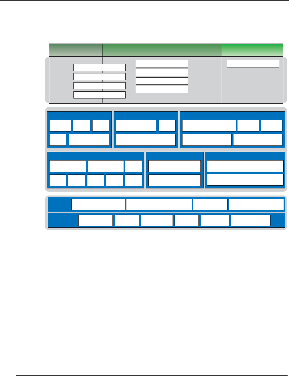
The following figure illustrates the packaging of the features in the Standard Edition and Premium Edition along with
the supported technologies and platforms.
Platform control File system provisioning
Instrumentation
Host management
Dashboard
Data management
User management
Failure analysis
Power management
Standard edition Premium edition Options
Features
Framework
Web
services Java RMI
TCP Middleware API
Presentation layer
Multiplatform GUI CLI
Windows client interface
Logical/physical topology Inventory Metrics
Charts & graphs Health monitoring
Informatics
Platform management
HW provisioning DCMPower & console
SNMP PCP DRAC iLO IPMI
Data management
Version control system
File system
management
Services
Configuration & operations
management
Events & alert subsystem
T
echnologies
Platforms
Operating
systems Red Hat Enterprise Linux SUSE Linux Enterprise server Microsoft Windows (client)CentOS Linux
SGI Altix ICE
Architecture SGI Altix UVRackable Cloudrack SGI Octane x86_64 Platforms
Overview
Comprehensive System Monitoring
007-5642-005 13
Comprehensive System Monitoring
SGI Management Center uses multiple monitoring features to improve system efficiency. These monitors allow you to
examine system functionality from individual host components to the application level and help track system health,
trends, and bottlenecks. With the information collected through these monitors, you can more easily plan for future
computing needs—the more efficiently your cluster system operates, the more jobs it can run. Over the life of your
system, you can accelerate research and time-to-market.
SGI Management Center provides results in near real-time and uses only a minute amount of the CPU. All data is
displayed in a portable and easy-to-deploy Java-based GUI that runs on both Linux and Windows. Monitoring values
include CPU usage, disk I/O, file system usage, kernel and operating system information, CPU load, memory usage,
network information and bandwidth, and swap usage. Administrators may also write plug-ins to add functionality or
monitor a specific device or application.
Version Controlled Image Management
Version control greatly simplifies the task of cluster administration by allowing system administrators to track upgrades
and changes to the system image. If a problem arises with a system image, system administrators can even revert to a
previous, more robust version of the image. By allowing system administrators to update the operating system and other
applications both quickly and efficiently, version control ensures that organizations receive the highest return on their
cluster system investment.
In cases where only minor changes are made to VCS-controlled images, SGI Management Center allows you to apply
updates without re-provisioning. See VCS Upgrade on page 144.
Fast Multicast Provisioning
Thanks to fast multicast provisioning, SGI Management Center can add or update new images in a matter of minutes—
no matter how many hosts your system contains. This saves time by allowing system administrators to quickly
provision and incrementally update the cluster system as needed; and since updates take only a few minutes, this means
less down-time and fewer system administration headaches.
Memory Failure Analysis
SGI Management Center supports failure analysis for memory errors via memlog, a software component of SGI
Foundation Software. When the memlog software is installed and functional, the Failure Analysis panel within the SGI
Management Center will be populated with pertinent memory data.
Support for SGI Altix UV Systems
This section pertains to the SGI Altix UV 100 and SGI Altix UV 1000 systems (large-memory systems). This section
does not pertain to SGI Altix UV 10 hosts, as they can be treated as general cluster nodes by SGI Management Center.
SGI Management Center support for SGI Altix UV large-memory systems includes the following functionality:
•Partition monitoring
•Provisioning
•Hierarchical tree population
•Event management
In order to support SGI Altix UV large-memory systems, SGI Management Center requires the SGI SMN bundle
software to be pre-installed.
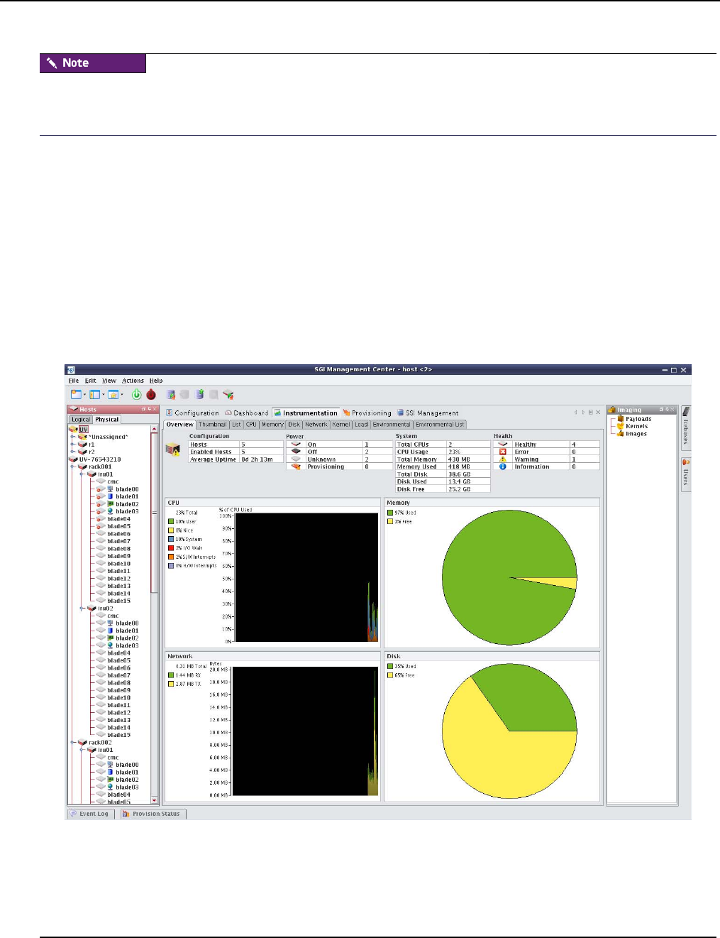
Overview
Support for SGI Altix UV Systems
007-5642-005
14
For UV systems (with the exception of UV 10 systems), a UV license is required for SGI Management Center. If you
install a cluster/server license, some features will not work correctly, such as automatic discovery of blades and chassis
management controllers (CMCs).
Configuration
The following are SGI Management Center configuration requirements for UV systems:
•A UV license is required for SGI Management Center.
•EFI Boot and Direct PXE Boot settings should both be enabled in the preferences on the General tab. The subnet
should also be set to 172.21.0.0 with a subnet mask of 255.255.0.0.
•In the Platform Management preferences tab, ensure that uvcon is selected as the default device for both power
and console support.
With the SMN software running on the SMN, SGI Management Center supports automatic discovery of the CMCs,
blades, and the SSI partition. The CMCs and blades are shown in the host tree in the physical view (shown in the
following figure). The SSI partition is shown in the logical view.
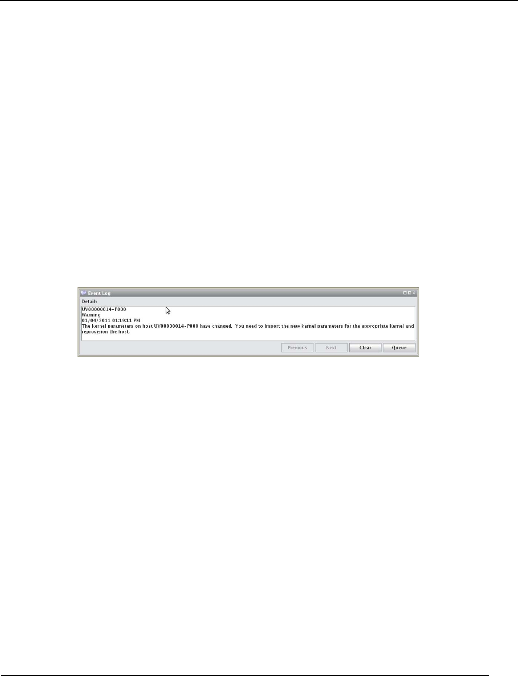
Overview
Support of SGI Prism XL Systems
007-5642-005 15
Provisioning
When a UV license is installed, new images will be set up as UV SSI images by default. In the event that an image is
not intended for a UV SSI, right-click on the image and go to Properties. Uncheck UV SSI and click Apply.
A UV SSI image includes a defined EFI boot partition. During the provision, /boot/EFI will be mounted as VFAT and
used for the purpose of an EFI boot. Existing contents of the EFI boot partition will be preserved. Note that SGI
Management Center does not create any of the contents of /boot/EFI.
To provision a UV SSI, right-click on the SSI partition in the logical view of the host tree and mouse over Provisioning.
Alternatively, you can go to the Provisioning tab, select the VCS or working image, and select the SSI partition to
provision in the host tree on the left.
Once the provisioning is in progress, you can monitor the status of the blades by right-clicking on a blade in the
physical view of the SGI Management Center host tree and clicking Connect to Console. To monitor the status of the
provisioning of the SSI, right-click on the SSI partition in the logical view and click Connect to Console.
Kernel Parameters
The UV SSI automatically determines the best kernel boot parameters for your UV hardware. Consult the UV
documentation for details. If these kernel parameters change (for example, due to a hardware change), SGI
Management Center will send a warning alert in the Event Log panel. The warning will indicate that the kernel
parameters have changed and will instruct you to import the new kernel parameters for the appropriate kernel.
Section Importing Kernel Parameters from a Running Host on page 83 describes how you import the kernel
parameters.
Support of SGI Prism XL Systems
SGI Management Center provides limited support for the SGI Prism XL platforms. Currently, this extends to the
monitoring of NVIDIA and AMD GPUs (items like temperature, fan speed, memory usage, and ECC). For a listing of
GPU solutions supported by SGI see http://www.sgi.com/pdfs/4235.pdf.
SGI Management Center requires special licensing for the GPU Monitoring feature.
Auto Node Discovery
SGI Management Center provides the Discover interface to greatly assist you in adding new compute nodes to your
host tree. Discover will determine the pertinent MAC addresses for the new nodes. For more details and usage
information, See “Using the Discover Interface” on page 197.
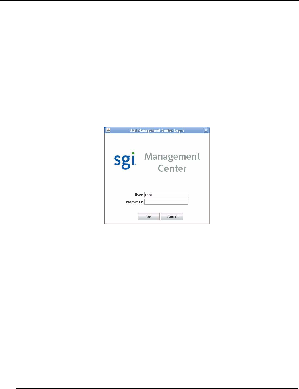
Using the Management Center Interface
Starting Management Center
007-5642-005
16
Using the Management Center Interface
The Management Center interface includes menus, a tool bar, tabbed panels, and frames with navigation trees that allow
you to navigate and configure the cluster. From this interface you can add compute hosts and regions to the cluster and
create payloads and kernels to provision the hosts.
Starting Management Center
After you have installed the program and have restarted your X session, you can start the Management Center interface
from the command line interface.
1. Open a command line console.
2. Log in as root.
3. On the command line, enter mgrclient and press Enter.
The Management Center Login is displayed.
4. Enter a user name (root by default) and password (root by default) and click OK.
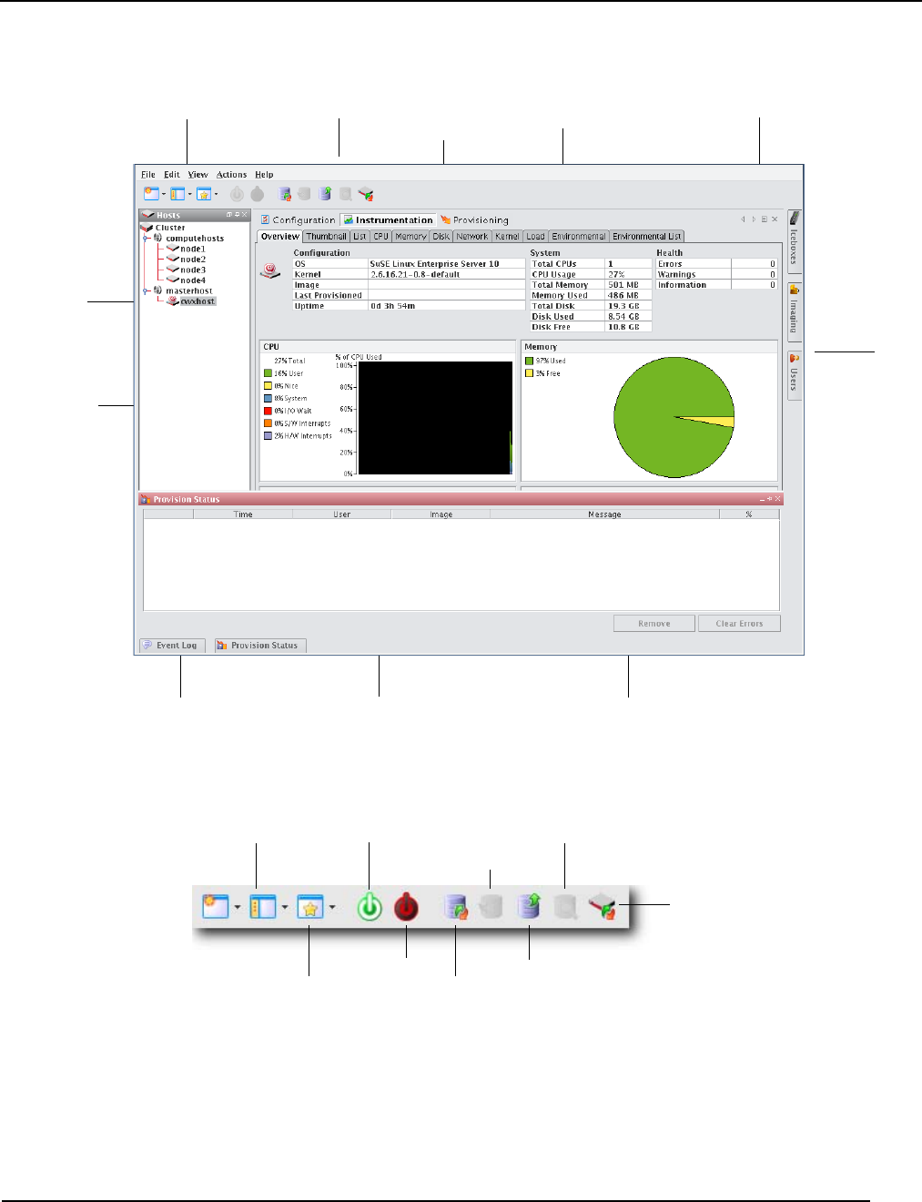
Using the Management Center Interface
Starting Management Center
007-5642-005 17
The Management Center interface is displayed.
Menus — A collection of pull-down menus that provide access to system features and functionality.
Tool Bar — The tool bar provides quick access to common tasks and features.
Server Name — The name of the server on which Management Center is running.
System Tabs — Allow you to navigate and configure the cluster. Tabs may be opened, closed, and repositioned as
needed.
Menus Server Name
Tool Bar System Tabs Frame Controls
Docked
Frame
Frame Tabs Upper Pane Lower Pane
Frame
Tabs
Navigation
Tree
VCS Check Out
VCS
Power OnFrame
Layouts Power Off
VCS Check In
Host Compare
VCS Status
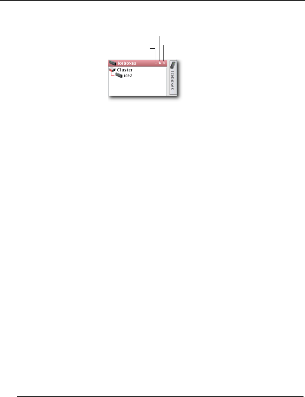
Using the Management Center Interface
Starting Management Center
007-5642-005
18
Frame Controls — Lets you dock, un-dock, hide, minimize, and close frames.
Frames — Provide you with specific control over common aspects of cluster systems (for example, imaging and user
accounts). Each frame tab opens a frame containing a navigation tree that allows you to manage system components
easily. The navigation tree is found in most frames and is used to help organize cluster components. You may dock,
close, or relocate frames and frame tabs as needed.
Upper/Lower Panes — These panes allow you to view cluster information in a structured environment.
Auto-hide
Close
Hide
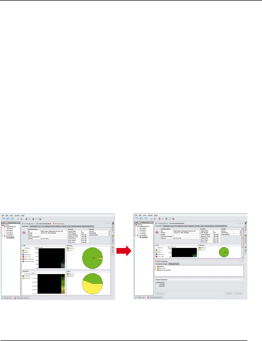
Customizing the Interface
Customizing System Tabs
007-5642-005 19
Customizing the Interface
Management Center is flexible and can be modified to meet your specific needs. For example, you can arrange the
interface to make it easier to view multiple frames or configure it to display only those items related to a particular task
(such as provisioning). You can save each view as a custom layout and easily toggle between saved views — which is
helpful if you have multiple users administering your clusters.
Customizing System Tabs
The system tabs include Configuration, Dashboard, Instrumentation, and Provisioning. You can open, close, or
rearrange these system tabs as needed.
Closing Tabs
1. Click and display the tab you want to close.
2. Click the Close icon at the right of the tab’s pane.
Opening Tabs
•From the View menu, select Tabs > <name of tab>.
or
•Select the Tab you want to display.
or
•Click the Tab icon in the tool bar and select the name of the tab you want to display.
Arranging Tabs
REORDERING TABS
•Click a tab and drag it to a new position.
CREATING SPLIT PANE VIEWS
1. Right-click a tab and select New Horizontal Group or New Vertical Group.
2. The tab appears in a new horizontal or vertical pane.
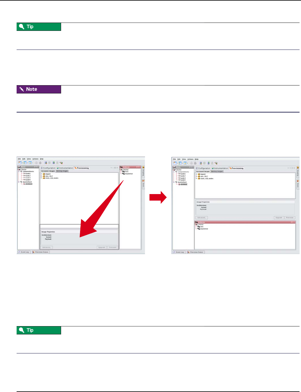
Customizing the Interface
Dockable Frames
007-5642-005
20
To move tabs between groups, right-click the tab and select Move to Next Tab Group. You can also drag and drop tabs
between groups.
Dockable Frames
Management Center dockable frames can be opened, closed and repositioned to meet your needs.
Before you can reposition a frame, you must click the Auto-Hide button to make the frame always visible. See Frame
Controls — Lets you dock, un-dock, hide, minimize, and close frames. on page 18.
To Move a Dockable Frame
1. Open the frame and toggle the Auto-Hide button to Off.
2. Click the frame’s title bar and drag it to a new position in the interface.
Layouts
Customized views of the Management Center interface are easily saved and accessed from the View menu or opened
with the Layouts button on the toolbar.
Saving the Current Layout
1. From the View menu, select Manage Layouts.
2. Select Save Current Layout.
To overwrite an existing layout with the current view, move the mouse over the layout and select Overwrite from the
popup menu.
3. Enter the name of the new layout and click OK.

Customizing the Interface
Layouts
007-5642-005 21
Opening a Saved Layout
1. On the tool bar, click the Layouts button, or select Layouts from the View menu.
2. Select the layout you want to open from the popup menu.
Renaming a Layout
1. From the View menu, select Manage Layouts.
2. Move the mouse over the layout you want to rename and select Rename from the popup menu.
3. Enter the new name of the layout and click OK.
Adding a Layout Description
1. From the View menu, select Manage Layouts.
2. Move the mouse over the layout you want to add a description to and select Describe from the popup menu.
3. In the Input dialog, enter a brief description and click OK.
Deleting a Layout
1. From the View menu, select Manage Layouts.
2. Move the mouse over the layout you want to delete and select Delete from the popup menu.
Setting a Default Layout
The default layout launches every time you start Management Center (by default, the System Default layout). To
change the default layout:
1. From the View menu, select Manage Layouts.
2. Move the mouse over the layout you want to set as the default and select Set as Default from the popup menu.
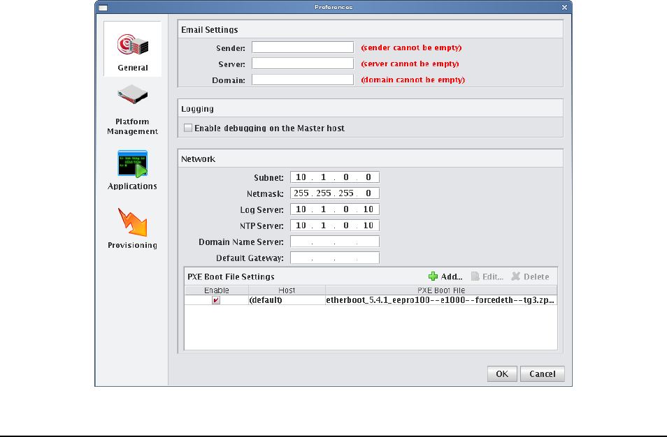
007-5642-005 23
Chapter 3
Preferences and Settings
Preferences
Management Center preferences allow you to configure the global settings and default behavior for your cluster.
Preferences include general settings, platform management configurations, applications, and provisioning. Although
these settings apply to the entire cluster, you may override certain preferences as needed (such as, provisioning).
You can access preferences by selecting Preferences from the Edit menu.
General

Preferences
Configure Network and Email Settings
007-5642-005
24
Configure Network and Email Settings
1. In the Management Center interface, select Preferences from the Edit menu.
2. In the Preferences dialog, make sure the General button is selected.
3. In the Email Settings section, enter the sender, server, and domain information.
Use the email settings to send notifications of cluster events.
•Sender — Used as the “From” address.
•Server — Must be a valid SMTP server and must be configured to receive emails from the authorized domain.
•Domain — The domain used to send email.
4. Configure the network settings.
The network settings must be configured before provisioning the cluster for the first time. The base network subnet
and netmask are mandatory. All other fields are optional.
•Base Network Subnet — The private network used by the cluster (typically a 192.168.x.x or 10.x.x.x net-
work). To set the subnet, the last octet should be a 0.
•Netmask — The subnet mask used in your cluster.
•Log Server, NTP Server, Domain Name Server (DNS), and Default Gateway — Used to set up DHCP set-
tings. On a small to medium-sized system, these are typically the Master Host (by default, the log and NTP
servers are set to use the Master Host). The DNS and default gateway are not set by default, but you should set
them if you require all hosts to have external access to the cluster system.
5. Configure Preboot Execution Environment (PXE) Settings.
By default, Management Center is configured to boot using PXE. The default PXE boot configuration utilizes a 3-
stage boot process and supports the e1000, e1000e, bnx2, tgz, and r8169 drivers to load the X-SLAM protocol,
which uses scalable multicast to provision nodes.
Management Center also supports booting with zpxe-formatted ROM files using tftp to load the X-SLAM client.
Additional zpxe-formatted ROM files which support some common node configurations are installed in the
/tftpboot/mgr directory. Open the preferences dialog from the Edit menu and browse to locate the desired file to use
for tftp boot. If the file is located in a different directory, Management Center copies the file to the /tftpboot/mgr
directory.
To reset Management Center to the default configuration, choose the file pxelinux.0 in the /tftpboot/mgr directory.
Nodes that are configured with Etherboot client are also supported and will boot without using TFTP.
To Set a Default PXE Boot File for All Hosts:
A. Click Add to open the Add PXE Boot Entry dialog.
B. Select (default) from the drop-down list.
C. Enter the path of the “zpxe” file to use by default or browse to locate the file.
D. (Optional) Enable or disable the boot entry.
E. Click OK.
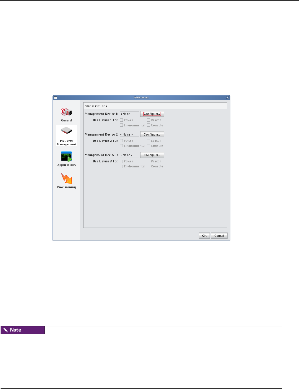
Preferences
Platform Management
007-5642-005 25
To Set a PXE Boot File for a Specific Host
A. Click Add to open the Add PXE Boot Entry dialog.
B. Select one of the configured hosts from the drop-down list.
C. Enter the path of the “zpxe” file to use by default or browse to locate the file.
D. (Optional) Enable or disable the boot entry.
E. Click OK.
6. Click OK to save the settings and close the Preferences dialog.
Platform Management
Global Options
Management Center supports multiple platform management interfaces. This is useful if you are using multiple
platforms for system management (for instance, one interface for power management and another for environmental
monitoring). The global options section of the preferences dialog allows you to set the default options used for the
majority of hosts in the system, although some hosts may still need additional configuration.
Set the most common options by configuring Device 1, 2, and 3. From the configuration dialog, select the Platform
Management Device Type you want to use: Icebox (not currently supported), Roamer, IPMI, FreeIPMI, DRAC, ILO,
Powerman, or Conman). The check boxes below each device indicate which features are available to be managed by the
device. If you configure multiple devices, you can select or clear these check boxes to indicate which device will
manage this feature. See also Intel Data Center Manager (DCM) on page 28.
Not all management controllers have the same feature set. DRAC and ILO support only power control and Conman
supports only serial console control. Roamer supports serial console control and power control. IPMI supports all
features, but you may want to use other interfaces for power and serial console control and IPMI for controlling the
beacon and environmental monitoring.
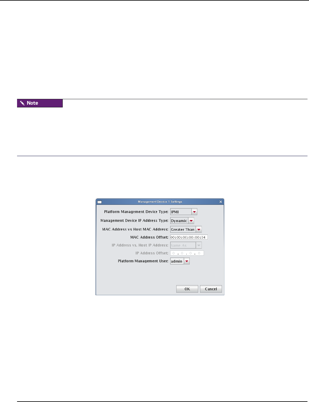
Preferences
Platform Management
007-5642-005
26
Roamer, IPMI, DRAC, ILO
Roamer, IPMI, ILO, and DRAC are typically configured using only global options. Prior to configuring the
Management Device, you must configure the IP address of the controller. This is typically set dynamically via DHCP
but can also be set statically. If you choose to assign the IP address dynamically, add the device’s MAC address and IP
address as a secondary interface under each Management Center host. This causes Management Center to automatically
add an entry for the interface in the /etc/dhcpd.conf file and attempt to configure it via DHCP.
Management Center provides three Management Device IP Address Types: Dynamic, Relative, and Static. These
address types are described below, but you may also want to refer to IPMI on page 45 and DRAC and ILO on page 47
for additional information and examples.
To configure platform management to use a remote power control device such as IPMI, ILO, or DRAC, you must first
create the power control user. See Configure the Master Host and Management Center on page 37.
In order for DRAC to successfully control power on DRAC-enabled hosts, you must install the racadm utility on the
Master Host. You may obtain the racadm RPM, mgmtst-racadm-4.5.0-335.1386.rpm, from the /misc directory of the
Management Center CD or from SGI technical support.
Dynamic If you are setting up the Management Device dynamically and the device's interface MAC address is an
offset of the management interface, set the Management Device IP Address Type to Dynamic and enter the MAC
Address Offset. This is typical for IPMI implementations with on-board BMC controllers. For example, a host whose
management interface MAC address is 00:11:22:33:44:55 might have a Management Device with a MAC address of
00:11:22:33:44:58. In this case, the MAC offset would be 00:00:00:00:00:03 (Greater Than).
Relative If you are setting up the Management Device dynamically or statically and the device’s interface IP address is
an offset of the management interface, set the Management Device IP address type to Relative and use the IP Address
Offset. This is typical when using ILO or an IPMI controller with an add-on BMC daughter card. For example, a host
with an IP address of 10.0.0.1 might have a Management Device with an IP address of 10.0.2.1. In this case, the IP
offset would be 0.0.2.0 (Greater).
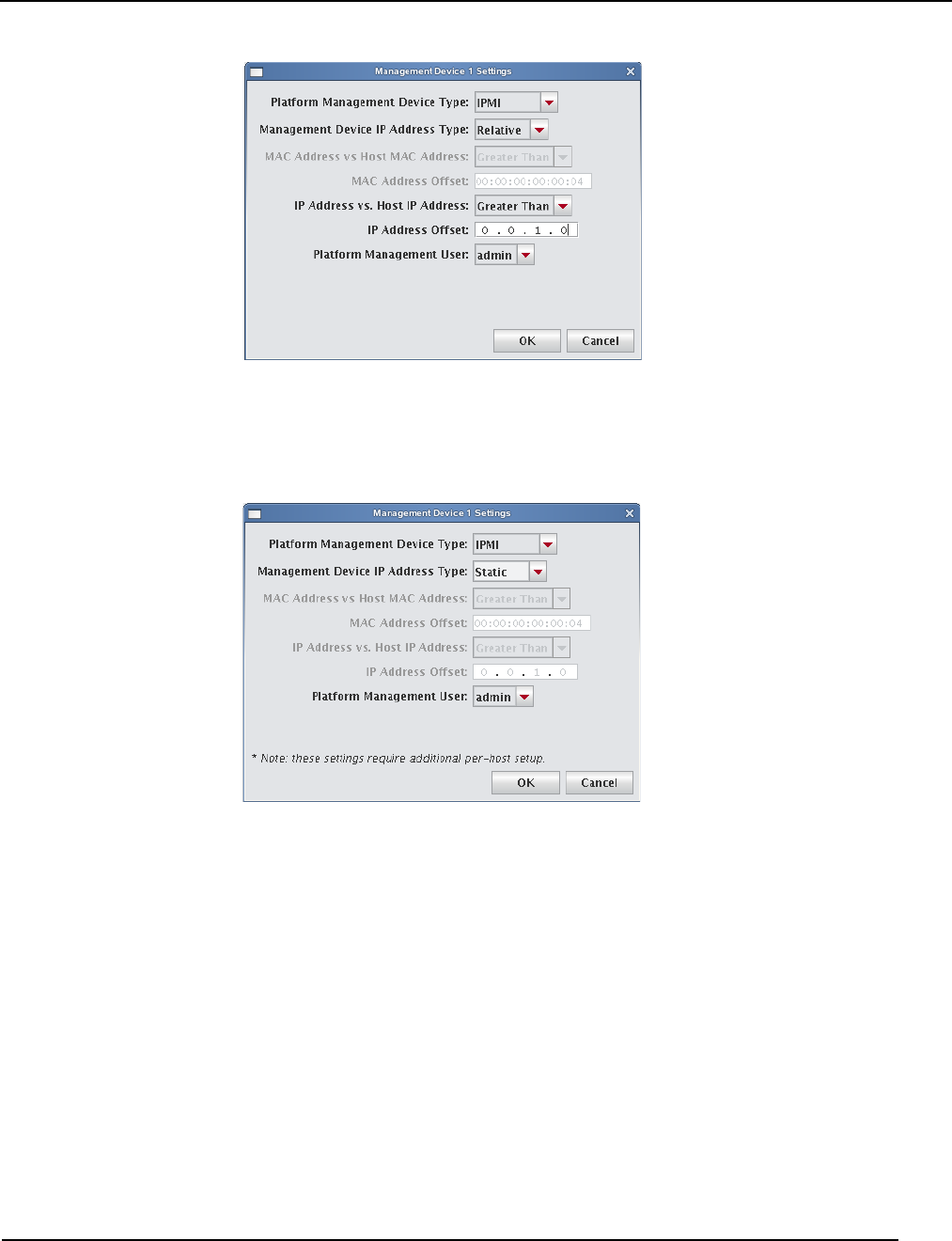
Preferences
Platform Management
007-5642-005 27
Static If you are setting up the Management Device dynamically or statically and the device’s interface MAC address
or IP address does not correlate with either the MAC or IP address of the management interface, set the Management
Device IP address type to Static—this is not typical. If you select Static, you must configure the IP address manually on
a per-host basis.

Preferences
Platform Management
007-5642-005
28
Conman
Conman is a serial console management program designed to support a large number of devices simultaneously.
Conman supports multiple serial controllers (including IPMI) and provides continuous serial logging and multiplexing
that allows you to share a serial connection for logging and access, or between multiple consoles.
Conman is available under the GPL and is installed by default on SGI systems. Conman can be obtained from SGI as
RPM packages or from http://home.gna.org/conman/.
Prior to selecting Conman for serial access, you must install the conman RPM on the Master Host, then configure
conman by defining the serial devices and consoles in /etc/conman.conf. Additional information on conman is available
from the man pages by entering man conman.conf.
Before you can begin using conman, you must start its daemon, conmand (installed as
/etc/init.d/conmand). For information on using conman, see conman on page 216.
Intel Data Center Manager (DCM)
Management Center supports power monitoring and scaling through the utilization of the Intel Data Center Manager
(DCM) technology. DCM provides Management Center with a robust power management API. This integration
includes power state control, power utilization monitoring, and power policy definition and enforcement.
SPECIAL HARDWARE AND LICENSING
Enabling DCM requires special hardware for your system and an appropriate SGI license key for feature activation. If
this feature was not pre-configured for your cluster in Manufacturing, contact SGI for information about enabling this
feature.
SGI Management Center provides power monitoring for each node configured for DCM-based management. DCM-
based management may be enabled for any node with a DCM-compatible design. Such units include Intel-based
chipsets with IPMI and Intel Power Node Manager (IPNM) as well as other vendor technologies providing standards-
based power management. Typically, PMBUS-compliant hardware is required.
ENABLING DCM
To enable DCM-based management for compliant hardware, do the following:
1. Configure the appropriate IPMI endpoint parameters.
Use the Platform Management pane of the host-configure panel (Configuration tab) or the global preferences dia-
logue:
Edit —> Preferences —> Platform Management
See section Roamer, IPMI, DRAC, ILO on page 26 for more information on configuring the platform management
preferences for IPMI.
2. Add a DCM management device.
You can use the same interfaces as in step 1. It is not necessary to target the DCM management device toward any
particular management subsystem (power, beacon, environmental or console) but you must enter the DCM access
information in the management device settings dialogue. When you select Configure in the Platform
Management section to enable a new management device, you must specify values for the fields in the following
table:
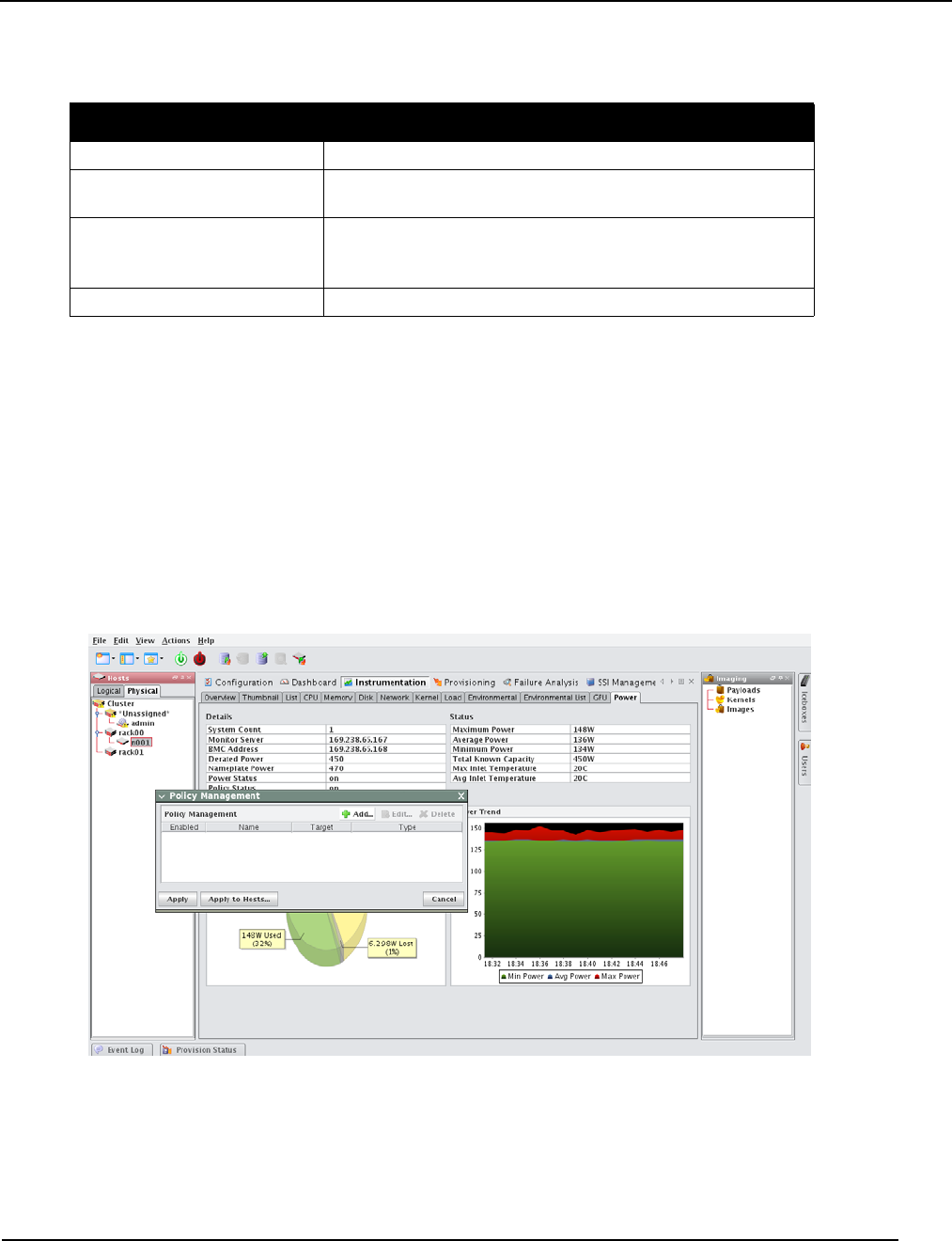
Preferences
Platform Management
007-5642-005 29
Once configured, SGI Management Center will synchronize with DCM and achieve model consistency. Management
Center will begin to receive event updates from the DCM service. You can access power monitoring data through
Instrumentation —> Power . See Power Tab on page 162.
POWER POLICY MANAGEMENT
Management Center provides power policy management capability for licensed customers whose systems comply with
the aforementioned requirements for Management Center DCM integration. You can access the managment functions
in two ways:
• Action —> Power
•Right-clicking on a cluster-tree target in the Hosts side bar.
Selecting Policy from the Power sub-menu displays the Policy Management dialog box.
Any existing policy definitions will be displayed.
Field Description
Management Device Type Select DCM.
DCM Primary Host Name Provides the DCM server hostname or IP address used to access the
DCM service.
Nameplate Power Provides the maximum PSU output power for the monitored
equipment. (Using the global options pane will create a per-node
default nameplate power.)
Platform Management User Provides authenticated access to the node management infrastructure.
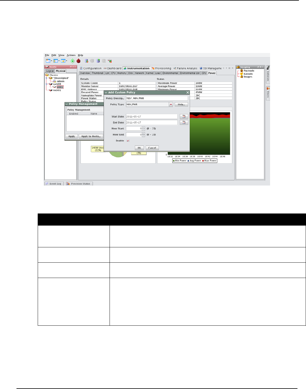
Preferences
Platform Management
007-5642-005
30
Adding New Policies
New policies may be defined for the selected physical target or for the cluster as a whole (if selected) by clicking Add
from the Policy Management dialog box. The GUI displays the Add Custom Policy dialog box for policy definition.
You can select one of the policy types described in the table below:
Policy Type Description
CUSTOM_PWR_LIMIT Defines a maximum power threshold for the endpoint. If you select
CUSTOM_PWR_LIMIT, you will be prompted to enter Power Limit, (an integer
representing the allowable power threshold in Watts).
MIN_PWR Defines a policy which enforces the minimum operational power for the selected target
(an entity or a group of entities).
MIN_PWR_ON_INLET_
TEMP_TRIGGER Establishes a MIN_PWR policy that is enforced upon detection of a specific temperature
threshold within the target.
STATIC_PWR_LIMIT Constructs immutable power budgets for entities that have special characteristics.
Policies that are defined on groups of nodes (a rack or cluster, for example) may overlap
with those defined for individual nodes and, typically, the policies attempt to achieve the
highest possible power savings. STATIC_PWR_LIMIT may be used to preserve a
specific power allocation budget for targeted endpoints within the cluster. If further
CUSTOM_PWR_LIMIT restrictions are placed upon the endpoint directly or by the
application of a group policy, the STATIC_PWR_LIMIT budget will take precedent.
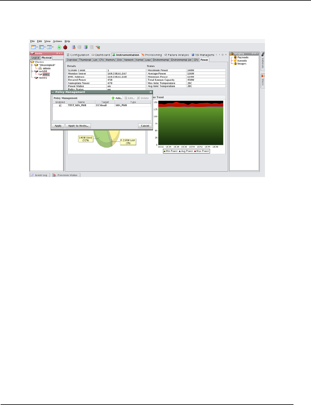
Preferences
Platform Management
007-5642-005 31
The updated Policy Management dialog box reflects the new addition.
Activating Policies
You can activate a power policy in an on-demand fashion or non-interactively via schedule definition. To do so
interactively (on demand), use the Edit feature of the Policy Management dialog box. Simply select the Enable check
box in the resulting display.
You can create and enable a schedule definition upon policy creation by entering valid values in the following fields:
•Start Date
•End Date
•Hour Start
•Hour End
You can later access these fields using the Edit feature from the Policy Management dialog box. The Hour Start to
Hour End interval defines how the policy will be activated on a day-to-day basis.
Disabling Policies
A policy may be disabled at any time either by deleting the policy from the Policy Management dialog box (using the
Delete button) or by using the Edit feature and de-selecting the Enable check box.
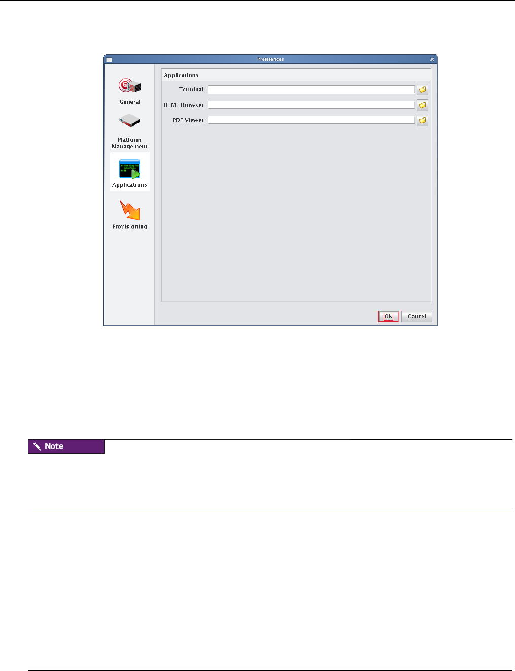
Preferences
Applications
007-5642-005
32
Applications
APPLICATIONS
The applications option allows you to select the default applications used for specific actions and file types.
Terminal Enter the executable path of the application you want to use for your terminal window. The terminal
application is used when opening a serial console to the host. By default, Management Center uses an xterm with the
following options:
xterm -geom 80x25 -T “Console of {host}” -sb -bg black -fg gray -sl 1000 -e /usr/bin/
telnet {system.rna.host} {port}
The Management Center terminal field supports the use of the following variables:
{host} The host name used to set the console name (optional).
{system.rna.host} The host name of the Master Host (required).
{port} The dynamic port set by the Master Host (required).
Management Center uses any terminal that supports spawning an external command (usually the '-e' flag). The full
path to the terminal and the '-e /usr/bin/telnet {system.rna.host}{port}' statement are the only
requirements. All other items are optional. Consider the following examples:
Cygwin terminal on Windows:
C:\cygwin\bin\rxvt.exe -sr -sl 10000 -fg white -bg black -fn fixedsys -fb fixedsys -T
“Console of {host}” -tn cygwin -e /usr/bin/telnet {system.rna.host} {port}
Simple white xterm on Linux:
/usr/bin/xterm -e /usr/bin/telnet {system.rna.host} {port}
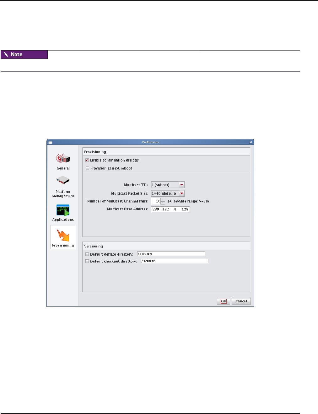
Preferences
Provisioning Settings
007-5642-005 33
Gnome-terminal on Linux:
/usr/bin/gnome-terminal -t “Console of {host}” -e /usr/bin/telnet {system.rna.host}
{port}
If you use Konsole or Gnome-terminal, you can use the default settings used by your desktop.
HTML Browser Enter the executable path of the application you want to use as your HTML browser. On Linux, the
default browser is Firefox. On Windows, Management Center uses your default browser.
PDF Viewer Enter the executable path of the application you want to use to view PDFs such as the SGI Management
Center System Administrator’s Guide or Release Notes. On Linux, the defaults are Acrobat Reader then xpdf. On
Windows, Management Center uses your default PDF reader.
Provisioning Settings
Preferences
Provisioning Settings
007-5642-005
34
Provisioning
These settings let you control the default provisioning behavior.
You can overwrite these settings from the Advanced Provisioning dialog. See Advanced Provisioning Options on
page 145.
Enable Confirmation Dialogs Select this option if you want to display a confirmation dialog when you provision
hosts.
Provision at Next Reboot When checked, hosts are not provisioned until you reboot them manually or with a script.
When unchecked, Management Center automatically restarts hosts or powers them down to begin the provisioning
process.
Multicast TTL Sets the Multicast TTL or Time-To-Live on a multicast packet. The default, 1, restricts multicast
packets to the subnet (the cluster’s internal network). If you are using multicast across networks and multiple switches
across a private network, select 32. If you plan to use multicast across a company WAN, use 64 (the maximum TTL that
multicast supports).
Multicast Packet Size Sets the maximum size of multicast packets (by default, 1446).
Number of Multicast Channel Pairs Management Center uses one channel for downloading the kernel and
RAMdisk, and another channel for downloading the payload. Typically, you will need only one channel per image
used; however, depending on the number of images in use on the system, you may require additional multicast
channels. If you run out of channels, a “No Available Channels” error occurs when you attempt to provision. By
default, 10 channel pairs are configured on your system.
Multicast Base Address The multicast base address specifies what multicast subnet you will use, starting at the last
octet and increasing by 1. By default, Management Center sets the base multicast address to 239.192.0.128 with 10
channels, which uses addresses from 239.192.0.128-137. If you have multiple Management Center Master Hosts on the
same network, they should use a different subnet or different ranges within that subnet. For example, Master 1 might
use 239.192.0.128-137 and Master 2 might use 239.192.1.128-137. Other multicast ranges such as 224.0.0.x may also
be suitable for your network.
If you change your multicast base address, you must verify that the multicast default route includes the new base
address. See Configure Multicast Routes on page 39 for information on configuring multicast routes.
After changing multicast settings, you must restart your server.

Configuring IPMI
Configure the IPMI BMC
007-5642-005 35
Specify the Download Path of the Payload During the provisioning process, Management Center downloads the
payload to the host’s root directory. Depending on the size of the payload, this may require a very large root partition.
To use a smaller root partition, you may download the payload to a different partition by specifying the image.path in
$MGR_HOME/etc/ProvisioningService.profile:
# Uncomment this variable to manually set the download path
# of the provisioning image file (__image__). The default
# path (/mnt) is shown in the example below
# image.path=/mnt
You should be aware of the following:
1. The directory you select must belong to its own partition (for example, if you are downloading to /scratch, it must
belong to its own partition).
2. During this point of the provisioning process, the file system is still mounted by the ramdisk. Because of this, you
must include /mnt in the image.path. For example, to mount /scratch, the image.path would be
/mnt/scratch.
In either case, Management Center reverts to the root partition if the partition doesn't exist or if the path is wrong.
Versioning
These options allow you to configure default directories used to check items in and out of VCS and to open large files
created when importing a payload.
Default Checkout Directory When enabled, Management Center uses this directory as a scratch directory for
checking items in and out of VCS. Use this if you have limited space on the partition containing $MGR_HOME.
Default Deflate Directory When enabled, this option allows you to specify an alternate path in which to open large
files created when importing a payload. Use this if you have limited space on the partition containing $MGR_HOME.
Configuring IPMI
Configure the IPMI BMC
The BMC(s) for the nodes should be set up to use networking and serial over LAN. You will also need to know the
username and password that will be used for power control and serial with the BMC(s) in order to use power control
and serial over LAN with the Management Center. The ipmitool utility allows you to set the username and password
used to access the BMC on a host. This tool also allows you to set the LAN parameters of the BMC. For more
information, consult the manual Guide to Administration, Programming Environments, and Tools Available on SGI
Altix XE Systems (007-4901-xxx) or third-party documentation (in the case of third-party node types).

Configuring IPMI
Configure the ipmitool_options.profile
007-5642-005
36
Configure the ipmitool_options.profile
By default, the Management Center uses the Lanplus interface to send remote commands to IPMI BMC(s). Use the file
$MGR_HOME/etc/ipmitool_options.profile if the BMC needs specific options to be passed on to the ipmitool
command line (for example, oem type or encryption settings). After making any changes, enter /etc/init.d/mgr restart
to restart the services.
Example:
# Use standard options globally
ipmitool.power._default_=-I lanplus
ipmitool.status._default_=-I lanplus
ipmitool.sol._default_=-I lanplus
# Use Intel OEM Options for Node n015
ipmitool.power.n015=-I lanplus -o intelplus
ipmitool.status.n015=-I lanplus -o intelplus
ipmitool.sol.n015=-I lanplus -o intelplus
Configure the Payload and Kernel
Before you can begin using IPMI, you must configure the kernel and payload to support IPMI as follows:
1. Add the following modules (available in drivers/char/ipmi under the kernel modules tree) to the kernel with
which you will be provisioning:
ipmi_devintf
ipmi_si
ipmi_msghandler
2. In the kernel parameters, set the serial console and baud rate.
For SGI clusters, the defaults are ttyS1 and 115200, respectively.
3. Install either OpenIPMI or Freeipmi into the payload if neither is already installed.You can obtain OpenIPMI from
the SLES or RHEL distribution CD/DVD. Freeipmi can be obtained from http://www.gnu.org/software/freeipmi.
4. If you are using OpenIPMI, run the following command to enable the ipmi daemon on the master host:
chroot $MGR_HOME “chkconfig ipmi on”
OpenIPMI requires the kernel binary RPM installed in the payload in order for the ipmi daemon to run properly.

Configuring IPMI
Configure the Master Host and Management Center
007-5642-005 37
Configure the Master Host and Management Center
The following section describes how to configure your Master Host to use IPMI and how to prepare your system
(through Management Center) for IPMI control:
1. Install Ipmitool on the Master Host to allow you to perform IPMI-related tasks such as powering off hosts, execut-
ing beacon operations, and activating SOL.
The SDR cache is created in $MGR_HOME/ipmi/sdrcache.dat on each host. If the $MGR_HOME/ipmi directory or the
sdrcache.dat file cannot be created, monitoring will fail.
2. Start Management Center.
3. Create a new user (see Adding a User on page 64).
4. Assign the new user the name and password configured for BMC controllers (for SGI systems, admin and ipmi).
This gives you full access to IPMI controls on the hosts.
5. Assign the user to the power group and make power the primary group for the user.
This user is not required for monitoring temperature and fans but is required for power control and beaconing. This user
cannot log into Management Center.
6. In the Platform Management pane, select Override Global Settings.
7. Select IPMI as the Platform Management Device Type.
8. Select the Management Device IP Address Type:
A. Dynamic Enter a hexadecimal MAC offset.
For example, if you choose a Greater Than offset of 00:00:00:00:00:04 and the host’s MAC address is
00:15:C5:EA:A7:7B, the MAC Address used for power operations will be 00:15:C5:EA:A7:7F (the sum of
the original MAC address and the offset).
B. Relative Choose an IP address offset and select whether it is Greater Than, the Same As, or Less Than
the host’s IP address.
For example, if you choose a Greater Than offset of 0.0.1.0 and the host’s IP address is 10.3.0.14, the
host’s BMC address will be 10.3.1.14. This is the IP address used for power operations (the sum of the orig-
inal IP address and the offset).
C. Static If you choose Static or if you wish to use different settings for each host, you must configure the
IPMI options individually for each host.
9. (Optional) Select the MAC Address vs. Host MAC Address type:
A. Not Related
B. Greater Than
C. Less Than
10. (Optional) Enter the MAC Address Offset.
11. Select the MAC Address to use to manage this host.
12. (Optional) Select the IP Address vs. Host IP Address type:
A. Greater Than
B. Less Than
C. Same As

Configuring DHCP
Configure DHCP Settings
007-5642-005
38
13. (Optional) Enter the IP address offset from the management interface.
14. (Optional) Enter the IP address for the host.
15. Select a Platform Management User.
Users must belong to Power as their primary group to appear in this list. See Groups on page 67.
16. Click OK.
Configuring DHCP
If you are using Dynamic Host Configuration Protocol (DHCP) you need to configure it on your master host to ensure
proper communication with your compute nodes.
1. In a command line shell, log on as root.
2. Open /etc/sysconfig/dhcpd.
3. Look for the DHCPD_INTERFACE line and make sure it ends with =''ethx''.
4. Replace “x” with the host interface you use.
Example:
DHCPD_INTERFACE="eth1"
5. Save and close the file.
Configure DHCP Settings
When provisioning occurs, Management Center automatically modifies DHCP settings and restarts the service. If you
make manual DHCP modifications and want Management Center to stop, start, restart, or reload DHCP, use the
controls in the DHCP menu.
When working with DHCP, ensure that the server installation includes DHCP and, if the subnet on which the cluster
will run differs from 10.0.0.0, edit the Network subnet field in the preferences dialog.
The DHCP option of the Actions menu allows you to perform the following operations:
•Stop the DHCP server.
•Start the DHCP server.
•Restart the DHCP server.
•Reload the dhcpd.conf file.
Changes made to /etc/dhcpd.conf are overwritten when you provision the host.

Configure TFTP
Configure Multicast Routes
007-5642-005 39
Configure Multicast Routes
When provisioning nodes, the default multicast configuration may not work properly. You can use the following steps
to ensure that multicast routing is configured to use the management interface.
The following examples use a multicast network of 224.0.0.0/4 to provide broad multicast support, but you can also use
a more narrow multicast route such as 239.192.0.0/16. By default, the base multicast address in Management Center is
239.192.0.128.
SLES
1. Enter the following from the command line to temporarily add the route (where eth1 is the management interface):
route add -net 224.0.0.0 netmask 240.0.0.0 dev eth1
2. Make the change persistent by adding the following to file /etc/sysconfig/network/routes:
224.0.0.0 0.0.0.0 240.0.0.0 eth1 multicast
RHEL
1. Enter the following from the command line to temporarily add the route (where eth1 is the management interface):
route add -net 224.0.0.0 netmask 240.0.0.0 dev eth1
2. Make the change persistent by adding the following to file /etc/sysconfig/network-scripts/route-eth1:
224.0.0.0/4 dev eth1
Configure TFTP
Management Center places boot files in /tftpboot/mgr. The tftp or atftp daemon must use /tftpboot as the home for tftp
boot files. If you are using the tftp package that is included with the RHEL 6 distribution, you must change the
parameter server_args in /etc/xinetd.d/tftp to use /tftpboot as the home for tftp boot files.
Example /etc/xinetd.d/tftp file:
service tftp
{
disable = no
socket_type = dgram
protocol = udp
wait = yes
user = root
server = /usr/sbin/in.tftpd
server_args = -s /tftpboot
per_source = 11
cps = 100 2
flags = IPv4
}

Configure TFTP
Configure Multicast Routes
007-5642-005
40
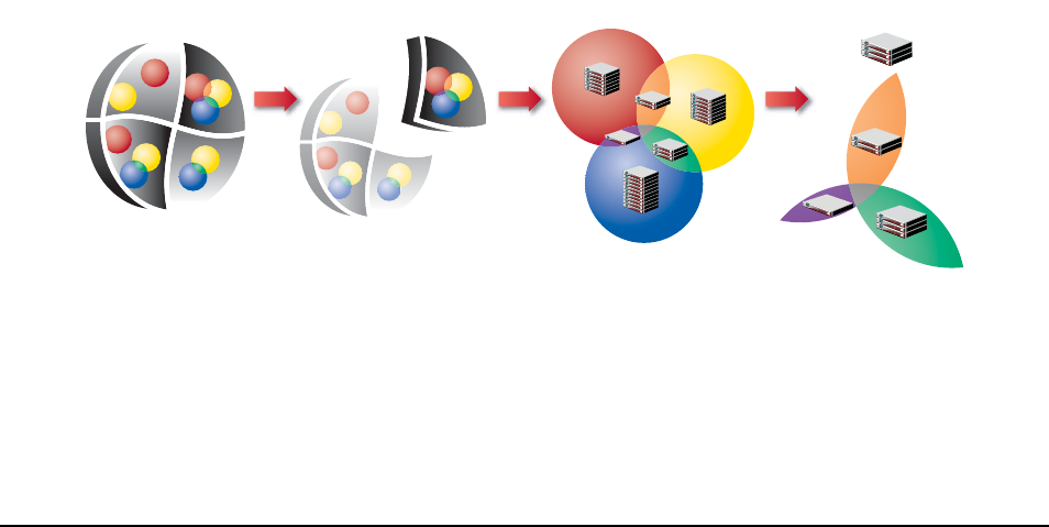
007-5642-005 41
Chapter 4
Cluster Configuration
Clustered Environments
In a clustered environment, there is always at least one host that acts as the master of the remaining hosts (for large
systems, multiple masters may be required). This host, commonly referred to as the Management Center Master Host,
is reserved exclusively for managing the cluster and is not typically available to perform tasks assigned to the remaining
hosts.
To manage the remaining hosts in the cluster, you can use the following grouping mechanisms:
•Partitions
Partitions include a strict set of hosts that may not be shared with other partitions.
•Regions
Regions are a subset of a partition and may contain any hosts that belong to the same partition. Hosts contained
within a partition may belong to a single region or may be shared with multiple regions. Dividing up the system can
help simplify cluster management and allows you to enable different privileges on various parts of the system.
•Racks
You can use racks to represent the physical layout of your cluster.
Cluster Partitions Regions Hosts
Shared Hosts

Setting Up Your Cluster
007-5642-005
42
Setting Up Your Cluster
Management Center divides system configuration into several components:
•Adding Hosts on page 43
•Partitions on page 55
•Regions on page 57
•Racks on page 60
•User Administration on page 63
•Adding a User on page 64
•Groups on page 67
•Roles on page 70
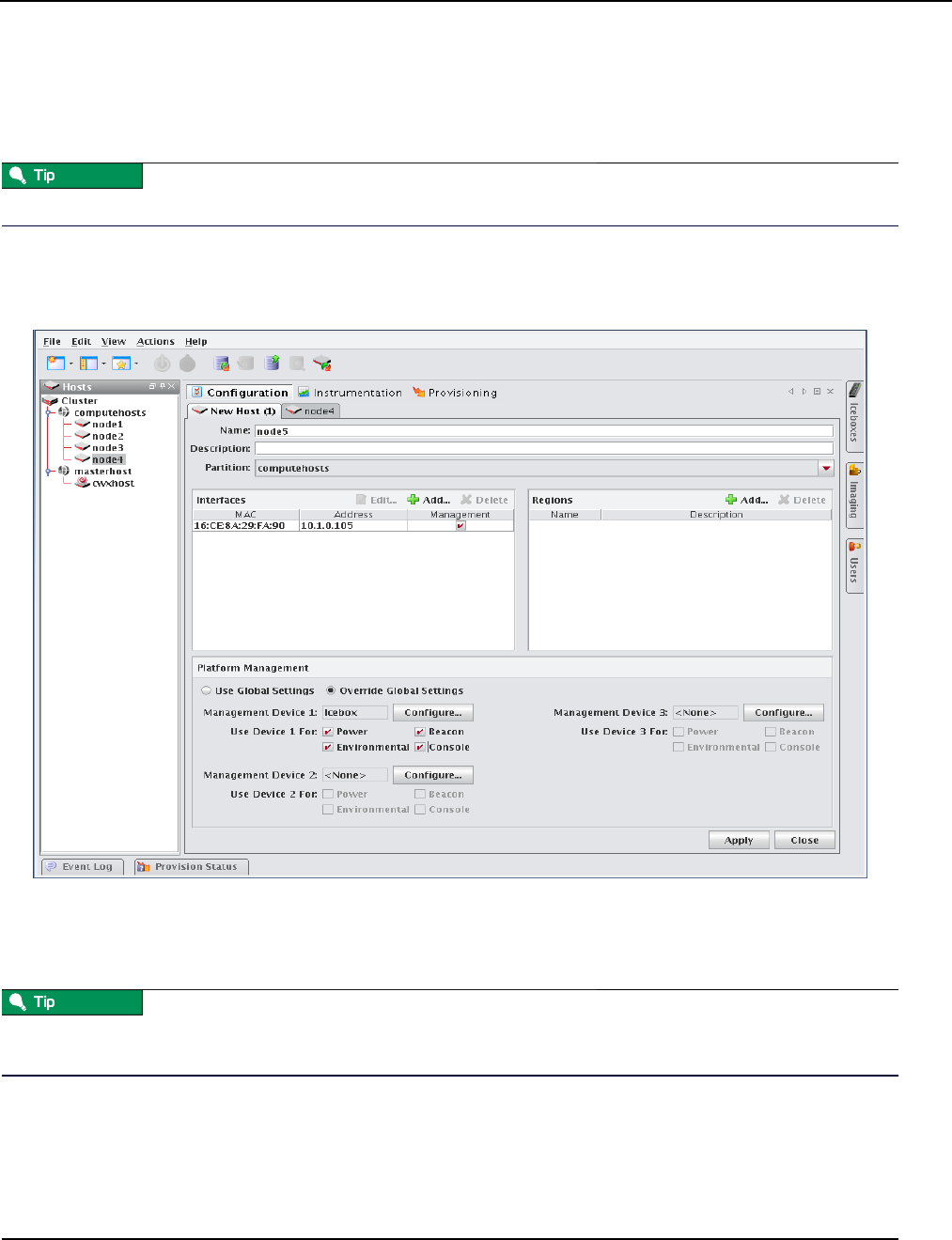
Adding Hosts
007-5642-005 43
Adding Hosts
To add a host, you must provide the host name, description, MAC address, IP address, and the partition and region to
which the host belongs. Hosts can be added only after you have set up a Master Host.
You can also import a list of existing hosts. See Import Hosts on page 49.
1. Select the Cluster icon in the Hosts frame.
2. Select New Host from the File menu or right-click in the host navigation tree and select New Host.
A new host pane appears.
3. Enter the host name.
4. (Optional) Enter a description.
5. (Optional) Select the name of the partition to which this host belongs from the drop-down menu.
If you right-click a partition or region in the navigation tree and select New Host, the host is automatically assigned to
that partition or region.
6. Create Regions and Interfaces assignments as needed.
7. Click Apply to create the new host.
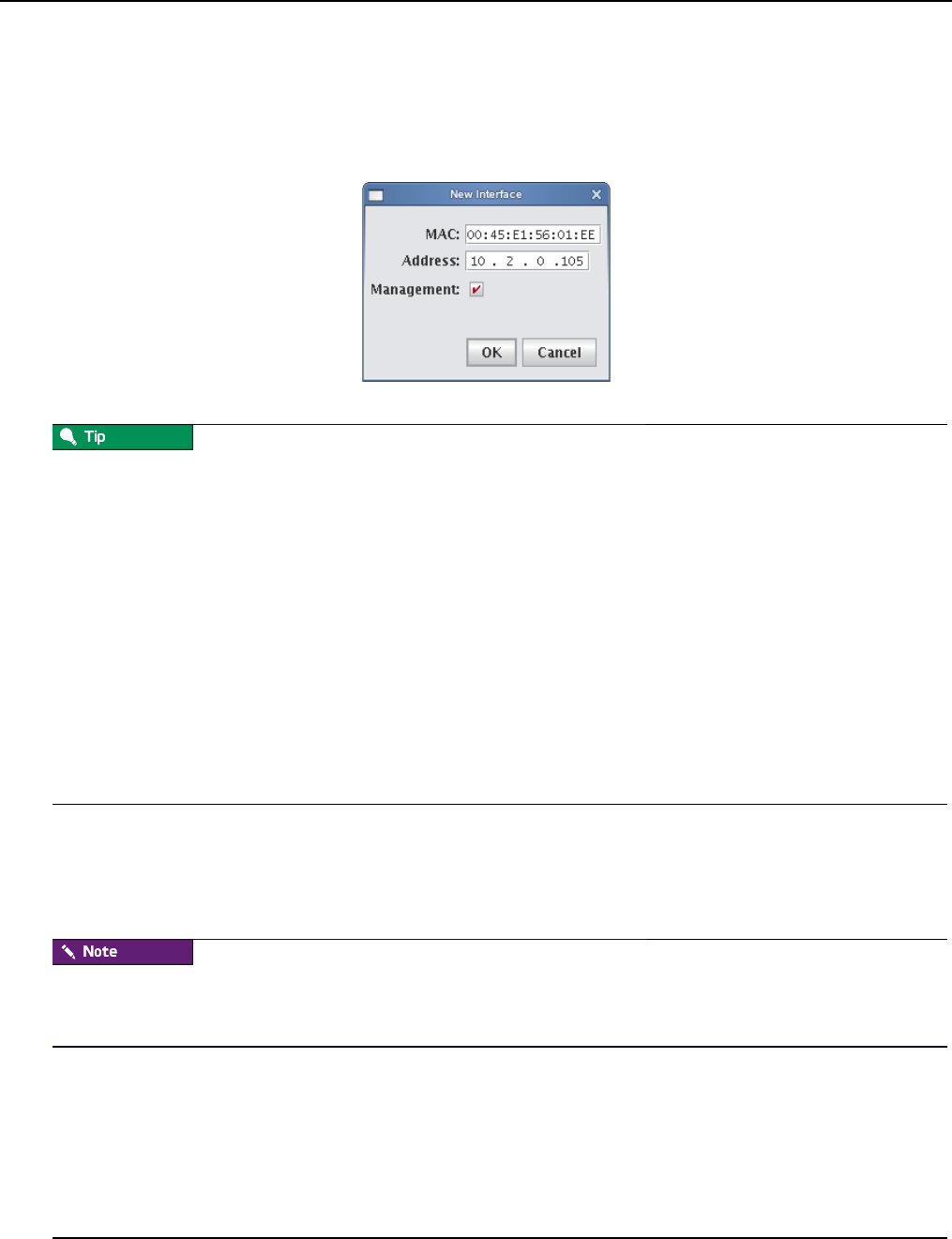
Adding Hosts
007-5642-005
44
Add Interfaces
The Interfaces pane allows you to create new interfaces and assign host management responsibilities.
1. In the Interfaces pane, click Add.
The New Interface dialog appears.
2. Enter the host’s MAC and IP addresses.
To find the MAC address of a new, un-provisioned host, you must watch the output from the serial console. Etherboot
displays the host’s MAC address on the console when the host first boots. For example:
Etherboot 5.1.2rc5.eb7 (GPL) Tagged ELF64 ELF (Multiboot) for EEPRO100]
Relocating _text from: [000242d8,00034028) to [17fdc2b0,17fec000)
Boot from (N)etwork (D)isk (F)loppy or from (L)ocal?
Probing net...
Probing pci...Found EEPRO100 ROM address 0x0000
[EEPRO100]Ethernet addr: 00:02:B3:11:03:77
Searching for server (DHCP)...
(*If conman is set up and working, this information is also contained in the conman log file for the host — typically
located in /var/log/conman/console.n[1-x])
To find the MAC address on a host that is already running, enter ifconfig -a in the CLI and look for the HWaddr of
the management interface.
3. Click Management to use the Management Center interface to manage the host.
Management Center stores the interface and automatically writes it to dhcp.conf.
4. Add any additional interfaces required for this host.
Management Center records the interfaces and writes them to dhcpd.conf.
If you are using IPMI or another third-party power controller, you should add the BMC’s MAC address and the IP
address you are going to assign it. Management Center will set up DHCP to connect to the BMC. In the Platform
Management settings, you can select this interface and use it for operations.
5. Click OK.

Configure Platform Management
007-5642-005 45
Assign Regions
The Regions pane allows you to identify any regions to which the host belongs.
1. (Optional) In the Regions pane, click Add.
The Select Regions dialog appears.
2. Select the region to which the host belongs. (To select multiple regions, use the Shift or Ctrl keys.)
3. Click OK.
Configure Platform Management
Platform management allows you to configure the power and temperature Management Devices you will use for each
host.
By default, platform management uses the device specified in your Global preferences settings to control hosts in the
cluster. To override this setting, select Override Global Settings.
IPMI
Typically, hosts use one or more Ethernet interfaces. With IPMI, ILO, and DRAC, each host uses at least two
interfaces: one management interface and one IPMI/ILO/DRAC interface. The management interface is configured for
booting and provisioning, the IPMI/ILO/DRAC interface is used to gather environmental and sensor data (for example,
fan speeds) from the host and perform power operations. Additional interfaces are used only for setting up host names
and IP addresses.
ILO and DRAC support power control only — they do not support temperature and sensor monitoring.
In order for Platform Management to work correctly, you must first define interfaces for each host (see Add Interfaces
on page 44). In some cases, you must manually configure an IP address for the Platform Management Controller—in
most cases, however, you can use DHCP to configure this address. To view information about each interface, see
dhcpd.conf.
The IPMI dialog defines which interface is used for Platform Management. Typically, the Management Device is easily
identified because its MAC or IP address is an offset of the host. For example, a host with a MAC address of
00:11:22:33:44:56 and an IP address of 10.0.0.1 might have a Management Device with a MAC address
00:11:22:33:44:59 and set an IP address of 10.0.2.1. In this case, the MAC offset would be 000000000003 (Greater)
and the IP offset would be 0.0.2.0 (Greater).
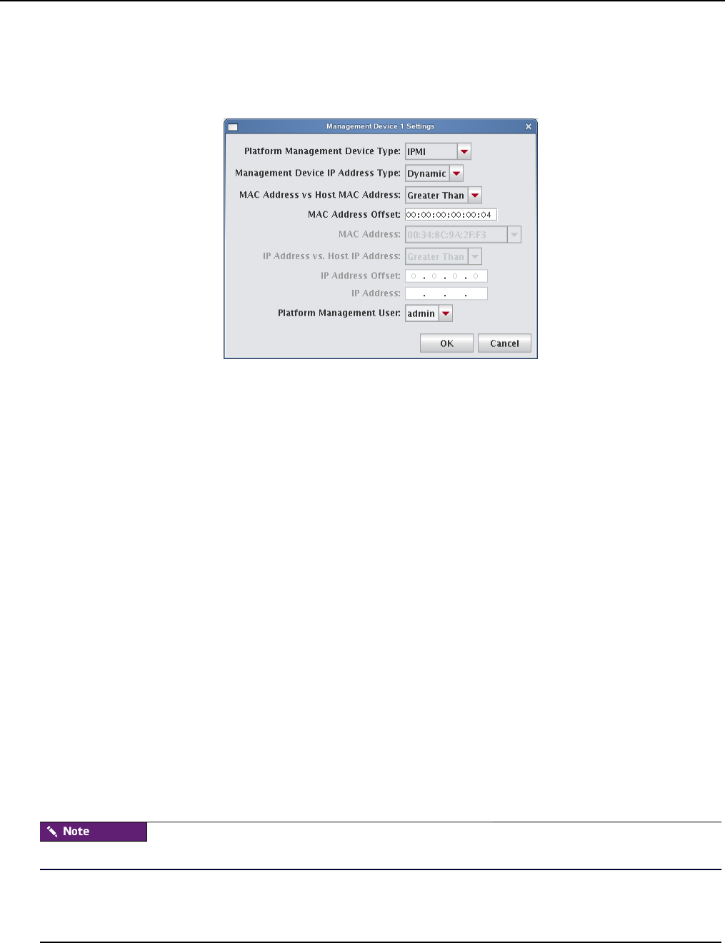
Configure Platform Management
007-5642-005
46
TO CONFIGURE IPMI OR ROAMER SETTINGS ON YOUR HOST
1. Select Override Global Settings.
2. Select IPMI or Roamer from the Platform Management Device Type drop-down list.
3. Select the Management Device IP Address Type:
A. Dynamic — Enter a hexadecimal MAC offset. For example, if you choose a Greater Than offset of
00:00:00:00:00:04 and the host’s MAC address is 00:15:C5:EA:A7:7B, the MAC Address used for power
operations will be 00:15:C5:EA:A7:7F (the sum of the original MAC address and the offset).
B. Relative — Choose an IP address offset and select whether it is Greater Than, the Same As, or Less Than
the host’s IP address. For example, if you choose a Greater Than offset of 0.0.1.0 and the host’s IP address is
10.3.0.14, the host’s BMC address will be 10.3.1.14. This is the IP address used for power operations (the
sum of the original IP address and the offset).
C. Static — If you choose Static or if you wish to use different settings for each host, you must configure the
IPMI options individually for each host.
4. (Optional) Select the MAC Address vs. Host MAC Address type:
A. Not Related
B. Greater Than
C. Less Than
5. (Optional) Enter the MAC Address Offset.
6. Select the MAC Address to use to manage this host.
7. (Optional) Select the IP Address vs. Host IP Address type:
A. Greater Than
B. Less Than
C. Same As
8. (Optional) Enter the IP address offset from the management interface.
9. (Optional) Enter the IP address for the host.
10. Select a Platform Management User.
Users must belong to Power as their primary group to appear in this list.
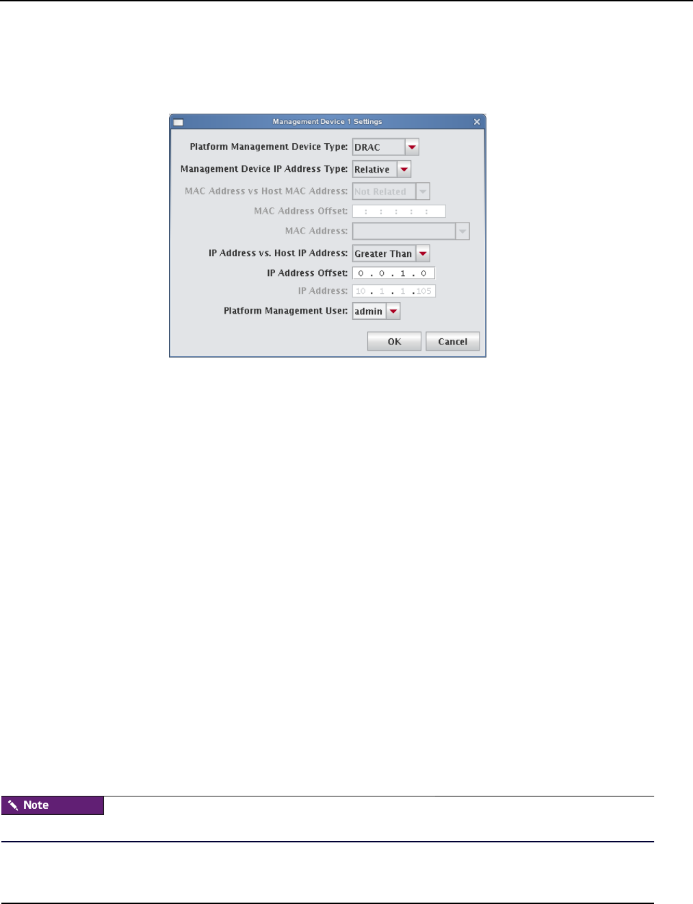
Configure Platform Management
007-5642-005 47
DRAC and ILO
1. Select Override Global Settings.
2. Select DRAC or ILO as the Platform Management Device Type.
3. Select the Management Device IP Address Type:
A. Dynamic — Enter a hexadecimal MAC offset. For example, if you choose a Greater Than offset of
00:00:00:00:00:04 and the host’s MAC address is 00:15:C5:EA:A7:7B, the MAC Address used for power
operations will be 00:15:C5:EA:A7:7F (the sum of the original MAC address and the offset).
B. Relative — Choose an IP address offset and select whether it is Greater Than, the Same as, or Less Than the
host’s IP address. For example, if you choose a Greater Than offset of 0.0.1.0 and the host’s IP address is
10.3.0.14, the host’s BMC address will be 10.3.1.14. This is the IP address used for power operations (the
sum of the original IP address and the offset).
C. Static If you choose Static or if you wish to use different settings for each host, you must configure the
DRAC and ILO options individually for each host.
4. (Optional) Select the MAC Address vs. Host MAC Address type:
A. Not Related
B. Greater Than
C. Less Than
5. (Optional) Enter the MAC Address Offset.
6. Select the MAC Address to use to manage this host.
7. (Optional) Select the IP Address vs. Host IP Address type:
A. Greater Than
B. Less Than
C. Same As
8. (Optional) Enter the IP address offset from the management interface.
9. (Optional) Enter the IP address for the host.
10. Select a Platform Management User.
Users must be members of the Power group to appear in this list.

Edit a Host
007-5642-005
48
Edit a Host
Editing hosts allows you to change information previously saved about a host, edit host configurations, or move hosts in
and out of partitions and regions.
To Edit a Host
1. Select a host from the host navigation tree. (To select multiple hosts, use the Shift or Ctrl keys.)
2. Select Edit from the Edit menu or right-click the hosts in the navigation tree and select Edit.
Management Center displays the host pane for each selected host. From this view, you can make changes to the
hosts.
Changing the name of the Master Host may prevent the cluster from functioning correctly. For information on changing
the name of the Master Host, see Renaming the Management Center Master Host on page 48.
3. Click Apply.
Renaming the Management Center Master Host
Before changing the name of the Master Host, consider applications that require the use of this name (for example, job
schedulers, mpi “machines” files, and other third-party software). In some cases, you may need to consult with
application vendors regarding special instructions for changing the name of the Master Host.
When you change the Master Host name, all Management Center services, hosts, and clients must be able to resolve the
new name. To ensure that your system functions properly after renaming the Master Host, you must update the host
name in several files. To rename your Master Host:
1. Select the Master Host in the host navigation tree.
2. Select Edit from the Edit menu or right-click on the Master Host and select Edit. Management Center displays the
host pane.
3. In the host pane, enter a new name and click Apply.
4. Exit Management Center.
5. In a command line, enter /etc/init.d/mgr stop to shut down Management Center services on the system.
6. On the Master Host, edit the $MGR_HOME/@genesis.profile to use the new name (system.rna.host).
7. On the Master Host, edit the $MGR_HOME/etc/Activator.profile and change all instances of the host name to use
the new name.
8. Add the new Master Host name to the alias list in /etc/hosts. For example:
10.168.18.3 host.sgi.com host <new_name>
9. Restart Management Center.
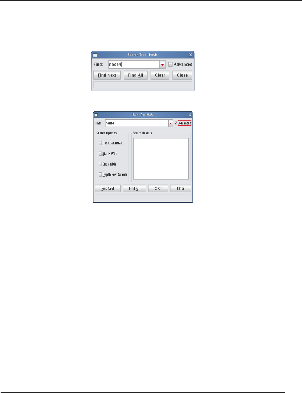
Find a Host
007-5642-005 49
Find a Host
To Find a Host in the Host Navigation Tree
1. Select Find from the Edit menu.
2. Enter the name of a host and click Find Next.
3. (Optional) Click Advanced to enable more extensive search options.
Delete a Host
Deleting a host removes it from the cluster.
To Delete a Host
1. Select the host you want to delete from the host navigation tree. (To select multiple hosts, use the Shift or Ctrl
keys).
2. Select Delete from the Edit menu or right-click the selected hosts in the navigation tree and select Delete.
Management Center asks you to confirm your action.
3. Click OK to delete the hosts.
Import Hosts
Management Center provides an easy way to import a large group of hosts from a file. When importing a list of hosts, it
is important to note that Management Center imports only host information. Management Center accepts the following
file types: nodes.conf, dbix, or CSV.

Import Hosts
007-5642-005
50
To Import a List of Hosts
1. Obtain or create a host list file for importing. The following examples depict nodes.conf, dbix, and CSV file
formats:
A. nodes.conf
SGI nodes.conf format lists one host per line with properties being space or tab
delimited:
MAC HOSTNAME IP_ADDRESS BOOT_MODE UNIQUE_NUM DESCRIPTION
Example:
0050455C0392 n001 192.168.4.1 boot_mode 1 Node_n001
0050455C03A2 n002 192.168.4.2 boot_mode 2 Node_n002
B. dbix
dbix
hosts.<hostname>.description: <description>
hosts.<hostname>.enabled:true
hosts.<hostname>.name:<hostname>
hosts.<hostname>.partition:<partition>
interfaces.<MAC_address1>.address:<IP_address1>
interfaces.<MAC_address1>.mac:<MAC_address1>
interfaces.<MAC_address1>.management:true
interfaces.<MAC_address1>.owner:<hostname>
interfaces.<MAC_address2>.address:<IP_address2>
interfaces.<MAC_address2>.mac:<MAC_address2>
interfaces.<MAC_address2>.management:false
interfaces.<MAC_address2>.owner:<hostname>
Example:
hosts.n1.description:Added automatically by add_hosts.shasd
hosts.n1.enabled:true
hosts.n1.name:n1
hosts.n1.partition:computehosts
interfaces.0030482acc96.address:10.0.1.1
interfaces.0030482acc96.mac:0030482acc96
interfaces.0030482acc96.management:true
interfaces.0030482acc96.owner:n1
interfaces.0030482acc9a.address:10.0.2.1
interfaces.0030482acc9a.mac:0030482acc9a
interfaces.0030482acc9a.management:false
interfaces.0030482acc9a.owner:n1
Dbix files are created primarily by obtaining and editing a Management Center database file.
C. CSV
HOSTNAME,MAC_ADDRESS1,IP_ADDRESS1,DESCRIPTION,MAC_ADDRESS2,IP_ADDRESS2
Example:
n14,”0040482acc96,0040482acc9a”,”10.4.1.1,10.4.2.1”,Description
2. Select Import Host List from the File menu.
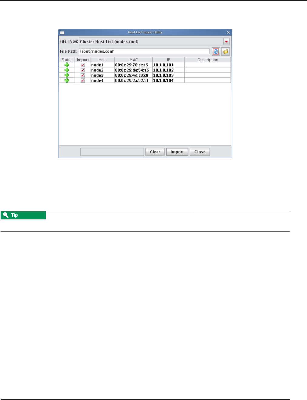
Import Hosts
007-5642-005 51
The Host List Import Utility dialog appears.
3. Select the host list file type you are importing.
If you change the file type, click Refresh to update the dialog.
4. Enter the path for the file you want to import or click Browse to locate the file.
5. Review the list of hosts to import and un-check any hosts you do not want.
Errors display for items that cannot be imported.
To clear the list of selected hosts, click Clear.
6. Click Import to import the list of hosts.
7. Click Close.
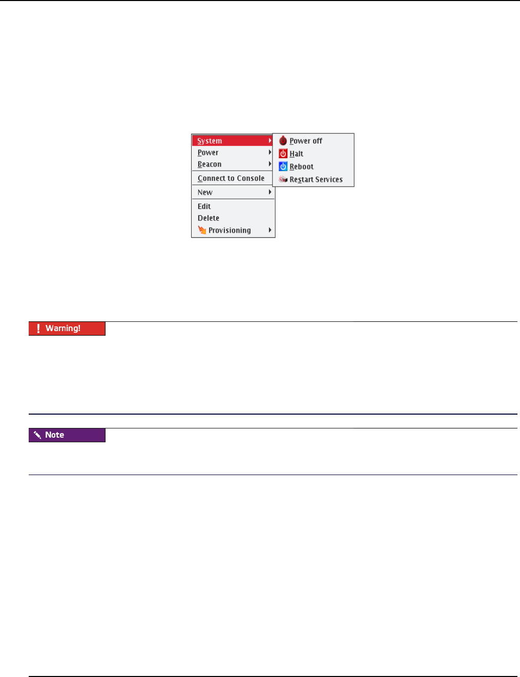
Host Power Controls
007-5642-005
52
Host Power Controls
The Power Management feature provides you with the ability to remotely reset, power up, power down, and cycle
power to hosts installed in your system. Power status information for each host is available through the instrumentation
tab. See Overview Tab on page 150 and Thumbnail Tab on page 151.
System
The System options in the right-click menu execute power-related events on the hosts.
POWER OFF
Issues the Linux /sbin/poweroff command to stop all applications and services running on the host and, if the
hardware allows, to power off the host. If you have used the /sbin/shutdown command to successfully shut down
and reboot hosts at the next power cycle, you should be safe to enable this option. To enable shutdown, set the
shutdown.button.enable option in HostAdministrationService.profile to true.
Using the shutdown option requires that the BIOS is enabled to support boot at power up — the default behavior for
LinuxBIOS. This setting, also referred to as Power State Control or Power On Boot, is typically enabled for most
server-type motherboards.
If you do not enable this BIOS setting, hosts that are shut down may become unusable until you press the power button
on each host. For the location of your host power switch, please consult your host installation documentation.
The power connection to the host remains active unless you click Off. To return the host to normal operational status,
cycle the power.
HALT
Issues the Linux /sbin/halt command to stop all applications and services running on the host and, if the hardware
allows, power off the host.
REBOOT
Shuts down and restarts all applications and services on the host.
RESTART SERVICES
Restarts the Management Center services on the selected hosts.
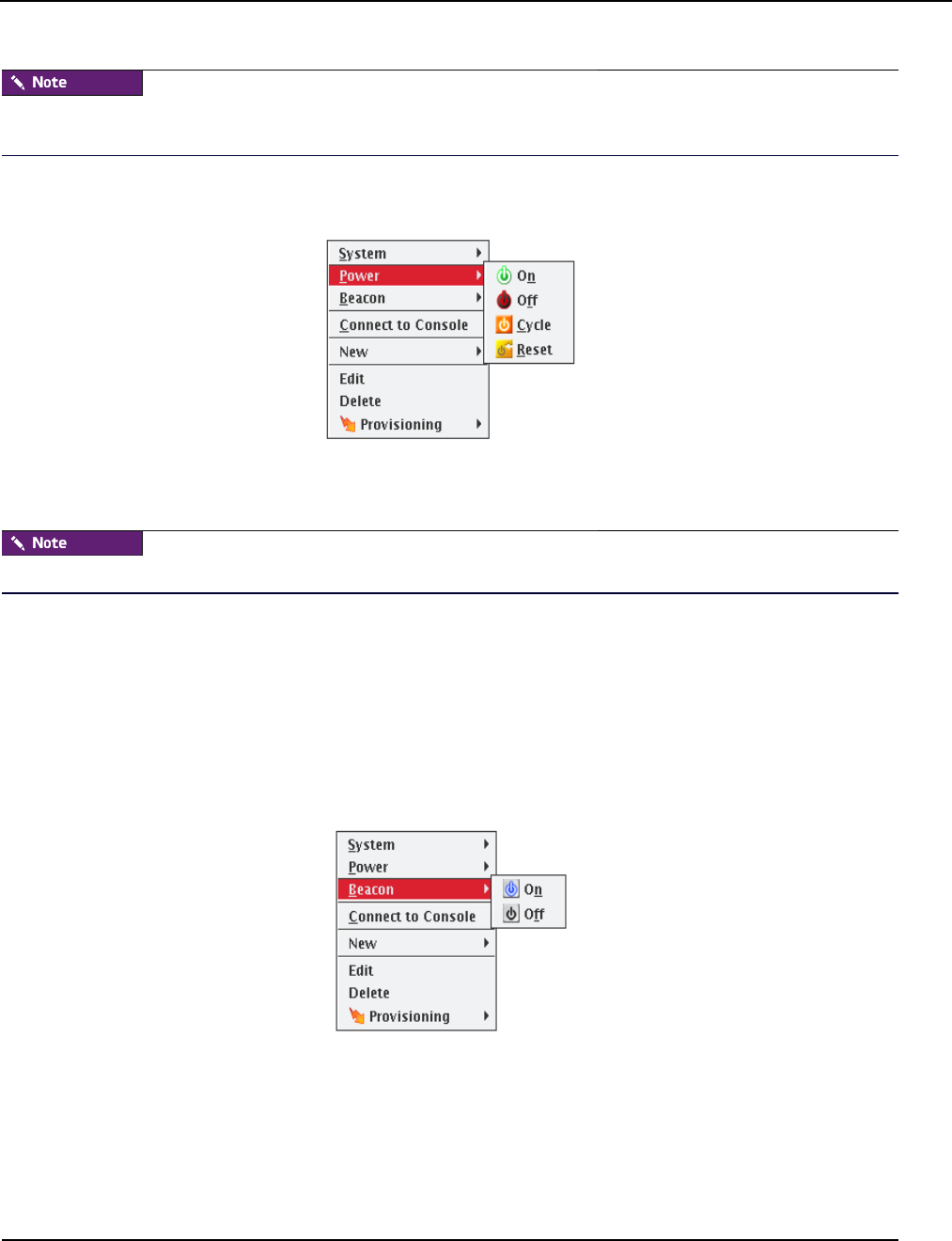
Host Power Controls
007-5642-005 53
You cannot restart Management Center services on the Master Host from the GUI. You must perform this action from
the CLI.
Power
The Power options in the right-click menu execute power-related events from your power management device.
ON
Turn on power to the host.
If you are unable to power a host on or off, the port may be locked.
OFF
Immediately turn off power to the host.
CYCLE
Turn off the power, then back on. This is useful for multiple hosts.
RESET
Send a signal to the motherboard to perform a soft boot of the host.
Beacon
BEACON ON
To identify a specific host in a cluster for troubleshooting purposes, click Beacon On to flash a light from the host. Use
the Shift and Ctrl keys to select multiple hosts.By default, the beacon icon appears next to the selected host(s) for 180
seconds. You can change this default time by changing the timeout.beacon.seconds parameter in file
$MGR_HOME/etc/PlatformManagementService.profile.

Console
007-5642-005
54
The beacon function works only if the hardware installed in your cluster supports beacons (i.e., the hosts support IPMI
or ILO).
BEACON OFF
Turn off the beacon.
Console
Connecting to the console allows you to monitor activity on a host-by-host basis. When you connect to the console,
Management Center opens a terminal window for each host and allows you to view host activity or execute bash and
other general command-line operations necessary for troubleshooting. You can also use the console to apply specific
configurations or enhancements to a payload that you can import and use at a later time.
To Connect to the Console
Before you can connect to a console, you must configure the platform management settings for your hosts to direct
them to the serial device they will use (such as IPMI or Conman) and enable the Console option. You must install and
configure conman it before you can use it. See Conman on page 28 and conman on page 216 for additional information
about configuration and CLI controls.
1. Select the host on which you want to open a console from the host navigation tree.
To select multiple hosts, use the Shift or Ctrl keys.
2. Right-click on a selected host and select Connect to Console.
A console opens for each host.
3. Enter bash or other general CLI commands as needed to configure the host.
4. When finished, close the console.
Roamer KVM
When using Roamer-enabled nodes, you can connect to the Roamer KVM from the Management Center GUI. When
you connect to the KVM console, Management Center opens a console window using Java. This allows you to control
the host as you would with a keyboard, monitor, and mouse.
Before you can connect to a console, you must configure the platform management settings for your host to use Roamer
and enable the Console option. This configures the host to use Roamer for the serial console.
To connect to the Roamer KVM, use the following steps:
1. Select the host on which you want to open a console from the host navigation tree.
2. Right-click on a selected host and select Connect to KVM.
A Java KVM console opens for the host.
3. When finished, close the console.
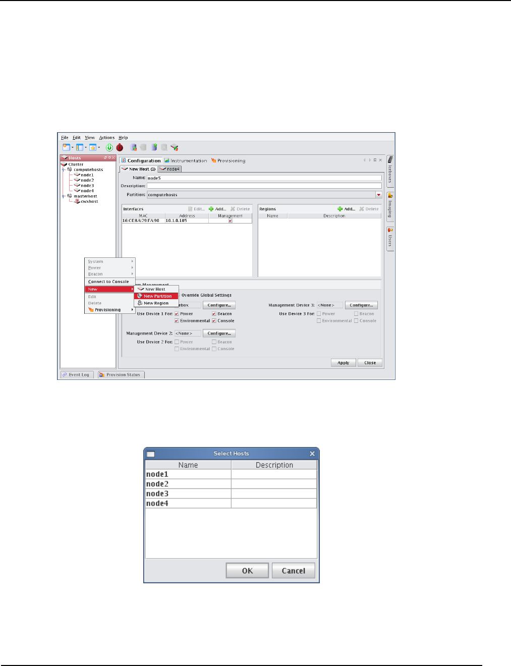
Partitions
Adding Partitions
007-5642-005 55
Partitions
You can use partitions to group clusters into non-overlapping collections of hosts. Instrumentation, provisioning, power
control, and administrative tasks can be performed on this collection of hosts by selecting the partition in the host tree.
Adding Partitions
1. Right-click in the Hosts navigation tree and select New Partition or select New Partition from the File menu.
2. Enter a partition name.
3. (Optional) Enter a description.
4. In the Hosts pane, click Add to display the Select Hosts dialog.
5. Select hosts to add to this partition and click OK.
6. Click Apply.
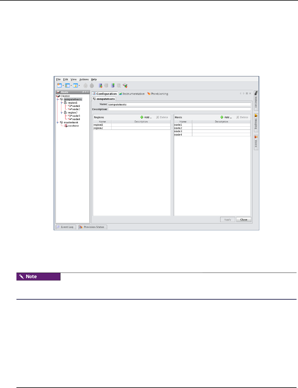
Partitions
Editing Partitions
007-5642-005
56
Editing Partitions
Editing a partition allows you to change previously saved information about a partition. You can edit or remove regions,
alter partition configurations, disable partitions, or remove partitions from the host.
1. Select a partition from the host navigation tree.
2. Select Edit from the Edit menu or right-click on the partitions in the host navigation tree and select Edit.
3. Use the Partition pane to make changes to the partition).
4. Click Apply to accept the changes or click Close to abort this action.
Deleting Partitions
Deleting a partition allows you to remove unused partitions from the system.
If you delete a partition, all regions and hosts associated with the partition will move to the default partition. To delete
regions and hosts, refer to Regions on page 57 and Adding Hosts on page 43.
1. Select the partitions you want to delete from the host navigation tree.
2. Select Delete from the Edit menu or right-click on the partitions in the navigation tree and select Delete.
3. Click OK to delet the partitions.
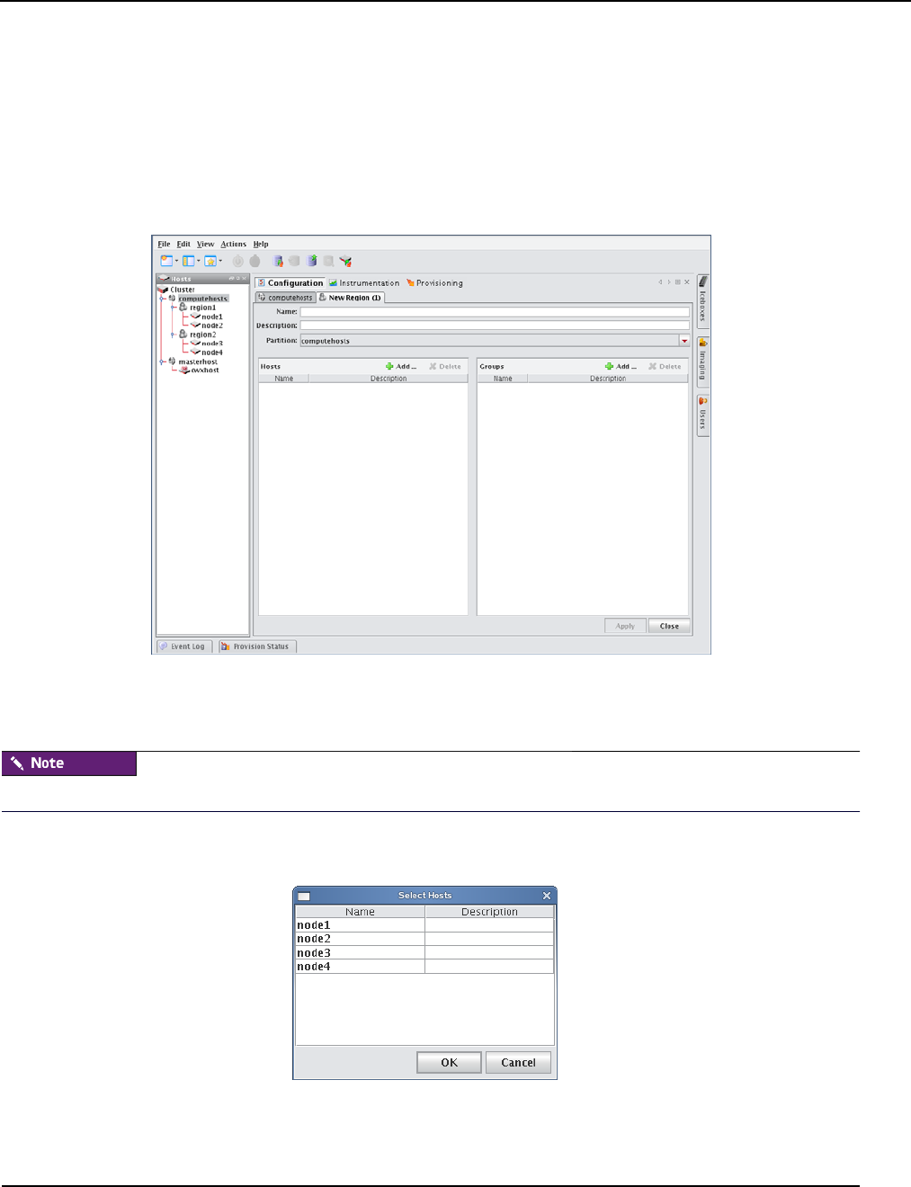
Regions
Creating Regions
007-5642-005 57
Regions
A region is a subset of a partition and may share any hosts that belong to the same partition — even if the hosts are
currently used by another region.
Creating Regions
1. Select New Region from the File menu or right-click in the host navigation tree and select New Region.
2. Enter the name.
3. (Optional) Enter a description.
4. (Optional) Select the name of the partition you want to assign the region to from the drop-down list.
Regions not assigned to a partition become part of the default or unassigned partition.
5. In the Hosts pane, click Add to assign hosts to the region.
6. In the Select Hosts dialog, select the hosts you want to add to the region.
7. Click OK to add the hosts.
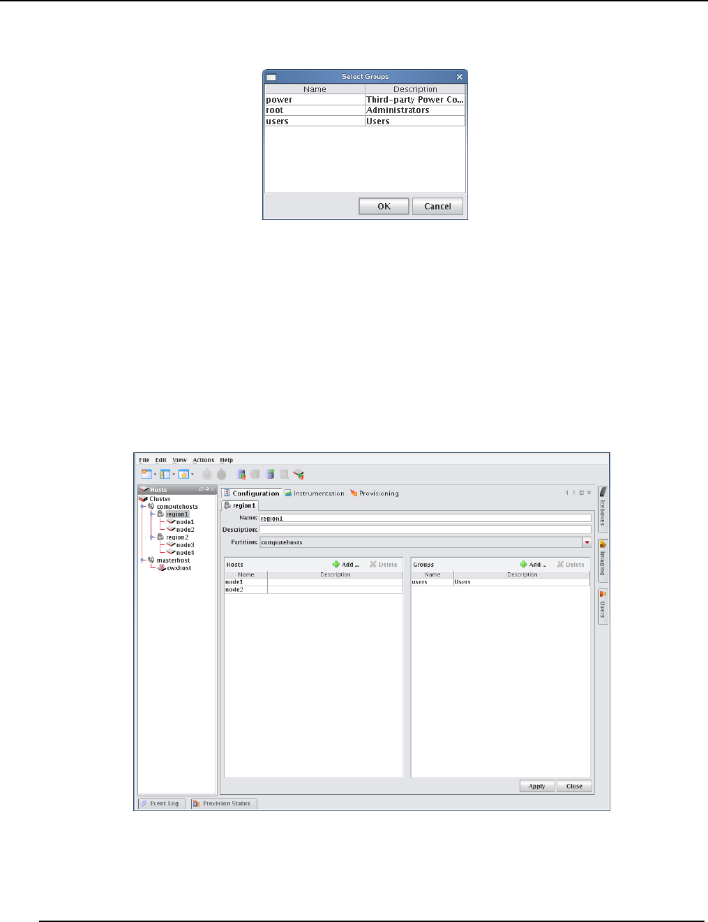
Regions
Editing Regions
007-5642-005
58
8. In the Groups pane, click Add.
9. Select the groups you want to add to the region.
Adding groups to the region defines which users may access the hosts assigned to the region.
10. Click OK to add the groups.
11. Click Apply.
Editing Regions
Editing regions allows you to change previously saved information about a region or to modify region memberships by
adding or removing groups or hosts.
1. Select a region from the host navigation tree.
2. Select Edit from the Edit menu or right-click the regions in the navigation tree and select Edit.
3. Make changes to the regions (such as adding or deleting hosts).
4. Click Apply.

Regions
Deleting Regions
007-5642-005 59
Deleting Regions
Deleting a region allows you to remove unused regions from the system.
1. Select the region you want to delete from the host navigation tree.
2. Select Delete from the Edit menu or right-click on the regions in the navigation tree and select Delete.
3. Click OK to remove the regions.
If you delete a region, all hosts associated with the region return to the partition to which the region belonged. If the
region was not part of a partition, the hosts move to the default partition.
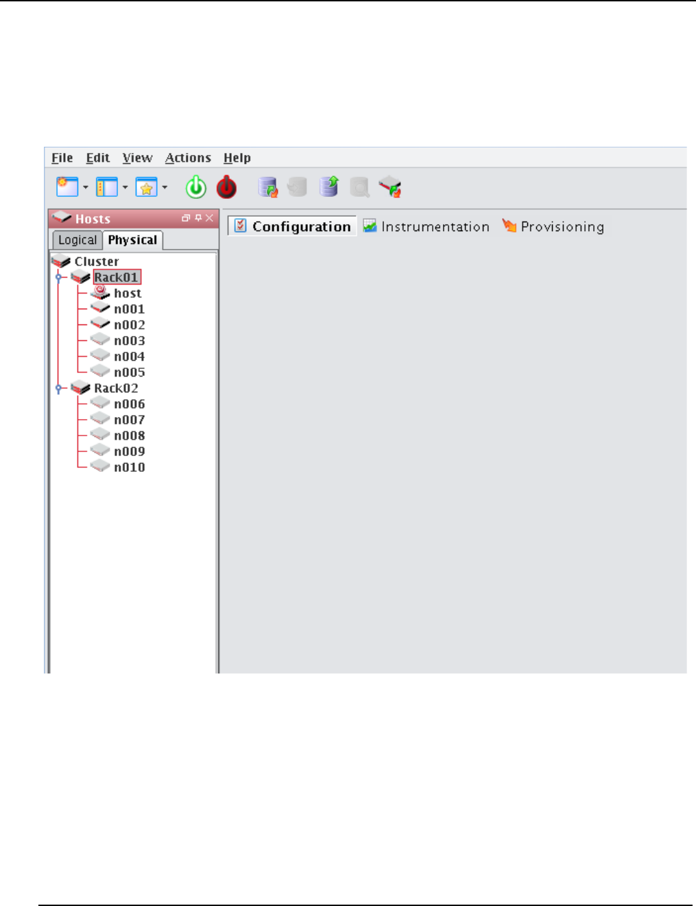
Racks
Deleting Regions
007-5642-005
60
Racks
To aid in the management of the cluster, you can use racks to represent the physical layout of the cluster into non-
overlapping collections of hosts. If you have hosts which are not assigned a rack, they will appear in a rack labelled
Unassigned.
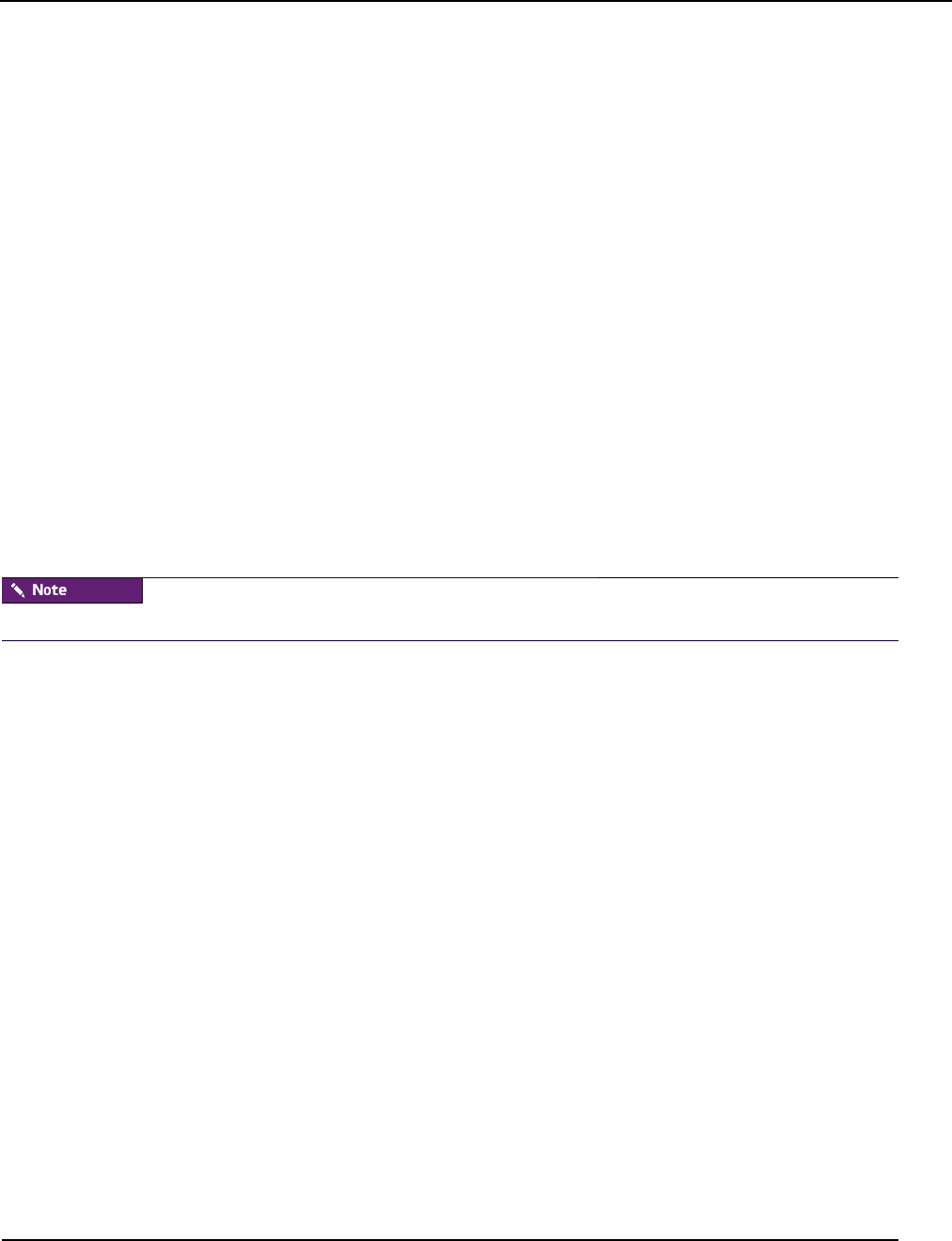
Racks
Adding Racks
007-5642-005 61
Adding Racks
1. Right-click in the Hosts navigation tree and select New Rack or select New Rack from the File menu.
2. Enter a rack name.
3. (Optional) Enter a description.
4. In the Hosts pane, click Add to display the Select Hosts dialog.
5. Select hosts to add to this rack and click OK.
6. Click Apply.
Editing Racks
Editing a rack allows you to change previously saved information about a rack. You can edit rack information, alter
rack configurations, or remove racks.
1. Select a rack from the host navigation tree.
2. Select Edit from the Edit menu or right-click on the racks in the host navigation tree and select Edit.
3. Use the rack pane to make changes to the rack.
4. Click Apply to accept the changes or Close to abort this action.
Deleting Racks
If you delete a rack, all hosts associated with the rack will be moved to rack Unassigned.
1. Select the rack(s) you want to delete from the host navigation tree.
2. Select Delete from the Edit menu or right-click on the rack(s) in the navigation tree and select Delete.
3. Click OK to delete the rack(s).
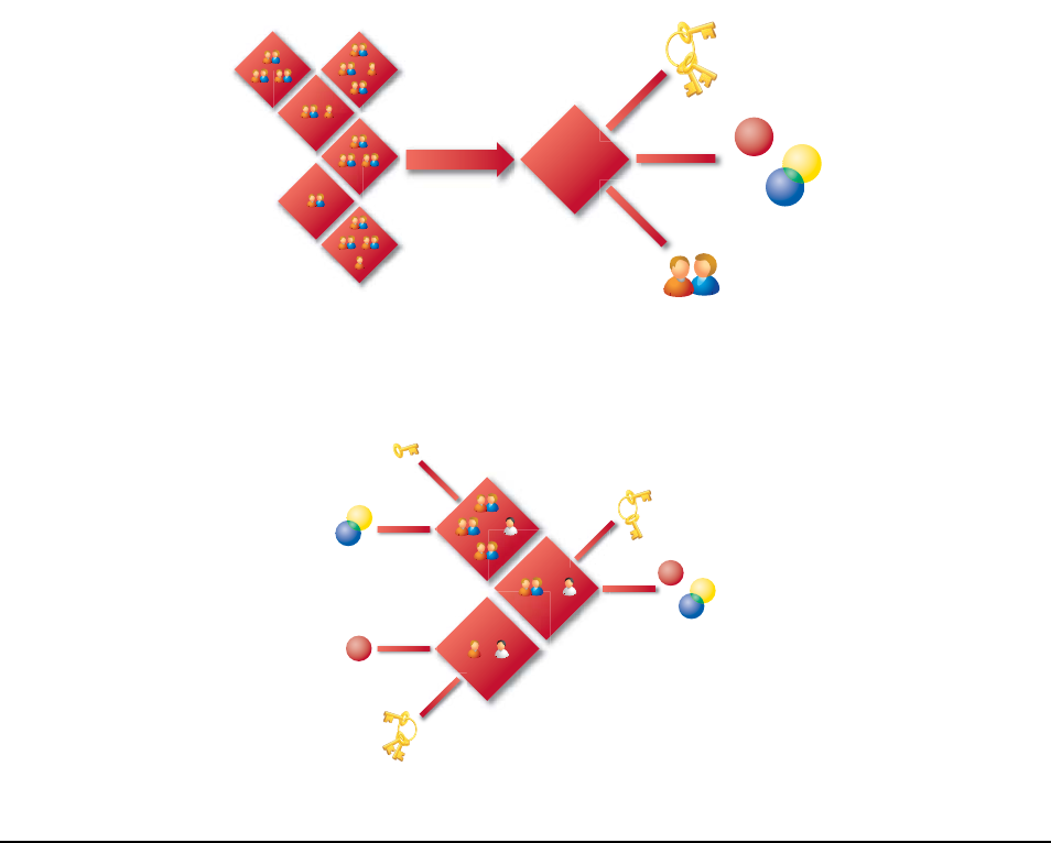
007-5642-005 63
Chapter 5
User Administration
Management Center allows you to configure groups, users, roles, and privileges to establish a working environment on
the cluster. A group refers to an organization with shared or similar needs that is structured using specific roles
(permissions and privileges) and region access that may be unique to the group or shared with other groups. Members
of a group (users) inherit all rights and privileges defined for the group(s) to which they belong.
For example, a user assigned to multiple groups (as indicated by the following diagram) has different rights and
privileges within each group. This flexibility allows you to establish several types of user roles: full administration,
group administration, user, or guest.
Users
Roles
Regions
Group
Groups
Multi-Group Users
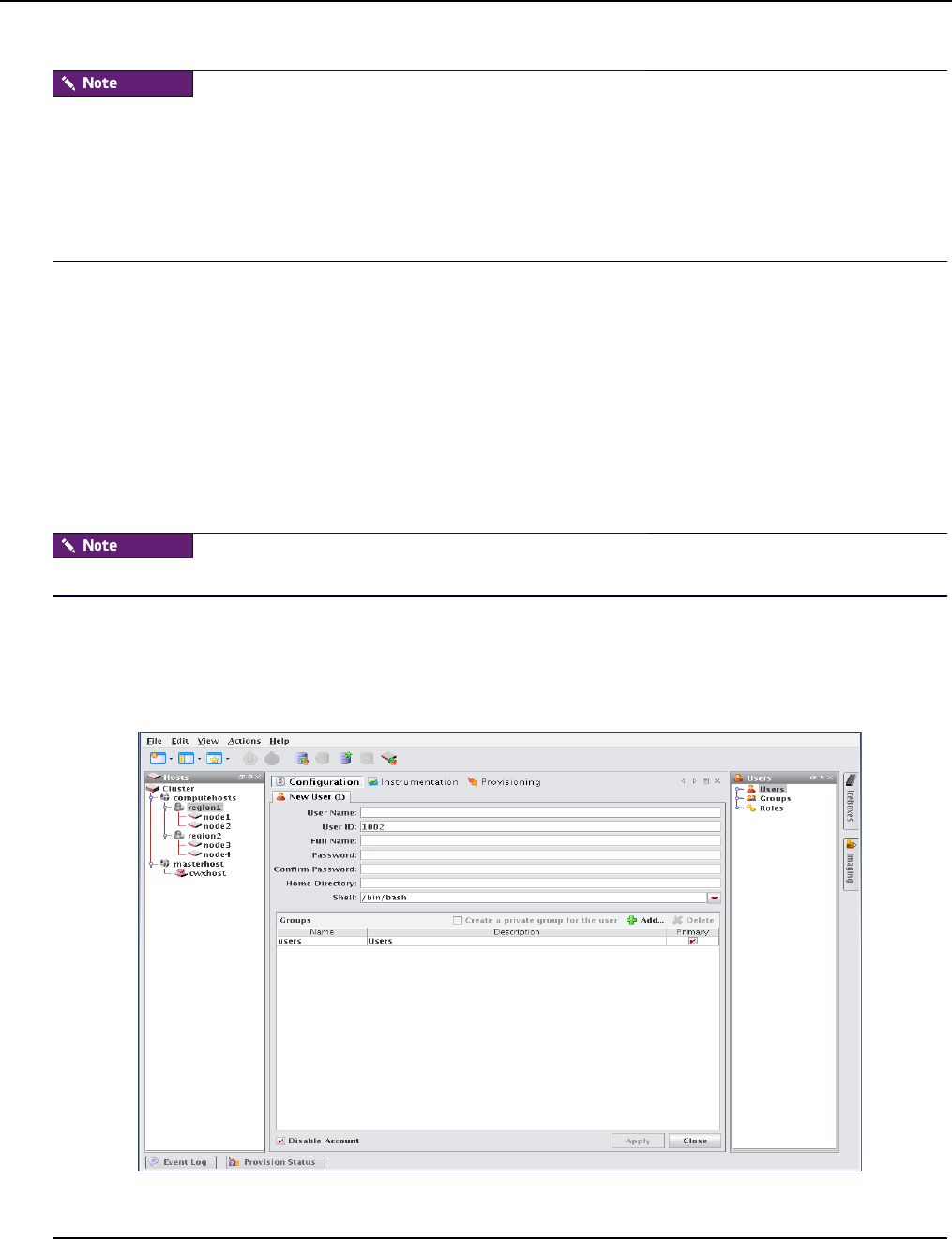
Default User Administration Settings
Adding a User
007-5642-005
64
Management Center currently supports adding users and groups to payloads only—it does not support the management
of local users and groups on the Master Host. Users with local Unix accounts do not automatically have Management
Center accounts, and this information cannot be imported into Management Center.
If you are using local authentication in your payloads and intend to add Management Center users or groups, ensure that
the user and group IDs (UIDs and GIDs, respectively) match up between the accounts on the Master Host and
Management Center. Otherwise, NFS may not work properly.
Default User Administration Settings
Management Center implements the following structure during the installation process:
•The root and guest user accounts are created.
•The root, power, and users groups are created.
•The root and user roles are created.
•All privileges allowed by the installed license are created.
After installation, Management Center allows you to create, modify, or delete groups, users, roles, and privileges as
needed.
You cannot remove the root user.
Adding a User
Adding a user to Management Center creates an account for the user and grants access to the system.
1. Select New User from the File menu or right-click in the user navigation tree and select New User.
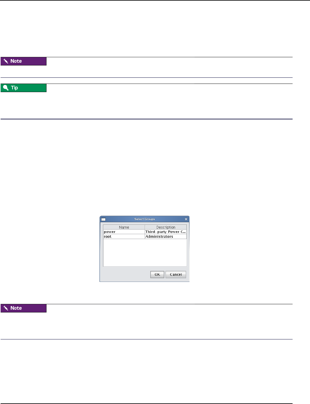
Default User Administration Settings
Adding a User
007-5642-005 65
2. Enter the user’s login name.
3. (Optional) Management Center assigns a system-generated user ID. Enter any changes to the ID in the User ID
field.
4. Enter the user’s first and last name in the Full Name field.
The Management Center UID must match the system UID.
If a user already has an account and you would like to apply the account to the Master Host and compute hosts, add the
user to your payload during payload creation. When you provision, Management Center creates the account on the
hosts. See Payload Local User and Group Account Management on page 92.
5. Enter and confirm a user password.
6. (Optional) Enter a home directory (for example, /home/username).
7. (Optional) Enter a shell for this user or select an existing one from the drop-down list. (By default, Management
Center uses /bin/bash.)
8. Click Apply.
Defining User Groups
The groups pane allows you to identify the group(s) to which the user belongs. Users are allowed to be part of any
number of groups, but granting access to multiple groups may allow users unnecessary privileges to various parts of the
system. See Roles on page 70.
1. To add the user to a group, click Add.
2. Select the groups you want associated with the user.
Each user must belong to a primary group. If not, Management Center automatically assigns the user to the “users”
group. If you are using third-party power controls such as IPMI, the power group must be the primary group for all
users who will use these controls. See Power on page 67.
3. Click OK.
4. (Optional) Select Create a private group for the user to create a new group with the same name as the user.
5. (Optional) Check Disable Account to prevent users from logging into this account and to exclude this account
from future payloads without deleting the account.
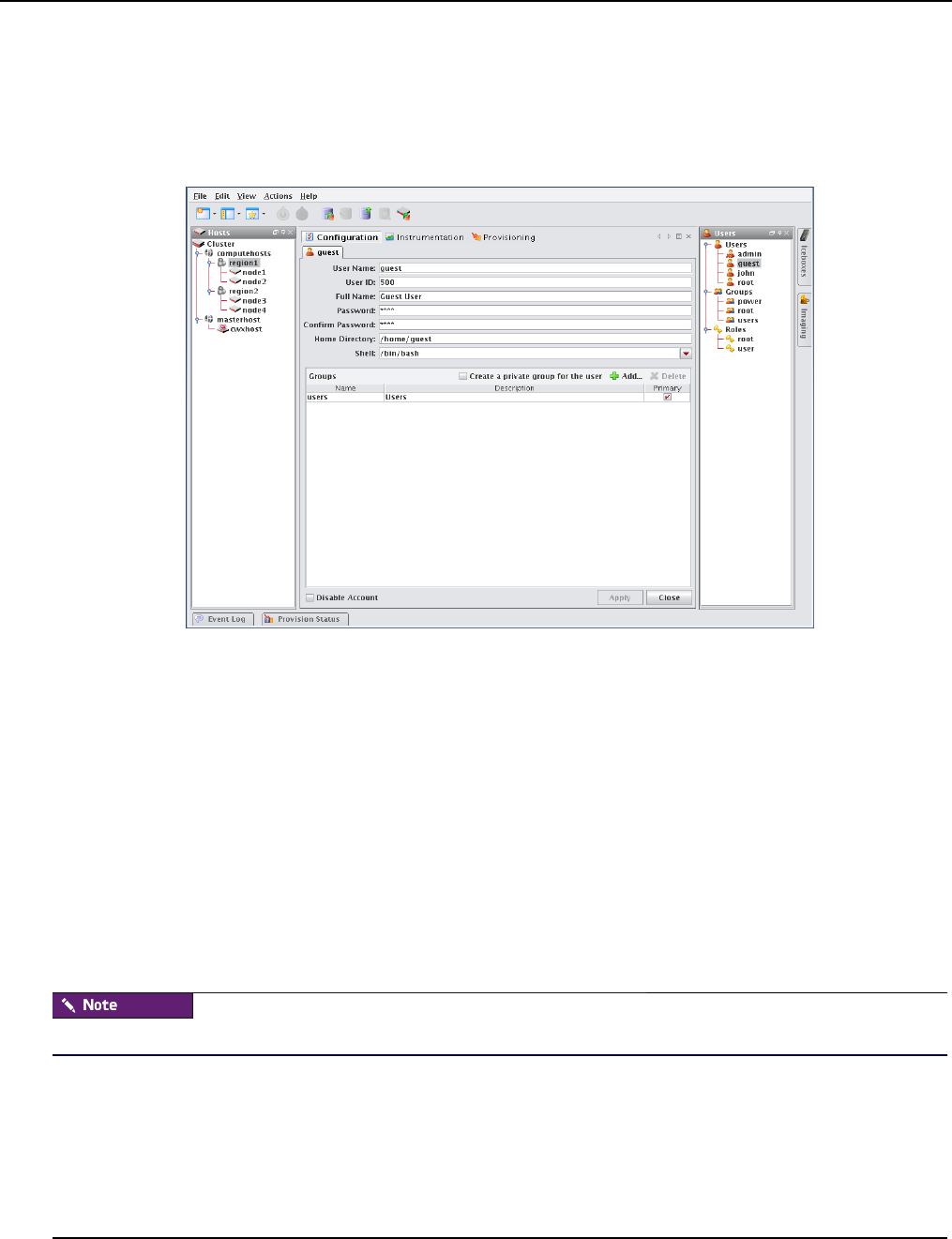
Default User Administration Settings
Editing User Accounts
007-5642-005
66
Editing User Accounts
Editing a user account allows you to change information previously saved about a user.
1. Select a user from the user navigation tree.
2. Select Edit from the Edit menu or right-click a user in the navigation tree and select Edit.
3. Click Apply.
Disabling a User Account
Disabling a user account allows you to render the account temporarily inoperative without removing it.
1. Select a user from the user navigation tree.
2. Select Edit from the Edit menu or right-click a user in the navigation tree and select Edit.
3. Select Disable Account.
4. Click Apply.
Deleting a User Account
Deleting a user allows you to remove unused user accounts from the system. To temporarily disable a user account, see
Disabling a User Account on page 66.
You cannot remove the root user.
To Delete a User
1. Select the users you want to delete from the user navigation tree.
2. Select Delete from the Edit menu or right-click the user names and select Delete.
3. Click OK to remove the users.
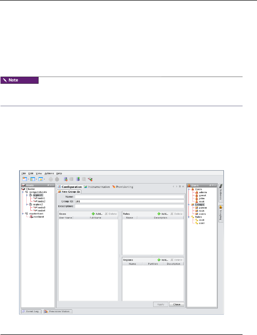
Groups
Adding a Group
007-5642-005 67
Groups
The following sections outline the fundamentals of adding, editing, and deleting groups. By default, Management
Center enables the following groups, but you can create new groups as needed:
Power The power group contains the user names and passwords that will be used to manage IPMI and other 3rd-party
power controllers. By default, this group has no role associated with it, so users assigned to this group cannot typically
log into Management Center. Although temperature and fan monitoring do not require that a user is assigned to this
group, you must assign a user to the power group in order to use power control and beaconing for IPMI-enabled
devices.
When using third-party power controls such as IPMI, the power group must be the primary group for all users who will
access these controls (see Defining User Groups on page 65). Users who belong to the power group cannot log into
Management Center.
Root The root group typically contains users with full administrative privileges.
Users The users group typically includes all users with access to the cluster. By default, the Users group is associated
with the Users role. Management Center automatically assigns all users to the “users” group.
Adding a Group
Adding groups creates a collection of users with shared or similar needs (for example, an engineering, testing, or
administrative group).
1. Select New Group from the File menu or right-click in the user navigation tree and select New Group.
2. Enter the group name.
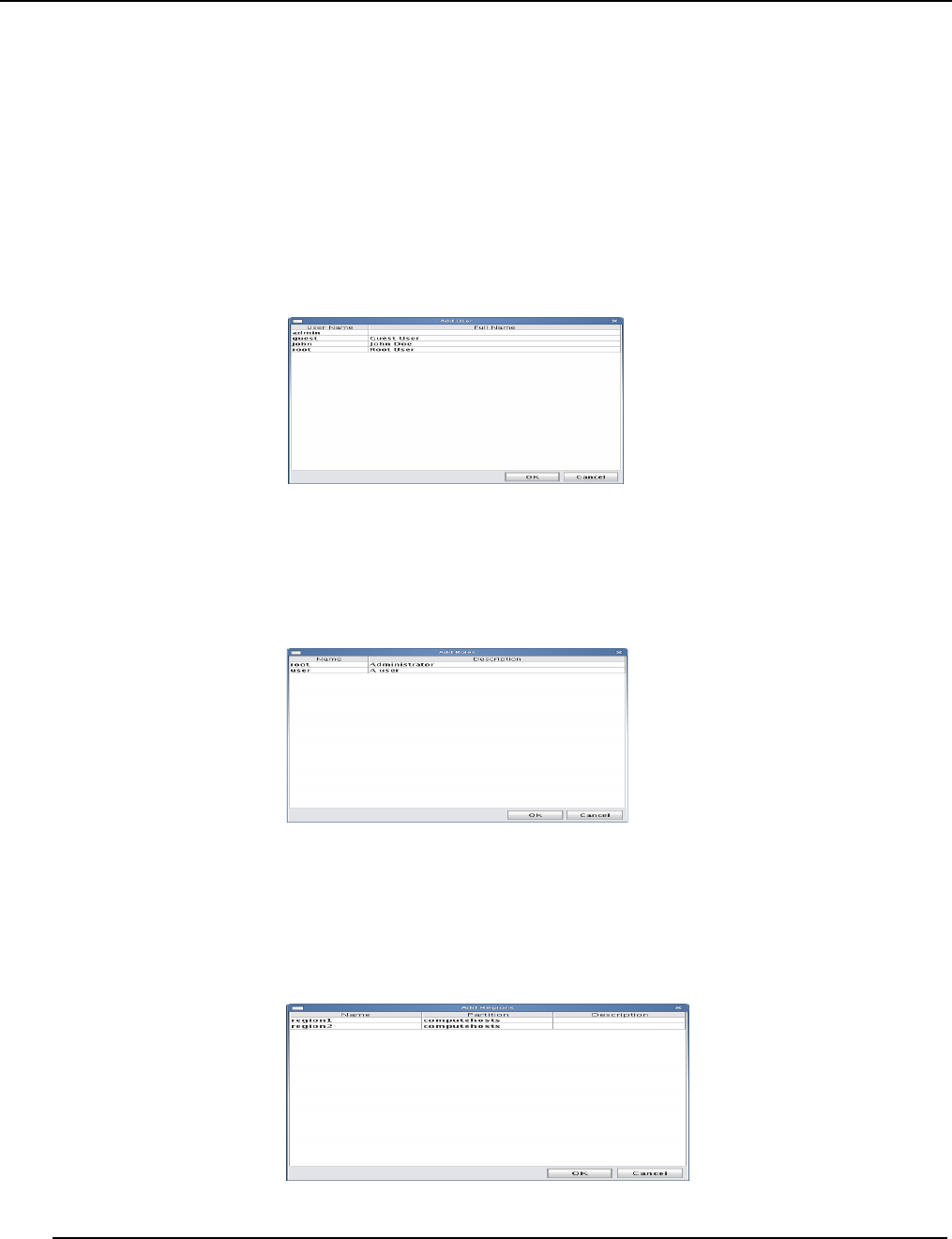
Groups
Adding a Group
007-5642-005
68
3. (Optional) Management Center assigns a system-generated Group ID. Enter any changes to the ID in the Group ID
field.
4. (Optional) Enter a description.
5. Click Apply.
ADD USERS
The Users pane allows you to identify the users that belong to the current group. Users are allowed to be part of any
number of groups, but granting access to multiple groups may allow users unnecessary privileges to various parts of the
system. See Roles on page 70.
1. To add a user to the group, click Add.
2. Select the users to add to the group (use the Shift or Ctrl keys to select multiple users.
3. Click OK.
ASSIGN ROLES
The Roles pane allows you to assign specific roles to the group.
1. Click Add in the Roles field.
2. Select the roles to assign to the group.
3. Click OK.
ASSIGN REGIONS
The Regions pane allows you to grant a group access to specific regions of the system. See User Administration on
page 63.
1. Click Add in the Regions field.
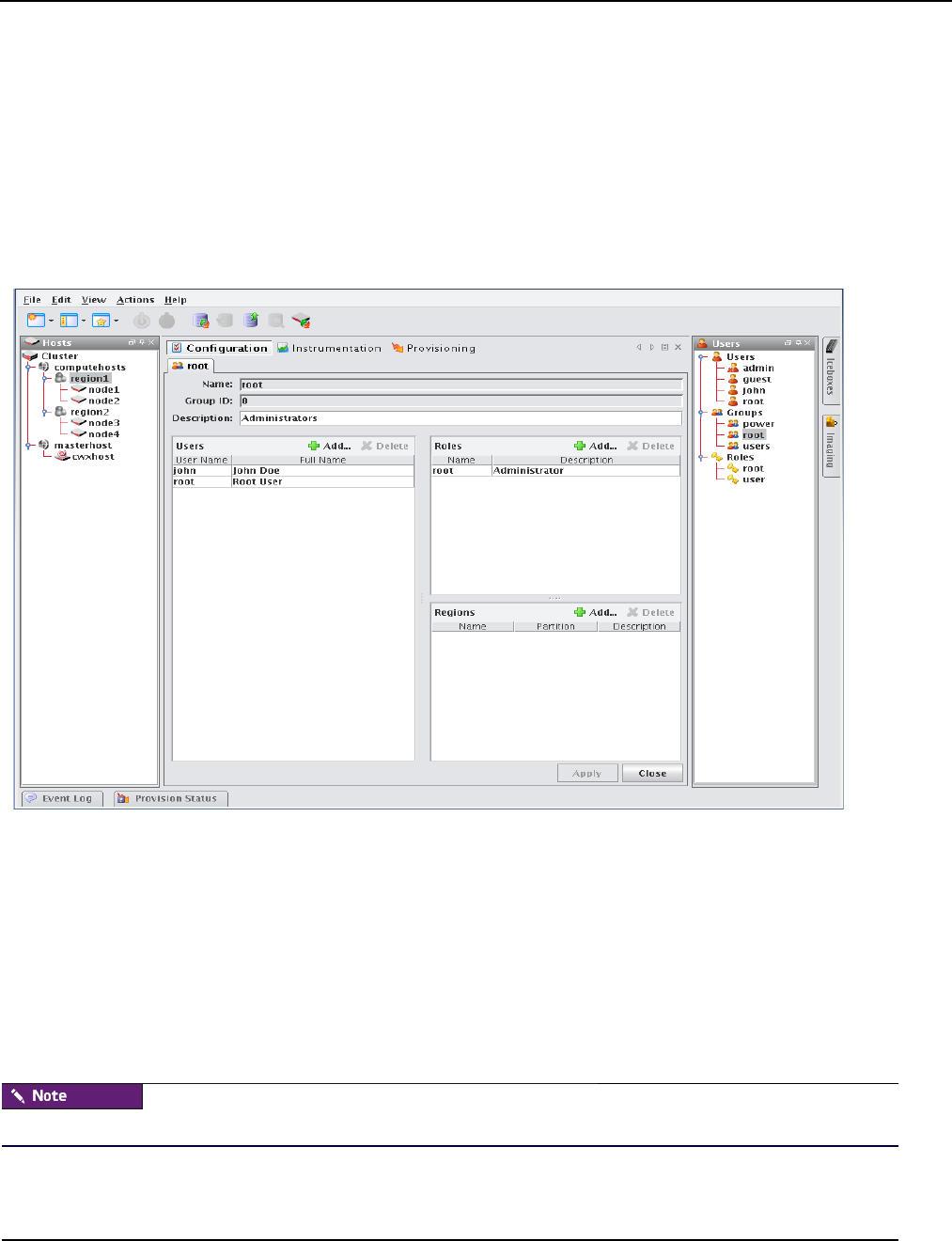
Groups
Editing a Group
007-5642-005 69
2. Select the regions to assign to the group.
3. Click OK.
Editing a Group
Editing a group allows you to change previously saved information about a group or modify group memberships by
adding or removing users.
1. Select a group from the user navigation tree.
2. Select Edit from the Edit menu or right-click a group name in the navigation tree and select Edit.
3. Make changes by adding or deleting users, roles, and regions as needed.
4. Click Apply.
Deleting a Group
Deleting a group allows you to remove unused groups from the system.
1. Select the groups you want to delete from the user navigation tree.
2. Select Delete from the Edit menu or right-click group names in the navigation tree and select Delete.
3. Click OK.
You cannot remove the root, power, or users groups.
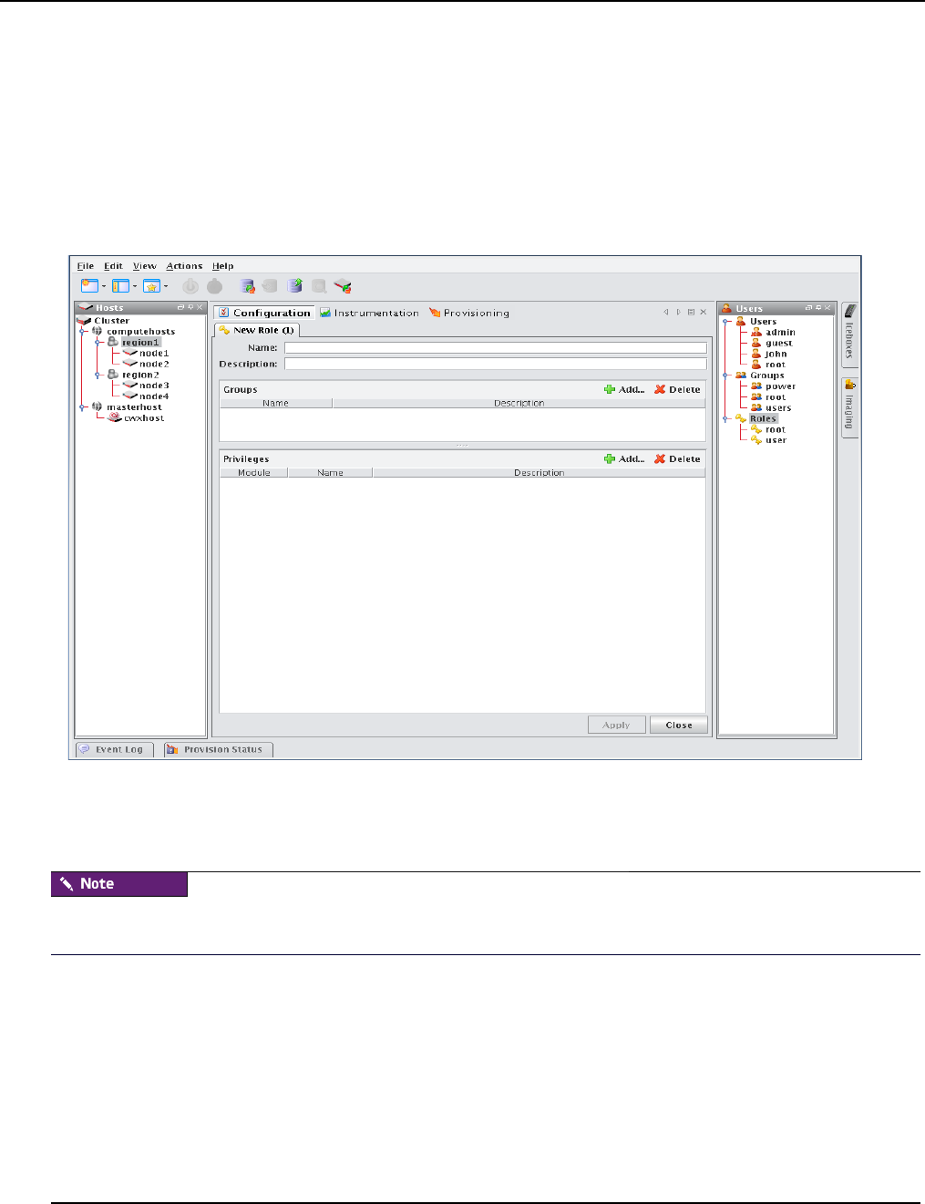
Roles
Adding a Role
007-5642-005
70
Roles
The following sections outline the fundamentals of adding, editing, and deleting roles. Roles are associated with groups
and privileges, and define the functionality assigned to each group. Several groups can use the same role.
Adding a Role
Adding a role to Management Center allows you to define and grant system privileges to groups.
1. Select New Role from the File menu or right-click in the Users frame and select New Role.
2. Enter the role name.
3. (Optional) Enter a description.
4. Click Apply.
Adding or revoking privileges will not affect users that are currently logged into Management Center. Changes take
effect only after the users close Management Center and log in again.
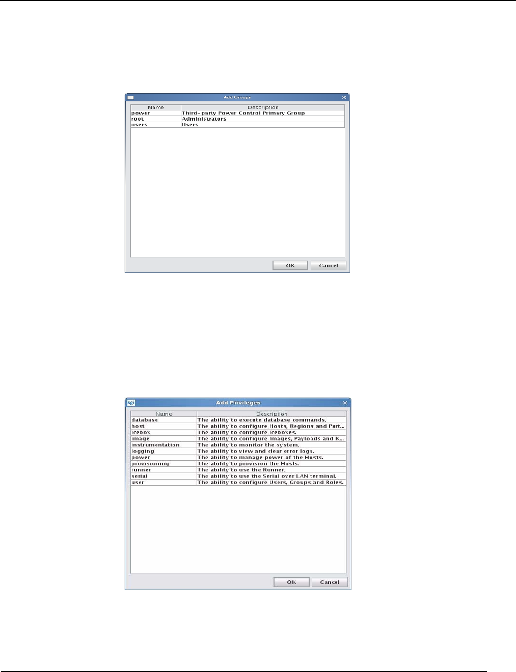
Roles
Adding a Role
007-5642-005 71
ASSIGNING GROUPS TO ROLES
The Groups pane allows you to assign roles to multiple groups. This permits users to have varied levels of access
throughout the system.
1. Click Add in the Groups pane.
2. Select the groups you want to assign to the role.
3. Click OK.
GRANTING PRIVILEGES
The Privileges pane allows you to assign permissions to a role. Any user with the role will have these permissions in the
system. See Privileges on page 73.
1. Click Add in the Privileges pane.
2. Select the privileges you want to grant to the current role.
3. Click OK.
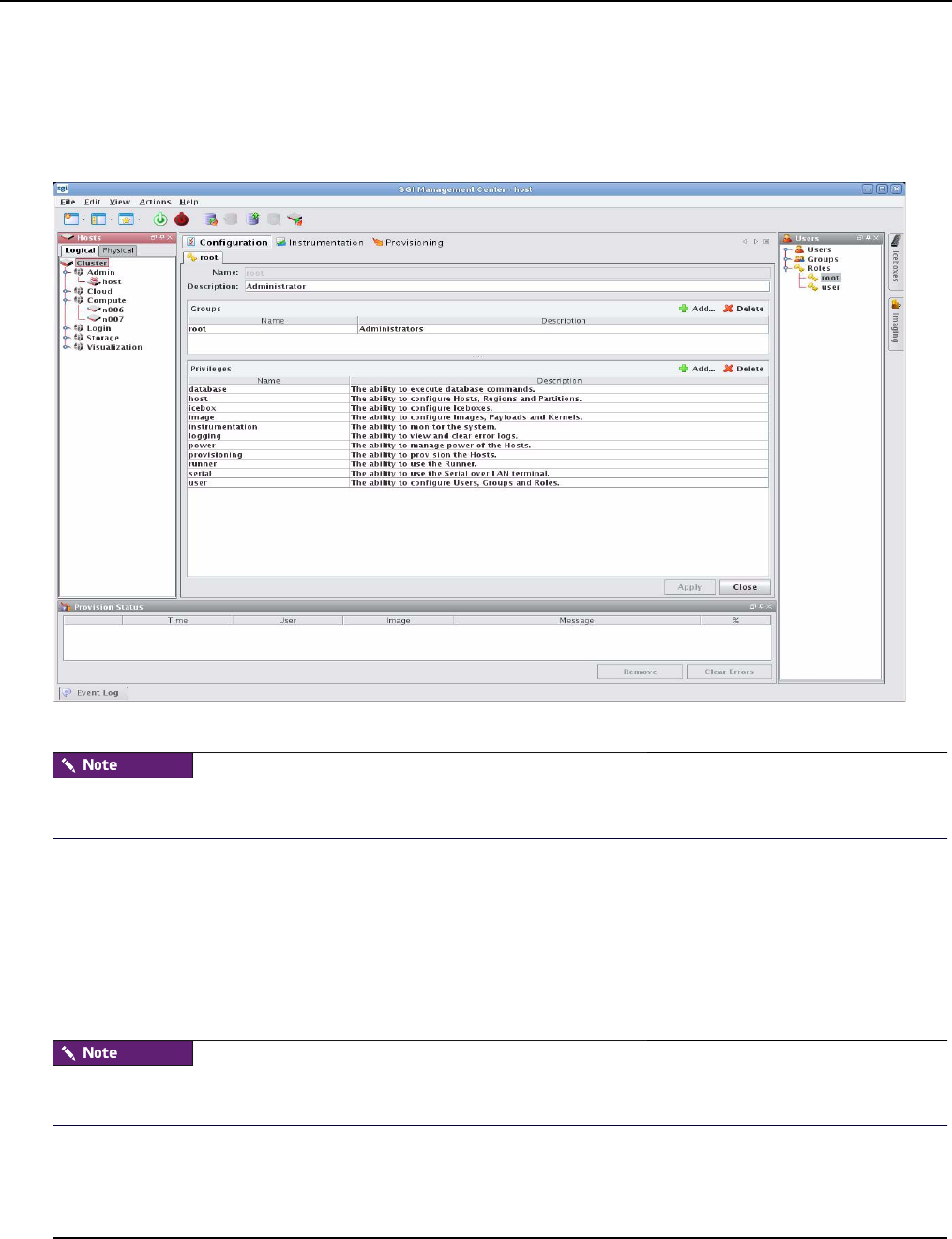
Roles
Editing a Role
007-5642-005
72
Editing a Role
Editing roles allows you to modify privileges defined for a group.
1. Select a role from the user navigation tree.
2. Select Edit from the Edit menu or right-click role names in the navigation tree and select Edit..
3. Make changes as needed and click Apply.
Deleting a role will not affect the privileges of a user that is currently logged into Management Center. Changes will
take effect only after you restart the Management Center client.
Deleting Roles
Deleting a role removes any user privileges assigned to the role.
1. Select the role you want to delete from the user navigation tree.
2. Select Delete from the Edit menu or right-click role names in the navigation tree and select Delete.
3. Click OK.
Deleting a role does not affect the privileges of a user that is currently logged into Management Center. Changes take
effect only after you restart the Management Center client. Also note that you cannot delete the root role.

Roles
Privileges
007-5642-005 73
Privileges
Privileges are permissions or rights that grant varying levels of access to system users. Management Center allows you
to assign privileges as part of a role, then assign the role to specific user groups. Users assigned to multiple groups will
have different roles and access within each group. This flexibility allows you to establish several types of roles you can
assign to users: full administration, group administration, user, or guest. See User Administration on page 63. The
following table lists the privileges established for the Management Center module at the function and sub-function
levels:
Module Name Description
Management Center Database The ability to execute database commands from the command line.
Host The ability to configure Hosts, Regions, and Partitions.
Icebox The ability to configure Iceboxes.
Image The ability to configure Images, Payloads, and Kernels.
Instrumentation The ability to monitor the system.
Logging The ability to view and clear error logs.
Power The ability to manage power to hosts.
Provisioning The ability to provision hosts.
Serial The ability to use the Serial over LAN terminal.
User The ability to configure Users, Groups, and Roles.
007-5642-005 75
Chapter 6
Imaging, Version Control, and
Provisioning
Overview
Management Center version-controlled image management allows you to create and store images that can be used to
install and configure hosts in your system. An image may contain file system information, utilities used for
provisioning, one payload, and one kernel—although you may create and store many payloads and kernels. The
payload contains the operating system, applications, libraries, configuration files, locale and time zone settings, file
system structure, selected local user and group accounts (managed by Management Center), and any centralized user
authentication settings to install on each host (e.g., NIS, LDAP, and Kerberos). The kernel is the Linux kernel.
For a list of Management Center-supported operating systems, see Operating System Requirements on page 2.
This chapter provides both GUI and command-line interface directions to assist you in configuring and maintaining
images, and in using them to provision hosts. The image configuration process allows you to select a kernel and
payload, and also configures the boot utilities and partition layout. Once the new image is complete, you can check it
into the Version Control System and provision hosts with the new image. See Version Control System (VCS) on
page 134 and Provisioning on page 141.
Image Stored
kernels
Stored
payloads
Payload
Kernel
Image

Payload Management
Configuring a Payload Source
007-5642-005
76
Payload Management
Payloads are stored versions of the operating system and any applications installed on the hosts. Payloads are
compressed and transferred to the hosts via multicast during the provisioning process.
Configuring a Payload Source
Before you can build a new payload, you must have a package source available for use. A package source can be the
RHEL or SLES physical media, ISO media, ftp or http install, or media copied to your hard drive.
Physical Media
If you are using physical media, you must insert it and mount it for your CDROM:
/mnt/cdrom
or
/media/dvd
CD ISOs
If you are using the CD ISOs, you must mount the ISOs one at a time to simulate using the CDROM:
mount -o loop <ISO_name> <mount_point>
Using either the multiple disks or multiple ISOs may require switching between disks several times.
DVD ISOs
DVD ISOs are perhaps the most convenient because they are simply mounted and do not require changing disks. To use
a DVD ISO:
mount -o loop <ISO_name> <mount_point>
FTP or HTTP
You must follow the operating system vendors recommendations for setting up a network based installation. Some
problems have been reported using Apache 2.2.
Copying the Media
If you have CD media or CD ISOs and will be creating multiple payloads or requiring additional packages following
payload creation, it is worthwhile to copy the distribution to the hard drive. See Red Hat Installations below or SUSE
Linux Enterprise Server Installations on page 77 for instructions on how to copy the installation disks for your
distribution.
RED HAT INSTALLATIONS
If you choose to copy the entire contents of each disc rather than the files described below, you must copy disc1 LAST.
Failure to copy disks in the correct order may produce payload creation failures (for example, package aaa_base may
not be found).
1. Mount disk 1 and copy the contents of the entire disk to a location on the hard drive:
mount /mnt/cdrom
or

Payload Management
Configuring a Payload Source
007-5642-005 77
mount -o loop RHEL-x86_64-WS-disc1.iso /mnt/cdrom
mkdir /mnt/redhat
cp -r /mnt/cdrom/* /mnt/redhat
2. Mount disk 2 and copy the *.rpm files from the RPMS directory to the RPMS directory on the hard drive:
cp /mnt/cdrom/RedHat/RPMS/*.rpm /mnt/redhat/RedHat/RPMS
3. Mount each remaining disk and copy the RPMS directory to the RPMS directory on the hard drive.
SUSE LINUX ENTERPRISE SERVER INSTALLATIONS
If you choose to copy the entire contents of each disc rather than the files described below, you must copy disc1 LAST.
Failure to copy disks in the correct order may produce payload creation failures (e.g., package aaa_base may not be
found).
1. Mount disk 1 and copy the contents of the entire disk to a location on the hard drive:
mount /media/cdrom
or
mount -o loop SLES-9-x86-64-CD1.iso /media/cdrom
mkdir /mnt/suse
cp -r /media/cdrom/* /mnt/suse
2. Mount disk 2 and copy the RPMs from each architecture subdirectory to the SuSE directory on the hard drive:
cp -r /media/cdrom/suse/noarch/* /mnt/suse/suse/noarch
cp -r /media/cdrom/suse/i586/* /mnt/suse/suse/i586
cp -r /media/cdrom/suse/i686/* /mnt/suse/suse/i686
cp -r /media/cdrom/suse/src/* /mnt/suse/suse/src
cp -r /media/cdrom/suse/nosrc/* /mnt/suse/suse/nosrc
cp -r /media/cdrom/suse/x86_64/* /mnt/suse/suse/x86_64
3. Mount each remaining disk and copy the RPMs from each architecture subdirectory to the SUSE directory.
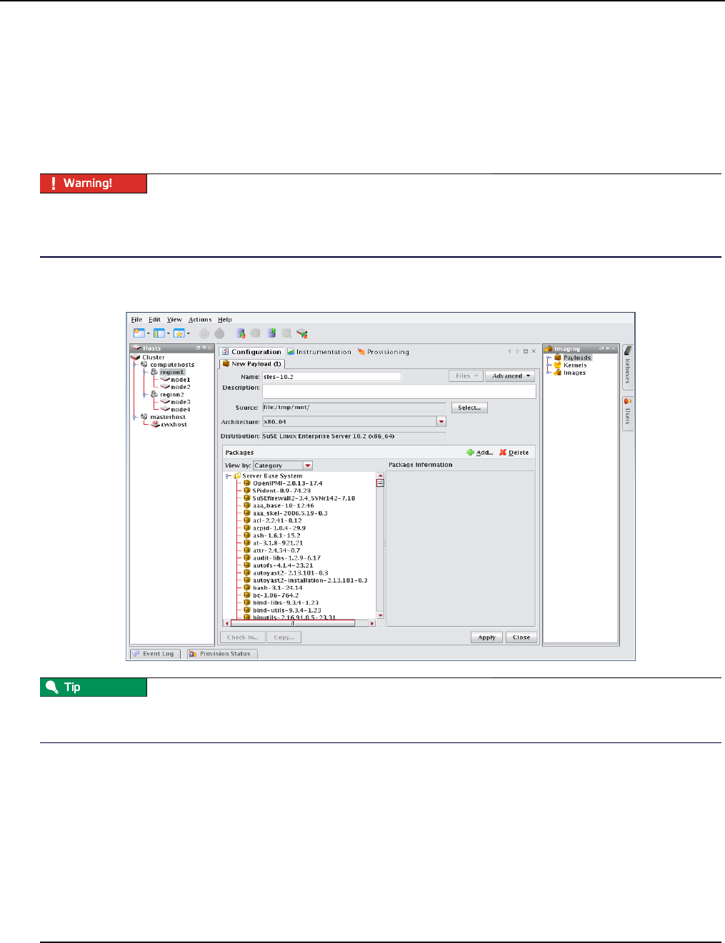
Payload Management
Creating a Payload
007-5642-005
78
Creating a Payload
Payloads are initially created using a supported Linux distribution installation media (CD-ROM, FTP, NFS) to build a
base payload (see Operating System Requirements on page 2 for a list of supported distributions) or by importing a
payload from a previously provisioned host. Additions and changes are applied by adding or removing packages, or by
editing files through the GUI or CLI. Changes to the Payload are managed by the Management Center Version Control
System (VCS). Package information and files are stored and may be browsed through Management Center.
Please consult SGI before upgrading your Linux distribution or kernel. Upgrading to a distribution or kernel not
approved for use on your system may render Management Center inoperable or otherwise impair system functionality.
Technical Support is not provided for unapproved system configurations.
To create a new payload from a Linux distribution:
1. Select New Payload from the File menu or right-click in the imaging navigation tree and select New Payload.
To create a new payload using a payload from a host you have already configured, see Importing a Payload from an
Existing Host on page 81.
2. Enter a payload name.
3. (Optional) Enter a description.
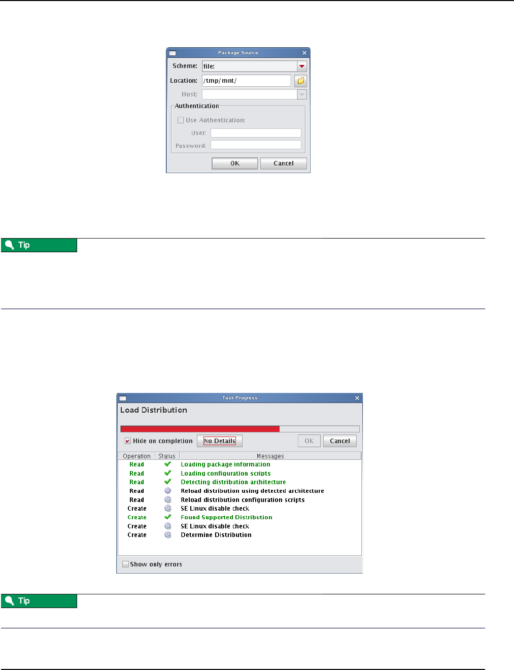
Payload Management
Creating a Payload
007-5642-005 79
4. Click Select next to the Source field.
5. Select the Scheme (file, http://, or ftp://) from the drop-down list.
6. Enter the location of the top level directory for the Linux distribution or, click the Browse icon if you selected the
File scheme to locate the directory.
If you are creating multiple payloads from the same distribution source, it may be faster and easier to copy the
distribution onto the hard drive. This also prevents you from having to switch CD-ROMs during the payload creation
process. See Red Hat Installations on page 76 and SUSE Linux Enterprise Server Installations on page 77 for specific
details on installing these distributions.
7. (Optional) If you select http:// or ftp://, enter a host.
8. (Optional) If you select Use Authentication, enter a username and password.
9. Click OK.
As the distribution loads, the progress of the payload creation is displayed along with the operation status
messages.
Select Hide on Completion to close the Task Progress dialog if no errors or warnings occur.
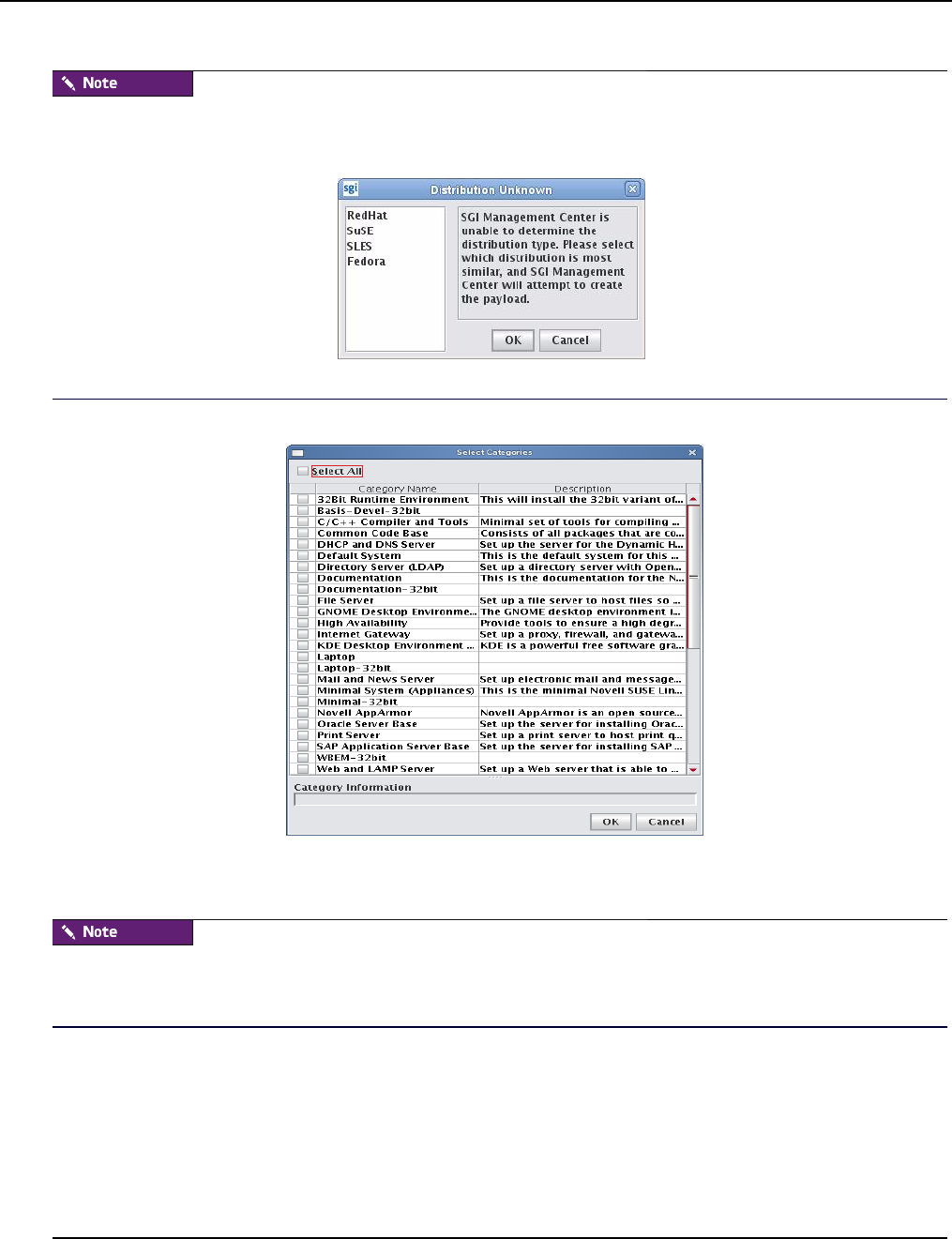
Payload Management
Creating a Payload
007-5642-005
80
If Management Center is unable to detect payload attributes, the Distribution Unknown dialog appears. From this
dialog, select the distribution type that most closely resembles your distribution and Management Center will attempt to
create your payload.
10. (Optional) In the packages pane, click Add to include additional packages in the payload.
11. Select which payload categories to install or remove by clicking the checkbox next to each package.
When you select a “core” category to include in a payload, Management Center automatically selects packages that are
essential in allowing the capability to run. However, you may include additional packages at any time. See Adding a
Package to an Existing Payload on page 84.
12. Click OK.
13. (Optional) From the Packages pane, select packages you want to remove from the payload, then click Delete in the
packages pane.
14. (Optional) Configure advanced settings you want to apply to the payload. See Payload File Configuration on
page 89, Payload Authentication Management on page 90, and Payload Local User and Group Account
Management on page 92.
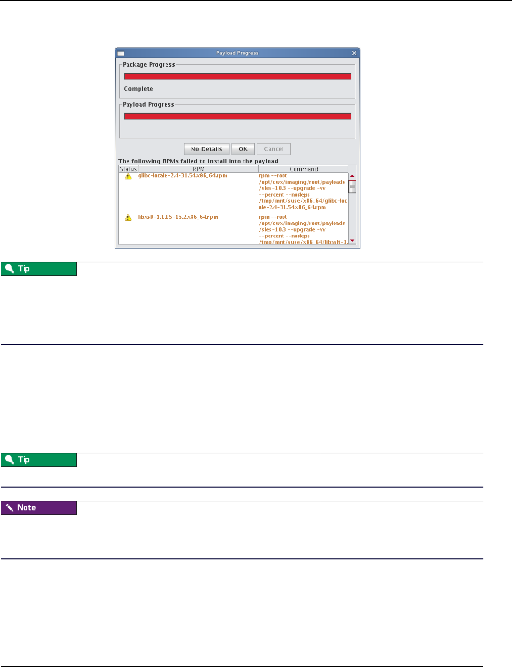
Payload Management
Creating a Payload
007-5642-005 81
15. Click Apply.
If an RPM installation error occurs during the payload creation process, Management Center enables the Details button
and allows you to view which RPM produced the error.
To view error information about a failed command, click the command description field. You may copy the contents of
this field and run it from the CLI to view specific details about the error.
16. (Optional) Select any payload files you wish to include with, remove from, or edit from the File drop-down list.
See Add and Update Payload Files or Directories on page 96.
17. (Optional) Click Check In to import the new payload into VCS. See also Version Control System (VCS) on
page 134.
Creating a Copy of an Existing Payload
1. Right-click on a payload in the imaging navigation tree and select Copy.
If a payload is open in the GUI, click Copy in the lower left of the panel to create a copy of the payload.
When you copy of a payload, Management Center creates a working copy of the payload — in other words, the payload
that is checked out into the $MGR_HOME/imaging/<username>/payloads directory. To create a copy of a versioned
payload, use VCS Management on page 137.
2. In the Copy Payload dialog, enter the name of the new payload and click OK.
Importing a Payload from an Existing Host
Creating a payload from an existing host is helpful in situations where a specific host is already configured the way you
want it. This feature allows you to create new payloads that use the configuration and distribute the image to other
hosts.
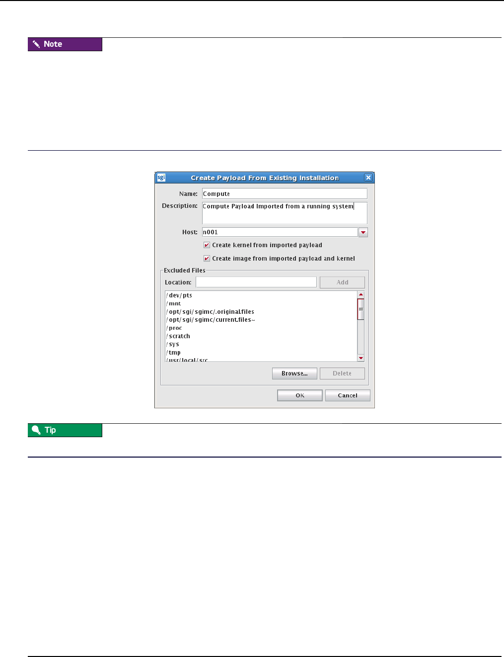
Payload Management
Creating a Payload
007-5642-005
82
On RHEL, temporarily disable SE Linux while importing the payload. If you do not require SE Linux, you may want to
leave it disabled.
To disable SE Linux:
1. Navigate to the Imaging tab.
2. Select the kernel you are using and edit the kernel parameters.
3. Add selinux=0 as a parameter.
4. Reboot the host and import the payload.
3. Select Import Payload from the File menu.
You can also import a payload using pmgr from the command line. See pmgr on page 248.
4. Enter a payload name.
5. (Optional) Enter a description.
6. Enter the host name you are creating the payload from or select a host from the drop-down list.
7. Use the following check box selections to indicate whether or not an image and kernel should be created:
* Create kernel from imported payload creates a kernel with the same name as the payload and populates the
list of modules in the kernel to match that of the running host.
* Create image from imported payload and kernel creates an image and attempts to re-create all local
filesystems from the list of partitions on the running host.
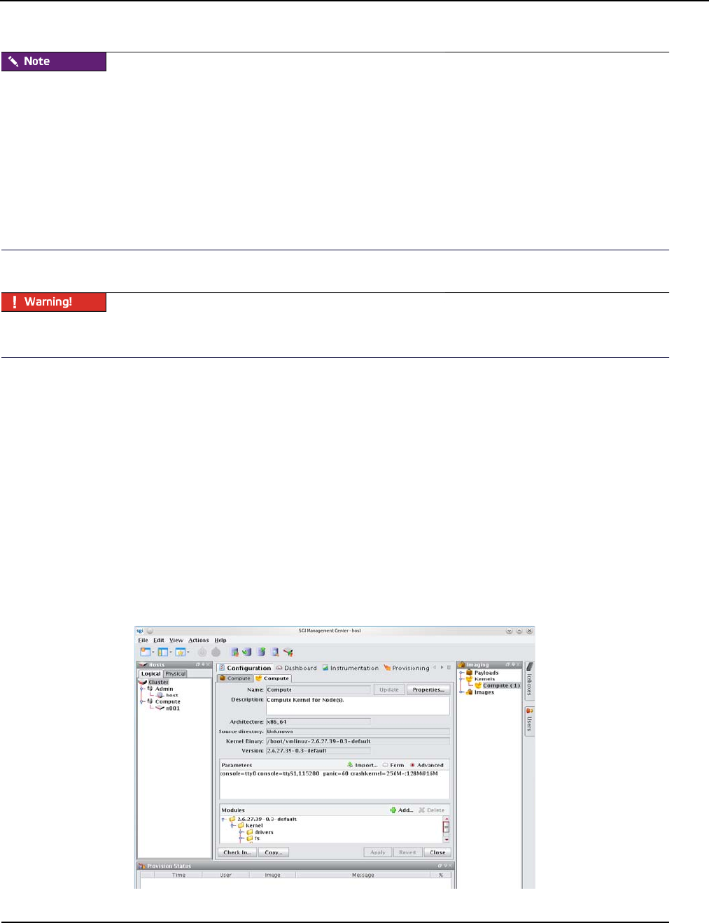
Payload Management
Importing Kernel Parameters from a Running Host
007-5642-005 83
* In the imported kernel, check the list of kernel modules that is generated and the list of kernel boot parameters that
are generated. You may need to customize them according to your needs.
* In the imported image, check the partition scheme and add/remove partitions as necessary.
* LVM is not supported. If you have LVM partitions on the running host, you will need to create traditional partitions
in the image manually.
* If you have any remote filesystem mounts on the running host, such as static NFS mounts, they will not be defined in
the new image. They will need to be defined manually.
8. (Optional) Review the Excluded Files list and remove any files you want to exclude from the payload.
If you include a symlink when creating a payload, excluding the target produces a dangling symbolic link. This link
may cause an exception and abort payload creation when Management Center attempts to repair missing directories.
9. (Optional) Enter the location of any file you want to exclude from the payload and click Add. Click Browse to
locate a file on your system.
10. Click OK.
Importing Kernel Parameters from a Running Host
Management Center allows you to import the list of kernel parameters from a running host. This is especially useful
when you have imported a payload (and kernel/image) from a running host and you want the kernel parameters to
match those of the running host.
To import the kernel parameters, do the following:
1. Open the imaging pane, find the desired kernel, and double-click it.
2. On the resulting kernel configuration panel (shown in the following figure), click the Import... button.
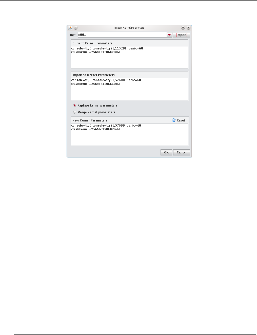
Payload Management
Adding a Package to an Existing Payload
007-5642-005
84
3. In the Import Kernel Parameters window that appears, select the desired host and click Import.
4. Select either Replace kernel parameters or Merge kernel parameters and click the OK button.
5. Examine the list of kernel parameters that was generated and make any needed changes.
6. Update the kernel and image and check in any changes.
Adding a Package to an Existing Payload
Adding a package to a payload allows you to make additions or changes to the default Linux installation. For a list of
supported distributions, see Operating System Requirements on page 2. If you add packages to the payload that contain
new or updated kernel modules and complications occur (or if the modules are needed to boot the system), then you
should create a new kernel. See To Create a Kernel from a Payload on page 103.
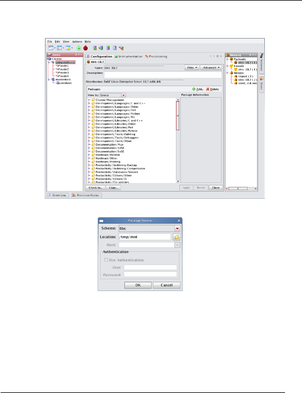
Payload Management
Adding a Package to an Existing Payload
007-5642-005 85
To add a package, do the following:
1. Right-click a payload name in the imaging navigation tree and select Edit.
2. In the Packages pane, click Add.
3. Select a scheme (file, http://, or ftp://).
4. Enter the Location of the top level directory for the Linux distribution, a directory containing RPM packages, or the
location of an individual package. If you selected the File scheme, click the Browse icon to locate the package.
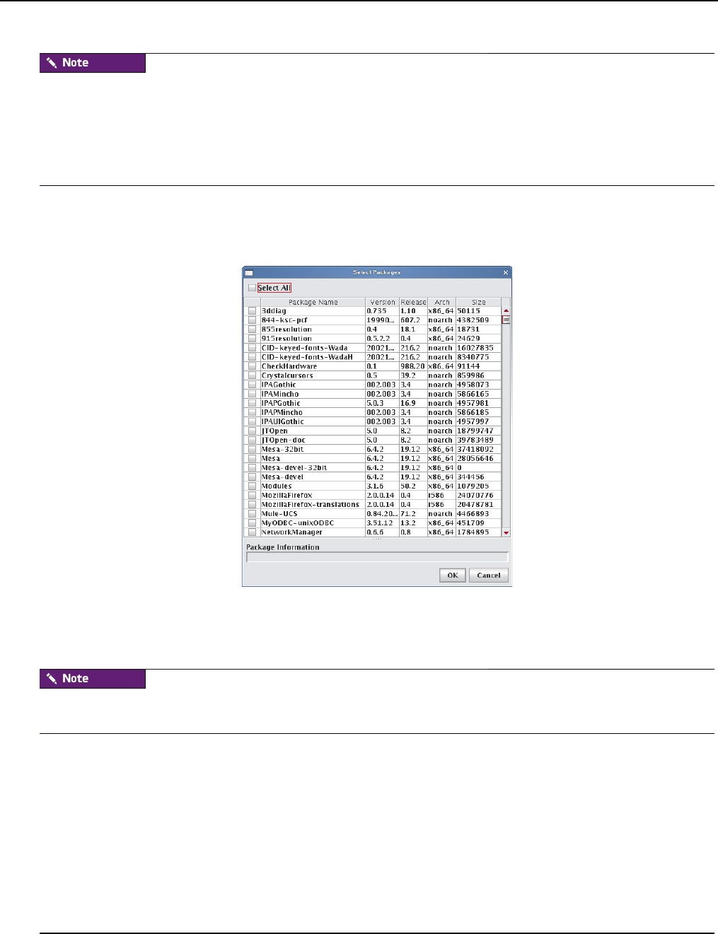
Payload Management
Adding a Package to an Existing Payload
007-5642-005
86
If the browse button does not launch a dialog, a DNS name resolution error may exist. The DNS server name must be
specified in the client — not the IP address.
If you have several packages in a directory, select the directory. Management Center displays all packages in the
directory — you can choose which packages you want to install. Management Center resolves package dependencies
(see Payload Package Dependency Checks on page 87).
5. (Optional) If you selected http:// or ftp://, enter a host.
6. (Optional) If you selected Use Authentication, enter a username and password.
7. Click OK.
8. Select the packages you want to install.
9. Click OK.
10. Click Apply to save changes.
Before adding the package, Management Center performs a package dependency check. See Payload Package
Dependency Checks on page 87 for information about dependency errors.
11. Click Check In to check the payload into VCS.
12. Update the image to use the new payload.
13. Re-provision the hosts with the new image or update the payload on the hosts using VCS Upgrade on page 144.
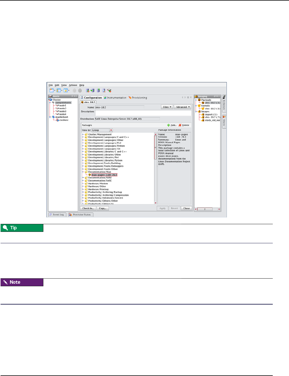
Payload Management
Remove a Payload Package
007-5642-005 87
Remove a Payload Package
The Packages pane of the payload panel provides a view into the current packages installed in the payload. See also
Payload Package Dependency Checks on page 87.
To Remove a Payload Package
1. Right-click on a payload in the imaging navigation tree and select Edit. The payload panel appears.
2. From the package list in the Packages pane, select a package group or expand the group to view individual
packages.
To view individual packages instead of package groups, change the View Packages By option.
3. Click Delete.
4. Click OK to remove the packages.
5. Click Apply to save changes.
Before adding the package, Management Center performs a package dependency check. See Payload Package
Dependency Checks on page 87 for information about dependency errors.
Payload Package Dependency Checks
Before performing package addition, update, or removal, Management Center performs a package dependency check.
Any failures identified through the dependency check are displayed in the Resolve Dependency Failures dialog. From
this dialog, you can choose a course of action to address the failure(s).
ADDING A PACKAGE
When adding a package, you may correct dependency failures by selecting one of the following options:
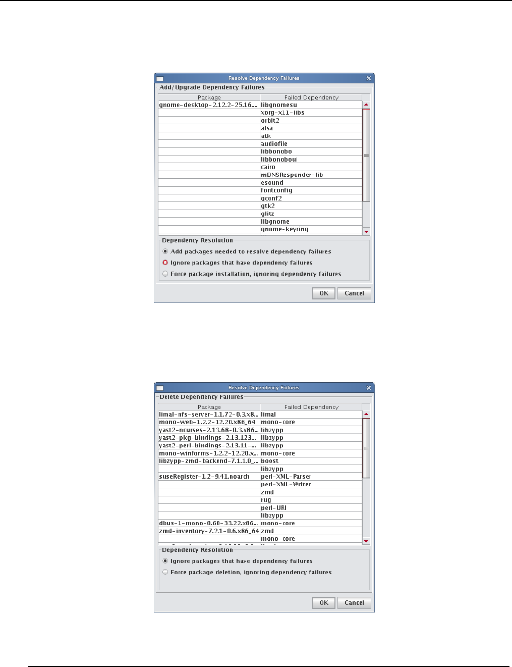
Payload Management
Remove a Payload Package
007-5642-005
88
•Add packages needed to resolve dependency failures.
•Ignore packages that have dependency failures.
•Force package installation, ignoring dependency failures.
REMOVING A PACKAGE
When removing a package, you may correct dependency failures by selecting one of the following options:
•Ignore packages that have dependency failures.
•Force package deletion, ignoring dependency failures.
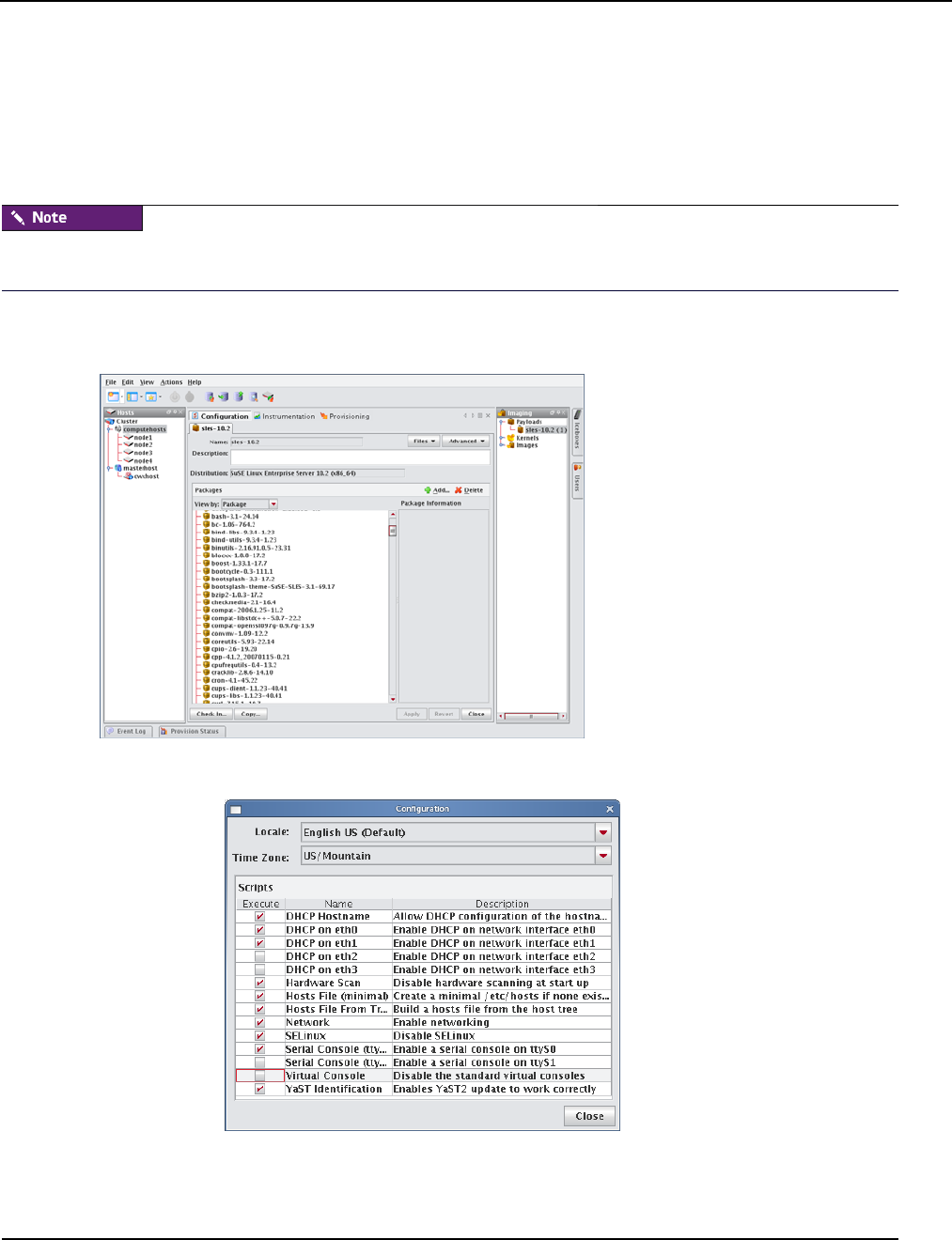
Payload Management
Payload File Configuration
007-5642-005 89
Payload File Configuration
Payload file configuration allows you to set up configuration options when creating or editing a payload including:
DHCP Network, Network, Serial Console, Virtual Console, and more. When you click Apply, the scripts that
correspond to the selected item(s) run on the payload. It is important to note that the selected script(s) run at the time
you click Apply—this list is not an indication of scripts that have run at some point on the system.
The list of options available is based on the distribution selected. The options displayed in the example below are
SUSE-based distributions (SUSE Linux Enterprise Server 10).
To Configure a Payload
1. Right-click on a payload in the imaging navigation tree and select Edit.
2. Select Configuration from the Advanced drop-down list and click the check box by each script you want to
enable.
3. Click Apply.
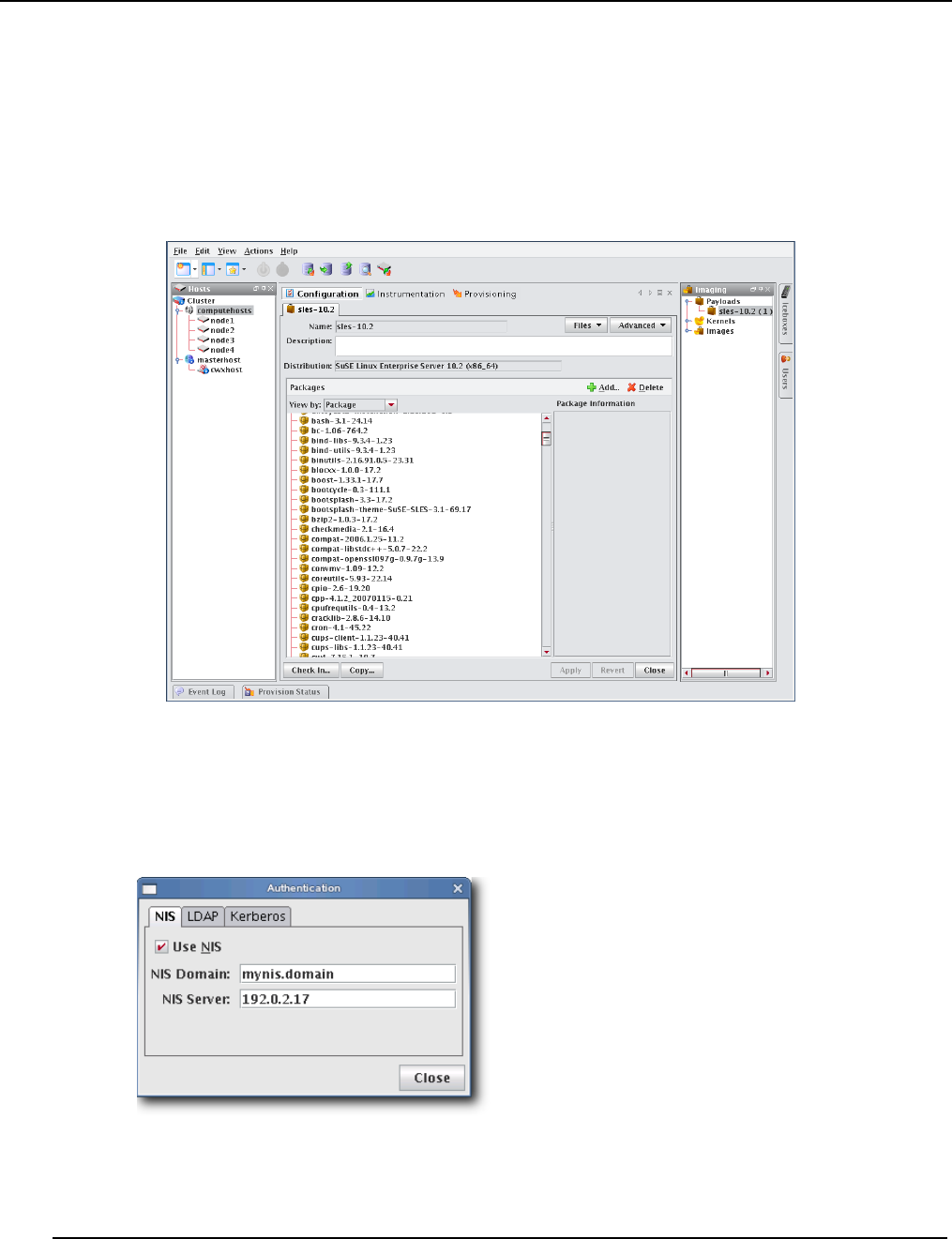
Payload Management
Payload Authentication Management
007-5642-005
90
Payload Authentication Management
Payload Authentication manages the authentication settings for the payload. This option allows you to enable, disable,
or modify the settings for supported remote authentication schemes. Management Center supports the following remote
authentication schemes:
•Network Information Service (NIS)
•Lightweight Directory Access Protocol (LDAP)
•Kerberos (a network authentication protocol)
To Configure NIS Authentication
1. Right-click on a payload in the imaging navigation tree and select Edit. The payload panel appears.
2. Select Authentication from the Advanced pull-down menu. The Authentication dialog appears.
3. Select the NIS tab.
A. Click the Use NIS option.
B. Enter the NIS domain.
C. (Optional) Enter the NIS Server.
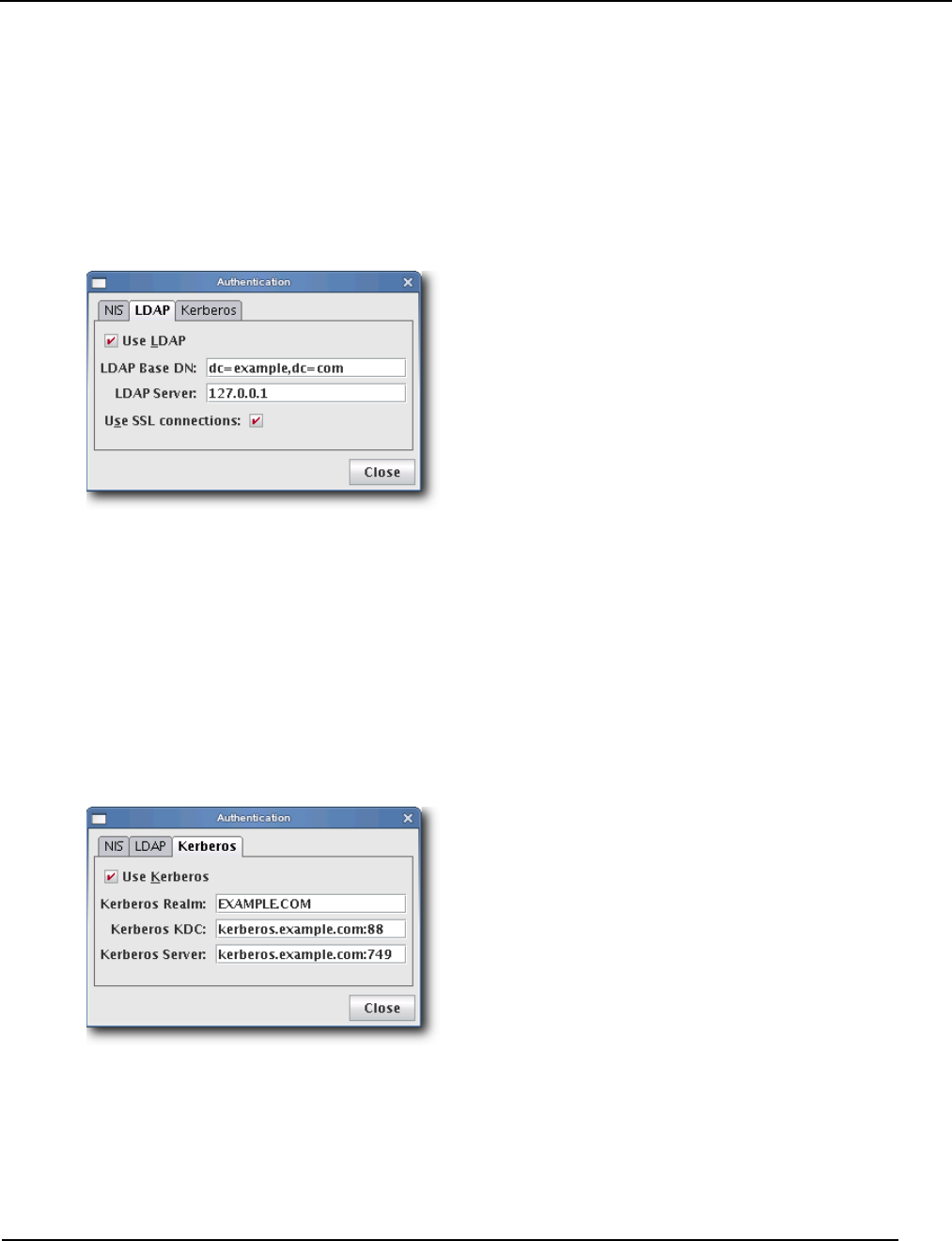
Payload Management
Payload Authentication Management
007-5642-005 91
4. Click Close.
5. Click Apply to save changes. Click Revert or Close to abort this action.
To Configure LDAP Authentication
1. Right-click on a payload in the imaging navigation tree and select Edit. The payload panel appears.
2. Select Authentication from the Advanced pull-down menu. The Authentication dialog appears.
3. Select the LDAP tab.
A. Click the Use LDAP option.
B. Enter the LDAP Base DN (Distinguished Name).
C. Enter the LDAP Server.
D. (Optional) Click Use SSL connections if you want to connect to the LDAP server via SSL.
4. Click Close.
5. Click Apply to save changes. Click Revert or Close to abort this action.
To Configure Kerberos Authentication
1. Right-click on a payload in the imaging navigation tree and select Edit. The payload panel appears.
2. Select Authentication from the Advanced pull-down menu. The Authentication dialog appears.
3. Select the Kerberos tab.
A. Click the Use Kerberos option.
B. Enter the Kerberos Realm.
C. Enter the Kerberos KDC (Key Distribution Center).
D. Enter the Kerberos Server.
4. Click Close.
5. Click Apply to save changes. Click Revert or Close to abort this action.
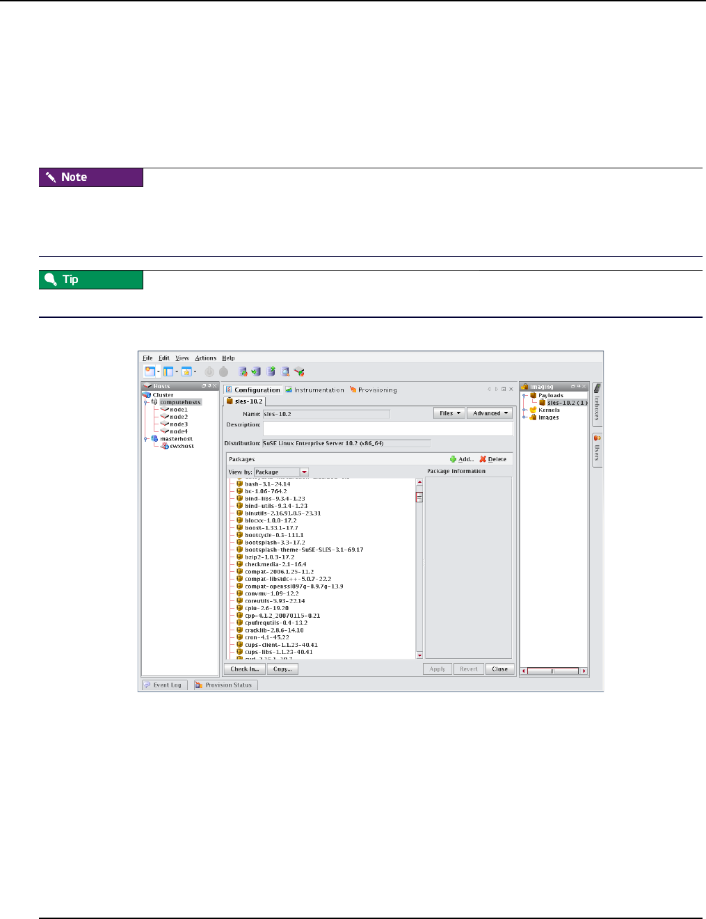
Payload Management
Payload Local User and Group Account Management
007-5642-005
92
Payload Local User and Group Account Management
The Local Accounts payload management option provides a means for managing local accounts in payloads. This
option allows you to:
•Add a local user or group account known to Management Center to the payload (see User Administration on
page 63).
•Delete a local user or group account from the payload.
Local account management does not support moving local accounts from the host.
Local user and group accounts that are reserved for system use do not display and cannot be added or deleted. The root
account is added automatically. Management Center handles group dependencies.
Software that requires you to add groups (e.g., Myrinet Group) can be managed through user accounts.
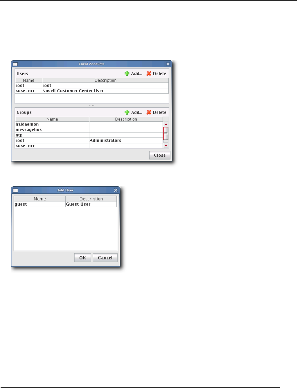
Payload Management
Payload Local User and Group Account Management
007-5642-005 93
Local User Accounts
TO ADD A LOCAL USER ACCOUNT TO A PAYLOAD
1. Right-click on a payload in the imaging navigation tree and select Edit. The payload panel appears.
2. Select Local Accounts from the Advanced pull-down menu. The Local Accounts dialog appears.
3. In the Users pane, click Add. The Add User dialog appears.
4. Select the user(s) to add to the payload (use the Shift or Ctrl keys to select multiple users).
5. Click OK to add the user(s) or click Cancel to abort this action.
6. Click Apply to save changes. Click Revert or Close to abort this action.
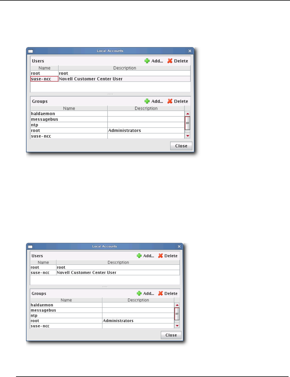
Payload Management
Payload Local User and Group Account Management
007-5642-005
94
DELETE A LOCAL USER ACCOUNT FROM A PAYLOAD
1. Right-click on a payload in the imaging navigation tree and select Edit. The payload panel appears.
2. Select Local Accounts from the Advanced pull-down menu. The Local Accounts dialog appears.
3. Select the user(s) to remove from the payload (use the Shift or Ctrl keys to select multiple users).
4. Click Delete to remove the user(s).
5. Click Close.
6. Click Apply to complete the process. Click Revert or Close to abort this action.
Group User Accounts
ADD A GROUP USER ACCOUNT TO A PAYLOAD
1. Right-click on a payload in the imaging navigation tree and select Edit. The payload panel appears.
2. Select Local Accounts from the Advanced pull-down menu. The Local Accounts dialog appears.
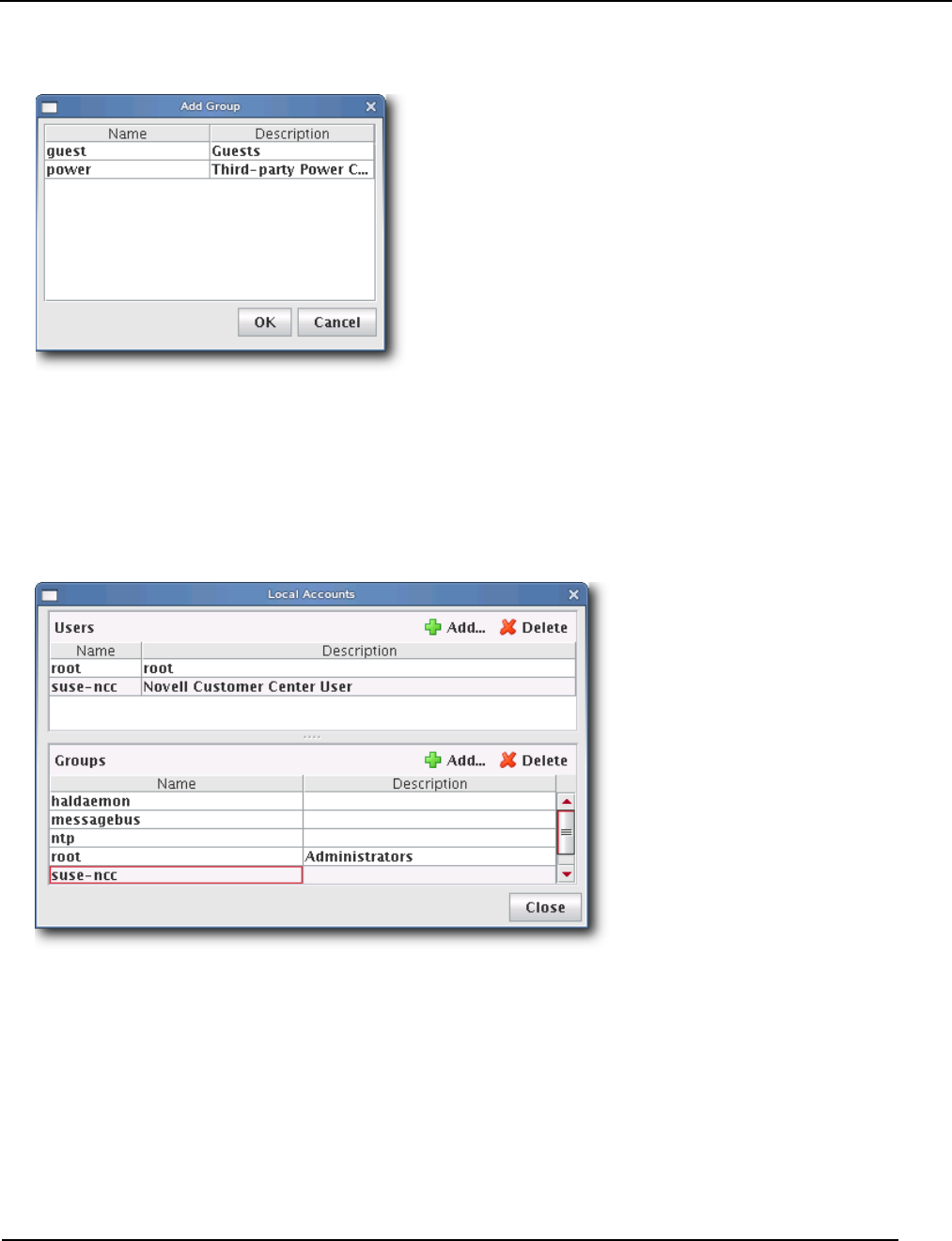
Payload Management
Payload Local User and Group Account Management
007-5642-005 95
3. In the Groups pane, click Add. The Add Group dialog appears.
4. Select the group(s) to add to the payload (use the Shift or Ctrl keys to select multiple users).
5. Click OK to add the group(s) or click Cancel to abort this action.
6. Click Apply to complete the process. Click Revert or Close to abort this action.
DELETE A GROUP USER ACCOUNT FROM A PAYLOAD
1. Right-click on a payload in the imaging navigation tree and select Edit. The payload panel appears.
2. Select Local Accounts from the Advanced pull-down menu. The Local Accounts dialog appears.
3. Select the group(s) to remove from the payload (use the Shift or Ctrl keys to select multiple groups).
4. Click Delete to remove the group(s).
5. Click Close.
6. Click Apply to complete the process. Click Revert or Close to abort this action.
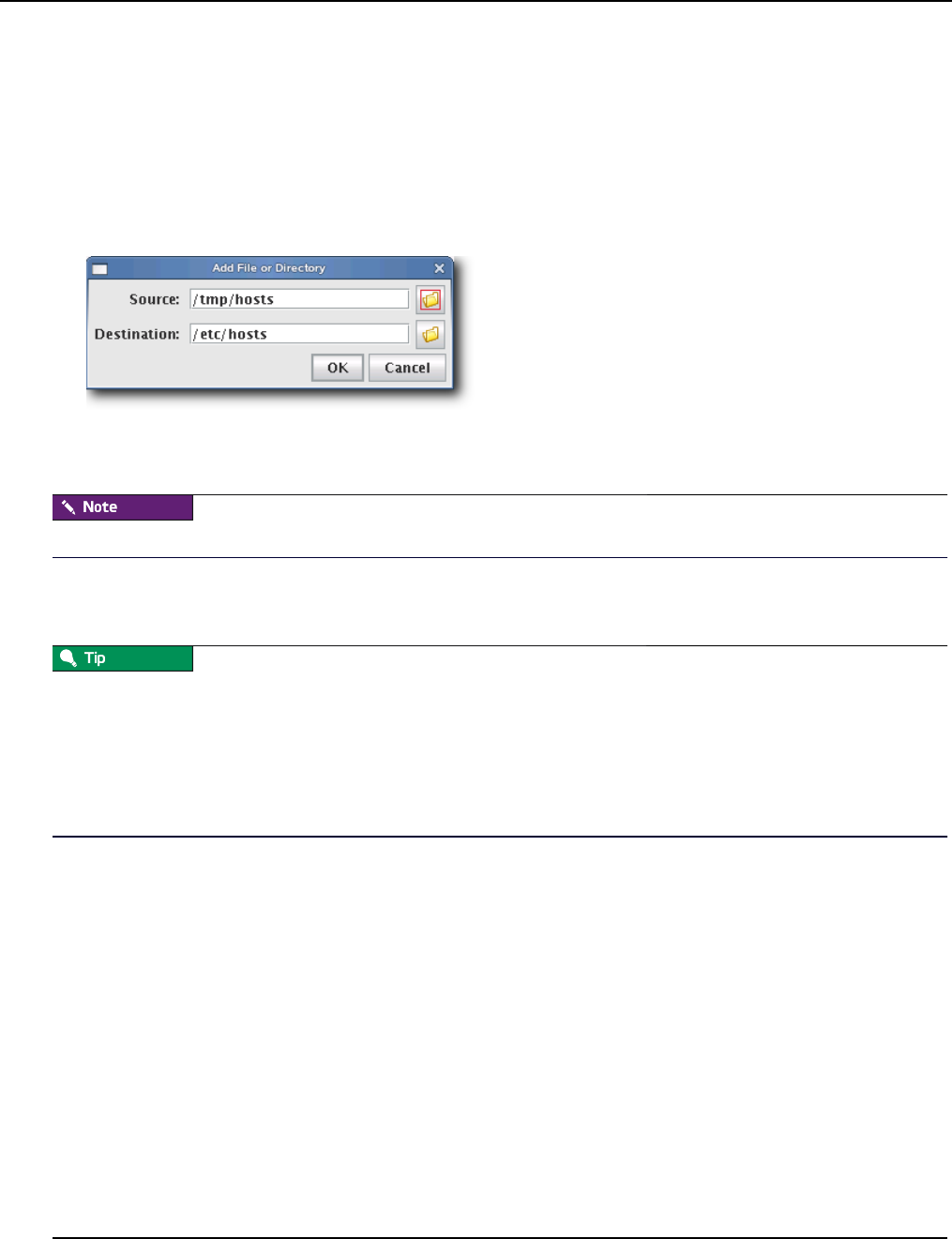
Payload Management
Add and Update Payload Files or Directories
007-5642-005
96
Add and Update Payload Files or Directories
Adding and updating payload files allows you to select a file or directory from the Master Host’s file system and copy it
into the payload.
To Add or Update a Payload File or Directory
1. Right-click on a payload in the imaging navigation tree and select Edit. The payload panel appears.
2. Select Add File from the Files pull-down menu. The Add File or Directory dialog appears.
3. Enter the source for the new file in the Source field or click Browse to locate the source.
4. Enter the destination for the new file in the Destination field or click Browse to select the destination.
The destination specified is relative to the payload root.
5. Click OK to save changes or click Cancel to abort this action.
6. Click Apply to complete the process. Click Revert or Close to abort this action.
If a working copy of a payload is available, you can enter the payload directory and make changes to the payload
manually from the CLI. Working copies of payloads are stored at:
$MGR_HOME/imaging/<username>/payloads/<payload_name>
From this directory, enter chroot to change the directory to your root (/) directory. After making changes, check the
payload into VCS.
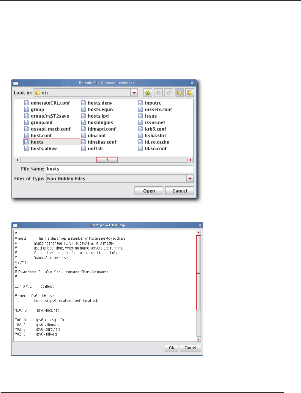
Payload Management
Edit a Payload File with the Text Editor
007-5642-005 97
Edit a Payload File with the Text Editor
Management Center allows you to edit payload files with a text editor. Files edited in this manner are treated as plain
text and only basic editing tools such as insert, cut, and paste are available.
To Edit a Payload File with the Text Editor
1. Right-click on a payload in the imaging navigation tree and select Edit. The payload panel appears.
2. Select Edit File from the Files pull-down menu. The Remote File Chooser appears.
3. Select the file to edit and click Open. The text editor window appears.
4. Edit the file as necessary, then click OK to save changes or click Cancel to abort this action.
5. Click Apply to complete the configuration. Click Revert or Close to abort this action.
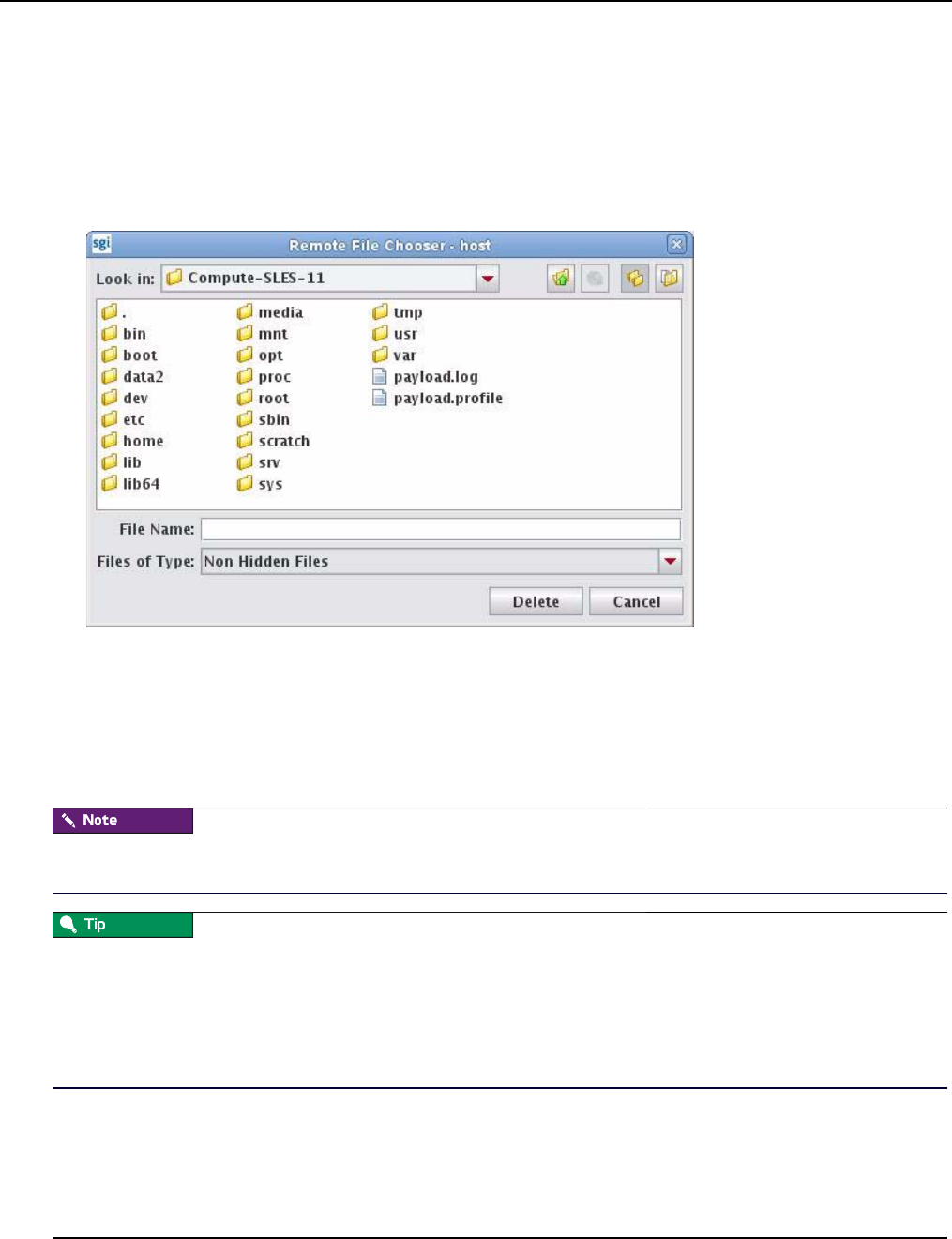
Payload Management
Delete Payload Files
007-5642-005
98
Delete Payload Files
Deleting a payload file allows you to exclude a specific file(s) from a payload.
To Delete a File from a Payload
1. Right-click on a payload in the imaging navigation tree and select Edit. The payload panel appears.
2. Select Delete File from the Files pull-down menu. The Remote File Chooser appears.
3. Select the file(s) you want to remove, then click Delete to remove the files or Cancel to abort this action.
4. Click Apply to complete the process. Click Revert or Close to abort this action.
Delete a Payload
To Delete a Working Copy of a Payload
Before you delete the working copy of your payload, use the VCS status option to verify that the payload is checked in.
See Version Control System (VCS) on page 134 for details on using version control.
Once you check the payload into VCS, you may remove the directory from within your working user directory (e.g., to
save space):
$MGR_HOME/imaging/<username>/payloads/<name>
To verify that your changes were checked in, use the VCS status option. See Version Control System (VCS) on page 134
for details on using the version control system.
1. Right-click on a payload in the imaging navigation tree and select Delete.
2. Management Center asks you to confirm your action.

Payload Management
Install Management Center into the Payload
007-5642-005 99
Install Management Center into the Payload
When working with payloads, Management Center requires that each payload contain some basic Management Center
services. These services allow Management Center to control various parts of the system, including instrumentation
services and the monitoring and event subsystem.
To install via the SGI Management Center GUI, do the following:
1. Open the Imaging frame.
2. Double-click your payload to open it.
3. Click Add (to add aditional packages).
4. On the Management Center media, browse to the sgi/x86_64 directory (if using SLES) or the RPMS directory (if
using RHEL) and select the following packages:
•sgimc-payload
•java-1.6.0-sun
You can also install into the payload from the command line using the RPM "root" parameter. For example:
# cd /mnt/cdrom/sgi/x86_64
# rpm -ivh --root=$MGR_HOME/imaging/root/payloads/Compute java-1.6.0-sun-1.6.0.17-
sgi700c1.sles11.x86_64.rpm
# rpm -ivh --root=$MGR_HOME/imaging/root/payloads/Compute sgimc-payload-1.0.0-
sgi700c1.sles11.x86_64.rpm

Payload Management
Installation on a Running Altix UV SSI or Cluster Compute Node
007-5642-005
100
Installation on a Running Altix UV SSI or Cluster Compute Node
The sgimc-payload package can be installed on a running SGI Altix UV SSI or cluster compute node. After installing
the sgimc-payload RPM package, you should run the following script:
/opt/sgi/sgimc/bin/configure_payload.sh
The following is an example of the configure_payload.sh script with user entries shown in bold:
# configure_payload.sh
This script will configure the SGI Management Center Payload Daemon service to work
correctly with the SGI Management Center server. You will need the following pieces of
information to enable this script to successfully complete the setup.
1. The name of the server where the SGI Managment Center server is running. This name
should match what the server is calling itself in the file /opt/sgi/sgimc/
@genesis.profile. The entry is listed as system.rna.host.
2. The IP address of the server where the SGI Management Center Server is running. This
should be the IP address for the management network.
3. The name that this host is known by in the database of SGI Management Center. This does
not have to match the actual hostname that this system knows itself as.
4. The IP address of this system on the management network. This IP address should also
be present in the SGI Management Center database.
Note: the two host names should be simple host names, not fully qualified domain names.
Please enter the name of the server: host
Please enter the IP address of the server: 172.21.0.1
Please enter the name of this host from the server database: UV00000014-P000
Please enter the IP address of this host: 172.21.1.0
You entered the following:
Server Name = host
Server IP = 172.21.0.1
Host Name = UV00000014-P000
Host IP = 172.21.1.0
The SGI Management Center Payload Daemon service has been configured. You should restart
the Name Service Cache Daemon before attempting to start the payload daemon service.
Execute the following commands to restart the Name Service Cache Daemon and the SGI
Management Center Payload Daemon service:
/etc/init.d/nscd restart
/etc/init.d/mgr restart
Note that the script prompts for the host name as defined in the server database–that is, the host name from the host tree
in the SGI Management Center GUI. If you are installing on a running UV SSI, use the name of the partition (usually of
the format UVxxxxxxxx-Pyyy). If you are installing on a non-UV, generic cluster node, it will be the name of the node in
the host tree (for example, n001). If the node is not present in the tree, you must add an entry for it.
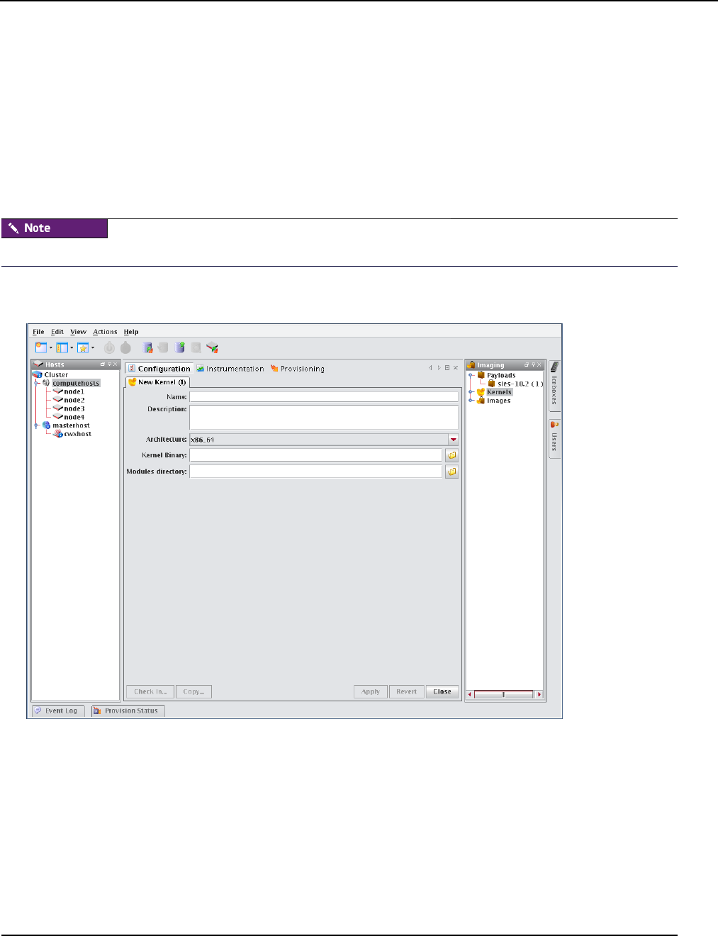
Kernel Management
Create a Kernel
007-5642-005 101
Kernel Management
Kernels may be customized for particular applications and used on specific hosts to achieve optimal system
performance. Management Center uses VCS to help you manage kernels used on your system.
Create a Kernel
The following sections review the steps necessary to create a kernel for use in provisioning your cluster.
To Create a Kernel Using an Existing Binary
For information on building a new kernel from source, see To Build a New Kernel from Source on page 104.
1. Select New Kernel from the File menu or right-click in the imaging navigation tree and select New Kernel. A new
kernel pane appears.
2. Enter the name of the Kernel.
3. (Optional) Enter a description of the kernel.
4. Select the hardware architecture.
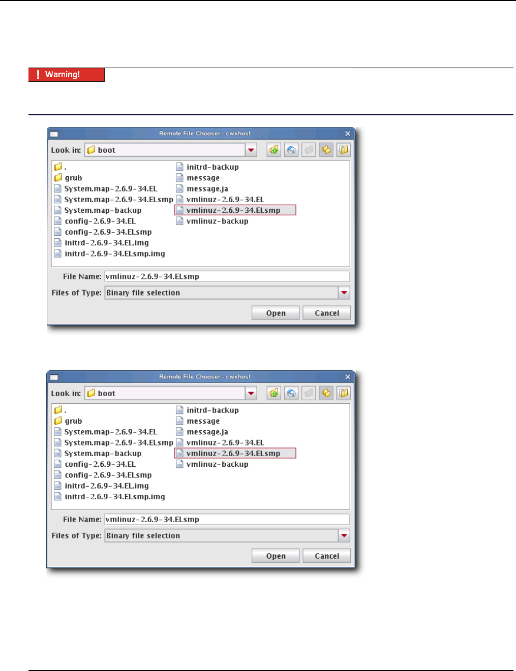
Kernel Management
Create a Kernel
007-5642-005
102
5. Specify the full path to the kernel binary or click Browse to open the Remote File Chooser and select the kernel
binary.
Make sure you select a kernel binary that begins with vmlinuz and not vmlinux. This will result in provisioning
problems later on.
6. Specify the location of the modules directory (e.g., /lib/modules) or click Browse to open the Remote File Chooser.
7. Select the modules directory and click Open.
8. Click Apply to create the kernel. Click Revert or Close to abort this action.
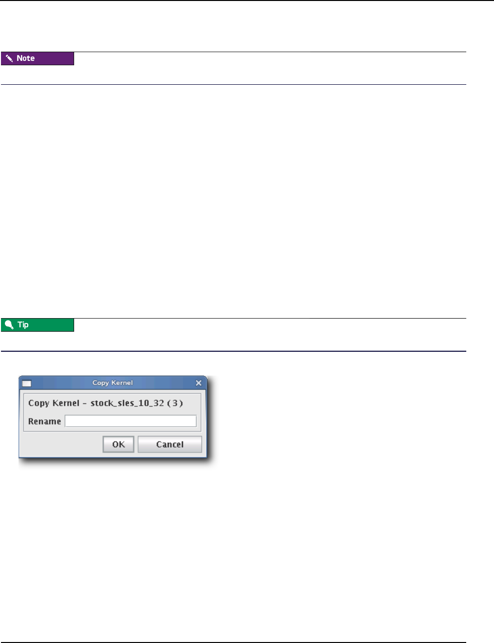
Kernel Management
Create a Kernel
007-5642-005 103
9. (Optional) Click Check In to import the kernel into VCS.
To make configuration changes to the kernel, see Edit a Kernel on page 107.
To Create a Kernel from a Payload
If you have specific packages in your payload that contain specific kernel binaries or modules, you may need to create
your kernel from the payload. This ensures that the modules and kernel binary in the kernel match exactly with what is
contained in the payload.
To create the kernel from the payload, follow steps 1 through 9 from the preceding section To Create a Kernel Using an
Existing Binary on page 101 but with the following modifications/clarifications:
•When selecting the binary (step 5), browse to $MGR_HOME/imaging/root/payloads/<payload name>/boot/
(for example, /opt/sgi/sgimc/imaging/root/payloads/Compute/boot/).
•After you select the correct kernel binary and browse for the modules directory (step 6), Management Center will
default to a path inside your payload (for example, /opt/sgi/sgimc/imaging/root/payloads/Compute/lib/modules).
Select the appropriate modules directory and click Open.
•If you are creating a kernel to replace an existing kernel, you can see the list of modules that was used in the old
kernel by examining /opt/sgi/sgimc/imaging/root/kernels/<kernel name>/kernel.profile.
To Create a Copy of an Existing Kernel
1. Right-click on a kernel in the imaging navigation tree and select Copy.
2. Select a kernel from the navigation tree, then right-click on the payload and select Copy.
You may also open a kernel for editing, then click the Copy button at the lower left of the panel.
3. Management Center prompts you for the name of the new kernel.
4. Enter the name of the new kernel and click OK. Click Cancel to abort this action.

Kernel Management
Create a Kernel
007-5642-005
104
To Build a New Kernel from Source
If you want to use a stock vendor kernel already loaded on your system, see To Create a Kernel Using an Existing
Binary on page 101. Otherwise, use the following procedure to build a new kernel from source:
Please consult SGI before upgrading your Linux distribution or kernel. Upgrading to a distribution or kernel not
approved for use on your system may render Management Center inoperable or otherwise impair system functionality.
Technical Support is not provided for unapproved system configurations.
1. Obtain and install the kernel source RPM for your distribution from your distribution CD-ROMs or distribution
vendor. This places the kernel source code under /usr/src, typically in a directory named
linux-2.<minor>.<patch>-<revision> (if building a Red Hat Enterprise Linux kernel, Management Center places
the source code into /usr/src/kernels/2.<minor>.<patch>-<revision>).
Because you don’t need the kernel source RPM in your payload, install the RPM on the host.
2. If present, review the README file inside the kernel source for instructions on how to build and configure the
kernel.
It is highly recommended the you use, or at least base your configuration on one of the vendor’s standard kernel
configurations.
3. Typically, a standard configuration file is installed in the /boot directory, usually as
config-2.<minor>.<patch>-<revision>. You may also use a stock configuration file installed as .config in the
kernel source directory or available in a sub-directory (typically /configs) of the kernel source directory.
To use a stock configuration, copy it to the kernel source directory and run make oldconfig.
4. Build the kernel and its modules using the make bzImage && make modules command. If your distribution uses
the Linux 2.4 kernel, use make dep && make bzImage && make modules but DO NOT install the kernel.
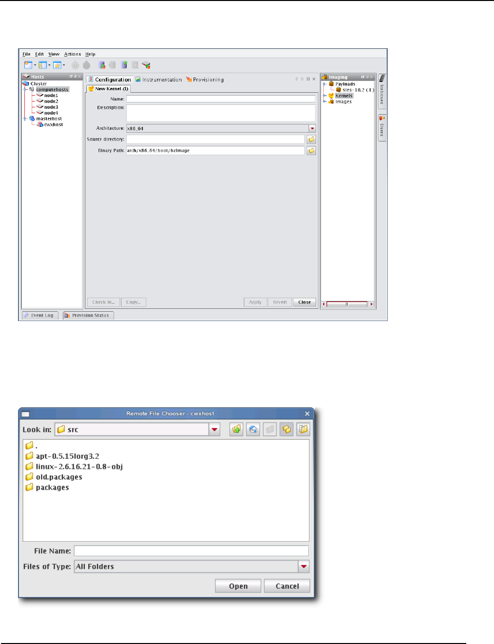
Kernel Management
Create a Kernel
007-5642-005 105
5. Select Source Kernel from the File menu. A new kernel pane appears.
6. Enter the name of the Kernel.
7. (Optional) Enter a description of the kernel.
8. Select the hardware architecture.
9. Enter the location of the kernel source (i.e., where you unpacked the kernel source) in the Source Directory field or
click Browse to open the Remote File Chooser. By default, kernel source files are located in /usr/src.
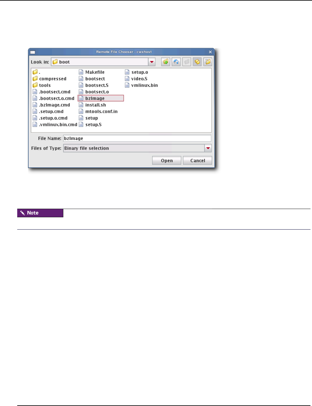
Kernel Management
Create a Kernel
007-5642-005
106
10. Select the source directory and click Open.
11. (Optional) Enter the binary path of the kernel (e.g., arch/i386/boot/bzImage) or click Browse to open the Remote
File Chooser.
12. Select the modules directory and click Open.
13. Click Apply to create the kernel. Click Revert or Close to abort this action.
14. (Optional) Click Check In to import the kernel into VCS.
To make configuration changes to the kernel, see Edit a Kernel on page 107.
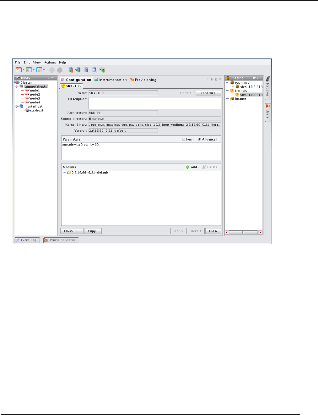
Kernel Management
Edit a Kernel
007-5642-005 107
Edit a Kernel
To Edit a Kernel
1. Right-click a kernel in the imaging navigation tree and select Edit.
2. (Optional) Edit the kernel’s description in the Description field.
3. (Optional) Click Update to update a kernel that has been recompiled for some reason (e.g., a change in kernel
configuration). Management Center updates the kernel based on the Source Directory and Binary Path used when
you created the kernel. See To Create a Kernel Using an Existing Binary on page 101.
4. (Optional) Click Properties to view the *.config and System.map files for the kernel (if they existed when you
imported the kernel).
5. (Optional) Edit the Parameters pane using the Form or Advanced view. The form view organizes and displays the
basic required options and provides the default values required for IPMI. The Advanced view allows you to view
all configurations in an editable text field and allows you to configure the kernel’s command-line parameters string.
A. Select Serial Console to specify which console (tty0 or tty1) you will use to communicate with hosts.
B. Select Baud Rate to change the baud rate used on your system.
C. Select RAMdisk Size to change the size of the RAMdisk configured on your system.
6. (Optional) In the modules pane, click Add to include new modules in this kernel. You may select modules
individually (files ending in *.ko) or you can add a directory and allow Management Center to automatically select
all modules and directories recursively. See Modules on page 108.
7. (Optional) In the modules pane, select any module(s) you want to remove from the kernel and click Delete.
8. Click Apply to complete the process. Click Revert or Close to abort this action.

Kernel Management
Edit a Kernel
007-5642-005
108
9. (Optional) Click Check In to commit changes to the kernel into VCS.
10. (Optional) Click Copy to create a copy of this kernel. See To Create a Copy of an Existing Kernel on page 103.
MODULES
Many provisioning systems use a basic kernel to boot and provision the host, then reboot with an optimized kernel that
will run on the host. Management Center requires only a single kernel to boot and run; however, you must compile any
additional functionality into the kernel (i.e., monolithic) or add loadable kernel modules to the kernel (i.e., modular).
Management Center loads the modules during the provisioning process.
If you encounter problems when provisioning hosts on your cluster, check to see that you compiled your kernel
correctly. If you compiled a modular kernel, you must include ethernet or file system modules before the host can
provision properly. Use the serial console to watch the host boot.
In some cases, it may be necessary to install kernel modules on a host during the provisioning process, but not load
them at boot time. Because an image ties a kernel and payload together, modules can be copied to the host by adding
them to an image rather than adding them to a payload.
To add modules to an image, run mkdir -p ramdisk/lib/modules from the images directory. For example, if you were
running as root and your image name were ComputeHost:
cd $MGR_HOME/imaging/root/images/ComputeHost
mkdir -p ramdisk/lib/modules/<linux name & version>/kernel/
mkdir -p ramdisk/lib/modules/<kernel name with version>/kernel/net/e1000
Then copy the modules you want to an appropriate subdirectory of the modules directory:
cp /usr/src/linux/drivers/net/e1000/e1000.ko
ramdisk/lib/modules/<linux name & version>/kernel/net
ramdisk/lib/modules/<linux name & version>/kernel/net/e1000/
You may wish to look at your local /lib/modules directory if you have questions about the directory structure. During
the boot process, the kernel automatically loads the modules that were selected in the kernel configuration screen. The
additional modules will be copied to the host during the finalize stage. This method keeps the payload independent from
the kernel and allows you to load the modules after the host boots.
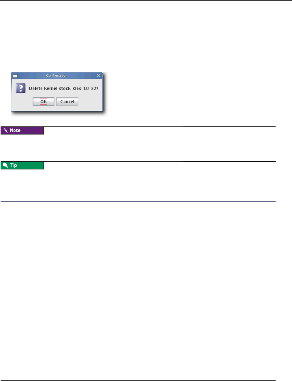
Kernel Management
Delete a Kernel
007-5642-005 109
Delete a Kernel
To Delete a Working Copy of a Kernel
1. Select the Imaging tab.
2. Right-click on the kernel in the imaging navigation tree and select Delete.
3. Management Center asks you to confirm your action.
Before you delete the working copy of your kernel, check VCS to verify that the kernel is checked in. See Version
Control System (VCS) on page 134 for details on using version control.
Once you check the kernel into VCS, you may delete the working copy of the kernel from your working directory (e.g.,
to save space).
$MGR_HOME/imaging/<username>/<kernel>/<name>
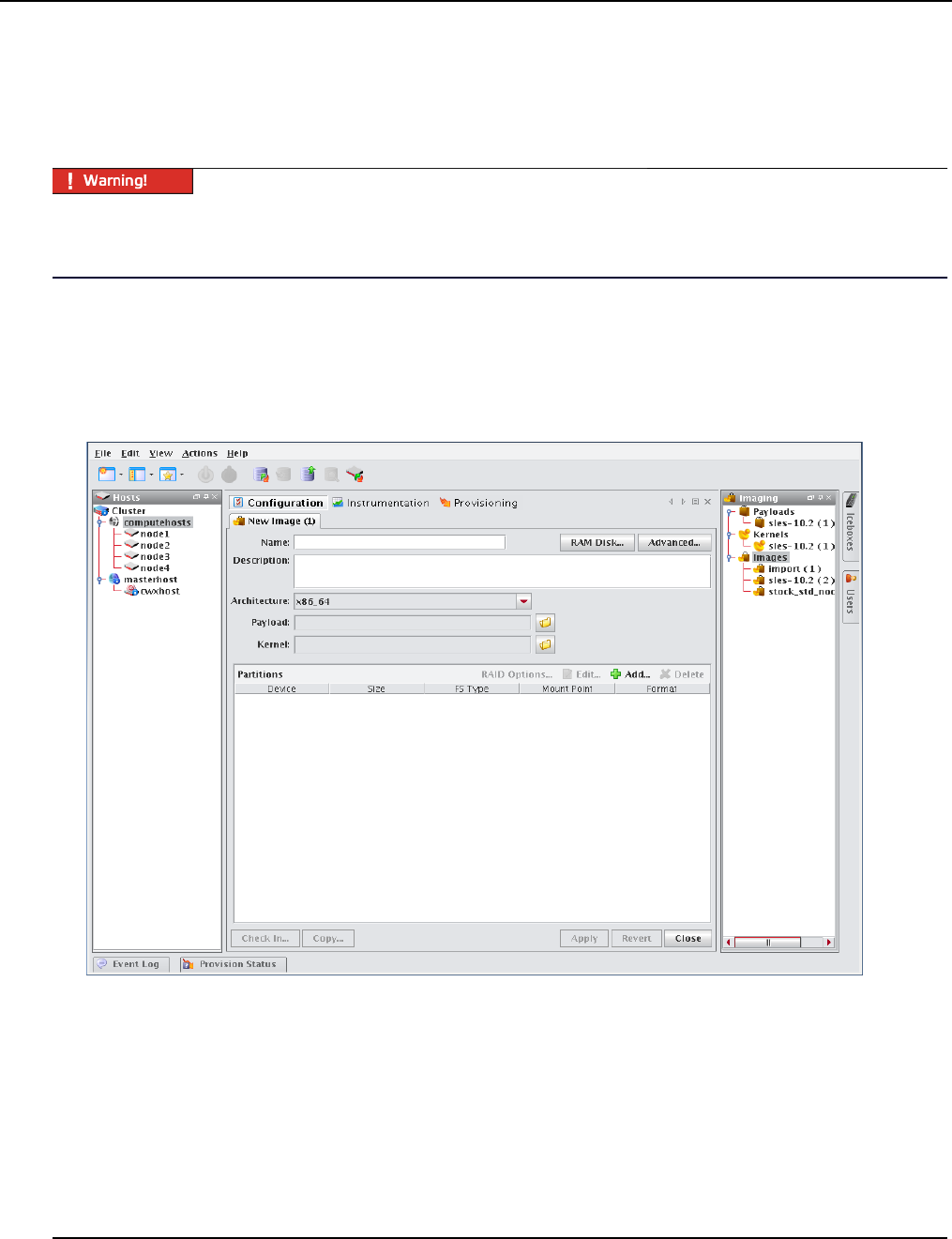
Image Management
Create an Image
007-5642-005
110
Image Management
Images contain exactly one payload and one kernel, and allow you to implement tailored configurations on various
hosts throughout the cluster.
Please consult SGI before upgrading your Linux distribution or kernel. Upgrading to a distribution or kernel not
approved for use on your system may render Management Center inoperable or otherwise impair system functionality.
Technical Support is not provided for unapproved system configurations.
Create an Image
To Create an Image
1. Select New Image from the File menu or right-click in the imaging navigation tree and select New Image. A New
Image pane appears.
2. Enter the name of the new image in the Name field.
3. (Optional) Enter a description of the new image in the Description field.
4. Select the architecture supported by the kernel.
5. Select a Kernel by clicking Browse. To install additional kernel modules that do not load at boot time, see Modules
on page 108.
6. Select a Payload by clicking Browse.
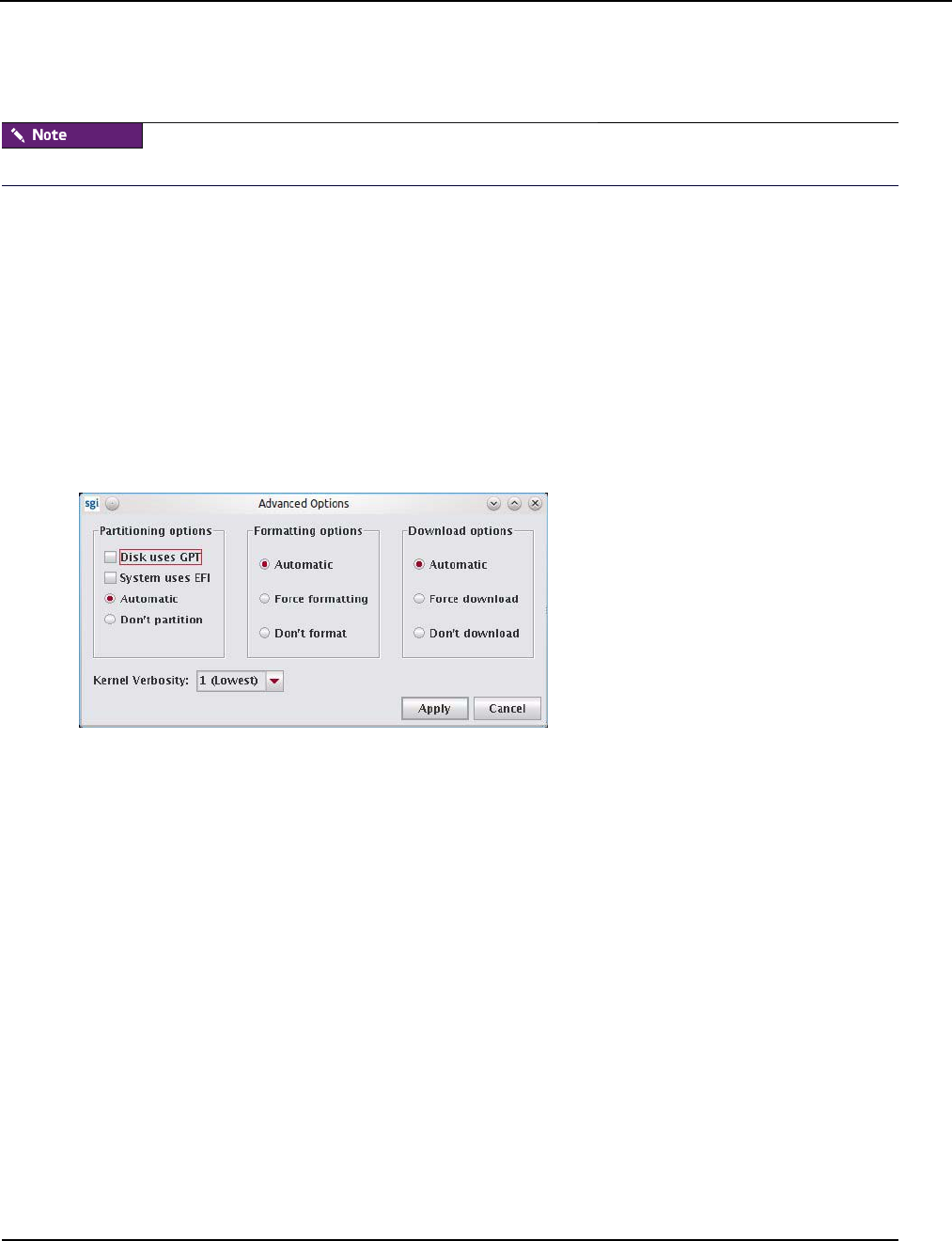
Image Management
Create an Image
007-5642-005 111
7. Define the partition scheme used for the compute hosts—the partition scheme must include a root (/) partition. See
To Create a Partition for an Image on page 114.
Kernel support for selected file systems must be included in the selected kernel (or as modules).
8. (Optional) Implement RAID. See Managing Partitions on page 114.
9. (Optional) If you need to make modifications to the way hosts boot during the provisioning process, select the
RAM Disk tab. See RAM Disk on page 128.
10. (Optional) Click the Advanced button to display the Advanced Options dialog. This dialog allows you to configure
partitioning behavior and payload download settings (see Advanced Imaging Options).
11. Click Apply to complete the process. Click Revert or Close to abort this action.
Advanced Imaging Options
The Advanced Options dialog allows you to configure partitioning behavior and payload download settings. These
settings are persistent, but may be overridden from the Advanced Provisioning Options dialog. See Advanced
Provisioning Options on page 145.
PARTITIONING OPTIONS
This option allows you to configure the partition settings used when provisioning a host. You may automatically
partition a host if the partitioning scheme changes or choose to never partition the host. You may also specify if the
image should use GPT partition tables or EFI. See Managing Partitions on page 114.
FORMATTING OPTIONS
These options allow you to configure the partition formatting settings used when provisioning a host. You may
automatically format when drives need to be formatted (for example, if the payload or the partitioning scheme changes),
always re-create all partitions (including those that are exempt from being overwritten), or choose to never format.
DOWNLOAD OPTIONS
These options allow you to automatically download a payload if a newer version is available (or if the current payload
is not identical to that contained in the image), always download the payload, or choose to never download a payload.
KERNEL VERBOSITIY
The kernel verbosity level (1–8) allows you to control debug messages displayed by the kernel during provisioning. The
default value 1 is the least verbose and 8 is the most.
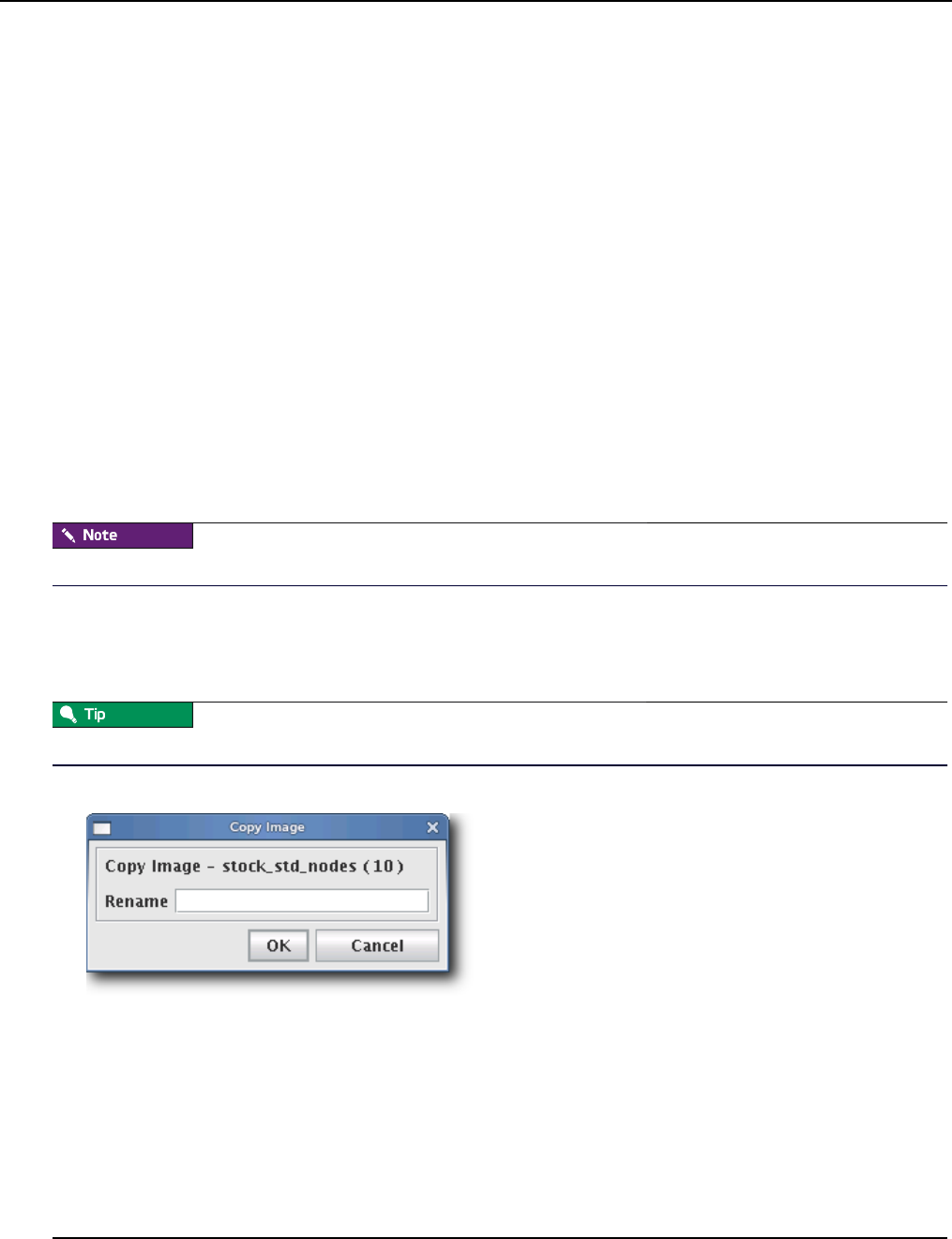
Image Management
Delete an Image
007-5642-005
112
boot.profile
Management Center generates the file, boot.profile, each time you save an image (overwriting the previous file in
/etc/boot.profile). The boot profile contains information about the image and is required for the boot process to function
properly. You may configure the following temporary parameters:
dmesg.level The verbosity level (1-8) of the kernel—1 (the default) is the least verbose and 8 is the
most.
partition Configure the hard drive re-partitioning status (Automatic, Always, Never). By default,
Automatic.
partition.once Override the current drive re-partitioning status (Default, On, Off). By default, Default.
image Configure the image download behavior (Automatic, Always, Never). By default,
Automatic. Always and Never will download the image even if it is up-to-date.
image.once Override the current image download behavior (Default, On, Off). By default, Default.
To view the current download behavior, see Advanced Imaging Options on page 111.
image.path Specifies where to store the downloaded image. By default, /mnt.
To change the configuration of one of these parameters, add the parameter (e.g., dmesg.level: 7) to the boot.profile and
provision using that image. You may also configure most of these values from the GUI. See Select an Image and
Provision on page 141.
Changes made to image settings remain in effect until the next time you save the image.
To Create a Copy of an Existing Image
1. Select the Imaging tab.
2. Select an image from the navigation tree, then right-click on the image and select Copy.
You may also open an image for editing, then click the Copy button.
3. Management Center prompts you for the name of the new image.
4. Enter the name of the new image and click OK. Click Cancel to abort this action.
Delete an Image
To Delete a Working Copy of an Image
1. Right-click an image in the imaging navigation tree and select Delete.
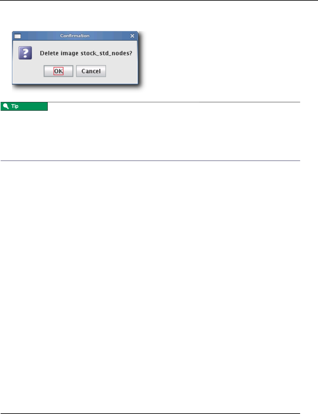
Image Management
Delete an Image
007-5642-005 113
2. Management Center asks you to confirm your action.
Once you check the image into VCS, you may remove the directory from within your working user directory (e.g., to
save space).
$MGR_HOME/imaging/<username>/images/<name>
To verify that your changes were checked in, use the VCS status option. See Version Control System (VCS) on page 134
for details on using version control.
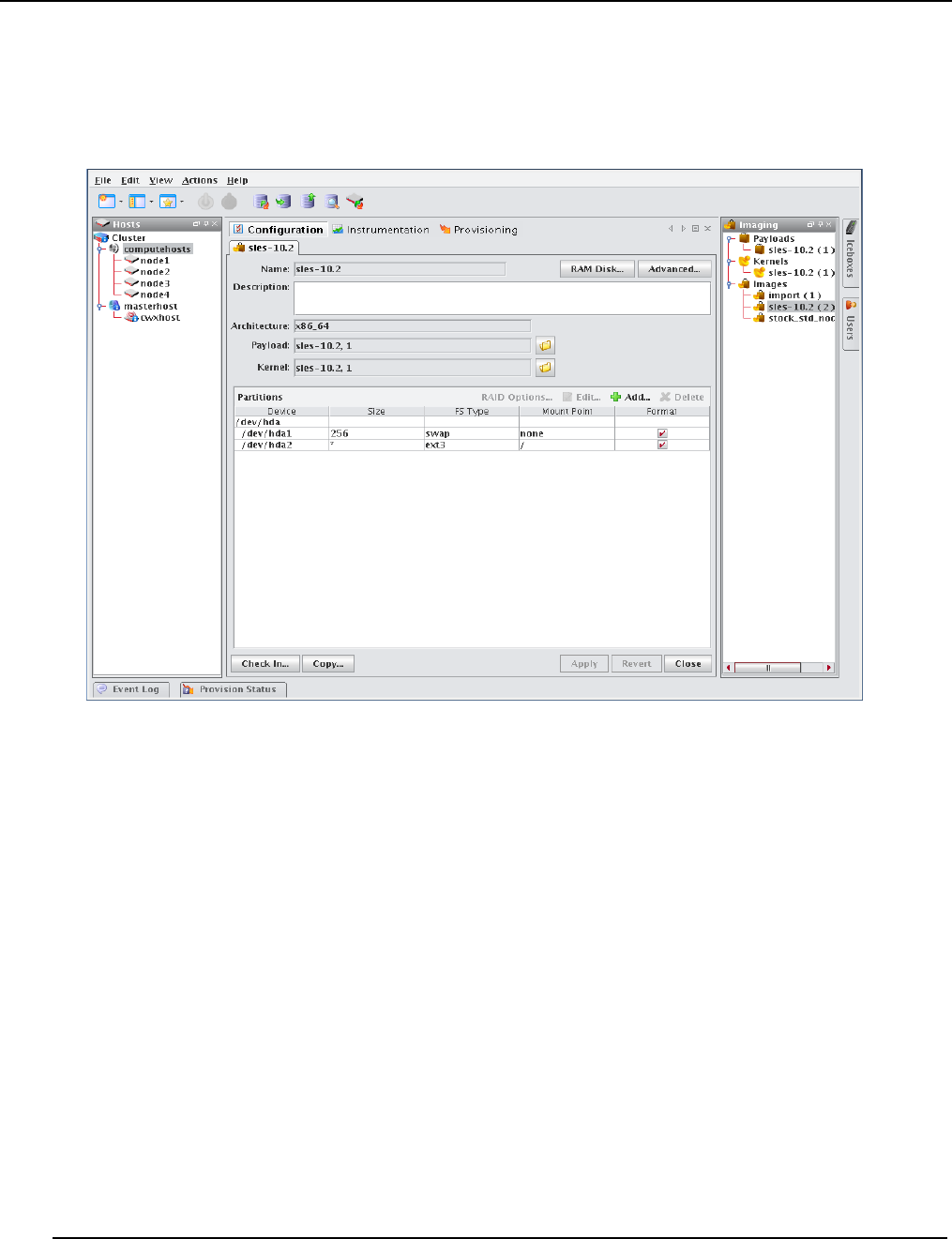
Image Management
Managing Partitions
007-5642-005
114
Managing Partitions
To Create a Partition for an Image
1. Right-click on an image in the imaging navigation tree and select Edit. The Image panel appears.
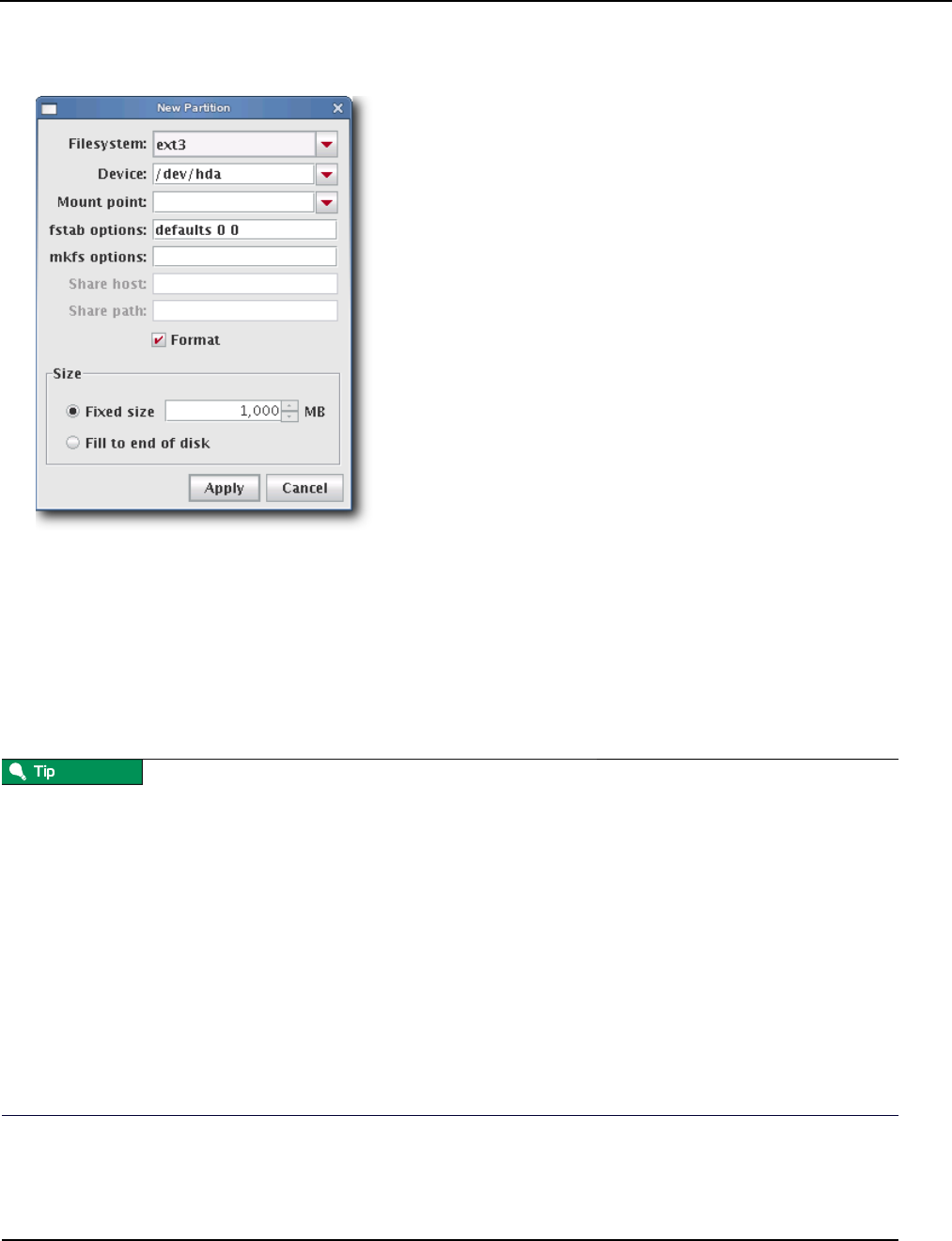
Image Management
Managing Partitions
007-5642-005 115
2. In the partitions pane, click Add to create a new partition. The New Partition dialog appears.
3. Select a file system type from the Filesystem pull-down menu. To create a diskless host, see Diskless Hosts on
page 125.
4. Enter the device on which to add the partition or select a device from the drop-down list. Supported devices include
the following, but the most common is /dev/hda because hosts typically have only one disk and use IDE:
•/dev/hda—Primary IDE Disk
•/dev/hdb—Secondary IDE Disk
•/dev/sda—Primary SCSI Disk
•/dev/sdb—Secondary SCSI Disk
If you are using non-standard hosts, you can add additional storage devices to the partitioning drop-down list. The
Image Administration Service profile, $MGR_HOME/etc/ImageAdministrationService.profile, allows you to configure
non-standard hard drives. This profile contains options that allow you to set the drive name (available when partitioning
the disk at the time of creating or modifying an image) and the prefix for a partition on the drive (if one exists). By
default these values are commented out, but may be commented in as needed. Once drives are configured, they become
available via Management Center.
Profile options are as follows:
partitioning.devices:cciss/c0d0
The name of the storage device where the device file is located (e.g., /dev/cciss/c0d0).
partitioning.devices.cciss/c0d0.naming:p
The partition prefix for the device defined by the previous key (e.g., cciss/c0d0).
In this example, the partition will look like c0d0p1, c0d0p2, and so on.
5. Enter a Mount Point or select one from the pull-down menu.

Image Management
Managing Partitions
007-5642-005
116
6. (Optional) Enter the fstab options. The /etc/fstab file controls where directories are mounted and, because
Management Center writes and manages the fstab on the hosts, any changes made on the hosts are overwritten
during provisioning.
7. (Optional) Enter the mkfs options to use when creating the file system (i.e., file size limits, symlinks, journalling).
For example, to change the default block size for ext3 to 4096, enter -b 4096 in the mkfs options field.
8. (Optional) If creating an NFS mount, enter the NFS host.
9. (Optional) If creating an NFS mount, enter the NFS share.
10. (Optional) Un-check the Format option to make the partition exempt from being overwritten or formatted when
you provision the host. This may be overridden by the Force formatting option or from the boot.profile (see Select
an Image and Provision on page 141 and boot.profile on page 112).
After partitioning the hard disk(s) on a host for the first time, you can make a partition on the disk exempt from being
overwritten or formatted when you provision the host. However, deciding not to format the partition may have an
adverse affect on future payloads—some files may remain from previous payloads. This option is not allowed if the
partition sizes change when you provision the host.
For nodes with external storage, detach the storage when provisioning. The discovery order may present the external
storage first and, consequently, Management Center will use the storage for the filesystems it manages.
11. Select the partition size:
•Fixed size allows you to define the size of the partition (in MBs).
•Fill to end of disk allows you to create a partition that uses any space that remains after defining partitions with
fixed sizes.
It is wise to allocate slightly more memory than is required on some partitions. To estimate the amount of memory
needed by a partition, use the du -hc command.
12. Click Apply to save changes or click Cancel to abort this action.
13. (Optional) Click Check In to import the image into VCS.
14. Click Apply to complete the process. Click Revert or Close to abort this action.
Management Center generates the file, boot.profile, each time you save an image. For a description of the information
contained in this file, see boot.profile on page 112.
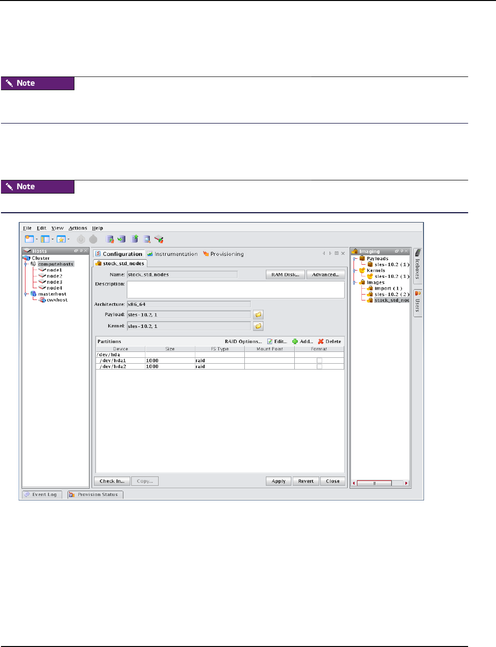
Image Management
RAID Partitions
007-5642-005 117
RAID Partitions
To Create a RAID Partition
When adding a RAID partition, the host typically requires two disks and at least two previously created software RAID
partitions (one per disk).
1. Right-click on an image in the imaging navigation tree and select Edit. The image pane appears.
2. In the partitions pane, click Add to create the appropriate number of software RAID partitions for the RAID you
are creating. See To Create a Partition for an Image on page 114.
The RAID button is disabled until you create at least two RAID partitions.
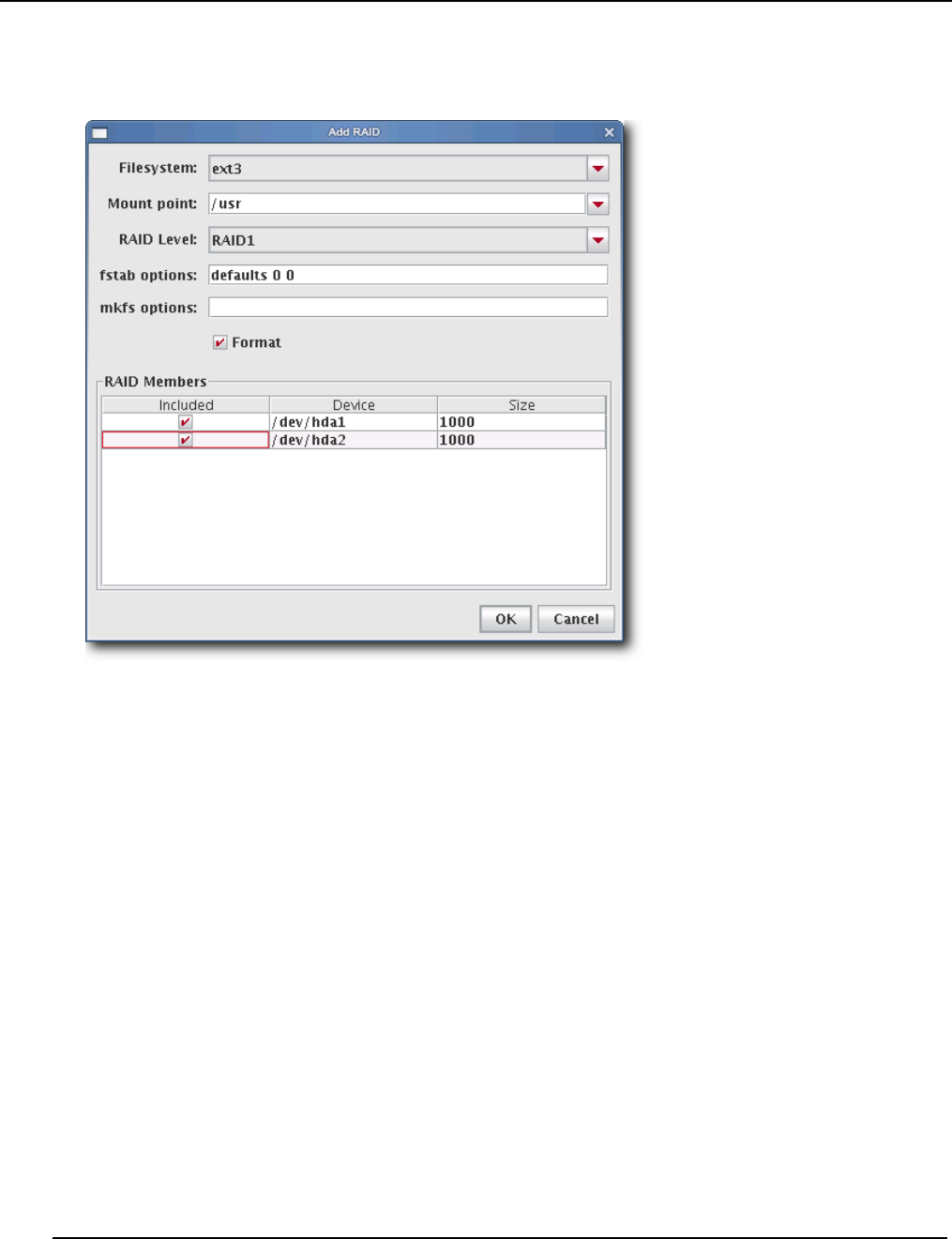
Image Management
RAID Partitions
007-5642-005
118
3. Click the RAID button to assign the partitions a file system, mount point, and RAID level. The Add RAID dialogue
appears.
4. Select a file system type from the Filesystem pull-down menu.
5. Enter a Mount point or select one from the pull-down menu.
6. Select a RAID level from the RAID Level pull-down menu. This level affects the size of the resulting RAID and
the number of RAID partitions required to create it (e.g., RAID0 and RAID1 require 2 RAID partitions, RAID5
requires 3 RAID partitions).
7. (Optional) Enter the fstab options. The /etc/fstab file controls where directories are mounted and, because
Management Center writes and manages the fstab on the hosts, any changes made on the hosts are overwritten
during provisioning.
8. (Optional) Enter the mkfs options to use when creating the file system (i.e., file size limits, symlinks, journalling).
For example, to change the default block size for ext3 to 4096, enter -b 4096 in the mkfs field.
9. From the RAID Members list, select the currently unused RAID partitions to include in this RAID.
10. Click OK to save changes or click Cancel to abort this action.
11. Click Apply to complete the process. Click Revert or Close to abort this action.
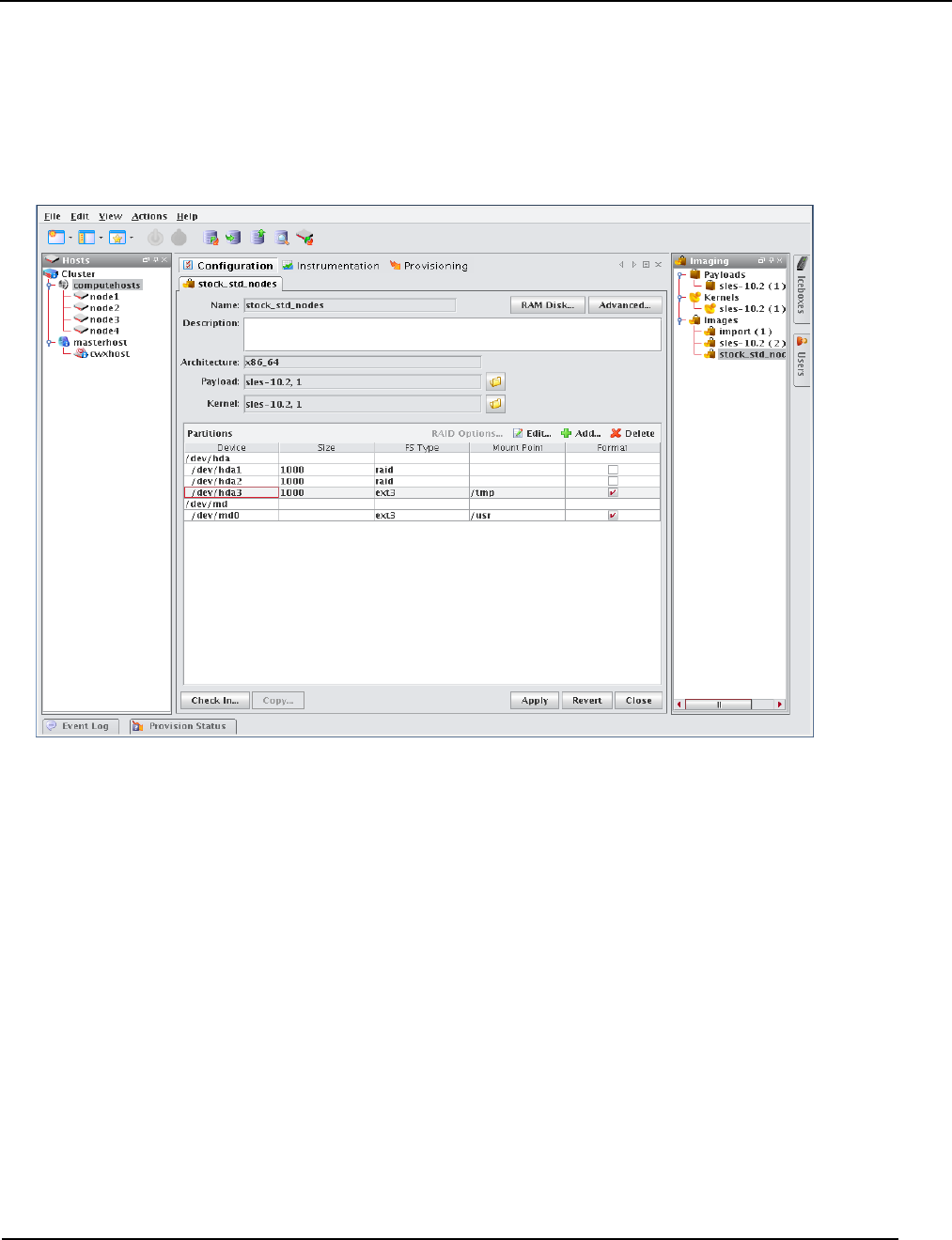
Image Management
Edit a Partition
007-5642-005 119
Edit a Partition
To Edit a Partition on an Image
1. Right-click an image in the imaging navigation tree and select Edit. The image panel appears.
2. In the partitions pane, select the partition you want to edit from the list of partitions.
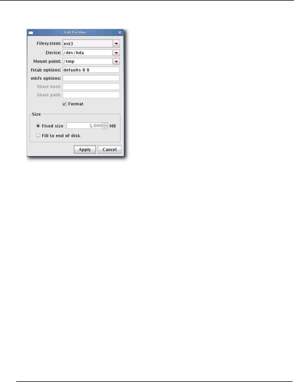
Image Management
Edit a Partition
007-5642-005
120
3. Click Edit in the partitions pane. The Edit Partition dialog appears.
4. Make any necessary changes to the partition, then click Apply to accept the changes. Click Cancel to abort this
action.
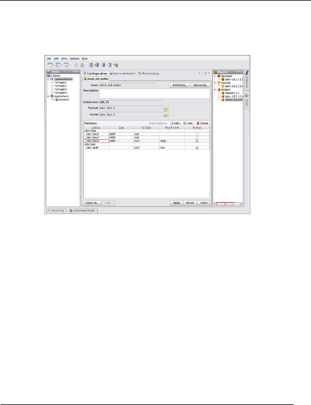
Image Management
Delete a Partition
007-5642-005 121
Delete a Partition
To Delete a Partition from an Image
1. Right-click an image in the imaging navigation tree and select Edit. The image panel appears.
2. From the partitions pane, select the partition you want to delete from the list of partitions. To select multiple
partitions, use the Shift or Ctrl keys.
3. Click Delete.
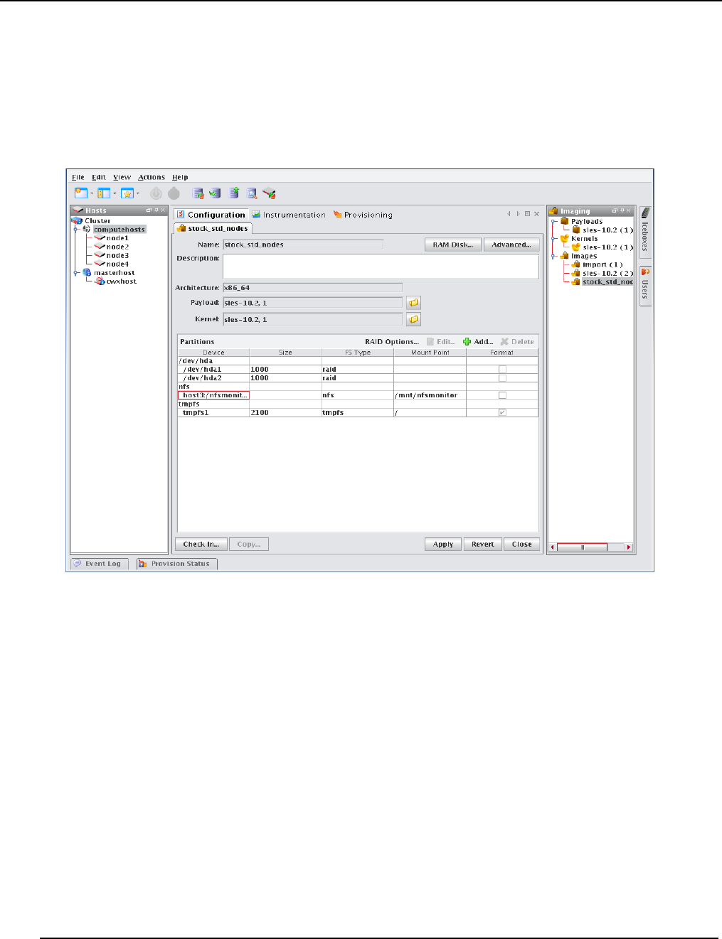
Image Management
User-Defined File Systems
007-5642-005
122
User-Defined File Systems
Establishing a user-defined file system allows you to create a raw partition that you may format with a file system not
supported by Management Center.
To Create a Partition with a User-defined File System
1. Right-click on an image in the imaging navigation tree and select Edit. The image panel appears.
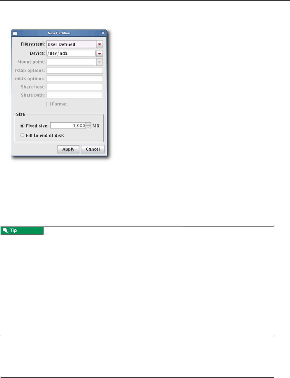
Image Management
User-Defined File Systems
007-5642-005 123
2. From the partitions pane, click Add. The New Partition dialog appears.
3. Select User Defined from the Filesystem pull-down menu.
4. Enter the device on which to add the partition or select a device from the pull-down menu. Supported devices
include the following, but the most common is /dev/hda because hosts typically have only one disk and use IDE:
•/dev/hda—Primary IDE Disk
•/dev/hdb—Secondary IDE Disk
•/dev/sda—Primary SCSI Disk
•/dev/sdb—Secondary SCSI Disk
If you are using non-standard hosts, you can add additional storage devices to the partitioning drop-down list. The
Image Administration Service profile, $MGR_HOME/etc/ImageAdministrationService.profile, allows you to configure
non-standard hard drives. This profile contains options that allow you to set the drive name (available when partitioning
the disk at the time of creating or modifying an image) and the prefix for a partition on the drive (if one exists). By
default these values are commented out, but may be commented in as needed. Once drives are configured, they become
available via Management Center.
Profile options are as follows:
partitioning.devices:cciss/c0d0
The name of the storage device where the device file is located (e.g., /dev/cciss/c0d0).
partitioning.devices.cciss/c0d0.naming:p
The partition prefix for the device defined by the previous key (e.g., cciss/c0d0).
In this example, the partition will look like c0d0p1, c0d0p2, and so on.
5. Create a plug-in to create the user-defined file system. Everything required to build and mount the file system will
need to be included in the RAMdisk. Kernel modules needed to support the file system must be added to the kernel
you selected. See Plug-ins for the Boot Process on page 130.

Image Management
User-Defined File Systems
007-5642-005
124
6. Select the partition size:
•Fixed partition size allows you to define the size of the partition (in MBs).
•Fill to end of disk allows you to create a partition that uses any space that remains after defining partitions with
fixed sizes.
7. Click Apply to save changes or click Cancel to abort this action.
8. Click Check In to import the image into VCS.
9. Click Apply to complete the process. Click Revert or Close to abort this action.
Management Center generates the file, boot.profile, each time you save an image. See boot.profile on page 112 for a
description of the information contained in this file.
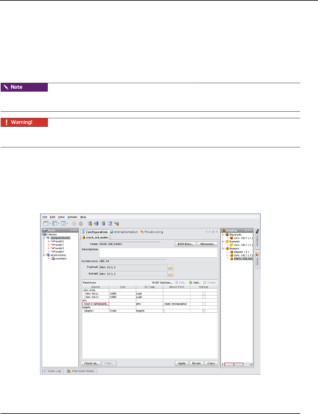
Image Management
Diskless Hosts
007-5642-005 125
Diskless Hosts
Management Center provides support for diskless hosts. For optimal performance, Management Center implements
diskless hosts by installing the operating system into the host’s physical memory, generally referred to as RAMfs or
TmpFS. Because the OS is stored in memory, it is recommended that you use a minimal Linux installation to avoid
consuming excess memory. An optimized Linux installation is typically around 100-150MB, but may be as small as
30MB depending on which libraries are installed. Management Center also supports local scratch or swap space on the
hosts.
Potentially large directories like /home should never be stored in RAM. Rather, they should be shared through a global
storage solution.
When using diskless hosts, the file system is stored in memory. Changes made to the host’s file system will be lost when
the host reboots. If changes are required, make them in the payload first.
SGI offers secure diskless systems for classified environments. These include integration of micro installation with a
globally mounted file system and scripts that optimize and simplify diskless management. Additional options for
diskless systems are available through SGI Professional Services. Please contact SGI or speak with your SGI
representative for more information.
To Configure a Diskless Host
1. Right-click on an image in the imaging navigation tree and select Edit. The image panel appears.
2. From the partitions pane, click Add. The New Partition dialog appears.
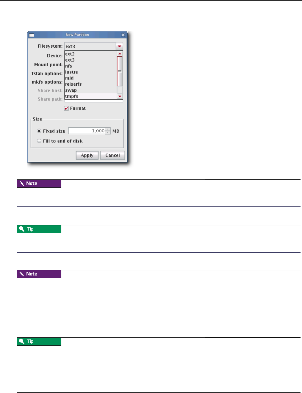
Image Management
Diskless Hosts
007-5642-005
126
3. Select the tmpfs or nfs file system type from the Filesystem pull-down menu.
Although diskless hosts may use either tmpfs or nfs partitions, they must use only one type. If you are converting or
editing a diskless host, change all partitions to the same type.
4. Enter the Mount Point or select one from the pull-down menu (diskless hosts use root “/” as the mount point).
In most Linux installations, the majority of the OS is stored in the /usr directory. To help conserve memory, you may
elect to share the /usr directory via NFS or another global file system.
5. (Optional) Enter the fstab options. The /etc/fstab file controls where directories are mounted.
Because Management Center writes and manages the fstab on the hosts, any changes made on the hosts are overwritten
during provisioning.
6. Select the partition size:
•Fixed partition size allows you to define the size of the partition (in MBs).
•Fill to end of disk allows you to create a partition that uses any space that remains after defining partitions with
fixed sizes.
It is wise to allocate slightly more memory than is required on some partitions. To estimate the amount of memory
needed by a partition, use the du -hc command.
It is important to note that memory allocated to a partition is not permanently consumed. For example, consider
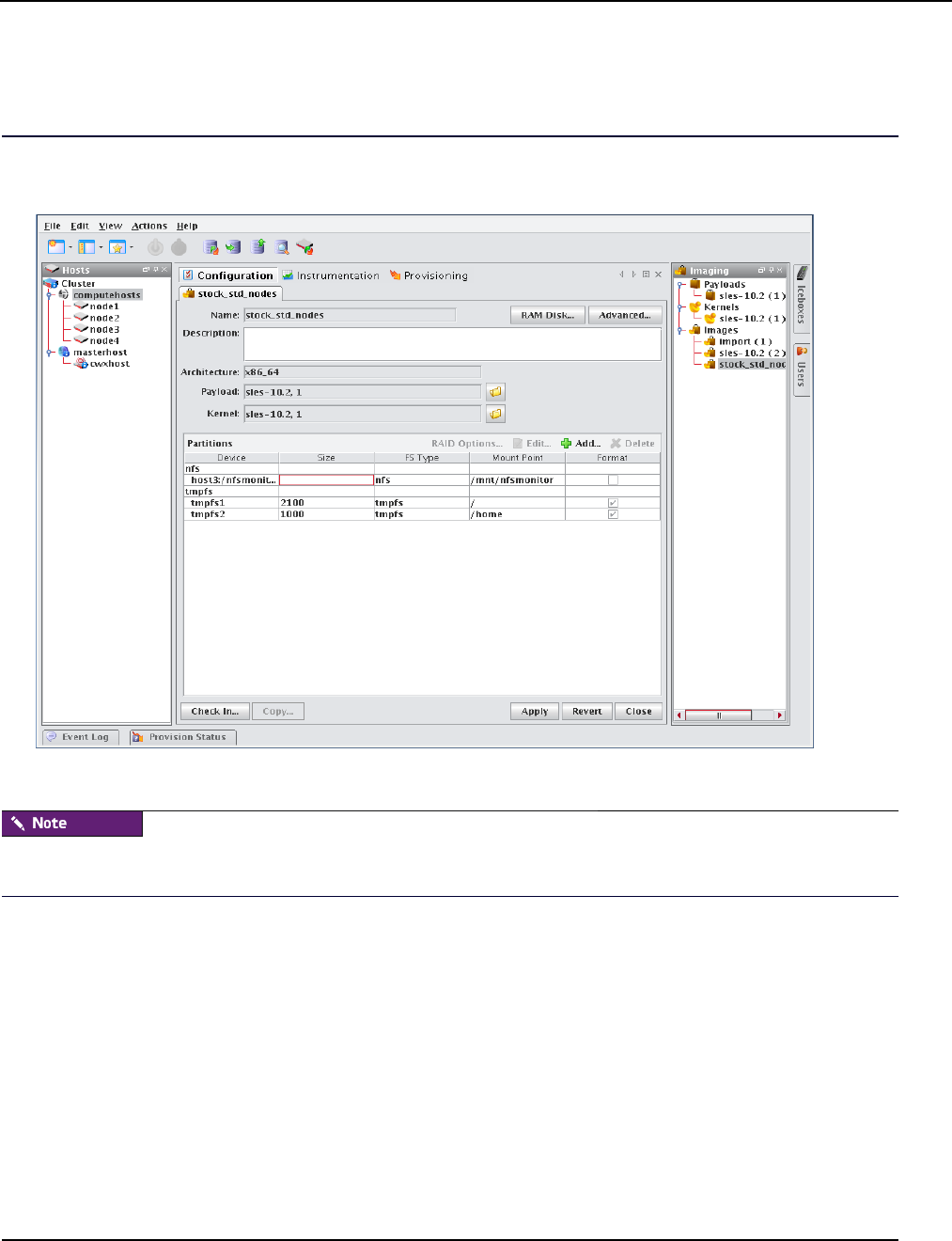
Image Management
Diskless Hosts
007-5642-005 127
programs that need to write temporary files in a /tmp partition. Although you may configure the partition to use a
maximum of 50 MB of memory, the actual amount used depends on the contents of the partition. If the /tmp partition is
empty, the amount of memory used is 0 MB.
7. Click Apply to save changes or click Cancel to abort this action.
8. Click Check In to import the image into VCS.
9. Click Apply to complete the process. Click Revert or Close to abort this action.
Management Center generates the file, boot.profile, each time you save an image. See boot.profile on page 112 for a
description of the information contained in this file.
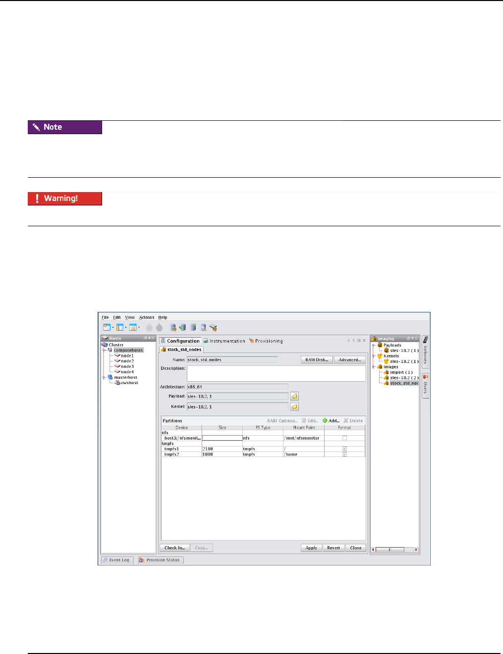
Image Management
RAM Disk
007-5642-005
128
RAM Disk
The RAM Disk is a small disk image that is created and loaded with the utilities required to provision the host. When
the host first powers on, it loads the kernel and mounts the RAM Disk as the root file system. In order for host
provisioning to succeed, the RAM Disk must contain specific boot utilities. Under typical circumstances, you will not
need to add boot utilities unless you are creating something such as a custom, pre-finalized script that needs utilities not
required by standard Linux versions (e.g., modprobe).
Management Center uses two “skeleton” RAM Disks—one for ia32 and another for both AMD-64 and EM64T. These
skeleton disks are located in $MGR_HOME/ramdisks and should never be modified manually. All changes must be
performed through Management Center or in $MGR_HOME/imaging/<username>/images/<image_name>/ramdisk.
Modifications made to the RAM Disk are permanent for ALL images.
To Add Boot Utilities
Adding boot utilities to the RAM Disk allows you to create such things as custom, pre-finalized scripts using utilities
that are not required for standard Linux versions.
1. Right-click on an image n the imaging navigation tree and select Edit. The image panel appears.
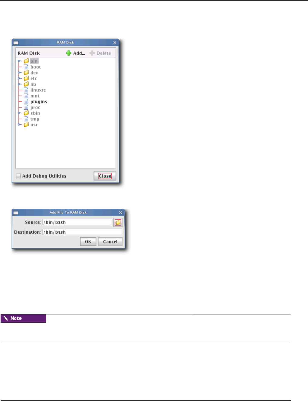
Image Management
RAM Disk
007-5642-005 129
2. Click the RAM Disk button. The RAM Disk dialog appears. Default files from the skeleton RAM Disk are grayed
out—any changes or updates appear in black.
3. Click Add. The Add File to RAM Disk dialog appears.
4. Enter the boot utility path in the Source field or click Browse to locate a utility.
5. Specify the Destination location in which to install the boot utility in the RAM Disk file system.
6. Click OK to install the boot utility or click Cancel to abort this action.
7. (Optional) Select Add Debug Utilities to apply additional debugging utilities to the RAM Disk.
8. Click Apply to complete the process. Click Revert or Close to abort this action.
Management Center generates the file, boot.profile, each time you save an image. See boot.profile on page 112 for a
description of the information contained in this file.
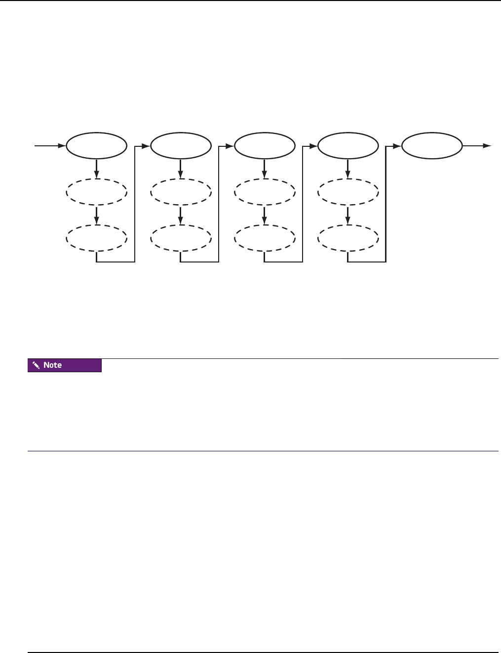
Image Management
Plug-ins for the Boot Process
007-5642-005
130
Plug-ins for the Boot Process
A host requires a boot process to initialize hardware, load drivers, and complete the necessary tasks to initiate a login
prompt. The boot process is composed of five main stages and allows you to include additional plug-ins at each stage to
expand system capabilities. During the boot process, the system moves from stage to stage installing any plug-ins
specified. If you do not specify any plug-ins, the host will boot using the built-in boot process. The boot process is as
follows:
•initialize Stage one creates writable directories and loads any kernel modules.
•identify Stage two uses DHCP to get the IP address and host name.
•partition Stage three creates partitions and file systems.
•image Stage four downloads and extracts the payload.
•finalize Stage five configures Management Center services to run with the host name retrieved from
DHCP.
All plug-ins must be added inside the RAM Disk under /plugins/<filename>.
The provisioning plug-in scripts run each time the node is booted with an image that contained that plug-in at the time it
was provisioned. This is not dependent on whether or not a new payload is being downloaded or similar situations.
Plug-in scripts should be written in such a way that running it multiple times against the same installed payload will not
cause problems.
initialize
/plugins/postinitialize
/plugins/preidentify
identify
/plugins/postidentify
/plugins/prepartition
partition
/plugins/postpartition
/plugins/preimage
image
/plugins/postimage
/plugins/prefinalize
finalize
Stage 1 Stage 2 Stage 3 Stage 4 Stage 5
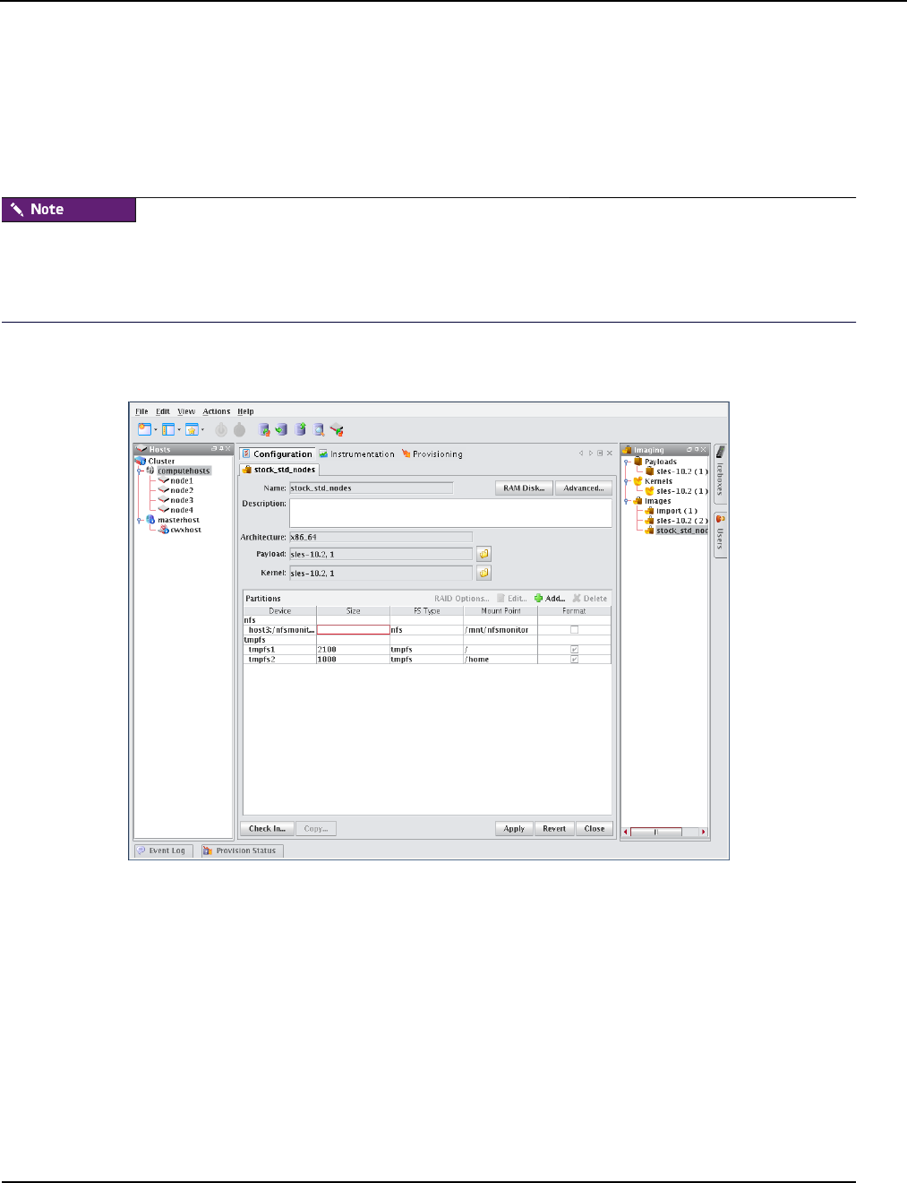
Image Management
Plug-ins for the Boot Process
007-5642-005 131
To Add a Plug-in
The following example depicts how to run a script during the boot process.
1. Write a shell or Perl script to run during the boot process. For example, to run a script immediately after
partitioning a drive, name the script postpartition and add it to the plugins directory in the RAMdisk
(i.e., /plugins/<filename>).
You must add all necessary utilities for your plug-in script to the RAM Disk. For example, if you use a Perl script as a
plug-in, you must add the Perl binary and all necessary shared libraries and modules to the RAM Disk. The shared
libraries for a utility may be determined using the ldd(1) command. Please note that adding these items significantly
increases the size of the RAM Disk. See To Add Boot Utilities on page 128.
2. Right-click on an image in the imaging navigation tree and select Edit. The image panel appears.
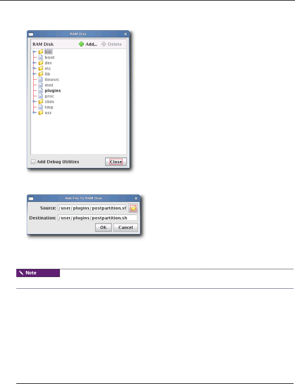
Image Management
Plug-ins for the Boot Process
007-5642-005
132
3. Click the RAM Disk button. The RAM Disk dialog appears.
4. Click Add. The Add File To RAM Disk dialog appears.
5. Enter the boot utility path in the Source field or click Browse to locate a plug-in.
6. Specify the installation location in the Destination field.
All scripts must be installed in the /plugins/ directory. However, you can overwrite other utilities.

Image Management
Plug-ins for the Boot Process
007-5642-005 133
7. Click OK to install the utility or click Cancel to abort this action. The new plugins appear in the RAM Disk dialog.
8. (Optional) Select Add Debug Utilities to apply additional debugging utilities to the RAM Disk.
9. Click Close.
10. Click Apply to complete the process. Click Revert or Close to abort this action.
Management Center generates the file, boot.profile, each time you save an image. See boot.profile on page 112 for a
description of the information contained in this file.
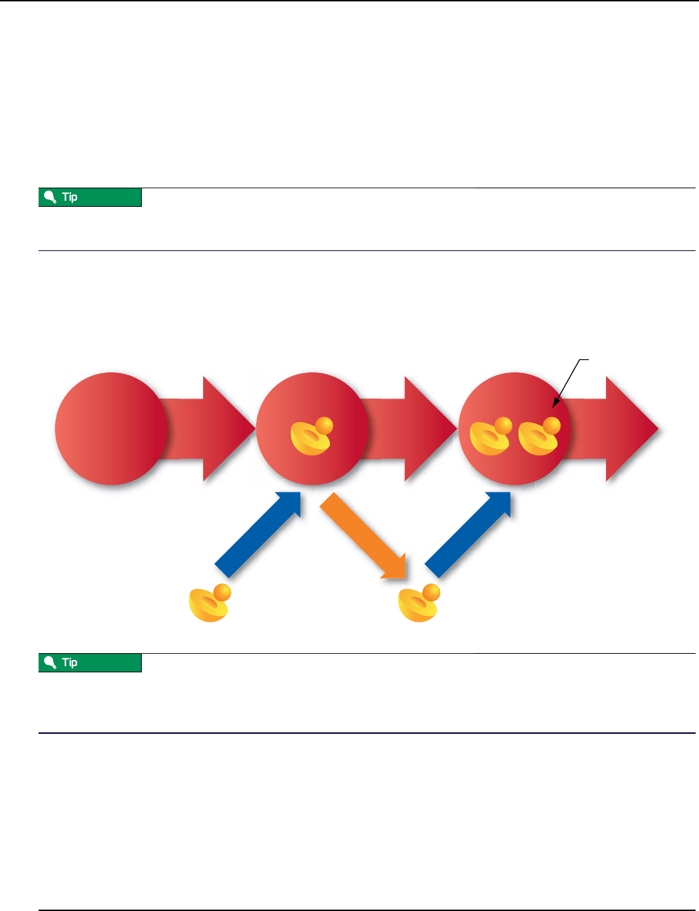
Version Control System (VCS)
Version Control
007-5642-005
134
Version Control System (VCS)
The Management Center Version Control System allows users with privileges to manage changes to payloads, kernels,
or images (similar in nature to managing changes in source code with a version control system). The Version Control
System is accessed via the VCS menu and supports common Check-Out and Check-In operations. Items are version
controlled by the user—when an item is checked out, it can be modified locally and checked back in. For information
on initially placing a payload, kernel, or image under version control, see Payload Management on page 76, Kernel
Management on page 101, or Image Management on page 110.
You can also use VCS Management to copy a payload, kernel, or image and create a new version. See VCS
Management on page 137.
Version Control
The following diagram illustrates version control for a kernel. The process begins with a working copy of a kernel that
is checked into VCS as a versioned kernel. The kernel is then checked out of VCS, modified (as a working copy of the
kernel), and checked back into VCS as a new version of the original kernel.
If another user checks out a copy of the same item you are working with and checks it back into VCS before you do,
you must either discard your changes and check out the latest version of the item or create a new branch that does not
contain the items checked in by the other user.
A Working Copy of a payload, kernel, or image is currently present in the working area (e.g. $MGR_HOME/imaging/
<user>/payloads). A Versioned payload, kernel, or image is a revision of a payload, kernel, or image stored in VCS.
Management Center displays payloads, kernels, or images that are currently checked out of VCS in the imaging tree.
These items may be edited only while they are checked out, but you may check them into VCS to store your changes. If
you are not using a working copy of an item (e.g., it is checked into VCS), you can delete it to conserve space.
Check In
New Version
Check Out
VCS VCS
Working Copy of Kernel
(
version 0
)
(Versioned) (Versioned)
Working Copy of Kernel
(
version 1
)
Check In
VCS
12

Version Control System (VCS)
Version Branching
007-5642-005 135
Version Branching
Image management works with VCS to allow you to branch any payload, kernel, or image under version control
arbitrarily from any version. Suppose, for example, that a payload under version control was gradually optimized to suit
specific hardware contained in a cluster. If the optimization were performed in stages (where each stage was a different
VCS revision), VCS would contain multiple versions of the payload.
Now suppose that you added some new hosts with slightly different hardware specifications to the cluster, but the last
few revisions of the payload use optimizations that are incompatible with the new hardware. Using the version
branching feature, you could create a new branch of the payload based on an older version that does not contain the
offending optimizations. The new branch could be used with the new hosts, while the remaining hosts could use the
original payload.
Kernel (1) Kernel (2) Kernel (3) Kernel (4)
Kernel (3.1) Kernel (3.2)
VCS
New Branch
Check Out
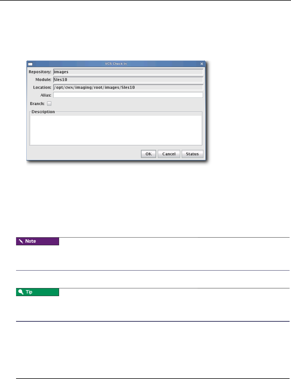
Version Control System (VCS)
Version Control Check-in
007-5642-005
136
Version Control Check-in
To Check In a Payload, Kernel, or Image
1. After making changes to a payload, kernel, or image, click Check In or select Check In from the VCS menu. The
VCS Import dialog appears.
2. (Optional) Enter an alias to use when referring to this version. The alias is the name displayed in the VCS Log
between the parentheses:
1(<Alias>)
February 26, 2004 9:14:17 AM MST, root
Description of changes...
3. (Optional) Select Branch to create a new branch of this item. Do not select this option if you want Management
Center to create a new revision on the current branch.
If another user checks out a copy of the same item you are working with and checks it back into VCS before you do,
you must either discard your changes and check out the latest version of the item or create a new branch that does not
contain the items checked in by the other user.
4. Click OK to continue or click Cancel to abort this action.
VCS Check In may fail if you have insufficient disk space. To monitor the amount of available disk space, configure the
disk space monitor to log this information, e-mail the administrator, or run a script when disk space is low. See
Management Center Monitoring and Event Subsystem on page 165 for details.
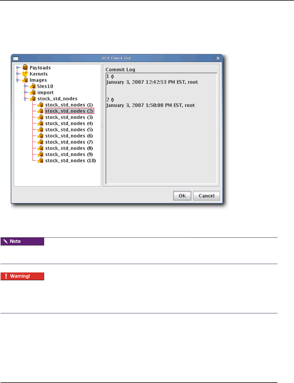
Version Control System (VCS)
Version Control Check-out
007-5642-005 137
Version Control Check-out
To Check Out a Payload, Kernel, or Image
1. Select Check Out from the VCS option in the Actions menu. The VCS Check Out dialog appears.
2. Select the payload, kernel, or image you want to check out of VCS (use the Shift or Ctrl keys to select multiple
items).
When you check out a payload, kernel, or image, Management Center creates a working copy of the item. If you check
out the root of a payload, kernel, or image, Management Center selects the tip revision.
Every time a user creates a payload (or checks a payload out of VCS), Management Center stores a working copy of the
payload in the user’s $MGR_HOME/imaging directory. To accommodate this process, Management Center requires a
minimum of 10 GB of disk space. Once the payload is checked into VCS, the user may safely remove the contents of
the imaging directory.
3. Click OK. Management Center places the item(s) into a working directory where you may make changes. Click
Cancel to abort this action.
VCS Management
The VCS management console allows you to copy, delete, or view the change history for a particular package, kernel,
or image.
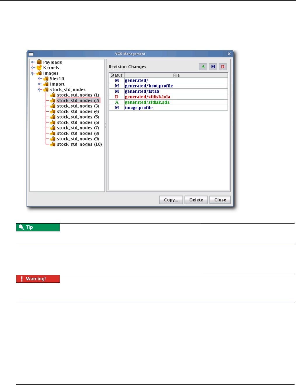
Version Control System (VCS)
VCS Management
007-5642-005
138
To Launch the VCS Management Console
1. Select Manage from the VCS option in the Actions menu. The VCS Management dialog appears.
2. Select a payload, kernel, or image for which to display a change history.
Click the Add (A), Modify (M), or Delete (D) options to include or exclude specific information.
3. To remove a versioned payload, kernel, or image from VCS, select the item from the navigation tree and click
Delete. When deleting a version of any item, all subsequent versions are also deleted (i.e., deleting version 4 also
removes versions 5, 6, and so on).
If you select Payloads, Kernels, or Images from the navigation tree, clicking Delete will remove ALL payloads, kernels,
or images from the system.
4. To copy a payload, kernel, or image, right-click on the item in the navigation tree and select Copy. Management
Center prompts you for a new name, then creates a new copy of the item in VCS.
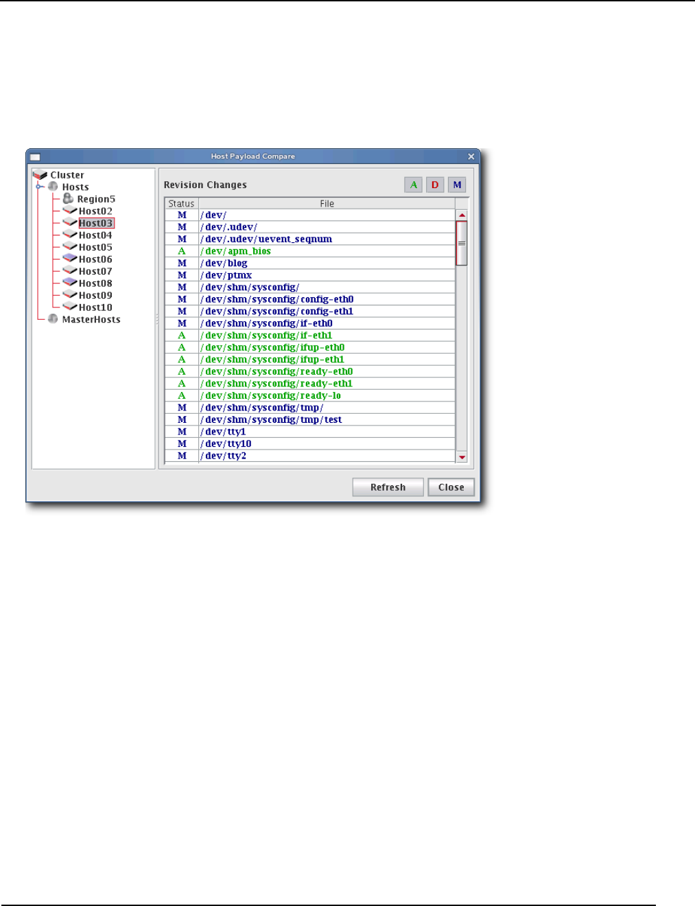
Version Control System (VCS)
VCS Host Compare
007-5642-005 139
VCS Host Compare
The Host Compare feature allows you to compare the payload currently installed on a host with the latest version of the
payload stored in VCS. This is useful when determining whether or not to re-provision a host with a new payload.
Similar to the VCS Management Console, this option displays all additions, modifications, and deletions made to the
payload since you last used it to provision the host.
TO EXCLUDE FILES FROM THE COMPARISON LIST
1. Open the file, $MGR_HOME/etc/exclude.files (a copy of this file should exist on all hosts):
proc
dev/pts
etc/ssh/ssh_host_dsa_key
etc/ssh/ssh_host_dsa_key.pub
etc/ssh/ssh_host_key
etc/ssh/ssh_host_key.pub
etc/ssh/ssh_host_rsa_key
etc/ssh/ssh_host_rsa_key.pub
media
mnt
root/.ssh
scratch
sys
tmp
usr/local/src
usr/share/doc
usr/src
var/cache/
var/lock

Version Control System (VCS)
VCS Host Compare
007-5642-005
140
var/log
var/run
var/spool/anacron
var/spool/at
var/spool/atjobs
var/spool/atspool
var/spool/clientmqueue
var/spool/cron
var/spool/mail
var/spool/mqueue
var/tmp
2. Edit the file as needed, then save your changes.
It is best to edit this file while it is in the payload so it can be copied to all hosts.
VersionControlService.profile
Management Center uses VersionControlService.profile, a global default exclude list that is not distribution-specific.
You may add files or directories to this list to prevent Management Center from checking them into VCS—particularly
helpful when importing payloads from the working directory. To remove items from the exclusion list, comment them
out of the profile.
Also contained in the VersionControlService.profile, the deflate.temp:/<dir> parameter allows you to specify an
alternate path for large files created while importing a payload.
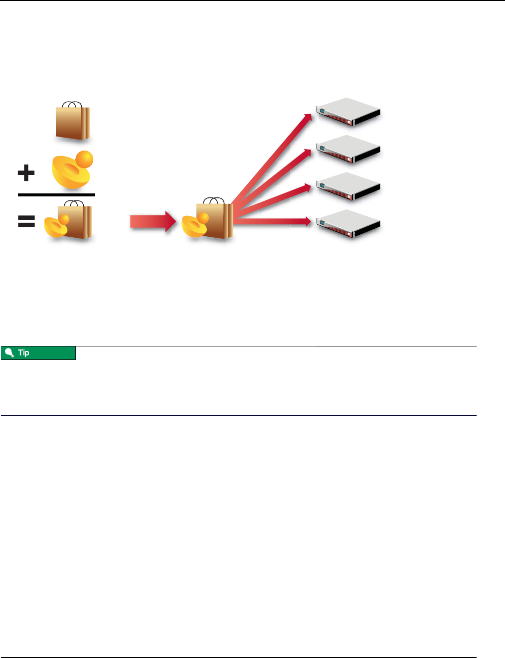
Provisioning
Select an Image and Provision
007-5642-005 141
Provisioning
The Management Center provisioning service allows you to create an image from a payload and kernel, then apply that
image to multiple hosts. When provisioning, you can select a versioned image stored in VCS or use a working copy of
an image from your working directory. The following illustration depicts an image that is provisioned to multiple hosts.
Select an Image and Provision
To Select an Image and Provision
1. Select the host(s) you want to provision from the navigation tree (use the Shift or Ctrl keys to select multiple hosts).
If you want to provision a host using the latest revision of an image stored in VCS, you can right-click a host and select
Provision. Management Center displays a popup menu and allows you to select the image you want to use to provision.
If you have made only minor changes to an image and want to upgrade your hosts to use the new image, see VCS
Upgrade on page 144.
Host
Host
Host
Host
Provision
Payload
Kernel
Image
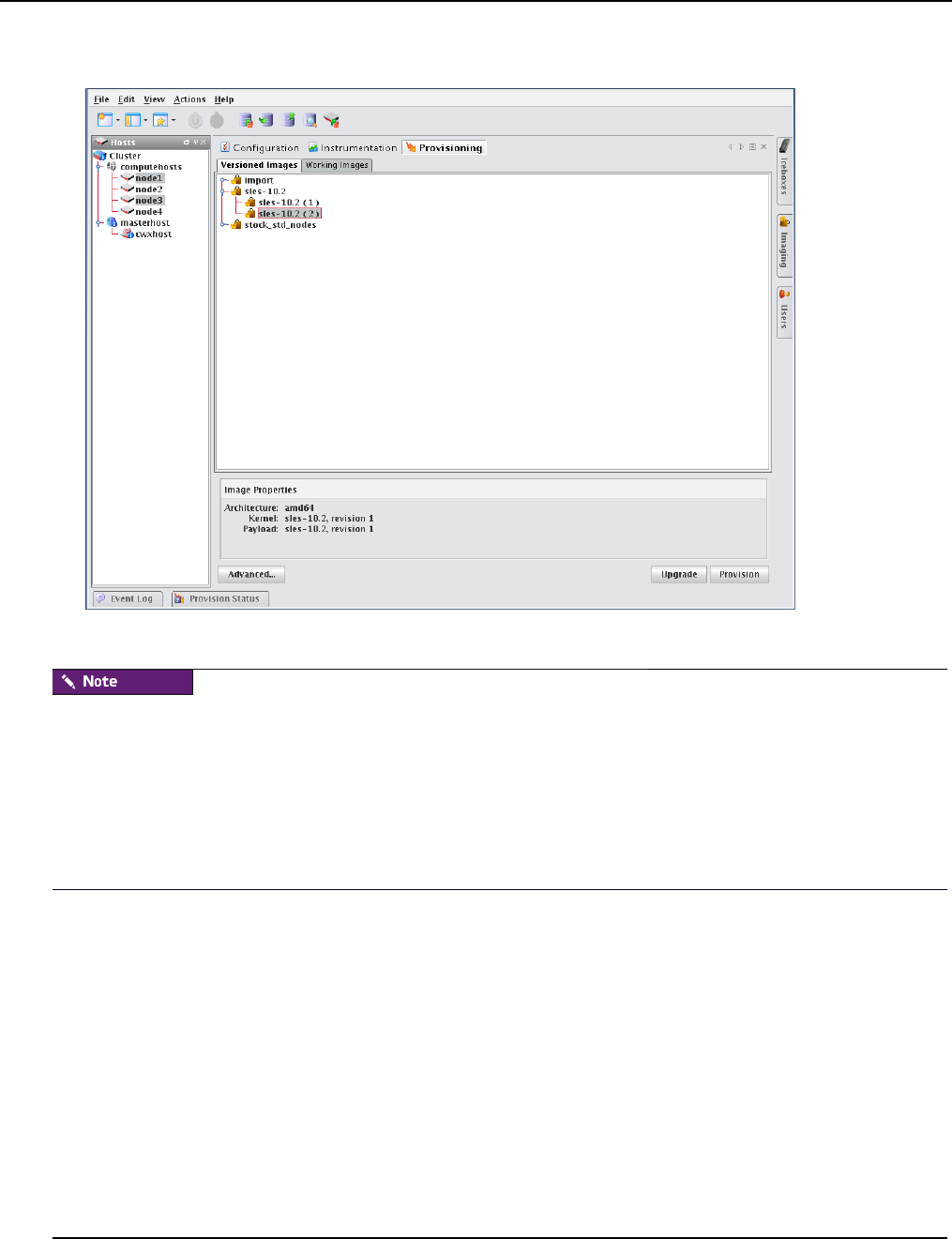
Provisioning
Select an Image and Provision
007-5642-005
142
2. Select the Provisioning tab.
3. Select the Versioned Images or Working Images tab.
A Versioned image is a revision of an image that is checked into VCS. A Working image has not been checked into VCS
and is currently present in the working area (e.g., $MGR_HOME/imaging/<user>/images). This allows you to test
changes prior to checking in. See Version Control System (VCS) on page 134 for details on using the version control
system.
A Working Copy of an image is currently present in the working area (e.g., $MGR_HOME/imaging/<user>/images). A
Versioned image is a revision of an image stored in VCS. See Version Control System (VCS) on page 134 for details on
using the version control system.
4. Select the image you want to use to provision the host(s).
5. (Optional) Click the Advanced button to display the Advanced Options dialog (see Advanced Provisioning Options
on page 145). This dialog allows you to override partitioning, payload, and kernel verbosity settings.
6. Click Provision to distribute the image to the selected hosts. Management Center asks you to confirm your action.
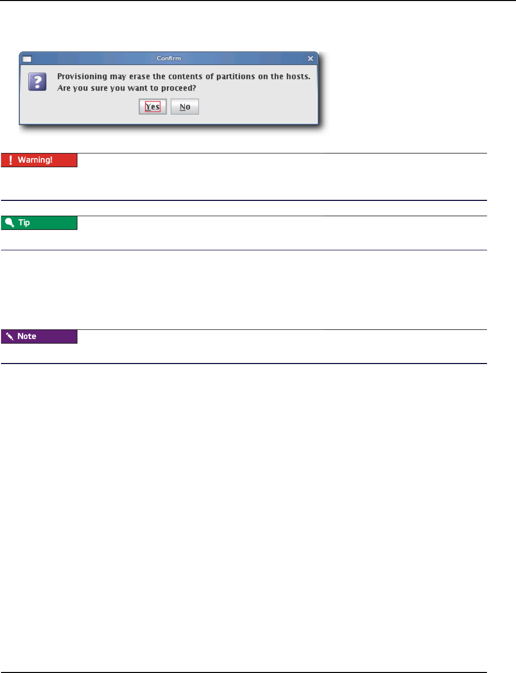
Provisioning
Select an Image and Provision
007-5642-005 143
7. Click Yes to provision the host(s) or click No to abort this action.
When you click Yes, Management Center re-provisions the hosts using the new image. Any pending or running jobs on
the selected host(s) are lost.
To disable the provisioning confirmation dialog, see Provisioning on page 34.
Right-click Provisioning
1. Select the host(s) you want to provision from the navigation tree (use the Shift or Ctrl keys to select multiple hosts).
2. Right-click a host and select Provision. Management Center displays a popup menu and allows you to select the
image you will use to provision.
Right-click provisioning uses the latest revision of an image stored in VCS.
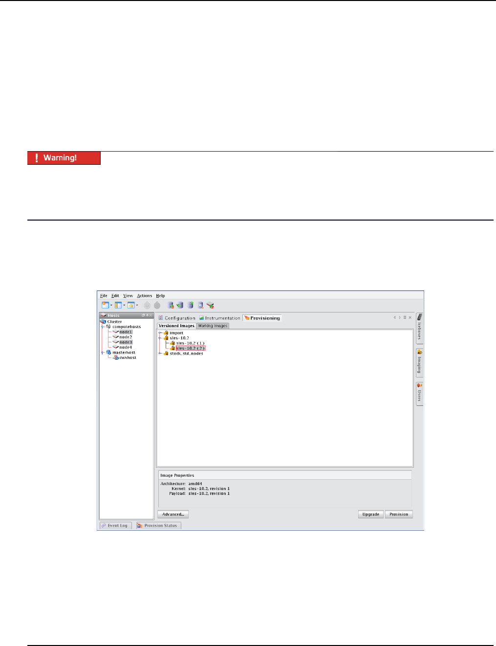
Provisioning
VCS Upgrade
007-5642-005
144
VCS Upgrade
VCS Upgrade is a quick, easy way to make small changes to hosts. Unlike provisioning (which requires rebooting the
host and reformatting its hard drive), the VCS Upgrade feature copies the VCS revision to the host and inflates it while
the host is running. Using the upgrade feature requires that you check all changes into the payload, that the payload
revision is updated in the image, and that you check in the image.
The update feature will update only those hosts with files managed by the payload and will not affect the running kernel
or file system information. If there are changes to the kernel or image, they will not take place until the host is re-
provisioned with that image. You cannot “downgrade” a host by using an older version of a payload.
Major changes made to hosts should be done using provisioning. This ensures that all hosts are homogenous and takes
full advantage of multicast. Also, VCS Upgrade leaves the image and payload on the host out of sync from what is
available in the VCS repository—for this reason, SGI recommends that you use Advanced Provisioning Options on
page 145 to schedule the hosts to be re-provisioned with the selected image the next time they reboot.
To Upgrade a Host(s)
1. Select the Provisioning tab.
2. Open the Versioned Images tab and select the image you want to use to upgrade the host(s)
3. Select the host(s) you want to upgrade from the navigation tree (use the Shift or Ctrl keys to select multiple hosts).
4. Click Update to update the image to the selected hosts. As the operation begins, a status dialog appears.
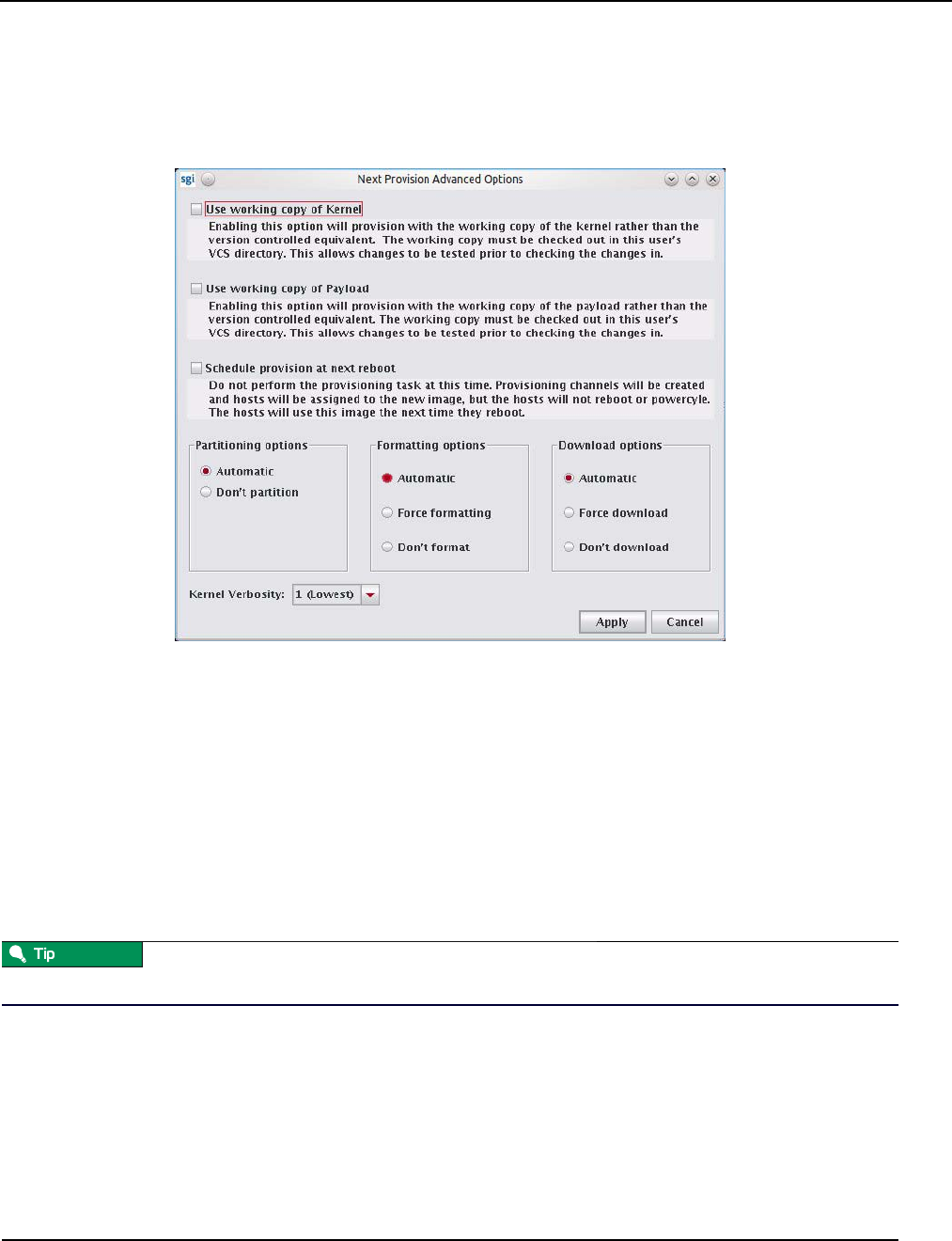
Provisioning
Advanced Provisioning Options
007-5642-005 145
Advanced Provisioning Options
The Advanced Options dialog allows you to temporarily modify partitioning behavior, payload download settings, and
Kernel verbosity. These settings are not persistent, they simply override those configurations made using the Advanced
Image Options dialog. See Advanced Imaging Options on page 111.
USE WORKING COPY OF KERNEL
Enable this option to use the working copy of the kernel in place of its version-controlled equivalent. This allows you to
test your changes prior to checking them in.
USE WORKING COPY OF PAYLOAD
Enable this option to use the working copy of the payload in place of its version-controlled equivalent. Because
working copies of payloads are often shared, hosts associated with the working copy are updated to use the latest
version when they reboot—but only if the payload was modified or used to provision other hosts.
SCHEDULE PROVISION AT NEXT REBOOT
Enable this option to postpone provisioning until the next time you reboot the hosts. Provisioning channels are created
and hosts are assigned to the new image, but the hosts cannot reboot or cycle power without being provisioned.
To change the default scheduled provisioning setting, see Provisioning on page 34.
Scheduling a provision at next reboot can be especially useful when used with PBS. For example, you may make
updates to a payload, then schedule provisioning to occur only after the current tasks are complete. To do this, the root
user (who must be allowed to submit jobs) can submit a job to each host instructing it to reboot.

Provisioning
Advanced Provisioning Options
007-5642-005
146
The root user can submit jobs to PBS only if acl_roots is configured. To configure acl_roots, run qmgr and enter the
following from the qmgr prompt:
qmgr: set server acl_roots += root
If you already set up additional ACLs, you will also need to add root to those ACLs. For example, suppose you have an
acl_users list that allows access to a queue, workq. The command to add root to the ACL would be:
# set queue workq acl_users += root
The following is a sample PBS script you might use to reboot hosts:
#################################################
#!/bin/bash
for i in `seq 1 64`
do echo \#PBS -N Reboot_n$i > Reboot_n$i.pbs
echo \#PBS -joe >> Reboot_n$i.pbs
echo \#PBS -V >> Reboot_n$i.pbs
echo \#PBS -l nodes=n$i >> Reboot_n$i.pbs
echo \#PBS -q workq >> Reboot_n$i.pbs
echo \#PBS -o /dev/null >> Reboot_n$i.pbs
echo \/sbin\/reboot >> Reboot_n$i.pbs
echo done >> Reboot_n$i.pbs
qsub < Reboot_n$i.pbs
rm Reboot_n$i.pbs
done
#################################################
PARTITIONING OPTIONS
This option allows you override the current partition settings. You can automatically partition an iamge if the partition
changes or choose not to re-partition drives.
FORMATTING OPTIONS
You can automatically format partitions if the payload or partitioning scheme changes, force formatting of all
partitions—including those that are exempt from being overwritten (see Partitions on page 55), or choose not to format.
PAYLOAD DOWNLOAD OPTIONS
The payload options allow you to automatically download a payload if a newer version is available (or if the current
payload is not identical to that contained in the image), force Management Center to download a new copy of the
image—regardless of the image status, or choose not to download a payload.
KERNEL VERBOSITY
The kernel verbosity level (1-8) allows you to control debug messages displayed by the kernel during provisioning. The
default value, 1, is the least verbose and 8 is the most.
007-5642-005 147
Chapter 7
Instrumentation and Events
Instrumentation
The Management Center instrumentation service provides the ability to monitor system health and activity for every
host in the cluster. Hosts may be monitored collectively to provide a general system overview, or individually to allow
you to view the configuration of a particular host (useful when diagnosing problems with a particular host or
configuration). From the Instrumentation tab, you can view statistical data for the following areas:
•Overview
•Thumbnail
•List
•CPU
•Memory
•Disk
•Network
•Kernel
•Load
•Environmental
•Environmental List
•GPU
•Power
When monitoring the Management Center Master Host, the name of the Master Host must match the name assigned in
$MGR_HOME/@genesis.profile.
When using the Management Center client by exporting an X session over an SSH connection, enabling the gradient fill
and anti-aliasing options for instrumentation may adversely affect the performance of the GUI. This is common on
slower systems. To improve system performance, disable the Gradient Fill and Anti-Aliasing options under the View
menu. For best performance, install a Management Center Client.
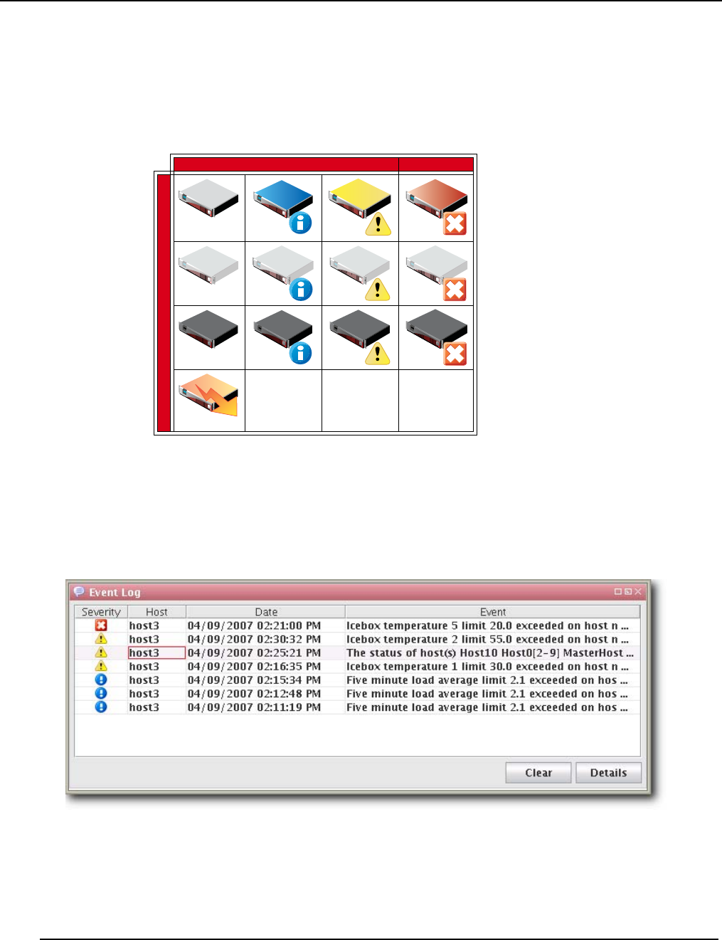
Instrumentation
States
007-5642-005
148
States
Management Center uses the following icons to provide visual cues about system status. These icons appear next to
each host viewed with the instrumentation service or from the navigation tree. Similar icons appear next to clusters,
partitions, and regions to indicate the status of hosts contained therein.
Event Log
Management Center also tracks events logged for each host in the cluster. The Management Center event log is located
on the instrumentation overview screen. If you select multiple hosts (or a container such as a cluster, partition, or
region), the log shows messages for any host in the selection. If you select a single host, the event log shows messages
for this host only. Events have three severity levels: error, warning, and information. For additional details on
instrumentation event monitoring, see Management Center Monitoring and Event Subsystem on page 165.
Logging
States
Healthy Informational Warning Critical Error
On Unknown Off Provisioning

Instrumentation
Menu Controls
007-5642-005 149
Menu Controls
The output for the instrumentation service is easily configured and displayed using menu controls located in the View
menu.
View Menu
Metrics Select and display custom metrics defined for your system—this option is not available to all tab views. See
Metrics on page 178 for information on defining metrics.
Interval Set the frequency (in seconds) with which to gather and display data—10, 5, or 1.
Layout Arrange how the instrumentation panel displays information.
Filter List hosts that are in specific states (Thumbnail tab only).
Size Change the display size of thumbnails (Small, Medium, Large).
Sort Organize and display statistical data according to the name or state of the host(s).
Temperatures Select the format in which to display temperatures (Celsius, Fahrenheit).
Anti-Aliasing Apply smoothing to line graphs.
Gradient Fill Apply fill colors to line graphs.
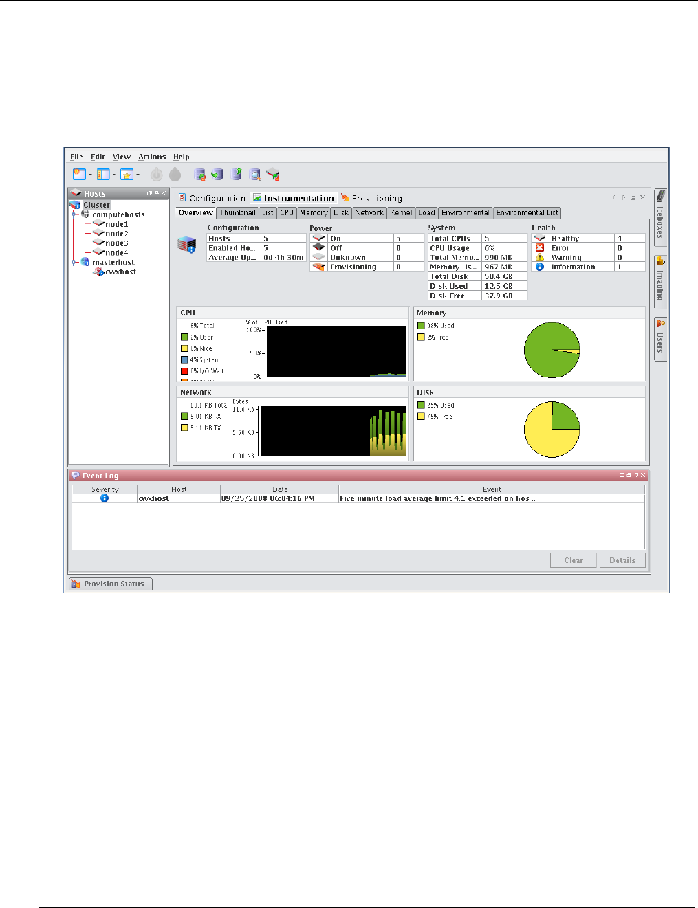
Instrumentation
Overview Tab
007-5642-005
150
Overview Tab
The Overview tab provides details about the configuration, power status, resource utilization, and health status of the
host(s) selected in the host navigation tree. Selecting a Cluster, Partition, or Region in the tree displays all hosts
contained in it. See States on page 148 for a list of system health indicators and Event Log on page 148 for information
regarding messages generated by the host(s).
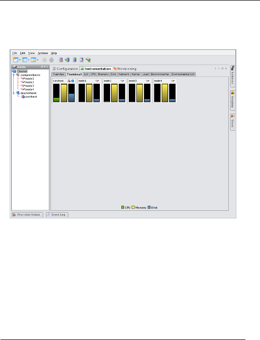
Instrumentation
Thumbnail Tab
007-5642-005 151
Thumbnail Tab
The Thumbnail tab displays a graphical representation of the system health, event log status, CPU usage, memory
availability, and disk space. From the View menu, you may filter hosts to display only those in a specific state, resize
the thumbnails, or sort the hosts by name or state. See States on page 148 for a list of system health indicators.
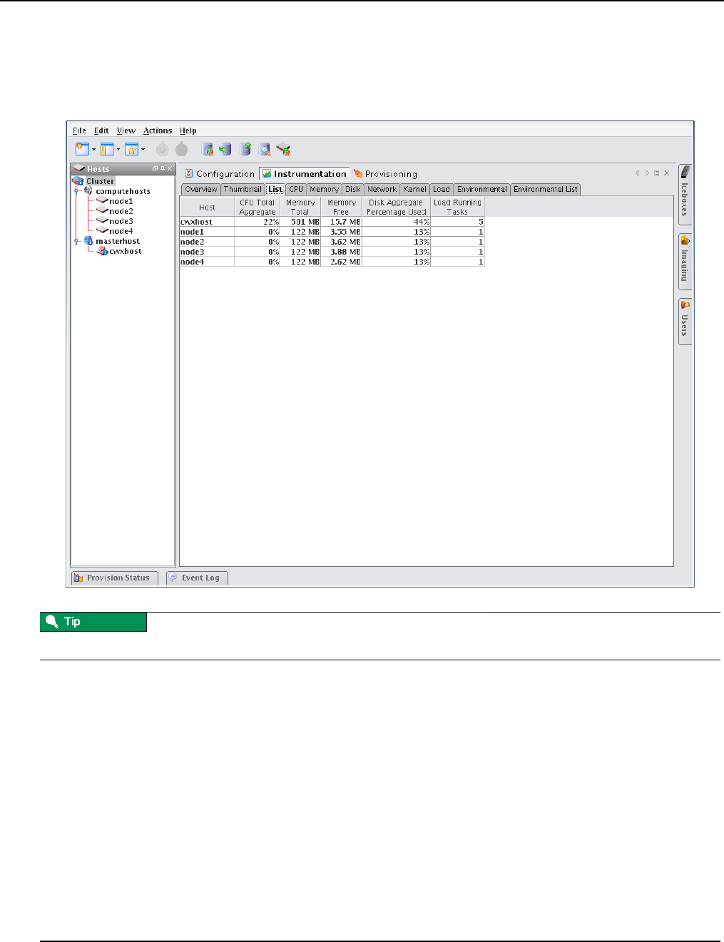
Instrumentation
List Tab
007-5642-005
152
List Tab
The List tab displays all pre-configured and custom metrics being observed by the instrumentation service. To add
metrics to this list, select Metrics from the View menu. To create new metrics, see Instrumentation on page 147.
You may copy and paste the contents of list view tables for use in other applications.
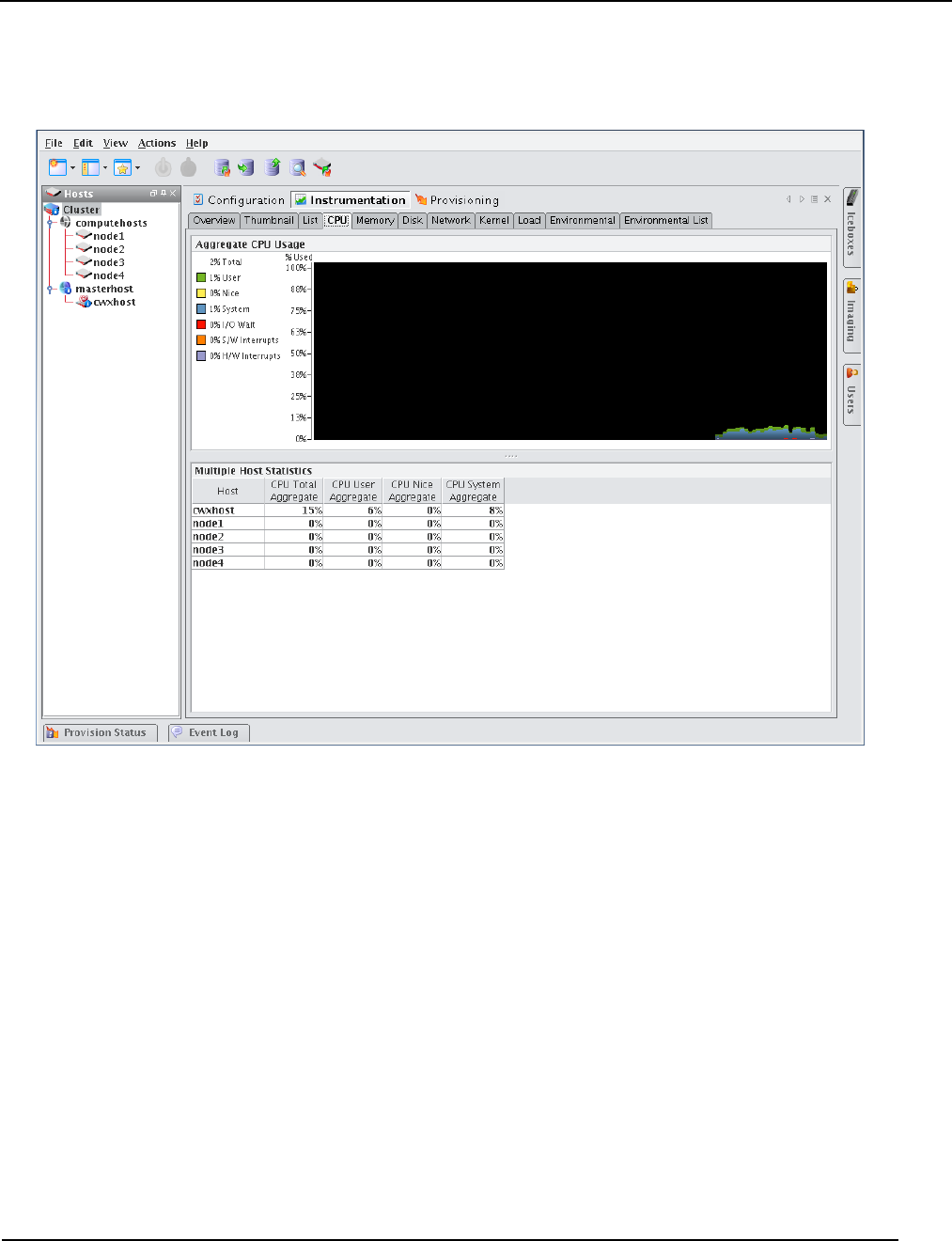
Instrumentation
CPU Tab
007-5642-005 153
CPU Tab
Select the CPU tab to monitor the CPU utilization for the selected host(s).
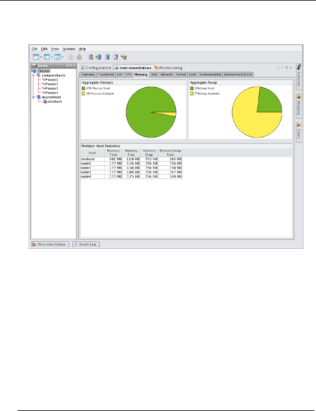
Instrumentation
Memory Tab
007-5642-005
154
Memory Tab
Select the Memory tab to monitor the physical and virtual memory utilization for the selected host(s).
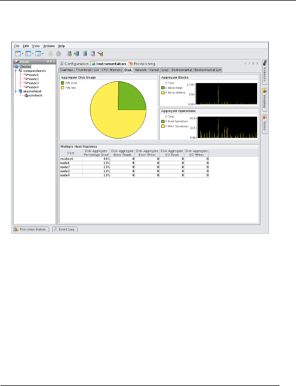
Instrumentation
Disk Tab
007-5642-005 155
Disk Tab
Select the Disk tab to monitor the disk I/O and usage for the selected host(s).
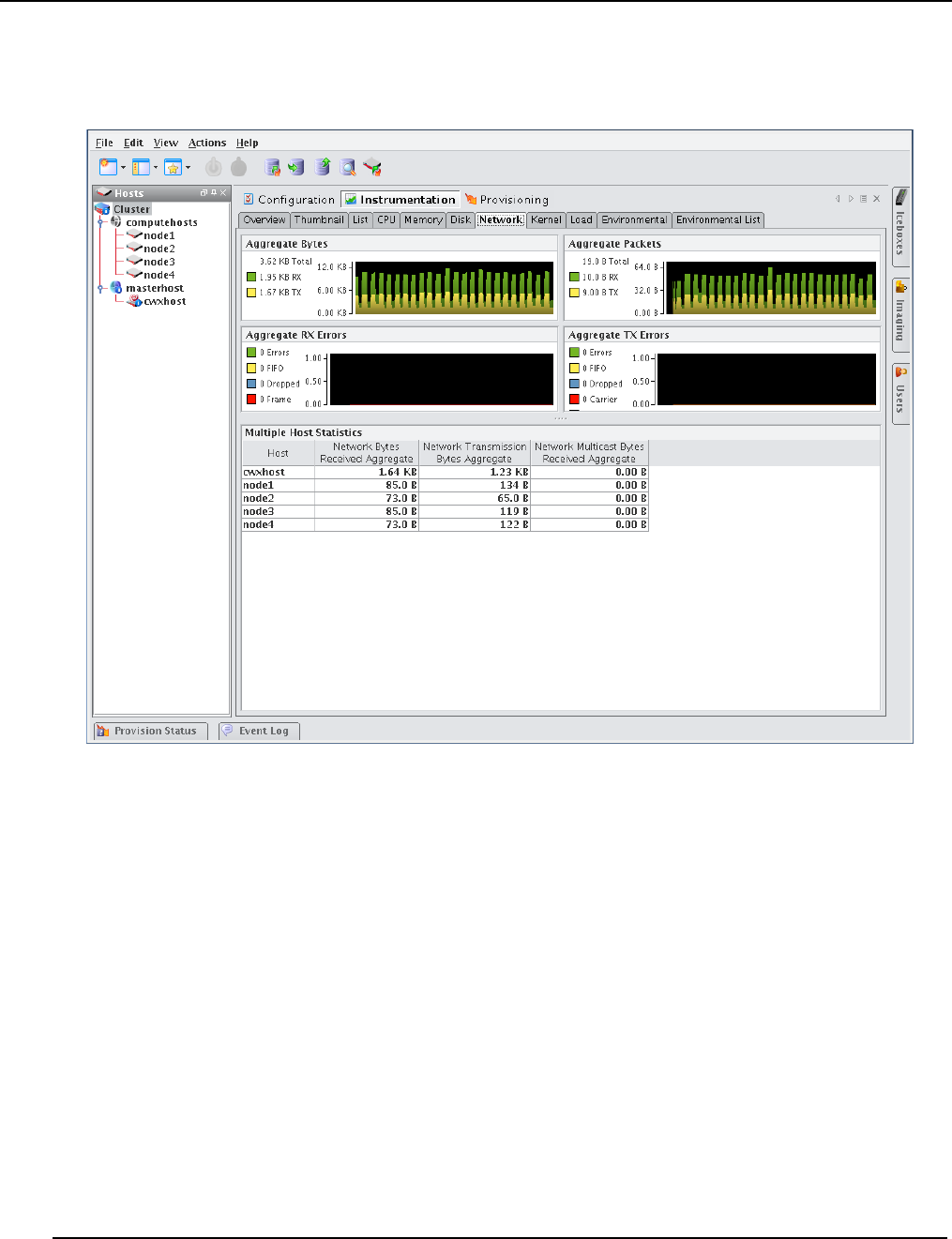
Instrumentation
Network Tab
007-5642-005
156
Network Tab
Select the Network tab to monitor packet transmissions and errors for the selected host(s).
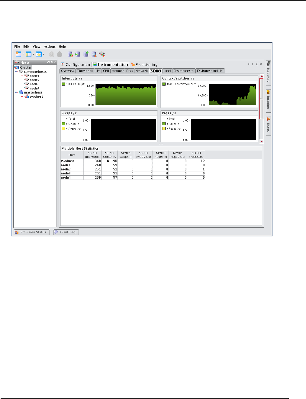
Instrumentation
Kernel Tab
007-5642-005 157
Kernel Tab
Select the Kernel tab to monitor the kernel information for the selected host(s).
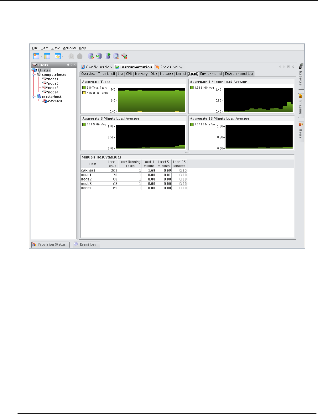
Instrumentation
Load Tab
007-5642-005
158
Load Tab
Select the Load tab to monitor the load placed on the selected host(s).
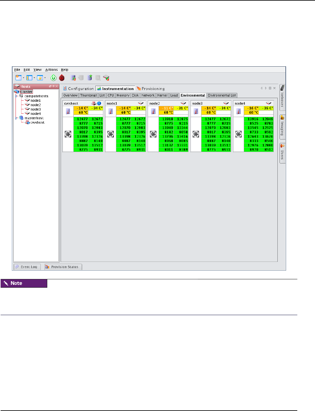
Instrumentation
Environmental Tab
007-5642-005 159
Environmental Tab
Select the Environmental tab to view the temperature summary readings for the selected host(s). Each summary
contains up to five temperature readings—four processor temperatures followed by the ambient host temperature
(which requires an Icecard). On hosts that support IPMI, these temperature readings differ slightly—two processor
temperatures, two power supply temperatures, and the ambient host temperature.
The processor temperature readings for IPMI-based hosts indicate the amount of temperature change that must occur
before the CPU’s thermal control circuitry activates to prevent damage to the CPU. These are not actual CPU
temperatures.
From the Environmental tab, you can access the following options from the View menu:
Filter Filter and display hosts based on error status
Size Change the size of the thumbnail view (small, medium, or large). Small thumbnails support a mouse-over function
to display a host summary.
Temperatures Set temperature options to display values as Celsius or Fahrenheit. Temperatures range from Green
(Cool) to Yellow (warm) to Red (Hot). Fan speeds follow the same convention—slow or stopped fans appear in red.
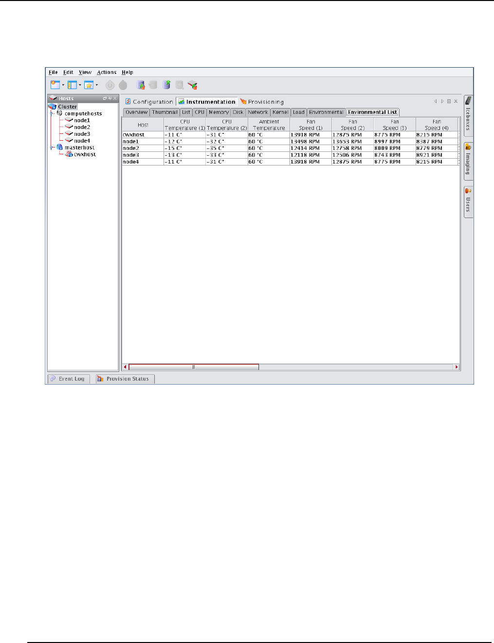
Instrumentation
Environmental List Tab
007-5642-005
160
Environmental List Tab
Select the Environmental tab to open the list view of the temperature summary readings for the selected host(s).
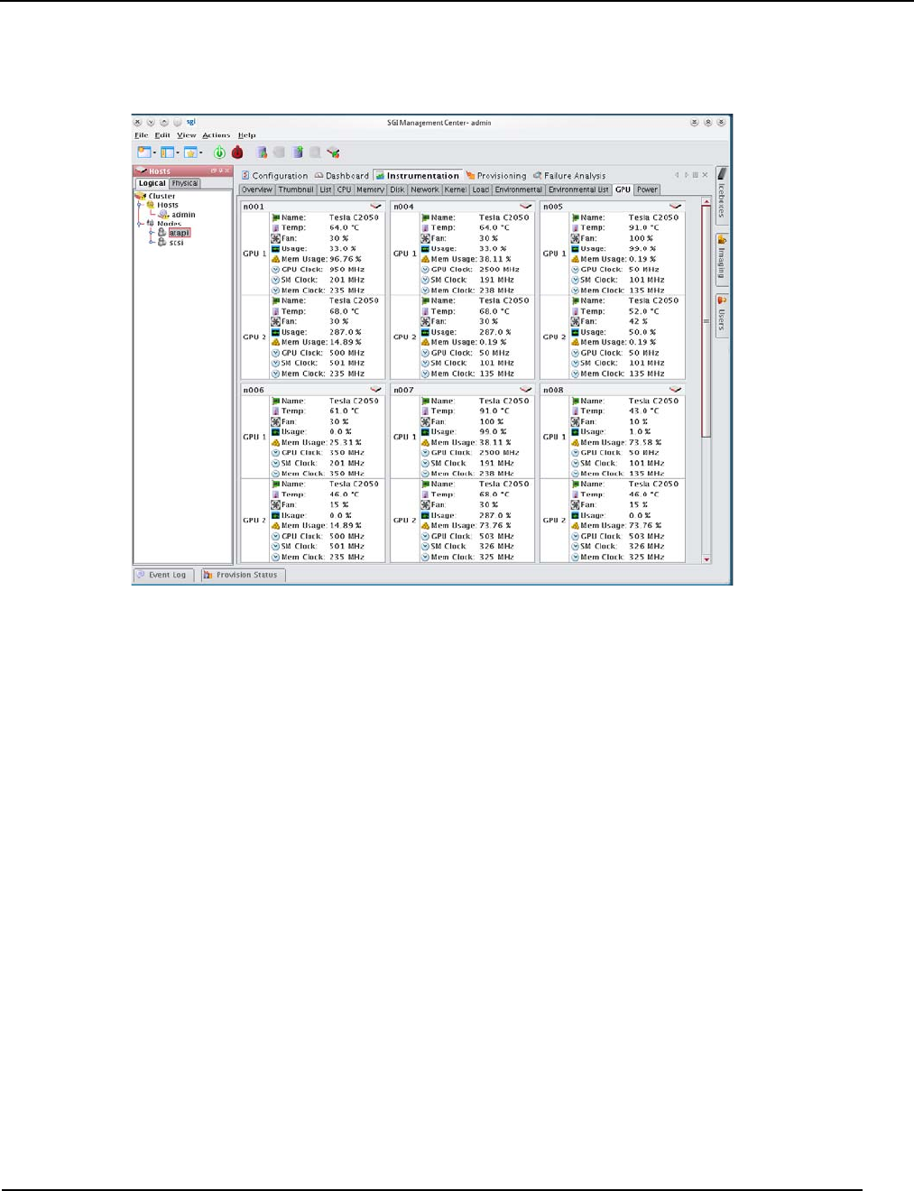
Instrumentation
GPU Tab
007-5642-005 161
GPU Tab
As shown in the panel above, SGI Management Center provides monitoring of supported GPUs (items like
temperature, fan speed, memory usage, and ECC). For a listing of GPU solutions supported by SGI see
http://www.sgi.com/pdfs/4235.pdf.
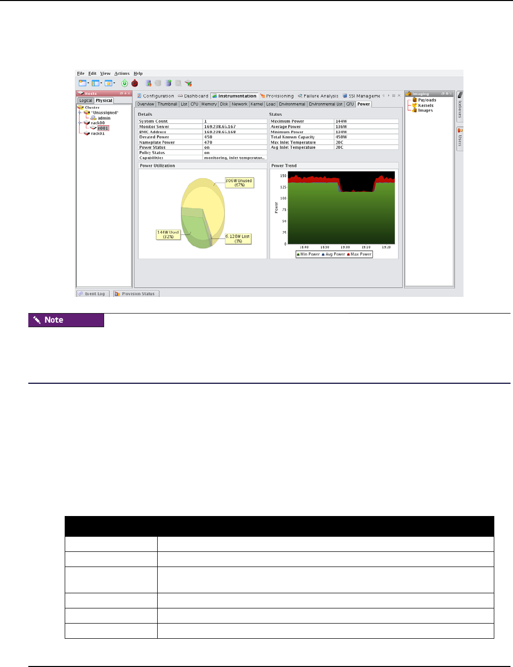
Instrumentation
Power Tab
007-5642-005
162
Power Tab
The SGI Management Center DCM integration uses indirect TCP communications through an external web service
provider to accumulate and display power monitoring data. This results in a delay in updating instrumentation for every
tree selection change. Consequently, the waiting time for initial Power panel updates for large-scale systems using
DCM may be several minutes in duration.
The following are the primary components of the Power panel:
•Details table
•Status table
•Power Utilization pie chart
•Power Trend chart
Details Table
The Details table contains configuration details for various power-related entities.
Attribute Description
System Count Displays the number of systems associated with the selected entity, if available.
Monitor Server Displays the power service provider location currently in use.
BMC Address Shows the endpoint BMC address currently in use (if several or none are offered, this
entry is unavailable.)
Derated Power Displays the calculated derated power for the endpoint.
Nameplate Power Displays the calculated or configured nameplate power for the endpoint.
Power Status Indicates the mechanical power state of the endpoint.

Instrumentation
Power Tab
007-5642-005 163
Status Table
The Status table contains power sampling and measurement data.
The Power Utilization Pie Chart
The Power Utilization pie chart displays the three metrics in the following chart:
The Power Trend Chart
The Power Trend chart displays the same miniumum, average, and maximum metrics that are shown in the Status
table but does so in an interactive, historical chart. This chart features user-defined zooming and scaling and you can
save the chart for reporting purposes. Simply right-click on the chart or click and drag the mouse to explore further.
Policy Status Indicates the policy activation status for the endpoint.
Capabilities Describes the discovered power monitoring/MGT capabilities for the endpoint.
Data Item Description
Maximum Power Total maximum power measurement recorded in any monitoring cycle for all sampling
intervals within the aggregation period applied for the selected entity (which may be a
group).
max{ sum_T1(max_N1{ P1, P2,...,Pn}, ..., max_Nn{...}), ..., sum_Tn(...)}
Average Power Sum of the entity/group mean power measurements as given by the sum of the arithmetic
mean of power measurements for all sub-nodes within the specified entity/group for all
sampling intervals within the aggregation period.
avg{ sum_T1(avg_N1{ P1, P2, ..., Pn}, ..., avg_Nn{...}), ..., sum_Tn(...)}
Minimum Power Result calculated much like Maximum Power, but with floor. Pn is the last monitoring
cycle in a sampling interval. Tn is the last sampling interval in an aggregation period.
Total Known Capacity A measured, calculated and/or configured sum of all of the derated power components for
the selected endpoint.
Max Inlet Temperature
Avg Inlet Temperature Taken from a prescribed IPMI/SMBUS-accessible inlet-air sensor for the endpoint (if
available).
Metric Description
Used Indicates the last instantaneously sampled power measurement for the endpoint.
Unused Calculated as the total-known-capacity less the used figure.
Lost Calculated using the configured or estimated power factor for the endpoint, and is
generally an estimate on the efficiency of the power distribution for a node or rack.
Attribute Description
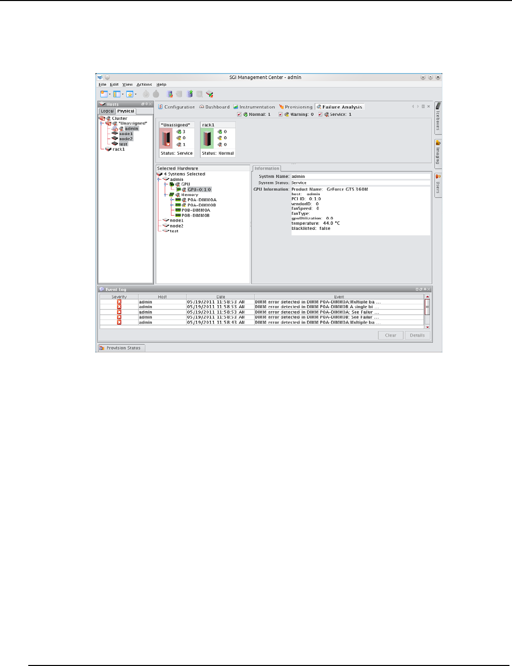
Failure Analysis
Power Tab
007-5642-005
164
Failure Analysis
SGI Management Center supports failure analysis for memory errors via memlog, a software component of SGI
Foundation Software.

Management Center Monitoring and Event Subsystem
Power Tab
007-5642-005 165
Management Center Monitoring and Event Subsystem
Management Center uses a monitoring and event system to track system values. This system includes monitors,
metrics, listeners, and loggers that collect values from the cluster, then display this information using the Management
Center instrumentation GUI (see Instrumentation on page 147). You can extend the standard monitoring and event
system to include custom values and set thresholds for user-defined events. For example:
•Monitoring custom values using scripts.
•Displaying custom values in the Management Center list view.
•Setting thresholds on values and taking an action if these thresholds are exceeded.
•Logging custom error conditions in the Management Center log.
•Running custom scripts as event actions.
Monitors run at a set interval and collect information from each host. Listeners receive information about metrics from
the instrumentation service, then determine if the values are reasonable. If a listener determines that a metric is above or
below a set threshold, the listener triggers a logger to take a specific action.
Typically, configuration files are host-specific and are located in the $MGR_HOME/etc directory. If you modify the
configuration files, you can copy them into the payload to make them available on each host after you provision.
By default, Management Center creates a backup of the $MGR_HOME/etc directory during installation and copies it to
$MGR_HOME/etc.bak.<date>.<timestamp>

Management Center Monitoring and Event Subsystem
Monitors
007-5642-005
166
Monitors
Management Center Monitors run periodically on the cluster and provide metrics that are gathered, processed, and
displayed using the Management Center instrumentation GUI. Using monitors allows you to “tune” Management
Center to meet your exact system needs by enabling or disabling specific monitors or by setting the rate at which
monitors run. In cases where pre-defined monitors simply do not meet your specific needs, Management Center also
allows you to create custom monitors (see Custom Monitors on page 174). The following table lists the Management
Center default monitors.
All standard Management Center monitors are configured in the InstrumentationMonitors.profile in the
$MGR_HOME/etc directory. The format of the monitor configuration in the file is generally as follows (where <time>
is in milliseconds):
<name>: com.lnxi.instrumentation.server.<monitor_name>
<name>.interval: <time>
When working with standard monitors, it is strongly recommended that you leave all monitors enabled—however, you
can increase how often these monitors run. Raising the interval can reduce CPU time and network use for monitoring.
Because Management Center uses very little CPU processing time on the compute hosts, values as high as 1 second
(1000 milliseconds) are nearly undetectable. By default, some monitors are set to run at 5 seconds (5000 milliseconds)
or longer.
When monitoring the Management Center Master Host, the name of the Master Host must match the name assigned in
$MGR_HOME/@genesis.profile.
Monitor Name Interval
NFS Client 5
NFS Server 5
BlueSmoke 500
Disk 5
Disk Space 60
Identity 5
Kernel 5
LinuxBIOS 86400
Load 15
Memory 5
Network 5
Uptime 60
Environmental 5
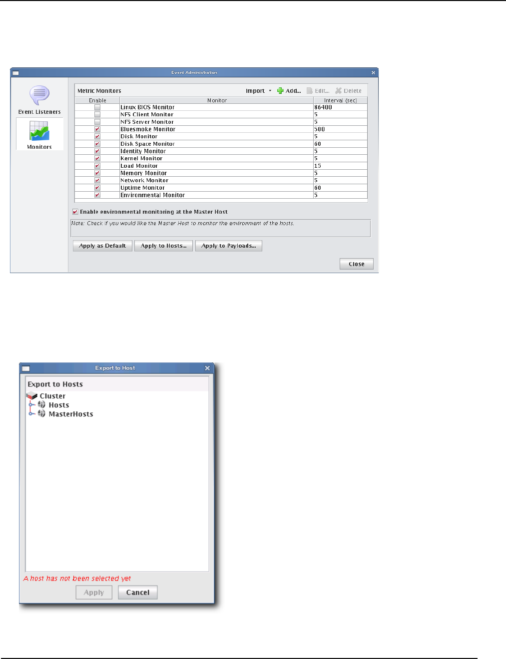
Management Center Monitoring and Event Subsystem
Monitors
007-5642-005 167
To Enable or Disable a Monitor
1. Select Event Administration from the Edit menu. The Event Administration dialog appears.
2. Select Monitors.
3. Check or un-check the box next to each monitor you want to enable or disable.
4. (Optional) Click Apply as Default to apply the listener configuration as the default on the Master Host and payload.
Management Center saves the listeners in InstrumentationMonitors.profile.default.
5. (Optional) Click Apply to Hosts to apply the monitor to a specific host(s). The Export to Hosts dialog appears.
A. Select the host(s) to which to export the monitors from the navigation tree.
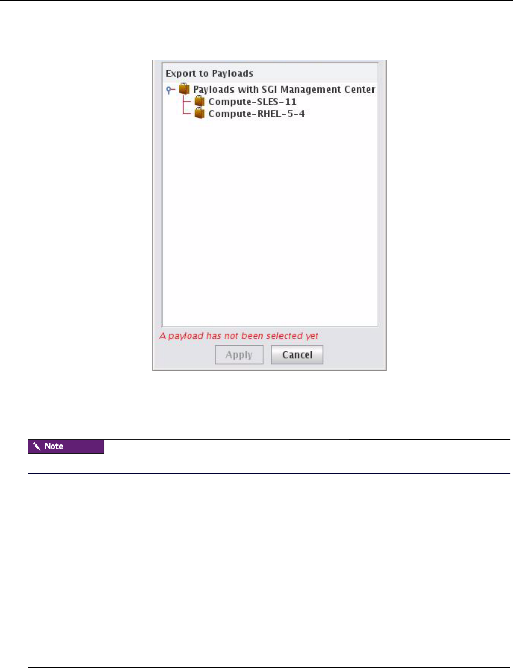
Management Center Monitoring and Event Subsystem
Monitors
007-5642-005
168
B. Click Apply to save changes or click Close to abort this action.
6. (Optional) Click Apply to Payloads to include these monitors as part of a payload. The Export to Payloads appears.
A. Select the payload(s) to which to apply the monitors.
B. Click Apply to save changes or click Cancel to abort this action.
7. Click Close to complete this action and close the Event Administration dialog.
If you click close without applying your changes, all modifications will be lost.
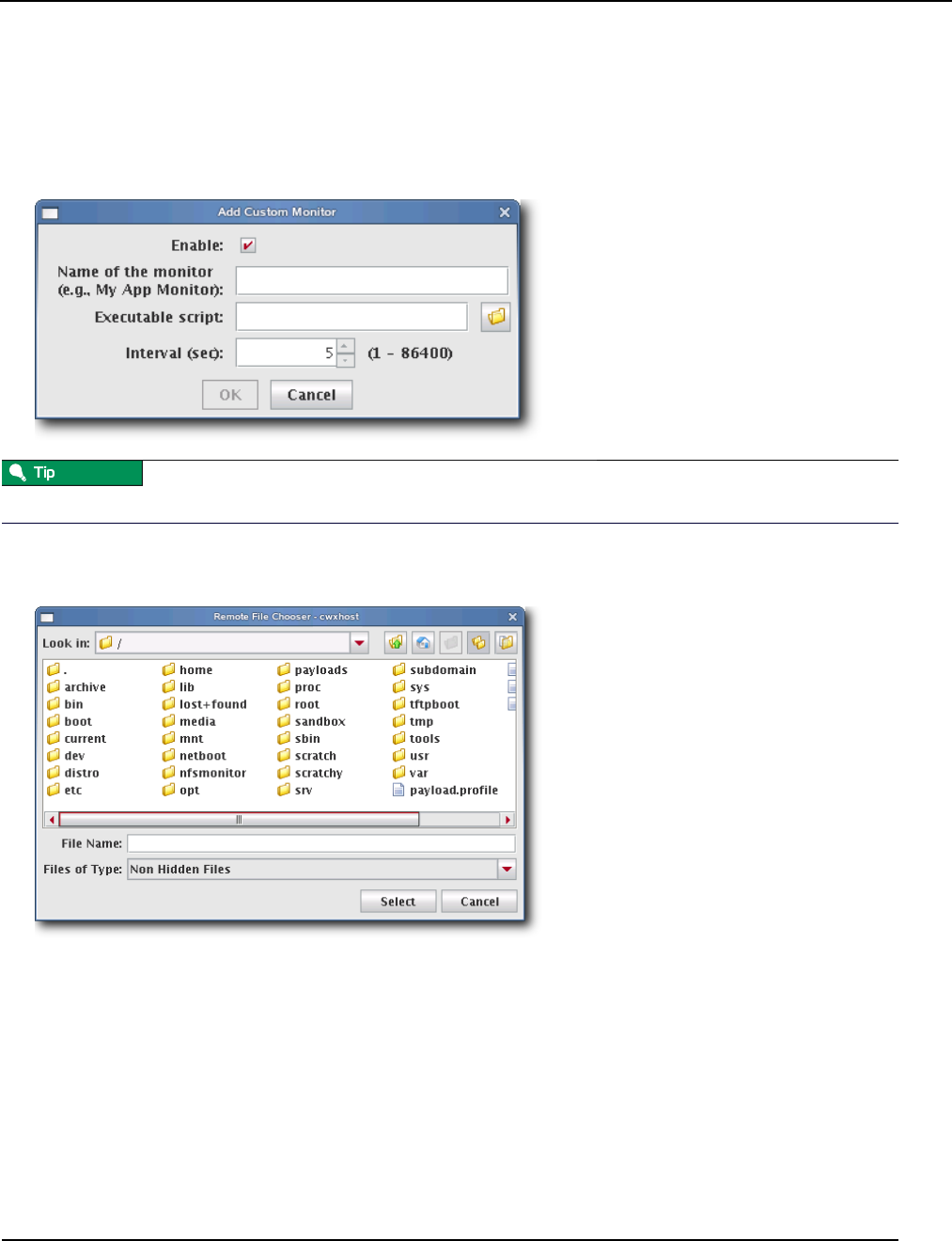
Management Center Monitoring and Event Subsystem
Monitors
007-5642-005 169
To Add a Monitor
1. Select Event Administration from the Edit menu. The Event Administration dialog appears.
2. Select Monitors.
3. Click Add. The Add Custom Monitor dialog appears.
For information on creating a custom monitor, see Custom Monitors on page 174.
4. Enter the name of the monitor.
5. Enter the path of the executable script used for this monitor or click browse to locate the script.
6. Enter the monitoring interval (in seconds).
7. Check the Enable option to activate the listener.
8. Click OK to continue or click Cancel to abort this action.
9. (Optional) Apply the monitor to hosts or payloads.

Management Center Monitoring and Event Subsystem
Monitors
007-5642-005
170
10. Click Apply as Default to save the monitor.
When you add a monitor and click Apply as Default, Management Center saves the monitor as one of the default
monitors—all future payloads will contain the new monitor. Furthermore, the new monitor will be included any time
you install Management Center into a payload.
11. Click Close.
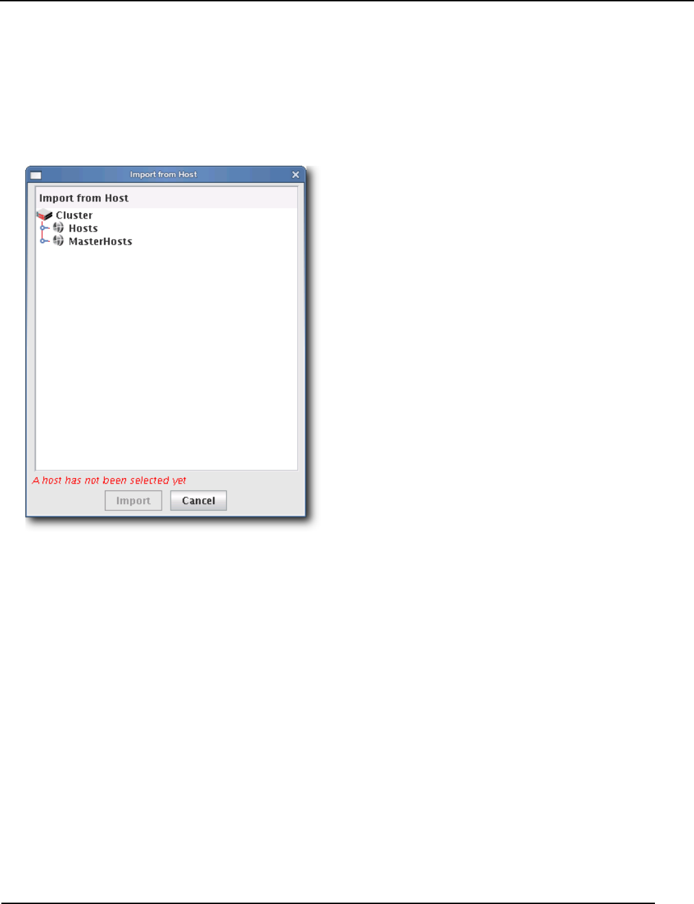
Management Center Monitoring and Event Subsystem
Monitors
007-5642-005 171
To Import Monitors
IMPORT FROM HOST
1. Select Event Administration from the Edit menu. The Event Administration dialog appears.
2. Select Monitors.
3. Click Import and select Import from Host. The Import from Hosts dialog appears.
4. Select the host from which to import listeners and click Import. Click Cancel to abort this action.
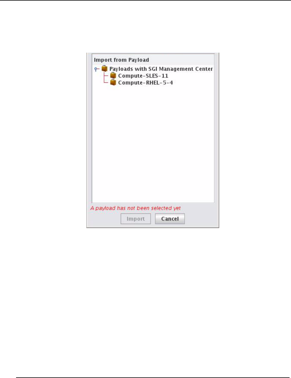
Management Center Monitoring and Event Subsystem
Monitors
007-5642-005
172
IMPORT FROM PAYLOAD
1. Select Event Administration from the Edit menu. The Event Administration dialog appears.
2. Select Monitors.
3. Click Import and select Import from Payload. The Import from Payloads dialog appears.
4. Select the payload from which to import listeners and click Import. Click Cancel to abort this action.
IMPORT DEFAULT
1. Select Event Administration from the Edit menu. The Event Administration dialog appears.
2. Select Monitors.
3. Click Import and select Import Default. Management Center restores all monitors stored as default monitors in
InstrumentationMonitors.profile.default. See To Enable or Disable a Listener on page 183 for information on
adding default listeners.
RESTORE FACTORY SETTINGS
1. Select Event Administration from the Edit menu. The Event Administration dialog appears.
2. Select Monitors.
3. Click Import and select Restore Factory Settings. Management Center reverts the default monitors that shipped
with Management Center.
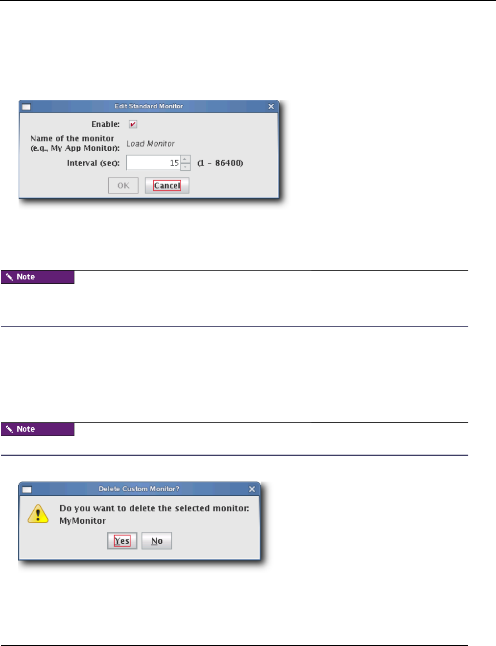
Management Center Monitoring and Event Subsystem
Monitors
007-5642-005 173
To Edit a Monitor
1. Select Event Administration from the Edit menu. The Event Administration dialog appears.
2. Select Monitors.
3. Double-click a monitor in the list or select the monitor and click Edit. The edit dialog appears.
4. Make any necessary modifications, then click OK to apply your changes. Click Cancel to abort this action.
5. (Optional) Apply the monitor to hosts or payloads.
6. Click Apply as Default to save the monitor.
When you change a monitor and click Apply as Default, Management Center saves the monitor as one of the default
monitors—all future payloads will contain the new monitor. Furthermore, the new monitor will be included any time
you install Management Center into a payload.
7. Click Close.
To Delete a Monitor
1. Select Event Administration from the Edit menu. The Event Administration dialog appears.
2. Select Monitors.
3. Select a listener from the list and click Delete.
You cannot delete Management Center default monitors—these monitors can be disabled only.
4. Management Center asks you to confirm your action.
5. Click Yes to delete the listener or click No to abort this action.

Management Center Monitoring and Event Subsystem
Custom Monitors
007-5642-005
174
Custom Monitors
Custom monitors are added by creating a new monitor with the Management Center GUI and including a user-defined
program or script that returns information in a format Management Center can process.
The name must be unique for each monitor.
Test scripts carefully! Running an invalid script may cause undesired results with Management Center.
Because monitors typically invoke a script (e.g., bash, perl), using values of less than 5 seconds is not recommended
(but is supported). To use a custom monitor, the program or script called by the monitor must return values to STDOUT
in key:value pairs that use the following format:
hosts.<hostname>.<name>.<key1>:<value1>\n
hosts.<hostname>.<name>.<key2>:<value2>\n
The <hostname> refers to the name of the host from which you are running the script.
When monitoring the Management Center Master Host, the name of the Master Host must match the name assigned in
$MGR_HOME/@genesis.profile.
The <name> is the same name used in the InstrumentationMonitors.profile.default.
The <key> parameter refers to what is being monitored.
The <value> is the return value for that key. The script can return one or more items as long as they all have a key and
value. The value can be any string or number, but the script is responsible for the formatting. The \n at the end is a
newline character (required).

Management Center Monitoring and Event Subsystem
Custom Monitors
007-5642-005 175
To Add a Custom Monitor
You must configure new metrics as part of this process. See Custom Metrics Example on page 180 for a continuation of
this example.
1. Open InstrumentationMonitors.profile.default from $MGR_HOME/etc.
2. Add the new monitor to the custom monitors profile. The following example uses perl to monitor how many users
are logged into a host. The script returns two values: how many people are logged in and who the people are. The
script name is $MGR_HOME/bin/who.pl and returns who.who and who.count.
#!/usr/bin/perl -w
# Basic modules are allowed
use IO::File;
use Sys::Hostname;
$host = hostname;
my @users;
# This opens the program and runs it. Don't forget the '|' on the end
my $fh = new IO::File('/usr/bin/who |');
# If the program was started
if (defined $fh) {
# Then loop through its output until you get an eof.
while (defined($line = <$fh>)) {
if ($line =~ m/^\w+.*/) {
$line =~ m/^(\w+).*$/;
push(@users,$1);
}
}
# Close the file.
$fh->close();
}
# Remove duplicate entries of who.
%seen = ();
foreach $item (@users) {
push(@uniq, $item) unless $seen{$item}++;
}
# Count how many items are in the array for our count
$count = scalar(@uniq);
# Rather than an array of values, just return a single text string;
foreach $users(@uniq) {
$who .= “$users,”;
}
chop($who);
print “hosts.”. $host . “.who.count:” . $count .“\n”;
print “hosts.”. $host . “.who.who:” . join(“,”, $who).“\n”;
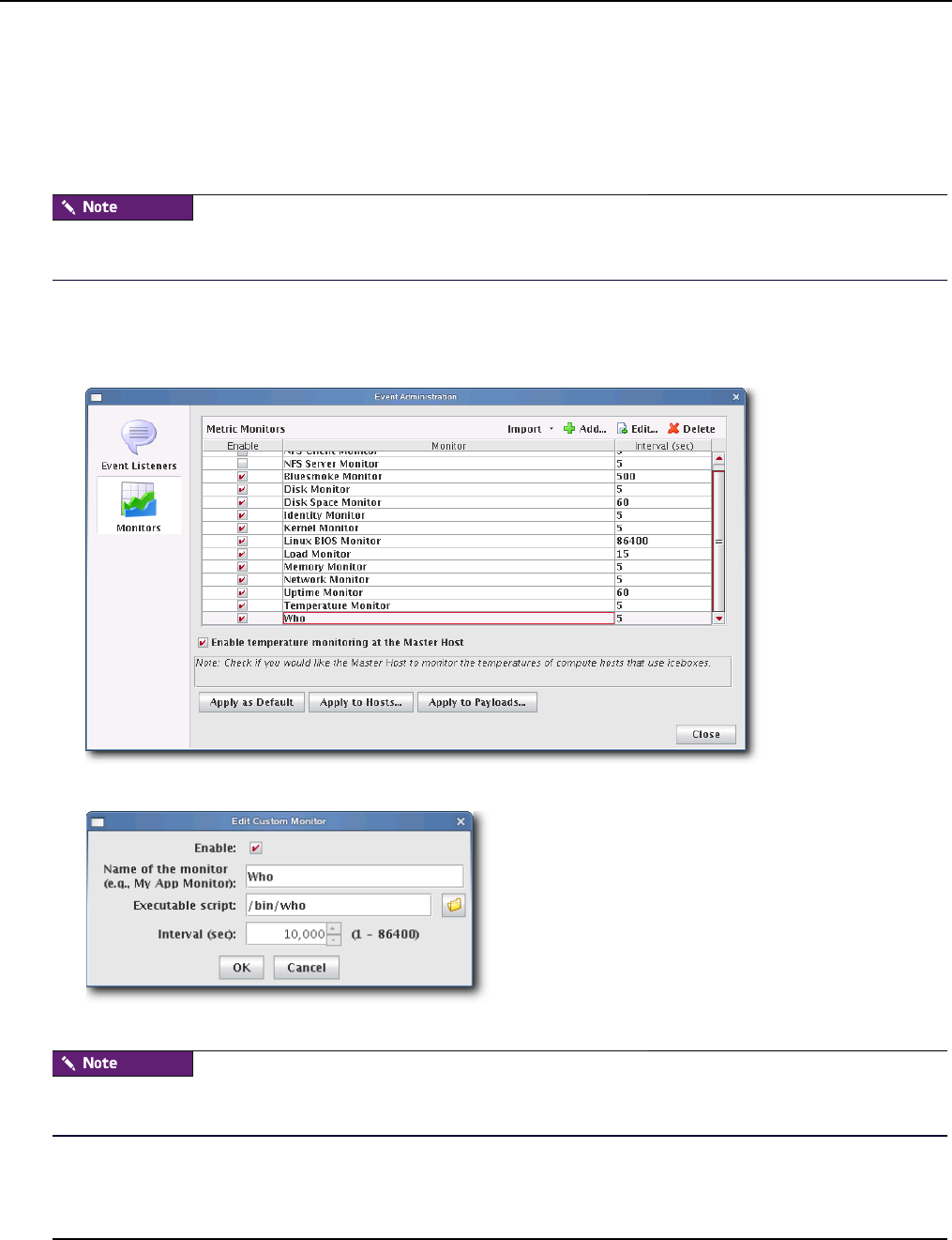
Management Center Monitoring and Event Subsystem
Custom Monitors
007-5642-005
176
When you run the script on host “n2” (assuming that perl and the perl modules above are installed correctly), the
following prints to STDOUT:
[root@n2 root]# ./who.pl
hosts.n2.who.count:1
hosts.n2.who.who:root
The script MUST exist on the hosts that will run this monitor. Therefore, you must either copy this script to each host
($MGR_HOME/bin) or configure the payload to include the script and provision the hosts with the new payload.
3. Restart Management Center services.
4. Select Event Administration from the Edit menu. The Event Administration dialog appears.
5. Select Monitors—Management Center displays the new monitor.
6. (Optional) Open and edit the listener as needed.
7. Apply the monitor to the host(s) you want to monitor.
When applying listeners to a host, the image used to provision the host must use a payload that contains Management
Center. See Install Management Center into the Payload on page 99.
8. (Optional) Apply the monitor to payloads.

Management Center Monitoring and Event Subsystem
Custom Monitors
007-5642-005 177
9. Click Apply as Default to save the monitor.
When you add a monitor and click Apply as Default, Management Center saves the monitor as one of the default
monitors—all future payloads will contain the new monitor. Furthermore, the new monitor will be included any time
you install Management Center into a payload.
10. Click Close.
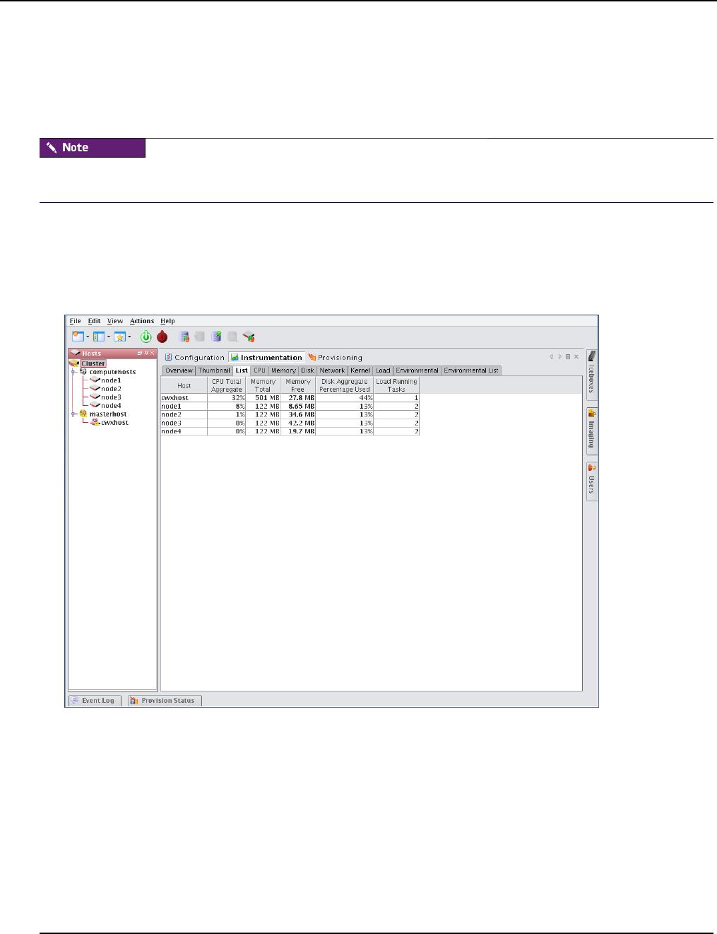
Management Center Monitoring and Event Subsystem
Metrics
007-5642-005
178
Metrics
Metrics refer to data collected by monitors that is processed and displayed by the Management Center instrumentation
service. The types of metrics collected are feature-specific and Management Center allows you to view metrics for an
individual host or group of hosts. For a list of available metrics, see Pre-configured Metrics on page 255.
Before you can display a custom metric, you must define a custom monitor to collect the data. See Custom Monitors on
page 174.
To Display Custom Metrics
1. Select the Instrumentation tab.
2. Select the host(s) for which you want to display metrics in the host navigation tree.
3. Select the List tab.
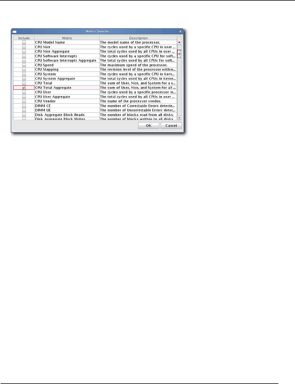
Management Center Monitoring and Event Subsystem
Metrics
007-5642-005 179
4. Select Metrics from the Edit menu. The Metric Selector appears.
5. Select the metrics you want to include, then click OK. The metrics appear in the List tab.
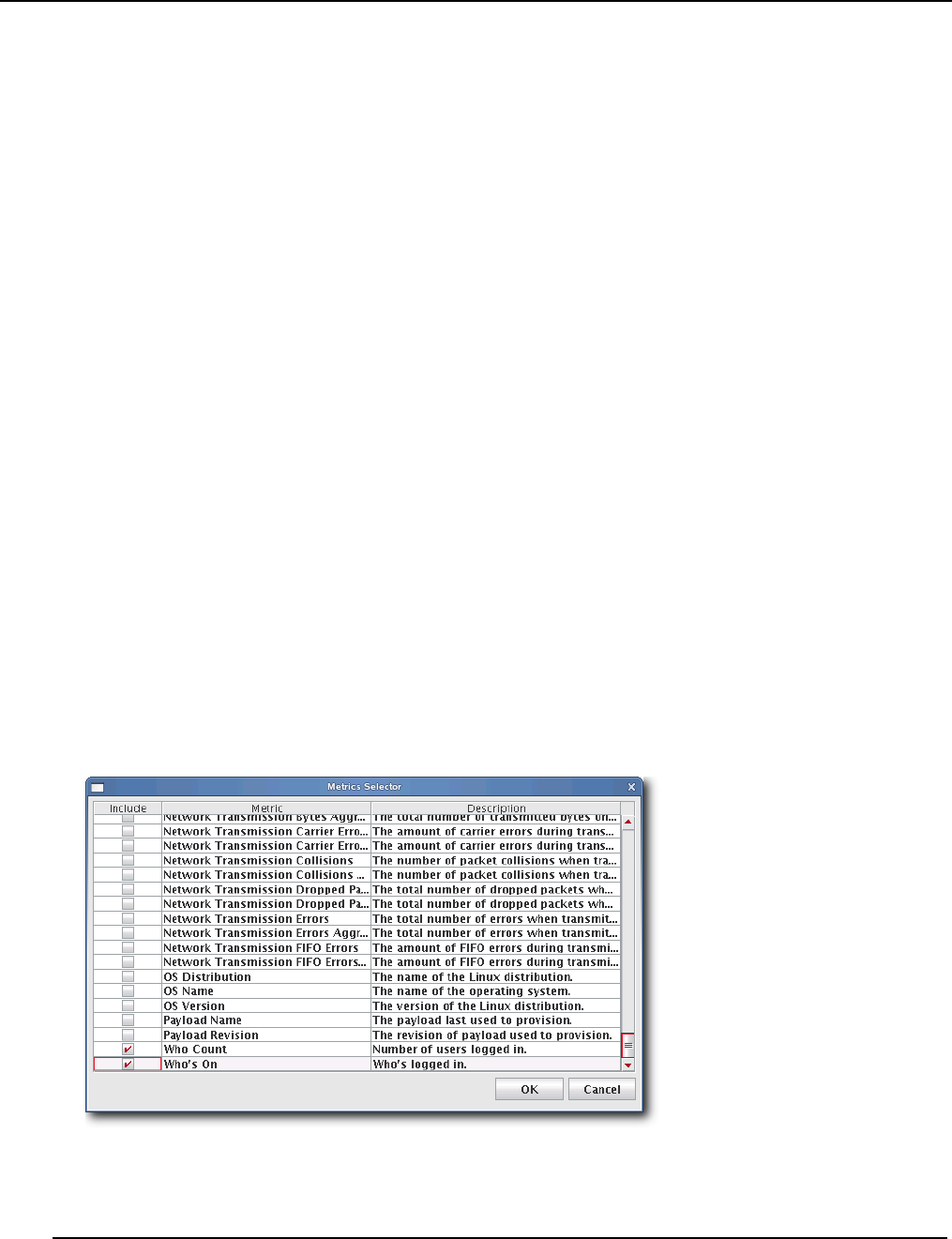
Management Center Monitoring and Event Subsystem
Metrics
007-5642-005
180
Metrics Selector
The Metrics Selector reads from Metrics.profile in the $MGR_HOME/etc directory on each Management Center client.
You may add custom metrics to this profile by making additions in the proper file format:
hosts.<name>.<key>.label:<metric_title>
hosts.<name>.<key>.description:<description>
hosts.<name>.<key>.type:java.lang.<type>
hosts.<name>.<key>.pattern:<pattern>
•The <name> is the host name.
•The <metric_title> is the title displayed in the Management Center list monitoring view and in the metric selector
dialog.
•The <description> indicates what the monitor does and appears in the metric selector dialog.
•The <type> is either “Number” or “String.” Numbers are right justified and Strings are left-justified in the Manage-
ment Center list view.
•The <pattern> helps set the column width for the Management Center list monitoring view. The column width
should reflect the number of characters typically returned by the value. If the returned value has 10-12 characters, the
pattern would be 12 zeros (000000000000). For example, if the returned value is a percent, the pattern should be
“100%” or 4 zeros (0000).
CUSTOM METRICS EXAMPLE
Continuing with the example introduced in To Add a Custom Monitor on page 175, add the following to the
Metrics.profile on the Management Center client—then restart the client:
hosts.who.count.label=Who Count
hosts.who.count.description=Number of users logged in.
hosts.who.count.type=java.lang.Number
hosts.who.count.pattern=00
hosts.who.who.label=Who's On
hosts.who.who.description=Who's logged in.
hosts.who.who.type=java.lang.String
hosts.who.who.pattern=0000000
The new metrics appear in the Metrics Selector dialog.
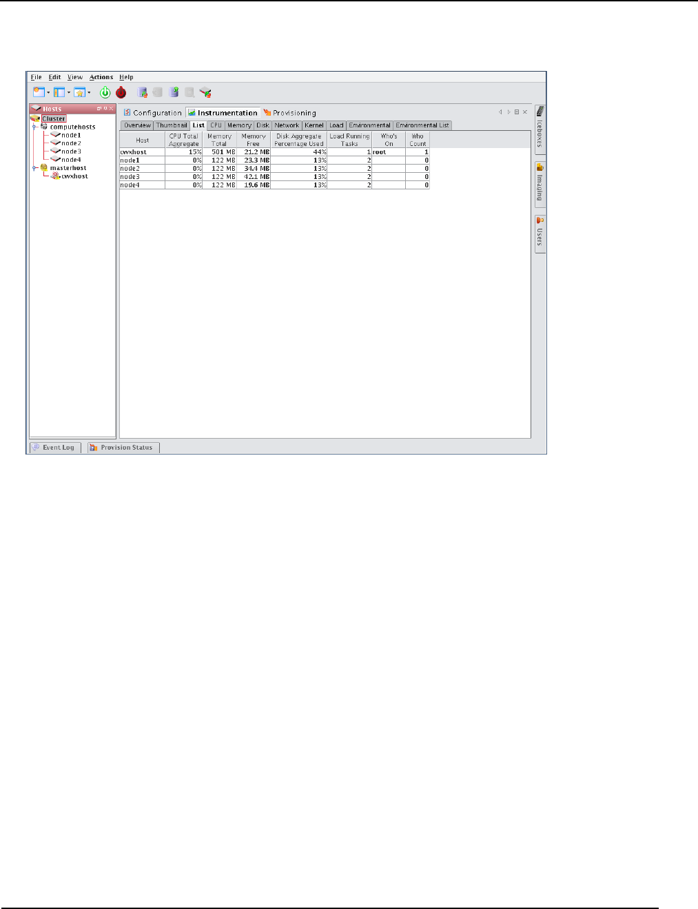
Management Center Monitoring and Event Subsystem
Metrics
007-5642-005 181
The “who” additions also appear in the Instrumentation List view:

Management Center Monitoring and Event Subsystem
Event Listeners
007-5642-005
182
Event Listeners
Event Listeners allow you to easily monitor your cluster and trigger events (loggers) when you exceed specific
thresholds. Event listeners may be configured on specific hosts (including the Master Host) and included on payloads
that contain Management Center (see Install Management Center into the Payload on page 99). By default,
Management Center includes a basic collection of listeners, but allows you to add custom listeners as needed. You may
also import listeners from an existing host or payload, import the default listeners, or restore the factory settings. The
following table lists the default listeners:
The temperature listener is divided into a CPU temperature listener and an ambient temperature listener. The CPU
temperature listener is triggered by any CPU and the CPU that trips it is specified in the message. By separating the
ambient temperature, Management Center supports a negative threshold for PEKI temperatures and a positive threshold
for ambient temperatures.
Listener Name Threshold Message
System Swap Space 512000000 Master Host is using swap space.
Memory (EDAC)
(Correctable Errors)
500 Memory Error Detection and Correction (EDAC—AKA BlueSmoke)
detected {2} correctable memory error(s) on host {3}.
Memory (EDAC)
(Uncorrectable Errors)
1 Memory Error Detection and Correction (EDAC—AKA BlueSmoke)
detected {2} correctable memory error(s) on host {3}.
LinuxBIOS Bootmode 0Management Center has detected that LinuxBIOS is running in Fall-
backmode. This may indicate an error with BIOS settings. As a result,
this host may not be running at full performance.
System Load 2.1 Five minute load average limit {0} exceeded on host {3} (current load
average {2})
Host Power Status The following host(s) have stopped responding: {0}. The following
host(s) are still not responding - {1}. This may be due to the host(s) fail-
ing, network congestion, or Management Center services being
stopped.
Ambient Temperature (Warning) 55 Ambient Temperature limit {0} exceeded on host {3} (current tempera-
ture {2}).
Ambient Temperature (Error) Ambient Temperature limit {0} exceeded on host {3} (current tempera-
ture {2}). Shutting down.
CPU Temperature (Warning) CPU Temperature 1 limit {0} exceeded on host {3} (current tempera-
ture {2}).
CPU Temperature (Error) CPU Temperature 1 limit {0} exceeded on host {3} (current tempera-
ture {2}).
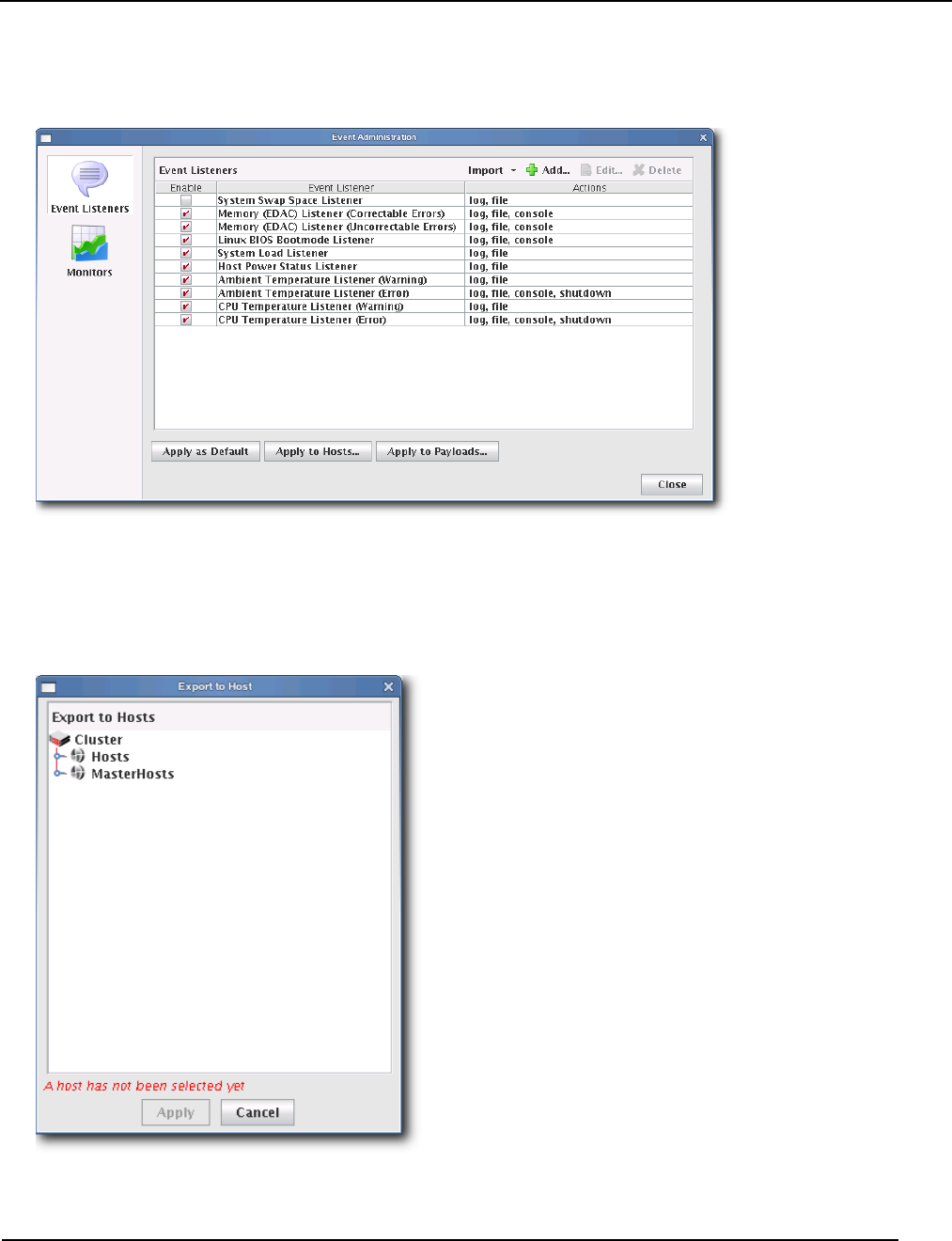
Management Center Monitoring and Event Subsystem
Event Listeners
007-5642-005 183
To Enable or Disable a Listener
1. Select Event Administration from the Edit menu. The Event Administration dialog appears.
2. Select Event Listeners.
3. Check or un-check the box next to each listener you want to enable or disable.
4. (Optional) Click Apply as Default to apply the listener configuration as the default on the Master Host and payload.
Management Center saves the listeners in InstrumentationListeners.profile.default.
5. (Optional) Click Apply to Hosts to apply the listener to a specific host(s). The Export to Hosts dialog appears.
A. Select the host(s) to which to export the listeners from the navigation tree.
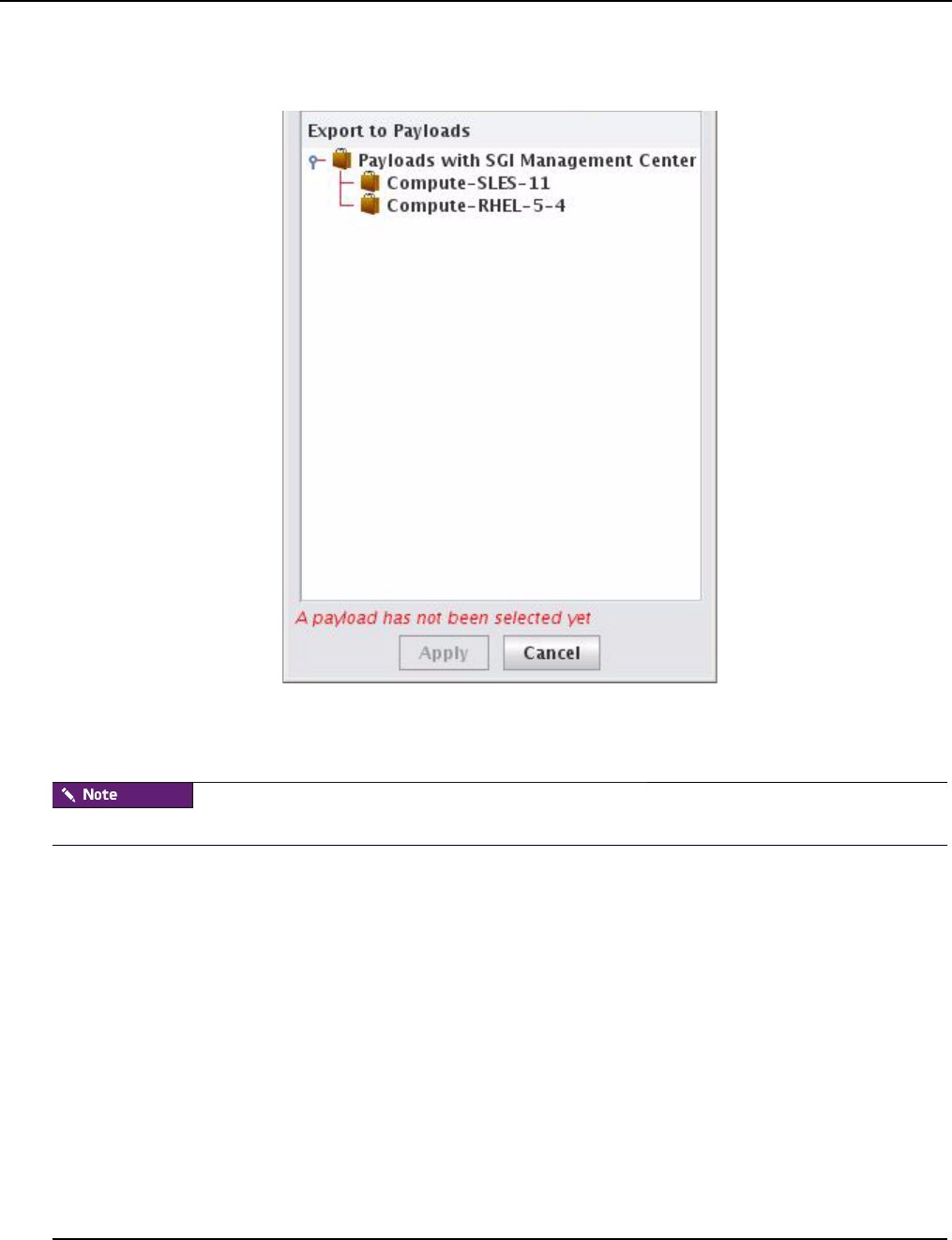
Management Center Monitoring and Event Subsystem
Event Listeners
007-5642-005
184
B. Click Apply to save changes or click Close to abort this action.
6. (Optional) Click Apply to Payloads to include these listeners as part of a payload. The Export to Payloads appears.
A. Select the payload(s) to which to apply the listeners.
B. Click Apply to save changes or click Cancel to abort this action.
7. Click Close to complete this action and close the Event Administration dialog.
If you click close without applying your changes, all modifications will be lost.
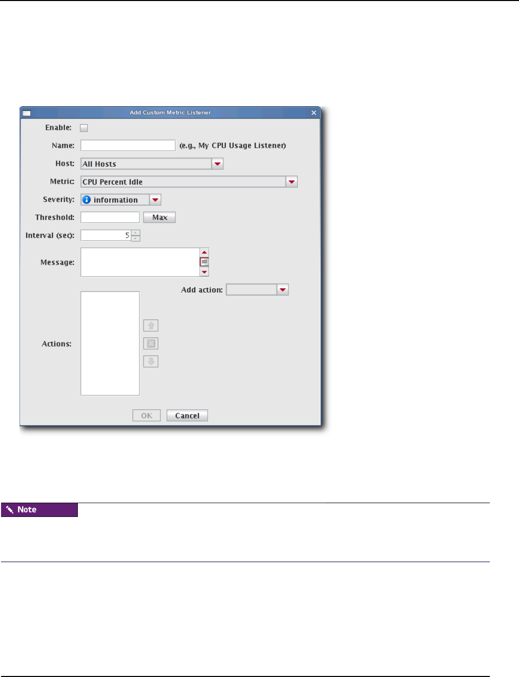
Management Center Monitoring and Event Subsystem
Event Listeners
007-5642-005 185
To Add a Listener
1. Select Event Administration from the Edit menu. The Event Administration dialog appears.
2. Select Event Listeners.
3. Click Add. The Add Listener Metric dialog appears.
4. Enter the name of the listener.
5. Select the host(s) on which to enable the listener.
6. Select the metric to monitor. For a list of available metrics, see Pre-configured Metrics on page 255.
If you write a custom monitor and want to use one or more of the metrics from that monitor, you must edit the
CustomMetrics.profile to include the metrics, then restart Management Center—otherwise, no custom listeners will be
defined. CustomMetrics.profile uses the same format as Metrics.profile, discussed in Metrics Selector on page 180.
7. Specify the severity level of the event (Information, Warning, Error).
8. Enter the threshold for the metric and click the Max/Min button to specify whether this value is the maximum of
minimum threshold.
9. Enter the monitoring interval (in seconds).
10. Enter a message to display with this listener.
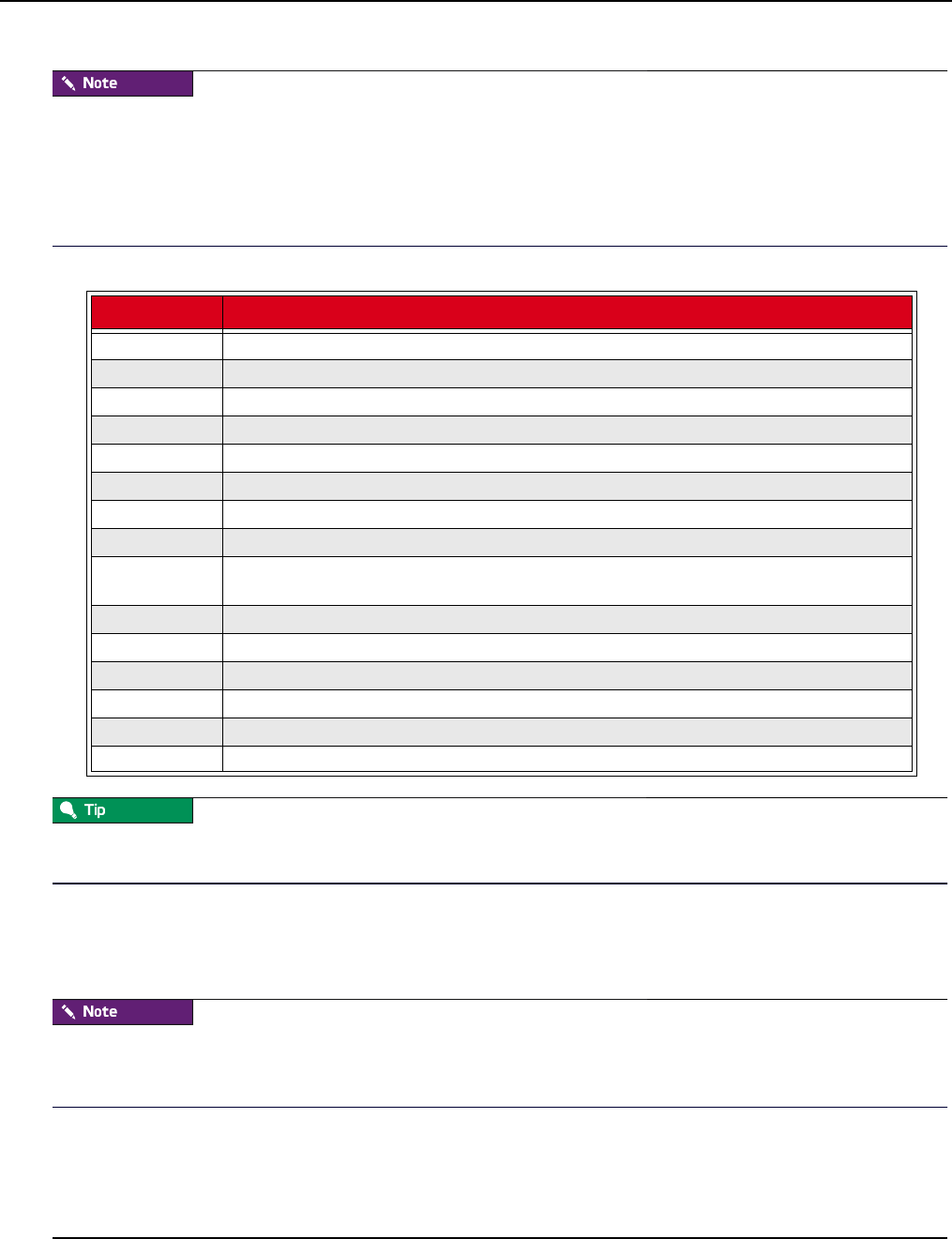
Management Center Monitoring and Event Subsystem
Event Listeners
007-5642-005
186
The message is user-configurable and contains the content of the log message or e-mail message. Several variables are
available in the message:
{0} = Threshold
{1} = Metric Name
{2} = Metric Value at the time the listener was triggered
{3} = Hostname
11. Add actions to perform if this event is triggered. Available actions are listed in the following table:
The Actions list allows you to configure the order in which actions should occur. You may also click Delete to remove
an action from the list.
12. Check the Enable option to activate the listener.
13. Click OK to continue or click Cancel to abort this action.
14. Click Apply as Default to save the listener.
When you add a listener and click Apply as Default, Management Center saves the listener as one of the default
listeners—all future payloads will contain the new listener. Furthermore, the new listener will be included any time you
install Management Center into a payload.
15. Click Close.
Action Description
email Send an event notification e-mail to a comma-delimited list of recipients.
script Executes a user-selected script when triggered.
snmp Sends SNMP messages to a user-specified trap host.
beacon Turns the beacon on for the host.
console Sends event information to the console.
file Sends event information to $MGR_HOME/log/event.log
halt Halts the host on which HostAdministrationService is running (user-specified).
log Displays event information in the Event Log GUI.
pbsoff Automatically set the host status to offline. The pbsoff action requires some additional configura-
tion. See PBS Configuration on page 187.
powercycle Cycles power to the host.
poweron Powers the host on.
poweroff Powers the host off.
reboot Soft reboots the host.
shutdown Shut down the host.
syslog Sends an event message to the syslog.

Management Center Monitoring and Event Subsystem
Event Listeners
007-5642-005 187
PBS CONFIGURATION
The pbsoff action uses the pbsnodes command. This command is installed on the hosts as part of the PBS package—
however, the PBS server is not typically configured to authenticate from other hosts in the system. In order for the
pbsoff action to be successful, you must allow pbsnodes to run from the hosts. To do this, set the pbs manager via qmgr:
qmgr -c “set server managers = root@*.<cluster>.<domain>.<base>”
For example:
qmgr -c “set server managers = root@*.engr.mycompany.com”
You can test this configuration by running the following command on one of the hosts:
pbsnodes -o <hostname>
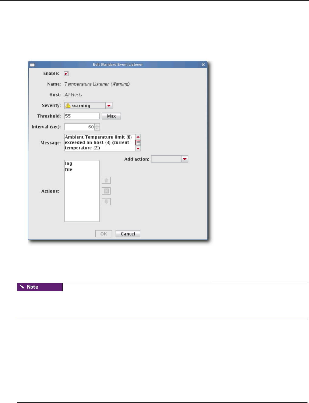
Management Center Monitoring and Event Subsystem
Event Listeners
007-5642-005
188
To Edit a Listener
1. Select Event Administration from the Edit menu. The Event Administration dialog appears.
2. Select Event Listeners.
3. Double-click a listener in the list or select the listener and click Edit. The edit dialog appears.
4. Make any necessary modifications, then click OK to apply your changes. Click Cancel to abort this action.
5. (Optional) Apply the listener to hosts or payloads.
6. Click Apply as Default to save the listener.
When you change a listener and click Apply as Default, Management Center saves the listener as one of the default
listeners—all future payloads will contain the new listener. Furthermore, the new listener will be included any time you
install Management Center into a payload.
7. Click Close.
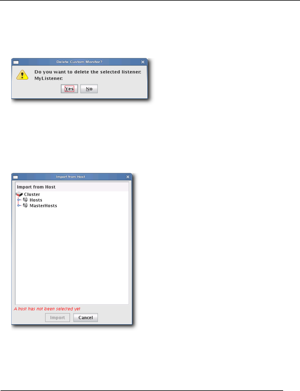
Management Center Monitoring and Event Subsystem
Event Listeners
007-5642-005 189
To Delete a Listener
1. Select Event Administration from the Edit menu. The Event Administration dialog appears.
2. Select a listener from the list and click Delete.
3. Management Center asks you to confirm your action.
4. Click Yes to delete the listener or click No to abort this action.
To Import Listeners
IMPORT FROM HOST
1. Select Event Administration from the Edit menu. The Event Administration dialog appears.
2. Select Event Listeners.
3. Click Import and select Import from Host. The Import from Hosts dialog appears.
4. Select the host from which to import listeners and click Import. Click Cancel to abort this action.
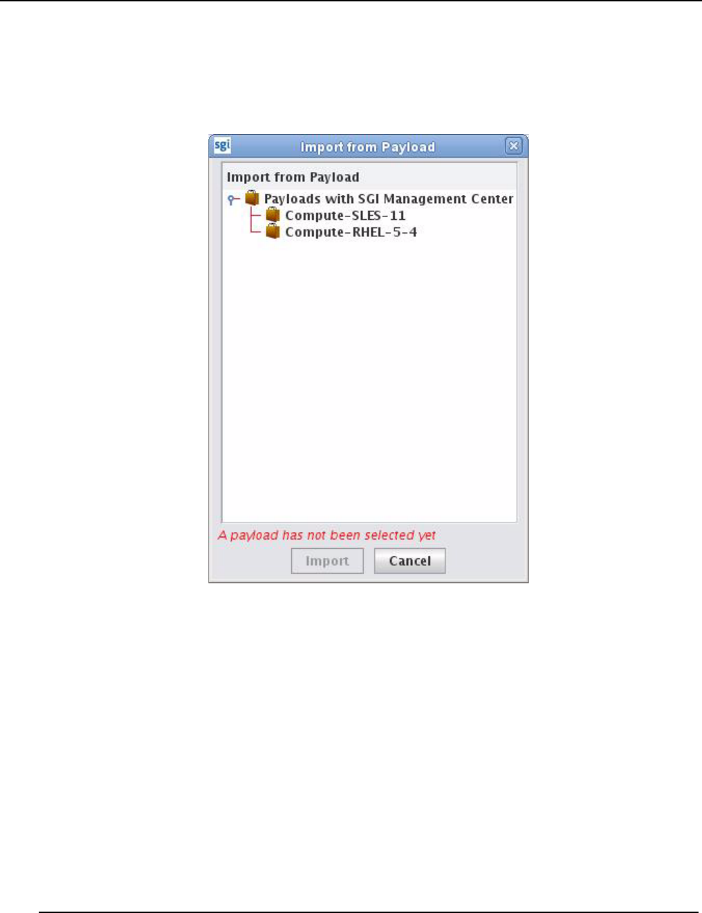
Management Center Monitoring and Event Subsystem
Event Listeners
007-5642-005
190
IMPORT FROM PAYLOAD
1. Select Event Administration from the Edit menu. The Event Administration dialog appears.
2. Select Event Listeners.
3. Click Import and select Import from Payload. The Import from Payloads dialog appears.
4. Select the payload from which to import listeners and click Import. Click Cancel to abort this action.
IMPORT DEFAULT
1. Select Event Administration from the Edit menu. The Event Administration dialog appears.
2. Select Event Listeners.
3. Click Import and select Import Default. Management Center restores all listeners stored as default listeners in
InstrumentationListeners.profile.default. See To Enable or Disable a Listener on page 183 for information on
adding default listeners.
RESTORE FACTORY SETTINGS
1. Select Event Administration from the Edit menu. The Event Administration dialog appears.
2. Select Event Listeners.
3. Click Import and select Restore Factory Settings. Management Center reverts the default listeners that shipped with
Management Center.
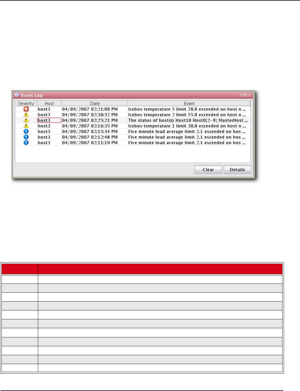
Management Center Monitoring and Event Subsystem
Loggers
007-5642-005 191
Loggers
Loggers refer to actions taken when a threshold exceeds its maximum or minimum value. Common logger events
include sending messages to the centralized Management Center event log, logging to a file, logging to the serial
console, and shutting down the host.
MANAGEMENT CENTER EVENT LOG
The event log is located on the instrumentation overview screen. If you select multiple hosts (or a container such as a
cluster, partition, or region), the log shows messages for any host in the selection. If you select a single host, the
message log shows messages for this host only. Messages have three severity levels: error, warning, and informational.
TEMPLATEFORMATTER
You may extend the abilities of pre-configured and custom loggers (located in $MGR_HOME/etc/Logging.profile)
using the template field of the TemplateFormatter. The template field allows you to configure the types of messages
displayed by loggers. For example, the message template type used in the following example is %m:
formatters.com.lnxi.instrumentation.event: \
com.xeroone.logging.TemplateFormatter
formatters.com.lnxi.instrumentation.event.template: %m
The following table contains a list of supported message templates:
Template Description
%N Sequential record number. This number resets each time the virtual machine restarts.
%T Creation time.
%C Channel.
%S Severity.
%M Message.
%E Event.
%EN Event name.
%ET Event trace.
%AN Application name.
%AM Application moniker.
%AST Application start time.

Management Center Monitoring and Event Subsystem
Loggers
007-5642-005
192
%AV Application version.
%HN Host name.
%HM Host moniker.
%MS Memory size.
%MF Memory free.
%OSN Operating system name.
%OSV Operating system version.
%% Literal % character.
'' Literal ' (single quote) character.
'Escape character for quoted text.
Template Description

007-5642-005 193
Chapter 8
Upgrading SGI Management Center
This chapter describes how you upgrade SGI Management Center from the following base versions:
•SGI Management Center 1.x
•SGI ISLE Cluster Manager 2.x
General Tasks
Regardless of the base version, you will need to do the following:
•Back up the product database.
•Upgrade the sgimc-payload package in all existing payloads.
•Update any existing images to use the new payload revision and check in the image.
Updating the image also refreshes the list of RAM disk files that need to be copied the next time you provision. If
you do not perform this step, you may get error running cp messages in the provisioning status panel.
The following sections describe upgrading items specific to the base version from which you are upgrading.
If you upgrade from a cluster running SGI Management Center 1.3 or older, the contents of all partitions on a node will
be lost the first time you provision.

Upgrading from a Previous Version of SGI Management Center
007-5642-005
194
Upgrading from a Previous Version of SGI Management
Center
The following steps outline the best practices for upgrading from a previous version of SGI Management Center.
1. Back up the database as a safeguard.
To do this, issue the following command as root:
# dbix -x > <filename>
For example:
# dbix -x > /root/SMC1.0-backup.dbix
2. Install the sgimc package, ice, and all other dependencies:
- sgimc
- sgimc-server
- sgimc-tftp
- sgimc-tftpboot or sgimc-atftp
- db48
- libdb_java
- ice
- ice-java
- ice-libs
- mkelfImage
- shout (if installing on an SGI Altix UV system)
The appropriate packages will be replaced.
After installing the new shout package, you should configure the shout daemon to be enabled on boot and restart
the shout daemon:
# chkconfig shout on
# /etc/init.d/shout restart
3. Copy over custom settings, if applicable.
Upon upgrade, SGI Management Center backs up all the previous files in /opt/sgi/sgimc/etc/<datestamp> with a
symbolic link called /opt/sgi/sgimc/etc.bak that points to the latest backup. You may copy custom settings that
were present in the previous SGI Management Center installation. For example, if you had custom settings applied
for Instrumentation and Event listeners, you can copy to /opt/sgi/sgimc/etc the settings from the following files:
/opt/sgi/sgimc/etc.bak/InstrumentationMonitors.profile
/opt/sgi/sgimc/etc.bak/InstrumentationListeners.profile
You can perform a diff to see what has changed. For example:
# diff -r /opt/sgi/sgimc/etc /opt/sgi/sgimc/etc.bak
4. Restart the services:
# /etc/init.d/mgr restart

Upgrading from SGI ISLE Cluster Manager 2.x
007-5642-005 195
Upgrading from SGI ISLE Cluster Manager 2.x
If you are upgrading from SGI ISLE Cluster Manager 2.x to SGI Management Center, you should use the following
process:
1. Back up the dbix database and the settings directory.
For example:
# dbix -x > /data1/islecm_backup.dbix
# cp -a /opt/sgi/islecm/etc /data1/islecm_etc_backup
You should check that there is text in the dbix backup file in order to confirm that the dbix backup succeeded.
2. Install the sgimc package, ice, and all other dependencies:
- sgimc
- sgimc-server
- sgimc-tftp
- sgimc-tftpboot or sgimc-atftp
- db48
- libdb_java
- ice
- ice-java
- ice-libs
- mkelfImage
- java-1.6.0-sun
- java-1.6.0-sun-fonts
The appropriate packages will be replaced.
3. Log out and back in to source the environment.
4. Restart the services in the new environment:
# /etc/init.d/mgr restart

Upgrading from SGI ISLE Cluster Manager 2.x
007-5642-005
196
5. Move over the imaging and vcs contents to their new home.
Note:The following steps assume the destination directories are empty or non-existent. Make sure there are no files
or directories in the destination with the same name as the files being moved.
# mkdir -p /opt/sgi/sgimc/vcs
# mkdir -p /opt/sgi/sgimc/imaging/root/payloads
# mkdir -p /opt/sgi/sgimc/imaging/root/kernels
# mkdir -p /opt/sgi/sgimc/imaging/root/images
# mv /opt/sgi/islecm/vcs/* /opt/sgi/sgimc/vcs/
# mv /opt/sgi/islecm/imaging/root/payloads/* /opt/sgi/sgimc/imaging/root/payloads/
# mv /opt/sgi/islecm/imaging/root/kernels/* /opt/sgi/sgimc/imaging/root/kernels/
# mv /opt/sgi/islecm/imaging/root/images/* /opt/sgi/sgimc/imaging/root/images/
6. Copy over custom settings if applicable.
You may copy custom settings that were present in the ISLE Cluster Manager installation. The files are kept in
directory /opt/sgi/islecm/etc. For example, if you had custom settings applied for Instrumentation and Event
listeners, you can copy to /opt/sgi/sgimc/etc the settings from the following files:
/data1/islecm_etc_backup/InstrumentationMonitors.profile
/data1/islecm_etc_backup/InstrumentationListeners.profile
You can perform a diff to see what has changed. For example:
# diff -r /data1/islecm_etc_backup /opt/sgi/sgimc/etc
NOTE: Most of the files end in .profile and do not contain static path information. If you copy a custom version of
exclude.files, change all references from /opt/sgi/islecm to /opt/sgi/sgimc. Example:
# cd /opt/sgi/sgimc/etc
# sed -i "s/opt\/sgi\/islecm/opt\/sgi\/sgimc/g" exclude.files
7. Restore the dbix database:
# dbix -i < /data1/islecm_backup/islecm_backup.dbix
8. Restart the services:
# /etc/init.d/mgr restart
You can safely remove the "jdk" package (for example, jdk-1.5.0_17-fcs) if it was installed for SGI ISLE Cluster
Manager and you do not need it otherwise. Any leftover islecm-java packages from previous versions of SGI ISLE
Cluster Manager may also be removed. Similarly, you can remove the db46 package if it was installed with a previous
version of SGI Management Center and is no longer being used otherwise.

007-5642-005 197
Chapter 9
Using the Discover Interface
When you add new nodes to your cluster, you must provide profile information about the new nodes to SGI
Management Center—notably, information like the the MAC addresses of the compute nodes and of the BMCs in the
new compute nodes. SGI Management Center provides the Discover interface to assist you in determining
(discovering) the pertinent MAC addresses and adding the new nodes to your cluster.
There is both a graphical and command-line interface for Discover. This chapter describes how you can use each to
discover compute nodes.
This does not pertain to SGI Altix UV large-memory platforms. For those platforms, SGI Management Center uses the
system management node (SMN) and its associated SMN software bundle to discover its chassis management
controllers (CMCs) and blades.
Software Requirements
In order to use Discover, a premium-licensed feature, you need to install the following packages:
•discover
•discover-common
•discover-server
•sgi-common-python
•sgi-management-device
•cattr
After installing these packages, you must also start the Discover daemon:
# service discoverd start
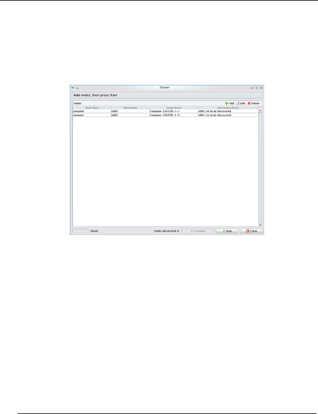
The Graphical Interface
007-5642-005
198
The Graphical Interface
Use the following procedure to add new nodes:
1. Select Discover from the File menu.
2. In the initial window, press Add to add the new nodes.
3. After the addition of the new nodes, press Start.
4. Apply power to the nodes but do not turn the nodes on.
The system searches for MAC addresses and determines if they belong to a BMC, Ethernet switch, or unknown device.
The Continue button is enabled as soon as at least one BMC is found.
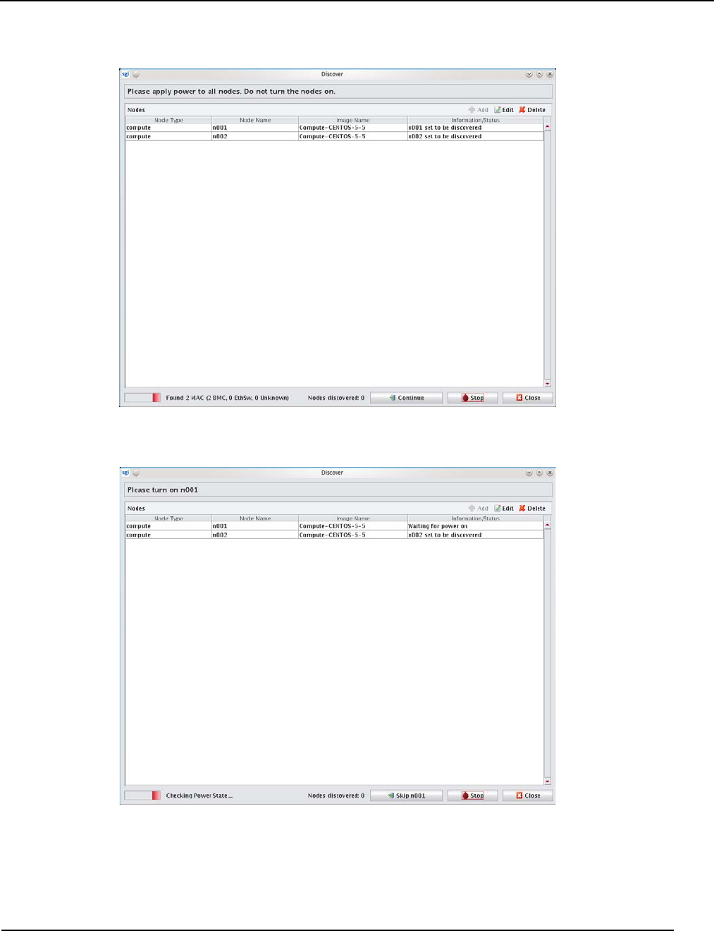
The Graphical Interface
007-5642-005 199
5. Once Discover finds the MACs for the BMCs, press Continue.
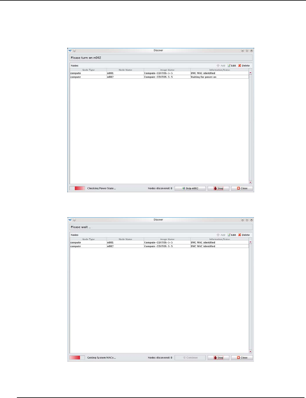
The Graphical Interface
007-5642-005
200
6. Power on the designated nodes as requested by Discover.
As Discover detects the BMCs, it associates the MACs with the BMCs in order.
Once that the BMCs have been ordered, the Discover will determine the system MAC for each node.
After discovering the system MACs, the nodes will be added to the hosts tree.
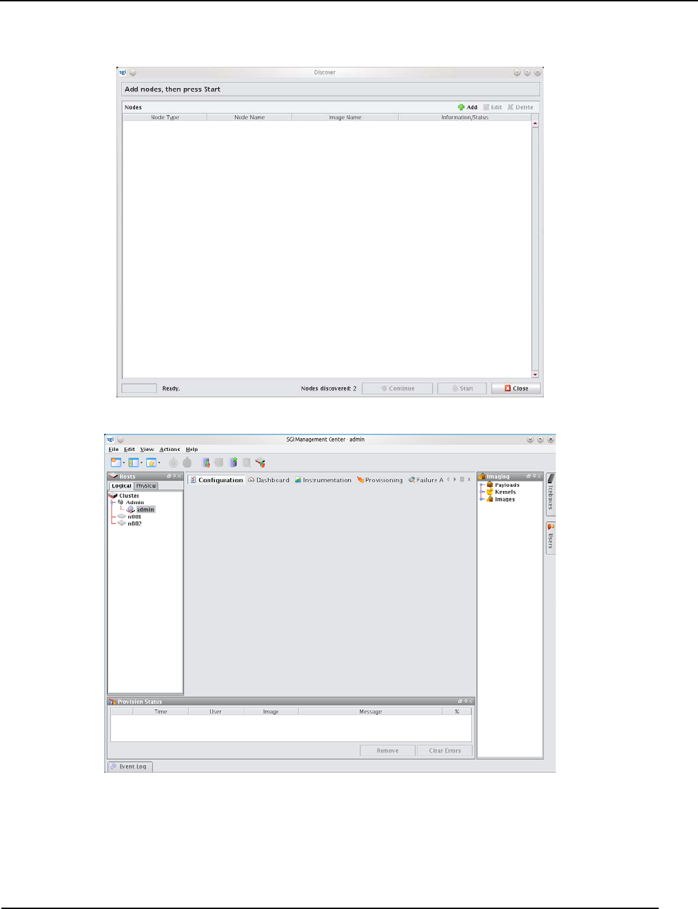
The Graphical Interface
007-5642-005 201

The Command-Line Interface
007-5642-005
202
The Command-Line Interface
The Discover command-line interface is somewhat parallel to that of the graphical interface. The following example
illustrates the process:
# discover --compute 0 --compute 1
First, you will be asked to apply power to all nodes:
*** Please apply power to all nodes. Do not turn the nodes on.
Discover will then show you the BMCs as they are detected:
Found BMC: 00:30:48:32:1b:89 (1 remaining)
Found BMC: 00:30:48:94:1a:a3 (0 remaining)
Once all BMCs are found, Discover verifies that they are all powered off. If nodes are on, you will be asked to power
them off. Once all nodes are in a powered off state you will see the following:
Verification that all nodes are currently powered off was successful.
Next, Discover determines the order of the BMCs by having you power on each node in order:
*** Please turn ON: compute0
compute0’s BMC is 00:30:48:94:1a:a3
*** Please turn ON: compute1
compute1’s BMC is 00:30:48:32:1b:89
After ordering is done, Discover will finish without the need for any further interaction. During this process, discovery
determines the MAC addresses for the systems themselves:
Starting fully automated portion of discovery.
compute0 bmc:00:30:48:94:1a:a3 system:00:30:48:34:2a:b0 (1 remaining)
compute1 bmc:00:30:48:32:1b:89 system:00:30:48:32:91:9a (0 remaining)
After all MACs are collected, the nodes are added and discovery is done:
Adding nodes...
Discovery complete.
You may now provision the nodes normally.

007-5642-005 203
Chapter 10
Troubleshooting
This chapter describes some troubleshooting steps for various problems that may arise. If you encounter a problem not
listed here or the suggested solution does not work, contact SGI Customer Support. See Product Support on page x.
The following topics appear in this chapter:
•Debug Logs on page 204
•Support Information Tool on page 204
•Startup Daemon Fails on the Master Host on page 204
•Nodes in Provisioning or Unknown State after Provisioning on page 205
•Temperatures and Fan Speeds Not Registering on page 205
•Inordinately High CPU Usage on Head Node on page 205
•Insufficient Number of Provisioning Channels on page 205
•Kernel Modules Not Loading on Compute Nodes on page 206
•Command-line Boot Parameters Not Honored on page 206
•Payload Check-in Error on page 206
•Invalid or Expired License Message on page 207
•Resource Usage Too High on Head Node on page 207
•Altix UV Provisioning Stops While Loading Kernel on page 208

Debug Logs
007-5642-005
204
Debug Logs
When you are encountering problems with SGI Management Center, it is often helpful to turn on debugging. In the
Management Center GUI, go to the Preferences screen:
Edit —> Preferences
Check the box next to Enable debugging on the master host.
Alternatively, you can turn on debugging by modifying file /opt/sgi/sgimc/etc/system-clustermanager.profile on any
master host, client install node, or payload install node. Add the following text to the file:
system.logging:com.lnxi.debug
logging.level: DEBUG
The following logs are generated:
/opt/sgi/sgimc/log/debug.log
/opt/sgi/sgimc/log/SGIMC-server.log
/tmp/SGIMC-<username>.log
Once you reproduce the problem that is occurring, examine these logs for information about the cause of the problem.
There are often log entries (like warnings and/or exceptions) that are not an indication of an actual problem.
Support Information Tool
To generate a set of support information to send to SGI Product Support, run the following command:
# /opt/sgi/sgimc/bin/generate_support_info.sh
This script generates a compressed tarball, sgimc_info_<datestamp>.tgz, which contains the troubleshooting
information. Send this file to SGI Product Support.
Startup Daemon Fails on the Master Host
Symptom
Upon trying to start the Management Center GUI or any one of the command-line utilities, you may see a Java Runtime
Exception (Cannot assign requested address).
Resolution
Ensure that the RNA host name (default: admin) of the master host is present in the in the /etc/hosts file.
Example:
10.0.10.1 admin.default.domain admin loghost
This should not be a loopback address such as 127.0.0.1. You can find the RNA host name by checking
/opt/sgi/sgimc/@genesis.profile.

Nodes in Provisioning or Unknown State after Provisioning
007-5642-005 205
Nodes in Provisioning or Unknown State after Provisioning
Symptom
After provisioning, the nodes remain in the provisioning or unknown state.
Resolution
Make sure that the host name of the node and the host name of the master host appear in the /etc/hosts file on the node.
Example:
10.0.10.1 admin.default.domain admin loghost
10.0.1.1 n001.default.domain n001
Temperatures and Fan Speeds Not Registering
Symptom
Temperatures and fan speeds are not appearing in the Environmental tab under Instrumentation for a particular host.
Resolution
This can occur if the IPMI cache file is corrupted or the BMC has been replaced by a different hardware type. You can
clear the IPMI cache using the following command:
# rm /opt/sgi/sgimc/ipmi/*
Inordinately High CPU Usage on Head Node
Symptom
During provisioning, if the payload takes vast amounts of time to download or fails to download completely, you may
see the following on the screen with no progress:
Downloading 0% [ ]
Resolution
The most common cause of this behavior is a misconfiguration of IGMP in the management network switches. Please
verify multicast routing is enabled on the switch. In some cases, you may need to enable IGMP Snooping. For some
switches, it is required to disable spanning tree protocol or enable RTSP / Edge Routing. Consult your switch
documentation for information about how to configure your switch.
Insufficient Number of Provisioning Channels
Symptom
When you attempt to provision, you see a message that indicates there are no more provisioning channels.
Resolution
In the Management Center GUI, do the following:
1. Go to the Preferences screen:
Edit —> Preferences
2. Click Provisioning.
3. Raise the number of multicast channels. (The maximum is 30.)

Kernel Modules Not Loading on Compute Nodes
007-5642-005
206
If the preceding steps fail to resolve the issue, you may have too many combinations of payloads/kernels assigned to
various nodes in the system. This can be resolved by re-provisioning all nodes with one image, which will free the rest
of the available payload/kernel combinations.
Kernel Modules Not Loading on Compute Nodes
Symptom
The expected kernel modules do not load upon booting the compute nodes.
Resolution
You should open the kernel in Management Center GUI and select the desired kernel modules to load. Adding them to
/etc/sysconfig/kernel in the payload and running mkinitrd will not work, since nodes are booted from the network and
the list of modules depends on the modules defined in the Management Center kernel. All module dependencies must
be added as well.
Command-line Boot Parameters Not Honored
Symptom
Command-line parameters listed in /boot/grub/menu.lst or /boot/efi/efi/SuSE/elilo.conf do not take effect.
Resolution
Nodes that are provisioned by Management Center do not boot from grub or EFI. In order to specify command-line
parameters, do the following:
1. Open the specified kernel in Management Center GUI.
2. In the Parameters frame, select Advanced.
3. Enter the desired command-line parameters (for example, cgroup_disable=memory).
Payload Check-in Error
Symptom
When attempting to check in a payload, you receive the error message Error checking in <payload name>.
Resolution
Try the following:
1. Ensure you have not run out of disk space in the filesystem that contains /opt/sgi/sgimc.
2. Ensure that you do not have any extra mounts in the payload. For example, unmount sys or dev in
/opt/sgi/sgimc/imaging/root/payloads/<name> .
3. With debugging enabled, re-attempt the check-in and then examine /opt/sgi/sgimc/log/debug.log for additional
information about the error.

Invalid or Expired License Message
007-5642-005 207
Invalid or Expired License Message
Symptom
Even though you have installed a license, you receive the following message:
The license is invalid or has expired.
Resolution
One or more the following might solve the problem:
•Restart the Management Center daemon:
# service mgr restart
•Inspect file /etc/lk/keys.dat for corruption or missing characters (for example—missing lines or an unmatched,
single quotation mark).
•Ensure that the system time/date is correct.
•Run the following command and examine the output for information about the current state of the license:
# lk_verify
Resource Usage Too High on Head Node
Symptom
The head node is experiencing high load levels from the Management Center application. The DNA process may be
showing abnormally high CPU usage.
Resolution
Management Center is actively managing power and instrumentation on the cluster. This can take a significant amount
of resources especially on a large cluster. For this reason, do not use the master host as a compute resource. However, if
Management Center is persistently experiencing an inordinately high level of resource usage and you have already tried
restarting the Management Center daemon, it may help to disable IPMI environmental gathering from the master host.
Each host will then monitor its own temperature and fan speeds and send the data to the master host.
To disable environmental monitoring from the master host, do the following:
1. In the Management Center GUI, go to the Event Administration screen.
Edit —> Event Administration
2. Click Monitoring.
3. Un-check the box for Enable environmental gathering from the master host.
4. Click Apply As Default.
5. Click Apply to Hosts and proceed to select the desired hosts.
6. To make the change permanent, click Apply to Payloads.
7. Select all desired payloads and click Apply.
You must restart the Management Center daemon on the master host and on all nodes.

Altix UV Provisioning Stops While Loading Kernel
007-5642-005
208
Altix UV Provisioning Stops While Loading Kernel
Symptom
When provisioning an Altix UV system, the kernel console output stops after the following messages are displayed on
the screen:
.ELILO v3.12 for EFI/x86_64
Loading kernel kexec-boot/bzImage... done
Loading file kexec-boot/initramfs.gz...done
Resolution
In the Management Center GUI, open the general network preferences and put a check in the box for Direct PXE Boot.
Re-provision the Altix UV system.
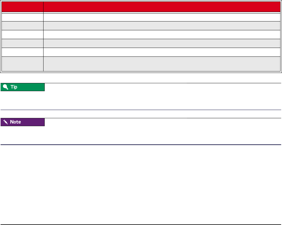
007-5642-005 209
Chapter 11
Command-Line Interface
Command-Line Syntax and Conventions
CLI commands documented in this guide adhere to the following rules—commands entered incorrectly may produce
the “Command not recognized” error message.
Help for all CLI commands is available through man pages. To access the man pages, enter man page from the CLI.
The cwx man page describes all command-line utilities available in Management Center.
All CLI command arguments documented in this chapter are shown using colon notation only ({--partition:|-p:}). You
may also use a space or an equal sign (i.e., --description , -M=) with these arguments.
Convention Description
xyz Items in bold indicate mandatory parameters or keywords (e.g., all).
<variable> <> Angle brackets and italics indicate a user-defined variable (e.g., an IP address or host name)
[x] [ ] Square brackets indicate optional items.
[x|y|z] [ | ] Square brackets with a vertical bar indicate a choice of an optional value.
{x|y|z} { | } Braces with a vertical bar indicate a choice of a required value.
[x{y|z}] [ { | } ] A combination of square brackets and braces with vertical bars indicates a required choice of an
optional parameter.

CLI Commands
007-5642-005
210
CLI Commands
Most of the CLI commands outlined in this chapter are exclusive to the Management Center Master Host.
CLI Commands
conman {
[[-b <host>[<host> ...<host_n>]]|
[-d <destination>[:<port>]]|
[-e <character>]|
[-f]|
[-F <file_name>]|
[-h]|
[-j]|
[-l <file_name>]|
[-L]|
[-m]|
[-q]|
[-Q]|
[-r]|
[-v]|
[-V]]
<host_console>
}

CLI Commands
007-5642-005 211
cwhost {
[partadd [{--description:|-d:} <partition_description>] [--enable:] [--disable:]
[{--regions:|-R} <region1>[,<region2>...]] [{--hosts:|-h} <host1>[,<host2>...]]
<partition>|
[partmod {[{--name:|-n:} <partition_name>] [{--description:|-d:}
<partition_description>]
[--enable:] [--disable:] [{--regions:|-R} <region1>[,<region2>...]]
[{--hosts:|-h} <host1>[,<host2>...]]} <partition>]|
[partdel <partition_name>]|
[partshow [<partition_1>[<partition_2> ...<partition_n>]]]|
[regionadd [{--description:|-d:} <region_description>] [{--partition:|-p:}
<partition_description>]
[--enable:] [--disable:] [{--hosts:|-h} <host1>[,<host2>...]]
[{--groups:|-g} <group1>[,<group2>...]] <region>]|
[regionmod {--name:|-n:} <region> [{--description:|-d:} <region_description>]
[{--partition:|-p:} <partition_description>] [--enable:] [--disable:]
[{--hosts:|-h} <host1>[,<host2>...]]
[{--groups:|-g} <group1>[,<group2>...]] <region>]<region>]|
[regiondel <region>]|
[regionshow [<region_1>[<region_2> ...<region_n>]]]|
[hostadd <host1> <mac1> <ip1>[<host2> <mac2> <ip2>] [{--description:|-d:}
<host_description>]
[--enable:] [--disable:] [{--partition:|-p:} <partition_description>]
[{--regions:|-R:} <region_1>[,<region_2>,...<region_n>]]
[{--iceboxes:|-i:} <icebox_1>:<port>[,<icebox_2>:<port>,...<icebox_3>:<port>]]]|
[hostmod <host> [{--name:|-n:} <host>] [{--interfaces:|-I}
<mac1>|<ip1>[,<mac2>|<ip2>]]
[{--description:|-d:} <host_description>] [--enable:] [--disable:]
[{--partition:|-p:} <partition_description>]
[{--regions:|-R:} <region_1>[,<region_2>,...<region_n>]]
[{--iceboxes:|-i:} <icebox_1>:<port>[,<icebox_2>:<port>,...<icebox_3>:<port>]]]|
[hostdel <host>]|
[hostshow [<host_1>[<host_1> ...<host_n>]]]|
[ifaceadd <host> <mac> <ip> [{--management:|-M:}]]|
[ifacemod <mac>|<ip> [{--management:|-M:}] [--mac:|-m:} <mac>] [{--ip:|-i:} <ip>]
[{--hostname:|-h:} <host>]]|
[ifacedel <mac>|<ip>]|
[ifaceshow [<mac_1>|<ip_1>[<mac_2>|<ip_2> ...<mac_n>|<ip_n>]]]|
[iceboxadd <icebox> <mac> <ip> [{--description:|-d:} <icebox_description>]
[{--password:|-p:} <password>] [{--hosts:|-h:} <host1>:<port1>[,<host2>:<port2>...]]]|
[iceboxmod <icebox> [{--name:|-n:} <icebox>] [{--mac:|-m:} <mac>] [{--ip:|-i:} <ip>]
[{--description:|-d:} <icebox_description>] [{--password:|-p:} <password>]
[{--hosts:|-h:} <host1>:<port1>[,<host2>:<port2>...]]]|
[iceboxdel <icebox>]|
[iceboxshow [<icebox_1>[<icebox_2> ...<icebox_n>]]]|
[inflate <host-range1>[<host-range2> ...]]|
[deflate <host1>[<host2> ...]]|
[{--verbose|-v}]|
[-signature]|
[{-usage|-help|-?}]
}
CLI Commands

CLI Commands
007-5642-005
212
cwpower {
{
[--on:|-1:]|
[--off:|-0:]|
[--cycle:|-C:]|
[--reset:|-R:]|
[--powerstatus:|-S:]|
[--reboot:|-r:]|
[--halt:|-h:]|
[--down:|-d:]|
[--hoststatus:|-s:]|
[--flash|-f]|
[--unflash|-u]|
[--beacon|-b]|
[--severity|-e]|
[{--verbose:|-v:} [--progressive:|-p:]]
}
<host_1>[<host_1> ...<host_n>]|
[-signature]|
[{-usage|-help|-?}]
}
cwprovision {
[{--download-path:|-d:}<path>
{--image:|-i:}<image>
{--image.revision:|-I:}<revision>
{--kernel:|-k:}[<kernel>]
[{--kernel-log-level:|-l:}[<level>]]
{--payload:|-p:}[<payload>]
[{--payload-download:|-D:}yes|no|default]
[--update --payload.revision:<revision>]
[{--repartition:|-R:}yes|no|default]
[{--working-image:|-w:}<name>]|
[{--next-reboot:|-n:}]]|
[{--query-last-image:|-q} [--uncompressed-hostnames:|-u]]
<host_1>[<host_1> ...<host_n>]}|
[-signature]|
[{-usage|-help|-?}]
}
CLI Commands

CLI Commands
007-5642-005 213
cwuser {
[useradd [{--description:|-c:}“<description>”] [{--home:|-d:}<home_directory>]
[{--group:|-g:}<primary_group>]
[{--groups:|-G:}<secondary_group_1>[,<secondary_group_2>,...<secondary_group_n>]]
[{--password:|-p:}<encrypted_password>] [{--shell:|-s:}<shell>] [{--uid:|-u:}<uid>]
[{--enable:|-U}] [{--disable:|-L:}] [{--normal:|-n:}] <user>]|
[usermod [{--description:|-c:}“<description>”] [{--home:|-d:}<home_directory>]
[{--group:|-g:}<primary_group>]
[{--groups:|-G:}<secondary_group_1>[,<secondary_group_2>,...<secondary_group_n>]]
[{--password:|-p:}<encrypted_password>] [{--shell:|-s:}<shell>] [{--uid:|-u:}<uid>]
[{--enable:|-U}] [{--disable:|-L:}] [{--name:|-l:}<user>] <user>]|
[userdel <user>]|
[usershow [<user_1>[<user_2> ...<user_n>]]]|
[passwd <user>]|
[encryptpasswd]|
[groupadd [{--description:|-d:}“<description>”] [{--gid:|-g:}<gid>]
[[{--roles:|-r:}<role_1>] [,<role_2>...<role_n>]]
[{--regions:|-R:}<region_1>[,<region_2>...<region_3>]] <group>]|
[groupmod [{--description:|-d:}“<description>”] [{--gid:|-g:}<gid>]
[[{--roles:|-r:}<role_1>] [,<role_2>,...<role_n>]]
[{--regions:|-R:}<region_1>[,<region_2>,...<region_3>]]
[{--name:|-n:}<group>] <group>]|
[groupdel <group>]|
[groupshow [<group_1>[<group_2> ...<group_n>]]]|
[roleadd [{--description:|-d:}“<description>”]
[{--privileges:|-p:}<privilege_1>[,<privilege_2>,...<privilege_n>]] <role>]|
[rolemod [{--description:|-d:}“<description>”]
[{--privileges:|-p:}<privilege_1>[,<privilege_2>,...<privilege_n>]]
[{--name:|-n:}<role>] <role>]|
[roledel <role>]|
[roleshow [<role_1>[<role_2> ...<role_n>]]]|
[privshow [<privilege_1>[<privilege_2> ...<privilege_n>]]]|
[{--verbose|-v}]|
[-signature]|
[{-usage|-help|-?}]
}
dbix {
[{-d|--delete} <context_1>[<context_2> ...<context_n>]]|
[{-i|--import} <context>] |
[{-x|--export} <context_1>[<context_2> ...<context_n>]]|
[{-usage|-help|-?}]
}
dbx {
[{--domain:|-d} <domain>] [{--format:|-f:} <format>] [{-usage|-help|-?}] [-
runtime[:verbose]]
[-signature] [-splash]
}
CLI Commands

CLI Commands
007-5642-005
214
imgr {
{--image:|-i:}<image> [{--kernel:|-k:}<kernel>] [{--kernel-
revision:|-K:}<kernel_revision>]
[{--payload:|-p:}<payload>] [{--payload.revision:|-P:}<payload_revision>]
[{--force:|-f:}] [{--list:|-l:}]|
[{-usage|-help|-?}]
}
kmgr {
{--name:|-n:}<name> [{--description:|-d:}“<description>”]
{--path:|-p:}<path_to_Linux_kernel_source> [{--kernel:|-k:}<name_of_binary>]
[{--architecture:|-a:}<architecture>] [{--modules:|-m:}] [{--binary:|-b:}] [{--list:|-
l:}]|
[{-usage|-help|-?}]
}
pdcp {[
[-w <host>[,<host>...,<host_n>]]|
[-x <host>[,<host>...,<host_n>]]|
[-a]|
[-i]|
[-r]|
[-p]|
[-q]|
[-f <number>]|
[-l <user>]|
[-t <seconds>]|
[-d]]
<source>[<source>... <source_n>]
<destination>
}
pdsh {
[[-w <host>[,<host>...,<host_n>]]|
[-x <host>[,<host>...,<host_n>]]|
[-a]|
[-i]|
[-q]|
[-f <number>]|
[-s]|
[-l <user>]|
[-t <seconds>]|
[-u <seconds>]|
[-n <tasks_per_host>]|
[-d]|
[-S]|
<host>[,<host>...,<host_n>]]
<command>
}
CLI Commands

CLI Commands
007-5642-005 215
pmgr {
[[{--description:|-d:}“<description>”] [{--include:|-i:}<include_file_or_directory>]
[{--include-from:|-I:}<file_containing_list>] [{--location:|-l:}<location_dir>]
[{--silent:|-s:}<silent>]
[{--exclude:|-x:}<exclude_file_or_dir>]] [{--exclude-from:|-X:}<file_containing_list>]
<payload_name>| [{-usage|-help|-?}]
}
powerman {
[[{--on|-1}]|
[{--off|-0}]|
[{--cycle|-c}]|
[{--reset|-r}]|
[{--flash|-f}]|
[{--unflash|-u}]|
[{--list|-l}]|
[{--query|-q}]|
[{--node|-n}]|
[{--beacon|-b}]|
[{--temp|-t}]|
[{--help|-h}]|
[{--license|-L}]|
[{--destination|-d} host[:port]]|
[{--version|-V}]|
[{--device|-D}]|
[{--telemetry|-T}]|
[{--exprange|-x}]]
<host>[<host> ...<host_n>]
}
vcs {
[{identify| id}]|
[status]|
[include <files>]|
[exclude <files>]|
[archive <filename>]|
[import -R:<repository> -M:<module> [-n:<name>] [-d:“<description>”] [<files>]]|
[commit [-n:<name>] [-d:“<description>”] [<files>]]|
[branch [-n:<name>] [-d:“<description>”] [<files>]]|
[{checkout | co} -R:<repository> -M:<module> [-r:<revision>|<branch>|<name>]]|
[{update | up} [-r:<revision>|<branch>|<name>] [<files>]]|
[name [-R:<repository>] [-M:<module>] [-r:<revision>|<branch>|<name>] <text>]|
[describe [-R:<repository>] [-M:<module>] [-r:<revision>|<branch>|<name>] <text>]|
[{narrate | log} [-R:<repository> -M:<module>] [-r:<revision>|<branch>|<name>]]|
[iterate [-R:<repository> [-M:<module> [-r:<revision>|<branch>|<name>]]]]|
[list]|
[{-usage|-help|-?}]
}
CLI Commands

conman
007-5642-005
216
conman
conman {
[[-b <host>[<host> ...<host_n>]]|
[-d <destination>[:<port>]]|
[-e <character>]|
[-f]|
[-F <file_name>]|
[-h]|
[-j]|
[-l <file_name>]|
[-L]|
[-m]|
[-q]|
[-Q]|
[-r]|
[-v]|
[-V]]
<host_console>
}
Description
The Conman client allows you to connect to remote consoles managed by conmand. Console names are separated by
spaces or commas and matched to the configuration via globbing. Regular expression matching can be enabled with the
-r option.
Conman supports three console access modes: monitor (read-only), interactive (read-write), and broadcast (write-only).
Unless otherwise specified, conman opens the console session in interactive mode (the default).
To use Conman for serial access (that is, as your platform management device), Conman must be installed on the
Master Host and the console(s) must be configured in /etc/conman.conf. The Conman daemon (installed as /etc/init.d/
conmand) must also be started.
You can obtain Conman from http://home.gna.org/conman/. Additional information on Conman is available from the
man pages by entering man conman.conf.
Parameters
[-b <host>[<host> ...<host_n>]]
(Optional) Broadcast to multiple host consoles (write-only). You may enter a range of
hosts or a space-delimited list of hosts (e.g., host[1-4 7 9]).
Data sent by the client is copied to all specified consoles in parallel, but console output
is not sent back to the client. You can use this option in conjunction with -f or -j.
[-d <destination>[:<port>]] (Optional) Specify the location of the conmand daemon, overriding the default
[127.0.0.1:7890]. This location may contain a host name or IP address and be followed
by an optional colon and port number.
[-e <character>] (Optional) Specify the client escape character, overriding the default (&).

conman
007-5642-005 217
[-f] (Optional) Specify that write-access to the console should be forced, thereby stealing
the console away from existing clients with write privileges. As connections are
terminated, conmand informs the original clients of who perpetrated the theft.
[-F <file_name>] (Optional) Read console names or patterns from a file with the specified name. Only
one console name may be specified per line. Leading and trailing white space, blank
lines, and comments (i.e., lines beginning with a #) are ignored.
[-h] (Optional) Display a summary of the command-line options.
[-j] (Optional) Specify that write-access to the console should be joined, thereby sharing the
console with existing clients that have write privileges. As privileges are granted,
conmand informs the original clients that privileges have been granted to new clients.
[-l <file_name>] (Optional) Log console session output to a file with the specified name.
[-L] (Optional) Display license information.
[-m] (Optional) Monitor a console (read-only).
[-q] (Optional) Query conmand for consoles matching the specified names or patterns.
Output from this query can be saved to file for use with the -F option.
[-Q] (Optional) Enable quiet-mode, suppressing informational messages. This mode can be
toggled on and off from within a console session via the &Q escape.
[-r] (Optional) Match console names via regular expressions instead of globbing.
[-v] (Optional) Enable verbose mode.
[-V] (Optional) Display version information.
<host_console> The name of the host to which to connect.
ESCAPE CHARACTERS
Conman supports the following escapes and assumes the default escape character (&):
&? Display a list of all escapes currently available.
&. Terminate the connection.
&& Send a single escape character.
&B Send a serial-break to the remote console.
&F Switch from read-only to read-write via a force.
&I Display information about the connection.
&J Switch from read-only to read-write via a join.
&L Replay the last 4KB of console output. This escape requires that logging is enabled for
the console in the conmand configuration.
&M Switch from read-write to read-only.
&Q Toggle quiet-mode to display or suppress informational messages.
&R Reset the host associated with this console. This escape requires that resetcmd is
specified in the conmand configuration.
&Z Suspend the client.

conman
007-5642-005
218
ENVIRONMENT
The following environment variables may be used to override default settings.
CONMAN_HOST Specifies the host name or IP address at which to contact conmand, but may be
overridden with the -d command-line option. Although a port number separated by a
colon may follow the host name (i.e., host:port), the CONMAN_PORT environment
variable takes precedence. If you do not specify a host, the default host IP address
(127.0.0.1) is used.
CONMAN_PORT Specifies the port on which to contact conmand, but may be overridden by the -d
command-line option. If not set, the default port (7890) is used.
CONMAN_ESCAPE The first character of this variable specifies the escape character, but may be overridden
by the -e command-line option. If not set, the default escape character (&) is used.
Client and server communications are not yet encrypted.
Example 1
To connect to host console n1, enter:
conman n1
Once in conman, enter &. to exit or &? to display a list of conman commands.
Example 2
To broadcast (write-only) to multiple hosts, enter:
conman -b n[1-10]
To view the output of broadcast commands on a group of hosts, use the conmen command before you begin entering
commands from conman. Conmen opens a new window for each host and displays the host output.
For example, the following command opens new consoles for hosts n2-n4:
conmen n[2-4]

cwhost
007-5642-005 219
cwhost
cwhost {
[partadd [{--description:|-d:} <partition_description>] [--enable:] [--disable:]
[{--regions:|-R} <region1>[,<region2>...]] [{--hosts:|-h} <host1>[,<host2>...]]
<partition>|
[partmod {[{--name:|-n:} <partition_name>] [{--description:|-d:}
<partition_description>]
[--enable:] [--disable:] [{--regions:|-R} <region1>[,<region2>...]]
[{--hosts:|-h} <host1>[,<host2>...]]} <partition>]|
[partdel <partition_name>]|
[partshow [<partition_1>[<partition_2> ...<partition_n>]]]|
[regionadd [{--description:|-d:} <region_description>] [{--partition:|-p:}
<partition_description>]
[--enable:] [--disable:] [{--hosts:|-h} <host1>[,<host2>...]]
[{--groups:|-g} <group1>[,<group2>...]] <region>]|
[regionmod {--name:|-n:} <region> [{--description:|-d:} <region_description>]
[{--partition:|-p:} <partition_description>] [--enable:] [--disable:]
[{--hosts:|-h} <host1>[,<host2>...]]
[{--groups:|-g} <group1>[,<group2>...]] <region>]<region>]|
[regiondel <region>]|
[regionshow [<region_1>[<region_2> ...<region_n>]]]|
[hostadd <host1> <mac1> <ip1>[<host2> <mac2> <ip2>] [{--description:|-d:}
<host_description>]
[--enable:] [--disable:] [{--partition:|-p:} <partition_description>]
[{--regions:|-R:} <region_1>[,<region_2>,...<region_n>]]
[{--iceboxes:|-i:} <icebox_1>:<port>[,<icebox_2>:<port>,...<icebox_3>:<port>]]]|
[hostmod <host> [{--name:|-n:} <host>] [{--interfaces:|-I} <mac1>|<ip1>[,<mac2>|<ip2>]]
[{--description:|-d:} <host_description>] [--enable:] [--disable:]
[{--partition:|-p:} <partition_description>]
[{--regions:|-R:} <region_1>[,<region_2>,...<region_n>]]
[{--iceboxes:|-i:} <icebox_1>:<port>[,<icebox_2>:<port>,...<icebox_3>:<port>]]]|
[hostdel <host>]|
[hostshow [<host_1>[<host_1> ...<host_n>]]]|
[ifaceadd <host> <mac> <ip> [{--management:|-M:}]]|
[ifacemod <mac>|<ip> [{--management:|-M:}] [--mac:|-m:} <mac>] [{--ip:|-i:} <ip>]
[{--hostname:|-h:} <host>]]|
[ifacedel <mac>|<ip>]|
[ifaceshow [<mac_1>|<ip_1>[<mac_2>|<ip_2> ...<mac_n>|<ip_n>]]]|
[iceboxadd <icebox> <mac> <ip> [{--description:|-d:} <icebox_description>]
[{--password:|-p:} <password>] [{--hosts:|-h:} <host1>:<port1>[,<host2>:<port2>...]]]|
[iceboxmod <icebox> [{--name:|-n:} <icebox>] [{--mac:|-m:} <mac>] [{--ip:|-i:} <ip>]
[{--description:|-d:} <icebox_description>] [{--password:|-p:} <password>]
[{--hosts:|-h:} <host1>:<port1>[,<host2>:<port2>...]]]|
[iceboxdel <icebox>]|
[iceboxshow [<icebox_1>[<icebox_2> ...<icebox_n>]]]|
[inflate <host-range1>[<host-range2> ...]]|
[deflate <host1>[<host2> ...]]|
[{--verbose|-v}]|
[-signature]|
[{-usage|-help|-?}]
}

cwhost
007-5642-005
220
Description
The Host Administration (cwhost) utility allows you to add, modify, view the current state of, or delete any partition,
region, host, interface, or Icebox in your cluster.

cwhost
007-5642-005 221
Subcommands
partadd
Add a partition to the cluster.
[{--description:|-d:} <partition_description>]
(Optional) A brief description of the partition. If you do not specify a description, this
field remains blank.
[--enable:] [--disable:] (Optional) Indicates whether or not the partition is enabled. If you do not specify this
option, Management Center will enable the partition.
[{--regions:|-R} <region1>[,<region2>...]]
(Optional) The list of regions that are members of this partition. If you do not specify
any regions, none are included in the partition.
[{--hosts:|-h} <host1>[,<host2>...]]
(Optional) The list of hosts that are members of this partition. If you do not specify any
hosts, none are included in the partition.
<partition> The name of the partition to add.
partmod
Modify a partition on the cluster. Unchanged entries remain the same.
[{--name:|-n:} <partition_name>]
(Optional) Change the partition name. If you do not specify a name, Management
Center uses the current partition name.
[{--description:|-d:} <partition_description>]
(Optional) A brief description of the partition. If you do not specify a description,
Management Center uses the current partition description.
[--enable:] [--disable:] (Optional) Indicates whether or not the partition is enabled. If you do not specify this
option, the partition remains in its original state.
[{--regions:|-R} <region1>[,<region2>...]]
(Optional) The list of regions that are members of this partition. If you do not specify
any regions, the partition remains in its original state.
[{--hosts:|-h} <host1>[,<host2>...]]
(Optional) The list of hosts that are members of this partition. If you do not specify any
hosts, the partition remains in its original state.
<partition> The name of the partition to add.
partdel
Delete a partition from the cluster.
<partition_name> The name of the partition to delete.
partshow
Display the current settings for a partition(s).
[<partition_1>[<partition_2> ...<partition_n>]]
(Optional) The name(s) of the partition(s) for which to display the current settings.
Multiple entries are delimited by spaces. Leave this option blank to display all
partitions.

cwhost
007-5642-005
222
regionadd
Add a region to a partition.
[{--description:|-d:} <region_description>]
(Optional) A brief description of the region. If you do not specify a description, this
field remains blank.
[{--partition:|-p:} <partition_description>]
(Optional) The partition to which this region belongs. If you do not specify a partition,
Management Center assigns the region to the default or unassigned partition.
[--enable:] [--disable:] (Optional) Indicates whether or not the region is enabled. If you do not specify this
option, Management Center will enable the region.
[{--hosts:|-h} <host1>[,<host2>...]]
(Optional) The list of hosts that are members of this region. If you do not specify this
option, the region will not contain any member hosts.
[{--groups:|-g} <group1>[,<group2>...]]
(Optional) The list of groups that may access this region. If you do not specify this
option, the region will not be available to any groups.
<region> The name of the new region.
regionmod
Modify a region on the cluster. Unchanged entries remain the same.
{--name:|-n:} <region> (Optional) Change the region name. If you do not specify a name, Management Center
uses the current region name.
[{--description:|-d:} <region_description>]
(Optional) A brief description of the region. If you do not specify a description,
Management Center uses the current region description.
[{--partition:|-p:} <partition_description>]
(Optional) The partition to which this region belongs. If you do not specify a partition,
Management Center assigns the region to the original partition specified.
[--enable:] [--disable:] (Optional) Indicates whether or not the region is enabled. If you do not specify this
option, the region remains in its original state.
[{--hosts:|-h} <host1>[,<host2>...]]
(Optional) The list of hosts that are members of this region. If you do not specify any
hosts, the region remains in its original state.
[{--groups:|-g} <group1>[,<group2>...]]
(Optional) The list of groups that may access this region. If you do not specify any
groups, the region remains in its original state.
<region> The name of the region to modify.
regiondel
Delete a region from the cluster.
<region> The name of the region to delete.

cwhost
007-5642-005 223
regionshow
Display the current settings for a region(s).
[<region_1>[<region_2> ...<region_n>]]
(Optional) The name of the region(s) for which to display the current settings. Multiple
entries are delimited by spaces. Leave this option blank to display all regions.
hostadd
Add a host to the cluster.
<host1> <mac1> <ip1>[<host2><mac2><ip2>]
The name of each new host, its MAC address, and its IP address. The first host specified
is the management interface. Multiple entries are space-delimited.
[{--description:|-d:} <host_description>]
(Optional) A brief description of the host. If you do not specify a description, this field
remains blank.
[--enable:] [--disable:] (Optional) Indicates whether or not the host is enabled. If you do not specify this option,
Management Center enables the host.
[{--partition:|-p:} <partition_description>]
(Optional) The partition to which this host belongs. If you do not specify a partition,
Management Center assigns the host to the default or unassigned partition.
[{--regions:|-r:} <region_1>[,<region_2>,...<region_n>]]
(Optional) The region(s) to which this host belongs. If you do not specify a region,
Management Center does not assign the host to any region. Multiple entries are comma-
delimited.
[{--iceboxes:|-i:} <icebox_1>:<port>[,<icebox_2>:<port>,...<icebox_3>:<port>]]
(Optional) The Icebox(es) and port(s) to which this host is connected. If you do not
specify an Icebox and port, Management Center assumes that the host is not connected
to an Icebox. Multiple entries are comma-delimited.
hostmod
Modify a host on the cluster—unchanged entries remain the same.
<host> The name of the host to modify.
{--name:|-n:} <host> The host’s new name.
[{--interfaces:|-I} <mac1>|<ip1>[,<mac2>|<ip2>]]
(Optional) A list of interfaces with which this host is associated. If none of the specified
interfaces are management interfaces, Management Center marks the first interface as
the management interface.
[{--description:|-d:} <host_description>]
(Optional) A brief description of the host. If you do not specify a description,
Management Center uses the current host description.
[--enable: {yes|no}] (Optional) Indicates whether or not the host is enabled. If you do not specify this option,
the host remains in its original state.
[{--partition:|-p:} <partition_description>]
(Optional) The partition to which this host belongs. If you do not specify a partition, the
host remains associated with the original partition specified.

cwhost
007-5642-005
224
[{--regions:|-r:} <region_1>[,<region_2>,...<region_n>]]
(Optional) The region(s) to which this host belongs. If you do not specify a partition, the
host will not belong to any region. Multiple entries are comma-delimited.
[{--iceboxes:|-i:} <icebox_1>:<port>[,<icebox_2>:<port>,...<icebox_3>:<port>]]
(Optional) The Iceboxes and ports to which this host is connected. If you do not specify
an Icebox and port, Management Center assumes that the host is not connected to an
Icebox. Multiple entries are comma-delimited.
hostdel
Delete a host.
<host> The name of the host to delete.
hostshow
Display the current settings for a host(s).
[<host_1>[<host_1> ...<host_n>]]
(Optional) The name of the host(s) for which to display the current settings. Multiple
entries are delimited by spaces. Leave this option blank to display all hosts.
ifaceadd
Add an interface to the cluster.
<host> The name of the host on which you added the interface.
<mac> The MAC address of the interface.
<ip> The IP address of the interface.
[{--management:|-M:}] (Optional) Specify whether or not this interface is a management interface. If you do not
specify this option, Management Center assumes that this interface is not a management
interface.
ifacemod
Modify an interface on the cluster—unchanged entries remain the same.
<mac> The MAC address of the interface.
<ip> The IP address of the interface.
[{--management:|-M:}] (Optional) Specify whether or not this interface is a management interface. If you do not
specify this option, the interface remains in its original state.
[--mac:|-m:} <mac>] (Optional) Change the interface’s hardware or MAC address.
[{--ip:|-i:} <ip>] (Optional) Change the interface’s IP address.
[{--hostname:|-h:} <host>] (Optional) Change the host to which this interface belongs.
ifacedel
Delete an interface from the cluster.
<mac> The MAC address of the interface to delete.
<ip> The IP address of the interface to delete.

cwhost
007-5642-005 225
ifaceshow
Display the current settings for an interface(s).
[<mac_1>|<ip_1>[<mac_2>|<ip_2> ...<mac_n>|<ip_n>]]
(Optional) The MAC or IP address(es) of the interface(s) for which to display the
current settings. Multiple entries are delimited by spaces. Leave this option blank to
display all interfaces.
iceboxadd
Add an Icebox to the cluster.
<host> The name of the new Icebox.
<mac> The MAC address of the new Icebox.
<ip> The IP address of the new Icebox.
[{--description:|-d:} <icebox_description>]
(Optional) A brief description of the Icebox. If you do not specify a description, this
field remains blank.
[{--password:|-p:} <password>]
(Optional) The Icebox’s administrative password. If you do not specify a password,
Management Center uses the default password “icebox”.
[{--hosts:|-h:} <host1>:<port1>[,<host2>:<port2>...]]
(Optional) A list of hosts connected to the Icebox and the ports to which they are
connected. If you do not specify this option, Management Center assumes that the hosts
are not connected to an Icebox.
iceboxmod
Modify an Icebox on the cluster—unchanged entries remain the same.
<icebox> The name of the Icebox to modify.
[{--name:|-n:} <icebox>] (Optional) The Icebox’s new name.
[{--mac:|-m:} <mac>] (Optional) Change the Icebox’s hardware or MAC address.
[{--ip:|-i:} <ip>] (Optional) Change the Icebox’s IP address.
[{--description:|-d:} <icebox_description>]
(Optional) A brief description of the Icebox. If you do not specify a description,
Management Center uses the current Icebox description.
[{--password:|-p:} <password>]
(Optional) The Icebox’s administrative password. If you do not specify a password,
Management Center uses the original password.
[{--hosts:|-h:} <host1>:<port1>[,<host2>:<port2>...]]
(Optional) A list of hosts connected to the Icebox and the ports to which they are
connected. If you do not specify this option, Management Center assumes that the hosts
remain in their original state.
iceboxdel
Delete a Management Center Icebox.
<icebox> The name of the Icebox to delete.

cwhost
007-5642-005
226
iceboxshow
Display the current settings for an Icebox(es).
[<icebox_1>[<icebox_2> ...<icebox_n>]]
(Optional) The Icebox(es) for which to display the current setting(s). Multiple entries
are delimited by spaces. Leave this option blank to display all Iceboxes.
inflate <host-range1>[<host-range2> ...]
(Optional) Allows you to change between full and compressed host list format. Inflate
the specified host range(s) to display a full list of hosts.
deflate <host1>[<host2> ...] (Optional) Allows you to change between full and compressed host list format. Deflate
the specified host range(s) to display a compressed host list.
[{--verbose|-v}] (Optional) Display verbose output when performing operations. This option is common
to all subcommands.
[-signature] (Optional) Displays the application signature. The application signature contains the
name, description, version, and build information of this application.
[{-usage|-help|-?}] (Optional) Display help information for the command and exit. All other options are
ignored.
Examples
EXAMPLE 1
View the layout of the system:
cwhost hostshow
EXAMPLE 2
Get details of the system:
cwhost hostshow -v
EXAMPLE 3
Create a region called group1:
cwhost regionadd group1
EXAMPLE 4
Add a host to region group1 with the host name n1, the mac 0005b342afe1, and the IP address 10.0.0.1:
cwhost hostadd -r:group1 n1 0005b342afe1 10.0.0.1
EXAMPLE 5
Add host n2 to the group1 region:
cwhost hostmod -r:group1 n2

cwhost
007-5642-005 227
EXAMPLE 6
Deflate the host list n1, n2, n3, and n4:
cwhost deflate n1 n2 n3 n4
n[1-4]
EXAMPLE 7
Inflate the host list n[1-4]:
cwhost inflate n[1-4]
n1
n2
n3
n4

cwpower
007-5642-005
228
cwpower
cwpower {
{
[--on:|-1:]|
[--off:|-0:]|
[--cycle:|-C:]|
[--reset:|-R:]|
[--powerstatus:|-S:]|
[--reboot:|-r:]|
[--halt:|-h:]|
[--down:|-d:]|
[--hoststatus:|-s:]|
[--flash|-f]|
[--unflash|-u]|
[--beacon|-b]|
[--severity|-e]|
[{--verbose:|-v:} [--progressive:|-p:]]
}
<host_1>[<host_1> ...<host_n>]|
[-signature]|
[{-usage|-help|-?}]
}
Description
The Power Administration (cwpower) utility allows you to perform power administration operations on a host(s) within
the cluster. Operations include power on, power off, power cycle, reset, reboot, halt, and power down (a soft power off).
You may also query the current power status of a particular host(s).
You may specify only one power administration operation option each time you use the cwpower command.
Parameters
[--on|-1] (Optional) Turn on power to the specified host(s).
[--off|-0] (Optional) Turn off power to the specified host(s).
[--cycle|-C] (Optional) Cycle power to the specified host(s).
[--reset|-R] (Optional) Perform a hardware reset for the specified host(s).
[--powerstatus|-S] (Optional) Query the hard power status for the specified host(s).
[--reboot|-r] (Optional) Reboot the specified host(s).
[--halt|-h] (Optional) Halt the specified host(s).
[--down|-d] (Optional) Execute a soft power down on the specified host(s).
[--hoststatus|-s] (Optional) Query the host administration power status for the specified host(s).
[--flash|-f] (Optional) Turn the beacon on for the specified host(s).
[--unflash|-u] (Optional) Turn the beacon off for the specified host(s).
[--beacon|-b] (Optional) Report the beacon status for the specified host(s).
[--severity|-e]| (Optional) Report the error status for the specified host(s).

cwpower
007-5642-005 229
[{--verbose|-v} [--progressive|-p]]
(Optional) Change the standard output to verbose. Output displays the power status of
each host, one per line. To display output as information becomes available, select the
progressive option—progressive output is not guaranteed to be sorted and is not
summarized.
<host_1>[<host_1> ...<host_n>]
The name of the host(s) for which to execute the specified operation. You may enter a
range of hosts or a space-delimited list of hosts (e.g., host[1-4 7 9]).
[-signature] (Optional) Displays the application signature. The application signature contains the
name, description, version, and build information of this application.
[{-usage|-help|-?}] (Optional) Display help information for the command and exit. All other options are
ignored.
Examples
EXAMPLE 1
To Power on hosts 1–10:
cwpower -1 n[1-10]
EXAMPLE 2
Power off host 1:
cwpower -0 n1
EXAMPLE 3
Power cycle hosts 2–5:
cwpower -C n[2-5]
EXAMPLE 4
Check the status (On, Off, Unknown, Provisioning) of hosts 1–10:
cwpower -s n[1-10]

cwprovision
007-5642-005
230
cwprovision
cwprovision {
[{--download-path:|-d:}<path>
{--image:|-i:}<image>
{--image.revision:|-I:}<revision>
{--kernel:|-k:}[<kernel>]
[{--kernel-log-level:|-l:}[<level>]]
{--payload:|-p:}[<payload>]
[{--payload-download:|-D:}yes|no|default]
[--update --payload.revision:<revision>]
[{--repartition:|-R:}yes|no|default]
[{--working-image:|-w:}<name>]|
[{--next-reboot:|-n:}]]|
[{--query-last-image:|-q} [--uncompressed-hostnames:|-u]]
<host_1>[<host_1> ...<host_n>]}|
[-signature]|
[{-usage|-help|-?}]
}
Description
The Provisioning (cwprovision) utility allows you to provision or update a host(s) on the cluster and use working copies
to override the kernel and payload associated with the image. See Provisioning on page 141 and Version Control
System (VCS) on page 134.
Parameters
{--download-path:|-d:}<path>
The path to which to download the image during the boot process (by default,
/mnt).
{--image:|-i:}<image> The image to use to provision the host(s). Unless you specify the working image option,
Management Center assumes that the image is a version-controlled image.
{--image.revision:|-I:}<revision>
The revision of the image to use to provision the host(s). If you specify a branch
revision, Management Center uses the tip revision of the branch. If you do not specify a
revision or a working image, Management Center uses the tip revision of the image.
Revisions may be specified either numerically or by alias.
The image.revision option is not available in conjunction with the working-image option.
{--kernel:|-k:}[<kernel>] The working copy of the kernel associated with the image used to provision the host(s).
The name is required only if two or more working copies of the kernel exist.
[{--kernel-log-level:|-l:}[<level>]]
Select the kernel verbosity level used to control debug messages. This level may range
from 1 (the least verbose) to 8 (the most verbose). By default, the verbosity level is 1.
cwprovision
007-5642-005 231
Power Management{--payload:|-p:}[<payload>]
The working copy of the payload associated with the image used to provision the
host(s). The name is required only if two or more working copies of the payload exist.
[{--payload-download:|-D:}yes|no|default]
(Optional) Specify whether or not to force a download of the payload to the host during
this provisioning operation. The default option automatically detects whether or not to
download the payload. See Advanced Provisioning Options on page 145.
[--update --payload.revision:<revision>]
Update the host(s) with the version of the payload specified.
[{--repartition:|-R:}yes|no|default]
(Optional) Specify whether or not to force a repartition of the host during this
provisioning operation. The default option automatically detects whether or not to
repartition the host. See Advanced Provisioning Options on page 145.
[{--working-image:|-w:}<name>]
(Optional) Use the working copy of the specified image to provision the host(s).
The working-image option is not available in conjunction with the image.revision option.
[{--next-reboot:|-n:}] (Optional) Provision the selected host(s) after the next reboot.
[{--query-last-image:|-q}] (Optional) Display the name and revision of the last image used to provision the host(s).
By default, this option displays a list of compressed host names and their corresponding
images. To change this format, use the uncompressed-hostnames option. The
uncompressed format displays hosts and images in a colon-separated list that is easily
parsed by command-line tools. Each line follows the format:
<host_name>:[VCS| Working] Image:<image_name>:
{<VCS_revision>|<user_name>}: <kernel>:<payload>
The kernel and payload specify zero (0) if you use the VCS version and one (1) if you use the working version to
override the kernel or payload using the advanced provisioning options.
The query-last-image option can display image and host information even if the host is down.
[{--uncompressed-hostnames:|-u}]
(Optional) Select this option to change the output format for query-last-image to list one
host name and corresponding image per line. This option can be used only with query-
last-image.
<host_1>[<host_1> ...<host_n>]
The name of the host(s) to provision. You may enter a range of hosts or a space-
delimited list of hosts (e.g., host[1-4 7 9]).
[-signature] (Optional) Displays the application signature. The application signature contains the
name, description, version, and build information of this application.
[{-usage|-help|-?}] (Optional) Display help information for the command and exit. All other options are
ignored.

cwprovision
007-5642-005
232
Examples
Use vcs iterate -R:images to see what images are available for provisioning. For a list of working images, use imgr --
list.
EXAMPLE 1
To provision hosts 2–4 with image Compute_Host:
cwprovision -i:Compute_Host n[2-4]
EXAMPLE 2
To provision hosts 2–4 with an older version (version 3) of the image Compute_Host:
cwprovision -i:Compute_Host -I:3 n[2-4]
EXAMPLE 3
To set advanced options to force re-partitioning and download the payload for hosts 2–4:
cwprovision -i:Compute_Host -I:3 -R:yes -D:yes n[2-4]
EXAMPLE 4
To provision hosts 2–10 after the next reboot:
cwprovision -i:rhel4_img --next-reboot n[2-10]
EXAMPLE 5
To update hosts 6-8 with revision 9 of the payload:
cwprovision --update --payload.revision:9 n[6-8]

cwuser
007-5642-005 233
cwuser
cwuser {
[useradd [{--description:|-c:}“<description>”] [{--home:|-d:}<home_directory>]
[{--group:|-g:}<primary_group>]
[{--groups:|-G:}<secondary_group_1>[,<secondary_group_2>,...<secondary_group_n>]]
[{--password:|-p:}<encrypted_password>] [{--shell:|-s:}<shell>] [{--uid:|-u:}<uid>]
[{--enable:|-U}] [{--disable:|-L:}] [{--normal:|-n:}] <user>]|
[usermod [{--description:|-c:}“<description>”] [{--home:|-d:}<home_directory>]
[{--group:|-g:}<primary_group>]
[{--groups:|-G:}<secondary_group_1>[,<secondary_group_2>,...<secondary_group_n>]]
[{--password:|-p:}<encrypted_password>] [{--shell:|-s:}<shell>] [{--uid:|-u:}<uid>]
[{--enable:|-U}] [{--disable:|-L:}] [{--name:|-l:}<user>] <user>]|
[userdel <user>]|
[usershow [<user_1>[<user_2> ...<user_n>]]]|
[passwd <user>]|
[encryptpasswd]|
[groupadd [{--description:|-d:}“<description>”] [{--gid:|-g:}<gid>]
[[{--roles:|-r:}<role_1>] [,<role_2>...<role_n>]]
[{--regions:|-R:}<region_1>[,<region_2>...<region_3>]] <group>]|
[groupmod [{--description:|-d:}“<description>”] [{--gid:|-g:}<gid>]
[[{--roles:|-r:}<role_1>] [,<role_2>,...<role_n>]]
[{--regions:|-R:}<region_1>[,<region_2>,...<region_3>]]
[{--name:|-n:}<group>] <group>]|
[groupdel <group>]|
[groupshow [<group_1>[<group_2> ...<group_n>]]]|
[roleadd [{--description:|-d:}“<description>”]
[{--privileges:|-p:}<privilege_1>[,<privilege_2>,...<privilege_n>]] <role>]|
[rolemod [{--description:|-d:}“<description>”]
[{--privileges:|-p:}<privilege_1>[,<privilege_2>,...<privilege_n>]]
[{--name:|-n:}<role>] <role>]|
[roledel <role>]|
[roleshow [<role_1>[<role_2> ...<role_n>]]]|
[privshow [<privilege_1>[<privilege_2> ...<privilege_n>]]]|
[{--verbose|-v}]|
[-signature]|
[{-usage|-help|-?}]
}
Description
The User Administration (cwuser) utility allows you to perform user, group, and role administration operations on the
cluster. Operations include adding, modifying, deleting, and displaying the current state of users, groups, and roles.
Subcommands
useradd
Add a Management Center user account.
[{--description:|-c:}“<description>”]
The user’s description (e.g., the user’s full name). If you do not specify a description,
this field remains blank.
[{--home:|-d:}<home_directory>]
The user’s home directory (by default, /home/<user>).

cwuser
007-5642-005
234
[{--group:|-g:}<primary_group>]
The user’s primary group. You may enter the group name or its numerical gid. If you do
not enter a primary group, Management Center will do one of the following:
Red Hat Linux
Create a group with the same name as the user and assign the primary
group to that group (unless you specify the [--normal:|-n:] option).
SuSE Linux
The primary group for the user is the default group specified for users,
usually users.
[{--groups:|-G:}<secondary_group_1>[,<secondary_group_2>,...<secondary_group_n>]]
The secondary group(s) to which the user belongs. If you do not specify this option, the
user belongs to no secondary groups. Multiple entries are delimited by commas.
[{--password:|-p:}<encrypted_password>]
The user’s encrypted password. If you do not specify a password, Management Center
disables the account.
[{--shell:|-s:}<shell>] The user’s login shell. If you do not specify this option, Management Center assigns /
bin/bash as the user’s login shell.
[{--uid:|-u:}<uid>] The user’s uid. If you do not specify a uid, Management Center assigns the first
available uid greater than 499.
[{--enable:|-U}] [{--disable:|-L:}]
These options allow you to enable or disable the user’s account. The -U (unlock) and -L
(lock) options are provided for compatibility with the useradd utility and allow you to
enable and disable the user’s account respectively. If you do not specify either of these
options, the user’s account is enabled by default (unless no password is supplied).
[{--normal:|-n:}] If you do not specify a group for the user on Red Hat Linux, Management Center will
behave as it does with most other versions of Linux. The user’s primary group uses the
default user group, users.
<user> The user’s login name.
usermod
Modify an existing Management Center user account.
[{--description:|-c:}“<description>”]
The user’s description (e.g., the user’s full name). If you do not specify a description,
Management Center uses the current description.
[{--home:|-d:}<home_directory>]
The user’s home directory. If left blank, the current home directory.
[{--group:|-g:}<primary_group>]
The user’s primary group. You may enter the group name or its numerical gid. If you do
not enter a primary group, Management Center uses the current group assignment.
[{--groups:|-G:}<secondary_group_1>[,<secondary_group_2>,...<secondary_group_n>]]
The secondary group(s) to which the user belongs. If you do not specify this option,
Management Center assigns the user to any secondary groups previously assigned.
Multiple entries are delimited by commas.

cwuser
007-5642-005 235
[{--password:|-p:}<encrypted_password>]
Change the user’s encrypted password. If you do not specify a password, Management
Center uses the current password.
[{--shell:|-s:}<shell>] The user’s login shell. If you do not specify this option, Management Center uses the
login shell previously assigned to the user.
[{--uid:|-u:}<uid>] The user’s uid. If you do not specify a uid, Management Center uses the current uid.
[{--enable:|-U}] [{--disable:|-L:}]
These options allow you to enable or disable the user’s account. The -U (unlock) and -L
(lock) options are provided for compatibility with the useradd utility and allow you to
enable and disable the user’s account respectively. If you do not specify either of these
options, the user’s account is enabled by default (unless no password is supplied).
[{--name:|-l:}<user>] Change the login name for the user’s account. If you do not specify this option,
Management Center uses the previous login name.
<user> The user’s login name.
userdel
Delete a Management Center user account.
<user> The user’s login name.
usershow
Display the current settings for Management Center user(s).
[<user_1>[<user_2> ...<user_n>]]
(Optional) The user’s(s’) login name(s). Multiple entries are delimited by spaces. Leave
this option blank to display all users.
passwd
Alter the password for a Management Center user. After making the change, Management Center prompts you to re-
enter the password.
<user> The user’s login name.
encryptpasswd
This option allows you to encrypt a clear text password into the Management Center encrypted format and display it on
screen. You may then copy and paste the encrypted password when creating a new user account. See example on
page 238.
Encrypted password strings often contain characters with which the Linux shell has problems. To overcome this,
encrypted text must be escaped using single quotes:
cwuser usermod '-p:$1$Jx^VLEZy$/7SmJmEbmbVMQW13kxaIg.' john
groupadd
Add a group to Management Center.
[{--description:|-d:}“<description>”]
The group’s description. If you do not specify a description, this field remains blank.
[{--gid:|-g:}<gid>] The group’s gid. If you do not specify a gid, Management Center assigns the first
available gid greater than 499.

cwuser
007-5642-005
236
[{--roles:|-r:}<role_1>[,<role_2>,...<role_n>]]
The roles associated with the group. If you do not specify a role(s), the group is not
associated with any roles. Multiple entries are delimited by commas.
[{--regions:|-R:}<region_1>[,<region_2>,...<region_3>]]
The region(s) associated with the group. If you do not specify a region(s), Management
Center does not associate the group with any regions. Multiple entries are delimited by
commas.
<group> Group name.
groupmod
Modify an existing Management Center group.
[{--description:|-d:}“<description>”]
The group’s description. If you do not specify a description, Management Center uses
the current group description.
[{--gid:|-g:}<gid>] The group’s gid. If you do not specify a gid, Management Center uses the gid
previously assigned.
[{--roles:|-r:}<role_1>[,<role_2>,...<role_n>]]
The roles associated with the group. If you do not specify a role(s), the group maintains
its previous role associations. Multiple entries are delimited by commas.
[{--regions:|-R:}<region_1>[,<region_2>,...<region_3>]]
The regions associated with the group. If you do not specify a region(s), Management
Center maintains the current region associations. Multiple entries are delimited by
commas.
[{--name:|-n:}<group>] Use this option to change the group name. If you do not specify a name, the group name
remains unchanged.
<group> Current group name.
groupdel
Delete a Management Center group.
<group> Group name.
groupshow
Display the current settings for Management Center group(s).
[<group_1>[<group_2> ...<group_n>]]
(Optional) Group name(s) for which to display the current settings. Multiple entries are
delimited by spaces. Leave this option blank to display all groups.
roleadd
Add a role to the Management Center database.
[{--description:|-d:}“<description>”]
The role’s description. If you do not specify a role description, this field remains blank.
[{--privileges:|-p:}<privilege_1>[,<privilege_2>,...<privilege_n>]]
The privileges associated with the role. If you do not specify a privilege(s),
Management Center does not assign any privileges to the role. Multiple entries are
delimited by commas.
<role> The name of the role.
rolemod
Modify an existing Management Center role.

cwuser
007-5642-005 237
[{--description:|-d:}“<description>”]
The role’s description. If you do not specify a description for the role, Management
Center uses the current description.
[{--privileges:|-p:}<privilege_1>[,<privilege_2>,...<privilege_n>]]
The privileges associated with the role. If you do not specify a privilege(s),
Management Center uses current privilege associations. Multiple entries are delimited
by commas.
[{--name:|-n:}<role>] Use this option to change the name of the role. If you do not specify a name, the role
name remains unchanged.
<role> The name of the current role.
roledel
Delete a Management Center role.
<role> The name of the role to delete.
roleshow
Display the current settings for Management Center role(s).
[<role_1>[<role_2> ...<role_n>]]
(Optional) The name of the role(s) for which to display the current settings. Multiple
entries are delimited by spaces. Leave this option blank to display all roles.
privshow
Display the current settings for Management Center privilege(s).
[<privilege_1>[<privilege_2> ...<privilege_n>]]
(Optional) The privilege(s) for which to display the current settings. Multiple entries are
delimited by spaces. Leave this option blank to display all privileges.
[{--verbose|-v}] (Optional) Display verbose output when performing operations. This option is common
to all subcommands.
[-signature] (Optional) Displays the application signature. The application signature contains the
name, description, version, and build information of this application.
[{-usage|-help|-?}] (Optional) Display help information for the command and exit. All other options are
ignored.
Examples
EXAMPLE 1
Display the current users in the system:
cwuser usershow -v

cwuser
007-5642-005
238
EXAMPLE 2
Add the user john to the users group:
cwuser useradd -g:users john
John’s account will be disabled until you add a password.
EXAMPLE 3
Add an encrypted password to a new user account:
cwuser encryptpasswd
<Enter, then verify password>
The command outputs an encrypted string to use when creating the new account.
$1$Jx^VLEZy$/7SmJmEbmbVMQW13kxaIg
Because encrypted password strings often contain characters with which the Linux shell has problems, encrypted text
and user names containing spaces (e.g., John Johnson) must be escaped using single quotes.
Create the new user account using the encrypted password.
cwuser useradd '-p:$1$Jx^VLEZy$/7SmJmEbmbVMQW13kxaIg.' -d:/home/john -s:/bin/bash -
uid:510 -g:users -c:”John Johnson” john

dbix
007-5642-005 239
dbix
dbix {
[{-d|--delete} <context_1>[<context_2> ...<context_n>]]|
[{-i|--import} <context>] |
[{-x|--export} <context_1>[<context_2> ...<context_n>]]|
[{-usage|-help|-?}]
}
Description
The dbix application provides support for importing, exporting, and deleting Management Center database entries. The
application uses the standard input and output streams for reading and writing data, and the delete and export options
accept an optional space-delimited list of contexts (a context refers to the path to the database attributes on which to
perform the operation).
Parameters
[{-d|--delete} <context_1>[<context_2> ...<context_n>]]
Delete entries under the specified context(s).
[{-i|--import} <context>] Import entries from stdin.
[{-x|--export} <context_1>[<context_2> ...<context_n>]]
Export entries for the specified context(s) to stdout.
[{-usage|-help|-?}] (Optional) Display help information for the command and exit. All other options are
ignored.
Examples
EXAMPLE 1
Export the entire database to a file:
dbix -x > cwx.4.0-May.20.2007.db
EXAMPLE 2
Export the hosts section of the database to a file:
dbix -x hosts > cwx.4.0-hosts.db
EXAMPLE 3
Delete the entire database:
dbix -d
(confirm action)
EXAMPLE 4
Import a new database (or additions):
dbix -i < cwx.4.0-new_hosts.db

dbx
007-5642-005
240
dbx
dbx {
[{--domain:|-d} <domain>] [{--format:|-f:} <format>] [{-usage|-help|-?}] [-
runtime[:verbose]]
[-signature] [-splash]
}
Description
This utility exports specific file formats from the database. Supported formats include a simple host name list typically
used for mpich, pdsh, etc., an IP address to host name map (/etc/hosts), and configuration files for powerman and
conman.
Parameters
Arguments and option values are case sensitive. Option names are not.
[{--domain:|-d} <domain>] (Optional) Domain name.
[{--format:|-f:} <format>] (Optional) Output file format. Supported formats are defined as follows:
names
Simple host name list.
hosts
IP address to host name map.
powerman
Powerman configuration file.
conman
Conman configuration file.
[{-usage|-help|-?}] (Optional) Display help information for the command and exit. All other options are
ignored.
[-runtime[:verbose]] (Optional) Provides specific information about the current Java runtime environment.
[-signature] (Optional) Displays the application signature. The application signature contains the
name, description, version, and build information of this application.
[-splash] (Optional) Enables the presentation of the application caption or splash screen. By
default, on.
Examples
EXAMPLE 1
Use dbx to configure a powerman.conf file:
dbx -f:conman > /etc/conman.conf
EXAMPLE 2
Use dbx to configure a hosts file:
dbx -f:hosts -d:sgi.com > /etc/hosts
imgr
007-5642-005 241
imgr
imgr {
{--image:|-i:}<image> [{--kernel:|-k:}<kernel>] [{--kernel-
revision:|-K:}<kernel_revision>]
[{--payload:|-p:}<payload>] [{--payload.revision:|-P:}<payload_revision>]
[{--force:|-f:}] [{--list:|-l:}]|
[{-usage|-help|-?}]
}
Description
The imgr command is used to modify the kernel or payload of an existing image. To create a new image, please refer to
Image Management on page 110. The Imaging CLI allows you to perform the following operations:
•Specify a kernel for an image
•Specify a payload for an image
If you change a kernel or payload, Management Center rebuilds the image but still requires that you commit the image
to VCS. See vcs on page 251.
Parameters
{--image:|-i:}<image> The name of the image to modify. By default, Management Center selects the version of
the image that was most recently checked in.
[{--kernel:|-k:}<kernel>] (Optional) The name of the kernel to modify.
[{--kernel-revision:|-K:} (Optional) Specify which kernel revision to use. If you do not specify a revision, you
will be asked whether or not to use the latest revision.
[{--payload:|-p:}<payload>]
(Optional) The name of the payload.
[{--payload.revision:|-P:}<payload_revision>]
(Optional) Specify which payload revision to use. If you do not specify a revision, you
will be asked whether or not to use the latest revision.
[{--force:|-f:}] (Optional) Select the force option to automatically select the latest revision of a payload
or kernel. Selecting this option suppresses the prompt that asks you whether or not to
use the latest revision.
[{--list:|-l:}] (Optional) Display a list of working images.
[{-usage|-help|-?}] (Optional) Display help information for the command and exit. All other options are
ignored.
Examples
Update image Compute to use revision 4 of kernel-2.4:
imgr -i:Compute -k:linux-2.4 -K:4
To use the latest revision of a payload in an image:
imgr -i:MyImage -p:MyPayload
You have not specified the payload revision (latest is 1)
Using latest revisions, continue (yes/no)?
yes

kmgr
007-5642-005
242
kmgr
kmgr {
{--name:|-n:}<name> [{--description:|-d:}“<description>”]
{--path:|-p:}<path_to_Linux_kernel_source> [{--kernel:|-k:}<name_of_binary>]
[{--architecture:|-a:}<architecture>] [{--modules:|-m:}] [{--binary:|-b:}] [{--list:|-
l:}]|
[{-usage|-help|-?}]
}
Description
The kmgr command is used to create a kernel package from a binary kernel or from a kernel source directory. The
utility copies the binary kernel, .config, System.map, and modules to the kernel directory.
Parameters
{--name:|-n:}<name> The kernel name.
[{--description:|-d:}:“<description>”]
(Optional) A brief description of the kernel.
{--path:|-p:}<path_to_Linux_kernel_source>
The path to the kernel source.
[{--kernel:|-k:}<name_of_binary>]
(Optional) The binary name of the kernel. By default,
arch/<architecture_selected>/boot/bzImage
[{--architecture:|-a:}<architecture>]
(Optional) The kernel architecture: amd64 or ia32 (by default, ia32).
[{--modules:|-m:}] (Optional) The absolute path to lib/modules/<kernel_version>.
[{--binary:|-b:}] (Optional) Enable support for binary kernels.
[{--list:|-l:}] (Optional) Display a list of working kernels.
[{-usage|-help|-?}] (Optional) Display help information for the command and exit. All other options are
ignored.
Example 1
Create a new kernel named linux-2.4:
kmgr -n:linux-2.4 -p:/usr/src/linux-2.4.20-8 -a:i386
Example 2
Create a new kernel, linux-2.6, from a binary kernel:
kmgr -b -n:linux-2.6 -k:/boot/vmlinuz-2.6.16-smp -a:x86_64 -d:”Linux 2.6.16 SMP kernel”

pdcp
007-5642-005 243
pdcp
pdcp {[
[-w <host>[,<host>...,<host_n>]]|
[-x <host>[,<host>...,<host_n>]]|
[-a]|
[-i]|
[-r]|
[-p]|
[-q]|
[-f <number>]|
[-l <user>]|
[-t <seconds>]|
[-d]]
<source>[<source>... <source_n>]
<destination>
}
Description
Pdcp is a parallel copy command used to copy files from a Master Host to all or selected hosts in the cluster. Unlike rcp
which copies files only to an individual host, pdcp can copy files to multiple remote hosts in parallel. When pdcp
receives SIGINT (Ctrl+C), it lists the status of current threads. A second SIGINT within one second terminates the
program.
Parameters
TARGET HOST LIST OPTIONS
If you do not specify any of the following options, the WCOLL environment variable must point to a file that contains a
list of hosts, one per line.
[-w <host>[,<host>...,<host_n>]]
(Optional) Execute this operation on the specified host(s). You may enter a range of
hosts or a comma-delimited list of hosts (e.g., host[1-4,7,9]). Any list that consists of a
single “-” character causes pdsh to read the target hosts from stdin, one per line.
No spaces are allowed in comma-delimited lists.
[-x <host>[,<host>...,<host_n>]]
(Optional) Exclude the specified hosts from this operation. You may enter a range of
hosts or a comma-delimited list of hosts (e.g., host[1-4,7,9]). You may use this option in
conjunction with other target host list options such as -a.
[-a] (Optional) Perform this operation on all hosts in the cluster.
[-i] (Optional) Use this option in conjunction with -a or -g to request canonical host names.
By default, pdsh uses reliable host names.
Gender or -g classifications are not currently supported in this version of pdsh.

pdcp
007-5642-005
244
[-r] (Optional) Copy recursively.
[-p] (Optional) Preserve modification time and modes.
[-q] (Optional) List option values and target hosts.
[-f <number>] (Optional) Set the maximum number of simultaneous remote copies (by default, 32).
[-l <user>] (Optional) This option allows you to copy files as another user, subject to authorization.
For BSD rcmd, the invoking user and system must be listed in the user’s *.rhosts file
(even for root).
[-t <seconds>] (Optional) Set the connect time-out (by default, 10 seconds)—this is concurrent with the
normal socket level time-out.
[-d] (Optional) Include more complete thread status when receiving SIGINT and, when
finished, display connect and command time statistics on stderr.
<source>[<source>... <source_n>]
List the source file(s) you want to copy from the Master Host. To copy multiple files,
enter a space-delimited list of files (e.g., pdcp -a /source1 /source2 /source3 /
destination).
The destination is always the last file in the list.
<destination> The location to which to copy the file. The destination is set off from the source by a
space.
Example 1
Copy /etc/hosts to foo01–foo05:
pdcp -w foo[01-05] /etc/hosts /etc
Example 2
Copy /etc/hosts to foo0 and foo2–foo5:
pdcp -w foo[0-5] -x foo1 /etc/hosts /etc
Example 3
To copy a file to all hosts in the cluster:
pdcp -a /etc/hosts /etc/
Example 4
To copy a directory recursively:
pdcp -a -r /scratch/dir /scratch
Example 5
To copy multiple files to a directory
pdcp -a /etc/passwd /etc/shadow /etc/group /etc

pdsh
007-5642-005 245
pdsh
pdsh {
[[-w <host>[,<host>...,<host_n>]]|
[-x <host>[,<host>...,<host_n>]]|
[-a]|
[-i]|
[-q]|
[-f <number>]|
[-s]|
[-l <user>]|
[-t <seconds>]|
[-u <seconds>]|
[-n <tasks_per_host>]|
[-d]|
[-S]|
<host>[,<host>...,<host_n>]]
<command>
}
Description
To use pdsh, it must be installed and configured. You can obtain pdsh from http://sourceforge.net/projects/pdsh/.
Pdsh is a variant of the rsh command. However, unlike rsh which runs commands only on an individual host, pdsh
allows you to issue parallel commands on groups of hosts. When pdsh receives SIGINT (Ctrl+C), it lists the status of
current threads. A second SIGINT within one second terminates the program. If set, the DSHPATH environment
variable is the PATH for the remote shell.
If a command is not specified on the command line, pdsh runs interactively, prompting for commands, then executing
them when terminated with a carriage return. In interactive mode, target hosts that time-out on the first command are
not contacted for subsequent commands. Commands prefaced with an exclamation point are executed on the local
system.
Parameters
TARGET HOST LIST OPTIONS
[-w <host>[,<host>...,<host_n>]]
(Optional) Execute this operation on the specified host(s). You may enter a range of
hosts or a comma-delimited list of hosts (e.g., host[1-4,7,9]). Any list that consists of a
single “-” character causes pdsh to read the target hosts from stdin, one per line.
No spaces are allowed in comma-delimited lists.
[-x <host>[,<host>...,<host_n>]]
(Optional) Exclude the specified hosts from this operation. You may enter a range of
hosts or a comma-delimited list of hosts (e.g., host[1-4,7,9]). You may use this option in
conjunction with other target host list options such as -a.
[-a] (Optional) Perform this operation on all hosts in the cluster. By default, a list of all hosts
installed in the cluster is available under /etc/pdsh/machines.

pdsh
007-5642-005
246
[-i] (Optional) Use this option in conjunction with -a or -g to request canonical host names.
By default, pdsh uses reliable host names.
Gender or -g classifications are not currently supported in this version of pdsh.
[-q] (Optional) List option values and target hosts.
[-f <number>] (Optional) Set the maximum number of simultaneous remote commands (by default,
32).
[-s] (Optional) Combine the remote command stderr with stdout. Combining these
commands saves one socket per connection but breaks remote cleanup when pdsh is
interrupted with a Ctrl+C.
[-l <user>] (Optional) This option allows you to run remote commands as another user, subject to
authorization. For BSD rcmd, the invoking user and system must be listed in the user’s
*.rhosts file (even for root).
[-t <seconds>] (Optional) Set the connect time-out (by default, 10 seconds)—this is concurrent with the
normal socket level time-out.
[-u <seconds>] (Optional) Limit the amount of time a remote command is allowed to execute (by
default, no limit is defined).
[-n <tasks_per_host>] (Optional) Set the number of tasks spawned per host. In order for this to be effective, the
underlying remote shell service must support spawning multiple tasks.
[-d] (Optional) Include more complete thread status when receiving SIGINT and, when
finished, display connect and command time statistics on stderr.
[-S] (Optional) Return the largest of the remote command return values.
<host>[,<host>...,<host_n>]
The name of the host(s) on which to execute the specified operation. You may enter a
range of hosts or a comma-delimited list of hosts (e.g., host[1-4,7,9]).
No spaces are allowed in comma-delimited lists.
<command> The command you want to execute on the host(s).
Example 1
Run a command on foo7 and foo9–foo15:
pdsh -w foo[7,9-15] <command>
Example 2
Run a command on foo0 and foo2–foo5:
pdsh -w foo[0-5] -x foo1 <command>

pdsh
007-5642-005 247
Example 3
In some instances, it is preferable to run pdsh commands using a pdsh shell. To open the shell for a specific group of
hosts, enter the following:
pdsh -w foo[0-5]
From the shell, you may enter commands without specifying the host names:
pdsh> date
To exit the pdsh shell, type exit.

pmgr
007-5642-005
248
pmgr
pmgr {
[[{--description:|-d:}“<description>”] [{--include:|-i:}<include_file_or_directory>]
[{--include-from:|-I:}<file_containing_list>] [{--location:|-l:}<location_dir>]
[{--silent:|-s:}<silent>]
[{--exclude:|-x:}<exclude_file_or_dir>]] [{--exclude-from:|-X:}<file_containing_list>]
<payload_name>| [{-usage|-help|-?}]
}
Description
The pmgr utility generates a Management Center payload from an existing Linux installation to use on a specified
host—however, Management Center services must be running on the remote host. An exclude list (or file) allows you to
manage which files and directories you want to exclude from the payload (e.g., remote NFS mounted directories or /
proc).
Parameters
[-d:“<description>”] (Optional) The description of the payload.
[-i:<include_file_or_directory>]
(Optional) Enter the name of the file or directory to include in the payload. When you
specify a directory, the payload will include all files and subdirectories contained in the
directory.
To include a previously excluded item (i.e., a file or directory contained in an excluded directory), enter the name of the
file or subdirectory.
[{--include-from:|-I:}<file_containing_list>]
(Optional) Enter the name of the file that contains a list of all files to include in the
payload.
[-l:<location_dir>] (Optional) The directory in which to create the payload. By default, the user's payload
working directory with the payload name appended.
[-s:<silent>] (Optional) Omit all output other than errors, including the payload creation progress
meter and final summary. This is useful when scripting pmgr.
[-x:<exclude_file_or_dir>] (Optional) Exclude the named file or directory from the payload. Excluding a directory
excludes all files and subdirectories.
[{--exclude-from:|-X:}<file_containing_list>]
(Optional) Enter the name of the file that contains a list of all files to exclude from the
payload.
<payload_name> The name of the payload.
[{-usage|-help|-?}] (Optional) Display help information for the command and exit. All other options are
ignored.
Example
The following example demonstrates how to create a new payload from an existing host installation, n2, and exclude
some unwanted directories from the payload:
pmgr -x:/proc:/home:/var/log:/dev/pts:/mnt -h=n2 n2_payload

powerman
007-5642-005 249
powerman
powerman {
[[{--on|-1}]|
[{--off|-0}]|
[{--cycle|-c}]|
[{--reset|-r}]|
[{--flash|-f}]|
[{--unflash|-u}]|
[{--list|-l}]|
[{--query|-q}]|
[{--node|-n}]|
[{--beacon|-b}]|
[{--temp|-t}]|
[{--help|-h}]|
[{--license|-L}]|
[{--destination|-d} host[:port]]|
[{--version|-V}]|
[{--device|-D}]|
[{--telemetry|-T}]|
[{--exprange|-x}]]
<host>[<host> ...<host_n>]
}
Description
To use Powerman for power control (that is, as your platform management device), Powerman must be installed and
configured. You can obtain Powerman from http://sourceforge.net/projects/powerman/.
Powerman offers power management controls for hosts in clustered environments. Controls include power on, power
off, and power cycle via remote power control (RPC) devices. Target host names are mapped to plugs on RPC devices
in powerman.conf.
Parameters
[{--on|-1}] (Optional) Power hosts On.
[{--off|-0}] (Optional) Power hosts Off.
[{--cycle|-c}] (Optional) Cycle power to hosts.
[{--reset|-r}] (Optional) Assert hardware reset for hosts (if implemented by RPC).
[{--flash|-f}] (Optional) Turn beacon On for hosts (if implemented by RPC).
[{--unflash|-u}] (Optional) Turn beacon Off for hosts (if implemented by RPC).
[{--list|-l}] (Optional) List available hosts. If possible, output is compressed into host ranges.
[{--query|-q}] (Optional) Query plug status of a host(s). If you do not specify a host(s), powerman
queries the plug status of all hosts. Status is not cached—powermand queries the
appropriate RPC’s each time you use this option. Hosts connected to RPC’s that cannot
be contacted (e.g., due to network failure) are reported as status unknown. If possible,
output is compressed into host ranges.
[{--node|-n}] (Optional) Query host power status (if implemented by RPC). If you do not specify a
host(s), powerman queries the power status of all hosts. Please note that this option

powerman
007-5642-005
250
returns the host’s power status only, not its operational status. A host in the Off state
could be On at the plug and operating in standby power mode.
[{--beacon|-b}] (Optional) Query beacon status (if implemented by RPC). If you do not specify a
host(s), powerman queries the beacon status of all hosts.
[{--temp|-t}] (Optional) Query host temperature (if implemented by RPC). If you do not specify a
host(s), powerman queries the temperature of all hosts. Temperature information is not
interpreted by powerman and is reported as received from the RPC on one line per host,
prefixed by the host name.
[{--help|-h}] (Optional) Display option summary.
[{--license|-L}] (Optional) Show powerman license information.
[{--destination|-d} host[:port]]
(Optional) Connect to a powerman daemon on a non-default host and optional port.
[{--version|-V}] (Optional) Display the powerman version number.
[{--device|-D}] (Optional) Display RPC status information. If you specify a host(s), powerman displays
only RPC’s that match the host list.
[{--telemetry|-T}] (Optional) Displays RPC telemetry information as commands are processed. This is
useful for debugging device scripts.
[{--exprange|-x}] (Optional) Expand host ranges in query responses.
<host>[<host> ...<host_n>]
The name of the host(s) on which to execute the specified operation. You may enter a
range of hosts or a space- or comma-delimited list of hosts (e.g., host[1-4 7 9] or
host[1-4 7,9]).
FILES
/usr/sbin/powermand
/usr/bin/powerman
/usr/bin/pm
/etc/powerman/powerman.conf
/etc/powerman/*.dev
Example 1
To power on hosts bar, baz, and n01–n05:
powerman --on bar baz n[01-05]
Example 2
To turn off hosts n4 and n7–n9:
powerman -0 n4,n[7-9]

vcs
007-5642-005 251
vcs
vcs {
[{identify| id}]|
[status]|
[include <files>]|
[exclude <files>]|
[archive <filename>]|
[import -R:<repository> -M:<module> [-n:<name>] [-d:“<description>”] [<files>]]|
[commit [-n:<name>] [-d:“<description>”] [<files>]]|
[branch [-n:<name>] [-d:“<description>”] [<files>]]|
[{checkout | co} -R:<repository> -M:<module> [-r:<revision>|<branch>|<name>]]|
[{update | up} [-r:<revision>|<branch>|<name>] [<files>]]|
[name [-R:<repository>] [-M:<module>] [-r:<revision>|<branch>|<name>] <text>]|
[describe [-R:<repository>] [-M:<module>] [-r:<revision>|<branch>|<name>] <text>]|
[{narrate | log} [-R:<repository> -M:<module>] [-r:<revision>|<branch>|<name>]]|
[iterate [-R:<repository> [-M:<module> [-r:<revision>|<branch>|<name>]]]]|
[list]|
[{-usage|-help|-?}]
}
Description
Manage version controlled directories within Management Center.
Parameters
[{identify| id}] (Optional) Display information about the module contained in the current working
directory.
[status] (Optional) Display the status of the files within the current working directory including
whether they have been added (A), modified (M) or deleted (D).
[include <files>] (Optional) Add provided list of files to the include list. You may also use this option to
override a specific file exclusion.
[exclude <files>] (Optional) Add provided list of files to the exclude list. Excluding files allows you to
remove files that may cause problems (e.g., when trying to archive files).
[archive <filename>] (Optional) Create an archive of the current working directory in the given file. This
option may be used to archive a host and include it in VCS as a payload.
[import -R:<repository> -M:<module> [-n:<name>] [-d:“<description>”] [<files>]]
(Optional) Create a new module with the provided list of files or all of the current
working directory.
[commit [-n:<name>] [-d:“<description>”] [<files>]]
(Optional) Insert a new revision in the module using the provided list of files or any
working copy modifications.
[branch [-n:<name>] [-d:“<description>”] [<files>]]
(Optional) Insert a new revision that is not on tip using the provided list of files or any
working copy modifications.
[{checkout| co} -R:<repository> -M:<module> [-r:<revision>|<branch>|<name>]]
(Optional) Retrieve an existing revision from a module. The contents of the module will
be stored in a new directory named after the module.

vcs
007-5642-005
252
[{update| up} [-r:<revision>|<branch>|<name>] [<files>]]
(Optional) Update the current directory to use the latest tip revision of a branch (3.4),
the main trunk of a specific branch (4), or a branch with a specific name (Golden). The
files option allows you to update a specific file contained in a payload.
[name [-R:<repository>] [-M:<module>] [-r:<revision>|<branch>|<name>] <text>]
(Optional) Add, modify or delete the optional name or alias of a revision. Names are
unique revision identifiers for the entire module. A blank for the name will delete the
previous value.
[describe [-R:<repository>] [-M:<module>] [-r:<revision>|<branch>|<name>] <text>]
(Optional) Add, modify or delete the optional description of a revision. A blank for the
description will delete the previous value.
[{narrate| log} [-R:<repository> -M:<module>] [-r:<revision>|<branch>|<name>]]
(Optional) Display the history of a module revision.
[iterate [-R:<repository> [-M:<module> [-r:<revision>|<branch>|<name>]]]]
(Optional) Display the organizational information of the version service.
[list] (Optional) Display a list of all category types (payloads, kernels, and images) that have
been checked into VCS.
[{-usage|-help|-?}] (Optional) Display help information for the command and exit. All other options are
ignored.
Examples
EXAMPLE 1
Display a list of images contained in the Version Control System:
vcs iterate -R:images
EXAMPLE 2
Display a list of files that have changed since the last time the Compute payload was checked out:
cd $MGR_HOME/imaging/root/payloads/Compute
vcs status
EXAMPLE 3
List current versions of all category types (payloads, kernels, and images) checked into VCS:
vcs list
Images
- - - - - - - - - - - - - - - - - - - - - - - - - - - - - - - - - - - - - - - - - - - - - - - - - - - - - - - - -
MyImage (1) - Kernel: MyKernel (3) Payload: MyPayload (6.1.4)
TestImage (1) - Kernel: Compute (2) Payload: SLES10 (23)
Kernels
- - - - - - - - - - - - - - - - - - - - - - - - - - - - - - - - - - - - - - - - - - - - - - - - - - - - - - - - -
MyKernel (5)
Compute (2)
Payloads
- - - - - - - - - - - - - - - - - - - - - - - - - - - - - - - - - - - - - - - - - - - - - - - - - - - - - - - - -
MyPayload (6.1.7)
SLES9 (34)
SLES10 (23)
EXAMPLE 4
Check out a specific revision, 8, of a version controlled payload named Compute:
vcs checkout -R:payloads -M:Compute -r:8

vcs
007-5642-005 253
EXAMPLE 5
Use VCS to make sure you have the latest revision of what was originally checked out in the previous example:
cd $MGR_HOME/imaging/<username>/payloads/Compute
vcs update
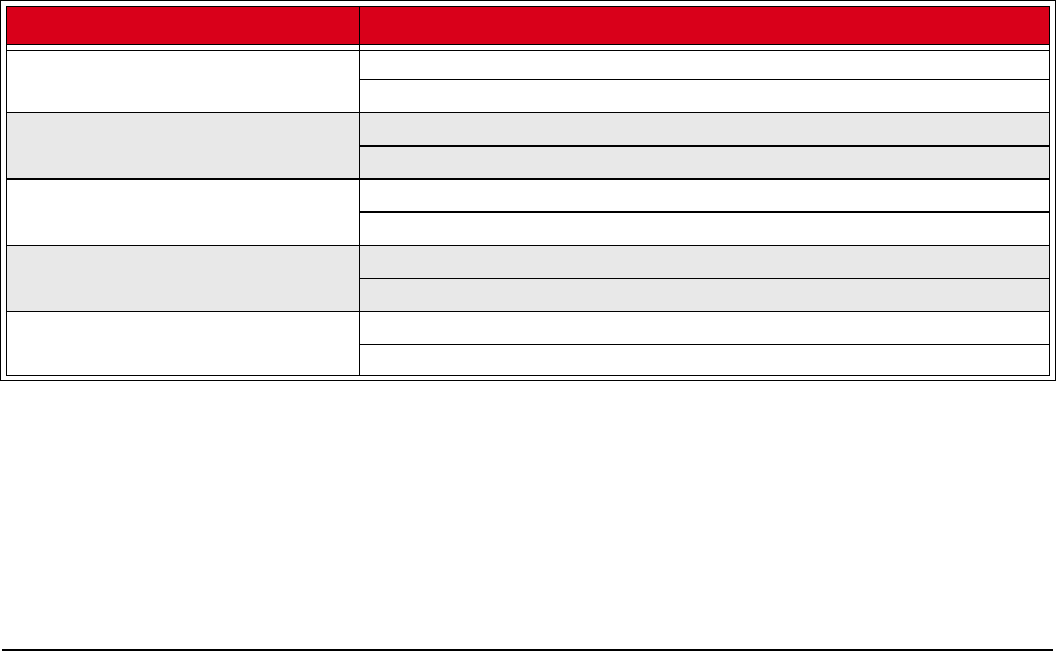
007-5642-005 255
Appendix
Pre-configured Metrics
The CustomMetrics.profile is the file used to define which metrics are available in the Add a Custom Metric Listener
dialog. The Metrics.profile is the file used to define which metrics are available from the Metrics Selector dialog to
view in the instrumentation service.
Both the Metrics.profile and CustomMetrics.profile use the same format and need to be edited only if you have written
a custom monitoring script and configured it as a custom monitor. Then, if you want to:
•Display the custom metrics in the List View, add the new metrics to the Metrics.profile.
•Set thresholds on the custom metrics, add the new metrics to the CustomMetrics.profile.
CPU
Metric Name Format and Description
CPU Percent Idle Aggregate hosts.{host.moniker}cpu.idle.pattern=100%
Percentage of time the CPU is idle.
CPU Percent I/O Wait Aggregate hosts.{host.moniker}.cpu.iowait.pattern=100%
The total cycles used by all CPUs waiting for I/O.
CPU Percent Nice Aggregate hosts.{host.moniker}.cpu.nice.pattern=100%
The total cycles used by all CPUs in user mode with low priority.
CPU Percent System Aggregate hosts.{host.moniker}.cpu.system.pattern=100%
The total cycles used by all CPUs in kernel mode.
CPU Percent User Aggregate hosts.{host.moniker}.cpu.user.pattern=100%
The total cycles used by all CPUs in user mode.

Pre-configured Metrics
Disk
007-5642-005
256
Disk
Kernel
Metric Name Format and Description
Disk Reads (blocks per second) hosts.{host.moniker}.disks.hda.block.reads.pattern=00000
0
The number of blocks read from a disk.
Disk Writes (blocks per second) hosts.{host.moniker}.disks.hda.block.writes.pattern=0000
00
The number of blocks written to a disk.
Disk I/O Read (bytes per second) hosts.{host.moniker}.disks.hda.io.reads.pattern=000000
The number of I/O reads from a disk.
Disk I/O Writes (bytes per second) hosts.{host.moniker}.disks.hda.io.writes.pattern=000000
The number of I/O writes to a disk.
Disk (hda[1-4]) Capacity Used (bytes) hosts.{host.moniker}.disks.hda1.capacity.used.pattern=0,
000 MB
The disk capacity used for disk hda1, hda2, hda3, or hda4.
Disk (hda[1-4]) Capacity Free (bytes) hosts.{host.moniker}.disks.hda1.capacity.free.pattern=0,
000 MB
The disk capacity free for disk hda1, hda2, hda3, or hda4.
Disk (hda[1-4]) Percentage Used hosts.{host.moniker}.disks.hda1.percentage.used.pattern=
100%
The disk percentage used for disk hda1, hda2, hda3, or hda4.
Disk (sda[1-4]) Capacity Used (bytes) hosts.{host.moniker}.disks.sda1.capacity.used.pattern=0,
000 MB
The disk capacity used for disk sda1, sda2, sda3, or sda4.
Disk (sda[1-4]) Capacity Free (bytes) hosts.{host.moniker}.disks.sda1.capacity.free.pattern=0,
000 MB
The disk capacity free for disk sda1, sda2, sda3, or sda4.
Disk (sda[1-4]) Percentage Used hosts.{host.moniker}.disks.sda1.percentage.used.pattern=
100%
The disk percentage used for disk sda1, sda2, sda3, or sda4.
Metric Name Format and Description
Kernel Context Switches (per second) hosts.{host.moniker}.kernel.contexts.pattern=000000
The number of context switches the system has undergone.
Kernel Interrupts (per second) hosts.{host.moniker}.kernel.interrupts.pattern=000000
The number of interrupts received from the system since boot.
Kernel Running Processes hosts.{host.moniker}.kernel.processes.pattern=00000
The number of forks since boot.
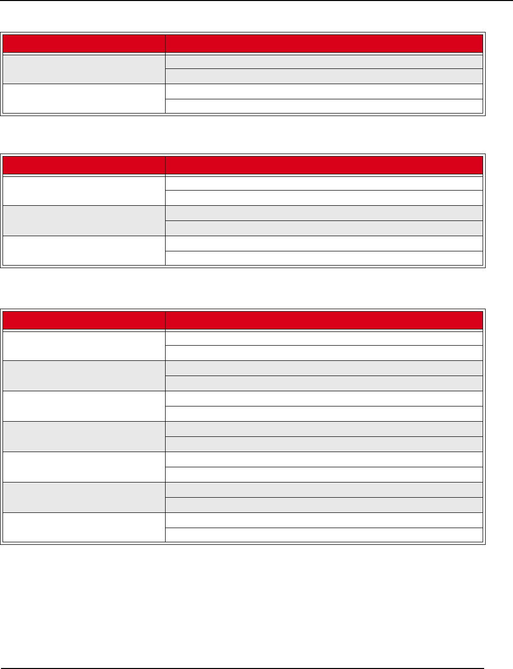
Pre-configured Metrics
Load
007-5642-005 257
Load
Memory
Kernel Swaps In hosts.{host.moniker}.kernel.swaps.in.pattern=000000
The number of swap pages that have been brought in.
Kernel Swaps Out hosts.{host.moniker}.kernel.swaps.out.pattern=000000
The number of swap pages that have been sent out.
Metric Name Format and Description
Load - 15 Minute hosts.{host.moniker}.load.15m.pattern=0.00
The number of tasks in the run state averaged over 15 minutes.
Load - 1 Minute hosts.{host.moniker}.load.1m.pattern=0.00
The number of tasks in the run state averaged over 1 minute.
Load - 5 Minute hosts.{host.moniker}.load.5m.pattern=0.00
The number of tasks in the run state averaged over 5 minutes.
Metric Name Format and Description
Memory Active (bytes) hosts.{host.moniker}.memory.active.pattern=0,000 MB
The amount of active memory.
Memory Cached (bytes) hosts.{host.moniker}.memory.cached.pattern=0,000 MB
The amount of cached memory.
Memory Used (bytes) hosts.{host.moniker}.memory.committed.pattern=0,000 MB
The amount of used memory.
Memory Free (bytes) hosts.{host.moniker}.memory.free.pattern=0,000 MB
The total amount of free memory.
Memory Swap Cached (bytes) hosts.{host.moniker}.memory.swap.cached.pattern=0,000 MB
The amount of cached swap.
Memory Swap Free (bytes) hosts.{host.moniker}.memory.swap.free.pattern=0,000 MB
The amount of free swap space.
Memory Total (bytes) hosts.{host.moniker}.memory.total.pattern=0,000 MB
The total amount of memory.
Metric Name Format and Description

Pre-configured Metrics
Network
007-5642-005
258
Network
Metric Name Format and Description
Network (eth0) Bytes Received
(per second)
hosts.{host.moniker}.network.eth0.rx.bytes.pattern=0,000
MB
The total number of bytes received on all interfaces.
Network (eth0) Packets Received
(per second)
hosts.{host.moniker}.network.eth0.rx.packets.pattern=0,0
00 MB
The total number of received packets on all interfaces.
Network (eth0) Bytes Transmitted (per
second)
hosts.{host.moniker}.network.eth0.tx.bytes.pattern=0,000
MB
The total number of transmitted bytes on all interfaces.
Network (eth0) Packets Transmitted (per
second)
hosts.{host.moniker}.network.eth0.tx.packets.pattern=0,0
00 MB
The total number of packets transmitted on all interfaces.
Network (eth1) Bytes Received
(per second)
hosts.{host.moniker}.network.eth1.rx.bytes.pattern=0,000
MB
The total number of bytes received on all interfaces.
Network (eth1) Packets Received
(per second)
hosts.{host.moniker}.network.eth1.rx.packets.pattern=0,0
00 MB
The total number of received packets on all interfaces.
Network (eth1) Bytes Transmitted (per
second)
hosts.{host.moniker}.network.eth1.tx.bytes.pattern=0,000
MB
The total number of transmitted bytes on all interfaces.
Network (eth1) Packets Transmitted (per
second)
hosts.{host.moniker}.network.eth1.tx.packets.pattern=0,0
00 MB
The total number of packets transmitted on all interfaces.

007-5642-005 259
Glossary
Anti-aliasing A technique used to smooth images and text to improve their appearance on screen.
Architecture-independent Allows hardware or software to function regardless of hardware platform.
Baud rate A unit of measure that describes data transmission rates (in bits per second).
Block size The largest amount of data that the file system will allocate contiguously.
boot.profile A file that contains instructions on how to boot a host.
Boot utilities Utilities added to the RAM Disk that run during the boot process. Boot utilities allow you to create such
things as custom, pre-finalized scripts using utilities that are not required for standard Linux versions.
Cluster Clustering is a method of linking multiple computers or compute hosts together to form a unified and more
powerful system. These systems can perform complex computations at the same level as a traditional supercomputer by
dividing the computations among all of the processors in the cluster, then gathering the data once the computations are
completed. A cluster refers to all of the physical elements of your SGI solution, including the Management Center
Master Host, compute hosts, Management Center, UPS, high-speed network, storage, and the cabinet.
Management Center Master Host The Management Center Master Host is the host that controls the remaining hosts
in a cluster (for large systems, multiple masters may be required). This host is reserved exclusively for managing the
cluster and is not typically available to perform tasks assigned to the remaining hosts.
DHCP Dynamic Host Configuration Protocol. Assigns dynamic IP addresses to devices on a network.
Diskless host A host whose operating system and file system are installed into physical memory. This method is
generally referred to as RAMfs or TmpFS.
EBI An ELF Binary Image that contains the kernel, kernel options, and a RAM Disk.
Event engine Allows administrators to trigger events based on a change in system status (e.g., when processors rise
above a certain temperature or experience a power interruption). Administrators may configure triggers to inform users
of a specific event or to take a specific action.
Ext Original extended file system for Linux systems. Provides 255-character filenames and supports files sizes up to 2
Gigabytes.
Ext2 The second extended file system for Linux systems. Offers additional features that make the file system more
compatible with other file systems and provides support for file system extensions, larger file sizes (up to 4 Terabytes),
symbolic links, and special file types.
Ext3 Provides a journaling extension to the standard ext2 file system on Linux. Journaling reduces time spent
recovering a file system, critical in environments where high availability is important.
Group A group refers to an organization with shared or similar needs. A cluster may contain multiple groups with
unique or shared rights and privileges. A group may also refer to an administrator-defined collection of hosts within a
cluster that perform tasks such as data serving, Web serving, and computational number crunching.

Glossary
007-5642-005
260
Health monitoring An element of the Instrumentation Service used to track and display the state of all hosts in the
system. Health status icons appear next to each host viewed with the instrumentation service or from the navigation tree
to provide visual cues about system health. Similar icons appear next to clusters, partitions, and regions to indicate the
status of hosts contained therein.
Host An individual server or computer within the cluster that operates in parallel with other hosts in the cluster. Hosts
may contain multiple processors.
image.profile A file used to generate boot.profile. This file contains information about the image, including the
payload, kernel, and partition layout.
IP address A 32-bit number that identifies each sender or receiver of information.
Kerberos Kerberos is a network authentication protocol. It is designed to provide strong authentication for client/
server applications by using secret-key cryptography.
Kernel The binary kernel, a .config file, System.map, and modules (if any).
LDAP Lightweight Directory Access Protocol is an Internet protocol that email programs use to look up contact
information from a server.
Listener A listener constantly reads and reviews system metrics. Configuring listener thresholds allows you to trigger
loggers to address specific issues as they arise.
Logger The action taken when a threshold exceeds its maximum or minimum value. Common logger events include
sending messages to the centralized Management Center message log, logging to a file, logging to the serial console,
and shutting down the host.
MAC address A hardware address unique to each device installed in the system.
Metrics Used to track logger events and report data to the instrumentation service (where it may be monitored).
MIB Management Information Base. The MIB is a tree-shaped information structure that defines what sort of data can
be manipulated via SNMP.
Monitors Monitors run periodically on hosts and provide the metrics that are gathered, processed, and displayed using
the Management Center instrumentation service.
Multi-user Allows multiple administrators to simultaneously log into and administer the cluster.
Netmask A string of 0's and 1's that mask or screen out the network part of an IP address so only the host computer
portion of the address remains. The binary 1's at the beginning of the mask turn the network ID portion of the IP address
into 0's. The binary 0's that follow allow the host ID to remain. A commonly used netmask is 255.255.255.0 (255 is the
decimal equivalent of a binary string of eight ones).
NIS Network Information Service makes information available throughout the entire network.
Node See Host.
Partition Partitions are used to separate clusters into non-overlapping collections of hosts.
Payload A compressed file system that is downloaded via multicast during the provisioning process.
Plug-ins Programs or utilities added to the boot process that expand system capabilities.
RAID Redundant Array of Independent Disks. Provides a method of accessing multiple, independent disks as if the
array were one large disk. Spreading data over multiple disks improves access time and reduces the risk of losing all
data if a drive fails.
RAM Disk A small, virtual drive that is created and loaded with the utilities that are required when you provision the
host. In order for host provisioning to succeed, the RAM Disk must contain specific boot utilities. Under typical
circumstances, you will not need to add boot utilities unless you are creating something such as a custom, pre-finalized
script that needs utilities not required by standard Linux versions (e.g., modprobe).
RHEL Red Hat Enterprise Linux.

Glossary
007-5642-005 261
Region A region is a subset of a partition and may share any hosts that belong to the same partition—even if the hosts
are currently used by another region.
Role Roles are associated with groups and privileges, and define the functionality assigned to each group.
Secure remote access The ability to monitor and control the cluster from a distant location through an SSL-encrypted
connection. Administrators have the benefit of secure remote access to their clusters through any Java-enhanced
browser. Management Center can be used remotely, allowing administrators access to the cluster from anywhere in the
world.
Secure Shell (SSH) SSH is used to create a secure connection to the CLI. Connections made with SSH are encrypted
and safe to use over insecure networks.
SLES SUSE Linux Enterprise Server.
Version branching The ability to modify an existing payload, kernel, or image under version control and check it back
into VCS as a new, versioned branch of the original item.
Version Control System (VCS) The Management Center Version Control System allows users with privileges to
manage changes to payloads, kernels, or images (similar in nature to managing changes in source code with a version
control system such as CVS). The Version Control System supports common Check-Out and Check-In operations.
Versioned copy A versioned copy of a payload, kernel, or image is stored in VCS.
Working copy A working copy of a payload, kernel, or image is currently present in the working area only
(e.g., $MGR_HOME/imaging/<user>/ payloads). Working copies are not stored in VCS.

007-5642-005 263
Index
A
accounts
disable user 65
enable 65
manage group 92
manage local 92
acl_roots 146
add boot utilities 128
custom monitors 175
directory to payload 96
file to payload 96
group 67
user account to payload 94
host 15, 43, 197
kernel modules without loading 108
listener 185
local user account to payload 93
monitor 169
package
to existing payload 84
partition 55
plug-in 131
RAID partition 117
role 70
user 64
to group 68
administration levels 63
Altix ICE vii, 11
Altix UV systems 3, 13, 14, 100, 208
AMD GPUs 15
annotations
electric shock ix
note ix
tip ix
warning ix
anti-aliasing 147, 149
appearance
interface 19
applications preferences 32
apply listeners
as default 167, 183
to hosts 167, 183
to payloads 168, 184
authentication
management, payload 90
auto node discovery 15, 197
B
beacon
turn off 54
turn on 53
block size 107, 116
bootprocess, plug-ins for 130
troubleshooting 206
utilities, add 128
boot.profile 112, 129
branch, version 135
C
chassis management controllers (CMCs) 14
check into VCS
image 136
kernel 136
payload 136
check out of VCS
image 137
kernel 137
payload 137
CLI 259
client platforms 3
cluster 41, 63

007-5642-005
Index
D
264
environment 63
host administration 219
power administration 228
provisioning 230
system monitoring 147
user administration 233
CMCs 14
command-line interface 209, 259
conman 216
cwhost 219
cwpower 228
cwprovision 230
cwuser 233
dbix 239
dbx 240
imgr 241
kmgr 242
pdcp 243
pdsh 245
pmgr 248
powerman 249
vcs 251
compute host (See host)
configure
NIS 90
conman 25, 216
connect to console 54
console 54
copyfrom VCS 138
image 112
kernel 103
payload 81
CPUmetrics 255
tab 153
utilization 153
create
group 67
host 43
image 110
kernel 101
kernel from binary 242
multiple payloads from source 79
partition 55, 114
password
Icebox 225
user 65, 234
payload 78
region 57
role 70
csv 49
Customer Service x, 203, 204
customize the interface 19
cwhost 219
cwpower 228
cwprovision 230
cwuser 233
D
Data Center Manager (DCM) 2, 28
dbix 49, 239
dbx 240
DCM 2, 28
debugging 204
default user administration settings 64
delete
all payloads, kernels, and images 138
file(s) from payload 98
group 69
account from payload 95
host 49
image partition 121
listener 189
local user account from payload 94
monitor 173
package from payload 84
partition 56
payload 98
region 59
role 72
user account 66
working copy of image 112
working copy of kernel 109
working copy of payload 98
dependency checks, package 87
DHCP 3, 38
dhcpd.conf 38
disable
anti-aliasing 147
gradient fill 147
Kerberos 91
LDAP 91
listener 183
monitor 167
NIS 90
user account 65, 66
Discover interface 15, 197
disk

Index
E
265
007-5642-005
aggregate usage 155
fill to end of 126
I/O 155
metrics 256
tab 155
diskless hosts 125
configure 125
mount point 126
display
custom metrics 178
distribution, upgrade 2
dmesg.level 112
DNS name resolution 86
dockable frames 18, 20
Documentation
available via the World Wide Web viii
DRAC 1, 25, 47
Dynamic Host Configuration Protocol (DHCP) 3
E
edit group 69
host 48
Icebox password 225
image partition 119
kernel 107
listener 188
monitor 173
partition 56
password 66, 235
payload 87
using text editor 97
region 58
role 72
user account 66
electric shock ix
enable
anti-aliasing 147
gradient fill 147
Kerberos 91
LDAP 91
listeners 183
monitor 167
NIS 90
user account 65
environment monitoring 160, 165
environmental tab 159
errors
messages 191
RPM 81
troubleshooting 203
event
listeners 182
log 148, 191
monitoring 165
exclude
files and directories from VCS 140
exclude file(s) from payload 83
F
features, Management Center 12
feedback, documentation ix
file exclude file(s) from payload 83
system, user-defined 122
fill to end of disk 126
filter 149, 151
find host 49
format partition 116
frames
controls 18
dockable 18, 20
FreeIPMI 25
Freeipmi 3
fstab 116, 126
G
general preferences 23
general tab 150
GID 64, 68
GPU monitoring 15, 161
gradient fill 147, 149
group 63, 67
add 67
account to payload 94
assign roles to 68
assign to role 71
assign user to 65
delete 69
account from payload 95
edit 69
GID 64, 68
grant access to region 68
power 65, 67
primary 65
region, add to 58

007-5642-005
Index
H
266
root 67
user membership 65
users 67
H
halt host 52
hardware
system requirements 1
health
monitoring 147
event log 148
system status icons 148
status 150
host 41, 63
add 15, 43, 197
to partition 55
administration 41, 63
grant privileges 73
beacon
turn off 54
turn on 53
CLI administration 220
configure
diskless host 125
cycle power to 53
delete 49
diskless 125
edit 48
event log 148
find 49
halt 52
import 49
load monitoring 158
Management Center Master 41
rename 48
names 4
power
turn off 52, 53
turn on 53
power management 52
provision 141
using CLI 230
reboot 52
region
add host to 57
assign host to 45
reset 53
shared 41, 63
shut down 52
states 148
upgrade 144
I
Icebox
administration privileges 73
create password for 225
modify password 225
icons, system status 148
ILO 1, 25, 47
image 75, 112
add modules without loading 108
check into VCS 136
check out from VCS 137
CLI controls 241
copy 112
create 110
delete all 138
delete partition 121
delete working copy of image 112
edit image partition 119
management 110
partition 114
privileges, enable imaging 73
provision 141
select image 141
versioned 134
working copy 134
image.once 112
image.path 112
imgr 241
import
binary kernel 242
default listeners 190
host list 49
listener 189
listener from payload 190
listeners from payload 190
monitors
from payload 172
monitors from host 171
informational messages 191
install
Management Center 4
client 5
into payload 99
instrumentation 147
CPU utilization 153
custom monitors 174

Index
J
267
007-5642-005
diskaggregate usage 155
I/O 155
enhance performance 147
event log 148
health status 150
host load 158
kernel information 157
list view 152
memory utilization 154
menu controls 149
metrics, define 178
metrics, pre-configured 255
monitoring and event subsystem 165
packet transmissions 156
power status 150
resource utilization 150
system configuration 150
system status 148
overview 150
temperature readings 159, 160
thumbnail view 151
Intel Data Center Manager (DCM) 28
DCM
Data Center Manager (DCM) 1
Intel Power Node Manager (IPNM) 1, 2, 28
interface
customized appearance 19
management 44
map 16
split-pane view 19
interval 149
IP address 260
host 44
IPMI 1, 25, 35, 45
IPMItool 3
ipmitool utility 35
IPNM 1, 2, 28
ISLE Cluster Manager, upgrading from 193
J
Jpackage Utilities 3
K
Kerberos 91
kernel 75
build from source 101
check into VCS 136
check out from VCS 137
CLI controls 242
copy 103
create 101
create from binary 242
delete all 138
delete working copy of kernel 109
edit 107
install modules without loading 108
loadable modules 108
management 101
metrics 256
modular 108
monolithic 108
troubleshooting 206
upgrade 2
verbosity level 111, 146, 230
versioned 134
working copy 134
kernel tab 157
kmgr 242
L
layouts 20
open saved 21
save 20
set default 21
LDAP 91
licensing 8, 207
links, dangling symbolic 83
list view 149, 152
listeners 165, 190
add 185
apply as default 167, 183
apply to hosts 167, 183
apply to payloads 168, 184
delete 189
disable 183
edit 188
enable 183
event 182
import 189
loadmetrics 257
load tab 158
loadable kernel modules 108
loggers 165, 191
TemplateFormatter 191

007-5642-005
Index
M
268
M
MAC addresses 197
maintenance operations 8
management
interface 44
management network 4
VCS 138
Management Center
administration
grant privileges 73
features 12
install into payload 99
install on client 5
interface
customize 19
map 16
split-pane view 19
introduction 11
Master Host
rename 48
preferences 23
applications 32
general 23
platform management 25
provisioning settings 33
Premium Edition vii, 11
product definition vii, 11
server, start and stop 8
services 9
Standard Edition vii, 11
upgrading 193
Managment Center
platforms 1
system requirements 2
Master Host
definition 41
rename 48
system requirements 1
memlog 3, 13, 164
memory
estimate partition requirements 116, 126
metrics 257
utilization 154
Memory Failure Analysis 3
memory failure analysis 13, 164
memory tab 154
metrics 178, 255
alignment 180
CPU 255
custom 180
disk 256
display custom 178
instrumentation service 149
kernel 256
load 257
memory 257
metrics selector 180
network 258
mkfs 116
modules
install without loading 108
loadable kernel 108
modules subtab 108
monitoring
event 165
system health 147
monitors 165, 166
add 169
add custom 175
custom 174
delete 173
disable 167
edit 173
enable 167
import from host 171
import from payload 172
multicast
route configuration 39
N
navigation tree 18
netmask 260
network metrics 258
network tab 156
Network Time Protocol (NTP) 3
NFS 64
NIS 90
nodes.conf 49
note ix
NTP 3
NVIDIA GPUs 15
O
openlayouts 21
operating system requirements 2
override global settings 45

Index
P
269
007-5642-005
overview, system status 150
P
package
add to existing payload 84
dependency checks 87
remove from payload 87
packet transmissions 156
partition 41, 55, 63, 112
add 55
host to 55
RAID 117
create 114
user-defined file system 122
delete 56
delete from image 121
edit 56
edit image partition 119
estimate memory requirements 116, 126
format 116
manage 114
overwrite protection 116
partition this time 146
partitioning behavior 111
save 116
size fill to end of disk 116, 124, 126
fixed 116, 124, 126
partition.once 112
password
create Icebox 225
create new 65, 234
encrypt 235
modify 66, 235
modify Icebox 225
payload 75
account management, local user 92
add directory to 96
file to 96
group user account to 94
local user account to 93
package to existing 84
attributes, troubleshoot 80
authentication management 90
check into VCS 136
check out from VCS 137
check-in error 206
CLI controls 248
configure 89
copy 81
create 78
multiple payloads from source 79
dangling symbolic links 83
delete 98
file(s) from payload 98
group account from payload 95
local user account from payload 94
working copy of payload 98
delete all 138
download this time 146
edit using CLI 96
with text editor 97
exclude file(s) 83
file configuration 89
group account management 92
install Management Center into 99
management 76
package dependency checks 87
pmgr 248
remove package from 87
script, enable 89
update directory 96
update file 96
versioned 134
working copy 134
PBS 145
PBS Professional 4
pdcp 243
pdsh 245
PEKI temperatures 182
permissions 73
See role; privileges
physical memory utilization 154
plaforms, Management Center 1
platform management 1
DRAC 47
ILO 47
IPMI 45
platform management preferences 25
platforms, Management Center
Management Center
platforms 12
plug-ins
add 131
for boot process 130
power 53
CLI administration 228

007-5642-005
Index
Q
270
control 52
cycle
to host 53
group 65, 67
management 28, 162
management, host 52
monitoring 28, 162
policy 28
powerman 249
status 150
turn off
to host 53
turn off host 52
turn on
to host 53
powerman 25, 249
pre-configured metrics 255
preferences
applications 32
general 23
Management Center 23
platform management 25
provisioning settings 33
Premium Edition, Management Center vii, 11
primary
group 65
Prism XL platforms 15
privileges 73
change user 72
database 73
host administration 73
Icebox administration 73
imaging 73
instrumentation 73
logging 73
Management Center 73
power 73
provisioning 73
serial 73
user administration 73
problems 203
product definition, Management Center vii, 11
Product Support x, 203, 204
provision 141
CLI controls 230
disable confirmation dialog 143
enable confirmation dialog 143
format partition 116
provisioning settings preferences 33
right-click 143
schedule at next reboot 145
select an image 141
troubleshooting 205, 208
Q
qmgr 146
R
racks 41, 60
RAID 117
RAM Disk 128
block size 107
RAMfs 125
reboot host 52
region 41, 57, 63
add group to 58
host to 57
assign to host 45
create 57
delete 59
edit 58
grant group access to 68
remove
file(s) from payload 98
group 69
group account from payload 95
host 49
local user account from payload 94
package from payload 87
partition 56
region 59
role 72
user account 66
rename
host 48
Management Center Master Host 48
requirements
hardware 1
operating system 2
software 3
resethost 53
resource
utilization 150
restore factory settings 190
RHEL 260
right-click menu 52

Index
S
271
007-5642-005
connect to console 54
provisioning 143
rights
See role; privileges
Roamer 1, 25
Roamer KVM 54
role 63, 70
add 70
assign group to 71
assign to group 68
delete 72
edit 72
grant privileges and permissions 71
root group 67
routes, multicast 39
RPM
errors 81
S
savelayouts 20
partition 116
scalability 6
schedule provision at next reboot 145
script, enable in payload 89
search, tree 49
server platforms 2
SGI Altix UV systems 3, 13, 14, 100, 208
SGI Foundation Software 13, 164
SGI Prism XL platforms 15
shut down a host 52
size thumbnail 151
SLES 261
SMN 13, 14
SMN bundle software 3, 13
software
requirements 3
sort 149
split-pane view 19
SSL 91
Standard Edition, Management Center vii, 11
start Management Center server 8
state, host 148
stop Management Center server 8
symbolic links, dangling 83
symlink 83
system
configuration 150
health 147
requirements
hardware 1
operating system 2
status
event log 148
icons 148
overview 150
system management node (SMN) 3, 13, 14
T
task progress dialog 79
Technical Support x, 203, 204
Telnet client 3
temperature
changing thresholds 165
monitoring 149, 160
PEKI 182
readings 159
troubleshooting 205
TemplateFormatter 191
TFTP 3, 39
third-party power controls 65, 67
thumbnail
size 149
view 151
thumbnail view 149
tip ix
TmpFS 125
toolbar 17
transmissions, packet 156
Trivial File Transfer Protocol (TFTP) 3, 39
troubleshooting
general 203
payload attributes 80
RPM errors 81
U
UID 64, 65
upgrade
distribution 2
kernel 2
VCS upgrade 144
upgrading Management Center 193
user 63, 64
add 64
local user account to payload 93
to group 68

Index
007-5642-005
272
administration 63
default settings 64
privileges 73
assign to group 65
CLI administration 233
delete
local user account from payload 94
delete account 66
disable account 66
edit account 66
group membership 65
multi-group 63
UID 64, 65
user-defined file system 122
users group 67
UV systems 3, 13, 14, 100, 208
V
VCS 134
branch 136
CLI controls 251
command-line controls 251
copy 138
exclude files and directories 140
management console 138
upgrade 144
verbosity level, kernel 111, 146, 230
version
branching 135
control system 134
check into 136
check out 137
vcs command 251
versioned copy 134, 261
VersionControlService.profile 140
virtual memory utilization 154
W
warning ix
warning messages 191
Windows clients 3
working copy 134, 261
