Altix_UV10 007 5645 002
User Manual: 007-5645-002
Open the PDF directly: View PDF ![]() .
.
Page Count: 182 [warning: Documents this large are best viewed by clicking the View PDF Link!]

SGI® Altix® UV 10 System User’s Guide
007-5645-002

COPYRIGHT
© 2010 SGI. All rights reserved; provided portions may be copyright in third parties, as indicated elsewhere herein. No permission is granted to copy, distribute,
or create derivative works from the contents of this electronic documentation in any manner, in whole or in part, without the prior written permission of SGI.
LIMITED RIGHTS LEGEND
The software described in this document is “commercial computer software” provided with restricted rights (except as to included open/free source) as specified
in the FAR 52.227-19 and/or the DFAR 227.7202, or successive sections. Use beyond license provisions is a violation of worldwide intellectual property laws,
treaties and conventions. This document is provided with limited rights as defined in 52.227-14.
The electronic (software) version of this document was developed at private expense; if acquired under an agreement with the USA government or any
contractor thereto, it is acquired as “commercial computer software” subject to the provisions of its applicable license agreement, as specified in (a) 48 CFR
12.212 of the FAR; or, if acquired for Department of Defense units, (b) 48 CFR 227-7202 of the DoD FAR Supplement; or sections succeeding thereto.
Contractor/manufacturer is SGI, 46600 Landing Parkway, Fremont, CA 94538.
TRADEMARKS AND ATTRIBUTIONS
Altix, SGI, SGI ProPack, the SGI logo, and Supportfolio are trademarks or registered trademarks of Silicon Graphics International Corp. or its subsidiaries in
the United States and other countries.
Intel, Itanium, and Xeon are trademarks or registered trademarks of Intel Corporation or its subsidiaries in the United States and other countries. Internet
Explorer and MS-DOS are registered trademarks of Microsoft Corporation. Linux is a registered trademark of Linus Torvalds, used with permission by SGI.
Novell and Novell Netware are registered trademarks of Novell Inc. PCIe and PCI-X are registered trademarks of PCI SIG. Red Hat and all Red Hat-based
trademarks are trademarks or registered trademarks of Red Hat, Inc. in the United States and other countries. SUSE LINUX and the SUSE logo are registered
trademarks of Novell, Inc. UNIX is a registered trademark in the United States and other countries, licensed exclusively through X/Open Company, Ltd.
All other trademarks mentioned herein are the property of their respective owners.
Adaptec, HostRAID, and the Adaptec logo are registered trademarks of Adaptec Inc.

007-5645-002 iii
Contents
About This Guide . . . . . . . . . . . . . . . . . . . . . . .xvii
Safety and Regulatory Information . . . . . . . . . . . . . . . . . . .xvii
Important Safety Instructions . . . . . . . . . . . . . . . . . . .xvii
Warnings . . . . . . . . . . . . . . . . . . . . . . . .xvii
1 Introduction and System Components Overview . . . . . . . . . . . . . . 1
Dimensions and Clearance Requirements . . . . . . . . . . . . . . . . . 2
System Features Overview . . . . . . . . . . . . . . . . . . . . . 3
System Scalability . . . . . . . . . . . . . . . . . . . . . . 4
System Serviceability . . . . . . . . . . . . . . . . . . . . . 4
System Availability. . . . . . . . . . . . . . . . . . . . . . 4
System Manageability . . . . . . . . . . . . . . . . . . . . . 5
Front Control Panel and Operator Panel . . . . . . . . . . . . . . . . 5
Rear I/O. . . . . . . . . . . . . . . . . . . . . . . . . 6
System Front Panel . . . . . . . . . . . . . . . . . . . . . . . 6
Operator Panel/Front Control Panel. . . . . . . . . . . . . . . . . . . 7
System Status LED States . . . . . . . . . . . . . . . . . . . . 9
LAN Activity Status . . . . . . . . . . . . . . . . . . . . 9
Hard Drive Status LED . . . . . . . . . . . . . . . . . . . 9
System Status/Fault LED . . . . . . . . . . . . . . . . . . . 9
System Power LED . . . . . . . . . . . . . . . . . . . . 10
System Rear . . . . . . . . . . . . . . . . . . . . . . . . . 11
Rear Status LEDs . . . . . . . . . . . . . . . . . . . . . . 13
Rear PCIe Slots . . . . . . . . . . . . . . . . . . . . . . . 13
Processors . . . . . . . . . . . . . . . . . . . . . . . . . 14
System Memory . . . . . . . . . . . . . . . . . . . . . . . . 14
Power Subsystem . . . . . . . . . . . . . . . . . . . . . . . 15
System Configuration . . . . . . . . . . . . . . . . . . . . . . 16

iv 007-5645-002
Contents
Power Supply Modules . . . . . . . . . . . . . . . . . . . . . . 17
Cooling Subsystem . . . . . . . . . . . . . . . . . . . . . . . 20
Hot Swap PCI Express Slots . . . . . . . . . . . . . . . . . . . . . 22
Peripherals . . . . . . . . . . . . . . . . . . . . . . . . . 23
Hot-Swap Hard Drive . . . . . . . . . . . . . . . . . . . . . 23
Optical Drive Bay . . . . . . . . . . . . . . . . . . . . . . 24
Half-height Drive Bay (5 1/4-inch) . . . . . . . . . . . . . . . . . . 25
System Boards . . . . . . . . . . . . . . . . . . . . . . . . 25
I/O Configuration Rules . . . . . . . . . . . . . . . . . . . . . . 26
2 System Safety . . . . . . . . . . . . . . . . . . . . . . . . 31
Electrical Safety Precautions. . . . . . . . . . . . . . . . . . . . . 31
Lifting Precautions . . . . . . . . . . . . . . . . . . . . . . . 32
General Safety Precautions . . . . . . . . . . . . . . . . . . . . . 33
ESD Precautions . . . . . . . . . . . . . . . . . . . . . . . . 34
3 Starting Up and Shutting Down the System . . . . . . . . . . . . . . . . 35
Powering On the System . . . . . . . . . . . . . . . . . . . . . . 35
Shutting Down the System . . . . . . . . . . . . . . . . . . . . . 35
4 System Utilities . . . . . . . . . . . . . . . . . . . . . . . . 37
Using the BIOS Setup Utility . . . . . . . . . . . . . . . . . . . . 37
System Configuration Reset. . . . . . . . . . . . . . . . . . . . 37
Console Redirection . . . . . . . . . . . . . . . . . . . . . . . 38
Serial Configuration Settings . . . . . . . . . . . . . . . . . . . 38
Keystroke Mappings. . . . . . . . . . . . . . . . . . . . . . 38
Setup Alias Keys . . . . . . . . . . . . . . . . . . . . . 38
Standalone <Esc> Key for Headless Operation . . . . . . . . . . . . . 39
Limitations . . . . . . . . . . . . . . . . . . . . . . . . 39
Interface to Server Management . . . . . . . . . . . . . . . . . . 39
Platform Confidence Test . . . . . . . . . . . . . . . . . . . . . 39
Quick Test . . . . . . . . . . . . . . . . . . . . . . . . 40
Comprehensive Test. . . . . . . . . . . . . . . . . . . . . . 40
Comprehensive Test with Continuous Looping. . . . . . . . . . . . . . . 41
Running the Platform Confidence Test. . . . . . . . . . . . . . . . 41

Contents
007-5645-002 v
System Setup and Configuration Utilities . . . . . . . . . . . . . . . . 42
Save and Restore Configuration (SYSCFG) . . . . . . . . . . . . . . 42
FWPIAUPD Firmware Load Utility . . . . . . . . . . . . . . . . 43
One-boot Flash Update Utility (OFU) . . . . . . . . . . . . . . . . 43
FRUSDR Load Utility . . . . . . . . . . . . . . . . . . . . . 43
Extensible Firmware Interface (EFI) Shell . . . . . . . . . . . . . . . . 44
5 Maintenance and Upgrade Procedures . . . . . . . . . . . . . . . . . 49
Static-Sensitive Device . . . . . . . . . . . . . . . . . . . . . . 49
Precautions . . . . . . . . . . . . . . . . . . . . . . . . 49
Lifting Precautions . . . . . . . . . . . . . . . . . . . . . . . 50
Removing and Installing the Rack Rails . . . . . . . . . . . . . . . . . 51
Removing the Rack Rails . . . . . . . . . . . . . . . . . . . . 52
Installing the Rack Rails . . . . . . . . . . . . . . . . . . . . 52
Removing the Cable Management Arm. . . . . . . . . . . . . . . . . . 54
Installing the Cable Management Arm . . . . . . . . . . . . . . . . . 56
Removing and Installing the Chassis Cover. . . . . . . . . . . . . . . . . 58
Removing the Top Cover . . . . . . . . . . . . . . . . . . . . 58
Installing the Top Cover . . . . . . . . . . . . . . . . . . . . 59
Hot Swapping a Hard Drive . . . . . . . . . . . . . . . . . . . . . 60
Removing a Hard Drive Carrier . . . . . . . . . . . . . . . . . . 61
Mounting a Hard Drive in a Carrier . . . . . . . . . . . . . . . . . 62
Installing a Hard Drive Carrier . . . . . . . . . . . . . . . . . . . 63
Hot Swapping a Power Supply . . . . . . . . . . . . . . . . . . . . 64
Removing and Installing Hot-Swap PCI Express Add-in Cards . . . . . . . . . . . 67
Removing a Hot-Swap PCIe Card . . . . . . . . . . . . . . . . . . 67
Installing a Hot-Swap PCIe Card . . . . . . . . . . . . . . . . . . 68
Installing and Removing Non-Hot Swap PCI Express Add-in Cards . . . . . . . . . . 70
Removing a Non-Hot Swap PCIe Card. . . . . . . . . . . . . . . . . 71
Installing a Non-Hot Swap PCIe Card . . . . . . . . . . . . . . . . . 72
Removing and Installing System Fans . . . . . . . . . . . . . . . . . . 73
Removing the Hot-Swap Fan Modules . . . . . . . . . . . . . . . . . 73
Installing the Hot-Swap Fan Modules . . . . . . . . . . . . . . . . . 74
Removing System Fan Modules (non Hot-Swap) . . . . . . . . . . . . . . 75

vi 007-5645-002
Contents
Installing the System Fan Modules (non Hot-Swap) . . . . . . . . . . . . . 76
Hot Swapping Memory Risers . . . . . . . . . . . . . . . . . . . . 77
Removing a Memory Riser . . . . . . . . . . . . . . . . . . . . 77
Installing a Memory Riser . . . . . . . . . . . . . . . . . . . . 79
Installing and Removing Memory Air Baffles . . . . . . . . . . . . . . . . 80
Installing a Memory Air Baffle . . . . . . . . . . . . . . . . . . . 81
Removing a Memory Air Baffle. . . . . . . . . . . . . . . . . . . 81
Installing and Removing DIMMs . . . . . . . . . . . . . . . . . . . 82
Memory Riser DIMM Slot Locations . . . . . . . . . . . . . . . . . 82
Supported Memory Configurations . . . . . . . . . . . . . . . . . . 83
Installing DIMMs . . . . . . . . . . . . . . . . . . . . . . 83
Removing DIMMs . . . . . . . . . . . . . . . . . . . . . . 84
6 BIOS . . . . . . . . . . . . . . . . . . . . . . . . . . . 85
Splash Logo / Diagnostic Screen. . . . . . . . . . . . . . . . . . . . 85
BIOS Boot Popup Menu . . . . . . . . . . . . . . . . . . . . . . 85
BIOS Setup Utility . . . . . . . . . . . . . . . . . . . . . . . 86
Operation . . . . . . . . . . . . . . . . . . . . . . . . 86
Page Layout . . . . . . . . . . . . . . . . . . . . . . . . 86
Entering BIOS Setup . . . . . . . . . . . . . . . . . . . . . 87
Keyboard Commands . . . . . . . . . . . . . . . . . . . . . 87
Menu Selection Bar . . . . . . . . . . . . . . . . . . . . . . 89
BIOS Setup Utility Screens . . . . . . . . . . . . . . . . . . . . 89
Main Screen. . . . . . . . . . . . . . . . . . . . . . . 90
Advanced Screen . . . . . . . . . . . . . . . . . . . . . 92
Processor Configuration Screen . . . . . . . . . . . . . . . . . 93
Memory Configuration Screen . . . . . . . . . . . . . . . . . . 98
Configure Memory RAS and Performance Screen. . . . . . . . . . . . 101
Memory Board Information Screens . . . . . . . . . . . . . . . 104
Mass Storage Controller Configuration Screen . . . . . . . . . . . . 106
Serial Port Configuration Screen . . . . . . . . . . . . . . . . 109
USB Configuration Screen . . . . . . . . . . . . . . . . . . 111
PCI Configuration Screen . . . . . . . . . . . . . . . . . . 114
System Acoustic and Performance Configuration . . . . . . . . . . . . 117

Contents
007-5645-002 vii
Security Screen . . . . . . . . . . . . . . . . . . . . .117
Server Management Screen . . . . . . . . . . . . . . . . . .120
Console Redirection Screen . . . . . . . . . . . . . . . . . .123
Server Management System Information Screen . . . . . . . . . . . . .125
Boot Options Screen . . . . . . . . . . . . . . . . . . . .127
Add New Boot Option Screen . . . . . . . . . . . . . . . . . .130
Delete Boot Option Screen . . . . . . . . . . . . . . . . . .131
Hard Disk Order Screen . . . . . . . . . . . . . . . . . . .132
CDROM Order Screen. . . . . . . . . . . . . . . . . . . .133
Floppy Order Screen . . . . . . . . . . . . . . . . . . . .134
Network Device Order Screen. . . . . . . . . . . . . . . . . .135
BEV Device Order Screen. . . . . . . . . . . . . . . . . . .136
Boot Manager Screen . . . . . . . . . . . . . . . . . . . .137
Error Manager Screen . . . . . . . . . . . . . . . . . . . .138
Exit Screen. . . . . . . . . . . . . . . . . . . . . . .139
Loading BIOS Defaults . . . . . . . . . . . . . . . . . . . . . .140
Clearing the BIOS Password . . . . . . . . . . . . . . . . . . . .141
A POST Codes . . . . . . . . . . . . . . . . . . . . . . . .143
POST Progress Codes and Messages . . . . . . . . . . . . . . . . . .143
POST Error Messages and Handling . . . . . . . . . . . . . . . . . .149
POST Error Beep Codes. . . . . . . . . . . . . . . . . . . . . .152
BMC Beep Codes . . . . . . . . . . . . . . . . . . . . . . .152
B Power Supply Modules Safety Instructions . . . . . . . . . . . . . . . .153
Power Supply Configuration . . . . . . . . . . . . . . . . . . . .153
Installing the Protective Ground Wire . . . . . . . . . . . . . . . . . .154
C Installation and Maintenance Safety Instructions . . . . . . . . . . . . . .157

007-5645-002 ix
Figures
Figure 1-1 SGI Altix UV 10 Front View . . . . . . . . . . . . 1
Figure 1-2 SGI Altix UV 10 Angle View . . . . . . . . . . . . 2
Figure 1-3 SGI Altix UV 10 System. . . . . . . . . . . . . . 3
Figure 1-4 SGI Altix UV 10 System Front Panel . . . . . . . . . . 7
Figure 1-5 Operator Panel Controls and Indicators . . . . . . . . . . 8
Figure 1-6 SGI Altix UV 10 Rear View . . . . . . . . . . . . . 11
Figure 1-7 SGI Altix UV 10 System Rear . . . . . . . . . . . . 12
Figure 1-8 Power Supply Indicators . . . . . . . . . . . . . . 19
Figure 1-9 Cooling Fan Locations . . . . . . . . . . . . . . 21
Figure 1-10 Peripheral Area . . . . . . . . . . . . . . . . 23
Figure 1-11 Hard Drive Carrier . . . . . . . . . . . . . . . 24
Figure 1-12 Optical Drive . . . . . . . . . . . . . . . . . 24
Figure 1-13 Half-height Drive (5 1/4-inch) . . . . . . . . . . . . 25
Figure 1-14 SGI Altix UV 10 System Block Diagram . . . . . . . . . 26
Figure 2-1 Lifting the SGI UV 10 System Into a Rack . . . . . . . . . 33
Figure 5-1 Lifting the SGI UV 10 System Into a Rack . . . . . . . . . 51
Figure 5-2 Removing the Inner Rack Rail from the Slide Rails . . . . . . . 52
Figure 5-3 Installing the Inner Rail on the Server . . . . . . . . . . 53
Figure 5-4 Installing the Slide Rails on the Rack Mounting. . . . . . . . 53
Figure 5-5 Installing the Server onto the Rack Mounting . . . . . . . . 54
Figure 5-6 Removing the Cable Management Arm from the Extension . . . . 54
Figure 5-7 Removing the Inner and Outer Rail Right CMA Connector. . . . . 55
Figure 5-8 Removing the Cable Management Arm Extention . . . . . . . 55
Figure 5-9 Installing the Cable Management Arm Extension . . . . . . . 56
Figure 5-10 Installing the Inner Rail CMA Connector . . . . . . . . . 57
Figure 5-11 Installing the Cable Management Art to the Extension . . . . . . 57
Figure 5-12 Removing the Chassis Cover. . . . . . . . . . . . . 59
Figure 5-13 Installing the Chassis Cover . . . . . . . . . . . . . 60

x007-5645-002
Figures
Figure 5-14 Hard Driver Carrier . . . . . . . . . . . . . . . 61
Figure 5-15 Removing a Hard Drive Carrier . . . . . . . . . . . . 62
Figure 5-16 Removing the HDD Blank from the Hard Drive Carrier . . . . . . 63
Figure 5-17 Attaching the Hard Drive to the Carrier . . . . . . . . . . 63
Figure 5-18 Installing the Hard Drive into the Altix UV 10 System . . . . . . 64
Figure 5-19 Power Supply Indicators . . . . . . . . . . . . . . 65
Figure 5-20 Removing a Power Supply . . . . . . . . . . . . . 66
Figure 5-21 Installing a Power Supply. . . . . . . . . . . . . . 66
Figure 5-22 Removing a Hot-swap PCIe Card. . . . . . . . . . . . 67
Figure 5-23 Removing a PCIe Card . . . . . . . . . . . . . . 68
Figure 5-24 Installing a PCIe Add-in Card . . . . . . . . . . . . 69
Figure 5-25 Adding a Hot-swap PCIe Add-in Card . . . . . . . . . . 70
Figure 5-26 Removing a Non-Hot Swap PCIe Card . . . . . . . . . . 71
Figure 5-27 Removing a PCIe Expansion Slot Cover . . . . . . . . . . 72
Figure 5-28 Installing a Non-Hot Swap PCIe Card . . . . . . . . . . 73
Figure 5-29 Removing a System Fan Module . . . . . . . . . . . . 74
Figure 5-30 Installing a System Fan Module . . . . . . . . . . . . 75
Figure 5-31 Removing the System Fans . . . . . . . . . . . . . 76
Figure 5-32 Installing the System Fans . . . . . . . . . . . . . 76
Figure 5-33 Pressing the Memory Riser Attention Button. . . . . . . . . 78
Figure 5-34 Releasing a Memory Riser . . . . . . . . . . . . . 78
Figure 5-35 Removing a Memory Riser . . . . . . . . . . . . . 79
Figure 5-36 Installing a Memory Riser . . . . . . . . . . . . . 80
Figure 5-37 Installing a Memory Air Baffle . . . . . . . . . . . . 81
Figure 5-38 Removing a Memory Air Baffle . . . . . . . . . . . . 82
Figure 5-39 Memory Riser DIMM Locations . . . . . . . . . . . . 82
Figure 5-40 Install a DIMM . . . . . . . . . . . . . . . . 83
Figure 6-1 Setup Utility—Main Screen . . . . . . . . . . . . . 90
Figure 6-2 Setup Utility—Advanced Screen . . . . . . . . . . . . 93
Figure 6-3 Setup Utility—Processor Configuration Screen . . . . . . . . 94
Figure 6-4 Setup Utility—Memory Configuration Screen . . . . . . . . 99
Figure 6-5 Setup Utility—Configure Memory and RAS and Performance Screen . 102
Figure 6-6 Setup Utility—Memory Board Information Screens . . . . . . 105

Figures
007-5645-002 xi
Figure 6-7 Setup Utility—Mass Storage Controller Configuration Screen . . . .107
Figure 6-8 Setup Utility—Serial Port Configuration Screen . . . . . . .110
Figure 6-9 Setup Utility—USB Configuration Screen . . . . . . . . .112
Figure 6-10 Setup Utility—PCI Configuration Screen . . . . . . . . .114
Figure 6-11 Setup Utility—Acoustic and Performance Configuration . . . . .117
Figure 6-12 Setup Utility—Security Screen . . . . . . . . . . . .118
Figure 6-13 Setup Utiltiy—Server Management Configuration Screen . . . . .121
Figure 6-14 Setup Utility—Console Redirection Screen . . . . . . . . .124
Figure 6-15 Setup Utility—Server Management System Information Screen . . .126
Figure 6-16 Setup Utility—Boot Options Screen . . . . . . . . . . .128
Figure 6-17 Setup Utility—Add New Boot Option Screen . . . . . . . .131
Figure 6-18 Setup Utility—Delete Boot Option Screen . . . . . . . . .132
Figure 6-19 Setup Utility—Hard Disk Order Screen . . . . . . . . . .133
Figure 6-20 Setup Utility—CDROM Order Screen . . . . . . . . . .134
Figure 6-21 Setup Utility—Floppy Order Screen . . . . . . . . . . .135
Figure 6-22 Setup Utility—Network Device Order Screen . . . . . . . .135
Figure 6-23 Setup Utility—BEV Device Order Screen . . . . . . . . .137
Figure 6-24 Setup Utility—Boot Manager Screen . . . . . . . . . .138
Figure 6-25 Setup Utility—Error Manager Screen . . . . . . . . . .138
Figure 6-26 Setup Utility—Exit Screen . . . . . . . . . . . . .139
Figure B-1 Power Supply Modules Configuration . . . . . . . . . .154
Figure B-2 Installing the Ground Wire . . . . . . . . . . . . .155

007-5645-002 xiii
Tables
Table 1-1 System Front Panel Componets . . . . . . . . . . . . 6
Table 1-2 System Status LED s and Operator Panel Controls . . . . . . . 8
Table 1-3 Front Panel Connectors . . . . . . . . . . . . . . 8
Table 1-4 LAN1 LAN2, LAN3, LAN4 status LEDs (green) . . . . . . . 9
Table 1-5 Hard Drive Activity and Fault Status LED (green) . . . . . . . 9
Table 1-6 System Status/Fault LED (green/amber). . . . . . . . . . 9
Table 1-7 System Power LED (green) . . . . . . . . . . . . . 10
Table 1-8 System Rear Items and Descriptions. . . . . . . . . . . 12
Table 1-9 Rear LAN Port LED Status Activity. . . . . . . . . . . 13
Table 1-10 PCIe Slots . . . . . . . . . . . . . . . . . 13
Table 1-11 Maximum System Configuration Support . . . . . . . . . 16
Table 1-12 AC Input Rating . . . . . . . . . . . . . . . . 17
Table 1-13 DC Output Voltage . . . . . . . . . . . . . . . 18
Table 1-14 850W Power Suppy Load Ratings . . . . . . . . . . . 18
Table 1-15 Power Supply Indicators . . . . . . . . . . . . . . 19
Table 1-16 Hot Swap PCEe Power LEDs . . . . . . . . . . . . 22
Table 1-17 Hot Swap PCIe Attention LEDs . . . . . . . . . . . . 22
Table 1-18 Hard Drive Carrier LED Indicators . . . . . . . . . . . 24
Table 4-1 Console Redirection Escape Sequences . . . . . . . . . . 39
Table 4-2 System Configuration Tools and Supported Operating Systems . . . 42
Table 4-3 EFI Commands . . . . . . . . . . . . . . . . 44
Table 5-1 HDD LED Activity Status . . . . . . . . . . . . . 61
Table 5-2 Power Supply Indicators . . . . . . . . . . . . . . 65
Table 6-1 BIOS Setup Page Layout. . . . . . . . . . . . . . 87
Table 6-2 BIOS Setup—Keyboard Command Bar . . . . . . . . . . 88
Table 6-3 Setup Utility—Main Screen Fields . . . . . . . . . . . 91
Table 6-4 Setup Utility—Advanced Screen Fields . . . . . . . . . . 93

xiv 007-5645-002
Tables
Table 6-5 Setup Utility—Processor Configuration Screen Fields . . . . . . 94
Table 6-6 Setup Utility—Memory Configuration Screen Fields . . . . . 100
Table 6-7 Setup Utility—Configure Memory RAS and Performance Screen Fields 102
Table 6-8 Setup Utility—Memory Board Information Screen Fields . . . . 106
Table 6-9 Setup Utility—Mass Storage Controller Configuration Screen Fields . 108
Table 6-10 Setup Utility—Serial Port Configuration Screen Fields . . . . . 110
Table 6-11 Setup Utility—USB Controller Configuration Screen Fields. . . . 112
Table 6-12 Setup Utility—PCI Configuration Screen Fields . . . . . . . 115
Table 6-13 Setup Utility—Acoustic and Performance Configuration Screen Fields . 117
Table 6-14 Setup Utility—Security Screen Fields . . . . . . . . . 118
Table 6-15 Setup Utility—Server Management Configuration Screen Fields . . 121
Table 6-16 Setup Utility—Console Redirection Screen Fields . . . . . . 124
Table 6-17 Setup Utility—Server Management Information Screen Fields . . . 126
Table 6-18 Setup Utility—Boot Options Screen Fields . . . . . . . . 128
Table 6-19 Setup Utility—Add New Boot Option Screen Fields. . . . . . 131
Table 6-20 Setup Utility—Delete Boot Option Screen Fields . . . . . . 132
Table 6-21 Setup Utiliity—Hard Disk Order Screen Fields . . . . . . . 133
Table 6-22 Setup Utility—CDROM Order Screen Fields . . . . . . . 134
Table 6-23 Setup Utility—Floppy Order Screen Fields . . . . . . . . 135
Table 6-24 Setup Utility—Network Device Order Screen Fields. . . . . . 136
Table 6-25 Setup Utility—BEV Device Order Screen Fields. . . . . . . 137
Table 6-26 Setup Utility—Boot Manager Screen Fields . . . . . . . . 138
Table 6-27 Setup Utility—Error Manager Screen Fields . . . . . . . . 138
Table 6-28 Setup Utility—Exit Screen Fields. . . . . . . . . . . 139
Table A-1 Port 80 POST Code LEDs . . . . . . . . . . . . 143
Table A-2 POST Progress Codes and Messages . . . . . . . . . . 144
Table A-3 POST Error Manager Messages and Handling . . . . . . . 150
Table A-4 Beep Codes . . . . . . . . . . . . . . . . 152
Table A-5 BMC Beep Codes . . . . . . . . . . . . . . . 152
Table C-1 System Safety Guidelines . . . . . . . . . . . . . 157

007-5645-002 xv
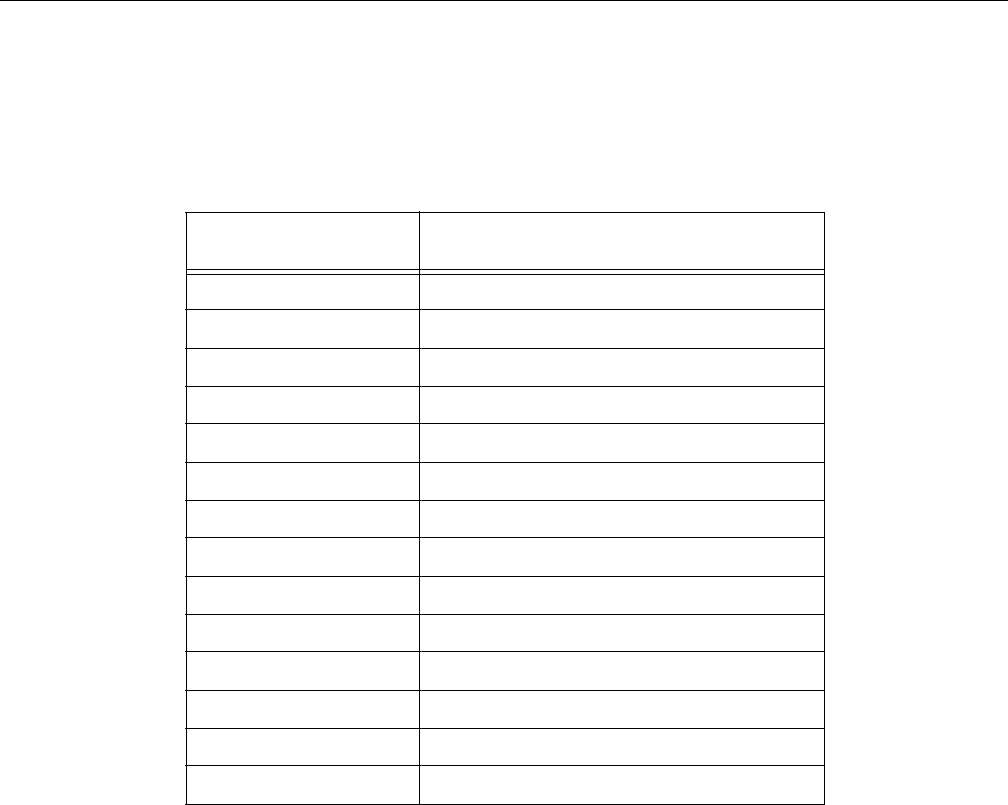
Record of Revision
Version Description
001 April 2010
Original printing.
002 August 2010
Updated Appendix B, “Power Supply Modules Safety Instructions”

007-5645-002 xvii
.About This Guide
This guide provides an overview of the installation, architecture, general operation, and
descriptions of the major components in the SGI Altix UV 10 system. It also provides basic
troubleshooting and maintenance information, BIOS information, and important safety and
regulatory specifications.
Audience
This guide is written for owners, installers, system administrators, and users of the SGI Altix UV
10 computer system. It is written with the assumption that the reader has a good working
knowledge of computers and computer systems.
Safety and Regulatory Information
Important Safety Instructions
Read all caution and safety statements in this document before performing any of the instructions.
Warnings
Heed safety instructions: Before working with your server product, whether you are using this
guide or any other resource as a reference, pay close attention to the safety instructions. You must
adhere to the assembly instructions in this guide to ensure and maintain compliance with existing
product certifications and approvals. Use only the described, regulated components specified in
this guide. Use of other products / components will void the UL listing and other regulatory
approvals of the product and will most likely result in noncompliance with product regulations in
the region(s) in which the product is sold.

xviii 007-5645-002
System power on/off: The power button DOES NOT turn off the system AC power. To remove
power from system, you must unplug the AC power cord from the wall outlet. Make sure the AC
power cord is unplugged before you open the chassis, add, or remove any components.
Hazardous conditions, devices and cables: Hazardous electrical conditions may be present on
power, telephone, and communication cables. Turn off the server and disconnect the power cord,
telecommunications systems, networks, and modems attached to the server before opening it.
Otherwise, personal injury or equipment damage can result.
Electrostatic discharge (ESD) and ESD protection: ESD can damage drives, boards, and other
parts. We recommend that you perform all procedures in this chapter only at an ESD workstation.
If one is not available, provide some ESD protection by wearing an antistatic wrist strap attached
to chassis ground any unpainted metal surface on your server when handling parts.
ESD and handling boards: Always handle boards carefully. They can be extremely sensitive to
ESD. Hold boards only by their edges. After removing a board from its protective wrapper or from
the server, place the board component side up on a grounded, static free surface. Use a conductive
foam pad if available but not the board wrapper. Do not slide board over any surface.

: About This Guide
007-5645-002 xix
Related Publications
The following SGI and LSI documents are relevant to the SGI Altix UV 10 server:
•MegaRAID SAS Software User’s Guide, publication number, 860-0488-00x
•MegaRAID 1078-based SAS RAID Controllers User’s Guide, publication number
860-0489-00x
•LSI Integrated SAS for RAID User’s Guide, publication number 860-0476-00x
•SGI ProPack 7 for Linux Service Pack 1 Start Here, publication number 007-5640-002
•SGI InfiniteStorage series documentation
• Man pages (online)
You can obtain SGI documentation (as well as the pertinent LSI books), release notes, or man
pages in the following ways:
• Refer to the SGI Technical Publications Library at http://docs.sgi.com. Various formats are
available. This library contains the most recent and most comprehensive set of online books,
release notes, man pages, and other information.
• You can also view man pages by typing man <title> on a command line.
SGI systems include a set of Linux® man pages, formatted in the standard UNIX® “man page”
style. Important system configuration files and commands are documented on man pages. These
are found online on the internal system disk (or DVD-CD) and are displayed using the man
command. For example, to display the man page for the xscsidisktest command, type the
following on a command line:
man xscsidisktest
For additional information about displaying man pages using the man command, see man(1).
In addition, the apropos command locates man pages based on keywords. For example, to
display a list of man pages that describe disks, type the following on a command line:
apropos disk
For information about setting up and using apropos, see apropos(1).

xx 007-5645-002
Conventions
The following conventions are used throughout this document:
Product Support
SGI provides a comprehensive product support and maintenance program for its products. SGI
also offers services to implement and integrate Linux applications in your environment.
• Refer to http://www.sgi.com/support/
• If you are in North America, contact the Technical Assistance Center at
+1 800 800 4SGI or contact your authorized service provider.
• If you are outside North America, contact the SGI subsidiary or authorized distributor in
your country.
Convention Meaning
Command This fixed-space font denotes literal items such as commands, files,
routines, path names, signals, messages, and programming language
structures.
variable The italic typeface denotes variable entries and words or concepts being
defined. Italic typeface is also used for book titles.
user input This bold fixed-space font denotes literal items that the user enters in
interactive sessions. Output is shown in nonbold, fixed-space font.
[ ] Brackets enclose optional portions of a command or directive line.
... Ellipses indicate that a preceding element can be repeated.
man page(x) Man page section identifiers appear in parentheses after man page names.
GUI element This font denotes the names of graphical user interface (GUI) elements such
as windows, screens, dialog boxes, menus, toolbars, icons, buttons, boxes,
fields, and lists.

: About This Guide
007-5645-002 xxi
Reader Comments
If you have comments about the technical accuracy, content, or organization of this document,
contact SGI. Be sure to include the title and document number of the manual with your comments.
(Online, the document number is located in the front matter of the manual. In printed manuals, the
document number is located at the bottom of each page.)
You can contact SGI in any of the following ways:
• Send e-mail to the following address: techpubs@sgi.com
• Contact your customer service representative and ask that an incident be filed in the SGI
incident tracking system.
• Send mail to the following address:
SGI
Technical Publications
46600 Landing Parkway
Fremont, CA 94538
SGI values your comments and will respond to them promptly.
007-5645-002 1
Chapter 1
1. Introduction and System Components Overview
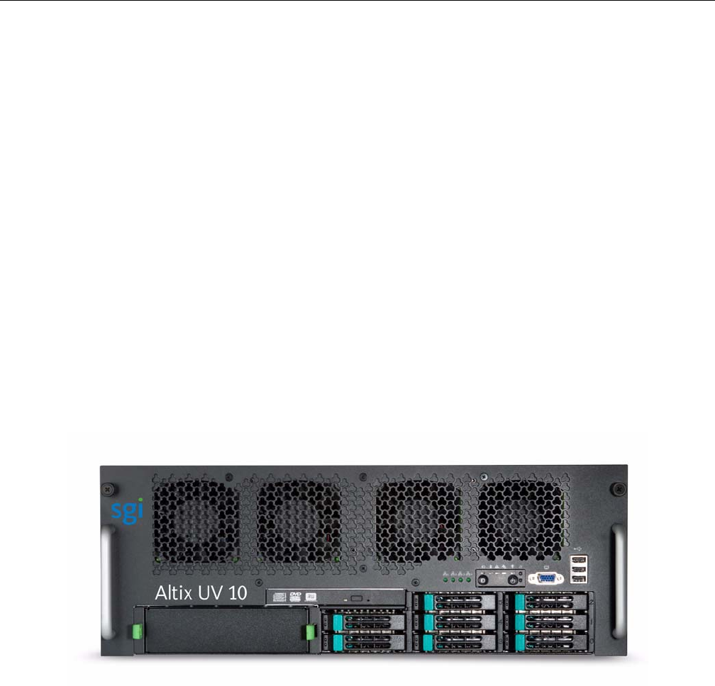
The SGI Altix UV 10 system, as shown in Figure 1-1 and see Figure 1-3, is a 4U, high-density,
rack-mount server system with support for one to four Intel® Xeon® 7500 series processor
(Nehalem-EX) or Intel® Xeon® Processor 7600 series (Westmere-EX) processors and up to 64
DDR3 RDIMMs / 512GB DDR3 RDIMM memory. Features include the following:
• Up to four hot swap PCIe add-in cards, or eleven total PCIe add-in cards
• Up to eight hot swappable memory risers carrying up to eight DIMMs each
• Support for up to four multi-core Intel® Xeon® Processor 7500 series (Nehalem-EX) or
Intel® Xeon® Processor 7600 series (Westmere-EX)
•SAS Riser
• Four hot swap redundant power supply modules
• Eight hot swap redundant cooling fans
• Up to eight hot swap SAS/SATA hard drives
Figure 1-1 SGI Altix UV 10 Front View
2007-5645-002
1: Introduction and System Components Overview
Dimensions and Clearance Requirements
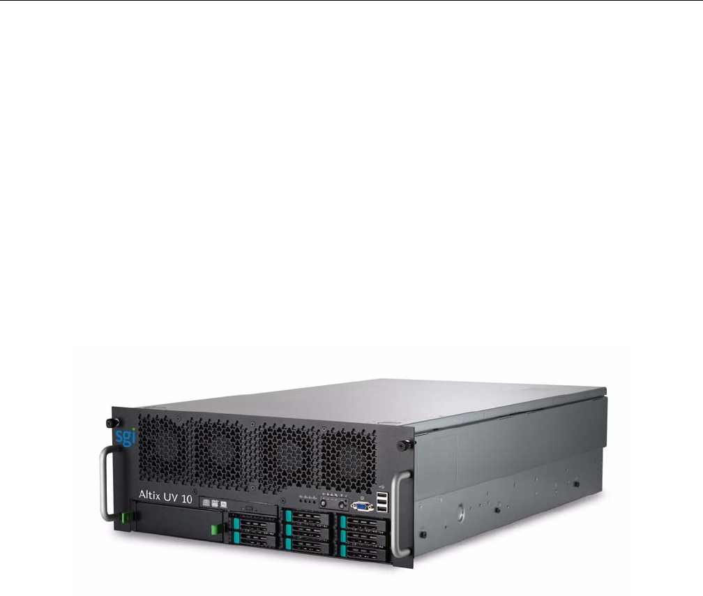
The SGI Altix UV 10 systems has the following dimensions (see Figure 1-2):
• Height: 4U / 6.8 inches (173.8 mm)
• Depth: 27.7 inches (704 mm)
• Width: 16.7 inches (424 mm)
• Weight: 110.23 lbs (50 kg) – estimated
Clearance requirments are, as follows:
• Front Clearance: 3 inches (76 mm)
• Side Clearance: 1 inch (25 mm)
• Rear Clearance: 6 inches (152 mm)
Figure 1-2 SGI Altix UV 10 Angle View
System Features Overview
007-5645-002 3
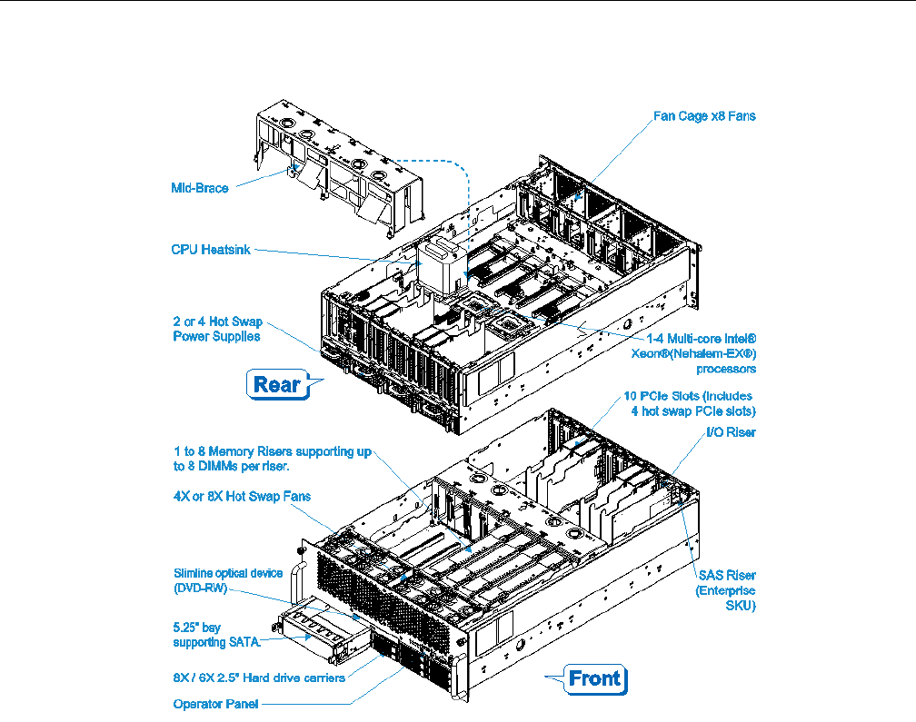
Figure 1-3 SGI Altix UV 10 System
System Features Overview
This section provides an overview of the SGI Altix UV 10 system features and components.

4007-5645-002
1: Introduction and System Components Overview
System Scalability
System scalability features are, as follows:
• One to four processors are supported.
• Supports two generations of processors; Intel® Xeon® 7500 series processors (Nehalem-EX
and Westmere-EX)
• SAS Riser: 6 Gb SAS RAID card
• Up to eight 2.5 inch SAS/SATA hard drives
• Up to eleven PCIe adapters (Including the SAS Riser)
• Up to 512GB DDR3 RDIMM memory support (16GB/QRx4 RDIMM x 32 or 8GB/DRx4
RDIMM x 64)
System Serviceability
System sericeability features are, as follows:
• Front access to hot swap hard disk drives
• Easily maintained hot swap fans with individual LED indicators
• Rear access hot swap power supplies with LED indicators
• System power and system status LEDs
• System ID buttons and LEDs on front panel and rear of system
• LED indicators for PCIe hot-swap operations
• Memory configuration and status LEDs, located on memory riser modules
• Color-coded parts to identify both hot swap and non-hot swap serviceable components
System Availability
System availability features are, as follows:
• Eleven PCIe slots (including one SAS riser slot), with four slots supporting hot-swap
• Four 850W high efficiency power supplies in a redundant (2+2 or 3+1) configuration

System Features Overview
007-5645-002 5
• Eight hot swap system fans in a redundant (7+1) configuration or four hot swap fans in a
non-redundant configuration
• Eight hot swap 2.5-inch SAS/SATA hard disk drives
• Eight memory risers
• SAS Riser supporting RAID with optional battery backup for storing buffer data.
System Manageability
System manageablity features are, as follows:
• Remote management
• Intelligent Platform Management Interface (IPMI) 2.0 compliant
• Wired for Management (WfM) 2.0 compliant
• Remote diagnostics support
• iBMC baseboard management controller
Front Control Panel and Operator Panel
Front control panel and operator panel features are, as follows:
• System power button and LED
• System reset button
•NMI button
• System ID button and LED
• System status LED
• Hard drive status LED
• LAN1, LAN2, LAN3 and LAN4 status LEDs
• Video connector
• Three USB 2.0 ports
• Fan status / fault LED

6007-5645-002
1: Introduction and System Components Overview
Rear I/O
Rear I/O features are, as follows:
• Four GbE LAN ports
• One I/O riser Management Ethernet Port via Intel® RMM3 (optional in Value SKU)
• Video connector
• Serial port connector
• System status LED
• Fan status / Fault LED
•CSS LED
• System ID button and LED
• Two USB 2.0 ports
• POST code LEDs
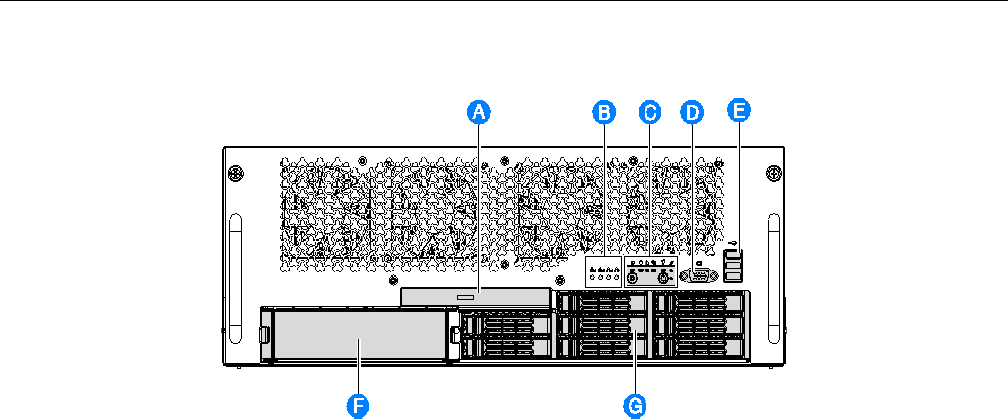
System Front Panel
Figure 1-4 shows the front view of the system. The front panel provides access to the following
components described in Table 1-1:
Table 1-1 System Front Panel Componets
IItem Description
A Optical drive
B Rear LAN LEDs (from I/O Riser)
C Operator panel
D Video Connector
E USB 2.0 ports
F 5 ¼ - inch peripheral bay (SATA cable included)
G Hot swap hard drive bays
Operator Panel/Front Control Panel
007-5645-002 7
Figure 1-4 SGI Altix UV 10 System Front Panel
Operator Panel/Front Control Panel
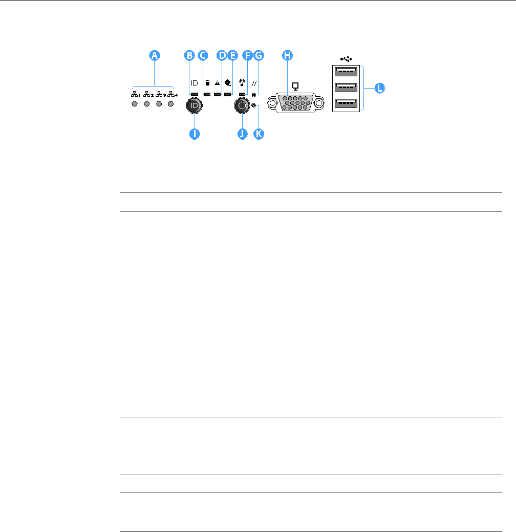
The front panel contains the following controls and indicators as shown in Figure 1-5 and
described in Table 1-2.
• Operator Panel with system control buttons and LED status indicators
• Four LED status indicators for the rear LAN ports
• One video connector supporting 1280 x 1024 resolution
• Three USB 2.0 ports
8007-5645-002
1: Introduction and System Components Overview
Figure 1-5 Operator Panel Controls and Indicators
Table 1-3 describes the front panel connectors.
Table 1-2 System Status LED s and Operator Panel Controls
IItem Description
A LAN1, LAN2, LAN3, LAN4 status LEDs (green)
B System ID LED (blue) Blue ID that identifies the system through server management or
locally
C Hard drive status LED (green) - Indicates hard drive activity and fault stats
D System status/fault LED (green/amber)
E Fan fault LED (amber)
F System power LED (green) - Indicates system power status
G System reset button - Resets the system
I System ID button - Toggles ID LED
J System power button - Toggles system power
K NMI button - Asserts NMI
Table 1-3 Front Panel Connectors
Item Description
H Video port, standard VGA compatible, 15-pin connector (1280 x 1024 resolution support)
L Three USB 2.0 ports, 4-pin connectors

Operator Panel/Front Control Panel
007-5645-002 9
System Status LED States
This section describes the front panel LED states.
LAN Activity Status
Table 1-4 shows the front panel LAN LEDs activity status. See item A in Figure 1-5.
Hard Drive Status LED
Table 1-5 shows the hard drive LED activity status. See intem C in Figure 1-5.
System Status/Fault LED
Table 1-6 shows the system LED activity status/fault. See item D in Figure 1-5.
Table 1-4 LAN1 LAN2, LAN3, LAN4 status LEDs (green)
Color LED
Behavior Description
Off Idle
Green Blinking LAN access
Green On LAN link/no access
Table 1-5 Hard Drive Activity and Fault Status LED (green)
Color LED
Behavior Description
Green Blinking HDD access or spin up/down
Off No access and no fault
Table 1-6 System Status/Fault LED (green/amber)
Color LED
Behavior Descriptions
Off Not ready AC power off, POST error
Green - On Ready System booted and ready

10 007-5645-002
1: Introduction and System Components Overview
System Power LED
Table 1-7 shows the system power LED activity status. See item F in Figure 1-5.
Green -
Blinking
Non-critical
Alarm
Non-critical temperature threshold asserted.
Non-critical voltage threshold asserted.
Non-critical fan threshold asserted.
Fan redundancy lost, sufficient system cooling maintained. (This does not
apply to non-redundant systems.)
Power supply predictive failure.
Power supply redundancy lost. (This does not apply to non-redundant systems.)
Amber -
Blinking
Non-Fatal
Alarm
CATERR asserted.
Critical temperature threshold asserted.
Critical voltage threshold asserted.
Critical fan threshold asserted.
VRD hot asserted.
SMI Timeout asserted.
Amber - On Critical
alarm
NMI asserted.
CPU Missing.
Thermtrip asserted.
Non-recoverable temperature threshold asserted.
·Non-recoverable voltage threshold asserted.
Table 1-7 System Power LED (green)
Color/LED
Behavior State ACPI
Off Power off No
Green - On Power on No
Off S5 Yes
Table 1-6 System Status/Fault LED (green/amber) (continued)
Color LED
Behavior Descriptions
System Rear
007-5645-002 11
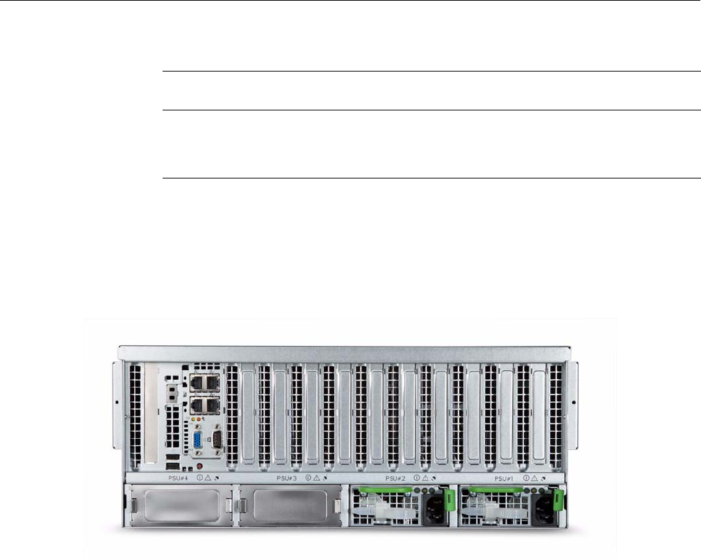
System Rear
Figure 1-6 and Figure 1-7 shows the rear view of the system with the componets described in
Table 1-8.
Figure 1-6 SGI Altix UV 10 Rear View
User-accessible connectors, PCIe slots, and power supply modules are located at the rear of the
system. These components are described in the following ‘sections.
Green -
Blinking
S1 Yes
Green - On S0 Yes
Table 1-7 System Power LED (green)
Color/LED
Behavior State ACPI
12 007-5645-002
1: Introduction and System Components Overview
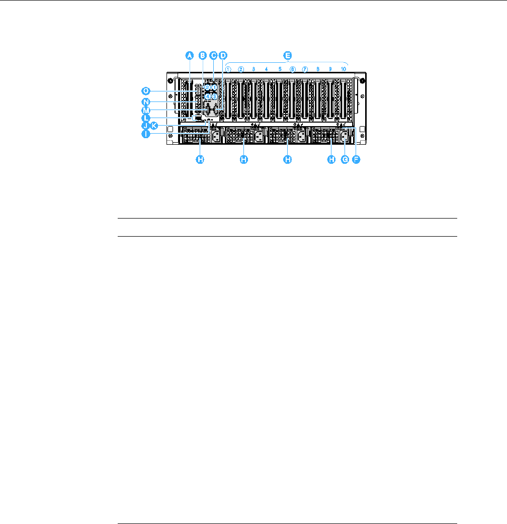
Figure 1-7 SGI Altix UV 10 System Rear
Table 1-8 System Rear Items and Descriptions
Item Description
A SAS Riser Slot - PCIe Gen-2x8, ½ length, x8 connector
B I/O Riser Quad Gigabit Ethernet Ports:
Four LAN ports, RJ45 connector. From upper left: LAN 2 and 1; and LAN 4
and 3 at the bottom For information on LAN port LED status, see Table 1-9
C I/O Riser module
D Serial Port connector
E PCIe Gen-2x8 slots (See Table 1-10.)
F Power Supply Unit Status LEDs. See “Power Subsystem” on page 15 and
“Power Supply Modules” on page 17 for details.
G AC input power connector (4 bays, from right to left: PSU#1, PSU#2, PSU#3,
PSU#4)
H Hot swap power supply
I System ID button
J System Status/Fault LED
K System ID LED: Blue ID that identifies the system through server management
or locally
L USB 2.0 ports (x2)

System Rear
007-5645-002 13
Rear Status LEDs
Table 1-9 shows LAN port LED status activity.
Rear PCIe Slots
Table 1-10 shows rear PCIe slot descriptions.
M VGA video port - standard VGA compatible, 15-pin connector supporting up
to 1600X1200 resolution
N 8x POST code LEDs. See Appendix A, “POST Codes” for details.
O I/O Riser Management Ethernet Port (Intel RMM3)
Table 1-9 Rear LAN Port LED Status Activity
LED Color State
Status LED - Green On – Ethernet link is detected
Off – no Ethernet connection
Blinking – Ethernet link is active
Speed LED -
Green/Amber (dual
color)
Off – 10 Mbps
Green On – 100 Mbps
Amber On – 1000 Mbps
Table 1-10 PCIe Slots
PCIe Slot
Number Description
1 PCIe Gen-2x8, ¾ in. x8 conn., hot swap
2 PCIe Gen-2x8, ¾ in. x8 conn., hot swap
3 PCIe Gen-2x4, ½ in., x8 conn.
Table 1-8 System Rear Items and Descriptions (continued)
Item Description

14 007-5645-002
1: Introduction and System Components Overview
Note: Legacy I/O devices, such as, video cards are only supported on slot #1, 2, 3, 4 or 10.
Processors
One to four 64-bit Intel® Xeon® Processor 7500 series (Nehalem-EX) or 64-bit Intel® Xeon®
Processor 7600 series (Westmere-EX) are supported.
System Memory
The memory risers connect to the main board through 8 PCI Express (PCIe) connectors. One to
eight memory risers can be installed via PCIe x16 card edge connectors. Memory air baffles are
needed to restrict airflow to empty memory riser slots. Key features of the memory risers are
discussed in “Memory Riser” on page 19.
4 PCIe Gen-2x4, ½ length, x8 conn.
5 PCIe Gen-2x16, ¾ in., x16 conn.
6 PCIe Gen-2x8, ¾ in., x8 conn., hot swap
7 PCIe Gen-2x8, ¾ in., x8 conn., hot swap
8 PCIe Gen-2x4, ¾ in., x8 conn
9 PCIe Gen-1x4, ½ in., x8 conn.
10 PCIe Gen-1x4, ½ in., x8 conn.
Table 1-10 PCIe Slots
PCIe Slot
Number Description

Power Subsystem
007-5645-002 15
Power Subsystem
Warning: For the initial release of the SGI Altix UV 10 system, power supply modules
must be connected to separate AC power sources or have a grounding wire installed for
standalone systems. This only applies to systems with a grounding warning label shown in
Figure B-1. See Appendix B, “Power Supply Modules Safety Instructions” and shipped
with a grounding wire. If your system serial number is UV10-00000053 or greater, Appendix
B information does NOT apply.
There are four power bays providing space for up to four power supply modules that connect to
the power distribution board (PDB). The dimensions of the power supply module is 3.72-inches
(W) x 15.75-inches (D) x 1.57-inches (H). There are two dual-motor fans located within each
power supply module drawing air through the hard drives and across the power distribution board.
Each power supply module has a handle to assist insertion and extraction without tools.
The PDB distributes the power in two ways. There are connectors on the back edge of the board
that mate to the power supplies. In addition, there are cables that route power up to the main board
and to the hot-swap backplane.
The SGI Altix UV 10 system power subsystem supports up to four 850W high efficiency power
supplies. The hot swap power supply modules are rated at 850W over an input range of
100-127VAC@10A or 200-240 VAC@5A.
The total power requirement for the SGI Altix UV 10 system exceeds the 240 VA energy hazard
limit that defines an operator-accessible area. As a result, only qualified technical personnel
should access the processor, memory, and non-hot swap areas while the system is energized.
The power subsystem can be configured as follows:
• With four power supply modules installed, a fully configured system has (2+2 or 3+1) power
redundancy
• With three, two or one power supply module installed, the system does not have redundant
power at 200-240 VAC input, three power supply module is capable of handling the
maximum power requirements for a fully configured SGI Altix UV 10 system, which
includes the following:
– Four processors
– 512GB of memory
!

16 007-5645-002
1: Introduction and System Components Overview
– Eleven PCIe add-in cards (including the SAS RAID riser)
– Eight hard disk drives
– One optical drive
– One tape drive
System Configuration
Table 1-11 shows the maximum system configuration support.
When the system is configured with four power supply modules, the hot swap feature allows the
user to replace a failed power supply module without affecting the system functionality.
Table 1-11 Maximum System Configuration Support
System Components Description
Processors 4
Memory risers 8
DIMM rank/DIMM quantiy 8 Memory Risers with 8 DIMMs on each riser
I/O riser Yes
SAS riser Yes
Hot Swap/Total PCIe* 7 + 1
System fans Yes
2.5” HDDs 8
Optical device Yes
5.25” tape device Yes
Power supply 2 + 2
12V available power 2316
Power redundancy AC/DC
*Exclude SAS riser slot.
Power Supply Modules
007-5645-002 17
The power subsystem receives AC power through four power cords. When four power supply
modules and four power cords are installed, the system supports 2+2 or 3+1 power cord
redundancy.
This feature allows the system to be powered by four separate AC sources. In this configuration,
the system continues to function without interruption if two or one of the AC sources fails.
A 3-volt lithium battery provides power to the RTC when the Main Board is powered down. The
expected battery life is greater than 5 years.
Power Supply Modules
Warning: For the initial release of the SGI Altix UV 10 system, power supply modules
must be connected to separate AC power sources or have a grounding wire installed for
standalone systems. This only applies to systems with a grounding warning label shown in
Figure B-1. See Appendix B, “Power Supply Modules Safety Instructions”.
The output rating of each power supply is 850 watts when operated between 200 VAC and 240
VAC. Modules are current-sharing and have auto-ranging input. Each power supply is 7.75 inches
wide, 14.5 inches deep, and 1.47 inches high. The power supply modules have universal AC input
with Power Factor Correction (PFC) Distributed Power Supplies (DPS). The AC input receptacle
is an IEC-320 C14 15A rated for a 250 VAC minimum.
The power supply operates over the range and limits shown in Table 1-12.
When input power is applied to the power supply, any initial current surge or spike of 10 ms or
less should not exceed 55A. Any additional inrush current surges or spikes in the form of AC
cycles or multiple AC cycles greater than 10 ms, and less than 150 ms, must not exceed 25A.
Table 1-12 AC Input Rating
Parameter Minimum Nominal Maximum Start Up VAC Power Off VAC
Voltage (115) 90 Vrms 100-127 Vrms 140 Vrms 85 VAC +/-4 VAC 75 VAC +/-5 VAC
Voltage (220) 180 Vrms 200-240 Vrms 264 Vrms
Frequency 47 Hz 50/60 63 Hz
!

18 007-5645-002
1: Introduction and System Components Overview
The power supply has DC outputs of 12 V and 3.3 VSB. The 12 V main power is distributed
through the server and is converted locally at the point-of-load using embedded Voltage Regulator
Module (VRM) converters. The power supply is capable of power-safe monitoring.
The DC output voltages remain within the ranges shown in Table 1-13 when operating at steady
state and dynamic loading conditions. These limits include the peak-peak ripple/noise.
The combined continuous output power for all outputs does not exceed 850W. Each output has
the maximum and minimum current rating shown in Table 1-14.
Note: *Values are at the system level. For 2+2/or 3+1 redundant systems, the load each power
supply provides is based on its current sharing accuracy.
Figure 1-8 shows the the locations of the power supply indicators.
Table 1-13 DC Output Voltage
Parameter Tolerance Minimum Nominal Maximum Units
+12V -5%/+5% +11.40 +12.00 +12.60 VDC
+3.3V
standby
-3%/+5% +3.20 +3.30 +3.46 VDC
Table 1-14 850W Power Suppy Load Ratings
Output Level Minimum* Nominal* Maximum* Peak*
+12V 0A 69A 88A
+3.3V standby 0A 6.0A
Power Supply Modules
007-5645-002 19
Figure 1-8 Power Supply Indicators
Caution: Power supplies must be hot swapped within three minutes to prevent overheating. This
time period applies only to the time that the power supply is physically removed, not from the time
of failure.
Table 1-15 shows power supply LED status activity.
Table 1-15 Power Supply Indicators
Power Supply Condition Staus LED (A) Fail LED (B) AC LED (C)
No AC power to any of the power supplies Off Off Off
AC Cord Unplugged 0.5 Hz blinking
green
Off Off
AC Present but only 3.3VSB on (PS off (or
power supply in cold redundant state.
1 HZ blinking
green
Off Solid green
Output On and OK Solid green Off Solid green
Power supply warning events where the
power supply continues to operate: High
temperature, high power, high current, slow
fan
1 Hz blinking
amber
Off Solid green
Power supply critical event causing a
shutdown: failure, overcurrent, overvoltage,
or fan failure.
Off Amber Solid green
!

20 007-5645-002
1: Introduction and System Components Overview
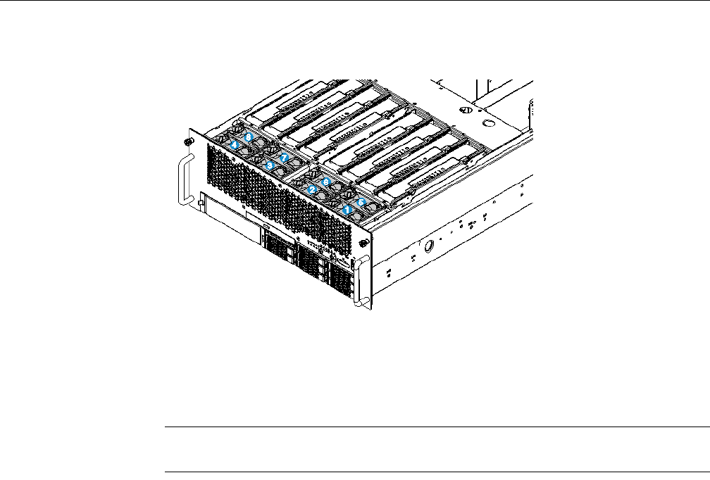
Cooling Subsystem
The SGI Altix UV 10 system contains two cooling fan zones comprising a total of eight system
fans located at the upper front of the system and two dual-motor fans located within each power
supply module. The basic chassis structure is divided into a lower section of 1U height and upper
section of 3U height.
The upper section is cooled with up to eight 80 mm fans positioned in front of the system
exhausting into the memory, CPU, and PCIe regions. The lower section is cooled by fans located
within the PSUs drawing air through the hard drives and across the power distribution board.
The eight hot swap fan modules that are located at the upper front of the chassis can be removed
from the chassis when the chassis cover is removed (See Figure 1-9). The fans are docked on the
front panel fan board (FPFB).
The fan modules have following features:
• Form factor: 80x80x38mm
• Hot swap blind-mate connector
• Fan presence, PWM, tachometer, and fault signals
• Support Fault LED
• RV isolation
• Tool-less service at the module level
• Keying feature to prevent incorrect installation
Cooling Subsystem
007-5645-002 21
Figure 1-9 Cooling Fan Locations
In addition, there are two dual-motor fans located within each power supply drawing air through
the hard drives and across the power distribution board.
Note: The cooling system is non redundant in a non-redundant power supply system
configuration.
The zones are designed to be redundant in order to maintain system cooling in the event of fan
failure. To maintain system performance, only one of the eight fans can fail at any one time.
Each fan assembly has a single LED to indicate its status. In the event of a fan failure, the LED
illuminates amber. Failed system fans can be hot swapped out inside of the chassis with the cover
removed. The maximum time limit to perform a fan hot swap operation is three minutes before
affecting system performance.
Each fan (or pair of redundant fans in series) provides cooling for a zone of the mainboard that
includes two memory riser slots and one CPU socket. Dividers separate the memory risers to allow
for proper airflow for each riser. If only one memory riser is installed for a fan, a memory air baffle
must be installed over the adjacent opening in the fan cage. The memory air baffle restricts airflow
to the area where no memory riser is present, ensuring proper airflow over installed DIMMS.
Memory air baffles are not needed for parts of the mainboard where no memory risers are present.

22 007-5645-002
1: Introduction and System Components Overview
The system thermal design maintains an operating ambient temperature between 0°- 55°C
delivered to the board. This may result in internal local ambient temperatures greater than 55°C.
It is not required that the maximum internal temperature be less than 55°C in all locations.
The ambient air temperature inside the chassis may exceed 55°C in certain locations such as
directly behind the Boxboro chipset, in close proximity to VR components, and at the exhaust of
the PCIe cards. This is not a violation of the board specification and is normal and expected in
those locations.
Hot Swap PCI Express Slots
The four hot swap PCIe slots have power and attention LEDs. The attention button is used to
invoke a hot swap sequence to remove or add an adapter without using the software interface. The
green arrow on the PCIe divider label identifies the LEDs. Table 1-16 shows hot swap PCIe slot
power LEDs..
Table 1-17 shows attention LEDs
Table 1-16 Hot Swap PCEe Power LEDs
Green Power LED State Definition
Off Power off: Power has been removed from the slot. A card can be
inserted or removed
On Power on: The slot is powered on. A card cannot be inserted or
removed.
Blinking Power transition: The slot is powering up or down. A card cannot be
inserted or removed.
Table 1-17 Hot Swap PCIe Attention LEDs
Amber Attention LED State Definition
Off Normal: Normal operation.
On Attention: Power fault or operational problem has occurred
with this slot.
Blinking Locate: The slot is being identified.

Peripherals
007-5645-002 23
Peripherals
The following peripheral devices are supported:
• Hard Disk Drives
• Slim-line SATA DVD-RW drive
• One 5.25” device bay
A hot swap backplane (HSBP) provides power and I/O for the hard disk drives and slimline optical
drive. A separate 4-pin 12V molex power connector is provided for powering the 5.25” device.
I/O for the 5.25” device can be accomplished via one of the SATA connectors on the mainboard.
Figure 1-10 shows the periperal device area.
Figure 1-10 Peripheral Area
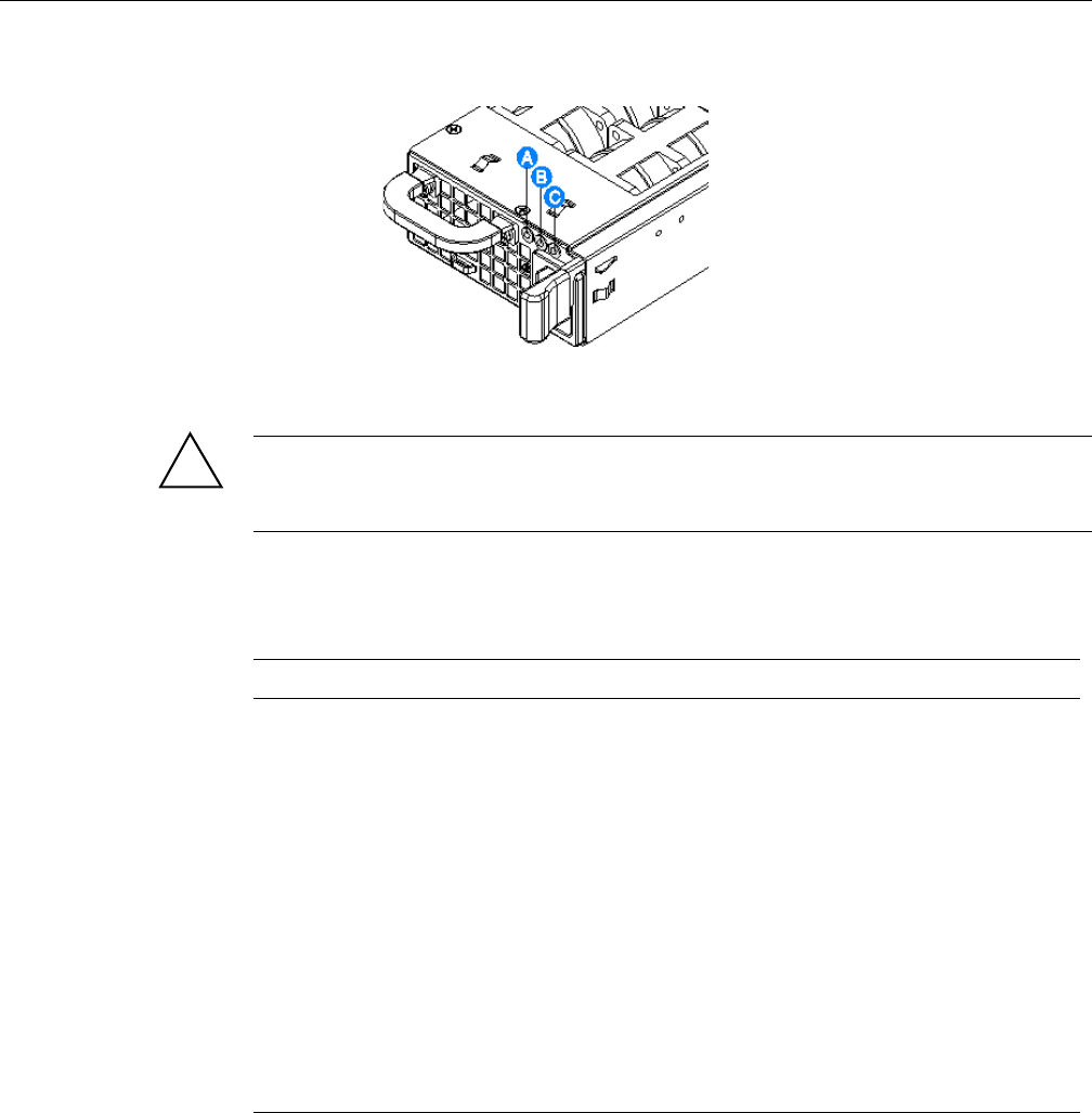
Hot-Swap Hard Drive
The hard drive carrier is an assembly that provides guidance for hot swapping. It contains two
integrated light pipes to transfer the LED indicator light driven by the SGPIOs, and an
insertion/extraction mechanism that includes a hard drive bezel. Figure 1-11 shows the hot-swap
hard drive carrier. Item A points to the carrier latch. Item B points to the green LED. Item C points
to the Amber LED. Table 1-18 shows the LED status activity.
24 007-5645-002
1: Introduction and System Components Overview
Figure 1-11 Hard Drive Carrier
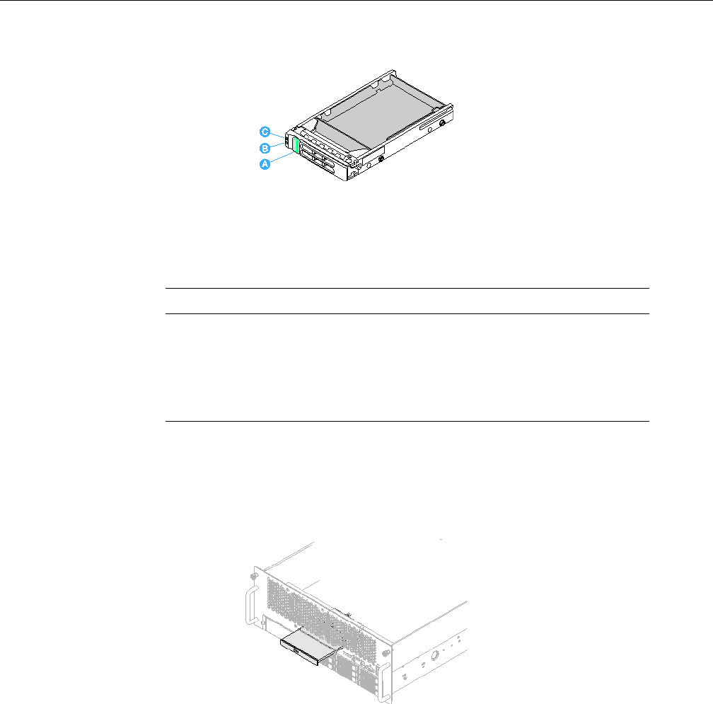
Optical Drive Bay
Figure 1-12 shows the optical drive bay.
Figure 1-12 Optical Drive
Table 1-18 Hard Drive Carrier LED Indicators
Hard Drive Carrier LED State Description
Green Blinking HDD access or spin up/down
Amber - On HDD fault
Amber - Blinking Predictive failure, rebuild, identify
Off No access and no fault
System Boards
007-5645-002 25
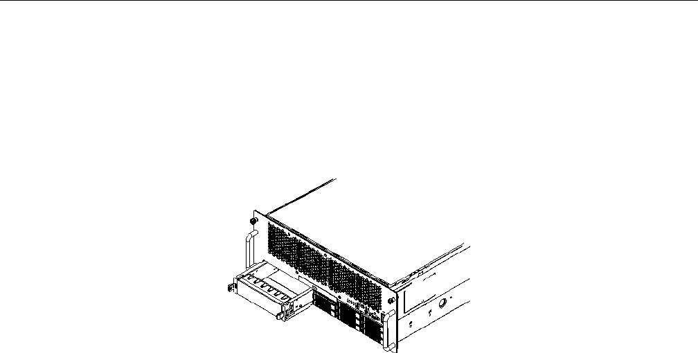
Half-height Drive Bay (5 1/4-inch)
The system includes a bay that can support a half height 5.25” tape device as shown in
Figure 1-13. The system includes a 5.25” device blank for the 5.25” device opening. It matches
the shape and interface of a 5.25” device. The blank includes the 5.25” device rails such that field
upgrade to 5.25” device is possible.
Figure 1-13 Half-height Drive (5 1/4-inch)
System Boards
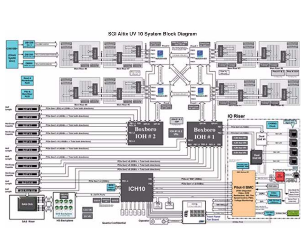
The board set consists of the following (see Figure 1-14):
• Main board
• Memory riser
•I/O riser
• Hot swap backplane
• Front panel fan board
• Power distribution board
• Operator panel board
• SAS Riser: 6 Gb SAS RAID card
26 007-5645-002
1: Introduction and System Components Overview
Figure 1-14 SGI Altix UV 10 System Block Diagram
I/O Configuration Rules
The Altix UV 10 has two Intel IOH (Boxboro) parts (IOH1 and IOH2) that enable PCI-E devices
(see Figure 1-14).
IOH1 drives slots 1, 2, 3, 4 and 10.
IOH2 drives slots 5, 6, 7, 8 and 9.

I/O Configuration Rules
007-5645-002 27
Slots 1, 2, 6 and 7 are hot plug capable. All slots except 9 and 10 are PCI-E Gen2; therefore, slots
9 and 10 should be reserved for the lowest performance devices or unused unless all other slots
are filled.
The Altix UV 10, along with all other I/O rich platforms, has 64K bytes of I/O space. The 64k
bytes is divided between the two IOHs in a fixed manner, as follows:
• IOH1 has 40kB
• IOH2 has 24kB.
The allocation of I/O space can be changed in the PCI Config screen of the BIOS setup. In
addition, all four hot plug slots are pre-allocated with extra PCI I/O space to accommodate the
potential addition of a card after the system is booted.

The following table describes the features of each PCIe slot.
Slot Source Gen PCIe
Connector PCIe
Width PCIe Card
Length PCIe Card
Height Hot
Pluggable
1 IOH1 2 x8 x8 3/4 Full Yes
2 IOH1 2 x8 x8 3/4 Full Yes
3 IOH1 2 x8 x4 1/2 Full No
4 IOH1 2 x8 x4 1/2 Full No
5 IOH2 2 x16 x16 3/4 Full No
6 IOH2 2 x8 x8 3/4 Full Yes
7 IOH2 2 x8 x8 3/4 Full Yes
8 IOH2 2 x8 x4 3/4 Full No
9 IOH2 1 x8 x4 1/2 Full No
10 IOH1/
ICH10
1x8 x4 1/2 Full No
I/O Configuration Rules
007-5645-002 29
The suggested location for various cards is impacted by the card's performance, lane width
requirements, and its use of I/O space.
The following table defines the recommended PCIe card slot placements for typical systems:
Card Type Suggested Slot Order
(in order of populating more than one)
PCIE-GFX-1800 5
PCIE-FC8-4P-G2 1, 6, 2, 5, 7
PCIE-FC8-2P-G1 1, 6, 2, 7, 5
PCIE-FC-2P-LS-D 1, 6, 2, 7, 5
PCIE-SCSI-U4-2P-L Any
LSU-ER-SASRAID 1, 6, 2, 7, 5
PCIE-6G-SAS-8E 1, 6, 2, 7, 5
PCIE-SAS-LS-2P4X 1, 6, 2, 7, 5
PCIE-10G-OR-RDMA 5, 6, 1, 7, 2
PCIE-GENET-C-4P-LP Any
PCIE-GENET-C-2P Any
PCIE-IB-HCA-CONNX 5, 6, 1, 7, 2
PCIE-IB-HCA-QDR-2P 5, 6, 1, 7, 2
PCIE-IB-HCA-QDR-1P 5, 6, 1, 7, 2

30 007-5645-002
1: Introduction and System Components Overview

007-5645-002 31
Chapter 2
2. System Safety
This chapter describes basic safety precautions.
Electrical Safety Precautions
Basic electrical safety precautions should be followed to protect yourself from harm and the SGI
Altix UV 10 system from damage, as follows:
• Be aware of the locations of the power on/off switch on the chassis as well as the room's
emergency power-off switch, disconnection switch or electrical outlet. If an electrical accident
occurs, you can then quickly remove power from the system.
• Do not work alone when working with high voltage components.
• Power should always be disconnected from the system when removing or installing main system
components, such as the serverboard, memory modules and SATA drives. When disconnecting
power, you should first power down the operating system first and then unplug the power cords.
The unit has more than one power supply cord. Disconnect two power supply cords before
servicing to avoid electrical shock.
• When working around exposed electrical circuits, another person who is familiar with the
power-off controls should be nearby to switch off the power if necessary.
• Use only one hand when working with powered-on electrical equipment. This is to avoid making
a complete circuit, which will cause electrical shock. Use extreme caution when using metal tools,
which can easily damage any electrical components or circuit boards they come into contact with.
• Do not use mats designed to decrease static electrical discharge as protection from electrical
shock. Instead, use rubber mats that have been specifically designed as electrical insulators.
• The power supply power cords must include a grounding plug and must be plugged into
grounded electrical outlets.
32 007-5645-002
2: System Safety
• Serverboard Battery
Caution: There is a danger of explosion if the onboard battery is installed upside down,
which will reverse its polarites . This battery must be replaced only with the same or an
equivalent type recommended by the manufacturer. Dispose of used batteries according to the
manufacturer's instructions.
• DVD-ROM Laser
Caution: This server may have come equipped with a DVD-ROM drive. To prevent direct
exposure to the laser beam and hazardous radiation exposure, do not open the enclosure or
use the unit in any unconventional way.
Lifting Precautions
When installing an SGI Altix UV 10 system in a rack, two people are required. With a person on
each side of the chassis, lift it and move it into the equipment rack, as shown in Figure 2-1.
!
!

General Safety Precautions
007-5645-002 33
Figure 2-1 Lifting the SGI UV 10 System Into a Rack
Warning: Two people are required to lift an SGI Altix UV 10 System.
General Safety Precautions
Follow these rules to ensure general safety:
• Keep the area around the SGI Altix UV 10 system clean and free of clutter.
• Place the chassis top cover and any system components that have been removed away from
the system or on a table so that they won't accidentally be stepped on.
!

34 007-5645-002
2: System Safety
• While working on the system, do not wear loose clothing such as neckties and unbuttoned
shirt sleeves, which can come into contact with electrical circuits or be pulled into a cooling
fan.
• Remove any jewelry or metal objects from your body, which are excellent metal conductors
that can create short circuits and harm you if they come into contact with printed circuit
boards or areas where power is present.
• After accessing the inside of the system, close the system back up and secure it to the rack
unit with the retention screws after ensuring that all connections have been made.
ESD Precautions
Caution: Electrostatic discharge (ESD) is generated by two objects with different electrical
charges coming into contact with each other. An electrical discharge is created to neutralize this
difference, which can damage electronic components and printed circuit boards.
The following measures are generally sufficient to neutralize this difference before contact is
made to protect your equipment from ESD:
• Use a grounded wrist strap designed to prevent static discharge.
• Keep all components and printed circuit boards (PCBs) in their antistatic bags until ready for
use.
• Touch a grounded metal object before removing the board from the antistatic bag.
• Do not let components or PCBs come into contact with your clothing, which may retain a
charge even if you are wearing a wrist strap.
• Handle a board by its edges only; do not touch its components, peripheral chips, memory
modules or contacts.
• When handling chips or modules, avoid touching their pins.
• Put the serverboard and peripherals back into their antistatic bags when not in use.
• For grounding purposes, make sure your computer chassis provides excellent conductivity
between the power supply, the case, the mounting fasteners and the serverboard.
!
007-5645-002 35
Chapter 3
3. Starting Up and Shutting Down the System
This chapter describes how to power up and shut down your system.
Powering On the System
Press the power button on the front control panel. The fans start and POST begins.
Note: It might take two minutes or longer for video to be displayed, depending on the amount of
memory installed.
The server attempts to boot from the first device on the list of available devices in the boot
manager. If this device is not available, it moves to the second device. It continues down the list
until it reaches the first available device.
Shutting Down the System
To shut down the system, perform the following steps:
1. Exit the operating system if applicable.
2. Press and hold the power button until the system shuts down.
Caution: Powering down the server with the power button does not remove all power. The +3.3V
standby power is available even when the system is not running. To remove standby power,
unplug all power cords from the system.
!

007-5645-002 37
Chapter 4
4. System Utilities
Using the BIOS Setup Utility
The BIOS Setup Utility is a text-based utility that allows you to configure the system and view
and change device settings and view environmental information for the system. The interface
consists of several screens, called pages, each of which contains information or links to other
pages. The first page in Setup displays links for general categories. These links lead to pages
containing specific configuration settings.
The BIOS Setup Utility is functional through console redirection over various terminal emulation
standards. This may limit some functionality due to compatibility. For example, colors, some keys
or key sequences, and mouse support may be limited.
To enter the BIOS Setup Utility press <F2> when prompted during POST to access the Systems
Options Menu.
For additional information on navigating and using the BIOS utility, see Chapter 6, “BIOS.”
System Configuration Reset
You can restore the system configuration to the default values. When you reset the system to the
default values, The BIOS loads default system configuration values during the next POST. Use
one of these methods if you want to return to the defaults:
•Use <F9> in the BIOS Setup Utility.
• In the BIOS Setup Utility Exit menu, select “Load Default Values”.
• Power down the system but do not remove the AC power cords.
• Power on the system
Note: The SGI Altix UV 10 system does not support any other mechanisms to clear NVRAM.

38 007-5645-002
4: System Utilities
Console Redirection
The BIOS supports keyboard and video redirection through a serial link (serial port). When
console redirection is enabled, local (host server) keyboard input and video output are passed to
both the local keyboard and video connections and to the remote console through the serial link.
Keyboard inputs from both sources are valid and video is displayed to both outputs.
With console redirection, the system can be operated without a host keyboard or monitor and run
entirely from a remote console. Setup and any other text-based utilities can be accessed through
console redirection.
Serial Configuration Settings
For optimal configuration of Serial Over LAN (SOL) or EMP, see the Intel® Server System
Integrated Baseboard Management Controller Core External Product Specification.
The BIOS does not require that the splash logo be turned off for console redirection to function.
The BIOS supports multiple consoles, some of which are in graphics mode and some in text mode.
The graphics consoles can display the logo while the text consoles receive the redirected text.
Console redirection ends at the beginning of the Legacy OS boot (INT 19h).
Keystroke Mappings
During console redirection, the remote terminal, which may be a dumb terminal or a system with
a modem running a communication program, sends keystrokes to the local server. The server
passes video back over this same link. The keystroke mappings follow VT-UTF8 format with the
extensions defined in the following sections.
Setup Alias Keys
The <Del> and <Ctrl>-<function key> combinations are synonyms for the <F2> or
“Setup” key. These are not prompted for in screen messages. These hot keys are defined only for
console redirection support, and are not used on locally attached keyboards.

Platform Confidence Test
007-5645-002 39
Standalone <Esc> Key for Headless Operation
The Microsoft Headless Design Guidelines describes a specific implementation for the <Esc>
key as a single standalone keystroke:
•<Esc> followed by a two-second pause must be interpreted as a single escape.
•<Esc> followed within two seconds by one or more characters that do not form a sequence
described in this specification must be interpreted as <Esc> plus the character or characters,
not as an escape sequence.
The escape sequence in Table 4-1 is an input sequence. This means it is sent to the BIOS from the
remote terminal.
Limitations
• BIOS console redirection terminates after an EFI-aware operating system calls EFI Boot
Service ExitBootServices. The operating system is responsible for continuing the Console
Redirection after that point.
• BIOS console redirection is a text console. Graphical data, such as a logo, are not redirected.
Interface to Server Management
If the BIOS determines that console redirection is enabled, it passes the baud rate through the
Intelligent Platform Management Bus (IPMB) to the appropriate management controller.
Platform Confidence Test
The Platform Confidence Test (PCT) diagnostic utility is included on the SGI Altix UV 10 System
Resource CD. It probes for the hardware at the start of each test and reports the identified
components. In this way, the PCT indirectly identifies many assembly and cabling errors (broken
Table 4-1 Console Redirection Escape Sequences
Escape Sequence Description
<Esc>R<Esc>r<Esc>R
Defaults to “disabled”.
Remote console reset

40 007-5645-002
4: System Utilities
or improperly seated cables) when installed components are not reported. The test displays results
for field replaceable units, such as the processor modules, the server board, drives, and memory.
Three Platform Confidence Tests (PCT) are available. The duration of each test depends on the
number of processors and the amount of memory installed. On completion of each test and after
the test results are displayed, the program returns to the main menu.
Quick Test
The quick test checks the core components of the system to ensure they are functioning properly.
The test modules that are run during the quick test include:
• Cache
• Processor
• Real-time clock
• Memory
•I/O Hub
• QuickPath Interconnect
Comprehensive Test
The comprehensive test performs a thorough test of the system components. The test modules that
are run during the comprehensive test include:
• Processor
• Cache
• Graphics
• Memory
• Keyboard
•I/O Hub
• Real-time clock
• PCI Bus (including PCI, PCIX, PCIe)
• Universal serial bus

Platform Confidence Test
007-5645-002 41
•Super I/O
•SAS
•ICHx
• Hard drives
•NIC
• Baseboard management controller
• QuickPath Interconnect
•HSC
• RMM3
The processor floating-point unit (FPU) is tested and more extensive tests are run on the memory
and cache. Extensive tests are run on the onboard peripheral controllers, integrated components,
and the chipset.
Comprehensive Test with Continuous Looping
This is identical to the comprehensive test, but it runs continuously until the operator interrupts
the test cycle by pressing the <F10> key. The system transfers to the test menu screen with the
pass / fail status displayed, along with the number of test loops completed.
Running the Platform Confidence Test
To run the platform confidence test, perform the following steps:
1. Insert the Resource CD into a Windows*-based system.
2. Allow the autorun feature to launch the graphical user interface. If autorun does not
launch the GUI, launch it manually by double-clicking the CD-ROM drive.
3. From the Drivers and Utilities menu, choose “EFI” and then “Platform Diagnostics
Utility”.
4. Choose an appropriate option:
• If you want to run the Platform Diagnostics Utility from a CD, burn the *.iso image to a
CD.

42 007-5645-002
4: System Utilities
• If you want to run the Platform Diagnostics Utility from a USB flash drive, install the
flash drive onto your system, open the *.zip file and copy the files to the root of your
USB flash drive.
5. Install the USB flash drive or the CD that contains the Platform Diagnostics utility into the
Server System to be tested. Boot the system.
6. Press <F2> when prompted to enter the BIOS Setup utility.
7. From the BIOS Setup utility, go to the Boot Manager menu and choose “EFI Shell.”
8. The Platform Diagnostics Utility starts to load and prompts you to respond to the licensing
agreement. Upon your agreement, the utility starts and you see the menu of test options.
System Setup and Configuration Utilities
Setup and configuration utilities are either on the Server Deployment Toolkit CD or the Server
Management Software CD. Table 4-2 shows system configuration tools and supported operating
systems.
Save and Restore Configuration (SYSCFG)
You can use the command-line utility to perform the following:
• Save a subset of BIOS and firmware settings to a file.
• Write BIOS and firmware settings from a file to a server.
Table 4-2 System Configuration Tools and Supported Operating Systems
Utility Windows Windows Server
2003 EFI Linux
SELViewer x x
Save and Restore System
Configuration (SysConfig)
xxx
FWPIAUPD Firmware Load utility x x
iFlash32 BIOS Load utility x x
FRUSDR Load utility x x
One-Boot Flash Update (OFU) x x

Platform Confidence Test
007-5645-002 43
• Configure selected firmware settings.
• Configure selected BIOS CMOS settings.
• Change BIOS boot order.·
• Display selected firmware settings.
• Display selected BIOS settings.
FWPIAUPD Firmware Load Utility
The Firmware Update utility updates these server management controllers:
• Baseboard management controller (BMC)
• Hot swap controller (HSC)
•ME Firmware
• RMM3
One-boot Flash Update Utility (OFU)
The One-Boot Flash Update (OFU) utility is an OS-present command-line utility that uses
configuration (CFG) files to allow users to update
• System BIOS
• Server management firmware of the baseboard management controller (BMC)
• Hot swap controller (HSC) firmware
• Field replaceable units (FRU). Existing FRU data can also be modified.
• Sensor data records (SDR)
•ME Firmware
• RMM3
FRUSDR Load Utility
The FRUSDR Load utility updates and modifies the server management subsystem's product level
field replacement unit data and sensor data record repository, and displays the System
Management BIOS (SMBIOS) non-volatile storage components.

44 007-5645-002
4: System Utilities
The FRU is initially factory-programmed and can be updated later by using the FRUSDR utility
to update specific FRU areas and fields. You cannot change the size of any FRU area from the size
defined in the original FRU Header.
Run the FRUSDR Load utility each time you upgrade or replace the hardware in your server;
excluding add-in cards, hard drives, fans, and RAM. The FRUSDR Load utility programs the
sensors that the server management software monitors.
With the FRUSDR Load Utility, you can:
• Discover the product configuration based on instructions in a master configuration file.
• Display the FRU information.
• Update the non-volatile storage device associated with the baseboard management controller
(BMC) that holds the SDR and FRU information.
• Generically handle FRU devices that might not be associated with the BMC.
• Supply command lines and interactive input through the standard input device.
• View and direct results to the standard output device.
Extensible Firmware Interface (EFI) Shell
The EFI shell application allows other EFI applications to be launched, EFI device drivers to be
loaded, and operating systems to be booted. The combination of the EFI firmware and the EFI
Shell provides an environment that can be modified and adapted to many hardware configurations.
The EFI shell provides a set of basic commands to manage files and EFI NVRAM shell and boot
variables. Table 4-3 shows a list of these basic commands.
Table 4-3 EFI Commands
Command Description
<drive_name>: Change drives. For example, entering fs0: and pressing the
<Enter> key changes the drive to the LS-240 drive
alias [-bdv] [sname] [value] Sets or gets alias settings
attrib [-b] [+/- rhs] [file] Views or sets file attributes
cd [path] Changes the directory

Platform Confidence Test
007-5645-002 45
cls [background color] Clears the screen
comp file1 file2 Compares two files
connect [-r] [-c]
Handle#1/2DeviceHandle#
DriverHandle#
Binds the EFI driver to a device and starts the driver
cp [-r] file [file] ... [dest] Copies files and directories, [-r] = recursive
date [mm/dd/yyyy] Gets or sets the date
dblk device [Lba] [Blocks] Performs a hex dump of BlkIo Devices
devices [-b] [-1XXX] Displays devices
devtree [-b] [-d] Displays device tree
dh [-b] [-p prot_id] | [handle] Dumps handle information
disconnect DeviceHandle#
[DriverHandle# [ChildHandle#]
Disconnects device from driver
dmem {address] [size] [;MMIO] Displays the contents of memory
dmpstore Dumps the variable store
drivers [-b] [-lXXX] Displays drivers
drvcfg [-c] [-lXXX] [-f] [-v] [-s] Invokes the driver configuration protocol
drvdiag [-c] [-lXXX] [-s] [-e] [- m] Invokes the driver diagnostics protocol
echo [[-on | -off] | [text] Echoes text to the standard output device or toggles script echo
edit [filename] Opens the text editor allowing you to create or edit a file
eficompress infile outfile Compresses an EFI file
Efidecompress infile outfile Decompresses an EFI file
endfor Provides a delimiter for loop constructs (scripts only)
endif Provides a delimiter for IF THEN constructs (scripts only)
for var in <set> Display or Modifies EFI shell environment variables
Table 4-3 EFI Commands (continued)
Command Description

46 007-5645-002
4: System Utilities
guid [-b] [sname] Dumps known guide ids
goto label Goto Force batch file execution to jump to specified location
help [-b] [internal_command] Displays help information
hexedit [[-f]FileName|[-d DiskName
Offset Size]|[-m Offset Size]]
Edits in HEX mode
if [not] condition then Provides conditional constructs (scripts only)
load driver_name Loads a driver
loadpcirom romfile Loads a PCIe option ROM
ls [-b] [dir] [dir] ... Obtains directory listings
map [-bdvr] [sname[:]] [handle] Maps sname to device path
mem [address] [size] [;MMIO] Dumps Memory or Memory Mapped IO
memmap [-b] Dumps memory map
mkdir dir [dir] Creates a new directory
mm address [Width] [;Type] [n] Memory Modify: type = Mem, MMIO, IO, PCIe, [n] for non
interactive mode when inside a .nsh file
mode [col row] Sets or gets the current graphics mode
mount BlkDevice [sname[:]] Mounts a file system on a block device
mv [src?] [dst] Move one or more files/directories to destination
pause Prompts to quit or continue (scripts only)
pci [bus_dev] [func] Displays PCIe device information
reconnect DeviceHandle#
[DriverHandle# [ChildHandle#]] | [-r]
Reconnects one or more drivers from a device
reset [reset_string] Performs a cold reset
rm file/dir [file/dir] Removes files or directories
stall microseconds Delays for the specified number of microseconds
Table 4-3 EFI Commands (continued)
Command Description

Platform Confidence Test
007-5645-002 47
time [hh:mm:ss] Gets or sets the time
type [-a] [-u] [-b] file Displays the contents of a file
ver Displays version information
vol fs [volume_label] Sets or displays a volume label
Table 4-3 EFI Commands (continued)
Command Description

007-5645-002 49
Chapter 5
5. Maintenance and Upgrade Procedures
This chapter covers the steps required to install components and perform maintenance on the SGI
Altix UV 10 chassis. For component installation, follow the steps in the order given to eliminate
the most common problems encountered. If some steps are unnecessary, skip ahead to the step that
follows.
Tools and Supplies Required:
• Phillips (cross head) screwdriver, #2 bit
• Flat-head screwdriver
• Antistatic wrist strap and conductive foam pad (recommended)
Warning: Review the warnings and precautions listed in the manual before setting up or
servicing this chassis. These include information in Chapter 2: System Safety and the
warning/precautions listed in the setup instructions.
Static-Sensitive Device
Electrostatic discharge (ESD) can damage electronic components. To prevent damage to any
printed circuit boards (PCBs), it is important to handle them very carefully. The following
measures are generally sufficient to protect your equipment from ESD damage.
Precautions
• Use a grounded wrist strap designed to prevent static discharge.
• Touch a grounded metal object before removing any board from its antistatic bag.
!

50 007-5645-002
5: Maintenance and Upgrade Procedures
• Handle a board by its edges only; do not touch its components, peripheral chips, memory
modules or gold contacts.
• When handling chips or modules, avoid touching their pins.
• Put the serverboard, add-on cards and peripherals back into their antistatic bags when not in use.
• For grounding purposes, make sure your computer chassis provides excellent conductivity
between the power supply, the case, the mounting fasteners and the serverboard.
Lifting Precautions
When installing an SGI Altix UV 10 system in a rack, two people are required. With a person on
each side of the chassis, lift it and move it into the equipment rack, as shown in Figure 5-1.
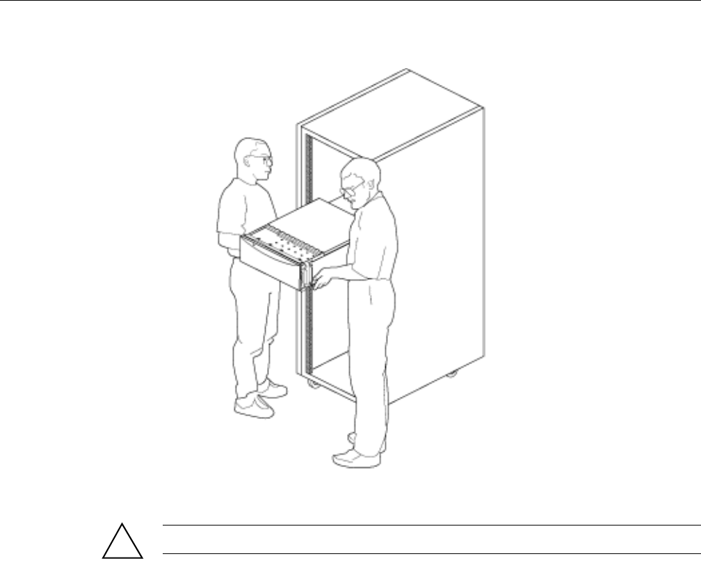
Removing and Installing the Rack Rails
007-5645-002 51
Figure 5-1 Lifting the SGI UV 10 System Into a Rack
Warning: Two people are required to lift an SGI Altix UV 10 System.
Removing and Installing the Rack Rails
Rack rails are provided to allow for easy access to the top cover and internal components when
the system is mounted on a rack.
!
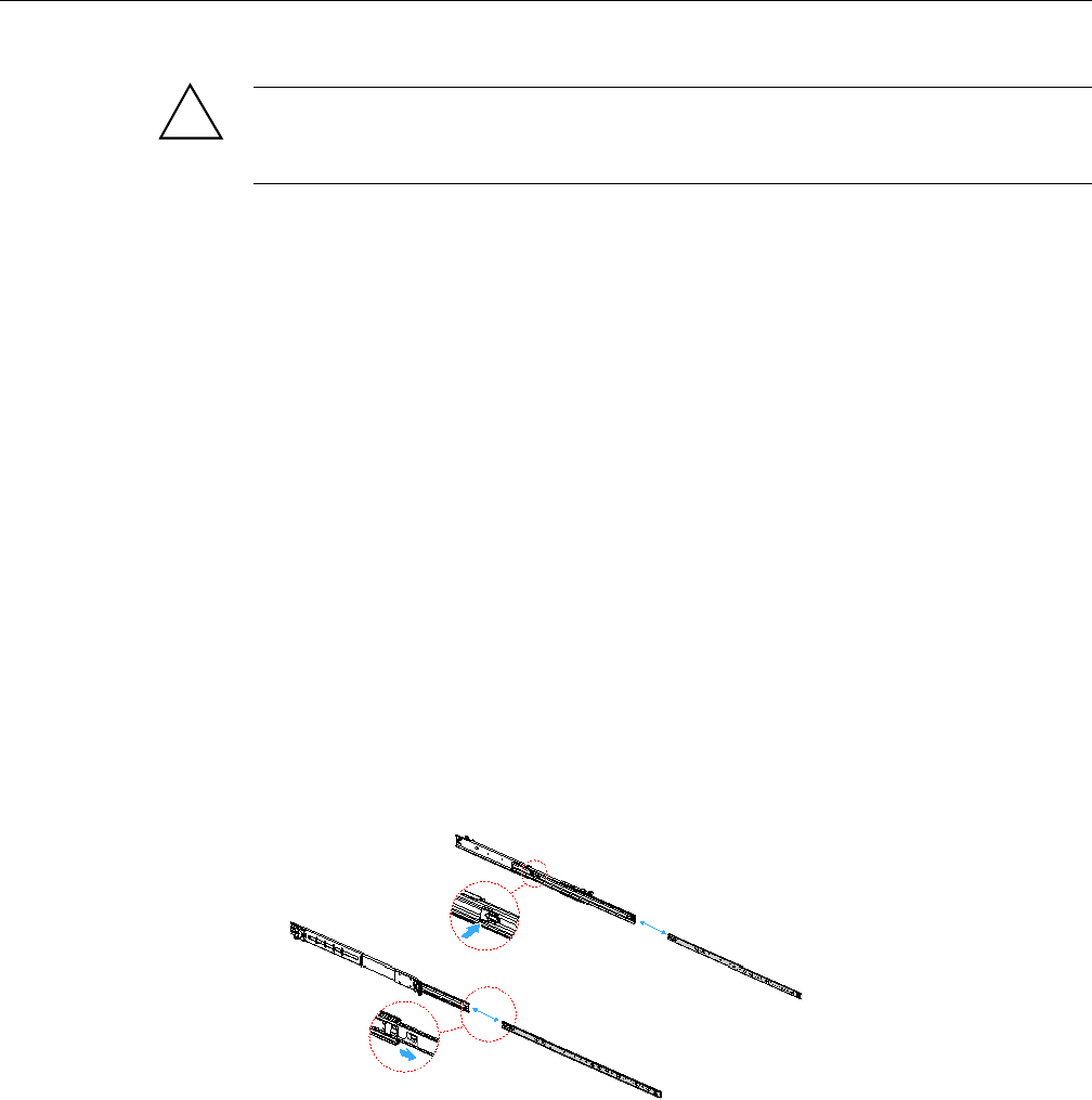
52 007-5645-002
5: Maintenance and Upgrade Procedures
Warning: The rail racks are designed to carry only the weight of the server system. Do
not use rail-mounted equipment as a workspace. Do not place additional load onto any
rail-mounted equipment.
Removing the Rack Rails
When it is necessary to service the rack or remove the system from a rack mounting, remove the
rack rails, as follows:
1. Press the release latch on the inner rail and remove the server system with inner rails from
the rack mounting.
2. Detach the slide rails from the rack mounting system.
3. Lift the leaf lock and slide the inner rail along the server sides to lift the inner rail off.
4. Slide the inner rails back into the slide rails for storage.
Installing the Rack Rails
When the server is to be installed into a rack, it is necessary to install two rack mount rails onto
the server chassis prior to installing the server into the rack. Follow the procedures below to install
your rack mount rails onto your server. Before you proceed, check the parts list for all parts.
1. Remove the slide rail from the inner rail by pressing on the latch on the inner rail and sliding
the rack rail free, as shown in Figure 5-2.
Figure 5-2 Removing the Inner Rack Rail from the Slide Rails
!
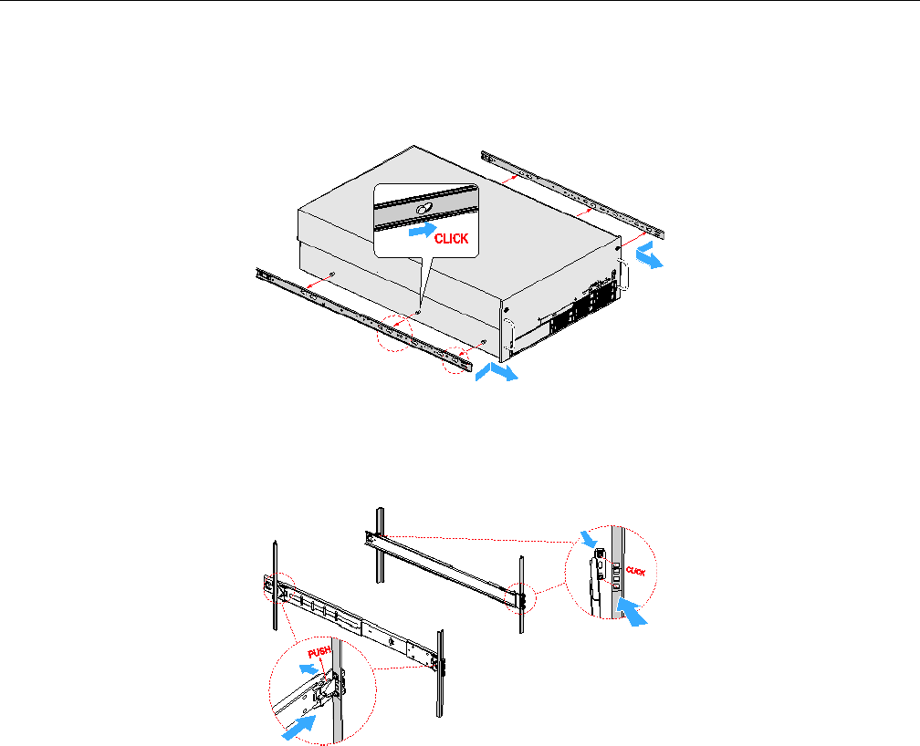
Removing and Installing the Rack Rails
007-5645-002 53
2. Locate and position the inner rail on the system chassis, sliding the inner rail into place, as
shown in Figure 5-3.
Figure 5-3 Installing the Inner Rail on the Server
3. Secure the slide rails in place on the rack mounting system, as shown in Figure 5-4.
Figure 5-4 Installing the Slide Rails on the Rack Mounting
4. Align the slide rail with the inner rail and slide the server forward until the rails’ latches lock,
as shown in Figure 5-5.
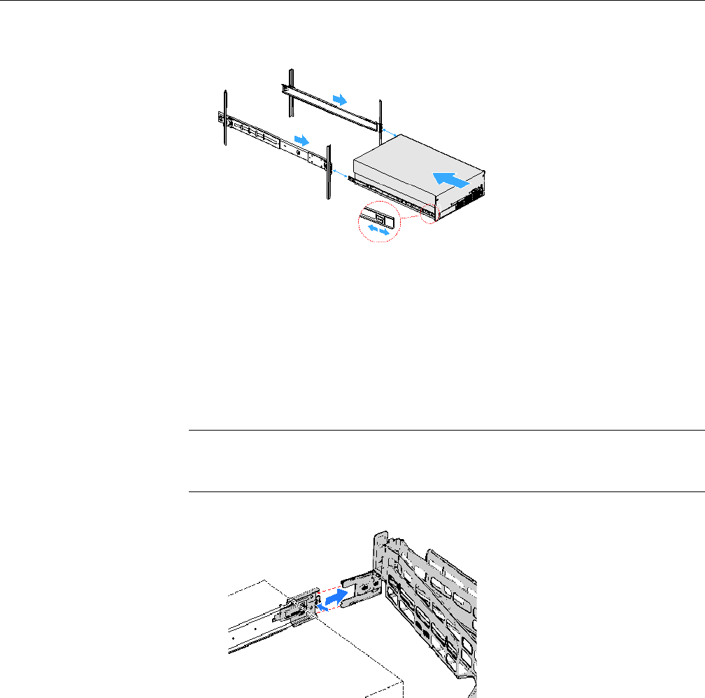
54 007-5645-002
5: Maintenance and Upgrade Procedures
Figure 5-5 Installing the Server onto the Rack Mounting
Removing the Cable Management Arm
To remove the cable management arm (CMA), perform the following steps:
1. Press the latch to release and remove the cable management arm from the cable management
extension on the left outer rail, as shown in Figure 5-6.
Note: By orientation from the rear of the system this rail is on the right. This is the left rail
according to the system designation of defining left and right from the front, and all
descriptions follow the system designation.
Figure 5-6 Removing the Cable Management Arm from the Extension
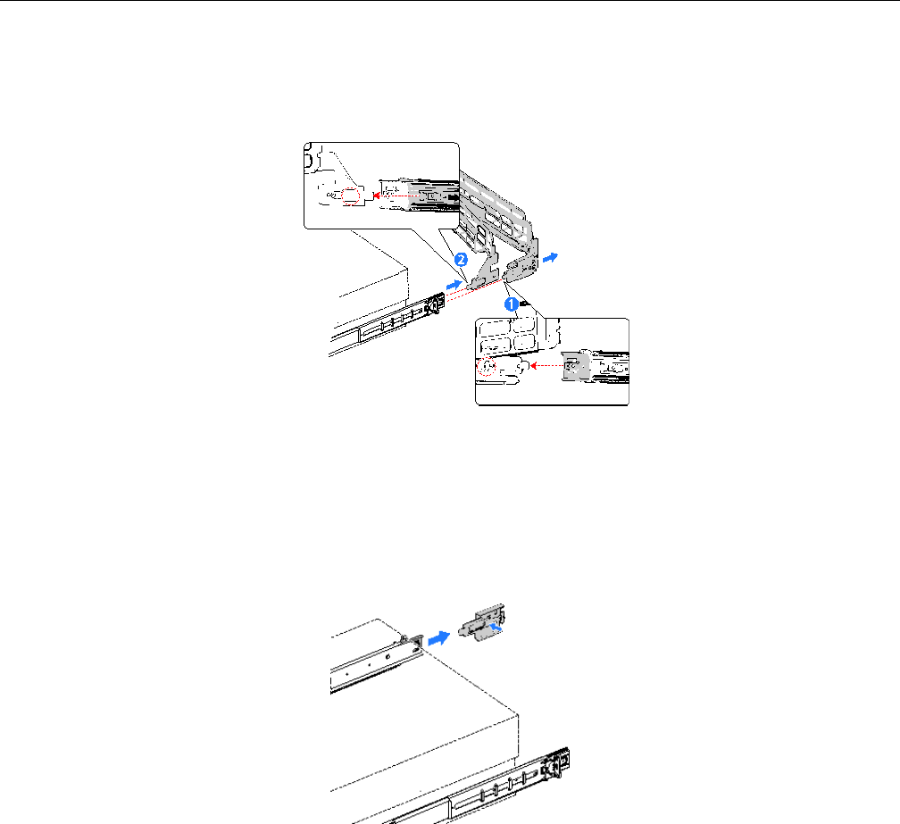
Removing the Cable Management Arm
007-5645-002 55
2. Press the latch to release and remove the CMA connector of the outer arm of the cable
management arm from the right outer rail, item 1, as shown in Figure 5-7.
Figure 5-7 Removing the Inner and Outer Rail Right CMA Connector
3. Press the latch to release and remove the CMA connector of the inner arm of the cable
management arm from the right inner rail, item 2, as shown in Figure 5-7.
4. Press the latch and remove the cable management arm extension from the left outer rail, as
shown in Figure 5-8.
Figure 5-8 Removing the Cable Management Arm Extention
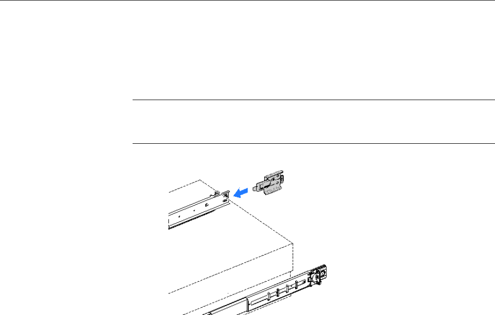
56 007-5645-002
5: Maintenance and Upgrade Procedures
Installing the Cable Management Arm
To install the cable management arm (CMA), perform the following steps:
1. Connect the cable management arm extension into the left outer rail, as show in Figure 5-9.
Note: By orientation from the rear of the system this rail is on the right. This is the left rail
according to the system designation of defining left and right from the front, and all
descriptions follow the system designation.
Figure 5-9 Installing the Cable Management Arm Extension
2. Connect the CMA connector of the inner arm of the cable management arm into the right
inner slide rail, item 1, as shown in Figure 5-10.
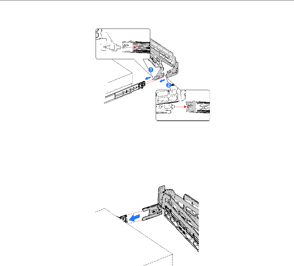
Removing the Cable Management Arm
007-5645-002 57
Figure 5-10 Installing the Inner Rail CMA Connector
3. Connect the CMA connector of the outer arm of the cable management arm into the right
outer rail, item 2, as shown in Figure 5-10.
4. Connect the extension connector of the cable management arm into the extension placed in
the left outer rail in step 1, as shown in Figure 5-11.
Figure 5-11 Installing the Cable Management Art to the Extension
58 007-5645-002
5: Maintenance and Upgrade Procedures
Removing and Installing the Chassis Cover
Warning: Make sure the rack is anchored securely so it does not tilt forward when the
server is extended. A crush hazard exists if the rack tilts forward. This could cause serious
injury.
Follow these precautions:
Caution: For proper cooling and airflow, do not operate the server for more than three minutes
with the cover removed. Do not leave the chassis cover open or a system fan removed any longer
than necessary; system cooling could be reduced.
Caution: The server comes with a removable top cover that allows the PCIe cards, memory risers,
and the system fans to be hot swapped, and other system components to be serviced. Except for
components described in this chapter, a qualified service technician must perform all servicing.
Caution: Provide electrostatic discharge (ESD) protection by wearing an antistatic wrist strap
attached to chassis ground of the system-any unpainted metal surface-when handling components.
Removing the Top Cover
Before removing the top cover, observe the safety guidelines in step 1.
To remove the top cover, follow the steps 2 through 5.
1. If you are not replacing a hot swap component:
• Turn off and disconnect all peripheral devices connected to the server.
• Power down the system by pressing and holding the power button on the front of the
chassis for several seconds.
• After the server shuts down, unplug all AC power cords to remove standby power from
the system.
!
!
!
!
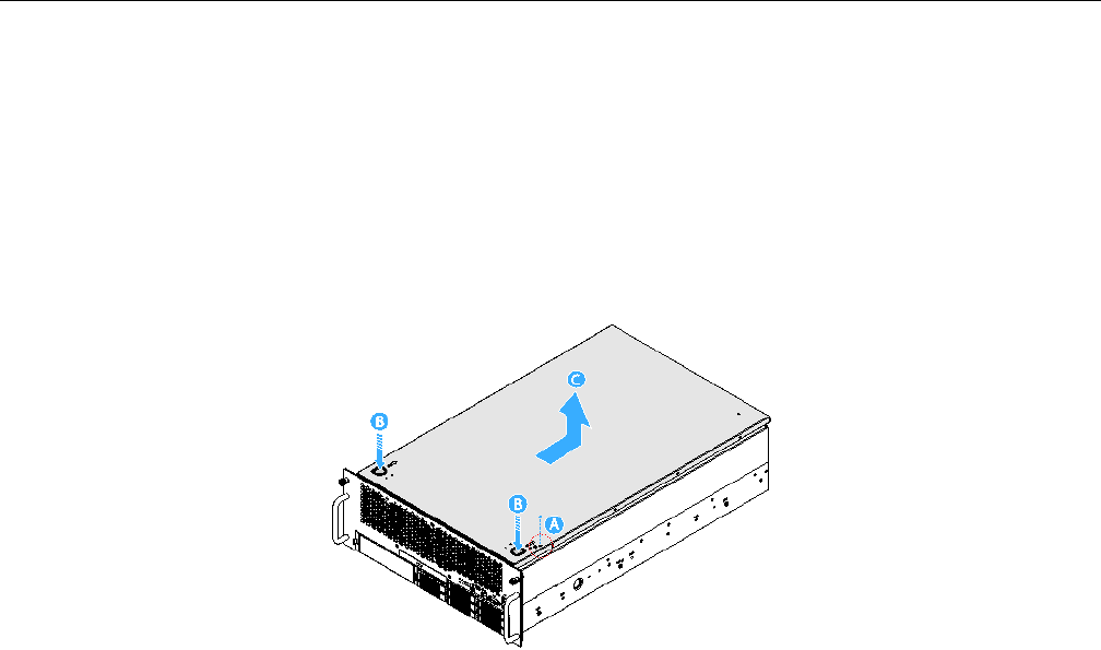
Removing and Installing the Chassis Cover
007-5645-002 59
2. If the system is mounted in a rack, slide it out far enough to expose the entire top cover.
3. Remove the one screw in the top cover. See letter “A” in Figure 5-12.
4. Press down on the two latch buttons on the top cover and slide the top cover off the latches.
See letter “B” in Figure 5-12.
5. Slide the top cover toward the rear until it stops, and then lift the cover to remove it. See
letter “C” in Figure 5-12.
Figure 5-12 Removing the Chassis Cover
Installing the Top Cover
To install the top cover, perform the following steps:
1. Place the cover over the chassis so that the side edges of the cover sit just inside the chassis
sidewalls and the tabs on the cover align with the slots in the chassis.
2. Slide the cover forward until it clicks into place. See letter “A” in Figure 5-13.
3. Replace the one screw in the top cover. See letter “B” in Figure 5-13.
4. Reconnect all peripheral devices and the AC power cords.
5. Slide the system back into the rack.
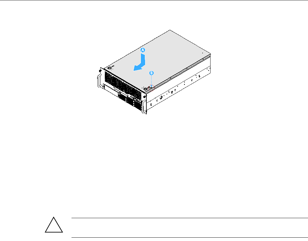
60 007-5645-002
5: Maintenance and Upgrade Procedures
Figure 5-13 Installing the Chassis Cover
Hot Swapping a Hard Drive
The SGI Altix UV 10 system supports eight hot swap drive carriers. Each carrier holds a standard
2.5-inch SATA or SAS hard drive.
The procedures in this section describe how to determine drive status, remove a faulty drive, and
install a new drive. If a drive is in a redundant configuration, you can install or replace a hot swap
hard drive without powering down the server.
Caution: To ensure proper airflow and server cooling, all drive bays must contain either a carrier
with a hard drive installed in it or a carrier with a HDD blank installed.
Item A in Figure 5-14 points to the hard drive latch. The drive carriers contain light-pipes that
allow LED indicators to display the hard drive status (see itmes B and C in Figure 5-14). Table 5-1
describes the the HDD LED activity status.
!
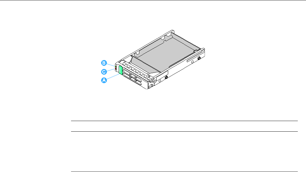
Hot Swapping a Hard Drive
007-5645-002 61
Figure 5-14 Hard Driver Carrier
Removing a Hard Drive Carrier
To remove a hard drive carrier, perform the following steps:
1. Press the green drive carrier latch. See “A” in Figure 5-15.
2. Open the bezel fully. See “B” in Figure 5-15.
3. Pull the bezel to remove the drive carrier from the chassis. See “C” in Figure 5-15.
4. Place the drive carrier on a clean, static-free work surface.
Table 5-1 HDD LED Activity Status
HDD LED State Description
LED (B) Green – Blinking HDD access or spin up/down
LED (C) Amber – On
Amber – Blinking
Off
HDD fault
Predictive failure, rebuild, identify
No access and no fault
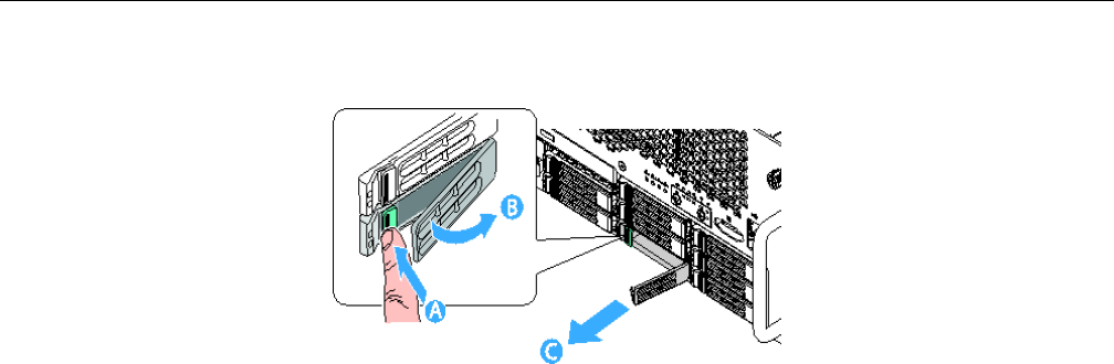
62 007-5645-002
5: Maintenance and Upgrade Procedures
Figure 5-15 Removing a Hard Drive Carrier
Mounting a Hard Drive in a Carrier
To mount a hard drive in a carrier, perform the following steps:
1. Remove the hard drive from the protective wrapper and place it on a clean ESD protected
work surface.
2. Set any jumpers and/or switches on the drive according to the drive manufacturer's
instructions.
3. If the drive carrier is installed in the chassis, remove it and place it on a clean static-free
work surface. For instructions, see “Removing a Hard Drive Carrier” on page 61.
4. Remove the four screws that hold the HDD blank in place. See letter “A” in Figure 5-16.
5. Remove the HDD blank from the carrier. See letter “B” in Figure 5-16.
6. Store the HDD blank for future reinstallation.
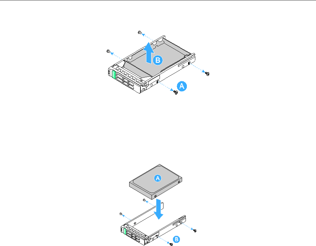
Hot Swapping a Hard Drive
007-5645-002 63
Figure 5-16 Removing the HDD Blank from the Hard Drive Carrier
7. Position the drive in the carrier with the label-side up and the connector end of the drive
facing the back of the carrier. See letter “A” in Figure 5-17.
8. Align the holes in the drive to the holes in the drive carrier slide track and replace the four
screws that were attached to the blanks. See letter “B” in Figure 5-17.
Figure 5-17 Attaching the Hard Drive to the Carrier
Installing a Hard Drive Carrier
To install a hard drive carrier, perform the following steps:
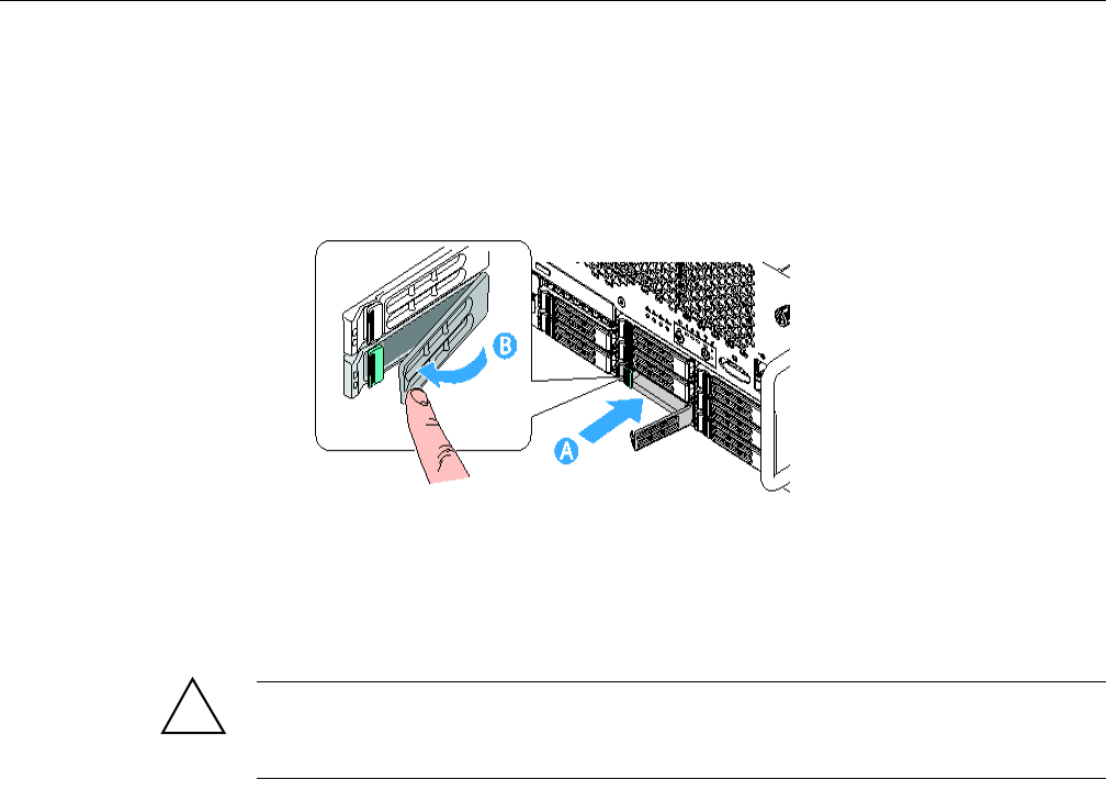
64 007-5645-002
5: Maintenance and Upgrade Procedures
1. With the drive carrier handle fully open, slide the drive carrier all the way into the drive bay
in the chassis. See letter “A” in Figure 5-18.
2. 2. Close the drive carrier handle to lock the hard drive carrier in position. See letter “B” in
Figure 5-18.
Figure 5-18 Installing the Hard Drive into the Altix UV 10 System
Hot Swapping a Power Supply
Warning: For the initial release of the SGI Altix UV 10 system, power supply modules
must be connected to separate AC power sources for standalone systems. See Appendix B,
“Power Supply Modules Safety Instructions”.
If your SGI Altix UV 10 system is configured with four power supplies, you can replace a failed
or failing power supply without powering down the server. Use the LEDs at the front of the power
supply as shown in Figure 5-19 to determine the power supply status. Each power supply module
has three status LEDs above the input connector. If the center LED is lit, the power supply needs
to be replaced.
!
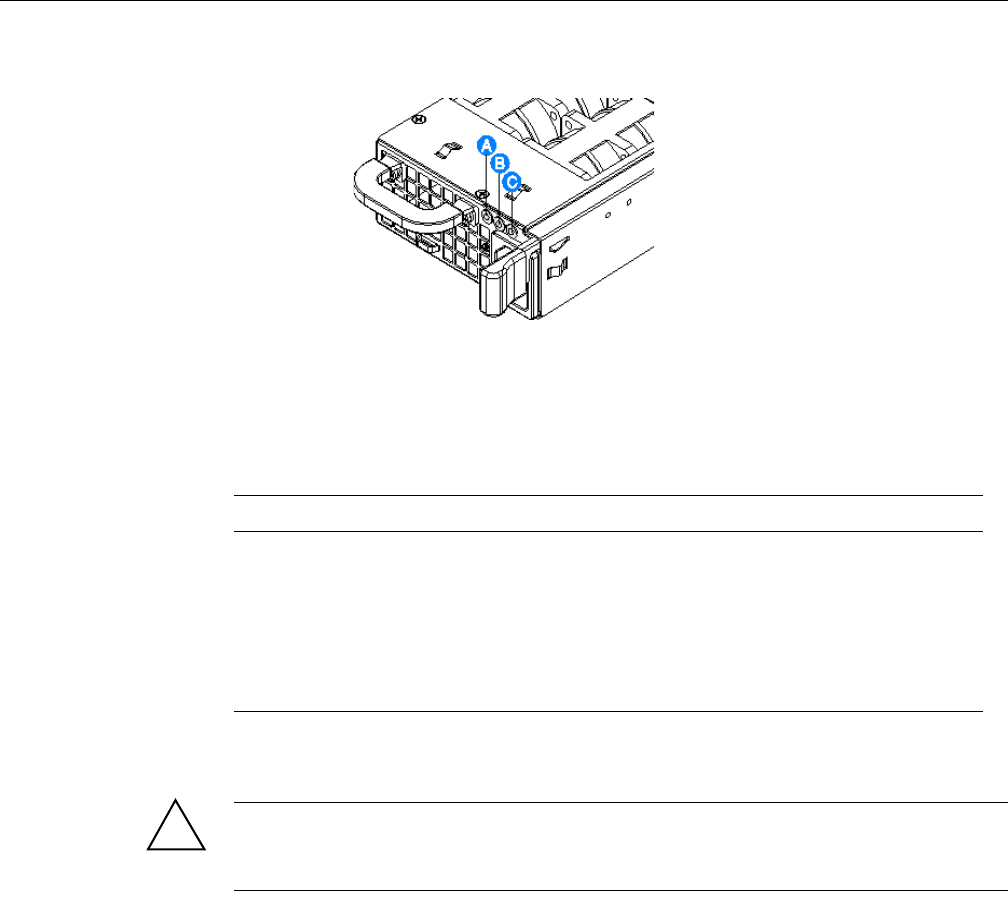
Hot Swapping a Power Supply
007-5645-002 65
Figure 5-19 Power Supply Indicators
Table 5-2 shows the power supply LED indicators status activity. See Figure 5-19 for the location
of the LEDs.
To remove a power supply, perform the following steps:
Caution: Because of chassis airflow disruption, a power supply bay should never be vacant for
more than three minutes when the server power is on. Exceeding five-minutes might cause the
system to exceed the maximum acceptable temperature and possibly damage system components.
1. Remove the AC power cord from the power supply to be removed. See letter “A” in
Figure 5-20.
2. Press in the latch to release the power supply module. See letter “B” in Figure 5-20.
3. Pull the power supply from the chassis and set it on a clean, ESD-protected work surface.
See letter “C ” in Figure 5-20.
Table 5-2 Power Supply Indicators
LED Loccation Purpose Description
A (left) Power Good LED
(green)
This LED is lit whenever the power is turned on.
B (center) Fault LED
(amber)
This LED is lit when a power fault occurred within the power
supply.
C (right) AC OK LED
(green)
This LED is lit whenever the AC power cord is plugged in to
an active AC power source.
!
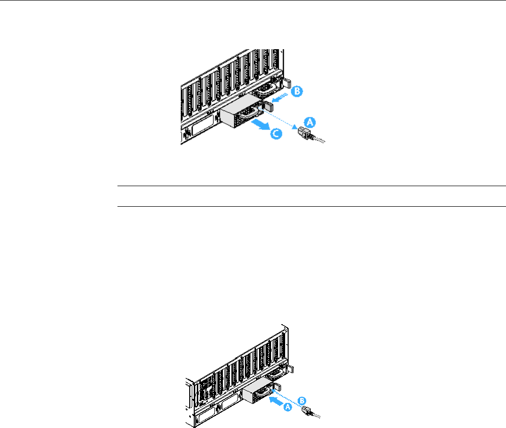
66 007-5645-002
5: Maintenance and Upgrade Procedures
Figure 5-20 Removing a Power Supply
Note: Power supply redundancy is available if four power supplies are installed.
4. Remove the new power supply from the protective packaging and place it on a clean ESD
protected work surface.
5. Slide the new power supply module into the power supply bay, with the AC inlet connector
on the right side, until it clicks and latches in place. See letter “A” in Figure 5-21.
6. Plug the power cord into the AC receptacle on the power supply. See letter “B” in
Figure 5-21. Use the LEDs on the power supply to confirm the power supply is functioning.
Figure 5-21 Installing a Power Supply
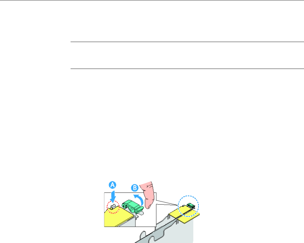
Removing and Installing Hot-Swap PCI Express Add-in Cards
007-5645-002 67
Removing and Installing Hot-Swap PCI Express Add-in Cards
Note: Cards can be hot swapped only in PCIe slots 1, 2, 6, and 7. The server must be powered
down to install or remove a card from PCIe slots 3 through 5, 8 through 10 and the SAS riser slot.
When looking at the system from the front, slot 1 is on the right.
Removing a Hot-Swap PCIe Card
To remove a hot-swap PCIe card, perform the following steps:
1. Remove the top cover. For instructions, see “Removing the Top Cover” on page 58.
2. Disconnect any cables attached to the card.
3. Press the LED light pipe switch on the PCIe card cover, and wait for the LED to turn off. See
letter “A” in Figure 5-22.
4. Rotate the green retention latch at the top front of the card slot into the up position. See letter
“B” in Figure 5-22.
Figure 5-22 Removing a Hot-swap PCIe Card
5. Lift the flap on the PCIe divider. See letter “C” in Figure 5-23.
6. Pull up on the card to remove it. See letter “D” in Figure 5-23.
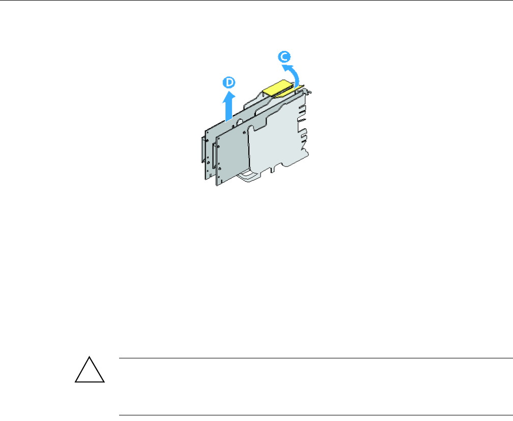
68 007-5645-002
5: Maintenance and Upgrade Procedures
Figure 5-23 Removing a PCIe Card
7. Store the card in an antistatic protective wrapper.
8. To install a replacement PCIe card: see .
9. Install an expansion slot cover by sliding it down to cover the opening if no PCIe
replacement card is installed.
10. Install the top cover. For instructions, see “Installing the Top Cover” on page 59.
Installing a Hot-Swap PCIe Card
Caution: Only PCIe add-in cards in PCIe slots 1, 2, 6, and 7 can be hot swapped. If you are
removing a PCIe card in PCIe slots 3 through 5 or 8 through 10,
see “Installing and Removing Non-Hot Swap PCI Express Add-in Cards” on page 70. When
looking at the system from the front, slot 1 is on the right.
To install a hot-swap PCIe card, perfomr the following steps:
1. If your operating system supports it, use your operating system or GUI application to power
down the PCIe slot.
2. Remove the top cover. For instructions, see “Removing the Top Cover” on page 58.
3. Being careful not to touch the components or gold edge-connectors on the add-in card,
remove the card from the anti-static bag and place it on a clean, ESD protected work surface.
!
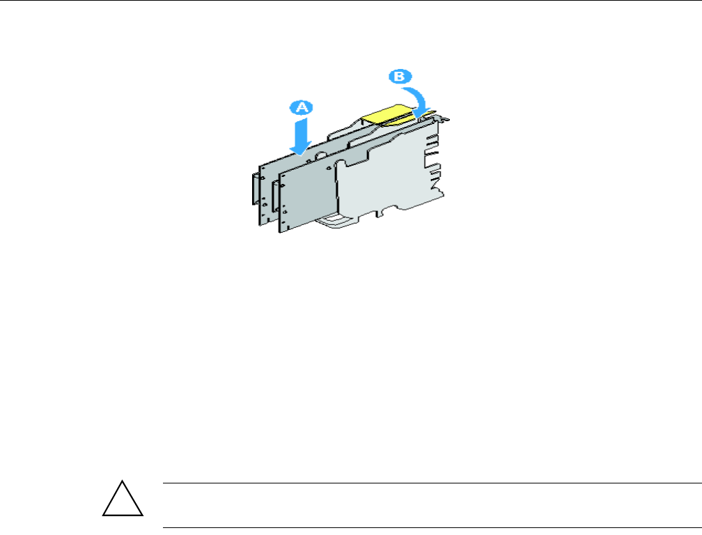
Removing and Installing Hot-Swap PCI Express Add-in Cards
007-5645-002 69
Figure 5-24 Installing a PCIe Add-in Card
4. Rotate the green retention latch at the rear of the card slot into the up position.
5. Remove the expansion slot cover by sliding it up.
6. Lift the flap on the PCIe divider.
7. Align and slide the adapter board down until it seats in its connector.
8. Press the card down firmly until it seats into the slot. See letter “A” in Figure 5-24.
9. Close the flap on the PCIe divider. See letter “B” in Figure 5-24.
To install a hot-swap PCIe add-in card, perform the following steps:
Caution: Some accessory/option board outputs exceed Class 2 or limited power source limits.
Use appropriate interconnecting cabling in accordance with the national electrical code
1. Rotate the green retention latch at the rear of the card slot into the down position. See letter
“C” in Figure 5-25.
2. Connect any required cabling to the PCIe add-in card.
!
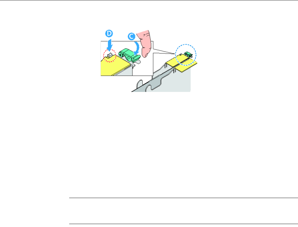
70 007-5645-002
5: Maintenance and Upgrade Procedures
Figure 5-25 Adding a Hot-swap PCIe Add-in Card
3. If using the operating system hot-plug interface:
• Wait for the software user interface to appear on your monitor and then confirm the
device to be enabled.
• Wait for the power LED to turn on.
If using the hardware hot-plug interface:
• Press the attention button for the slot. See letter “D” in Figure 5-25. If you need to abort
the hot-plug operation, press the attention button again within five seconds.
• Wait for power LED to turn on.
Note: For either the operating system interface or the hardware hot-plug interface, if the amber
attention LED is on, a power fault has occurred. You may need to remove the adapter, wait for the
LED to turn off, and re-start the hot insertion.
4. Install the top cover. For instructions, see “Installing the Top Cover” on page 59.
Installing and Removing Non-Hot Swap PCI Express Add-in Cards
This section describes how to reomove or install non-hot swap PCIe add-in cards.
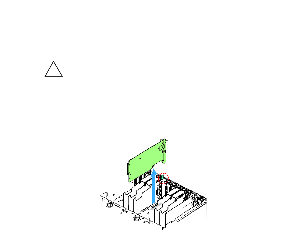
Installing and Removing Non-Hot Swap PCI Express Add-in Cards
007-5645-002 71
Removing a Non-Hot Swap PCIe Card
PCIe cards in slots 1, 2, 6 and 7 can be hot swapped. If you want to hot swap a card in one of these
slots, see “Removing and Installing Hot-Swap PCI Express Add-in Cards” on page 67.
Caution: AC power must be removed from the system before servicing a non-hot swap PCIe
card. You might damage your system if you do not power it down before removing or installing a
card in slots 3 through 5 and 8 through 10.
1. Remove the top cover. For instructions, see “Removing the Top Cover” on page 58.
2. Disconnect any cables attached to the PCIe card.
3. Rotate the retention latch into the up position, as shown in Figure 5-26.
Figure 5-26 Removing a Non-Hot Swap PCIe Card
4. Pull up on the card to remove it.
5. Place the PCIe card on a clean, static-free work surface or inside a static-free plastic bag.
6. To install a replacement PCIe card, see “Installing a Non-Hot Swap PCIe Card” on page 72,
otherwise, install a PCIe expansion slot cover.
7. Install the top cover. For instructions, see “Installing the Top Cover” on page 59.
!
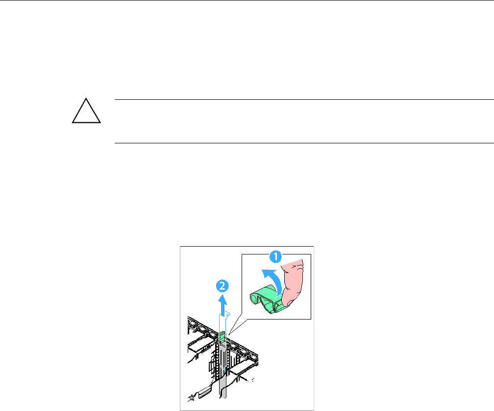
72 007-5645-002
5: Maintenance and Upgrade Procedures
Installing a Non-Hot Swap PCIe Card
PCIe cards in slots 1, 2, 6 and 7 can be hot swapped. If you want to hot swap a card in one of these
slots, see “Installing a Hot-Swap PCIe Card” on page 68.
Caution: AC power must be removed from the system before servicing a non-hot swap PCIe
card. You might damage your system if you do not power it down before removing or installing a
card in slots 3 through 5 and 8 through 10.
1. Remove the top cover. For instructions, see “Removing the Top Cover” on page 58.
2. Being careful not to touch the components or the gold edge connectors on the PCIe card,
remove it from its protective wrapper. Place the card component-side up on a clean,
static-free work surface.
3. Rotate the retention latch into the up position, item 1, as show in Figure 5-27.
Figure 5-27 Removing a PCIe Expansion Slot Cover
4. If necessary, remove the expansion slot cover in the slot you are using by sliding it up from
inside the chassis, item 2, as shown in Figure 5-27.
5. Align and slide the adapter board down until it seats in its connector, item 1, as shown
Figure 5-28.
!
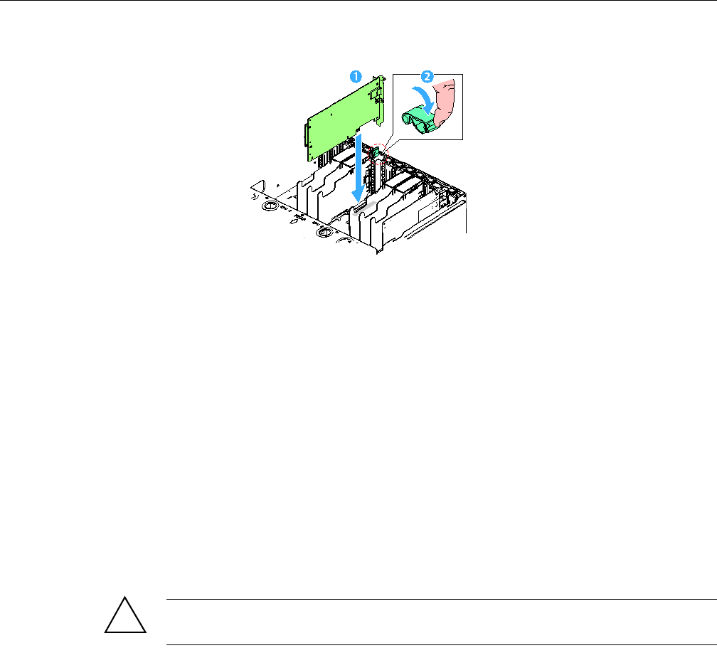
Removing and Installing System Fans
007-5645-002 73
Figure 5-28 Installing a Non-Hot Swap PCIe Card
6. Rotate the retention latch at the rear of the card slot into the down position, item 2, as shown
in Figure 5-28.
7. Attach any required cables to the PCIe card.
8. Install the top cover. For instructions, see “Installing the Top Cover” on page 59.
Removing and Installing System Fans
On the SGI Altix UV 10 system, eight cooling fans are located at the front of the chassis; seven
for normal operation, with an additional one for redundant operation in the event of fan failure.
The top cover must be removed before these fans can be serviced. You can replace a failed cooling
fan assembly without turning off the power to the server only if the remaining system fans are fully
functional. Each fan assembly uses an amber LED to indicate a failed fan condition. If the amber
LED is on, the fan assembly needs to be replaced. The LED remains off during normal operation.
Caution: System cooling is reduced during the fan replacement process. Do not leave a system
fan removed for longer than three minutes. Do not touch the fan blades while they are turning.
Removing the Hot-Swap Fan Modules
To remove a hot-swap fan module, perform the following steps:
!
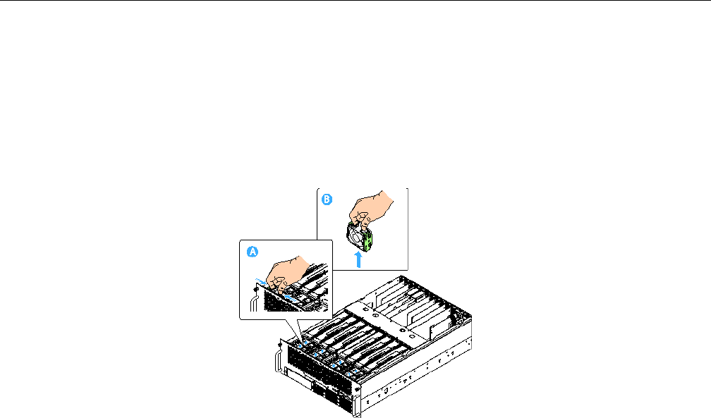
74 007-5645-002
5: Maintenance and Upgrade Procedures
1. Remove the top cover. For instructions, see “Removing the Top Cover” on page 58.
2. Locate the fan assembly you are replacing. If a fan in the assembly has failed, the amber
LED on the fan model lights.
3. Grasp the fan by the finger latches and squeeze together.
4. Lift the fan upward as shown in Figure 5-29.
Figure 5-29 Removing a System Fan Module
Installing the Hot-Swap Fan Modules
To install a hot-swap fan module, perform the following steps:
1. Lower the replacement fan into the fan bay as shown in Figure 5-30.
2. Push down on the fan until it clicks into place.
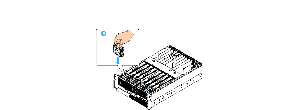
Removing and Installing System Fans
007-5645-002 75
Figure 5-30 Installing a System Fan Module
3. Install the top cover. For instructions, see “Installing the Top Cover” on page 59.
Removing System Fan Modules (non Hot-Swap)
To remove a system fan module, perform the following steps:
1. Power down the system.
2. Remove the top cover. For instructions, see “Removing a Hard Drive Carrier” on page 61.
3. Locate the fan assembly you are replacing. If a fan in the assembly has failed, the amber
LED on the fan model lights.
4. Grasp the fan by the finger latches and squeeze together.
5. Lift the fan upward as shown in Figure 5-31.
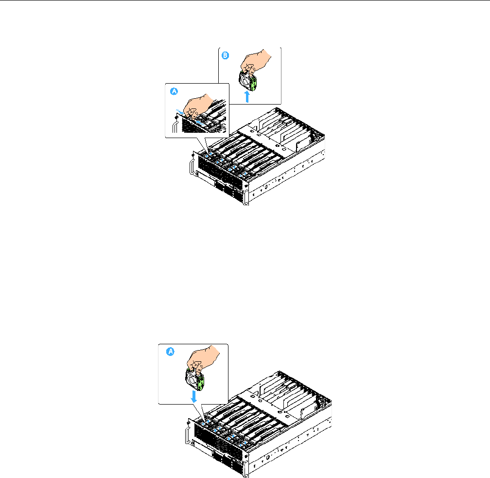
76 007-5645-002
5: Maintenance and Upgrade Procedures
Figure 5-31 Removing the System Fans
Installing the System Fan Modules (non Hot-Swap)
To install a system fan module, perform the following steps:
1. Lower the replacement fan into the fan bay.
2. Push down on the fan until it clicks into place as shown in Figure 5-32.
Figure 5-32 Installing the System Fans
Hot Swapping Memory Risers
007-5645-002 77
3. Install the top cover. For instructions, see “Installing the Top Cover” on page 59.
4. Power up the system.
Hot Swapping Memory Risers
At least one memory riser with two DIMMs must be installed for the system to function. Each of
the four CPUs can support one or two memory risers. Each installed CPU must have at least one
memory riser present for it to function.
If two memory risers are installed for a CPU, one of the risers may be removed while the system
is operating. This allows for the replacement of faulted DIMMs while ensuring continuous
operation of the system.
Warning: The CPU must have at least two DIMMS supporting it during hot swap
operations.
Removing a Memory Riser
Warning: Memory dividers must be installed at all times during operation for proper
airflow
To remove a memory riser, perform the following steps:
1. Remove the top cover. For instructions, see “Removing the Top Cover” on page 58.
Warning: Defective memory risers removed should be directly replaced in exactly the
original configuration. Do not hot swap defective memory in a new configuration.
2. Press the Attention button on the Memory Riser. See letter “A” in Figure 5-33. The attention
LED blinks for 5 seconds then turns off. Then the power button starts blinking. The power
button blinks until all memory has been flushed from the riser. When the power button turns
off the Memory Riser is safe to remove.
!
!
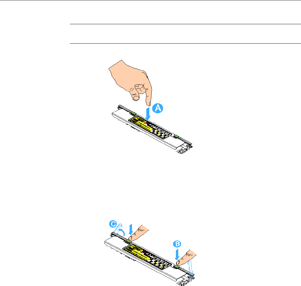
78 007-5645-002
5: Maintenance and Upgrade Procedures
Note: Pressing the attention button again while the attention LED is flashing cancels the
operation.
Figure 5-33 Pressing the Memory Riser Attention Button
3. Press the left and right green latches on the memory bracket downward to release the
memory bracket levers. See letter “B” in Figure 5-34.
4. Rotate the levers upward to disengage the memory riser from the main board. See letter “C”
in Figure 5-34.
Figure 5-34 Releasing a Memory Riser
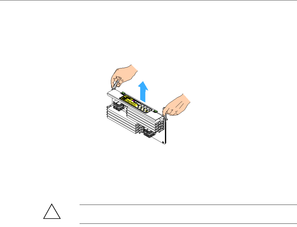
Hot Swapping Memory Risers
007-5645-002 79
5. Lift the memory riser by the levers of the memory bracket to pull it from the server as shown
in Figure 5-35.
6. Ensure the fan zone airflow configuration is correct, install or remove a memory air baffle if
necessary. For instructions, see “Installing and Removing Memory Air Baffles” on page 80.
Figure 5-35 Removing a Memory Riser
Installing a Memory Riser
To remove a memory riser, perform the following steps:
Warning: When adding new memory, obey the memory population rules. See
“Supported Memory Configurations” on page 83.
1. Ensure the levers on the memory bracket are in the open / up position.
2. Align the edges of the bracket in the bracket guides and slide the memory riser into the main
board as shown in Figure 5-36.
!
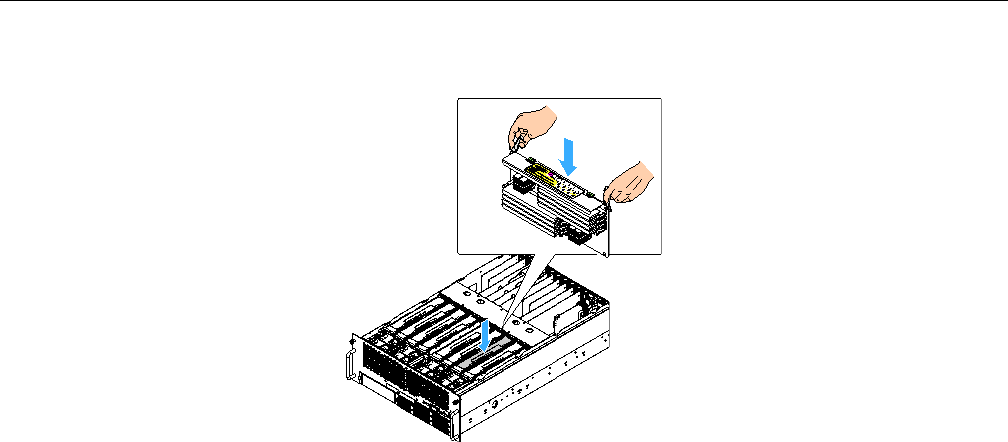
80 007-5645-002
5: Maintenance and Upgrade Procedures
Figure 5-36 Installing a Memory Riser
3. Once the board is lowered as far as possible, rotate the levers downward so they latch into
place to firmly engage the board into the memory riser slot.
4. Press the attention button. The attention LED and the power LED start blinking. When the
attention LED turns off and the power LED turns solid the system has finished adding the
memory riser.
5. Ensure the fan zone airflow configuration is correct, installing or removing a memory
airflow baffle if necessary. For instructions, see “Installing and Removing Memory Air
Baffles” on page 80.
6. Install the top cover. For instructions, see “Installing the Top Cover” on page 59.
Installing and Removing Memory Air Baffles
Each front fan has an internal fan zone comprising of two memory slots. See Figure 5-37. For
proper airflow each fan zone must have one of three configurations:
• Two memory risers
• One memory riser and one memory air baffle
• Two air baffles
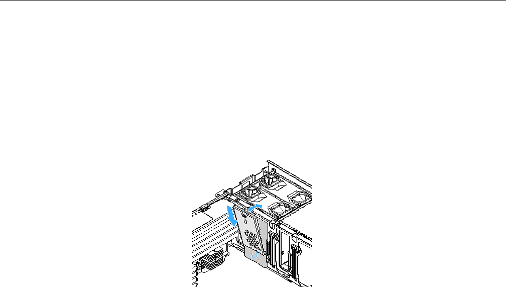
Installing and Removing Memory Air Baffles
007-5645-002 81
Installing a Memory Air Baffle
Install a memory air baffle when a fan zone has one memory riser (only). To install a memory air
baffle, perform the following steps:
1. Remove the top cover. For instructions, see “Removing the Top Cover” on page 58.
2. Place the bottom of the memory air baffle into the slot.as shown in Figure 5-37.
3. Push the top of the air baffle into the slot till it latches in place.
Figure 5-37 Installing a Memory Air Baffle
4. Install the top cover. For instructions, see “Installing the Top Cover” on page 59.
Removing a Memory Air Baffle
Remove a memory air baffle when a fan zone has two memory risers installed. To remove a
memory air baffle, perform the following steps:
1. Remove the top cover. For instructions, see “Removing the Top Cover” on page 58.
2. Press down on the tab at the top of the memory air baffle to release it as shown in
Figure 5-38.
3. Lift the memory air baffle out of the system.
4. Install the top cover. For instructions, see “Installing the Top Cover” on page 59.
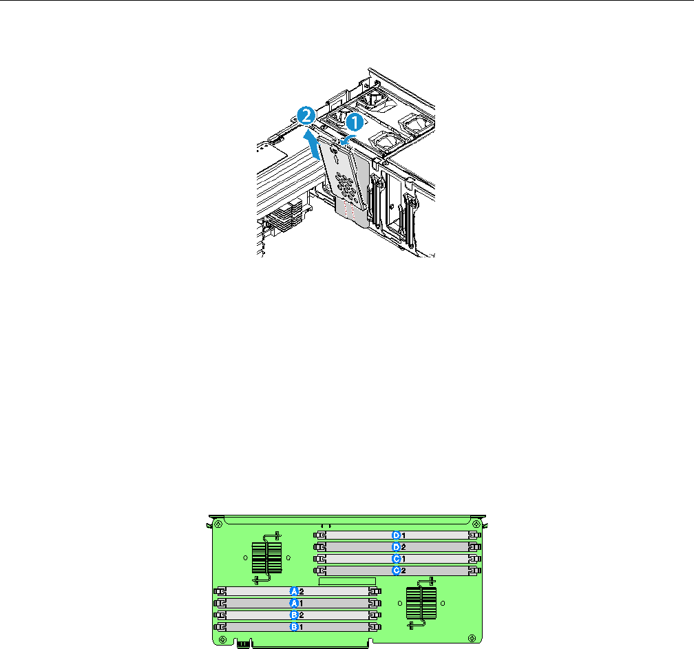
82 007-5645-002
5: Maintenance and Upgrade Procedures
Figure 5-38 Removing a Memory Air Baffle
Installing and Removing DIMMs
Memory is contained on memory risor cards that are called in-line memory modules (DIMMs).
DIMMs are installed one per DIMM slot.
Memory Riser DIMM Slot Locations
Each memory riser contains 8 DIMM slots with the designations shown Figure 5-39.
Figure 5-39 Memory Riser DIMM Locations
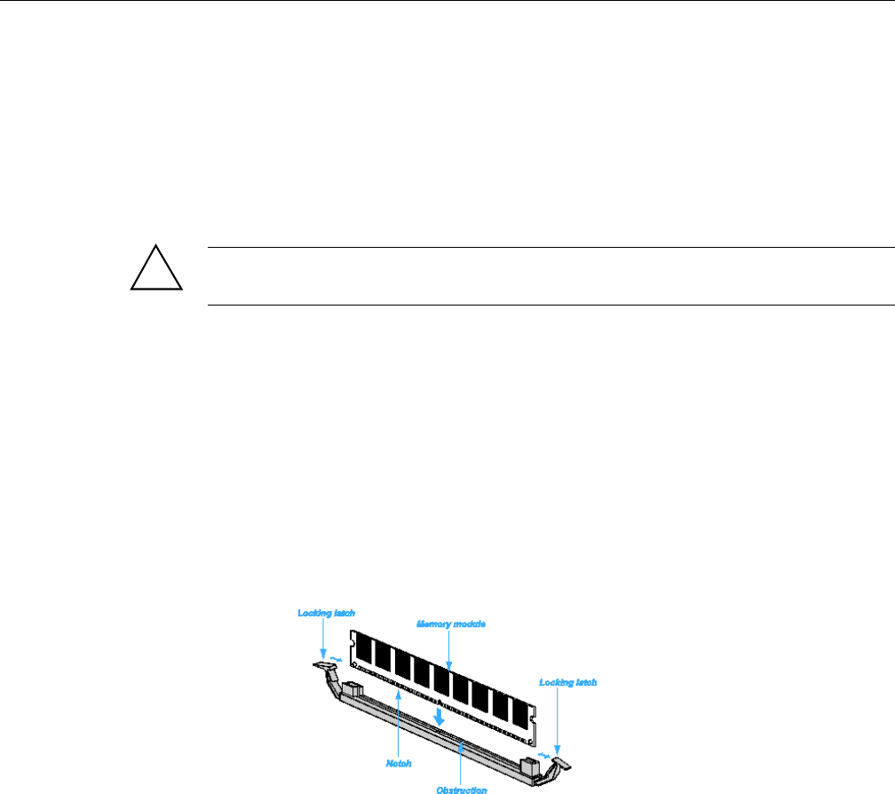
Installing and Removing DIMMs
007-5645-002 83
Supported Memory Configurations
The SGI Altix UV 10 system ships with two memory risers and can have 16, 32, or 64 total
DIMMs.
Installing DIMMs
Caution: Use extreme care when installing a DIMM. Applying too much pressure can damage
the connector. DIMMs are keyed and can be inserted in only one way.
• Hold DIMMs only by the edges. Do not touch the components or gold edge connectors.
• Install DIMMs with gold-plated edge connectors only.
• The maximum allowable DIMM height is 3 cm; do not install DIMMs that exceed this
height
To install DIMMs, perform the following steps:
1. Remove the top cover. For instructions, see “Removing the Top Cover” on page 58.
2. Remove the memory riser. For instructions, see “Removing a Memory Riser” on page 77.
3. Open the plastic levers on each end of the DIMM socket(s) as shown in Figure 5-40.
Figure 5-40 Install a DIMM
4. Remove the DIMM from its antistatic container. Hold the DIMM only by the edges. Do not
touch the components or gold edge connectors.
5. Install DIMMs in the correct order.
!
84 007-5645-002
5: Maintenance and Upgrade Procedures
6. Position the DIMM above the socket. Align the notch on the bottom edge of the DIMM with
the key in the DIMM socket.
7. Insert the bottom edge of the DIMM into the socket.
8. Push down on the top edge of the DIMM. The levers at each end of the DIMM socket close.
Make sure the levers close securely.
9. Install the top cover. For instructions, see “Installing the Top Cover” on page 59.
Removing DIMMs
Caution: Use extreme care when removing DIMMs. Too much pressure can damage the
connector. Apply only enough pressure on the plastic levers to release the DIMM.
1. Remove the top cover. For instructions, see “Removing the Top Cover” on page 58.
2. Remove the memory riser. For instructions, see “Removing a Memory Riser” on page 77
3. Open the plastic levers on each end of the DIMM socket(s) as shown in Figure 5-40. The
DIMM lifts from the socket.
4. Remove the DIMM holding the DIMM only by the edges. Do not touch the DIMM
components or the gold edge connectors. Store it in an antistatic bag.
5. Install replacement DIMMs if necessary. For instructions, see “Installing DIMMs” on
page 83.
6. Install the memory riser. For instructions, see “Installing a Memory Riser” on page 79.
Warning: Warning Memory riser dividers must be installed at all times during operation
for proper airflow.
7. Install the top cover. For instructions, see “Installing the Top Cover” on page 59
!
!

007-5645-002 85
Chapter 6
6. BIOS
This chapter describes the AMI BIOS Setup Utility for the SGI Altix UV 10 system.
Splash Logo / Diagnostic Screen
The Logo / Diagnostic Screen appear in one of two forms:
• If Quiet Boot is enabled in the BIOS setup, a logo splash screen is displayed. By default,
Quiet Boot is enabled in the BIOS setup. If the logo is displayed during POST, press <Esc>
to hide the logo and display the diagnostic screen.
• · If a logo is not present in the flash ROM, or if Quiet Boot is disabled in the system
configuration, the summary and diagnostic screen is displayed.
The diagnostic screen displays the following information:
• ·BIOS ID.
• Platform name.
• Total memory detected (Total size of all installed DDR3 DIMMs).
• Processor information (Intel branded string, speed, and number of physical processors
identified).
• Keyboards detected, if plugged in.
• Mouse devices detected, if plugged in.
BIOS Boot Popup Menu
The BIOS Boot Specification (BBS) provides a Boot pop-up menu that can be invoked by pressing
the <F6> key during POST. The BBS pop-up menu displays all available boot devices. The list
order in the pop-up menu is not the same as the boot order in BIOS setup; the pop-up menu simply

86 007-5645-002
6: BIOS
lists all of the bootable devices from which the system can be booted, and allows a manual
selection of the desired boot device.
When an Administrator password is installed in the Setup, the Administrator password will be
required in order to access the Boot pop-up menu using the <F6> key. If a User password is
entered, the Boot pop-up menu will not even appear – the user will be taken directly to the Boot
Manager in the Setup, where a User password allows only booting in the order previously defined
by the Administrator.
BIOS Setup Utility
The BIOS Setup utility is a text-based utility that allows the user to configure the system and view
current settings and environment information for the platform devices. The Setup utility controls
the platform's built-in devices, the boot manager, and error manager.
The BIOS Setup interface consists of a number of pages or screens. Each page contains
information or links to other pages. The advanced tab in Setup displays a list of general categories
as links. These links lead to pages containing a specific category‘s configuration.
The following sections describe the look and behavior for the platform setup.
Operation
The BIOS Setup has the following features:
• Localization - The BIOS Setup uses the Unicode standard and is capable of displaying setup
forms in all languages currently included in the Unicode standard. The Intel® Server Board
BIOS is only available in English.
• Console Redirection - The BIOS Setup is functional via console redirection over various
terminal emulation standards. This may limit some functionality for compatibility, for
example, usage of colors or some keys or key sequences or support of pointing devices.
Page Layout
The setup page layout is sectioned into functional areas. Each occupies a specific area of the
screen and has dedicated functionality. The following table lists and describes each functional
area.

BIOS Setup Utility
007-5645-002 87
Entering BIOS Setup
To enter the BIOS Setup, press the <F2> function key during boot time when the OEM or Intel
logo is displayed. The following message is displayed on the diagnostics screen and under the
Quiet Boot logo screen:
Press <F2> to enter setup
When the Setup is entered, the Main screen is displayed. However, serious errors cause the system
to display the Error Manager screen instead of the Main screen.
Keyboard Commands
The bottom right portion of the Setup screen provides a list of commands that are used to navigate
through the Setup utility. These commands are displayed at all times.
Table 6-1 BIOS Setup Page Layout
Functional Area Description
Title Bar The title bar is located at the top of the screen and displays the title of the
form (page) the user is currently viewing. It may also display
navigational information.
Setup Item List The Setup Item List is a set of controllable and informational items. Each
item in the list occupies the left column of the screen. A Setup Item may
also open a new window with more options for that functionality on the
board.
Item Specific Help Area The Item specific Help area is located on the right side of the screen and
contains help text for the highlighted Setup Item. Help information may
include the meaning and usage of the item, allowable values, effects of
the options, etc.
Keyboard Command Bar The Keyboard Command Bar is located at the bottom right of the screen
and continuously displays help for keyboard special keys and navigation
keys.

88 007-5645-002
6: BIOS
Each Setup menu page contains a number of features. Each feature is associated with a value field,
except those used for informative purposes. Each value field contains configurable parameters.
Depending on the security option chosen and in effect by the password, a menu feature‘s value
may or may not be changed. If a value cannot be changed, its field is made inaccessible and
appears grayed out.
Table 6-2 BIOS Setup—Keyboard Command Bar
Key Option Description
<Enter> Execute
Command
The <Enter> key is used to activate submenu when the selected feature is
a submenu, or to display a pick list if a selected option has a value field,
or to select a subfield for multi-valued features like time and date. If a
pick list is displayed, the <Enter> key selects the currently highlighted
item, undoes the pick list, and returns the focus to the parent menu.
<Esc> Exit The <Esc> key provides a mechanism for backing out of any field. When
the <Esc> key is pressed while editing any field or selecting features of
a menu, the parent menu is re-entered. When the <Esc> key is pressed in
any submenu, the parent menu is re-entered. When the <Esc> key is
pressed in any major menu, the exit confirmation window is displayed
and the user is asked whether changes can be discarded. If No is selected
and the <Enter> key is pressed, or if the <Esc> key is pressed, the user is
returned to where they were before <Esc> was pressed, without affecting
any existing settings. If Yes is selected and the <Enter> key is pressed,
the setup is exited and the BIOS returns to the main System Options
Menu screen.
- Select Item The up arrow is used to select the previous value in a pick list, or the
previous option in a menu item's option list. The selected item must then
be activated by pressing the <Enter> key.
- Select Item The down arrow is used to select the next value in a menu items option
list, or a value fields pick list. The selected item must then be activated
by pressing the <Enter> key.
´ Select Menu Te left and right arrow keys are used to move between the major menu
pages. The keys have no effect if a sub-menu or pick list is displayed.
<Tab> Select Field The <Tab> key is used to move between fields. For example, <Tab> can
be used to move from hours to minutes in the time item in the main menu.
- Change Value The minus key on the keypad is used to change the value of the current
item to the previous value. This key scrolls through the values in the
associated pick list without displaying the full list.

BIOS Setup Utility
007-5645-002 89
Menu Selection Bar
The Menu selection bar is located at the top of the BIOS Setup Utility screen. It displays the major
menu selections available to the user. By using the left and right arrow keys, the user can select
the listed menus. Some menus are hidden and become available by scrolling to the left or right of
the current selection.
BIOS Setup Utility Screens
The following sections describe the screens available for the configuration of a server platform.
In these sections, tables describe the contents of each screen. These tables follow the following
guidelines:
• The text and values in the Setup Item, Options, and Help Text columns displayed on the
BIOS Setup screens.
• In the Options column, the default values are displayed in bold. These values do not appear
in bold on the BIOS Setup screen. The bold text in this document is to serve as a reference
point.
• The Comments column provides additional information where it may be helpful. This
information does not appear on the BIOS Setup screens.
+ Change Value The plus key on the keypad is used to change the value of the current
menu item to the next value. This key scrolls through the values in the
associated pick list without displaying the full list. On 106-key Japanese
keyboards, the plus key has a different scan code than the plus key on the
other keyboards, but will have the same effect.
<F9> Setup Defaults Pressing the <F9> key causes the following to display: Load Optimized
Defaults? Yes No If Yes is highlighted and <Enter> is pressed, all Setup
fields are set to their default values. If No is highlighted and <Enter> is
pressed, or if the <Esc> key is pressed, the user is returned to where they
were before <F9> was pressed without affecting any existing field
values.
Table 6-2 BIOS Setup—Keyboard Command Bar (continued)
Key Option Description
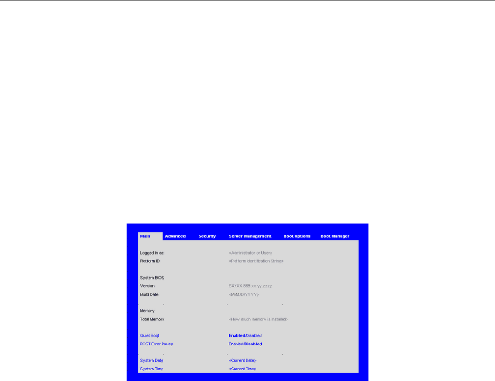
90 007-5645-002
6: BIOS
• Information enclosed in angular brackets (< >) in the screen shots identifies text that can
vary, depending on the option(s) installed. For example <Current Date> is replaced by the
actual current date.
• Information enclosed in square brackets ([ ]) in the tables identifies areas where the user
must type in text instead of selecting from a provided option.
• Whenever information is changed (except Date and Time), the system requires a save and
reboot to take place. Pressing <ESC> discards the changes and boots the system according to
the boot order set from the last boot.
Main Screen
The Main screen is the first screen that appears when the BIOS Setup is entered, unless an error
has occurred. If an error has occurred, the Error Manager screen appears instead.
Figure 6-1 Setup Utility—Main Screen

BIOS Setup Utility
007-5645-002 91
Table 6-3 Setup Utility—Main Screen Fields
Setup Item
Options
(Default in
Boldface) Help Text Comments
Logged in as: Information only. Displays
password level that setup is
running in: Administrator or
User. With no passwords set,
Administrator is the default
mode.
Platform ID Information only. Displays the
Platform ID.
System BIOS
Version Information only. Displays the
current BIOS version.
xx = major version
yy = minor version
zzzz = build number
Build Date Information only. Displays the
current BIOS build date.
Memory
Size Information only. Displays the
total physical memory installed
in the system, in MB or GB.
The term physical memory
indicates the total memory
discovered in the form of
installed DDR3 DIMMs.
Quiet Boot Enabled
Disabled
[Enabled] Display the logo
screen during POST. [Disabled]
Display the diagnostic screen
during POST.

92 007-5645-002
6: BIOS
Advanced Screen
The Advanced screen provides an access point to configure several options. On this screen, you
can select the option to be configured. Configurations are performed on the selected screen, and
not directly on the Advanced screen.
To access this screen from the Main screen, press the right arrow until the Advanced screen is
selected.
POST Error Pause Enabled
Disabled [Enabled] Go to the Error
Manager for critical POST
errors. [Disabled] Attempt to
boot and do not go to the Error
Manager for critical POST
errors.
If enabled, the POST Error
Pause option takes the system to
the error manager to review the
errors when major errors occur.
Minor and fatal error displays
are not affected by this setting.
System Date [Day of week
MM/DD/YYYY]
System Date has configurable
fields for Month, Day, and Year.
Use [Enter] or [Tab] key to
select the next field. Use [+] or
[-] key to modify the selected
field.
System Time [HH:MM:SS] System Time has configurable
fields for Hours, Minutes, and
Seconds. Hours are in 24-hour
format. Use [Enter] or [Tab] key
to select the next field. Use [+]
or [-] key to modify the selected
field.
Table 6-3 Setup Utility—Main Screen Fields (continued)
Setup Item
Options
(Default in
Boldface) Help Text Comments
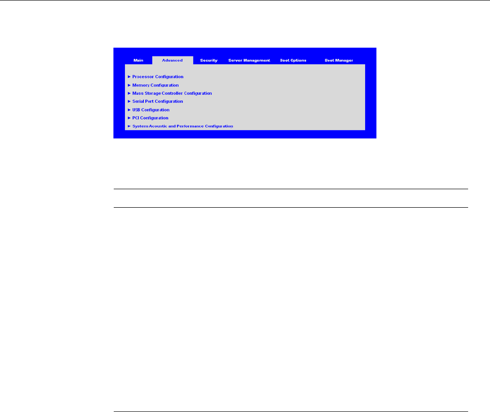
BIOS Setup Utility
007-5645-002 93
Figure 6-2 Setup Utility—Advanced Screen
Processor Configuration Screen
The Processor configuration screen allows you to view the processor core frequency and system
bus frequency and to enable or disable several processor options. This screen also allows the user
to view information about a specific processor.
To access this screen from the Main screen, select Advanced > Processor.
Table 6-4 Setup Utility—Advanced Screen Fields
Setup Item Options Help Text Comments
Processor Configuration View/Configure processor
information and settings.
Memory Configuration View/Configure memory information
and settings.
Mass Storage Controller
Configuration
View/Configure mass storage
controller information and settings.
Serial Port Configuration View/Configure serial port
information and settings.
USB Configuration View/Configure USB information and
settings.
PCI Configuration View/Configure PCI information and
settings.
System Acoustic and
Performance Configuration
View/Configure system acoustic and
performance information and settings.
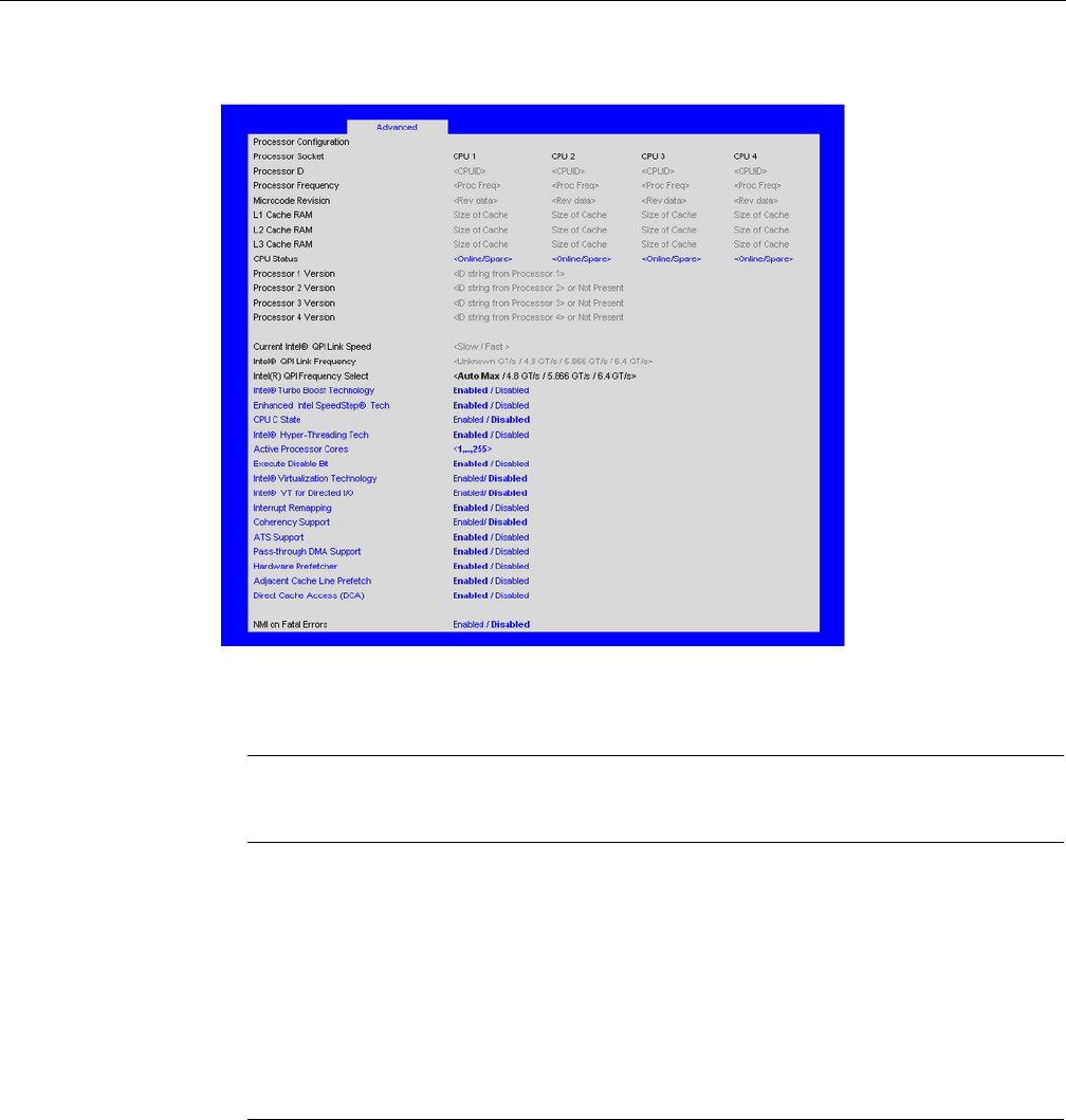
94 007-5645-002
6: BIOS
Figure 6-3 Setup Utility—Processor Configuration Screen
Table 6-5 Setup Utility—Processor Configuration Screen Fields
Setup Item
Options
(Default in
Boldface) Help Text Comments
Processor ID Information only. Processor
CPUID
Processor
Frequency
Information only. Current
frequency of the processor.
Core Frequency Information only. Frequency
at which the processors are
currently running.
Microcode
Revision
Information only. Revision of
the loaded microcode.

BIOS Setup Utility
007-5645-002 95
L1 Cache RAM Information only. Size of the
Processor L1 Cache.
L2 Cache RAM Information only. Size of the
Processor L2 Cache
L3 Cache RAM Information only. Size of the
Processor L3 Cache.
CPU Status Information only. Indicates
whether this CPU is online, or
selected as spare.
Processor 1
Version
Information only. ID string
from the Processor.
Processor 2
Version
Information only. ID string
from the Processor.
Processor 3
Version
Information only. ID string
from the Processor.
Processor 4
Version
Information only. ID string
from the Processor.
Current Intel QPI
Link Speed
Information only. Current
speed that the QPI Link is
using.
IntelQPI Link
Frequency
Information only. Current
frequency that the QPI Link is
using.
Table 6-5 Setup Utility—Processor Configuration Screen Fields (continued)
Setup Item
Options
(Default in
Boldface) Help Text Comments

96 007-5645-002
6: BIOS
Intel QPI
Frequency Select Auto Max
4.8 GT/s
5.866 GT/s
6.4 GT/s
Allows for selecting the IOH Intel(R)
QuickPath Interconnect Frequency.
Recommended to leave in [Auto Max]
so that BIOS can match the processor
and IOH Intel QuickPath Interconnect
frequencies. Set to [Auto Strap] to
force processor to force processor to
the IOH strapped frequency. If not
strapped, then [Auto Max] frequency
will be used.
Intel Turbo Boost
Technology Enabled
Disabled
Intel Turbo Boost Technology allows
the processor to automatically
increase its frequency if it is running
below power, temperature, and current
specifications.
This option is only visible if
all processors in the system
have Intel Turbo Boost
Technology available.
Enhanced Intel
SpeedStep
Technology
Enabled
Disabled
Enhanced Intel SpeedStep Technology
allows the system to dynamically
adjust processor voltage and core
frequency, which can result in
decreased average power
consumption and decreased average
heat production. Contact your OS
vendor regarding OS support of this s
feature.
CPU C State Enabled
Disabled Significantly reduces the power of the
processor during idle periods. Contact
your OS vendor regarding OS support
of this feature.
Intel
Hyper-Threading
Technology
Enabled
Disabled
Intel Hyper-Threading Technology
allows multithreaded software
applications to execute threads in
parallel within each processor.
Contact your OS vendor regarding OS
support of this feature.
Table 6-5 Setup Utility—Processor Configuration Screen Fields (continued)
Setup Item
Options
(Default in
Boldface) Help Text Comments

BIOS Setup Utility
007-5645-002 97
Actice Processor
Cores
1,..,255 Each bit position represents a core to
be enabled in each processor package.
Execute Disable
Bit Enabled
Disabled
Execute Disable Bit can help prevent
certain classes of malicious buffer
overflow attacks. Contact your OS
vendor regarding OS support of this
feature.
Intel
Virtualization
Technology
Enabled
Disabled Intel Virtualization Technology allows
a platform to run multiple operating
systems and applications in
independent partitions. Note: A
change to this option requires the
system to be powered off and then
back on before the setting takes effect.
Intel
Virtualization
Technology for
Directed I/O
Enabled
Disabled Enable/Disable Intel Virtualization
Technology for Directed I/O (Intel
VT-d). Report the I/O device
assignment to VMM through DMAR
AC Tables.
Interrupt
Remapping Enabled
Disabled
Enable/Disable Intel VT-d Interrupt
Remapping support.
This option only appears
when Intel Virtualization
Technology for Directed I/O is
enabled.
Coherency
Support
Enabled
Disabled Enable/Disable Intel VT-d Coherency
support.
This option only appears
when Intel Virtualization
Technology for Directed I/O is
enabled.
ATS Support Enabled
Disabled
Enable/Disable Intel VT-d Address
Translation Services (ATS) support.
This option only appears
when Intel Virtualization
Technology for Directed I/O is
enabled.
Table 6-5 Setup Utility—Processor Configuration Screen Fields (continued)
Setup Item
Options
(Default in
Boldface) Help Text Comments

98 007-5645-002
6: BIOS
Memory Configuration Screen
The Memory configuration screen allows you to view details about the system memory DDR3
DIMMs that are installed. This screen also allows you to open the Configure Memory RAS and
Performance screen.
To access this screen from the Main screen, select Advanced > Memory.
Pass-through
DMA Support Enabled
Disabled
Enable/Disable Intel VT-d
Pass-through DMA support.
This option only appears
when Intel Virtualization
Technology for Directed I/O is
enabled.
Hardware
Prefetcher Enabled
Disabled
Hardware Prefetcher is a speculative
prefetch unit within the processor(s).
Note: Modifying this setting may
affect system performance.
Adjacent Cache
Line Prefetch Enabled
Disabled
[Enabled] - Cache lines are fetched in
pairs (even line + odd line).
[Disabled] - Only the current cache
line required is fetched. Note:
Modifying this setting may affect
system performance.
Direct Cache
Access (DCA) Enabled
Disabled
Allows processors to increase the I/O
performance by placing data from I/O
devices directly into the processor
cache.
NMI on Fatal
Errors Disabled
Enabled
When enabled, causes NMI to be the
preferred mode of halting OS instead
of the default Machine Check mode.
Table 6-5 Setup Utility—Processor Configuration Screen Fields (continued)
Setup Item
Options
(Default in
Boldface) Help Text Comments
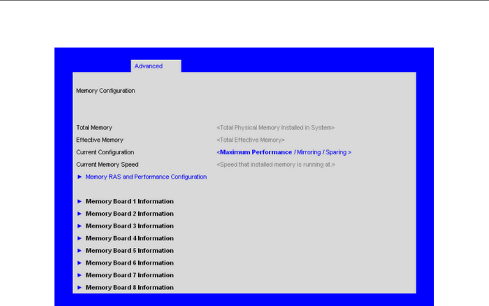
BIOS Setup Utility
007-5645-002 99
Figure 6-4 Setup Utility—Memory Configuration Screen

100 007-5645-002
6: BIOS
Table 6-6 Setup Utility—Memory Configuration Screen Fields
Setup Item
Options
(Default in
Boldface) Help Text Comments
Total Memory Information only. The amount of
memory available in the system in the
form of installed DDR-3 DIMMs, in
units of MB or GB.
Effective
Memory
Information only. The amount of
memory available to the OS in MB or
GB. The Effective Memory is the
difference between Total Physical
Memory and the sum of all memory
reserved for internal usage, RAS
redundancy and SMRAM. This
difference includes the sum of all
DDR-3 DIMMs that failed Memory
BIST during POST, or were disabled
by the BIOS during memory discovery
phase in order to optimize memory
configuration.
Current
Configuration Maximum
Performance
Mirroring
Sparing
Information only. Displays one of the
following:
- Max Performace Mode: System
memory is configured for max
performance.
- Mirror Mode: System memory is
configured for maximum reliability in
the form of memory mirroring.
- Sparing Mode: System memory is
configured for RAS with optimal
effective memory.

BIOS Setup Utility
007-5645-002 101
Configure Memory RAS and Performance Screen
The Configure Memory RAS and Performance screen allows you to customize several memory
configuration options, such as whether to use Memory Mirroring or Memory Sparing.
To access this screen from the Main screen, select Advanced > Memory > Configure Memory
RAS and Performance.
Current Memory
Speed
Information only. Displays speed the
memory is running at.
Memory RAS and
Performance
Configuration
Configure memory
RAS (Reliability,
Availability, and
Serviceability) and view
current memory
performance
information and
settings.
Select to configure the memory RAS
and performance. This takes the user
to a different screen.
Table 6-6 Setup Utility—Memory Configuration Screen Fields (continued)
Setup Item
Options
(Default in
Boldface) Help Text Comments
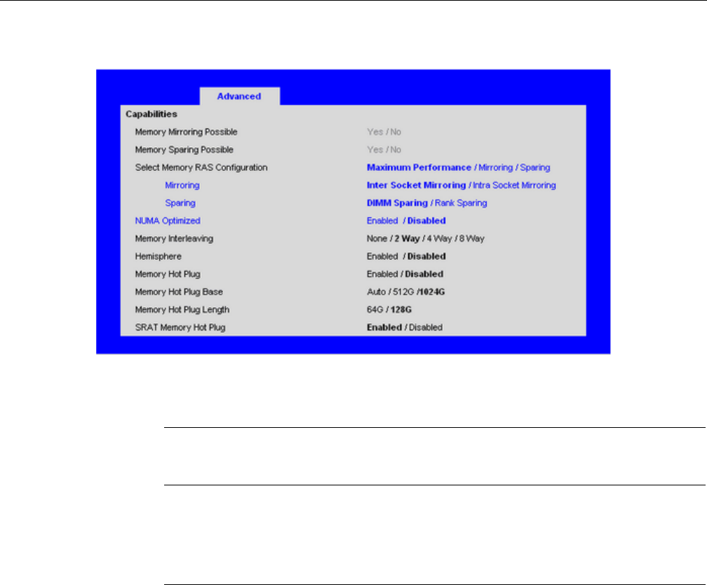
102 007-5645-002
6: BIOS
Figure 6-5 Setup Utility—Configure Memory and RAS and Performance Screen
Table 6-7 Setup Utility—Configure Memory RAS and Performance Screen Fields
Setup Item
Options
(Default in
Boldface) Help Text Comments
Memory
Mirroring
Possible
Yes / No Information only. Specifies if
mirroring is possible.
Memory DIMM
Sparing Possible
Yes / No Information only: Specifies if
DIMM sparing is possible.

BIOS Setup Utility
007-5645-002 103
Select Memory
RAS
Configuration
Maximum
Performance
Mirroring
Sparing
Available modes depend on the
current memory population.
[Maximum Performance] -
Optimizes system performance.
[Mirroring] - Optimizes
reliability by using half of
physical memory as a backup.
Sparing] - Improves reliability
by reserving memory for use as
a replacement in the event of
DIMM failure.
Mirroring Mode Inter-Socket
Mirroring
Intra-Socket
Mirroring
Mirroring is supported across
Integrated Memory Controllers
where one memory riser is
mirrored with another.
[Inter-Socket Mirroring] - IMC
is mirrored across two sockets.
[Intra-Socket Mirroring] - IMC
is mirrored with the other IMC
in the same socket.
Appears when Mirroring is
selected in RAS configuration.
And Hemisphere mode is
disabled.
Sparing Mode DIMM Sparing
Rank Sparing
Select Sparing Mode to use
spare DIMM or Rank within the
Integrated Memory Controller
on a memory riser.
Appears when Sparing is
selected in RAS configuration.
NUMA
Optimized
Enabled
Disabled If enabled, BIOS includes ACPI
tables that are required for
NUMA aware Operating
Systems.
Memory
Interleaving
none
2 Way
4 Way
8 Way
Enable/Disable memory
interleaving. NUMA setting is
required for Memory RAS.
Hemisphere Enabled
Disabled Enable/Disable Hemisphere
Mode.
Table 6-7 Setup Utility—Configure Memory RAS and Performance Screen Fields (continued)
Setup Item
Options
(Default in
Boldface) Help Text Comments

104 007-5645-002
6: BIOS
Memory Board Information Screens
The Memory Board Information screen allows you to view the status of each memory riser in the
system.
When a DIMM fails during BIST (Early POST - MRC) all four DIMMs in the lock-step DDR3
Channel Pair will be disabled. This is due to DDR3 Channel Failure & Lock-step.
Memory Hot Plug Enabled
Disabled Enable/Disable Memory Hot
Plug.
Memory Hot Plug
Base
Auto
512G
1024G
Set memory hot plug mapping
base in system.
Memory Hot Plug
Length
64G
128G Set memory hot plug mapping
length for each board.
SRAT Memory
Hot Plug Enabled
Disabled
Fix for OS that does not support
memory hot plug. Ex: SuSE
SLES10 SP2. Enable by default.
Disable will clear all hot plug
bits and remove the hot plug
entries in SRAT table.
Table 6-7 Setup Utility—Configure Memory RAS and Performance Screen Fields (continued)
Setup Item
Options
(Default in
Boldface) Help Text Comments
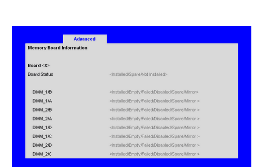
BIOS Setup Utility
007-5645-002 105
Figure 6-6 Setup Utility—Memory Board Information Screens

106 007-5645-002
6: BIOS
Mass Storage Controller Configuration Screen
The Mass Storage configuration screen allows you to configure the SATA/SAS controller when
it is present on the baseboard, midplane or backplane of an Intel system.
To access this screen from the Main menu, select Advanced > Mass Storage.
Table 6-8 Setup Utility—Memory Board Information Screen Fields
Setup Item
Options
(Default in
Boldface) Help Text Comments
Board Status Note: X denotes the Board ID from A-H. Indicates
the status of the board.
DIMM_ XY Displays the state of each DIMM socket present on
the board. Each DIMM socket field reflects one of
the following possible states:
- Installed: There is a DDR3DIMM installed in this
slot.
- Not Installed: There is no DDR3 DIMM installed
in this slot.
- Disabled: The DDR3 DIMM installed in this slot
has been disabled by the BIOS in order to optimize
memory configuration.
- Failed: The DDR3 DIMM installed in this slot is
faulty /malfunctioning.
- Spare Unit: The DDR3 DIMM is functioning as a
spare unit for memory RAS purposes.
- Mirror Unit: The DDR3 DIMM is functioning as a
mirror unit for memory RAS purposes. Note: X
denotes the Board identifier <A-H>.
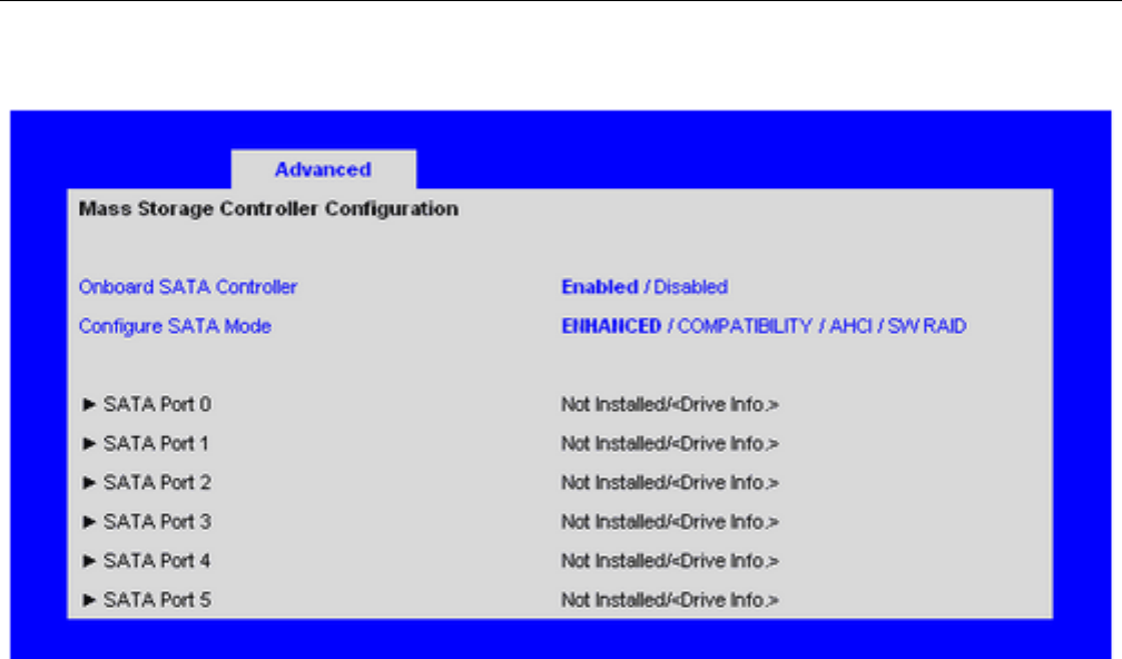
BIOS Setup Utility
007-5645-002 107
Figure 6-7 Setup Utility—Mass Storage Controller Configuration Screen

108 007-5645-002
6: BIOS
Table 6-9 Setup Utility—Mass Storage Controller Configuration Screen Fields
Setup Item Options (Default
in Boldface) Help Text Comments
Onboard
SATA
Controller
Enabled
Disabled
On-board Serial ATA (SATA)
controller.
SATA Mode ENHANCED
COMPATIBILITY
AHCI
SW RAID
[ENHANCED] - Supports up to
six SATA ports with IDE Native
Mode.
[COMPATIBILITY] - Supports
up to four SATA ports[0/1/2/3]
with IDE Legacy mode and two
SATA ports[4/5] with IDE
Native Mode.
[AHCI] - Supports all SATA
ports using the Advanced Host
Controller Interface.
[SW RAID] - Supports
configuration of SATA ports for
RAID via RAID configuration
software.
This field does not appear when
the Onboard SATA Controller is
disabled. Changing this setting
requires a reboot before HDD
boot order can be set. [SW
RAID] option is unavailable
when EFI Optimized Boot is
enabled, since SW RAID can
only be used in Legacy Boot
mode.
SATA Port 0 < Not Installed / Drive
information>
Information only. This field is
unavailable when RAID Mode
is enabled.
SATA Port 1 < Not Installed / Drive
information>
Information only. This field is
unavailable when RAID Mode
is enabled.
SATA Port 2 < Not Installed / Drive
information>
Information only. This field is
unavailable when RAID Mode
is enabled.
SATA Port 3 < Not Installed / Drive
information>
Information only. This field is
unavailable when RAID Mode
is enabled.

BIOS Setup Utility
007-5645-002 109
Serial Port Configuration Screen
The Serial Ports Configuration screen allows you to configure the Serial A [COM 1] and Serial B
[COM2] ports.
To access this screen from the Main screen, select Advanced > Serial Port.
SATA Port 4 < Not Installed / Drive
information>
Information only. This field is
unavailable when RAID Mode
is enabled.
SATA Port 5 < Not Installed / Drive
information>
Information only. This field is
unavailable when RAID Mode
is enabled.
Table 6-9 Setup Utility—Mass Storage Controller Configuration Screen Fields (continued)
Setup Item Options (Default
in Boldface) Help Text Comments
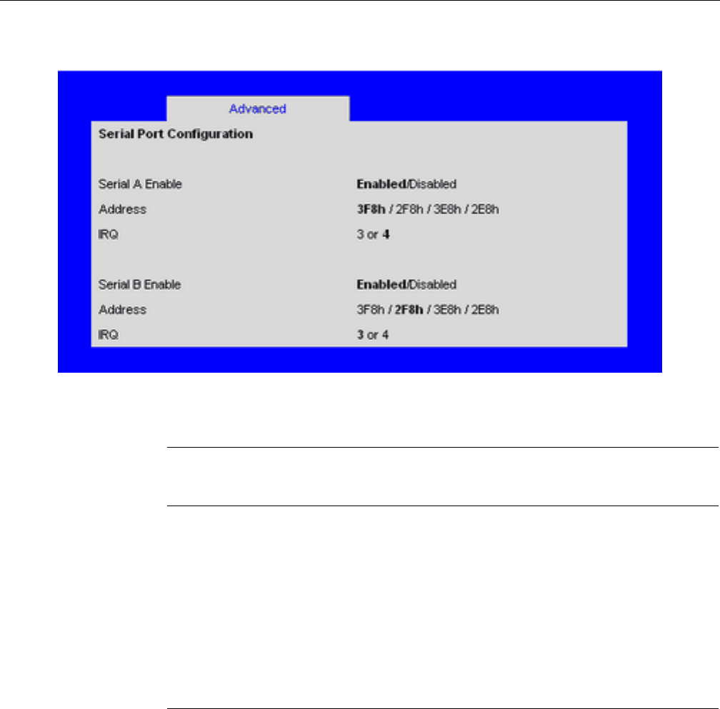
110 007-5645-002
6: BIOS
Figure 6-8 Setup Utility—Serial Port Configuration Screen
Table 6-10 Setup Utility—Serial Port Configuration Screen Fields
Setup Item
Options
(Default in
Boldface) Help Text Comments
Serial A Enable Enabled
Disabled
Enable or Disable Serial port A.
Address 3F8h
2F8h
3E8h
2E8h
Select Serial port A base I/O address.
IRQ 3
4Select Serial port A interrupt request (IRQ) line.
Serial B Enable Enabled
Disabled
Enable or Disable Serial port B.

BIOS Setup Utility
007-5645-002 111
USB Configuration Screen
The USB Configuration screen allows you to configure the USB controller options.
To access this screen from the Main screen, select Advanced > USB Configuration.
Address 3F8h
2F8h
3E8h
2E8h
Select Serial port B base I/O address.
IRQ 3
4
Select Serial port B interrupt request (IRQ) line.
Table 6-10 Setup Utility—Serial Port Configuration Screen Fields (continued)
Setup Item
Options
(Default in
Boldface) Help Text Comments
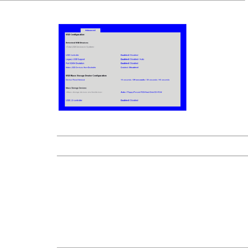
112 007-5645-002
6: BIOS
Figure 6-9 Setup Utility—USB Configuration Screen
Table 6-11 Setup Utility—USB Controller Configuration Screen Fields
Setup Item
Options
(Default in
Boldface) Help Text Comments
Detected USB
Devices
Information only. This field
displays number of USB devices
in the system.
USB Controller Enabled
Disabled
[Enabled] - All on-board USB
controllers are turned on and
accessible by the OS.
[Disabled] - All on-board USB
controllers are turned off and
inaccessible by the OS.
Legacy USB
Support Enabled
Disabled
Auto USB device boot support
and PS/2 emulation for USB
keyboard and USB mouse
devices. [Auto] - Legacy USB
support is enabled if a USB device
is attached.
This field is grayed out if the
USB Controller is disabled.

BIOS Setup Utility
007-5645-002 113
Port 60/64
Emulation Enabled
Disabled
I/O port 60h/64h emulation
support. Note: This may be
needed for legacy USB keyboard
support when using an OS that is
USB unaware.
This field is grayed out if the
USB Controller is disabled.
Make USB
Devices Non-
Bootable
Enabled
Disabled Exclude USB in Boot Table.
[Enabled] - This removes all USB
Mass Storage devices as Boot
options.
[Disabled] - This allows all USB
Mass Storage devices as Boot
options.
This field is grayed out if the
USB Controller is disabled.
Device Reset
timeout
10 sec
20 sec
30 sec
40 sec
USB Mass Storage device Start
Unit command timeout. Setting to
a larger value provides more time
for a mass storage device to be
ready, if needed.
This field is grayed out if the
USB Controller is disabled.
<One line per
device> Auto
Floppy Forced
FDD Hard Disk
CD-ROM
[Auto] - USB devices less than
530 MB are emulated as floppies.
[Forced FDD] - HDD formatted
drive are emulated as a FDD (for
example, ZIP drive).
This field is hidden if no USB
Mass storage devices are
installed. This field is grayed
out if the USB Controller is
disabled. This setup screen can
show a maximum of eight
devices on this screen. If more
than eight devices are installed
in the system, the USB Devices
Enabled will show the correct
count, but only the first eight
devices can be displayed here.
USB 2.0
controller Enabled
Disabled
On-board USB ports are enabled
to support USB 2.0 mode.
Contact your OS vendor regarding
OS support of this feature.
This field is grayed out if the
USB Controller is disabled.
Table 6-11 Setup Utility—USB Controller Configuration Screen Fields (continued)
Setup Item
Options
(Default in
Boldface) Help Text Comments
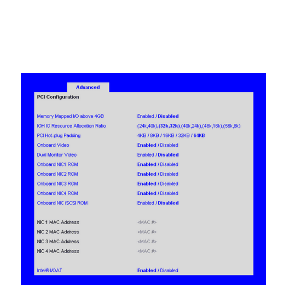
114 007-5645-002
6: BIOS
PCI Configuration Screen
The PCI Configuration Screen allows you to configure the PCI add-in cards, onboard NIC
controllers, and video options.
To access this screen from the Main screen, select Advanced > PCI.
Figure 6-10 Setup Utility—PCI Configuration Screen

BIOS Setup Utility
007-5645-002 115
Table 6-12 Setup Utility—PCI Configuration Screen Fields
Setup Item Options (Default
in Boldface) Help Text Comments
Memory Mapped
I/O above 4GB
Enabled
Disabled Enable or disable memory mapped I/O
of64-bit PCI devices to 4 GB or
greater address space.
IOH IO Resource
Allocation Ratio
IOH0:24k,IOH1:40k
IOH0:32k,IOH1:32k
IOH0:40k,IOH1:24k
IOH0:48k,IOH1:16k
IOH0:56k,IOH1:8k
Distribute IO resource (of total 64k)
between IOH0 and IOH1 as per your
system requirement.
Value of IO resource
(of total 64k) between
IOH0 and IOH1 will
be 40k: 24k in
Manufacturing Mode.
PCI Hot-plug
Padding
4KB
8KB
16KB
32KB
64KB
Select the amount of space
pre-initialized and reserved for PCI
Express Hot-added devices.
Onboard Video Enabled
Disabled
On-board video controller. Warning:
System video is completely disabled if
this option is disabled and an add-in
video adapter is not installed.
When disabled, the
system requires an
add- in video card in
order for the video to
be seen.
Dual Monitor
Video
Enabled
Disabled If enabled, both the onboard video
controller and an add-in video adapter
are enabled for system video. The
on-board video controller becomes the
primary video device.
Onboard NIC1
ROM Enabled
Disabled
If enabled, loads the embedded option
ROM for the on-board network
controllers. Warning: If [Disabled] is
selected, NIC1 cannot be used to boot
or wake the system.
Onboard NIC2
ROM Enabled
Disabled
If enabled. loads the embedded option
ROM for the on-board network
controllers. Warning: If [Disabled] is
selected, NIC2 cannot be used to boot
or wake the system.

116 007-5645-002
6: BIOS
Onboard NIC3
ROM Enabled
Disabled
If enabled, loads the embedded option
ROM for the on-board network
controllers. Warning: If [Disabled] is
selected, NIC3 cannot be used to boot
or wake the system.
Onboard NIC4
ROM Enabled
Disabled
If enabled, loads the embedded option
ROM for the on-board network
controllers. Warning: If [Disabled] is
selected, NIC4 cannot be used to boot
or wake the system.
Onboard NIC
iSCSI ROM
Enabled
Disabled If enabled, loads the embedded option
ROM for the on-board network
controllers. Warning: If [Disabled] is
selected, NIC1 and NIC2 cannot be
used to boot or wake the system.
This option is grayed
out and not accessible
if either the NIC1 or
NIC2 ROMs are
enabled.
NIC 1 MAC
Address
No entry allowed. Information only. 12
hex digits of the MAC
address.
NIC 2 MAC
Address
No entry allowed. Information only. 12
hex digits of the MAC
address.
NIC 3 MAC
Address
No entry allowed. Information only. 12
hex digits of the MAC
address.
NIC 4 MAC
Address
No entry allowed. Information only. 12
hex digits of the MAC
address.
Intel I/OAT Enabled
Disabled
Intel I/O Acceleration Technology
(I/OAT) accelerates TCP/IP
processing for onboard NICs, delivers
data-movement efficiencies across the
entire server platform, and minimizes
system overhead.
Table 6-12 Setup Utility—PCI Configuration Screen Fields (continued)
Setup Item Options (Default
in Boldface) Help Text Comments
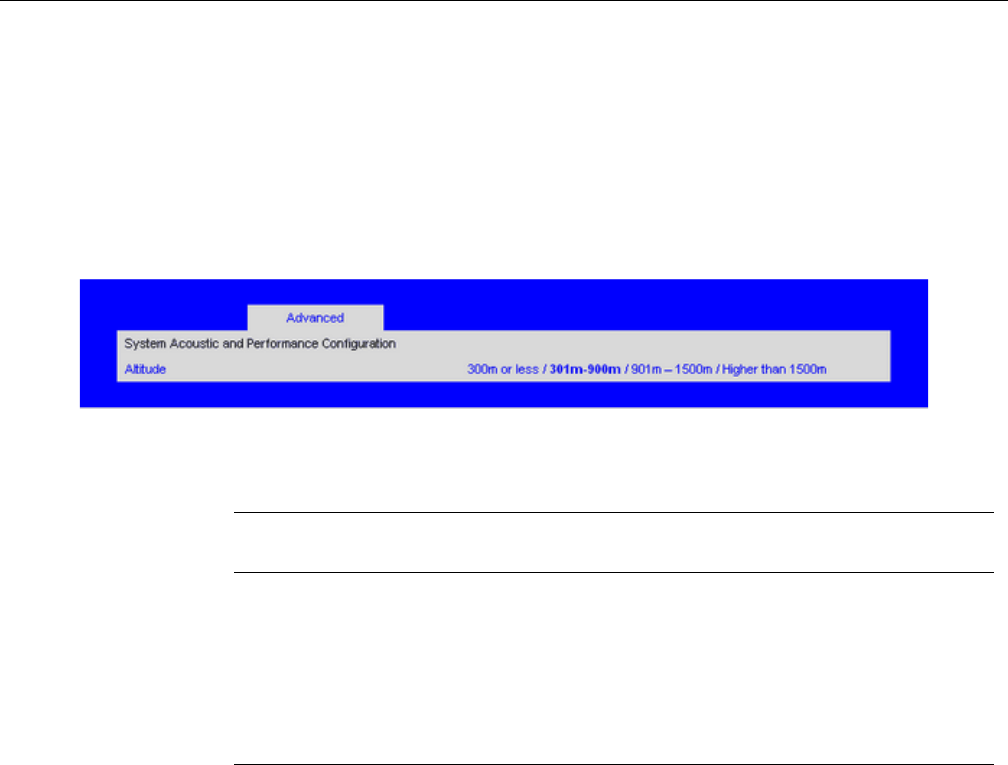
BIOS Setup Utility
007-5645-002 117
System Acoustic and Performance Configuration
The System Acoustic and Performance Configuration screen allows you to configure the thermal
characteristics of the system.
To access this screen from the Main screen, select Advanced > System Acoustic and
Performance Configuration.
Figure 6-11 Setup Utility—Acoustic and Performance Configuration
Security Screen
The Security screen allows you to enable and set the user and administrative password. This is
done to lock out the front panel buttons so they cannot be used. This screen also allows the user
to enable and activate the Trusted Platform Module (TPM) security settings.
To access this screen from the Main screen, select Security.
Table 6-13 Setup Utility—Acoustic and Performance Configuration Screen Fields
Setup Item Options (Default
in Boldface) Help Text Comments
Altitude 300m or less
301m-900m
901m-1500m
Higher than 1500m
[300m or less] (980ft or less) Optimal
performance setting near sea level.
[301m - 900m] (980ft - 2950ft) Optimal
performance setting at moderate elevation.
[901m 1500m] (2950ft 4920ft) Optimal
performance setting at high elevation.
[Higher than 1500m] (4920ft or greater) Optimal
performance setting at the highest elevations.
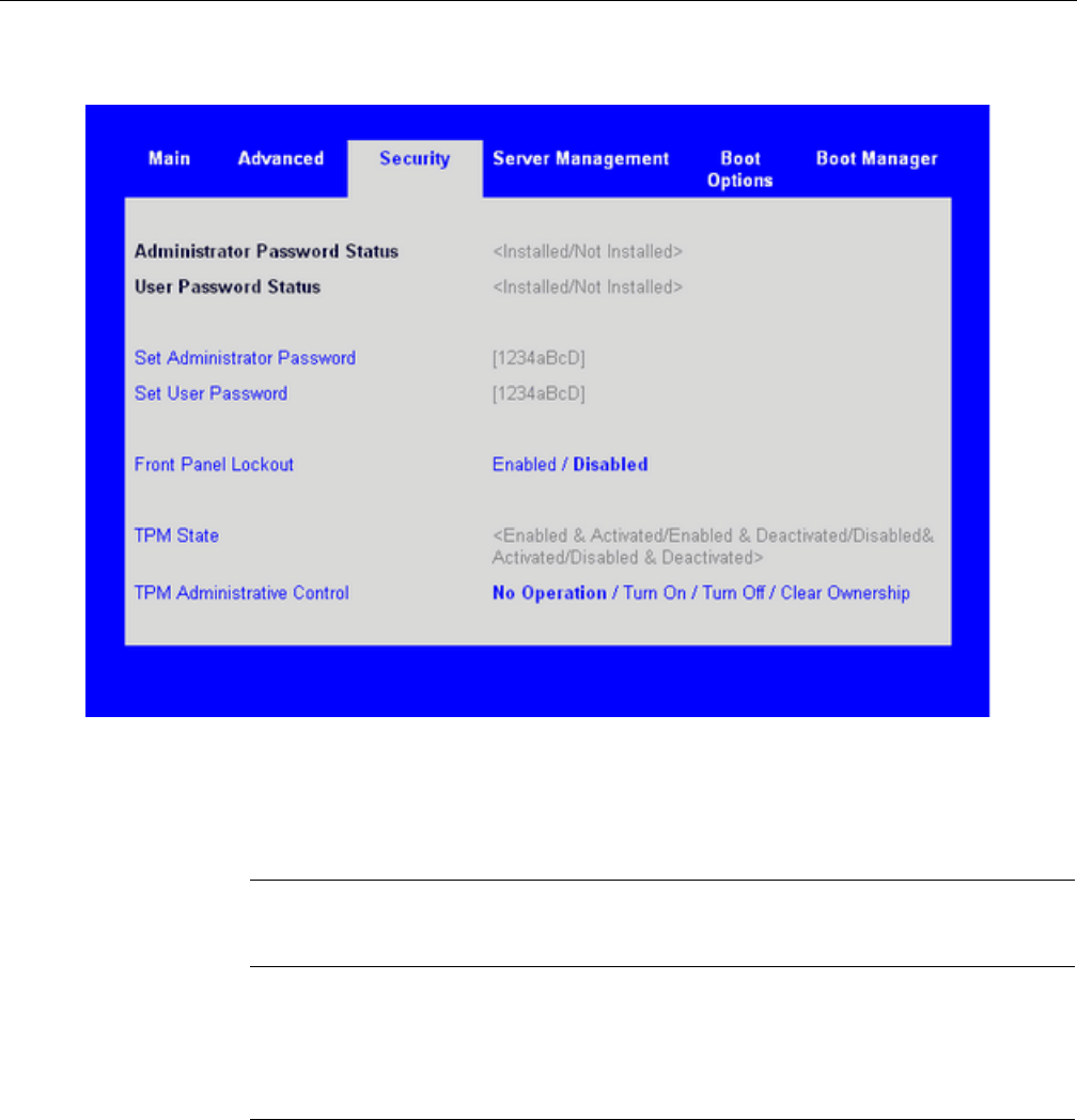
118 007-5645-002
6: BIOS
Figure 6-12 Setup Utility—Security Screen
Table 6-14 Setup Utility—Security Screen Fields
Setup Item
Options
(Default in
Boldface) Help Text Comments
Administrator
Password Status
<Installed
Not Installed>
Information only. Indicates the
status of the administrator
password.
User Password
Status
<Installed
Not Installed>
Information only. Indicates the
status of the user password.

BIOS Setup Utility
007-5645-002 119
Set Administrator
Password
[123aBcD] Administrator password is used
to control change access to the
BIOS Setup Utility. Only
alphanumeric characters can be
used. Maximum length is 7
characters. It is case sensitive.
Note: Administrator password
must be set in order to use the
user account.
This option is only to control
access to the setup.
Administrator has full access to
all the setup items. Clearing the
Administrator password also
clears the user password.
Set User
Password
[123aBcD] User password is used to control
entry access to BIOS Setup
Utility. Only alphanumeric
characters can be used.
Maximum length is 7
characters. It is case sensitive.
Note: Removing the
administrator password also
automatically removes the user
password.
This option is available only if
the administrator password is
installed. This option only
protects the setup. User
password only has limited
access to the setup items.
Front Panel
Lockout
Enabled
Disabled If enabled, locks the power
button and reset button on the
system’s front panel. If
[Enabled] is selected, power and
reset must be controlled via a
system management interface.
Table 6-14 Setup Utility—Security Screen Fields (continued)
Setup Item
Options
(Default in
Boldface) Help Text Comments

120 007-5645-002
6: BIOS
Server Management Screen
The Server Management screen allows you to configure several server management features. This
screen also provides an access point to the screens for configuring console redirection and
displaying system information.
To access this screen from the Main screen, select Server Management.
TPM State Enabled and
Activated
Enabled and
Deactivated
Disabled and
Activated
Disabled and
Deactivated
Information only. Shows the
current TPM device state. A
disabled TPM device does not
execute commands that use the
TPM functions and TPM
security operations are not
available. An enabled and
deactivated TPM is in the same
state as a disabled TPM except
setting of the TPM ownership is
allowed if not present already.
An enabled and activated TPM
executes all commands that use
the TPM functions and TPM
security operations are also
available.
TPM
Administrative
Control
No Operation
Turn On
Turn Off
Clear Ownership
[No Operation] - No changes to
current state.
[Turn On] - Enables and
activates TPM.
[Turn Off] - Disables and
deactivates TPM.
[Clear Ownership] - Removes
the TPM ownership
authentication and returns the
TPM to a factory default state.
Note: The BIOS setting returns
to [No Operation] on every boot
cycle by default.
Table 6-14 Setup Utility—Security Screen Fields (continued)
Setup Item
Options
(Default in
Boldface) Help Text Comments
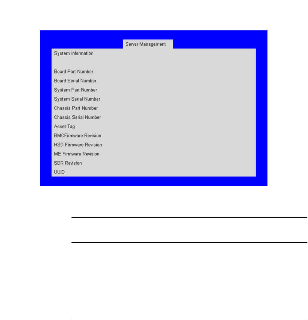
BIOS Setup Utility
007-5645-002 121
Figure 6-13 Setup Utiltiy—Server Management Configuration Screen
Table 6-15 Setup Utility—Server Management Configuration Screen Fields
Setup Item
Options
(Default in
Boldface) Help Text Comments
Assert NMI on
SERR Enabled
Disabled
On SERR, generate an NMI and
log an error. Note: [Enabled]
must be selected for the Assert
NMI on PERR setup option to
be visible.
Assert NMI on
PERR Enabled
Disabled
On PERR, generate an NMI and
log an error. Note: This option
is only active if the Assert NMI
on SERR option is [Enabled]
selected.

122 007-5645-002
6: BIOS
Resume on AC
Power Loss Stay Off
Last state Reset
System action to take on AC
power loss recovery. [Stay Off]
System stays off. [Last State]
System returns to the same state
before the AC power loss.
[Reset] System powers on.
Clear System Event
Log
Enabled
Disabled If enabled, clears the System
Event Log. All current entries
will be lost. Note: This option is
reset to [Disabled] after a
reboot.
FRB-2 Enable Enabled
Disabled
Fault Resilient Boot (FRB). If
enabled, the BIOS programs the
BMC watchdog timer for
approximately 6 minutes. If the
BIOS does not complete POST
before the timer expires, the
BMC resets the system.
O/S Boot Watchdog
Timer
Enabled
Disabled If enabled, the BIOS programs
the watchdog timer with the
timeout value selected. If the
OS does not complete booting
before the timer expires, the
BMC resets the system and an
error is logged. Requires OS
support or Intel Management
Software.
O/S Boot Watchdog
Timer Policy Power Off
Reset
If the OS boot watchdog timer is
enabled, this is the system action
taken if the watchdog timer
expires. [Reset] System
performs a reset. [Power Off]
System powers off.
Grayed out when O/S Boot
Watchdog Timer is disabled.
Table 6-15 Setup Utility—Server Management Configuration Screen Fields (continued)
Setup Item
Options
(Default in
Boldface) Help Text Comments

BIOS Setup Utility
007-5645-002 123
Console Redirection Screen
The Console Redirection screen allows you to enable or disable console redirection and to
configure the connection options for this feature.
To access this screen from the Main screen, select Server Management > Console Redirection.
O/S Boot Watchdog
Timer Timeout
5 minutes
10 minutes
15 minutes
20 minutes
If the OS watchdog timer is
enabled, this is the timeout value
used by the BIOS to configure
the watchdog timer.
Grayed out when O/S Boot
Watchdog Timer is disabled.
Plug & Play BMC
Detection
Enabled
Disabled If enabled, the BMC is
detectable by Oss that support
plug and play loading of an
IPMI driver. Do not enable if
your OS does not support this
driver.
ACPI 1.0 Support Enabled
Disabled [Enabled] Publish ACPI 1.0
version of FADT in Root
System Description Table. May
be required for compatibility
with OS versions that only
support ACPI 1.0.
Needs to be [Enabled] for
Windows 2000 support.
Console
Redirection
View/Configure console
redirection information and
settings.
Takes the user to the Console
Redirection screen.
System Information View system information. Takes the user to the System
Information screen.
BMC LAN
Configuration
View/Configure BMC LAN
channel and User settings.
Takes the user to the BMC
configuration screen. Note:
This item does not appear on
some models.
Table 6-15 Setup Utility—Server Management Configuration Screen Fields (continued)
Setup Item
Options
(Default in
Boldface) Help Text Comments
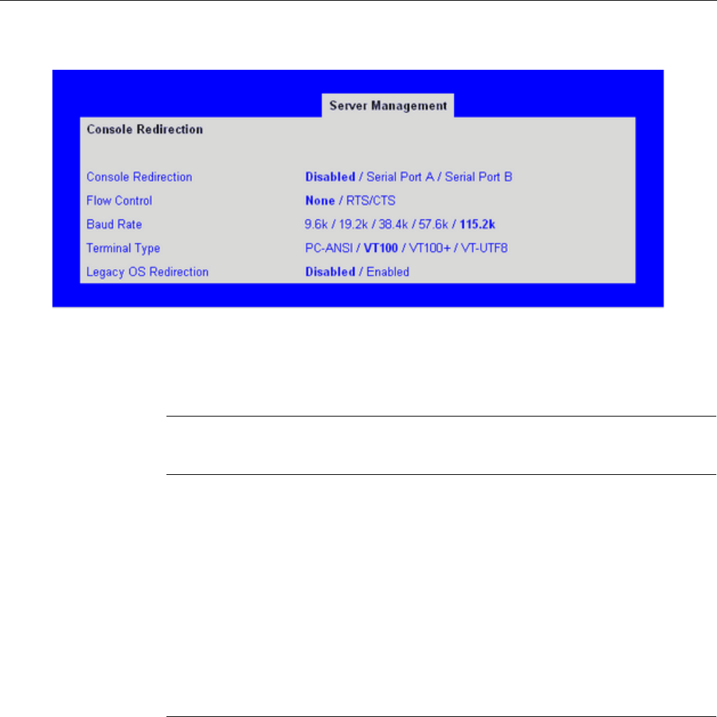
124 007-5645-002
6: BIOS
Figure 6-14 Setup Utility—Console Redirection Screen
Table 6-16 Setup Utility—Console Redirection Screen Fields
Setup Item
Options
(Default in
Boldface) Help Text Comments
Console
Redirection Disabled
Serial Port A
Serial Port B
Console redirection allows a serial port to be
used for server management tasks.
[Disabled] - No console redirection.
[Serial Port A] - Configure serial port A for
console redirection.
[Serial Port B] - Configure serial port B for
console redirection. Enabling this option
disables the display of the Quiet Boot logo
screen during POST.
Flow Control None
RTS/CTS
Flow control is the handshake protocol. Setting
must match the remote terminal application.
[None] - Configure for no flow control.
[RTS/CTS] - Configure for hardware flow
control.

BIOS Setup Utility
007-5645-002 125
Server Management System Information Screen
The Server Management System Information screen allows you to view part numbers, serial
numbers, and firmware revisions.
To access this screen from the Main screen, select Server Management > System Information.
Baud Rate 9600
19.2K
38.4K
57.6K
115.2K
Serial port transmission speed. Setting must
match the remote terminal application.
Terminal Type PC-ANSI
VT100
VT100+
VT-UTF8
Character formatting used for console
redirection. Setting must match the remote
terminal application.
Legacy OS
Redirection Disabled
Enabled
This option enables legacy OS redirection (i.e.,
DOS) on serial port. If it is enabled, the
associated serial port is hidden from the legacy
OS.
Table 6-16 Setup Utility—Console Redirection Screen Fields (continued)
Setup Item
Options
(Default in
Boldface) Help Text Comments
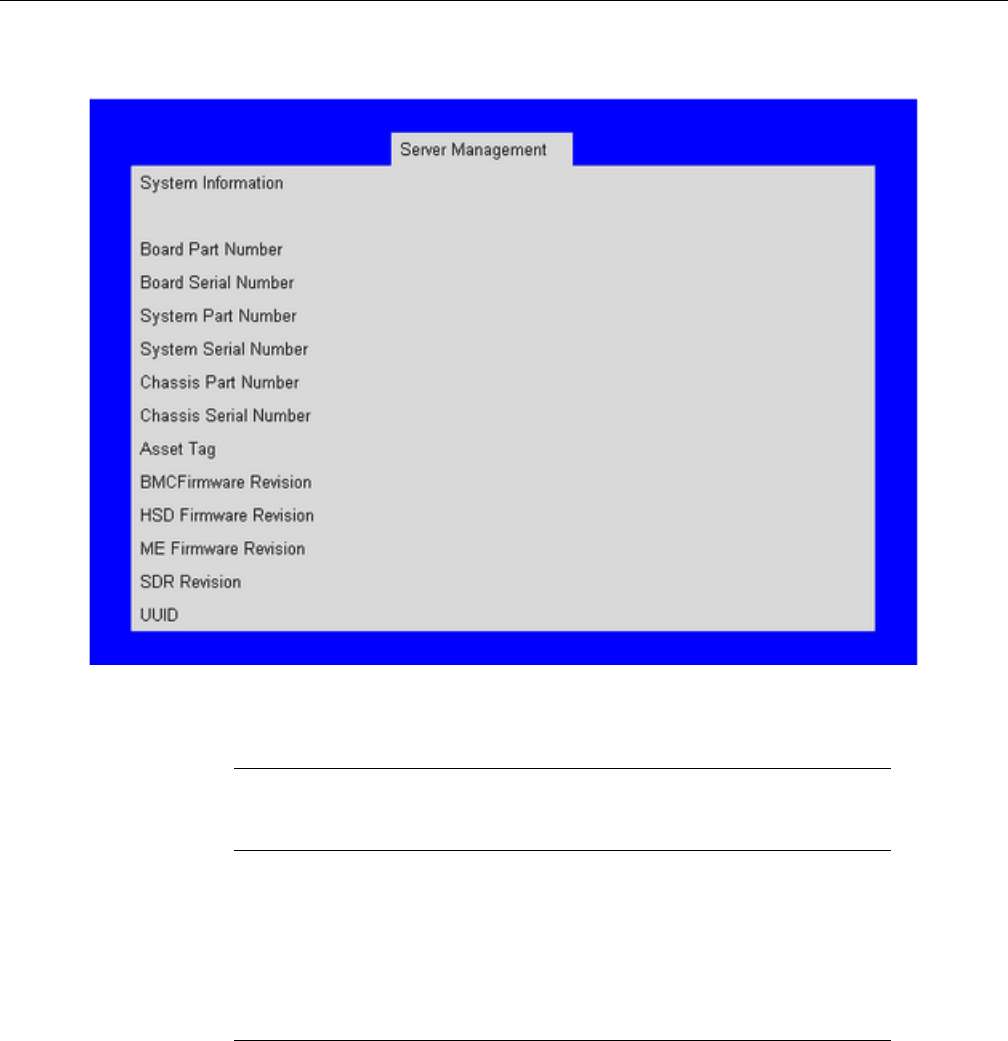
126 007-5645-002
6: BIOS
Figure 6-15 Setup Utility—Server Management System Information Screen
Table 6-17 Setup Utility—Server Management Information Screen Fields
Setup Item
Options
(Default in
Boldface) Help Text Comments
Board Part Number Information only
Board Serial Number Information only
System Part Number Information only
System Serial Number Information only
Chassis Part Number Information only

BIOS Setup Utility
007-5645-002 127
Boot Options Screen
The Boot Options screen displays any bootable media encountered during POST, and allows you
to configure desired order in which boot devices are to be tried. The first boot device in the
specified boot order will be used to boot the system.
To access this screen from the Main screen, select Boot Options.
Chassis Serial Number Information only
Asset Tag Information only
BMC Firmware Revision Information only
HSC Firmware Revision Information only
ME Firmware Revision Information only
SDR Revision Information only
UUID Information only
Table 6-17 Setup Utility—Server Management Information Screen Fields (continued)
Setup Item
Options
(Default in
Boldface) Help Text Comments
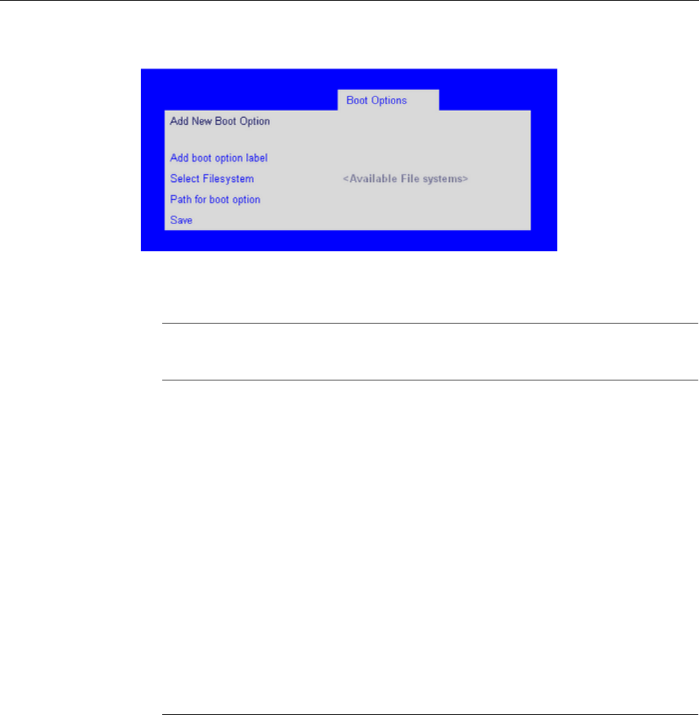
128 007-5645-002
6: BIOS
Figure 6-16 Setup Utility—Boot Options Screen
Table 6-18 Setup Utility—Boot Options Screen Fields
Setup Item
Options
(Default in
Boldface) Help Text Comments
Boot Timeout 0 - 65535 The number of seconds the
BIOS should pause at the end of
POST to allow the user to press
the [F2] key for entering the
BIOS Setup utility. Valid values
are 0-65535. Zero is the default.
A value of 65535 causes the
system to go to the Boot
Manager menu and wait for user
input for every system boot.
After entering the desired
timeout, press the Enter key to
register that timeout value to the
system. These settings are in
seconds.
Boot Option #x Available boot
devices.
Set system boot order by
selecting the boot option for this
position.
Hard Disk Order Set the order of the legacy
devices in this group.
This field appears when 1 or
more hard disk drives are in the
system.
CDROM Order Set the order of the legacy
devices in this group.
This field appears when 1 or
more CDROM drives are in the
system.

BIOS Setup Utility
007-5645-002 129
Floppy Order Set the order of the legacy
devices in this group.
This field appears when one or
more floppy drives are in the
system.
Network Device
Order
Set the order of the legacy
devices in this group.
This field appears when 1 or
more of these devices are
available in the system.
BEV Device
Order
Set the order of the legacy
devices in this group.
This field appears when 1 or
more of these devices are
available in the system.
Add New Boot
Option
Add a new EFI boot option to
the boot order.
This option is only displayed if
an EFI bootable device is
available to the system, i.e., an
USB drive.
Delete Boot
Option
Remove an EFI boot option
from the boot order.
If the EFI shell is deleted, it is
restored on the next system
reboot. It cannot be
permanently deleted.
EFI Optimized
Boot
Enabled Disabled If enabled, the BIOS only loads
modules required for booting
EFI- aware Operating Systems.
This field is grayed out when
[SW RAID] SATA Mode is
Enabled. SW RAID can only be
used in Legacy Boot mode.
Use Legacy Video
for EFI OS
Enabled Disabled If enabled, the BIOS use the
legacy video ROM instead of the
EFI video ROM.
This field appears only when
EFI Optimized Boot is enabled.
Table 6-18 Setup Utility—Boot Options Screen Fields (continued)
Setup Item
Options
(Default in
Boldface) Help Text Comments

130 007-5645-002
6: BIOS
If all types of bootable devices are installed in the system, then the default boot order is as follows:
• CD/DVD-ROM
• Floppy Disk Drive
• Hard Disk Drive
• PXE Network Device
• BEV (Boot Entry Vector) Device
• EFI Shell and EFI Boot paths
To force the system to boot to EFI Shell, add the line #FORCE_EFI_BOOT to the beginning of
the file startup.nsh.
Add New Boot Option Screen
The Add Boot Option screen allows you to add an EFI boot option from the boot order.
To access this screen from the Main screen, select Boot Options > Add New Boot Option.
Boot Option
Retry
Enabled Disabled If enabled, this continually
retries non- EFI-based boot
options without waiting for user
input.
USB Boot
Priority
Enabled Disabled If enabled, newly discovered
USB devices are moved to the
top of their boot device category.
If disabled, newly discovered
USB devices are moved to the
bottom of their boot device
category.
This option enables or disables
the USB Reorder functionality.
Table 6-18 Setup Utility—Boot Options Screen Fields (continued)
Setup Item
Options
(Default in
Boldface) Help Text Comments
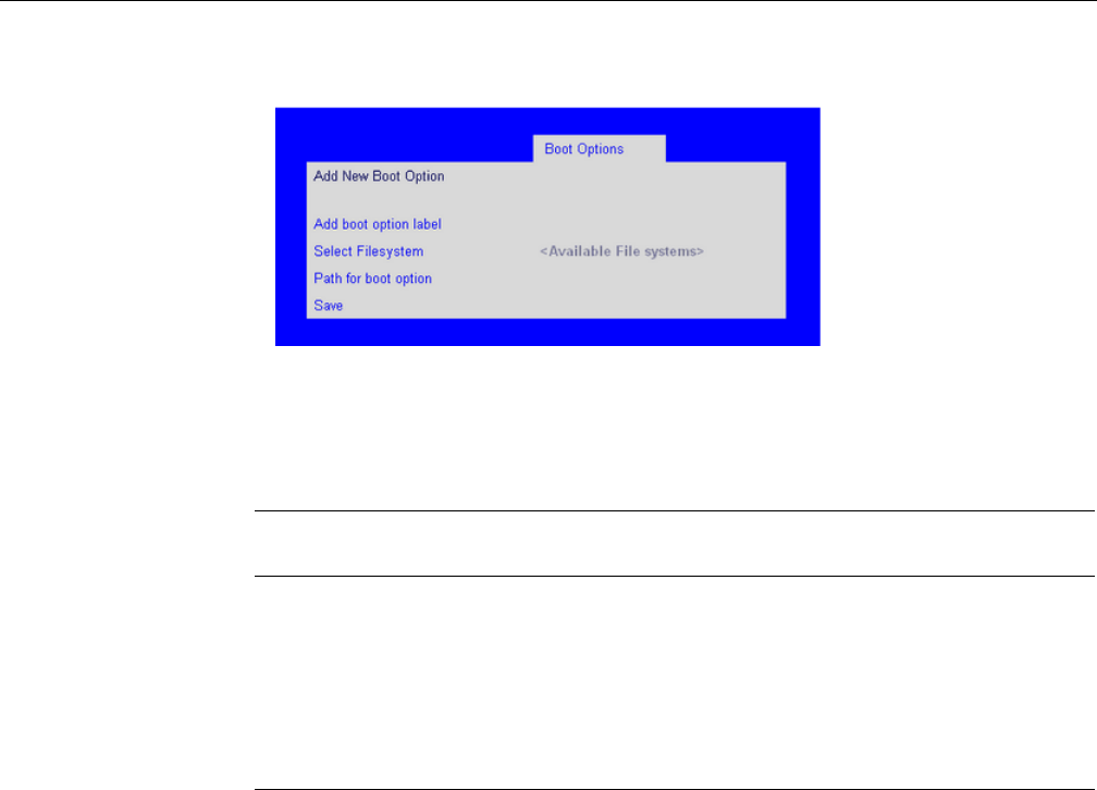
BIOS Setup Utility
007-5645-002 131
Figure 6-17 Setup Utility—Add New Boot Option Screen
Delete Boot Option Screen
The Delete Boot Option screen allows you to remove an EFI boot option from the boot order. Note
that while the Internal EFI Shell can be deleted in this screen, it is restored to the Boot Order on
the next reboot. The Internal EFI Shell cannot be permanently deleted.
To access this screen from the Main screen, select Boot Options > Delete Boot Options.
Table 6-19 Setup Utility—Add New Boot Option Screen Fields
Setup Item Options (Default
in Boldface) Help Text Comments
Add boot option label Create the label for the new bootoption.
Select Filesystem Select one from the
list.
Select a filesystem from the list.
Path for boot option Enter the path to the boot option in the
format \path\filename.efi
Save Save the boot option.
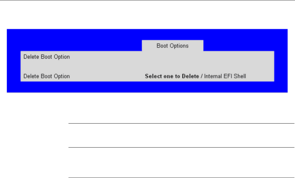
132 007-5645-002
6: BIOS
Figure 6-18 Setup Utility—Delete Boot Option Screen
Hard Disk Order Screen
The Hard Disk Order screen allows you to control the hard disks.
To access this screen from the Main screen, select Boot Options > Hard Disk Order.
Table 6-20 Setup Utility—Delete Boot Option Screen Fields
Setup Item
Options
(Default in
Boldface) Help Text Comments
Delete Boot
Option
Select one to
Delete Internal
EFI Shell.
Remove an EFI boot option
from the boot order.
If the EFI shell is deleted, it is
restored on the next system
reboot. It cannot be
permanently deleted.
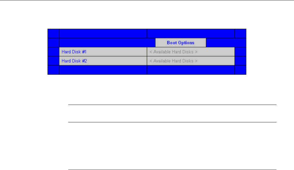
BIOS Setup Utility
007-5645-002 133
Figure 6-19 Setup Utility—Hard Disk Order Screen
CDROM Order Screen
The CDROM Order screen allows you to control the CDROM devices.
To access this screen from the Main screen, select Boot Options > CDROM Order.
Table 6-21 Setup Utiliity—Hard Disk Order Screen Fields
Setup Item Options (Default in
Boldface) Help Text Comments
Hard Disk #1 Available Legacy devices
for this device group.
Set the system boot order by
selecting a boot option for
this position.
Hard Disk #2 Available Legacy devices
for this device group.
Set the system boot order by
selecting a boot option for
this position.

134 007-5645-002
6: BIOS
Figure 6-20 Setup Utility—CDROM Order Screen
Floppy Order Screen
The Floppy Order screen allows you to control the floppy devices.
To access this screen from the Main screen, select Boot Options > Floppy Order.
Table 6-22 Setup Utility—CDROM Order Screen Fields
Setup Item Options (Default in
Boldface) Help Text Comments
CDROM #1 Available Legacy devices
for this device group.
Set the system boot order by
selecting a boot option for
this position.
CDROM #2 Available Legacy devices
for this device group.
Set the system boot order by
selecting a boot option for
this position.
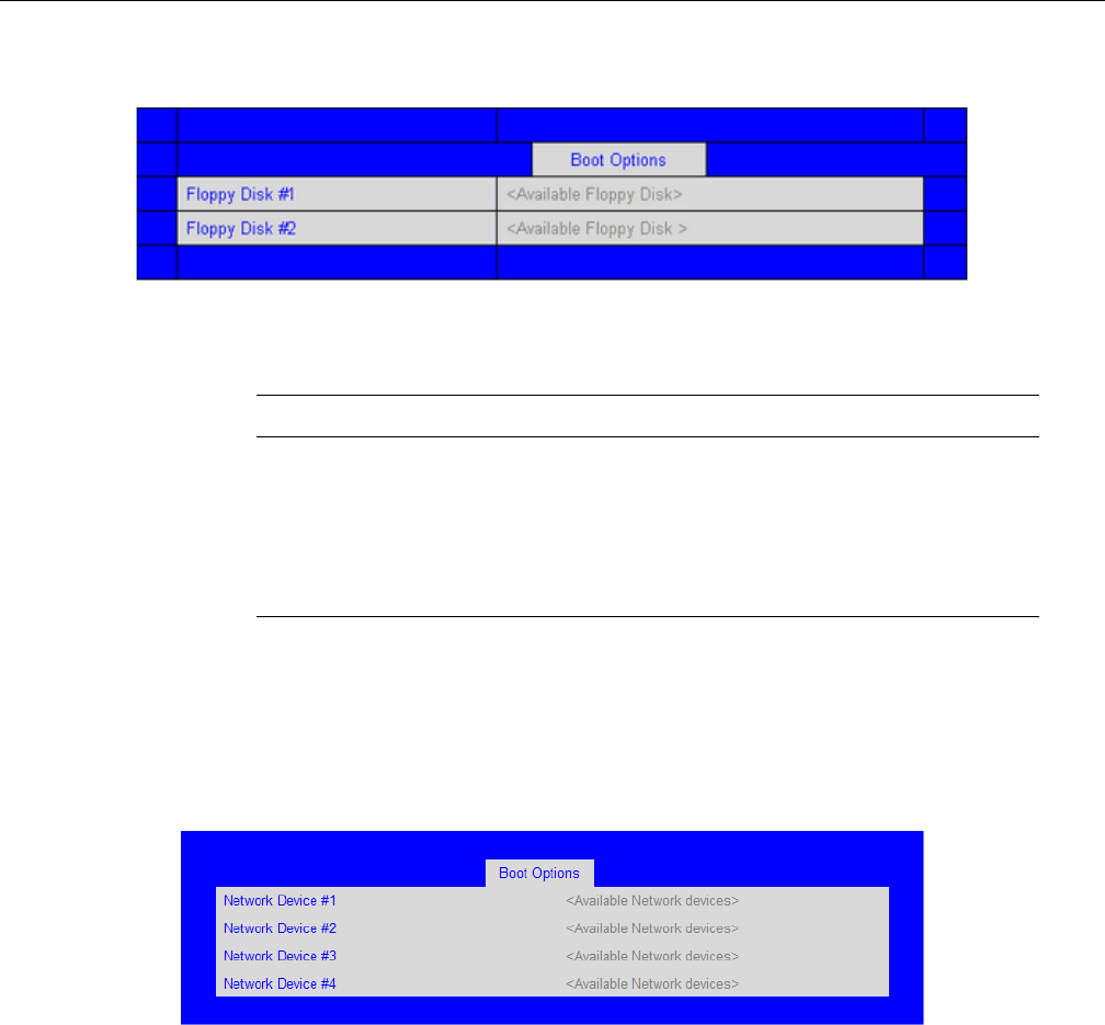
BIOS Setup Utility
007-5645-002 135
Figure 6-21 Setup Utility—Floppy Order Screen
Network Device Order Screen
The Network Device Order screen allows you to control the network bootable devices.
To access this screen from the Main screen, select Boot Options > Network Device Order.
Figure 6-22 Setup Utility—Network Device Order Screen
Table 6-23 Setup Utility—Floppy Order Screen Fields
Setup Item Options Help Text Comments
Floppy Disk #1 Available Legacy devices
for this device group.
Set the system boot order by
selecting a boot option for
this position.
Floppy Disk #2 Available Legacy devices
for this device group.
Set the system boot order by
selecting a boot option for
this position.

136 007-5645-002
6: BIOS
BEV Device Order Screen
The BEV Device Order screen allows you to control the BEV bootable devices.
To access this screen from the Main screen, select Boot Options > BEV Device Order.
Table 6-24 Setup Utility—Network Device Order Screen Fields
Setup Item Options (Default in
Boldface) Help Text Comments
Network Device #1 Available Legacy devices
for this device group.
Set the system boot order by
selecting a boot option for
this position.
Network Device #2 Available Legacy devices
for this device group.
Set the system boot order by
selecting a boot option for
this position.
Network Device #3 Available Legacy devices
for this device group.
Set the system boot order by
selecting a boot option for
this position.
Network Device #4 Available Legacy devices
for this device group.
Set the system boot order by
selecting a boot option for
this position.
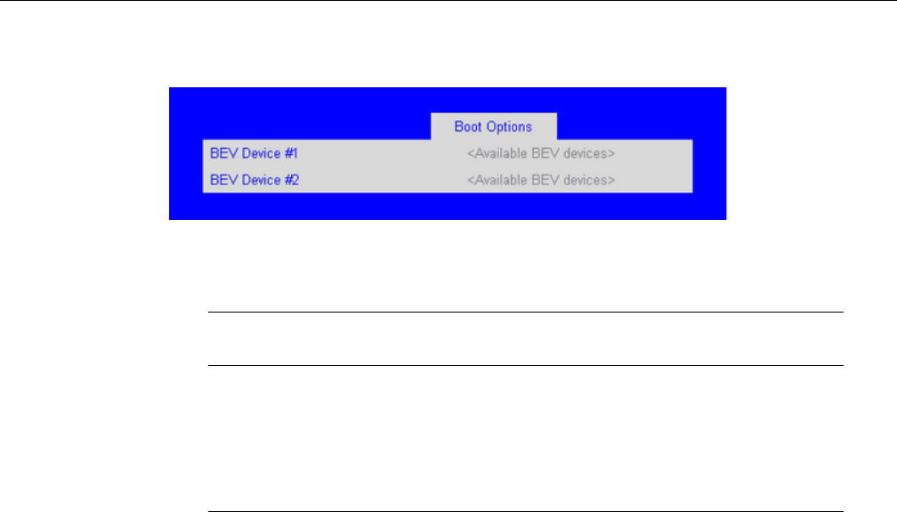
BIOS Setup Utility
007-5645-002 137
Figure 6-23 Setup Utility—BEV Device Order Screen
Boot Manager Screen
The Boot Manager screen allows you to view a list of devices available for booting, and to select
a boot device for immediately booting the system.
To access this screen from the Main screen, select Boot Manager.
Table 6-25 Setup Utility—BEV Device Order Screen Fields
Setup Item Options (Default in
Boldface) Help Text Comments
BEV Device #1 Available Legacy devices
for this device group.
Set the system boot order by
selecting a boot option for
this position.
BEV Device #2 Available Legacy devices
for this device group.
Set the system boot order by
selecting a boot option for
this position.
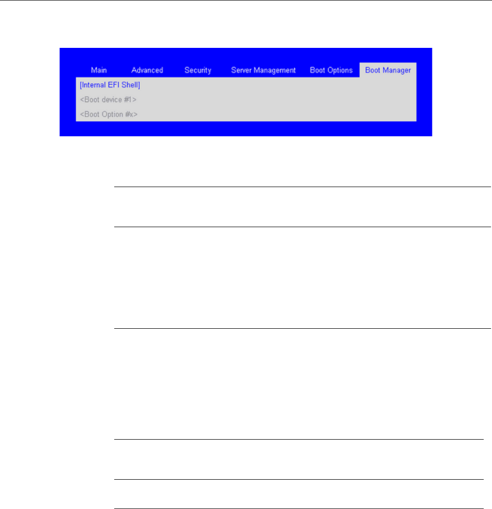
138 007-5645-002
6: BIOS
Figure 6-24 Setup Utility—Boot Manager Screen
Error Manager Screen
The Error Manager screen displays any errors encountered during POST.
Figure 6-25 Setup Utility—Error Manager Screen
Table 6-26 Setup Utility—Boot Manager Screen Fields
Setup Item
Options
(Default in
Boldface) Help Text Comments
Internal EFI Shell Select this option to boot now. Note: This list is not
the system boot option order. Use the Boot Options
menu to view and configure the system boot option
order.
Boot Device #x Select this option to boot now. Note: This list is not
the system boot option order. Use the Boot Options
menu to view and configure the system boot option
order.
Table 6-27 Setup Utility—Error Manager Screen Fields
Setup Item
Options
(Default in
Boldface) Help Text Comments
Displays System Errors Information only. Displays errors that
occurred during the POST.
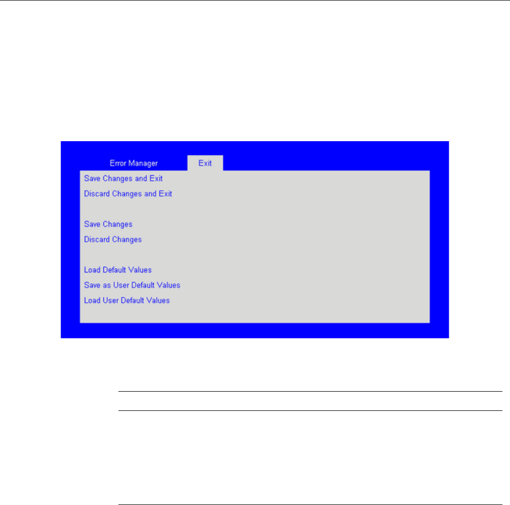
BIOS Setup Utility
007-5645-002 139
Exit Screen
The Exit screen allows you to choose whether to save or discard the configuration changes made
on the other screens. It also allows you to restore the server to the factory defaults or to save or
restore them to a set of user-defined default values. If Load Default Values is selected, the factory
default settings (noted in bold in the tables in this chapter) are applied. If Load User Default
Values is selected, the system is restored to previously saved user-defined default values.
Figure 6-26 Setup Utility—Exit Screen
Table 6-28 Setup Utility—Exit Screen Fields
Setup Item Help Text Comments
Save Changes and Exit Exit the BIOS Setup utility after
saving changes. The system reboots if
required. The [F10] key can also be
used.
For confirmation only if any of the
setup fields were modified.
Discard Changes and
Exit
Exit the BIOS Setup utility without
saving changes. The [Esc] key can
also be used.
For confirmation only if any of the
setup fields were modified.

140 007-5645-002
6: BIOS
Loading BIOS Defaults
Different mechanisms exist for resetting the system configuration to the default values. When a
request to reset the system configuration is detected, the BIOS loads the default system
configuration values during the next POST. The request to reset the system to the defaults can be
sent in the following ways:
Pressing <F9> from within the BIOS Setup utility.
• Moving the BIOS Recovery jumper.
• Issuing an IPMI command (set System Boot options command)
• Choosing Load User Defaults from the Exit page of the BIOS Setup loads user set defaults
instead of the BIOS factory defaults.
Save Changes Save changes without exiting the
BIOS Setup Utility. Note: Saved
changes may require a system reboot
before taking effect.
For confirmation only if any of the
setup fields were modified.
Discard Changes Discard changes made since the last
Save Changes operation was
performed.
For confirmation only if any of the
setup fields were modified.
Load Default Values Load factory default values for all
BIOS Setup utility options. The [F9]
key can also be used.
A confirmation prompt appears.
Save as User Default
Values
Save current BIOS Setup utility values
as custom user default values. If
needed, the user default values can be
restored via the Load User Default
Values option below. Note: Clearing
the CMOS or NVRAM does not cause
the User Default values to be reset to
the factory default values.
A confirmation prompt appears.
Load User Default
Values
Load user default values. A confirmation prompt appears.
Table 6-28 Setup Utility—Exit Screen Fields (continued)
Setup Item Help Text Comments

Clearing the BIOS Password
007-5645-002 141
The recommended steps to load the BIOS defaults are:
1. Power down the system (Do not remove AC power).
2. Move the BIOS Recovery jumper (J6D1) ( from pins 1-2 to pins 2-3.
3. Move the Clear CMOS jumper from pins 2-3 to pins 1-2.
4. Power up the system.
Clearing the BIOS Password
If the administrator password to the BIOS has been misplaced, a hardware reset may be performed
to allow access to the BIOS and Operating System.
To clear the BIOS Password:
1. Power down the system
2. Move the BIOS Recovery jumper (J6D1) from pins 1-2 to pins 2-3.
3. Move the Clear CMOS jumper from pins 2-3 to pins 1-2.
4. Power up the system.

007-5645-002 143
Appendix A
A. POST Codes
The system BIOS displays error messages on the video screen. Before video initialization, beep
codes inform you of errors. POST error codes are logged in the event log. The BIOS displays
POST error codes on the video monitor.
Eight light-emitting diodes indicate the raw binary output of port 80 values. These LEDs are
arranged so you can see a direct correlation to the binary equivalent. Table A-1 shows the
correlation of port 80 post code bit to LED reference designator.
POST Progress Codes and Messages
During the system boot process, the BIOS executes several platform configuration processes, each
of which is assigned a specific hex POST code number. As each configuration routine is started,
the BIOS displays the POST code on the POST code diagnostic LEDs found on the back edge of
the server board. To assist in troubleshooting a system hang during the POST process, the
Table A-1 Port 80 POST Code LEDs
Port 80 POST Code Bit LED Reference Designator
7 (MSB) DS4E8
6DS4E7
5DS4E6
4DS4E5
3DS4E4
2DS4E3
1DS4E2
0 (LSB) DS4E1

144 007-5645-002
A: POST Codes
diagnostic LEDs can be used to identify the last POST process to be executed. Table A-2 shows
POST progress codes and messages.
Table A-2 POST Progress Codes and Messages
Progress Code Progress Code Definition
Host Processor
0x10 Power-on initialization of the host processor (Boot Strap Processor)
0x11 Host processor cache initialization (including AP)
0x12 Starting application processor initialization
0x13 SMM initialization
Chipset
0x21 Initializing a chipset component
Memory
0x22 Reading configuration data from memory (SPD on DIMM)
0x23 Detecting presence of memory
0x24 Programming timing parameters in the memory controller
0x25 Configuring memory parameters in the memory controller
0x26 Optimizing memory controller settings
0x27 Initializing memory, such as ECC init
0x28 Testing memory
PCIe Bus
0x50 Enumerating PCIe buses
0x51 Allocating resources to PCIe buses
0x52 Hot-plug PCIe controller initialization
0x53-0x57 Reserved for PCIe Bus
USB

POST Progress Codes and Messages
007-5645-002 145
0x58 Resetting USB bus
0x59 Reserved for USB devices
ATA / ATAPI /
SATA
Progress Code Progress Code Definition
0x5A Resetting SATA bus and all devices
0x5B Reserved for ATA
SMBUS
0x5C Resetting SMBUS
0x5D Reserved for SMBUS
Local Console
0x70 Resetting the video controller (VGA)
0x71 Disabling the video controller (VGA)
0x72 Enabling the video controller (VGA)
Remote Console
0x78 Resetting the console controller
0x79 Disabling the console controller
0x7A Enabling the console controller
Keyboard (only
USB)
0x90 Resetting the keyboard
0x91 Disabling the keyboard
0x92 Detecting the presence of the keyboard
0x93 Enabling the keyboard
0x94 Clearing keyboard input buffer
Table A-2 POST Progress Codes and Messages (continued)
Progress Code Progress Code Definition

146 007-5645-002
A: POST Codes
0x95 Instructing keyboard controller to run Self Test (PS2 only)
Mouse (only
USB)
0x98 Resetting the mouse
0x99 Detecting the mouse
0x9A Detecting the presence of mouse
0x9B Enabling the mouse
Fixed Media
0xB0 Resetting fixed media device
0xB1 Disabling fixed media device
0xB2 Detecting the presence of a fixed media device (hard drive detection,
etc.)
0xB3 Enabling/configuring a fixed media device
Removable
Media
0xB8 Resetting the removable media device
0xB9 Disabling the removable media device
0xBA Detecting the presence of a removable media device (CDROM
detection, etc.)
0xBC Enabling/configuring a removable media device
Boot Device
Selection
0xDy Trying boot selection y (where y = 0 to F)
Progress Code Progress Code Definition
Table A-2 POST Progress Codes and Messages (continued)
Progress Code Progress Code Definition

POST Progress Codes and Messages
007-5645-002 147
Pre-EFI
Initialization
(PEI) Core (not
accompanied by
a beep code)
0xE0 Started dispatching early initialization modules (PEIM)
0xE2 Initial memory found, configured, and installed correctly
0xE1, 0xE3 Reserved for initialization module use (PEIM)
Driver eXecution
Environment
(DXE) Core (not
accompanied by
a beep code)
0xE4 Entered EFI driver execution phase (DXE)
0xE5 Started dispatching drivers
0xE6 Started connecting drivers
DXE Drivers
(not
accompanied by
a beep code)
0xE7 Waiting for user input
0xE8 Checking password
0xE9 Entering the BIOS Setup
0xEA Flash Update
0xEE Calling Int 19. One beep unless silent boot is enabled.
0xEF Unrecoverable Boot failure
Runtime Phase /
EFI Operating
System Boot
Table A-2 POST Progress Codes and Messages (continued)
Progress Code Progress Code Definition

148 007-5645-002
A: POST Codes
0xF4 Entering the sleep state
0xF5 Exiting the sleep state
0xF8 Operating system has requested EFI to close boot services
ExitBootServices() has been called
0xF9 Operating system has switched to virtual address mode
SetVirtualAddressMap() has been called
0xFA Operating system has requested the system to reset ResetSystem () has
been called
Pre-EFI
Initialization
Module (PEIM) /
Recovery
0x30 Crisis recovery has been initiated because of a user request
0x31 Crisis recovery has been initiated by software (corrupt flash)
0x34 Loading crisis recovery capsule
0x35 Handing off control to the crisis recovery capsule
0x3F Unable to complete crisis recovery
Memory Error
Codes
(Accompanied
by a beep code)
0xE1 No Usable Memory Error: No memory in the system, or SPD bad so no
memory could be detected.
0xEB Memory Test Error: memory failed Hardware BIST.
0xED Population Error: RDIMMs and UDIMMs cannot be mixed in the
system.
0xEE Mismatch Error: more than 2 Quad Ranked DIMMS in a channel
Table A-2 POST Progress Codes and Messages (continued)
Progress Code Progress Code Definition

POST Error Messages and Handling
007-5645-002 149
POST Error Messages and Handling
The POST Error Manager displays error messages reported by the system BIOS during POST.
The system BIOS truncates the 32-bit EFI POST Progress Code associated with the error to 16-bit
values for display in the POST Error Manager.
The POST Error Manager behavior in response to the error is defined by the error severity reported
by the BIOS. Errors are categorized in one of three severity levels. The system behavior in
response to severity level of: the following:
Fatal:
• The BIOS logs an error to the POST Error Manager.
• The BIOS logs an error message to the BMC System Event Log (SEL).
• The BIOS unconditionally enters POST Error Manager to display error message.
• The BIOS halts the system to prevent boot.
• The user needs to replace the faulty part and restart the system
Major.
• The BIOS logs an error to the POST Error Manager.
• The BIOS logs an error message to the BMC System Event Log (SEL).
• The BIOS continues booting in a degraded state by default (i.e. BIOS does not
automatically enter the POST Error Manager to display the error message)
• The user can override this default behavior by configuring the BIOS Setup POST Error
Pause option to Enabled. This forces the system to enter the POST Error Manager and
display the error message before booting.
• The user can choose to take immediate corrective action or continue booting.
Minor
• The BIOS logs an error to the POST Error Manager.
• The BIOS continues booting with a degraded state (i.e. BIOS does not automatically
enter the POST Error Manager to display the error message).
• The user may want to replace the erroneous unit.

150 007-5645-002
A: POST Codes
The POST Error Manager reports a maximum of 500 errors on any single boot cycle. Errors are
automatically cleared from the Error Manager on each boot. Table A-3 shows POST error
manager messages and handling.
Table A-3 POST Error Manager Messages and Handling
Error Code Error Message Response
0x0012 CMOS Date/Time not set. Major
0x0048 Password check failed. Major
0x0108 Keyboard locked error. Minor
0x0109 Keyboard stuck key error. Minor
0x0113 The SAS RAID firmware cannot run properly. The user
should attempt to reflash the firmware.
Major
0x0140 PCIe Parity Error (PERR). Fatal
0x0141 PCIe resource conflict error. Major
0x0146 PCIe out of resources error. Major
0x0192 Processor cache size mismatch detected. Fatal
0x0193 Processor stepping mismatch. Minor
0x0194 Processor family mismatch detected. Fatal
0x0195 Processor Intel(R) QPI speed mismatch. Major
0x0196 Processor model mismatch. Fatal
0x0197 Processor speeds mismatched. Fatal
0x0198 Processor family is not supported. Fatal
0x019F Processor and chipset stepping configuration is
unsupported. By continuing to boot, you acknowledge you
are operating in an unsupported configuration.
Major
0x5220 CMOS/NVRAM configuration cleared. Major
0x5221 Passwords cleared by jumper. Major
0x5224 Password Clear jumper is set. Major
0x8120 Processor Thermal Trip error. Major

POST Error Messages and Handling
007-5645-002 151
0x8130 Processor Disabled Major
0x8140 Processor FRB-3 timeout. Major
0x8160 Processor unable to apply microcode update. Major
0x8170 Processor Built-In Self Test (BIST) failure. Major
0x8180 Processor microcode update not found. Minor
0x8190 Watchdog Timer failed on last boot. Major
0x8198 OS boot watchdog timer failure. Major
0x8300 Baseboard Management Controller failed self test. Major
0x84F2 Baseboard Management Controller failed to respond. Major
0x84F3 Baseboard Management Controller in Update Mode. Major
0x84F4 Baseboard Management Controller Sensor Data Record
empty.
Major
0x84FF Baseboard Management Controller System Event Log full. Minor
0x8604 Chipset Reclaim of non critical variables complete. Minor
0xA000 TPM device not detected. Major
0xA001 TPM device is missing or not responding. Major
Table A-3 POST Error Manager Messages and Handling (continued)
Error Code Error Message Response

152 007-5645-002
A: POST Codes
POST Error Beep Codes
Table A-4 lists POST error beep codes. Prior to system video initialization, the BIOS uses beep
codes to inform users about error conditions. The beep code is followed by a user visible code on
POST Progress LEDs.
BMC Beep Codes
The BMC may generate beep codes upon detection of failure conditions. Beep codes are sounded
each time the problem is discovered (for example, on each power-up attempt), but are not sounded
continuously. supported codes are listed in Table A-5. Each digit in the code is represented by a
sequence of beeps whose count is equal to the digit.
Table A-4 Beep Codes
Beeps Error
Message
POST
Progress
Code Description
3 Memory
error
System halted because a fatal error related to the memory was
detected.
Table A-5 BMC Beep Codes
Code Reason for Beep Associated Sensors Supported
1-5-2-1 No CPUs installed or first CPU socket is empty. CPU Missing Sensor Yes
1-5-4-2 Power fault: DC power unexpectedly lost (power
good dropout).
Power unit - power unit
failure offset.
Yes
1-5-4-4 Power control fault (power good assertion
timeout).
Power unit - soft power
control failure offset.
Yes

007-5645-002 153
Appendix B
B. Power Supply Modules Safety Instructions
For the initial release of the SGI Altix UV 10 system, the power supply modules require separate
AC power sources, as shown in Figure B-1, and a protective ground wire installed, as shown in
Figure B-2, to prevent the power supply module leakage current (touch current) from exceeding
the safety specification. If your system serial number is UV10-00000053 or greater, Appendix B
information does NOT apply.
Note: This appendix applies to standalone systems. If your SGI Altix UV 10 system is installed
in a rack with SGI power distribution units (PDUs), this appendix does not apply.
Power Supply Configuration
Warning: For the initial release of the SGI Altix UV 10 system, the power supply modules
must be connected to separate AC power sources for standalone systems. This applies to
systems shipped with a grounding wire as shown in Figure B-2.
Figure B-1 shows the power supply modules connected to separate AC power sources.
!

154 007-5645-002
B: Power Supply Modules Safety Instructions
Figure B-1 Power Supply Modules Configuration
Installing the Protective Ground Wire
A bond wire of at least 18 AWG copper stranded wire and at least 1 meter (3.28 feet) long is
required to ground the server system (see Figure B-2). To install the protective grounding wire,
follow the steps below.
1. Locate the grounding bolt on the chassis rear left side wall designated by the ground symbol.
2. Remove the outer nut from the bolt. See item 1 in Figure B-2.
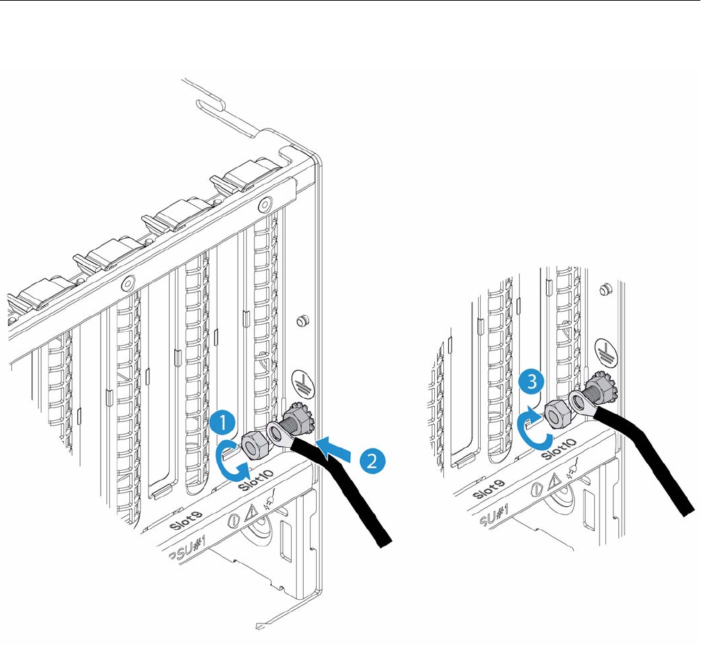
Installing the Protective Ground Wire
007-5645-002 155
Figure B-2 Installing the Ground Wire
3. Attach the bond wire ring terminal with the lug on the inner nut. See item 2 in the
Figure B-2.

156 007-5645-002
B: Power Supply Modules Safety Instructions
4. Replace the outer nut. See item 3 in Figure B-2.
Note: The grounding wire lug goes between the two nuts on the bolt.
5. Adjust the bond wire to fit into the cable management arm.
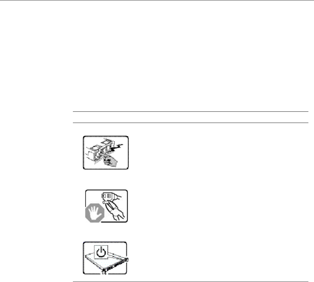
007-5645-002 157
Appendix C
C. Installation and Maintenance Safety Instructions
This appendix provides a summary of safety instructions for system installation, assembly, or
maintenance. Table C-1 shows common sense system safety guidelines.
Table C-1 System Safety Guidelines
Symbol Description
The power supply in this product contains no user-serviceable parts. Refer
servicing only to qualified personnel.
Do not attempt to modify or use the supplied AC power cord if it is not the
exact type required. A product with more than one power supply will have
a separate AC power cord for each supply.
The power button on the system does not turn off system AC power. To
remove AC power from the system, you must unplug each AC power cord
from the wall outlet or power supply. The power cord(s) is considered the
disconnect device to the main (AC) power. The socket outlet that the
system plugs into shall be installed near the equipment and shall be easily
accessible.
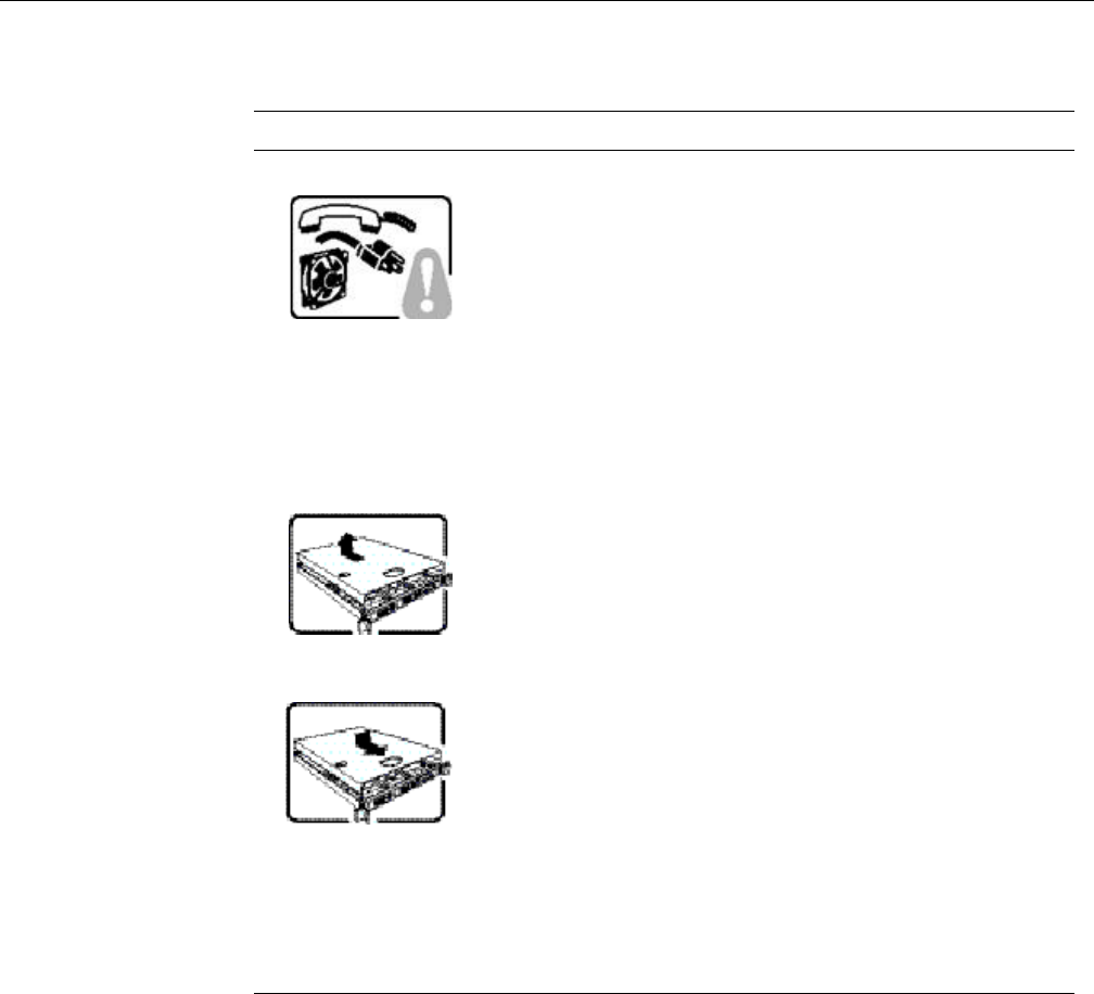
158 007-5645-002
C: Installation and Maintenance Safety Instructions
SAFETY STEPS: Whenever you remove the chassis covers to access the
inside of the system, follow these steps:
1. Turn off all peripheral devices connected to the system.
2. Turn off the system by pressing the power button.
3. Unplug all AC power cords from the system or from wall outlets.
4. Label and disconnect all cables connected to I/O connectors or ports on
the back of the system.
.5. Provide some electrostatic discharge (ESD) protection by wearing an
antistatic wrist strap attached to chassis ground of the system-any
unpainted metal surface-when handling components.
6. Do not operate the system with the chassis covers removed.
After you have completed the six SAFETY steps above, you can remove
the system covers. To do this:
1. Unlock and remove the padlock from the back of the system if a padlock
has been installed.
2. Remove and save all screws from the covers.
3. Remove the cover(s).
For proper cooling and airflow, always reinstall the chassis covers before
turning on the system. Operating the system without the covers in place
can damage system parts. To install the covers:
1. Check first to make sure you have not left loose tools or parts inside the
system.
2. Check that cables, add-in cards, and other components are properly
installed
.3. Attach the covers to the chassis with the screws removed earlier, and
tighten them firmly.
4. Insert and lock the padlock to the system to prevent unauthorized access
inside the system.
5. Connect all external cables and the AC power cord(s) to the system.
Table C-1 System Safety Guidelines (continued)
Symbol Description
007-5645-002 159
A microprocessor and heat sink may be hot if the system has been running.
Also, there may be sharp pins and edges on some board and chassis parts.
Contact should be made with care. Consider wearing protective gloves.
Danger of explosion if the battery is incorrectly replaced. Replace only
with the same or equivalent type recommended by the equipment
manufacturer. Dispose of used batteries according to manufacturer’s
instructions.
The system is designed to operate in a typical office environment.Choose
a site that is:
Clean and free of airborne particles (other than normal room dust)
Well ventilated and away from sources of heat including direct sunlight
Away from sources of vibration or physical shock.
Isolated from strong electromagnetic fields produced by electrical devices.
In regions that are susceptible to electrical storms, we recommend you
plug your system into a surge suppressor and disconnect
telecommunication lines to your modem during electrical storms.
Provided with a properly grounded wall outlet.
Provided with sufficient space to access the power supply cord(s), because
they serve as the product’s main power disconnect.
Table C-1 System Safety Guidelines (continued)
Symbol Description
160 007-5645-002
C: Installation and Maintenance Safety Instructions
The rail racks are designed to carry only the weight of the server system.
Do not use rail-mounted equipment as a work space. Do not place
additional load onto any rail-mounted equipment.
Heavy object. Indicates two people are required to safely handle the
system.
Table C-1 System Safety Guidelines (continued)
Symbol Description
