Iss 007 5818 003
User Manual: 007-5818-003
Open the PDF directly: View PDF ![]() .
.
Page Count: 178 [warning: Documents this large are best viewed by clicking the View PDF Link!]
- Record of Revision
- Contents
- Introduction
- System Overview
- System Interfaces
- System Software
- System Maintenance
- Troubleshooting
- Technical Specifications
- BIOS Error Codes
- Zone Permission Groups Rules

SGI® Modular InfiniteStorage™ (MIS) Platform
User Guide
007-5818-003

COPYRIGHT
© 2012 Silicon Graphics International Corp. All rights reserved; provided portions may be copyright in third parties, as indicated elsewhere herein. No
permission is granted to copy, distribute, or create derivative works from the contents of this electronic documentation in any manner, in whole or in part,
without the prior written permission of SGI.
LIMITED RIGHTS LEGEND
The software described in this document is “commercial computer software” provided with restricted rights (except as to included open/free source) as specified
in the FAR 52.227-19 and/or the DFAR 227.7202, or successive sections. Use beyond license provisions is a violation of worldwide intellectual property laws,
treaties and conventions. This document is provided with limited rights as defined in 52.227-14.
The electronic (software) version of this document was developed at private expense; if acquired under an agreement with the USA government or any
contractor thereto, it is acquired as “commercial computer software” subject to the provisions of its applicable license agreement, as specified in (a) 48 CFR
12.212 of the FAR; or, if acquired for Department of Defense units, (b) 48 CFR 227-7202 of the DoD FAR Supplement; or sections succeeding thereto.
Contractor/manufacturer is SGI, 46600 Landing Parkway, Fremont, CA 94538.
TRADEMARKS AND ATTRIBUTIONS
Silicon Graphics, SGI, the SGI logo, InfiniteStorage, and Supportfolio are trademarks or registered trademarks of Silicon Graphics International Corp. or its
subsidiaries in the United States and/or other countries worldwide.
Fusion-MPT, Integrated RAID, MegaRAID, and LSI Logic are trademarks or registered trademarks of LSI Logic Corporation.InfiniBand is a registered
trademark of the InfiniBand Trade Association. Intel and Xeon are trademarks or registered trademarks of Intel Corporation or its subsidiaries in the United
States and other countries. Internet Explorer and Windows are registered trademarks of Microsoft Corporation. Java and Java Virtual Machine are trademarks
or registered trademarks of Sun Microsystems, Inc. Linux is a registered trademark of Linus Torvalds, used with permission by SGI. Novell and Novell Netware
are registered trademarks of Novell Inc. PCIe and PCI-X are registered trademarks of PCI SIG. Red Hat and all Red Hat-based trademarks are trademarks or
registered trademarks of Red Hat, Inc. in the United States and other countries. Sharp is a registered trademark of Sharp corporation. SUSE LINUX and the
SUSE logo are registered trademarks of Novell, Inc. VMware is a registered trademark or trademark of VMware, Inc. in the United States and/or other
jurisdictions.
All other trademarks mentioned herein are the property of their respective owners.
Adaptec, HostRAID, and the Adaptec logo are registered trademarks of Adaptec Inc.

007-5818-003 iii
Record of Revision
Version Description
001 June 2012
Original printing.
002 August 2012
Edited and updated for technical and editorial changes. Images updated to reflect
changes, added Zones and CLI Zoning Tool software information, available RAID
configurations updated.
003 October 2012
Electromagnetic Compatibility (EMC) compliance and safety information included.
Section on CPU/Riser/HBA configuration restrictions and options added. Weight
safety maximums included. Additional information on RAID options and conditions
provided. Includes updates from the stand-alone version of Chapter 3 issued in
September 2012. Information on grouping control added per customer feedback
(Appendix C).

iv 007-5818-003
:

007-5818-003 v
Contents
Introduction . . . . . . . . . . . . . . . . . . . . . . . . xix
Audience. . . . . . . . . . . . . . . . . . . . . . . . . . xix
Important Information . . . . . . . . . . . . . . . . . . . . . . xix
Safety Precautions . . . . . . . . . . . . . . . . . . . . . . xix
ESD Precautions . . . . . . . . . . . . . . . . . . . . . . xxi
Safety & Emissions . . . . . . . . . . . . . . . . . . . . . . . xxi
Electromagnetic Compatibility . . . . . . . . . . . . . . . . . . .xxii
Safety Certification . . . . . . . . . . . . . . . . . . . . . .xxii
Chapter Descriptions . . . . . . . . . . . . . . . . . . . . . xxiii
Related Publications. . . . . . . . . . . . . . . . . . . . . . xxiv
Conventions . . . . . . . . . . . . . . . . . . . . . . . . .xxv
Product Support . . . . . . . . . . . . . . . . . . . . . . . .xxv
CRU/FRU . . . . . . . . . . . . . . . . . . . . . . . .xxv
Purchasable Support & Maintenance Programs . . . . . . . . . . . . . xxvi
Reader Comments . . . . . . . . . . . . . . . . . . . . . . xxvi
1 System Overview . . . . . . . . . . . . . . . . . . . . . . . 1
MIS Enclosure . . . . . . . . . . . . . . . . . . . . . . . . 5
Front Grille and Control Panels . . . . . . . . . . . . . . . . . . 6
Rear Panel Components . . . . . . . . . . . . . . . . . . . . 7
MIS Common Modules . . . . . . . . . . . . . . . . . . . . . . 10
Power Supply Module . . . . . . . . . . . . . . . . . . . . . 10
Fan Assembly Module . . . . . . . . . . . . . . . . . . . . . 11
StorBrick Module . . . . . . . . . . . . . . . . . . . . . . 12
MIS Server Platform or JBOD Unit. . . . . . . . . . . . . . . . . . . 14
Server Module . . . . . . . . . . . . . . . . . . . . . . . 14
Layout of Server CPUs, and PCIe Risers HBAs . . . . . . . . . . . . . . 20
Boot Drives Module . . . . . . . . . . . . . . . . . . . . . 21

vi 007-5818-003
Contents
MIS JBOD I/O Module . . . . . . . . . . . . . . . . . . . . . 22
System Block Diagram . . . . . . . . . . . . . . . . . . . . . . 23
2 System Interfaces . . . . . . . . . . . . . . . . . . . . . . . 25
Control Panel . . . . . . . . . . . . . . . . . . . . . . . . . 25
MIS Server Control Panel . . . . . . . . . . . . . . . . . . . . 25
MIS JBOD Control Panel . . . . . . . . . . . . . . . . . . . . 27
Disk Drive LEDs . . . . . . . . . . . . . . . . . . . . . . . . 28
Power Supply LEDs . . . . . . . . . . . . . . . . . . . . . . . 28
BMC Integrated Web Console . . . . . . . . . . . . . . . . . . . . 29
System Information . . . . . . . . . . . . . . . . . . . . . . 30
FRU Information . . . . . . . . . . . . . . . . . . . . . 31
System Debug Log . . . . . . . . . . . . . . . . . . . . . 32
CPU Information . . . . . . . . . . . . . . . . . . . . . 34
DIMM Information . . . . . . . . . . . . . . . . . . . . . 34
Server Health . . . . . . . . . . . . . . . . . . . . . . . 35
Sensor Readings . . . . . . . . . . . . . . . . . . . . . 35
Event Log . . . . . . . . . . . . . . . . . . . . . . . 36
Power Statistics . . . . . . . . . . . . . . . . . . . . . . 37
Configuration Tab . . . . . . . . . . . . . . . . . . . . . . 38
IPv4 Network . . . . . . . . . . . . . . . . . . . . . . 39
IPv6 Network . . . . . . . . . . . . . . . . . . . . . . 40
Users . . . . . . . . . . . . . . . . . . . . . . . . 42
Login . . . . . . . . . . . . . . . . . . . . . . . . 43
LDAP . . . . . . . . . . . . . . . . . . . . . . . . 45
VLAN . . . . . . . . . . . . . . . . . . . . . . . . 46
SSL . . . . . . . . . . . . . . . . . . . . . . . . . 48
Remote Session . . . . . . . . . . . . . . . . . . . . . . 48
Mouse Mode . . . . . . . . . . . . . . . . . . . . . . 50
Keyboard Macros . . . . . . . . . . . . . . . . . . . . . 52
Alerts . . . . . . . . . . . . . . . . . . . . . . . . 54
Alert Email . . . . . . . . . . . . . . . . . . . . . . . 55
Node Manager . . . . . . . . . . . . . . . . . . . . . . 56
Remote Control Tab . . . . . . . . . . . . . . . . . . . . . . 59

Contents
007-5818-003 vii
Console Redirection . . . . . . . . . . . . . . . . . . . . 59
Server Power Control . . . . . . . . . . . . . . . . . . . . . 61
3 System Software . . . . . . . . . . . . . . . . . . . . . . . 65
Overview . . . . . . . . . . . . . . . . . . . . . . . . . 65
Section Guide . . . . . . . . . . . . . . . . . . . . . . . . 66
Linux Zoning Tools . . . . . . . . . . . . . . . . . . . . . . . 68
Installing Linux Software . . . . . . . . . . . . . . . . . . . . 68
MegaRAID Storage Manager for Linux . . . . . . . . . . . . . . . 68
MegaCli64 for Linux . . . . . . . . . . . . . . . . . . . . 69
Zones for Linux . . . . . . . . . . . . . . . . . . . . . 69
CLI Zoning Tool for Linux . . . . . . . . . . . . . . . . . . 70
Verify Drives Seen. . . . . . . . . . . . . . . . . . . . . 71
Linux Zones Tool . . . . . . . . . . . . . . . . . . . . . . 71
Installing a Drive through Zones for Linux . . . . . . . . . . . . . . 74
Creating the Drive Groups in MegaRAID for Linux . . . . . . . . . . . . 77
Formatting the Drives using YaST2 in Linux . . . . . . . . . . . . . . 79
Removing a Drive in Zones for Linux. . . . . . . . . . . . . . . . 83
Additional Features in Zones for Linux . . . . . . . . . . . . . . . . 85
Loading .csv Configuration Files in Linux . . . . . . . . . . . . . . 86
Save a Configuration to .csv file in Linux . . . . . . . . . . . . . . . 86
Windows Zoning Tools . . . . . . . . . . . . . . . . . . . . . . 88
Installing Windows Software . . . . . . . . . . . . . . . . . . . 88
MegaRAID Storage Manager for Windows . . . . . . . . . . . . . . 88
MegaCli64 for Windows . . . . . . . . . . . . . . . . . . . 89
Zones for Windows . . . . . . . . . . . . . . . . . . . . 89
Python for Windows . . . . . . . . . . . . . . . . . . . . 91
CLI Zoning Tool for Windows . . . . . . . . . . . . . . . . . 91
Verify Drives Seen in Windows . . . . . . . . . . . . . . . . . 92
Zones for Windows. . . . . . . . . . . . . . . . . . . . . . 92
Installing a Drive in Zones for Windows . . . . . . . . . . . . . . . 95
Creating the Drive Groups in MegaRAID for Windows . . . . . . . . . . . 98
Formatting the Drives in Windows Server Manager . . . . . . . . . . . .100
Removing a Drive in Zones for Windows . . . . . . . . . . . . . . .106

viii 007-5818-003
Contents
Additional Features in Zones for Windows . . . . . . . . . . . . . . . 107
Loading .csv Configuration Files in Zones for Windows . . . . . . . . . . 107
Adapter Assignment Synchronization in Zones for Windows . . . . . . . . . 108
Save a Configuration to .csv file in Zones for Windows . . . . . . . . . . 109
CLI Zoning Tool . . . . . . . . . . . . . . . . . . . . . . . 109
Preparing to Zone using the CLI Zoning Tool . . . . . . . . . . . . . . 110
Editing the ShackCLI.ini file for Linux . . . . . . . . . . . . . . 111
Editing the ShackCLI.ini file for Windows . . . . . . . . . . . . . 112
CLI Zoning Tool Main Menu . . . . . . . . . . . . . . . . . 113
Zoning Using CLI Zoning Tool . . . . . . . . . . . . . . . . . . 117
Editing the .csv File for the CLI Zoning Tool . . . . . . . . . . . . . . 119
Disk RAID Support . . . . . . . . . . . . . . . . . . . . . . 122
RAID 0 . . . . . . . . . . . . . . . . . . . . . . . . 123
RAID 1 . . . . . . . . . . . . . . . . . . . . . . . . 124
RAID 5 . . . . . . . . . . . . . . . . . . . . . . . . 125
RAID 6 . . . . . . . . . . . . . . . . . . . . . . . . 125
RAID 00 . . . . . . . . . . . . . . . . . . . . . . . . 126
RAID 10 . . . . . . . . . . . . . . . . . . . . . . . . 127
RAID 50 . . . . . . . . . . . . . . . . . . . . . . . . 128
RAID 60 . . . . . . . . . . . . . . . . . . . . . . . . 128
RAID Configuration Notes . . . . . . . . . . . . . . . . . . . 129
4 System Maintenance . . . . . . . . . . . . . . . . . . . . . 133
Detecting Component Failures . . . . . . . . . . . . . . . . . . . 134
Sliding the Chassis Forward/Backwards . . . . . . . . . . . . . . . . . 134
Removing the Front or Rear Chassis Cover . . . . . . . . . . . . . . . . 134
Replacing a Power Supply . . . . . . . . . . . . . . . . . . . . 135
Replacing a Fan Module . . . . . . . . . . . . . . . . . . . . . 136
Replacing a Disk Drive . . . . . . . . . . . . . . . . . . . . . 137
Removing the Drive . . . . . . . . . . . . . . . . . . . . . 138
Re-installing the Drive . . . . . . . . . . . . . . . . . . . . 139
Checking the System Air Flow . . . . . . . . . . . . . . . . . . . 140

Contents
007-5818-003 ix
5 Troubleshooting . . . . . . . . . . . . . . . . . . . . . . .141
No Video . . . . . . . . . . . . . . . . . . . . . . . . .141
Losing the System’s Setup Configuration . . . . . . . . . . . . . . . . .141
I/O Time-outs and MegaRAID Drivers . . . . . . . . . . . . . . . . . .142
Safe Power-Off . . . . . . . . . . . . . . . . . . . . . . . .142
A Technical Specifications . . . . . . . . . . . . . . . . . . . . .143
B BIOS Error Codes . . . . . . . . . . . . . . . . . . . . . . .147
C Zone Permission Groups Rules . . . . . . . . . . . . . . . . . . .149

x007-5818-003
Contents

007-5818-003 xi
Figures
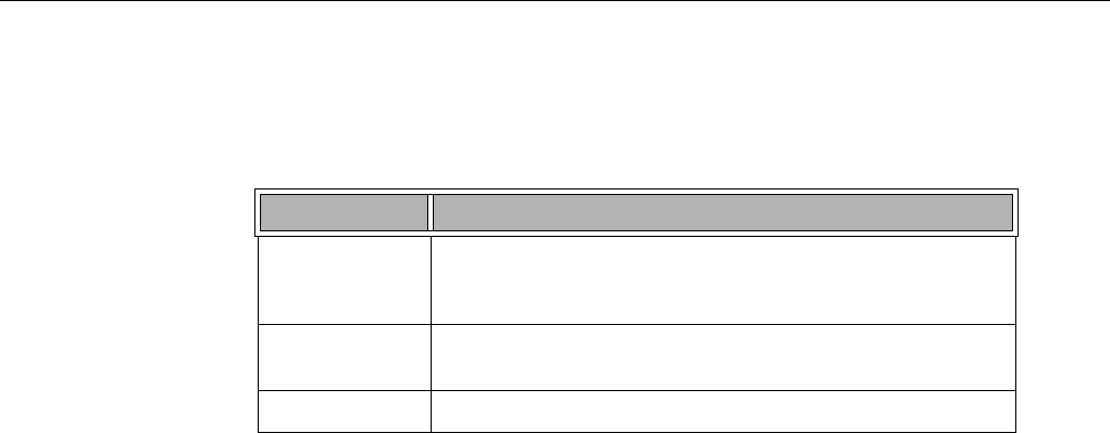
Figure 1-1 SGI Destination Rack (D-Rack) . . . . . . . . . . . . 4
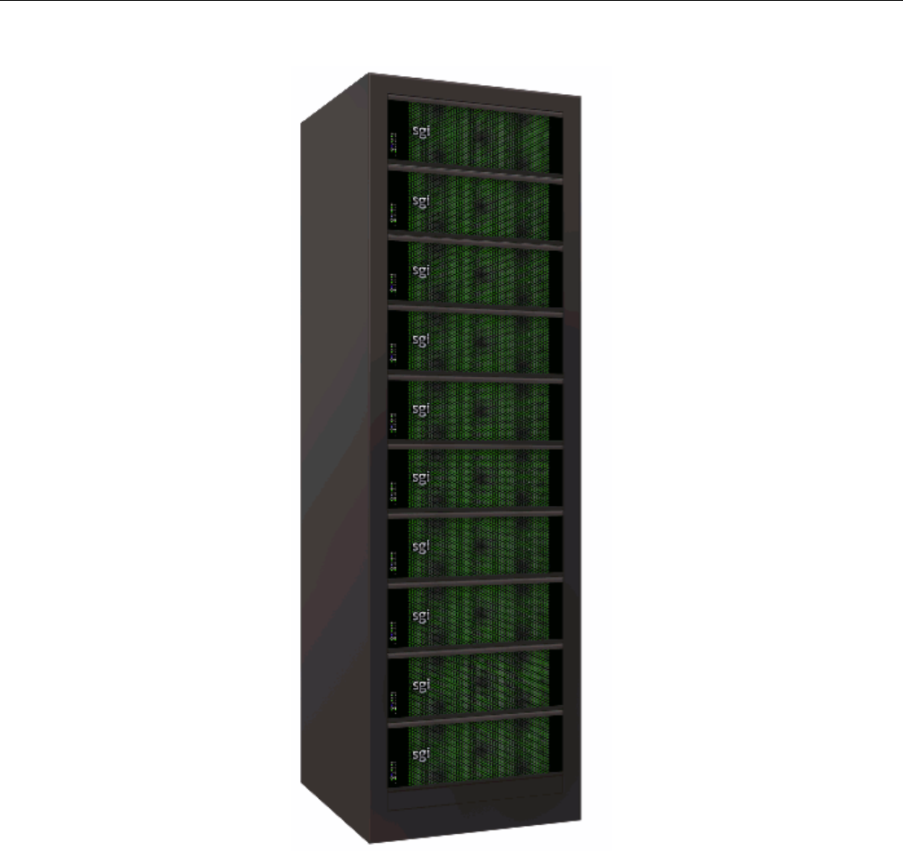
Figure 1-2 MIS Chassis and Case . . . . . . . . . . . . . . 5
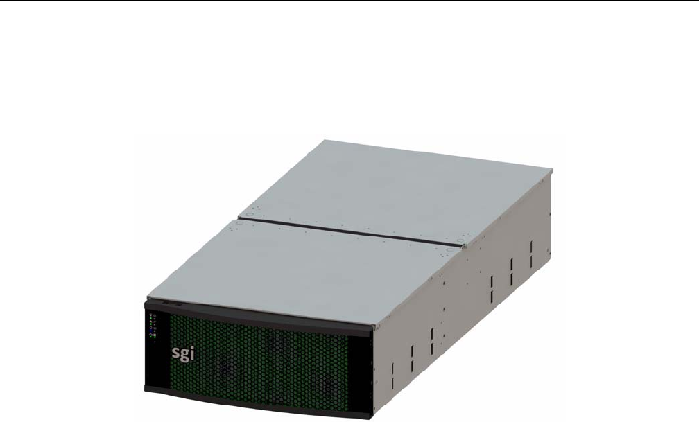
Figure 1-3 Bi-directional rail mount . . . . . . . . . . . . . . 6
Figure 1-4 Single Control Panel . . . . . . . . . . . . . . . 7
Figure 1-5 Dual Control Panel . . . . . . . . . . . . . . . 7
Figure 1-6 Rear View – MIS Server Platform (single server) . . . . . . . 8
Figure 1-7 Rear View – MIS Server Platform (single server, four power supplies). . 8
Figure 1-8 Rear View – MIS Server Platform (dual server). . . . . . . . 8
Figure 1-9 Rear View – MIS Server Platform (single dual-server module) . . . . 9
Figure 1-10 Rear View – MIS JBOD Unit (single I/O module) . . . . . . . 9
Figure 1-11 Rear View – MIS JBOD unit (dual I/O modules) . . . . . . . 9
Figure 1-12 Power Supply Module (rated at 1100 Watts) . . . . . . . . 11
Figure 1-13 Power Supply Numbering . . . . . . . . . . . . . 11
Figure 1-14 Fan Assembly Module (each contains two impellers) . . . . . . 11
Figure 1-15 StorBrick Modules for 3.5" or 2.5" 15mm Drives (left)
and 2.5" 9.5 mm Drives (right) . . . . . . . . . . . . 12
Figure 1-16 3.5" 15mm Drive and Carrier . . . . . . . . . . . . 13
Figure 1-17 3.5" 15mm Drive Carrier (top view, with thumb latch) . . . . . . 13
Figure 1-18 Two 2.5" 9.5mm Drives and Carrier . . . . . . . . . . . 13
Figure 1-19 2.5" 9.5mm Drive Carrier (isometric view with dual thumb latches) . . 14
Figure 1-20 MIS Server Platform (single server) . . . . . . . . . . . 15
Figure 1-21 MIS Server Platform (dual server) . . . . . . . . . . . 16
Figure 1-22 MIS JBOD Unit . . . . . . . . . . . . . . . . 17
Figure 1-23 MIS Server Module – single server . . . . . . . . . . . 18
Figure 1-24 Server Module (single server) – component view . . . . . . . 18
Figure 1-25 MIS Server Module – dual server (half height) . . . . . . . . 19
Figure 1-26 Dual Server Module – component view . . . . . . . . . . 19
Figure 1-27 CPU and PCIe Riser layout . . . . . . . . . . . . . 20

xii 007-5818-003
Figure 1-28 HBA population layout . . . . . . . . . . . . . . 21
Figure 1-29 Boot Drive Module . . . . . . . . . . . . . . . 22
Figure 1-30 I/O Module for MIS JBOD Unit . . . . . . . . . . . . 22
Figure 1-31 MIS JBOD Midplane I/O Connector (right & left views) . . . . . 23
Figure 1-32 System-Level Block Diagram. . . . . . . . . . . . . 24
Figure 2-1 MIS Control Panel . . . . . . . . . . . . . . . 26
Figure 2-2 Disk Drive LEDs . . . . . . . . . . . . . . . . 28
Figure 2-3 Power Supply LEDs
. . . . . . . . . . . . . . . . . . . . 28
Figure 2-4 BMC Web Console – System Information Page . . . . . . . . 31
Figure 2-5 BMC Web Console – FRU Information . . . . . . . . . . 32
Figure 2-6 BMC Web Console – System Debug Log . . . . . . . . . 33
Figure 2-7 BMC Web Console – CPU Information . . . . . . . . . . 34
Figure 2-8 BMC Web Console – DIMM Information . . . . . . . . . 35
Figure 2-9 BMC Web Console – Server Health . . . . . . . . . . . 36
Figure 2-10 BMC Web Console – Event Log . . . . . . . . . . . . 37
Figure 2-11 BMC Web Console – Power Statistics . . . . . . . . . . 38
Figure 2-12 BMC Web Console – IPv4 Network Settings . . . . . . . . 40
Figure 2-13 BMC Web Console – IPv6 Network Settings . . . . . . . . 42
Figure 2-14 BMC Web Console – Login Security Settings . . . . . . . . 44
Figure 2-15 BMC Web Console – LDAP Settings. . . . . . . . . . . 46
Figure 2-16 BMC Web Console – VLAN Settings . . . . . . . . . . 47
Figure 2-17 BMC Web Console – SSL Upload . . . . . . . . . . . 48
Figure 2-18 BMC Web Console – Remote Session . . . . . . . . . . 50
Figure 2-19 BMC Web Console – Mouse Mode Setting . . . . . . . . . 51
Figure 2-20 BMC Web Console – Logout, Refresh, and Help buttons . . . . . 52
Figure 2-21 BMC Web Console – Keyboard Macros . . . . . . . . . . 52
Figure 2-22 BMC Web Console – Alerts . . . . . . . . . . . . . 55
Figure 2-23 BMC Web Console – Alert Email Settings . . . . . . . . . 56
Figure 2-24 BMC Web Console – Node Manager Power Policies . . . . . . 57
Figure 2-25 BMC Web Console – Console Redirection (greyed-out). . . . . . 60
Figure 2-26 BMC Web Console – Launch Console button (available) . . . . . 60
Figure 2-27 Remote Console – Java redirection window . . . . . . . . . 61

Figures
007-5818-003 xiii
Figure 2-28 BMC Web Console – Power Control and Status. . . . . . . . 62
Figure 3-1 Zones – First-use path configuration. . . . . . . . . . . 70
Figure 3-2 Zones – Error message: Improper path . . . . . . . . . . 70
Figure 3-3 Linux Zones Welcome . . . . . . . . . . . . . . 71
Figure 3-4 Zones User Interface . . . . . . . . . . . . . . . 72
Figure 3-5 Zones – Show All, Open Session, Save Session, Download Session, and Exit
buttons . . . . . . . . . . . . . . . . . . 72
Figure 3-6 Zones – Opening a Session . . . . . . . . . . . . . 73
Figure 3-7 Zones – Enter Session Alias . . . . . . . . . . . . . 73
Figure 3-8 Zones – Alias Help Warning Message . . . . . . . . . . 74
Figure 3-9 Zones – Adapter tabs . . . . . . . . . . . . . . . 74
Figure 3-10 Zones – Show All . . . . . . . . . . . . . . . 75
Figure 3-11 Zones – Adapter Assignment Warning Message . . . . . . . 75
Figure 3-12 Zones – Select StorBricks for download . . . . . . . . . . 76
Figure 3-13 MegaRAID – Create a Virtual Drive. . . . . . . . . . . 77
Figure 3-14 MegaRAID – Create Virtual Drive mode . . . . . . . . . 77
Figure 3-15 Create Virtual Drive – Drive Group Settings . . . . . . . . 78
Figure 3-16 Create Virtual Drive – Summary. . . . . . . . . . . . 78
Figure 3-17 Yast2 Server Manager GUI . . . . . . . . . . . . . 79
Figure 3-18 YaST2 – Warning Message . . . . . . . . . . . . . 80
Figure 3-19 YaST2 – Drives have appeared . . . . . . . . . . . . 80
Figure 3-20 YaST2 – Add button . . . . . . . . . . . . . . . 81
Figure 3-21 YaST2 – Select Partition Size . . . . . . . . . . . . 81
Figure 3-22 YaST2 – Format & Mount the Drive. . . . . . . . . . . 81
Figure 3-23 YaST2 – Check for Partition . . . . . . . . . . . . . 82
Figure 3-24 YaST – Click Finish . . . . . . . . . . . . . . . 82
Figure 3-25 YaST2 – Disk Mounting (in process) . . . . . . . . . . 83
Figure 3-26 Zones – Downloading setting to StorBrick(s) . . . . . . . . 84
Figure 3-27 Zones – Are you sure to download files to expander? . . . . . . 85
Figure 3-28 Zones – Select CSV File (Linux) . . . . . . . . . . . 86
Figure 3-29 Zones – Save Configuration to .csv . . . . . . . . . . . 86
Figure 3-30 Zones – Save CSV pop-up . . . . . . . . . . . . . 87
Figure 3-31 Zones – Select Directory navigation pane . . . . . . . . . 87

xiv 007-5818-003
Figure 3-32 Zones – Error: Improper Directory Selection. . . . . . . . . 88
Figure 3-33 Zones – First-use path configuration (Windows) . . . . . . . . 90
Figure 3-34 Zones – Error messages from improper path configuration . . . . . 91
Figure 3-35 Windows Server Manager – Disk Management . . . . . . . . 92
Figure 3-36 Zones for Windows Welcome . . . . . . . . . . . . 93
Figure 3-37 Zones Windows User Interface . . . . . . . . . . . . 93
Figure 3-38 Zones – Open Session, Save Session, Download Session, and Exit buttons . 93
Figure 3-39 Zones – Open Session. . . . . . . . . . . . . . . 94
Figure 3-40 Zones – Enter Session Alias . . . . . . . . . . . . . 94
Figure 3-41 Zones – Alias Help Warning Message . . . . . . . . . . 95
Figure 3-42 Zones – Adapter tabs (Windows) . . . . . . . . . . . . 95
Figure 3-43 Zones – Show All . . . . . . . . . . . . . . . . 96
Figure 3-44 Zones – Adapter Assignment Warning Message . . . . . . . . 96
Figure 3-45 Zones – Select StorBricks for download . . . . . . . . . . 97
Figure 3-46 Zones tool – Verify download . . . . . . . . . . . . 98
Figure 3-47 MegaRAID – Create a Virtual Drive . . . . . . . . . . . 98
Figure 3-48 MegaRAID – Create Virtual Drive mode. . . . . . . . . . 99
Figure 3-49 Create Virtual Drive – Simple Settings . . . . . . . . . . 99
Figure 3-50 Create Virtual Drive – Summary . . . . . . . . . . . 100
Figure 3-51 Server Manager – Disk Management . . . . . . . . . . 101
Figure 3-52 Server Manager – Initialize Disks . . . . . . . . . . 101
Figure 3-53 Server Manager – Select GPT (GUID Partition Table) . . . . . 102
Figure 3-54 Server Manager – Disks Initialized and Online . . . . . . . 102
Figure 3-55 Server Manager – New Simple Volume . . . . . . . . . 103
Figure 3-56 Server Manager – New Simple Volume Wizard . . . . . . . 103
Figure 3-57 New Simple Volume Wizard – Volume Size. . . . . . . . 104
Figure 3-58 New Simple Volume Wizard – Assign Drive Letter or Path . . . . 104
Figure 3-59 New Simple Volume Wizard – Format Partition . . . . . . . 105
Figure 3-60 New Simple Volume Wizard – Settings Confirmation . . . . . 105
Figure 3-61 New Simple Volume in Server Manager . . . . . . . . . 106
Figure 3-62 Zones – Verify Download. . . . . . . . . . . . . 106
Figure 3-63 Zones – Select CSV File . . . . . . . . . . . . . 107
Figure 3-64 Zones – Error message: Canceling csv file selection (Windows) . . 108

Figures
007-5818-003 xv
Figure 3-65 Zones – Select All, Unselect All buttons. . . . . . . . . .108
Figure 3-66 MIS-S9D proprietary network interface . . . . . . . . . .111
Figure 3-67 Block diagram of MIS-Server StorBrick SB0 . . . . . . . .121
Figure 3-68 RAID 0 . . . . . . . . . . . . . . . . . .123
Figure 3-69 RAID 1 . . . . . . . . . . . . . . . . . .124
Figure 3-70 RAID 5 . . . . . . . . . . . . . . . . . .125
Figure 3-71 RAID 6 . . . . . . . . . . . . . . . . . .125
Figure 3-72 RAID 00 . . . . . . . . . . . . . . . . . .126
Figure 3-73 RAID 10 . . . . . . . . . . . . . . . . . .127
Figure 3-74 RAID 50 . . . . . . . . . . . . . . . . . .128
Figure 3-75 RAID 60 . . . . . . . . . . . . . . . . . .128
Figure 3-76 RAID 1 with one drive per StorBrick . . . . . . . . . .129
Figure 3-77 RAID 1 with two drives spanning a StorBrick . . . . . . . .130
Figure 3-78 RAID 5 or 6 with one drive per StorBrick . . . . . . . . .131
Figure 3-79 Loss of a drive with multiple drives on a StorBrick does not affect RAID 6, but
will impact RAID 5 . . . . . . . . . . . . . . .131
Figure 3-80 Three drive loss in RAID 6 require StorBrick replacement . . . . .131
Figure 4-1 Front & Rear Chassis Covers . . . . . . . . . . . .135
Figure 4-2 Replacing a Power Supply . . . . . . . . . . . . .136
Figure 4-3 Replacing a Fan Module . . . . . . . . . . . . . .137
Figure 4-4 Hard Drive Carrier . . . . . . . . . . . . . . .139
Figure 4-5 MIS Chassis Midspan Support Brace . . . . . . . . . .140
Figure C-1 Zone Permission Groups – Example 1 . . . . . . . . . .150
Figure C-2 Zone Permission Groups – Example 2 . . . . . . . . . .151

xvi 007-5818-003

007-5818-003 xvii
Tables
Table -1 MIS Server Platform Region and EMC Compliance References . . .xxii
Table -2 MIS Server Platform Region and EMC Compliance References . . xxiii
Table 2-1 MIS Server Platform Control Panel Buttons and LEDs . . . . . . 26
Table 2-2 Disk Drive LEDs . . . . . . . . . . . . . . . 28
Table 2-3 Power Supply LEDs . . . . . . . . . . . . . . . 29
Table 2-4 System Information Details . . . . . . . . . . . . . 30
Table 2-5 Supported Key Names . . . . . . . . . . . . . . 53
Table 2-6 Server Power Control Actions . . . . . . . . . . . . 61
Table 2-7 System Information Details . . . . . . . . . . . . . 63
Table 3-1 Zone Group Implementation . . . . . . . . . . . . .110
Table 3-2 CLI Zoning Tool Menu Options and Descriptions . . . . . . .114
Table 3-3 Zone Group Implementation . . . . . . . . . . . . .120
Table A-1 Technical Specifications . . . . . . . . . . . . . .143
Table B-1 BMC Beep Codes . . . . . . . . . . . . . . .147

xviii 007-5818-003

007-5818-003 xix
.Introduction
This guide describes the features and components of the SGI® Modular InfiniteStorage™ (MIS)
platform. With two main configurations possible for the enclosure (server and storage, or JBOD—
Just Bunch Of Disks) this guide covers the different configurations, their respective components,
interface panels, indicator lights and meanings, software, maintenance, and troubleshooting.
Audience
This guide is written for owners/users of the MIS platform. It is written with the assumption that
the reader has a good working knowledge of computers, servers, networking, hardware, software
and RAID arrays.
Important Information
The following section details several safety precautions that should be observed at all times. First,
a fully loaded MIS Platform can weigh up to 220lbs. Second, electricity is a major concern,
especially Electrostatic Discharge (ESD), detailed later in this section. Please read these sections
carefully prior to using the MIS Platform.
Safety Precautions
Do NOT wear loose clothing, such as neckties or unbuttoned shirt sleeves, while working on the
unit which can be pulled into a cooling fan or tangled in cabling.
Remove any jewelry any metal objects from your body, which are excellent electrical conductors,
and can harm you and/or cause short circuits if they come into contact with printed circuit boards
or powered areas.

xx 007-5818-003
Introduction
Be aware of the locations of the power on/off switch on the chassis as well as the room's
emergency power-off switch, disconnection switch or electrical outlet. If an electrical accident
occurs, you can then quickly remove power from the system.
Do NOT work alone when working with high voltage components.
When working around exposed electrical circuits, another person should be nearby, who is
familiar with the power-off controls, to switch off the power if necessary.
Use only one hand when working with powered-on electrical equipment. This is to avoid making
a complete circuit, which will cause electrical shock. Use extreme caution when using metal tools,
which can easily damage any electrical components or circuit boards with which they come into
contact.
Do NOT use mats designed to decrease static electrical discharge as protection from electrical
shock. Instead, use rubber mats that have been specifically designed as electrical insulators.
The power supply power cords must include a grounding plug and must be plugged into grounded
electrical outlets.
Do NOT attempt to transport/move a fully loaded MIS system. An MIS system can weigh up to
220lbs. when fully loaded. If the system must be moved, first remove the drives from the chassis.
When lifting the system, two people (one at each end) should lift slowly with feet spread apart to
distribute the weight. Always follow safe lifting practices when moving heavy objects. More
information on moving large objects, requiring a two-person team, is available in the Centers for
Disease Control’s, “Ergonomic Guidelines for Manual Material Handling”
(http://www.cdc.gov/niosh/docs/2007-131/pdfs/2007-131.pdf)
Power should always be disconnected from the system when removing or installing system
components that are not hot-swappable, such as server boards and memory modules. When
disconnecting power, you should first do a clean shut down of the operating system, then power
down the system, and then unplug all power cords (the unit has more than one power supply cord).
More information on powering off the MIS Platform is available in Chapter 4, “System
Maintenance.”

Introduction
007-5818-003 xxi
ESD Precautions
Caution: Electrostatic Discharge (ESD) is generated by two objects with different electrical
charges coming into contact with each other. An electrical discharge is created to neutralize this
difference, which can damage electronic components and printed circuit boards.
The following measures are generally sufficient to neutralize this difference before contact is
made to protect your equipment from ESD:
• Use a grounded wrist strap designed to prevent static discharge.
• Keep all components and printed circuit boards (PCBs) in their antistatic bags until ready for
use.
• Touch a grounded metal object before removing the board from the antistatic bag.
• Do not let components or PCBs come into contact with your clothing, which may retain a
charge even if you are wearing a wrist strap.
• Handle a board by its edges only; do not touch its components, peripheral chips, memory
modules or contacts.
• When handling chips or modules, avoid touching their pins.
• Put the server board and peripherals back into their antistatic bags when not in use.
• For grounding purposes, make sure your computer chassis provides excellent conductivity
between the power supply, the case, the mounting fasteners and the server board.
Safety & Emissions
The following is a list of agency approvals for MIS on safety and emissions.
!

xxii 007-5818-003
Introduction
Electromagnetic Compatibility
Table -1 lists the region and compliance reference for EMC (Electromagnetic Compatibility)
compliance.
Safety Certification
Underwriters Laboratories (UL) provides safety certification for electronic devices. UL offers a
Functional Safety Listing Mark that can be added for those qualifying companies in the process
of getting a traditional Listing from UL. In essence, the Functional Safety Listing Mark replaces
the traditional UL listing mark on products certified for functional safety. Functional safety
examines the efficacy of the safety-related system by considering the input variables to a device
and confirming that the activating quantities of the output are within its designed
parameters/ratings. So it goes beyond the traditional fire and electric shock safety associated with
Table -1 MIS Server Platform Region and EMC Compliance References
Region Compliance Reference
Australia/
New Zealand
AS/NZS 3548 (Emissions)
Canada/USA CSA 60950 / UL60950/
60950-1 cert to CAN/CSA STD C22.2 No. 60950-1
Industry Canada ICES-003
FCC CFR47, Part 15
CENELEC Europe EN55022 Emissions
EN55024 Immunity
International CISPR 22/ CISPR 24
Japan VCCI Certification
Korea KCC Certification
Taiwan BSMI CNS 13438
China CCC
Russia GOST
Introduction
007-5818-003 xxiii
the traditional UL Listing Mark. Table -2 lists the region and compliance reference for EMC
(Electromagnetic Compatibility) compliance.
Chapter Descriptions
Chapter 1, “System Overview‚” describes the hardware components of the MIS enclosures, the
common modules in unit, and the major differences between the MIS Server Platform and MIS
JBOD Unit. Additional information includes the operating systems supported, and RAID
configurations possible with the MIS enclosures.
Chapter 2, “System Interfaces‚” describes the hardware and software interfaces used to operate
the MIS Server and MIS JBOD. This includes the front control panel, disk drive LEDs, power
supply LEDs, and the BMC Web Console.
Chapter 3, “System Software‚” covers the software used on the MIS Platforms, including
installation information for the tools, using the MegaRAID tool, and the available zoning software
(Zones and CLI Zoning Tool). Depending on the operating system, there are certain prerequisite
programs and this chapter gives instructions for download and installation of these programs.In
this chapter are step-by-step instructions for Zones tool, its features and their function, plus
warnings and error codes. Screen shots are given for a walk-through of the tool. detailed in this
chapter next are step-by-step instructions for zoning using the CLI Zoning tool (the only tool that
can zone JBODs at this time).
Chapter 4, “System Maintenance‚” describes how to use Sensor Data Records for detecting
component failures, and service instructions for modules that are customer replaceable units
(CRUs). The service instructions include how to move the chassis forward or backwards in the
rack, how to remove the case front and read covers, how to remove the midspan support bar for
ease of access to cabling, how to replace a power supply, how to replace a storage drive in a
Table -2 MIS Server Platform Region and EMC Compliance References
Region Compliance Reference
Canada/USA CSA 60950 / UL60950/
Compliance Document UL report
60950-1 cert to CAN/CSA STD C22.2 No. 60950-1
IEC (Europe) IEC60950-1 – CB Certification, CE Mark
Compliance Document UL report
Russia GOST

xxiv 007-5818-003
Introduction
StorBrick, how to replace a boot drive, how to replace a fan module, and additional air-flow
precautions.
Chapter 5, “Troubleshooting‚” describes some problem-solving techniques, plus when and how
to contact customer support.
Appendix A, “Technical Specifications,” gives the technical specifications for the MIS
enclosures.
Appendix B, “BIOS Error Codes,” details the beep codes used when a problem is detected by the
BMC environmental controls.
Related Publications
The following documents are relevant to the MIS Platform:
•MegaRAID SAS Software User Guide, publication number 51530-00, Rev E.
•MegaRAID 6Gb/s SAS RAID Controllers User Guide, publication number 41450-02, Rev E.
•Intel Server Boards and Server Platforms Server Management Guide,
publication number 37830-002
•SGI Foundation Software, publication number 007-5641-00x
•SGI Performance Suite, publication number 007-5680-00x
• SGI InfiniteStorage series documentation (http://techpubs.sgi.com)
• Man pages (http://www.linuxmanpages.com/)
Various formats of SGI documentation, release notes, and man pages are available. The SGI
Technical Publications Library (http://docs.sgi.com/) contains the most recent and most
comprehensive set of online books, release notes, man pages, and other information. Refer to the
SGI Supportfolio™ web page for documents which access requires a support contract (as do the
MegaRAID books cited above). See “Product Support” on page xxv. You can also view man
pages by typing man <title> on a command line in Linux.

Introduction
007-5818-003 xxv
Conventions
The following conventions are used throughout this document:
Product Support
SGI provides a comprehensive product support and maintenance program for its products, as
follows:
• If you are in North America, contact the Technical Assistance Center at +1 800 800
4SGI (4744) or contact your authorized service provider.
• If you are outside North America, contact the SGI subsidiary or authorized distributor in
your country. International customers can visit http://www.sgi.com/support/ Click on
the “Support Centers” link under the “Online Support” heading for information on how
to contact your nearest SGI customer support center.
CRU/FRU
Some of the components on the MIS Platform are customer-replaceable units (CRUs), meaning
that these modules were designed to be repaired/replaced by you, the customer. These include fan
assemblies, power supplies, storage drives, and boot drives, all of which are hot-swappable.
However, many of the other components on the MIS Platform should be serviced by SGI field
technicians ONLY, so as not to violate the warranty agreement. The components are
field-technician replaceable units, or FRUs. It is important to note that our CRUs can be easily
installed and replaced by customers, which enables a speedy recovery of proper system operation.
Convention Meaning
Command This fixed-space font denotes literal items such as commands, files,
routines, path names, signals, messages, and programming language
structures.
variable The italic typeface denotes variable entries and words or concepts being
defined. Italic typeface is also used for book titles.
[ ] Brackets enclose optional portions of a command or directive line.
GUI element This font denotes the names of graphical user interface (GUI) elements such
as windows, screens, dialog boxes, menus, toolbars, icons, buttons, boxes,
fields, and lists.

xxvi 007-5818-003
Introduction
For additional information about CRUs, please see:
• Customer Replaceable Units (CRUs) Installation Policy
•Customer Replaceable Units (CRU) and Customer Obligations\
Purchasable Support & Maintenance Programs
SGI provides several comprehensive product support and maintenance programs for its products.
SGI also offers services to implement and integrate Linux applications in your environment.
• Refer to http://www.sgi.com/services/
• If you are in North America, contact the Technical Assistance Center at
+1-800-800-4SGI (4744), or contact your authorized service provider.
• If you are outside North America, contact the SGI subsidiary or authorized distributor in
your country. See http://www.sgi.com/global/index.html for more information.
Reader Comments
If you have comments about the technical accuracy, content, or organization of this document,
please contact SGI. Be sure to include the title and document number of the manual with your
comments. (Online, the document number is located in the front matter of the manual. In printed
manuals, the document number is located at the bottom of each page.)
You can contact SGI in any of the following ways:
• Send e-mail to the following address: techpubs@sgi.com
• Contact your customer service representative, and ask that an incident be filed in the SGI
incident tracking system.
• Send mail to the following address:
SGI
Technical Publications
46600 Landing Parkway
Fremont, CA 94538
SGI values your comments, and will respond to them promptly.

007-5818-003 1
Chapter 1
1. System Overview
The SGI Modular InfiniteStorage Platform is a high-density, integrated storage server platform.
The MIS Platform uses a 4U rackmount system, and can be either a compute and storage server,
or a “Just Bunch Of Disks” expansion storage unit (MIS JBOD unit). The MIS Server Platform
can be single or dual server. Up to 5 MIS enclosures (server & JBODs) or 6 JBODs can be
mounted into a SGI Destination rack (D-Rack), as shown in Figure 1-1. (Other 3rd-party 19" racks
are also supported.) A D-Rack has space for up to 10 enclosures, however, due to floor weight
regulations, only 5-6 units may be installed in a single D-Rack. See
Features of the modular design of the MIS Platform include:
• Up to 72 (3.5" or 2.5" 15mm) and a maximum of 144 (2.5" 9.5mm) storage drives in the
Server Platform
• Up to 81 (3.5" or 2.5" 15mm) and a maximum of 162 (2.5" 9.5mm) storage drives in the
JBOD unit
• All fit in a standard size 4U chassis: height 6.94" (176mm), width 16.9" (429.2mm), depth
36" (914.4mm).
Storage drives can be 3.5" or 2.5" (15mm or 9.5mm), SAS or SATA, rotational or SSD drives. Up
to four JBOD units can be attached to one MIS Dual Server Platform.
Warning: Rotational SAS drives and rotational SATA drives cannot be included in the
same enclosure due to vibration conflicts.
The MIS Server Platform features:
• Up to 2 server modules per platform.
• One or two Intel® Xeon® E5-2600 series processors per server motherboard.
!

2007-5818-003
1: System Overview
• Intel Turbo Boost Technology 2.0 that automatically allows processor cores to run faster
than the base operating frequency, if the cores are operating below power, current, and
temperature specification limits (< 35ºC ambient).
• Up to 8 DDR3 DIMMs (4 GB, 8 GB, or 16 GB) for a single-server motherboard
configuration, and up to 16 DIMMs for a dual-server motherboard configuration.
• Up to 4 HBAs for a single server, full-height (4.25") and half-depth (3.375"), externally or
internally facing. Up to 4 HBAs (half-height, half-depth; 2 per server module) for a dual
server. There are an additional two internally facing, half-height and half-depth HBAs per
server module, used by the system. The MIS Single Server Platform can have a total of six
HBAs, where a Dual Server Platform can have a maximum of eight (including those used by
the system).
• Up to 3 PCIe riser cards for single server systems (dual-servers have a mandatory 3 PCIe
risers, regardless of card count).
• Up to four battery back up units for a single server module. Up to three battery back up units
per server module for a dual server platform, for a total maximum of six. (Unique BBU PCIe
technology allows the inclusion of BBUs without the consumption of any of the available
PCIe slots.)
• Two boot drives per server: SAS or SATA, rotational or SSD, up to 300GB, mirrored using
RAID 1.
• Dual GbE networking onboard, with an optional 2 port 10GbE, 2 port GbE, or 4 port 8Gb
FC PCIe cards (4 optional networking PCIe cards maximum, external facing only; risers 1
and 2).
Warning: Floor loading has a maximum weight allowance of 250lbs per square foot, not
including the service area. Floor loading must be less than 250lbs per square foot, including
the service area. There can be a total of 6 JBODs or 6 MIS Servers per D-Rack, or a
combined total of 5. For maximum efficiency and performance, it is suggested that the
maximum number of enclosures in a single D-Rack is 1 MIS Dual Server enclosure with 4
JBODs (two JBODs per server module). A 5th JBOD can be tolerated weight-wise, but 4 is
the suggested performance maximum.
The System Overview will first explore the “MIS Enclosure,” including “Front Grille and Control
Panels” on page 6, “Rear Panel Components” on page 7. Next, the “MIS Common Modules” on
page 10 is covered, including the power supply modules, fan modules, and StorBrick modules.
“MIS Server Platform or JBOD Unit” on page 14, discusses the presence of the “Server Module”
on page 14, its available features and associated “Boot Drives Module” on page 22, or the
!

4007-5818-003
1: System Overview
Figure 1-1 SGI Destination Rack (D-Rack)
MIS Enclosure
007-5818-003 5
MIS Enclosure
The MIS enclosure, whether it is a server or JBOD, consists of a chassis, case (with front bezel
grille, control panel and rear ports).
Figure 1-2 MIS Chassis and Case
The SGI MIS chassis features a front bezel display with an internal EMI grille (Figure 1-2). The
unique bi-directional sliding rail mounts (Figure 1-3) allow the unit to be slid forwards 20" or
backwards 18" to access disk drives and other serviceable components. This also makes for an
overall safer rack design, as chassis do not need to be extended their full length to be serviced.
6007-5818-003
1: System Overview
Figure 1-3 Bi-directional rail mount
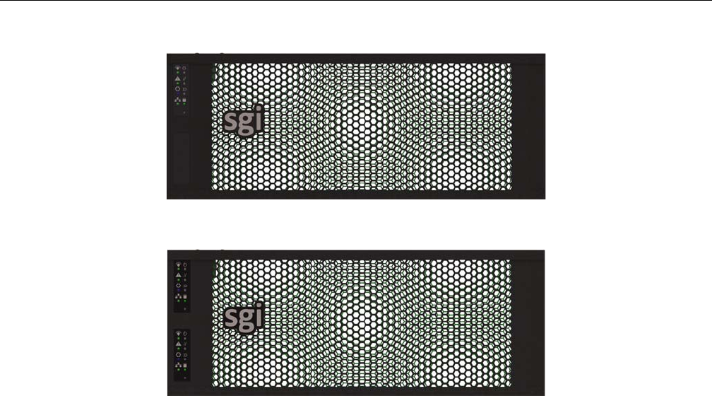
Front Grille and Control Panels
Next to the bezel grille, up to two control panels can be present on the MIS Platform, one for each
server in the MIS Server Platform, or one for each I/O unit on the MIS JBOD. Figure 1-4 shows
a single control panel and Figure 1-5 shows two control panels.
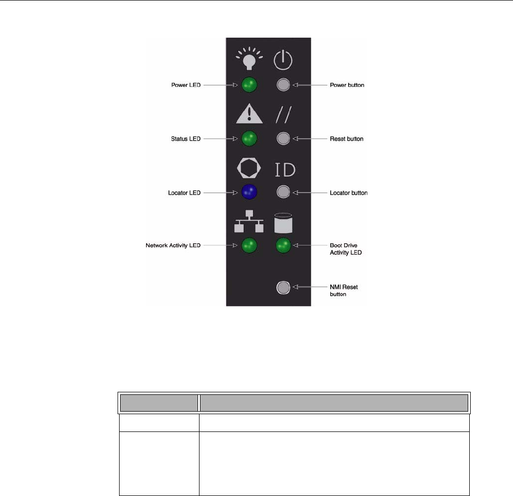
Each control panel has a Power LED, Power button, Status LED, Reset Button, Locator LED,
Locator button, Network Activity LED, Boot Drive Activity LED, and NMI Reset button (to be
used by SGI field operatives only). Indicator light meanings and button functions are explained
in, “Control Panel” in Chapter 2.
MIS Enclosure
007-5818-003 7
Figure 1-4 Single Control Panel
Figure 1-5 Dual Control Panel
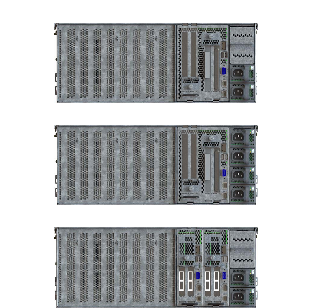
Rear Panel Components
The appearance of the rear panel on the MIS chassis will depend on what modules are installed.
An MIS Platform can have up to four power supplies, each with their own AC power inputs (only
two are pictured in any of the figures here). They are high-efficiency, hot-swappable power
supplies rated at 1100 Watts.
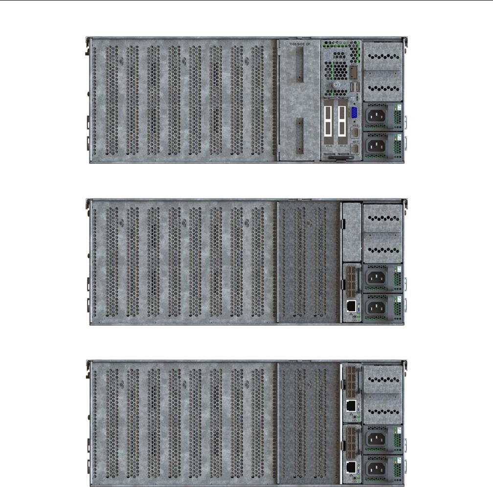
All rear panels feature clearly silk-screened labels next to the port in question. The MIS Server
Platform (single server) in Figure 1-6, features a single server module with two USB ports, a video
port, and two NIC ports. Figure 1-7 show a MIS Server Platform with the optional four power
supplies. The MIS Server Platform (dual server) rear panel as shown in Figure 1-8 has a second
server module with its own set of USB ports, video port, and NIC ports. Figure 1-9 shows an MIS
Server Platform (single dual-server module) which features dual server construction with a single
server installed, and the option of upgrade to include a second server later. Figure 1-11 shows the
rear panel of the MIS JBOD with two I/O modules.
8007-5818-003
1: System Overview
Figure 1-6 Rear View – MIS Server Platform (single server)
Figure 1-7 Rear View – MIS Server Platform (single server, four power supplies)
Figure 1-8 Rear View – MIS Server Platform (dual server)
MIS Enclosure
007-5818-003 9
Figure 1-9 Rear View – MIS Server Platform (single dual-server module)
Figure 1-10 Rear View – MIS JBOD Unit (single I/O module)
Figure 1-11 Rear View – MIS JBOD unit (dual I/O modules)

10 007-5818-003
1: System Overview
MIS Common Modules
This section describes the common internal modules of the MIS enclosure. Designed to deliver a
high level of reliability, scalability and manageability, the MIS platform makes use of modules to
contain key components. Whether the unit is an MIS Server or a JBOD, both chassis contain the
following hot-swappable modules:
• Up to four power supplies (two redundant) (Figure 1-12);
• Six fan assemblies (Figure 1-14);
• Capacity drives installed in StorBricks (Figure 1-15).
The power supply modules are high-efficiency, hot-swappable power supplies rated at 1100
Watts, AC Input: 100–240 VAC (50-60Hz), single or three phase. There are six hot-swappable fan
modules housing one fan with two counter-rotating impellers. And instead of the conventional
disk architecture, the unique StorBrick modules—innovative, highly-dense drive modules used to
house drive bays—allows the platform to maximize storage density.
Each MIS Server has eight StorBricks modules, and each MIS JBOD has nine, with the ninth
module taking the place of the compute server module. Each StorBrick module holds up to nine
3.5" or 2.5" (15mm), SAS or SATA, rotational or SSD drives, or, using the dual-slot drive option,
eighteen 2.5" (9.5mm), SAS or SATA, rotational or SSD drives.
Warning: Rotational SAS drives and rotational SATA drives cannot be included in the
same inclosure due to vibration conflicts.
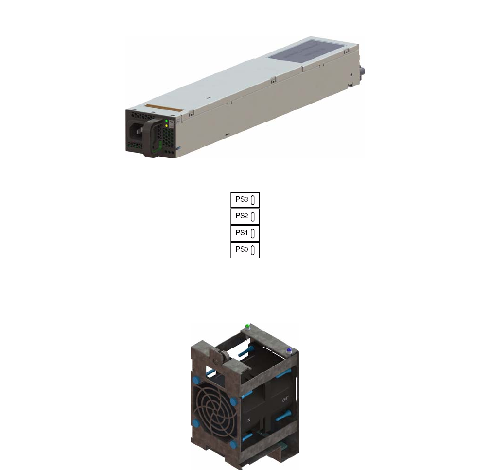
Power Supply Module
One to four power supplies provide power for the SGI MIS server. Power supplies are configured
for N+N support. The power supplies provide 12VDC main power and 5VDC standby power. The
power supplies are hot-swappable and can be replaced under full load. Power supplies are
numbered 0-3 from the bottom up, on the rear panel of the enclosure (Figure 1-13).
!
MIS Common Modules
007-5818-003 11
Figure 1-12 Power Supply Module (rated at 1100 Watts)
Figure 1-13 Power Supply Numbering
Fan Assembly Module
Figure 1-14 Fan Assembly Module (each contains two impellers)
12 007-5818-003
1: System Overview
Six fan assemblies mounted in the middle of the chassis cool the system. Each hot-swappable fan
assembly contains two impellers. Air flows from the front to the back of the enclosure. The fan
baseboard distributes power and control signals to the fan assemblies. Firmware on the fan
baseboard monitors the fan speeds and temperatures within the enclosure. The SMS adjusts the
individual fan speeds as needed to continuously provide optimal cooling for the enclosure.
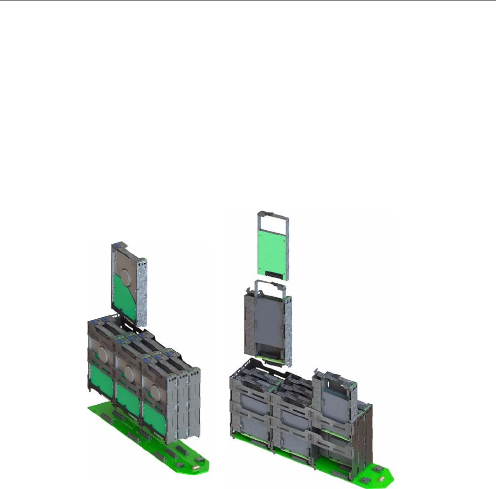
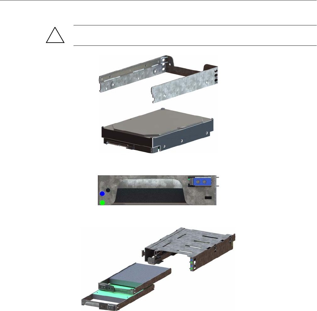
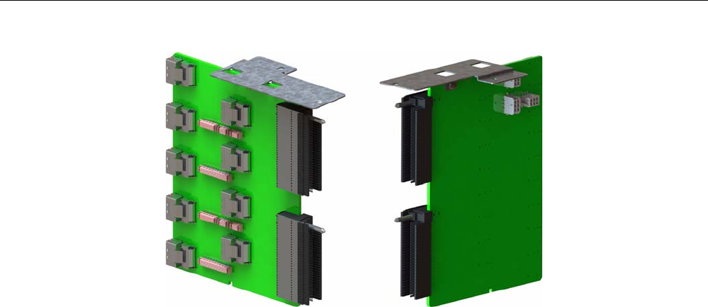
StorBrick Module
Each StorBrick Module contains up to nine 3.5" or 2.5" 15mm drives (Figure 1-15), or eighteen
2.5" 9mm drives (), mounted in the StorBrick using proprietary drive carriers (Figure 1-16). A
sliding thumb latch securely fastens the drive carriers in place (Figure 1-17, thumb latch is
pictured in blue, but is grey on the actual product). StorBricks use SAS-2 protocol, which enables
the system to use SAS and/or SATA drives (rotational disks or SSDs).
Figure 1-15 StorBrick Modules for 3.5" or 2.5" 15mm Drives (left)
and 2.5" 9.5 mm Drives (right)
MIS Common Modules
007-5818-003 13
Warning: Rotational SAS drives and rotational SATA drives cannot be included in the
same inclosure due to vibration conflicts.
Figure 1-16 3.5" 15mm Drive and Carrier
Figure 1-17 3.5" 15mm Drive Carrier (top view, with thumb latch)
Figure 1-18 Two 2.5" 9.5mm Drives and Carrier
!

14 007-5818-003
1: System Overview
Figure 1-19 2.5" 9.5mm Drive Carrier (isometric view with dual thumb latches)
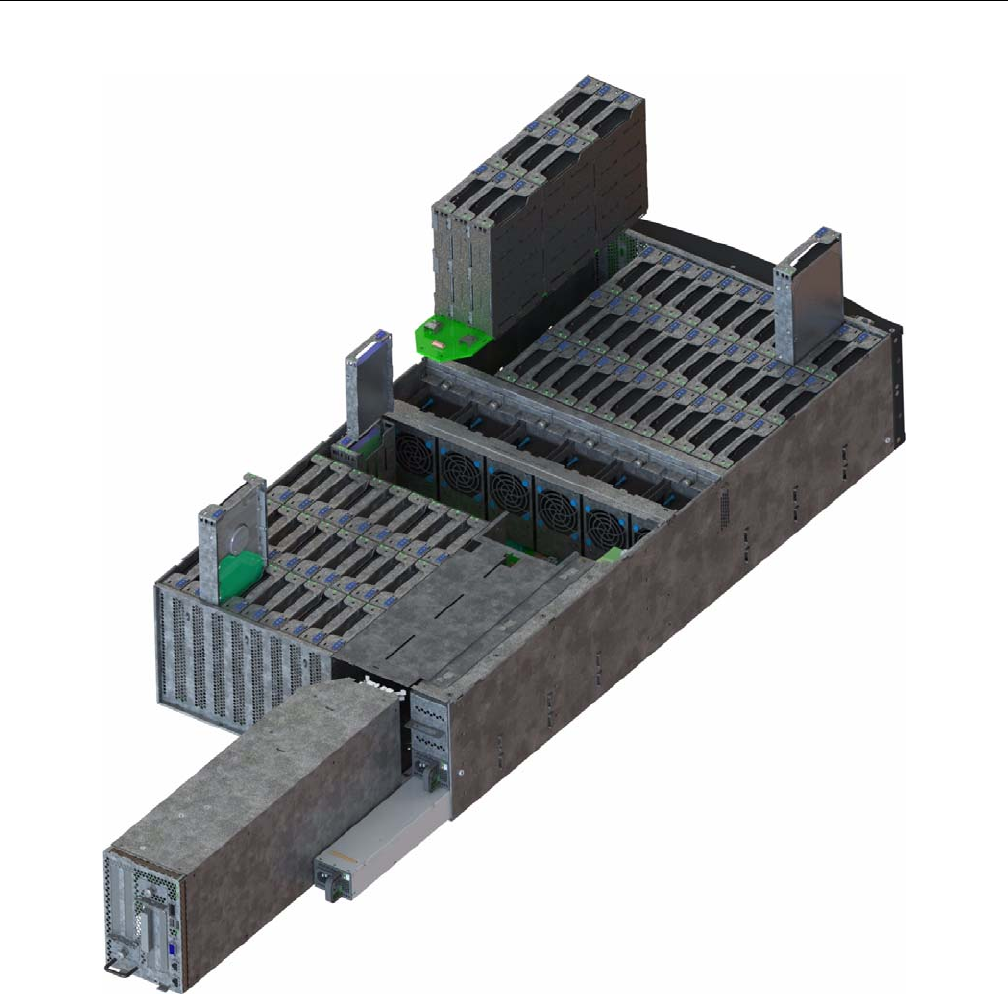
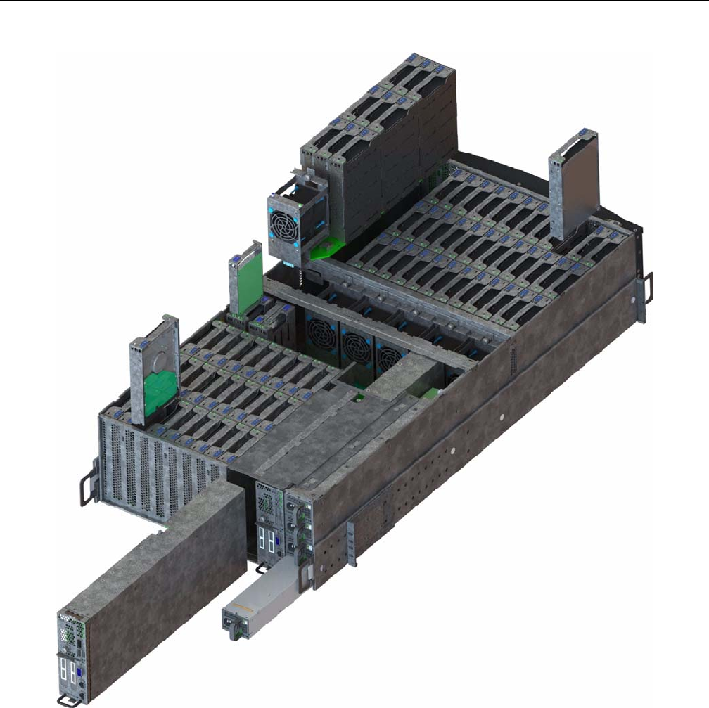
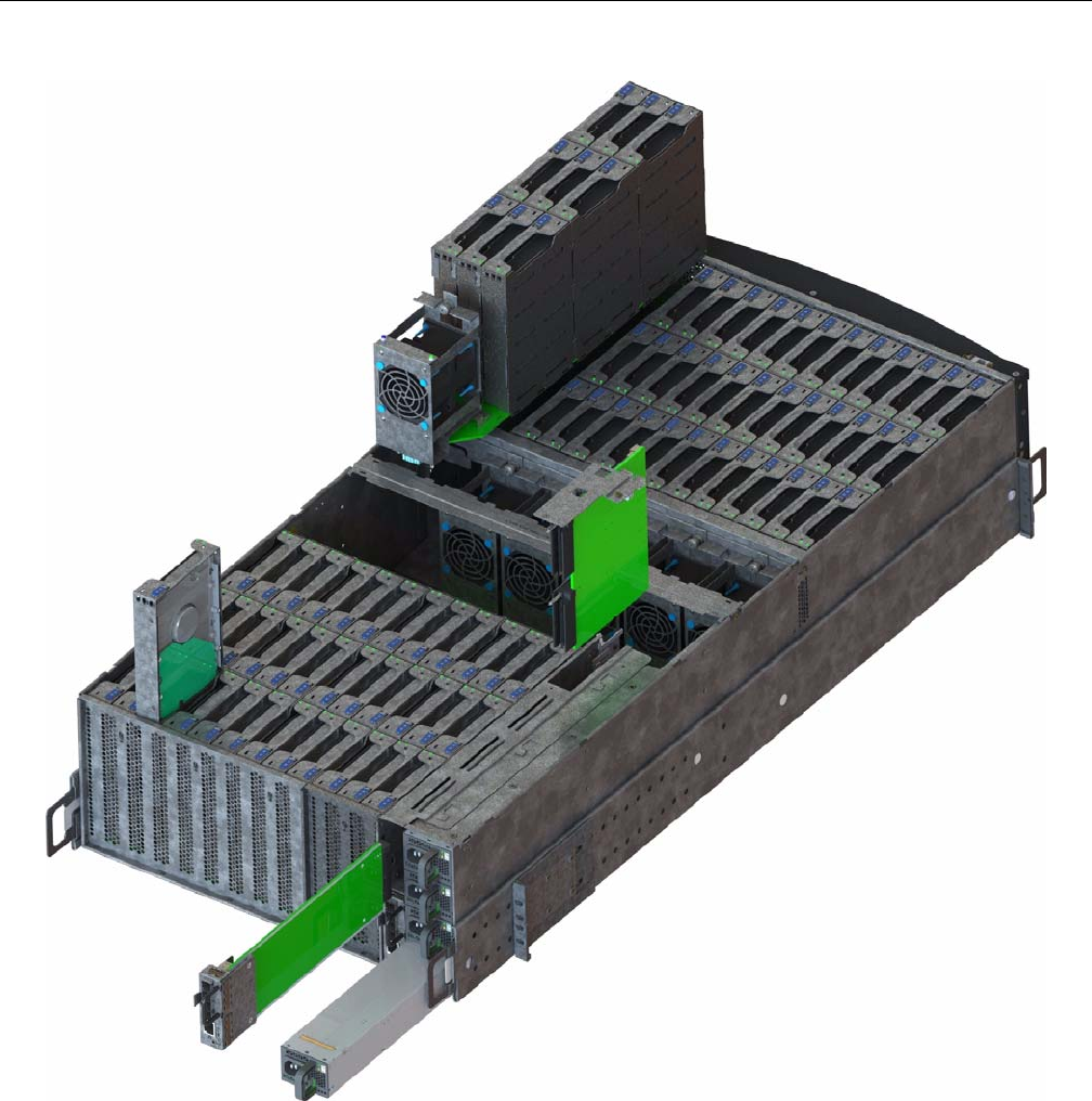
MIS Server Platform or JBOD Unit
The key difference between the MIS Server Platform (Figure 1-20 or Figure 1-21) and the MIS
JBOD Unit (Figure 1-22) is the presence of the compute server module (Figure 1-23 or
Figure 1-25) and boot drives (Figure 1-29) in the Server Platform, or a ninth StorBrick
(Figure 1-15) and I/O modules (Figure 1-30) and associated midplane (Figure 1-31) in the JBOD.
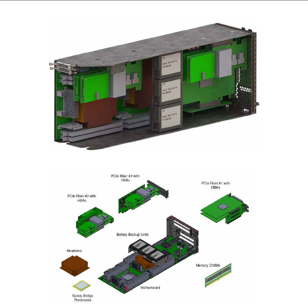
Server Module
The MIS Server Platform can be single- or dual-server (Figure 1-23 or Figure 1-25) depending on
whether it has one or two compute server modules. Each compute server module can have:
• Up to two Intel® Xeon® E5-2600 series processors per motherboard, with Intel Turbo Boost
Technology 2.0: if the cores are operating below power, current, and temperature specs (<
35°C ambient) limits, they automatically run faster than base operating speed.
• 8 DDR3 DIMMs (4 GB, 8 GB, or 16 GB) for a single-server board configuration. Up to 16
DIMMs for a dual-server board configuration,
• Up to 4 HBAs for a single server, full-height (4.25") and half-depth (3.375"), externally or
internally facing. Up to 4 HBAs (half-height, half-depth; 2 per server module) for a dual
server. (See Figure 1-27 on page 20)
• Up to three PCIe riser cards for a single server (dual servers have a mandatory 3 PCIe risers).
• Up to four battery back up units for a single server module. Up to three battery back up units
per server module for a dual server platform, for a total maximum of six. (Unique BBU PCIe
technology allows the inclusion of BBUs without the consumption of any of the available
PCIe slots.)
MIS Server Platform or JBOD Unit
007-5818-003 15
Figure 1-20 MIS Server Platform (single server)
16 007-5818-003
1: System Overview
Figure 1-21 MIS Server Platform (dual server)
MIS Server Platform or JBOD Unit
007-5818-003 17
Figure 1-22 MIS JBOD Unit
18 007-5818-003
1: System Overview
Figure 1-23 MIS Server Module – single server
Figure 1-24 Server Module (single server) – component view
MIS Server Platform or JBOD Unit
007-5818-003 19
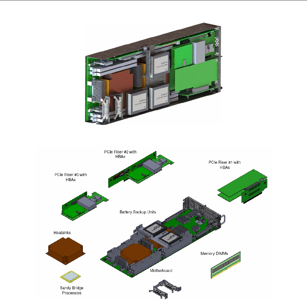
Figure 1-25 MIS Server Module – dual server (half height)
Figure 1-26 Dual Server Module – component view
20 007-5818-003
1: System Overview
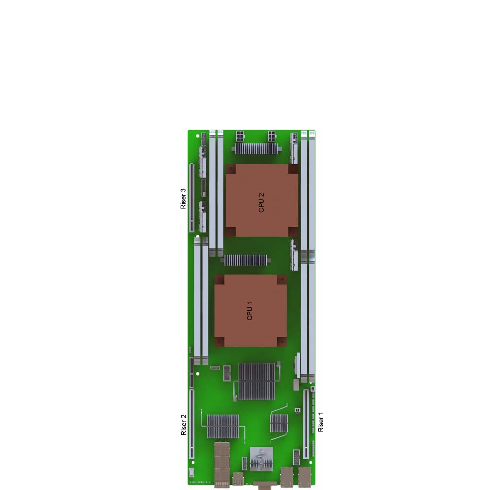
Layout of Server CPUs, and PCIe Risers HBAs
Figure 1-27 shows the CPU and riser layout. Because of cabling restrictions in a single server,
single CPU systems, only two internal SAS HBAs are allowed. The first CPU handles Riser 1
and 2. The optional second CPU would manage Riser 3. If the second CPU is not installed, Riser 3
is non-operational.When a second CPU is installed, HBAs populated on Riser 3 are internal facing
SAS HBAs only, which connect to the StorBricks (Figure 1-28).
Figure 1-27 CPU and PCIe Riser layout
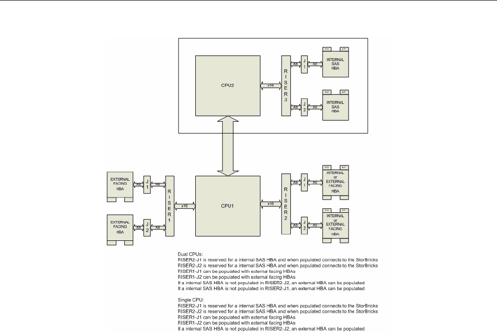
MIS Server Platform or JBOD Unit
007-5818-003 21
Figure 1-28 HBA population layout
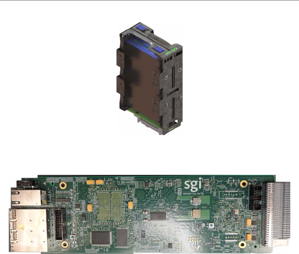
Boot Drives Module
Each MIS Server Platform features two boot drives per server module (up to four total – mirrored
using LSI software RAID 1). These drives are SAS or SATA, rotational or SSD, up to 300GB,
used to store server data and the server operating system. Supported operating systems include:
• Microsoft® Windows® 2008 R2 SP1 (not shipped with product),
• Red Hat® Enterprise Linux (RHEL) 6.2,
• SUSE LINUX® Enterprise Server 11 SP1, or
•VMware® ESX 5.0
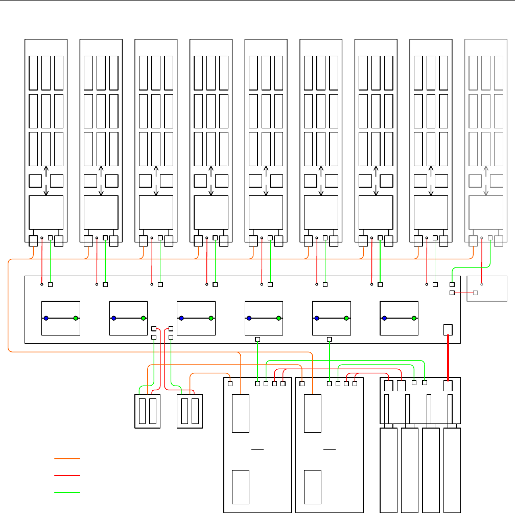
24 007-5818-003
1: System Overview
Figure 1-32 System-Level Block Diagram
18
44
X36
SAS
EXP
012
345
678
STORBRICK
7
5V
POL PWR
CTL
18
44
X36
SAS
EXP
012
345
678
STORBRICK
0
5V
POL PWR
CTL
18
44
X36
SAS
EXP
012
345
678
STORBRICK
1
5V
POL PWR
CTL
18
44
X36
SAS
EXP
012
345
678
STORBRICK
2
5V
POL PWR
CTL
18
44
X36
SAS
EXP
012
345
678
STORBRICK
3
5V
POL PWR
CTL
18
44
X36
SAS
EXP
012
345
678
STORBRICK
4
5V
POL PWR
CTL
18
44
X36
SAS
EXP
012
345
678
5V
POL PWR
CTL
18
44
X36
SAS
EXP
012
345
678
5V
POL PWR
CTL
18
44
X36
SAS
EXP
012
345
678
5V
POL PWR
CTL
STORBRICK
5STORBRICK
6STORBRICK
8
FAN0A
FAN0B
FAN1A
FAN1B
FAN2A
FAN2B
FAN3A
FAN3B
FAN4A
FAN4B
FAN5A
FAN5B
PS0PS1PS2PS3
CM0
IO0
CM1
IO1
PDU
FANB
SAS
Side
IO
SAS
Side
IO
JBOD
only
SAS signals
Power
Control signals
HOST
Side
IO
HOST
Side
IO
CM1
Boot
CM0
Boot

Control Panel
007-5818-003 25
Chapter 2
2. System Interfaces
This chapter describes the hardware and software interfaces of the MIS platforms. Both the MIS
server platform and MIS JBOD storage unit have a front control panel, disk drive LED codes, and
power supply LED codes. The control panel lights and buttons have different meanings and
functions, depending on whether the machine is the MIS Server Platform or MIS JBOD unit. The
disk drive LED codes and power supply LED codes remain the same whether the system is a
server platform or JBOD unit. Additionally, there are four programs used to initialize and monitor
the MIS machines. This chapter details the hardware interfaces, their functions and indications, as
well as the Baseboard Management Controllers (BMC) Web Console. These programs provide
power management features, environmental monitoring, etc.
Note: SGI provides features beyond those of IMPI 2.0, for instance, chassis intrusion detection,
which will gracefully power down the system if the case cover is left off for more than 15 minutes.
Control Panel
MIS Server Control Panel
The control panel (Figure 2-1) interface consists of five indicator lights and four buttons. More
information on remote functionality and the Web Console and Terminal Tool is presented at the
end of this chapter.
26 007-5818-003
2: System Interfaces
Figure 2-1 MIS Control Panel
The NMI Reset button (Non-Maskable Interrupt) should not be used, except under the direct
supervision from technical support.
Table 2-1 MIS Server Platform Control Panel Buttons and LEDs
LED/Button Description
Power LED Green LED lit means power is on.
Power button If the system is off, pushing this button powers on the system. If the
operating system is running, pushing this button shuts down the
operating system and powers off the system gracefully. If the operating
system is hung, holding the button down for 10 seconds or more will
power off the system for a hard reset.

Control Panel
007-5818-003 27
MIS JBOD Control Panel
The control panel (Figure 2-1) for the MIS JBOD is exactly the same as the MIS Server Platform.
However, some of the buttons do not have the same function as they do on the MIS Server. Since
there is no boot drive module in a JBOD, the Boot Drive Activity LED, located next to the
Network Activity LED, is present, but inactive.
Important: When there are two I/O modules on a JBOD, the top control panel connects to the
bottom I/O module on the back of the unit, and vice versa, the bottom control panel accesses the
top I/O module.
Status LED This indicator will be lit whenever there is AC power available to the
power supplies, whether the unit is on or off. Green means the system is
in good working order. Yellow indicates a problem with the system, and
service is required.
Reset button The service reset button. When pushed, this button causes the server to
reboot and, if the problem is cleared by the reset, returns the Status LED
to green.
Locator LED Blue LED is lit on the front and the back to help locate the unit in a rack
or bay.
Locator button The Locator LED will be lit blue when the Locator button is pushed.
There is a corresponding LED on the back of the server that will be blue.
When the Locator button is pushed again, the LED will go off. This
function may also be activated remotely using the Intel BMC Web
Console and pressing the virtual button, or using the Linux IPMI
Terminal Tool:
-H <ip address> -P <password> -U <user> chassis identification
NIC Activity LED The green LED will be active whenever there is any network traffic
occurring on the base board NIC ports.
Boot Drive
Activity LED
The LED is lit whenever the boot drives are being accessed.
NMI Reset button Used only under the direction of technical support personnel.
Table 2-1 MIS Server Platform Control Panel Buttons and LEDs (continued)
LED/Button Description
28 007-5818-003
2: System Interfaces
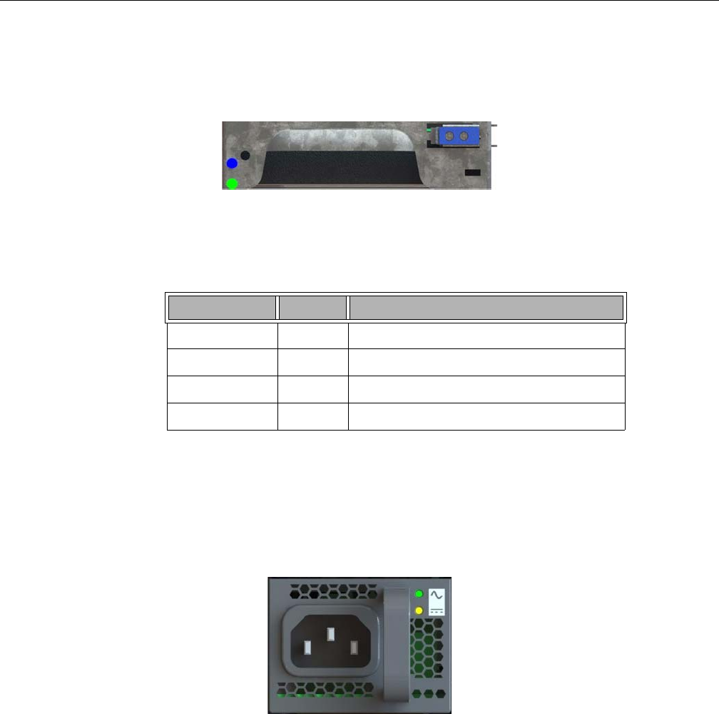
Disk Drive LEDs
Figure 2-2 shows the green/yellow and blue disk drive LEDs.
Figure 2-2 Disk Drive LEDs
Table 2-2 describes the meaning of disk drive LEDs.
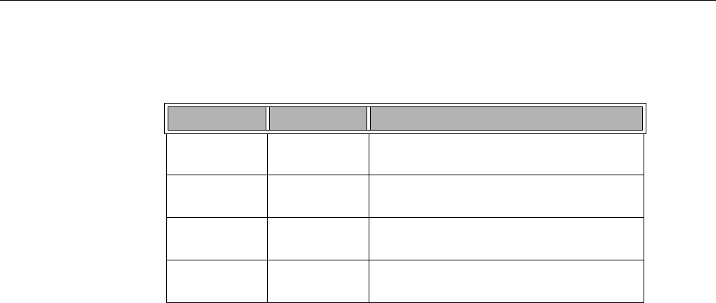
Power Supply LEDs
There are two LEDs located on the face plate of the power supply, one green on top, and one
bi-color yellow/green below (Figure 2-3). Table 2-3 describes the function of the power supply
LEDs
Figure 2-3 Power Supply LEDs
Table 2-2 Disk Drive LEDs
Bi-color LED Blue LED Drive Status
Off Off Drive is off and can be removed.
Green Off Drive is on.
Yellow Off Service required.
Off/Green/Yellow On Indicates drive location.
BMC Integrated Web Console
007-5818-003 29
BMC Integrated Web Console
The control panel and various other LEDs are used to monitor the overall status of the system and
its components. Underlying the light-guided diagnostics provided through the various LEDs on
the control panel, power supplies, motherboard, etc. are the BMC/IPMI interfaces. The MIS server
supports the platform management features (environmental monitoring, power management, etc.)
provided by the Intel BMCs and IPMI 2.0. Moreover, the BMCs have features beyond those of
IPMI 2.0 (for instance, detection of chassis intrusion).
The BMC Integrated Web Console is a web-based program provided by Intel, and is used to give
general system information such as system diagnostics, server health, environmental reporting,
and event logs. Additionally, the BMC-IWC provides a remote virtual control panel for the MIS
Server, allowing for remote locating and reboot.
For more information, see the platform management documentation for the Intel S2600JF
motherboard in Intel Server Boards and Server Platforms Server Management Guide (publication
number 37830-002)
This section gives you a high-level description of each Integrated BMC Web Console page. It is
organized in sections corresponding to the four tabs in the horizontal menu. Within each section,
each menu on the left-hand side is illustrated and described in detail.
Table 2-3 Power Supply LEDs
Green LED Bi-color LED Power Supply Status
Off Off No AC power to the supply, power is off on the front
of the machine.
Off Yellow Problem indicated (voltage, fan failure, AC failure,
etc.)
On Blinking Yellow AC available, power supply in standby mode
(powered off on the front)
On Green AC available to the power supply, power supply is
on and functioning normally.

30 007-5818-003
2: System Interfaces
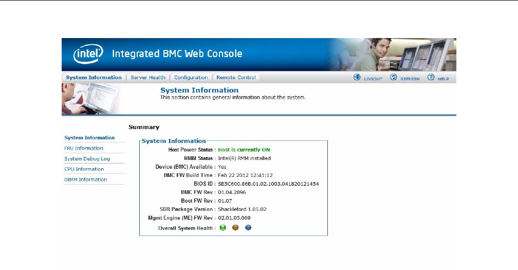
System Information
After login, by default, the BMC Web Console opens on the System Information page. The
System information page displays a summary of the general system information. This includes the
power status and the version of firmware, and has the following information about the server.
In the left navigation pane, There are five menu options. After System Information comes FRU
Information, System Debug Log, CPU Information, and DIMM information.
Table 2-4 System Information Details
Information Details
Host Power Status Shows the power status of the host (on/off).
RMM Status Indicates if the Intel RMM4 card is present.
Device (BMC) Available Indicates if the BMC is available for normal
management tasks.
BMC FW Build Time The date and time of the installed BMC firmware.
BMC FW Rev Major and minor revision of the BMC firmware.
Boot FW Rev Major and minor revision of the BOOT firmware.
SDR Package Version Version of the Sensor Data Record.
Mgmt Engine (ME) FW Rev Major and minor revision of the Management
Engine firmware.
Overall System Health Green/Yellow and Blue
BMC Integrated Web Console
007-5818-003 31
Figure 2-4 BMC Web Console – System Information Page
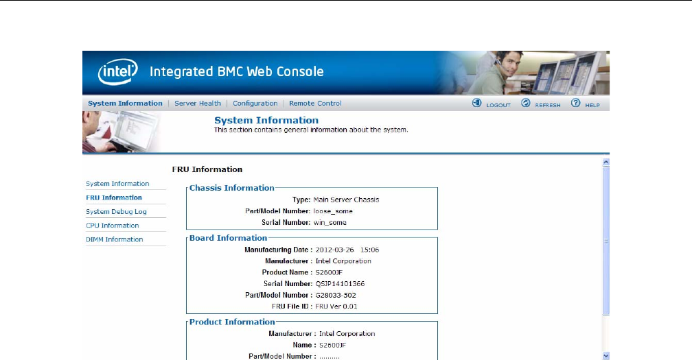
FRU Information
The Field Replaceable Unit (FRU) Information page displays information from the FRU
repository of the host system.
FRU Chassis Information includes: Type, Part/Model Number, and Serial Number. FRU Board
Information includes: Manufacturing Date, Manufacturer, Product Name, Serial Number,
Part/Model Number, and FRU File ID. FRU Product Information includes: Manufacturer,
Name, Part/Model Number, Version, Serial Number, Asset Tag, and FRU File ID.
32 007-5818-003
2: System Interfaces
Figure 2-5 BMC Web Console – FRU Information
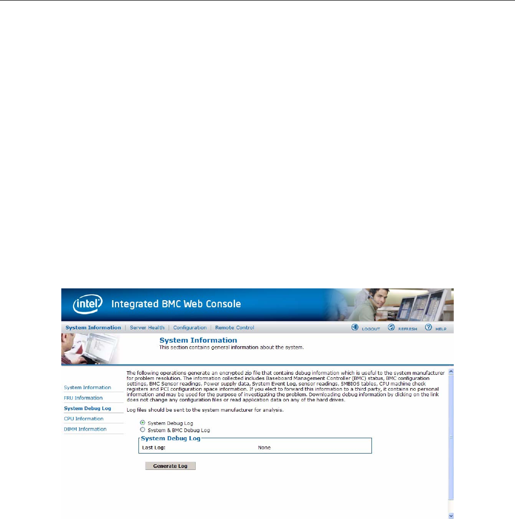
System Debug Log
The System Debug Log page allows administrators to collect system debug information. This
feature allows a user to export data into a file that is retrievable for the purpose of sending to an
Intel engineer or Intel partners for enhanced debugging capability. Select either the “System
Debug Log” or the “System & BMC Debug Log” and press the Run button. It may take some time
for the debug information to be collected.
The files are compressed, encrypted, and password protected. The file is not meant to be viewable
by the end user but rather to provide additional debugging capability to your system manufacturer
or an Intel support engineer. Once the debug log dump is finished you can click the debug log
filename to save the results as a .zip file on your client system. The file can then be sent to your
system manufacturer or an Intel support engineer for analysis.
System Debug Log Type
The System Debug Log data is mainly used by the system manufacturer for analysis. Baseboard
Management Controller (BMC) status, BMC configuration settings, BMC Sensor readings, Power
supply data, System Event Log, sensor readings, SMBIOS tables, CPU machine check registers
BMC Integrated Web Console
007-5818-003 33
and PCI configuration space information. The System & BMC Debug Log contains regular
System Debug Log plus the BMC debug log.
Last Log
Shows the time of the last data collection. Collection times older than three minutes will be
marked as an “Old” debug log.
Encryption
The resulting zip file will be encrypted for privacy, and may only be extracted for analysis by an
authorized representative of the system manufacturer.
Generate Log
Click the Generate Log button to collect recent Debug Log data. The resulting compressed archive
will be downloaded to your system by clicking on the debug log link. You may also choose to
download the data at a later time using the debug log link. Note that it is recommended that fresh
data always be downloaded for analysis.
Figure 2-6 BMC Web Console – System Debug Log
34 007-5818-003
2: System Interfaces
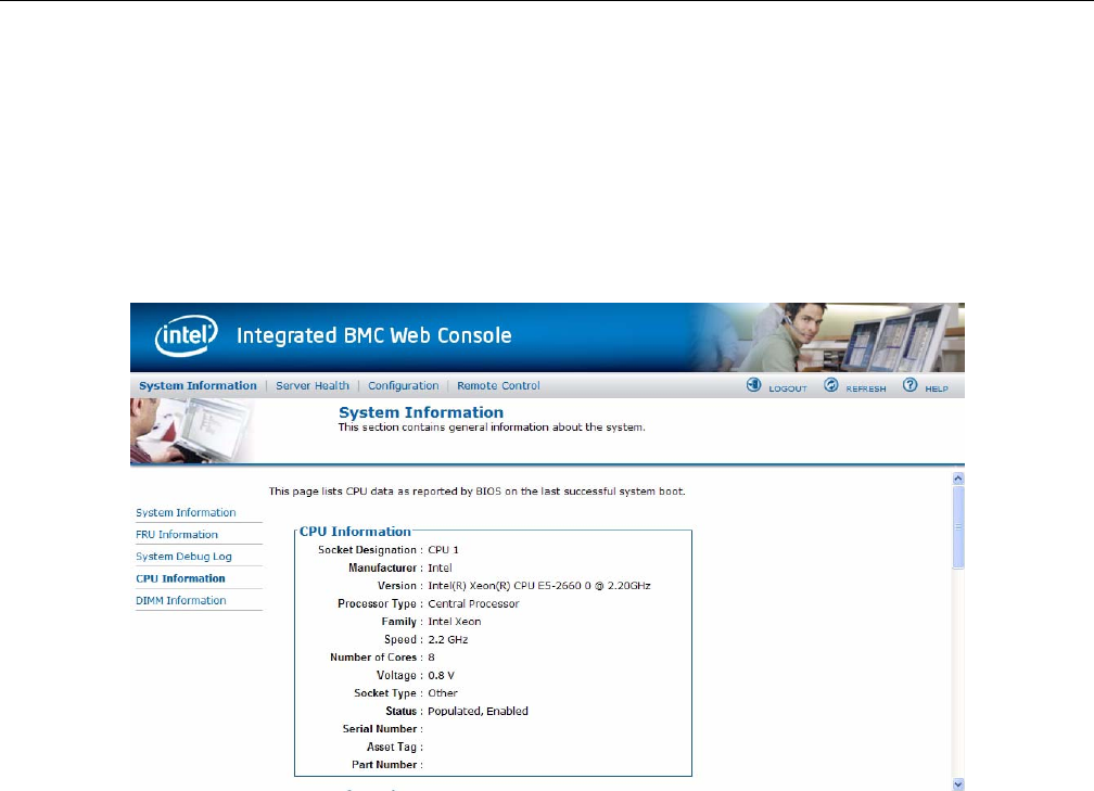
CPU Information
The CPU Information page displays information on the processor(s) installed in the server.
The data in the CPU Asset Information page is collected from SMBIOS entries sent from the BIOS
to the Baseboard Management Controller at the end of POST. If there is no data available, or the
data is stale, please reset the system, allow it to complete POST, and refresh the page using the
refresh button above.
Figure 2-7 BMC Web Console – CPU Information
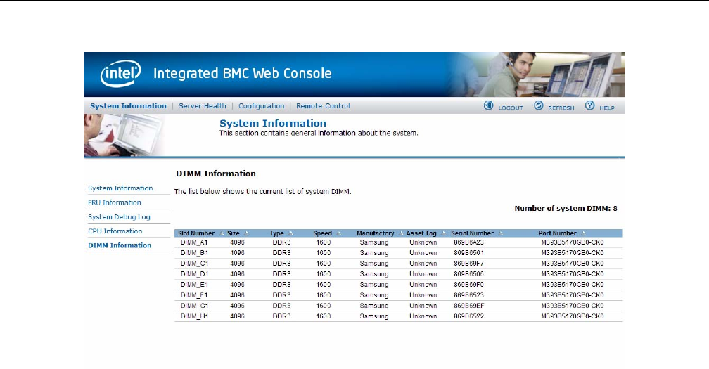
DIMM Information
The DIMM Information page displays information on DIMM modules installed on the host
system.
Slot Number is DIMM location on the motherboard. The location is marked as A0, B1 and so on.
BMC Integrated Web Console
007-5818-003 35
Figure 2-8 BMC Web Console – DIMM Information
Server Health
The Server Health tab shows you data related to the server's health, such as sensor readings, the
event log, and power statistics as explained in the following sub sections. Click on the Server
Health tab to select the various pages. By default, this tab opens the Sensor Readings page.
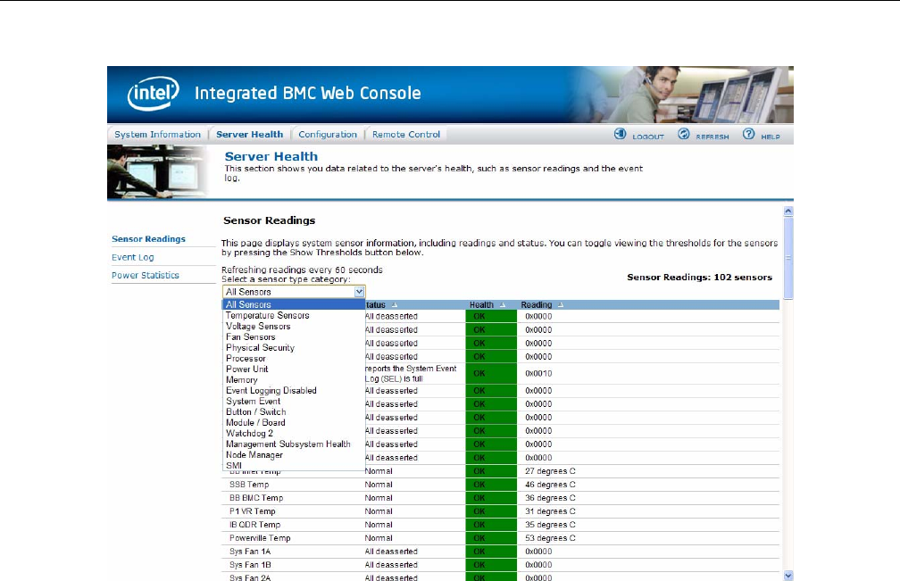
Sensor Readings
The Sensor Readings page displays system sensor information including status, health, and
reading. By default the sensor readings are updated every 60 seconds but this can be changed by
entering a value in the Set auto-refresh in seconds selection box and then pressing the Set button.
Sensor Selection drop-down box allows you to select the type of sensor readings to display in the
list. The default is set to All Sensors, with other options: Temperature Sensors, Voltage Sensors,
Fan Sensors, Physical Security, Processor, Power Unit, Memory, Event Logging Disable, System
Event, Button/Switch, Module/Board, Watchdog Sensor, Management Subsystem Health, Node
Manager, and SMI.
36 007-5818-003
2: System Interfaces
Figure 2-9 BMC Web Console – Server Health
Click Show Thresholds to expand the list, showing low and high threshold assignments. Use
scroll bar at bottom to move display left and right.
• CT: Critical threshold
• NC: Non-critical threshold
Click Hide Thresholds to return to original display, hiding the threshold values, showing only the
name, status and reading for selected sensors. Click Refresh to refresh the selected sensor
readings.
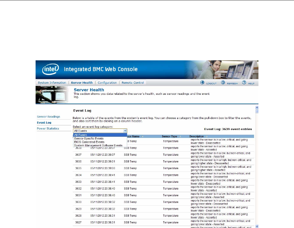
Event Log
The Event Log is a table of the events from the system's event log. You can choose a category
from the pull-down box to filter the events, and also sort them by clicking on a column header.
BMC Integrated Web Console
007-5818-003 37
The filters available are All Events, Sensor-Specific Event, BIOS Generated events, and System
Management Software Events. Use this page to view and save the Event log. Event Log Category
selects the type of events to display in the list. Event Log List is a list of the events with their ID,
time stamp, sensor name, sensor type, and description. Click Clear Event Log to clear the event
logs. Click on Save Event Log to download the event logs to local system.
Figure 2-10 BMC Web Console – Event Log
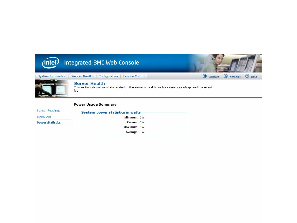
Power Statistics
This section shows you data related to the server's health, such as sensor readings and the event
log. Use this page to determine server power usage. In order to collect readings for this page, a
PMBus enabled power supply must be attached to the server, and the server must be in a ACPI S0
(DC power on) state to report statistics data. System Power Statistics include:
• Minimum: Calculated as a minimum value of all power readings since last statistics reset.
38 007-5818-003
2: System Interfaces
• Current: Present power reading.
• Maximum: Calculated as a maximum value of all power readings since last statistics reset.
• Average: Calculated as the arithmetic average of all power readings since last statistics reset.
Figure 2-11 BMC Web Console – Power Statistics
Configuration Tab
The Configuration tab of the BMC Web Console is used to configure various settings, such as
alerts, users, or network. It contains the following menu options in the left navigation pane: IPv4
Network, IPv6 Network, Users, Login, LDAP, VLAN, SSL, Remote Session, Mouse Mode,
Keyboard Macros, Alerts, Alert Email, Node Manager.

BMC Integrated Web Console
007-5818-003 39
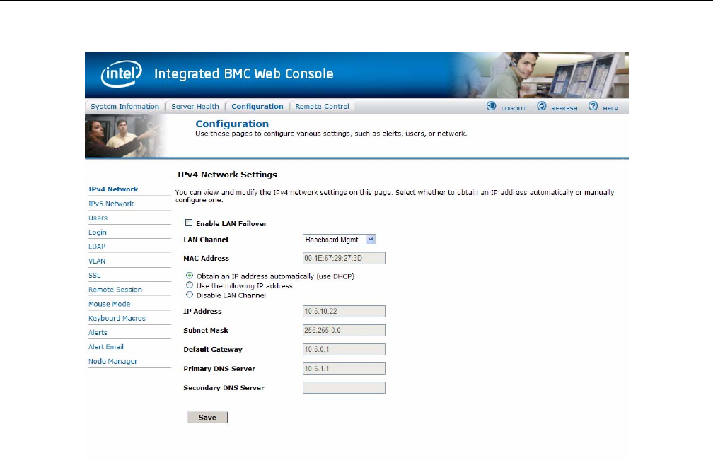
IPv4 Network
Use this page to configure the network settings for server management.
Enable LAN Failover
Enabling failover bonds all available ethernet interfaces into the first LAN Channel. When the
primary interfaces lease is lost one of the secondary interfaces is activated automatically with the
same IP address.
LAN Channel Number
It lists the LAN Channel(s) available for server management. The LAN channels describe the
physical NIC connection on the server. Intel® RMM channel is the add-in RMM NIC. The
Baseboard Management channel is the onboard, shared NIC configured for management and
shared with the operating system.
MAC Address
The MAC address of the device (read only).
IP Address
Select the type of IP assignment with the radio buttons. If configuring a static IP, enter the
requested IP Address, Subnet Mask, Gateway, Primary DNS and Secondary DNS Server in the
given fields.
• IP Address made of 4 numbers separated by dots as in xxx.xxx.xxx.xxx.
•‘xxx’ ranges from 0 to 255.
•First ‘xxx’ must not be 0.
Caution: The RMM IP address must be on a different subnet than the baseboard IP address used
for management traffic.
40 007-5818-003
2: System Interfaces
Figure 2-12 BMC Web Console – IPv4 Network Settings
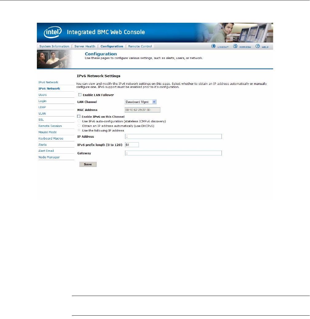
IPv6 Network
Use this page to configure the IPv6 network settings for server management.
Enable LAN Failover
Enabling failover bonds all available ethernet interfaces into the first LAN Channel. When the
primary interfaces lease is lost one of the secondary interfaces is activated automatically with the
same IP address.

BMC Integrated Web Console
007-5818-003 41
LAN Channel Number
It lists the LAN Channel(s) available for server management. The LAN channels describe the
physical NIC connection on the server. Intel® RMM channel is the add-in RMM NIC. The
Baseboard Management channel is the onboard, shared NIC configured for management and
shared with the operating system.
MAC Address
The MAC address of the device (read only).
Enable IPv6 on this Channel
This check box must be selected to enable any IPv6 network traffic on this channel.
IP Address configuration
IPv6 auto-configuration enables Stateless configuration using ICMPv6 router/neighbor
discovery.
Obtain an IP address automatically enables DHCPv6.
Use the following IP address enables static IP assignment.
IP Address
Select the type of IP assignment with the radio buttons. If configuring a static IP, enter the
requested IP Address, IPv6 prefix length, and optionally the Gateway in the given fields.
• IPv6 addresses consist of 8 4 digit hexadecimal numbers separated by colons.
• A :: can be used for a single sequence of two or more zero fields.
Caution: The RMM IP address must be on a different subnet than the baseboard IP address used
for management traffic.
42 007-5818-003
2: System Interfaces
Figure 2-13 BMC Web Console – IPv6 Network Settings
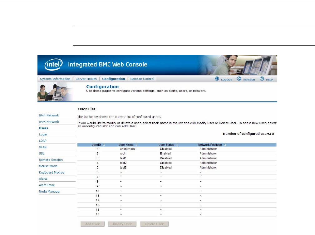
Users
The list of configured users, along with their status and network privilege is displayed. Use this
page to configure the IPMI users and privileges for this server.
•Add User – Select an empty slot in the list and click to add a new user.
•Modify User – Select a user in the list and click to modify their settings.
•Delete User – Select a user in the list and click to delete.
Note: UserID 1 (anonymous) may not be renamed or deleted. UserID 2 (root) may not be renamed
or deleted; nor can the network privileges of UserID 2 be changed.
BMC Integrated Web Console
007-5818-003 43
Caution: User Names cannot be changed. To rename a User you must first delete the existing
User, then add the User with the new name.
Login
Use this page to configure login security settings for server management.
Failed Login Attempts
Set the number of failed login attempts a user is allowed before being locked out. Zero means no
lockout. Default is 3 attempts.

44 007-5818-003
2: System Interfaces
User Lockout Time (min)
Set the time in minutes that the user is locked out before being allowed to login again. Zero means
no lockout and unlocks all currently locked out users. Default is 1 min.
Force HTTPS
Enable this option to force the User to user Secure Login for Web using HTTPS protocol. It will
use the certificate uploaded under 'Configuration->SSL'.
Web Session Timeout
Set the maximum web service timeout in seconds. Timeout should be between 60 and 10800
seconds. Default timeout is 1800 seconds.
Figure 2-14 BMC Web Console – Login Security Settings

BMC Integrated Web Console
007-5818-003 45
LDAP
To enable/disable LDAP, check or uncheck the Enable LDAP Authentication checkbox
respectively.
LDAP Authentication
Check this box to enable LDAP authentication, then enter the required information to access the
LDAP server.
Port
Specify the LDAP Port.
IP Address
The IP address of LDAP server
• IP Address made of 4 numbers separated by dots as in xxx.xxx.xxx.xxx.
•‘xxx’ ranges from 0 to 255.
•First ‘xxx’ must not be 0.
Bind Password
Authentication password for LDAP server; the password must be at least 4 characters long.
Bind DN
The Distinguished Name of the LDAP server, e.g. cn=Manager, dc=my-domain,
dc=com.
Searchbase
The searchbase of the LDAP server, e.g. dc=my-domain, dc=com.
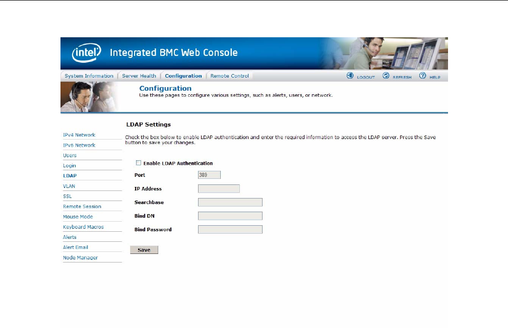
46 007-5818-003
2: System Interfaces
Figure 2-15 BMC Web Console – LDAP Settings
VLAN
Use this page to configure an 802.1Q VLAN private network on the specified LAN channel.
LAN Channel
It lists the LAN Channel(s) available for server management. The LAN channels describe the
physical NIC connection on the server. Intel® RMM channel is the add-in RMM NIC. The
Baseboard Mgmt channel is the onboard, shared NIC configured for management and shared with
the operating system.
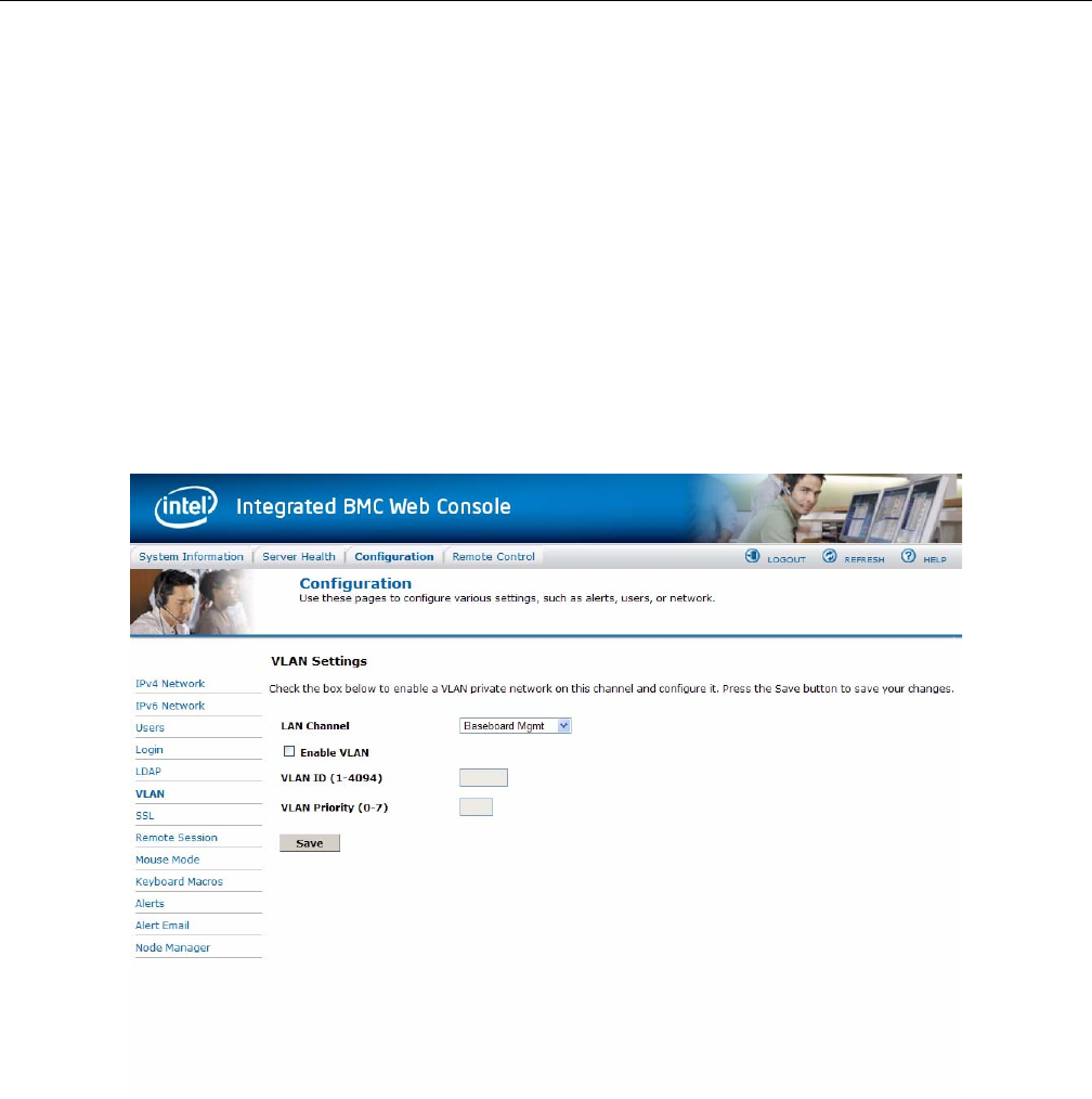
BMC Integrated Web Console
007-5818-003 47
Enable VLAN
Check to enable VLAN on this channel. When enabled, the BMC only accepts packets with the
correct VLAN Identifier field. All outgoing packets are marked with that VLAN ID.
VLAN ID
Specify the VLAN ID to use. Values are from 1 to 4094. Only one ID can be used at a time, and
VLAN must first be disabled before a new ID can be configured on a given LAN channel.
VLAN Priority
Specify the VLAN Priority field to place in outgoing packets. Values are from 0 (best effort) to 7
(highest); 1 represents the lowest priority. 0 is the default.
Figure 2-16 BMC Web Console – VLAN Settings
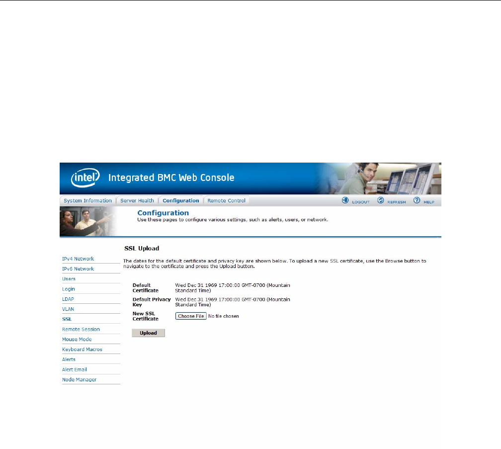
48 007-5818-003
2: System Interfaces
SSL
The SSL Upload page shows dates for the default certificate and privacy key. Use this page to
upload an SSL certificate and privacy key, which allows the device to be accessed in secured
mode.
First upload the SSL certificate, and then device will prompt to upload privacy key. If either of the
files are invalid the device will send a notification. The device will give notification on Successful
upload. On successful upload device will prompt to reboot the device. If you want to reboot click
Ok or click Cancel to cancel the reboot operation.
Figure 2-17 BMC Web Console – SSL Upload
Remote Session
Use this page to enable/disable encryption on KVM or Media during a redirection session.

BMC Integrated Web Console
007-5818-003 49
KVM Encryption
Enable/Disable encryption on KVM data during a redirection session. Choose any one from the
supported encryption techniques.
Keyboard/Mouse Only
If KVM Encryption is set to None, the Keyboard & Mouse data can still be encrypted using
Blowfish encryption. This option has the least performance impact while still encrypting the most
important data.
Media Encryption
Enable/Disable encryption of Media data during a redirection session. Disabling encryption can
improve performance of KVM or Media redirection.
USB Key Emulation Mode
Two types of emulation are:
• Floppy - Emulated USB Key will be detected as Floppy drive in remote machine.
• Hard disk - Emulated USB Key will be detected as Hard disk (or) Removable drive in
remote machine.
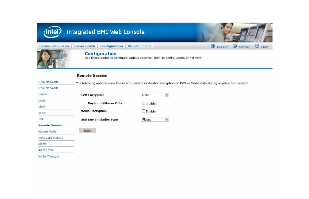
50 007-5818-003
2: System Interfaces
Figure 2-18 BMC Web Console – Remote Session
Mouse Mode
Mouse Mode shows you which mode the mouse is currently in, and allows you to change the
mouse mode to the following options: Absolute Mode, Relative Mode, and Other Mode
Absolute Mode
Select to have the absolute position of the local mouse sent to the server. Use this mode for
Windows OS and newer Red Hat linux versions (RHEL 6.x).
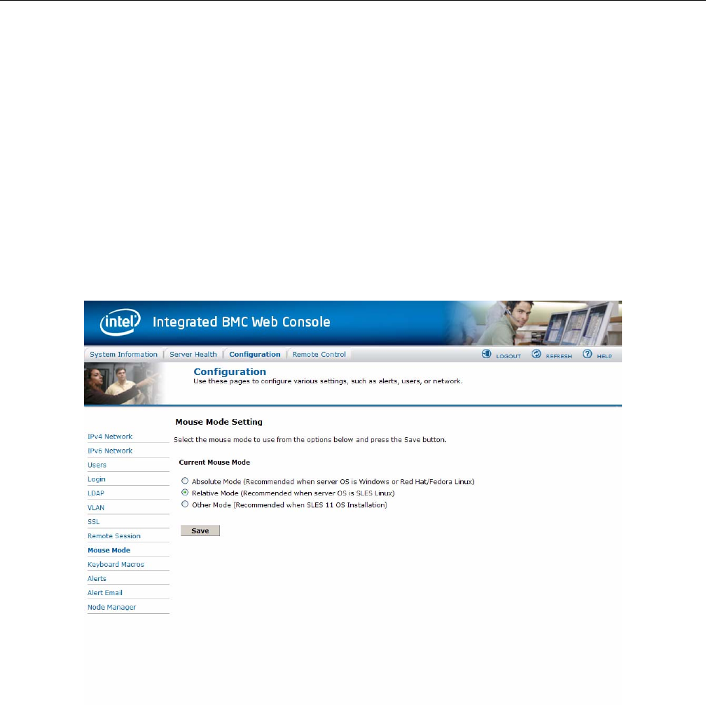
BMC Integrated Web Console
007-5818-003 51
Relative Mode
Select Relative Mode to have the calculated relative mouse position displacement sent to the
server. Use this mode for other Linux releases such as SUSE (SLES) and older versions of Red
Hat (RHEL 5.x). For best results, server OS mouse acceleration/threshold settings can be reduced,
or mouse calibration in JViewer performed.
Other Mode
Select Other Mode to have the calculated displacement from the local mouse in the center
position, sent to the server. Under this mode ALT+C should be used to switch between Host and
client mouse cursor. Use this mode for SLES 11 Linux OS installation.
The mouse mode is set by clicking the Save button.
Figure 2-19 BMC Web Console – Mouse Mode Setting
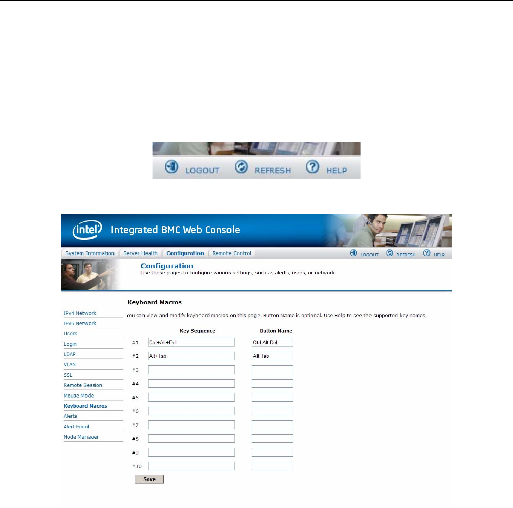
52 007-5818-003
2: System Interfaces
Keyboard Macros
The Keyboard Macros page is where you can view and modify keyboard macros. Key Sequence
is the sequence of key events to playback when the macro button is pushed. Button Name is the
optional short name to appear on the button of the Remote Console. If left blank, the key sequence
string will be used as the button name. Click the Help button in the upper right corner
(Figure 2-20), to see the supported key names (Table 2-5). In this example, two macros have been
defined: Ctrl+Alt+Del and Alt+Tab (Figure 2-21).
Figure 2-20 BMC Web Console – Logout, Refresh, and Help buttons
Figure 2-21 BMC Web Console – Keyboard Macros

BMC Integrated Web Console
007-5818-003 53
Key Sequence
When using a key sequence, keep the following definitions in mind:
• '+' between keys indicates the keys should be held down together
• '-' between keys indicates the previous keys should first be released before the new key is
pressed
• '*' inserts a one second pause in the key sequence.
Caution: Video is not updated during macro execution.
Examples:
Ctrl+Alt+Del
Ctrl+B-Enter-**Enter
Ctrl+B-Enter-*\*-Enter
Keys
Key names are either a printable character such as “a”, “5”, “@”, etc. or else one of the
non-printable keys in the table below. Names in parentheses are aliases for the same key. Numeric
keypad keys are prefixed with “NP_”.
A plain ‘*’ means a pause; use ‘\*’ for the actual ‘*’ key. The ‘\’ key must also be escaped as ‘\\’.
Table 2-5 Supported Key Names
Shift (LShift) RShift Ctrl (LCtrl) RCtrl
Alt (LAlt) RAlt (AltGr) Win (LWin) RWin
Enter Esc F1 - F12
Bksp Tab CapsLk Space
Ins Del Home End
PgUp PgDn Context (Menu)
Up Left Down Right

54 007-5818-003
2: System Interfaces
Note: Key sequences are sent to the target as scancodes that get interpreted by the target OS, so
they will be affected by modifiers such as Numlock as well as the OS keyboard language setting.
Alerts
The Alerts page allows you to configure which system events generate Alerts and the external
network destinations they should be sent to.
When one of the selected system events occurs, an alert is generated and sent to the configured
destination(s). Each LAN channel can have up to two destinations.
Globally Enable Platform Event Filtering
Global control for enabling or disabling platform event filtering. When filtering is globally
disabled through this setting, alerts will not be sent. This can be used to prevent sending alerts until
you have fully specified your desired alerting policies.
Select Events
Select one or more system events that will trigger an Alert. Clearing all events disables Alerts.
These events correspond to the IPMI preconfigured Platform Event Filters.
LAN Channel
Select which LAN Channel to configure destinations for. Each LAN Channel has it's own set of
up to two destinations. Alert destinations can be one of two types:
•SNMP Trap
• Email (requires Alert Email to be configured)
NumLk NP_Div NP_Mult NP_Minus
NP_Plus NP_0 - NP_9 NP_Dec NP_Enter
PrtSc (SysRq) ScrLk Pause (Break)
Table 2-5 Supported Key Names
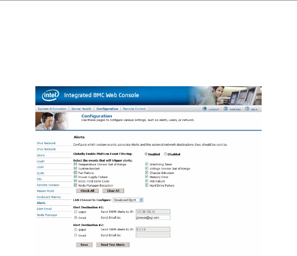
BMC Integrated Web Console
007-5818-003 55
The Check All button selects all events to generate Alerts. The Clear All button unchecks all
events so no Alerts will be generated. Click the Save button to save any changes made.
Send Test Alert
To test whether an alert will reach it's destination, set the LAN Channel field to the desired channel
and configure at least one destination. Then click Send Test Alerts to send a simple test alert to
the destination(s) for that Channel.
Figure 2-22 BMC Web Console – Alerts
Alert Email
Alert Email Settings allows you to configure how Alerts are sent by email to an external SMTP
Mailserver. Each LAN Channel has a separate configuration, selected through the drop-down
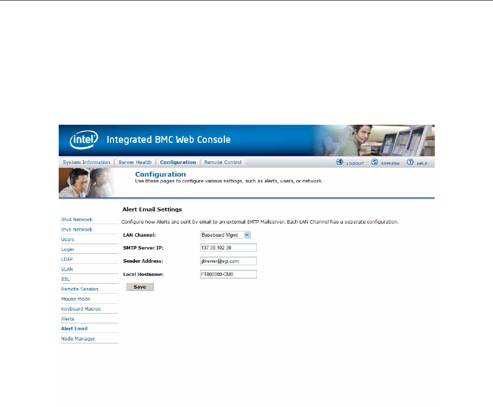
56 007-5818-003
2: System Interfaces
menu. The SMTP Server IP is the IP address of the remote SMTP Mailserver that Alert email
should be sent to. The IP Address is made of 4 numbers separated by dots as in
xxx.xxx.xxx.xxx where ‘xxx’ ranges from 0 to 255 and the first ‘xxx’ group must not be
0. The Sender Address is the string to be put in the From: field of outgoing Alert emails. Local
Hostname is the hostname of the local machine that is generating the alert, included in the
outgoing Alert email. The Local Hostname is a string of maximum 31 alpha-numeric characters.
Spaces and special characters are not allowed.
Figure 2-23 BMC Web Console – Alert Email Settings
Node Manager
Use this page to configure the system's Node Manager.
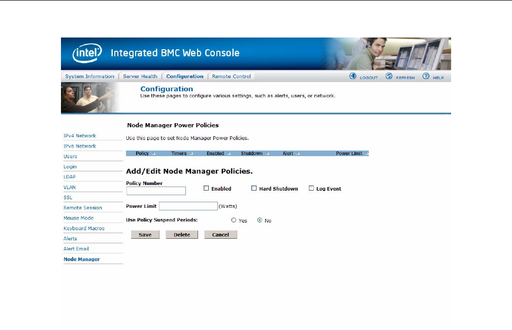
BMC Integrated Web Console
007-5818-003 57
Figure 2-24 BMC Web Console – Node Manager Power Policies
Node Manager Power Policies
This table lists the currently-configured policies. Selecting an item from the table will populate
the editable fields in the settings section below.
Policy Number
The policy number to add/edit/delete. Valid range is 0-255.
In the policy table, policy numbers with an asterisk (*) are policies set externally using a
non-platform domain. Changing parameters on these policies will not affect their triggers, trigger
limits, reporting periods, correction timeouts, or aggressive CPU throttling settings.

58 007-5818-003
2: System Interfaces
Enabled
Check this box if the policy is to be enabled immediately.
Hard Shutdown
Check this box to enable a hard shutdown if the policy is exceeded and cannot be corrected within
the correction timeout period.
Log Event
Check this box to enable the node manager to send a platform event message to the BMC when a
policy is exceeded.
Power Limit
The desired platform power limit, in watts.
Use Policy Suspend Periods
If enabled, you may configure policy suspend periods. Each policy may have up to five suspend
periods.
Suspend periods are repeatable by day-of-week. Start and stop times are designated in 24 hour
format, in increments of 6 minutes. To specify a suspend period crossing midnight, two suspend
periods must be used.
Policy Defaults
For all policies set through this web page, several default values will be applied:
• Domain: Platform - Power for the entire platform.
• Trigger: None - Always monitor after end of POST.
• Aggressive CPU Power Correction: AUTO - Use of T-states and memory throttling
controlled by policy exception actions.
• Trigger Limit: None.
• Reporting Period: 10 seconds - This is a rolling average for reporting only. It will not affect
the average power monitored by the node manager.

BMC Integrated Web Console
007-5818-003 59
• Correction Timeout: 22.555 seconds - Maximum time for the NM to correct power before
taking an exception action (i.e. shutdown or alert).
Remote Control Tab
This section of the BMC Web Console allows you to remotely monitor and control the server.
Options available in the left navigation pane are Console Redirection for remote server
management. Server Power Control shows the current power status, and allows power
operations. Finally the Virtual Front Panel is a graphic display of the front panel allowing for
remote front panel functionality.
Console Redirection
From the Console Redirection page, if available, you can launch the remote console KVM
redirection window. The remote console requires an RMM (Remote Management Module) add-in
card, otherwise the launch button is greyed-out (Figure 2-25).
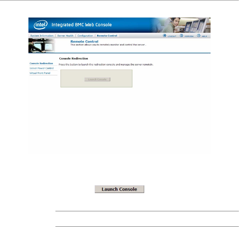
60 007-5818-003
2: System Interfaces
Figure 2-25 BMC Web Console – Console Redirection (greyed-out)
Clicking on Launch Console (Figure 2-26) will prompt for download of JViewer.jnlp file. When
the file is downloaded and launched, the Java redirection window will be displayed.
Figure 2-26 BMC Web Console – Launch Console button (available)
Note: Java Run-Time Environment (JRE, version 6 update 10 or later) must be installed on client
prior to launch of JNLP file.
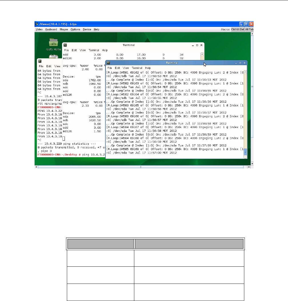
BMC Integrated Web Console
007-5818-003 61
Figure 2-27 Remote Console – Java redirection window
Server Power Control
This page shows the power status of the server and the following power control operations can be
performed:
Table 2-6 Server Power Control Actions
Option Details
Reset Server Selecting this option will hard reset the host
without powering off.
Force-enter BIOS Setup Check this option to enter into the BIOS setup
after resetting the server.
Power Off Server Selecting this option will immediately power
off the host.
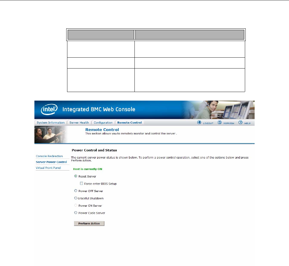
62 007-5818-003
2: System Interfaces
Figure 2-28 BMC Web Console – Power Control and Status
Graceful Shutdown Selecting this option will soft power off the
host.
Power On Server Selecting this option will power on the host.
Power Cycle Server Selecting this option will immediately power
off the host, then power it back on after one
second.
Table 2-6 Server Power Control Actions
Option Details

BMC Integrated Web Console
007-5818-003 63
All power control actions are done through the BMC and are immediate actions. It is suggested to
gracefully shut down the operating system via the KVM interface or other interface before
initiating power actions.functionaryVirtual Front Panel
The Virtual Front Panel is a graphic representation of the front panel, providing remote
functionality virtually.
Table 2-7 System Information Details
Button Details
Power Button Power button is used to Power ON or Power
OFF
Reset Button Reset Button is used to reset the server while
system is ON
Chassis ID Button When Chassis ID button is pressed then the
chassis ID LED, on the front and rear of the
unit are lit (solid blue). If the button is pressed
again the chassis ID LED turns off.
NMI Button At present, NMI button is disabled.
Status LED Status LED will reflect the system status and
will automatically sync with BMC every 60
seconds. If any abnormality occurs in system,
then status LED will change accordingly.
Thermal fault means fault occurred in one of
Thermal sensors present in BMC. Fan fault
means fault occurred in one of the system fans.
System fault means a fault occurred because of
system errors. Power fault means fault
occurred in one of Power sensors Here, fault
means a sensor value crossed
upper-non-critical, or upper-critical value, or
lower-non-critical value, or lower-critical
value.
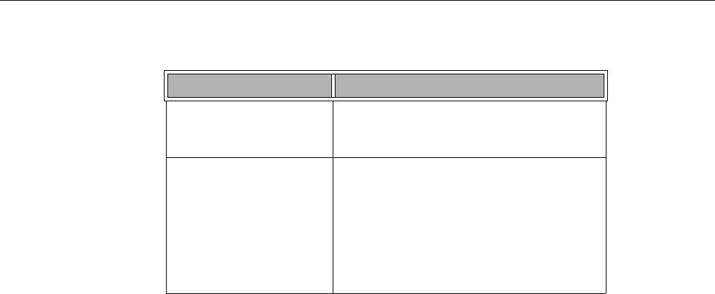
64 007-5818-003
2: System Interfaces
Power LED Power LED shows system power status. If
LED is green then System is ON. If LED is
grey then System is OFF.
Chassis ID LED The Chassis ID LED will be lit blue when the
Chassis ID LED button is pushed. This is the same
as the Locator LED on the physical control panel
(Table 2-1). When the Locator button is pushed
again, the LED will be lit. There is a corresponding
LED on the back of the server that will be lit blue as
well. This function can be done physically through
the Control Panel (Figure 2-1).
Table 2-7 System Information Details
Button Details

007-5818-003 65
Chapter 3
3. System Software
Overview
This chapter contains information on each of the software sets necessary for zoning MIS Servers
and JBODs, organized in four sections: “Linux Zoning Tools” on page 68, “Windows Zoning
Tools” on page 88, “CLI Zoning Tool” on page 109, and “Disk RAID Support” on page 122.
Zoning is required when multiple SAS connections are operational, in order to stop drives from
being affected by other non-owner SAS controllers (HBAs). Zoning allows the various SAS
connections to be accessible only to the drives that they own. Essentially, zoning allows an
administrator to control who can see what. When no zoning is enabled, all the SAS connections
can see all of the drives. For dual-ported SAS drives, both ports will be exposed, so the drives will
show up twice. This situation will cause conflict between the HBAs.
Zoning can be either hard or soft. In hard zoning, each device is assigned to a particular zone, and
this assignment does not change. In soft zoning, device assignments can be changed by the
network administrator to accommodate variations in the demands on different servers in the
network. T10 or PHY-based Zoning may be implemented on the MIS Server. For the MIS JBOD,
only PHY-based Zoning is supported at this time.
Zones for Linux and Windows features a GUI for ease-of-use, but is limited to 72 drives, requires
an LSI MegaRAID card, and cannot zone JBODs at this time (future releases will). The CLI
Zoning Tool is command line only, but is able to zone any number of JBODs or MIS servers.
There are two main tools for zoning, the SGI Zones application and the SGI CLI Zoning Tool.
Both zoning tools require the presence of other programs in order to operate. The Zones
application offers a GUI interface, but is not able to zone JBODs at this time (future releases will
support zoning JBODs). The CLI Zoning Tool can zone JBODs, but is a command-line only
application.

66 007-5818-003
3: System Software
Important: The Zones program is run on the server you wish to zone. JBODs are zoned through
the hardware using the CLI Zoning tool installed on a server or laptop and using an Ethernet
crossover cable to connect a server/laptop running either a Windows or a Linux operating system
and the CLI Zoning application software.
Section Guide
This Guide is organized into four sections, “Linux Zoning Tools” on page 68, “Windows Zoning
Tools” on page 88, “CLI Zoning Tool” on page 109, and “Disk RAID Support” on page 122.
Inside the first three sections you will find instructions on downloading and installing the software
needed, and the steps to prepare for, and zone MIS Platforms. The final section contains
information on the different RAID configurations available, advantages and disadvantages of each
configuration, as well as best practices.
Within the first section, “Linux Zoning Tools”, “Installing Linux Software” on page 68 gives
instructions for downloading and installing the programs required to run the Linux-based zoning
tools. The GUI software programs used are “MegaRAID Storage Manager for Linux”,
“MegaCli64 for Linux”, and “Zones for Linux”. This section also includes information in
downloading the command-line-only “CLI Zoning Tool for Linux”. Instructions for zoning using
the Linux tools are given:
• “Verify Drives Seen” on page 71
• “Verify Drives Seen” on page 71
• “Installing a Drive through Zones for Linux” on page 74
• “Creating the Drive Groups in MegaRAID for Linux” on page 77
• “Formatting the Drives using YaST2 in Linux” on page 79
• “Removing a Drive in Zones for Linux” on page 83
“Additional Features in Zones for Linux” on page 85 details the extra features available in Zones
for Linux including (from page 24):
• “Loading .csv Configuration Files in Linux”
• “Save a Configuration to .csv file in Linux”
Information on using the CLI Zoning Tool can be found in “CLI Zoning Tool” on page 109.

Section Guide
007-5818-003 67
The second section, “Windows Zoning Tools”, contains “Installing Windows Software” on
page 88. Here are instructions for downloading and installing the programs required to run the
Windows-based zoning tools. The GUI software programs used are “MegaRAID Storage
Manager for Windows”, “MegaCli64 for Windows”, “Zones for Windows”, “Python for
Windows”. This section also contains information on downloading the “CLI Zoning Tool for
Windows” on page 91. Instructions on using the Windows GUI are given:
• “Verify Drives Seen in Windows” on page 92
• “Verify Drives Seen in Windows” on page 92
• “Installing a Drive in Zones for Windows” on page 95
• “Creating the Drive Groups in MegaRAID for Windows” on page 98
• “Formatting the Drives in Windows Server Manager” on page 100
• “Removing a Drive in Zones for Windows” on page 106
“Additional Features in Zones for Windows” on page 107 details “Loading .csv Configuration
Files in Zones for Windows” on page 107, “Adapter Assignment Synchronization in Zones for
Windows” on page 108, and “Save a Configuration to .csv file in Zones for Windows” on
page 109.
The third section details out the “CLI Zoning Tool,” the command-line-only tool that is currently
the only tool that can zone JBODs, as well as MIS Servers. The CLI Zoning Tool requires the
presence of Python 2.6 or 2.7 to be present in order to run. Python is standard on most Linux-based
machines, and will need to be installed for Windows-based machines for the CLI Zoning tool to
run. (See “Python for Windows‚” on page 91). “Preparing to Zone using the CLI Zoning Tool‚”
on page 110 gives instruction on what is necessary before “Zoning Using CLI Zoning Tool‚” on
page 117 and “Editing the .csv File for the CLI Zoning Tool‚” on page 119.
Finally, “Disk RAID Support” on page 122 explains the different RAID arrays available and the
benefits and drawbacks of each. There are special considerations in creating RAID arrays for use
on StorBricks, that is, there are RAID configurations, namely 6+2 and 7+2, that ensures there is
no single point of failure on the StorBricks within the MIS system. “RAID Configuration Notes”
on page 129 details how to manage those concerns.

68 007-5818-003
3: System Software
Linux Zoning Tools
The following instructions are for Linux-based MIS Servers, and for Linux-based machines
installing the CLI Zoning Tool. (Operation of the CLI Zoning Tool remains the same across
platforms. See “CLI Zoning Tool” on page 109 for more information.)
Installing Linux Software
There are three programs necessary for SGI Zones for Linux management of MIS systems. These
programs give operational control over the hardware and its performance, including zoning of the
drives. They are MegaRAID Storage Manager, MegaCli64, and Zones for Linux. To run the CLI
Zoning Tool on a Linux machine, only one program is necessary (the CLI Zoning Tool itself).
MegaRAID Storage Manager for Linux
Note: MegaRAID Storage Manager is not necessary for zoning using the CLI Zoning Tool.
The MegaRAID Storage Manager is used to prepare the drives for zoning using the Zones tool,
and creating the drive groups after zoning using the Zones tool.
1. Go to http://lsi.com and search for MegaRAID Storage Manager.
2. Select and accept the latest Linux version for download and save the .tar file.
3. Change directory to where you have saved your .tar file (e.g., # cd /usr)
4. Unzip the .tar file, # tar –xf <filename.tar> (e.g.,
# tar –xf MSM_linux_x64_installer-12.01.03-00.tar)
5. Once the folder has unzipped properly, a new folder will appear called disk.
6. Change your directory into the disk folder (i.e., # cd /usr/disk)
7. Install the Dependencies, (i.e., # ./install.csh)
8. Install the MegaRAID Storage Manager rpm file, # rpm –ivh
<MegaRAID_Storage_Manager_currentversion.rpm> (e.g.,
# rpm –ivh MegaRAID_Storage_Manager-12.01.03-00.noarch.rpm)
9. Change to /usr/local directory, where MegaRAID Storage Manager will appear
(i.e., # cd /usr/local/MegaRAID\ Storage\ Manager/)

Linux Zoning Tools
007-5818-003 69
10. Issue ./startupui.sh command to start MegaRAID Storage Manager GUI (i.e.,
# ./startupui.sh).
MegaRAID Storage Manager GUI for Linux will appear.
MegaCli64 for Linux
MegaCli64 is a program required for the Zones tool to match the StorBrick to the adapters. It runs
in the background underneath Zones.
1. Go to http://lsi.com and search for MegaCli64.
2. Select and accept the latest Linux version for download.
3. Once downloaded, unzip the folder (e.g., #tar –xf <tarfilename.tar>)
4. Install MegaCli rpm file (e.g., #rpm –ivh <rpmfilename.rpm>)
Zones for Linux
Zones is proprietary SGI software, used to zone drives on the MIS Server Platform (and eventually
MIS JBOD units as well). To install the software complete the following instructions.
1. Go to http://support.sgi.com
2. Download the latest Linux version of Zones.
3. Unzip Zones.tar (e.g., # tar –xf Zones.tar). A Zones folder will appear.
4. Copy the Zones folder into the /opt directory, thus creating the /opt/Zones
directory
Warning: Zones must be installed in the /opt/Zones/ directory or it will not work.
5. Change directory into the new Zones folder (e.g., # cd /opt/Zones)
Run the Zones program by typing # python GUI.py.
Note: On first use, the Zones program will ask you to enter the paths to MegaCli64 (Figure 3-1).
The default path for MegaCli64 is /opt/MegaRAID/MegaCli. These paths can be changed at
any time by going to menu option Setup > Tools.
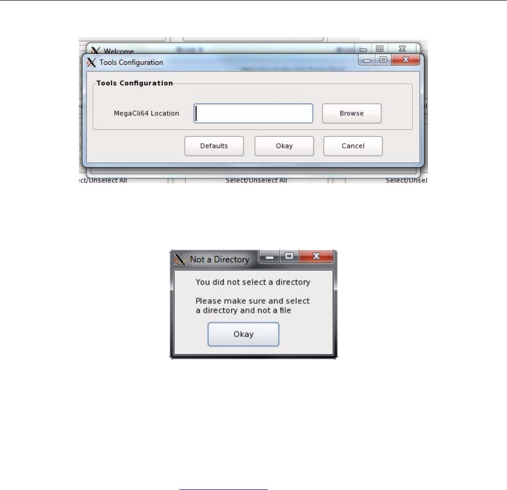
70 007-5818-003
3: System Software
Figure 3-1 Zones – First-use path configuration
If the path is improperly set, an error message will appear. The following error message means
that the path set is for a folder that does not contain MegaCLI64 (Figure 3-2).
Figure 3-2 Zones – Error message: Improper path
CLI Zoning Tool for Linux
The CLI Zoning Tool is proprietary SGI software, used to zone drives on the MIS Server Platform
and MIS JBOD units, and is the only tool that can zone JBODs at this time (future releases of
Zones will support zoning JBODs). To install the software:
1. Create a directory for the application: mkdir /opt/ShackCLI
2. Go to http://support.sgi.com
3. Download the latest version of ShackCLI_release_xxx.zip into the above directory
4. Extract the files: unzip ShackCLI_release_xxx.zip
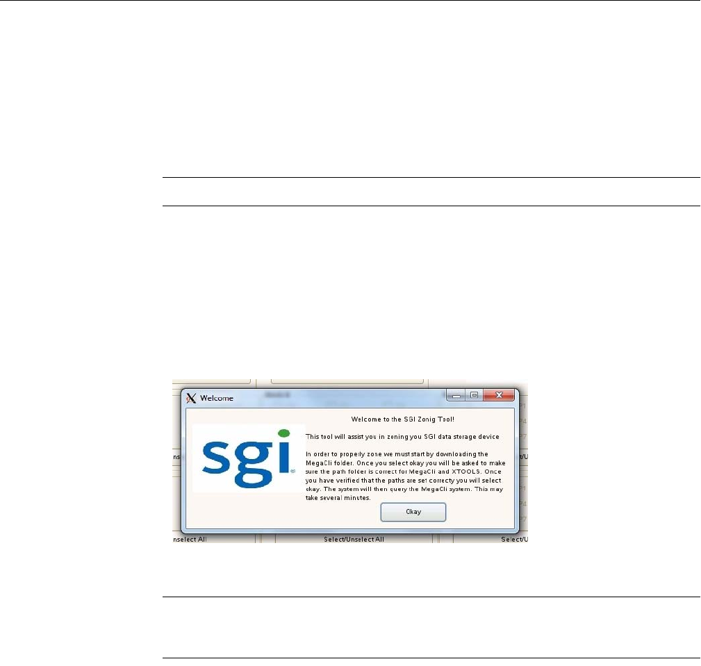
Linux Zoning Tools
007-5818-003 71
To run the CLI Zoning Tool, follow the instructions given in “CLI Zoning Tool” on page 109.
Verify Drives Seen
In Linux systems, open Partitioner and verify the only disks the system sees are system drives,
labeled /opt/ (Figure 3-23 on page 82).
Note: Unconfiguring drives removes them from the system.
Linux Zones Tool
The SGI Zones tool is a proprietary software program that uses a GUI interface to zone the drives
in the MIS Server. Future releases will support zoning JBODs as well.
Open the Zones tool. In Linux, this is done by changing to the /opt/Zones folder and typing
# python GUI.py.
Figure 3-3 Linux Zones Welcome
Note: When Zones for Linux opens, leave the terminal window, from which you launched Zones,
open. This window must be left open or the program shuts down. It will be used later in
downloading session information to the StorBricks.
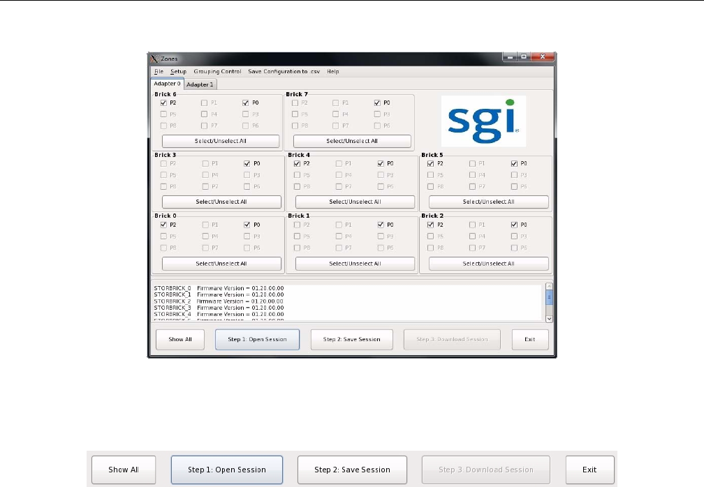
72 007-5818-003
3: System Software
Figure 3-4 Zones User Interface
To begin zoning, click Open Session (Figure 3-5). This queries each expander for the information
contained in the expander .bin file.
Figure 3-5 Zones – Show All, Open Session, Save Session, Download Session, and Exit buttons
Click Create New Session (Figure 3-6).
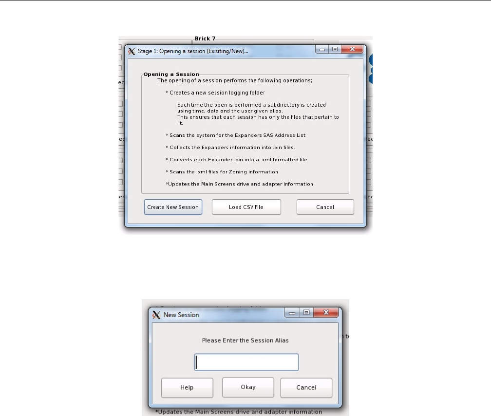
Linux Zoning Tools
007-5818-003 73
Figure 3-6 Zones – Opening a Session
The Zones program will ask you for a Session Alias (Figure 3-7). This alias will be added to a
time stamp to create folder for that session’s files: YYMMDD_HHMMSS_alias.
Figure 3-7 Zones – Enter Session Alias
Enter an alias and click Okay.
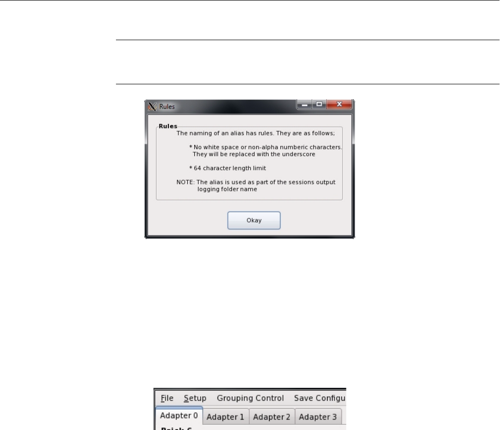
74 007-5818-003
3: System Software
Note: Aliases have a 64 character limit, and may not contain spaces or non-alpha-numeric
characters; these will be replaced with an underscore if used and a warning message will appear
(Figure 3-8).
Figure 3-8 Zones – Alias Help Warning Message
In Zones for Linux, .bin files are automatically named #.bin where # is the number of the
StorBrick in question. After the .bin file has been fetched, each file in converted into an XML
file, named using the same convention, with the file extension .xml (e.g., #.xml).
Upon opening, Zones for Linux will show a blank template for zoning. It will not show any zoning
that may be currently implemented. It does not show drives that are presently installed or zones
that are currently active. Each adapter has its own tab above the StorBrick layouts (Figure 3-9).
The number of Adapter tabs will directly correspond to the number of Adapters Zones sees in the
system.
Figure 3-9 Zones – Adapter tabs
Installing a Drive through Zones for Linux
After creating a new session, click the Show All button. This enables all boxes on all adapters
(Figure 3-10), even if there are no drives physically present. This is so a drive can be zoned to the
system that isn’t seen by the system yet.
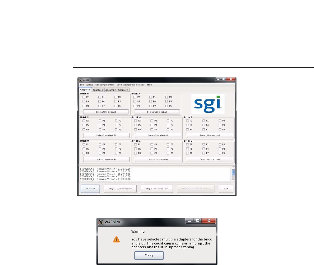
Linux Zoning Tools
007-5818-003 75
Note: If a drive is zoned to more than one adapter, a warning message (Figure 3-11) will appear.
In Windows, this warning tells which adapter that drive is already zoned to, and a message asking
if you would like to continue. In Linux, there is just a warning message asking if you would like
to continue. It is possible to zone one drive to two adapters. This is allowed, but not suggested, as
it can cause data collisions.
Figure 3-10 Zones – Show All
Figure 3-11 Zones – Adapter Assignment Warning Message
Check the boxes for the drives you want to zone (Figure 3-12) according to the configuration of
your liking. Click Save Session. This takes the screen configuration and saves it to an .xml file
that is then converted into a .bin file.
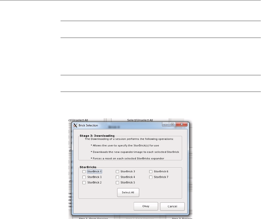
76 007-5818-003
3: System Software
Note: The Save Session button will become enabled whenever a change has been made in the
Zones configuration.
In Linux, the name of the new .bin file is STORBRICK_#.bin where the only new element to
the file name is the STORBRICK_. In Windows, the name of the new .bin file is
sbn#_****.bin where the only new element to the file name is the n after sb.
Important: Each time the Save Session button is pushed, these files are overwritten. There is no
way to retrieve previously saved information.
Click the Download button. Once complete, this function pushes the files back into the expanders.
Select which StorBricks to push the files to, and click Okay to push the files.
Figure 3-12 Zones – Select StorBricks for download
In Linux, downloads are confirmed through the terminal window, which show a pane where you
can verify Image Validation and Checksum have passed, and then download files by
entering Y (see Figure 3-27 on page 85).
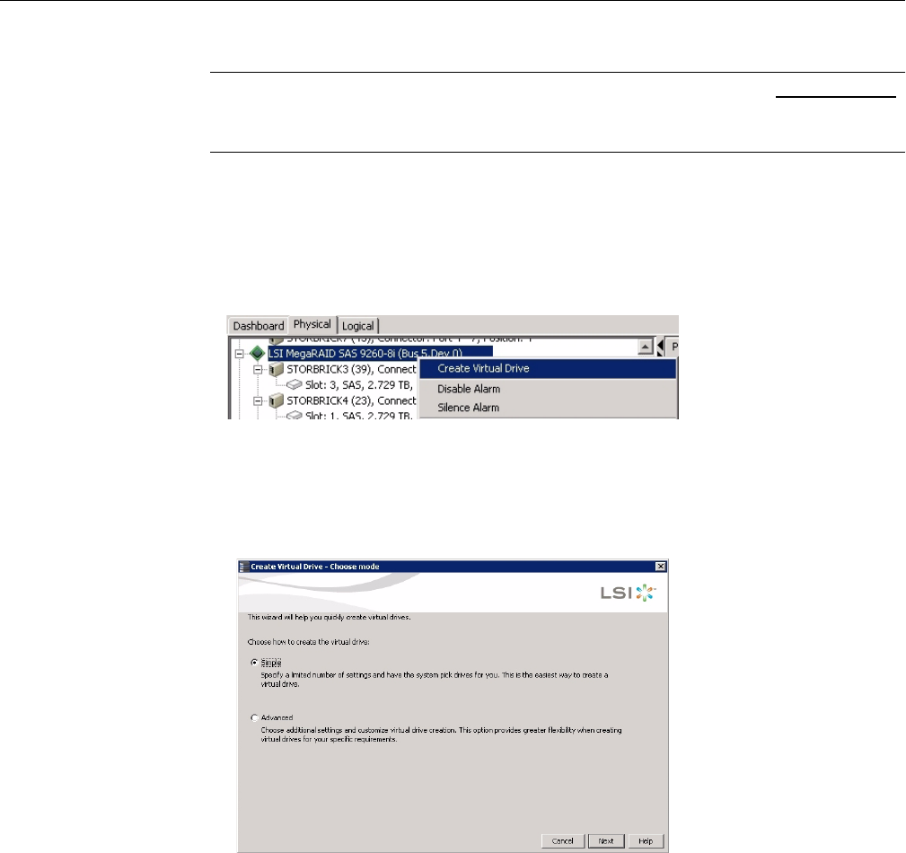
Linux Zoning Tools
007-5818-003 77
Warning: If Y is chosen and the Image Validation and Checksum have not passed,
unknown results will occur, including losing expander information, requiring a field
technician to service the machine.
Power cycle the machine.
Creating the Drive Groups in MegaRAID for Linux
Right-click on the expander and select Create a Virtual Drive (Figure 3-13).
Figure 3-13 MegaRAID – Create a Virtual Drive
A screen will pop up asking you to choose Simple or Advanced (Figure 3-14). In Simple mode,
the drives are chosen for you. In Advanced mode, you get to choose the drives, and are given
additional selections in RAID levels, allowing for spanned (00, 10, 50, 60) drives.
Figure 3-14 MegaRAID – Create Virtual Drive mode
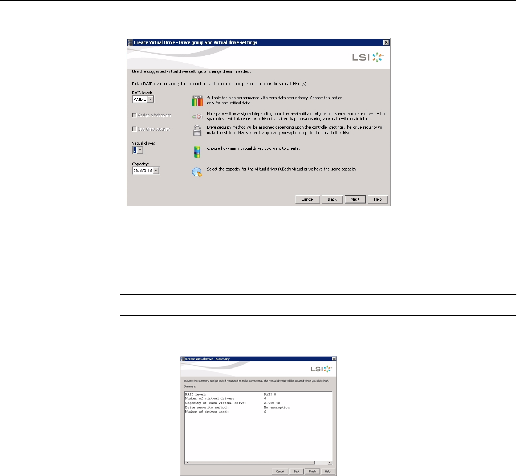
78 007-5818-003
3: System Software
Figure 3-15 Create Virtual Drive – Drive Group Settings
Choose Write Back BBU (battery back-up unit). This mode is the safest and the fastest, and will
automatically switch from caching mode to write-straight-to-disk whenever battery power has
reached low. Write Through writes straight to disk. Write Back is a cached data flow.
Warning: If you select Write Back and power to the system is lost, data is lost.
Click Next, and a summary screen verifying settings will appear (Figure 3-16).
Figure 3-16 Create Virtual Drive – Summary
If the settings are correct, click Finish, and click Ok.
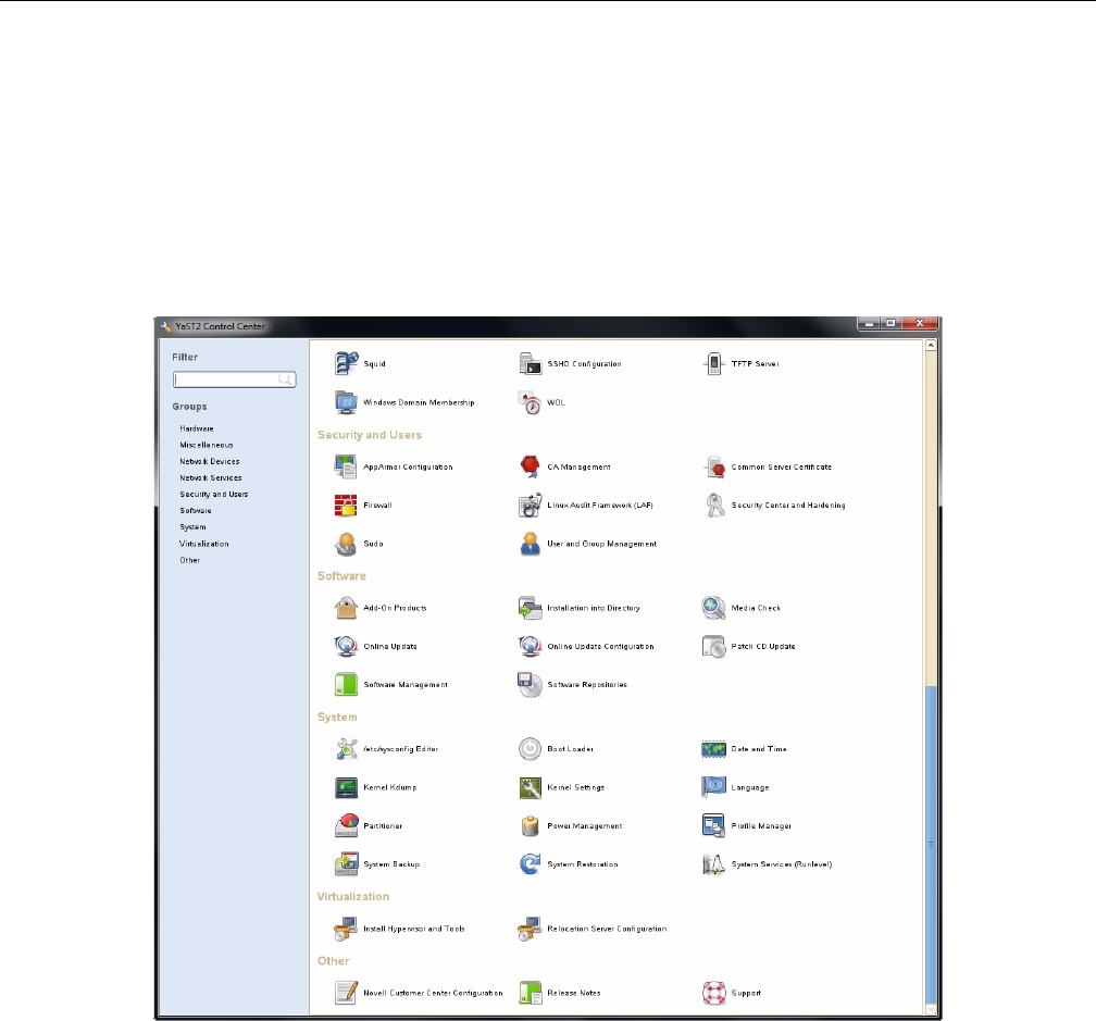
Linux Zoning Tools
007-5818-003 79
Formatting the Drives using YaST2 in Linux
Drives may be formatted using YaST2 Partitioner. In Linux, the folders that the drives will be
mounted to need to be created first. Each mount will need a new folder. Some Linux customers
will have the ability to issue the YaST2 command, bringing up a GUI to partition drives.
Otherwise, drives are formatted and mounted using command line.
1. Issue YaST2 command (i.e., # yast2) to launch the YaST 2 Server Manager GUI
(Figure 3-17).
Figure 3-17 Yast2 Server Manager GUI
2. Double-click Partitioner to launch.
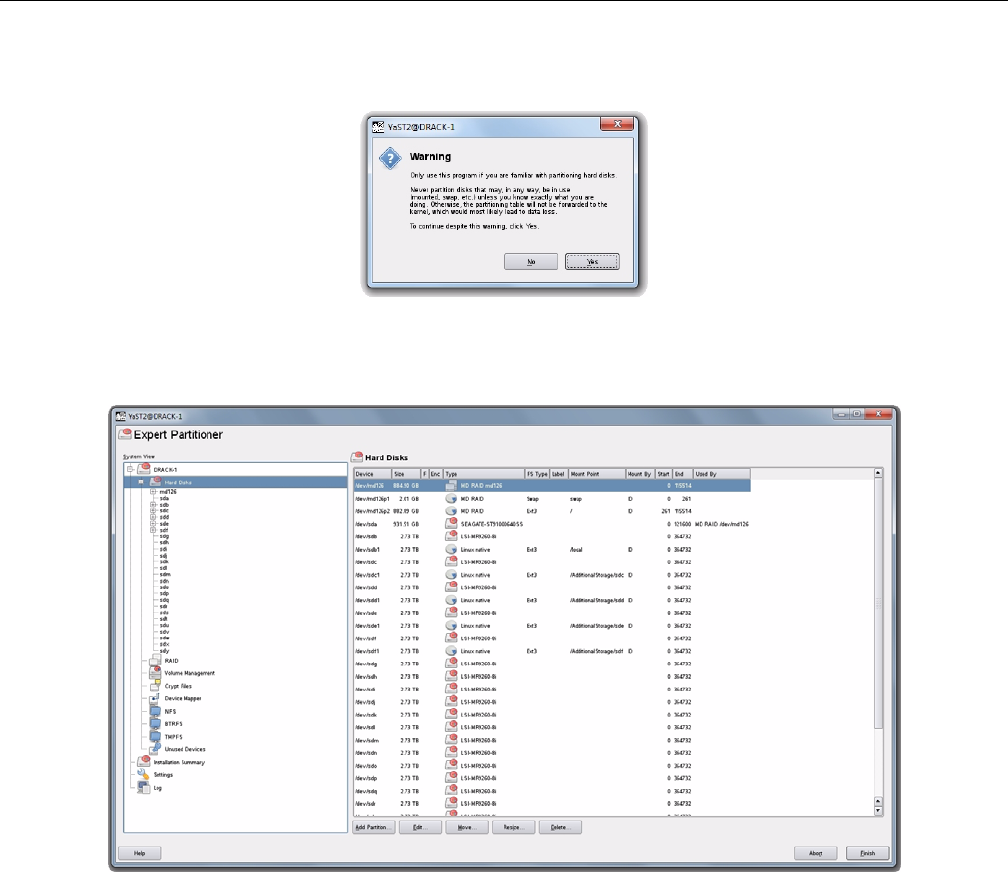
80 007-5818-003
3: System Software
3. A warning message will appear (Figure 3-18). Click Yes.
Figure 3-18 YaST2 – Warning Message
4. Verify that all of your disks have appeared under Hard Disks (Figure 3-19).
Figure 3-19 YaST2 – Drives have appeared
5. Under Hard Disks, select the disk you would like to partition and click Add at the bottom of
the screen (Figure 3-20).
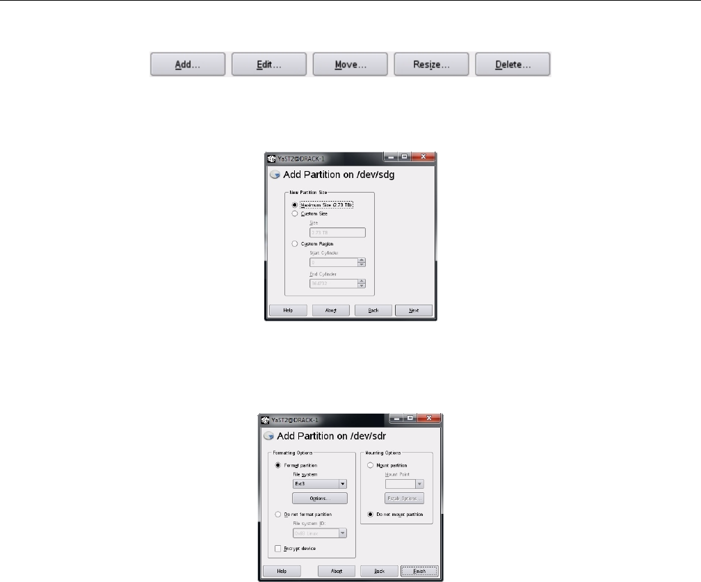
Linux Zoning Tools
007-5818-003 81
Figure 3-20 YaST2 – Add button
6. Select the partition size (Figure 3-21) and click Next.
Figure 3-21 YaST2 – Select Partition Size
7. Format the partition using ext3, mount the disk to your desired folder, and click Finish
(Figure 3-22).
Figure 3-22 YaST2 – Format & Mount the Drive
8. Verify the partition shows up (Figure 3-23) and click Next.
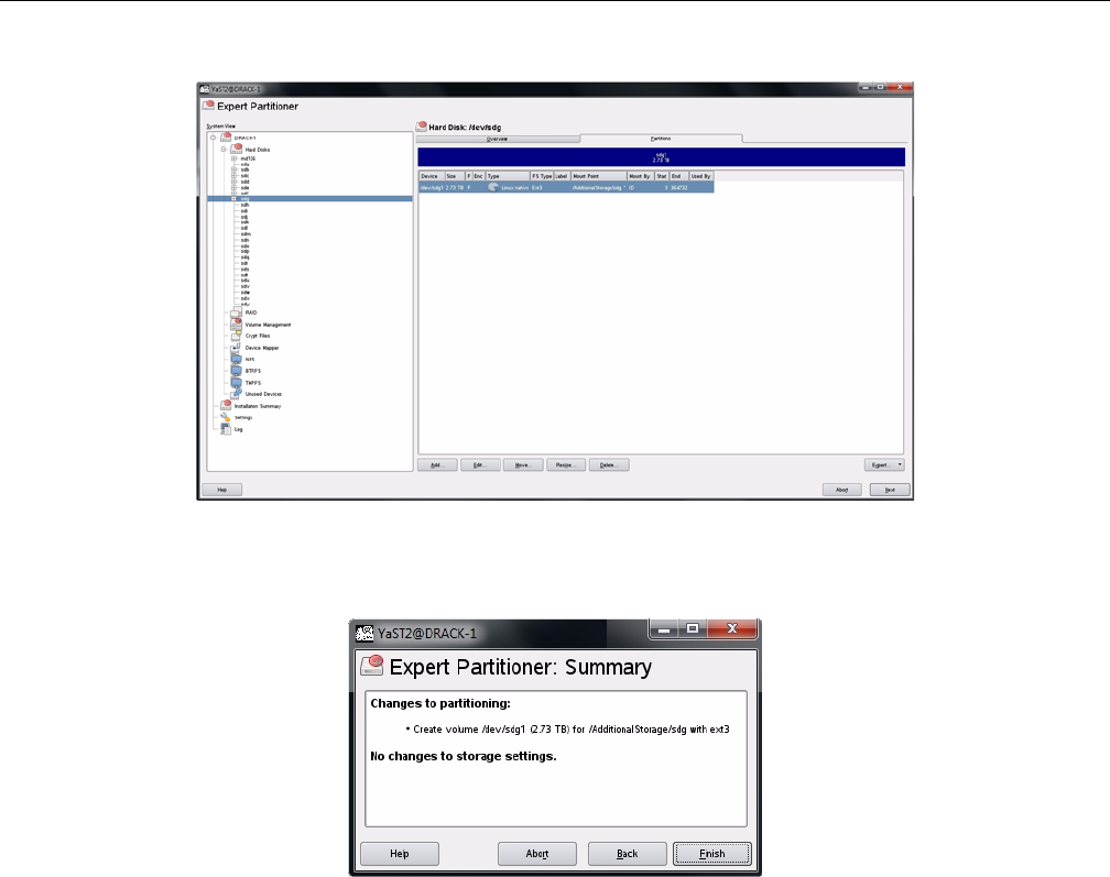
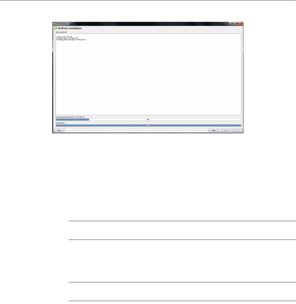
Linux Zoning Tools
007-5818-003 83
Figure 3-25 YaST2 – Disk Mounting (in process)
Once the disk is mounted (Figure 3-25), the system will return you to the beginning YaST2 GUI.
Removing a Drive in Zones for Linux
From the Zones user interface (Figure 3-4 on page 72), you can unzone a drive from an adapter
by unchecking boxes. Once the drives are unzoned, click the Save Session button (Figure 3-5 on
page 72). This action takes the configuration shown on the screen, saves it to an .xml file, that is
then converted into a .bin file, and stores it on the expander card.
Note: The Save Session button will become enabled whenever a change has been made in the
Zones user interface.
In Linux, the name of the new .bin file is STORBRICK_#.bin where the only new element to
the file name is the STORBRICK_. In Windows, the name of the new .bin file is
sbn#_****.bin where the only new element to the file name is the n after sb.
Important: Each time the Save Session button is pushed, these files are overwritten. There is no
way to retrieve previously saved information.
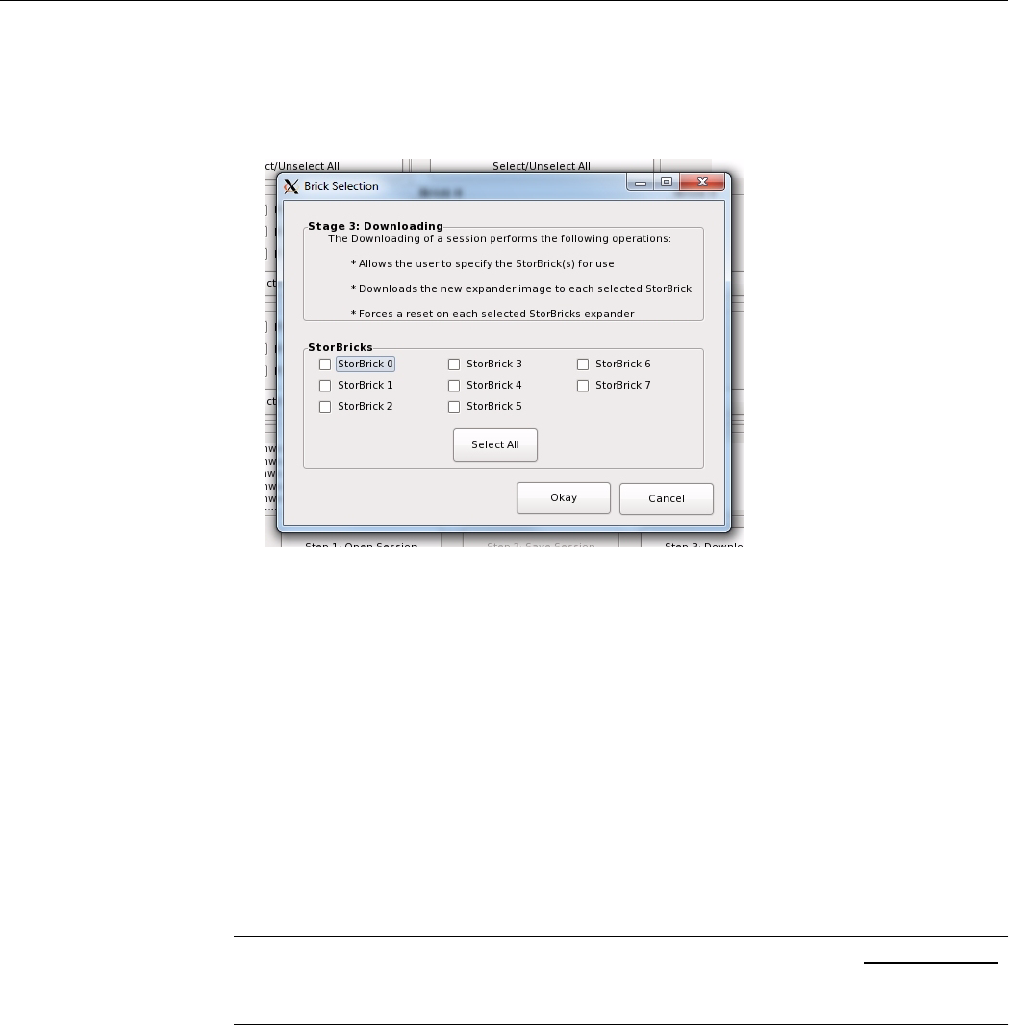
84 007-5818-003
3: System Software
Click the Download Session button. A window will appear asking you which StorBricks you
would like to download to, by selecting checkboxes next to the corresponding StorBrick
(Figure 3-26), or choosing Select All. Click Okay when satisfied.
Figure 3-26 Zones – Downloading setting to StorBrick(s)
After clicking Okay, go to the terminal window that was started automatically upon launching the
Zones for Linux tool (“Linux Zones Tool Note‚” on page 71). In this window, check to see that
the values for Image Validation and Checksum are both listed as Passed. If they are, a
Y will be the default option in answer to the question: Are you sure to download file
to expander? [sic]. You will have to answer Y for each StorBrick you wish to download files
to (Figure 3-27).
If either Image Validation or Checksum have failed, the default answer will be N, which
is what you should choose if they have failed. If N is chosen, the information is not sent to the
StorBrick, and that StorBrick is skipped. (Reasons for Image Validation or Checksum not
passing could be—for example—an invalid template file or conversion from .xml to .bin
failed.)
Warning: If Y is chosen and the Image Validation and Checksum have not passed,
unknown results will occur, including losing expander information, requiring a field
technician to service the machine.
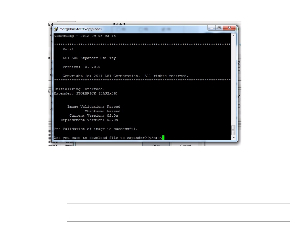
Linux Zoning Tools
007-5818-003 85
Figure 3-27 Zones – Are you sure to download files to expander?
If Image Validation or Checksum are showing as Failed, choose N to answer the
question: Are you sure to download file to expander? [sic] Once all downloads
have either been answered Y or N, if any of the downloads were answered N, you must close and
re-open the Zones program.
Warning: If there are ANY failed downloads, DO NOT REBOOT OR POWER CYCLE
THE MACHINE under ANY circumstance.
If the problem of failed Image Validation or Checksum continues, contact SGI Technical
Support (“Product Support” on page xxv of the MIS User Guide). Otherwise, once all the
downloads have passed and been answered Y, power-cycle the machine for these changes to take
effect.
Additional Features in Zones for Linux
The Zones application also includes tools for “Loading .csv Configuration Files in Linux” and
“Save a Configuration to .csv file in Linux”. Their instructions are provided here.
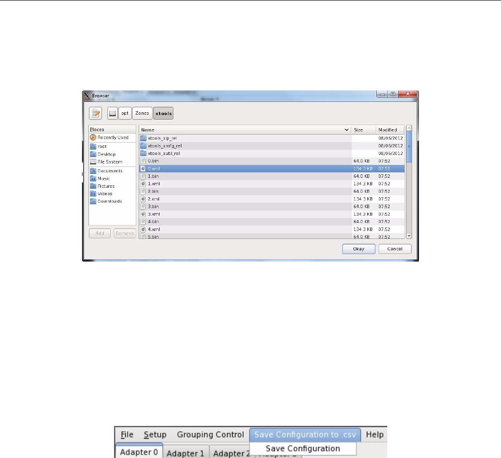
86 007-5818-003
3: System Software
Loading .csv Configuration Files in Linux
One option for zoning is editing zoning values in a .csv file, created through spreadsheet
programs that support .csv file extension (e.g., Microsoft Excel).
Figure 3-28 Zones – Select CSV File (Linux)
To begin in either version, select Open Session (Figure 3-6 on page 73). Select Load CSV File.
Enter an alias for the session (Figure 3-7 on page 73) and click Okay. A File Location pane will
open (Figure 3-28). Select the .csv file you wish to upload, and click Okay. The configuration
entered in the .csv file will show in the Zones GUI (Figure 3-4), with the exception that the
zoning may need to be synchronized with the hardware, explained below.
Save a Configuration to .csv file in Linux
The Zones tool also allows you to save configurations created in the GUI as a .csv file. In the
top menu bar, there is the option to Save Configuration to csv (Figure 3-29).
Figure 3-29 Zones – Save Configuration to .csv
Click that menu option, and in the drop-down menu that appears, click Save Configuration
(Figure 3-29). A Save CSV pop-up window will appear (Figure 3-30), asking you to enter a
Directory (file location) and File Name (name for the .csv file).
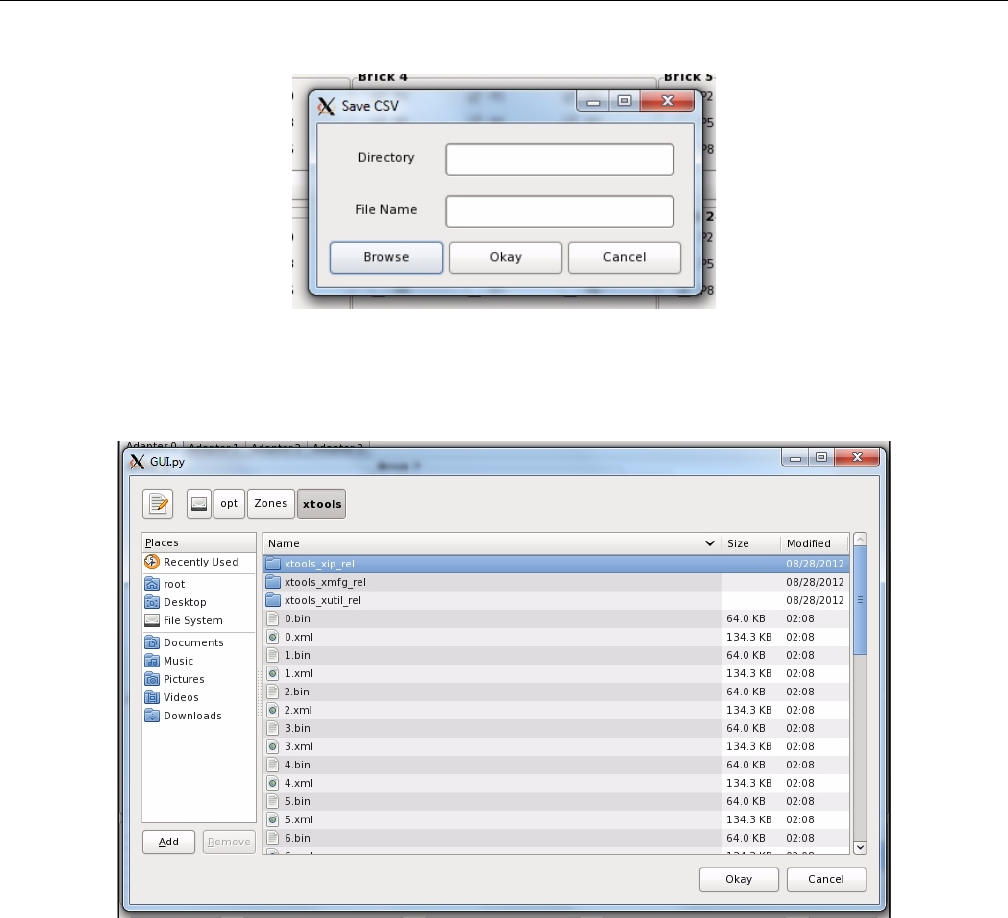
Linux Zoning Tools
007-5818-003 87
Figure 3-30 Zones – Save CSV pop-up
There is also the option to browse to a directory using the Browse button. This will open a
navigation pane where you can select the directory (Figure 3-31).
Figure 3-31 Zones – Select Directory navigation pane
If a directory is not chosen, or an improper directory choice is made (choosing a program instead
of a file, etc.) an error message will appear (Figure 3-32).
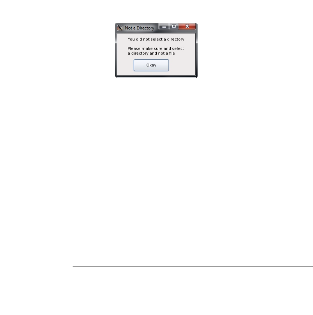
88 007-5818-003
3: System Software
Figure 3-32 Zones – Error: Improper Directory Selection
Once satisfied, click Okay (Figure 3-32). The values set in the GUI will be output as a .csv file
in the directory selected earlier.
Windows Zoning Tools
The following instructions are for Windows-based MIS Servers, and for Windows-based
machines installing the CLI Zoning Tool. (Operation of the CLI Zoning Tool remains the same
across platforms. See “CLI Zoning Tool” on page 109 for more information.)
Installing Windows Software
There are four programs necessary for Windows management of MIS systems. These programs
give operational control over the hardware and its performance, including zoning of the drives.
They are MegaRAID Storage Manager, MegaCli64, Zones, and Python. To run the CLI Zoning
Tool on a Windows machine, the machine must have Python installed as well as the CLI Zoning
Tool itself.
MegaRAID Storage Manager for Windows
Note: MegaRAID Storage Manager is not necessary for zoning using the CLI Zoning Tool.
The MegaRAID Storage Manager is used to prepare the drives for zoning, and to create the drive
groups after zoning.
1. Go to http://lsi.com and search for MegaRAID Storage Manager.
2. Select and accept the latest Windows version for download.

Windows Zoning Tools
007-5818-003 89
3. Download and install.
MegaRAID Storage Manager GUI for Windows will appear.
MegaCli64 for Windows
MegaCli64 is a program required for the Zones tool to match the StorBrick to the adapters. It runs
in the background underneath Zones.
1. Go to http://lsi.com and search for MegaCli64.
2. Select and accept the latest Windows version for download.
3. Download and install.
Zones for Windows
Zones is proprietary SGI software, used to zone drives on the MIS Server Platform.
1. Go to http://support.sgi.com
2. Download the latest Windows version of Zones.
3. Unzip the Zones.zip file. Make sure that destination the files will be extracted to is
c:\. A Zones folder will be created automatically, generating the directory
c:\Zones\
To run Zones, go to Start > Run, and type in c:\Zones\Zones.exe, and click Okay.
Note: On first use, the Zones will ask you to enter the paths to MegaCli64 (Figure 3-33). The
default path for MegaCli64 is C:\Program Files (x86)\MegaRAID Storage
Manager\MegaCLI\MegaCli64 and C:\Zones\XTOOLS is the default path for
XTOOLS. These paths can be changed at any time by going to menu option Setup > Tools.
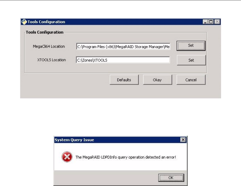
90 007-5818-003
3: System Software
Figure 3-33 Zones – First-use path configuration (Windows)
If the path is improperly set, an error message will appear. The following error messages means
that the path set is for a folder that does not contain MegaCLI64, and Zones will not run properly
(or the system may crash).
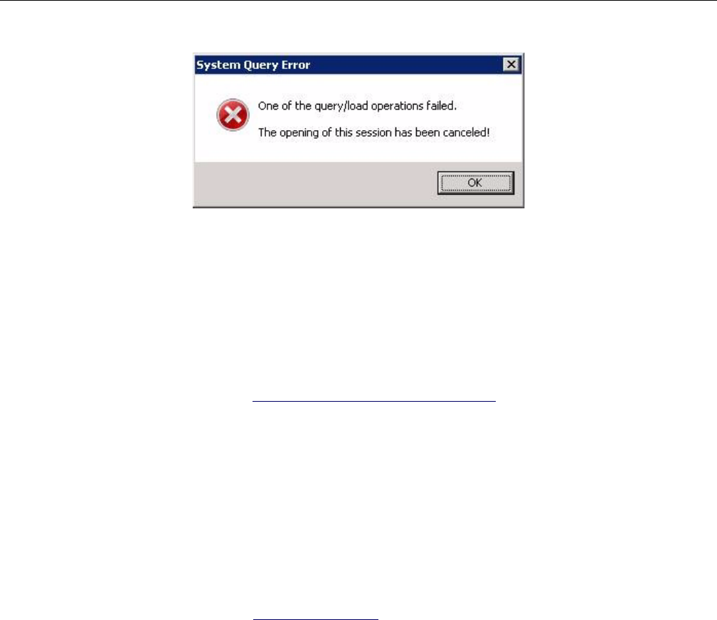
Windows Zoning Tools
007-5818-003 91
Figure 3-34 Zones – Error messages from improper path configuration
If the path for the tools are set incorrectly, they must be re-set and the Zones program closed and
re-started for the correct paths to take effect.
Python for Windows
The CLI Zoning Tool requires Python, version 2.6 or 2.7, be installed on the machine that will
perform the zoning.
1. Go to http://www.python.org/download/releases/ and select the latest version of Python.
2. Download and start the installation.
3. The installation will ask which directory in which to install python (the default is
c:\Python##\ where ## is the version number).
4. On the Customize Python pane, click Next.
5. On the Complete Python Installation pane, click Finish.
CLI Zoning Tool for Windows
To install the CLI Zoning Tool software:
1. Go to http://support.sgi.com
2. Download the latest Windows version of the CLI Zoning Tool.
3. Unzip ShackCLI_release_xxx. The program will ask if you want to create a
directory name for the .zip file, click Yes.
To run the CLI Zoning Tool, follow the instructions given in “CLI Zoning Tool” on page 109.
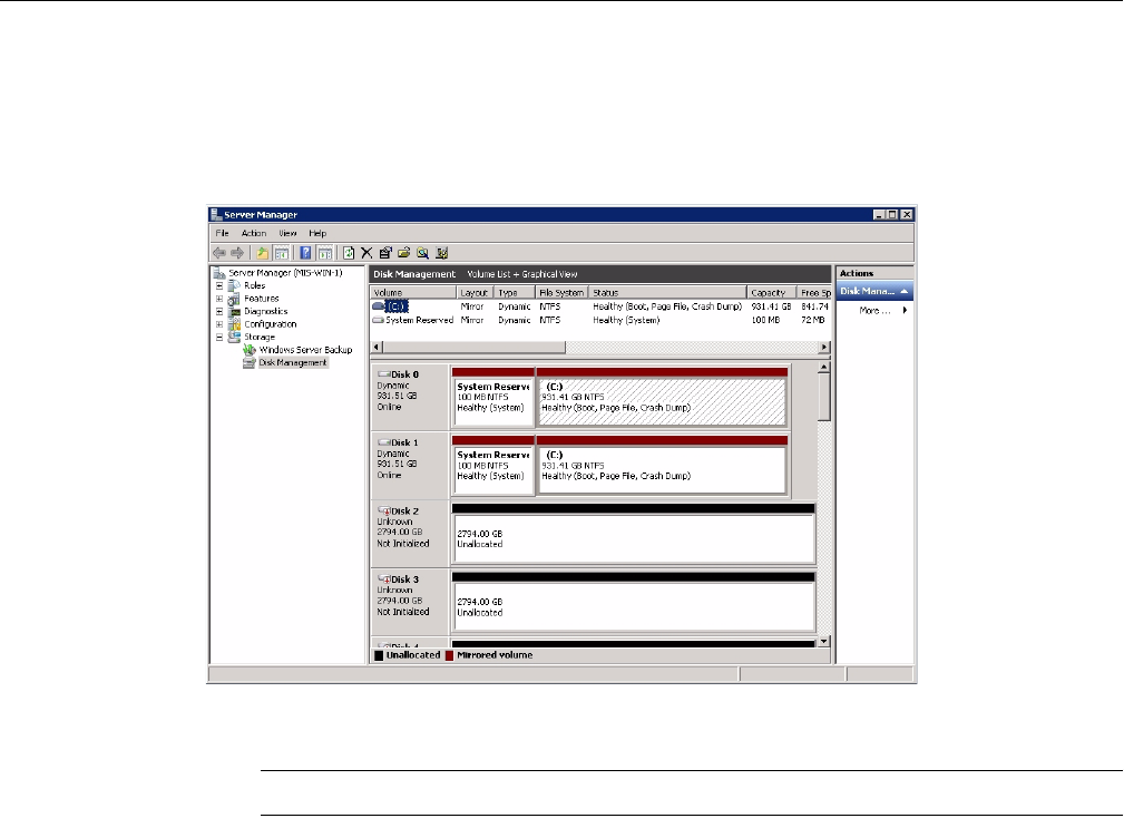
92 007-5818-003
3: System Software
Verify Drives Seen in Windows
In Windows, open Server Manager (Figure 3-35). Verify that the only disks the system sees are
system drives, and that they are labeled c:/.
Figure 3-35 Windows Server Manager – Disk Management
Note: Unconfiguring drives removes them from the system.
Zones for Windows
The SGI Zones tool is a proprietary software program that uses a GUI interface to zone the drives
in the MIS Server. Future releases will support zoning JBODs as well.
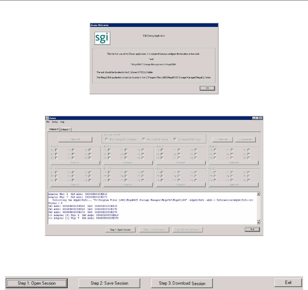
Windows Zoning Tools
007-5818-003 93
Figure 3-36 Zones for Windows Welcome
Figure 3-37 Zones Windows User Interface
To begin zoning, click the Open Session button (Figure 3-38). This queries each expander for the
information contained in the expander .bin file.
Figure 3-38 Zones – Open Session, Save Session, Download Session, and Exit buttons
Click Open New Session (Figure 3-39).
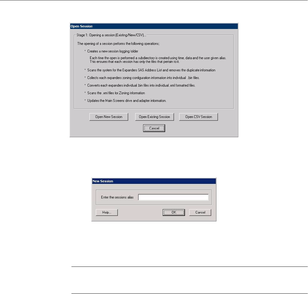
94 007-5818-003
3: System Software
Figure 3-39 Zones – Open Session
The Zones program will ask you for a Session Alias (Figure 3-40). This alias will be added to a
time stamp to create folder for that session’s files: YYMMDD_HHMMSS_alias.
Figure 3-40 Zones – Enter Session Alias
Enter an alias and click Okay. Each expander card’s information is fetched using cmd.exe and
placed in the session folder as .bin files.
Note: Aliases have a 64 character limit, and may not contain spaces or non-alpha-numeric
characters; these will be replaced with an underscore if used and a warning message will appear
(Figure 3-41).
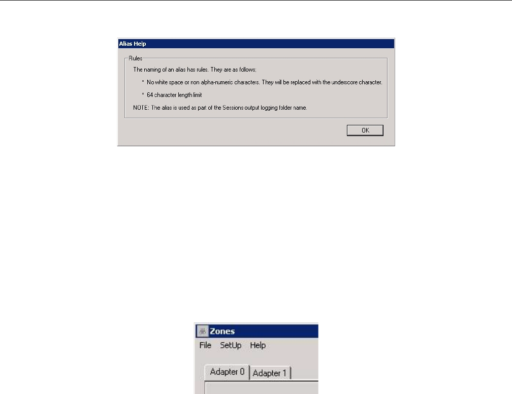
Windows Zoning Tools
007-5818-003 95
Figure 3-41 Zones – Alias Help Warning Message
In Zones for Windows, .bin files are automatically named sb#_****.bin where sb stands
for StorBrick, # is the number of the StorBrick in question, and **** are the last four digits of
the expander card’s SAS address. After the .bin file has been fetched, each file in converted into
an XML file, named using the same convention, with the file extension .xml (e.g.,
sb#_****.xml).
Upon opening, Zones UI will show drives that are presently installed and zones that are currently
active. A checkbox will be enabled to show that a drive is in a StorBrick. A check mark in a
checkbox that is enabled shows that the drive is zoned for that adapter. Each adapter has its own
tab above the StorBrick layouts (Figure 3-42). The number of Adapter tabs will directly
correspond to the number of adapters Zones sees in the system.
Figure 3-42 Zones – Adapter tabs (Windows)
Installing a Drive in Zones for Windows
After creating a new session, click the Show All button. This enables all boxes on all adapters
(Figure 3-43), even if there are no drives physically present. This is so a drive can be zoned to the
system that isn’t seen by the system yet.
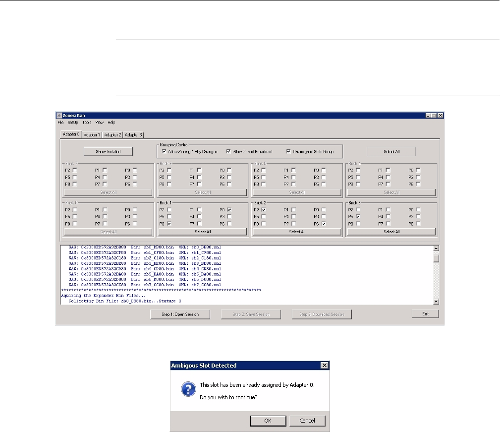
96 007-5818-003
3: System Software
Note: If a drive is zoned to more than one adapter, a warning message (Figure 3-44) will appear.
In Windows, this warning tells which adapter that drive is already zoned to, and a message asking
if you would like to continue. It is possible to zone one drive to two adapters. This is allowed, but
not suggested, as it can cause data collisions.
Figure 3-43 Zones – Show All
Figure 3-44 Zones – Adapter Assignment Warning Message
Check the boxes for the drives you want to zone, according to the configuration of your liking.
Click Save Session. This takes the screen configuration and saves it to an .xml file that is then
converted into a .bin file.
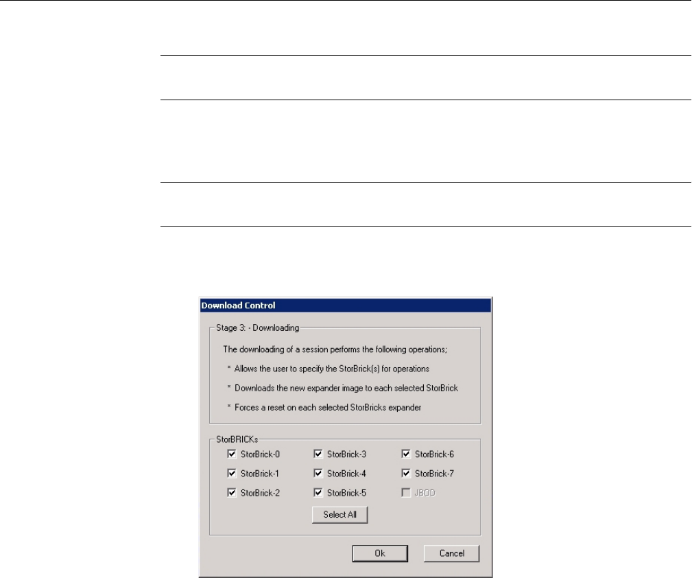
Windows Zoning Tools
007-5818-003 97
Note: The Save Session button will become enabled whenever a change has been made in the
Zones configuration.
The name of the new .bin file is sbn#_****.bin where the only new element to the file name
is the n after sb.
Important: Each time the Save Session button is pushed, these files are overwritten. There is no
way to retrieve previously saved information.
Click the Download button. Once complete, this function pushes the .bin files back into the
expanders. Select which StorBricks to push the files to, and click Ok to push the files.
Figure 3-45 Zones – Select StorBricks for download
In Windows, a prompt will appear asking to confirm the download operation.
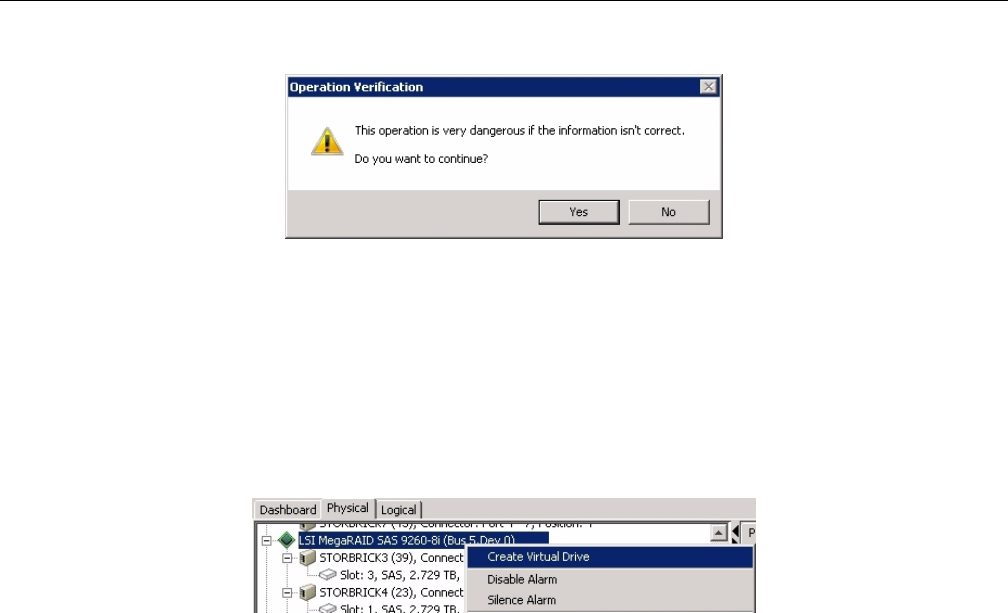
98 007-5818-003
3: System Software
Figure 3-46 Zones tool – Verify download
Click Yes to verify and finish downloading. Power cycle the machine. Click Ok to power off the
machine for power-cycling.
Creating the Drive Groups in MegaRAID for Windows
Power on the machine to complete power-cycle. Open MegaRAID. Right-click on the controller
and select Create a Virtual Drive (Figure 3-47).
Figure 3-47 MegaRAID – Create a Virtual Drive
A screen will pop up asking you to choose Simple or Advanced (Figure 3-48). In Simple mode,
the drives are chosen for you. In Advanced mode, you get to choose the drives, and are given
additional selections in RAID levels, allowing for spanned (00, 10, 50, 60) drives.
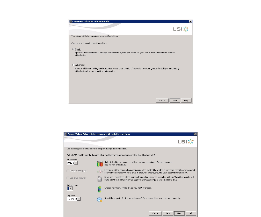
Windows Zoning Tools
007-5818-003 99
Figure 3-48 MegaRAID – Create Virtual Drive mode
Create the drive groups.
Figure 3-49 Create Virtual Drive – Simple Settings
Choose Write Back BBU (battery back-up unit). This mode is the safest and the fastest, and will
automatically switch from caching mode to write-straight-to-disk whenever battery power has
reached threshold. Write Through writes straight to disk. Write Back is a cached data flow.
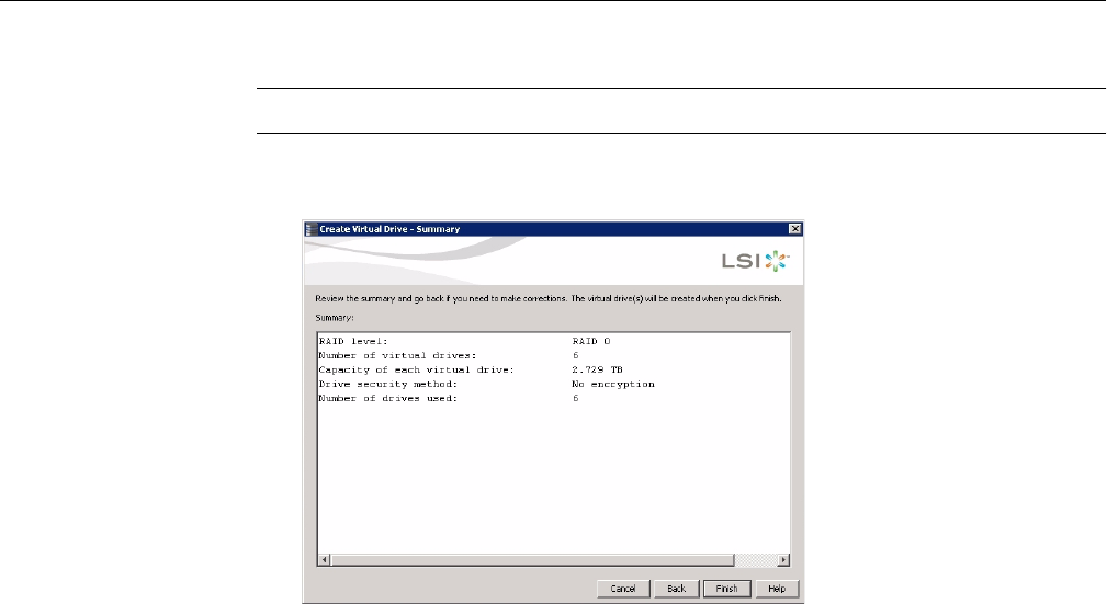
100 007-5818-003
3: System Software
Warning: If you select Write Back and power to the system is lost, data is lost.
Click Next, and a summary screen verifying settings will appear (Figure 3-50).
Figure 3-50 Create Virtual Drive – Summary
If the settings are correct, click Finish, and click Ok.
Formatting the Drives in Windows Server Manager
Drives are formatted using Windows Server Manager (Figure 3-51). Open Server Manager—the
screen should start at Disk Management with the drives showing. If not, click Storage in the
system tree, and click Disk Management. The collection of disks/raidsets will now show.
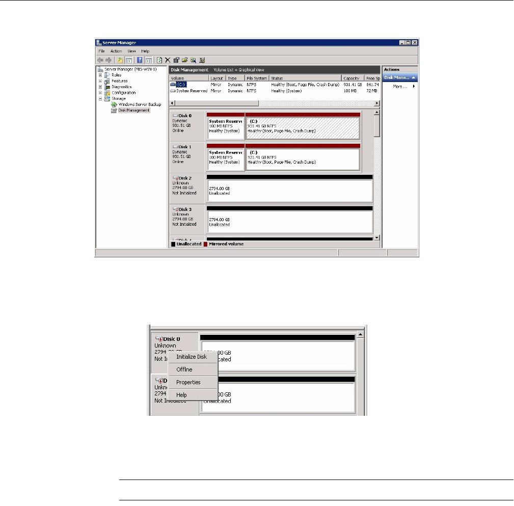
Windows Zoning Tools
007-5818-003 101
Figure 3-51 Server Manager – Disk Management
Right click in the grey area of the first non-system disk. In the menu that appears choose Initialize
Disk (Figure 3-52).
Figure 3-52 Server Manager – Initialize Disks
A pop-up window will appear, showing all the uninitialized disks (Figure 3-53).
Warning: Be sure to select GPT (GUID Partition Table).
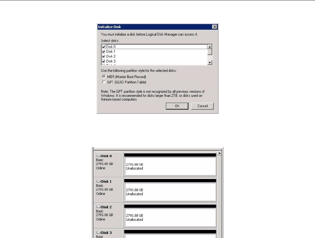
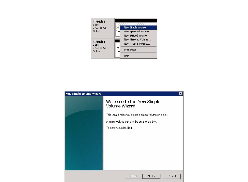
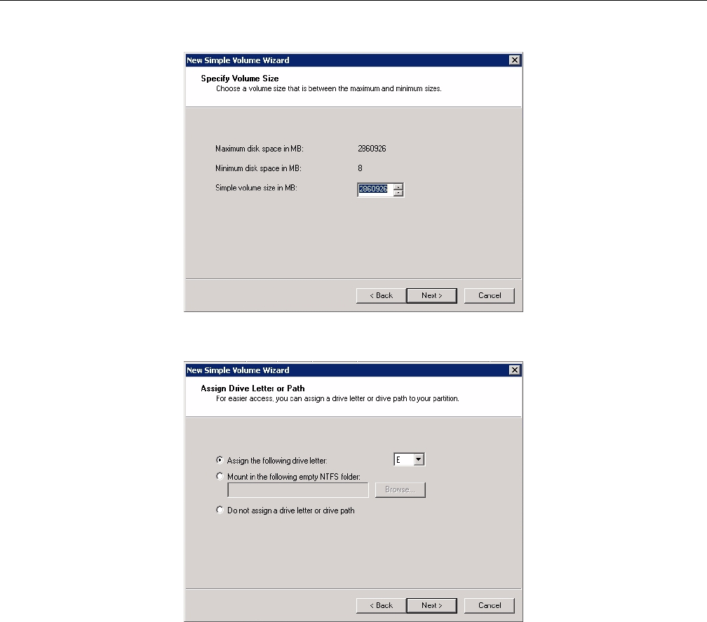
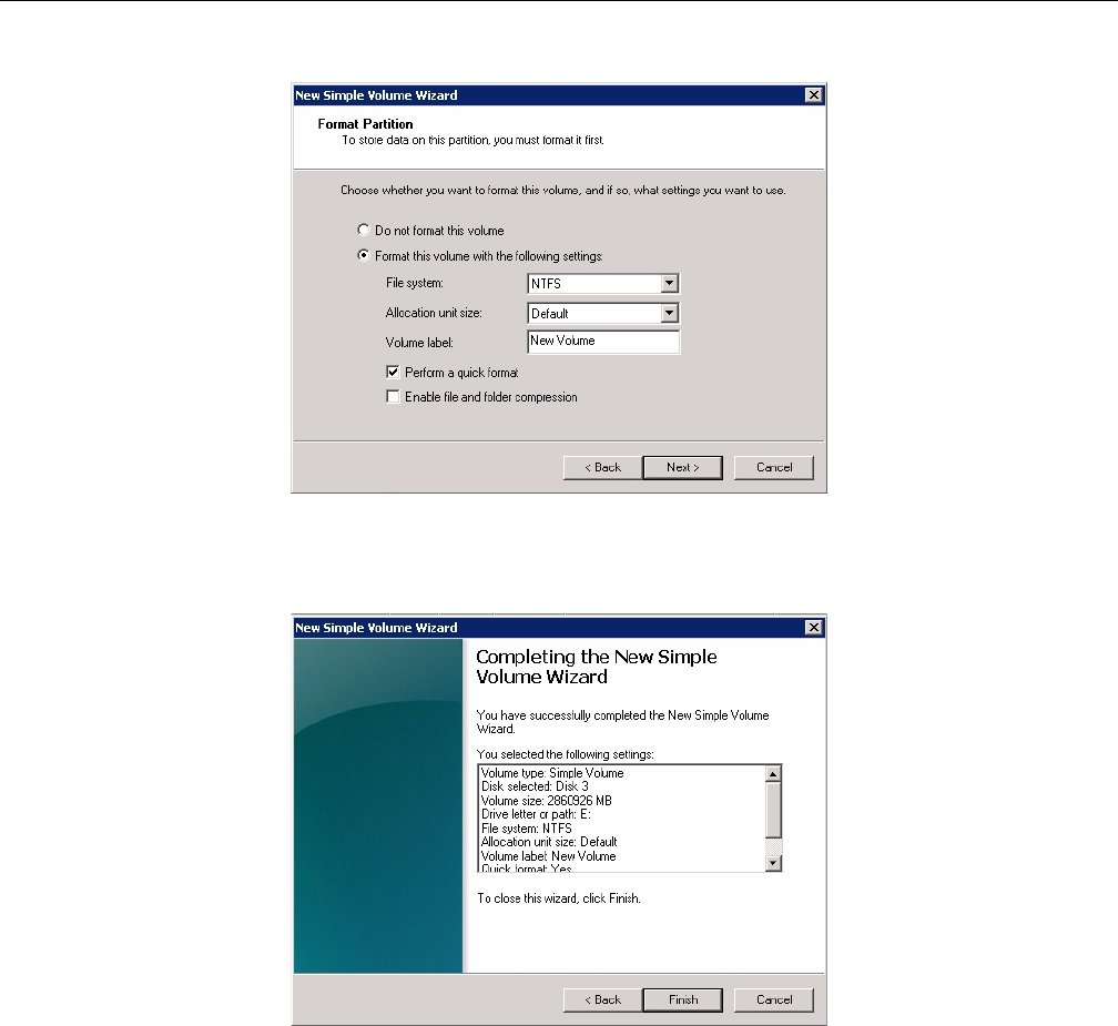
Windows Zoning Tools
007-5818-003 105
Figure 3-59 New Simple Volume Wizard – Format Partition
Select the format settings to be used, and click Next (Figure 3-59).
Figure 3-60 New Simple Volume Wizard – Settings Confirmation
Click Finish to format the disks (Figure 3-60). New volumes will show in the Disk Management
window below the volumes (Figure 3-61).
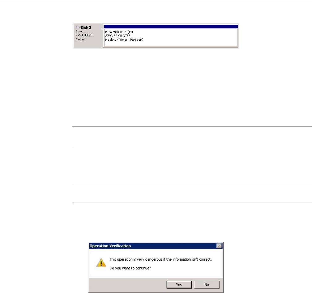
106 007-5818-003
3: System Software
Figure 3-61 New Simple Volume in Server Manager
Removing a Drive in Zones for Windows
From the Zones user interface (Figure 3-37 on page 93), you can unzone a drive from an adapter
by unchecking boxes. Once the drives are unzoned, click the Save Session button (Figure 3-38 on
page 93). This action takes the configuration shown on the screen, saves it to an .xml file, that is
then converted into a .bin file, and stores it on the expander card.
Note: The Save Session button will become enabled whenever a change has been made in the
Zones user interface.
In Windows, the name of the new .bin file is sbn#_****.bin where the only new element
to the file name is the n after sb.
Important: Each time the Save Session button is pushed, these files are overwritten. There is no
way to retrieve previously saved information.
Click the Download Session button (Figure 3-38 on page 93). This function pushes the files back
into the expanders. Select which StorBricks to push the files to, and click Yes (Figure 3-62) to
push the files.
Figure 3-62 Zones – Verify Download
Power cycle the machine to have these changes take effect.
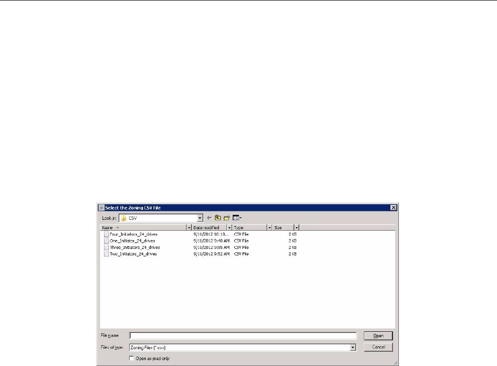
Windows Zoning Tools
007-5818-003 107
Additional Features in Zones for Windows
The Zones application also includes tools for loading a .csv file, adapter synchronization, and
saving a .csv file.
Loading .csv Configuration Files in Zones for Windows
One option for zoning is editing zoning values in a .csv file, created through spreadsheet
programs that support .csv file extension (e.g., Microsoft Excel). Zoning assignments done in
this way will assign zoning at the hardware level, whereas zoning through the Zones GUI zones
at the MegaRAID Storage Manager level, which may or may not correspond with the hardware.
Synchronizing the two is handled at the hardware level and not through the Zones program (see
“Adapter Assignment Synchronization in Zones for Windows” on page 108).
[
Figure 3-63 Zones – Select CSV File
To begin, select Open Session (Figure 3-38 on page 93). Select Load CSV File. The alias for the
session is the .csv file name with the “.csv” removed. A File Location pane will open
(Figure 3-63). Select the .csv file you wish to upload, and click Okay. The configuration entered
in the .csv file will show in the Zones GUI (Figure 3-37 on page 93), with the exception that the
zoning may need to be synchronized with the hardware, explained below.
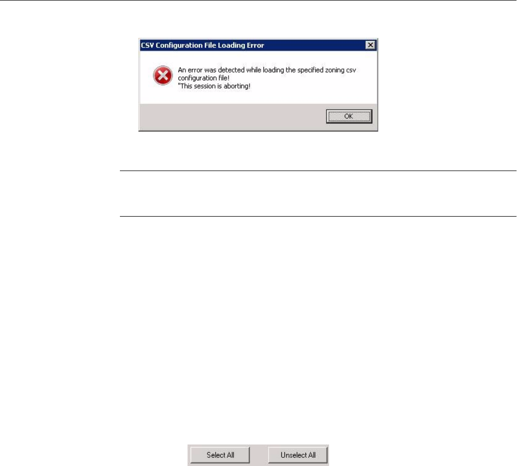
108 007-5818-003
3: System Software
Figure 3-64 Zones – Error message: Canceling csv file selection (Windows)
Note: If you wish to cancel selecting a .csv file, and click the Cancel button on the Select the
Zoning CSV File, you will receive an error message (Figure 3-64). Click Okay to continue
canceling the Select .csv File operation.
Adapter Assignment Synchronization in Zones for Windows
If the adapter assignment in the .csv file loaded (hardware-level assignment) does not
correspond with how MegaRAID Storage Manager assigns the adapters (on a first-see/first-come
software-level assignment), then Zones will show what drives are present on which adapters, but
the zoning will not be there.
To fix this, select Open Session (Figure 3-39 on page 94). Select Create New Session, enter an
alias for the session, and click Ok. Next, click the Unselect All button, located in the upper right
corner of the Zones for Windows UI (Figure 3-65). Now you can assign the drives on the Adapter
tabs, to configure the tool so that it is synchronized with the hardware. Click the Step 2: Save
Session button, and then click the Step 3: Download Session button (Figure 3-38 on page 93).
Select the StorBricks on which you wish to push the new configuration (usually all, in this instance
– Figure 3-45 on page 97). Click Ok. Click Yes to power cycle the machine (i.e., let the MIS
Platform shut down gracefully and then power it back on). This will change the MegaRAID
assignment.
Figure 3-65 Zones – Select All, Unselect All buttons

CLI Zoning Tool
007-5818-003 109
Save a Configuration to .csv file in Zones for Windows
The Zones tool for Windows saves the configurations created in the GUI as a .csv file. This is
done automatically when you save the session, and the .csv file is saved in the session folder.
CLI Zoning Tool
This initial release of the CLI Zoning tool introduces proprietary SGI software, used to zone drives
on a MIS Server Platform and MIS JBOD units. The tool also supports diagnostic functions useful
to Field Service.
In the T10 implementation, SAS zoning access control is implemented by linked switch and
expander devices, with zoning enabled. These devices define a Zoned Portion of a Service
Delivery System (ZPSDS). No host device intervention is required. Each zoning expander device
within the MIS Enclosure maintains an identical zone permission table, so zone access control is
maintained across the entire ZPSDS. The difference between the expanders lies in the definition
of the PHY Zone groups that defines to which Zone Group (ZG) each of the 36 PHY’s belongs.
The Permission Table then maps the Initiator Zone Groups to the Target Zone groups.
The CLI Zoning Tool performs changes through the use of Comma Separated Values (CSV) files.
A Session is defined as the act of querying, editing, saving, and downloading the expander's binary
zoning information.
Important: JBODs are zoned through the hardware using the CLI Zoning tool; only PHY-based
Zoning is supported at this time.
The CLI Zoning Tool runs on any Windows/Linux host that has Python 2.6 or Python 2.7.1
installed. The target MIS JBOD/Server does not require an OS since the CLI Zoning Tool uses the
FanBase Ethernet connection to access the StorBricks. The CLI Zoning Tool allows the zoning of
drive groups larger than 72, hence, it is able to zone JBODs, and multiple JBODs, as single zones.
Table 3-1 is how the Zone Groups (ZG) are implemented in the MIS Enclosure. There are 256
possible ZG in the MIS Enclosure which allows for our maximum drive count of 162.

110 007-5818-003
3: System Software
A configuration file is used by the CLI application to zone the StorBricks. A set of standard
configuration files are included with the CLI Zoning Tool software package. A custom file
can be created, using a spreadsheet application and then saving it as a .csv file (see “Editing the
.csv File for the CLI Zoning Tool” on page 119).
Preparing to Zone using the CLI Zoning Tool
CLI Zoning uses the MIS-S9D proprietary network interface. This interface is to be used ONLY
when zoning. It is located at the front of the chassis at the upper right corner (Figure 3-66). The
chassis must be slid out forward at least one inch in order to connect a network crossover cable.
(See “Sliding the Chassis Forward/Backwards‚” on page 134.)
Table 3-1 Zone Group Implementation
Zone Group Description
ZG0 The Dead Zone that only talks to ZG 127
ZG0 – ZG1 Always enabled
ZG2–3 Enabled for initiators
ZG2 For Initiators that have SMP Zoning Access
ZG3 Initiators that have access to Broadcast
ZG4–7 Reserved per SAS Specification
ZG8–15 The eight possible initiators
ZG16–96 For drives 0–80 for 81 possible drives
ZG97–127 Reserved in the MIS implementation

CLI Zoning Tool
007-5818-003 111
Figure 3-66 MIS-S9D proprietary network interface
Ensure the MIS system is powered on. Use an Ethernet crossover cable to connect a server/laptop
running either a Windows or a Linux operating system and the CLI Zoning application software.
The network port connected to the server/laptop must be set to 192.168.0.xxx (10 will do).
The static IP address of the Fan Base is set to 192.168.0.3, verify connectivity to the Fan Base
with a ping command to 192.168.0.3 from the server/laptop. Verify it responds. If not it will
be necessary to power cycle the MIS server or JBOD.
Editing the ShackCLI.ini file for Linux
In the /opt/ShackCLI directory, open up the ShackCLI.ini file with an editor or vi.
The following is a sample file:
[main]
# Input filename. This must be either a pathname or a simple
# dash (-), which signifies we'll use standard in.
input_source = cli
target = 192.168.0.3
[maxsize]
# When we hit this threshold, we'll alert for maximum
# file size.
threshold = 100
[display]
show_footer = yes
# Fill up all SB infomation before going to Menu
auto_fill = no
[default]
#MIS_Variant = JBOD

112 007-5818-003
3: System Software
MIS_Variant = SERVER
storbrick = 0 1 2 3 4 5 6 7
#storbrick = 0 1 2 3 4 5 6 7 8
cmd = menu
pcsv = /opt/ShackCLI/MIS-Server_2HBA_zoning__PCSV.csv
pbcsv = /opt/ShackCLI/MIS-JBOD_1-IOMOD_zoning_PBCSV.csv
zcsv = /opt/ShackCLI/Zone_Phy_Default.csv
max_zones = 255
max_phys = 36
response_delay_default = 20
First, verify that the target IP address is 192.168.0.3 and is not commented out (i.e., there is
no # at the beginning of the line). Next, make the needed changes to the file, as follows.
1. Set the MIS Variant to the type of system to be zoned, JBOD or SERVER. (Be sure the
other is commented out.)
2. Change the StorBrick count to be either 0–7 for a server, or 0–8 for a JBOD.
3. Select the type of zoning file to be used pcsv, zcsv, or pbcsv.
4. Add the path to where the configuration file is located.
5. Unless issues develop, leave the remaining selections at default.
6. Save the ShackCLI.ini file and close.
7. Execute the CLI command: python ShackCLI.py -–ini ShackCLI.ini
-–cmd menu.
This will set the StorBricks to debug mode, and display a menu (“CLI Zoning Tool Main Menu”
on page 113).
Editing the ShackCLI.ini file for Windows
In the C:\python##\ directory, open up the ShackCLI.ini file with an editor or vi.
The following is a sample file:
[main]
# Input filename. This must be either a pathname or a simple
# dash (-), which signifies we'll use standard in.
input_source = cli
target = 192.168.0.3
[maxsize]
# When we hit this threshold, we'll alert for maximum
# file size.
threshold = 100

CLI Zoning Tool
007-5818-003 113
[display]
show_footer = yes
# Fill up all SB infomation before going to Menu
auto_fill = no
[default]
#MIS_Variant = JBOD
MIS_Variant = SERVER
storbrick = 0 1 2 3 4 5 6 7
#storbrick = 0 1 2 3 4 5 6 7 8
cmd = menu
pcsv = C:\python##\MIS-Server_2HBA_zoning__PCSV.csv
pbcsv = C:\python##\MIS-JBOD_1-IOMOD_zoning_PBCSV.csv
zcsv = C:\python##\Zone_Phy_Default.csv
max_zones = 255
max_phys = 36
response_delay_default = 20
First, verify that the target IP address is 192.168.0.3 and is not commented out (i.e., there is
no # at the beginning of the line). Next, make the needed changes to the file, as follows.
1. Set the MIS Variant to the type of system to be zoned, JBOD or SERVER. (Be sure the
other is commented out.)
2. Change the StorBrick count to be either 0–7 for a server, or 0–8 for a JBOD.
3. Select the type of zoning file to be used pcsv, zcsv, or pbcsv.
4. Add the path to where the configuration file is located.
5. Unless issues develop, leave the remaining selections at default.
6. Save the ShackCLI.ini file and close.
7. Execute the CLI command: python ShackCLI.py -–ini ShackCLI.ini
-–cmd menu.
This will set the StorBricks to debug mode, and display a menu (“CLI Zoning Tool Main Menu”).
CLI Zoning Tool Main Menu
The main menu of the CLI Zoning Tool gives the following options, as listed below and described
in Table 3-2.
1) Set Active Storbrick(s)
2) Display Current StorBrick(s) Zoning
3) Update StorBrick(s) Permissions Table From CSV
4) Update StorBrick(s) Phy Zones From CSV
5) Update StorBrick(s) Phy Based Zoning from CSV

114 007-5818-003
3: System Software
6) Change Zoning type (Server <-> JBOD)
7) Save current StorBrick(s) Zoning to CSV
8) Display StorBrick(s) Settings
9) Display CLI Settings
10) Enter StorBrick CLI (Must select a single StorBrick)
11) Reboot FanBase - will not reset StorBricks
12) Reset FanBase - Danger. This will reset StorBricks
13) Force Storbrick(s) into Debug Mode
14) Exit Storbrick(s) Debug Mode
15) Display PHY Error Counters for selected StorBricks
16) Display PHY Information for selected StorBricks
17) Display StorBrick UUID for selected StorBricks
18) Display StorBrick Firmware Revision Levels for Selected StorBricks
0) Exit CLI - back to command prompt
Table 3-2 CLI Zoning Tool Menu Options and Descriptions
Menu Option Description
1) Set Active
Storbrick(s)
This menu option allows user to select the StorBrick(s) to act
upon. The StorBricks may be entered in any order: 0 1 2 3 4 5 6 7
or 7 6 5 4 3 2 1 0, or in subsets: 0 or 0 1, etc. Storbrick numbers
must be less than or equal 7 for MIS Server and less than or equal
8 for MIS JBOD.
2) Display Current
StorBrick(s) Zoning
Displays the Zoning configuration that is currently stored in the
StorBricks.
3) Update StorBrick(s)
Permissions Table From
CSV
This menu option uses the csv file described in the ini file
under the heading ‘pcsv’ to modify the T10 Zoning Permission
Tables for the selected StorBricks. If no csv file has been
specified in the ini file the CLI Zoning Tool will prompt the
user for the name of the csv file to use.
4) Update StorBrick(s)
Phy Zones From CSV
This menu option uses the csv file described in the ini file
under the heading ‘zcsv’ to modify the T10 PHY Zone Groups
for the selected StorBricks. If no csv file has been specified in
the ini file the CLI Zoning Tool will prompt the user for the
name of the csv file to use.

CLI Zoning Tool
007-5818-003 115
5) Update StorBrick(s)
Phy Based Zoning from
CSV
This menu option uses the csv file described in the ini file
under the heading ‘pbcsv’ to modify the PHY Based Zoning
Tables for the selected StorBricks. This is the only supported
Zoning configuration for MIS JBOD and is an optional
configuration for MIS Server and MIS DC Server. Only one of
PHY Based and T10 Zoning should be implemented within an
MIS Server (although it is technically possible to mix the Zoning
types) and only one of PHY Based Zoning may be supported in
an MIS JBOD.
6) Change Zoning type
(Server <-> JBOD)
This menu option allows the user to change the zoning type from
SERVER/JBOD to JBOD/SERVER. This command will cause
the Selected STORBRICKS T10 Supported flag to be set/unset
depending what the current Zoning type is. For Example, if the
current Zoning type is PHY Based and the user selects this option
then the T10 Zoning Supported flag will be set enabling T10
Zoning to be implemented instead.
7) Save current
StorBrick(s) Zoning to
CSV
This menu option allows the user to save the current configuration
of the Enclosures Zoning in a file. This file is compatible with the
CLI commands that require a csv file to update Zoning. The csv
file format for PHY Based and T10 Zoning are identical therefore
one use of this command is to dump a MIS system’s T10 Zoning
configuration and then rewrite the same file as a PHY Based
configuration.
8) Display StorBrick(s)
Settings
This menu option simply displays information about the selected
StorBricks such as their SAS Addresses.
9) Display CLI Settings This menu option simply displays information about the CLI
Zoning Tool that is generally contained in the ini file but may
be changed in the course of operating the CLI Zoning Tool
through CLI commands.
10) Enter StorBrick CLI
(Must select a single
StorBrick)
This menu option is for Diagnostics support only.
11) Reboot FanBase -
will not reset
StorBricks
This menu option will invoke a soft reboot of the FanBase and no
StorBricks shall be reset.
Table 3-2 CLI Zoning Tool Menu Options and Descriptions (continued)
Menu Option Description

116 007-5818-003
3: System Software
Note: Options 10, 13 and 14 are to be used ONLY with the assistance of technical support.
Here are the valid Command Line commands:
usage: ShackCLI.py [-h] --cmd CMD [--sbcmd SBCMD] [--target TARGET]
[--sb SB] [--ini INI] [--zcsv ZCSV] [--pcsv PCSV]
[--zones ZONES] [--delay DELAY] [--pbcsv PBCSV]
[--mistype MISTYPE] [--v, V]
12) Reset FanBase -
Danger. This will reset
StorBricks
This menu option will invoke a cold start of the FanBase and all
StorBricks shall be reset.
13) Force Storbrick(s)
into Debug Mode
This menu option places the selected StorBrick(s) into debug
mode which allows most of the other menu options to work. At
start of day all StorBrick(s) defined in the ini file will
automatically be put in Debug Mode therefore it is not generally
necessary to run this command.
14) Exit Storbrick(s)
Debug Mode
Has no affect at this time and is reserved for future
implementations.
15) Display PHY Error
Counters for selected
StorBricks
This menu option displays all the PHY Error Counters for the
Selected StorBrick(s).
16) Display PHY
Infomation for selected
StorBricks
This menu option displays all the PHY information for the
selected StorBrick(s). this information includes the PHY’s
connected link rate, Zone Group and SAS/SATA connection
types.
17) Display StorBrick
UUID for selected
StorBricks
This menu option displays the UUID for the selected
StorBrick(s). The UUID is displayed in human readable form.
18) Display StorBrick
Firmware Revision Levels
for Selected StorBricks
This menu option displays all the Firmware Revision Level
information for the selected StorBrick(s).
0) Exit CLI - back to
command prompt
This menu option will exit the CLI Zoning Tool.
Table 3-2 CLI Zoning Tool Menu Options and Descriptions (continued)
Menu Option Description

CLI Zoning Tool
007-5818-003 117
MIS Command Line Interface optional arguments:
-h, --help show this help message and exit
--cmd CMD command to execute
--sbcmd SBCMD Command to send to SB
--target TARGET target ip address (if not 192.168.0.3)
--sb SB Index(s) of StorBrick
--ini INI Initialization file
--zcsv ZCSV CSV file name for Zoning PHY Groups
--pcsv PCSV CSV file name for Zoning Permission Tables
--zones ZONES Maximum Permission Table Entries
--delay DELAY FanBase delay before expect StorBrick result
--pbcsv PBCSV CSV file name for Phy Based Zoning
--mistype MISTYPE JBOD or SERVER
--v, V Display the version of the Shack CLI
In the menu above, this executes option 2:
python ShackCLI.py –ini ShackCLI.ini –cmd dzone
This executes option 3:
python ShackCLI.py –ini ShackCLI.ini –cmd uperm
This executes option 4:
python ShackCLI.py –ini ShackCLI.ini –cmd uphyz
This executes option 5:
python ShackCLI.py –ini ShackCLI.ini –cmd uphyb
Zoning Using CLI Zoning Tool
First, select option 2 from the Main Menu to display the current zoning. When displayed, 0
indicates that the path to that drive is disabled. An x indicates that it is active to that SAS path.
For the MIS-Server, Initiator0 = SAS lane 0 which is connected to HBA-A lane 0,
initiator1 = SAS lane 1 which is connected to HBA-B lane 0, initiator2 =
SAS lane 2 which is connected to HBA-C lane 0, initiator3 = SAS lane 3 which
is connected to HBA-D lane 0. Initator4-7 are not used at this time and will be set to 0.
Since the .csv data is organized by drives, and the drives are numbered by StorBrick, we can
start at SB[0:0]. The drive numbers in an MIS Enclosure are numbered from 0-143 for the MIS
Server and 0-162 for the MIS JBOD.
Example (truncated, lines 021–190 & 195–250, for space):
StorBrick 0 Permission Table

118 007-5818-003
3: System Software
2 2 2 1 1 1 1 1 1
Zone 5 2 2 9 9 6 5 2 2 9 9 6 6 3 3 0
Group 5 4 3 2 1 0 9 8 7 6 5 4 3 2 1 0
000 00000000 00000000 00000000 00000000 00000000 00000000 00000000 00000002
001 ffffffff ffffffff ffffffff ffffffff ffffffff ffffffff ffffffff ffffffff
002 00000000 00000000 00000000 00000000 00000000 00000000 00000000 0000ff02
003 00000000 00000000 00000000 00000000 00000000 00000000 00000000 0000ff02
004 00000000 00000000 00000000 00000000 00000000 00000000 00000000 00000002
005 00000000 00000000 00000000 00000000 00000000 00000000 00000000 00000002
006 00000000 00000000 00000000 00000000 00000000 00000000 00000000 00000002
007 00000000 00000000 00000000 00000000 00000000 00000000 00000000 00000002
008 00000000 00000000 44444444 44444444 00000000 88111111 11111111 1111010e
009 00000000 00000000 08888888 88888888 00000001 11222222 22222222 2222020e
010 00000000 00000000 11111111 11111111 00000000 22444444 44444444 4444040e
011 00000000 00000000 22222222 22222222 00000000 44888888 88888888 8888080e
012 00000000 00000000 00000000 00000000 00000000 00000000 00000000 0000000e
013 00000000 00000000 00000000 00000000 00000000 00000000 00000000 0000000e
014 00000000 00000000 00000000 00000000 00000000 00000000 00000000 0000000e
015 00000000 00000000 00000000 00000000 00000000 00000000 00000000 0000000e
016 00000000 00000000 00000000 00000000 00000000 00000000 00000000 00000102
017 00000000 00000000 00000000 00000000 00000000 00000000 00000000 00000202
018 00000000 00000000 00000000 00000000 00000000 00000000 00000000 00000402
019 00000000 00000000 00000000 00000000 00000000 00000000 00000000 00000802
020 00000000 00000000 00000000 00000000 00000000 00000000 00000000 00000102
191 00000000 00000000 00000000 00000000 00000000 00000000 00000000 00000002
192 00000000 00000000 00000000 00000000 00000000 00000000 00000000 00000002
193 00000000 00000000 00000000 00000000 00000000 00000000 00000000 00000002
194 00000000 00000000 00000000 00000000 00000000 00000000 00000000 00000002
195 00000000 00000000 00000000 00000000 00000000 00000000 00000000 00000002
196 00000000 00000000 00000000 00000000 00000000 00000000 00000000 00000002
251 00000000 00000000 00000000 00000000 00000000 00000000 00000000 00000002
252 00000000 00000000 00000000 00000000 00000000 00000000 00000000 00000002
253 00000000 00000000 00000000 00000000 00000000 00000000 00000000 00000002
254 00000000 00000000 00000000 00000000 00000000 00000000 00000000 00000002
255 00000000 00000000 00000000 00000000 00000000 00000000 00000000 00000002
Phy Zoning for StorBrick 0
Requested Inside
Inside ZPSDS
PHY Group Persistence ZPSDS Persistent
00 220 Yes No No
01 220 Yes No No
02 220 Yes No No
03 220 Yes No No
04 011 Yes No No
05 010 Yes No No
06 009 Yes No No
07 008 Yes No No
08 017 Yes No No
09 089 Yes No No
10 088 Yes No No
11 016 Yes No No
12 091 Yes No No
13 019 Yes No No
14 094 Yes No No
15 022 Yes No No
16 092 Yes No No
17 020 Yes No No

CLI Zoning Tool
007-5818-003 119
18 095 Yes No No
19 023 Yes No No
20 024 Yes No No
21 096 Yes No No
22 021 Yes No No
23 093 Yes No No
24 090 Yes No No
25 018 Yes No No
26 220 Yes No No
27 220 Yes No No
28 220 Yes No No
29 220 Yes No No
30 220 Yes No No
31 220 Yes No No
32 220 Yes No No
33 220 Yes No No
34 220 Yes No No
35 220 Yes No No
When ready to zone, complete the following instructions.
1. Execute option 7 to make a copy of the current configuration (be sure to add .csv as
the file extension). Example: MIS-System1-zoning-092012-121103.csv
2. Edit the .csv file to the desired zone configuration. Once satisfied, save the file with a
different name so as not to over write the saved one.
3. Change the name in the ShackCLI.ini file to point it to the new file.
4. Select the update option that fits the configuration (option 3, 4, or 5).
5. Select option 12 to reset the StorBricks and invoke the zoning changes.
6. Verify that the zoning is correct by executing option 2 and reviewing the configuration
file.
7. Power cycle the MIS server and reboot any head-of-string controller of a JBOD to
refresh the information in the servers.
Once power-cycling is complete, verify the changes by executing the command:
python ShackCLI.py –ini ShackCLI.ini –cmd dzone.
If satisfied, disconnect from the MIS-S9D network interface, and slide the chassis back into the
rack.
Editing the .csv File for the CLI Zoning Tool
A configuration file made of comma separated values (a “csv” file) is used by the CLI application
to zone the StorBricks. A set of standard configuration files are included with the software

120 007-5818-003
3: System Software
package. A custom file can be created, using a spreadsheet application and then saving it as a
.csv file.
Figure 3-67 is a block diagram of MIS JBOD StorBrick SB0. The other 8 StorBrick for the MIS
JBOD repeat this, but are offset to other lanes from the I/O modules.
Table 3-3 gives a portion of a csv file. A 1 in the spreadsheet indicates that the drive in question
is accessible by the above HBA. The 0 indicates that the path is disabled.
Table 3-3 Zone Group Implementation
SB0
Drive
HBA-A
Indicator 1
HBA-B
Indicator 2
HBA-C
Indicator 3
HBA-D
Indicator 4
N/U
Indicator 5
N/U
Indicator 6
N/U
Indicator 7
N/U
Indicator 8
010000000
101000000
200100000
300010000
410000000
501000000
600100000
700010000
810000000
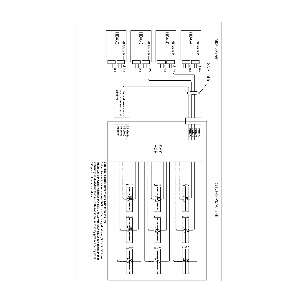
CLI Zoning Tool
007-5818-003 121
Figure 3-67 Block diagram of MIS-Server StorBrick SB0

122 007-5818-003
3: System Software
Disk RAID Support
The MIS Platform supports both software and hardware RAID, standard and nested. Disk
performance is improved because more than one disk can be accessed simultaneously. Fault
tolerance is improved because data loss caused by a hard drive failure can be recovered by
rebuilding missing data from the remaining data or parity drives.
The MIS Platform supports the following RAID levels:
• RAID 0 (striping without parity or mirroring, Figure 3-68)
• RAID 1 (mirrored without parity or striping, Figure 3-69)
• RAID 5 (striping with parity, Figure 3-70)
• RAID 6 (striping with dual parity, Figure 3-71)
• RAID 00 (spanned drive group striped set from a series of RAID 0 drive groups,
Figure 3-72)
• RAID 10 (mirrored stripes across spanned drive groups, Figure 3-73)
• RAID 50 (distributed parity and striping across spanned drive groups, Figure 3-74)
• RAID 60 (distributed parity, with two independent parity blocks per stripe in each RAID set,
and disk striping across spanned drive groups, Figure 3-75)
The onboard MIS server zoning application is supported in both Windows and Linux operating
systems. There is also an external FanBase CLI, where a system running either Windows or Linux
can be used to zone the JBOD in addition to MIS Servers. When LSI MegaRAID HBAs are used,
they support RAID 0, RAID 1, RAID 5 and RAID 6, along with their variants. Where ever
possible, the zoning and RAID selection for a MIS server should provide for the maximum
amount of availability in the event of a StorBrick failure. The StorBrick has four SAS lanes into
it from up to four SAS RAID HBAs. These SAS lanes are inputs to a SAS expander that connects
to the drives installed in the StorBrick. Since there are eight StorBrick in the MIS-Server, each
with nine drives, the highest availability for the data would be RAID groupings that span the
StorBricks. More information and examples provided in “RAID Configuration Notes” on
page 129.
Important: Unless specified, all systems ship as RAID 6.

Disk RAID Support
007-5818-003 123
RAID 0
Figure 3-68 RAID 0
A RAID 0 splits data evenly across two or more disks (striped) without parity information for
speed. RAID 0 provides no data redundancy. It provides improved performance and additional
storage, but no fault tolerance. RAID 0 is normally used to increase performance, although it can
also be used as a way to create a large logical disk out of a two or more physical ones. RAID 0
provides high data throughput, especially for large files in an environment that does not require
fault tolerance.
RAID 0 is useful for setups such as large read-only NFS servers, where mounting many disks is
time-consuming or impossible and redundancy is irrelevant. Any drive failure destroys the array,
and the likelihood of failure increases with more drives in the array (at a minimum, catastrophic
data loss is almost twice as likely compared to single drives without RAID). A single drive failure
destroys the entire array because when data is written to a RAID 0 volume, the data is broken into
fragments called blocks. The number of blocks is dictated by the stripe size, which is a
configuration parameter of the array. The blocks are written to their respective drives
simultaneously on the same sector. This allows smaller sections of the entire chunk of data to be
read off each drive in parallel, increasing bandwidth. RAID 0 does not implement error checking,
so any error is uncorrectable. More drives in the array means higher bandwidth, but greater risk
of data loss.
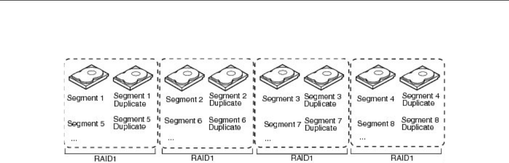
124 007-5818-003
3: System Software
RAID 1
Figure 3-69 RAID 1
A RAID 1 writes identically to two drives, thereby producing a “mirrored set” (at least two drives
are required to constitute such an array). This is useful when read performance or reliability is
more important than data storage capacity. Such an array can only be as big as the smallest
member disk. A classic RAID 1 mirrored pair contains two disks, which increases reliability
geometrically over a single disk. Since each member contains a complete copy of the data, and
can be addressed independently, ordinary wear-and-tear reliability is raised by the power of the
number of self-contained copies.
The array continues to operate as long as at least one drive is functioning. With appropriate
operating system support, there can be increased read performance, and only a minimal write
performance reduction; implementing RAID 1 with a separate controller for each drive in order to
perform simultaneous reads (and writes) is sometimes called multiplexing (or duplexing when
there are only two drives). RAID 1 is good for applications that require small capacity, but
complete data redundancy. (The server boot drive modules are configured for RAID 1.)
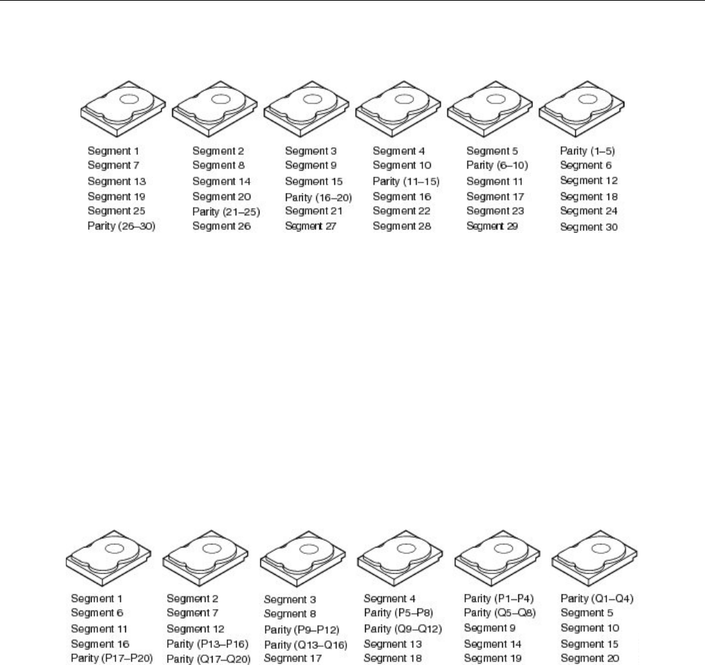
Disk RAID Support
007-5818-003 125
RAID 5
Figure 3-70 RAID 5
A RAID 5 uses block-level striping with parity data distributed across all member disks, creating
low-cost redundancy. In most implementations, a minimum of three disks is required for a
complete RAID 5 configuration. A concurrent series of blocks—one on each of the disks in an
array—is collectively called a stripe. The disk used for the parity block is staggered from one
stripe to the next, hence the term distributed parity blocks. RAID 5 writes are expensive in terms
of disk operations and traffic between the disks and the controller. RAID 5 striping and distributed
parity data across all drives provides high data throughput, especially for small, random access.
Fault tolerance is maintained by ensuring that the parity information for any given block of data
is placed on a drive separate from those used to store the data itself. The performance of a RAID
5 array can be “adjusted” by trying different stripe sizes until one is found that is well-matched to
the application being used.
RAID 6
Figure 3-71 RAID 6
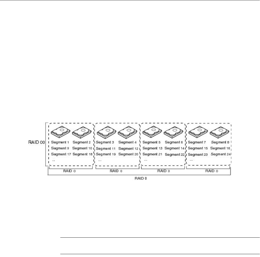
126 007-5818-003
3: System Software
RAID 6 (block-level striping with double distributed parity) extends RAID 5 by adding an
additional parity block. RAID 6 does not have a performance penalty for read operations, but it
does have a performance penalty on write operations because of the overhead associated with
parity calculations. Any form of RAID that can continue to execute read and write requests to all
of a RAID array's virtual disks in the presence of any two concurrent disk failures. This makes
larger RAID groups more practical, especially for high-availability systems. This becomes
increasingly important as large-capacity drives lengthen the time needed to recover from the
failure of a single drive. Single-parity RAID levels are as vulnerable to data loss as a RAID 0 array
until the failed drive is replaced and its data rebuilt; the larger the drive, the longer the rebuild
takes. Double parity gives additional time to rebuild the array without the data being at risk if a
single additional drive fails before the rebuild is complete. Like RAID 5, a single drive failure
results in reduced performance of the entire array until the failed drive has been replaced and the
associated data rebuilt.
RAID 00
Figure 3-72 RAID 00
A RAID 00 drive group is a spanned drive group that creates a striped set from a series of RAID
0 drive groups. RAID 00 does not provide any data redundancy, but along with RAID 0, RAID 00
offers the best performance of any RAID level. RAID 00 breaks up data into smaller segments and
stripes the data segments across each drive in the drive groups. The size of each data segment is
determined by the stripe size. RAID 00 offers high bandwidth.
Note: RAID level 00 is not fault tolerant. If a drive in a RAID 0 drive group fails, the whole virtual
drive (all drives associated with the virtual drive) fails.
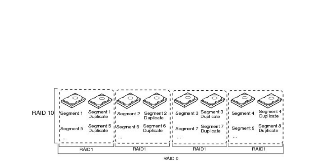
Disk RAID Support
007-5818-003 127
By breaking up a large file into smaller segments, the RAID controller can use both SAS drives
and SATA drives to read or write the file faster. RAID 00 involves no parity calculations to
complicate the write operation, which makes RAID 00 ideal for applications that require high
bandwidth but do not require fault tolerance. Figure 3-72 shows an example of a RAID 00 drive
group.
RAID 10
Figure 3-73 RAID 10
RAID 10 is a combination of RAID 0 and RAID 1 and consists of stripes across mirrored spans.
RAID 10 breaks up data into smaller blocks and mirrors the blocks of data to each RAID 1 drive
group. The first RAID 1 drive in each drive group then duplicates its data to the second drive. The
size of each block is determined by the stripe size parameter, which is set during the creation of
the RAID set. The RAID 1 virtual drives must have the same stripe size.
Spanning is used because one virtual drive is defined across more than one drive group. Virtual
drives defined across multiple RAID 1 level drive groups are referred to as RAID level 10, (1+0).
Data is striped across drive groups to increase performance by enabling access to multiple drive
groups simultaneously.
Each spanned RAID 10 virtual drive can tolerate multiple drive failures, as long as each failure is
in a separate drive group. If there are drive failures, less than the total drive capacity is available.
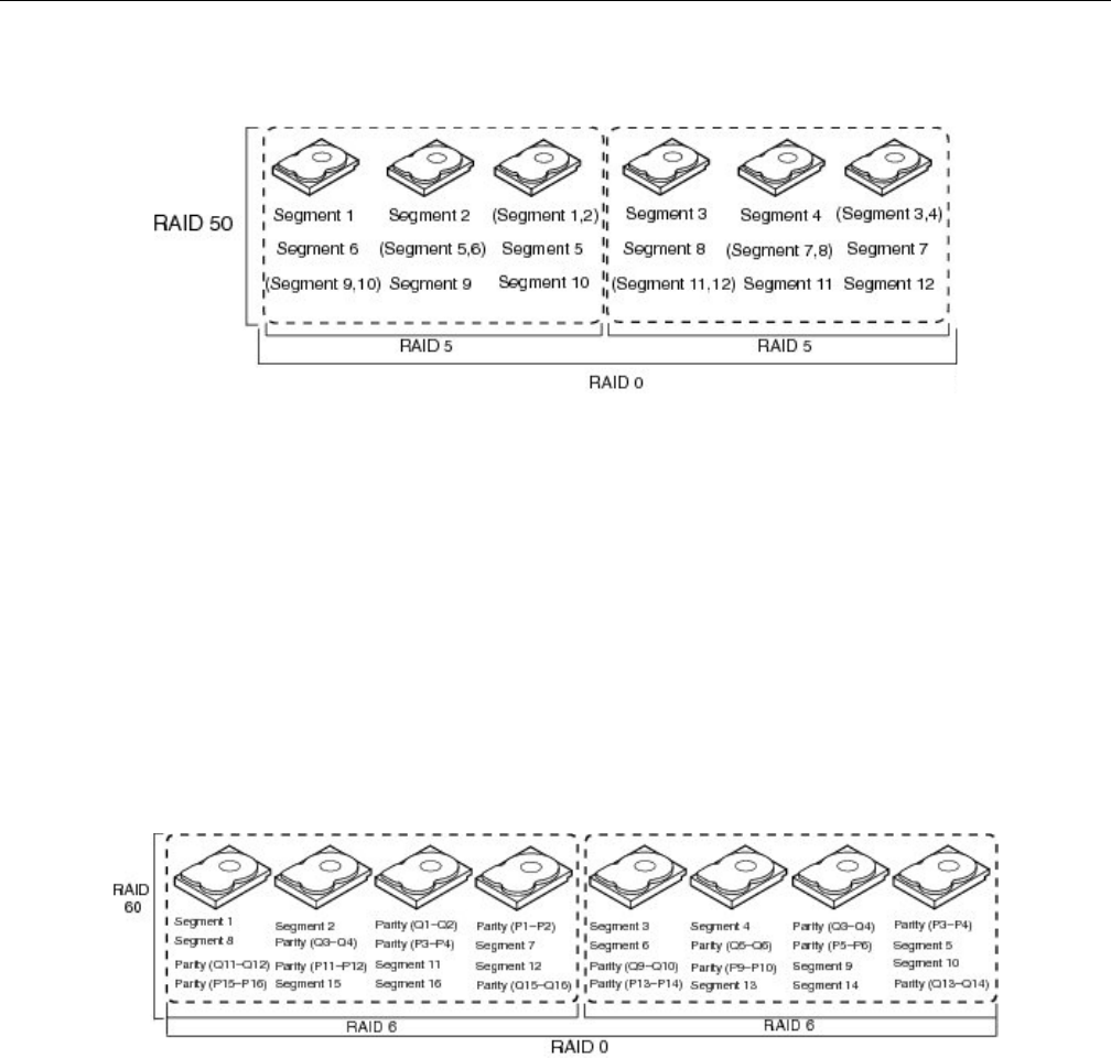
128 007-5818-003
3: System Software
RAID 50
Figure 3-74 RAID 50
A RAID 50 combines the straight block-level striping of RAID 0 with the distributed parity of
RAID 5. This is a RAID 0 array striped across RAID 5 elements. It requires at least 6 drives. RAID
50 improves upon the performance of RAID 5 particularly during writes, and provides better fault
tolerance than a single RAID level does. This level is recommended for applications that require
high fault tolerance, capacity and random positioning performance.
As the number of drives in a RAID set increases, and the capacity of the drives increase, this
impacts the fault-recovery time correspondingly as the interval for rebuilding the RAID set
increases. RAID 50 works best with data that requires high reliability, high request rates, high data
transfers, and medium-to-large capacity.
RAID 60
Figure 3-75 RAID 60
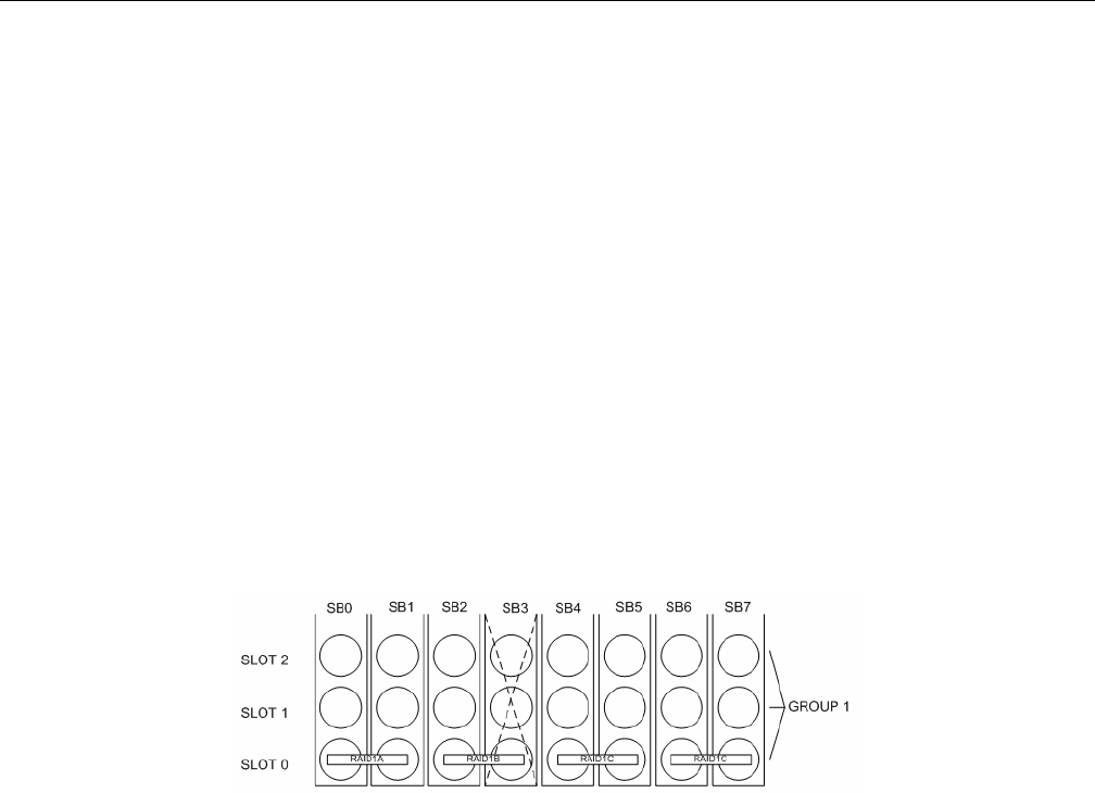
Disk RAID Support
007-5818-003 129
A RAID 60 combines the straight block-level striping of RAID 0 with the distributed double parity
of RAID 6. That is, a RAID 0 array striped across RAID 6 elements. As it is based on RAID 6,
two disks from each of the RAID 6 sets could fail without loss of data. Also failures while a single
disk is rebuilding in one RAID 6 set will not lead to data loss. RAID 60 has improved fault
tolerance, any two drives can fail without data loss and up to four total as long as it is only two
from each RAID 6 sub-array.
Striping helps to increase capacity and performance without adding disks to each RAID 6 set
(which would decrease data availability and could impact performance). RAID 60 improves upon
the performance of RAID 6. Despite the fact that RAID 60 is slightly slower than RAID 50 in
terms of writes due to the added overhead of more parity calculations, when data security is
concerned this performance drop may be negligible.
RAID Configuration Notes
To get the best availability, treat each drive brick as an enclosure. For a RAID 1 with only one
drive per StorBrick in the group, the loss of a StorBrick does not affect the availability of the data
(Figure 3-76).
Figure 3-76 RAID 1 with one drive per StorBrick
However, with two drives spanning a StorBrick, the loss of a StorBrick will cause the data to be
unavailable until the failed storbrick is replaced (Figure 3-77).
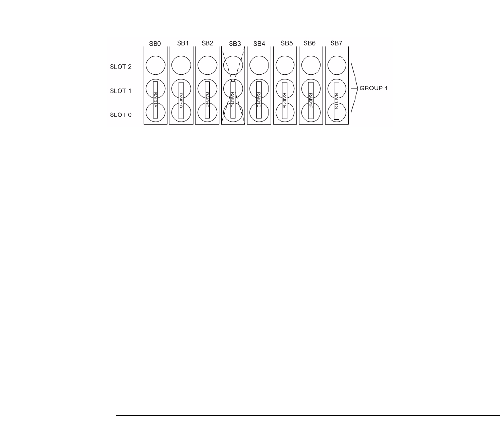
130 007-5818-003
3: System Software
Figure 3-77 RAID 1 with two drives spanning a StorBrick
For redundancy, choose one drive from each drive brick as you build the LUNs. Configure the
drives in a RAID group to span the StorBricks. For instance, configuring 8 drives from StorBrick
0 as a RAID5, 7+1 group will work. However, if that StorBrick (StorBrick 0) fails, all 8 drives
will become inaccessible, making that RAID group’s data unavailable until the StorBrick is
replaced.
If, however, drive 0 from each StorBrick (SB0-0, SB1-0, SB2-0, SB3-0, SB4-0, SB5-0,
SB6-0 and SB7-0) is used to make up the RAID 5, 7+1 group, and any StorBrick were to fail,
only one drive of that group would be affected. The RAID 5 algorithm would be able to recover
the data from the remaining drives and the RAID group would remain available. Configurations
varies based on needs for capacity versus protection.
There is also the option to assign both a RAID group dedicated spare drive or a global spare drive.
For example, a RAID 5 group could be a 6+1 with a dedicated spare drive. In a full up system you
would have 9 sets of these RAID groups, all spread across the StorBricks. One method for greater
capacity is available by configuring 8 groups of 7+1, one group of 6+1 and a global spare. In a
RAID 6 6+2, a spare my not be desirable at all, as one is already part of the group automatically.
For configurations that maximize storage, can allow unavailability of data for a time and/or predict
a high-success rate for StorBricks, very large RAID groups may be desirable. For typical RAID
usage, RAID 5 7+1 or RAID 6 6+2 are most likely.
Warning: Do not configure multiple drives in a RAID group to be on the same StorBrick.
Since there are eight StorBrick in the MIS-Server, each with nine drives, the highest availability
for the data would be RAID groupings that span the StorBricks. For example, a RAID 6
configuration should have eight drives, one from each StorBrick. In this configuration, if a
StorBrick failed, the data would still be available. For RAID 5 or RAID 6, with one drive per
StorBrick in a group, the loss of a StorBrick (SB3) does not affect the availability of the data
(Figure 3-78).
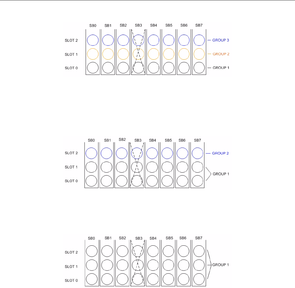
Disk RAID Support
007-5818-003 131
Figure 3-78 RAID 5 or 6 with one drive per StorBrick
If a larger RAID group is desired, it would have to have multiple drives on a StorBrick. Then if a
StorBrick were to fail, two drives would be unavailable. If this were a RAID 6 implementation,
the data would still be available, though another StorBrick failure or even a drive failure in that
group would cause a loss of data availability. If this were a RAID 5 implementation, the data
would become unavailable until the failed StorBrick is replaced (Figure 3-79).
Figure 3-79 Loss of a drive with multiple drives on a StorBrick does not affect RAID 6, but will impact
RAID 5
For RAID 6 with three drives of the group spanning a StorBrick, the data is unavailable until the
failed StorBrick is replaced (Figure 3-80).
Figure 3-80 Three drive loss in RAID 6 require StorBrick replacement


007-5818-003 133
Chapter 4
4. System Maintenance
For warranty and safety considerations, SGI designates the following chassis components as
customer-replaceable units (CRUs):
• Power supplies
•Fans
• Disk drives
These components are all hot-swappable; that is, you can replace them without powering down
the storage server. A trained service technician should install and replace all other components.
This chapter describes how you replace the CRUs and check the system airflow:
• “Detecting Component Failures” on page 134
• “Sliding the Chassis Forward/Backwards” on page 134
• “Removing the Front or Rear Chassis Cover” on page 134
• “Replacing a Power Supply” on page 135
• “Replacing a Fan Module” on page 136
• “Replacing a Disk Drive” on page 137
• “Checking the System Air Flow” on page 140
Tools Required: The only tool you will need to perform maintenance is a #1 and #2 Phillips
screwdriver.
Warning: Review the warnings and precautions listed in, “Important Information” on
page xix, before setting up or servicing this chassis.
!

134 007-5818-003
4: System Maintenance
Detecting Component Failures
In general, when a system component fails, the operating system/storage management system
(OS/SMS) receives an alert. The OS/SMS generates an alert to the monitoring application for your
storage server. The alerts include the system serial number, the suspect component, and a
summary of the fault. For most components, you should inform SGI service of the fault and
forward the information from the alerts.
In addition to the alerts, the control panel on the chassis front panel can indicate component
failures in the case of power supplies, fans, and drives. See Chapter 2, “System Interfaces”.
For more information about alert generation and management, see “Power Supply LEDs” on
page 29.
Sliding the Chassis Forward/Backwards
The cable management system of the MIS chassis allows it to be slid forward (20") or backwards
(18"). You will need to slide the chassis out to service some of its components. To slide the chassis
out, follow these steps:
1. Push the two release latches in, at the front and rear, towards the center of the chassis.
2. Pull the chassis out using the handles. The chassis will latch at the 20- or 18-inch limit.
3. To slide the chassis back in, depress the two release latches near the rail and slide it back in.
Removing the Front or Rear Chassis Cover
Important: When a chassis cover is removed, an intrusion sensor monitored by the SMS will
detect its removal. If the cover is off for more than 15 minutes or any system temperature sensor
exceeds its threshold limit, the server will perform an orderly shutdown and power-off.
As shown in Figure 4-1, the top of the chassis is bifurcated; that is, there is a front and rear chassis
cover. Except for power supply maintenance, all service actions require that you remove the front
or rear chassis cover. This section describes the steps.
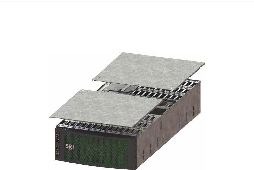
Replacing a Power Supply
007-5818-003 135
1. To remove a chassis cover, first follow the instructions in “Sliding the Chassis
Forward/Backwards” on page 134.
2. Remove the single security screw from the cover.
3. Push the detent, and slide the cover out and up from the chassis.
Figure 4-1 Front & Rear Chassis Covers
Replacing a Power Supply
To replace a failed power supply, do the following:
1. Using the OS/SMS interface for your system, verify the fault (failed unit) and its location.
2. Locate the failed unit: it should have a lighted yellow service LED. See Figure 4-2.
3. Unplug the power supply that will be replaced.
4. Push the release tab on the back of the power supply.
5. Pull the power supply out using the handle.
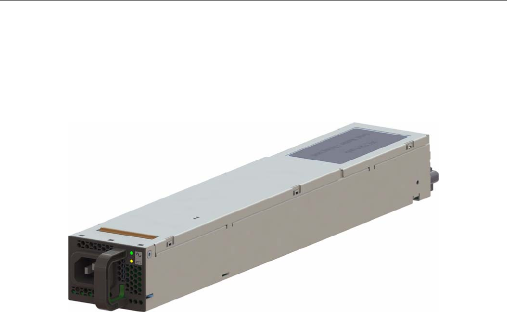
136 007-5818-003
4: System Maintenance
6. Replace the failed power module with another of the same model.
7. Push the new power supply module into the power bay until it clicks into the locked position.
8. Plug the AC power cord back into the module and power up the server.
9. Once power supply is verified good, clear the service required status via the OS/SMS
interface.
Figure 4-2 Replacing a Power Supply
Replacing a Fan Module
To replace a fan module, do the following:
1. Using the OS/SMS for your system, verify the fault (failed unit).
2. Using the OS/SMS, set the system to a service state for the removal of the faulted fan. The
OS/SMS will turn off the fan module. It will then turn on the locator LED (blue) for that fan
module.
3. Remove the front chassis cover. (See “Removing the Front or Rear Chassis Cover” on
page 134.)
4. Locate the fan module with the illuminated blue LED (Figure 4-3).
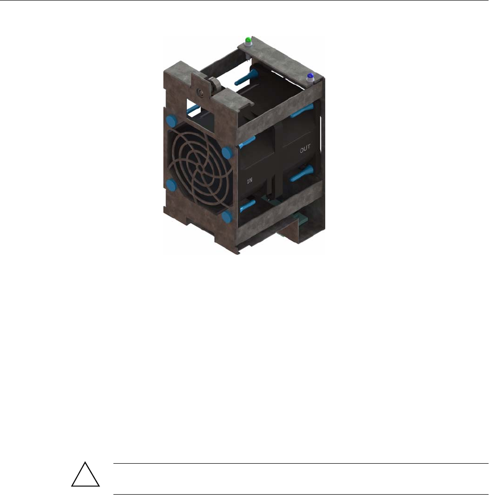
Replacing a Disk Drive
007-5818-003 137
Figure 4-3 Replacing a Fan Module
5. Loosen the thumbscrew, pull out the faulted fan by pulling upward on both the front and rear
flanges, and replace it.
6. Once the fan module is replaced, seat the fan by pushing between the two leds until it seats.
7. Re-install the chassis cover and security screw.
8. Unlock the chassis from the extended position and push it back until it locks into the stowed
position.
9. Using your OS/SMS, return the system to a normal state and the new fan module will be
powered on.
Replacing a Disk Drive
Important: Empty drive carriers cannot be inserted into the storbricks, so slots without HDDs
will not have carriers.
!

138 007-5818-003
4: System Maintenance
To replace a failed disk drive:
1. Using the OS/SMS for your system, verify the fault (failed unit).
2. Using the OS/SMS, set the system to a service state for the removal of the faulted drive. The
OS/SMS will turn off the drive. It will then turn on the locator LED (blue) for that drive.
3. Remove the chassis cover. (See “Removing the Front or Rear Chassis Cover” on page 134.)
4. Locate the faulted drive with the illuminated blue LED and remove it from its StorBrick (or
boot drive bay). (See “Removing the Drive” on page 138.)
5. Replace the faulted drive. (See “Re-installing the Drive” on page 139.)
6. Once the drive is replaced, re-install the chassis cover and security screw.
7. Unlock the chassis from the extended position and push it back until it locks into the stowed
position.
8. Using the OS/SMS, return the system to a normal state. The new drive will be powered on.
9. Using the OS/SMS, clear the service required status. At this time the rebuild or mirroring of
the data to the new drive will begin.
Removing the Drive
As shown in Figure 4-4, the drives are mounted in driver carriers to simplify their installation and
removal from the drive bricks or boot drive bays in the chassis.
To remove the drive, perform the following steps:
1. Ensure that the drive LEDs are off (except the blue locator LED), indicating that the drive is
not in use and can be removed.
2. Unlatch the drive carrier by sliding the grey latch toward the drive and pull the drive carrier
out of the StorBrick or boot drive bay.
3. Remove the four screws that secure the drive to the drive carrier.
4. Remove the drive from the carrier.
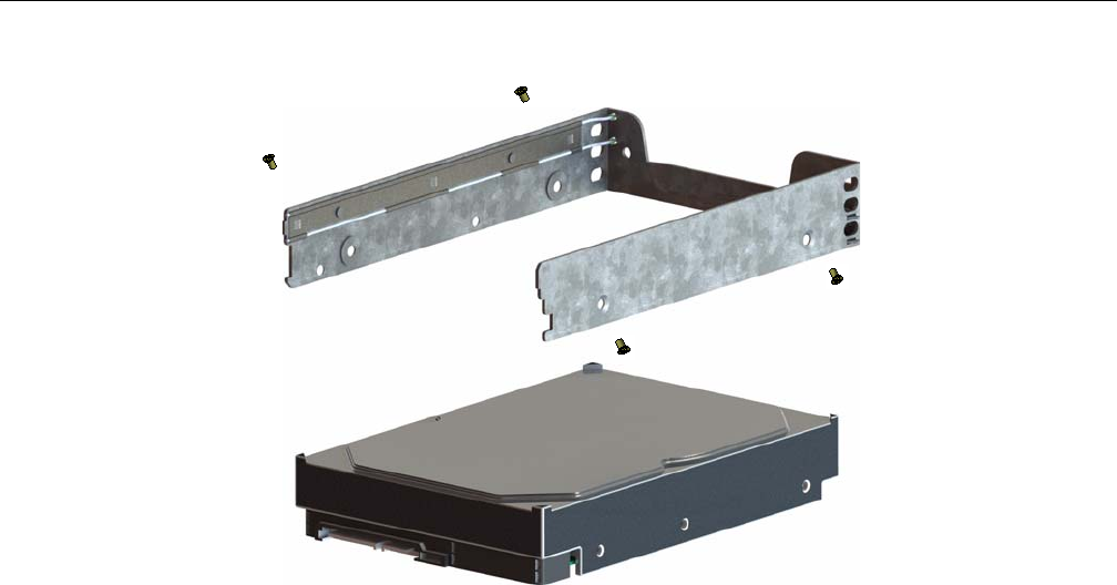
Replacing a Disk Drive
007-5818-003 139
Figure 4-4 Hard Drive Carrier
Re-installing the Drive
To re-install a hard drive into the hard drive carrier, perform the following steps:
1. Place the hard drive carrier on a flat, stable surface such as a desk, table, or work bench.
2. Slide the hard drive into the carrier with the printed circuit board side facing down.
3. Carefully align the mounting holes in the hard drive and the carrier.
Make sure the bottom of the hard drive and bottom of the hard drive carrier are flush.
4. Secure the hard drive using the four screws (see Figure 4-4).
5. Replace the drive carrier into the chassis.
6. Push the drive carrier down to lock it place.
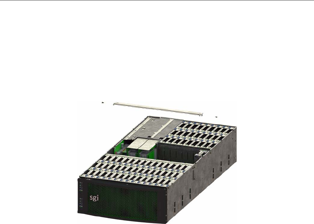
140 007-5818-003
4: System Maintenance
Checking the System Air Flow
To check the air flow for an MIS enclosure, perform the following steps:
1. Remove the chassis cover. (See “Removing the Front or Rear Chassis Cover” on page 134)
2. Remove the midspan: unscrew the Phillips screws from either end of the brace, and lift away
the brace.
3. Make sure there are no objects wires or foreign objects obstruct air flow through the chassis.
Pull all excess cabling out of the airflow path.
Figure 4-5 MIS Chassis Midspan Support Brace

007-5818-003 141
Chapter 5
5. Troubleshooting
This chapter describes troubleshooting for the problems listed below. Chapter 2, “System
Interfaces,” describes use of the control panel to monitor the overall system status and the status
of specific components. Chapter 4, “System Maintenance,”describes how to replace defective
components.
• “No Video” on page 141
• “Losing the System’s Setup Configuration” on page 141
• “I/O Time-outs and MegaRAID Drivers” on page 142
• “Safe Power-Off” on page 142
For help beyond what is mentioned in this document, see “Product Support” on page xxv.
No Video
If the power is on but there is no video, remove all add-on cards and cables. Use the speaker to
determine if any beep codes exist. Refer to Appendix B, “BIOS Error Codes” for details.
Losing the System’s Setup Configuration
Make sure that you are using a high quality power supply. A poor quality power supply may cause
the system to lose the CMOS setup information. If this does not fix the Setup Configuration
problem, contact your vendor for repairs.

142 007-5818-003
5: Troubleshooting
I/O Time-outs and MegaRAID Drivers
To avoid I/O time-outs with certain workloads, the megaraid_sas driver needs to have the
poll_mode_io variable set to 1. For Novell operating systems on SGI InfiniteStorage servers,
the file /etc/modprobe.conf.local needs the following line added:
options megaraid_sas poll_mode_io=1
This modification will be made on systems shipped from the factory, but if a system is installed
or upgraded in the field, this change will have to be made after installation/upgrade.
Safe Power-Off
There are several safe power-off methods for an MIS Server or JBOD. They include,
• Using the OS GUI power-off button at the console screen, if a keyboard/mouse/video
monitor is connected.
• Pushing and holding the Power button on the front panel (see Figure 2-1 on page 26).
• When logged in via an ssh session and executing a “shutdown” or “poweroff”
command.
• When logged in to the BMC and using the power control page to power off the sever.
• Using the remote console screen GUI power-off button, if a KVM RMM4Lite session is
established through the BMC.
If the platform is an MIS dual-server and both servers are powered up, performing the above steps
only powers off the server with which you are working. The fans, drives and second server will
remain powered on until the second server is powered off, then all power (but standby) will be
turned off.
For a JBOD Unit, the power button on the front panel will turn off the power to that I/O module.
If a second module is installed and powered on, it, the fans and the drives will remain on until it,
too, is powered off.
007-5818-003 143
Appendix A
A. Technical Specifications
Table A-1 describes the technical specifications for the SGI MIS platform.
Table A-1 Technical Specifications
Attribute Specification
Overview
Profile 4U Standard-depth chassis
Product type SGI MIS Server Platform (single or dual server), or SGI MIS JBOD
Unit
Connectivity Up to four SGI MIS JBOD units per SGI MIS Dual Server
Mount –Standard 19-inch rack-compatible rail mount (weight-dependent)
–SGI 19-inch Destination Rack (D-Rack), 42U
–Up to 10 chassis per D-Rack
Chassis Dimensions
Height 6.94" (176 mm)
Width 16.9" (429.2 mm)
Depth 36" (914.4 mm)
Max weight 220 lbs.
Power
AC Input 100–240 VAC (50-60Hz), single or three phase
Safety –UL/CSA certified to UL6050-1
–CE/CB certified to EN60950/IEC60950
EMC –North America FCC Class A
–Europe EN55022/EN55024
Operating Environment

144 007-5818-003
A: Technical Specifications
Operating
temperature
range
–41º to 95º F (5º to 35º C)
–processor cores automatically allowed to run faster than the base
operating frequency, if the cores are operating below power, current,
and temperature specification limits (< 35ºC ambient)
Non-operating
temperature
range
-40º to 140º F (minus 40º to 60º C)
Operating
humidity range
10% to 90% non-condensing
Non-operating
Humidity
10% to 95% non-condensing
SGI MIS Server Specifications
Servers/System –One or two server modules per system
–Single- or dual-socket processors per server
Processor support –Supports Intel® Xeon® E5-2600 series processors
–Supports Intel Turbo Boost Technology 2.0
Max cores 16 per server (32 per system)
Memory –Up to 8 DDR3 DIMMs (4 GB, 8 GB, or 16 GB) for a single-server
motherboard configuration
–Up to 16 DIMMs for a dual-server motherboard configuration.
–Max 128GB per server
Boot drives –Two per server, mirrored using RAID 1
–3.5" or 2.5" (15mm or 9.5mm)
–SAS or SATA
–Rotational or SSD
–Up to 300 GB
Supported
operating
systems
–RHEL 6.2
–SLES 11 SP1
–VMware ESX 5.0
–Windows 2008 R2 SP1
Networking Up to four user-specified PCIe HBAs, full-height (4.25") and half-depth
(3.375"), externally or internally facing
Table A-1 Technical Specifications (continued)
Attribute Specification

007-5818-003 145
Expansion slots Single server: 6 x PCIe gen 2
Dual server: 4 x PCIe gen 2 per server (8 total)
RAID controllers –8 to 32 SAS ports via 8-port PCIe cards
–Support for RAID 0, 1, 5, 6, 00, 10, 50, and 60
External storage
attachment
Up to 4 SGI MIS JBOD Units via PCIe cards
Internal storage –Up to 81 SAS or SATA 15mm, 2.5" or 3.5" drives
–Up to 162 SAS or SATA 9.5mm, 2.5" drives
–Drive size and capacity can be mixed in groups of 8
–Supported internal drives: SAS or SATA, rotational or SSD
SGI MIS JBOD Specifications
Internal Storage –Up to 81 SAS or SATA 15mm, 2.5" or 3.5" drives
–Up to 162 SAS or SATA 9.5mm, 2.5" drives
–Drive type and size can be mixed in groups of 9
–Supported internal drives: SAS or SATA, rotational or SSD
Connectivity 8 or optional 16 SAS ports
Table A-1 Technical Specifications (continued)
Attribute Specification

007-5818-003 147
Appendix B
B. BIOS Error Codes
The BMC may generate beep codes upon detection of failure conditions. Beep codes are sounded
each time the problem is discovered (for example, on each power-up attempt) but are not sounded
continuously. Common supported codes are listed in Table B-1.
In Table B-1, each digit in the code is represented by a sequence of beeps whose count is equal to
the digit.
Table B-1 BMC Beep Codes
Beep Code Reason for Beep Associated
Sensors Supported
1-5-2-1 No CPUs installed or first CPU socket is
empty.
CPU Missing sensor Yes
1-5-2-4 MSID Mismatch. MSID Mismatch
sensor.
Yes
1-5-4-2 Power fault: DC power is unexpectedly
lost (power good dropout).
Power unit—power
unit failure offset.
Yes
1-5-4-4 Power control fault (power good assertion
time-out).
Power unit—soft
power control failure
offset.
Yes
1-5-1-2 VR Watchdog Timer sensor assertion VR Watchdog timer
1-5-1-4 The system does not power on or
unexpectedly powers off and a power
supply unit (PSU) is present that is an
incompatible model with one or more
other PSUs in the system.
PSU status

007-5818-003 149
Appendix C
C. Zone Permission Groups Rules
There three group controls within the expanders that must be set. These are Allow Broadcast,
Allow Zoning and Phy (Physical) Changes, and Unassigned Slot Group. The Allow Broadcast
bit is set to that the sever can send and receive broadcasts. The Allow Zoning and Phy Changes
bit is set so that hot-swapping drives is allowed. The Unassigned Slot Group bit is set so that
drives that are yet to be zoned are still recognized by the system.
The first 8 bits are the Master Group. The first bit (0) has access to bit 1 and nothing else. This is
why the Master Group 0 is always set to 0, to avoid an extra step. Master Group 1 is all FF—it
“sees” everyone. Master Groups 2 & 3 talk to all the Initiators (bits 8-15), and currently, Master
Groups 4-7 point up to Master Group 1 (this may change in the future).
The next 8 bits are the Initiator Groups. Bit 8 through 11 corresponds to Adapter 1, Paths 0
through 3 and bits 12-15 correspond to Adapter 2, Paths 4 through 7. The next 16 through 24 bits
are the zone permission groups, with the 25th bit always set for the unassigned slot. The remaining
bits are reserved for future use. See Figure C-1 and Figure C-2 for examples.
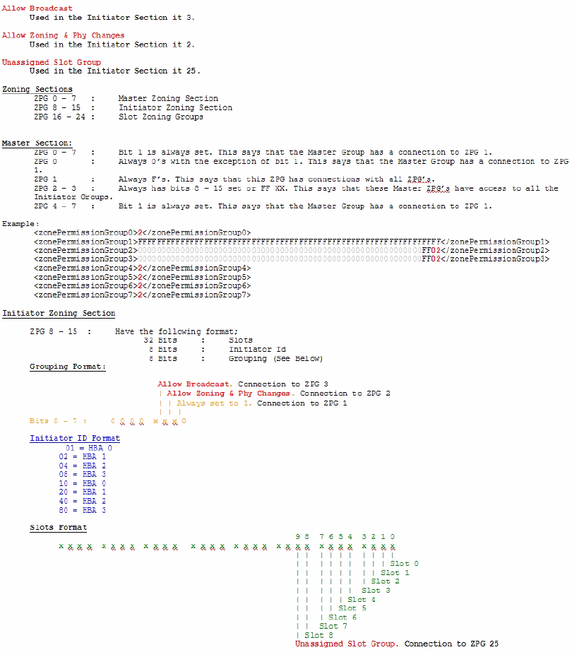
Figure C-1 Zone Permission Groups – Example 1
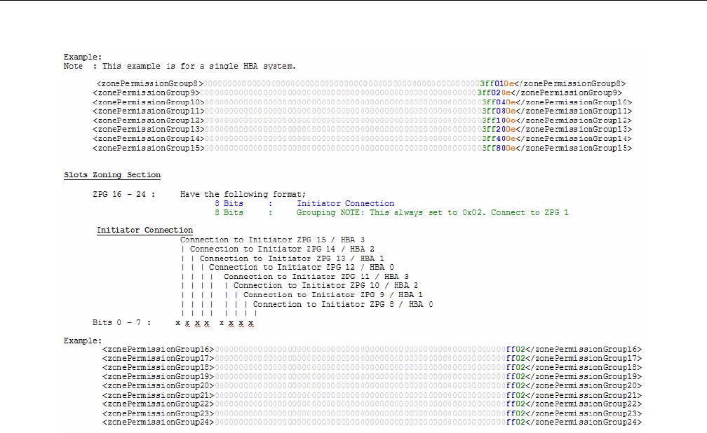
007-5818-003 151
Figure C-2 Zone Permission Groups – Example 2

152 007-5818-003
C: Zone Permission Groups Rules
