007 5828 001
User Manual: 007-5828-001
Open the PDF directly: View PDF ![]() .
.
Page Count: 1383 [warning: Documents this large are best viewed by clicking the View PDF Link!]
- Table of Contents
- SANtricity ES Concepts for Version 10.77
- Storing Your Data
- Introducing the Storage Management Software
- Configuring the Storage Arrays
- Maintaining and Monitoring Storage Arrays
- Glossary
- Site Preparation
- Specifications of the Model 3040 40U Cabinet
- Model 3040 40U Cabinet Configurations
- Model 3040 40U Cabinet Dimensions
- Model 3040 40U Cabinet Weights
- Model 3040 40U Cabinet Temperature and Humidity
- Model 3040 40U Cabinet Altitude Ranges
- Model 3040 40U Cabinet Airflow, Heat Dissipation, and Service Clearances
- Model 3040 40U Cabinet Site Wiring and Power
- Model 3040 40U Cabinet Power Requirements
- Model 3040 40U Cabinet Grounding
- Model 3040 40U Cabinet Power Distribution
- Model 3040 40U Cabinet Power Cords and Receptacles
- Specifications of the CE7900 Controller Tray
- CE7900 Controller Tray Dimensions
- CE7900 Controller Tray Weight
- CE7900 Controller Tray Shipping Dimensions
- CE7900 Controller Tray Temperature and Humidity
- CE7900 Controller Tray Altitude Ranges
- CE7900 Controller Tray Airflow and Heat Dissipation
- CE7900 Controller Tray Acoustic Noise
- CE7900 Controller Tray Site Wiring and Power
- CE7900 Controller Tray Power Cords and Receptacles
- Preparing the Network for the Controllers
- Specifications of the CE7922 Controller Tray
- CE7922 Controller Tray Dimensions
- CE7922 Controller Tray Weight
- CE7922 Controller Tray Shipping Dimensions
- CE7922 Controller Tray Temperature and Humidity
- CE7922 Controller Tray Altitude Ranges
- CE7922 Controller Tray Airflow and Heat Dissipation
- CE7922 Controller Tray Acoustic Noise
- CE7922 Controller Tray Site Wiring and Power
- CE7922 Controller Tray Power Cords and Receptacles
- Preparing the Network for the Controllers
- Specifications of the CE6998 Controller Tray
- CE6998 Controller Tray Dimensions
- CE6998 Controller Tray Weight
- CE6998 Controller Tray Shipping Dimensions
- CE6998 Controller Tray Temperature and Humidity
- CE6998 Controller Tray Altitude Ranges
- CE6998 Controller Tray Airflow and Heat Dissipation
- CE6998 Controller Tray Acoustic Noise
- CE6998 Controller Tray Site Wiring and Power
- CE6998 Controller Tray Power Cords and Receptacles
- Preparing the Network for the Controllers
- Specifications of the CDE2600 Controller-Drive Tray
- CDE2600 Controller-Drive Tray Dimensions
- CDE2600 Controller-Drive Tray Weight
- CDE2600 Controller-Drive Tray Shipping Dimensions
- CDE2600 Controller-Drive Tray Temperature and Humidity
- CDE2600 Controller-Drive Tray Altitude Ranges
- CDE2600 Controller-Drive Tray Airflow and Heat Dissipation
- CDE2600 Controller-Drive Tray Acoustic Noise
- CDE2600 Controller-Drive Tray Site Wiring and Power
- CDE2600 Controller-Drive Tray Power Input
- CDE2600 Controller-Drive Tray Power Factor Correction
- CDE2600 Controller-Drive Tray AC Power Cords and Receptacles
- CDE2600 Controller-Drive Tray Optional DC Power Connector Cables and Source Wires
- Preparing the Network for the Controllers
- Specifications of the CDE2600-60 Controller-Drive Tray
- CDE2600-60 Controller-Drive Tray Dimensions
- CDE2600-60 Controller-Drive Tray Weight
- CDE2600-60 Controller-Drive Tray Shipping Dimensions
- CDE2600-60 Controller-Drive Tray Temperature and Humidity
- CDE2600-60 Controller-Drive Tray Altitude Ranges
- CDE2600-60 Controller-Drive Tray Airflow and Heat Dissipation
- CDE2600-60 Controller-Drive Tray Acoustic Noise
- CDE2600-60 Controller-Drive Tray Site Wiring and Power
- CDE2600-60 Controller-Drive Tray Power Input
- CDE2600-60 Controller-Drive Tray Power Factor Correction
- CDE2600-60 Controller-Drive Tray AC Power Cords and Receptacles
- Preparing the Network for the Controllers
- Specifications of the CDE4900 Controller-Drive Tray
- CDE4900 Controller-Drive Tray Dimensions
- CDE4900 Controller-Drive Tray Weight
- CDE4900 Controller-Drive Tray Shipping Dimensions
- CDE4900 Controller-Drive Tray Temperature and Humidity
- CDE4900 Controller-Drive Tray Altitude Ranges
- CDE4900 Controller-Drive Tray Airflow and Heat Dissipation
- CDE4900 Controller-Drive Tray Acoustic Noise
- CDE4900 Controller-Drive Tray Site Wiring and Power
- CDE4900 Controller-Drive Tray Power Input
- CDE4900 Controller-Drive Tray Power Factor Correction
- CDE4900 Controller-Drive Tray AC Power Cords and Receptacles
- CDE4900 Controller-Drive Tray Optional DC Power Connector Cables and Source Wires
- Preparing the Network for the Controllers
- Specifications of the CDE3994 Controller-Drive Tray
- CDE3994 Controller-Drive Tray Dimensions
- CDE3994 Controller-Drive Tray Weight
- CDE3994 Controller-Drive Tray Shipping Dimensions
- CDE3994 Controller-Drive Tray Temperature and Humidity
- CDE3994 Controller-Drive Tray Altitude Ranges
- CDE3994 Controller-Drive Tray Airflow and Heat Dissipation
- CDE3994 Controller-Drive Tray Acoustic Noise
- CDE3994 Controller-Drive Tray Site Wiring and Power
- CDE3994 Controller-Drive Tray Power Input
- CDE3994 Controller-Drive Tray Power Factor Correction
- CDE3994 Controller-Drive Tray AC Power Cords and Receptacles
- CDE3994 Controller-Drive Tray Optional DC Power Connector Cables and Source Wires
- Preparing the Network for the Controllers
- Specifications of the AM1331 and AM1333 Controller-Drive Trays
- AM1331and AM1333 Controller-Drive Tray Dimensions
- AM1331 and AM1333 Controller-Drive Trays Weight
- AM1331 and AM1333 Controller-Drive Trays Shipping Dimensions
- AM1331 and AM1333 Controller-Drive Trays Temperature and Humidity
- AM1331 and AM1333 Controller-Drive Trays Altitude Ranges
- AM1331 and AM1333 Controller-Drive Trays Airflow and Heat Dissipation
- AM1331 and AM1333 Controller-Drive Trays Acoustic Noise
- AM1331 and AM1333 Controller-Drive Trays Site Wiring and Power
- AM1331 and AM1333 Controller-Drive Trays Power Input
- AM1331 and AM1333 Controller-Drive Trays Power Factor Correction
- AM1331 and AM1333 Controller-Drive Trays AC Power Cords and Receptacles
- AM1331 and AM1333 Controller-Drive Trays Optional DC Power Connector Cables and Source Wires
- Preparing the Network for the Controllers
- Specifications of the AM1532 Controller-Drive Tray
- AM1532 Controller-Drive Tray Dimensions
- AM1532 Controller-Drive Tray Weight
- AM1532 Controller-Drive Tray Shipping Dimensions
- AM1532 Controller-Drive Tray Temperature and Humidity
- AM1532 Controller-Drive Tray Altitude Ranges
- AM1532 Controller-Drive Tray Airflow and Heat Dissipation
- AM1532 Controller-Drive Tray Acoustic Noise
- AM1532 Controller-Drive Tray Site Wiring and Power
- AM1532 Controller-Drive Tray Power Input
- AM1532 Controller-Drive Tray Power Factor Correction
- AM1532 Controller-Drive Tray AC Power Cords and Receptacles
- AM1532 Controller-Drive Tray Optional DC Power Connector Cables and Source Wires
- Preparing the Network for the Controllers
- Specifications of the AM1932 Controller-Drive Tray
- AM1932 Controller-Drive Tray Dimensions
- AM1932 Controller-Drive Tray Weight
- AM1932 Controller-Drive Tray Shipping Dimensions
- AM1932 Controller-Drive Tray Temperature and Humidity
- AM1932 Controller-Drive Tray Altitude Ranges
- AM1932 Controller-Drive Tray Airflow and Heat Dissipation
- AM1932 Controller-Drive Tray Acoustic Noise
- AM1932 Controller-Drive Tray Site Wiring and Power
- AM1932 Controller-Drive Tray Power Input
- AM1932 Controller-Drive Tray Power Factor Correction
- AM1932 Controller-Drive Tray AC Power Cords and Receptacles
- AM1932 Controller-Drive Tray Optional DC Power Connector Cables and Source Wires
- Preparing the Network for the Controllers
- Specifications of the DE1600 Drive Tray
- DE1600 Drive Tray Dimensions
- DE1600 Drive Tray Weight
- DE1600 Drive Tray Shipping Dimensions
- DE1600 Drive Tray Temperature and Humidity
- DE1600 Drive Tray Altitude Ranges
- DE1600 Drive Tray Airflow and Heat Dissipation
- DE1600 Drive Tray Acoustic Noise
- DE1600 Drive Tray Site Wiring and Power
- DE1600 Drive Tray Power Input
- DE1600 Drive Tray Power Factor Correction
- DE1600 Drive Tray AC Power Cords and Receptacles
- DE1600 Drive Tray Optional DC Power Connector Cables and Source Wires
- Specifications of the DE5600 Drive Tray
- DE5600 Drive Tray Dimensions
- DE5600 Drive Tray Weight
- DE5600 Drive Tray Shipping Dimensions
- DE5600 Drive Tray Temperature and Humidity
- DE5600 Drive Tray Altitude Ranges
- DE5600 Drive Tray Airflow and Heat Dissipation
- DE5600 Drive Tray Acoustic Noise
- DE5600 Drive Tray Site Wiring and Power
- DE5600 Drive Tray AC Power Input
- DE5600 Drive Tray Power Factor Correction
- DE5600 Drive Tray AC Power Cords and Receptacles
- DE5600 Drive Tray Optional DC Power Connector Cables and Source Wires
- Specifications of the DE6600 Drive Tray
- DE6600 Drive Tray Dimensions
- DE6600 Drive Tray Weight
- DE6600 Drive Tray Shipping Dimensions
- DE6600 Drive Tray Temperature and Humidity
- DE6600 Drive Tray Altitude Ranges
- DE6600 Drive Tray Airflow and Heat Dissipation
- DE6600 Drive Tray Acoustic Noise
- DE6600 Drive Tray Site Wiring and Power
- DE6600 Drive Tray Power Input
- DE6600 Drive Tray Power Factor Correction
- DE6600 Drive Tray AC Power Cords and Receptacles
- Specifications of the DE6900 Drive Tray
- DE6900 Drive Tray Dimensions
- DE6900 Drive Tray Weight
- DE6900 Drive Tray Shipping Dimensions
- DE6900 Drive Tray Temperature and Humidity
- DE6900 Drive Tray Altitude Ranges
- DE6900 Drive Tray Airflow and Heat Dissipation
- DE6900 Drive Tray Acoustic Noise
- DE6900 Drive Tray Site Wiring and Power
- DE6900 Drive Tray Power Input
- DE6900 Drive Tray Power Factor Correction
- DE6900 Drive Tray AC Power Cords and Receptacles
- Specifications of the FC4600 Drive Tray
- FC4600 Drive Tray Dimensions
- FC4600 Drive Tray Weight
- FC4600 Drive Tray Shipping Dimensions
- FC4600 Drive Tray Temperature and Humidity
- FC4600 Drive Tray Altitude Ranges
- FC4600 Drive Tray Airflow and Heat Dissipation
- FC4600 Drive Tray Acoustic Noise
- FC4600 Drive Tray Site Wiring and Power
- FC4600 Drive Tray Power Input
- FC4600 Drive Tray Power Factor Correction
- FC4600 Drive Tray AC Power Cords and Receptacles
- FC4600 Drive Tray Optional DC Power Connector Cables and Source Wires
- Specifications of the AT2655 Drive Tray
- AT2655 Drive Tray Dimensions
- AT2655 Drive Tray Weight
- AT2655 Drive Tray Shipping Dimensions
- AT2655 Drive Tray Temperature and Humidity
- AT2655 Drive Tray Altitude Ranges
- AT2655 Drive Tray Airflow and Heat Dissipation
- AT2655 Drive Tray Acoustic Noise
- AT2655 Drive Tray Site Wiring and Power
- AT2655 Drive Tray Power Input
- AT2655 Drive Tray Power Factor Correction
- AT2655 Drive Tray Power Cords and Receptacles
- Specifications of the FC2610 Drive Tray
- FC2610 Drive Tray Dimensions
- FC2610 Drive Tray Weight
- FC2610 Drive Tray Shipping Dimensions
- FC2610 Drive Tray Temperature and Humidity
- FC2610 Drive Tray Altitude Ranges
- FC2610 Drive Tray Airflow and Heat Dissipation
- FC2610 Drive Tray Acoustic Noise
- FC2610 Drive Tray Site Wiring and Power
- FC2610 Drive Tray Power Input
- FC2610 Drive Tray Power Factor Correction
- FC2610 Drive Tray Power Cords and Receptacles
- Specifications of the FC2600 Drive Tray
- FC2600 Drive Tray Dimensions
- FC2600 Drive Tray Weight
- FC2600 Drive Tray Temperature and Humidity
- FC2600 Drive Tray Altitude Ranges
- FC2600 Drive Tray Airflow and Heat Dissipation
- FC2600 Drive Tray Acoustic Noise
- FC2600 Drive Tray Site Wiring and Power
- FC2600 Drive Tray Power Input
- FC2600 Drive Tray Power Correction Factor
- FC2600 Drive Tray AC Power Cords and Receptacles
- Specifications of the DM1300 Drive Tray
- DM1300 Drive Tray Dimensions
- DM1300 Drive Tray Weight
- DM1300 Drive Tray Shipping Dimensions
- DM1300 Drive Tray Temperature and Humidity
- DM1300 Drive Tray Altitude Ranges
- DM1300 Drive Tray Airflow and Heat Dissipation
- DM1300 Drive Tray Acoustic Noise
- DM1300 Drive Tray Site Wiring and Power
- DM1300 Drive Tray Power Input
- DM1300 Drive Tray Power Factor Correction
- DM1300 Drive Tray AC Power Cords and Receptacles
- DM1300 Drive Tray Optional DC Power Connector Cables and Source Wires
- Regulatory Compliance Statements
- Specifications of the Model 3040 40U Cabinet
- CDE2600 Controller-Drive Tray Installation
- Step 1 – Preparing for a CDE2600 Controller-Drive Tray Installation
- Step 2 – Installing and Configuring the Switches
- Step 3 – Installing the Host Bus Adapters for the CDE2600 Controller-Drive Tray
- Step 4 – Installing the CDE2600 Controller-Drive Tray
- Step 5 – Connecting the CDE2600 Controller-Drive Tray to the Hosts
- Step 6 – Installing the Drive Trays for the CDE2600 Controller-Drive Tray Configurations
- Step 7 – Connecting the CDE2600 Controller-Drive Tray to the Drive Trays
- Key Terms
- Things to Know – CDE2600 Controller-Drive Tray
- Things to Know – Drive Trays with the CDE2600 Controller-Drive Tray
- Things to Know – Drive Tray Cabling Configurations – Simplex System
- Things to Know – Drive Tray Cabling Configurations – Duplex System
- Procedure – Connecting the DE1600 Drive Trays and the DE5600 Drive Trays
- Step 8 – Connecting the Ethernet Cables
- Step 9 – Connecting the Power Cords
- Step 10 – Turning on the Power and Checking for Problems in a CDE2600 Controller-Drive Tray Configuration
- Procedure – Turning On the Power to the Storage Array and Checking for Problems in a CDE2600 Controller-Drive Tray Configuration
- Things to Know – LEDs on the CDE2600 Controller-Drive Tray
- Things to Know – General Behavior of the LEDs on the CDE2600 Controller-Drive Tray
- Things to Know – LEDs on the DE1600 Drive Tray and the DE5600 Drive Tray
- General Behavior of the LEDs on the DE1600 Drive Tray, and the DE5600 Drive Tray
- Things to Know – Service Action Allowed LEDs
- Things to Know – Sequence Code Definitions for the CDE2600 Controller-Drive Tray
- Things to Know – Lock-Down Codes for the CDE2600 Controller-Drive Tray
- Things to Know – Diagnostic Code Sequences for the CDE2600 Controller-Drive Tray
- Things to Know – Seven-Segment Display for the DE1600 Drive Tray and the DE5600 Drive Tray
- CDE2600-60 Controller-Drive Tray Installation
- Step 1 – Preparing for a CDE2600-60 Controller-Drive Tray Installation
- Step 2 – Installing and Configuring the Switches
- Step 3 – Installing the Host Bus Adapters for the CDE2600 Controller-Drive Tray
- Step 4 – Installing the CDE2600 Controller-Drive Tray
- Step 5 – Connecting the CDE2600 Controller-Drive Tray to the Hosts
- Step 6 – Installing the Drive Trays for the CDE2600-60 Controller-Drive Tray Configurations
- Step 7 – Connecting the CDE2600-60 Controller-Drive Tray to the Drive Trays
- Step 8 – Connecting the Ethernet Cables
- Step 9 – Connecting the Power Cords
- Step 10 – Turning on the Power and Checking for Problems in a CDE2600-60 Controller-Drive Tray Configuration
- Procedure – Turning On the Power to the Storage Array and Checking for Problems in a CDE2600-60 Controller-Drive Tray Configuration
- Things to Know – LEDs on the CDE2600-60 Controller-Drive Tray
- Things to Know – General Behavior of the LEDs on the CDE2600 Controller-Drive Tray
- LEDs on the DE6600 Drive Tray
- LEDs on the DE6600 Drive Drawers
- LEDs on the DE6600 Drives
- General Behavior of the LEDs on the DE6600 Drive Tray
- Things to Know – Service Action Allowed LEDs
- Things to Know – Sequence Code Definitions for the CDE2600-60 Controller-Drive Tray
- Things to Know – Lock-Down Codes for the CDE2600-60 Controller-Drive Tray
- Things to Know – Diagnostic Code Sequences for the CDE2600-60 Controller-Drive Tray
- Supported Diagnostic Codes for the DE6600 Drive Tray on the Seven-Segment Display
- CE7900 Controller Tray Installation
- Step 1 – Preparing for a CE7900 Controller Tray Installation
- Step 2 – Installing and Configuring the Switches
- Step 3 – Installing the Host Bus Adapters for the CE7900 Controller Tray
- Step 4 – Installing the Controller Tray
- Step 5 – Connecting the Controller Tray to the Hosts
- Step 6 – Installing the Drive Trays for the CE7900 Controller Tray Configurations
- Things to Know – General Installation of the CE7900 Controller Tray
- Things to Know – General Installation of the FC4600 Drive Tray
- Things to Know – General Installation of the DE6900 Drive Tray
- For Additional Information on Drive Tray Installation
- Procedure – Installing the FC4600 Drive Tray
- Procedure – Installing Drives for the FC4600 Drive Tray
- Things to Know – Link Rate Switch on the FC4600 Drive Tray
- Procedure – Setting the Link Rate Switch on the FC4600 Drive Tray
- Steps to Install – DE6900 Drive Tray
- Procedure – Installing Drives in the DE6900 Drive Tray
- Step 7 – Connecting the Controller Tray to the Drive Trays
- Step 8 – Connecting the Ethernet Cables
- Step 9 – Connecting the Power Cords in a CE7900 Controller Tray Configuration
- Step 10 – Turning on the Power and Checking for Problems in a CE7900 Controller Tray Configuration
- Procedure – Turning on the Power to the Storage Array and Checking for Problems
- Things to Know – LEDs on the CE7900 Controller Tray
- Things to Know – Service Action Allowed LED
- General Behavior of the LEDs on the Drive Trays
- Service Action LEDs on the Drive Tray
- Things to Know – LEDs on the DE6900 Drive Tray
- Things to Know – LEDs on the FC4600 Drive Tray
- Supported Diagnostic Codes on the Seven-Segment Display for the DE6900 Drive Tray and the FC4600 Drive Tray
- CDE4900 Controller-Drive Tray Installation
- Step 1 – Preparing for an Installation
- Step 2 – Installing and Configuring the Switches
- Step 3 – Installing the Host Bus Adapters for the CDE4900 Controller-Drive Tray Configuration
- Step 4 – Installing the CDE4900 Controller-Drive Tray
- Step 5 – Connecting the CDE4900 Controller-Drive Tray to the Hosts
- Step 6 – Installing the Drive Trays for the CDE4900 Controller-Drive Tray Configurations
- Things to Know – General Installation
- For Additional Information on Drive Tray Installation
- Procedure – Installing the FC4600 Drive Tray
- Things to Know – Adding Drive Trays to an Existing Storage Array
- Things to Know – Link Rate Switch on the FC4600 Drive Tray
- Procedure – Setting the Link Rate Switch on the FC4600 Drive Tray
- Step 7 – Connecting the CDE4900 Controller-Drive Tray to the Drive Trays
- Step 8 – Connecting the Ethernet Cables
- Step 9 – Connecting the Power Cords in a CDE4900 Controller-Drive Tray Configuration
- Step 10 – Turning on the Power and Checking for Problems in a CDE4900 Controller-Drive Tray Configuration
- Procedure – Turning On the Power to the Storage Array and Checking for Problems in a CDE4900 Controller-Drive Tray Configuration
- Things to Know – LEDs on the Controller-Drive Tray
- General Behavior of the LEDs on the Drive Trays
- LEDs on the FC4600 Drive Tray
- LEDs on the FC4600 Drives
- Things to Know – Service Action Allowed LEDs
- Hardware Cabling
- Cabling Concepts and Best Practices
- Cabling Concepts
- Fabric (Switched) Topologies Compared to Direct-Attach Topologies
- Drive Tray
- Controller Tray
- Controller-Drive Tray
- Host Channels and Drive Channels
- Host Ports and Drive Ports
- Dual-Ported Drives
- Preferred Controllers and Alternate Controllers
- Alternate Path Software
- Failover
- Redundant and Non-Redundant
- Single Point of Failure
- SFP Transceivers, Fiber-Optic Cables, and Copper Cables
- Host Adapters
- Host Interface Cards
- Network Interface Cards
- Switches and Zoning
- In-Band Management and Out-of-Band Management
- Best Practices
- Drive Cabling for Redundancy
- Host Cabling for Redundancy
- Host Cabling for Remote Volume Mirroring
- Cabling for Performance
- Fibre Channel Drive-Side Trunking
- Considerations for Drive Channel Speed
- Multiple Types of Drive Trays
- Single-Controller Topologies and Dual-Controller Topologies
- Copper Cables and Fiber-Optic Cables
- Cabling for Drive Trays That Support Loop Switch Technology
- Labeling Cables
- Cabling Information Provided by SANtricity ES Storage Manager
- Adding New Drive Trays to an Existing Storage Array
- Common Procedures
- Cabling Concepts
- Product Compatibility
- Host Cabling
- Drive Cabling
- Drive Channel Redundancy for the CE7900 Controller Tray and the CE7922 Controller Tray
- Drive Channel Redundancy for the CE6998 Controller Tray
- Drive Channel Redundancy for the CDE4900 Controller-Drive Tray
- Drive Channel Redundancy for the CDE3994 Controller-Drive Tray and the CDE3992 Controller-Drive Tray
- Drive Channel Redundancy for the CDE2600 Controller-Drive Tray
- Drive Channel Redundancy for the CDE2600-60 Controller-Drive Tray
- ESM Canister Arrangements
- Drive Cabling Topologies for the CE7900 Controller Tray and the CE7922 Controller Tray
- Cabling for the CE7922 or CE7900 Controller Tray and One to Four FC4600 Drive Trays
- Cabling for the CE7922 or CE7900 Controller Tray and Five to Eight FC4600 Drive Trays
- One CE7922 or CE7900 Controller Tray and Nine to 16 FC4600 Drive Trays
- One CE7922 or CE7900 Controller Tray and 17 to 28 FC4600 Drive Trays
- One CE7922 or CE7900 Controller Tray and One to Four DE6900 Drive Trays without Trunking
- One CE7900 Controller Tray Five to Eight DE6900 Drive Trays without Trunking
- One CE7900 Controller Tray and One to Four DE6900 Drive Trays with Trunking
- One CE7900 Controller Tray and Five to Eight DE6900 Drive Trays with Drive-Side Trunking
- One CE7900 Controller Tray and Multiple Types of Drive Trays
- Drive Cabling Topologies for the CE6998 Controller Tray
- Drive Cabling Topologies for the CDE4900 Controller-Drive Tray
- Drive Cabling Topologies for the CDE3994 Controller-Drive Tray and the CDE3992 Controller-Drive Tray
- One CDE3994 Controller-Drive Tray or CDE3992 Controller-Drive Tray and One Drive Tray
- One CDE3994 Controller-Drive Tray or CDE3992 Controller-Drive Tray and Two Drive Trays
- One CDE3994 Controller-Drive Tray or CDE3992 Controller-Drive Tray and Three Drive Trays
- One CDE3994 Controller-Drive Tray or CDE3992 Controller-Drive Tray and Four Drive Trays
- One CDE3994 Controller-Drive Tray or CDE3992 Controller-Drive Tray and Five Drive Trays
- One CDE3994 Controller-Drive Tray or CDE3992 Controller-Drive Tray and Six Drive Trays
- One CDE3994 Controller-Drive Tray or CDE3992 Controller-Drive Tray and Multiple Types of Drive Trays
- Drive Cabling Topologies for the CDE2600 Controller-Drive Tray
- Drive Cabling Topologies for the CDE2600-60 Controller-Drive Tray
- Ethernet Cabling
- Component Locations
- Port Locations on the CE7922 Controller Tray and the CE7900 Controller Tray
- Component Locations on the CE6998 Controller Tray
- Component Locations on the CDE4900 Controller-Drive Tray
- Component Locations on the CDE3994 Controller-Drive Tray and the CDE3992 Controller-Drive Tray
- Component Locations on the CDE2600 Controller-Drive Tray
- Component Locations on the CDE2600-60 Controller-Drive Tray
- Component Locations on the DE6900 Drive Tray
- Component Locations on the DE6600 Drive Tray
- Component Locations on the FC4600 Drive Tray
- Component Locations on the AT2655 Drive Tray
- Component Locations on the FC2610 Drive Tray
- Component Locations on the FC2600 Drive Tray
- Component Locations on the DE1600 and DE5600 Drive Trays
- Adding a Drive Tray to an Existing System
- Hardware Installation for Remote Volume Mirroring
- Cabling Concepts and Best Practices
- Initial Configuration and Software Installation
- Step 1 – Deciding on the Management Method
- Step 2 – Setting Up the Storage Array for Windows Server 2008 Server Core
- Procedure – Configuring the Network Interfaces
- Procedure – Setting the iSCSI Initiator Services
- Procedure – Installing the Storage Management Software
- Procedure – Configuring the iSCSI Ports
- Procedure – Configuring and Viewing the Targets
- Procedure – Establishing a Persistent Login to a Target
- Procedure – Verifying Your iSCSI Configuration
- Procedure – Reviewing Other Useful iSCSI Commands
- Procedure – Configuring Your Storage Array
- Step 3 – Installing the SANtricity ES Storage Manager Software
- Step 4 – Configuring the Host Bus Adapters
- Procedure – Configuring the HBAs
- Procedure – Changing the Emulex HBA Driver Configuration (Linux OS)
- Procedure – Changing the Emulex HBA Driver Configuration (Solaris OS)
- Procedure – Changing the Emulex HBA Driver Configuration (Windows Server 2003 OS and Windows Server 2008 OS)
- Procedure – Changing the QLogic HBA Configuration (BIOS Settings)
- Procedure – Changing the QLogic HBA Configuration (Solaris OS)
- Procedure – Changing the QLogic HBA Configuration (Windows Server 2003 OS and Windows Server 2008 OS)
- Procedure – Configuring the HBAs
- Step 5 – Starting SANtricity ES Storage Manager
- Step 6 – Adding the Storage Array
- Step 7 – Naming the Storage Array
- Step 8 – Resolving Problems
- Step 9 – Adding Controller Information for the Partially Managed Storage Array
- Step 10 – Manually Configuring the Controllers
- Step 11 – Setting a Password
- Step 12 – Removing a Storage Array
- Step 13 – Configuring Email Alerts and SNMP Alerts
- Step 14 – Changing the Cache Memory Settings
- Step 15 – Enabling the Premium Features
- Step 16 – Defining the Hosts
- Step 17 – Configuring the Storage
- Step 18 – Downloading the Drive and ATA Translator Firmware for SATA Drives and the DE6900 Drive Tray
- Remote Volume Mirroring Premium Feature
- About the Remote Volume Mirroring Premium Feature
- Using Other Premium Features with Remote Volume Mirroring
- Switching Zoning Configurations for Remote Volume Mirroring
- Journaling File Systems and Remote Volume Mirroring
- Prerequisites for Creating a Remote Volume Mirror
- Obtaining the Remote Volume Mirroring Premium Feature Key
- Enabling the Remote Volume Mirroring Premium Feature
- Activating the Remote Volume Mirroring Premium Feature
- Creating a Remote Volume Mirror
- Controller Ownership/Preferred Path in a Remote Volume Mirror
- Changing the Controller Ownership/Preferred Path for a Remote Volume Mirror
- Viewing Information about a Remote Volume Mirror or a Mirror Repository Volume in the Storage Array Profile
- Viewing Information about a Remote Volume Mirror or a Mirror Repository Volume in the Properties Pane
- Viewing the Logical Elements of the Secondary Volume in a Remote Volume Mirror
- Viewing the Physical Components or the Logical Elements of the Primary Volume in a Remote Volume Mirror
- Changing the Write Mode and the Consistency Group Membership in a Remote Volume Mirror
- Resynchronizing Volumes in a Remote Volume Mirror
- Changing the Synchronization Priority and the Synchronization Method of a Remote Volume Mirror
- Normally Synchronized Volumes in a Remote Volume Mirror
- Unsynchronized Volumes in a Remote Volume Mirror
- Automatically Resynchronizing Volumes in a Remote Volume Mirror
- Manually Resynchronizing Volumes in a Remote Volume Mirror
- Reversing the Roles of the Primary Volume and the Secondary Volume in a Remote Volume Mirror
- Promoting the Secondary Volume or Demoting the Primary Volume in a Remote Volume Mirror
- Suspending a Remote Volume Mirror
- About Resumed Remote Volume Mirrors
- Resuming a Remote Volume Mirror
- Testing Communication Between the Primary Volume and the Secondary Volume in a Remote Volume Mirror
- Deleting a Volume from a Mirrored Pair in a Storage Array
- Removing a Remote Volume Mirror from a Storage Array
- Disabling the Remote Volume Mirroring Premium Feature
- Deactivating the Remote Volume Mirroring Premium Feature
- Volume Copy Premium Feature
- About the Volume Copy Premium Feature
- Obtaining the Volume Copy Premium Feature Key
- Enabling the Volume Copy Premium Feature
- Volume Copy States
- Input/Output Performance During a Volume Copy Operation
- Volume Copy Restrictions
- Volume Copy and Snapshot Volumes
- Volume Copy and Journaling File System Formatting
- Creating a Volume Copy
- About the Controller Ownership/Preferred Path
- Monitoring the Progress of a Volume Copy in the Copy Manager
- Viewing Additional Information about a Volume Copy in the Storage Array Profile
- Viewing the Physical Components and Logical Elements of a Source Volume in a Volume Copy
- Viewing the Logical Elements of a Target Volume in a Volume Copy
- Copy Manager Operations
- Re-Copying a Volume Copy
- Stopping an In-Progress Volume Copy
- Removing a Volume Copy Pair from a Storage Array
- Changing the Modification Priority of a Volume Copy
- Changing the Target Volume Permissions for a Volume Copy
- Obtaining the Volume Copy Premium Feature Key
- Disabling the Volume Copy Premium Feature
- Volume Copy Troubleshooting Tips
- Support Monitor Installation and Overview
- Volume Group Relocation
- Understanding Concepts, Restrictions, and Requirements of Volume Group Relocation
- Volume Group Relocation
- Software Restrictions and Firmware Restrictions
- General Restrictions of Volume Group Relocation
- Moving Drive Trays from Multiple Storage Arrays into a Single Storage Array
- Moving Drives to a Storage Array with No Current Drive Trays
- Hitachi Drives Installed in a Just a Bunch of Disks (JBOD) Drive Tray Reports Drives as Missing
- Missing Volumes and Offline Volumes Appear After Volume Group Relocation
- Excessive Volume Group Relocation
- Maximum Number of Drives in a Storage Array
- Volumes Might Become Unstable After Drives Have Been Relocated
- Solid State Disk (SSD) Drives
- Drive Firmware Restrictions
- Premium Feature Restrictions
- Requirements for Moving Configured Hardware
- Moving Drives to a New Storage Array for Additional Capacity – Data Is Preserved
- Relocation Process Overview
- Relocation Procedure
- Checking the Status of the Source Storage Array and the Destination Storage Array
- Deleting the Volume Groups from the Source Storage Array
- Removing the Drives from the Source Storage Array
- Installing the Drives in the Destination Storage Array
- Initializing the Drives in the Destination Storage Array
- Deleting a Volume Group in the Destination Storage Array
- Exporting and Importing a Volume Group
- Moving a Volume Group to a Different Storage Array – Data Is Preserved
- Relocation Process Overview
- Locating the Drives in a Volume Group
- Checking the Status of the Source Storage Array and the Destination Storage Array
- Removing the Copy Pairs
- Removing the Mirror Relationships
- Deleting a Snapshot Volume
- Checking the NVSRAM Bit for the Destination Storage Array
- Changing the NVSRAM Bit for the Destination Storage Array
- Removing the Drives from the Source Storage Array
- Deleting a Missing Volume
- Installing the Drives into the Destination Storage Array
- Defining New Storage Partitions
- Completing the Volume Group Relocation
- Moving a Drive Tray to a Different Storage Array – Data Is Preserved
- Relocation Process Overview
- Locating the Drives in a Volume Group
- Checking the Status of the Source Storage Array and the Destination Storage Array
- Removing Copy Pairs
- Removing the Mirror Relationships
- Deleting a Snapshot Volume
- Checking the NVSRAM Bit for the Destination Storage Array
- Changing the NVSRAM Bit for the Destination Storage Array
- Removing and Relocating the Drives
- Moving the Drive Trays from the Source Storage Array to the Destination Storage Array
- Turning On the Power to the Source Storage Array
- Deleting a Missing Volume
- Installing the Drive Trays into the Destination Storage Array
- Installing the Drives into the Destination Storage Array
- Defining New Storage Partitions
- Completing the Volume Group Relocation
- Understanding Concepts, Restrictions, and Requirements of Volume Group Relocation
- Failover Drivers
- Overview of Failover Drivers
- Failover Configuration Diagrams
- How a Failover Driver Responds to a Data Path Failure
- Responding to a Data Path Failure
- Load-Balancing Policies
- Configuring Failover Drivers for the Windows OS and the Linux OS
- Failover Drivers for the Windows Operating System
- Microsft Multipath Input/Output
- Windows OS Restrictions
- Native SCSI-2 Release/Reservation Commands in a Multipath Environment
- Translating SCSI-2 Reservation/Release Commands to SCSI-3 Persistent Reservations
- Per-Protocol I/O Timeout Values
- Selective LUN Transfer
- Windows Failover Cluster
- Reduced Failover Timing
- Wait Time Settings
- Path Congestion Detection and Online/Offline Path States
- Device Specific Module for the Microsoft MPIO Solution
- Device Manager
- Determining if a Path Has Failed
- Frequently Asked Questions About Windows Failover Drivers
- Installing or Upgrading SANtricity ES and DSM on the Windows OS
- Removing SANtricity ES and DSM from the Windows OS
- WinObj
- Failover Drivers for the Linux Operating System
- Linux OS Restrictions
- Unique Features of RDAC from LSI
- Configuration Settings for Windows DSM and Linux RDAC
- Prerequisites for Installing RDAC on the Linux OS
- Installing SANtricity ES Storage Manager and RDAC on the Linux OS
- Configuring Failover Drivers for the Linux OS
- Compatibility and Migration
- mppUtil Utility
- Frequently Asked Questions about Linux Failover Drivers
- Device Mapper Multipath for the Linux Operating System
- Failover Drivers for the Solaris Operating System
- Solaris OS Restrictions
- Prerequisites for Installing MPxIO on the Solaris OS for the First Time
- Prerequisites for Installing MPxIO on a Solaris OS That Previously Ran RDAC
- Installing MPxIO on the Solaris 9 OS
- Enabling MPxIO on the Solaris 10 OS
- Configuring Failover Drivers for the Solaris OS
- Frequently Asked Questions About Solaris Failover Drivers
- System Upgrade for Hardware and Software
- Preparing to Upgrade Your Storage Management Software
- Upgrading the Storage Array to SANtricity ES Storage Manager Version 10.75
- Software Packages
- Controller Trays and Controller-Drive Trays
- Supported Trays and the Maximum Number of Drives and Volumes
- Supported Drive Trays
- Software Compatibility for Controller-Drive Trays and Controller Trays
- HBAs and Driver Information
- Upgrading Trays in the Storage Array
- Upgrading the Firmware and the NVSRAM
- Upgrading from Limited High Availability (LHA) to Full High Availability (FHA)
- Required Computing Environment
- Supported Operating Systems for SANtricity ES Storage Manager
- Supported Operating Systems for the Storage Management Station Only
- Failover Protection Using Multi-Path Drivers
- Java Runtime Environment
- System Requirements for the HP-UX Operating System
- System Requirements for the AIX Operating System
- System Requirements for the Solaris Operating System
- System Requirements for the Linux Operating System
- System Requirements for the Windows Operating System
- System Requirements for the VMware Operating System
- Boot Device Installation
- Boot Device Support
- Installing the Boot Device
- Starting the Client Software
- Configuring the Boot Volume on the Storage Array
- Configuring the Boot Volume on an Unconfigured Capacity Node
- Configuring the Boot Volume on a Free Capacity Node
- Ensuring a Single Path to the Storage Array
- Preparing the Host
- Completing the Installation Process
- Preparing to Upgrade Your Storage Management Software
- Command Line Interface and Script Commands for Version 10.77
- Formatting the Commands
- Script Commands
- Commands Listed by Function
- Commands Listed Alphabetically
- Activate Host Port
- Activate iSCSI Initiator
- Activate Remote Volume Mirroring Feature
- Activate Storage Array Firmware
- Autoconfigure Storage Array
- Autoconfigure Storage Array Hot Spares
- Check Remote Mirror Status
- Check Volume Parity
- Clear Drive Channel Statistics
- Clear Storage Array Configuration
- Clear Storage Array Event Log
- Clear Storage Array Firmware Pending Area
- Clear Volume Reservations
- Clear Volume Unreadable Sectors
- Create Host
- Create Host Group
- Create Host Port
- Create iSCSI Initiator
- Create RAID Volume (Automatic Drive Select)
- Create RAID Volume (Free Extent Based Select)
- Create RAID Volume (Manual Drive Select)
- Create Remote Mirror
- Create Snapshot Volume
- Create Storage Array Security Key
- Create Volume Copy
- Create Volume Group
- Deactivate Remote Mirror
- Delete Host
- Delete Host Group
- Delete Host Port
- Delete iSCSI Initiator
- Delete Snapshot Volume
- Delete Volume
- Delete Volume Group
- Diagnose Controller
- Diagnose Controller iSCSI Host Cable
- Diagnose Remote Mirror
- Disable External Security Key Management
- Disable Storage Array Feature
- Disable Storage Array Remote Status Notification
- Download Drive Firmware
- Download Environmental Card Firmware
- Download Power Supply Firmware
- Download Storage Array Drive Firmware
- Download Storage Array Firmware/NVSRAM
- Download Storage Array NVSRAM
- Download Tray Configuration Settings
- Enable Controller Data Transfer
- Enable External Security Key Management
- Enable Storage Array Feature
- Enable Storage Array Remote Status Notification
- Enable Volume Group Security
- Export Storage Array Security Key
- Import Storage Array Security Key
- Load Storage Array DBM Database
- Recopy Volume Copy
- Recover RAID Volume
- Re-create External Security Key
- Re-create Remote Volume Mirroring Repository Volume
- Re-create Snapshot
- Re-create Snapshot Collection
- Remove Remote Mirror
- Remove Volume Copy
- Remove Volume LUN Mapping
- Repair Volume Parity
- Replace Drive
- Reset Controller
- Reset Storage Array Battery Install Date
- Reset Storage Array Diagnostic Data
- Reset Storage Array Infiniband Statistics Baseline
- Reset Storage Array iSCSI Baseline
- Reset Storage Array RLS Baseline
- Reset Storage Array SAS PHY Baseline
- Reset Storage Array SOC Baseline
- Reset Storage Array Volume Distribution
- Resume Remote Mirror
- Revive Drive
- Revive Volume Group
- Save Controller NVSRAM
- Save Drive Channel Fault Isolation Diagnostic Status
- Save Drive Log
- Save Storage Array Configuration
- Save Storage Array DBM Database
- Save Storage Array DBM Validator
- Save Storage Array Diagnostic Data
- Save Storage Array Events
- Save Storage Array Firmware Inventory
- Save Storage Array InfiniBand Statistics
- Save Storage Array iSCSI Statistics
- Save Storage Array Performance Statistics
- Save Storage Array RLS Counts
- Save Storage Array SAS PHY Counts
- Save Storage Array SOC Counts
- Save Storage Array State Capture
- Save Storage Array Support Data
- Save Tray Log
- Set Controller
- Set Controller Service Action Allowed Indicator
- Set Drawer Service Action Allowed Indicator
- Set Drive Channel Status
- Set Drive Hot Spare
- Set Drive Service Action Allowed Indicator
- Set Drive State
- Set Foreign Drive to Native
- Set Host
- Set Host Channel
- Set Host Group
- Set Host Port
- Set iSCSI Initiator
- Set iSCSI Target Properties
- Set Remote Mirror
- Set Session
- Set Snapshot Volume
- Set Storage Array
- Set Storage Array ICMP Response
- Set Storage Array iSNS Server IPv4 Address
- Set Storage Array iSNS Server IPv6 Address
- Set Storage Array iSNS Server Listening Port
- Set Storage Array iSNS Server Refresh
- Set Storage Array Learn Cycle
- Set Storage Array Redundancy Mode
- Set Storage Array Remote Status Notification
- Set Storage Array Security Key
- Set Storage Array Time
- Set Storage Array Tray Positions
- Set Storage Array Unnamed Discovery Session
- Set Tray Alarm
- Set Tray Identification
- Set Tray Service Action Allowed Indicator
- Set Volume
- Set Volume Copy
- Set Volume Group
- Set Volume Group Forced State
- Show Cache Backup Device Diagnostic Status
- Show Cache Memory Diagnostic Status
- Show Controller
- Show Controller Diagnostic Status
- Show Controller NVSRAM
- Show Current iSCSI Sessions
- Show Drive
- Show Drive Channel Statistics
- Show Drive Download Progress
- Show Host Interface Card Diagnostic Status
- Show Host Ports
- Show Remote Volume Mirroring Volume Candidates
- Show Remote Volume Mirroring Volume Synchronization Progress
- Show Storage Array
- Show Storage Array Auto Configure
- Show Storage Array Host Topology
- Show Storage Array LUN Mappings
- Show Storage Array Negotiation Defaults
- Show Storage Array Remote Status Notification
- Show Storage Array Unconfigured iSCSI Initiators
- Show Storage Array Unreadable Sectors
- Show String
- Show Volume
- Show Volume Action Progress
- Show Volume Copy
- Show Volume Copy Source Candidates
- Show Volume Copy Target Candidates
- Show Volume Group
- Show Volume Group Export Dependencies
- Show Volume Group Import Dependencies
- Show Volume Performance Statistics
- Show Volume Reservations
- Start Cache Backup Device Diagnostic
- Start Cache Memory Diagnostic
- Start Configuration Database Diagnostic
- Start Controller Diagnostic
- Start Controller Trace
- Start Drive Channel Fault Isolation Diagnostics
- Start Drive Channel Locate
- Start Drive Initialize
- Start Drive Locate
- Start Drive Reconstruction
- Start Host Interface Card Diagnostic
- Start iSCSI DHCP Refresh
- Start Remote Volume Mirroring Synchronization
- Start Secure Drive Erase
- Start Storage Array iSNS Server Refresh
- Start Storage Array Locate
- Start Tray Locate
- Start Volume Group Defragment
- Start Volume Group Export
- Start Volume Group Import
- Start Volume Group Locate
- Start Volume Initialization
- Stop Cache Backup Device Diagnostic
- Stop Cache Memory Diagnostic
- Stop Configuration Database Diagnostic
- Stop Controller Diagnostic
- Stop Drive Channel Fault Isolation Diagnostics
- Stop Drive Channel Locate
- Stop Drive Locate
- Stop Host Interface Card Diagnostic
- Stop Snapshot
- Stop Storage Array Drive Firmware Download
- Stop Storage Array iSCSI Session
- Stop Storage Array Locate
- Stop Tray Locate
- Stop Volume Copy
- Stop Volume Group Locate
- Suspend Remote Mirror
- Validate Storage Array Security Key
- Deprecated Commands and Parameters
- Configuring and Maintaining a Storage Array Using the Command Line Interface
- About the Command Line Interface
- About the Script Commands
- Configuring a Storage Array
- Using the Snapshot Premium Feature
- Using the Remote Volume Mirroring Premium Feature
- How Remote Volume Mirroring Works
- Creating a Remote-Mirror Pair
- Changing Remote Volume Mirroring Settings
- Suspending and Resuming a Mirror Relationship
- Removing a Mirror Relationship
- Deleting a Primary Volume or a Secondary Volume
- Disabling the Remote Volume Mirroring Premium Feature
- Deactivating the Remote Volume Mirroring Premium Feature
- Interaction with Other Premium Features
- Using the Volume Copy Premium Feature
- Maintaining a Storage Array
- Examples of Information Returned by the Show Commands
- Example Script Files
- Asynchronous Remote Volume Mirroring Utility
- Simplex-to-Duplex Conversion

SGI InfiniteStorage 4000 Series and 5000 Series
Storage Systems Guide
(ISSM 10.77)
007-5828-001 January 2012

The information in this document supports the SGI InfiniteStorage 4000 series and 5000 series storage
systems (ISSM 10.77). Refer to the table below to match your specific SGI InfiniteStorage product
with the model numbers used in this document.
SGI Model #
Netapp Model
Netapp
Compliance
Model
Notes
TP9600H 6091 (XBB1) 1500
TP9700F 6091 (XBB1) 1500
IS4500F 6091 (XBB1) 1500
TP9600F 3994 and 3992 4600
IS4000H 3994 4600
IS350 3992 4600
IS220 1932 (MaryJane)
1333 (Keystone)
DE1300 (Shea)
3600
IS4100 4900 (Matterhorn) 4600 FC HICs only
IS-DMODULE16-Z FC4600 (Wrigley) 4600
IS-DMODULE60 DE6900 (Wembley-FC) 6900
IS4600 7091 (XBB2) 1550 4Gb FC, 8Gb FC, HICs
only
IS5012 2600 (Snowmass) 3650 FC and SAS HICs only
IS5024 2600 (Snowmass) 5350
IS5060 2600 (Snowmass) 6600
IS-DMODULE12 & IS2224
(JBOD) DE1600 (Ebbets) 3650
IS-DMODULE24 DE5600 (Camden) 5350
IS-DMODULE60-SAS DE6600 (W-SAS) 6600
IS5512 5400 (Pike Peak) 3650
IS5524 5400 (Pike Peak) 5350
IS5560 5400 (Pike Peak) 6600

SANtricity_10.77 February 2011
LSI Corporation
- 3 -
Table of Contents
SANtricity ES Concepts for Version 10.77............................................................................................................... 32
Storing Your Data................................................................................................................................................... 33
Storage Arrays..................................................................................................................................................33
Storage Area Networks.................................................................................................................................... 33
Management Methods...................................................................................................................................... 33
Out-of-Band Management..........................................................................................................................34
In-Band Management.................................................................................................................................34
RAID Levels and Data Redundancy................................................................................................................ 34
Dynamic RAID-Level Migration.................................................................................................................. 35
RAID Level Configuration Table................................................................................................................ 35
Hardware Redundancy..................................................................................................................................... 37
Controller Cache Memory.......................................................................................................................... 37
Tray Loss Protection.................................................................................................................................. 38
Drawer Loss Protection..............................................................................................................................38
Hot Spare Drives........................................................................................................................................39
Channel Protection.....................................................................................................................................40
I/O Data Path Protection.................................................................................................................................. 40
Multi-Path Driver with AVT Enabled.......................................................................................................... 41
Multi-Path Driver with AVT Disabled......................................................................................................... 41
Target Port Group Support........................................................................................................................ 41
Load Balancing................................................................................................................................................. 41
Round Robin with Subset.......................................................................................................................... 42
Least Queue Depth with Subset................................................................................................................42
Least Path Weight with Subset..................................................................................................................42
Introducing the Storage Management Software.....................................................................................................43
Enterprise Management Window..................................................................................................................... 43
Parts of the Enterprise Management Window...........................................................................................43
EMW Devices Tab..................................................................................................................................... 44
EMW Setup Tab.........................................................................................................................................46
Adding and Removing a Storage Array.....................................................................................................46
Array Management Window............................................................................................................................. 47
Starting the Array Management Window...................................................................................................47
Summary Tab.............................................................................................................................................47
Logical Tab.................................................................................................................................................48
Physical Tab...............................................................................................................................................49
Mappings Tab.............................................................................................................................................51
AMW Setup Tab.........................................................................................................................................53
Support Tab................................................................................................................................................54
Managing Multiple Software Versions........................................................................................................54
Configuring the Storage Arrays.............................................................................................................................. 55
Volumes and Volume Groups.......................................................................................................................... 55
Standard Volumes......................................................................................................................................55
Volume Groups.......................................................................................................................................... 56
Volume Group Creation............................................................................................................................. 56
Dynamic Capacity Expansion.................................................................................................................... 58
Register the Volume with the Operating System.......................................................................................59
Premium Features............................................................................................................................................ 59
SANshare Storage Partitioning.................................................................................................................. 59
Snapshot Volume Premium Feature..........................................................................................................60
Remote Volume Mirroring Premium Feature.............................................................................................63
Volume Copy Premium Feature................................................................................................................ 66

SANtricity_10.77 February 2011
LSI Corporation
- 4 -
SafeStore Drive Security and SafeStore Enterprise Key Manager........................................................... 72
SafeStore Data Assurance Premium Feature........................................................................................... 76
Solid State Disks........................................................................................................................................77
Heterogeneous Hosts....................................................................................................................................... 78
Password Protection.........................................................................................................................................78
Persistent Reservations Management..............................................................................................................78
HotScale Technology........................................................................................................................................79
Maintaining and Monitoring Storage Arrays........................................................................................................... 80
Storage Array Health........................................................................................................................................80
Background Media Scan............................................................................................................................80
Event Monitor............................................................................................................................................. 80
Alert Notifications....................................................................................................................................... 81
Performance Monitor..................................................................................................................................82
Viewing Operations in Progress.......................................................................................................................85
Retrieving Trace Buffers...................................................................................................................................85
Upgrading the Controller Firmware.................................................................................................................. 86
Monitoring the Status of the Download............................................................................................................87
Problem Notification..........................................................................................................................................89
Event Log Viewer............................................................................................................................................. 89
Storage Array Problem Recovery.....................................................................................................................90
Recovery Guru..................................................................................................................................................90
Glossary...................................................................................................................................................................91
A........................................................................................................................................................................91
C........................................................................................................................................................................91
D........................................................................................................................................................................91
F........................................................................................................................................................................ 92
H........................................................................................................................................................................92
I......................................................................................................................................................................... 93
L........................................................................................................................................................................ 93
M....................................................................................................................................................................... 93
N........................................................................................................................................................................93
O........................................................................................................................................................................93
P........................................................................................................................................................................94
R........................................................................................................................................................................94
S........................................................................................................................................................................96
T........................................................................................................................................................................ 98
U........................................................................................................................................................................98
V........................................................................................................................................................................98
W.......................................................................................................................................................................98
Site Preparation........................................................................................................................................................... 99
Specifications of the Model 3040 40U Cabinet.................................................................................................... 102
Model 3040 40U Cabinet Configurations....................................................................................................... 104
Model 3040 40U Cabinet Dimensions............................................................................................................106
Model 3040 40U Cabinet Weights................................................................................................................. 106
Model 3040 40U Cabinet Temperature and Humidity....................................................................................108
Model 3040 40U Cabinet Altitude Ranges.....................................................................................................108
Model 3040 40U Cabinet Airflow, Heat Dissipation, and Service Clearances............................................... 108
Model 3040 40U Cabinet Site Wiring and Power.......................................................................................... 109
Model 3040 40U Cabinet Power Requirements.............................................................................................110
Model 3040 40U Cabinet Grounding............................................................................................................. 112
Model 3040 40U Cabinet Power Distribution................................................................................................. 112
Model 3040 40U Cabinet Power Cords and Receptacles............................................................................. 114
Specifications of the CE7900 Controller Tray...................................................................................................... 116
CE7900 Controller Tray Dimensions..............................................................................................................117

SANtricity_10.77 February 2011
LSI Corporation
- 5 -
CE7900 Controller Tray Weight..................................................................................................................... 117
CE7900 Controller Tray Shipping Dimensions...............................................................................................118
CE7900 Controller Tray Temperature and Humidity......................................................................................118
CE7900 Controller Tray Altitude Ranges....................................................................................................... 119
CE7900 Controller Tray Airflow and Heat Dissipation................................................................................... 119
CE7900 Controller Tray Acoustic Noise.........................................................................................................120
CE7900 Controller Tray Site Wiring and Power............................................................................................ 120
CE7900 Controller Tray Power Cords and Receptacles................................................................................121
Preparing the Network for the Controllers......................................................................................................121
Specifications of the CE7922 Controller Tray...................................................................................................... 123
CE7922 Controller Tray Dimensions..............................................................................................................124
CE7922 Controller Tray Weight..................................................................................................................... 124
CE7922 Controller Tray Shipping Dimensions...............................................................................................125
CE7922 Controller Tray Temperature and Humidity......................................................................................125
CE7922 Controller Tray Altitude Ranges....................................................................................................... 126
CE7922 Controller Tray Airflow and Heat Dissipation................................................................................... 126
CE7922 Controller Tray Acoustic Noise.........................................................................................................127
CE7922 Controller Tray Site Wiring and Power............................................................................................ 127
CE7922 Controller Tray Power Cords and Receptacles................................................................................128
Preparing the Network for the Controllers......................................................................................................128
Specifications of the CE6998 Controller Tray...................................................................................................... 130
CE6998 Controller Tray Dimensions..............................................................................................................130
CE6998 Controller Tray Weight..................................................................................................................... 131
CE6998 Controller Tray Shipping Dimensions...............................................................................................132
CE6998 Controller Tray Temperature and Humidity......................................................................................132
CE6998 Controller Tray Altitude Ranges....................................................................................................... 132
CE6998 Controller Tray Airflow and Heat Dissipation................................................................................... 133
CE6998 Controller Tray Acoustic Noise.........................................................................................................133
CE6998 Controller Tray Site Wiring and Power............................................................................................ 134
CE6998 Controller Tray Power Cords and Receptacles................................................................................134
Preparing the Network for the Controllers......................................................................................................135
Specifications of the CDE2600 Controller-Drive Tray.......................................................................................... 136
CDE2600 Controller-Drive Tray Dimensions..................................................................................................137
CDE2600 Controller-Drive Tray Weight......................................................................................................... 138
CDE2600 Controller-Drive Tray Shipping Dimensions...................................................................................139
CDE2600 Controller-Drive Tray Temperature and Humidity..........................................................................139
CDE2600 Controller-Drive Tray Altitude Ranges...........................................................................................140
CDE2600 Controller-Drive Tray Airflow and Heat Dissipation....................................................................... 140
CDE2600 Controller-Drive Tray Acoustic Noise.............................................................................................141
CDE2600 Controller-Drive Tray Site Wiring and Power................................................................................ 142
CDE2600 Controller-Drive Tray Power Input................................................................................................. 142
CDE2600 Controller-Drive Tray Power Factor Correction............................................................................. 143
CDE2600 Controller-Drive Tray AC Power Cords and Receptacles..............................................................143
CDE2600 Controller-Drive Tray Optional DC Power Connector Cables and Source Wires...........................143
Preparing the Network for the Controllers......................................................................................................144
Specifications of the CDE2600-60 Controller-Drive Tray..................................................................................... 145
CDE2600-60 Controller-Drive Tray Dimensions.............................................................................................145
CDE2600-60 Controller-Drive Tray Weight.................................................................................................... 146
CDE2600-60 Controller-Drive Tray Shipping Dimensions..............................................................................147
CDE2600-60 Controller-Drive Tray Temperature and Humidity.....................................................................147
CDE2600-60 Controller-Drive Tray Altitude Ranges......................................................................................148
CDE2600-60 Controller-Drive Tray Airflow and Heat Dissipation.................................................................. 148
CDE2600-60 Controller-Drive Tray Acoustic Noise....................................................................................... 149
CDE2600-60 Controller-Drive Tray Site Wiring and Power........................................................................... 149

SANtricity_10.77 February 2011
LSI Corporation
- 6 -
CDE2600-60 Controller-Drive Tray Power Input............................................................................................149
CDE2600-60 Controller-Drive Tray Power Factor Correction........................................................................ 150
CDE2600-60 Controller-Drive Tray AC Power Cords and Receptacles........................................................ 150
Preparing the Network for the Controllers......................................................................................................150
Specifications of the CDE4900 Controller-Drive Tray.......................................................................................... 151
CDE4900 Controller-Drive Tray Dimensions..................................................................................................151
CDE4900 Controller-Drive Tray Weight......................................................................................................... 152
CDE4900 Controller-Drive Tray Shipping Dimensions...................................................................................153
CDE4900 Controller-Drive Tray Temperature and Humidity..........................................................................153
CDE4900 Controller-Drive Tray Altitude Ranges...........................................................................................154
CDE4900 Controller-Drive Tray Airflow and Heat Dissipation....................................................................... 154
CDE4900 Controller-Drive Tray Acoustic Noise.............................................................................................155
CDE4900 Controller-Drive Tray Site Wiring and Power................................................................................ 155
CDE4900 Controller-Drive Tray Power Input................................................................................................. 156
CDE4900 Controller-Drive Tray Power Factor Correction............................................................................. 156
CDE4900 Controller-Drive Tray AC Power Cords and Receptacles..............................................................156
CDE4900 Controller-Drive Tray Optional DC Power Connector Cables and Source Wires...........................157
Preparing the Network for the Controllers......................................................................................................157
Specifications of the CDE3994 Controller-Drive Tray.......................................................................................... 159
CDE3994 Controller-Drive Tray Dimensions..................................................................................................160
CDE3994 Controller-Drive Tray Weight......................................................................................................... 161
CDE3994 Controller-Drive Tray Shipping Dimensions...................................................................................162
CDE3994 Controller-Drive Tray Temperature and Humidity..........................................................................162
CDE3994 Controller-Drive Tray Altitude Ranges...........................................................................................163
CDE3994 Controller-Drive Tray Airflow and Heat Dissipation....................................................................... 163
CDE3994 Controller-Drive Tray Acoustic Noise.............................................................................................164
CDE3994 Controller-Drive Tray Site Wiring and Power................................................................................ 164
CDE3994 Controller-Drive Tray Power Input................................................................................................. 165
CDE3994 Controller-Drive Tray Power Factor Correction............................................................................. 165
CDE3994 Controller-Drive Tray AC Power Cords and Receptacles..............................................................165
CDE3994 Controller-Drive Tray Optional DC Power Connector Cables and Source Wires...........................166
Preparing the Network for the Controllers......................................................................................................166
Specifications of the AM1331 and AM1333 Controller-Drive Trays..................................................................... 168
AM1331and AM1333 Controller-Drive Tray Dimensions............................................................................... 169
AM1331 and AM1333 Controller-Drive Trays Weight.................................................................................... 169
AM1331 and AM1333 Controller-Drive Trays Shipping Dimensions..............................................................170
AM1331 and AM1333 Controller-Drive Trays Temperature and Humidity.....................................................170
AM1331 and AM1333 Controller-Drive Trays Altitude Ranges......................................................................171
AM1331 and AM1333 Controller-Drive Trays Airflow and Heat Dissipation.................................................. 171
AM1331 and AM1333 Controller-Drive Trays Acoustic Noise....................................................................... 172
AM1331 and AM1333 Controller-Drive Trays Site Wiring and Power........................................................... 172
AM1331 and AM1333 Controller-Drive Trays Power Input............................................................................173
AM1331 and AM1333 Controller-Drive Trays Power Factor Correction........................................................ 174
AM1331 and AM1333 Controller-Drive Trays AC Power Cords and Receptacles.........................................174
AM1331 and AM1333 Controller-Drive Trays Optional DC Power Connector Cables and Source Wires...... 174
Preparing the Network for the Controllers......................................................................................................175
Specifications of the AM1532 Controller-Drive Tray.............................................................................................176
AM1532 Controller-Drive Tray Dimensions....................................................................................................177
AM1532 Controller-Drive Tray Weight........................................................................................................... 177
AM1532 Controller-Drive Tray Shipping Dimensions.....................................................................................178
AM1532 Controller-Drive Tray Temperature and Humidity............................................................................178
AM1532 Controller-Drive Tray Altitude Ranges............................................................................................. 178
AM1532 Controller-Drive Tray Airflow and Heat Dissipation......................................................................... 179
AM1532 Controller-Drive Tray Acoustic Noise...............................................................................................179

SANtricity_10.77 February 2011
LSI Corporation
- 7 -
AM1532 Controller-Drive Tray Site Wiring and Power...................................................................................180
AM1532 Controller-Drive Tray Power Input................................................................................................... 180
AM1532 Controller-Drive Tray Power Factor Correction............................................................................... 181
AM1532 Controller-Drive Tray AC Power Cords and Receptacles................................................................181
AM1532 Controller-Drive Tray Optional DC Power Connector Cables and Source Wires.............................181
Preparing the Network for the Controllers......................................................................................................182
Specifications of the AM1932 Controller-Drive Tray.............................................................................................183
AM1932 Controller-Drive Tray Dimensions....................................................................................................183
AM1932 Controller-Drive Tray Weight........................................................................................................... 184
AM1932 Controller-Drive Tray Shipping Dimensions.....................................................................................185
AM1932 Controller-Drive Tray Temperature and Humidity............................................................................185
AM1932 Controller-Drive Tray Altitude Ranges............................................................................................. 185
AM1932 Controller-Drive Tray Airflow and Heat Dissipation......................................................................... 186
AM1932 Controller-Drive Tray Acoustic Noise...............................................................................................186
AM1932 Controller-Drive Tray Site Wiring and Power...................................................................................187
AM1932 Controller-Drive Tray Power Input................................................................................................... 187
AM1932 Controller-Drive Tray Power Factor Correction............................................................................... 188
AM1932 Controller-Drive Tray AC Power Cords and Receptacles................................................................188
AM1932 Controller-Drive Tray Optional DC Power Connector Cables and Source Wires.............................188
Preparing the Network for the Controllers......................................................................................................189
Specifications of the DE1600 Drive Tray..............................................................................................................190
DE1600 Drive Tray Dimensions.....................................................................................................................191
DE1600 Drive Tray Weight............................................................................................................................ 191
DE1600 Drive Tray Shipping Dimensions......................................................................................................192
DE1600 Drive Tray Temperature and Humidity.............................................................................................192
DE1600 Drive Tray Altitude Ranges.............................................................................................................. 193
DE1600 Drive Tray Airflow and Heat Dissipation.......................................................................................... 193
DE1600 Drive Tray Acoustic Noise................................................................................................................194
DE1600 Drive Tray Site Wiring and Power................................................................................................... 194
DE1600 Drive Tray Power Input.................................................................................................................... 195
DE1600 Drive Tray Power Factor Correction................................................................................................ 196
DE1600 Drive Tray AC Power Cords and Receptacles.................................................................................196
DE1600 Drive Tray Optional DC Power Connector Cables and Source Wires............................................. 196
Specifications of the DE5600 Drive Tray..............................................................................................................198
DE5600 Drive Tray Dimensions.....................................................................................................................199
DE5600 Drive Tray Weight............................................................................................................................ 200
DE5600 Drive Tray Shipping Dimensions......................................................................................................200
DE5600 Drive Tray Temperature and Humidity.............................................................................................200
DE5600 Drive Tray Altitude Ranges.............................................................................................................. 201
DE5600 Drive Tray Airflow and Heat Dissipation.......................................................................................... 201
DE5600 Drive Tray Acoustic Noise................................................................................................................202
DE5600 Drive Tray Site Wiring and Power................................................................................................... 202
DE5600 Drive Tray AC Power Input..............................................................................................................203
DE5600 Drive Tray Power Factor Correction................................................................................................ 204
DE5600 Drive Tray AC Power Cords and Receptacles.................................................................................204
DE5600 Drive Tray Optional DC Power Connector Cables and Source Wires............................................. 204
Specifications of the DE6600 Drive Tray..............................................................................................................206
DE6600 Drive Tray Dimensions.....................................................................................................................207
DE6600 Drive Tray Weight............................................................................................................................ 208
DE6600 Drive Tray Shipping Dimensions......................................................................................................209
DE6600 Drive Tray Temperature and Humidity.............................................................................................209
DE6600 Drive Tray Altitude Ranges.............................................................................................................. 209
DE6600 Drive Tray Airflow and Heat Dissipation.......................................................................................... 210
DE6600 Drive Tray Acoustic Noise................................................................................................................211

SANtricity_10.77 February 2011
LSI Corporation
- 8 -
DE6600 Drive Tray Site Wiring and Power................................................................................................... 211
DE6600 Drive Tray Power Input.................................................................................................................... 211
DE6600 Drive Tray Power Factor Correction................................................................................................ 212
DE6600 Drive Tray AC Power Cords and Receptacles.................................................................................212
Specifications of the DE6900 Drive Tray..............................................................................................................213
DE6900 Drive Tray Dimensions.....................................................................................................................214
DE6900 Drive Tray Weight............................................................................................................................ 214
DE6900 Drive Tray Shipping Dimensions......................................................................................................215
DE6900 Drive Tray Temperature and Humidity.............................................................................................215
DE6900 Drive Tray Altitude Ranges.............................................................................................................. 216
DE6900 Drive Tray Airflow and Heat Dissipation.......................................................................................... 216
DE6900 Drive Tray Acoustic Noise................................................................................................................217
DE6900 Drive Tray Site Wiring and Power................................................................................................... 218
DE6900 Drive Tray Power Input.................................................................................................................... 218
DE6900 Drive Tray Power Factor Correction................................................................................................ 218
DE6900 Drive Tray AC Power Cords and Receptacles.................................................................................219
Specifications of the FC4600 Drive Tray..............................................................................................................220
FC4600 Drive Tray Dimensions..................................................................................................................... 221
FC4600 Drive Tray Weight.............................................................................................................................222
FC4600 Drive Tray Shipping Dimensions...................................................................................................... 223
FC4600 Drive Tray Temperature and Humidity............................................................................................. 223
FC4600 Drive Tray Altitude Ranges.............................................................................................................. 224
FC4600 Drive Tray Airflow and Heat Dissipation.......................................................................................... 224
FC4600 Drive Tray Acoustic Noise................................................................................................................225
FC4600 Drive Tray Site Wiring and Power....................................................................................................225
FC4600 Drive Tray Power Input.................................................................................................................... 226
FC4600 Drive Tray Power Factor Correction.................................................................................................226
FC4600 Drive Tray AC Power Cords and Receptacles.................................................................................226
FC4600 Drive Tray Optional DC Power Connector Cables and Source Wires..............................................226
Specifications of the AT2655 Drive Tray..............................................................................................................228
AT2655 Drive Tray Dimensions..................................................................................................................... 228
AT2655 Drive Tray Weight.............................................................................................................................229
AT2655 Drive Tray Shipping Dimensions...................................................................................................... 230
AT2655 Drive Tray Temperature and Humidity............................................................................................. 230
AT2655 Drive Tray Altitude Ranges.............................................................................................................. 231
AT2655 Drive Tray Airflow and Heat Dissipation...........................................................................................231
AT2655 Drive Tray Acoustic Noise................................................................................................................ 232
AT2655 Drive Tray Site Wiring and Power....................................................................................................232
AT2655 Drive Tray Power Input.....................................................................................................................233
AT2655 Drive Tray Power Factor Correction.................................................................................................233
AT2655 Drive Tray Power Cords and Receptacles....................................................................................... 233
Specifications of the FC2610 Drive Tray..............................................................................................................234
FC2610 Drive Tray Dimensions..................................................................................................................... 234
FC2610 Drive Tray Weight.............................................................................................................................235
FC2610 Drive Tray Shipping Dimensions...................................................................................................... 236
FC2610 Drive Tray Temperature and Humidity............................................................................................. 236
FC2610 Drive Tray Altitude Ranges.............................................................................................................. 237
FC2610 Drive Tray Airflow and Heat Dissipation.......................................................................................... 237
FC2610 Drive Tray Acoustic Noise................................................................................................................238
FC2610 Drive Tray Site Wiring and Power....................................................................................................239
FC2610 Drive Tray Power Input.................................................................................................................... 239
FC2610 Drive Tray Power Factor Correction.................................................................................................239
FC2610 Drive Tray Power Cords and Receptacles.......................................................................................240
Specifications of the FC2600 Drive Tray..............................................................................................................241

SANtricity_10.77 February 2011
LSI Corporation
- 9 -
FC2600 Drive Tray Dimensions..................................................................................................................... 242
FC2600 Drive Tray Weight.............................................................................................................................242
FC2600 Drive Tray Temperature and Humidity............................................................................................. 243
FC2600 Drive Tray Altitude Ranges.............................................................................................................. 243
FC2600 Drive Tray Airflow and Heat Dissipation.......................................................................................... 244
FC2600 Drive Tray Acoustic Noise................................................................................................................245
FC2600 Drive Tray Site Wiring and Power....................................................................................................245
FC2600 Drive Tray Power Input.................................................................................................................... 245
FC2600 Drive Tray Power Correction Factor.................................................................................................246
FC2600 Drive Tray AC Power Cords and Receptacles.................................................................................246
Specifications of the DM1300 Drive Tray.............................................................................................................247
DM1300 Drive Tray Dimensions.................................................................................................................... 248
DM1300 Drive Tray Weight............................................................................................................................248
DM1300 Drive Tray Shipping Dimensions..................................................................................................... 249
DM1300 Drive Tray Temperature and Humidity............................................................................................ 249
DM1300 Drive Tray Altitude Ranges..............................................................................................................249
DM1300 Drive Tray Airflow and Heat Dissipation..........................................................................................250
DM1300 Drive Tray Acoustic Noise............................................................................................................... 251
DM1300 Drive Tray Site Wiring and Power...................................................................................................251
DM1300 Drive Tray Power Input....................................................................................................................251
DM1300 Drive Tray Power Factor Correction................................................................................................252
DM1300 Drive Tray AC Power Cords and Receptacles................................................................................ 252
DM1300 Drive Tray Optional DC Power Connector Cables and Source Wires.............................................252
Regulatory Compliance Statements......................................................................................................................254
CDE2600 Controller-Drive Tray Installation............................................................................................................256
Step 1 – Preparing for a CDE2600 Controller-Drive Tray Installation..................................................................257
Key Terms.......................................................................................................................................................258
Gathering Items.............................................................................................................................................. 258
Basic Hardware........................................................................................................................................259
CDE2600 Configuration Cables and Connectors.................................................................................... 260
Product DVDs...........................................................................................................................................262
Tools and Other Items............................................................................................................................. 263
Things to Know – SFP Transceivers, Fiber-Optic Cables, Copper Cables, and SAS Cables........................264
Things to Know – Taking a Quick Glance at the Hardware in a CDE2600 Controller-Drive Tray
Configuration...................................................................................................................................................265
For Additional Information on the CDE2600 Controller-Drive Tray Configuration..........................................274
Step 2 – Installing and Configuring the Switches.................................................................................................275
Things to Know – Switches............................................................................................................................275
Procedure – Installing and Configuring Switches.......................................................................................... 277
Step 3 – Installing the Host Bus Adapters for the CDE2600 Controller-Drive Tray..............................................279
Key Terms.......................................................................................................................................................279
Things to Know – Host Bus Adapters and Ethernet Network Interface Cards...............................................279
Procedure – Installing Host Bus Adapters..................................................................................................... 279
Step 4 – Installing the CDE2600 Controller-Drive Tray........................................................................................281
Things to Know – General Installation........................................................................................................... 281
Procedure – Installing the CDE2600 Controller-Drive Tray........................................................................... 281
Step 5 – Connecting the CDE2600 Controller-Drive Tray to the Hosts............................................................... 285
Key Terms.......................................................................................................................................................285
Things to Know – Host Channels.................................................................................................................. 285
Procedure – Connecting Host Cables on a CDE2600 Controller-Drive Tray.................................................286
Step 6 – Installing the Drive Trays for the CDE2600 Controller-Drive Tray Configurations................................. 293
Things to Know – General Installation of Drive Trays with the CDE2600 Controller-Drive Tray.................... 293
For Additional Information on Drive Tray Installation.....................................................................................293

SANtricity_10.77 February 2011
LSI Corporation
- 10 -
Procedure – Installing the DE1600 Drive Tray and the DE5600 Drive Tray..................................................293
Procedure – Installing Drives for the DE1600 and the DE5600 Drive Trays................................................. 302
Step 7 – Connecting the CDE2600 Controller-Drive Tray to the Drive Trays...................................................... 304
Key Terms.......................................................................................................................................................304
Things to Know – CDE2600 Controller-Drive Tray........................................................................................ 304
Things to Know – Drive Trays with the CDE2600 Controller-Drive Tray....................................................... 304
Things to Know – Drive Tray Cabling Configurations – Simplex System...................................................... 305
Things to Know – Drive Tray Cabling Configurations – Duplex System........................................................305
Procedure – Connecting the DE1600 Drive Trays and the DE5600 Drive Trays...........................................308
Step 8 – Connecting the Ethernet Cables............................................................................................................311
Key Terms.......................................................................................................................................................311
Things to Know – Connecting Ethernet Cables............................................................................................. 311
Procedure – Connecting Ethernet Cables......................................................................................................311
Step 9 – Connecting the Power Cords.................................................................................................................312
Things to Know – AC Power Cords...............................................................................................................312
Things to Know – DC Power Cords...............................................................................................................312
Procedure – Connecting AC Power Cords.................................................................................................... 313
Procedure – Connecting DC Power Cords.................................................................................................... 313
Step 10 – Turning on the Power and Checking for Problems in a CDE2600 Controller-Drive Tray
Configuration......................................................................................................................................................... 314
Procedure – Turning On the Power to the Storage Array and Checking for Problems in a CDE2600 Controller-
Drive Tray Configuration.................................................................................................................................314
Things to Know – LEDs on the CDE2600 Controller-Drive Tray................................................................... 314
Things to Know – General Behavior of the LEDs on the CDE2600 Controller-Drive Tray.............................322
Things to Know – LEDs on the DE1600 Drive Tray and the DE5600 Drive Tray..........................................325
General Behavior of the LEDs on the DE1600 Drive Tray, and the DE5600 Drive Tray............................... 330
Things to Know – Service Action Allowed LEDs........................................................................................... 331
Things to Know – Sequence Code Definitions for the CDE2600 Controller-Drive Tray.................................332
Things to Know – Lock-Down Codes for the CDE2600 Controller-Drive Tray...............................................333
Things to Know – Diagnostic Code Sequences for the CDE2600 Controller-Drive Tray............................... 334
Things to Know – Seven-Segment Display for the DE1600 Drive Tray and the DE5600 Drive Tray............. 336
CDE2600-60 Controller-Drive Tray Installation.......................................................................................................338
Step 1 – Preparing for a CDE2600-60 Controller-Drive Tray Installation.............................................................339
Key Terms.......................................................................................................................................................339
Gathering Items.............................................................................................................................................. 340
Basic Hardware........................................................................................................................................340
CDE2600 Configuration Cables and Connectors.................................................................................... 341
Product DVDs...........................................................................................................................................344
Tools and Other Items............................................................................................................................. 344
Things to Know – SFP Transceivers, Fiber-Optic Cables, Copper Cables, and SAS Cables........................345
Things to Know – Taking a Quick Glance at the Hardware in a CDE2600-60 Controller-Drive Tray
Configuration...................................................................................................................................................347
For Additional Information on the CDE2600-60 Controller-Drive Tray Configuration.....................................353
Step 2 – Installing and Configuring the Switches.................................................................................................354
Things to Know – Switches............................................................................................................................354
Procedure – Installing and Configuring Switches.......................................................................................... 356
Step 3 – Installing the Host Bus Adapters for the CDE2600 Controller-Drive Tray..............................................358
Key Terms.......................................................................................................................................................358
Things to Know – Host Bus Adapters and Ethernet Network Interface Cards...............................................358
Procedure – Installing Host Bus Adapters..................................................................................................... 358
Step 4 – Installing the CDE2600 Controller-Drive Tray........................................................................................360
Things to Know – General Installation........................................................................................................... 360
Steps to Install – CDE2600-60 Controller-Drive Tray.................................................................................... 360

SANtricity_10.77 February 2011
LSI Corporation
- 11 -
Step 5 – Connecting the CDE2600 Controller-Drive Tray to the Hosts............................................................... 371
Key Terms.......................................................................................................................................................371
Things to Know – Host Channels on the CDE2600-60 Controller-Drive Tray............................................... 371
Procedure – Connecting Host Cables on a CDE2600-60 Controller-Drive Tray............................................372
Step 6 – Installing the Drive Trays for the CDE2600-60 Controller-Drive Tray Configurations............................ 379
Things to Know – General Installation of Drive Trays with the CDE2600-60 Controller-Drive Tray............... 379
Steps to Install – DE6600 Drive Tray............................................................................................................ 379
Steps to Install – Drives on the DE6600 Drive Tray......................................................................................389
Step 7 – Connecting the CDE2600-60 Controller-Drive Tray to the Drive Trays................................................. 393
Key Terms.......................................................................................................................................................393
Things to Know – CDE2600-60 Controller-Drive Tray...................................................................................393
Things to Know – Drive Trays with the CDE2600-60 Controller-Drive Tray.................................................. 394
Things to Know – CDE2600-60 Drive Tray Cabling Configurations – Duplex System...................................394
Procedure – Connecting the DE6600 Drive Tray.......................................................................................... 396
Step 8 – Connecting the Ethernet Cables............................................................................................................399
Key Terms.......................................................................................................................................................399
Things to Know – Connecting Ethernet Cables............................................................................................. 399
Procedure – Connecting Ethernet Cables......................................................................................................399
Step 9 – Connecting the Power Cords.................................................................................................................400
Things to Know – AC Power Cords...............................................................................................................400
Procedure – Connecting AC Power Cords.................................................................................................... 400
Step 10 – Turning on the Power and Checking for Problems in a CDE2600-60 Controller-Drive Tray
Configuration......................................................................................................................................................... 401
Procedure – Turning On the Power to the Storage Array and Checking for Problems in a CDE2600-60
Controller-Drive Tray Configuration................................................................................................................401
Things to Know – LEDs on the CDE2600-60 Controller-Drive Tray..............................................................401
Things to Know – General Behavior of the LEDs on the CDE2600 Controller-Drive Tray.............................407
LEDs on the DE6600 Drive Tray................................................................................................................... 410
LEDs on the DE6600 Drive Drawers............................................................................................................. 414
LEDs on the DE6600 Drives..........................................................................................................................415
General Behavior of the LEDs on the DE6600 Drive Tray............................................................................416
Things to Know – Service Action Allowed LEDs........................................................................................... 417
Things to Know – Sequence Code Definitions for the CDE2600-60 Controller-Drive Tray............................418
Things to Know – Lock-Down Codes for the CDE2600-60 Controller-Drive Tray..........................................419
Things to Know – Diagnostic Code Sequences for the CDE2600-60 Controller-Drive Tray..........................420
Supported Diagnostic Codes for the DE6600 Drive Tray on the Seven-Segment Display............................ 422
CE7900 Controller Tray Installation.........................................................................................................................424
Step 1 – Preparing for a CE7900 Controller Tray Installation..............................................................................425
Key Terms.......................................................................................................................................................425
Gathering Items.............................................................................................................................................. 425
Basic Hardware for CE7900 Configurations............................................................................................ 426
Cables and Connectors for a CE7900 Controller Tray Configuration......................................................427
Product DVDs...........................................................................................................................................428
Tools and Other Items............................................................................................................................. 428
Things to Know – SFP Transceivers, Fiber-Optic Cables, and Copper Cables...................................... 429
Things to Know – Taking a Quick Glance at the CE7900 Configuration Hardware.......................................431
For Additional Information on the CE7900 Controller-Drive Tray Configuration............................................ 435
Step 2 – Installing and Configuring the Switches.................................................................................................436
Things to Know – Switches............................................................................................................................436
Procedure – Installing and Configuring Switches.......................................................................................... 438
Step 3 – Installing the Host Bus Adapters for the CE7900 Controller Tray......................................................... 440
Key Terms.......................................................................................................................................................440
Things to Know – Host Adapters................................................................................................................... 440

SANtricity_10.77 February 2011
LSI Corporation
- 12 -
Procedure – Installing Host Bus Adapters..................................................................................................... 441
Step 4 – Installing the Controller Tray..................................................................................................................443
Things to Know – General Installation........................................................................................................... 443
Steps to Install – CE7900 Controller Tray..................................................................................................... 443
Step 5 – Connecting the Controller Tray to the Hosts......................................................................................... 446
Key Terms.......................................................................................................................................................446
Things to Know – Host Channels on the CE7900 Controller Tray................................................................ 447
Things to Know – Host Interface Cards.........................................................................................................447
Procedure – Connecting Host Cables on the CE7900 Controller Tray..........................................................448
Step 6 – Installing the Drive Trays for the CE7900 Controller Tray Configurations............................................. 452
Things to Know – General Installation of the CE7900 Controller Tray.......................................................... 452
Things to Know – General Installation of the FC4600 Drive Tray................................................................. 452
Things to Know – General Installation of the DE6900 Drive Tray................................................................. 452
For Additional Information on Drive Tray Installation.....................................................................................453
Procedure – Installing the FC4600 Drive Tray...............................................................................................453
Procedure – Installing Drives for the FC4600 Drive Tray.............................................................................. 458
Things to Know – Link Rate Switch on the FC4600 Drive Tray.................................................................... 459
Procedure – Setting the Link Rate Switch on the FC4600 Drive Tray...........................................................460
Steps to Install – DE6900 Drive Tray............................................................................................................ 461
Procedure – Installing Drives in the DE6900 Drive Tray............................................................................... 469
Step 7 – Connecting the Controller Tray to the Drive Trays................................................................................472
Key Terms.......................................................................................................................................................472
Things to Know – CE7900 Controller Tray.................................................................................................... 472
Things to Know – DE6900 Drive Tray........................................................................................................... 473
Things to Know – FC4600 Drive Tray........................................................................................................... 474
Things to Know – Mixing Drive Tray Types...................................................................................................475
Things to Know – Connecting the Drive Trays.............................................................................................. 475
Procedure – Connecting DE6900 Drive Trays and FC4600 Drive Trays to the CE7900 Controller Tray....... 475
Step 8 – Connecting the Ethernet Cables............................................................................................................487
Key Terms.......................................................................................................................................................487
Things to Know – Connecting Ethernet Cables............................................................................................. 487
Procedure – Connecting Ethernet Cables......................................................................................................487
Step 9 – Connecting the Power Cords in a CE7900 Controller Tray Configuration............................................. 488
Things to Know – AC Power Cords...............................................................................................................488
Procedure – Connecting AC Power Cords.................................................................................................... 488
Step 10 – Turning on the Power and Checking for Problems in a CE7900 Controller Tray Configuration........... 489
Procedure – Turning on the Power to the Storage Array and Checking for Problems...................................489
Things to Know – LEDs on the CE7900 Controller Tray...............................................................................489
Things to Know – Service Action Allowed LED............................................................................................. 492
General Behavior of the LEDs on the Drive Trays........................................................................................ 493
Service Action LEDs on the Drive Tray......................................................................................................... 494
Things to Know – LEDs on the DE6900 Drive Tray...................................................................................... 494
LEDs on the DE6900 Drive Tray.............................................................................................................495
LEDs on the Drive Drawers.....................................................................................................................498
LEDs on the DE6900 Drives....................................................................................................................499
Things to Know – LEDs on the FC4600 Drive Tray...................................................................................... 500
LEDs on the FC4600 Drive Tray............................................................................................................. 500
LEDs on the FC4600 Drives....................................................................................................................503
Supported Diagnostic Codes on the Seven-Segment Display for the DE6900 Drive Tray and the FC4600
Drive Tray....................................................................................................................................................... 503
CDE4900 Controller-Drive Tray Installation............................................................................................................506
Step 1 – Preparing for an Installation...................................................................................................................507
Key Terms.......................................................................................................................................................507

SANtricity_10.77 February 2011
LSI Corporation
- 13 -
Gathering Items.............................................................................................................................................. 507
Basic Hardware........................................................................................................................................508
Cables and Connectors on the CDE4900 Controller-Drive Tray Configuration....................................... 509
Product DVDs...........................................................................................................................................511
Tools and Other Items............................................................................................................................. 511
Things to Know – SFP Transceivers, Fiber-Optic Cables, Copper Cables, and SAS Cables........................512
Things to Know – Taking a Quick Glance at the Hardware.......................................................................... 513
For Additional Information.............................................................................................................................. 517
Step 2 – Installing and Configuring the Switches.................................................................................................518
Things to Know – Switches............................................................................................................................518
Procedure – Installing and Configuring Switches.......................................................................................... 520
Step 3 – Installing the Host Bus Adapters for the CDE4900 Controller-Drive Tray Configuration........................522
Key Terms.......................................................................................................................................................522
Things to Know – Host Bus Adapters and Ethernet Network Interface Cards...............................................522
Procedure – Installing Host Bus Adapters..................................................................................................... 522
Step 4 – Installing the CDE4900 Controller-Drive Tray........................................................................................524
Things to Know – General Installation........................................................................................................... 524
Procedure – Installing the CDE4900 Controller-Drive Tray........................................................................... 524
Step 5 – Connecting the CDE4900 Controller-Drive Tray to the Hosts............................................................... 527
Key Terms.......................................................................................................................................................527
Things to Know – Host Channels.................................................................................................................. 527
Procedure – Connecting Host Cables............................................................................................................528
Step 6 – Installing the Drive Trays for the CDE4900 Controller-Drive Tray Configurations................................. 532
Things to Know – General Installation........................................................................................................... 532
For Additional Information on Drive Tray Installation.....................................................................................532
Procedure – Installing the FC4600 Drive Tray...............................................................................................532
Things to Know – Adding Drive Trays to an Existing Storage Array............................................................. 537
Things to Know – Link Rate Switch on the FC4600 Drive Tray.................................................................... 538
Procedure – Setting the Link Rate Switch on the FC4600 Drive Tray...........................................................539
Step 7 – Connecting the CDE4900 Controller-Drive Tray to the Drive Trays...................................................... 540
Key Terms.......................................................................................................................................................540
Things to Know – CDE4900 Controller-Drive Tray........................................................................................ 540
Procedure – Cabling a Drive Tray to a Storage Array with Power but No I/O Activity...................................541
Procedure – Cabling a Drive Tray to a Storage Array with No Power and No I/O Activity.............................542
Step 8 – Connecting the Ethernet Cables............................................................................................................544
Key Terms.......................................................................................................................................................544
Things to Know – Connecting Ethernet Cables............................................................................................. 544
Procedure – Connecting Ethernet Cables......................................................................................................544
Step 9 – Connecting the Power Cords in a CDE4900 Controller-Drive Tray Configuration................................. 545
Things to Know – AC Power Cords...............................................................................................................545
Things to Know – DC Power Cords...............................................................................................................545
Procedure – Connecting AC Power Cords.................................................................................................... 546
Procedure – Connecting DC Power Cords.................................................................................................... 546
Step 10 – Turning on the Power and Checking for Problems in a CDE4900 Controller-Drive Tray
Configuration......................................................................................................................................................... 547
Procedure – Turning On the Power to the Storage Array and Checking for Problems in a CDE4900 Controller-
Drive Tray Configuration.................................................................................................................................547
Things to Know – LEDs on the Controller-Drive Tray................................................................................... 547
General Behavior of the LEDs on the Drive Trays........................................................................................ 551
LEDs on the FC4600 Drive Tray....................................................................................................................552
LEDs on the FC4600 Drives.......................................................................................................................... 555
Things to Know – Service Action Allowed LEDs........................................................................................... 555

SANtricity_10.77 February 2011
LSI Corporation
- 14 -
Hardware Cabling...................................................................................................................................................... 557
Cabling Concepts and Best Practices.................................................................................................................. 558
Cabling Concepts............................................................................................................................................558
Fabric (Switched) Topologies Compared to Direct-Attach Topologies.................................................... 558
Drive Tray.................................................................................................................................................558
Controller Tray..........................................................................................................................................559
Controller-Drive Tray................................................................................................................................ 559
Host Channels and Drive Channels........................................................................................................ 559
Host Ports and Drive Ports......................................................................................................................560
Dual-Ported Drives................................................................................................................................... 560
Preferred Controllers and Alternate Controllers.......................................................................................560
Alternate Path Software........................................................................................................................... 560
Failover.....................................................................................................................................................561
Redundant and Non-Redundant.............................................................................................................. 561
Single Point of Failure..............................................................................................................................561
SFP Transceivers, Fiber-Optic Cables, and Copper Cables................................................................... 561
Host Adapters...........................................................................................................................................562
Host Interface Cards................................................................................................................................ 562
Network Interface Cards.......................................................................................................................... 563
Switches and Zoning................................................................................................................................563
In-Band Management and Out-of-Band Management.............................................................................564
Best Practices.................................................................................................................................................565
Drive Cabling for Redundancy.................................................................................................................566
Host Cabling for Redundancy..................................................................................................................567
Host Cabling for Remote Volume Mirroring.............................................................................................567
Cabling for Performance.......................................................................................................................... 567
Fibre Channel Drive-Side Trunking..........................................................................................................567
Considerations for Drive Channel Speed................................................................................................ 568
Multiple Types of Drive Trays..................................................................................................................568
Single-Controller Topologies and Dual-Controller Topologies.................................................................570
Copper Cables and Fiber-Optic Cables...................................................................................................570
Cabling for Drive Trays That Support Loop Switch Technology..............................................................570
Labeling Cables........................................................................................................................................571
Cabling Information Provided by SANtricity ES Storage Manager.......................................................... 572
Adding New Drive Trays to an Existing Storage Array............................................................................572
Common Procedures......................................................................................................................................572
Handling Static-Sensitive Components....................................................................................................572
Installing an SFP Transceiver and a Fiber-Optic Cable.......................................................................... 572
Installing a Copper Cable with a Passive SFP Transceiver.................................................................... 574
Installing an iSCSI Cable......................................................................................................................... 574
Installing a SAS Cable.............................................................................................................................575
Product Compatibility............................................................................................................................................ 576
Host Channel Information by Model...............................................................................................................576
Drive Channel Information by Model..............................................................................................................577
Drive Tray Information by Model....................................................................................................................579
Host Cabling..........................................................................................................................................................581
Host Interface Connections............................................................................................................................ 581
Maximum Number of Host Connections........................................................................................................ 582
Direct-Attach Topologies.................................................................................................................................583
One Host to a Controller Tray or a Controller-Drive Tray....................................................................... 583
Two Hosts to a Controller Tray or a Controller-Drive Tray......................................................................584
One Single-HBA Host to a Single-Controller Controller Tray or a Single-Controller Controller-Drive
Tray...........................................................................................................................................................585
Switch Topologies...........................................................................................................................................586
One Host to a Controller Tray or a Controller-Drive Tray....................................................................... 586

SANtricity_10.77 February 2011
LSI Corporation
- 15 -
Two Hosts to a Controller Tray or a Controller-Drive Tray......................................................................587
Four Hosts to a Controller Tray or a Controller-Drive Tray..................................................................... 588
Mixed Topologies............................................................................................................................................589
Drive Cabling.........................................................................................................................................................591
Drive Channel Redundancy for the CE7900 Controller Tray and the CE7922 Controller Tray......................591
Drive Channel Redundancy for the CE6998 Controller Tray.........................................................................592
Drive Channel Redundancy for the CDE4900 Controller-Drive Tray.............................................................593
Drive Channel Redundancy for the CDE3994 Controller-Drive Tray and the CDE3992 Controller-Drive
Tray................................................................................................................................................................. 593
Drive Channel Redundancy for the CDE2600 Controller-Drive Tray.............................................................594
Drive Channel Redundancy for the CDE2600-60 Controller-Drive Tray........................................................594
ESM Canister Arrangements..........................................................................................................................595
Drive Cabling Topologies for the CE7900 Controller Tray and the CE7922 Controller Tray..........................596
Cabling for the CE7922 or CE7900 Controller Tray and One to Four FC4600 Drive Trays.................... 597
Cabling for the CE7922 or CE7900 Controller Tray and Five to Eight FC4600 Drive Trays....................598
One CE7922 or CE7900 Controller Tray and Nine to 16 FC4600 Drive Trays....................................... 600
One CE7922 or CE7900 Controller Tray and 17 to 28 FC4600 Drive Trays.......................................... 602
One CE7922 or CE7900 Controller Tray and One to Four DE6900 Drive Trays without Trunking..........604
One CE7900 Controller Tray Five to Eight DE6900 Drive Trays without Trunking..................................605
One CE7900 Controller Tray and One to Four DE6900 Drive Trays with Trunking................................ 607
One CE7900 Controller Tray and Five to Eight DE6900 Drive Trays with Drive-Side Trunking.............. 611
One CE7900 Controller Tray and Multiple Types of Drive Trays............................................................ 615
Drive Cabling Topologies for the CE6998 Controller Tray.............................................................................616
One CE6998 Controller Tray and One Drive Tray.................................................................................. 616
One CE6998 Controller Tray and Two Drive Trays................................................................................ 616
One CE6998 Controller Tray and Four Drive Trays................................................................................617
One CE6998 Controller Tray and Eight Drive Trays............................................................................... 619
One CE6998 Controller Tray and Multiple Types of Drive Trays............................................................ 621
Drive Cabling Topologies for the CDE4900 Controller-Drive Tray.................................................................623
Drive Cabling Topologies for the CDE3994 Controller-Drive Tray and the CDE3992 Controller-Drive
Tray................................................................................................................................................................. 629
One CDE3994 Controller-Drive Tray or CDE3992 Controller-Drive Tray and One Drive Tray................ 629
One CDE3994 Controller-Drive Tray or CDE3992 Controller-Drive Tray and Two Drive Trays.............. 630
One CDE3994 Controller-Drive Tray or CDE3992 Controller-Drive Tray and Three Drive Trays............630
One CDE3994 Controller-Drive Tray or CDE3992 Controller-Drive Tray and Four Drive Trays..............632
One CDE3994 Controller-Drive Tray or CDE3992 Controller-Drive Tray and Five Drive Trays.............. 633
One CDE3994 Controller-Drive Tray or CDE3992 Controller-Drive Tray and Six Drive Trays................ 635
One CDE3994 Controller-Drive Tray or CDE3992 Controller-Drive Tray and Multiple Types of Drive
Trays.........................................................................................................................................................637
Drive Cabling Topologies for the CDE2600 Controller-Drive Tray.................................................................639
Drive Cabling Topologies for the CDE2600 Controller-Drive Tray With DE1600 or DE5600 Drive
Trays.........................................................................................................................................................640
Drive Cabling Topologies for the CDE2600-60 Controller-Drive Tray............................................................642
Drive Cabling Topologies for the CDE2600-60 Controller-Drive Tray With DE6600 Drive Trays............ 643
Ethernet Cabling....................................................................................................................................................646
Direct Out-of-Band Ethernet Topology........................................................................................................... 646
Fabric Out-of-Band Ethernet Topology.......................................................................................................... 647
Component Locations........................................................................................................................................... 648
Port Locations on the CE7922 Controller Tray and the CE7900 Controller Tray...........................................648
Component Locations on the CE6998 Controller Tray.................................................................................. 649
Component Locations on the CDE4900 Controller-Drive Tray...................................................................... 650
Component Locations on the CDE3994 Controller-Drive Tray and the CDE3992 Controller-Drive Tray....... 651
Component Locations on the CDE2600 Controller-Drive Tray...................................................................... 652
Component Locations on the CDE2600-60 Controller-Drive Tray................................................................. 658
Component Locations on the DE6900 Drive Tray......................................................................................... 662

SANtricity_10.77 February 2011
LSI Corporation
- 16 -
Component Locations on the DE6600 Drive Tray......................................................................................... 663
Component Locations on the FC4600 Drive Tray......................................................................................... 664
Component Locations on the AT2655 Drive Tray..........................................................................................665
Component Locations on the FC2610 Drive Tray......................................................................................... 665
Component Locations on the FC2600 Drive Tray......................................................................................... 666
Component Locations on the DE1600 and DE5600 Drive Trays.................................................................. 666
Adding a Drive Tray to an Existing System......................................................................................................... 668
Getting Ready.................................................................................................................................................668
HotScale Technology......................................................................................................................................668
Adding Redundant Drive Channels................................................................................................................ 668
Adding One Non-Redundant Drive Channel.................................................................................................. 668
Hardware Installation for Remote Volume Mirroring.............................................................................................670
Site Preparation.............................................................................................................................................. 670
Switch Zoning Overview.................................................................................................................................670
Hardware Installation...................................................................................................................................... 671
Highest Availability Campus Configuration – Recommended........................................................................673
Switch Zoning for Highest Availability Campus Configuration.................................................................674
Cabling for the Highest Availability Campus Configuration..................................................................... 675
Campus Configuration.................................................................................................................................... 678
Switch Zoning for the Campus Configuration..........................................................................................679
Cabling for the Campus Configuration.................................................................................................... 680
Intra-Site Configuration...................................................................................................................................683
Switch Zoning for the Intra-Site Configuration.........................................................................................684
Cabling for the Intra-Site Configuration................................................................................................... 685
Installing and Using Remote Volume Mirroring with a Wide Area Network................................................... 688
Line Capacities.........................................................................................................................................689
Initial Configuration and Software Installation.......................................................................................................690
Step 1 – Deciding on the Management Method...................................................................................................691
Key Terms.......................................................................................................................................................691
Steps to Decide – Management Method....................................................................................................... 691
Things to Know – In-Band and Out-of-Band Requirements.......................................................................... 693
Step 2 – Setting Up the Storage Array for Windows Server 2008 Server Core...................................................696
Procedure – Configuring the Network Interfaces........................................................................................... 696
Procedure – Setting the iSCSI Initiator Services........................................................................................... 697
Procedure – Installing the Storage Management Software........................................................................... 697
Procedure – Configuring the iSCSI Ports...................................................................................................... 698
Procedure – Configuring and Viewing the Targets........................................................................................ 698
Procedure – Establishing a Persistent Login to a Target.............................................................................. 699
Procedure – Verifying Your iSCSI Configuration........................................................................................... 699
Procedure – Reviewing Other Useful iSCSI Commands............................................................................... 699
Procedure – Configuring Your Storage Array................................................................................................ 700
Step 3 – Installing the SANtricity ES Storage Manager Software........................................................................701
Key Terms.......................................................................................................................................................701
Things to Know – All Operating Systems...................................................................................................... 701
Things to Know – Specific Operating Systems..............................................................................................701
Things to Know – System Requirements.......................................................................................................702
Procedure – Installing the SANtricity ES Storage Manager Software............................................................704
Things to Know – Software Packages........................................................................................................... 705
Procedure – Manually Installing RDAC on the Linux OS.............................................................................. 708
Step 4 – Configuring the Host Bus Adapters....................................................................................................... 710
Procedure – Configuring the HBAs................................................................................................................710
Procedure – Changing the Emulex HBA Driver Configuration (Linux OS).............................................. 711
Procedure – Changing the Emulex HBA Driver Configuration (Solaris OS)............................................711

SANtricity_10.77 February 2011
LSI Corporation
- 17 -
Procedure – Changing the Emulex HBA Driver Configuration (Windows Server 2003 OS and Windows
Server 2008 OS)......................................................................................................................................712
Procedure – Changing the QLogic HBA Configuration (BIOS Settings)..................................................713
Procedure – Changing the QLogic HBA Configuration (Solaris OS).......................................................714
Procedure – Changing the QLogic HBA Configuration (Windows Server 2003 OS and Windows Server
2008 OS)..................................................................................................................................................715
Step 5 – Starting SANtricity ES Storage Manager...............................................................................................716
For Additional Information.............................................................................................................................. 716
Procedure – Starting SANtricity ES Storage Manager...................................................................................716
Things to Know – Enterprise Management Window and Array Management Window.................................. 716
Step 6 – Adding the Storage Array...................................................................................................................... 719
Things to Know – Storage Array....................................................................................................................719
Procedure – Automatically Adding a Storage Array...................................................................................... 719
Procedure – Manually Adding a Storage Array............................................................................................. 719
Things to Know – Rescanning the Host for a New Storage Array.................................................................720
Procedure – Rescanning the Host for a New Storage Array.........................................................................721
Step 7 – Naming the Storage Array.....................................................................................................................722
Things to Know – Naming the Storage Array................................................................................................ 722
Procedure – Naming a Storage Array............................................................................................................722
Step 8 – Resolving Problems...............................................................................................................................723
Steps to Resolve – Problems.........................................................................................................................723
Things to Know – Support Monitor Profiler....................................................................................................723
Retrieving Trace Buffers.................................................................................................................................723
Step 9 – Adding Controller Information for the Partially Managed Storage Array................................................ 725
Key Terms.......................................................................................................................................................725
Things to Know – Partially Managed Storage Arrays.................................................................................... 725
Procedure– Automatically Adding a Partially-Managed Storage Array..........................................................725
Step 10 – Manually Configuring the Controllers...................................................................................................727
Things to Know – Manually Configuring the Controllers................................................................................727
Things to Know – Options for Manually Configuring the Controllers............................................................. 727
Option 1 – Use the In-Band Management Method Initially (Recommended).......................................... 728
Option 2 – Set Up a Private Network......................................................................................................728
Procedure – Configuring the Management Station........................................................................................728
Procedure – Configuring the Controllers........................................................................................................728
Step 11 – Setting a Password..............................................................................................................................732
Things to Know – Passwords.........................................................................................................................732
Procedure – Setting a Password................................................................................................................... 732
Step 12 – Removing a Storage Array.................................................................................................................. 733
Things to Know – Removing Storage Arrays.................................................................................................733
Procedure – Removing a Storage Array........................................................................................................733
Step 13 – Configuring Email Alerts and SNMP Alerts......................................................................................... 734
Key Terms.......................................................................................................................................................734
Things to Know – Alert Notifications..............................................................................................................734
Procedure – Setting Alert Notifications.......................................................................................................... 734
Step 14 – Changing the Cache Memory Settings................................................................................................736
Key Terms.......................................................................................................................................................736
Things to Know – Cache Memory Settings................................................................................................... 736
Procedure – Viewing the Cache Memory Size Information........................................................................... 736
Procedure – Changing the Cache Memory Settings......................................................................................736
Procedure – Changing the Volume Cache Memory Settings........................................................................ 737
Step 15 – Enabling the Premium Features.......................................................................................................... 738
Key Terms.......................................................................................................................................................738
Things to Know – Premium Features............................................................................................................ 738

SANtricity_10.77 February 2011
LSI Corporation
- 18 -
Procedure – Enabling the Premium Features................................................................................................738
Step 16 – Defining the Hosts............................................................................................................................... 739
Things to Know – Hosts.................................................................................................................................739
Things to Know – Host Groups......................................................................................................................739
Things to Know – Storage Partitions............................................................................................................. 739
Procedure – Defining the Hosts.....................................................................................................................742
Procedure – Defining the iSCSI Hosts...........................................................................................................742
Step 17 – Configuring the Storage.......................................................................................................................743
Key Terms.......................................................................................................................................................743
Things to Know – Data Assurance................................................................................................................ 744
Things to Know – Allocating Capacity........................................................................................................... 744
Things to Know – Volume Groups and Volumes...........................................................................................745
Things to Know – Host-to-Volume Mappings and Storage Partitions............................................................745
Things to Know – Hot Spare Drives.............................................................................................................. 746
Things to Know – Full Disk Encryption..........................................................................................................746
Procedure – Configuring the Storage.............................................................................................................748
Step 18 – Downloading the Drive and ATA Translator Firmware for SATA Drives and the DE6900 Drive Tray...750
Procedure – Starting the Download Process................................................................................................. 751
Procedure – Selecting the Drive and the ATA Translator Firmware..............................................................751
Procedure – Updating the Firmware.............................................................................................................. 752
Procedure – Monitoring the Progress of the Download.................................................................................752
Remote Volume Mirroring Premium Feature..........................................................................................................754
About the Remote Volume Mirroring Premium Feature....................................................................................... 755
Primary Volumes and Secondary Volumes....................................................................................................755
Mirror Repository Volumes.............................................................................................................................755
Using Other Premium Features with Remote Volume Mirroring.......................................................................... 756
Using the SANshare Storage Partitioning Premium Feature with Remote Volume Mirroring........................ 756
Using the Snapshot Volume Premium Feature with Remote Volume Mirroring.............................................756
Using the Volume Copy Premium Feature with Remote Volume Mirroring................................................... 756
Using the Dynamic Volume Expansion Premium Feature with Remote Volume Mirroring............................ 757
Switching Zoning Configurations for Remote Volume Mirroring...........................................................................758
Journaling File Systems and Remote Volume Mirroring...................................................................................... 759
Prerequisites for Creating a Remote Volume Mirror............................................................................................ 760
Obtaining the Remote Volume Mirroring Premium Feature Key.......................................................................... 761
Enabling the Remote Volume Mirroring Premium Feature...................................................................................762
Activating the Remote Volume Mirroring Premium Feature................................................................................. 763
Creating a Volume Group and Mirror Repository Volumes from the Unconfigured Capacity of the Storage
Array................................................................................................................................................................763
Creating Mirror Repository Volumes in an Existing Volume Group............................................................... 764
Creating a Remote Volume Mirror........................................................................................................................765
Selecting the Secondary Volume................................................................................................................... 765
Setting the Write Mode...................................................................................................................................765
Setting the Synchronization Priority and the Synchronization Method...........................................................766
Completing the Remote Volume Mirror..........................................................................................................767
Controller Ownership/Preferred Path in a Remote Volume Mirror....................................................................... 768
Changing the Controller Ownership/Preferred Path for a Remote Volume Mirror................................................769
Viewing Information about a Remote Volume Mirror or a Mirror Repository Volume in the Storage Array
Profile.....................................................................................................................................................................770
Viewing Information about a Remote Volume Mirror or a Mirror Repository Volume in the Properties Pane....... 771
Viewing the Logical Elements of the Secondary Volume in a Remote Volume Mirror......................................... 772

SANtricity_10.77 February 2011
LSI Corporation
- 19 -
Viewing the Physical Components or the Logical Elements of the Primary Volume in a Remote Volume
Mirror..................................................................................................................................................................... 773
Changing the Write Mode and the Consistency Group Membership in a Remote Volume Mirror........................774
Resynchronizing Volumes in a Remote Volume Mirror........................................................................................775
Changing the Synchronization Priority and the Synchronization Method of a Remote Volume Mirror........... 775
Normally Synchronized Volumes in a Remote Volume Mirror....................................................................... 776
Unsynchronized Volumes in a Remote Volume Mirror.................................................................................. 777
Automatically Resynchronizing Volumes in a Remote Volume Mirror........................................................... 777
Manually Resynchronizing Volumes in a Remote Volume Mirror.................................................................. 778
Reversing the Roles of the Primary Volume and the Secondary Volume in a Remote Volume Mirror.................779
Promoting the Secondary Volume or Demoting the Primary Volume in a Remote Volume Mirror....................... 780
Suspending a Remote Volume Mirror.................................................................................................................. 781
About Resumed Remote Volume Mirrors.............................................................................................................782
Resuming a Remote Volume Mirror..................................................................................................................... 783
Testing Communication Between the Primary Volume and the Secondary Volume in a Remote Volume
Mirror..................................................................................................................................................................... 784
Deleting a Volume from a Mirrored Pair in a Storage Array................................................................................ 785
Deleting a Primary Volume in a Mirrored Pair from a Storage Array.............................................................785
Deleting a Secondary Volume in a Mirrored Pair from a Storage Array........................................................ 786
Removing a Remote Volume Mirror from a Storage Array.................................................................................. 787
Disabling the Remote Volume Mirroring Premium Feature..................................................................................788
Deactivating the Remote Volume Mirroring Premium Feature.............................................................................789
Volume Copy Premium Feature...............................................................................................................................790
About the Volume Copy Premium Feature...........................................................................................................791
Components of the Volume Copy Premium Feature..................................................................................... 791
Improve Storage Array Performance..............................................................................................................791
Expand Storage Capacity...............................................................................................................................791
Create Data Backup Volumes........................................................................................................................792
Obtaining the Volume Copy Premium Feature Key............................................................................................. 793
Enabling the Volume Copy Premium Feature......................................................................................................794
Volume Copy States............................................................................................................................................. 795
Input/Output Performance During a Volume Copy Operation.............................................................................. 796
System Performance Factors.........................................................................................................................796
Copy Modification Priority Setting.................................................................................................................. 796
Copy Modification Priority Rate......................................................................................................................796
Volume Copy Restrictions.....................................................................................................................................797
Read/Write Restrictions.................................................................................................................................. 797
Source Volume Restrictions........................................................................................................................... 797
Target Volume Restrictions............................................................................................................................ 797
Volume Copy and Data Assurance Restrictions............................................................................................ 798
Volume Copy and Snapshot Volumes..................................................................................................................800
Designating a Source Volume of a Snapshot Volume as the Target Volume of a Volume Copy...................800
Restoring Data to a Source Volume from its Associated Snapshot Volume..................................................800
Volume Copy and Journaling File System Formatting......................................................................................... 801
Creating a Volume Copy.......................................................................................................................................802
Selecting the Source Volume and the Target Volume in a Volume Copy Pair.............................................. 802
About the Controller Ownership/Preferred Path.............................................................................................802
Changing the Controller Ownership/Preferred Path for a Volume Copy........................................................803
About the Controller Ownership/Preferred Path................................................................................................... 804

SANtricity_10.77 February 2011
LSI Corporation
- 20 -
Monitoring the Progress of a Volume Copy in the Copy Manager.......................................................................805
Viewing Additional Information about a Volume Copy in the Storage Array Profile............................................. 806
Viewing the Physical Components and Logical Elements of a Source Volume in a Volume Copy...................... 807
Viewing the Logical Elements of a Target Volume in a Volume Copy.................................................................808
Copy Manager Operations....................................................................................................................................809
Re-Copying a Volume Copy................................................................................................................................. 810
Stopping an In-Progress Volume Copy................................................................................................................ 811
Removing a Volume Copy Pair from a Storage Array......................................................................................... 812
Changing the Modification Priority of a Volume Copy..........................................................................................813
Changing the Target Volume Permissions for a Volume Copy............................................................................814
Obtaining the Volume Copy Premium Feature Key............................................................................................. 815
Disabling the Volume Copy Premium Feature..................................................................................................... 816
Volume Copy Troubleshooting Tips......................................................................................................................817
Troubleshooting Modification Operations....................................................................................................... 817
Troubleshooting Failed Volume Copy Operations..........................................................................................817
Support Monitor Installation and Overview............................................................................................................818
Overview of the Support Monitor Version 4.9...................................................................................................... 819
Supported Features for the Support Monitor................................................................................................. 819
Supported Operating Systems for Support Monitor....................................................................................... 819
Supported Firmware Versions and Supported RAID Controllers................................................................... 820
System Requirements.....................................................................................................................................821
Software Restrictions......................................................................................................................................822
Installing, Upgrading, and Uninstalling Support Monitor.......................................................................................823
Installing Support Monitor or Upgrading from a Previous Version of Support Monitor...................................823
Installing Profiler Server with SANtricity ES............................................................................................ 823
Installing Profiler Agent............................................................................................................................ 824
Uninstalling the Support Monitor.................................................................................................................... 824
Describing Support Monitor.................................................................................................................................. 826
Registering Support Monitor...........................................................................................................................826
Rescanning Devices....................................................................................................................................... 826
Collecting and Saving Support Data.............................................................................................................. 826
Support Data File-Naming Conventions.................................................................................................. 827
SOC and RLS File-Naming Conventions.................................................................................................827
Emailing Support Information......................................................................................................................... 827
Frequently Asked Questions.................................................................................................................................828
Volume Group Relocation........................................................................................................................................ 837
Understanding Concepts, Restrictions, and Requirements of Volume Group Relocation.................................... 838
Volume Group Relocation.............................................................................................................................. 838
Upgrade and Downgrade Restrictions for RAIDCore 1 and RAIDCore 2................................................838
Software Restrictions and Firmware Restrictions...........................................................................................838
Firmware Requirements for Source Storage Arrays and Destination Storage Arrays............................. 839
Persistent Reservations Are Not Preserved in Volumes or Volume Groups (Storage Management
Software Version 8.4x and Later)............................................................................................................839
Support for 256 Volumes Per Partition (Storage Management Software Version 8.4x and Later)...........839
General Restrictions of Volume Group Relocation........................................................................................ 839
Moving Drive Trays from Multiple Storage Arrays into a Single Storage Array....................................... 839
Moving Drives to a Storage Array with No Current Drive Trays..............................................................840
Hitachi Drives Installed in a Just a Bunch of Disks (JBOD) Drive Tray Reports Drives as Missing......... 840
Missing Volumes and Offline Volumes Appear After Volume Group Relocation..................................... 840
Excessive Volume Group Relocation.......................................................................................................840

SANtricity_10.77 February 2011
LSI Corporation
- 21 -
Maximum Number of Drives in a Storage Array......................................................................................841
Volumes Might Become Unstable After Drives Have Been Relocated....................................................841
Solid State Disk (SSD) Drives................................................................................................................. 841
Drive Firmware Restrictions........................................................................................................................... 841
Premium Feature Restrictions........................................................................................................................841
Snapshot Volumes (Storage Management Software Version 8.x and Later).......................................... 842
Remote Volume Mirroring (Storage Management Software Version 8.20 and Later)..............................845
Volume Copy (Storage Management Software Version 8.4x and Later).................................................845
SafeStore Drive Security..........................................................................................................................845
Data Assurance........................................................................................................................................846
Solid State Disk (SSD) Drives................................................................................................................. 846
Requirements for Moving Configured Hardware............................................................................................846
Checking the Version of the Enterprise Management Window............................................................... 846
Checking the Version of the Array Management Window.......................................................................847
Creating Storage Array All Support Data Collections..............................................................................847
Checking the Version of the Controller Firmware....................................................................................848
Checking the Host Types.........................................................................................................................848
Moving Drives to a New Storage Array for Additional Capacity – Data Is Preserved.......................................... 849
Relocation Process Overview.........................................................................................................................849
Relocation Procedure..................................................................................................................................... 849
Checking the Status of the Source Storage Array and the Destination Storage Array............................849
Deleting the Volume Groups from the Source Storage Array................................................................. 851
Removing the Drives from the Source Storage Array............................................................................. 852
Installing the Drives in the Destination Storage Array.............................................................................852
Initializing the Drives in the Destination Storage Array........................................................................... 854
Deleting a Volume Group in the Destination Storage Array....................................................................855
Exporting and Importing a Volume Group............................................................................................................856
Exporting a Volume Group.............................................................................................................................856
Importing a Volume Group............................................................................................................................. 857
Moving a Volume Group to a Different Storage Array – Data Is Preserved.........................................................858
Relocation Process Overview.........................................................................................................................858
Locating the Drives in a Volume Group.........................................................................................................858
Checking the Status of the Source Storage Array and the Destination Storage Array.................................. 859
Removing the Copy Pairs.............................................................................................................................. 862
Removing the Mirror Relationships................................................................................................................ 862
Deleting a Snapshot Volume..........................................................................................................................863
Checking the NVSRAM Bit for the Destination Storage Array.......................................................................864
Changing the NVSRAM Bit for the Destination Storage Array...................................................................... 865
Removing the Drives from the Source Storage Array....................................................................................866
Deleting a Missing Volume.............................................................................................................................867
Installing the Drives into the Destination Storage Array................................................................................ 868
Defining New Storage Partitions.................................................................................................................... 869
Completing the Volume Group Relocation.....................................................................................................870
Moving a Drive Tray to a Different Storage Array – Data Is Preserved............................................................... 871
Relocation Process Overview.........................................................................................................................871
Locating the Drives in a Volume Group.........................................................................................................871
Checking the Status of the Source Storage Array and the Destination Storage Array.................................. 873
Removing Copy Pairs.....................................................................................................................................875
Removing the Mirror Relationships................................................................................................................ 876
Deleting a Snapshot Volume..........................................................................................................................877
Checking the NVSRAM Bit for the Destination Storage Array.......................................................................878
Changing the NVSRAM Bit for the Destination Storage Array...................................................................... 878
Removing and Relocating the Drives.............................................................................................................879
Moving the Drive Trays from the Source Storage Array to the Destination Storage Array............................ 880

SANtricity_10.77 February 2011
LSI Corporation
- 22 -
Turning On the Power to the Source Storage Array......................................................................................882
Deleting a Missing Volume.............................................................................................................................884
Installing the Drive Trays into the Destination Storage Array........................................................................ 885
Installing the Drives into the Destination Storage Array................................................................................ 886
Defining New Storage Partitions.................................................................................................................... 887
Completing the Volume Group Relocation.....................................................................................................888
Failover Drivers..........................................................................................................................................................889
Overview of Failover Drivers.................................................................................................................................890
Supported Failover Drivers Matrix..................................................................................................................890
Failover Driver Setup Considerations.............................................................................................................891
Failover Configuration Diagrams...........................................................................................................................892
Single-Host Configuration...............................................................................................................................892
Multi-Host Configuration................................................................................................................................. 893
Supporting Redundant Controllers................................................................................................................. 894
How a Failover Driver Responds to a Data Path Failure.....................................................................................896
Responding to a Data Path Failure......................................................................................................................897
Responding to a Data Path Failure When You Are a System Administrator................................................. 897
Responding to a Data Path Failure When You Are a Customer and Technical Support Representative.......897
Load-Balancing Policies........................................................................................................................................ 898
Least Queue Depth........................................................................................................................................ 898
Round Robin with Subset I/O.........................................................................................................................898
Least Weighted Paths.................................................................................................................................... 898
Configuring Failover Drivers for the Windows OS and the Linux OS...................................................................899
Dividing I/O Activity Between Two RAID Controllers to Obtain the Best Performance.................................. 899
Changing the Preferred Path Online Without Stopping the Applications....................................................... 899
Failover Drivers for the Windows Operating System............................................................................................900
Microsft Multipath Input/Output.......................................................................................................................900
Windows OS Restrictions...............................................................................................................................900
Native SCSI-2 Release/Reservation Commands in a Multipath Environment............................................... 900
Translating SCSI-2 Reservation/Release Commands to SCSI-3 Persistent Reservations............................ 900
Per-Protocol I/O Timeout Values....................................................................................................................901
Selective LUN Transfer.................................................................................................................................. 901
Windows Failover Cluster...............................................................................................................................902
Reduced Failover Timing................................................................................................................................902
Wait Time Settings......................................................................................................................................... 904
Path Congestion Detection and Online/Offline Path States...........................................................................905
Configuration Settings for Windows DSM and Linux RDAC....................................................................905
Example Configuration Settings for the Path Congestion Detection Feature.......................................... 909
Device Specific Module for the Microsoft MPIO Solution.............................................................................. 910
Device Specific Module Driver Directory Structures................................................................................911
Configuration Settings for Windows DSM and Linux RDAC....................................................................912
Windows DSM Configuration Settings.....................................................................................................916
dsmUtil Utility............................................................................................................................................917
Device Manager..............................................................................................................................................920
Determining if a Path Has Failed...................................................................................................................921
Frequently Asked Questions About Windows Failover Drivers......................................................................921
Installing or Upgrading SANtricity ES and DSM on the Windows OS........................................................... 924
Removing SANtricity ES and DSM from the Windows OS............................................................................925
WinObj.............................................................................................................................................................925
Failover Drivers for the Linux Operating System................................................................................................. 926
Linux OS Restrictions.....................................................................................................................................926
Unique Features of RDAC from LSI.............................................................................................................. 927
Configuration Settings for Windows DSM and Linux RDAC..........................................................................927

SANtricity_10.77 February 2011
LSI Corporation
- 23 -
Prerequisites for Installing RDAC on the Linux OS....................................................................................... 931
Installing SANtricity ES Storage Manager and RDAC on the Linux OS........................................................ 932
Installing RDAC Manually on the Linux OS.............................................................................................932
Making Sure that RDAC Is Installed Correctly on the Linux OS............................................................. 933
Configuring Failover Drivers for the Linux OS............................................................................................... 934
Compatibility and Migration............................................................................................................................ 935
mppUtil Utility..................................................................................................................................................935
Frequently Asked Questions about Linux Failover Drivers............................................................................ 938
Device Mapper Multipath for the Linux Operating System...................................................................................941
Device Mapper Features................................................................................................................................ 941
Known Limitations and Issues of the Device Mapper....................................................................................941
Installing the Device Mapper Multi-Path.........................................................................................................942
Setting Up the multipath.conf File..................................................................................................................943
Installing the Device Mapper Multi-Path for SLES 11.1.......................................................................... 943
Copy and Rename the Sample File........................................................................................................ 943
Determine the Attributes of a MultiPath Device.......................................................................................943
Using the Device Mapper Devices.................................................................................................................945
Troubleshooting the Device Mapper.............................................................................................................. 946
Failover Drivers for the Solaris Operating System............................................................................................... 947
Solaris OS Restrictions...................................................................................................................................947
Prerequisites for Installing MPxIO on the Solaris OS for the First Time........................................................947
Prerequisites for Installing MPxIO on a Solaris OS That Previously Ran RDAC...........................................947
Installing MPxIO on the Solaris 9 OS............................................................................................................ 948
Enabling MPxIO on the Solaris 10 OS.......................................................................................................... 949
Configuring Failover Drivers for the Solaris OS.............................................................................................949
Frequently Asked Questions About Solaris Failover Drivers......................................................................... 950
System Upgrade for Hardware and Software.........................................................................................................952
Preparing to Upgrade Your Storage Management Software................................................................................953
Upgrading the Storage Array to SANtricity ES Storage Manager Version 10.75...........................................953
Software Packages.........................................................................................................................................954
Installation Options...................................................................................................................................955
Checking the Current Version of the Storage Management Software.....................................................956
Controller Trays and Controller-Drive Trays.................................................................................................. 956
Supported Trays and the Maximum Number of Drives and Volumes............................................................957
Supported Drive Trays....................................................................................................................................958
Software Compatibility for Controller-Drive Trays and Controller Trays.........................................................959
HBAs and Driver Information..........................................................................................................................963
Driver Information.....................................................................................................................................963
Upgrading Trays in the Storage Array..................................................................................................................965
Upgrading Options for the Supported Trays.................................................................................................. 965
Upgrading the Controller-Drive Trays.............................................................................................................966
Converting a Controller-Drive Tray to a Drive Tray and Adding a Controller Tray.........................................967
Replacing an Existing Controller Tray with a CE7900 Controller Tray.......................................................... 968
Upgrading the Firmware and the NVSRAM......................................................................................................... 971
Upgrading from Limited High Availability (LHA) to Full High Availability (FHA)....................................................973
Terms Applicable to LHA and FHA................................................................................................................973
Upgrading an LHA ESM to an FHA ESM......................................................................................................974
Required Computing Environment........................................................................................................................977
Supported Operating Systems for SANtricity ES Storage Manager.............................................................. 977
Supported Operating Systems for the Storage Management Station Only....................................................977
Failover Protection Using Multi-Path Drivers................................................................................................. 978
Java Runtime Environment............................................................................................................................ 979
System Requirements for the HP-UX Operating System.............................................................................. 979

SANtricity_10.77 February 2011
LSI Corporation
- 24 -
System Requirements for the AIX Operating System....................................................................................979
System Requirements for the Solaris Operating System...............................................................................980
System Requirements for the Linux Operating System................................................................................. 980
System Requirements for the Windows Operating System........................................................................... 981
System Requirements for the Windows Server 2003 Operating System................................................ 981
System Requirements for the Windows XP Operating System...............................................................982
System Requirements for the Windows Server 2008 Operating System................................................ 983
System Requirements for the Windows Vista and Windows 7 Operating Systems.................................984
System Requirements for the VMware Operating System............................................................................ 985
Boot Device Installation........................................................................................................................................ 986
Boot Device Support.......................................................................................................................................986
Installing the Boot Device...............................................................................................................................986
Starting the Client Software........................................................................................................................... 987
Configuring the Boot Volume on the Storage Array...................................................................................... 987
Configuring the Boot Volume on an Unconfigured Capacity Node................................................................988
Configuring the Boot Volume on a Free Capacity Node................................................................................989
Ensuring a Single Path to the Storage Array.................................................................................................990
Preparing the Host..........................................................................................................................................991
Completing the Installation Process............................................................................................................... 991
Command Line Interface and Script Commands for Version 10.77.....................................................................993
Formatting the Commands................................................................................................................................... 994
Structure of a CLI Command......................................................................................................................... 994
Interactive Mode.......................................................................................................................................994
CLI Command Wrapper Syntax...............................................................................................................995
Command Line Terminals........................................................................................................................996
Structure of a Script Command....................................................................................................................1000
Synopsis of the Script Commands........................................................................................................ 1001
Recurring Syntax Elements....................................................................................................................1003
Naming Conventions.....................................................................................................................................1010
Formatting CLI Commands.......................................................................................................................... 1011
Formatting Rules for Script Commands....................................................................................................... 1011
Usage Guidelines..........................................................................................................................................1013
Detailed Error Reporting...............................................................................................................................1013
Exit Status.....................................................................................................................................................1014
Adding Comments to a Script File............................................................................................................... 1015
Firmware Compatibility Levels......................................................................................................................1016
Script Commands................................................................................................................................................1017
Commands Listed by Function.....................................................................................................................1017
Controller Commands............................................................................................................................ 1017
Drive Commands....................................................................................................................................1018
Host Topology Commands.....................................................................................................................1019
iSCSI Commands...................................................................................................................................1020
Remote Volume Mirroring Commands...................................................................................................1020
Session Command................................................................................................................................. 1021
Snapshot Commands.............................................................................................................................1021
Storage Array Commands......................................................................................................................1021
Tray Commands.....................................................................................................................................1023
Uncategorized Commands.....................................................................................................................1024
Volume Commands................................................................................................................................1024
Volume Copy Commands...................................................................................................................... 1025
Volume Group Commands.....................................................................................................................1025
Commands Listed Alphabetically..................................................................................................................1025
Activate Host Port.................................................................................................................................. 1025
Activate iSCSI Initiator........................................................................................................................... 1026

SANtricity_10.77 February 2011
LSI Corporation
- 25 -
Activate Remote Volume Mirroring Feature...........................................................................................1026
Activate Storage Array Firmware...........................................................................................................1030
Autoconfigure Storage Array..................................................................................................................1030
Autoconfigure Storage Array Hot Spares.............................................................................................. 1033
Check Remote Mirror Status................................................................................................................. 1034
Check Volume Parity..............................................................................................................................1035
Clear Drive Channel Statistics............................................................................................................... 1036
Clear Storage Array Configuration.........................................................................................................1036
Clear Storage Array Event Log..............................................................................................................1037
Clear Storage Array Firmware Pending Area........................................................................................1037
Clear Volume Reservations................................................................................................................... 1038
Clear Volume Unreadable Sectors........................................................................................................ 1038
Create Host............................................................................................................................................ 1039
Create Host Group.................................................................................................................................1040
Create Host Port.................................................................................................................................... 1040
Create iSCSI Initiator............................................................................................................................. 1041
Create RAID Volume (Automatic Drive Select)..................................................................................... 1042
Create RAID Volume (Free Extent Based Select).................................................................................1047
Create RAID Volume (Manual Drive Select)......................................................................................... 1050
Create Remote Mirror............................................................................................................................ 1054
Create Snapshot Volume.......................................................................................................................1056
Create Storage Array Security Key....................................................................................................... 1063
Create Volume Copy..............................................................................................................................1064
Create Volume Group............................................................................................................................ 1066
Deactivate Remote Mirror...................................................................................................................... 1070
Delete Host.............................................................................................................................................1070
Delete Host Group................................................................................................................................. 1071
Delete Host Port.....................................................................................................................................1072
Delete iSCSI Initiator..............................................................................................................................1072
Delete Snapshot Volume....................................................................................................................... 1073
Delete Volume........................................................................................................................................1073
Delete Volume Group.............................................................................................................................1074
Diagnose Controller................................................................................................................................1075
Diagnose Controller iSCSI Host Cable..................................................................................................1076
Diagnose Remote Mirror........................................................................................................................1077
Disable External Security Key Management......................................................................................... 1078
Disable Storage Array Feature.............................................................................................................. 1079
Disable Storage Array Remote Status Notification................................................................................1079
Download Drive Firmware......................................................................................................................1080
Download Environmental Card Firmware.............................................................................................. 1081
Download Power Supply Firmware........................................................................................................1082
Download Storage Array Drive Firmware.............................................................................................. 1083
Download Storage Array Firmware/NVSRAM........................................................................................1084
Download Storage Array NVSRAM....................................................................................................... 1085
Download Tray Configuration Settings.................................................................................................. 1085
Enable Controller Data Transfer............................................................................................................ 1086
Enable External Security Key Management.......................................................................................... 1086
Enable Storage Array Feature............................................................................................................... 1087
Enable Storage Array Remote Status Notification.................................................................................1088
Enable Volume Group Security............................................................................................................. 1089
Export Storage Array Security Key........................................................................................................1089
Import Storage Array Security Key........................................................................................................ 1090
Load Storage Array DBM Database...................................................................................................... 1091
Recopy Volume Copy............................................................................................................................ 1092
Recover RAID Volume...........................................................................................................................1093

SANtricity_10.77 February 2011
LSI Corporation
- 26 -
Re-create External Security Key............................................................................................................1097
Re-create Remote Volume Mirroring Repository Volume......................................................................1098
Re-create Snapshot............................................................................................................................... 1100
Re-create Snapshot Collection.............................................................................................................. 1102
Remove Remote Mirror..........................................................................................................................1102
Remove Volume Copy........................................................................................................................... 1103
Remove Volume LUN Mapping............................................................................................................. 1103
Repair Volume Parity............................................................................................................................. 1104
Replace Drive.........................................................................................................................................1105
Reset Controller..................................................................................................................................... 1106
Reset Storage Array Battery Install Date.............................................................................................. 1107
Reset Storage Array Diagnostic Data....................................................................................................1107
Reset Storage Array Infiniband Statistics Baseline............................................................................... 1108
Reset Storage Array iSCSI Baseline..................................................................................................... 1108
Reset Storage Array RLS Baseline....................................................................................................... 1109
Reset Storage Array SAS PHY Baseline.............................................................................................. 1109
Reset Storage Array SOC Baseline...................................................................................................... 1109
Reset Storage Array Volume Distribution..............................................................................................1110
Resume Remote Mirror..........................................................................................................................1110
Revive Drive...........................................................................................................................................1111
Revive Volume Group............................................................................................................................1112
Save Controller NVSRAM......................................................................................................................1112
Save Drive Channel Fault Isolation Diagnostic Status.......................................................................... 1113
Save Drive Log...................................................................................................................................... 1113
Save Storage Array Configuration......................................................................................................... 1114
Save Storage Array DBM Database......................................................................................................1115
Save Storage Array DBM Validator....................................................................................................... 1116
Save Storage Array Diagnostic Data.....................................................................................................1116
Save Storage Array Events................................................................................................................... 1117
Save Storage Array Firmware Inventory................................................................................................1118
Save Storage Array InfiniBand Statistics...............................................................................................1119
Save Storage Array iSCSI Statistics......................................................................................................1120
Save Storage Array Performance Statistics.......................................................................................... 1120
Save Storage Array RLS Counts...........................................................................................................1121
Save Storage Array SAS PHY Counts.................................................................................................. 1121
Save Storage Array SOC Counts.......................................................................................................... 1122
Save Storage Array State Capture........................................................................................................ 1123
Save Storage Array Support Data......................................................................................................... 1123
Save Tray Log........................................................................................................................................1124
Set Controller......................................................................................................................................... 1124
Set Controller Service Action Allowed Indicator.................................................................................... 1128
Set Drawer Service Action Allowed Indicator........................................................................................ 1129
Set Drive Channel Status...................................................................................................................... 1130
Set Drive Hot Spare...............................................................................................................................1131
Set Drive Service Action Allowed Indicator........................................................................................... 1132
Set Drive State.......................................................................................................................................1133
Set Foreign Drive to Native................................................................................................................... 1134
Set Host..................................................................................................................................................1135
Set Host Channel...................................................................................................................................1136
Set Host Group...................................................................................................................................... 1137
Set Host Port..........................................................................................................................................1137
Set iSCSI Initiator...................................................................................................................................1138
Set iSCSI Target Properties.................................................................................................................. 1139
Set Remote Mirror..................................................................................................................................1140
Set Session............................................................................................................................................ 1142

SANtricity_10.77 February 2011
LSI Corporation
- 27 -
Set Snapshot Volume............................................................................................................................ 1143
Set Storage Array.................................................................................................................................. 1145
Set Storage Array ICMP Response.......................................................................................................1148
Set Storage Array iSNS Server IPv4 Address.......................................................................................1149
Set Storage Array iSNS Server IPv6 Address.......................................................................................1150
Set Storage Array iSNS Server Listening Port......................................................................................1150
Set Storage Array iSNS Server Refresh............................................................................................... 1151
Set Storage Array Learn Cycle..............................................................................................................1151
Set Storage Array Redundancy Mode...................................................................................................1152
Set Storage Array Remote Status Notification...................................................................................... 1153
Set Storage Array Security Key.............................................................................................................1153
Set Storage Array Time......................................................................................................................... 1154
Set Storage Array Tray Positions.......................................................................................................... 1154
Set Storage Array Unnamed Discovery Session...................................................................................1155
Set Tray Alarm.......................................................................................................................................1155
Set Tray Identification............................................................................................................................ 1156
Set Tray Service Action Allowed Indicator.............................................................................................1157
Set Volume.............................................................................................................................................1158
Set Volume Copy................................................................................................................................... 1165
Set Volume Group................................................................................................................................. 1166
Set Volume Group Forced State........................................................................................................... 1168
Show Cache Backup Device Diagnostic Status.................................................................................... 1168
Show Cache Memory Diagnostic Status............................................................................................... 1169
Show Controller......................................................................................................................................1169
Show Controller Diagnostic Status........................................................................................................ 1172
Show Controller NVSRAM..................................................................................................................... 1173
Show Current iSCSI Sessions............................................................................................................... 1173
Show Drive.............................................................................................................................................1174
Show Drive Channel Statistics...............................................................................................................1176
Show Drive Download Progress............................................................................................................ 1177
Show Host Interface Card Diagnostic Status........................................................................................ 1178
Show Host Ports.................................................................................................................................... 1178
Show Remote Volume Mirroring Volume Candidates........................................................................... 1179
Show Remote Volume Mirroring Volume Synchronization Progress.....................................................1179
Show Storage Array...............................................................................................................................1180
Show Storage Array Auto Configure..................................................................................................... 1184
Show Storage Array Host Topology...................................................................................................... 1186
Show Storage Array LUN Mappings......................................................................................................1187
Show Storage Array Negotiation Defaults............................................................................................. 1188
Show Storage Array Remote Status Notification...................................................................................1189
Show Storage Array Unconfigured iSCSI Initiators............................................................................... 1189
Show Storage Array Unreadable Sectors..............................................................................................1189
Show String............................................................................................................................................1190
Show Volume......................................................................................................................................... 1190
Show Volume Action Progress.............................................................................................................. 1192
Show Volume Copy................................................................................................................................1192
Show Volume Copy Source Candidates................................................................................................1193
Show Volume Copy Target Candidates.................................................................................................1194
Show Volume Group..............................................................................................................................1194
Show Volume Group Export Dependencies.......................................................................................... 1195
Show Volume Group Import Dependencies.......................................................................................... 1195
Show Volume Performance Statistics....................................................................................................1196
Show Volume Reservations...................................................................................................................1197
Start Cache Backup Device Diagnostic.................................................................................................1197
Start Cache Memory Diagnostic............................................................................................................ 1199

SANtricity_10.77 February 2011
LSI Corporation
- 28 -
Start Configuration Database Diagnostic...............................................................................................1201
Start Controller Diagnostic..................................................................................................................... 1202
Start Controller Trace.............................................................................................................................1203
Start Drive Channel Fault Isolation Diagnostics.................................................................................... 1205
Start Drive Channel Locate....................................................................................................................1206
Start Drive Initialize................................................................................................................................ 1207
Start Drive Locate.................................................................................................................................. 1207
Start Drive Reconstruction..................................................................................................................... 1208
Start Host Interface Card Diagnostic..................................................................................................... 1209
Start iSCSI DHCP Refresh.................................................................................................................... 1211
Start Remote Volume Mirroring Synchronization...................................................................................1212
Start Secure Drive Erase....................................................................................................................... 1212
Start Storage Array iSNS Server Refresh............................................................................................. 1213
Start Storage Array Locate.................................................................................................................... 1213
Start Tray Locate................................................................................................................................... 1214
Start Volume Group Defragment........................................................................................................... 1214
Start Volume Group Export....................................................................................................................1215
Start Volume Group Import....................................................................................................................1215
Start Volume Group Locate................................................................................................................... 1216
Start Volume Initialization.......................................................................................................................1216
Stop Cache Backup Device Diagnostic................................................................................................. 1217
Stop Cache Memory Diagnostic............................................................................................................ 1217
Stop Configuration Database Diagnostic............................................................................................... 1218
Stop Controller Diagnostic..................................................................................................................... 1218
Stop Drive Channel Fault Isolation Diagnostics.................................................................................... 1219
Stop Drive Channel Locate....................................................................................................................1219
Stop Drive Locate.................................................................................................................................. 1220
Stop Host Interface Card Diagnostic..................................................................................................... 1220
Stop Snapshot........................................................................................................................................1220
Stop Storage Array Drive Firmware Download......................................................................................1221
Stop Storage Array iSCSI Session........................................................................................................ 1222
Stop Storage Array Locate.................................................................................................................... 1222
Stop Tray Locate....................................................................................................................................1222
Stop Volume Copy................................................................................................................................. 1223
Stop Volume Group Locate................................................................................................................... 1223
Suspend Remote Mirror.........................................................................................................................1223
Validate Storage Array Security Key..................................................................................................... 1224
Deprecated Commands and Parameters........................................................................................................... 1226
Deprecated Commands................................................................................................................................1226
Deprecated Parameters................................................................................................................................1230
Configuring and Maintaining a Storage Array Using the Command Line Interface......................................... 1232
About the Command Line Interface....................................................................................................................1233
Structure of a CLI Command....................................................................................................................... 1233
Interactive Mode.....................................................................................................................................1234
CLI Command Wrapper Syntax.............................................................................................................1234
Command Line Terminals......................................................................................................................1236
Formatting CLI Commands.......................................................................................................................... 1239
Usage Examples...........................................................................................................................................1240
Exit Status.....................................................................................................................................................1241
About the Script Commands...............................................................................................................................1244
Structure of a Script Command....................................................................................................................1244
Synopsis of the Script Commands...............................................................................................................1246
Recurring Syntax Elements..........................................................................................................................1248
Usage Guidelines..........................................................................................................................................1255

SANtricity_10.77 February 2011
LSI Corporation
- 29 -
Adding Comments to a Script File............................................................................................................... 1255
Configuring a Storage Array............................................................................................................................... 1256
Configuration Concepts................................................................................................................................ 1257
Controllers.............................................................................................................................................. 1257
Drives......................................................................................................................................................1259
Hot Spare Drives....................................................................................................................................1261
SafeStore Drive Security with Full Disk Encryption...............................................................................1262
Volume Groups...................................................................................................................................... 1263
Volumes..................................................................................................................................................1264
RAID Levels........................................................................................................................................... 1266
Hosts.......................................................................................................................................................1267
Host Groups........................................................................................................................................... 1267
Host Bus Adapter Host Ports.................................................................................................................1268
Logical Unit Numbers.............................................................................................................................1268
Configuring a Storage Array.........................................................................................................................1268
Determining What Is on Your Storage Array.........................................................................................1269
Clearing the Configuration..................................................................................................................... 1271
Using the Auto Configure Command.....................................................................................................1272
Using the Create Volume Command.....................................................................................................1274
Modifying Your Configuration....................................................................................................................... 1277
Setting the Controller Clocks................................................................................................................. 1277
Setting the Storage Array Password..................................................................................................... 1277
Setting the Storage Array Host Type.....................................................................................................1278
Setting the Storage Array Cache...........................................................................................................1279
Setting the Modification Priority............................................................................................................. 1282
Assigning Global Hot Spares.................................................................................................................1283
Saving a Configuration to a File............................................................................................................ 1283
Using the Snapshot Premium Feature............................................................................................................... 1284
How Snapshot Works...................................................................................................................................1284
Creating a Snapshot Volume....................................................................................................................... 1285
Creating a Snapshot Volume with User-Assigned Drives..................................................................... 1286
Creating a Snapshot Volume with Software-Assigned Drives............................................................... 1287
Creating a Snapshot Volume by Specifying a Number of Drives.......................................................... 1287
User-Defined Parameters.......................................................................................................................1288
Snapshot Volume Names and Snapshot Repository Volume Names................................................... 1290
Changing Snapshot Volume Settings...........................................................................................................1290
Stopping, Restarting, and Deleting a Snapshot Volume..............................................................................1291
Using the Remote Volume Mirroring Premium Feature..................................................................................... 1293
How Remote Volume Mirroring Works.........................................................................................................1293
Mirror Repository Volumes.....................................................................................................................1294
Mirror Relationships............................................................................................................................... 1294
Data Replication.....................................................................................................................................1294
Link Interruptions or Secondary Volume Errors.....................................................................................1295
Resynchronization.................................................................................................................................. 1296
Creating a Remote-Mirror Pair..................................................................................................................... 1296
Performance Considerations..................................................................................................................1297
Enabling the Remote Volume Mirroring Premium Feature....................................................................1297
Activating the Remote Volume Mirroring Premium Feature.................................................................. 1297
Determining Candidates for a Remote-Mirror Pair................................................................................ 1300
Creating a Remote-Mirror Pair...............................................................................................................1300
Changing Remote Volume Mirroring Settings..............................................................................................1301
Suspending and Resuming a Mirror Relationship........................................................................................1302
Removing a Mirror Relationship...................................................................................................................1303
Deleting a Primary Volume or a Secondary Volume................................................................................... 1303
Disabling the Remote Volume Mirroring Premium Feature..........................................................................1303

SANtricity_10.77 February 2011
LSI Corporation
- 30 -
Deactivating the Remote Volume Mirroring Premium Feature.....................................................................1303
Interaction with Other Premium Features.................................................................................................... 1304
Storage Partitioning................................................................................................................................1304
Volume Copy..........................................................................................................................................1304
Dynamic Volume Expansion.................................................................................................................. 1305
Using the Volume Copy Premium Feature.........................................................................................................1306
How Volume Copy Works............................................................................................................................ 1306
Source Volume.......................................................................................................................................1306
Target Volume........................................................................................................................................1307
Volume Copy and Persistent Reservations........................................................................................... 1307
Storage Array Performance................................................................................................................... 1308
Restrictions............................................................................................................................................. 1308
Volume Copy Commands...................................................................................................................... 1308
Creating a Volume Copy.............................................................................................................................. 1309
Enabling the Volume Copy Premium Feature....................................................................................... 1310
Determining Volume Copy Candidates..................................................................................................1310
Creating a Volume Copy........................................................................................................................1310
Viewing Volume Copy Properties.................................................................................................................1311
Changing Volume Copy Settings................................................................................................................. 1312
Recopying a Volume.................................................................................................................................... 1313
Stopping a Volume Copy............................................................................................................................. 1314
Removing Copy Pairs...................................................................................................................................1314
Interaction with Other Premium Features.................................................................................................... 1314
Storage Partitioning................................................................................................................................1315
Snapshot Volumes................................................................................................................................. 1315
Remote Volume Mirroring...................................................................................................................... 1316
Maintaining a Storage Array............................................................................................................................... 1318
Routine Maintenance....................................................................................................................................1318
Running a Media Scan.......................................................................................................................... 1318
Running a Redundancy Check.............................................................................................................. 1319
Resetting a Controller............................................................................................................................ 1319
Enabling a Controller Data Transfer...................................................................................................... 1320
Resetting the Battery Age......................................................................................................................1320
Removing Persistent Reservations........................................................................................................ 1320
Synchronizing the Controller Clocks......................................................................................................1320
Locating Drives.......................................................................................................................................1320
Relocating a Volume Group...................................................................................................................1321
Performance Tuning..................................................................................................................................... 1322
Monitoring the Performance...................................................................................................................1322
Changing the RAID Levels.................................................................................................................... 1323
Changing the Segment Size.................................................................................................................. 1323
Changing the Cache Parameters...........................................................................................................1324
Defragmenting a Volume Group............................................................................................................ 1324
Troubleshooting and Diagnostics................................................................................................................. 1325
Detailed Error Reporting........................................................................................................................ 1325
Collecting All Support Data....................................................................................................................1325
Collecting Drive Data............................................................................................................................. 1327
Diagnosing a Controller..........................................................................................................................1327
Running Read Link Status Diagnostics................................................................................................. 1328
Collecting Switch-on-a-Chip Error Statistics.......................................................................................... 1331
Recovery Operations.................................................................................................................................... 1332
Setting the Controller Operational Mode............................................................................................... 1332
Changing the Controller Ownership.......................................................................................................1333
Initializing a Drive...................................................................................................................................1333
Reconstructing a Drive...........................................................................................................................1333

SANtricity_10.77 February 2011
LSI Corporation
- 31 -
Initializing a Volume............................................................................................................................... 1333
Redistributing Volumes...........................................................................................................................1334
Replacing Canisters............................................................................................................................... 1334
Examples of Information Returned by the Show Commands.............................................................................1337
Show Storage Array..................................................................................................................................... 1337
Show Controller NVSRAM............................................................................................................................1351
Show Volume................................................................................................................................................1354
Show Drive Channel Stat............................................................................................................................. 1360
Show Drive....................................................................................................................................................1365
Example Script Files........................................................................................................................................... 1372
Configuration Script Example 1....................................................................................................................1372
Configuration Script Example 2....................................................................................................................1374
Asynchronous Remote Volume Mirroring Utility................................................................................................. 1375
Description of the Asynchronous Remote Volume Mirroring Utility..............................................................1375
Operation of the Asynchronous Remote Volume Mirroring Utility................................................................1375
Running the Asynchronous Remote Volume Mirroring Utility...................................................................... 1376
Configuration Utility.......................................................................................................................................1376
Simplex-to-Duplex Conversion............................................................................................................................1379
General Steps...............................................................................................................................................1379
Tools and Equipment....................................................................................................................................1379
Step 1 – Installing the Duplex NVSRAM..................................................................................................... 1379
Downloading the NVSRAM by Using the Command Line Interface...................................................... 1380
Downloading the NVSRAM by Using the GUI.......................................................................................1380
Copying NVSRAM from the Installation CD.......................................................................................... 1380
Step 2 – Setting the Configuration to Duplex.............................................................................................. 1381
Step 3 – Installing the Second Controller.................................................................................................... 1381
Step 4 – Connecting the Host Cables......................................................................................................... 1382
Step 5 – Connecting the Controller to a Drive Tray.................................................................................... 1382
Step 6 – Running Diagnostics......................................................................................................................1383

SANtricity_10.77 February 2011
LSI Corporation
- 32 -
SANtricity ES Concepts for Version 10.77
These topics provide the conceptual framework necessary to understand the features and functions of the
SANtricity ES Storage Manager for Version 10.77.

SANtricity_10.77 February 2011
LSI Corporation
- 33 -
Storing Your Data
The topics in this section describe the basic storage concepts, methods for managing storage arrays,
including data-protection strategies, and multi-path failover drivers.
For additional information and detailed procedures for the options described in this section, refer to the online
help topics for your version of the storage management software.
Storage Arrays
A storage array has redundant components, including drives, controllers, power supplies, and fans. These
redundant components keep the storage array operational if a single component fails.
The storage array configuration provides a secure and robust system with which to store large amounts
of data and allows for a variety of backup and retrieval scenarios. Administrators can set up the storage
management software to maintain a specific level of security and configuration on the storage area network,
such that the network requires little human interaction to perform its daily functions.
Storage Area Networks
A storage area network (SAN) transfers data between computers and storage systems. A SAN is comprised
of many hardware components. Each hardware component might have a device manager or third-party
management software.
A SAN includes one or more storage arrays that are managed by one or more servers or hosts running the
SANtricity ES Storage Manager.
NOTE The SANtricity ES Storage Manager software is also referred to as the storage management
software.
You can use the storage management software to add, monitor, manage, and remove the storage arrays on
your SAN.
Within the storage management software, you can configure the data to be stored in a particular configuration
over a series of physical storage components and logical (virtual) storage components.
The I/O data and management instructions are sent from a host to the controllers in the storage array. When
the I/O data reaches the controllers, they are distributed across a series of drives, which are mounted in trays.
The SAN can also include storage management stations, which also run the storage management software.
A storage management station manages the storage arrays but does not send I/O data to them. Although
physical storage array configurations vary, all SANs work using these basic principles.
Management Methods
Depending on your system configuration, you can use an out-of-band management method, an in-band
management method, or both to manage a storage array controller from a storage management station or
host.
IMPORTANT A maximum of eight storage management stations can concurrently monitor an out-of-
band managed storage array. This limit does not apply to systems that manage the storage array through the
in-band management method.
SANtricity_10.77 February 2011
LSI Corporation
- 34 -
Out-of-Band Management
You can use the out-of-band management method to manage a storage array directly over the network
through an Ethernet connection, from a storage management station to the ethernet port on the controllers.
This management method lets you manage all of the functions in the storage array.
IMPORTANT Storage management stations require Transmission Control Protocol/Internet Protocol
(TCP/IP) to support the out-of-band management of storage arrays.
In-Band Management
You can use the in-band management method to manage a storage array in which the controllers are
managed through an I/O connection from a storage management station to a host that is running host-agent
software. The I/O connection can be Serial Attached SCSI (SAS), Fibre Channel (FC), or internet SCSI
(iSCSI). The host-agent software receives communication from the storage management client software
and passes it to the storage array controllers along an I/O connection. The controllers also use the I/O
connections to send event information back to the storage management station through the host.
When you add storage arrays by using this management method, you must specify only the host name or IP
address of the host. After you add the specific host name or IP address, the host-agent software automatically
detects any storage arrays that are connected to that host.
NOTE Systems running desktop (non-server) Windows operating systems and desktop Linux operating
systems can be used only as storage management stations. You cannot use systems running desktop
operating systems to perform I/O to the storage array and to run the host-agent software.
RAID Levels and Data Redundancy
RAID is an acronym for Redundant Array of Independent Disks. The storage solution stores the same data or
information about the data (parity) in different places on multiple hard drives. Data can be written in parallel to
multiple drives, which can improve performance. If a drive fails, the redundant data or parity data is used to
regenerate the data on the replacement drive.
RAID relies on a series of configurations, called levels, to determine how user data and redundancy data are
written to and retrieved from the drives. Each level provides different performance features and protection
features. The storage management software offers six formal RAID level configurations: RAID Level 0, RAID
Level 1, RAID Level 3, RAID Level 5, RAID Level 6, and RAID Level 10.
RAID Level 1, RAID Level 3, RAID Level 5, RAID Level 6, and RAID Level 10 write redundancy data to the
drive media for fault tolerance. The redundancy data might be a copy of the data or parity data. Parity data
is derived through a logical operation on the data, and is used for reconstruction of lost data. The parity data
might exist on only one drive, or the parity data might be distributed among all of the drives in a volume group.
The controller logically groups a set of drives together to create a volume group. Each volume group can
contain one or more volumes. You can configure only one RAID level across each volume group. Each
volume group stores its own redundancy data. The capacity of the volume group is the aggregate capacity of
the member drives, minus the capacity that is reserved for redundancy data. The amount of capacity needed
for redundancy data depends on the RAID level used.
SANtricity_10.77 February 2011
LSI Corporation
- 35 -
Dynamic RAID-Level Migration
Dynamic RAID-Level Migration (DRM) is a modification operation that lets you change the RAID level on
a selected volume group without impacting the I/O. You can continue to access data on volume groups,
volumes, and drives during the migration process.
The volume group must contain sufficient free space and the required number of drives, or the DRM request
is rejected. You cannot cancel the DRM operation after the process begins.
NOTE If RAID Level 6 is a premium feature on your storage array, you must enable RAID Level 6 with
a feature key file before migrating a volume group to RAID Level 6.
RAID Level Configuration Table
RAID Level Short Description Detailed Description
RAID Level 0 No protection against
loss of a drive (non-
redundant), striping
mode
A minimum of one drive is required for RAID
Level 0.
RAID Level 0 can use the maximum number
of drives in a storage array.
You can use RAID Level 0 for high-
performance needs, but it does not provide
data redundancy.
Data is striped across all of the drives in the
volume group.
Do not use this RAID level for high data-
availability needs. RAID Level 0 is better for
non-critical data.
A single drive failure in a volume group causes
all of the volumes associated with the volume
group to fail, and data loss will occur
RAID Level 1
or RAID Level
10
Striping and mirroring
mode A minimum of two drives are required for
RAID Level 1: one for the user data and one
for the mirrored data. If you select four or
more drives, RAID Level 10 is automatically
configured across the volume group: two
drives for the user data, and two drives for the
mirrored data.
RAID Level 1 and RAID Level 10 can use the
maximum number of drives in a storage array.
RAID Level 1 and RAID Level 10 typically
provide the best write performance, but not in
all cases. On a RAID Level 1 volume, data is
written to a duplicate drive. On a RAID Level
10 volume, data is striped across mirrored
pairs.
If one of the drives in a drive-pair fails, the
system can instantly switch to the other drive
without any loss of data or service.
SANtricity_10.77 February 2011
LSI Corporation
- 36 -
RAID Level Short Description Detailed Description
RAID Level 1 and RAID Level 10 use drive
mirroring to make an exact copy from one
drive to another.
A single drive failure causes associated
volumes to become degraded, but the mirror
drive allows access to the data.
Two or more drive failures in a volume group
causes the volumes associated with the
volume group to fail, and data loss will occur.
RAID Level 3 High-bandwidth mode A minimum of three drives is required for RAID
Level 3.
RAID Level 3 is limited to a maximum of 30
drives in a volume group.
RAID Level 3 stripes both user data and
redundancy data (parity) across the drives.
RAID Level 3 uses the equivalent of the
capacity of one drive (in a volume group) for
redundancy data.
RAID Level 3 is used for applications with
large data transfers, such as multimedia or
medical imaging that write and read large
sequential chunks of data.
A single drive failure in a volume group causes
the associated volumes to become degraded,
but the redundancy data allows access to the
data.
Two or more drive failures in a volume group
causes the volumes associated with the
volume group to fail, and data loss will occur.
RAID Level 5 High I/O mode A minimum of three drives is required for RAID
Level 5.
RAID Level 5 is limited to a maximum of 30
drives in a volume group.
RAID Level 5 stripes both user data and
redundancy data (parity) across the drives.
RAID Level 5 uses the equivalent of the
capacity of one drive (in a volume group) for
redundancy data.
A single drive failure in a volume group causes
associated volumes to become degraded,
but the redundancy data allows access to the
data.
SANtricity_10.77 February 2011
LSI Corporation
- 37 -
RAID Level Short Description Detailed Description
Two or more drive failures in a volume group
causes the volumes associated with the
volume group to fail, and data loss will occur.
RAID Level 6 High I/O mode with
simultaneous drive
failure protection
A minimum of five drives is required for RAID
Level 6.
RAID Level 6 is limited to a maximum of 30
drives in a volume group.
RAID Level 6 stripes both user data and
redundancy data (parity) across the drives.
RAID Level 6 uses the equivalent of the
capacity of two drives (in a volume group) for
redundancy data.
RAID Level 6 provides the best data
availability. RAID Level 6 protects against
the simultaneous failure of two volume group
member drives by using two independent
error-correction schemes.
Hardware Redundancy
Data-protection strategies provided by the storage array hardware include controller cache memory, hot spare
drives, background media scans, and channel protection.
Controller Cache Memory
Write caching, or caching a drive segment to a memory buffer before writing to the drive, can increase I/O
performance during data transfers.
Write-cache mirroring protects data during a controller-memory failure or a cache-memory failure. When
you enable write cache, cached data is mirrored across two redundant controllers with the same cache size.
Therefore, if one controller fails, the alternate controller can complete all outstanding write operations.
To prevent data loss or corruption, the controller periodically writes cache data to a drive (flushes the cache)
when the amount of unwritten data in the cache reaches a certain level, called a start percentage, or when
data has been in the cache for a predetermined amount of time. The controller continues to write data to
a drive until the amount of data in the cache drops to a stop percentage level. You can configure the start
percentage and the stop percentage to suit your own storage requirements. For example, you can specify
that the controller start flushing the cache when it reaches 80-percent full and stop flushing the cache when it
reaches 16-percent full.
In case of power outages, data in the controller cache memory is protected. Controller trays and controller-
drive trays contain batteries that protect the data in the cache by maintaining a level of power until the data
can be written to the drive media or a flash memory card.
If the controller supports a flash memory card, the cache data can be written to the flash memory card when a
power outage occurs. For example, the CDE2600 controller-drive tray supports a flash memory card to write
the cache data. The battery is only needed to maintain power while the data in the cache is written to the flash
memory card. The flash memory card provides nonvolatile backup of the cache data in case of long power
outages. When power is restored to the controllers, the cache data can be read from the flash memory card.
SANtricity_10.77 February 2011
LSI Corporation
- 38 -
If a power outage occurs when there is no UPS, and there is no battery or the battery is damaged, the data in
the cache that has not been written to the drive media is lost. This situation occurs even if the data is mirrored
to the cache memory of both controllers. It is, therefore, important to change the batteries in the controller tray
and the controller-drive tray at the recommended time intervals.
Tray Loss Protection
When you create a volume group using the tray loss protection feature, all of the drives in the volume group
are found in different drive trays. Tray loss protection provides more data protection if access to the tray is
lost. This feature is used by default when you choose the automatic configuration option.
Tray loss protection depends on the number of trays that are available, the value set for the Redundant
Array of Independent Disks (RAID) level, and the number of drives in the volume group. For example, tray
loss protection cannot be achieved if a RAID Level 5 volume group is comprised of eight drives, but there
are only three trays. Configuring your volume groups to have tray loss protection is recommended. If your
configuration supports the minimum number of drive trays for your RAID level, create your volume groups to
have tray loss protection.
RAID Level Criteria for Tray Loss Protection
RAID Level 0 No tray loss protection (RAID Level 0 does
not provide redundancy).
RAID Level 1 or RAID
Level 10 For RAID Level 1, the volume group must use
a minimum of two drives found in separate
trays. For RAID Level 10, the volume group
must use a minimum of four drives found in
separate trays.
RAID Level 3 The volume group must use a minimum of
three drives found in separate trays.
RAID Level 5 The volume group must use a minimum of
three drives found in separate trays.
RAID Level 6 The volume group must use a minimum of
five drives, with a maximum of two drives in
any tray.
Drawer Loss Protection
Drawer loss protection is a characteristic of a volume group, which is available only in the DE6900 drive tray.
In drive trays that contain drives in drawers, a drawer failure can lead to inaccessibility of data on the volumes
in a volume group. A drawer might fail because of a loss of power, a failure of an environmental services
monitor (ESM), or a failure of an internal component within the drawer.
The availability of drawer loss protection for a volume group is based on the location of the drives that
comprise the volume group. In the event of a single drawer failure, data on the volumes in a volume group
remains accessible if the volume group has drawer loss protection. If a drawer fails and the volume group is
drawer loss protected, the volume group changes to Degraded status, and the data remains accessible.
To achieve drawer loss protection, make sure that the drives that comprise a volume group are located in
different drawers with respect to their RAID levels as shown in this table.
SANtricity_10.77 February 2011
LSI Corporation
- 39 -
RAID Level Criteria for Drawer Loss Protection
RAID Level 3 and
RAID Level 5 RAID Level 3 and RAID Level 5 require a minimum of three drives. Place
all of the drives in different drawers for a RAID Level 3 volume group and
for a RAID Level 5 volume group to achieve drawer loss protection. Drawer
loss protection cannot be achieved for RAID Level 3 and RAID Level 5 if
more than one drive is placed in the same drawer.
RAID Level 6 RAID Level 6 requires a minimum of five drives. Place all of the drives in
different drawers or place a maximum of two drives in the same drawer
and the remaining drives in different drawers to achieve drawer loss
protection for a RAID Level 6 volume group.
RAID Level 1 and
RAID Level 10 RAID Level 1 requires a minimum of two drives. Make sure that each drive
in a mirrored pair is located in a different drawer.
If you make sure that each drive in a mirrored pair is located in a different
drawer, you can have more than two drives of the volume group within the
same drawer. For example, if you create a RAID Level 1 volume group
with six drives (three mirrored pairs), you can achieve the drawer loss
protection for the volume group with only two drawers as shown in this
example:
Six-drive RAID Level 1 volume group:
Mirror pair 1 = Drive in tray 1, drawer 1, slot 1, and drive in tray 1,
drawer 2, slot 1
Mirror pair 2 = Drive in tray 1, drawer 1, slot 2, and drive in tray 1,
drawer 2, slot 2
Mirror pair 3 = Drive in tray 1, drawer 1, slot 3, and drive in tray 2,
drawer 2, slot 3
RAID Level 10 requires a minimum of four drives. Make sure that each
drive in a mirrored pair is located in a different drawer.
RAID Level 0 You cannot achieve drawer loss protection because the RAID Level 0
volume group does not have redundancy.
NOTE If you create a volume group by using the Automatic drive selection method, the storage
management software attempts to choose drives that provide drawer loss protection. If you create a volume
group by using the Manual drive selection method, you must use the criteria that are specified in the previous
table. For more information about how to create volume groups, refer to the Using the Create Volume Group
Wizard online help topic in the Array Management Window of SANtricity ES Storage Manager.
If a volume group already has a Degraded status due to a failed drive when a drawer fails, drawer loss
protection does not protect the volume group. The data on the volumes becomes inaccessible.
Hot Spare Drives
A valuable strategy to protect data is to assign available drives in the storage array as hot spare drives. A hot
spare is a drive, containing no data, that acts as a standby in the storage array in case a drive fails in a RAID
Level 1, RAID Level 3, RAID Level 5, RAID Level 6, or RAID Level 10 volume group. The hot spare adds
another level of redundancy to the storage array. Generally, hot spare drives must have capacities that are
equal to or greater than the used capacity on the drives that they are protecting. Hot spare drives must be of
the same media type and same interface type as the drives that they are protecting.

SANtricity_10.77 February 2011
LSI Corporation
- 40 -
If a drive fails in the storage array, the hot spare can be substituted automatically for the failed drive without
requiring your intervention. If a hot spare is available when a drive fails, the controller uses redundancy data
to reconstruct the data onto the hot spare. After the failed drive is physically replaced, you can use either of
the following options to restore the data:
When you have replaced the failed drive, the data from the hot spare is copied back to the replacement
drive. This action is called copyback.
You can assign the hot spare as a permanent member of the volume group. Performing the copyback
function is not required for this option.
The availability of tray loss protection and drawer loss protection for a volume group depends on the location
of the drives that comprise the volume group. Tray loss protection and drawer loss protection might be lost
because of a failed drive and the location of the hot spare drive. To make sure that tray loss protection and
drawer loss protection are not affected, you must replace a failed drive to initiate the copyback process.
The storage array automatically selects Data Assurance (DA) capable drives for hot spare coverage of DA-
enabled volumes. Make sure to have DA-capable drives in the storage array for hot spare coverage of DA-
enabled volumes.
Security capable drives provide coverage for both security capable and non-security capable drives. Non-
security capable drives can provide coverage only for other non-security capable drives.
If you do not have a hot spare, you can still replace a failed drive while the storage array is operating. If the
drive is part of a RAID Level 1, RAID Level 3, RAID Level 5, RAID Level 6, or RAID Level 10 volume group,
the controller uses redundancy data to automatically reconstruct the data onto the replacement drive. This
action is called reconstruction.
Channel Protection
In a Fibre Channel environment, channel protection is usually present for any storage array. When the
storage array is cabled correctly, two redundant arbitrated loops (ALs) exist for each drive.
I/O Data Path Protection
Input/output (I/O) data path protection to a redundant controller in a storage array is accomplished with these
multi-path drivers:
The Auto-Volume Transfer (AVT) feature and the Multi-Path I/O (MPIO) driver in the Windows operating
system (OS).
The Multi-Path Proxy (MPP) -based Redundant Dual Active Controller (RDAC) multi-path driver in the
Linux OS.
The Multi-Plexed I/O (MPxIO) driver in the Solaris OS.
The native failover driver using Target Port Group Support (TPGS) in the HP-UX OS version 11.31.
The native failover driver in the VMware OS.
The native failover driver using TPGS in the Mac OS X.
AVT is a built-in feature of the controller firmware that permits ownership of a volume to be transferred to a
second controller if the preferred controller fails. When you use AVT with a multi-path driver, AVT helps to
make sure that an I/O data path is always available for the volumes in the storage array.
SANtricity_10.77 February 2011
LSI Corporation
- 41 -
If a component, such as a controller, a cable, or an environmental services monitor (ESM), fails, or an error
occurs on the data path to the preferred controller, AVT and the multi-path driver automatically transfer the
volume groups and volumes to the alternate “non-preferred” controller for processing. This failure or error is
called a failover.
Multi-path drivers, such as MPIO, RDAC, and MPxIO, are installed on host computers that access the storage
array and provide I/O path failover. The AVT feature is used specifically for single-port cluster failover. The
AVT feature mode is automatically selected by the host type.
Multi-Path Driver with AVT Enabled
Enabling AVT in your storage array and using it with a host multi-path driver helps to make sure that an I/O
data path is always available for the storage array volumes.
When you create a volume in a storage array where AVT is enabled, a controller must be assigned to own the
volume, called the preferred owner. The preferred controller normally receives the I/O requests to the volume.
If a problem along the data path, such as a component failure, causes an I/O request to fail, the multi-path
driver sends the I/O to the alternate controller.
IMPORTANT You should have the multi-path driver installed at all times. You should always enable the
AVT mode. Set the AVT mode to a single port cluster host type.
After the I/O data path problem is corrected, the preferred controller automatically re-establishes ownership of
the volume as soon as the multi-path driver detects that the path is normal again.
Multi-Path Driver with AVT Disabled
When you disable AVT in your storage array, the I/O data path is still protected as long as a multi-path driver
is installed on each host that is connected to the storage array. However, when an I/O request is sent to a
specified volume, and a problem occurs along the data path to its preferred controller, all volumes on the
preferred controller are transferred to the alternate controller, not just the specified volume.
Target Port Group Support
Target Port Group Support (TPGS) is another multi-path driver that is available on specific combinations of
operating systems and failover drivers that can be present on a host. TPGS provides failover for a storage
array. Failover is an automatic operation that switches the data path for a volume from the preferred controller
to the alternate controller in the case of a hardware failure.
TPGS is part of the ANSI T10 SPC-3 specification. It is implemented in the controller firmware. TPGS is
similar to other multi-pathing options, such as Auto-Volume Transfer (AVT) and Redundant Dual Active
Controller (RDAC), which were developed prior to defining a multi-pathing standard. The advantage of TPGS
is that it is based on the current standard, which allows interoperability with multi-pathing solutions from other
vendors. Interoperability with other multi-pathing solutions simplifies administration of the host.
Each host type uses only one of the multi-path methods: RDAC, AVT, or TPGS.
Load Balancing
Load balancing is the redistribution of read/write requests to maximize throughput between the server and the
storage array. Load balancing is very important in high workload settings or other settings where consistent
service levels are critical. The multi-path driver transparently balances I/O workload without administrator
intervention. Without multi-path software, a server sending I/O requests down several paths might operate
with very heavy workloads on some paths, while other paths are not used efficiently.

SANtricity_10.77 February 2011
LSI Corporation
- 42 -
The multi-path driver determines which paths to a device are in an active state and can be used for load
balancing. The load-balancing policy uses one of three algorithms: round robin, least queue depth, or least
path weight. Multiple options for setting the load-balancing policies let you optimize I/O performance when
mixed host interfaces are configured. The load-balancing policies that you can choose depend on your
operating system. Load balancing is performed on multiple paths to the same controller, but not across both
controllers.
Operating System Multi-Path Driver Load Balancing Policy
Windows MPIO DSM Round robin, least queue depth,
least path weight
Red Hat Enterprise Linux
(RHEL) RDAC Round robin, least queue depth
SUSE Linux Enterprise
(SLES) RDAC Round robin, least queue depth
Solaris MPxIO Round robin
Round Robin with Subset
The round-robin with subset I/O load-balancing policy routes I/O requests, in rotation, to each available data
path to the controller that owns the volumes. This policy treats all paths to the controller that owns the volume
equally for I/O activity. Paths to the secondary controller are ignored until ownership changes. The basic
assumption for the round-robin policy is that the data paths are equal. With mixed-host support, the data
paths might have different bandwidths or different data transfer speeds.
Least Queue Depth with Subset
The least queue depth with subset policy is also known as the least I/Os policy or the least requests policy.
This policy routes the next I/O request to the data path on the controller that owns the volume that has the
least outstanding I/O requests queued. For this policy, an I/O request is a command in the queue. The type of
command or the number of blocks that are associated with the command is not considered. The least queue
depth with subset policy treats large block requests and small block requests equally. The data path selected
is one of the paths in the path group of the controller that owns the volume.
Least Path Weight with Subset
The least path weight with subset policy assigns a weight factor to each data path to a volume. An I/O request
is routed to the path with the lowest weight value to the controller that owns the volume. If more than one data
path to the volume has the same weight value, the round-robin with subset path selection policy is used to
route I/O requests between the paths with the same weight value.
SANtricity_10.77 February 2011
LSI Corporation
- 43 -
Introducing the Storage Management Software
The topics in this section describe the basic layout of the SANtricity ES Storage Manager software. The
SANtricity ES Storage Manager software has two windows that provide management functionality and a
graphical representation of your storage array: the Enterprise Management Window (EMW) and the Array
Management Window (AMW).
NOTE The SANtricity ES Storage Manager software is also referred to as the storage management
software.
In general, you will use the following process when using the storage management software. You use the
EMW to add the storage arrays that you want to manage and monitor. Through the EMW, you also receive
alert notifications of errors that affect the storage arrays. If you are notified in the EMW that a storage array
has a non-Optimal status, you can start the AMW for the affected storage array to show detailed information
about the storage array condition.
IMPORTANT Depending on your version of storage management software, the views, menu options,
and functionality might differ from the information presented in this section. For information about available
functionality, refer to the online help topics that are supplied with your version of the storage management
software.
Enterprise Management Window
The Enterprise Management Window (EMW) is the first window to appear when you start the storage
management software. The EMW lets you perform these management tasks:
Discover hosts and storage arrays automatically on your local sub-network.
Manually add and remove hosts and storage arrays.
Monitor the health of the storage arrays and report a high-level status by using the applicable icon.
Configure alert notifications through email or Simple Network Management Protocol (SNMP) and report
events to the configured alert destinations.
Launch the applicable Array Management Window (AMW) for a selected storage array to perform detailed
configuration and management operations.
Run scripts to perform batch management tasks on a particular storage array. For example, scripts might
be run to create new volumes or to download new controller firmware. For more information on running
scripts, refer to the online help topics in the EMW.
Upgrade the controller firmware.
A local configuration file stores all of the information about storage arrays that you have added and any email
destinations or SNMP traps that you have configured.
Parts of the Enterprise Management Window
The Enterprise Management Window (EMW) has these areas that provide options for managing your storage
array.
SANtricity_10.77 February 2011
LSI Corporation
- 44 -
Part Description
Title
bar “Enterprise Management” in the title bar text indicates that this is the EMW.
Menu
bar The menu bar contains various options to manage the storage arrays. For
more information about menu bar options, refer to the EMW Menu Bar
Options online help topic in the Enterprise Management Window of SANtricity
ES Storage Manager.
Toolbar The toolbar contains icons that are shortcuts to common commands. To show
the toolbar, select View >> Toolbar.
Tabs The EMW contains two tabs:
Devices – Shows the discovered storage arrays and their status and also
shows unidentified storage arrays.
Setup – Allows you to perform initial setup tasks with the storage
management software.
Status
bar The Status bar shows a summary of the health of your storage arrays,
messages, and a progress bar. To show the Status bar, select View >>
Status Bar.
EMW Devices Tab
The Devices tab in the EMW presents two views of the storage arrays that are managed by the storage
management station:
Tree view
Table view
Tree View
The Tree view provides a tree-structured view of the nodes in the storage system. The Tree view shows two
types of nodes:
Discovered Storage Arrays
Unidentified Storage Arrays
Both the Discovered Storage Arrays node and the Unidentified Storage Arrays node are child nodes of the
storage management station node.
The Discovered Storage Arrays node has child nodes that represent the storage arrays that are currently
managed by the storage management station. Each storage array is labeled with its machine name and is
always present in the Tree view. When storage arrays and hosts with attached storage arrays are added to
the EMW, the storage arrays become child nodes of the Discovered Storage Arrays node.
NOTE If you move the mouse over the storage array node, a tooltip shows the controller’s IP address.
The Unidentified Storage Arrays node shows storage arrays that the storage management station cannot
access because the name or IP address does not exist.
You can perform these actions on the nodes in the Tree view:

SANtricity_10.77 February 2011
LSI Corporation
- 45 -
Double-click the storage management station node and the Discovered Storage Arrays node to expand or
collapse the view of the child nodes.
Double-click a storage array node to launch the Array Management Window for that storage array.
Right-click a node to open a pop-up menu that contains the applicable actions for that node.
The right-click menu for the Discovered Storage Arrays node contains these options:
Add Storage Array
Automatic Discovery
Refresh
These options are the same as the options in the Tools menu. For more information, refer to the online help
topics in the Enterprise Management Window.
Table View
Each managed storage array is represented by a single row in the Table view. The columns in the Table view
show data about the managed storage array.
Column Description
Name The name of the managed storage array. If the managed storage array
is unnamed, the default name is Unnamed.
Type The type of managed storage array. This type is represented by an
icon.
Status An icon and a text label that report the status of the managed storage
array.
Management
Connections Out-of-Band – This storage array is an out-of-band storage array.
In-Band – This storage array is an in-band storage array that is
managed through a single host.
Out-of-Band, In-Band – This storage array is a storage array that is
both out-of-band and in-band.
Click Details to see more information about any of these connections.
Comment Any comments that you have entered about the specific managed
storage array.
Sort the rows in the Table view in ascending order or descending order by either clicking a column heading or
by selecting one of these commands:
View >> By Name
View >> By Status
View >> By Management Connection
View >> By Comment
Showing Managed Storage Arrays in the Table View
You can change the way that managed storage arrays appear in the Table view.
SANtricity_10.77 February 2011
LSI Corporation
- 46 -
Select the storage management station node to show all of the known managed storage arrays in the
Table view.
Select a Discovered Storage Array node or an Undiscovered Storage Array node in the Tree view to show
any storage arrays that are attached to that specific host in the Table view.
NOTE If you have not added any storage arrays, the Table view is empty.
Select a storage array node in the Tree view to show only that storage array in the Table view.
NOTE Selecting an Unidentified node in the Tree view shows an empty Table view.
EMW Setup Tab
The EMW Setup tab is a gateway to tasks that you can perform when you set up a storage array. Using the
EMW Setup tab, you can perform these tasks:
Add a storage array
Name or rename a storage array
Configure an alert
Manage a storage array by launching the Array Management Window (AMW)
Upgrade the controller firmware
Open the Inherit Systems Settings window
Adding and Removing a Storage Array
You can add a storage array by using these methods in the storage management software.
Location Procedure
Tree view Right-click the root node from the Tree view, and select Add Storage
Array from the pop-up menu.
Toolbar Click the icon to add the storage array.
Edit menu Select Edit >> Add Storage Array.
Setup tab Select Add Storage Array.
You can remove a storage array by using these methods, which remove only the icon from the view without
physically deleting the storage array. You can select more than one storage array to delete at a time.
Location Procedure
Tree view Right-click the storage array that you want to remove from the Tree
view, and select Remove >> Storage Array from the pop-up menu.
Toolbar Select the storage array that you want to remove from the Tree view or
Table view, and click the icon to remove the storage array.

SANtricity_10.77 February 2011
LSI Corporation
- 47 -
Location Procedure
Edit menu Select the storage array that you want to remove from the Tree view or
Table view, and select Edit >> Remove >> Storage Array.
Array Management Window
The Array Management Window (AMW) is a JavaTM technology-based software that is launched from the
Enterprise Management Window (EMW). The AMW provides management functions for a single storage
array. You can have more than one AMW open at the same time to manage different storage arrays. The
AMW includes these management functions for a storage array:
Provides storage array options, such as locating a storage array, configuring a storage array, renaming a
storage array, or changing a password.
Provides the ability to configure volumes from your storage array capacity, define hosts and host groups,
and grant host or host group access to sets of volumes called storage partitions.
Monitors the health of storage array components and reports a detailed status using applicable icons.
Provides you with the applicable recovery procedures for a failed logical component or a failed hardware
component.
Presents a view of the Event Log for the storage array.
Presents profile information about hardware components, such as controllers and drives.
Provides controller management options, such as changing ownership of volumes or placing a controller
online or offline.
Provides drive management options, such as assigning hot spares and locating the drive.
Monitors storage array performance.
Starting the Array Management Window
To start the Array Management Window (AMW) from the Enterprise Management Window (EMW), perform
one of these tasks:
Click the Devices tab, and double-click the name of the storage array that you want to manage.
Click the Devices tab, right-click the name of the storage array you want to manage, and select Manage
Storage Array.
Click the Devices tab, and select Tools >> Manage Storage Array.
Click the Setup tab, and select Manage a Storage Array. In the Select Storage Array dialog, select the
name of the storage array that you want to manage, and click OK.
Summary Tab
The Summary tab in the AMW shows information about the storage array. Links to the Storage Array Profile
dialog, relevant online help topics, and the storage concepts tutorial also appear. Additionally, the link to the
Recovery Guru dialog appears when the storage array needs attention.
In the Summary tab, you can view this information:
The status of the storage array
The hardware components in the storage array
SANtricity_10.77 February 2011
LSI Corporation
- 48 -
The capacity of the storage array
The hosts, the mappings, and the storage partitions in the storage array
The volume groups and volumes in the storage array
Logical Tab
The Logical tab in the AMW contains two panes: the Logical pane and the Properties pane.
NOTE You can resize either pane by dragging the splitter bar, located between the two panes, to the
right or to the left.
Logical Pane
The Logical pane provides a tree-structured view of the logical nodes. Click the plus (+) sign or the minus (-)
sign adjacent to a node to expand or collapse the view. You can right-click a node to open a pop-up menu
that contains the applicable actions for that node.
Nodes in the Logical Pane
The storage array, or root node, has three types of child nodes.
Child Nodes of the
Root Node Description of the Child Nodes
Unconfigured
Capacity This node represents the storage array capacity that is not configured
into a volume group.
Volume Group This node has two types of child nodes:
Volume – This node represents a configured and defined volume.
Multiple Volume nodes can exist under a Volume Group node.
Free Capacity – This node represents a region of capacity that
you can use to create one or more new volumes within the volume
group. Multiple Free Capacity nodes can exist under a Volume
Group node.
NOTE Multiple Unconfigured Capacity nodes appear if your storage array contains drives with different
media types (hard drive or Solid State Disk [SSD]) and different interface types. Each drive type has an
associated Unconfigured Capacity node shown under the Total Unconfigured Capacity node if unassigned
drives are available in the drive tray.
Types of Volumes
These types of volumes appear under the Volume Group node:
Standard volumes is the basic structure that you create in the storage array to store data. A volume is
configured from a volume group with a specific RAID level to meet the software application's needs for
data availability and I/O performance. The operating system sees a volume as one drive.
Primary volumes that participate in a mirror relationship in the primary role. Primary volumes are standard
volumes with a synchronized mirror relationship. The remote secondary volume that is associated with
the primary volume appears as a child node.
SANtricity_10.77 February 2011
LSI Corporation
- 49 -
Secondary volumes appear directly under the Volume Group node when the local storage array contains
this volume.
Mirror repository volumes are special volumes in the storage array that are created as a resource for
each controller in both local storage arrays and remote storage arrays. The controller stores duplicate
information on the mirror repository volume, including information about remote writes that are not yet
written to the secondary volume.
Snapshot repository volumes is a volume in the storage array that is used as a resource for a snapshot
volume.
Snapshot volumes are child nodes of their associated base volume.
Source volumes are standard volumes that participate in a volume copy relationship. Source volumes
are used as the copy source for a target volume. Source volumes accept host I/O requests and store
application data. A source volume can be a standard volume, a snapshot volume, a snapshot base
volume, or a Remote Volume Mirroring primary volume.
Target volumes are standard volumes that participate in a volume copy relationship and contain a copy
of the data from the source volume. Target volumes are read-only and do not accept write requests.
A target volume can be created from a standard volume, the base volume of a snapshot volume, or
a Remote Volume Mirror primary volume. The volume copy overwrites any existing volume data if an
existing volume is used as a target.
Properties Pane
The Properties pane provides detailed information about the component selected in the Logical pane. The
information varies depending on what type of component is selected.
You can view the physical components that are associated with a logical component by selecting the Logical
tab, right-clicking a component, and selecting View Associated Physical Components.
Physical Tab
The Physical tab in the AMW contains two panes: the Physical pane and the Properties pane.
NOTE You can resize either pane by dragging the splitter bar, located between the two panes, to the
right or to the left.
The Physical pane provides a view of the hardware components in a storage array, including their status. You
can right-click a hardware component to open a pop-up menu that contains the applicable actions for that
component.
NOTE The orientation of the Physical pane is determined by the actual layout of the storage array. For
example, if the storage array has horizontal drive trays, the storage management software shows horizontal
drive trays in the Physical pane.
The Properties pane provides information for the hardware component that is selected in the Physical pane.
The information in the Properties pane is specific to each hardware component. If you select a controller icon
in the Physical pane, a list of properties for that controller is shown in the Properties pane. If you select drive
icon in the Physical pane, a list of properties for that drive is shown in the Properties pane.
Controller Status
The status of each controller is indicated by an icon in the Physical pane. This table describes the various
controller icons. Depending on your hardware model, the icons might differ from the icons shown in this table.
SANtricity_10.77 February 2011
LSI Corporation
- 50 -
Icon Status
Online, Optimal
Offline
Service Mode
Slot Empty
Needs Attention (if applicable for your
hardware model)
Suspended (if applicable for your
hardware model)
View Tray Components
The View Tray Components command on each tray shows the status of the secondary components within
the tray, such as power supplies, fans, and temperature sensors.
Drive Trays
For each drive tray that is attached to the storage array, a drive tray appears in the Physical pane. If your
storage array contains different media types or different interface types, a drive type icon appears to indicate
the type of drives in the drive tray. This table describes the different drive type icons that might appear.
Icon Status
This drive tray contains only hard drives.
SANtricity_10.77 February 2011
LSI Corporation
- 51 -
Icon Status
This drive tray contains only Solid State Disks (SSDs).
This table describes the different drive interface type icons that might appear.
Icon Status
This drive tray contains only full disk encryption (FDE)
security capable drives.
This drive tray contains only Serial Attached SCSI
(SAS) drives.
This drive tray contains only Fibre Channel (FC) drives.
This drive tray contains only Serial ATA (SATA) drives.
This drive tray contains only Data Assurance (DA)
capable drives.
You can click Show in the Physical pane to view where a specific drive type is located in the drive tray.
Mappings Tab
The Mappings tab in the AMW contains two panes: the Topology pane and the Defined Mappings pane.
NOTE You can resize either pane by dragging the splitter bar, located between the two panes, to the
right or to the left.
Topology Pane
The Topology pane shows a tree-structured view of logical nodes that are related to storage partitions. Click
the plus (+) sign or the minus (-) sign adjacent to a node to expand or collapse the view. You can right-click a
node to open a pop-up menu that contains the applicable actions for that node.
Nodes in the Topology Pane
The storage array, or the root node, has these types of child nodes.
Child Nodes of the
Root Node Description of the Child Nodes
Undefined Mappings The Undefined Mapping node has one type of child node.
SANtricity_10.77 February 2011
LSI Corporation
- 52 -
Child Nodes of the
Root Node Description of the Child Nodes
Individual Undefined Mapping – Represents a volume with an
undefined mapping. Multiple Volume nodes can exist under an
Undefined Mappings node.
Default Group NOTE If SANshare Storage Partitioning is disabled, all of the
created volumes are in the Default Group.
A Default Group node has two types of child nodes:
Host Group – Defined host groups that are not participating in
specific mappings are listed. This node can have host child nodes,
which can have child host port nodes.
Host – Defined hosts that are not part of a specific host group but
are part of the Default Group and are not participating in specific
mappings are listed. This node can have child host port nodes.
Unassociated Host
Port Identifier An Unassociated Host Port Identifier node has one type of child node.
Host Port Identifier – Host port identifier that has not been associated
with any host.
Host Group A Host Group node has one type of child node.
Host – Defined hosts that belong to this defined host group are listed.
This node can have child host port nodes.
NOTE The host nodes that are child nodes of this host group
can also participate in mappings specific to the individual host rather
than the host group.
Host A Host node has one type of child node.
Host Port – This node has child nodes that represent all of the host
ports or single ports on a host adapter that are associated with this
host.
Storage Partition Icon
The storage partition icon, when present in the Topology pane, indicates that a storage partition has been
defined for a host group, or a host. This icon also appears in the status bar when storage partitions have been
defined.
Defined Mappings Pane
The Defined Mappings pane shows the mappings associated with a node selected in the Topology pane.
The information in the table appears for a selected node.
SANtricity_10.77 February 2011
LSI Corporation
- 53 -
Column Name Description
Volume Name The user-supplied volume name.
The factory-configured access volume also appears in this column.
NOTE An access volume mapping is not required for a storage
array with an in-band connection and can be removed.
Accessible By Shows the Default Group, a defined host group, or a defined host that
has been granted access to the volume in the mapping.
LUN The LUN assigned to the specific volume that the host or hosts use to
access the volume.
Volume Capacity Shows the volume capacity in units of GB.
Type Indicates whether the volume is a standard volume or a snapshot
volume.
You can right-click a volume name in the Defined Mappings pane to open a pop-up menu. The pop-up menu
contains options to change and remove the mappings.
The information shown in the Defined Mappings pane varies according to what node you select in the
Topology pane, as shown in this table.
Node Selected Information That Appears in the Defined Mappings
Pane
Root (storage array) node All defined mappings.
Default Group node or any child node
of the Default Group All mappings that are currently defined for the Default
Group (if any).
Host Group node (outside of Default
Group) All mappings that are currently defined for the Host
Group.
Host node that is a child node of a
Host Group node All mappings that are currently defined for the Host
Group, plus any mappings specifically defined for a
specific host.
Host Port node or individual host port
node outside of the Default Group All mappings that are currently defined for the host
port’s associated host.
AMW Setup Tab
The AMW Setup tab provides links to these tasks:
Locating the storage array
Renaming the storage array
Setting a storage array password
Configuring the network parameters for the iSCSI host ports
Configuring the storage array

SANtricity_10.77 February 2011
LSI Corporation
- 54 -
Mapping volumes to hosts
Saving configuration parameters in a file
Defining the hosts and host ports
Configuring the Ethernet management ports
Viewing and enabling the premium features
Managing the additional iSCSI settings for authentication, identification, and discovery
The iSCSI options are shown in the AMW Setup tab only when the controllers contain iSCSI host ports.
Support Tab
The Support tab in the AMW provides links to these tasks:
Recovering from a storage array failure by using the Recovery Guru
Gathering support information, such as the Event Log and a description of the storage array, to send to
your Customer and Technical Support representative
Viewing the description of all components and properties of the storage array
Downloading the controller firmware, the NVSRAM, the drive firmware, the ESM firmware, and the ESM
configuration settings
Viewing the Event Log of the storage array
Viewing the online help topics
Viewing the version and copyright information of the storage management software
You can click a link to open the corresponding dialog.
Managing Multiple Software Versions
When you open the Array Management Window (AMW) to manage a storage array, the version of software
that is appropriate for the version of firmware that the storage array uses is opened. For example, you
manage two storage arrays using this software; one storage array has firmware version 6.14, and the other
has firmware version 7.7x, where x represents a number. When you open the AMW for a particular storage
array, the correct AMW version is used. The storage array with firmware version 6.14 uses version 9.14 of the
storage management software, and the storage array with firmware version 7.7x uses version 10.7x of the
storage management software. You can verify the version that you are currently using by selecting Help >>
About in the AMW.
This bundling of previous versions of the AMW provides the flexibility of upgrading the firmware only on
selected storage arrays instead of having to perform an upgrade on all of the storage arrays at one time.
SANtricity_10.77 February 2011
LSI Corporation
- 55 -
Configuring the Storage Arrays
The topics in this section describe the methods for configuring storage arrays, including managing security,
and premium features.
For additional information and detailed procedures for the options described in this section, refer to the online
help topics in SANtricity ES Storage Manager.
Volumes and Volume Groups
When you configure a storage array for the first time, you must consider which data protection strategy is
most appropriate for your storage array, together with how the total storage capacity must be organized into
volumes and shared among hosts.
The storage management software identifies several distinct volumes:
Standard volumes
Snapshot volumes
Snapshot repository volumes
Primary volumes
Secondary volumes
Mirror repository volumes
Source volumes
Target volumes
Standard Volumes
A standard volume is a logical structure that is created on a storage array for data storage. A standard volume
is defined from a set of drives called a volume group, which has a defined RAID level and capacity. You
can create a volume from unconfigured capacity, unassigned drives, or Free Capacity nodes on the storage
array. If you have not configured any volumes on the storage array, the only node that is available is the
Unconfigured Capacity node.
Use the Create Volume Wizard to create one or more volumes on the storage array. During the volume
creation process, the wizard prompts you to select the capacity to allocate for the volumes and to define basic
volume parameters and optional advanced volume parameters for the volume.
IMPORTANT The host operating system might have specific limits about how many volumes that the
host can access. You must consider these limits when you create volumes that are used by a particular host.
Storage Array Maximum Number of
Volumes per Storage Array Maximum Number of
Volumes per Storage
Partition
CE7900 controller tray Up to 2048 Up to 256
CDE2600 controller-drive tray Up to 512 Up to 256
CDE4900 controller-drive tray Up to 1024 Up to 256

SANtricity_10.77 February 2011
LSI Corporation
- 56 -
Volume Groups
A volume group is a set of drives that the controller logically groups together to provide one or more volumes
to an application host. All of the drives in a volume group must have the same media type and interface type.
To create a volume group, you must specify two key parameters: the RAID level and the capacity (how large
you want the volume group to be). You can either select the automatic choices provided by the software or
select the manual method to indicate the specific drives to include in the volume group. Whenever possible,
use the automatic method because the storage management software provides the best selections for drive
groupings.
Volume Group Creation
The Create Volume Group Wizard guides you through the steps to create one or more volume groups in a
storage array and to configure basic volume group parameters and optional volume group parameters.
IMPORTANT The storage management software determines the default initial capacity selections
based on whether you select free capacity, unconfigured capacity, or unassigned drives in the Create Volume
Group Wizard. After the wizard begins, you can change the capacity by defining a new volume capacity.
You can organize available capacity on a storage array by using these types of storage spaces:
Free capacity – Free capacity is unassigned space in a volume group that you can use to create a
volume. When you create a volume from free capacity, an additional volume is created on an existing
volume group.
Unconfigured capacity – Unconfigured capacity is available space on drives of a storage array that
has not been assigned to a volume group. One unconfigured capacity node exists for each type of drive
media and drive interface.
Unassigned drive – An unassigned drive is a drive that is not being used in a volume group or is not
assigned as a hot spare.
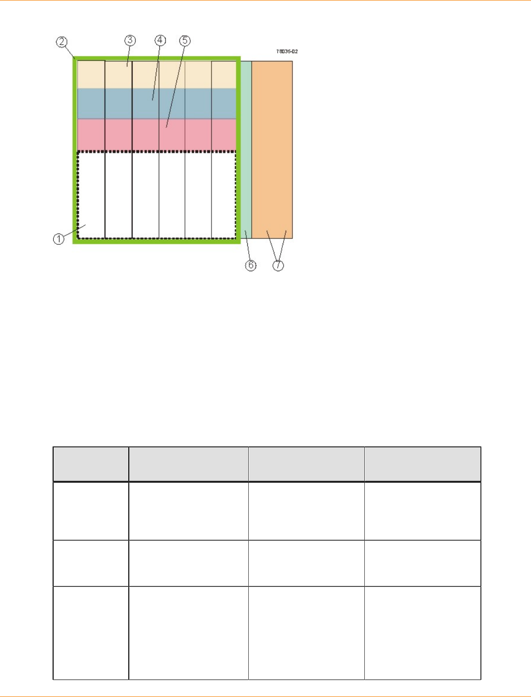
SANtricity_10.77 February 2011
LSI Corporation
- 57 -
1. Free Capacity
2. Volume Group
3. Volume
4. Volume
5. Volume
6. Hot Spare Drive
7. Unconfigured Capacity
Specifying Volume Parameters
Parameter Free Capacity Unconfigured
Capacity Unassigned Drive
Volume
Group
Creation
The volume group is
predefined. You must create a
volume group before
configuring a new
volume.
You must create a
volume group before
configuring a new
volume.
Specify
Capacity/
Name Dialog
Assign a name to the
volume. Change the
default capacity.
Assign a name to the
volume. Change the
default capacity.
Assign a name to the
volume. Change the
default capacity.
Storage
Partitioning
will be used
Select the Map Later
using the Mappings
View option. This
option specifies that a
LUN not be assigned
to the volume during
volume creation. This
Select the Map Later
using the Mappings
View option. This
option specifies that a
LUN not be assigned
to the volume during
volume creation. This
Select the Map Later
using the Mappings
View option. This
option specifies that a
LUN not be assigned
to the volume during
volume creation. This
SANtricity_10.77 February 2011
LSI Corporation
- 58 -
Parameter Free Capacity Unconfigured
Capacity Unassigned Drive
option defines specific
mappings and creates
storage partitions.
option defines specific
mappings and creates
storage partitions.
option defines specific
mappings and creates
storage partitions.
Storage
Partitioning
will not be
used
Select the Default
Mapping option. This
option automatically
assigns the next
available LUN in the
Default Group to the
volume. The option
grants volume access
to host groups or hosts
that have no specific
mappings, which are
shown under the Default
Group node in the
Topology pane.
Select the Default
Mapping option. This
option automatically
assigns the next
available LUN in the
Default Group to the
volume. The option
grants volume access
to host groups or hosts
that have no specific
mappings, which
are shown under the
Default Group node in
the Topology pane.
Select the Default
Mapping option. This
option automatically
assigns the next
available LUN in the
Default Group to the
volume. The option
grants volume access
to host groups or hosts
that have no specific
mappings, which
are shown under the
Default Group node in
the Topology pane.
Advanced
Volume
Parameters
You can customize
these advanced volume
parameters:
Volume I/O
characteristics
Preferred controller
owner
You can customize
these advanced volume
parameters:
Volume I/O
characteristics
Preferred controller
owner
You can customize
these advanced volume
parameters:
Volume I/O
characteristics
Preferred controller
owner
Dynamic Capacity Expansion
Dynamic Capacity Expansion (DCE) is a modification operation in the storage management software that
increases the capacity of a volume group. This modification operation allows you to add unassigned drives to
a volume group. Adding unassigned drives increases the free capacity in the volume group. You can use this
free capacity to create additional volumes.
This operation is considered to be dynamic because you have the ability to continually access data in the
volume group throughout the entire operation.
Keep these guidelines in mind when you add unassigned drives to a volume group:
The number of unassigned drives that you can select for a DCE modification operation is limited by the
controller firmware. You can add two unassigned drives at a time. However, after you have completed a
DCE operation, you can add more drives again until the desired capacity is reached.
The existing volumes in the volume group do not increase in size when you add unassigned drives to
expand the free capacity. This operation redistributes existing volume capacity over the larger number of
drives in the volume group.
The unassigned drives that you are adding to the volume group must be of the same media type and
interface type. Mixing different drive types within a single volume group is not permitted. Whenever
possible, select drives that have a capacity equal to the capacities of the current drives in the volume
group.

SANtricity_10.77 February 2011
LSI Corporation
- 59 -
In a RAID Level 1 volume group, you must add two drives to make sure that data redundancy is
configured.
Only security capable drives can be added to a security enabled volume group or a security capable
volume group.
In a volume group that is Data Assurance (DA) capable and contains a DA-enabled volume, you can add
only DA-capable drives.
Register the Volume with the Operating System
After you have created all of your volumes and have assigned mappings, use a volume registration utility,
such as the hot_add utility when using RDAC, to scan the mapped volumes and register the volumes with the
operating system.
You can run the hot_add utility to make sure that the operating system is aware of the newly created volumes.
If available for your operating system, you can run the host-based SMdevices utility to associate the physical
storage array name and the volume name.
Premium Features
The storage management software has the following premium features that provide data-protection
strategies:
SANshare Storage Partitioning
Snapshot Volume
Remote Volume Mirroring (this premium feature is supported only in storage arrays with the Fibre
Channel [FC] host ports)
Volume Copy
SafeStore Drive Security and SafeStore Enterprise Key Manager
SafeStore Data Assurance (DA)
Solid State Disks (SSDs)
SANshare Storage Partitioning
SANshare Storage Partitioning lets hosts with different operating systems share access to a storage array.
Hosts with different operating systems that share access to a storage array are called heterogeneous hosts.
A storage partition is a logical entity that consists of one or more storage array volumes that can be shared
among hosts. To create a storage partition after the total storage capacity has been configured into volumes,
you must define a single host or collection of hosts (or host group) that will access the storage array. Then
you must define a mapping, which lets you specify the host group or the host that will have access to a
particular volume in your storage array.
Based on the premium feature key file purchased, the storage management software can support the
maximum storage partitions shown in this table.
Storage Array Maximum Number of Storage
Partitions Supported
CE7900 controller tray Up to 512
SANtricity_10.77 February 2011
LSI Corporation
- 60 -
Storage Array Maximum Number of Storage
Partitions Supported
CDE2600 controller-drive tray Up to 128
CDE4900 controller-drive tray Up to 128
You can define a maximum of 256 volumes per partition (except for the HP-UX 11.23 operating system); this
number is limited to the total number of volumes on your storage array.
Snapshot Volume Premium Feature
The Snapshot Volume premium feature creates a logical point-in-time image of another volume. Snapshot
Volume is a premium feature of the storage management software. You or your storage vendor must enable
this premium feature.
Because the only data blocks that are physically stored in the snapshot repository volume are those that have
changed since the time that the snapshot volume was created, the snapshot volume uses less drive space
than a full physical copy.
Typically, you create a snapshot so that an application (for example, a backup application) can access the
snapshot and read the data; meanwhile, the base volume stays online and is user accessible. When the
backup is completed, the snapshot volume is no longer needed.
You can also create snapshots of a base volume and write data to the snapshot volumes to perform testing
and analysis. Before upgrading your database management system, for example, you can use snapshot
volumes to test different configurations. Then you can use the performance data that is provided by the
storage management software to help you decide how to configure your live database system. The maximum
number of snapshots supported by the storage array is shown in this table.
Storage Array Maximum Number of
Snapshots per Volume Maximum Number of
Snapshots per Storage
Array
CE7900 controller tray Up to 16 Up to 1024
CDE2600 controller-drive tray Up to 16 Up to 256
CDE4900 controller-drive tray Up to 8 Up to 512
Creating Snapshot Volumes
When a snapshot volume is created, the controller suspends I/O activity to the base volume for a few seconds
while it creates a physical volume, called the snapshot repository volume. The snapshot repository volume
stores the snapshot volume metadata and the copy-on-write data.
You can create snapshot volumes by using the Create Snapshot Volume Wizard in the Array Management
Window. The first dialog of the Create Snapshot Volume Wizard lets you select either the simple path or
the advanced path to be followed through the wizard. You can choose the simple path to create a snapshot
volume if the volume group of the base volume has the required amount of free capacity. The simple path lets
you specify the basic parameters for the snapshot volume. The simple path accepts the default settings for
the advanced parameters.

SANtricity_10.77 February 2011
LSI Corporation
- 61 -
NOTE If sufficient free capacity is not available in the volume group of the base volume, the Create
Snapshot Volume Wizard uses the advanced path by default.
In the advanced path, either you can choose to place the snapshot repository volume in another volume
group, or you can use unconfigured capacity in the storage array to create a new volume group. The
advanced path lets you customize the advanced settings for the snapshot volume, such as the full conditions
of the snapshot repository volume and the notification settings.
If you want to create a snapshot volume that performs snapshot operations at a later time or at regularly
occurring intervals, specify a schedule. If you do not specify a schedule, the snapshot operation occurs
immediately.
Scheduling Snapshots
If you want to create a snapshot volume that performs snapshot operations at a later time or at regularly
occurring intervals, add a schedule to the snapshot volume. If you do not add a schedule to the snapshot
volume, the snapshot operation occurs immediately. You can add a schedule when you create a snapshot
volume, or you can add a schedule to an existing snapshot volume. Each snapshot volume can have only one
schedule.
Typical Uses of Scheduling Snapshots
Scheduled backups – For example, an application stores business-critical data in two volumes in the
storage array. You back up this data every work day at 11:00 p.m. To accomplish this type of backup, select
the first volume. Create a schedule that runs once a day on Monday, Tuesday, Wednesday, Thursday, and
Friday. Choose a time between the end of your work day and 11:00 p.m. Select a starting date of today
and no end date. Apply this schedule to the second volume, also. Map the two snapshot volumes to your
backup host, and perform the regular backup procedures. Unmap the two snapshot volumes before the next
scheduled snapshot operation time. If you do not unmap the snapshot volumes, the storage array skips the
next snapshot operation to avoid data corruption.
Rapid recovery – In this example, you back up your data at the end of every work day and keep hourly
snapshots from 8:00 a.m. to 5:00 p.m. If data loss or corruption occurs during the work day, you can recover
the data from the snapshots so that the data loss window is smaller than one hour. To accomplish this type
of recovery, create a schedule that contains a start time of 8:00 a.m. and an end time of 5:00 p.m. Select 10
snapshots per day on Monday, Tuesday, Wednesday, Thursday, and Friday. Select a start date of today and
no end date. Create an end-of-day backup as described in the "Scheduled backups" example.
Guidelines for Creating Schedules
Keep the following guidelines in mind when creating schedules for snapshot volumes:
Either you can create a schedule when you create a snapshot volume, or you can add a schedule to an
existing snapshot volume.
Scheduled snapshot operations do not take place when these conditions occur:
The snapshot volume is mapped.
The storage array is offline or powered off.
The snapshot volume is used as a source volume in a Volume Copy operation, and the status of the
copy operation is Pending or In progress.
If you delete a snapshot volume that has a schedule, the schedule is also deleted.
SANtricity_10.77 February 2011
LSI Corporation
- 62 -
Schedules are stored in the configuration database in the storage array. The management station does
not need to be running the Enterprise Management Window (EMW) or the Array Management Window
(AMW) for the scheduled snapshot operation to occur.
Enabling and Disabling Schedules
You temporarily can suspend scheduled snapshot operations by disabling the schedule. When a schedule
is disabled, the schedule’s timer continues to run, but the scheduled snapshot operations do not occur. This
table shows the icons for scheduled snapshots.
Icon Description
The schedule is enabled. Scheduled snapshots will occur.
The schedule is disabled. Scheduled snapshots will not
occur.
Discontinuing the Use of a Snapshot Volume
As long as a snapshot volume is enabled, storage array performance is affected by the copy-on-write activity
to the associated snapshot repository volume. When you no longer need a snapshot volume, you can disable
it, reuse it, or delete it.
Disable – Stops copy-on-write activity. This option keeps the snapshot volume and snapshot repository
volume intact.
Reuse – Creates a different point-in-time image of the same base volume. This action takes less time to
configure than re-creating the snapshot volume.
Delete – Completely removes the snapshot volume and the associated snapshot repository volume. If
you want to re-enable a snapshot volume, you must re-create it.
Disabling and Restarting Multiple Snapshots
If multiple volumes require regular snapshots for backup purposes, keeping the snapshots enabled might
significantly affect storage array performance. In this situation, you can disable the snapshot function for
multiple volumes and then restart the snapshots for all of the volumes before the next backup is scheduled.
The list of snapshots to be restarted is treated as a single operation. The new point-in-time snapshot images
are created from the previously defined parameters. If an error is encountered on any of the listed snapshots,
none of the snapshots on the list are re-created.
Dynamic Volume Expansion
IMPORTANT Increasing the capacity of a standard volume is only supported on certain operating
systems. If volume capacity is increased on a host operating system that is not supported, the expanded
capacity is unusable, and you cannot restore the original volume capacity.
Dynamic Volume Expansion (DVE) is a modification operation that increases the capacity of standard
volumes or snapshot repository volumes. The increase in capacity can be achieved by using any free
capacity available on the volume group of the standard volume or the snapshot repository volume. Data is
accessible on volume groups, volumes, and drives throughout the entire modification operation.
SANtricity_10.77 February 2011
LSI Corporation
- 63 -
If you receive a warning that the snapshot repository volume is in danger of becoming full, you can use the
DVE modification operation to increase the capacity of the snapshot repository volume.
Increasing the capacity of a snapshot repository volume does not increase the capacity of the associated
snapshot volume. The capacity of the snapshot volume is always based on the capacity of the base volume at
the time that the snapshot volume was created.
Remote Volume Mirroring Premium Feature
The Remote Volume Mirroring premium feature is used for online, real-time data replication between storage
arrays over a remote distance. Storage array controllers manage the mirroring, which is transparent to host
machines and software applications. You create one or more mirrored volume pairs that consist of a primary
volume at the primary site and a secondary volume at a secondary, remote site. After you create the mirror
relationship between the two volumes, the current owner of the primary volume copies all of the data from the
primary volume to the secondary volume. This process is called a full synchronization.
There is a base number of defined mirrors that are allowed for each storage array. You can increase the
number of defined mirrors that are allowed per model with the purchase of an optional feature pack upgrade
key. This table shows the maximum number of defined mirrors to which you can upgrade with a feature pack
upgrade key.
Storage Array Maximum Number of Defined
Mirrors
CE7900 controller tray Up to 128
CDE2600 controller-drive tray Up to 16
CDE4900 controller-drive tray Up to 64
The Remote Volume Mirroring premium feature is not supported in a simplex configuration. You must disable
the Remote Volume Mirroring premium feature before converting a storage array from a duplex configuration
to a simplex configuration. The Remote Volume Mirroring premium feature is supported only in storage arrays
with the Fibre Channel (FC) host ports. The Remote Volume Mirroring premium feature also requires a Fibre
Channel network switch.
ATTENTION Possible loss of data access – You cannot create a mirror relationship if the primary
volume contains unreadable sectors. Furthermore, if an unreadable sector is discovered during a mirroring
operation, the mirror relationship fails.
NOTE Because replication is managed on a per-volume basis, you can mirror individual volumes in a
primary storage array to appropriate secondary volumes in several different remote storage arrays.
Disaster Recovery
The secondary, remote volume is unavailable to secondary host applications while mirroring is in progress. In
the event of a disaster at the primary site, you can fail over to the secondary site. To fail over, perform a role
reversal to promote the secondary volume to a primary volume. Then the recovery host is able to access the
newly promoted volume, and business operations can continue.

SANtricity_10.77 February 2011
LSI Corporation
- 64 -
Data Replication
When the current owner of the primary volume receives a write request from a host, the controller first logs
information about the write to a special volume. This volume is called a mirror repository volume. It writes the
data to the primary volume. Next, the controller initiates a remote write operation to copy the affected data
blocks to the secondary volume at the remote site.
Finally, the controller sends an I/O completion indication back to the host system to confirm that the data was
copied successfully to the secondary storage array. The write mode that you selected when you first created
a remote volume mirror determines when the I/O completion indication is sent to the host system.
The storage management software provides two write modes:
Synchronous – When you select this write mode, any host write requests are written to the primary
volume and then copied to the secondary storage volume. The controller sends an I/O completion
indication to the host system after the copy has been successfully completed.
Asynchronous – When you select this write mode, host write requests are written to the primary volume.
Then the controller sends an I/O completion indication back to the host system before the data has been
successfully copied to the secondary storage array.
When write caching is enabled on either the primary volume or the secondary volume, the I/O completion is
sent when data is in the cache on the side (primary or secondary) where write caching is enabled. When write
caching is disabled on either the primary volume or the secondary volume, the I/O completion is not sent until
the data has been stored to physical media on that side.
Host write requests received by the controller are handled normally. No communication takes place between
the primary storage array and the secondary storage array.
Link Interruptions or Secondary Volume Errors
When processing write requests, the primary controller might be able to write to the primary volume, but a link
interruption prevents communication with the remote secondary controller.
In this case, the remote write cannot complete to the secondary volume. The primary volume and the
secondary volume are no longer appropriately mirrored. The primary controller changes the mirrored pair into
Unsynchronized status and sends an I/O completion to the primary host. The primary host can continue to
write to the primary volume, but remote writes do not take place.
When connectivity is restored between the current owner of the primary volume and the current owner of
the secondary volume, a full synchronization takes place. Only the blocks of data that have changed on the
primary volume during the link interruption are copied to the secondary volume. The mirrored pair changes
from an Unsynchronized state to Mirror Synchronization in Progress status.
The primary controller also marks the mirrored pair as Unsynchronized when a volume error on the secondary
side prevents the remote write from completing. For example, an offline secondary volume or a failed
secondary volume can cause the remote mirror to become unsynchronized. When the volume error is
corrected (the secondary volume is placed online or is recovered to Optimal status), a full synchronization
automatically begins. The mirrored pair then changes to Synchronization in Progress status.
Connectivity and Volume Ownership
A primary controller attempts to communicate only with its matching controller in the secondary storage array.
For example, controller A in the primary storage array attempts communication only with controller A in the
secondary storage array. The controller (A or B) that owns the primary volume determines the current owner

SANtricity_10.77 February 2011
LSI Corporation
- 65 -
of the secondary volume. If the primary volume is owned by controller A on the primary side, the secondary
volume is owned by controller A on the secondary side. If primary controller A cannot communicate with
secondary controller A, controller ownership changes do not take place.
The next remote write processed automatically triggers a matching ownership change on the secondary side
if one of these conditions exists:
When an I/O path error causes a volume ownership change on the primary side
If the storage administrator changes the current owner of the primary volume
For example, a primary volume is owned by controller A, and then you change the controller owner to
controller B. In this case, the next remote write changes the controller owner of the secondary volume from
controller A to controller B. Because controller ownership changes on the secondary side are controlled by
the primary side, they do not require any special intervention by the storage administrator.
Controller Resets and Storage Array Power Cycles
Sometimes a remote write is interrupted by a controller reset or a storage array power cycle before it can be
written to the secondary volume. The storage array controller does not need to perform a full synchronization
of the mirrored volume pair in this case. A controller reset causes a controller ownership change on the
primary side from the preferred controller owner to the alternate controller in the storage array. When a
remote write has been interrupted during a controller reset, the new controller owner on the primary side
reads information stored in a log file in the mirror repository volume of the preferred controller owner. It then
copies the affected data blocks from the primary volume to the secondary volume, eliminating the need for a
full synchronization of the mirrored volumes.
Remote Volume Mirroring Premium Feature Activation
Like other premium features, you enable the Remote Volume Mirroring premium feature by purchasing a
feature key file from your storage supplier. You must enable the premium feature on both the primary storage
array and the secondary storage array.
Unlike other premium features, you also must activate the premium feature after you enable it. To activate
the premium feature, use the Activate Remote Volume Mirroring Wizard in the Array Management Window
(AMW). Each controller in the storage array must have its own mirror repository volume for logging write
information to recover from controller resets and other temporary interruptions. The Activate Remote Volume
Mirroring Wizard guides you to specify the placement of the two mirror repository volumes (on newly created
free capacity or existing free capacity in the storage array).
After you activate the premium feature, one Fibre Channel (FC) host side I/O port on each controller is
solely dedicated to Remote Volume Mirroring operations. Host-initiated I/O operations are not accepted by
the dedicated port. I/O requests received on this port are accepted only from remote controllers that are
participating in Remote Volume Mirroring operations with the controller.
Connectivity Requirements
You must attach dedicated Remote Volume Mirroring ports to a Fibre Channel fabric environment. In addition,
these ports must support the Directory Service interface and the Name Service.
You can use a fabric configuration that is dedicated solely to the Remote Volume Mirroring ports on each
controller. In this case, host systems can connect to the storage arrays using fabric, Fibre Channel Arbitrated
Loop (FC-AL), or point-to-point configurations. These configurations are totally independent of the dedicated
Remote Volume Mirroring fabric.
SANtricity_10.77 February 2011
LSI Corporation
- 66 -
Alternatively, you can use a single Fibre Channel fabric configuration for both the Remote Volume Mirroring
connectivity and for the host I/O paths to the controllers.
The maximum distance between the primary site and the secondary site is 10 km (6.2 miles), using single-
mode fiber gigabit interface converters (GBICs) and optical long-wave GBICs.
Restrictions
These restrictions apply to mirrored volume candidates and storage array mirroring:
RAID level, caching parameters, and segment size can be different on the two mirrored volumes.
The secondary volume must be at least as large as the primary volume.
The only type of volume that can participate in a mirroring relationship is a standard volume. Snapshot
volumes cannot participate.
You can create a snapshot volume by using either a primary volume or a secondary volume as the base
volume.
A primary volume can be a source volume or a target volume in a volume copy. A secondary volume
cannot be a source volume or a target volume unless a role reversal was initiated after the copy has
completed. If a role reversal is initiated during a Copy in Progress status, the copy fails and cannot be
restarted.
A given volume might participate in only one mirror relationship.
Volume Copy Premium Feature
ATTENTION Possible loss of data access – The volume copy operation overwrites existing data on
the target volume and renders the volume read-only to hosts. This option fails all snapshot volumes that are
associated with the target volume, if any exist.
The Volume Copy premium feature copies data from one volume (the source) to another volume (the target)
in a single storage array.
Use the Volume Copy premium feature to perform these tasks:
Copy data from volume groups that use smaller capacity drives to volume groups that use larger capacity
drives.
Create an online copy of data from a volume within a storage array, while still being able to write to the
volume with the copy in progress.
Back up data or restore snapshot volume data to the base volume.
Volume Copy is a premium feature of the storage management software and must be enabled either by you
or your storage vendor.
Storage Array Maximum Number of Volume Copies per
Storage Array
CE7900 controller tray Up to 2047
CDE2600 controller-drive tray Up to 511
CDE4900 controller-drive tray Up to 1023
SANtricity_10.77 February 2011
LSI Corporation
- 67 -
Volume Copy Features
Data Copying for Greater Access
As your storage requirements for a volume change, use the Volume Copy premium feature to copy data to
a volume in a volume group that uses larger capacity drives within the same storage array. This premium
feature lets you perform these functions:
Move data to larger drives; for example, 73 GB to 146 GB
Change to drives with a higher data transfer rate; for example, 2 Gb/s to 4 Gb/s
Change to drives using new technologies for higher performance
Data Backup
The Volume Copy premium feature lets you back up a volume by copying data from one volume to another
volume in the same storage array. You can use the target volume as a backup for the source volume, for
system testing, or to back up to another device, such as a tape drive.
Snapshot Volume Data Restoration to the Base Volume
If you need to restore data to the base volume from its associated snapshot volume, use the Volume Copy
premium feature to copy data from the snapshot volume to the base volume. You can create a volume copy
of the data on the snapshot volume, and then copy the data to the base volume.
ATTENTION Possible loss of data – If you are using the Windows 2000 operating system or the
Linux operating system, use the Volume Copy premium feature with the Snapshot Volume premium feature to
restore snapshot volume data to the base volume. Otherwise, the source volume and the target volume can
become inaccessible to the host.
Types of Volume Copies
You can perform either an offline volume copy or an online volume copy. To ensure data integrity, all I/O
to the target volume is suspended during either volume copy operation. This suspension occurs because
the state of data on the target volume is inconsistent until the procedure is complete. After the volume copy
operation is complete, the target volume automatically becomes read-only to the hosts.
The offline and online volume copy operations are described as follows.
Offline Copy
An offline copy reads data from the source volume and copies it to a target volume, while suspending all
updates to the source volume with the copy in progress. All updates to the source volume are suspended
to prevent chronological inconsistencies from being created on the target volume. The offline volume copy
relationship is between a source volume and a target volume.
Source volumes that are participating in an offline copy are available for read requests only while a volume
copy has a status of In Progress or Pending. Write requests are allowed after the offline copy has completed.
If the source volume has been formatted with a journaling file system, any attempt to issue a read request to
the source volume might be rejected by the storage array controllers, and an error message might appear.
The journaling file system driver issues a write request before it attempts to issue the read request. The
controller rejects the write request, and the read request might not be issued due to the rejected write request.
This condition might result in an error message appearing, which indicates that the source volume is write
protected. To prevent this issue from occurring, do not attempt to access a source volume that is participating
SANtricity_10.77 February 2011
LSI Corporation
- 68 -
in an offline copy while the volume copy has a status of In Progress. Also, make sure that the Read-Only
attribute for the target volume is disabled after the volume copy has completed to prevent error messages
from appearing.
Online Copy
An online copy creates a point-in-time snapshot copy of a volume within a storage array, while still being
able to write to the volume with the copy in progress. This function is achieved by creating a snapshot of the
volume and using the snapshot as the actual source volume for the copy. The online volume copy relationship
is between a snapshot volume and a target volume. The volume for which the point-in-time image is created
is known as the base volume and must be a standard volume in the storage array.
A snapshot volume and a snapshot repository volume are created during the online copy operation. The
snapshot volume is not an actual volume containing data; rather, it is a reference to the data that was
contained on a volume at a specific time. For each snapshot that is taken, a snapshot repository volume
is created to hold the copy-on-write data for the snapshot. The snapshot repository volume is used only to
manage the snapshot image.
Before a data block on the source volume is modified, the contents of the block to be modified are copied to
the snapshot repository volume for safekeeping. Because the snapshot repository volume stores copies of the
original data in those data blocks, further changes to those data blocks write only to the source volume.
NOTE If the snapshot volume that is used as the copy source is active, the base volume performance
is degraded due to copy-on-write operations. When the copy is complete, the snapshot is disabled, and the
base volume performance is restored. Although the snapshot is disabled, the repository infrastructure and
copy relationship remain intact.
The online copy function is enabled with the Snapshot Volume premium feature. To use the online copy
function, you must enable the Snapshot Volume premium feature by purchasing a feature key file from your
storage vendor.
Components of the Volume Copy Premium Feature
The Volume Copy premium feature includes these components:
Create Copy Wizard, which assists in creating a volume copy.
You can use the Create Copy Wizard to guide you through the following steps in creating a Volume Copy:
Selecting a source volume from a list of available volumes and the type of copy you want to perform
(offline or online)
Selecting a target volume from a list of available volumes
Allocating capacity for the snapshot repository volume for online copy types
Setting the copy priority for the volume copy
When you have completed the wizard dialogs, the volume copy starts, and data is read from the source
volume and written to the target volume. Operation in Progress icons appear on the source volume and the
target volume while the volume copy has a status of In Progress or Pending.
Copy Manager, which monitors volume copies after they have been created.
After you create a volume copy with the Create Copy Wizard, you can monitor the volume copy through the
Copy Manager. You can use the Copy Manager to perform the following actions:

SANtricity_10.77 February 2011
LSI Corporation
- 69 -
Monitor the progress of a volume copy
Stop a volume copy
Re-copy a volume copy
Remove copy pairs
Change target volume permissions
Change copy priority
Keep these guidelines in mind when you create a volume copy.
Failed Controller You must manually change controller
ownership to the alternate controller to allow
the volume copy to complete under all of
these conditions:
The preferred controller of the source
volume fails.
The ownership transfer does not occur
automatically in the failover.
Volume Failover for Online Copy Types Ownership changes affect the base volume
and all of its snapshots. The same controller
should own the base volume, the snapshot
volume, and the snapshot repository volume.
The rules that apply to the base volume for
host-driver-based or controller-based failover
modes also apply to the associated snapshots
and snapshot repository volumes. If a failover
situation occurs, all related volumes change
controller ownership as a group.
Volume Copy and Modification Operations
for Offline Copy Types For offline copy operations, if a modification
operation is running on a source volume or
a target volume, and the volume copy has
a status of In Progress, Pending, or Failed,
the volume copy does not take place. If a
modification operation is running on a source
volume or a target volume after a volume
copy has been created, the modification
operation must complete before the volume
copy can start. If a volume copy has a status
of In Progress, any modification operation
does not take place.
Preferred Controller Ownership During a volume copy, the same controller
must own both the source volume and the
target volume. If both volumes do not have
the same preferred controller when the
volume copy starts, the ownership of the
target volume is automatically transferred to
the preferred controller of the source volume.
When the volume copy is completed or is
stopped, ownership of the target volume
is restored to its preferred controller. If

SANtricity_10.77 February 2011
LSI Corporation
- 70 -
ownership of the source volume is changed
during the volume copy, ownership of the
target volume is also changed.
Failed Volume Copy A volume copy can fail due to these
conditions:
A read error from the source volume
A write error to the target volume
A failure in the storage array that affects
the source volume or the target volume,
such as a remote volume mirror role
reversal
When the volume copy fails, a Needs
Attention icon appears in the Array
Management Window. While a volume copy
has this status, the host has read-only access
to the source volume. Read requests from
and write requests to the target volume do
not take place until the failure is corrected by
using the Recovery Guru.
Volume Copy Status If eight volume copies with a status of In
Progress exist, any subsequent volume
copy will have a status of Pending, which
remains until one of the eight volume copies
completes.
Snapshot Volume A volume copy fails all snapshot volumes
that are associated with the target volume,
if any exist. If you select a base volume of a
snapshot volume, you must disable all of the
snapshot volumes that are associated with
the base volume before you can select it as
a target volume. Otherwise, the base volume
cannot be used as a target volume.
A volume copy overwrites data on the target
volume and automatically makes the target
volume read-only to hosts.
Snapshot Failure If a snapshot volume that is serving as an
online copy fails, the volume copy relationship
is still maintained between the snapshot
volume and the target volume. If the snapshot
failure occurs when the physical copy is in
progress, the status of “Failed” is displayed in
the Copy Manager.
Volume Consistency When using the online volume copy
operation, make sure that the source volume
is in a consistent state. If the source volume is
not consistent, the online volume copy is also
inconsistent. An inconsistent volume might be
unusable for its purpose, such as backup.

SANtricity_10.77 February 2011
LSI Corporation
- 71 -
Copy Failure for Online Copy Types A copy failure terminates the copy-on-write
process for the snapshot volume. If a copy
failure occurs due to a snapshot failure
because of snapshot repository volume
overflow, you can correct the failure by
deleting the copy relationship and re-creating
it.
Restrictions on Volume Copy
These restrictions apply to the source volume, the target volume, and the storage array when performing
volume copy operations.
For an offline volume copy, the source volume is available for read requests only while a volume copy has
a status of In Progress or Pending. Write requests are allowed after the volume copy is completed.
You can use a volume as a target volume in only one volume copy at a time.
The maximum allowable number of volume copies per storage array depends on the number of target
volumes that are available in your storage array.
A storage array can have up to eight volume copies running at any given time.
The capacity of the target volume must be equal to or greater than the capacity of the source volume.
For an offline volume copy, a source volume can be one of the following volumes:
A standard volume
A snapshot volume
A snapshot base volume
A remote volume mirror primary volume
For an online volume copy, a source volume can only be a standard volume.
If the source volume is a primary volume, the capacity of the target volume must be equal to or greater
than the usable capacity of the source volume.
You cannot use the snapshot volume copy until after the online copy operation completes.
You cannot use any of the Snapshot Volume options (Disable, Re-create, Create Copy, Delete,
and Rename) or perform host mapping on a snapshot volume that was created using the online copy
operation in the Create Copy Wizard.
A target volume can be one of these volumes:
A standard volume
A base volume of a disabled snapshot volume or a failed snapshot volume
A remote volume mirror primary volume
NOTE If you choose a base volume of a snapshot volume as your target volume, you must disable
all snapshot volumes that are associated with the base volume before you can select it as a target volume.
Otherwise, you cannot use the base volume as a target volume.
Volumes that have these statuses cannot be used as a source volume or a target volume:

SANtricity_10.77 February 2011
LSI Corporation
- 72 -
A volume that is reserved by the host cannot be selected as a source volume or a target volume
A volume that is in a modification operation
A volume that is the source volume or a target volume in another volume copy operation with a status of
Failed, In Progress, or Pending
A volume with a status of Failed
A volume with a status of Degraded
For detailed information about this premium feature, refer to the online help topics in the Array Management
Window.
SafeStore Drive Security and SafeStore Enterprise Key Manager
SafeStore Drive Security is a premium feature that prevents unauthorized access to the data on a Full Disk
Encryption (FDE) drive that is physically removed from the storage array. Controllers in the storage array
have a security key. Secure drives provide access to data only through a controller that has the correct
security key. SafeStore Drive Security is a premium feature of the storage management software and must be
enabled either by you or your storage vendor.
The SafeStore Drive Security premium feature requires security capable FDE drives. A security capable FDE
drive encrypts data during writes and decrypts data during reads. Each security capable FDE drive has a
unique drive encryption key.
When you create a secure volume group from security capable drives, the drives in that volume group
become security enabled. When a security capable drive has been security enabled, the drive requires the
correct security key from a controller to read or write the data. All of the drives and controllers in a storage
array share the same security key. The shared security key provides read and write access to the drives,
while the drive encryption key on each drive is used to encrypt the data. A security capable drive works like
any other drive until it is security enabled.
Whenever the power is turned off and turned on again, all of the security enabled drives change to a security
locked state. In this state, the data is inaccessible until the correct security key is provided by a controller.
The SafeStore Enterprise Key Manager premium feature integrates external key management products.
You can view the SafeStore Drive Security status of any drive in the storage array. The status information
reports whether the drive is in one of these states:
Security Capable
Secure – Security enabled or security disabled
Read/Write Accessible – Security locked or security unlocked
You can view the SafeStore Drive Security status of any volume group in the storage array. The status
information reports whether the storage array is in one of these states:
Security Capable
Secure
This table interprets the security properties status of a volume group.
SANtricity_10.77 February 2011
LSI Corporation
- 73 -
Volume Group Security Properties
Security Capable – yes Security Capable – no
Secure – yes The volume group is composed of
all FDE drives and is in a Secure
state.
Not applicable. Only FDE
drives can be in a Secure
state.
Secure – no The volume group is composed
of all FDE drives and is in a Non-
Secure state.
The volume group is not
entirely composed of FDE
drives.
When the SafeStore Drive Security premium feature has been enabled, the Drive Security menu appears in
the Storage Array menu. The Drive Security menu has these options:
Security Key Management
Create Security Key
Change Security Key
Save Security Key
Validate Security Key
Import Security Key File
The Security Key Management option lets you specify how to manage the security key. By default, the
security key is managed locally by the controllers. The controllers generate the security key and save the
security key in the nonvolatile static random access memory (NVSRAM) of the controllers. You can use the
SafeStore Enterprise Key Manager to have an external key management server generate the security key.
NOTE If you have not created a security key for the storage array, the Create Security Key option is
active. If you have created a security key for the storage array, the Create Security Key option is inactive
with a check mark to the left. The Change Security Key option, the Save Security Key option, and the
Validate Security Key option are now active.
The Import Security Key File option is active if there are any security locked drives in the storage array.
When the SafeStore Drive Security premium feature has been enabled, the Secure Drives option appears in
the Volume Group menu. The Secure Drives option is active if these conditions are true:
The selected storage array is not security enabled but is comprised entirely of security capable drives.
The storage array does not contain any snapshot base volumes or snapshot repository volumes.
The volume group is in an Optimal state.
A security key is set up for the storage array.
The Secure Drives option is inactive if the conditions are not true.
The Secure Drives option is inactive with a check mark to the left if the volume group is already security
enabled.
SANtricity_10.77 February 2011
LSI Corporation
- 74 -
You can erase security enabled drives so that you can reuse the drives in another volume group, in another
storage array, or if you are decommissioning the drives. When you erase security enabled drives, you make
sure that the data cannot be read. When all of the drives that you have selected in the Physical pane are
security enabled, and none of the selected drives are part of a volume group, the Secure Erase option
appears in the Drive menu.
The storage array password protects a storage array from potentially destructive operations by unauthorized
users. The storage array password is independent from the SafeStore Drive Security premium feature and
should not be confused with the pass phrase that is used to protect copies of a security key. However, it is
good practice to set a storage array password before you create, change, or save a security key or unlock
secure drives.
Using SafeStore Enterprise Key Manager
The SafeStore Enterprise Key Manager premium feature lets you specify how to manage the security
key. You can choose to manage the security key locally by the controllers or externally by an external key
management server. By default, the security key is managed locally by the controllers. The controllers
generate the security key and save the security key in the nonvolatile static random access memory
(NVSRAM) of the controllers. You can also use the SafeStore Enterprise Key Manager to have an external
key management server generate the security key. To change the management method, select Storage
Array >> SafeStore Drive Security >> Security Key Management.
ATTENTION Changing the method of managing the security key from local to external requires
creating and saving a new security key. This action makes any previously saved security key for the storage
array invalid.
NOTE External key management must be enabled for both the source storage array, from which the
key is saved, and any target storage array that imports the key. The key management server used by the
source storage array must be accessible to the target storage array.
A copy of the security key must be kept on some other storage medium for backup, in case of controller
failure or for transfer to another storage array. A pass phrase that you provide is used to encrypt and decrypt
the security key for storage on other media. The storage array password protects a storage array from
potentially destructive operations by unauthorized users. The storage array password is independent from
the SafeStore Drive Security premium feature and should not be confused with the pass phrase that is used
to protect copies of a security key. However, it is good practice to set a storage array password before you
change a security key.
Creating a Security Key
Drives with the full disk encryption technology are security capable. This capability enables the controller
to apply security to every security capable drive in the storage array. The controller firmware creates a key
and activates the drive’s security function, which encrypts data as it enters, and decrypts data as it is read.
Without the key, the data written on a drive is inaccessible and unreadable. A security enabled drive can also
be configured to require a password, PIN, or certificate; however, this function is separate from the encryption
and decryption processes.
The storage array password protects a storage array from potentially destructive operations by unauthorized
users. The storage array password is independent from the SafeStore Drive Security premium feature and
should not be confused with the pass phrase that is used to protect copies of a SafeStore Drive Security key.
However, it is good practice to set a storage array password before you create a SafeStore Drive Security
key.
SANtricity_10.77 February 2011
LSI Corporation
- 75 -
After the controller creates the key, the storage array moves from a state of security capable to a state of
security enabled. The security enabled condition requires the drives to obtain a key to access their media. As
an added security measure, when power is applied to the storage array, the drives are all placed in a security
locked state. They are only unlocked during drive initialization with the controller’s key. The security unlocked
state allows the drives to be accessible so that read and write activities can be performed.
Changing a Security Key
A new security key is generated by the controller firmware for these reasons:
You need to change the security key.
You need to change the method of managing the security key from local to external.
ATTENTION Changing the method of managing the security key makes any previously saved security
keys invalid.
The new security key is stored in the nonvolatile static random access memory (NVSRAM) of the controllers.
The new key replaces the previous key. You cannot see the security key directly. A copy of the security key
must be kept on some other storage medium for backup, in case of controller failure or for transfer to another
storage array. A pass phrase that you provide is used to encrypt and decrypt the security key for storage on
other media.
The storage array password protects a storage array from potentially destructive operations by unauthorized
users. The storage array password is independent from the SafeStore Drive Security feature and should not
be confused with the pass phrase that is used to protect copies of a SafeStore Drive Security key. However, it
is good practice to set a storage array password before you change a SafeStore Drive Security key.
Saving a Security Key
You save an externally storable copy of the security key when the security key is first created and each time
it is changed. You can create additional storable copies at any time. To save a new copy of the security key,
you must provide a pass phrase. The pass phrase that you choose does not need to match the pass phrase
that was used when the security key was created or last changed. The pass phrase is applied to the particular
copy of the security key that you are saving.
Keep these guidelines in mind when you create a pass phrase:
The pass phrase must be between eight and 32 characters long.
The pass phrase must contain at least one uppercase letter.
The pass phrase must contain at least one lowercase letter.
The pass phrase must contain at least one number.
The pass phrase must contain at least one non-alphanumeric character, for example, <, >, @, or +.
The characters you enter are not readable in the Pass phrase text box.
The storage array password protects a storage array from potentially destructive operations by unauthorized
users. The storage array password is independent from the SafeStore Drive Security feature and should not
be confused with the pass phrase that is used to protect copies of a security key. However, it is good practice
to set a storage array password before you save a security key.

SANtricity_10.77 February 2011
LSI Corporation
- 76 -
Unlocking Secure Drives
You can export a security enabled volume group to move the associated drives to a different storage array.
After you install those drives in the new storage array, you must unlock the drives before data can be read
from or written to the drives. To unlock the drives, you must supply the security key from the original storage
array. The security key on the new storage array will be different and will not be able to unlock the drives.
You must supply the security key from a security key file that was saved on the original storage array. You
must provide the pass phrase that was used to encrypt the security key file to extract the security key from
this file.
The storage array password protects a storage array from potentially destructive operations by unauthorized
users. The storage array password is independent from the SafeStore Drive Security feature and should not
be confused with the pass phrase that is used to protect copies of a security key. However, it is good practice
to set a storage array password before you unlock secure drives.
Validating the Security Key
You validate a file in which a security key is stored through the Validate Security Key dialog. To transfer,
archive, or back up the security key, the controller firmware encrypts (or wraps) the security key and stores it
in a file. You must provide a pass phrase and identify the corresponding file to decrypt the file and recover the
security key.
NOTE You can also install the security key from an external key management server. External key
management must be enabled for both the source storage array and the target storage array. The key
management server used by the source storage array must be accessible by the target storage array.
Data can be read from a security enabled drive only if a controller in the storage array provides the correct
security key. If you move security enabled drives from one storage array to another, you must also import
the appropriate security key to the new storage array. Otherwise, the data on the security enabled drives that
were moved is inaccessible.
IMPORTANT After 20 consecutive unsuccessful attempts to validate a security key, you might be
blocked from making further attempts at validation. The Recovery Guru guides you to reset the limit and make
additional attempts. Data on the drives is temporarily inaccessible during the reset procedure.
SafeStore Data Assurance Premium Feature
The SafeStore Data Assurance (DA) premium feature checks for and corrects errors that might occur as
data is moved within the controller, such as from cache to the drive. This checking leads to correction of
write errors and increases data integrity across the entire storage system. DA is implemented using the SCSI
direct-access block-device protection information model. DA creates error-checking information, such as a
cyclic redundancy check (CRC) and appends that information to each block of data. Any errors that might
occur when a block of data is transmitted or stored is then detected and corrected by checking the data with
its error-checking information.
Only certain configurations of hardware, including DA-capable drives, controllers, and host interface cards
(HICs), support the DA premium feature. When you install the DA premium feature on a storage array,
SANtricity ES Storage Manager provides options to use DA with certain operations. For example, you can
create a volume group that includes DA-capable drives and then create a volume within that volume group
that is DA enabled. Other operations that use a DA-enabled volume have options to support the DA premium
feature.

SANtricity_10.77 February 2011
LSI Corporation
- 77 -
For detailed information about this premium feature, refer to the online help topics in the Array Management
Window.
Solid State Disks
Some controllers and drive trays now support Solid State Disks (SSDs). SSDs are data storage devices that
use solid state memory (flash) to store data persistently. An SSD emulates a conventional hard drive, thus
easily replacing it in any application. SSDs are available with the same interfaces used by hard drives.
The advantages of SSDs over hard drives are:
Faster start up (no spin up)
Faster access to data (no rotational latency or seek time)
Higher I/O operations per second (IOPS)
Higher reliability with fewer moving parts
Lower power usage
Less heat produced and less cooling required
SSD support is a premium feature of the storage management software that must be enabled by either you or
your storage vendor.
Identifying SSDs
You can identify SSDs in the storage management software either by the label “SSD” or this icon.
In addition to drive firmware, SSDs have field-programmable gate array (FPGA) code that might be updated
periodically. An FPGA version is listed in the drive properties, which you can see in the storage management
software by selecting a drive on the Physical tab. Also, SSDs do not have a speed listed in the drive
properties like hard drives do.
Creating Volume Groups
All of the drives in a volume group must have the same media type (hard drive or SSD) and the same
interface type. Hot spare drives must also be of the same drive type as the drives they are protecting.
Wear Life
A flash-based SSD has a limited wear life before individual memory locations can no longer reliably persist
data. The drive continuously monitors itself and reports its wear life status to the controller. Two mechanisms
exist to alert you that an SSD is nearing the end of its useful life: average erase count and spare blocks
remaining. You can find these two pieces of information in the drive properties, which you can see in the
storage management software by selecting a drive on the Physical tab.
The average erase count is reported as a percentage of the rated lifetime. When the average erase count
reaches 80 percent, an event is logged to the Major Event Log (MEL). At this time, you should schedule the
replacement of the SSD. When the average erase count reaches 90 percent, a Needs Attention condition
occurs. At this time, you should replace the SSD as soon as possible.
The spare blocks remaining are reported as a percentage of the total blocks. When the number of spare
blocks remaining falls below 20 percent, an event is logged to the MEL. At this time, you should schedule
the replacement of the SSD. When the number of spare blocks remaining falls below 10 percent, a Needs
Attention condition occurs. At this time, you should replace the SSD as soon as possible.
SANtricity_10.77 February 2011
LSI Corporation
- 78 -
Write Caching
Write caching will always be enabled for SSDs. Write caching improves performance and extends the life of
the SSD.
Background Media Scans
Background media scans are not necessary for SSDs because of the high reliability of SSDs.
Heterogeneous Hosts
Heterogeneous hosts are hosts with different operating systems that share access to the same storage array.
When you change a host type, you are changing the operating system (OS) for the host adapter’s host port.
To specify different operating systems for attached hosts, you must specify the appropriate host type when
you define the host ports for each host. Host types can be completely different operating systems, or can
be variants of the same operating system. By specifying a host type, you define how the controllers in the
storage array will work with the particular operating system on the hosts that are connected to it.
Password Protection
IMPORTANT Running operations that alter the configuration of your storage array can cause serious
damage, including data loss. Configuring a password for each storage array that you manage prevents
unauthorized access to destructive commands.
For added security, you can configure each storage array with a password to protect it from unauthorized
access. A password protects any options that the controller firmware deems destructive. These options
include any functions that change the state of the storage array, such as creating a volume or modifying the
cache setting.
IMPORTANT If you forget the password, contact your Customer and Technical Support representative.
After the password has been set on the storage array, you are prompted for that password the first time you
attempt an operation in the Array Management Window that can change the state of the storage array, such
as modifying the cache settings. You are asked for the password only once during a single management
session.
For storage arrays with a password and alert notifications configured, any attempts to access the storage
array without the correct password are reported.
The storage management software provides other security features to protect data, including generation
numbering to prevent replay attacks and hashing and encryption to guard against client spoofing and
snooping.
Persistent Reservations Management
ATTENTION Customer and Technical Support representative supervision required – Do not
perform this procedure unless you are supervised by your Customer and Technical Support representative.
Persistent reservation management lets you view and clear volume reservations and associated registrations.
Persistent reservations are configured and managed through the cluster server software and prevent other
hosts from accessing particular volumes.

SANtricity_10.77 February 2011
LSI Corporation
- 79 -
Unlike other types of reservations, a persistent reservation performs these functions:
Reserves access across multiple host ports
Provides various levels of access control
Offers the ability to query the storage array about registered ports and reservations
Optionally, provides for persistence of reservations in the event of a storage array power loss
The storage management software lets you manage persistent reservations by performing these tasks:
Viewing registration and reservation information for all of the volumes in the storage array
Saving detailed information on volume reservations and registrations
Clearing all registrations and reservations for a single volume or for all of the volumes in the storage
array.
HotScale Technology
HotScale™ technology lets you configure, reconfigure, add, or relocate storage array capacity without
interrupting user access to data.
Port bypass technology automatically opens ports and closes ports when drive trays are added to or removed
from your storage array. Fibre Channel loops stay intact so that system integrity is maintained throughout the
process of adding and reconfiguring your storage array.
For more information about using the HotScale technology, contact your Customer and Technical Support
representative.

SANtricity_10.77 February 2011
LSI Corporation
- 80 -
Maintaining and Monitoring Storage Arrays
The topics in this section describe the methods for maintaining storage arrays, including troubleshooting
storage array problems, recovering from a storage array problem using the Recovery Guru, and configuring
alert notifications using the Event Monitor.
For additional conceptual information and detailed procedures for the options described in this section, refer
to the Learn About Monitoring Storage Arrays online help topic in the Enterprise Management Window.
Storage Array Health
IMPORTANT To receive notification of events for the storage arrays, you must configure alert
notifications in the Enterprise Management Window, and the Event Monitor must be running.
The Enterprise Management Window summarizes the conditions of all of the known storage arrays being
managed. Appropriate status indicators appear in the Tree view on the Devices tab, the Table view on the
Devices tab, and the Health Summary Status area in the lower-left corner of the window. To show the status
bar, select View >> Status Bar.
Background Media Scan
A background media scan is a background process that is performed by the controllers to provide error
detection on the drive media. A background media scan can find media errors before they disrupt normal
drive reads and writes. The background media scan process scans all volume data to make sure that it can
be accessed. The errors are reported to the Event Log.
A background media scan runs on all volumes in the storage array for which it has been enabled. You must
enable the media scan for the entire storage array, and for individual volumes. If you enable a redundancy
check, the background media scan also scans the redundancy data on a RAID Level 1 volume, a RAID Level
3 volume, a RAID Level 5 volume, or a RAID Level 6 volume.
Event Monitor
The Event Monitor runs continuously in the background, monitoring activity on a storage array and checking
for problems. Examples of problems include impending drive failures or failed controllers. If the Event
Monitor detects any problems, it can notify a remote system by using email notifications, Simple Network
Management Protocol (SNMP) trap messages, or both, if the Enterprise Management Window is not running.
The Event Monitor is a client that is bundled with the client software. Install the Event Monitor on a computer
that runs 24 hours a day. The client and the Event Monitor are installed on a storage management station or
a host that is connected to the storage arrays. Even if you choose not to install the Event Monitor, you can still
configure alert notifications on the computer on which the client software is installed.
The following figure shows how the Event Monitor and the Enterprise Management Window client software
send alerts to a remote system. The storage management station contains a file with the name of the storage
array being monitored and the address to which alerts will be sent. The alerts and errors that occur on the
storage array are continuously being monitored by the client software and the Event Monitor. The Event
Monitor continues to monitor the client, even after the client software package is shut down. When an event is
detected, a notification is sent to the remote system.
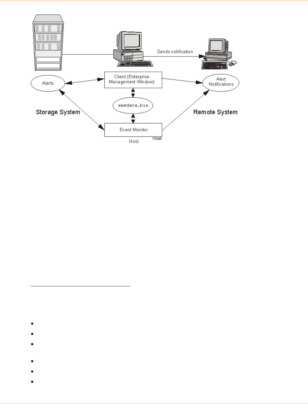
SANtricity_10.77 February 2011
LSI Corporation
- 81 -
Because the Event Monitor and the Enterprise Management Window share the information to send alert
messages, the Enterprise Management Window has some visual cues to assist in the installation and
synchronization of the Event Monitor.
Using the Event Monitor involves these three key steps:
1. Installing the client software
2. Setting up the alert destinations for the storage arrays that you want to monitor from the Enterprise
Management Window
3. Synchronizing the Enterprise Management Window and the Event Monitor
Alert Notifications
You can configure alert notifications by using the storage management software.
Configuring Alert Notifications
You must configure alert notification settings to receive email notifications or SNMP notifications when an
event occurs in a storage array. The notification summarizes the event and details about the affected storage
array, including these items:
The name of the affected storage array
The host IP address (for an in-band managed storage array)
The host name and ID (shown as out-of-band if the storage array is managed through the Ethernet
connection of each controller)
The event error type related to an Event Log entry
The date and the time when the event occurred
A brief description of the event
SANtricity_10.77 February 2011
LSI Corporation
- 82 -
IMPORTANT To set up alert notifications using SNMP traps, you must copy and compile a
management information base (MIB) file on the designated network management station.
Three key steps are involved in configuring alert notifications:
1. Select a node in the Enterprise Management Window that shows alert notifications for the storage
arrays that you want to monitor. You can select every storage array being managed, every storage array
attached to and managed through a particular host, and individual storage arrays.
2. Configure email destinations, if desired.
3. Configure SNMP trap destinations, if desired. The SNMP trap destination is the IP address or the host
name of a station running an SNMP service, such as a network management station.
Customer Support Alert Notifications
If an event occurs in a storage array, the Enterprise Management Window contains options to configure the
system to send email notifications to a specified customer support group. After the alert notification option
is configured, the email alert notification summarizes the event, provides details about the affected storage
array, and provides customer contact information. For more information about setting up this file, contact your
Customer and Technical Support representative.
Performance Monitor
The Performance Monitor provides visibility into performance activity across your monitored storage devices.
You can use the Performance Monitor to perform these tasks:
View in real time the values of the data collected for a monitored device. This capability helps you to
determine if the device is experiencing any problems.
See a historical view of a monitored device to identify when a problem started or what caused a problem.
Specify various reporting attributes, such as time increments and filtering criteria, to examine performance
trends and to pinpoint the cause of availability and performance issues.
Display data in tabular format (actual values of the collected metrics) or graphical format (primarily as line-
graphs), or export the data to a file.
About Metrics
Metrics are measurements of the data that the Performance Monitor collects from the storage devices that
you monitor. Metrics help to pinpoint problems and define their cause. Metrics define the types of data that
you collect as well as the type of data source from which you collect the data.
Performance Metric Data
You can collect the following metric data:
Total I/Os – Total I/Os performed by this device since the beginning of the polling session.
Read Percentage – The percentage of total I/Os that are read operations for this device. Write
percentage can be calculated as 100 minus this value.
Cache Hit Percentage – The percentage of total I/Os that are processed with data from the cache rather
than requiring a read from drive.
I/O per second – The number of I/O requests serviced per second during the current polling interval (also
called an I/O request rate).
SANtricity_10.77 February 2011
LSI Corporation
- 83 -
KBs or MBs per second – The transfer rate during the current polling interval. The transfer rate is the
amount of data in kilobytes (Table view) or megabytes (Graphical view) that can be moved through the I/
O data connection in a second (also called throughput).
NOTE A kilobyte is equal to 1024 bytes, and a megabyte is equal to 1024 x 1024 bytes (1,048,576
bytes).
Metric Sources
Metrics define how the Performance Monitor collects data from supported data sources called metric sources.
Metric sources are the aspects of a storage array or a controller that provide data. You can configure the
Performance Monitor to report data from the following metric sources:
Volume
Volume group
Controller
Storage array
You can use the data to create reports, and make tuning decisions based on the data values. If a value is
outside of the desired range or is in an undesired state, you can take action to correct the problem.
NOTE The Performance Monitor reports volume metrics and volume group metrics at the storage array
level, regardless of volume controller ownership changes that might occur during monitoring.
Viewing Performance Data
The Performance Monitor provides both real-time analysis and historical context of performance metrics. The
metrics are available in either of two views:
Table view – In the Table view, the data is displayed in a tabular format. The actual numeric values of the
collected metrics are displayed in a data table.
Graphical view – In the Graphical view, the data is presented with a single x-axis and a single y-axis.
The x-axis represents the time for which you selected to view performance data. The y-axis represents
the metric you selected to view for a particular metric source.
Performance Tuning
The Performance Monitor provides you with data about devices. You use this data to make storage array
tuning decisions, as described in the following table. When performance issues are encountered, tuning is
required to alleviate the issues.
Performance
Metric Data Implications for Performance Tuning
Total I/Os This data is useful for monitoring the I/O activity of a specific controller and a
specific volume, which can help identify possible high-traffic I/O areas.
If the I/O rate is slow on a volume, try increasing the volume group size by
selecting Volume Group >> Add Free Capacity (Drives).
You might notice a disparity in the total I/Os (workload) of controllers. For
example, the workload of one controller is heavy or is increasing over time
while that of the other controller is lighter or more stable. In this case, you

SANtricity_10.77 February 2011
LSI Corporation
- 84 -
Performance
Metric Data Implications for Performance Tuning
might want to change the controller ownership of one or more volumes to
the controller with the lighter workload. Use the volume total I/O statistics to
determine which volumes to move.
You might want to monitor the workload across the storage array. Look at the
Total I/Os column of the Storage Array Totals row in the Performance Monitor
window. If the workload continues to increase over time while application
performance decreases, you might need to add additional storage arrays. By
adding storage arrays to your enterprise, you can continue to meet application
needs at an acceptable performance level.
Read
Percentage Use the Read Percentage for a volume to determine actual application
behavior. If a low percentage of read activity exists relative to write activity,
you might want to change the RAID level of a volume group from RAID Level 5
to RAID Level 1 to obtain faster performance.
Cache Hit
Percentage A higher cache hit percentage is desirable for optimal application performance.
A positive correlation exists between the cache hit percentage and the I/O
rates.
The cache hit percentage of all of the volumes might be low or trending
downward. This trend might indicate inherent randomness in access patterns.
In addition, at the storage array level or the controller level, this trend might
indicate the need to install more controller cache memory if you do not have
the maximum amount of memory installed.
If an individual volume is experiencing a low cache hit percentage, consider
enabling dynamic cache read prefetch for that volume. Dynamic cache read
prefetch can increase the cache hit percentage for a sequential I/O workload.
KB/s or MB/s The transfer rates of the controller are determined by the application I/O
size and the I/O rate. Generally, small application I/O requests result in a
lower transfer rate but provide a faster I/O rate and shorter response time.
With larger application I/O requests, higher throughput rates are possible.
Understanding your typical application I/O patterns can help you determine the
maximum I/O transfer rates for a specific storage array.
IOPS Factors that affect input/output operations per second (IOPS) include these
items:
Access pattern (random or sequential)
I/O size
RAID level
Segment size
The number of drives in the volume groups or storage array
The higher the cache hit rate, the higher I/O rates will be.
You can see performance improvements caused by changing the segment
size in the IOPS statistics for a volume. Experiment to determine the optimal
segment size, or use the file system size or database block size.
Higher write I/O rates are experienced with write caching enabled compared to
disabled. In deciding whether to enable write caching for an individual volume,
look at the current IOPS and the maximum IOPS. You should see higher rates
SANtricity_10.77 February 2011
LSI Corporation
- 85 -
Performance
Metric Data Implications for Performance Tuning
for sequential I/O patterns than for random I/O patterns. Regardless of your
I/O pattern, enable write caching to maximize the I/O rate and to shorten the
application response time.
For detailed information about the Performance Monitor, refer to the online help topics in the Array
Management Window.
Viewing Operations in Progress
The Operations in Progress dialog displays all of the long-running operations that are currently running in the
storage array. From this dialog, you cannot interact with the operations. You can only view their progress.
The Operations in Progress dialog remains open until you close it or until you close the Array Management
Window (AMW). You can do other tasks in the AMW while the Operations in Progress dialog is open.
You can view the progress for the following long-running operations:
Dynamic Capacity Expansion (DCE) – Adding capacity to a volume group
Dynamic RAID Migration (DRM) – Changing the RAID level of a volume group
Checking the data redundancy of a volume group
Defragmenting a volume group
Initializing a volume
Dynamic Volume Expansion (DVE) – Adding capacity to a volume
Dynamic Segment Size (DSS) – Changing the segment size of a volume
Reconstruction – Reconstructing data from parity because of unreadable sectors or a failed drive
Copyback – Copying data from a hot spare drive to a new replacement drive
Volume copy
Synchronizing a remote mirror
For detailed information about this feature, refer to the online help topics in the Array Management Window.
Retrieving Trace Buffers
NOTE Use this option only under the guidance of your Customer and Technical Support representative.
You can save trace information to a compressed file. The firmware uses the trace buffers to record
processing, including exception conditions, that might be useful for debugging. Trace information is stored in
the current buffer. You have the option to move the trace information to the flushed buffer after you retrieve
the information. You can retrieve trace buffers without interrupting the operation of the storage array and with
minimal effect on performance.

SANtricity_10.77 February 2011
LSI Corporation
- 86 -
A zip-compressed archive file is stored at the location you specify on the host. The archive contains
trace files from one or both of the controllers in the storage array along with a descriptor file named
trace_description.xml. Each trace file includes a header that identifies the file format to the analysis
software used by the Customer and Technical Support representative. The descriptor file has the following
information:
The World Wide Identifier (WWID) for the storage array.
The serial number of each controller.
A time stamp.
The version number for the controller firmware.
The version number for the management application programming interface (API).
The model ID for the controller board.
The collection status (success or failure) for each controller. If the status is Failed, the reason for failure is
noted, and there is no trace file for the failed controller.
For detailed information about this feature, refer to the online help topics in the Array Management Window.
Upgrading the Controller Firmware
You can upgrade the firmware of the controllers in the storage array by using the storage management
software.
In the process of upgrading the firmware, the firmware file is downloaded from the host to the controller.
After downloading the firmware file, you can upgrade the controllers in the storage array to the new firmware
immediately. Optionally, you can download the firmware file to the controller and upgrade the firmware later at
a more convenient time.
The process of upgrading the firmware after downloading the firmware file is known as activation. During
activation, the existing firmware file in the memory of the controller is replaced with the new firmware file.
The firmware upgrade process requires that the controllers have enough free memory space in which the
firmware file resides until activation.
A version number exists for each firmware file. For example, 06.60.08.00 is a version number for a firmware
file. The first two digits indicate the major revision of the firmware file. The remaining digits indicate the minor
revision of the firmware file. You can view the version number of a firmware file in the Upgrade Controller
Firmware window and the Download Firmware dialog. For more information, refer to the Downloading the
Firmware online help topic in the Enterprise Management Window.
The process of upgrading the firmware can be either a major upgrade or a minor upgrade depending on
the version of the firmware. For example, the process of upgrading the firmware is major if the version of
the current firmware is 06.60.08.00, and you want to upgrade the firmware to version 07.36.12.00. In this
example, the first two digits of the version numbers are different and indicate a major upgrade. In a minor
upgrade, the first two digits of the version numbers are the same. For example, the process of upgrading the
firmware is minor if the version of the current firmware is 06.60.08.00, and you want to upgrade the firmware
to version 06.60.18.00 or any other minor revision of the firmware.
You can use the Enterprise Management Window to perform both major upgrades and minor upgrades. You
can use the Array Management Window to perform minor upgrades only.
The storage management software checks for existing conditions in the storage array before upgrading the
firmware. Any of these conditions in the storage array can prevent the firmware upgrade:

SANtricity_10.77 February 2011
LSI Corporation
- 87 -
An unsupported controller type or controllers of different types that are in the storage array that cannot be
upgraded
One or more failed drives
One or more hot spare drives that are in use
One or more volume groups that are incomplete
Operations, such as defragmenting a volume group, downloading of drive firmware, and others, that are
in progress
Missing volumes that are in the storage array
Controllers that have a status other than Optimal
The storage partitioning database is corrupt
A data validation error occurred in the storage array
The storage array has a Needs Attention status
The storage array is unresponsive, and the storage management software cannot communicate with the
storage array
The Event Log entries are not cleared
You can correct some of these conditions by using the Array Management Window. However, for some of
the conditions, you might need to contact your Customer and Technical Support representative. The storage
management software saves the information about the firmware upgrade process in log files. This action
helps the Customer and Technical Support representative to understand the conditions that prevented the
firmware upgrade.
You can view the status of a storage array in the Status area of the Upgrade Controller Firmware window.
Based on the status, you can select one or more storage arrays for which you want to upgrade the firmware.
You also can use the command line interface (CLI) to download and activate firmware to several storage
arrays. For more information, refer to the About the Command Line Interface online help topic in the
Enterprise Management Window.
Monitoring the Status of the Download
Monitor the progress and completion status of the firmware and NVSRAM download to the controllers to
make sure that errors did not occur. After the Confirm Download dialog is dismissed, the file is transferred
to the storage array. Each controller is sent the new file one at a time. If the file transfer to the first controller
succeeds, then the file is transferred to the second controller. The status of the file transfer and the update to
each participating controller appear in the Upgrade Controller Firmware window.
NOTE When the firmware download successfully completes, a dialog might appear stating that the
current version of the Array Management Window (AMW) is not compatible with the new firmware just
downloaded. If you see this message, dismiss the AMW for the storage array, and open it again after
selecting the storage array in the Enterprise Management Window (EMW) and selecting Tools >> Manage
Storage Array. This action launches a new version of the AMW that is compatible with the new firmware.
The progress and status of optimal controllers that are participating in the download appear. Controllers with
statuses other than Optimal are not represented.
SANtricity_10.77 February 2011
LSI Corporation
- 88 -
Status Description
During Firmware or NVSRAM Download
Progress bar Transferring the firmware or the NVSRAM and the completed
percentage
During Firmware or NVSRAM Activation
Progress bar Activating the firmware or the NVSRAM and the completed
percentage of firmware activation
After Download and Results
Firmware Pending The storage array has pending firmware that is ready for
activation.
Refreshing The storage array status is refreshing.
Error An error occurred during the operation.
Unresponsive The storage array cannot be contacted.
Not-upgradeable The storage array cannot be upgraded for one or more reasons.
For more information, refer to the Upgrading the Controller
Firmware online help topic.
Health Check Passed No problems were detected, and you can upgrade the storage
array.
Upgradeable: Needs
Attention One or more problems were detected, but you can still upgrade
the storage array.
Firmware Upgraded The firmware is successfully upgraded in the storage array.
SANtricity_10.77 February 2011
LSI Corporation
- 89 -
During firmware downloads, the storage management software periodically polls the controller to see if the
download has completed successfully. Sometimes, controller problems occur that keep the download from
occurring. This table shows the results of firmware downloads if a controller is failed.
Task Result
You download new firmware to a storage
array. A controller in the storage array fails,
and you replace the failed controller with a
new one.
After the new controller is installed,
the storage array detects the controller
replacement and synchronizes the firmware
on both controllers.
You download new firmware to a storage
array. A controller in the storage array fails,
but you place the controller back online
(assuming the problem was with something
other than the controller).
The firmware synchronization does not occur.
Problem Notification
IMPORTANT To receive notification of events for the storage arrays, the Enterprise Management
Window (EMW) or the Event Monitor must be running. In addition, you must have configured the alert
notifications in the Enterprise Management Window.
Typically, storage array problems are indicated by using these status notifications:
A Needs Attention status icon appears in several locations:
In the Status bar of the EMW
In the Tree view and the Table view on the Devices tab of the EMW
In the title bar of the Array Management Window (AMW)
In the storage array name and status area above the tabs in the AMW
On the Summary tab, the Logical tab, and the Physical tab in the AMW
Event Log Viewer
The Event Log is a detailed record of events that occur in the storage array. You can use the Event Log as
a supplementary diagnostic tool to the Recovery Guru for tracing storage array events. Always refer to the
Recovery Guru first when you attempt to recover from component failures in the storage array.
The Event Log is stored in reserved areas on the disks in the storage array.
You can perform these actions in the Event Log window:
View and filter the events that are displayed in the Event Log.
Update the display to retrieve any new events.
View detailed information about a selected event.
Save selected Event Log data to a file.
Clear the events in the Event Log.

SANtricity_10.77 February 2011
LSI Corporation
- 90 -
The Event Log displays three levels of events: Critical, Informational, and Warning. To configure the
destination addresses for delivery of email and SNMP trap messages that contain event details affecting
managed storage arrays, select Edit >> Configure Alerts in the Enterprise Management Window. For more
information about SMTP notification, refer to the online help topics in the Enterprise Management Window.
Viewing the Event Log
From the Array Management Window (AMW), select Advanced >> Troubleshooting >> View Event Log.
Several minutes might elapse for an event to be logged and to become visible in the Event Log window.
Storage Array Problem Recovery
When you see a storage array Needs Attention icon or link, launch the Recovery Guru. The Recovery Guru
is a component of the Array Management Window that diagnoses the problem and provides the appropriate
procedure to use for troubleshooting.
Recovery Guru
The Recovery Guru window is divided into three panes:
Summary - This pane lists storage array problems.
Details - This pane shows information about the selected problem in the Summary pane.
Recovery Procedure - This pane lists the appropriate steps to resolve the selected problem in the
Summary pane.
For detailed information about the Recovery Guru, refer to the online help topics in the Array Management
Window.

SANtricity_10.77 February 2011
LSI Corporation
- 91 -
Glossary
A
Auto-Volume Transfer (AVT)
A feature of the controller firmware that helps to manage each volume in a storage array. When used with
a multi-path driver, AVT helps to make sure that an I/O data path always is available for the volumes in the
storage array.
C
configured capacity
Space on drives in a storage array that has been designated for use in a volume group.
controller
A circuit board and firmware that is located within a controller tray or a controller-drive tray. A controller
manages the input/output (I/O) between the host system and data volumes.
copyback
The process of copying data from a hot spare drive to a replacement drive. When a failed drive has been
physically replaced, a copyback operation automatically occurs from the hot spare drive to the replacement
drive.
D
Default Group
A standard node to which all host groups, hosts, and host ports that do not have any specific mappings are
assigned. The standard node shares access to any volumes that were automatically assigned default logical
unit numbers (LUNs) by the controller firmware during volume creation.
duplex
A disk array system with two active controllers handling host input/output (I/O) requests, referred to as dual-
active controllers.
Dynamic RAID-Level Migration (DRM)
A modification operation that changes the Redundant Array of Independent Disks (RAID) level on a selected
volume group. During the entire modification process, the user can access data on volume groups, volumes,
and drives in the storage management software. The user cannot cancel this operation after it starts.
Dynamic Volume Expansion (DVE)
A modification operation in the storage management software that increases the capacity of a standard
volume or a snapshot repository volume. The operation uses the free capacity available on the volume
group of the standard volume or the snapshot repository volume. This operation is considered to be dynamic
because the user has the ability to continually access data on volume groups, volumes, and drives throughout
the entire operation.

SANtricity_10.77 February 2011
LSI Corporation
- 92 -
F
Fibre Channel (FC)
A high-speed, serial, storage and networking interface that offers higher performance and greater capacity
and cabling distance. FC offers increased flexibility and scalability for system configurations and simplified
cabling. FC is a host interface that is a channel-network hybrid using an active, intelligent interconnection
scheme (topology) to connect devices over a serial bus. The storage management software uses this
connection between the host (where it is installed) and each controller in the storage array to communicate
with the controllers.
firmware
Low-level program code that is installed into programmable read-only memory (PROM), where it becomes
a permanent part of a computing device. The firmware contains the programming needed for boot and to
implement storage management tasks.
Free Capacity node
A contiguous region of unassigned capacity on a defined volume group. The user assigns free capacity space
to create volumes.
full disk encryption (FDE)
A type of drive technology that can encrypt all data being written to its disk media.
H
HBA host port
The physical and electrical interface on the host bus adapter (HBA) that provides for the connection between
the host and the controller. Most HBAs will have either one or two host ports. The HBA has a unique World
Wide Identifier (WWID) and each HBA host port has a unique WWID.
heterogeneous hosts
Hosts with different operating systems that share access to the same storage array.
host
A computer that is attached to a storage array. A host accesses volumes assigned to it on the storage array.
The access is through the HBA host ports or through the iSCSI host ports on the storage array.
host group
A logical entity that identifies a collection of hosts that share access to the same volumes.
hot spare drive
A spare drive that contains no data and that acts as a standby in case a drive fails in a RAID Level 1, RAID
Level 3, RAID Level 5, or RAID Level 6 volume. The hot spare drive can replace the failed drive in the
volume.

SANtricity_10.77 February 2011
LSI Corporation
- 93 -
I
in-band management
A method to manage a storage array in which a storage management station sends commands to the storage
array through the host input/output (I/O) connection to the controller.
L
logical unit number (LUN)
The number assigned to the address space that a host uses to access a volume. Each host has its own LUN
address space. Therefore, the same LUN can be used by different hosts to access different volumes.
M
media scan
A background process that runs on all volumes in the storage array for which it has been enabled. A media
scan provides error detection on the drive media. The media scan process scans all volume data to verify that
it can be accessed. Optionally, the media scan process also scans the volume redundancy data.
mirror repository volume
A special volume on the storage array that is created as a resource for each controller in both local storage
arrays and remote storage arrays. The controller stores duplicate information on the mirror repository volume,
including information about remote writes that are not yet written to the secondary volume. The controller
uses the mirrored information to recover from controller resets and from accidental powering-down of storage
arrays.
N
network management station (NMS)
A console with installed network management software that is Simple Network Management Protocol (SNMP)
compliant. The NMS receives and processes information about managed network devices in a form that is
supported by the Management Information Base (MIB) that the NMS uses.
SANtricity ES Storage Manager provides information about critical events, using SNMP trap messages, to the
configured NMS.
node
CONTEXT [Network] [Storage System] An addressable entity connected to an input/output (I/O) bus or
network. Used primarily to refer to computers, storage devices, and storage subsystems. The component of a
node that connects to the bus or network is a port. (The Dictionary of Storage Networking Terminology)
O
out-of-band management
A method to manage a storage array in which a storage management station sends commands to the storage
array through the Ethernet connections on the controller.

SANtricity_10.77 February 2011
LSI Corporation
- 94 -
P
parity
A method that provides complete data redundancy while requiring that only a fraction of the storage capacity
of mirroring. The data and parity blocks are divided between the drives so that if any single drive is removed
(or fails), the data on the drive can be reconstructed. Data is reconstructed by using the data on the remaining
drives. The parity data might exist on only one drive, or the parity data might be distributed between all of the
drives in the Redundant Array of Independent Disks (RAID) group.
premium feature
A feature that is not available in the standard configuration of the storage management software.
primary volume
A standard volume in a mirror relationship that accepts host input/output (I/O) and stores application data.
When the mirror relationship is first created, data from the primary volume is copied in its entirety to the
associated secondary volume. The primary volume contains the original user data in a mirroring relationship.
protocol
CONTEXT [Fibre Channel] [Network] [SCSI] A set of rules for using an interconnect or a network so that
information conveyed on the interconnect can be correctly interpreted by all parties to the communication.
Protocols include such aspects of communication as data representation, data item ordering, message
formats, message and response sequencing rules, block data transmission conventions, timing requirements,
and so forth. (The Dictionary of Storage Networking Terminology, 2004)
R
RAID Level 0
A level of non-redundant Redundant Array of Independent Disks (RAID) in which data is striped across a
volume or volume group. RAID Level 0 provides high input/output (I/O) performance and works well for non-
critical data. All drives are available for storing user data; however, data redundancy does not exist. Data
availability is more at risk than with other RAID levels, because any single drive failure causes data loss and a
volume status of Failed.
RAID Level 0 is not actually RAID unless it is combined with other features to provide data and functional
redundancy, regeneration, and reconstruction, such as RAID Level 1+0 or RAID Level 5+0.
RAID Level 1
A redundant Redundant Array of Independent Disks (RAID) level in which identical copies of data are
maintained on pairs of drives, also known as mirrored pairs. RAID Level 1 uses disk mirroring to make an
exact copy from one drive to another drive.
RAID Level 1 offers the best data availability, but only half of the drives in the volume group are available for
user data. If a single drive fails in a RAID Level 1 volume group, all associated volumes become degraded,
but the mirrored drive allows access to the data. RAID Level 1 can survive multiple drive failures as long
as no more than one failure exists per mirrored pair. If a drive pair fails in a RAID Level 1 volume group, all
associated volumes fail, and all data is lost.

SANtricity_10.77 February 2011
LSI Corporation
- 95 -
RAID Level 3
A high-bandwidth mode Redundant Array of Independent Disks (RAID) level in which both user data and
redundancy data (parity) are striped across the drives. The equivalent of one drive's capacity is used for
redundancy data. RAID Level 3 is good for large data transfers in applications, such as multimedia or medical
imaging, that read and write large sequential blocks of data.
If a single drive fails in a RAID Level 3 volume group, all associated volumes become degraded, but the
redundancy data allows access to the data. If two or more drives fail in a RAID Level 3 volume group, all
associated volumes fail, and all data is lost.
RAID Level 5
A high input/output (I/O) Redundant Array of Independent Disks (RAID) level in which data and redundancy
are striped across a volume group or volume. The equivalent of one drive's capacity is used for redundancy
data. RAID Level 5 is good for multiuser environments, such as database or file system storage, where typical
I/O size is small, and there is a high proportion of read activity.
If a single drive fails in a RAID Level 5 volume group, then all associated volumes become degraded, but the
redundancy data allows access to the data. If two or more drives fail in a RAID Level 5 volume group, then all
associated volumes fail, and all data is lost.
RAID Level 6
A further development of Redundant Array of Independent Disks (RAID) Level 5. RAID Level 6 protects
against simultaneous failure of two member drives by using two independent error correction schemes.
Although RAID Level 6 provides ultra-high data reliability, its write penalty is even more severe than that
of RAID Level 5 because redundant information must be generated and written twice for each application
update. As with RAID Level 4 and RAID Level 5, the write penalty in RAID Level 6 is often mitigated by other
storage technologies, such as caching.
RAID Level 10
A striping and mirroring mode used for high performance.
redundancy (data)
Additional information stored along with user data that enables a controller to reconstruct lost data.
Redundant Array of Independent Disks (RAID) Level 1 uses mirroring for redundancy. RAID Level 3, RAID
Level 5, and RAID Level 6 use redundancy information, sometimes called parity, that is constructed from the
data bytes and is striped along with the data on each drive.
redundancy (hardware)
The use of some hardware components that take over operation when the original hardware component fails.
For example, if one power-fan canister fails in a tray, the second power-fan canister can take over the power
and cooling requirements for the tray.
redundancy check
A scan of volume redundancy data, performed as a part of a background media scan.

SANtricity_10.77 February 2011
LSI Corporation
- 96 -
Redundant Array of Independent Disks (RAID)
CONTEXT [Storage System] A disk array in which part of the physical storage capacity is used to store
redundant information about user data stored on the remainder of the storage capacity. The redundant
information enables regeneration of user data in the event that one of the array's member disks or the access
path to it fails.
Although it does not conform to this definition, disk striping is often referred to as RAID (RAID Level 0). (The
Dictionary of Storage Networking Terminology)
remote mirror
A mirrored volume pair that consists of a primary volume at the primary site and a secondary volume at a
secondary, remote site.
The secondary, remote volume is unavailable to secondary host applications while mirroring is underway. In
the event of disaster at the primary site, the user can fail over to the secondary site. The failover is done by
performing a role reversal to promote the secondary volume to a primary volume. Then the recovery host will
be able to access the newly promoted volume, and business operations can continue.
remote mirroring
A configuration in which data on one storage array (the primary storage array) is mirrored across a fabric
storage area network (SAN) to a second storage array (the secondary storage array). In the event that the
primary storage array fails, mirrored data at the secondary site is used to reconstruct the data in the volumes.
role reversal
The acts of promoting the secondary volume to be the primary volume of a mirrored volume pair and
demoting the primary volume to be the secondary volume.
S
secondary volume
A standard volume in a mirror relationship that maintains a mirror (or copy) of the data from its associated
primary volume. The secondary volume is available for host read requests only. Write requests to the
secondary volume are not permitted. In the event of a disaster or catastrophic failure of the primary site, the
secondary volume can be promoted to a primary role.
Simple Network Management Protocol (SNMP)
CONTEXT [Network] [Standards] An IETF protocol for monitoring and managing systems and devices in a
network. The data being monitored and managed is defined by a Management Information Base (MIB). The
functions supported by the protocol are the request and retrieval of data, the setting or writing of data, and
traps that signal the occurrence of events. (The Dictionary of Storage Networking Terminology)
simplex
A one-way transmission of data. In simplex communication, communication can only flow in one direction and
cannot flow back the other way.

SANtricity_10.77 February 2011
LSI Corporation
- 97 -
snapshot repository volume
A volume in the storage array that is made as a resource for a snapshot volume. A snapshot repository
volume holds snapshot volume metadata and copy-on-write data for a specified snapshot volume.
snapshot volume
A point-in-time image of a standard volume. A snapshot is the logical equivalent of a complete physical copy,
but a snapshot is created much more quickly than a physical copy. In addition, a snapshot requires less
unconfigured capacity.
SNMP trap
A notification event issued by a managed device to the network management station when a significant event
occurs. A significant event is not limited to an outage, a fault, or a security violation.
Solid State Disk (SSD)
[Storage System] A disk whose storage capability is provided by solid-state random access or flash memory
rather than magnetic or optical media.
A solid state disk generally offers very high access performance compared to that of rotating magnetic disks,
because it eliminates mechanical seek and rotation time. It may also offer very high data transfer capacity.
Cost per byte of storage, however, is typically higher. (The Dictionary of Storage Networking Terminology)
source volume
A standard volume in a volume copy that accepts host input/output (I/O) and stores application data. When
the volume copy is started, data from the source volume is copied in its entirety to the target volume.
standard volume
A logical component created on a storage array for data storage. Standard volumes are also used when
creating snapshot volumes and remote mirrors.
storage management station
A computer running storage management software that adds, monitors, and manages the storage arrays on a
network.
storage partition
A logical entity that is made up of one or more storage array volumes. These storage array volumes can be
accessed by a single host or can be shared with hosts that can be part of a host group.
striping
CONTEXT [Storage System] Short for data striping; also known as Redundant Array of Independent Disks
(RAID) Level 0 or RAID 0. A mapping technique in which fixed-size consecutive ranges of virtual disk
data addresses are mapped to successive array members in a cyclic pattern. (The Dictionary of Storage
Networking Terminology)

SANtricity_10.77 February 2011
LSI Corporation
- 98 -
T
target volume
A standard volume in a volume copy that contains a copy of the data from the source volume.
topology
The logical layout of the components of a computer system or network and their interconnections. Topology
deals with questions of what components are directly connected to other components from the standpoint
of being able to communicate. It does not deal with questions of physical location of components or
interconnecting cables. (The Dictionary of Storage Networking Terminology)
U
Unconfigured Capacity node
The capacity present in the storage array from drives that have not been assigned to a volume group.
V
volume
The logical component created for the host to access storage on the storage array. A volume is created from
the capacity available on a volume group. Although a volume might consist of more than one drive, a volume
appears as one logical component to the host.
Volume Copy
A premium feature that copies data from one volume (the source volume) to another volume (the target
volume) within a single storage array.
volume group
A set of drives that is logically grouped and assigned a RAID level. Each volume group created provides the
overall capacity needed to create one or more volumes.
W
write caching
An operation in which data is moved from the host to the cache memory on the controllers. This operation
allows the controllers to copy the data to the drives that comprise a volume. Write caching helps improve data
throughput by storing the data from the host until the controller can access the volume and move the data.

SANtricity_10.77 February 2011
LSI Corporation
- 99 -
Site Preparation
This guide defines the hardware, power, and environmental requirements that must be met prior to the
installation of the following products:
The Model 3040 40U cabinet
The CE7900 controller tray
The CE7922 controller tray
The CE6998 controller tray
The CDE2600 controller-drive tray
The CDE2600-60 controller-drive tray
The CDE4900 controller-drive tray
The CDE3994 controller-drive tray
The AM1331 and AM1333 controller-drive trays
The AM1532 controller-drive tray
The AM1932 controller-drive tray
The DE1600 drive tray
The DE5600 drive tray
The DE6600 drive tray
The DE6900 drive tray
The FC4600 drive tray
The AT2655 drive tray
The FC2610 drive tray
The FC2600 drive tray
The DM1300 drive tray
About This Guide
This guide contains site preparation information that defines the hardware, power, and environmental
requirements.
Use this guide prior to delivery and installation to make sure that the appropriate and required preparation
tasks are completed. This guide does not explain procedures for installing the hardware trays or for installing
and configuring the software.
This guide helps you make decisions about ventilation, electrical power, floor loading, and network
configuration. Conduct a power survey to make sure that the storage array’s input power is free of noise,
spikes, and fluctuations.
Refer to the Product Release Notes for SANtricity ES Storage Manager® for any updated information
regarding hardware, software, or firmware products that might not be covered in this guide.

SANtricity_10.77 February 2011
LSI Corporation
- 100 -
Intended Readers
This guide is intended for system operators, system administrators, and technical support personnel who are
responsible for installation and setup of the storage array. They must have the following skills:
Familiarity with computer system operations
Understanding of disk storage technology, Redundant Array of Independent Disks (RAID) concepts,
networking, and Fibre Channel, Infiniband, and iSCSI technologies
Basic knowledge of storage area network (SAN) hardware functionality (controllers, drives, and hosts)
and SAN cabling
Related Publications
The following guides have information that is related to the site preparation process. You can obtain any
of these documents by contacting a Customer and Technical Support representative or your storage
representative.
Model 3040 40U Cabinet Hardware Installation Guide
CE7900 Controller Tray Initial Setup Guide
CE7922 Controller Tray Initial Setup Guide
CE6998 Controller Tray Initial Setup Guide
CDE2600 Controller-Drive Tray Initial Setup Guide
CDE2600-60 Controller-Drive Tray Initial Setup Guide
CDE4900 Controller-Drive Tray Initial Setup Guide
CDE3994 Controller-Drive Tray Initial Setup Guide
AM1331 and AM1333 Controller-Drive Trays Initial Setup Guide
AM1532 Controller-Drive Tray Initial Setup Guide
AM1932 Controller-Drive Tray Initial Setup Guide
DE1600 Drive Tray Initial Setup Guide
DE5600 Drive Tray Initial Setup Guide
DE6600 Drive Tray Initial Setup Guide
DE6900 Drive Tray Initial Setup Guide
FC4600 Drive Tray Initial Setup Guide
AT2655 Drive Tray Initial Setup Guide
FC2610 Drive Tray Initial Setup Guide
FC2600 Drive Tray Initial Setup Guide
DM1300 Drive Tray Initial Setup Guide
Product Release Notes for SANtricity ES Storage Manager
Web Address
For information related to the products mentioned in this document, go to the following website:
http://www.lsi.com/storage_home/products_home/external_raid/index.html

SANtricity_10.77 February 2011
LSI Corporation
- 101 -
Additional Information
From the LSI Technical Support website, you can find contact information, query the knowledge base, submit
a service request, download patches, or search for documentation. Visit the LSI Technical Support website at:
http://www.lsi.com/support/index.html.
SANtricity_10.77 February 2011
LSI Corporation
- 102 -
Specifications of the Model 3040 40U Cabinet
The Model 3040 40U cabinet has these standard features:
A detachable rear door
Standard Electronic Industry Association (EIA) support rails that provide mounting holes for installing
devices into a standard 48.3-cm (19-in.) wide cabinet
Four roller casters and four adjustable leveling feet that are located beneath the cabinet for moving the
cabinet and then leveling the cabinet in its final location
A stability foot that stabilizes the cabinet after it is installed in its permanent location
Access openings for interface cables
Two AC power distribution units (PDUs) that allow integrated power connection and power handling
capacity for controller trays, controller-drive trays, and drive trays
WARNING (W05) Risk of bodily injury – If the bottom half of the cabinet is empty, do not install
components in the top half of the cabinet. If the top half of the cabinet is too heavy for the bottom half, the
cabinet might fall and cause bodily injury. Always install a component in the lowest available position in the
cabinet.
WARNING (W07) Risk of bodily injury – Only move a populated cabinet with a forklift or adequate
help from other persons. Always push the cabinet from the front to prevent it from falling over.
A fully populated cabinet can weigh more than 909 kg (2000 lb). The cabinet is difficult to move, even on a flat
surface. If you must move the cabinet along an inclined surface, remove the components from the top half of
the cabinet, and make sure that you have adequate help.
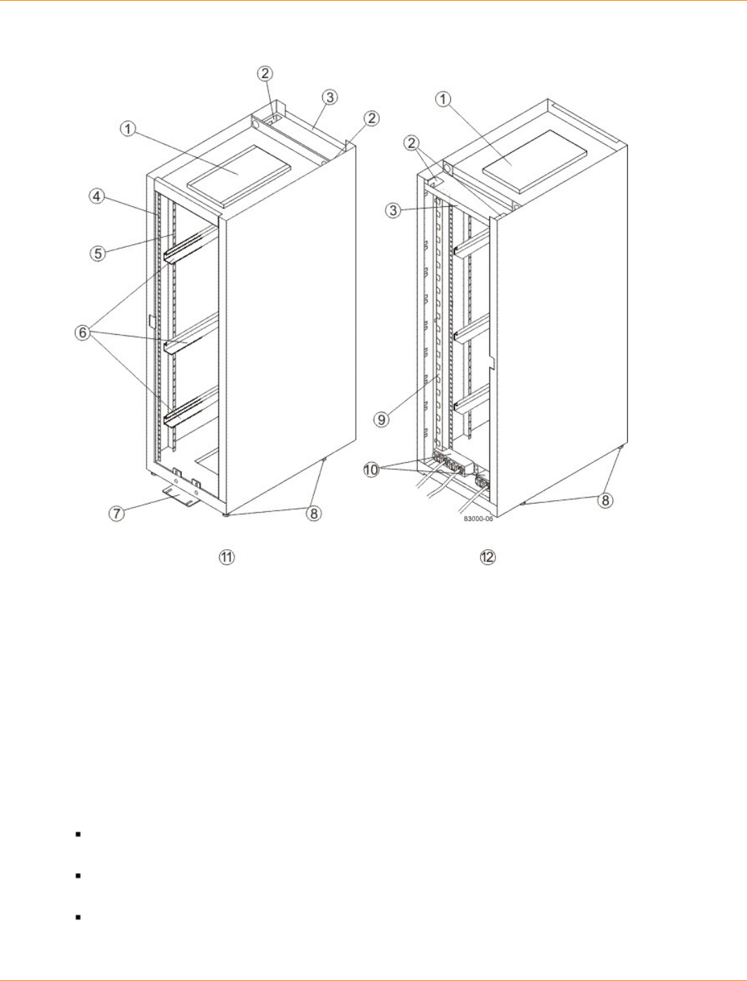
SANtricity_10.77 February 2011
LSI Corporation
- 103 -
Components of the Model 3040 40U Cabinet – Front View and Rear View
1. Ventilation Cover
2. Interface Cable Access Openings
3. Rear Plate
4. EIA Support Rails
5. Vertical Support Rails
6. Cabinet Mounting Rails
7. Stability Foot
8. Adjustable Leveling Feet
9. Power Strip
10. AC Power Distribution Units
11. Front of the Cabinet
12. Rear of the Cabinet
You can configure the cabinet to meet your data storage needs. Standard cabinet configurations consist of a
combination of these types of trays:
Controller tray – Contains one or two controllers, one interconnect-battery canister, and two power-fan
canisters.
Controller-drive tray – Contains drives, redundant cooling fans and power supplies, and, depending on
the model, one or two controllers.
Drive tray – Contains drives, redundant cooling fans and power supplies, and one or two environmental
services monitors (ESMs).
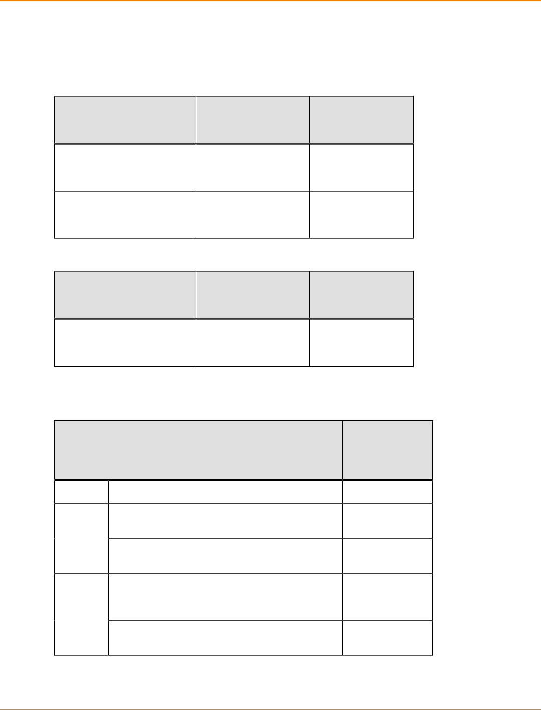
SANtricity_10.77 February 2011
LSI Corporation
- 104 -
Model 3040 40U Cabinet Configurations
The following table lists the limitations when populating your cabinet with DE6900 drive trays.
DE6900 Drive Trays That Can Be Installed in the Cabinet
Number of Controller Trays Controller Tray Maximum Number
of DE6900 Drive
Trays
1 (72A PDUs are required
if you are installing DE6900
drive trays)
CE7900 controller tray 8
2 (72A PDUs are required
if you are installing DE6900
drive trays)
CE7900 controller tray 8
DE6600 Drive Trays That Can Be Installed in the Cabinet
Number of Controller Trays Controller Tray Maximum Number
of DE6900 Drive
Trays
1 (72A PDUs are required
if you are installing DE6600
drive trays)
CDE2600-60
controller-drive tray 2
The following table displays the maximum combination of FC4600 drive trays allowed in one cabinet.
FC4600 Drive Trays That Can Be Installed in the Cabinet
Number of Controller Trays or Controller-Drive Trays and
the Specific Types Maximum
Number of
FC4600 Drive
Trays
0 No controller trays or controller-drive trays 13
CE7900 controller tray, CE7922 controller tray, or
CE6998 controller tray 121
CDE4900 controller-drive tray or CDE3994
controller-drive tray 6
CE7900 controller trays, CE7922 controller trays,
CE6998 controller trays, or CDE4900 controller-
drive trays
102
CDE4900 controller-drive tray or CDE3994
controller-drive tray 11
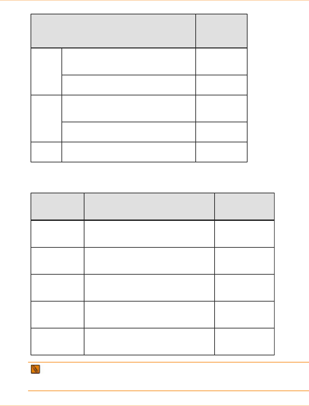
SANtricity_10.77 February 2011
LSI Corporation
- 105 -
Number of Controller Trays or Controller-Drive Trays and
the Specific Types Maximum
Number of
FC4600 Drive
Trays
CE7900 controller trays, CE7922 controller trays,
CE6998 controller trays, or CDE4900 controller-
drive trays
93
CDE4900 controller-drive tray or CDE3994
controller-drive tray 10
CE7900 controller trays, CE7922 controller trays,
CE6998 controller trays, or CDE4900 controller-
drive trays
84
CDE4900 controller-drive tray or CDE3994
controller-drive tray 9
5 CDE4900 controller-drive tray or CDE3994
controller-drive tray 8
The following table displays the maximum combination of DM1300 drive trays allowed in one cabinet.
DM1300 Drive Trays That Can Be Installed in the Cabinet
Number of
Controller-Drive
Trays
Controller-Drive Tray Maximum Number
of DM1300 Drive
Trays
1 AM1331 or AM1333 controller-drive tray
or AM1532 controller-drive tray or AM1932
controller-drive tray
3
2 AM1331 or AM1333 controller-drive trays
or AM1532 controller-drive tray or AM1932
controller-drive trays
6
3 AM1331 or AM1333 controller-drive trays
or AM1532 controller-drive tray or AM1932
controller-drive trays
9
4 AM1331 or AM1333 controller-drive trays
or AM1532 controller-drive tray or AM1932
controller-drive trays
12
5 AM1331 or AM1333 controller-drive trays
or AM1532 controller-drive tray or AM1932
controller-drive trays
15
NOTE These configurations are based on the standard storage array configurations that are shipped
from the factory. The number of controller trays, controller-drive trays, and drive trays in a cabinet can be
modified at the customer site.
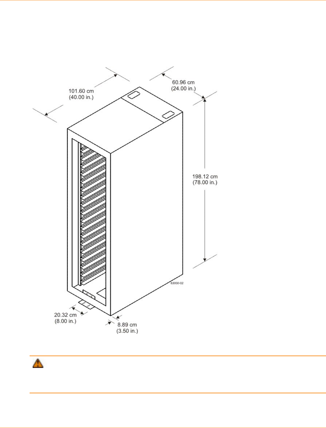
SANtricity_10.77 February 2011
LSI Corporation
- 106 -
Model 3040 40U Cabinet Dimensions
Make sure that the area where you will place the cabinet has sufficient space to install and service the cabinet
and the storage array components.
Dimensions of the Model 3040 40U Cabinet – Front View
Model 3040 40U Cabinet Weights
ATTENTION Risk of damage to flooring – The weight of the cabinet might exceed the flooring
load specifications. A fully-loaded 3040 40U cabinet weighs up to 1090 kg (2400 lb). Before you install your
components, make sure that your flooring is strong enough to support the weight of the cabinet and its
components.
Record the total weight of your cabinet and its components. Keep this information in a place where you can
refer to it when you check for flooring load restrictions or elevator weight restrictions.

SANtricity_10.77 February 2011
LSI Corporation
- 107 -
Weights of the Model 3040 40U Cabinet, Trays, and Crate
Component Weight Notes
Cabinet 138.80 kg (306.0
lb) Empty with the rear door
installed
Power distribution unit (PDUs [pair]) 19.96 kg (44.0
lb)
Mounting rails (pair) 1.59 kg (3.50 lb)
CE7900 controller tray 36.79 kg (81.1
lb) Maximum configuration
CE7922 controller tray 36.79 kg (81.1
lb) Maximum configuration
CE6998 controller tray 36.79 kg (81.1
lb) Maximum configuration
CDE2600 controller-drive tray 27 kg (59.52 lb) Maximum configuration
CDE2600-60 controller-drive tray 105.2 kg (232.0
lb) Maximum configuration
CDE4900 controller-drive tray 38.15 kg (84.1
lb) Maximum configuration
CDE3994 controller-drive tray 38.60 kg (85.1
lb) Maximum configuration
AM1331 controller-drive tray 25.58 kg (63.0
lb) Maximum configuration
AM1333 controller-drive tray 25.58 kg (63.0
lb) Maximum configuration
AM1932 controller-drive tray 25.58 kg (63.0
lb) Maximum configuration
DE6600 drive tray 105.2 kg (232.0
lb) Maximum configuration
DE6900 drive tray 100.0 kg (220.0
lb) Maximum configuration
FC4600 drive tray 42.18 kg (93.0
lb) Maximum configuration
AT2655 drive tray 40.0 kg (88.0 lb) Maximum configuration
FC2610 drive tray 40.0 kg (88.0 lb) Maximum configuration
FC2600 drive tray 40.4 kg (89.0 lb) Maximum configuration
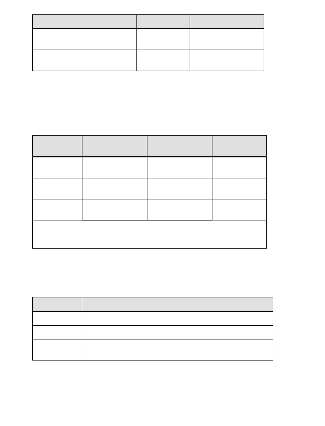
SANtricity_10.77 February 2011
LSI Corporation
- 108 -
Component Weight Notes
DM1300 drive tray 25.86 kg (57.0
lb) Maximum configuration
Shipping crate (worldwide
shipments only) 136.08 kg (300.0
lb) Empty
Model 3040 40U Cabinet Temperature and Humidity
An air-conditioned cooling environment helps to make sure that the ambient temperatures surrounding the
cabinet are maintained. This type of environment helps your storage array components to run at operating
temperatures that will enhance the overall reliability of your storage.
Temperature Requirements and Humidity Requirements for the Model 3040 40U Cabinet
Environment Temperature Range Temperature
Change Relative
Humidity
Operating* 10°C to 35° C
(50°F to 95°F) 10°C per hour
(18°F per hour) 20% to 80%
Storage –10°C to 45°C
(14°F to 113°F) 15°C per hour
(27°F per hour) 10% to 90%
Transit –40°C to 65°C
(–40°F to 149°F) 20°C per hour
(36°F per hour) 5% to 95%
*If you plan to operate a storage array at an altitude between 1000 m to 3000 m
(3280 ft to 9842 ft) above sea level, lower the environmental temperature 1.7°C
(3.3°F) for every 1000 m (3280 ft) above sea level.
The maximum allowed dew point is 28°C (82°F), with a maximum humidity gradient of 10 percent per hour.
Model 3040 40U Cabinet Altitude Ranges
Altitude Ranges for the Model 3040 40U Cabinet
Environment Altitude
Operating 30.5 m (100 ft) below sea level to 3000 m (9842 ft) above sea level
Storage 30.5 m (100 ft) below sea level to 3000 m (9842 ft) above sea level
Transit 30.5 m (100 ft) below sea level to 12,000 m (40,000 ft) above sea
level
Model 3040 40U Cabinet Airflow, Heat Dissipation, and Service Clearances
Air flows through the cabinet from the front to the rear. Allow at least 76 cm (30 in.) of clearance in front of the
cabinet, and at least 61 cm (24 in.) of clearance behind the cabinet for service clearance, ventilation, and heat
dissipation. The total depth required for the cabinet plus clearance is 240 cm (94 in.). The cabinet does not
require side clearances.
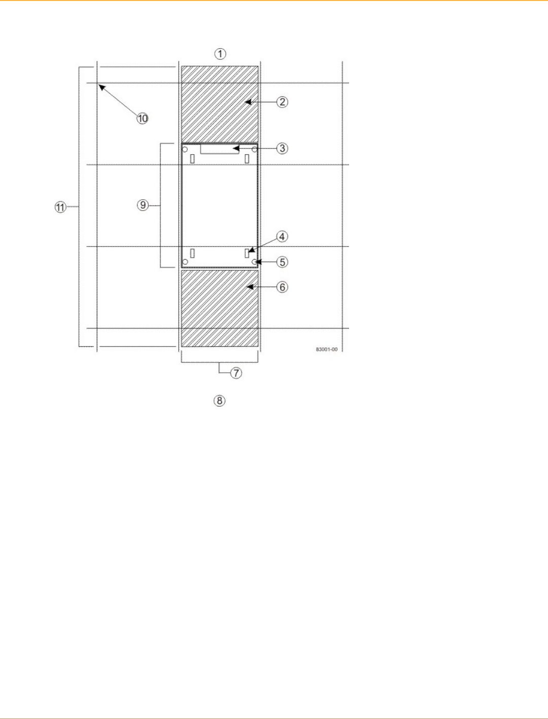
SANtricity_10.77 February 2011
LSI Corporation
- 109 -
Area Requirements for the Model 3040 40U Cabinet – Top View
1. Rear of the Cabinet
2. Required Rear Service Area – 61 cm (24 in.)
3. Cable Access
4. Roller Caster
5. Adjustable Leveling Foot
6. Required Front Service Area – 76 cm (30 in.)
7. Width of the Cabinet – 61 cm (24 in.)
8. Front of the Cabinet
9. Depth of the Cabinet – 102 cm (40 in.)
10. Computer Floor Grid – 61 cm x 61 cm (24 in. x 24 in.)
11. Total Clearance Depth – 240 cm (94 in.)
Do not place anything in front of the cabinet or behind the cabinet that would interfere with air flow. The
cabinet’s ventilation is essential to make sure that ambient air is available to correctly cool your storage array.
Total heat dissipation is a function of the number and type of trays that are installed in the cabinet. Use
the table in Model 3040 40U Cabinet Power Requirements to calculate the total heat dissipation for your
configuration. For the total Btu/Hr for the cabinet, add the value for each of the individual trays together.
Model 3040 40U Cabinet Site Wiring and Power
The AC power distribution units in the cabinet use common industrial wiring.
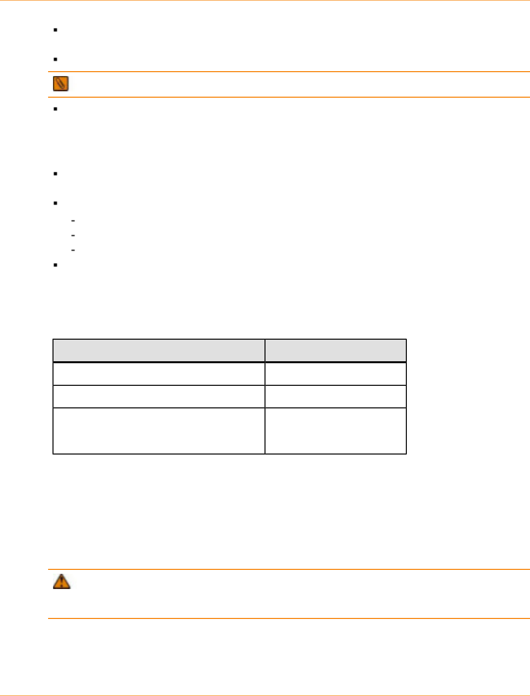
SANtricity_10.77 February 2011
LSI Corporation
- 110 -
AC power source – The AC power source must provide the correct voltage, current, and frequency that
are specified on the tray and the serial number label.
Protective ground – Site wiring must include a protective ground connection to the AC power source.
NOTE Protective ground is also known as safety ground or chassis ground.
Circuit overloading – Power circuits and associated circuit breakers must provide enough power and
overload protection. An external, independent AC power source that is isolated from large switching loads
is recommended to run your storage array. The power going to the AC power distribution boxes and other
components in the cabinet should not have air-conditioning motors, elevator motors, or factory loads on
the same circuit.
Tray power distribution – All units attached to the two individual power strip outlets inside the cabinet
must be wide-ranging between 180 VAC and 264 VAC, 50–60 Hz.
Power interruptions – The cabinet and trays can withstand these applied voltage interruptions:
Input transient – 50 percent of the nominal voltage
Duration – One-half cycle
Maximum frequency – Once every 10 seconds
Power failures – If a total power failure occurs, the trays in the cabinet automatically perform a power#on
recovery sequence without operator intervention.
Model 3040 40U Cabinet Power Requirements
AC Power Requirements for the Model 3040 40U Cabinet
Parameter Requirement
Nominal voltage 200 VAC to 240 VAC
Frequency 50 Hz to 60 Hz
Nominal current (typical)
Varies depending upon the number and type
of trays that are installed in the cabinet.
10.0 A to 24.0 A
The Model 3040 40U cabinet contains power strips that provide either 48A or 72A of usable power.
The 48A power strips provide up to 48A of usable power through four 12A banks of power. This power is
provided to 21 power outlets that are located in the rear of the cabinet.
The 72A power strips provide up to 72A of usable power through six 12A banks of power. This power is
provided by 24 ICE320 power outlets on each power distribution unit (PDU). The 72A power strips are only
used with the DE6900 drive tray.
ATTENTION Risk of exceeding maximum amperage – You must calculate the load of the devices in
the cabinet to make sure that you do not exceed the 24.0 A maximum. As an example, one controller tray (2.2
A) and four drive trays (1.8 A each) would draw approximately 9.4 A (2.2 + 1.8 + 1.8 + 1.8 + 1.8).

SANtricity_10.77 February 2011
LSI Corporation
- 111 -
Power Calculations and Heat Calculations for the Model 3040 40U Cabinet
Component KVA Watts Btu/
Hr Amps (240
VAC)
Cabinet PDU (for 48A
PDUs) 9.60* 9600* 32,784*
Cabinet PDU (for 72A
PDUs) 14.4 14400 49,176
Cabinet PDU/12A bank
(for both 48A and 72A
PDUs)
2.40* 2400* 8196*
CE7900 controller tray 0.562 540 1842 2.25
CE7922 controller tray 0.562 540 1842 2.25
CE6998 controller tray 0.546 525 1811 2.19
CDE2600-60 controller-
drive tray 1.268 1222 4180 6.30
CDE4900 controller-drive
tray 0.624 600 2047 2.50
CDE3994 controller-drive
tray 0.624 600 2047 2.50
AM1331or AM1333
controller-drive tray 0.398 394 1346 2.30
AM1932 controller-drive
tray 0.458 453 1548 2.30
DE6600 drive tray
(requires 72A PDUs) 1.268 1222 4180 6.30
DE6900 drive tray
(requires 72A PDUs) 1.71 1632 5570 6.00
FC4600 drive tray 0.462 444 1517 1.85
AT2655 drive tray 0.329 316 1078 1.65
FC2610 drive tray 0.384 369 1526 1.65
FC2600 drive tray 0.375 366 1229 1.65
DM1300 drive tray 0.362 358 1224 2.30
*The maximum ratings at 200 VAC. The Btu/Hr calculation is based on
the maximum current rating that the power distribution unit can provide.
SANtricity_10.77 February 2011
LSI Corporation
- 112 -
Model 3040 40U Cabinet Grounding
To prevent personal injury or electrostatic discharge (ESD), make sure that the cabinet is correctly grounded.
The ground must have the correct low impedance so that there is no build-up of voltage on any equipment or
on any exposed surfaces. Grounding is especially important to eliminate shock hazards, and to facilitate the
operation of circuit-protective devices.
Use good metal-to-metal bonding techniques, such as bared metal washers and internal star washers or
external star washers. It is not enough to provide ground paths through anodized material or hinges. Never
use sheet metal screws to attach a ground. Refer to the Underwriters Laboratory (UL) safety agency for more
information about the correct grounding techniques to use.
Consider a low impedance grounding and lightning protection when you plan for and install an electrical
system. Your electrical contractor must meet local code requirements and national code requirements when
installing an electrical system.
NOTE Local codes and local standards might have more stringent requirements. Always comply with
local codes.
Model 3040 40U Cabinet Power Distribution
The Model 3040 40U cabinet has two identical AC power distribution units, each of which has a separate
power cord. Depending on your configuration, each AC power distribution unit supports either North American
(USA and Canada) components or worldwide (excluding USA and Canada) components. Each AC power
distribution unit includes these parts:
Two cords per side, NEMA L6-30P or IEC 309
Four circuit breakers per side, 15 A each, for 48A PDUs
Six circuit breakers per side, 15 A each, for 72A PDUs
Twenty IEC 320 power outlets per side, plus an additional outlet for the optional fan tray
NOTE For pluggable equipment, the electrical outlet must be installed near the equipment and must be
easily accessible.
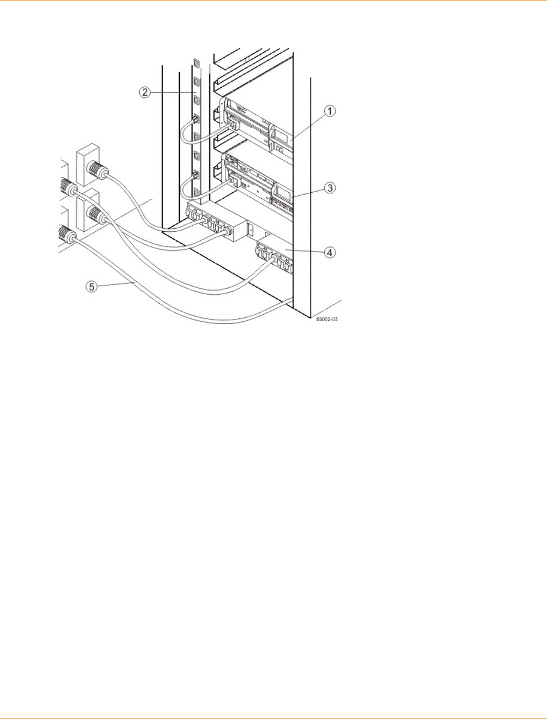
SANtricity_10.77 February 2011
LSI Corporation
- 113 -
Circuit Breakers and Electrical Outlets for 48A PDUs
1. Controller Tray
2. Power Strip
3. Drive Tray
4. AC Power Distribution Unit
5. AC Power Cords
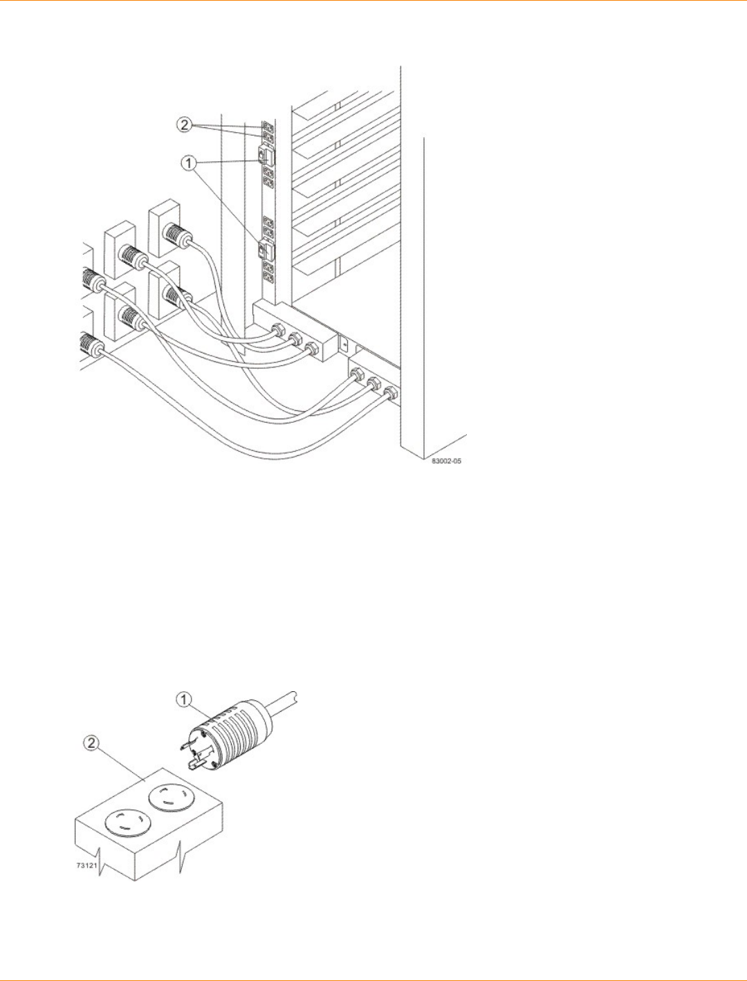
SANtricity_10.77 February 2011
LSI Corporation
- 114 -
Circuit Breakers and Electrical Outlets for 72A PDUs
1. Circuit Breakers
2. Electrical Outlets
Model 3040 40U Cabinet Power Cords and Receptacles
The cabinet is equipped with two AC power distribution units. Each AC power distribution unit contains four
15-A circuit breakers on each side. Depending on your installation, the AC power distribution units in your
cabinet have either North American (USA and Canada) power cords or worldwide (except USA and Canada)
power cords. Connect each AC power distribution unit power cord to an independent power source outside of
the cabinet.
NEMA L6-30 Power Cord and Receptacle (North American)
1. 250-VAC, 30-A Plug (North American)
2. Receptacle

SANtricity_10.77 February 2011
LSI Corporation
- 115 -
IEC 309 Power Cord and Receptacle (Worldwide, except USA and Canada)
1. 230-VAC, 32-A Plug (Worldwide, except USA and Canada)
2. Receptacle
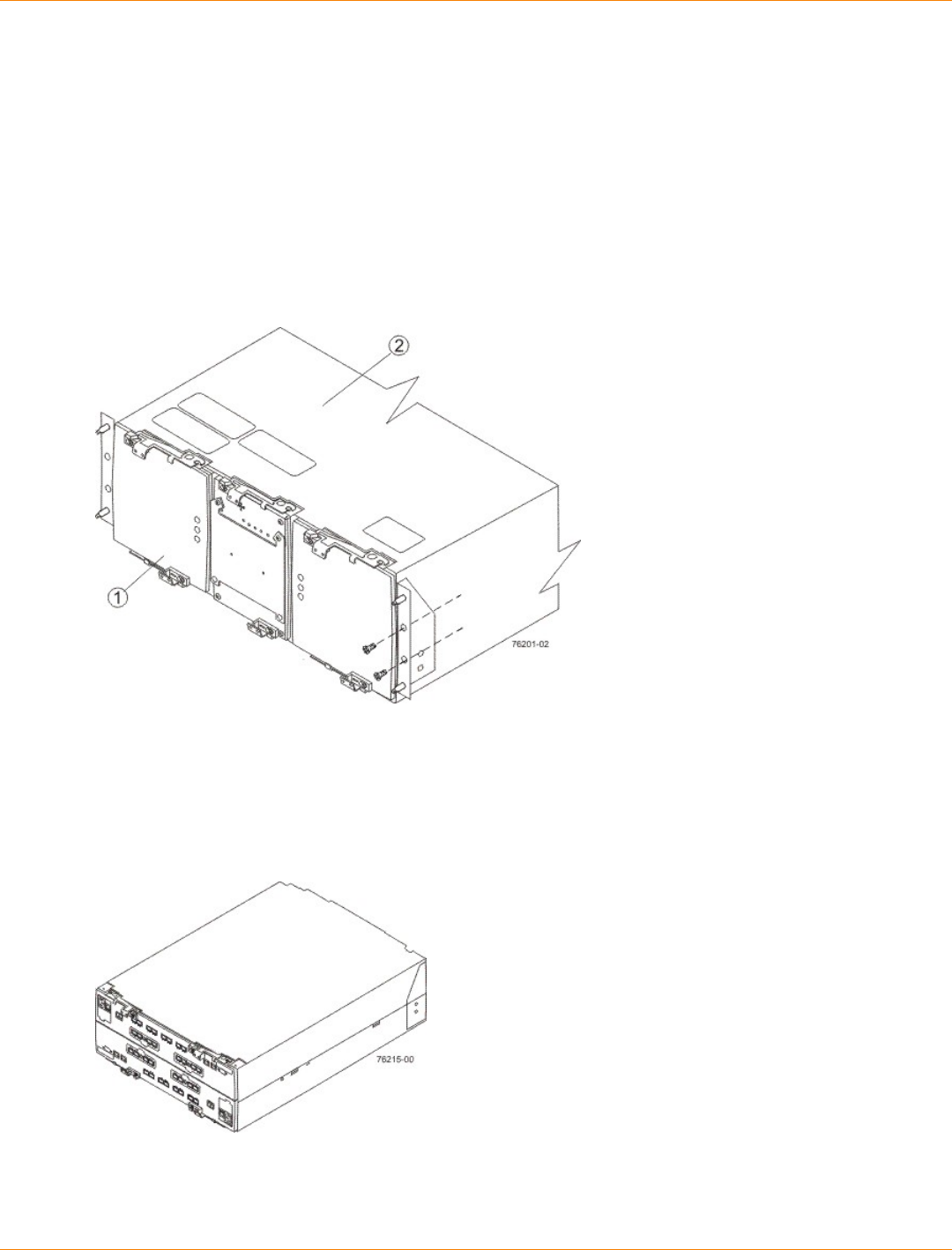
SANtricity_10.77 February 2011
LSI Corporation
- 116 -
Specifications of the CE7900 Controller Tray
The CE7900 controller tray is a compact, rackmounted unit that provides high-capacity disk storage for Fibre
Channel, Infiniband, and iSCSI environments, depending on the choice of the host interface card.
The CE7900 controller tray contains two power-fan canisters that include the power supplies and fans.
One power-fan canister can provide electrical power and cooling to the controller tray if the other power-fan
canister is turned off or malfunctions.
In the front, behind the bezel, are two power-fan canisters and one interconnect-battery canister.
CE7900 Controller Tray – Front View
1. Power-Fan Canisters (Left and Right) and the Interconnect-Battery Canister (Center)
2. Top of the CE7900 Controller Tray
In the rear are two controller canisters with controller A on the top and controller B on the bottom. Controller A
is upside down, and controller B is right-side up.
CE7900 Controller Tray – Rear View
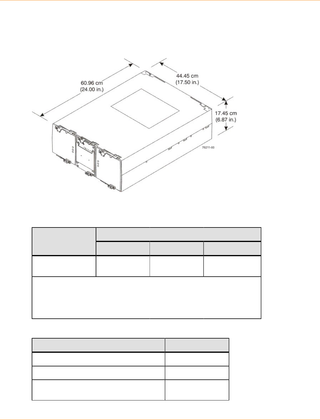
SANtricity_10.77 February 2011
LSI Corporation
- 117 -
CE7900 Controller Tray Dimensions
The CE7900 controller tray conforms to the 48.3-cm (19-in.) rack standard.
Dimensions of the CE7900 Controller Tray – Front View
CE7900 Controller Tray Weight
Weights of the CE7900 Controller Tray
WeightUnit
Maximum* Empty** Shipping***
CE7900 controller
tray 36.79 kg (81.1 lb) 13.15 kg (29.0 lb) 49.44 kg (109.0 lb)
*Maximum weight indicates a controller tray with all of its components installed.
**Empty weight indicates a controller tray with the controller canisters, the power-fan
canisters, and the interconnect-battery canister removed.
***Shipping weight indicates the maximum weight of a controller tray and all shipping
material.
Component Weights of the CE7900 Controller Tray
Component Weight
Controller canister 6.24 kg (13.8 lb)
Power-fan canister 3.719 kg (8.20 lb)
Interconnect-battery canister (with two batteries
installed) 4.082 kg (9.00 lb)
SANtricity_10.77 February 2011
LSI Corporation
- 118 -
Component Weight
Battery canister 1.134 kg (2.50 lb)
CE7900 Controller Tray Shipping Dimensions
Shipping Carton Dimensions for the CE7900 Controller Tray
Height Width Depth
44.45 cm (17.50 in.) – Includes the
height of the pallet. 62.23 cm (24.50 in.) 78.74 cm (31.00 in.)
CE7900 Controller Tray Temperature and Humidity
Temperature Requirements and Humidity Requirements for the CE7900 Controller Tray
Condition Parameter Requirement
Operating range 10°C to 40°C (32°F to 104°F)
Maximum rate of change 10°C (18°F) per hour
Storage range –10°C to 65°C (14°F to 149°F)
Maximum rate of change 15°C (27°F) per hour
Transit range –40°C to 65°C (–40°F to
149°F)
Temperature*
Maximum rate of change 20°C (36°F) per hour
Operating range 20% to 80%
Storage range 10% to 93%
Transit range 5% to 95%
Maximum dew point 26°C (79°F)
Relative humidity
(no condensation)
Maximum gradient 10% per hour
*If you plan to operate a system at an altitude between 1000 m to 3048 m (3280 ft
to 10,000 ft) above sea level, lower the environmental temperature 1.7°C (3.3°F) for
every 1000 m (3280 ft) above sea level.
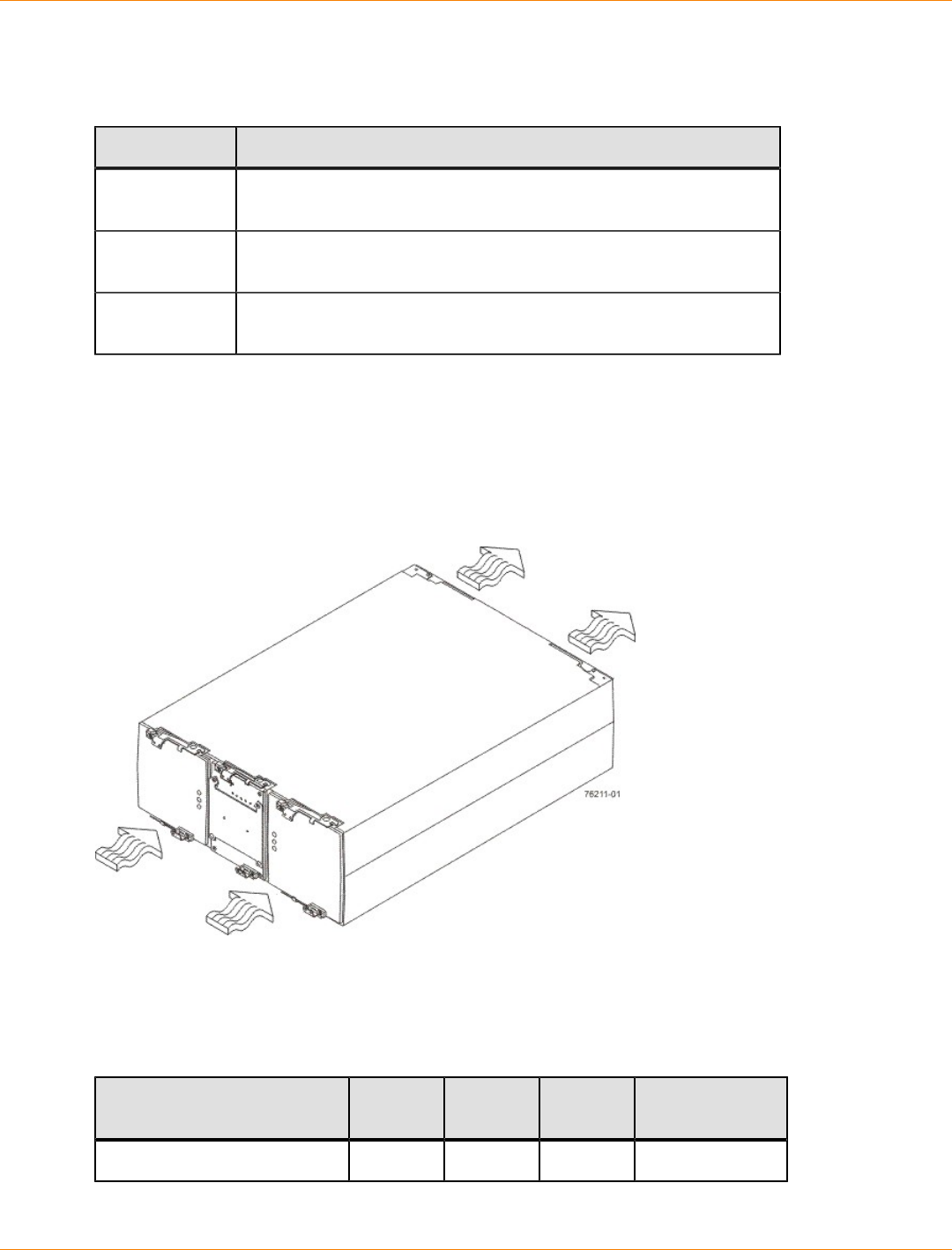
SANtricity_10.77 February 2011
LSI Corporation
- 119 -
CE7900 Controller Tray Altitude Ranges
Altitude Ranges for the CE7900 Controller Tray
Environment Altitude
Operating 30.5 m (100 ft) below sea level to 3048 m (10,000 ft) above sea
level
Storage 30.5 m (100 ft) below sea level to 3048 m (10,000 ft) above sea
level
Transit 30.5 m (100 ft) below sea level to 12,000 m (40,000 ft) above sea
level
CE7900 Controller Tray Airflow and Heat Dissipation
Airflow goes from the front of the controller tray to the rear of the controller tray. Allow at least 76 cm (30 in.)
of clearance in front of the controller tray and at least 61 cm (24 in.) of clearance behind the controller tray for
service clearance, ventilation, and heat dissipation.
Airflow Through the CE7900 Controller Tray – Front View
The tabulated power and heat dissipation values in the following table are the maximum measured operating
power. Maximum configuration units are typically operated at higher data rates or have larger random access
memory (RAM) capabilities.
Power Ratings and Heat Dissipation for the CE7900 Controller Tray
Component KVA Watts
(AC) Btu/Hr Amps (240
VAC)
CE7900 controller tray 0.562 540 1842 2.25

SANtricity_10.77 February 2011
LSI Corporation
- 120 -
CE7900 Controller Tray Acoustic Noise
Sound Levels for the CE7900 Controller Tray
Measurement Level
Sound power 6.0 bels
Sound pressure 60 dBA
CE7900 Controller Tray Site Wiring and Power
The agency ratings for the CE7900 controller tray are 5.40 A at 100 VAC and 2.25 A at 240 VAC. These
ratings are the overall maximum currents for this system.
The CE7900 controller tray uses wide-ranging redundant power supplies that automatically accommodate
voltages to the AC power source. The power supplies operate within the range of 90 VAC to 264 VAC, at
a minimum frequency of 50 Hz and a maximum frequency of 60 Hz. Voltage levels can fluctuate within the
specified range. The power supplies meet standard voltage requirements for both North American (USA and
Canada) operation and worldwide (except USA and Canada) operation. The power supplies use standard
industrial wiring with line-to-neutral or line-to-line power connections.
Keep this information in mind when you prepare the installation site for the controller tray:
Protective ground – Site wiring must include a protective ground connection to the AC power source.
NOTE Protective ground is also known as safety ground or chassis ground.
Circuit overloading – Power circuits and associated circuit breakers must provide enough power
and overload protection. To prevent damage to the controller tray, isolate its power source from large
switching loads, such as air-conditioning motors, elevator motors, and factory loads.
Power interruptions – The controller tray can withstand these applied voltage interruptions:
Input transient – 50 percent of the nominal voltage
Duration – One-half cycle
Maximum frequency – Once every 10 seconds
Power failures – If a total power failure occurs, the controller tray automatically performs a power-on
recovery sequence without operator intervention after the power is restored.
NOTE When a power failure occurs, the controller tray uses battery power to back up the data that is in
cache.
If you are installing a large storage array configuration, you must make sure that you are supplying the correct
AC source voltages and not creating an over-current situation.
When calculating the cabinet’s total power requirements, take the controller tray’s 540 W and divide it by
the cabinet’s input voltage. If you are using 240 VAC, you obtain a maximum current of 2.25 A. Then add
the amperage of each drive tray. If each drive tray uses 1.85 A, then 10 drive trays would use 18.5 A. In this
example, your total storage array would use a rated maximum of 20.75 A.
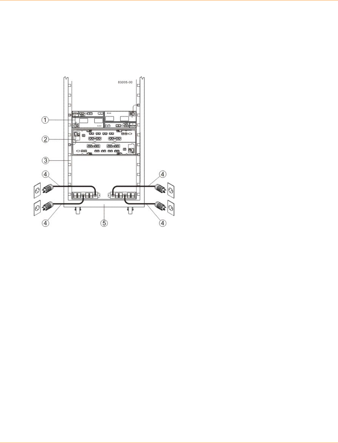
SANtricity_10.77 February 2011
LSI Corporation
- 121 -
CE7900 Controller Tray Power Cords and Receptacles
Each CE7900 controller tray is shipped with two AC power cords. Each AC power cord connects one of
the power-fan canisters in the controller tray to an independent, external AC power source, such as a wall
receptacle, or to any acceptable uninterruptible power supply (UPS).
AC Power Distribution to a CE7900 Storage Array – Rear View
1. AC Power Cord to the Drive Tray
2. AC Power Cord to the CE7900 Controller Tray
3. Power Strip Portion of the Power Distribution Unit
4. AC Power Cord to the External Power Source
5. Rear of the Cabinet
The optional UPS equipment is either placed external from the cabinet, or it is placed at the bottom of the
cabinet. UPS devices provide a continuous supply of electrical power when utility power is unavailable. Some
UPS equipment can also provide power conditioning to protect your storage array from voltage spikes, line
noise, and undesirable power fluctuations, such as brownout. Contact an electrician to help you select and
install the correct UPS equipment.
The switched-rack power distribution unit (PDU) is also available for some customer-supplied cabinets. These
new PDUs are stand-alone, network-manageable devices that allow programmable control of the power
outlets. This capability enables you to control each outlet independently, manage power sequencing, and
monitor the aggregate current draw through the switched-rack PDU. Additional equipment may be used to
support temperature monitoring as well.
Preparing the Network for the Controllers
If you plan to use Ethernet connections from the storage management station to the controllers, you will use
the out-of-band management method. For this configuration, meet with your network administrator before
you order and install the equipment so that you can prepare for the setup and management of the devices
on the IP network. Each controller uses its Ethernet management ports to connect to the IP network and
communicate with the other devices on the IP network (often requiring a special application to set up the
protocol).

SANtricity_10.77 February 2011
LSI Corporation
- 122 -
Your network administrator can pre-assign the addresses that you need to manage the communication
between the devices on the IP network. Depending on your storage configuration, you will need the following
addresses:
Up to two network IP addresses for each controller
Up to two subnet mask addresses for each controller
Either two IPv4 addresses (one static and one dynamic) or one IPv6 address for each controller
A Dynamic Host Configuration Protocol (DHCP) address for each controller
If switches are used in your storage environment, you must know if zoning will be used, and how it will be
configured.
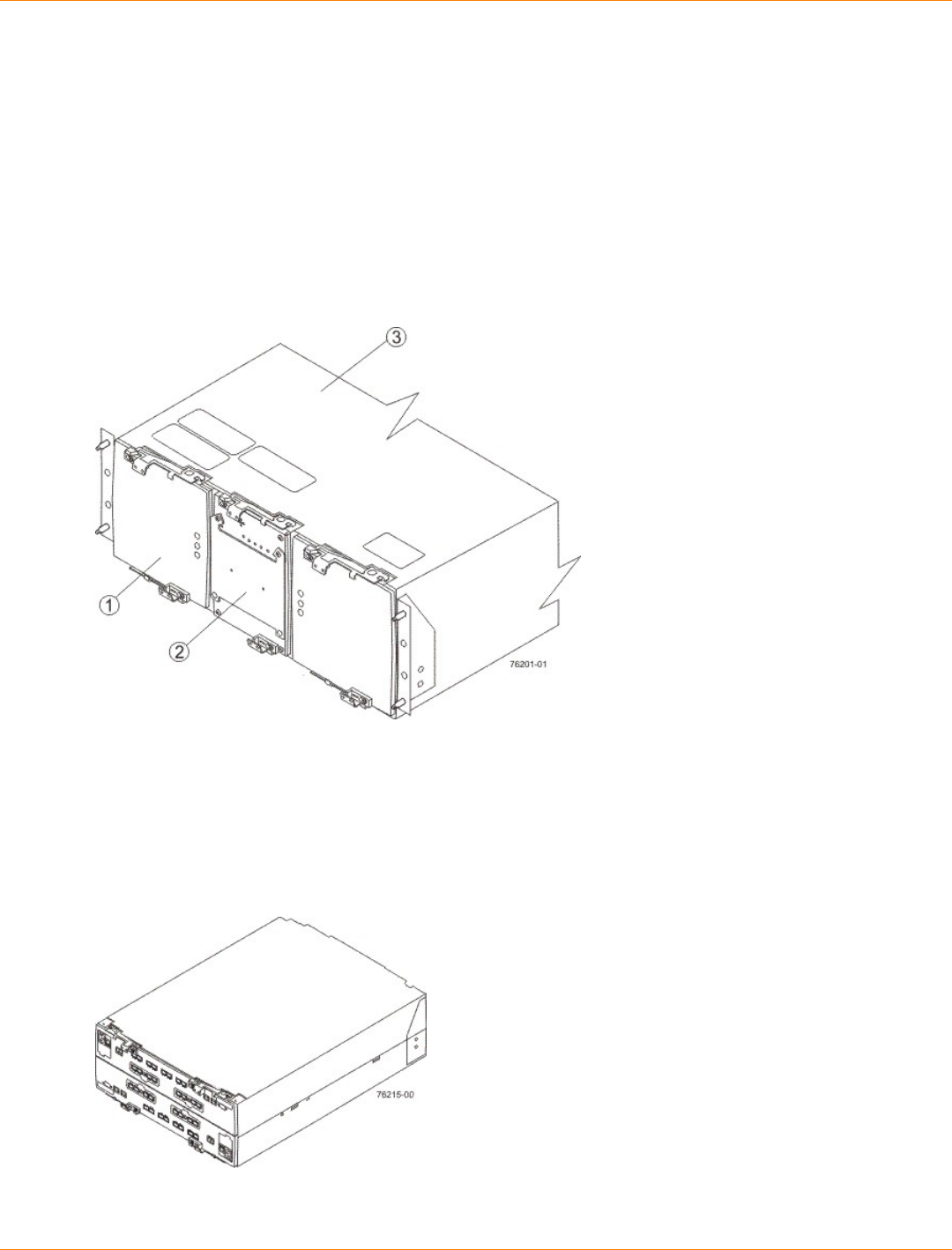
SANtricity_10.77 February 2011
LSI Corporation
- 123 -
Specifications of the CE7922 Controller Tray
The CE7922 controller tray is a compact, rackmounted unit that provides high-capacity disk storage for
Infiniband environments.
The CE7922 controller tray contains two power-fan canisters that include the power supplies and fans.
One power-fan canister can provide electrical power and cooling to the controller tray if the other power-fan
canister is turned off or malfunctions.
In the front, behind the bezel, are two power-fan canisters and one interconnect-battery canister.
CE7922 Controller Tray – Front View
1. Power-Fan Canisters (Left and Right)
2. Interconnect-Battery Canister (Center)
3. Top of the CE7922 Controller Tray
In the rear are two controller canisters, with controller A on the top and controller B on the bottom. Controller
A is upside down, and controller B is right-side up.
CE7922 Controller Tray – Rear View

SANtricity_10.77 February 2011
LSI Corporation
- 124 -
CE7922 Controller Tray Dimensions
The CE7922 controller tray conforms to the 48.3-cm (19-in.) rack standard.
Dimensions of the CE7922 Controller Tray – Front View
CE7922 Controller Tray Weight
Weights of the CE7922 Controller Tray
WeightUnit
Maximum* Empty** Shipping***
CE7922 controller
tray 36.79 kg (81.1 lb) 13.15 kg (29.0 lb) 49.44 kg (109.0 lb)
*Maximum weight indicates acontroller tray with all of its components installed.
**Empty weight indicates a controller tray with the controller canisters, the power-fan
canisters, and the interconnect-battery canister removed.
***Shipping weight indicates the maximum weight of a controller tray and all shipping
material.
Component Weights of the CE7922 Controller Tray
Component Weight
Controller canister 6.24 kg (13.8 lb)
Power-fan canister 3.719 kg (8.20 lb)
Interconnect-battery canister (with two
batteries installed) 4.082 kg (9.00 lb)

SANtricity_10.77 February 2011
LSI Corporation
- 125 -
Component Weight
Battery canister 1.134 kg (2.50 lb)
CE7922 Controller Tray Shipping Dimensions
Shipping Carton Dimensions for the CE7922 Controller Tray
Height Width Depth
44.45 cm (17.50 in.) – Includes the
height of the pallet. 62.23 cm (24.50 in.) 78.74 cm (31.00 in.)
CE7922 Controller Tray Temperature and Humidity
Temperature Requirements and Humidity Requirements for the CE7922 Controller Tray
Condition Parameter Requirement
Operating range 10°C to 40°C (32°F to 104°F)
Maximum rate of change 10°C (18°F) per hour
Storage range –10°C to 65°C (14°F to 149°F)
Maximum rate of change 15°C (27°F) per hour
Transit range –40°C to 65°C (–40°F to
149°F)
Temperature*
Maximum rate of change 20°C (36°F) per hour
Operating range 20% to 80%
Storage range 10% to 93%
Transit range 5% to 95%
Maximum dew point 26°C (79°F)
Relative humidity
(no condensation)
Maximum gradient 10% per hour
*If you plan to operate a system at an altitude between 1000 m to 3048 m (3280 ft
to 10,000 ft) above sea level, lower the environmental temperature 1.7°C (3.3°F) for
every 1000 m (3280 ft) above sea level.

SANtricity_10.77 February 2011
LSI Corporation
- 126 -
CE7922 Controller Tray Altitude Ranges
Altitude Ranges for the CE7922 Controller Tray
Environment Altitude
Operating 30.5 m (100 ft) below sea level to 3048 m (10,000 ft) above sea
level
Storage 30.5 m (100 ft) below sea level to 3048 m (10,000 ft) above sea
level
Transit 30.5 m (100 ft) below sea level to 12,000 m (40,000 ft) above sea
level
CE7922 Controller Tray Airflow and Heat Dissipation
Airflow goes from the front of the controller tray to the rear of the controller tray. Allow at least 76 cm (30 in.)
in clearance in front of the controller tray and at least 61 cm (24 in.) in clearance behind the controller tray for
service clearance, ventilation, and heat dissipation.
Airflow Through the CE7922 Controller Tray – Front View
The tabulated power and heat dissipation values in the following table are the maximum measured operating
power. Maximum configuration units are typically operated at higher data rates or have larger random access
memory (RAM) capabilities.
Power Ratings and Heat Dissipation for the CE7922 Controller Tray
Component KVA Watts
(AC) Btu/Hr Amps (240
VAC)
CE7922 controller tray 0.562 540 1842 2.25
SANtricity_10.77 February 2011
LSI Corporation
- 127 -
CE7922 Controller Tray Acoustic Noise
Sound Levels for the CE7922 Controller Tray
Measurement Level
Sound power 6.0 bels
Sound pressure 60 dBA
CE7922 Controller Tray Site Wiring and Power
The agency ratings for the CE7922 controller tray are 5.40 A at 100 VAC and 2.25 A at 240 VAC. These
ratings are the overall maximum currents for this system.
The CE7922 controller tray uses wide-ranging redundant power supplies that automatically accommodate
voltages to the AC power source. The power supplies operate within the range of 90 VAC to 264 VAC, at
a minimum frequency of 50 Hz and a maximum frequency of 60 Hz. Voltage levels can fluctuate within the
specified range. The power supplies meet standard voltage requirements for both North American (USA and
Canada) operation and worldwide (except USA and Canada) operation. The power supplies use standard
industrial wiring with line-to-neutral or line-to-line power connections.
Consider this information when you prepare the installation site for the controller tray:
Protective ground – Site wiring must include a protective ground connection to the AC power source.
NOTE Protective ground is also known as safety ground or chassis ground.
Circuit overloading – Power circuits and associated circuit breakers must provide enough power
and overload protection. To prevent damage to the controller tray, isolate its power source from large
switching loads, such as air-conditioning motors, elevator motors, and factory loads.
Power interruptions – The controller tray can withstand these applied voltage interruptions:
Input transient – 50 percent of the nominal voltage
Duration – One-half cycle
Maximum frequency – Once every 10 seconds
Power failures – If a total power failure occurs, the controller tray automatically performs a power-on
recovery sequence without operator intervention after the power is restored.
NOTE When a power failure occurs, the controller tray uses battery power to back up the data that is in
cache.
If you are installing a large storage array configuration, you must make sure that you are supplying the correct
AC source voltages and not creating an over-current situation.
When calculating the cabinet’s total power requirements, take the controller tray’s 540 W, and divide it by
the cabinet’s input voltage. If you are using 240 VAC, you obtain a maximum current of 2.25 A. Then add
the amperage of each drive tray. If each drive tray uses 1.85 A, then 10 drive trays would use 18.5 A. In this
example, your total storage array would use a rated maximum of 20.75 A.

SANtricity_10.77 February 2011
LSI Corporation
- 128 -
CE7922 Controller Tray Power Cords and Receptacles
Each CE7922 controller tray is shipped with two AC power cords. Each AC power cord connects one of
the power-fan canisters in the controller tray to an independent, external AC power source, such as a wall
receptacle or an uninterruptible power supply (UPS).
AC Power Distribution to a CE7922 Storage Array – Rear View
1. AC Power Cord to the Drive Tray
2. AC Power Cord to the CE7922 Controller Tray
3. Power Strip Portion of the Power Distribution Unit
4. AC Power Cord to the External Power Source
5. Rear of the Cabinet
The optional UPS equipment is either placed external from the cabinet, or it is placed at the bottom of the
cabinet. UPS devices provide a continuous supply of electrical power when utility power is unavailable. Some
UPS equipment can also provide power conditioning to protect your storage array from voltage spikes, line
noise, and undesirable power fluctuations, such as brownout. Contact an electrician to help you select and
install the correct UPS equipment.
Switched-rack power distribution units (PDUs) are also available for some customer-supplied cabinets. These
new PDUs are stand-alone, network-manageable devices that allow programmable control of the power
outlets. This capability enables you to control each outlet independently, manage power sequencing, and
monitor the aggregate current draw through the switched-rack PDU. Additional equipment may be used to
support temperature monitoring as well.
Preparing the Network for the Controllers
If you plan to use Ethernet connections from the storage management station to the controllers, you will use
the out-of-band management method. For this configuration, meet with your network administrator before
you order and install the equipment so that you can prepare for the setup and management of the devices
on the IP network. Each controller uses its Ethernet management ports to connect to the IP network and
communicate with the other devices on the IP network (often requiring a special application to set up the
protocol).

SANtricity_10.77 February 2011
LSI Corporation
- 129 -
Your network administrator can pre-assign the addresses that you need to manage the communication
between the devices on the IP network. Depending on your storage configuration, you will need the following
addresses:
Up to two network IP addresses for each controller
Up to two subnet mask addresses for each controller
Either two IPv4 addresses (one static and one dynamic) or one IPv6 address for each controller
A Dynamic Host Configuration Protocol (DHCP) address for each controller
If switches are used in your storage environment, you must know if zoning will be used, and how it will be
configured.
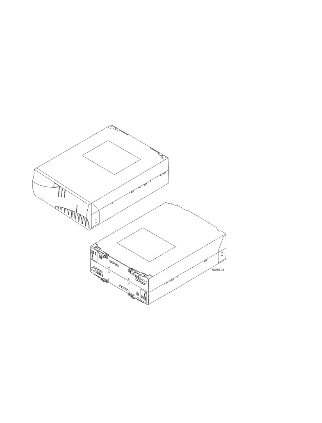
SANtricity_10.77 February 2011
LSI Corporation
- 130 -
Specifications of the CE6998 Controller Tray
The CE6998 controller tray is a compact, rackmounted unit that provides high-capacity disk storage for Fibre
Channel environments.
The CE6998 controller tray contains two power-fan canisters that include the power supplies and fans.
One power-fan canister can provide electrical power and cooling to the controller tray if the other power-fan
canister is turned off or malfunctions.
In the front, behind the bezel, are two power-fan canisters and one interconnect-battery canister. In the rear
are two controller canisters, with controller A on the top and controller B on the bottom. Controller A is upside
down, and controller B is right-side up.
CE6998 Controller Tray – Front View and Rear View
CE6998 Controller Tray Dimensions
The CE6998 controller tray conforms to the 48.3-cm (19-in.) rack standard.
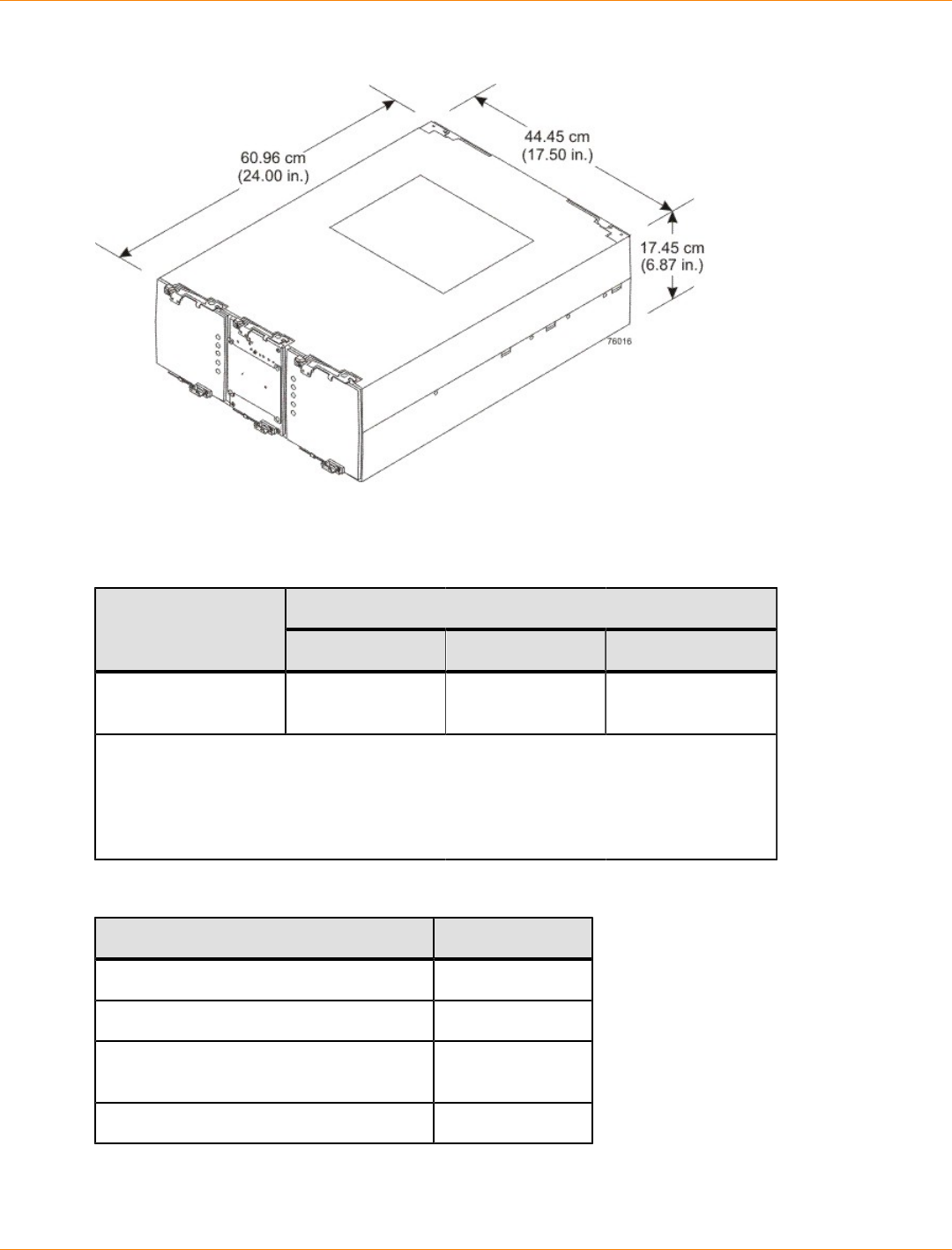
SANtricity_10.77 February 2011
LSI Corporation
- 131 -
Dimensions of the CE6998 Controller Tray – Front View
CE6998 Controller Tray Weight
Weights of the CE6998 Controller Tray
WeightUnit
Maximum* Empty** Shipping***
CE6998 controller
tray 36.79 kg (81.1 lb) 13.15 kg (29.0 lb) 49.44 kg (109.0 lb)
*Maximum weight indicates a controller tray with all of its components installed.
**Empty weight indicates a controller tray with the controller canisters, the power-fan
canisters, and the interconnect-battery canister removed.
***Shipping weight indicates the maximum weight of the controller tray and all
shipping material.
Component Weights of the CE6998 Controller Tray
Component Weight
Controller canister 6.24 kg (13.8 lb)
Power-fan canister 3.719 kg (8.20 lb)
Interconnect-battery canister (with two
batteries installed) 4.082 kg (9.00 lb)
Battery canister 1.134 kg (2.50 lb)
SANtricity_10.77 February 2011
LSI Corporation
- 132 -
CE6998 Controller Tray Shipping Dimensions
Shipping Carton Dimensions for the CE6998 Controller Tray
Height Width Depth
44.45 cm (17.50 in.) – Includes the
height of the pallet. 62.23 cm (24.50 in.) 78.74 cm (31.00 in.)
CE6998 Controller Tray Temperature and Humidity
Temperature Requirements and Humidity Requirements for the CE6998 Controller Tray
Condition Parameter Requirement
Operating range 0°C to 40°C (32°F to 104°F)
Maximum rate of change 10°C (18°F) per hour
Storage range –10°C to 65°C (14°F to 149°F)
Maximum rate of change 15°C (27°F) per hour
Transit range –40°C to 65°C (–40°F to
149°F)
Temperature*
Maximum rate of change 20°C (36°F) per hour
Operating range 20% to 80%
Storage range 10% to 93%
Transit range 5% to 95%
Maximum dew point 26°C (79°F)
Relative humidity
(no condensation)
Maximum gradient 10% per hour
*If you plan to operate a system at an altitude between 1000 m to 3048 m (3280 ft
to 10,000 ft) above sea level, lower the environmental temperature 1.7°C (3.3°F) for
every 1000 m (3280 ft) above sea level.
CE6998 Controller Tray Altitude Ranges
Altitude Ranges for the CE6998 Controller Tray
Environment Altitude
Operating 30.5 m (100 ft) below sea level to 3048 m (10,000 ft) above sea
level
Storage 30.5 m (100 ft) below sea level to 3048 m (10,000 ft) above sea
level
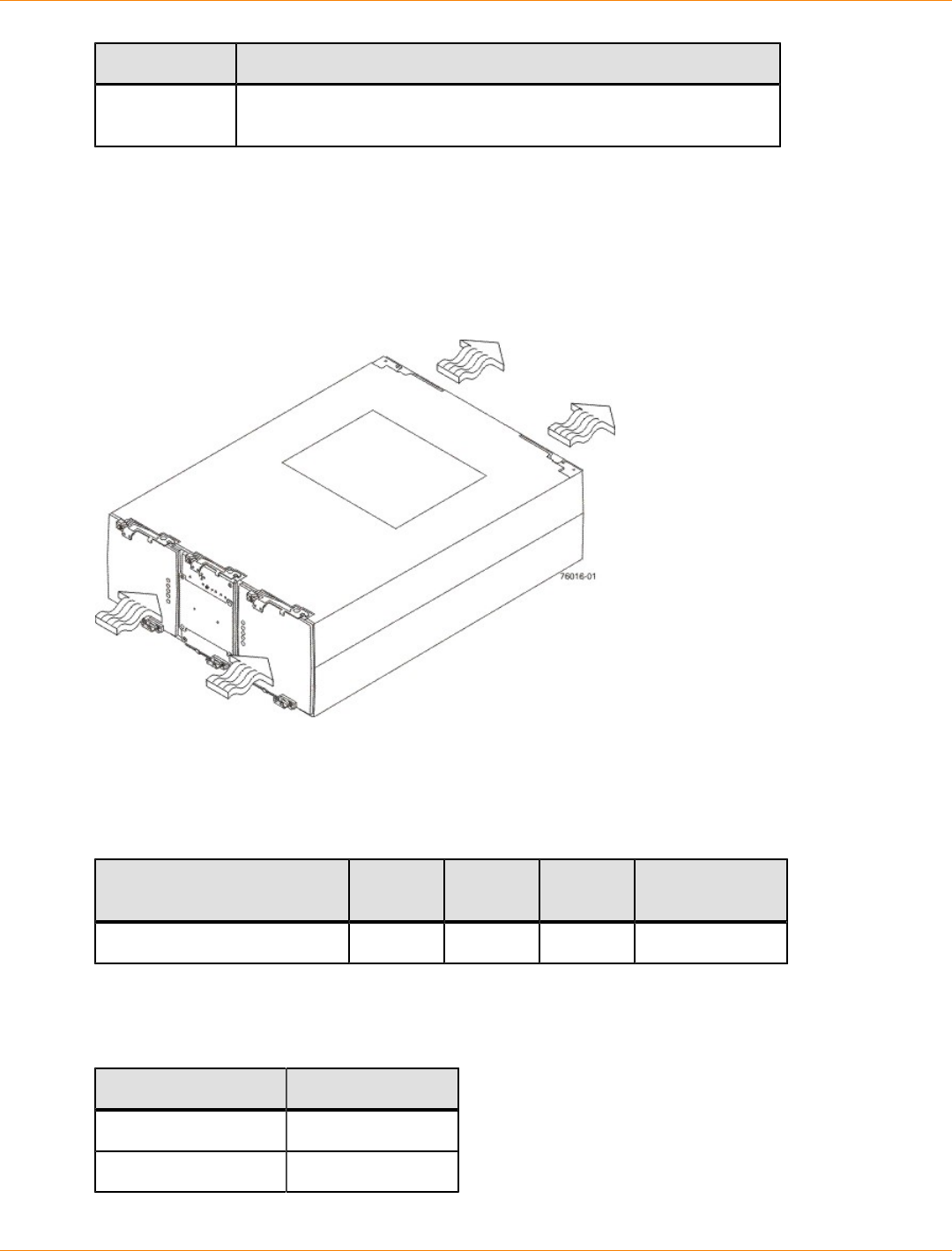
SANtricity_10.77 February 2011
LSI Corporation
- 133 -
Environment Altitude
Transit 30.5 m (100 ft) below sea level to 12,000 m (40,000 ft) above sea
level
CE6998 Controller Tray Airflow and Heat Dissipation
Airflow goes from the front of the controller tray to the rear of the controller tray. Allow at least 76 cm (30 in.)
of clearance in front of the controller tray and at least 61 cm (24 in.) of clearance behind the controller tray for
service clearance, ventilation, and heat dissipation.
Airflow Through the CE6998 Controller Tray – Front View
The tabulated power and heat dissipation values in the following table are the maximum measured operating
power. Maximum configuration units are typically operated at higher data rates or have larger random access
memory (RAM) capabilities.
Power Ratings and Heat Dissipation for the CE6998 Controller Tray
Component KVA Watts
(AC) Btu/Hr Amps (240
VAC)
CE6998 controller tray 0.546 525 1791 2.19
CE6998 Controller Tray Acoustic Noise
Sound Levels for the CE6998 Controller Tray
Measurement Level
Sound power 6.0 bels
Sound pressure 60 dBA
SANtricity_10.77 February 2011
LSI Corporation
- 134 -
CE6998 Controller Tray Site Wiring and Power
The agency ratings for the CE6998 controller tray are 5.25 A at 100 VAC and 2.19 A at 240 VAC. These
ratings are the overall maximum currents for this system.
The CE6998 controller tray uses wide-ranging redundant power supplies that automatically accommodate
voltages to the AC power source. The power supplies operate within the range of 90 VAC to 264 VAC, at
a minimum frequency of 50 Hz and a maximum frequency of 60 Hz. Voltage levels can fluctuate within the
specified range. The power supplies meet standard voltage requirements for both North American (USA and
Canada) operation and worldwide (except USA and Canada) operation. The power supplies use standard
industrial wiring with line-to-neutral or line-to-line power connections.
Keep this information in mind when you prepare the installation site for the controller tray:
Protective ground – Site wiring must include a protective ground connection to the AC power source.
NOTE Protective ground is also known as safety ground or chassis ground.
Circuit overloading – Power circuits and associated circuit breakers must provide enough power
and overload protection. To prevent damage to the controller tray, isolate its power source from large
switching loads, such as air-conditioning motors, elevator motors, and factory loads.
Power interruptions – The controller tray can withstand these applied voltage interruptions:
Input transient – 50 percent of the nominal voltage
Duration – One-half cycle
Maximum frequency – Once every 10 seconds
Power failures – If a total power failure occurs, the controller tray automatically performs a power-on
recovery sequence without operator intervention after the power is restored.
NOTE When a power failure occurs, the controller tray uses battery power to back up the data that is in
cache.
If you are installing a large storage array configuration, you must make sure that you are supplying the correct
AC source voltages, and not creating an over-current situation.
When calculating the cabinet’s total power requirements, take the controller tray’s 525 W, and divide it by
the cabinet’s input voltage. If you are using 240 VAC, you obtain a maximum current of 2.19 A. Then add
the amperage of each drive tray. If each drive tray uses 1.85 A, then 10 drive trays would use 18.5 A. In this
example, your total storage array would use a rated maximum of 20.69 A.
CE6998 Controller Tray Power Cords and Receptacles
Each CE6998 controller tray is shipped with two AC power cords. Each AC power cord connects one of
the power-fan canisters in the controller tray to an independent, external AC power source, such as a wall
receptacle, or to any uninterruptible power supply (UPS).
The optional UPS equipment is either placed external from the cabinet, or it is placed at the bottom of the
cabinet. UPS devices provide a continuous supply of electrical power when utility power is unavailable. Some
UPS equipment can also provide power conditioning to protect your storage array from voltage spikes, line
noise, and undesirable power fluctuations, such as brownout. Contact an electrician to help you select and
install the correct UPS equipment.

SANtricity_10.77 February 2011
LSI Corporation
- 135 -
Switched-rack PDUs are also available for some customer-supplied cabinets. These new PDUs are stand-
alone, network-manageable devices that allow programmable control of the power outlets. This capability
enables you to control each outlet independently, manage power sequencing, and monitor the aggregate
current draw through the switched-rack PDU. Additional equipment may be used to support temperature
monitoring as well.
Preparing the Network for the Controllers
If you plan to use Ethernet connections from the storage management station to the controllers, you will use
the out-of-band management method. For this configuration, meet with your network administrator before
you order and install the equipment so that you can prepare for the setup and management of the devices
on the IP network. Each controller uses its Ethernet management ports to connect to the IP network and
communicate with the other devices on the IP network (often requiring a special application to set up the
protocol).
Your network administrator can pre-assign the addresses that you need to manage the communication
between the devices on the IP network. Depending on your storage configuration, you will need the following
addresses:
Up to two network IP addresses for each controller
Up to two subnet mask addresses for each controller
Either two IPv4 addresses (one static and one dynamic) or one IPv6 address for each controller
A Dynamic Host Configuration Protocol (DHCP) address for each controller
If switches are used in your storage environment, you must know if zoning will be used, and how it will be
configured.
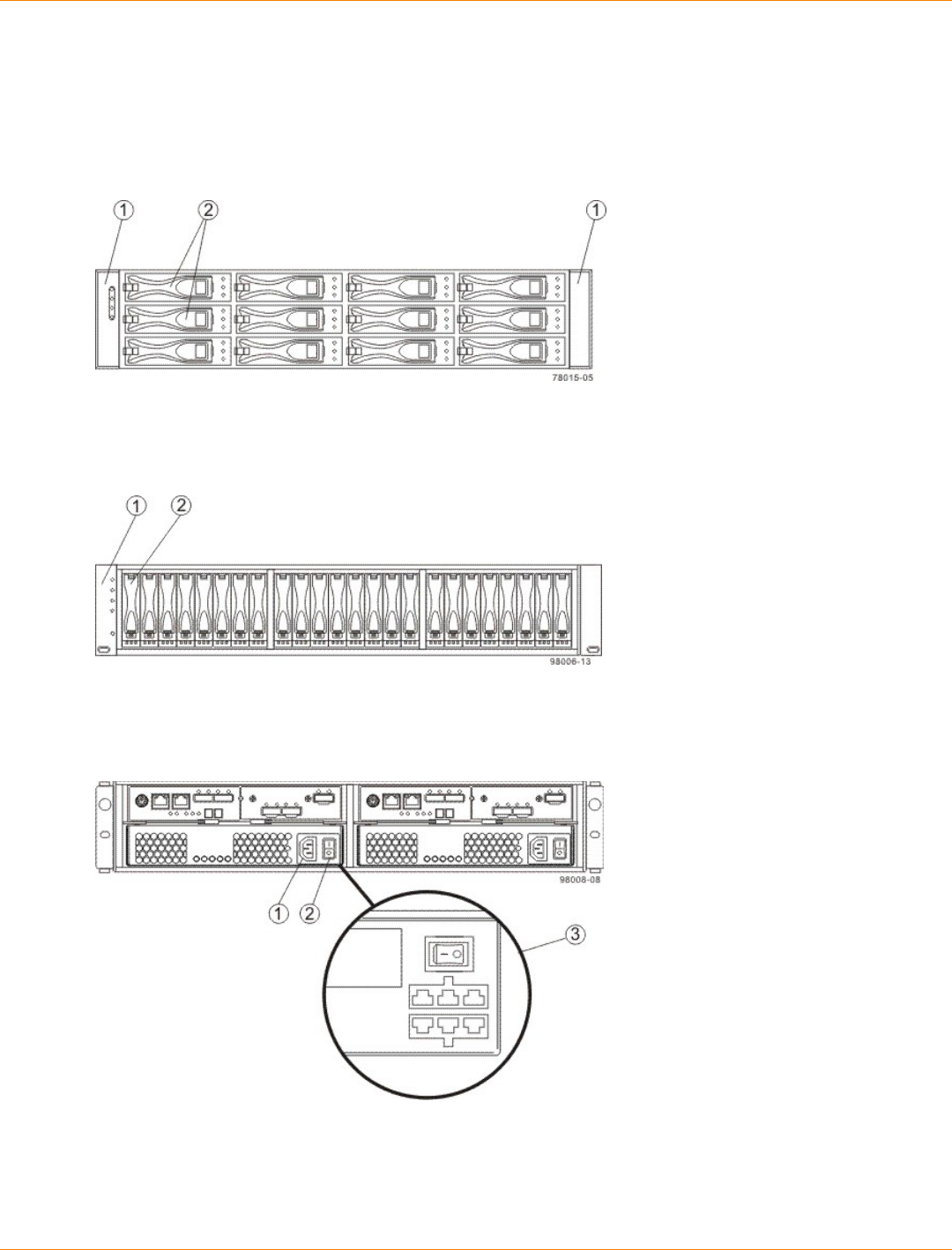
SANtricity_10.77 February 2011
LSI Corporation
- 136 -
Specifications of the CDE2600 Controller-Drive Tray
The CDE2600 controller-drive tray is available in a rackmount model, with a capacity of either 12 drives or 24
drives.
CDE2600 Controller-Drive Tray with 12 Drives – Front View
1. End Caps (the Left End Cap Has the Controller-Drive Tray Summary LEDs)
2. Drive Canisters
CDE2600 Controller-Drive Tray with 24 Drives – Front View
1. End Caps (the Left End Cap Has the Controller-Drive Tray Summary LEDs)
2. Drive Canisters
CDE2600 Controller-Drive Tray Duplex Configuration – Rear View
1. AC Power Connector on the AC Power-Fan Canister
2. AC Power Switch
3. DC Power Connector and DC Power Switch on the Optional DC Power-Fan Canister
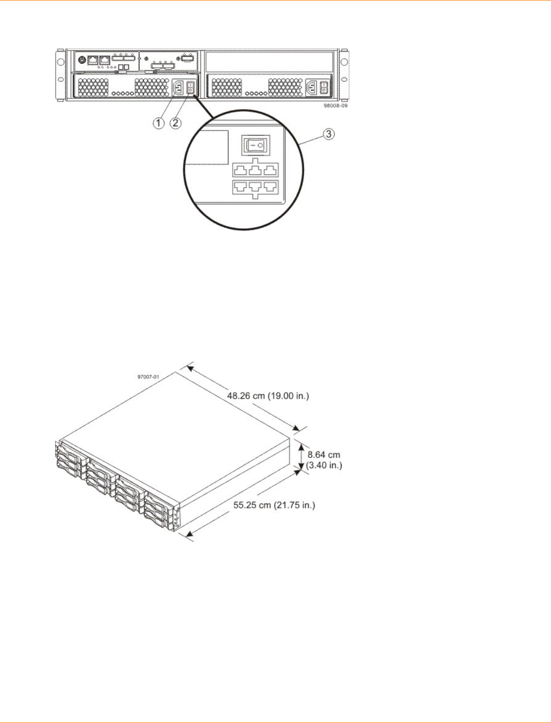
SANtricity_10.77 February 2011
LSI Corporation
- 137 -
CDE2600 Controller-Drive Tray Simplex Configuration – Rear View
1. AC Power Connector
2. AC Power Switch
3. Optional DC Power Connector and DC Power Switch
CDE2600 Controller-Drive Tray Dimensions
The CDE2600 controller-drive tray conforms to the 48.3-cm (19.0-in.) rack standard.
Dimensions of the CDE2600 Controller-Drive Tray (12-Drive Model) – Front View
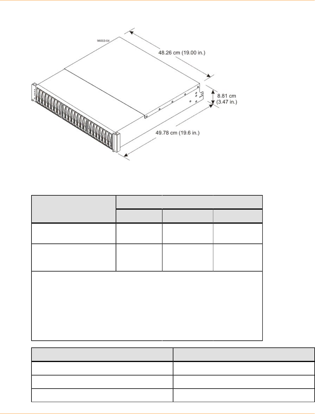
SANtricity_10.77 February 2011
LSI Corporation
- 138 -
Dimensions of the CDE2600 Controller-Drive Tray (24-Drive Model) – Front View
CDE2600 Controller-Drive Tray Weight
Weights of the CDE2600 Controller-Drive Tray
WeightUnit
Maximum* Empty** Shipping***
Controller-Drive Tray, with
twelve 8.89-cm (3.5-in.) drives 27 kg (59.52
lb) 18.60 kg (41.01
lb) 31.75 kg (70.0
lb)
Controller-Drive Tray, with
twenty-four 6.35-cm (2.5-in.)
drives
26 kg (57.32
lb) 21.70 kg (47.84
lb) 31.75 kg (70.0
lb)
*Maximum weight indicates a controller-drive tray with all of its drives and other
components installed. Because drive weights can vary greatly, this value can vary from
the value specified as much as either 0.3 kg (0.66 lb) times the maximum number of
drives per controller-drive tray for 3.5-in. SATA drives or 0.08 kg (0.18 lb) times the
maximum number of drives per controller-drive tray for 2.5-in. SATA drives.
**Empty weight indicates a controller-drive tray with the controller canisters, the power-
fan canisters, and the drives removed.
***Shipping weight indicates the maximum weight of the controller-drive tray and
allshipping material.
Component Weight
Controller canister 2.131 kg (4.70 lb)
Power-fan canister 2.500 kg (5.51 lb)
2.5-in. SATA drive 0.3 kg (0.66 lb)
SANtricity_10.77 February 2011
LSI Corporation
- 139 -
Component Weight
3.5-in. SATA drive 1.0 kg (2.2 lb)
CDE2600 Controller-Drive Tray Shipping Dimensions
Shipping Carton Dimensions for the CDE2600 Controller-Drive Tray
Height Width Depth
24.13 cm (9.5 in.)* 63.50 cm (25 in.) 58.42 cm (23 in.)
24.13 cm (9.5 in.)** 68.58 cm (27 in.) 58.42 cm (23 in.)
*Controller-Drive Tray with twelve 3.5-in. drives.
**Controller-Drive Tray with twenty-four 2.5-in. drives.
CDE2600 Controller-Drive Tray Temperature and Humidity
Temperature Requirements and Humidity Requirements for the CDE2600 Controller-Drive Tray
Condition Parameter Requirement
Operating range (both cabinet
and subsystem) 10°C to 35°C (50°F to 104°F)
Maximum rate of change 10°C (50°F) per hour
Storage range –10°C to 50°C (14°F to
122°F)
Maximum rate of change 15°C (59°F) per hour
Transit range –40°C to 60°C (–40°F to
140°F)
Temperature
Maximum rate of change 20°C (68°F) per hour
Operating range (both cabinet
and subsystem) 20% to 80%
Storage range 10% to 90%
Transit range 5% to 90%
Operating gradient 10°C (50°F) per hour
maximum
Storage gradient 15°C (59°F) per hour
maximum
Relative
humidity (no
condensation)
Transit gradient 20°C (68°F) per hour
maximum
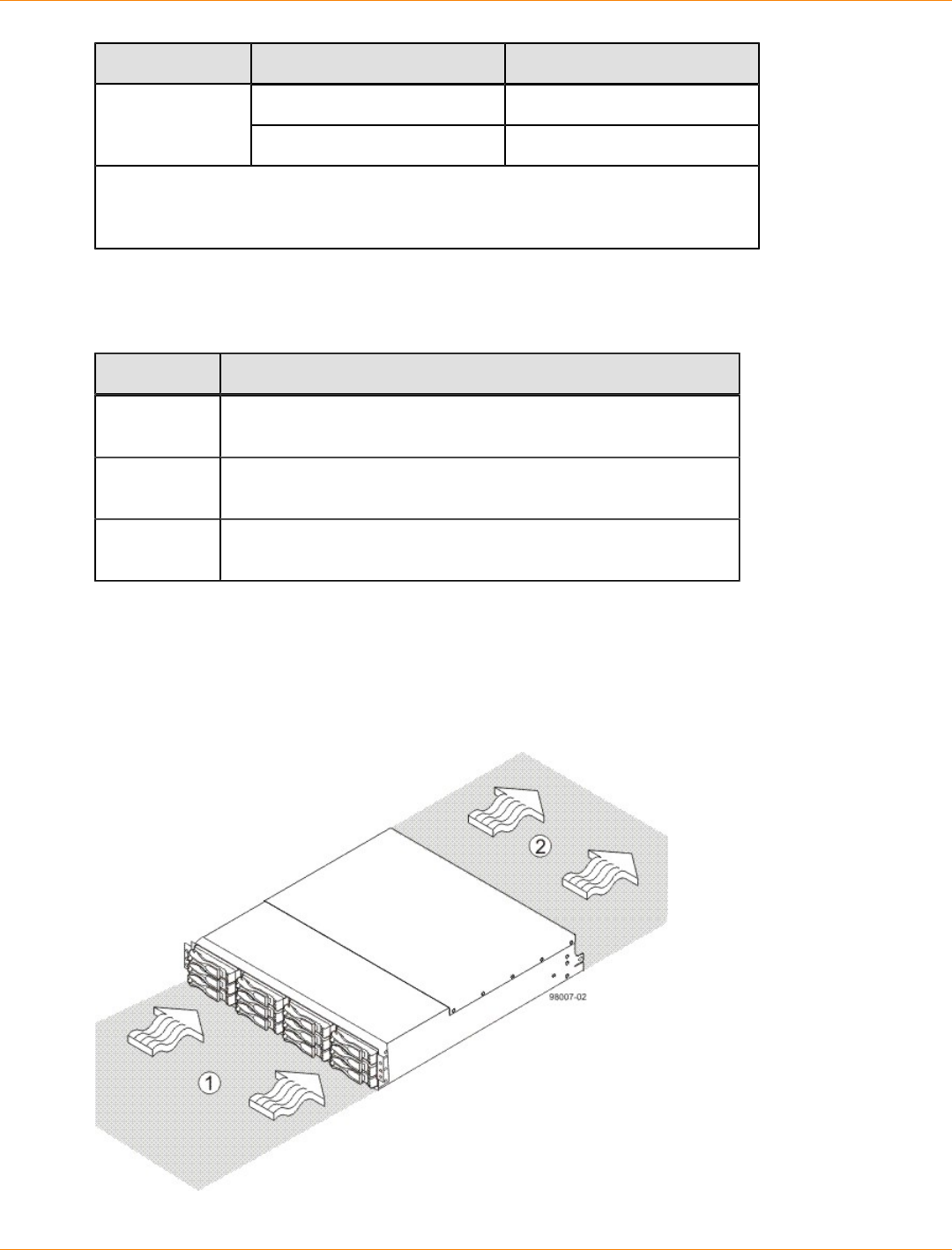
SANtricity_10.77 February 2011
LSI Corporation
- 140 -
Condition Parameter Requirement
Maximum dew point 26°C (79°F)
Maximum gradient 10% per hour
*If you plan to operate a system at an altitude between 1000 m to 3000 m (3280 ft
to 9842 ft) above sea level, lower the environmental temperature 1.7°C (3.3°F) for
every 1000 m (3280 ft) above sea level.
CDE2600 Controller-Drive Tray Altitude Ranges
Altitude Ranges for the CDE2600 Controller-Drive Tray
Environment Altitude
Operating 30.5 m (100 ft) below sea level to 3000 m (9840 ft) above sea
level
Storage 30.5 m (100 ft) below sea level to 3000 m (9840 ft) above sea
level
Transit 30.5 m (100 ft) below sea level to 12,000 m (40,000 ft) above
sea level
CDE2600 Controller-Drive Tray Airflow and Heat Dissipation
Allow at least 76 cm (30 in.) of clearance in front of the controller-drive tray and 61 cm (24 in.) behind the
controller-drive tray for service clearance, ventilation, and heat dissipation.
Airflow Through the Controller-Drive Tray with 12 Drives – Front View
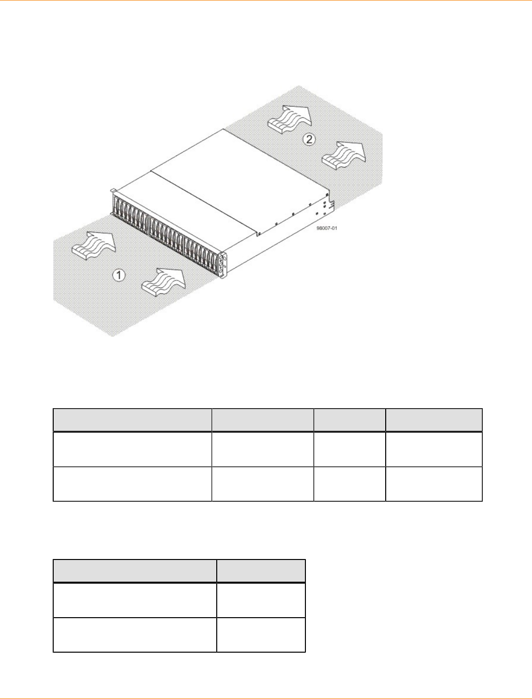
SANtricity_10.77 February 2011
LSI Corporation
- 141 -
1. 76 cm (30 in.) clearance in front of the cabinet
2. 61 cm (24 in.) clearance behind the cabinet
Airflow Through the Controller-Drive Tray with 24 Drives – Front View
1. 76 cm (30 in.) clearance in front of the cabinet
2. 61 cm (24 in.) clearance behind the cabinet
Power and Heat Dissipation for the CDE2600 Controller-Drive Tray
Component KVA Watts (AC) Btu/Hr
Controller canisters with two
power-fan canisters and 12 drives 0.400 399 1366
Controller canisters with two
power-fan canisters and 24 drives 0.331 330 1127
CDE2600 Controller-Drive Tray Acoustic Noise
Acoustic Noise at 25°C for the CDE2600 Controller-Drive Tray
Measurement Level
Sound power (standby operation) 6.5 bels
maximum
Sound pressure (normal
operation) 65 dBA maximum
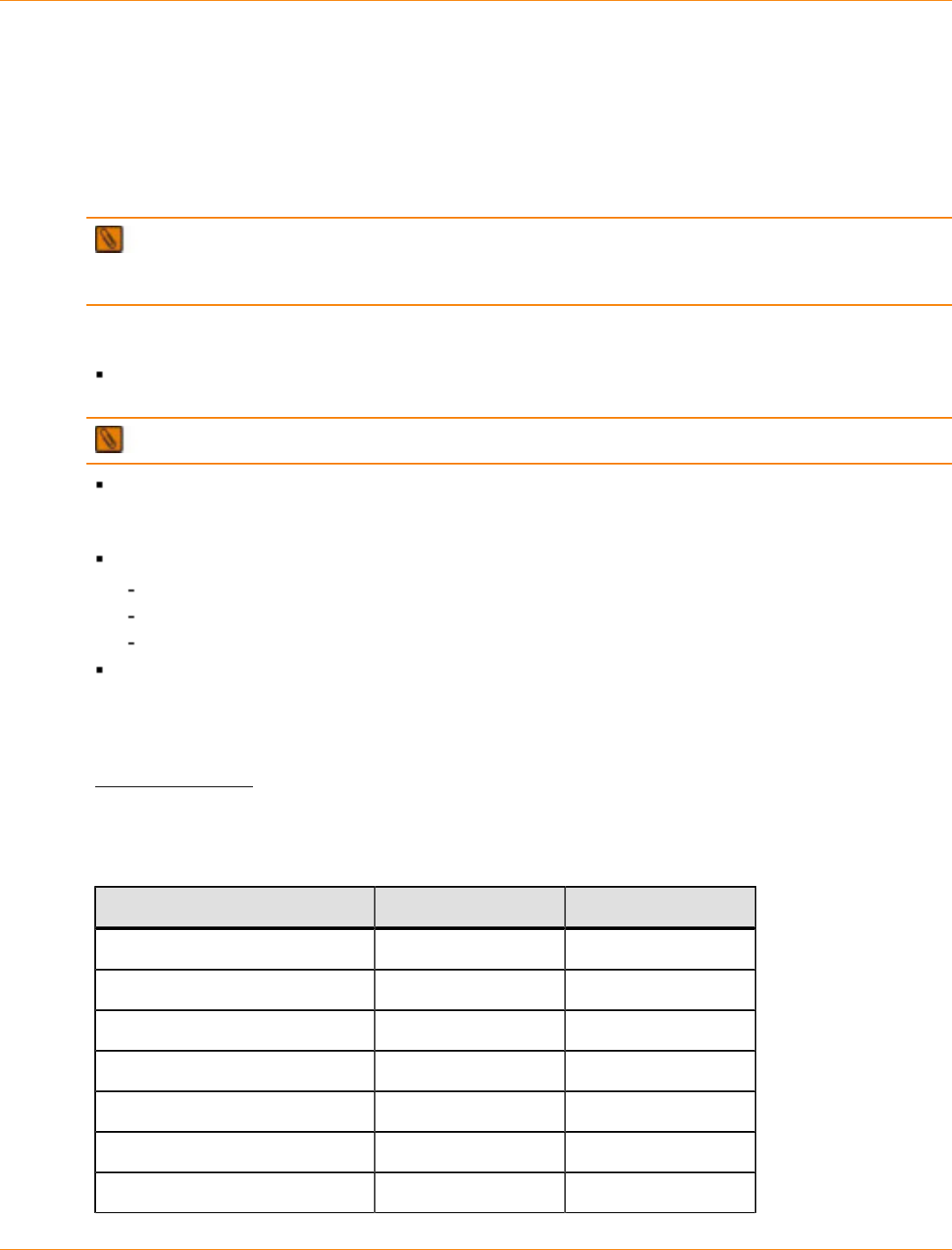
SANtricity_10.77 February 2011
LSI Corporation
- 142 -
CDE2600 Controller-Drive Tray Site Wiring and Power
The CDE2600 controller-drive tray uses wide-ranging, redundant power supplies that automatically
accommodate voltages to the AC power source or the optional –48-VDC power source. The power supplies
meet standard voltage requirements for both North American (USA and Canada) operation and worldwide
(except USA and Canada) operation. The power supplies use standard industrial wiring with line-to-neutral or
line-to-line power connections.
NOTE Power for the optional –48-VDC power configuration is supplied by a centralized DC power plant
instead of the AC power source in the cabinet. Refer to the associated manufacturer’s documentation for
specific DC power source requirements.
Keep this information in mind when you prepare the installation site for the controller-drive tray:
Protective ground – Site wiring must include a protective ground connection to the AC power source or
the optional –48-VDC power source.
NOTE Protective ground is also known as safety ground or chassis ground.
Circuit overloading – Power circuits and associated circuit breakers must provide enough power and
overload protection. To prevent damage to the controller-drive tray, isolate its power source from large
switching loads, such as air-conditioning motors, elevator motors, and factory loads.
Power interruptions – The controller-drive tray can withstand these applied voltage interruptions:
Input transient – 50 percent of the nominal voltage
Duration – One-half cycle
Frequency – Once every 10 seconds
Power failures – If a total power failure occurs, the controller-drive tray automatically performs a power-
on recovery sequence without operator intervention.
CDE2600 Controller-Drive Tray Power Input
AC Power Input
Each power supply contains one 10-A slow-blow fuse.
AC Power Requirements for the CDE2600 Controller-Drive Tray
Parameter Low Range High Range
Nominal voltage 100 VAC 240 VAC
Frequency 50 to 60 Hz 50 to 60 Hz
Idle current 3.97 A* 1.63 A**
Maximum operating current 4.25 A* 1.68 A**
Sequential Drive Group Spin Up 4.27 A 1.76 A
Simultaneous Drive Spin Up 6.13 A 2.71 A
System Rating Plate Label 7.0 A 2.9 A
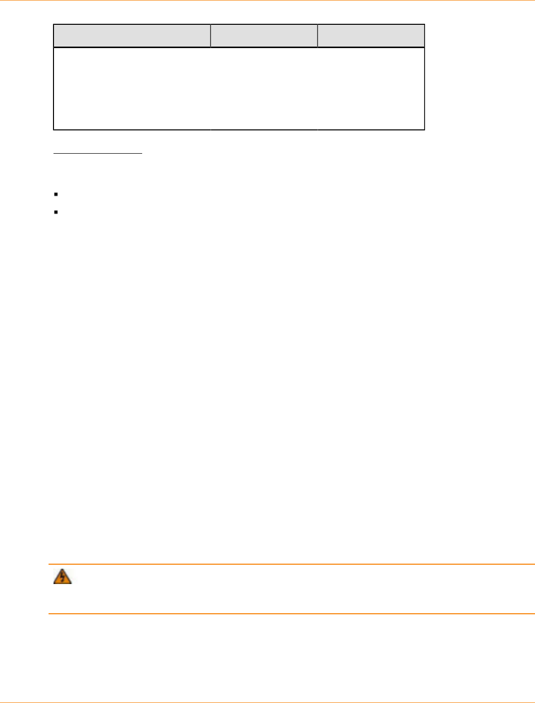
SANtricity_10.77 February 2011
LSI Corporation
- 143 -
Parameter Low Range High Range
* Typical current: 100 VAC, 60 Hz at 0.87 power supply efficiency and 0.99 power
factor. These numbers can vary significantly, depending upon the drives tested in
the particular configuration.
**Typical current: 240 VAC, 60 Hz at 0.87 power supply efficiency and 0.99 power
factor. These numbers can vary significantly, depending upon the drives tested in
the particular configuration.
DC Power Input
Nominal input voltages for the DC power source are as follows:
Low range: –42 VDC
High range: –60 VDC
The maximum operating current is 21.7 A.
CDE2600 Controller-Drive Tray Power Factor Correction
Power factor correction is applied within the power supply, which maintains the power factor of the controller-
drive tray at greater than 0.95 with nominal input voltage.
CDE2600 Controller-Drive Tray AC Power Cords and Receptacles
Each CDE2600 controller-drive tray is shipped with two AC power cords. Each AC power cord connects one
of the power supplies in a controller-drive tray to an independent, external AC power source, such as a wall
receptacle or a UPS.
If you have a cabinet with internal power cabling, such as a ladder cord, you do not need the AC power cords
that are shipped with the controller-drive tray.
DC power is an option that is available for use with youra controller-drive tray and drive trays. For more
information, see CDE2600 Controller-Drive Tray Optional DC Power Connector Cables and Source Wires.
CDE2600 Controller-Drive Tray Optional DC Power Connector Cables and
Source Wires
The CDE2600 controller-drive tray is shipped with –48-VDC power connector cables if the DC power option
is ordered. The –48-VDC power connector cable plugs into the DC power connector on the rear of the
controller-drive tray. The three source wires on the other end of the power connector cable connect the
controller-drive tray to centralized DC power plant equipment, typically through a bus bar above the cabinet.
WARNING (W12) Risk of electrical shock – This unit has more than one power source. To remove
all power from the unit, all DC MAINS must be disconnected by removing all power connectors (item 4 below)
from the power supplies.
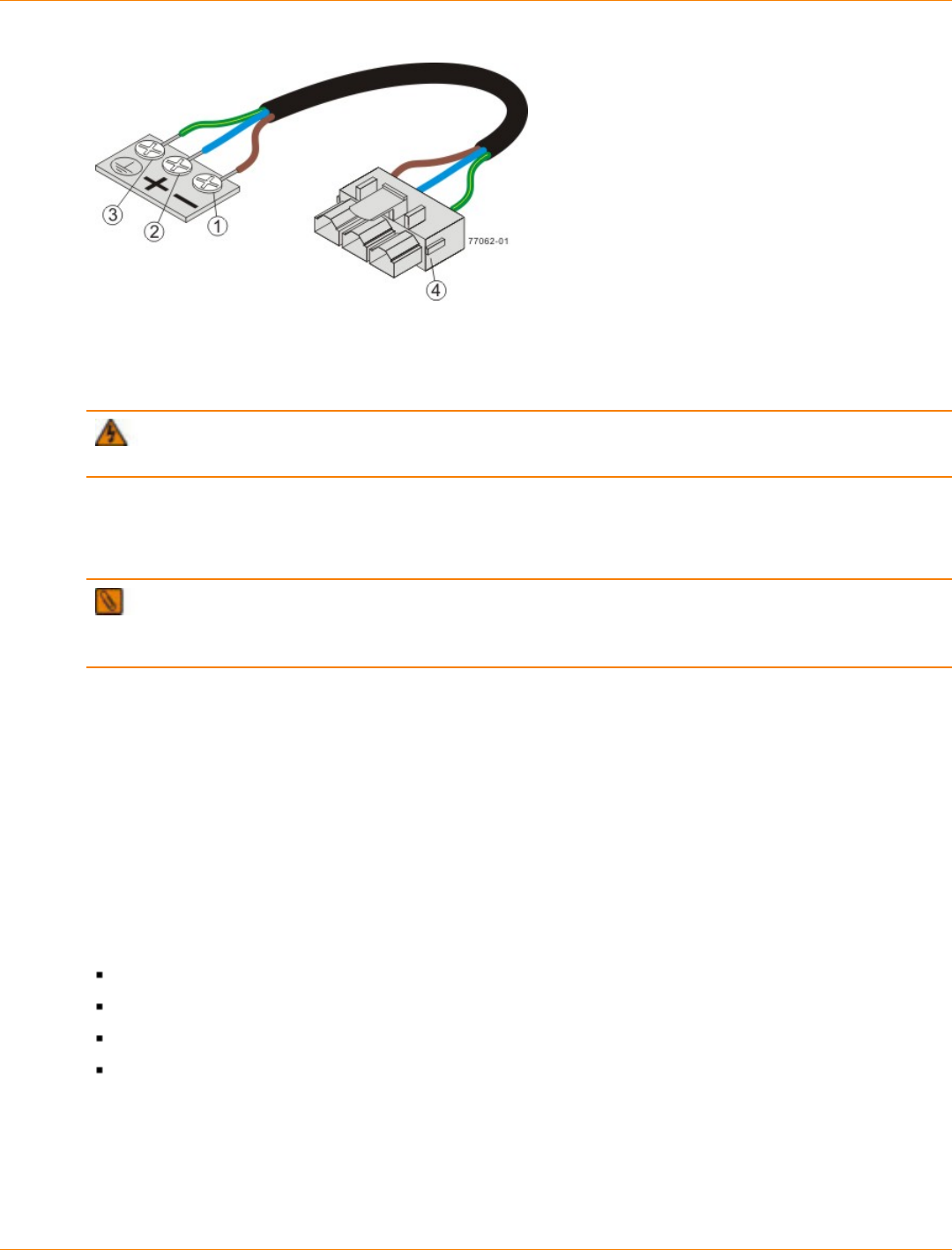
SANtricity_10.77 February 2011
LSI Corporation
- 144 -
1. Supply (Negative), Brown Wire, –48 VDC
2. Return (Positive), Blue Wire
3. Ground, Green and Yellow Wire
4. DC Power Connector
WARNING (W14) Risk of bodily injury – A qualified service person is required to make the DC
power connection according to NEC and CEC guidelines.
Two (or, optionally, four) DC power connector cables are provided with each controller-drive tray. Two DC
power connectors are on the two DC power supplies on the rear of each controller-drive tray if additional
redundancy is required.
NOTE It is not mandatory that you connect the second DC power connection on the DC power supplies
of the controller-drive tray. The second DC power connection is provided for additional redundancy only and
can be connected to a second DC power bus.
Preparing the Network for the Controllers
If you plan to use Ethernet connections from the storage management station to the controllers, you will use
the out-of-band management method. For this configuration, meet with your network administrator before
you order and install the equipment so that you can prepare for the setup and management of the devices
on the IP network. Each controller uses its Ethernet management ports to connect to the IP network and
communicate with the other devices on the IP network (often requiring a special application to set up the
protocol).
Your network administrator can pre-assign the addresses that you need to manage the communication
between the devices on the IP network. Depending on your storage configuration, you will need the following
addresses:
Up to two network IP addresses for each controller
Up to two subnet mask addresses for each controller
Either two IPv4 addresses (one static and one dynamic) or one IPv6 address for each controller
A Dynamic Host Configuration Protocol (DHCP) address for each controller
If switches are used in your storage environment, you must know if zoning will be used, and how it will be
configured.
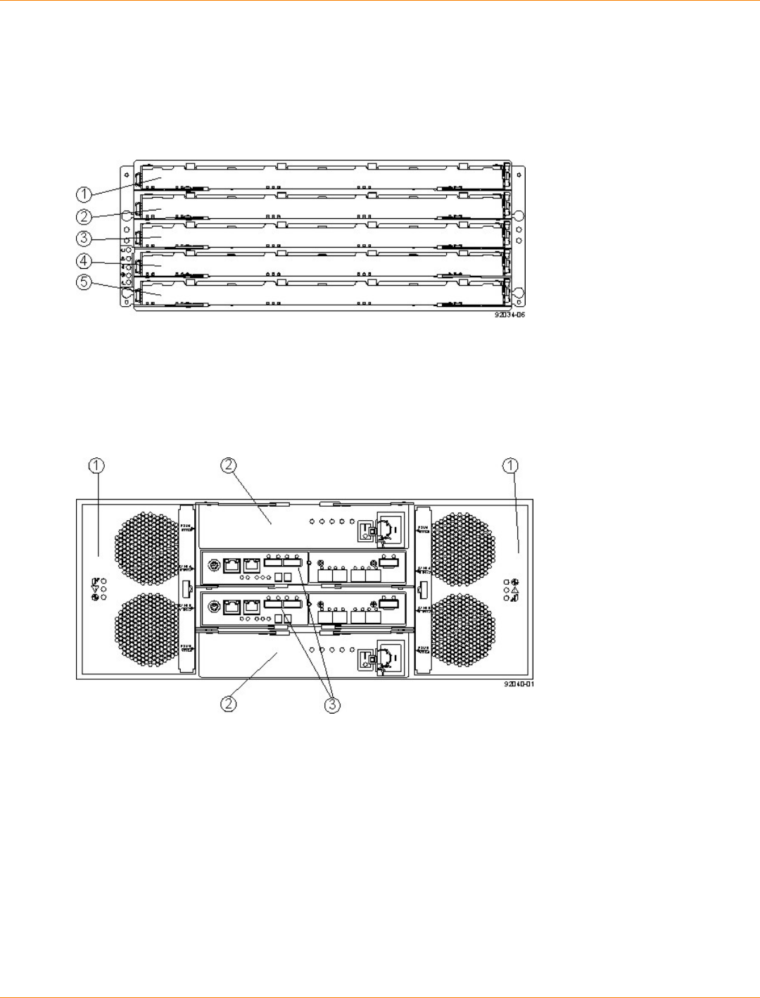
SANtricity_10.77 February 2011
LSI Corporation
- 145 -
Specifications of the CDE2600-60 Controller-Drive Tray
The CDE2600-60 controller-drive tray is a high-density SAS 2.0 (6-Gb/s) drive enclosure with 60 near-line
3.5” SAS drives, housed in five drawers with 12 drives each.
CDE2600-60 Controller-Drive Tray – Front View with Bezel Removed
1. Drive Drawer 1
2. Drive Drawer 2
3. Drive Drawer 3
4. Drive Drawer 4
5. Drive Drawer 5
CDE2600-60 Controller-Drive Tray – Rear View
1. Fan Canisters
2. Power Canisters
3. Controller-Drive Tray Canisters
CDE2600-60 Controller-Drive Tray Dimensions
The CDE2600-60 controller-drive tray conforms to the 48.3-cm (19.0-in.) rack standard.
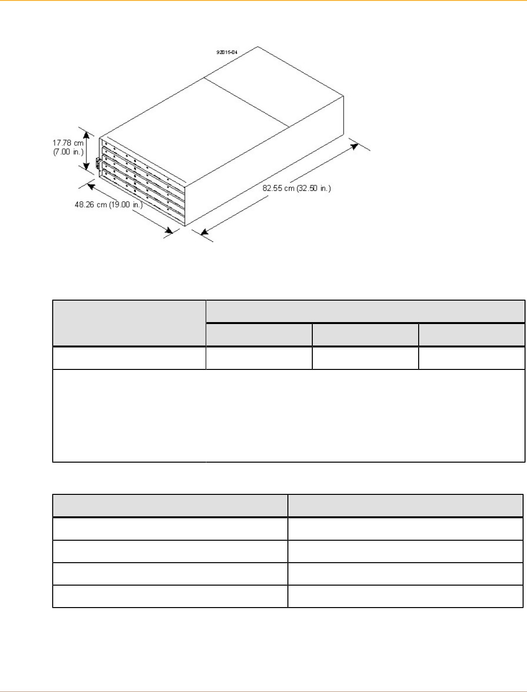
SANtricity_10.77 February 2011
LSI Corporation
- 146 -
Dimensions of the CDE2600-60 Controller-Drive Tray – Front View
CDE2600-60 Controller-Drive Tray Weight
Weights of the CDE2600-60 Controller-Drive Tray
WeightUnit
Maximum* Empty** Shipping***
CDE2600-60 controller-drive tray 105.2 kg (232 lb) 59.8 kg (132 lb) 193.2 kg (426 lb)
*Maximum weight indicates a controller-drive tray with all of its drives and other components installed.
Because drive weights can vary greatly, this value can vary from the value specified as much as 0.3 kg
(0.6 lb) times the maximum number of drives per drive tray for drives weighing 0.725 kg (1.6 lb).
**Empty weight indicates a drive tray without the controller canisters, the power canisters, the fan
canisters, and the drives.
***Shipping weight indicates the empty weight of a drive tray and all shipping material, as well as the
weight of the 60 drives that are shipped separately in multipack cartons.
Component Weights of the CDE2600-60 Controller-Drive Tray
Component Weight
Controller canister 2.99 kg (6.60 lb)
Power canister 2.5 kg (5.5 lb)
Fan canister Approximately 1 kg (2.16 lb)
Drive 0.74 kg (1.64 lb)

SANtricity_10.77 February 2011
LSI Corporation
- 147 -
CDE2600-60 Controller-Drive Tray Shipping Dimensions
Shipping Carton Dimensions for the CDE2600-60 Controller-Drive Tray
Height Width Depth
48.26 cm (19 in.) 60.96 cm (24.00 in.) 100.97 cm (39.75 in.)
CDE2600-60 Controller-Drive Tray Temperature and Humidity
Temperature Requirements and Humidity Requirements for the CDE2600-60 Controller-Drive Tray
Condition Parameter Requirement
Operating range (both cabinet
and subsystem) 10°C to 35°C (50°F to 104°F)
Maximum rate of change 10°C (50°F) per hour
Storage range –10°C to 50°C (14°F to
122°F)
Maximum rate of change 15°C (59°F) per hour
Transit range –40°C to 60°C (–40°F to
140°F)
Temperature
Maximum rate of change 20°C (68°F) per hour
Operating range (both cabinet
and subsystem) 20% to 80%
Storage range 10% to 90%
Transit range 5% to 90%
Operating gradient 10°C (50°F) per hour
maximum
Storage gradient 15°C (59°F) per hour
maximum
Transit gradient 20°C (68°F) per hour
maximum
Maximum dew point 26°C (79°F)
Relative
humidity (no
condensation)
Maximum gradient 10% per hour
If you plan to operate a system at an altitude between 1000 m to 3000 m (3280 ft
to 9842 ft) above sea level, lower the environmental temperature 1.7°C (3.3°F) for
every 1000 m (3280 ft) above sea level.
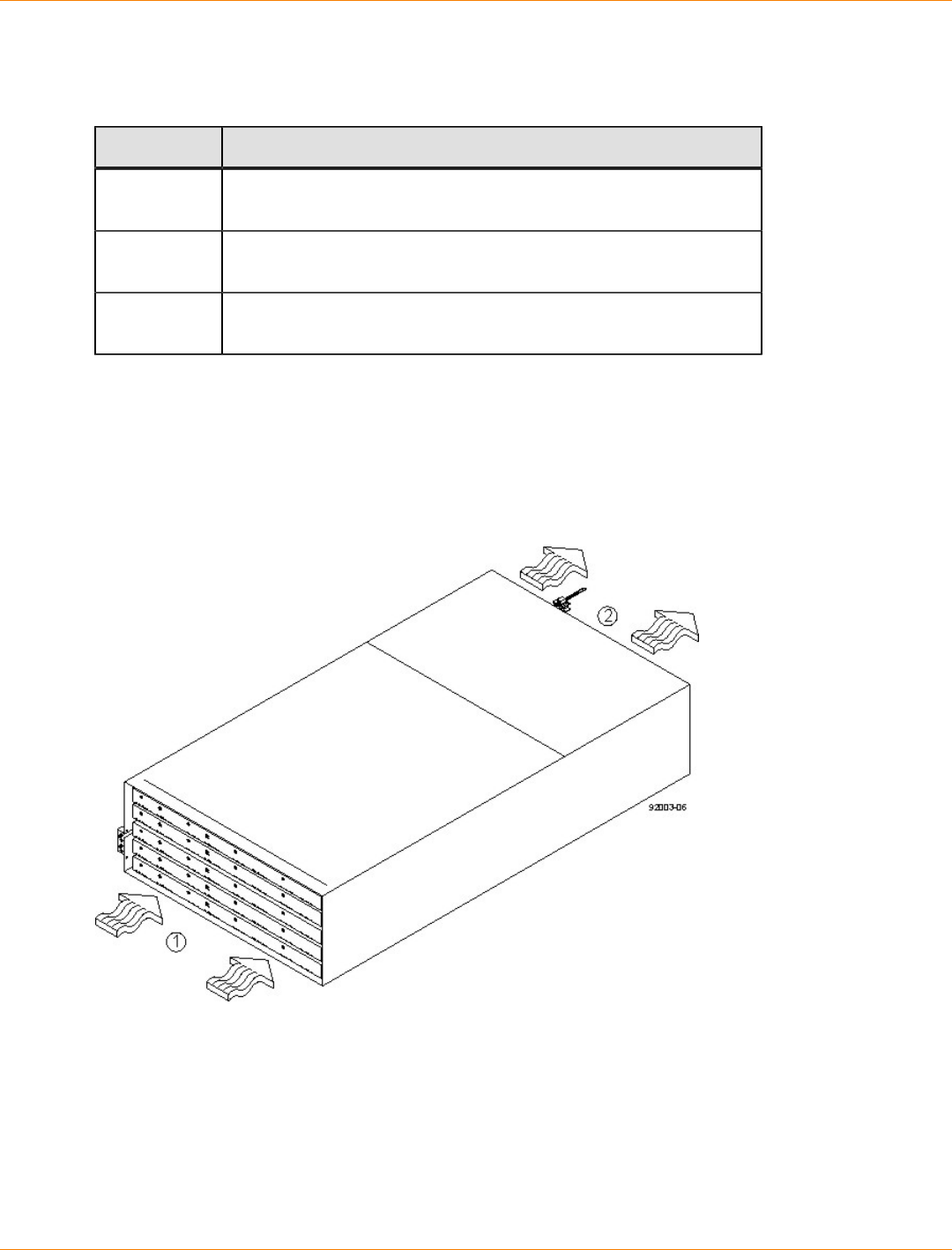
SANtricity_10.77 February 2011
LSI Corporation
- 148 -
CDE2600-60 Controller-Drive Tray Altitude Ranges
Altitude Ranges for the CDE2600-60 Controller-Drive Tray
Environment Altitude
Operating 30.5 m (100 ft) below sea level to 3000 m (9842 ft) above sea
level
Storage 30.5 m (100 ft) below sea level to 3000 m (9842 ft) above sea
level
Transit 30.5 m (100 ft) below sea level to 12,000 m (40,000 ft) above sea
level
CDE2600-60 Controller-Drive Tray Airflow and Heat Dissipation
Airflow goes from the front of the CDE2600-60 controller-drive tray to the rear of the controller-drive tray.
Allow at least 81 cm (32 in.) of clearance in front of the CDE2600-60 controller-drive tray and at least 61 cm
(24 in.) of clearance behind the controller-drive tray for service clearance, ventilation, and heat dissipation.
Airflow Through the CDE2600-60 Controller-Drive Tray – Front View
1. 81 cm (32 in.) clearance in front of the cabinet
2. 61 cm (24 in.) clearance behind the cabinet
The tabulated power and heat dissipation values in the following table are the maximum measured operating
power.
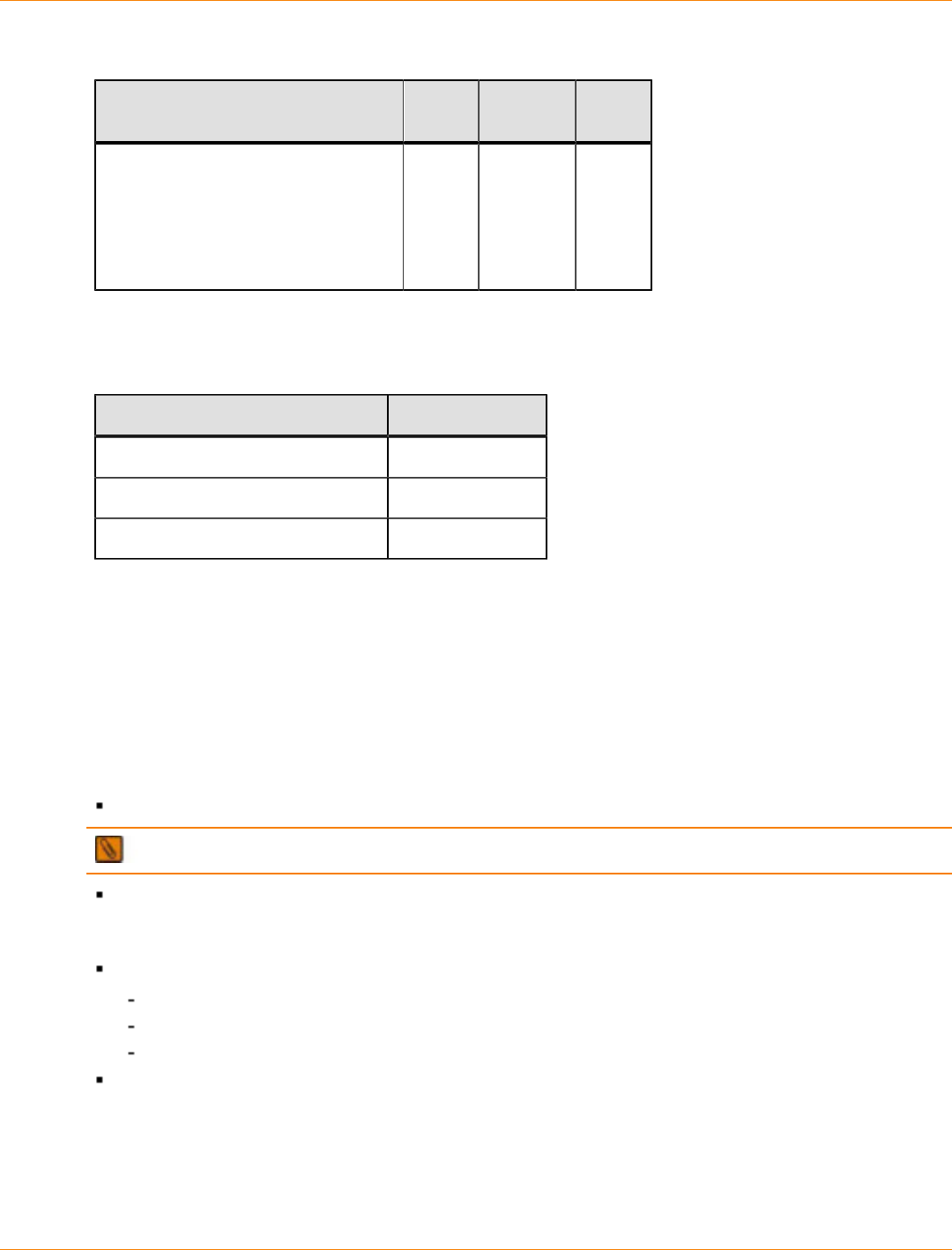
SANtricity_10.77 February 2011
LSI Corporation
- 149 -
Power Ratings and Heat Dissipation for the CDE2600-60 Controller-Drive Tray
Unit KVA Watts
(AC) Btu/hr
CDE2600-60 controller-drive
tray with two power supplies,
two controller trays, 60 drives
(Seagate 2000-Gb SAS drives and
controllers), and two fan canisters,
full speed
1.268 1222 4180
CDE2600-60 Controller-Drive Tray Acoustic Noise
Acoustic Noise at 25°C for the CDE2600-60 Controller-Drive Tray
Measurement Level
Sound power (standby operation) 6.5 bels
Sound power (normal operation) 6.8 bels
Sound pressure 68 dBA
CDE2600-60 Controller-Drive Tray Site Wiring and Power
The CDE2600-60 controller-drive tray uses wide-ranging, redundant power supplies that automatically
accommodate voltages to the AC power source. The power supplies meet standard voltage requirements
for both North American (USA and Canada) operation and worldwide (except USA and Canada) operation.
The power supplies use standard industrial wiring with line-to-neutral power connections or line-to-line power
connections.
Keep this information in mind when you prepare the installation site for the controller-drive tray:
Protective ground – Site wiring must include a protective ground connection to the AC power source.
NOTE Protective ground is also known as safety ground or chassis ground.
Circuit overloading – Power circuits and associated circuit breakers must provide enough power and
overload protection. To prevent damage to the drive tray, isolate its power source from large switching
loads, such as air-conditioning motors, elevator motors, and factory loads.
Power interruptions – The controller-drive tray can withstand these applied voltage interruptions:
Input transient – 50 percent of the nominal voltage
Duration – One-half cycle
Frequency – Once every 10 seconds
Power failures – If a total power failure occurs, the drive tray automatically performs a power-on recovery
sequence without operator intervention after the power is restored.
CDE2600-60 Controller-Drive Tray Power Input
Each power supply contains one 15-A slow-blow fuse.
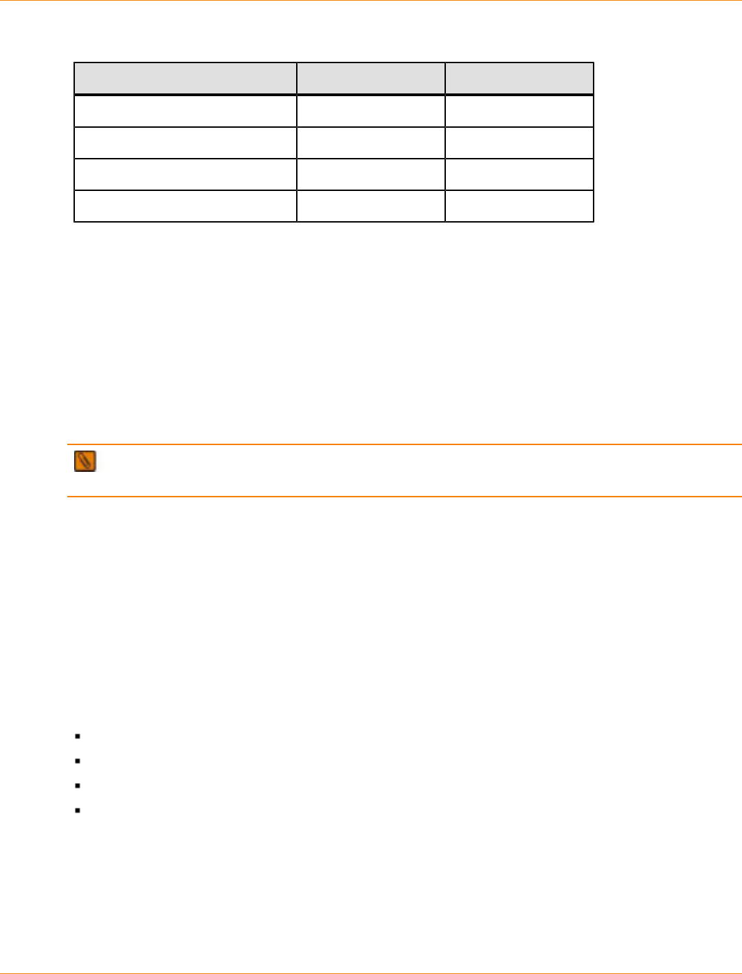
SANtricity_10.77 February 2011
LSI Corporation
- 150 -
AC Power Requirements for the CDE2600-60 Controller-Drive Tray
Parameter Low Range High Range
Nominal voltage 200 VAC 240 VAC
Frequency 50 Hz 60 Hz
Idle current 5.1 A 6.0 A
Maximum operating current 6.3 A 7.56 A
CDE2600-60 Controller-Drive Tray Power Factor Correction
Power factor correction is applied within the power supply, which maintains the power factor of the
CDE2600-60 controller-drive tray at greater than 0.95 with nominal input voltage.
CDE2600-60 Controller-Drive Tray AC Power Cords and Receptacles
Each CDE2600-60 controller-drive tray is shipped with two AC power cords, which fit the standard AC outlets
in the destination country. Each AC power cord connects one of the power canisters in the drive tray to an
independent, external AC power source, such as a wall receptacle, or to any uninterruptible power supply
(UPS).
NOTE Possible risk of equipment failure – To ensure proper cooling, the CDE2600-60 controller-
drive tray always uses two power supplies.
Preparing the Network for the Controllers
If you plan to use Ethernet connections from the storage management station to the controllers, you will use
the out-of-band management method. For this configuration, meet with your network administrator before
you order and install the equipment so that you can prepare for the setup and management of the devices
on the IP network. Each controller uses its Ethernet management ports to connect to the IP network and
communicate with the other devices on the IP network (often requiring a special application to set up the
protocol).
Your network administrator can pre-assign the addresses that you need to manage the communication
between the devices on the IP network. Depending on your storage configuration, you will need the following
addresses:
Up to two network IP addresses for each controller
Up to two subnet mask addresses for each controller
Either two IPv4 addresses (one static and one dynamic) or one IPv6 address for each controller
A Dynamic Host Configuration Protocol (DHCP) address for each controller
If switches are used in your storage environment, you must know if zoning will be used, and how it will be
configured.
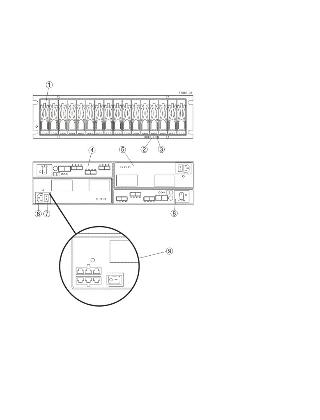
SANtricity_10.77 February 2011
LSI Corporation
- 151 -
Specifications of the CDE4900 Controller-Drive Tray
The CDE4900 controller-drive tray is available as a rackmount model that provides high-capacity disk storage
for Fibre Channel or iSCSI environments.
The CDE4900 controller-drive tray contains the components shown in the following figure.
CDE4900 Controller-Drive Tray – Front View and Rear View
1. (Front View) Drive Canister
2. Alarm Mute Switch
3. (Rear View) Link Rate Switch
4. Controller A (Inverted)
5. Power-Fan Canister
6. AC Power Connector
7. AC Power Switch
8. Battery Canister
9. Optional DC Power Connector and DC Power Switch
CDE4900 Controller-Drive Tray Dimensions
The CDE4900 controller-drive tray conforms to the 48.3-cm (19.0-in.) rack standard.
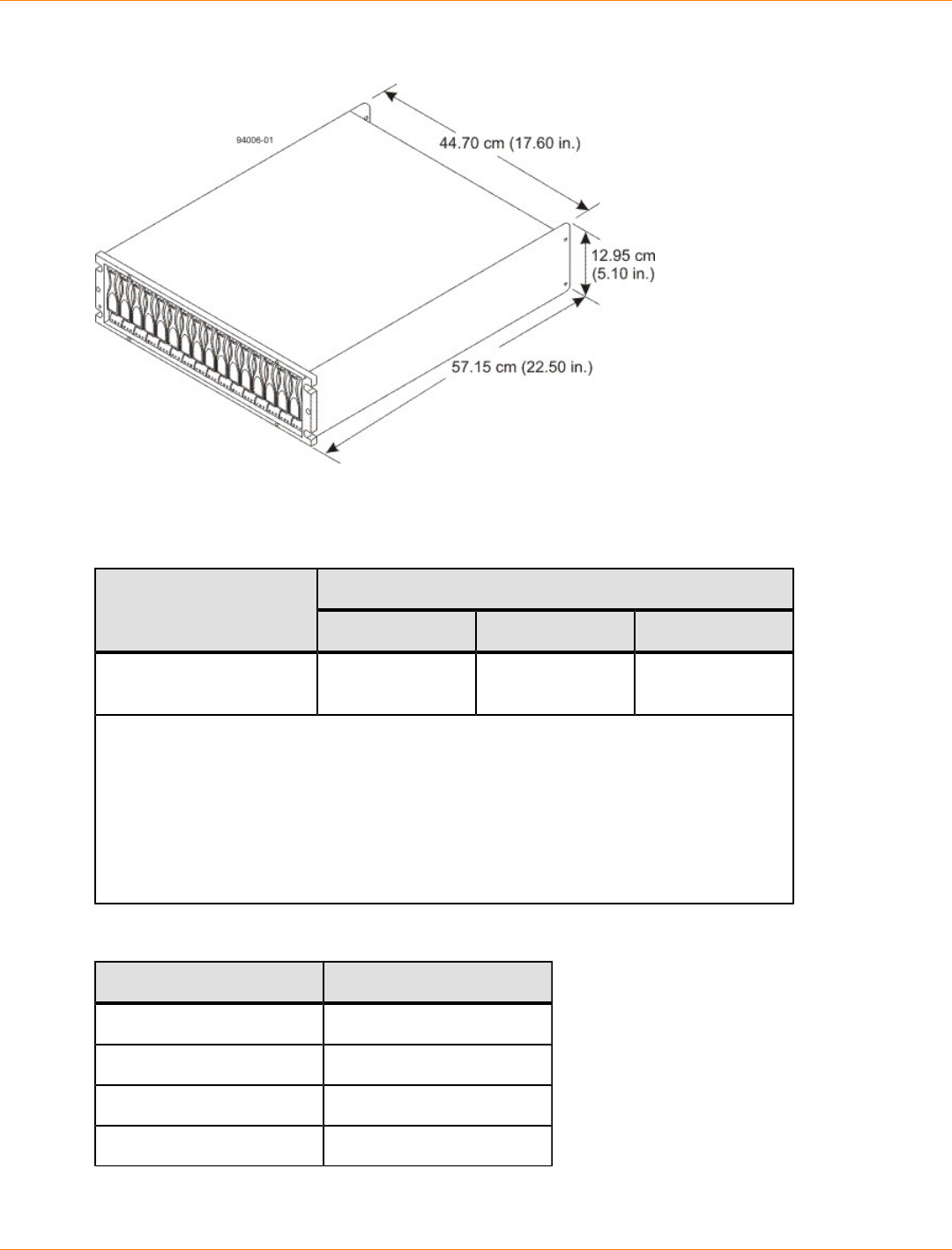
SANtricity_10.77 February 2011
LSI Corporation
- 152 -
Dimensions of the CDE4900 Controller-Drive Tray – Front View
CDE4900 Controller-Drive Tray Weight
Weights of the CDE4900 Controller-Drive Tray
WeightUnit
Maximum* Empty** Shipping***
CDE4900 controller-drive
tray 38.15 kg (84.1 lb) 22.67 kg (50.0 lb) 51.70 kg (114.0
lb)
*Maximum weight indicates a controller-drive tray with all of its drives and other
components installed. Because drive weights can vary greatly, this value can vary from
the value specified as much as 0.3 kg (0.6 lb) times the maximum number of drives per
controller-drive tray for drives weighing 1.0 kg (2.2 lb).
**Empty weight indicates a controller-drive tray with the controller canisters, the power-
fan canisters, and the drives removed.
***Shipping weight indicates the maximum weight of a controller-drive tray and all
shipping material.
Component Weights of the Controller-Drive Tray
Component Weight
Controller canister 1.995 kg (4.40 lb)
Power-fan canister 3.629 kg (8.00 lb)
ESM canister 1.814 kg (4.00 lb)
Battery 0.544 kg (1.20 lb)

SANtricity_10.77 February 2011
LSI Corporation
- 153 -
Component Weight
Drive Approximately 1.0 kg (2.2
lb)
CDE4900 Controller-Drive Tray Shipping Dimensions
Shipping Carton Dimensions for the CDE4900 Controller-Drive Tray
Height Width Depth
45.72 cm (18.00 in.) –
Includes the height of the
pallet.
60.96 cm (24.00
in.) 81.28 cm (32.00
in.)
CDE4900 Controller-Drive Tray Temperature and Humidity
Temperature Requirements and Humidity Requirements for the CDE4900 Controller-Drive Tray
Condition Parameter Requirement
Operating range 10°C to 40°C (50°F to 104°F) without the
battery
10°C to 35°C (50°F to 95°F) with the
battery
Maximum rate of change 10°C (18°F) per hour
Storage range –10°C to 50°C (14°F to 122°F) without the
battery
–10°C to 45°C (14°F to 113°F) with the
battery (three-month maximum in storage)
Maximum rate of change 15°C (27°F) per hour
Transit range –40°C to 60°C (–40°F to 140° F) without
the battery
–20°C to 60°C (–4°F to 140°F) with the
battery (one-week maximum in transit)
Temperature*
Maximum rate of change 20°C (36°F) per hour
Operating range 20% to 80%
Storage range 10% to 90%
Transit range 5% to 95%
Relative
humidity (no
condensation)
Maximum dew point 26°C (79°F)
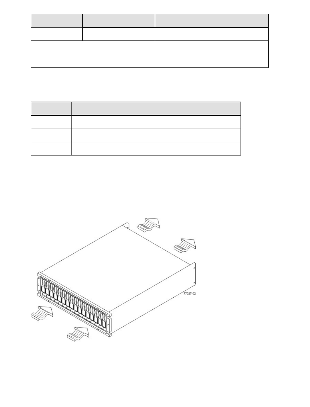
SANtricity_10.77 February 2011
LSI Corporation
- 154 -
Condition Parameter Requirement
Maximum gradient 10% per hour
*If you plan to operate a system at an altitude between 1000 m to 3000 m (3280 ft to 9842
ft) above sea level, lower the environmental temperature 1.7°C (3.3°F) for every 1000 m
(3280 ft) above sea level.
CDE4900 Controller-Drive Tray Altitude Ranges
Altitude Ranges for the CDE4900 Controller-Drive Tray
Environment Altitude
Operating 30.5 m (100 ft) below to 3,000 m (9840 ft) above sea level
Storage 30.5 m (100 ft) below to 3,000 m (9840 ft) above sea level
Transit 30.5 m (100 ft) below to 12,000 m (40,000 ft) above sea level
CDE4900 Controller-Drive Tray Airflow and Heat Dissipation
Airflow goes from the front of the controller-drive tray to the rear of the controller-drive tray. Allow at least 76
cm (30 in.) of clearance in front of the controller-drive tray and at least 61 cm (24 in.) of clearance behind the
controller-drive tray for service clearance, ventilation, and heat dissipation.
Airflow Through the CDE4900 Controller-Drive Tray – Front View
The tabulated power and heat dissipation values in the following table are the maximum measured operating
power. Maximum configuration units are typically operated at high data rates or have larger random access
memory (RAM) capabilities.
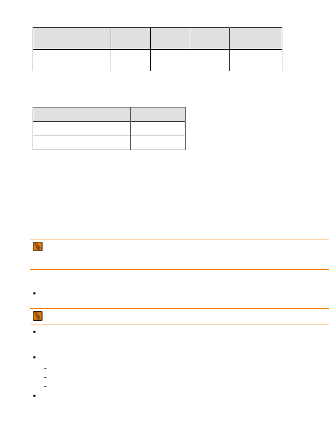
SANtricity_10.77 February 2011
LSI Corporation
- 155 -
Power Ratings and Heat Dissipation for the CDE4900 Controller-Drive Tray
Component KVA Watts (AC) Btu/Hr Amps (240
VAC)
CDE4900 controller-drive
tray 0.624 600 2047 2.50
CDE4900 Controller-Drive Tray Acoustic Noise
Sound Levels for the CDE4900 Controller-Drive Tray
Measurement Level
Sound power 6.5 bels
Sound pressure 65 dBA
CDE4900 Controller-Drive Tray Site Wiring and Power
The agency ratings for the CDE4900 controller-drive tray are 6.00 A at 100 VAC and 2.50 A at 240 VAC.
These ratings are the overall maximum AC currents for this system.
The CDE4900 controller-drive tray uses wide-ranging, redundant power supplies that automatically
accommodate voltages to the AC power source or the optional –48-VDC power source. The power supplies
meet standard voltage requirements for both North American (USA and Canada) operation and worldwide
(except USA and Canada) operation. The power supplies use standard industrial wiring with line-to-neutral or
line-to-line power connections.
NOTE Power for the optional –48-VDC power configuration is supplied by a centralized DC power plant
instead of the AC power source in the cabinet. Refer to the associated manufacturer’s documentation for
specific DC power source requirements.
Keep this information in mind when you prepare the installation site for the controller-drive tray:
Protective ground – Site wiring must include a protective ground connection to the AC power source or
the optional –48-VDC power source.
NOTE Protective ground is also known as safety ground or chassis ground.
Circuit overloading – Power circuits and associated circuit breakers must provide enough power and
overload protection. To prevent damage to the controller-drive tray, isolate its power source from large
switching loads, such as air-conditioning motors, elevator motors, and factory loads.
Power interruptions – The controller-drive tray can withstand these applied voltage interruptions:
Input transient – 50 percent of the nominal voltage
Duration – One-half cycle
Maximum frequency – Once every 10 seconds
Power failures – If a total power failure occurs, the controller-drive tray automatically performs a power-
on recovery sequence without operator intervention after the power is restored.
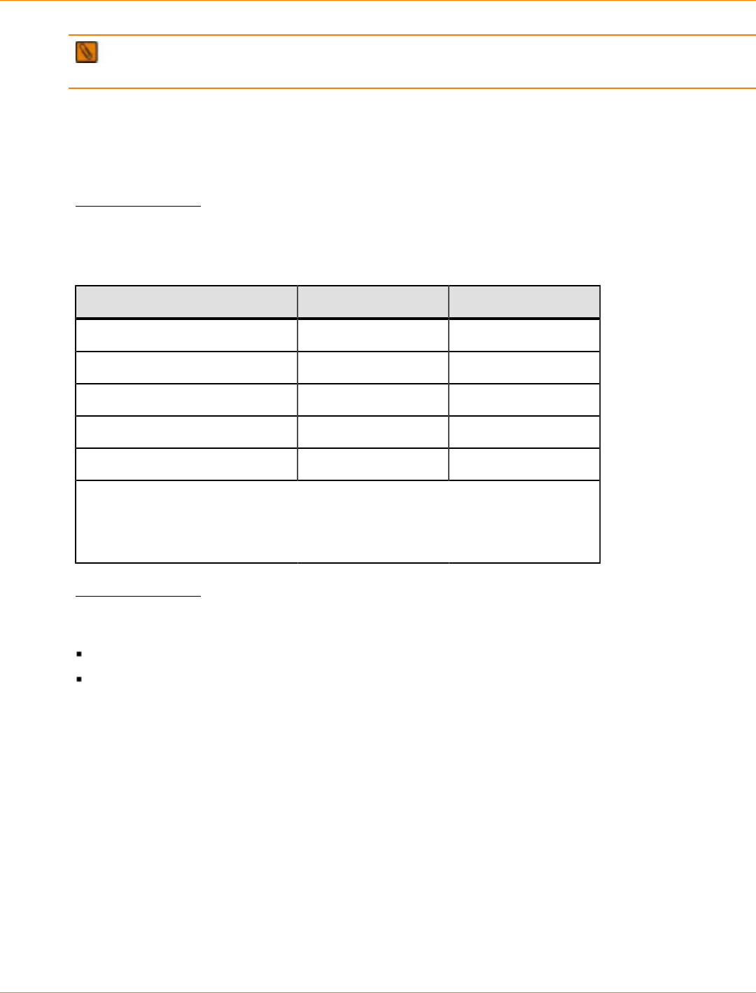
SANtricity_10.77 February 2011
LSI Corporation
- 156 -
NOTE When a power failure occurs, the controller-drive tray uses battery power to back up the data
that is in cache.
If you are installing a large storage system configuration, you must make sure that you are supplying the
correct AC source voltages, and not creating an over-current situation.
CDE4900 Controller-Drive Tray Power Input
AC Power Input
Each power supply contains one 15-A slow-blow fuse.
AC Power Requirements for the CDE4900 Controller-Drive Tray
Parameter Low Range High Range
Nominal voltage 115 VAC 230 VAC
Frequency 50 to 60 Hz 50 to 60 Hz
Idle current 3.81 A* 1.98 A**
Maximum operating current 3.96 A* 2.06 A**
Maximum surge current 5.52 A* 2.72 A**
*Typical current: 115 VAC, 60 Hz at 0.77 power supply efficiency and 0.96 power
factor.
**Typical current: 230 VAC, 60 Hz at 0.77 power supply efficiency and 0.96 power
factor.
DC Power Input
Nominal input voltages for the DC power source are as follows:
Low range: –36 VDC
High range: –72 VDC
The maximum operating current is 17 A.
CDE4900 Controller-Drive Tray Power Factor Correction
Power factor correction is applied within the power-fan canister of each CDE4900 controller-drive tray, which
maintains the power factor of the controller-drive tray at greater than 0.96 with nominal input voltage.
CDE4900 Controller-Drive Tray AC Power Cords and Receptacles
Each CDE4900 controller-drive tray is shipped with two AC power cords, which fit the standard AC outlets
in the destination country. Each AC power cord connects one of the power-fan canisters in the controller-
drive tray to an independent, external AC power source, such as a wall receptacle or an uninterruptible power
supply (UPS).
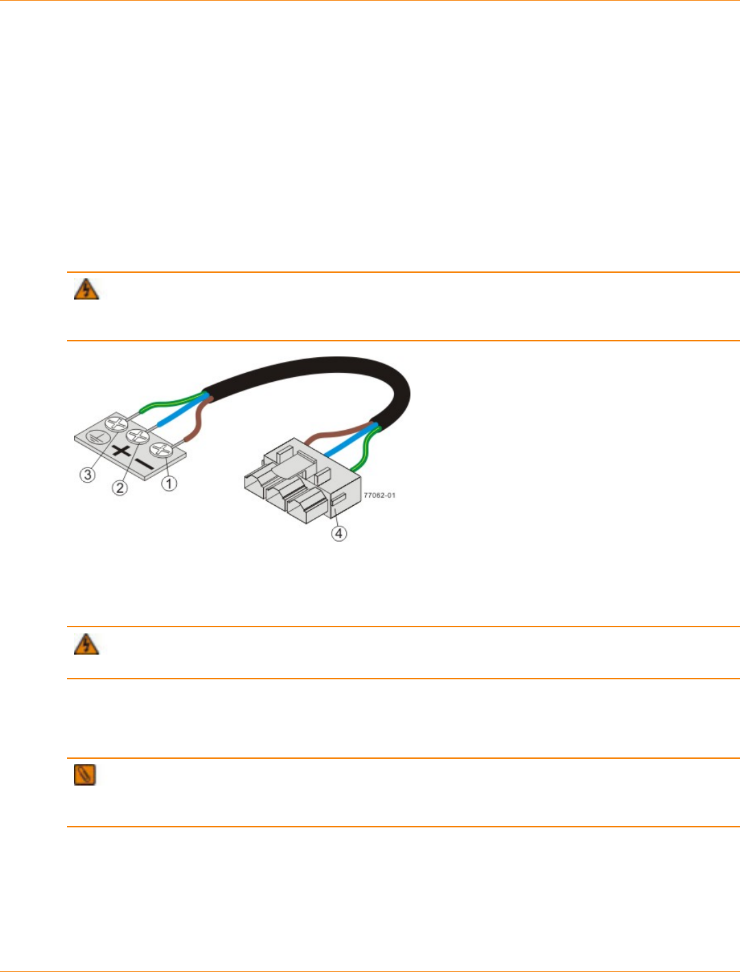
SANtricity_10.77 February 2011
LSI Corporation
- 157 -
DC power is an option that is available for use with your controller-drive tray and drive tray. For more
information, see “CDE4900 Controller-Drive Tray Optional DC Power Connector Cables and Source Wires”.
If you have a cabinet with internal power cabling, such as a ladder cord, you do not need the AC power cords
that are shipped with the controller-drive tray.
CDE4900 Controller-Drive Tray Optional DC Power Connector Cables and
Source Wires
The CDE4900 controller-drive tray is shipped with –48-VDC power connector cables if the DC power option
is ordered. The –48-VDC power connector cable plugs into the DC power connector on the rear of the
controller-drive tray. The three source wires on the other end of the power connector cable connect the
controller-drive tray to centralized DC power plant equipment, typically through a bus bar above the cabinet.
WARNING (W12) Risk of electrical shock – This unit has more than one power source. To remove
all power from the unit, all DC MAINS must be disconnected by removing all power connectors (item 4 below)
from the power supplies.
1. Supply (Negative), Brown Wire, –48 VDC
2. Return (Positive), Blue Wire
3. Ground, Green and Yellow Wire
4. DC Power Connector
WARNING (W14) Risk of bodily injury – A qualified service person is required to make the DC
power connection according to NEC and CEC guidelines.
Two (or, optionally, four) DC power connector cables are provided with each controller-drive tray. Two DC
power connectors are on the two DC power supplies on the rear of each controller-drive tray if additional
redundancy is required.
NOTE It is not mandatory that you connect the second DC power connection on the DC power supplies
of the controller-drive tray. The second DC power connection is provided for additional redundancy only and
can be connected to a second DC power bus.
Preparing the Network for the Controllers
If you plan to use Ethernet connections from the storage management station to the controllers, you will use
the out-of-band management method. For this configuration, meet with your network administrator before
you order and install the equipment so that you can prepare for the setup and management of the devices

SANtricity_10.77 February 2011
LSI Corporation
- 158 -
on the IP network. Each controller uses its Ethernet management ports to connect to the IP network and
communicate with the other devices on the IP network (often requiring a special application to set up the
protocol).
Your network administrator can pre-assign the addresses that you need to manage the communication
between the devices on the IP network. Depending on your storage configuration, you will need the following
addresses:
Up to two network IP addresses for each controller
Up to two subnet mask addresses for each controller
Either two IPv4 addresses (one static and one dynamic) or one IPv6 address for each controller
A Dynamic Host Configuration Protocol (DHCP) address for each controller
If switches are used in your storage environment, you must know if zoning will be used, and how it will be
configured.
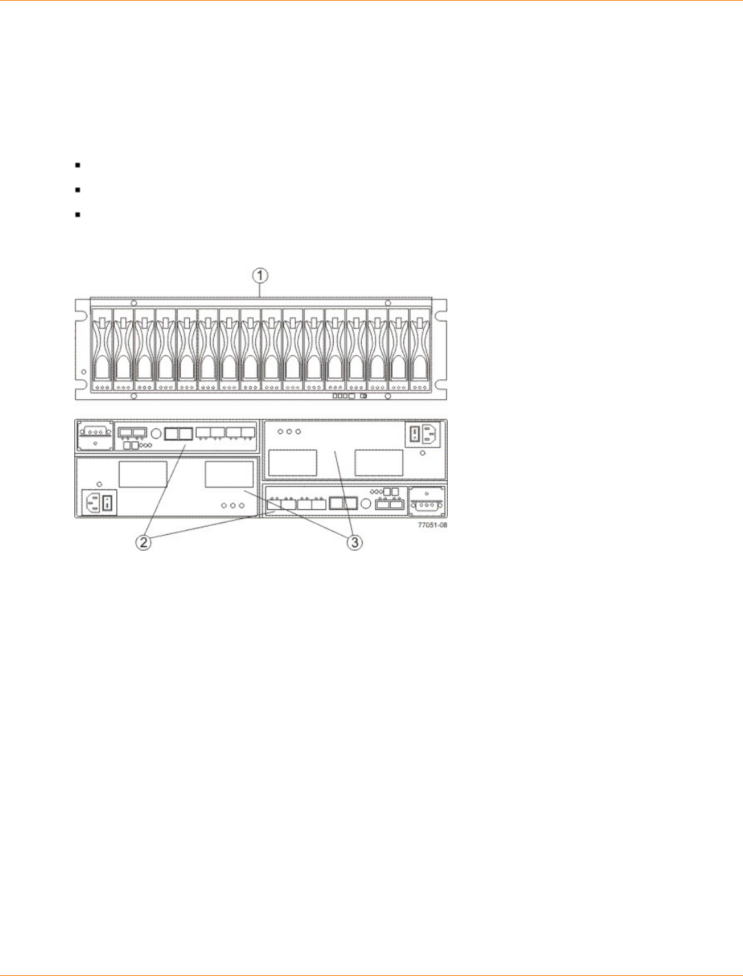
SANtricity_10.77 February 2011
LSI Corporation
- 159 -
Specifications of the CDE3994 Controller-Drive Tray
The CDE3994 controller-drive tray is available as a rackmount model or a deskside model that provides high-
capacity disk storage for Fibre Channel environments.
The CDE3994 controller-drive tray contains these components:
A maximum of 16 Fibre Channel or SATA drives
Two power-fan canisters
One or two controllers
CDE3994 Controller-Drive Tray (Rackmount Model) – Front View and Rear View
1. Drive Canisters
2. Controller Canisters
3. Power-Fan Canisters
Usually an AC power source is used to supply power to the power-fan canister. A DC power option is also
available.
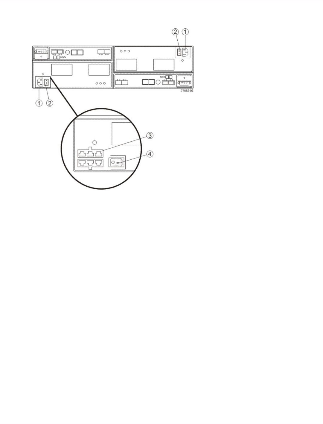
SANtricity_10.77 February 2011
LSI Corporation
- 160 -
Power Source Options for the CDE3994 Controller-Drive Tray – Rear View
1. AC Power Connectors
2. AC Power Switches
3. (Optional) Two DC Power Connectors
4. (Optional) DC Power Switch
CDE3994 Controller-Drive Tray Dimensions
The CDE3994 controller-drive tray conforms to the 48.3-cm (19.0-in.) rack standard.
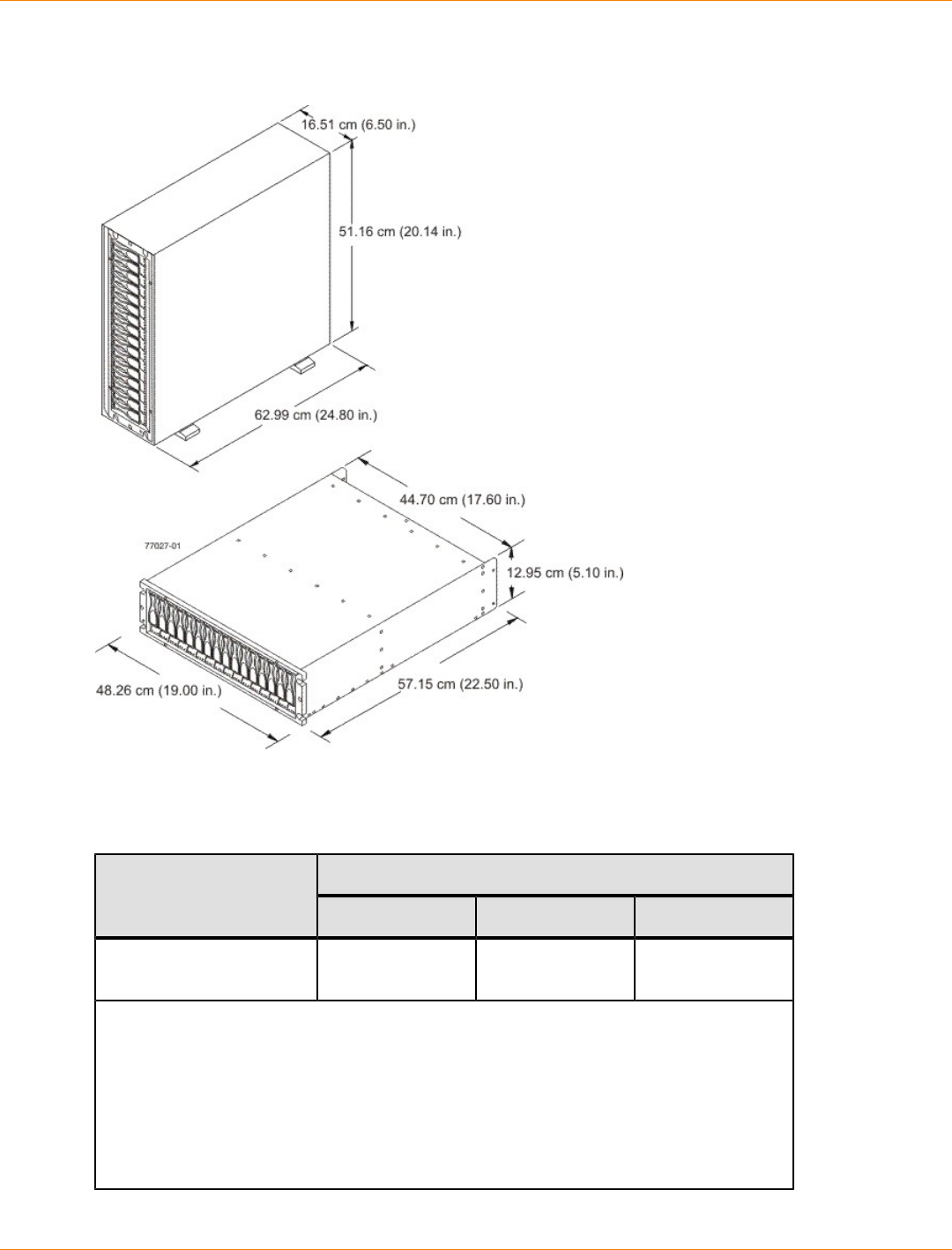
SANtricity_10.77 February 2011
LSI Corporation
- 161 -
Dimensions of the CDE3994 Controller-Drive Tray (Deskside Model and Rackmount Model) – Front
View
CDE3994 Controller-Drive Tray Weight
Weights of the CDE3994 Controller-Drive Tray
WeightUnit
Maximum* Empty** Shipping***
CDE3994 controller-drive
tray 41 kg (91 lb) 15.88 kg (35.0 lb) 52.16 kg (115.0
lb)
*Maximum weight indicates a controller-drive tray with all of its drives and other
components installed. Because drive weights can vary greatly, this value can vary from
the value specified as much as 0.3 kg (0.6 lb) times the maximum number of drives per
controller-drive tray for drives weighing 1.0 kg (2.2 lb).
**Empty weight indicates a controller-drive tray with the controller canisters, the power-
fan canisters, and the drives removed.
***Shipping weight indicates the maximum weight of a controller-drive tray and all
shipping material.

SANtricity_10.77 February 2011
LSI Corporation
- 162 -
CDE3994 Controller-Drive Tray Shipping Dimensions
Shipping Carton Dimensions for the CDE3994 Controller-Drive Tray
Height Width Depth
45.72 cm (18.00 in.) –
Includes the height of the
pallet.
62.23 cm (24.50
in.) 80.65 cm (31.75
in.)
CDE3994 Controller-Drive Tray Temperature and Humidity
Temperature Requirements and Humidity Requirements for the CDE3994 Controller-Drive Tray
Condition Parameter Requirement
Operating range 10°C to 40°C (50°F to 104°F) without the
battery
10°C to 35°C (50°F to 95°F) with the
battery
Maximum rate of change 10°C (18°F) per hour
Storage range –10°C to 50°C (14°F to 122°F) without the
battery
–10°C to 45°C (14°F to 113°F) with the
battery (three-month maximum in storage)
Maximum rate of change 15°C (27°F) per hour
Transit range –40°C to 60°C (–40°F to 140° F) without
the battery
–20°C to 60°C (–4°F to 140°F) with the
battery (one-week maximum in transit)
Temperature*
Maximum rate of change 20°C (36°F) per hour
Operating range 20% to 80%
Storage range 10% to 90%
Transit range 5% to 95%
Maximum dew point 26°C (79°F)
Relative
humidity (no
condensation)
Maximum gradient 10% per hour
*If you plan to operate a system at an altitude between 1000 m to 3000 m (3280 ft to 9842
ft) above sea level, lower the environmental temperature 1.7°C (3.3°F) for every 1000 m
(3280 ft) above sea level.
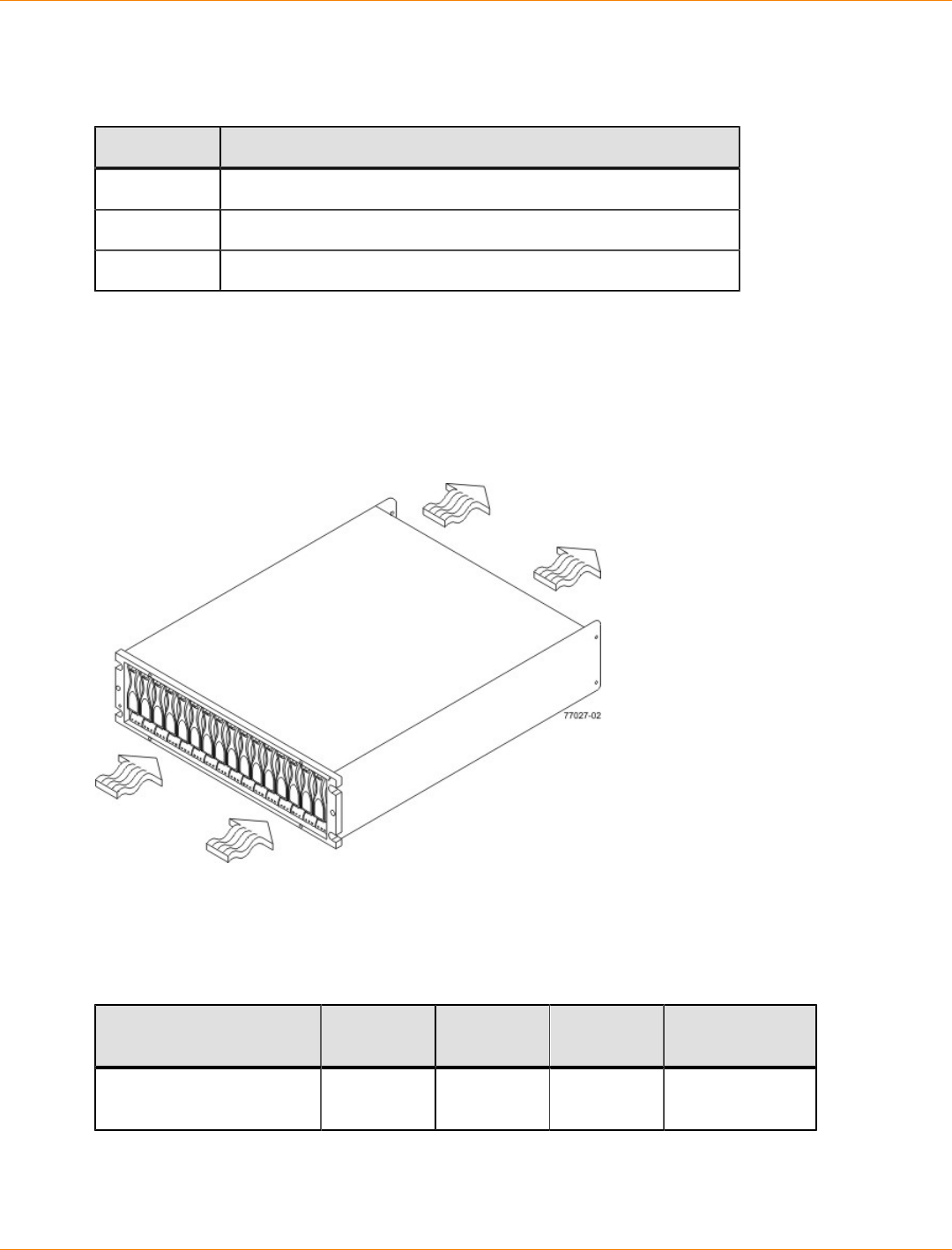
SANtricity_10.77 February 2011
LSI Corporation
- 163 -
CDE3994 Controller-Drive Tray Altitude Ranges
Altitude Ranges for the CDE3994 Controller-Drive Tray
Environment Altitude
Operating 30.5 m (100 ft) below to 3,000 m (9840 ft) above sea level
Storage 30.5 m (100 ft) below to 3,000 m (9840 ft) above sea level
Transit 30.5 m (100 ft) below to 12,000 m (40,000 ft) above sea level
CDE3994 Controller-Drive Tray Airflow and Heat Dissipation
Airflow goes from the front of the controller-drive tray to the rear of the controller-drive tray. Allow at least 76
cm (30 in.) of clearance in front of the controller-drive tray and at least 61 cm (24 in.) of clearance behind the
controller-drive tray for service clearance, ventilation, and heat dissipation.
Airflow Through the CDE3994 Controller-Drive Tray – Front View
The tabulated power and heat dissipation values inthe following table are the maximum measured operating
power. Maximum configuration units are typically operated at high data rates or have larger random access
memory (RAM) capabilities.
Power Ratings and Heat Dissipation for the CDE3994 Controller-Drive Tray
Component KVA Watts (AC) Btu/Hr Amps (240
VAC)
CDE3994 controller-drive
tray 0.624 600 2047 2.50
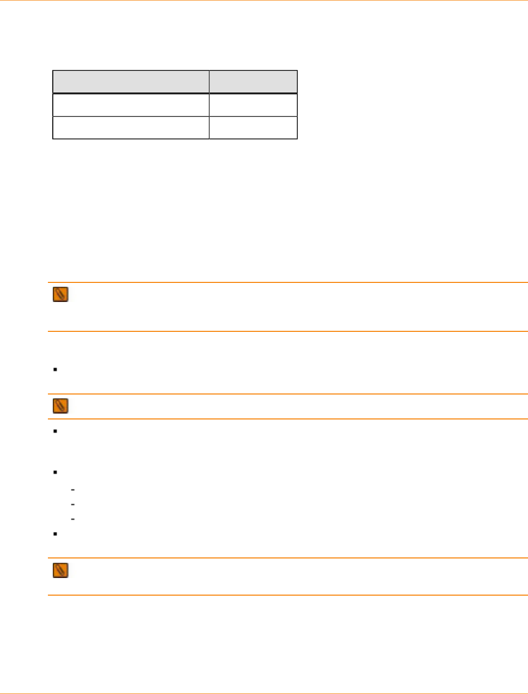
SANtricity_10.77 February 2011
LSI Corporation
- 164 -
CDE3994 Controller-Drive Tray Acoustic Noise
Sound Levels for the CDE3994 Controller-Drive Tray
Measurement Level
Sound power 6.5 bels
Sound pressure 65 dBA
CDE3994 Controller-Drive Tray Site Wiring and Power
The agency ratings for the CDE3994 controller-drive tray are 6.00 A at 100 VAC and 2.50 A at 240 VAC.
These ratings are the overall maximum AC currents for this system.
The CDE3994 controller-drive tray uses wide-ranging, redundant power supplies that automatically
accommodate voltages to the AC power source or the optional –48-VDC power source. The power supplies
meet standard voltage requirements for both North American (USA and Canada) operation and worldwide
(except USA and Canada) operation. The power supplies use standard industrial wiring with line-to-neutral or
line-to-line power connections.
NOTE Power for the optional –48-VDC power configuration is supplied by a centralized DC power plant
instead of the AC power source in the cabinet. Refer to the associated manufacturer’s documentation for
specific DC power source requirements.
Keep this information in mind when you prepare the installation site for the controller-drive tray:
Protective ground – Site wiring must include a protective ground connection to the AC power source or
the optional –48-VDC power source.
NOTE Protective ground is also known as safety ground or chassis ground.
Circuit overloading – Power circuits and associated circuit breakers must provide enough power and
overload protection. To prevent damage to the controller-drive tray, isolate its power source from large
switching loads, such as air-conditioning motors, elevator motors, and factory loads.
Power interruptions – The controller-drive tray can withstand these applied voltage interruptions:
Input transient – 50 percent of the nominal voltage
Duration – One-half cycle
Maximum frequency – Once every 10 seconds
Power failures – If a total power failure occurs, the controller-drive tray automatically performs a power-
on recovery sequence without operator intervention after the power is restored.
NOTE When a power failure occurs, the controller-drive tray uses battery power to back up the data
that is in cache.
If you are installing a large storage system configuration, you must make sure that you are supplying the
correct AC source voltages, and not creating an over-current situation.

SANtricity_10.77 February 2011
LSI Corporation
- 165 -
CDE3994 Controller-Drive Tray Power Input
AC Power Input
Each power supply contains one 15-A slow-blow fuse.
AC Power Requirements for the CDE3994 Controller-Drive Tray
Parameter Low Range High Range
Nominal voltage 115 VAC 230 VAC
Frequency 50 to 60 Hz 50 to 60 Hz
Idle current 3.81 A* 1.98 A**
Maximum operating current 3.96 A* 2.06 A**
Maximum surge current 5.52 A* 2.72 A**
*Typical current: 115 VAC, 60 Hz at 0.77 power supply efficiency and 0.96 power
factor.
**Typical current: 230 VAC, 60 Hz at 0.77 power supply efficiency and 0.96 power
factor.
DC Power Input
Nominal input voltages for the DC power source are as follows:
Low range: –36 VDC
High range: –72 VDC
The maximum operating current is 17 A.
CDE3994 Controller-Drive Tray Power Factor Correction
Power factor correction is applied within the power-fan canister of each CDE3994 controller-drive tray, which
maintains the power factor of the controller-drive tray at greater than 0.96 with nominal input voltage.
CDE3994 Controller-Drive Tray AC Power Cords and Receptacles
Each CDE3994 controller-drive tray is shipped with two AC power cords, which fit the standard AC outlets
in the destination country. Each AC power cord connects one of the power-fan canisters in the controller-
drive tray to an independent, external AC power source, such as a wall receptacle or an uninterruptible power
supply (UPS).
DC power is an option that is available for use with your controller-drive tray and drive tray. For more
information, refer to “CDE3994 Controller-Drive Tray Optional DC Power Connector Cables and Source
Wires."
If you have a cabinet with internal power cabling, such as a ladder cord, you do not need the AC power cords
that are shipped with the controller-drive tray.
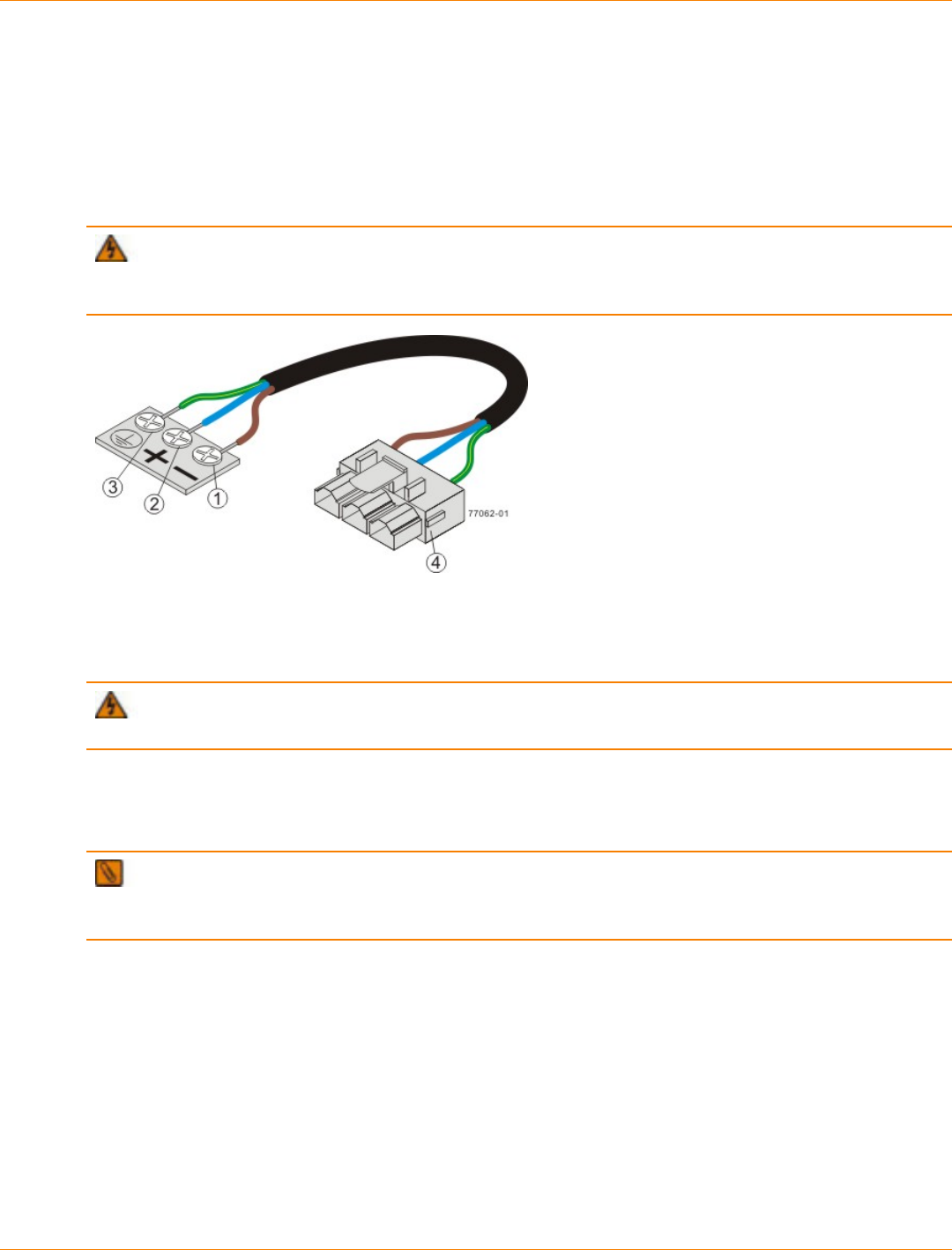
SANtricity_10.77 February 2011
LSI Corporation
- 166 -
CDE3994 Controller-Drive Tray Optional DC Power Connector Cables and
Source Wires
The CDE3994 controller-drive tray is shipped with –48-VDC power connector cables if the DC power option
is ordered. The –48-VDC power connector cable plugs into the DC power connector on the rear of the
controller-drive tray. The three source wires on the other end of the power connector cable connect the
controller-drive tray to centralized DC power plant equipment, typically through a bus bar above the cabinet.
WARNING (W12) Risk of electrical shock – This unit has more than one power source. To remove
all power from the unit, all DC MAINS must be disconnected by removing all power connectors (item 4 below)
from the power supplies.
1. Supply (Negative), Brown Wire, –48 VDC
2. Return (Positive), Blue Wire
3. Ground, Green and Yellow Wire
4. DC Power Connector
WARNING (W14) Risk of bodily injury – A qualified service person is required to make the DC
power connection according to NEC and CEC guidelines.
Two (or, optionally, four) DC power connector cables are provided with each controller-drive tray. Two DC
power connectors are on the two DC power supplies on the rear of each controller-drive tray if additional
redundancy is required.
NOTE It is not mandatory that you connect the second DC power connection on the DC power supplies
of the controller-drive tray. The second DC power connection is provided for additional redundancy only and
can be connected to a second DC power bus.
Preparing the Network for the Controllers
If you plan to use Ethernet connections from the storage management station to the controllers, you will use
the out-of-band management method. For this configuration, meet with your network administrator before
you order and install the equipment so that you can prepare for the setup and management of the devices
on the IP network. Each controller uses its Ethernet management ports to connect to the IP network and
communicate with the other devices on the IP network (often requiring a special application to set up the
protocol).
Your network administrator can pre-assign the addresses that you need to manage the communication
between the devices on the IP network. Depending on your storage configuration, you will need the following
addresses:

SANtricity_10.77 February 2011
LSI Corporation
- 167 -
Up to two network IP addresses for each controller
Up to two subnet mask addresses for each controller
Either two IPv4 addresses (one static and one dynamic) or one IPv6 address for each controller
A Dynamic Host Configuration Protocol (DHCP) address for each controller
If switches are used in your storage environment, you must know if zoning will be used, and how it will be
configured.
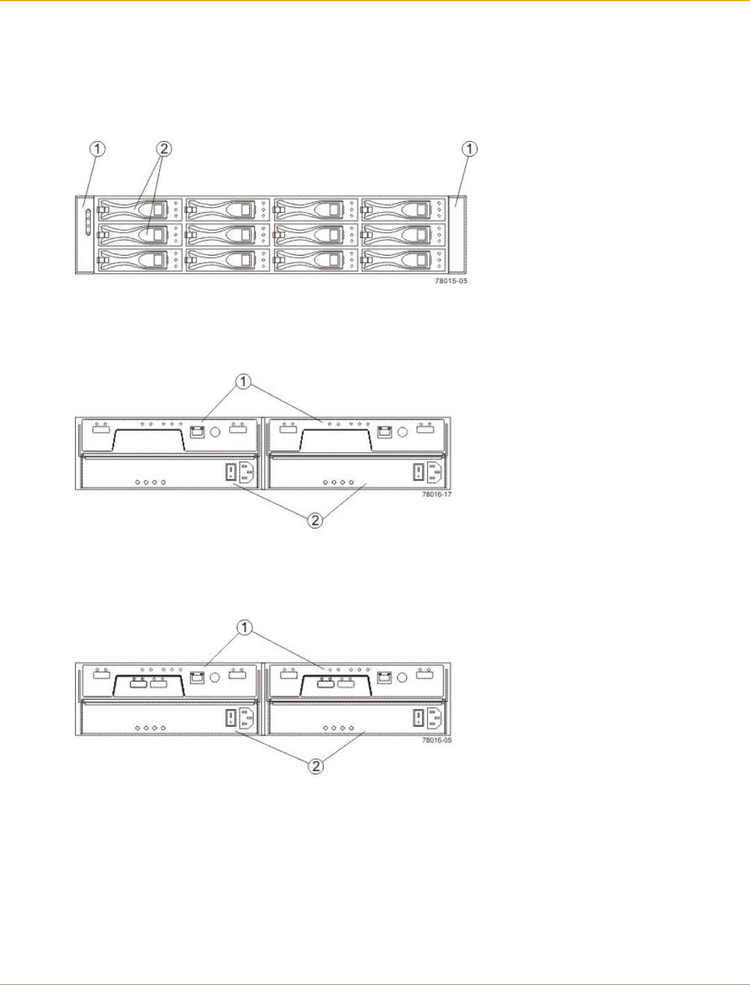
SANtricity_10.77 February 2011
LSI Corporation
- 168 -
Specifications of the AM1331 and AM1333 Controller-Drive Trays
The AM1331 and AM1333 controller-drive trays are available in rackmount models.
AM1331 and AM1333 Controller-Drive Trays – Front View
1. End Caps (the Left End Cap Has the Controller-Drive Tray Summary LEDs)
2. Drives
AM1331 Controller-Drive Tray – Rear View
1. Controller Canisters
2. Power-Fan Canisters
AM1333 Controller-Drive Tray – Rear View
1. Controller Canisters
2. Power-Fan Canisters
Usually, an AC power source supplies power to the power-fan canister. A DC poweroption is also available.
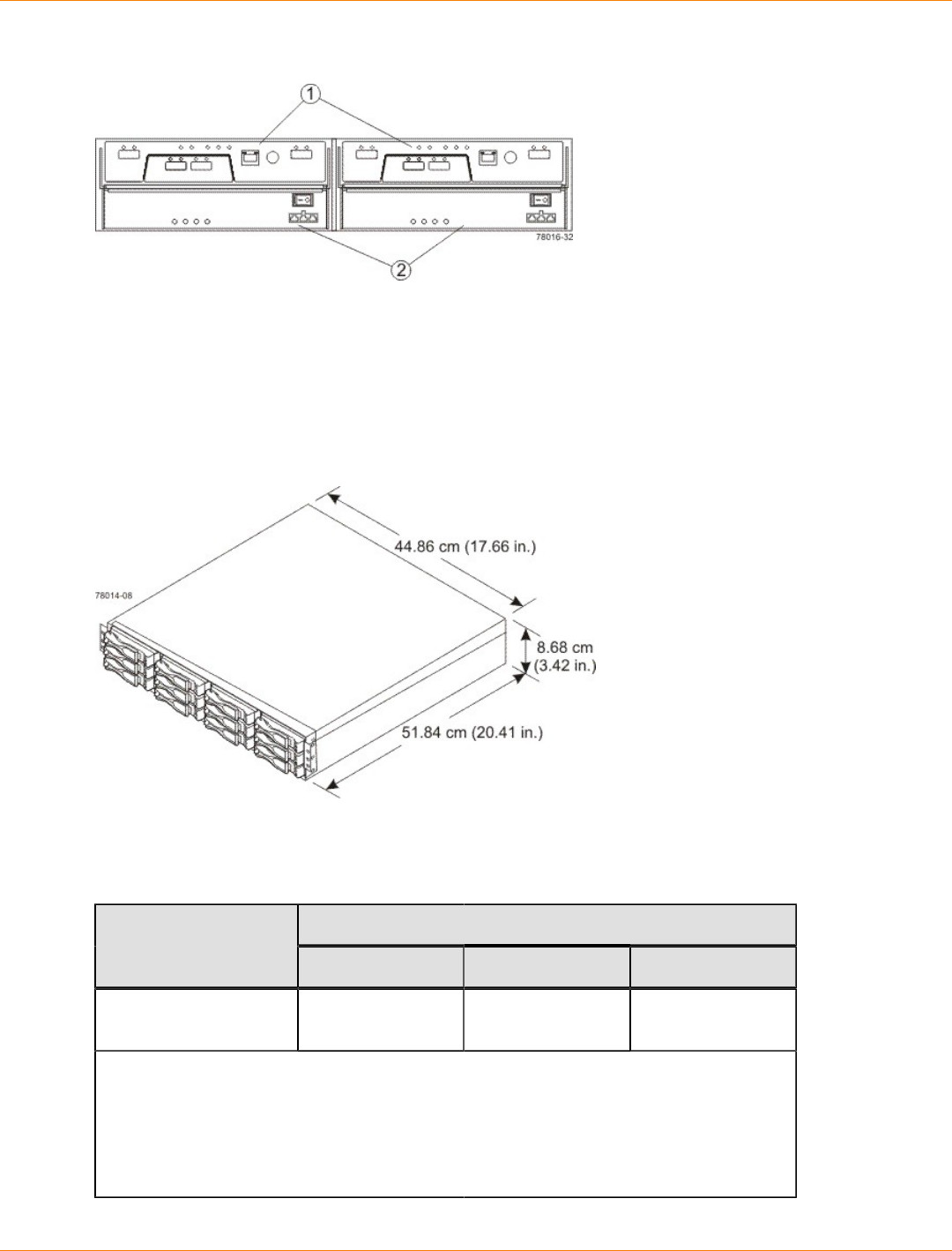
SANtricity_10.77 February 2011
LSI Corporation
- 169 -
AM1333 Controller-Drive Tray – Power Source Options Rear View
1. Controller Canisters
2. DC Power Switch on an Optional Power-Fan Canister
AM1331and AM1333 Controller-Drive Tray Dimensions
The AM1331and AM1333 controller-drive tray conforms to the 48.3-cm (19.0-in.) rack standard.
Dimensions of the AM1331and AM1333 Controller-Drive Tray – Front View
AM1331 and AM1333 Controller-Drive Trays Weight
Weights of the AM1331 and AM1333 Controller-Drive Trays
WeightUnit
Maximum* Empty** Shipping***
AM1331 and AM1333
controller-drive trays 25.86 kg (57 lb) 6.80 kg (15 lb) 25.00 kg (55.0 lb)
*Maximum weight indicates a controller-drive tray with all of its drives and other
components installed. Because drive weights can vary greatly, this value can vary from
the value specified as much as 0.3 kg (0.6 lb) times the maximum number of drives per
controller-drive tray for drives weighing 1.0 kg (2.2 lb).
**Empty weight indicates a controller-drive tray with the controller canisters, the power-
fan canisters, and the drives removed.
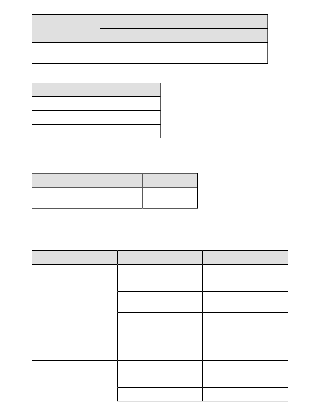
SANtricity_10.77 February 2011
LSI Corporation
- 170 -
WeightUnit
Maximum* Empty** Shipping***
***Shipping weight indicates the maximum weight of the controller-drive tray and all
shipping material.
Component Weights of the AM1331 and AM1333 Controller-Drive Trays
Component Weight
ESM canister 0.907 kg (2.00 lb)
Power-fan canister 2.267 kg (5.00 lb)
Drive 1.0 kg (2.2 lb)
AM1331 and AM1333 Controller-Drive Trays Shipping Dimensions
Shipping Carton Dimensions for the AM1331 and AM1333 Controller-Drive Trays
Height Width Depth
8.68 cm (3.42 in.) 51.84 cm (20.41
in.) 44.86 cm (17.66
in.)
AM1331 and AM1333 Controller-Drive Trays Temperature and Humidity
Temperature Requirements and Humidity Requirements for the AM1331 and AM1333 Controller-Drive
Trays
Condition Parameter Requirement
Operating range 10°C to 35°C (50°F to 95°F)
Maximum rate of change 10°C (18°F) per hour
Storage range –10°C to 45°C (14°F to
113°F)
Maximum rate of change 15°C (27°F) per hour
Transit range –20°C to 60°C (–40°F to
149°F) for one week
Temperature*
Maximum rate of change 20°C (36°F) per hour
Operating range 20% to 80%
Storage range 10% to 90%
Relative humidity (no
condensation)
Transit range 5% to 95%
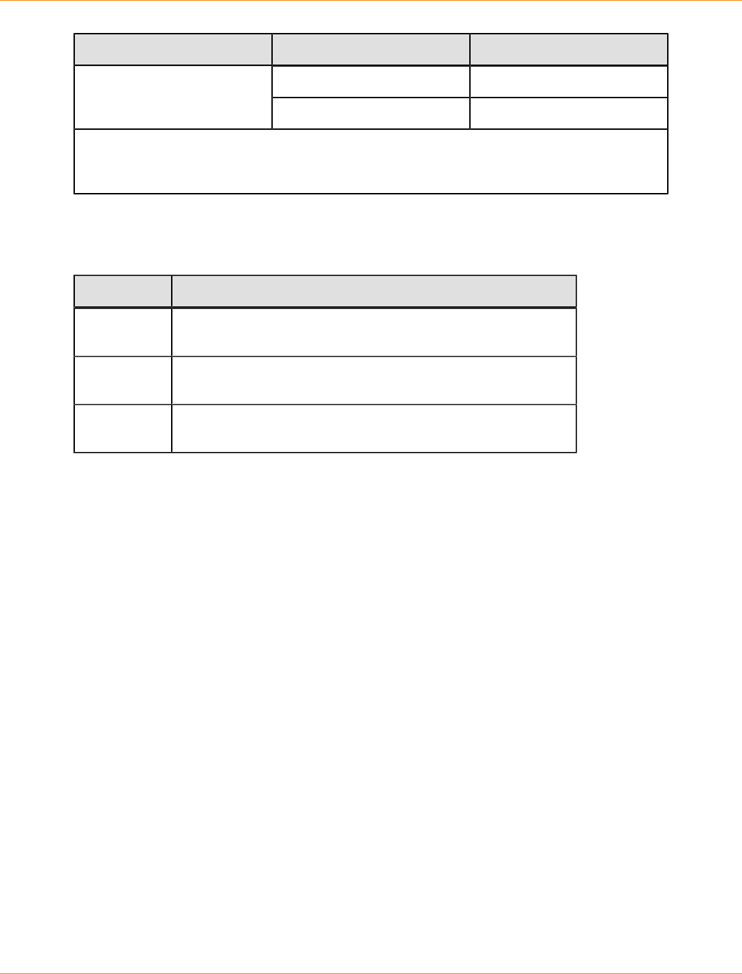
SANtricity_10.77 February 2011
LSI Corporation
- 171 -
Condition Parameter Requirement
Maximum dew point 26°C (79°F)
Maximum gradient 10% per hour
*If you plan to operate a system at an altitude between 1000 m to 3000 m (3280 ft to 9842 ft)
above sea level, lower the environmental temperature 1.7°C (3.3°F) for every 1000 m (3280 ft)
above sea level.
AM1331 and AM1333 Controller-Drive Trays Altitude Ranges
Altitude Ranges for the AM1331 and AM1333 Controller-Drive Trays
Environment Altitude
Operating 30.5 m (100 ft) below sea level to 3000 m (9842 ft) above sea
level
Storage 30.5 m (100 ft) below sea level to 3000 m (9842 ft) above sea
level
Transit 30.5 m (100 ft) below sea level to 12,000 m (40,000 ft) above
sea level
AM1331 and AM1333 Controller-Drive Trays Airflow and Heat Dissipation
Allow at least 76 cm (30 in.) of clearance in front of the controller-drive tray and 61 cm (24 in.) behind the
controller-drive tray for service clearance, ventilation, and heat dissipation.
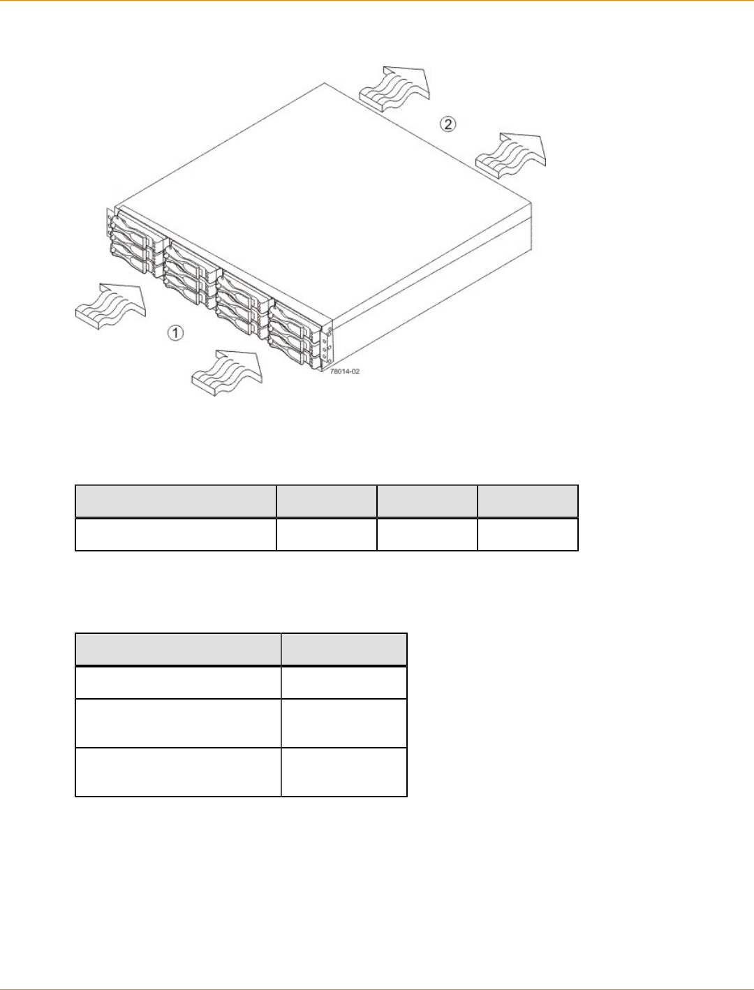
SANtricity_10.77 February 2011
LSI Corporation
- 172 -
Airflow Through the AM1331 and AM1333 Controller-Drive Trays – Front View
1. 76 cm (30 in.) clearance in front of the cabinet
2. 61 cm (24 in.) clearance behind the cabinet
Power and Heat Dissipation for the AM1331 and AM1333 Controller-Drive Trays
Component KVA Watts (AC) Btu/Hr
Controller canister 0.398 394 1346
AM1331 and AM1333 Controller-Drive Trays Acoustic Noise
Sound Levels for the AM1331 and AM1333 Controller-Drive Trays
Measurement Level
ES 2-10-02 Standard Level 2 0.5 bels margin
Sound power (standby
operation 6.5 bels
Sound power (normal
operation) 6.8 bels
AM1331 and AM1333 Controller-Drive Trays Site Wiring and Power
The AM1331 and AM1333 controller-drive trays use wide-ranging, redundant power supplies that
automatically accommodate voltages to the AC power source. The power supplies meet standard voltage
requirements for both North American (USA and Canada) operation and worldwide (except USA and
Canada) operation. The power supplies use standard industrial wiring with line-to-neutral or line-to-line power
connections.
SANtricity_10.77 February 2011
LSI Corporation
- 173 -
Keep this information in mind when you prepare the installation site for the controller-drive tray:
Protective ground – Site wiring must include a protective ground connection to the AC power source.
NOTE Protective ground is also known as safety ground or chassis ground.
Circuit overloading – Power circuits and associated circuit breakers must provide enough power and
overload protection. To prevent damage to the controller-drive tray, isolate its power source from large
switching loads, such as air-conditioning motors, elevator motors, and factory loads.
Power interruptions – The controller-drive tray can withstand these applied voltage interruptions:
Input transient – 50 percent of the nominal voltage
Duration – One-half cycle
Frequency – Once every 10 seconds
Power failures – If a total power failure occurs, the controller-drive tray automatically performs a power-
on recovery sequence without operator intervention.
AM1331 and AM1333 Controller-Drive Trays Power Input
AC Power Input
Each power supply contains one 10-A slow-blow fuse.
AC Power Requirements for the AM1331 and AM1333 Controller-Drive Trays
Parameter Low Range High Range
Nominal voltage 100 VAC 240 VAC
Frequency 50 to 60 Hz 50 to 60 Hz
Idle current 3.140 A–3.750 A* 1.34 A–1.58 A**
Maximum operating
current 4.01 A–4.08 A* 1.69 A–1.70 A**
*Typical voltage: 100 VAC, 60 Hz at 0.77 power supply efficiency and 0.96 power
factor. The range provided shows that these numbers can vary significantly,
depending upon the drives tested in the particular configuration.
**Typical voltage: 240 VAC, 50 Hz at 0.77 power supply efficiency and 0.96 power
factor. The range provided shows that these numbers can vary significantly,
depending upon the drives tested in the particular configuration.
DC Power Input
Nominal input voltages for the DC power source are as follows:
Low range: –36 VDC
High range: –72 VDC
The maximum operating current is 17 A.
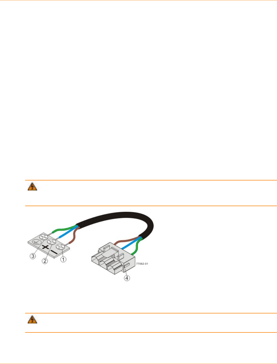
SANtricity_10.77 February 2011
LSI Corporation
- 174 -
AM1331 and AM1333 Controller-Drive Trays Power Factor Correction
Power factor correction is applied within the power supply, which maintains the power factor of the controller-
drive tray at greater than 0.95 with nominal input voltage.
AM1331 and AM1333 Controller-Drive Trays AC Power Cords and Receptacles
Each AM1331 and AM1333 controller-drive tray is shipped with two AC power cords. Each AC power cord
connects one of the power supplies in a controller-drive tray to an independent, external AC power source,
such as a wall receptacle or a UPS.
DC power is an option that is available for use with your controller-drive tray and drive tray. For more
information, see “AM1331 and AM1333 Controller-Drive Trays Optional DC Power Connector Cables and
Source Wires.”
If you have a cabinet with internal power cabling, such as a ladder cord, you do not need the AC power cords
that are shipped with the controller-drive tray.
AM1331 and AM1333 Controller-Drive Trays Optional DC Power Connector
Cables and Source Wires
The AM1331 and AM1333 controller-drive trays are shipped with –48-VDC power connector cables if the DC
power option is ordered. The –48-VDC power connector cable plugs into the DC power connector on the rear
of the controller-drive tray. The three source wires on the other end of the power connector cable connect the
controller-drive tray to centralized DC power plant equipment, typically through a bus bar above the cabinet.
WARNING (W12) Risk of electrical shock – This unit has more than one power source. To remove
all power from the unit, all DC MAINS must be disconnected by removing all power connectors (item 4 below)
from the power supplies.
1. Supply (Negative), Brown Wire, –48 VDC
2. Return (Positive), Blue Wire
3. Ground, Green and Yellow Wire
4. DC Power Connector
WARNING (W14) Risk of bodily injury – A qualified service person is required to make the DC
power connection according to NEC and CEC guidelines.
Two DC power connector cables are provided with each controller-drive tray. Two DC power connectors are
on the two DC power supplies on the rear of each controller-drive tray if additional redundancy is required.
SANtricity_10.77 February 2011
LSI Corporation
- 175 -
NOTE It is not mandatory that you connect the second DC power connection on the DC power supplies
of the controller-drive tray. The second DC power connection is provided for additional redundancy only and
can be connected to a second DC power bus.
Preparing the Network for the Controllers
If you plan to use Ethernet connections from the storage management station to the controllers, you will use
the out-of-band management method. For this configuration, meet with your network administrator before
you order and install the equipment so that you can prepare for the setup and management of the devices
on the IP network. Each controller uses its Ethernet management ports to connect to the IP network and
communicate with the other devices on the IP network (often requiring a special application to set up the
protocol).
Your network administrator can pre-assign the addresses that you need to manage the communication
between the devices on the IP network. Depending on your storage configuration, you will need the following
addresses:
Up to two network IP addresses for each controller
Up to two subnet mask addresses for each controller
Either two IPv4 addresses (one static and one dynamic) or one IPv6 address for each controller
A Dynamic Host Configuration Protocol (DHCP) address for each controller
If switches are used in your storage environment, you must know if zoning will be used, and how it will be
configured.
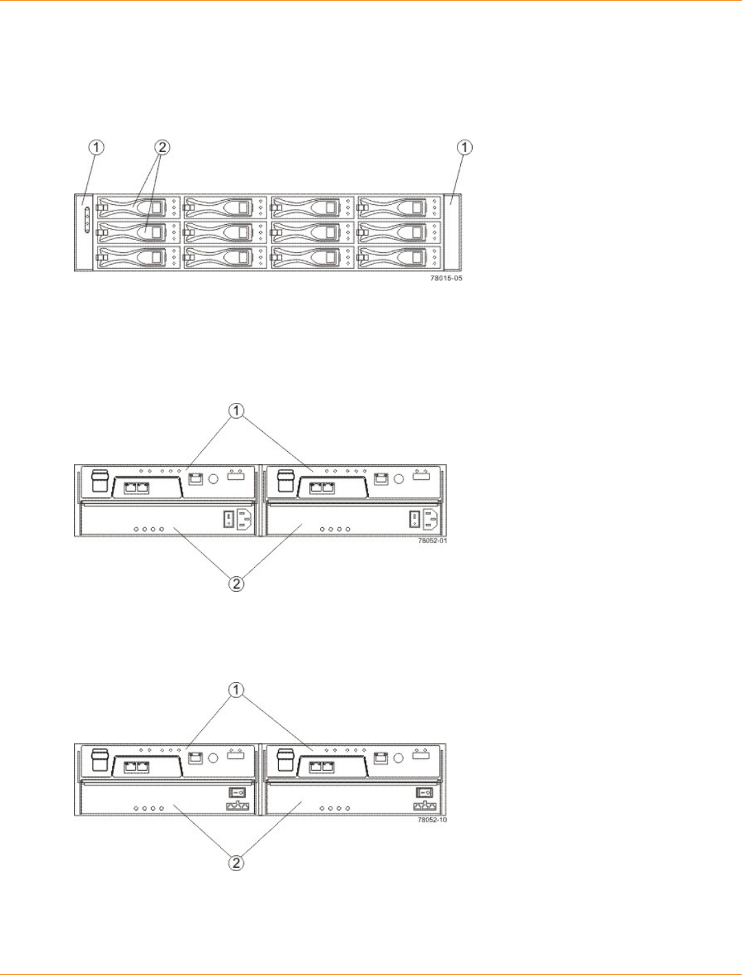
SANtricity_10.77 February 2011
LSI Corporation
- 176 -
Specifications of the AM1532 Controller-Drive Tray
The AM1532 controller-drive tray is available in a rackmount model.
AM1532 Controller-Drive Tray – Front View
1. End Caps (the Left End Cap Has the Controller-Drive Tray Summary LEDs)
2. Drives
Usually, an AC power source supplies power to the power-fan canister. A DC poweroption is also available.
AM1532 Controller-Drive Tray – Rear View
1. Controller Canisters
2. Power-Fan Canisters
AM1532 Controller-Drive Tray – Power Source Options Rear View
1. Controller Canisters
2. DC Power Switch on an Optional Power-Fan Canister
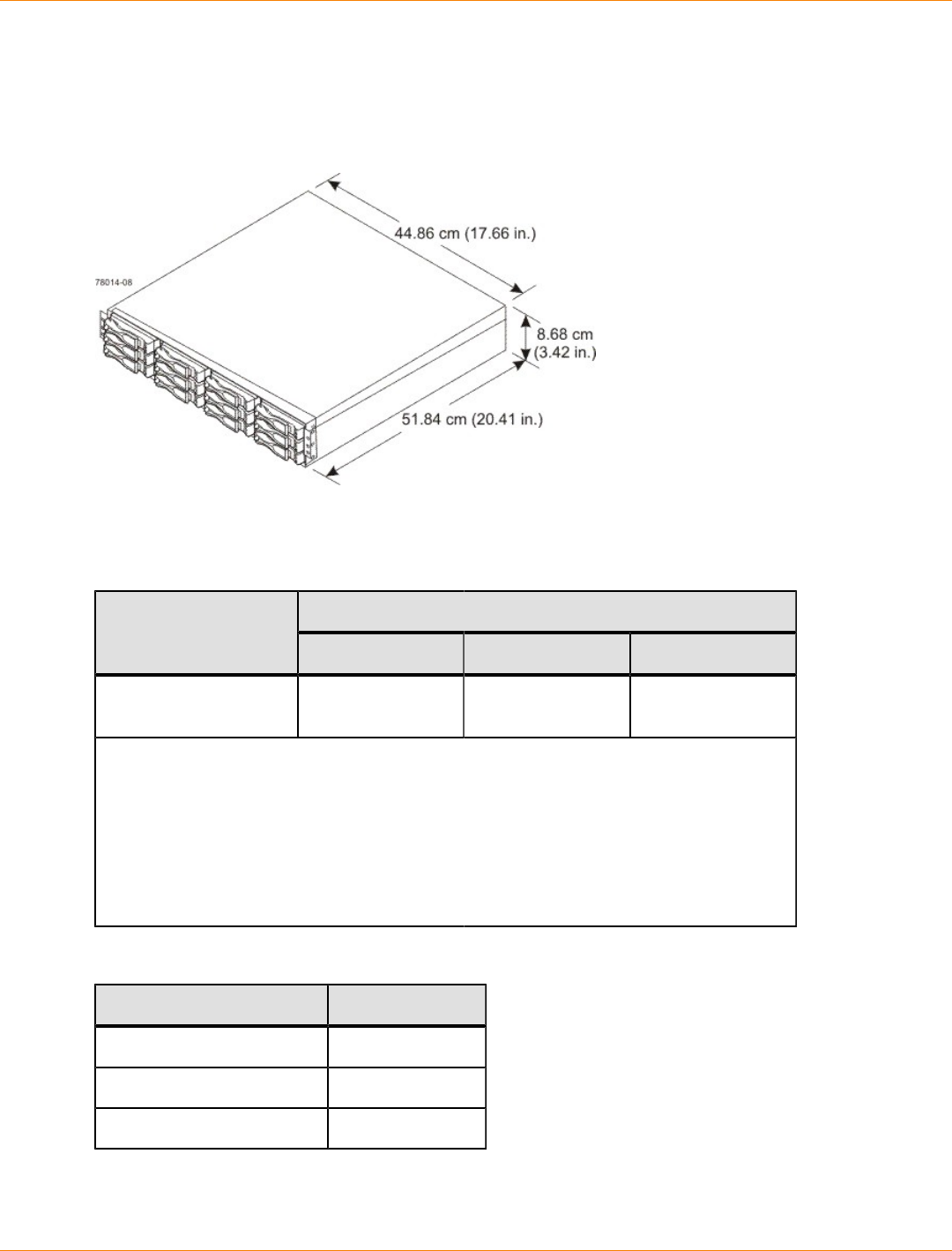
SANtricity_10.77 February 2011
LSI Corporation
- 177 -
AM1532 Controller-Drive Tray Dimensions
The AM1532 controller-drive tray conforms to the 48.3-cm (19.0-in.) rack standard.
Dimensions of the AM1532 Controller-Drive Tray – Front View
AM1532 Controller-Drive Tray Weight
Weights of the AM1532 Controller-Drive Tray
WeightUnit
Maximum* Empty** Shipping***
AM1532 controller-
drive tray 25.86 kg (57 lb) 6.80 kg (15 lb) 25.00 kg (55.0 lb)
*Maximum weight indicates a controller-drive tray with all of its drives and other
components installed. Because drive weights can vary greatly, this value can vary from
the value specified as much as 0.3 kg (0.6 lb) times the maximum number of drives per
controller-drive tray for drives weighing 1.0 kg (2.2 lb).
**Empty weight indicates a controller-drive tray with the controller canisters, the power-
fan canisters, and the drives removed.
***Shipping weight indicates the maximum weight of the controller-drive tray and all
shipping material.
Component Weights of the AM1532 Controller-Drive Tray
Component Weight
ESM canister 0.907 kg (2.00 lb)
Power-fan canister 2.267 kg (5.00 lb)
Drive 1.0 kg (2.2 lb)
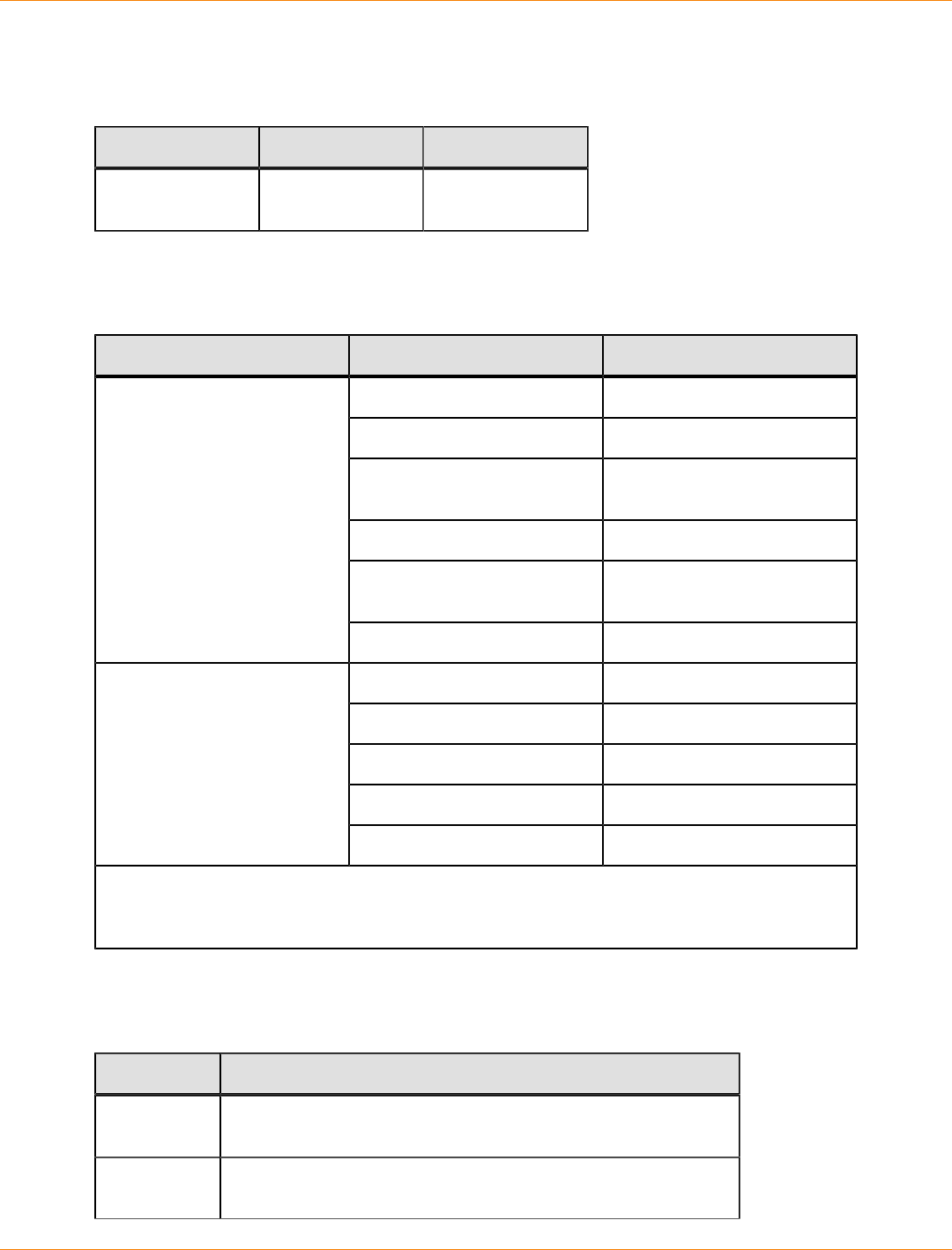
SANtricity_10.77 February 2011
LSI Corporation
- 178 -
AM1532 Controller-Drive Tray Shipping Dimensions
Shipping Carton Dimensions for the AM1532 Controller-Drive Tray
Height Width Depth
8.68 cm (3.42 in.) 51.84 cm (20.41
in.) 44.86 cm (17.66
in.)
AM1532 Controller-Drive Tray Temperature and Humidity
Temperature Requirements and Humidity Requirements for the AM1532 Controller-Drive Tray
Condition Parameter Requirement
Operating range 10°C to 35°C (50°F to 95°F)
Maximum rate of change 10°C (18°F) per hour
Storage range –10°C to 45°C (14°F to
113°F)
Maximum rate of change 15°C (27°F) per hour
Transit range –20°C to 60°C (–40°F to
140°F) for one week
Temperature
Maximum rate of change 20°C (36°F) per hour
Operating range 20% to 80%
Storage range 10% to 90%
Transit range 5% to 95%
Maximum dew point 26°C (79°F)
Relative humidity (no
condensation)
Maximum gradient 10% per hour
*If you plan to operate a system at an altitude between 1000 m to 3000 m (3280 ft to 9842 ft)
above sea level, lower the environmental temperature 1.7°C (3.3°F) for every 1000 m (3280 ft)
above sea level.
AM1532 Controller-Drive Tray Altitude Ranges
Altitude Ranges for the AM1532 Controller-Drive Tray
Environment Altitude
Operating 30.5 m (100 ft) below sea level to 3000 m (9842 ft) above sea
level
Storage 30.5 m (100 ft) below sea level to 3000 m (9842 ft) above sea
level

SANtricity_10.77 February 2011
LSI Corporation
- 179 -
Environment Altitude
Transit 30.5 m (100 ft) below sea level to 12,000 m (40,000 ft) above
sea level
AM1532 Controller-Drive Tray Airflow and Heat Dissipation
Allow at least 76 cm (30 in.) of clearance in front of the controller-drive tray and 61 cm (24 in.) behind the
controller-drive tray for service clearance, ventilation, and heat dissipation.
Airflow Through the AM1532 Controller-Drive Tray – Front View
1. 76 cm (30 in.) clearance in front of the cabinet
2. 61 cm (24 in.) clearance behind the cabinet
Power and Heat Dissipation for the AM1532 Controller-Drive Tray
Component KVA Watts (AC) Btu/Hr
Controller canister 0.458 453 1548
AM1532 Controller-Drive Tray Acoustic Noise
Sound Levels for the AM1532 Controller-Drive Tray
Measurement Level
ES 2-10-02 Standard Level 2 0.5 bels margin
Sound power (standby
operation) 6.5 bels
SANtricity_10.77 February 2011
LSI Corporation
- 180 -
Measurement Level
Sound power (normal
operation) 6.8 bels
AM1532 Controller-Drive Tray Site Wiring and Power
The AM1532 controller-drive tray uses wide-ranging, redundant power supplies that automatically
accommodate voltages to the AC power source. The power supplies meet standard voltage requirements for
both North American (USA and Canada) operation and worldwide (except USA and Canada) operation. The
power supplies use standard industrial wiring with line-to-neutral or line-to-line power connections.
Keep this information in mind when you prepare the installation site for the controller-drive tray:
Protective ground – Site wiring must include a protective ground connection to the AC power source.
NOTE Protective ground is also known as safety ground or chassis ground.
Circuit overloading – Power circuits and associated circuit breakers must provide enough power and
overload protection. To prevent damage to the controller-drive tray, isolate its power source from large
switching loads, such as air-conditioning motors, elevator motors, and factory loads.
Power interruptions – The controller-drive tray can withstand these applied voltage interruptions:
Input transient – 50 percent of the nominal voltage
Duration – One-half cycle
Frequency – Once every 10 seconds
Power failures – If a total power failure occurs, the controller-drive tray automatically performs a power-
on recovery sequence without operator intervention.
AM1532 Controller-Drive Tray Power Input
AC Power Input
Each power supply contains one 10-A slow-blow fuse.
AC Power Requirements for the AM1532 Controller-Drive Tray
Parameter Low Range High Range
Nominal voltage 100 VAC 240 VAC
Frequency 50 to 60 Hz 50 to 60 Hz
Idle current 3.96 A* 1.74 A**
Maximum operating current 4.08 A* 1.70 A**
*Typical current: 100 VAC, 60 Hz at 0.77 power supply efficiency and 0.96
power factor. These numbers can vary significantly, depending upon the
drives tested in the particular configuration.
**Typical current: 240 VAC, 60 Hz at 0.77 power supply efficiency and 0.96
power factor. These numbers can vary significantly, depending upon the
drives tested in the particular configuration.

SANtricity_10.77 February 2011
LSI Corporation
- 181 -
DC Power Input
Nominal input voltages for the DC power source are as follows:
Low range: –36 VDC
High range: –72 VDC
The maximum operating current is 17 A.
AM1532 Controller-Drive Tray Power Factor Correction
Power factor correction is applied within the power supply, which maintains the power factor of the controller-
drive tray at greater than 0.95 with nominal input voltage.
AM1532 Controller-Drive Tray AC Power Cords and Receptacles
Each AM1532 controller-drive tray is shipped with two AC power cords. Each AC power cord connects one
of the power supplies in a controller-drive tray to an independent, external AC power source, such as a wall
receptacle or a UPS.
DC power is an option that is available for use with your controller-drive tray and drive tray. For more
information, see “AM1532 Controller-Drive Tray Optional DC Power Connector Cables and Source Wires.”
If you have a cabinet with internal power cabling, such as a ladder cord, you do not need the AC power cords
that are shipped with the controller-drive tray.
AM1532 Controller-Drive Tray Optional DC Power Connector Cables and
Source Wires
The AM1532 controller-drive tray is shipped with –48-VDC power connector cables if the DC power option
is ordered. The –48-VDC power connector cable plugs into the DC power connector on the rear of the
controller-drive tray. The three source wires on the other end of the power connector cable connect the
controller-drive tray to centralized DC power plant equipment, typically through a bus bar above the cabinet.
WARNING (W12) Risk of electrical shock – This unit has more than one power source. To remove
all power from the unit, all DC MAINS must be disconnected by removing all power connectors (item 4 below)
from the power supplies.
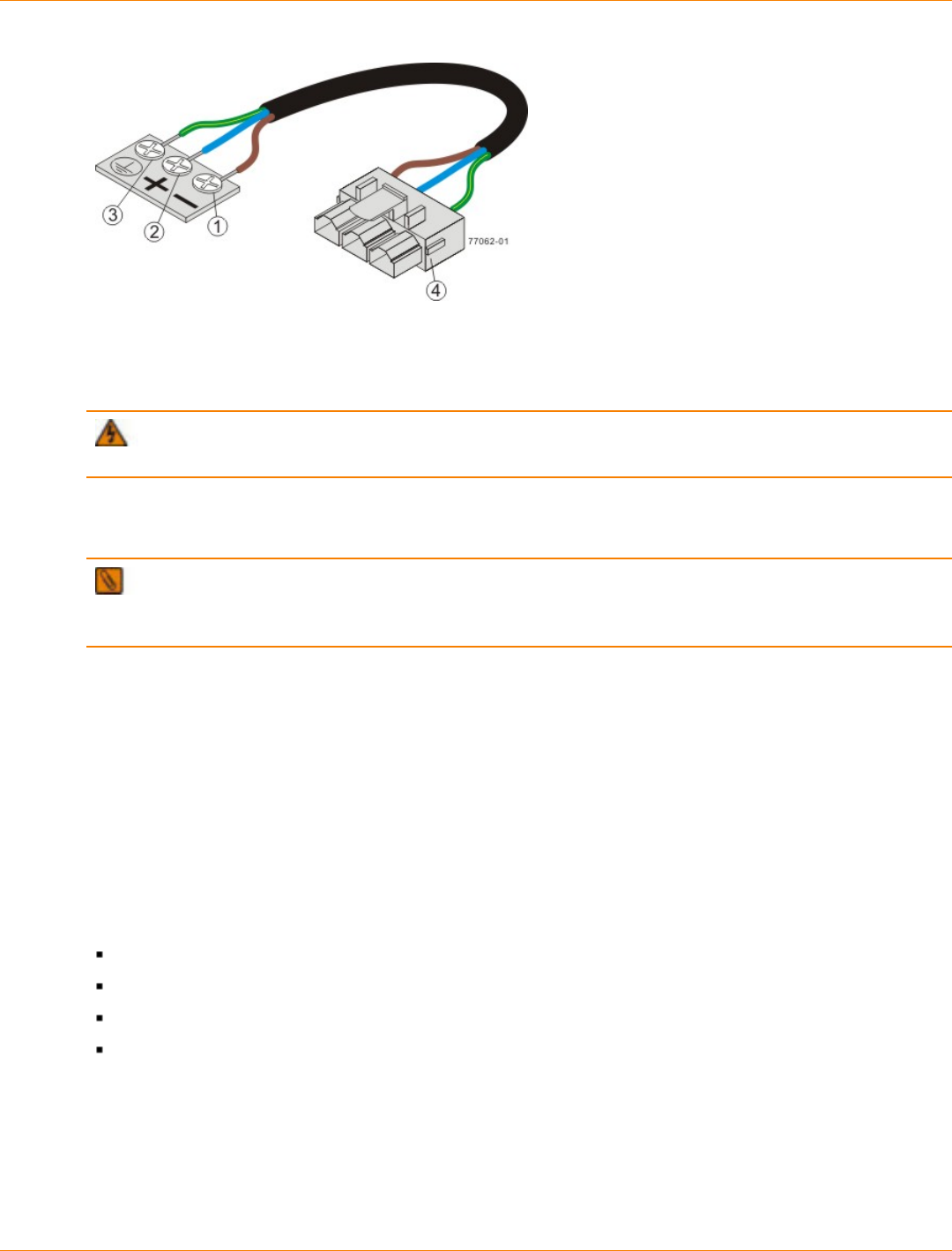
SANtricity_10.77 February 2011
LSI Corporation
- 182 -
1. Supply (Negative), Brown Wire, –48 VDC
2. Return (Positive), Blue Wire
3. Ground, Green and Yellow Wire
4. DC Power Connector
WARNING (W14) Risk of bodily injury – A qualified service person is required to make the DC
power connection according to NEC and CEC guidelines.
Two DC power connector cables are provided with each controller-drive tray. Two DC power connectors are
on the two DC power supplies on the rear of each controller-drive tray if additional redundancy is required.
NOTE It is not mandatory that you connect the second DC power connection on the DC power supplies
of the controller-drive tray. The second DC power connection is provided for additional redundancy only and
can be connected to a second DC power bus.
Preparing the Network for the Controllers
If you plan to use Ethernet connections from the storage management station to the controllers, you will use
the out-of-band management method. For this configuration, meet with your network administrator before
you order and install the equipment so that you can prepare for the setup and management of the devices
on the IP network. Each controller uses its Ethernet management ports to connect to the IP network and
communicate with the other devices on the IP network (often requiring a special application to set up the
protocol).
Your network administrator can pre-assign the addresses that you need to manage the communication
between the devices on the IP network. Depending on your storage configuration, you will need the following
addresses:
Up to two network IP addresses for each controller
Up to two subnet mask addresses for each controller
Either two IPv4 addresses (one static and one dynamic) or one IPv6 address for each controller
A Dynamic Host Configuration Protocol (DHCP) address for each controller
If switches are used in your storage environment, you must know if zoning will be used, and how it will be
configured.
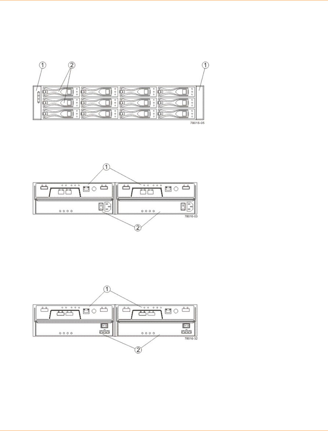
SANtricity_10.77 February 2011
LSI Corporation
- 183 -
Specifications of the AM1932 Controller-Drive Tray
The AM1932 controller-drive tray is available in a rackmount model.
AM1932 Controller-Drive Tray – Front View
1. End Caps (the Left End Cap Has the Controller-Drive Tray Summary LEDs)
2. Drives
AM1932 Controller-Drive Tray – Rear View
1. Controller Canisters
2. Power-Fan Canisters
Usually, an AC power source supplies power to the power-fan canister. A DC poweroption is also available.
AM1932 Controller-Drive Tray – Power Source Options Rear View
1. Controller Canisters
2. DC Power Switch on an Optional Power-Fan Canister
AM1932 Controller-Drive Tray Dimensions
The AM1932 controller-drive tray conforms to the 48.3-cm (19.0-in.) rack standard.
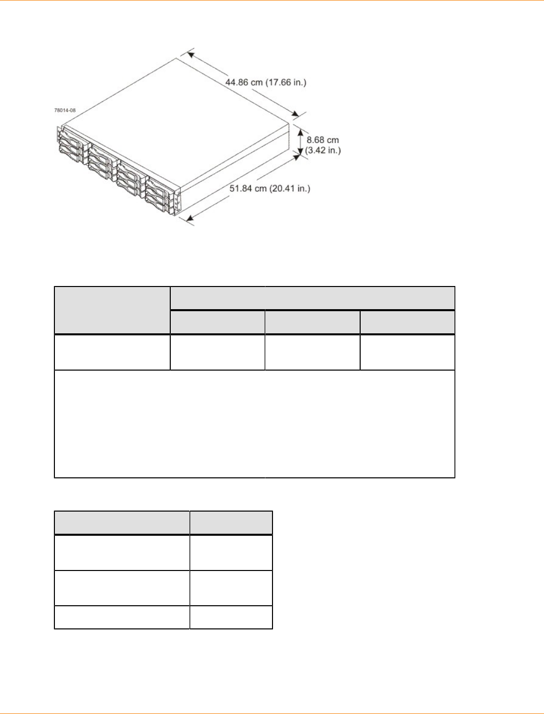
SANtricity_10.77 February 2011
LSI Corporation
- 184 -
Dimensions of the AM1932 Controller-Drive Tray – Front View
AM1932 Controller-Drive Tray Weight
Weights of the AM1932 Controller-Drive Tray
WeightUnit
Maximum* Empty** Shipping***
AM1932 controller-
drive tray 25.86 kg (57 lb) 6.80 kg (15 lb) 25.00 kg (55.0 lb)
*Maximum weight indicates a controller-drive tray with all of its drives and other
components installed. Because drive weights can vary greatly, this value can vary from
the value specified as much as 0.3 kg (0.6 lb) times the maximum number of drives per
controller-drive tray for drives weighing 1.0 kg (2.2 lb).
**Empty weight indicates a controller-drive tray with the controller canisters, the power-
fan canisters, and the drives removed.
***Shipping weight indicates the empty weight of a controller-drive tray and all shipping
material.
Component Weights of the AM1932 Controller-Drive Tray
Component Weight
ESM canister 0.907 kg (2.00
lb)
Power-fan canister 2.267 kg (5.00
lb)
Drive 1.0 kg (2.2 lb)

SANtricity_10.77 February 2011
LSI Corporation
- 185 -
AM1932 Controller-Drive Tray Shipping Dimensions
Shipping Carton Dimensions for the AM1932 Controller-Drive Tray
Height Width Depth
8.68 cm (3.42 in.) 51.84 cm (20.41
in.) 44.86 cm (17.66
in.)
AM1932 Controller-Drive Tray Temperature and Humidity
Temperature Requirements and Humidity Requirements for the AM1932 Controller-Drive Tray
Condition Parameter Requirement
Operating range 10°C to 35°C (50°F to 95F)
Maximum rate of change 10°C (18°F) per hour
Storage range –10°C to 45°C (14°F to
113°F)
Maximum rate of change 15°C (27°F) per hour
Transit range –20°C to 60°C (–40°F to
140°F)
Temperature*
Maximum rate of change 20°C (36°F) per hour
Operating range 20% to 80%
Storage range 10% to 90%
Transit range 5% to 95%
Maximum dew point 26°C (79°F)
Relative humidity (no
condensation)
Maximum gradient 10% per hour
*If you plan to operate a system at an altitude between 1000 m to 3000 m (3280 ft to 9842 ft)
above sea level, lower the environmental temperature 1.7°C (3.3°F) for every 1000 m (3280 ft)
above sea level.
AM1932 Controller-Drive Tray Altitude Ranges
Altitude Ranges for the AM1932 Controller-Drive Tray
Environment Altitude
Operating 30.5 m (100 ft) below sea level to 3000 m (9842 ft) above sea
level
Storage 30.5 m (100 ft) below sea level to 3000 m (9842 ft) above sea
level
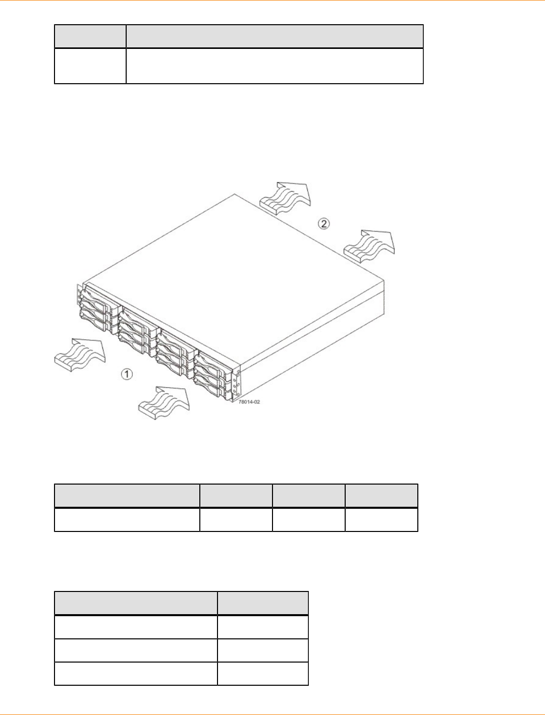
SANtricity_10.77 February 2011
LSI Corporation
- 186 -
Environment Altitude
Transit 30.5 m (100 ft) below sea level to 12,000 m (40,000 ft) above
sea level
AM1932 Controller-Drive Tray Airflow and Heat Dissipation
Allow at least 76 cm (30 in.) of clearance in front of the controller-drive tray and 61 cm (24 in.) behind the
controller-drive tray for service clearance, ventilation, and heat dissipation.
Airflow Through the AM1932 Controller-Drive Tray – Front View
1. 76 cm (30 in.) clearance in front of the cabinet
2. 61 cm (24 in.) clearance behind the cabinet
Power and Heat Dissipation for the AM1932 Controller-Drive Tray
Component KVA Watts (AC) Btu/Hr
Controller canister 0.458 453 1548
AM1932 Controller-Drive Tray Acoustic Noise
Sound Levels for the AM1932 Controller-Drive Tray
Measurement Level
ES 2-10-02 Standard Level 2 0.5 bels margin
Sound power (standby operation) 6.5 bels
Sound power (normal operation) 6.8 bels
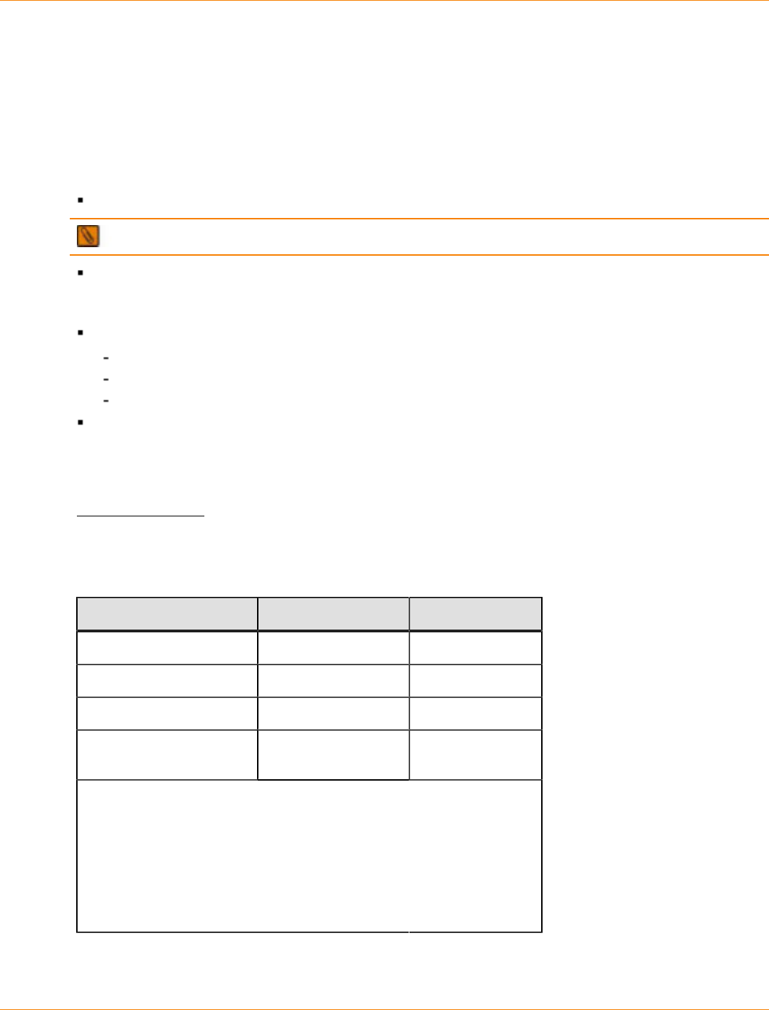
SANtricity_10.77 February 2011
LSI Corporation
- 187 -
AM1932 Controller-Drive Tray Site Wiring and Power
The AM1932 controller-drive tray uses wide-ranging, redundant power supplies that automatically
accommodate voltages to the AC power source. The power supplies meet standard voltage requirements for
both North American (USA and Canada) operation and worldwide (except USA and Canada) operation. The
power supplies use standard industrial wiring with line-to-neutral or line-to-line power connections.
Keep this information in mind when you prepare the installation site for the controller-drive tray:
Protective ground – Site wiring must include a protective ground connection to the AC power source.
NOTE Protective ground is also known as safety ground or chassis ground.
Circuit overloading – Power circuits and associated circuit breakers must provide enough power and
overload protection. To prevent damage to the controller-drive tray, isolate its power source from large
switching loads, such as air-conditioning motors, elevator motors, and factory loads.
Power interruptions – The controller-drive tray can withstand these applied voltage interruptions:
Input transient – 50 percent of the nominal voltage
Duration – One-half cycle
Frequency – Once every 10 seconds
Power failures – If a total power failure occurs, the controller-drive tray automatically performs a power-
on recovery sequence without operator intervention.
AM1932 Controller-Drive Tray Power Input
AC Power Input
Each power supply contains one 10-A slow-blow fuse.
AC Power Requirements for the AM1932 Controller-Drive Tray
Parameter Low Range High Range
Nominal voltage 100 VAC 240 VAC
Frequency 50 to 60 Hz 50 to 60 Hz
Idle current 2.90 A–3.96 A* 1.25 A–1.74A**
Maximum operating
current 3.14 A–4.01 A* 1.35 A–1.70 A**
*Typical voltage: 100 VAC, 60 Hz at 0.77 power supply efficiency and
0.96 power factor. The range provided shows that these numbers can
vary significantly, depending upon the drives tested in the particular
configuration.
**Typical voltage: 240 VAC, 50 Hz at 0.77 power supply efficiency and
0.96 power factor. The range provided shows that these numbers can
vary significantly, depending upon the drives tested in the particular
configuration.
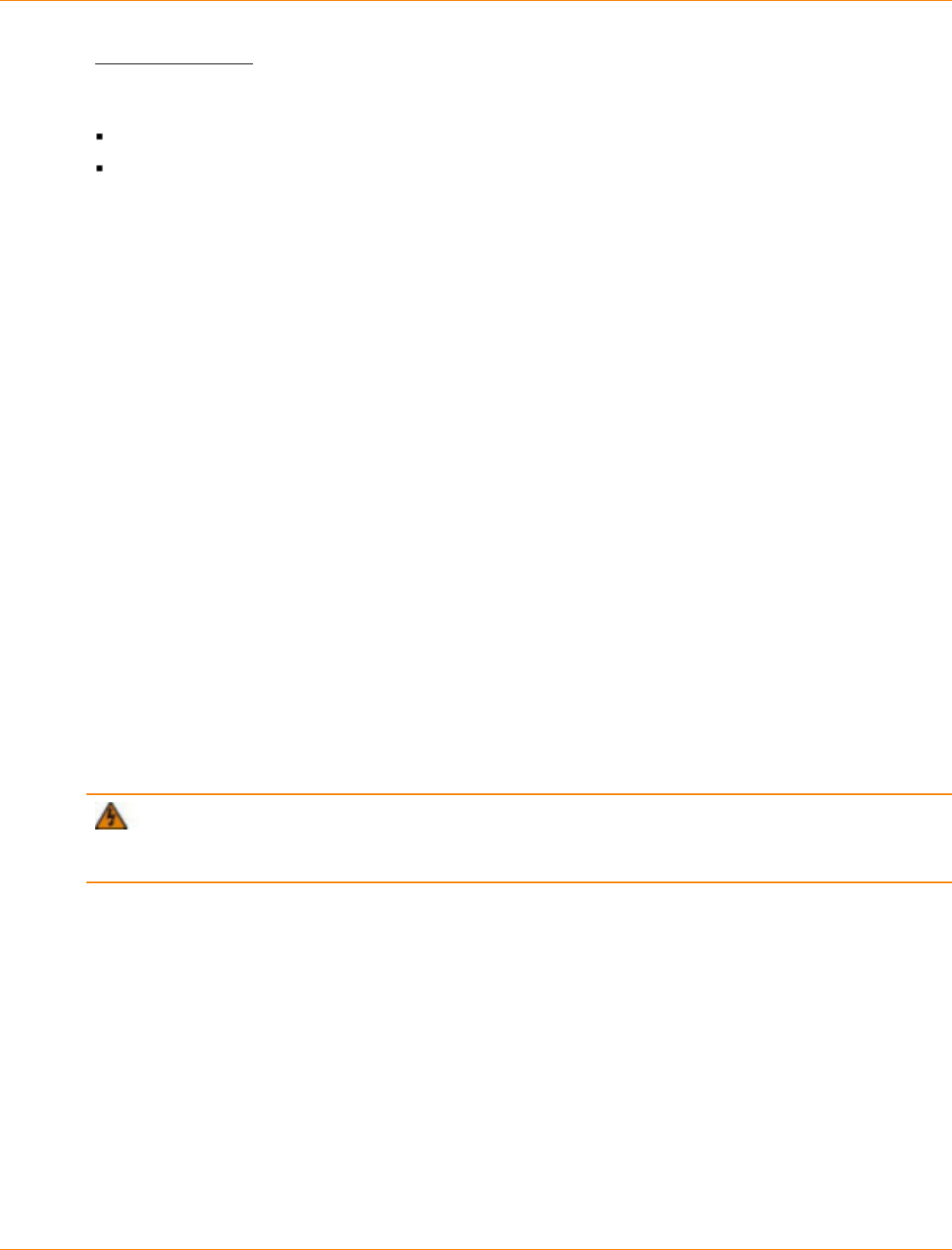
SANtricity_10.77 February 2011
LSI Corporation
- 188 -
DC Power Input
Nominal input voltages for the DC power source are as follows:
Low range: –36 VDC
High range: –72 VDC
The maximum operating current is 17 A.
AM1932 Controller-Drive Tray Power Factor Correction
Power factor correction is applied within the power supply, which maintains the power factor of the controller-
drive tray at greater than 0.95 with nominal input voltage.
AM1932 Controller-Drive Tray AC Power Cords and Receptacles
Each AM1932 controller-drive tray is shipped with two AC power cords. Each AC power cord connects one
of the power supplies in a controller-drive tray to an independent, external AC power source, such as a wall
receptacle or a UPS.
DC power is an option that is available for use with your controller-drive tray and drive tray. For more
information, see “AM1932 Controller-Drive Tray Optional DC Power Connector Cables and Source Wires.”
If you have a cabinet with internal power cabling, such as a ladder cord, you do not need the AC power cords
that are shipped with the controller-drive tray.
AM1932 Controller-Drive Tray Optional DC Power Connector Cables and
Source Wires
The AM1932 controller-drive tray is shipped with –48-VDC power connector cables if the DC power option
is ordered. The –48-VDC power connector cable plugs into the DC power connector on the rear of the
controller-drive tray. The three source wires on the other end of the power connector cable connect the
controller-drive tray to centralized DC power plant equipment, typically through a bus bar above the cabinet.
WARNING (W12) Risk of electrical shock – This unit has more than one power source. To remove
all power from the unit, all DC MAINS must be disconnected by removing all power connectors (item 4 below)
from the power supplies.

SANtricity_10.77 February 2011
LSI Corporation
- 189 -
1. Supply (Negative), Brown Wire, –48 VDC
2. Return (Positive), Blue Wire
3. Ground, Green and Yellow Wire
4. DC Power Connector
WARNING (W14) Risk of bodily injury – A qualified service person is required to make the DC
power connection according to NEC and CEC guidelines.
Two DC power connector cables are provided with each controller-drive tray. Two DC power connectors are
on the two DC power supplies on the rear of each controller-drive tray if additional redundancy is required.
NOTE It is not mandatory that you connect the second DC power connection on the DC power supplies
of the controller-drive tray. The second DC power connection is provided for additional redundancy only and
can be connected to a second DC power bus.
Preparing the Network for the Controllers
If you plan to use Ethernet connections from the storage management station to the controllers, you will use
the out-of-band management method. For this configuration, meet with your network administrator before
you order and install the equipment so that you can prepare for the setup and management of the devices
on the IP network. Each controller uses its Ethernet management ports to connect to the IP network and
communicate with the other devices on the IP network (often requiring a special application to set up the
protocol).
Your network administrator can pre-assign the addresses that you need to manage the communication
between the devices on the IP network. Depending on your storage configuration, you will need the following
addresses:
Up to two network IP addresses for each controller
Up to two subnet mask addresses for each controller
Either two IPv4 addresses (one static and one dynamic) or one IPv6 address for each controller
A Dynamic Host Configuration Protocol (DHCP) address for each controller
If switches are used in your storage environment, you must know if zoning will be used, and how it will be
configured.
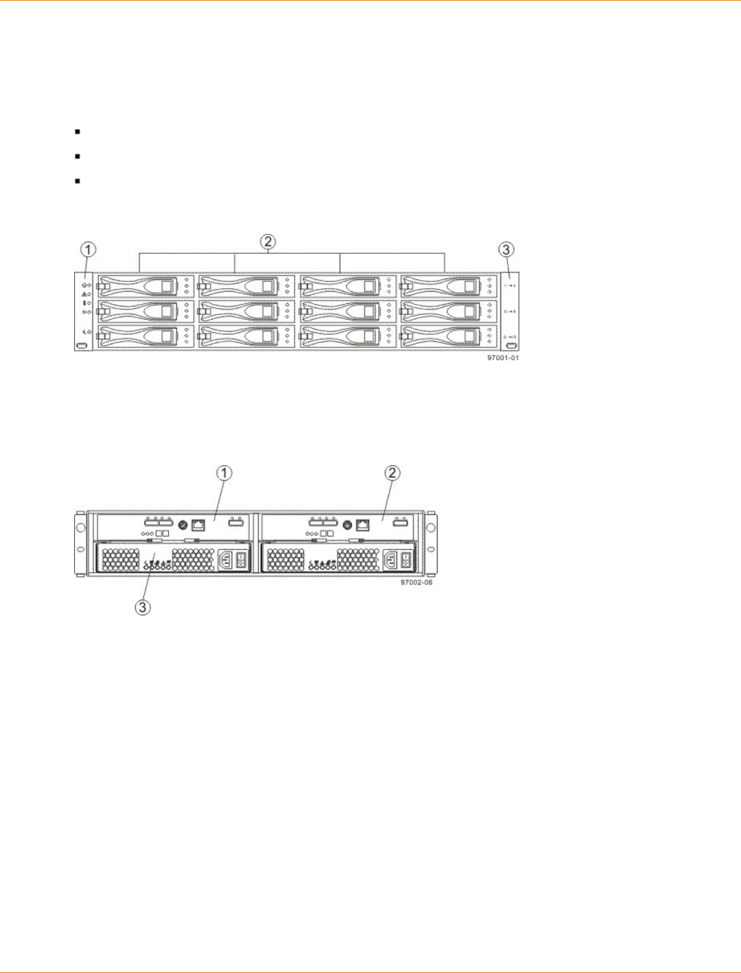
SANtricity_10.77 February 2011
LSI Corporation
- 190 -
Specifications of the DE1600 Drive Tray
The DE1600 drive tray contains Serial Attached SCSI (SAS) drives. Each DE1600 drive tray contains these
components:
A maximum of 12 drives
One or two power-supply fan canisters
One or two environmental services monitor (ESM) canisters
DE1600 Drive Tray – Front View
1. End Caps (the Left End Cap Has the Drive Tray LEDs)
2. Drives
3. Right End Cap
DE1600 Drive Tray – Rear View
1. ESM A Canister
2. ESM B Canister
3. Power-Fan A Canister
Usually, an AC power source supplies power to the power-fan canister. A DC poweroption is also available.
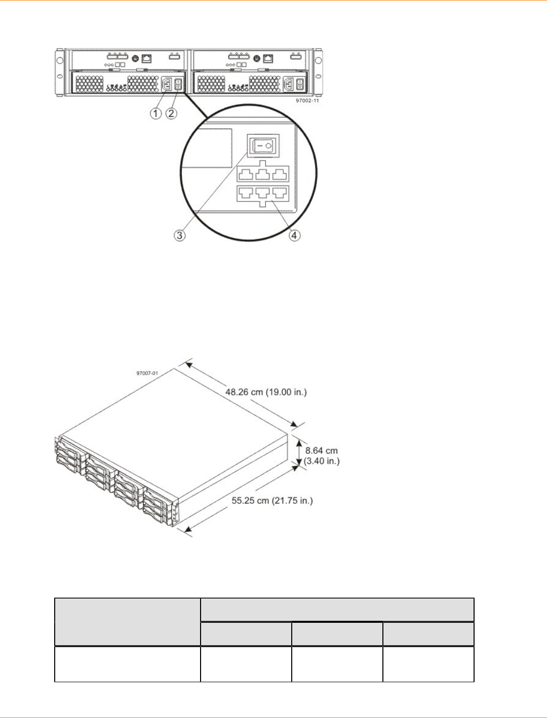
SANtricity_10.77 February 2011
LSI Corporation
- 191 -
DE1600 Drive Tray – Power Source Options Rear View
1. AC Power Connector on the AC Power-Fan Canister
2. AC Power Switch
3. DC Power Switch on an Optional DC Power-Fan Canister
4. Optional DC Power Connector and DC Power Switch
DE1600 Drive Tray Dimensions
Dimensions of the DE1600 Drive Tray – Front View
DE1600 Drive Tray Weight
Weights of the DE1600 Drive Tray
WeightUnit
Maximum* Empty** Shipping***
DE1600 drive tray 27 kg (59.52 lb) 18.60 kg (41.01
lb) 31.75 kg (70.0 lb)
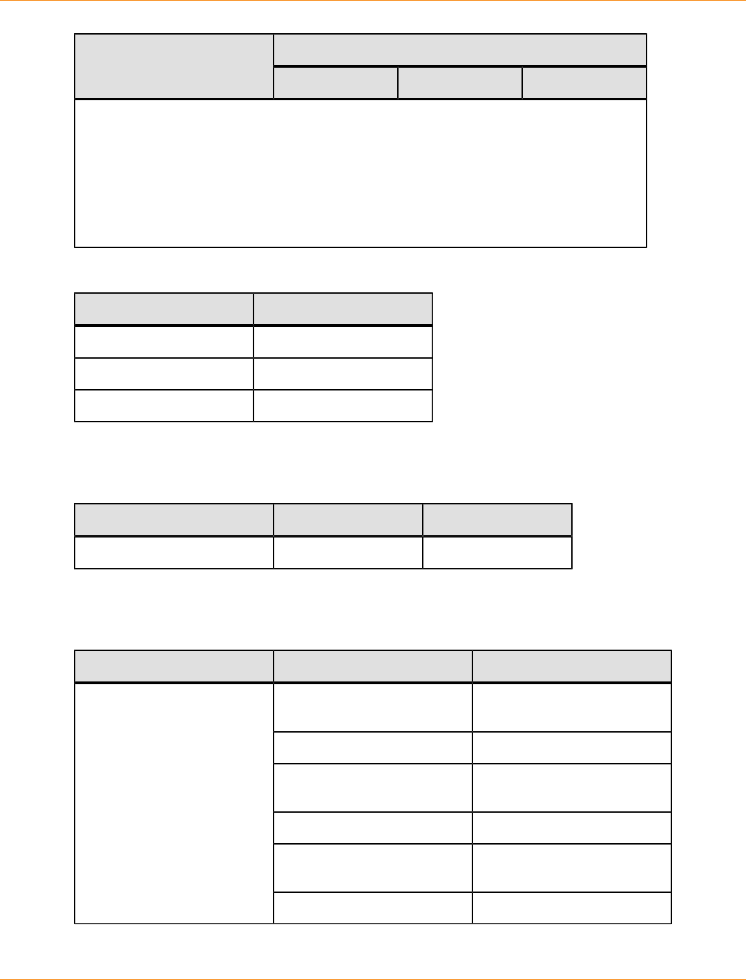
SANtricity_10.77 February 2011
LSI Corporation
- 192 -
WeightUnit
Maximum* Empty** Shipping***
*Maximum weight indicates adrive tray with all of its drives and other components installed.
Because drive weights can vary greatly, this value can vary from the value specified as
much as 0.3 kg (0.6 lb) times the maximum number of drives per drive tray for 3.5-in. SAS
drives.
**Empty weight indicates a drive tray with the ESM canisters, the power-fan canisters, and
the drives removed.
***Shipping weight indicates the maximum weight of a fully-populated drive tray and all
shipping material.
Component Weights of the DE1600 Drive Tray
Component Weight
ESM canister 1.75 kg (3.86 lb)
Power-fan canister 2.5 kg (5.51 lb)
3.5-in. SAS drive 1.00 kg (2.20 lb)
DE1600 Drive Tray Shipping Dimensions
Drive Tray and Shipping Carton Dimensions for the DE1600 Drive Tray
Height Width Depth
24.13 cm (9.5 in.) 58.42 cm (23.00 in.) 68.58 cm (27 in.)
DE1600 Drive Tray Temperature and Humidity
Temperature Requirements and Humidity Requirements for the DE1600 Drive Tray
Condition Parameter Requirement
Operating range (both cabinet
and subsystem) 10°C to 40°C (50°F to 104°F)
Maximum rate of change 10°C (50°F) per hour
Storage range –10°C to 50°C (14°F to
122°F)
Maximum rate of change 15°C (59°F) per hour
Transit range –40°C to 60°C (–40°F to
140°F)
Temperature
Maximum rate of change 20°C (68°F) per hour
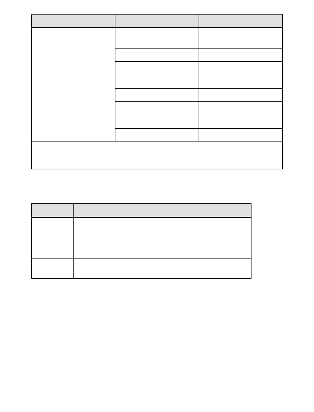
SANtricity_10.77 February 2011
LSI Corporation
- 193 -
Condition Parameter Requirement
Operating range (both cabinet
and subsystem) 20% to 80%
Storage range 10% to 90%
Transit range 5% to 90%
Operating gradient 10°C (50°F) per hour
Storage gradient 15°C (59°F) per hour
Transit gradient 20°C (68°F) per hour
Maximum dew point 26°C (79°F)
Relative humidity (no
condensation)
Maximum gradient 10% per hour
*If you plan to operate a system at an altitude between 1000 m to 3000 m (3280 ft to 9842 ft)
above sea level, lower the environmental temperature 1.7°C (3.3°F) for every 1000 m (3280 ft)
above sea level.
DE1600 Drive Tray Altitude Ranges
Altitude Ranges for the DE1600 Drive Tray
Environment Altitude
Operating 30.5 m (100 ft) below sea level to 3000 m (9840 ft) above sea
level
Storage 30.5 m (100 ft) below sea level to 3000 m (9840 ft) above sea
level
Transit 30.5 m (100 ft) below sea level to 12,000 m (40,000 ft) above sea
level
DE1600 Drive Tray Airflow and Heat Dissipation
Airflow goes from the front of the drive tray to the rear of the drive tray. Allow at least 76 cm (30 in.) of
clearance in front of the drive tray and at least 61 cm (24 in.) of clearance behind the drive tray for service
clearance, ventilation, and heat dissipation.
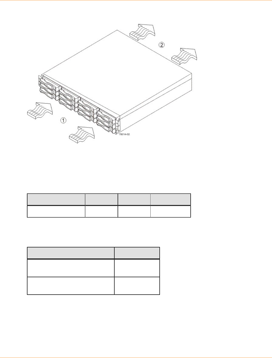
SANtricity_10.77 February 2011
LSI Corporation
- 194 -
Airflow Through the DE1600 Drive Tray – Front View
1. 76 cm (30 in.) clearance in front of the cabinet
2. 61 cm (24 in.) clearance behind the cabinet
The tabulated power and heat dissipation values in the following table are the maximum measured operating
power.
Power Ratings and Heat Dissipation for the DE1600 Drive Tray
Unit KVA AC Watts Btu/Hr
DE1600 drive tray 0.276 276 945
DE1600 Drive Tray Acoustic Noise
Acoustic Noise at 25°C for the DE1600 Drive Tray
Measurement Level
Sound power (standby operation) 6.5 bels
maximum
Sound power (normal operation) 6.8 bels
maximum
DE1600 Drive Tray Site Wiring and Power
The DE1600 drive tray uses wide-ranging, redundant power supplies that automatically accommodate
voltages to the AC power source or the optional –48-VDC power source. The power supplies meet standard
voltage requirements for both North American (USA and Canada) operation and worldwide (except USA and
Canada) operation. The power supplies use standard industrial wiring with line-to-neutral or line-to-line power
connections.
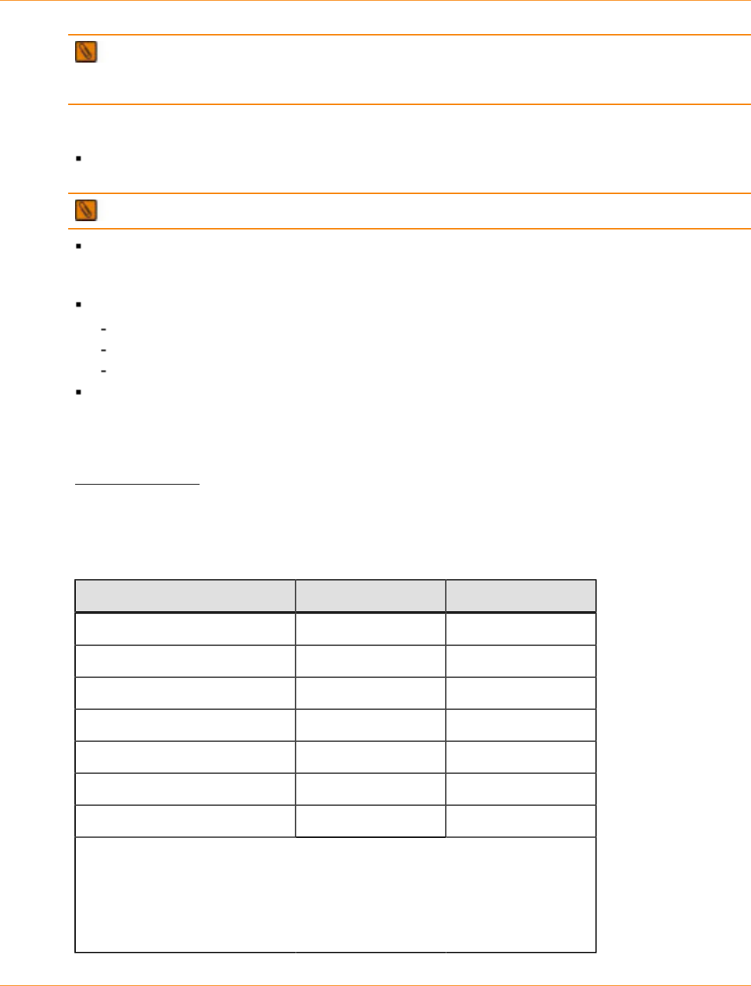
SANtricity_10.77 February 2011
LSI Corporation
- 195 -
NOTE Power for the optional –48-VDC power configuration is supplied by a centralized DC power plant
instead of the AC power source in the cabinet. Refer to the associated manufacturer’s documentation for
specific DC power source requirements.
Keep this information in mind when preparing the installation site for the drive tray:
Protective ground – Site wiring must include a protective ground connection to the AC power source or
the optional –48-VDC power source.
NOTE Protective ground is also known as safety ground or chassis ground.
Circuit overloading – Power circuits and associated circuit breakers must provide enough power and
overload protection. To prevent damage to the drive tray, isolate its power source from large switching
loads, such as air-conditioning motors, elevator motors, and factory loads.
Power interruptions – The drive tray can withstand these applied voltage interruptions:
Input transient – 50 percent of the nominal voltage
Duration – One-half cycle
Maximum frequency – Once every 10 seconds
Power failures – If a total power failure occurs, the drive tray automatically performs a power-on recovery
sequence without operator intervention after the power is restored.
DE1600 Drive Tray Power Input
AC Power Input
The AC power sources must provide the correct voltage, current, and frequency specified on the tray and
serial number label.
AC Power Requirements for the DE1600 Drive Tray
Parameter Low Range High Range
Nominal voltage 100 VAC 240 VAC
Frequency 50 to 60 Hz 50 to 60 Hz
Idle current 2.96 A* 1.23 A**
Maximum operating current 3.03 A* 1.26 A**
Sequential Drive Group Spin Up 4.23 A 1.76 A
Simultaneous Drive Spin Up 4.43 A 1.83 A
System Rating Plate Label 7.0 A 2.9 A
* Typical current: 100 VAC, 60 Hz at 0.87 power supply efficiency and 0.99 power
factor. These numbers can vary significantly, depending upon the drives tested in
the particular configuration.
**Typical current: 240 VAC, 60 Hz at 0.87 power supply efficiency and 0.99 power
factor. These numbers can vary significantly, depending upon the drives tested in
the particular configuration.
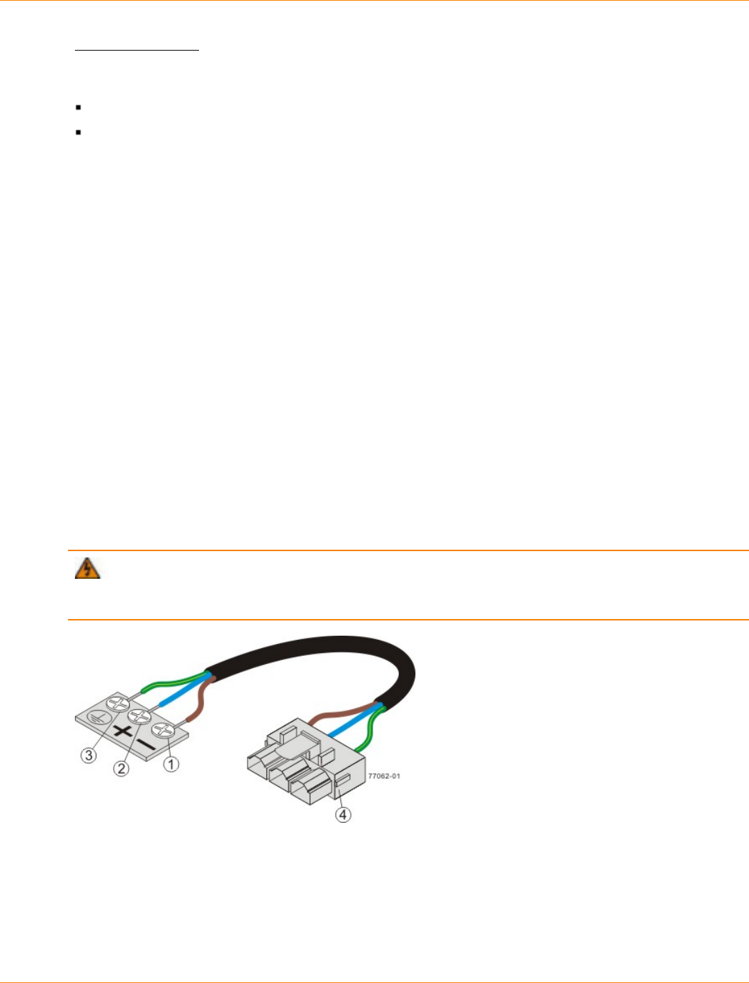
SANtricity_10.77 February 2011
LSI Corporation
- 196 -
DC Power Input
Nominal input voltages for the DC power source are as follows:
Low range: –42VDC
High range: –60 VDC
The maximum operating current is 21.7 A.
DE1600 Drive Tray Power Factor Correction
Power factor correction is applied within the power supply of each DE1600 drive tray, which maintains the
power factor of the drive tray at greater than 0.95 with nominal input voltage.
DE1600 Drive Tray AC Power Cords and Receptacles
Each DE1600 drive tray is shipped with two AC power cords, which use standard AC outlets in the destination
country. Each AC power cord connects one of the power supplies in the drive tray to an independent, external
AC power source, such as a wall receptacle, or to any uninterruptible power supply (UPS).
DC power is an option that is available for use with your DE1600 drive tray. For more information, see
"DE1600 Drive Tray Optional DC Power Connector Cables and Source Wires."
DE1600 Drive Tray Optional DC Power Connector Cables and Source Wires
The DE1600 drive tray is shipped with –48-VDC power connector cables if the DC power option is ordered.
The –48-VDC power connector cable plugs into the DC power connector on the rear of the drive tray. The
three source wires on the other end of the power connector cable connect the drive tray to centralized DC
power plant equipment, typically through a bus bar above the cabinet.
WARNING (W12) Risk of electrical shock – This unit has more than one power source. To remove
all power from the unit, all DC MAINS must be disconnected by removing all power connectors (item 4 below)
from the power supplies.
1. Supply (Negative), Brown Wire, –48 VDC
2. Return (Positive), Blue Wire
3. Ground, Green and Yellow Wire
4. DC Power Connector

SANtricity_10.77 February 2011
LSI Corporation
- 197 -
WARNING (W14) Risk of bodily injury – A qualified service person is required to make the DC
power connection according to NEC and CEC guidelines.
Two (or, optionally, four) DC power connector cables are provided with each drive tray. Two DC power
connectors are on the two power-fan canisters on the rear of each drive tray if additional redundancy is
required.
NOTE It is not mandatory that you connect the second DC power connection on the power-fan canister
of the drive tray. The second DC power connection is provided for additional redundancy only and can be
connected to a second DC power bus.
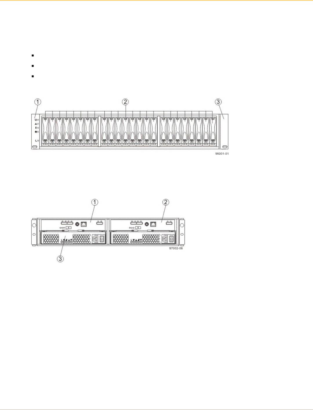
SANtricity_10.77 February 2011
LSI Corporation
- 198 -
Specifications of the DE5600 Drive Tray
The DE5600 drive tray contains Serial Attached SCSI (SAS) drives. Each DE5600 drive tray contains these
components:
A maximum of 24 drives
One or two power-supply fan canisters
One or two environmental services monitor (ESM) canisters
DE5600 Drive Tray – Front View
1. Left End Cap (Has the Drive Tray LEDs)
2. Drives
3. Right End Cap
DE5600 Drive Tray – Rear View
1. ESM A Canister
2. ESM B Canister
3. Power-Fan Canister
Usually, an AC power source supplies power to the power-fan canister. A DC power option is also available.
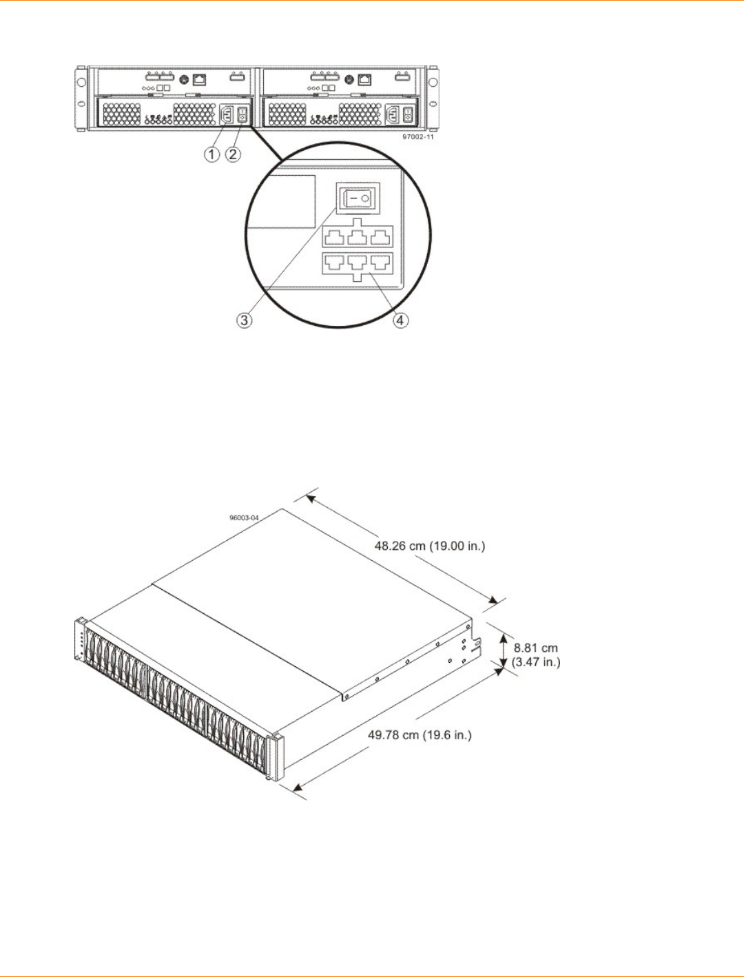
SANtricity_10.77 February 2011
LSI Corporation
- 199 -
DE5600 Drive Tray Power Source Options – Rear View
1. AC Power Switch on the AC Power-Fan Canister
2. AC Power Connector
3. DC Power Switch on an Optional DC Power-Fan Canister
4. DC Power Connector
DE5600 Drive Tray Dimensions
Dimensions of the DE5600 Drive Tray – Front View
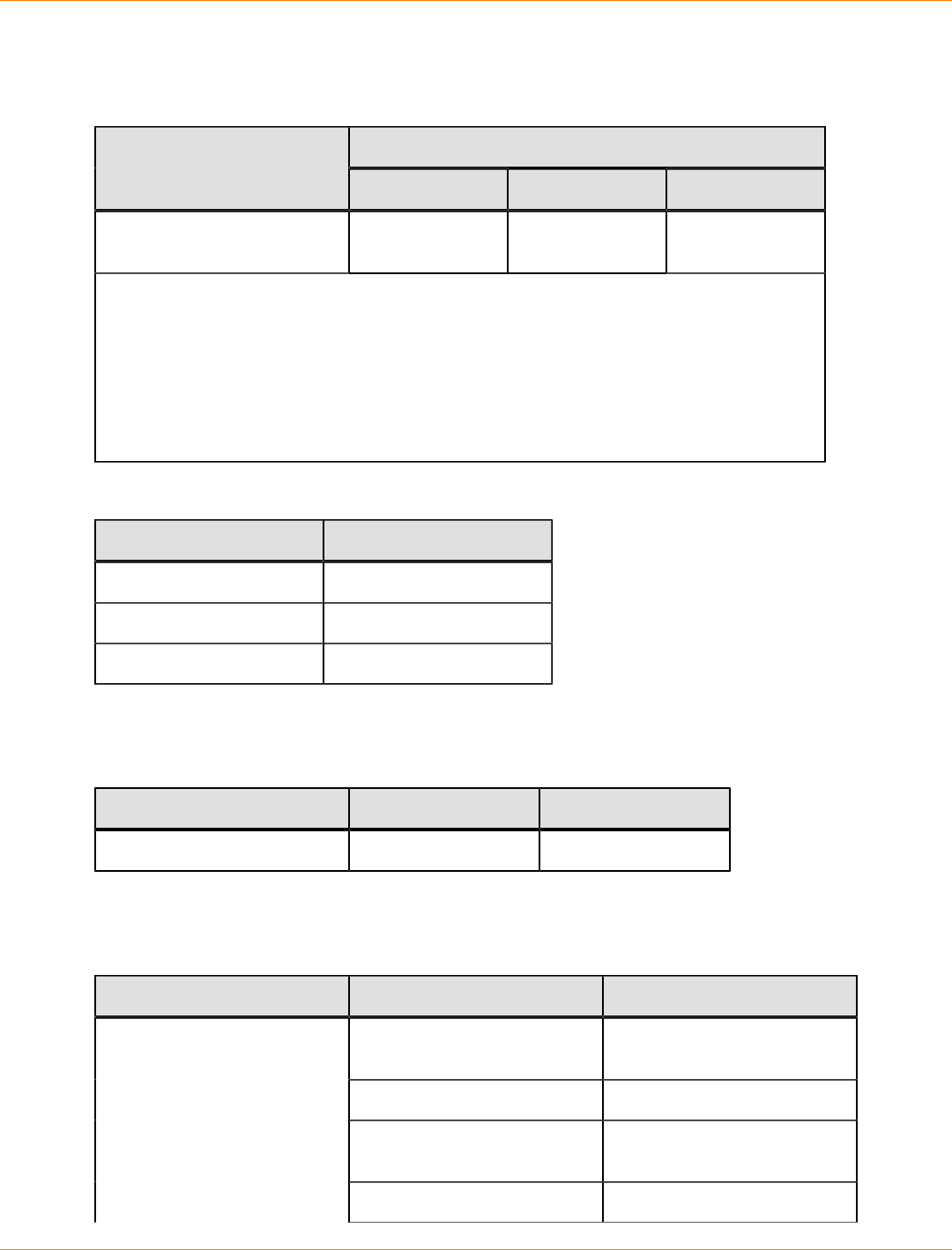
SANtricity_10.77 February 2011
LSI Corporation
- 200 -
DE5600 Drive Tray Weight
Weights of the DE5600 Drive Tray
WeightUnit
Maximum* Empty** Shipping***
DE5600 drive tray 26 kg (57.32 lb) 21.70 kg (47.84
lb) 31.75 kg (70.0 lb)
*Maximum weight indicates a drive tray with all of its drives and other components
installed. Because drive weights can vary greatly, this value can vary from the value
specified as much as 0.08 kg (0.18 lb) times the maximum number of drives per drive tray
for 2.5-in. SAS drives.
**Empty weight indicates a drive tray with the ESM canisters, the power-fan canisters, and
the drives removed.
***Shipping weight indicates the maximum weight of a fully-populated drive tray and all
shipping material.
Component Weights of the DE5600 Drive Tray
Component Weight
ESM canister 0.907 kg (2.00 lb)
Power-fan canister 2.500 kg (5.51 lb)
2.5-in. SAS drive 0.3 kg (0.6 lb)
DE5600 Drive Tray Shipping Dimensions
Drive Tray and Shipping Carton Dimensions for the DE5600 Drive Tray
Height Width Depth
24.13 cm (9.5 in.) 58.42 cm (23.00 in.) 63.50 cm (25 in.)
DE5600 Drive Tray Temperature and Humidity
Temperature Requirements and Humidity Requirements for the DE5600 Drive Tray
Condition Parameter Requirement
Operating range (both cabinet
and subsystem) 10°C to 35° C 50°F to 104°F)
Maximum rate of change 10°C (18°F) per hour]
Storage range –10°C to 50°C (14°F to
122°F)
Temperature
Maximum rate of change 15°C (59°F) per hour
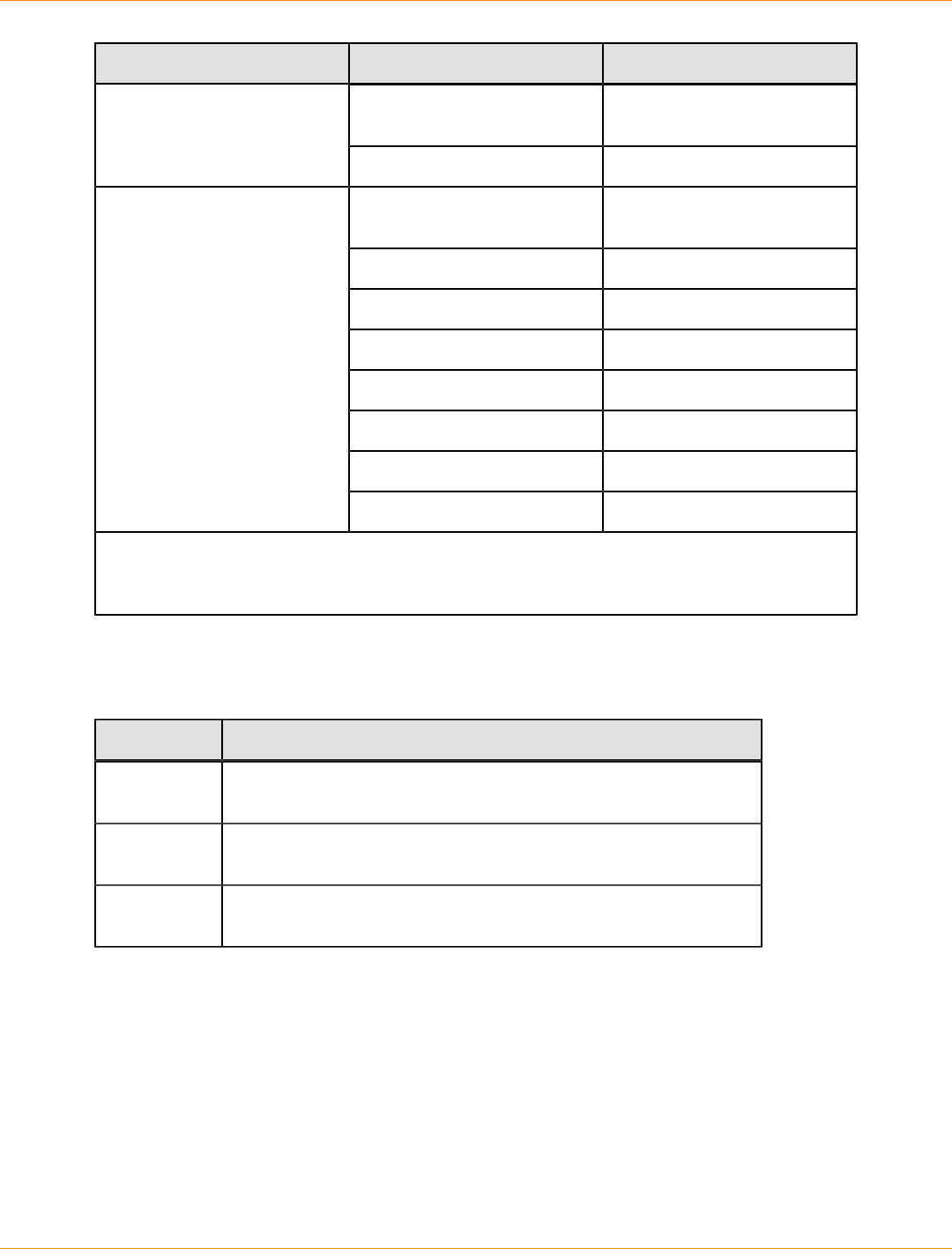
SANtricity_10.77 February 2011
LSI Corporation
- 201 -
Condition Parameter Requirement
Transit range –40°C to 60°C (–40°F to
140°F)
Maximum rate of change 20°C (68°F) per hour
Operating range (both cabinet
and subsystem) 20% to 80%
Storage range 10% to 90%
Transit range 5% to 90%
Operating gradient 10°C (50°F) per hour
Storage gradient 15°C (59°F) per hour
Transit gradient 20°C (68°F) per hour
Maximum dew point 26°C (79°F)
Relative humidity (no
condensation)
Maximum gradient 10% per hour
*If you plan to operate a system at an altitude between 1000 m to 3000 m (3280 ft to 9842 ft)
above sea level, lower the environmental temperature 1.7°C (3.3°F) for every 1000 m (3280 ft)
above sea level.
DE5600 Drive Tray Altitude Ranges
Altitude Ranges for the DE5600 Drive Tray
Environment Altitude
Operating 30.5 m (100 ft) below sea level to 3000 m (9840 ft) above sea
level
Storage 30.5 m (100 ft) below sea level to 3000 m (9840 ft) above sea
level
Transit 30.5 m (100 ft) below sea level to 12,000 m (40,000 ft) above sea
level
DE5600 Drive Tray Airflow and Heat Dissipation
Airflow goes from the front of the drive tray to the rear of the drive tray. Allow at least 76 cm (30 in.) of
clearance in front of the drive tray and at least 61 cm (24 in.) of clearance behind the drive tray for service
clearance, ventilation, and heat dissipation.
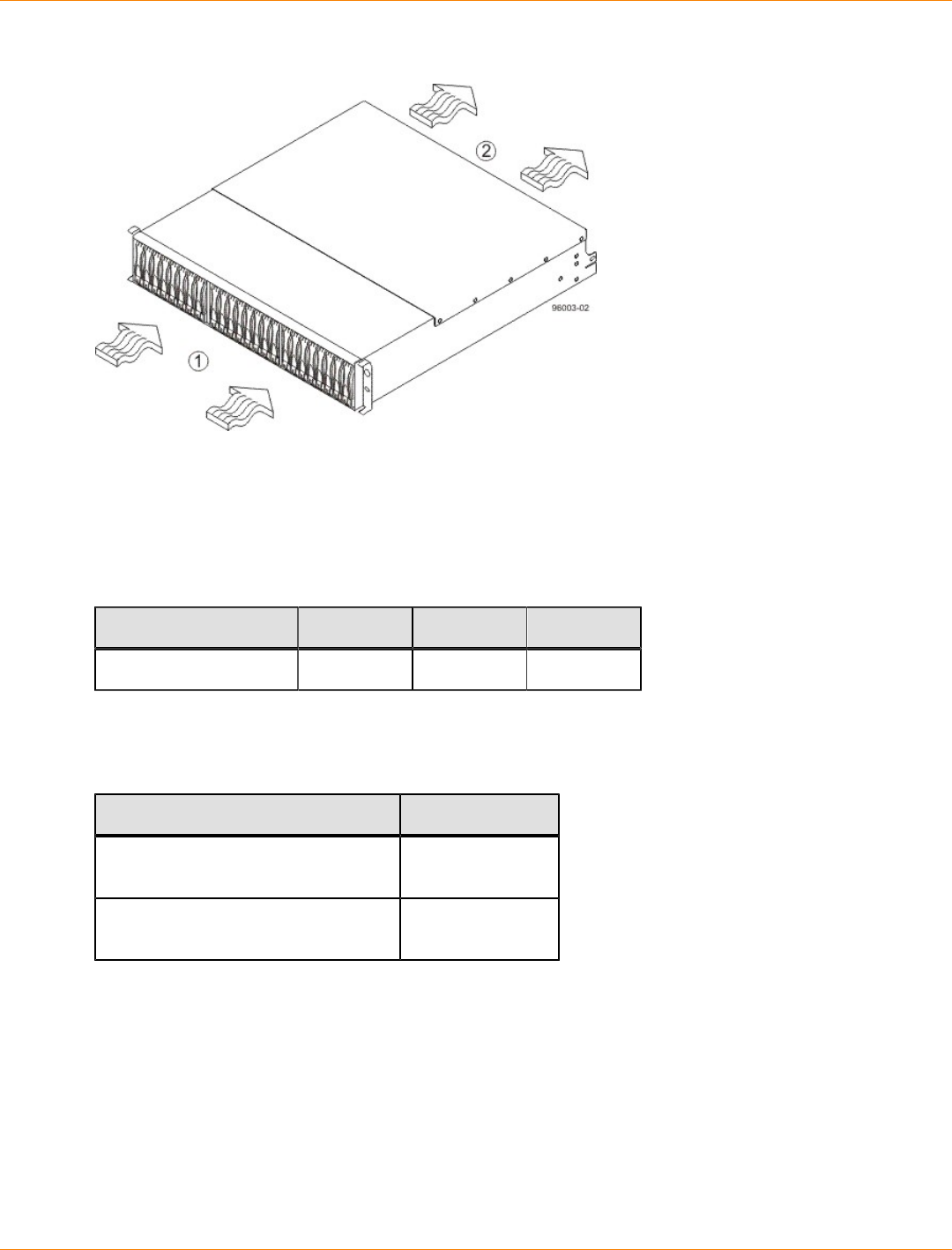
SANtricity_10.77 February 2011
LSI Corporation
- 202 -
Airflow Through the DE5600 Drive Tray – Front View
1. 76 cm (30 in.) clearance in front of the cabinet
2. 61 cm (24 in.) clearance behind the cabinet
The tabulated power and heat dissipation values in the following table are the maximum measured operating
power.
Power Ratings and Heat Dissipation for the DE5600 Drive Tray
Unit KVA Watts (AC) Btu/Hr
DE5600 drive tray 0.241 240.1 821
DE5600 Drive Tray Acoustic Noise
Acoustic Noise at 25°C for the DE5600 Drive Tray
Measurement Level
Sound power (standby operation) 6.5 bels
maximum
Sound power (normal operation) 6.8 bels
maximum
DE5600 Drive Tray Site Wiring and Power
The DE5600 drive tray uses wide-ranging, redundant power supplies that automatically accommodate
voltages to the AC power source or the optional –48-VDC power source. The power supplies meet standard
voltage requirements for both North American (USA and Canada) operation and worldwide (except USA and
Canada) operation. The power supplies use standard industrial wiring with line-to-neutral or line-to-line power
connections.

SANtricity_10.77 February 2011
LSI Corporation
- 203 -
NOTE Power for the optional –48-VDC power configuration is supplied by a centralized DC power plant
instead of the AC power source in the cabinet. Refer to the associated manufacturer’s documentation for
specific DC power source requirements.
Keep this information in mind when preparing the installation site for the drive tray:
Protective ground – Site wiring must include a protective ground connection to the AC power source or
the optional –48-VDC power source.
NOTE Protective ground is also known as safety ground or chassis ground.
Circuit overloading – Power circuits and associated circuit breakers must provide enough power and
overload protection. To prevent damage to the drive tray, isolate its power source from large switching
loads, such as air-conditioning motors, elevator motors, and factory loads.
Power interruptions – The drive tray can withstand these applied voltage interruptions:
Input transient – 50 percent of the nominal voltage
Duration – One-half cycle
Maximum frequency – Once every 10 seconds
Power failures – If a total power failure occurs, the drive tray automatically performs a power-on recovery
sequence without operator intervention after the power is restored.
DE5600 Drive Tray AC Power Input
AC Power Input
The AC power sources must provide the correct voltage, current, and frequency specified on the tray and
serial number label.
AC Power Requirements for the DE5600 Drive Tray
Parameter Low Range High Range
Nominal voltage 100 VAC 240 VAC
Frequency 50 to 60 Hz 50 to 60 Hz
Idle current 2.96 A* 1.23 A**
Maximum operating current 3.03 A* 1.26 A**
Sequential Drive Group Spin Up 4.23 A 1.76 A
Simultaneous Drive Spin Up 4.43 A 1.83 A
System Rating Plate Label 7.0 A 2.9 A
* Typical current: 100 VAC, 60 Hz at 0.87 power supply efficiency and 0.99 power
factor. These numbers can vary significantly, depending upon the drives tested in
the particular configuration.
**Typical current: 240 VAC, 60 Hz at 0.87 power supply efficiency and 0.99 power
factor. These numbers can vary significantly, depending upon the drives tested in
the particular configuration.
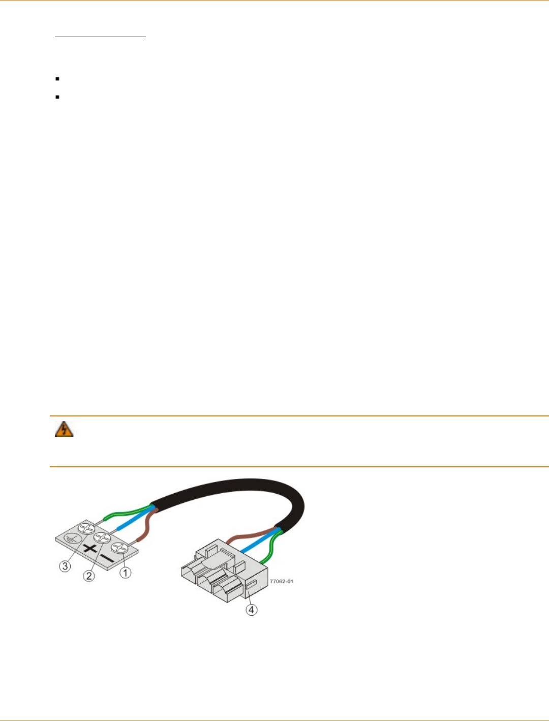
SANtricity_10.77 February 2011
LSI Corporation
- 204 -
DC Power Input
Nominal input voltages for the DC power source are as follows:
Low range: –42 VDC
High range: –60 VDC
The maximum operating current is 21.7 A.
DE5600 Drive Tray Power Factor Correction
Power factor correction is applied within the power supply of each DE5600 drive tray, which maintains the
power factor of the drive tray at greater than 0.95 with nominal input voltage.
DE5600 Drive Tray AC Power Cords and Receptacles
Each DE5600 drive tray is shipped with two AC power cords, which use the standard AC outlets in the
destination country. Each AC power cord connects one of the power supplies in the drive tray to an
independent, external AC power source, such as a wall receptacle, or to any uninterruptible power supply
(UPS).
DC power is an option that is available for use with your DE5600 drive tray. For more information, see
"DE5600 Drive Tray Optional DC Power Connector Cables and Source Wires."
DE5600 Drive Tray Optional DC Power Connector Cables and Source Wires
The DE5600 drive tray is shipped with –48-VDC power connector cables if the DC power option is ordered.
The –48-VDC power connector cable plugs into the DC power connector on the rear of the drive tray. The
three source wires on the other end of the power connector cable connect the drive tray to centralized DC
power plant equipment, typically through a bus bar above the cabinet.
WARNING (W12) Risk of electrical shock – This unit has more than one power source. To remove
all power from the unit, all DC MAINS must be disconnected by removing all power connectors (item 4 below)
from the power supplies.
1. Supply (Negative), Brown Wire, –48 VDC
2. Return (Positive), Blue Wire
3. Ground, Green and Yellow Wire
4. DC Power Connector

SANtricity_10.77 February 2011
LSI Corporation
- 205 -
WARNING (W14) Risk of bodily injury – A qualified service person is required to make the DC
power connection according to NEC and CEC guidelines.
Two (or, optionally, four) DC power connector cables are provided with each drive tray. Two DC power
connectors are on the two power-fan canisters on the rear of each drive tray if additional redundancy is
required.
NOTE It is not mandatory that you connect the second DC power connection on the power-fan canister
of the drive tray. The second DC power connection is provided for additional redundancy only and can be
connected to a second DC power bus.
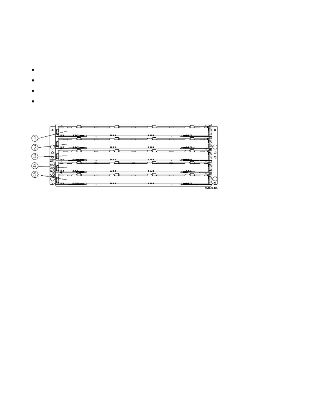
SANtricity_10.77 February 2011
LSI Corporation
- 206 -
Specifications of the DE6600 Drive Tray
The DE6600 drive tray is a high-density SAS 2.0 (6Gb/s) drive enclosure with 60 near-line 3.5” SAS drives,
housed in five drawers with 12 drives each.
The DE6600 drive tray contains these components:
Up to 60 SAS drives
Two power canisters
Two fan canisters
Two environmental services monitor (ESM) canisters
DE6600 Drive Tray – Front View with Bezel Removed
1. Drive Drawer 1
2. Drive Drawer 2
3. Drive Drawer 3
4. Drive Drawer 4
5. Drive Drawer 5
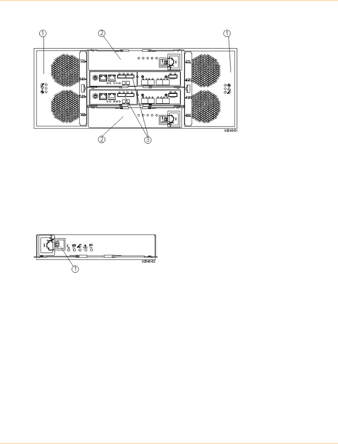
SANtricity_10.77 February 2011
LSI Corporation
- 207 -
DE6600 Drive Tray – Rear View
1. Fan Canisters
2. Power Canisters
3. ESM Canisters
An AC power source supplies power to the power canister.
Power Source Options for the DE6600 Drive Tray – Rear View
1. AC Power Switch on the Power Canister
The drive trays come with drive interface ports that enable you to establish up to four drive channels when
using the CE7900 controller tray for your disk storage solution.
DE6600 Drive Tray Dimensions
The DE6600 drive tray is only available as a rackmount model that conforms to the 100-cm (40.0-in.) rack
depth.
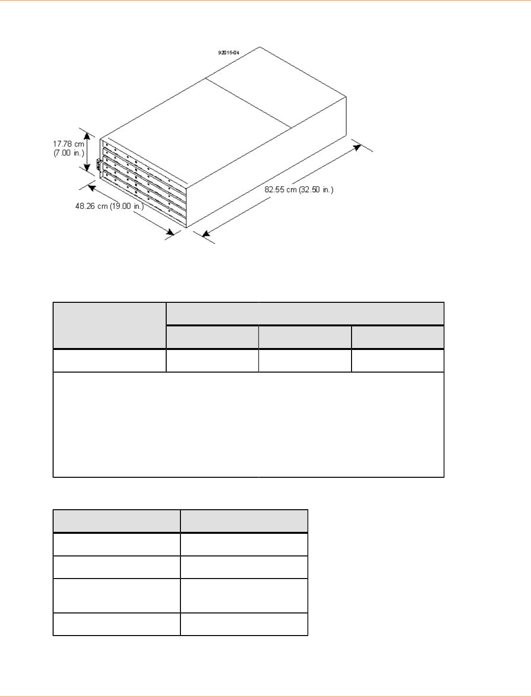
SANtricity_10.77 February 2011
LSI Corporation
- 208 -
Dimensions of the DE6600 Drive Tray – Front View
DE6600 Drive Tray Weight
Weights of the DE6600 Drive Tray
WeightUnit
Maximum* Empty** Shipping***
DE6600 drive tray 105.2 kg (232 lb) 59.8 kg (132 lb) 193.2 kg (426 lb)
*Maximum weight indicates a drive tray with all of its drives and other components
installed. Because drive weights can vary greatly, this value can vary from the value
specified as much as 0.3 kg (0.6 lb) times the maximum number of drives per drive tray
for drives weighing 0.725 kg (1.6 lb).
**Empty weight indicates a drive tray with the ESM canisters, the power canisters, the
fan canisters, and the drives removed.
***Shipping weight indicates the empty weight of a drive tray and all shipping material,
as well as the weight of the 60 drives that are shipped separately in multipack cartons.
Component Weights of the DE6600 Drive Tray
Component Weight
ESM canister 1.65 kg (3.64 lb)
Power canister 2.5 kg (5.5 lb)
Fan canister Approximately 1 kg (2.16
lb)
Drive 0.74 kg (1.64 lb)

SANtricity_10.77 February 2011
LSI Corporation
- 209 -
DE6600 Drive Tray Shipping Dimensions
Shipping Carton Dimensions for the DE6600 Drive Tray
Height Width Depth
48.26 cm (19 in.) 60.96 cm (24.00
in.) 100.97 cm (39.75 in.)
DE6600 Drive Tray Temperature and Humidity
Temperature Requirements and Humidity Requirements for the DE6600 Drive Tray
Condition Parameter Requirement
Operating range 0°C to 35°C (32°F to 95°F)
Maximum rate of change 10°C (95°F) per hour
Storage range –10°C to 50°C (95°F to 122°F)
Maximum rate of change 15°C (59°F) per hour
Transit range –40°C to 60°C (–40°F to 140° F)
without the battery
Temperature*
Maximum rate of change 20°C (68°F) per hour
Operating range 20% to 80%
Storage range 10% to 90%
Transit range 5% to 95%
Maximum dew point 26°C (79°F)
Relative
humidity (no
condensation)
Maximum gradient 10% per hour
*If you plan to operate a system at an altitude between 1000 m to 3000 m (3280 ft to
9842 ft) above sea level, lower the environmental temperature 1.7°C (3.3°F) for every
1000 m (3280 ft) above sea level.
DE6600 Drive Tray Altitude Ranges
Altitude Ranges for the DE6600 Drive Tray
Environment Altitude
Operating 30.5 m (100 ft) below sea level to 3000 m (9842 ft) above sea
level
Storage 30.5 m (100 ft) below sea level to 3000 m (9842 ft) above sea
level
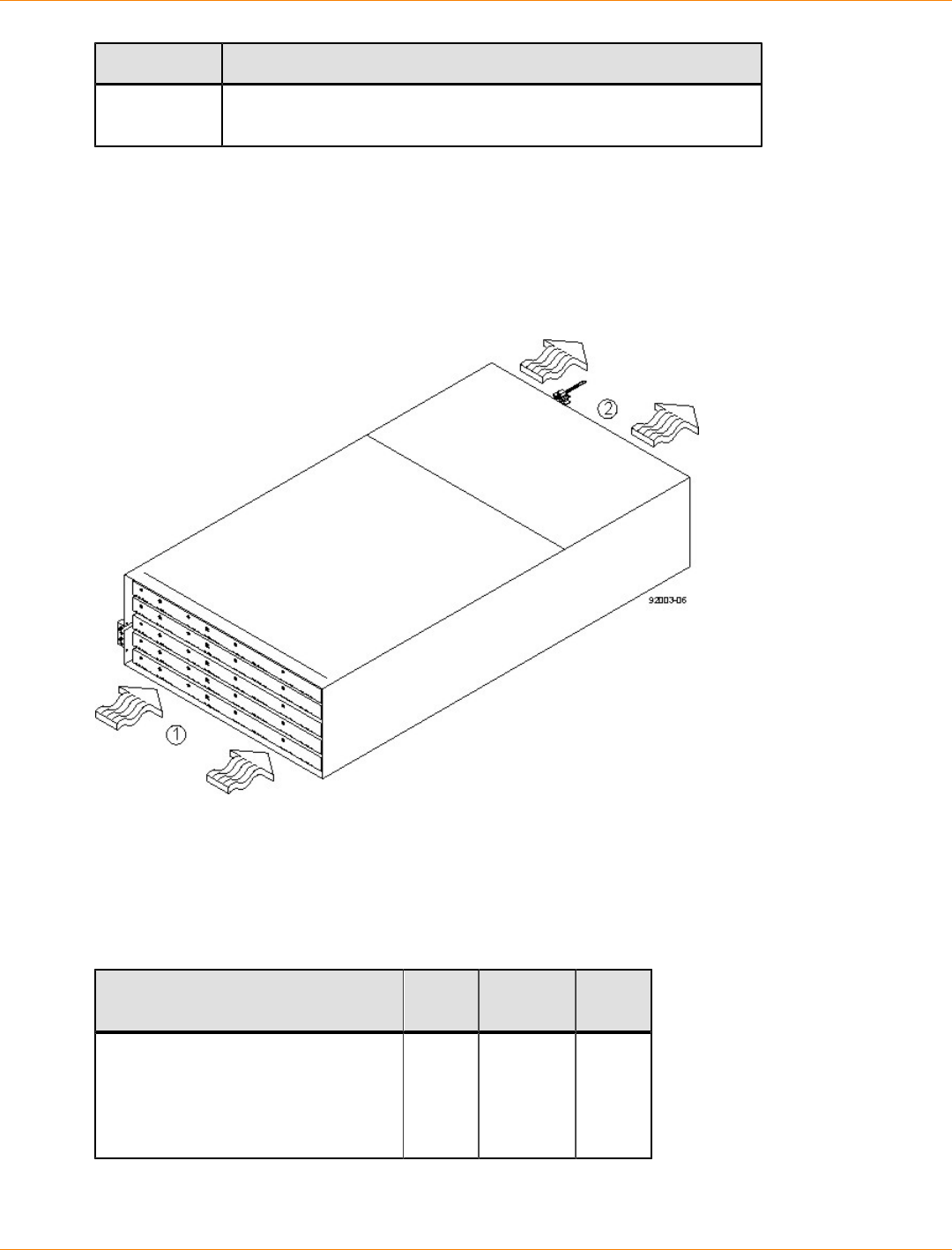
SANtricity_10.77 February 2011
LSI Corporation
- 210 -
Environment Altitude
Transit 30.5 m (100 ft) below sea level to 12,000 m (40,000 ft) above sea
level
DE6600 Drive Tray Airflow and Heat Dissipation
Airflow goes from the front of the drive tray to the rear of the drive tray. Allow at least 81 cm (32 in.) of
clearance in front of the drive tray and at least 61 cm (24 in.) of clearance behind the drive tray for service
clearance, ventilation, and heat dissipation.
Airflow Through the DE6600 Drive Tray – Front View
1. 81 cm (32 in.) clearance in front of the cabinet
2. 61 cm (24 in.) clearance behind the cabinet
The tabulated power and heat dissipation values in the following table represent the maximum measured
operating power.
Power Ratings and Heat Dissipation for the DE6600 Drive Tray
Unit KVA Watts
(AC) Btu/hr
DE6600 drive tray with two power
supplies, two ESMs, 60 drives
(Seagate 2000-Gb SAS drives and
controllers), and two fan canisters,
full speed
1.268 1222 4180
SANtricity_10.77 February 2011
LSI Corporation
- 211 -
DE6600 Drive Tray Acoustic Noise
Sound Levels for the DE6600 Drive Tray
Measurement Level
Sound power (standby
operation) 6.5 bels
Sound power (normal
operation) 6.8 bels
Sound pressure 68 dBA
DE6600 Drive Tray Site Wiring and Power
The agency ratings for the DE6600 drive tray are 7.56 A at 200 VAC and 6.3 A at 240 VAC. These ratings are
the overall maximum AC currents for this system.
The DE6600 drive tray uses wide-ranging, redundant power supplies that automatically accommodate
voltages to the AC power source. The power supplies meet standard voltage requirements for both
North American (USA and Canada) operation and worldwide (except USA and Canada) operation. The
power supplies use standard industrial wiring with line-to-neutral power connections or line-to-line power
connections.
Keep this information in mind when you prepare the installation site for the drive tray:
Protective ground – Site wiring must include a protective ground connection to the AC power source.
NOTE Protective ground is also known as safety ground or chassis ground.
Circuit overloading – Power circuits and associated circuit breakers must provide enough power and
overload protection. To prevent damage to the drive tray, isolate its power source from large switching
loads, such as air-conditioning motors, elevator motors, and factory loads.
Power interruptions – The drive tray can withstand these applied voltage interruptions:
Input transient – 50 percent of the nominal voltage
Duration – One-half cycle
Maximum frequency – Once every 10 seconds
Power failures – If a total power failure occurs, the drive tray automatically performs a power-on recovery
sequence without operator intervention after the power is restored.
DE6600 Drive Tray Power Input
Each power supply contains one 15-A slow-blow fuse.
AC Power Requirements for the DE6600 Drive Tray
Parameter High Range
Nominal voltage 200 to 240 VAC
Frequency 50 to 60 Hz
SANtricity_10.77 February 2011
LSI Corporation
- 212 -
Parameter High Range
Idle current 6.0 A
Maximum operating current 7.56 A
Maximum surge current 8.0 A
DE6600 Drive Tray Power Factor Correction
Power factor correction is applied within the power canister of each DE6600 drive tray, which maintains the
power factor of the drive tray at no less than 0.95 with at all input voltage levels.
DE6600 Drive Tray AC Power Cords and Receptacles
Each DE6600 drive tray is shipped with two AC power cords, which fit the standard AC outlets in the
destination country. Each AC power cord connects one of the power canisters in the drive tray to an
independent, external AC power source, such as a wall receptacle, or to any uninterruptible power supply
(UPS).
ATTENTION Possible risk of equipment failure – To ensure proper cooling, the DE6600 drive tray
always uses two power supplies.
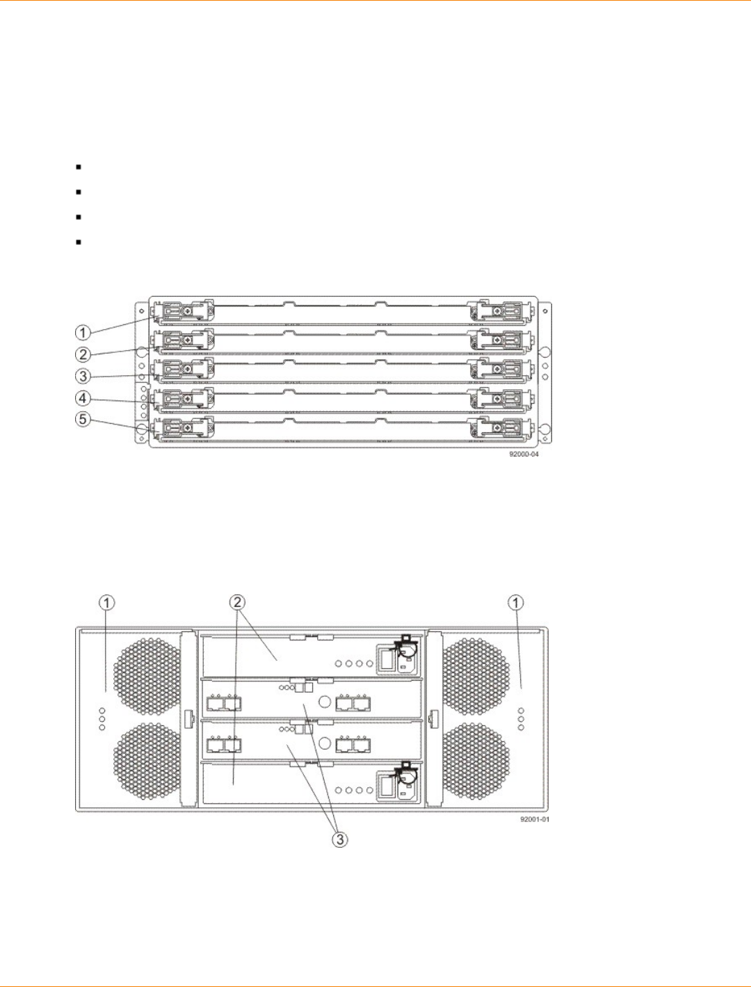
SANtricity_10.77 February 2011
LSI Corporation
- 213 -
Specifications of the DE6900 Drive Tray
The DE6900 drive tray has five separate drawers and is capable of handling 4-Gb Fibre Channel speeds.
Each drive drawer contains up to 12 drives, making 60 drives the total capacity of the DE6900 drive tray.
The DE6900 drive tray contains these components:
Up to 60 SATA drives
Two power canisters
Two fan canisters
Two environmental services monitor (ESM) canisters
DE6900 Drive Tray – Front View with Bezel Removed
1. Drive Drawer 1
2. Drive Drawer 2
3. Drive Drawer 3
4. Drive Drawer 4
5. Drive Drawer 5
DE6900 Drive Tray – Rear View
1. Fan Canisters
2. Power Canisters
3. ESM Canisters
An AC power source supplies power to the power canister.
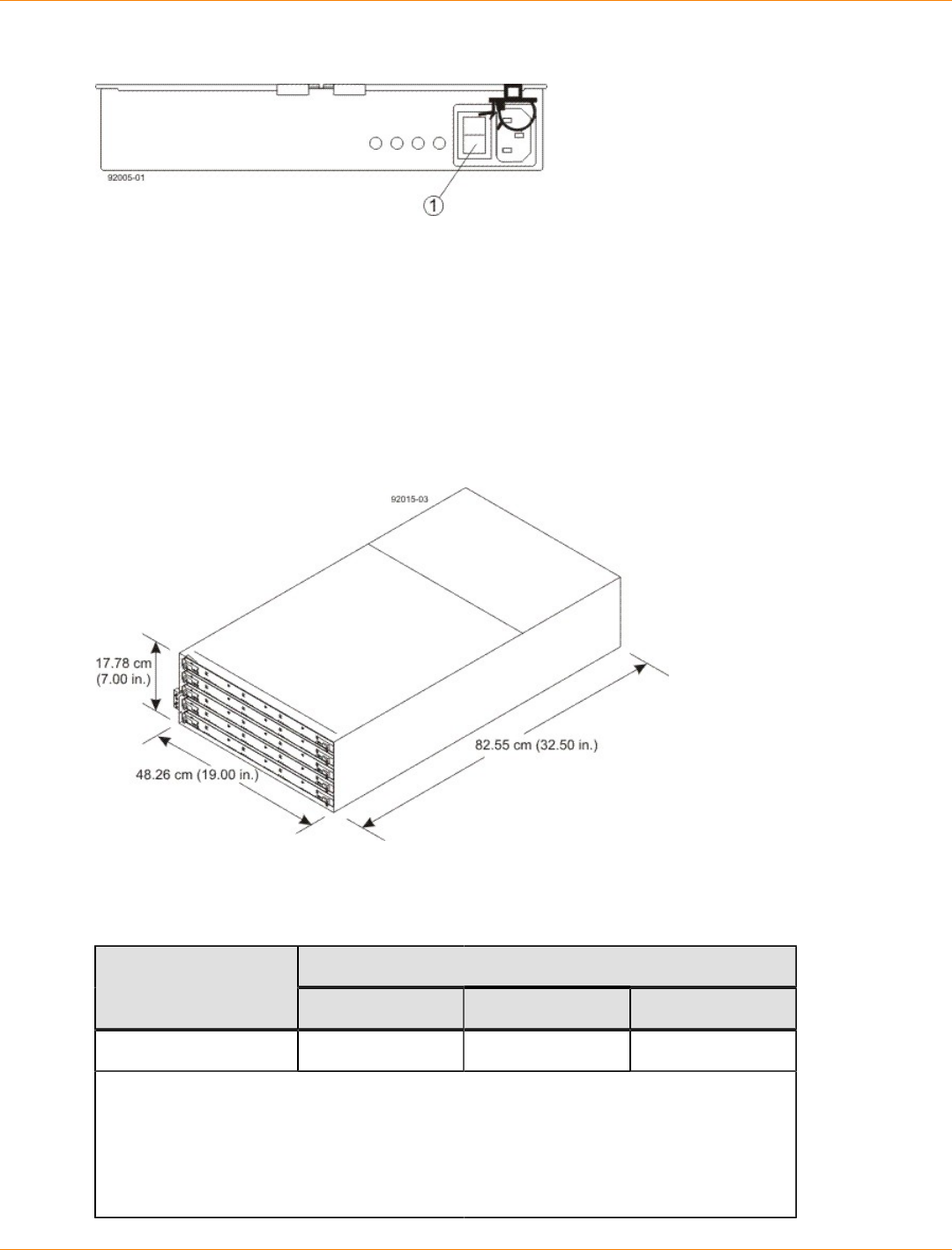
SANtricity_10.77 February 2011
LSI Corporation
- 214 -
Power Source Options for the DE6900 Drive Tray – Rear View
1. AC Power Switch on the Power Canister
The drive trays come with drive interface ports that enable you to establish up to four drive channels when
using the CE7900 controller tray for your disk storage solution.
DE6900 Drive Tray Dimensions
The DE6900 drive tray is only available as a rackmount model that conforms to the 100-cm (40.0-in.) rack
depth.
Dimensions of the DE6900 Drive Tray – Front View
DE6900 Drive Tray Weight
Weights of the DE6900 Drive Tray
WeightUnit
Maximum* Empty** Shipping***
DE6900 drive tray 102.1 kg (225 lb) 56.7 kg (125 lb) 192 kg (420 lb)
*Maximum weight indicates a drive tray with all of its drives and other components
installed. Because drive weights can vary greatly, this value can vary from the value
specified as much as 0.3 kg (0.6 lb) times the maximum number of drives per drive tray
for drives weighing 0.725 kg (1.6 lb).
**Empty weight indicates a drive tray with the ESM canisters, the power canisters, the
fan canisters, and the drives removed.
SANtricity_10.77 February 2011
LSI Corporation
- 215 -
WeightUnit
Maximum* Empty** Shipping***
***Shipping weight indicates the empty weight of a drive tray and all shipping material,
as well as the weight of the 60 drives that are shipped separately in multi-pack cartons.
Component Weights of the DE6900 Drive Tray
Component Weight
ESM canister 1.65 kg (3.64 lb)
Power canister 2.5 kg (5.46 lb)
Fan canister Approximately 1 kg (2.2
lb)
Drive 0.74 kg (1.64 lb)
DE6900 Drive Tray Shipping Dimensions
Shipping Carton Dimensions for the DE6900 Drive Tray
Height Width Depth
48.26 cm (19 in.) 60.96 cm (24.00
in.) 100.97 cm (39.75 in.)
DE6900 Drive Tray Temperature and Humidity
Temperature Requirements and Humidity Requirements for the DE6900 Drive Tray
Condition Parameter Requirement
Operating range 0°C to 35°C (32°F to 95°F)
Maximum rate of change 10°C (95°F) per hour
Storage range –10°C to 50°C (95°F to 122°F)
Maximum rate of change 15°C (59°F) per hour
Transit range –40°C to 60°C (–40°F to 140° F)
without the battery
Temperature*
Maximum rate of change 20°C (68°F) per hour
Operating range 20% to 80%
Storage range 10% to 90%
Relative
humidity (no
condensation)
Transit range 5% to 95%
SANtricity_10.77 February 2011
LSI Corporation
- 216 -
Condition Parameter Requirement
Maximum dew point 26°C (79°F)
Maximum gradient 10% per hour
*If you plan to operate a system at an altitude between 1000 m to 3000 m (3280 ft to
9842 ft) above sea level, lower the environmental temperature 1.7°C (3.3°F) for every
1000 m (3280 ft) above sea level.
DE6900 Drive Tray Altitude Ranges
Altitude Ranges for the DE6900 Drive Tray
Environment Altitude
Operating 30.5 m (100 ft) below sea level to 3000 m (9842 ft) above sea
level
Storage 30.5 m (100 ft) below sea level to 3000 m (9842 ft) above sea
level
Transit 30.5 m (100 ft) below sea level to 12,000 m (40,000 ft) above sea
level
DE6900 Drive Tray Airflow and Heat Dissipation
Airflow goes from the front of the drive tray to the rear of the drive tray. Allow at least 81 cm (32 in.) of
clearance in front of the drive tray and at least 61 cm (24 in.) of clearance behind the drive tray for service
clearance, ventilation, and heat dissipation.
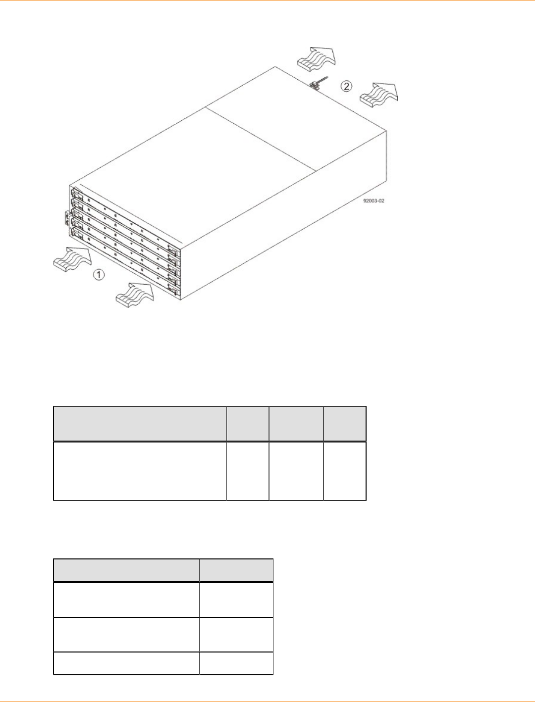
SANtricity_10.77 February 2011
LSI Corporation
- 217 -
Airflow Through the DE6900 Drive Tray – Front View
1. 81 cm (32 in.) clearance in front of the cabinet
2. 61 cm (24 in.) clearance behind the cabinet
The tabulated power and heat dissipation values in the following table are the maximum measured operating
power.
Power Ratings and Heat Dissipation for the DE6900 Drive Tray
Unit KVA Watts
(AC) Btu/hr
DE6900 drive tray with two power
supplies, two ESMs, 60 drives
(Seagate 1000-Gb SATA), and two
fan canisters, full speed
1.203 1181 4039
DE6900 Drive Tray Acoustic Noise
Sound Levels for the DE6900 Drive Tray
Measurement Level
Sound power (standby
operation) 6.5 bels
Sound power (normal
operation) 6.8 bels
Sound pressure 68 dBA
SANtricity_10.77 February 2011
LSI Corporation
- 218 -
DE6900 Drive Tray Site Wiring and Power
The agency ratings for the DE6900 drive tray are 8.64 A at 200 VAC and 7.20 A at 240 VAC. These ratings
are the overall maximum AC currents for this system.
The DE6900 drive tray uses wide-ranging, redundant power supplies that automatically accommodate
voltages to the AC power source. The power supplies meet standard voltage requirements for both North
American (USA and Canada) operation and worldwide (except USA and Canada) operation. The power
supplies use standard industrial wiring with line-to-neutral or line-to-line power connections.
Keep this information in mind when you prepare the installation site for the drive tray:
Protective ground – Site wiring must include a protective ground connection to the AC power source.
NOTE Protective ground is also known as safety ground or chassis ground.
Circuit overloading – Power circuits and associated circuit breakers must provide enough power and
overload protection. To prevent damage to the drive tray, isolate its power source from large switching
loads, such as air-conditioning motors, elevator motors, and factory loads.
Power interruptions – The drive tray can withstand these applied voltage interruptions:
Input transient – 50 percent of the nominal voltage
Duration – One-half cycle
Maximum frequency – Once every 10 seconds
Power failures – If a total power failure occurs, the drive tray automatically performs a power-on recovery
sequence without operator intervention after the power is restored.
DE6900 Drive Tray Power Input
Each power supply contains one 15-A slow-blow fuse.
AC Power Requirements for the DE6900 Drive Tray
Parameter High Range
Nominal voltage 200 to 240 VAC
Frequency 50 to 60 Hz
Idle current 5.5 A
Maximum operating current 9.4 A
Maximum surge current 10.34 A
DE6900 Drive Tray Power Factor Correction
Power factor correction is applied within the power canister of each DE6900 drive tray, which maintains the
power factor of the drive tray at no less than 0.95 with at all input voltage levels.

SANtricity_10.77 February 2011
LSI Corporation
- 219 -
DE6900 Drive Tray AC Power Cords and Receptacles
Each DE6900 drive tray is shipped with two AC power cords, which fit the standard AC outlets in the
destination country. Each AC power cord connects one of the power canisters in the drive tray to an
independent, external AC power source, such as a wall receptacle, or to any uninterruptible power supply
(UPS).
ATTENTION Possible risk of equipment failure – To ensure proper cooling, the DE6900 drive tray
always uses two power supplies.
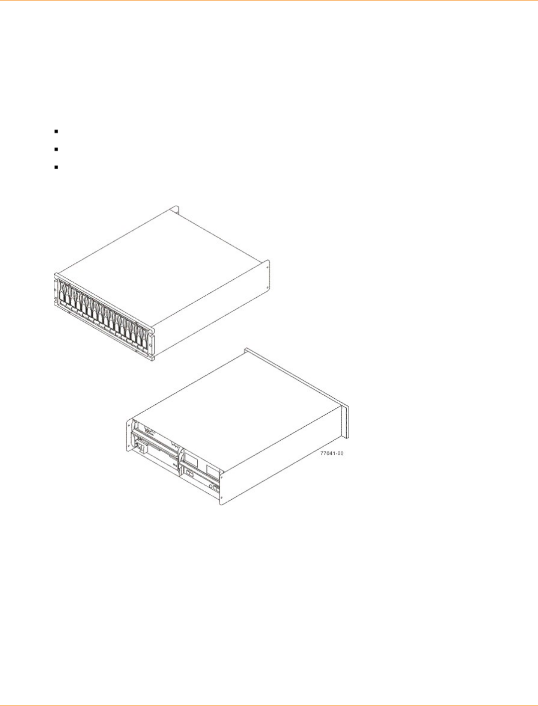
SANtricity_10.77 February 2011
LSI Corporation
- 220 -
Specifications of the FC4600 Drive Tray
The FC4600 drive tray is a 16-slot drive tray capable of handling 4-Gb Fibre Channel speeds. The drive tray
is designed to be used by disk storage customers who desire top-of-the-line storage arrays. It comes in a
deskside model and a rackmount model.
The FC4600 drive tray contains these components:
Up to 16 Fibre Channel drives
Two power-fan canisters
Two environmental services monitor (ESM) canisters
FC4600 Drive Tray – Front View and Rear View
Usually, an AC power source supplies power to the power-fan canister. A DC power option is also available.
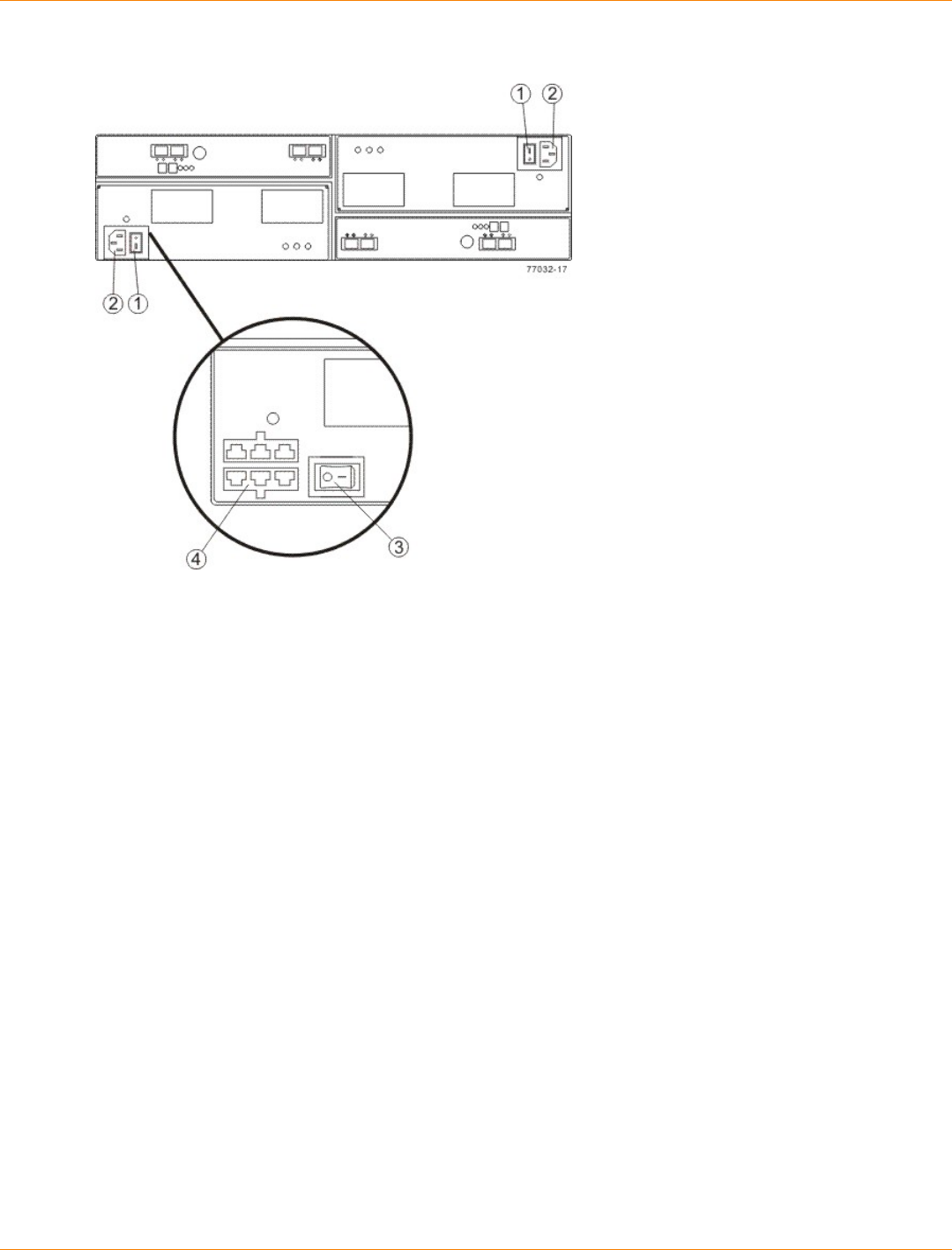
SANtricity_10.77 February 2011
LSI Corporation
- 221 -
Power Source Options for the FC4600 Drive Tray – Rear View
1. AC Power Switch on the AC Power-Fan Canister
2. AC Power Connector
3. DC Power Switch on an Optional Power-Fan Canister
4. Two DC Power Connectors
The drive trays come with drive interface ports that enable you to establish up to eight drive channels when
using the CE7900 controller tray for your disk storage solution.
FC4600 Drive Tray Dimensions
The FC4600 drive tray conforms to the 48.3-cm (19.0-in.) rack standard.
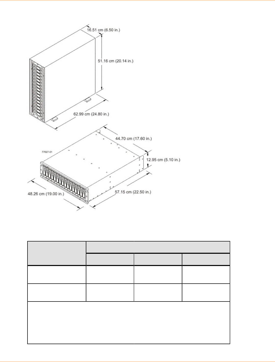
SANtricity_10.77 February 2011
LSI Corporation
- 222 -
Dimensions of the FC4600 Drive Tray (Deskside Model and Rackmount Model) – Front View
FC4600 Drive Tray Weight
Weights of the FC4600 Drive Tray
WeightUnit
Maximum* Empty** Shipping***
FC4600 drive tray,
deskside model 54.88 kg (121.0
lb) 28.58 kg (63.0 lb) 66.68 kg (147.0
lb)
FC4600 drive tray,
rackmount model 42.18 kg (93.0 lb) 15.88 kg (35.0 lb) 53.98 kg (119.0
lb)
*Maximum weight indicates a drive tray with all of its drives and other components
installed. Because drive weights can vary greatly, this value can vary from the value
specified as much as 0.3 kg (0.6 lb) times the maximum number of drives per drive tray
for drives weighing 1.0 kg (2.2 lb).
**Empty weight indicates a drive tray with the ESM canisters, the power-fan canisters,
and the drives removed.
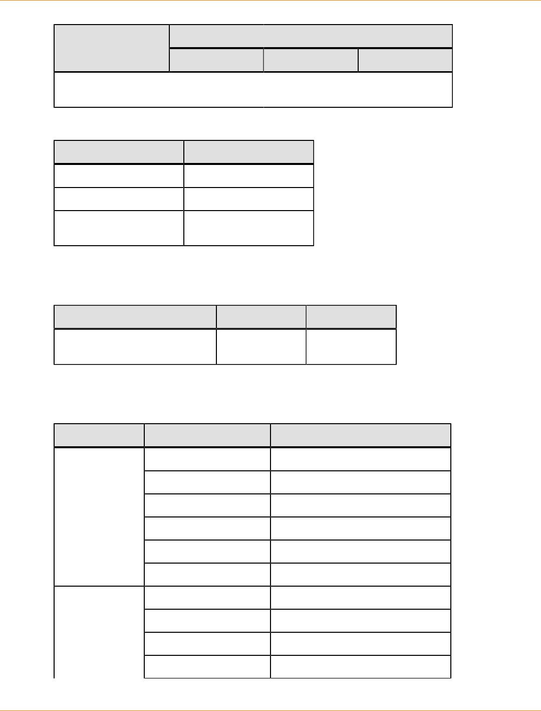
SANtricity_10.77 February 2011
LSI Corporation
- 223 -
WeightUnit
Maximum* Empty** Shipping***
***Shipping weight indicates the maximum weight of a drive tray and all shipping
material.
Component Weights of the FC4600 Drive Tray
Component Weight
ESM canister 2.313 kg (5.10 lb)
Power-fan canister 2.449 kg (5.40 lb)
Drive Approximately 1.0 kg (2.2
lb)
FC4600 Drive Tray Shipping Dimensions
Shipping Carton Dimensions for the FC4600 Drive Tray
Height Width Depth
45.72 cm (18.00 in.) – Includes
the height of the pallet. 62.23 cm (24.50
in.) 80.65 cm (31.75
in.)
FC4600 Drive Tray Temperature and Humidity
Temperature Requirements and Humidity Requirements for the FC4600 Drive Tray
Condition Parameter Requirement
Operating range 10°C to 40°C (50°F to 104°F)
Maximum rate of change 10°C (18°F) per hour
Storage range –10°C to 50°C (14°F to 122°F)
Maximum rate of change 15°C (27°F) per hour
Transit range –40°C to 60°C (–40°F to 140° F)
Temperature*
Maximum rate of change 20°C (36°F) per hour
Operating range 20% to 80%
Storage range 10% to 90%
Transit range 5% to 95%
Relative
humidity (no
condensation)
Maximum dew point 26°C (79°F)
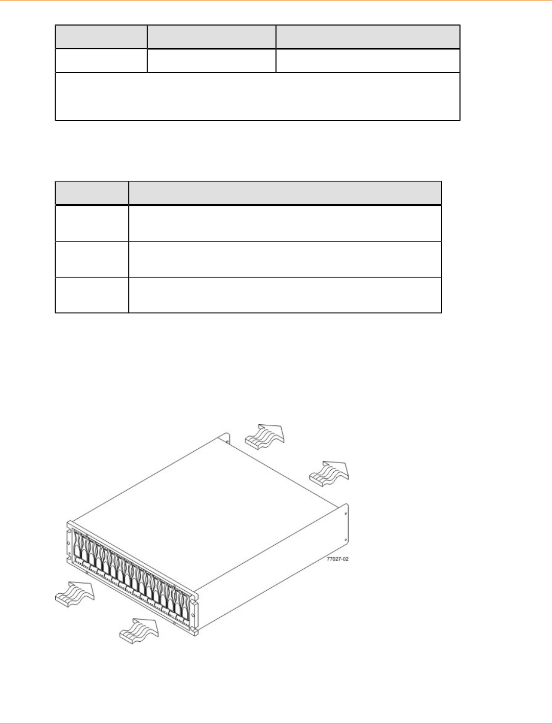
SANtricity_10.77 February 2011
LSI Corporation
- 224 -
Condition Parameter Requirement
Maximum gradient 10% per hour
*If you plan to operate a system at an altitude between 1000 m to 3000 m (3280 ft to
9842 ft) above sea level, lower the environmental temperature 1.7°C (3.3°F) for every
1000 m (3280 ft) above sea level.
FC4600 Drive Tray Altitude Ranges
Altitude Ranges for the FC4600 Drive Tray
Environment Altitude
Operating 30.5 m (100 ft) below sea level to 3000 m (9842 ft) above sea
level
Storage 30.5 m (100 ft) below sea level to 3000 m (9842 ft) above sea
level
Transit 30.5 m (100 ft) below sea level to 12,000 m (40,000 ft) above sea
level
FC4600 Drive Tray Airflow and Heat Dissipation
Airflow goes from the front of the drive tray to the rear of the drive tray. Allow at least 76 cm (30 in.) of
clearance in front of the drive tray and at least 61 cm (24 in.) of clearance behind the drive tray for service
clearance, ventilation, and heat dissipation.
Airflow Through the FC4600 Drive Tray – Front View
The tabulated power and heat dissipation values in the following table are the maximum measured operating
power.
SANtricity_10.77 February 2011
LSI Corporation
- 225 -
Power Ratings and Heat Dissipation for the FC4600 Drive Tray
Unit KVA Watts (AC) Btu/hr Amps (240
VAC)
FC4600 drive tray 0.462 444 1517 1.85
FC4600 Drive Tray Acoustic Noise
Sound Levels for the FC4600 Drive Tray
Measurement Level
Sound power 6.5 bels
Sound pressure 65 dBA
FC4600 Drive Tray Site Wiring and Power
The agency ratings for the FC4600 drive tray are 4.44 A at 100 VAC and 1.85 A at 240 VAC. These ratings
are the overall maximum AC currents for this system.
The FC4600 drive tray uses wide-ranging, redundant power supplies that automatically accommodate
voltages to the AC power source or the optional –48-VDC power source. The power supplies meet standard
voltage requirements for both North American (USA and Canada) operation and worldwide (except USA and
Canada) operation. The power supplies use standard industrial wiring with line-to-neutral or line-to-line power
connections.
NOTE Power for the optional –48-VDC power configuration is supplied by a centralized DC power plant
instead of the AC power source in the cabinet. Refer to the associated manufacturer’s documentation for
specific DC power source requirements.
Keep this information in mind when you prepare the installation site for the drive tray:
Protective ground – Site wiring must include a protective ground connection to the AC power source or
the optional –48-VDC power source.
NOTE Protective ground is also known as safety ground or chassis ground.
Circuit overloading – Power circuits and associated circuit breakers must provide enough power and
overload protection. To prevent damage to the drive tray, isolate its power source from large switching
loads, such as air-conditioning motors, elevator motors, and factory loads.
Power interruptions – The drive tray can withstand these applied voltage interruptions:
Input transient – 50 percent of the nominal voltage
Duration – One-half cycle
Maximum frequency – Once every 10 seconds
Power failures – If a total power failure occurs, the drive tray automatically performs a power-on recovery
sequence without operator intervention after the power is restored.

SANtricity_10.77 February 2011
LSI Corporation
- 226 -
FC4600 Drive Tray Power Input
AC Power Input
Each power supply contains one 15-A slow-blow fuse.
AC Power Requirements for the FC4600 Drive Tray
Parameter Low Range High Range
Nominal voltage 90 to 136 VAC 180 to 264 VAC
Frequency 50 to 60 Hz 50 to 60 Hz
Idle current 3.78 A* 1.98 A**
Maximum operating current 3.90 A* 2.06 A**
Maximum surge current (16-drive
spin up) 5.25 A* 2.67 A**
*Typical current: 115 VAC, 60 Hz at 0.73 power supply efficiency and 0.96 power
factor.
**Typical current: 230 VAC, 60 Hz at 0.73 power supply efficiency and 0.96 power
factor.
DC Power Input
Nominal input voltages for the DC power source are as follows:
Low range: –36 VDC
High range: –72 VDC
The maximum operating current is 17 A.
FC4600 Drive Tray Power Factor Correction
Power factor correction is applied within the power-fan canister of each FC4600 drive tray, which maintains
the power factor of the drive tray at greater than 0.99 with nominal input voltage.
FC4600 Drive Tray AC Power Cords and Receptacles
Each FC4600 drive tray is shipped with two AC power cords, which fit the standard AC outlets in the
destination country. Each AC power cord connects one of the power-fan canisters in the drive tray to an
independent, external AC power source, such as a wall receptacle, or to any uninterruptible power supply
(UPS).
FC4600 Drive Tray Optional DC Power Connector Cables and Source Wires
The FC4600 drive tray is shipped with –48-VDC power connector cables if the DC power option is ordered.
The –48-VDC power connector cable plugs into the DC power connector on the rear of the drive tray. The
three source wires on the other end of the power connector cable connect the drive tray to centralized DC
power plant equipment, typically through a bus bar above the cabinet.
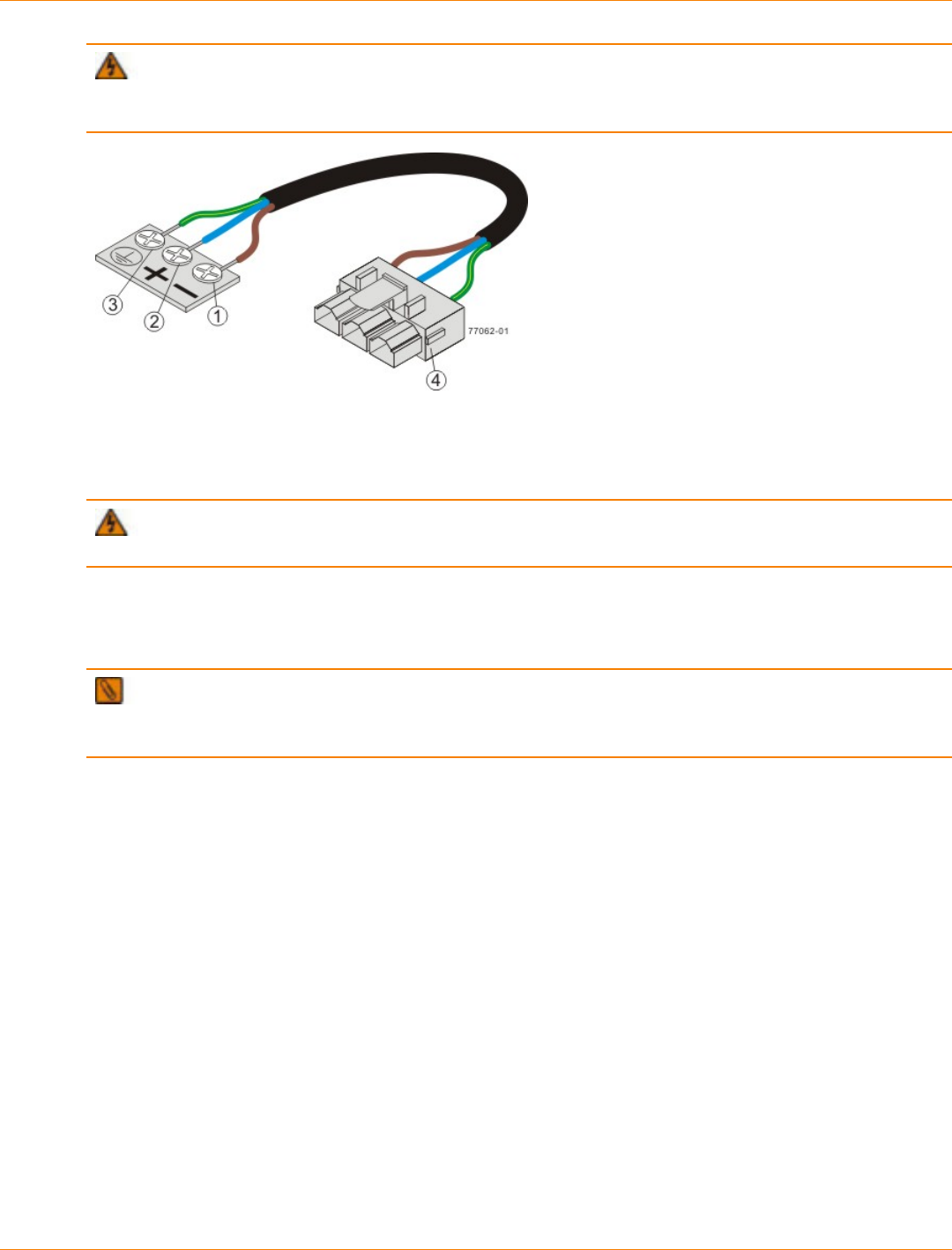
SANtricity_10.77 February 2011
LSI Corporation
- 227 -
WARNING (W12) Risk of electrical shock – This unit has more than one power source. To remove
all power from the unit, all DC MAINS must be disconnected by removing all power connectors (item 4 below)
from the power supplies.
1. Supply (Negative), Brown Wire, –48 VDC
2. Return (Positive), Blue Wire
3. Ground, Green and Yellow Wire
4. DC Power Connector
WARNING (W14) Risk of bodily injury – A qualified service person is required to make the DC
power connection according to NEC and CEC guidelines.
Two (or, optionally, four) DC power connector cables are provided with each drive tray. Two DC power
connectors are on the two power-fan canisters on the rear of each drive tray if additional redundancy is
required.
NOTE It is not mandatory that you connect the second DC power connection on the power-fan canister
of the drive tray. The second DC power connection is provided for additional redundancy only and can be
connected to a second DC power bus.
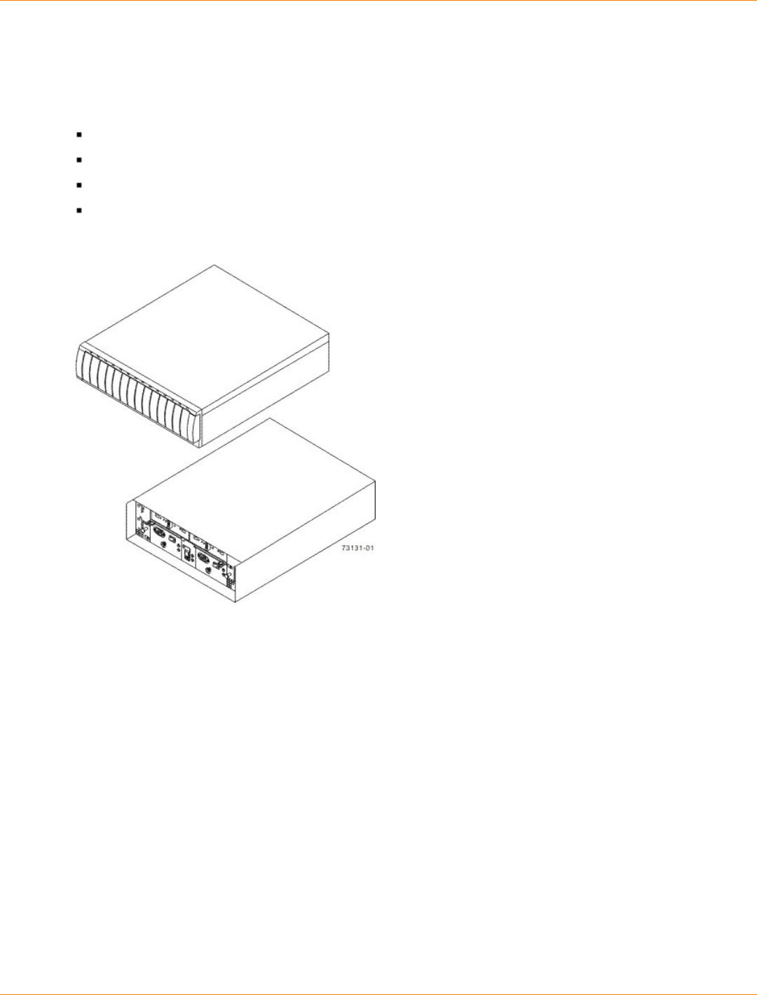
SANtricity_10.77 February 2011
LSI Corporation
- 228 -
Specifications of the AT2655 Drive Tray
The AT2655 drive tray contains Serial Advanced Technology Attachment (SATA) drives that provide storage
in a Fibre Channel environment. Each AT2655 drive tray contains these components:
Two to fourteen drives
One or two environmental services monitor (ESM) canisters
Two power supplies
Two fans
AT2655 Drive Tray – Front View and Rear View
AT2655 Drive Tray Dimensions
A deskside model and a rackmount model of the AT2655 drive tray are available. The rackmount model
conforms to the 48.3-cm (19.0-in.) rack standard.
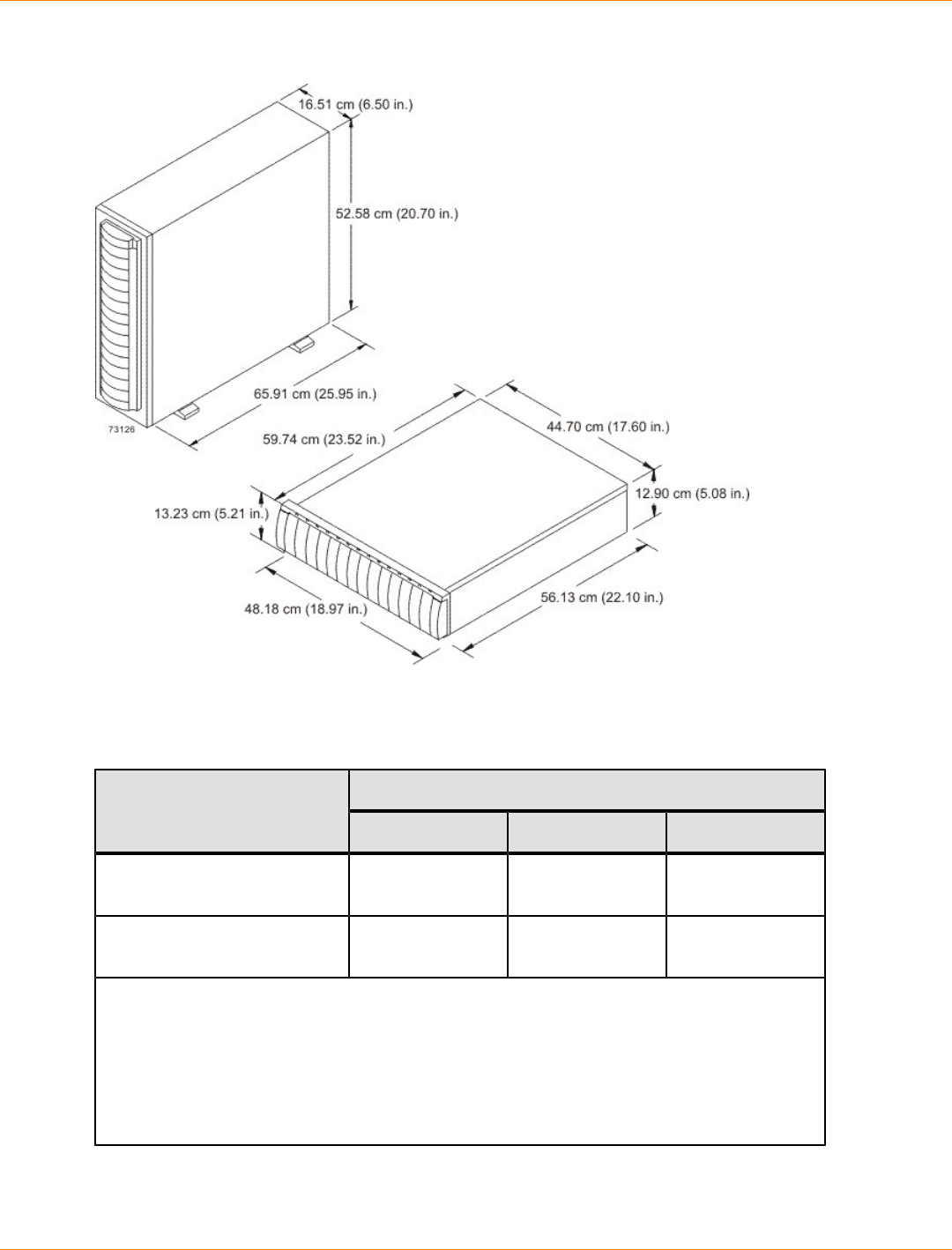
SANtricity_10.77 February 2011
LSI Corporation
- 229 -
Dimensions of the AT2655 Drive Tray (Deskside Model and Rackmount Model) – Front View
AT2655 Drive Tray Weight
Weights of the AT2655 Drive Tray
WeightUnit
Maximum* Empty** Shipping***
AT2655 drive tray, deskside
model 52.62 kg (116.0
lb) 28.58 kg (63.0 lb) 64.41 kg (142.0
lb)
AT2655 drive tray, rackmount
model 39.92 kg (88.0 lb) 15.88 kg (35.0 lb) 51.71 kg (114.0
lb)
*Maximum weight indicates a drive tray with all of its drives and other components
installed. Because drive weights can vary greatly, this value can vary from the value
specified as much as 0.3 kg (0.6 lb) times the maximum number of drives per drive tray for
drives weighing 1.0 kg (2.2 lb).
**Empty weight indicates a drive tray with the ESM canisters, the power supply canisters,
the fan canisters, and the drives removed.
***Shipping weight indicates the maximum weight of a drive tray and all shipping material.
SANtricity_10.77 February 2011
LSI Corporation
- 230 -
Component Weights of the AT2655 Drive Tray
Component Weight
ESM canister 1.678 kg (3.70 lb)
Power supply canister 2.449 kg (5.40 lb)
Fan canister 0.998 kg (2.20 lb)
Drive Approximately 1.0 kg (2.2
lb)
AT2655 Drive Tray Shipping Dimensions
Shipping Carton Dimensions for the AT2655 Drive Tray
Height Width Depth
44.45 cm (17.50 in.) –
Includes the height of the
pallet.
62.23 cm (24.50 in.) 74.93 cm (29.50 in.)
AT2655 Drive Tray Temperature and Humidity
Temperature Requirements and Humidity Requirements for the AT2655 Drive Tray
Condition Parameter Requirement
Operating range 10°C to 40°C (50°F to 104°F)
Maximum rate of change 10°C (18°F) per hour
Storage range –10°C to 65°C (14°F to
149°F)
Maximum rate of change 15°C (27°F) per hour
Transit range –40°C to 65°C (–40°F to
149°F)
Temperature*
Maximum rate of change 20°C (36°F) per hour
Operating range 20% to 80%
Storage range 10% to 90%
Transit range 5% to 95%
Maximum dew point 26°C (79°F)
Relative
humidity (no
condensation)
Maximum gradient 10% per hour
SANtricity_10.77 February 2011
LSI Corporation
- 231 -
Condition Parameter Requirement
*If you plan to operate a system at an altitude between 1000 m to 3000 m (3280 ft
to 9842 ft) above sea level, lower the environmental temperature 1.7°C (3.3°F) for
every 1000 m (3280 ft) above sea level.
AT2655 Drive Tray Altitude Ranges
Altitude Ranges for the AT2655 Drive Tray
Environment Altitude
Operating 30.5 m (100 ft) below sea level to 3000 m (9842 ft) above sea
level
Storage 30.5 m (100 ft) below sea level to 3000 m (9842 ft) above sea
level
Transit 30.5 m (100 ft) below sea level to 12,000 m (40,000 ft) above
sea level
AT2655 Drive Tray Airflow and Heat Dissipation
Airflow goes from the front of the drive tray to the rear of the drive tray. Allow at least 76 cm (30 in.) of
clearance in front of the drive tray and at least 61 cm (24 in.) of clearance behind the drive tray for service
clearance, ventilation, and heat dissipation.
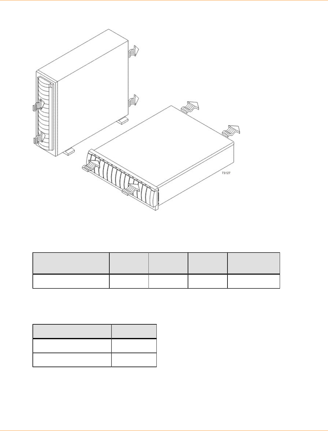
SANtricity_10.77 February 2011
LSI Corporation
- 232 -
Airflow Through the AT2655 Drive Tray – Front View
The tabulated power and heat dissipation values in the following table are the maximum measured operating
power.
Power Ratings and Heat Dissipation for the AT2655 Drive Tray
Unit KVA Watts (AC) Btu/hr Amps (240
VAC)
AT2655 drive tray 0.329 316 1078 1.32
AT2655 Drive Tray Acoustic Noise
Sound Levels for the AT2655 Drive Tray
Measurement Level
Sound power 6.0 bels
Sound pressure 60 dBA
AT2655 Drive Tray Site Wiring and Power
The AT2655 drive tray uses wide-ranging, redundant power supplies that automatically accommodate
voltages to the AC power source. The power supplies meet standard voltage requirements for both North
American (USA and Canada) operation and worldwide (except USA and Canada) operation. The power
supplies use standard industrial wiring with line-to-neutral or line-to-line power connections.
SANtricity_10.77 February 2011
LSI Corporation
- 233 -
Keep this information in mind when you prepare the installation site for the drive tray:
Protective ground – Site wiring must include a protective ground connection to the AC power source.
NOTE Protective ground is also known as safety ground or chassis ground.
Circuit overloading – Power circuits and associated circuit breakers must provide enough power and
overload protection. To prevent damage to the drive tray, isolate its power source from large switching
loads, such as air-conditioning motors, elevator motors, and factory loads.
Power interruptions – The drive tray can withstand these applied voltage interruptions:
Input transient – 50 percent of the nominal voltage
Duration – One-half cycle
Maximum frequency – Once every 10 seconds
Power failures – If a total power failure occurs, the drive tray automatically performs a power-on recovery
sequence without operator intervention after the power is restored.
AT2655 Drive Tray Power Input
Each power supply contains one 10-A slow-blow fuse.
AC Power Requirements for the AT2655 Drive Tray
Parameter Low Range High Range
Nominal voltage 90 to 136 VAC 180 to 264 VAC
Frequency 50 to 60 Hz 50 to 60 Hz
Idle current 2.65 A* 1.31 A**
Maximum operating current 2.78 A* 1.43 A**
Maximum surge current 4.00 A* 2.03 A**
*Typical current: 115 VAC, 60 Hz at 0.73 power supply efficiency and 0.96
power factor.
**Typical current: 230 VAC, 60 Hz at 0.73 power supply efficiency and 0.96
power factor.
AT2655 Drive Tray Power Factor Correction
Power factor correction is applied within the power supply of each AT2655 drive tray, which maintains the
power factor of the drive tray at greater than 0.99 with nominal input voltage.
AT2655 Drive Tray Power Cords and Receptacles
Each AT2655 drive tray is shipped with two AC power cords, which use the standard AC outlets in the
destination country. Each AC power cord connects one of the power supplies in the drive tray to an
independent, external AC power source, such as a wall receptacle, or to any uninterruptible power supply
(UPS).
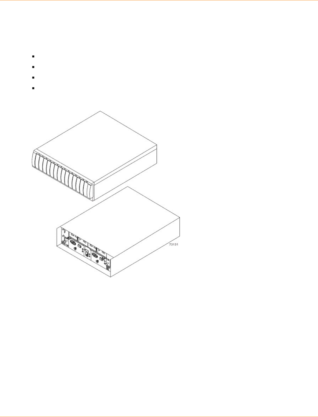
SANtricity_10.77 February 2011
LSI Corporation
- 234 -
Specifications of the FC2610 Drive Tray
The FC2610 drive tray contains Fibre Channel drives that provide storage in a Fibre Channel environment.
Each FC2610 drive tray contains these components:
A maximum of 14 drives
Two fan canisters
Two power supply canisters
One or two environmental services monitor (ESM) canisters
FC2610 Drive Tray – Front View and Rear View
FC2610 Drive Tray Dimensions
A deskside model and a rackmount model of the FC2610 drive tray are available. The rackmount model
conforms to the 48.3-cm (19.0-in.) rack standard.

SANtricity_10.77 February 2011
LSI Corporation
- 235 -
Dimensions of the FC2610 Drive Tray(Deskside Model and Rackmount Model) – Front View
FC2610 Drive Tray Weight
Weights of the FC2610 Drive Tray
WeightUnit
Maximum* Empty** Shipping***
FC2610 drive tray, deskside
model 52.62 kg (116.0
lb) 28.58 kg (63.0 lb) 64.41 kg (142.0
lb)
FC2610 drive tray, rackmount
model 39.92 kg (88.0 lb) 15.88 kg (35.0 lb) 51.71 kg (114.0
lb)
*Maximum weight indicates a drive tray with all of its drives and other components
installed. Because drive weights can vary greatly, this value can vary from the value
specified as much as 0.3 kg (0.6 lb) times the maximum number of drives per drive tray for
drives weighing 1.0 kg (2.2 lb).
**Empty weight indicates a drive tray with the ESM canisters, the power-supply canisters,
the fan canisters, and the drives removed.
***Shipping weight indicates the maximum weight of a drive tray and all shipping material.

SANtricity_10.77 February 2011
LSI Corporation
- 236 -
Component Weights of the FC2610 Drive Tray
Component Weight
ESM canister 1.678 kg (3.70 lb)
Power supply canister 2.449 kg (5.40 lb)
Fan canister 0.998 kg (2.20 lb)
Drive Approximately 1.0 kg (2.2
lb)
FC2610 Drive Tray Shipping Dimensions
Shipping Carton Dimensions for the FC2610 Drive Tray
Height Width Depth
44.45 cm (17.50 in.) –
Includes the height of the
pallet.
62.23 cm (24.50 in.) 74.93 cm (29.50 in.)
FC2610 Drive Tray Temperature and Humidity
Temperature Requirements and Humidity Requirements for the FC2610 Drive Tray
Condition Parameter Requirement
Operating range 10°C to 40°C (50°F to 104°F)
Maximum rate of change 10°C (18°F) per hour
Storage range –10°C to 65°C (14°F to
149°F)
Maximum rate of change 15°C (27°F) per hour
Transit range –40°C to 65°C (–40°F to
149°F)
Temperature*
Maximum rate of change 20°C (36°F) per hour
Operating range 20% to 80%
Storage range 10% to 90%
Transit range 5% to 95%
Maximum dew point 26°C (79°F)
Relative
humidity (no
condensation)
Maximum gradient 10% per hour

SANtricity_10.77 February 2011
LSI Corporation
- 237 -
Condition Parameter Requirement
*If you plan to operate a system at an altitude between 1000 m to 3000 m (3280 ft
to 9842 ft) above sea level, lower the environmental temperature 1.7°C (3.3°F) for
every 1000 m (3280 ft) above sea level.
FC2610 Drive Tray Altitude Ranges
Altitude Ranges for the FC2610 Drive Tray
Environment Altitude
Operating 30.5 m (100 ft) below sea level to 3000 m (9842 ft) above sea
level
Storage 30.5 m (100 ft) below sea level to 3000 m (9842 ft) above sea
level
Transit 30.5 m (100 ft) below sea level to 12,000 m (40,000 ft) above sea
level
FC2610 Drive Tray Airflow and Heat Dissipation
Airflow goes from the front of the drive tray to the rear of the drive tray. Allow at least 76 cm (30 in.) of
clearance in front of the drive tray and at least 61 cm (24 in.) of clearance behind the drive tray for service
clearance, ventilation, and heat dissipation.
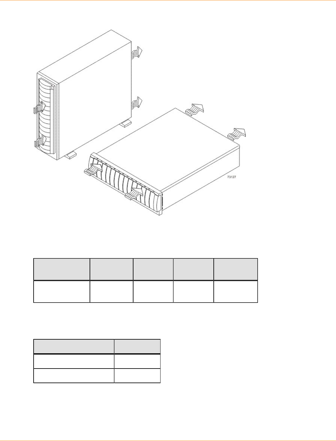
SANtricity_10.77 February 2011
LSI Corporation
- 238 -
Airflow Through the FC2610 Drive Tray – Front View
The tabulated power and heat dissipation values in the following table are the maximum measured operating
power.
Power Ratings and Heat Dissipation for the FC2610 Drive Tray
Unit KVA Watts (AC) Btu/Hr Amps (240
VAC)
FC2610 drive
tray 0.384 369 1259 1.54
FC2610 Drive Tray Acoustic Noise
Sound Levels for the FC2610 Drive Tray
Measurement Level
Sound power 6.0 bels
Sound pressure 60 dBA
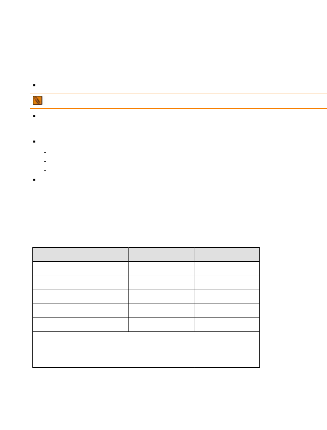
SANtricity_10.77 February 2011
LSI Corporation
- 239 -
FC2610 Drive Tray Site Wiring and Power
The FC2610 drive tray uses wide-ranging, redundant power supplies that automatically accommodate
voltages to the AC power source. The power supplies meet standard voltage requirements for both North
American (USA and Canada) operation and worldwide (except USA and Canada) operation. The power
supplies use standard industrial wiring with line-to-neutral or line-to-line power connections.
Keep this information in mind when preparing the installation site for the drive tray:
Protective ground – Site wiring must include a protective ground connection to the AC power source.
NOTE Protective ground is also known as safety ground or chassis ground.
Circuit overloading – Power circuits and associated circuit breakers must provide enough power and
overload protection. To prevent damage to the drive tray, isolate its power source from large switching
loads, such as air-conditioning motors, elevator motors, and factory loads.
Power interruptions – The drive tray can withstand these applied voltage interruptions:
Input transient – 50 percent of the nominal voltage
Duration – One-half cycle
Maximum frequency – Once every 10 seconds
Power failures – If a total power failure occurs, the drive tray automatically performs a power-on recovery
sequence without operator intervention after the power is restored.
FC2610 Drive Tray Power Input
The AC power sources must provide the correct voltage, current, and frequency specified on the tray and
serial number label.
AC Power Requirements for the FC2610 Drive Tray
Parameter Low Range High Range
Nominal voltage 115 VAC 230 VAC
Frequency 50 to 60 Hz 50 to 60 Hz
Idle current 3.81 A* 1.98 A**
Maximum operating current 3.96 A* 2.06 A**
Maximum surge current 5.52 A* 2.72 A**
*Typical current: 115 VAC, 60 Hz at 0.77 power supply efficiency and 0.96 power
factor.
**Typical current: 230 VAC, 60 Hz at 0.77 power supply efficiency and 0.96 power
factor.
FC2610 Drive Tray Power Factor Correction
Power factor correction is applied within the power supply of each FC2610 drive tray, which maintains the
power factor of the drive tray at greater than 0.99 with nominal input voltage.

SANtricity_10.77 February 2011
LSI Corporation
- 240 -
FC2610 Drive Tray Power Cords and Receptacles
Each FC2610 drive tray is shipped with two AC power cords, which use the standard AC outlets in the
destination country. Each AC power cord connects one of the power supplies in the drive tray to an
independent, external AC power source, such as a wall receptacle, or to any uninterruptible power supply
(UPS).
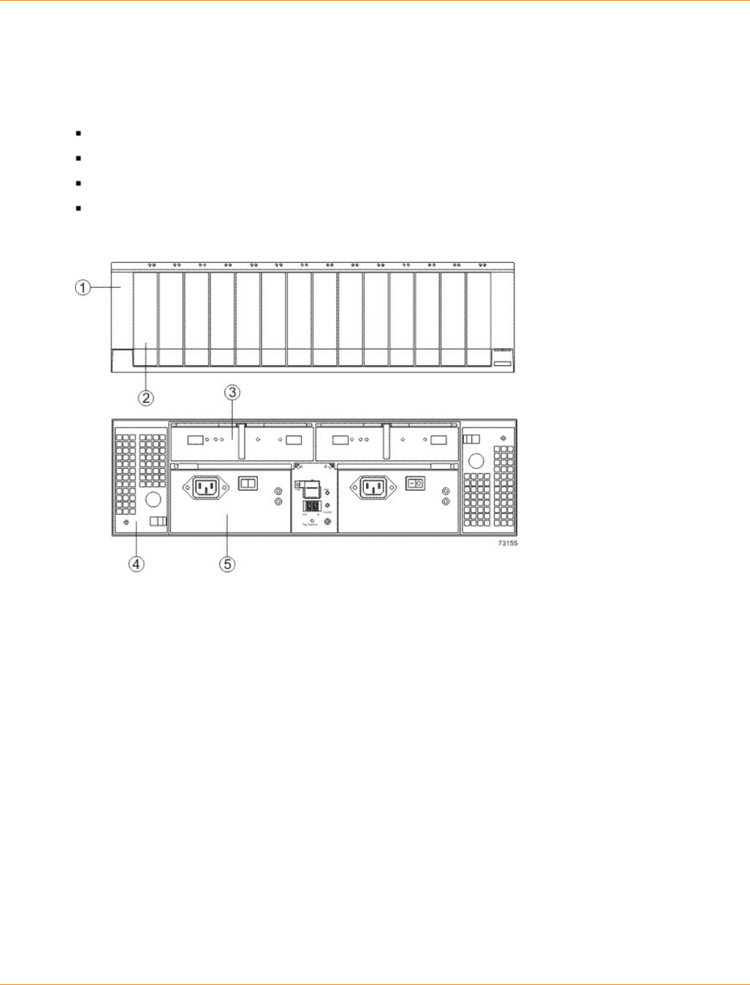
SANtricity_10.77 February 2011
LSI Corporation
- 241 -
Specifications of the FC2600 Drive Tray
The FC2600 drive tray is available as a rackmount model or a deskside model that provides high-capacity
disk storage for Fibre Channel environments. Each FC2600 drive tray contains these components:
A maximum of 14 drives
Two fan canisters
Two power-supply canisters
One or two environmental services monitor (ESM) canisters
FC2600 Drive Tray – Front View and Rear View
1. Bezel
2. Drive
3. ESM Canister
4. Fan Canister
5. Power Supply Canister
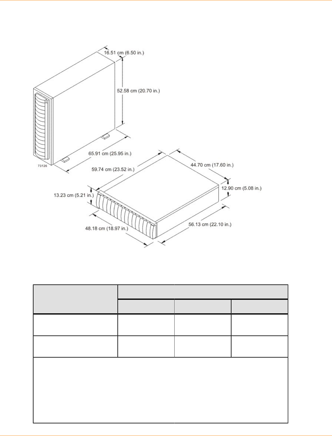
SANtricity_10.77 February 2011
LSI Corporation
- 242 -
FC2600 Drive Tray Dimensions
Dimensions of the FC2600 Drive Tray (Deskside Model and Rackmount Model) – Front View
FC2600 Drive Tray Weight
Weights of the FC2600 Drive Tray
WeightUnit
Maximum* Empty** Shipping***
FC2600 drive tray, deskside
model 53.1 kg (117.0 lb) 28.0 kg (63.0 lb) 64.9 kg (143.0 lb)
FC2600 drive tray,
rackmount model 40.40 kg (89.0 lb) 15.9 kg (35.0 lb) 52.2 kg (115.0 lb)
*Maximum weight indicates a drive tray with all of its drives and other components
installed. Because drive weights can vary greatly, this value can vary from the value
specified as much as 0.3 kg (0.6 lb) times the maximum number of drives per drive tray for
drives weighing 1.0 kg (2.2 lb).
**Empty weight indicates a drive tray with the ESM canisters, the power-supply canisters,
fan canisters, and drives removed.
***Shipping weight indicates the maximum weight of the drive tray and all shipping
material.
SANtricity_10.77 February 2011
LSI Corporation
- 243 -
Component Weights of the FC2600 Drive Tray
Component Weight
Drive 1.00 kg (2.2 lb)
ESM 1.59 kg (3.7 lb)
Power supply 2.45 kg (5.39 lb)
FC2600 Drive Tray Temperature and Humidity
Temperature Requirements and Humidity Requirements for the FC2600 Drive Tray
Condition Parameter Requirement
Operating range 10°C to 40°C (50°F to 104°F)
Maximum rate of change 10°C (18°F) per hour
Storage range –10°C to 65°C (14°F to
149°F)
Maximum rate of change 15°C (27°F) per hour
Transit range –40°C to 65°C (–40°F to
149°F)
Temperature*
Maximum rate of change 15°C (27°F) per hour
Operating range 20% to 80%
Storage range 10% to 90%
Transit range 5% to 95%
Maximum dew point 26°C (79°F)
Relative
humidity (no
condensation)
Maximum gradient 10% per hour
*If you plan to operate a system at an altitude between 1000 m to 3000 m (3280 ft
to 9842 ft) above sea level, lower the environmental temperature 1.7°C (3.3°F) for
every 1000 m (3280 ft) above sea level.
FC2600 Drive Tray Altitude Ranges
Altitude Ranges for the FC2600 Drive Tray
Environment Altitude
Operating 30.5 m (100 ft) below sea level to 3000 m (9842 ft) above sea
level
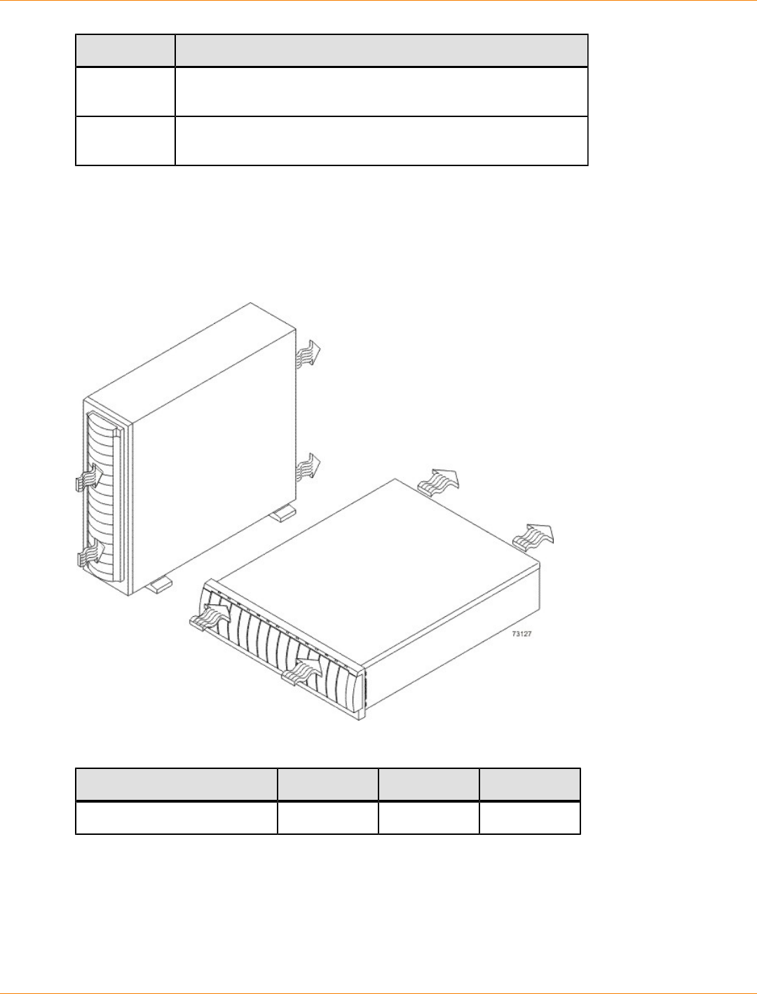
SANtricity_10.77 February 2011
LSI Corporation
- 244 -
Environment Altitude
Storage 30.5 m (100 ft) below sea level to 3000 m (9842 ft) above sea
level
Transit 30.5 m (100 ft) below sea level to 12,000 m (40,000 ft) above
sea level
FC2600 Drive Tray Airflow and Heat Dissipation
Allow at least 76 cm (30 in.) in front of the drive tray and at least 61 cm (24 in.) behind the drive tray for
service clearance, ventilation, and heat dissipation.
Airflow Through the FC2600 Drive Tray
Power and Heat Dissipation for the FC2600 Drive Tray
Unit KVA Watts (AC) Btu per hour
FC2600 drive tray 0.375 366 1229

SANtricity_10.77 February 2011
LSI Corporation
- 245 -
FC2600 Drive Tray Acoustic Noise
Sound Levels for the FC2600 Drive Tray
Measurement Level
Sound power 6.0 bels
Sound pressure 60 dBA
FC2600 Drive Tray Site Wiring and Power
The FC2600 drive tray uses wide-ranging, redundant power supplies that automatically accommodate
voltages to the AC power source. The power supplies meet standard voltage requirements for both North
American (USA and Canada) operation and worldwide (except USA and Canada) operation. The power
supplies use standard industrial wiring with line-to-neutral or line-to-line power connections.
Protective ground – Site wiring must include a protective ground connection to the AC power source.
NOTE Protective ground is also known as safety ground or chassis ground.
Circuit overloading – Power circuits and associated circuit breakers must provide enough power and
overload protection. To prevent damage to the drive tray, isolate its power source from large switching
loads, such as air-conditioning motors, elevator motors, and factory loads.
Power interruptions – The drive tray can withstand these applied voltage interruptions:
Input transient – 50 percent of the nominal voltage
Duration – One-half cycle
Frequency – Once every 10 seconds
Power failures – If a total power failure occurs, the drive tray automatically performs a power-on recovery
sequence without operator intervention.
FC2600 Drive Tray Power Input
Each power supply contains one 10-A slow-blow fuse.
AC Power Requirements for the FC2600 Drive Tray
Parameter Low Range High Range
Nominal voltage 90 to 136 VAC 180 to 264 VAC
Frequency 50 to 60 Hz 50 to 60 Hz
Idle current 2.93 A* 1.27 A**
Maximum operating current 3.18 A 1.37 A
Maximum surge current 5.85 A 2.36 A
*Typical current: 115 VAC, 60 Hz at 0.73 power supply efficiency and
0.96 power factor.

SANtricity_10.77 February 2011
LSI Corporation
- 246 -
Parameter Low Range High Range
**Typical current: 230 VAC, 60 Hz at 0.73 power supply efficiency and
0.96 power factor.
FC2600 Drive Tray Power Correction Factor
Power factor correction is applied within the power supply of each FC2600 drive tray, which maintains the
power factor of the drive tray at greater than 0.99 with nominal input voltage.
FC2600 Drive Tray AC Power Cords and Receptacles
Each FC2600 drive tray is shipped with two AC power cords that are appropriate for use in a typical outlet
in the destination country. Each AC power cord connects one of the power supplies in a drive tray to an
independent, external AC power source, such as a wall receptacle or a UPS.
If you have a cabinet with internal power cabling, such as a ladder cord, you do not need the AC power cords
that are shipped with the drive tray.
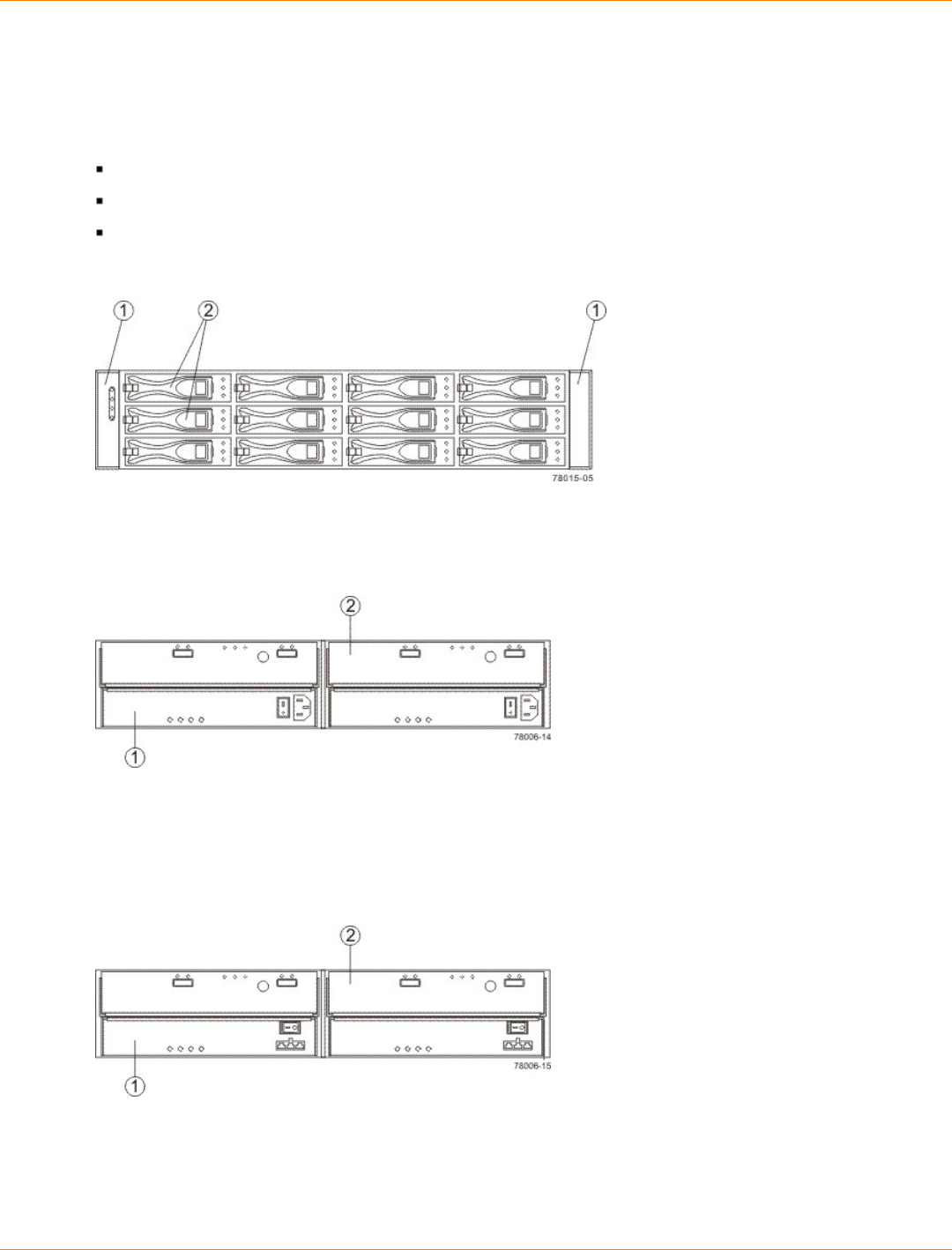
SANtricity_10.77 February 2011
LSI Corporation
- 247 -
Specifications of the DM1300 Drive Tray
The DM1300 drive tray contains Serial Attached SCSI (SAS) drives. Each DM1300 drive tray contains these
components:
A maximum of 12 drives
Two power-supply fan canisters
One or two environmental services monitor (ESM) canisters
DM1300 Drive Tray – Front View
1. End Caps (the Left End Cap has the Drive Tray LEDs)
2. Drive Canisters
DM1300 Drive Tray – Rear View
1. Power-Fan Canister
2. ESM Canister
Usually, an AC power source supplies power to the power-fan canister. A DC poweroption is also available.
DM1300 Drive Tray Power Source Options – Rear View
1. Controller Canister
2. DC Power Switch on an Optional Power-Fan Canister
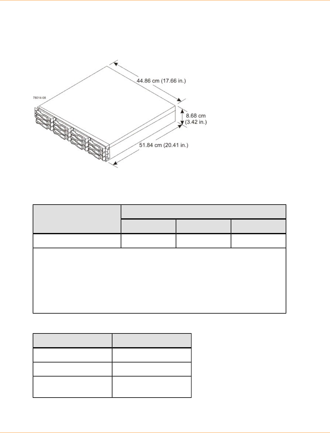
SANtricity_10.77 February 2011
LSI Corporation
- 248 -
DM1300 Drive Tray Dimensions
The DM1300 drive tray conforms to the 48.3-cm (19.0-in.) rack standard.
Dimensions of the DM1300 Drive Tray – Front View
DM1300 Drive Tray Weight
Weights of the DM1300 Drive Tray
WeightUnit
Maximum* Empty** Shipping***
DM1300 drive tray 25.86 kg (57.0 lb) 6.80 kg (15.0 lb) 25.00 kg (55.0 lb)
*Maximum weight indicates a drive tray with all of its drives and other components
installed. Because drive weights can vary greatly, this value can vary from the value
specified as much as 0.3 kg (0.6 lb) times the maximum number of drives per drive tray for
drives weighing 1.0 kg (2.2 lb).
**Empty weight indicates a drive tray with the ESM canisters, the power-fan canisters, and
the drives removed.
***Shipping weight indicates the maximum weight of a fully-populated drive tray and all
shipping material.
Component Weights of the DM1300 Drive Tray
Component Weight
ESM canister 0.907 kg (2.00 lb)
Power-fan canister 2.267 kg (5.00 lb)
Drive Approximately 1.0 kg (2.2
lb)
SANtricity_10.77 February 2011
LSI Corporation
- 249 -
DM1300 Drive Tray Shipping Dimensions
Shipping Carton Dimensions for the DM1300 Drive Tray
Height Width Depth
25.40 cm (10.00 in.) 60.76 cm (24.00 in.) 44.86 cm (78.74 in.)
DM1300 Drive Tray Temperature and Humidity
Temperature Requirements and Humidity Requirements for the DM1300 Drive Tray
Condition Parameter Requirement
Operating range 10°C to 40°C (50°F to 104°F)
Maximum rate of change 10°C (18°F) per hour
Storage range –10°C to 50°C (14°F to
122°F)
Maximum rate of change 15°C (27°F) per hour
Transit range –40°C to 60°C (–40°F to
140°F)
Temperature*
Maximum rate of change 20°C (36°F) per hour
Operating range 20% to 80%
Storage range 10% to 90%
Transit range 5% to 95%
Maximum dew point 26°C (79°F)
Relative
humidity (no
condensation)
Maximum gradient 10% per hour
*If you plan to operate a system at an altitude between 1000 m to 3000 m (3280 ft
to 9842 ft) above sea level, lower the environmental temperature 1.7°C (3.3°F) for
every 1000 m (3280 ft) above sea level.
DM1300 Drive Tray Altitude Ranges
Altitude Ranges for the DM1300 Drive Tray
Environment Altitude
Operating 30.5 m (100 ft) below sea level to 3000 m (9842 ft) above sea
level
Storage 30.5 m (100 ft) below sea level to 3000 m (9842 ft) above sea
level
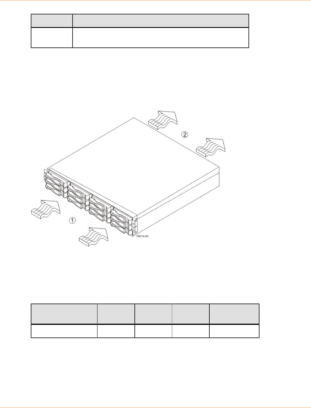
SANtricity_10.77 February 2011
LSI Corporation
- 250 -
Environment Altitude
Transit 30.5 m (100 ft) below sea level to 12,000 m (40,000 ft) above sea
level
DM1300 Drive Tray Airflow and Heat Dissipation
Airflow goes from the front of the drive tray to the rear of the drive tray. Allow at least 76 cm (30 in.) of
clearance in front of the drive tray and at least 61 cm (24 in.) of clearance behind the drive tray for service
clearance, ventilation, and heat dissipation.
Airflow Through the DM1300 Drive Tray – Front View
1. 76 cm (30 in.) clearance in front of the cabinet
2. 61 cm (24 in.) clearance behind the cabinet
The tabulated power and heat dissipation values in the following table are the maximum measured operating
power.
Power Ratings and Heat Dissipation for the DM1300 Drive Tray
Unit KVA Watts (AC) Btu/Hr Amps (240
VAC)
DM1300 drive tray 0.362 358 1224 1.54
SANtricity_10.77 February 2011
LSI Corporation
- 251 -
DM1300 Drive Tray Acoustic Noise
Sound Levels for the DM1300 Drive Tray
Measurement Level
ES 2-10-02 Standard Level 2 0.5 bels
margin
Sound power (standby
operation) 6.5 bels
Sound power (normal operation) 6.8 bels
DM1300 Drive Tray Site Wiring and Power
The DM1300 drive tray uses wide-ranging, redundant power supplies that automatically accommodate
voltages to the AC power source. The power supplies meet standard voltage requirements for both North
American (USA and Canada) operation and worldwide (except USA and Canada) operation. The power
supplies use standard industrial wiring with line-to-neutral or line-to-line power connections.
Keep this information in mind when preparing the installation site for the drive tray:
Protective ground – Site wiring must include a protective ground connection to the AC power source.
NOTE Protective ground is also known as safety ground or chassis ground.
Circuit overloading – Power circuits and associated circuit breakers must provide enough power and
overload protection. To prevent damage to the drive tray, isolate its power source from large switching
loads, such as air-conditioning motors, elevator motors, and factory loads.
Power interruptions – The drive tray can withstand these applied voltage interruptions:
Input transient – 50 percent of the nominal voltage
Duration – One-half cycle
Maximum frequency – Once every 10 seconds
Power failures – If a total power failure occurs, the drive tray automatically performs a power-on recovery
sequence without operator intervention after the power is restored.
DM1300 Drive Tray Power Input
AC Power Input
The AC power sources must provide the correct voltage, current, and frequency specified on the tray and
serial number label.
AC Power Requirements for the DM1300 Drive Tray
Parameter Low Range High Range
Nominal voltage 100 VAC 240 VAC
Frequency 50 to 60 Hz 50 to 60 Hz
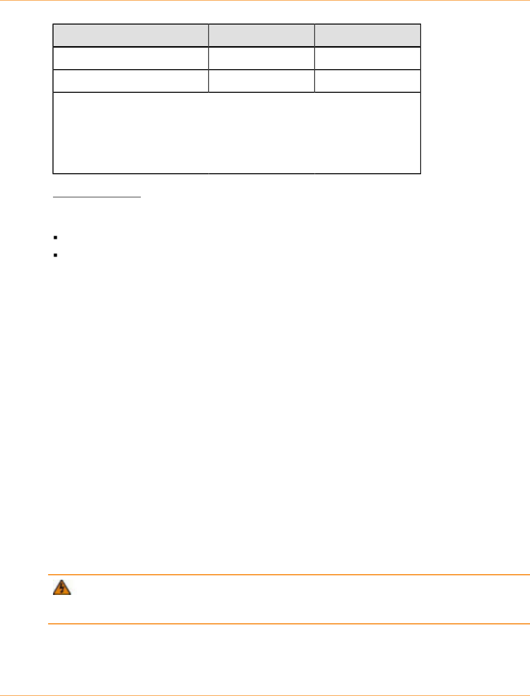
SANtricity_10.77 February 2011
LSI Corporation
- 252 -
Parameter Low Range High Range
Idle current 3.96 A* 1.74 A**
Maximum operating current 4.08 A* 1.70 A**
*Typical current: 100 VAC, 60 Hz at 0.77 power supply efficiency and 0.96 power
factor. These numbers can vary significantly, depending upon the drives tested in
the particular configuration.
**Typical current: 240 VAC, 60 Hz at 0.77 power supply efficiency and 0.96 power
factor. These numbers can vary significantly, depending upon the drives tested in
the particular configuration.
DC Power Input
Nominal input voltages for the DC power source are as follows:
Low range: –36 VDC
High range: –72 VDC
The maximum operating current is 17 A.
DM1300 Drive Tray Power Factor Correction
Power factor correction is applied within the power supply of each DM1300 drive tray, which maintains the
power factor of the drive tray at greater than 0.95 with nominal input voltage.
DM1300 Drive Tray AC Power Cords and Receptacles
Each DM1300 drive tray is shipped with two AC power cords, which use standard AC outlets in the
destination country. Each AC power cord connects one of the power supplies in the drive tray to an
independent, external AC power source, such as a wall receptacle, or to any uninterruptible power supply
(UPS).
Usually an AC power source supplies power to the power-fan canister. A DC power option is also available.
For more information about the DC power option, see “DM1300 Drive Tray Optional DC Power Connector
Cables and Source Wires.”
DM1300 Drive Tray Optional DC Power Connector Cables and Source Wires
The DM1300 drive tray is shipped with –48-VDC power connector cables if the DC power option is ordered.
The –48-VDC power connector cable plugs into the DC power connector on the rear of the drive tray. The
three source wires on the other end of the power connector cable connect the drive tray to centralized DC
power plant equipment, typically through a bus bar above the cabinet.
WARNING (W12) Risk of electrical shock – This unit has more than one power source. To remove
all power from the unit, all DC MAINS must be disconnected by removing all power connectors (item 4 below)
from the power supplies.
SANtricity_10.77 February 2011
LSI Corporation
- 253 -
1. Supply (Negative), Brown Wire, –48 VDC
2. Return (Positive), Blue Wire
3. Ground, Green and Yellow Wire
4. DC Power Connector
WARNING (W14) Risk of bodily injury – A qualified service person is required to make the DC
power connection according to NEC and CEC guidelines.
Two DC power connector cables are provided with each drive tray. Two DC power connectors are on the two
power-fan canisters on the rear of each drive tray if additional redundancy is required.
NOTE It is not mandatory that you connect the second DC power connection on the power-fan canister
of the drive tray. The second DC power connection is provided for additional redundancy only and can be
connected to a second DC power bus.

SANtricity_10.77 February 2011
LSI Corporation
- 254 -
Regulatory Compliance Statements
FCC Radio Frequency Interference Statement
This equipment has been tested and found to comply with the limits for a Class A digital device, pursuant
to Part 15 of the Federal Communications Commission (FCC) Rules. These limits are designed to provide
reasonable protection against harmful interference in a commercial installation. This equipment generates,
uses, and can radiate radio frequency energy and, if not installed and used in accordance with the
instructions, may cause harmful interference to radio communications. Operation of this equipment in a
residential area is likely to cause harmful interference, in which case the user will be required to correct the
interference at his/her own expense.
LSI Corporation is not responsible for any radio or television interference caused by unauthorized modification
of this equipment or the substitution or attachment of connecting cables and equipment other than
those specified by LSI. It is the user’s responsibility to correct interference caused by such unauthorized
modification, substitution, or attachment.
Laser Products Statement
This equipment uses Small Form-factor Pluggable (SFP) optical transceivers, which are unmodified Class
1 laser products pursuant to 21 CFR, Subchapter J, Section 1040.10. All optical transceivers used with this
product are required to be 21 CFR certified Class 1 laser products. For outside the USA, this equipment
has been tested and found compliant with Class 1 laser product requirements contained in European
Normalization standard EN 60825-1 1994+A11. Class 1 levels of laser radiation are not considered to be
hazardous and are considered safe based upon current medical knowledge. This class includes all lasers or
laser systems which cannot emit levels of optical radiation above the exposure limits for the eye under any
exposure conditions inherent in the design of the laser products.
LSI Corporation is not responsible for any damage or injury caused by unauthorized modification of this
equipment or the substitution or attachment of connecting cables and equipment other than those specified
by LSI. It is the user’s responsibility to correct interference caused by such unauthorized modification,
substitution, or attachment.
This Class A digital apparatus meets all requirements of the Canadian Interference-Causing Equipment
Regulations.
Cet appareil numérique de la classé A respecte toutes les exigences du Règlement sure le matèriel brouilleur
du Canada.

SANtricity_10.77 February 2011
LSI Corporation
- 255 -

SANtricity_10.77 February 2011
LSI Corporation
- 256 -
CDE2600 Controller-Drive Tray Installation
This topic provides basic information for installing the CDE2600 controller-drive tray and the corresponding
drive trays (the DE1600 drive tray and the DE5600 drive tray) in a storage array. After you have completed
these tasks, go to the Initial Configuration and Software Installation electronic document topics or the PDF on
the SANtricity ES Storage Manager Installation DVD.
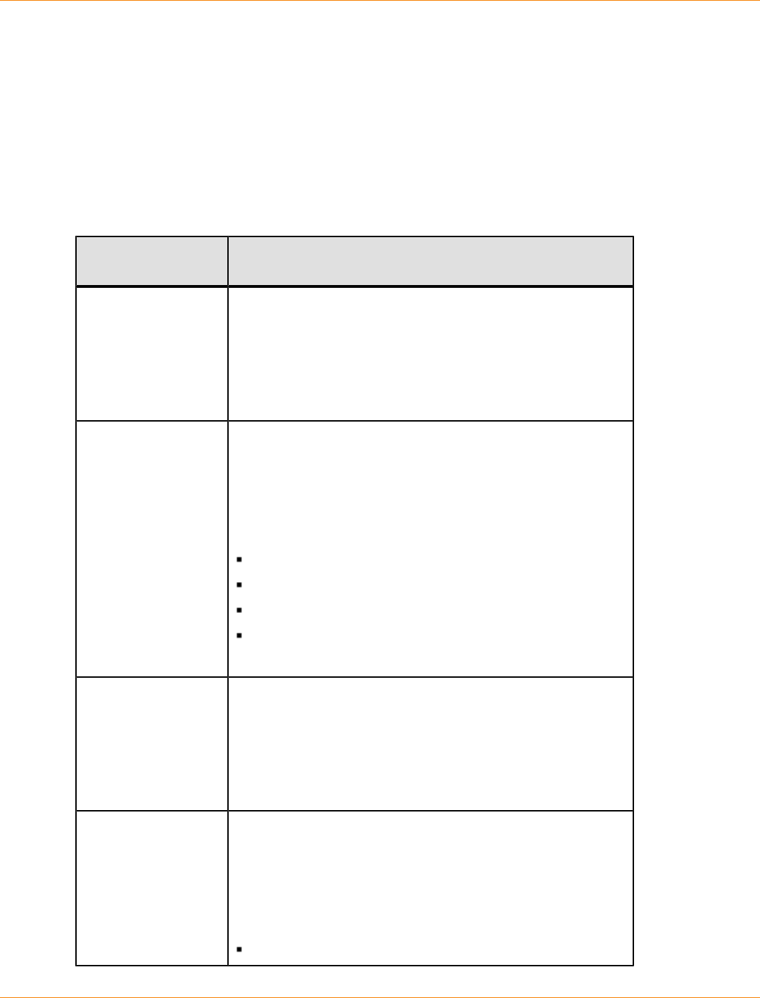
SANtricity_10.77 February 2011
LSI Corporation
- 257 -
Step 1 – Preparing for a CDE2600 Controller-Drive Tray
Installation
Storage arrays for 6-Gb/s SAS drives consist of a CDE2600 controller-drive tray, or a CDE2600 controller-
drive tray and one or more DE1600 or DE5600 drive trays in a cabinet. Use this document to install the
CDE2600 controller-drive trays and all necessary drive trays for your configuration.
The following table shows the various configuration options.
CDE2600 Controller-Drive Tray Options
CDE2600
Configurations Options
Simplex (one
controller) CDE2600
controller-drive tray
with no host interface
card
A maximum of 96 drives that you can upgrade to 192. The
upgrade is a Premium feature.
Any combination of CDE2600 controller-drive trays attached
to DE1600 drive trays or DE5600 drive trays, not to exceed a
maximum of 96 (or 192) drive slots in the storage array.
Two 6-Gb/s host connectors.
8-GB battery backup.
Simplex CDE2600
controller-drive tray
with a host interface
card
A maximum of 96 drives that you can upgrade to 192. The
upgrade is a Premium feature.
Any combination of CDE2600 controller-drive trays attached
to DE1600 drive trays or DE5600 drive trays, not to exceed a
maximum of 96 (or 192) drive slots in the storage array.
Two 6-Gb/s host connectors, in addition to one of the following
host interface cards:
Two 6-Gb/s SAS connectors
Four 1-Gb/s iSCSI connectors
Two 10-Gb/s iSCSI connectors
Four 8-Gb/s Fibre Channel (FC) connectors
8-GB battery backup.
Duplex (two
controllers) CDE2600
controller-drive
tray without a host
interface card
A maximum of 96 drives that you can upgrade to 192. The
upgrade is a Premium feature.
Any combination of CDE2600 controller-drive trays attached
to DE1600 drive trays or DE5600 drive trays, not to exceed a
maximum of 96 (or 192) drive slots in the storage array.
Two 6-Gb/s host connectors.
8-GB battery backup.
Duplex CDE2600
controller-drive tray
with a host interface
card
A maximum of 96 drives that you can upgrade to 192. The
upgrade is a Premium feature.
Any combination of CDE2600 controller-drive trays attached
to DE1600 drive trays or DE5600 drive trays, not to exceed a
maximum of 96 (or 192) drive slots in the storage array.
Two 6-Gb/s host connectors, in addition to one of the following
host interface cards:
Two 6-Gb/s SAS connectors
SANtricity_10.77 February 2011
LSI Corporation
- 258 -
CDE2600
Configurations Options
Four 1-Gb/s iSCSI connectors
Two 10-Gb/s iSCSI connectors
Four 8-Gb/s FC connectors
8-GB battery backup.
ATTENTION Possible hardware damage – To prevent electrostatic discharge damage to the tray,
use proper antistatic protection when handling tray components.
Key Terms
storage array
A collection of both physical components and logical components for storing data. Physical components
include drives, controllers, fans, and power supplies. Logical components include volume groups and
volumes. These components are managed by the storage management software.
controller-drive tray
One tray with drives, one or two controllers, fans, and power supplies. The controller-drive tray provides the
interface between a host and a storage array.
controller
A circuit board and firmware that is located within a controller tray or a controller-drive tray. A controller
manages the input/output (I/O) between the host system and data volumes.
drive tray
One tray with drives, one or two environmental services monitors (ESMs), power supplies, and fans. A drive
tray does not contain controllers.
environmental services monitor (ESM)
A canister in the drive tray that monitors the status of the components. An ESM also serves as the connection
point to transfer data between the drive tray and the controller.
Small Form-factor Pluggable (SFP) transceiver
A component that enables Fibre Channel duplex communication between storage array devices. SFP
transceivers can be inserted into host bus adapters (HBAs), controllers, and environmental services monitors
(ESMs). SFP transceivers can support either copper cables (the SFP transceiver is integrated with the cable)
or fiber-optic cables (the SFP transceiver is a separate component from the fiber-optic cable).
Gathering Items
Before you start installing the controller-drive tray, you must have installed the cabinet in which the controller-
drive tray will be mounted.
SANtricity_10.77 February 2011
LSI Corporation
- 259 -
Use the tables in this section to verify that you have all of the necessary items to install the controller-drive
tray.
Basic Hardware
Basic Hardware
Item Included
with the
Controller-
Drive Tray
Cabinet
Make sure that your cabinet meets the
installation site specifications of the various
CDE2600 storage array components. Refer
to the Storage System Site Preparation
Guide for more information.
Depending on the power supply limitations
of your cabinet, you might need to install
more than one cabinet to accommodate
the different components of the CDE2600
storage array. Refer to the installation guide
for your cabinet for instructions on installing
the cabinet.
DE1600 drive tray with end caps that are
packaged separately.
DE5600 drive tray with end caps that are
packaged separately.
Mounting rails and screws
The mounting rails that are available with the
drive tray are designed for an industry-standard
cabinet.
Fibre Channel switch (optional)
SAS switch (optional)
Gigabit Ethernet switch (optional)
SANtricity_10.77 February 2011
LSI Corporation
- 260 -
Item Included
with the
Controller-
Drive Tray
Host with Fibre Channel host bus adapters
(HBAs) (optional)
Host with iSCSI HBAs (optional) or a network
interface card (optional)
Host with SAS HBAs (optional)
CDE2600 Configuration Cables and Connectors
Cables and Connectors
Item Included with the
Controller-Drive
Tray or Drive
Trays
AC power cords.
The controller-drive tray and the drive trays ship
with power cords for connecting to an external
power source, such as a wall plug. Your cabinet
might have special power cords that you use
instead of the power cords that ship with the
controller-drive tray and the drive trays.
(Optional) Two DC power connector cables are
provided with each drive tray for connection to
centralized DC power plant equipment.
Four DC power connector cables are provided if
additional redundancy is required.
A qualified service person is required to
make the DC power connection per NEC and
CEC guidelines. A two-pole 20-amp circuit
breaker is required between the DC power
source and the drive tray for over-current and
short-circuit protection. Before turning off any
power switches on a DC-powered drive tray,
first you must disconnect the two-pole 20-amp
circuit breaker.
For the DC power option only
Copper SAS cables - Use for all drive-side
connections within the storage array.
Fiber-optic cables - Use for FC connections to the
drive trays.
For the differences between the fiber-optic cables
and the copper Fibre Channel (FC) cables, see
Things to Know – SFP Transceivers, Fiber-Optic
Cables, Copper Cables, and SAS Cables .
SANtricity_10.77 February 2011
LSI Corporation
- 261 -
Item Included with the
Controller-Drive
Tray or Drive
Trays
Small Form-factor Pluggable (SFP) transceivers
The SFP transceivers connect fiber-optic cables
to host ports and drive ports.
Four or eight SFP transceivers are included with
the controller-drive tray; one for each of the host
channel ports on the controllers.
Depending on your connection requirements,
you might need to purchase additional SFP
transceivers (two SFP transceivers for each
fiber-optic cable).
Depending on the configuration of your
storage array, you might need to use various
combinations of four different types of SFP
transceivers: 8-Gb/s Fibre Channel, 6-Gb/
s SAS, 1-Gb/s iSCSI, or 10-Gb/s iSCSI.
These SFP transceivers are not generally
interchangeable.
You must purchase only Restriction of
Hazardous Substances (RoHS)-compliant SFP
transceivers.
Copper Fibre Channel cables (optional)
Use these cables for connections within the storage
array.
For the differences between the fiber-optic cables
and the copper Fibre Channel cables, see “Things
to Know – SFP Transceivers, Fiber-Optic Cables,
Copper Cables, and SAS Cables.”
Ethernet cable
This cable is used for out-of-band storage array
management and for 1-Gb/s iSCSI connections.
For information about out-of-band storage array
management, see the description for "Deciding on
the Management Method" in Initial Configuration
and Software Installation electronic document
topics or the PDF on the SANtricity ES Storage
Manager Installation DVD.
SANtricity_10.77 February 2011
LSI Corporation
- 262 -
Item Included with the
Controller-Drive
Tray or Drive
Trays
SAS cables
The SAS cables connect the host to the controller-
drive tray. If you install a drive tray, you must use
SAS cables to connect the controller-drive tray to
the drive tray.
Serial cable
This cable is used for support only. You do not need
to connect it during initial installation.
DB9-to-PS2 adapter cable
This cable adapts the DB9 connector on
commercially available serial cables to the PS2
connector on the controller.
Product DVDs
Product DVDs
Item Included
with the
Controller-
Drive Tray
Firmware DVD
Firmware is already installed on the
controllers.
The files on the DVD are backup copies.
SANtricity ES Storage Manager Installation DVD
SANtricity ES Storage Manager software and
documentation.
To access product documentation,
use the documentation map file,
doc_launcher.html, which is located in
the docs directory.
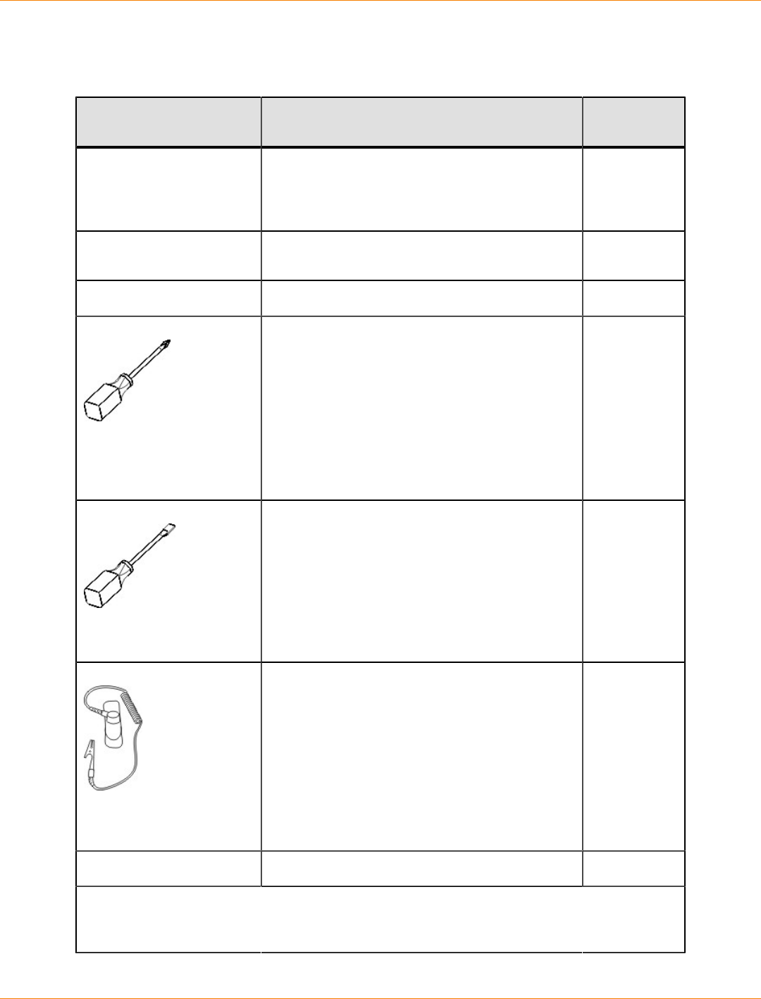
SANtricity_10.77 February 2011
LSI Corporation
- 263 -
Tools and Other Items
Tools and Other Items
Item Included
with the Tray
Labels
Help you to identify cable connections and lets
you more easily trace cables from one tray to
another
A cart
Holds the tray and components
A mechanical lift (optional)
A Phillips screwdriver
A flat-blade screwdriver
Anti-static protection
A flashlight
Use the Compatibility Matrix, at the following website, to obtain the latest hardware
compatibility information.
http://www.lsi.com/compatibilitymatrix/
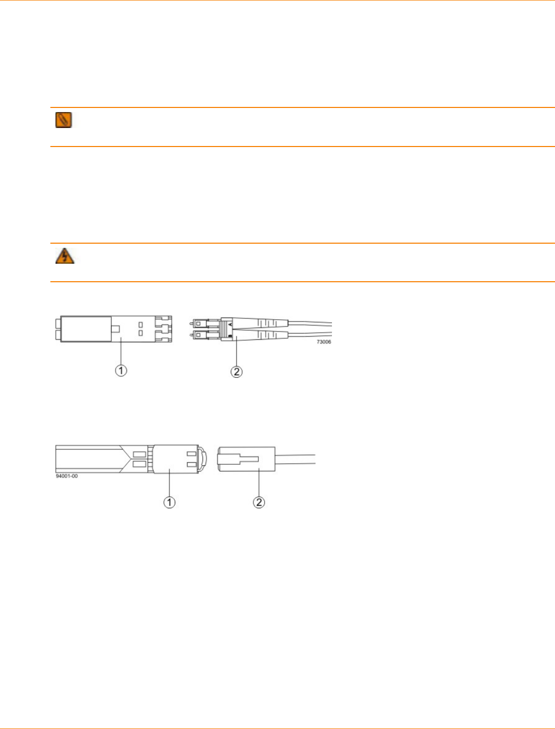
SANtricity_10.77 February 2011
LSI Corporation
- 264 -
Things to Know – SFP Transceivers, Fiber-Optic Cables, Copper Cables, and
SAS Cables
The figures in this topic display the fiber-optic cables, copper cables, SFP transceivers., and SAS cables with
a SFF-8088 Connector.
NOTE Your SFP transceivers and cables might look slightly different from the ones shown. The
differences do not affect the performance of the SFP transceivers.
The controller-drive tray supports SAS, Fibre Channel (FC), and iSCSI host connections and SAS drive
connections. FC host connections can operate at 8 Gb/s or at a lower data rate. Ports for 8-Gb/s Fibre
Channel host connections require SFP transceivers designed for this data rate. These SFP transceivers look
similar to other SFP transceivers but are not compatible with other types of connections. SFP transceivers
for 1-Gb/s iSCSI and 10-Gb/s iSCSI connections have a different physical interface for the cable and are not
compatible with other types of connections.
WARNING (W03) Risk of exposure to laser radiation – Do not disassemble or remove any part of a
Small Form-factor Pluggable (SFP) transceiver because you might be exposed to laser radiation.
Fiber-Optic Cable Connection
1. Active SFP Transceiver
2. Fiber-Optic Cable
1-Gb/s iSCSI Cable Connection
1. Active SFP Transceiver
2. Copper Cable with RJ-45 Connector
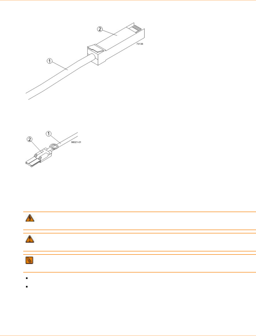
SANtricity_10.77 February 2011
LSI Corporation
- 265 -
Copper Fibre Channel Cable Connection
1. Copper Fibre Channel Cable
2. Passive SFP Transceiver
SAS Cable Connection
1. SAS Cable
2. SFF-8088 Connector
Things to Know – Taking a Quick Glance at the Hardware in a CDE2600
Controller-Drive Tray Configuration
WARNING (W14) Risk of bodily injury – A qualified service person is required to make the DC
power connection according to NEC and CEC guidelines.
CAUTION (C05) Electrical grounding hazard – This equipment is designed to permit the connection
of the DC supply circuit to the earthing conductor at the equipment.
IMPORTANT Each tray in the storage array must have a minimum of two drives for proper operation. If
the tray has fewer than two drives, a power supply error is reported.
The top of the controller-drive tray is the side with labels.
The configuration of the host ports might appear different on your system depending on which host
interface card configuration is installed.
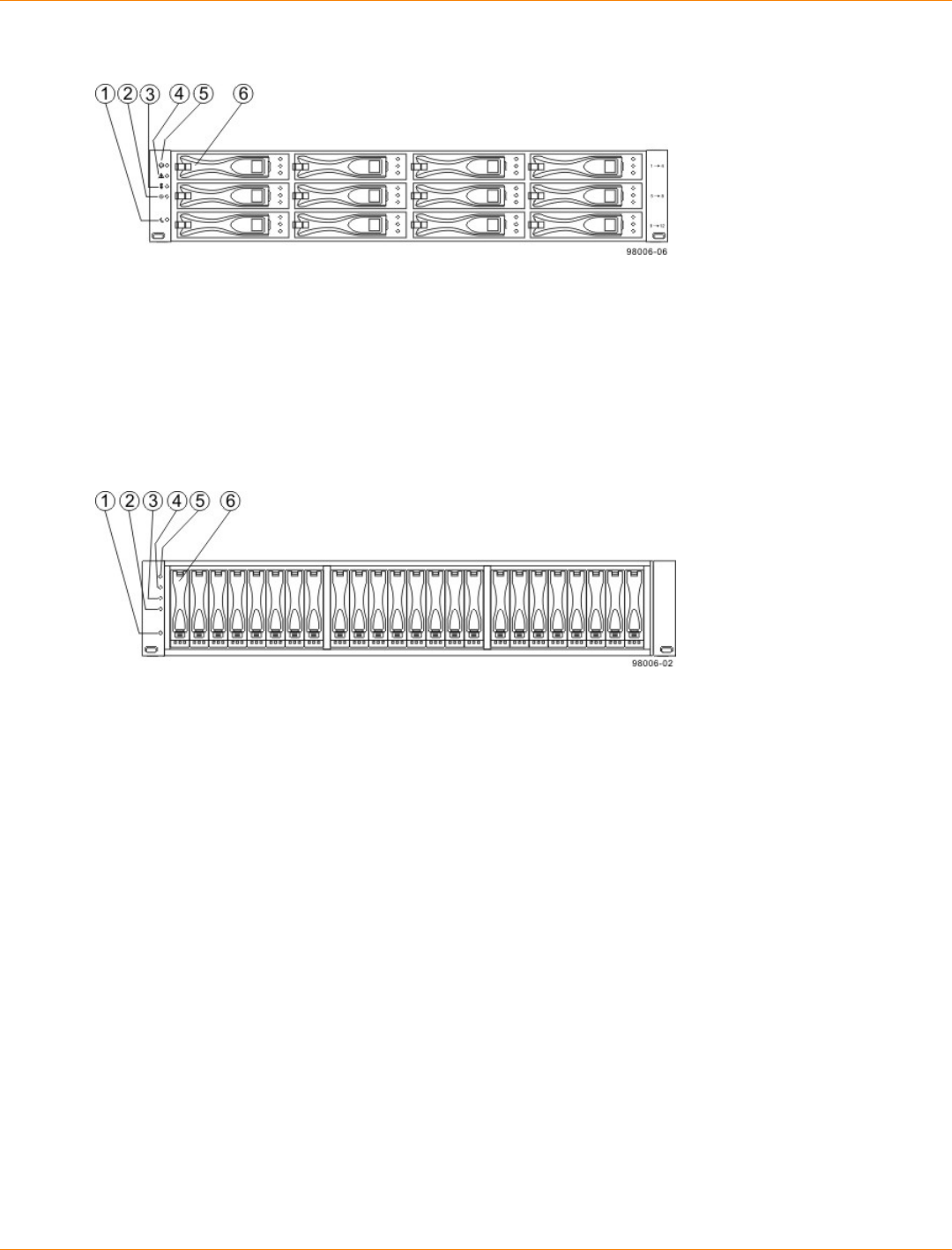
SANtricity_10.77 February 2011
LSI Corporation
- 266 -
CDE2600 Controller-Drive Tray with 12 Drives – Front View
1. End Cap Standby Power LED
2. End Cap Power LED
3. End Cap Over-Temperature LED
4. End Cap Service Action Required LED
5. End Cap Locate LED
6. Drive Canister
CDE2600 Controller-Drive Tray with 24 Drives – Front View
1. End Cap Standby Power LED
2. End Cap Power LED
3. End Cap Over-Temperature LED
4. End Cap Service Action Required LED
5. End Cap Locate LED
6. Drive Canister
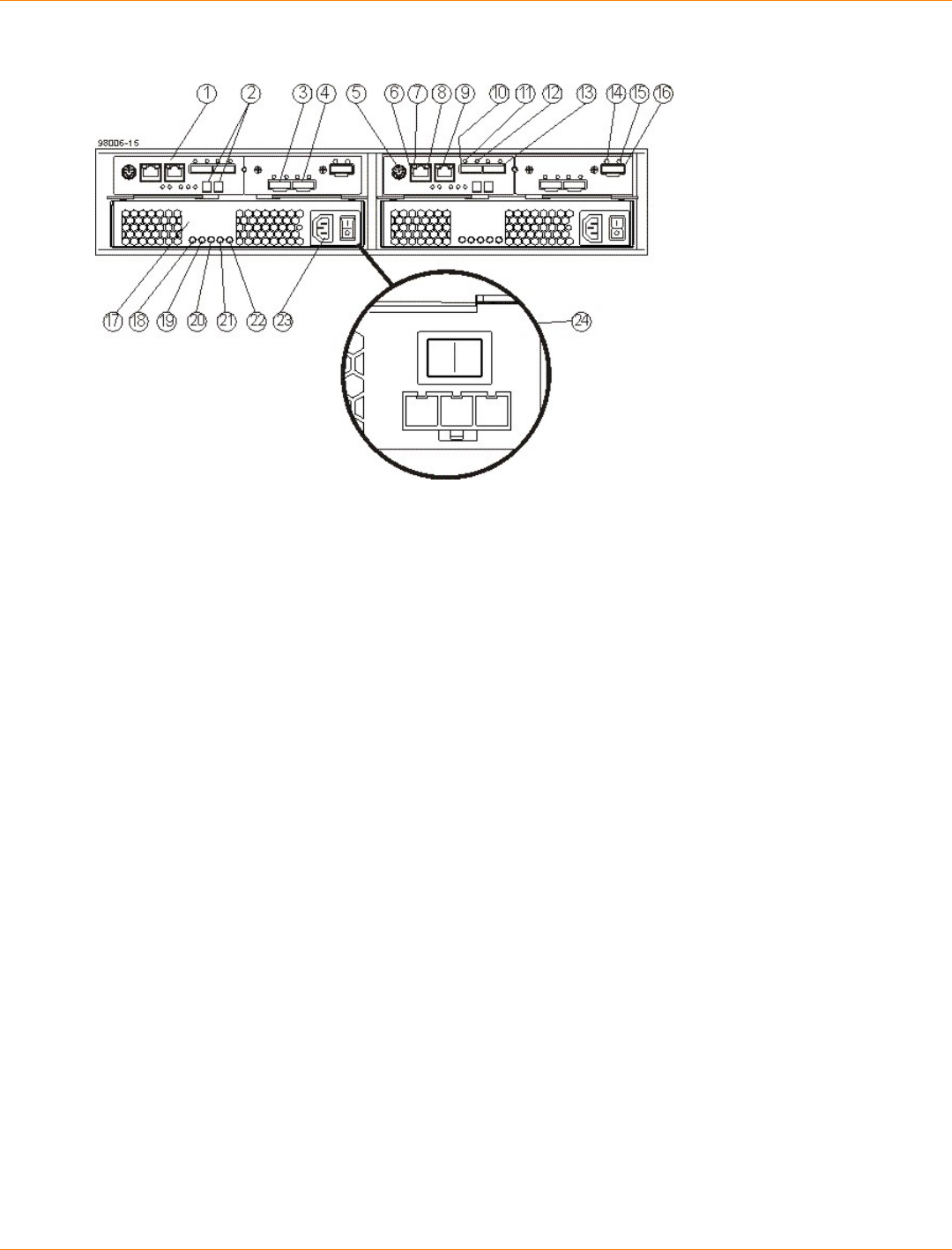
SANtricity_10.77 February 2011
LSI Corporation
- 267 -
CDE2600 Controller-Drive Tray Duplex Configuration– Rear View
1. Controller A Canister
2. Seven-Segment Display
3. Host Interface Card Connector 1
4. Host Interface Card Connector 2
5. Serial Connector
6. Ethernet Connector 1
7. Ethernet Link Active LED
8. Ethernet Link Rate LED
9. Ethernet Connector 2
10. Host SFF-8088 Connector 2 (Native)
11. Host Link 2 Fault LED
12. Host Link 2 Active LED
13. Base Host SFF-8088 Connector 1
14. ESM Expansion Fault LED
15. ESM Expansion Active LED
16. Expansion SFF-8088 Port Connector
17. Power-Fan Canister
18. Standby Power LED
19. Power-Fan DC Power LED
20. Power-Fan Service Action Allowed LED
21. Power-Fan Service Action Required LED
22. Power-Fan AC Power Connector and Switch
23. Power-Fan DC Power Connector and Switch
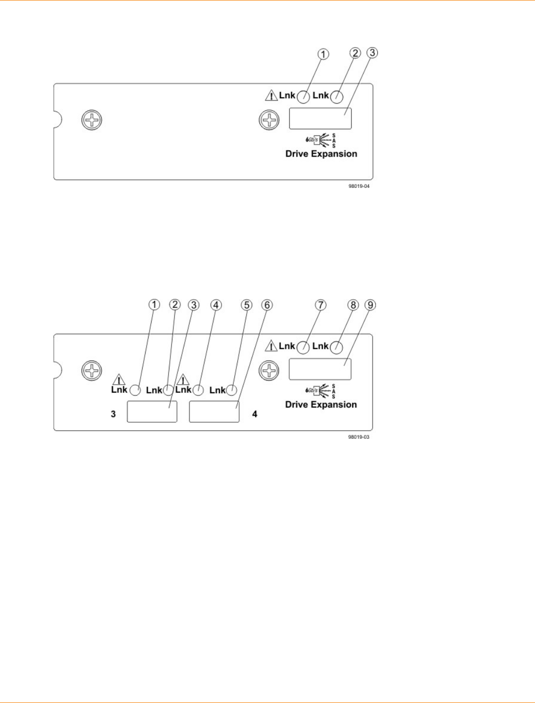
SANtricity_10.77 February 2011
LSI Corporation
- 268 -
CDE2600 Right-Rear Subplate with No Host Interface Card
1. ESM Expansion Fault LED
2. ESM Expansion Active LED
3. Expansion SFF-8088 Port Connector
CDE2600 Right-Rear Subplate with a SAS Host Interface Card
1. Host Interface Card Link 3 Up LED
2. Host Interface Card Link 3 Active LED
3. SFF-8088 Host Interface Card Connector 3
4. Host Interface Card Link 4 Up LED
5. Host Interface Card Link 4 Active LED
6. SFF-8088 Host Interface Card Connector 4
7. ESM Expansion Fault LED
8. ESM Expansion Active LED
9. Expansion SFF-8088 Port Connector

SANtricity_10.77 February 2011
LSI Corporation
- 269 -
CDE2600 Right-Rear Subplate with an FC Host Interface Card
1. Host Interface Card Link 3 Up LED
2. Host Interface Card Link 3 Active LED
3. FC Host Interface Card Connector 3
4. Host Interface Card Link 4 Up LED
5. Host Interface Card Link 4 Active LED
6. FC Host Interface Card Connector 4
7. Host Interface Card Link 5 Up LED
8. Host Interface Card Link 5 Active LED
9. FC Host Interface Card Connector 5
10. Host Interface Card Link 6 Up LED
11. Host Interface Card Link 6 Active LED
12. FC Host Interface Card Connector 6
13. ESM Expansion Fault LED
14. ESM Expansion Active LED
15. Expansion SFF-8088 Port Connector
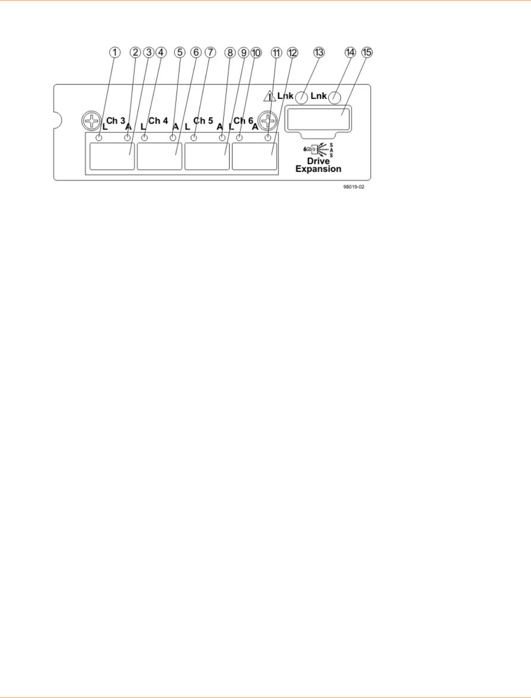
SANtricity_10.77 February 2011
LSI Corporation
- 270 -
CDE2600 Right-Rear Subplate with a 1-Gb iSCSI Host Interface Card
1. Host Interface Card Link 3 Up LED
2. Host Interface Card Link 3 Active LED
3. iSCSI Host Interface Card Connector 3
4. Host Interface Card Link 4 Up LED
5. Host Interface Card Link 4 Active LED
6. iSCSI Host Interface Card Connector 4
7. Host Interface Card Link 5 Up LED
8. Host Interface Card Link 5 Active LED
9. iSCSI Host Interface Card Connector 5
10. Host Interface Card Link 6 Up LED
11. Host Interface Card Link 6 Active LED
12. iSCSI Host Interface Card Connector 6
13. ESM Expansion Fault LED
14. ESM Expansion Active LED
15. Expansion SFF-8088 Port Connector
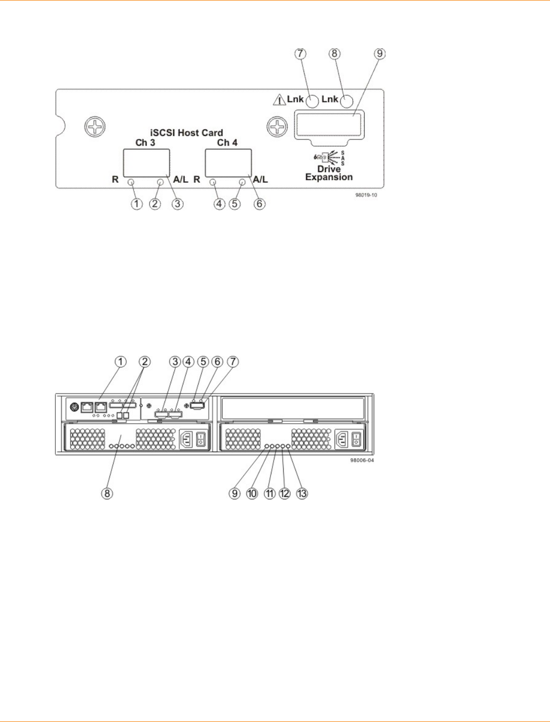
SANtricity_10.77 February 2011
LSI Corporation
- 271 -
CDE2600 Right-Rear Subplate with a 10-Gb iSCSI Host Interface Card
1. Host Interface Card Link 3 Up LED
2. Host Interface Card Link 3 Active LED
3. iSCSI Host Interface Card Connector 3
4. Host Interface Card Link 4 Up LED
5. Host Interface Card Link 4 Active LED
6. iSCSI Host Interface Card Connector 4
7. ESM Expansion Fault LED
8. ESM Expansion Active LED
9. Expansion SFF-8088 Port Connector
CDE2600 Controller-Drive Tray Simplex Configuration – Rear View
1. Controller A Canister
2. Seven-Segment Display
3. Host Interface Card Connector 1
4. Host Interface Card Connector 2
5. ESM Expansion Fault LED
6. ESM Expansion Active LED
7. Expansion Port SFF-8088 Connector
8. Power-Fan A Canister (optional)
9. Standby Power LED
10. Power-Fan DC Power LED
11. Power-Fan Service Action Allowed LED
12. Power-Fan Service Action Required LED
13. Power-Fan AC Power LED
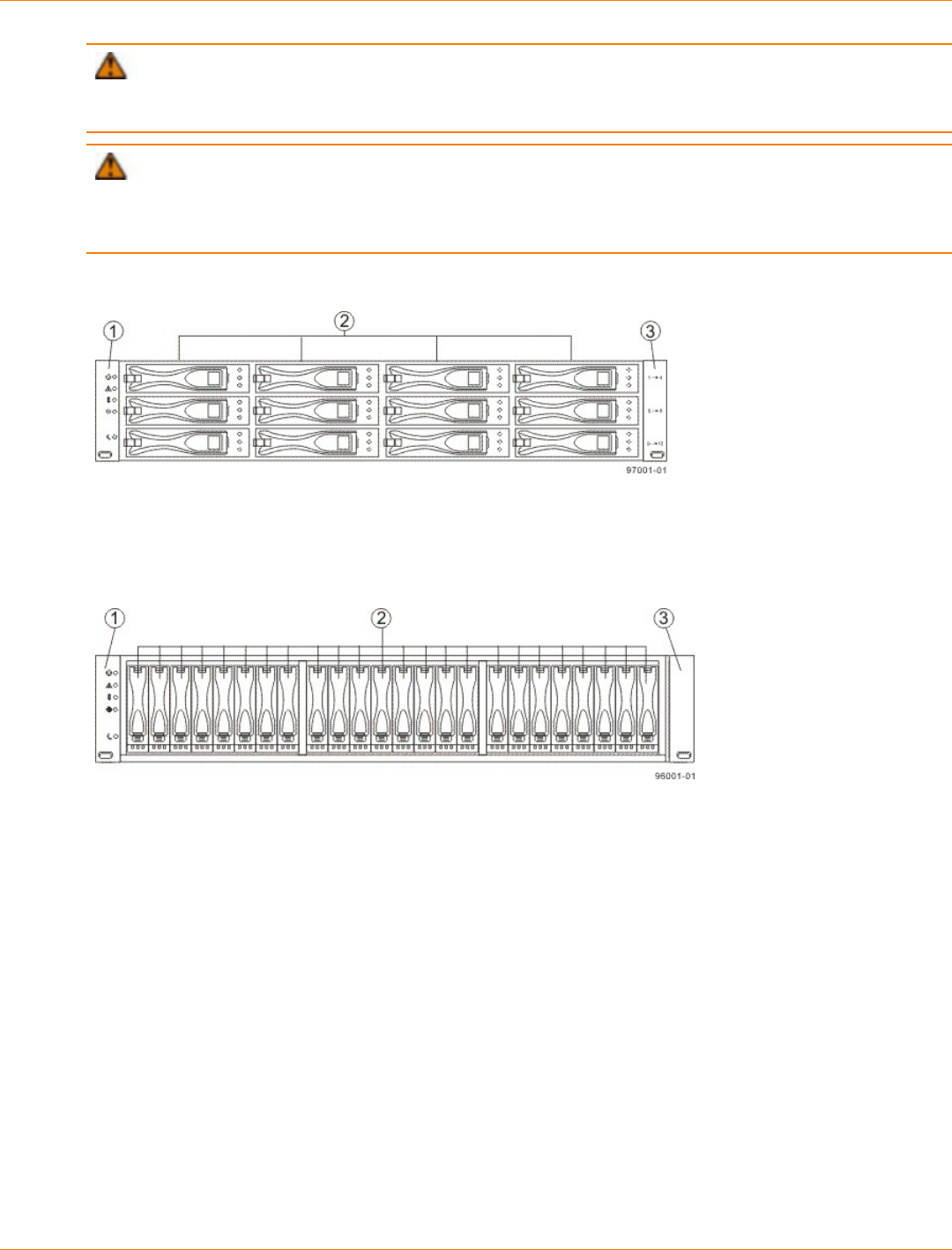
SANtricity_10.77 February 2011
LSI Corporation
- 272 -
ATTENTION Possible equipment damage – You must use the supported drives in the drive tray
to ensure proper performance. For information about supported drives, contact a Customer and Technical
Support representative.
ATTENTION Risk of equipment malfunction – To avoid exceeding the functional and environmental
limits, install only drives that have been provided or approved by the original manufacturer. Not all controller-
drive trays are shipped with pre-populated drives. System integrators, resellers, system administrators, or
users of the controller-drive tray can install the drives.
DE1600 Drive Tray – Front View
1. Left End Cap (Has the Drive Tray LEDs)
2. Drives
3. Right End Cap
DE5600 Drive Tray – Front View
1. Left End Cap (Has the Drive Tray LEDs)
2. Drives
3. Right End Cap
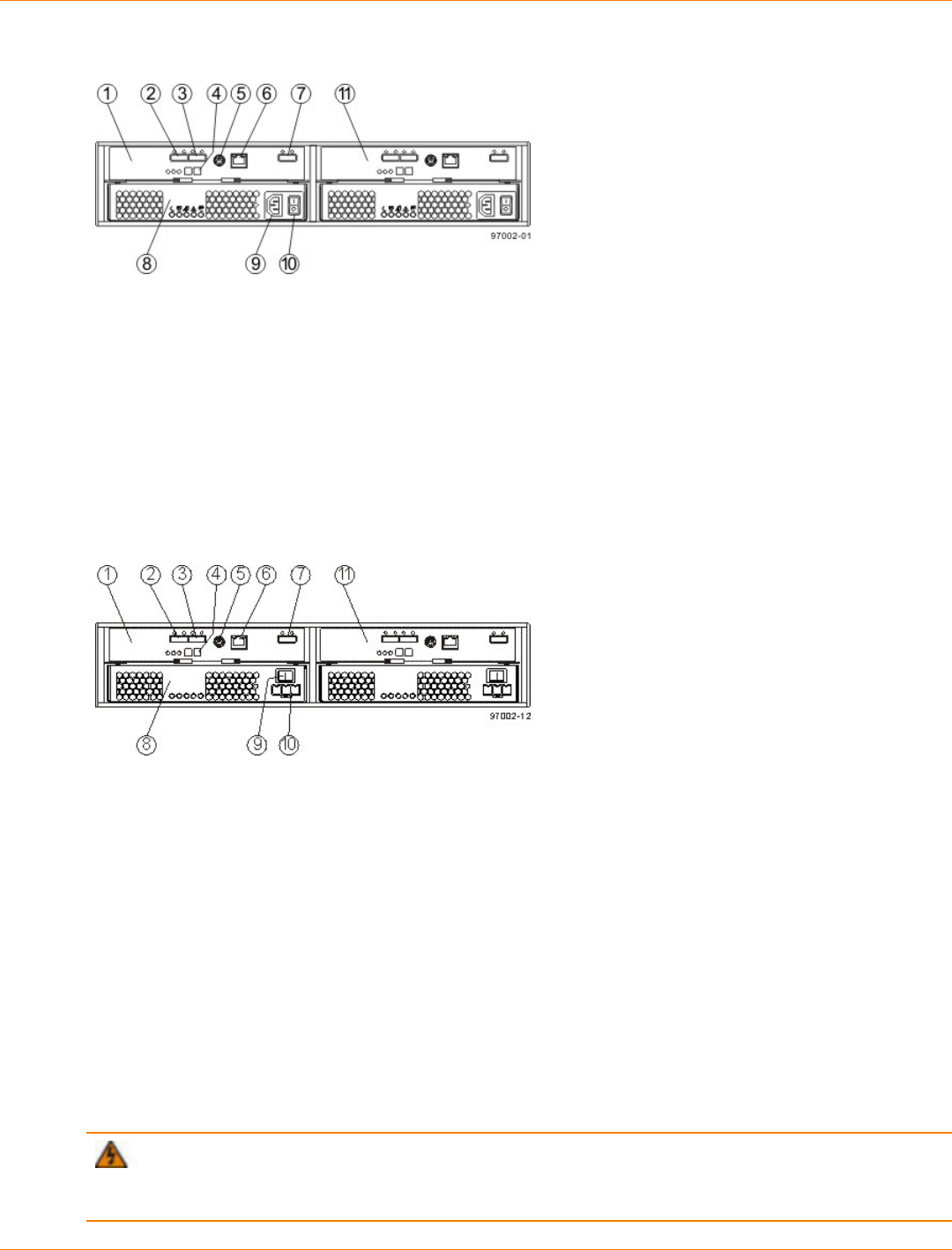
SANtricity_10.77 February 2011
LSI Corporation
- 273 -
DE1600 Drive Tray or DE5600 Drive Tray with AC Power Option – Rear View
1. ESM A Canister
2. Host Connector 1
3. Host Connector 2
4. Seven-Segment Display Indicators
5. Serial Connector
6. Ethernet Connector
7. Expansion Port SFF-8088 Connector
8. Power-Fan Canister
9. Power Connector
10. Power Switch
11. ESM B Canister
DE1600 Drive Tray or DE5600 Drive Tray with DC Power Option – Rear View
1. ESM A Canister
2. Host Connector 1
3. Host Connector 2
4. Seven-Segment Display Indicators
5. Serial Connector
6. Ethernet Connector
7. Expansion Port SFF-8088 Connector
8. Power-Fan Canister
9. Power Connector
10. Power Switch
11. ESM B Canister
You can order an optional DC power supply connection and connector cables for the drive tray. A qualified
service person is required to make the DC power connection per NEC and CEC guidelines. A two-pole
30-amp circuit breaker is required between the DC power source and the drive tray for over-current and short-
circuit protection. Before turning off any power switches on a DC-powered drive tray, you must disconnect the
two-pole 30-amp circuit breaker.
WARNING (W12) Risk of electrical shock – This unit has more than one power source. To remove
all power from the unit, all DC MAINS must be disconnected by removing all power connectors (item 4 below)
from the power supplies.
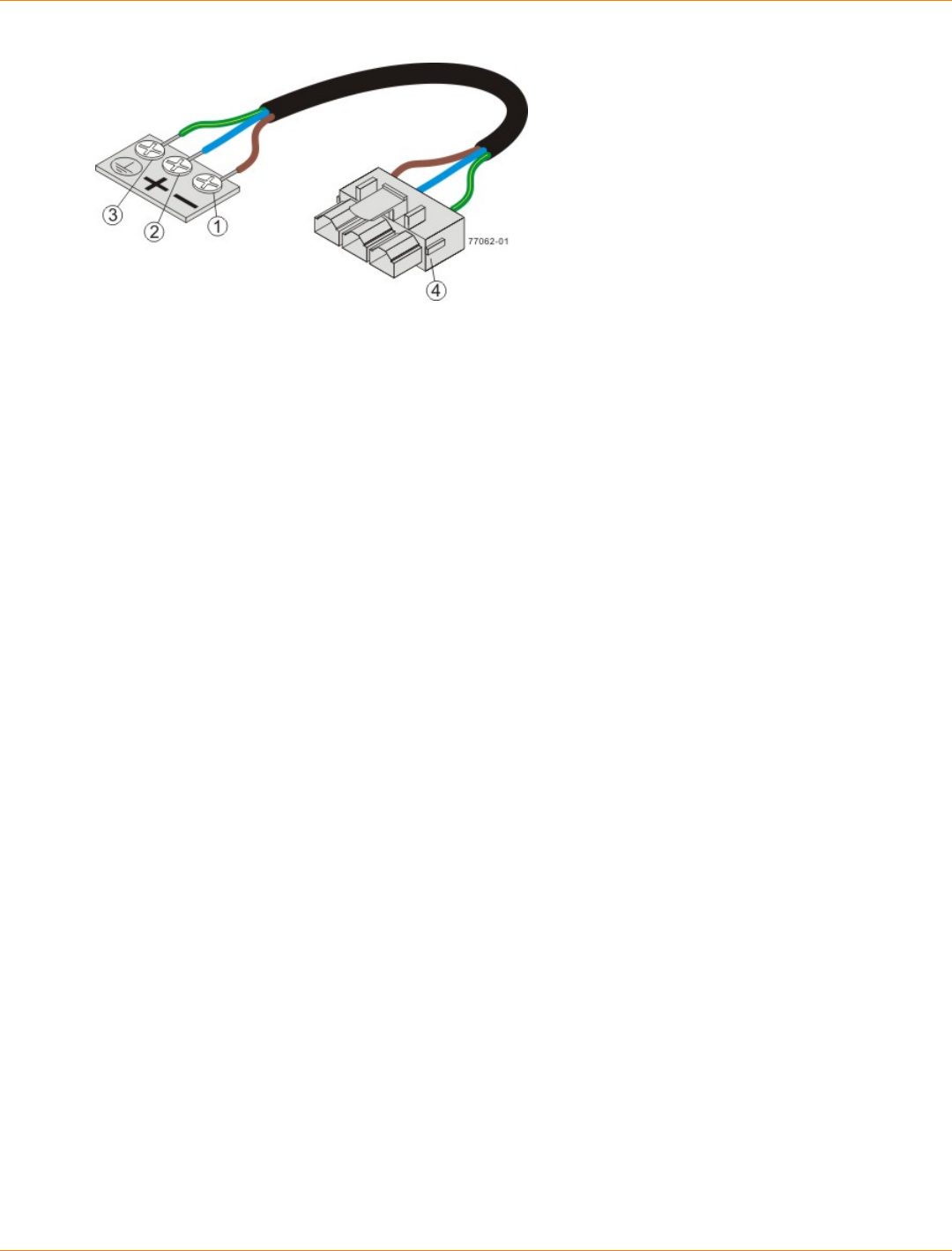
SANtricity_10.77 February 2011
LSI Corporation
- 274 -
1. Supply (Negative), Brown Wire, -48 VDC
2. Return (Positive), Blue Wire
3. Ground, Green/Yellow Wire
4. DC Power Connector
For Additional Information on the CDE2600 Controller-Drive Tray
Configuration
Refer to the Storage System Site Preparation Guide on the SANtricity ES Storage Manager Installation DVD
for information about the installation requirements of the various CDE2600 storage array components.

SANtricity_10.77 February 2011
LSI Corporation
- 275 -
Step 2 – Installing and Configuring the Switches
Things to Know – Switches
IMPORTANT Most of the switches, as shipped from the vendor, require an update to their firmware to
work correctly with the storage array.
Depending on the configuration of your storage array, you might use Fibre Channel switches and iSCSI
switches.
The switches in the following table are certified for use with a CDE2600 storage array, a CDE2600-60 storage
array, a CDE4900 storage array, and a CE7900 storage array, which all use SANtricity ES Storage Manager
Version 10.77.
Supported Switches
Vendor Model Fibre
Channel iSCSI SAS
200E Yes No No
3200 Yes No No
3800 Yes No No
3900 Yes No No
3950 Yes No No
12000 Yes No No
3850 Yes No No
3250 Yes No No
24000 Yes No No
4100 Yes No No
48000 Yes No No
5000 Yes No No
300 Yes No No
5100 Yes No No
5300 Yes No No
7500 Yes No No
7800 Yes No No
Brocade
DCX Yes No No

SANtricity_10.77 February 2011
LSI Corporation
- 276 -
Vendor Model Fibre
Channel iSCSI SAS
FCOE No Yes No
9506 Yes No No
9509 Yes No No
9216 Yes No No
9216i Yes No No
9120 Yes No No
914x Yes No No
9513 Yes No No
9020 Yes No No
MDS9000 Yes No No
9222i Yes No No
9134 Yes No No
Catalyst 2960 No Yes No
Catalyst 3560 No Yes No
Cisco
Catalyst 3750G-24TS No Yes No
LSI 6160 No No Yes
3232 Yes No No
3216 Yes No No
4300 Yes No No
4500 Yes No No
6064 Yes No No
6140 Yes No No
4400 Yes No No
McData
4700 Yes No No
6140 No Yes No
6142 No Yes No
QLogic
SANbox2-8 Yes No No

SANtricity_10.77 February 2011
LSI Corporation
- 277 -
Vendor Model Fibre
Channel iSCSI SAS
SANbox2-16 Yes No No
SANbox5200 Yes No No
SANbox3600 Yes No No
SANbox3800 Yes No No
SANbox5208 Yes No No
SANbox5600 Yes No No
SANbox5800 Yes No No
SANbox9000 Yes No No
5324 No Yes NoPowerConnect
6024 No Yes No
If required, make the appropriate configuration changes for each switch that is connected to the storage array.
Refer to the switch’s documentation for information about how to install the switch and how to use the
configuration utilities that are supplied with the switch.
Procedure – Installing and Configuring Switches
1. Install your switch according to the vendor’s documentation.
2. Use the Compatibility Matrix at the website http://www.lsi.com/compatibilitymatrix/ to obtain this
information:
The latest hardware compatibility information
The models of the switches that are supported
The firmware requirements and the software requirements for the switches
3. Update the switch’s firmware by accessing it from the applicable switch vendor’s website.
This update might require that you cycle power to the switch.
4. Find your switch in the following table to see whether you need to make further configuration changes.
Use your switch’s configuration utility to make the changes.
Supported Switch Vendors and Required Configuration Changes
Switch
Vendor Configuration Changes
Required? Next Step
Brocade Yes
Change the In-Order Delivery
(IOD) option to ON.
Make the change, and go to
“Step 3 – Installing the Host
Bus Adapters for the CDE2600
Controller-Drive Tray.”

SANtricity_10.77 February 2011
LSI Corporation
- 278 -
Switch
Vendor Configuration Changes
Required? Next Step
Cisco Yes
Change the In-Order Delivery
(IOD) option to ON.
Make the change, and go to
“Step 3 – Installing the Host
Bus Adapters for the CDE2600
Controller-Drive Tray.”
LSI No “Step 3 – Installing the Host
Bus Adapters for the CDE2600
Controller-Drive Tray.”
McData No “Step 3 – Installing the Host
Bus Adapters for the CDE2600
Controller-Drive Tray.”
QLogic No “Step 3 – Installing the Host
Bus Adapters for the CDE2600
Controller-Drive Tray.”
PowerConnect No “Step 3 – Installing the Host
Bus Adapters for the CDE2600
Controller-Drive Tray.”

SANtricity_10.77 February 2011
LSI Corporation
- 279 -
Step 3 – Installing the Host Bus Adapters for the CDE2600
Controller-Drive Tray
Key Terms
HBA host port
The physical and electrical interface on the host bus adapter (HBA) that provides for the connection between
the host and the controller. Most HBAs will have either one or two host ports. The HBA has a unique World
Wide Identifier (WWID) and each HBA host port has a unique WWID.
HBA host port world wide name
A 16-character unique name that is provided for each port on the host bus adapter (HBA).
host bus adapter (HBA)
A physical board that resides in the host. The HBA provides for data transfer between the host and the
controllers in the storage array over the I/O host interface. Each HBA contains one or more physical ports.
Things to Know – Host Bus Adapters and Ethernet Network Interface Cards
The CDE2600 controller-drive tray supports dual 6-Gb/s SAS host connections and optional host interface
cards (HICs) for dual 6-Gb/s SAS, four 1-Gb/s iSCSI, two 10-Gb iSCSI, and four 8-Gb/s FC connections.
The connections on a host must match the type (SAS HBAs for SAS, FC HBAs for FC, or iSCSI HBAs or
Ethernet network interface cards [NICs] for iSCSI) of the HICs to which you connect them. For the best
performance, HBAs for SAS and FC connections should support the highest data rate supported by the
HICs to which they connect.
For maximum hardware redundancy, you must install a minimum of two HBAs (for either SAS or FC host
connections) or two NICs or iSCSI HBAs (for iSCSI host connections) in each host. Using both ports of a
dual-port HBA or a dual-port NIC provides two paths to the storage array but does not ensure redundancy
if an HBA or a NIC fails.
NOTE You can use the Compatibility Matrix to obtain information about the supported models of the
HBAs and their requirements. Go to http://www.lsi.com/compatibilitymatrix/, and select the desired Developer
Partner Program link. Check its Compatibility Matrix to make sure you have an acceptable configuration.
Most of the HBAs, as shipped from the vendor, require updated firmware and software drivers to work
correctly with the storage array. For information about the updates, refer to the website of the HBA
vendor.
Procedure – Installing Host Bus Adapters
1. Go to http://www.lsi.com/compatibilitymatrix/, and select the desired Developer Partner Program link.
Check its Compatibility Matrix to make sure you have an acceptable configuration.
The Compatibility Matrix provides this information:
The latest hardware compatibility information
The models of the HBAs that are supported
The firmware requirements and the software requirements for the HBAs
2. Install your HBA according to the vendor documentation.

SANtricity_10.77 February 2011
LSI Corporation
- 280 -
NOTE If your operating system is Windows Server 2008 Server Core, you might have additional
installation requirements. Refer to the Microsoft Developers Network (MSDN) for more information about
Windows Server 2008 Server Core. You can access these resources from www.microsoft.com.
3. Install the latest version of the firmware for the HBA. You can find the latest version of the firmware for the
HBA at the HBA vendor website.
IMPORTANT The remaining steps are general steps to obtain the HBA host port World Wide Name
from the HBA BIOS utility. If you have installed the host context agent on all of your hosts, you do not need
to perform these steps. If you are performing these steps, the actual prompts and screens vary depending
on the vendor that provides the HBA. Also, some HBAs have software utilities that you can use to obtain the
world wide name for the port instead of using the BIOS utility.
4. Reboot or start your host.
5. While your host is booting, look for the prompt to access the HBA BIOS utility.
6. Select each HBA to view its HBA host port world wide name.
7. Record the following information for each host and for each HBA connected to the storage array:
The name of each host
The HBAs in each host
The HBA host port world wide name of each port on the HBA
The following table shows examples of the host and HBA information that you must record.
Examples of HBA Host Port World Wide Names
Host Name Associated HBAs HBA Host Port World
Wide Name
Vendor x, Model y (dual port) 37:38:39:30:31:32:33:32
37:38:39:30:31:32:33:33
ICTENGINEERING
Vendor a, Model y (dual port) 42:38:39:30:31:32:33:42
42:38:39:30:31:32:33:44
Vendor a, Model b (single
port) 57:38:39:30:31:32:33:52ICTFINANCE
Vendor x, Model b (single
port) 57:38:39:30:31:32:33:53
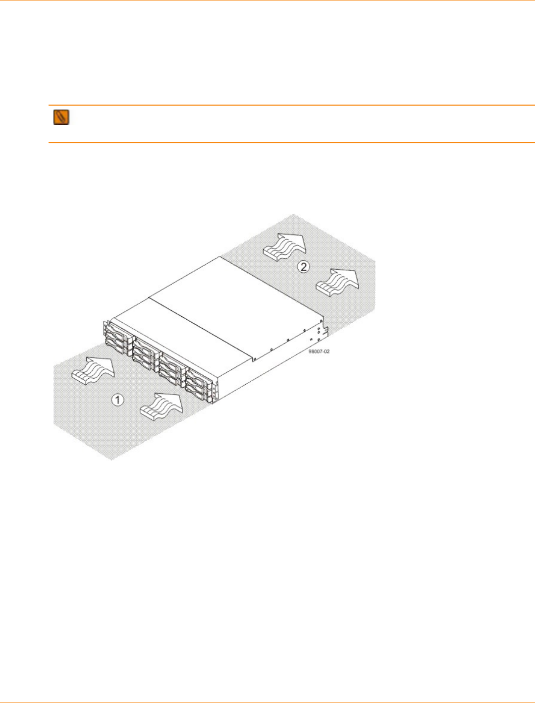
SANtricity_10.77 February 2011
LSI Corporation
- 281 -
Step 4 – Installing the CDE2600 Controller-Drive Tray
Things to Know – General Installation
The power supplies meet standard voltage requirements for both domestic and worldwide operation.
IMPORTANT Make sure that the combined power requirements of your trays do not exceed the power
capacity of your cabinet.
Procedure – Installing the CDE2600 Controller-Drive Tray
Airflow Direction Through and Clearance Requirements for the CDE2600 Controller-Drive Tray with 12
Drives
1. 76-cm (30-in.) clearance in front of the cabinet
2. 61-cm (24-in.) clearance behind the cabinet
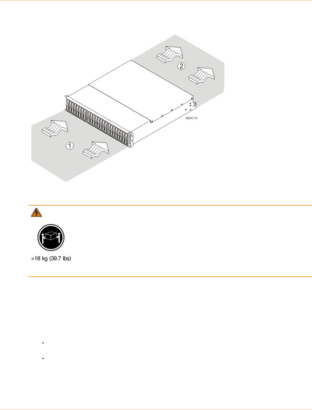
SANtricity_10.77 February 2011
LSI Corporation
- 282 -
Airflow Direction Through and Clearance Requirements for the CDE2600 Controller-Drive Tray with 24
Drives
1. 76-cm (30-in.) clearance in front of the cabinet
2. 61-cm (24-in.) clearance behind the cabinet
WARNING (W08) Risk of bodily injury –
Two persons are required to safely lift the component.
1. Make sure that the cabinet is in the final location. Make sure that the cabinet installation site meets the
clearance requirements (see the previous two figures for “Airflow Direction Through and Clearance
Requirements for the CDE2600 Controller-Drive Tray with 12 Drives" and "Airflow Direction Through and
Clearance Requirements for the CDE2600 Controller-Drive Tray with 24 Drives").
2. Lower the feet on the cabinet, if required, to keep it from moving.
3. Install the mounting rails in the cabinet. For more information, refer to the installation instructions that are
included with your mounting rails.
If you are installing the mounting rails above an existing tray, position the mounting rails directly
above the existing tray.
If you are installing the mounting rails below an existing tray, allow 17.8-cm (7.00-in.) clearance below
the existing tray.
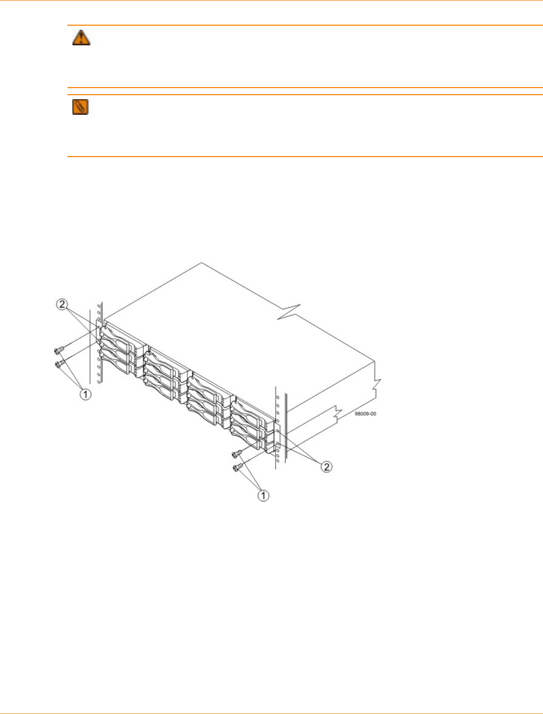
SANtricity_10.77 February 2011
LSI Corporation
- 283 -
ATTENTION Risk of equipment malfunction – To avoid exceeding the functional and
environmental limits, install only drives that have been provided or approved by the original manufacturer.
Not all controller-drive trays are shipped with pre-populated drives. System integrators, resellers, system
administrators, or users of the controller-drive tray can install the drives.
NOTE Make sure that you place the controller-drive tray in the middle portion of the cabinet while
allowing room for drive trays to be placed above and below the controller-drive tray. As you add drive
trays, position them below and above the controller-drive tray, alternating so that the cabinet does not
become top heavy.
4. With the help of one other person, slide the rear of the controller-drive tray onto the mounting rails. Make
sure that the top mounting holes on the controller-drive tray align with the mounting rail holes of the
cabinet (see the following two figures for "Securing the CDE2600 Controller-Drive Tray with 12 Drives to
the Cabinet" and "Securing the CDE2600 Controller-Drive Tray with 24 Drives to the Cabinet").
The rear of the controller-drive tray slides into the slots on the mounting rails.
Securing the CDE2600 Controller-Drive Tray with 12 Drives to the Cabinet
1. Screws
2. Mounting Holes
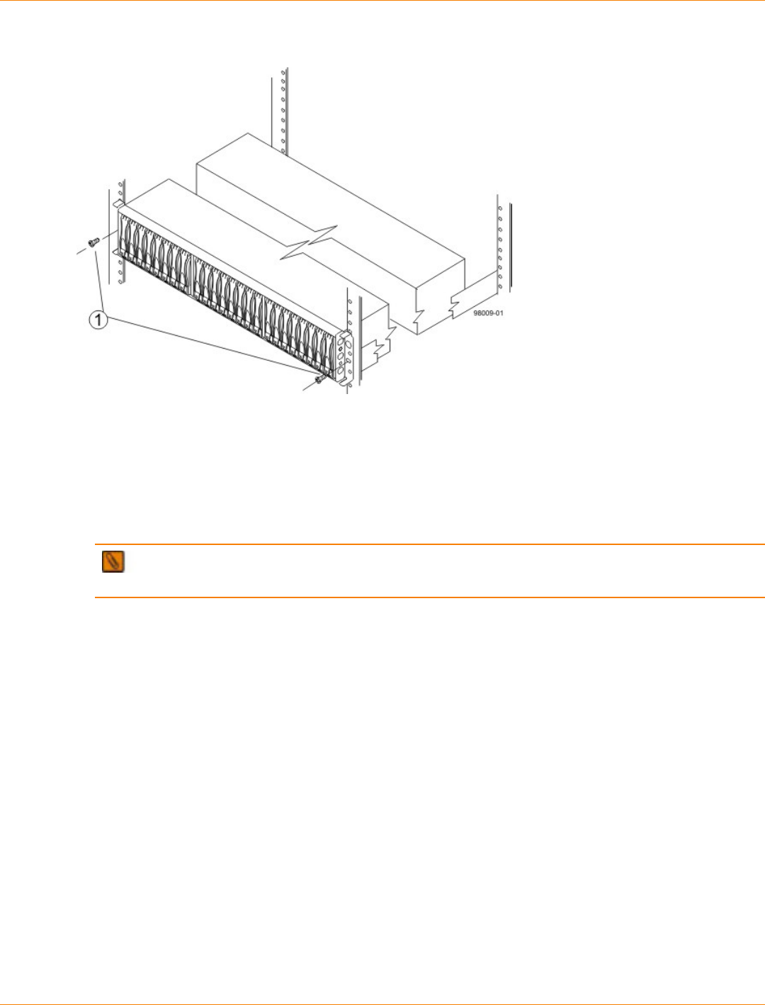
SANtricity_10.77 February 2011
LSI Corporation
- 284 -
Securing the CDE2600 Controller-Drive Tray with 24 Drives to the Cabinet
1. Screws
NOTE The rear of the controller-drive tray contains two controllers. The top of the controller-drive
tray is the side with the labels.
5. Secure the screws in the top mounting holes and the bottom mounting holes on each side of the
controller-drive tray.
6. Secure the rear of the of the controller-drive tray to the cabinet by using two screws to attach the flanges
on each side at the rear of the controller-drive tray to the mounting rails.
7. Install the bezel on the front of the controller-drive tray.
8. Install the drive trays. Refer to Step 7 – Connecting the CDE2600 Controller-Drive Tray to the Drive
Trays.

SANtricity_10.77 February 2011
LSI Corporation
- 285 -
Step 5 – Connecting the CDE2600 Controller-Drive Tray to the
Hosts
Key Terms
direct topology
A topology that does not use a switch.
switch topology
A topology that uses a switch.
topology
The logical layout of the components of a computer system or network and their interconnections. Topology
deals with questions of what components are directly connected to other components from the standpoint
of being able to communicate. It does not deal with questions of physical location of components or
interconnecting cables. (The Dictionary of Storage Networking Terminology)
Things to Know – Host Channels
ATTENTION Possible hardware damage – To prevent electrostatic discharge damage to the tray,
use proper antistatic protection when you handle tray components.
Each controller has from two to six host ports.
Two of the host ports are standard and support 6-Gb/s SAS data rates.
Two to four of the host ports are optional, and, if present, are located on a host interface card (HIC). The
following types of HICs are supported:
NOTE In configurations where a HIC does not exist, the space is covered with a blank faceplate.
Two SAS connectors at 6-Gb/s
Four iSCSI connectors at 1-Gb/s
Two iSCSI connectors at 10-Gb/s
Four FC connectors at 8-Gb/s
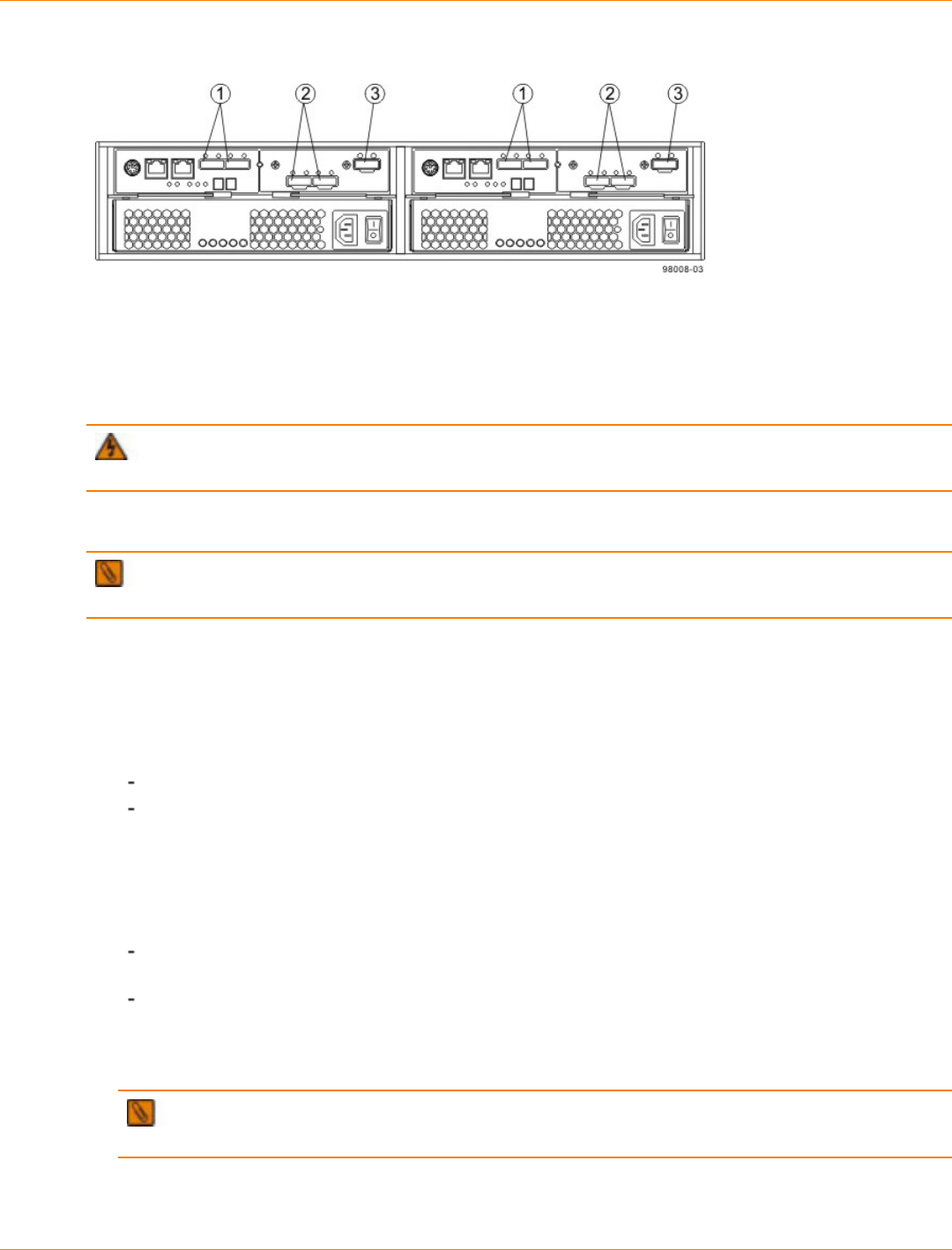
SANtricity_10.77 February 2011
LSI Corporation
- 286 -
Host Channels on the Controllers – Rear View
1. Standard Host Connectors
2. Host Interface Card (HIC) Connectors (SAS in this Example)
3. SAS Expansion Connector
WARNING (W03) Risk of exposure to laser radiation – Do not disassemble or remove any part of a
Small Form-factor Pluggable (SFP) transceiver because you might be exposed to laser radiation.
Procedure – Connecting Host Cables on a CDE2600 Controller-Drive Tray
IMPORTANT Make sure that you have installed the HBAs. Refer to the documentation for the HBAs for
information about how to install the HBA and how to use the supplied configuration utilities.
The type of HICs (SAS, FC, or iSCSI) must match the type of the host bus adapters (HBAs) or network
interface cards (for iSCSI only) to which you connect them.
See the examples in the following section for example cabling patterns.
1. Perform one of these actions:
You are using an FC HIC – Go to step 2.
You are using either a SAS or an iSCSI HIC – Go to step 4. Connections for both SAS and iSCSI
use copper cables with RJ-45 connectors and do not require SFP transceivers.
2. Make sure that the appropriate type of SFP transceiver is inserted into the host channel.
3. If a black, plastic plug is in the SFP transceiver, remove it.
4. Perform one of these actions:
You are using either a SAS or an iSCSI HIC – Starting with the first host channel of each controller,
plug one end of the cable into the host channel.
You are using an FC HIC – Starting with the first host channel of each controller, plug one end of the
cable into the SFP transceiver in the host channel.
The cable is either an Ethernet cable with RJ-45 connectors for 1-Gb/s iSCSI or 6-Gb/s SAS connections,
or a fiber-optic cable for FC connections.
IMPORTANT If Remote Volume Mirroring connections are required, do not connect a host to the
highest numbered host channel.
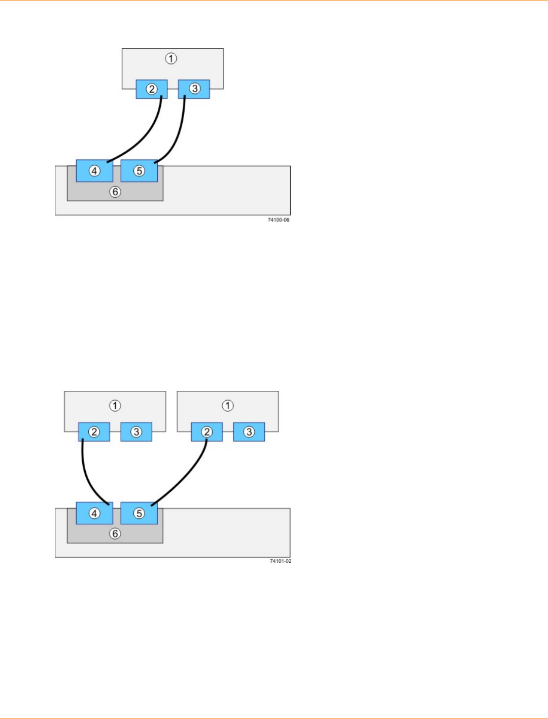
SANtricity_10.77 February 2011
LSI Corporation
- 287 -
Direct Topology – One Host Connected to a SingleController
1. Host
2. HBA 1 or NIC 1
3. HBA 2 or NIC 2
4. Host Port 1
5. Host Port 2
6. Controller A
Direct Topology – Two Hosts Connected to a Single Controller
1. Host
2. HBA 1 or NIC 1
3. HBA 2 or NIC 2
4. Host Port 1
5. Host Port 2
6. Controller A

SANtricity_10.77 February 2011
LSI Corporation
- 288 -
Switch Topology – Two Hosts Connected to a Single Controller Through a Switch
1. Host
2. HBA 1 or NIC 1
3. HBA 2 or NIC 2
4. Host Port 1
5. Host Port 2
6. Controller A
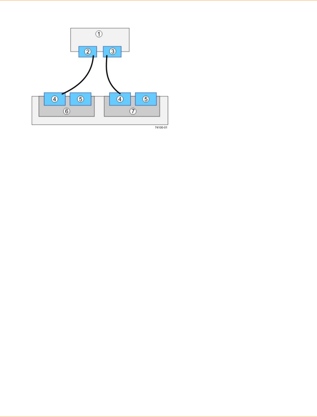
SANtricity_10.77 February 2011
LSI Corporation
- 289 -
Direct Topology – One Host and a Dual Controller-Drive Tray
1. Host
2. HBA 1 or NIC 1
3. HBA 2 or NIC 2
4. Host Port 1
5. Host Port 2
6. Controller A
7. Controller B
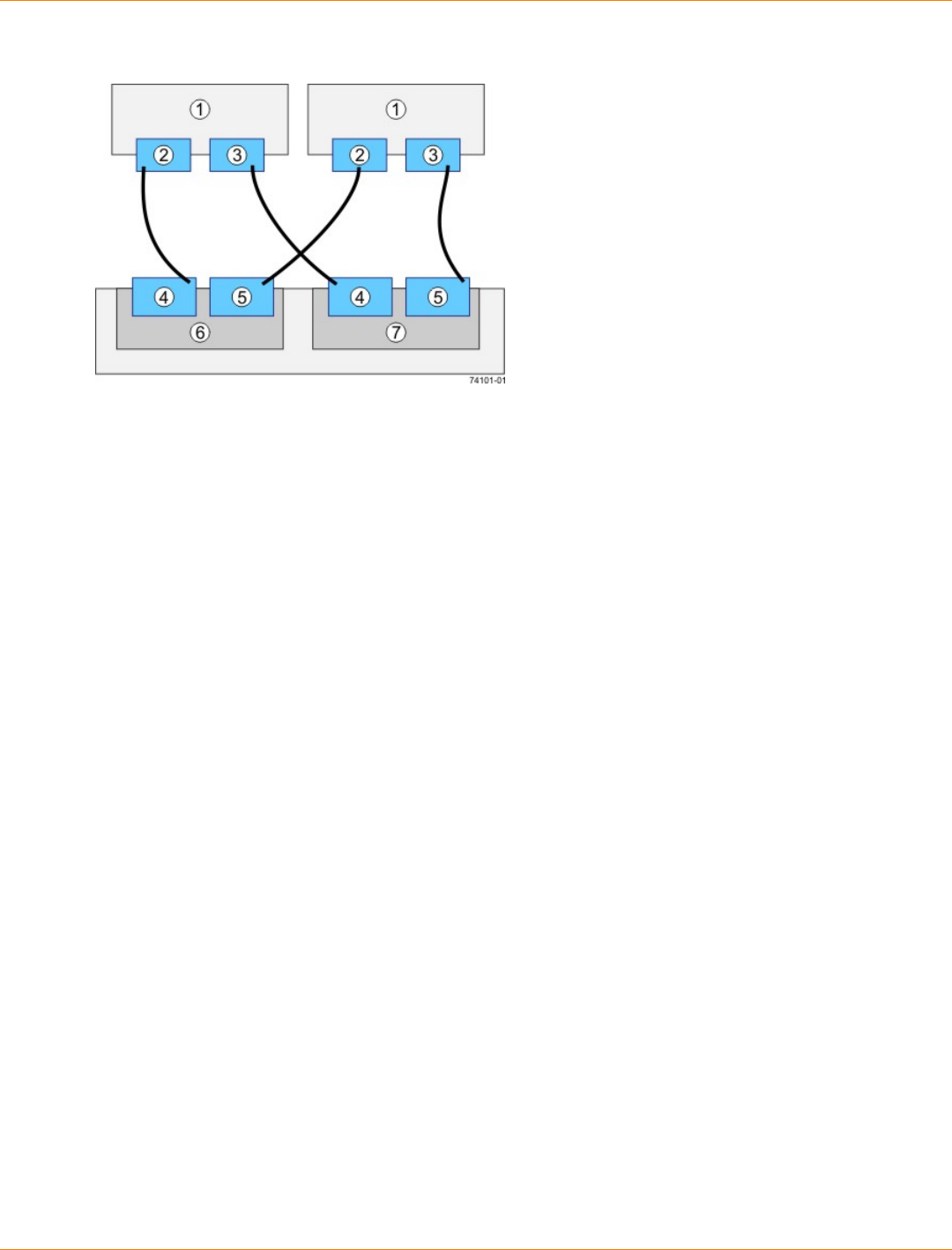
SANtricity_10.77 February 2011
LSI Corporation
- 290 -
Direct Topology – Two Hosts and a Dual Controller-Drive Tray for Maximum Redundancy
1. Hosts
2. HBA 1 or NIC 1
3. HBA 2 or NIC 2
4. Host Port 1
5. Host Port 2
6. Controller A
7. Controller B
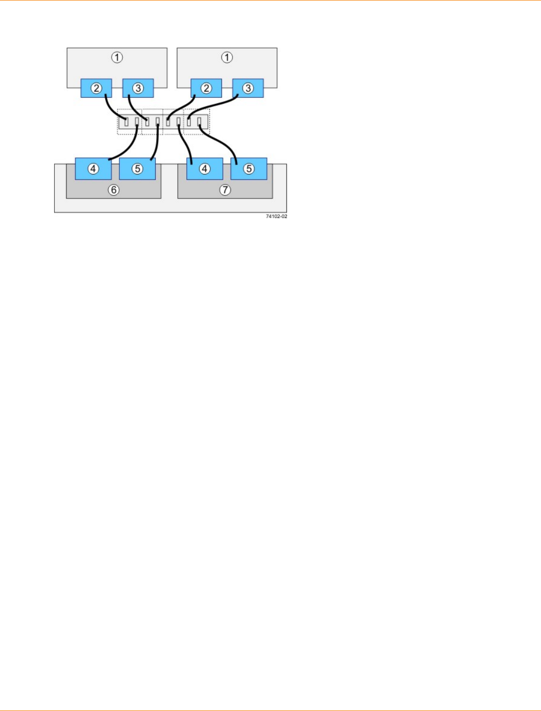
SANtricity_10.77 February 2011
LSI Corporation
- 291 -
Mixed Topology – Two Hosts and a Dual Controller-Drive Tray
1. Hosts
2. HBA 1 or NIC 1
3. HBA 2 or NIC 2
4. Host Port 1
5. Host Port 2
6. Controller A
7. Controller B
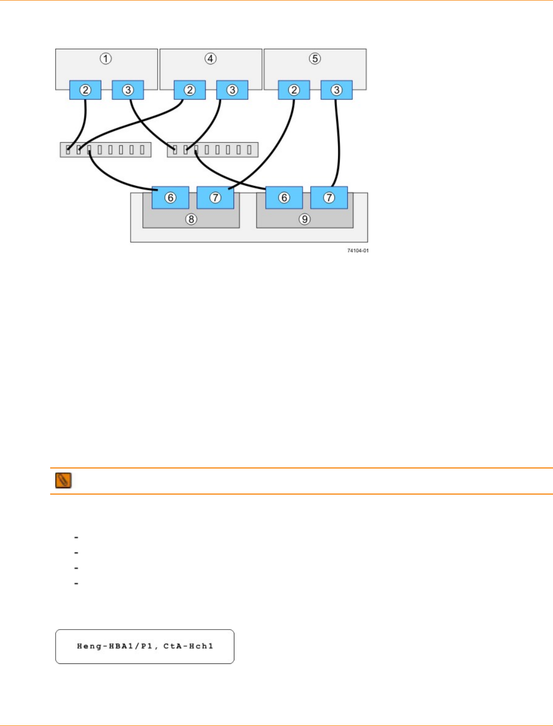
SANtricity_10.77 February 2011
LSI Corporation
- 292 -
Mixed Topology – Three Hosts and a Dual Controller-Drive Tray
1. Host 1
2. HBA 1 or NIC 1
3. HBA 2 or NIC 2
4. Host 2
5. Host 3
6. Host Port 1
7. Host Port 2
8. Controller A
9. Controller B
5. Plug the other end of the cable either into an HBA in the host (direct topology) or into a switch (fabric
topology).
NOTE The SAS host interface does not support a switch topology.
6. Affix a label to each end of the cable with this information. A label is very important if you need to
disconnect cables to service a controller. Include this information on the labels:
The host name and the HBA port (for direct topology)
The switch name and the port (for fabric topology)
The controller ID (for example, controller A)
The host channel ID (for example, host channel 1)
Example label abbreviation – Assume that a cable is connected between port 1 in HBA 1 of a host
named Engineering and host channel 1 of controller A. A label abbreviation could be as follows.
7. Repeat step 3 through step 6 for each controller and host channel that you intend to use.
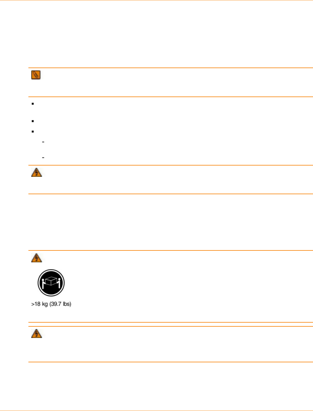
SANtricity_10.77 February 2011
LSI Corporation
- 293 -
Step 6 – Installing the Drive Trays for the CDE2600 Controller-
Drive Tray Configurations
Things to Know – General Installation of Drive Trays with the CDE2600
Controller-Drive Tray
IMPORTANT If you are installing the drive tray in a cabinet with other trays, make sure that the
combined power requirements of the drive tray and the other trays do not exceed the power capacity of your
cabinet. For more information, refer to the SANtricity ES Storage Manager Installation DVD.
Special site preparation is not required for any of these drive trays beyond what is normally found in a
computer lab environment.
The power supplies meet standard voltage requirements for both domestic and worldwide operation.
Take these precautions:
Install the drive trays in locations within the cabinet that let you evenly distribute the drive trays
around the controller-drive tray.
Keep as much weight as possible in the bottom half of the cabinet.
WARNING (W15) Risk of bodily injury – An empty tray weighs approximately 56.7 kg (125 lb).
Three persons are required to safely move an empty tray. If the tray is populated with components, a
mechanized lift is required to safely move the tray.
For Additional Information on Drive Tray Installation
Refer to the Storage System Site Preparation Guide on the SANtricity ES Storage Manager Installation DVD
for important considerations about cabinet installation.
Procedure – Installing the DE1600 Drive Tray and the DE5600 Drive Tray
WARNING (W08) Risk of bodily injury –
Two persons are required to safely lift the component.
WARNING (W05) Risk of bodily injury – If the bottom half of the cabinet is empty, do not install
components in the top half of the cabinet. If the top half of the cabinet is too heavy for the bottom half, the
cabinet might fall and cause bodily injury. Always install a component in the lowest available position in the
cabinet.
You can install the drive tray into an industry standard cabinet.
This procedure describes how to install the mounting rails into an industry standard cabinet.
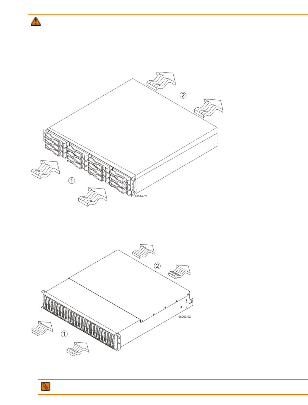
SANtricity_10.77 February 2011
LSI Corporation
- 294 -
ATTENTION Possible hardware damage – To prevent electrostatic discharge damage to the tray,
use proper antistatic protection when handling tray components.
1. Make sure that the cabinet is in the final location. Make sure that you meet the clearance requirements
shown in the following two figures.
DE1600 Drive Tray Airflow and Clearance Requirements
1. 76 cm (30 in.) clearance in front of the cabinet
2. 61 cm (24 in.) clearance behind the cabinet
DE5600 Drive Tray Airflow and Clearance Requirements
1. 76 cm (30 in.) clearance in front of the cabinet
2. 61 cm (24 in.) clearance behind the cabinet
NOTE Fans pull air through the tray from front to back across the drives.
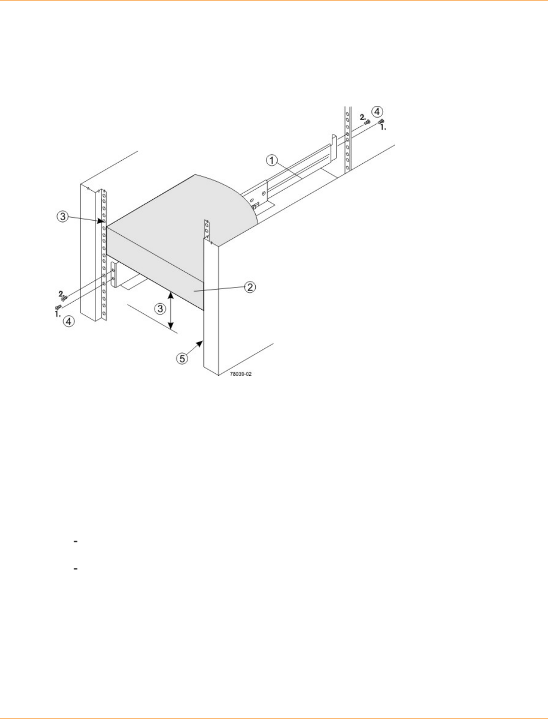
SANtricity_10.77 February 2011
LSI Corporation
- 295 -
2. Lower the feet on the cabinet to keep the cabinet from moving.
3. Remove the drive tray and all contents from the shipping carton.
4. Position the mounting rails in the cabinet.
Positioning the Mounting Rails in the Cabinet
1. Mounting Rail
2. Existing Tray
3. Clearance Above and Below the Existing Tray
4. Screws for Securing the Mounting Rail to the Cabinet (Front and Rear)
5. Industry Standard Cabinet
If you are installing the mounting rails above an existing tray, position the mounting rails directly
above the tray.
If you are installing the mounting rails below an existing tray, allow 8.8-cm (3.5-in.) vertical clearance
for a drive tray or a controller-drive tray.
5. Attach the mounting rails to the cabinet by performing these substeps:
a. Make sure that the adjustment screws on the mounting rail are loose so that the mounting rail can
extend or contract as needed.

SANtricity_10.77 February 2011
LSI Corporation
- 296 -
Attaching the Mounting Rails to the Cabinet
1. Cabinet Mounting Holes
2. Adjustment Screws for Locking the Mounting Rail Length
3. Mounting Rails
4. Clip for Securing the Rear of the Drive Tray
b. Place the mounting rail inside the cabinet, and extend the mounting rail until the flanges on the
mounting rail touch the inside of the cabinet.
c. Make sure that the alignment spacers on the front flange of the mounting rail fit into the mounting
holes in the cabinet.
The front flange of each mounting rail has two alignment spacers. The alignment spacers are
designed to fit into the mounting holes in the cabinet. The alignment spacers help position and hold
the mounting rail.
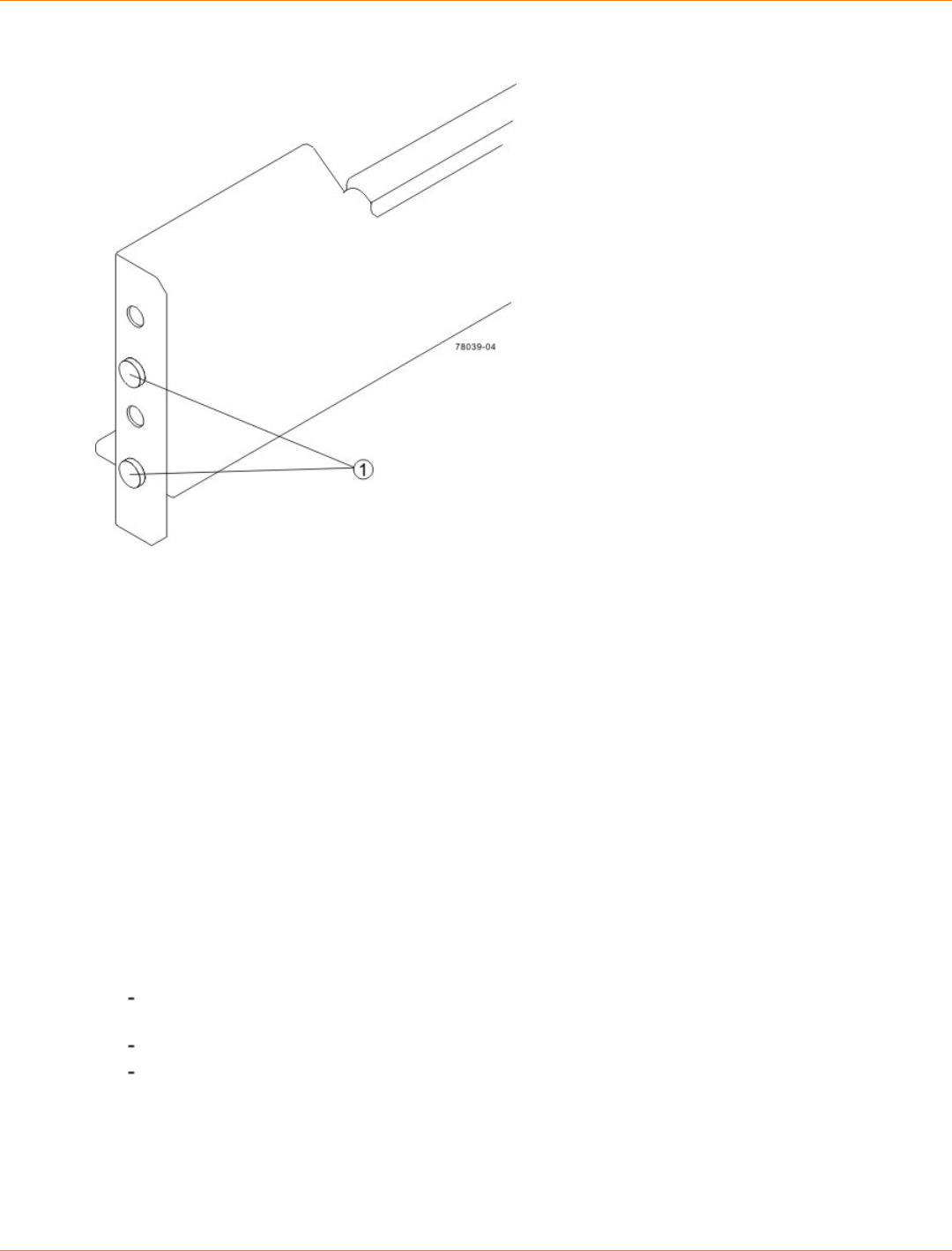
SANtricity_10.77 February 2011
LSI Corporation
- 297 -
Alignment Spacers on the Mounting Rail
1. Alignment Spacers
d. Insert one M5 screw through the front of the cabinet and into the top captured nut in the mounting rail.
Tighten the screw.
e. Insert two M5 screws through the rear of the cabinet and into the captured nuts in the rear flange in
the mounting rail. Tighten the screws.
f. Tighten the adjustment screws on the mounting rail.
g. Repeat substep a through substep f to install the second mounting rail.
6. With the help of one other person, slide the rear of the drive tray onto the mounting rails. The rear edge
of the drive tray must fit into the clip on the mounting rail. The drive tray is correctly aligned when these
conditions are met:
The mounting holes on the front flanges of the drive tray align with the mounting holes on the front of
the mounting rails.
The rear edge of the drive tray sheet metal fits into the clip on the mounting rail.
The holes in the drive tray sheet metal for the rear hold-down screws align with the captured nuts in
the side of the mounting rails.
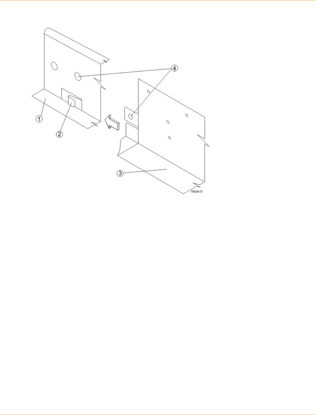
SANtricity_10.77 February 2011
LSI Corporation
- 298 -
Sliding the Drive Tray into the Clip on the Mounting Rail
1. Mounting Rail
2. Clip
3. Partial View of the Drive Tray Rear Sheet Metal
4. Align the hole in the drive tray sheet metal with the captured nut in the mounting rail.
7. Secure the front of the drive tray to the cabinet. Use the two screws to attach the flange on each side of
the front of the drive tray to the mounting rails.
a. Insert one M5 screw through the bottom hole of a flange on the drive tray so that the screw goes
through the cabinet rail and engages the bottom captured nut in the mounting rail. Tighten the screw.
b. Repeat substep a for the second flange.
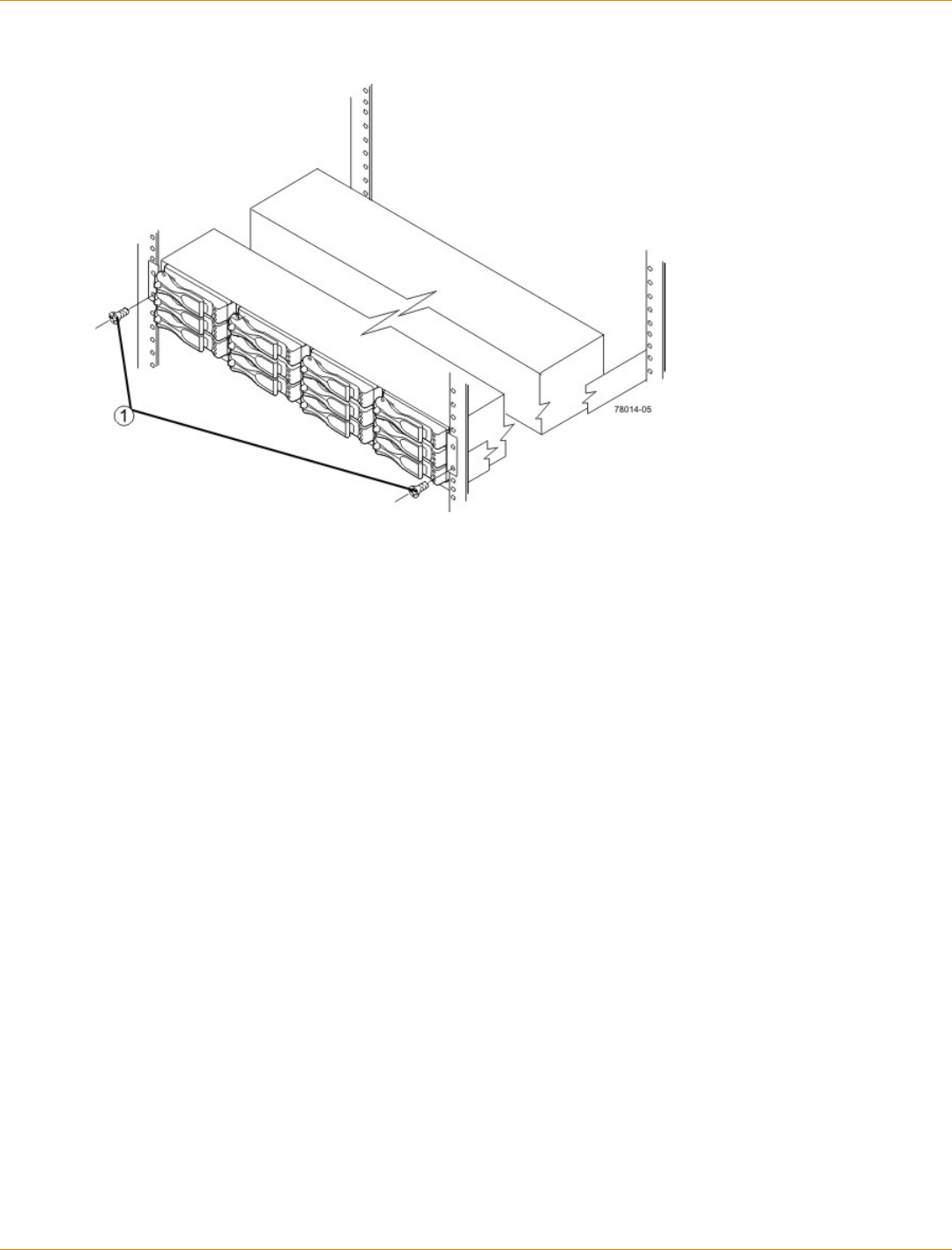
SANtricity_10.77 February 2011
LSI Corporation
- 299 -
Attaching the Front of the DE1600 Drive Tray
1. Screws for Securing the Front of the Drive Tray
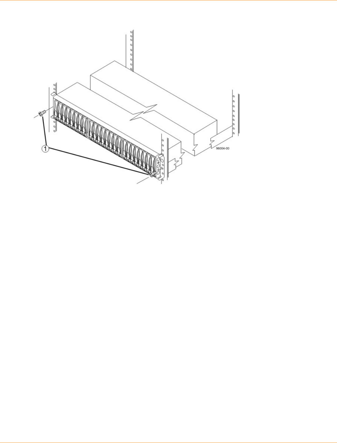
SANtricity_10.77 February 2011
LSI Corporation
- 300 -
Attaching the Front of the Drive Tray
1. Screws for Securing the Front of the Drive Tray
8. Secure the side of the drive tray to the mounting rails by performing these substeps:
a. Insert one M4 screw through the side sheet metal of the drive tray into the captured nut on the side of
the mounting rail. Tighten the screw.
b. Repeat substep a for the other side.
9. Attach the plastic end caps onto the front of the drive tray.
a. Put the top of the end cap on the hinge tab that is part of the drive tray mounting flange.
b. Gently press on the bottom of the end cap until it snaps into place over the retainer on the bottom of
the drive tray mounting flange.
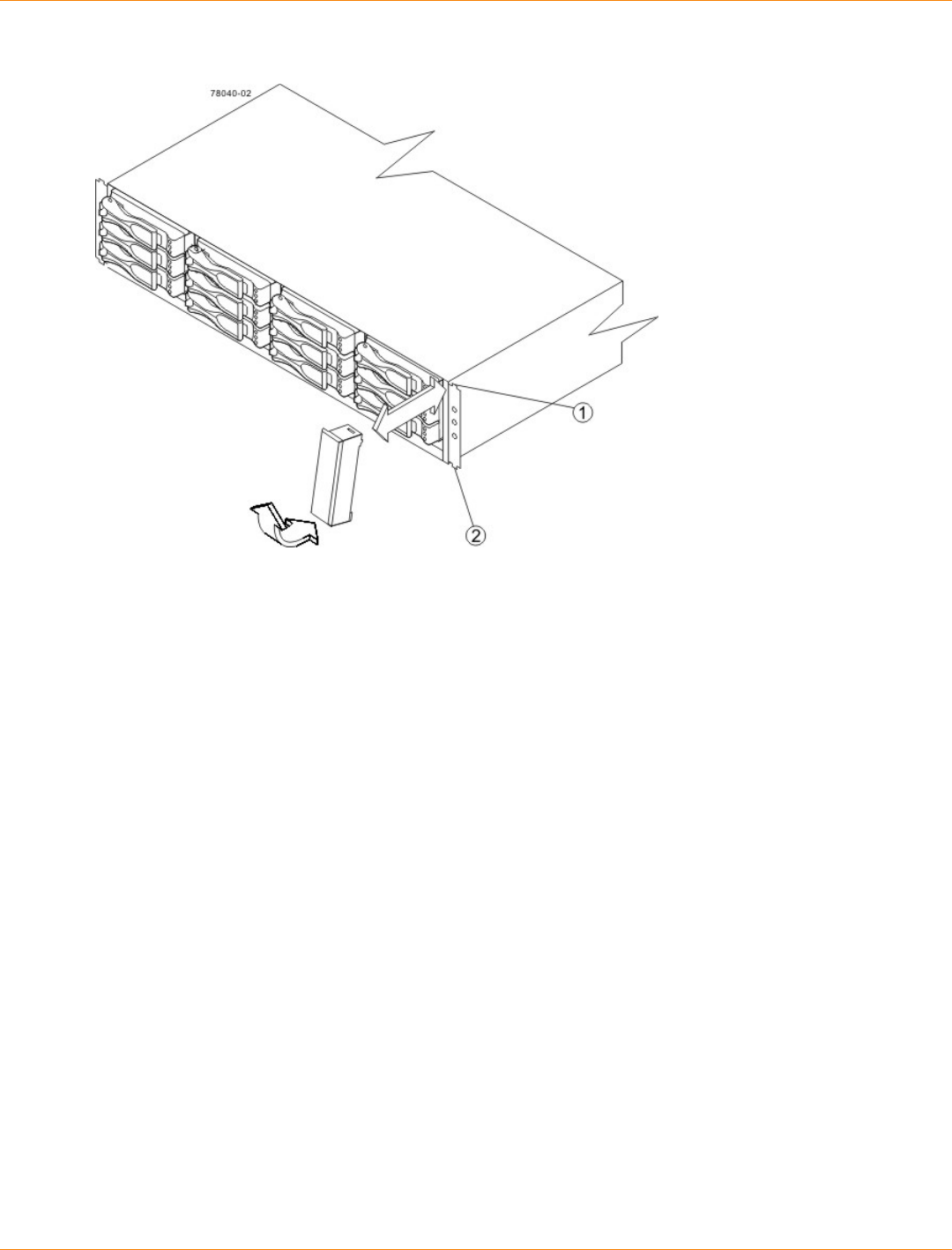
SANtricity_10.77 February 2011
LSI Corporation
- 301 -
Attaching the End Caps to the DE1600 Drive Tray
1. Hinge Tab
2. Retainer
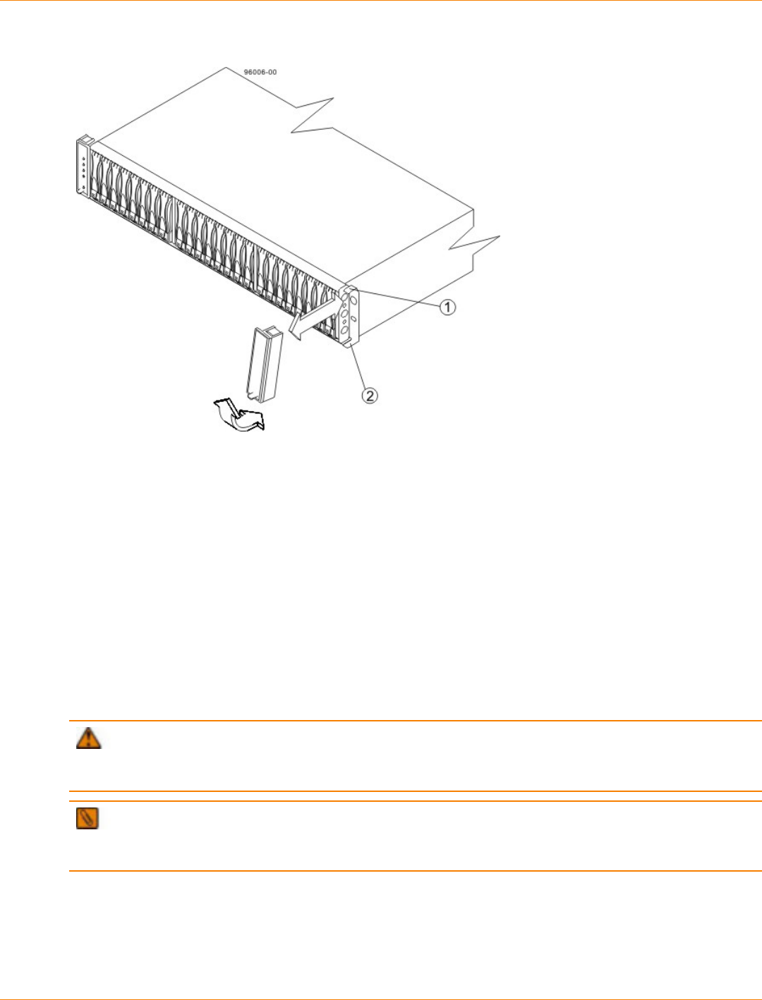
SANtricity_10.77 February 2011
LSI Corporation
- 302 -
Attaching the End Caps to the DE5600 Drive Tray
1. Hinge Tab
2. Retainer
Procedure – Installing Drives for the DE1600 and the DE5600 Drive Trays
In some situations, the drive tray might be delivered without the drives installed. Follow the steps in this
procedure to install the drives. If your drive tray already has drives installed, you can skip this step and go to
either “Things to Know – AC Power Cords” or “Things to Know – DC Power Cords.”
ATTENTION Risk of equipment malfunction – To avoid exceeding the functional and environmental
limits, install only drives that have been provided or approved by the original manufacturer. Drives might be
shipped but not installed. System integrators, resellers, system administrators, or users can install the drives.
NOTE The installation order is from top to bottom and left to right. The installation order is important
because the drives might already contain configuration information that depends upon the correct sequence
of the drives in the tray.
1. Beginning with the first drive slot in the upper-left side of the drive tray, place the drive on the slot guides,
and slide the drive all the way into the slot.
2. Push the drive handle to the right (DE1600 drive tray) or down (DE5600 drive tray) to lock the drive
securely in place.
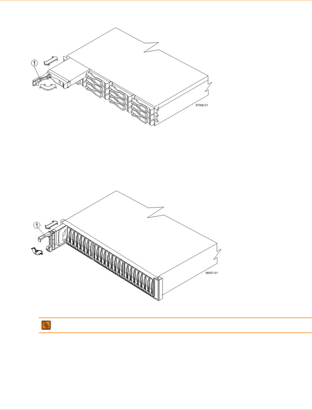
SANtricity_10.77 February 2011
LSI Corporation
- 303 -
Installing a Drive in a DE1600 Drive Tray
1. Drive Handle
Installing a Drive in a DE5600 Drive Tray
1. Drive Handle
NOTE In some applications, the drive handle might have the hinge on the right.
3. Install the second drive beneath the first drive (DE1600 drive tray) or to the right of the first drive (DE5600
drive tray).
4. Install the other drives top to bottom and then left to right (DE1600 drive tray) or to the right (DE5600 drive
tray).
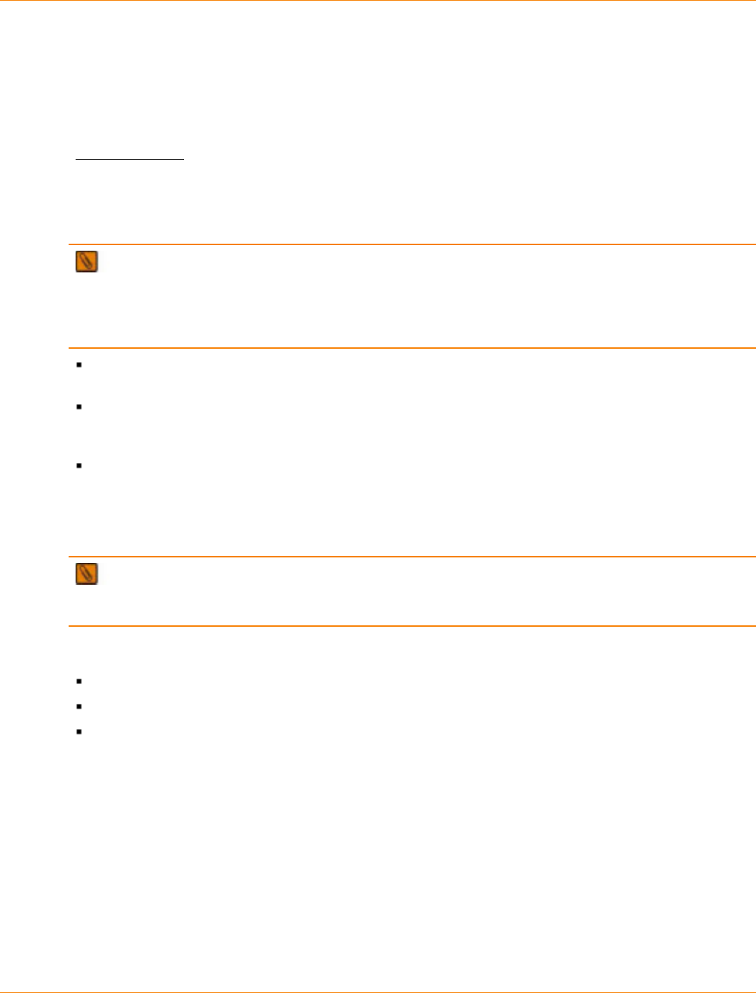
SANtricity_10.77 February 2011
LSI Corporation
- 304 -
Step 7 – Connecting the CDE2600 Controller-Drive Tray to the
Drive Trays
Key Terms
drive channel
The path for the transfer of data between the controllers and the drives in the storage array.
Things to Know – CDE2600 Controller-Drive Tray
NOTE On the CDE2600 controller-drive tray, each controller has a pair of levers with handles for
removing the controller from the controller-drive tray. One of these handles on each controller is located next
to a host connector. The close spacing between the handle and the host connector might make it difficult to
remove a cable that is attached to the host connector. If this problem occurs, use a flat-blade screwdriver to
push in the release component on the cable connector.
The CDE2600 controller-drive tray supports both the DE1600 drive tray and the DE5600 drive tray for
expansion.
The maximum number of drive slots in the storage array is 96 (expandable to 192, including the 12 or 24
drive slots in the controller-drive tray. Exceeding 96 (or 192) drive slots makes the storage array invalid.
The controllers cannot perform operations that modify the configuration, such as creating new volumes.
Each controller has one dual-ported SAS expansion connector to connect to the drive trays.
Drive Channel Ports on the CDE2600 Controller-Drive Tray – Rear View
1. Controller Canister
2. SAS Expansion Connector
IMPORTANT To maintain data access in the event of the failure of a controller, an ESM, or a drive
channel, you must connect a drive tray or a string of drive trays to both drive channels on a redundant path
pair.
Things to Know – Drive Trays with the CDE2600 Controller-Drive Tray
Each DE1600 drive tray can contain a maximum of twelve 8.89-cm (3.5-in.) drives.
Each DE5600 drive tray can contain a maximum of twenty-four 6.35-cm (2.5-in.) drives.
The ESMs on the DE1600 drive tray and the DE5600 drive tray contain two sets of In connectors and one
set of Out connectors.
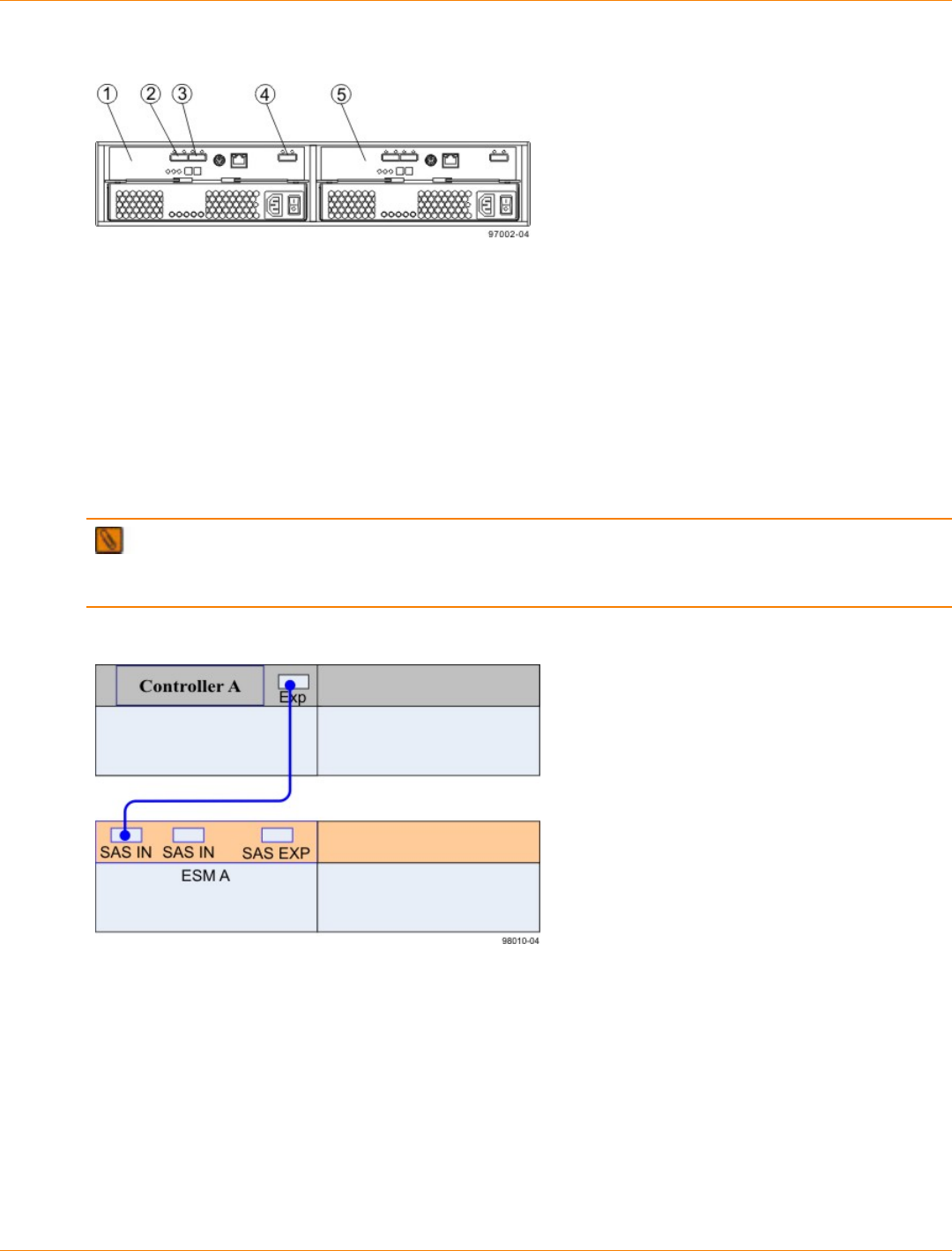
SANtricity_10.77 February 2011
LSI Corporation
- 305 -
DE1600 Drive Tray and DE5600 Drive Tray – Rear View
1. ESM A
2. SAS Connector 1 (In)
3. SAS Connector 2 (In)
4. Expansion Connector (Out)
5. ESM B
Things to Know – Drive Tray Cabling Configurations – Simplex System
The following figure shows an example of cable configurations from the simplex CDE2600 controller-drive tray
to either a DE1600 drive tray or a DE5600 drive tray. Use this example as a guide to connect cables in your
storage array.
IMPORTANT Configurations for connecting cables in a simplex system do not provide for tray loss
protection. Loss of a drive tray that has a second drive tray connected to it means that you cannot access the
second drive tray.
Controller-Drive Tray Above the Drive Tray
Things to Know – Drive Tray Cabling Configurations – Duplex System
The figures in this topic show examples of cable configurations from the controller-drive tray to the drive trays.
Use these examples as guides to connect cables in your storage array.
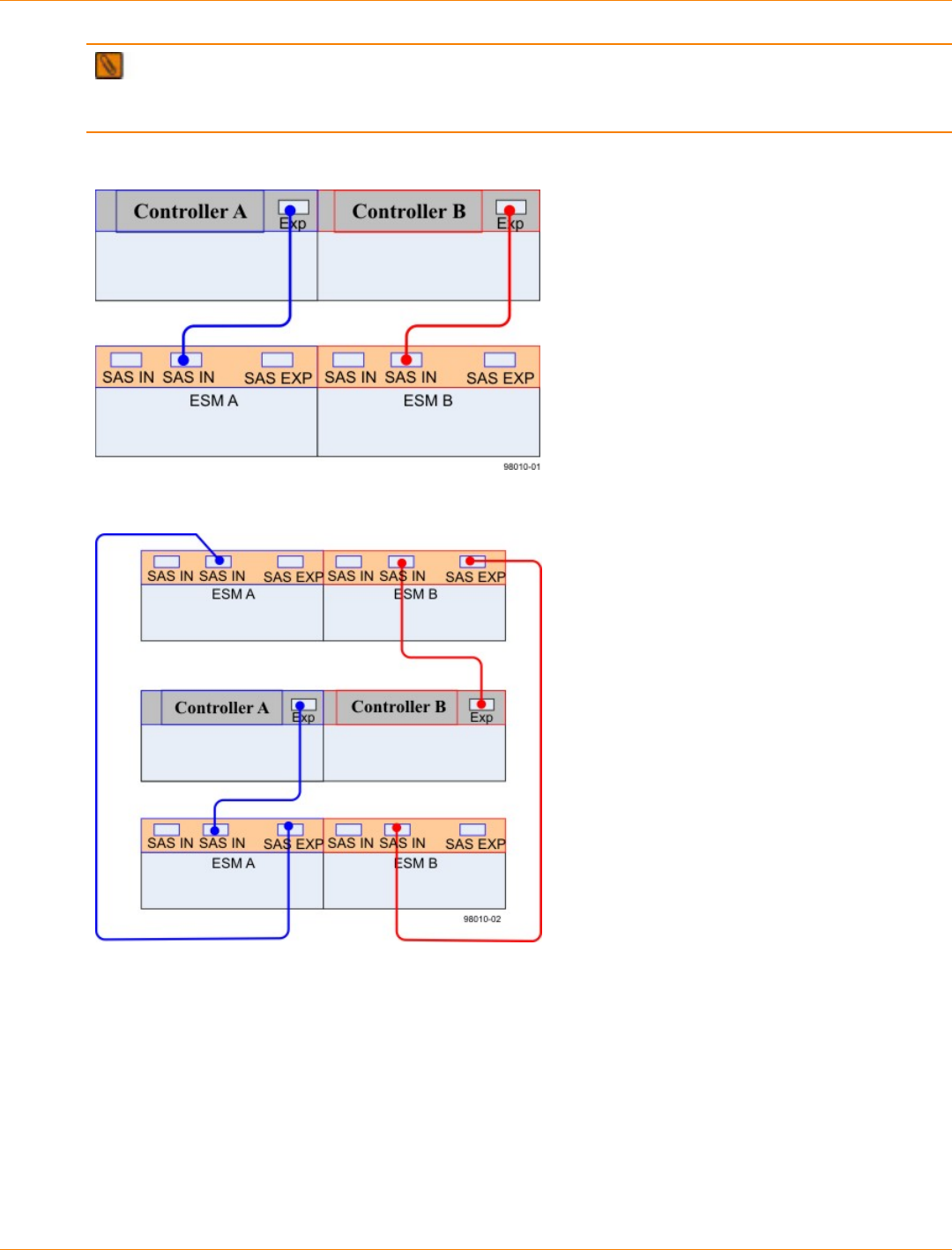
SANtricity_10.77 February 2011
LSI Corporation
- 306 -
IMPORTANT The configuration shown in the fourth image in this topic provides an example of tray
loss protection. With tray loss protection, if one drive tray cannot be accessed, you still have access to the
remaining drive trays.
Controller-Drive Tray Above the Drive Tray
Controller-Drive Tray Between Two Drive Trays
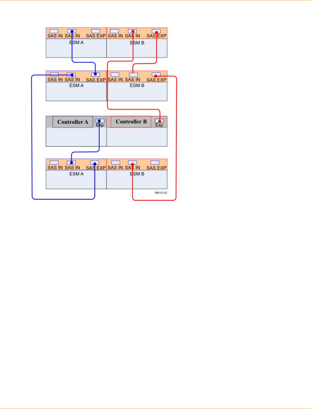
SANtricity_10.77 February 2011
LSI Corporation
- 307 -
Controller-Drive Tray with Three Drive Trays
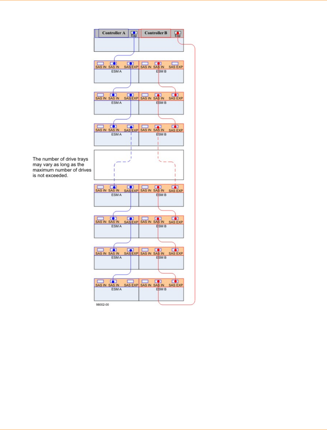
SANtricity_10.77 February 2011
LSI Corporation
- 308 -
Connecting Cables for Maximum Redundancy and Tray Loss Protection
Procedure – Connecting the DE1600 Drive Trays and the DE5600 Drive Trays
1. Use the following table to determine the number of SAS cables that you need.
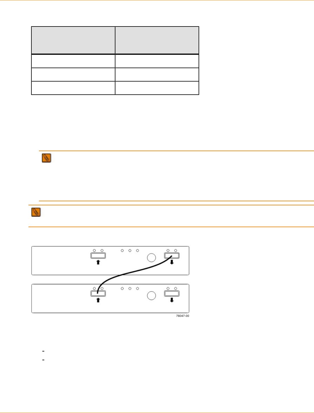
SANtricity_10.77 February 2011
LSI Corporation
- 309 -
Drive Tray Cables
Number of Drive Trays that
You Plan to Connect to the
Controller-Drive Tray
Number of Cables Required
1 2
2 4
3 6
2. If there is a black, plastic plug in the SAS expansion connector of the controller, remove it.
3. Insert one end of the cable into the SAS expansion connector on the controller in slot A in the controller-
drive tray.
4. Insert the other end of the cable into the connector with an up arrow on the ESM in slot A in the drive tray.
5. Are you adding more drive trays?
IMPORTANT Each ESM in a drive tray has three expansion connectors: two on the left-center of
the ESM and one in the upper-right side. When connecting from an ESM in one drive tray to an ESM in
another drive tray, make sure that you connect the connector on the upper-right to one of the connectors
on the left-center. The following figure shows these arrows on an ESM. If the cable is connected either
between the two left-center ESM connectors or between two upper-right ESM connectors, communication
between the two drive trays is lost.
NOTE It does not matter which of the two left-center ESM connectors you use to connect to the
expansion connector on the far-right side.
Connecting a Cable from One ESM to a Second ESM
Yes – Go to step 6.
No – Go to step 9.
6. In the ESM in the first drive tray, insert one end of the cable into the connector on the far-right side.
7. In the ESM in the next drive tray, insert the other end of the cable into one of the connectors in the left-
center of the ESM.
8. Repeat step 6 through step 7 for each drive tray that you intend to add to the storage array.
SANtricity_10.77 February 2011
LSI Corporation
- 310 -
9. To each end of the cables, attach a label with this information:
The controller ID (for example, controller A)
The ESM ID (for example, ESM A)
The ESM connector (In or Out)
The drive tray ID
For example, if you are connecting controller A to the In connector on ESM A in drive tray 1, the label on
the controller end of the cable will have this information:
CtA-Dch1, Dm1-ESM_A (left), In – Controller End
The label on the drive tray end of the cable will have this information:
Dm1-ESM_A (left), In, CtrlA
10. If you are installing the controller-drive tray with two controllers, repeat step 2 through step 9 for the
controller in slot B in the controller-drive tray.
IMPORTANT To connect cables for maximum redundancy, the cables attaching controller B must be
connected to the drive trays in the opposite tray order as for controller A. That is, the last drive tray in the
chain from controller A must be the first drive tray in the chain from controller B.
SANtricity_10.77 February 2011
LSI Corporation
- 311 -
Step 8 – Connecting the Ethernet Cables
Key Terms
in-band management
A method to manage a storage array in which a storage management station sends commands to the storage
array through the host input/output (I/O) connection to the controller.
out-of-band management
A method to manage a storage array in which a storage management station sends commands to the storage
array through the Ethernet connections on the controller.
Things to Know – Connecting Ethernet Cables
ATTENTION Risk of security breach – Connect the Ethernet ports on the controller tray to a private
network segment behind a firewall. If the Ethernet connection is not protected by a firewall, your storage array
might be at risk of being accessed from outside of your network.
These Ethernet connections are intended for out-of-band management and have nothing to do with the
iSCSI host interface cards (HICs), whether 1Gb/s or 10Gb/s.
Ethernet port 2 on each controller is reserved for access by your Customer and Technical Support
representative.
In limited situations in which the storage management station is connected directly to the controller tray,
you must use an Ethernet crossover cable. An Ethernet crossover cable is a special cable that reverses
the pin contacts between the two ends of the cable.
Procedure – Connecting Ethernet Cables
Perform these steps to connect Ethernet cables for out-of-band management. If you use only in-band
management, skip these steps.
1. Connect one end of an Ethernet cable into the Ethernet port 1 on controller A.
2. Connect the other end to the applicable network connection.
3. Repeat step 1 through step 2 for controller B.
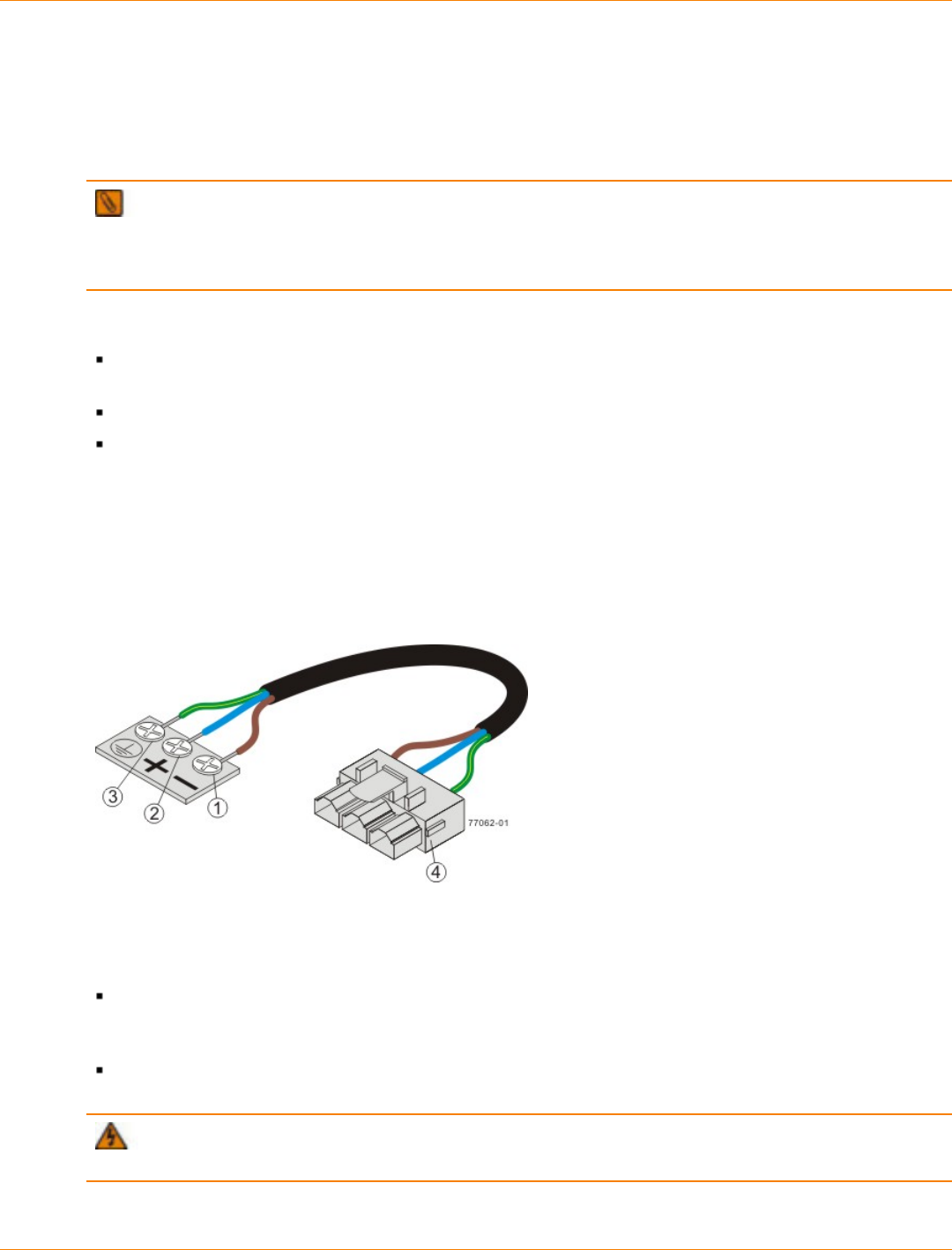
SANtricity_10.77 February 2011
LSI Corporation
- 312 -
Step 9 – Connecting the Power Cords
The CDE2600 controller-drive tray, the DE1600 drive tray, and the DE5600 drive tray can have either
standard power connections to an AC power source or the optional connections to a DC power source (–48
VDC).
IMPORTANT Make sure that you do not turn on the power to the controller-drive tray or the connected
drive trays until this documentation instructs you to do so. For the correct procedure for turning on the
power, see “Step 10 – Turning on the Power and Checking for Problems in a CDE2600 Controller-Drive Tray
Configuration.”
Things to Know – AC Power Cords
For each AC power connector on the drive tray, make sure that you use a separate power source in the
cabinet. Connecting to independent power sources maintains power redundancy.
To ensure proper cooling and assure availability, the drive trays always use two power supplies.
You can use the power cords shipped with the drive tray with typical outlets used in the destination
country, such as a wall receptacle or an uninterruptible power supply (UPS). These power cords,
however, are not intended for use in most EIA-compliant cabinets.
Things to Know – DC Power Cords
If your drive tray has the DC power option installed, review the following information.
DC Power Cable
1. Supply (negative), brown wire, –48 VDC
2. Return (positive), blue wire
3. Ground, green/yellow wire
4. DC power connector
Each power-fan canister has two DC power connectors. Be sure to use a separate power source for each
power-fan canister in the drive tray to maintain power redundancy. You may, optionally, connect each DC
power connector on the same power-fan canister to a different source for additional redundancy.
A two-pole 30-amp circuit breaker is required between the DC power source and the drive tray for over-
current and short-circuit protection.
WARNING (W14) Risk of bodily injury – A qualified service person is required to make the DC
power connection according to NEC and CEC guidelines.
SANtricity_10.77 February 2011
LSI Corporation
- 313 -
Procedure – Connecting AC Power Cords
1. Make sure that the circuit breakers in the cabinet are turned off.
2. Make sure that both of the Power switches on the drive trays are turned off.
3. Connect the primary power cords from the cabinet to the external power source.
4. Connect a cabinet interconnect power cord (or power cords specific to your particular cabinet) to the AC
power connector on each power canister in the drive tray.
5. If you are installing other drive trays in the cabinet, connect a power cord to each power canister in the
drive trays.
Procedure – Connecting DC Power Cords
WARNING (W14) Risk of bodily injury – A qualified service person is required to make the DC
power connection according to NEC and CEC guidelines.
IMPORTANT Make sure that you do not turn on power to the drive tray until this guide instructs you to
do so. For the proper procedure for turning on the power, see “Turning on the Power”.
IMPORTANT Before turning off any power switches on a DC-powered drive tray, you must disconnect
the two-pole 20-amp circuit breaker.
1. Disconnect the two-pole 20-amp circuit breaker for the storage array.
2. Make sure that all of the DC power switches on the DC-powered drive tray are turned off.
3. Connect the DC power connector cables to the DC power connectors on the rear of thecontroller tray or
controller-drive tray, and drive trays.
NOTE The three source wires on the DC power connector cable (–48 VDC) connect the drive tray
to centralized DC power plant equipment, typically through a bus bar located above the cabinet.
NOTE It is not mandatory that the second DC power connection on each of the drive tray’s DC
power-fan canisters be connected. The second DC power connection is for additional redundancy only
and may be connected to a second DC power bus.
4. Have a qualified service person connect the other end of the DC power connector cables to the DC power
plant equipment as follows:
a. Connect the brown –48 VDC supply wire to the negative terminal.
b. Connect the blue return wire to the positive terminal.
c. Connect the green/yellow ground wire to the ground terminal.
SANtricity_10.77 February 2011
LSI Corporation
- 314 -
Step 10 – Turning on the Power and Checking for Problems in a
CDE2600 Controller-Drive Tray Configuration
After you complete this task, you can install the software and perform basic configuration tasks on your
storage array. Continue with the Initial Configuration and Software Installation in these electronic document
topics or through the PDF that is available on the SANtricity ES Storage Manager Installation DVD.
Procedure – Turning On the Power to the Storage Array and Checking for
Problems in a CDE2600 Controller-Drive Tray Configuration
IMPORTANT You must turn on the power to all of the connected drive trays before you turn on the
power for the controller-drive tray. Performing this action makes sure that the controllers recognize each
attached drive tray.
NOTE While the power is being applied to the trays, the LEDs on the front and the rear of the trays
come on and go off intermittently.
1. Turn on both Power switches on each drive tray that is attached to the controller-drive tray. Depending on
your configuration, it can take several minutes for each drive tray to complete the power-on process.
IMPORTANT Before you go to step 2, check the LEDs on the drive trays to verify that the power
was successfully applied to all of the drive trays. Wait 30 seconds after turning on the power to the drive
trays before turning on the power to the controller-drive tray.
2. Turn on both Power switches on the rear of the controller-drive tray. Depending on your configuration, it
can take several minutes for the controller-drive tray to complete the power-on process.
3. Check the LEDs on the front and the rear of the controller-drive tray and the attached drive trays.
4. If you see any amber LEDs, make a note of their location.
Things to Know – LEDs on the CDE2600 Controller-Drive Tray
The following topics provide details on the LEDs found on the CDE2600 controller-drive tray.
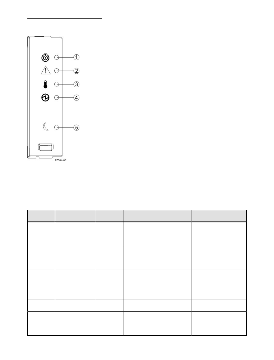
SANtricity_10.77 February 2011
LSI Corporation
- 315 -
LEDs on the Left End Cap
LEDs on the Left End Cap
1. Controller-Drive Tray Locate LED
2. Service Action Required LED
3. Controller-Drive Tray Over-Temperature LED
4. Power LED
5. Standby Power LED
LEDs on the Left End Cap
Location LED Color On Off
1 Controller-
Drive Tray
Locate
White Identifies a controller-drive
tray that you are trying to
find.
Normal status.
2 Service Action
Required Amber A component within the
controller-drive tray needs
attention.
Normal status.
3 Controller-
Drive Tray
Over-
Temperature
Amber The temperature of the
controller-drive tray has
reached an unsafe level.
Normal status.
4 Power Green Power is present. Power is not present.
5 Standby Power Green The controller-drive tray is
in Standby Power mode. The controller-drive
tray is not in Standby
Power mode.
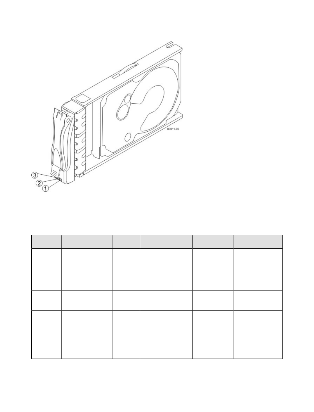
SANtricity_10.77 February 2011
LSI Corporation
- 316 -
LEDs on the Drive
LEDs on the Drive
1. Drive Power LED
2. Drive Service Action Required LED
3. Drive Service Action Allowed LED
LEDs on the Drive
Location LED Color On Blinking Off
1 Drive Power Green The power
is turned on,
and the drive
is operating
normally.
Drive I/O
activity is
taking place.
The power is
turned off.
2 Drive Service
Action Required Amber An error has
occurred. Normal status.
3 Drive Service
Action Allowed Blue The drive canister
can be removed
safely from the
controller-drive
tray.
The drive
canister cannot
be removed
safely from the
controller-drive
tray.
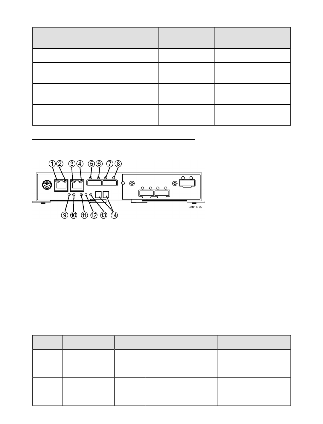
SANtricity_10.77 February 2011
LSI Corporation
- 317 -
Drive State Represented by LEDs
Drive State Drive Power LED
(Green) Drive Service Action
Required LED (Amber)
Power is not applied. Off Off
Normal operation – The power is turned on,
but drive I/O activity is not occurring. On Off
Normal operation – Drive I/O activity is
occurring. Blinking Off
Service action required – A fault condition
exists, and the drive is offline. On On
LEDs on the Controller Canister Main Faceplate
LEDs on the Controller Canister Main Faceplate
1. Ethernet Connector 1 Link Rate LED
2. Ethernet Connector 1 Link Active LED
3. Ethernet Connector 2 Link Rate LED
4. Ethernet Connector 1 Link Active LED
5. Host Link 1 Service Action Required LED
6. Host Link 1 Service Action Allowed LED
7. Host Link 2 Service Action Required LED
8. Host Link 2 Service Action Allowed LED
9. Battery Service Action Required LED
10. Battery Charging LED
11. Controller Service Action Allowed LED
12. Controller Service Action Required LED
13. Cache Active LED
14. Seven-Segment Tray ID
LEDs on the Controller Canister Main Faceplate
Location LED Color On Off
1 Ethernet
Connector 1
Link Rate LED
Green There is a 100BASE-T
rate. There is a 10BASE-T
rate.
2 Ethernet
Connector 1
Link Active LED
Green The link is up (LED
blinks when there is
activity).
The link is not active.

SANtricity_10.77 February 2011
LSI Corporation
- 318 -
Location LED Color On Off
3 Ethernet
Connector 2
Link Rate LED
Green There is a 100BASE-T
rate. There is a 10BASE-T
rate.
4 Ethernet
Connector 2
Link Active LED
Green The link is up (the LED
blinks when there is
activity).
The link is not active.
5 Host Link 1
Service Action
Required LED
Amber At least one of the four
PHYs is working, but
another PHY cannot
establish the same link
to the device connected
to the Host IN port
connector.
No link error has
occurred.
6 Host Link 1
Service Action
Allowed LED
Green At least one of the four
PHYs in the Host IN
port is working and a
link exists to the device
connected to the IN port
connector.
A link error has occurred.
7 Host Link 2
Service Action
Required LED
Amber At least one of the four
PHYs is working, but
another PHY cannot
establish the same link
to the device connected
to the Host IN port
connector.
No link error has
occurred.
8 Host Link 2
Service Action
Allowed LED
Green At least one of the four
PHYs in the Host IN
port is working and a
link exists to the device
connected to the IN port
connector.
A link error has occurred.
9 Battery Service
Action Required
LED
Amber The battery in the
controller canister has
failed.
Normal status.
10 Battery Charging
LED Green The battery is fully
charged. The LED
blinks when the battery
is charging.
The controller canister
is operating without a
battery or the existing
battery has failed.
11 Controller
Service Action
Allowed LED
Blue The controller canister
can be removed safely
from the controller-drive
tray.
The controller canister
cannot be removed
safely from the
controller-drive tray.
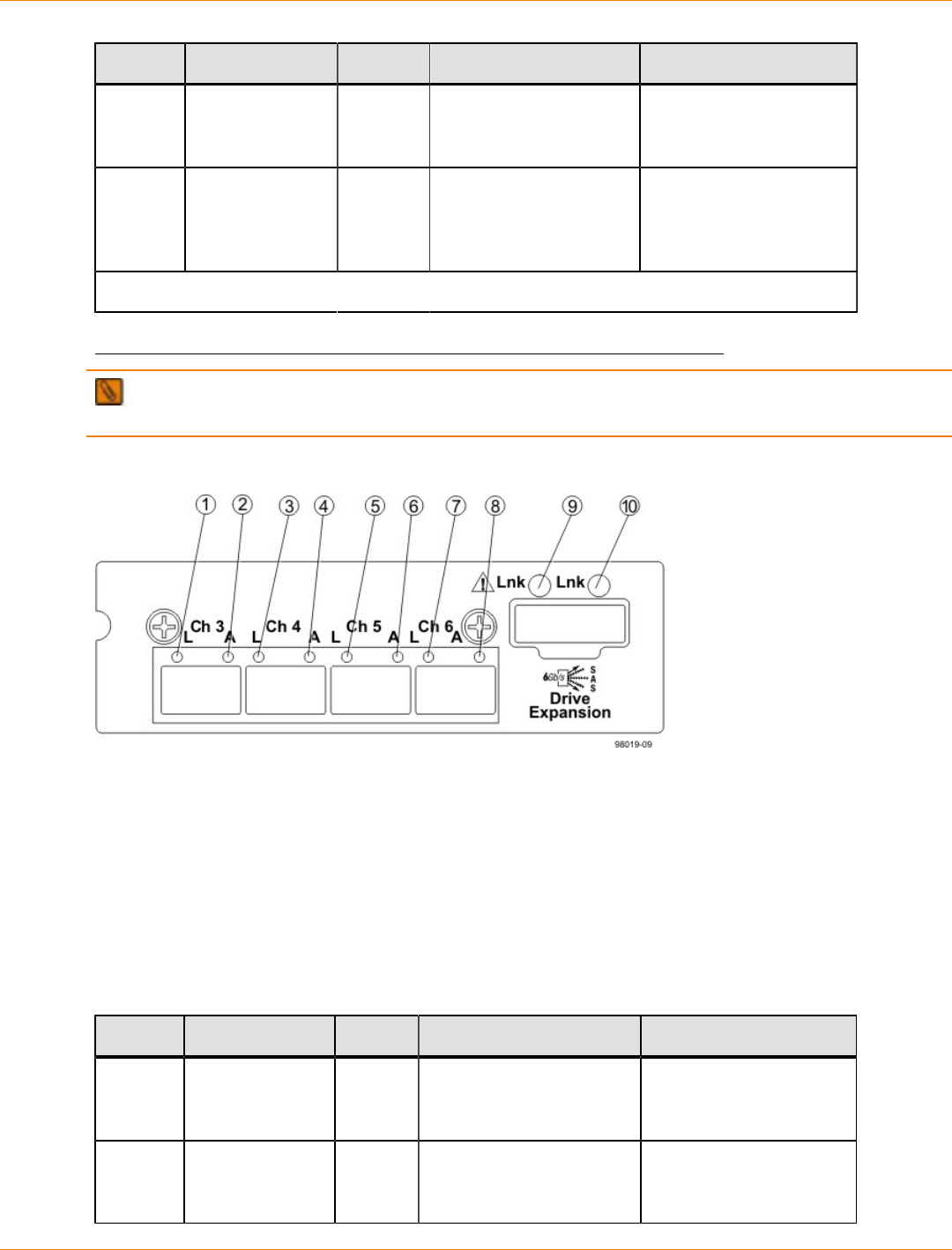
SANtricity_10.77 February 2011
LSI Corporation
- 319 -
Location LED Color On Off
12 Controller
Service Action
Required LED
Amber A fault exists within the
controller canister. Normal status.
13 Cache Active
LED Green Cache is active.* Cache is inactive or the
controller canister has
been removed from the
controller-drive tray.
* After an AC power failure, this LED blinks while cache offload is in process.
LEDs on the Controller Canister Host Interface Card Subplates
NOTE The following figure shows an iSCSI host interface card (HIC), but the CDE2600 controller-drive
tray also supports a four-connector FC HIC and a two-connector SAS HIC with comparable LEDs.
LEDs on the Controller Canister Host Interface Card Subplates
1. Host Interface Card Link 3 Up LED
2. Host Interface Card Link 3 Active LED
3. Host Interface Card Link 4 Up LED
4. Host Interface Card Link 4 Active LED
5. Host Interface Card Link 5 Up LED
6. Host Interface Card Link 5 Active LED
7. Host Interface Card Link 6 Up LED
8. Host Interface Card Link 6 Active LED
9. Expansion Fault LED
10. Expansion Active LED
LEDs on the Controller Canister Host Interface Card Subplates*
Location LED Color On Off
1 Host Interface
Card Link 3 Up
LED
Green The Ethernet link has
auto-negotiated to 1 Gb/
s.
The Ethernet link is
down or does not auto-
negotiate to 1 Gb/s.
2 Host Interface
Card Link 3
Active LED
Green The link is up (LED blinks
when there is activity). The link is not active.

SANtricity_10.77 February 2011
LSI Corporation
- 320 -
Location LED Color On Off
3 Host Interface
Card Link 4 Up
LED
Green The Ethernet link has
auto-negotiated to 1 Gb/
s.
The Ethernet link is
down or does not auto-
negotiate to 1 Gb/s.
4 Host Interface
Card Link 4
Active LED
Green The link is up (LED blinks
when there is activity). The link is not active.
5 Host Interface
Card Link 5 Up
LED
Green The Ethernet link has
auto-negotiated to 1 Gb/
s.
The Ethernet link is
down or does not auto-
negotiate to 1 Gb/s.
6 Host Interface
Card Link 5
Active LED
Green The link is up (LED blinks
when there is activity). The link is not active.
7 Host Interface
Card Link 6 Up
LED
Green The Ethernet link has
auto-negotiated to 1 Gb/
s.
The Ethernet link is
down or does not auto-
negotiate to 1 Gb/s.
8 Host Interface
Card Link 6
Active LED
Green The link is up (LED blinks
when there is activity). The link is not active.
9 Expansion Fault
LED Amber At least one of the four
PHY is working, but
another PHY cannot
establish the same link
to the device connected
to the Expansion OUT
connector.
Normal status.
10 Expansion
Active LED Green At least one of the
four PHYs in the OUT
connector is working and
a link has been made to
the device connected to
the Expansion connector.
The link is not active.
* "LEDs on the Controller Canister Host Interface Card Subplates" shows the four-port iSCSI
host interface card (HIC), which can also be a four-port FC HIC or a two-port SAS HIC.
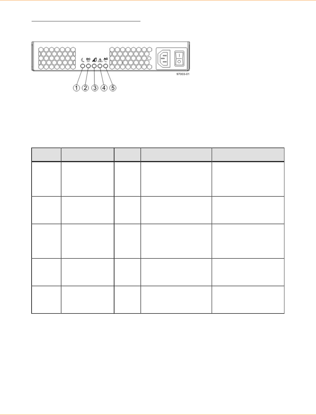
SANtricity_10.77 February 2011
LSI Corporation
- 321 -
LEDs on the Power-Fan Canister
LEDs on the Power-Fan Canister
1. Standby Power LED
2. Power-Fan DC Power LED
3. Power-Fan Service Action Allowed LED
4. Power-Fan Service Action Required LED
5. Power-Fan AC Power LED
LEDs on the Power-Fan Canister
Location LED Color On Off
1 Standby Power Green The controller-drive tray
is in Standby mode,
and DC power is not
available.
The controller-drive
tray is not in Standby
mode, and DC power is
available.
2 Power-Fan DC
Power Green DC power from the
power-fan canister is
available.
DC power from the
power-fan canister is not
available.
3 Power-Fan
Service Action
Allowed
Blue The power-fan canister
can be removed safely
from the controller-drive
tray.
The power-fan canister
cannot be removed
safely from the
controller-drive tray.
4 Power-Fan
Service Action
Required
Amber A fault exists within the
power-fan canister. Normal status.
5 Power-Fan AC
Power Green AC power to the power-
fan canister is present. AC power to the power-
fan canister is not
present.
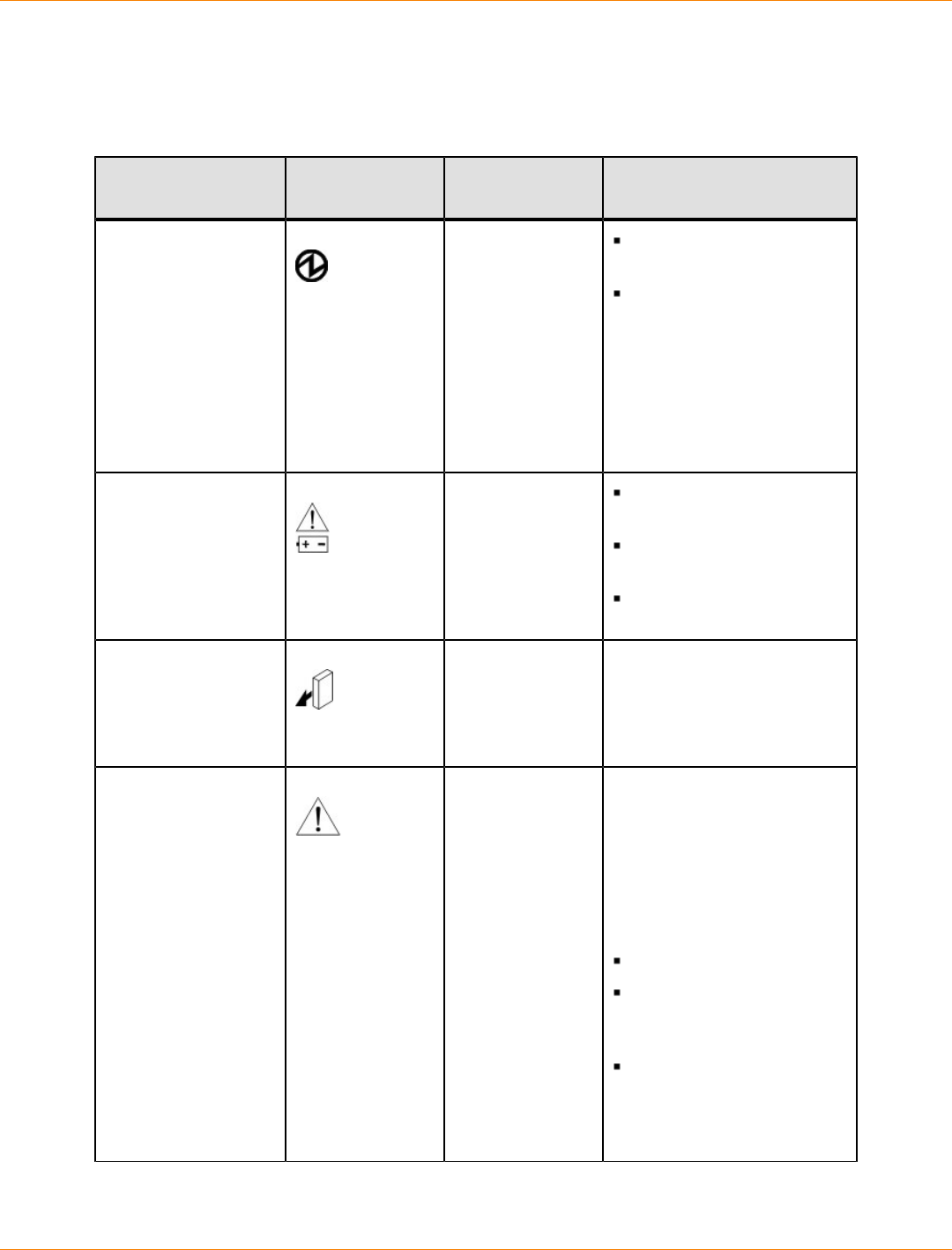
SANtricity_10.77 February 2011
LSI Corporation
- 322 -
Things to Know – General Behavior of the LEDs on the CDE2600 Controller-
Drive Tray
LED Symbols and General Behavior
LED Symbol Location
(Canisters) Function
Power Power-fan
Interconnect-
battery
On – The controller has
power.
Off – The controller does
not have power.
NOTE – The controller
canisters do not have a
Power LED. They receive
their power from the power
supplies inside the power-fan
canisters.
Battery Fault Battery On – The battery is
missing or has failed.
Off – The battery is
operating normally.
Blinking – The battery is
charging.
Service Action
Allowed Drive (left LED,
no symbol)
Power-fan
Controller
Battery
On – You can remove the
canister safely.
See “Things to Know –
Service Action Allowed
LEDs.”
Service Action
Required (Fault) Drive On – When the drive tray
LED is on, the cable is
attached and at least one
lane has a link up status, but
at least one lane has a link
down status.
Off – One of the following
conditions exists:
No cable is attached.
A cable is attached, and
all lanes have a link up
status.
A cable is attached, and
all lanes have a link down
status.
.
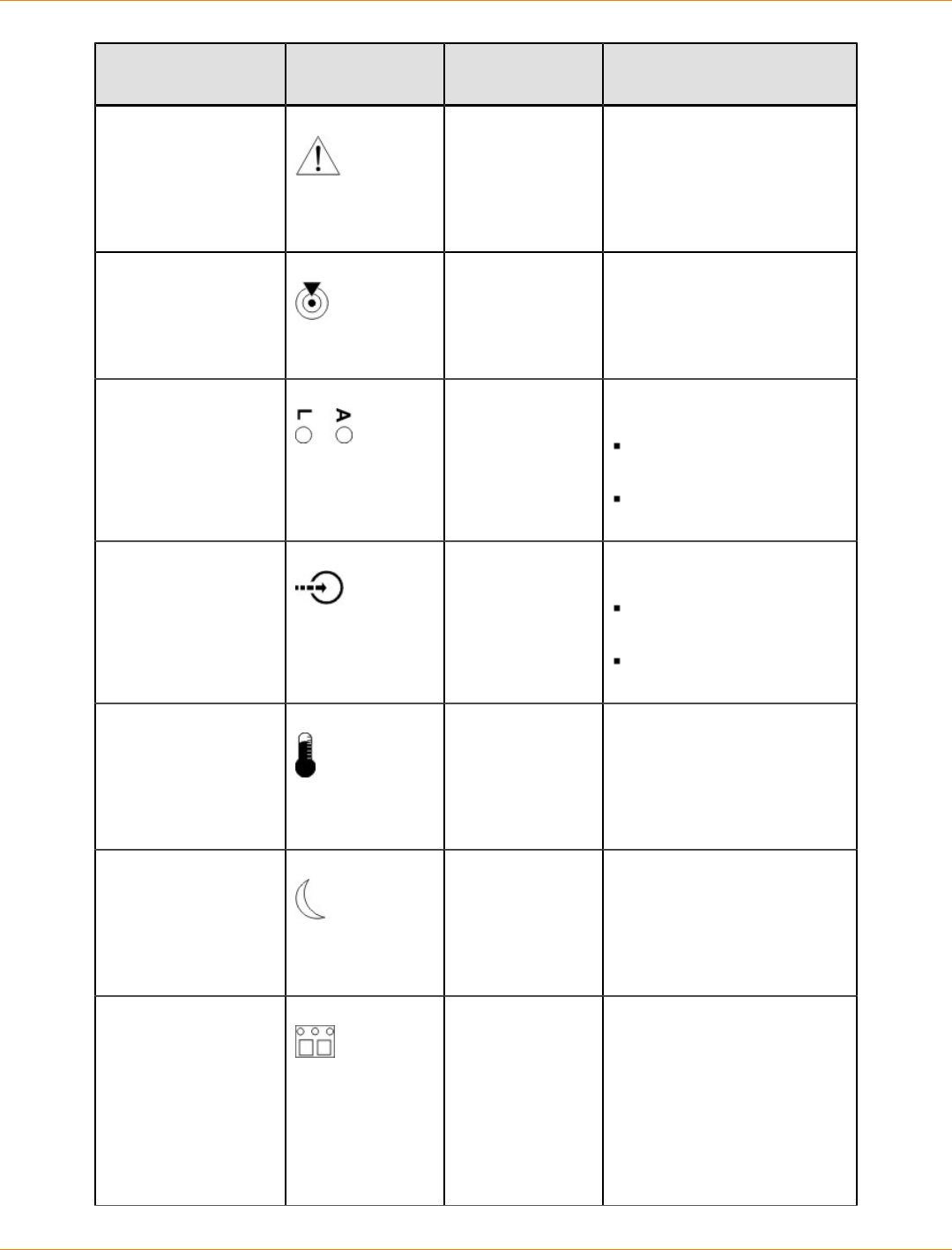
SANtricity_10.77 February 2011
LSI Corporation
- 323 -
LED Symbol Location
(Canisters) Function
Service Action
Required (Fault) Controller
Power-fan
canister
On – The controller or the
power-fan canister needs
attention.
Off – The controller and
the power-fan canister are
operating normally.
Locate Front frame On – Assists in locating the
tray.
Host Channel
Connection (iSCSI) Controller The status of the host
channel is indicated:
“L” LED on – A link is
established.
“A” LED on – Activity
(data transfer) is present.
Cache Active Controller The activity of the cache is
indicated:
On – Data is in the
cache.
Off – No data is in the
cache.
Controller-Drive Tray
Over-Temperature Front bezel on
the controller-
drive tray
On – The temperature of the
drive tray has reached an
unsafe condition.
Off – The temperature of the
drive tray is within operational
range.
Standby Power Front bezel on
the controller-
drive tray
On – The controller tray is in
standby mode and the main
DC power is off.
Off – The controller-drive tray
is not in standby mode and
the main DC power is on.
Seven-Segment ID
Diagnostic Display Controller The tray ID or a diagnostic
code is indicated (see “Things
to Know – Dynamic Display
Sequence Definitions on the
Seven-Segment Display”).
For example, if some of the
cache memory dual in-line
memory modules (DIMMs)
are missing in a controller,
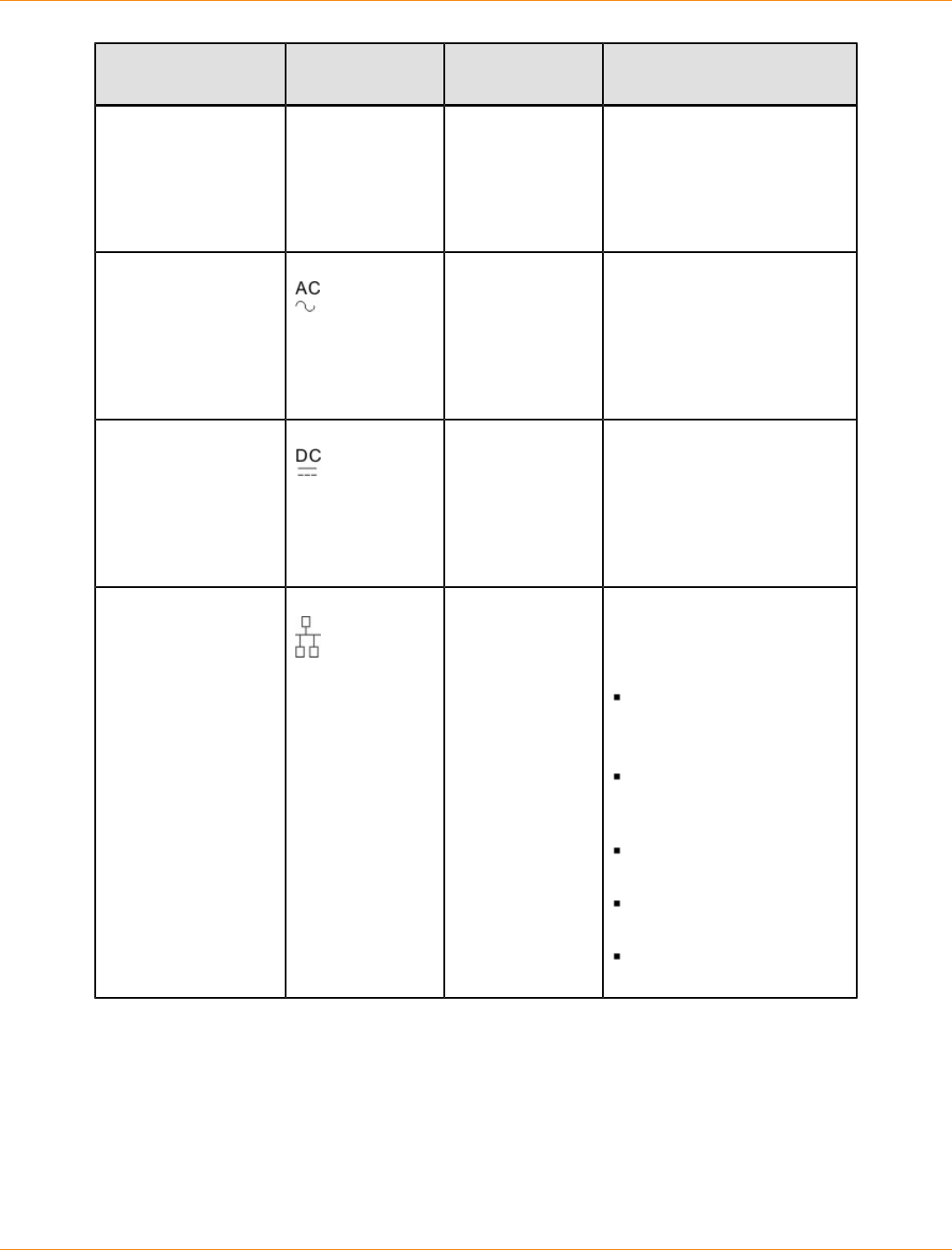
SANtricity_10.77 February 2011
LSI Corporation
- 324 -
LED Symbol Location
(Canisters) Function
error code L8 appears in
the diagnostic display (see
“Things to Know – Supported
Diagnostic Lock-Down Codes
on the Seven-Segment
Display”).
AC power Power-fan
NOTE – The LED
is directly above
or below the AC
power switch and
the AC power
connector.
Indicates that the power
supply is receiving AC power
input.
DC power Power-fan
NOTE – The LED
is directly above
or below the DC
power switch and
the DC power
connector.
Indicates that the power
supply is receiving DC power
input.
Ethernet Speed and
Ethernet Activity Controller The speed of the Ethernet
ports and whether a link
has been established are
indicated:
Left LED On –
1-Gb/s speed.
Left LED Off –
100BASE-T or 10BASE-T
speed.
Right LED On – A link is
established.
Right LED Off – No link
exists.
Right LED blinking –
Activity is occurring.
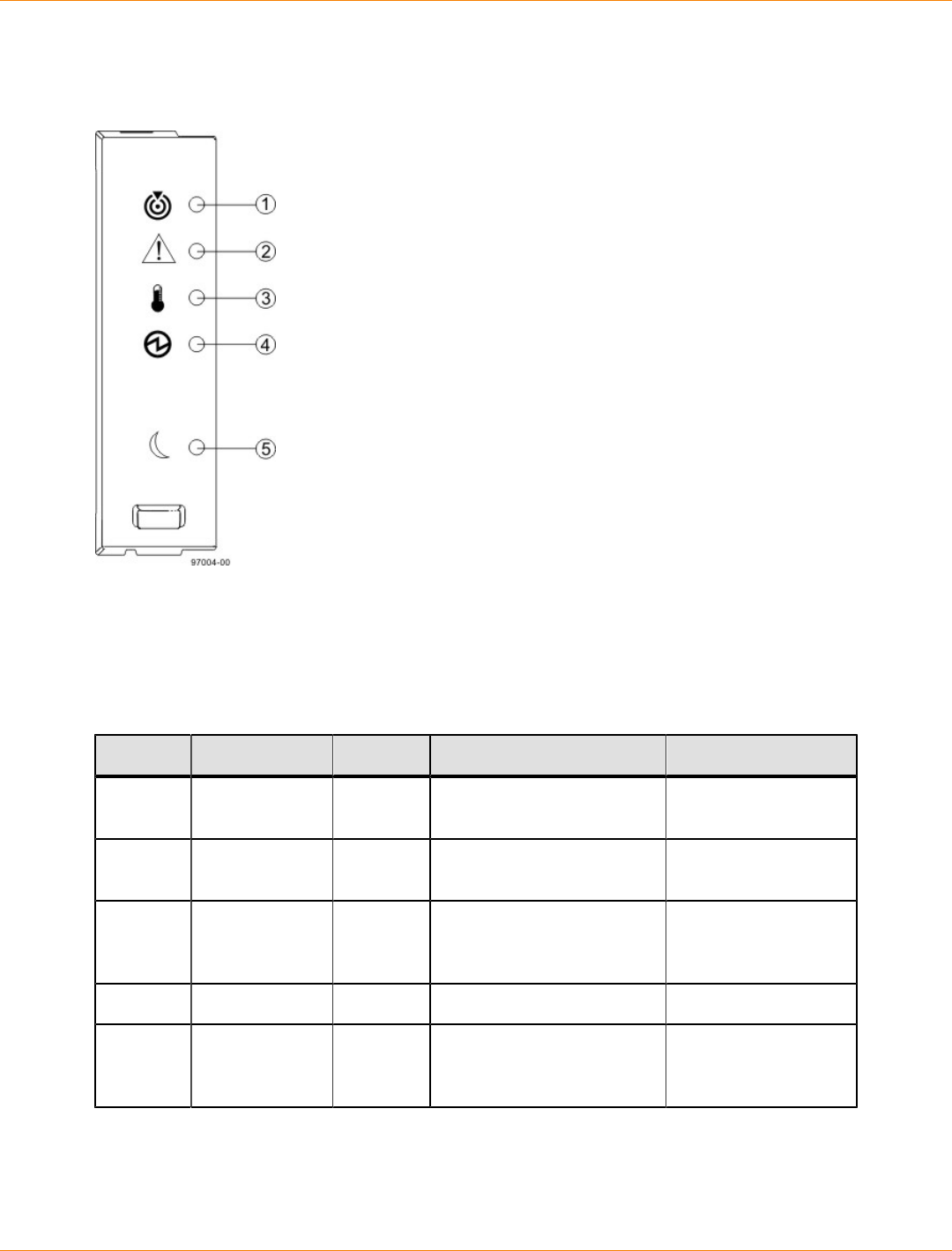
SANtricity_10.77 February 2011
LSI Corporation
- 325 -
Things to Know – LEDs on the DE1600 Drive Tray and the DE5600 Drive Tray
LEDs on the Left End Cap
1. Drive Tray Locate LED
2. Service Action Required LED
3. Drive Tray Over-Temperature LED
4. Power LED
5. Standby Power LED
LEDs on the Left End Cap
Location LED Color On Off
1 Drive Tray
Locate White Identifies a drive tray that
you are trying to find. Normal status.
2 Service Action
Required Amber A component within the
drive tray needs attention. Normal status.
3 Drive Tray
Over-
Temperature
Amber The temperature of the
drive tray has reached an
unsafe level.
Normal status.
4 Power Green Power is present. Power is not present.
5 Standby Power Green The drive tray is in Standby
Power mode. The drive tray is not
in Standby Power
mode.
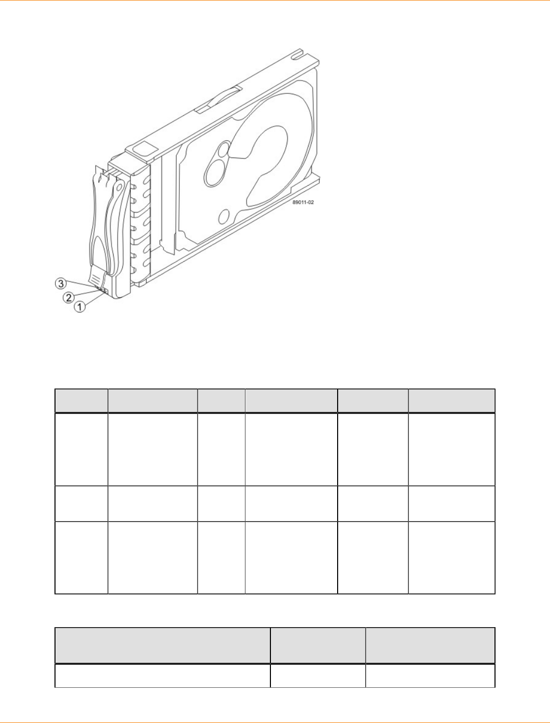
SANtricity_10.77 February 2011
LSI Corporation
- 326 -
LEDs on the Drive
1. Drive Power LED
2. Drive Service Action Required LED
3. Drive Service Action Allowed LED
LEDs on the Drive
Location LED Color On Blinking Off
1 Drive Power Green The power
is turned on,
and the drive
is operating
normally.
Drive I/O
activity is
taking place.
The power is
turned off.
2 Drive Service
Action Required Amber An error has
occurred. Normal status.
3 Drive Service
Action Allowed Blue The drive canister
can be removed
safely from the
drive tray.
The drive
canister cannot
be removed
safely from the
drive tray.
Drive State Represented by LEDs
Drive State Drive Power LED
(Green) Drive Service Action
Required LED (Amber)
Power is not applied. Off Off
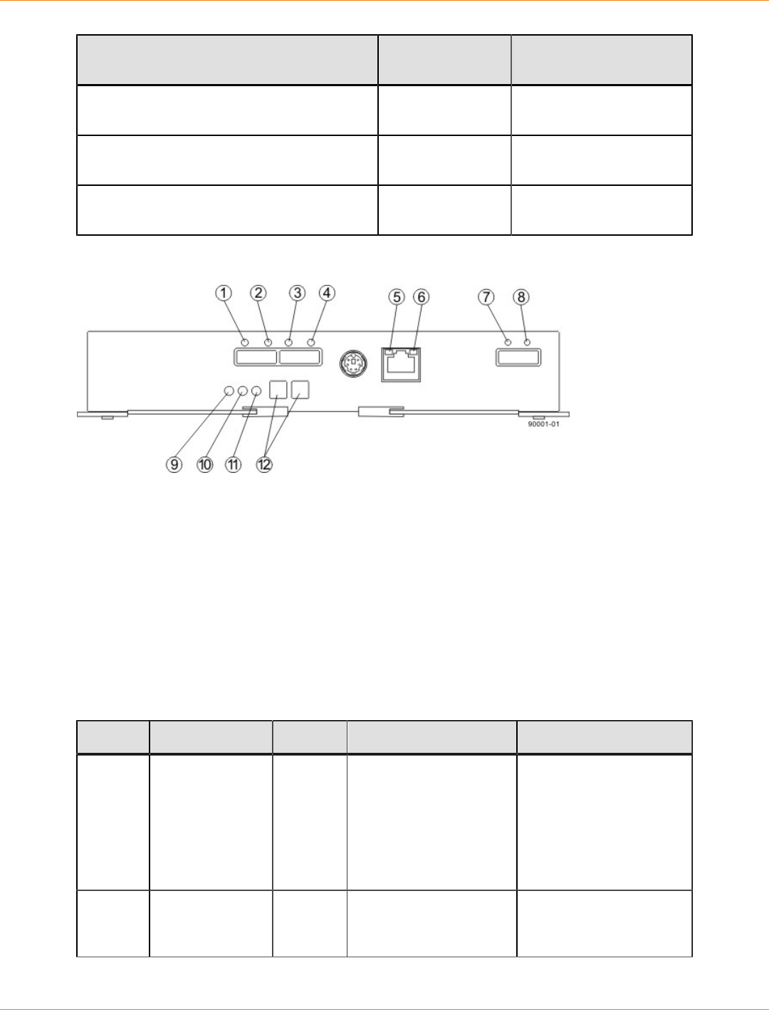
SANtricity_10.77 February 2011
LSI Corporation
- 327 -
Drive State Drive Power LED
(Green) Drive Service Action
Required LED (Amber)
Normal operation – The power is turned on,
but drive I/O activity is not occurring. On Off
Normal operation – Drive I/O activity is
occurring. Blinking Off
Service action required – A fault condition
exists, and the drive is offline. On On
LEDs on the ESM Canister
1. Host Link 1 Fault LED
2. Host Link 1 Active LED
3. Host Link 2 Fault LED
4. Host Link 2 Active LED
5. Ethernet Link Active LED
6. Ethernet Link Rate LED
7. ESM Expansion Link Fault LED
8. ESM Expansion Link Active LED
9. ESM Service Action Allowed LED
10. ESM Service Action Required LED
11. ESM Power LED
12. Seven-Segment Tray ID
LEDs on the ESM Canister
Location LED Color On Off
1 Host Link 1 Fault Amber At least one PHY of
the four connectors is
working, but another
PHY cannot establish
the same link to the
device connected to the
Host IN port connector.
No link error has
occurred.
2 Host Link 1
Active Green At least one of the four
PHYs in the IN port
is working, and a link
A link error has occurred.

SANtricity_10.77 February 2011
LSI Corporation
- 328 -
Location LED Color On Off
exists to the device
connected to the Host
IN connector.
3 Host Link 2 Fault Amber At least one PHY of
the four connections is
working, but another
PHY cannot establish
the same link to the
device connected to the
Host IN port connector
No link error has
occurred.
4 Host Link 2
Active Green At least one of the four
PHYs in the IN port
is working, and a link
exists to the device
connected to the Host
IN connector.
A link error has occurred.
5 Ethernet Link
Active Green The link is up. (The LED
blinks when there is
activity.)
The link is not active.
6 Ethernet Link
Rate Green There is a 100BASE-T
rate. There is a 10BASE-T
rate.
7 ESM Expansion
Link Fault Amber At least one of the
four PHYs in the OUT
port is working, but
another PHY cannot
establish the same link
to the Expansion OUT
connector.
Normal status.
8 ESM Expansion
Link Active Green At least one of the
four PHYs in the OUT
port is working, and
a link exists to the
device connected to
the Expansion OUT
connector.
A link error has occurred.
9 ESM Service
Action Allowed Blue The ESM can be
removed safely from the
drive tray.
The ESM cannot be
removed safely from the
drive tray.
10 ESM Service
Action Required Amber A fault exists within
the ESM. (This LED
defaults on at power
up. This LED turns off
after the software has
completed its power up
self-test sequence.)
Normal status.
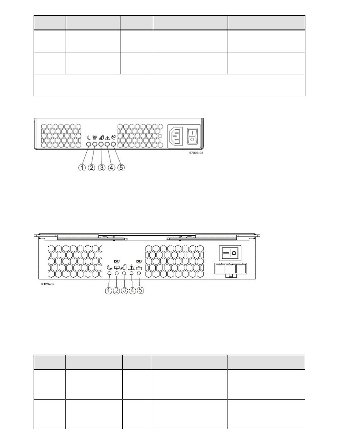
SANtricity_10.77 February 2011
LSI Corporation
- 329 -
Location LED Color On Off
11 ESM Power Green 12V power to the ESM
is present. Power is not present to
the ESM.
12 Seven-Segment
Tray ID Green See note. Not applicable.
*For more information about the seven-segment tray IDs, see “Tray ID Diagnostic Codes for
the DE1600 Drive Tray and the DE5600 Drive Tray on the Seven-Segment Display.”
LEDs on the AC Power-Fan Canister
1. Standby Power LED
2. Power-Fan Output DC Power LED
3. Power-Fan Service Action Allowed LED
4. Power-Fan Service Action Required LED
5. Power-Fan Input AC Power LED
LEDs on the DC Power-Fan Canister
1. Standby Power LED
2. Power-Fan Output DC Power LED
3. Power-Fan Service Action Allowed LED
4. Power-Fan Service Action Required LED
5. Power-Fan Input DC Power LED
LEDs on the Power-Fan Canister
Location LED Color On Off
1 Standby Power Green The drive tray is in
Standby mode, and DC
power is not available.
The drive tray is not in
Standby mode, and DC
power is available.
2 Power-Fan DC
Power Green DC power from the
power-fan canister is
available.
DC power from the
power-fan canister is not
available.
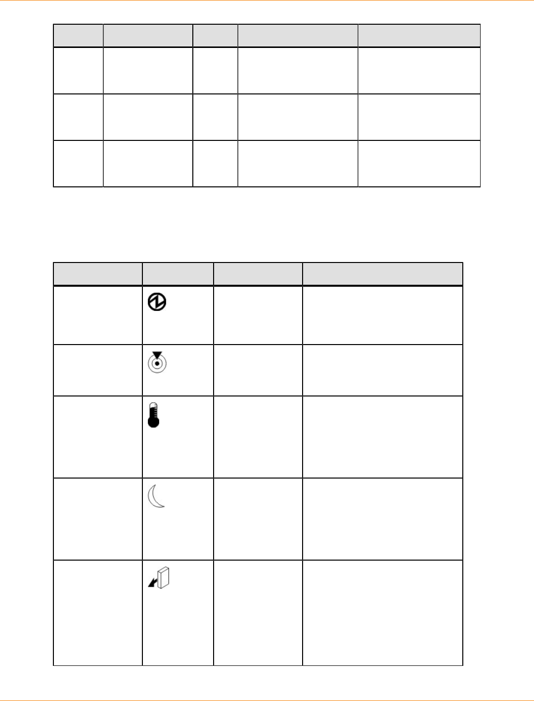
SANtricity_10.77 February 2011
LSI Corporation
- 330 -
Location LED Color On Off
3 Power-Fan
Service Action
Allowed
Blue The power-fan canister
can be removed safely
from the drive tray.
The power-fan canister
cannot be removed
safely from the drive tray.
4 Power-Fan
Service Action
Required
Amber A fault exists within the
power-fan canister. Normal status.
5 Power-Fan AC
Power Green AC power to the power-
fan canister is present. AC power to the power-
fan canister is not
present.
General Behavior of the LEDs on the DE1600 Drive Tray, and the DE5600 Drive
Tray
LED Symbols and General Behavior
LED Symbol Location General Behavior
Power Drive tray
ESM canister
Power-fan
canister
On – Power is applied to the drive
tray or the canister.
Off – Power is not applied to the
drive tray or the canister.
Drive Tray Locate Front bezel on
the drive tray On or blinking – Indicates the
drive tray that you are trying to
find.
Drive Tray Over-
Temperature Front bezel on
the drive tray On – The temperature of the
drive tray has reached an unsafe
condition.
Off – The temperature of the
drive tray is within operational
range.
Standby Power Front bezel on
the drive tray On – The drive tray is in Standby
mode, and the main DC power is
off.
Off – The drive tray is not in
Standby mode, and the main DC
power is on.
Service Action
Allowed ESM canister
Power-fan
canister
Drive
On – It is safe to remove the ESM
canister, the power-fan canister,
or the drive.
Off – Do not remove the ESM
canister, the power-fan canister,
or the drive.
The drive has an LED but no
symbol.

SANtricity_10.77 February 2011
LSI Corporation
- 331 -
LED Symbol Location General Behavior
Service Action
Required (Fault) ESM canister
Power-fan
canister
Drive
On – When the drive tray LED is
on, a component within the drive
tray needs attention.
On – The ESM canister, the
power-fan canister, or the drive
needs attention.
Off – The ESM canister, the
power-fan canister, and the drive
are operating normally.
The drive has an LED but no
symbol.
AC Power ESM canister
Power-fan
canister
On – AC power is present.
Off – AC power is not present.
DC Power Power-fan
canister On – Regulated DC power from
the power canister and the fan
canister is present.
Off – Regulated DC power from
the power-fan canister is not
present.
Link Service
Action Required
(Fault)
ESM canister On – The cable is attached and
at least one lane has a link-up
status, but one lane has a link-
down status.
Off – The cable is not attached,
the cable is attached and all lanes
have a link-up status, or the cable
is attached and all lanes have a
link-down status.
Link Up Two LEDs
above each
expansion
connector
ESM canister On – The cable is attached and
at least one lane has a link-up
status.
Off – The cable is not attached,
or the cable is attached and all
lanes have a link-down status.
Things to Know – Service Action Allowed LEDs
Each controller canister, power-fan canister, and battery canister has a Service Action Allowed LED. The
Service Action Allowed LED lets you know when you can remove a canister safely.
ATTENTION Possible loss of data access – Never remove a controller canister, a power-fan
canister, or a battery canister unless the appropriate Service Action Allowed LED is on.
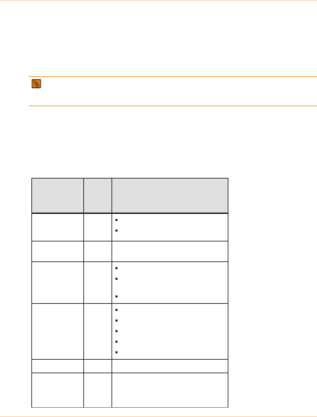
SANtricity_10.77 February 2011
LSI Corporation
- 332 -
If a controller canister or a power-fan canister fails and must be replaced, the Service Action Required (Fault)
LED on that canister comes on to indicate that service action is required. The Service Action Allowed LED
also comes on if it is safe to remove the canister. If data availability dependencies exist or other conditions
that dictate a canister should not be removed, the Service Action Allowed LED stays off.
The Service Action Allowed LED automatically comes on or goes off as conditions change. In most cases,
the Service Action Allowed LED comes on when the Service Action Required (Fault) LED comes on for a
canister.
IMPORTANT If the Service Action Required (Fault) LED comes on but the Service Action Allowed
LED is off for a particular canister, you might need to service another canister first. Check your storage
management software to determine the action that you should take.
Things to Know – Sequence Code Definitions for the CDE2600 Controller-Drive
Tray
During normal operation, the tray ID display on each controller canister displays the controller-drive tray ID.
The Diagnostic LED (lower-digit decimal point) comes on when the display is used for diagnostic codes and
goes off when the display is used to show the tray ID.
Sequence Code Definitions for the CDE2600 Controller-Drive Tray
Category Category
Code
(See
Note 1)
Detail Codes (See Note 2)
Startup error SE+
(See
Note 3)
88+ Power-on default.
dF+ Power-on diagnostic fault.
Operational error OE+ Lx+ Lock-down codes. (See the following
table.)
Operational state OS+ OL+ = Offline.
bb+ = Battery backup (operating on
batteries).
Cf+ = Component failure.
Component
failure CF+ dx+ = Processor or cache DIMM.
Cx = Cache DIMM.
Px+ = Processor DIMM.
Hx+ = Host interface card.
Fx+ = Flash drive.
Diagnostic failure dE+ Lx+ = Lock-down code.
Category
delimiter dash+ The separator between category-detail
code pairs is used when more than one
category detail code pair exists in the
sequence.
SANtricity_10.77 February 2011
LSI Corporation
- 333 -
Category Category
Code
(See
Note 1)
Detail Codes (See Note 2)
End-of-sequence
delimiter Blank
(See
Note 4)
The end-of-sequence delimiter is
automatically inserted by the hardware at
the end of a code sequence.
Notes:
1 A two-digit code that starts a dynamic display sequence.
2 A two-digit code that follows the category code with more specific
information.
3 The plus (+) sign indicates that a two-digit code displays with the
Diagnostic LED on.
4 No codes display, and the Diagnostic LED is off.
Things to Know – Lock-Down Codes for the CDE2600 Controller-Drive Tray
Use the following table to determine the diagnostic lock-down code definitions on the Seven-Segment Display
in the controller canister for the CDE2600 controller-drive tray.
Supported Diagnostic Lock-Down Codes on the Seven-Segment Display
Diagnostic Code Description
– – The firmware is booting.
.8, 8., or 88 This ESM is being held in reset by another ESM.
AA The ESM A firmware is in the process of booting (the
diagnostic indicator is not yet set).
bb The ESM B firmware is in the process of booting (the
diagnostic indicator is not yet set).
L0 The controller types are mismatched, which result in a
suspended controller state.
L2 A persistent memory error has occurred, which results in a
suspended controller state.
L3 A persistent hardware error has occurred, which results in a
suspended controller state.
L4 A persistent data protection error has occurred, which results
in a suspended controller state.
L5 An auto-code synchronization (ACS) failure has been
detected, which results in a suspended controller state.
L6 An unsupported host interface card has been detected, which
results in a suspended controller state.

SANtricity_10.77 February 2011
LSI Corporation
- 334 -
Diagnostic Code Description
L7 A sub-model identifier either has not been set or has been
mismatched, which results in a suspended controller state.
L8 A memory configuration error has occurred, which results in a
suspended controller state.
L9 A link speed mismatch condition has been detected in either
the ESM or the power supply, which results in a suspended
controller state.
Lb A host interface card configuration error has been detected,
which results in a suspended controller state.
LC A persistent cache backup configuration error has been
detected, which results in a suspended controller state.
Ld A mixed cache memory DIMMs condition has been detected,
which results in a suspended controller state.
LE Uncertified cache memory DIMM sizes have been detected,
which result in a suspended controller state.
LF The controller has locked down in a suspended state with
limited symbol support.
LH A controller firmware mismatch been detected, which results
in a suspended controller state.
LL The controller cannot access either midplane SBB EEP-ROM,
which results in a suspended controller state.
Ln A canister is not valid for a controller, which results in a
suspended controller state.
LP Drive port mapping tables are not detected, which results in a
suspended controller state.
LU The start-of-day (SOD) reboot limit has been exceeded, which
results in a suspended controller state.
Things to Know – Diagnostic Code Sequences for the CDE2600 Controller-
Drive Tray
Use the following table to determine the code sequences on the Seven-Segment Display in the controller
canister for the CDE2600 controller-drive tray. These repeating sequences can be used to diagnose potential
problems with the controller tray.

SANtricity_10.77 February 2011
LSI Corporation
- 335 -
Diagnostic Code Sequences for the CDE2600 Controller-Drive Tray
Displayed Diagnostic Code
Sequences Description
SE+ 88+ blank- One of the following power-on conditions
exists:
Controller power-on
Controller insertion
Controller inserted while held in reset
xy - Normal operation.
OS+ Sd+ blank- Start-of-day (SOD) processing.
OS+ OL+ blank- The controller is placed in reset while
displaying the tray ID.
OS+ bb+ blank- The controller is operating on batteries
(cache backup).
OS+ CF+ Hx + blank- A failed host card has been detected.
OS+ CF+ Fx + blank- A failed flash drive has been detected.
SE+ dF + blank- A non-replaceable component failure has
been detected.
SE+ dF + dash+ CF+ Px +
blank- A processor DIMM failure has been detected.
SE+ dF + dash+ CF+ Cx +
blank- A cache memory DIMM failure has been
detected.
SE+ dF + dash+ CF+ dx +
blank- A processor or cache DIMM failure has been
detected.
SE+ dF + dash+ CF+ Hx +
blank- A host card failure has been detected.
OE+ Lx + blank- A lockdown condition has been detected.
OE+ L2+ dash+ CF+ Px +
blank- Persistent processor DIMM ECC errors have
been detected, which result in a suspended
controller state.
OE+ L2+ dash+ CF+ Cx +
blank- Persistent cache DIMM ECC errors have
been detected, which result in a suspended
controller state.
OE+ L2+ dash+ CF+ dx +
blank- Persistent processor or cache DIMM ECC
errors have been detected, which result in a
suspended controller state.
SANtricity_10.77 February 2011
LSI Corporation
- 336 -
Displayed Diagnostic Code
Sequences Description
OE+ LC+ blank- The write-protect switch is set during cache
restore, which results in a suspended
controller state.
OE+ LC+ dd + blank- The memory size is changed from bad
data in the flash drives, which results in a
suspended controller state.
DE+ L2+ dash+ CF+ Cx +
blank- A cache memory diagnostic has been
reported failed, which results in a suspended
controller state.
Things to Know – Seven-Segment Display for the DE1600 Drive Tray and the
DE5600 Drive Tray
During normal operation, the tray ID display on each ESM displays the drive tray ID. The Diagnostic LED
(lower-digit decimal point) comes on when the display is used for diagnostic codes and goes off when the
display is used to show the tray ID.
NOTE If a power-on or reset occurs, the Diagnostic LED, the Heartbeat LED (upper-digit decimal
point), and all seven segments of both digits come on. The Diagnostic LED remains on until the drive tray ID
appears.
Supported Diagnostic Codes
Diagnostic
Code ESM State Description
.8, 8., or 88 Suspended This ESM is being held in reset by another ESM.
L0 Suspended The ESM types are mismatched.
L2 Suspended A persistent memory error has occurred.
L3 Suspended A persistent hardware error has occurred.
L9 Suspended An over-temperature condition has been detected in
either the ESM or the power supply.
LL Suspended The midplane SBB VPD EEPROM cannot be
accessed.
Ln Suspended The ESM canister is not valid for this drive tray.
LP Suspended Drive port mapping tables are not found.
H0 Suspended An ESM Fibre Channel interface failure has occurred.

SANtricity_10.77 February 2011
LSI Corporation
- 337 -
Diagnostic
Code ESM State Description
H1 Suspended An SFP transceiver speed mismatch (a 2-Gb/s SFP
transceiver is installed when the drive tray is operating
at 4 Gb/s) indicates that an SFP transceiver must be
replaced. Look for the SFP transceiver with a blinking
amber LED.
H2 Suspended The ESM configuration is invalid or incomplete, and it
operates in a Degraded state.
H3 Suspended The maximum number of ESM reboot attempts has
been exceeded.
H4 Suspended This ESM cannot communicate with the alternate
ESM.
H5 Suspended A midplane harness failure has been detected in the
drive tray.
H6 Suspended An ESM firmware failure has been detected.
H8 SFP transceivers are present in currently unsupported
ESM slots, either 2A or 2B. Secondary trunking SFP
transceiver slots 2A and 2B are not supported. Look
for the SFP transceiver with the blinking amber LED,
and remove it.
H9 A non-catastrophic hardware failure has occurred.
The ESM is operating in a Degraded state.
J0 Suspended The ESM canister is incompatible with the drive tray
firmware.

SANtricity_10.77 February 2011
LSI Corporation
- 338 -
CDE2600-60 Controller-Drive Tray Installation
This topic provides basic information for installing the CDE2600-60 controller-drive tray and the corresponding
DE6600 drive tray in a storage array. After you complete these tasks, go to the Initial Configuration
and Software Installation electronic document topics or the PDF on the SANtricity ES Storage Manager
Installation DVD.
SANtricity_10.77 February 2011
LSI Corporation
- 339 -
Step 1 – Preparing for a CDE2600-60 Controller-Drive Tray
Installation
Storage arrays for 6-Gb/s SAS drives consist of a CDE2600-60 controller-drive tray, or a CDE2600-60
controller-drive tray and either one or two DE6600 drive trays in a cabinet. Use the instructions in this
document to install the CDE2600-60 controller-drive trays and all necessary drive trays for your configuration.
The following table shows the various configuration options.
CDE2600-60 Controller-Drive Tray Options
CDE2600-60
Configurations Options
Duplex (two
controllers)
CDE2600-60
controller-drive
tray without a host
interface card
A maximum of 180 drives.
A configuration of a single CDE2600-60 controller-drive
tray attached to either one or two DE6600 drive trays, for a
maximum of 180 drives in the storage array.
Two 6-Gb/s host connectors.
An 8-GB battery backup.
Duplex CDE2600-60
controller-drive tray
with a host interface
card
A maximum of 180 drives in the storage array.
A configuration of a single CDE2600-60 controller-drive
tray attached to either one or two DE6600 drive trays, for a
maximum of 180 drives in the storage array.
Two 6-Gb/s host connectors, in addition to one of the following
host interface cards:
Two 6-Gb/s SAS connectors
Four 1-Gb/s iSCSI connectors
Two 10-Gb/s iSCSI connectors
Four 8-Gb/s FC connectors
An 8-GB battery backup.
ATTENTION Possible hardware damage – To prevent electrostatic discharge damage to the tray,
use proper antistatic protection when handling tray components.
Key Terms
storage array
A collection of both physical components and logical components for storing data. Physical components
include drives, controllers, fans, and power supplies. Logical components include volume groups and
volumes. These components are managed by the storage management software.
controller-drive tray
One tray with drives, one or two controllers, fans, and power supplies. The controller-drive tray provides the
interface between a host and a storage array.
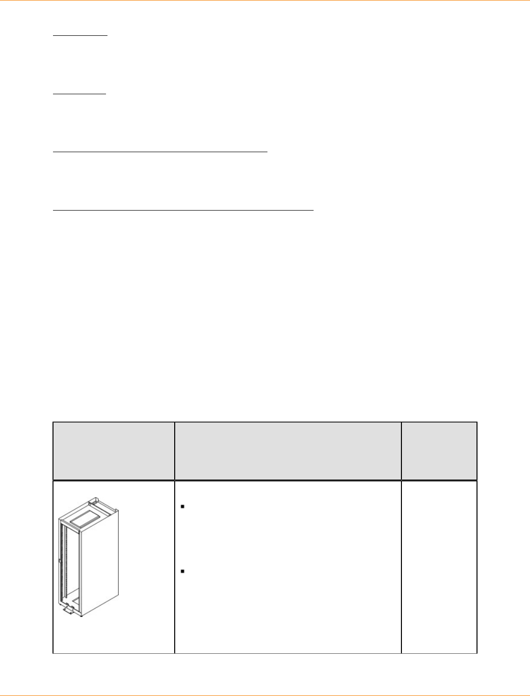
SANtricity_10.77 February 2011
LSI Corporation
- 340 -
controller
A circuit board and firmware that is located within a controller tray or a controller-drive tray. A controller
manages the input/output (I/O) between the host system and data volumes.
drive tray
One tray with drives, one or two environmental services monitors (ESMs), power supplies, and fans. A drive
tray does not contain controllers.
environmental services monitor (ESM)
A canister in the drive tray that monitors the status of the components. An ESM also serves as the connection
point to transfer data between the drive tray and the controller.
Small Form-factor Pluggable (SFP) transceiver
A component that enables Fibre Channel duplex communication between storage array devices. SFP
transceivers can be inserted into host bus adapters (HBAs), controllers, and environmental services monitors
(ESMs). SFP transceivers can support either copper cables (the SFP transceiver is integrated with the cable)
or fiber-optic cables (the SFP transceiver is a separate component from the fiber-optic cable).
Gathering Items
Before you start installing the controller-drive tray, you must have installed the cabinet in which the controller-
drive tray will be mounted.
Use the tables in this section to verify that you have all of the necessary items to install the controller-drive
tray.
Basic Hardware
Basic Hardware
Item Included
with the
Controller-
Drive Tray
Cabinet
Make sure that your cabinet meets the
installation site specifications of the various
CDE2600-60 storage array components.
Refer to the Storage System Site Preparation
Guide for more information.
Depending on the power supply limitations
of your cabinet, you might need to install
more than one cabinet to accommodate the
different components of the CDE2600-60
storage array. Refer to the installation guide
for your cabinet for instructions on installing
the cabinet.
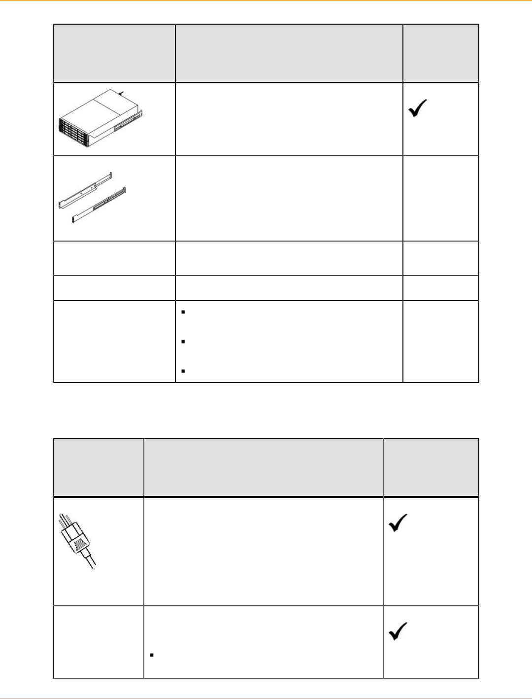
SANtricity_10.77 February 2011
LSI Corporation
- 341 -
Item Included
with the
Controller-
Drive Tray
DE6600 drive tray (shown with the separately
packaged mounting rails attached).
Mounting rails and screws.
The mounting rails that are available with the
drive tray are designed for an industry-standard
cabinet.
Fibre Channel switch (optional).
SAS switch (optional).
Gigabit Ethernet switch (optional).
Host with Fibre Channel host bus adapters
(HBAs) (optional).
Host with iSCSI HBAs (optional) or a network
interface card (optional).
Host with SAS HBAs (optional).
CDE2600 Configuration Cables and Connectors
Cables and Connectors
Item Included with the
Controller-Drive
Tray or Drive
Trays
AC power cords.
The controller-drive tray and the drive trays ship
with power cords for connecting to an external
power source, such as a wall plug. Your cabinet
might have special power cords that you use
instead of the power cords that ship with the
controller-drive tray and the drive trays.
(Optional) Two DC power connector cables are
provided with each drive tray for connection to
centralized DC power plant equipment.
Four DC power connector cables are provided if
additional redundancy is required. For the DC power option only
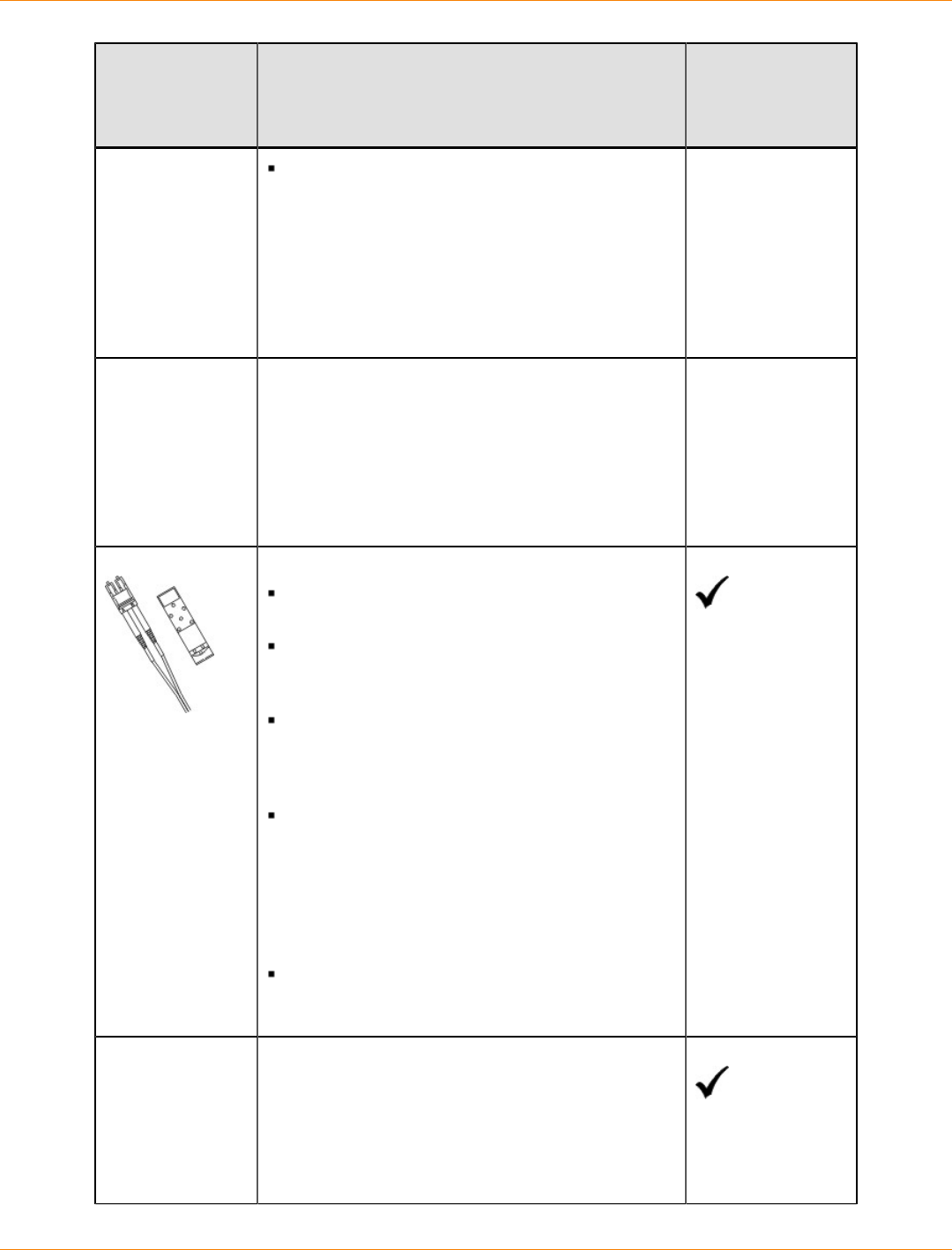
SANtricity_10.77 February 2011
LSI Corporation
- 342 -
Item Included with the
Controller-Drive
Tray or Drive
Trays
A qualified service person is required to
make the DC power connection per NEC and
CEC guidelines. A two-pole 20-amp circuit
breaker is required between the DC power
source and the drive tray for over-current and
short-circuit protection. Before turning off any
power switches on a DC-powered drive tray,
first you must disconnect the two-pole 20-amp
circuit breaker.
Copper SAS cables - Use for all drive-side
connections within the storage array.
Fiber-optic cables - Use for FC connections to the
drive trays.
For the differences between the fiber-optic cables
and the copper Fibre Channel (FC) cables, see
Things to Know – SFP Transceivers, Fiber-Optic
Cables, Copper Cables, and SAS Cables .
Small Form-factor Pluggable (SFP) transceivers
The SFP transceivers connect fiber-optic cables
to host ports and drive ports.
Four or eight SFP transceivers are included with
the controller-drive tray; one for each of the host
channel ports on the controllers.
Depending on your connection requirements,
you might need to purchase additional SFP
transceivers (two SFP transceivers for each
fiber-optic cable).
Depending on the configuration of your
storage array, you might need to use various
combinations of four different types of SFP
transceivers: 8-Gb/s Fibre Channel, 6-Gb/
s SAS, 1-Gb/s iSCSI, or 10-Gb/s iSCSI.
These SFP transceivers are not generally
interchangeable.
You must purchase only Restriction of
Hazardous Substances (RoHS)-compliant SFP
transceivers.
Copper Fibre Channel cables (optional)
Use these cables for connections within the storage
array.
For the differences between the fiber-optic cables
and the copper Fibre Channel cables, see “Things
to Know – SFP Transceivers, Fiber-Optic Cables,
Copper Cables, and SAS Cables.”
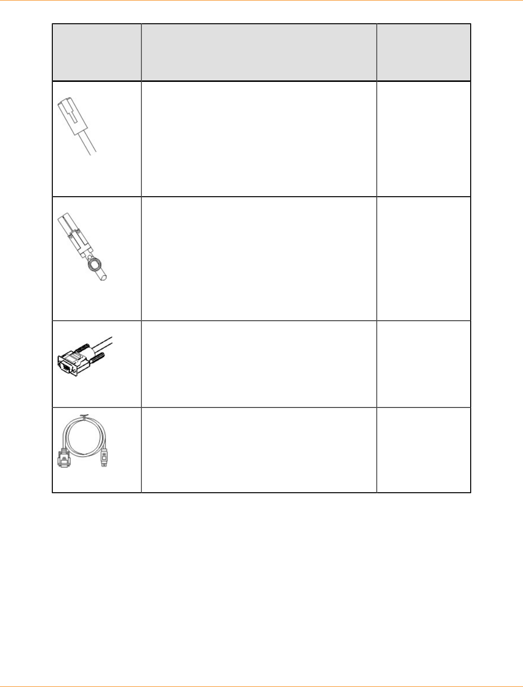
SANtricity_10.77 February 2011
LSI Corporation
- 343 -
Item Included with the
Controller-Drive
Tray or Drive
Trays
Ethernet cable
This cable is used for out-of-band storage array
management and for 1-Gb/s iSCSI connections.
For information about out-of-band storage array
management, see the description for "Deciding on
the Management Method" in Initial Configuration
and Software Installation electronic document
topics or the PDF on the SANtricity ES Storage
Manager Installation DVD.
SAS cables
The SAS cables connect the host to the controller-
drive tray. If you install a drive tray, you must use
SAS cables to connect the controller-drive tray to
the drive tray.
Serial cable
This cable is used for support only. You do not need
to connect it during initial installation.
DB9-to-PS2 adapter cable
This cable adapts the DB9 connector on
commercially available serial cables to the PS2
connector on the controller.
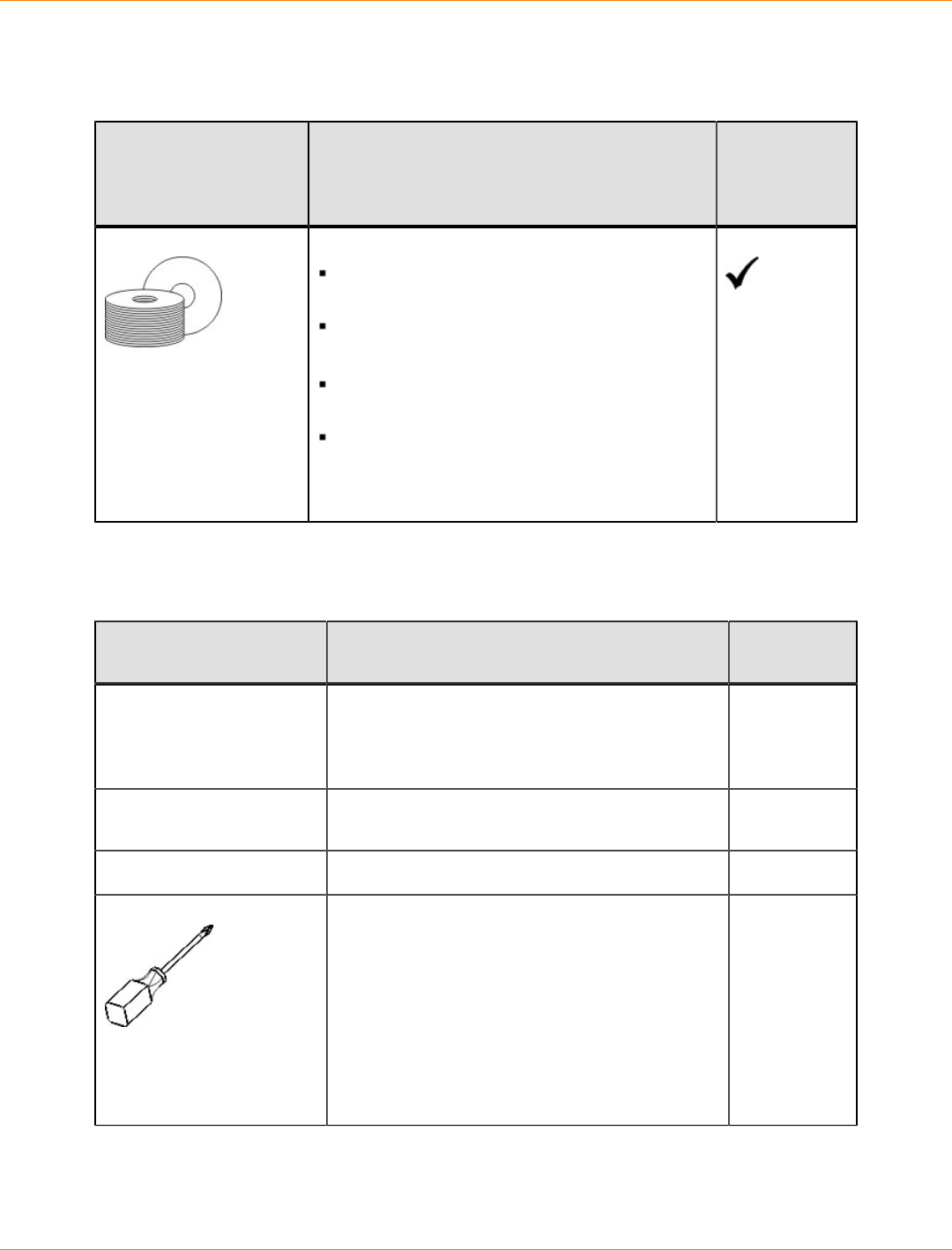
SANtricity_10.77 February 2011
LSI Corporation
- 344 -
Product DVDs
Product DVDs
Item Included
with the
Controller-
Drive Tray
Firmware DVD
Firmware is already installed on the
controllers.
The files on the DVD are backup copies.
SANtricity ES Storage Manager Installation DVD
SANtricity ES Storage Manager software and
documentation.
To access product documentation,
use the documentation map file,
doc_launcher.html, which is located in
the docs directory.
Tools and Other Items
Tools and Other Items
Item Included
with the Tray
Labels
Help you to identify cable connections and lets
you more easily trace cables from one tray to
another
A cart
Holds the tray and components
A mechanical lift (optional)
A Phillips screwdriver
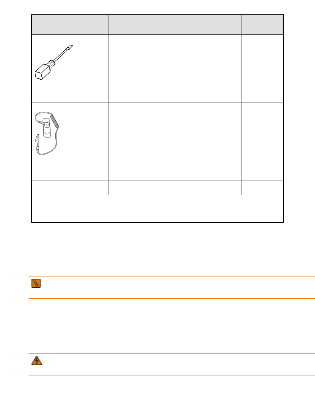
SANtricity_10.77 February 2011
LSI Corporation
- 345 -
Item Included
with the Tray
A flat-blade screwdriver
Anti-static protection
A flashlight
Use the Compatibility Matrix, at the following website, to obtain the latest hardware
compatibility information.
http://www.lsi.com/compatibilitymatrix/
Things to Know – SFP Transceivers, Fiber-Optic Cables, Copper Cables, and
SAS Cables
The figures in this topic display the fiber-optic cables, copper cables, SFP transceivers., and SAS cables with
a SFF-8088 Connector.
NOTE Your SFP transceivers and cables might look slightly different from the ones shown. The
differences do not affect the performance of the SFP transceivers.
The controller-drive tray supports SAS, Fibre Channel (FC), and iSCSI host connections and SAS drive
connections. FC host connections can operate at 8 Gb/s or at a lower data rate. Ports for 8-Gb/s Fibre
Channel host connections require SFP transceivers designed for this data rate. These SFP transceivers look
similar to other SFP transceivers but are not compatible with other types of connections. SFP transceivers
for 1-Gb/s iSCSI and 10-Gb/s iSCSI connections have a different physical interface for the cable and are not
compatible with other types of connections.
WARNING (W03) Risk of exposure to laser radiation – Do not disassemble or remove any part of a
Small Form-factor Pluggable (SFP) transceiver because you might be exposed to laser radiation.
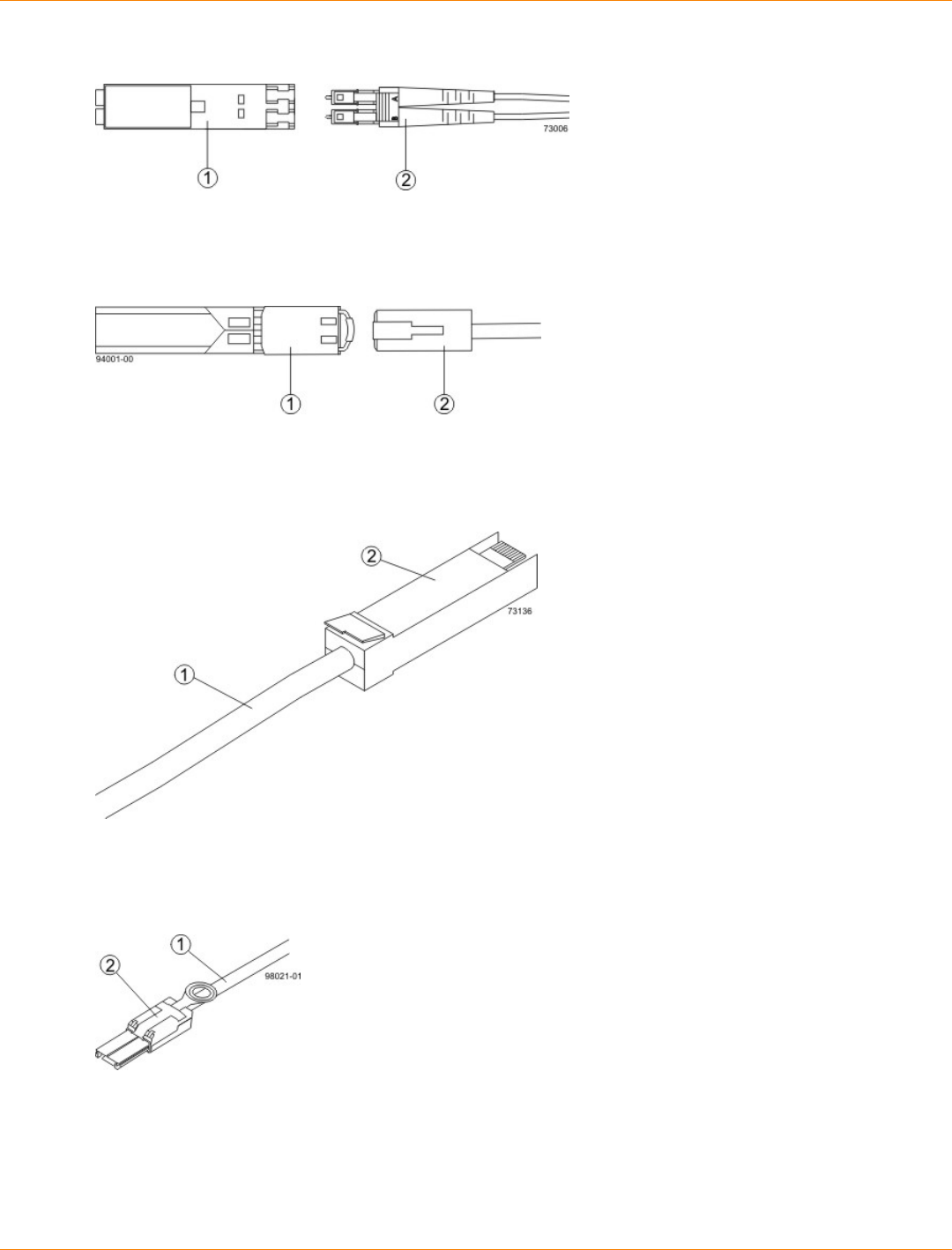
SANtricity_10.77 February 2011
LSI Corporation
- 346 -
Fiber-Optic Cable Connection
1. Active SFP Transceiver
2. Fiber-Optic Cable
1-Gb/s iSCSI Cable Connection
1. Active SFP Transceiver
2. Copper Cable with RJ-45 Connector
Copper Fibre Channel Cable Connection
1. Copper Fibre Channel Cable
2. Passive SFP Transceiver
SAS Cable Connection
1. SAS Cable
2. SFF-8088 Connector
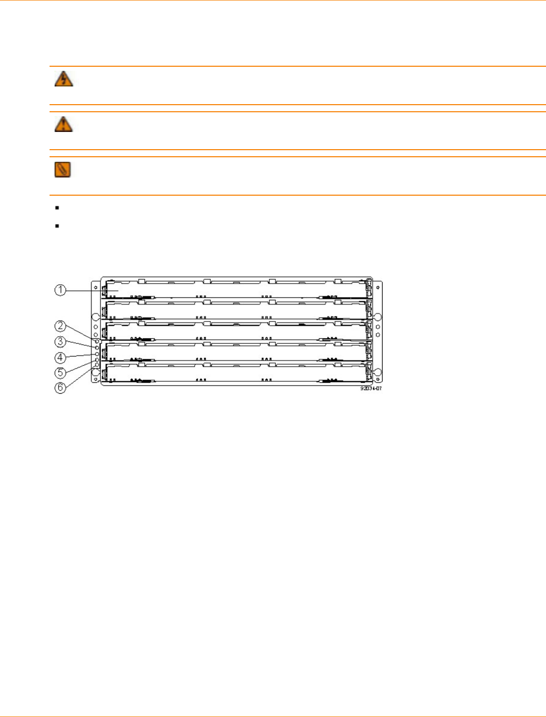
SANtricity_10.77 February 2011
LSI Corporation
- 347 -
Things to Know – Taking a Quick Glance at the Hardware in a CDE2600-60
Controller-Drive Tray Configuration
WARNING (W14) Risk of bodily injury – A qualified service person is required to make the DC
power connection according to NEC and CEC guidelines.
CAUTION (C05) Electrical grounding hazard – This equipment is designed to permit the connection
of the DC supply circuit to the earthing conductor at the equipment.
NOTE Each tray in the storage array must have a minimum of two drives for proper operation. If the
tray has fewer than two drives, a power supply error is reported.
The top of the controller-drive tray is the side with labels.
The configuration of the host ports might appear different on your system depending on which host
interface card configuration is installed.
CDE2600-60 Controller-Drive Tray – Front View
1. Drive Drawer
2. End Cap Locate LED
3. End Cap Service Action Required LED
4. End Cap Over-Temperature LED
5. End Cap Power LED
6. End Cap Standby Power LED

SANtricity_10.77 February 2011
LSI Corporation
- 348 -
CDE2600-60 Controller-Drive Tray Duplex Configuration– Rear View
1. Fan Canister
2. Fan Canister Power LED
3. Fan Canister Service Action Required LED
4. Fan Canister Service Action Allowed LED
5. Serial Connector
6. Ethernet Link 1 Active LED
7. Ethernet Connector 1
8. Ethernet Link 1 Rate LED
9. Ethernet Link 2 Active LED
10. Ethernet Connector 2
11. Ethernet Link 2 Rate LED
12. Host Link 2 Fault LED
13. Base Host SFF-8088 Connector 2
14. Host Link 2 Active LED
15. Host Link 1 Fault LED
16. Host Link 1 Active LED
17. Base Host SFF-8088 Connector 1
18. Controller A Canister
19. ESM Expansion Fault LED
20. ESM Expansion Active LED
21. Expansion SFF-8088 Port Connector
22. Second Seven-Segment Display Field
23. First Seven-Segment Display Field
24. Cache Active LED
25. Controller A Service Action Required LED
26. Controller A Service Action Allowed LED
27. Battery Service Action Required LED
28. Battery Charging LED
29. Power Canister
30. Power Canister AC Power LED
31. Power Canister Service Action Required LED
32. Power Canister Service Action Allowed LED
33. Power Canister DC Power LED
34. Power Canister Standby Power LED

SANtricity_10.77 February 2011
LSI Corporation
- 349 -
CDE2600-60 Right-Rear Subplate with No Host Interface Card
1. ESM Expansion Fault LED
2. ESM Expansion Active LED
3. Expansion SFF-8088 Port Connector
CDE2600-60 Right-Rear Subplate with a SAS Host Interface Card
1. Host Interface Card Link 3 Up LED
2. Host Interface Card Link 3 Active LED
3. SFF-8088 Host Interface Card Connector 3
4. Host Interface Card Link 4 Up LED
5. Host Interface Card Link 4 Active LED
6. SFF-8088 Host Interface Card Connector 4
7. ESM Expansion Fault LED
8. ESM Expansion Active LED
9. Expansion SFF-8088 Port Connector

SANtricity_10.77 February 2011
LSI Corporation
- 350 -
CDE2600-60 Right-Rear Subplate with an FC Host Interface Card
1. Host Interface Card Link 3 Up LED
2. Host Interface Card Link 3 Active LED
3. FC Host Interface Card Connector 3
4. Host Interface Card Link 4 Up LED
5. Host Interface Card Link 4 Active LED
6. FC Host Interface Card Connector 4
7. Host Interface Card Link 5 Up LED
8. Host Interface Card Link 5 Active LED
9. FC Host Interface Card Connector 5
10. Host Interface Card Link 6 Up LED
11. Host Interface Card Link 6 Active LED
12. FC Host Interface Card Connector 6
13. ESM Expansion Fault LED
14. ESM Expansion Active LED
15. Expansion SFF-8088 Port Connector

SANtricity_10.77 February 2011
LSI Corporation
- 351 -
CDE2600-60 Right-Rear Subplate with a 1-Gb iSCSI Host Interface Card
1. Host Interface Card Link 3 Up LED
2. Host Interface Card Link 3 Active LED
3. iSCSI Host Interface Card Connector 3
4. Host Interface Card Link 4 Up LED
5. Host Interface Card Link 4 Active LED
6. iSCSI Host Interface Card Connector 4
7. Host Interface Card Link 5 Up LED
8. Host Interface Card Link 5 Active LED
9. iSCSI Host Interface Card Connector 5
10. Host Interface Card Link 6 Up LED
11. Host Interface Card Link 6 Active LED
12. iSCSI Host Interface Card Connector 6
13. ESM Expansion Fault LED
14. ESM Expansion Active LED
15. Expansion SFF-8088 Port Connector
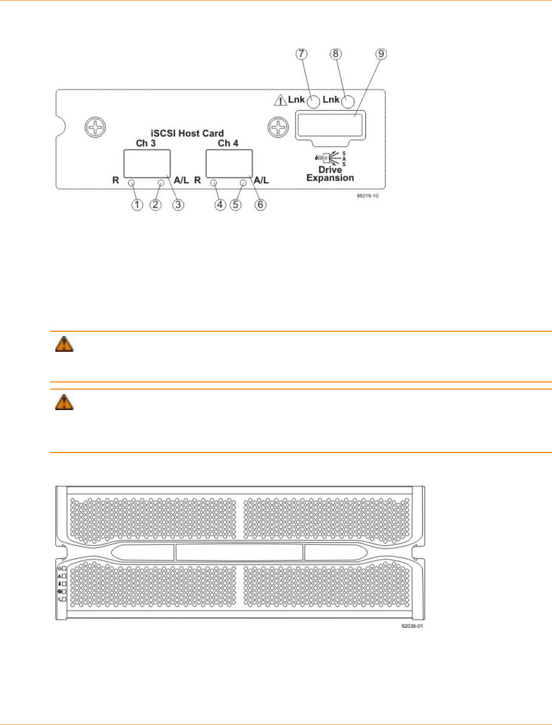
SANtricity_10.77 February 2011
LSI Corporation
- 352 -
CDE2600-60 Right-Rear Subplate with a 10-Gb iSCSI Host Interface Card
1. Host Interface Card Link 3 Up LED
2. Host Interface Card Link 3 Active LED
3. iSCSI Host Interface Card Connector 3
4. Host Interface Card Link 4 Up LED
5. Host Interface Card Link 4 Active LED
6. iSCSI Host Interface Card Connector 4
7. ESM Expansion Fault LED
8. ESM Expansion Active LED
9. Expansion SFF-8088 Port Connector
ATTENTION Possible equipment damage – You must use the supported drives in the drive tray to
ensure proper performance. For information on supported drives, contact a Customer and Technical Support
representative.
ATTENTION Risk of equipment malfunction – To avoid exceeding the functional and environmental
limits, install only drives that have been provided or approved by the original manufacturer. Not all controller-
drive trays are shipped with prepopulated drives. System integrators, resellers, system administrators, or
users of the controller-drive tray can install the drives.
DE6600 Drive Tray – Front View with Bezel
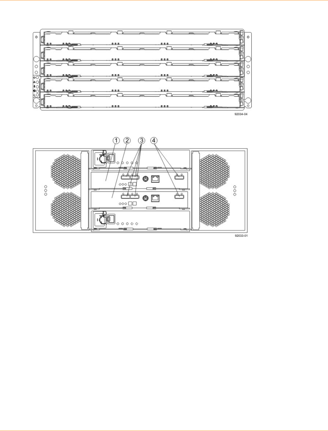
SANtricity_10.77 February 2011
LSI Corporation
- 353 -
DE6600 Drive Tray – Front View with Bezel Removed
DE6600 Drive Tray – Rear View
1. ESM A
2. ESM B
3. SAS IN Connectors
4. Expansion Connectors
For Additional Information on the CDE2600-60 Controller-Drive Tray
Configuration
Refer to the Storage System Site Preparation Guide on the SANtricity ES Storage Manager Installation DVD
for information about the installation requirements of the various CDE2600-60 storage array components.

SANtricity_10.77 February 2011
LSI Corporation
- 354 -
Step 2 – Installing and Configuring the Switches
Things to Know – Switches
IMPORTANT Most of the switches, as shipped from the vendor, require an update to their firmware to
work correctly with the storage array.
Depending on the configuration of your storage array, you might use Fibre Channel switches and iSCSI
switches.
The switches in the following table are certified for use with a CDE2600 storage array, a CDE2600-60 storage
array, a CDE4900 storage array, and a CE7900 storage array, which all use SANtricity ES Storage Manager
Version 10.77.
Supported Switches
Vendor Model Fibre
Channel iSCSI SAS
200E Yes No No
3200 Yes No No
3800 Yes No No
3900 Yes No No
3950 Yes No No
12000 Yes No No
3850 Yes No No
3250 Yes No No
24000 Yes No No
4100 Yes No No
48000 Yes No No
5000 Yes No No
300 Yes No No
5100 Yes No No
5300 Yes No No
7500 Yes No No
7800 Yes No No
Brocade
DCX Yes No No

SANtricity_10.77 February 2011
LSI Corporation
- 355 -
Vendor Model Fibre
Channel iSCSI SAS
FCOE No Yes No
9506 Yes No No
9509 Yes No No
9216 Yes No No
9216i Yes No No
9120 Yes No No
914x Yes No No
9513 Yes No No
9020 Yes No No
MDS9000 Yes No No
9222i Yes No No
9134 Yes No No
Catalyst 2960 No Yes No
Catalyst 3560 No Yes No
Cisco
Catalyst 3750G-24TS No Yes No
LSI 6160 No No Yes
3232 Yes No No
3216 Yes No No
4300 Yes No No
4500 Yes No No
6064 Yes No No
6140 Yes No No
4400 Yes No No
McData
4700 Yes No No
6140 No Yes No
6142 No Yes No
QLogic
SANbox2-8 Yes No No
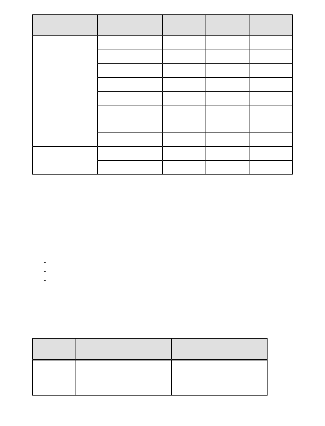
SANtricity_10.77 February 2011
LSI Corporation
- 356 -
Vendor Model Fibre
Channel iSCSI SAS
SANbox2-16 Yes No No
SANbox5200 Yes No No
SANbox3600 Yes No No
SANbox3800 Yes No No
SANbox5208 Yes No No
SANbox5600 Yes No No
SANbox5800 Yes No No
SANbox9000 Yes No No
5324 No Yes NoPowerConnect
6024 No Yes No
If required, make the appropriate configuration changes for each switch that is connected to the storage array.
Refer to the switch’s documentation for information about how to install the switch and how to use the
configuration utilities that are supplied with the switch.
Procedure – Installing and Configuring Switches
1. Install your switch according to the vendor’s documentation.
2. Use the Compatibility Matrix at the website http://www.lsi.com/compatibilitymatrix/ to obtain this
information:
The latest hardware compatibility information
The models of the switches that are supported
The firmware requirements and the software requirements for the switches
3. Update the switch’s firmware by accessing it from the applicable switch vendor’s website.
This update might require that you cycle power to the switch.
4. Find your switch in the following table to see whether you need to make further configuration changes.
Use your switch’s configuration utility to make the changes.
Supported Switch Vendors and Required Configuration Changes
Switch
Vendor Configuration Changes
Required? Next Step
Brocade Yes
Change the In-Order Delivery
(IOD) option to ON.
Make the change, and go to
“Step 3 – Installing the Host
Bus Adapters for the CDE2600
Controller-Drive Tray.”

SANtricity_10.77 February 2011
LSI Corporation
- 357 -
Switch
Vendor Configuration Changes
Required? Next Step
Cisco Yes
Change the In-Order Delivery
(IOD) option to ON.
Make the change, and go to
“Step 3 – Installing the Host
Bus Adapters for the CDE2600
Controller-Drive Tray.”
LSI No “Step 3 – Installing the Host
Bus Adapters for the CDE2600
Controller-Drive Tray.”
McData No “Step 3 – Installing the Host
Bus Adapters for the CDE2600
Controller-Drive Tray.”
QLogic No “Step 3 – Installing the Host
Bus Adapters for the CDE2600
Controller-Drive Tray.”
PowerConnect No “Step 3 – Installing the Host
Bus Adapters for the CDE2600
Controller-Drive Tray.”

SANtricity_10.77 February 2011
LSI Corporation
- 358 -
Step 3 – Installing the Host Bus Adapters for the CDE2600
Controller-Drive Tray
Key Terms
HBA host port
The physical and electrical interface on the host bus adapter (HBA) that provides for the connection between
the host and the controller. Most HBAs will have either one or two host ports. The HBA has a unique World
Wide Identifier (WWID) and each HBA host port has a unique WWID.
HBA host port world wide name
A 16-character unique name that is provided for each port on the host bus adapter (HBA).
host bus adapter (HBA)
A physical board that resides in the host. The HBA provides for data transfer between the host and the
controllers in the storage array over the I/O host interface. Each HBA contains one or more physical ports.
Things to Know – Host Bus Adapters and Ethernet Network Interface Cards
The CDE2600 controller-drive tray supports dual 6-Gb/s SAS host connections and optional host interface
cards (HICs) for dual 6-Gb/s SAS, four 1-Gb/s iSCSI, two 10-Gb iSCSI, and four 8-Gb/s FC connections.
The connections on a host must match the type (SAS HBAs for SAS, FC HBAs for FC, or iSCSI HBAs or
Ethernet network interface cards [NICs] for iSCSI) of the HICs to which you connect them. For the best
performance, HBAs for SAS and FC connections should support the highest data rate supported by the
HICs to which they connect.
For maximum hardware redundancy, you must install a minimum of two HBAs (for either SAS or FC host
connections) or two NICs or iSCSI HBAs (for iSCSI host connections) in each host. Using both ports of a
dual-port HBA or a dual-port NIC provides two paths to the storage array but does not ensure redundancy
if an HBA or a NIC fails.
NOTE You can use the Compatibility Matrix to obtain information about the supported models of the
HBAs and their requirements. Go to http://www.lsi.com/compatibilitymatrix/, and select the desired Developer
Partner Program link. Check its Compatibility Matrix to make sure you have an acceptable configuration.
Most of the HBAs, as shipped from the vendor, require updated firmware and software drivers to work
correctly with the storage array. For information about the updates, refer to the website of the HBA
vendor.
Procedure – Installing Host Bus Adapters
1. Go to http://www.lsi.com/compatibilitymatrix/, and select the desired Developer Partner Program link.
Check its Compatibility Matrix to make sure you have an acceptable configuration.
The Compatibility Matrix provides this information:
The latest hardware compatibility information
The models of the HBAs that are supported
The firmware requirements and the software requirements for the HBAs
2. Install your HBA according to the vendor documentation.

SANtricity_10.77 February 2011
LSI Corporation
- 359 -
NOTE If your operating system is Windows Server 2008 Server Core, you might have additional
installation requirements. Refer to the Microsoft Developers Network (MSDN) for more information about
Windows Server 2008 Server Core. You can access these resources from www.microsoft.com.
3. Install the latest version of the firmware for the HBA. You can find the latest version of the firmware for the
HBA at the HBA vendor website.
IMPORTANT The remaining steps are general steps to obtain the HBA host port World Wide Name
from the HBA BIOS utility. If you have installed the host context agent on all of your hosts, you do not need
to perform these steps. If you are performing these steps, the actual prompts and screens vary depending
on the vendor that provides the HBA. Also, some HBAs have software utilities that you can use to obtain the
world wide name for the port instead of using the BIOS utility.
4. Reboot or start your host.
5. While your host is booting, look for the prompt to access the HBA BIOS utility.
6. Select each HBA to view its HBA host port world wide name.
7. Record the following information for each host and for each HBA connected to the storage array:
The name of each host
The HBAs in each host
The HBA host port world wide name of each port on the HBA
The following table shows examples of the host and HBA information that you must record.
Examples of HBA Host Port World Wide Names
Host Name Associated HBAs HBA Host Port World
Wide Name
Vendor x, Model y (dual port) 37:38:39:30:31:32:33:32
37:38:39:30:31:32:33:33
ICTENGINEERING
Vendor a, Model y (dual port) 42:38:39:30:31:32:33:42
42:38:39:30:31:32:33:44
Vendor a, Model b (single
port) 57:38:39:30:31:32:33:52ICTFINANCE
Vendor x, Model b (single
port) 57:38:39:30:31:32:33:53
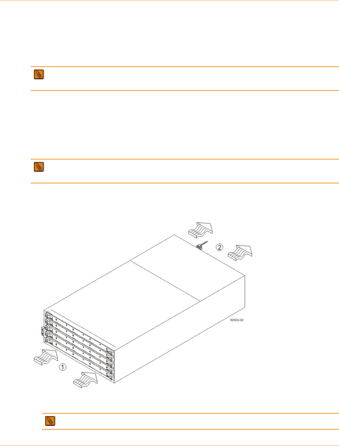
SANtricity_10.77 February 2011
LSI Corporation
- 360 -
Step 4 – Installing the CDE2600 Controller-Drive Tray
Things to Know – General Installation
The power supplies meet standard voltage requirements for both domestic and worldwide operation.
IMPORTANT Make sure that the combined power requirements of your trays do not exceed the power
capacity of your cabinet.
Steps to Install – CDE2600-60 Controller-Drive Tray
You can install the high-density, 6-Gb SAS SBB 2.0-compliant CDE2600-60 controller-drive tray into an
Industry-standard cabinet, provided it has a depth of 100 cm (40 in.):
A minimum depth of 76 cm (30 in.) between the front EIA support rails and the rear EIA support rails is
required.
NOTE If you are mounting the CDE2600-60 controller-drive tray in a cabinet with square holes, use the
eight shoulder washers in the rail kit to align the screws in the holes (see step 4 through step 7).
1. Make sure that the cabinet is in the final location. Make sure that you meet the clearance requirements
shown in the following figure.
Controller-Drive Tray Airflow and Clearance Requirements
1. 81 cm (32 in.) clearance in front of the cabinet
2. 61 cm (24 in.) clearance behind the cabinet
NOTE Fans pull air through the controller-drive tray from front to back across the drives.
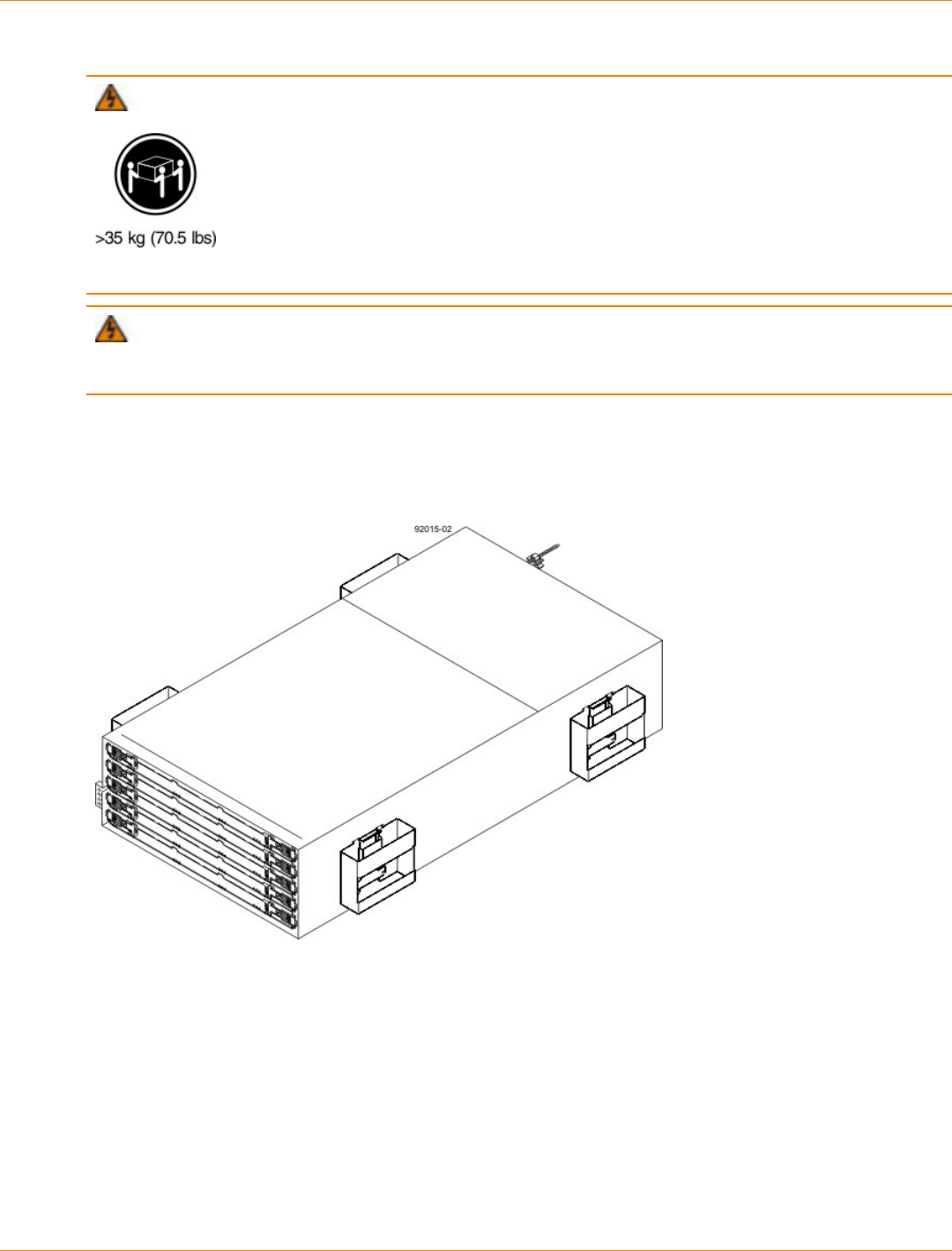
SANtricity_10.77 February 2011
LSI Corporation
- 361 -
2. Lower the feet on the cabinet to keep the cabinet from moving.
WARNING (W09) Risk of bodily injury –
Three persons are required to safely lift the component.
WARNING (W15) Risk of bodily injury – An empty tray weighs approximately 56.7 kg (125 lb).
Three persons are required to safely move an empty tray. If the tray is populated with components, a
mechanized lift is required to safely move the tray.
3. With the help of at least two other persons, remove the drive tray and all of the contents from the shipping
carton, using the four controller-drive tray handles (two to a side) as shown in the figure " Figure 2". Set
the drive tray aside.
CDE2600-60 Controller-Drive Tray with Controller-Drive Tray Handles (Two on Each Side)
4. Position the mounting rails in the cabinet.

SANtricity_10.77 February 2011
LSI Corporation
- 362 -
Positioning the Mounting Rails in the Cabinet
1. Screws for Securing the Mounting Rail to the Cabinet (Front)
2. Screws for Securing the Mounting Rail to the Cabinet (Rear)
3. Existing Tray
4. Industry Standard Cabinet
If you are installing the mounting rails above an existing tray, position the mounting rails directly
above the controller-drive tray.
If you are installing the mounting rails below an existing tray, allow 17.8-cm (7-in.) vertical clearance
for a CDE2600-60 controller-drive tray.
5. To attach the mounting rails to the cabinet, do one of the following:
If you are using the long fixed size mounting rails, go to step 6.
If you are using the shorter adjustable mounting rails, go to step 7.
6. To attach the long mounting rails to the cabinet, perform these substeps:
a. Make sure that the adjustment screws on the mounting rail are loose so that the mounting rail can
extend or contract as needed.

SANtricity_10.77 February 2011
LSI Corporation
- 363 -
Attaching the Long Mounting Rails to the Cabinet
1. Front of the Mounting Rail
2. Two M4 Screws for the Rear EIA Support Rail
3. Front of the Cabinet
4. Two M5 Screws for the Front EIA Support Rail
5. Adjustable Rail Tightening Screws
6. Rear Hold-Down Screw
7. Cabinet Mounting Holes on the Front EIA Support Rail
8. Cabinet Mounting Holes on the Rear EIA Support Rail
9. Mounting Rail Lip
b. Remove the rear hold-down screw. It protrudes from the inside of the rail and prevents you from
sliding the drive tray onto the rails.
c. Place the mounting rail inside the cabinet, and extend the mounting rail until the flanges on the
mounting rail touch the inside of the cabinet.
d. Insert one M5 screw through the front of the cabinet, and screw it into the top captured nut in the
mounting rail.
e. Insert two M5 screws through the rear of the cabinet, and screw them into the captured nuts in the
rear flange in the mounting rail.
f. Tighten the adjustment screws on the mounting rail.
g. Repeat substep a through substep f to install the second mounting rail.
h. Insert one M5 screw through the front of the mounting rail. You use this screw to attach the controller-
drive tray to the cabinet.
7. To attach the shorter, adjustable size mounting rails to the cabinet, perform these sets of substeps:
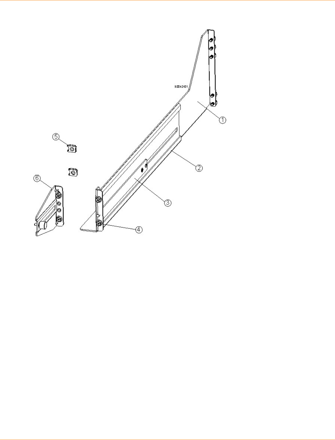
SANtricity_10.77 February 2011
LSI Corporation
- 364 -
Short Adjustable Mounting Rail -- Left Side
1. Front of the Mounting Rail
2. Rear of the Mounting Rail
3. Rail Fix Bar
4. Two M5 Screws for the Front EIA Support Rail
5. Two Clips for the Front EIA Support Rail
6. Rear Bracket
a. Make sure that the adjustment screws on the mounting rail are loose so that the mounting rail can
extend or contract as needed (see the figure Figure 5).
b. Place the mounting rail inside the cabinet, and extend the mounting rail until the flanges on the
mounting rail touch the inside of the cabinet (see the figure Figure 6).
c. Insert one M5 screw through the front of the cabinet, and screw it into the top captured nut in the
mounting rail.
d. Insert two M4 screws through the rear of the cabinet, and screw them into the captured nuts in the
rear flange in the mounting rail.
e. Tighten the adjustment screws on the mounting rail.
f. Repeat substep a through substep f to install the second mounting rail.
g. Insert one M5 screw through the front of the mounting rail. This screw will attach the drive tray to the
cabinet.
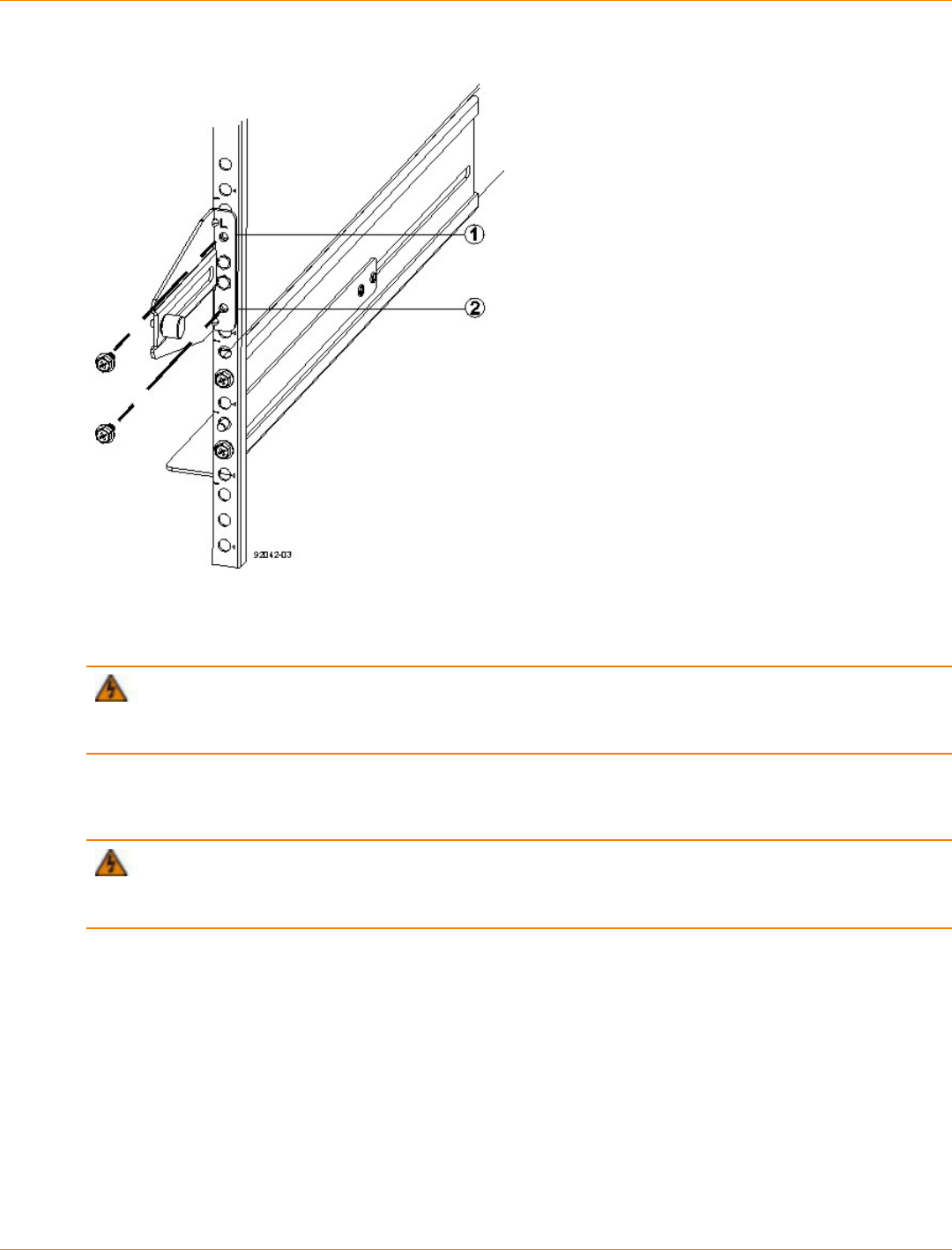
SANtricity_10.77 February 2011
LSI Corporation
- 365 -
Short Adjustable Mounting Rail Attached to the Cabinet
1. Top Cabinet Mounting Hole on the Rear EIA Support Rail
2. Bottom Cabinet Mounting Hole on the Rear EIA Support Rail
8. Remove the bezel from the front of the drive tray.
WARNING (W15) Risk of bodily injury – An empty tray weighs approximately 56.7 kg (125 lb).
Three persons are required to safely move an empty tray. If the tray is populated with components, a
mechanized lift is required to safely move the tray.
9. With the help of at least two other persons, slide the rear of the controller-drive tray onto the mounting
rails. The controller-drive tray is correctly aligned when the mounting holes on the front flanges of the
controller-drive tray align with the mounting holes on the front of the mounting rails.
WARNING (W15) Risk of bodily injury – An empty tray weighs approximately 56.7 kg (125 lb).
Three persons are required to safely move an empty tray. If the tray is populated with components, a
mechanized lift is required to safely move the tray.
10. After the controller-drive tray is correctly aligned, remove the enclosure lift handles as shown in the figure
Figure 7:
a. Use your thumb to unlatch and remove the rear enclosure lift handles (two to a side).
b. Use the front enclosure lift handles to slide the drive tray all the way into the cabinet.
c. Once the drive tray is securely in the cabinet, use your thumb to unlatch and remove the front
enclosure lift handles (two to a side).

SANtricity_10.77 February 2011
LSI Corporation
- 366 -
Removing an Enclosure Lift Handle from the Controller-Drive Tray
1. Pull the thumb latch away from the controller-drive tray to detach the hook.
2. Shift the handle down to release the other four hooks.
3. Move the handle away from the drive tray.
11. Secure the front of the controller-drive tray to the cabinet. Use the four screws to attach the flange on
each side of the front of the controller-drive tray to the mounting rails.
a. Insert two M5 screws through the bottom holes of a flange on the controller-drive tray so that the
screws go through the EIA support rail and engage the bottom captured nuts in the mounting rail.
Tighten the screws.
b. Repeat substep a for the second flange.
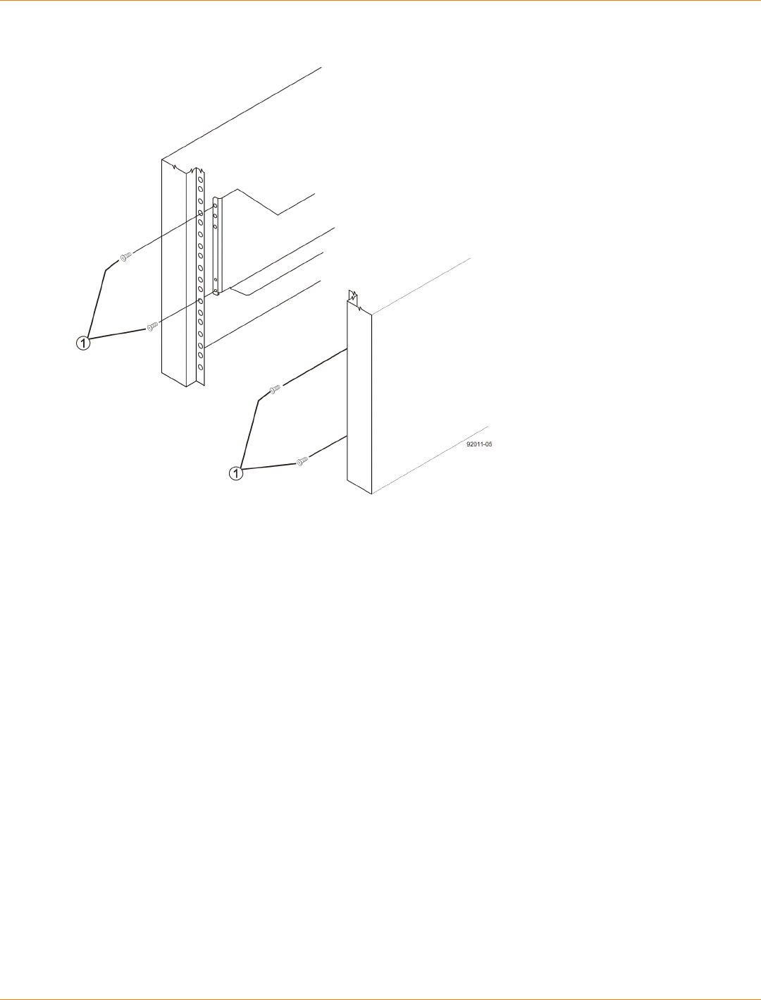
SANtricity_10.77 February 2011
LSI Corporation
- 367 -
Attaching the Front of the Controller-Drive Tray
1. Four Screws for Securing the Front of the Controller-Drive Tray
12. Remove the fan canister from the drive tray by pressing on the tab holding the fan canister handle in
place, and then pulling the fan canister toward you.
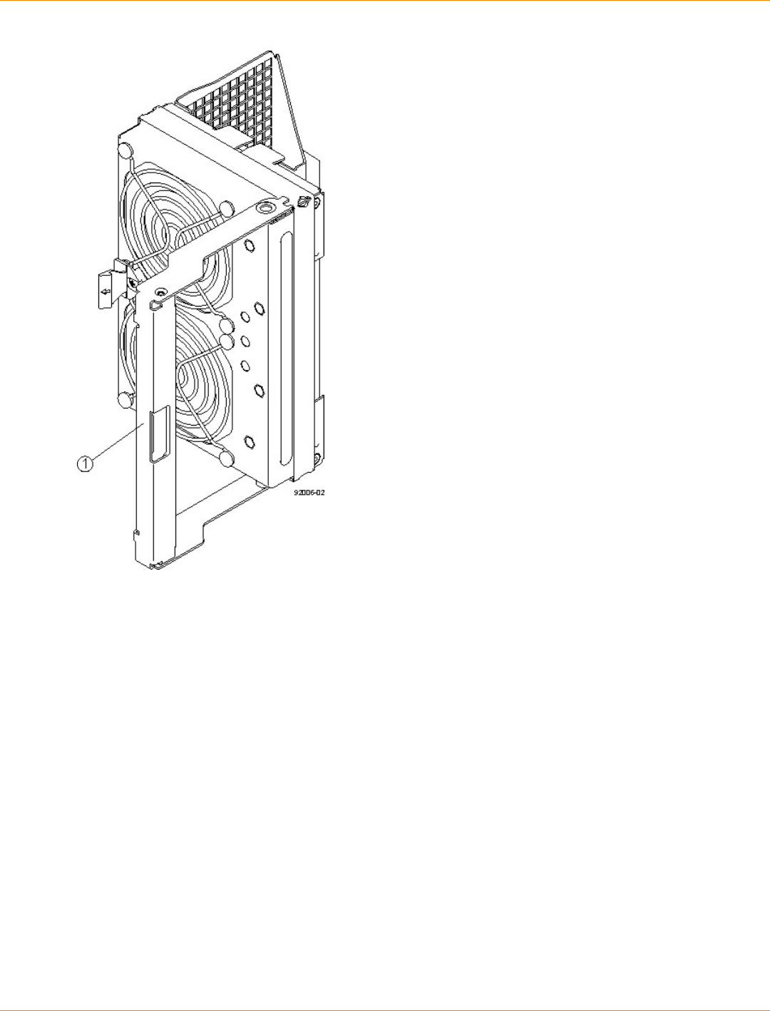
SANtricity_10.77 February 2011
LSI Corporation
- 368 -
1. Fan Canister Handle
13. Use the fan canister handle to pull the fan canister out of the drive tray.
14. Secure the side of the controller-drive tray to the mounting rails by performing these substeps:

SANtricity_10.77 February 2011
LSI Corporation
- 369 -
Securing the Controller-Drive Tray to the Rails
1. 10-32 Screw
a. Insert a 10-32 screw through the side sheet metal of the controller-drive tray into the captured nut on
the side of the mounting rail. Tighten the screws.
b. Repeat substep a for the other side.
NOTE After the controller-drive tray is installed, there should be seven screws on each side (right
and left) of the cabinet.
NOTE Make sure that each drive drawer in the controller-drive tray is securely fastened to ensure
proper air flow to the drives.
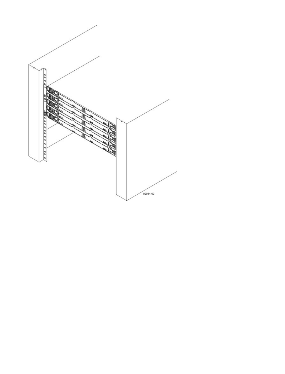
SANtricity_10.77 February 2011
LSI Corporation
- 370 -
Controller-Drive Tray Installed in the Cabinet
15. Slide the fan canister all the way back into the drive tray until the tab on the fan canister latches.
16. Attach the bezel onto the front of the controller-drive tray.
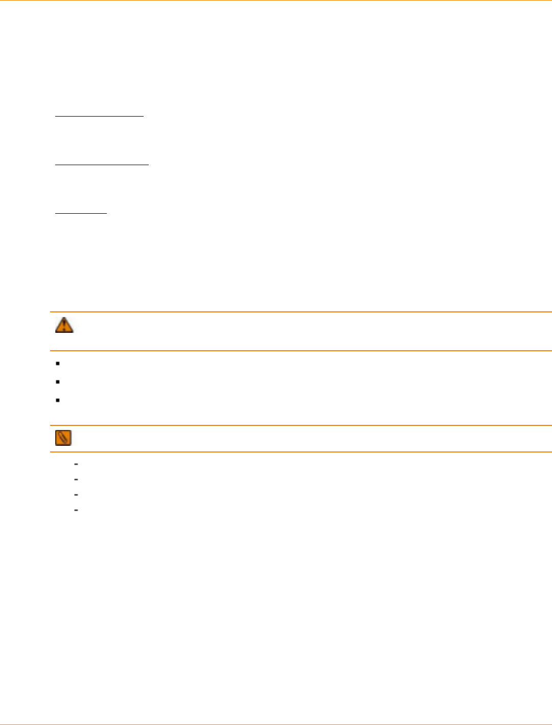
SANtricity_10.77 February 2011
LSI Corporation
- 371 -
Step 5 – Connecting the CDE2600 Controller-Drive Tray to the
Hosts
Key Terms
direct topology
A topology that does not use a switch.
switch topology
A topology that uses a switch.
topology
The logical layout of the components of a computer system or network and their interconnections. Topology
deals with questions of what components are directly connected to other components from the standpoint
of being able to communicate. It does not deal with questions of physical location of components or
interconnecting cables. (The Dictionary of Storage Networking Terminology)
Things to Know – Host Channels on the CDE2600-60 Controller-Drive Tray
ATTENTION Possible hardware damage – To prevent electrostatic discharge damage to the tray,
use proper antistatic protection when you handle tray components.
Each controller has from two to six host ports.
Two of the host ports are standard and support 6-Gb/s SAS data rates.
Two to four of the host ports are optional, and, if present, are located on a host interface card (HIC). The
following types of HICs are supported:
NOTE In configurations where a HIC does not exist, the space is covered with a blank faceplate.
Two SAS connectors at 6-Gb/s
Four iSCSI connectors at 1-Gb/s
Two iSCSI connectors at 10-Gb/s
Four FC connectors at 8-Gb/s
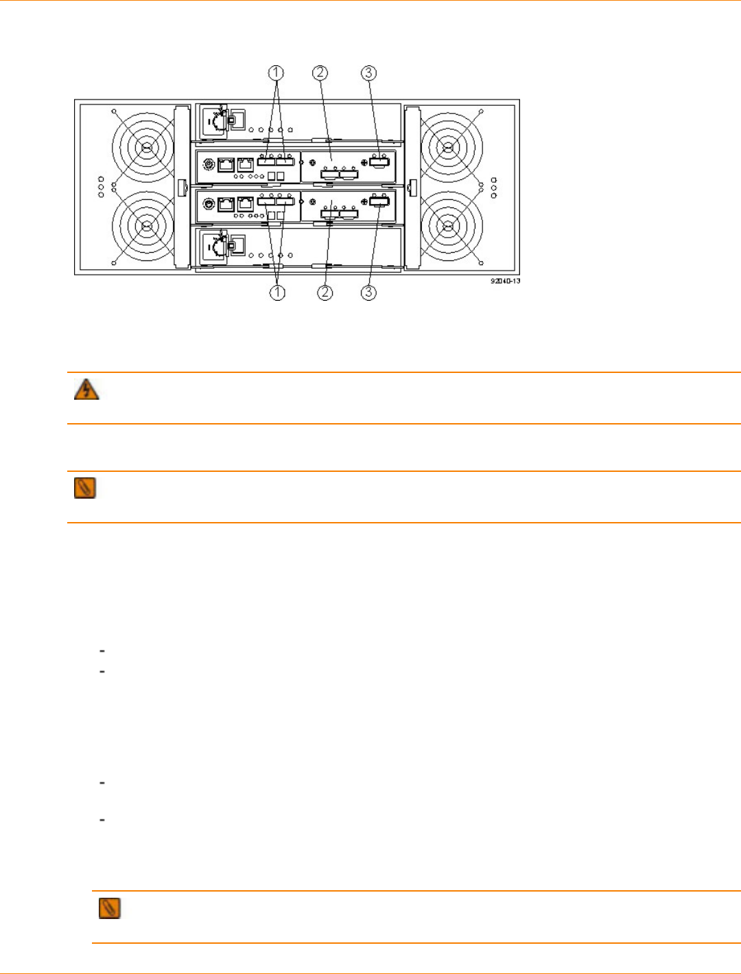
SANtricity_10.77 February 2011
LSI Corporation
- 372 -
Host Channels on the CDE2600-60 Controllers – Rear View
1. Standard Host Connectors
2. Host Interface Card (HIC) Connectors (SAS in this Example)
3. SAS Expansion Connector
WARNING (W03) Risk of exposure to laser radiation – Do not disassemble or remove any part of a
Small Form-factor Pluggable (SFP) transceiver because you might be exposed to laser radiation.
Procedure – Connecting Host Cables on a CDE2600-60 Controller-Drive Tray
IMPORTANT Make sure that you have installed the HBAs. Refer to the documentation for the HBAs for
information about how to install the HBA and how to use the supplied configuration utilities.
The type of HICs (SAS, FC, or iSCSI) must match the type of the host bus adapters (HBAs) or network
interface cards (for iSCSI only) to which you connect them.
See the examples in the following section for example cabling patterns.
1. Perform one of these actions:
You are using an FC HIC – Go to step 2.
You are using either a SAS or an iSCSI HIC – Go to step 4. Connections for both SAS and iSCSI
use copper cables with RJ-45 connectors and do not require SFP transceivers.
2. Make sure that the appropriate type of SFP transceiver is inserted into the host channel.
3. If a black, plastic plug is in the SFP transceiver, remove it.
4. Perform one of these actions:
You are using either a SAS or an iSCSI HIC – Starting with the first host channel of each controller,
plug one end of the cable into the host channel.
You are using an FC HIC – Starting with the first host channel of each controller, plug one end of the
cable into the SFP transceiver in the host channel.
The cable is either an Ethernet cable with RJ-45 connectors for 1-Gb/s iSCSI or 6-Gb/s SAS connections,
or a fiber-optic cable for FC connections.
IMPORTANT If Remote Volume Mirroring connections are required, do not connect a host to the
highest numbered host channel.

SANtricity_10.77 February 2011
LSI Corporation
- 373 -
Direct Topology – One Host Connected to a SingleController
1. Host
2. HBA 1 or NIC 1
3. HBA 2 or NIC 2
4. Host Port 1
5. Host Port 2
6. Controller A
Direct Topology – Two Hosts Connected to a Single Controller
1. Host
2. HBA 1 or NIC 1
3. HBA 2 or NIC 2
4. Host Port 1
5. Host Port 2
6. Controller A
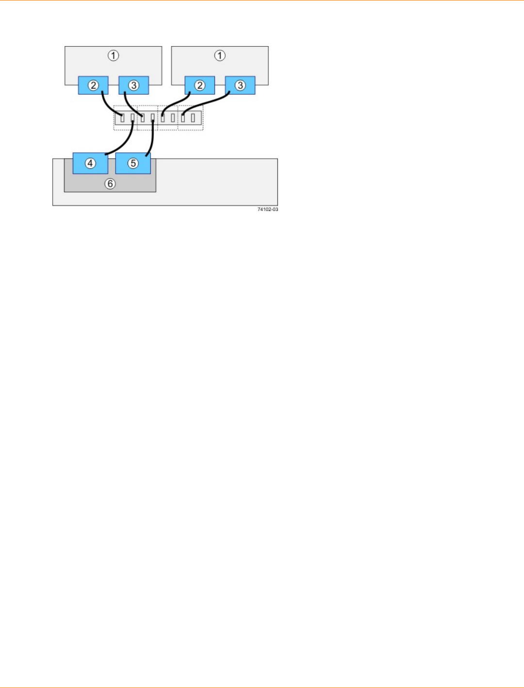
SANtricity_10.77 February 2011
LSI Corporation
- 374 -
Switch Topology – Two Hosts Connected to a Single Controller Through a Switch
1. Host
2. HBA 1 or NIC 1
3. HBA 2 or NIC 2
4. Host Port 1
5. Host Port 2
6. Controller A

SANtricity_10.77 February 2011
LSI Corporation
- 375 -
Direct Topology – One Host and a Dual Controller-Drive Tray
1. Host
2. HBA 1 or NIC 1
3. HBA 2 or NIC 2
4. Host Port 1
5. Host Port 2
6. Controller A
7. Controller B

SANtricity_10.77 February 2011
LSI Corporation
- 376 -
Direct Topology – Two Hosts and a Dual Controller-Drive Tray for Maximum Redundancy
1. Hosts
2. HBA 1 or NIC 1
3. HBA 2 or NIC 2
4. Host Port 1
5. Host Port 2
6. Controller A
7. Controller B

SANtricity_10.77 February 2011
LSI Corporation
- 377 -
Mixed Topology – Two Hosts and a Dual Controller-Drive Tray
1. Hosts
2. HBA 1 or NIC 1
3. HBA 2 or NIC 2
4. Host Port 1
5. Host Port 2
6. Controller A
7. Controller B

SANtricity_10.77 February 2011
LSI Corporation
- 378 -
Mixed Topology – Three Hosts and a Dual Controller-Drive Tray
1. Host 1
2. HBA 1 or NIC 1
3. HBA 2 or NIC 2
4. Host 2
5. Host 3
6. Host Port 1
7. Host Port 2
8. Controller A
9. Controller B
5. Plug the other end of the cable either into an HBA in the host (direct topology) or into a switch (fabric
topology).
NOTE The SAS host interface does not support a switch topology.
6. Affix a label to each end of the cable with this information. A label is very important if you need to
disconnect cables to service a controller. Include this information on the labels:
The host name and the HBA port (for direct topology)
The switch name and the port (for fabric topology)
The controller ID (for example, controller A)
The host channel ID (for example, host channel 1)
Example label abbreviation – Assume that a cable is connected between port 1 in HBA 1 of a host
named Engineering and host channel 1 of controller A. A label abbreviation could be as follows.
7. Repeat step 3 through step 6 for each controller and host channel that you intend to use.
SANtricity_10.77 February 2011
LSI Corporation
- 379 -
Step 6 – Installing the Drive Trays for the CDE2600-60 Controller-
Drive Tray Configurations
Things to Know – General Installation of Drive Trays with the CDE2600-60
Controller-Drive Tray
IMPORTANT If you are installing the drive tray in a cabinet with other trays, make sure that the
combined power requirements of the drive tray and the other trays do not exceed the power capacity of your
cabinet. For more information, refer to the SANtricity ES Storage Manager Installation DVD.
Special site preparation is not required for any of these drive trays beyond what is normally found in a
computer lab environment.
The power supplies meet standard voltage requirements for both domestic and worldwide operation.
Take these precautions:
Install the drive trays in locations within the cabinet that let you evenly distribute the drive trays
around the controller-drive tray.
Keep as much weight as possible in the bottom half of the cabinet.
NOTE Refer to the Storage System Site Preparation Guide on the SANtricity ES Storage Manager
Installation DVD for important considerations about cabinet installation.
WARNING (W15) Risk of bodily injury – An empty tray weighs approximately 56.7 kg (125 lb).
Three persons are required to safely move an empty tray. If the tray is populated with components, a
mechanized lift is required to safely move the tray.
Steps to Install – DE6600 Drive Tray
You can install the high-density, 6-Gb SAS SBB 2.0-compliant DE6600 drive tray into an Industry-standard
cabinet, provided it has a depth of 100 cm (40 in.):
A minimum depth of 76 cm (30 in.) between the front EIA support rails and the rear EIA support rails is
required.
NOTE If you are mounting the DE6600 drive tray in a cabinet with square holes, use the eight shoulder
washers in the rail kit to align the screws in the holes (see step 4 through step 7).
1. Make sure that the cabinet is in the final location. Make sure that you meet the clearance requirements
shown in the following figure.
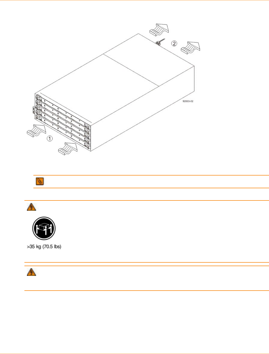
SANtricity_10.77 February 2011
LSI Corporation
- 380 -
Drive Tray Airflow and Clearance Requirements
1. 81 cm (32 in.) clearance in front of the cabinet
2. 61 cm (24 in.) clearance behind the cabinet
NOTE Fans pull air through the drive tray from front to back across the drives.
2. Lower the feet on the cabinet to keep the cabinet from moving.
WARNING (W09) Risk of bodily injury –
Three persons are required to safely lift the component.
WARNING (W15) Risk of bodily injury – An empty tray weighs approximately 56.7 kg (125 lb).
Three persons are required to safely move an empty tray. If the tray is populated with components, a
mechanized lift is required to safely move the tray.
3. With the help of at least two other persons, remove the drive tray and all of the contents from the shipping
carton, using the four drive tray handles (two to a side) as shown in the following figure. Set the drive tray
aside.
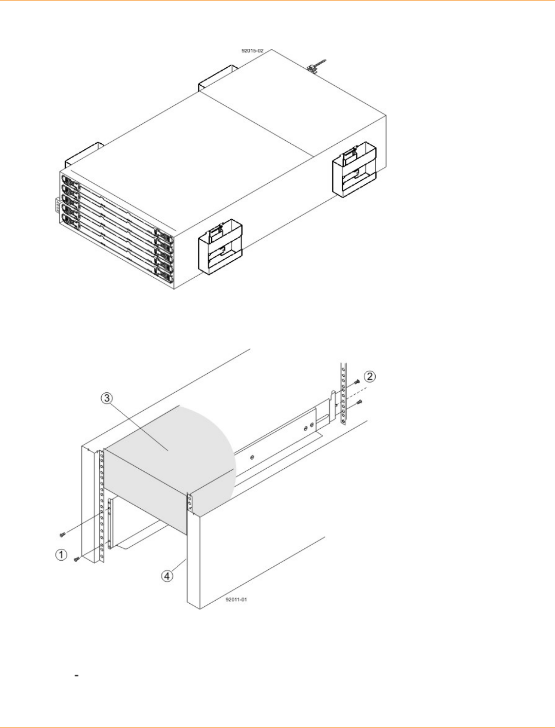
SANtricity_10.77 February 2011
LSI Corporation
- 381 -
DE6600 Drive Tray with Drive Tray Handles (Two on Each Side)
4. Position the mounting rails in the cabinet.
Positioning the Mounting Rails in the Cabinet
1. Screws for Securing the Mounting Rail to the Cabinet (Front)
2. Screws for Securing the Mounting Rail to the Cabinet (Rear)
3. Existing Tray
4. Industry Standard Cabinet
If you are installing the mounting rails above an existing tray, position the mounting rails directly
above the tray.
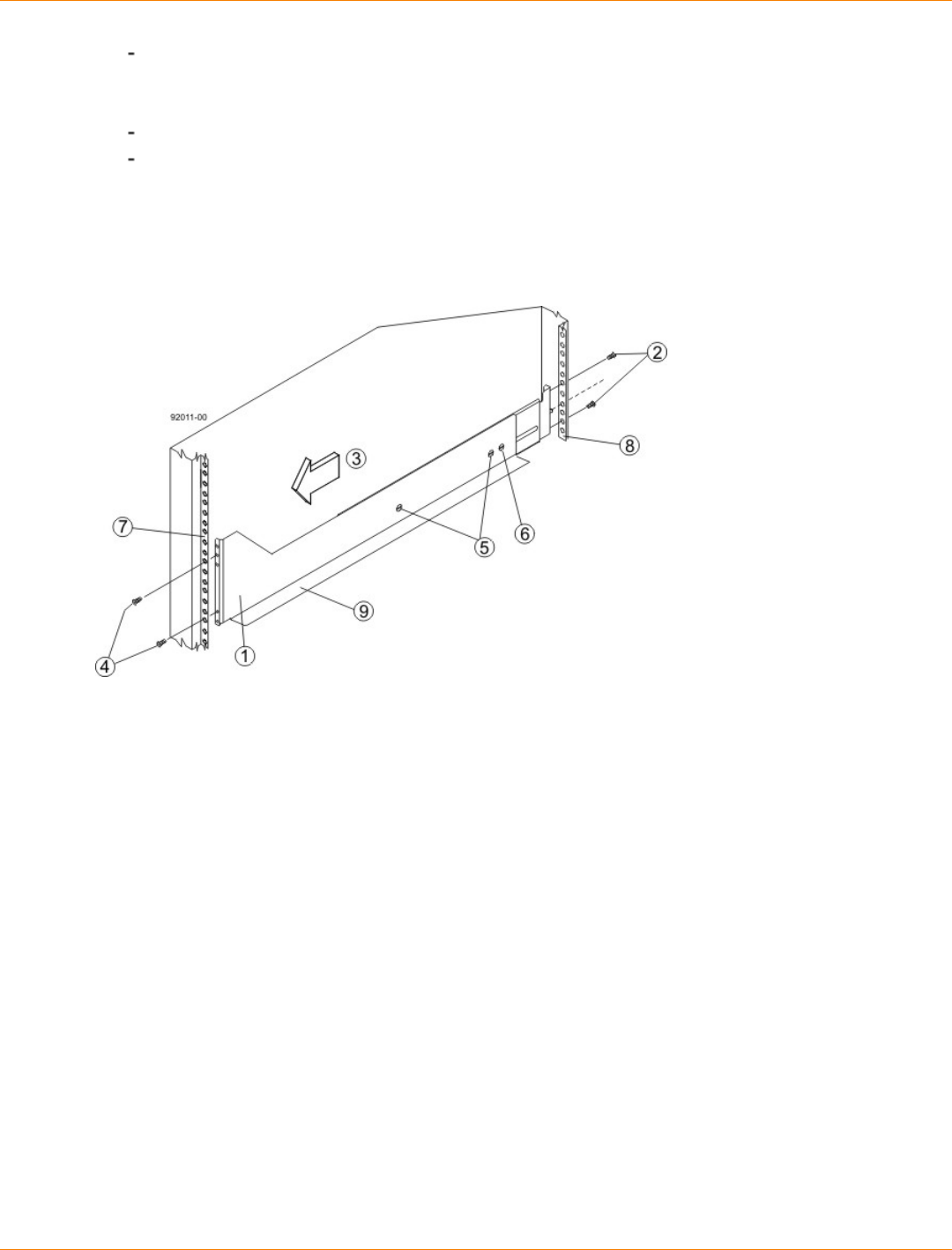
SANtricity_10.77 February 2011
LSI Corporation
- 382 -
If you are installing the mounting rails below an existing tray, allow 17.8-cm (7-in.) vertical clearance
for a DE6600 drive tray.
5. To attach the mounting rails to the cabinet, do one of the following:
If you are using the long fixed size mounting rails, go to step 6.
If you are using the shorter adjustable mounting rails, go to step 7.
6. To attach the long mounting rails to the cabinet, perform these substeps:
a. Make sure that the adjustment screws on the mounting rail are loose so that the mounting rail can
extend or contract as needed.
Attaching the Long Mounting Rails to the Cabinet
1. Front of the Mounting Rail
2. Two M4 Screws for the Rear EIA Support Rail
3. Front of the Cabinet
4. Two M5 Screws for the Front EIA Support Rail
5. Adjustable Rail Tightening Screws
6. Rear Hold-Down Screw
7. Cabinet Mounting Holes on the Front EIA Support Rail
8. Cabinet Mounting Holes on the Rear EIA Support Rail
9. Mounting Rail Lip
b. Remove the rear hold-down screw. It protrudes from the inside of the rail and prevents you from
sliding the drive tray onto the rails.
c. Place the mounting rail inside the cabinet, and extend the mounting rail until the flanges on the
mounting rail touch the inside of the cabinet.
d. Insert one M5 screw through the front of the cabinet, and screw it into the top captured nut in the
mounting rail.
e. Insert two M5 screws through the rear of the cabinet, and screw them into the captured nuts in the
rear flange in the mounting rail.
f. Tighten the adjustment screws on the mounting rail.
g. Repeat substep a through substep f to install the second mounting rail.
h. Insert one M5 screw through the front of the mounting rail. You use this screw to attach the drive tray
to the cabinet.
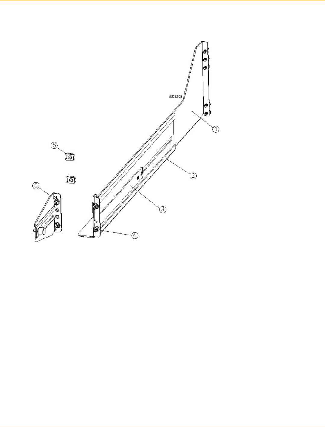
SANtricity_10.77 February 2011
LSI Corporation
- 383 -
7. To attach the shorter, adjustable size mounting rails to the cabinet, perform these sets of substeps:
Short Adjustable Mounting Rail -- Left Side
1. Front of the Mounting Rail
2. Rear of the Mounting Rail
3. Rail Fix Bar
4. Two M5 Screws for the Front EIA Support Rail
5. Two Clips for the Front EIA Support Rail
6. Rear Bracket
a. Make sure that the adjustment screws on the mounting rail are loose so that the mounting rail can
extend or contract as needed (see the figure Figure 5.
b. Place the mounting rail inside the cabinet, and extend the mounting rail until the flanges on the
mounting rail touch the inside of the cabinet (see the figure Figure 6.
c. Insert one M5 screw through the front of the cabinet, and screw it into the top captured nut in the
mounting rail.
d. Insert two M5 screws through the rear of the cabinet, and screw them into the captured nuts in the
rear flange in the mounting rail.
e. Tighten the adjustment screws on the mounting rail.
f. Repeat substep a through substep f to install the second mounting rail.
g. Insert one M5 screw through the front of the mounting rail. This screw will attach the drive tray to the
cabinet.
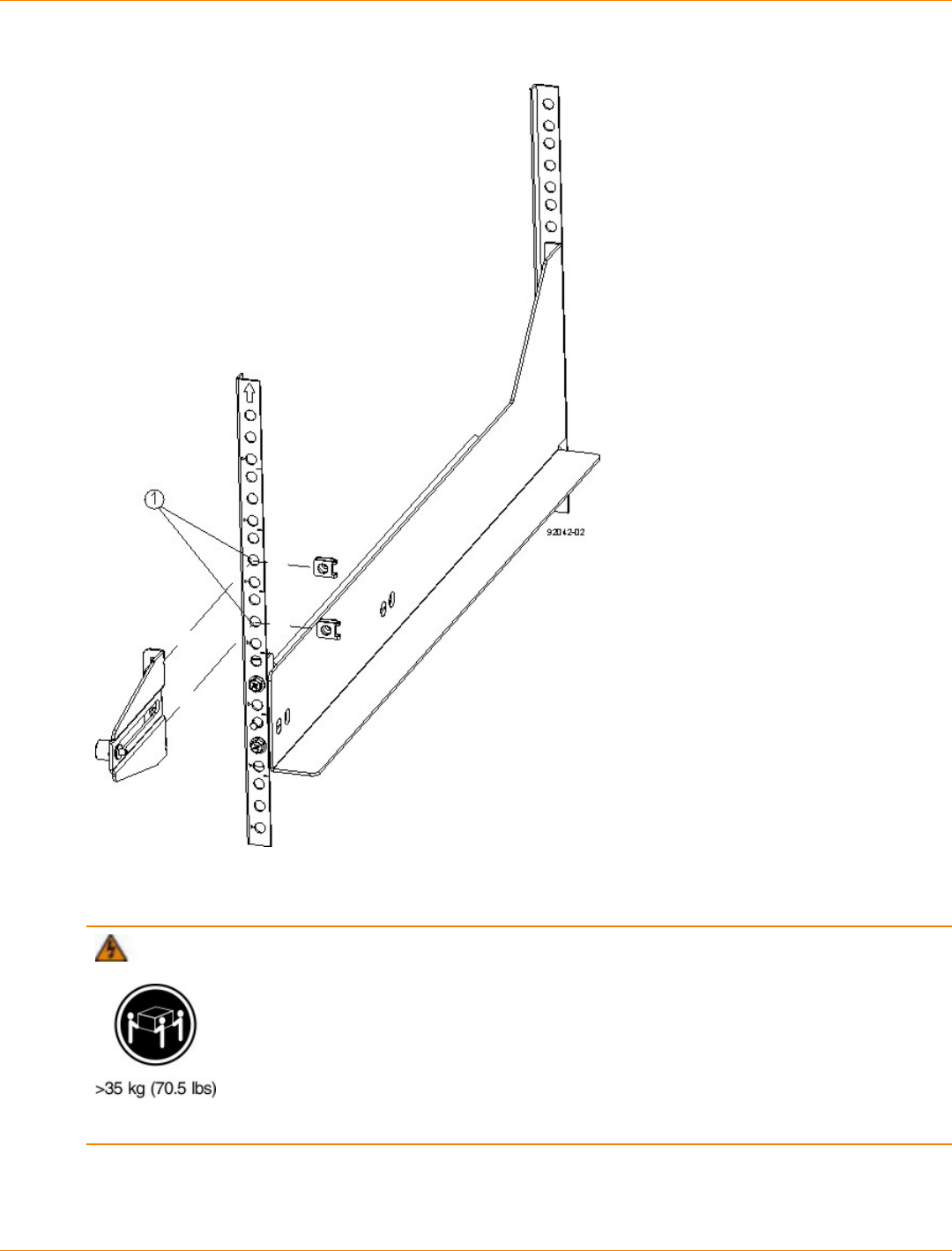
SANtricity_10.77 February 2011
LSI Corporation
- 384 -
Short Adjustable Mounting Rail Attached to the Cabinet
1. Cabinet Mounting Holes on the Front EIA Support Rail
8. Remove the bezel from the front of the drive tray.
WARNING (W09) Risk of bodily injury –
Three persons are required to safely lift the component.
9. With the help of at least two other persons, slide the rear of the drive tray onto the mounting rails. The
drive tray is correctly aligned when the mounting holes on the front flanges of the drive tray align with the
mounting holes on the front of the mounting rails.
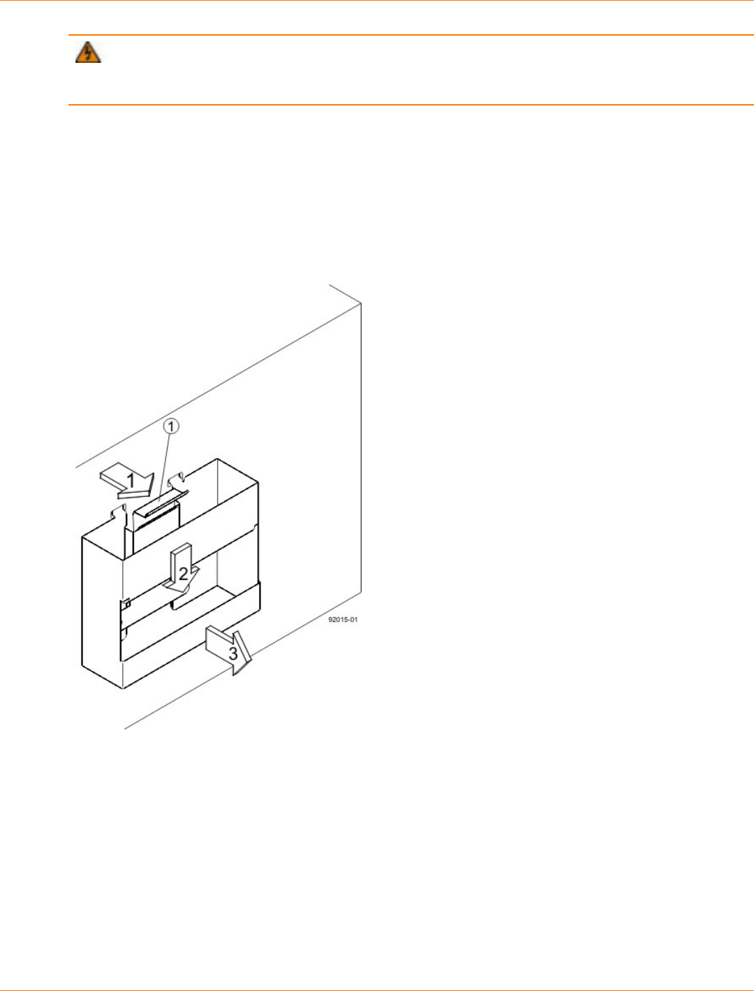
SANtricity_10.77 February 2011
LSI Corporation
- 385 -
WARNING (W15) Risk of bodily injury – An empty tray weighs approximately 56.7 kg (125 lb).
Three persons are required to safely move an empty tray. If the tray is populated with components, a
mechanized lift is required to safely move the tray.
10. After the controller-drive tray is correctly aligned, remove the enclosure lift handles as shown in the figure
Figure 7:
a. Use your thumb to unlatch and remove the rear enclosure lift handles (two to a side).
b. Use the front enclosure lift handles to slide the drive tray all the way into the cabinet.
c. Once the drive tray is securely in the cabinet, use your thumb to unlatch and remove the front
enclosure lift handles (two to a side).
Removing an Enclosure Lift Handle from the Drive Tray
1. Pull the thumb latch away from the drive tray to detach the hook.
2. Shift the handle down to release the other four hooks.
3. Move the handle away from the drive tray.
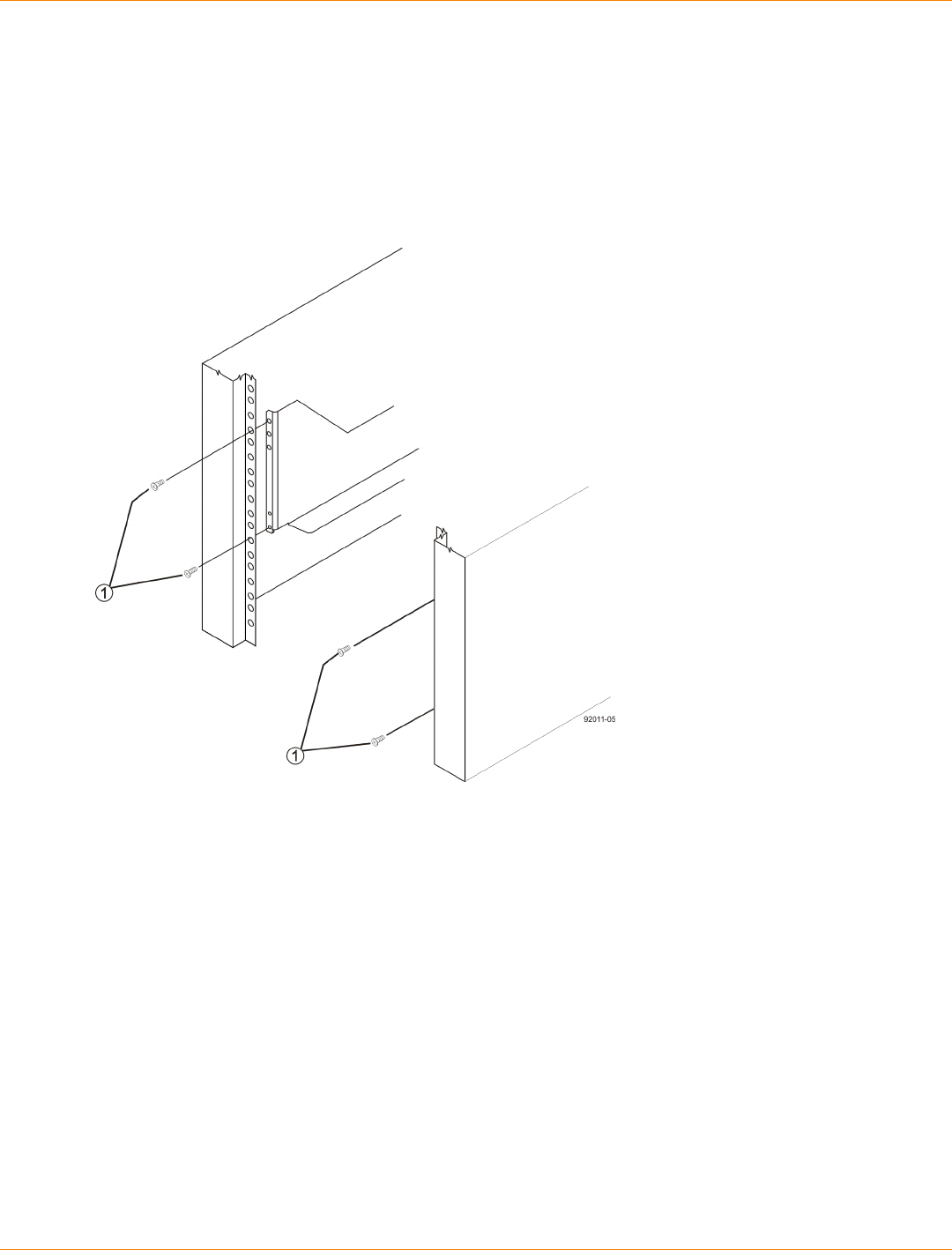
SANtricity_10.77 February 2011
LSI Corporation
- 386 -
11. Secure the front of the drive tray to the cabinet. Use the four screws to attach the flange on each side of
the front of the drive tray to the mounting rails.
a. Insert two M5 screws through the bottom holes of a flange on the drive tray so that the screws go
through the EIA support rail and engage the bottom captured nuts in the mounting rail. Tighten the
screws.
b. Repeat substep a for the second flange.
Attaching the Front of the Drive Tray
1. Four Screws for Securing the Front of the Drive Tray
12. Remove the fan canister from the drive tray by pressing on the tab holding the fan canister handle in
place, and then pulling the fan canister toward you.

SANtricity_10.77 February 2011
LSI Corporation
- 387 -
1. Fan Canister Handle
13. Use the fan canister handle to pull the fan canister out of the drive tray.
14. Secure the side of the drive tray to the mounting rails by performing these substeps:
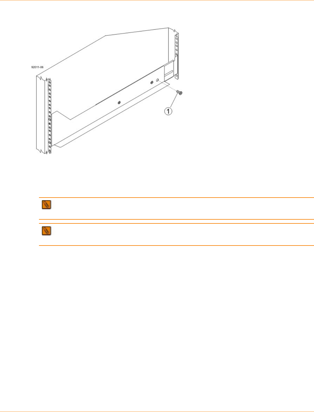
SANtricity_10.77 February 2011
LSI Corporation
- 388 -
Securing the Drive Tray to the Rails
1. 10-32 Screw
a. Insert a 10-32 screw through the side sheet metal of the drive tray into the captured nut on the side of
the mounting rail. Tighten the screws.
b. Repeat substep a for the other side.
NOTE After the drive tray is installed, there should be seven screws on each side (right and left) of
the cabinet.
NOTE Make sure that each drive drawer in the drive tray is securely fastened to ensure proper air
flow to the drives.
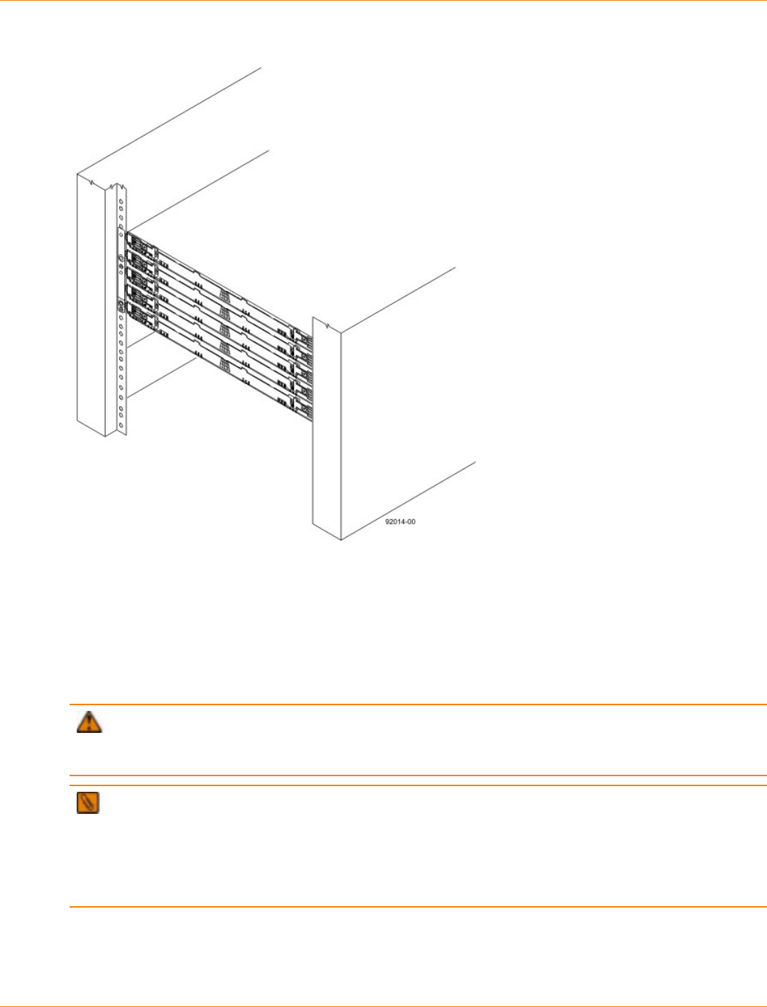
SANtricity_10.77 February 2011
LSI Corporation
- 389 -
Drive Tray Installed in the Cabinet
15. Slide the fan canister all the way back into the drive tray until the tab on the fan canister latches.
16. Attach the bezel onto the front of the drive tray.
Steps to Install – Drives on the DE6600 Drive Tray
The DE6600 drive tray is shipped with the drive drawers installed, but the drives are not installed. Follow the
steps in this procedure to install the drives.
ATTENTION Risk of equipment malfunction – To avoid exceeding the functional and environmental
limits, install only drives that have been provided or approved by the original manufacturer. Drives might be
shipped but not installed. System integrators, resellers, system administrators, or users can install the drives.
IMPORTANT The installation order within each drawer is from left to right in rows. Slots 1, 4, 7 and
10 must have a drive installed in these locations to make sure there is sufficient air flow to the drives. To
verify these slots, consult the overlay on the front of each of the five drive drawers. Make sure the four drives
in each row are adjacent to each other. The long edge of each drive should touch the drive next to it. To
maintain a uniform airflow across all drive drawers, the drive tray must be configured with a minimum of 20
drives, with four drives in the front row of each of the five drive drawers.
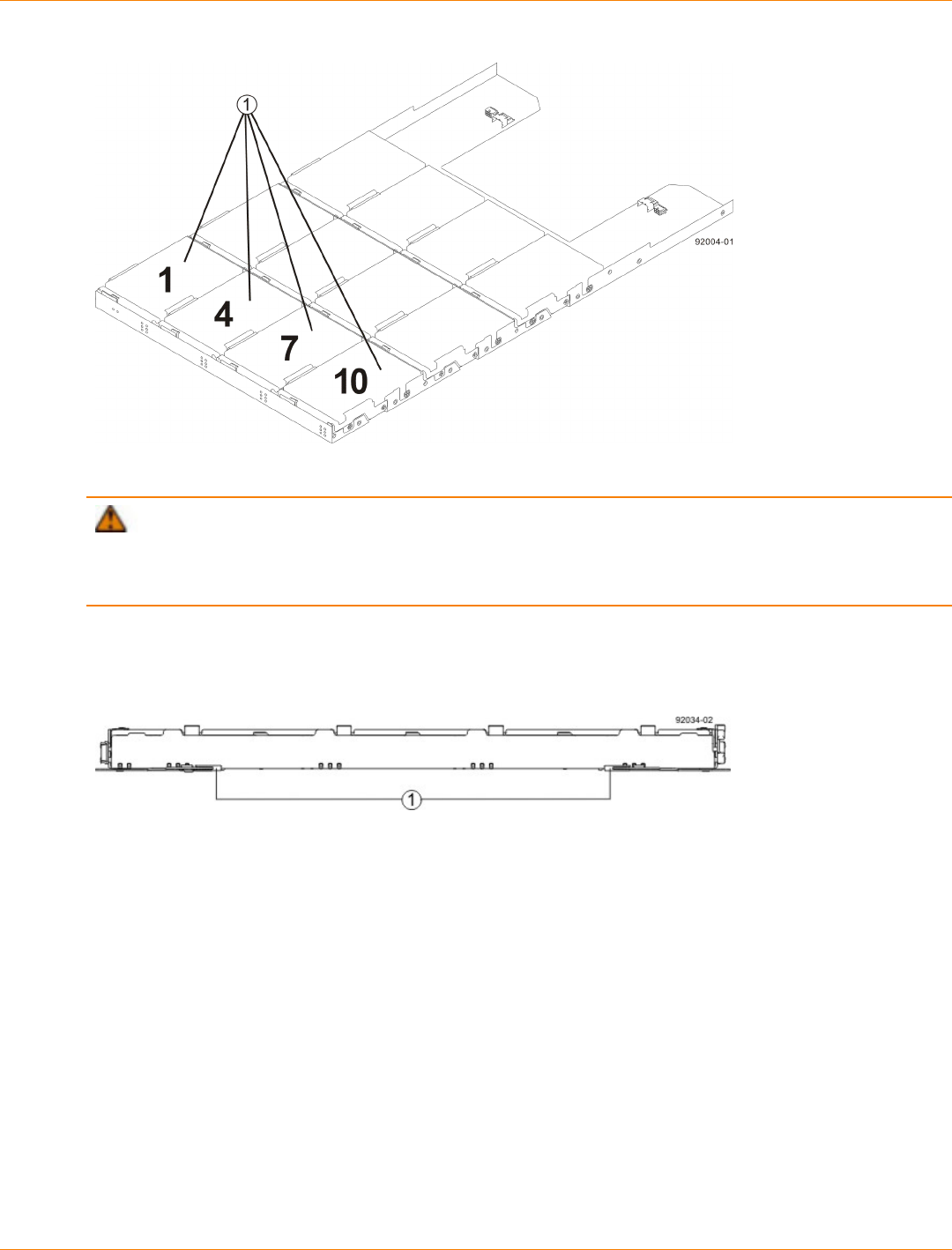
SANtricity_10.77 February 2011
LSI Corporation
- 390 -
1. DE6600 Drive Tray with Slots 1, 4, 7, and 10
ATTENTION Risk of equipment malfunction – For the DE6600 drive tray, you can only replace
one canister or drive at a time. Refer to the “Replacing a Drive on the DE6600 Drive tray” instructions on the
Software and Documentation DVD, and make sure you have the replacement drive in hand before starting the
task.
1. Beginning with the top drawer in the drive tray, release the levers on each side of the drawer by pulling
both towards the center.
Levers on the Drive Drawer
2. Pull on the extended levers to pull the drive drawer out to its full extension without removing it from the
drive tray.
3. Starting with the first drive, raise the drive handle to the vertical position (*** UNDEFINED CROSS-REF
FORMAT [FigureOrTableNum] ***).
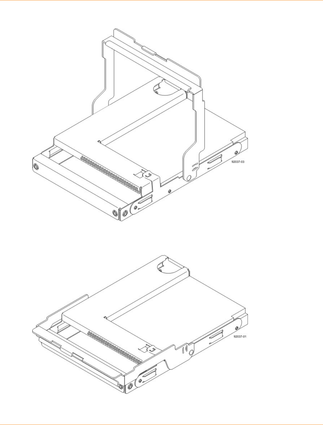
SANtricity_10.77 February 2011
LSI Corporation
- 391 -
Raised Drive Handle
4. Align the two raised buttons on each side over the matching gap in the drive channel on the drawer.
Side View of Drive with Raised Handle
1. Raised Buttons
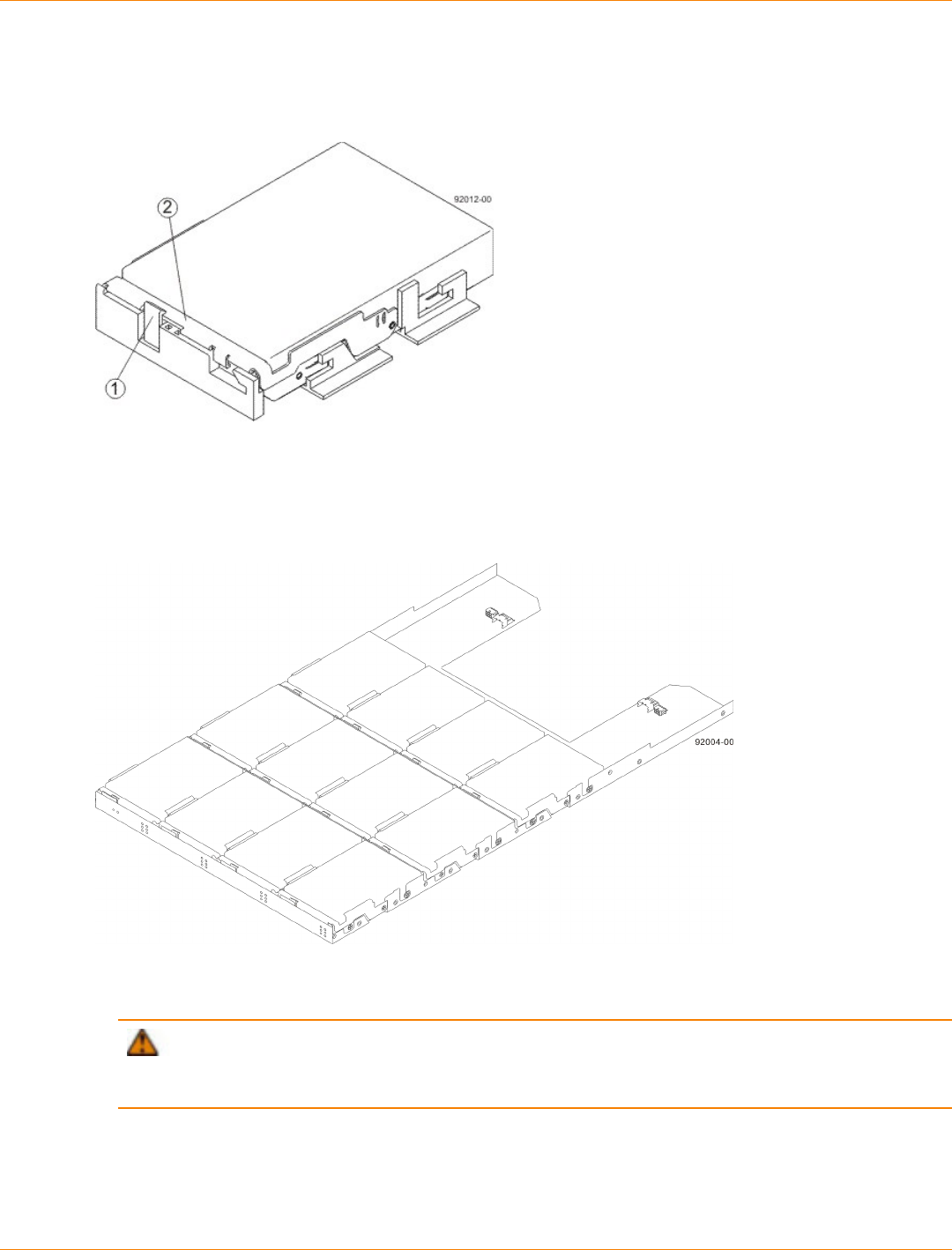
SANtricity_10.77 February 2011
LSI Corporation
- 392 -
5. Lower the drive straight down, and then rotate the drive handle down until the drive snaps into place
under the drive release lever.
Drive Release Lever Locked by the Drive Handle
1. Drive Release Lever
2. Drive Handle
6. Install the other drives in rows from left to right until the drive drawer is fully populated.
Fully-Populated Drive Drawer
7. Push the drive drawer all the way back into the drive tray, closing the levers on each side of the drive
drawer.
ATTENTION Risk of equipment malfunction – Make sure you push both levers to each side so
the drive drawer is completely closed. The drive drawer must be completely closed to prevent excess
airflow, which has the potential to damage the drives.
8. Continue onto the next drive drawer, repeating step 1 through step 7 for each drive drawer in the
configuration.
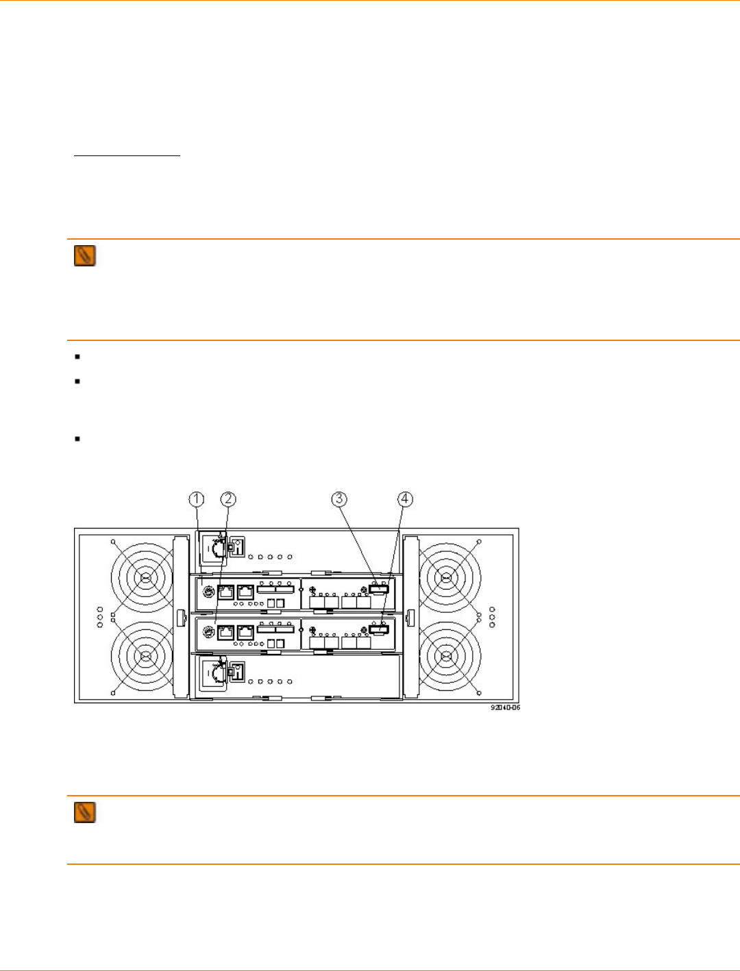
SANtricity_10.77 February 2011
LSI Corporation
- 393 -
Step 7 – Connecting the CDE2600-60 Controller-Drive Tray to the
Drive Trays
Key Terms
drive channel
The path for the transfer of data between the controllers and the drives in the storage array.
Things to Know – CDE2600-60 Controller-Drive Tray
NOTE On the CDE2600-60 controller-drive tray, each controller has a pair of levers with handles for
removing the controller from the controller-drive tray. One of these handles on each controller is located next
to a host connector. The close spacing between the handle and the host connector might make it difficult to
remove a cable that is attached to the host connector. If this problem occurs, use a flat-blade screwdriver to
push in the release component on the cable connector.
The CDE2600-60 controller-drive tray supports the DE6600 drive tray for expansion.
The maximum number of drive slots in the storage array is 180 drive slots, including up to 60 drive slots in
the controller-drive tray. Exceeding 180 drive slots makes the storage array invalid. The controllers cannot
perform operations that modify the configuration, such as creating new volumes.
Each controller has one dual-ported SAS expansion connector to connect to the drive trays.
Drive Channel Ports on the CDE2600-60 Controller-Drive Tray – Rear View
1. Controller A Canister
2. Controller B Canister
3. Controller A SAS Expansion Connector
4. Controller B SAS Expansion Connector
IMPORTANT To maintain data access in the event of the failure of a controller, an ESM, or a drive
channel, you must connect a drive tray or a string of drive trays to both drive channels on a redundant path
pair.
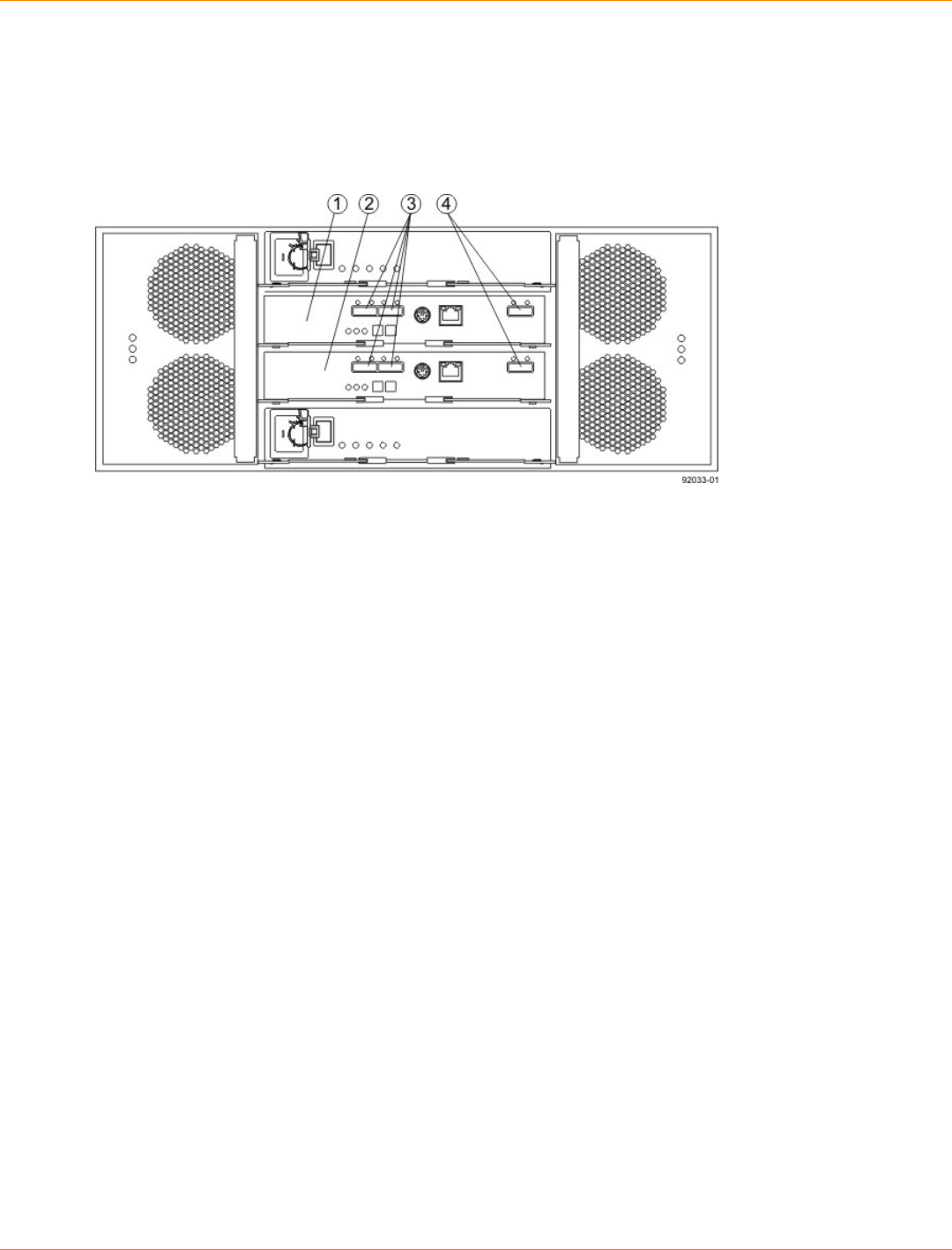
SANtricity_10.77 February 2011
LSI Corporation
- 394 -
Things to Know – Drive Trays with the CDE2600-60 Controller-Drive Tray
Each DE6600 drive tray can contain a maximum of sixty 8.89-cm (3.5-in.) drives housed with five drawers of
12drives each.
DE6600 Drive Tray – Rear View
1. ESM A
2. ESM B
3. SAS IN Connectors
4. Expansion Connectors
Things to Know – CDE2600-60 Drive Tray Cabling Configurations – Duplex
System
The figures in this topic show examples of cable configurations from the controller-drive tray to the drive trays.
Use these examples as guides to connect cables in your storage array.

SANtricity_10.77 February 2011
LSI Corporation
- 395 -
Controller-Drive Tray Above the Drive Tray
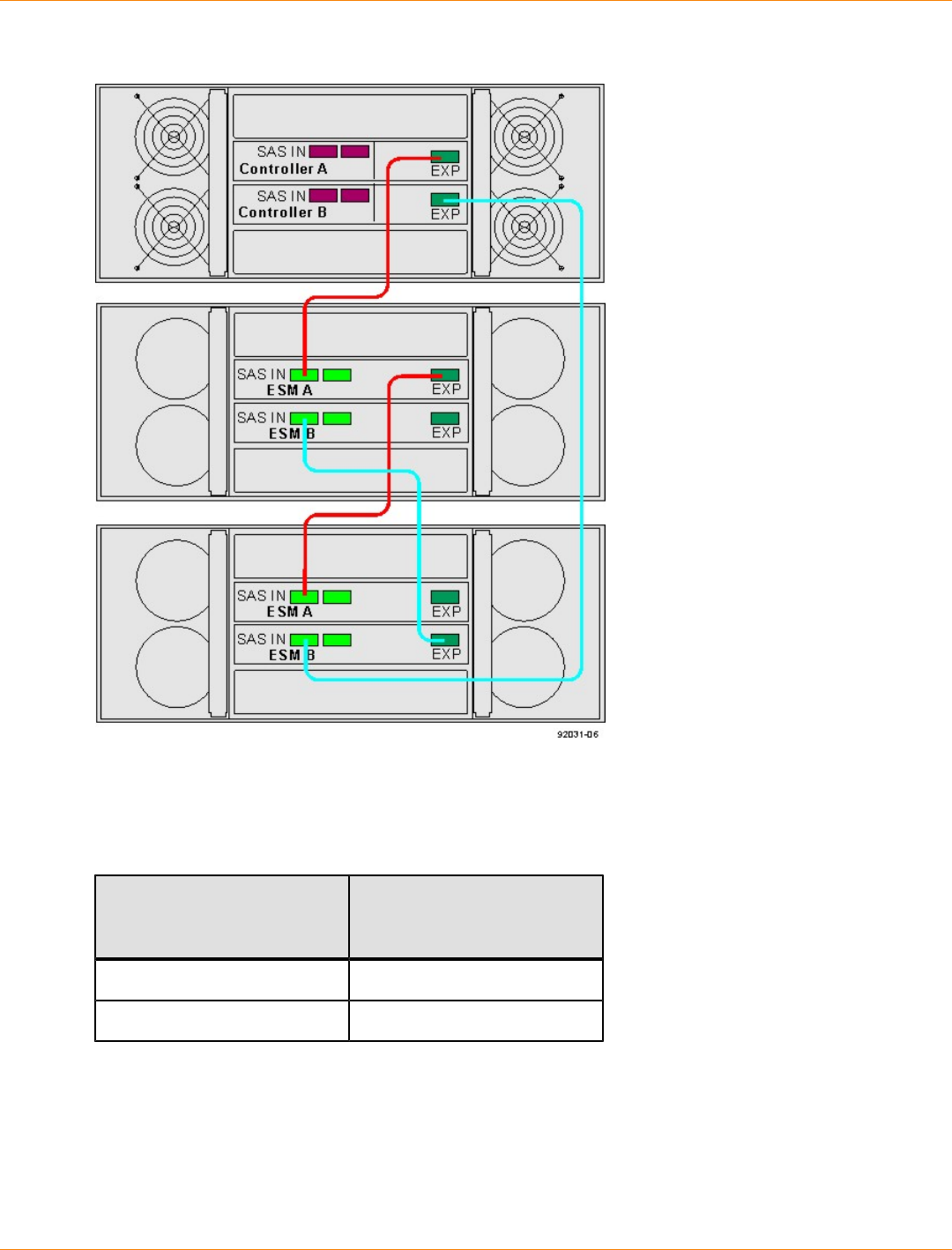
SANtricity_10.77 February 2011
LSI Corporation
- 396 -
Controller-Drive Tray Between Two Drive Trays
Procedure – Connecting the DE6600 Drive Tray
1. Use the following table to determine the number of SAS cables that you need.
Drive Tray Cables
Number of Drive Trays that
You Plan to Connect to the
Controller-Drive Tray
Number of Cables Required
1 2
2 4
2. If there is a black, plastic plug in the SAS expansion connector of the controller, remove it.
3. Insert one end of the cable into the SAS expansion connector on the controller in slot A in the controller-
drive tray.
4. Insert the other end of the cable into the connector with an up arrow on the ESM in slot A in the drive tray.
5. Are you adding more drive trays?
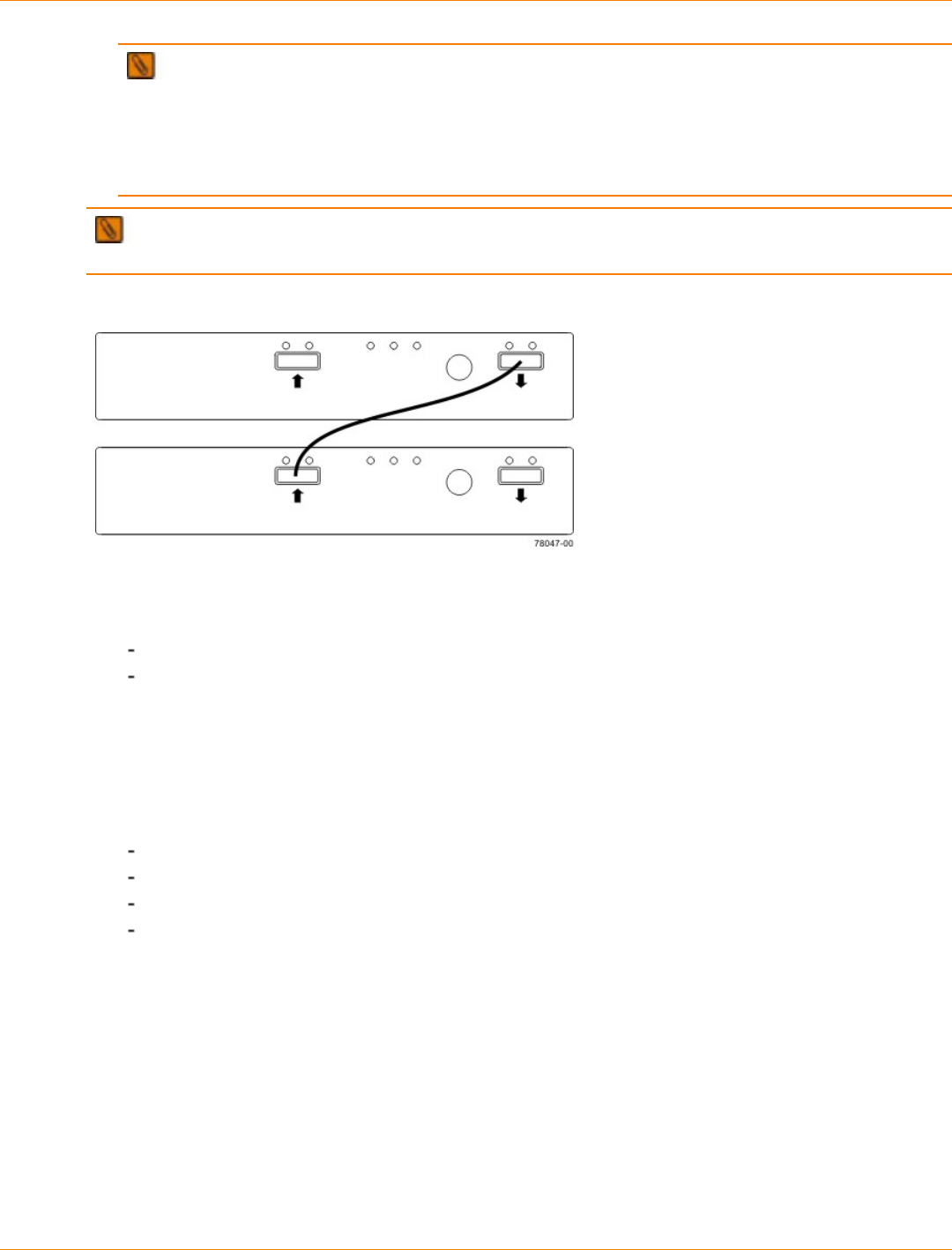
SANtricity_10.77 February 2011
LSI Corporation
- 397 -
IMPORTANT Each ESM in a drive tray has three expansion connectors: two on the left-center of
the ESM and one in the upper-right side. When connecting from an ESM in one drive tray to an ESM in
another drive tray, make sure that you connect the connector on the upper-right to one of the connectors
on the left-center. The following figure shows these arrows on an ESM. If the cable is connected either
between the two left-center ESM connectors or between two upper-right ESM connectors, communication
between the two drive trays is lost.
NOTE It does not matter which of the two left-center ESM connectors you use to connect to the
expansion connector on the far-right side.
Connecting a Cable from One ESM to a Second ESM
Yes – Go to step 6.
No – Go to step 9.
6. In the ESM in the first drive tray, insert one end of the cable into the connector on the far-right side.
7. In the ESM in the next drive tray, insert the other end of the cable into one of the connectors in the left-
center of the ESM.
8. Repeat step 6 through step 7 for each drive tray that you intend to add to the storage array.
9. To each end of the cables, attach a label with this information:
The controller ID (for example, controller A)
The ESM ID (for example, ESM A)
The ESM connector (In or Out)
The drive tray ID
For example, if you are connecting controller A to the In connector on ESM A in drive tray 1, the label on
the controller end of the cable will have this information:
CtA-Dch1, Dm1-ESM_A (left), In – Controller End
The label on the drive tray end of the cable will have this information:
Dm1-ESM_A (left), In, CtrlA
10. If you are installing the controller-drive tray with two controllers, repeat step 2 through step 9 for the
controller in slot B in the controller-drive tray.

SANtricity_10.77 February 2011
LSI Corporation
- 398 -
IMPORTANT To connect cables for maximum redundancy, the cables attaching controller B must be
connected to the drive trays in the opposite tray order as for controller A. That is, the last drive tray in the
chain from controller A must be the first drive tray in the chain from controller B.

SANtricity_10.77 February 2011
LSI Corporation
- 399 -
Step 8 – Connecting the Ethernet Cables
Key Terms
in-band management
A method to manage a storage array in which a storage management station sends commands to the storage
array through the host input/output (I/O) connection to the controller.
out-of-band management
A method to manage a storage array in which a storage management station sends commands to the storage
array through the Ethernet connections on the controller.
Things to Know – Connecting Ethernet Cables
ATTENTION Risk of security breach – Connect the Ethernet ports on the controller tray to a private
network segment behind a firewall. If the Ethernet connection is not protected by a firewall, your storage array
might be at risk of being accessed from outside of your network.
These Ethernet connections are intended for out-of-band management and have nothing to do with the
iSCSI host interface cards (HICs), whether 1Gb/s or 10Gb/s.
Ethernet port 2 on each controller is reserved for access by your Customer and Technical Support
representative.
In limited situations in which the storage management station is connected directly to the controller tray,
you must use an Ethernet crossover cable. An Ethernet crossover cable is a special cable that reverses
the pin contacts between the two ends of the cable.
Procedure – Connecting Ethernet Cables
Perform these steps to connect Ethernet cables for out-of-band management. If you use only in-band
management, skip these steps.
1. Connect one end of an Ethernet cable into the Ethernet port 1 on controller A.
2. Connect the other end to the applicable network connection.
3. Repeat step 1 through step 2 for controller B.

SANtricity_10.77 February 2011
LSI Corporation
- 400 -
Step 9 – Connecting the Power Cords
The CDE2600 controller-drive tray, the DE1600 drive tray, and the DE5600 drive tray can have either
standard power connections to an AC power source or the optional connections to a DC power source (–48
VDC).
IMPORTANT Make sure that you do not turn on the power to the controller-drive tray or the connected
drive trays until this documentation instructs you to do so. For the correct procedure for turning on the power,
see “.”
Things to Know – AC Power Cords
For each AC power connector on the drive tray, make sure that you use a separate power source in the
cabinet. Connecting to independent power sources maintains power redundancy.
To ensure proper cooling and assure availability, the drive trays always use two power supplies.
You can use the power cords shipped with the drive tray with typical outlets used in the destination
country, such as a wall receptacle or an uninterruptible power supply (UPS). These power cords,
however, are not intended for use in most EIA-compliant cabinets.
Procedure – Connecting AC Power Cords
1. Make sure that the circuit breakers in the cabinet are turned off.
2. Make sure that both of the Power switches on the drive trays are turned off.
3. Connect the primary power cords from the cabinet to the external power source.
4. Connect a cabinet interconnect power cord (or power cords specific to your particular cabinet) to the AC
power connector on each power canister in the drive tray.
5. If you are installing other drive trays in the cabinet, connect a power cord to each power canister in the
drive trays.
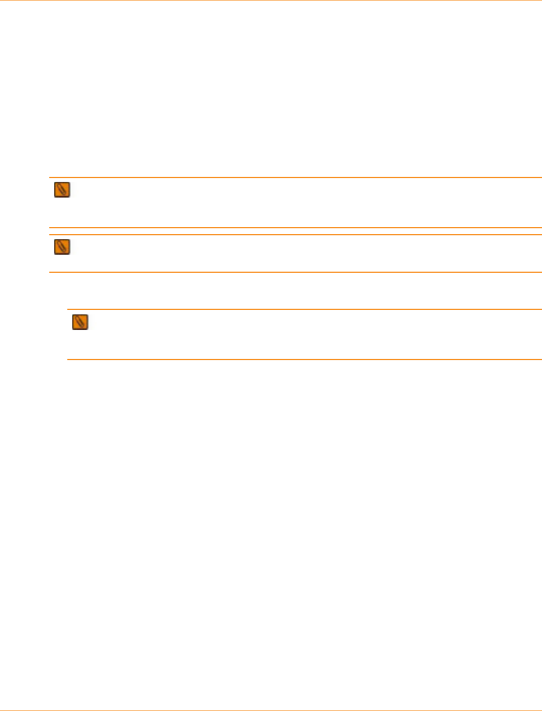
SANtricity_10.77 February 2011
LSI Corporation
- 401 -
Step 10 – Turning on the Power and Checking for Problems in a
CDE2600-60 Controller-Drive Tray Configuration
Once you complete this task, you can install the begin to install the software and perform basic configuration
tasks on your storage array. Continue with the Initial Configuration and Software Installation in these
electronic document topics or through the PDF that is available on the SANtricity ES Storage Manager
Installation DVD.
Procedure – Turning On the Power to the Storage Array and Checking for
Problems in a CDE2600-60 Controller-Drive Tray Configuration
IMPORTANT You must turn on the power to all of the connected drive trays before you turn on the
power for the controller-drive tray. Performing this action makes sure that the controllers recognize each
attached drive tray.
NOTE While the power is being applied to the trays, the LEDs on the front and the rear of the trays
come on and go off intermittently.
1. Turn on both Power switches on each drive tray that is attached to the controller-drive tray. Depending on
your configuration, it can take several minutes for each drive tray to complete the power-on process.
IMPORTANT Before you go to step 2, check the LEDs on the drive trays to verify that the power
was successfully applied to all of the drive trays. Wait 30 seconds after turning on the power to the drive
trays before turning on the power to the controller-drive tray.
2. Turn on both Power switches on the rear of the controller-drive tray. Depending on your configuration, it
can take several minutes for the controller-drive tray to complete the power-on process.
3. Check the LEDs on the front and the rear of the controller-drive tray and the attached drive trays.
4. If you see any amber LEDs, make a note of their location.
Things to Know – LEDs on the CDE2600-60 Controller-Drive Tray
The following topics provide details on the LEDs found on the CDE2600-60 controller-drive tray.
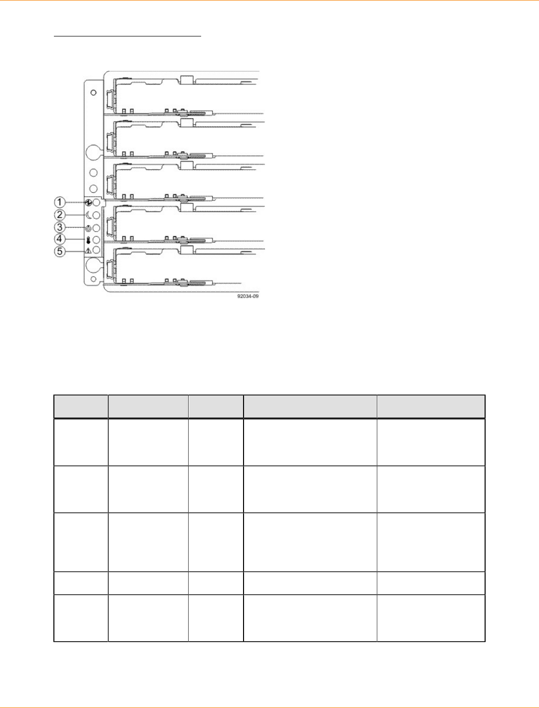
SANtricity_10.77 February 2011
LSI Corporation
- 402 -
LEDs on the Left End Cap
LEDs on the Left End Cap
1. Controller-Drive Tray Locate LED
2. Service Action Required LED
3. Controller-Drive Tray Over-Temperature LED
4. Power LED
5. Standby Power LED
LEDs on the Left End Cap
Location LED Color On Off
1 Controller-
Drive Tray
Locate
White Identifies a controller-drive
tray that you are trying to
find.
Normal status.
2 Service Action
Required Amber A component within the
controller-drive tray needs
attention.
Normal status.
3 Controller-
Drive Tray
Over-
Temperature
Amber The temperature of the
controller-drive tray has
reached an unsafe level.
Normal status.
4 Power Green Power is present. Power is not present.
5 Standby Power Green The controller-drive tray is
in Standby Power mode. The controller-drive
tray is not in Standby
Power mode.
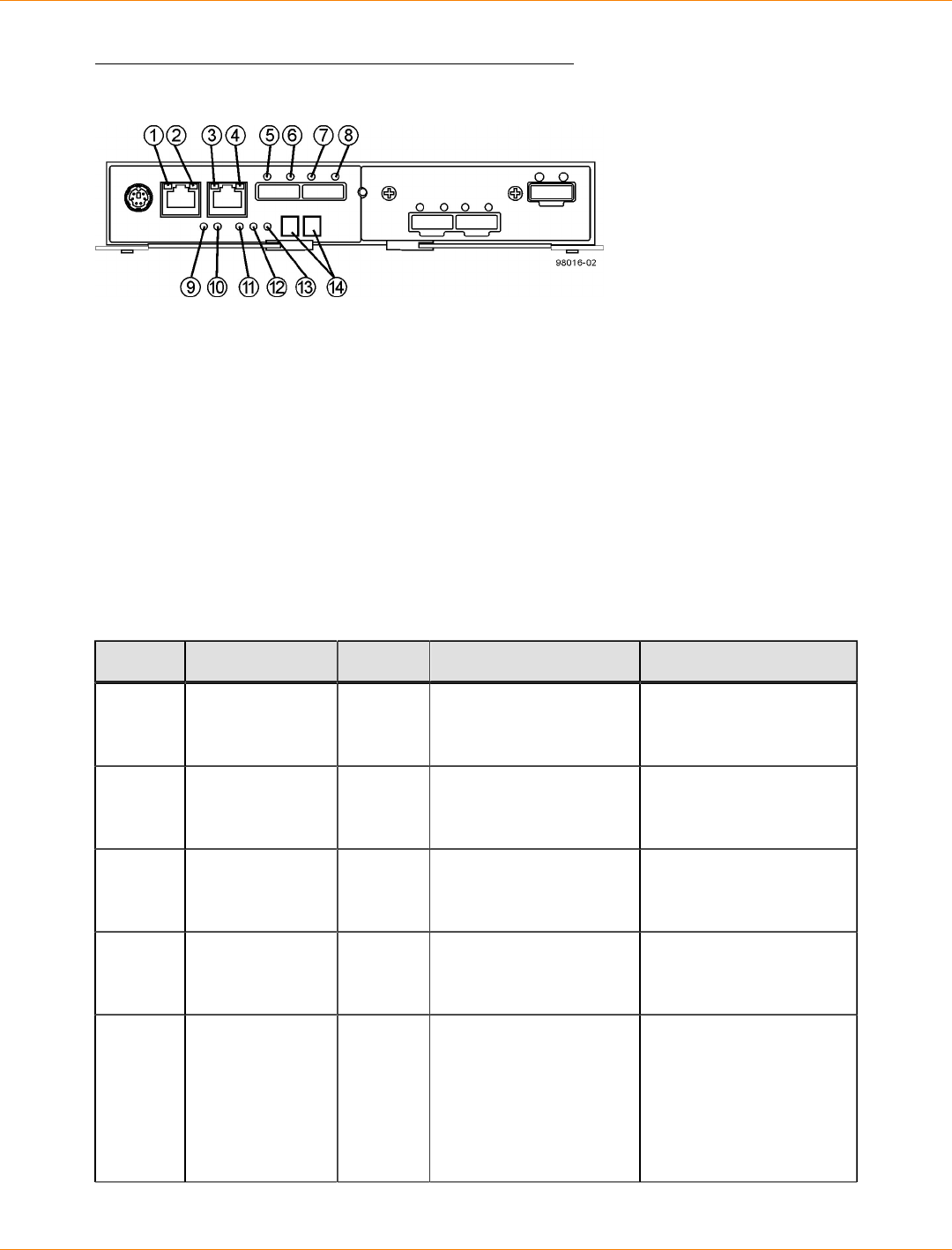
SANtricity_10.77 February 2011
LSI Corporation
- 403 -
LEDs on the Controller Canister Main Faceplate
LEDs on the Controller Canister Main Faceplate
1. Ethernet Connector 1 Link Rate LED
2. Ethernet Connector 1 Link Active LED
3. Ethernet Connector 2 Link Rate LED
4. Ethernet Connector 1 Link Active LED
5. Host Link 1 Service Action Required LED
6. Host Link 1 Service Action Allowed LED
7. Host Link 2 Service Action Required LED
8. Host Link 2 Service Action Allowed LED
9. Battery Service Action Required LED
10. Battery Charging LED
11. Controller Service Action Allowed LED
12. Controller Service Action Required LED
13. Cache Active LED
14. Seven-Segment Tray ID
LEDs on the Controller Canister Main Faceplate
Location LED Color On Off
1 Ethernet
Connector 1
Link Rate LED
Green There is a 100BASE-T
rate. There is a 10BASE-T
rate.
2 Ethernet
Connector 1
Link Active LED
Green The link is up (LED
blinks when there is
activity).
The link is not active.
3 Ethernet
Connector 2
Link Rate LED
Green There is a 100BASE-T
rate. There is a 10BASE-T
rate.
4 Ethernet
Connector 2
Link Active LED
Green The link is up (the LED
blinks when there is
activity).
The link is not active.
5 Host Link 1
Service Action
Required LED
Amber At least one of the four
PHYs is working, but
another PHY cannot
establish the same link
to the device connected
to the Host IN port
connector.
No link error has
occurred.

SANtricity_10.77 February 2011
LSI Corporation
- 404 -
Location LED Color On Off
6 Host Link 1
Service Action
Allowed LED
Green At least one of the four
PHYs in the Host IN
port is working and a
link exists to the device
connected to the IN port
connector.
A link error has occurred.
7 Host Link 2
Service Action
Required LED
Amber At least one of the four
PHYs is working, but
another PHY cannot
establish the same link
to the device connected
to the Host IN port
connector.
No link error has
occurred.
8 Host Link 2
Service Action
Allowed LED
Green At least one of the four
PHYs in the Host IN
port is working and a
link exists to the device
connected to the IN port
connector.
A link error has occurred.
9 Battery Service
Action Required
LED
Amber The battery in the
controller canister has
failed.
Normal status.
10 Battery Charging
LED Green The battery is fully
charged. The LED
blinks when the battery
is charging.
The controller canister
is operating without a
battery or the existing
battery has failed.
11 Controller
Service Action
Allowed LED
Blue The controller canister
can be removed safely
from the controller-drive
tray.
The controller canister
cannot be removed
safely from the
controller-drive tray.
12 Controller
Service Action
Required LED
Amber A fault exists within the
controller canister. Normal status.
13 Cache Active
LED Green Cache is active.* Cache is inactive or the
controller canister has
been removed from the
controller-drive tray.
* After an AC power failure, this LED blinks while cache offload is in process.
LEDs on the Controller Canister Host Interface Card Subplates
NOTE The figure immediately below shows an iSCSI host interface card (HIC), but the CDE2600
controller-drive tray also supports a four-connector FC HIC and a two-connector SAS HIC with comparable
LEDs.
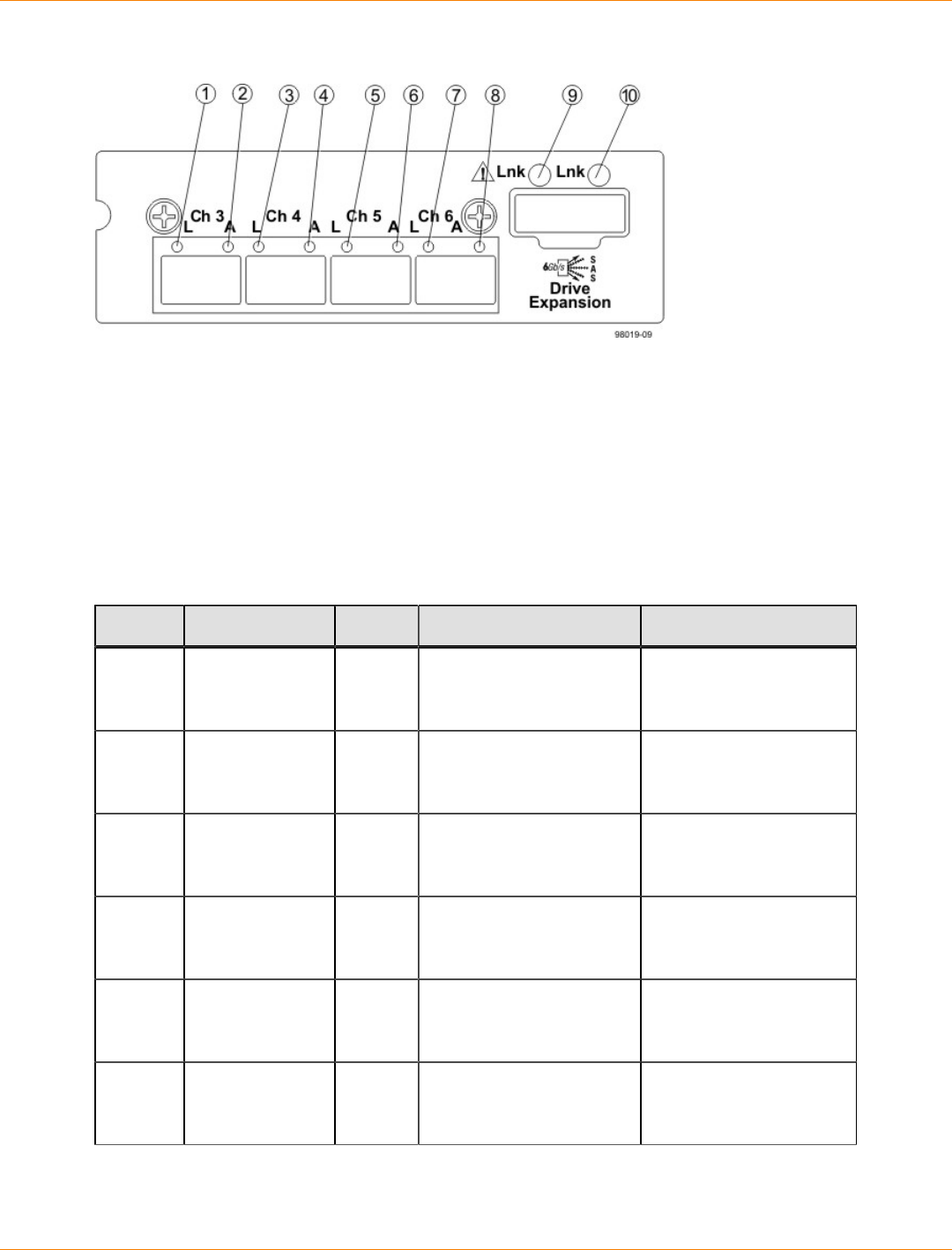
SANtricity_10.77 February 2011
LSI Corporation
- 405 -
LEDs on the Controller Canister Host Interface Card Subplates
1. Host Interface Card Link 3 Up LED
2. Host Interface Card Link 3 Active LED
3. Host Interface Card Link 4 Up LED
4. Host Interface Card Link 4 Active LED
5. Host Interface Card Link 5 Up LED
6. Host Interface Card Link 5 Active LED
7. Host Interface Card Link 6 Up LED
8. Host Interface Card Link 6 Active LED
9. Expansion Fault LED
10. Expansion Active LED
LEDs on the Controller Canister Host Interface Card Subplates*
Location LED Color On Off
1 Host Interface
Card Link 3 Up
LED
Green The Ethernet link has
auto-negotiated to 1 Gb/
s.
The Ethernet link is
down or does not auto-
negotiate to 1 Gb/s.
2 Host Interface
Card Link 3
Active LED
Green The link is up (LED blinks
when there is activity). The link is not active.
3 Host Interface
Card Link 4 Up
LED
Green The Ethernet link has
auto-negotiated to 1 Gb/
s.
The Ethernet link is
down or does not auto-
negotiate to 1 Gb/s.
4 Host Interface
Card Link 4
Active LED
Green The link is up (LED blinks
when there is activity). The link is not active.
5 Host Interface
Card Link 5 Up
LED
Green The Ethernet link has
auto-negotiated to 1 Gb/
s.
The Ethernet link is
down or does not auto-
negotiate to 1 Gb/s.
6 Host Interface
Card Link 5
Active LED
Green The link is up (LED blinks
when there is activity). The link is not active.
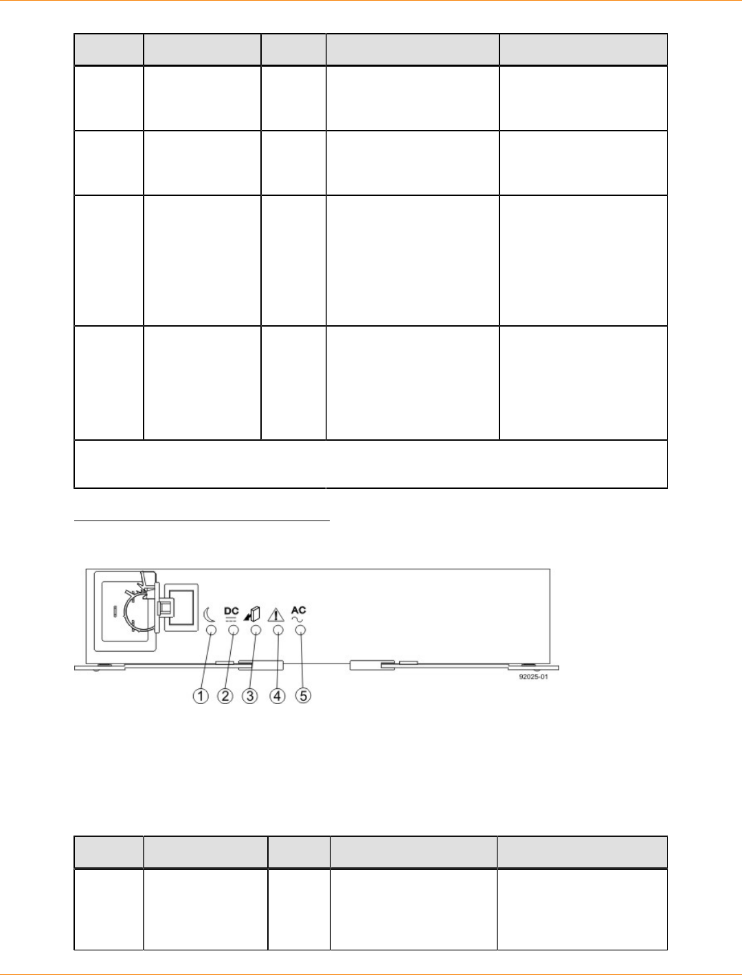
SANtricity_10.77 February 2011
LSI Corporation
- 406 -
Location LED Color On Off
7 Host Interface
Card Link 6 Up
LED
Green The Ethernet link has
auto-negotiated to 1 Gb/
s.
The Ethernet link is
down or does not auto-
negotiate to 1 Gb/s.
8 Host Interface
Card Link 6
Active LED
Green The link is up (LED blinks
when there is activity). The link is not active.
9 Expansion Fault
LED Amber At least one of the four
PHY is working, but
another PHY cannot
establish the same link
to the device connected
to the Expansion OUT
connector.
Normal status.
10 Expansion
Active LED Green At least one of the
four PHYs in the OUT
connector is working and
a link has been made to
the device connected to
the Expansion connector.
The link is not active.
* "LEDs on the Controller Canister Host Interface Card Subplates" shows the four-port iSCSI
host interface card (HIC), which can also be a four-port FC HIC or a two-port SAS HIC.
LEDs on the Power-Fan Canister
LEDs on the Power-Fan Canister
1. Standby Power LED
2. Power-Fan DC Power LED
3. Power-Fan Service Action Allowed LED
4. Power-Fan Service Action Required LED
5. Power-Fan AC Power LED
LEDs on the Power-Fan Canister
Location LED Color On Off
1 Standby Power Green The controller-drive tray
is in Standby mode,
and DC power is not
available.
The controller-drive
tray is not in Standby
mode, and DC power is
available.
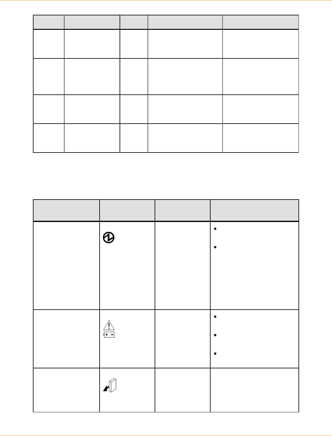
SANtricity_10.77 February 2011
LSI Corporation
- 407 -
Location LED Color On Off
2 Power-Fan DC
Power Green DC power from the
power-fan canister is
available.
DC power from the
power-fan canister is not
available.
3 Power-Fan
Service Action
Allowed
Blue The power-fan canister
can be removed safely
from the controller-drive
tray.
The power-fan canister
cannot be removed
safely from the
controller-drive tray.
4 Power-Fan
Service Action
Required
Amber A fault exists within the
power-fan canister. Normal status.
5 Power-Fan AC
Power Green AC power to the power-
fan canister is present. AC power to the power-
fan canister is not
present.
Things to Know – General Behavior of the LEDs on the CDE2600 Controller-
Drive Tray
LED Symbols and General Behavior
LED Symbol Location
(Canisters) Function
Power Power-fan
Interconnect-
battery
On – The controller has
power.
Off – The controller does
not have power.
NOTE – The controller
canisters do not have a
Power LED. They receive
their power from the power
supplies inside the power-fan
canisters.
Battery Fault Battery On – The battery is
missing or has failed.
Off – The battery is
operating normally.
Blinking – The battery is
charging.
Service Action
Allowed Drive (left LED,
no symbol)
Power-fan
Controller
Battery
On – You can remove the
canister safely.
See “Things to Know –
Service Action Allowed
LEDs.”
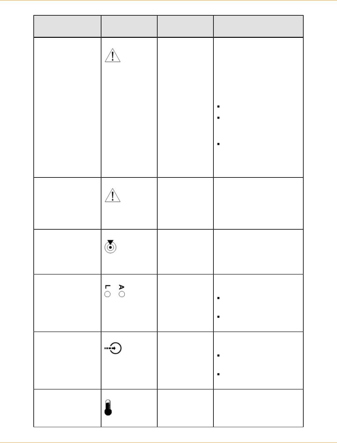
SANtricity_10.77 February 2011
LSI Corporation
- 408 -
LED Symbol Location
(Canisters) Function
Service Action
Required (Fault) Drive On – When the drive tray
LED is on, the cable is
attached and at least one
lane has a link up status, but
at least one lane has a link
down status.
Off – One of the following
conditions exists:
No cable is attached.
A cable is attached, and
all lanes have a link up
status.
A cable is attached, and
all lanes have a link down
status.
.
Service Action
Required (Fault) Controller
Power-fan
canister
On – The controller or the
power-fan canister needs
attention.
Off – The controller and
the power-fan canister are
operating normally.
Locate Front frame On – Assists in locating the
tray.
Host Channel
Connection (iSCSI) Controller The status of the host
channel is indicated:
“L” LED on – A link is
established.
“A” LED on – Activity
(data transfer) is present.
Cache Active Controller The activity of the cache is
indicated:
On – Data is in the
cache.
Off – No data is in the
cache.
Controller-Drive Tray
Over-Temperature Front bezel on
the controller-
drive tray
On – The temperature of the
drive tray has reached an
unsafe condition.

SANtricity_10.77 February 2011
LSI Corporation
- 409 -
LED Symbol Location
(Canisters) Function
Off – The temperature of the
drive tray is within operational
range.
Standby Power Front bezel on
the controller-
drive tray
On – The controller tray is in
standby mode and the main
DC power is off.
Off – The controller-drive tray
is not in standby mode and
the main DC power is on.
Seven-Segment ID
Diagnostic Display Controller The tray ID or a diagnostic
code is indicated (see “Things
to Know – Dynamic Display
Sequence Definitions on the
Seven-Segment Display”).
For example, if some of the
cache memory dual in-line
memory modules (DIMMs)
are missing in a controller,
error code L8 appears in
the diagnostic display (see
“Things to Know – Supported
Diagnostic Lock-Down Codes
on the Seven-Segment
Display”).
AC power Power-fan
NOTE – The LED
is directly above
or below the AC
power switch and
the AC power
connector.
Indicates that the power
supply is receiving AC power
input.
DC power Power-fan
NOTE – The LED
is directly above
or below the DC
power switch and
the DC power
connector.
Indicates that the power
supply is receiving DC power
input.
Ethernet Speed and
Ethernet Activity Controller The speed of the Ethernet
ports and whether a link
has been established are
indicated:
Left LED On –
1-Gb/s speed.
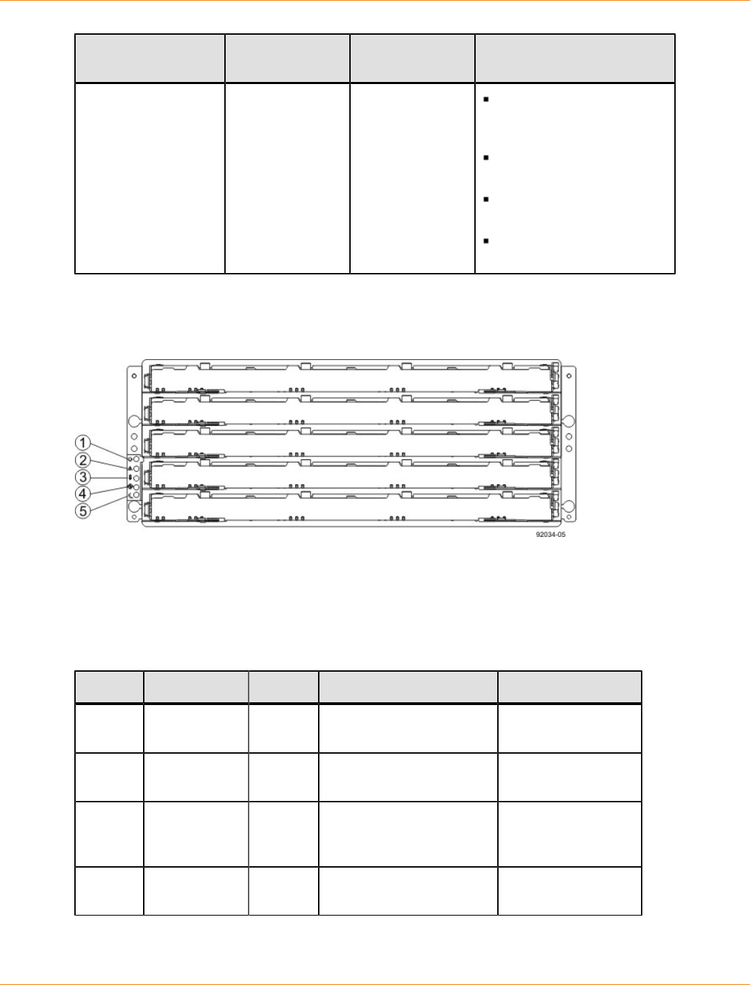
SANtricity_10.77 February 2011
LSI Corporation
- 410 -
LED Symbol Location
(Canisters) Function
Left LED Off –
100BASE-T or 10BASE-T
speed.
Right LED On – A link is
established.
Right LED Off – No link
exists.
Right LED blinking –
Activity is occurring.
LEDs on the DE6600 Drive Tray
LEDs on the Left End Cap
1. Drive Tray Locate LED
2. Drive Tray Service Action Required LED
3. Drive Tray Over-Temperature LED
4. Power LED
5. Standby Power LED
LEDs on the Left End Cap
Location LED Color On Off
1 Drive Tray
Locate White Identifies a drive tray that
you are trying to find. Normal status.
2 Service Action
Required Amber A component within the
drive tray needs attention. Normal status.
3 Drive Tray
Over-
Temperature
Amber The temperature of the
drive tray has reached an
unsafe level.
Normal status.
4 Power Green Power is present. Power is not
present.
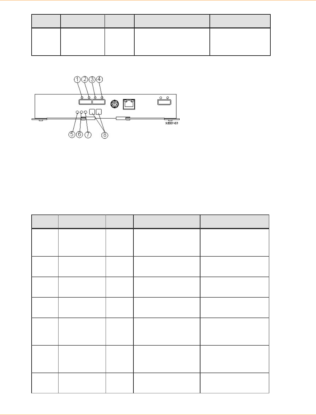
SANtricity_10.77 February 2011
LSI Corporation
- 411 -
Location LED Color On Off
5 Standby
Power Green The drive tray is in
Standby Power mode. The drive tray is not
in Standby Power
mode.
LEDs on the ESM Canister
1. ESM Link Fault LED (Port 1A Bypass)
2. ESM Link LED (Port 1A Data Rate)
3. ESM Link LED (Port 1B Data Rate)
4. ESM Link Fault LED (Port 1B Bypass)
5. ESM Service Action Allowed LED
6. ESM Service Action Required LED
7. ESM Power LED
8. Seven-Segment Tray ID
LEDs on the ESM Canister
Location LED Color On Off
1 ESM Link
Fault (Port 1A
Bypass)
Amber A link error has
occurred. No link error has
occurred.
2 ESM Link (Port
1A) Green The link is up. A link error has
occurred.
3 ESM Link (Port
1B Bypass) Green The link is up. A link error has
occurred.
4 ESM Link Fault
(Port 1B) Amber A link error has
occurred. No link error has
occurred.
5 ESM Service
Action Allowed Blue The ESM can be
removed safely from
the drive tray.
The ESM cannot be
removed safely from
the drive tray.
6 ESM Service
Action
Required
Amber A fault exists within the
ESM. Normal status.
7 ESM Power Green Power to the ESM is
present. Power is not present to
the ESM.
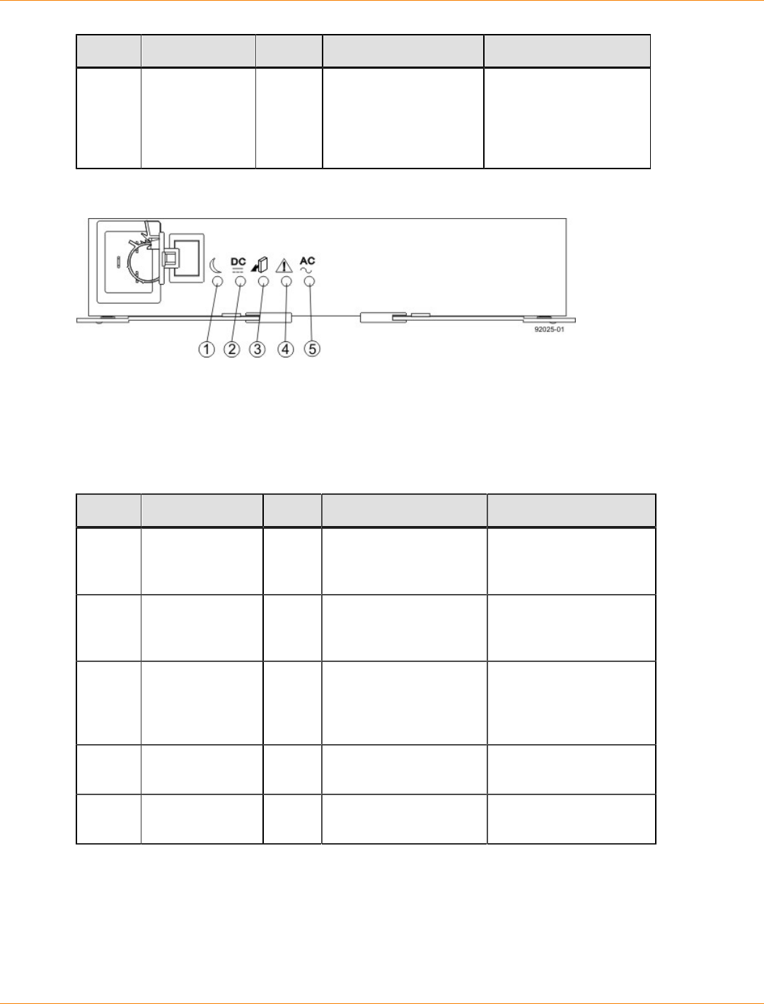
SANtricity_10.77 February 2011
LSI Corporation
- 412 -
Location LED Color On Off
8 Seven-
Segment Tray
ID
Green For more information,
see “Supported
Diagnostic Codes on
the Seven-Segment
Display”.
Not applicable.
LEDs on the Power Canister
1. Standby Power LED
2. Power DC Power LED
3. Power Service Action Allowed LED
4. Power Service Action Required LED
5. Power AC Power LED
LEDs on the Power Canister
Location LED Color On Off
1 Standby Power Green The drive tray is in
Standby mode and DC
power is not available.
The drive tray is not in
Standby mode and DC
power is available.
2 Power DC
Power Green DC power from the
power canister is
available.
DC power from the
power canister is not
available.
3 Power Service
Action Allowed Blue The power canister can
be removed safely from
the drive tray.
The power canister
cannot be removed
safely from the drive
tray.
4 Power Service
Action Required Amber A fault exists within the
power canister. Normal status.
5 Power AC
Power Green AC power to the power
canister is present. AC power to the power
canister is not present.
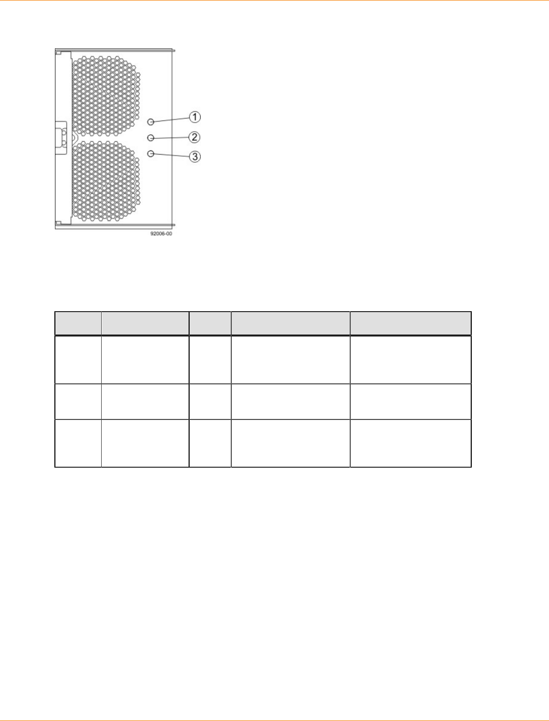
SANtricity_10.77 February 2011
LSI Corporation
- 413 -
LEDs on the Fan Canister
1. Power LED
2. Service Action Required LED
3. Service Action Allowed LED
LEDs on the Fan Canister
Location LED Color On Off
1 Power Green Power from the fan
canister is available. Power to the fan
customer-replaceable
unit (CRU) is available.
2 Service Action
Required Amber A fault exists within the
fan canister. Normal status.
3 Service Action
Allowed Blue The fan canister can
be removed safely from
the drive tray.
The fan canister cannot
be removed safely from
the drive tray.
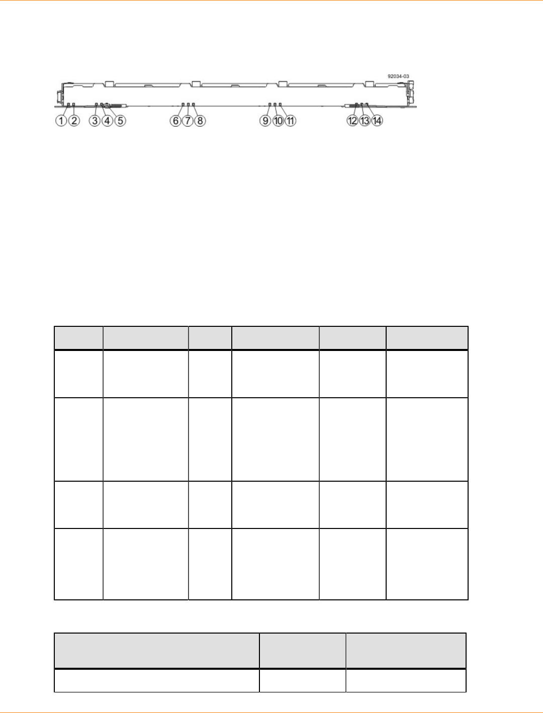
SANtricity_10.77 February 2011
LSI Corporation
- 414 -
LEDs on the DE6600 Drive Drawers
LEDs on the Drawer
1. Drive Drawer Status Service Action Required LED
2. Drive Drawer Status Service Action Allowed LED
3. Drive 1 Activity LED
4. Drive 2 Activity LED
5. Drive 3 Activity LED
6. Drive 4 Activity LED
7. Drive 5 Activity LED
8. Drive 6 Activity LED
9. Drive 7 Activity LED
10. Drive 8 Activity LED
11. Drive 9 Activity LED
12. Drive 10 Activity LED
13. Drive 11 Activity LED
14. Drive 12 Activity LED
LEDs on the Drawer
Location LED Color On Blinking Off
1 Drive Drawer
Service Action
Required
Amber An error has
occurred. Normal status.
2 Drive Drawer
Service Action
Allowed
Blue The drive
canister can be
removed safely
from the drive
drawer in the
drive tray.
The drive
canister cannot
be removed
safely from the
drive drawer in
the drive tray.
2 Drive or Drawer
Service Action
Required
Amber An error has
occurred. Normal status.
3–14 Drive Activity for
drives 1 through
12 in the drive
drawer
Green The power
is turned on,
and the drive
is operating
normally.
Drive I/
O activity
is taking
place.
The power is
turned off.
Drive State Represented by the LEDs
Drive State Drive Activity
LED (Green) Drive Service Action
Required LED (Amber)
Power is not applied. Off Off
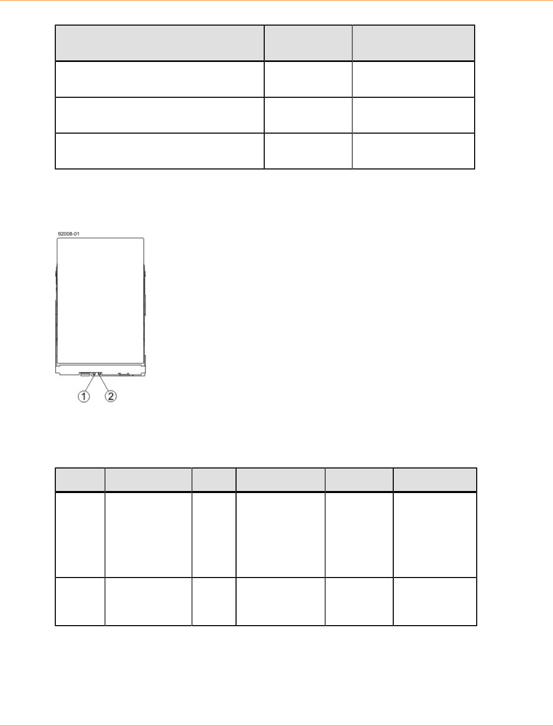
SANtricity_10.77 February 2011
LSI Corporation
- 415 -
Drive State Drive Activity
LED (Green) Drive Service Action
Required LED (Amber)
Normal operation – The power is turned on,
but drive I/O activity is not occurring. On Off
Normal operation – Drive I/O activity is
occurring. Blinking Off
Service action required – A fault condition
exists, and the drive is offline. On On
LEDs on the DE6600 Drives
LEDs on the DE6600 Drive
1. Drive Service Action Allowed LED
2. Drive Service Action Required LED
LEDs on the Drives
Location LED Color On Blinking Off
1 Drive Drawer
Service Action
Allowed
Blue The drive
canister can be
removed safely
from the drive
drawer in the
drive tray.
The drive
canister cannot
be removed
safely from the
drive drawer in
the drive tray.
2 Drive or Drawer
Service Action
Required
Amber An error has
occurred. Normal status.
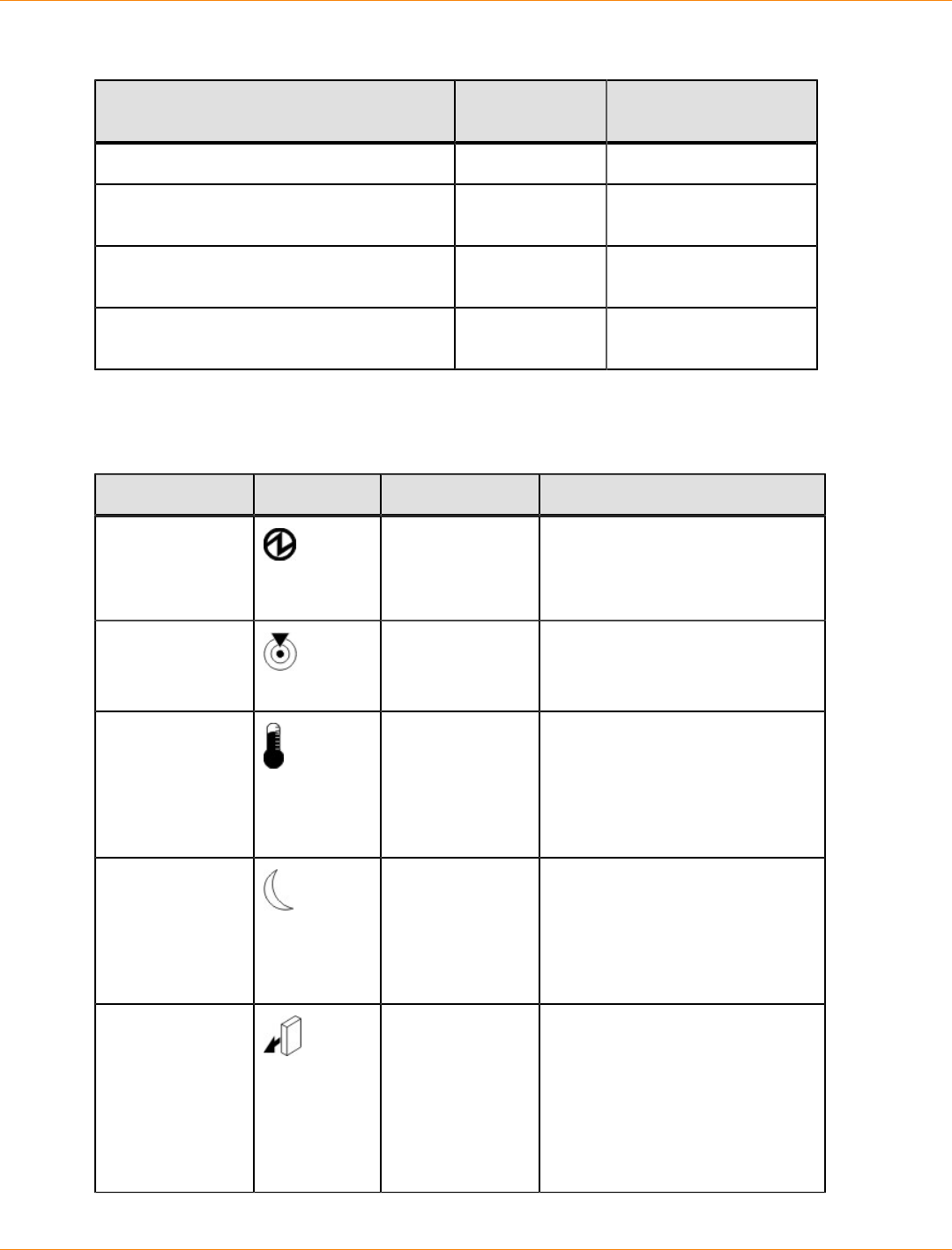
SANtricity_10.77 February 2011
LSI Corporation
- 416 -
Drive State Represented by the LEDs
Drive State Drive Activity
LED (Green) Drive Service Action
Required LED (Amber)
Power is not applied. Off Off
Normal operation – The power is turned on,
but drive I/O activity is not occurring. On Off
Normal operation – Drive I/O activity is
occurring. Blinking Off
Service action required – A fault condition
exists, and the drive is offline. On On
General Behavior of the LEDs on the DE6600 Drive Tray
DE6600 Drive Tray LED Symbols and General Behavior
LED Symbol Location General Behavior
Power Drive tray
ESM canister
Power-fan
canister
On – Power is applied to the drive
tray or the canister.
Off – Power is not applied to the
drive tray or the canister.
Drive Tray Locate Front bezel on
the drive tray On or blinking – Indicates the
drive tray that you are trying to
find.
Drive Tray Over-
Temperature Front bezel on
the drive tray On – The temperature of the
drive tray has reached an unsafe
condition.
Off – The temperature of the
drive tray is within operational
range.
Standby Power Front bezel on
the drive tray On – The drive tray is in Standby
mode, and the main DC power is
off.
Off – The drive tray is not in
Standby mode, and the main DC
power is on.
Service Action
Allowed ESM canister
Power-fan
canister
Drive
On – It is safe to remove the ESM
canister, the power-fan canister,
or the drive.
Off – Do not remove the ESM
canister, the power-fan canister,
or the drive.
The drive has an LED but no
symbol.
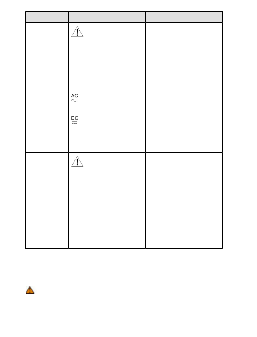
SANtricity_10.77 February 2011
LSI Corporation
- 417 -
LED Symbol Location General Behavior
Service Action
Required (Fault) ESM canister
Power-fan
canister
Drive
On – When the drive tray LED is
on, a component within the drive
tray needs attention.
On – The ESM canister, the
power-fan canister, or the drive
needs attention.
Off – The ESM canister, the
power-fan canister, and the drive
are operating normally.
The drive has an LED but no
symbol.
AC Power ESM canister
Power-fan
canister
On – AC power is present.
Off – AC power is not present.
DC Power Power-fan
canister On – Regulated DC power from
the power canister and the fan
canister is present.
Off – Regulated DC power from
the power-fan canister is not
present.
Link Service
Action Required
(Fault)
ESM canister On – The cable is attached and
at least one lane has a link-up
status, but one lane has a link-
down status.
Off – The cable is not attached,
the cable is attached and all lanes
have a link-up status, or the cable
is attached and all lanes have a
link-down status.
Link Up Two LEDs
above each
expansion
connector
ESM canister On – The cable is attached and
at least one lane has a link-up
status.
Off – The cable is not attached,
or the cable is attached and all
lanes have a link-down status.
Things to Know – Service Action Allowed LEDs
Each controller canister, power-fan canister, and battery canister has a Service Action Allowed LED. The
Service Action Allowed LED lets you know when you can remove a canister safely.
ATTENTION Possible loss of data access – Never remove a controller canister, a power-fan
canister, or a battery canister unless the appropriate Service Action Allowed LED is on.

SANtricity_10.77 February 2011
LSI Corporation
- 418 -
If a controller canister or a power-fan canister fails and must be replaced, the Service Action Required (Fault)
LED on that canister comes on to indicate that service action is required. The Service Action Allowed LED
also comes on if it is safe to remove the canister. If data availability dependencies exist or other conditions
that dictate a canister should not be removed, the Service Action Allowed LED stays off.
The Service Action Allowed LED automatically comes on or goes off as conditions change. In most cases,
the Service Action Allowed LED comes on when the Service Action Required (Fault) LED comes on for a
canister.
IMPORTANT If the Service Action Required (Fault) LED comes on but the Service Action Allowed
LED is off for a particular canister, you might need to service another canister first. Check your storage
management software to determine the action that you should take.
Things to Know – Sequence Code Definitions for the CDE2600-60 Controller-
Drive Tray
During normal operation, the tray ID display on each controller canister displays the controller-drive tray ID.
The Diagnostic LED (lower-digit decimal point) comes on when the display is used for diagnostic codes and
goes off when the display is used to show the tray ID.
Sequence Code Definitions for the CDE2600-60 Controller-Drive Tray
Category Category
Code
(See
Note 1)
Detail Codes (See Note 2)
Startup error SE+
(See
Note 3)
88+ Power-on default.
dF+ Power-on diagnostic fault.
Operational error OE+ Lx+ Lock-down codes (See the following
table.)
Operational state OS+ OL+ = Offline.
bb+ = Battery backup (operating on
batteries).
Cf+ = Component failure.
Component
failure CF+ dx+ = Processor or cache DIMM.
Cx = Cache DIMM.
Px+ = Processor DIMM.
Hx+ = Host interface card.
Fx+ = Flash drive.
Diagnostic failure dE+ Lx+ = Lock-down code.
Category
delimiter dash+ The separator between category-detail
code pairs is used when more than one
category detail code pair exists in the
sequence.

SANtricity_10.77 February 2011
LSI Corporation
- 419 -
Category Category
Code
(See
Note 1)
Detail Codes (See Note 2)
End-of-sequence
delimiter Blank
(See
Note 4)
The end-of-sequence delimiter is
automatically inserted by the hardware at
the end of a code sequence.
Notes:
1 A two-digit code that starts a dynamic display sequence.
2 A two-digit code that follows the category code with more specific
information.
3 The plus (+) sign indicates that a two-digit code displays with the
Diagnostic LED on.
4 No codes display, and the Diagnostic LED is off.
Things to Know – Lock-Down Codes for the CDE2600-60 Controller-Drive Tray
Use the following table to determine the diagnostic lock-down code definitions on the Seven-Segment Display
in the controller canister for the CDE2600-60 controller-drive tray.
Supported Diagnostic Lock-Down Codes on the Seven-Segment Display
Diagnostic Code Description
– – The firmware is booting.
.8, 8., or 88 This ESM is being held in reset by another ESM.
AA The ESM A firmware is in the process of booting (the
diagnostic indicator is not yet set).
bb The ESM B firmware is in the process of booting (the
diagnostic indicator is not yet set).
L0 The controller types are mismatched, which result in a
suspended controller state.
L2 A persistent memory error has occurred, which results in a
suspended controller state.
L3 A persistent hardware error has occurred, which results in a
suspended controller state.
L4 A persistent data protection error has occurred, which results
in a suspended controller state.
L5 An auto-code synchronization (ACS) failure has been
detected, which results in a suspended controller state.
L6 An unsupported host interface card has been detected, which
results in a suspended controller state.

SANtricity_10.77 February 2011
LSI Corporation
- 420 -
Diagnostic Code Description
L7 A sub-model identifier either has not been set or has been
mismatched, which results in a suspended controller state.
L8 A memory configuration error has occurred, which results in a
suspended controller state.
L9 A link speed mismatch condition has been detected in either
the ESM or the power supply, which results in a suspended
controller state.
Lb A host interface card configuration error has been detected,
which results in a suspended controller state.
LC A persistent cache backup configuration error has been
detected, which results in a suspended controller state.
Ld A mixed cache memory DIMMs condition has been detected,
which results in a suspended controller state.
LE Uncertified cache memory DIMM sizes have been detected,
which result in a suspended controller state.
LF The controller has locked down in a suspended state with
limited symbol support.
LH A controller firmware mismatch been detected, which results
in a suspended controller state.
LL The controller cannot access either midplane SBB EEP-ROM,
which results in a suspended controller state.
Ln A canister is not valid for a controller, which results in a
suspended controller state.
LP Drive port mapping tables are not detected, which results in a
suspended controller state.
LU The start-of-day (SOD) reboot limit has been exceeded, which
results in a suspended controller state.
Things to Know – Diagnostic Code Sequences for the CDE2600-60 Controller-
Drive Tray
Use the following table to determine the code sequences on the Seven-Segment Display in the controller
canister for the CDE2600-60 controller-drive tray. These repeating sequences can be used to diagnose
potential problems with the controller tray.

SANtricity_10.77 February 2011
LSI Corporation
- 421 -
Diagnostic Code Sequences for the CDE2600-60 Controller-Drive Tray
Displayed Diagnostic Code
Sequences Description
SE+ 88+ blank- One of the following power-on conditions
exists:
Controller power-on
Controller insertion
Controller inserted while held in reset
xy - Normal operation.
OS+ Sd+ blank- Start-of-day (SOD) processing.
OS+ OL+ blank- The controller is placed in reset while
displaying the tray ID.
OS+ bb+ blank- The controller is operating on batteries
(cache backup).
OS+ CF+ Hx + blank- A failed host card has been detected.
OS+ CF+ Fx + blank- A failed flash drive has been detected.
SE+ dF + blank- A non-replaceable component failure has
been detected.
SE+ dF + dash+ CF+ Px +
blank- A processor DIMM failure has been detected.
SE+ dF + dash+ CF+ Cx +
blank- A cache memory DIMM failure has been
detected.
SE+ dF + dash+ CF+ dx +
blank- A processor or cache DIMM failure has been
detected.
SE+ dF + dash+ CF+ Hx +
blank- A host card failure has been detected.
OE+ Lx + blank- A lockdown condition has been detected.
OE+ L2+ dash+ CF+ Px +
blank- Persistent processor DIMM ECC errors have
been detected, which result in a suspended
controller state.
OE+ L2+ dash+ CF+ Cx +
blank- Persistent cache DIMM ECC errors have
been detected, which result in a suspended
controller state.
OE+ L2+ dash+ CF+ dx +
blank- Persistent processor or cache DIMM ECC
errors have been detected, which result in a
suspended controller state.

SANtricity_10.77 February 2011
LSI Corporation
- 422 -
Displayed Diagnostic Code
Sequences Description
OE+ LC+ blank- The write-protect switch is set during cache
restore, which results in a suspended
controller state.
OE+ LC+ dd + blank- The memory size is changed from bad
data in the flash drives, which results in a
suspended controller state.
DE+ L2+ dash+ CF+ Cx +
blank- A cache memory diagnostic has been
reported failed, which results in a suspended
controller state.
Supported Diagnostic Codes for the DE6600 Drive Tray on the Seven-Segment
Display
Supported Diagnostic Codes
Diagnostic Code Description
– – The firmware is booting.
.8, 8., or 88 This ESM is being held in reset by another ESM.
AA ESM A firmware is in the process of booting (the diagnostic
indicator is not yet set).
bb ESM B firmware is in the process of booting (the diagnostic
indicator is not yet set).
L0 The controller types are mismatched.
L2 A persistent memory error has occurred.
L3 A persistent hardware error has occurred.
L9 An over-temperature condition has been detected in either the
ESM or the power supply.
H0 An ESM Fibre Channel interface failure has occurred.
H1 An SFP transceiver speed mismatch (a 2-Gb SFP transceiver
is installed when the drive tray is operating at 4 Gb) indicates
that an SFP transceiver must be replaced. Look for the SPF
transceiver with a blinking amber LED.
H2 The ESM configuration is invalid or incomplete, operating in
Degraded state.
H3 The maximum number of ESM reboot attempts has been
exceeded.

SANtricity_10.77 February 2011
LSI Corporation
- 423 -
Diagnostic Code Description
H4 This ESM cannot communicate with the alternate ESM.
H5 A midplane harness failure has been detected in the drive
tray.
H6 A catastrophic ESM hardware failure has been detected.
H9 A non-catastrophic hardware failure has occurred. The ESM is
operating in a Degraded state.
J0 The ESM canister is incompatible with the drive tray firmware.

SANtricity_10.77 February 2011
LSI Corporation
- 424 -
CE7900 Controller Tray Installation
This topic provides basic information for installing the CE7900 controller tray and the corresponding drive
trays (the FC4600 drive tray and the DE6900 drive tray) in a storage array. After you have completed these
tasks, you will continue onto the Initial Configuration and Software Installation electronic document topics or
the PDF on the SANtricity ES Storage Manager Installation DVD.

SANtricity_10.77 February 2011
LSI Corporation
- 425 -
Step 1 – Preparing for a CE7900 Controller Tray Installation
The CE7900 storage array consists of a CE7900 controller tray and one or more drive trays in a cabinet. Use
this initial setup guide to install the CE7900 controller tray. This document includes instructions for installing
the DE6900 drive trays or FC4600 drive trays.
Key Terms
storage array
A collection of both physical components and logical components for storing data. Physical components
include drives, controllers, fans, and power supplies. Logical components include volume groups and
volumes. These components are managed by the storage management software.
controller tray
One tray with one or two controllers. The controller tray also contains power supplies, fans, and other
supporting components. The controller tray provides the interface between a host and a storage array. A
controller tray does not have drives for storing data.
controller
A circuit board and firmware that is located within a controller tray or a controller-drive tray. A controller
manages the input/output (I/O) between the host system and data volumes.
drive tray
One tray with drives, one or two environmental services monitors (ESMs), power supplies, and fans. A drive
tray does not contain controllers.
environmental services monitor (ESM)
A canister in the drive tray that monitors the status of the components. An ESM also serves as the connection
point to transfer data between the drive tray and the controller.
Small Form-factor Pluggable (SFP) transceiver
A component that enables Fibre Channel duplex communication between storage array devices. SFP
transceivers can be inserted into host bus adapters (HBAs), controllers, and environmental services monitors
(ESMs). SFP transceivers can support either copper cables (the SFP transceiver is integrated with the cable)
or fiber-optic cables (the SFP transceiver is a separate component from the fiber-optic cable).
Gathering Items
Before you start installing the controller tray, you must have installed the cabinet in which the controller tray
will be mounted.
Use the tables in this section to verify that you have all of the necessary items to install the controller tray.
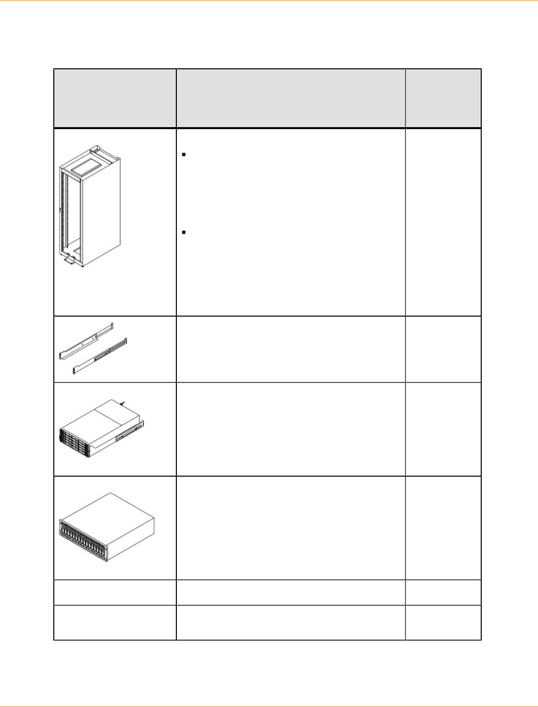
SANtricity_10.77 February 2011
LSI Corporation
- 426 -
Basic Hardware for CE7900 Configurations
Basic Hardware
Item Included
with the
Controller
Tray
Cabinet
Make sure that your cabinet meets the
installation site specifications of the various
CE7900 storage array components. Refer
to the Storage System Site Preparation
Guide on the SANtricity ES Storage Manager
Installation DVD for more information.
Depending on the power supply limitations
of your cabinet, you might need to install
more than one cabinet to accommodate
the different components of the CE7900
storage array. Refer to the installation guide
for your cabinet for instructions on installing
the cabinet.
Mounting rails and screws
DE6900 drive tray (shown with the separately
packaged mounting rails attached).
FC4600 drive tray with end caps that are
packaged separately.
Fibre Channel switch (optional)
Host with Fibre Channel host bus adapters
(HBAs)
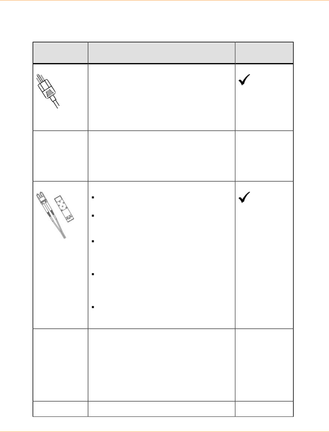
SANtricity_10.77 February 2011
LSI Corporation
- 427 -
Cables and Connectors for a CE7900 Controller Tray Configuration
Cables and Connectors
Item Included with the
Controller Tray
AC power cords
The controller-drive tray and the drive trays ship
with power cords for connecting to an external
power source, such as a wall plug. Your cabinet
might have special power cords that you use
instead of the power cords that ship with the
controller-drive tray and the drive trays.
Use fiber-optic cables for Fibre Channel
connections to the drive trays.
For the differences between the fiber-optic cables
and the copper Fibre Channel (FC) cables, see
“Things to Know – SFP Transceivers, Fiber-Optic
Cables, and Copper Cables”.
Small Form-factor Pluggable (SFP) transceivers
The SFP transceivers connect fiber-optic cables
to host ports and drive ports.
Four or eight SFP transceivers are included
with the controller tray; one for each of the host
channel ports on the controllers.
Depending on your connection requirements,
you might need to purchase additional SFP
transceivers (two SFP transceivers for each
fiber-optic cable).
Depending on the configuration of your storage
array, you might need to use three different
types of SFP transceivers: 10-Gb/s iSCSI, 8-
Gb/s Fibre Channel, and 4-Gb/s Fibre Channel.
You must purchase only Restriction of
Hazardous Substances (RoHS)-compliant SFP
transceivers.
Copper Fibre Channel cables (optional)
Use these cables for connections within the storage
array.
For the differences between the fiber-optic cables
and the copper Fibre Channel cables, see the
“Deciding on the Management Method" topic
in either the Initial Configuration and Software
Installation electronic topics or the PDF on the
SANtricity ES Storage Manager Installation DVD.
Fiber-optic InfiniBand cables
SANtricity_10.77 February 2011
LSI Corporation
- 428 -
Item Included with the
Controller Tray
Use these cables (or copper InfiniBand cables)
with InfiniBand switches for InfiniBand connections
between a controller tray and the hosts.
Ethernet cable
This cable is used for out-of-band storage array
management and for 1-Gb/s iSCSI connections.
For information about out-of-band storage
array management, see the “Deciding on the
Management Method" topic in either the Initial
Configuration and Software Installation electronic
topics or the PDF on the SANtricity ES Storage
Manager Installation DVD.
Product DVDs
Product DVDs
Item Included with
the Controller
Tray
Firmware DVD
Firmware is already installed on the
controllers.
The files on the DVD are backup copies.
SANtricity ES Storage Manager Installation DVD
SANtricity ES Storage Manager software and
documentation.
To access product documentation,
use the documentation map file,
doc_launcher.html, which is located in
the docs directory.
Tools and Other Items
Tools and Other Items
Item Included
with the Tray
Labels
Help you to identify cable connections and lets
you more easily trace cables from one tray to
another
A cart
Holds the tray and components
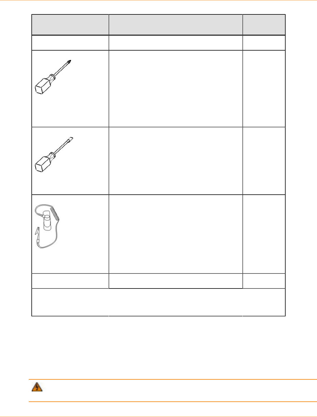
SANtricity_10.77 February 2011
LSI Corporation
- 429 -
Item Included
with the Tray
A mechanical lift (optional)
A Phillips screwdriver
A flat-blade screwdriver
Anti-static protection
A flashlight
Use the Compatibility Matrix, at the following website, to obtain the latest hardware
compatibility information.
http://www.lsi.com/compatibilitymatrix/
Things to Know – SFP Transceivers, Fiber-Optic Cables, and Copper Cables
The following figures show two types of cables and SFP transceivers for Fibre Channel connections. Your
SFP transceivers and cables might look slightly different from the ones shown. The differences do not affect
the performance of the SFP transceivers. Host connections that use 8-Gb/s Fibre Channel connections
require a different type of SFP transceiver from that required by either 4-Gb/s Fibre Channel connections or
10-Gb/s iSCSI connections.
WARNING (W03) Risk of exposure to laser radiation – Do not disassemble or remove any part of a
Small Form-factor Pluggable (SFP) transceiver because you might be exposed to laser radiation.
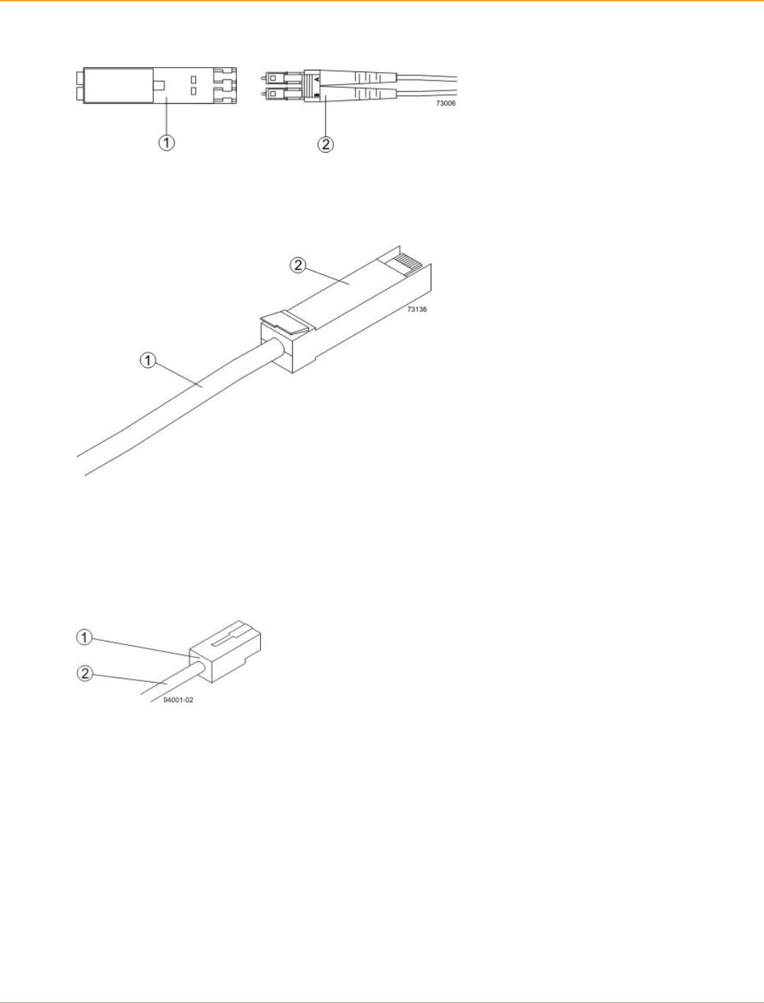
SANtricity_10.77 February 2011
LSI Corporation
- 430 -
Fiber-Optic Cable Connection
1. Active SFP Transceiver
2. Fiber-Optic Cable
Copper Fibre Channel Cable Connection
1. Copper Fibre Channel Cable
2. Passive SFP Transceiver
Host connections with iSCSI require a copper cable with RJ-45 connectors as shown in the following figure.
Connections using iSCSI do not require SFP transceivers.
iSCSI Cable with an RJ-45 Connector
1. RJ-45 Connector
2. iSCSI Cable
Host connections with InfiniBand require a fiber-optic cable with InfiniBand connectors as shown in the
following figure. Connections using InfiniBand do not require SFP transceivers.
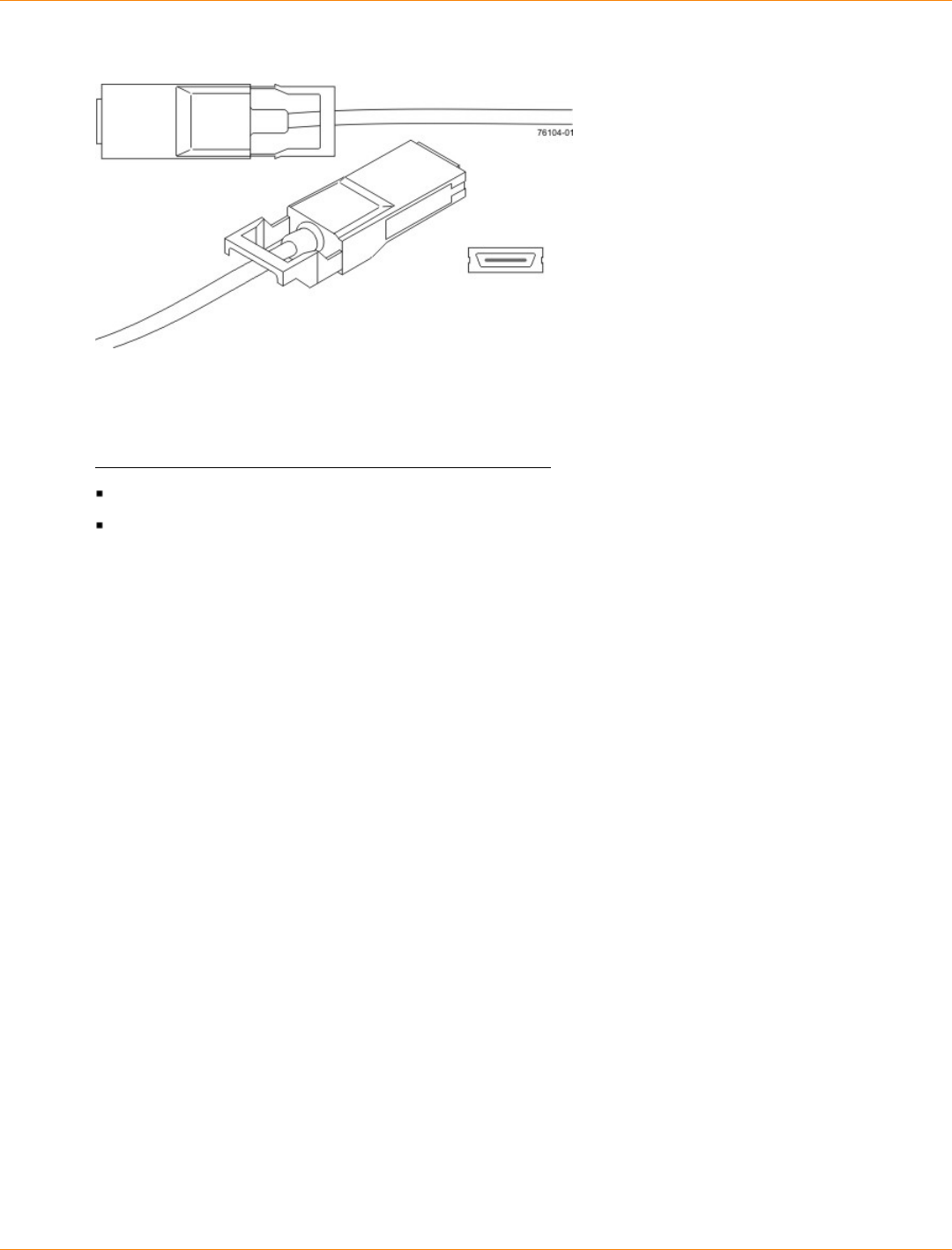
SANtricity_10.77 February 2011
LSI Corporation
- 431 -
InfiniBand Cable with Built-In Connectors
Things to Know – Taking a Quick Glance at the CE7900 Configuration
Hardware
Characteristics of the CE7900 Controller Tray
The top controller, controller A, is inverted from the bottom controller, controller B.
The top of the controller tray is the side with labels.
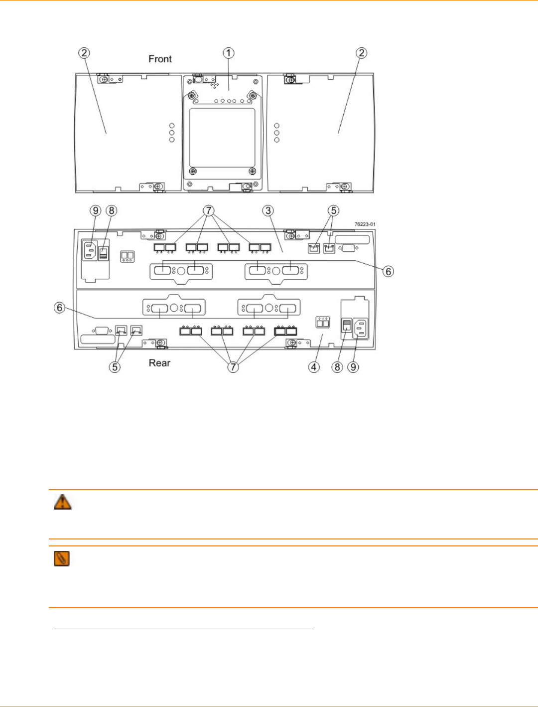
SANtricity_10.77 February 2011
LSI Corporation
- 432 -
CE7900 Controller Tray – Front View and Rear View
1. (Front View) Interconnect-Battery Canister
2. Power-Fan Canisters
3. (Rear View) Controller A (Inverted)
4. Controller B
5. Ethernet Ports
6. Host Channels
7. Dual-Ported Drive Channels
8. AC Power Switch
9. AC Input
ATTENTION Risk of equipment malfunction – To avoid exceeding the functional and environmental
limits, install only drives that have been provided or approved by the original manufacturer. Drives might be
shipped but not installed. System integrators, resellers, system administrators, or users can install the drives.
NOTE You must use the current drive canisters in the drive tray to ensure proper performance. Using
older or “legacy” drives might damage the connectors. Additionally, the latch might not hold the drive in place,
which causes the drive to be disconnected and taken offline. For more information on supported drives,
contact a Customer and Technical Support representative.
Characteristics of the DE6900 Controller Tray
The DE6900 drive tray consists of five drawers that can contain up to 60 SATA drives in a Fibre Channel host
connection to a CE7900 controller tray.
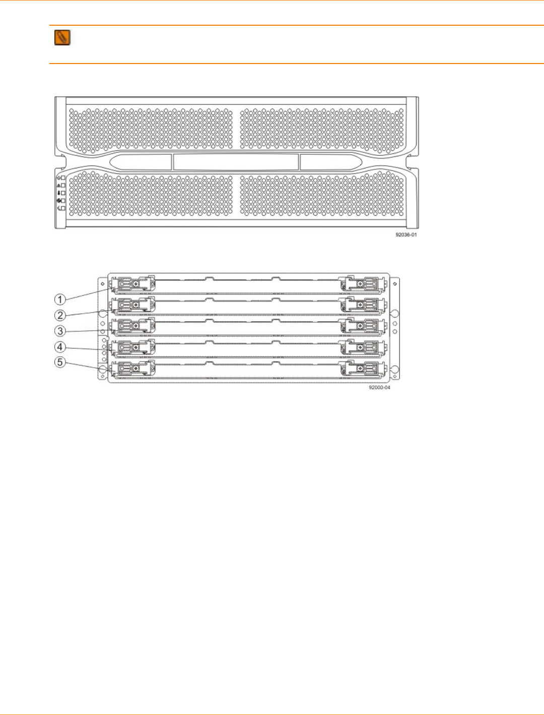
SANtricity_10.77 February 2011
LSI Corporation
- 433 -
IMPORTANT The installation order within each drawer is from left to right in rows. Slots 1, 4, 7, and 10
must have a drive installed in these locations to make sure there is sufficient air flow to the drives.
DE6900 Drive Tray – Front View with the Bezel
DE6900 Drive Tray – Front View with the Bezel Removed
1. Drive Drawer 1
2. Drive Drawer 2
3. Drive Drawer 3
4. Drive Drawer 4
5. Drive Drawer 5
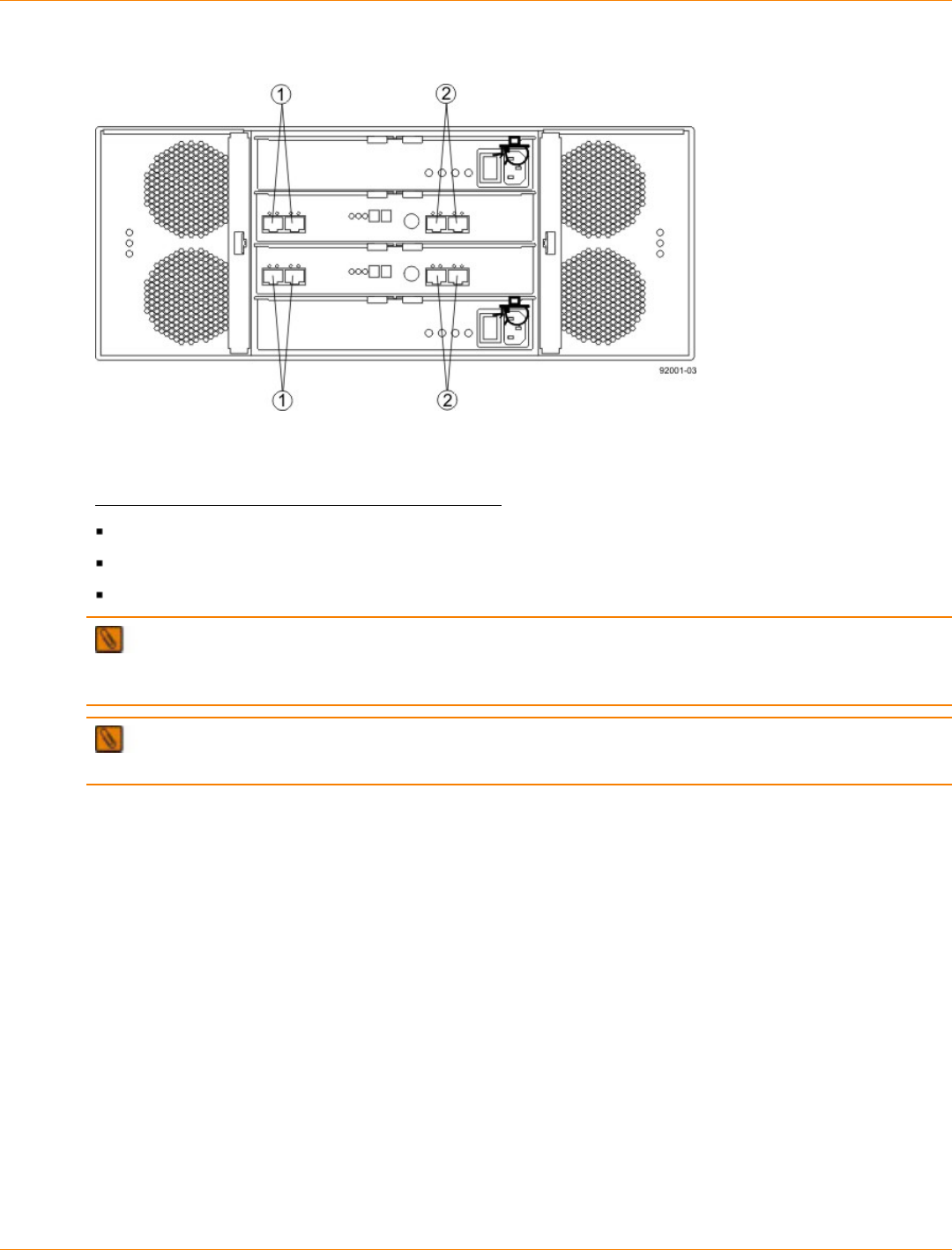
SANtricity_10.77 February 2011
LSI Corporation
- 434 -
DE6900 Drive Tray – Rear View
1. Standard Expansion Connectors
2. Drive-Side Trunking Expansion Connectors
Characteristics of the FC4600 Drive Tray
The top-left ESM is inverted from the bottom-right ESM.
The top-right power-fan canister is inverted from the bottom-left power-fan canister.
The drive tray is in the correct (top) orientation when the lights of the drives are at the bottom (Figure
NOTE The FC4600 drive tray is available in rackmount models and deskside models. The components
for the deskside model are identical to the components of the rackmount model. The deskside model is
situated as if the rackmount model is sitting on its left side.
IMPORTANT Each FC4600 drive tray in the storage array must have a minimum of two drives for
proper operation. If the tray has fewer than two drives, a power supply error is reported.
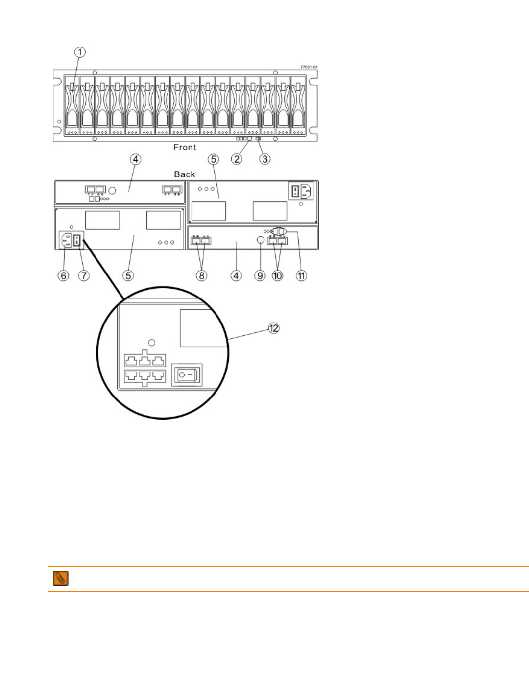
SANtricity_10.77 February 2011
LSI Corporation
- 435 -
FC4600 Drive Tray – Front View
1. Drive Canister
2. Alarm Mute Button
3. Link (Data) Rate Switch (4 Gb/s or 2 Gb/s)
4. ESM Canister
5. Power-Fan Canister
6. AC Power Connector
7. AC Power Switch
8. In/Out Ports
9. Serial Port
10. In/Out Ports (Reserved for future use)
11. Tray ID / Seven-Segment Diagnostic Display
12. (Optional) DC Power Connectors and DC Power Switch
NOTE The DC Power Option is not available within the CE7900 Controller Tray Configuration.
For Additional Information on the CE7900 Controller-Drive Tray Configuration
Refer to the Storage System Site Preparation Guide on the SANtricity ES Storage Manager Installation DVD
for information about the installation requirements of the various CE7900 storage array components.
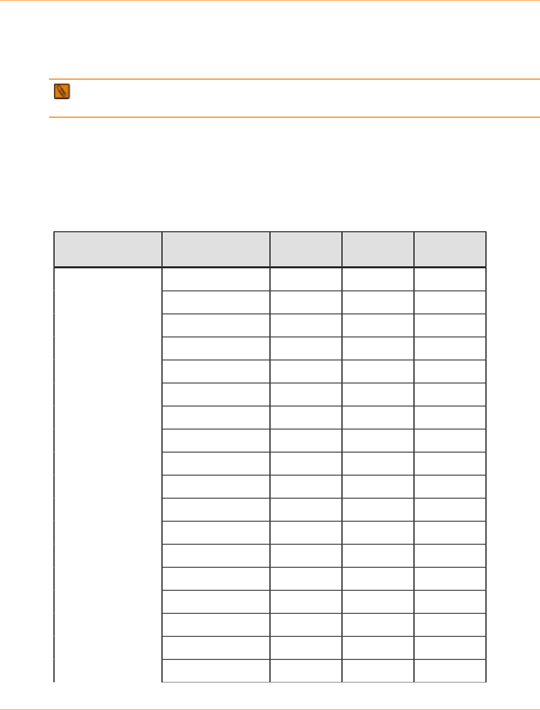
SANtricity_10.77 February 2011
LSI Corporation
- 436 -
Step 2 – Installing and Configuring the Switches
Things to Know – Switches
IMPORTANT Most of the switches, as shipped from the vendor, require an update to their firmware to
work correctly with the storage array.
Depending on the configuration of your storage array, you might use Fibre Channel switches and iSCSI
switches.
The switches in the following table are certified for use with a CDE2600 storage array, a CDE2600-60 storage
array, a CDE4900 storage array, and a CE7900 storage array, which all use SANtricity ES Storage Manager
Version 10.77.
Supported Switches
Vendor Model Fibre
Channel iSCSI SAS
200E Yes No No
3200 Yes No No
3800 Yes No No
3900 Yes No No
3950 Yes No No
12000 Yes No No
3850 Yes No No
3250 Yes No No
24000 Yes No No
4100 Yes No No
48000 Yes No No
5000 Yes No No
300 Yes No No
5100 Yes No No
5300 Yes No No
7500 Yes No No
7800 Yes No No
Brocade
DCX Yes No No

SANtricity_10.77 February 2011
LSI Corporation
- 437 -
Vendor Model Fibre
Channel iSCSI SAS
FCOE No Yes No
9506 Yes No No
9509 Yes No No
9216 Yes No No
9216i Yes No No
9120 Yes No No
914x Yes No No
9513 Yes No No
9020 Yes No No
MDS9000 Yes No No
9222i Yes No No
9134 Yes No No
Catalyst 2960 No Yes No
Catalyst 3560 No Yes No
Cisco
Catalyst 3750G-24TS No Yes No
LSI 6160 No No Yes
3232 Yes No No
3216 Yes No No
4300 Yes No No
4500 Yes No No
6064 Yes No No
6140 Yes No No
4400 Yes No No
McData
4700 Yes No No
6140 No Yes No
6142 No Yes No
QLogic
SANbox2-8 Yes No No

SANtricity_10.77 February 2011
LSI Corporation
- 438 -
Vendor Model Fibre
Channel iSCSI SAS
SANbox2-16 Yes No No
SANbox5200 Yes No No
SANbox3600 Yes No No
SANbox3800 Yes No No
SANbox5208 Yes No No
SANbox5600 Yes No No
SANbox5800 Yes No No
SANbox9000 Yes No No
5324 No Yes NoPowerConnect
6024 No Yes No
If required, make the appropriate configuration changes for each switch that is connected to the storage array.
Refer to the switch’s documentation for information about how to install the switch and how to use the
configuration utilities that are supplied with the switch.
Procedure – Installing and Configuring Switches
1. Install your switch according to the vendor’s documentation.
2. Use the Compatibility Matrix at the website http://www.lsi.com/compatibilitymatrix/ to obtain this
information:
The latest hardware compatibility information
The models of the switches that are supported
The firmware requirements and the software requirements for the switches
3. Update the switch’s firmware by accessing it from the applicable switch vendor’s website.
This update might require that you cycle power to the switch.
4. Find your switch in the following table to see whether you need to make further configuration changes.
Use your switch’s configuration utility to make the changes.
Supported Switch Vendors and Required Configuration Changes
Switch
Vendor Configuration Changes
Required? Next Step
Brocade Yes
Change the In-Order Delivery
(IOD) option to ON.
Make the change, and go to
“.Step 3 – Installing the Host
Bus Adapters for the CE7900
Controller Tray”

SANtricity_10.77 February 2011
LSI Corporation
- 439 -
Switch
Vendor Configuration Changes
Required? Next Step
Cisco Yes
Change the In-Order Delivery
(IOD) option to ON.
Make the change, and go to
“Step 3 – Installing the Host
Bus Adapters for the CE7900
Controller Tray.”
McData No “Step 3 – Installing the Host
Bus Adapters for the CE7900
Controller Tray.”
QLogic No “Step 3 – Installing the Host
Bus Adapters for the CE7900
Controller Tray.”
PowerConnect No “Step 3 – Installing the Host
Bus Adapters for the CE7900
Controller Tray.”
SANtricity_10.77 February 2011
LSI Corporation
- 440 -
Step 3 – Installing the Host Bus Adapters for the CE7900
Controller Tray
Key Terms
HBA host port
The physical and electrical interface on the host bus adapter (HBA) that provides for the connection between
the host and the controller. Most HBAs will have either one or two host ports. The HBA has a unique World
Wide Identifier (WWID) and each HBA host port has a unique WWID.
HBA host port world wide name
A 16-character unique name that is provided for each port on the host bus adapter (HBA).
host bus adapter (HBA)
A physical board that resides in the host. The HBA provides for data transfer between the host and the
controllers in the storage array over the I/O host interface. Each HBA contains one or more physical ports.
Things to Know – Host Adapters
Host connections might be Fibre Channel connections through host bus adapters (HBAs), InfiniBand
connections through host channel adapters (HCAs), or iSCSI connections through Ethernet adapters. The
CE7900 controller tray can have host interface cards (HICs) for any of these types of connections. The type of
a host adapter installed in a host must match the type of the HIC to which it connects. When host connections
are made through switches, the switches must support the speed and protocol of the connection.
For maximum hardware redundancy, you must install a minimum of two host adapters in each host. Dual-
ported host adapters provide two paths into the storage array but do not ensure redundancy if the entire
host adapter fails.
Most of the host adapters, as shipped from the vendor, require updated firmware and software drivers
to work correctly with the storage array. For information about the updates, refer to the web site of the
vendor for the host adapter.
NOTE You can use the Compatibility Matrix to obtain information about the supported models of the
host adapters and their requirements. Go to the web page at http://www.lsi.com/CompatibilityMatrix/. In the
search form, choose Host Adapter from the Product drop-down list. Use the search form to make sure you
have an acceptable configuration.
For best performance, cable an 8-Gb/s Fibre Channel HIC to an 8-Gb/s HBA. If the data rate for the HBA
is lower, the data transfer will occur at the lower rate. For instance, if you cable an 8-Gb/s Fibre Channel
HIC to a 4-Gb/s HBA, the data transfer rate is 4 Gb/s.
You cannot mix InfiniBand connections with other types of connections.
It is possible for a host to have both iSCSI (Ethernet) and Fibre Channel (HBA) adapters for connections to a
storage array that has a mix of HICs. Several restrictions apply to such configurations.
The root boot feature is not supported for hosts with mixed connections to one storage array.
Cluster configurations are supported for hosts with mixed connections to one storage array.
When the host operating system is VMware, mixing of connection types within a partition is not supported.
SANtricity_10.77 February 2011
LSI Corporation
- 441 -
When the host operating system is Windows, mixing of connection types within a storage partition is not
supported. A single server that attaches to multiple storage partitions on a single array must not have any
overlap in LUN number assignments given to the volumes.
For other operating systems, mixed connection types from a host to a single storage array are not
supported.
Procedure – Installing Host Bus Adapters
1. Go to http://www.lsi.com/compatibilitymatrix/, and select the desired Developer Partner Program link.
Check its Compatibility Matrix to make sure you have an acceptable configuration.
The Compatibility Matrix provides this information:
The latest hardware compatibility information
The models of the HBAs that are supported
The firmware requirements and the software requirements for the HBAs
2. Install your HBA according to the vendor documentation.
NOTE If your operating system is Windows Server 2008 Server Core, you might have additional
installation requirements. Refer to the Microsoft Developers Network (MSDN) for more information about
Windows Server 2008 Server Core. You can access these resources from www.microsoft.com.
3. Install the latest version of the firmware for the HBA. You can find the latest version of the firmware for the
HBA at the HBA vendor website.
IMPORTANT The remaining steps are general steps to obtain the HBA host port World Wide Name
from the HBA BIOS utility. If you have installed the host context agent on all of your hosts, you do not need
to perform these steps. If you are performing these steps, the actual prompts and screens vary depending
on the vendor that provides the HBA. Also, some HBAs have software utilities that you can use to obtain the
world wide name for the port instead of using the BIOS utility.
4. Reboot or start your host.
5. While your host is booting, look for the prompt to access the HBA BIOS utility.
6. Select each HBA to view its HBA host port world wide name.
7. Record the following information for each host and for each HBA connected to the storage array:
The name of each host
The HBAs in each host
The HBA host port world wide name of each port on the HBA
The following table shows examples of the host and HBA information that you must record.
Examples of HBA Host Port World Wide Names
Host Name Associated HBAs HBA Host Port World
Wide Name
Vendor x, Model y (dual port) 37:38:39:30:31:32:33:32
37:38:39:30:31:32:33:33
ICTENGINEERING
Vendor a, Model y (dual port) 42:38:39:30:31:32:33:42
42:38:39:30:31:32:33:44

SANtricity_10.77 February 2011
LSI Corporation
- 442 -
Host Name Associated HBAs HBA Host Port World
Wide Name
Vendor a, Model b (single
port) 57:38:39:30:31:32:33:52ICTFINANCE
Vendor x, Model b (single
port) 57:38:39:30:31:32:33:53
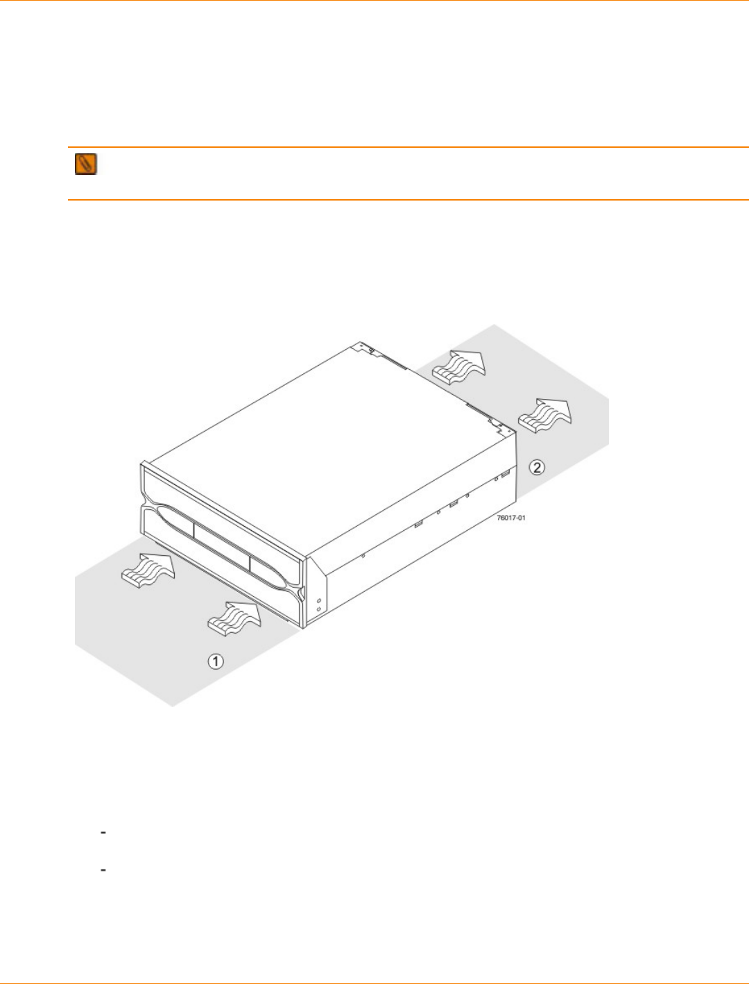
SANtricity_10.77 February 2011
LSI Corporation
- 443 -
Step 4 – Installing the Controller Tray
Things to Know – General Installation
The power supplies meet standard voltage requirements for both domestic and worldwide operation.
IMPORTANT Make sure that the combined power requirements of your trays do not exceed the power
capacity of your cabinet.
Steps to Install – CE7900 Controller Tray
1. Make sure that the cabinet is in the final location. Make sure that the cabinet installation site meets the
clearance requirements.
Airflow Direction Through and Clearance Requirements for the Controller Tray
1. 76-cm (30-in.) clearance in front of the cabinet
2. 61-cm (24-in.) clearance behind the cabinet
2. Lower the feet on the cabinet, if required, to keep it from moving.
3. Install the mounting rails in the cabinet. For more information, refer to the installation instructions that are
included with your mounting rails.
If you are installing the mounting rails above an existing tray, position the mounting rails directly
above the tray.
If you are installing the mounting rails below an existing tray, allow 17.8-cm (7.00-in.) clearance below
the existing tray.
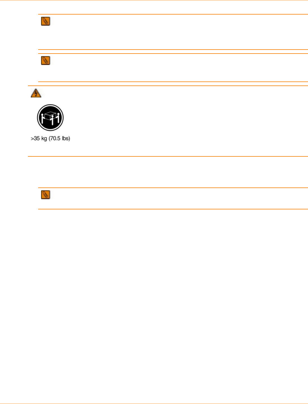
SANtricity_10.77 February 2011
LSI Corporation
- 444 -
NOTE If you are installing only FC4600 drive trays, make sure that you place the controller tray in
the middle portion of the cabinet while allowing room for drive trays to be placed above and below the
controller tray. As you add drive trays, position them below and above the controller tray, starting below
and alternating so that the cabinet does not become top heavy.
NOTE If you are installing DE6900 drive trays, make sure that you place the controller tray so that
you can install all of the DE6900 drive trays below it. Install DE6900 drive trays starting from the bottom of
the cabinet.
WARNING (W09) Risk of bodily injury –
Three persons are required to safely lift the component.
4. With the help of two other persons, slide the rear of the controller tray onto the mounting rails, and make
sure that the top mounting holes on the controller tray align with the mounting rail holes of the cabinet.
The rear of the controller tray slides into the slots on the mounting rails.
NOTE The rear of the controller tray contains two controllers. The top of the controller tray is the
side with the labels.
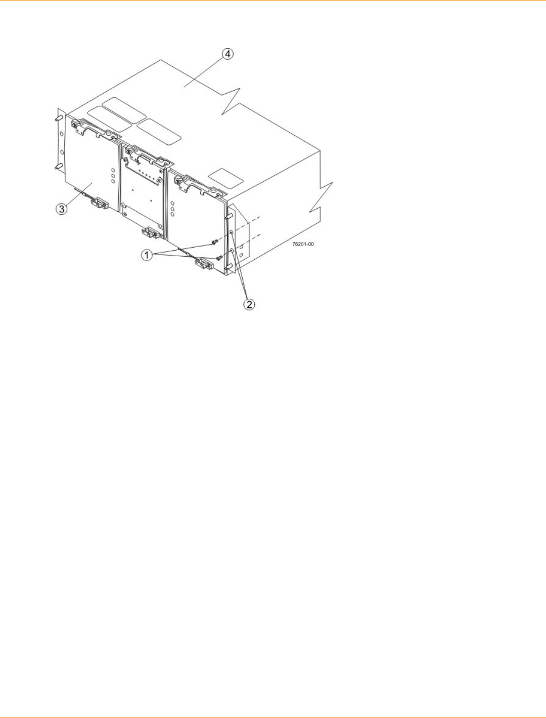
SANtricity_10.77 February 2011
LSI Corporation
- 445 -
Securing the Controller Tray to the Cabinet
1. Screws
2. Mounting Holes
3. Front
4. Top (with Labels)
5. Secure screws in the top mounting holes and the bottom mounting holes on each side of the controller
tray.
6. Install the bezel on the front of the controller tray.
7. Install the drive trays. Refer to "Step 7 – Connecting the Controller Tray to the Drive Trays" for information
about installing the FC4600 drive tray and the DE6900 drive tray.

SANtricity_10.77 February 2011
LSI Corporation
- 446 -
Step 5 – Connecting the Controller Tray to the Hosts
Key Terms
access volume
A special volume that is used by the host-agent software to communicate management requests and event
information between the management station and the storage array. An access volume is required only for in-
band management.
direct topology
A topology that does not use a switch.
Dynamic Host Configuration Protocol (DHCP)
CONTEXT [Network] An Internet protocol that allows nodes to dynamically acquire ('lease') network
addresses for periods of time rather than having to pre-configure them. DHCP greatly simplifies the
administration of large networks, and networks in which nodes frequently join and depart. (The Dictionary of
Storage Networking Terminology)
in-band management
A method to manage a storage array in which a storage management station sends commands to the storage
array through the host input/output (I/O) connection to the controller.
out-of-band management
A method to manage a storage array in which a storage management station sends commands to the storage
array through the Ethernet connections on the controller.
stateless address autoconfiguration
A method for setting the Internet Protocol (IP) address of an Ethernet port automatically. This method is
applicable only for IPv6 networks.
switch topology
A topology that uses a switch.
topology
The logical layout of the components of a computer system or network and their interconnections. Topology
deals with questions of what components are directly connected to other components from the standpoint
of being able to communicate. It does not deal with questions of physical location of components or
interconnecting cables. (The Dictionary of Storage Networking Terminology)
World Wide Identifier (WWID)
CONTEXT [Fibre Channel] A unique 64-bit number assigned by a recognized naming authority (often using
a block assignment to a manufacturer) that identifies a node process or node port. A WWID is assigned for
the life of a connection (device). Most networking physical transport network technologies use a world wide
unique identifier convention. For example, the Ethernet Media Access Control Identifier is often referred to as
the MAC address. (The Dictionary of Storage Networking Terminology)
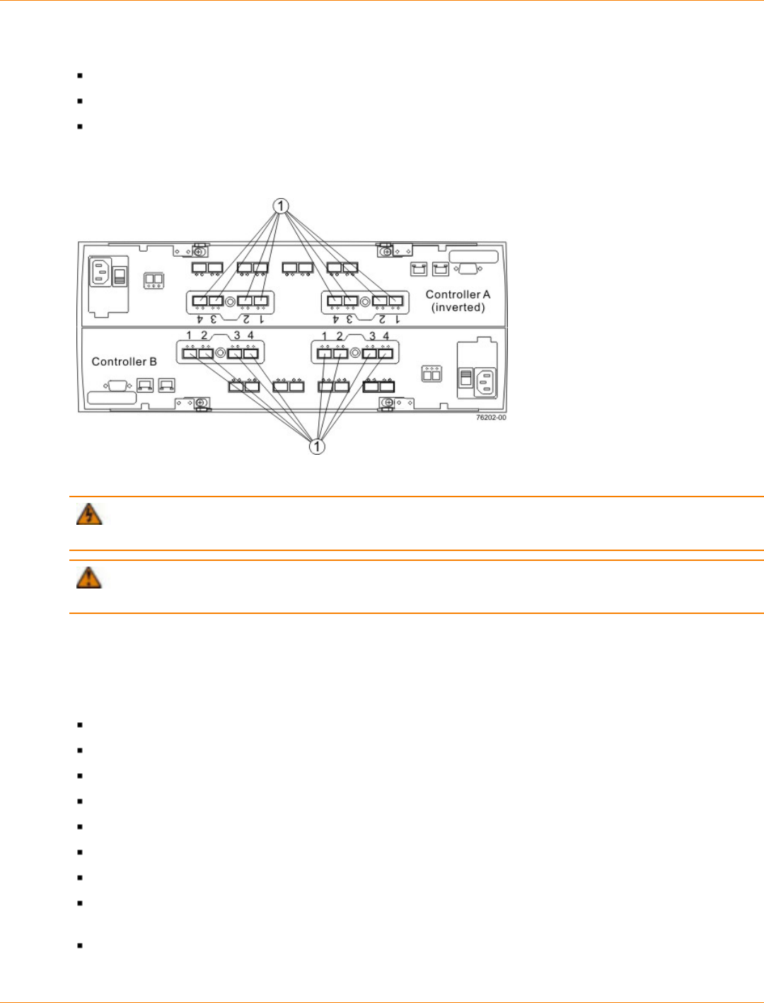
SANtricity_10.77 February 2011
LSI Corporation
- 447 -
Things to Know – Host Channels on the CE7900 Controller Tray
Each controller has four dual-ported host channels.
Each group of two channels is associated with one host interface card.
Controller A is inverted from controller B, which means that its host channels are upside-down and
numbered in reverse order.
Host Channels on the Controllers – Rear View
1. Host Channels
WARNING (W03) Risk of exposure to laser radiation – Do not disassemble or remove any part of a
Small Form-factor Pluggable (SFP) transceiver because you might be exposed to laser radiation.
ATTENTION Possible hardware damage – To prevent electrostatic discharge damage to the tray,
use proper antistatic protection when you handle tray components.
Things to Know – Host Interface Cards
The CE7900 controller tray supports several types of host interface cards (HICs) for different speeds an
protocol. Keep these guidelines in mind:
20-Gb/s InfiniBand
10-Gb/s iSCSI
8-Gb/s Fibre Channel
4-Gb/s Fibre Channel
1-Gb/s iSCSI
A CE7900 controller tray with InfiniBand HICs must have only InfiniBand HICs.
If you connect a 4-Gb/s Fibre Channel HIC with an 8-Gb/s HBA on a host, the data transfer rate is 4 Gb/s.
A controller might have a mix with one 4-Gb/s Fibre Channel HIC and one 8-Gb/s Fibre Channel HIC or it
might have a mix with one Fibre Channel HIC and one 1-Gb/s iSCSI HIC or one 10-Gb/s iSCSI HIC.
When HICs are mixed, each controller in a duplex system must have the exact same HIC configuration.
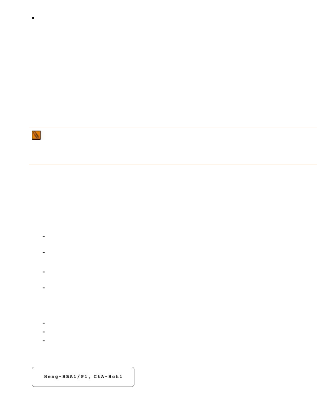
SANtricity_10.77 February 2011
LSI Corporation
- 448 -
When Fibre Channel HICs with different data rates are mixed and you are cabling for redundancy, cable
the HBAs on the host to the HICs with the same data rate, one on controller A and one on controller B.
Procedure – Connecting Host Cables on the CE7900 Controller Tray
Make sure that you have installed your host adapters. Refer to the documentation for your host adapters for
information about how to install the host adapter and how to use the supplied configuration utilities.
The figures in this section show Fibre Channel connections as examples and identify HBA1 and HBA2 as
connecting points on the hosts. For other configurations, these connecting points might be host channel
adapters (HCAs) for InfiniBand connections, Ethernet adapters for iSCSI connections, or a combination of
one HBA and one iSCSI Ethernet adapter.
Fibre Channel and InfiniBand connections require fiber-optic cables. Connections for iSCSI require copper
cables with RJ-45 connectors. The cabling patterns are the same for all types of cables and connectors.
IMPORTANT Small Form-factor Pluggable (SFP) transceivers are required for Fibre Channel and
InfiniBand host connections for 20-Gb/s InfiniBand, 10-Gb/s iSCSI, 8-Gb/s Fibre Channel, and 4-Gb/s Fibre
Channel connections, each requires a different type of SFP transceiver. Be sure to use SFP transceivers that
match the data rate and protocol for the connection that you are making.
This procedure is for a direct topology as shown in Figure 1–1. See Figure 1–2 and Figure 1–3 for example
cabling patterns for fabric and mixed topologies. A Fibre Channel host connections require SFP transceivers
in the HIC and in the HBA.
1. If you are cabling a Fibre Channel connection, make sure that an SFP transceiver is inserted into the host
port on the HIC and the corresponding port on the HBA in the host. Make sure that any black plastic plugs
that might be present are removed from the SFP transceivers.
2. Starting with the first host channel of each controller, perform one of these actions:
For a Fibre Channel or an InfiniBand connection, plug one end of the cable into the SFP transceiver
in a port.
For an iSCSI connection, plug the RJ-45 connector on one end of the cable directly into a port.
3. Plug the other end of the cable into one of the host adapter ports in the host.
For a Fibre Channel or an InfiniBand connection, plug one end of the cable into the SFP transceiver
in a port.
For an iSCSI connection, plug the RJ-45 connector on one end of the cable directly into a port.
Make sure that the speed and protocol used by the host adapter match those used by the HIC.
4. Affix a label to each end of the cable with the following information. A label is very important if you need to
disconnect cables to service a controller.
The host name and the host adapter port
The controller ID (for example, controller A)
The host channel ID (for example, host channel 1)
Example label abbreviation – Assume that a cable is connected between port 1 in HBA 1 of a host
named Engineering and host channel 1 of controller A.
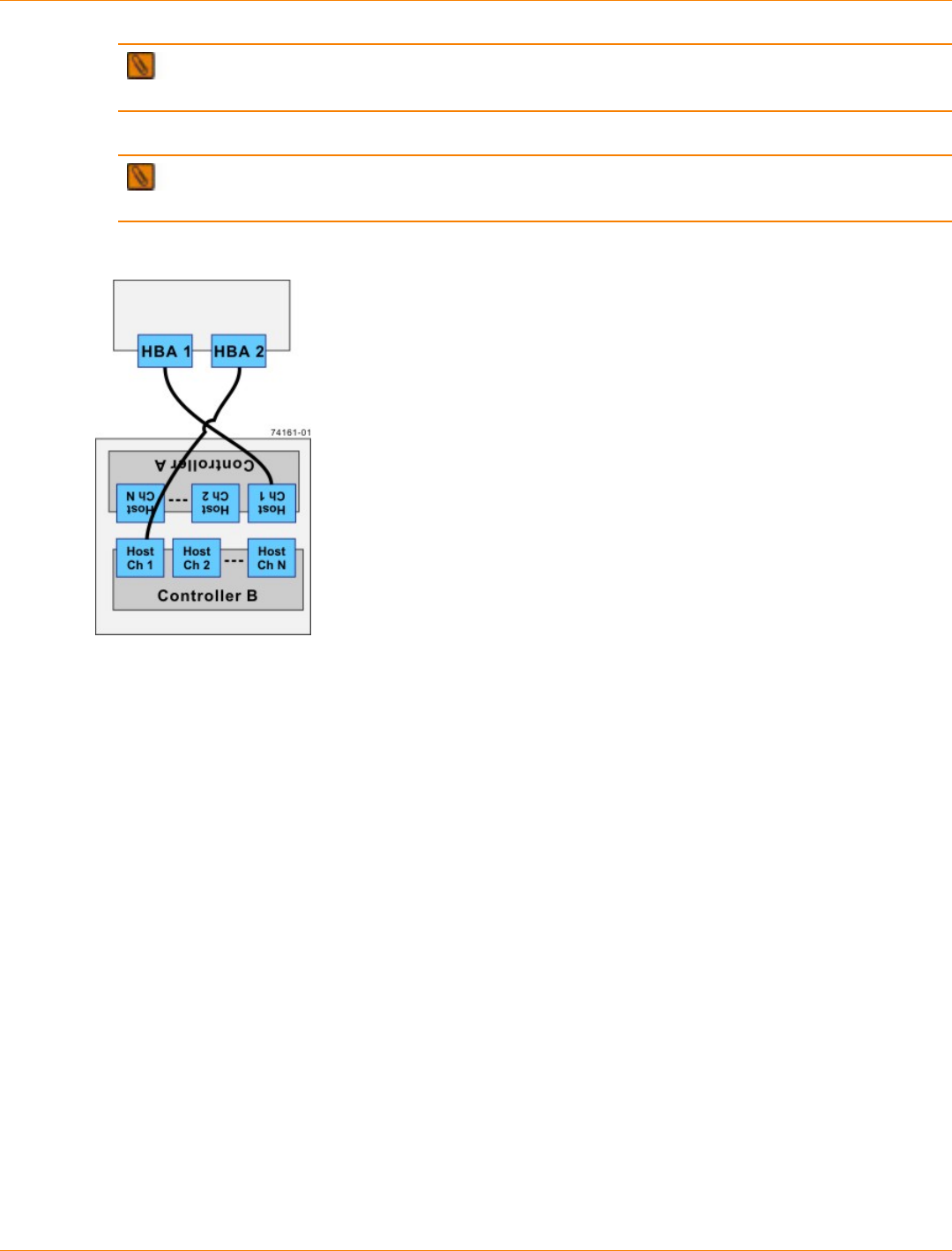
SANtricity_10.77 February 2011
LSI Corporation
- 449 -
NOTE If you are cabling for a fabric or mixed topology, include the appropriate switch name and
port number on the label.
5. Repeat step 2 through step 4 for each controller and host channel that you intend to use.
NOTE If you do not use a host channel, remove the SFP transceiver. You can use a 4-Gb/s SFP
transceiver in a drive channel port or in an ESM on the drive tray.
Direct Topology – One Host and a Dual-Controller Controller Tray
The box on the top in the preceding figure is the host, and the box on the bottom is the controller tray.

SANtricity_10.77 February 2011
LSI Corporation
- 450 -
Fabric Topology – One Host and a Dual-Controller Controller Tray with a Switch
The box on the top of the switch in the preceding figure is the host, and the box on the bottom is the controller
tray.
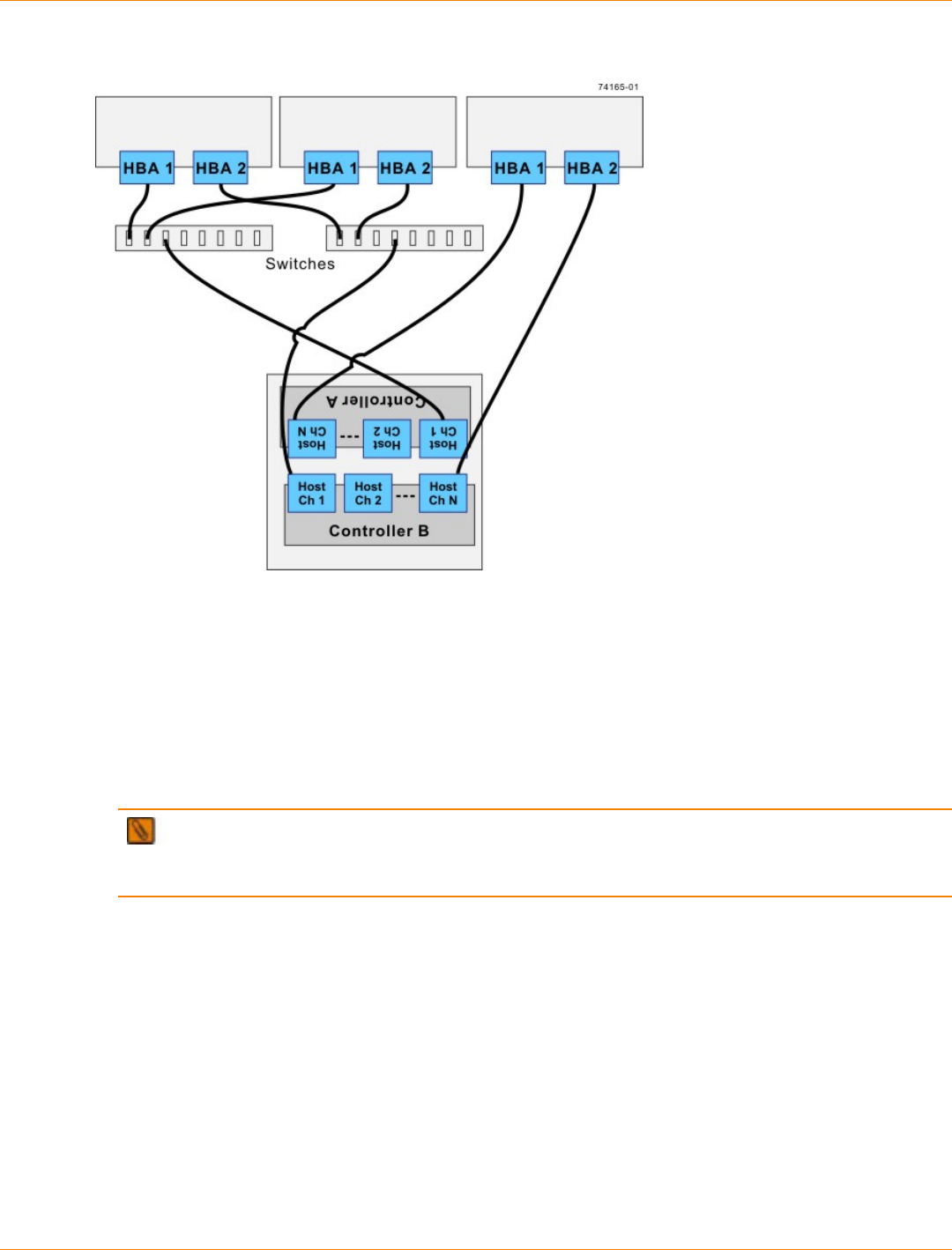
SANtricity_10.77 February 2011
LSI Corporation
- 451 -
Mixed Topology – Three Hosts and a Dual-Controller Controller Tray
The boxes on the top of the switch in the preceding figure are the hosts, and the box on the bottom is the
controller tray.
IMPORTANT The highest numbered host channel might be reserved for use with the Remote
Volume Mirroring premium feature. If Remote Volume Mirroring connections are required, do not connect
a host to the highest-numbered host channel.
SANtricity_10.77 February 2011
LSI Corporation
- 452 -
Step 6 – Installing the Drive Trays for the CE7900 Controller Tray
Configurations
Things to Know – General Installation of the CE7900 Controller Tray
Special site preparation is not required for these trays beyond what is normally found in a computer lab
environment.
The power supplies meet standard voltage requirements for both domestic and worldwide operation.
IMPORTANT If you are installing the CE7900 controller tray in a cabinet with other drive trays, make
sure that the combined power requirements of the controller tray and the other drive trays do not exceed the
power capacity of your cabinet.
Things to Know – General Installation of the FC4600 Drive Tray
IMPORTANT After you install the drive tray, you might replace drives or install additional drives. If you
replace or add more than one drive without powering down the drive tray, install the drives one at a time. Wait
10 seconds after you insert each drive before inserting the next one.
If you are installing FC4600 drive trays and the CE7900 controller-drive tray at the same time, take these
precautions:
Install the controller-drive tray in a location within the cabinet that lets you evenly distribute the drive
trays around the controller-drive tray.
Keep as much weight as possible in the bottom half of the cabinet.
ATTENTION Potential damage to drives – Turning the power off and on without waiting for the drives
to spin down can damage the drives. Always wait at least 60 seconds from when you turn off the power until
you turn on the power again.
Things to Know – General Installation of the DE6900 Drive Tray
IMPORTANT After you install the drive tray, you might replace drives or install additional drives. If you
replace or add more than one drive without powering down the drive tray, install the drives one at a time. Wait
10 seconds after you insert each drive before inserting the next one.
If you are installing DE6900 drive trays and the CE7900 controller tray at the same time, take these
precautions:
Keep as much weight as possible in the bottom half of the cabinet.
Install the DE6900 drive trays in the bottom of the cabinet, placing the controller tray directly above
them.
Do not handle the drives in each of the five drawers of the DE6900 drive tray unless absolutely
necessary.
ATTENTION Risk of bodily injury – Do not use equipment in the cabinet as a shelf or work space.
ATTENTION Risk of equipment damage – You must install the DE6900 drive tray must be installed
in a cabinet before performing any service operations, such as operating or moving drawers. Place the
DE6900 drive tray on a flat surface for transportation by using a cart or a mechanized lift.
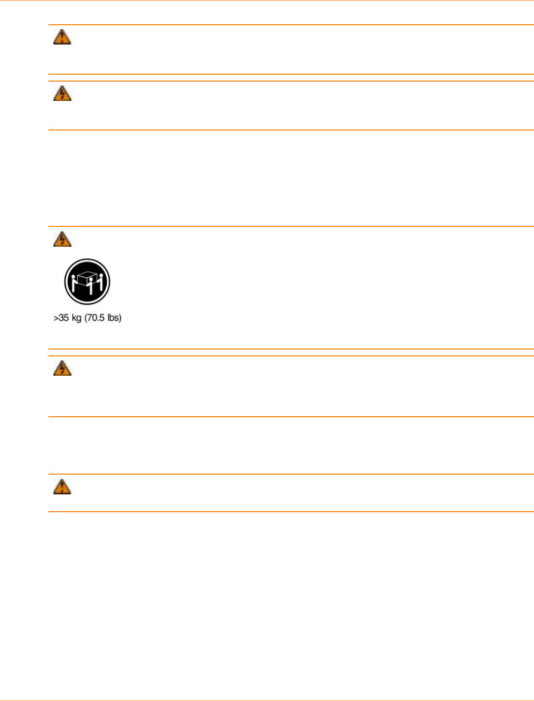
SANtricity_10.77 February 2011
LSI Corporation
- 453 -
ATTENTION Potential damage to drives – Turning the power off and on without waiting for the drives
to spin down can damage the drives. Always wait at least 60 seconds from when you turn off the power until
you turn on the power again.
WARNING (W15) Risk of bodily injury – An empty tray weighs approximately 56.7 kg (125 lb).
Three persons are required to safely move an empty tray. If the tray is populated with components, a
mechanized lift is required to safely move the tray.
For Additional Information on Drive Tray Installation
Refer to the Storage System Site Preparation Guide on the SANtricity ES Storage Manager Installation DVD
for important considerations about cabinet installation.
Procedure – Installing the FC4600 Drive Tray
WARNING (W09) Risk of bodily injury –
Three persons are required to safely lift the component.
WARNING (W05) Risk of bodily injury – If the bottom half of the cabinet is empty, do not install
components in the top half of the cabinet. If the top half of the cabinet is too heavy for the bottom half, the
cabinet might fall and cause bodily injury. Always install a component in the lowest available position in the
cabinet.
Install the FC4600 drive tray into an industry standard cabinet.
This procedure describes how to install the mounting rails into an industry standard cabinet.
ATTENTION Possible hardware damage – To prevent electrostatic discharge damage to the tray,
use proper antistatic protection when handling tray components.
1. Make sure that the cabinet is in the final location. Make sure that you meet the clearance requirements
shown below.
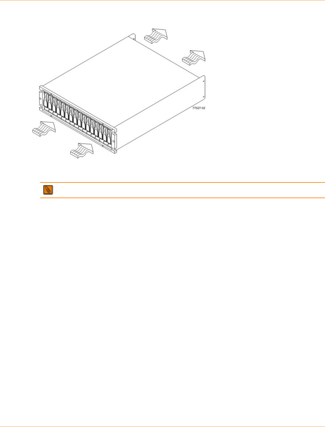
SANtricity_10.77 February 2011
LSI Corporation
- 454 -
Drive Tray Airflow and Clearance Requirements
1. 76 cm (30 in.) clearance in front of the cabinet
2. 61 cm (24 in.) clearance behind the cabinet
NOTE Fans pull air through the tray from front to rear across the drives.
2. Lower the feet on the cabinet to keep the cabinet from moving.
3. Remove the drive tray and all contents from the shipping carton.
4. Position the mounting rails in the cabinet.
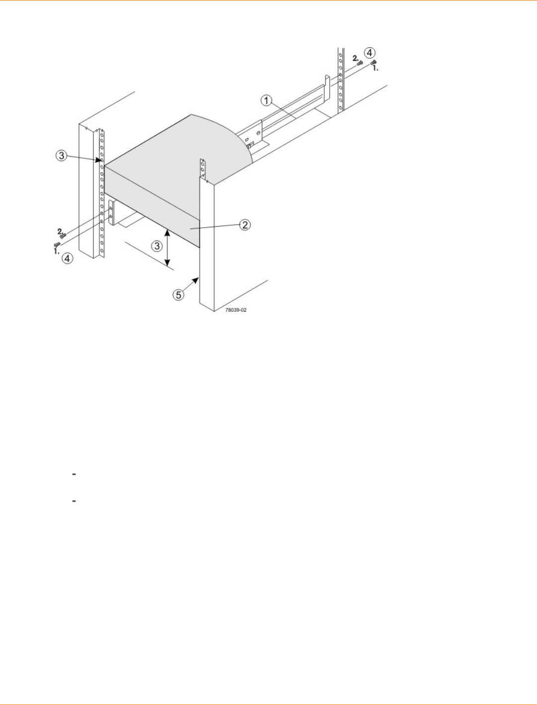
SANtricity_10.77 February 2011
LSI Corporation
- 455 -
Positioning the Mounting Rails in the Cabinet
1. Mounting Rail
2. Existing Tray
3. Clearance Above and Below the Existing Tray
4. Screws for Securing the Mounting Rail to the Cabinet (Front and Rear)
5. Industry Standard Cabinet
If you are installing the mounting rails above an existing tray, position the mounting rails directly
above the tray.
If you are installing the mounting rails below an existing tray, allow 8.8-cm (3.5-in.) vertical clearance
for the drive tray.
5. Attach the mounting rails to the cabinet by performing these substeps:
a. Make sure that the adjustment screws on the mounting rail are loose so that the mounting rail can
extend or contract as needed.
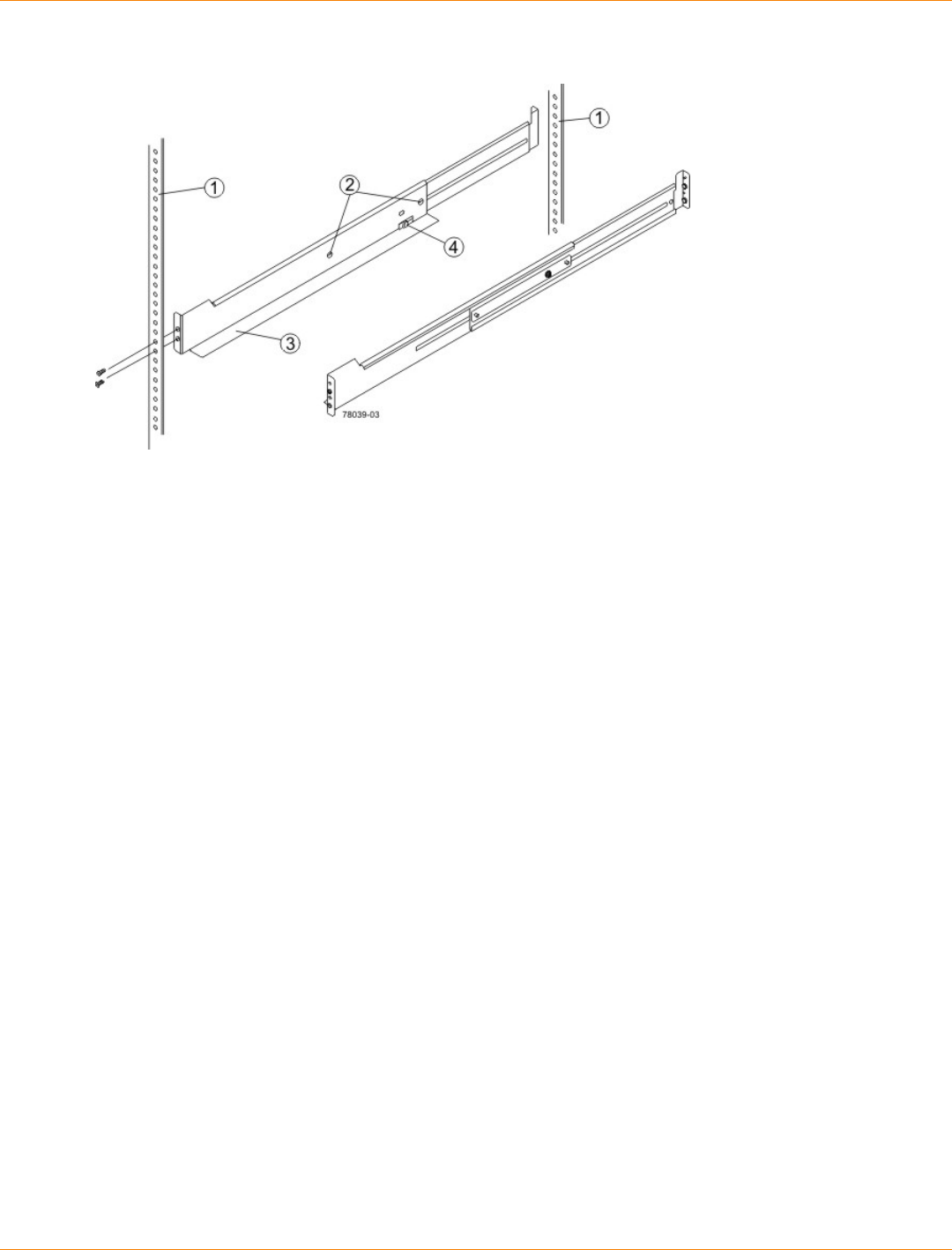
SANtricity_10.77 February 2011
LSI Corporation
- 456 -
Attaching the Mounting Rails to the Cabinet
1. Cabinet Mounting Holes
2. Adjustment Screws for Locking the Mounting Rail Length
3. Mounting Rails
4. Clip for Securing the Rear of the Drive Tray
b. Place the mounting rail inside the cabinet, and extend the mounting rail until the flanges on the
mounting rail touch the inside of the cabinet.
c. Make sure that the alignment spacers on the front flange of the mounting rail fit into the mounting
holes in the cabinet.
The front flange of each mounting rail has two alignment spacers. The alignment spacers are
designed to fit into the mounting holes in the cabinet. The alignment spacers help position and hold
the mounting rail.
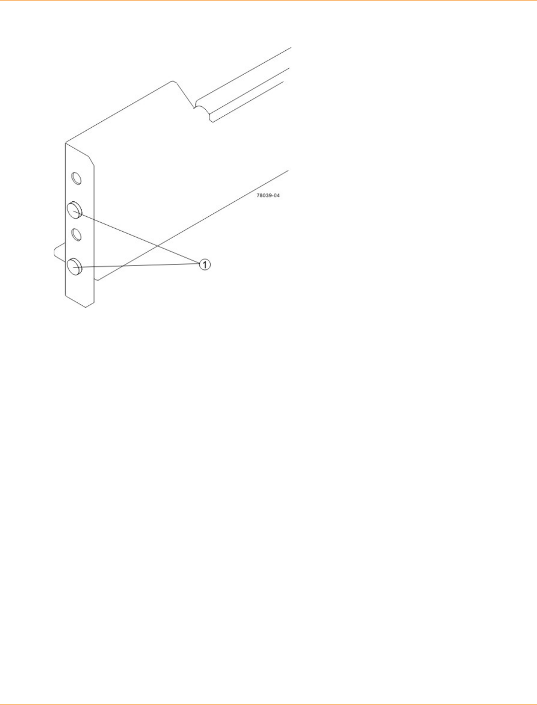
SANtricity_10.77 February 2011
LSI Corporation
- 457 -
Alignment Spacers on the Mounting Rail
1. Alignment Spacers
d. Insert one M5 screw through the front of the cabinet and into the top captured nut in the mounting rail.
Tighten the screw.
e. Insert two M5 screws through the rear of the cabinet and into the captured nuts in the rear flange in
the mounting rail. Tighten the screws.
f. Tighten the adjustment screws on the mounting rail.
g. Repeat substep a through substep f to install the second mounting rail.
6. With the help of two other persons, slide the rear of the drive tray onto the mounting rails.
The mounting holes on the front flanges of the drive tray align with the mounting holes on the front of the
mounting rails.
7. Secure the front of the drive tray to the cabinet by using four screws.
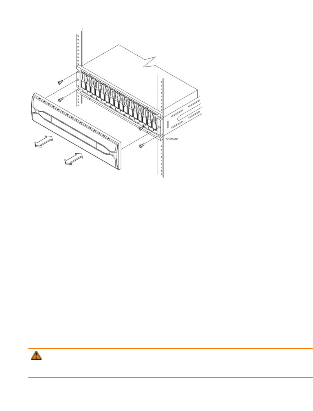
SANtricity_10.77 February 2011
LSI Corporation
- 458 -
Attaching the Front of the Drive Tray
1. Screws for Securing the Front of the Drive Tray
8. Using two screws, attach the flange on each side of the rear of the drive tray to the mounting rails.
Procedure – Installing Drives for the FC4600 Drive Tray
In some situations, the drive tray might be delivered without the drives installed. Follow the steps in this
procedure to install the drives. If your drive tray already has drives installed, you can skip this step and go to
“Things to Know – AC Power Cords”.
ATTENTION Risk of equipment malfunction – To avoid exceeding the functional and environmental
limits, install only drives that have been provided or approved by the original manufacturer. Drives might be
shipped but not installed. System integrators, resellers, system administrators, or users can install the drives.
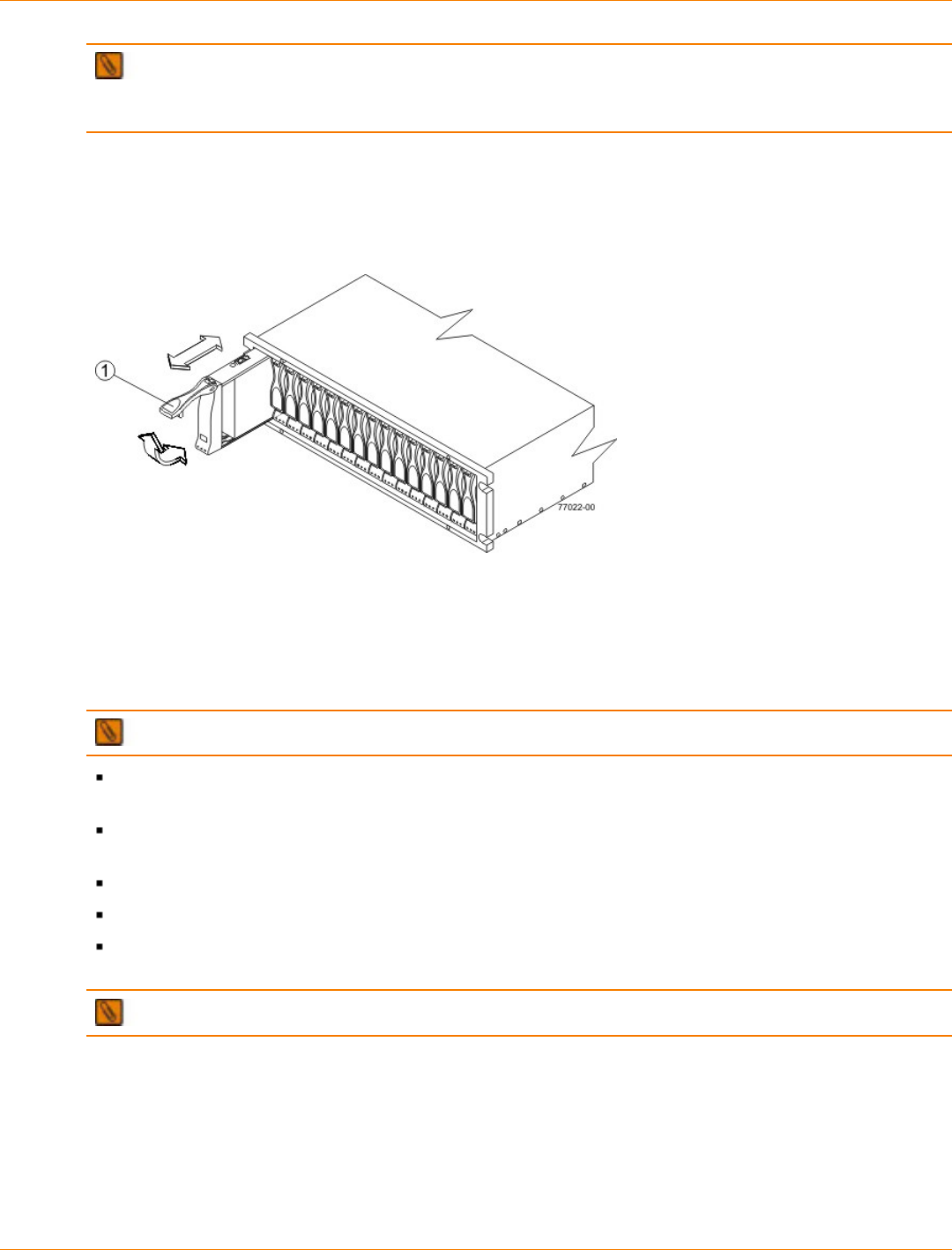
SANtricity_10.77 February 2011
LSI Corporation
- 459 -
NOTE The installation order is from left to right. The installation order is important because the drives
might already contain configuration information that depends upon the correct sequence of the drives in the
tray.
1. Beginning with the first drive slot in the left side of the drive tray, place the drive on the slot guides, and
slide the drive all the way into the slot.
2. Push the drive handle down to lock the drive securely in place.
Installing a Drive in a FC4600 Drive Tray
1. Drive Handle
3. Install the second drive to the right of the first drive.
4. Install each drive to the right of the last installed drive.
Things to Know – Link Rate Switch on the FC4600 Drive Tray
IMPORTANT Change the Link Rate switch only when the power is not turned on to the drive tray.
Use the Link Rate switch to select the data transfer rate between the ESMs, the drives, and the
controllers. The Link Rate switch is located on the rear of the drive tray on the ESMs.
All drive trays that are connected to the same drive channel must be set to operate at the same data
transfer rate (speed).
The drives in the drive tray must support the selected link rate speed.
The setting of the Link Rate switch determines the speed of the drives.
If a drive in the drive tray does not support the link rate speed, the drive will show up as a bypassed drive
in the storage management software.
IMPORTANT Change the Link Rate switch only when no power is applied to the drive tray.
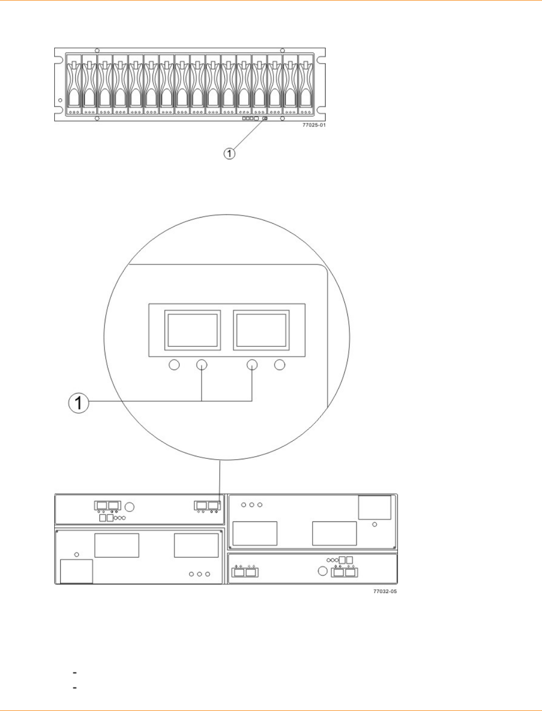
SANtricity_10.77 February 2011
LSI Corporation
- 460 -
Setting the Link Rate Switch on the FC4600 Drive Tray – Front View
1. Link Rate Switch (4 Gb/s or 2 Gb/s)
Link Rate LEDs on the FC4600 Drive Tray – Rear View
1. Link Rate LEDs Right On = 2 Gb/s Left and Right On = 4 Gb/s
Procedure – Setting the Link Rate Switch on the FC4600 Drive Tray
1. Check to see if the Link Rate switch is set to the 4-Gb/s data transfer rate.
If the link rate is set to 4-Gb/s, you do not need to change the setting.
If the link rate is set to 2-Gb/s, go to step 2.
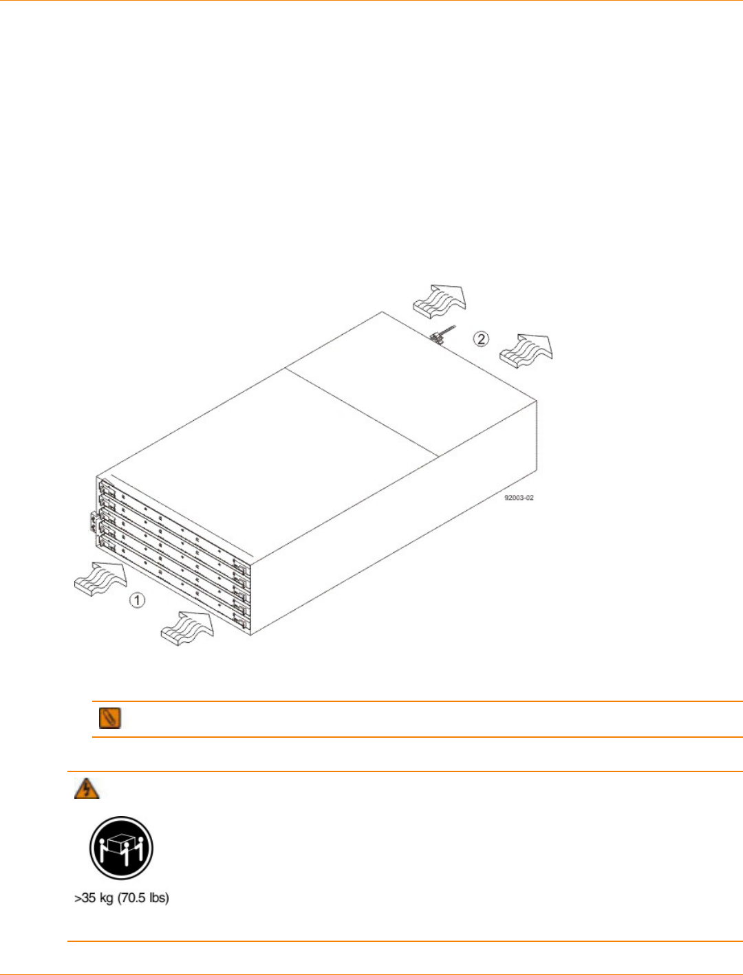
SANtricity_10.77 February 2011
LSI Corporation
- 461 -
2. Make sure that no power is applied to the drive tray.
3. Move the switch to the 4-Gb/s (left) position.
Steps to Install – DE6900 Drive Tray
Install the DE6900 drive tray an industry standard cabinet that has a depth of 100 cm (40 in.).
A minimum depth of 76 cm (30 in.) must exist between the front EIA support rails and the rear EIA support
rails.
1. Make sure that the cabinet is in the final location. Make sure that you meet the clearance requirements
shown in the following figure.
Drive Tray Airflow and Clearance Requirements for the DE6900 Drive Tray
1. 81 cm (32 in.) clearance in front of the cabinet
2. 61 cm (24 in.) clearance behind the cabinet
NOTE Fans pull air through the drive tray from front to rear across the drives.
2. Lower the feet on the cabinet to keep the cabinet from moving.
WARNING (W09) Risk of bodily injury –
Three persons are required to safely lift the component.
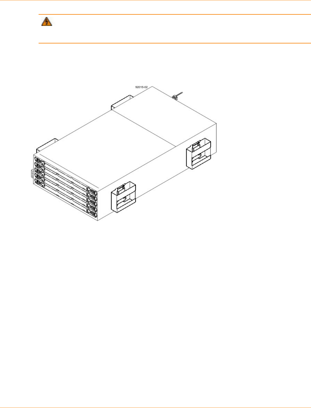
SANtricity_10.77 February 2011
LSI Corporation
- 462 -
WARNING (W15) Risk of bodily injury – An empty tray weighs approximately 56.7 kg (125 lb).
Three persons are required to safely move an empty tray. If the tray is populated with components, a
mechanized lift is required to safely move the tray.
3. With the help of at least two other persons, remove the drive tray and all of the contents from the shipping
carton, using the four drive tray handles (two to a side) as shown in the following figure. Set the drive tray
aside.
DE6900 Drive Tray with Drive Tray Handles (Two on Each Side)
4. Position the mounting rails in the cabinet.
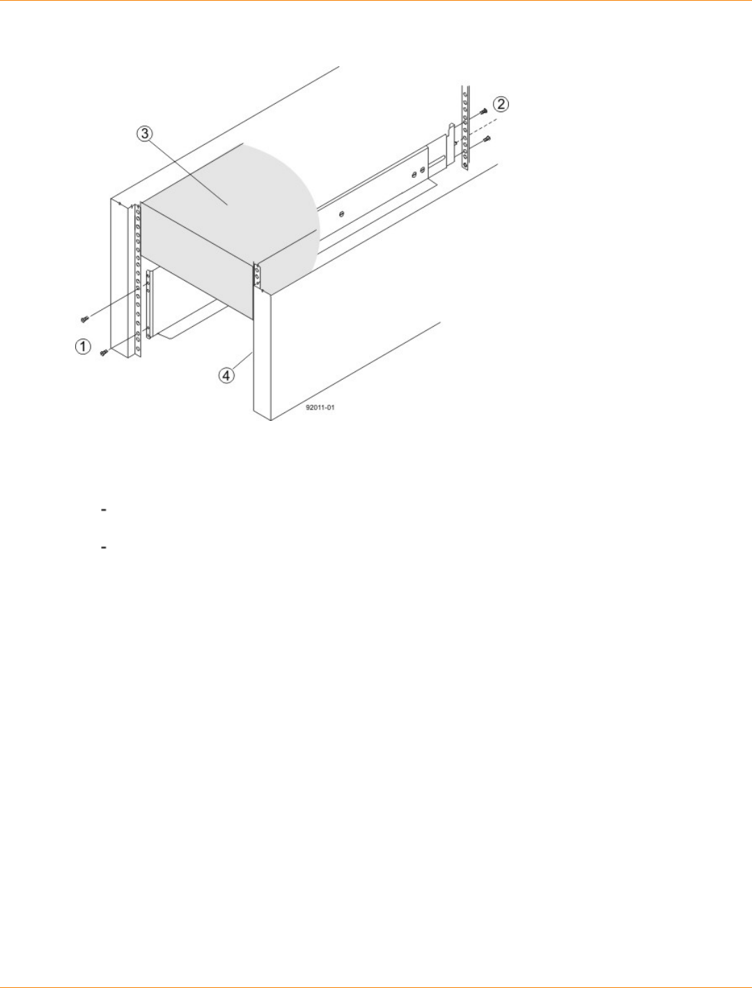
SANtricity_10.77 February 2011
LSI Corporation
- 463 -
Positioning the DE6900 Mounting Rails in the Cabinet
1. Screws for Securing the Mounting Rail to the Cabinet (Front)
2. Screws for Securing the Mounting Rail to the Cabinet (Rear)
3. Existing Tray
4. Industry Standard Cabinet
If you are installing the mounting rails above an existing tray, position the mounting rails directly
above the tray.
If you are installing the mounting rails below an existing tray, allow 17.8-cm (7-in.) vertical clearance
for a DE6900 drive tray.
5. To attach the mounting rails to the cabinet, perform these substeps:
a. Make sure that the adjustment screws on the mounting rail are loose so that the mounting rail can
extend or contract as needed.
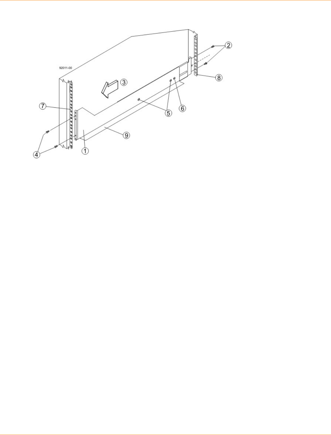
SANtricity_10.77 February 2011
LSI Corporation
- 464 -
Attaching the Mounting Rails to the Cabinet
1. Front of the Mounting Rail
2. Two M4 Screws for the Rear EIA Support Rail
3. Front of the Cabinet
4. Two M5 Screws for the Front EIA Support Rail
5. Adjustable Rail Tightening Screws
6. Rear Hold-Down Screw
7. Cabinet Mounting Holes on the Front EIA Support Rail
8. Cabinet Mounting Holes on the Rear EIA Support Rail
9. Mounting Rail Lip
b. Remove the rear hold-down screw. It protrudes from the inside of the rail and prevents you from
sliding the drive tray onto the rails.
c. Place the mounting rail inside the cabinet, and extend the mounting rail until the flanges on the
mounting rail touch the inside of the cabinet.
d. Insert one M5 screw through the front of the cabinet, and screw it into the top captured nut in the
mounting rail.
e. Insert two M4 screws through the rear of the cabinet, and screw them into the captured nuts in the
rear flange in the mounting rail.
f. Tighten the adjustment screws on the mounting rail.
g. Repeat substep a through substep f to install the second mounting rail.
h. Insert one M5 screw through the front of the mounting rail. This screw will attach the drive tray to the
cabinet.
6. Remove the bezel from the front of the drive tray.
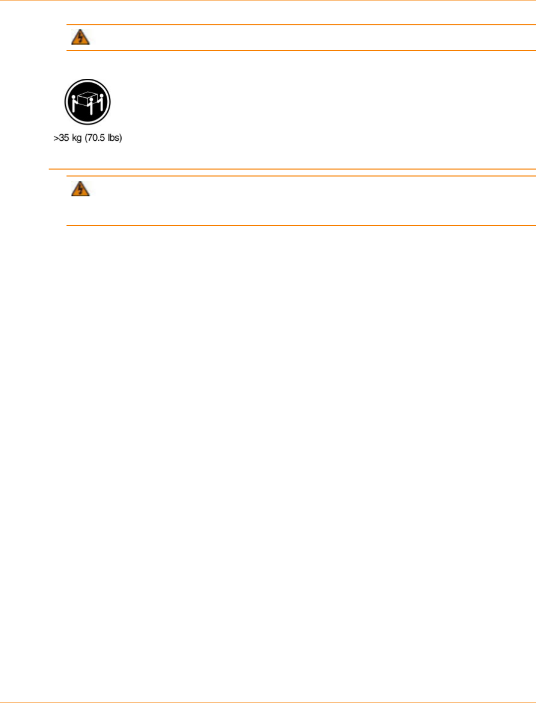
SANtricity_10.77 February 2011
LSI Corporation
- 465 -
WARNING
(W09) Risk of bodily injury –
Three persons are required to safely lift the component.
WARNING (W15) Risk of bodily injury – An empty tray weighs approximately 56.7 kg (125 lb).
Three persons are required to safely move an empty tray. If the tray is populated with components, a
mechanized lift is required to safely move the tray.
7. With the help of at least two other persons, slide the rear of the drive tray onto the mounting rails. The
drive tray is correctly aligned when the mounting holes on the front flanges of the drive tray align with the
mounting holes on the front of the mounting rails.
8. After the drive tray is correctly aligned, use your thumb to unlatch the four drive handles (two to a side),
and remove the handles from the drive tray, from the rear to the front as shown in the following figure.
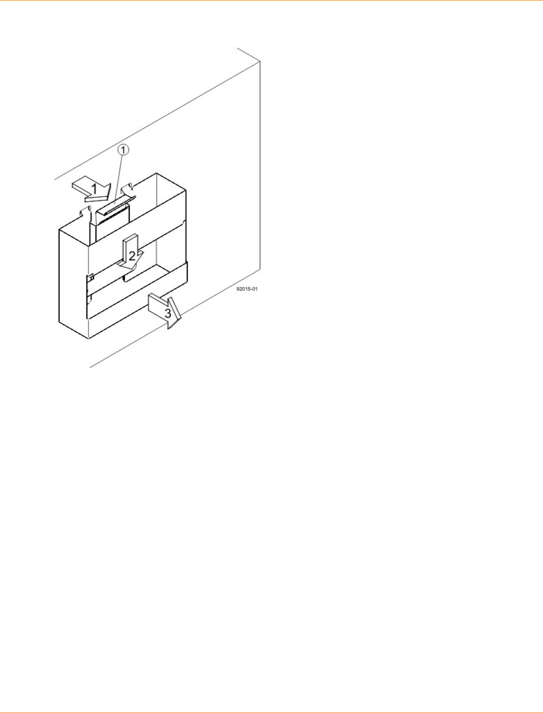
SANtricity_10.77 February 2011
LSI Corporation
- 466 -
Removing a Drive Handle from the DE6900 Drive Tray
1. Pull the thumb latch away from the drive tray to detach the hook.
2. Shift the handle down to release the other four hooks.
3. Move the handle away from the drive tray.
9. Secure the front of the drive tray to the cabinet. Use the four screws to attach the flange on each side of
the front of the drive tray to the mounting rails.
a. Insert two 10-32 screws through the bottom holes of a flange on the drive tray so that the screws go
through the EIA support rail and engage the bottom captured nuts in the mounting rail. Tighten the
screws.
b. Repeat substep a for the second flange.
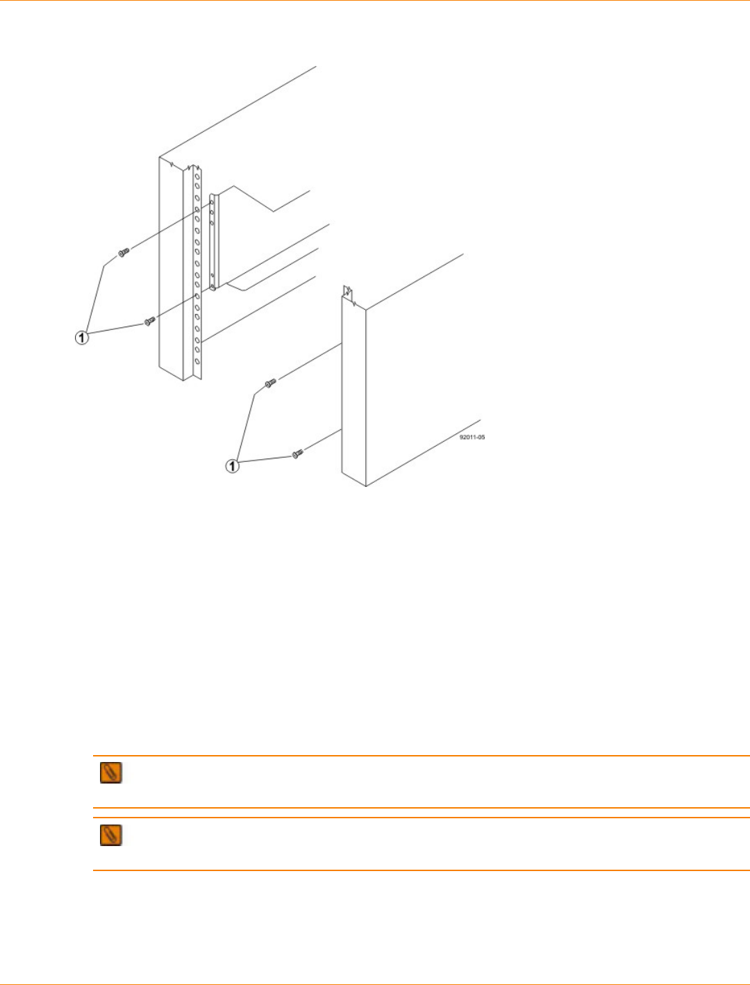
SANtricity_10.77 February 2011
LSI Corporation
- 467 -
Attaching the Front of the DE6900 Drive Tray
1. Four Screws for Securing the Front of the Drive Tray
10. Secure the side of the drive tray to the mounting rails by performing these substeps:
a. Insert a 10-32 screw through the side sheet metal of the drive tray into the captured nut on the side of
the mounting rail. Tighten the screws.
b. Repeat substep a for the other side.
NOTE After the drive tray is installed, make sure that seven screws are on each side (right and left)
of the cabinet.
NOTE Make sure that each drive drawer in the drive tray is securely fastened to ensure correct air
flow to the drives.
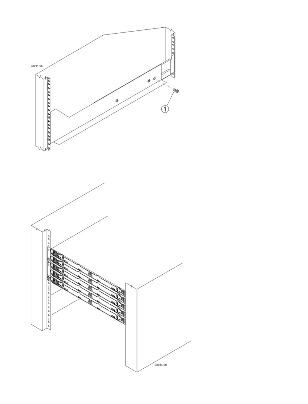
SANtricity_10.77 February 2011
LSI Corporation
- 468 -
Securing the DE6900 Drive Tray to the Rails
1. 10-32 Screw
DE6900 Drive Tray Installed in the Cabinet
11. Attach the bezel onto the front of the drive tray.
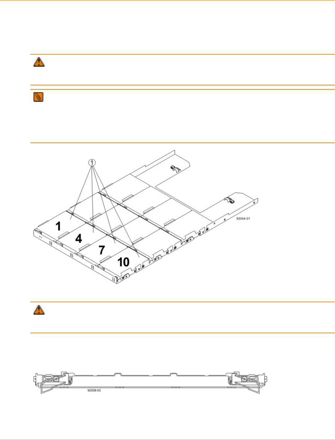
SANtricity_10.77 February 2011
LSI Corporation
- 469 -
Procedure – Installing Drives in the DE6900 Drive Tray
The DE6900 drive tray is shipped with the drive drawers installed, but the drives are not installed. Follow the
steps in this procedure to install the drives.
ATTENTION Risk of equipment malfunction – To avoid exceeding the functional and environmental
limits, install only drives that have been provided or approved by the original manufacturer. Drives might be
shipped but not installed. System integrators, resellers, system administrators, or users can install the drives.
IMPORTANT The installation order within each drawer is from left to right in rows. Slots 1, 4, 7 and
10 must have a drive installed in these locations to make sure there is sufficient air flow to the drives. To
verify these slots, consult the overlay on the front of each of the five drive drawers. Make sure the four drives
in each row are adjacent to each other. The long edge of each drive should touch the drive next to it. To
maintain a uniform airflow across all drive drawers, the drive tray must be configured with a minimum of 20
drives, with four drives in the front row of each of the five drive drawers.
1. Slots 1, 4, 7, and 10 in the DE6900 Drive Tray
ATTENTION Risk of equipment malfunction – For the DE6900 drive tray, you can only replace one
canister or drive at a time. Refer to the “Replacing a Failed Drive” instructions on the SANtricity ES Storage
Manager Installation DVD, and make sure you have the replacement drive in hand before starting the task.
1. Starting with the top drawer in the drive tray, release the levers on each side of the drawer by pulling both
towards the center.
Levers on the Drive Drawer
2. Pull on the extended levers to pull the drive drawer out to its full extension without removing it from the
drive tray.
3. Starting with the first drive, raise the drive handle to the vertical position.
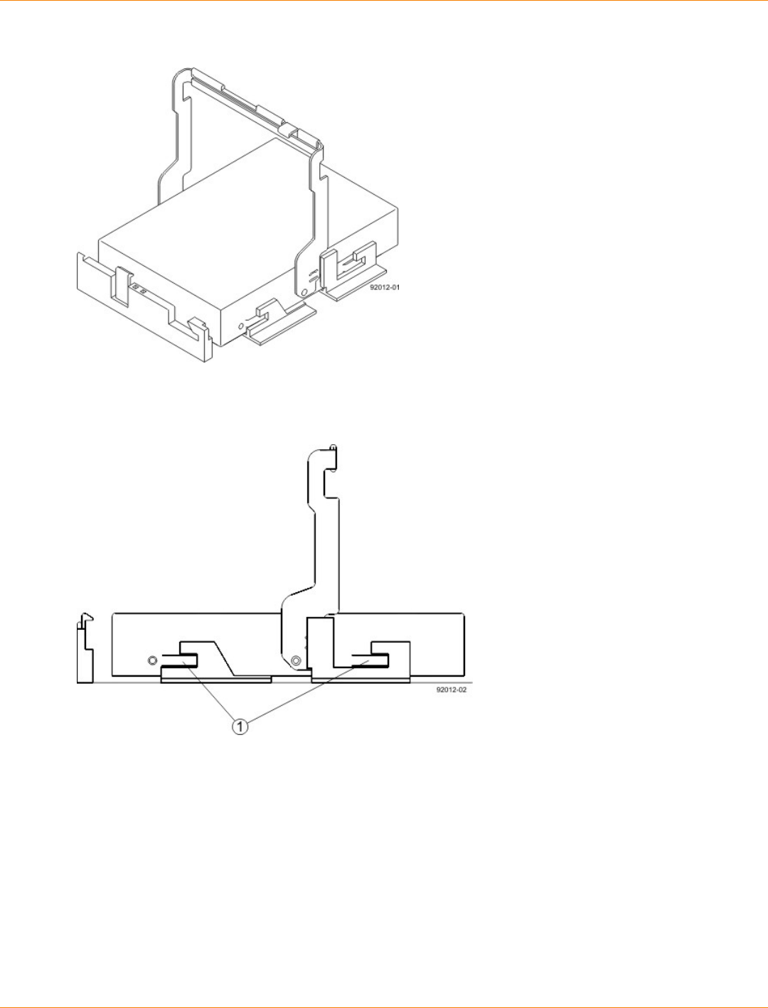
SANtricity_10.77 February 2011
LSI Corporation
- 470 -
Raised Drive Handle
4. Align the two raised buttons on each side over the matching gap in the drive channel on the drawer.
Side View of Drive with Raised Handle
1. Raised Buttons
5. Lower the drive straight down, and then rotate the drive handle down until the drive snaps into place
under the drive release lever.
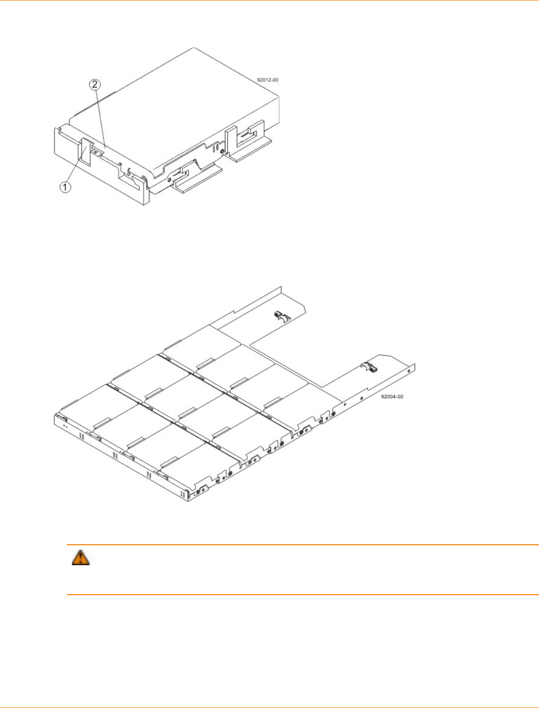
SANtricity_10.77 February 2011
LSI Corporation
- 471 -
Drive Release Lever Locked by the Drive Handle
1. Drive Release Lever
2. Drive Handle
6. Install the other drives in rows from left to right, front to back, until the drive drawer is fully populated.
Fully-Populated Drive Drawer
7. Push the drive drawer all the way back into the drive tray, and close the levers on each side of the drive
drawer.
ATTENTION Risk of equipment malfunction – Make sure you push both levers to each side so
that the drive drawer is completely closed. The drive drawer must be completely closed to prevent excess
airflow, which has the potential to damage the drives.
8. Continue onto the next drive drawer, repeating step 1 through step 7 for each drive drawer in the
configuration.
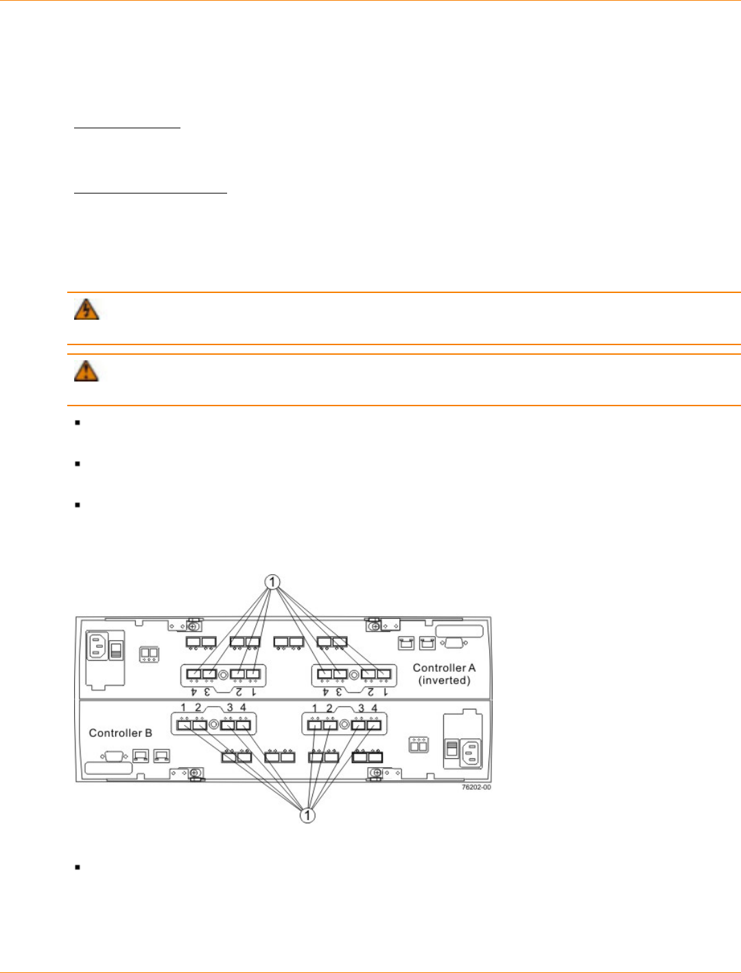
SANtricity_10.77 February 2011
LSI Corporation
- 472 -
Step 7 – Connecting the Controller Tray to the Drive Trays
Key Terms
drive channel
The path for the transfer of data between the controllers and the drives in the storage array.
trunked connection
A connected device pair with two or more cables connecting the two devices. In other words, each device has
two or more channel ports that are connected to two or more channel ports on the other device.
Things to Know – CE7900 Controller Tray
WARNING (W03) Risk of exposure to laser radiation – Do not disassemble or remove any part of a
Small Form-factor Pluggable (SFP) transceiver because you might be exposed to laser radiation.
ATTENTION Possible hardware damage – To prevent electrostatic discharge damage to the tray,
use proper antistatic protection when you handle tray components.
The CE7900 controller tray supports only FC4600 drive trays and DE6900 drive trays. You cannot
connect any other type of drive tray to the controller tray.
Each controller has four drive channels, and each drive channel has two ports, so each controller has
eight drive ports.
Controller A is inverted from controller B, which means that its drive channels are upside-down and
numbered in reverse.
Drive Channel Ports on the Controller Tray – Rear View
1. Drive Channel Ports
A controller tray has eight redundant path pairs that are formed using one drive channel of controller A
and one drive channel of controller B. The following figure shows the redundant pairs in a controller tray.
The following table lists the numbers of the redundant path pairs and the drive ports of the drive channels
from which the redundant path pairs are formed.
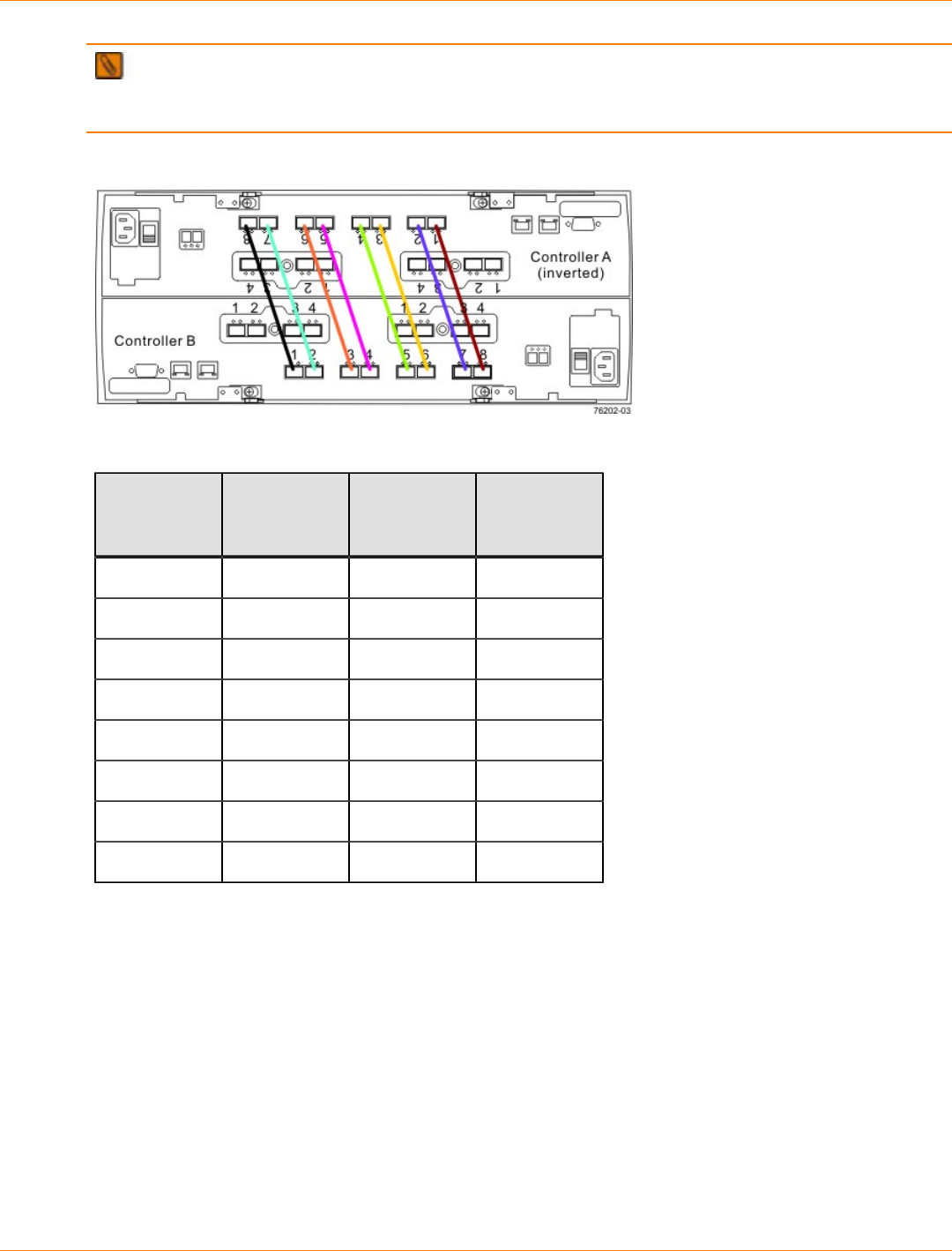
SANtricity_10.77 February 2011
LSI Corporation
- 473 -
IMPORTANT To maintain data access in the event of the failure of a controller, an ESM, or a drive
channel, you must connect a drive tray or a string of drive trays to both drive channels on a redundant path
pair.
Redundant Path Pairs on the Controller Tray
Redundant Path Pairs on a Controller Tray
Drive
Ports on
Controller A
Drive
Channels on
Controller A
Drive
Ports on
Controller B
Drive
Channels on
Controller B
Port 8 Channel 1 Port 1 Channel 5
Port 7 Channel 1 Port 2 Channel 5
Port 6 Channel 2 Port 3 Channel 6
Port 5 Channel 2 Port 4 Channel 6
Port 4 Channel 3 Port 5 Channel 7
Port 3 Channel 3 Port 6 Channel 7
Port 2 Channel 4 Port 7 Channel 8
Port 1 Channel 4 Port 8 Channel 8
Things to Know – DE6900 Drive Tray
Each DE6900 drive tray can contain a maximum of 60 drives. The ESMs on the DE6900 drive tray contain
two sets of In and Out ports, one set for standard cabling and another for use with drive-side trunking. This
document describes standard cabling. Refer to the Hardware Cabling electronic document topics or the
SANtricity ES Storage Manager Installation DVD for information on cabling with drive-side trunking.
The DE6900 drive tray is large and heavy. It requires special handling for installation. For more information,
refer to "Steps to Install – DE6900 Drive Tray".
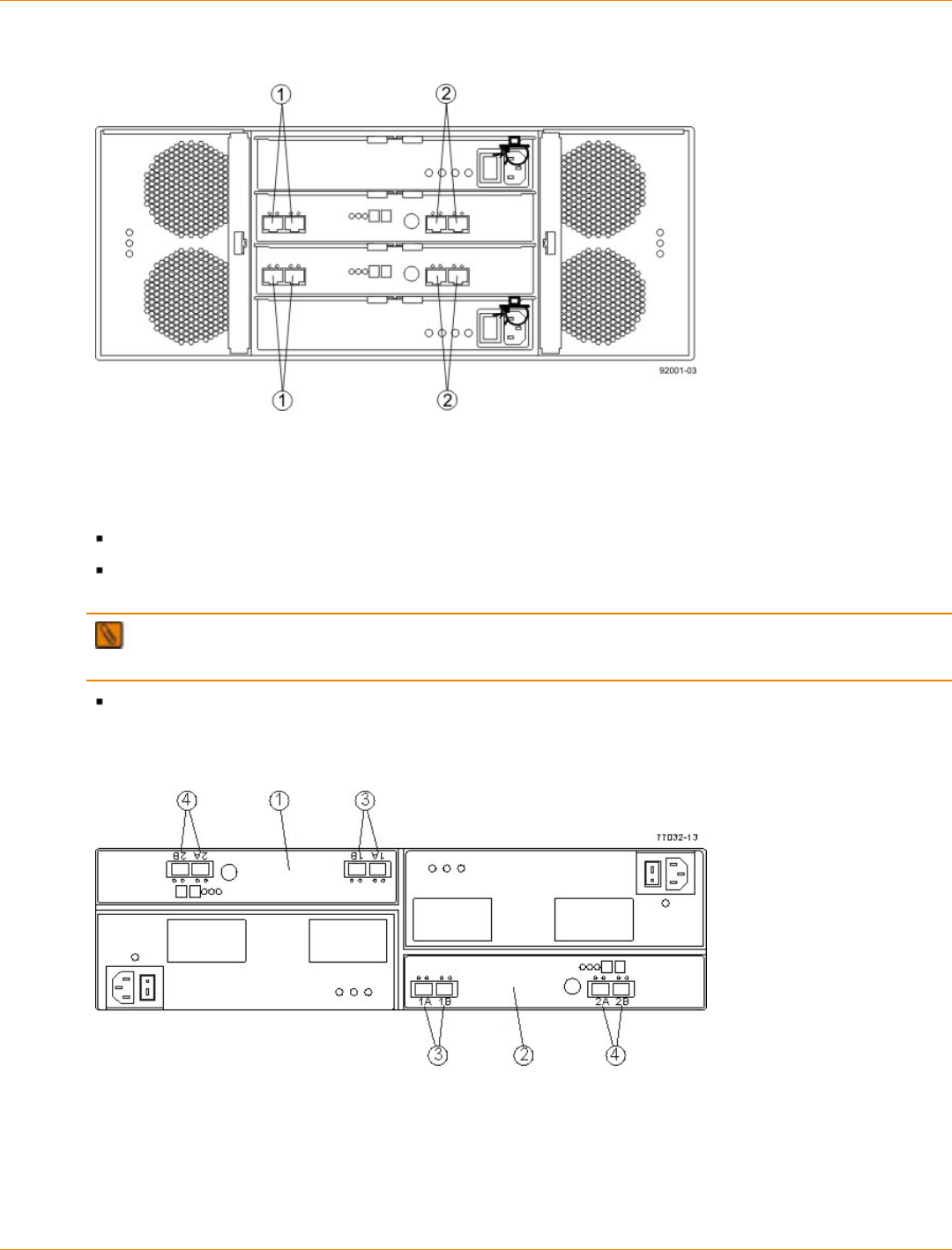
SANtricity_10.77 February 2011
LSI Corporation
- 474 -
DE6900 Drive Tray – Rear View
1. Standard In and Out Ports
2. Drive-Side Trunking In and Out Ports
Things to Know – FC4600 Drive Tray
Each FC4600 drive tray can contain a maximum of 16 drives.
The ESMs on the FC4600 drive tray contain two sets of In and Out ports (labeled 1A and 1B and 2A and
2B). Use only port 1A and port 1B. Port 2A and port 2B are reserved for future use.
NOTE Make sure that an SFP transceiver is not inserted into port 2A or port 2B of the ESMs. The
amber LED on the ESM comes on if an SFP transceiver is inserted in any of these ports.
ESM B is installed right-side-up, and ESM A is installed upside-down. Keep this in mind when you
connect cables to this drive tray.
FC4600 Drive Tray – Rear View
1. ESM A (Inverted)
2. ESM B
3. Port 1A (In) and Port 1B (Out)
4. Port 2A and Port 2B (Reserved)
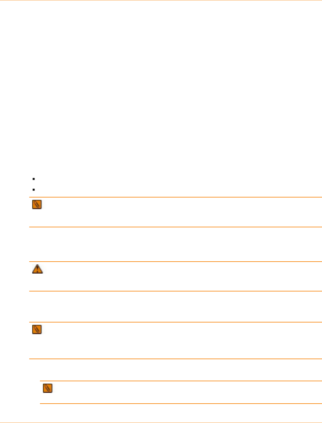
SANtricity_10.77 February 2011
LSI Corporation
- 475 -
Things to Know – Mixing Drive Tray Types
When a mix of FC4600 drive trays and DE6900 drive trays is cabled to the controller tray, the total number of
drives must not exceed 448. If FC4600 drive trays and DE6900 drive trays are mixed on the same loop, the
loop must not have more than two DE6900 drive trays or more than seven FC4600 drive trays.
Things to Know – Connecting the Drive Trays
Cable drive trays to the controller tray by using fiber-optic cables with Small Form-factor Pluggable (SFP)
transceivers for 4-Gb/s Fibre Channel connections. The figures in "Procedure – Connecting DE6900 Drive
Trays and FC4600 Drive Trays to the CE7900 Controller Tray" shows representative configurations for
standard cabling.
You can cable the CE7900 controller tray to DE6900 drive trays, FC4600 drive trays, or a combination of
the two. No more than seven FC4600 drive trays may be cabled to one loop pair and no more than 28 total
FC4600 drive trays may be cabled to the controller tray. No more than two DE6900 drive trays may be cabled
to one loop pair and no more than eight total DE6900 drive trays may be cabled to the controller tray.
If you are adding the drive tray to an existing storage array, look at the storage array profile for your storage
array. The storage array profile shows information about the number of drive trays that are supported by your
storage array. The storage array profile shows this information:
The number of drive trays that are currently attached to the storage array
The number of drive trays that you are allowed to add to the storage array
IMPORTANT Do not add more drive trays than the storage array supports. Adding more drive trays
makes the storage array invalid. You cannot perform configuration operations, but you can continue to
transfer I/O data to the existing volumes.
HotScale™ technology lets you configure, reconfigure, add, or relocate storage array capacity without
interrupting user access to data. Contact a Customer and Technical Support representative before
proceeding. Refer to the on the SANtricity ES Storage Manager Installation DVD for more information.
ATTENTION Possible loss of data access – Contact a Customer and Technical Support
representative if you plan to add a drive tray to an existing storage array under either of the following
conditions: The power is not turned off to the controller tray, or data transfer continues to the storage array.
Procedure – Connecting DE6900 Drive Trays and FC4600 Drive Trays to the
CE7900 Controller Tray
NOTE This procedure describes standard cabling for the DE6900 drive tray and the FC4600 drive
tray. Drive-side trunking for the DE6900 drive tray follows a different pattern. Refer to either the Hardware
Cabling electronic document topics or to the PDF on the SANtricity ES Storage Manager Installation DVD for
information on how to cable for drive-side trunking.
1. Insert an SFP transceiver into the drive channel port, and plug one end of the fiber-optic cable into the
drive channel port.
NOTE Before you use an SFP transceiver, if a black, plastic plug is in the port where the SFP
transceiver will be inserted, remove the plug.
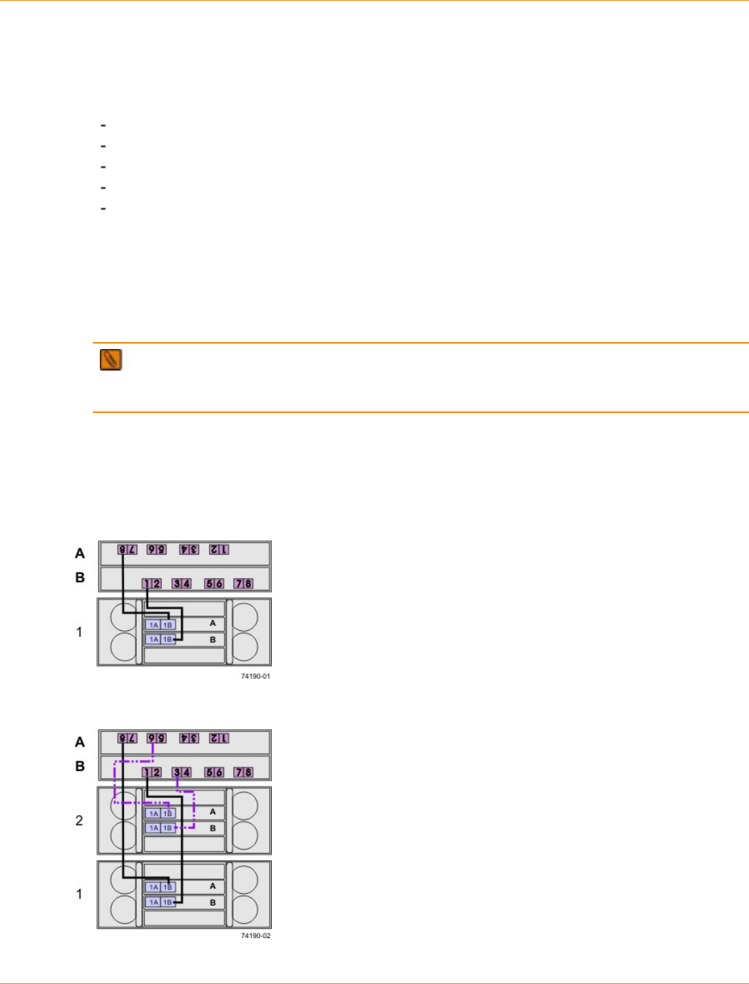
SANtricity_10.77 February 2011
LSI Corporation
- 476 -
2. Insert an SFP transceiver into the applicable In (1A) port or Out (1B) port on the ESM in the drive tray,
and plug the other end of the fiber-optic cable into the applicable In (1A) port or Out (1B) port.
3. Affix a label to each end of the cable using this recommended scheme. A label is useful if you need to
disconnect cables later to service a controller.
The controller ID (for example, controller A)
The drive channel number and the port ID (for example, drive channel 1, port 4)
The ESM ID (for example, ESM A)
The ESM port ID (for example, 1A or 1B)
The drive tray ID
Example label abbreviation– Assume that a cable is connected between drive channel 1, port 4, of
controller A to the Out (1B) port of the left ESM (A) in drive tray 1. A label abbreviation could be as
follows.
CtA-Dch1/P4, Dm1-ESM_A(left), IB
4. Repeat step 1 through step 3 for each controller and drive channel that you intend to use.
NOTE You must connect the cables from one drive tray to the next (daisy-chaining), starting with
the ninth FC4600 drive tray. If only DE6900 drive trays are used, all drive trays up to the maximum of
eight are connected directly to the CE7900 controller tray for standard cabling.
Example: In the cabling configuration figures that follow, the controller tray is placed in the center, and the
controllers are labeled as A and B. The FC4600 drive trays are placed above the controller tray and below
the controller tray. The DE6900 drive trays are placed below the controller tray, beginning at the bottom of the
cabinet. The drive trays are labeled as 1, 2, 3, and so on.
One CE7900 Controller Tray and One DE6900 Drive Tray
One CE7900 Controller Tray and Two DE6900 Drive Trays
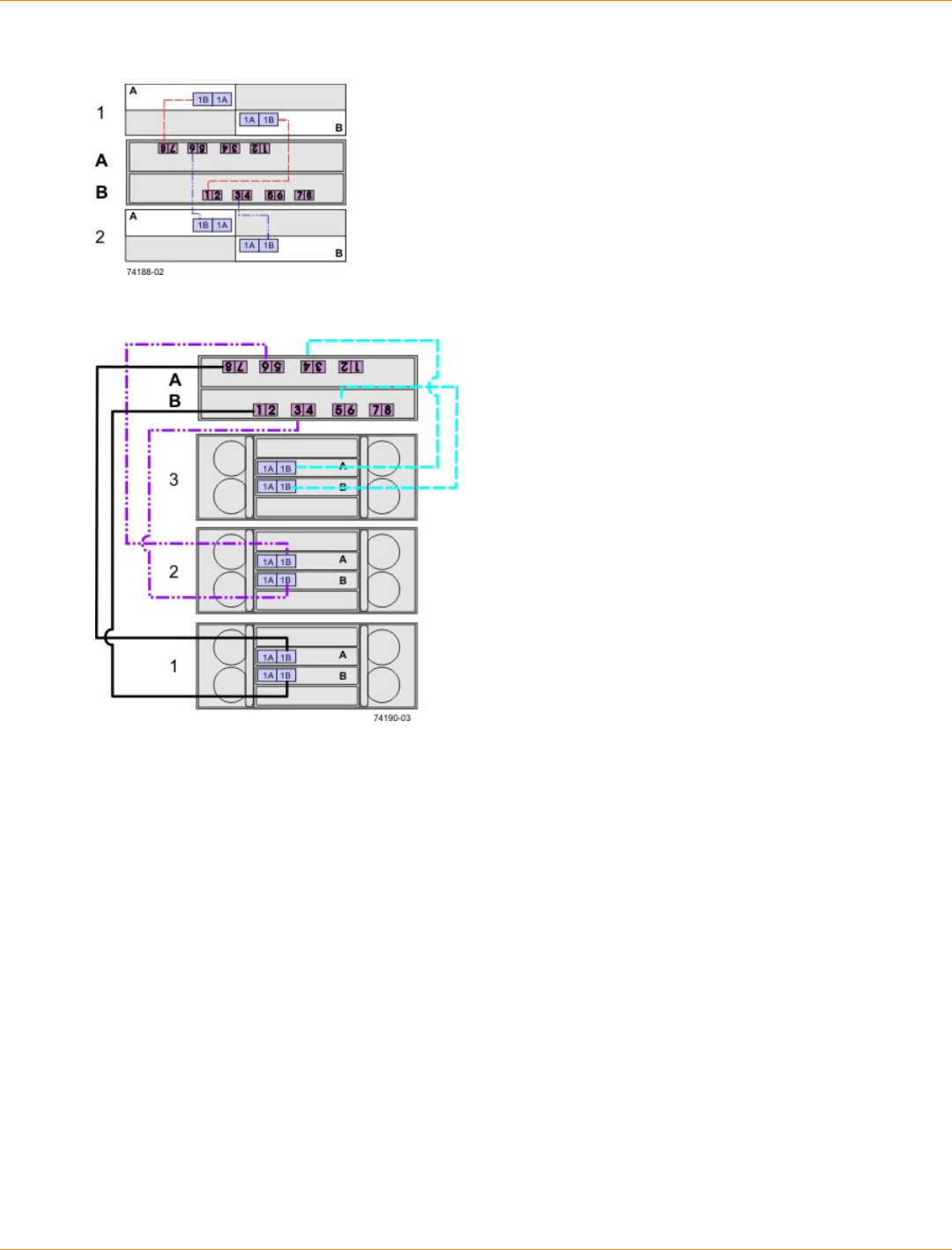
SANtricity_10.77 February 2011
LSI Corporation
- 477 -
One CE7900 Controller Tray and Two FC4600 Drive Trays
One CE7900 Controller Tray and Three DE6900 Drive Trays

SANtricity_10.77 February 2011
LSI Corporation
- 478 -
One CE7900 Controller Tray and Four DE6900 Drive Trays
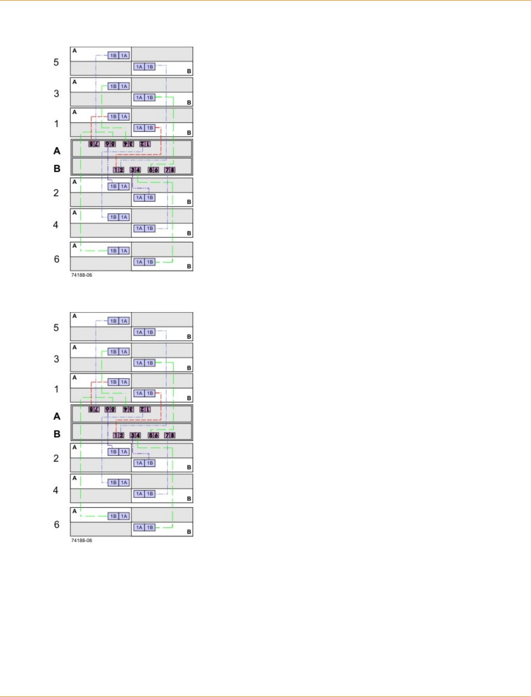
SANtricity_10.77 February 2011
LSI Corporation
- 479 -
One CE7900 Controller Tray and Four FC4600 Drive Trays
One CE7900 Controller Tray and Six FC4600 Drive Trays
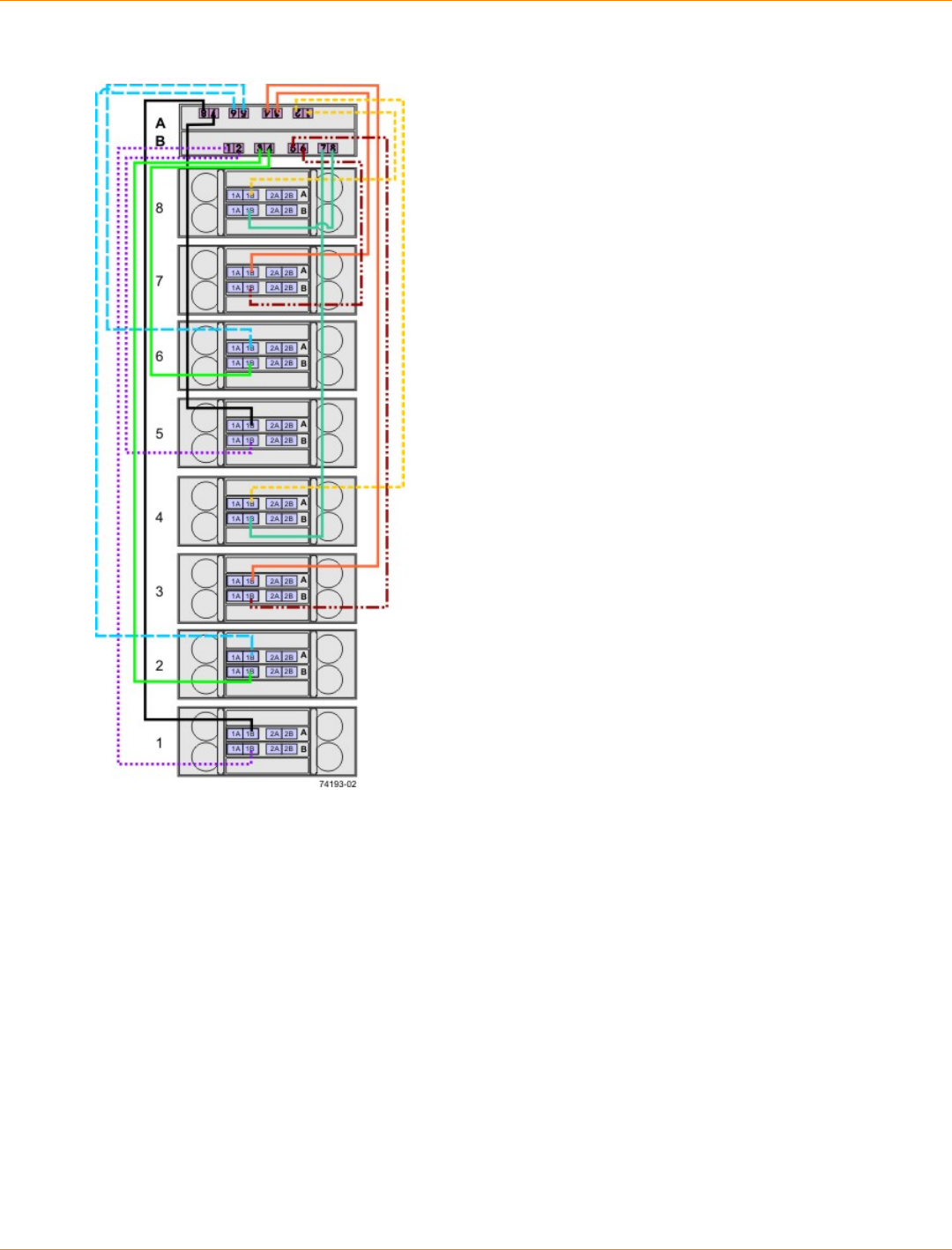
SANtricity_10.77 February 2011
LSI Corporation
- 480 -
One CE7900 Controller Tray and Eight DE6900 Drive Trays
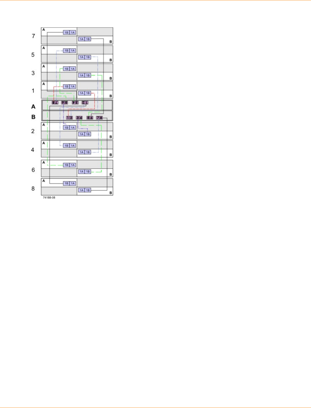
SANtricity_10.77 February 2011
LSI Corporation
- 481 -
One CE7900 Controller Tray and Eight FC4600 Drive Trays
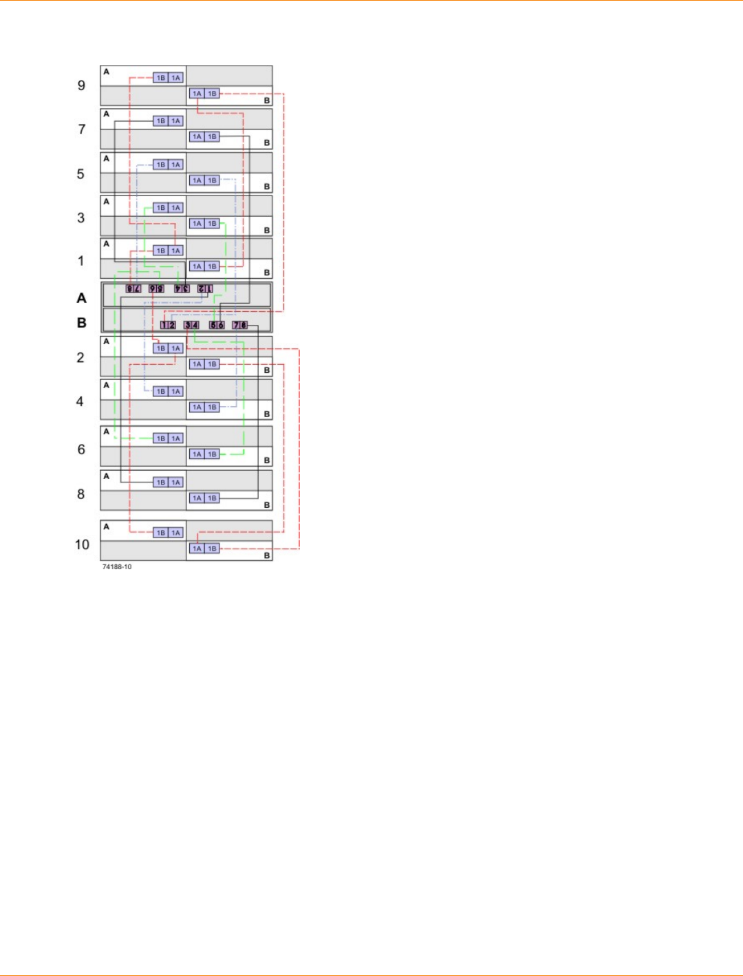
SANtricity_10.77 February 2011
LSI Corporation
- 482 -
One CE7900 Controller Tray and 10 FC4600 Drive Trays
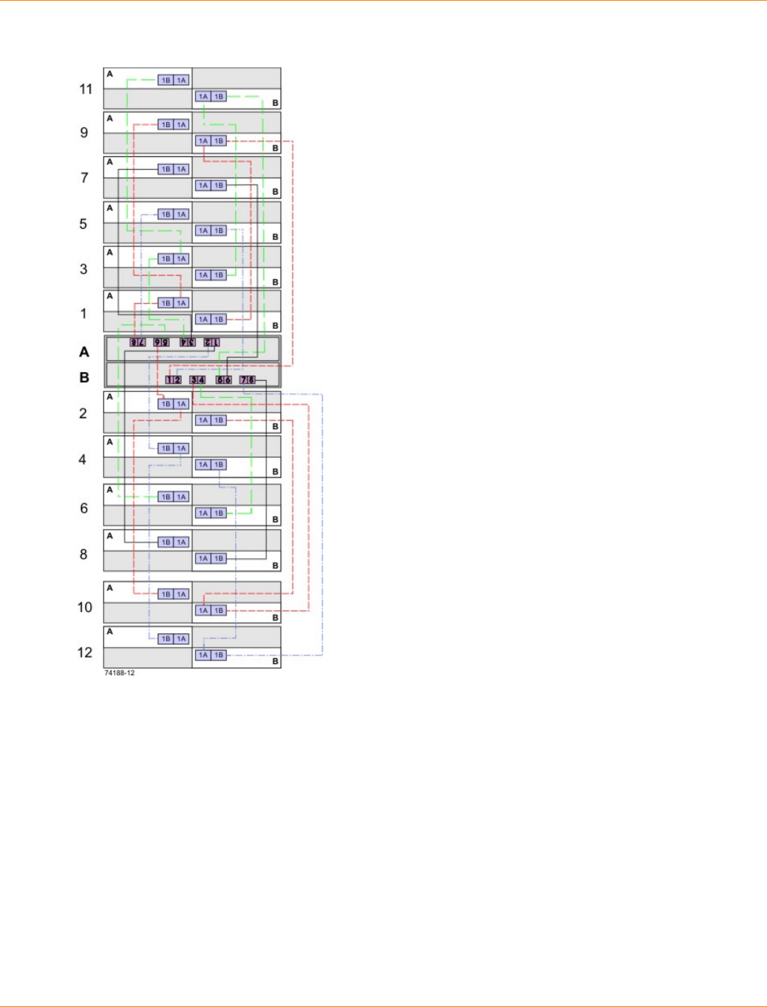
SANtricity_10.77 February 2011
LSI Corporation
- 483 -
One CE7900 Controller Tray and 12 FC4600 Drive Trays
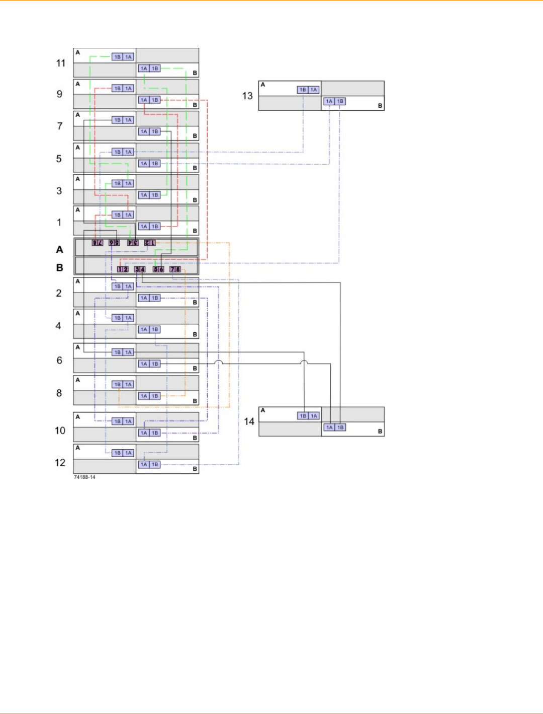
SANtricity_10.77 February 2011
LSI Corporation
- 484 -
One CE7900 Controller Tray and 14 FC4600 Drive Trays
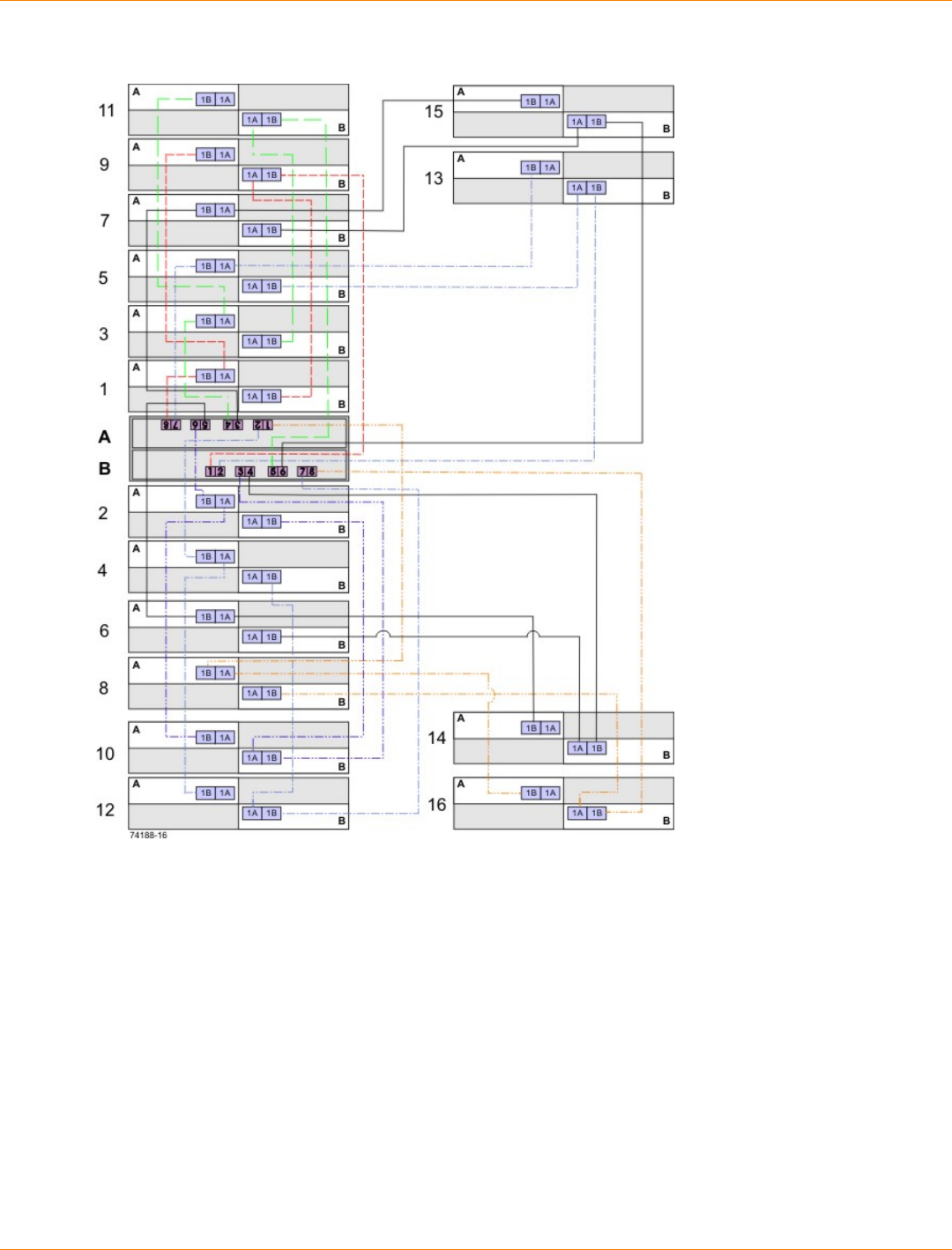
SANtricity_10.77 February 2011
LSI Corporation
- 485 -
One CE7900 Controller Tray and 16 FC4600 Drive Trays
You can add drive trays in series to each redundant pair of drive ports up to 28 drive trays. In a configuration
with 28 drive trays, four of the port pairs will have four drive trays each, while the other four will have three
drive trays each. Figure 1–14 shows this arrangement schematically. The physical arrangement of the drive
trays in cabinets will depend on your particular installation.
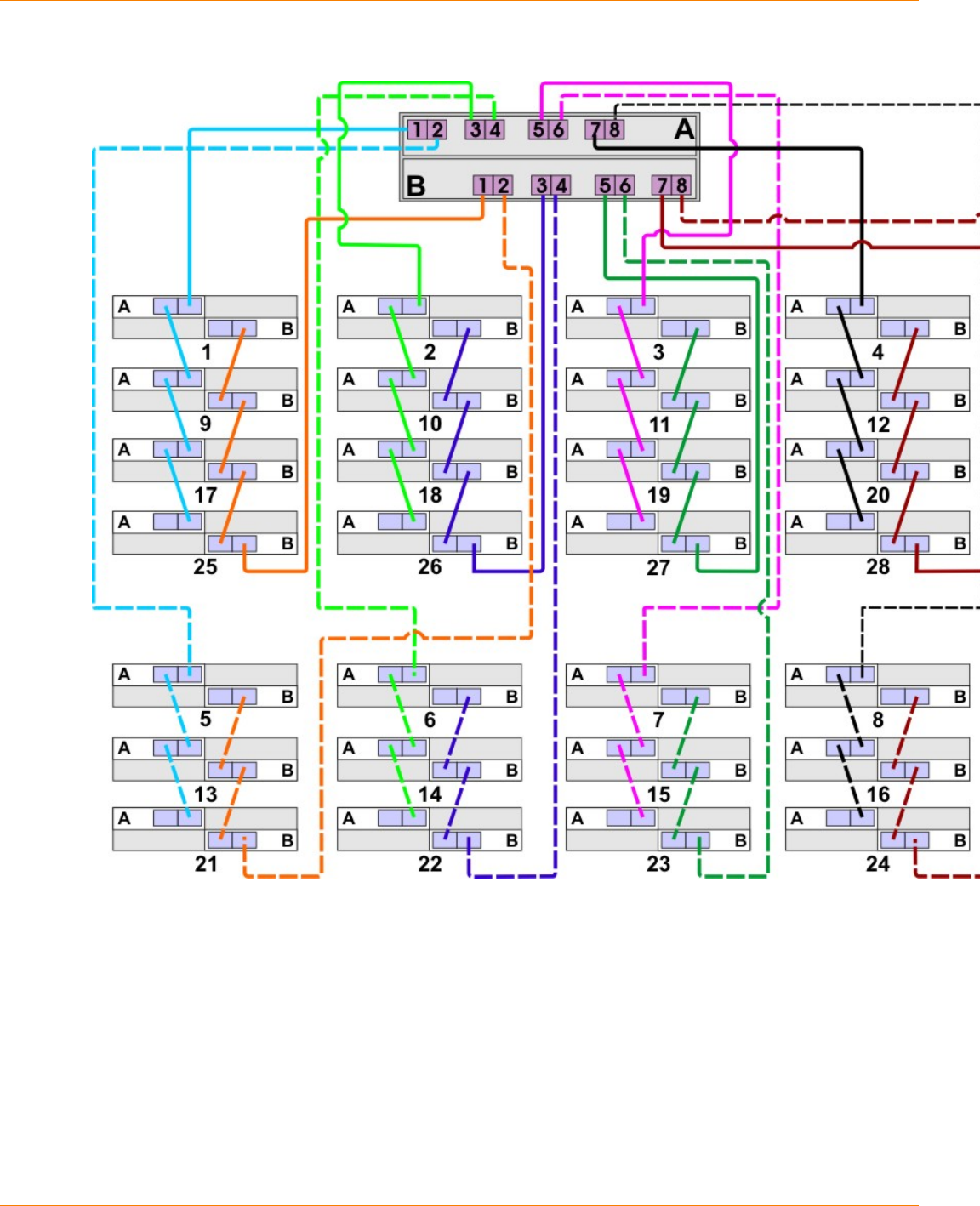
SANtricity_10.77 February 2011
LSI Corporation
- 486 -
One CE7900 Controller Tray and 28 FC4600 Drive Trays

SANtricity_10.77 February 2011
LSI Corporation
- 487 -
Step 8 – Connecting the Ethernet Cables
Key Terms
in-band management
A method to manage a storage array in which a storage management station sends commands to the storage
array through the host input/output (I/O) connection to the controller.
out-of-band management
A method to manage a storage array in which a storage management station sends commands to the storage
array through the Ethernet connections on the controller.
Things to Know – Connecting Ethernet Cables
ATTENTION Risk of security breach – Connect the Ethernet ports on the controller tray to a private
network segment behind a firewall. If the Ethernet connection is not protected by a firewall, your storage array
might be at risk of being accessed from outside of your network.
These Ethernet connections are intended for out-of-band management and have nothing to do with the
iSCSI host interface cards (HICs), whether 1Gb/s or 10Gb/s.
Ethernet port 2 on each controller is reserved for access by your Customer and Technical Support
representative.
In limited situations in which the storage management station is connected directly to the controller tray,
you must use an Ethernet crossover cable. An Ethernet crossover cable is a special cable that reverses
the pin contacts between the two ends of the cable.
Procedure – Connecting Ethernet Cables
Perform these steps to connect Ethernet cables for out-of-band management. If you use only in-band
management, skip these steps.
1. Connect one end of an Ethernet cable into the Ethernet port 1 on controller A.
2. Connect the other end to the applicable network connection.
3. Repeat step 1 through step 2 for controller B.

SANtricity_10.77 February 2011
LSI Corporation
- 488 -
Step 9 – Connecting the Power Cords in a CE7900 Controller Tray
Configuration
The CE7900 controller tray, the DE6900 drive tray, and the FC4600 drive tray have standard power
connections to an AC power source.
IMPORTANT Make sure that you do not turn on the power to the controller tray or the connected drive
trays until this documentation instructs you to do so. For the correct procedure for turning on the power, see
“Step 10 – Turning on the Power and Checking for Problems in a CE7900 Controller Tray Configuration.”
Things to Know – AC Power Cords
For each AC power connector on the drive tray, make sure that you use a separate power source in the
cabinet. Connecting to independent power sources maintains power redundancy.
To ensure proper cooling and assure availability, the drive trays always use two power supplies.
You can use the power cords shipped with the drive tray with typical outlets used in the destination
country, such as a wall receptacle or an uninterruptible power supply (UPS). These power cords,
however, are not intended for use in most EIA-compliant cabinets.
Procedure – Connecting AC Power Cords
1. Make sure that the circuit breakers in the cabinet are turned off.
2. Make sure that both of the Power switches on the drive trays are turned off.
3. Connect the primary power cords from the cabinet to the external power source.
4. Connect a cabinet interconnect power cord (or power cords specific to your particular cabinet) to the AC
power connector on each power canister in the drive tray.
5. If you are installing other drive trays in the cabinet, connect a power cord to each power canister in the
drive trays.
SANtricity_10.77 February 2011
LSI Corporation
- 489 -
Step 10 – Turning on the Power and Checking for Problems in a
CE7900 Controller Tray Configuration
Once you complete this task, you can install the begin to install the software and perform basic configuration
tasks on your storage array. Continue with the Initial Configuration and Software Installation in these
electronic document topics or through the PDF that is available on the SANtricity ES Storage Manager
Installation DVD.
Procedure – Turning on the Power to the Storage Array and Checking for
Problems
IMPORTANT You must turn on the power to all of the connected drive trays before you turn on the
power for the controller tray. Performing this action makes sure that the controllers recognize each attached
drive tray.
NOTE While the power is being applied to the trays, the LEDs on the front and the rear of the trays
come on and go off intermittently.
1. Turn on both Power switches on each drive tray that is attached to the controller tray. Depending on your
configuration, it can take several minutes for each drive tray to complete the power-on process.
IMPORTANT Before you go to step 2, check the LEDs on the drive tray to verify that the power was
successfully applied to all of the drive trays. Wait 30 seconds after turning on the power to the drive tray
before turning on the power to the controller tray.
2. Turn on both Power switches on the rear of the controller tray. Depending on your configuration, it can
take several minutes for the controller tray to complete the power-on process.
3. Check the LEDs on the front and the rear of the controller tray and the attached drive trays (see “Things
to Know – LEDs on the CE7900 Controller Tray,” "Things to Know – LEDs on the DE6900 Drive
Tray,"and “Things to Know – LEDs on the FC4600 Drive Tray”).
4. If you see any amber LEDs, make a note of their location.
Things to Know – LEDs on the CE7900 Controller Tray
LEDs on the Controller Tray
LED Symbol Location
(Canisters) Function
Power Power-fan
Interconnect-
battery
On – The canister has
power.
Off – The canister does
not have power.
NOTE – The controller
canisters do not have a
Power LED. They receive
their power from the power
supplies inside the power-fan
canisters.
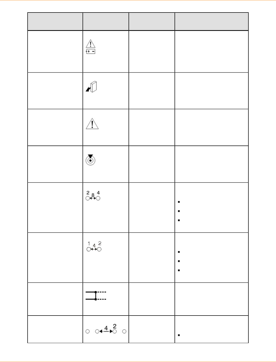
SANtricity_10.77 February 2011
LSI Corporation
- 490 -
LED Symbol Location
(Canisters) Function
Battery Needs
Attention Interconnect-
battery On – A problem exists with
the battery.
Service Action
Allowed Power-fan
Controller
Interconnect-
battery
On – You can remove the
canister safely.
See “Things to Know –
Service Action Allowed
LEDs.”
Service Action
Required (Fault) Power-fan
Controller
Interconnect-
battery
On – A problem exists with
the canister.
Locate Interconnect-
battery On – A tray is located.
Host Channel Speed
(8-Gb/s Fibre
Channel Host
Interface Card)
Controller The speed of the host
channel is indicated:
Left LED on – 2 Gb/s
Right LED on – 4 Gb/s
Left LED and right LED
on – 8 Gb/s
Host Channel Speed
(4-Gb/s Fibre
Channel Host
Interface Card)
Controller The speed of the host
channel is indicated:
Left LED on – 1 Gb/s
Right LED on – 2 Gb/s
Left LED and right LED
on – 4 Gb/s
Drive Port Bypass Controller On – A bypassed port is
indicated.
Drive Channel Speed Controller The speed of the drive
channel is indicated:
Right LED on – 2 Gb/s
SANtricity_10.77 February 2011
LSI Corporation
- 491 -
LED Symbol Location
(Canisters) Function
Left LED and right LED
on – 4 Gb/s
Cache Active Controller The activity of the cache is
indicated:
Blinking – Data is in
cache.
Off – No data is in cache.
Tray ID Numeric
Display and
Diagnostic Display
Controller The tray ID or a diagnostic
code is indicated (see the
"Supported Diagnostic
Codes" table that follows at
the end of this section).
For example, if some of the
cache memory dual in-line
memory modules (DIMMs)
are missing in a controller,
error code L8 appears in the
diagnostic display.
Ethernet Speed and
Ethernet Activity Controller The speed of the Ethernet
ports and whether a link
has been established are
indicated:
Left LED on –
1000BASE-T speed
Left LED off – 100BASE-
T or 10BASE-T speed
Right LED on – A link is
established.
Right LED off – No link
exists.
Right LED blinking –
Activity is occurring.
Supported Diagnostic Codes
Diagnostic Code Description
L0 The controller types are mismatched.
L1 The interconnect-battery canister is missing.
L2 A persistent memory error has occurred.
L3 A persistent hardware error has occurred.
SANtricity_10.77 February 2011
LSI Corporation
- 492 -
Diagnostic Code Description
L4 A persistent data protection error has occurred.
L5 The auto-code synchronization (ACS) has failed.
L6 An unsupported host interface card is installed.
L7 The sub-model identifier is not set or is mismatched.
L8 A memory configuration error has occurred.
L9 A link speed mismatch has occurred.
LA Reserved.
Lb Host card configuration error has occurred.
LC Persistent cache backup configuration error has occurred.
Ld Mixed cache memory DIMMs exist.
LE Uncertified cache memory DIMM sizes exist.
LF Lockdown with limited SYMbol support exists exist.
LH Controller firmware mismatch has occurred.
Things to Know – Service Action Allowed LED
Each controller canister, power-fan canister, and interconnect-battery canister has a Service Action Allowed
LED, which is a blue LED. The Service Action Allowed LED lets you know when you can remove a canister
safely.
ATTENTION Possible loss of data access – Never remove a controller canister, a power-fan
canister, or an interconnect-battery canister unless the Service Action Allowed LED is on.
If a controller canister, a power-fan canister, or a interconnect-battery canister fails and must be replaced,
the Service Action Required (Fault) LED (an amber LED) on that canister comes on to indicate that service
action is required. The Service Action Allowed LED also comes on if it is safe to remove the canister. If data
availability dependencies exist or other conditions that dictate a canister should not be removed, the Service
Action Allowed LED stays off.
The Service Action Allowed LED automatically comes on or goes off as conditions change. In most cases,
the Service Action Allowed LED comes on when the Service Action Required (Fault) LED comes on for a
canister.
IMPORTANT If the Service Action Required (Fault) LED comes on but the Service Action Allowed
LED is off for a particular canister, you might need to service another canister first. Check your storage
management software to determine the action that you should take.
SANtricity_10.77 February 2011
LSI Corporation
- 493 -
General Behavior of the LEDs on the Drive Trays
LED Symbols and General Behavior on the Drive Trays
LED Symbol Location General Behavior
Power Drive tray
ESM canister
Power-fan
canister
On – Power is applied to the drive
tray or the canister.
Off – Power is not applied to the
drive tray or the canister.
Service Action
Allowed ESM canister
Power-fan
canister
Drive
On – It is safe to remove the ESM
canister, the power-fan canister, or
the drive.
Off – Do not remove the ESM
canister, the power-fan canister, or
the drive.
The drive has an LED but no
symbol.
Service Action
Required (Fault) ESM canister
Power-fan
canister
Drive
On – When the drive tray LED is
on, a component within the drive
tray needs attention.
On – The ESM canister, the
power-fan canister, or the drive
needs attention.
Off – The ESM canister, the
power-fan canister, and the drive
are operating normally.
The drive has an LED but no
symbol.
Locate Front bezel on
the drive tray On or blinking – Indicates the
drive tray that you are trying to find.
Over-
Temperature Front bezel on
the DE6900
drive tray
On – The temperature of the
drive tray has reached an unsafe
condition.
Off – The temperature of the drive
tray is within operational range.
Drive Port
Bypass ESM canister Indicates if a port has been
bypassed.
Drive Channel
Speed ESM canister Indicates the speed of the drive
channel:
If the right LED is On -- 2 Gb/s
If both LED are Off -- 4 Gb/s
SANtricity_10.77 February 2011
LSI Corporation
- 494 -
LED Symbol Location General Behavior
AC Power ESM canister
Power-fan
canister
Note LED is
directly above
or below AC
Power Switch
and AC Power
Connectors
On – AC power is present.
Off – AC power is not present.
DC Power Power-fan
canister Indicates the power supply is
outputting DC power
Service Action LEDs on the Drive Tray
ATTENTION Possible loss of data access – Never remove any canister unless the appropriate
Service Action Allowed LED is turned on.
Each canister in the drive tray has two service action LEDs.
Service Action Required LED – This LED comes on to indicate that a condition exists that requires
service.
Service Action Allowed LED – This LED comes on when it is safe to remove a failed canister. If data
availability dependencies or other conditions exist that dictate that a canister should not be removed, the
Service Action Allowed LED stays off. The Service Action Allowed LED automatically comes on or goes
off as conditions change.
IMPORTANT If the Service Action Required LED is on but the Service Action Allowed LED is off for a
particular canister, you might need to service another canister first. Check your storage management software
to determine the action that you should take.
NOTE In most cases, the Service Action Allowed LED comes on when the Service Action Required
LED is on for a canister.
Things to Know – LEDs on the DE6900 Drive Tray
The following topics describe the LEDs that are available on DE6900 drive tray.
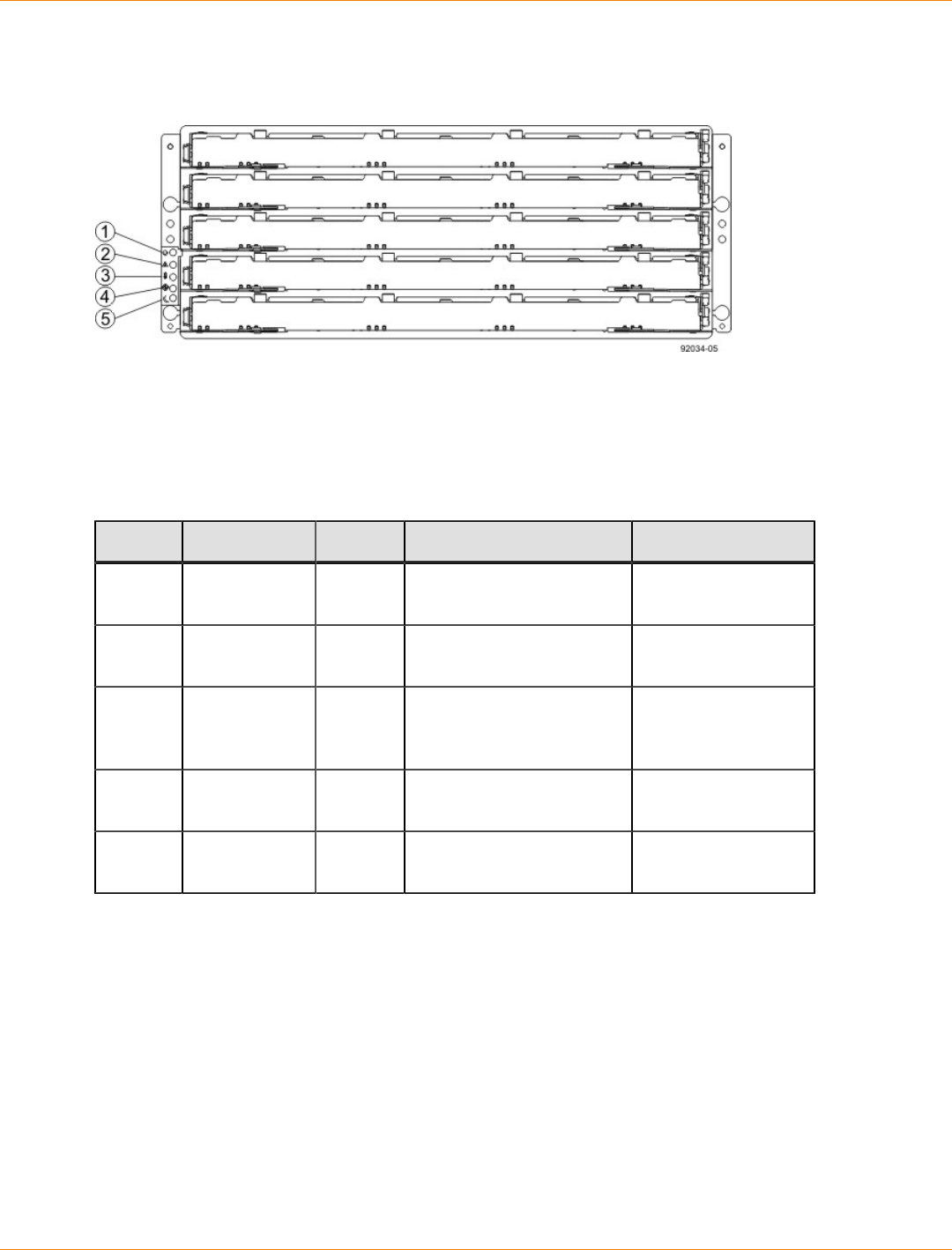
SANtricity_10.77 February 2011
LSI Corporation
- 495 -
LEDs on the DE6900 Drive Tray
LEDs on the DE6900 Left End Cap
1. Drive Tray Locate LED
2. Drive Tray Service Action Required LED
3. Drive Tray Over-Temperature LED
4. Power LED
5. Standby Power
LEDs on the DE6900 Left End Cap
Location LED Color On Off
1 Drive Tray
Locate White Identifies a drive tray that
you are trying to find. Normal status.
2 Service Action
Required Amber A component within the
drive tray needs attention. Normal status.
3 Drive Tray
Over-
Temperature
Amber The temperature of the
drive tray has reached an
unsafe level.
Normal status.
4 Power Green Power is present. Power is not
present.
5 Standby Green The drive tray is in
Standby mode. The drive tray is not
in Standby mode.

SANtricity_10.77 February 2011
LSI Corporation
- 496 -
LEDs on the DE6900 ESM Canister
1. ESM Link Fault LED (Port 1A Bypass)
2. ESM Link LED (Port 1A Data Rate)
3. ESM Link LED (Port 1B Data Rate)
4. ESM Link Fault LED (Port 1B Bypass)
5. ESM Service Action Allowed LED
6. ESM Service Action Required LED
7. ESM Power LED
8. Seven-Segment Tray ID
LEDs on the DE6900 ESM Canister
Location LED Color On Off
1 ESM Link
Fault (Port 1A
Bypass)
Amber A link error has
occurred. No link error has
occurred.
2 ESM Link (Port
1A) Green The link is up. A link error has
occurred.
3 ESM Link (Port
1B Bypass) Green The link is up. A link error has
occurred.
4 ESM Link Fault
(Port 1B) Amber A link error has
occurred. No link error has
occurred.
5 ESM Service
Action Allowed Blue The ESM can be
removed safely from
the drive tray.
The ESM cannot be
removed safely from
the drive tray.
6 ESM Service
Action
Required
Amber A fault exists within the
ESM. Normal status.
7 ESM Power Green Power to the ESM is
present. Power is not present to
the ESM.
8 Seven-
Segment Tray
ID
Green For more information,
see “Supported
Diagnostic Codes on
the Seven-Segment
Display”.
Not applicable.
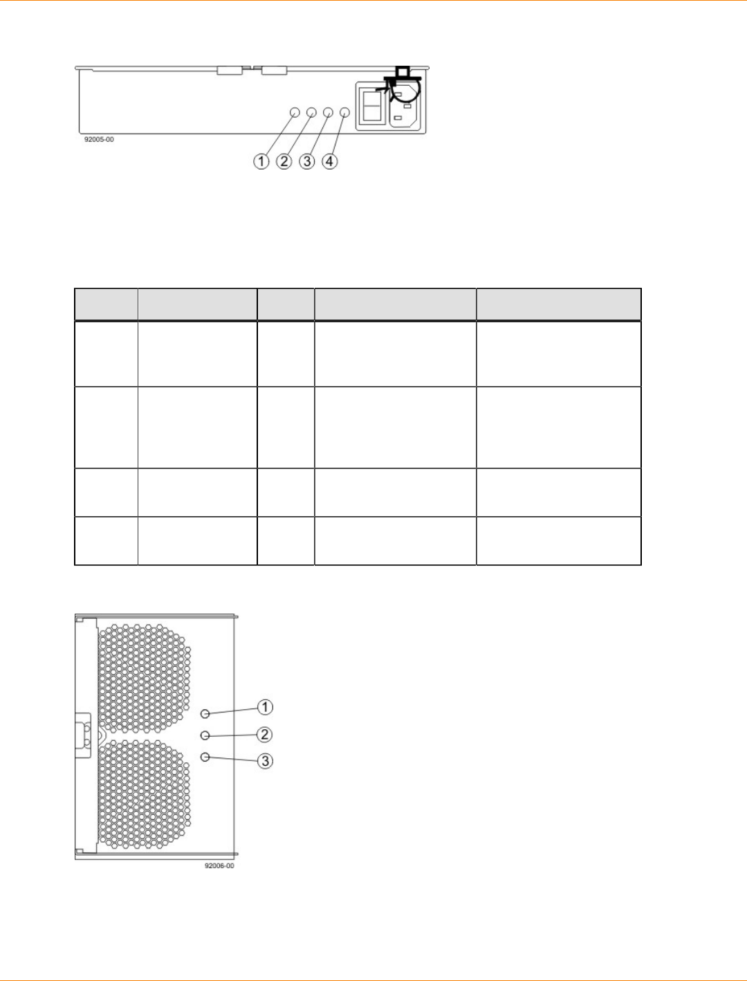
SANtricity_10.77 February 2011
LSI Corporation
- 497 -
LEDs on the DE6900 Power Canister
1. Power DC Power LED
2. Power Service Action Allowed LED
3. Power Service Action Required LED
4. Power AC Power LED
LEDs on the DE6900 Power Canister
Location LED Color On Off
1 Power DC
Power Green DC power from the
power canister is
available.
DC power from the
power canister is not
available.
2 Power Service
Action Allowed Blue The power canister can
be removed safely from
the drive tray.
The power canister
cannot be removed
safely from the drive
tray.
3 Power Service
Action Required Amber A fault exists within the
power canister. Normal status.
4 Power AC
Power Green AC power to the power
canister is present. AC power to the power
canister is not present.
LEDs on the DE6900 Fan Canister
1. Power LED
2. Fan Service Action Required LED
3. Fan Service Action Allowed LED
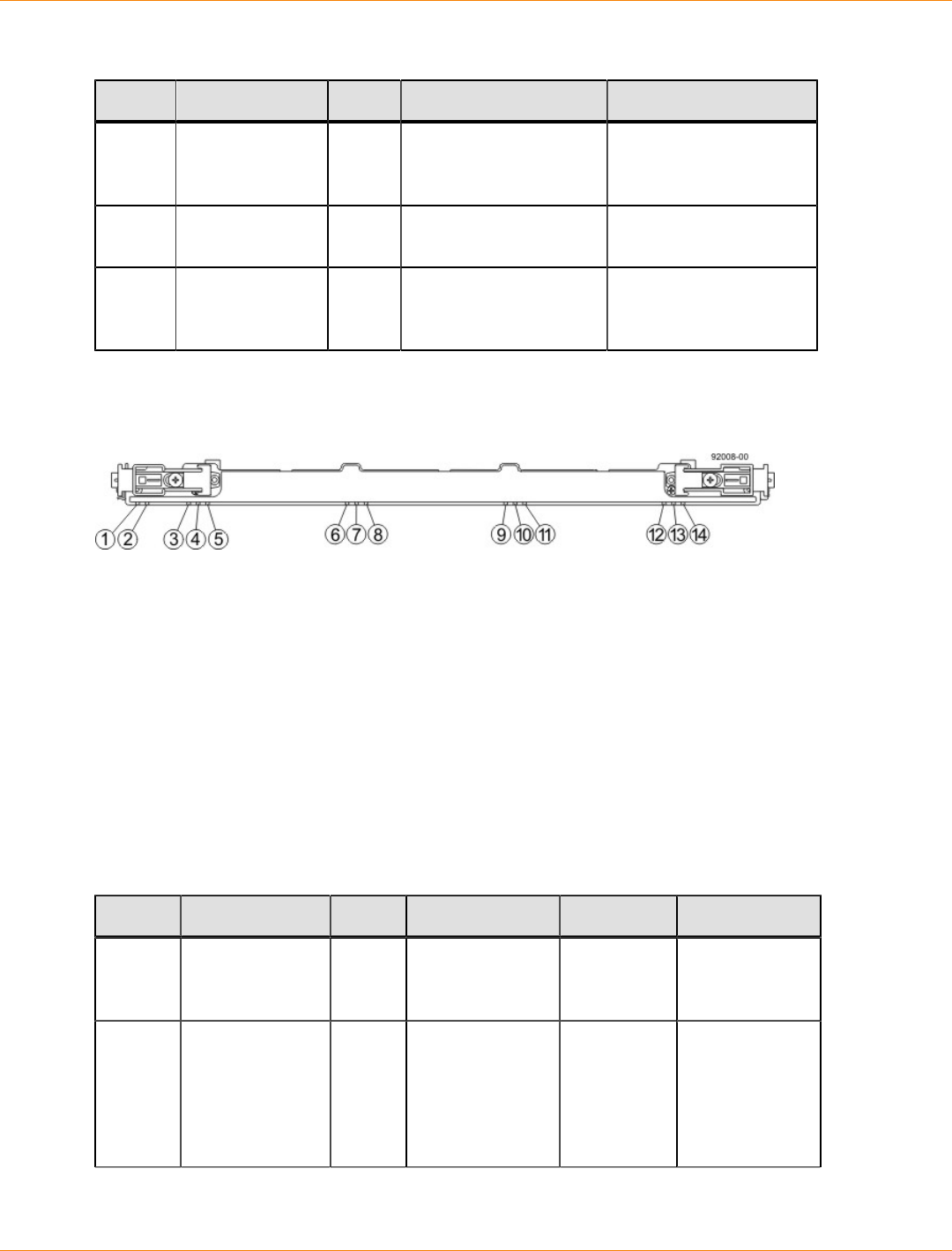
SANtricity_10.77 February 2011
LSI Corporation
- 498 -
LEDs on the DE6900 Fan Canister
Location LED Color On Off
1 Power Green Power from the fan
canister is available. Power to the fan
customer-replaceable
unit (CRU) is available.
2 Fan Service
Action Required Amber A fault exists within the
fan canister. Normal status.
3 Fan Service
Action Allowed Blue The fan canister can
be removed safely from
the drive tray.
The fan canister cannot
be removed safely from
the drive tray.
LEDs on the Drive Drawers
LEDs on the Drawer
1. Drive Drawer Service Action Required LED
2. Drive Drawer Service Action Allowed LED
3. Drive 1 Activity LED
4. Drive 2 Activity LED
5. Drive 3 Activity LED
6. Drive 4 Activity LED
7. Drive 5 Activity LED
8. Drive 6 Activity LED
9. Drive 7 Activity LED
10. Drive 8 Activity LED
11. Drive 9 Activity LED
12. Drive 10 Activity LED
13. Drive 11 Activity LED
14. Drive 12 Activity LED
LEDs on the Drawer
Location LED Color On Blinking Off
1 Drive Drawer
Service Action
Required
Amber An error has
occurred. Normal status.
2 Drive Drawer
Service Action
Allowed
Blue The drive
canister can be
removed safely
from the drive
drawer in the
drive tray.
The drive
canister cannot
be removed
safely from the
drive drawer in
the drive tray.
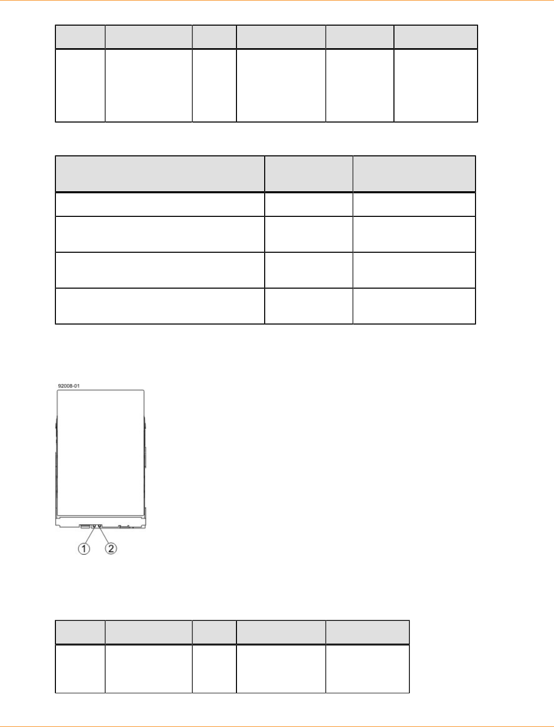
SANtricity_10.77 February 2011
LSI Corporation
- 499 -
Location LED Color On Blinking Off
3–14 Drive Activity for
drives 1 through
12 in the drive
drawer
Green The power
is turned on,
and the drive
is operating
normally.
Drive I/
O activity
is taking
place.
The power is
turned off.
Drive State Represented by the LEDs
Drive State Drive Activity
LED (Green) Drive Service Action
Required LED (Amber)
Power is not applied. Off Off
Normal operation – The power is turned on,
but drive I/O activity is not occurring. On Off
Normal operation – Drive I/O activity is
occurring. Blinking Off
Service action required – A fault condition
exists, and the drive is offline. On On
LEDs on the DE6900 Drives
LEDs on the DE6900 Drive
1. Drive Service Action Allowed LED
2. Drive Service Action Required LED
LEDs on the Drives
Location LED Color On Off
1 Drive Service
Action Allowed Blue The drive
canister can be
removed safely
The drive
canister cannot
be removed
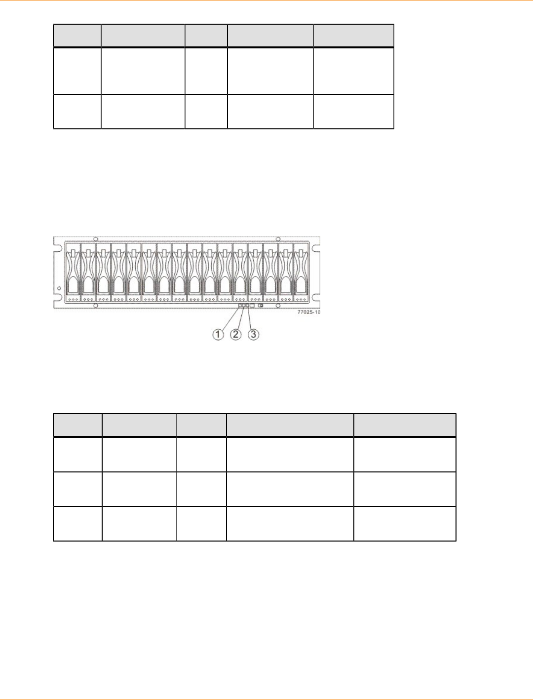
SANtricity_10.77 February 2011
LSI Corporation
- 500 -
Location LED Color On Off
from the drive
drawer in the
drive tray.
safely from the
drive drawer in
the drive tray.
2 Drive Service
Action Required Amber An error has
occurred. Normal status.
Things to Know – LEDs on the FC4600 Drive Tray
The following topics describe the LEDs that are available on FC4600 drive tray.
LEDs on the FC4600 Drive Tray
LEDs on the FC4600 – Front View
1. Drive Tray Locate LED
2. Drive Tray Service Action Required LED
3. Power LED
LEDs on the FC4600 Left End Cap
Location LED Color On Off
1 Drive Tray
Locate White Identifies a drive tray that
you are trying to find. Normal status.
2 Service Action
Required Amber A component within the
drive tray needs attention. Normal status.
3 Power Green Power is present. Power is not
present.
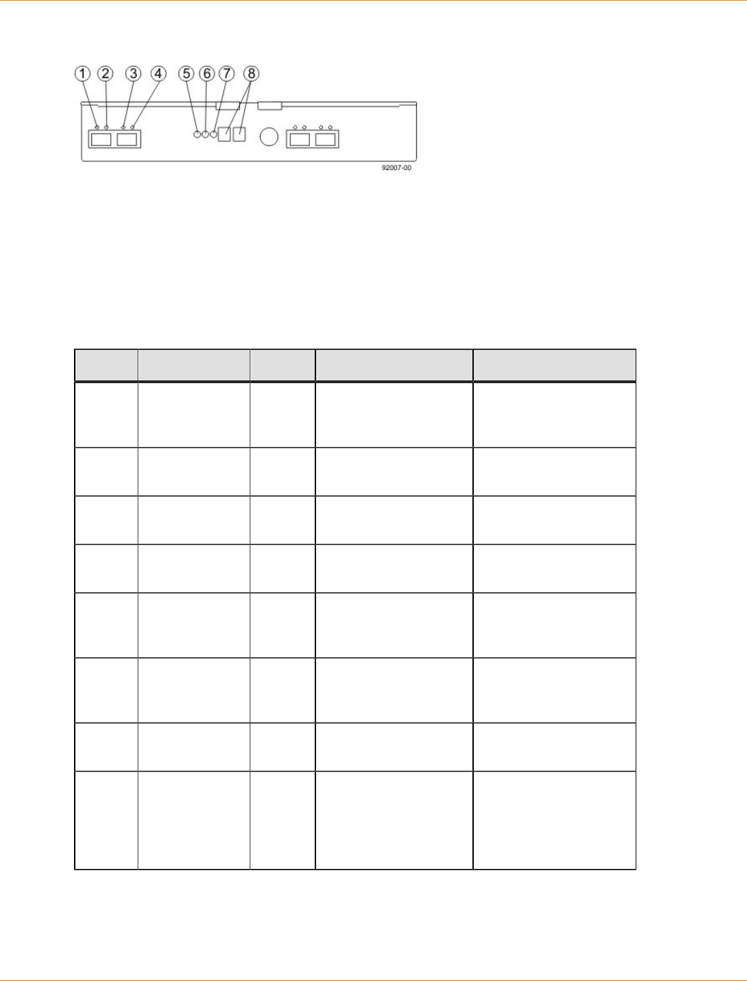
SANtricity_10.77 February 2011
LSI Corporation
- 501 -
LEDs on the FC4600 ESM Canister
1. ESM Link Fault LED (Port 1A Bypass)
2. ESM Link LED (Port 1A Data Rate)
3. ESM Link LED (Port 1B Data Rate)
4. ESM Link Fault LED (Port 1B Bypass)
5. ESM Service Action Allowed LED
6. ESM Service Action Required LED
7. ESM Power LED
8. Seven-Segment Tray ID
LEDs on the FC4600 ESM Canister
Location LED Color On Off
1 ESM Link
Fault (Port 1A
Bypass)
Amber A link error has
occurred. No link error has
occurred.
2 ESM Link (Port
1A) Green The link is up. A link error has
occurred.
3 ESM Link (Port
1B Bypass) Green The link is up. A link error has
occurred.
4 ESM Link Fault
(Port 1B) Amber A link error has
occurred. No link error has
occurred.
5 ESM Service
Action Allowed Blue The ESM can be
removed safely from
the drive tray.
The ESM cannot be
removed safely from
the drive tray.
6 ESM Service
Action
Required
Amber A fault exists within the
ESM. Normal status.
7 ESM Power Green Power to the ESM is
present. Power is not present to
the ESM.
8 Seven-
Segment Tray
ID
Green For more information,
see “Supported
Diagnostic Codes on
the Seven-Segment
Display”.
Not applicable.
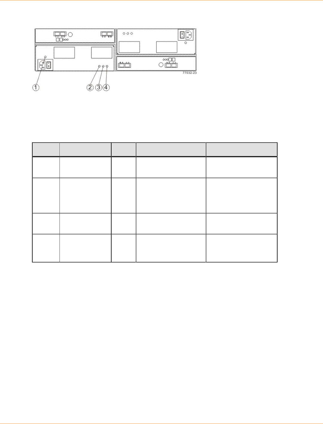
SANtricity_10.77 February 2011
LSI Corporation
- 502 -
LEDs on the FC4600 Power Canister
1. Power AC Power LED
2. Power Service Action Allowed LED
3. Power Service Action Required LED
4. Power DC Power LED
LEDs on the FC4600 Power Canister
Location LED Color On Off
1 Power AC
Power Green AC power to the power
canister is present. AC power to the power
canister is not present.
2 Power Service
Action Allowed Blue The power canister can
be removed safely from
the drive tray.
The power canister
cannot be removed
safely from the drive
tray.
3 Power Service
Action Required Amber A fault exists within the
power canister. Normal status.
4 Power DC
Power Green DC power from the
power canister is
available.
DC power from the
power canister is not
available.
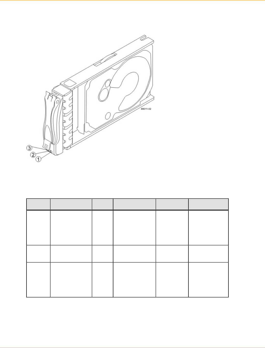
SANtricity_10.77 February 2011
LSI Corporation
- 503 -
LEDs on the FC4600 Drives
LEDs on the FC4600 Drive
1. Drive Power LED
2. Drive Service Action Required LED
3. Drive Service Action Required LED
LEDs on the Drives
Location LED Color On Blinking Off
1 Drive Power Green The power
is turned on,
and the drive
is operating
normally.
Drive I/O
is taking
place.
The power is
turned off.
2 Drive Service
Action Required Amber An error has
occurred. Normal status.
3 Drive Service
Action Allowed Blue The drive
canister can be
removed safely
from the drive
tray.
The drive
canister cannot
be removed
safely from the
drive tray.
Supported Diagnostic Codes on the Seven-Segment Display for the DE6900
Drive Tray and the FC4600 Drive Tray
The following table provides the diagnostic that can appear on the both the FC4600 drive tray and the
DE6900 drive tray.

SANtricity_10.77 February 2011
LSI Corporation
- 504 -
NOTE The diagnostic codes concerning drive-side trunking only apply to the DE6900 drive tray.
Supported Diagnostic Codes
Diagnostic Code Description
– – The firmware is booting.
.8, 8., or 88 This ESM is being held in reset by another ESM.
AA ESM A firmware is in the process of booting (the diagnostic
indicator is not yet set).
bb ESM B firmware is in the process of booting (the diagnostic
indicator is not yet set).
L0 The controller types are mismatched.
L2 A persistent memory error has occurred.
L3 A persistent hardware error has occurred.
L9 An over-temperature condition has been detected in either the
ESM or the power supply.
H0 An ESM Fibre Channel interface failure has occurred.
H1 An SFP transceiver speed mismatch (a 2-Gb/s SFP
transceiver is installed when the drive tray is operating at 4
Gb/s) indicates that an SFP transceiver must be replaced.
Look for the SPF transceiver with a blinking amber LED.
H2 The ESM configuration is invalid or incomplete or is operating
in a Degraded state.
H3 The maximum number of ESM reboot attempts has been
exceeded.
H4 This ESM cannot communicate with the alternate ESM.
H5 A midplane harness failure has been detected in the drive
tray.
H6 A catastrophic ESM hardware failure has been detected.
H8 SFP transceivers are present in currently unsupported ESM
slots, either 2A or 2B. Secondary trunking SFP transceiver
slots 2A and 2B are not supported. Look for the SFP
transceiver with the blinking amber LED, and remove it.
H9 A non-catastrophic hardware failure has occurred. The ESM is
operating in a Degraded state.
J0 The ESM canister is incompatible with the drive tray firmware.

SANtricity_10.77 February 2011
LSI Corporation
- 505 -
Diagnostic Code Description
J1 The drive-side trunk links are connected to two different
components, and both links are not operational. Examine both
links indicated by the blinking LEDs, and re-cable the links to
match the drive-side trunking cabling diagrams.
J2 An error has occurred. A cross-connected trunk port pair is the
result of one of these three situations:
A trunk pair from the local component is not connected to
a trunked pair of SFP ports on the remote component.
A trunk pair from the remote component is not connected
to a trunked pair of SFP ports on the local component.
Both the local connections and the remote connections
for an interconnecting pair of links are not connected to
trunked pairs of SFP ports.
Examine both links indicated by the blinking LEDs, and
re-cable the links to match the existing drive-side trunking
diagrams.
J3 An error has occurred. Three or more links are connected
from one component to another. No more than two links are
supported from one component to another. Examine all links
indicated by the blinking LEDs, and re-cable the links to match
the existing drive-side trunking diagrams.
J4 The trunk pair Primary and Dup swapped. Both links indicated
by the blinking bypass LEDs are operational, but their cabling
connections must be switched on either the local component
end or the remote component end.
J5 The trunk pair is operational, but it is cabled incorrectly. At
least one Out link is connected to the In link, or one In link is
connected to an Out link. Both links indicated by the blinking
bypass LEDs are operational, but they must be re-cabled on
one end so that the Primary Out is connected to Primary In,
and Dup Out is connected to Dup In.

SANtricity_10.77 February 2011
LSI Corporation
- 506 -
CDE4900 Controller-Drive Tray Installation
This topic provides basic information for installing the CDE4900 controller-drive tray and the FC4600 drive
tray in a storage array. After you have completed these tasks, you will continue onto the Initial Configuration
and Software Installation electronic document topics or the PDF on the SANtricity ES Storage Manager
Installation DVD.

SANtricity_10.77 February 2011
LSI Corporation
- 507 -
Step 1 – Preparing for an Installation
The CDE4900 storage array consists of a CDE4900 controller-drive tray and one or more FC4600 drive trays
in a cabinet. This document includes instructions for installing the FC4600 drive trays.
ATTENTION Possible hardware damage – To prevent electrostatic discharge damage to the tray,
use proper antistatic protection when handling tray components.
Key Terms
storage array
A collection of both physical components and logical components for storing data. Physical components
include drives, controllers, fans, and power supplies. Logical components include volume groups and
volumes. These components are managed by the storage management software.
Also known as RAID tray.
controller-drive tray
One tray with drives, one or two controllers, fans, and power supplies. The controller-drive tray provides the
interface between a host and a storage array.
See also , drive tray, storage array.
controller
A circuit board and firmware that is located within a controller tray or a controller-drive tray. A controller
manages the input/output (I/O) between the host system and data volumes.
drive tray
One tray with drives, one or two environmental services monitors (ESMs), power supplies, and fans. A drive
tray does not contain controllers.
See also controller-drive tray, .
environmental services monitor (ESM)
A canister in the drive tray that monitors the status of the components. An ESM also serves as the connection
point to transfer data between the drive tray and the controller.
Small Form-factor Pluggable (SFP) transceiver
A component that enables Fibre Channel duplex communication between storage array devices. SFP
transceivers can be inserted into host bus adapters (HBAs), controllers, and environmental services monitors
(ESMs). SFP transceivers can support either copper cables (the SFP transceiver is integrated with the cable)
or fiber-optic cables (the SFP transceiver is a separate component from the fiber-optic cable).
Gathering Items
Before you start installing the controller-drive tray, you must have installed the cabinet in which the controller-
drive tray will be mounted.
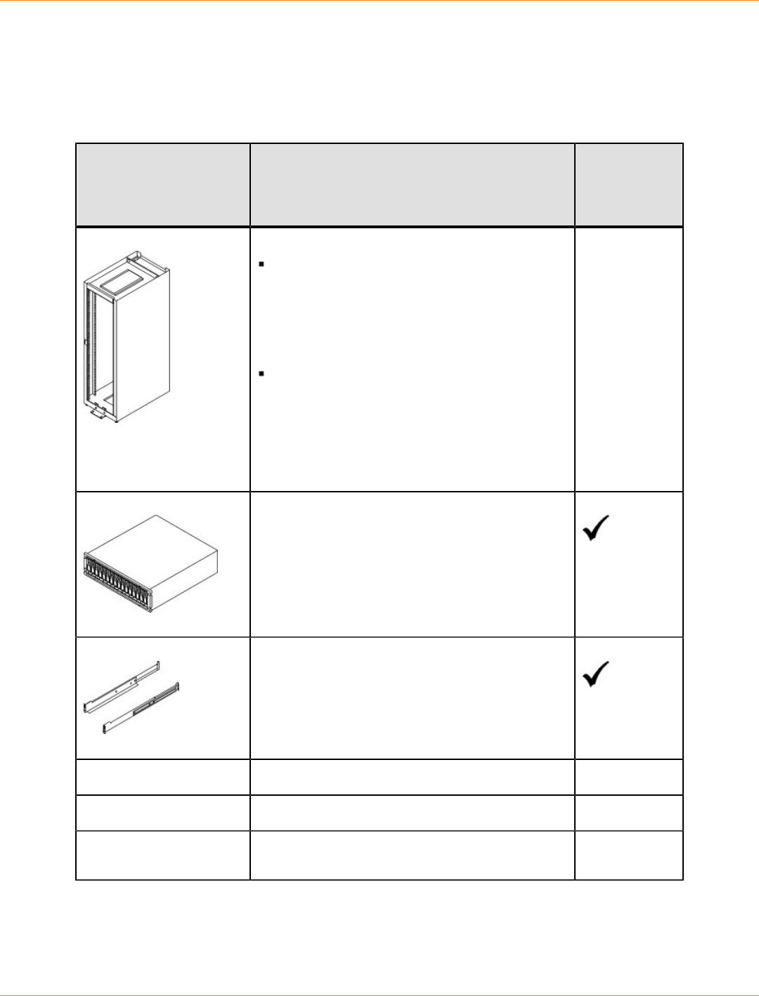
SANtricity_10.77 February 2011
LSI Corporation
- 508 -
Use the tables in this section to verify that you have all of the necessary items to install the controller-drive
tray.
Basic Hardware
Basic Hardware
Item Included
with the
Controller-
Drive Tray
Cabinet
Make sure that your cabinet meets the
installation site specifications of the various
CDE4900 storage array components. Refer
to the Storage System Site Preparation
Guide on the SANtricity ES Storage Manager
Installation DVD for more information.
Depending on the power supply limitations
of your cabinet, you might need to install
more than one cabinet to accommodate
the different components of the CDE4900
storage array. Refer to the installation guide
for your cabinet for instructions on installing
the cabinet.
FC4600 drive tray with end caps that are
packaged separately.
Mounting rails and screws
Fibre Channel switch (optional)
iSCSI switch (optional)
Host with Fibre Channel or iSCSI host bus
adapters (HBAs)
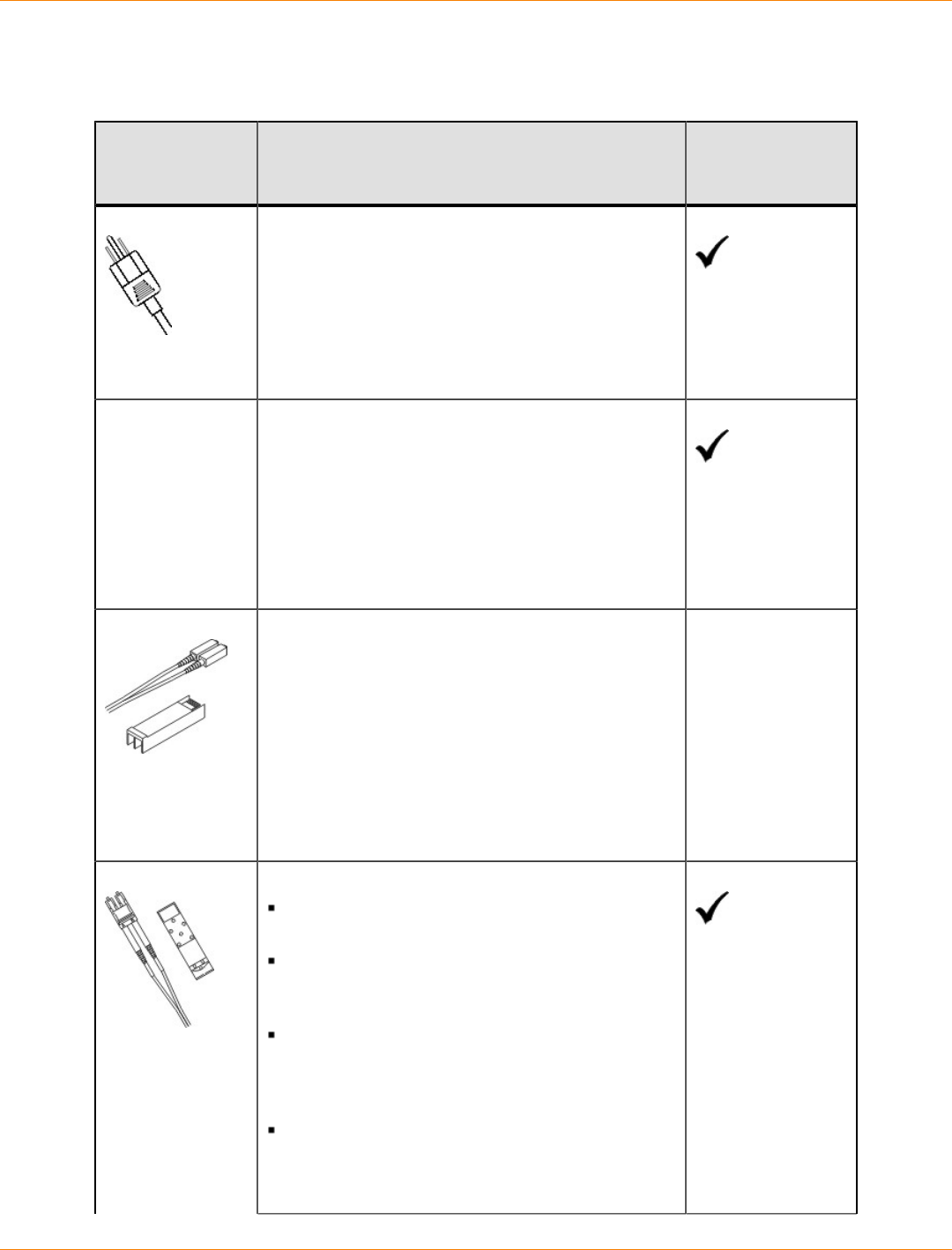
SANtricity_10.77 February 2011
LSI Corporation
- 509 -
Cables and Connectors on the CDE4900 Controller-Drive Tray Configuration
Cables and Connectors
Item Included with the
Controller-Drive
Tray
AC power cords
The controller-drive tray ships with power cords for
connecting to an external power source, such as a
wall plug. Your cabinet might have special power
cords that you use instead of the power cords that
ship with the controller-drive tray.
DC power connector cables (optional)
With the DC power option, the controller-drive tray
ships with two or four DC power connector cables
(depending on the requirements for redundancy).
You use the DC power connector cables to connect
to a DC power source.
NOTE – A two-pole 20-amp circuit breaker is
required between the DC power source and the
controller-drive tray.
Included only with
the DC power
option
Fiber-optic cables
Use these cables for connections to the hosts and
within the storage array.
For the differences between the fiber-optic cables
and the copper Fibre Channel (FC) cables, see the
"Step 1 – Deciding on the Management Method"
topic from Storage Array Installation and Initial
Configuration for SANtricity ES Storage Manager
Version 10.75, in either the online documentation or
from the SANtricity ES Storage Manager Installation
DVD.
Small Form-factor Pluggable (SFP) transceivers
The SFP transceivers connect fiber-optic cables
to host ports and drive ports.
Four or eight SFP transceivers are included with
the controller-drive tray; one for each of the host
channel ports on the controllers.
Depending on your connection requirements,
you might need to purchase additional SFP
transceivers (two SFP transceivers for each
fiber-optic cable).
Depending on the configuration of your
storage array, you might need to use various
combinations of four different types of SFP
transceivers: 8-Gb/s Fibre Channel, 4-Gb/s
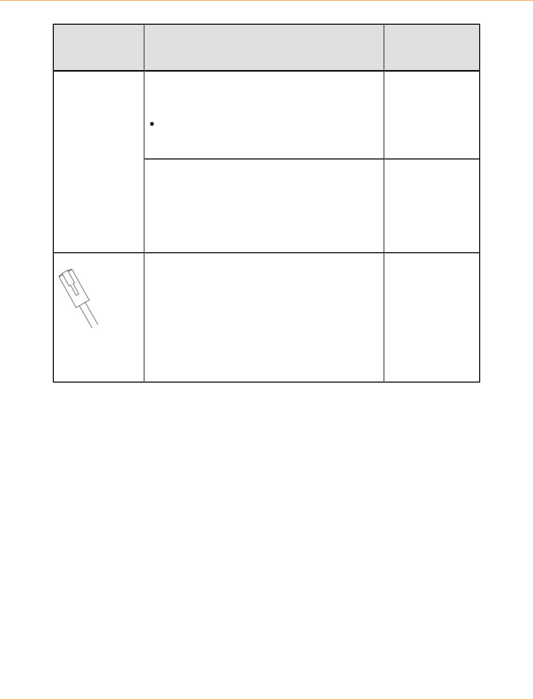
SANtricity_10.77 February 2011
LSI Corporation
- 510 -
Item Included with the
Controller-Drive
Tray
Fibre Channel, 10-Gb/s iSCSI, or 1-Gb/s iSCSI.
These SFP transceivers are not generally
interchangeable.
You must purchase only Restriction of
Hazardous Substances (RoHS)-compliant SFP
transceivers.
Copper Fibre Channel cables (optional)
Use these cables for connections within the storage
array.
For the differences between the fiber-optic cables
and the copper Fibre Channel cables, see Things
to Know – SFP Transceivers, Fiber-Optic Cables,
Copper Cables, and SAS Cables.
Ethernet cable
This cable is used for out-of-band storage array
management and for 1-Gb/s iSCSI connections.
For information about out-of-band storage array
management, see the "Step 1 – Deciding on the
Management Method" topic from Storage Array
Installation and Initial Configuration for SANtricity
ES Storage Manager Version 10.75, in either the
online documentation or from the SANtricity ES
Storage Manager Installation DVD.

SANtricity_10.77 February 2011
LSI Corporation
- 511 -
Product DVDs
Product DVDs
Item Included
with the
Controller-
Drive Tray
Firmware DVD
Firmware is already installed on the
controllers.
The files on the DVD are backup copies.
SANtricity ES Storage Manager Installation DVD
SANtricity ES Storage Manager software and
documentation.
To access product documentation,
use the documentation map file,
doc_launcher.html, which is located in
the docs directory.
Tools and Other Items
Tools and Other Items
Item Included
with the Tray
Labels
Help you to identify cable connections and lets
you more easily trace cables from one tray to
another
A cart
Holds the tray and components
A mechanical lift (optional)
A Phillips screwdriver
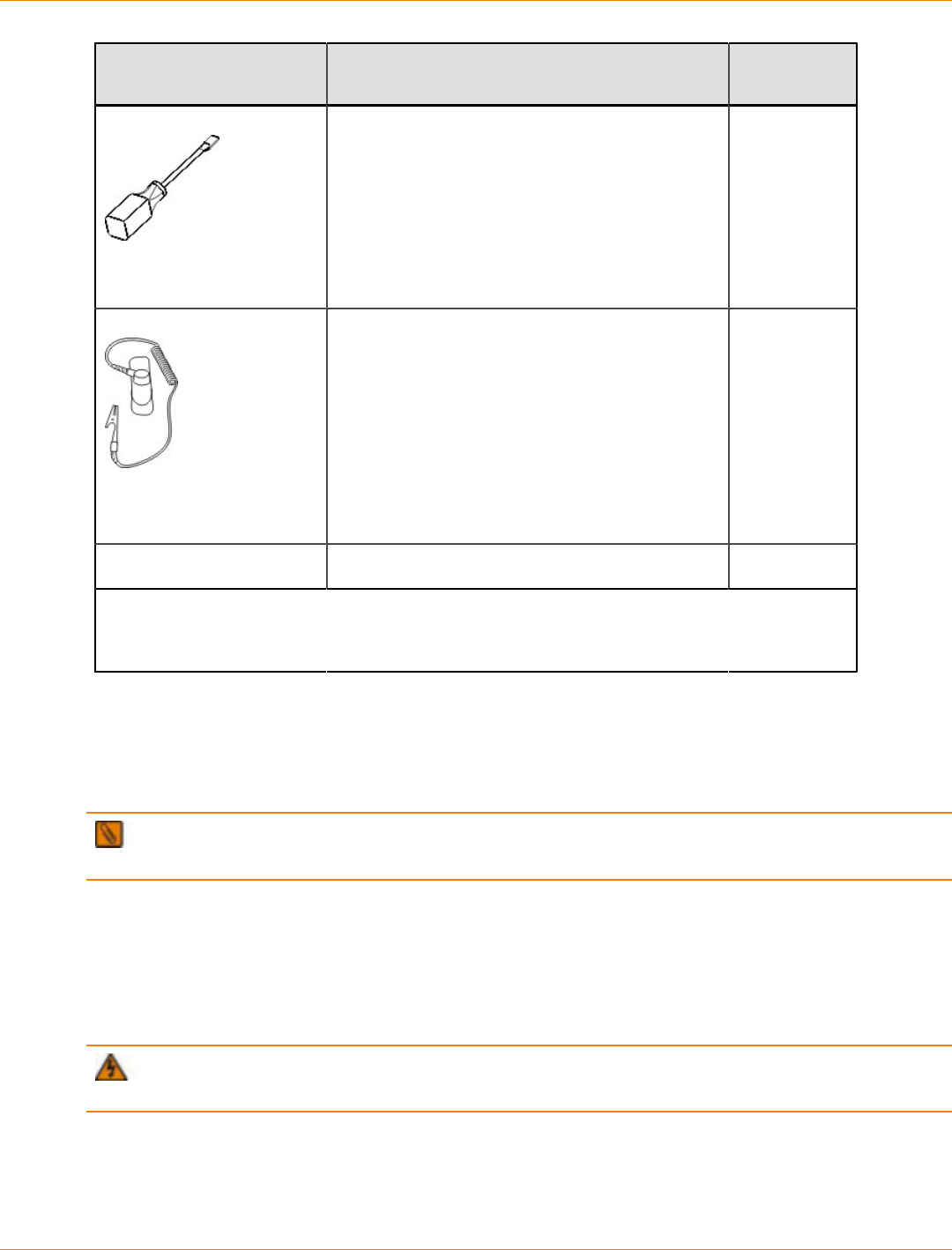
SANtricity_10.77 February 2011
LSI Corporation
- 512 -
Item Included
with the Tray
A flat-blade screwdriver
Anti-static protection
A flashlight
Use the Compatibility Matrix, at the following website, to obtain the latest hardware
compatibility information.
http://www.lsi.com/compatibilitymatrix/
Things to Know – SFP Transceivers, Fiber-Optic Cables, Copper Cables, and
SAS Cables
The figures in this topic display the fiber-optic, copper cables, and SFP transceivers.
NOTE Your SFP transceivers and cables might look slightly different from the ones shown. The
differences do not affect the performance of the SFP transceivers.
The controller-drive tray supports SAS, Fibre Channel (FC), and iSCSI host connections and SAS drive
connections. FC host connections might operate at 8 Gb/s or at a lower data rate. Ports for 8-Gb/s Fibre
Channel host connections require SFP transceivers designed for this data rate. These SFP transceivers look
similar to other SFP transceivers but are not compatible with other types of connections. SFP transceivers for
1-Gb/s iSCSI connections and 10-Gb/s iSCSI connections have a different physical interface for the cable and
are not compatible with other types of connections.
WARNING (W03) Risk of exposure to laser radiation – Do not disassemble or remove any part of a
Small Form-factor Pluggable (SFP) transceiver because you might be exposed to laser radiation.
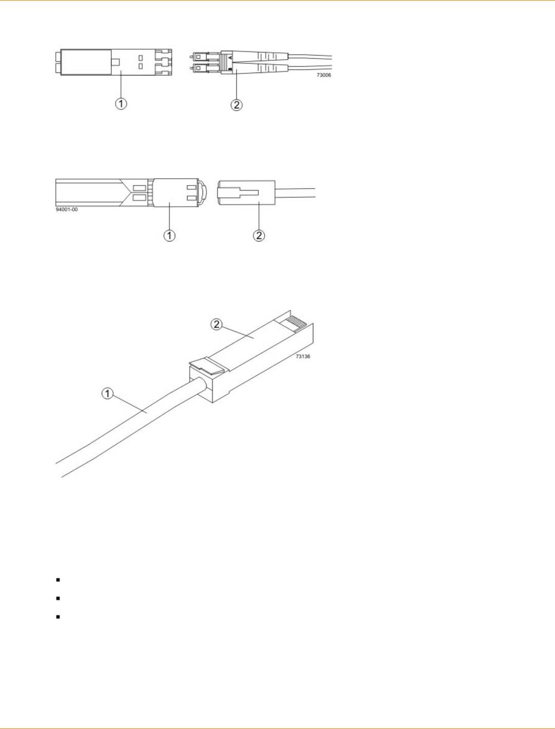
SANtricity_10.77 February 2011
LSI Corporation
- 513 -
Fiber-Optic Cable Connection
1. Active SFP Transceiver
2. Fiber-Optic Cable
1-Gb/s iSCSI Cable Connection
1. Active SFP Transceiver
2. Copper Cable with RJ-45 Connector
Copper Fibre Channel Cable Connection
1. Copper Fibre Channel Cable
2. Passive SFP Transceiver
Things to Know – Taking a Quick Glance at the Hardware
For the CDE4900 controller-drive tray:
The top controller, controller A, is inverted from the bottom controller, controller B.
The top of the controller-drive tray is the side with labels.
The configuration of the host ports might appear different on your system depending on which host
interface card configuration is installed.
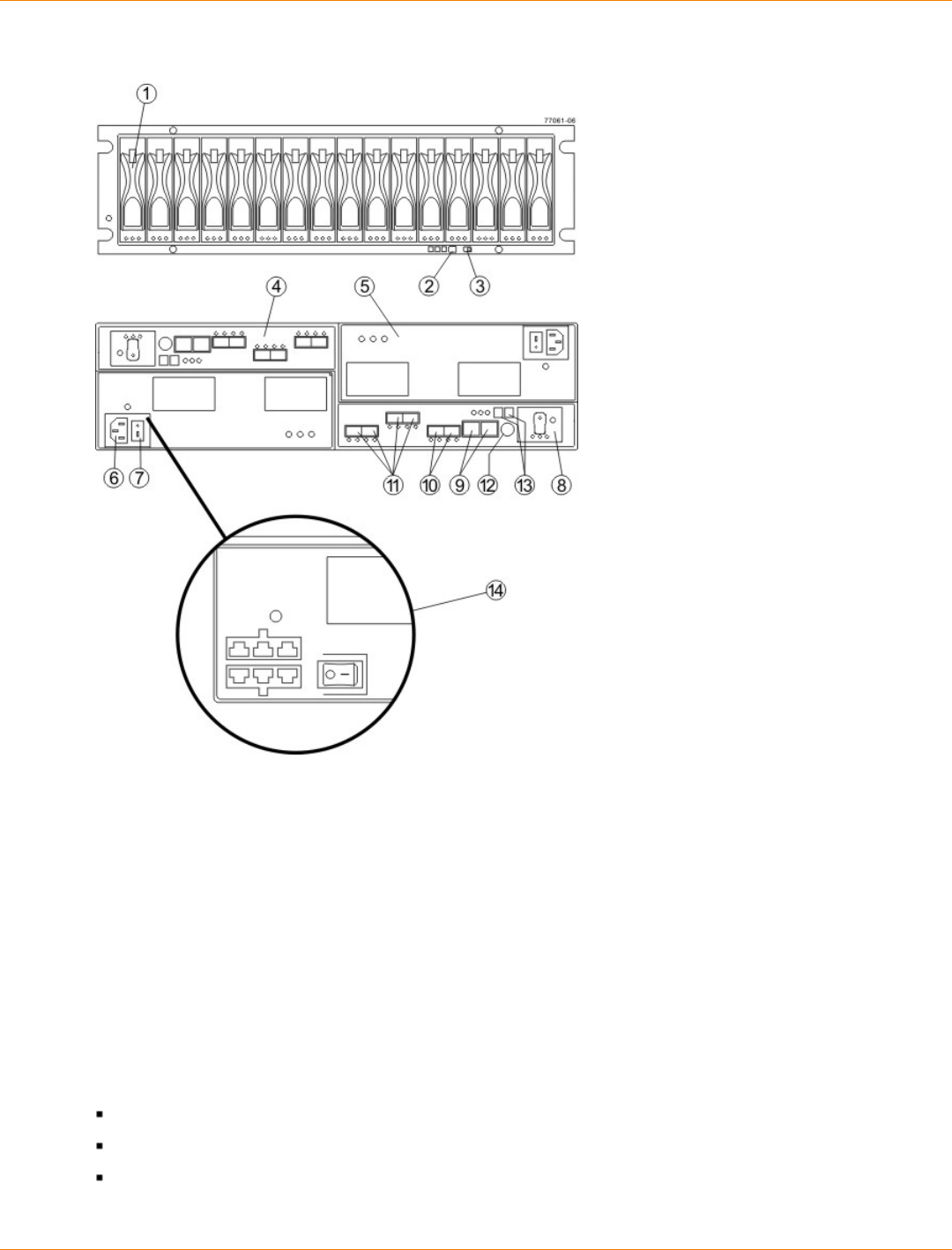
SANtricity_10.77 February 2011
LSI Corporation
- 514 -
CDE4900 Controller-Drive Tray – Front View and Rear View
1. (Front View) Drive Canister
2. Alarm Mute Switch
3. Link Rate Switch
4. Controller A (Inverted)
5. Power-Fan Canister
6. AC Power Connector
7. AC Power Switch
8. Battery Canister
9. Ethernet Ports
10. Drive Channels
11. Host Channels
12. Serial Port
13. Seven-Segment Display
14. Optional DC Power Connector and DC Power Switch
For the FC4600 drive tray:
The top-left ESM is inverted from the bottom-right ESM.
The top-right power-fan canister is inverted from the bottom-left power-fan canister.
The drive tray is in the correct (top) orientation when the lights of the drives are at the bottom (Figure
SANtricity_10.77 February 2011
LSI Corporation
- 515 -
NOTE The drive tray is available in rackmount models and deskside models. The components for the
deskside model are identical to the components of the rackmount model. The deskside model is situated as if
the rackmount model is sitting on its left side.
NOTE You must use the current drive canisters in the drive tray to ensure proper performance. Using
older or “legacy” drives might damage the connectors. Additionally, the latch might not hold the drive in place,
which causes the drive to be disconnected and taken offline. For more information on supported drives,
contact a Customer and Technical Support representative.
WARNING (W14) Risk of bodily injury – A qualified service person is required to make the DC
power connection according to NEC and CEC guidelines.
CAUTION (C05) Electrical grounding hazard – This equipment is designed to permit the connection
of the DC supply circuit to the earthing conductor at the equipment.
ATTENTION Risk of equipment malfunction – To avoid exceeding the functional and environmental
limits, install only drives that have been provided or approved by the original manufacturer. Drives might be
shipped but not installed. System integrators, resellers, system administrators, or users can install the drives.
IMPORTANT Each tray in the storage array must have a minimum of two drives for proper operation. If
the tray has fewer than two drives, a power supply error is reported.
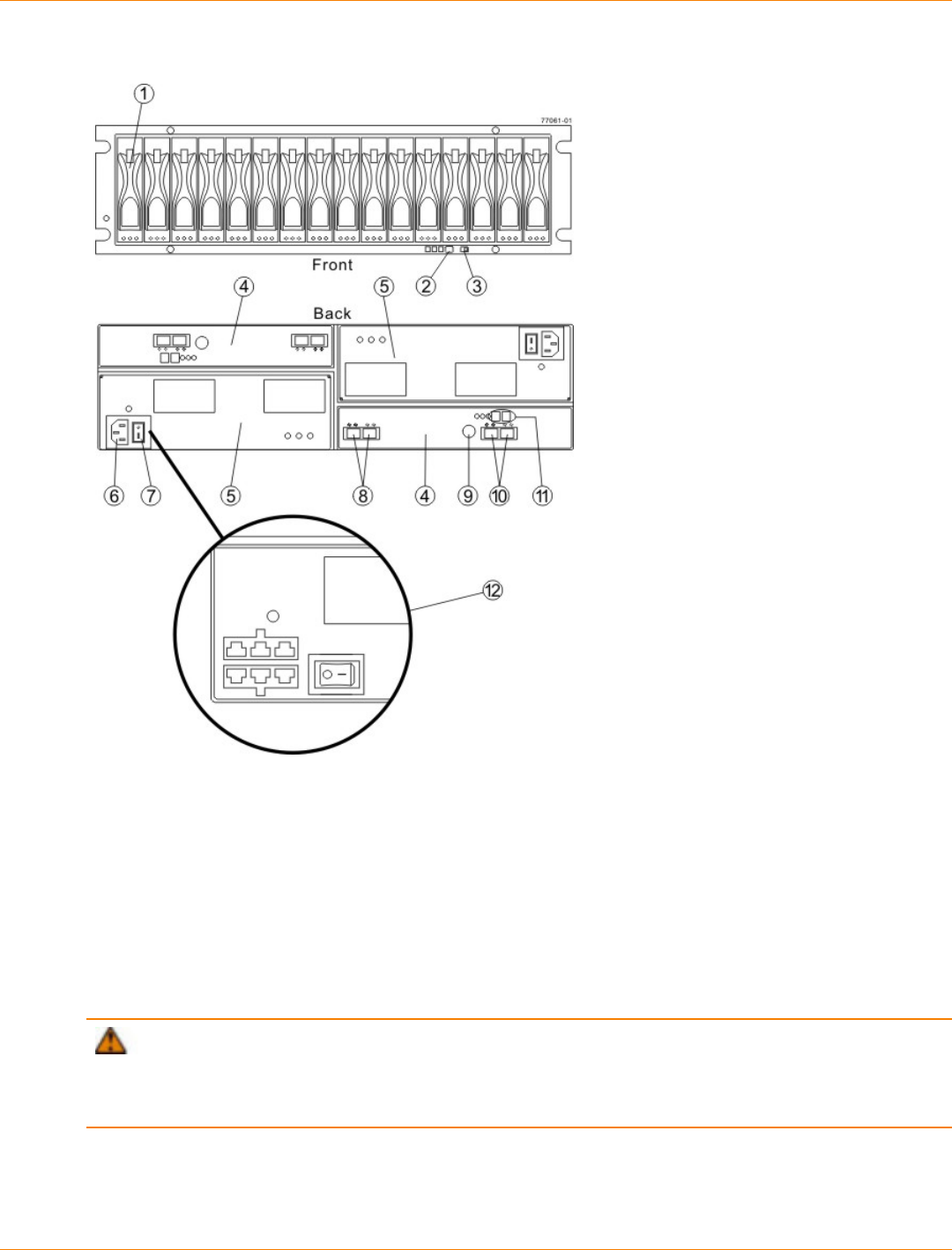
SANtricity_10.77 February 2011
LSI Corporation
- 516 -
FC4600 Drive Tray – Front View and Rear View
1. Drive Canister
2. Alarm Mute Button
3. Link (Data) Rate Switch (4 Gb/s or 2 Gb/s)
4. ESM Canister
5. Power-Fan Canister
6. AC Power Connector
7. AC Power Switch
8. In/Out Ports
9. Serial Port
10. In/Out Ports (Reserved for future use)
11. Tray ID / Seven-Segment Diagnostic Display
12. (Optional) DC Power Connectiors and DC Power Switch
ATTENTION Possible equipment damage – You must use the drives in the drive tray to ensure
proper performance. Using older or “legacy” drives might damage the connectors. Additionally, the latch might
not hold the drive in place, which causes the drive to be disconnected and taken offline. For information on
supported drives, contact a Customer and Technical Support representative.
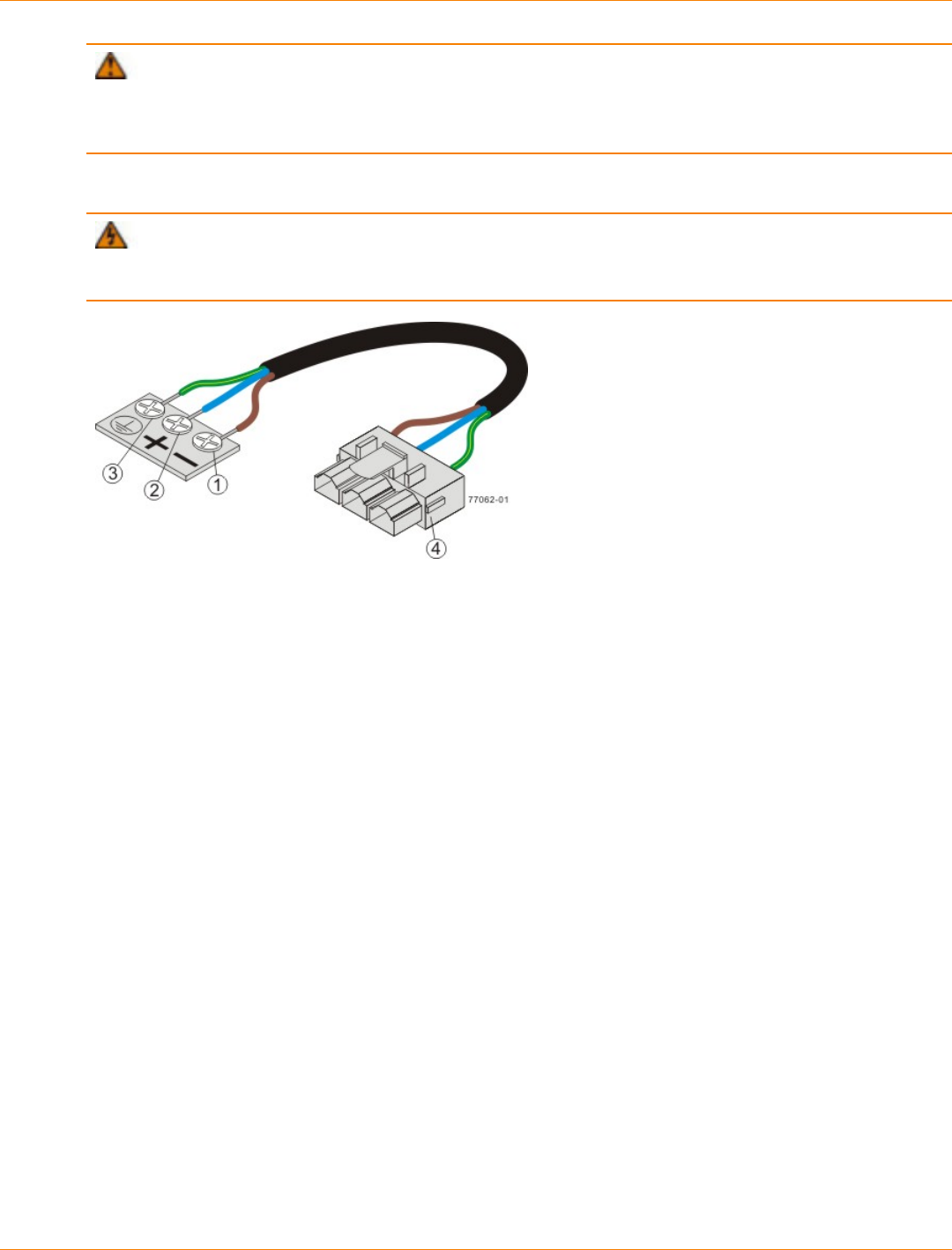
SANtricity_10.77 February 2011
LSI Corporation
- 517 -
ATTENTION Risk of equipment malfunction – To avoid exceeding the functional and environmental
limits, install only drives that have been provided or approved by the original manufacturer. Not all controller-
drive trays are shipped with pre-populated drives. System integrators, resellers, system administrators, or
users of the controller-drive tray can install the drives.
The following warning applies if you have the DC power option for the controller-drive tray.
WARNING (W12) Risk of electrical shock – This unit has more than one power source. To remove
all power from the unit, all DC MAINS must be disconnected by removing all power connectors (item 4 below)
from the power supplies.
1. Supply (Negative), Brown Wire, -48 VDC
2. Return (Positive), Blue Wire
3. Ground, Green/Yellow Wire
4. DC Power Connector
For Additional Information
Refer to the Storage System Site Preparation Guide on the SANtricity ES Storage Manager Installation DVD
for information about the installation requirements of the various CDE4900 storage array components.

SANtricity_10.77 February 2011
LSI Corporation
- 518 -
Step 2 – Installing and Configuring the Switches
Things to Know – Switches
IMPORTANT Most of the switches, as shipped from the vendor, require an update to their firmware to
work correctly with the storage array.
Depending on the configuration of your storage array, you might use Fibre Channel switches and iSCSI
switches.
The switches in the following table are certified for use with a CDE2600 storage array, a CDE2600-60 storage
array, a CDE4900 storage array, and a CE7900 storage array, which all use SANtricity ES Storage Manager
Version 10.77.
Supported Switches
Vendor Model Fibre
Channel iSCSI SAS
200E Yes No No
3200 Yes No No
3800 Yes No No
3900 Yes No No
3950 Yes No No
12000 Yes No No
3850 Yes No No
3250 Yes No No
24000 Yes No No
4100 Yes No No
48000 Yes No No
5000 Yes No No
300 Yes No No
5100 Yes No No
5300 Yes No No
7500 Yes No No
7800 Yes No No
Brocade
DCX Yes No No

SANtricity_10.77 February 2011
LSI Corporation
- 519 -
Vendor Model Fibre
Channel iSCSI SAS
FCOE No Yes No
9506 Yes No No
9509 Yes No No
9216 Yes No No
9216i Yes No No
9120 Yes No No
914x Yes No No
9513 Yes No No
9020 Yes No No
MDS9000 Yes No No
9222i Yes No No
9134 Yes No No
Catalyst 2960 No Yes No
Catalyst 3560 No Yes No
Cisco
Catalyst 3750G-24TS No Yes No
LSI 6160 No No Yes
3232 Yes No No
3216 Yes No No
4300 Yes No No
4500 Yes No No
6064 Yes No No
6140 Yes No No
4400 Yes No No
McData
4700 Yes No No
6140 No Yes No
6142 No Yes No
QLogic
SANbox2-8 Yes No No
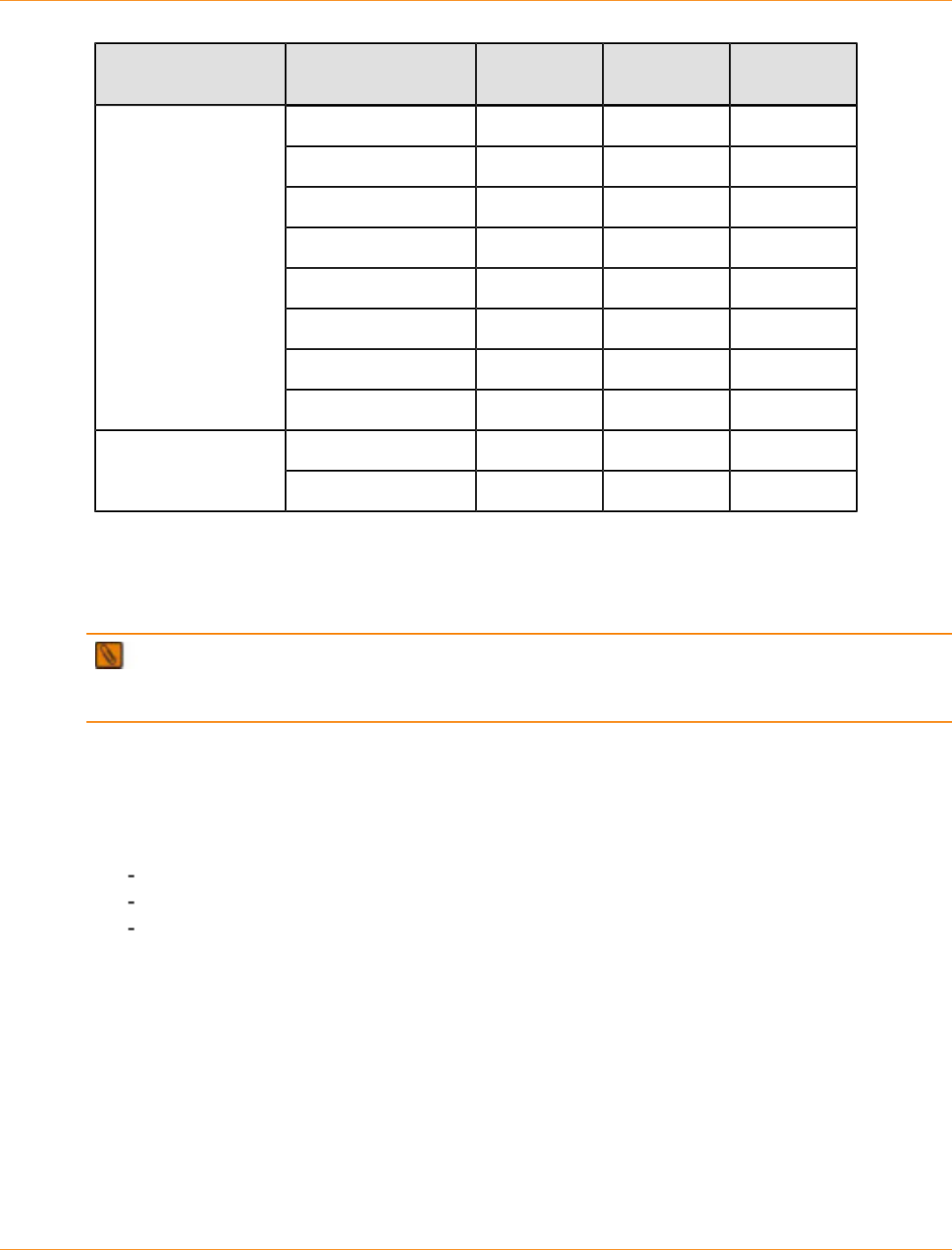
SANtricity_10.77 February 2011
LSI Corporation
- 520 -
Vendor Model Fibre
Channel iSCSI SAS
SANbox2-16 Yes No No
SANbox5200 Yes No No
SANbox3600 Yes No No
SANbox3800 Yes No No
SANbox5208 Yes No No
SANbox5600 Yes No No
SANbox5800 Yes No No
SANbox9000 Yes No No
5324 No Yes NoPowerConnect
6024 No Yes No
If required, make the appropriate configuration changes for each switch that is connected to the storage array.
Refer to the switch’s documentation for information about how to install the switch and how to use the
configuration utilities that are supplied with the switch.
NOTE Refer to the Compatibility Matrix (http://www.lsi.com/CompatibilityMatrix/) for the latest
information. As new switches are tested and certified to work with various hardware and software
combinations, they are added to the Compatibility Matrix.
Procedure – Installing and Configuring Switches
1. Install your switch according to the vendor’s documentation.
2. Use the Compatibility Matrix at the website http://www.lsi.com/compatibilitymatrix/ to obtain this
information:
The latest hardware compatibility information
The models of the switches that are supported
The firmware requirements and the software requirements for the switches
3. Update the switch’s firmware by accessing it from the applicable switch vendor’s website.
This update might require that you cycle power to the switch.
4. Find your switch in the following table to see whether you need to make further configuration changes.
Use your switch’s configuration utility to make the changes.

SANtricity_10.77 February 2011
LSI Corporation
- 521 -
Supported Switch Vendors and Required Configuration Changes
Switch
Vendor Configuration Changes
Required? Next Step
Brocade Yes
Change the In-Order Delivery
(IOD) option to ON.
Make the change, and go
to “Step 3 – Installing the
Host Bus Adapters for the
CDE4900 Controller-Drive Tray
Configuration.”
Cisco Yes
Change the In-Order Delivery
(IOD) option to ON.
Make the change, and go
to “Step 3 – Installing the
Host Bus Adapters for the
CDE4900 Controller-Drive Tray
Configuration.”
McData No “Step 3 – Installing the
Host Bus Adapters for the
CDE4900 Controller-Drive Tray
Configuration.”
QLogic No “Step 3 – Installing the
Host Bus Adapters for the
CDE4900 Controller-Drive Tray
Configuration.”
PowerConnect No “Step 3 – Installing the
Host Bus Adapters for the
CDE4900 Controller-Drive Tray
Configuration.”
SANtricity_10.77 February 2011
LSI Corporation
- 522 -
Step 3 – Installing the Host Bus Adapters for the CDE4900
Controller-Drive Tray Configuration
Key Terms
HBA host port
The physical and electrical interface on the host bus adapter (HBA) that provides for the connection between
the host and the controller. Most HBAs will have either one or two host ports. The HBA has a unique World
Wide Identifier (WWID) and each HBA host port has a unique WWID.
HBA host port world wide name
A 16-character unique name that is provided for each port on the host bus adapter (HBA).
host bus adapter (HBA)
A physical board that resides in the host. The HBA provides for data transfer between the host and the
controllers in the storage array over the I/O host interface. Each HBA contains one or more physical ports.
Things to Know – Host Bus Adapters and Ethernet Network Interface Cards
The CDE2600 controller-drive tray supports dual 6-Gb/s SAS host connections and optional host interface
cards (HICs) for dual 6-Gb/s SAS, four 1-Gb/s iSCSI, two 10-Gb iSCSI, and four 8-Gb/s FC connections.
The connections on a host must match the type (SAS HBAs for SAS, FC HBAs for FC, or iSCSI HBAs or
Ethernet network interface cards [NICs] for iSCSI) of the HICs to which you connect them. For the best
performance, HBAs for SAS and FC connections should support the highest data rate supported by the
HICs to which they connect.
For maximum hardware redundancy, you must install a minimum of two HBAs (for either SAS or FC host
connections) or two NICs or iSCSI HBAs (for iSCSI host connections) in each host. Using both ports of a
dual-port HBA or a dual-port NIC provides two paths to the storage array but does not ensure redundancy
if an HBA or a NIC fails.
NOTE You can use the Compatibility Matrix to obtain information about the supported models of the
HBAs and their requirements. Go to http://www.lsi.com/compatibilitymatrix/, and select the desired Developer
Partner Program link. Check its Compatibility Matrix to make sure you have an acceptable configuration.
Most of the HBAs, as shipped from the vendor, require updated firmware and software drivers to work
correctly with the storage array. For information about the updates, refer to the website of the HBA
vendor.
Procedure – Installing Host Bus Adapters
1. Go to http://www.lsi.com/compatibilitymatrix/, and select the desired Developer Partner Program link.
Check its Compatibility Matrix to make sure you have an acceptable configuration.
The Compatibility Matrix provides this information:
The latest hardware compatibility information
The models of the HBAs that are supported
The firmware requirements and the software requirements for the HBAs
2. Install your HBA according to the vendor documentation.
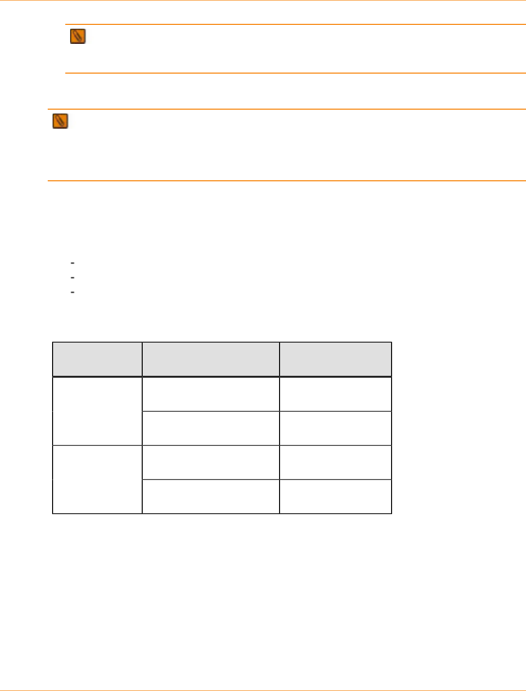
SANtricity_10.77 February 2011
LSI Corporation
- 523 -
NOTE If your operating system is Windows Server 2008 Server Core, you might have additional
installation requirements. Refer to the Microsoft Developers Network (MSDN) for more information about
Windows Server 2008 Server Core. You can access these resources from www.microsoft.com.
3. Install the latest version of the firmware for the HBA. You can find the latest version of the firmware for the
HBA at the HBA vendor website.
IMPORTANT The remaining steps are general steps to obtain the HBA host port World Wide Name
from the HBA BIOS utility. If you have installed the host context agent on all of your hosts, you do not need
to perform these steps. If you are performing these steps, the actual prompts and screens vary depending
on the vendor that provides the HBA. Also, some HBAs have software utilities that you can use to obtain the
world wide name for the port instead of using the BIOS utility.
4. Reboot or start your host.
5. While your host is booting, look for the prompt to access the HBA BIOS utility.
6. Select each HBA to view its HBA host port world wide name.
7. Record the following information for each host and for each HBA connected to the storage array:
The name of each host
The HBAs in each host
The HBA host port world wide name of each port on the HBA
The following table shows examples of the host and HBA information that you must record.
Examples of HBA Host Port World Wide Names
Host Name Associated HBAs HBA Host Port World
Wide Name
Vendor x, Model y (dual port) 37:38:39:30:31:32:33:32
37:38:39:30:31:32:33:33
ICTENGINEERING
Vendor a, Model y (dual port) 42:38:39:30:31:32:33:42
42:38:39:30:31:32:33:44
Vendor a, Model b (single
port) 57:38:39:30:31:32:33:52ICTFINANCE
Vendor x, Model b (single
port) 57:38:39:30:31:32:33:53
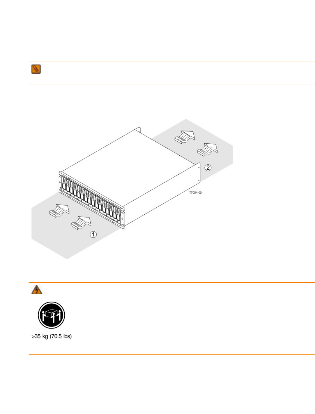
SANtricity_10.77 February 2011
LSI Corporation
- 524 -
Step 4 – Installing the CDE4900 Controller-Drive Tray
Things to Know – General Installation
The power supplies meet standard voltage requirements for both domestic and worldwide operation.
IMPORTANT Make sure that the combined power requirements of your trays do not exceed the power
capacity of your cabinet.
Procedure – Installing the CDE4900 Controller-Drive Tray
Airflow Direction Through and Clearance Requirements for the Controller-Drive Tray
1. 76-cm (30-in.) clearance in front of the cabinet
2. 61-cm (24-in.) clearance behind the cabinet
WARNING (W09) Risk of bodily injury –
Three persons are required to safely lift the component.
1. Make sure that the cabinet is in the final location. Make sure that the cabinet installation site meets the
clearance requirements.
2. Lower the feet on the cabinet, if required, to keep it from moving.
3. Install the mounting rails in the cabinet. For more information, refer to the installation instructions that are
included with your mounting rails.
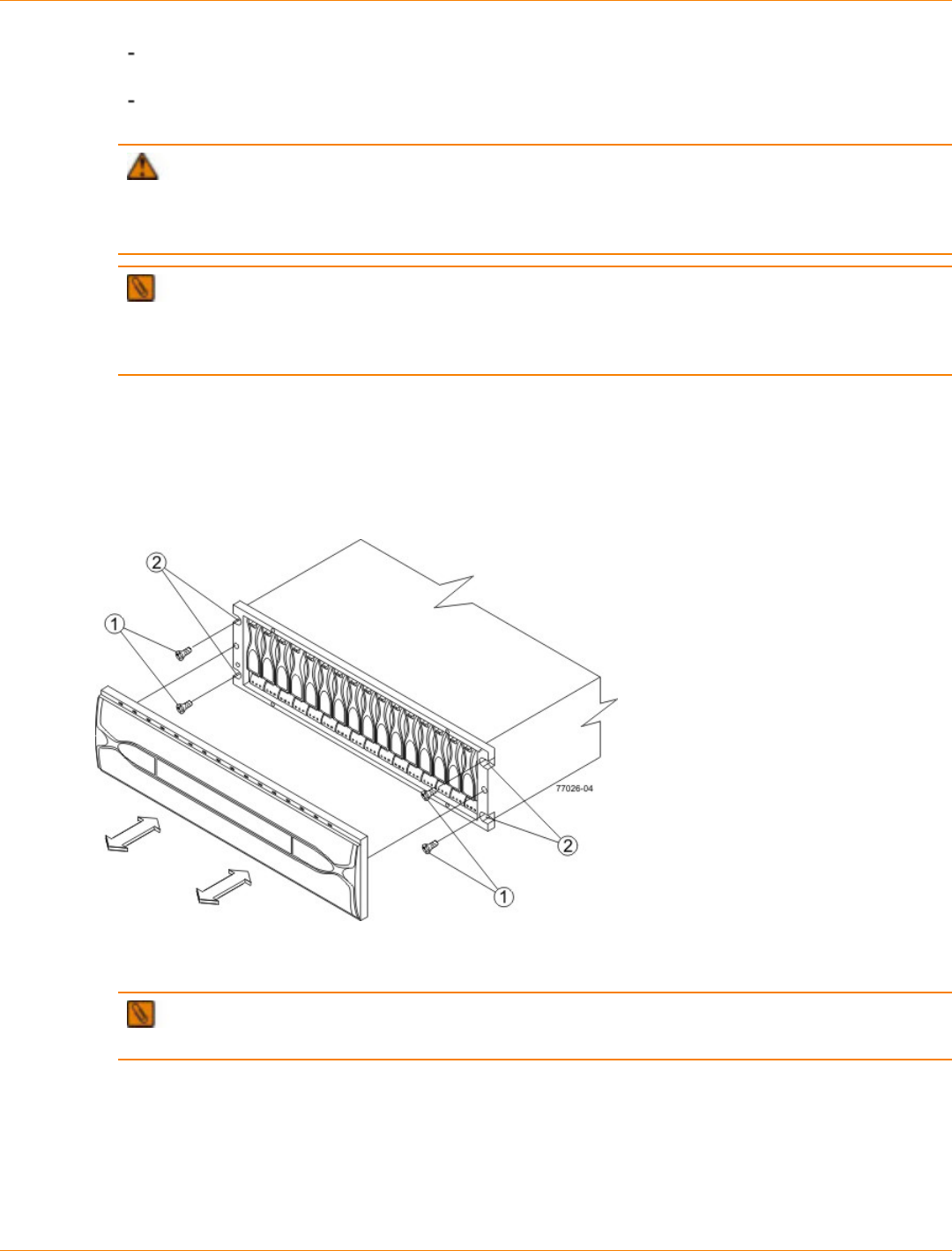
SANtricity_10.77 February 2011
LSI Corporation
- 525 -
If you are installing the mounting rails above an existing tray, position the mounting rails directly
above the tray.
If you are installing the mounting rails below an existing tray, allow 17.8-cm (7.00-in.) clearance below
the existing tray.
ATTENTION Risk of equipment malfunction – To avoid exceeding the functional and
environmental limits, install only drives that have been provided or approved by the original manufacturer.
Not all controller-drive trays are shipped with pre-populated drives. System integrators, resellers, system
administrators, or users of the controller-drive tray can install the drives.
NOTE Make sure that you place the controller-drive tray in the middle portion of the cabinet while
allowing room for drive trays to be placed above and below the controller-drive tray. As you add drive
trays, position them below and above the controller-drive tray, alternating so that the cabinet does not
become top heavy.
4. With the help of two other persons, slide the rear of the controller-drive tray onto the mounting rails.
Make sure that the top mounting holes on the controller-drive tray align with the mounting rail holes of the
cabinet.
The rear of the controller-drive tray slides into the slots on the mounting rails.
Securing the Controller-Drive Tray to the Cabinet
1. Screws
2. Mounting Holes
NOTE The rear of the controller-drive tray contains two controllers. The top of the controller-drive
tray is the side with the labels.
5. Secure screws in the top mounting holes and the bottom mounting holes on each side of the controller-
drive tray.
6. Secure the back or the of the controller-drive tray to the cabinet by using two screws to attach the flanges
on each side at the back of the controller-drive tray to the support rails.
7. Install the bezel on the front of the controller-drive tray.

SANtricity_10.77 February 2011
LSI Corporation
- 527 -
Step 5 – Connecting the CDE4900 Controller-Drive Tray to the
Hosts
Key Terms
direct topology
A topology that does not use a switch.
See also switch topology.
switch topology
A topology that uses a switch.
See also direct topology.
topology
The logical layout of the components of a computer system or network and their interconnections. Topology
deals with questions of what components are directly connected to other components from the standpoint
of being able to communicate. It does not deal with questions of physical location of components or
interconnecting cables. (The Dictionary of Storage Networking Terminology)
Things to Know – Host Channels
ATTENTION Possible hardware damage – To prevent electrostatic discharge damage to the tray,
use proper antistatic protection when you handle tray components.
Each controller has two or four host ports.
Two of the host ports are standard and support 8-Gb/s, 4-Gb/s or 2 Gb/s Fibre Channel (FC) data rates.
The data rate will auto-negotiate to the highest value supported by the host.
Two of the host ports are optional, and, if present, are located on a replaceable host interface card (HIC).
Two different types of HICs are supported. One option has two FC host ports with the same specifications
as the standard host ports. The second option has two iSCSI host ports. The iSCSI host ports can be
used for 10-Gb/s connections or 1-Gb/s connections. The data rate for the iSCSI ports must be set
manually, and each data rate requires a different type of SFP transceiver.
Labeling on the face plate of the HIC identifies the type of connection: FC or iSCSI. If no HIC is installed,
a blank face plate covers the location for the HIC.
Controller A is inverted from controller B, which means that its host channels are upside-down.
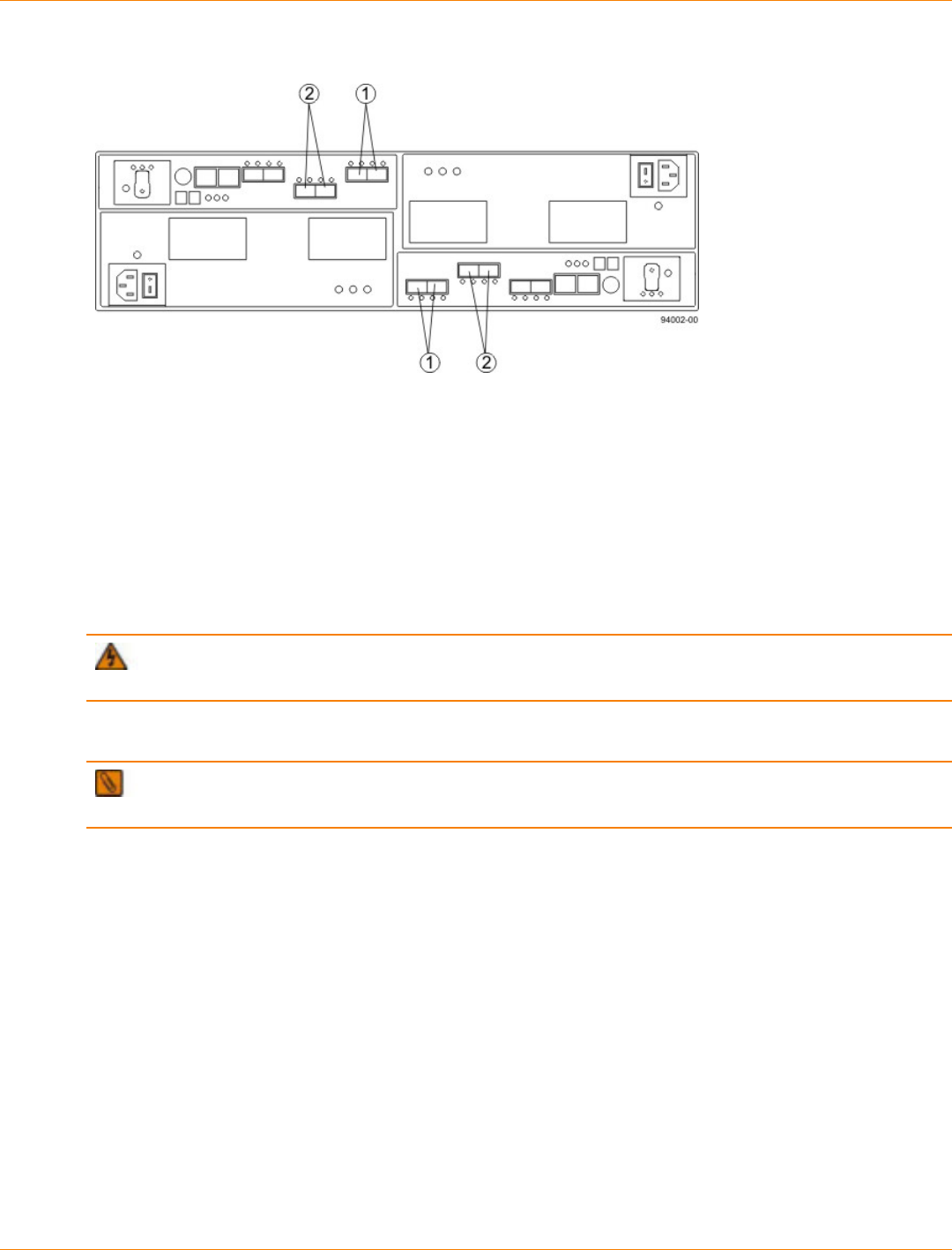
SANtricity_10.77 February 2011
LSI Corporation
- 528 -
Host Channels on the Controllers – Rear View
1. Standard Host Channels
2. Optional Host Channels
WARNING (W03) Risk of exposure to laser radiation – Do not disassemble or remove any part of a
Small Form-factor Pluggable (SFP) transceiver because you might be exposed to laser radiation.
Procedure – Connecting Host Cables
IMPORTANT Make sure that you have installed your HBAs. Refer to the documentation for your HBAs
for information about how to install the HBA and how to use the supplied configuration utilities.
The type of HICs, Fibre Channel (FC) or iSCSI, must match the type of the host bus adapters (HBAs) to
which you connect them. If you are mixing FC host connections and iSCSI host connections, each host
connection of a redundant pair must connect to the same type of host port, one on controller A and one on
controller B.
Fiber-optic connections for 8-Gb/s FC require special SFP transceivers that support the higher data rate.
Similarly, 10-Gb/s fiber-optic iSCSI connections require special SFP transceivers. 10-Gb/s iSCSI connections
require both special SFP transceivers and Ethernet cables. SFP transceivers installed in the controller, the
host, and, optionally, the switch must all support the same data rate to achieve the best performance.
If you are using iSCSI with a fabric topology, the iSCSI connections might require a different type of switch
from the FC connections.
Refer to the figures just below for example cabling patterns.
1. Make sure that the appropriate type of SFP transceiver is inserted into the host channel.
2. If a black, plastic plug is in the SFP transceiver, remove it.
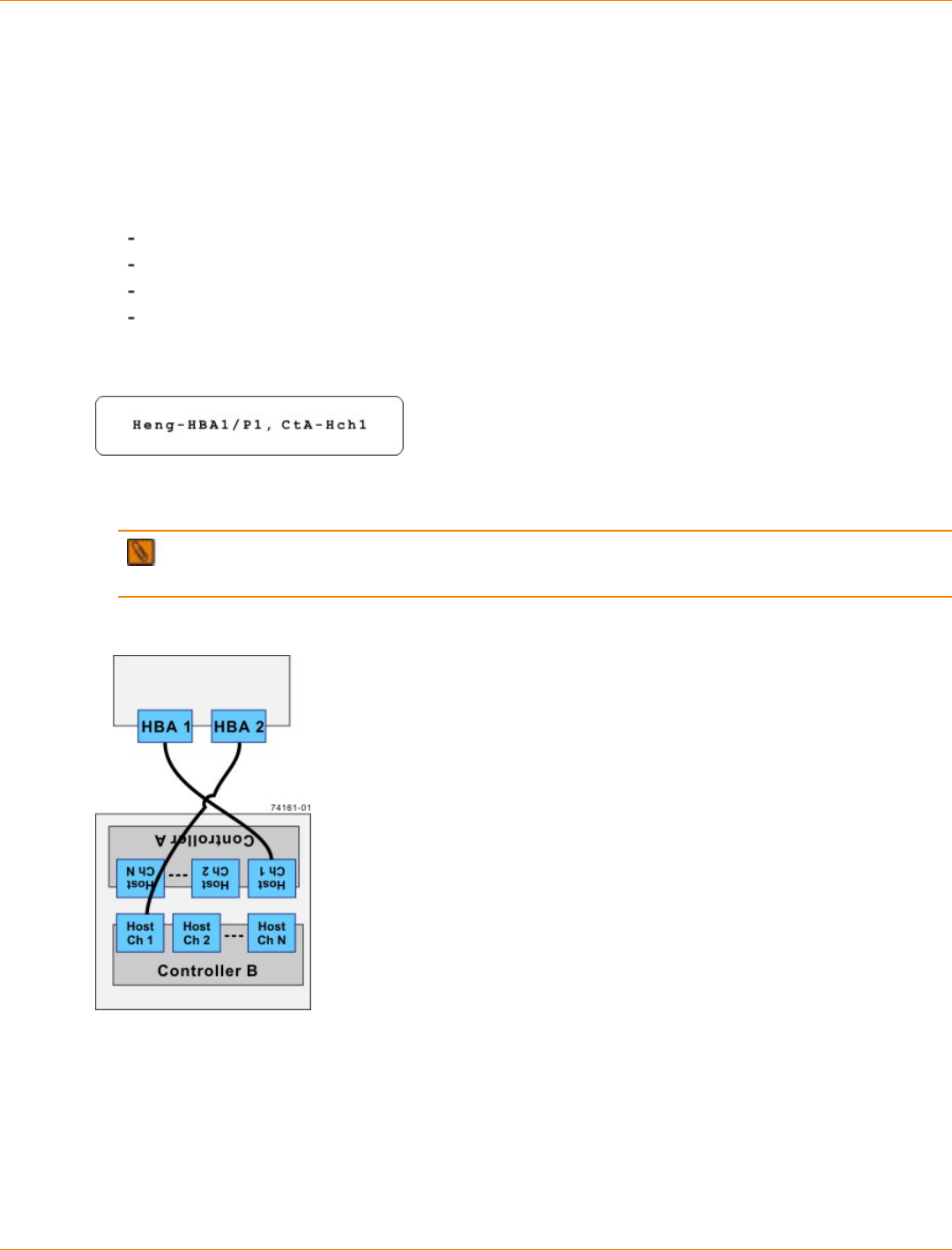
SANtricity_10.77 February 2011
LSI Corporation
- 529 -
3. Starting with the first host channel of each controller, plug one end of the cable into the SFP transceiver in
the host channel.
The cable is an Ethernet cable with RJ-45 connectors for 1-Gb/s iSCSI connections, or a fiber-optic cable
for all other types of connections.
4. Plug the other end of the cable into an HBA in the host (direct topology) or into a switch (fabric topology).
5. Affix a label to each end of the cable with this information. A label is very important if you need to
disconnect cables to service a controller. Include this information on the labels:
The host name and the HBA port (for direct topology)
The switch name and the port (for fabric topology)
The controller ID (for example, controller A)
The host channel ID (for example, host channel 1)
Example label abbreviation – Assume that a cable is connected between port 1 in HBA 1 of a host
named Engineering and host channel 1 of controller A. A label abbreviation could be as follows.
6. Repeat step 1 through step 5 for each controller and host channel that you intend to use.
NOTE If you do not use a Fibre Channel host port, remove the SFP transceiver. You might be able
to use this SFP transceiver in a drive channel port or in an ESM on a drive tray.
Direct Topology – One Host and a Dual-Controller Controller-Drive Tray
The box on the top in is the host, and the box on the bottom is the controller-drive tray.
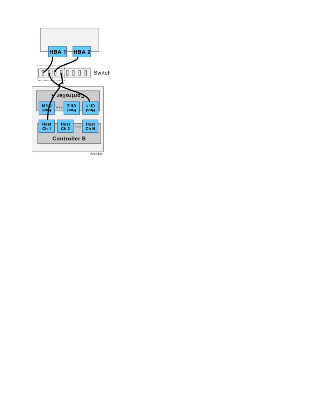
SANtricity_10.77 February 2011
LSI Corporation
- 530 -
Fabric Topology – One Host and a Dual-Controller Controller-Drive Tray with a Switch
The box on the top of the switch is the host, and the box on the bottom is the controller-drive tray.
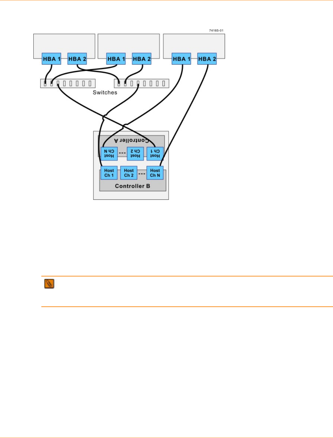
SANtricity_10.77 February 2011
LSI Corporation
- 531 -
Mixed Topology – Three Hosts and a Dual-Controller Controller-Drive Tray
The boxes on the top of the switch are the hosts, and the box on the bottom is the controller-drive tray.
IMPORTANT The highest numbered host channel is generally used for Remote Volume Mirroring
connections. If Remote Volume Mirroring connections are required, do not connect a host to the highest
numbered host channel.
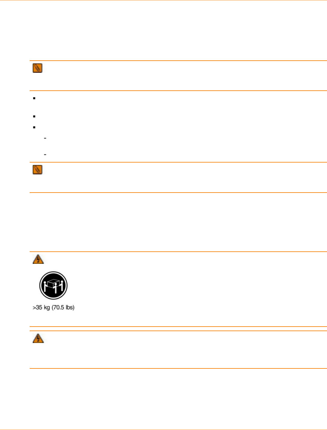
SANtricity_10.77 February 2011
LSI Corporation
- 532 -
Step 6 – Installing the Drive Trays for the CDE4900 Controller-
Drive Tray Configurations
Things to Know – General Installation
IMPORTANT If you are installing the drive tray in a cabinet with other trays, make sure that the
combined power requirements of the drive tray and the other trays do not exceed the power capacity of your
cabinet.
Special site preparation is not required for this drive tray beyond what is normally found in a computer lab
environment.
The power supplies meet standard voltage requirements for both domestic and worldwide operation.
If you are installing drive trays and the controller-drive tray at the same time, take these precautions:
Install the controller-drive tray in a location within the cabinet that lets you evenly distribute the drive
trays around the controller-drive tray.
Keep as much weight as possible in the bottom half of the cabinet.
IMPORTANT After you install the drive tray, you might replace drives or install additional drives. If you
replace or add more than one drive without powering down the drive tray, install the drives one at a time. Wait
10 seconds after you insert each drive before inserting the next one.
For Additional Information on Drive Tray Installation
Refer to the Storage System Site Preparation Guide on the SANtricity ES Storage Manager Installation DVD
for important considerations about cabinet installation.
Procedure – Installing the FC4600 Drive Tray
WARNING (W09) Risk of bodily injury –
Three persons are required to safely lift the component.
WARNING (W05) Risk of bodily injury – If the bottom half of the cabinet is empty, do not install
components in the top half of the cabinet. If the top half of the cabinet is too heavy for the bottom half, the
cabinet might fall and cause bodily injury. Always install a component in the lowest available position in the
cabinet.
Install the FC4600 drive tray into an industry standard cabinet.
This procedure describes how to install the mounting rails into an industry standard cabinet.
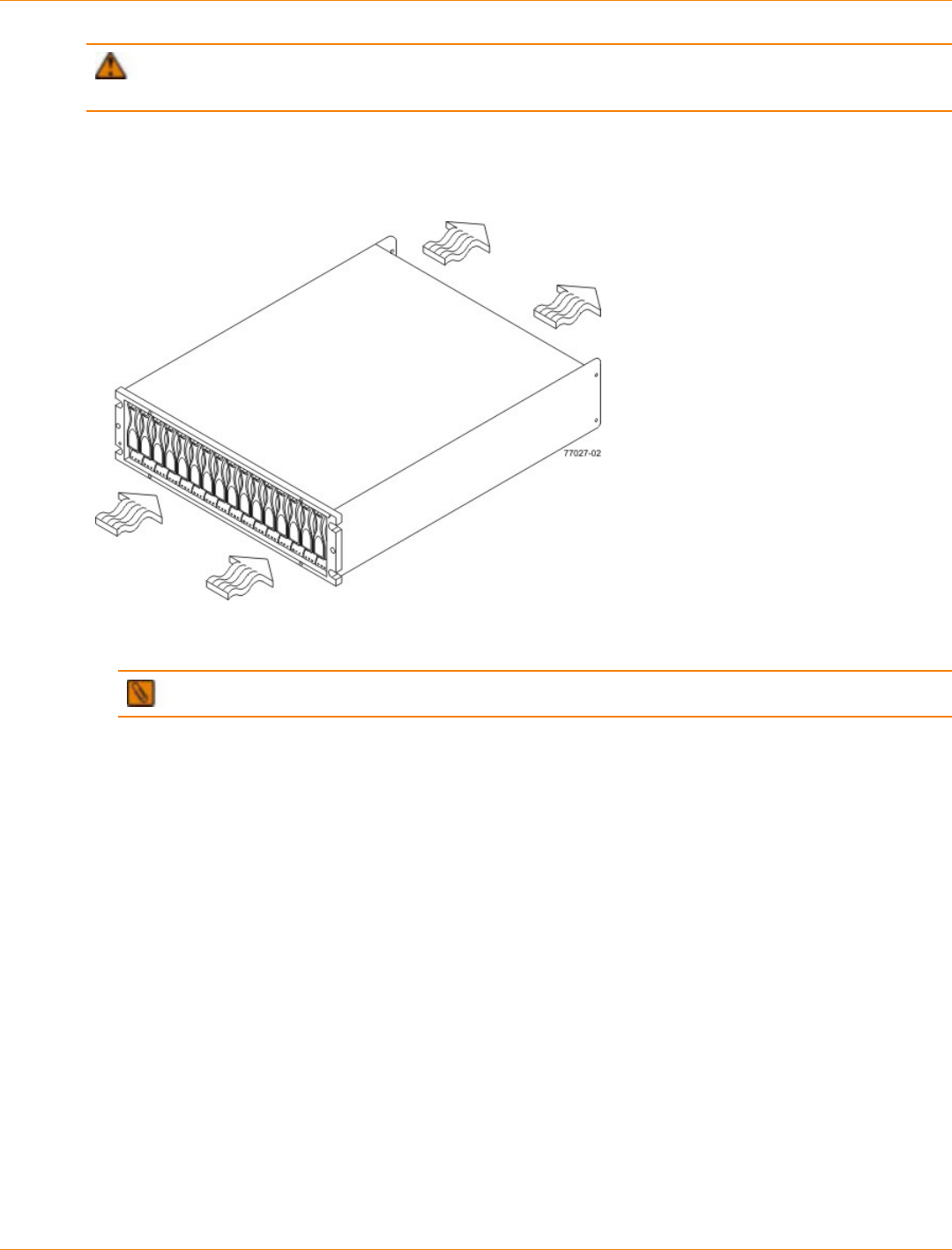
SANtricity_10.77 February 2011
LSI Corporation
- 533 -
ATTENTION Possible hardware damage – To prevent electrostatic discharge damage to the tray,
use proper antistatic protection when handling tray components.
1. Make sure that the cabinet is in the final location. Make sure that you meet the clearance requirements
shown below.
Drive Tray Airflow and Clearance Requirements
1. 76 cm (30 in.) clearance in front of the cabinet
2. 61 cm (24 in.) clearance behind the cabinet
NOTE Fans pull air through the tray from front to rear across the drives.
2. Lower the feet on the cabinet to keep the cabinet from moving.
3. Remove the drive tray and all contents from the shipping carton.
4. Position the mounting rails in the cabinet.

SANtricity_10.77 February 2011
LSI Corporation
- 534 -
Positioning the Mounting Rails in the Cabinet
1. Mounting Rail
2. Existing Tray
3. Clearance Above and Below the Existing Tray
4. Screws for Securing the Mounting Rail to the Cabinet (Front and Rear)
5. Industry Standard Cabinet
If you are installing the mounting rails above an existing tray, position the mounting rails directly
above the tray.
If you are installing the mounting rails below an existing tray, allow 8.8-cm (3.5-in.) vertical clearance
for the drive tray.
5. Attach the mounting rails to the cabinet by performing these substeps:
a. Make sure that the adjustment screws on the mounting rail are loose so that the mounting rail can
extend or contract as needed.

SANtricity_10.77 February 2011
LSI Corporation
- 535 -
Attaching the Mounting Rails to the Cabinet
1. Cabinet Mounting Holes
2. Adjustment Screws for Locking the Mounting Rail Length
3. Mounting Rails
4. Clip for Securing the Rear of the Drive Tray
b. Place the mounting rail inside the cabinet, and extend the mounting rail until the flanges on the
mounting rail touch the inside of the cabinet.
c. Make sure that the alignment spacers on the front flange of the mounting rail fit into the mounting
holes in the cabinet.
The front flange of each mounting rail has two alignment spacers. The alignment spacers are
designed to fit into the mounting holes in the cabinet. The alignment spacers help position and hold
the mounting rail.

SANtricity_10.77 February 2011
LSI Corporation
- 536 -
Alignment Spacers on the Mounting Rail
1. Alignment Spacers
d. Insert one M5 screw through the front of the cabinet and into the top captured nut in the mounting rail.
Tighten the screw.
e. Insert two M5 screws through the rear of the cabinet and into the captured nuts in the rear flange in
the mounting rail. Tighten the screws.
f. Tighten the adjustment screws on the mounting rail.
g. Repeat substep a through substep f to install the second mounting rail.
6. With the help of two other persons, slide the rear of the drive tray onto the mounting rails.
The mounting holes on the front flanges of the drive tray align with the mounting holes on the front of the
mounting rails.
7. Secure the front of the drive tray to the cabinet by using four screws.
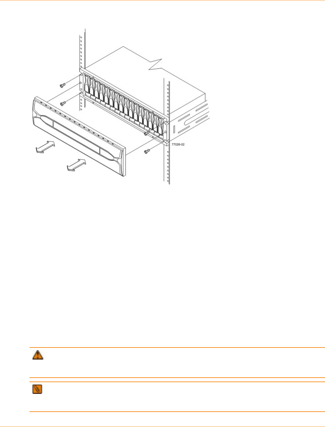
SANtricity_10.77 February 2011
LSI Corporation
- 537 -
Attaching the Front of the Drive Tray
1. Screws for Securing the Front of the Drive Tray
8. Using two screws, attach the flange on each side of the rear of the drive tray to the mounting rails.
Things to Know – Adding Drive Trays to an Existing Storage Array
If you plan to add a new drive tray to an existing storage array, select one of the following procedures.
ATTENTION Potential loss of data access – If you plan to add a drive tray to an existing storage
array while the storage array is powered on and receiving data I/O (method 3 below), you must contact a
Customer and Technical Support representative to assist you in adding the drive tray.
IMPORTANT Drive trays can be powered by either the standard AC power supply or the optional
DC power supply (–48 VDC). Before turning off any power switches on a DC-powered drive tray, you must
disconnect the two-pole 20-amp circuit breaker.
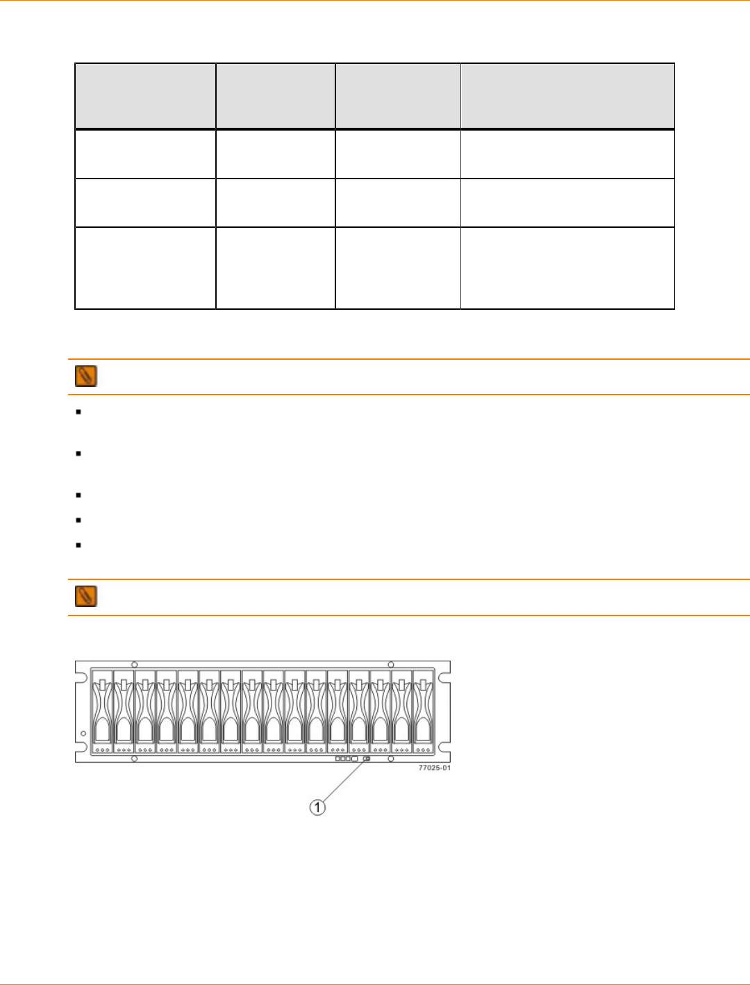
SANtricity_10.77 February 2011
LSI Corporation
- 538 -
Procedures for Adding a Drive Tray to an Existing Storage Array
Addition Methods Storage Array
Receiving
Power?
Storage Array
Receiving Data? Procedure
1 – Power but no I/
O activity Yes No
2 – No power and
no I/O activity No No
3 – Power and I/O
activity Yes Yes Contact a Customer
and Technical Support
representative before beginning
this procedure.
Things to Know – Link Rate Switch on the FC4600 Drive Tray
IMPORTANT Change the Link Rate switch only when the power is not turned on to the drive tray.
Use the Link Rate switch to select the data transfer rate between the ESMs, the drives, and the
controllers. The Link Rate switch is located on the rear of the drive tray on the ESMs.
All drive trays that are connected to the same drive channel must be set to operate at the same data
transfer rate (speed).
The drives in the drive tray must support the selected link rate speed.
The setting of the Link Rate switch determines the speed of the drives.
If a drive in the drive tray does not support the link rate speed, the drive will show up as a bypassed drive
in the storage management software.
IMPORTANT Change the Link Rate switch only when no power is applied to the drive tray.
Setting the Link Rate Switch on the FC4600 Drive Tray – Front View
1. Link Rate Switch (4 Gb/s or 2 Gb/s)
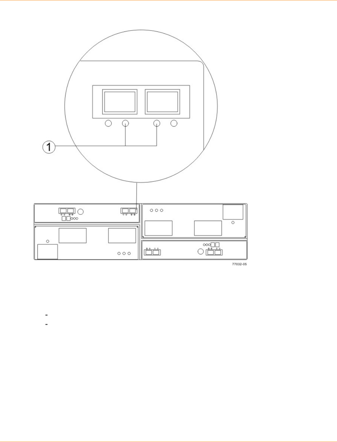
SANtricity_10.77 February 2011
LSI Corporation
- 539 -
Link Rate LEDs on the FC4600 Drive Tray – Rear View
1. Link Rate LEDs Right On = 2 Gb/s Left and Right On = 4 Gb/s
Procedure – Setting the Link Rate Switch on the FC4600 Drive Tray
1. Check to see if the Link Rate switch is set to the 4-Gb/s data transfer rate.
If the link rate is set to 4-Gb/s, you do not need to change the setting.
If the link rate is set to 2-Gb/s, go to step 2.
2. Make sure that no power is applied to the drive tray.
3. Move the switch to the 4-Gb/s (left) position.
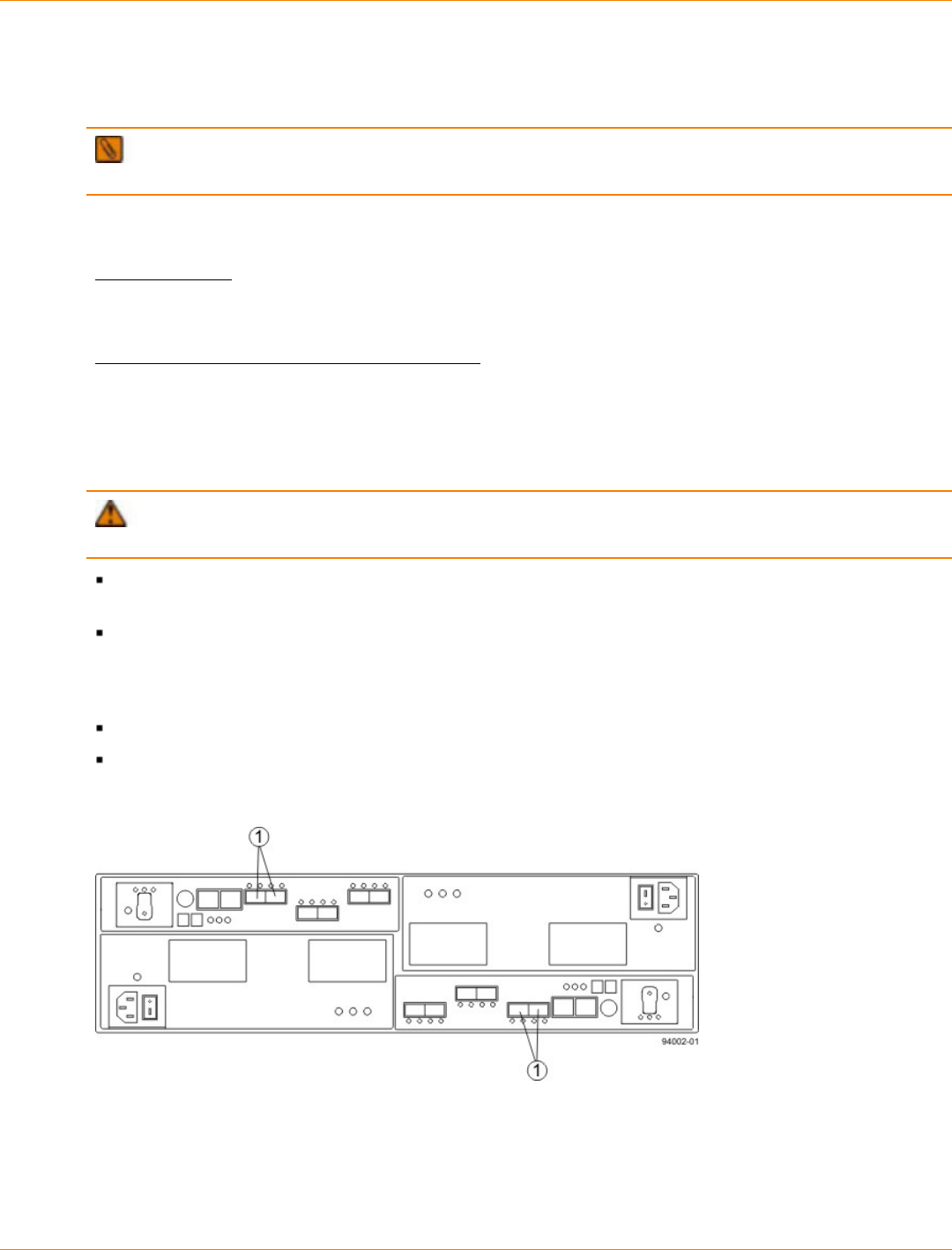
SANtricity_10.77 February 2011
LSI Corporation
- 540 -
Step 7 – Connecting the CDE4900 Controller-Drive Tray to the
Drive Trays
NOTE The maximum number of drives in a configuration is 112. These numbers include drives in the
controller-drive tray and drives in the drive trays that are attached to the controller-drive tray.
Key Terms
drive channel
The path for the transfer of data between the controllers and the drives in the storage array.
environmental services monitor (ESM)
A canister in the drive tray that monitors the status of the components. An ESM also serves as the connection
point to transfer data between the drive tray and the controller.
Things to Know – CDE4900 Controller-Drive Tray
ATTENTION Possible hardware damage – To prevent electrostatic discharge damage to the tray,
use proper antistatic protection when you handle tray components.
The CDE4900 controller-drive tray supports FC4600 drive trays for expansion. You cannot connect any
other type of drive tray to the controller-drive tray.
The maximum number of drives in the storage array is 112, including those in the CDE4900 controller-
drive tray. Some CDE4900 controller-drive tray models have a lower limit for the number of drives. You
must not exceed the limit for your model. Adding more drive trays makes the storage array invalid. The
controllers cannot perform operations that modify the configuration, such as creating new volumes.
Each controller has one dual-ported drive channel.
Controller A is inverted from controller B, which means that its drive channels are upside-down.
Drive Channel Ports on the Controller-Drive Tray – Rear View
1. Drive Channel Ports
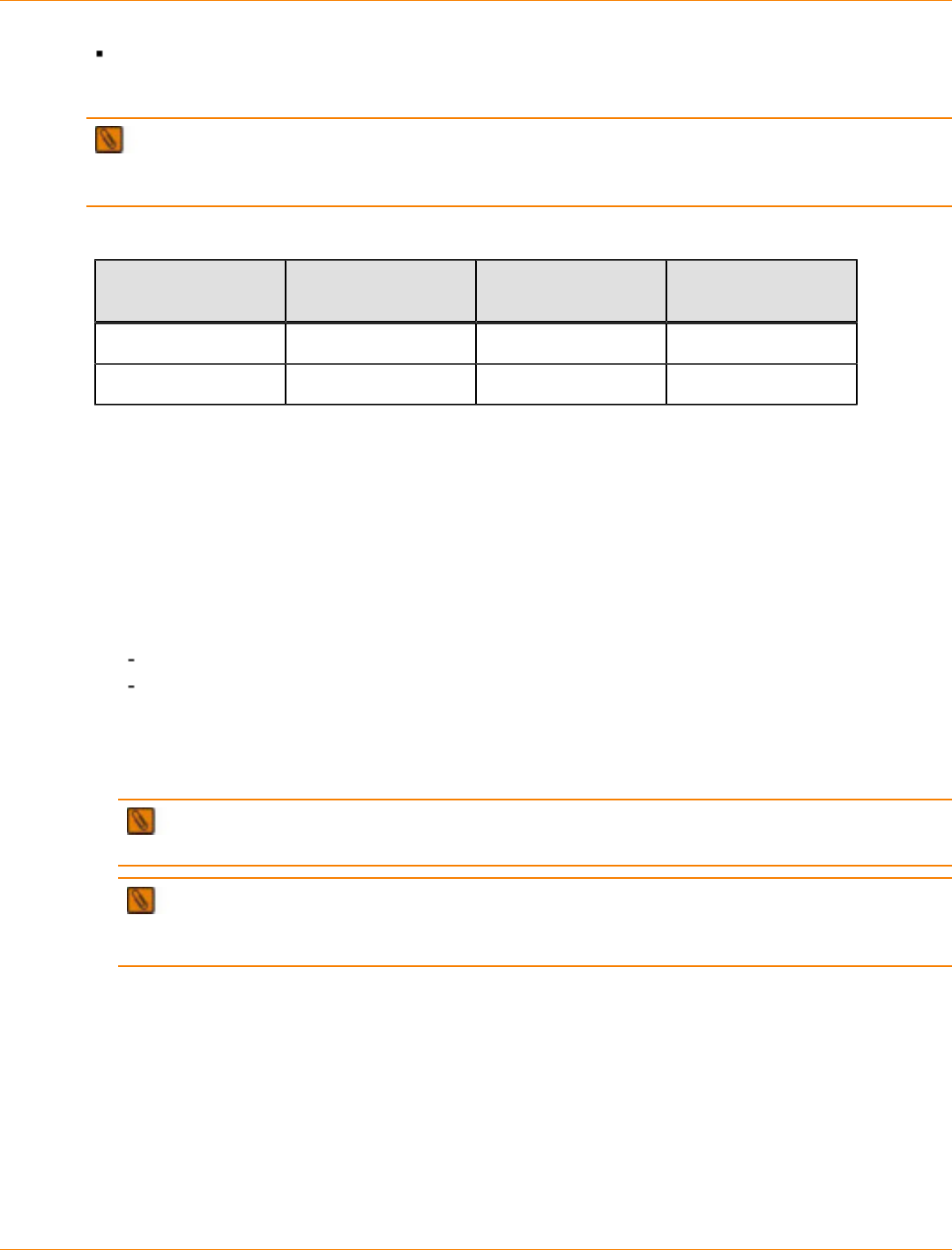
SANtricity_10.77 February 2011
LSI Corporation
- 541 -
A controller-drive tray has two redundant path pairs that are formed using one drive channel of controller
A and one drive channel of controller B. See the following table for a list of the numbers of the redundant
path pairs and the drive ports of the drive channels from which the redundant path pairs are formed.
IMPORTANT To maintain data access in the event of the failure of a controller, an ESM, or a drive
channel, you must connect a drive tray or a string of drive trays to both drive channels on a redundant path
pair.
Redundant Path Pairs on a Controller-Drive Tray
Drive Ports on
Controller A Drive Channels on
Controller A Drive Ports on
Controller B Drive Channels on
Controller B
Port 1 Channel 1 Port 1 Channel 2
Port 2 Channel 1 Port 2 Channel 2
Procedure – Cabling a Drive Tray to a Storage Array with Power but No I/O
Activity
The drive tray can have either standard power connections to an AC power source or the optional
connections to a DC power source (–48 VDC).
1. Make sure that there is no I/O activity to the storage array.
2. Choose one of the following actions based on whether you will connect the drive tray with the standard
power connections to an AC power source to the optional connections to a DC power source.
Connect to a DC power source – Perform step 3 through step step 6.
Connect to an AC power source – Perform step 7 through step 11.
3. Disconnect the two-pole 20-amp circuit breaker for the storage array.
4. Make sure that all of the DC power switches on the DC-powered drive tray are turned off.
5. Connect the DC power connector cables to the DC power connectors on the rear of the drive tray.
NOTE The three source wires on the DC power connector cable (–48 VDC) connect the drive tray
to centralized DC power plant equipment, typically through a bus bar located above the cabinet.
NOTE You do not need to connect the second DC power connection on each of the drive tray’s
DC power-fan canisters. The second DC power connection is for additional redundancy only and may be
connected to a second DC power bus.
6. Have a qualified service person connect the other end of the DC power connector cables to the DC power
plant equipment as follows:
a. Connect the brown –48 VDC supply wire to the negative terminal.
b. Connect the blue return wire to the positive terminal.
c. Connect the green/yellow ground wire to the ground terminal. You are finished with this procedure.
7. Add the AC-powered drive tray to the end of the series of existing drive trays (for cabling details, refer to
the Hardware Cabling Guide and the related topics online or that document on the SANtricity ES Storage
Manager Installation DVD).
8. Make sure that both of the Power switches on the drive tray are turned off.
SANtricity_10.77 February 2011
LSI Corporation
- 542 -
9. Connect the primary AC power cords from the cabinets to the external power source.
10. Connect a cabinet power ladder (or power cords specific to your particular cabinet) to the AC power
connector on each power-fan canister in the drive tray.
11. If you are installing other drive trays in the cabinet, connect a power cord to each power-fan canister in
the drive trays.
Procedure – Cabling a Drive Tray to a Storage Array with No Power and No I/O
Activity
The drive tray can have either standard power connections to an AC power source or the optional
connections to a DC power source (–48 VDC).
IMPORTANT Make sure that you do not turn on power to the drive tray until this document instructs
you to do so. For the proper procedure for turning on the power, see “Step 10 – Turning on the Power and
Checking for Problems in a CDE4900 Controller-Drive Tray Configuration” .
1. Add the drive tray to the end of the series of existing drive trays (for cabling details, refer to either
the Hardware Cabling electronic document topics or the PDF on the SANtricity ES Storage Manager
Installation DVD.
2. Choose one of the following actions based on whether you will connect the drive tray with the standard
power connections to an AC power source to the optional connections to a DC power source.
Connect to a DC power source – Perform step 3 through step 6.
Connect to an AC power source – Perform step 7 through step 9.
IMPORTANT Before turning off any power switches on a DC-powered drive tray, you must
disconnect the two-pole 20-amp circuit breaker.
3. Disconnect the two-pole 20-amp circuit breaker for the storage array.
4. Make sure that all of the DC power switches on the DC-powered drive tray are turned off.
5. Connect the DC power connector cables to the DC power connectors on the rear of the drive tray.
NOTE The three source wires on the DC power connector cable (–48 VDC) connect the drive tray
to centralized DC power plant equipment, typically through a bus bar located above the cabinet.
NOTE You do not need to connect the second DC power connection on each of the drive tray’s
DC power-fan canisters. The second DC power connection is for additional redundancy only and may be
connected to a second DC power bus.
6. Have a qualified service person connect the other end of the DC power connector cables to the DC power
plant equipment as follows:
a. Connect the brown –48 VDC supply wire to the negative terminal.
b. Connect the blue return wire to the positive terminal.
c. Connect the green/yellow ground wire to the ground terminal.
7. Make sure that both of the Power switches on the drive tray are turned off.
8. Connect the primary AC power cords from the cabinets to the external power source.
9. Connect a cabinet power ladder (or power cords specific to your particular cabinet) to the AC power
connector on each power-fan canister in the drive tray.

SANtricity_10.77 February 2011
LSI Corporation
- 543 -
10. If you are installing other drive trays in the cabinet, connect a power cord to each power-fan canister in
the drive trays.
SANtricity_10.77 February 2011
LSI Corporation
- 544 -
Step 8 – Connecting the Ethernet Cables
Key Terms
in-band management
A method to manage a storage array in which a storage management station sends commands to the storage
array through the host input/output (I/O) connection to the controller.
See also out-of-band management.
out-of-band management
A method to manage a storage array in which a storage management station sends commands to the storage
array through the Ethernet connections on the controller.
See also in-band management.
Things to Know – Connecting Ethernet Cables
ATTENTION Risk of security breach – Connect the Ethernet ports on the controller tray to a private
network segment behind a firewall. If the Ethernet connection is not protected by a firewall, your storage array
might be at risk of being accessed from outside of your network.
These Ethernet connections are intended for out-of-band management and have nothing to do with the
iSCSI host interface cards (HICs), whether 1Gb/s or 10Gb/s.
Ethernet port 2 on each controller is reserved for access by your Customer and Technical Support
representative.
In limited situations in which the storage management station is connected directly to the controller tray,
you must use an Ethernet crossover cable. An Ethernet crossover cable is a special cable that reverses
the pin contacts between the two ends of the cable.
Procedure – Connecting Ethernet Cables
Perform these steps to connect Ethernet cables for out-of-band management. If you use only in-band
management, skip these steps.
1. Connect one end of an Ethernet cable into the Ethernet port 1 on controller A.
2. Connect the other end to the applicable network connection.
3. Repeat step 1 through step 2 for controller B.
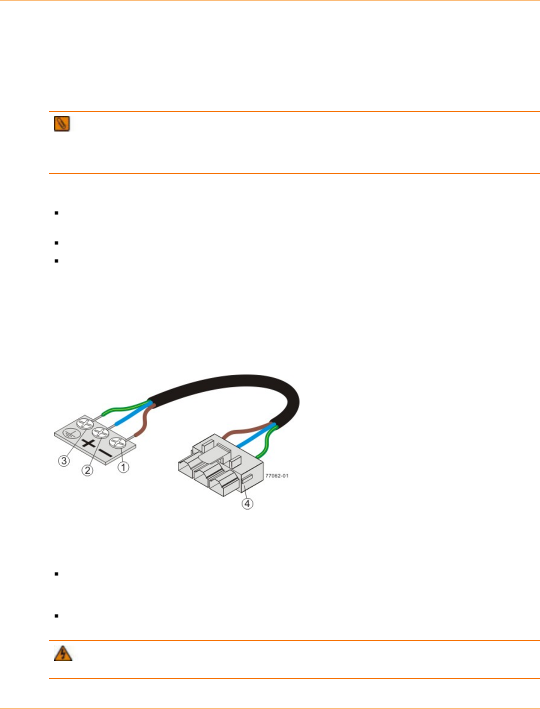
SANtricity_10.77 February 2011
LSI Corporation
- 545 -
Step 9 – Connecting the Power Cords in a CDE4900 Controller-
Drive Tray Configuration
The CDE4900 controller-drive tray and the FC4600 drive tray can have either standard power connections to
an AC power source or the optional connections to a DC power source (–48 VDC).
IMPORTANT Make sure that you do not turn on the power to the controller-drive tray or the connected
drive trays until this documentation instructs you to do so. For the correct procedure for turning on the power,
see “Procedure – Turning On the Power to the Storage Array and Checking for Problems in a CDE4900
Controller-Drive Tray Configuration.”
Things to Know – AC Power Cords
For each AC power connector on the drive tray, make sure that you use a separate power source in the
cabinet. Connecting to independent power sources maintains power redundancy.
To ensure proper cooling and assure availability, the drive trays always use two power supplies.
You can use the power cords shipped with the drive tray with typical outlets used in the destination
country, such as a wall receptacle or an uninterruptible power supply (UPS). These power cords,
however, are not intended for use in most EIA-compliant cabinets.
Things to Know – DC Power Cords
If your drive tray has the DC power option installed, review the following information.
DC Power Cable
1. Supply (negative), brown wire, –48 VDC
2. Return (positive), blue wire
3. Ground, green/yellow wire
4. DC power connector
Each power-fan canister has two DC power connectors. Be sure to use a separate power source for each
power-fan canister in the drive tray to maintain power redundancy. You may, optionally, connect each DC
power connector on the same power-fan canister to a different source for additional redundancy.
A two-pole 30-amp circuit breaker is required between the DC power source and the drive tray for over-
current and short-circuit protection.
WARNING (W14) Risk of bodily injury – A qualified service person is required to make the DC
power connection according to NEC and CEC guidelines.

SANtricity_10.77 February 2011
LSI Corporation
- 546 -
Procedure – Connecting AC Power Cords
1. Make sure that the circuit breakers in the cabinet are turned off.
2. Make sure that both of the Power switches on the drive trays are turned off.
3. Connect the primary power cords from the cabinet to the external power source.
4. Connect a cabinet interconnect power cord (or power cords specific to your particular cabinet) to the AC
power connector on each power canister in the drive tray.
5. If you are installing other drive trays in the cabinet, connect a power cord to each power canister in the
drive trays.
Procedure – Connecting DC Power Cords
WARNING (W14) Risk of bodily injury – A qualified service person is required to make the DC
power connection according to NEC and CEC guidelines.
IMPORTANT Make sure that you do not turn on power to the drive tray until this guide instructs you to
do so. For the proper procedure for turning on the power, see “Turning on the Power”.
IMPORTANT Before turning off any power switches on a DC-powered drive tray, you must disconnect
the two-pole 20-amp circuit breaker.
1. Disconnect the two-pole 20-amp circuit breaker for the storage array.
2. Make sure that all of the DC power switches on the DC-powered drive tray are turned off.
3. Connect the DC power connector cables to the DC power connectors on the rear of thecontroller tray or
controller-drive tray, and drive trays.
NOTE The three source wires on the DC power connector cable (–48 VDC) connect the drive tray
to centralized DC power plant equipment, typically through a bus bar located above the cabinet.
NOTE It is not mandatory that the second DC power connection on each of the drive tray’s DC
power-fan canisters be connected. The second DC power connection is for additional redundancy only
and may be connected to a second DC power bus.
4. Have a qualified service person connect the other end of the DC power connector cables to the DC power
plant equipment as follows:
a. Connect the brown –48 VDC supply wire to the negative terminal.
b. Connect the blue return wire to the positive terminal.
c. Connect the green/yellow ground wire to the ground terminal.
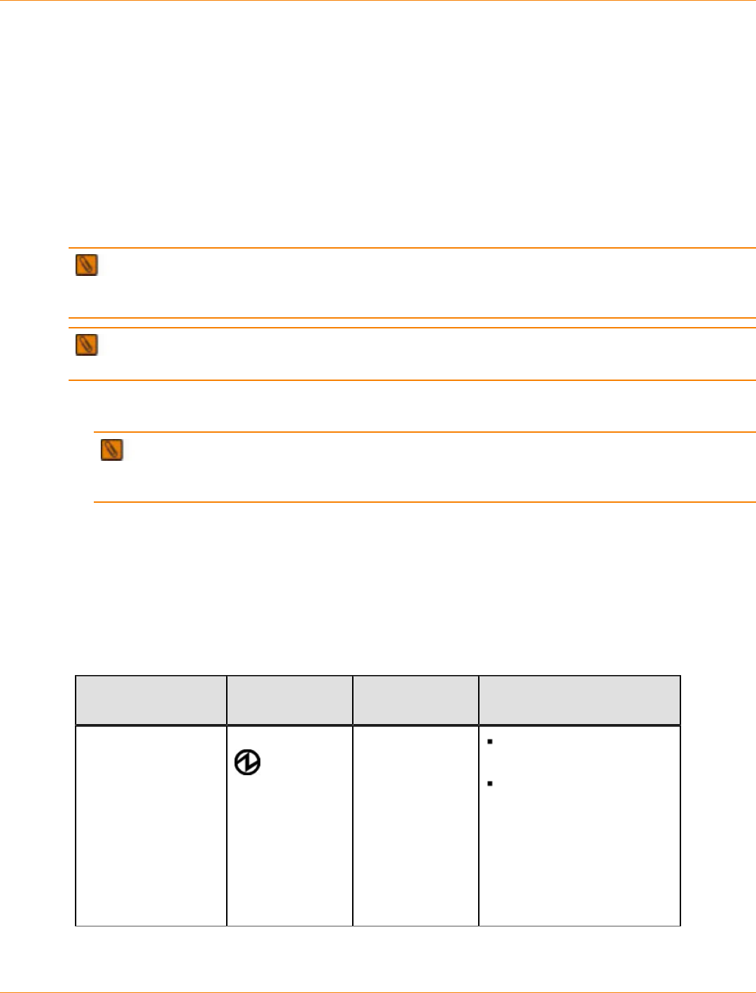
SANtricity_10.77 February 2011
LSI Corporation
- 547 -
Step 10 – Turning on the Power and Checking for Problems in a
CDE4900 Controller-Drive Tray Configuration
Once you complete this task, you can install the begin to install the software and perform basic configuration
tasks on your storage array. Continue with the Initial Configuration and Software Installation in these
electronic document topics or through the PDF that is available on the SANtricity ES Storage Manager
Installation DVD.
Procedure – Turning On the Power to the Storage Array and Checking for
Problems in a CDE4900 Controller-Drive Tray Configuration
IMPORTANT You must turn on the power to all of the connected drive trays before you turn on the
power for the controller-drive tray. Performing this action makes sure that the controllers recognize each
attached drive tray.
NOTE While the power is being applied to the trays, the LEDs on the front and the rear of the trays
come on and go off intermittently.
1. Turn on both Power switches on each drive tray that is attached to the controller-drive tray. Depending on
your configuration, it can take several minutes for each drive tray to complete the power-on process.
IMPORTANT Before you go to step 2, check the LEDs on the drive trays to verify that the power
was successfully applied to all of the drive trays. Wait 30 seconds after turning on the power to the drive
trays before turning on the power to the controller-drive tray.
2. Turn on both Power switches on the rear of the controller-drive tray. Depending on your configuration, it
can take several minutes for the controller-drive tray to complete the power-on process.
3. Check the LEDs on the front and the rear of the controller-drive tray and the attached drive trays.
4. If you see any amber LEDs, make a note of their location.
Things to Know – LEDs on the Controller-Drive Tray
LEDs on the Controller-Drive Tray
LED Symbol Location
(Canisters) Function
Power Power-fan
Interconnect-
battery
On – The canister has
power.
Off – The canister does
not have power.
NOTE – The controller
canisters do not have a
Power LED. They receive
their power from the power
supplies inside the power-fan
canisters.
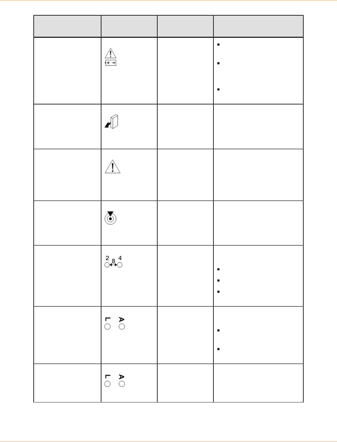
SANtricity_10.77 February 2011
LSI Corporation
- 548 -
LED Symbol Location
(Canisters) Function
Battery Charging Battery On – The battery is
charged and ready.
Off – There is a battery
fault or the battery has
discharged.
Blinking – The battery is
charging.
Service Action
Allowed Drive (left light,
no symbol
Power-fan
Controller
Battery
On – You can remove the
canister safely.
Service Action
Required (Fault) Front frame
Drive (middle
light, no symbol)
Power-fan
Controller
Battery
On – A problem exists with
the canister.
Locate Front frame On – This LED assists in
locating the tray.
Host Channel Speed Controller The speed of the host
channel is indicated:
Left LED on – 2 Gb/s
Right LED on – 4 Gb/s
Left LED and right LED
on – 8 Gb/s
Host Channel
Connection (iSCSI) Controller The status of the host
channel is indicated:
“L” LED on – A link is
established.
“A” LED on – Activity
(data transfer) is present.
Drive Port Bypass Controller On – A bypassed port is
indicated.
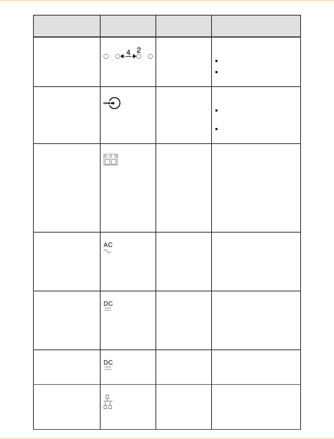
SANtricity_10.77 February 2011
LSI Corporation
- 549 -
LED Symbol Location
(Canisters) Function
Drive Channel Speed Controller The speed of the drive
channel is indicated:
Right LED on – 2 Gb/s
Left LED and right LED
on – 4 Gb/s
Cache Active Controller The activity of the cache is
indicated:
Blinking – Data is in the
cache.
Off – No data is in the
cache.
Seven Segment ID
Numeric Display and
Diagnostic Display
Controller The tray ID or a diagnostic
code is indicated. For more
information, refer to the table
below on Seven Segment
Diagnostic Display codes.
For example, if some of the
cache memory dual in-line
memory modules (DIMMs)
are missing in a controller,
error code L8 appears in the
diagnostic display.
AC power Power-fan
NOTE – The LED
is directly above
or below the AC
power switch and
the AC power
connector.
Indicates that the power
supply is receiving AC power
input.
DC power Power-fan
NOTE – The LED
is directly above
or below the DC
power switch and
the DC power
connector.
Indicates that the power
supply is receiving DC power
input.
Direct Current
Enabled Power-fan Indicates that the power
supply is outputting DC
power.
Ethernet Speed and
Ethernet Activity Controller The speed of the Ethernet
ports and whether a link
has been established are
indicated:
SANtricity_10.77 February 2011
LSI Corporation
- 550 -
LED Symbol Location
(Canisters) Function
Left LED on –
1000BASE-T speed.
Left LED off – 100BASE-
T or 10BASE-T speed.
Right LED on – A link is
established.
Right LED off – No link
exists.
Right LED blinking –
Activity is occurring.
Supported Diagnostic Codes
Diagnostic Code Description
L0 The controller types are mismatched.
L1 The interconnect-battery canister is missing.
L2 A persistent memory error has occurred.
L3 A persistent hardware error has occurred.
L4 A persistent data protection error has occurred.
L5 The auto-code synchronization (ACS) has failed.
L6 An unsupported host interface card is installed.
L7 The sub-model identifier is not set or is mismatched.
L8 A memory configuration error has occurred.
L9 A link speed mismatch has occurred.
LA Reserved
Lb A host card configuration error has occurred.
LC A persistent cache backup configuration error has occurred.
Ld Mixed cache memory DIMMs are present.
LE Uncertified cache memory DIMM sizes exist.
LF Lockdown with limited SYMbol support exists.
LH A controller firmware mismatch has occurred.

SANtricity_10.77 February 2011
LSI Corporation
- 551 -
General Behavior of the LEDs on the Drive Trays
LED Symbols and General Behavior on the Drive Trays
LED Symbol Location General Behavior
Power Drive tray
ESM canister
Power-fan
canister
On – Power is applied to the drive
tray or the canister.
Off – Power is not applied to the
drive tray or the canister.
Service Action
Allowed ESM canister
Power-fan
canister
Drive
On – It is safe to remove the ESM
canister, the power-fan canister, or
the drive.
Off – Do not remove the ESM
canister, the power-fan canister, or
the drive.
The drive has an LED but no
symbol.
Service Action
Required (Fault) ESM canister
Power-fan
canister
Drive
On – When the drive tray LED is
on, a component within the drive
tray needs attention.
On – The ESM canister, the
power-fan canister, or the drive
needs attention.
Off – The ESM canister, the
power-fan canister, and the drive
are operating normally.
The drive has an LED but no
symbol.
Locate Front bezel on
the drive tray On or blinking – Indicates the
drive tray that you are trying to find.
Over-
Temperature Front bezel on
the DE6900
drive tray
On – The temperature of the
drive tray has reached an unsafe
condition.
Off – The temperature of the drive
tray is within operational range.
Drive Port
Bypass ESM canister Indicates if a port has been
bypassed.
Drive Channel
Speed ESM canister Indicates the speed of the drive
channel:
If the right LED is On -- 2 Gb/s
If both LED are Off -- 4 Gb/s
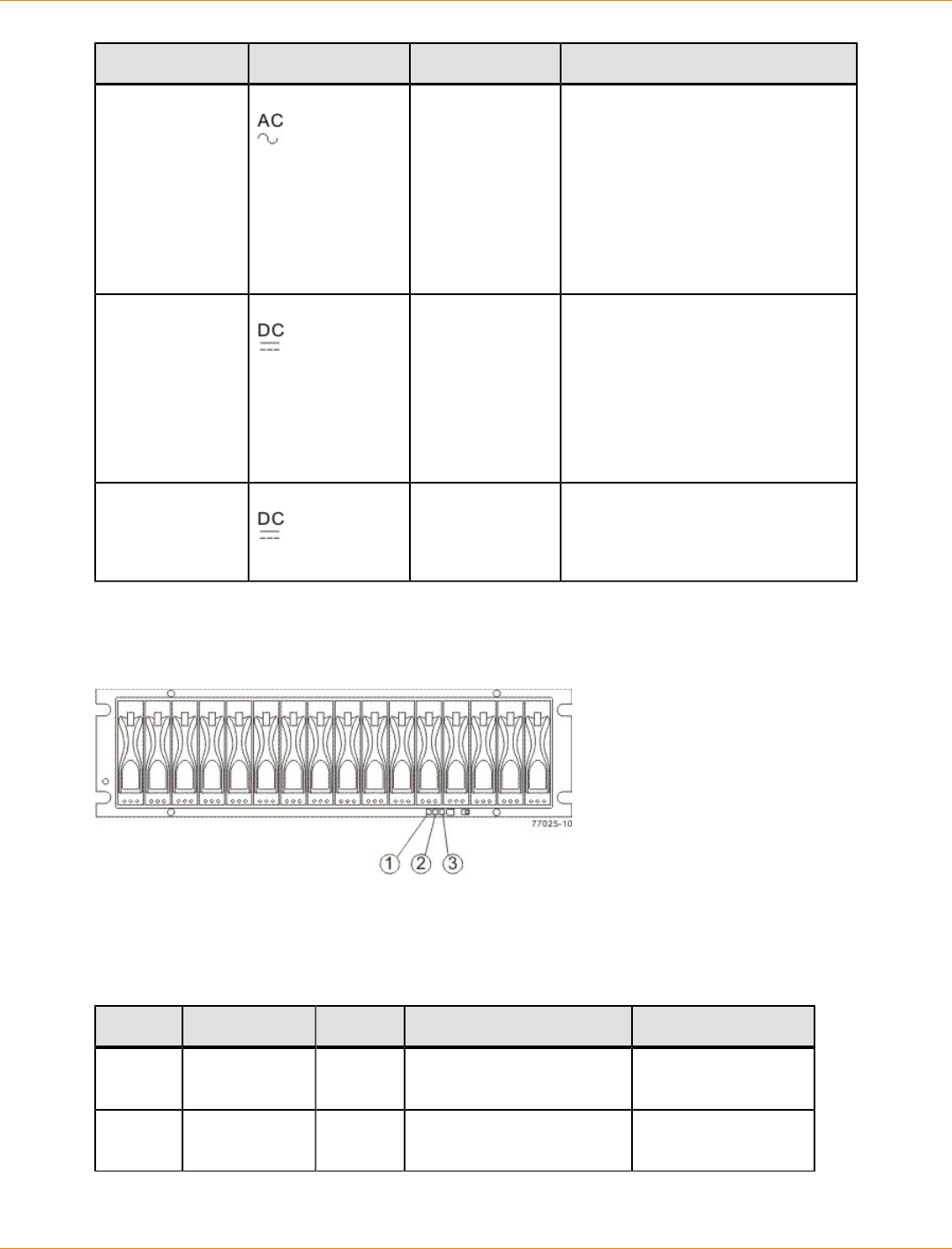
SANtricity_10.77 February 2011
LSI Corporation
- 552 -
LED Symbol Location General Behavior
AC Power ESM canister
Power-fan
canister
Note LED is
directly above
or below AC
Power Switch
and AC Power
Connectors
On – AC power is present.
Off – AC power is not present.
DC Power
(optional) Power-fan
canister
Note LED is
directly above
or below DC
Power Switch
and DC Power
Connectors
On – Regulated DC power from
the power canister and the fan
canister is present.
Off – Regulated DC power from
the power-fan canister is not
present.
DC Power Power-fan
canister Indicates the power supply is
outputting DC power
LEDs on the FC4600 Drive Tray
LEDs on the FC4600 – Front View
1. Drive Tray Locate LED
2. Drive Tray Service Action Required LED
3. Power LED
LEDs on the FC4600 Left End Cap
Location LED Color On Off
1 Drive Tray
Locate White Identifies a drive tray that
you are trying to find. Normal status.
2 Service Action
Required Amber A component within the
drive tray needs attention. Normal status.
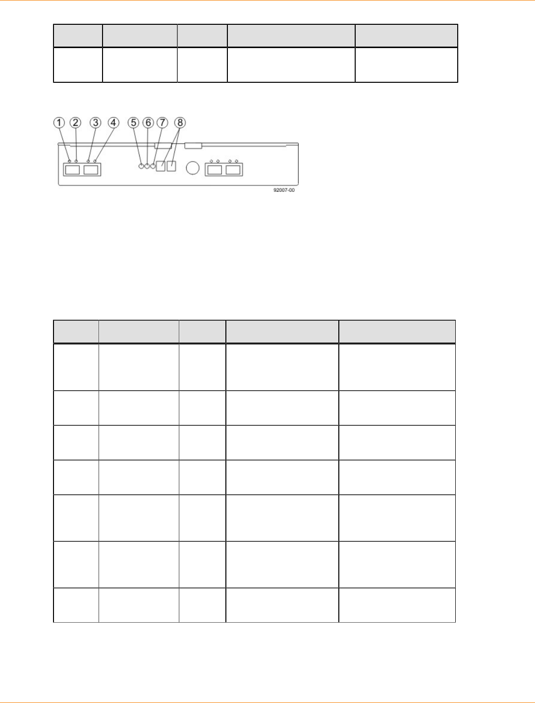
SANtricity_10.77 February 2011
LSI Corporation
- 553 -
Location LED Color On Off
3 Power Green Power is present. Power is not
present.
LEDs on the FC4600 ESM Canister
1. ESM Link Fault LED (Port 1A Bypass)
2. ESM Link LED (Port 1A Data Rate)
3. ESM Link LED (Port 1B Data Rate)
4. ESM Link Fault LED (Port 1B Bypass)
5. ESM Service Action Allowed LED
6. ESM Service Action Required LED
7. ESM Power LED
8. Seven-Segment Tray ID
LEDs on the FC4600 ESM Canister
Location LED Color On Off
1 ESM Link
Fault (Port 1A
Bypass)
Amber A link error has
occurred. No link error has
occurred.
2 ESM Link (Port
1A) Green The link is up. A link error has
occurred.
3 ESM Link (Port
1B Bypass) Green The link is up. A link error has
occurred.
4 ESM Link Fault
(Port 1B) Amber A link error has
occurred. No link error has
occurred.
5 ESM Service
Action Allowed Blue The ESM can be
removed safely from
the drive tray.
The ESM cannot be
removed safely from
the drive tray.
6 ESM Service
Action
Required
Amber A fault exists within the
ESM. Normal status.
7 ESM Power Green Power to the ESM is
present. Power is not present to
the ESM.
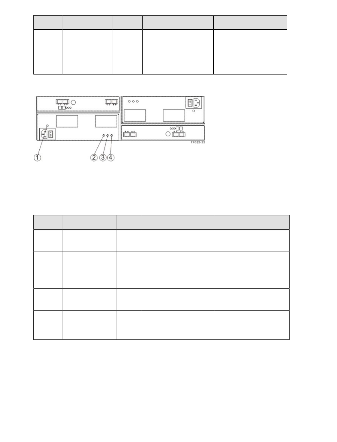
SANtricity_10.77 February 2011
LSI Corporation
- 554 -
Location LED Color On Off
8 Seven-
Segment Tray
ID
Green For more information,
see “Supported
Diagnostic Codes on
the Seven-Segment
Display”.
Not applicable.
LEDs on the FC4600 Power Canister
1. Power AC Power LED
2. Power Service Action Allowed LED
3. Power Service Action Required LED
4. Power DC Power LED
LEDs on the FC4600 Power Canister
Location LED Color On Off
1 Power AC
Power Green AC power to the power
canister is present. AC power to the power
canister is not present.
2 Power Service
Action Allowed Blue The power canister can
be removed safely from
the drive tray.
The power canister
cannot be removed
safely from the drive
tray.
3 Power Service
Action Required Amber A fault exists within the
power canister. Normal status.
4 Power DC
Power Green DC power from the
power canister is
available.
DC power from the
power canister is not
available.
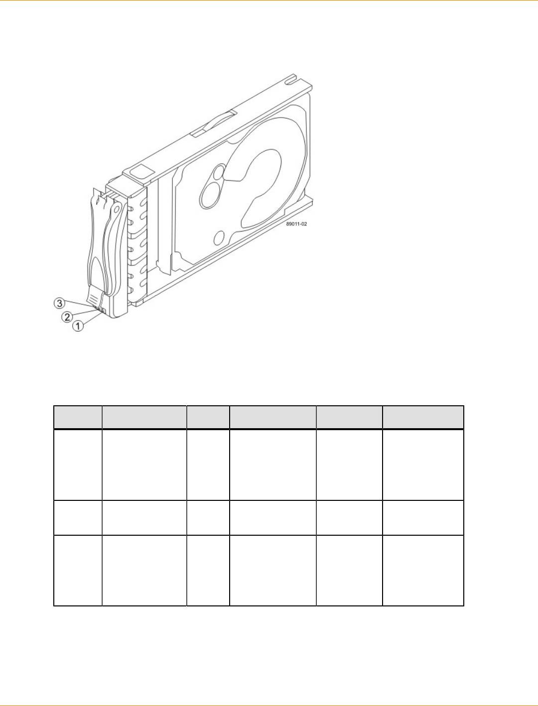
SANtricity_10.77 February 2011
LSI Corporation
- 555 -
LEDs on the FC4600 Drives
LEDs on the FC4600 Drive
1. Drive Power LED
2. Drive Service Action Required LED
3. Drive Service Action Required LED
LEDs on the Drives
Location LED Color On Blinking Off
1 Drive Power Green The power
is turned on,
and the drive
is operating
normally.
Drive I/O
is taking
place.
The power is
turned off.
2 Drive Service
Action Required Amber An error has
occurred. Normal status.
3 Drive Service
Action Allowed Blue The drive
canister can be
removed safely
from the drive
tray.
The drive
canister cannot
be removed
safely from the
drive tray.
Things to Know – Service Action Allowed LEDs
Each controller canister, power-fan canister, and battery canister has a Service Action Allowed LED. The
Service Action Allowed LED lets you know when you can remove a canister safely.
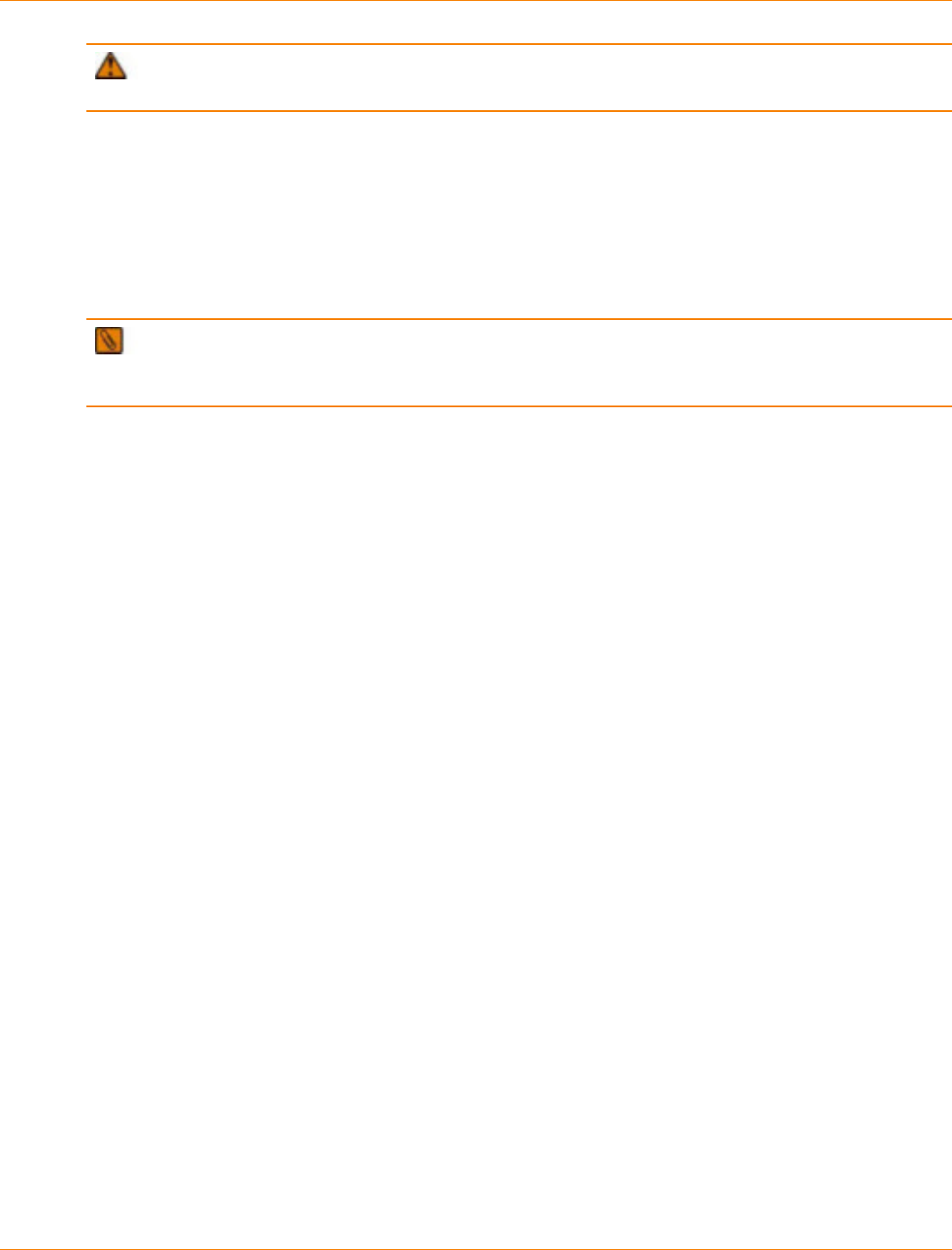
SANtricity_10.77 February 2011
LSI Corporation
- 556 -
ATTENTION Possible loss of data access – Never remove a controller canister, a power-fan
canister, or a battery canister unless the appropriate Service Action Allowed LED is on.
If a controller canister or a power-fan canister fails and must be replaced, the Service Action Required (Fault)
LED on that canister comes on to indicate that service action is required. The Service Action Allowed LED
also comes on if it is safe to remove the canister. If data availability dependencies exist or other conditions
that dictate a canister should not be removed, the Service Action Allowed LED stays off.
The Service Action Allowed LED automatically comes on or goes off as conditions change. In most cases,
the Service Action Allowed LED comes on when the Service Action Required (Fault) LED comes on for a
canister.
IMPORTANT If the Service Action Required (Fault) LED comes on but the Service Action Allowed
LED is off for a particular canister, you might need to service another canister first. Check your storage
management software to determine the action that you should take.

SANtricity_10.77 February 2011
LSI Corporation
- 557 -
Hardware Cabling
This document provides conceptual and procedural information for cabling various combinations of the
components that make up a storage array.
Controller trays:
CE7922 controller tray
CE7900 controller tray
CE6998 controller tray
CE6994 controller tray
Controller-drive trays:
CDE4900 controller-drive tray
CDE3994 controller-drive tray
CDE3992 controller-drive tray
CDE2600 controller-drive tray
Drive trays:
DE6900 drive tray
FC4600 drive tray
AT2655 drive tray
FC2610 drive tray
FC2600 drive tray
DE5600 drive tray
DE1600 drive tray
This document also describes host cabling and cabling for out-of-band management.
This document is intended for system operators, system administrators, and technical support personnel
who are responsible for the installation and the setup of the storage array. Users must be familiar with basic
computer system operations. In addition, they should understand disk storage technology, Redundant Array
of Independent Disks (RAID) concepts, networking, and Fibre Channel technologies. The reader must have
a basic knowledge of storage area network (SAN) hardware functionality (controllers, drives, and hosts) and
SAN cabling.
For information related to the products mentioned in this document, go to http://www.lsi.com/storage_home/
products_home/external_raid/index.html.
From the LSI Technical Support website, you can find contact information, query the knowledge base, submit
a service request, download patches, or search for documentation. Visit the LSI Technical Support website at
http://www.lsi.com/support/index.html.

SANtricity_10.77 February 2011
LSI Corporation
- 558 -
Cabling Concepts and Best Practices
This chapter has three sections:
The first section, “Cabling Concepts,” provides definitions of the terms used in this document. This section
is intended primarily for reference. Read the entire section to increase your overall understanding of the
storage array and help you to optimize your storage array.
The second section, “Best Practices,” contains information that might affect your choice of cabling
topologies. Read this section to understand the options for cabling your storage array.
The third section, “Common Procedures,” contains procedures that you will need to perform while you
are cabling the storage array. Read this section to understand tasks that might be required to cable your
storage array.
Cabling Concepts
This section defines terms and concepts that are used in this document.
Fabric (Switched) Topologies Compared to Direct-Attach Topologies
Fabric topologies use a switch. Direct-attach topologies do not use a switch. A switched topology is required if
the number of hosts to connect to a controller tray or controller-drive tray is greater than the number available
host ports on the tray.
Host connections might be InfiniBand, Fibre Channel, iSCSI, or a mix of Fibre Channel and iSCSI. Switches
must support the required connection type or types. A combination of switches of different types might be
appropriate for some configurations that support a mixture of connection types.
Drive Tray
A drive tray contains drives but no controllers. Drive trays usually are attached to either a controller tray or
a controller-drive tray so that the controller in the controller tray or the controller-drive tray can configure,
access, and manage the storage space in the drive tray. Drive trays can be differentiated by type, which are
described in the following subsections.
Switched Bunch of Disks
Switched Bunch of Disks (SBOD) is a device that takes all of the drives that are operating in a single Fibre
Channel-Arbitrated Loop (FC-AL) segment and provides each drive with access to one or more controllers in
a point-to-point fashion. This action is accomplished in a way that appears to be compliant with the FC-AL-2
protocol. As a result, system firmware changes are not required.
In this document, the FC2610 drive trays and the FC4600 drive trays are referred to as SBODs in the cabling
diagrams. The AT2655 drive trays are identified as SATA (Serial Advanced Technology). The following figure
shows an example of this type of labeling for drive trays. The DE6900 drive trays and DE6600 drive trays are
SBODs and can be mixed only with FC4600 drive trays. Do not mix FC2600 drive trays with other types of
drive trays on the same loop.
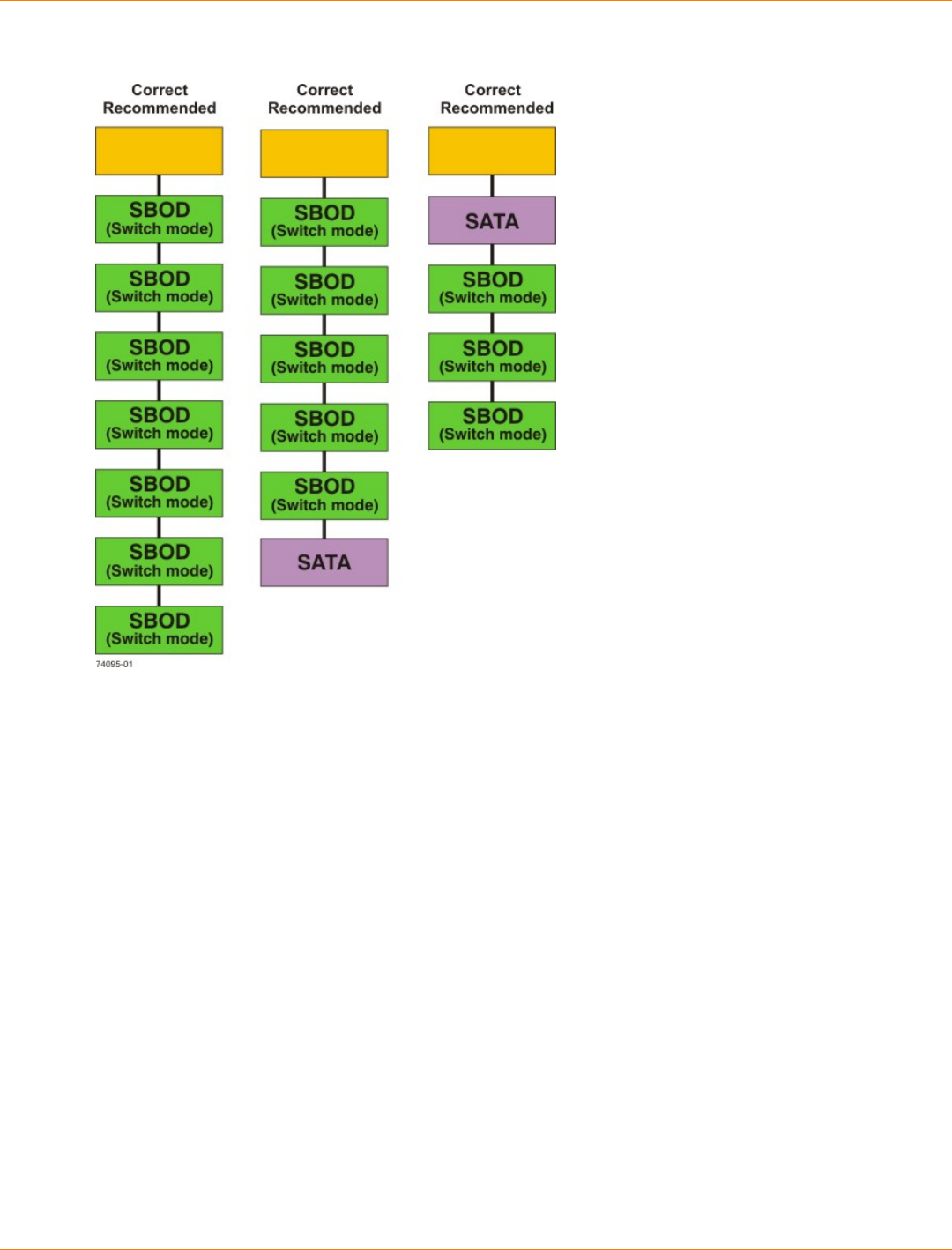
SANtricity_10.77 February 2011
LSI Corporation
- 559 -
SBOD Labeling in Cabling Diagrams
Controller Tray
A controller tray contains controllers. A controller tray does not contain drives. Controller trays configure,
access, and manage the storage space of attached drive trays.
Controller-Drive Tray
A controller-drive tray contains both controllers and drives. The controllers configure, access, and manage
the storage space of the drives in the controller-drive tray. A controller-drive tray might configure, access, and
manage the storage space of other attached drive trays, depending upon the model.
Host Channels and Drive Channels
In this document, the term channel refers to a path for the transfer of data information and control information
between the host and the controller, or between the drive trays and the controller trays or controller-drive
trays. A data path from a host to a controller is a host channel. A host channel might be Fibre Channel,
InfiniBand, iSCSI, or Serial Attached SCSI (SAS). A path from a drive trays to a controller trays or a controller-
drive trays is a drive channel. Each drive channel is defined by a single Fibre Channel-Arbitrated Loop or by a
series of SAS devices connected through expanders. Controllers have between two and eight available host
channels, and between one and eight available drive channels, depending upon the model. The maximum
number of hosts per host channel and the maximum number of drives per drive channel depends upon the
model. For model-specific information, see the topics under "Product Compatibility."

SANtricity_10.77 February 2011
LSI Corporation
- 560 -
IMPORTANT When you mix different types of drive trays, you must consider the total number of drives
that are available in the final configuration of the storage array. For example, if you mix FC4600 drive trays
with FC2610 drive trays, the total number of drives might be more than the maximum number that each drive
channel can support.
Host Ports and Drive Ports
The ports are the physical connectors on the controller tray or the controller-drive tray that, along with the
cabling, enable the transfer of data. If the port communicates with the host server, it is a host port. If the port
communicates with a drive tray, it is a drive port. The figures in the topics under "Component Locations" show
the connectors on the rear of each of the various trays. These figures will help you differentiate between host
ports and drive ports.
Dual-Ported Drives
Each drive in a controller-drive tray or a drive tray is dual ported. Circuitry in the drive tray or the controller-
drive tray connects one drive port to one channel and the other port to another channel. Therefore, if one
drive port or drive channel fails, the data on the drive is accessible through the other drive port or drive
channel.
SATA drives are not dual ported; however, the electronics in the AT2655 drive tray emulate the behavior of
dual-ported drives. Each SATA drive is available through two paths.
Preferred Controllers and Alternate Controllers
The preferred controller is the controller that “owns” a volume or a volume group. SANtricity ES Storage
Manager automatically selects the preferred controller when a volume is created, or the user can override the
default selection.
Several conditions will force the preferred controller to fail over to the alternate controller. When this event
occurs, ownership of the volume is shifted to the alternate controller. These conditions might initiate failover:
The preferred controller is physically removed.
The preferred controller is being updated with new firmware.
The preferred controller has sustained a fatal event.
The paths used by the preferred controller to access either the drives or the host are called the preferred
paths, and the redundant paths are the alternate paths. If a failure occurs that causes the preferred path
to become inaccessible, the alternate path software detects the failure and automatically switches to the
alternate path.
Alternate Path Software
Alternate path software or an alternate path (failover) driver is a software tool that provides redundant data
path management between the host bus adapter (HBA) and the controller. This tool is installed on the host in
a system that provides redundant HBAs and paths. The tool discovers and identifies multiple paths to a single
logical unit number (LUN) and establishes a preferred path to that LUN. If any component in the preferred
path fails, the alternate path software automatically reroutes input/output (I/O) requests to the alternate path
so that the system continues to operate without interruption.
To learn how alternate path software works with SANtricity ES Storage Manager features to provide data
path protection, refer to the topics under Conecpts or the corresponding PDF document on the SANtricity ES
Storage Manager Installation DVD.

SANtricity_10.77 February 2011
LSI Corporation
- 561 -
Failover
Failover is an automatic operation that switches from a failed component or failing component to an
operational component. In the case of a Redundant Array of Independent Disks (RAID) controller failover, an
operational controller takes over the ownership of volumes. The operational controller processes I/O from the
host in place of the failing component or failed controller. Controller failover is possible only in controller trays
or in controller-drive trays that contain two controllers.
In a system in which the alternate path software tool is installed on the host, the data paths through the failed
HBA are replaced by data paths through the surviving HBA.
For more information, refer to the topics under Failover or to the corresponding PDF on the SANtricity ES
Storage Manager Installation DVD.
Redundant and Non-Redundant
The term redundant means “more than one” and indicates the existence of something more than what is
essential to accomplish a task. In RAID technology, redundancy means that duplicated components or data
exist, or an alternate means can provide essential services. This redundancy ensures the availability of data
in case a component fails.
In most RAID systems, most of the components are redundant, but that the system might not be fully
redundant. In other words, there might be one or two components whose individual failures would cause loss
of access to data. Therefore, a fully redundant system duplicates all components and is configured to make
sure that the duplicate components can be accessed in case of a failure. The manner in which the system is
cabled is an essential component of creating a successfully configured redundant system.
Single Point of Failure
Any component or path that is not duplicated (redundant) or whose failure can cause loss of data access is
called a potential single point of failure. The cabling scenarios in this document note the components that
present a potential single point of failure. Choose a cabling topology that does not create a single point of
failure.
SFP Transceivers, Fiber-Optic Cables, and Copper Cables
Controller-drive trays, controller trays, and drive trays use fiber-optic cables or copper cables for Fibre
Channel connections. For copper Fibre Channel cables, a passive copper Small Form-factor Pluggable (SFP)
transceiver is attached to each end of the cable. InfiniBand connections are made with fiber-optic cables. If
your system will be connected with Fibre Channel or InfiniBand fiber-optic cables, you must install an active
SFP transceiver into each port in which a fiber-optic cable will be connected before plugging in the fiber-optic
cable. Connections for 1-Gb/s iSCSI require SFP transceivers. Connections for 1-Gb/s iSCSI use copper
cables with RJ-45 connectors and do not require SFP transceivers. Connections for SAS use copper cables
with SFF 8088 connectors and do not require SFP transceivers. The following figures show the two types of
cables that use SFP transceivers. Note that your SFP transceivers and cables might look slightly different
from the ones shown. The differences do not affect the performance of the SFP transceivers.
WARNING (W03) Risk of exposure to laser radiation – Do not disassemble or remove any part of a
Small Form-factor Pluggable (SFP) transceiver because you might be exposed to laser radiation.
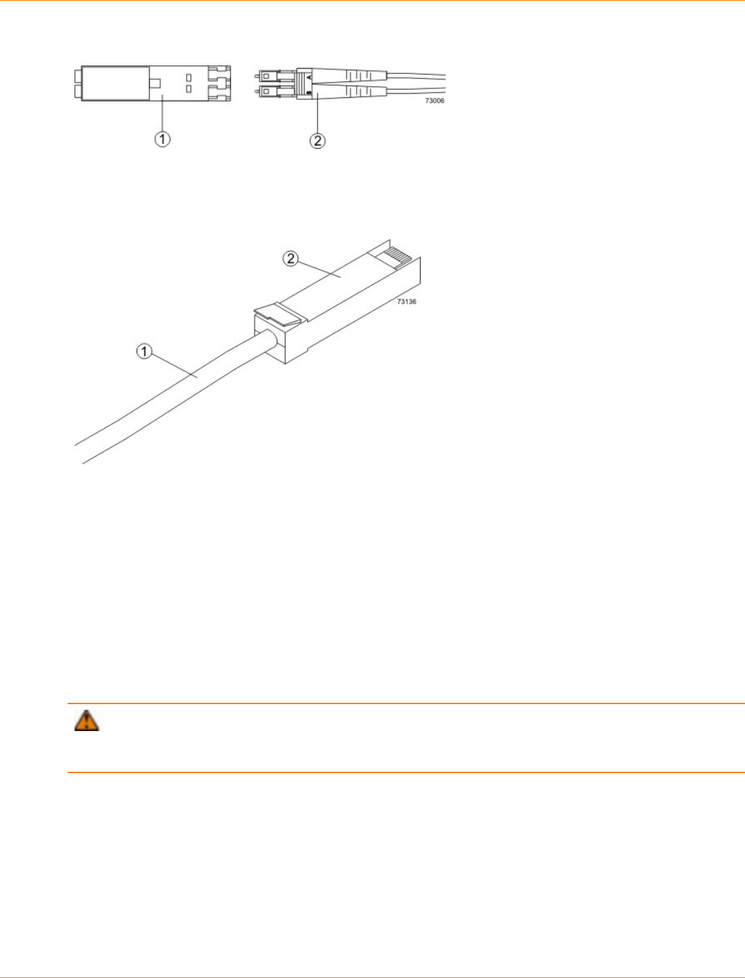
SANtricity_10.77 February 2011
LSI Corporation
- 562 -
Active SFP Transceiver with Fiber-Optic Cable
1. Active SFP Transceiver
2. Fiber-Optic Cable
Passive SFP Transceiver with Copper Cable
1. Copper Cable
2. Passive SFP Transceiver
Host Adapters
Each connection from a host port on a controller tray or a controller-drive tray to a host is made through
a host adapter on the host. A host adapter can be a host bus adapter (HBA) for Fibre Channel or SAS
connections, a host channel adapter (HCA) for InfiniBand connections, or an Ethernet adapter for iSCSI
connections. The host adapter provides the interface to the internal bus of the host. For hardware
redundancy, use two host adapters in each host computer. The two host adapters must be of the same type
(HBAs, HCAs, or Ethernet). For duplex controller trays or duplex controller-drive trays, connect each host
adapter to a different controller in a controller tray or a controller-drive tray to make sure that the server will be
accessible even if one HBA or one controller fails.
ATTENTION Possible loss of data access – Do not use a combination of HBAs from different
vendors in the same storage area network (SAN). For the HBAs to perform correctly, use HBAs from only one
manufacturer in a SAN.
You can obtain information about supported host adapters from the Compatibility Matrix. To check for
current compatibility, refer to the Compatibility Matrix at http://www.lsi.com/compatibilitymatrix/, and click the
Compatibility Matrix link.
Host Interface Cards
Each controller in a CE7900 controller tray has one or two host interface cards (HICs) that contain the host
ports. Each controller in a CDE4900 controller-drive tray has two Fibre Channel host ports built in, as well as
an optional HIC for additional host ports. Each controller in a CDE2600 controller-drive tray or a CDE2600-60
controller-drive tray has two SAS host ports built in, as well as an optional HIC for additional host ports.

SANtricity_10.77 February 2011
LSI Corporation
- 563 -
An HIC is cabled to a host adapter: a host bus adapter (HBA) for Fibre Channel or SAS, a host channel
adapter (HCA) for InfiniBand, or an Ethernet adapter for iSCSI. The host adapter in the host must match the
type of HIC to which it is cabled.
Network Interface Cards
A network interface card (NIC) is an expansion board that is installed in the host server. Some servers are
equipped with an integrated NIC. The NIC supports Ethernet technology. The NIC is required for network
communication. Each Ethernet cable connection for out-of-band storage array management is made through
an NIC (see the topics under "In-Band Management and Out-of-Band Management").
NOTE It is the responsibility of the customer to obtain the required NICs and to install them.
Switches and Zoning
A switch is an intelligent device that connects multiple devices. A switch allows data transfer between
the devices, depending upon the designated source (initiator) and the destination (target) of the data.
Switches can redirect traffic to ports other than the designated destination, if necessary. A switch provides full
bandwidth per port and high-speed routing of data.
Zoning allows a single hardware switch to function as two or more virtual switches. In a zoned configuration,
communication among devices in each zone is independent of communication among devices in another
zone or zones. Zoned switches allow an administrator to restrict access to specific areas within a storage
area network (SAN).
How Initiators and Targets Respond to Zoning
When an initiator first accesses the fabric, it queries the World Wide Identifier (WWID) name server for all
of the attached disks and drive trays and their capabilities. Zoning is like a filter that the WWID name server
applies to the query from the initiator that limits the information returned by the WWID name server to the
initiator. A zone defines the WWID of the initiator and the WWID of the devices that a particular zone is
allowed to access. Devices that are not part of the zone are not returned as accessible devices.
The fabric provides universal access for all initiators and targets. Any initiator can query (probe) the fabric
for all targets, which can affect performance when many targets are connected to the fabric. The querying
process also provides access to devices for which access is not needed. Use zoning to limit the number of
devices that an initiator can access. Within your storage area network, you should zone the fabric switches so
that the initiators do not “see” or communicate with each other.
How Best to Approach Zone Configuration
Some of the cabling topologies shown in this document require the use of a zoned switch. By default, the
switch uses no zoning, which is not sufficiently robust for most applications. You must configure the switch
before you use it.
Zone configuration is managed on a per-fabric basis. While you can administer zone configuration from
any switch, use the best practice of selecting one switch for all zone administration. Give preference to the
primary switches within the SAN, and choose only a switch that has the most up-to-date storage management
software and switch management software installed on it.
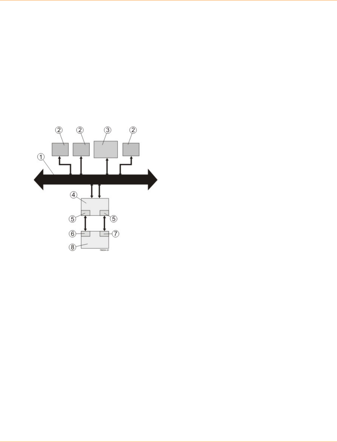
SANtricity_10.77 February 2011
LSI Corporation
- 564 -
In-Band Management and Out-of-Band Management
A system administrator manages a storage array from a storage management station, which is a workstation
on which the SANtricity ES Storage Manager Client is installed. Requests and status information sent
between the storage array and the storage management station are managed in one of two ways: in-band or
out-of-band. A storage array that uses out-of-band management requires a different network topology from a
storage array that uses in-band management.
When you use in-band management, a SANtricity ES Storage Manager agent running on the host receives
requests from the management station. The host agent processes the requests through the host I/O interface
to the storage array. The host I/O interface might be Fibre Channel, serial-attached Small Computer System
Interface (SAS), InfiniBand, or Internet SCSI (iSCSI).
Example of In-Band Management Topology
1. Ethernet Network
2. User Workstations Sending and Receiving Data
3. Storage Management Station
4. Host
5. Host Adapters
6. Controller A
7. Controller B
8. Controller Tray or Controller-Drive Tray for the Storage Array
When you use out-of-band management, the storage management station is connected, through an Ethernet
network, to each of the controllers in the controller tray or the controller-drive tray.
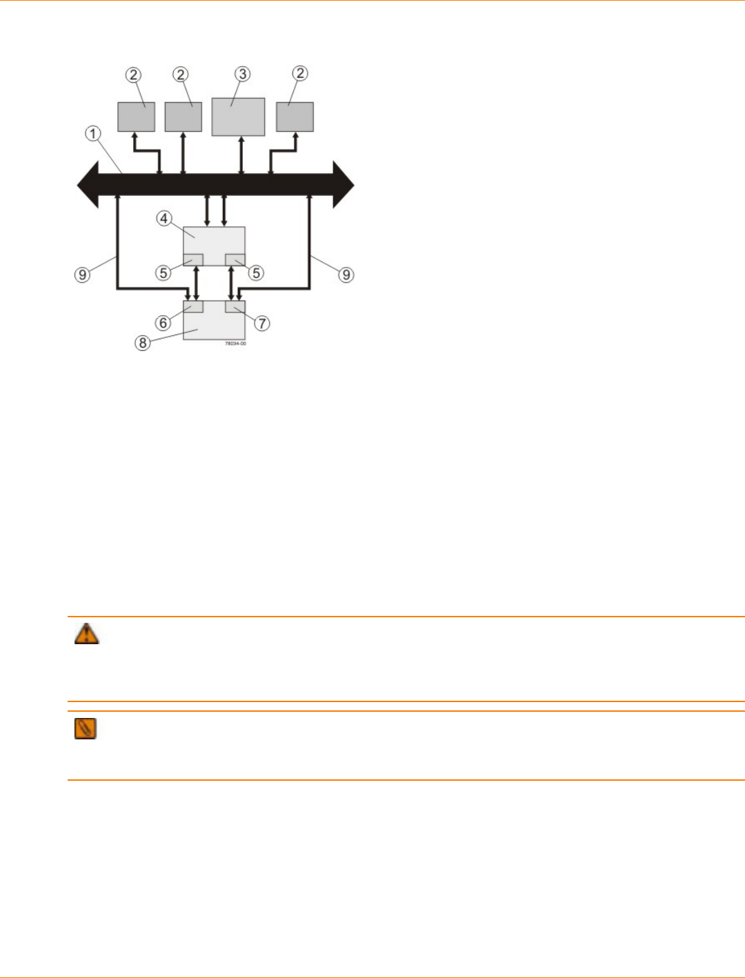
SANtricity_10.77 February 2011
LSI Corporation
- 565 -
Example of Out-of-Band Management Topology
1. Ethernet Network
2. User Workstations Sending and Receiving Data
3. Storage Management Station
4. Host
5. Host Adapters
6. Controller A
7. Controller B
8. Controller Tray or Controller-Drive Tray for the Storage Array
9. Ethernet Cable from the Controllers to the Ethernet Network
When using out-of-band management, a Dynamic Host Configuration Protocol (DHCP) server is
recommended for assigning Internet Protocol (IP) addresses and other network configuration settings.
A DHCP server provides the network administrators the ability to manage and automatically assign IP
addresses. If a DHCP server is not used, you must manually configure the controllers. For more information,
refer to the Adding a Host or Storage Array online help topic in the Enterprise Management Window.
ATTENTION Risk of unauthorized access to or loss of data – If the out-of-band management
method is used, connect the Ethernet ports on the controller tray or the controller-drive tray to a private
network segment behind a firewall. If the Ethernet connection is not protected by a firewall, your storage array
might be at risk of being accessed from outside of your network.
IMPORTANT Where two Ethernet ports are available on each controller (four total), you can use one of
the ports on each controller for out-of-band Ethernet connections. Reserve the second Ethernet port on each
controller for access by your Customer and Technical Support representative.
For information about how to create a redundant out-of-band topology, see the topics under “Drive Cabling.”
Best Practices
This section explains recommended cabling practices. To make sure that your cabling topology results in
optimal performance and reliability, familiarize yourself with these best practices.
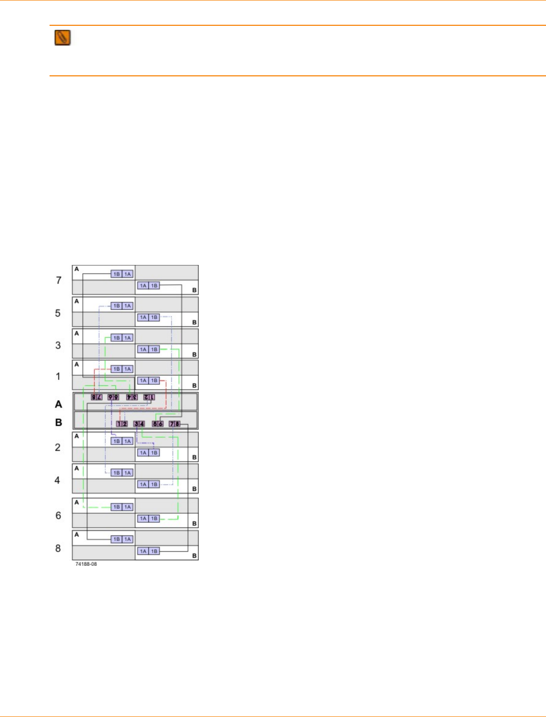
SANtricity_10.77 February 2011
LSI Corporation
- 566 -
IMPORTANT If your existing storage array cabling does not comply with the best practices described in
this section, do not re-cable your storage array unless specifically requested to do so by your Customer and
Technical Support representative.
Drive Cabling for Redundancy
When attaching the drive trays, use a cabling topology that does not create a single point of failure. A single
point of failure might appear as a drive tray failure or another component failure in the middle of a grouping
of drive trays. If a drive tray fails, you can no longer access the drive trays beyond the point of failure. By
creating an alternate path, you make sure that the drive trays are accessible in the event of a drive tray
failure.
The following figure shows a typical cabling scenario. In this example, each of the eight drive trays has two
connections directly to the controller tray: one from ESM A to controller A and one from ESM B to controller B.
Each redundant path pair on the controller tray connects to one drive tray. The ESM 1B ports are used for all
of the connections.
Cabling for Eight Drive Trays
Note how the controller tray (denoted by A and B in the figure) is conveniently situated in the middle of the
arrangement, which enables you to use cables that are all the same length. Positioning the controller tray
near the middle of the cabinet also helps prevent the cabinet from becoming top heavy as drive trays are
added.
For cabling examples, ranging from simple to complex, see the topics under “Drive Cabling.”
SANtricity_10.77 February 2011
LSI Corporation
- 567 -
Host Cabling for Redundancy
To ensure that, in the event of a host channel failure, the storage array will stay accessible to the host,
establish two physical paths from each host to the controllers, and install alternate path software on the host.
This cabling topology, when used with alternate path software, makes sure that a redundant path exists from
the host to the controllers.
ATTENTION Possible loss of data access – You must install alternate path software or an alternate
path (failover) driver on the host to support failover in the event of an HBA failure or a host channel failure.
For examples of redundant topologies, see the topics under “Host Cabling.”
Host Cabling for Remote Volume Mirroring
The Remote Volume Mirroring premium feature provides online, real-time replication of data between storage
arrays over a remote distance. In the event of a disaster or a catastrophic failure at one storage array, you
can promote a second storage array to take over responsibility for computing services. See the topics under
“Hardware Installation for Remote Volume Mirroring” for detailed information about cabling for Remote
Volume Mirroring.
The Remote Volume Mirroring premium feature requires a dedicated host port for mirroring data between
storage arrays. After the Remote Volume Mirroring premium feature has been activated, one host I/O port on
each controller is solely dedicated to mirroring operations.
NOTE One of the host ports on each controller must be dedicated for the communication that occurs
between the two storage arrays (primary volumes and secondary volumes). If you are not using the Remote
Volume Mirroring premium feature, these host ports are available for ordinary host connections.
Cabling for Performance
Generally speaking, performance is enhanced by maximizing bandwidth, which is the ability to process more
I/O across more channels. Therefore, a configuration that maximizes the number of host channels and the
number of drive channels available to process I/O will maximize performance. Of course, faster processing
speeds also maximize performance.
The DE6900 drive tray supports drive-side trunking. You can use drive-side trunking with the appropriate
cabling configuration to, potentially, double the bandwidth available by making two drive channels
simultaneously available to the same drive tray or loop.
In addition to planning a topology that provides maximum performance, choose a RAID level that suits
the planned applications. For information on RAID levels, refer to the topics under Concepts or to the
corresponding PDF document on the SANtricity ES Storage Manager Installation DVD.
Fibre Channel Drive-Side Trunking
Drive trays that support drive-side trunking can be cabled to a controller tray through a cabling pattern that
doubles the bandwidth available to the drive trays. Trunking is possible only with drive trays that have Fibre
Channel switch on a chip (SOC) loop-switch technology.
Drive-side trunking is an important feature for high-density drive trays because it enables a configuration
with fewer drive trays connected to a controller tray to take advantage of the maximum bandwidth available
for drive connections. For example, a storage array consisting of four DE6900 drive trays connected using
SANtricity_10.77 February 2011
LSI Corporation
- 568 -
drive-side trunking to a CE7900 controller tray with two controllers can take advantage of all of the available
bandwidth on the controller tray. Without drive-side trunking, the four drive trays can only use half of the
available bandwidth.
Each environmental services monitor (ESM) on a drive tray that is capable of drive-side trunking has four
ports. In the previous example, two ports on each ESM would connect to each of two ports of a dual-ported
drive channel on the controller tray. A new drive tray could be added to the example configuration by cabling
two ports on each ESM of the new drive tray to the two available ports on each ESM of one of the existing
drive trays. The new drive tray would then share Fibre Channel loops with the drive tray to which it is cabled.
Considerations for Drive Channel Speed
When you connect multiple drive trays to the same drive channel, all of the drive trays must operate at the
same speed. If you plan to combine drive trays that operate at different speeds on the same drive channel,
you must set all of the drive trays to operate at the lowest common speed. The following table lists the
operating speeds of each supported drive tray.
Specifications for the Drive Trays
Model Port Speed Drives per
Tray Maximum Number
of Drive Trays per
Loop
FC4600 drive tray 4 Gb/s 16 7
FC2610 drive tray 2 Gb/s 14 8
AT2655 drive tray 2 Gb/s 14 8
DE6900 drive tray 4 Gb/s 60 2
DE5600 drive tray 6 Gb/s 24 7
DE1600 drive tray 6 Gb/s 12 15
Multiple Types of Drive Trays
IMPORTANT Before you create a topology that combines multiple models of drive trays, make sure
that your controller tray or controller-drive tray supports this feature. You must configure the controller tray or
controller-drive tray to support multiple models of drive trays.
You can combine multiple drive tray models in a single storage array topology. Keep the following rules and
guidelines in mind when you plan to cable your storage array with more than one drive tray type:
To achieve maximum throughput performance, distribute drive trays across redundant drive channels in a
controller tray or a controller-drive tray.
Configure FC2610 drive trays and FC4600 drive trays (SBODs) in series as described in “Cabling for
Drive Trays That Support Loop Switch Technology.”
Do not create multiple series of FC2610 drive trays and FC4600 drive trays (SBODs) that are separated
by AT2655 SATA drive trays.
Whenever possible, and with consideration of the previously stated rules and guidelines, place all like
drive trays on the same drive channel.
SANtricity_10.77 February 2011
LSI Corporation
- 569 -
When you cable drive trays to a CE7900 controller tray, do not mix multiple types of drive trays on the
same loop.
Do not exceed the maximum number of drives that each drive channel can support. Mixing drive trays
that contain 16 drives with drive trays that contain 14 drives can exceed the maximum number of drives
that are supported on a drive channel. Similarly, mixing drive trays that contain 24 drives with drive trays
that contain 12 drives can exceed the maximum number of drives that are supported on a drive channel.
When you cable drive trays to a controller-drive tray, keep in mind that the drives installed in the
controller-drive tray count toward the maximum number of drives supported on a drive channel.
The following table summarizes the supported combinations of controller trays or controller-drive trays with
drive trays.
Drive Tray Cabling Combinations
DE6900
Drive Tray FC4600
Drive Tray AT2655
Drive Tray FC2610
Drive Tray FC2600
Drive Tray
CE7922
Controller
Tray
Up to two
per loop pair;
eight per
controller tray
Mixing
drive tray
types is not
supported
Up to seven
per loop
pair; 28 per
controller tray
Not
supported Not
supported Not
supported
CE7900
Controller
Tray
Up to two DE6900 drive
trays per loop pair; eight
per controller tray
Up to seven FC4600
drive trays per loop pair;
28 per controller tray
When mixing FC4600
and DE6900 drive trays
on the same loop, only
one DE6900 drive tray
and up to three FC4600
drive trays can share a
loop.
Not
supported Not
supported Not
supported
CE6998
Controller
Tray
Not
supported
CE6994
Controller
Tray
Not
supported
Up to seven FC4600 drive trays per channel; up to 14 per
controller tray
Up to eight AT2655, FC2610, or FC2600 drive trays per
channel; up to 16 per controller tray
When a channel has a mixture of FC4600, AT2655,
FC2610, or FC2600 drive trays, up to seven drive trays
per channel; up to 14 drive trays per controller tray
When a controller tray has a mixture of FC4600, AT2655,
FC2610, or FC2600 drive trays but each channel has only
one type of drive tray, up to seven drive trays for each
channel with FC4600 drive trays, up to eight drive trays for
each channel with other drive tray types
SANtricity_10.77 February 2011
LSI Corporation
- 570 -
DE6900
Drive Tray FC4600
Drive Tray AT2655
Drive Tray FC2610
Drive Tray FC2600
Drive Tray
CDE4900
Controller-
Drive Tray
Not
supported Up to six per
controller-
drive tray
Not
supported Not
supported Not
supported
CDE3994
Controller-
Drive Tray
Not
supported
CDE3992
Controller-
Drive Tray
Not
supported
Up to seven attached drive trays if no drives are in the
controller-drive tray
Up to six attached drive trays if no drives are in the
controller-drive tray
MIxing different drive tray types on the same loop is
supported
Single-Controller Topologies and Dual-Controller Topologies
If you are creating a topology for a controller tray or a controller-drive tray that contains only one controller,
you can attach only drive trays that contain a single environmental services monitor (ESM). Do not attach a
drive tray that contains two ESMs to a single-controller controller tray or a single-controller controller-drive
tray.
Copper Cables and Fiber-Optic Cables
You can use a combination of copper cables and fiber-optic cables to connect the drive trays to a controller
tray or to a controller-drive tray. However, when a drive tray communicates with the controller tray (or the
controller-drive tray) indirectly, through another drive tray, the connections between the drive tray and the
controller tray (or the controller-drive tray) and between the two drive trays must use the same type of cable.
Fiber-optic cables are required for host connections.
Cabling for Drive Trays That Support Loop Switch Technology
The FC2610 drive trays and the FC4600 drive trays operate internally as an array of drives that are
connected in a point-to-point configuration by an FC-AL loop switch. These drive trays are referred to as
a Switched Bunch of Disks (SBOD). Drive trays without loop switch support operating as a string of drives
on an arbitrated loop. SBOD drive trays operate more reliably than drive trays that use a traditional loop
configuration. The loop switch also reduces transfer latency, which can increase performance in some
configurations. To operate in Switch mode, you must cluster SBOD drive trays together when they are
combined with other types of drive trays in a storage array topology.
The SBOD drive trays operate in Switch mode either when an SBOD drive tray is connected singly to a
controller tray or a controller-drive tray, or when multiple SBOD drive trays are connected in series to a
controller tray or a controller-drive tray. An SBOD drive tray operates in Hub mode when a single SBOD drive
tray is connected in series with other drive trays that do not support a loop switch. The SBOD drive trays also
operate in Hub mode when multiple SBOD drive trays are interspersed in series with other drive trays that
do not support a loop switch. The SBOD drive tray does not take advantage of the internal switch technology
when operating in Hub mode. Some statistics that are available in switch mode are not available in Hub
mode.
If SBOD drive trays are not clustered together correctly, the SANtricity ES Storage Manager software shows
a Needs Attention status for the SBOD drive trays. A Needs Attention status does not prevent the SBOD
drive trays from processing data; however, the Needs Attention status persists until you change the cabling
topology. To maximize the performance of SBOD drive trays, always cable the SBOD drive trays in a series.
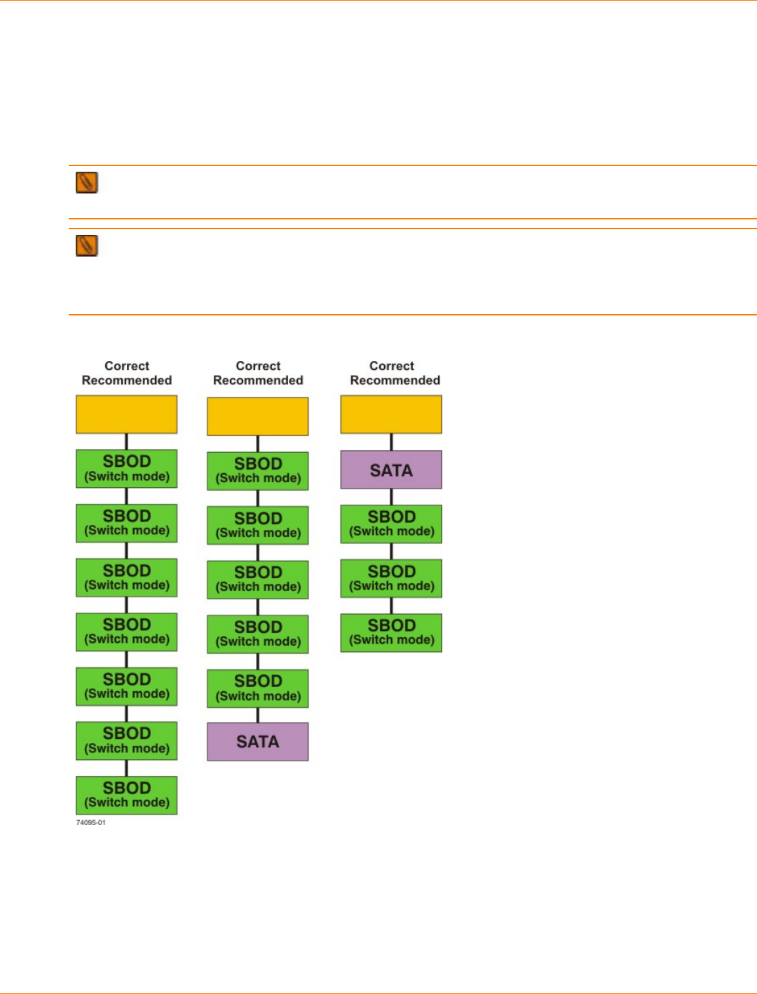
SANtricity_10.77 February 2011
LSI Corporation
- 571 -
The following figure shows a simple block diagram of three recommended topologies for SBOD drive trays.
All three scenarios shown in the figure are arranged to maximize performance. The scenario on the left of the
figure (all SBODs) also offers the advantage of flexible drive cabling; for example, connecting two In ports or
two Out ports. This flexible approach to drive cabling is enabled by the Fibre Channel-Arbitrated Loop feature.
In the figure, the FC2610 drive trays or the FC4600 drive trays are identified as SBODs. The AT2655 drive
trays are identified as SATA (Serial Advanced Technology Attachment).
IMPORTANT When you connect drive trays to the CE7922 controller tray or the CE7900 controller tray,
you must not mix different types of drive trays on the same loop.
IMPORTANT When you mix different types of drive trays, you must consider the total number of drives
that are available in the final configuration of the storage array. For example, if you mix FC4600 drive trays
with FC2610 drive trays, the total number of drives might be more than the maximum number that each drive
channel can support.
Suitable Cabling Topologies for Multiple SBOD Drive Trays
Labeling Cables
Cabling is an important part of creating a robust storage array. Labeling the cables identifies system
components, drive channels, and loops. System maintenance is easier when the cables are correctly
identified. Label both ends of each cable. You can use adhesive office labels that are folded in half over
the ends of each cable. Mark the labels with the port identifiers to which the cable is connected. If you use
the recommended topologies in as described in the topics under “Host Cabling” and “Drive Cabling,” label

SANtricity_10.77 February 2011
LSI Corporation
- 572 -
each cable with the channel number noted in the table that you are following. You can provide additional
information by using color-coded cable straps (or ties) to group all of the cables associated with one
component, drive channel, or loop.
If a component fails, you must disconnect the cables, replace the failed component, and reattach the cables.
Detailed labeling of the cables will simplify the component replacement process.
If you add a new drive tray to an existing configuration, correctly labeled cables will help you identify where to
connect the new drive tray.
Cabling Information Provided by SANtricity ES Storage Manager
After you have completed your cabling topology and installed the SANtricity ES Storage Manager software,
you can view cabling information through the SANtricity ES Storage Manager software. The SANtricity ES
Storage Manager software shows a table that lists all of the connections in the cabling topology and identifies
any incorrectly cabled drive channels or non-redundant drive channels. For more information, refer to the
online help topics in the SANtricity ES Storage Manager software.
Adding New Drive Trays to an Existing Storage Array
HotScale™ technology enables you to add drive trays to an existing storage array without interrupting power
or data transfer to the storage array. See the topics under “Drive Cabling” for the recommended cabling
patterns for various numbers of attached drive trays.
When the number of drive trays exceeds the number or drive ports on a controller, the cabling pattern
changes significantly. At this point, you will start to use the “A” ports on the ESMs, and additional drive trays
connect to the controller tray indirectly, through other drive trays.
If you are adding additional drive trays to an existing configuration so that the total number of attached drive
trays will increase from fewer than the number of drive ports per controller to a total that is greater than that
number, you will need to re-cable some of the drive trays that were previously installed.
Common Procedures
This section provides procedures that are common to most cable installations.
Handling Static-Sensitive Components
Static electricity can damage dual inline memory modules (DIMMs), system boards, and other static-sensitive
components. To prevent damaging the system, follow these precautions:
Move and store all components in the static-protective packaging in which they came.
Place components on a grounded surface before removing them from their static-protective packaging.
Grounded surfaces include static-dissipating mats or grounded workstations.
Always be properly grounded when touching a static-sensitive component. To properly ground yourself,
wear a wrist strap or boot strap made for this purpose.
Handle the component by its edges. Do not touch solder joints, pins, or printed circuitry.
Use conductive field service tools.
Installing an SFP Transceiver and a Fiber-Optic Cable
You must install SFP transceivers into each connector to which you will connect a fiber-optic cable.
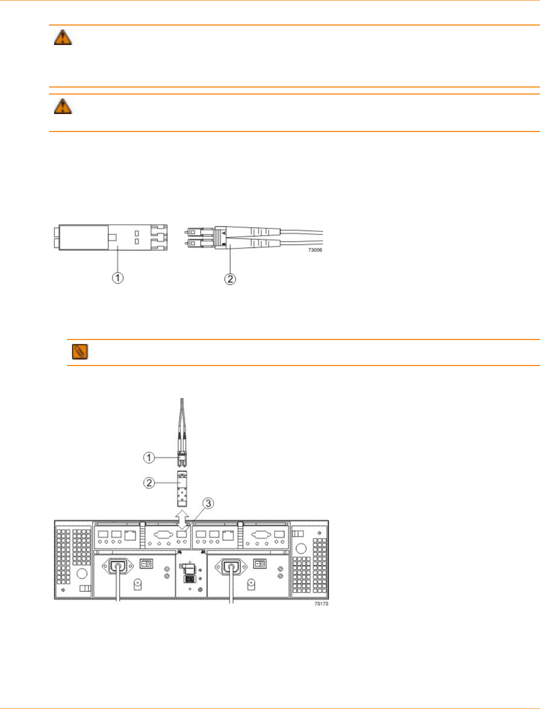
SANtricity_10.77 February 2011
LSI Corporation
- 573 -
ATTENTION Possible loss of data access – Fiber-optic cables are fragile. Bending, twisting, folding,
or pinching fiber-optic cables can cause damage to the cables, degraded performance, or possible loss of
data access. To prevent damage, do not twist, fold, pinch, or step on the cables. Do not bend the cables in
less than a 5-cm (2-in.) radius.
ATTENTION Possible hardware damage – To prevent electrostatic discharge damage to the tray,
use proper antistatic protection when handling tray components.
1. Put on antistatic protection.
2. Make sure that your cables are fiber-optic cables by comparing them to the fiber-optic cable shown in the
following figure. Your SFP transceivers might look slightly different from the one shown. The differences
do not affect the performance of the SFP transceiver.
SFP Transceiver and Fiber-Optic Cable
1. SFP Transceiver
2. Fiber-Optic Cable
3. Insert an SFP transceiver into the port in which the fiber-optic cable will be installed.
IMPORTANT Make sure that the SFP transceiver installs with an audible click.
Installing an SFP Transceiver
1. Fiber-Optic Cable
2. SFP Transceiver
3. Drive Tray Port
4. Install the fiber-optic cable.
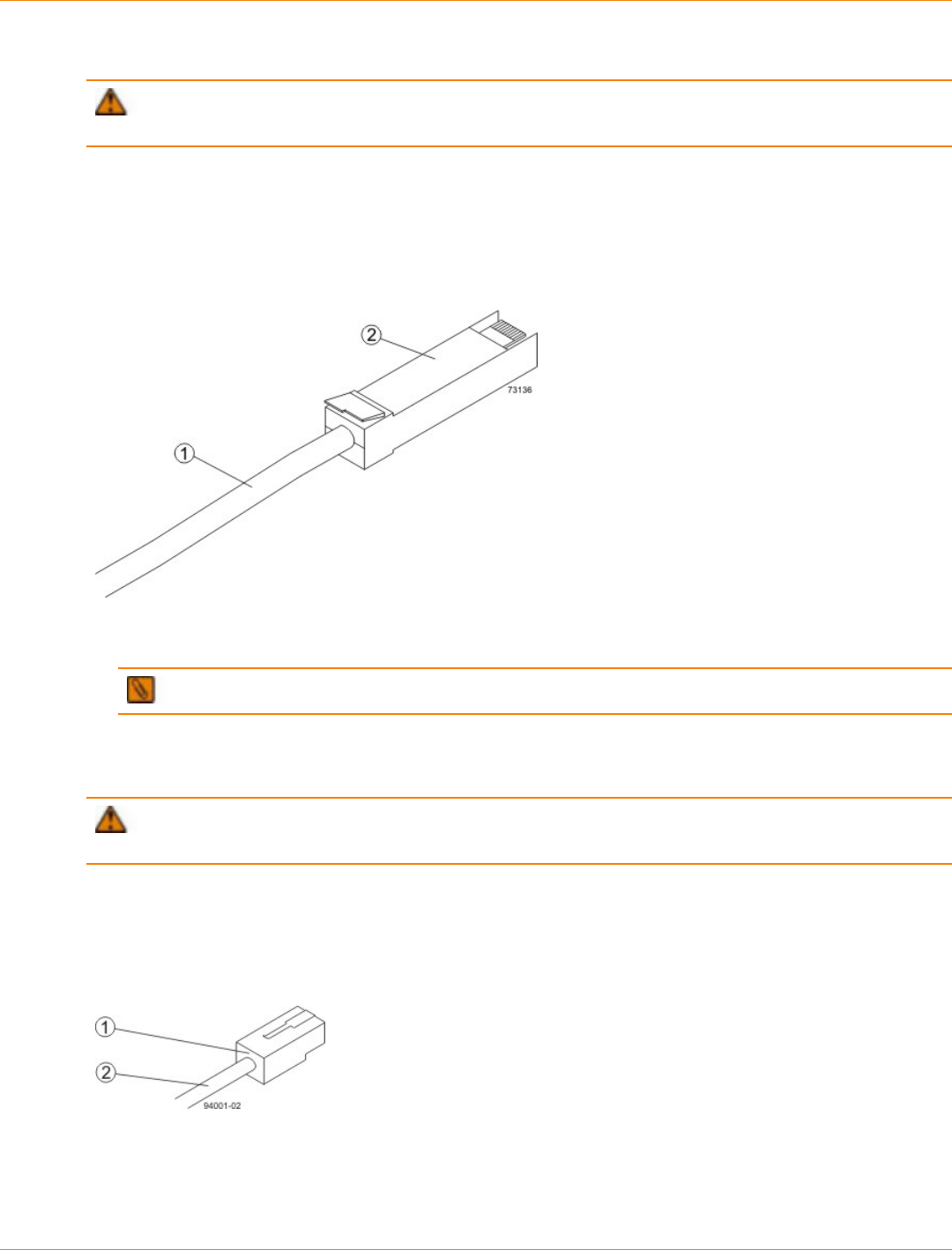
SANtricity_10.77 February 2011
LSI Corporation
- 574 -
Installing a Copper Cable with a Passive SFP Transceiver
ATTENTION Possible hardware damage – To prevent electrostatic discharge damage to the tray,
use proper antistatic protection when handling tray components.
1. Put on antistatic protection.
2. Verify that your cables are copper cables by comparing them to the cable shown in the following figure.
Your passive SFP transceivers might look slightly different from the one shown. The differences do not
affect the performance of the SFP transceiver.
Passive SFP Transceiver and Copper Cable
1. Copper Cable
2. Passive SFP Transceiver
IMPORTANT Ensure that the passive SFP transceiver installs with an audible click.
3. Insert the passive SFP transceiver into the port in which the copper cable will be installed.
Installing an iSCSI Cable
ATTENTION Possible hardware damage – To prevent electrostatic discharge damage to the tray,
use proper antistatic protection when handling tray components.
1. Put on antistatic protection.
2. Verify that you have the correct cables for an iSCSI connections by comparing them to the cable shown in
the following figure. Cables for iSCSI connections do not require SFP transceivers.
iSCSI Cable with an RJ-45 Connector
1. RJ-45 Connector
2. iSCSI Cable
3. For each cable, insert one RJ-45 connector into a host interface card port on the controller-drive tray or
the controller tray and the other RJ-45 connector into a port on the host’s Ethernet adapter.
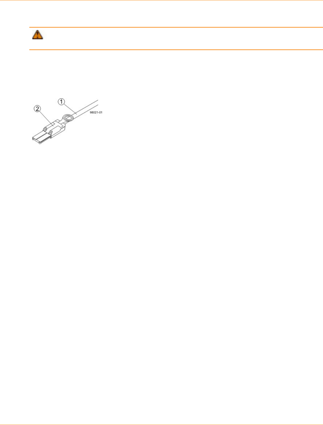
SANtricity_10.77 February 2011
LSI Corporation
- 575 -
Installing a SAS Cable
ATTENTION Possible hardware damage – To prevent electrostatic discharge damage to the tray,
use proper antistatic protection when handling tray components.
1. Put on antistatic protection.
2. Verify that you have the correct cables for a SAS connections by comparing them to the cable shown in
the following figure. Cables for SAS connections do not require SFP transceivers.
SAS Cable with an SFF-8088 Connector
1. SAS Cable
2. SFF-8088 Connector
3. For each cable, insert one SFF-8088 connector into a host interface card port on the controller-drive tray
or the controller tray and the other SFF-8088 connector into an port on the host’s HBA.

SANtricity_10.77 February 2011
LSI Corporation
- 576 -
Product Compatibility
This chapter lists all currently supported products, along with their host and drive channel specifications.
Host Channel Information by Model
The following table lists the specifications and restrictions that affect host-cabling topologies. Make sure that
your planned controller tray topology or your planned controller-drive tray topology is compatible with these
specifications and restrictions.
Host Channel Information for Controller Trays and Controller-Drive Trays
Product Host Port
Type Maximum
Host
Port
Speed
Number
of Host
Ports
per
Controller
Maximum
Number
of Hosts
per
Cluster
Maximum
Number
of
Hosts
Cable
Type
CE7922 controller
tray InfiniBand 2 Gb/s
4 Gb/s 0, 4, or 8 16 2048 Copper
or fiber-
optic
InfiniBand
Cables
Fibre
Channel 8 Gb/
s (with
8-Gb/s
HICs)
0, 4, or 8 16 2048 Fiber-
optic
iSCSI 1 Gb/s
10 Gb/s 0, 4, or 8 16 256 Copper
CE7900 controller
tray
InfiniBand 20 Gb/s 0, 4, or 8 16 256 Fiber-
optic
InfiniBand
Cables
CE6998 controller
tray Fibre
Channel 4 Gb/s 4 16 1024 Fiber-
optic
Fibre
Channel 8 Gb/s 2 or 4 16 640 Fiber-
optic
CDE4900
controller-drive tray
iSCSI 1 Gb/s
10 Gb/s 2 16 640 Copper
CDE3994
controller-drive tray Fibre
Channel 2 Gb/s 4 16 1024 Fiber-
optic
CDE3992
controller-drive tray Fibre
Channel 2 Gb/s 2 or 4 16 256 Fiber-
optic
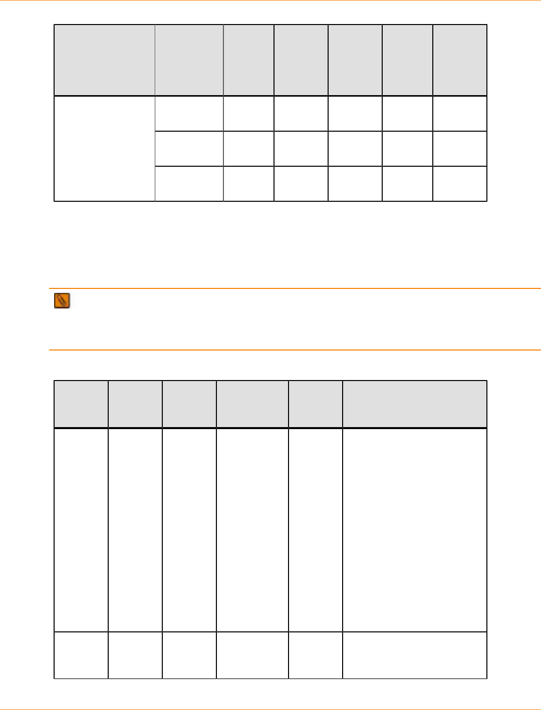
SANtricity_10.77 February 2011
LSI Corporation
- 577 -
Product Host Port
Type Maximum
Host
Port
Speed
Number
of Host
Ports
per
Controller
Maximum
Number
of Hosts
per
Cluster
Maximum
Number
of
Hosts
Cable
Type
SAS 6 Gb/s
10 Gb/s 2 or 4 16 256 Copper
Fibre
Channel 8 Gb/s 0 or 4 16 256 Fiber-
optic
CDE2600
controller-drive tray
CDE2600-60
controller-drive tray
iSCSI 1 Gb/s
10 Gb/s 0 or 4 16 256 Copper
Drive Channel Information by Model
The following table lists the specifications and restrictions that affect cabling between controller trays and
drive trays or between controller-drive trays and drive trays. Make sure that the topology you plan for your
drive trays is compatible with these specifications and restrictions.
IMPORTANT When you mix different types of drive trays, you must consider the total number of drives
that are available in the final configuration of the storage array. For example, if you mix FC4600 drive trays
with FC2610 drive trays, the total number of drives might be more than the maximum number that each drive
channel can support.
Drive Channel Information for Controller Trays and Controller-Drive Trays
Product Drive
Port
Speeds
Maximum
Number
of Drives
Supported
Drive Trays Cable
Type Notes
CE7922
controller
tray
2 Gb/s or
4 Gb/s 480 DE6900
FC4600 Copper
FC
cables
or fiber-
optic FC
cables
The 480 maximum number
of drives is possible only
for a configuration with
eight DE6900 drive trays
with no other types of drive
trays. There is a limit of two
expansion drive trays for
each redundant pair of loops.
Up to 448 drives are possible
when FC4600 drive trays are
used exclusively. There is a
limit of seven expansion drive
trays for each redundant pair
of loops.
Mixing drive types is not
supported.
CE7900
controller
tray
2 Gb/s or
4 Gb/s 480 DE6900
FC4600 Copper
FC
cables
The 480 maximum number
of drives is possible only
for a configuration with

SANtricity_10.77 February 2011
LSI Corporation
- 578 -
Product Drive
Port
Speeds
Maximum
Number
of Drives
Supported
Drive Trays Cable
Type Notes
or fiber-
optic FC
cables
Copper
iSCSI
cables
eight DE6900 drive trays
with no other types of drive
trays. There is a limit of two
expansion drive trays for
each redundant pair of loops.
Up to 448 drives are possible
when FC4600 drive trays are
used exclusively. There is a
limit of seven expansion drive
trays for each redundant pair
of loops.
Mixing drive tray types is
supported. The maximum
number of drives for a mixed
configuration is 448.
With a CE7900 controller
tray, FC4600 drive trays
support solid-state drives
(SSDs). A drive tray can have
both SSDs and hard disk
drives. The maximum number
of SSDs for the storage array
is 20.
CE6998
controller
tray and
CE6994
controller
tray
2 Gb/s or
4 Gb/s 224 FC4600
AT2655
FC2610
FC2600
Copper
FC
cables
or fiber-
optic FC
cables
If you are using the
FC4600 drive tray in your
configuration, design for a
limit of seven expansion drive
trays for each redundant
pair of loops. With the
AT2655, FC2610, or FC2600
expansion drive trays, the
limit is eight per channel pair.
Mixing drive types is
supported. When a channel
has a mix of FC4600,
AT2655, FC2610, or FC2600
drive trays, up to seven drive
trays per channel and up to
14 drive trays per controller
tray are supported.
When a controller tray has
a mix of FC4600, AT2655,
FC2610, or FC2600 drive
trays but each channel has
only one type of drive tray,
up to seven drive trays for
each channel with FC4600
drive trays and up to eight

SANtricity_10.77 February 2011
LSI Corporation
- 579 -
Product Drive
Port
Speeds
Maximum
Number
of Drives
Supported
Drive Trays Cable
Type Notes
drive trays for each channel
with other drive tray types are
supported.
CDE4900
controller-
drive tray
4 Gb/s 112 FC4600 Copper
FC
cables
or fiber-
optic FC
cables
Copper
iSCSI
cables
Design for a limit of six
expansion drive trays per
dual-ported drive channel.
CDE3994
controller-
drive
tray and
CDE3992
controller-
drive tray
2 Gb/s or
4 Gb/s 112 FC4600
AT2655
FC2610
FC2600
Copper
FC
cables
or fiber-
optic FC
cables
Mixing different drive tray
types on the same loop is
supported.
Up to seven attached drive
trays if there are no drives
in the controller-drive tray
and up to six attached drive
trays if there are drives in
the controller-drive tray are
supported.
CDE2600
controller-
drive tray
6 Gb/s
SAS 192 DE1600
DE5600
DE6600
SAS
cables The CDE2600 controller-drive
tray has both 12-drive and
24-drive configurations.
The DE1600 drive tray has up
to 12 drives.
The DE5600 drive tray has up
to 24 drives.
The DE6600 has up to 60
drives.
CDE2600-60
controller-
drive tray
DE6600 SAS
cables The DE6600 has up to 60
drives.
Drive Tray Information by Model
The following table lists the drive tray specifications that might affect your topology. Make sure that your
planned topology is compatible with these specifications and restrictions.
IMPORTANT When you mix different types of drive trays, you must consider the total number of drives
that are available in the final configuration of the storage array. For example, if you mix FC4600 drive trays
with FC2610 drive trays, the total number of drives might be more than the maximum number that each drive
channel can support.
SANtricity_10.77 February 2011
LSI Corporation
- 580 -
Specifications for Drive Trays
Model Port Speed Drives per
Tray Maximum Number of Drive
Trays per Channel
DE6900 drive tray 4 Gb/s 60 2
DE6600 drive tray 6 Gb/s 60 2
FC4600 drive tray 4 Gb/s 16 7
FC2610 drive tray 2 Gb/s 14 8
FC2600 drive tray 2 Gb/s 14 8
AT2655 drive tray 2 Gb/s 14 8
DE5600 drive tray 6 Gb/s 24 4
DE1600 drive tray 6 Gb/s 12 8
SANtricity_10.77 February 2011
LSI Corporation
- 581 -
Host Cabling
This chapter provides examples of possible cabling topologies between one or more hosts and a controller
tray or a controller-drive tray. Direct-attach topologies, fabric topologies, and mixed topologies are addressed.
You are not limited to using only these topologies. Examples are provided to show basic concepts to help
you define an optimal host-cabling topology. A table that lists the maximum supported number of hosts is
included.
For host port locations on the specific controller tray model or controller-drive tray model that you are
installing, see the topics under “Component Locations.”
IMPORTANT If you are using the Remote Volume Mirroring premium feature, see the topics under
“Hardware Installation for Remote Volume Mirroring” for information on cabling using a host port between two
storage arrays.
Host Interface Connections
The CE7900 controller tray connects to hosts through one or two host interface cards (HICs). The CDE4900
controller-drive tray has built-in (base) Fibre Channel (FC) connectors for host connections and might also
have an optional HIC. The CDE2600 controller-drive tray and the CDE2600-60 controller-drive tray have
built-in (base) SAS connectors for host connections and might also have an optional HIC. All other supported
controller trays and controller-drive trays connect through built-in ports.
Types of Host Port Configurations and HICs for Controller Trays and Controller-Drive Trays
Controller Type Base Ports HIC 1 HIC 2
CE7900 None Quad 4-Gb/s FC
or
Quad 8-Gb/s FC
or
Dual 1-Gb/s
iSCSI
Dual 10-Gb/s
iSCSI
None or
Quad 4-Gb/s FC
or
Quad 8-Gb/s FC
or
Dual 1-Gb/s
iSCSI
Dual 10-Gb/s
iSCSI
CDE4900 Dual 8-Gb/s FC None or
Dual 8-Gb/s FC
or
Dual 1-Gb/s
iSCSI
None
CDE2600
CDE2600-60 Dual 6-Gb/2 SAS None or
Dual 6-Gb/2 SAS
Quad 8-Gb/s FC
or
Quad 1-Gb/s
iSCSI
Dual 10-Gb/s
iSCSI
None
SANtricity_10.77 February 2011
LSI Corporation
- 582 -
A CE7900 controller tray, a CDE4900 controller-drive tray, a CDE2600 controller-drive tray or a CDE2600-60
controller-drive tray can mix host interfaces of different types, with some restrictions. In all cases, when host
interface types are mixed, both controllers in a duplex controller tray or a duplex controller-drive tray must
have the same arrangement of HICs. Each controller must have the same type of HIC in the same relative
position as the other controller.
NOTE On the CDE2600 controller-drive tray, each controller has a pair of levers with handles for
removing the controller from the controller-drive tray. If a controller has a HIC installed, one of these handles
on the controller is located next to a host port on the HIC. The close spacing between the handle and the host
port might make it difficult to remove a cable that is attached to the host port. If this problem occurs, use a flat-
blade screwdriver to compress the release on the cable connector.
A HIC is connected to a host adapter: a host bus adapter (HBA) for Fibre Channel or SAS, or an Ethernet
adapter for iSCSI. The host adapter in the host must match the type of HIC to which it is connected.
For best performance, connect an 8-Gb/s Fibre Channel HIC to an 8-Gb/s HBA. If the data rate for the HBA
is lower, the data transfer rate will be at the lower rate. For instance, if you connect an 8-Gb/s Fibre Channel
HIC to a 4-Gb/s HBA, the data transfer rate is 4 Gb/s.
It is possible for a host to have both iSCSI and Fibre Channel adapters for connections to a storage array that
has a mix of HICs. Several restrictions apply to such configurations:
The root boot feature is not supported for hosts with mixed connections to one storage array.
Cluster configurations are supported for hosts with mixed connections to one storage array.
When the host operating system is VMware, mixing connection types within a storage partition is not
supported.
When the host operating system is Windows, mixing connection types within a storage partition is not
supported. A single server that attaches to multiple storage partitions on a single storage array must not
have any overlap in LUN number assignments given to the volumes.
For other operating systems, mixed connection types from a host to a single storage array are not
supported.
Maximum Number of Host Connections
Maximum Number of Host Connections by Model to a Controller Tray or a Controller-Drive Tray
Model Maximum Number of Hosts
CE7922 controller tray and
CE7900 controller tray 2048
CE6998 controller tray and
CE6994 controller tray 1024
CDE4900 controller-drive tray 640
CDE3994 controller-drive tray
and 1024
CDE3992 controller-drive tray 256
CDE2600 controller-drive tray 256
SANtricity_10.77 February 2011
LSI Corporation
- 583 -
Model Maximum Number of Hosts
CDE2600-60 controller-drive tray 256
ATTENTION Possible loss of data access – Do not use a combination of HBAs from different
vendors in the same storage area network. For the HBAs to perform correctly, use only HBAs from one
manufacturer in a SAN.
Direct-Attach Topologies
The host-to-controller tray topologies presented in this section do not use switches. The host adapters might
be HBAs for Fibre Channel or SAS, HCAs for InfiniBand, or Ethernet for iSCSI. Some controller trays and
controller-drive trays support more direct host connections than the examples shown. To cable more host
connections, follow the pattern established by the examples in this section.
When a host is cabled to a dual-controller controller-drive tray or a dual-controller controller tray, each
attached host should have two host adapters installed. For redundancy, connect one host adapter to
controller A and the other to controller B.
One Host to a Controller Tray or a Controller-Drive Tray
The following table lists the components in this topology that are non-redundant and present a risk of a single
point of failure. The following figure shows an example of a direct-attach topology with one host and a dual-
controller controller tray or a dual-controller controller-drive tray.
The example in the figure identifies HBA1 and HBA2 as connecting points on the host. For other
configurations, these connecting points might be host channel adapters (HCAs) for InfiniBand connections,
Ethernet adapters for iSCSI connections, or a combination of one HBA and one iSCSI Ethernet adapter.
ATTENTION Possible loss of data access – You must install alternate path software or an alternate
path (failover) driver on the host to support failover in the event of an HBA, an HCA, or an iSCSI Ethernet
adapter failure or a host channel failure.
Redundant and Non-Redundant Components in a Direct-Attached Configuration with One Host and a
Controller Tray or a Controller-Drive Tray
Component Redundant Non-Redundant
Host/server Non-redundant
HBA, HCA, or iSCSI
Ethernet adapter Redundant
Host-to-controller
cable Redundant
Controller Redundant
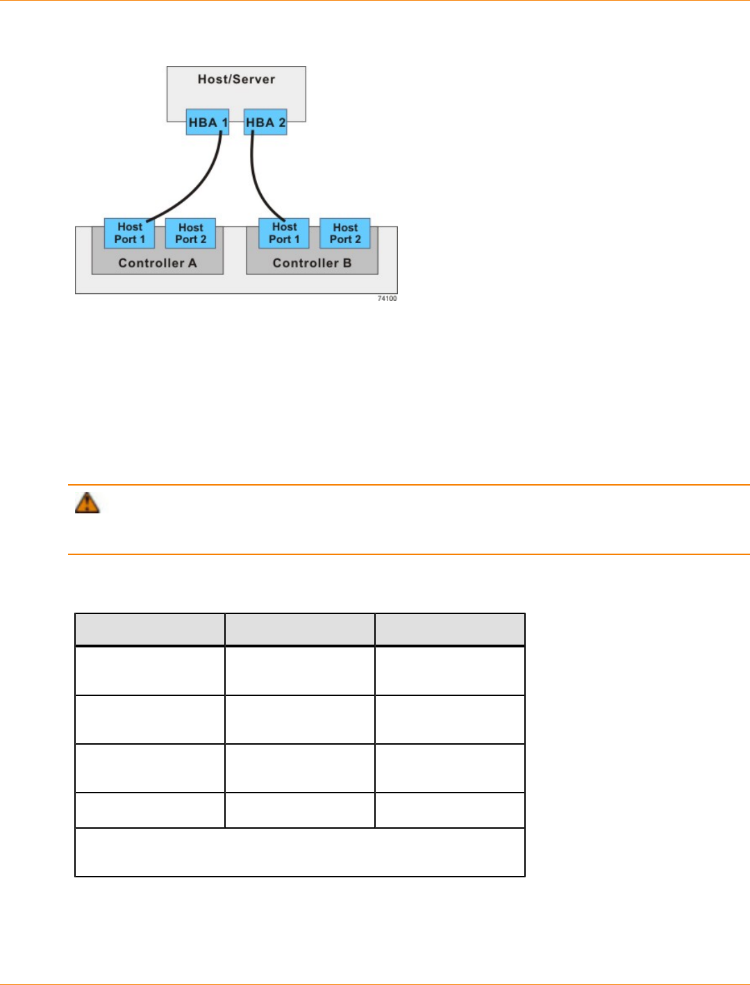
SANtricity_10.77 February 2011
LSI Corporation
- 584 -
Direct-Attach Topology – One Host and a Controller Tray or a Controller-Drive Tray
Two Hosts to a Controller Tray or a Controller-Drive Tray
The following table lists the components in this topology which are non-redundant and present a risk of a
single point of failure. The following figure shows an example of a direct-attach topology with two hosts and a
dual-controller controller or a dual-controller controller-drive tray.
The example in the figure shows HBA1 and HBA2 as connecting points on the host. For other configurations,
these connecting points might be host channel adapters (HCAs) for InfiniBand connections, Ethernet adapters
for iSCSI connections, or a combination of one HBA and one iSCSI Ethernet adapter.
ATTENTION Possible loss of data access – You must install alternate path software or an alternate
path (failover) driver on the host to support failover in the event of an HBA, HCA, or iSCSI Ethernet adapter
failure or a host channel failure.
Redundant and Non-Redundant Components in a Direct-Attached Configuration with Two Hosts and a
Controller Tray or a Controller-Drive Tray
Component Redundant Non-Redundant
Host/server (see
note) Redundant
HBA, HCA, or iSCSI
Ethernet adapter Redundant
Host-to-controller
cable Redundant
Controller Redundant
Note – The hosts/servers in this example must be clustered to be
redundant.
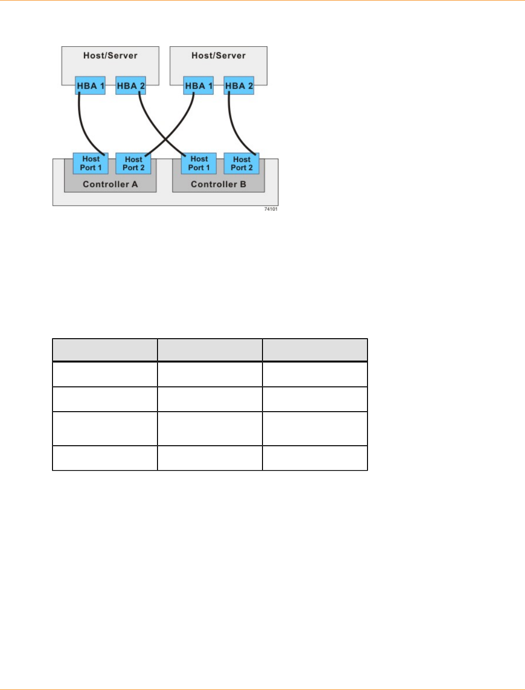
SANtricity_10.77 February 2011
LSI Corporation
- 585 -
Direct-Attach Topology – Two Hosts and a Controller Tray or a Controller-Drive Tray
One Single-HBA Host to a Single-Controller Controller Tray or a Single-Controller Controller-
Drive Tray
The following figure shows an example of a direct-attach topology with one host and a single-controller
controller tray or a single-controller controller-drive tray. The following table describes which of the
components in this topology are non-redundant and present a risk of a single point of failure.
Direct-Attach Topology – One Host and a Single-Controller Controller Tray or a Single-Controller
Controller-Drive Tray
Component Redundant Non-Redundant
Host/server Non-redundant
HBA Non-redundant
Host-to-controller
cable Non-redundant
Controller Non-redundant
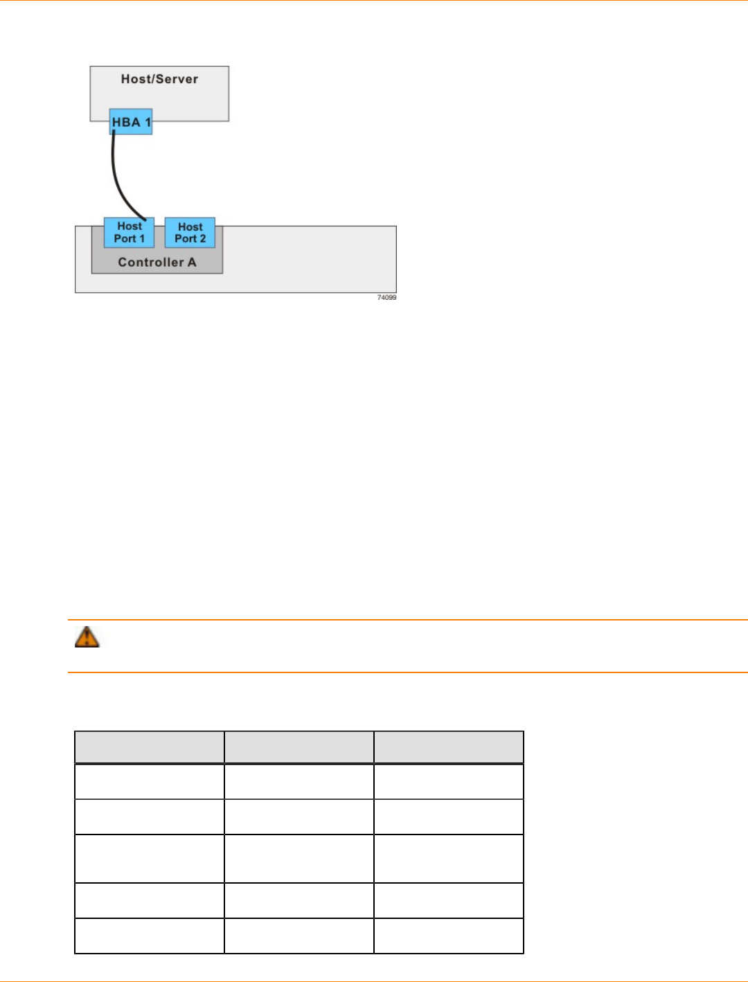
SANtricity_10.77 February 2011
LSI Corporation
- 586 -
Single-HBA Host to a Single-Controller Controller Tray or a Single-Controller Controller-Drive Tray
Switch Topologies
The host-to-controller tray topologies or host-to-controller-drive tray topologies presented in this section
include one or more switches. The host adapters in the hosts might be HBAs for Fibre Channel, HCAs for
InfiniBand, or Ethernet for iSCSI. Switches are not supported for SAS host connections.
When a host is cabled to a dual-controller controller-drive tray or a dual-controller controller tray, each
attached host should have two host adapters installed. For redundancy, attach each of the host adapters
to a different switch (or switch zone) so that one switch (or zone) connects to controller A and the other to
controller B in the controller tray or the controller-drive tray. In the case where a host has one HBA and one
iSCSI Ethernet adapter, the two connections might require two different types of switches.
One Host to a Controller Tray or a Controller-Drive Tray
The following figure shows an example of a switch topology with one host, a controller tray or a controller-
drive tray, and a zoned switch. The following table describes which of the components in this topology are
non-redundant and present a risk of a single point of failure.
ATTENTION Possible loss of data access – You must install alternate path software or an alternate
path (failover) driver on the host to support failover in the event of an HBA failure or a host channel failure.
Redundant and Non-Redundant Components in a Switched Configuration with One Host and a
Controller Tray or a Controller-Drive Tray
Component Redundant Non-Redundant
Host/server Non-redundant
Host adapter Redundant
Host-to-controller
cable Redundant
Switch Non-redundant
Controller Redundant
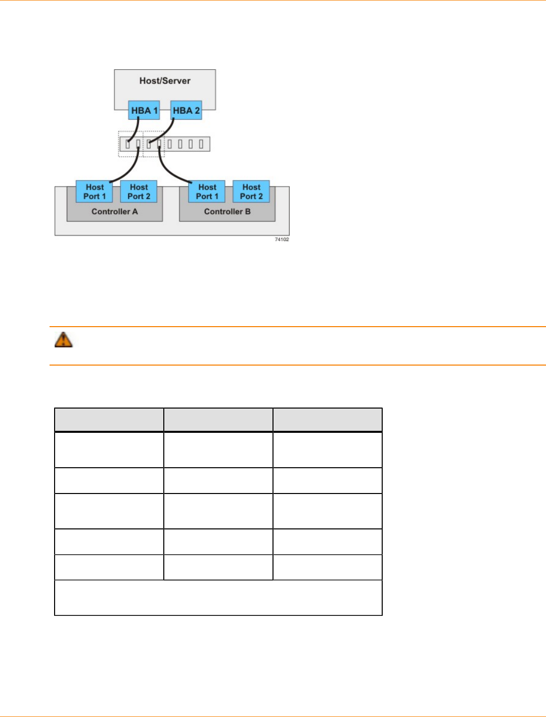
SANtricity_10.77 February 2011
LSI Corporation
- 587 -
In the following figure, each outlined group of ports represents a zone.
Switch Topology – One Host and a Controller Tray or a Controller-Drive Tray with a Switch
Two Hosts to a Controller Tray or a Controller-Drive Tray
The following figure shows an example of a switch topology with two hosts, a controller tray or a controller-
drive tray, and a zoned switch. The following table describes which of the components in this topology are
non-redundant and present a risk of a single point of failure.
ATTENTION Possible loss of data access – You must install alternate path software or an alternate
path (failover) driver on the host to support failover in the event of an HBA failure or a host channel failure.
Redundant and Non-Redundant Components in a Switched Configuration with Two Hosts and a
Controller Tray or a Controller-Drive Tray
Component Redundant Non-Redundant
Host/server (see
note) Redundant
Host adapter Redundant
Host-to-controller
cable Redundant
Switch Non-redundant
Controller Redundant
Note – The hosts/servers in this example must be clustered to be
redundant.
In the following figure, each outlined group of ports represents a zone.
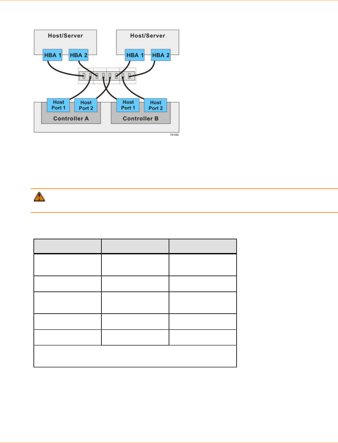
SANtricity_10.77 February 2011
LSI Corporation
- 588 -
Switch Topology – Two Hosts and a Controller Tray or a Controller-Drive Tray with a Zoned Switch
Four Hosts to a Controller Tray or a Controller-Drive Tray
The following figure shows an example of a switch topology with four hosts, a controller tray or a controller-
drive tray, and two zoned switches. The following table describes which of the components in this topology
are non-redundant and present a risk of a single point of failure.
ATTENTION Possible loss of data access – You must install alternate path software or an alternate
path (failover) driver on the host to support failover in the event of an HBA failure or a host channel failure.
Redundant and Non-Redundant Components in a Switched Configuration with Four Hosts and a
Controller Tray or a Controller-Drive Tray
Component Redundant Non-Redundant
Host/server (see
note) Redundant
Host adapter Redundant
Host-to-controller
cable Redundant
Switch Redundant
Controller Redundant
Note – The hosts/servers in this example must be clustered to be
redundant.
In the following figure, each outlined group of ports represents a zone.
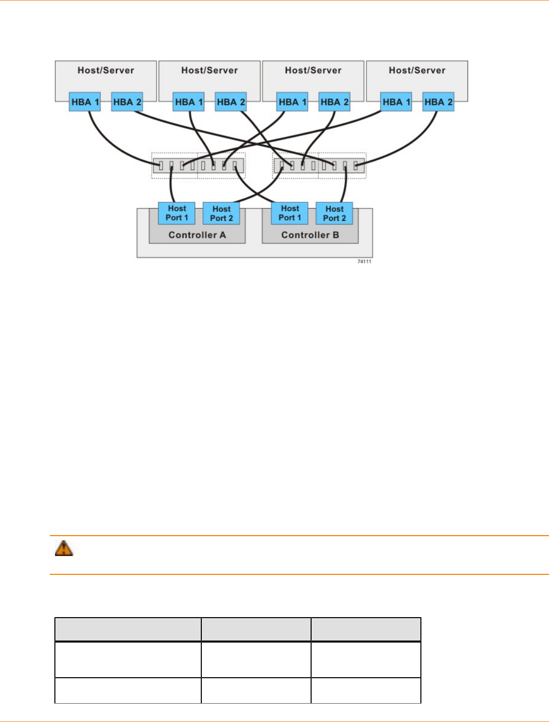
SANtricity_10.77 February 2011
LSI Corporation
- 589 -
Switch Topology – Four Hosts and a Controller Tray or a Controller-Drive Tray with Two Zoned
Switches
Mixed Topologies
The following table describes which of the components in this topology are non-redundant and present a risk
of a single point of failure. The following figure shows an example of a mixed topology; that is, a topology that
combines both switch topology and direct-attach topology. This example shows three hosts, a controller tray,
and two switches.
The example in the figure identifies HBA1 and HBA2 on each host as connecting points. For other
configurations, these connecting points might be host channel adapters (HCAs) for InfiniBand connections,
Ethernet adapters for iSCSI connections, or a combination of one HBA and one iSCSI Ethernet adapter.
Switches are not supported for SAS host connections.
When a host is cabled to a dual-controller controller-drive tray or a dual-controller controller tray, each
attached host should have two host adapters installed. The host adapters might be HBAs for Fibre Channel
or SAS, HCAs for InfiniBand, or Ethernet for iSCSI. For redundancy, attach each of the host adapters that
connects through a switch to a different switch (or switch zone) so that one switch (or zone) connects to
controller A and the other to controller B in the controller tray or the controller-drive tray. In the case where a
host has one HBA and one iSCSI Ethernet adapter, the two connections might require two different types of
switches. Redundancy for a host that attaches directly to a controller tray or a controller-drive tray requires
that each host adapter attach to a different controller.
ATTENTION Possible loss of data access – You must install alternate path software or an alternate
path (failover) driver on the host to support failover in the event of an HBA failure or a host channel failure.
Redundant and Non-Redundant Components in a Mixed Configuration with Three Hosts and a
Controller Tray or a Controller-Drive Tray
Component Redundant Non-Redundant
Host/servers 1 and 2 (see
note) Redundant
Host/server 3 Non-redundant
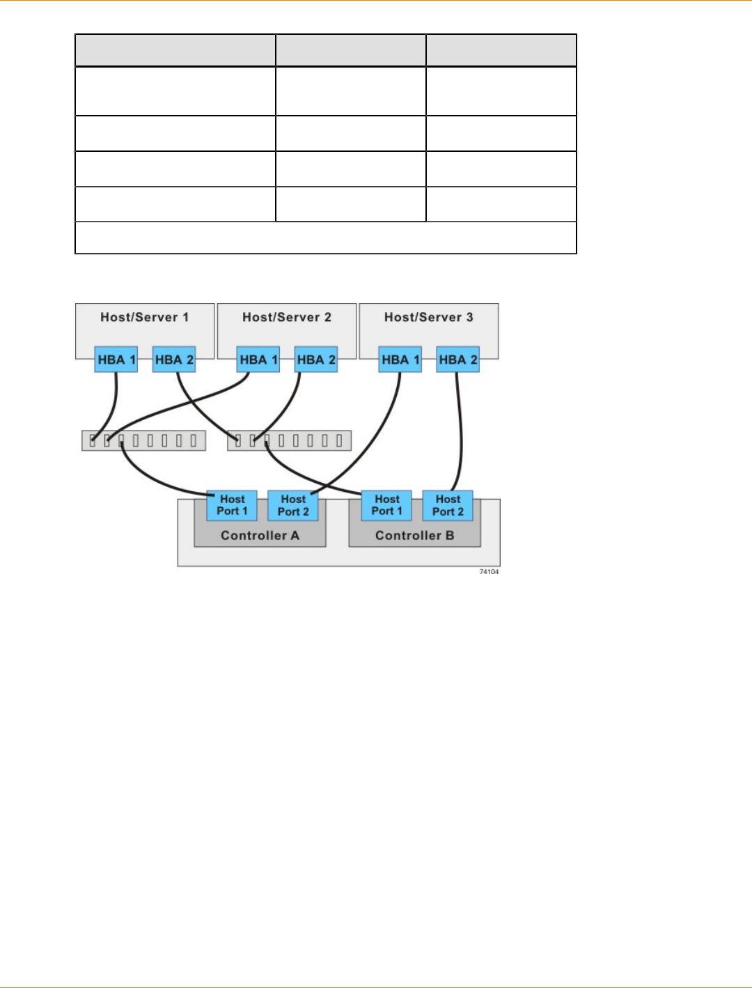
SANtricity_10.77 February 2011
LSI Corporation
- 590 -
Component Redundant Non-Redundant
HBA, HCA, or Ethernet iSCSI
adapter Redundant
Host-to-controller cable Redundant
Switch Redundant
Controller Redundant
Note – The hosts/servers in this example must be clustered to be redundant.
Mixed Topology – Three Hosts and a Controller Tray
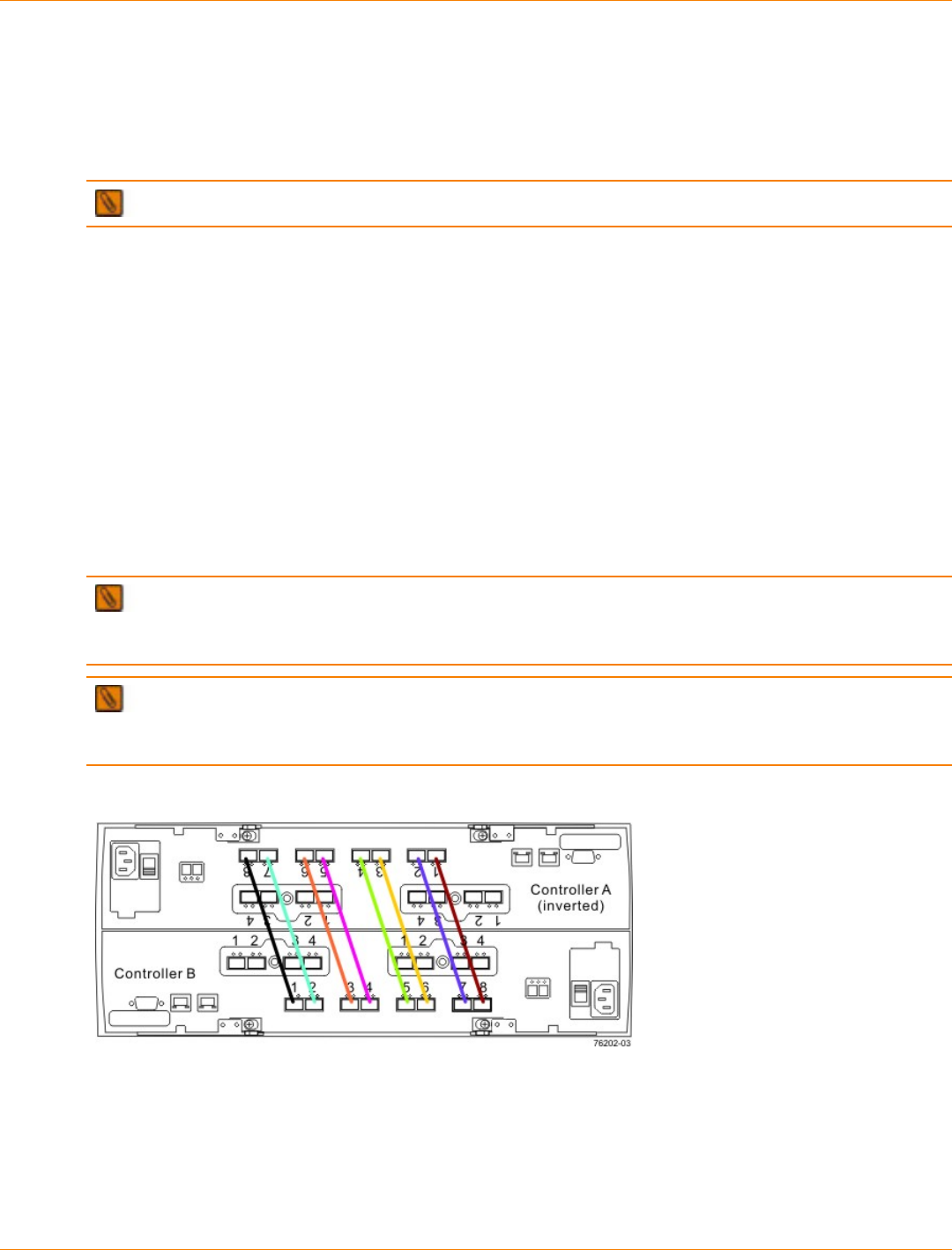
SANtricity_10.77 February 2011
LSI Corporation
- 591 -
Drive Cabling
This chapter provides examples of cabling between a controller tray or a controller-drive tray and the
environmental services monitors (ESMs) of one or more expansion drive trays. This chapter also shows
potential combinations of these products in storage array configurations.
IMPORTANT Every example in this chapter provides redundant access to each drive.
See the topics under “Component Locations” for drive port locations on the specified controller tray or
controller-drive tray and drive tray models that you are installing.
Refer to the section that applies to the controller tray or controller-drive tray to which you are cabling the drive
trays.
Drive Channel Redundancy for the CE7900 Controller Tray and the CE7922
Controller Tray
Each controller has four drive channels, and each drive channel has two ports. Therefore, each controller
has eight drive ports. A controller tray has eight redundant path pairs that are formed using one drive channel
of controller A and one drive channel of controller B. The following figure shows the redundant pairs in a
controller tray. The following table lists the numbers of the redundant path pairs and the drive ports of the
drive channels from which the redundant path pairs are formed.
IMPORTANT To maintain data access in the event of the failure of a controller, an ESM, or a drive
channel, you must connect a drive tray or multiple drive trays on a loop to both drive channels on a redundant
path pair.
IMPORTANT If you are connecting DE6900 drive trays and you plan to use the drive-side trunking
capability, you must connect each drive tray (or multiple drive trays on a loop) to both drive channels on each
of two redundant path pairs to maintain hardware redundancy.
Redundant Path Pairs on the CE7900 Controller Tray and the CE7922 Controller Tray
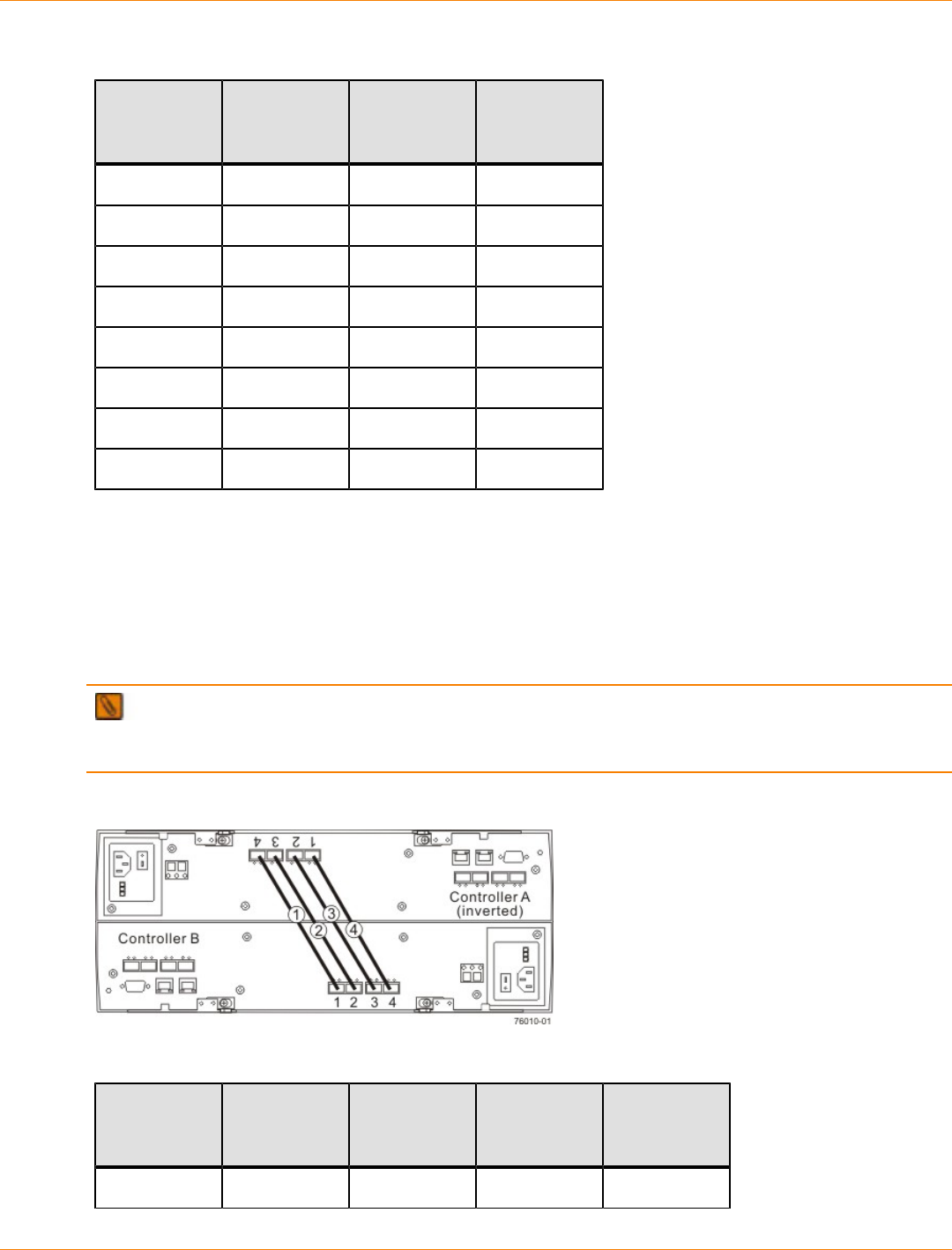
SANtricity_10.77 February 2011
LSI Corporation
- 592 -
Redundant Path Pairs on the CE7900 Controller Tray and the CE7922 Controller Tray
Drive
Ports on
Controller A
Drive
Channels on
Controller A
Ports on
Controller B Drive
Channels on
Controller B
Port 8 Channel 1 Port 1 Channel 5
Port 7 Channel 1 Port 2 Channel 5
Port 6 Channel 2 Port 3 Channel 6
Port 5 Channel 2 Port 4 Channel 6
Port 4 Channel 3 Port 5 Channel 7
Port 3 Channel 3 Port 6 Channel 7
Port 2 Channel 4 Port 7 Channel 8
Port 1 Channel 4 Port 8 Channel 8
Drive Channel Redundancy for the CE6998 Controller Tray
Each controller has two drive channels, and each drive channel has two ports. Therefore, each controller
has four drive ports. A controller tray has four redundant path pairs that are formed using one drive channel
of controller A and one drive channel of controller B. The following figure shows the redundant pairs in a
controller tray. The following table lists the numbers of the redundant path pairs and the drive ports of the
drive channels from which the redundant path pairs are formed.
IMPORTANT To maintain data access in the event of the failure of a controller, an ESM, or a drive
channel, you must connect a drive tray or a string of drive trays to both drive channels on a redundant path
pair.
Redundant Path Pairs on the CE6998 Controller Tray
Redundant Path Pairs on the CE6998 Controller Tray
Redundant
Path Pairs Drive
Ports on
Controller A
Drive
Channels on
Controller A
Ports on
Controller B Drive
Channels on
Controller B
1 Port 4 Channel 1 Port 1 Channel 3
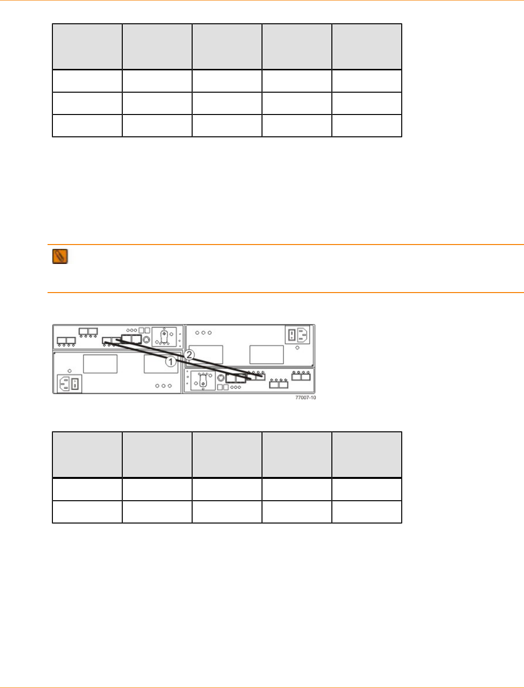
SANtricity_10.77 February 2011
LSI Corporation
- 593 -
Redundant
Path Pairs Drive
Ports on
Controller A
Drive
Channels on
Controller A
Ports on
Controller B Drive
Channels on
Controller B
2 Port 3 Channel 1 Port 2 Channel 3
3 Port 2 Channel 2 Port 3 Channel 4
4 Port 1 Channel 2 Port 4 Channel 4
Drive Channel Redundancy for the CDE4900 Controller-Drive Tray
Each controller has one drive channel, and each drive channel has two ports. Therefore, each controller has
two drive ports. A controller-drive tray has two redundant path pairs that are formed using one drive channel
of controller A and one drive channel of controller B. The following figure shows the redundant pairs in a
controller-drive tray. The following table lists the numbers of the redundant path pairs and the drive ports of
the drive channels from which the redundant path pairs are formed.
IMPORTANT To maintain data access in the event of the failure of a controller, an ESM, or a drive
channel, you must connect a drive tray or a string of drive trays to both drive channels on a redundant path
pair.
Redundant Path Pairs on the CDE4900 Controller-Drive Tray
Redundant Path Pairs on the CDE4900 Controller-Drive Tray
Redundant
Path Pairs Drive
Ports on
Controller A
Drive
Channels on
Controller A
Ports on
Controller B Drive
Channels on
Controller B
1 Port 2 Channel 1 Port 1 Channel 2
2 Port 1 Channel 1 Port 2 Channel 2
Drive Channel Redundancy for the CDE3994 Controller-Drive Tray and the
CDE3992 Controller-Drive Tray
Each controller has one drive channel, and each drive channel has two ports. Therefore, each controller has
two drive ports. A controller-drive tray has two redundant path pairs that are formed using one drive channel
of controller A and one drive channel of controller B. The following figure shows the redundant pairs in a
controller-drive tray. The following table lists the numbers of the redundant path pairs and the drive ports of
the drive channels from which the redundant path pairs are formed.
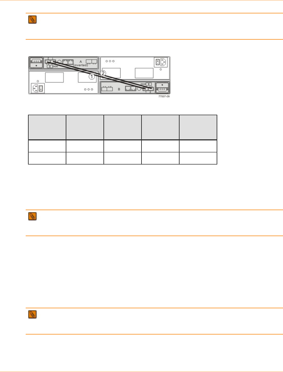
SANtricity_10.77 February 2011
LSI Corporation
- 594 -
IMPORTANT To maintain data access in the event of the failure of a controller, an ESM, or a drive
channel, you must connect a drive tray or a string of drive trays to both drive channels on a redundant path
pair.
Redundant Path Pairs on the CDE3994 Controller-Drive Tray and the CDE3992 Controller-Drive Tray
Redundant Path Pairs on the CDE3994 Controller-Drive Tray and the CDE3992 Controller-Drive Tray
Redundant
Path Pairs Drive
Ports on
Controller A
Drive
Channels on
Controller A
Ports on
Controller B Drive
Channels on
Controller B
1 Port 2 Channel 1 Port 1 Channel 2
2 Port 1 Channel 1 Port 2 Channel 2
Drive Channel Redundancy for the CDE2600 Controller-Drive Tray
Each controller in a CDE2600 has one drive port. When a controller-drive tray has two controllers, the drive
port on controller A and the drive port on controller B form a redundant pair. The following figure shows the
drive ports on a dual-controller configuration.
IMPORTANT To maintain data access in the event of the failure of a controller, an ESM, or a drive
channel, you must connect a drive tray or a string of drive trays to both drive ports on a dual-controller
configuration.
Redundant Path Pair on the CDE2600 Controller-Drive Tray
1. Controller Canisters
2. Drive Expansion Connectors (Redundant Path Pair)
Drive Channel Redundancy for the CDE2600-60 Controller-Drive Tray
Each controller in a CDE2600-60 controller-drive tray has one drive port. When a controller-drive tray has
two controllers, the drive port on controller A and the drive port on controller B form a redundant pair. The
following figure shows the drive ports on a dual-controller configuration.
IMPORTANT To maintain data access in the event of the failure of a controller, an ESM, or a drive
channel, you must connect a drive tray or a string of drive trays to both drive expansion ports on a dual-
controller configuration.
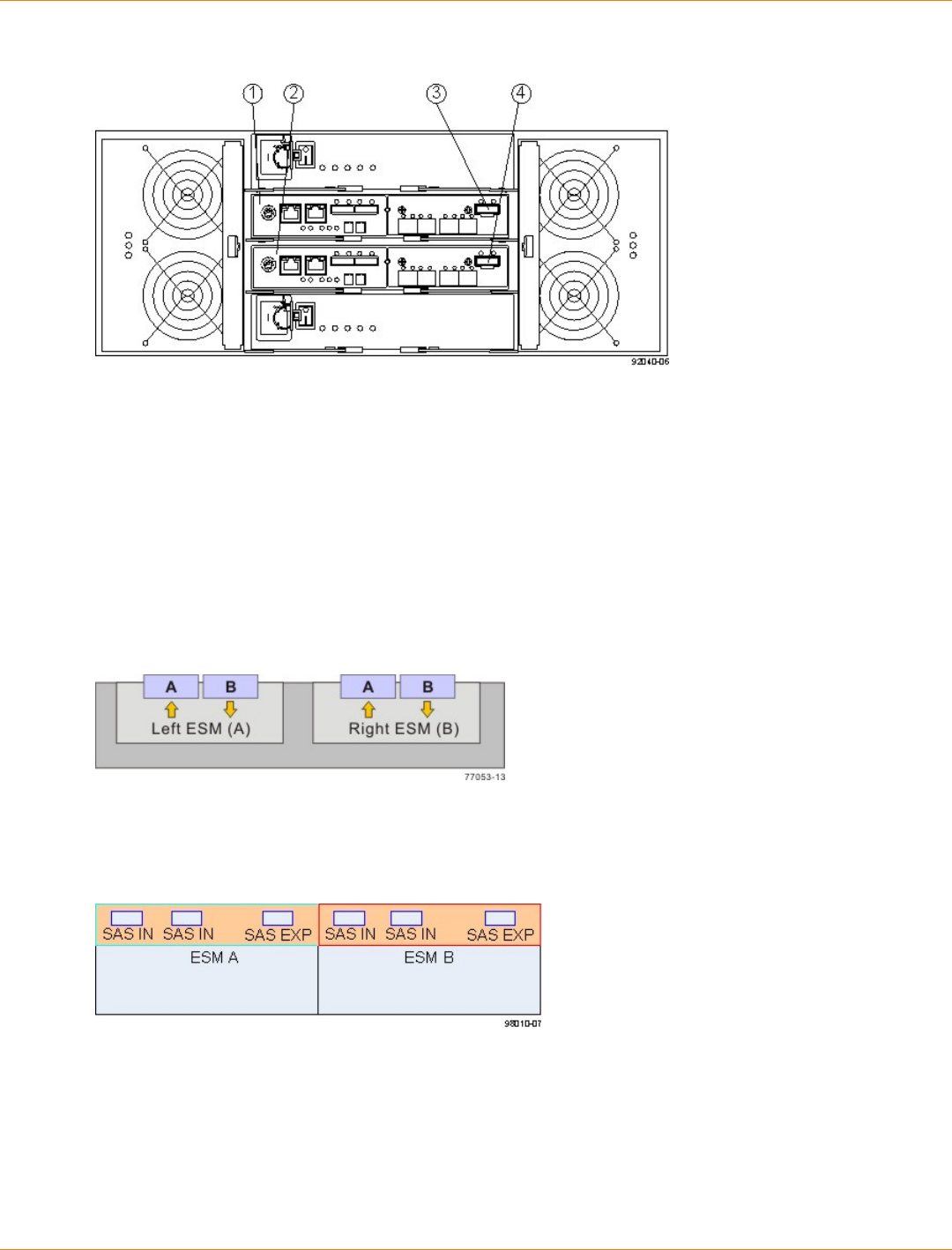
SANtricity_10.77 February 2011
LSI Corporation
- 595 -
Redundant Path Pair on the CDE2600-60 Controller-Drive Tray
1. Controller A
2. Controller B
3. Drive Expansion Connector (SAS)
4. Drive Expansion Connector (SAS)
ESM Canister Arrangements
Many of the figures in topics for drive cabling topologies show storage arrays that use drive trays with side-by-
side ESMs. Each ESM canister has one In port and one Out port (for Fibre Channel) or two SAS In ports and
one SAS Expansion port (SAS). The canisters are located adjacent to one another, as shown in the following
figures.
Drive Tray with Side-by-Side ESMs (Fibre Channel)
The following figure shows a drive tray with side-by-side ESMs and SAS ports.
Drive Tray with Side-by-Side ESMs (SAS)
The following figure shows another type of drive tray. This type of drive tray has inverted ESM canisters.
Other figures in this chapter show this type of drive tray.
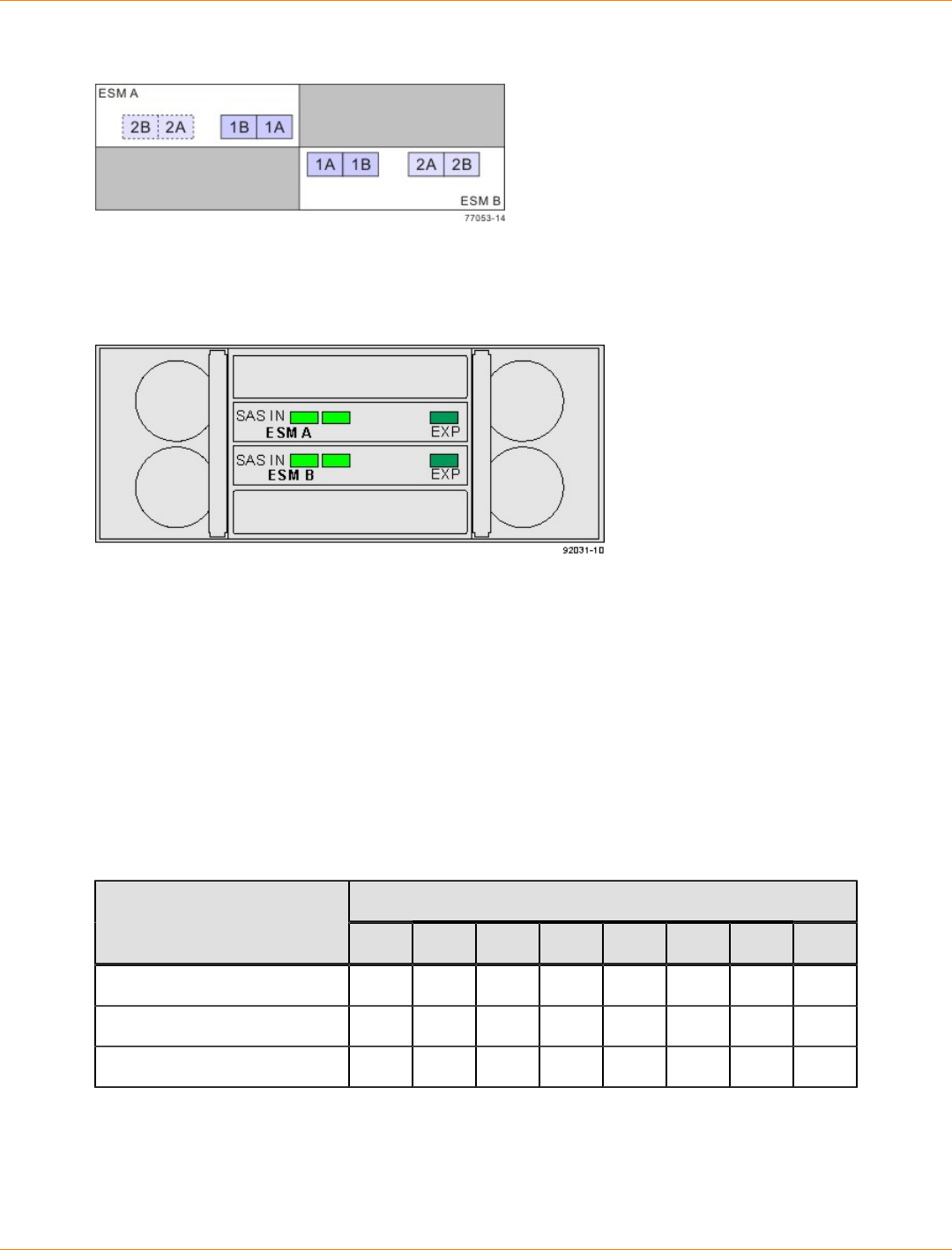
SANtricity_10.77 February 2011
LSI Corporation
- 596 -
Drive Tray with Inverted ESMs
The following figure shows a drive tray with ESM canisters one above the other.
Drive Tray with Stacked ESMs
Drive Cabling Topologies for the CE7900 Controller Tray and the CE7922
Controller Tray
You can cable the CE7922 controller tray only to FC4600 drive trays. No more than seven drive trays may be
cabled to one loop pair and no more than 28 total drive trays may be cabled to the controller tray.
You can cable the CE7900 controller tray to DE6900 drive trays, FC4600 drive trays, or a combination of
the two. No more than seven FC4600 drive trays may be cabled to any one loop pair and no more than two
DE6900 drive trays may be cabled to any one loop pair. When a mix of FC4600 drive trays and DE6900
drive trays is cabled to the controller tray, the total number of drives must not exceed 448. The following table
shows the allowed combinations of drive trays.
Drive Tray Combinations
FC4600 Drive Trays per Loop PairDE6900 Drive Trays per
Loop Pair 01234567
0No Yes Yes Yes Yes Yes Yes Yes
1Yes Yes Yes Yes No No No No
2Yes No No No No No No No
With a CE7900 controller tray, FC4600 drive trays support solid-state drives (SSDs). A drive tray may have
both SSDs and hard disk drives. The maximum number of SSDs for the storage array is 20.
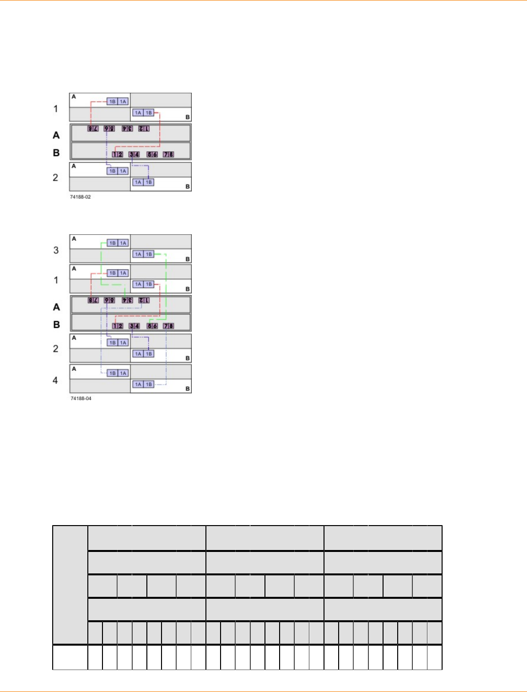
SANtricity_10.77 February 2011
LSI Corporation
- 597 -
Cabling for the CE7922 or CE7900 Controller Tray and One to Four FC4600 Drive Trays
The figures and tables in this section show representative configurations for redundant cabling.
One CE7922 or CE7900 Controller Tray and Two Drive Trays
One CE7922 or CE7900 Controller Tray and Four Drive Trays
The following table specifies the cabling pattern for a controller tray that is attached to one to four drive trays.
The “Cable” column indicates that two cables are used for each drive tray. In the rows for cable 1 and cable
2, for example, the “Xs” indicate that the cables are connected to controller A, channel 1, port 8 and controller
B, channel 5, port 1 respectively. The “Bs” in these rows indicate that the other ends of cable 1 and cable
2 are connected to port 1B of the left ESM (ESM A) and port 1B of the right ESM (ESM B) of drive tray 1
respectively. This pattern continues, using even-numbered ports on controller A and odd-numbered ports on
controller B for the first four drive trays.
One CE7922 or CE7900 Controller Tray and One to Four Drive Trays
Controller A Controller B
Channel Number Channel Number Drive Trays
Ch1 Ch2 Ch3 Ch4 Ch5 Ch6 Ch7 Ch8 1 2 3 4
Port Number Port Number ESMs (Left or Right)
Cable
8 7 6 5 4 3 2 1 1 2 3 4 5 6 7 8 L R L R L R L R
1 X B
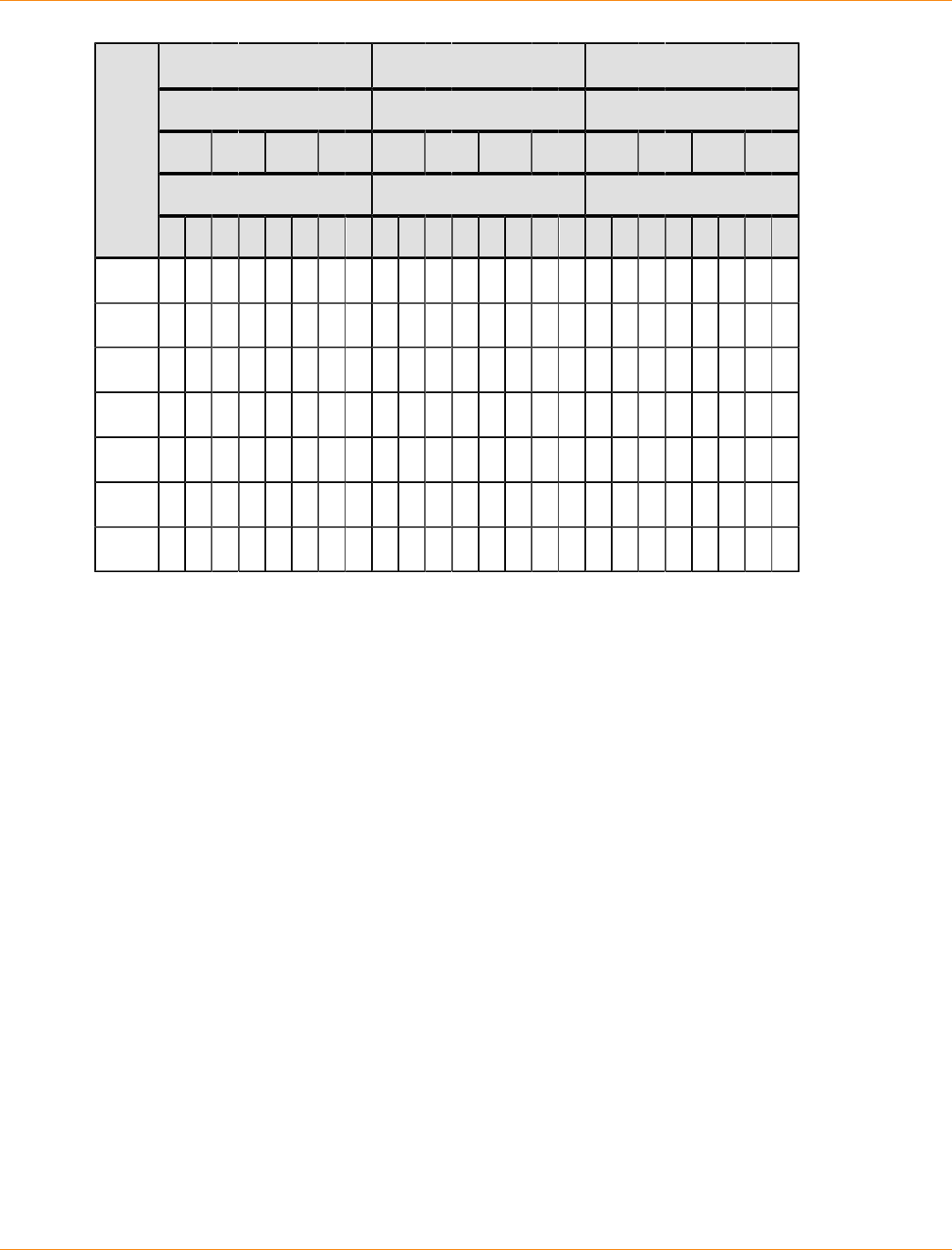
SANtricity_10.77 February 2011
LSI Corporation
- 598 -
Controller A Controller B
Channel Number Channel Number Drive Trays
Ch1 Ch2 Ch3 Ch4 Ch5 Ch6 Ch7 Ch8 1 2 3 4
Port Number Port Number ESMs (Left or Right)
Cable
8 7 6 5 4 3 2 1 1 2 3 4 5 6 7 8 L R L R L R L R
2 X B
3 X B
4 X B
5 X B
6 X B
7 X B
8 X B
Cabling for the CE7922 or CE7900 Controller Tray and Five to Eight FC4600 Drive Trays
The figures and tables in this section show representative configurations for redundant cabling. Use the
information in the previous topic to cable the first four drive trays, and then continue with this topic to cable up
to eight additional drive trays.

SANtricity_10.77 February 2011
LSI Corporation
- 599 -
One CE7922 or CE7900 Controller Tray and Eight Drive Trays
The following table specifies the cabling pattern for a controller tray that is attached to five to eight drive
trays. The “Cable” column indicates that two cables are used for each drive tray. In the rows for cable 9 and
cable 10, for example, the “Xs” indicate that the cables are connected to controller A, channel 1, port 7 and
controller B, channel 5, port 2 respectively. The “Bs” in these rows indicate that the other ends of cable 9 and
cable 10 are connected to port 1B of the left ESM1 and port 1B of the right ESM of drive tray 5 respectively.
This pattern continues, using odd-numbered ports on controller A and even-numbered ports on controller B
for up to eight drive trays.
One CE7922 or CE7900 Controller Tray and Five to Eight Drive Trays
Controller A Controller B
Channel Number Channel Number Drive Trays
Ch1 Ch2 Ch3 Ch4 Ch5 Ch6 Ch7 Ch8 5 6 7 8
Port Number Port Number ESMs (Left or Right)
Cable
8 7 6 5 4 3 2 1 1 2 3 4 5 6 7 8 L R L R L R L R
9 X B
10 X B
11 X B
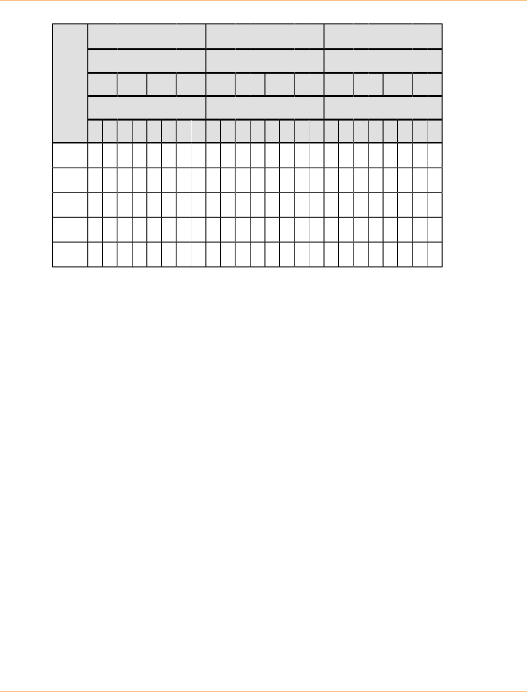
SANtricity_10.77 February 2011
LSI Corporation
- 600 -
Controller A Controller B
Channel Number Channel Number Drive Trays
Ch1 Ch2 Ch3 Ch4 Ch5 Ch6 Ch7 Ch8 5 6 7 8
Port Number Port Number ESMs (Left or Right)
Cable
8 7 6 5 4 3 2 1 1 2 3 4 5 6 7 8 L R L R L R L R
12 X B
13 X B
14 X B
15 X B
16 X B
One CE7922 or CE7900 Controller Tray and Nine to 16 FC4600 Drive Trays
When the number of drive trays exceeds eight, the cabling pattern changes significantly. From this point, you
will begin to use the “A” ports on the ESMs, and connect the drive trays beyond the eighth one to another
drive tray.
If you add drive trays to an existing configuration so that the total number of drive trays attached to one
controller tray increases from eight or fewer to a total of more than eight, you must re-cable some of the drive
trays that were previously cabled to that controller tray. For each new drive tray beyond the eighth one, in
addition to adding two cables to attach the new drive tray, you must move one cable on a previously installed
drive tray.
The following figure and table show an example where a ninth and tenth drive tray have been added
to a controller tray that previously had eight drive trays. Cable 1 remains the same as in the previous
configuration. The end of cable 2 that was previously connected to drive tray 1 now connects to drive tray 9.
Cables 17 and 18 are added between drive tray 1 and drive tray 9 so that they now connect in series. Drive
tray 10 is added using connections to drive tray 2 that follow the pattern of the connections between drive tray
1 and drive tray 9. Drive tray 3 is not connected to another drive tray, so its cabling remains the same (as it
does for drive trays 4 to 8, which do not appear in the table).
You can cable up to 16 drive trays by following the pattern shown in this example.
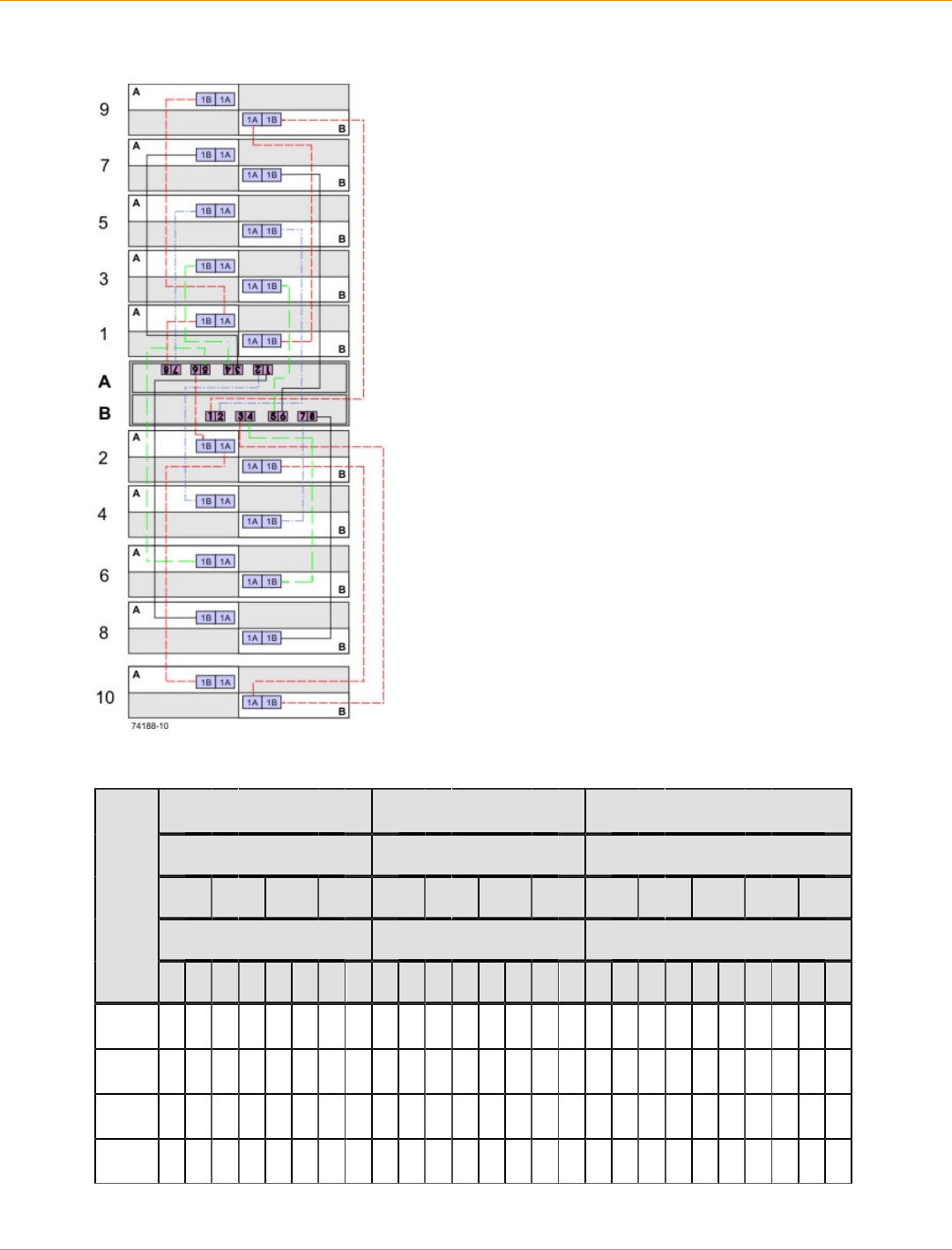
SANtricity_10.77 February 2011
LSI Corporation
- 601 -
One CE7922 or CE7900 Controller Tray and 10 Drive Trays
One CE7922 or CE7900 Controller Tray and 10 Drive Trays
Controller A Controller B
Channel Number Channel Number Drive Trays
Ch1 Ch2 Ch3 Ch4 Ch5 Ch6 Ch7 Ch8 1 2 3 9 10
Port Number Port Number ESMs (Left or Right)
Cable
8 7 6 5 4 3 2 1 1 2 3 4 5 6 7 8 L R L R L R L R L R
1 X B
2 X B
17 A B
18 B A
SANtricity_10.77 February 2011
LSI Corporation
- 602 -
Controller A Controller B
Channel Number Channel Number Drive Trays
Ch1 Ch2 Ch3 Ch4 Ch5 Ch6 Ch7 Ch8 1 2 3 9 10
Port Number Port Number ESMs (Left or Right)
Cable
8 7 6 5 4 3 2 1 1 2 3 4 5 6 7 8 L R L R L R L R L R
3 X B
4 X B
19 A B
20 B A
5 X B
6 X B
One CE7922 or CE7900 Controller Tray and 17 to 28 FC4600 Drive Trays
You can add drive trays in series to each redundant pair of drive ports up to 28 drive trays. In a configuration
with 28 drive trays, four of the port pairs will have four drive trays each, while the other four will have three
drive trays each. The following figure shows this arrangement schematically. The physical arrangement of the
drive trays in cabinets will depend on your particular installation.
The following table shows an example cabling pattern for adding three drive trays (drive trays 9, 17, and 25)
in series with drive tray 1. Add drive trays in series to each redundant pair of drive ports so that the number
of drive trays for each pair of drive ports remains balanced, to the extent possible. For example, do not add a
third drive tray in series with drive tray 1 on ports 8 and 1 if another pair of drive ports has only one drive tray
connected.
One CE7922 or CE7900 Controller Tray and Ten Drive Trays
Controller A Controller B
Channel Number Channel Number Drive Trays
Ch1 Ch2 Ch3 Ch4 Ch5 Ch6 Ch7 Ch8 1 9 17 25
Port Number Port Number ESMs (Left or Right)
Cable
8 7 6 5 4 3 2 1 1 2 3 4 5 6 7 8 L R L R L R L R
1 X B
2 X B
17 A B
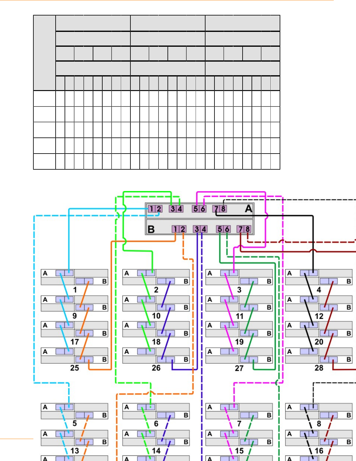
SANtricity_10.77 February 2011
LSI Corporation
- 603 -
Controller A Controller B
Channel Number Channel Number Drive Trays
Ch1 Ch2 Ch3 Ch4 Ch5 Ch6 Ch7 Ch8 1 9 17 25
Port Number Port Number ESMs (Left or Right)
Cable
8 7 6 5 4 3 2 1 1 2 3 4 5 6 7 8 L R L R L R L R
18 B A
33 A B
34 B A
49 A B
50 B A
One CE7922 or CE7900 Controller Tray and 28 Drive Trays
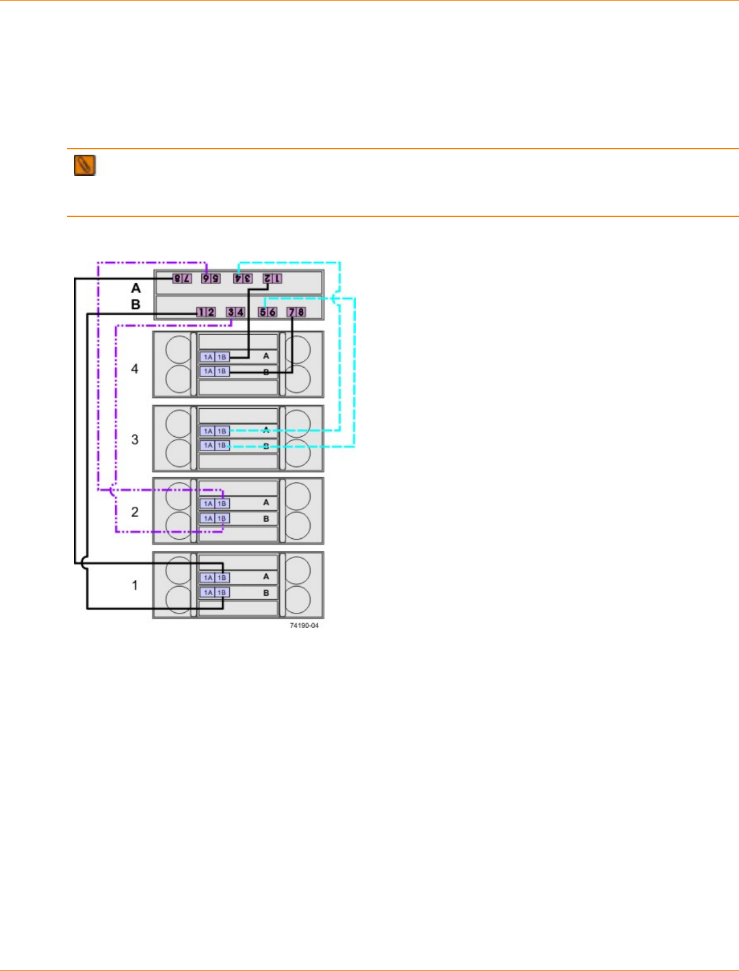
SANtricity_10.77 February 2011
LSI Corporation
- 604 -
One CE7922 or CE7900 Controller Tray and One to Four DE6900 Drive Trays without Trunking
In the cabling configuration figures that follow, the controller tray is placed on top, and the controllers are
labeled as A and B. Because the DE6900 drive trays are very heavy, they are installed starting at the bottom
of the cabinet. The drive trays are labeled from the bottom upward as 1, 2, 3, and so on. The figures in this
section show representative configurations for cabling.
NOTE The CE7900 controller tray and the DE6900 drive trays do not have to be stacked in this exact
order, and there is no requirement that you label the drive trays in this particular sequence. Just make sure
that the DE6900 drive trays are at the bottom of the cabinet.
One CE7900 Controller Tray and Four DE6900 Drive Trays without Trunking
The following table specifies the cabling pattern for a controller tray that is attached to one to four drive trays.
The “Cable” column indicates that two cables are used for each drive tray. In the rows for cable 1 and cable
2, for example, the “Xs” indicate that the cables are connected to controller A, channel 1, port 8 and controller
B, channel 5, port 1 respectively. The “Bs” in these rows indicate that the other ends of cable 1 and cable
2 are connected to port 1B of the top ESM (ESM A) and port 1B of the bottom ESM (ESM B) of drive tray 1
respectively. This pattern continues, using even-numbered ports on controller A and odd-numbered ports on
controller B for the first four drive trays.
SANtricity_10.77 February 2011
LSI Corporation
- 605 -
One CE7922 or CE7900 Controller Tray and One to Four Drive Trays without Trunking
Controller A Controller B
Channel Number Channel Number Drive Trays
Ch1 Ch2 Ch3 Ch4 Ch5 Ch6 Ch7 Ch8 1 2 3 4
Port Number Port Number ESMs (Left or Right)
Cable
8 7 6 5 4 3 2 1 1 2 3 4 5 6 7 8 L R L R L R L R
1 X B
2 X B
3 X B
4 X B
5 X B
6 X B
7 X B
8 X B
One CE7900 Controller Tray Five to Eight DE6900 Drive Trays without Trunking
In the cabling configuration shown in the following figure, the controller tray is placed on top, and the
controllers are labeled as A and B. Because the DE6900 drive trays are very heavy, they are installed starting
at the bottom of the cabinet. The drive trays are labeled from the bottom upward as 1, 2, 3, and so on.
NOTE The CE7900 controller tray and the DE6900 drive trays do not have to be stacked in this exact
order, and there is no requirement that you label the drive trays in this particular sequence. Just make sure
the DE6900 drive trays are at the bottom of the cabinet.
The figure and table in this topic show a representative configuration for redundant drive cabling. Use the
information in the previous topic to cable the first four drive trays, and then continue with this topic to cable up
to four additional drive trays.

SANtricity_10.77 February 2011
LSI Corporation
- 606 -
One CE7900 Controller Tray and Eight DE6900 Drive Trays without Trunking
The following table specifies the cabling pattern for a controller tray that is attached to five to eight drive
trays. The “Cable” column indicates that two cables are used for each drive tray. In the rows for cable 9 and
cable 10, for example, the “Xs” indicate that the cables are connected to controller A, channel 1, port 7 and
controller B, channel 5, port 2 respectively. The “Bs” in these rows indicate that the other ends of cable 1 and
cable 2 are connected to port 1B of the top ESM (ESM A) and port 1B of the bottom ESM (ESM B) of drive
tray 5 respectively. This pattern continues, using odd-numbered ports on controller A and even-numbered
ports on controller B for drive trays five through eight.
SANtricity_10.77 February 2011
LSI Corporation
- 607 -
One CE7900 Controller Tray and Five to Eight DE6900 Drive Trays without Trunking
Controller A Controller B
Channel Channel Drive Tray
Ch1 Ch2 Ch3 Ch4 Ch5 Ch6 Ch7 Ch8 5 6 7 8
Port Number Port Number ESM (Top or
Bottom)
Cable
8 7 6 5 4 3 2 1 1 2 3 4 5 6 7 8 T B T B T B T B
9 X B
10 X B
11 X B
12 X B
13 X B
14 X B
15 X B
16 X B
One CE7900 Controller Tray and One to Four DE6900 Drive Trays with Trunking
In the figures that follow, the controller tray is shown on top, and the controllers are labeled as A and B.
Because the DE6900 drive trays are very heavy, they are installed starting at the bottom of the cabinet. The
drive trays are labeled from the bottom upward as 1, 2, 3, and so on.
NOTE The CE7900 controller tray and the DE6900 drive trays do not have to be stacked in this exact
order, and there is no requirement that you label the drive trays in this particular sequence. Just make sure
the DE6900 drive trays are at the bottom of the cabinet.
Use the configuration examples in this section as a guide to configure your storage array to receive the
benefits of drive-side trunking cabling. Drive-side trunking uses the right side of the expansion ports on the
rear of the drive trays to allow the full bandwidth potential of the CE7900 controller tray.
Drive-side trunking requires that the ESMs have four ports to support trunked cascading connections to other
drive trays. These cascading connections only apply when eight DE6900 drive trays are connected to a single
controller tray.
The figures in this section show representative configurations for cabling.
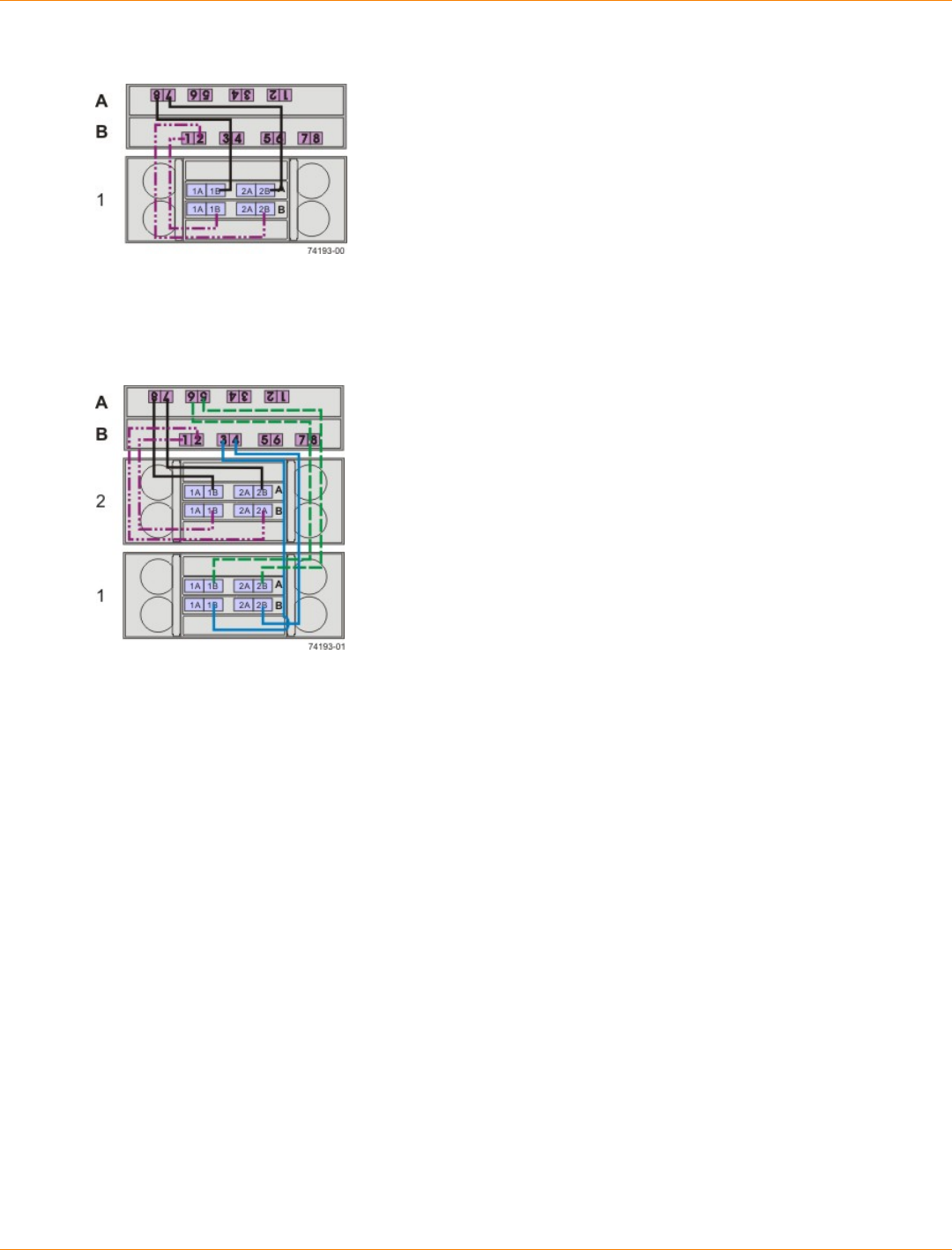
SANtricity_10.77 February 2011
LSI Corporation
- 608 -
One CE7900 Controller Tray and One DE6900 Drive Tray with Drive-Side Trunking
One CE7900 Controller Tray and Two DE6900 Drive Trays with Drive-Side Trunking
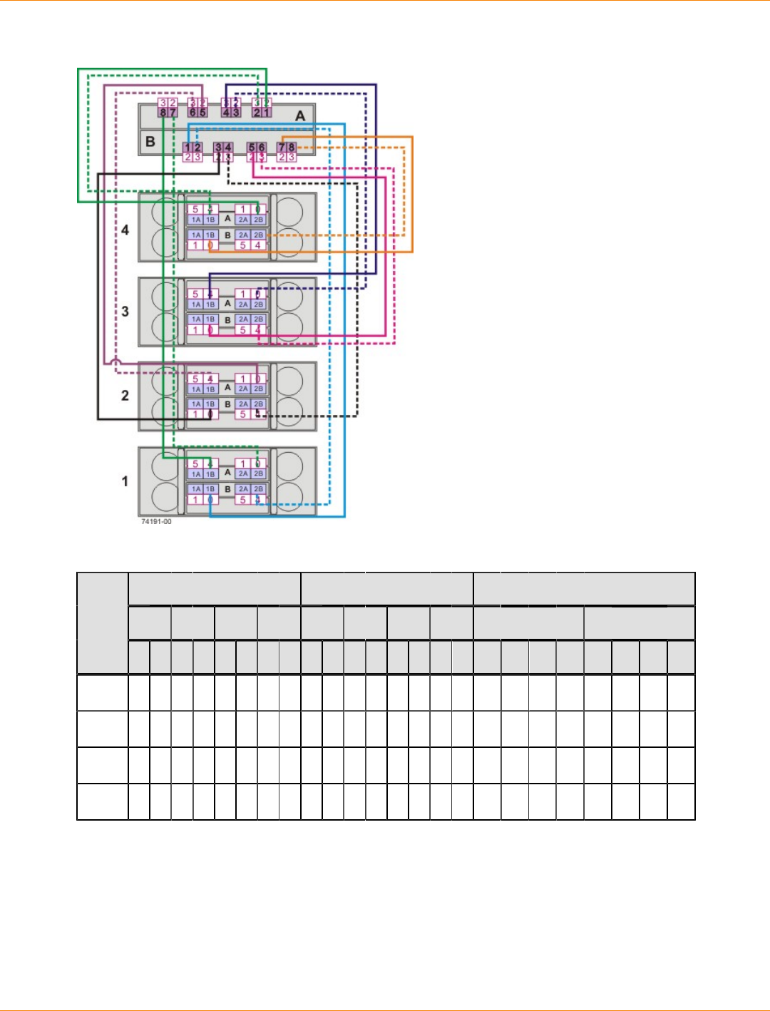
SANtricity_10.77 February 2011
LSI Corporation
- 609 -
One CE7900 Controller Tray and Four DE6900 Drive Trays with Drive-Side Trunking
One CE7900 Controller Tray and DE6900 Drive Tray 1 with Drive-Side Trunking
Controller A Controller B Drive Tray 1
Ch1 Ch2 Ch3 Ch4 Ch5 Ch6 Ch7 Ch8 Top ESM Bottom ESM
Cable
8 7 6 5 4 3 2 1 1 2 3 4 5 6 7 8 1A 1B 2A 2B 1A 1B 2A 2B
1 X X
2 X X
3 X X
4 X X
SANtricity_10.77 February 2011
LSI Corporation
- 610 -
One CE7900 Controller Tray and DE6900 Drive Tray 2 with Drive-Side Trunking
Controller A Controller B Drive Tray 2
Ch1 Ch2 Ch3 Ch4 Ch5 Ch6 Ch7 Ch8 Top ESM Bottom ESM
Cable
8 7 6 5 4 3 2 1 1 2 3 4 5 6 7 8 1A 1B 2A 2B 1A 1B 2A 2B
1 X X
2 X X
3 X X
4 X X
One CE7900 Controller Tray and DE6900 Drive Tray 3 with Drive-Side Trunking
Controller A Controller B Drive Tray 3
Ch1 Ch2 Ch3 Ch4 Ch5 Ch6 Ch7 Ch8 Top ESM Bottom ESM
Cable
8 7 6 5 4 3 2 1 1 2 3 4 5 6 7 8 1A 1B 2A 2B 1A 1B 2A 2B
1 X X
2 X X
3 X X
4 X X
One CE7900 Controller Tray and DE6900 Drive Tray 4 with Drive-Side Trunking
Controller A Controller B Drive Tray 4
Ch1 Ch2 Ch3 Ch4 Ch5 Ch6 Ch7 Ch8 Top ESM Bottom ESM
Cable
8 7 6 5 4 3 2 1 1 2 3 4 5 6 7 8 1A 1B 2A 2B 1A 1B 2A 2B
1 X X
2 X X
3 X X
4 X X

SANtricity_10.77 February 2011
LSI Corporation
- 611 -
One CE7900 Controller Tray and Five to Eight DE6900 Drive Trays with Drive-Side Trunking
In the cabling configuration figure that follows, the controller tray is placed on top, and the controllers are
labeled as A and B. Because the DE6900 drive trays are very heavy, they are installed starting at the bottom
of the cabinet. The drive trays are labeled from the bottom upward as 1, 2, 3, and so on.
NOTE The CE7900 controller tray and the DE6900 drive trays do not have to be stacked in this exact
order, and there is no requirement that you label the drive trays in this particular sequence. Just make sure
the DE6900 drive trays are at the bottom of the cabinet.
Use the configuration examples in this section as a guide to configure your storage array to receive the
benefits of drive-side trunking cabling. Drive-side trunking uses the right side of the expansion ports on the
rear of the drive trays to allow the full bandwidth potential of the CE7900 controller tray.
Drive-side trunking requires that the ESMs have four ports to support trunked cascading connections to other
drive trays. These cascading connections only apply when eight DE6900 drive trays are connected to a single
controller tray.
The figure in this section shows a representative configuration for cabling. Use the tables in this section to see
specific cabling patterns for other configurations.
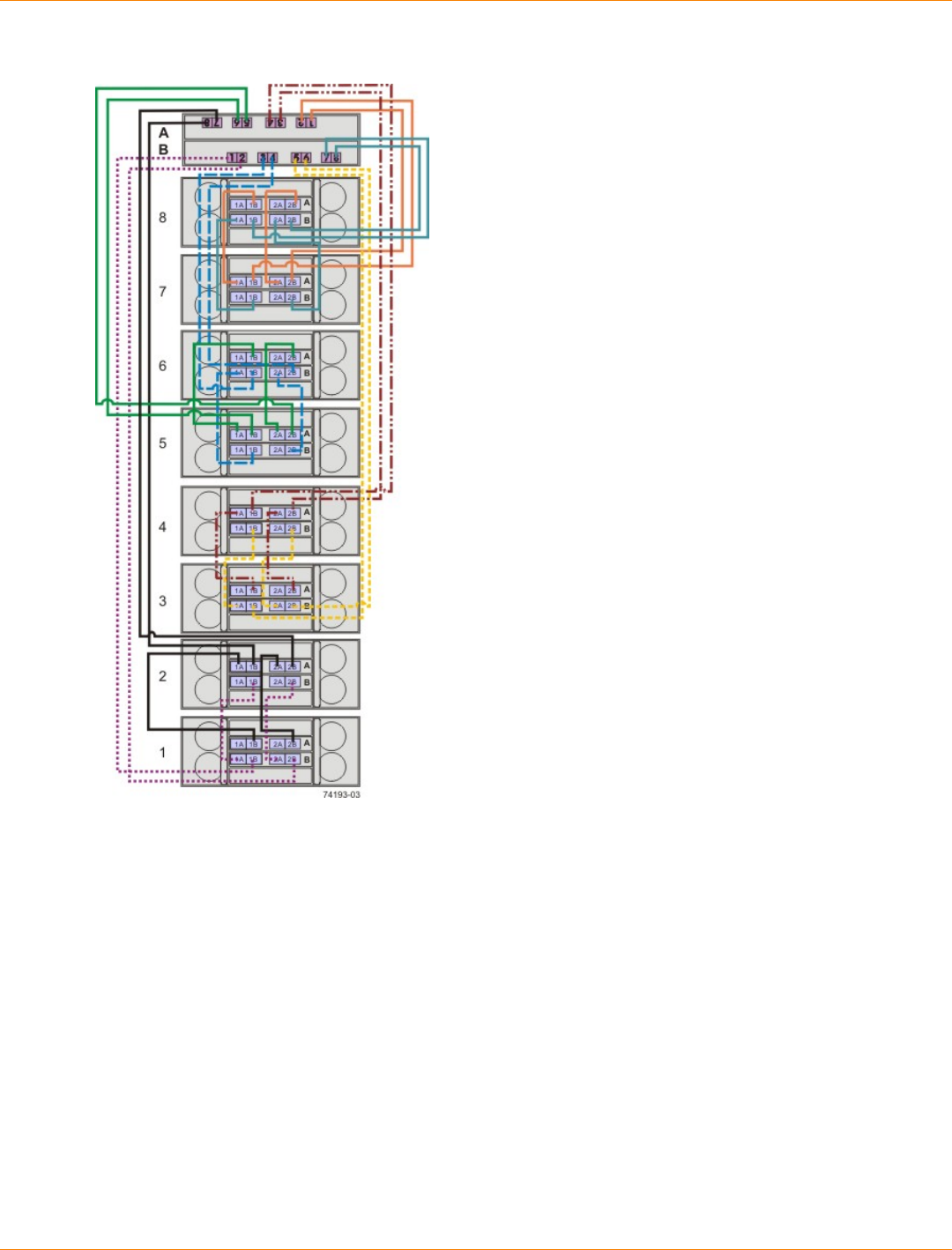
SANtricity_10.77 February 2011
LSI Corporation
- 612 -
One CE7900 Controller Tray and Eight DE6900 Drive Trays with Drive-Side Trunking
SANtricity_10.77 February 2011
LSI Corporation
- 613 -
One CE7900 Controller Tray and DE6900 Drive Trays 1 and 2 with Drive-Side Trunking
Controller A Controller B Drive Tray 1
Ch1 Ch2 Ch3 Ch4 Ch5 Ch6 Ch7 Ch8 Top ESM Bottom ESM
Cable
8 7 6 5 4 3 2 1 1 2 3 4 5 6 7 8 1A 1B 2A 2B 1A 1B 2A 2B
1 X X
2 X X
Drive Tray 1 Drive Tray 2
Top ESM Bottom ESM Top ESM Bottom ESM
Cable
1A 1B 2A 2B 1A 1B 2A 2B 1A 1B 2A 2B 1A 1B 2A 2B
3 X X
4 X X
5 X X
6 X X
Controller A Controller B Drive Tray 2
Ch1 Ch2 Ch3 Ch4 Ch5 Ch6 Ch7 Ch8 Top ESM Bottom ESM
Cable
8 7 6 5 4 3 2 1 1 2 3 4 5 6 7 8 1A 1B 2A 2B 1A 1B 2A 2B
7 X X
8 X X
One CE7900 Controller Tray and DE6900 Drive Trays 3 and 4 with Drive-Side Trunking
Controller A Controller B Drive Tray 3
Ch1 Ch2 Ch3 Ch4 Ch5 Ch6 Ch7 Ch8 Top ESM Bottom ESM
Cable
8 7 6 5 4 3 2 1 1 2 3 4 5 6 7 8 1A 1B 2A 2B 1A 1B 2A 2B
1 X X
2 X X
SANtricity_10.77 February 2011
LSI Corporation
- 614 -
Drive Tray 3 Drive Tray 4
Top ESM Bottom ESM Top ESM Bottom ESM
Cable
1A 1B 2A 2B 1A 1B 2A 2B 1A 1B 2A 2B 1A 1B 2A 2B
3 X X
4 X X
5 X X
6 X X
Controller A Controller B Drive Tray 4
Ch1 Ch2 Ch3 Ch4 Ch5 Ch6 Ch7 Ch8 Top ESM Bottom ESM
Cable
8 7 6 5 4 3 2 1 1 2 3 4 5 6 7 8 1A 1B 2A 2B 1A 1B 2A 2B
7 X X
8 X X
One CE7900 Controller Tray and DE6900 Drive Trays 5 and 6 with Drive-Side Trunking
Controller A Controller B Drive Tray 5
Ch1 Ch2 Ch3 Ch4 Ch5 Ch6 Ch7 Ch8 Top ESM Bottom ESM
Cable
8 7 6 5 4 3 2 1 1 2 3 4 5 6 7 8 1A 1B 2A 2B 1A 1B 2A 2B
1 X X
2 X X
Drive Tray 5 Drive Tray 6
Top ESM Bottom ESM Top ESM Bottom ESM
Cable
1A 1B 2A 2B 1A 1B 2A 2B 1A 1B 2A 2B 1A 1B 2A 2B
3 X X
4 X X
5 X X
6 X X
SANtricity_10.77 February 2011
LSI Corporation
- 615 -
Controller A Controller B Drive Tray 6
Ch1 Ch2 Ch3 Ch4 Ch5 Ch6 Ch7 Ch8 Top ESM Bottom ESM
Cable
8 7 6 5 4 3 2 1 1 2 3 4 5 6 7 8 1A 1B 2A 2B 1A 1B 2A 2B
7 X X
8 X X
One CE7900 Controller Tray and DE6900 Drive Trays 7 and 8 with Drive-Side Trunking
Controller A Controller B Drive Tray 7
Ch1 Ch2 Ch3 Ch4 Ch5 Ch6 Ch7 Ch8 Top ESM Bottom ESM
Cable
8 7 6 5 4 3 2 1 1 2 3 4 5 6 7 8 1A 1B 2A 2B 1A 1B 2A 2B
1 X X
2 X X
Drive Tray 7 Drive Tray 8
Top ESM Bottom ESM Top ESM Bottom ESM
Cable
1A 1B 2A 2B 1A 1B 2A 2B 1A 1B 2A 2B 1A 1B 2A 2B
3 X X
4 X X
5 X X
6 X X
Controller A Controller B Drive Tray 8
Ch1 Ch2 Ch3 Ch4 Ch5 Ch6 Ch7 Ch8 Top ESM Bottom ESM
Cable
8 7 6 5 4 3 2 1 1 2 3 4 5 6 7 8 1A 1B 2A 2B 1A 1B 2A 2B
7 X X
8 X X
One CE7900 Controller Tray and Multiple Types of Drive Trays
If you are cabling a mix of DE6900 drive trays and FC4600 drive trays, the following restrictions apply:
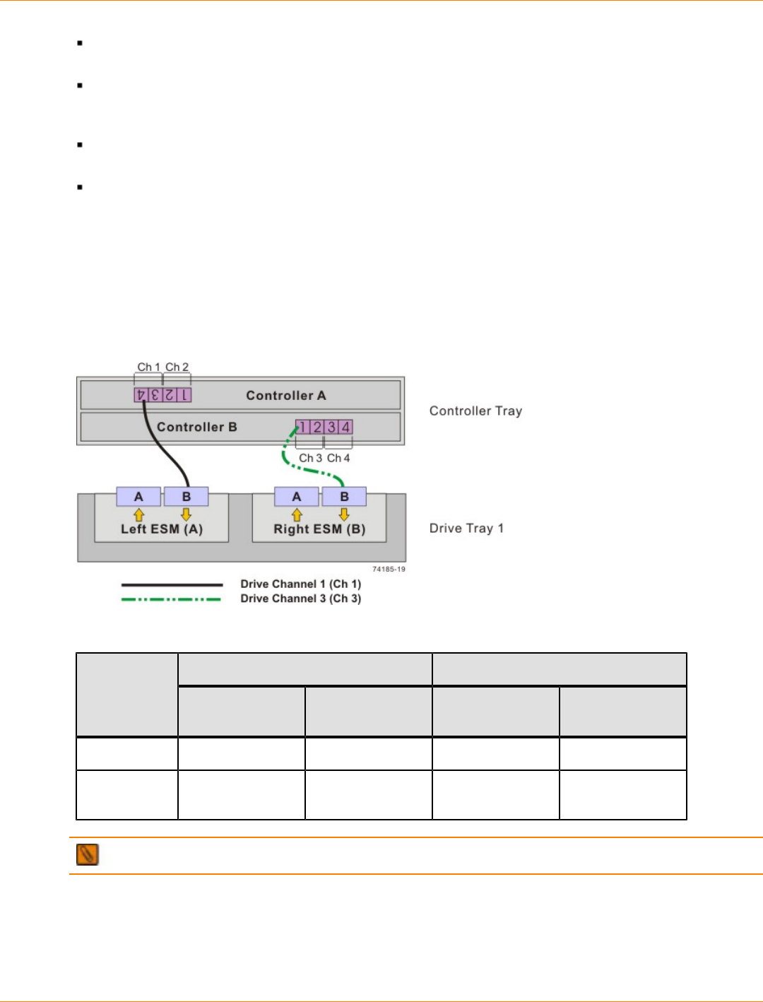
SANtricity_10.77 February 2011
LSI Corporation
- 616 -
Connect no more than two DE6900 drive trays per loop pair and no more than eight DE6900 drive trays
per controller tray.
Connect no more than seven FC4600 drive trays per loop pair and no more than 28 FC4600 drive
trays per controller tray. In configurations that contain one DE6900 drive tray, connect no more than 21
FC4600 drive trays per controller tray.
When FC4600 and DE6900 drive trays are mixed on the same loop, only one DE6900 drive tray and up
to three FC4600 drive trays can share a loop.
When FC4600 and DE6900 drive trays are mixed, the total number of drives must not exceed 448.
Drive Cabling Topologies for the CE6998 Controller Tray
One CE6998 Controller Tray and One Drive Tray
If you are cabling one CE6998 controller tray to one drive tray, use the cabling topology shown in the
following table and figure.
One CE6998 Controller Tray and One Drive Tray
One CE6998 Controller Tray and One Drive Tray
Connection Point Connection PointDrive
Channel Tray or
Component Port Number
and Location Tray or
Component Port Number
and Location
1 Controller A 4 Drive tray 1 Left ESM, port B
3 Controller B 1 Drive tray 1 Right ESM, port
B
NOTE If you have drive trays with inverted ESM canisters, see “ESM Canister Arrangements.”
One CE6998 Controller Tray and Two Drive Trays
If you are cabling one CE6998 controller tray to two drive trays, use the cabling topology described in the
following table and figure.
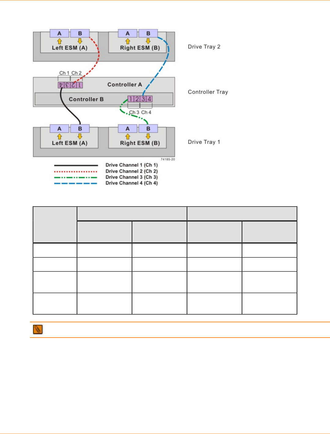
SANtricity_10.77 February 2011
LSI Corporation
- 617 -
One CE6998 Controller Tray and Two Drive Trays
One CE6998 Controller Tray and Two Drive Trays
Connection Point Connection PointDrive
Channel Tray or
Component Port Number
and Location Tray or
Component Port Number
and Location
1 Controller A 4 Drive tray 1 Left ESM, port B
2 Controller A 2 Drive tray 2 Left ESM, port B
3 Controller B 1 Drive tray 1 Right ESM, port
B
4 Controller B 3 Drive tray 2 Right ESM, port
B
NOTE If you have drive trays with inverted ESM canisters, see “ESM Canister Arrangements.”
One CE6998 Controller Tray and Four Drive Trays
If you are cabling one CE6998 controller tray to four drive trays, use the cabling topology shown in the
following figure and table.
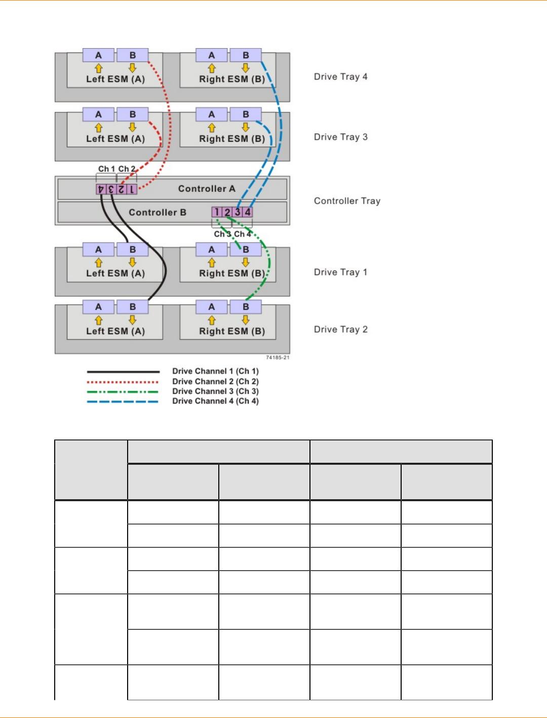
SANtricity_10.77 February 2011
LSI Corporation
- 618 -
One CE6998 Controller Tray and Four Drive Trays
One CE6998 Controller Tray and Four Drive Trays
Connection Point Connection PointDrive
Channel Tray or
Component Port Number
and Location Tray or
Component Port Number
and Location
Controller A 4 Drive tray 1 Left ESM, port B1
Controller A 3 Drive tray 2 Left ESM, port B
Controller A 2 Drive tray 3 Left ESM, port B2
Controller A 1 Drive tray 4 Left ESM, port B
Controller B 1 Drive tray 1 Right ESM, port
B
3
Controller B 2 Drive tray 2 Right ESM, port
B
4 Controller B 3 Drive tray 3 Right ESM, port
B

SANtricity_10.77 February 2011
LSI Corporation
- 619 -
Connection Point Connection PointDrive
Channel Tray or
Component Port Number
and Location Tray or
Component Port Number
and Location
Controller B 4 Drive tray 4 Right ESM, port
B
NOTE If you have drive trays with inverted ESM canisters, see “ESM Canister Arrangements.”
One CE6998 Controller Tray and Eight Drive Trays
If you are cabling one CE6998 controller tray to eight drive trays, use the cabling topology described in the
following table and figure.
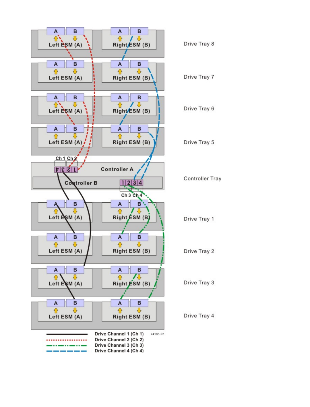
SANtricity_10.77 February 2011
LSI Corporation
- 620 -
One CE6998 Controller Tray and Eight Drive Trays

SANtricity_10.77 February 2011
LSI Corporation
- 621 -
One CE6998 Controller Tray and Eight Drive Trays
Connection Point Connection PointDrive
Channel Tray or
Component Port Number
and Location Tray or
Component Port Number
and Location
Controller A 4 Drive tray 1 Left ESM, port B
Drive tray 1 Drive tray 2 Left ESM, port B
Controller A 3 Drive tray 3 Left ESM, port B
1
Drive tray 3 Drive tray 4 Left ESM, port B
Controller A 2 Drive tray 6 Left ESM, port B
Drive tray 6 Drive tray 5 Left ESM, port B
Controller A 1 Drive tray 8 Left ESM, port B
2
Drive tray 8 Drive tray 7 Left ESM, port B
Controller B 1 Drive tray 2 Right ESM, port
B
Drive tray 2 Drive tray 1 Right ESM, port
B
Controller B 2 Drive tray 4 Right ESM, port
B
3
Drive tray 4 Drive tray 3 Right ESM, port
B
Controller B 3 Drive tray 5 Right ESM, port
B
Drive tray 5 Drive tray 6 Right ESM, port
B
Controller B 4 Drive tray 7 Right ESM, port
B
4
Drive tray 7 Drive tray 8 Right ESM, port
B
NOTE If you have drive trays with inverted ESM canisters, see “ESM Canister Arrangements.”
One CE6998 Controller Tray and Multiple Types of Drive Trays
If you are cabling more than one type of drive tray to the CE6998 controller tray, read these topics before you
choose a cabling topology:
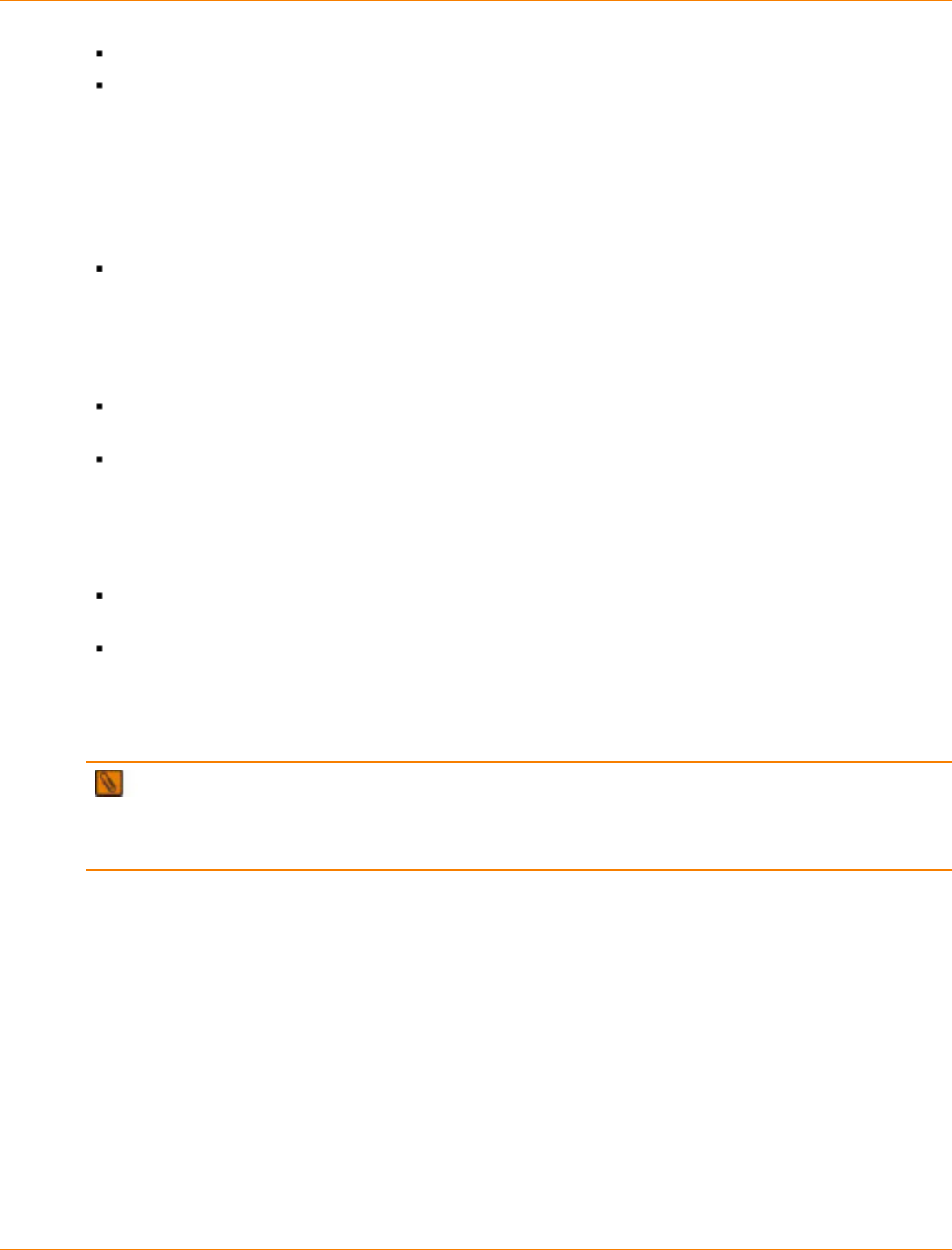
SANtricity_10.77 February 2011
LSI Corporation
- 622 -
Guidelines for Cabling FC2610 Drive Trays or FC4600 Drive Trays
Guidelines for Cabling AT2655 Drive Trays
Follow these guidelines for cabling multiple types of drive trays to maximize performance and accessibility.
Guidelines for Cabling FC2610 Drive Trays or FC4600 Drive Trays
Follow these guidelines for cabling a topology with multiple types of drive trays, including the FC2610 drive
trays or the FC4600 drive trays.
If your storage array includes FC2610 drive trays or FC4600 drive trays, cable the FC2610 drive trays
or the FC4600 drive trays so that they are the first devices on the drive channel (after controller A). The
first device on the drive channel is distinguished by the fact that the left ESM of the first device is cabled
directly to controller A of the controller tray. Because an optimal redundant cabling topology requires that
the redundant drive channel be cabled in the opposite order, this same device will be the last in the drive
channel when cabled to controller B.
Evenly distribute the FC2610 drive trays or the FC4600 drive trays in pairs or multiples across redundant
pairs of the available drive channels.
Do not cable a single FC2610 drive tray or a single FC4600 drive tray on a drive channel unless it is the
only FC2610 drive tray or FC4600 drive tray in the storage array.
Guidelines for Cabling AT2655 Drive Trays
Follow these guidelines for cabling a topology with multiple drive tray types, including AT2655 drive trays.
If your storage array includes AT2655 drive trays, cable the AT2655 drive trays so that they are the last
devices on the drive channel (from a top-down cabling perspective).
Distribute AT2655 drive trays across redundant pairs of drive channels to equalize the number of drive
trays on the available channels.
In the following figure, the FC2610 drive trays and the FC4600 drive trays are identified as SBODs (Switched
Bunch of Disks). The AT2655 drive tray is identified as SATA (Serial Advanced Technology Attachment).
IMPORTANT When you mix different types of drive trays, you must consider the total number of drives
that are available in the final configuration of the storage array. For example, if you mix FC4600 drive trays
with FC2610 drive trays, the total number of drives might be more than the maximum number that each drive
channel can support.
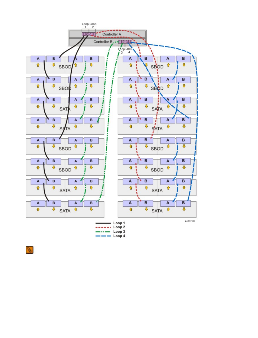
SANtricity_10.77 February 2011
LSI Corporation
- 623 -
One CE6998 Controller Tray and Multiple Types of Drive Trays
NOTE If you have drive trays with inverted ESM canisters, see the topic on “ESM Canister
Arrangements.”
Drive Cabling Topologies for the CDE4900 Controller-Drive Tray
This section provides examples of drive cabling topologies that can be used for cabling the CDE4900
controller-drive tray to FC4600 drive trays. Depending on the number of drive trays that you need to connect,
see the applicable figure for a cabling configuration. Each example provides redundant paths to the drives.
The total number of drives in the storage array, including the drives in the controller-drive tray and those in the
drive trays, must not exceed 112.
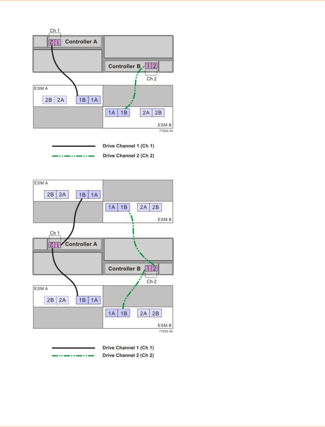
SANtricity_10.77 February 2011
LSI Corporation
- 624 -
One CDE4900 Controller-Drive Tray and One FC4600 Drive Tray
One CDE4900 Controller-Drive Tray and Two FC4600 Drive Trays
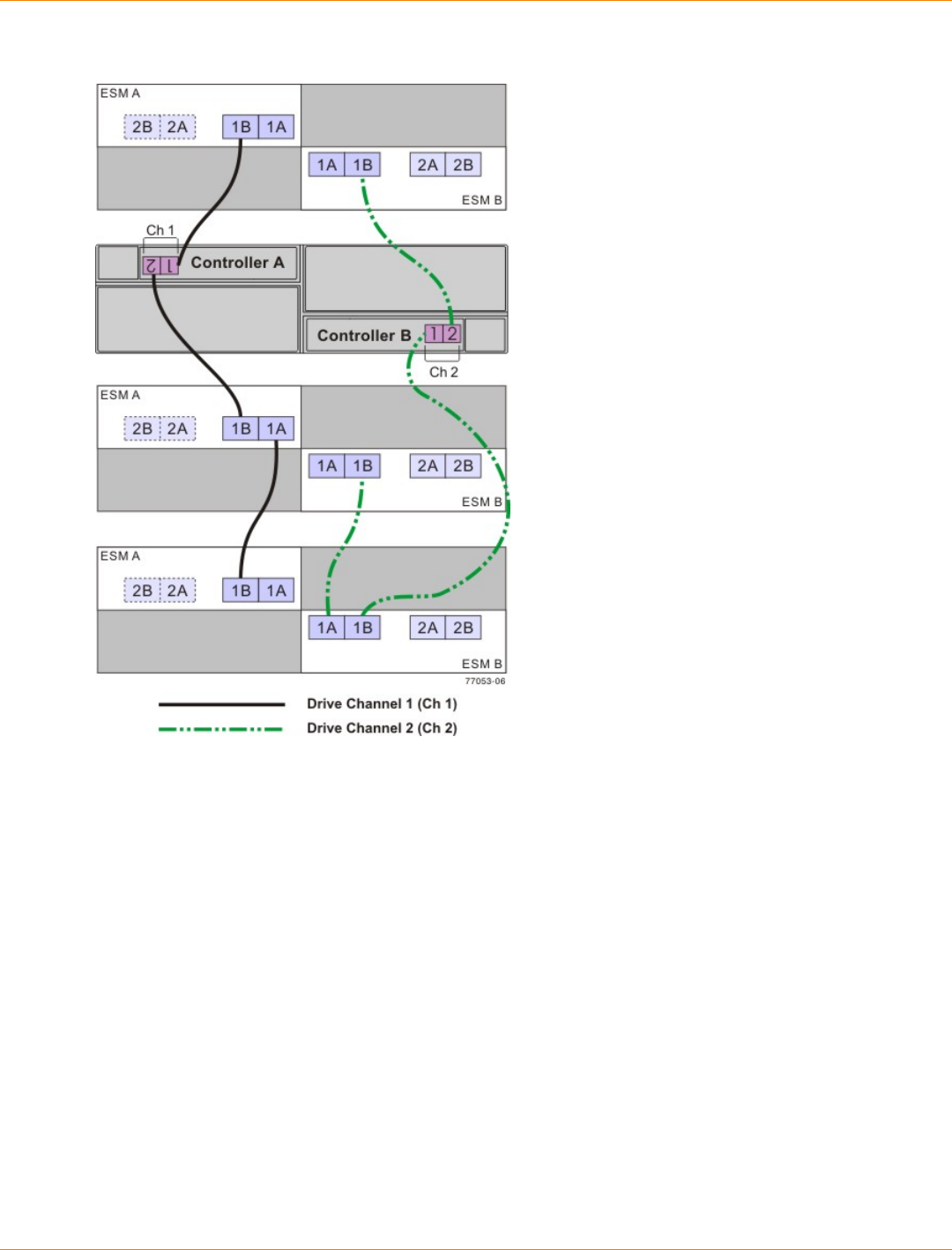
SANtricity_10.77 February 2011
LSI Corporation
- 625 -
One CDE4900 Controller-Drive Tray and Three FC4600 Drive Trays
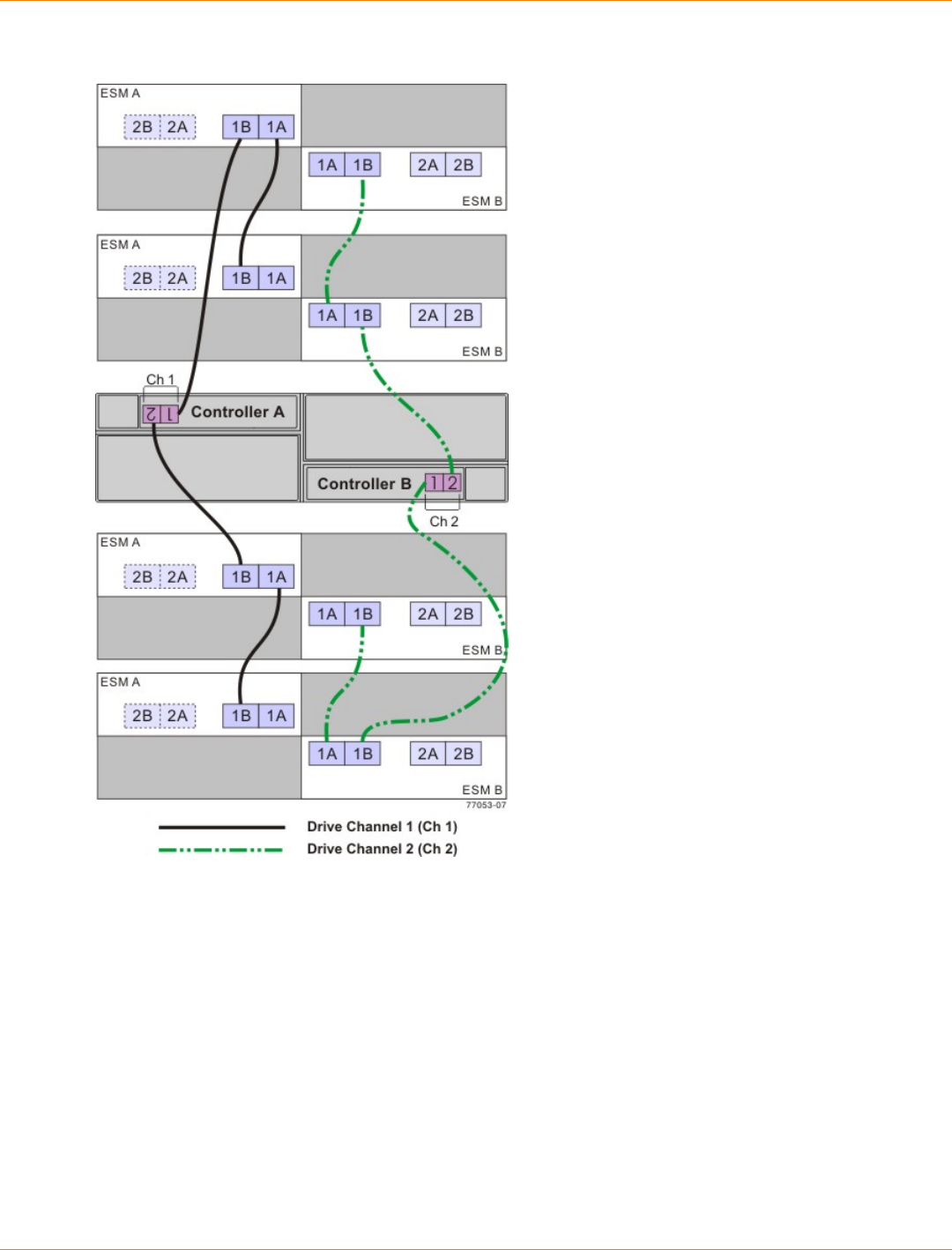
SANtricity_10.77 February 2011
LSI Corporation
- 626 -
One CDE4900 Controller-Drive Tray and Four FC4600 Drive Trays
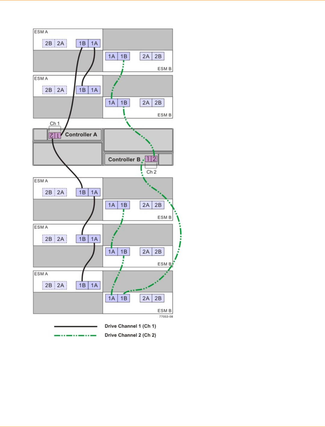
SANtricity_10.77 February 2011
LSI Corporation
- 627 -
One CDE4900 Controller-Drive Tray and Five FC4600 Drive Trays

SANtricity_10.77 February 2011
LSI Corporation
- 628 -
One CDE4900 Controller-Drive Tray and Six FC4600 Drive Trays
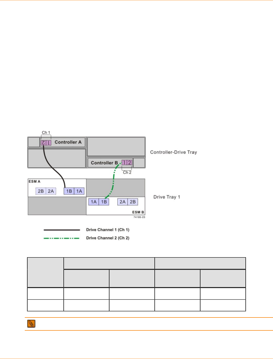
SANtricity_10.77 February 2011
LSI Corporation
- 629 -
Drive Cabling Topologies for the CDE3994 Controller-Drive Tray and the
CDE3992 Controller-Drive Tray
This section provides examples of drive cabling topologies that can be used for the CDE3994 controller-drive
tray. The controllers on the lower-cost CDE3992 controller-drive tray have two host ports and two drive ports.
The controllers on the higher-cost CDE3994 controller-drive tray have four host ports and two drive ports.
Each example provides redundant paths to the drives. If one of these examples is suitable for your hardware
and application, complete the cabling connections as described by the tables. However you decide to
implement your cabling, follow the recommendations in the "Best Practices" topic to ensure full availability of
data.
One CDE3994 Controller-Drive Tray or CDE3992 Controller-Drive Tray and One Drive Tray
If you are cabling one CDE3994 controller-drive tray to one drive tray, and that drive tray has inverted ESM
canisters, use the cabling topology described in the following table and figure.
One CDE3994 Controller-Drive Tray and One Drive Tray with Inverted ESMs
One CDE3994 Controller-Drive Tray and One Drive Tray with Inverted ESMs
Connection Point Connection PointDrive
Channel Tray or
Component Port Number
and Location Tray or
Component Port Number
and Location
1 Controller A 2 Drive tray 1 ESM A, port 1B
2 Controller B 1 Drive tray 1 ESM B, port 1B
NOTE If you have drive trays with side-by-side ESM canisters, see “ESM Canister Arrangements.”
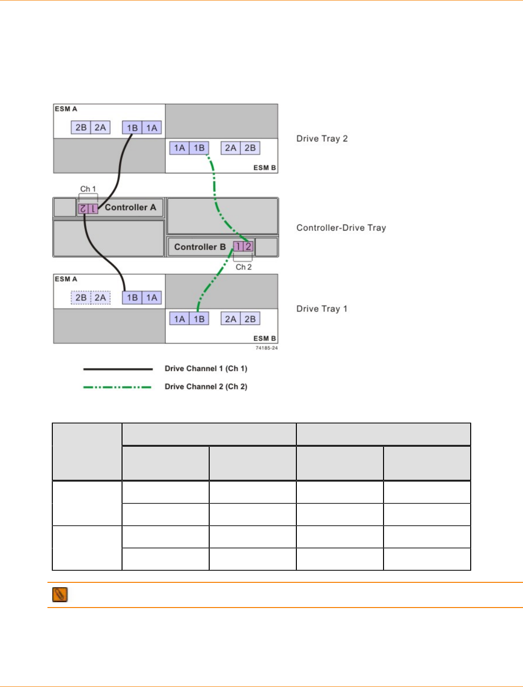
SANtricity_10.77 February 2011
LSI Corporation
- 630 -
One CDE3994 Controller-Drive Tray or CDE3992 Controller-Drive Tray and Two Drive Trays
If you are cabling one CDE3994 controller-drive tray to two drive trays, and those drive trays have inverted
ESM canisters, use the cabling topology shown in the following table and figure.
One CDE3994 Controller-Drive Tray and Two Drive Trays with Inverted ESMs
One CDE3994 Controller-Drive Tray and Two Drive Trays with Inverted ESMs
Connection Point Connection PointDrive
Channel Tray or
Component Port Number
and Location Tray or
Component Port Number
and Location
Controller A 1 Drive tray 2 ESM A, port 1B1
Controller A 2 Drive tray 1 ESM A, port 1B
Controller B 1 Drive tray 1 ESM B, port 1B2
Controller B 2 Drive tray 2 ESM B, port 1B
NOTE If you have drive trays with side-by-side ESM canisters, see “ESM Canister Arrangements.”
One CDE3994 Controller-Drive Tray or CDE3992 Controller-Drive Tray and Three Drive Trays
If you are cabling one CDE3994 controller-drive tray to three drive trays, and those drive trays have inverted
ESM canisters, use the cabling topology described in the following table and figure.
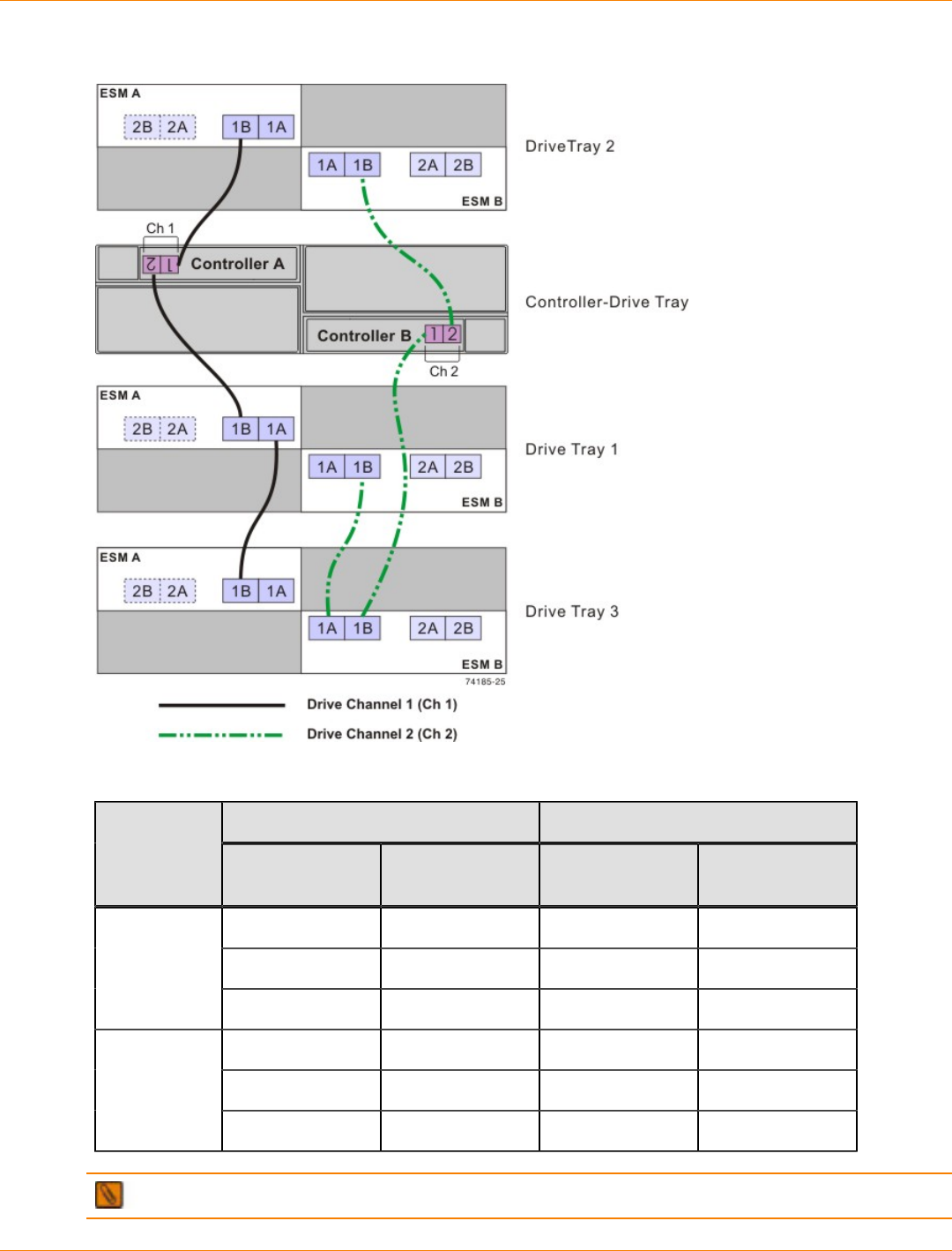
SANtricity_10.77 February 2011
LSI Corporation
- 631 -
One CDE3994 Controller-Drive Tray and Three Drive Trays with Inverted ESMs
One CDE3994 Controller-Drive Tray and Three Drive Trays with Inverted ESMs
Connection Point Connection PointDrive
Channel Tray or
Component Port Number
and Location Tray or
Component Port Number
and Location
Controller A 1 Drive tray 2 ESM A, Port 1B
Controller A 2 Drive tray 1 ESM A, Port 1B
1
Drive tray 1 ESM B, Port 1A Drive tray 3 ESM A, Port 1B
Controller B 1 Drive tray 3 ESM B, Port 1B
Drive tray 3 ESM B, Port 1A Drive tray 1 ESM B, Port 1B
2
Controller B 2 Drive tray 2 ESM B, Port 1B
NOTE If you have drive trays with side-by-side ESM canisters, see “ESM Canister Arrangements.”
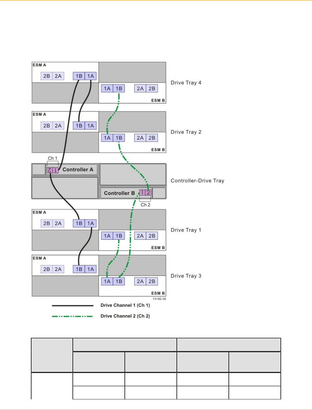
SANtricity_10.77 February 2011
LSI Corporation
- 632 -
One CDE3994 Controller-Drive Tray or CDE3992 Controller-Drive Tray and Four Drive Trays
If you are cabling one CDE3994 controller-drive tray to four drive trays, and those drive trays have inverted
ESM canisters, use the cabling topology described in the following figure and table.
One CDE3994 Controller-Drive Tray and Four Drive Trays with Inverted ESMs
One CDE3994 Controller-Drive Tray and Four Drive Trays with Inverted ESMs
Connection Point Connection PointDrive
Channel Tray or
Component Port Number
and Location Tray or
Component Port Number
and Location
Controller A 1 Drive tray 4* ESM A, port 1B1
Drive tray 4* ESM A, port 1A Drive tray 2* ESM A, port 1B
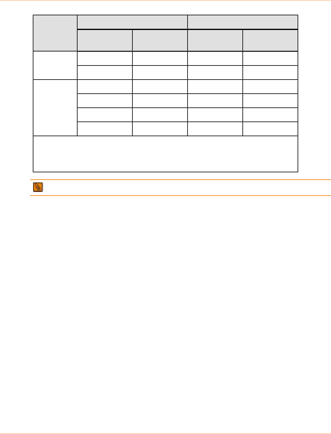
SANtricity_10.77 February 2011
LSI Corporation
- 633 -
Connection Point Connection PointDrive
Channel Tray or
Component Port Number
and Location Tray or
Component Port Number
and Location
Controller A 2 Drive tray 1* ESM A, port 1B
Drive tray 1* ESM A, port 1A Drive tray 3* ESM A, port 1B
Controller B 1 Drive tray 3* ESM B, port 1B
Drive tray 3* ESM B, port 1A Drive tray 1* ESM B, port 1B
Controller B 2 Drive tray 2* ESM B, port 1B
2
Drive tray 2* ESM B, port 1A Drive tray 4* ESM B, port 1B
*The firmware that controls the controller-drive tray automatically assigns drive tray tray IDs to
the FC4600 drive trays that will usually not match the drive tray numbers shown in this table
and preceding figure. The cabling is not affected by the assignment of drive tray tray IDs by the
firmware.
NOTE If you have drive trays with side-by-side ESM canisters, see “ESM Canister Arrangements.”
One CDE3994 Controller-Drive Tray or CDE3992 Controller-Drive Tray and Five Drive Trays
If you are cabling one CDE3994 controller-drive tray to five drive trays, and those drive trays have inverted
ESM canisters, use the cabling topology described in the following figure and table.
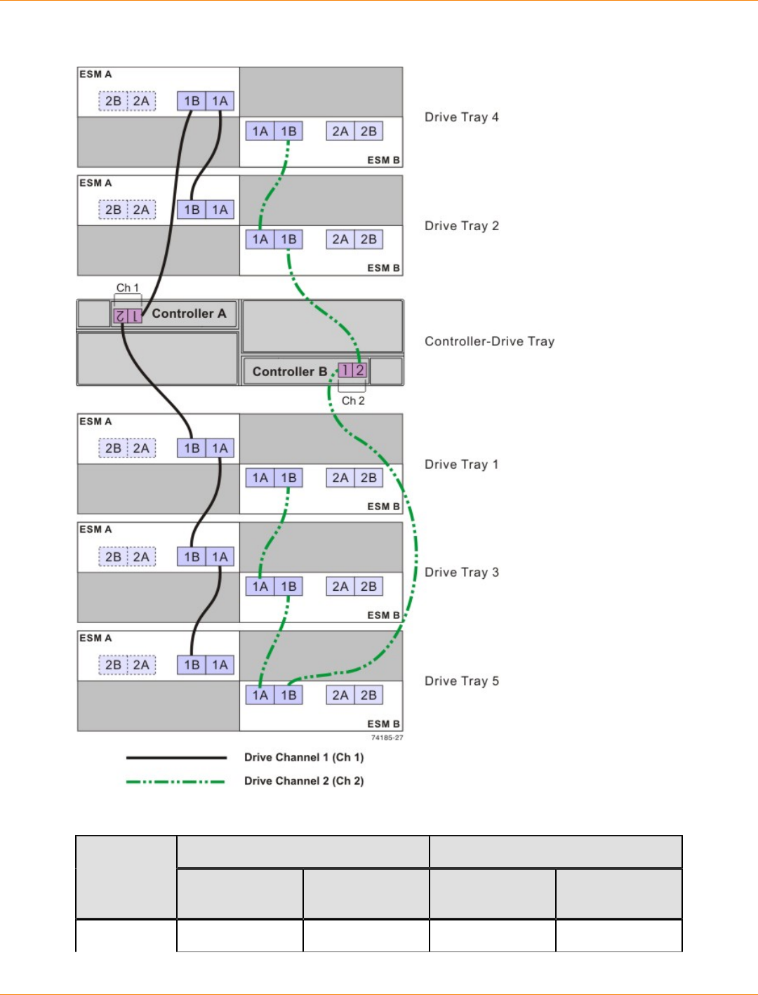
SANtricity_10.77 February 2011
LSI Corporation
- 634 -
One CDE3994 Controller-Drive Tray and Five Drive Trays with Inverted ESMs
One CDE3994 Controller-Drive Tray and Five Drive Trays with Inverted ESMs
Connection Point Connection PointDrive
Channel Tray or
Component Port Number
and Location Tray or
Component Port Number
and Location
1 Controller A 1 Drive tray 4 ESM A, port 1B
SANtricity_10.77 February 2011
LSI Corporation
- 635 -
Connection Point Connection PointDrive
Channel Tray or
Component Port Number
and Location Tray or
Component Port Number
and Location
Drive tray 4 ESM A, port 1A Drive tray 2 ESM A, port 1B
Controller A 2 Drive tray 1 ESM A, port 1B
Drive tray 1 ESM A, port 1A Drive tray 3 ESM A, port 1B
Drive tray 3 ESM A, port 1A Drive tray 5 ESM A, port 1B
Controller B 1 Drive tray 5 ESM B, port 1B
Drive tray 5 ESM B, port 1A Drive tray 3 ESM B, port 1B
Drive tray 3 ESM B, port 1A Drive tray 1 ESM B, port 1B
Controller B 2 Drive tray 2 ESM B, port 1B
2
Drive tray 2 ESM B, port 1A Drive tray 4 ESM B, port 1B
NOTE If you have drive trays with side-by-side ESM canisters, see “ESM Canister Arrangements.”
One CDE3994 Controller-Drive Tray or CDE3992 Controller-Drive Tray and Six Drive Trays
If you are cabling one CDE3994 controller-drive tray to six drive trays, and those drive trays have inverted
ESM canisters, use the cabling topology shown in the following table and figure.
IMPORTANT The CDE3994 controller-drive tray supports a maximum of seven drive trays. However,
if you are using the FC4600 drive tray in your configuration, plan for a limit of six FC4600 drive trays. Seven
FC4600 drive trays fully populated with drives exceed the maximum number of drives supported on a single
drive channel.
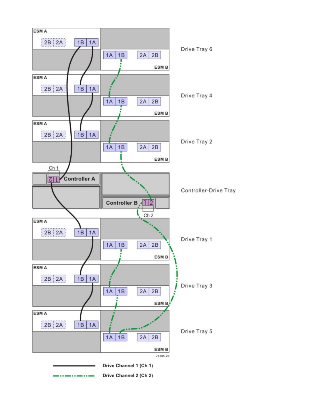
SANtricity_10.77 February 2011
LSI Corporation
- 636 -
One CDE3994 Controller-Drive Tray and Six Drive Trays with Inverted ESMs
SANtricity_10.77 February 2011
LSI Corporation
- 637 -
One CDE3994 Controller-Drive Tray and Six Drive Trays with Inverted ESMs
Connection Point Connection PointDrive
Channel Tray or
Component Port Number
and Location Tray or
Component Port Number
and Location
Controller A 1 Drive tray 6* ESM A, port 1B
Drive tray 6* ESM A, port 1A Drive tray 4* ESM A, port 1B
Drive tray 4* ESM A, port 1A Drive tray 2* ESM A, port 1B
Controller A 2 Drive tray 1* ESM A, port 1B
Drive tray 1* ESM A, port 1A Drive tray 3* ESM A, port 1B
1
Drive tray 3* ESM A, port 1A Drive tray 5* ESM A, port 1B
Controller B 1 Drive tray 5* ESM B, port 1B
Drive tray 5* ESM B, port 1A Drive tray 3* ESM B, port 1B
Drive tray 3* ESM B, port 1A Drive tray 1* ESM B, port 1B
Controller B 2 Drive tray 2* ESM B, port 1B
Drive tray 2* ESM B, port 1A Drive tray 4* ESM B, port 1B
2
Drive tray 4* ESM B, port 1A Drive tray 6* ESM B, port 1B
*The firmware for the controller-drive tray automatically assigns tray IDs to the FC4600 drive
trays. Those tray IDs usually will not match the drive tray numbers shown in this table and in
the preceding figure. The cabling pattern is not affected by the assignment of drive tray tray IDs
by the firmware.
NOTE If you have drive trays with side-by-side ESM canisters, see “ESM Canister Arrangements.”
One CDE3994 Controller-Drive Tray or CDE3992 Controller-Drive Tray and Multiple Types of
Drive Trays
If you are cabling more than one type of drive tray to the CDE3994 controller-drive tray, be sure to read these
topics before you choose a cabling topology:
“Multiple Types of Drive Trays”
“Cabling for Drive Trays That Support Loop Switch Technology”
Follow these guidelines for cabling multiple types of drive trays to maximize performance and accessibility.
(The first device on the drive channel is distinguished by the fact that the left ESM of the first device is cabled
directly to controller A of the controller tray or controller-drive tray. Because an optimal redundant cabling
topology requires that the redundant drive channel be cabled in the opposite order, this same device will be
the last in the drive channel when cabled to controller B.)

SANtricity_10.77 February 2011
LSI Corporation
- 638 -
The following figure provides an example of how flexible the cabling can be when you use a CDE3994
controller-drive tray as the controller. The firmware is able to detect, and correctly handle, combinations of
drive trays with both side-by-side ESMs and inverted ESMs. This feature allows you to easily add new drive
trays to your storage environment, while continuing to take advantage of pre-existing drive trays that you own.
If your storage array includes AT2655 drive trays, it is still advisable to cable the AT2655 drive trays so that
they are the last devices on the drive channel (farthest from controller A).
IMPORTANT When you mix different types of drive trays, you must consider the total number of drives
that are available in the final configuration of the storage array. For example, if you mix FC4600 drive trays
with FC2610 drive trays, the total number of drives might be more than the maximum number that each drive
channel can support.
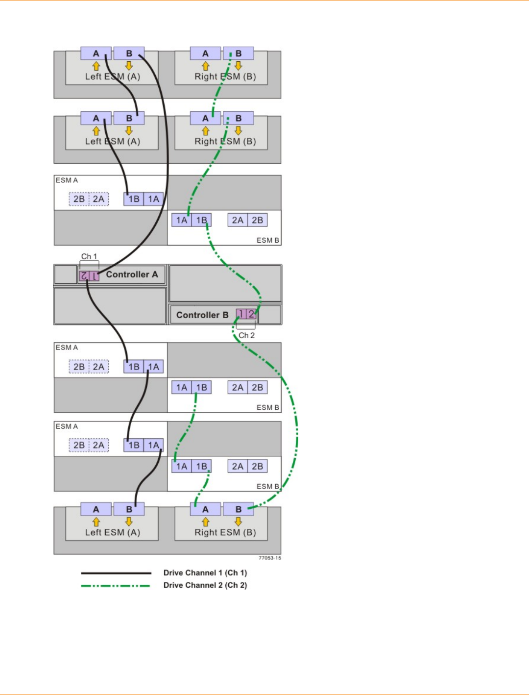
SANtricity_10.77 February 2011
LSI Corporation
- 639 -
One CDE3994 Controller-Drive Tray and Multiple Types of Drive Trays
Drive Cabling Topologies for the CDE2600 Controller-Drive Tray
This section provides examples of drive cabling topologies for the CDE2600 controller-drive tray. The
CDE2600 controller-drive tray can be cabled to DE1600 drive trays, DE5600 drive trays, or combinations of
these two drive trays. The total number of drives in the storage array, including the drives in the controller-
drive tray and those in the drive trays, must not exceed 192.
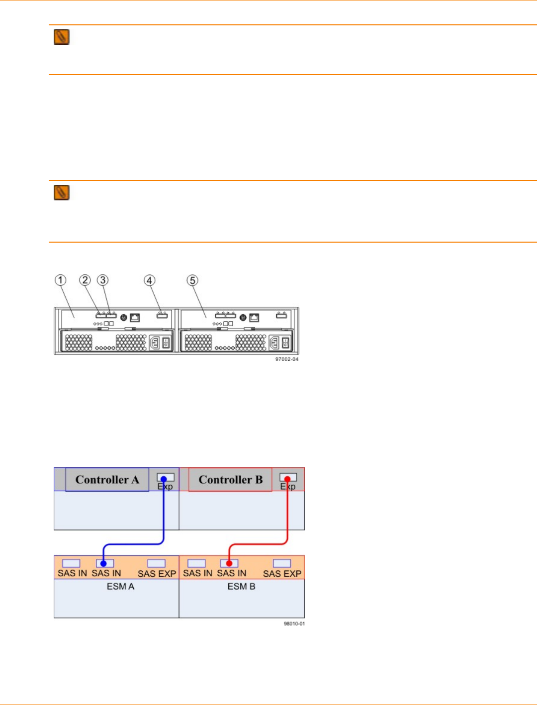
SANtricity_10.77 February 2011
LSI Corporation
- 640 -
IMPORTANT Simplex systems do not provide redundant connections to drive trays. If a connection or
an environmental services monitor (ESM) fails, all drive trays that connect to the controller-drive tray indirectly
through the failed connection or drive tray will become inaccessible.
Drive Cabling Topologies for the CDE2600 Controller-Drive Tray With DE1600 or DE5600 Drive
Trays
Depending on the number of drive trays that you need to connect, see the applicable figure for a cabling
topology. Each example shows a duplex controller-drive tray configuration with redundant paths to the drive
trays. For a simplex controller-drive tray configuration, use the cabling topology shown for controller A in the
applicable figure.
NOTE The following figures shows the SAS ports on a DE1600 drive tray or a DE5600 drive tray. You
may connect either of the SAS ports labeled SAS 1 and SAS 2 to the SAS expansion port on another drive
tray or on a controller-drive tray. You should not make connections to both the SAS 1 port and the SAS 2 port
on the same ESM.
SAS Ports on a DE1600 Drive Tray or a DE5600 Drive Tray
1. ESM A
2. SAS Port 1
3. SAS Port 2
4. SAS Expansion Port
5. ESM B
One CDE2600 Controller-Drive Tray and One Drive Tray
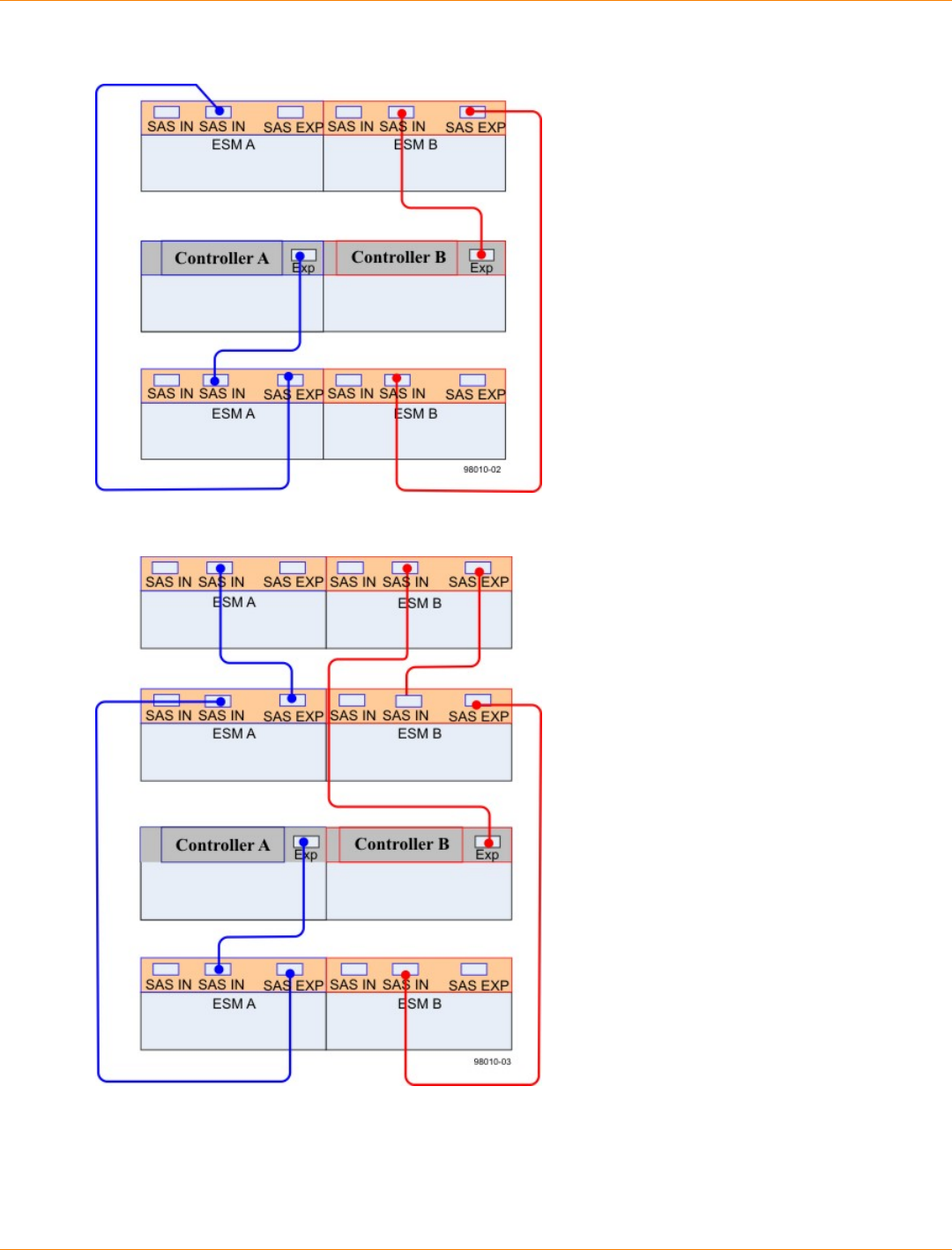
SANtricity_10.77 February 2011
LSI Corporation
- 641 -
One CDE2600 Controller-Drive Tray and Two Drive Trays
One CDE2600 Controller-Drive Tray and Three Drive Trays

SANtricity_10.77 February 2011
LSI Corporation
- 642 -
One CDE2600 Controller-Drive Tray and Eight Drive Trays
Drive Cabling Topologies for the CDE2600-60 Controller-Drive Tray
This section provides examples of drive cabling topologies for the CDE2600-60 controller-drive tray. The
CDE2600-60 controller-drive tray can be cabled only to DE6600 drive trays. The total number of drives in the
storage array, including the drives in the controller-drive tray and those in the drive trays, must not exceed
192.
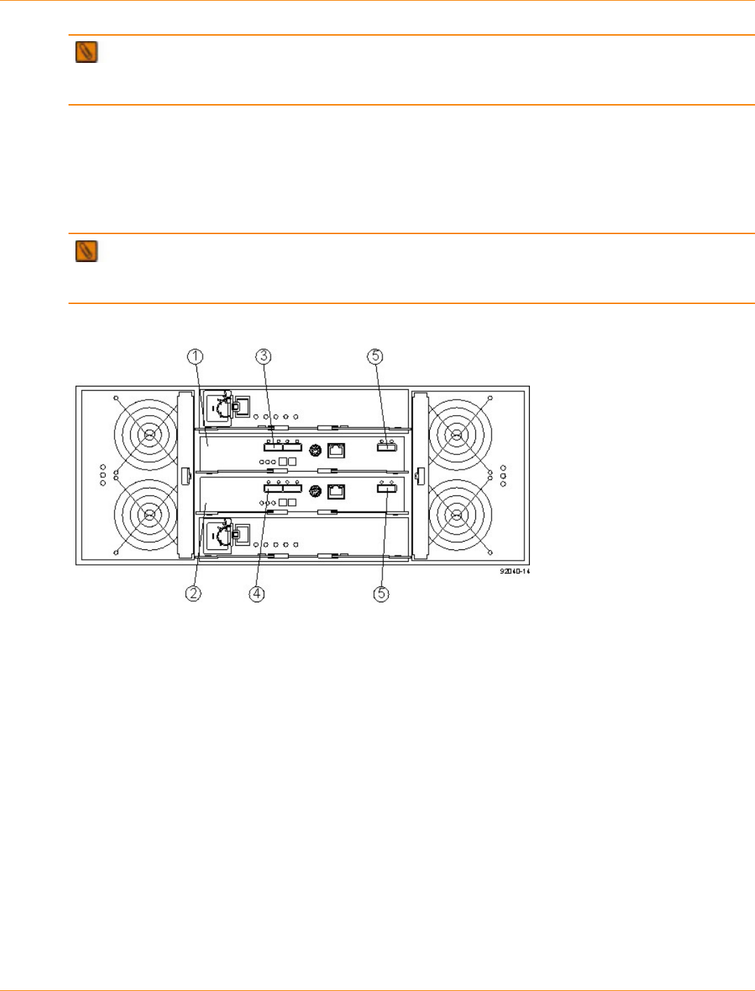
SANtricity_10.77 February 2011
LSI Corporation
- 643 -
IMPORTANT Simplex systems do not provide redundant connections to drive trays. If a connection or
an environmental services monitor (ESM) fails, all drive trays that connect to the controller-drive tray indirectly
through the failed connection or drive tray will become inaccessible.
Drive Cabling Topologies for the CDE2600-60 Controller-Drive Tray With DE6600 Drive Trays
Depending on the number of drive trays that you need to connect, see the applicable figure for a cabling
topology. Each example shows a duplex controller-drive tray configuration with redundant paths to the drive
trays. For a simplex controller-drive tray configuration, use the cabling topology shown for controller A in the
applicable figure.
NOTE The following figures show the SAS ports on a DE6600 drive tray. You may connect either of the
SAS ports labeled SAS 1 and SAS 2 to the SAS expansion port on another drive tray or on a controller-drive
tray. Do not make connections to both the SAS 1 port and the SAS 2 port on the same ESM.
SAS Ports on a DE6600 Drive Tray
1. ESM A
2. ESM B
3. SAS In Port
4. SAS In Port
5. SAS Expansion Ports
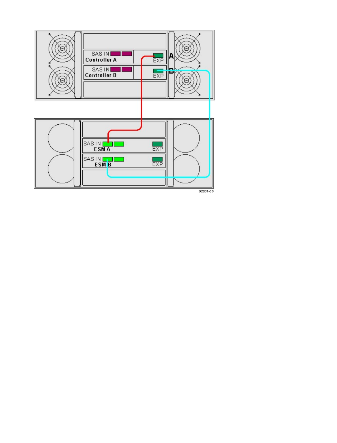
SANtricity_10.77 February 2011
LSI Corporation
- 644 -
One CDE2600-60 Controller-Drive Tray and One Drive Tray
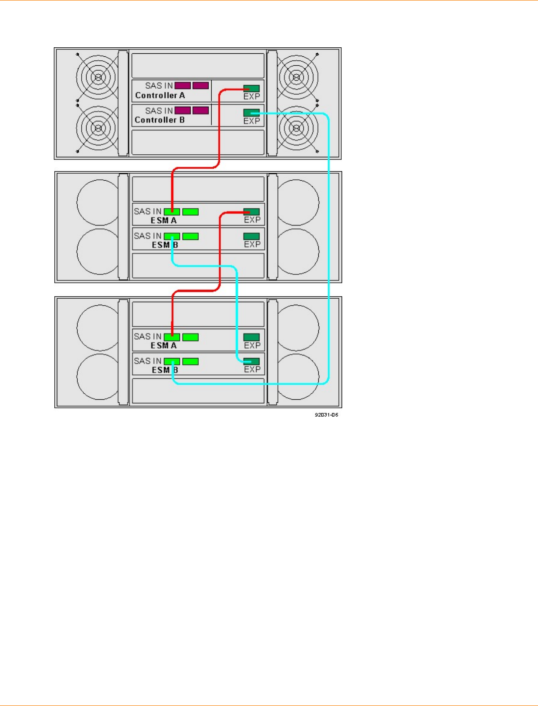
SANtricity_10.77 February 2011
LSI Corporation
- 645 -
One CDE2600-60 Controller-Drive Tray and Two Drive Trays
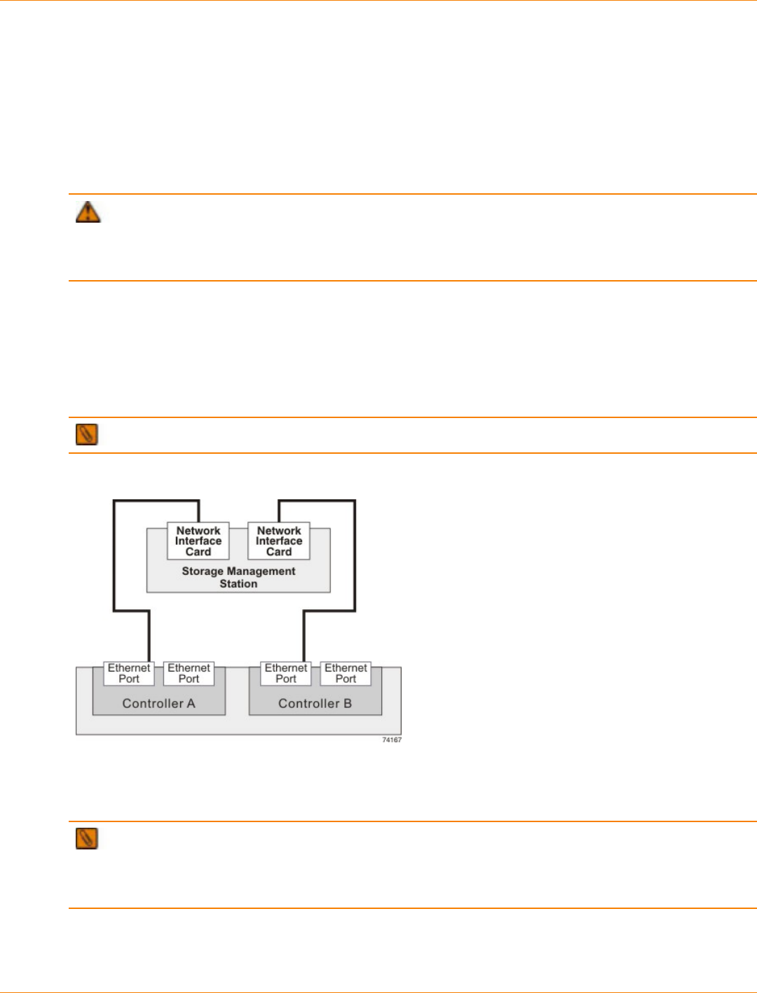
SANtricity_10.77 February 2011
LSI Corporation
- 646 -
Ethernet Cabling
This chapter provides examples of how to connect your storage array to an Ethernet network for out-of-band
storage array management. If you plan to use in-band storage array management, Ethernet cabling might not
be necessary for management connections.
For illustrations showing the Ethernet port locations on the specific controller tray model or controller-drive
tray model that you are installing, see the topics under “Component Locations.”
ATTENTION Possible loss of data access – If you use out-of-band management, connect the
Ethernet ports on the controller tray or the controller-drive tray to a private network segment behind a firewall.
If the Ethernet connection is not protected by a firewall, your storage array might be at risk of being accessed
from outside of your network.
Direct Out-of-Band Ethernet Topology
The following figure shows storage array management connections from the controller tray or controller-
drive tray to the Ethernet. In this topology, you must install a network interface card (NIC) in the storage
management station in which the client software resides. For dual controllers, you must install two NICs in the
storage management station.
NOTE For more information about NICs, see “Network Interface Cards.”
Network Out-of-Band Ethernet Topology
IMPORTANT In limited situations where the storage management station is connected directly to the
controller tray or the controller-drive tray, you must use an Ethernet crossover cable to connect the storage
management station to the Ethernet port. An Ethernet crossover cable is a special cable that reverses the pin
contacts between the two ends of the cable.
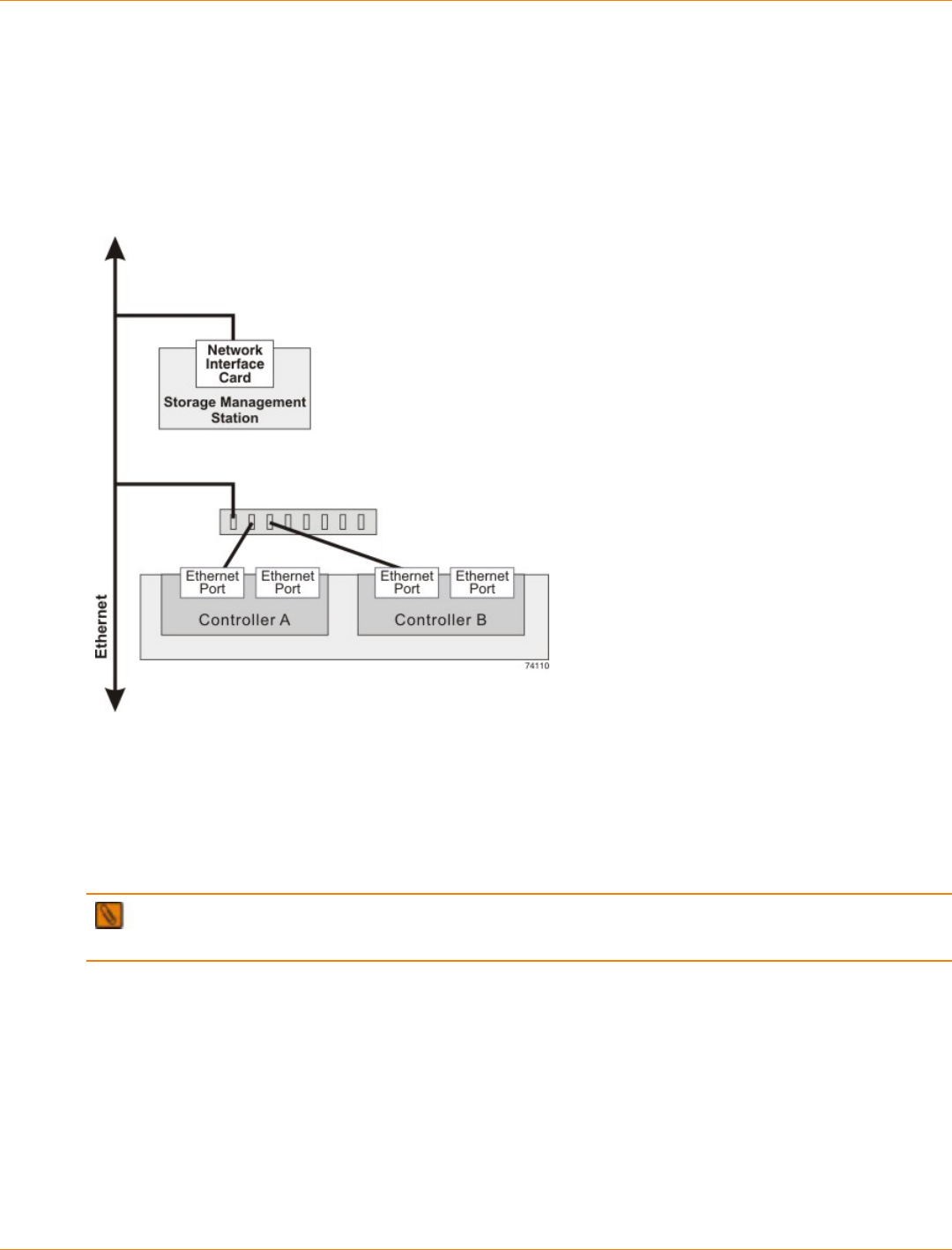
SANtricity_10.77 February 2011
LSI Corporation
- 647 -
Fabric Out-of-Band Ethernet Topology
The following figure shows two storage array management connections from the controller tray or the
controller-drive tray to two ports on an Ethernet switch. In this topology, you must install a NIC in the storage
management station where the client software resides. You must use Ethernet cables for all storage array
management connections.
Fabric Redundant Out-of-Band Ethernet Topology
For more information, see “In-Band Management and Out-of-Band Management.”
IMPORTANT If you have two available Ethernet ports on each controller, reserve one port on each
controller for access to the storage array by your Customer and Technical Support representative.
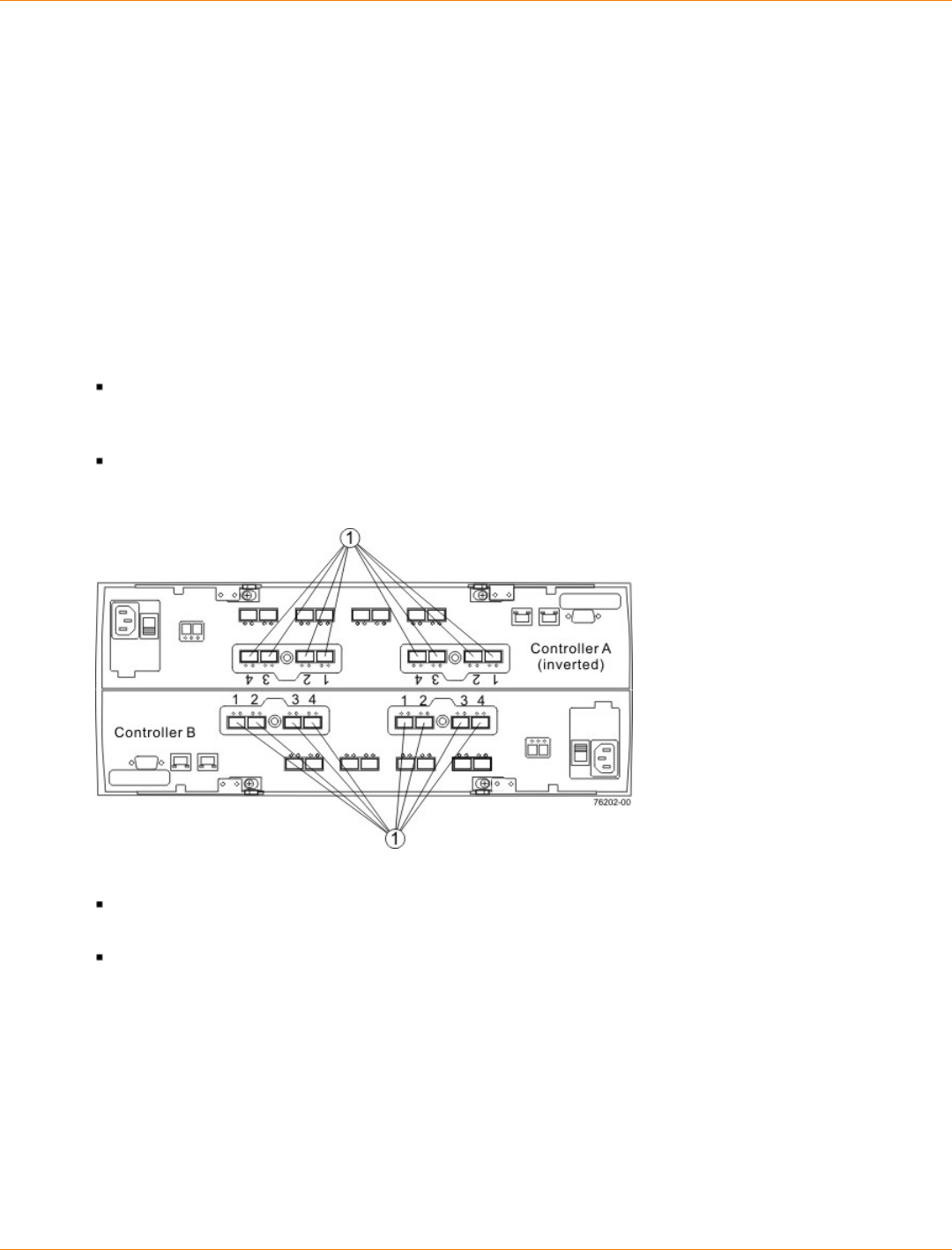
SANtricity_10.77 February 2011
LSI Corporation
- 648 -
Component Locations
This chapter provides shows the rear of each controller tray, controller-drive tray, and drive tray. The figures
identify the locations of controllers, environmental services monitors (ESMs), host ports, drive ports, and
Ethernet ports. The figures also show port identifiers.
Use the figures in the following topics to make sure that you have correctly identified the cable connection
points described under "Host Cabling," "Drive Cabling," and "Ethernet Cabling."
Port Locations on the CE7922 Controller Tray and the CE7900 Controller Tray
The CE7922 and CE7900 controller trays have host channels that you can attach to the hosts, and drive
channels that you can attach to the drive trays. The examples in this section show the CE7900 controller tray.
The port locations are the same for the CE7922 controller tray.
Each of the two controllers in the CE7900 controller tray might have two host cards with four host ports on
each card. This configuration is shown in the following figure. Some CE7900 controller trays might have
controllers with only one host card each.
Controller A is inverted from controller B, which means that its host channels are upside-down.
Host Channels on the CE7922 and CE7900 Controller Trays – Rear View
1. Host Channel Ports
Each controller in the CE7922 and CE7900 controller trays has four drive channels, and each drive
channel has two ports, so each controller has eight drive ports.
Controller A is inverted from controller B, which means that its drive channels are upside-down.
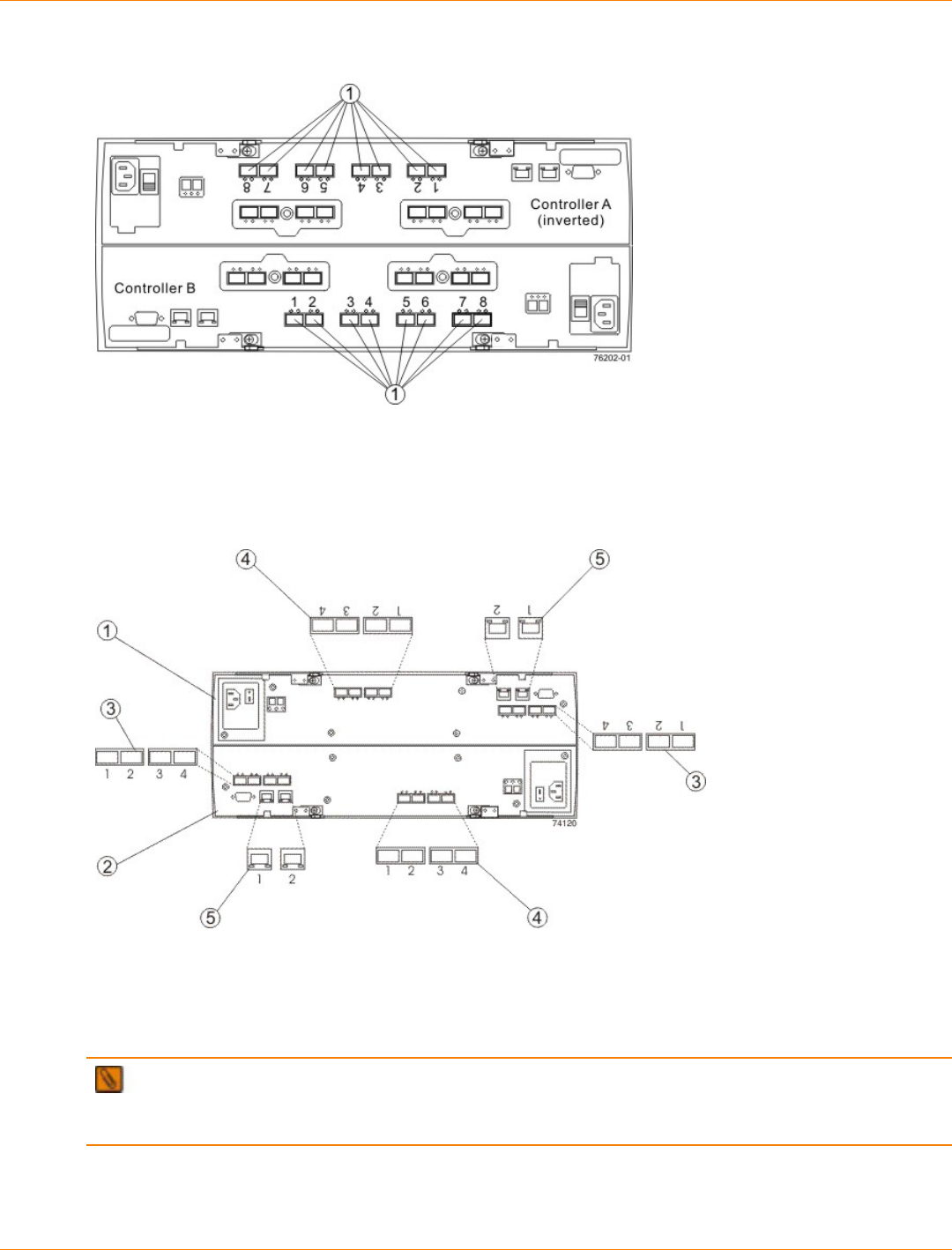
SANtricity_10.77 February 2011
LSI Corporation
- 649 -
Drive Channel Ports on the CE7922 and CE7900 Controller Trays – Rear View
1. Drive Channel Ports
Component Locations on the CE6998 Controller Tray
Component Locations on the CE6998 Controller Tray – Rear View
1. Controller A (Inverted)
2. Controller B
3. Host Ports
4. Drive Ports
5. Ethernet Ports
NOTE Host port 4 on each controller of the CE6998 controller tray is reserved for the Remote Volume
Mirroring premium feature. If you are not using the Remote Volume Mirroring premium feature, these host
ports are available for host connections.
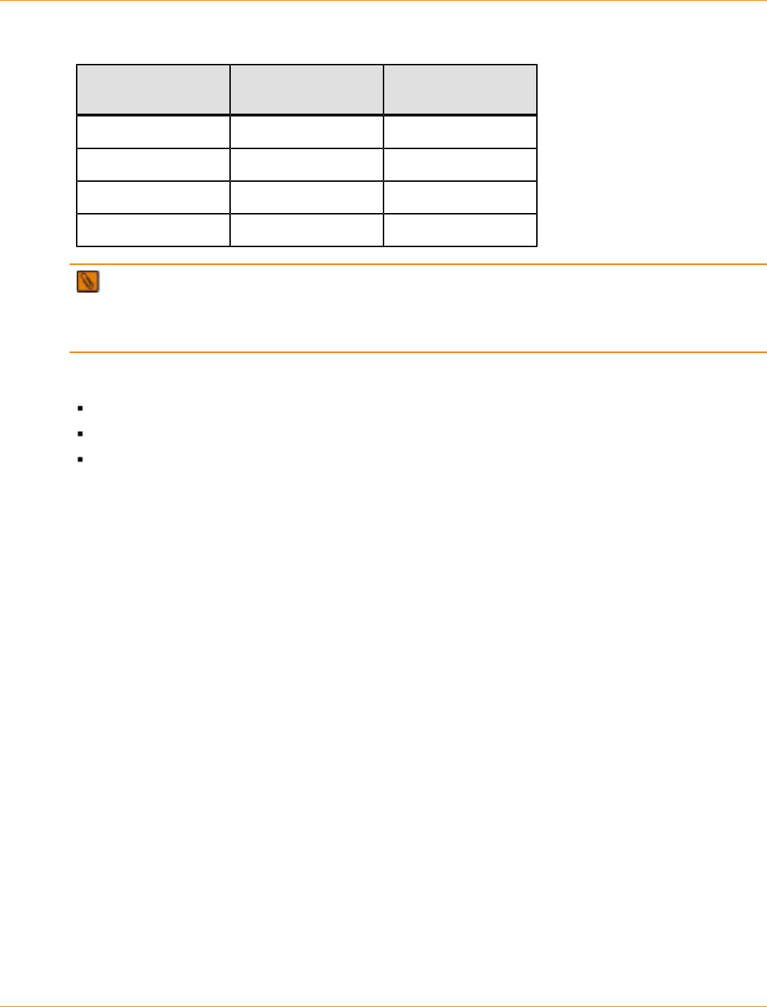
SANtricity_10.77 February 2011
LSI Corporation
- 650 -
Drive Ports and Drive Channels on the CE6998 Controller Tray
Drive Channel
Number Controller Drive Port Numbers
1 A 4 and 3
2 A 2 and 1
3 B 1 and 2
4 B 3 and 4
NOTE When you cable the CE6998 controller tray, it is important to note that drive channel 1 and drive
channel 3 are a redundant pair, and drive channel 2 and drive channel 4 are a redundant pair. In other words,
if a failure occurred in drive channel 1, drive channel 3 would allow communication with the drives. If a failure
occurred in drive channel 2, drive channel 4 would allow communication with the drives.
Component Locations on the CDE4900 Controller-Drive Tray
The top controller, controller A, is inverted from the bottom controller, controller B.
The top of the controller-drive tray is the side with labels.
The configuration of the host ports might appear different on your system depending on which host
interface card configuration is installed.

SANtricity_10.77 February 2011
LSI Corporation
- 651 -
CDE4900 Controller-Drive Tray – Front View and Rear View
1. Drive Canister
2. Alarm Mute Switch
3. Link Rate Switch
4. Controller A (Inverted)
5. Power-Fan Canister
6. AC Power Connector
7. AC Power Switch
8. Battery Canister
9. Ethernet Ports
10. Drive Channels
11. Host Channels
12. Serial Port
13. Seven-Segment Display
14. Optional DC Power Connector and DC Power Switch
Component Locations on the CDE3994 Controller-Drive Tray and the CDE3992
Controller-Drive Tray
The following figure shows the AC power option.
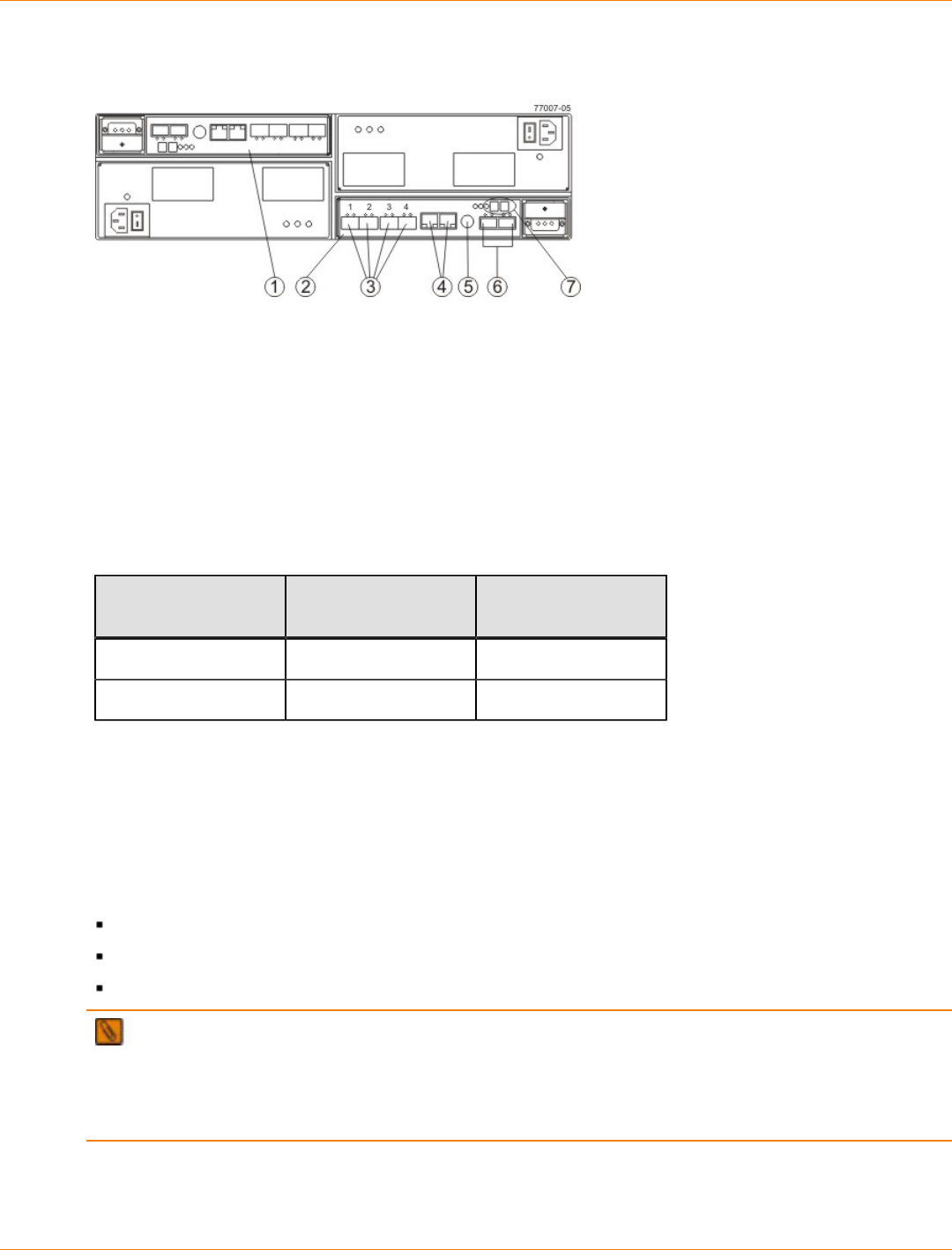
SANtricity_10.77 February 2011
LSI Corporation
- 652 -
Component Locations on the CDE3994 Controller-Drive Tray and the CDE3992 Controller-Drive Tray –
Rear View
1. Controller A (Inverted)
2. Controller B
3. Host Ports (2 Ports for the CDE3992 Controller-Drive Tray or 4 Ports for the CDE3994 Controller-Drive Tray)
4. Ethernet Ports
5. Serial Port
6. Dual-Ported Drive Ports
7. Seven-Segment Display
Drive Ports and Drive Channels on the CDE3994 Controller-Drive Tray and the CDE3992 Controller-
Drive Tray
Drive Channel
Number Controller Drive Port Identifier
1 A 2 and 1
2 B 1 and 2
Component Locations on the CDE2600 Controller-Drive Tray
The CDE2600 controller-drive tray is available in two different drive configurations: one with up to twelve 3.5-
in. drives and another with up to twenty-four 2.5-in. drives. With either drive configuration, the controller-drive
tray is available in two different controller configurations: simplex and duplex.
Keep these points in mind when you compare the figures in this section to your hardware.
The top of the controller-drive tray is the side with the labels.
The configuration of the host ports depends on which host interface card configuration is installed.
The figures in this section show the AC power option.
NOTE On the CDE2600 controller-drive tray, each controller has a pair of levers with handles for
removing the controller from the controller-drive tray. If a controller has a HIC installed, one of these handles
on the controller is located next to a host port on the HIC. The close spacing between the handle and the host
port might make it difficult to remove a cable that is attached to the host port. If this problem occurs, use a flat-
blade screwdriver to compress the release on the cable connector.

SANtricity_10.77 February 2011
LSI Corporation
- 653 -
CDE2600 Controller-Drive Tray with 12 Drives – Front View
1. Standby Power LED
2. Power LED
3. Over-Temperature LED
4. Service Action Required LED
5. Locate LED
6. Drive Canister
CDE2600 Controller-Drive Tray with 24 Drives – Front View
1. Standby Power LED
2. Power LED
3. Over-Temperature LED
4. Service Action Required LED
5. Locate LED
6. Drive Canister
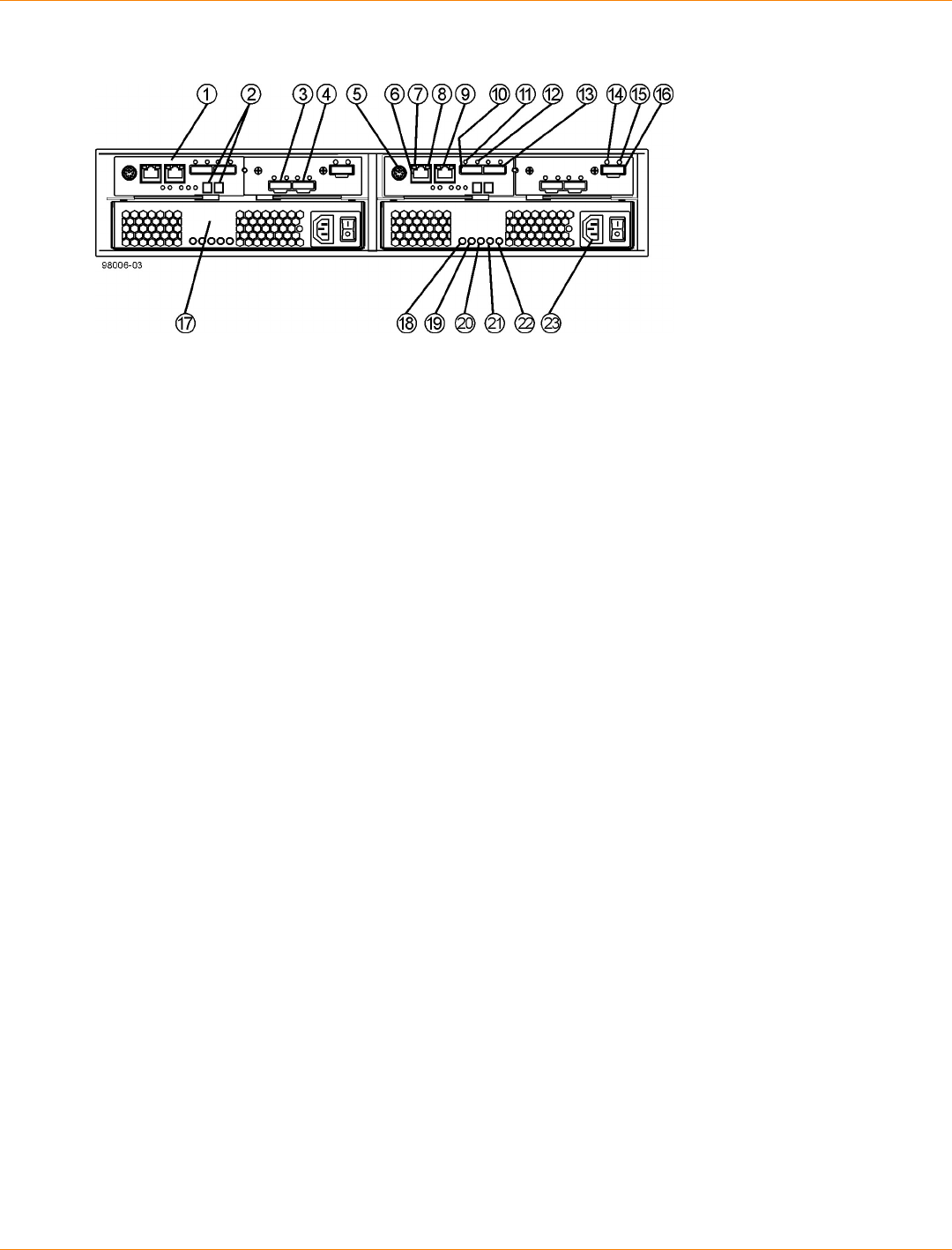
SANtricity_10.77 February 2011
LSI Corporation
- 654 -
CDE2600 Controller-Drive Tray Duplex Configuration – Rear View
1. Controller A Canister
2. Seven-Segment Display
3. Host Interface Card Connector 1
4. Host Interface Card Connector 2
5. Serial Connector
6. Ethernet Connector 1
7. Ethernet Link Active LED
8. Ethernet Link Rate LED
9. Ethernet Connector 2
10. Host SFF-8088 Connector 2
11. Host Link 2 Fault LED
12. Host Link 2 Active LED
13. Base Host SFF-8088 Connector 1
14. ESM Expansion Fault LED
15. ESM Expansion Active LED
16. Expansion SFF-8088 Port Connector
17. Power-Fan Canister
18. Standby Power LED
19. Power-Fan DC Power LED
20. Power-Fan Service Action Allowed LED
21. Power-Fan Service Action Required LED
22. Power-Fan AC Power LED

SANtricity_10.77 February 2011
LSI Corporation
- 655 -
CDE2600 Right-Rear Subplate with No Host Interface Card
1. ESM Expansion Fault LED
2. ESM Expansion Active LED
3. Expansion SFF-8088 Port Connector
CDE2600 Right-Rear Subplate with a SAS Host Interface Card
1. Host Interface Card Link 3 Up LED
2. Host Interface Card Link 3 Active LED
3. SFF-8088 Host Interface Card Connector 3
4. Host Interface Card Link 4 Up LED
5. Host Interface Card Link 4 Active LED
6. SFF-8088 Host Interface Card Connector 4
7. ESM Expansion Fault LED
8. ESM Expansion Active LED
9. Expansion SFF-8088 Port Connector
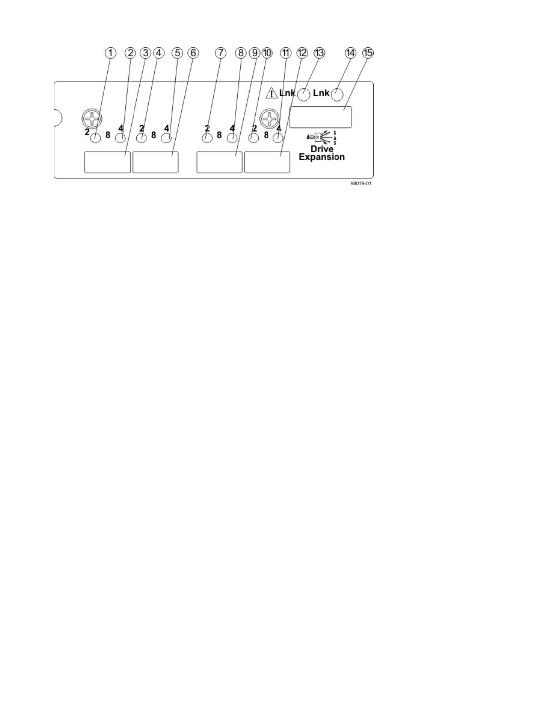
SANtricity_10.77 February 2011
LSI Corporation
- 656 -
CDE2600 Right-Rear Subplate with an FC Host Interface Card
1. Host Interface Card Link 3 Up LED
2. Host Interface Card Link 3 Active LED
3. FC Host Interface Card Connector 3
4. Host Interface Card Link 4 Up LED
5. Host Interface Card Link 4 Active LED
6. FC Host Interface Card Connector 4
7. Host Interface Card Link 5 Up LED
8. Host Interface Card Link 5 Active LED
9. FC Host Interface Card Connector 5
10. Host Interface Card Link 6 Up LED
11. Host Interface Card Link 6 Active LED
12. FC Host Interface Card Connector 6
13. ESM Expansion Fault LED
14. ESM Expansion Active LED
15. Expansion SFF-8088 Port Connector

SANtricity_10.77 February 2011
LSI Corporation
- 657 -
CDE2600 Right-Rear Subplate with an iSCSI Host Interface Card
1. Host Interface Card Link 3 Up LED
2. Host Interface Card Link 3 Active LED
3. iSCSI Host Interface Card Connector 3
4. Host Interface Card Link 4 Up LED
5. Host Interface Card Link 4 Active LED
6. iSCSI Host Interface Card Connector 4
7. Host Interface Card Link 5 Up LED
8. Host Interface Card Link 5 Active LED
9. iSCSI Host Interface Card Connector 5
10. Host Interface Card Link 6 Up LED
11. Host Interface Card Link 6 Active LED
12. iSCSI Host Interface Card Connector 6
13. ESM Expansion Fault LED
14. ESM Expansion Active LED
15. Expansion SFF-8088 Port Connector
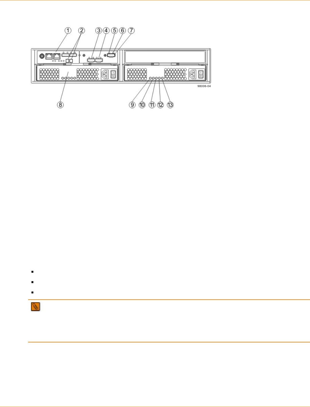
SANtricity_10.77 February 2011
LSI Corporation
- 658 -
CDE2600 Controller-Drive Tray SImplex Configuration – Rear View
1. Controller A Canister
2. Seven-Segment Display
3. Host Interface Card Connector 1
4. Host Interface Card Connector 2
5. ESM Expansion Fault LED
6. ESM Expansion Active LED
7. Expansion Port SFF-8088 Connector
8. Power-Fan A Canister
9. Standby Power LED
10. Power-Fan DC Power LED
11. Power-Fan Service Action Allowed LED
12. Power-Fan Service Action Required LED
13. Power-Fan AC Power LED
Component Locations on the CDE2600-60 Controller-Drive Tray
The CDE2600-60 controller-drive tray is available in two different controller configurations: simplex and
duplex.
Keep these points in mind when you compare the figures in this section to your hardware.
The top of the controller-drive tray is the side with the labels.
The configuration of the host ports depends on which host interface card configuration is installed.
The figures in this section show the AC power option.
NOTE On the CDE2600-60 controller-drive tray, each controller has a pair of levers with handles for
removing the controller from the controller-drive tray. If a controller has a HIC installed, one of these handles
on the controller is located next to a host port on the HIC. The close spacing between the handle and the host
port might make it difficult to remove a cable that is attached to the host port. If this problem occurs, use a flat-
blade screwdriver to compress the release on the cable connector.
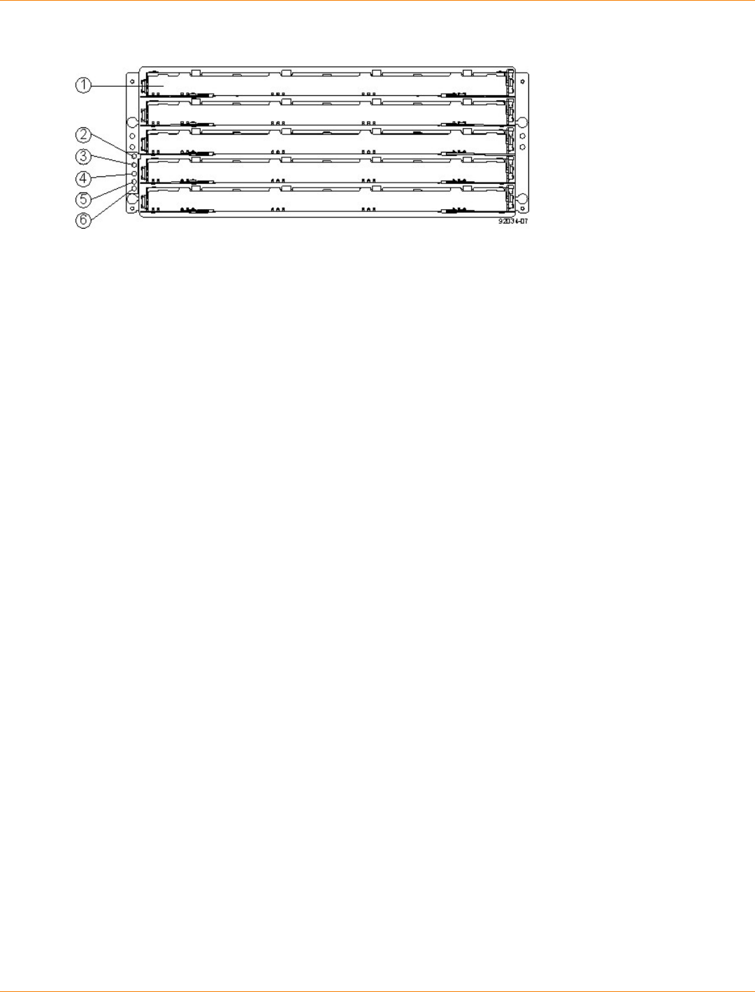
SANtricity_10.77 February 2011
LSI Corporation
- 659 -
CDE2600-60 Controller-Drive Tray – Front View
1. Standby Power LED
2. Power LED
3. Over-Temperature LED
4. Service Action Required LED
5. Locate LED
6. Drive Canister
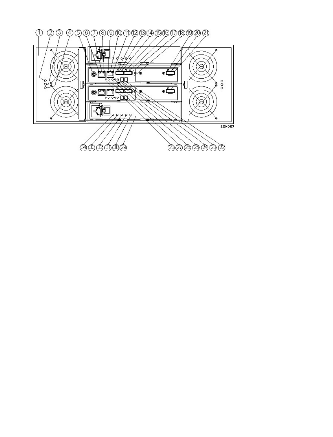
SANtricity_10.77 February 2011
LSI Corporation
- 660 -
CDE2600-60 Controller-Drive Tray – Rear View
1. Fan Canister
2. Fan Canister Power LED
3. Fan Canister Service Action Required LED
4. Fan Canister Service Action Allowed LED
5. Serial Connector
6. Ethernet Link 1 Active LED
7. Ethernet Connector 1
8. Ethernet Link 1 Rate LED
9. Ethernet Link 2 Active LED
10. Ethernet Connector 2
11. Ethernet Link 2 Rate LED
12. Host Link 2 Fault LED
13. Base Host SFF-8088 Connector 2
14. Host Link 2 Active LED
15. Host Link 1 Fault LED
16. Host Link 1 Active LED
17. Base Host SFF-8088 Connector 1
18. Controller A Canister
19. ESM Expansion Fault LED
20. ESM Expansion Active LED
21. Expansion SFF-8088 Port Connector
22. Second Seven-Segment Display Field
23. First Seven-Segment Display Field
24. Cache Active LED
25. Controller A Service Action Required LED
26. Controller A Service Action Allowed LED
27. Battery Service Action Required LED
28. Battery Charging LED
29. Power Canister
30. Power Canister AC Power LED
31. Power Canister Service Action Required LED
32. Power Canister Service Action Allowed LED
33. Power Canister DC Power LED
34. Power Canister Standby Power LED

SANtricity_10.77 February 2011
LSI Corporation
- 661 -
CDE2600-60 Right-Rear Subplate with No Host Interface Card
1. ESM Expansion Fault LED
2. ESM Expansion Active LED
3. Expansion SFF-8088 Port Connector
CDE2600-60 Right-Rear Subplate with a SAS Host Interface Card
1. Host Interface Card Link 3 Up LED
2. Host Interface Card Link 3 Active LED
3. SFF-8088 Host Interface Card Connector 3
4. Host Interface Card Link 4 Up LED
5. Host Interface Card Link 4 Active LED
6. SFF-8088 Host Interface Card Connector 4
7. ESM Expansion Fault LED
8. ESM Expansion Active LED
9. Expansion SFF-8088 Port Connector
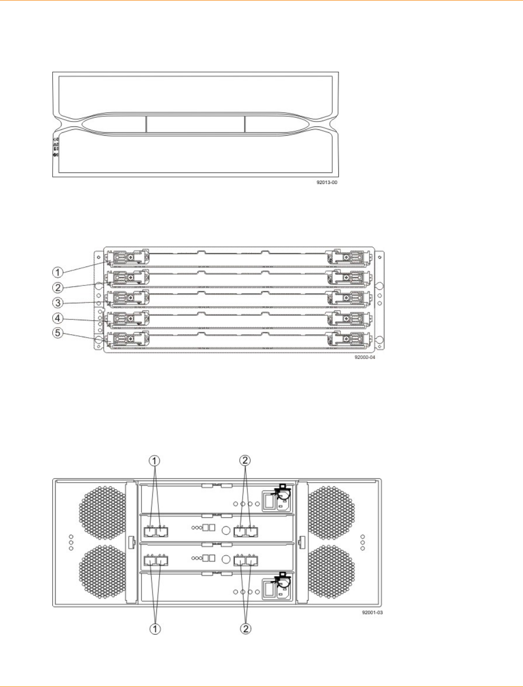
SANtricity_10.77 February 2011
LSI Corporation
- 662 -
Component Locations on the DE6900 Drive Tray
DE6900 Drive Tray – Front View with Bezel
DE6900 Drive Tray – Front View with Bezel Removed
1. Drive Drawer 1
2. Drive Drawer 2
3. Drive Drawer 3
4. Drive Drawer 4
5. Drive Drawer 5
DE6900 Drive Tray – Rear View
1. Standard Expansion Connectors
2. Drive-Side Trunking Expansion Connectors
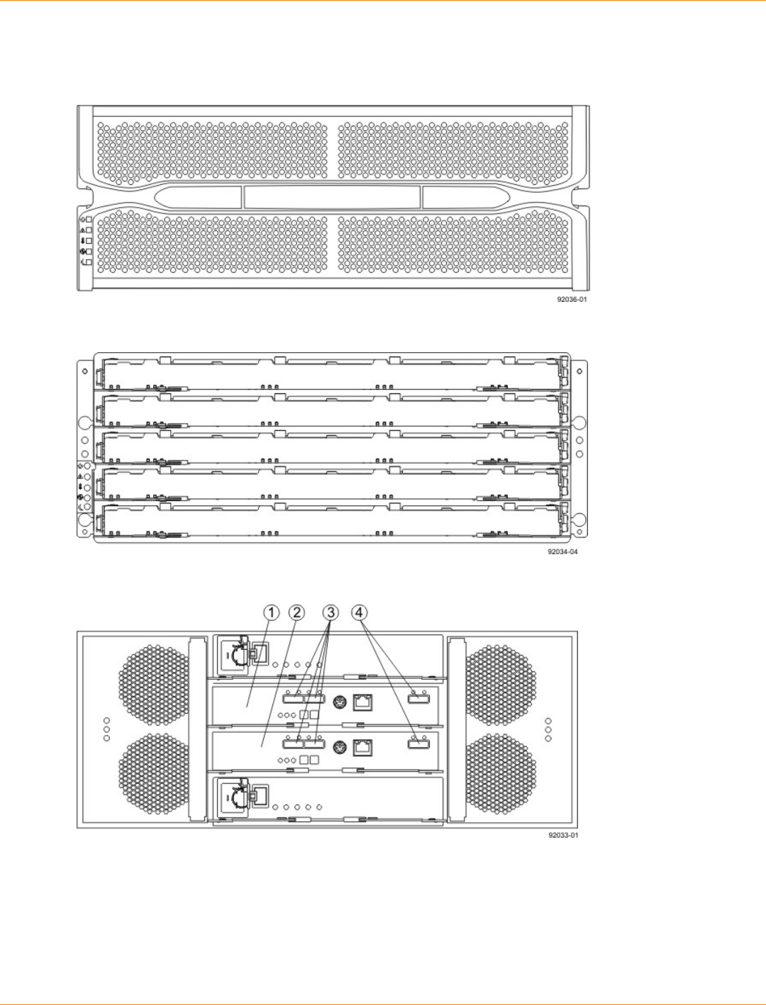
SANtricity_10.77 February 2011
LSI Corporation
- 663 -
Component Locations on the DE6600 Drive Tray
DE6600 Drive Tray – Front View with Bezel
DE6600 Drive Tray – Front View with Bezel Removed
DE6600 Drive Tray – Rear View
1. ESM A
2. ESM B
3. SAS In Connectors
4. Expansion Connectors
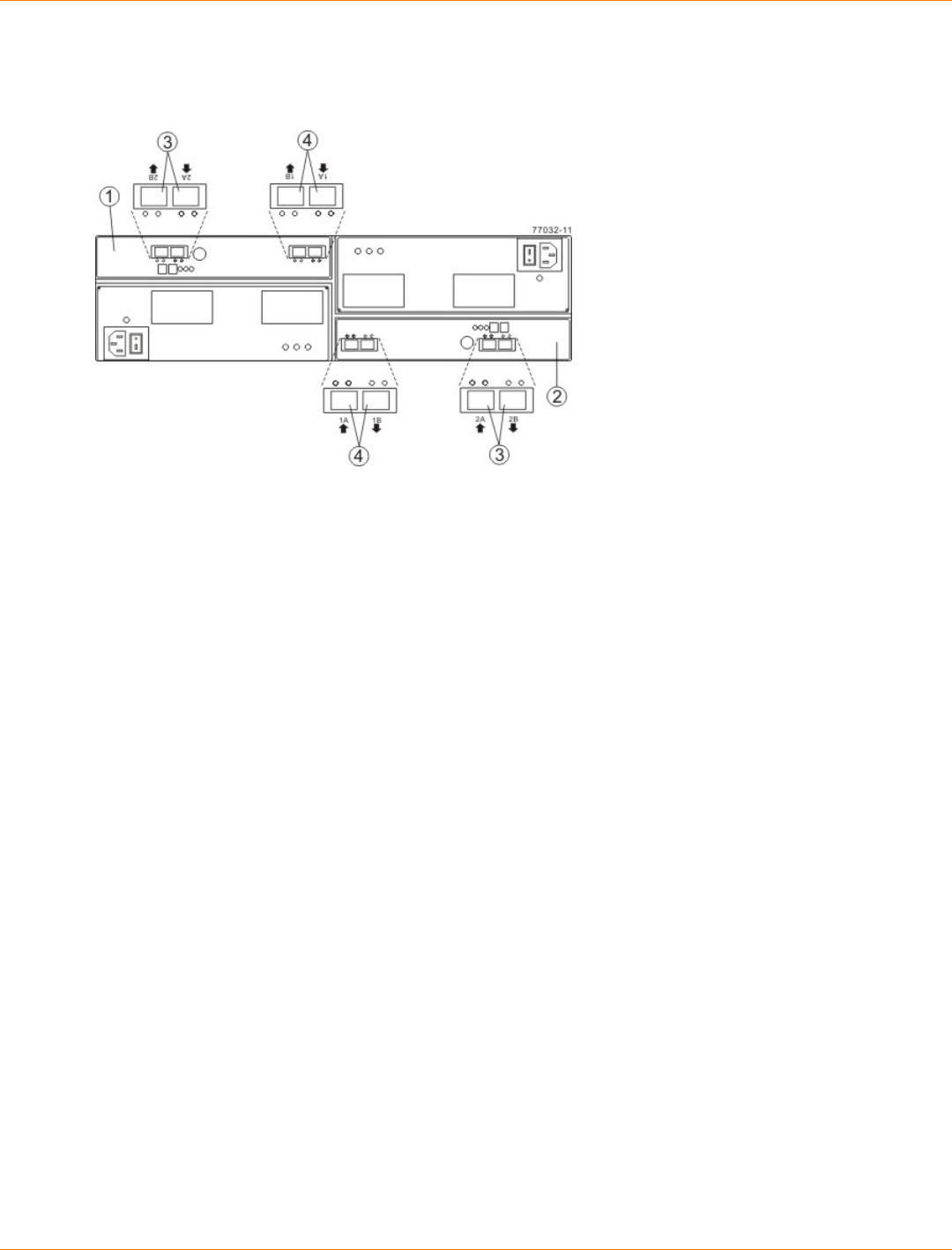
SANtricity_10.77 February 2011
LSI Corporation
- 664 -
Component Locations on the FC4600 Drive Tray
Component Locations on the FC4600 Drive Tray – Rear View
1. Left ESM
2. Right ESM
3. Secondary SFP Ports
4. Primary SFP Ports
The ESM on the FC4600 drive tray has four SFP ports. The two primary ports are active. The secondary ports
are reserved for future use. If SFP transceivers are placed in the secondary ports, the SFP Port LEDs blink,
as a reminder that these ports are not functioning.
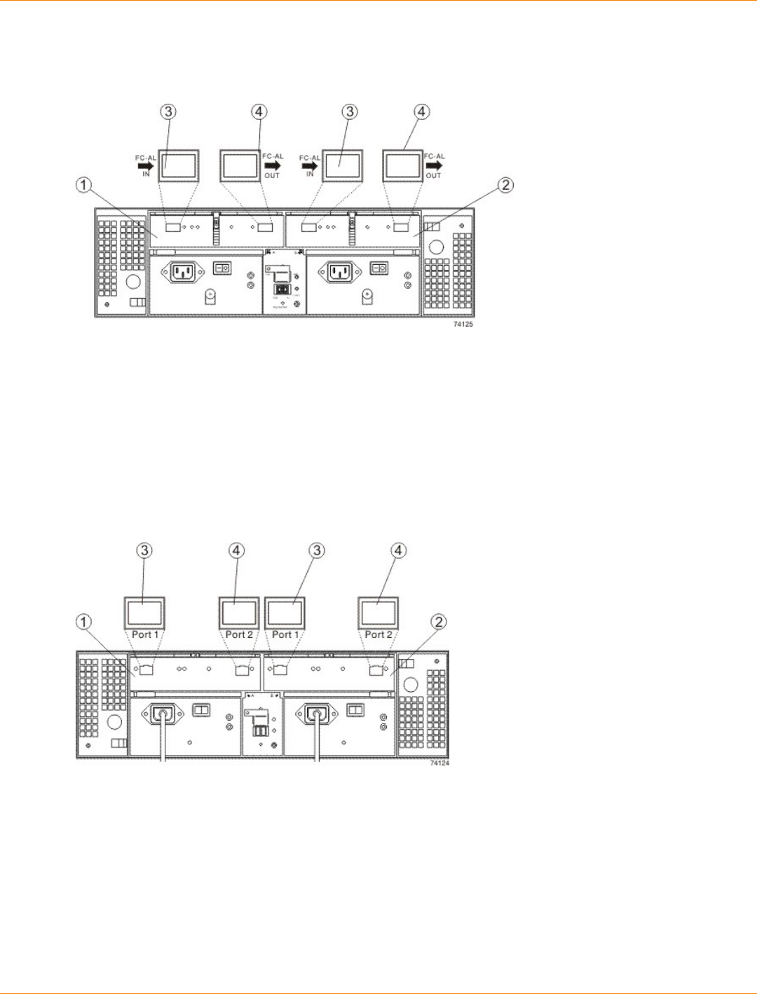
SANtricity_10.77 February 2011
LSI Corporation
- 665 -
Component Locations on the AT2655 Drive Tray
Component Locations on the AT2655 Drive Tray – Rear View
1. Left ESM
2. Right ESM
3. In Ports
4. Out Ports
Component Locations on the FC2610 Drive Tray
Component Locations on the FC2610 Drive Tray – Rear View
1. Left ESM
2. Right ESM
3. In Ports
4. Out Ports
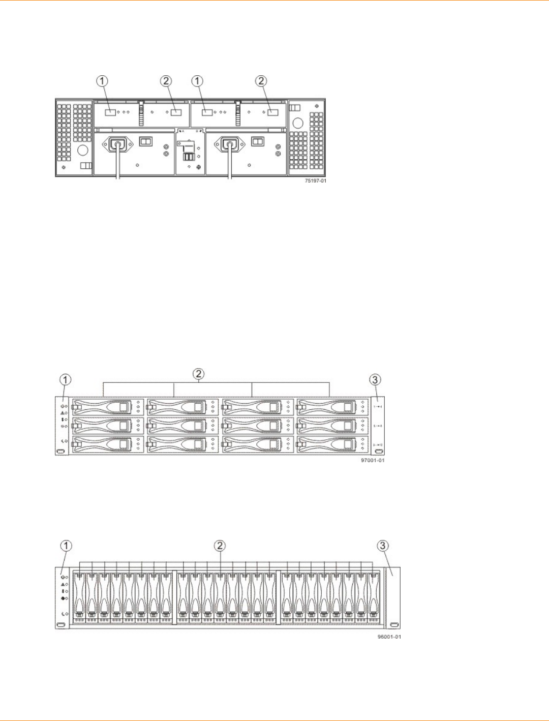
SANtricity_10.77 February 2011
LSI Corporation
- 666 -
Component Locations on the FC2600 Drive Tray
Component Locations on the FC2600 Drive Tray – Rear View
1. In Ports
2. Out Ports
Component Locations on the DE1600 and DE5600 Drive Trays
The DE1600 drive tray can have two to twelve 3.5-in. drives. The DE5600 drive tray can have two to twenty-
four 2.5-in. drives. The component locations on the rear of these drive trays are the same. The following
figures show the AC power option.
DE1600 Drive Tray – Front View
1. Left End Cap (has the Drive Tray LEDs)
2. Drives
3. Right End Cap
DE5600 Drive Tray – Front View
1. Left End Cap (has the Drive Tray LEDs)
2. Drives
3. Right End Cap
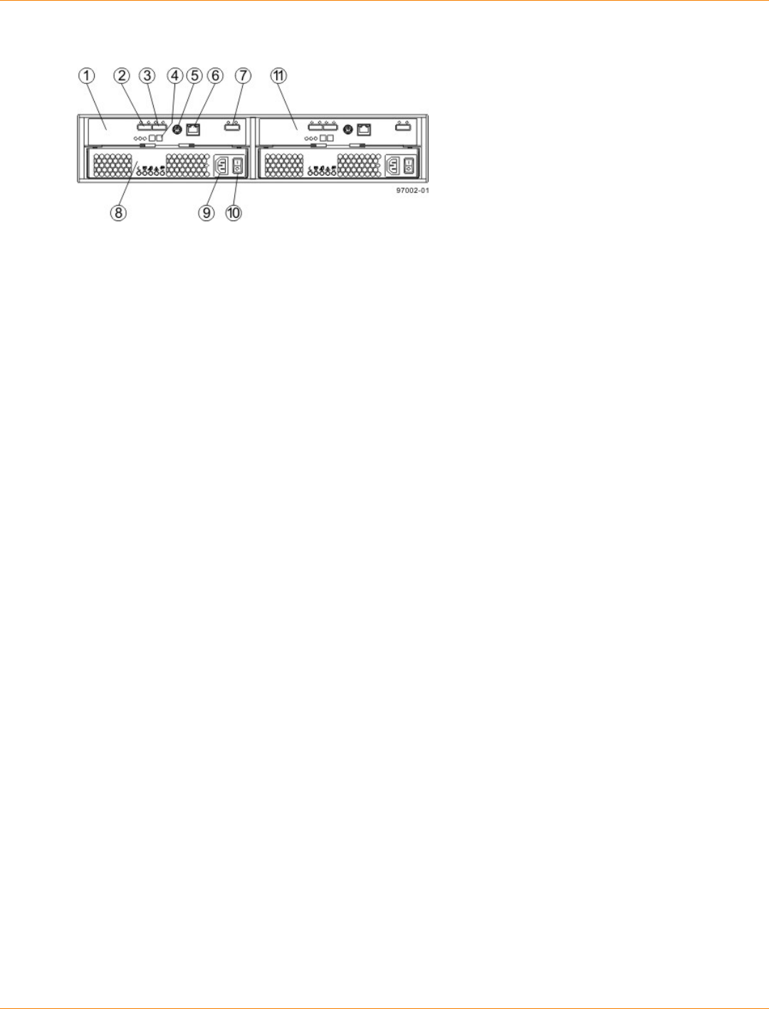
SANtricity_10.77 February 2011
LSI Corporation
- 667 -
DE1600 Drive Tray or DE5600 Drive Tray – Rear View
1. ESM A Canister
2. Host Connector 1
3. Host Connector 2
4. Seven-Segment Display Indicators
5. Serial Connector
6. Ethernet Connector
7. Expansion Port SFF-8088 Connector
8. Power-Fan Canister
9. Power Connector
10. Power Switch
11. ESM B Canister
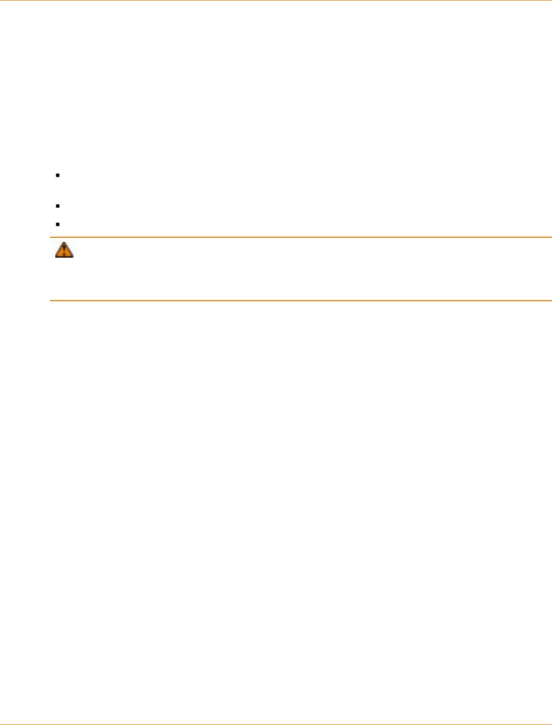
SANtricity_10.77 February 2011
LSI Corporation
- 668 -
Adding a Drive Tray to an Existing System
This chapter provides information about adding a drive tray to an existing system.
Getting Ready
If you need to add another drive tray to an existing storage array, contact your Customer and Technical
Support representative before proceeding. Your Customer and Technical Support representative might direct
you to complete preparatory tasks before installing and cabling the new drive tray. Some of these tasks might
include:
Creating, saving, and printing a storage array profile for all of the storage arrays that will be affected by
the upgrade
Performing a complete backup of all of the drives in the storage array
Making sure that the volume groups and associated volumes on the storage array have an Optimal status
ATTENTION Possible loss of data access – Contact your Customer and Technical Support
representative if you plan to add a drive tray to an existing storage array under either of the following
conditions: The power is not turned off to the controller tray or the controller-drive tray or data transfer
continues to the storage array.
HotScale Technology
HotScale™ technology lets you configure, reconfigure, add, or relocate storage array capacity without
interrupting user access to data.
Port bypass technology automatically opens ports and closes ports when drive trays are added to or removed
from your storage array. Fibre Channel loops stay intact so that system integrity is maintained throughout the
process of adding and reconfiguring your storage array.
For more information about using the HotScale technology, contact your Customer and Technical Support
representative.
Adding Redundant Drive Channels
If you are working with a storage array that has redundant drive channels, it is easy to add drive trays. Make
sure that you always maintain communication between a functioning controller and the existing drive trays
by only interrupting the continuity of a single drive channel at any one point in time. This precaution avoids
interruption of data availability.
Your Customer and Technical Support representative can provide assistance in maintaining access to data
during the upgrade of your storage array.
Adding One Non-Redundant Drive Channel
If you are working with a storage array that has only one drive channel, add the drive tray to the end of the
series of drive trays in the storage array. You do so while power is still applied to the other drive trays.

SANtricity_10.77 February 2011
LSI Corporation
- 669 -
ATTENTION Risk of equipment damage – If your FC4600 drive tray, DE1600 drive tray, or DE5600
drive tray uses the optional DC power connection, a different procedure exists for turning on and turning off
the power to a DC-powered drive tray. Refer to the topics under Storage Array Installation for the hardware
you are installing or refer to the corresponding PDF document on the SANtricity ES Storage Manager
Installation DVD.
1. Add the new drive tray to the end of the series of existing drive trays.
2. Install the additional cable.
3. Turn on the power to the new drive tray.
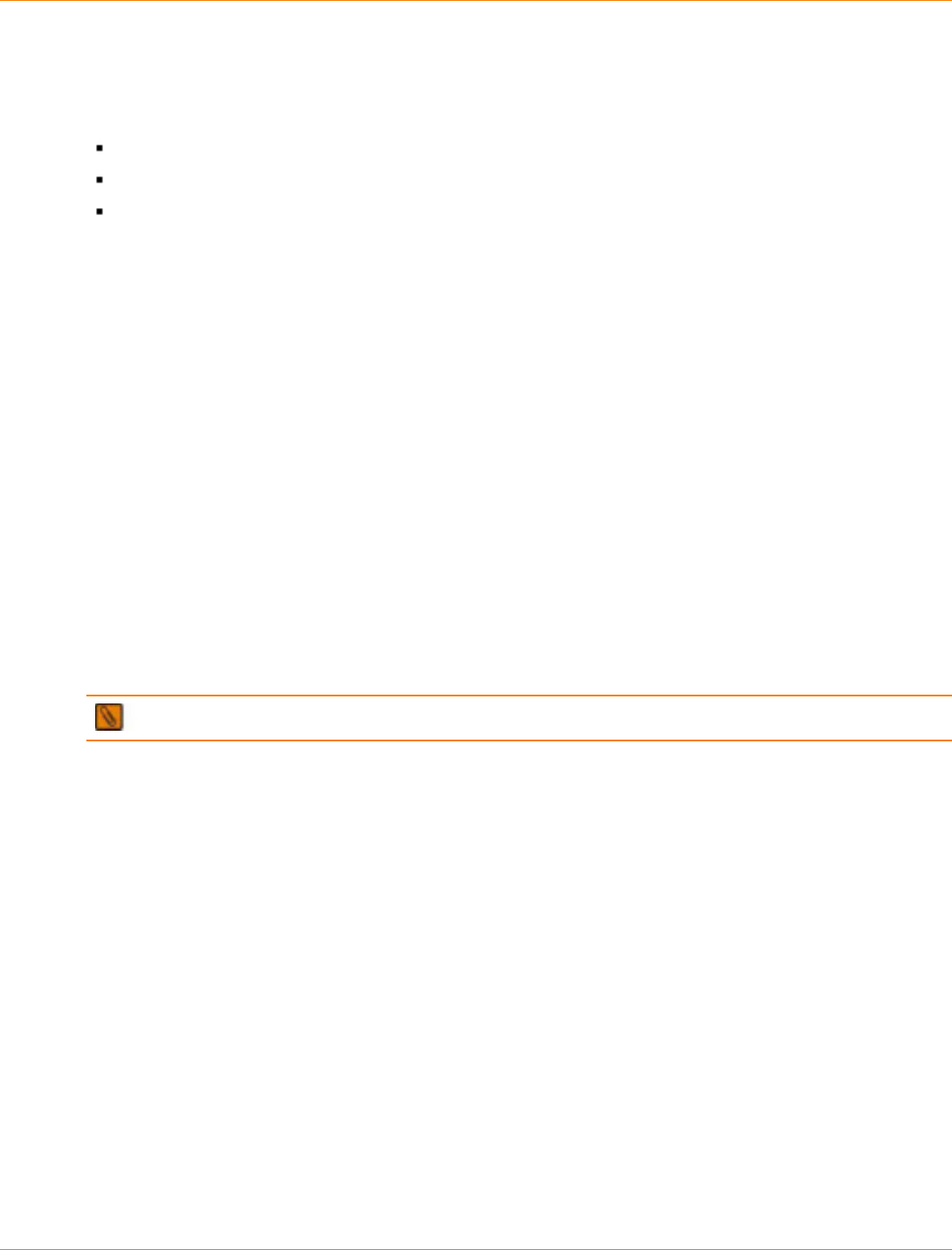
SANtricity_10.77 February 2011
LSI Corporation
- 670 -
Hardware Installation for Remote Volume Mirroring
This appendix provides information about these topics:
Site preparation
Hardware requirements
Cabling
Review this information and complete the steps before starting any hardware installation procedures. Refer to
the online help system for background information on the Remote Volume Mirroring (RVM) premium feature
and for software-related procedures to set the configuration of the feature and use it.
Site Preparation
The RVM premium feature can be used only with Fibre Channel host connections. You must have Fibre
Channel switches to use RVM and to create a fabric environment for data replication. These switches require
only minimal additional site preparation requirements beyond basic storage array operation.
For additional site preparation considerations for Fibre Channel switches, including power requirements
and physical dimensions and requirements, refer to the documentation that is provided by the switch
manufacturer.
Switch Zoning Overview
Because of possible restrictions at the host level, the supported Remote Volume Mirroring configurations
contain Fibre Channel switches. These Fibre Channel switches are zoned so that a single host adapter can
access only one controller per storage array. Additionally, all configurations use a separate zone for the ports
that are reserved for the Remote Volume Mirroring premium feature.
IMPORTANT Do not zone the uplink port (E_port) that connects (cascades) switches within a fabric.
Switch zoning configurations are typically set up by using the switch management software that is provided
by the manufacturer of the Fibre Channel switch. This software should have been included with the materials
that are provided when the switch was purchased.
When two or more Fibre Channel switches are cascaded together, the switch management software
combines the ports for all of the switches that are linked. For example, if two 16-port Fibre Channel switches
are cascaded with a physical connection using a Fibre Channel cable, the switch management software
shows ports 0 through 31 participating in the fabric rather than two switches each with ports 0 through 15.
Therefore, a zone that is created containing any of these ports can exist on multiple cascaded switches.
The following figure shows both cascaded and non-cascaded switches. The top-half of the figure shows a set
of cascaded switches that are on the same network. Therefore, Zone 1 is the same zone on Switch 1A as
Zone 1 is on Switch 1B. In a single-mode Fibre Channel environment, the two switches are connected by a
single port on each switch that is designated as an E_port, which is not in a zone.
The set of switches in the bottom half of the following figure is on the same network but is not cascaded.
Although both sets contain a Zone 1 (shown as Zone A in Switch 2), these zones are independent of each
other.
SANtricity_10.77 February 2011
LSI Corporation
- 671 -
Switch Zoning in Cascaded and non-Cascaded Fibre Channel Switches
For more information about Fibre Channel switch zoning or setting up a zone configuration, refer to the
manufacturer’s documentation that is provided with the switch.
Because of the varying Remote Volume Mirroring configurations, the switch zone settings are presented
preceding each configuration in this appendix.
Hardware Installation
Select one of the following configuration options to connect and configure one or more storage arrays for use
with the Remote Volume Mirroring premium feature.
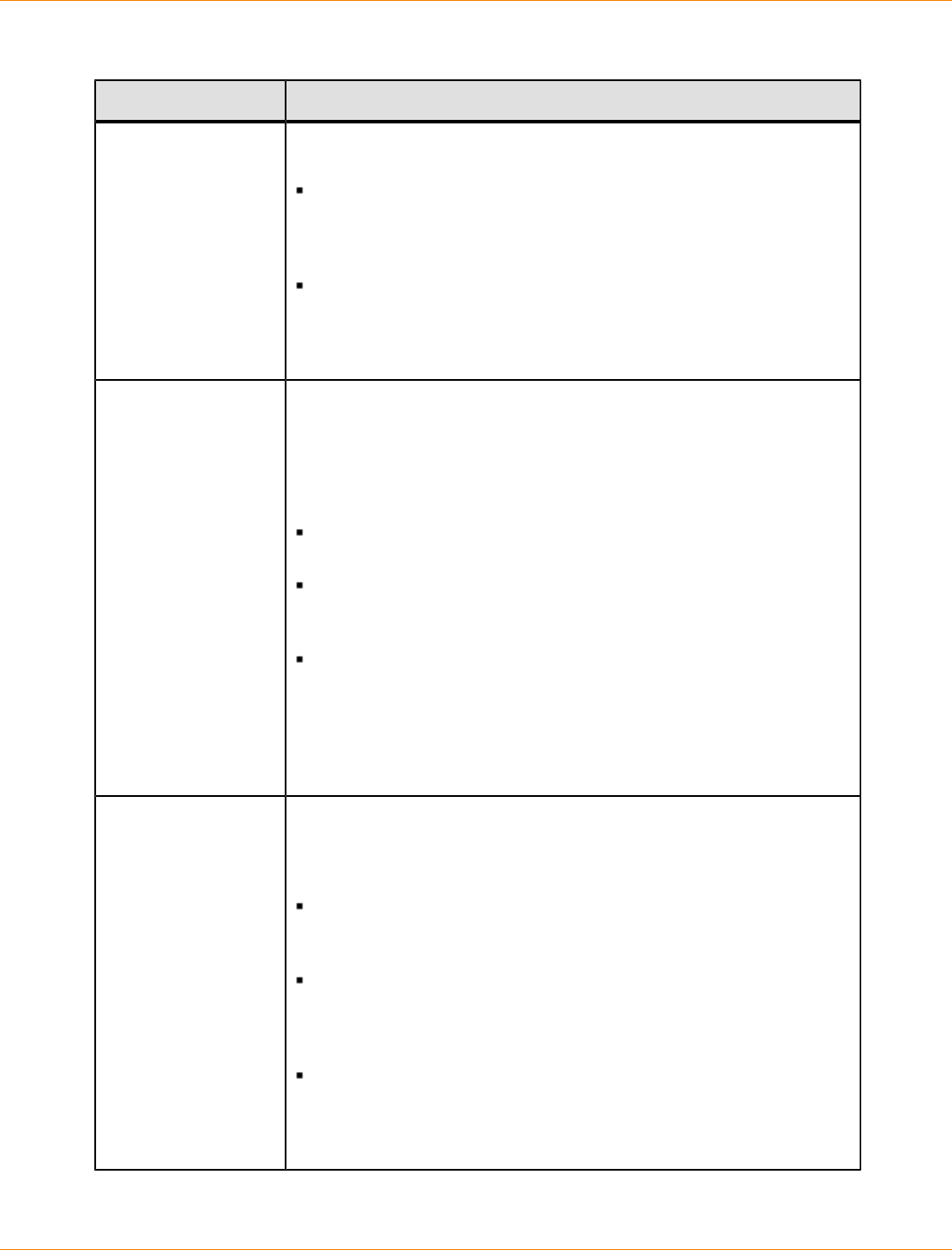
SANtricity_10.77 February 2011
LSI Corporation
- 672 -
Configuration Options for Remote Volume Mirroring
Configuration Description
Highest availability
campus configuration
(recommended)
This configuration has the greatest redundancy. It is the most stable of
the three configurations.
Two Fibre Channel switches (for a total of four) at both the primary
site and the secondary site provide for complete failover and
redundancy in the Fibre Channel switches and fabrics, in addition
to all storage array components and hosts.
A single point of failure does not exist in this configuration, and it is
the recommended configuration for the Remote Volume Mirroring
premium feature.
Go to "Highest Availability Campus Configuration – Recommended.”
Campus
configuration The campus configuration is a lower-cost configuration than the
highest availability campus configuration. Only one Fibre Channel
switch at the primary site and one at the secondary site exist, for a
total of two switches. This configuration essentially allows the minimum
required components to successfully operate the Remote Volume
Mirroring premium feature between two sites.
The number of Fibre Channel switches is reduced from four to two
and the number of fabrics from two to one.
This configuration is redundant for host bus adapters, controllers,
and Remote Volume Mirroring ports, but it has a single point of
failure for switches and fabric.
A switch failure does not usually result in a loss of data, but it does
affect data synchronization until the error is corrected. Therefore,
the highest availability campus configuration is the recommended
configuration, because data synchronization can continue for any
single switch failure.
Go to “Campus Configuration.”
Intra-site
configuration The intra-site configuration is the lowest-cost configuration of all three
configurations. It is used in environments where a long-distance fabric
is not required because of the close proximity of the hosts and storage
arrays.
Because the intra-site configuration only has two switches, it is
similar to the campus configuration. However, multiple-switch
fabrics do not exist in this configuration.
The configuration is redundant for host bus adapters, controllers,
Remote Volume Mirroring ports, and switches but is a single
point of failure for the site because all of the equipment can be
destroyed by the same disaster.
The highest availability campus configuration is the recommended
configuration, because it is fully redundant, which makes disaster
recovery easier.
Go to “Intra-Site Configuration.”

SANtricity_10.77 February 2011
LSI Corporation
- 673 -
Highest Availability Campus Configuration – Recommended
NOTE The highest availability campus configuration is the recommended configuration for the Remote
Volume Mirroring premium feature.
This configuration has two Fibre Channel switches at the primary site and two Fibre Channel switches
at the secondary site (four switches total), which provide for complete failover and redundancy. Failures
could involve Fibre Channel switches, Fibre Channel cables, and any host or storage array. Two Fibre
Channel switches at each site also provide redundancy to the local site in addition to a fully redundant remote
configuration. No single point of failure exists in the hardware components.
The following figure shows the highest availability campus configuration. The controller trays are shown
schematically with four host ports on each of two controllers in each controller tray. In this configuration, use
the A4 connection and the B4 connection for remote mirroring traffic instead of the A2 connection and the B2
connection. You can use controller ports A2, A3, B2, and B3 for additional host access if needed.
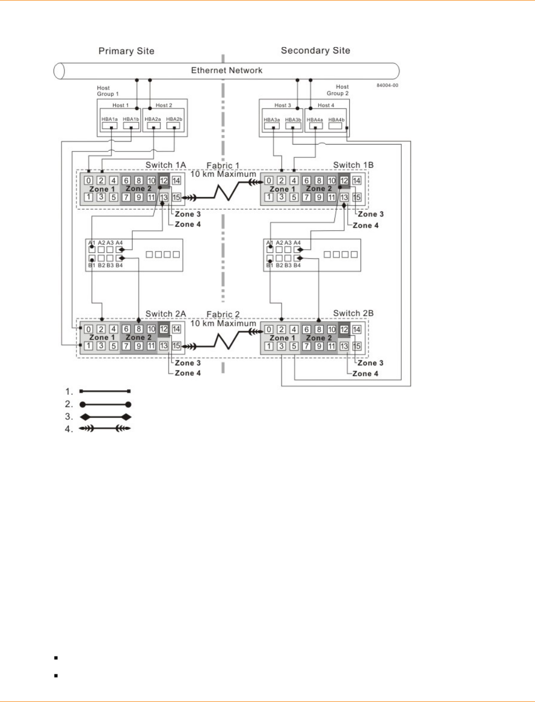
SANtricity_10.77 February 2011
LSI Corporation
- 674 -
Highest Availability Campus Configuration Using CE6994 Controller Trays
1. Host Fibre Channel Cable
2. Storage Array Fibre Channel Cable
3. Fibre Channel Cable Dedicated for the Remote Volume Mirroring Premium Feature
4. Fabric Uplink Cable
Switch Zoning for Highest Availability Campus Configuration
The highest availability campus configuration provides a separate zone for each reserved port for the Remote
Volume Mirroring premium feature.
The switches do not need to be zoned exactly as presented in this configuration. However, you must meet the
following requirements when zoning switches for the highest availability campus configuration.
There are a total of four zones in this configuration.
Zone 1 and zone 3 are on fabric 1 (switch 1A at the primary site, and switch 1B at the secondary site).
Zone 2 and zone 4 are on fabric 2 (switch 2A at the primary site, and switch 2B at the secondary site).
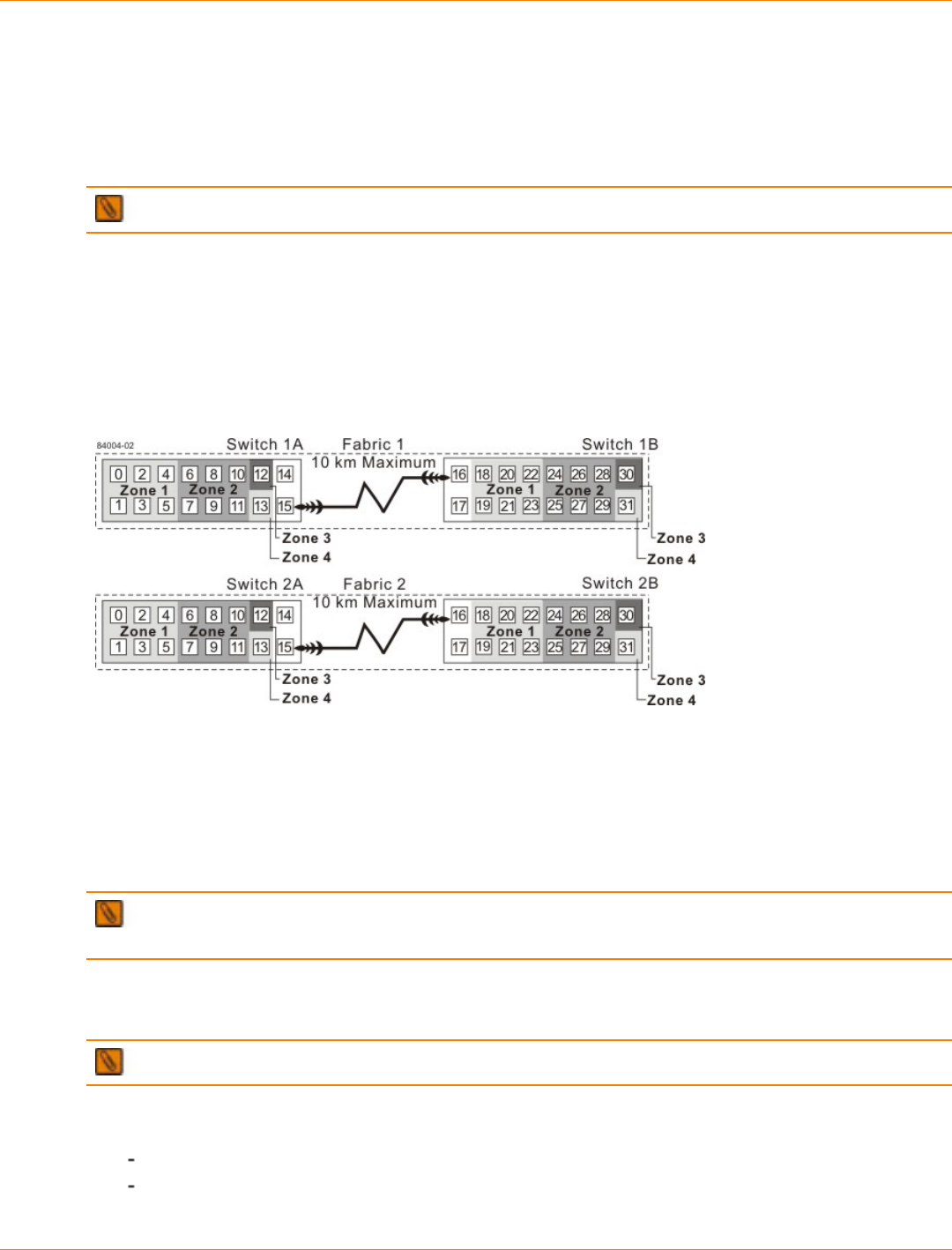
SANtricity_10.77 February 2011
LSI Corporation
- 675 -
Configure the zones on the switch so that there is one port per zone for a storage array connection and one
port per zone for each host. Switches are zoned so that a single host bus adapter port can access only one
controller per storage array.
Switches are zoned so that a single host bus adapter port can access only one controller for each storage
array.
NOTE Do not zone the uplink ports (E_ports) on any of the Fibre Channel switches.
The following figure shows how the four switches are zoned for the highest availability campus configuration.
The switches have 16 ports each, which leaves unused ports on each switch when following the preceding
requirements. The remaining ports can be distributed among the other zones. It is recommended, however,
that most of the remaining ports be assigned to the zones containing the host connections: zone 1 and zone
2. This port assignment allows easy setup for additional hosts to connect to the environment.
Switch Zoning for the Highest Availability Campus Configuration
Before you proceed, review the requirements listed in this section and the zoning shown in the figure to make
sure that all four switches are correctly zoned. For more information, see the “Switch Zoning Overview.”
Cabling for the Highest Availability Campus Configuration
IMPORTANT Start the installation at the primary site. Repeat these steps for the secondary site when
instructed to do so.
After the four Fibre Channel switches are correctly zoned, complete this procedure to set up the highest
availability campus configuration for the Remote Volume Mirroring premium feature.
NOTE Complete all connections by using Fibre Channel cables of the correct length.
1. Are you adding equipment for the Remote Volume Mirroring premium feature to an existing storage array
environment?
Yes – Stop I/O activity from all hosts before proceeding. Go to step 2.
No – The storage array installation is new. Go to step 3.
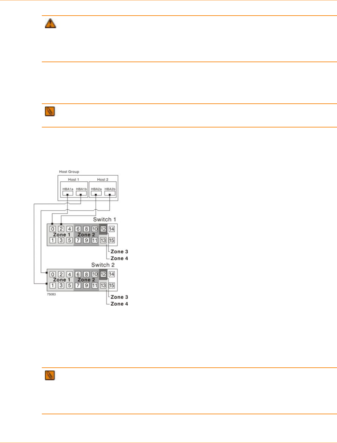
SANtricity_10.77 February 2011
LSI Corporation
- 676 -
ATTENTION Possible hardware damage – DC-powered controller-drive trays and drive trays
have special power procedures that you must follow beyond the procedures for AC-powered trays. To
get specific power-off and power-on procedures, refer to the topics under the storage array installation for
the hardware that you are installing or to the corresponding PDF document on the SANtricity ES Storage
Manager Installation DVD.
2. Turn off the power to all storage arrays, hosts, Fibre Channel switches, and any other equipment in the
storage array environment.
3. Make sure that cabling between all of the controller trays or controller-drive trays and the drive trays is
complete.
IMPORTANT Depending on which site is being configured, switch 1 represents switch 1A for the
primary site and switch 1B for the secondary site. This representation applies to switch 2 as well.
4. Connect the primary host bus adapter for each local host to an available port in zone 1 of switch 1.
The following figure shows the cabling that is described in step 4 and step 5.
Host Bus Adapter Connections to Fibre Channel Switches
NOTE You can connect the cables to any port in the correct zone of the switch for all of the
controller trays except the CE6998 controller tray. Host port 4 on each controller of the CE6998 controller
trays is reserved for using the Remote Volume Mirroring premium feature. If you are not using the
Remote Volume Mirroring premium feature, host port 4 on a CE6998 controller tray is available for host
connections.
5. Connect the secondary host bus adapter for each host at this site to an available port in zone 1 of
switch 2.
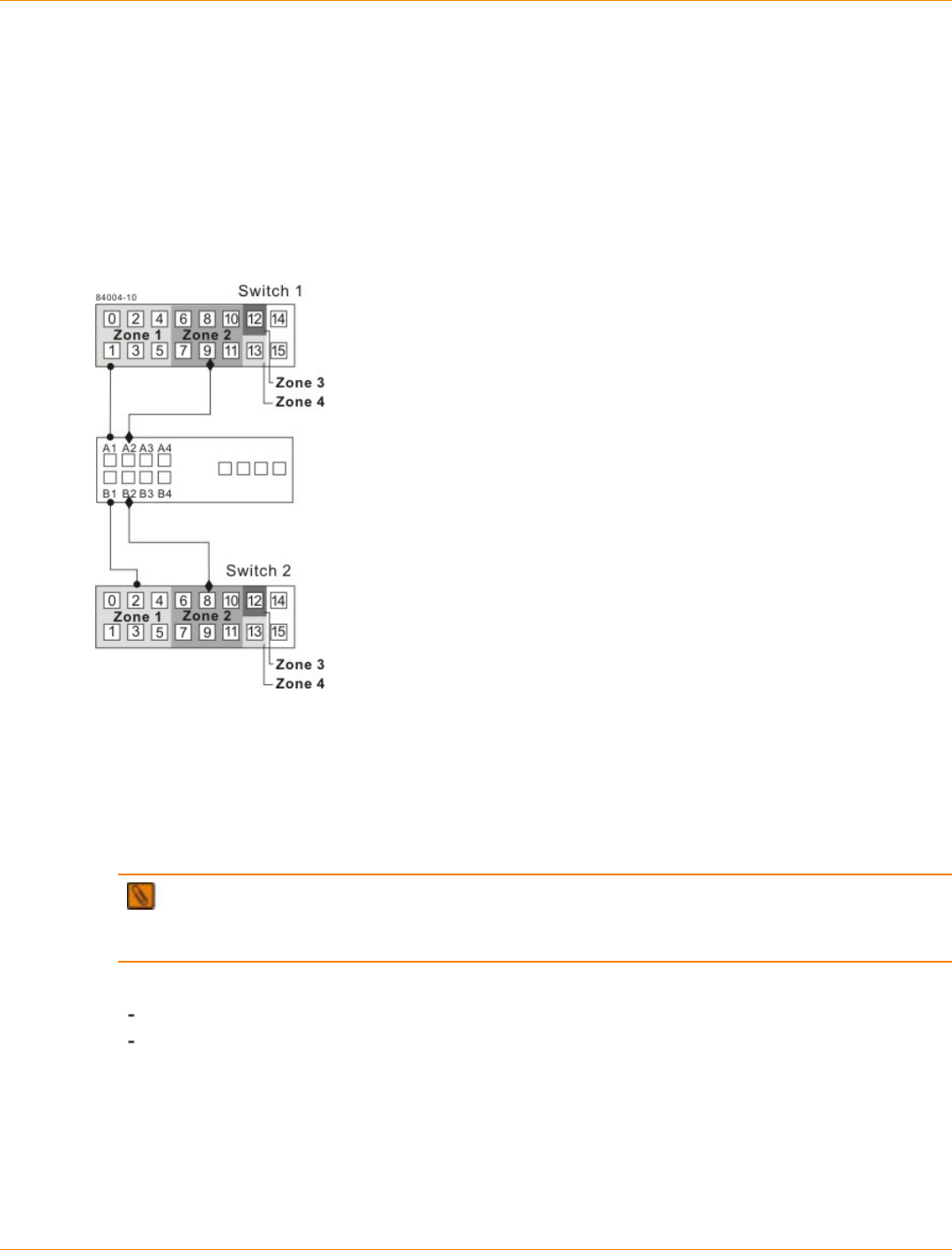
SANtricity_10.77 February 2011
LSI Corporation
- 677 -
6. Connect controller port A1 of the storage array to an available port in zone 1 of switch 1.
The figure following step 9 shows the cabling for CE6998 controller trays.
7. Connect controller port B1 of the storage array to an available port in zone 1 of switch 2.
8. Connect controller port A2 of the storage array to an available port in zone 2 of switch 1. In a four-host-
port system, connect controller port A4 to an available port in zone 2 of switch 1.
9. Connect controller port B2 of the storage array to an available port in zone 2 of switch 2. In a four-host-
port system, connect controller port B4 to an available port in zone 2 of switch 2.
Storage Array Connections to Fibre Channel Switches in the CE6998 Controller Tray
NOTE Controller port A2 and controller port B2 are reserved for mirror relationship synchronization
upon activation of the Remote Volume Mirroring premium feature. In a four-host-port system, controller
port A4 and controller port B4 are reserved.
10. The primary site cabling is now complete. Is the secondary site cabling complete?
No – Repeat step 1 through step 9 for the secondary site.
Yes – Go to step 11.
11. Complete the fabric environment for switch 1 by connecting switch 1A to switch 1B.
The following figure shows the cabling that is described in step 11 and step 12.
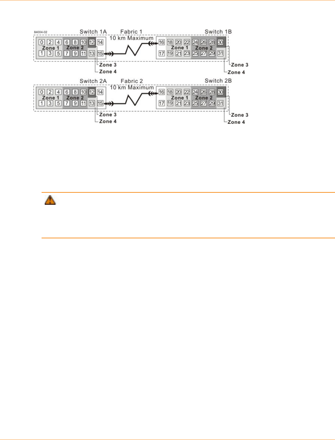
SANtricity_10.77 February 2011
LSI Corporation
- 678 -
Connecting Remote Switches to Complete Fabric Environments
12. Repeat step 11 for switch 2A and switch 2B to complete the fabric environment for switch 2.
13. Cabling for the highest availability campus configuration is complete. Repeat step 4 through step 10
for other storage arrays that exist in the same cabinet that use the Remote Volume Mirroring premium
feature.
ATTENTION Possible hardware damage – DC-powered controller-drive trays and drive trays
have special power procedures that you must follow beyond the procedures for AC-powered trays. To
get specific power-off and power-on procedures, refer to the topics under the storage array installation for
the hardware that you are installing or to the corresponding PDF document on the SANtricity ES Storage
Manager Installation DVD.
14. Turn on the power to all of the storage array hosts, Fibre Channel switches, and any other hardware at
both sites where the power was turned off.
The hardware installation is complete. To configure the storage management software to support mirror
relationships, refer to the online help topics.
Campus Configuration
The campus configuration offers the same functionality as the highest availability campus configuration, but
the campus configuration contains only one switch at each site, rather than two. The configuration is still
redundant for host bus adapters, controllers, and remote mirroring ports, but the configuration has a single
point of failure for switches. If a switch at either site fails, the Remote Volume Mirroring premium feature
cannot operate. For this reason, the highest availability campus configuration is highly recommended for total
environment redundancy.
The following figure shows a complete campus configuration. The controller trays are shown schematically
with four host ports on each of two controllers in each controller tray.
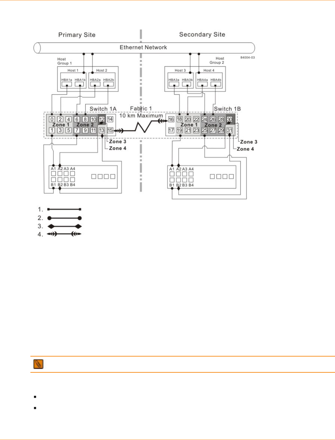
SANtricity_10.77 February 2011
LSI Corporation
- 679 -
Campus Configuration
1. Host Fibre Channel Cable
2. Storage Array Fibre Channel Cable
3. Fibre Channel Cable Dedicated for the Remote Volume Mirroring Premium Feature
4. Fabric Uplink Cable
Switch Zoning for the Campus Configuration
The campus configuration allows for a separate zone for each reserved port for the Remote Volume Mirroring
premium feature.
The switches do not need to be zoned exactly as presented in this configuration. However, you must meet the
following requirements when you zone switches for the campus configuration.
NOTE Do not zone the uplink ports (E_ports) on any of the Fibre Channel switches.
You must have a total of four zones in this configuration.
All zones exist on fabric 1 (switch 1A at the primary site, and switch 1B at the secondary site).
Zone 3 and zone 4 are reserved for the dedicated Remote Volume Mirroring premium feature
connections.
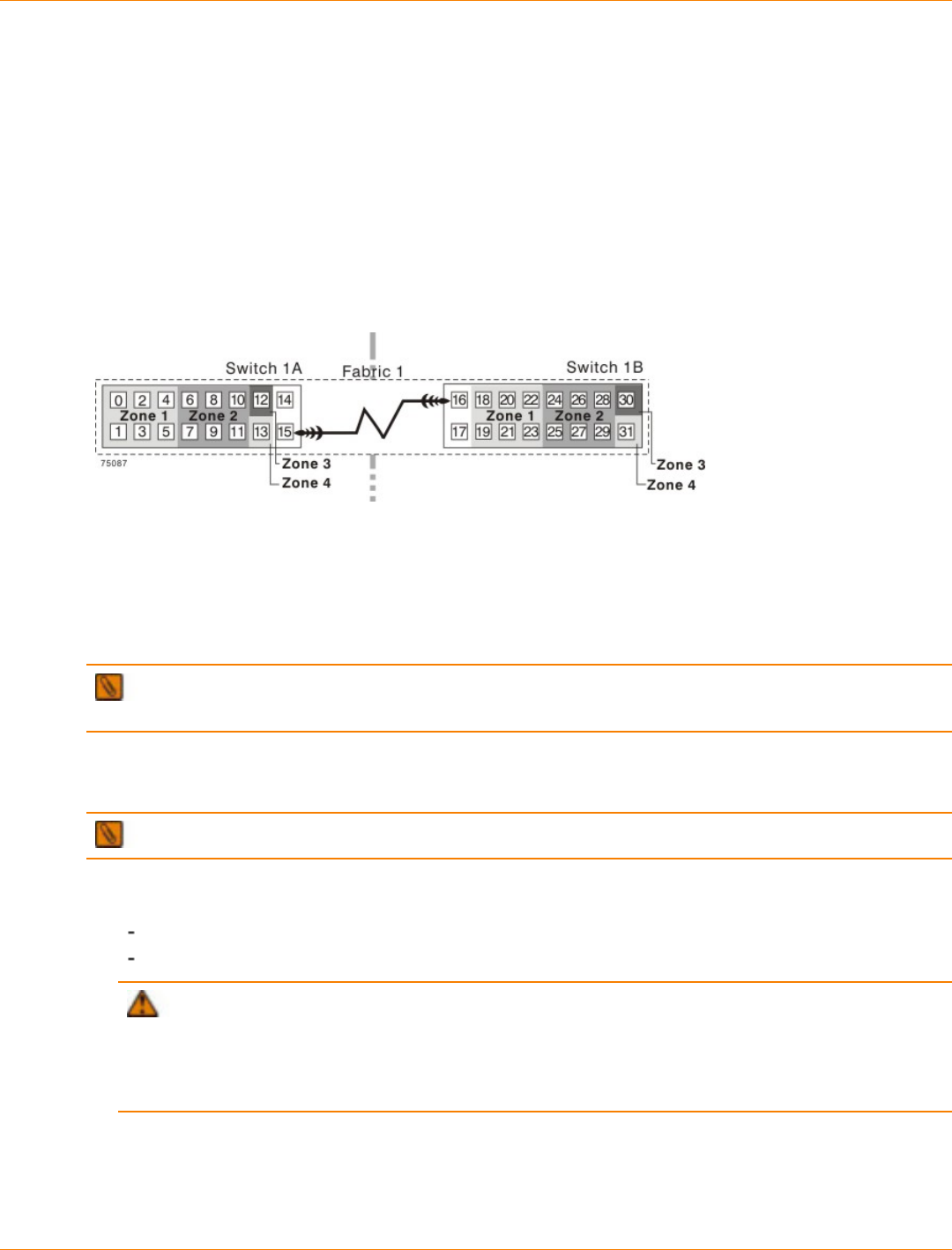
SANtricity_10.77 February 2011
LSI Corporation
- 680 -
You must configure the zones on the switches so that there is one port per zone for a storage array
connection and one port per zone for each host.
You must zone the switches so that a single host adapter can access only one controller per storage array.
The switches in the following figure contain 16 ports each, which leaves many unused ports per switch. The
remaining ports can be distributed among the other zones. However, it is recommended that most remaining
ports be assigned to the zones containing the host connections (zone 1). This setup allows connections for
additional hosts.
The following figure shows how the two switches are zoned for the campus configuration.
Switch Zoning for the Campus Configuration
Review the requirements in this section and the zoning example in the figure above to make sure that both
switches are correctly zoned before proceeding. For more information, see “Switch Zoning Overview.”
Cabling for the Campus Configuration
IMPORTANT Start the installation at the primary site. Repeat these steps for the secondary site when
instructed to do so.
After both Fibre Channel switches are correctly zoned, complete this procedure to set up the campus
configuration for the Remote Volume Mirroring premium feature.
NOTE Complete all connections by using Fibre Channel cables of the correct length.
1. Are you adding equipment for the Remote Volume Mirroring premium feature to an existing storage array
environment?
Yes – Stop I/O activity from all hosts before proceeding. Go to step 2.
No – This is a new storage array installation. Go to step 3.
ATTENTION Possible hardware damage – DC-powered controller-drive trays and drive trays
have special power procedures that you must follow beyond the procedures for AC-powered trays. To
get specific power-off and power-on procedures, refer to the topics under the storage array installation for
the hardware that you are installing or to the corresponding PDF document on the SANtricity ES Storage
Manager Installation DVD.
2. Turn off the power to all storage arrays, hosts, Fibre Channel switches, and any other equipment in the
storage array environment.
3. Make sure that basic cabling between all of the controller trays or controller-drive trays and the drive trays
on both storage arrays is complete.
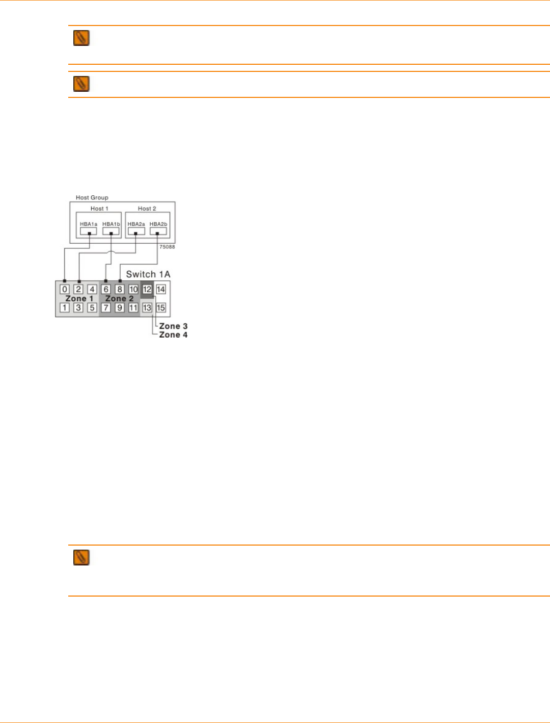
SANtricity_10.77 February 2011
LSI Corporation
- 681 -
IMPORTANT Depending on which site is being configured, switch 1 represents switch 1A for the
primary site and switch 1B for the secondary site.
NOTE You can connect the cables to any port in the correct zone of the switch.
4. Connect the primary host bus adapter for each host at this site to an available port in zone 1 of switch 1A.
The following figure shows the cabling that is described in step 4 and step 5.
5. Connect the secondary host bus adapter for each host at this site to an available port in zone 2 of
switch 1A.
Host Bus Adapter Connections to Fibre Channel Switches
6. Connect controller port A1 of the storage array to an available port in zone 1 of switch 1A.
The first figure following step 9 shows the storage array connected to Fibre Channel switches that is
described in step 6 through step 9. The second figure following step 9 shows the cabling configuration
schematically with four host ports on each of two controllers in each controller tray.
7. Connect controller port B1 of the storage array to an available port in zone 2 of switch 1A.
8. Connect controller port A2 of the storage array to an available port in zone 3 of switch 1A. In a four-host-
port system, connect controller port A4.
9. Connect controller port B2 of the storage array to an available port in zone 4 of switch 1A. In a four-host-
port system, connect controller port B4.
NOTE Controller ports A2 and B2 are reserved for mirror relationship synchronization upon
activation of the Remote Volume Mirroring premium feature. In a four-host-port system, controller port A4
and controller port B4 are reserved.
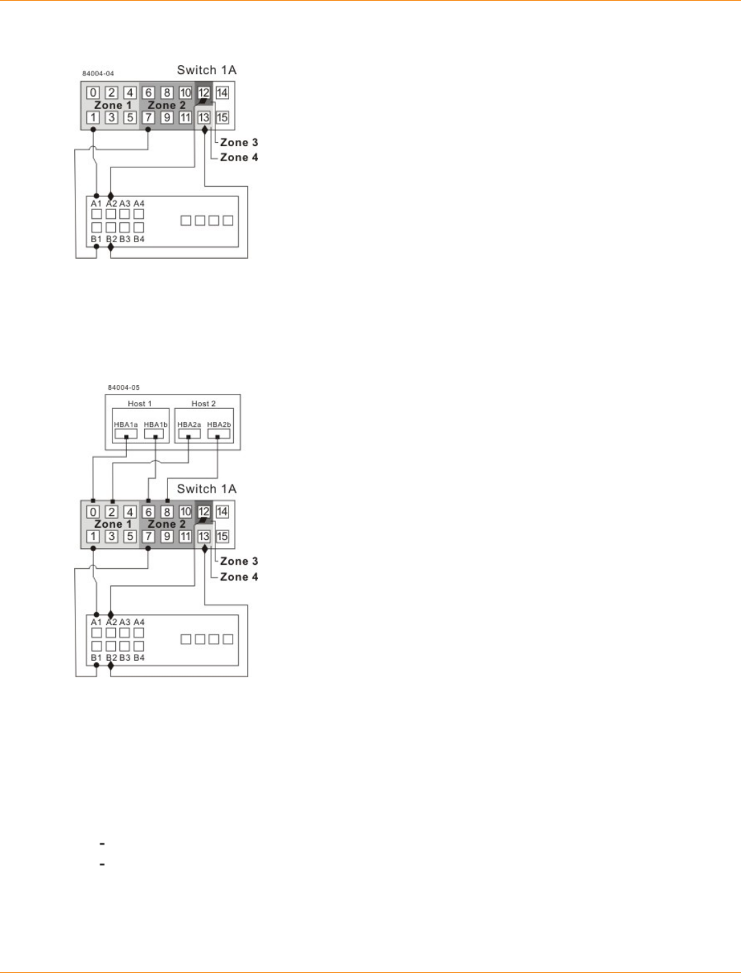
SANtricity_10.77 February 2011
LSI Corporation
- 682 -
Storage Array Connections to Fibre Channel Switches
Storage Array Connections to Fibre Channel Switches
10. The primary site cabling is now complete. Is the secondary site cabling complete?
No – Repeat step 1 through step 9 for the secondary site.
Yes – Go to step 11.
11. Complete fabric 1 by connecting switch 1A to switch 1B.
The following figure shows the cabling that is described in this step.
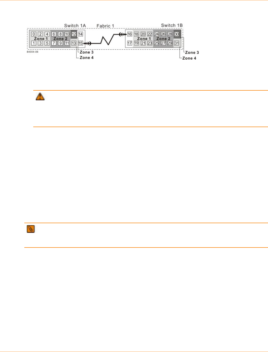
SANtricity_10.77 February 2011
LSI Corporation
- 683 -
Connecting Remote Switches to Complete the Fabric Environment
12. Cabling for the campus configuration is complete. Repeat step 4 through step 10 for any additional
storage arrays that exist in the same cabinet that will use the Remote Volume Mirroring premium feature.
ATTENTION Possible hardware damage – DC-powered controller-drive trays and drive trays
have special power procedures that you must follow beyond the procedures for AC-powered trays. To
get specific power-off and power-on procedures, refer to the topics under the storage array installation for
the hardware that you are installing or to the corresponding PDF document on the SANtricity ES Storage
Manager Installation DVD.
13. Turn on the power to all storage arrays, hosts, Fibre Channel switches, and any other hardware at both
sites where the power was turned off.
14. Hardware installation is complete. Refer to the online help topics for procedures to configure the storage
management software to support mirror relationships.
Intra-Site Configuration
The intra-site configuration is used in environments where a long-distance fabric is not required because of
the close proximity of the hosts and storage arrays. The configuration is still redundant for host bus adapters,
controllers, remote mirroring ports, and switches, but the configuration is a single point of failure for the site
because all of the equipment can be destroyed by the same disaster. For this reason, the highest availability
campus configuration is highly recommended for total environment redundancy.
The following figure shows a complete installation of the intra-site configuration.
IMPORTANT A switch failure in this configuration does not affect data access; however, as a result, an
Unsynchronized state might occur for all of the mirror relationships on both the primary storage arrays and the
secondary storage arrays.
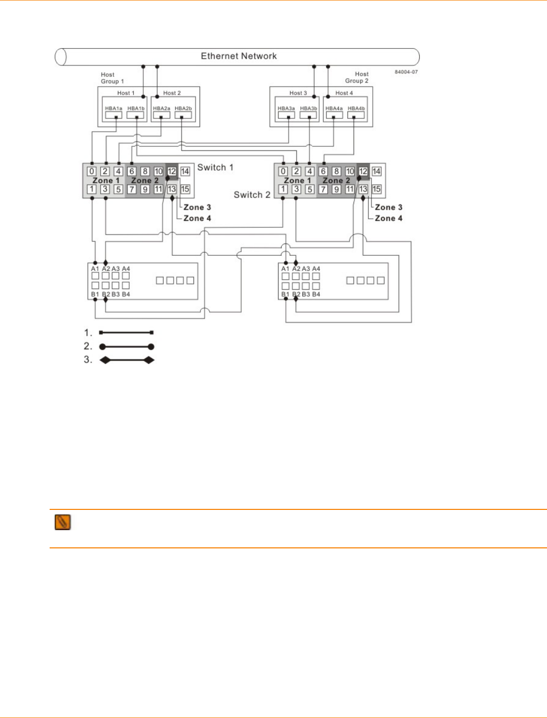
SANtricity_10.77 February 2011
LSI Corporation
- 684 -
Intra-Site Configuration Following a Complete Installation
1. Host Fibre Channel Cable
2. Storage Array Fibre Channel Cable
3. Fibre Channel Cable Dedicated for the Remote Volume Mirroring Premium Feature
Switch Zoning for the Intra-Site Configuration
The intra-site configuration provides switch redundancy, but the switches are not cascaded and are
independent of each other.
NOTE The switches do not need to be zoned exactly as presented in this configuration. However, you
must meet the following requirements when zoning switches for the intra-site configuration.
You must have a total of four zones on each controller in this configuration.
You must configure the zones on the switch so that there is one port per zone for a storage array connection
and one port per zone for each host.
You must zone the switches so that a single host adapter can only access one controller per storage array.
The switches in the following figure contain 16 ports each, which leaves many unused ports per switch.
The remaining ports can be distributed among the other zones. However, it is recommended that most of
the remaining ports be assigned to the zones containing the host connections: zone 1 and zone 2. This
assignment allows for easy setup for connecting additional hosts.
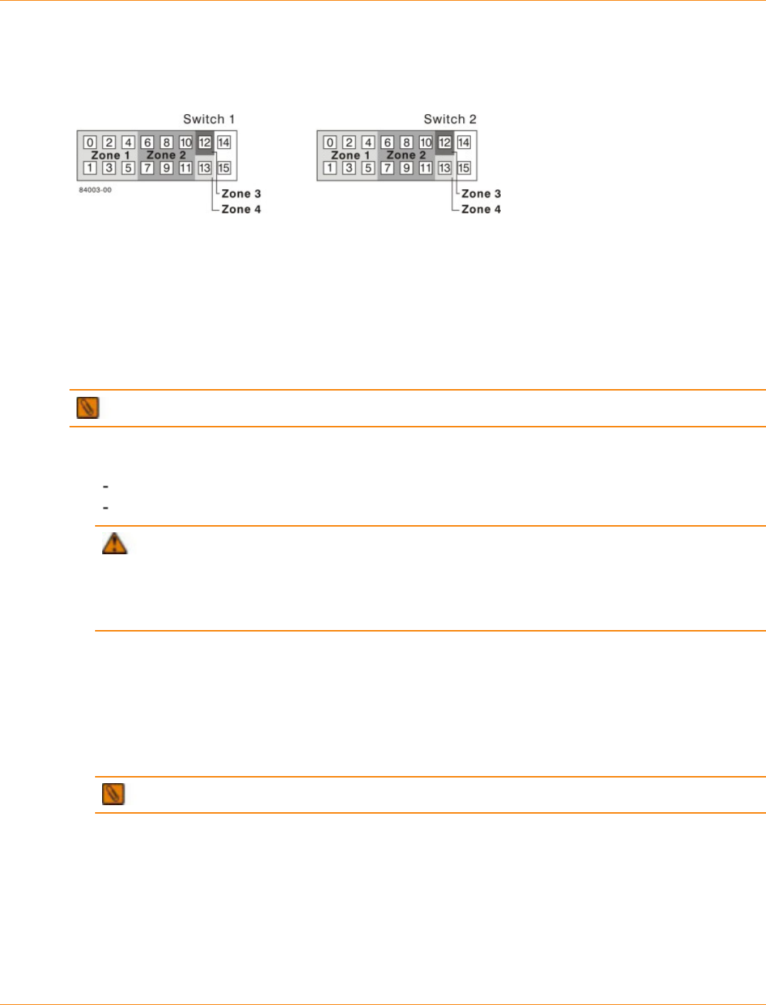
SANtricity_10.77 February 2011
LSI Corporation
- 685 -
For simplicity, in this example, the switches use one-half of the ports for each zone, although zone 3 and zone
4 require fewer ports.
Switch Zoning for the Intra-Site Configuration
Before proceeding, review the requirements in this section and the zoning example in the figures to make
sure that both switches are correctly zoned. For more information, see “Switch Zoning Overview.”
Cabling for the Intra-Site Configuration
After both Fibre Channel switches are correctly zoned, complete this procedure to set up the intra-site
configuration for the Remote Volume Mirroring premium feature.
NOTE Complete all connections by using Fibre Channel cables of the correct length.
1. Are you adding equipment for the Remote Volume Mirroring premium feature to an existing storage array
environment?
Yes – Stop I/O activity from all hosts before proceeding. Go to step 2.
No – This is a new storage array installation. Go to step 3.
ATTENTION Possible hardware damage – DC-powered controller-drive trays and drive trays
have special power procedures that you must follow beyond the procedures for AC-powered trays. To
get specific power-off and power-on procedures, refer to the topics under the storage array installation for
the hardware that you are installing or to the corresponding PDF document on the SANtricity ES Storage
Manager Installation DVD.
2. Turn off the power to all storage arrays, hosts, Fibre Channel switches, and any other equipment in the
storage array environment.
3. Make sure that basic cabling between all of the controller trays or controller-drive trays and the drive trays
is complete on both storage arrays as described in this document.
4. Connect the primary host bus adapter for each host to an available port in zone 1 of switch 1.
The following figure shows the cabling that is described in step 4.
NOTE You can connect the cables to any port in the correct zone of the switch.
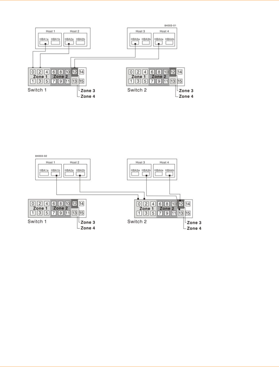
SANtricity_10.77 February 2011
LSI Corporation
- 686 -
Primary Host Bus Adapter Connections to Fibre Channel Switches
5. Connect the secondary host bus adapter for each host to an available port in zone 1 of switch 2.
The following figure shows the cabling that is described in this step.
Secondary Host Bus Adapter Connections to Fibre Channel Switches
6. Connect controller port A1 of the primary storage array to an available port in zone 1 of switch 1.
The following figure shows the cabling that is described in step 6 through step 9.
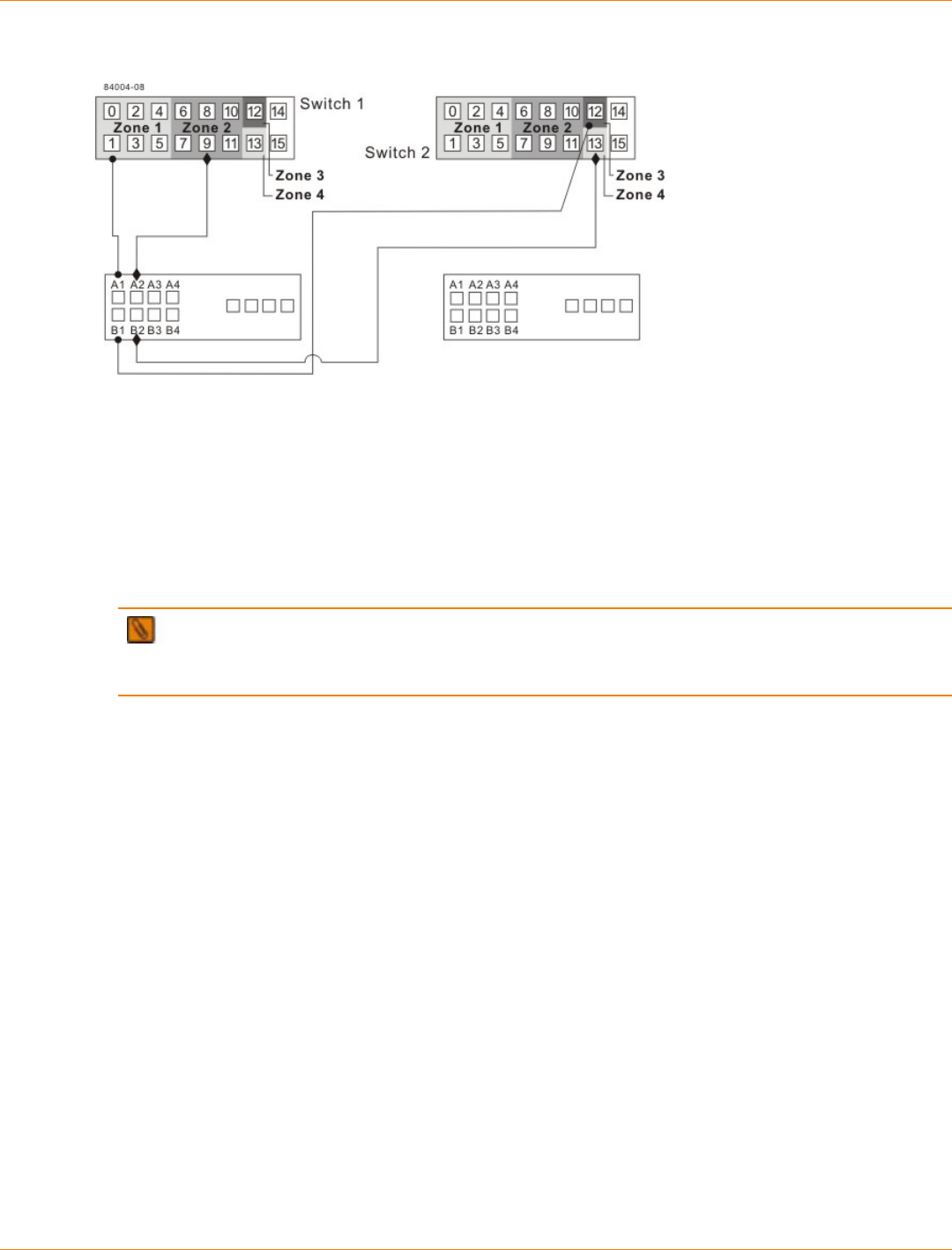
SANtricity_10.77 February 2011
LSI Corporation
- 687 -
Primary Storage Array Connections to Fibre Channel Switches
7. Connect controller port B1 of the primary storage array to an available port in zone 3 of switch 2.
8. Connect controller port A2 of the primary storage array to an available port in zone 2 of switch 1. In a four-
host-port system, connect controller port A4 to an available port in zone 2 of switch 1.
9. Connect controller port B2 of the primary storage array to an available port in zone 4 of switch 2. In a four-
host-port system, connect controller port B4 to an available port in zone 4 of switch 2.
NOTE Upon activation of the Remote Volume Mirroring premium feature, controller port A2
and controller port B2 are reserved for mirror relationship synchronization. In a four-host-port system,
controller port A4 and controller port B4 are reserved.
10. Connect controller port A1 of the secondary storage array to an available port in zone 1 of switch 1.
The figure following step 13 shows the cabling described in step 10 through step 13.
11. Connect controller port B1 of the secondary storage array to an available port in zone 3 of switch 2.
12. Connect controller port A2 of the secondary storage array to an available port in zone 2 of switch 1. In a
four-host-port system, connect controller port A4 to an available port in zone 2 of switch 1.
13. Connect controller port B2 of the secondary storage array to an available port in zone 4 of switch 2. In a
four-host-port system, connect controller port B4 to an available port in zone 4 of switch 2.
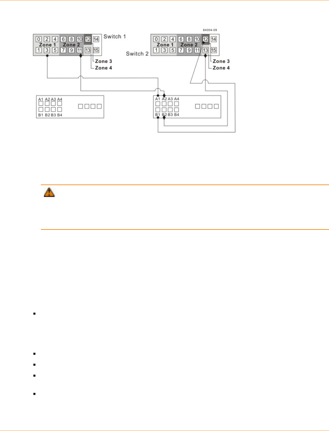
SANtricity_10.77 February 2011
LSI Corporation
- 688 -
Secondary Storage Array Connections to Fibre Channel Switches
14. Cabling for the intra-site configuration is complete. Repeat step 4 through step 13 for any additional
storage arrays that exist in the same cabinet that will use the Remote Volume Mirroring premium feature.
ATTENTION Possible hardware damage – DC-powered controller-drive trays and drive trays
have special power procedures that you must follow beyond the procedures for AC-powered trays. To
get specific power-off and power-on procedures, refer to the topics under the storage array installation for
the hardware that you are installing or to the corresponding PDF document on the SANtricity ES Storage
Manager Installation DVD.
15. Turn on the power to all storage arrays, hosts, Fibre Channel switches, and any other hardware where
power was turned off.
16. The hardware installation is complete. Refer to the online help topics for procedures to configure the
storage management software to support mirror relationships.
Installing and Using Remote Volume Mirroring with a Wide Area Network
When installing and using the Remote Volume Mirroring premium feature over a wide area network (WAN),
keep these guidelines in mind:
If you are setting up an FCIP router to perform asynchronous Remote Volume Mirroring, go to the
Compatibility Matrix. Select Router-FCIP in the Product field, and select the release of the storage
management software that you use in the Software Release field. Verify that the maximum latency
and distance are supported by referring to the vendor specifications for your router and by checking the
Compatibility Matrix. The Compatibility Matrix is found at http://www.lsi.com/compatibilitymatrix/.
FCIP router vendors and telecommunication vendors are responsible for setting up routing.
The smaller the bandwidth on the WAN, the longer it takes an asynchronous mirror to synchronize.
If the bandwidth does not exceed the average rate, you might not be able to synchronize the data at all.
For example, if the system writes at 1 Mb/s, it needs 2 Mb/s of bandwidth available.
If the mirroring is lagging far behind during production hours, suspend the mirror. During off-peak hours,
resume the mirror.
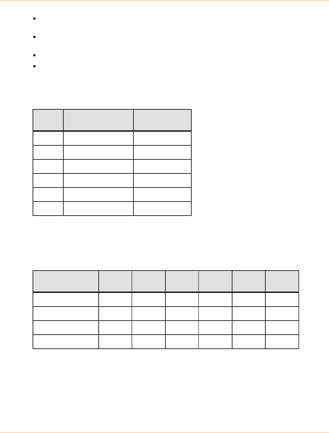
SANtricity_10.77 February 2011
LSI Corporation
- 689 -
If you need to keep the Remote Volume Mirroring on at all times, keep the mirror physically as close as
possible to the production site.
To determine the average write rate, you should use the available system utilities and should take
measurements during peak times.
If you anticipate adding any applications, determine the bandwidth needs for any future applications.
Acceptable lag times vary depending on the environment and should be determined on an individual
basis.
Line Capacities
Line Capacities and Line Speeds
Line
Type Capacity in Mb/s Speed in MB/s
T-1 1.544 0.193
T-3 43.232 5.404
OC-3 155.6352 19.454
OC-12 622.5408 77.8176
OC-48 2490.1632 311.27
OC-192 9960.6528 1245.085
The following table shows average write operations in Mb/s with corresponding line capacity calculations.
When the line capacity calculation is below 50 percent, the result is an adequate response-time performance
and a limited need for delta logging (when the mirror lags behind the data). When the line capacity calculation
is above 50 percent, the mirror can never catch up. Any transfers above 50 percent will start to lag.
Line Capacity Calculation for Various Write I/O Rates
Average Write Time
in Mb/s T-1 T-3 OC-3 OC-12 OC-18 OC-192
0.01 5.2% 0.2% 0.1% 0.0% 0.0% 0.0%
0.1 51.8% 1.9% 0.5% 0.1% 0.0% 0.0%
1 518.1% 18.5% 5.1% 1.3% 0.3% 0.1%
10 5181.3% 185.3% 51.4% 12.9% 3.2% 0.8%

SANtricity_10.77 February 2011
LSI Corporation
- 690 -
Initial Configuration and Software Installation
This document describes the decisions necessary for installing and starting SANtricity ES Storage Manager
for Version 10.77, and then performing initial configuration on your storage array. Consult this topic after
configuring and cabling the storage array through one of the hardware configuration guides for the CE7900
controller tray, the CDE2600 controller-drive tray, CDE2600-60 controller-drive tray, or the CDE4900
controller-drive tray.
SANtricity_10.77 February 2011
LSI Corporation
- 691 -
Step 1 – Deciding on the Management Method
You can manage a storage array using the in-band method, the out-of-band method, or both.
IMPORTANT You need to know the storage management method that you plan to use before you
install the software, connect the cables, and use the storage management software.
Key Terms
access volume
A special volume that is used by the host-agent software to communicate management requests and event
information between the management station and the storage array. An access volume is required only for in-
band management.
Dynamic Host Configuration Protocol (DHCP)
CONTEXT [Network] An Internet protocol that allows nodes to dynamically acquire ('lease') network
addresses for periods of time rather than having to pre-configure them. DHCP greatly simplifies the
administration of large networks, and networks in which nodes frequently join and depart. (The Dictionary of
Storage Networking Terminology)
in-band management
A method to manage a storage array in which a storage management station sends commands to the storage
array through the host input/output (I/O) connection to the controller.
out-of-band management
A method to manage a storage array in which a storage management station sends commands to the storage
array through the Ethernet connections on the controller.
stateless address autoconfiguration
A method for setting the Internet Protocol (IP) address of an Ethernet port automatically. This method is
applicable only for IPv6 networks.
World Wide Identifier (WWID)
CONTEXT [Fibre Channel] A unique 64-bit number assigned by a recognized naming authority (often using
a block assignment to a manufacturer) that identifies a node process or node port. A WWID is assigned for
the life of a connection (device). Most networking physical transport network technologies use a world wide
unique identifier convention. For example, the Ethernet Media Access Control Identifier is often referred to as
the MAC address. (The Dictionary of Storage Networking Terminology)
Steps to Decide – Management Method
IMPORTANT If you use the out-of-band management method but do not have a DHCP server, you
must manually configure your controllers. See “Step 10 – Manually Configuring the Controllers” for details.
1. Use the key terms and the following figures to determine the management method that you will use.
2. After reading the information in this section, add a check mark next to the management method that you
will use.
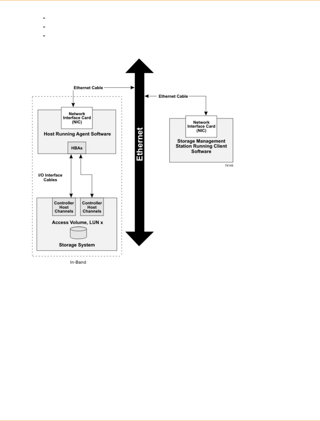
SANtricity_10.77 February 2011
LSI Corporation
- 692 -
__ In-band management method
__ Out-of-band management method
__ In-band management method and out-of-band management method
In-Band Management Topology
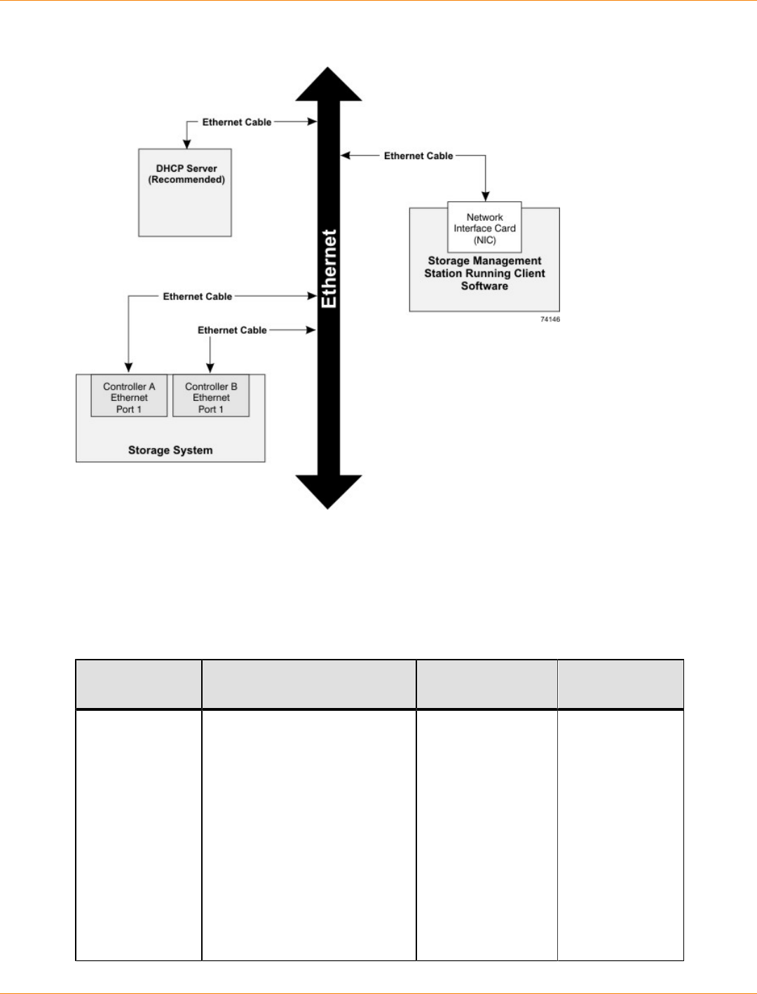
SANtricity_10.77 February 2011
LSI Corporation
- 693 -
Out-of-Band Management Topology
Things to Know – In-Band and Out-of-Band Requirements
Out-of-Band and In-Band Management Requirements
Management
Method Requirements Advantages Disadvantages
Out-of-band
without a DHCP
server
Connect separate Ethernet
cables to each controller.
Manually configure the network
settings on the controllers.
See “Manually Configuring
the Controllers” for more
information.
This method does
not use a logical
unit number (LUN)
on the host.
You do not need
to install the host-
agent software.
This method does
not use the SAS,
Fibre Channel, or
iSCSI bandwidth
for storage array
management
functions.
You must
manually
configure
the network
settings on the
controllers.
Ethernet cables
are required.

SANtricity_10.77 February 2011
LSI Corporation
- 694 -
Management
Method Requirements Advantages Disadvantages
Out-of-band –
IPv6 stateless
address auto-
configuration
without a DHCP
server (IPv6
networks only)
Connect separate Ethernet
cables to each controller.
Connect at least one router
for sending the IPv6 network
address prefix in the form of
router advertisements.
No additional
manual network
configuration is
required on the
controllers.
By default,
the controllers
automatically obtain
their IP addresses
by combining the
auto-generated link
local address and
the IPv6 network
address prefix
after you turn on
the power to the
controller-drive tray.
You do not need to
install host-agent
software.
This method does
not use a LUN on
the host.
This method does
not use the Fibre
Channel or iSCSI
bandwidth for
storage array
management
functions.
Ethernet cables
are required.
Out-of-band with
a DHCP server
(IPv4 networks
only)
Connect separate Ethernet
cables to each controller.
Assign either static IP
addresses or dynamic IP
addresses to the controllers.
It is recommended that you
assign static IP addresses.
Check your DHCP server
for the IP addresses that
are associated with the
media access control (MAC)
addresses of the controllers.
The MAC address appears on
a label on each controller in the
form: xx.xx.xx.xx.xx.xx.
No additional
manual network
configuration is
required on the
controllers.
By default,
the controllers
automatically obtain
their IP addresses
from the DHCP
server after you turn
on the power to the
controller-drive tray.
You do not need to
install host-agent
software.
This method does
not use a LUN on
the host.
Ethernet cables
are required.

SANtricity_10.77 February 2011
LSI Corporation
- 695 -
Management
Method Requirements Advantages Disadvantages
This method does
not use the Fibre
Channel or iSCSI
bandwidth for
storage array
management
functions.
In-band Install host-agent software on
at least one of the network-
attached hosts. The host-agent
software is included with the
storage management software.
This method requires a
special access volume to
communicate. This volume is
created automatically.
No additional
manual network
configuration is
required on the
controller.
This method uses
a LUN on the
host.
This method
uses the
Fibre Channel
bandwidth for
storage array
management
functions.

SANtricity_10.77 February 2011
LSI Corporation
- 696 -
Step 2 – Setting Up the Storage Array for Windows Server 2008
Server Core
If your host is running Windows Server 2008 Server Core, use the procedures in this section to configure
your storage array. Before you perform the procedures in this section, make sure that you have completed
the relevant hardware configuration. If your host is not running Windows Server 2008 Core, go to "Step 3 –
Installing the SANtricity ES Storage Manager Software."
If your host is running Windows Server 2008 Server Core, you must use the command line to install and
configure your storage array.
If you are using Fibre Channel host connections, perform these procedures:
1. Install the storage management software using "Step 3 – Installing the SANtricity ES Storage Manager
Software."
2. Configure your storage array using “Step 17 – Configuring the Storage.”
Perform the procedures in this section to configure the iSCSI initiator and to install the storage management
software:
1. Configure the network interfaces.
2. Set the iSCSI initiator services.
3. Install the storage management software.
4. Configure the iSCSI ports.
5. Configure and view the targets.
6. Establish a persistent login to a target.
7. Verify your iSCSI configuration.
8. Review other useful iSCSI commands.
9. Configure your storage array.
Refer to the Microsoft iSCSI Software Initiator 2.x Users Guide for more information about the commands
used in these steps. Refer to the Microsoft Developers Network (MSDN) for more information about Windows
Server 2008 Server Core. You can access these resources from www.microsoft.com.
Procedure – Configuring the Network Interfaces
1. Find the index for the iSCSI initiator by typing one of these commands and pressing Enter:
C:\>netsh interface ipv4 show interfaces
C:\>netsh interface ipv6 show interfaces
A list of all found interfaces appears:
Idx
Met
MTU
State
Name
2
10
1500
connected
Local Area Connection
1
50
4294967295
connected
Loopback Pseudo-Interface 1
3
20
1500
connected
Local Area Connection 2

SANtricity_10.77 February 2011
LSI Corporation
- 697 -
4
20
1500
connected
Local Area Connection 3
2. Set the IP address for the initiators.
For IPv4 initiators, type these commands from the command line:
C:\Users\administrator>netsh interface ipv4 set address name=3
source=static address=192.168.0.1 mask=255.255.255.0
C:\Users\administrator>netsh interface ipv4 set address name=4
source=static address=192.168.1.1 mask=255.255.255.0
For IPv6 initiators, type these commands from the command line:
C:\Users\administrator>netsh interface ipv6 set address name=3
source=static address=< IPv6 address > mask=255.255.255.0
C:\Users\administrator>netsh interface ipv6 set address name=4
source=static address=< IPv6 address > mask=255.255.255.0
In these commands, <IPv6 address> is the IPv6 address for the iSCSI initiator.
Procedure – Setting the iSCSI Initiator Services
Set the iSCSI initiator services to start automatically. From the command line, type this command:
sc\\server_name config msiscsi start=auto
In this command, server_name is the name of the host.
Procedure – Installing the Storage Management Software
The SANtricity ES Storage Manager executable is located on the SANtricity ES Storage Manager Installation
DVD.
1. Insert the DVD into the host DVD drive.
2. Locate the installation package that you want to install. From the command line, type one of these
commands:
<hsw executable.exe> -i console
<hsw executable.exe> -i silent
In these commands, <hsw executable.exe> is the file name for the storage management software
installation package.
When you specify the console parameter during the installation, questions appear on the console that
enable you to choose installation variables. This installation does not use a graphical user interface
(GUI). Contact your Customer and Technical Support representative if you need to change the installation
options.
When you specify the silent parameter during the installation, the command installs the storage
management software using all of the defaults. A silent installation uses a resource file that contains all
of the required information, and it does not return any windows until the installation is complete. This
installation does not use a graphical user interface (GUI). Contact your Customer and Technical Support
representative if you need to change the installation options.
3. Make sure that the appropriate files are listed in the installation directory.
A full installation should include these directories:
util (SMutil)

SANtricity_10.77 February 2011
LSI Corporation
- 698 -
client (SMclient)
agent (SMagent)
4. Type this SMcli command without options to make sure that SMcli was installed correctly.
SMcli <controller_A_IP_address> <controller_B_IP_address>
NOTE In the Windows operating system, you must perform this command from the client directory.
5. Make sure that an Incorrect Usage message is returned with a list of allowable SMcli options.
IMPORTANT To make sure that your configuration settings take effect, you must reboot the host
before starting the storage management software.
Procedure – Configuring the iSCSI Ports
Use the command line interface that is included in the storage management software to configure the
iSCSI ports. Refer to either the Command Line Interface and Script Commands for Version 10.77 electronic
document topics or the PDF on the SANtricity ES Storage Manager Installation DVD for instructions on how
to configure the iSCSI ports. The information in the programming guide applies to the SANtricity ES Storage
Manager software. You must complete these tasks:
1. Show a list of unconfigured iSCSI initiators.
2. Create an iSCSI initiator.
3. Set the iSCSI initiator.
4. Set the iSCSI target properties.
5. Show the current iSCSI sessions.
Procedure – Configuring and Viewing the Targets
Configure a target and, optionally, persist that target. You must configure each port on the target one time. If
you are using Challenge-Handshake Authentication Protocol (CHAP), you can also establish a CHAP user
name and password when you configure the target.
1. If you are not using CHAP, type this command for each port on the target from the command line:
iscsicli QAddTargetPortal <IP Address Target Controller>
In this command, <IP Address Target Controller> is the IP address for the target port that you
are configuring.
2. If you are using CHAP, type this command for each port on the target from the command line:
iscsicli QAddTargetPortal <IP Address Target Controller> <CHAP Username> <CHAP Password>
In this command:
<IP Address Target Controller> is the IP address for the target port that you are configuring.
<CHAP Username> and <CHAP Password> are the optional user name and password for the target
port that you are configuring.
3. After you have configured all of the ports on the target, you can show a list of all configured targets. From
the command line, type this command:
iscsicli ListTargets
A list of all found targets appears.
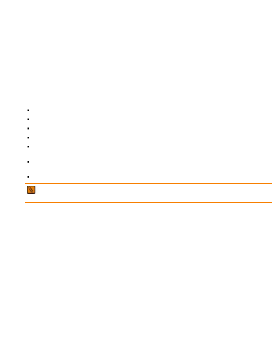
SANtricity_10.77 February 2011
LSI Corporation
- 699 -
Procedure – Establishing a Persistent Login to a Target
You can establish a persistent login to a target. A persistent login is the set of information required by an
initiator to log in to the target each time the initiator device is started. The login usually occurs when you start
the host. You cannot initiate a login to the target until after the host has finished rebooting. You must establish
a persistent login for each initiator-target combination or initiator-target path. This command requires 18
parameters. Several of the parameters use the default values and are indicated with *. Refer to the Microsoft
iSCSI Software Initiator 2.x Users Guide for a description of this command and the parameters.
From the command line, type this command:
iscsicli PersistentLoginTarget <Target Name> <ReportToPNP> <TargetPortalAddress>
<TCPPortNumberofTargetPortal> * * * <Login Flags> * * * * * * * * * <MappingCount>
In this command:
<Target Name> is the name of your target port as shown in the targets list.
<ReportToPNP> is set to T, which exposes the LUN to the operating system as a storage device.
<TargetPortalAddress> is the IP address for the target port.
<TCPPortNumberofTargetPortal> is set to 3260, which is the port number defined for use by iSCSI.
<Login Flags> is set to 0x2, which allows more than one session to be logged into a target at one
time.
<MappingCount> is set to 0, which indicates that no mappings are specified and no further parameters
are required.
* uses the default value for that parameter.
IMPORTANT To make sure that your configuration settings take effect, you must reboot the host before
continuing with these tasks.
Procedure – Verifying Your iSCSI Configuration
After you reboot the host, you can verify your configuration.
From the command line, type this command:
iscsici ListPersistentTargets
A list of persistent targets configured for all iSCSI initiators appears. Make sure that “Multipath Enabled”
appears in the output under Login Flags.
Procedure – Reviewing Other Useful iSCSI Commands
The commands listed in this section are useful for managing the iSCSI targets and iSCSI initiators.
This command shows the set of target mappings assigned to all of the LUNs to which all of the iSCSI initiators
are logged in.
iscsicli ReportTargetMappings
This command shows a list of active sessions for all iSCSI initiators.
iscsicli sessionlist

SANtricity_10.77 February 2011
LSI Corporation
- 700 -
This command sends a SCSI REPORT LUNS command to a target.
iscsicli ReportLUNS <SessionId>
This command removes a target from the list of persistent targets.
iscsicli RemovePersistentTarget <Initiator Name> <TargetName>
<Initiator Port Number> <Target Portal Address> <Target Portal Socket>
These commands and others are described in the Microsoft iSCSI Software Initiator 2.x Users Guide.
Procedure – Configuring Your Storage Array
You have these methods for configuring your storage array:
You can configure the storage array from a storage management station that is on the same network
as the storage array. This method is preferred. Go to “Step 17 – Configuring the Storage” to finish
configuring your storage array.
You also can configure the storage array using the command line interface. Refer to “Configuring a
Storage Array” in the Configuring and Maintaining a Storage Array Using the Command Line electronic
document topic or on the PDF on the SANtricity ES Storage Manager Installation DVD for information that
will help you configure your storage array.

SANtricity_10.77 February 2011
LSI Corporation
- 701 -
Step 3 – Installing the SANtricity ES Storage Manager Software
If you are running Windows Server 2008 Server Core, make sure that you have performed the tasks in Step 2
– Setting Up the Storage Array for Windows Server 2008 Server Core. If you are not running Windows Server
2008u Server Core, begin with the following tasks.
Key Terms
host
A computer that is attached to a storage array. A host accesses volumes assigned to it on the storage array.
The access is through the HBA host ports or through the iSCSI host ports on the storage array.
monitor
A software package that monitors the storage array and reports critical events.
multi-path driver
A driver that manages the input/output (I/O) data connection for storage arrays with redundant controllers. If a
component (cable, controller, host adapter, and so on) fails along with the I/O data connection, the multi-path
driver automatically reroutes all I/O operations to the other controller.
Redundant Dual Active Controller (RDAC) multi-path driver
A driver that manages the I/O data connection for storage arrays with dual controllers in a redundant
configuration. If a component fails along the connections, causing the host to lose communication with a
controller, the driver automatically reroutes all I/O operations to the other controller.
storage management station
A computer running storage management software that adds, monitors, and manages the storage arrays on a
network.
Things to Know – All Operating Systems
This section describes how to use the installation wizard to install the SANtricity ES Storage Manager
software (hereinafter referred to as the storage management software). The separate native installation
packages are supplied on the SANtricity ES Storage Manager Installation DVD in the native directory.
For the Windows Server 2003 operating system (OS), the Windows Server 2008 OS, the Linux OS,
and the Solaris OS, the storage management software supports using the storage array as a boot
device. For assistance with setting up this configuration, contact your Customer and Technical Support
representative.
NOTE If the Windows Server 2003 OS, the Windows Server 2008 OS, or the Linux OS is installed on a
computer with an Intel Itanium 2 (IA64) processor, you cannot use the storage array as a boot device.
Things to Know – Specific Operating Systems
Solaris OS:
The Solaris OS supports the use of the LSI Redundant Disk Array Controller (RDAC) multi-path driver
for failover if the number of data volumes is less than or equal to 32. For systems with more than 32 data
volumes, use the Multiplexed I/O (MPxIO) driver.

SANtricity_10.77 February 2011
LSI Corporation
- 702 -
The Solaris OS supports the use of the Sun Cluster software for clustering.
Windows XP OS and Windows Vista OS:
These operating systems support the SANtricity ES Storage Manager Client and Support Monitor
packages only.
Other storage management software packages are not available on the Window XP OS and the Windows
Vista OS, including the failover driver.
Systems running these operating systems can be used only as storage management stations.
Providers for Microsoft Virtual Disk Service (DVDS), Microsoft Volume Shadow Copy Service (VSS), and
Storage Networking Industry Association (SNIA) Storage Management Initiative (SMI) are not supported
on these operating systems.
Windows Server 2003 OS SP2 and Windows Server 2008 OS SP2:
When the RDAC multi-path driver is not installed, the Install Complete window shows an error message
that states that the installation is finished and that some warnings exist. The message suggests looking
at the installation log for details. The installation log contains a warning that a Win32 exception can be
found. This behavior is normal and expected. The installation was successful.
These operating systems support the use of the Microsoft Multi-Path I/O (MPIO) driver for failover.
Linux Red Hat 5.6 Client OS and SUSE Desktop 11.1 OS:
These operating systems support only the SANtricity ES Storage Manager Client package.
Other storage management software packages are not available on the Linux Red Hat 5 Client OS and
the SUSE Desktop 11.1 OS, including the failover driver.
Systems running these operating systems can be used only as storage management stations.
Red Hat Enterprise Linux OS and SUSE Linux Enterprise Server OS:
These operating systems support the use of the LSI RDAC multi-path driver for failover.
These operating systems support the use of the SteelEye® LifeKeeper, Novell Open Enterprise Server
(OES), and Native Red Hat Clustering software for clustering.
Things to Know – System Requirements
The following tables describe the operating system specifications, memory requirements, and disk space
requirements.
Operating System Version or Edition Requirements
Operating System System and Version or Edition
Windows XP x86-based system (32-bit and 64-bit)
Pentium or greater CPU or equivalent (233 MHz minimum)
Professional Service Pack 3 (SP3) or later
NOTE – Storage management station only.
Windows Server
2003 Standard Server Edition system (32-bit and 64-bit)
Standard Enterprise Edition, (32-bit and 64-bit)
x64 Edition (for AMD and EM64T support)
x86-based system (AMD64 and EM64T)
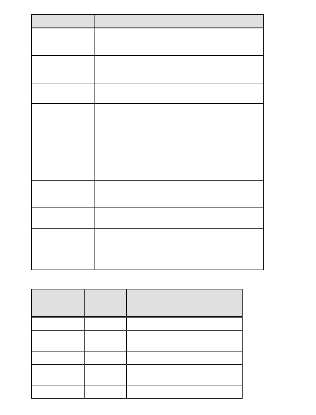
SANtricity_10.77 February 2011
LSI Corporation
- 703 -
Operating System System and Version or Edition
Windows Vista SP1 x86-based system (32-bit and 64-bit)
Pentium or greater CPU or equivalent (800 MHz minimum)
NOTE – Storage management station only.
Windows Server
2008 and Windows
Server Virtualization
x86-based system (AMD64 and EM64T)
Standard (Server Core) Edition, Enterprise (Server Core)
Edition, Web Edition
Macintosh OS X 10.5.8
10.6.3
Linux IA32
AMD64
EM64T
Red Hat Enterprise Linux 6.0
Red Hat Enterprise Linux 5.6
SUSE Linux Enterprise Server 10 SP 3
SUSE Linux Enterprise Server 11 SP1
Red Hat 5.0 Client (storage management stations only)
SUSE Linux Enterprise Server 10, SP 3 (storage management
stations only)
HP-UX IA64
PA-RISC
11.31
AIX Power PC processor
6.1, 7.1
Solaris SPARC-based system
x86-based system (Intel Xeon, and 32-bit AMD Operteron or
64-bit AMD Opteron)
Solaris 8 (SPARC only)
Solaris 10 Update 9
Temporary Disk Space Requirements
Operating
System Available
Temporary
Disk Space
Other Requirements
Windows XP 255 MB —
Windows Server
2003 291 MB —
Windows Vista 291 MB —
Windows Server
2008 291 MB —
Linux 390 MB —
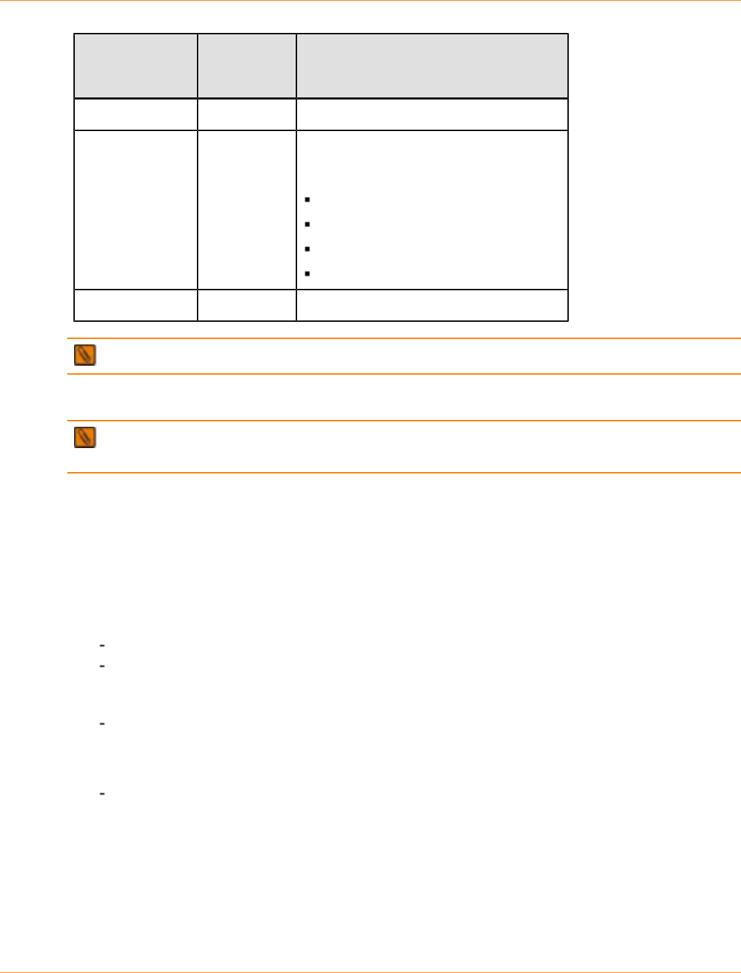
SANtricity_10.77 February 2011
LSI Corporation
- 704 -
Operating
System Available
Temporary
Disk Space
Other Requirements
HP-UX 582 MB —
AIX 525 MB For version 5.x, the Java runtime
environment requires these base level file
sets or later:
x11.adt.lib 5.x
x11.adt.motif 5.x
bos.adt.include 5.x
bos.adt.prof 5.x
Solaris 540 MB —
NOTE The minimum RAM requirement is 512 MB.
Procedure – Installing the SANtricity ES Storage Manager Software
IMPORTANT Make sure that you have the correct administrator or superuser privileges to install the
software.
1. Insert the SANtricity ES Storage Manager Installation DVD in the DVD drive.
Depending on your operating system, a program autoplays and shows a menu with installation selections.
If the menu does not appear, you must perform these tasks:
a. Manually open the install folder.
b. Locate the installation package that you want to install.
2. Install the software installation packages that are required for your storage configuration.
You might be required to open a window or terminal to run one of these commands.
hsw_executable.exe -i console
hsw_executable.exe -i silent
In the commands, hsw_executable.exe is the file name for the storage management software
installation package.
When using the console parameter during the installation, questions appear on the console that
enable you to choose installation variables. This installation does not use a graphical user interface
(GUI). Contact your Customer and Technical Support representative if you need to change the
installation options.
When using the silent parameter during the installation, the command installs the storage
management software using all of the defaults. A silent installation uses a resource file that contains
all of the required information, and it does not return any windows until the installation is complete.
This installation does not use a GUI. Contact your Customer and Technical Support representative if
you need to change the installation options.
Example: These examples show the actual command used to launch the installation wizard for a particular
operating system.
SANtricity_10.77 February 2011
LSI Corporation
- 705 -
Windows operating systems – Double-click the executable file. In general, the executable file begins
with SMIA followed by the operating system name, such as SMIA-WS32.exe.
UNIX operating systems – At the command prompt, type the applicable command to start the installer,
and press Enter. For example, type a command that is similar to this command: sh DVD_name.bin. In
this command, DVD_name.bin is the name of the installation DVD, such as SMIA-LINUX.bin.
NOTE If necessary, set the display environment to issue the command.
Example: Use the information in the on-screen instructions to install the software.
Things to Know – Software Packages
Client – This package contains the graphical user interface for managing the storage array. This package
also contains a monitor service that sends alerts when a critical problem exists with the storage array.
NOTE You can add from one to eight clients to your storage configuration.
Utilities – This package contains utilities that let the operating system recognize the volumes that you create
on the storage array and to view the operating system-specific device names for each volume.
Agent – This package contains software that allows a management station to communicate with the
controllers in the storage array over the I/O path of a host (see “Things to Know – In-Band and Out-of- Band
Requirements.”)
Failover driver – This package contains the multi-path driver that manages the I/O paths into the controllers
in the storage array. If a problem exists on the path or a failure occurs on one of the controllers, the driver
automatically reroutes the request from the hosts to the other controller in the storage array.
Java Access Bridge (JAB) – This package contains accessibility software that enables Windows-based
assistive technology to access and interact with the client application.
Support Monitor Profiler – This package gathers, records, and communicates data about the operation of
a storage array. The application is installed with the SANtricity ES Storage Manager if you choose either a
Typical or Management Station Installation.
NOTE The Microsoft Virtual Disk Service (VDS) and Volume Shadow Copy Service (VSS) providers
are a part of the SANtricity ES Storage Manager package for the Windows Server 2003 OS and the Windows
Server 2008 OS.
NOTE Use the figures and tables that follow to determine the software packages that should be
installed on each machine.
IMPORTANT You must install the utilities and the failover driver on each host that is attached to the
storage array.
IMPORTANT If you choose not to automatically enable the event monitor during installation, you will
not receive critical alert notifications.
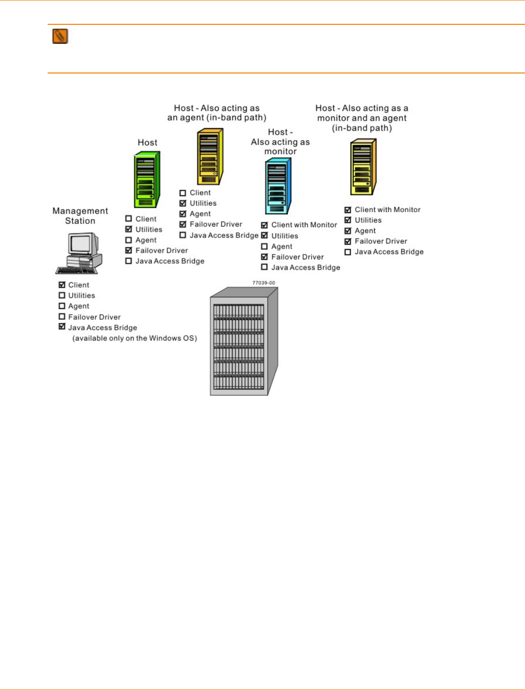
SANtricity_10.77 February 2011
LSI Corporation
- 706 -
IMPORTANT During the client installation, you are asked whether you want to start the monitor. Start
the monitor on only one host that runs continuously. If you start the monitor on more than one host, you
receive duplicate alert notifications about problems with the storage array.
Software Configurations
The storage array is the box at the bottom of this figure.

SANtricity_10.77 February 2011
LSI Corporation
- 707 -
Different Machines and Required Software
Machine Minimum Software
Required Installation Package
(Choose One) (See
the tables that
follow)
Notes
Management station Client Typical
Installation
Management
Station
Custom
Click No to
the prompt,
Automatically
start Monitor?
You must choose
Custom if you
want to install
the Java Access
Bridge software.
Host Utilities
Failover driver
Typical
Installation
Host
Custom
Click No to
the prompt,
Automatically
start Monitor?
Be aware that
some operating
systems require
the manual
installation of the
RDAC failover
driver.
Host – Also acting as
an agent for the in-
band management
method
Utilities
Agent
Failover driver
Typical
Installation
Host
Custom
Click No to the
prompt, Automatically
start Monitor?
Host – Also acting as
a monitor for sending
critical alerts
Client
Utilities
Failover driver
Typical
Installation
Custom
Click Yes to
the prompt,
Automatically
start Monitor?
Start the monitor
on only one
host that will run
continuously.
Host – Also acting as
an agent for the in-
band management
method and a
monitor for sending
critical alerts
Client
Utilities
Agent
Failover driver
Typical
Installation
Custom
Click Yes to
the prompt,
Automatically
start Monitor?
Start the monitor
on only one
host that will run
continuously.

SANtricity_10.77 February 2011
LSI Corporation
- 708 -
Installation Wizard Selections
Type of Installation Client Utilities Agent Failover JAB
Typical Installation X X X X —
Management Station X — — — —
Host Station — X X X —
Custom (you select
the packages) X X X X X
Java Access Bridge – Enables Windows OS-based assistive technology to access and interact
with the application.
Software Packages That Are Supported on Each Operating System
Operating System Client Utilities Agent Failover JAB
Windows XP and
Windows Vista X — — — X
Windows Server
2003 and Windows
Server 2008
X X X X X
Red Hat 5.5 Client
and SUSE Linux
Enterprise Desktop
11.1
X — — — —
Red Hat Enterprise
Linux and SUSE
Linux Enterprise
Server
X X X Manual A —
Solaris X X X X —
HP-UX XB X X X —
AIX X X X — —
NetWare XB X X X X
A See “Steps to Manually Install – RDAC on the Linux OS.”
B Windows Client or Linux Client only.
Procedure – Manually Installing RDAC on the Linux OS
1. To change to the directory where the RDAC source was untarred, type this command, and press Enter:
cd linuxrdac

SANtricity_10.77 February 2011
LSI Corporation
- 709 -
IMPORTANT For more information about installing RDAC, refer to the Readme.txt file in the
linuxrdac directory.
2. To clean the directory, type this command, and press Enter:
make clean
3. To compile the trays, type this command, and press Enter:
make
4. To install RDAC, type this command, and press Enter:
make install
5. After the make installation is completed, modify your bootloader configuration file.
For more information about modifying the bootloader configuration, refer to the output from the make
install command for Linux RDAC.
6. Read the Readme.txt file in the linuxrdac directory to complete the RDAC installation process.
7. Reboot or start your host.
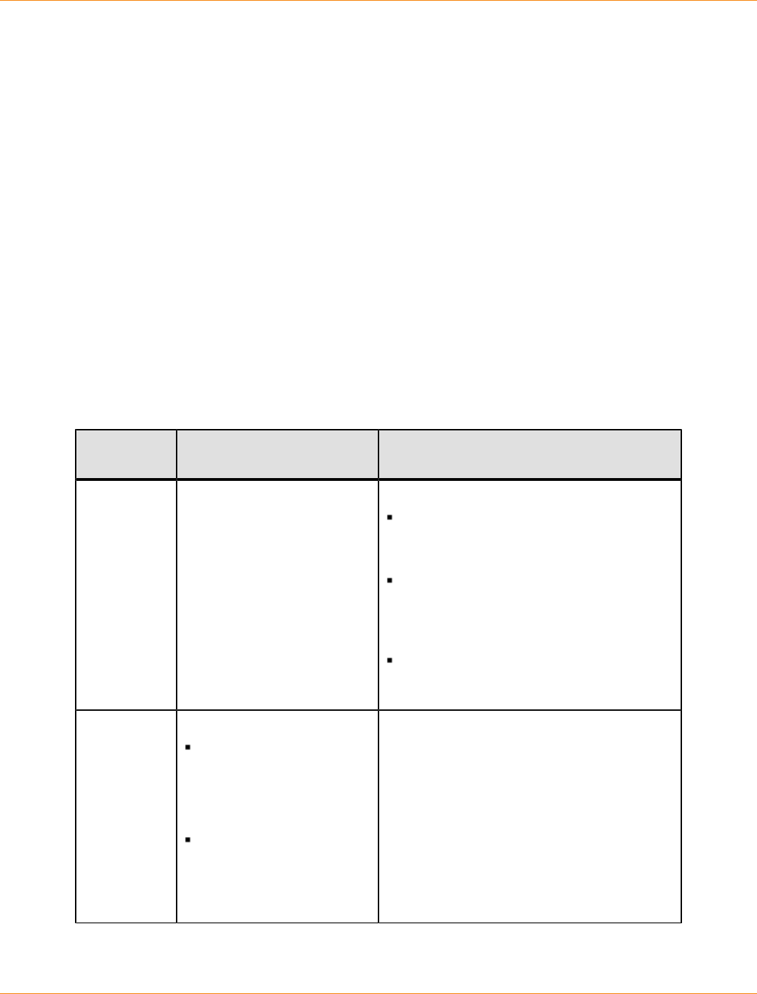
SANtricity_10.77 February 2011
LSI Corporation
- 710 -
Step 4 – Configuring the Host Bus Adapters
Procedure – Configuring the HBAs
A host bus adapter (HBA) is an adapter on the information bus of the host computer. This adapter acts as a
bridge and provides connectivity between both the host computer and the storage. Host bus adapters free
up critical server processing time. Depending on the configuration of your storage array, you must set up the
HBA to enable storage access using Fibre Channel, iSCSI or SAS connections.
This section provides information about configuring HBA settings for your Fibre Channel (FC) connections.
For information about configuring HBA settings for iSCSI and SAS connections, refer to the latest Product
Release Notes for SANtricity ES Storage Manager .
For the latest compatibility information about recommended HBA settings for FC, iSCSI, and SAS
connections, refer to the Storage Systems Compatibility Matrix, available at:
http://www.lsi.com/compatibilitymatrix/
Use the following table to determine whether you need to make any configuration changes for your HBA that
uses a Fibre Channel connection.
Configuration Changes for HBAs
HBA Vendor Configuration Changes
Required? Next Step
Emulex Yes Linux OS:
“Steps to Change – Emulex HBA Driver
(Linux OS)”
Solaris OS:
“Steps to Change – Emulex HBA Driver
(Solaris OS)”
Windows Server 2003 OS and Windows
Server 2008 OS:
“Steps to Change – Emulex HBA Driver
(Windows Server 2003 OS and Windows
Server 2008 OS)”
Hewlett-
Packard (HP) Yes
The only factory default
setting that you must
change is the I/O timeout
value. Set the value to
120.
You must change the I/
O timeout value for each
block device (volume)
that you create on the
storage array.
“Starting SANtricity ES Storage Manager”
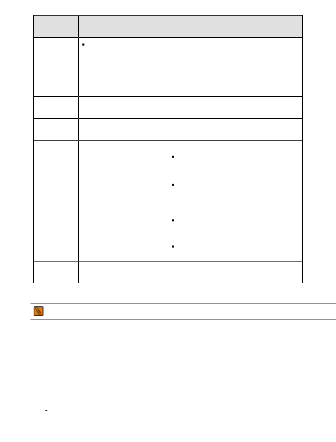
SANtricity_10.77 February 2011
LSI Corporation
- 711 -
HBA Vendor Configuration Changes
Required? Next Step
Because you must first
create the volumes,
use the instructions for
changing the I/O timeout
value in “Configuring
the Storage” in a later
section.
IBM No “Turning on the Power and Checking for
Problems.”
LSI No “Turning on the Power and Checking for
Problems.”
QLogic Yes
NOTE – The 2312 model is
not a QLogic HBA model. It is
a chip on the 2342 model.
Linux OS:
“Steps to Change – QLogic HBA (BIOS
Settings)”
Solaris OS:
“Steps to Change – QLogic HBA (Solaris
OS)”
Windows Server 2003 OS and Windows
Server 2008 OS:
“Steps to Change – QLogic HBA
(Windows Server 2003 OS and Windows
Server 2008 OS)”
“Steps to Change – QLogic HBA (BIOS
Settings)”
Sun No “Turning on the Power and Checking for
Problems.”
Procedure – Changing the Emulex HBA Driver Configuration (Linux OS)
NOTE This procedure applies to only the SUSE Linux Enterprise Server 9 OS.
1. Use Emulex’s HBAnyware tool to change this value:
lpfc_nodev_tmo = 60
2. Reboot your host.
3. Go to “Turning on the Power and Checking for Problems" topic at the end of your hardware configuration
document.
Procedure – Changing the Emulex HBA Driver Configuration (Solaris OS)
1. Change these values in the /kernel/drv/lpfc.conf configuration file:
Automap = value
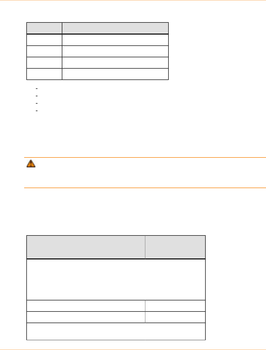
SANtricity_10.77 February 2011
LSI Corporation
- 712 -
Supported Values for Automap
Value Type of Binding
0Scan persistent binding only
1World-Wide Node Name (WWNN) binding
2WWPN binding
3DID binding
No-device-delay = 0
Network-on = 0
Linkdown-tmo = 60
Nodev-tmo = 60
2. Reboot your host.
3. Go to “Turning on the Power and Checking for Problems” at the end of your hardware configuration
document.
Procedure – Changing the Emulex HBA Driver Configuration (Windows Server 2003 OS and
Windows Server 2008 OS)
ATTENTION Possible data corruption – The Registry Editor is an advanced tool for changing
settings. If you make an error in the registry, your computer might not function correctly. Make sure that you
back up (export) your registry before you start this task. Refer to the online help topics on your host operating
system for more information.
1. Select Start >> Run on your operating system.
2. To start the Registry Editor, type regedit, and click OK.
3. Use the information in the following table to change the various registry values. Double-click the value to
change it.
Registry Value Changes for Emulex HBAs (Windows Server 2003 OS and Windows Server 2008 OS)
Registry Values Windows Server 2003
OS and Windows
Server 2008 OS
HKEY_LOCAL_MACHINE >> System >> CurrentControlSet >>
Services >> elxstor >> Parameters >> Device (under the
DriverParameter variable)
NOTE – DriverParameter is of the type REG_SZ. Add these parameters
to the DriverParameter string. Do not create a separate key for each of the
parameters.
LinkTimeOut 60
NodeTimeOut 60
HKEY_LOCAL_MACHINE >> System >> CurrentControlSet >>
Services >> md3dsm or mppdsm >> Parameters
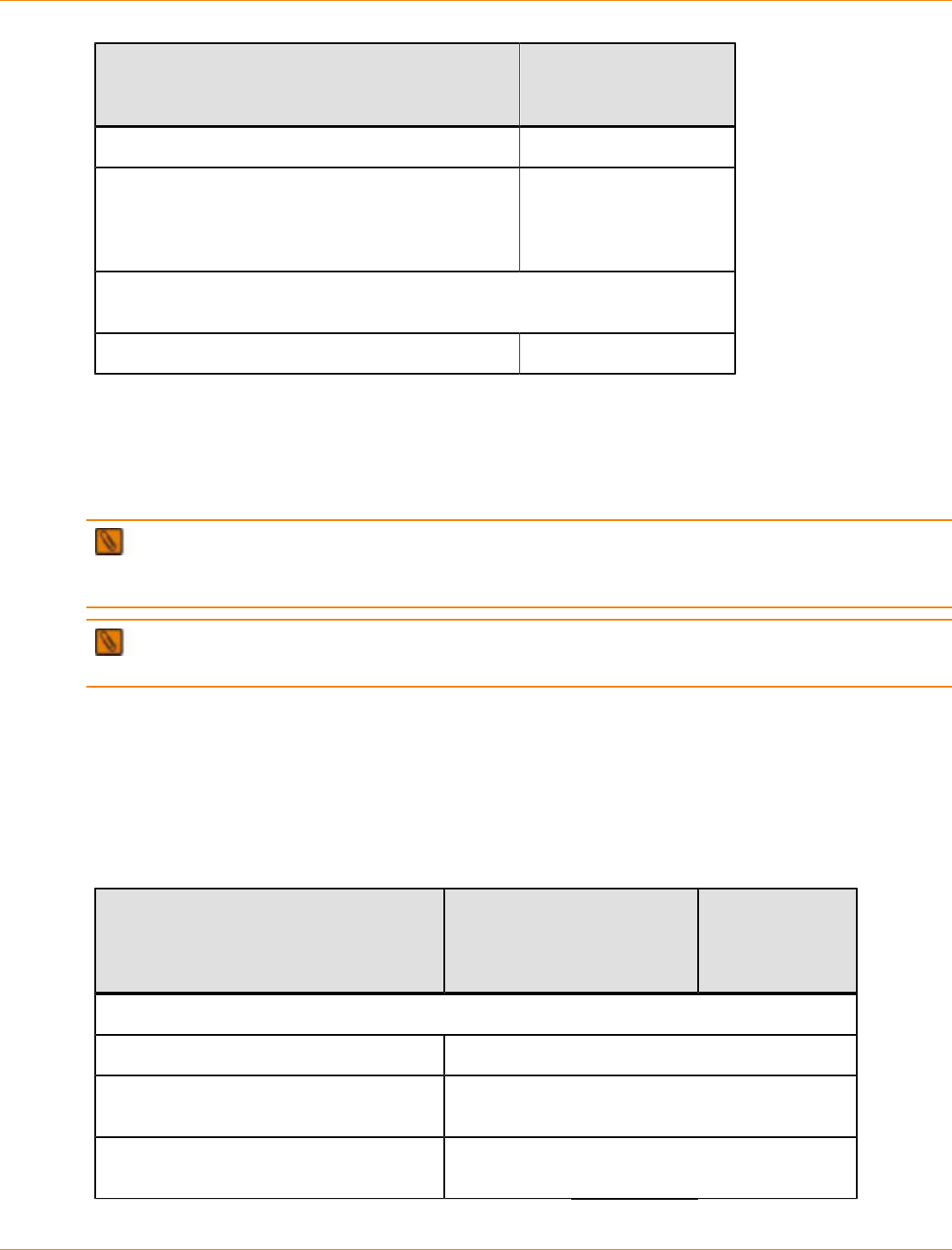
SANtricity_10.77 February 2011
LSI Corporation
- 713 -
Registry Values Windows Server 2003
OS and Windows
Server 2008 OS
SynchTimeOut (REG_DWORD) x78
DisableLunRebalance
[value_for_cluster] (REG_DWORD)
NOTE – Change this value only if you are using the
Microsoft Cluster Service.
0x03
HKEY_LOCAL_MACHINE >> System >> CurrentControlSet >>
Services >> Disk
TimeOutValue (REG_DWORD) x78
4. After you change the registry values, reboot your host.
5. Go to “Turning on the Power and Checking for Problems" at the end of your particular hardware
configuration document.
Procedure – Changing the QLogic HBA Configuration (BIOS Settings)
IMPORTANT You need to perform this procedure only if your operating system is the Linux OS, the
Windows Server 2003 OS, or the Windows Server 2008 OS. If your operating system is the Solaris OS, go to
“Steps to Change – QLogic HBA (Solaris OS).”
NOTE Instead of using the BIOS utility, you can use the software utility that is supplied with the QLogic
HBA.
1. Reboot or start your host.
2. While the host is booting, watch for the prompt, and press Alt-Q to access the BIOS utility.
3. Select an HBA to view its settings.
4. Select Configuration Settings, and make the applicable changes using the information in the following
table.
BIOS Settings for QLogic HBAs
Setting Linux OS Windows Server
2003 OS and
Windows Server
2008 OS
Host Adapter Settings
LoopResetDelay 8
AdapterHardLoopID (recommended
only for arbitrated loop topology) Enabled
HardLoopID(recommended only for
arbitrated loop topology) Any unique number. Typically set to 20, 21, or 22.
SANtricity_10.77 February 2011
LSI Corporation
- 714 -
Setting Linux OS Windows Server
2003 OS and
Windows Server
2008 OS
Advance Adapter Settings
ExecutionThrottle 256
LUNsperTarget
NOTE – 0 activates maximum LUN
support.
0 0
EnableTargetReset Yes
LoginRetryCount 30
PortDownRetryCount 35
LinkDownTimeout 60
5. Save the changes.
6. Repeat step 3 through step 5 for each QLogic HBA in each host.
7. Reboot your host.
8. Depending on your operating system, go to one of these steps:
Linux OS – “Turning on the Power and Checking for Problems” at the end of your particular hardware
configuration guide.
Windows Server 2003 OS and Windows Server 2008 OS – “Steps to Change – QLogic HBA
(Windows Server 2003 OS and Windows Server 2008 OS.”
Procedure – Changing the QLogic HBA Configuration (Solaris OS)
1. Change these values in the /kernel/drv/qla2300.conf configuration file:
execution-throttle = 255
login-retry-count = 30
enable-adapter-hard-loop-ID = 1 (Recommended only for arbitrated loop topology.)
adapter-hard-loop-ID = 125 (Recommended only for arbitrated loop topology. The ID must be
unique for each HBA.)
enable-target-reset = 1
reset-delay = 8
port-down-retry-count = 70
maximum-luns-per-target = 0 (0 activates maximum LUN support.)
2. Reboot your host.
3. Go to “Turning on the Power and Checking for Problems” at the end of your particular hardware
configuration guide.
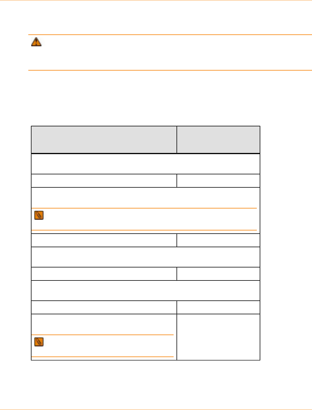
SANtricity_10.77 February 2011
LSI Corporation
- 715 -
Procedure – Changing the QLogic HBA Configuration (Windows Server 2003 OS and Windows
Server 2008 OS)
ATTENTION Possible data corruption – The Registry Editor is an advanced tool for changing
settings. If you make an error in the registry, your computer might not function correctly. Make sure that you
back up (export) your registry before you start this task. Refer to the online help topics on your host operating
system for more information.
1. Select Start >> Run on your operating system.
2. To start the Registry Editor, type regedit, and click OK.
3. Use the information in the following table to change the various registry values. Double-click the value to
change it.
Registry Value Changes for QLogic HBAs (Windows Server 2003 OS and Windows Server 2008 OS)
Setting Windows Server 2003 OS
and Windows Server 2008
OS
HKEY_LOCAL_MACHINE >> System >> CurrentControlSet >> Services >>
QL2300 >> Parameters >> Device
MaximumSGList (REG_WORD) 0xff
HKEY_LOCAL_MACHINE >> System >> CurrentControlSet >> Services >>
QL2300 >> Parameters >> Device under the DriverParameter variable
NOTE DriverParameter is of type REG_SZ. Add these parameters to the
DriverParameter string. Do not create a separate key for each of the parameters.
BusChange 0
HKEY_LOCAL_MACHINE >> System >> CurrentControlSet >> Services >>
Disk
TimeOutValue (REG_DWORD) x78
HKEY_LOCAL_MACHINE >> System >> CurrentControlSet >> Services >>
md3dsm or mppdsm >> Parameters
SynchTimeOut (REG_DWORD) x78
DisableLunRebalance [value_for_cluster]
(REG_DWORD)
NOTE This setting applies only to a cluster
configuration.
0x03
4. After you change the registry values, reboot your host.
5. Go to “Turning on the Power and Checking for Problems" at the end of your particular hardware
configuration guide.
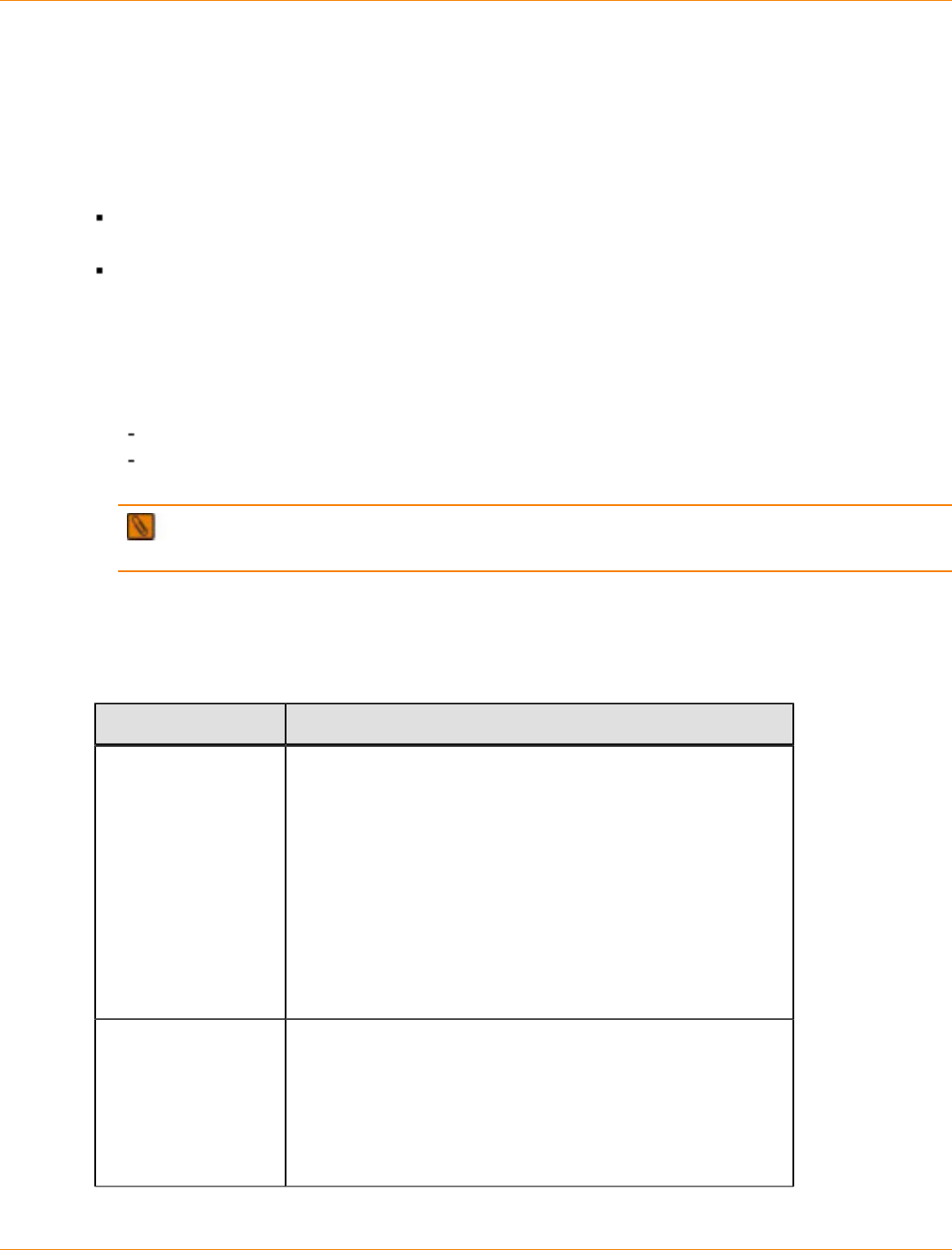
SANtricity_10.77 February 2011
LSI Corporation
- 716 -
Step 5 – Starting SANtricity ES Storage Manager
For Additional Information
For information about specific topics related to the SANtricity ES Storage Manager, refer to the following
resources:
SANtricity ES Storage Manager Concepts for Version 10.77 electronic document topics or to the PDF on
the SANtricity ES Storage Manager Installation DVD.
Online help topics in the Enterprise Management Window and the Array Management Window in
SANtricity ES Storage Manager.
Procedure – Starting SANtricity ES Storage Manager
1. At the prompt, type SMclient, and press Enter.
2. Do the storage arrays appear in the Enterprise Management Window?
Yes – You are finished with this procedure.
No – A dialog asks whether to add the storage arrays automatically or manually. For the steps to add
the storage arrays, see “Step 6 – Adding the Storage Array.”
NOTE The Enterprise Management Window and the Array Management Window are the two main
windows that you use to manage your storage array. The title at the top of each window identifies its type.
Things to Know – Enterprise Management Window and Array Management
Window
Overview of the Enterprise Management Window and the Array Management Window
User Interface Description
Enterprise
Management Window It is the main window that you see when you first start
SANtricity ES Storage Manager.
It provides you with a view of all of the storage arrays,
including the partially managed storage arrays, in your
management domain.
It allows you to automatically or manually add and remove
storage arrays, set alert notifications (email and SNMP), and
perform other high-level configuration functions.
It provides a high-level status of the health of each storage
array.
It allows you to manage and configure an individual storage
array by launching the Array Management Window.
Array Management
Window It provides you with all of the functions to configure, maintain,
and troubleshoot an individual storage array.
You launch the Array Management Window from the
Enterprise Management Window to manage an individual
storage array.
Multiple Array Management Windows can appear at the same
time (one for each storage array you want to manage).
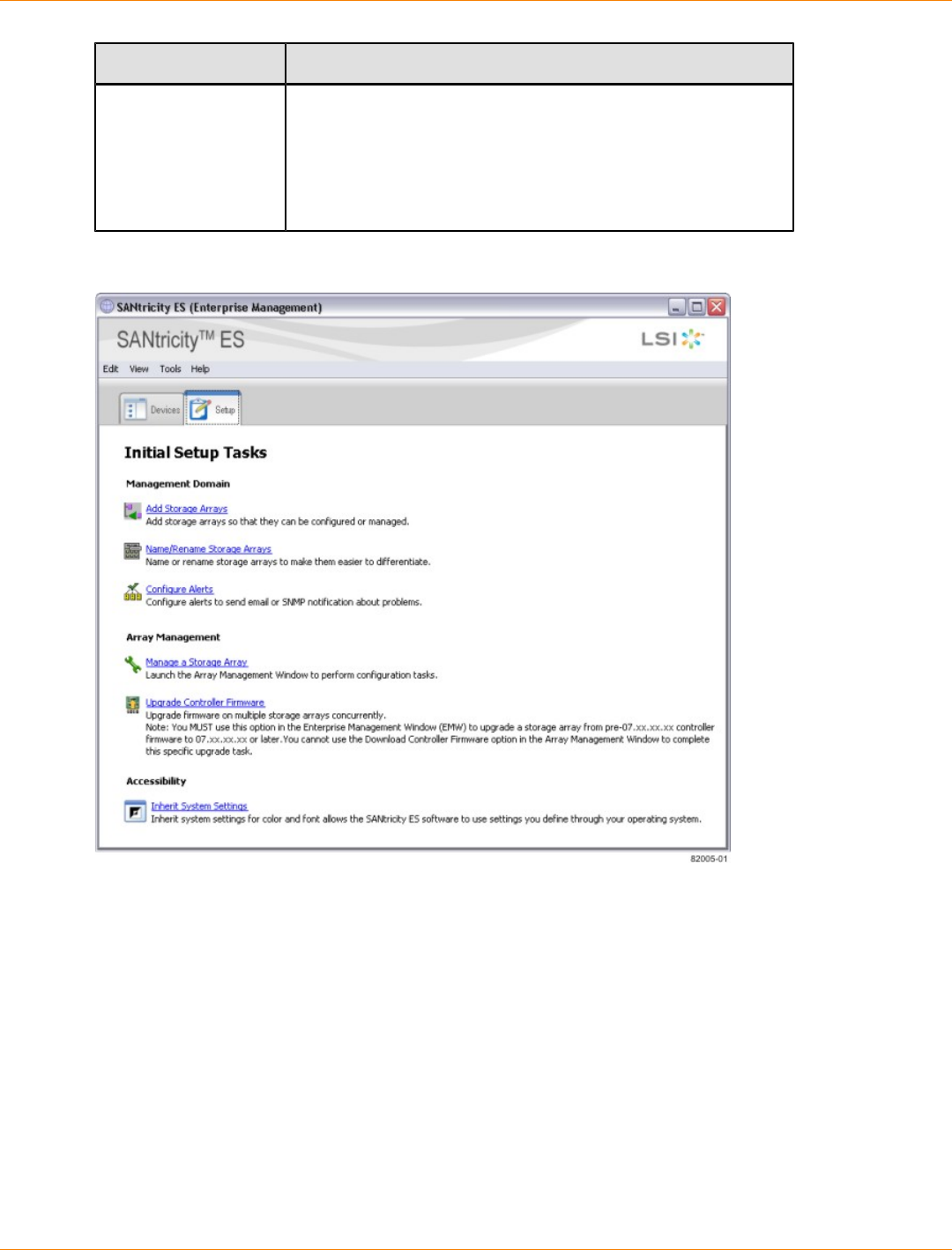
SANtricity_10.77 February 2011
LSI Corporation
- 717 -
User Interface Description
Enterprise
Management Window
Setup Tab and Array
Management Window
Setup Tab
When you first start either the Enterprise Management
Window or the Array Management Window, a Setup tab is
selected by default.
The Setup tab provides quick access to common setup tasks.
The tasks shown are different, depending on the window from
which the Setup tab was launched.
Enterprise Management Window with the Setup Tab Selected
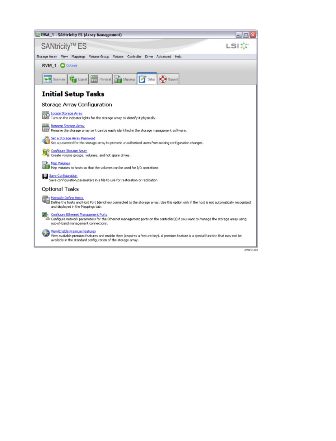
SANtricity_10.77 February 2011
LSI Corporation
- 718 -
Array Management Window with the Setup Tab Selected
SANtricity_10.77 February 2011
LSI Corporation
- 719 -
Step 6 – Adding the Storage Array
Things to Know – Storage Array
Make sure that you have connected all of the applicable cables.
Make sure that you have turned on the power to the storage array (attached drive trays first, and then the
controller-drive tray).
Make sure that you have installed the applicable storage management software.
Procedure – Automatically Adding a Storage Array
1. From the Enterprise Management Window, select Tools >> Automatic Discovery.
2. In the confirmation dialog, click OK to start the automatically discovery.
This process finds all of the storage arrays on the local sub-network. Several minutes might elapse to
complete the process.
3. Do you see the storage array in the Devices tab of the Enterprise Management Window?
Yes – Go to “Step 7 – Naming the Storage Array.”
No – Go to “Procedure – Manually Adding a Storage Array” (the storage array might reside outside
the local sub-network).
NOTE After adding the storage array, you can view or change the cache memory settings of the
storage array. See “Step 14 – Changing the Cache Memory Settings".
Procedure – Manually Adding a Storage Array
1. From the Enterprise Management Window, click the Add Storage Arrays link.
The Add New Storage Array – Manual dialog appears. By default, the Out-of-band management radio
button is selected.
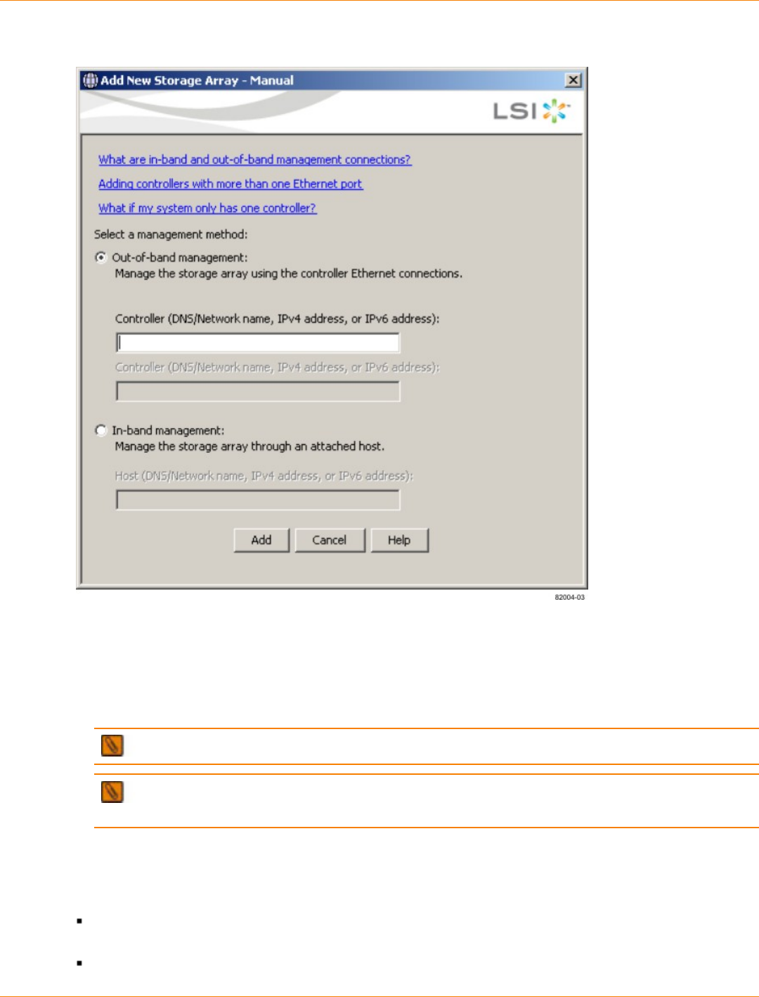
SANtricity_10.77 February 2011
LSI Corporation
- 720 -
Add New Storage Array – Manual Dialog
2. If you are using the in-band management method, select the In-band management radio button.
3. Manually enter the host names or the IP addresses of the controllers (out-of-band management method)
or the host name or IP address of the host that is running the host-agent software (in-band management
method), and click Add.
The storage array appears in the Enterprise Management Window.
NOTE You can enter the IP addresses in either the IPv4 format or the IPv6 format.
NOTE After adding the storage array, you can view or change the cache memory settings of the
storage array. See “Step 14 – Changing the Cache Memory Settings.”
Things to Know – Rescanning the Host for a New Storage Array
You can rescan your host to perform these actions:
Add new storage arrays that are connected to the host but are not shown in the Enterprise Management
Window.
Check the current status of storage arrays that are connected to the host.

SANtricity_10.77 February 2011
LSI Corporation
- 721 -
NOTE When you rescan your host for new storage arrays, you must stop and restart the host agent
before selecting the rescan option.
Procedure – Rescanning the Host for a New Storage Array
1. From the Devices tab in the Enterprise Management Window, select the host that you want to rescan.
NOTE If automatic discovery, rescan, add, or remove operations are in progress, you cannot
rescan for a storage array.
2. Select Tools >> Rescan.
3. In the confirmation dialog, click OK to start scanning the selected host for storage arrays.
This process adds new storage arrays and updates the status of the old storage arrays that are
connected to the selected host. Several minutes might elapse to complete the process.

SANtricity_10.77 February 2011
LSI Corporation
- 722 -
Step 7 – Naming the Storage Array
Things to Know – Naming the Storage Array
A storage array name can consist of letters, numbers, and the special characters underscore (_), hyphen
(-), and pound sign (#). No other special characters are permitted.
When you have named a storage array, the prefix "Storage Array" is automatically added to the name.
For example, if you named the storage array "Engineering," it appears as "Storage Array Engineering."
When you first discover a storage array or manually add it, the storage array will have a default name of
"unnamed."
Procedure – Naming a Storage Array
1. From the Setup tab on the Enterprise Management Window, click Name/Rename Storage Arrays.
The Name/Rename dialog appears.
2. Perform one of these actions, depending on the number of unnamed storage arrays:
More than one storage array is unnamed – Go to step 3.
One storage array is unnamed – Go to step 6.
3. Select one of the unnamed storage arrays, and then select Tools >> Locate Storage Array.
4. Find the physical storage array to make sure that you correlated it to the particular storage array listed.
5. Repeat step 3 through step 4 for each unnamed storage array.
6. Select an unnamed storage array in the top portion of the dialog.
The current name and any comment for the storage array appear at the bottom of the dialog.
7. Change the name of the storage array, add a comment (such as its location), and click OK.
The Warning dialog appears.
8. In the Warning dialog, perform one of these actions:
The host is not running any path failover drivers – Click Yes to change the name of the storage
array. Go to step 9.
The host is running a path failover driver – Click No. Go to step 9.
9. Do you need to name other storage arrays?
Yes – Click Apply to make the change and to keep the dialog open. Go to step 3.
No – Click OK to make the change and to close the dialog.

SANtricity_10.77 February 2011
LSI Corporation
- 723 -
Step 8 – Resolving Problems
If you noted any amber LEDs during “Turning on the Power and Checking for Problems,” the Enterprise
Management Window should show a corresponding indication.
Steps to Resolve – Problems
1. Click the Devices tab of the Enterprise Management Window to check the status of the storage arrays.
2. Double-click the storage array with the Needs Attention condition.
The associated Array Management Window (AMW) is launched.
3. Click the Physical tab of the AMW to see the configuration.
4. Perform one of these actions, depending on the status shown:
Optimal – No problems need to be resolved. Go to “Step 9 – Adding Controller Information for the
Partially Managed Storage Array.”
Needs Attention – Go to step 5.
Unresponsive – Refer to the online help topics in the Enterprise Management Window for the
procedure.
5. Select Storage Array, and click Recovery Guru to launch the Recovery Guru. Follow the steps in the
Recovery Guru.
Things to Know – Support Monitor Profiler
The Support Monitor Profiler is a software application that gathers, records, and communicates data about
the operations of a storage array. The application is installed with the SANtricity ES Storage Manager if you
choose a Typical or a Management Station installation. You also can install the Support Monitor Profiler by
choosing it as a component during a Custom installation of SANtricity ES Storage Manager.
When the Support Monitor Profiler is installed, the Profiler Console icon appears on your desktop. Click the
icon to open the application. The Support Monitor Profile allows you to perform the following tasks:
Register the Support Monitor.
Scan devices, log and view support data, System-on-a-chip (SOC) and Record-Level Sharing (RLS)
change log files, and email support data to the Customer and Technical Support representative.
Upgrade to the Full Profiler Support Monitor.
For more information about using the Support Monitor Profiler, refer to the Support Monitor Installation and
Overview electronic document topics or to the PDF on the SANtricity ES Storage Manager Installation DVD.
Retrieving Trace Buffers
Use the Advanced >>Troubleshooting >> Support Data >> Retrieve Trace Buffers option to save
trace information to a compressed file. The firmware uses the trace buffers to record processing, including
exception conditions, that might be useful for debugging. Trace information is stored in the current buffer. You
have the option to move the trace information to the flushed buffer after you retrieve the information. (The
option to move the trace information to the flushed buffer is not available if you select Flushed buffer from
the Trace Buffers list.) Because each controller has its own buffer, there might be more than one flushed
buffer. You can retrieve trace buffers without interrupting the operation of the storage array and with minimal
effect on performance.
NOTE Use this option only under the guidance of your Customer and Technical Support representative.

SANtricity_10.77 February 2011
LSI Corporation
- 724 -
A zip-compressed archive file is stored at the location you specify on the host. The archive contains
trace files from one or both of the controllers in the storage array along with a descriptor file named
trace_description.xml. Each trace file includes a header that identifies the file format to the analysis
software used by the Customer and Technical Support representative. The descriptor file has the following
information:
The World Wide Identifier (WWID) for the storage array.
The serial number of each controller.
A time stamp.
The version number for the controller firmware.
The version number for the management application programming interface (API).
The model ID for the controller board.
The collection status (success or failure) for each controller. (If the status is Failed, the reason for failure
is noted, and no trace file exists for the failed controller.)
1. From the Array Management Window, select Advanced >> Troubleshooting >> Support Data >>
Retrieve Trace Buffers.
2. Select the Controller A check box, the Controller B check box, or both check boxes.
If the controller status message to the right of a check box is Failed or Disabled, the check box is
disabled.
3. From the Trace Buffers drop-down list, select Current buffer, Flushed buffer, Current and flushed
buffers, or Current, flushed, and platform buffers.
4. If you choose to move the buffer, select the Move current trace buffer to the flushed buffer after
retrieval option.
The Move current trace buffer to the flushed buffer after retrieval option is not available if you
selected Flushed buffer in step 3.
5. In the Specify filename text box, either enter a name for the file to be saved (for example, C:
\filename.zip), or browse to a previously saved file if you want to overwrite that file.
6. Click Start.
The trace buffer information is archived to the file that you specified in step 5. If you click Cancel while the
retrieval process is in progress, and then click OK in the cancellation dialog that appears, the trace buffer
information is not archived, and the Retrieve Trace Buffers dialog remains open.
7. When the retrieval process is finished, the label on the Cancel button changes to Close. Choose one of
the following options:
To retrieve trace buffers again using different parameters, repeat step 2 through step 6.
To close the dialog and return to the Array Management Window, click Close.
SANtricity_10.77 February 2011
LSI Corporation
- 725 -
Step 9 – Adding Controller Information for the Partially Managed
Storage Array
IMPORTANT You only need to perform this step if you have partially managed storage arrays.
Key Terms
partially managed storage array
A condition that occurs when only one controller is defined or can be reached when the storage array is
added to or found by the storage management software. In this case, volume management operations can
be done only on volumes owned by the reachable controller. Many other management operations that require
access to both controllers are not available.
Things to Know – Partially Managed Storage Arrays
You can identify a storage array as a partially managed storage array if you see these indications for the
storage array:
When you close the Add New Storage Array – Manual dialog after adding the storage array, a Partially
Managed Storage Arrays dialog appears.
When you try to manage the storage array using the Array Management Window, a Partially Managed
Storage Arrays dialog appears.
When you select View >> Partially Managed Storage Arrays, the storage array is listed in the Partially
Managed Storage Arrays dialog.
When you place the cursor on the storage array, “partially managed” appears in the tooltip.
NOTE The tooltip indication appears only for out-of-band storage arrays.
Procedure– Automatically Adding a Partially-Managed Storage Array
NOTE These steps are for out-of-band partially managed storage arrays only. For in-band partially
managed storage arrays, verify the connection, and perform the steps in “Procedure – Rescanning the Host
for a New Storage Array” to rescan the host.
1. From the Enterprise Management Window, select View >> Partially Managed Storage Arrays.
2. Select the required partially managed storage array from the list of storage arrays.
3. Click Add More to add the information about the second controller.
The Add New Storage Array – Manual dialog appears.
4. Manually enter the host names or the IP addresses of the controllers (out-of-band management method)
or the host name or IP address of the host running the host-agent software (in-band management
method), and click Add.
The storage array appears in the Enterprise Management Window.
NOTE You can enter IP addresses in either the IPv4 format or the IPv6 format.

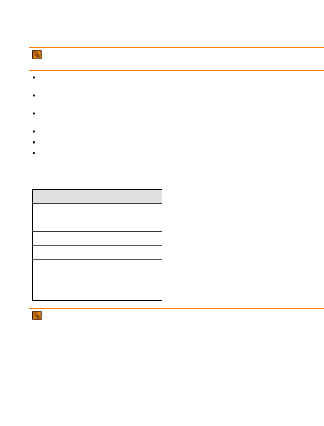
SANtricity_10.77 February 2011
LSI Corporation
- 727 -
Step 10 – Manually Configuring the Controllers
Things to Know – Manually Configuring the Controllers
IMPORTANT You need to perform this step only if you want to use the out-of-band management
method and you do not have a DHCP server to automatically assign IP addresses for the controllers.
See “Step 1 – Deciding on the Management Method” to determine if you need to make any configuration
changes to the controller.
In general, Ethernet port 1 on each controller is used for storage management, and Ethernet port 2 on
each controller is used by the Customer and Technical Support representative.
You should configure Ethernet port 2 only if your Customer and Technical Support representative asks
you to do so.
You can configure a gateway on only one of the Ethernet ports on each controller.
Ethernet port 1 and Ethernet port 2 must be on different sub-networks.
You can select one of the following speed and duplex mode combinations for your Ethernet ports. If
you select the auto-negotiate option, the controller will use the highest speed supported by the Ethernet
connection.
Supported Speed and Duplex Mode Combinations
Speed Duplex Mode
1000BASE-T Duplex
1000BASE-T Half Duplex
100BASE-T Duplex
100BASE-T Half Duplex
10BASE-T Duplex
10BASE-T Half Duplex
Auto-negotiate
NOTE Your controller might not support some of the speed and duplex mode combinations. You can
see the list of speed and duplex mode combinations that are supported on your controller when you change
your network configuration. (For the procedure to change your network configuration, see “Procedure –
Configuring the Controllers.”)
Things to Know – Options for Manually Configuring the Controllers
If you will use the out-of-band method and do not have a DHCP server, you have two options for manually
configuring your controllers.
SANtricity_10.77 February 2011
LSI Corporation
- 728 -
Option 1 – Use the In-Band Management Method Initially (Recommended)
This option requires that you install the host-agent software on one of the hosts that is attached to the storage
array and then use the in-band management method to initially discover the storage array and to manually
configure the controllers.
To discover the storage array and to manually configure the controllers, perform the procedure in “Procedure
– Configuring the Controllers.”
Option 2 – Set Up a Private Network
IMPORTANT This option is recommended only if the host on which you will use the in-band
management method does not support the host-agent software.
This option requires that you install the storage management software on a management station (such as
a laptop computer) and then set up a private network to initially discover the storage array and manually
configure the controllers.
You can either connect your management station directly into Ethernet port 1 on each controller or use a hub
(Ethernet switches or routers are not permitted).
To configure the management station, perform the procedure in “Procedure – Configuring the Management
Station.”
IMPORTANT If you connect the management station directly to the Ethernet ports on the controller-
drive tray, you must use an Ethernet crossover cable. The Ethernet crossover cable is a special cable that
reverses the pin contacts between the two ends of the cable.
Procedure – Configuring the Management Station
1. Change the IP address on the TCP/IP port on the management station from an automatic assignment to
a manual assignment by using the default IP address subnet of the controllers.
Make note of the current IP address of the management station so that you can revert back to it after
you have completed the procedure.
You must set the IP address for the management station to something other than the
controller IP addresses (for example, use 192.168.128.100 for an IPv4 network, or use
FE80:0000:0000:0000:02A0:B8FF:FE29:1D7C for an IPv6 network).
NOTE In an IPv4 network, the default IP addresses for Ethernet port 1 on controller A and
controller B are 192.168.128.101 and 192.168.128.102, respectively.
If your network is an IPv4 network, check the subnet mask to verify that it is set to 255.255.255.0,
which is the default setting.
Refer to your operating system documentation for instructions about how to change the network
settings on the management station and how to verify that the address has changed.
2. After you have configured your management station, perform the procedure in “Procedure – Configuring
the Controllers.”
Procedure – Configuring the Controllers
1. In the Devices tab on the Enterprise Management Window, double-click the storage array for which you
want to configure the controller network settings.
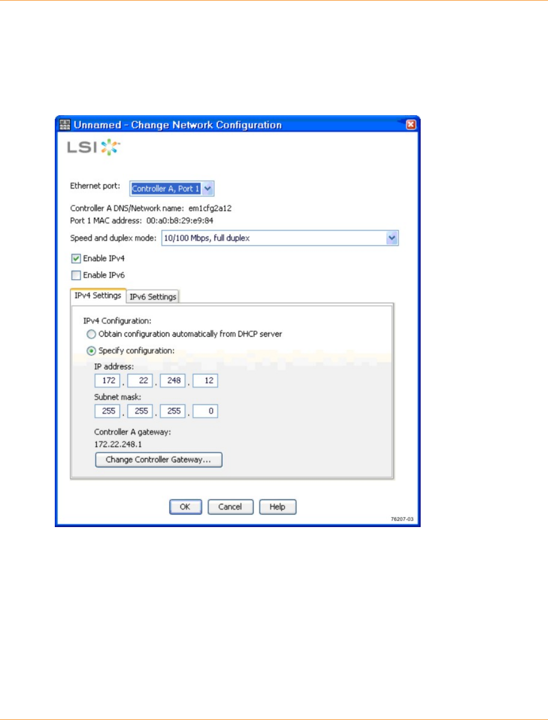
SANtricity_10.77 February 2011
LSI Corporation
- 729 -
The associated Array Management Window is launched.
2. Click the Physical tab.
3. Highlight controller A in the Physical pane of the Array Management Window, and select Controller >>
Configure >> Ethernet Management Ports.
Change Network Configuration Dialog with IPv4 Settings

SANtricity_10.77 February 2011
LSI Corporation
- 730 -
Change Network Configuration Dialog with IPv6 Settings
4. Select Controller A, Port 1 in the Ethernet port drop-down list.
5. From the Speed and duplex mode drop-down list, select Auto-negotiate.
ATTENTION Possible connectivity issues – After you select Auto-negotiate, make sure that
your Ethernet switch also is set to Auto-negotiate. Connectivity issues might occur if Auto-negotiate is
not selected in SANtricity ES Storage Manager and is not set for the Ethernet switch.
6. Depending on the format of your network configuration information, select the Enable IPv4 check box,
the Enable IPv6 check box, or both check boxes.
7. Depending on the format that you have selected, enter the network configuration information (IP address,
subnet mask, and gateway or IP address and routable IP address) in the IPv4 Settings tab or the IPv6
Settings tab.
NOTE You must obtain the network configuration information from your network administrator.
8. Select Controller B, Port 1 in the Ethernet port drop-down list, and repeat step 5 through step 7 for
controller B.

SANtricity_10.77 February 2011
LSI Corporation
- 731 -
9. Click OK.
10. If you are manually configuring the controllers using a private network, perform these actions after
configuring the controllers:
a. Disconnect the Ethernet cable from your management station, and reconnect the Ethernet cables
from the controllers into your regular network.
b. Complete the steps necessary to change the management station’s IP address back to what it was
originally.
SANtricity_10.77 February 2011
LSI Corporation
- 732 -
Step 11 – Setting a Password
Things to Know – Passwords
You need to set a password for your storage array to protect it from serious damage, such as data loss.
When you set a password, only authorized personnel are allowed to run the commands that change the
state of the storage array, such as commands to create volumes and the commands to modify the cache
settings.
For increased protection, use a long password with at least 15 alphanumeric characters. The maximum
password length is 30 characters.
Passwords are case sensitive.
You will be asked for a password only when you first attempt to change the configuration (such as
creating a volume) or when you first perform a destructive operation (such as deleting a volume). You
must exit both the Array Management Window and the Enterprise Management Window to be asked for
the password again.
Any type of view operation does not require a password at any time.
If you no longer want to have the storage array password-protected, enter the current password, and then
leave the New password text box and the Confirm password text box blank.
NOTE The storage array is different from the pass phrase used for SafeStore Drive Security.
IMPORTANT If you forget your password, you must contact your Customer and Technical Support
representative for help to reset it.
Procedure – Setting a Password
1. From the Setup tab on the Enterprise Management Window, click Manage a Storage Array.
The Select Storage Array dialog appears.
2. Highlight the storage array for which you want to set a password, and click OK.
The associated Array Management Window is launched.
3. From the Setup tab on the Array Management Window, click Set a Storage Array Password.
4. Follow the on-screen instructions. Click Help for more information.
5. Click OK.
SANtricity_10.77 February 2011
LSI Corporation
- 733 -
Step 12 – Removing a Storage Array
Things to Know – Removing Storage Arrays
When you remove a storage array, multiple storage arrays, or a host, they are removed from the
Enterprise Management Window of your storage management station. They can be viewed from other
storage management stations.
You can delete the storage arrays and hosts from the Tree view or the Table view. These views are
located on the Devices tab on the Enterprise Management Window. However, you can delete only one
storage array at a time from the Tree view.
Procedure – Removing a Storage Array
Use these steps to remove a storage array, multiple storage arrays, or a host to which multiple storage arrays
are connected.
1. From the Tree view or the Table view in the Enterprise Management Window Devices tab, select the
storage array, the storage arrays, or the host that you want to remove.
NOTE Before you try to remove a storage array, multiple storage arrays, or a host, you must close
all of the Array Management Windows and the Script Editor dialogs that are associated with the selected
storage arrays. If the Array Management Window or the Script Editor dialog is open for a storage array,
that storage array is not removed. All of the other storage arrays are removed.
2. Select Edit >> Remove.
3. In the confirmation dialog, click Yes to remove the storage array.
NOTE While removing multiple storage arrays, multiple confirmation dialogs, one for each storage
array, appear.
Depending on what you have selected to be removed, one of these actions occurs:
If you have selected a storage array, the storage array is removed from the Enterprise Management
Window.
If you have selected multiple storage arrays, the storage arrays are removed from the Enterprise
Management Window.
If you have selected a host, the host and its associated storage arrays are removed from the
Enterprise Management Window.
SANtricity_10.77 February 2011
LSI Corporation
- 734 -
Step 13 – Configuring Email Alerts and SNMP Alerts
Key Terms
Management Information Base (MIB)
CONTEXT [Management] The specification and formal description of a set of objects and variables that can
be read and possibly written using the Simple Network Management Protocol (SNMP). (The Dictionary of
Storage Networking Terminology, 2004)
Simple Network Management Protocol (SNMP)
CONTEXT [Network] [Standards] An IETF protocol for monitoring and managing systems and devices in a
network. The data being monitored and managed is defined by a Management Information Base (MIB). The
functions supported by the protocol are the request and retrieval of data, the setting or writing of data, and
traps that signal the occurrence of events. (The Dictionary of Storage Networking Terminology)
Things to Know – Alert Notifications
Setting alert destinations lets you specify addresses for the delivery of email messages and SNMP trap
messages whenever a critical problem exists with the storage array.
You must have the Event Monitor running on a machine (a management station or a host) to receive
alerts. The machine should be one that runs continuously.
IMPORTANT If you choose not to automatically enable the event monitor during installation, you do not
receive critical alert notifications.
Procedure – Setting Alert Notifications
1. From the Setup tab on the Enterprise Management Window, click Configure Alerts.
The Select Storage Array dialog appears.
2. Indicate on which storage arrays you want the alerts to be set, and click OK.
If you selected the All Storage Arrays choice, the main Alerts dialog appears.
If you selected the Individual Storage Array choice, you must first select the specific storage array
and click OK before the main Alerts dialog appears.
If you selected the Specific Host choice, you must first select a host and click OK before the main
Alerts dialog appears.
3. Specify the alerts that you want by using the tabs on the dialog. Use this information, and click OK when
you are finished setting the alerts.
Mail Server Tab
You must specify a mail server and an email sender address if you want to set email alerts. The mail
server and sender address are not required if you are setting SNMP alerts.
The Sender Contact Information is optional. Include the information if you plan to send alerts to your
Customer and Technical Support representative; otherwise, delete the fields.
Email Tab
Enter the email addresses in standard format, such as xxx@company.com.
If one of the email alerts that you configure is for your Customer and Technical Support
representative, make sure that you select the Event + Profile or Event + Support choice in the
Information to Send column. This additional information aids in troubleshooting your storage array.
The Event + Support choice includes the profile.

SANtricity_10.77 February 2011
LSI Corporation
- 735 -
SNMP Tab
To set up alert notifications using SNMP traps, you must copy and compile a Management
Information Base (MIB) file on the designated network management station.
The SNMP trap destination is the IP address or the host name of a station running an SNMP service.
At a minimum, this destination will be the network management station.

SANtricity_10.77 February 2011
LSI Corporation
- 736 -
Step 14 – Changing the Cache Memory Settings
Key Terms
cache memory
An area of random access memory (RAM) on the controller. This memory is dedicated to collecting and
holding related data until a drive tray or a storage tray is ready to process the data. Cache memory has a
faster access time than the actual drive media.
Things to Know – Cache Memory Settings
If the data requested from the host for a read exists in the cache memory from a previous operation, the
drive is not accessed. The requested data is read from the cache memory.
Write data is written initially to the cache memory. When a percentage of unwritten data is reached, the
data is flushed from or written to the drives.
During a controller failure, the data in the cache memory of the controller might be lost.
To protect data in the cache memory, you can set a low percentage of unwritten data in the cache
memory to trigger a flush to the drives. However, as the number of drive reads and drive writes increases,
this setting decreases performance.
When cache mirroring is enabled, if one controller in a controller tray or controller-drive tray fails, the
second controller takes over. The surviving controller uses its mirrored version of the failed controller’s
cache data to continue reading from and writing to the volumes previously managed by the failed
controller.
Procedure – Viewing the Cache Memory Size Information
1. From the Setup tab on the Enterprise Management Window, click Manage a Storage Array.
The Select Storage Array dialog appears.
2. Select the storage array that you want to manage, and click OK.
The associated Array Management Window is launched.
3. Click the Physical tab.
4. Select controller A in the Physical pane of the Array Management Window, and the Properties view
appears in the left pane.
5. Scroll through the Base tab until you find the cache information and the cache backup device information.
Procedure – Changing the Cache Memory Settings
1. From the Setup tab on the Enterprise Management Window, click Manage a Storage Array.
The Select Storage Array dialog appears.
2. Select the storage array that you want to manage, and click OK.
The associated Array Management Window is launched.
3. Select Storage Array >> Change >> Cache Settings.
The associated Change Cache Settings dialog appears.
4. Select the percentage of unwritten data in the cache to trigger a cache flush in the Start flushing text
box.
5. Select the percentage of unwritten data in the cache to stop a cache flush in progress in the Stop
flushing text box.

SANtricity_10.77 February 2011
LSI Corporation
- 737 -
6. Select the required cache block size, and click OK.
Procedure – Changing the Volume Cache Memory Settings
1. From the Setup tab on the Enterprise Management Window, click Manage a Storage Array.
The Select Storage Array dialog appears.
2. Select the storage array you want to manage, and click OK.
The associated Array Management Window is launched.
3. Select Volume >> Change >> Cache Settings.
The associated Change Cache Settings dialog appears.
4. To allow read operations from the host to be stored in the cache memory, select the Enable read
caching check box.
5. To allow write operations from the host to be stored in the cache memory, select the Enable write
caching check box.
6. Select the Enable write caching options by using the information in this list:
Enable write caching without batteries – Allows data from the drives to be written to the cache
memory even when the controller batteries are discharged completely, not fully charged, or not
present.
Enable write caching with mirroring – Mirrors data in the cache memory across two redundant
controllers that have the same cache memory size.
7. To enable copying of additional data while copying read operations data from the drives, select the
Dynamic cache read prefetch check box.
8. Click OK.

SANtricity_10.77 February 2011
LSI Corporation
- 738 -
Step 15 – Enabling the Premium Features
IMPORTANT If you did not obtain any premium feature key files from your storage vendor, skip this
step.
Key Terms
premium feature
A feature that is not available in the standard configuration of the storage management software.
Things to Know – Premium Features
You enable a premium feature through a feature key file that you obtain from your storage vendor. The
feature key file is either enabled or disabled. When a premium feature is disabled, it does not appear in the
graphical user interface (GUI).
If your system is a low-tier performance configuration and you want to upgrade to a high-tier performance
configuration, use the following procedure to obtain enhanced performance.
Procedure – Enabling the Premium Features
1. From the Setup tab on the Enterprise Management Window, click Manage a Storage Array.
The Select Storage Array dialog appears.
2. Highlight the storage array on which you want to enable a premium feature, and click OK.
The associated Array Management Window appears.
3. Select Storage Array >> Premium Features.
The associated Premium Features and Feature Pack Information dialog appears.
4. Select a feature from the Premium Feature list.
5. Click Enable.
The associated Select Feature Key File dialog appears.
6. Enter the file name of the feature key file for the particular premium feature that you want to enable.
7. Click OK to close the Select Feature Key File dialog.
The Premium Features installed on storage array drop-down list shows the name and the status of the
premium feature that you have enabled.
8. Repeat step 4 through step 7 for each premium feature that you want to enable.

SANtricity_10.77 February 2011
LSI Corporation
- 739 -
Step 16 – Defining the Hosts
IMPORTANT You must know the world wide port names of each HBA host port. If you have not already
recorded them, see “Installing Host Bus Adapters” for your particular configuration (CDE2600 Controller-
Drive Tray, CDE2600-60 controller-drive tray, CDE4900 controller-drive tray, or CE7900 controller tray) for
instructions to obtain these world wide port names.
IMPORTANT If you will not use storage partitions or you do not have the SANshare Storage
Partitioning premium feature enabled on your storage array, you can skip the information about “Things to
Know – Host Groups" and “Things to Know – Storage Partitions,” and go to either “Procedure – Defining the
Hosts” or “Procedure – Defining the iSCSI Hosts.”
Things to Know – Hosts
The host adapters in the hosts that are attached to the storage array are known to the storage management
software. However, the storage management software does not know which host adapters are associated
with which hosts. Use these steps to associate each host with its specific host adapters.
Things to Know – Host Groups
A host group is a group (cluster) of two or more hosts that share access, in a storage partition, to specific
volumes on the storage array. You can create an optional logical entity in the storage management
software. You must create a host group only if you will use storage partitions.
If you must define a host group, you can define it through the Define Hosts Wizard described in
“Procedure – Defining the Hosts.”
Things to Know – Storage Partitions
A storage partition is a logical entity that consists of one or more volumes that can be accessed by
a single host or can be shared among hosts that are part of a host group. You can think of a storage
partition as a virtual storage array. That is, take the physical storage array and divide it up into multiple
virtual storage arrays that you can then restrict to be accessible only by certain hosts.
SANshare Storage Partitioning is a premium feature. This premium feature was either already enabled
on your storage array at the factory, or you must purchase a feature key file from your storage vendor to
enable it.
You do not create storage partitions in this step, but you must understand them to define your hosts.
You do not need to create storage partitions if these conditions exist (see the first image below):
You have only one attached host that accesses all of the volumes on the storage array.
You plan to have all of the attached hosts share access to all of the volumes in the storage array.
Note that all of the attached hosts must have the same operating system (homogeneous), and you
must have special software on the hosts (such as clustering software) to manage volume sharing and
accessibility.
You do need to create storage partitions if these conditions exist (see the two images that display with no
partition required below):
You want certain hosts to access only certain volumes.
You have hosts with different operating systems (heterogeneous) attached in the same storage array.
You must create a storage partition for each type of host.
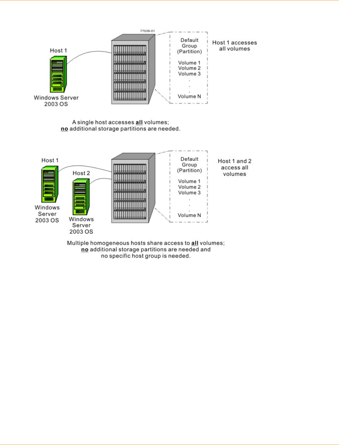
SANtricity_10.77 February 2011
LSI Corporation
- 740 -
Example of No Additional Storage Partitions Required
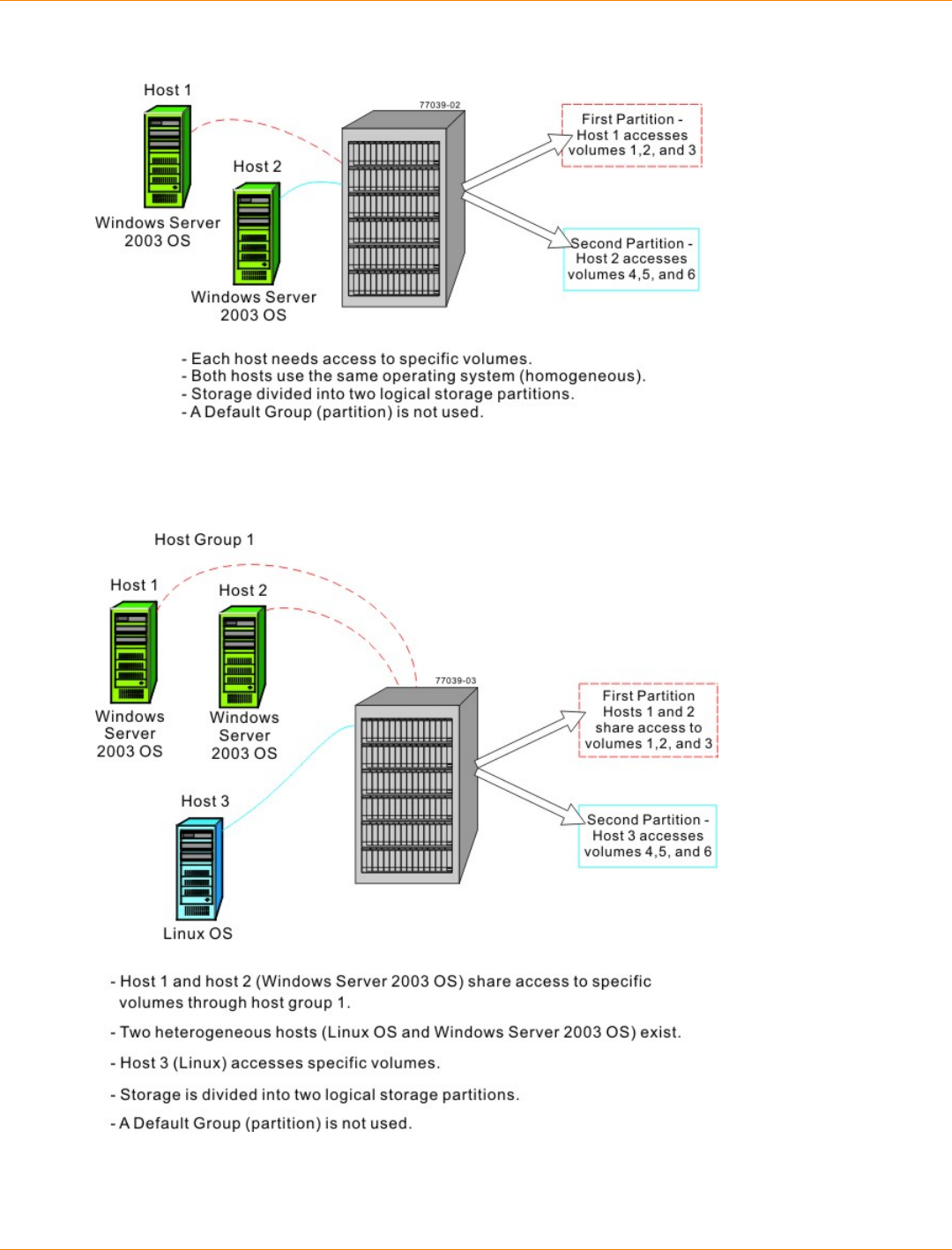
SANtricity_10.77 February 2011
LSI Corporation
- 741 -
Example of Additional Storage Partitions Required (Homogeneous Host)
Example of Additional Storage Partitions Required (Heterogeneous Hosts)

SANtricity_10.77 February 2011
LSI Corporation
- 742 -
Procedure – Defining the Hosts
1. From the Setup tab on the Enterprise Management Window, click Manage a Storage Array.
The Select Storage Array dialog appears.
2. Highlight the storage array on which you want to define a host, and click OK.
The associated Array Management Window is launched.
3. From the Setup tab on the Array Management Window, click Manually Define Hosts.
4. Use the on-screen instructions and the online help topics to define your hosts and associate the HBA host
ports. This procedure also allows you to define a host group.
Procedure – Defining the iSCSI Hosts
1. From the Setup tab on the Enterprise Management Window, click Manage a Storage Array.
The Select Storage Array dialog appears.
2. Highlight the storage array on which you want to define a host, and click OK.
The associated Array Management Window is launched.
3. From the Setup tab on the Array Management Window, click Configure iSCSI Host Ports.
4. On the Configure Ethernet port speed drop-down list, select either 10 Gbps or 1 Gbps to set the port
speed to either 10 Gb/s or 1 Gb/s. By default, this value is set to 10 Gbps.
5. Use the on-screen instructions and the online help topics to further define your hosts and associate the
HBA host ports. This procedure also allows you to define a host group.

SANtricity_10.77 February 2011
LSI Corporation
- 743 -
Step 17 – Configuring the Storage
Key Terms
Default Group
A standard node to which all host groups, hosts, and host ports that do not have any specific mappings are
assigned. The standard node shares access to any volumes that were automatically assigned default logical
unit numbers (LUNs) by the controller firmware during volume creation.
free capacity
Unassigned space in a volume group that can be used to make a volume.
full disk encryption (FDE)
A type of drive technology that can encrypt all data being written to its disk media.
hot spare drive
A spare drive that contains no data and that acts as a standby in case a drive fails in a RAID Level 1, RAID
Level 3, RAID Level 5, or RAID Level 6 volume. The hot spare drive can replace the failed drive in the
volume.
Redundant Array of Independent Disks (RAID)
CONTEXT [Storage System] A disk array in which part of the physical storage capacity is used to store
redundant information about user data stored on the remainder of the storage capacity. The redundant
information enables regeneration of user data in the event that one of the array's member disks or the access
path to it fails.
Although it does not conform to this definition, disk striping is often referred to as RAID (RAID Level 0). (The
Dictionary of Storage Networking Terminology)
storage partition
A logical entity that is made up of one or more storage array volumes. These storage array volumes can be
accessed by a single host or can be shared with hosts that can be part of a host group.
unconfigured capacity
The available space on drives of a storage array that has not been assigned to a volume group.
volume
The logical component created for the host to access storage on the storage array. A volume is created from
the capacity available on a volume group. Although a volume might consist of more than one drive, a volume
appears as one logical component to the host.
volume group
A set of drives that is logically grouped and assigned a RAID level. Each volume group created provides the
overall capacity needed to create one or more volumes.
SANtricity_10.77 February 2011
LSI Corporation
- 744 -
Things to Know – Data Assurance
The Data Assurance (DA) premium feature checks for and corrects errors that might occur as data is
communicated between a host and a storage array. DA is implemented using the SCSI direct-access block-
device protection information model. DA creates error-checking information, such as cyclic redundancy
checks (CRCs) and appends that information to each block of data. Any errors that might occur when a block
of data is either transmitted or stored are then detected and corrected by checking the data with its error-
checking information.
Only certain configurations of hardware, including DA-capable drives, controllers, and host interface cards
(HICs), support the DA premium feature. When you install the DA premium feature on a storage array,
SANtricity ES Storage Manager provides options to use DA with certain operations. For example, you can
create a volume group that includes DA-capable drives, and then create a volume within that volume group
that is DA-enabled. Other operations that use a DA-enabled volume have options to support the DA premium
feature.
If you choose to create a DA-capable volume group, select the Create a Data Assurance (DA) capable
volume group check box. This check box is enabled only when there is at least one DA-capable drive in the
storage array and is, by default, selected if it is enabled.
When the DA premium feature is enabled, the DA Enabled column appears in the Source volume list in the
Create Copy Wizard – Introduction dialog. If you choose to copy a DA-enabled source volume to a target
volume that is not DA enabled, you are prompted to confirm your choice. The copy can be completed, but the
resulting copy is not DA enabled.
IMPORTANT If a volume group is DA-capable and contains a DA-enabled volume, use only DA-
capable drives for hot spare coverage. A volume group that is not DA capable cannot include a DA-enabled
volume.
You can verify that a drive contains DA-enabled volumes by checking that the Data Assurance (DA) capable
property is set to "yes".
Things to Know – Allocating Capacity
You can create volumes from either unconfigured capacity or free capacity on an existing volume group.
If you create a volume from unconfigured capacity, you must first specify the parameters for a new
volume group (RAID level and capacity for a set of drives) before you specify the parameters for the
first volume on the new volume group.
If you create a volume from free capacity, you have to specify the parameters of only the volume,
because the volume group already exists.
As you configure the capacity on the storage array, make sure that you leave some unassigned drives
available. You might need to use these drives for these reasons:
To create additional volume groups for new capacity requirements
For hot spare drive protection
To increase the free capacity on an existing volume group to provide for future capacity needs
For additional storage required for certain premium features, such as Snapshot Volume
If your storage array contains more than one type of drive (such as Fibre Channel or SATA), an
Unconfigured Capacity node will be associated with each drive type. You cannot mix drives of different
types within the same volume group.
SANtricity_10.77 February 2011
LSI Corporation
- 745 -
If you are adding capacity to a Data Assurance (DA) -capable volume group, use only drives that are
DA capable. If you add a drive or drives that are not DA-capable, the volume group no longer has DA
capabilities, and you no longer have the option to enable DA on newly created volumes within the volume
group. The DA Capable column in the Available drives list shows the DA capabilities of each listed drive.
If you are adding capacity to a volume group that is not DA capable, do not use drives that are DA
capable because the volume group will not be able to take advantage of the capabilities of DA-capable
drives. The DA Capable column in the Available drives list shows the DA capabilities of each listed drive.
Things to Know – Volume Groups and Volumes
You can create a single volume or multiple volumes per volume group. Usually, you will create more
than one volume per volume group to address different data needs or because of limits on the maximum
capacity of a single volume.
NOTE If you choose to copy a Data Assurance (DA) enabled source volume to a target volume that is
not DA-enabled, you are prompted to confirm your choice. The copy can be completed, but the resulting copy
is not DA-enabled. For more information about how volume copy is affected by DA-enabled volumes, refer to
Volume Copy Premium Feature electronic document topics or the PDF located on the SANtricity ES Storage
Manager Installation DVD.
While creating volume groups, you must make sure that the drives that comprise the volume group are
located in different drive trays. This method of creating volume groups is called tray loss protection. Tray
loss protection guarantees accessibility to the data on the volumes in a volume group if a total loss of
communication occurs with a single drive tray. Communication loss might occur due to loss of power to
the drive tray or failure of the drive tray ESMs.
The RAID levels supported are RAID Level 0, RAID Level 1, RAID Level 3, RAID Level 5, RAID Level 6,
and RAID Level 10 (1 + 0).
RAID Level 0 provides no data redundancy.
RAID Level 10 is not a separate RAID level choice but is supported when you create a RAID Level 1
volume group that consists of four or more drives.
You can assign RAID Level 1 only to volume groups with an even number of drives.
You can assign RAID Level 3 or RAID Level 5 only to volume groups with three or more drives.
You can assign RAID Level 6 only to volume groups with five or more drives.
NOTE RAID Level 6 is a premium feature. This premium feature was either already enabled on
your storage array at the factory, or you must purchase a feature key file from your storage vendor to
enable it.
Things to Know – Host-to-Volume Mappings and Storage Partitions
Each volume that you create must be mapped to a logical address called a logical unit number (LUN).
The host uses this address to access data on the volume.
When you create a volume manually, you have two choices for mapping:
Default mapping – Choose this option if you do not intend to use storage partitions. The storage
management software will automatically assign a LUN to the volume and make the volume available
to all of the hosts that are attached to the storage array in the Default Group (partition).
Map later (assign specific mapping) – Choose this option if you intend to use storage partitions.
Use the Define Storage Partition Wizard to indicate the host group or host, specify the volumes that
you want the host group or host to access, and access the LUNs to assign to each volume.

SANtricity_10.77 February 2011
LSI Corporation
- 746 -
Things to Know – Hot Spare Drives
The hot spare drive adds a level of redundancy to your storage array. It is highly recommended that you
create hot spare drives for each type of drive in your storage array.
Hot spare drives do not provide protection for RAID Level 0 volume groups because data redundancy
does not exist on these volume groups.
A hot spare drive is not dedicated to a specific volume group but instead is global, which means that a hot
spare drive will be used for any failed drive in the storage array. The failed drive must be the same drive
type and have a capacity that is equal to or smaller than the particular hot spare drive.
Things to Know – Full Disk Encryption
SafeStore Drive Security and SafeStore Enterprise Key Manager (EKM) are premium features that prevent
unauthorized access to the data on a drive that is physically removed from the storage array. Controllers in
the storage array have a security key. Secure drives provide access to data only through a controller that
has the correct security key. The security key can be managed locally by the controllers or externally by an
external key management server, which is the EKM premium feature. Both SafeStore Drive Security and EKM
must be enabled either by you or your storage vendor.
The SafeStore Drive Security premium feature requires security-capable full disk encryption (FDE) drives.
A security-capable FDE drive encrypts data during writes and decrypts data during reads. Each security-
capable drive has a unique drive encryption key.
When you create a secure volume group from security-capable FDE drives, the drives in that volume group
become security enabled. When a security-capable FDE drive has been security enabled, the drive requires
the correct security key from a controller to read or write the data. All of the drives and controllers in a storage
array share the same security key. The shared security key provides read and write access to the drives,
while the drive encryption key on each drive is used to encrypt the data. A FDE drive works like any other
drive until it is security enabled.
Whenever the power is turned off and turned on again or is removed from the controller-drive tray, all of the
FDE drives change to a security locked state. In this state, the data is inaccessible until the correct security
key is provided by a controller.
You can view the SafeStore Drive Security status of any drive in the storage array from the Drive Properties
dialog. The status information reports whether the drive is:
Security-capable
Secure – Security enabled or disabled
Read/Write Accessible – Security locked or unlocked
You can view the security status of any volume group in the storage array from the Volume Group Properties
dialog. The status information reports whether the storage array is one of the following:
Security-capable
Secure
The following table shows how to interpret the security properties status of a volume group.
SANtricity_10.77 February 2011
LSI Corporation
- 747 -
Volume Group Security Properties
Security-Capable – Yes Security-Capable – No
Secure –
Yes The volume group is composed of
all FDE drives and is in a Secure
state.
Not applicable. Only FDE
drives can be in a Secure
state.
Secure – No The volume group is composed
of all FDE drives and is in a
Non - Secure state.
The volume group is not
entirely composed of FDE
drives.
When the SafeStore Drive Security premium feature has been enabled, the Drive Security menu appears in
the Storage Array menu. The Drive Security menu has these options:
Create Security Key
Change Security Key
Save Security Key
Unlock Drives
NOTE If you have not created a security key for the storage array, only the Create Security Key option
is active.
If you have created a security key for the storage array, the Create Security Key option is inactive with a
check mark to the left. The Change Security Key option and the Save Security Key options are now active.
The Unlock Drives option is active if any security-locked drives exist in the storage array.
When the SafeStore Drive Security premium feature has been enabled, the Secure Drives option appears in
the Volume Group menu. The Secure Drives option is active if these conditions are true:
The selected storage array is not security enabled but is composed entirely of security-capable drives.
The storage array contains no snapshot base volumes or snapshot repository volumes.
The volume group is in Optimal status.
A security key is set up for the storage array.
The Secure Drives option is inactive if the previous conditions are not true.
The Secure Drives option is inactive with a check mark to the left if the volume group is already security
enabled.
You can erase security-enabled drives instantly and permanently so that you can reuse the drives in another
volume group or in another storage array. You can also erase them if the drives are being decommissioned.
When you erase security-enabled drives, the data on that drive becomes permanently inaccessible and
cannot be read. When all of the drives that you have selected in the Physical pane are security enabled, and
none of the selected drives is part of a volume group, the Secure Erase option appears in the Drive menu.

SANtricity_10.77 February 2011
LSI Corporation
- 748 -
The storage array password protects a storage array from potentially destructive operations by unauthorized
users. The storage array password is independent from the SafeStore Drive Security premium feature and
should not be confused with the pass phrase that is used to protect copies of a SafeStore Drive Security
security key. However, it is good practice to set a storage array password before you create, change, or save
a SafeStore Drive Security security key or unlock secure drives.
Procedure – Configuring the Storage
1. From the Setup tab on the Enterprise Management Window, click Manage a Storage Array.
The Select Storage Array dialog appears.
2. Highlight the storage array on which you want to configure storage, and click OK.
The associated Array Management Window is launched.
3. From the Setup tab on the Array Management Window, click Configure Storage Array.
4. Choose the applicable configuration task:
Automatic configuration – This method creates volume groups with equal-sized capacity volumes
and also automatically assigns appropriate hot spare drive protection. Use this method if you do not
have unique capacity requirements for each volume or you want a quick method to configure volume
groups, volumes, and hot spare drives. You can choose from a list of suggested configurations, or
you can create your own custom configuration.
Create volume groups and volumes – This method creates one volume at a time but gives you
more control over the volume group and volume parameters (such as RAID level, volume group,
volume capacity, and so on). Use this method if you have unique capacity requirements for most of
the volumes that you will create and you want more control in specifying various parameters.
Configure hot spare drives – This method lets you either have the software automatically assign
applicable hot spare protection (which is identical to the automatic configuration method described
previously) or manually create a hot spare drive from an unassigned drive that you select.
5. To create the volume groups, volumes, and hot spare drives, perform one of these actions depending
on your storage partition requirements. Refer to the on-screen instructions and the online help topics for
more information.
No storage partition is required, and you selected the automatic configuration method – Go to
step 6.
No storage partition is required, and you selected the manual configuration method – Verify
whether all volumes are mapped to the Default Group, and go to step 8.
A storage partition is required – Go to step 7.
6. Perform these actions:
a. From the Setup tab on the Array Management Window, click Map Volumes.
b. Select the Default Group, and assign each volume a logical unit number (LUN).
c. Go to step 8.
NOTE To map all volumes into the Default Group, you should have selected the Default
Mapping option while creating the volumes.
7. Perform these actions:
a. Click the Mappings tab.
b. Specify the applicable host or host group, volumes, and LUNs.
c. Select Mappings >> Define, and click SANshare Storage Partitioning.
d. Refer to the on-screen instructions.
SANtricity_10.77 February 2011
LSI Corporation
- 749 -
e. Repeat step a through step d for each storage partition.
f. Go to step 8.
8. After you have created all of the volumes and mappings, use the applicable procedures on your hosts to
register the volumes and to make them available to your operating system.
Depending on your operating system, two utilities are included with the storage management
software (hot_add and SMdevices). These utilities help register the volumes with the hosts and also
show the applicable device names for the volumes.
You also will need to use specific tools and options that are provided with your operating system to
make the volumes available (that is, assign drive letters, create mount points, and so on). Refer to
your host operating system documentation for details.
If you are using the HP-UX OS, you must run this command on each host to change the I/O timeout
value to 120 seconds on each block device (volume) that you created on the storage array, where
cxtxdx is the device name of each volume.
pvchange -t 120 /dev/dsk/cxtxdx
NOTE If you reboot your host, you must run the pvchange command again.
NOTE After you configure the volume, you can change the cache memory settings of the volume.
See “Procedure – Changing the Volume Cache Memory Settings.”
SANtricity_10.77 February 2011
LSI Corporation
- 750 -
Step 18 – Downloading the Drive and ATA Translator Firmware
for SATA Drives and the DE6900 Drive Tray
Each SATA drive in a DE6900 drive tray is connected to a corresponding ATA translator (12 to a drawer).
The ATA translator provides Fibre Channel (FC) protocol to Serial Advanced Technology Attachment (SATA)
protocol translation for the SATA drives in the storage array.
Use the Drive/ATA Translator Firmware option to transfer a downloadable firmware file to the drives and
the Advanced Technology Attachment (ATA) translators in the storage array only if the drives and the ATA
translators in the storage array are experiencing firmware-related limitations or performance issues. Obtain
drive and ATA translator firmware only from your storage supplier.
You can download firmware files to multiple drives and ATA translators at a time to keep downtime to a
minimum.
ATTENTION Risk of application errors – Stop all I/O activity to the storage array before downloading
the firmware to prevent application errors. Before starting any firmware download, make sure that all data on
the affected drives is backed up.
Keep these important guidelines in mind when you download firmware to avoid the risk of application errors:
Downloading firmware incorrectly could result in damage to the drives or loss of data. Perform downloads
only under the guidance of your Customer and Technical Support representative.
Stop all I/O to the storage array before the download.
Make sure that the firmware that you download to the drives and the ATA translators is compatible with
the drives and the ATA translators that you select.
Do not make any configuration changes to the storage array while downloading the firmware.
ATTENTION Possible loss of data – Perform downloads only under the guidance of your Customer
and Technical Support representative. Downloading firmware files incorrectly could result in performance
problems or loss of data.
ATTENTION Possible damage to drives and loss of data – Do not make any configuration changes
to the storage array while downloading firmware files.
IMPORTANT Before you download firmware to all of the drives, and the ATA translators in the storage
array, consider downloading to just a few drives and ATA translators to make sure that the downloads are
successful and to test the performance of the new firmware. When you are satisfied that the new firmware
works correctly, download the firmware to the remaining drives and ATA translators.
IMPORTANT Downloads can take several minutes to complete. During a download, the Download
Drive and ATA Translator - Progress dialog appears. Do not attempt another operation when the Download
Drive and ATA Translator – Progress dialog is shown.
1. From the Array Management Window, select Advanced >> Maintenance >> Download >> Drive/ATA
Translator Firmware.
The Download Drive and ATA Translator Firmware - Introduction dialog appears.
2. Follow the directions on each dialog, and click Next to move to the next dialog.
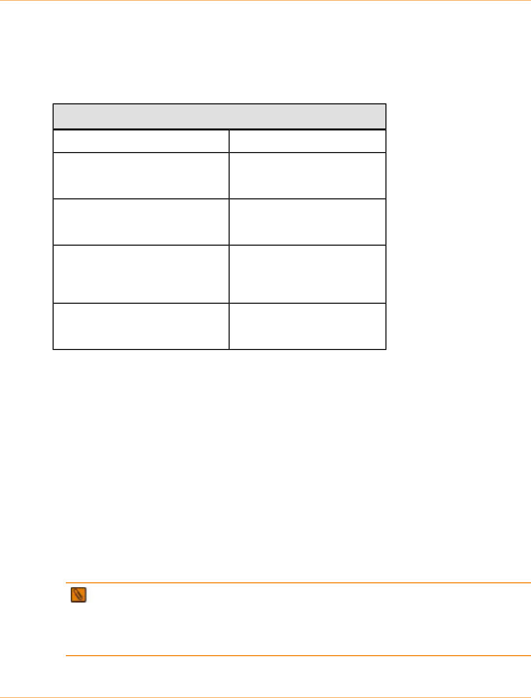
SANtricity_10.77 February 2011
LSI Corporation
- 751 -
Each dialog has context-sensitive help. Click Help to view the information applicable for that particular
dialog.
Postrequisite: A Preview of the Download Drive and ATA Translator Firmware Dialogs
Postrequisite: These dialogs appear as part of the firmware download.
Dialog Description
Download Drive and ATA Translator
Firmware Wizard – Introduction
Dialog
Provides information about
downloading the firmware to the
drives and the ATA translators.
Download Drive and ATA Translator
Firmware Wizard – Select Packages
Dialog
Lets you select the firmware
for the drives and the ATA
translators.
Download Drive and ATA Translator
Firmware Wizard – Select Services
Dialog
Lets you select the drives and
the ATA translators that you want
to update with the previously
selected firmware.
Download Drive and ATA Translator
Firmware Wizard – Download
Progress Dialog
Lets you monitor the progress of
the firmware download.
Procedure – Starting the Download Process
The Download Drive and ATA Translator Firmware - Introduction dialog is the first dialog of the Download
Drive and ATA Translator Firmware Wizard that downloads drive and Advanced Technology Attachment
(ATA) translator firmware to one or more drives and ATA translators in the storage array.
1. Review the information in the dialog to determine whether you are ready to download the firmware.
2. To continue with the firmware download process, click Next.
Procedure – Selecting the Drive and the ATA Translator Firmware
Use the Download Drive and ATA Translator Firmware - Select Packages dialog to select the drive and
Advanced Technology Attachment (ATA) translator firmware that you want to download.
1. To open the dialog to select the firmware, click Add, and navigate to the directory that contains the files
that you want to download.
2. Select up to four firmware files.
NOTE Selecting more than one firmware file to update the firmware of the same drive or ATA
translator might result in a file-conflict error. If a file-conflict error occurs, an error dialog appears. To
resolve this error, click OK, and remove all other firmware files except the one that you want to use for
updating the firmware of the drive or the ATA translator. To remove a firmware file, select the firmware file
in the Selected packages area, and click Remove.
3. To move to the next dialog, click Next.
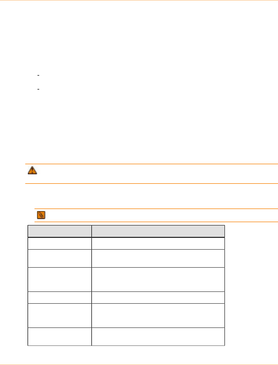
SANtricity_10.77 February 2011
LSI Corporation
- 752 -
Procedure – Updating the Firmware
Use the Download Drive and ATA Translator Firmware - Select Devices dialog to select the drives and the
Advanced Technology Attachment (ATA) translators that you want to update with the previously selected
firmware. The selected firmware for the drive appears in the Drive firmware information area. The selected
firmware for the ATA translator appears in the ATA translator firmware information area. If you must change
the firmware, click Back to return to the previous dialog.
1. Select the drives and ATA translators for which you want to download the firmware.
For one or more drives and ATA translators – In the Select devices area, select the drive and ATA
translator names.
For all compatible drives and ATA translators listed in the dialog – Click Select All.
2. Click Finish.
The Confirm Download dialog appears.
3. To start the firmware download, type yes in the text box.
4. Click OK.
Procedure – Monitoring the Progress of the Download
Use the Download Drive and ATA Translator Firmware - Progress dialog to monitor the progress of the drive
and the Advanced Technology Attachment (ATA) translator firmware download.
ATTENTION Possible loss of access to data or data loss – Stopping a firmware download might
result in drive unavailability or data loss.
1. Monitor the progress of the drive and the ATA translator firmware download. The progress and status of
each drive and each ATA translator that are participating in the download appears in the Progress column
of the Devices updated area and in the Progress summary area.
NOTE Each firmware download can take several minutes to complete.
Status Shown Definition
Scheduled The firmware download has not yet started.
In progress The firmware is being transferred to the drive or the
ATA translator.
Failed - partial The firmware was only partially transferred to the drive
before a problem prevented the rest of the file from
being transferred.
Failed - invalid state The firmware is not valid.
Failed - other The firmware could not be downloaded, possibly
because of a physical problem with the drive or the ATA
translator.
Not attempted The firmware was not downloaded. The download was
stopped before it could occur.

SANtricity_10.77 February 2011
LSI Corporation
- 753 -
Status Shown Definition
Successful The firmware was downloaded successfully.
NOTE A drive or an ATA translator does not show in the Devices updated area until a firmware
download is attempted or the firmware download process is stopped.
2. To stop the firmware download in progress, click Stop.
Any firmware downloads currently in progress are completed. Any drives or ATA translators that have
attempted firmware downloads show their individual status. Any remaining drives or ATA translators are
listed with a status of Not attempted.
3. If you want to save a text report of the progress summary, click Save As.
The report saves with a default .txt file extension. If you want to change the file extension or directory,
change the parameters in the Save As dialog.
4. Perform one of these actions:
To close the Drive Firmware Download Wizard – Click Close.
To start the wizard again – Click Transfer More.

SANtricity_10.77 February 2011
LSI Corporation
- 754 -
Remote Volume Mirroring Premium Feature
This topic describes how to obtain, enable, activate, and use the Remote Volume Mirroring premium feature
for SANtricity ES Storage Manager Version 10.75.

SANtricity_10.77 February 2011
LSI Corporation
- 755 -
About the Remote Volume Mirroring Premium Feature
The Remote Volume Mirroring premium feature is for online, real-time replication of data between two storage
arrays in separate locations. When you create a remote volume mirror, a mirrored volume pair is created.
The mirrored volume pair is created from two standard volumes, which are logical structures that are created
on a storage array for data storage. A standard volume can be a member of only one mirrored pair. The pair
consists of a primary volume at a local storage array and a secondary volume at a remote storage array.
If a disaster occurs, or if there is a catastrophic failure in the local storage array, you can promote the
secondary volume in the remote storage array to the role of primary volume to take over responsibility for
maintaining computer operations.
Primary Volumes and Secondary Volumes
Before you can create a remote volume mirror, you must enable and activate the Remote Volume Mirroring
premium feature on both the local storage array and the remote storage array. If a volume does not exist
on either the local storage array or the remote storage array, you must create the volumes. Both the local
storage array and the remote storage array show the primary volume and the secondary volume.
When both the primary volume and the secondary volume are available, you can create a mirrored pair.
When the remote volume mirror is first created, a full synchronization automatically occurs. The data from the
primary volume is copied completely to the secondary volume.
Mirror Repository Volumes
When you activate the Remote Volume Mirroring premium feature on the storage array, two mirror repository
volumes are created in one of the volume groups on the storage array. The controller stores mirroring
information on this volume, which includes information about remote writes that are not yet complete. You can
use this information to recover from controller resets and the accidental shutting down of storage arrays.
Capacity of the mirror repository volumes –
You can create the mirror repository volumes from the unconfigured free capacity of the volume
group.
You can create a new volume group and its member mirror repository volumes from the unconfigured
free capacity of the storage array.
The default names of the mirror repository volumes are Mirror Repository 1 and Mirror Repository 2.
You cannot change these names.
The activation process creates the mirror repository volumes with equal capacity. In a dual controller
storage array, the default capacity for both mirror repository volumes is either 128 MB or 256 MB.
You can neither increase the capacity nor decrease the capacity.
Mirror RAID levels of the mirror repository volumes – When you activate the Remote Volume
Mirroring premium feature and create the volume group and mirror repository volumes from the
unconfigured free capacity of the storage array, you select the RAID level for the volume group. However,
when you create the mirror repository volumes from an existing storage array, you do not select the RAID
level.
ATTENTION Potential loss of data – Because the data stored on the mirror repository volumes is
critical, do not create mirror repository volumes in an existing volume group that has RAID level 0. If you
create a new volume group for the mirror repository volumes, do not select RAID level 0.

SANtricity_10.77 February 2011
LSI Corporation
- 756 -
Using Other Premium Features with Remote Volume Mirroring
You can use the Remote Volume Mirroring premium feature with the following premium features that are
enabled and active on the primary storage array.
SANshare® Storage Partitioning – Go to Using the SANshare Storage Partitioning Premium Feature
with Remote Volume Mirroring.
Snapshot Volume – Go to Using the Snapshot Volume Premium Feature with Remote Volume Mirroring.
Volume Copy – Go to Using the Volume Copy Premium Feature with Remote Volume Mirroring.
Dynamic Volume Expansion (DVE) – Go to Using the Dynamic Volume Expansion Premium Feature
with Remote Volume Mirroring.
Using the SANshare Storage Partitioning Premium Feature with Remote
Volume Mirroring
The SANshare Storage Partitioning premium feature lets hosts share access to volumes in a storage array.
A storage partition is created when you define a collection of hosts (a host group) or a single host and then
define a volume-to-logical unit number (LUN) mapping. This mapping lets you define which host group or host
will have access to a particular volume in the storage array.
The storage partition definitions for the local storage array and the remote storage array are independent of
each other. If these definitions are put in place while the secondary volume is in a secondary role, it reduces
the administrative effort that is associated with site recovery if it becomes necessary to promote the volume to
a primary role.
Using the Snapshot Volume Premium Feature with Remote Volume Mirroring
A snapshot volume is a point-in-time image of a volume. Do not mount a snapshot volume on the same
server on which the primary volume is mounted in a remote volume mirror.
Using the Volume Copy Premium Feature with Remote Volume Mirroring
The Volume Copy premium feature copies data from a source volume to a target volume within the same
storage array.
A primary volume in a remote volume mirror can be either a source volume or a target volume in a
volume copy.
You can create a volume copy on the primary volume in a mirrored pair, but you cannot create a volume
copy on a secondary volume in a mirrored pair. You can make a copy of a secondary volume in two ways:
• Promote the secondary volume to the role of primary volume.
ATTENTION Potential loss of data access – If a role reversal is started while a volume copy
is in progress, the volume copy fails and cannot be restarted.
• Create a snapshot volume of the secondary volume, and then perform a volume copy on the
snapshot volume.

SANtricity_10.77 February 2011
LSI Corporation
- 757 -
Using the Dynamic Volume Expansion Premium Feature with Remote Volume
Mirroring
Dynamic Volume Expansion (DVE) increases the capacity of a volume. The increased capacity is achieved
by using the free capacity that is available on the volume group of the standard volume or the snapshot
repository volume.
Performing a DVE operation does not interrupt access to data on volume groups, volumes, or drives.
You can perform a DVE operation on a primary volume or a secondary volume of a mirrored pair. However,
you cannot perform a DVE operation on a mirror repository volume.
NOTE To perform a DVE operation, the remote volume mirror must be in an Optimal status. The
Properties pane in Logical view shows the status of a volume.

SANtricity_10.77 February 2011
LSI Corporation
- 758 -
Switching Zoning Configurations for Remote Volume Mirroring
Because of possible restrictions at the host level, the Remote Volume Mirroring configurations contain Fibre
Channel switches. These Fibre Channel switches are zoned so that a single host adapter can access only
one controller in a storage array. Additionally, all configurations use a separate zone for the ports that are
reserved for the Remote Volume Mirroring premium feature.
IMPORTANT Do not zone the uplink port (E_port) that connects (cascades) switches within a fabric.
Switch zoning configurations are typically set up by using the switch management software that is provided
by the manufacturer of the Fibre Channel switch. This software should have been included with the materials
that were provided when the switch was purchased.
When two or more Fibre Channel switches are cascaded together, the switch management software
combines the ports for all of the switches that are linked. For example, if two 16-port Fibre Channel switches
are cascaded with a physical connection using a Fibre Channel cable, the switch management software
shows ports 0 through 31 participating in the fabric rather than two switches each with ports 0 through 15.
Therefore, a zone that is created containing any of these ports can exist on multiple cascaded switches.

SANtricity_10.77 February 2011
LSI Corporation
- 759 -
Journaling File Systems and Remote Volume Mirroring
When you are using a journaling file system, you cannot gain read-only access to a remote volume. A
journaling file system does not let you mount the remote volume in Windows (NTFS); however, you can
mount the snapshot of the remote volume.

SANtricity_10.77 February 2011
LSI Corporation
- 760 -
Prerequisites for Creating a Remote Volume Mirror
Make sure the following prerequisites have been met before you create a remote volume mirror between two
storage arrays:
The Remote Volume Mirroring premium feature has been activated. For more information about enabling
and activating the premium feature, go to Activating the Remote Volume Mirroring Premium Feature.
The local storage array contains two mirror repository volumes.
The local storage array contains the primary volume, and the remote storage array contains the
secondary volume. If either volume does not exist, you must create it before you can create the remote
volume mirror.
The secondary volume meets these requirements:
The RAID level of the secondary volume can be different from the RAID level of the primary volume.
The capacity of the secondary volume must be equal to or greater than the capacity of the primary
volume.

SANtricity_10.77 February 2011
LSI Corporation
- 761 -
Obtaining the Remote Volume Mirroring Premium Feature Key
Before you can create a remote volume mirror, you must obtain the Remote Volume Mirroring premium
feature key, enable the premium feature, and activate it. If you have purchased the Remote Volume Mirroring
premium feature, contact your Customer and Technical Support representative to obtain the premium feature
key. The Customer and Technical Support representative will need the 30-character string in the Feature
Enable Identifier field in the Premium Features and Feature Pack Information window.
1. In the Array Management Window, select Storage Array >> Premium Features.
The Premium Features and Feature Pack Information window opens. The Premium Features list shows
the premium features that are installed on the storage array.
2. Find and record the 30-character string in the Feature Enable Identifier field.
The Customer and Technical Support representative uses the Feature Enable Identifier to generate the
premium feature key.
3. Contact the Customer and Technical Support representative to obtain the premium feature key.
4. Copy the Remote Volume Mirroring premium feature key to a directory from which you can retrieve it.
The default directory is C:\\Documents and Settings\My Documents.
NOTE You can enable and activate the Remote Volume Mirroring premium feature now, or you can
wait until you are ready to create a remote volume mirror.

SANtricity_10.77 February 2011
LSI Corporation
- 762 -
Enabling the Remote Volume Mirroring Premium Feature
Before you can create a remote volume mirror, you must obtain the premium feature key, enable the premium
feature, and activate it. You do not have to activate the Remote Volume Mirroring premium feature until you
are ready to use it.
1. On the menu bar in the Array Management Window, select Storage Array >> Premium Features.
The Premium Features and Features Pack window opens and shows a list of premium features installed
on the storage array.
2. Select Remote Volume Mirroring, and click Enable.
The My Documents directory appears.
3. Is the Remote Volume Mirroring premium feature key file in the My Documents directory?
Yes – Go to step 4.
No – Navigate to the appropriate directory, and go to step 4.
4. Select the Remote Volume Mirroring premium feature key file, and click OK.
The Enable Premium Feature confirmation message appears.
5. Click Yes.
The Premium Features installed on storage array list shows the Remote Volume Mirroring premium
features as enabled but deactivated.

SANtricity_10.77 February 2011
LSI Corporation
- 763 -
Activating the Remote Volume Mirroring Premium Feature
Before you can create a remote volume mirror, you must obtain the Remote Volume Mirroring premium
feature key, enable the premium feature, and activate it. You do not have to activate the Remote Volume
Mirroring premium feature until you are ready to use it.
When you activate the Remote Volume Mirroring premium feature, two default mirror repository volumes are
created.
The default names of the mirror repositories are Mirror repository 1, which is owned by controller A, and
Mirror repository 2, which is owned by controller B. You cannot change the default names of the mirror
repository volumes.
The mirror repository volumes have either 128-MB or 256-MB volume capacity. You cannot change the
default capacities of the mirror repository volumes.
To activate the Remote Volume Mirroring premium feature, perform these steps:
1. On the menu bar in the Array Management Window, select Storage Array >> Remote Volume
Mirroring >> Activate.
The Introduction (Activate Remote Volume Mirroring) wizard appears.
2. Select how to assign volume capacity and where to place the mirror repository volumes.
You can select how to assign volume capacity and where to place the mirror repository volumes in two
ways:
From the free capacity of existing volume groups – Go to Creating Mirror Repository Volumes in
an Existing Volume Group.
From the unconfigured free capacity of the storage array – Go to Creating a Volume Group and
Mirror Repository Volumes from the Unconfigured Capacity of the Storage Array.
Creating a Volume Group and Mirror Repository Volumes from the
Unconfigured Capacity of the Storage Array
You can use the total unconfigured capacity of the storage array, or you can use the unconfigured capacity of
the unassigned drives in the storage array.
1. In the Introduction (Activate Remote Volume Mirroring) wizard, select Unconfigured capacity (create a
new volume group), and click Next.
The Activate Remote Volume Mirroring - Create Volume Group wizard appears.
2. In the Volume Group Name text box, type a unique name for the volume group.
3. Select one of the drive selection methods.
Automatic – The storage management software generates a list of available capacity and drive
options for each available RAID level.
Manual – The storage management software generates a list of unselected drives.
4. Click Next.
If you selected Automatic, an empty Select Capacity table and a drop-down list of available RAID
levels appear. Go to step 5.
If you selected Manual, a populated Unselected Drives table, an empty Selected Drives table, and a
drop-down list of available RAID levels appears.
5. On the Select RAID level drop-down list, select the RAID level for the volume group.
The Select capacity table shows the available volumes for the RAID level.

SANtricity_10.77 February 2011
LSI Corporation
- 764 -
6. In the Select capacity table, select the drives and capacities for the new volume group, and click Next.
The Preview (Activate Remote Volume Mirroring) wizard appears.
7. Click Finish.
The Completed (Activate Remote Volume Mirroring) message appears.
8. Click OK.
The Remote Volume Mirroring premium feature is active, and the Logical pane shows the new volume
group and the two member mirror repository volumes.
Creating Mirror Repository Volumes in an Existing Volume Group
The capacity of the mirror repository volumes comes from the free capacity in the existing volume group.
By default, the mirror repository volumes each have either 128-MB or 256-MB capacity. You cannot create
the mirror repository volumes on a volume group with insufficient capacity. You cannot change the default
capacities of the mirror repository volumes.
1. In the Introduction (Activate Remote Volume Mirroring) wizard, select Free capacity on existing volume
groups.
2. From the list of available volume groups, select a volume group in which to place the mirror repository
volumes, and click Next.
The Preview (Activate Remote Volume Mirroring) wizard appears.
3. Click Finish.
The Completed (Activate Remote Volume Mirroring) message appears.
4. Click OK.
The Remote Volume Mirroring premium feature is active, and the Logical pane shows the two mirror
repository volumes in the volume group.

SANtricity_10.77 February 2011
LSI Corporation
- 765 -
Creating a Remote Volume Mirror
Before you create a remote volume mirror, verify that all of the prerequisites have been met. For more
information, go to Prerequisites for Creating a Remote Volume Mirror.
1. Open the Array Management Windows of both the local storage array and the remote storage array.
2. Verify that the Remote Volume Mirroring premium feature has been activated on both the local storage
array and the remote storage array
3. In the Array Management Window of the local storage array, select the Logical tab.
4. In the Logical pane of the local storage array, select the primary volume for the remote volume mirror.
5. On the menu bar in the Array Management Window, select Volume >> Remote Volume Mirroring >>
Create.
The Introduction (Activate Remote Volume Mirroring) wizard appears.
6. Click Next.
The Select Storage Array (Create Remote Volume Mirror) dialog appears. The Storage Arrays list shows
the remote storage arrays.
7. Select a storage array, and click Next.
The Select Secondary Volume (Create Remote Volume Mirror) wizard appears.
8. Go to Selecting the Secondary Volume.
Selecting the Secondary Volume
Prerequisite: Before you select the secondary volume, perform these tasks on the secondary volume
candidate:
1. Back up all data to the volume.
2. Stop all I/O activity to the volume.
3. Unmount the file system of the volume.
After you have selected the remote storage array and the primary volume, perform these steps:
1. In the Select Secondary Volume (Create Remote Volume Mirror) wizard, select the secondary volume.
IMPORTANT The secondary volume must have a capacity equal to or greater than the capacity of
the primary volume.
2. Click Next.
The Set Write Mode (Create Remote Volume Mirror) wizard appears.
3. Go to Setting the Write Mode.
Setting the Write Mode
The secondary host ports on the storage arrays are reserved for data synchronization between the primary
volume and the secondary volume in a mirrored volume pair. You can set the remote volume mirror to write
either synchronously or asynchronously.
SANtricity_10.77 February 2011
LSI Corporation
- 766 -
Synchronous mode – In the synchronous mode, the controller on the primary volume on the storage
array sends an I/O completion message back to the host storage array after the data has been
successfully copied to the secondary storage array. The synchronous mode is the preferred mode of
operation because it offers the best chance of full data recovery from the secondary storage array in the
event of a disaster; however, the data recovery can degrade the I/O performance of the host.
Asynchronous mode – In the asynchronous mode, the controller on the primary storage array sends an
I/O completion message to the host storage array before the data has been successfully copied to the
secondary storage array. The asynchronous mode offers faster host I/O performance; however, it does
not guarantee that data was successfully written to the secondary volume or that the write requests were
completed on the secondary volume in the same order they were initiated.
NOTE If you select the asynchronous mode, select whether to add the secondary volume to a write
consistency group.
Add to write consistency group option – A write consistency group makes sure that the secondary
volume receives write requests in the sequence initiated by the controller of the primary volume. You
have the option of adding the secondary volume to a write consistency group.
To set the write mode for the remote volume mirror, perform these steps:
1. In the Set Write Mode (Create Remote Volume Mirror) wizard, select either the Synchronous mode or
the Asynchronous mode.
2. Click Next.
The Select Synchronization Settings (Create Remote Volume Mirror) wizard appears.
3. Go to Setting the Synchronization Priority and the Synchronization Method.
Setting the Synchronization Priority and the Synchronization Method
You can set the priority for allocating system resources to synchronizing the remote volume mirror. When a
remote volume mirror synchronizes, system resources are allocated to the process.
Higher synchronization priorities allocate more resources to the process and might degrade I/O
performance.
Lower synchronization priorities allocate fewer resources to the process and have less impact on normal
I/O performance.
After you set the initial synchronization priority and synchronization method, you can change it. For more
information about resynchronizing volumes in a remote volume mirror, go to Resynchronizing Volumes in a
Remote Volume Mirror.
1. In the Select Synchronization Settings (Create Remote Volume Mirror) wizard, select the synchronization
priority on the Priority slide bar.
2. Select either Manual resynchronization or Automatic resynchronization.
Automatic resynchronization – Resynchronization starts immediately after communication is
restored between unsynchronized mirrored volumes.
Manual resynchronization– The mirrored pair must be manually resynchronized each time
communication is restored between unsynchronized mirrored volumes.
3. Click Next.
The Preview (Create Remote Volume Mirror) wizard appears.
4. Go to Completing the Remote Volume Mirror.

SANtricity_10.77 February 2011
LSI Corporation
- 767 -
Completing the Remote Volume Mirror
After you have selected the synchronization settings, perform these steps to complete the remote volume
mirror.
1. In the text box in the Preview (Create Remote Volume Mirror) wizard, type Yes, and click Finish.
If other volumes on the remote storage array meet the criteria to be a secondary volume, the Creation
Successful (Create Remote Volume Mirror) confirmation message appears. Go to step 2.
If no other volumes on the remote storage array meet the criteria to be a secondary volume, the
Completed (Create Remote Volume Mirror) message appears. Go to step 3.
2. Are you creating another remote volume mirror?
Yes – Click Yes. The Select Primary Volume (Create Remote Volume Mirror) dialog appears. To
continue creating another remote volume mirror, go to Creating a Remote Volume Mirror.
No – Click No. The Completed (Create Remote Volume Mirror) message appears. Go to step 3.
3. On the Completed (Create Remote Volume Mirror) message, click OK.
In the Array Management Windows of both the local storage array and the remote storage array,
the Logical panes show the mirrored volume pairs as members of their volume groups. In the Array
Management Window of the local storage array, the Properties pane shows the Mirror status as
Synchronizing, and the Synchronization - Progress bar shows the estimated time to completion.
To view detailed information about the volumes in a remote volume mirror, go to either Viewing
Information about a Remote Volume Mirror or a Mirror Repository Volume in the Properties Pane or
Viewing Information about a Remote Volume Mirror or a Mirror Repository Volume in the Storage
Array Profile.
SANtricity_10.77 February 2011
LSI Corporation
- 768 -
Controller Ownership/Preferred Path in a Remote Volume Mirror
During a remote volume mirroring operation, the same controller must own both the primary volume and the
secondary volume. If both volumes do not have the same preferred controller when a remote volume mirror
starts, the ownership of the secondary volume is automatically transferred to the preferred controller of the
primary volume.
When the remote volume mirror is completed or is stopped, ownership of the secondary volume is
restored to its preferred controller.
If ownership of the primary volume is changed during the remote volume mirror, ownership of the
secondary volume is also changed.
If a controller fails under any of the following conditions, you must manually change controller ownership to
the alternate controller to allow the remote volume mirror to finish.
A remote volume mirror has a status of In Progress.
The preferred controller of the primary volume fails.
The ownership transfer does not occur automatically during a failover.
ATTENTION Possible loss of data – Verify that either the volumes are not in use or a multi-path
driver is installed on the host. If you change the controller ownership/preferred path while an application is
using one of the volumes, I/O activity is disrupted, and I/O errors occur unless a multi-path host is installed on
the host. If a multi-path driver is not installed on the host, or if the multi-path driver is not the RDAC multi-path
driver, you must make operating system-specific modifications to make sure that the moved volume groups
can be accessed on the new path.
To change the controller ownership/preferred path setting, go to Changing the Controller Ownership/Preferred
Path for a Remote Volume Mirror.

SANtricity_10.77 February 2011
LSI Corporation
- 769 -
Changing the Controller Ownership/Preferred Path for a Remote
Volume Mirror
1. In the Array Management Window, select the Logical tab.
2. In the Logical pane, right-click the the volume for which to change the controller ownership and preferred
path.
3. Select Change >> Ownership/Preferred Path.
4. Select the new controller.
NOTE A dot identifies the current path and current controller. When the current path and current
controller are not the preferred path and preferred controller, you can select them.
The Confirm Change Ownership/Preferred Path message appears.
5. Click Yes.

SANtricity_10.77 February 2011
LSI Corporation
- 770 -
Viewing Information about a Remote Volume Mirror or a Mirror
Repository Volume in the Storage Array Profile
The storage array profile shows the most detailed information about the components of a remote volume
mirror and the mirror repository volumes. You can view detailed information about individual volumes in a
remote volume mirror and paired volumes in a remote volume mirror. You can view detailed information about
the mirror repository volumes in a storage array. You can also save the storage array profile information as a
text file.
You can also view information about a remote volume mirror in the Properties pane under the Logical
tab. For more information, go to Viewing Information about a Remote Volume Mirror or a Mirror Repository
Volume in the Properties Pane.
You can save all of the information or specific information under the Repositories tab or the Mirrors tab.
1. In the Array Management Window of either the local storage array or the remote storage array, select the
Summary tab.
2. In the Status area, click Storage Array Profile.
The storage array profile opens.
3. Select the Volumes tab.
4. Select either the Mirrors tab or the Repositories tab.
The Profile for Storage array page appears.
5. Perform either of these actions:
To return to the Array Management Window without saving the information – Click Close.
To save the information – Click Save As, and go to step 6.
6. In the Section Selection area in the Save Profile window, perform either of these actions:
Select All Sections, and go to step 7.
Select Select Sections, select each section for which to save the information, and go to step 7.
7. To save the file, perform either of these actions.
Save the file in the default My Documents directory – Go to step 8.
Save the file in another directory – On the Look in drop-down list, select a directory in which to
save the file, and go to step 8.
8. In the File name text box, type a name for the file, and click Save.
The file is saved as a <Profile date> *.txt file.

SANtricity_10.77 February 2011
LSI Corporation
- 771 -
Viewing Information about a Remote Volume Mirror or a Mirror
Repository Volume in the Properties Pane
The Properties pane shows of the physical and logical characteristics of a single volume in a mirrored pair or
a single mirror repository volume. The Properties pane is view-only. You can view more detailed information
or save the information in Storage Array Profile under the Summary tab. For more information, go to
Viewing Information about a Remote Volume Mirror or a Mirror Repository Volume in the Storage Array
Profile.
1. In the Array Management Window, select the Logical tab.
2. In the Logical pane, select either the primary volume or the secondary volume in the mirrored pair.
The Properties pane shows the properties for the selected volume. The Mirror status under Mirroring
properties shows the synchronization status of the mirrored pair. When the primary and secondary
volumes are synchronizing, the Mirror status shows a synchronizing icon.

SANtricity_10.77 February 2011
LSI Corporation
- 772 -
Viewing the Logical Elements of the Secondary Volume in a
Remote Volume Mirror
1. In the Array Management Window of local storage array, select the Logical tab.
2. In the Logical pane, right-click the secondary volume of the remote volume mirror.
3. Select View Associated Logical Elements.
The View Associated Logical Elements pop-up appears and shows these logical elements:
The primary volume and secondary volume and their locations.
The mirror repository volumes and their locations.

SANtricity_10.77 February 2011
LSI Corporation
- 773 -
Viewing the Physical Components or the Logical Elements of the
Primary Volume in a Remote Volume Mirror
1. In the Array Management Window of the storage array that contains the primary volume, select the
Logical tab.
2. In the Logical pane, right-click the primary volume, and perform either of these actions:
View the logical elements of the primary volume – Select View >> Associated Logical
Elements. The View Associated Logical Elements pop-up appears and shows visual representations
of these elements: the primary volume and the secondary volume in the remote volume mirror and
their locations and the mirror repository volumes in the storage array and their locations.
View the physical components of the primary volume – In the Properties pane, click View
Associated Physical Components. The View Associated Physical Components pop-up appears
and shows a visual representation of the primary volume in the remote volume mirror.

SANtricity_10.77 February 2011
LSI Corporation
- 774 -
Changing the Write Mode and the Consistency Group
Membership in a Remote Volume Mirror
The write mode of a remote volume mirror is selected when it is created. When you change the write mode
in an remote volume mirror, you can also change the secondary volume’s membership in a write consistency
group. For more information about write modes and write consistency groups, go to Setting the Write Mode.
IMPORTANT Before you change the write mode, verify the current write mode to make sure that the
change you are making is to the other write mode.
1. In the Array Management Window of the storage array that contains the primary volume, select the
Logical tab.
2. In the Logical pane, right-click the primary volume of the mirrored pair.
3. Select Change >> Write Mode.
The Change Write Mode dialog appears. The Mirrored pairs table shows all mirrored pairs in both the
local storage array and the remote storage array.
4. Select one or more mirrored pairs. To select all mirrored pairs, click Select All.
5. Select either the synchronous write mode or the asynchronous write mode.
6. Are you adding the secondary volume of the mirrored pair to a write consistency group?
Yes – Select the Add to consistency group check box.
No – Go to step 7.
7. Click OK.
The Change Write Mode confirmation message appears.
8. Click Yes.
The Mirroring properties section on the Properties pane in the Array Management Window for the local
storage array shows the following information:
The mirror status is Synchronized.
The write mode is either synchronous or asynchronous.
The secondary volume is either write consistent or not write consistent.
The Resynchronization method is either manual or automatic.

SANtricity_10.77 February 2011
LSI Corporation
- 775 -
Resynchronizing Volumes in a Remote Volume Mirror
There are two resynchronization methods:
Manual resynchronization – Go to Manually Resynchronizing Volumes in a Remote Volume Mirror.
Automatic resynchronization – Go to Automatically Resynchronizing Volumes in a Remote Volume
Mirror.
For more information about synchronization and resynchronization in remote volume mirrors, go to these
topics:
Normally Synchronized Volumes in a Remote Volume Mirror
Unsynchronized Volumes in a Remote Volume Mirror
Setting the Synchronization Priority and the Synchronization Method
Changing the Synchronization Priority and the Synchronization Method of a Remote Volume Mirror
Resynchronizing Volumes in a Remote Volume Mirror
You might need to periodically test the communication between the primary volume and the secondary
volume in a remote volume mirror, especially after resynchronizing the volumes. For more information, go to
Testing Communication Between the Primary Volume and the Secondary Volume in a Remote Volume Mirror.
Changing the Synchronization Priority and the Synchronization Method of a
Remote Volume Mirror
The synchronization priority defines how much processing time and resources are allocated to synchronizing
the primary volume and the secondary volume of a remote volume mirror relative to system performance.
Increasing the synchronization priority of a remote volume mirror might degrade system performance. You
can set the synchronization priority for a remote volume mirror at any time. Synchronization priorities can
affect these operations:
Performing a copyback
Performing a Dynamic Volume Expansion (DVE)
Reconstructing a volume
Initializing a volume
Changing the segment size of a volume
Defragmenting a volume group
Adding free capacity to a volume group
Changing the RAID level of a volume group
To change the synchronization priority and the synchronization method after a remote volume mirror was
created, perform these steps:
1. In the Array Management Window of the storage array that contains the primary volume of the mirrored
pair, right-click the Logical tab.
2. Select Change >> Synchronization Settings.
The Change Synchronization Settings dialog appears.
3. In the Mirrored pairs table, select the primary volume and the remote volume for which to change the
synchronization priority. To select all volumes, click Select All.

SANtricity_10.77 February 2011
LSI Corporation
- 776 -
4. On the Select Synchronization Priority slide bar, select the synchronization priority for the mirrored pair.
5. Select either Manual resynchronization or Automatic resynchronization.
Automatic resynchronization – Resynchronization starts immediately after communication is
restored between unsynchronized mirrored volumes.
Manual resynchronization – The mirrored pair must be manually resynchronized each time
communication is restored between unsynchronized mirrored volumes.
6. Click OK.
The Change Synchronization Settings confirmation message appears.
7. Click Yes.
The Change Synchronization Priority - Progress bar shows the progress of the resynchronization priority
change process for a remote volume mirror.
8. Click OK.
Normally Synchronized Volumes in a Remote Volume Mirror
In a normally synchronized remote volume mirror, controller owners manage the transfer of data from the
primary volume to the secondary volume. In a normal remote volume mirror, these events happen:
1. The primary volume receives a write request from a host.
2. The controller owner on the storage array logs information about the write operation to a mirror repository
volume in the storage array.
3. The controller owner writes the data to the primary volume.
4. The controller owner starts a data transfer operation to the secondary volume on the secondary storage
array.
The communication between a primary volume and a secondary volume can be either suspended or become
unsynchronized. If the communication between the primary volume and the secondary volume breaks, these
events happen:
1. The status of the mirrored pair changes to Unsynchronized.
2. A Needs Attention status appears for the storage array.
3. Data is written to the primary volume.
4. Write requests to the primary volume are logged.
5. The controller owner sends an I/O completion to the host sending the write request. Although the host
can continue to send write requests to the primary volume, no data transfer takes place to the secondary
volume. Writes to the secondary volume are suspended pending the restoration of communications
between the primary volume and the secondary volume.
When connectivity is restored between the primary volume and the secondary volume, the mirrored pair is
ready to be resynchronized.
NOTE When the primary volume and the secondary volume are resynchronized, only data that has
changed on the primary volume after the break in communication is transferred to the secondary volume.
ATTENTION Possible loss of data – If communication is broken after resynchronization starts
between the primary storage array and the secondary storage array, the new data might mix with the old data
on the secondary volume and render the data unusable in a disaster recovery situation.
SANtricity_10.77 February 2011
LSI Corporation
- 777 -
Unsynchronized Volumes in a Remote Volume Mirror
The communication between a primary volume and a secondary volume can either be suspended or become
unsynchronized. If the communication between the primary volume and the secondary volume breaks, these
events occur:
1. The status of the mirrored pair changes to Unsynchronized.
2. A Needs Attention status appears for the storage array.
3. Data is written to the primary volume.
4. Write requests to the primary volume are logged.
5. The controller owner sends an I/O completion to the host sending the write request. Although the host
can continue to send write requests to the primary volume, no data transfer takes place to the secondary
volume. Writes to the secondary volume are suspended pending the restoration of communications
between the primary volume and the secondary volume.
When connectivity is restored between the primary volume and the secondary volume, the mirrored pair is
ready to be resynchronized.
NOTE When the primary volume and the secondary volume are resynchronized, only data that has
changed on the primary volume after the break in communication is transferred to the secondary volume.
ATTENTION Possible loss of data – If communication is broken after resynchronization starts
between the primary storage array and the secondary storage array, the new data might mix with the old data
on the secondary volume and render the data unusable in a disaster recovery situation.
For more information about synchronization and resynchronization in remote volume mirrors, go to these
topics:
Normally Synchronized Volumes in a Remote Volume Mirror
Setting the Synchronization Priority and the Synchronization Method
Changing the Synchronization Priority and the Synchronization Method of a Remote Volume Mirror
Resynchronizing Volumes in a Remote Volume Mirror
Manually Resynchronizing Volumes in a Remote Volume Mirror
Automatically Resynchronizing Volumes in a Remote Volume Mirror
You might need to periodically test the communication between the primary volume and the secondary
volume in a remote volume mirror, especially after resynchronizing the volumes. For more information, go to
Testing Communication Between the Primary Volume and the Secondary Volume in a Remote Volume Mirror.
Automatically Resynchronizing Volumes in a Remote Volume Mirror
When automatic resynchronization is selected, the controller owner of the primary volume automatically
starts resynchronizing the data on the remote volume mirror pair immediately after communication is restored
between the primary volume and the remote volume.
ATTENTION Possible loss of data – If a resynchronization is interrupted while in progress, another
resynchronization automatically starts immediately after communication is restored between the primary
volume and the remote volume, which could destroy data integrity.

SANtricity_10.77 February 2011
LSI Corporation
- 778 -
With automatic resynchronization, you cannot add a secondary volume to a write consistency group;
therefore, write consistency during the resynchronization process is not preserved. The write order is not
consistent until the entire write consistency group achieves Optimal status. When the write consistency group
is in an Optimal state, consistency is achieved.
For more information about synchronization and resynchronization go to these topics:
Normally Synchronized Volumes in a Remote Volume Mirror
Unsynchronized Volumes in a Remote Volume Mirror
Setting the Synchronization Priority and the Synchronization Method
Changing the Synchronization Priority and the Synchronization Method of a Remote Volume Mirror
Resynchronizing Volumes in a Remote Volume Mirror
Manually Resynchronizing Volumes in a Remote Volume Mirror
You might need to periodically test the communication between the primary volume and the secondary
volume in a remote volume mirror, especially after resynchronizing the volumes. For more information, go
to Testing Communication Between the Primary Volume and the Secondary Volume in a Remote Volume
Mirror.
Manually Resynchronizing Volumes in a Remote Volume Mirror
When manual resynchronization is selected, you must manually resynchronize and resume the data transfer
on a remote volume mirror after communication is restored between the primary volume and the remote
volume. Manual resynchronization is the recommended setting for all remote volume mirrors for three
reasons:
You determine when resynchronization starts, so you can manage the process to mitigate the potential
impact on I/O performance.
In a disaster recovery situation, manual resynchronization offers the best chance of retrieving valid data.
When the secondary volume is in a write consistency group, manual resynchronization preserves the
write order.
For more information about synchronization and resynchronization in remote volume mirrors, go to these
topics:
Normally Synchronized Volumes in a Remote Volume Mirror
Unsynchronized Volumes in a Remote Volume Mirror
Setting the Synchronization Priority and the Synchronization Method
Changing the Synchronization Priority and the Synchronization Method of a Remote Volume Mirror
Resynchronizing Volumes in a Remote Volume Mirror
Automatically Resynchronizing Volumes in a Remote Volume Mirror
You might need to periodically test the communication between the primary volume and the secondary
volume in a remote volume mirror, especially after resynchronizing the volumes. For more information, go to
Testing Communication Between the Primary Volume and the Secondary Volume in a Remote Volume Mirror.
SANtricity_10.77 February 2011
LSI Corporation
- 779 -
Reversing the Roles of the Primary Volume and the Secondary
Volume in a Remote Volume Mirror
If the primary volume in a remote volume mirror fails in a disaster situation, you can reverse the roles of the
primary volume and the secondary volume to transfer the data back to the restored volume. Reversing the
roles promotes the secondary volume to the role of primary volume and demotes the primary volume to the
role of secondary volume in a remote volume mirror.
ATTENTION Potential loss of data access – If you try to reverse roles between the secondary
volume and the primary volume while a volume copy is in progress, the role reversal succeeds, but the
volume copy fails and cannot be restarted.
IMPORTANT You cannot perform a volume copy on a secondary volume in a remote volume mirror.
To create a volume copy of a secondary volume, you must reverse the roles of the secondary volume and the
primary volume, and then perform the volume copy on the new primary volume.
NOTE While a remote volume mirror is synchronizing, you cannot perform a volume copy on either the
primary volume or the secondary volume.
NOTE If you reverse roles between a secondary volume with less capacity than the primary volume
has, the role reversal succeeds, but the usable capacity of the new secondary volume (the original primary
volume) equals the total capacity of the new primary volume (the original secondary volume).

SANtricity_10.77 February 2011
LSI Corporation
- 780 -
Promoting the Secondary Volume or Demoting the Primary
Volume in a Remote Volume Mirror
You can either promote the secondary volume to the role of primary volume, or you can demote the primary
volume to the role of secondary volume.
1. In the Array Management Window of the storage array that contains the volume you are changing, click
the Logical tab.
2. Right-click the volume you are changing.
NOTE The primary volume can be on the remote storage array, and the secondary volume can be on
the local storage array.
Promoting the secondary volume to the role of primary volume – Select Change >> Role to
Primary. The Change to Primary message appears. Click Yes. The roles of the primary volume and
the secondary volume are reversed.
Demoting the primary volume to the role of secondary volume – Select Change >> Role to
Secondary. The Change to Secondary message appears. Click Yes. The roles of the primary volume
and the secondary volume are reversed.

SANtricity_10.77 February 2011
LSI Corporation
- 781 -
Suspending a Remote Volume Mirror
1. In the Array Management Window of the storage array with the primary volume, select the Logical tab.
2. In the Logical pane, right-click the primary volume of a mirrored pair, and select Suspend Mirroring.
The Suspend Mirrored Pair dialog appears. The Mirrored pairs table shows all mirrored pairs in the local
storage array and in the remote storage array.
3. Select one or more mirrored pairs to suspend. To select all mirrored pairs, click Select All.
4. Click Suspend.
The Suspend Mirror Relationship - Confirmation message appears.
5. In the text box, type Yes, and click OK.
The Suspend Mirrored Pair - Progress bar shows the progress of the suspension.
6. Click OK.
The Properties pane in the Array Management Window that contains the suspended primary volume
shows the Mirror status as Suspended. The Suspended icon appears next to the primary volume icon and
the secondary volume icon in the Logical pane in the Array Management Window.
SANtricity_10.77 February 2011
LSI Corporation
- 782 -
About Resumed Remote Volume Mirrors
When a remote volume mirror is suspended, data continues to read to the primary volume, but the data is
not written to the secondary volume. Writes to the primary volume are persistently logged in to the mirror
repository volumes.
After communications are restored in a remote volume mirror, data transfer between the primary volume and
the secondary volume must be resynchronized.
Automatic resynchronization – The data transfer automatically starts immediately after the volumes are
resynchronized.
Manual resynchronization – You must manually resume the remote volume mirror to restart the data
transfer. A suspended remote volume mirror stays in a Suspended status until it is manually resumed.
After the remote volume mirror resumes, data is automatically written to the secondary volume. Only the
regions of the primary volume that changed since the mirrored pair was suspended are written to the
secondary volume
ATTENTION Possible loss of data access – When you resume a remote volume mirror when either
the primary volume or the secondary volume is a member of a write consistency group, all other suspended
remote volume mirrors for mirrored pairs in the write consistency group also resume.
NOTE When the write mode is synchronous, you do not need to resynchronize the primary volume and
the secondary volume after you resume the remote volume mirror.

SANtricity_10.77 February 2011
LSI Corporation
- 783 -
Resuming a Remote Volume Mirror
1. In the Array Management Window of the storage array with the primary volume, select the Logical tab.
2. In the Logical pane, right-click the primary volume of the mirrored pair, and select Resume Mirroring.
The Resume Mirrored Pair dialog appears. The Mirrored pairs table shows all suspended mirrored pairs
in the local storage array and in the remote storage array.
3. Select one or more mirrored pairs. To select all mirrored pairs, click Select All.
4. Click Resume.
The Resume Mirrored Pair - Confirmation message appears.
5. Click Yes.
The remote volume mirror resumes. The Properties panes in the Array Management Windows for the
local storage array and the remote storage array show the mirror status as Synchronized for both the
primary volume and the secondary volume.
SANtricity_10.77 February 2011
LSI Corporation
- 784 -
Testing Communication Between the Primary Volume and the
Secondary Volume in a Remote Volume Mirror
You might need to test the communication between the primary volume and the secondary volume in a
remote volume mirror. This situation applies especially when the resynchronization method is manual or
during a disaster recovery scenario. For more information about synchronization and resynchronization in
remote volume mirrors, go to these topics:
Normally Synchronized Volumes in a Remote Volume Mirror
Unsynchronized Volumes in a Remote Volume Mirror
Setting the Synchronization Priority and the Synchronization Method
Changing the Synchronization Priority and the Synchronization Method of a Remote Volume Mirror
Resynchronizing Volumes in a Remote Volume Mirror
Automatically Resynchronizing Volumes in a Remote Volume Mirror
To test the communication between volumes in a remote volume mirror, perform these steps:
1. In the Array Managment Window of either the primary volume or the secondary volume, select the
Logical tab.
2. In the Logical pane, right-click the volume.
3. Select Test Mirror Communication.
The Mirror Communication Test Progress message appears.
IMPORTANT This process might take a while to complete.
SANtricity_10.77 February 2011
LSI Corporation
- 785 -
Deleting a Volume from a Mirrored Pair in a Storage Array
You can delete either a primary volume, a secondary volume, or both volumes from a mirrored pair in a
storage array.
ATTENTION Do not remove a mirror relationship to back up a mirrored volume. To perform backups
of either the primary volume or the secondary volume, suspend the remote volume mirror so that the mirror
relationship is not broken.
Deleting a Primary Volume in a Mirrored Pair from a Storage Array
ATTENTION Possible loss of data – Depending on which premium features are enabled on the
storage array, deleting a primary volume might delete all associated volumes, which can result in the
permanent loss of the data on those volumes.
IMPORTANT You cannot delete a primary volume while it is synchronizing.
When you delete a primary volume from a remote volume mirror, these events occur:
The primary volume is deleted from the storage array.
ATTENTION Loss of data – The volume is permanently deleted from the storage array, and all data
on the primary volume is permanently lost.
The mirror relationship breaks.
The capacity of the deleted volume becomes unconfigured free capacity in the storage array and is
available for creating new volumes.
The secondary volume becomes a regular, standard volume and is able to accept both reads and writes.
To delete a primary volume in a mirrored pair from a storage array, perform these steps:
1. Stop all I/O activity to the primary volume, and unmount any file systems on the primary volume.
2. In the Array Management Window of the storage array that contains the primary volume, select the
Logical tab.
3. In the Logical pane, right-click the primary volume, and select Delete.
The Delete Volumes dialog appears.
4. Select one or more volumes to delete, and click Delete.
The Confirm Delete Volume(s) message appears
5. In the text box, type Yes, and click OK.
The Delete Volumes - Progress bar appears.
6. When the deletion is complete, click OK.
The primary volume is deleted from the storage array. The secondary volume in the mirrored pair is a
regular standard volume in the storage array.
ATTENTION Loss of data – The primary volume is permanently deleted from the storage array,
and all data on the volume is permanently lost.
SANtricity_10.77 February 2011
LSI Corporation
- 786 -
Deleting a Secondary Volume in a Mirrored Pair from a Storage Array
ATTENTION Possible loss of data – Depending on which premium features are enabled on the
storage array, deleting a secondary volume might delete all associated volumes, which can result in the
permanent loss of the data on those volumes.
IMPORTANT You can delete a secondary volume while it is synchronizing.
When you delete a secondary volume, the mirror relationship is removed, and the remote volume mirror is
destroyed.
ATTENTION Possible loss of data – Deleting a secondary volume results in the permanent loss of
the data on the secondary volume.
To delete a primary volume in a mirrored pair from a storage array, perform these steps:
1. Stop all I/O activity on the secondary volume, and unmount any file systems on the secondary volume.
2. In the Array Management Window of the storage array that contains the secondary volume, select the
Logical tab.
3. In the Logical pane, right-click the secondary volume, and select Delete.
The Delete Volumes dialog appears.
4. Select one or more volumes to delete, and click Delete.
The Confirm Delete Volume(s) message appears.
5. In the text box, type Yes, and click OK.
The Delete Volumes - Progress bar appears.
6. When the deletion is complete, click OK.
The mirror relationship is removed, and the remote volume mirror is destroyed.
ATTENTION Loss of data – The secondary volume is deleted, and the data on the secondary
volume is permanently destroyed.
SANtricity_10.77 February 2011
LSI Corporation
- 787 -
Removing a Remote Volume Mirror from a Storage Array
Removing a remote volume mirror from a storage array returns both the primary volume and the secondary
volume to regular standard volumes. Normal I/O operations continue on the former primary volume. The
former secondary volume is available for normal I/O operations. Both volumes are read-write enabled. A
mirror relationship between the two volumes can be re-created unless one of the volumes has been deleted.
ATTENTION Possible loss of data access – Do not remove a mirror relationship to back up a
mirrored volume. To back up either the primary volume or the secondary volume, suspend the remote volume
mirror so that the mirror relationship is not broken.
NOTE No data on either volume is deleted.
1. In the Array Management Window of the storage array that contains the primary volume, select the
Logical tab.
2. In the Logical pane, right-click the primary volume of a mirrored pair, and select Remove Mirror
Relationship.
The Remove Mirror Relationship dialog appears. The Mirrored pairs table shows all mirrored pairs in the
local storage array and in the remote storage array.
3. Select one or more mirrored pairs for which to remove the relationship. To select all mirrored pairs, click
Select All.
4. Click Remove.
The Remove Mirror Relationship - Confirmation message appears.
5. Click Yes.
The Remove Mirrored Pair - Progress bar shows the progress of the removal process.

SANtricity_10.77 February 2011
LSI Corporation
- 788 -
Disabling the Remote Volume Mirroring Premium Feature
Before you can disable the Remote Volume Mirroring premium feature, the Remote Volume Mirroring
premium feature must have been deactivated on the storage array.
Deleting the Remote Volume Mirroring premium feature on this storage array does not affect remote volume
mirrors or the Remote Volume Mirroring premium features of other storage arrays; however, another storage
array cannot use this storage array as a remote storage array for creating a remote volume mirror.
NOTE To enable the Remote Volume Mirroring premium feature again, you must either retrieve the
Remote Volume Mirroring premium feature key or obtain a new one from your Customer and Technical
Support representative.
1. In the Array Management Window, select Storage Array >> Remote Volume Mirroring >> Deactivate.
The Deactivate Remote Volume Mirroring confirmation message appears.
2. Click Yes.
The Remote Volume Mirroring premium feature is deactivated, and the two mirror repository volumes are
deleted from the storage array.

SANtricity_10.77 February 2011
LSI Corporation
- 789 -
Deactivating the Remote Volume Mirroring Premium Feature
Before you can deactivate the Remote Volume Mirroring premium feature, all remote volume mirrors must
have been deactivated on the storage array.
After you have deactivated the Remote Volume Mirroring premium feature, you cannot create any more
remote volume mirrors on the storage array.
Deleting the Remote Volume Mirroring premium feature on this storage array does not affect remote volume
mirrors or the Remote Volume Mirroring premium features of other storage arrays; however, another storage
array cannot use this storage array as a remote storage array for creating a remote volume mirror.
1. In the Array Management Window, select Storage Array >> Remote Volume Mirroring >> Deactivate.
The Deactivate Remote Volume Mirroring confirmation message appears.
2. Click Yes.
The Remote Volume Mirroring premium feature is deactivated, and the two mirror repository volumes are
deleted from the storage array.

SANtricity_10.77 February 2011
LSI Corporation
- 790 -
Volume Copy Premium Feature
This topic describes how to obtain, activate, and use the Volume Copy premium feature for SANtricity ES
Storage Manager Version 10.75.

SANtricity_10.77 February 2011
LSI Corporation
- 791 -
About the Volume Copy Premium Feature
The Volume Copy premium feature enables you to create a point-in-time copy of a volume by creating two
separate volumes, the source volume and the target volume, on the same storage array. Volume Copy
performs a byte-by-byte copy from the source volume to the target volume; therefore, the data on the target
volume is identical to the data on the source volume. For more information about the Volume Copy premium
feature, go to these topics:
Components of the Volume Copy Premium Feature
Improve Storage Array Performance
Expand Storage Capacity
Create Data Backup Volumes
Components of the Volume Copy Premium Feature
The Volume Copy premium feature includes these components:
The Create Copy wizard, which guides you through these steps in creating a Volume Copy:
a. Selecting a source volume from a list of available volumes
b. Selecting a target volume from a list of available volumes
c. Setting the copy priority for the volume copy
The Copy Manager, where you can perform these actions:
Monitor the progress of a volume copy
Stop a volume copy
Recopy a volume copy
Remove copy pairs
Change target volume permissions
Change copy priority
Improve Storage Array Performance
Volume Copy enables you to improve storage array performance in these ways:
Obtain better performance by moving data to drives with higher transfer rates.
Obtain better performance by moving data to drives with newer technologies.
Expand Storage Capacity
As your storage requirements change, you can use the Volume Copy premium feature to expand storage
capacity.
Move data to volume groups with larger-capacity drives.
Move data to a volume in a volume group within the same storage array with larger-capacity drives.
Move data to volume groups that use larger-capacity drives within the same storage array.

SANtricity_10.77 February 2011
LSI Corporation
- 792 -
Create Data Backup Volumes
With Volume Copy, you can create a backup of a volume by copying data from one volume to another volume
in the same storage array. You can use the target volume as a backup for the source volume, for system
testing, or to back up to another device, such as a tape drive.

SANtricity_10.77 February 2011
LSI Corporation
- 793 -
Obtaining the Volume Copy Premium Feature Key
Before you can create a volume copy, you must obtain the Volume Copy premium feature key and enable
the premium feature. If you have purchased the Volume Copy premium feature, contact your Customer and
Technical Support representative to obtain the premium feature key.
The Customer and Technical Support representative will need the 30-character string in the Feature Enable
Identifier field in the Premium Features and Feature Pack Information window in Array Management Window
of the storage array.
To obtain the Volume Copy premium feature, perform these steps:
1. In the Array Management Window, select Storage Array >> Premium Features.
The Premium Features and Features Pack dialog opens and shows a list of premium features installed on
the storage array.
2. Find and record the 30-character string in the Feature Enable Identifier field.
The Customer and Technical Support representative uses the Feature Enable Identifier to generate the
premium feature key.
3. Copy the Volume Copy premium feature key to a directory from which you can retrieve it when you are
ready to enable the premium feature.
The default directory is C:\\Documents and Settings\My Documents.

SANtricity_10.77 February 2011
LSI Corporation
- 794 -
Enabling the Volume Copy Premium Feature
After you have obtained the Volume Copy premium feature key, perform these steps to enable the Volume
Copy premium feature:
1. On the menu bar in the Array Management Window, select Storage Array >> Premium Features.
The Premium Features and Features Pack dialog opens and shows a list of premium features installed on
the storage array.
2. Select Volume Copy, and click Enable.
The My Documents directory appears.
3. Is the Volume Copy premium feature key in the My Documents directory?
Yes – Go to step 5.
No – Navigate to the appropriate directory.
4. Select the Volume Copy premium feature key file, and click OK.
The Enable Premium Features confirmation message appears.
5. Click Yes.
The Premium Features installed on storage array list shows Volume Copy as enabled.

SANtricity_10.77 February 2011
LSI Corporation
- 795 -
Volume Copy States
In a volume copy, each copy relationship maintains its state independently. The available volume copy states
follow:
Halted – The initial state of a volume copy request. No data is moving between the source volume and
the target volume. The source volume can accept I/O requests. The target volume can accept read
requests. Based on its permission levels, the target volume can either accept or reject I/O requests.
Copy-Pending – A volume copy operation was requested but has not yet started. Both the source
volume and the target volume reject I/O requests.
Copy-in-Progress – Data is being copied from the source volume to the target volume. Both the source
volume and the target volume reject I/O requests.
Copy Failed – Data copying between the source volume and the target volume has stopped. Host I/O
requests are rejected.
Complete – After the copy operation is complete, all data has been transferred from the source volume
to the target volume. Source I/O requests are available. Based on its permission levels, the target volume
can either accept or reject I/O requests.

SANtricity_10.77 February 2011
LSI Corporation
- 796 -
Input/Output Performance During a Volume Copy Operation
During a volume copy operation, data is read from the source volume and written to the target volume in the
same storage array. Because the volume copy operation diverts controller processing resources from normal
I/O activity, I/O activity in the storage array can become degraded. You can use the volume copy modification
priority feature to designate how much processing time is allocated for a volume copy operation compared to
normal I/O activity. For more information, go to these topics:
System Performance Factors
Copy Modification Priority Setting
Copy Modification Priority Rate
System Performance Factors
These factors contribute to system performance:
I/O activity
Volume RAID level
Volume configuration – The number of drives in the volume group or cache parameters
Volume type – Snapshot volumes might take more time to copy than standard volumes
Copy Modification Priority Setting
The copy modification priority setting balances I/O activity with volume copy activity on a storage array. You
can select the copy modification priority while you are creating a new volume copy, or you can change it later
by using the Copy Manager.
Higher volume copy priorities allocate more resources to the volume copy operation and might degrade I/
O performance.
Lower volume copy priorities allocate fewer resources to the volume copy operation and have less impact
on normal I/O performance.
Copy Modification Priority Rate
Five copy modification priority rates are available:
Lowest
Low
Medium
High
Highest
I/O activity is prioritized, and the volume copy takes longer, when the copy modification priority is set to the
lowest priority rate. When the volume copy is prioritized, I/O activity for the storage array might be affected.

SANtricity_10.77 February 2011
LSI Corporation
- 797 -
Volume Copy Restrictions
The maximum allowable number of volume copies in a storage array depends on the number of target
volumes that are available on the storage array. For more specific information about volume copy restrictions,
go to the following topics:
Read/Write Restrictions
Source Volume Restrictions
Target Volume Restrictions
Read/Write Restrictions
During a volume copy operation, the source volume rejects write requests. After a volume copy operation is
finished, the copy request can be removed.
All information about the state of the volume copy is lost.
I/O restrictions are removed.
Both the source volume and the target volume can accept read requests and write requests.
Source Volume Restrictions
You can use these types of volumes as source volumes:
A standard volume
A snapshot volume
The source volume of a snapshot volume
The primary volume in a remote volume mirror
You cannot use these types of volumes as source volumes:
The secondary volume in a remote volume mirror
A volume currently in a modification operation
A volume that is reserved by the host
You cannot use volumes in these statuses as source volumes:
A source volume or a target volume in another volume copy that is in either a Failed status, and In
Progress status, or a Pending status
A volume in a Failed status
A volume in a Degraded status
Target Volume Restrictions
You can use a volume as a target volume in only one volume copy at a time. The capacity of the target
volume must be equal to or greater than the usable capacity of the source volume. You can use these types
of volumes as target volumes:
A standard volume
The source volume of a disabled or a failed snapshot volume
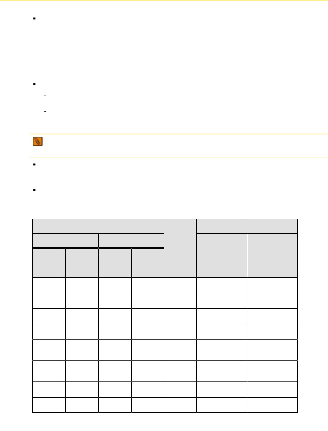
SANtricity_10.77 February 2011
LSI Corporation
- 798 -
The primary volume in a remote volume mirror
Volume Copy and Data Assurance Restrictions
Volume Copy operations are allowed based on Data Assurance attributes when the Data Assurance premium
feature is enabled on the storage array. When a volume to be copied is Data Assurance protected, the target
volume also should be, but is not required to be, protected. Protection information is supplied and checked for
the source volume and the target volume in the following manner:
Both the source volume and the target volume are Data Assurance protected –
All protection information fields are verified when reading data from the source volume. The Guard
Tag field and the Reference Tag field are propagated from the source volume to the target volume.
The fields are then verified when writing data to the target volume. The application target value
provided by the source volume is verified, and then it is replaced by the value associated with the
target volume as the data is transmitted to the target volume.
IMPORTANT In this case, the I/O controller must be able to verify and replace the Application Tag on
the fly.
The source volume is Data Assurance protected, but the target volume is not Data Assurance
protected – Protection information is verified as the data is read from the source volume. Protection
information is then verified and removed as the data is written to the target volume.
The target volume is Data Assurance protected, but the source volume is not Data Assurance
protected – Data Assurance information is inserted as data is written to the target volume.
Allowable Volume Copy Operations
Volume Data Assurance Attributes Application Tag Notes
Source Volume Target Volume
Data
Assurance
Enabled
ATO Data
Assurance
Enabled
ATO
Volume
Copy
Operation
Allowed Source
Application
Tag Source
Target
Application
Tag Source
No N/A No N/A Yes
No N/A Yes Controller Yes
No N/A Yes Host Yes
Yes Controller No N/A Yes Source default
Yes Host N/A N/A Yes Host
Application Tag
Yes Controller Yes Controller Yes Source Default Source
Application Tag
Yes Controller Yes Host No
Yes Host Yes Controller No
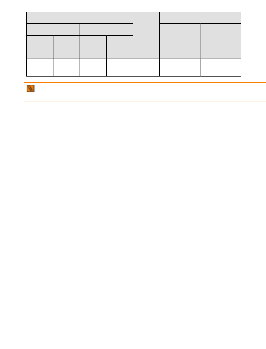
SANtricity_10.77 February 2011
LSI Corporation
- 799 -
Volume Data Assurance Attributes Application Tag Notes
Source Volume Target Volume
Data
Assurance
Enabled
ATO Data
Assurance
Enabled
ATO
Volume
Copy
Operation
Allowed Source
Application
Tag Source
Target
Application
Tag Source
Yes Host Yes Host Yes Host
Application Tag Source
Application Tag
NOTE Application Tag Ownership (ATO) shows whether the portion of the Data Assurance information
that is the application tag is owned by the controllers and should be validated for correctness.
SANtricity_10.77 February 2011
LSI Corporation
- 800 -
Volume Copy and Snapshot Volumes
These topics describe how Volume Copy works with snapshot volumes.
Designating a Source Volume of a Snapshot Volume as the Target Volume of a
Volume Copy
To designate the source volume of a snapshot volume as the target volume of a volume copy, you must
disable all snapshot volumes that are associated with the source volume before you can select it as a target
volume. If any snapshot volumes are associated with the target volume, the volume copy operation fails all of
the associated snapshot volumes.
Restoring Data to a Source Volume from its Associated Snapshot Volume
To restore data to a source volume from its associated snapshot volume, use Volume Copy to copy data from
the snapshot volume back to the source volume.
ATTENTION Possible loss of data access – If you are using the Windows 2000 operating system
or the Linux operating system, use Volume Copy with the Snapshot Volume premium feature to restore
snapshot volume data to the source volume. Otherwise, the source volume and the target volume can
become inaccessible to the host.
To restore the data to the source volume, perform these steps:
1. Create a volume copy of the snapshot volume, and copy the data from the snapshot volume to the target
volume of the volume copy.
2. Copy the data from the target volume back to the source volume.
NOTE Another method for producing a copy of the secondary volume is to create a snapshot volume of
the secondary volume, and then perform a volume copy operation on the snapshot volume.

SANtricity_10.77 February 2011
LSI Corporation
- 801 -
Volume Copy and Journaling File System Formatting
If the source volume was formatted with a journaling file system, the storage array might reject a read request
to the source volume, and an error message might appear. The journaling file system driver issues a write
request before it tries to issue the read request. The controller rejects the write request. This situation might
result in an error message that states that the source volume is write protected.
To prevent rejected write requests, do not try to access a source volume that is participating in a volume
copy operation while it is in an In Progress status.
To prevent an error message from appearing, make sure that the read-only permission for the target
volume is disabled after the volume copy has finished.
SANtricity_10.77 February 2011
LSI Corporation
- 802 -
Creating a Volume Copy
Before you can create a volume copy, the premium feature must be enabled on the storage array. When
you create a volume copy, make sure that the capacity of the target volume is equal to or greater than the
capacity of the source volume.
ATTENTION Potential loss of data – A volume copy overwrites all existing data on the target
volume, automatically makes the target volume read-only to the hosts, and fails all snapshot volumes that are
associated with the target volume.
Selecting the Source Volume and the Target Volume in a Volume Copy Pair
IMPORTANT A target volume must have a capacity equal to or greater than the source volume. Only
volumes that meet that criteria are candidates to be the target volume.
1. In the Array Management Window, select the Logical tab.
2. In the Logical pane, select the volume to copy.
3. On the menu bar, select Volume >> Copy >> Create.
The Introduction (Create Copy) wizard appears. The Source volume table shows the available volumes
you can select as the source volume. The volume you selected in the Logical pane is highlighted, but you
can select any volume in the list.
4. Select the source volume, and click Next.
One of these actions occurs:
When one or more volumes meet the criteria to be a target volume, the Target volume table appears.
If no volumes meet the criteria to be a target volume, the No Target Volume Candidates Found
message appears. Click OK to return to the Source volume table, and select another source volume.
5. In the Target volume table, select the target volume.
6. On the Select copy priority slide bar, select the priority for allocating system resources to the copy
operation, and click Next.
The Preview (Create Copy) wizard appears.
7. In the text box, type Yes to confirm starting the copy operation, and click Finish.
The volume copy starts, and data is read from the source volume and written to the target volume.
In the Logical pane in the Array Management Window, Operation in Progress icons appear on the
source volume and the target volume and show that the volume copy is in either a Pending status or
an In Progress status.
After the copy operation has finished, the Copy Started (Create Copy) message appears asking
whether you want to copy another source volume.
About the Controller Ownership/Preferred Path
During a volume copy, the same controller must own both the source volume and the target volume. If both
volumes do not have the same preferred controller when the volume copy starts, the ownership of the target
volume is automatically transferred to the preferred controller of the source volume.
When the volume copy is completed or is stopped, ownership of the target volume is restored to its
preferred controller.
SANtricity_10.77 February 2011
LSI Corporation
- 803 -
If ownership of the source volume is changed during the volume copy, ownership of the target volume is
also changed.
If a controller fails under any of the following conditions, you must manually change controller ownership to
the alternate controller to allow the volume copy to finish.
A volume copy has a status of In Progress.
The preferred controller of the source volume fails.
The ownership transfer does not occur automatically during a failover.
ATTENTION Possible loss of data – Verify that either the volumes are not in use or a multi-path
driver is installed on the host. If you change the controller ownership/preferred path while an application is
using one of the volumes, I/O activity is disrupted, and I/O errors occur unless a multi-path host is installed on
the host.
If a multi-path driver is not installed on the host, or if the multi-path driver is not the RDAC multi-path driver,
you must make operating system-specific modifications to make sure that the moved volume groups can be
accessed on the new path.
After a volume copy has been created, you can change its controller ownership and preferred path settings.
Go to Changing the Controller Ownership/Preferred Path for a Volume Copy.
Changing the Controller Ownership/Preferred Path for a Volume Copy
1. In the Array Management Window, select the Logical tab.
2. In the Logical pane, select the volume for which to change the controller ownership and preferred path.
3. On the menu bar, select Volume >> Change >> Ownership/Preferred Path.
4. Select the available controller.
NOTE A dot identifies the current preferred path and current controller, which are grayed-out and
cannot be changed.
The Confirm Change Ownership/Preferred Path message appears.
5. Click Yes.
SANtricity_10.77 February 2011
LSI Corporation
- 804 -
About the Controller Ownership/Preferred Path
During a volume copy, the same controller must own both the source volume and the target volume. If both
volumes do not have the same preferred controller when the volume copy starts, the ownership of the target
volume is automatically transferred to the preferred controller of the source volume.
When the volume copy is completed or is stopped, ownership of the target volume is restored to its
preferred controller.
If ownership of the source volume is changed during the volume copy, ownership of the target volume is
also changed.
If a controller fails under any of the following conditions, you must manually change controller ownership to
the alternate controller to allow the volume copy to finish.
A volume copy has a status of In Progress.
The preferred controller of the source volume fails.
The ownership transfer does not occur automatically during a failover.
ATTENTION Possible loss of data – Verify that either the volumes are not in use or a multi-path
driver is installed on the host. If you change the controller ownership/preferred path while an application is
using one of the volumes, I/O activity is disrupted, and I/O errors occur unless a multi-path host is installed on
the host.
If a multi-path driver is not installed on the host, or if the multi-path driver is not the RDAC multi-path driver,
you must make operating system-specific modifications to make sure that the moved volume groups can be
accessed on the new path.
After a volume copy has been created, you can change its controller ownership and preferred path settings.
Go to Changing the Controller Ownership/Preferred Path for a Volume Copy.

SANtricity_10.77 February 2011
LSI Corporation
- 805 -
Monitoring the Progress of a Volume Copy in the Copy Manager
You can monitor the progress of a volume copy in the Copy Manager only while the volume copyis in a
Pending status or in an In Progress status. However, in the storage array profile, you can view both the
progress of the volume copy operation and detailed information about all existing volume copies.
The Copy Manager shows all existing copy pairs for all volume copies for the storage array.
The Status column for the volume copy pair shows the completion percentage of the operation.
You can stop a volume copy operation while it is in an In Progress status. You can re-copy it later or
remove the copy pairs.
For more complete information about the Copy Manager, go to Copy Manager Operations.
To open the Copy Manager, perform these steps:
1. In the Array Management Window, select the Logical tab.
2. On the menu bar, select Volume >> Copy >> Copy Manager.
The Copy Manager appears.

SANtricity_10.77 February 2011
LSI Corporation
- 806 -
Viewing Additional Information about a Volume Copy in the
Storage Array Profile
In the storage array profile, you can view detailed information about the volumes in a volume copy and the
status of the volume copy operation. You can also view detailed information about all existing volume copies
in the storage array.
1. In the Array Management Window, select the Summary tab.
2. Click Storage Array Profile.
The summary page for the storage array appears.
3. Select the Volumes tab.
The summary page for the selected volume appears.
4. Select the Copies tab.
The summary page for the volume copies appears. The summary page shows detailed information about
all existing volume copies in the storage array.

SANtricity_10.77 February 2011
LSI Corporation
- 807 -
Viewing the Physical Components and Logical Elements of a
Source Volume in a Volume Copy
You can view visual representations of the physical components and the logical elements of a source volume
in a volume copy.
1. In the Array Management Window, select the Logical tab.
2. In the Logical pane, right-click the source volume, and perform either of these actions:
View the associated logical elements of the target volume – Select View >> Associated Logical
Elements. The View Associated Logical Elements pop-up appears and shows a visual representation
of the logical elements of the target volume.
View the associated physical elements of the source volume – Select View >> Associated
Physical Components. The View Associated Physical Components pop-up appears and shows a
visual representation of the physical components of the source volume.

SANtricity_10.77 February 2011
LSI Corporation
- 808 -
Viewing the Logical Elements of a Target Volume in a Volume
Copy
1. In the Array Management Window, select the Logical tab.
2. In the Logical pane, right-click the target volume.
3. Select View >> > Associated Logical Elements.
The View Associated Logical Elements pop-up appears and shows a visual representation of the logical
elements of the target volume.
SANtricity_10.77 February 2011
LSI Corporation
- 809 -
Copy Manager Operations
You can perform these actions in the Copy Manager:
Restart a volume copy operation that is in a Stopped status. For detailed instructions, go to Re-Copying a
Volume Copy.
Stop a volume copy operation that is in a Pending status or an In Progress status. For detailed
instructions, go to Stopping an In-Progress Volume Copy.
Remove copy pairs that are in a Stopped status or a Completed status. For detailed instructions, go to
Removing a Volume Copy Pair from a Storage Array.
Change the volume copy modification priority settings. You can change these settings while the volume
copy is in a Pending status, an In Progress status, or a Stopped status. For detailed instructions, go to
Changing the Modification Priority of a Volume Copy.
Change permissions for a target volume that is in a Completed status or a Stopped status. For detailed
instructions, go to Changing the Target Volume Permissions for a Volume Copy.
Monitor the progress of a volume copy operation while it is in a Pending status or an In Progress status.
For detailed instructions, go to Monitoring the Progress of a Volume Copy in the Copy Manager.
NOTE You can also monitor the progress of a volume copy in the storage array profile.

SANtricity_10.77 February 2011
LSI Corporation
- 810 -
Re-Copying a Volume Copy
You can create a new volume copy from a source volume to its target volume.
A volume re-copy starts the volume copy again from the beginning.
You can use the re-copy feature to start a failed volume copy operation or a stopped volume copy
operation or to re-copy an already completed volume copy.
ATTENTION Possible loss of data – A volume re-copy operation overwrites existing data on the
target volume. If the hosts have been mapped to the source volume, the data that is copied to the target
volume when you perform the re-copy operation might have changed since the previous volume copy was
created.
To re-copy a completed volume copy, perform these steps:
1. Stop all I/O to the source volume and the target volume.
2. Unmount any file systems on the source volume and the target volume.
3. In the Array Management Window, select the Logical tab.
4. On the menu bar, select Volume >> > Copy >> > Copy Manager.
The Copy Manager appears.
5. In the Copy Manager, select the source volume and target volume copy pair.
6. On the menu bar in the Copy Manager, select Copy >> > Re-copy.
The Re-Copy dialog appears. To change the copy priority, move the arrow in the Copy Priority slide bar
to the left or right.
7. In the text box, type Yes to confirm the re-copy operation, and click OK.
While a volume re-copy operation is in a Pending status or in an In Progress status, an icon appears next
to both the source volume and the target volume.
You can monitor the progress of a volume copy in the Copy Manager while a volume copy is in a Pending
status or in an In Progress status. For more information, go to Monitoring the Progress of a Volume Copy
in the Copy Manager.
You can view more-detailed information in the Storage Array Profile about which volumes are
participating in a volume re-copy and the status of the volume re-copy operation. For more information, go
to Viewing Additional Information about a Volume Copy in the Storage Array Profile.

SANtricity_10.77 February 2011
LSI Corporation
- 811 -
Stopping an In-Progress Volume Copy
You can stop an In-Progress volume copy before it has finished.
1. In the Array Management Window, select the Logical tab.
2. On the menu bar, select Volume >> > Copy Manager.
The Copy Manager appears.
3. In the Copy Manager, select one or more copy pairs for which to stop the volume copy.
4. On the menu bar in the Copy Manager, select Copy >> > Remove Copy Pairs.
The Stop Copy confirmation message appears.
5. Click Yes.
The Copy Manager shows the status of the volume copy as Stopped.
To start a volume copy again, select one or more volume copy pairs, and select Copy >> > Re-Copy
on the menu bar in the Copy Manager.
SANtricity_10.77 February 2011
LSI Corporation
- 812 -
Removing a Volume Copy Pair from a Storage Array
Removing a volume copy pair breaks the relationship between the source volume and the target volume.
After you remove a volume copy pair, you can use the source volume and the target volume again to create
new volume copies and new volume copy pairs.
NOTE No data is deleted from either the source volume or the target volume.
After you remove a volume copy pair, these events occur:
All copy-related attributes of the volume copy pair, including read-only protection, are removed.
Volume copy information for the volume copy pair is removed from the Volume Properties pane and from
the storage array profile.
The source volume and the target volume no longer appear as a volume copy pair in the Copy Manager.
To remove one or more volume copy pairs, perform these steps:
1. In the Array Management Window, select the Logical tab.
2. On the menu bar, select Volume >> Copy >> Copy Manager.
The Copy Manager appears.
3. In the Copy Manager, select one or more volume copy pairs to remove.
4. On the menu bar in the Copy Manager, select Copy >> Remove Copy Pairs.
The Remove Copy Pairs confirmation message appears.
5. Click Yes.
The Remove Copy Pairs - Progress bar shows the progress of the removal operation.
6. Click OK.
SANtricity_10.77 February 2011
LSI Corporation
- 813 -
Changing the Modification Priority of a Volume Copy
The modification priority defines how much processing time and resources are allocated to volume copy
modifications compared with system performance. Increasing the modification priority of a volume copy might
degrade system performance. You can set the modification priority of a volume group, and you can change
the modification priority of a volume after the volume group has finished. Modification priorities can affect
these operations:
Performing a copyback
Performing a Dynamic Volume Expansion (DVE)
Reconstructing a volume
Initializing a volume
Changing a volume’s segment size
Defragmenting a volume group
Adding free capacity to a volume group
Changing the RAID level of a volume group
To change the modification priority of a volume copy, perform these steps:
1. In the Array Management Window, select the Logical tab.
2. In the Logical pane, select the volume for which to change the modification priority.
3. On the menu bar in the Array Management Window, select Volume >> Change >> Modification
Priority.
The Change Modification Priority dialog appears.
The Select volumes table shows the volumes and the volume groups on the storage array.
The Select Modification Priority slide bar shows the priority level of the highlighted volume.
4. Select one or more volumes for which to change the modification priority.
NOTE When you select a single volume, the Select Modification Priority slide bar shows the
priority setting of the volume. When you select multiple volumes, the Select Modification Priority slide
bar shows the priority setting as Lowest for all volumes, regardless of the actual priority for each individual
volume.
To select nonadjacent volumes, press and hold the Ctrl key, and select each volume.
To select adjacent volumes, press and hold the Shift key, and select each volume.
To select all volumes, click Select All.
5. On the Select Modification Priority slide bar, select the modification priority for the volume or volumes,
and click OK.

SANtricity_10.77 February 2011
LSI Corporation
- 814 -
Changing the Target Volume Permissions for a Volume Copy
Read requests and write requests to the target volume do not take place while the volume copy is in either
a Pending status or an In Progress status, or if the volume copy fails. After the volume copy operation is
complete, the target volume automatically becomes read-only to the hosts.
To allow changes to the data on the target volume after the volume copy operation is complete, disable
the read-only permissions for the target volume.
To prevent changes to the data on the target volume after the volume copy operation is complete, enable
the read-only permissions for the target volume. You should preserve the data on the target volume under
the following circumstances:
You are using the target volume for backup purposes.
You are copying data from one storage array to a larger storage array for greater accessibility.
You are using the data on the target volume to copy back to the base volume of a disabled volume or
failed flashcopy volume.
To change target volume permissions, perform these steps:
1. In the Array Management Window, select the Logical tab.
2. On the menu bar, select Volume >>Copy >> Copy Manager.
The Copy Manager appears.
3. In the Copy Manager, select one or more copy pairs.
4. Select Change >> Target Volume Permissions.
5. Perform one of these actions:
Disable Read-Only permissions – Select Disable Read-Only. Read-write permissions are enabled
on the target volume and are automatically available to hosts after the volume copy has finished.
Make the target volume read-only to hosts – Select Read-Only. Read-only permissions are
enabled on the target volume. Write requests to the target volume are rejected even after the volume
copy has finished.

SANtricity_10.77 February 2011
LSI Corporation
- 815 -
Obtaining the Volume Copy Premium Feature Key
Before you can create a volume copy, you must obtain the Volume Copy premium feature key and enable
the premium feature. If you have purchased the Volume Copy premium feature, contact your Customer and
Technical Support representative to obtain the premium feature key.
The Customer and Technical Support representative will need the 30-character string in the Feature Enable
Identifier field in the Premium Features and Feature Pack Information window in Array Management Window
of the storage array.
To obtain the Volume Copy premium feature, perform these steps:
1. In the Array Management Window, select Storage Array >> Premium Features.
The Premium Features and Features Pack dialog opens and shows a list of premium features installed on
the storage array.
2. Find and record the 30-character string in the Feature Enable Identifier field.
The Customer and Technical Support representative uses the Feature Enable Identifier to generate the
premium feature key.
3. Copy the Volume Copy premium feature key to a directory from which you can retrieve it when you are
ready to enable the premium feature.
The default directory is C:\\Documents and Settings\My Documents.

SANtricity_10.77 February 2011
LSI Corporation
- 816 -
Disabling the Volume Copy Premium Feature
To disable the Volume Copy premium feature, perform these steps:
1. On the menu bar in the Array Management Window, select Storage Array >> Premium Features.
The Premium Features and Features Pack window opens and shows a list of premium features installed
on the storage array.
2. Select Volume Copy, and click Disable.
The Disable Premium Features confirmation message appears.
3. Click Yes.
The Premium Features installed on storage array list shows Volume Copy as disabled.
4. Click Close.

SANtricity_10.77 February 2011
LSI Corporation
- 817 -
Volume Copy Troubleshooting Tips
Troubleshooting Modification Operations
If you try to create a volume copy at the same time a modification operation is running on either the source
volume or the target volume, and the volume copy is in a Pending status, an In Progress status, or a Failed
status, the volume copy cannot start.
If a modification operation is running on a source volume or a target volume after a volume copy has been
created, the modification operation must complete before the volume copy can start.
While a volume copy is in an In Progress status, no modification operation can take place on either the source
volume or the target volume.
Troubleshooting Failed Volume Copy Operations
A volume copy can fail under these conditions:
A read error from the source volume occurs.
A write error to the target volume occurs.
A failure in the storage array occurs that affects the source volume or the target volume, such as a remote
volume mirror role reversal.
When a volume copy fails, a critical event is logged in the Event Log, and a Needs Attention icon appears in
the Array Management Window.
When a volume copy is in a Needs Attention status, the host has read-only access to the source volume.
Read requests from and write requests to the target volume are rejected until the failure is corrected by
using the Recovery Guru.

SANtricity_10.77 February 2011
LSI Corporation
- 818 -
Support Monitor Installation and Overview
How to install the Support Monitor with SANtricity ES Storage Manager Version 10.77 to assist service
organizations with the timely resolution of issues with your storage system.

SANtricity_10.77 February 2011
LSI Corporation
- 819 -
Overview of the Support Monitor Version 4.9
Support Monitor is a tool that will assist the service organization in timely resolution of issues with your
storage system. Support Monitor automatically gathers support data on a scheduled basis so that it is
immediately available for the service organization when an issue occurs. The support data that Support
Monitor gathers includes data such as the configuration file, the Major Event Log, and device statistics.
If a problem occurs, Support Monitor provides a mechanism for you to send the selected data to a Customer
and Technical Support representative. Support Monitor retains five scheduled sets of data and one on-
demand set of data. Customer and Technical Support can receive between one and six sets of data for each
storage array that is being monitored.
Support Monitor is included with LSI’s SANtricity® ES Storage Manager. You install Support Monitor with
SANtricity ES Storage Manager Version 10.77. Support Monitor collects data whether or not you have an
opened web browser. The default settings of Support Monitor polls all storage arrays visible by SANtricity
ES Storage Manager for data at 2:00 a.m. Support Monitor can be used with Internet Explorer® or Mozilla®
Firefox® web browsers.
This document provides information about the Support Monitor function of LSI Profiler. You might see
references to “Profiler Server” or “Profiler Agent” in the installation procedures. However, other than the
installation procedures, this document describes only Support Monitor functionality.
Supported Features for the Support Monitor
The Support Monitor contains the following supported features:
Bundled with SANtricity ES Storage Manager for ease of installation.
Allows automatic support data collection to be scheduled on daily, weekly, or monthly intervals.
Provides the ability to send five sets of scheduled support data and one set of on-demand support data to
Customer and Technical Support to identify any troubling trends or signs of problems.
Enables users to email the support data after the scheduled data collection is completed.
Allows for change log analysis of SOC and RLS Counters.
Collects and persists customer contact information through a software registration process.
Supported Operating Systems for Support Monitor
Review the specifications for your operating system to make sure that your system meets the minimum
requirements. The following table includes information about Support Monitor installation types supported
for each operating system. Some operating systems support Profiler Agent installer, while other operating
systems support the Support Monitor and SANtricity ES Storage Manager bundled installation.
NOTE When your operating system does not support the Support Monitor, you will select Custom
Installation during the installation process to ensure that only SANtricity ES Storage Manager will be installed
on the host. Make sure that you clear the Support Monitor option before installing SANtricity ES Storage
Manager. For installation instructions, see Chapter 2.

SANtricity_10.77 February 2011
LSI Corporation
- 820 -
Supported Operating Systems for Support Monitor
Operating System and Edition OS Version for Client
GUI Only Supported Installation
Windows Server 2003 Service Pack
2Windows XP
Professional SP3* LSI Profiler Server with
SANtricity ES
Windows Server 2008 (SP2, R2) Windows Vista*
(business edition or
later)
LSI Profiler Server with
SANtricity ES
Solaris 10 U8 (SPARC and x86) N/A LSI Profiler Server with
SANtricity ES
Red Hat Enterprise Linux 5 (x86,
x64) – latest update Red Hat 5 Client** LSI Profiler Server with
SANtricity ES
Red Hat Enterprise Linux 6 (x86) –
latest update Red Hat 6 Client**
SUSE Linux Enterprise Server 10
(SP3) – latest update SUSE Desktop 10** LSI Profiler Agent with
SANtricity ES
SUSE Linux Enterprise Server 11
(SP3) – latest update SUSE Desktop 11** LSI Profiler Agent with
SANtricity ES
HP-UX 11.23 N/A LSI Profiler Agent
HP-UX 11.31 N/A LSI Profiler Agent
AIX 6.1 N/A LSI Profiler Server with
SANtricity ES
AIX 7.1 N/A LSI Profiler Server with
SANtricity ES
* Client-only release. The consumer version can be used as a management station. No support
for I/O attachment. Both 32-bit and 64-bit are supported.
** Client-only release. The consumer version can be used as a management station. No
support for I/O attachment. Only 32-bit supported.
Supported Firmware Versions and Supported RAID Controllers
Supported Firmware Versions and Supported RAID Controllers
Controller Firmware VersionsRAID Controller
6.60 7.35 7.60 7.70 7.75 7.77
SHV2520 X
SHV2510 X

SANtricity_10.77 February 2011
LSI Corporation
- 821 -
Controller Firmware VersionsRAID Controller
6.60 7.35 7.60 7.70 7.75 7.77
SHV2600 X
SAT2600 X
CDE3992 X X
CDE3994 X X
CDE4900 XXXX
FC1275 X
CE6994 X X
CE6998 X X
CE7900 XXXX
AM1331/AM1333 X
AM1932 X
AM1532
26xx XXX
System Requirements
This section describes the operating system requirements needed to install and run Support Monitor.
Memory requirements – When installing Support Monitor combined with other host software (HSW)
components, including Client, Utilities, failover driver, and Java runtime, the memory requirement with
HSW components is 1.5 GB minimum (2 GB preferred); otherwise, 1 GB minimum (1.5 GB preferred) is
sufficient.
Hard drive space requirements – When installing Support Monitor combined with other HSW
components, including Client, Utilities, failover driver, and Java runtime, the hard drive space requirement
with HSW components is 2 GB; otherwise, 1 GB minimum (1.5 GB preferred) is sufficient.
Installation duration – 15 to 20 minutes, on average.
IP address – Static IP address required for the SANtricity ES host.
SMTP IP address – SMTP IP address required for emailing support data.
My SQL database – A pre-existing MySQL database on the host must be manually uninstalled before
you can install Support Monitor with SANtricity ES.
Server system resources – Support Monitor does not limit the amount of devices an agent can monitor.
You can set up an agent to monitor as many storage arrays as you want. However, the server system
needs to provide sufficient resources for monitoring a large number of storage arrays.

SANtricity_10.77 February 2011
LSI Corporation
- 822 -
Software Restrictions
This section describes some of the restrictions that you might encounter while using Support Monitor.
Installation restrictions – Support Monitor installation files include the Apache Tomcat® webserver
application. Support Monitor uses Apache Tomcat to provide information to the user interface. Any other
pre-existing applications on the host that use Apache Tomcat must be uninstalled before you install the
Support Profiler.
Make sure that the Support Monitor directory structure is removed from anti-virus and backup
applications.
Any pre-existing MySQL® database on the host that was not a part of Support Monitor installation
must be uninstalled before you install Support Monitor.
Due to library incompatibility, Support Monitor cannot be installed on Red Hat 6, x64 architecture (non
Itanium).
IP address restrictions – You must install Support Monitor on a host equipped with a static IP address.
DHCP server IP addresses are not supported by Support Monitor.
File size restrictions – If you monitor a large number of storage array systems, gathering support data
takes longer, and the compressed files are larger. Support Monitor compresses the collection data file to
be between 2 MB and 5 MB.
Data gathering restrictions – Support Monitor typically takes five minutes to seven minutes to collect
data. The data collection time can be as high as 20 minutes for a storage array with more than 100 drives.
For scheduled collection, this is a background process that does not affect the performance of Support
Monitor. When performing an on-demand collection, the GUI shows that collection has been completed.
Monitoring restrictions – No mechanisms exist that prevent multiple Support Monitor instances from
trying to find data from the same storage array; therefore, monitor each storage array from only one
Support Monitor instance. Gathering data from a storage array with multiple Support Monitor instances
can cause problems. You can prevent these problems if you selectively disable the support data
collection when multiple Support Monitor instances have access to the same storage array. You can
change the frequency of data gathering or turn off data gathering for a particular storage array from
Support Monitor.
Polling mechanism restriction – The data collection process of Support Monitor is multi-threaded with a
polling mechanism in place to find the maximum number of storage arrays at pre-defined timing intervals.
Storage array restrictions – You cannot use the Support Monitor application to add a storage array.
You must use the features in SANtricity ES Storage Manager to add a storage array, or use other storage
array management methods.
Storage array definition restrictions – To avoid redundant monitoring and data collections, define the
storage arrays only within one SANtricity ES session, where Support Monitor is installed. For example,
when installing multiple client instances of SANtricity ES, select one of the following options:
Choose to install Support Monitor on only one of the SANtricity ES clients.
Do not define the same set of storage arrays within multiple SANtricity ES sessions, if all of those
SANtricity ES sessions do have Support Monitor installed.
Storage array management restrictions – In-band management is not supported.
Uninstalling restrictions – When a profiler agent is uninstalled, all of the storage arrays that were
discovered via the agent still are present within the Support Monitor GUI under Monitored Array List. Prior
to uninstalling Support Monitor agent, you must manually remove the storage arrays from the SANtricity
Enterprise Management Window (EMW) instance on the Support Monitor agent host so that Support
Monitor no longer keeps the storage arrays under Monitored array list.

SANtricity_10.77 February 2011
LSI Corporation
- 823 -
Installing, Upgrading, and Uninstalling Support Monitor
This chapter describes how to install, upgrade, and uninstall Support Monitor. As previously described in
first table in Chapter 1, two types of installations exist, depending on your operating system. Some operating
systems support the Profiler Server installer, which automatically installs Support Monitor as it installs
SANtricity ES Storage Manager. Some operating systems support the Profiler Agent installer, which installs
SANtricity ES Storage Manager on the host without Profiler Server. This chapter describes both types of
installations.
Installing Support Monitor or Upgrading from a Previous Version of Support
Monitor
Installing Support Monitor replaces any previous versions of Support Monitor that you might have on your
system, if the Support Monitor major program versions are different (for example, from version 4.8 to 4.9).
The installation process for the storage management software automatically installs Support Monitor when
the installation type is either Typical or Management Station. The Custom installation offers the choice of
whether to install Support Monitor. Support Monitor is not available under the Host Installation option. To
correctly install Support Monitor, depending on your operating system, go to either "Installing Profiler Server
with SANtricity ES" on page 2-2 or "Installing Profiler Agent" on page 2-3.
Installing Profiler Server with SANtricity ES
These procedures are for installing or upgrading Support Monitor with the combined SANtricity ES Storage
Manager. When you select the installation type of either Typical or Management Station, this installation
automatically installs Support Monitor.
1. If you have a previous version of Support Monitor that was not installed as part of a SANtricity ES bundle,
installed, perform the steps in “Uninstalling the Support Monitor” on page 2-4 to completely remove that
version of the Support Monitor.
NOTE You must manually remove any MySQL database that was not part of a previous Support
Monitor installation.
2. For the Windows operating system, double-click the installation executable icon, and follow the wizard
installation steps provided on the screen.
NOTE When you install Support Monitor with SANtricity ES Storage Manager, you are not able to
specify an installation directory. The installation defaults to the SANtricity ES Storage Manager directory
structure.
After the installation completes, an icon appears on the desktop. To start Support Monitor, double-click
the icon to start a browser-based application that is independent of SANtricity ES Storage Manager.
3. For all UNIX operating systems, perform the following steps.
a. Login as root.
b. Assign execution permissions to the installation library.
# chmod +x SMIA-<OSTYPE>-<XX.XX.XX.XX>.bin
In this command, <OSTYPE> is the operating system name and <XX.XX.XX.XX> is the version
number.
c. Run the SANtricity ES Storage Manager installation script. Follow the directions provided on the
screen. Retain the UNIX installation files because they are also used to uninstall the software. You
can delete the original archive file.
SANtricity_10.77 February 2011
LSI Corporation
- 824 -
# ./SMIA-<OSTYPE>-<XX.XX.XX.XX>.bin
In this command, <OSTYPE> is the operating system name and <XX.XX.XX.XX> is the version
number.
To start Support Monitor, open a browser window and enter the URL for Support Monitor. The URL for the
Support Monitor is http://localhost:9000/. You also can access Support Monitor remotely.
Support Monitor generates a log after installation. Refer to the log for information about the installation
outcome and any error codes that might have occurred. The installation log for Windows is located at
/Program Files/StorageManager/Profiler_install.log. The installation log for UNIX is
located at /opt/StorageManager/Profiler_install.log.
Installing Profiler Agent
This installation process is for installing Profiler Agent, without Profiler Server. The Agent is needed only
when monitoring a storage array from a version of SANtricity ES that does not have a Server version. The
Agent reports information back to an instance of Support Monitor that is running on a supported Server with
SANtricity ES. In many cases, this instance of SANtricity ES can be used to monitor the storage array.
Before you install Profiler Agent, you must install SANtricity ES. During this installation, keep the following
points in mind:
Support Monitor must be installed first within the environment on a supported operating system platform.
For the operating system platform where Support Monitor is not supported, install only the SANtricity
ES client (by selecting Custom install and choosing to opt-out Support Monitor during the component
selection sequence of the installation). This option ensures that only SANtricity ES, without Support
Monitor, is installed on the host.
Install Profiler Agent, available as a stand-alone installer, under the SANtricity ES directory location on the
host (referenced in the previous bullet item) when prompted during the Profiler Agent installation.
During the Profiler Agent installation, you must provide the remote support monitor’s (profiler server) IP
address so that Profiler Agent can self register to the remote Profiler Server to complete agent-server
self-discovery.
After Profiler Agent self registers to the remote Profiler Server, all storage arrays managed by Profiler
Agent’s local SANtricity ES Enterprise Management Window will be discovered and added to the storage
array list under remote Profiler Server’s support monitor.
Uninstalling the Support Monitor
These instructions show you how to remove the combined SANtricity ES Storage Manager and Support
Monitor.
IMPORTANT Prior to uninstalling the Support Monitor agent, you must manually remove the storage
arrays from the SANtricity ES Enterprise Management Window instance on the Support Monitor agent host so
that Support Monitor no longer keeps the storage arrays under Monitored storage array list.
1. For the Windows operating system, select Add/Remove Programs in the Control Panel to remove
SANtricity ES Storage Manager. This procedure removes both SANtricity ES Storage Manager and
Support Monitor. The uninstallation procedure might leave files that were created by SANtricity ES
Storage Manager and Support Monitor after the installation was complete. These files might include trace
files, repository files, and other administrative files. Manually delete these files to completely remove
SANtricity ES Storage Manager and Support Monitor.

SANtricity_10.77 February 2011
LSI Corporation
- 825 -
2. For the UNIX operating system, go to the /opt/StorageManager/Uninstall SANtricity ES/
directory that contains the uninstall binary. Run the uninstall script using the # ./Uninstall_SANtricity_ES
command. This procedure removes both SANtricity ES Storage Manager and Support Monitor. The
uninstallation process might leave files that were not part of the original installation. Manually delete these
files to completely remove SANtricity ES Storage Manager and Support Monitor.
NOTE The UNIX uninstallation procedure uses the .bin file. The .bin files must be saved on the
host so that the combined SANtricity ES Storage Manager and Support Monitor uninstallation can occur.
The .bin files are approximately 150 MB in size.

SANtricity_10.77 February 2011
LSI Corporation
- 826 -
Describing Support Monitor
This chapter describes the following tasks:
Registering Support Monitor
Rescanning devices
Collecting and saving support data
Emailing support information to pre-defined email addresses
The Support Monitor screen lists all of the devices discovered by Support Monitor. This screen contains other
necessary information for each storage array, such as the storage array name, the host that is managing the
storage array, the collection status, the last collection time, the next collection time, and the emailing and
scheduling actions. For information about the features of Support Monitor, refer to the online help topics in
Support Monitor.
Registering Support Monitor
Registration information includes the name, address, and telephone number of the customer company.
Registration information also includes the name, telephone number, and email address of the contact and the
partner company.
The registration sequence stores the customer contact information within the Support Monitor database.
You can modify the contact information stored in the Support Monitor database through the Support Monitor
application. For detailed information about registering Support Monitor, refer to the online help topics in
Support Monitor.
Rescanning Devices
The Rescan Devices feature is available for re-discovering the configuration. Both the automated polling
option and the manual rescan option extract the change in configuration information from the .bin file. Click
Rescan Devices to update the configuration information. For more information about the Rescan Devices
option, refer to the online help topics of Support Monitor.
Collecting and Saving Support Data
Support Monitor lets you collect and save support data from your storage arrays. Collected information
includes data, such as the collection time, the collection frequency, the disabled collections, the starting day
for collection, and the file-naming conventions. Scheduled (also referred to as Periodic) and on-demand data
collection includes information such as the following types of data:
Support data collection
SOC file
RLS file
Configuration file
Profiler Server maintains five scheduled data collection sets. The newest scheduled data collection set
overrides the oldest data sets. The sixth data collection set is collected manually with a different filename.
Only the latest on-demand data collection set is preserved so be certain that the last on-demand data
collection is not needed before you initiate a new on-demand collection.

SANtricity_10.77 February 2011
LSI Corporation
- 827 -
For more information about how to perform support data or SOC and RLS change log collections, refer to the
online help in Support Monitor.
Support Data File-Naming Conventions
Support data file names are different, depending on whether the data is being collected on-demand or as a
scheduled data collection. On-demand data collection does not override scheduled data collection.
All of the collected support files are compressed in a file named arrayname_timestamp.zip. The zip file
name also contains a _p or _d. For example, arrayname_ptimestamp.zip for a periodic (scheduled) data
capture or arrayname_dtimestamp.zip for an on-demand data capture.
SOC and RLS File-Naming Conventions
SOC and RLS change log files share the same file-naming convention.
The files are compressed in a file named arrayname_Change_timestamp.zip. The zip file name also
contains a _p or _d. For example, arrayname_Change_ptimestamp.zip for periodic (scheduled) data
capture or arrayname_Change_dtimestamp.zip for an on-demand data capture.
Emailing Support Information
You can send collected support data and the SOC/RLS change log files to a designated email address list.
You can edit the email address and some of the other fields from one of the following screens.
On the Send Support Data screen, you can do the following:
Edit the email address in the Send to: field. If you change this email address, this change is not
persistent. The next time you open the Send Support Data screen, the pre-defined support email address
appears.
Add additional email addresses to the CC: field, but the email containing the support data and SOC/RLS
change log files still goes to the email address shown in the Send to: field.
Send the SOC/RLS change log files to a pre-defined email address by selecting the Send change log
files to a repository address check box. You cannot edit the repository email address field. Only change
log files can be sent to the repository email address. You can add additional email addresses to the CC:
field.
Edit the Subject: field, if you prefer a subject different than the initial default subject, which is <Storage
Array> Support Data. If you change this field, the text you enter is retained and does not return to the
initial default subject.
On the Schedule Support Data Collection screen, you can do the following:
Edit the email address in the Send to: field. The Email the scheduled collection data files to a
repository address check box is selected by default. You can change the Send to: field by unselecting
the check box, then entering a new email address in the Send to: field. This new email address is
retained until you change it again.
For information about emailing support data and SOC/RLS change log files, refer to the online help topics in
Support Monitor.

SANtricity_10.77 February 2011
LSI Corporation
- 828 -
Frequently Asked Questions
Support Monitor Issues and Resolutions
Issue Resolution
Installation, Registration, and Licensing
Do I have to install Support Monitor on a
separate management station? No. Support Monitor is installed with
SANtricity ES Storage Manager. Use
the same host for both storage array
management functions of the SANtricity
ES Storage Manager and Support Monitor
functions.
What actions does the SANtricity ES installer
take if a previous Support Monitor installation
exists?
If the Support Monitor major program versions
are different (for example, from version 4.8 to
4.9), installing Support Monitor replaces any
previous versions of Support Monitor on your
system.
Do I need to install the SMI-S Provider for
Support Monitor to work? No. For the Support Monitor Version 4.9
application, you do not need the SMI-S
Provider.
Can I customize the installation and opt out of
installing Support Monitor? Yes. You can choose to opt out of the Support
Monitor installation. Select the SANtricity ES
custom installation option and make sure that
the Support Monitor option is not selected.
Can I choose whether Support Monitor
services start automatically? No. Support Monitor 4.9 is considered a
persisting support application on the host to
aid service, field, and customer personnel.
Therefore, opting out from starting the profiler
services is not available.
When I register Support Monitor, where is
the registration data stored and how is the
registration retrieved or viewed?
The registration data is stored in Support
Monitor. You can view the registration
information by selecting Registration
Information in Support Monitor.
Does a pop-up reminder appear when I select
the "register later" option? No. You can access registration through the
left navigation menu at any time.
How are licenses handled? Support Monitor Version 4.9 uses an internal
license that does not have an expiration
date. You can obtain additional licenses by
contacting your sales representative.
How can I fix registration failures? If you receive an error during the registration
process, make sure that the email server IP
and the email address are set correctly on the
Server Setup page.
Data Collection

SANtricity_10.77 February 2011
LSI Corporation
- 829 -
Issue Resolution
What are the performance impacts on storage
for scheduled data gathering? For a medium configuration, defined as
four to five drive trays connected to either a
CE6998 controller or a CE7900 controller, the
collection overhead is about 15 to 20 minutes
when the storage array is in an Optimal state.
Because the Support Monitor collection
process uses out-of-band management, there
are no performance impacts on the I/O path
started by the profiler.
Can I configure the data that is being
collected? No. The type of commands used for data
collection are hard-coded within the Support
Monitor application, and you cannot change
or configure the data that is being collected.
Does the standard "collect all support
data" function in SANtricity ES behave any
differently when Support Monitor is installed?
No. Support Monitor does not affect existing
SANtricity ES features.
Can I send support data to an email address
other than the pre-defined location? Yes. You can change the Send to: field on
the Send Support Data screen, and you can
add additional email addresses in the CC:
field, if needed. Also, you can change the
body and subject line of the support email.
Can I modify the schedule for data collection? Yes. Click the Calendar icon to schedule the
data collection frequencies or the time for
each storage array that you are monitoring.
How can I tell whether the support capture
was successful in Support Monitor? When you are unable to collect support data
with either a scheduled data collection or an
on#demand collection process, an icon next
to the storage array shows the support data
collection status. A successful data collection
shows a green icon. A failed data collection
shows a red icon.
How can I determine what data might have
failed during the data collection procedure? View the collection log to debug the failed
collection. Also, the collection status icon
on the Support Monitor shows a "red-
failed" status when collection failures are
encountered.
Log files are found at <drive>\LSI
Corporation\Profiler Server
\webapps\ROOT\logs.
Do I get notified when a failure occurs? No explicit notification is provided when data
collection fails. However, the collection status
icon changes to a "red-failed" status.

SANtricity_10.77 February 2011
LSI Corporation
- 830 -
Issue Resolution
How can I configure Support Monitor so
that only one instance is performing data
collection out of many SANtricity ES Storage
Manager instances?
Install only instance of the server on one
of the SANtricity ES Storage Manager
instances. All of the other SANtricity ES
Storage Manager instances only require the
agent.
How can I configure Support Monitor so that
no more than one storage array is performing
scheduled data collection at any one time?
In Support Monitor, view the next data
collection time, and adjust the schedules so
that no two storage arrays have the same
next data collection time.
What is the optimum frequency for scheduled
support data collection? To avoid latency in completing the scheduled
collection task, schedule the support data
collection so that a collection is not tried from
multiple storage arrays at the same time.
What can I do if a scheduled data collection
fails? If a scheduled data collection fails, Support
Monitor retries the data collection a single
time. If the retry fails, the data collection
falls back to the normal schedule. Verify
the support log. Address the problem
being reported and start a manual data
collection. If the manual collection fails,
contact a Customer and Technical Support
representative to assist in resolving the
problem.
What can I do if an on-demand collection
fails? Verify the support log. Address the problem
reported, and start a new data collection.
What can I do if no support bundles are
available for emailing? Start a manual data collection or schedule
a collection by the most recent time and try
again.
What can I do if the support data email was
never delivered to the recipient? Support Monitor can only send an email to a
pre#defined, user-configured email address.
Make sure that the values for the email server
and the email address are correct in the
Server Setup page and try again.
Support Monitor will not be able to detect
email delivery failures due to:
Blocked emails at the recipient’s email
server
The recipient’s inbox is full
An email attachment-size limit is imposed
by the recipient’s email server
Support Monitor will be able to detect
configuration errors due to:
Incorrect email server (SMTP) name/IP
address within the server configuration

SANtricity_10.77 February 2011
LSI Corporation
- 831 -
Issue Resolution
Incorrect forwarding email address
Support Monitor will be able to detect
incorrect recipient’s email addresses
associated with:
The recipient’s email address: user name
portion
The recipient’s email address: domain
name portion
The logs associated with email-related errors
are in webserver.log at the following location:
\..\ProfilerServer\webapps\ROOT
\logs.
Storage Array Management
Does Support Monitor provide any analysis to
what might be wrong with the storage array? Yes. you can select two available files to
compute a SOC change log file, which can
help with an analysis of channel failures. See
the Compute Change Log Files screen in
Support Monitor.
How can I tell when a storage array is
removed in Support Monitor? When a storage array that was previously
managed by Support Monitor is removed from
SANtricity ES Storage Manager, the storage
array is relocated to the Unmanaged Arrays
area, which is visible only if there are any
unmanaged storage arrays. However, you still
can access previously collected support data
for that storage array for emailing purposes.
Why do some storage arrays appear in the
Unmonitored Storage Array table? Storage arrays appear in the Unmonitored
Storage Array table for different reasons.
For example, because the storage array was
removed from SANtricity ES Storage Manager
or because the storage array does not meet
the minimum controller firmware requirements
to be managed by Support Monitor.
What happens when I remove a storage array
from Support Monitor? If you use the Remove icon, support data is
not deleted from the host or SANtricity ES
Storage Manager. The support data is deleted
only from the Support Monitor view. The
previously collected support data files from
the removed storage arrays are still available
via file/folder access.
What can I do if no storage arrays are found
by Support Monitor? Be sure that the storage array is being
monitored by SANtricity ES and that the
Collection Agent is running. Verify the status
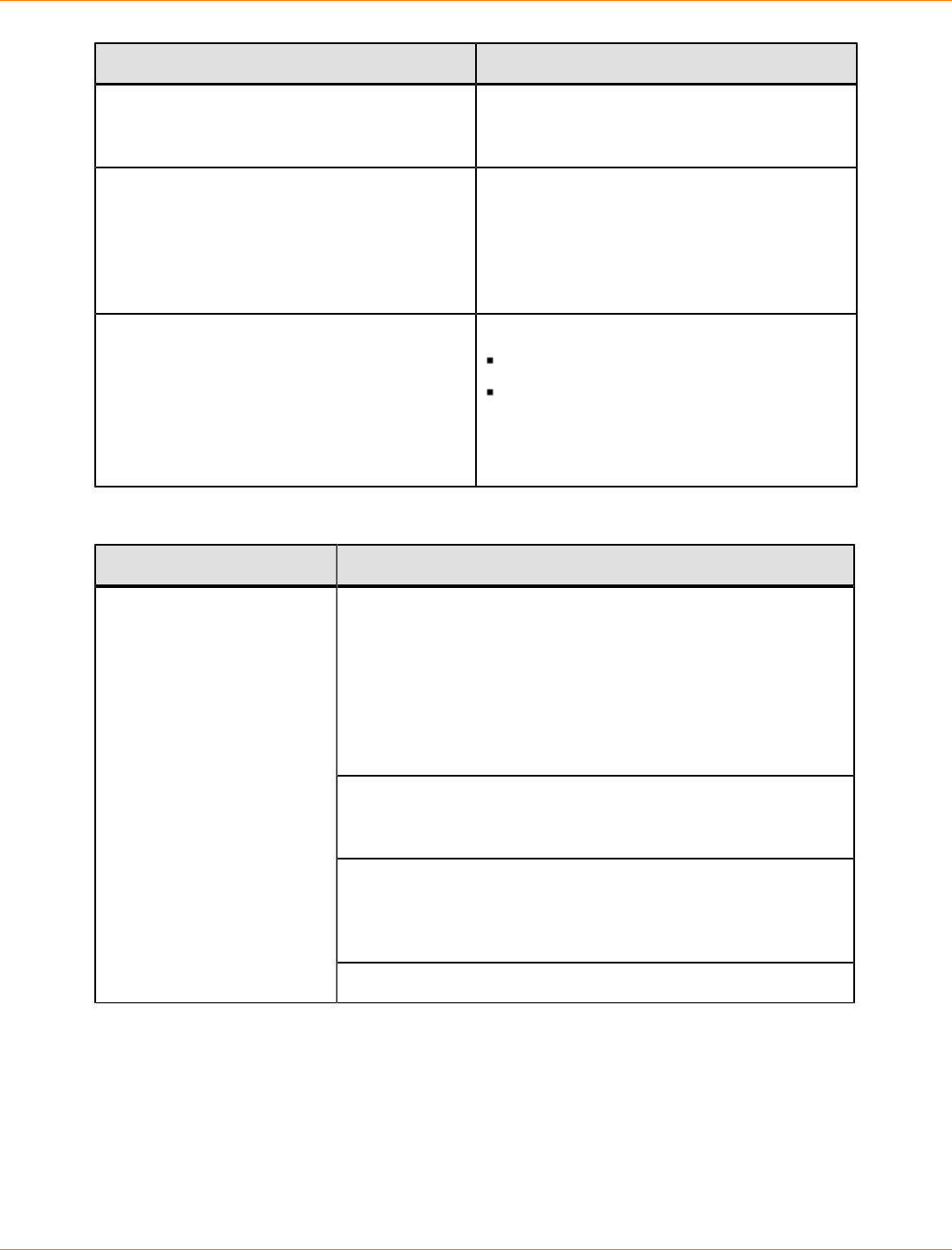
SANtricity_10.77 February 2011
LSI Corporation
- 832 -
Issue Resolution
of the storage array. Restart Support Monitor
services, and initiate manual discovery of the
storage arrays.
How can I see if the storage array discovery
process was successful? View the Support Monitor module log file for
the corresponding agent by selecting the
agent from the list and clicking the View Log
File button. Make sure that the storage array
is being monitored by SANtricity ES Storage
Manager.
Which logs are supplied when reporting a
support monitor issue? The log files supplied are:
mod.sys.support.Support.log
Kernel.log
Log files are found at <drive>\LSI
Corporation\Profiler Server
\webapps\ROOT\logs.
Support Monitor Module Log Messages
Type of Message Message Text
initializing <num> DeviceClients
This message shows the number of storage arrays being
monitored plus one more for Support Monitor.
DeviceClient created:
deviceType--><type>
deviceIdent--><id>
status--><status> –After the client is created, this variable logs
information about each storage array.
attempting to start <num> DeviceClients
This message shows that each device client was started and
initialized using the initializing DeviceClients command.
not starting DeviceClient ( <deviceClient name>
) since status is set to <status>
This message shows that when the status is anything other
than online, the client does not start.
Module online
registration

SANtricity_10.77 February 2011
LSI Corporation
- 833 -
Type of Message Message Text
This message appears when a storage array monitor
registration key is created for Support Monitor. The module’s
status is set to online, and the registration key is created for the
Support Monitor device to register with the server.
stopping <num> DeviceClients
This message appears when the configuration file updates with
new storage array information, and the module is temporarily
placed offline. The module then returns to online status to
refresh the information.
Module offline
<id> supportinfo - stopping ClientProxy
This message shows that a specific client is stopped.
Discovery
Discovery Discovery <id>
This message appears when the device id is assigned from
Profiler Server.
discovery( <id> ): discovering arrays/smtp on
<time> sec intervals
This message shows that the discovery data is established on
a scheduled frequency.
discovery( <id> ): discovering arrays/smtp from
on-demand request
This message shows that the discovery data is established
through a user-initiated action.
General discovery
messages
discovery( <id> ): discovery process completed
in <time> secs
This message indicates that the discovery process is complete.
discovery( <id> ): new array discovered-->Name:
<arrayName> , IP 1: <ip of controller 1> , IP
2: <ip of controller 2>
This message shows that the storage array is added to
SANtricity ES Storage Manager.
discovery( <id> ): no new arrays discovered
This message appears when the discovery is initiated but no
new storage arrays are found.
Storage array discovery
discovery( <id> ): unmanaged array detected--
>Name: <arrayName> , IP 1: <ip of controller
1> , IP 2: <ip of controller 2>

SANtricity_10.77 February 2011
LSI Corporation
- 834 -
Type of Message Message Text
This message shows that the storage array is removed from
SANtricity ES Storage Manager.
discovery( <id> ): no unmanaged arrays detected
This message appears when the discovery is initiated, but
no storage arrays are removed from SANtricity ES Storage
Manager.
SMTP discovery discovery( <id> ): discovered smtp server info
( <smtp server> ) and email from info ( <email
from> )
This message shows that the SMTP server information and the
email address are parsed from SANtricity ES Storage Manager.
Support Data Capture
<array name> stopping periodic support
capture, since previous <num> attempts have
failed
This message shows that a scheduled capture fails and one
retry is attempted. If that retry fails, this message is seen.
Retry related messages
<array name> retrying support capture since
last attempt failed. Retry attempt <num> of
<num>
This message appears when a scheduled capture fails, and
one retry is attempted.
Scheduled message <array name> started periodic support data
capture
This message appears when a scheduled data collection is
started.
On-demand message <array name> started on-demand support data
capture
This message appears when a user-initiated data collection is
started.
<array name> checking array firmware
This message shows that the firmware is being checked.
Messages when a support
data collection is in progress
<array name> valid array firmware ( <firmware
version> ) detected
This message appears when the firmware on the storage array
is valid.

SANtricity_10.77 February 2011
LSI Corporation
- 835 -
Type of Message Message Text
<array name> invalid firmware ( <firmware
version> ), not capturing support data.
Firmware must be 6.19.x.x, 6.23.x.x, 7.10.x.x,
7.15.x.x, 7.30.x.x, 7.36.x.x, 7.37.x.x,
7.50.x.x.
This message appears when the firmware on the storage array
is invalid.
<array name> capturing configuration file
This message indicates that the configuration file capture is
currently in progress.
<array name> capturing support bundle data
This message indicates that the support bundle capture is
currently in progress. This process could take several minutes.
<array name> capturing SOC counts
This message shows that the SOC counts capture is currently
in progress.
<array name> capturing RLS counts
This message shows that the RLS counts capture is currently in
progress.
<array name> support data capture completed
successfully. Duration of support data capture:
<time> secs
This message shows that the data is successfully captured.
<array name> support data capture failed, no
support file generated
This message appears when any error occurs during the
support capture, and no support file is generated. An error
message from the SANtricity ES Storage Manager command
line interface (CLI) appears.

SANtricity_10.77 February 2011
LSI Corporation
- 836 -
Type of Message Message Text
When examining collection logs for an array, you might
see an interrupted support data capture sequence. The
collection status for the array will be “failed” on Support Monitor
temporarily until you attempt a retry. The log entries might look
similar to the following:
23 Jan 2009 13:36:48 [WARN]- imp52 started on-
demand support data capture
23 Jan 2009 13:36:48 [WARN]- imp52 checking
array firmware
23 Jan 2009 13:37:02 [WARN]- imp52 valid array
firmware (7.36) detected
23 Jan 2009 13:37:06 [WARN]- imp52 capturing
configuration file
23 Jan 2009 13:37:09 [WARN]- imp52 capturing
array state
23 Jan 2009 13:37:52 [WARN]- imp52 capturing
esm state 23 Jan 2009 13:38:09 [ERROR]-
CpSupport.run(): caught InterruptedException
sleeping java.lang.InterruptedException: sleep
interrupted.
After some period of time, the support data capture will resume
on the array. The log entries pertaining to support data capture
resumption might look similar to the following:
23 Jan 2009 13:38:18 [WARN]-
CpSupportCapture(5).preStart(): support data
capture that started on Fri Jan 23 13:36:48 CST
2009 (1232739408381) was interrupted
23 Jan 2009 13:38:18 [WARN]- imp52 restarting
support capture that was interrupted 2 mins ago
23 Jan 2009 13:38:18 [WARN]- imp52 started on-
demand support data capture
Message when a support
data collection has failed.
Whenever the xml file is updated, the module has to reload.
The xml is updated whenever new arrays are discovered, are
found to be unmanaged, or when the schedule is updated. If in
the middle of a support capture, that support capture must be
restarted when the module comes back online.

SANtricity_10.77 February 2011
LSI Corporation
- 837 -
Volume Group Relocation
This document describes these four scenarios for volume group relocation:
How to move drives to a new storage array for additional capacity (data is not preserved)
How to export and import a volume group for security (data is preserved)
How to move a volume group to a different storage array (data is preserved)
How to move a drive tray to a different storage array (data is preserved)
SANtricity_10.77 February 2011
LSI Corporation
- 838 -
Understanding Concepts, Restrictions, and Requirements of
Volume Group Relocation
The topics in this section provide information you need to plan and prepare for volume group relocation.
ATTENTION Possible hardware damage – To prevent electrostatic discharge damage to the tray,
use proper antistatic protection when handling tray components.
Volume Group Relocation
ATTENTION Possible loss of data – If you physically move a storage array or storage array
components, you can cause data loss. This loss includes controllers that are not part of a volume group,
controller trays that are not part of a volume group, and controller-drive trays or drive trays after they have
been installed and configured as part of a volume group.
Use volume group relocation to move drives and drive trays within the same storage array or move them
to different storage arrays. The following features of SANtricity ES Storage Manager support volume copy
relocation.
A single, updated configuration database takes advantage of the 512-MB existing DACstore (which
provides the foundation needed for logical unit numbers [LUNs] that are larger than 2 TB), RAID Level 6,
increased partitions, and drives larger than 2 TB. Additionally, the single, updated configuration database
provides a way to manage migration scenarios.
Exported state, Contingent state, and Forced state are used for various conditions when migrating a
volume group from the source storage array to the destination storage array. The Export Volume Group
Wizard is used before migrating the volume group from the source storage array. The Import Volume
Group Wizard is used after migrating volume groups to the destination storage array. For information, see
the topics under “Exporting and Importing a Volume Group.”
A warning message appears when migrating configured volume groups if the number of volumes being added
overruns the maximum number of volumes allowed.
Upgrade and Downgrade Restrictions for RAIDCore 1 and RAIDCore 2
RAIDCore 1 does not have an export feature. Therefore, you can remove the drives or place them offline and
then remove them from the source storage array. When placing the drives in the destination storage array
that supports RAIDCore 2, the drives will appear in the Exported state or the Contingent state. Additionally,
the drives will be unusable and will remain in the Exported state or Contingent state until they are imported
using the import function.
RAIDCore 2-to-RAIDCore 1 migration is not supported. RAIDCore 1 does not know about RAIDCore 2, and
the metadata on the RAIDCore 2 drives has a DACstore number that has a later version so that the drives
show up as Unassigned or Failed in RAIDCore 1.
Software Restrictions and Firmware Restrictions
This section describes the supported software versions and firmware versions. This section also describes
restrictions that apply to specific versions of the storage management software.
SANtricity_10.77 February 2011
LSI Corporation
- 839 -
Firmware Requirements for Source Storage Arrays and Destination Storage Arrays
You can manage the source storage array in a volume group relocation procedure with the latest
maintenance version of the firmware.
The procedures in these topics were written assuming that the destination storage array is managed with
SANtricity ES Storage Manager 10.75 with firmware version 7.75 or later. If the destination storage array is
managed with a previous version of the firmware, refer to the Volume Group Relocation Customer Support
Guide for the previous version.
Persistent Reservations Are Not Preserved in Volumes or Volume Groups (Storage
Management Software Version 8.4x and Later)
When you move a volume or a volume group that was configured with a persistent reservation, the
reservation information and the registration information are not preserved.
Any reservation information or registration information that exists on a volume or a volume group is
automatically deleted when the destination storage array is relocated. For information about persistent
reservations, refer to the online help topics in the Array Management Window.
Support for 256 Volumes Per Partition (Storage Management Software Version 8.4x and Later)
IMPORTANT Possible loss of data access – If you try to map a volume to a logical unit number
(LUN) that exceeds the restriction on these operating systems, the host is unable to access the volume.
Many hosts are able to have 256 LUNs mapped per storage partition, but the number varies with the type
of operating system. Consider if you move a volume or a volume group from a storage array that supports
256 volumes per storage partition to a storage array that does not support 256 volumes. In this case, the
host cannot access any volumes that have been mapped to LUNs greater than what the operating system
supports. For information about the number of LUNs that are supported by each operating system, refer to the
online help topics.
The volume groups or the volumes that are associated with the LUN mappings remain intact. However, the
volume groups or the volumes are not available.
To recover from this situation, perform one of these actions:
If a volume is no longer needed, delete the volume.
If a LUN is available in the range that the operating system supports, remap the volume to a supported
LUN.
Map the volume to a different storage partition by using a LUN that the operating system supports.
General Restrictions of Volume Group Relocation
Several general restrictions apply that are not based on the controller firmware level or the version of
SANtricity ES Storage Manager.
Moving Drive Trays from Multiple Storage Arrays into a Single Storage Array
If you move drive trays from multiple, different storage arrays into a single destination storage array, you must
move all of the drive trays from the same storage array as a group into the new destination storage array.
SANtricity_10.77 February 2011
LSI Corporation
- 840 -
Make sure that all of the drive trays for a single group have been moved to the destination storage array
before you move the next group of drive trays.
If the drive trays are not moved as a group to the destination storage array, the newly relocated volume
groups might not appear in the Array Management Window.
Moving Drives to a Storage Array with No Current Drive Trays
If you import multiple drives or an entire drive tray into a destination storage array that does not have
any drive trays, you must make sure that the power to the controller tray or the controller-drive tray in the
destination storage array has been turned off before you attempt the relocation.
After you turn on the power to the destination storage array and it successfully recognizes the newly relocated
drives or drive trays, you can add more drives or drive trays without turning off the power to all of the drive
trays.
If you move an entire drive tray that has the DC power option, keep in mind that there are special
requirements for disconnecting and reconnecting DC power to the drive tray.
WARNING (W14) Risk of bodily injury – A qualified service person is required to make the DC
power connection according to NEC and CEC guidelines.
Hitachi Drives Installed in a Just a Bunch of Disks (JBOD) Drive Tray Reports Drives as
Missing
If you change tray IDs on Hitachi drives that are installed into a JBOD drive tray, you must restart the system.
If you do not restart the system, the tray IDs are not added to the loop, and the system reports the drives as
missing or absent.
Missing Volumes and Offline Volumes Appear After Volume Group Relocation
If you move volume groups or volumes from one storage array to another, the volumes appear to be absent
or can unexpectedly appear Offline.
To prevent this situation, make sure that all of the volumes that you move are taken offline before you try to
physically relocate them to the destination storage array.
Excessive Volume Group Relocation
IMPORTANT Do not relocate volume groups and volumes in an excessive manner into the same
storage array.
Excessive volume group relocation can be defined as follows: when the total number of volumes on the
destination storage array plus the number of volumes that are relocated to the destination storage array
exceed the total number of volumes that can be managed by the controllers in the destination storage array.
When excessive volume group relocation occurs, these conditions occur on the destination storage array:
All pre-existing standard RAID volumes on the destination storage array are kept.
All standard RAID volumes relocated to the destination storage array are kept.
If hot volume group relocation occurs, access to pre-existing volumes on the destination storage array is
maintained.
SANtricity_10.77 February 2011
LSI Corporation
- 841 -
If excessive volume group relocation occurs, the volume groups or the volumes that moved to the destination
storage array do not appear in the Array Management Window. In addition, they are not shown by the host,
even though the definitions are kept in the configuration. Critical Major Event Log (MEL) events are not
generated. The Array Management Window does not show that an excess volume group relocation has
occurred.
If pre-existing volumes on the destination storage array are deleted, the excess volumes might become visible
in the Array Management Window, and the excess volumes also become visible to the host. Usually, the
status of the excess volumes after they become visible is the same status they had before you moved the
excess volumes to the destination storage array. These excess volumes might show a Failed status. You can
recover them if you manually put the volume group online in the Array Management Window.
Maximum Number of Drives in a Storage Array
When you relocate drives, volume groups, or drive trays to a destination storage array, make sure that the
new configuration does not exceed the maximum number of drives that are supported by the controllers in the
destination storage array.
ATTENTION Possible data loss or corruption – If you exceed the number of drives by importing
more drives than the storage array supports, data loss or data corruption can occur.
Volumes Might Become Unstable After Drives Have Been Relocated
Volume groups or volumes that are moved from one storage array to the destination storage array can have
timing issues.
When you insert drives into the destination storage array, wait at least two minutes before you insert each
drive. If you do not wait two minutes, the storage array can become unstable.
Solid State Disk (SSD) Drives
The option to use Solid State Disk (SSD) drives in place of conventional drives is available as a premium
feature with some hardware. The FC4600 drive tray and the DE1600 drive tray can have SSD drives. If you
relocate a volume group that includes SSD drives, the destination hardware must support those drives.
Drive Firmware Restrictions
Relocation of drives from a drive tray with a 1-Gb/s data transfer rate to a drive tray with a 2-Gb/s data
transfer rate is restricted to drives with specific drive firmware levels.
ATTENTION Possible data loss or corruption – Perform a hot volume group relocation whenever
possible. This action makes sure that any volume groups or volumes that you move to different destination
storage arrays are correctly recognized and managed by the new storage array.
For information about the drive firmware, refer to the Compatibility Matrix, which is available in the LSI
Knowledge Database.
Premium Feature Restrictions
Premium features are not in the standard configuration of storage management software. Premium features
require a feature key file to enable each specific premium feature. Before you can move volume groups or
volumes, you must first enable the required premium features on the destination storage array.
SANtricity_10.77 February 2011
LSI Corporation
- 842 -
After you move a volume or a volume group that uses premium features to the destination storage array, an
Out of Compliance error message might appear. For procedures to correct the error, refer to the Recovery
Guru.
The following table lists the premium features that are available for all current releases of the storage
management software.
NOTE Support for 256 volumes per partition is not considered a premium feature because this support
was introduced as a supported feature in Version 8.40 of the storage management software.
Premium Features Available by Release
Premium Feature Release When the Premium Feature Became Available
Storage Partitioning All versions of the storage management software
Snapshot Volume SANtricity Storage Manager Version 8.00
Remote Volume Mirroring SANtricity Storage Manager Version 8.20
(SANtricity Storage Manager Version 9.10 for the SHV2600
controller-drive tray)
Volume Copy SANtricity Storage Manager Version 8.40
SafeStore Drive Security SANtricity ES Storage Manager Version 10.6
SafeStore Enterprise Key
Manager SANtricity ES Storage Manager Version 10.7
Solid State Disk Support SANtricity ES Storage Manager Version 10.7
Data Assurance SANtricity ES Storage Manager Version 10.75
Snapshot Volumes (Storage Management Software Version 8.x and Later)
IMPORTANT If you have created a snapshot volume of a base volume, in some cases, the base
volume and the snapshot repository volume can reside in different volume groups. If you want to keep the
data in the snapshot volume, you must locate and move all of the volume groups that contain snapshot
repository volumes that are associated with the snapshot volume. If you do not move all of the associated
volumes, the snapshot volume becomes unusable in both the source storage array and the destination
storage array.
When you create a snapshot volume, you can allocate capacity for the associated snapshot repository
volume in the same volume group as the base volume. You can also use free capacity on a different volume
group.
Situations can occur where not all of the associated components of the snapshot volume are moved to the
destination storage array, which result in failed volumes or absent volumes. Problems with volume ownership
might also occur while you relocate snapshot volume components that are located in different volume groups.
These sections describe the conditions that result when you move volume groups that contain some or all of
the snapshot volume components.
SANtricity_10.77 February 2011
LSI Corporation
- 843 -
Moving All of the Snapshot Volume Components
If you move a volume group that contains all of the snapshot volume information (base volume, snapshot
volume, and snapshot repository volume) from the source storage array to a destination storage array,
various conditions can occur.
NOTE These conditions also occur when multiple volume groups that contain all of the snapshot
volume components are moved at one time.
These conditions occur on the source storage array:
The controller firmware keeps full knowledge of the snapshot volume in the source storage array.
The base volume and the snapshot repository volumes appear as missing volumes or absent volumes.
Write requests to the snapshot volume cause the snapshot volume to fail.
Read requests to the snapshot volume can cause the snapshot volume to fail or can cause the host I/O
request to fail.
If you reinstall the physical drives into the original drive tray, the affected base volume, snapshot volume,
and snapshot repository volumes return to the state they were in before the drives were removed.
These conditions occur on the destination storage array:
The controller firmware puts full knowledge of the snapshot volume onto the destination storage array.
The snapshot volume is set to the same status as it was on the source storage array.
Moving a Base Volume and a Snapshot Volume without the Associated Snapshot Repository
Volume
If you move a volume group that contains a base volume and snapshot volume from the source storage array
to the destination storage array, various conditions occur.
NOTE In this case, the associated snapshot repository volume stays on the source storage array.
These conditions occur on the source storage array:
The controller firmware keeps full knowledge of the snapshot volume in the source storage array.
The base volume appears as an absent volume.
Host I/O requests to the base volume fail.
Write requests to the snapshot volume can cause the snapshot volume to fail.
Read requests to the snapshot volume can succeed or can cause the host I/O to fail.
These conditions occur on the destination storage array:
The controller firmware puts full knowledge of the snapshot volume on to the destination storage array.
The snapshot repository volume appears as an absent volume.
Write requests to the snapshot volume can cause the snapshot volume to fail.
Read requests to the snapshot volume can fail the snapshot volume.
If the snapshot repository volume is added to the system later, the snapshot volume stays failed.
SANtricity_10.77 February 2011
LSI Corporation
- 844 -
Moving a Snapshot Repository Volume without the Base Volume and the Snapshot Volume
If you move a volume group that contains a snapshot repository volume from the source storage array to a
destination storage array, various conditions occur.
NOTE In this case, the associated base volume and the snapshot volumes stay on the source storage
array.
These conditions occur on the source storage array:
The controller firmware keeps full knowledge of the snapshot volume in the source storage array.
The snapshot repository volume appears as an absent volume.
Host I/O to the base volume is permitted, but writes to the base volume cause the snapshot volume to fail.
Read requests to the snapshot volume can fail the snapshot volume or can cause the host I/O to fail.
If the physical drives are replaced into the original drive tray and the snapshot volume remains in an
Optimal status, the affected volumes are brought back to the state they were in before the snapshot
repository volume was moved. The affected volumes include the base volume, the snapshot volume, and
the snapshot repository volume. The snapshot volume becomes fully operational.
These conditions occur on the destination storage array:
The controller firmware puts full knowledge of the snapshot volume onto the destination storage array.
The base volume and the snapshot volume appear as absent volumes.
Host I/O requests to the base volume fail in the destination storage array because the base volume is not
present.
Write requests to the snapshot volume can cause the snapshot volume to fail.
Read requests to the snapshot volume can succeed or can cause the host I/O to fail.
Controller Ownership Changes During Relocation
During the volume group relocation process, you must make sure that controller ownership remains the same
for all of the volume groups that contain associated snapshot volume components.
When volume groups are relocated to a different storage array, controller ownership is assigned to controller
A by default. If a change in controller ownership occurs on the destination storage array before all of the
snapshot volume components are relocated, a dual-controller ownership situation might occur. The situation
where neither controller A nor controller B has ownership can also occur.
A change in controller ownership can result from a forced failover or can be the result of a manual change.
For example, a volume group that contains the base volume and the snapshot volume is moved to the
destination storage array. The volume group is owned by controller A by default. A forced failover occurs on
the destination storage array, which changes the controller ownership of the volume group to controller B.
When the volume group that contains the associated snapshot repository volume is moved to the destination
storage array, it is owned by controller A by default. This process results in a dual-ownership situation. Both
controller A and controller B attempt to assume ownership of all of the snapshot volume components.
To prevent dual-controller ownership or no-controller ownership situations, make sure that the second volume
group is not moved to the destination storage array until the controller ownership of the first volume group is
changed back to controller A.

SANtricity_10.77 February 2011
LSI Corporation
- 845 -
After both volume groups are moved, you can change the controller ownership to controller B for all volume
groups.
Remote Volume Mirroring (Storage Management Software Version 8.20 and Later)
Before you relocate volumes that participate in a mirror relationship, you must remove the mirror relationship
between the primary volume and the secondary volume. This action prevents orphan mirrors on the remote
storage array. For instructions about how to remove mirror relationships, refer to the topics under SANtricity
ES Storage Manager Remote Volume Mirroring , the corresponding PDF document on the SANtricity ES
Storage Manager Installation DVD, or the online help topics in the Array Management Window.
If drives that contain mirror repository volumes are moved from a source storage array that is managed by
SANtricity Storage Manager 8.20 or later to a destination storage array that is managed by SANtricity Storage
Manager 8.00, the mirror repository volumes are not deleted. You must return the drives to the source storage
array and deactivate the Remote Volume Mirroring premium feature before you attempt the relocation.
When you move mirror repository volumes from the source storage array to a destination storage array, the
mirror repository volume is automatically deleted and cannot be returned to the source storage array.
If the absent volume in the source storage array is deleted and the volume group is reinstalled in the source
storage array, the primary volume or the secondary volume appears as a standard volume with no mirroring
properties.
Volume Copy (Storage Management Software Version 8.4x and Later)
Before you relocate volume groups that contain volume copies from the source storage array to a destination
storage array, make sure that any copy pairs associated with the volumes that you move are removed. You
must also make sure that any copy pairs associated with the volumes that you move are removed for a single
source volume or a target volume in a copy pair.
For information about how to remove copy pairs, refer to the topics under SANtricity ES Storage Manager
Volume Copy, the corresponding PDF document on the SANtricity ES Storage Manager Installation DVD, or
the online help topics in the Array Management Window.
If a volume group that contains copy pairs is removed and reinstalled into the same storage array for security,
you do not need to remove the copy pairs before relocation. In this case, make sure that any volume copies
with a status of In Progress or Pending are stopped before you move the volume group. If you perform this
check, failure of the volume copies is prevented. For information, see "Exporting and Importing a Volume
Group."
SafeStore Drive Security
SafeStore Drive Security is a premium feature that prevents unauthorized access to the data on a Full Disk
Encryption (FDE) drive that is physically removed from the storage array. Controllers in the storage array
have a security key. Secure drives have hardware support for encryption and decryption and provide secure
access to data only through a controller that has the correct security key. All of the controllers in a storage
array must have the same security key.
To move security-enabled drives to a new storage array for additional capacity, you can first use the Secure
Erase option to erase the drives.
SANtricity_10.77 February 2011
LSI Corporation
- 846 -
To move a volume group that includes a security-enabled volume to a new storage array without loss of data,
you must also install the security key from the original storage array into the new storage array. Installing a
new security key in a storage array that previously had a different security key might result in data becoming
inaccessible. If the new storage array has a different security key installed and already has a security-enabled
volume, changing the security key will prevent access to the existing security-enabled volume.
Security capable drives can be used in volumes that are not security-enabled without enabling the drive
security feature. In that case, volume groups containing such drives can be relocated without regard for the
security key.
Data Assurance
The SafeStore Data Assurance (DA) premium feature checks for and corrects errors that might occur as data
is communicated between a host and a storage array. DA is implemented using the SCSI direct-access block-
device protection information model.
Only certain configurations of hardware that includ DA-capable drives support the DA premium feature. When
you install the DA premium feature on a storage array, SANtricity ES Storage Manager provides options to
use DA with certain operations. For example, you can create a volume group that includes DA-capable drives,
and then create a volume within that volume group that is DA-enabled.
When you move a volume group that includes a DA-enabled volume, the destination storage array must have
the DA premium feature installed to continue using the feature. If the feature is not installed on the destination
storage array, data will still be accessible on the volume without the error checking provided by DA.
Solid State Disk (SSD) Drives
The option to use Solid State Disk (SSD) drives in place of conventional drives is available as a premium
feature with some hardware. The FC4600 drive tray and the DE1600 drive tray can have SSD drives. If you
relocate a volume group that includes SSD drives, the destination hardware must support those drives.
Requirements for Moving Configured Hardware
Before you move any configured hardware, you must make sure that all of the requirements to move the
drives or the drive trays have been met. To make sure that all the requirements are met, complete all of the
tasks in this section.
ATTENTION Possible data loss or corruption – Export a volume group whenever possible. This
action makes sure that any volume groups or volumes that you move to different destination storage arrays
are correctly recognized and managed by the new storage array.
Checking the Version of the Enterprise Management Window
Make sure that the version of SANtricity ES Storage Manager that you use to open the Array Management
Windows for the source storage array and the destination storage array is supported.
1. Open the Enterprise Management Window.
2. Select Help >> About.
The About SANtricity ES Storage Manager window appears.
3. Write down the version number of the Enterprise Management Window.
4. Click OK.
5. Go to “Checking the Version of the Array Management Window.”

SANtricity_10.77 February 2011
LSI Corporation
- 847 -
Checking the Version of the Array Management Window
Make sure that the version of SANtricity ES Storage Manager that you use to manage both the source
storage array and the destination storage arrays is supported.
1. Open the Enterprise Management Window, if necessary.
2. Select the source storage array in the Device Tree, and start its Array Management Window.
If the Array Management Window for the selected storage array is already open on the storage
management station, a second Array Management Window does not open.
3. Select Help >> About.
The About SANtricity ES Storage Manager window appears.
4. Make sure that the version number of the Array Management Window is not restricted. For restrictions,
see "Software Restrictions and Firmware Restrictions."
5. Click OK.
6. Repeat step 2 through step 5 for the destination storage array.
7. Go to “Creating Storage Array All Support Data Collections.”
Creating Storage Array All Support Data Collections
Create and save a storage array all support data collection for each source storage array and each
destination storage array that is affected by the relocation procedure.
A storage array all support data collection provides a view of the current configuration and contains a
description of all the components and properties of a storage array.
All of the files gathered are compressed into a single archive in a zipped format.
1. To create a storage array all support data collection for the source storage array, perform these actions:
a. Open the Enterprise Management Window, if necessary.
b. Select the source storage array in the Device Tree, and start its Array Management Window.
If the Array Management Window for the selected storage array is already open on the storage
management station, a second Array Management Window does not open.
c. From the Logical/Physical tab, select the storage array root node.
d. Select Advanced >> Troubleshooting >> Collect All Support Data.
The Collect All Support Data dialog appears.
e. In the Specify filename text box, either enter a name for the file to be saved, or browse to a
previously saved file to overwrite an existing file.
f. Click Start.
A dialog shows the progress of the processing.
g. After all of the support files have been gathered and archived, click OK.
2. Repeat step 1 for the destination storage array.
3. Go to “Checking the Version of the Controller Firmware.”
SANtricity_10.77 February 2011
LSI Corporation
- 848 -
Checking the Version of the Controller Firmware
Make sure that the controller firmware version for all of the source storage arrays and the destination storage
arrays affected by the relocation is later than the required level. The version number is listed in the Summary
section of the storage array all support data collection. For more information about data collections, see
“Creating Storage Array All Support Data Collections.”
Based on the version of the controller firmware, perform one of these actions:
The version of the controller firmware is correct for the storage management software – Go to
“Checking the Host Types.”
The version of the controller firmware is not correct for the storage management software version
– Upgrade the controller firmware to an appropriate version, and go to “Checking the Host Types.” For
information about restrictions, see “Software Restrictions and Firmware Restrictions.”
Checking the Host Types
Make sure that the host types defined for the destination storage array are the same as the host types defined
for the source storage array. The operating system is listed in the Mappings section of the storage array all
support data collection.
ATTENTION Possible loss of data when you move volume groups created with SANtricity ES
Storage Manager Version 10.10 – You cannot move a volume group from a storage array that is managed
with SANtricity ES Storage Manager Version 10.10 to a storage array that is managed by an earlier version of
SANtricity ES Storage Manager. The configuration about the drives might be overwritten, and data loss can
occur.
1. Based on the type of relocation you want to do, perform one of these actions:
The operating system is the same on the hosts that are connected to the source storage array
and the destination storage array – Go to step 2.
The operating system is different for the hosts that are connected to the source storage
array and the destination storage array – You can move drives to another storage array to
gain additional capacity (data is not preserved). Go to “Moving Drives to a New Storage Array for
Additional Capacity – Data Is Preserved.”
2. Use one these options to move the drives and the drive trays:
Move the drives to another storage array to be used for additional capacity (data is not
preserved) – Go to “Moving Drives to a New Storage Array for Additional Capacity – Data Is
Preserved.”
Export and import volume groups (data is preserved) – Go to “Exporting and Importing a Volume
Group.”
Move configured volumes to another storage array (data is preserved) – Go to “Moving a
Volume Group to a Different Storage Array – Data Is Preserved.”
Move a drive tray from one storage array to another (data is preserved) – Go to “Moving a Drive
Tray to a Different Storage Array – Data Is Preserved.”
SANtricity_10.77 February 2011
LSI Corporation
- 849 -
Moving Drives to a New Storage Array for Additional Capacity –
Data Is Preserved
IMPORTANT Data is not preserved when you move drives to a new storage array to obtain additional
capacity.
This procedure removes all data and configuration information from the drives so that you have unconfigured
drives that can be reused.
Relocation Process Overview
ATTENTION Possible loss of data – When you delete a volume group and its volumes, all data is
removed, which includes snapshot volumes and associated snapshot repository volumes. The associated
volumes return to an Unassigned status. You cannot cancel this operation after it starts. Use this option only if
you do not want to keep the data or volume information on the drives.
You can move drives from one storage array to a destination storage array to add unconfigured capacity to
the destination storage array. You must remove all volume group information and volume information from the
drives while they reside on the source storage array. This action prepares the drives so that they come online
automatically in the destination storage array and are ready to configure for use.
To move drives from one storage array to another to add unconfigured capacity, perform the following
procedures:
1. Check the status of the source storage array and the destination storage array.
2. Delete the volume groups from the source storage array.
3. Remove the drives from the source storage array.
4. Install the drives in the destination storage array.
5. Initialize the drives in the destination storage array.
6. Delete a volume group in the destination storage array.
When the procedure is completed, the drives are ready to configure and use.
Relocation Procedure
Complete the procedures in these sections to move drives from a source storage array to a new destination
storage array for additional capacity.
Checking the Status of the Source Storage Array and the Destination Storage Array
1. Make sure that the requirements to move the drives have been met.
For information, see "Understanding Concepts, Restrictions, and Requirements of Volume Group
Relocation."
IMPORTANT Depending on the size of the storage array, a full backup could take several hours or
several days.
2. Make sure that the data that must be preserved on the volume group in the source storage array has
been backed up and transferred to another volume group.
SANtricity_10.77 February 2011
LSI Corporation
- 850 -
3. Make sure that empty drive slots are available in the destination storage array.
4. Open the Enterprise Management Window.
5. Select the storage array in the Device table, and start its Array Management Window.
6. In the Physical pane, make sure that the same number of empty drive slots exist as the number of drives
that you want to move.
IMPORTANT Before you can delete the volumes and the volume group, the volume group and
its associated standard volumes and snapshot repository volumes must have a status of Optimal in the
Logical pane of the Array Management Window.
7. Check the status of the volume group and its related volumes on the source storage array.
To view a message that describes the status, move your mouse pointer over the volume group or volume
in the Logical pane.
8. Based on the status of the volume group and volumes, perform one of these actions:
The status is Optimal – Go to step 11.
The status is Optimal - Operation in Progress – Go to step 9.
The status is Failed or Degraded – If a volume or snapshot repository volume appears with a Failed
status or a Degraded status, go to step 10.
9. If the Optimal - Operation in Progress indicator appears, perform these actions:
a. Wait for the volume modification operation to complete, which includes these processes:
• Defragmentation
• Copyback
• Initialization
• Dynamic segment sizing
• Dynamic reconstruction
• Dynamic RAID-level migration
• Dynamic capacity expansion
• Dynamic volume expansion
b. Make sure that the status of the volume group and the volume is Optimal.
c. Go to step 11.
10. Perform these actions:
a. Use the Recovery Guru to diagnose the problem and to present the appropriate recovery procedure.
b. Perform the recovery procedure.
c. Make sure that the volume has a status of Optimal.
d. Go to step 11.
IMPORTANT You can assign global hot spares on the source storage array, but they cannot be
in use for the specified volume group. The status of a global hot spare that is assigned but is not in use
is Standby/Optimal. If you move the mouse over a global hot spare in the Physical pane of the Array
Management Window, a message appears that describes the status.
11. Make sure that global hot spares are not in use for drives in the volume group that you move from the
source storage array.
SANtricity_10.77 February 2011
LSI Corporation
- 851 -
a. From the Logical pane, select the appropriate volume group.
b. In the Physical pane, make sure that blue association dots do not appear underneath any global hot
spare.
c. Go to “Deleting the Volume Groups from the Source Storage Array.”
Deleting the Volume Groups from the Source Storage Array
ATTENTION Possible loss of data – If you delete a volume group and its volumes, all data is
removed, which includes snapshot volumes and associated snapshot repository volumes. The associated
drives return to an Unassigned status. You cannot cancel this operation after it starts. Use this option only if
you do not want to retain the data or the volume information about the drives.
IMPORTANT To permanently remove any information about the deleted volumes, you must restart the
host system.
This procedure prepares the drives to come online automatically in the destination storage array to be ready
to configure and use.
IMPORTANT If mirror repository volumes exist in the volume group, and you delete the volume group,
the action does not remove the mirror repository volumes. You must deactivate the Remote Volume Mirroring
premium feature first. For information, refer to the topics under SANtricity ES Storage Manager Remote
Volume Mirroring , The corresponding PDF document on the SANtricity ES Storage Manager Installation
DVD, or the online help topics in the Array Management Window.
1. Stop I/O activity to the volume group on the source storage array, and unmount all file systems.
2. Physically locate the drives assigned to the volume group that you want to delete by turning the LED on
to each drive.
a. From the Logical pane of the Array Management Window for the source storage array, select the
appropriate volume group.
A blue association dot appears under each drive in the volume group in the Array Management
Window.
b. Select Volume Group >> Locate.
The Locate Volume Group dialog appears, and the drive LEDs blink above or below the drives in the
storage array.
3. Physically mark the drives in the storage array.
4. To stop the blinking LEDs, in the Locate Volume Group dialog, click OK.
5. From the Logical pane, select the volume group that you want to delete.
6. Select Volume Group >> Delete.
7. In the Delete Volume Group dialog, select one or more volume groups.
8. Click Delete.
9. In the Confirm Delete Volume Group dialog, type yes to confirm the removal of the selected volume
groups and any associated volumes.
10. Click OK.
In the Physical pane, the status of all of the associated assigned drives in the selected volume group
changes to an Unassigned status.
SANtricity_10.77 February 2011
LSI Corporation
- 852 -
In the Logical pane, the volume group and all of its associated volumes are deleted and their icons
are removed.
• If there is a current Unconfigured Capacity node, the raw capacity of the drives is added to it.
• If an Unconfigured Capacity node did not exist before the deletion operation of the volume group,
a new Unconfigured Capacity node is added to the Logical pane. The raw capacity of the drives is
added to it.
11. Go to “Removing the Drives from the Source Storage Array.”
Removing the Drives from the Source Storage Array
ATTENTION Possible hardware damage – To prevent electrostatic discharge damage to the tray,
use proper antistatic protection when handling tray components.
1. Create a storage array all support data collection.
For information about creating a storage array all support data collection, see "Creating Storage Array All
Support Data Collections."
a. Save the storage array all support data collection.
b. Open and view the storage array all support data collection files.
2. Put on antistatic protection.
ATTENTION Possible damage to drives – If you bump drives against another surface, the drive
mechanism or connectors can be damaged. To avoid damage when you remove or install a drive, always
place your hand under the drive canister to support its weight. Do not touch the electronics on the drive.
3. Open the lever on the first drive canister, and pull the drive out of the drive tray approximately 5 cm (2 in.)
to disengage the drive.
4. Wait at least two minutes for the drive to spin down.
The status of the drive changes from Unassigned to an empty drive slot in the Physical pane of the Array
Management Window.
5. Repeat step 3 through step 4 for each drive that must be removed.
6. After the drives have spun down, remove them from the drive tray. Put the drives on an antistatic,
cushioned surface away from magnetic fields.
Make sure that you put your hand under each drive to support its weight when you remove it from the
drive tray.
7. To maintain correct airflow, insert blank drive canisters into any empty drive slots in the drive trays in the
source storage array.
IMPORTANT To maintain correct airflow in the drive tray, you must fill all of the drive slots. If you
do not have drives for the drive slots, insert blank drive canisters.
8. Go to “Installing the Drives in the Destination Storage Array.”
Installing the Drives in the Destination Storage Array
IMPORTANT If all of the volume group information and the volume information was not removed
from the drives on the source storage array, unexpected volume groups can appear in the Logical pane
of the Array Management Window. This condition occurs after the drives are installed in the destination
storage array. Remove the volume group information and the volume information to return the drives to an
Unassigned status.
SANtricity_10.77 February 2011
LSI Corporation
- 853 -
IMPORTANT Wait at least two minutes for the controller to write information before you reinstall a
drive. If you install more than one drive and the controller is not given enough time to recognize each drive,
the storage array can enter into an Unstable status. If time is not available, you must restart both controllers,
which forces the controller to write the information to the DACstore.
1. Install the drives, one at a time, into the destination storage array.
a. Install the drive in one complete motion by inserting it all the way into the slot in the drive tray.
b. Lower (close) the lever to lock the drive securely in place.
c. Before you install the next drive, wait until the status of the empty drive slot changes to Unassigned in
the Physical pane of the Array Management Window.
2. Based on the status of the drive, perform one of these actions:
The status of the drive changes to Unassigned – Repeat step 1 to install all of drives, and go to
step 4.
The status of the drive does not change to Unassigned – Go to step 3.
3. If the status of the drive does not appear as Unassigned in the Physical pane of the Array Management
Window, perform these steps:
a. Open the lever, and pull the drive out of the drive tray approximately 5 cm (2 in.).
b. Wait at least two minutes for the drive to spin down.
c. Reinstall the drive in one complete motion by inserting it all the way into the slot.
d. Lower (close) the lever to lock the drive securely in place.
IMPORTANT If the drive does not appear in the Array Management Window, the drive might
be defective. Remove the drive, and replace it with another drive.
e. Before you install the next drive, wait at least two minutes until the drive appears in the Array
Management Window.
f. Repeat step a through step e until the status of all of the drives appears as Unassigned. Go to step 4.
4. Based on what appears in the Logical pane of the Array Management Window, perform one of these
actions:
The capacity of the drives is added successfully to the Unconfigured Capacity node – If the
capacity of the drives was added to the Unconfigured Capacity node in the Logical pane of the Array
Management Window, the drives have been moved successfully and are ready to be configured. To
complete the relocation process, configure the drives. For information about how to create volume
groups and volumes, refer to the online help topics in the Array Management Window.
Unexpected volume groups appear – If unexpected volume groups appear in the Logical pane of
the Array Management Window, the volume group information and the volume information might not
have been removed from the drives completely. You must remove the volume group information and
the volume information completely to return the drives to an Unassigned status and for the capacity of
the drives to be added to the Unconfigured Capacity node. Go to step 5.
5. Based on the status of the unexpected volume group, perform one of these actions:
The volume group is offline – Go to “Initializing the Drives in the Destination Storage Array.”
The volume group is online – Go to “Deleting a Volume Group in the Destination Storage Array.”
SANtricity_10.77 February 2011
LSI Corporation
- 854 -
Initializing the Drives in the Destination Storage Array
When volumes that were previously part of a multi-drive volume group are relocated from one storage array
to another, the volume groups can appear Offline in the Logical pane of the Array Management Window.
This situation occurs because the volume group information and the volume information about the drives are
incomplete.
To resolve the problem, you must initialize the drives. This action erases the volume group information and
the volume information and returns the selected drives to an Unassigned state. When you put the drives into
an Unassigned state, you add new capacity or additional unconfigured capacity to the storage array.
When the drives are initialized, the status of the drives changes to Unassigned. If a current Unconfigured
Capacity node exists, the raw capacity of the drives is added to it. Otherwise, a new Unconfigured Capacity
node is added to the Logical pane with the raw capacity of the drives added to it. When you initialize the
drives, all of the data is removed from the drives.
IMPORTANT If the status of the unexpected volume groups is Optimal, you must delete the volume
group. Go to “Deleting a Volume Group in the Destination Storage Array.”
After you have completed the procedure, the drives come online and are ready to be configured and used.
1. Make sure that the status of the volume group and its associated volumes is Offline.
These entities show an Offline status:
The volume group and the volume – If you move the mouse pointer over the volume group or
the volume in the Logical pane of the Array Management Window, a message shows the status as
Offline.
The drive needs attention – If you move the mouse pointer over the drives in the Physical pane of
the Array Management Window, a message shows the status as Offline.
ATTENTION Possible loss of data – If you initialize a drive, all of the volume information is
deleted, and the selected drives return to an Unassigned status. You cannot cancel this operation after it
starts.
2. From the Physical pane, select the drives that you want to initialize.
To select multiple drives, hold down the Ctrl key, and select the drives.
3. Select Advanced >> Recovery >> Initialize >> Drive.
4. To start the drive initialization process, type yes, and click OK.
When the storage arrays initialize, each volume icon shows as Operation in Progress in the Logical pane.
After the storage array initializes, the Array Management Window shows these conditions:
In the Physical pane, the status of the drives changes to Unassigned.
In the Logical pane, the volume group and all of its associated volumes are deleted, and their icons
are removed.
• If a current Unconfigured Capacity node exists, the raw capacity of the drives is added to it.
• If an Unconfigured Capacity node did not exist before the drive initialization operation, a new
Unconfigured Capacity node is added to the Logical pane. The raw capacity of the drives is
added to it.
5. To complete the relocation process, configure the drives.
For information about how to create volume groups and volumes, refer to the online help topics in the
Array Management Window.
SANtricity_10.77 February 2011
LSI Corporation
- 855 -
Deleting a Volume Group in the Destination Storage Array
IMPORTANT If the status of the unexpected volume groups is Offline, you must initialize the drives. Go
to “Initializing the Drives in the Destination Storage Array.”
IMPORTANT You must restart the host system to permanently remove any information about the
deleted volumes.
If unexpected volume groups appear with a status of Optimal in the Logical pane after you have initialized the
drives in the destination storage array, you must delete all of the volume groups and any associated volumes.
This action removes the volume group information and the volume information.
When you delete the volume groups, the status of the drives that made up the capacity of the volume group
changes to an Unassigned status. If a current Unconfigured Capacity node exists, the raw capacity of the
drives is added to it. Otherwise, a new Unconfigured Capacity node is added to the Logical pane that contains
the raw capacity of the drives. All of the data is removed from the drives.
1. From the Logical pane, select the volume group that you want to delete.
2. Select Volume Group >> Delete.
ATTENTION Possible loss of data – If you delete a volume group and its volumes, this action
removes all of the data, which includes any snapshot volumes or snapshot repository volumes. The
associated drives return to an Unassigned status. You cannot cancel this operation after it starts.
3. In the Delete Volume Group dialog, select one or more volume groups.
4. Click Delete.
5. In the Confirm Delete Volume Group dialog, type yes to confirm the removal of the volume groups.
6. Click OK.
In the Physical pane, the status of all of the associated assigned drives in the selected volume group
changes to an Unassigned status.
In the Logical pane, the volume group and all of its associated volumes are deleted, and their icons
are removed.
• If a current Unconfigured Capacity node exists, the raw capacity of the drives is added to it.
• If an Unconfigured Capacity node did not exist before the volume group deletion operation, a
new Unconfigured Capacity node is added to the Logical pane. The raw capacity of the drives is
added to it.
7. To complete the relocation process, configure the drives.
For information about how to create volume groups or volumes, refer to the online help topics in the Array
Management Window.
SANtricity_10.77 February 2011
LSI Corporation
- 856 -
Exporting and Importing a Volume Group
For specific information about the export process and the import process, refer to the online help topics in the
Array Management Window.
Volume group relocation lets you export a volume group so that you can import the volume group to a
different storage array. You can also export a volume group so that you can store the data offline.
ATTENTION Possible loss of data access – You must export a volume group before you move the
volume group or import the volume group.
Exporting a Volume Group
The export volume group operation prepares the drives in the volume group for removal. You can remove the
drives for offline storage, or you can import the volume group to a different storage array. After you complete
the export volume group operation, all of the drives are offline. Any associated volumes or Free Capacity
nodes no longer appear in the storage management software.
Non-Exportable Components
You must remove any non-exportable components before you can complete the export volume group
procedure. You must remove these components:
Persistent reservations
Host-to-volume mappings
Volume copy pairs
Snapshot volumes and snapshot repository volumes
Remote mirror pairs
Mirror repositories
Showing Volume Group Export Dependencies
The exportDependencies command shows a list of dependencies for the drives in a volume group that
you want move from one storage array to a destination storage array.
For information about how to show volume group export dependencies, refer to the online help topics in the
Array Management Window.
Starting Volume Group Export
The export command moves a volume group into an Exported state so that you can remove the drives that
comprise the volume group and reinstall the drives in a destination storage array.
NOTE Within the volume group, you cannot move volumes that are associated with the premium
features from one storage array to another storage array.
For information about how to start volume group export, refer to the online help topics in the Array
Management Window.
SANtricity_10.77 February 2011
LSI Corporation
- 857 -
Importing a Volume Group
The import volume group operation adds the exported volume group to the destination storage array. After
you complete the import volume group operation, all of the drives have Optimal status. Any associated
volumes or Free Capacity nodes now appear in the storage management software that is installed on the
destination storage array.
Non-Importable Components
Some components cannot be imported during the import volume group procedure. These components are
removed during the procedure:
Persistent reservations
Host-to-volume mappings
Volume copy pairs
Snapshot volumes and snapshot repository volumes
Remote mirror pairs
Mirror repositories
Showing the Volume Group Import Dependencies
The importDependencies command shows a list of dependencies for the drives in a volume group that
you want to move from one storage array to a destination storage array.
For information about how to show the volume group import dependencies, refer to the online help topics in
the Array Management Window.
Starting Volume Group Import
The import command moves a volume group into a Optimal status to create a newly introduced volume
group that is available to the destination storage array. The volume group must be in an Exported state or a
Contingent state before running this command. Upon successfully running the command, the volume group is
operational.
NOTE Within the volume group, you cannot move volumes that are associated with the premium
features from one storage array to a destination storage array.
For information about how to start the volume group import, refer to the online help topics in the Array
Management Window.
SANtricity_10.77 February 2011
LSI Corporation
- 858 -
Moving a Volume Group to a Different Storage Array – Data Is
Preserved
Relocation Process Overview
ATTENTION Possible data loss or corruption – Perform the hot volume group relocation whenever
possible. This action makes sure that any volume groups or volumes that you move to different destination
storage arrays are correctly recognized and managed by the new storage arrays.
IMPORTANT Use the procedures listed below only when you move a volume group from one storage
array to another (data is preserved).
To move a volume group from one storage array to another, perform these procedures. Each procedure has a
separate topic with detailed steps.
1. Locate the drives in the volume group.
2. Check the status of the source storage array and the destination storage array.
3. Remove the copy pairs.
4. Remove the mirror relationships.
5. Delete a snapshot volume.
6. Check the NVSRAM bit for the destination storage array.
7. Change the NVSRAM bit for the destination storage array (if needed).
8. Remove the drives from the source storage array.
9. Delete a missing volume.
10. Install the drives into the destination storage array.
11. Define new storage partitions.
12. Complete the volume group relocation.
Locating the Drives in a Volume Group
The drives that comprise a volume group usually are located in multiple drive trays in a storage array. If you
move a volume group from one storage array to another storage array, you are required to identify which
drives to relocate to the destination storage array. You are also required to identify which volume groups will
stay in the source storage array.
1. Based on whether snapshot volumes exist in the volume group, perform one of these actions:
Snapshot volumes exist in the volume group – Go to step 2.
Snapshot volumes do not exist in the volume group – Go to step 4.
IMPORTANT If you have created a snapshot volume of a base volume, in some cases, the
snapshot repository volume and base volume might reside in different volume groups. If you want to
keep the data in the snapshot volume, you must locate and move all of the volume groups that contain
snapshot repository volumes that are associated with the snapshot volume. If you do not move all of the
associated volumes, the snapshot volume will become unusable in both storage arrays.

SANtricity_10.77 February 2011
LSI Corporation
- 859 -
2. Locate the snapshot repository volume that is associated with the snapshot volume in the volume group
that you want to move.
a. Open the Enterprise Management Window.
b. Select the source storage array in the Device table, and start its Array Management Window.
If the Array Management Window for the selected storage array is already open on the storage
management station, a second Array Management Window does not open.
c. From the Logical pane, right-click a snapshot volume, and select View Associated Components
from the pop-up menu.
3. In the Volume - Associated Components dialog, make sure that the snapshot repository volume is in the
same volume group as the snapshot volume, and perform one of these actions:
The snapshot repository volume is in a different volume group – Repeat step 2 for the volume
group that contains the snapshot repository volume. When you have completed these tasks for all of
the volume groups, go to step 4.
The snapshot repository volume is in the same volume group – Go to step 4.
4. Physically locate the drives in the selected volume group by activating the LED on each drive.
a. In the Logical pane, select the volume group.
A blue association dot appears under each drive in the volume group in the Array Management
Window.
b. Select Volume Group >> Locate.
The Locate Volume Group dialog appears, and the Drive LEDs blink above or below the drives in the
storage array.
5. Physically mark the drives in the storage array to identify whether the drive is part of a volume group that
stays in the source storage array or whether the drive is part of a volume group that you want to move to
the destination storage array.
6. To stop the blinking LEDs, in the Locate Volume Group dialog, click OK.
7. Repeat step 1 through step 6 for all of the volume groups that you want to remove from the storage array.
8. Go to “Checking the Status of the Source Storage Array and the Destination Storage Array.”
Checking the Status of the Source Storage Array and the Destination Storage
Array
1. Make sure that the requirements to move the drives have been met.
For information, see “Understanding Concepts, Restrictions, and Requirements of Volume Group
Relocation.”
IMPORTANT Depending on the size of the storage array, a full backup could take several hours or
several days.
2. Make sure that the data that must be preserved on the volume group in the source storage array has
been backed up.
3. Determine whether the volume group that you move from the source storage array contains volumes that
participate in a volume copy.
a. Open the Enterprise Management Window.
b. Select the source storage array in the Device table, and start its Array Management Window.
If the Array Management Window for the selected storage array is already open on the storage
management station, a second Array Management Window does not open.

SANtricity_10.77 February 2011
LSI Corporation
- 860 -
c. In the Logical pane, look for any volumes that are a source volume or a target volume that you want
to participate in a volume copy.
4. Based on whether volumes that participate in a volume copy exist in the volume group, perform one of
these actions:
Volumes that participate in a volume copy exist in the volume group – Go to “Removing the
Copy Pairs.” When you have removed the volume copies from the source storage array, return to
step 5 in this procedure.
Volumes that participate in a volume copy do not exist in the volume group – Go to step 5.
5. Determine whether the volume group that you move contains mirror relationships.
a. Open the Enterprise Management Window.
b. Select the source storage array in the Device table, and start its Array Management Window.
If the Array Management Window for the selected storage array is already open on the storage
management station, a second Array Management Window does not open.
c. In the Logical pane, look for any volumes that are identified with a label as a primary volume or a
secondary volume.
6. Based on whether mirror relationships exist in the volume group, perform one of these actions:
Mirror relationships exist in the volume group – Go to “Removing the Mirror Relationships.” If you
remove the mirror relationships from the storage array, you prevent orphan mirrors in the secondary
storage array. When you have removed the mirror relationships, return to step 7 in this procedure.
Mirror relationships do not exist in the volume group – Go to step 7.
7. Determine whether the volume group that you will move contains snapshot volumes.
a. Open the Enterprise Management Window.
b. Select the source storage array in the Device table, and start its Array Management Window.
If the Array Management Window for the selected storage array is already open on the storage
management station, a second Array Management Window does not open.
c. In the Logical pane, look for any volumes that are identified with a label as a snapshot volume.
8. Based on whether snapshot volumes exist in the volume group, perform one of these actions.
Snapshot volumes exist in the volume group – Go to step 9.
Snapshot volumes do not exist in the volume group – Go to step 10.
IMPORTANT If you have created a snapshot volume of a base volume, and you do not want to
keep the data in the snapshot volume, delete the snapshot volume before you move the volume group.
9. Determine whether the snapshot volumes contain data that you want to keep, and perform one of these
actions:
Delete the snapshot volumes – Go to “Deleting a Snapshot Volume.” When you have deleted the
snapshot volumes, return to step 10 in this procedure.
Retain the snapshot volumes – Go to step 10.
10. Make sure that the number of drives in the volume group that you want to move is correct.
a. Open the Enterprise Management Window.
b. Select the source storage array in the Device table, and start its Array Management Window.
If the Array Management Window for the selected storage array is already open on the storage
management station, a second Array Management Window does not open.
c. In the Logical pane, select the volume group.

SANtricity_10.77 February 2011
LSI Corporation
- 861 -
A blue association dot appears under each drive in the volume group in the Array Management
Window.
d. Repeat step a through step c for all of the volume groups that you want to move to the destination
storage array.
11. Make sure that empty drive slots are available in the destination storage array.
a. Open the Enterprise Management Window.
b. Select the destination storage array in the Device table, and start its Array Management Window.
If the Array Management Window for the selected storage array is already open on the storage
management station, a second Array Management Window does not open.
c. In the Physical pane, make sure that the same number of empty drive slots are available as the
number of drives that you want to move.
12. Check the status of the volume group and its associated volumes in the source storage array.
To view a message that describes the status, move your mouse pointer over the volume group or the
volume in the Logical pane.
13. Based on the status indicator, perform one of these actions:
The status is Optimal or Contingent – Go to step 16.
The status is Optimal - Operation in Progress – Go to step 14.
The status is Failed or Degraded – Go to step 15.
14. If the Optimal - Operation in Progress indicator appears, perform these actions:
a. Wait for the volume modification operation to complete, which includes these processes:
• Defragmentation
• Copyback
• Initialization
• Dynamic segment sizing
• Dynamic reconstruction rate
• Dynamic RAID-level migration
• Dynamic capacity expansion
• Dynamic volume expansion
b. Make sure that the status of the volume group and the status of the volume are Optimal or
Contingent.
c. Go to step 16.
15. If a volume or a repository volume shows a Failed status or Degraded status, perform these actions:
a. Use the Recovery Guru to diagnose the problem and present the appropriate recovery procedure.
b. Make sure that the volume has a status of Optimal or Contingent.
c. Go to step 16.
16. Make sure that global hot spares are not in use for drives in the volume group that you move from the
source storage array.
a. Open the Enterprise Management Window.
b. Select the source storage array in the Device table, and start its Array Management Window.
If the Array Management Window for the selected storage array is already open on the storage
management station, a second Array Management Window does not open.
SANtricity_10.77 February 2011
LSI Corporation
- 862 -
c. In the Logical pane, select the appropriate volume group.
d. In the Physical pane, make sure that blue association dots do not appear underneath any global hot
spares.
17. Based on the status of any global hot spares, perform one of these actions:
Global hot spares are in use for a drive in the volume group – Use the Recovery Guru to
diagnose the problem and to show the appropriate recovery procedure. Perform the recovery
procedure, and make sure that global hot spares are not in use. Go to step 18.
Global hot spares are not in use for a drive in the volume group – Go to step 18.
18. Repeat step 1 through step 17 for all of the volume groups that you want to move.
19. Go to “Checking the NVSRAM Bit for the Destination Storage Array.”
Removing the Copy Pairs
Before you move volumes that participate in a volume copy to a different destination storage array, make sure
that any copy pairs are removed. This verification prevents absent volumes on the destination storage array.
IMPORTANT This option does not delete the source volume or the target volume. Data on the volumes
is not affected. As a result of this operation, you can select the target volume as a source volume or a target
volume for a new volume copy.
1. Open the Enterprise Management Window.
2. Select the source storage array in the Device table, and start its Array Management Window.
If the Array Management Window for the selected storage array is already open on the storage
management station, a second Array Management Window does not open.
3. Select Volume >> Copy >> Copy Manager.
The Copy Manager dialog appears.
4. Select one or more copy pairs in the table.
To select multiple copy pairs, either press Ctrl and the left mouse button, or press Shift and the left
mouse button.
5. Select Copy >> Remove Copy Pairs.
The Remove Copy Pairs dialog appears.
6. Click Yes.
The volume copy is removed.
7. Close Copy Manager.
8. To complete the checking of the status of the source storage array, return to step 5 in “Checking the
Status of the Source Storage Array and the Destination Storage Array.”
Removing the Mirror Relationships
Before you relocate volumes that participate in a mirror relationship, you must remove the mirror relationship
between the primary volumes and the secondary volumes. This action prevents orphan mirrors on the remote
storage array.
SANtricity_10.77 February 2011
LSI Corporation
- 863 -
IMPORTANT This option does not delete the primary volume, the secondary volume, or the mirror
repository volumes that support mirroring for the storage arrays. Data on the volumes is not affected. As a
result of this operation, the primary volume and the secondary volume become standard, host accessible,
non-mirrored volumes.
1. Open the Enterprise Management Window.
2. Select the source storage array in the Device table, and start its Array Management Window.
If the Array Management Window for the selected storage array is already open on the storage
management station, a second Array Management Window does not open.
3. In the Logical pane, select the primary volume or the secondary volume that is participating in the mirror
relationship.
4. Select Volume >> Remote Volume Mirroring >> Remove Mirror Relationship.
The Remove Mirror Relationship dialog appears.
5. From the Select one or more mirrored pairs list, select the mirrored volume pairs for which you want to
remove the mirror relationship.
To select multiple mirrored pairs, either press Ctrl and the left mouse button, or press Shift and the left
mouse button. To select all of the mirrored pairs, click the Select All button.
6. Click OK.
The Remove Mirror Relationship - Confirmation dialog appears.
7. Click Yes.
The Remove Mirror Relationship - Progress dialog appears. When the mirror relationship is removed, the
volumes in the mirrored pairs that you selected are no longer part of a mirror relationship. All data on the
volumes stays intact and available. Secondary volumes become accessible by hosts that are mapped to
them.
8. To complete the checking of the status of the source storage array, return to step 6 in “Checking the
Status of the Source Storage Array and the Destination Storage Array.”
Deleting a Snapshot Volume
ATTENTION Possible loss of data – If you delete a snapshot volume, all data is removed on the
volume, and the associated snapshot repository volume is deleted. This action occurs even if the snapshot
repository volume is not located in the same volume group. You cannot cancel this operation after it starts.
IMPORTANT Depending on the size of the storage array, a full backup could take several hours or
several days.
IMPORTANT A volume group and its associated standard volumes and snapshot repository volumes
must have a status of Optimal in the Logical pane of the Array Management Window before you can delete
them.
IMPORTANT A snapshot volume must have a status of Optimal or Contingent before you can delete it.
1. Back up any data on the volume.
2. Stop I/O activity to the destination storage array, and unmount all file systems.
3. Open the Enterprise Management Window.
4. Select the source storage array in the Device table, and start its Array Management Window.

SANtricity_10.77 February 2011
LSI Corporation
- 864 -
If the Array Management Window for the selected storage array is already open on the storage
management station, a second Array Management Window does not open.
IMPORTANT You cannot delete a volume that is part of a volume group that contains a drive that is
performing a copyback operation.
5. Make sure that the status of the snapshot volume is Optimal, Disabled, or Failed. If the volume has a
different status, correct any problems with the volume before you continue with this procedure.
6. In the Logical pane, select the snapshot volume that you want to delete.
7. Select Volume >> Delete.
To select multiple snapshot volumes, either press Ctrl and the left mouse button, or press Shift and the
left mouse button.
The Delete Volumes dialog appears.
8. Click Delete.
A confirmation dialog appears.
9. Type yes, and click OK.
The Delete Volume - Progress dialog appears while the snapshot volume and its associated snapshot
repository volume are deleted. The free capacity in the volume group increases or additional unconfigured
capacity becomes available.
For information about snapshot volumes, refer to the online help topics in the Array Management
Window.
10. If additional snapshot volumes are to be deleted, repeat step 5 through step 9.
11. If you see a system error message that relates to the deleted volume, either reconfigure your host
system, or restart your host system. These actions permanently remove any system information about the
volume.
12. To complete the checking of the status of the source storage array, return to step 10 in “Checking the
Status of the Source Storage Array and the Destination Storage Array.”
Checking the NVSRAM Bit for the Destination Storage Array
You must check the setting of the Disable Drive Migration feature bit (bit 1 in offset x35) in the NVSRAM on
the destination storage array before you can move the drives. Use the Script Editor dialog in the Enterprise
Management Window to check the setting.
Before you install volume groups that contain data that must be preserved, you must clear the Disable Drive
Migration feature bit (set it to 0) on the destination storage array.
1. Open the Enterprise Management Window, if necessary.
2. Select the destination storage array in the Device Tree view or the Device table.
3. Select Tools >> Execute Script.
4. In the upper pane of the Script Editor dialog, type these statements. Press Enter after each statement.
show controller [a] NVSRAMByte [0x35];
show controller [b] NVSRAMByte [0x35];
5. To run the script, from the menu bar on the Script Editor dialog, select Tools >> Execute Only.
Controller "a" NVSRAM offset 0x35 = byte_value.
SANtricity_10.77 February 2011
LSI Corporation
- 865 -
Controller "b" NVSRAM offset 0x35 = byte_value.
In these commands, byte_value = 0 enables drive migrations, or byte_value = 1 disables drive
migrations.
The current hexadecimal value of the Disable Drive Migration feature bit appears in the lower pane of the
Script Editor dialog.
6. Depending on the byte_value that is returned from each controller, perform one of these actions:
The byte value returned from each controller is 0x00 – The Disable Drive Migration feature bit is
cleared. Go to “Changing the NVSRAM Bit for the Destination Storage Array.”
The byte value returned from each controller is any value other than 0x00 – You must determine
the value of the Disable Drive Migration feature bit by using the Disable Drive Migration feature bit as
bit 1 of this NVSRAM offset. If you do not know how to perform this operation, contact the next level
of support for more information.
Changing the NVSRAM Bit for the Destination Storage Array
Before you install the drives from the source storage array into the destination storage array, you must clear
the Disable Drive Migration feature bit (set it to 0) on the destination storage array. Use the Script Editor in the
Enterprise Management Window to change the setting.
IMPORTANT After you clear the Disable Drive Migration feature bit (set it to 0), you must power off and
power on the entire storage array of the controller tray or the controller-drive tray.
1. Stop I/O activity to the destination storage array, and unmount all file systems.
2. Is the Script Editor dialog Open?
Yes – Select File >> New Script. Go to step 6.
No – Go to step 3.
3. Open the Enterprise Management Window, if necessary.
4. Select the destination storage array in the Device Tree view or the Device table.
5. Select Tools >> Execute Script.
6. Type these statements in the upper window in the Script Editor dialog. Press Enter after each statement.
set controller [a] NVSRAMByte [0x35] = 0x00;
set controller [b] NVSRAMByte [0x35] = 0x00;
7. To run the script, from the menu bar on the Script Editor dialog, select Tools >> Execute Only.
8. Turn off the power to the controller tray or the controller-drive tray.
9. Wait 20 seconds, and turn on the power to the controller tray or the controller-drive tray.
NOTE After you turn on the power to the controller tray or the controller-drive tray, wait for the
controllers to finish booting before proceeding to the next step.
10. To show the current hexadecimal values for the Disable Drive Migration feature bit, type these statements
in the upper pane of the Script Editor dialog. Press Enter after each statement.
show controller [a] NVSRAMByte [0x35];
show controller [b] NVSRAMByte [0x35];
SANtricity_10.77 February 2011
LSI Corporation
- 866 -
11. To run the script, from the menu bar on the Script Editor dialog, select Tools >> Execute Only.
12. Make sure that the current hexadecimal value of the Disable Drive Migration feature bit is set to 0.
The current hexadecimal value of the Disable Drive Migration feature bit appears in the lower pane of the
Script Editor dialog.
13. To close the Script Editor dialog, select File >> Exit.
14. To close the confirmation dialog and to return to the Enterprise Management Window, click No.
15. Go to “Removing and Relocating the Drives.”
Removing the Drives from the Source Storage Array
If the volume group contains snapshot volumes, and the base volume and snapshot repository volumes are
located in different volume groups, move the volumes in this order:
First, remove the volume group with the base volume from the storage array.
Second, remove the volume group with the snapshot repository volume.
You will need blank drive canisters to replace the drives that you remove.
ATTENTION Possible hardware damage – To prevent electrostatic discharge damage to the tray,
use proper antistatic protection when handling tray components.
1. Create a storage array all support data collection for the source storage array affected by the procedure.
a. Save the storage array all support data collection.
b. Open and view the storage array all support data collection files.
For information about creating a storage array all support data collection, see “Creating Storage Array All
Support Data Collections.”
2. Put on antistatic protection.
ATTENTION Possible damage to drives – If you bump drives against another surface, the drive
mechanism or connectors can be damaged. To avoid damage when you remove or install a drive, always
put your hand under the drive canister to support its weight. Do not touch the electronics on the drive.
3. Open the lever on the drive canister, and pull the drive out of the drive tray approximately 5 cm (2 in.).
4. Wait a minimum of two minutes for the drive to spin down.
The status of the drive changes from Unassigned to an empty drive slot in the Physical pane of the Array
Management Window.
5. Repeat step 3 through step 4 for each drive canister that must be removed.
6. After the drive has spun down, remove it from the drive tray, and put it on an antistatic, cushioned surface
away from magnetic fields.
Make sure that you put your hand under each drive to support its weight when you remove it from the
drive tray.
IMPORTANT To maintain correct airflow in the drive tray, you must fill all of the drive slots. If you
do not have drives for the drive slots, insert blank drive canisters.
7. Insert blank drive canisters into the empty drive slots.
SANtricity_10.77 February 2011
LSI Corporation
- 867 -
IMPORTANT After a volume group has been removed from the storage array, you might see
absent volumes in the Logical pane of the Array Management Window. For information about absent
volumes, refer to the online help topics in the Array Management Window.
8. Determine if any missing volumes are associated with the volume groups that you have removed.
a. Open the Enterprise Management Window.
b. Select the source storage array in the Device table, and start its Array Management Window.
If the Array Management Window for the selected storage array is already open on the storage
management station, a second Array Management Window does not open.
c. In the Logical pane, see if any missing volumes are associated with the volume group that you want
to move to the destination storage array.
d. Use the storage array all support data collection to identify the World Wide Identifier (WWID) for the
volume.
9. Based on the status of any missing volumes, perform one of these actions:
The missing volumes are associated with a volume group that you want to move to the
destination storage array – Go to “Deleting a Missing Volume.” When you have deleted the missing
volumes, return to step 8 in this procedure.
The missing volumes are not associated with a volume group that you want to move to the
destination storage array – Go to step 10.
10. To move multiple volume groups, repeat step 3 through step 9.
11. Go to “Installing the Drives into the Destination Storage Array.”
Deleting a Missing Volume
1. Open the Enterprise Management Window, if necessary.
2. Select the source storage array in the Device table, and start its Array Management Window.
If the Array Management Window for the selected storage array is already open on the storage
management station, a second Array Management Window does not open.
3. In the Logical pane, locate the missing volume.
4. Use the storage array all support data collection to identify the World Wide Identifier (WWID) for the
volume.
ATTENTION Data loss can occur if you delete an absent volume – If you delete a missing
volume, you permanently remove the volume from the configuration. Any associated snapshot volumes,
repository volumes, or volume-to-LUN mappings are also deleted. Do not delete missing volumes before
you confirm that the volumes are no longer required.
5. Make sure that the missing volume is no longer needed. If you delete the missing volume, you
permanently remove the volume from the configuration.
6. Delete any missing volumes that are associated with the volume group that you want to move to the
destination storage array.
a. In the Logical pane, select a missing volume.
b. Select Volume >> Delete.
The Delete Volumes dialog appears.
c. Click Delete.
The Confirm Delete Volume(s) dialog appears.
SANtricity_10.77 February 2011
LSI Corporation
- 868 -
d. To permanently delete the missing volume from the configuration, type yes, and click OK.
If this volume is the last missing volume under the Missing Volumes Group node, the Missing
Volumes Group node also is removed.
7. If additional missing volumes must be deleted, repeat step 3 through step 6.
8. If system error messages that relate to the deleted volume appear, either reconfigure your host system or
restart your host system to permanently remove any system information about the volume.
9. To complete the procedure to remove drives from the source storage array, return to step 8 in “Removing
the Drives from the Source Storage Array.”
Installing the Drives into the Destination Storage Array
When you complete this procedure, the drives come online automatically in the storage array.
IMPORTANT Volume group numbering on the destination storage array might change after all of the
drives in the volume group are installed. The controller automatically assigns volume group numbering for
current volume groups and relocated volume groups.
If you have created a snapshot volume of a base volume, in some cases, the snapshot repository volume
and the base volume might reside in different volume groups. If you want to keep the data in the snapshot
volume, you must locate and move all of the volume groups that contain the snapshot repository volumes that
associated with the snapshot volume. If you do not move all of the associated volumes, the snapshot volume
will become unusable in both storage arrays.
1. Open the Enterprise Management Window.
2. Select the destination storage array in the Device table, and start its Array Management Window.
If the Array Management Window for the selected storage array is already open on the storage
management station, a second Array Management Window does not open.
3. Make sure that empty drive slots are available in the Physical pane of the Array Management Window for
the destination storage array.
ATTENTION Possible hardware damage – To prevent electrostatic discharge damage to the
tray, use proper antistatic protection when handling tray components.
4. Put on antistatic protection.
5. Remove the blank drive canisters from the empty drive slots.
ATTENTION Possible damage to drives – If you bump drives against another surface, the drive
mechanism or connectors can be damaged. To avoid damage when you remove or install a drive, always
put your hand under the drive canister to support its weight. Do not touch the electronics on the drive.
6. Install the drive canisters, one at a time, into the destination storage array.
a. Install each drive in one complete motion by inserting it all the way into the slot.
b. Lower (close) the lever to lock the drive securely into place.
IMPORTANT Wait at least two minutes for the controller to write information before you
reinstall a drive. If you install more than one drive and the controller is not given enough time to
recognize each drive, the storage array can enter into an Unstable status. If time is not available, you
must restart both controllers, which forces the controllers to write the information.

SANtricity_10.77 February 2011
LSI Corporation
- 869 -
The volume group and its associated volumes will show an Offline status in the Array Management
Window until all of the drives in the volume group are replaced.
IMPORTANT Snapshot volumes do not have an Offline status indicator.
These entities show an Offline status:
•The volume group, the volume, and the snapshot repository volume – If you move the
mouse pointer over the volume group or the volume in the Logical pane of the Array Management
Window, a message shows the status as Offline.
•The drive needs attention – If you move the mouse pointer over the drives in the Physical pane
of the Array Management Window, a message shows the status as Offline.
7. Depending on whether the drive appears in the Physical pane of the Array Management Window, perform
one of these actions:
The drive appears in the Physical pane – The drive shows a Needs Attention status. Go to step 9.
The drive does not appear in the Physical pane – Go to step 8.
8. Reinstall the drive.
a. Open the lever, and pull the drive out of the drive tray approximately 5 cm (2 in.).
b. Wait at least two minutes for the drive to spin down.
c. Install the drive in one complete motion by inserting it all the way into the slot.
d. Lower (close) the lever to lock the drive securely in place.
e. Wait another two minutes until the drive appears in the Array Management Window before you install
the next drive.
The drives show a Needs Attention status in the Physical pane of the Array Management Window
until all of the drives from the volume group are installed.
9. Repeat step 5 through step 7 until all of the drives from the volume group are installed.
IMPORTANT The volume group shows an Offline status until all of the drives are installed. When
you install the last drive in the volume group, the volume can show a Failed status temporarily while the
controller is updating. When the update is completed, the volume group comes back online automatically
with an Optimal status.
10. When all of the drives have been installed, make sure that the volume group is back online by checking
the status indicators in the Array Management Window.
The volume group, the volume, and the snapshot repository volume show Optimal status
– If you move the mouse pointer on the volume group or volume in the Logical pane of the Array
Management Window, a message shows the status. A snapshot volume has an Optimal status
indicator or a Contingent status indicator.
The drive shows Assigned status and Optimal status – If you move the mouse pointer on the
drive in the Physical pane of the Array Management Window, a message shows the status.
11. When the volume group is back online, go to “Defining New Storage Partitions.”
Defining New Storage Partitions
Perform these steps if you had used Storage Partitioning to define volume-to-LUN mappings for a volume that
has been moved to the destination storage array.

SANtricity_10.77 February 2011
LSI Corporation
- 870 -
IMPORTANT Storage Partitioning is a premium feature that you must enable before you create or
change volume-to-LUN mappings.
1. Based on the status of storage partitions, perform one of these actions:
Storage partitions were deleted – If storage partitions were deleted while the volume group resided
in the source storage array, you must create new storage partitions when the volume group is
relocated to the destination storage array. If new storage partitions are not defined, hosts connected
to the destination storage array are not able to detect the volumes in the new volume group. Go to
step 3.
Volume-to-LUN mappings were changed to the Default Group – Go to step 2.
2. If you changed the host group for specific volume-to-LUN mappings to the Default Group while the
volume group resided in the source storage array, perform one of these actions:
You will use default mappings – The Default Group for the destination storage array detects the
volumes when you install the volume group in the destination storage array. Any hosts or host groups
in the Default Group of the destination storage array can access the volumes. Go to “Completing the
Volume Group Relocation.”
You will use Storage Partitioning – You can map a specific host or hosts to the volumes in the
destination storage array. Go to step 3.
3. To define a new storage partition, perform these actions:
a. Select a volume in the Topology pane of the Mappings tab.
b. To create a new volume-to-LUN mapping, select Mappings >> Define >> Storage Partitioning.
c. Follow the instructions on each dialog, and click Next when you are ready to move to the next dialog.
d. To complete the volume-to-LUN mapping, click Finish.
A dialog shows the progress of the processing.
e. To return to the Mappings, click OK.
4. Depending on whether you have additional volumes to map to hosts or host groups, perform one of these
actions:
You have additional volumes to map to hosts or host groups – Repeat step 3.
You are finished mapping volumes to hosts or host groups – Go to step 5.
5. Run the host hot_add utility, if applicable for your operating system.
6. Go to “Completing the Volume Group Relocation.”
Completing the Volume Group Relocation
1. Mount any file systems, if applicable, for the operating system.
2. Start the host applications that are associated with the volumes.
3. Create a storage array all support data collection for the source storage array that is affected by the
procedure.
a. Save the storage array all support data collection.
b. Open and view the storage array all support data collection files.
For information about creating a storage array all support data collection, see “Creating Storage Array All
Support Data Collections.”
4. Repeat step 3 for the destination storage array.
SANtricity_10.77 February 2011
LSI Corporation
- 871 -
Moving a Drive Tray to a Different Storage Array – Data Is
Preserved
Relocation Process Overview
NOTE Data is preserved when you successfully follow the procedures listed in this section to move a
drive tray from the source storage array to a different destination storage array.
NOTE If you are moving a drive tray that has the DC power option, the destination storage array must
be cabled for DC power.
WARNING (W14) Risk of bodily injury – A qualified service person is required to make the DC
power connection according to NEC and CEC guidelines.
To move a drive tray with volume groups from one storage array to another storage array, perform these
procedures, which are described in detail in the corresponding topics:
1. Locate the drives in a volume group.
2. Check the status of the source storage array and the destination storage array.
3. Remove the copy pairs.
4. Remove the mirror relationships.
5. Delete a snapshot volume.
6. Check the NVSRAM bit on the destination storage array.
7. Change the NVSRAM bit on the destination storage array.
8. Remove and relocate the drives in the source storage array.
9. Remove the drive tray from the source storage array.
10. Turn on the power to the source storage array.
11. Delete a missing volume.
12. Install the drive tray into the destination storage array.
13. Install the drives into the destination storage array.
14. Define new storage partitions.
15. Complete the volume group relocation.
ATTENTION Possible loss of data or data corruption – Perform a hot volume group relocation
whenever possible. This action makes sure that any volume groups or volumes that you move to different
destination storage arrays are correctly recognized and managed by the new storage array.
Locating the Drives in a Volume Group
The drives that include a volume group usually are located in multiple drive trays in a storage array. If you
move a drive tray from one storage array to another storage array, you are required to identify which volume
groups that you want to relocate to the destination storage array. You are also required to identify which
volume groups will remain in the source storage array.

SANtricity_10.77 February 2011
LSI Corporation
- 872 -
You must move the drives that remain in the source storage array to drive trays that will remain within the
source storage array. The drives that you want to move to the destination storage array will be installed after
the drive tray has been moved to the destination storage array.
1. Based on whether snapshot volumes exist in the volume group, perform one of these actions:
Snapshot volumes exist in the volume group – Go to step 2.
Snapshot volumes do not exist in the volume group – Go to step 4.
IMPORTANT If you have created a snapshot volume of a base volume, in some cases, the
snapshot repository volume and the base volume might reside in different volume groups. To keep
the data in the snapshot volume, you must locate and move all of the volume groups that contain the
snapshot repository volumes that are associated with the snapshot volume. If you do not move all of the
associated volumes, the snapshot volume will become unusable in both storage arrays.
2. Locate the snapshot repository volume that is associated with the snapshot volume in the volume group
that you want to move.
a. Open the Enterprise Management Window.
b. Select the source storage array in the Device table, and start its Array Management Window.
If the Array Management Window for the selected storage array is already open on the storage
management station, a second Array Management Window does not open.
c. From the Logical pane, right-click a snapshot volume, and select View Associated Components
from the pop-up menu.
d. In the Volume - Associated Components dialog, see if the snapshot repository volume is in the same
volume group as the snapshot volume.
3. Based on the location of the snapshot repository volume, perform one of these actions:
The snapshot repository volume is in a different volume group – Repeat step 2 for the volume
group that contains the snapshot repository volume. When you have completed these tasks for all of
the volume groups, go to step 4.
The snapshot repository volume is in the same volume group – Go to step 4.
4. Physically locate the drives in the selected volume group by activating the Locate LED on each drive.
a. Open the Enterprise Management Window, if necessary.
b. Select the source storage array in the Device table, and start its Array Management Window.
If the Array Management Window for the selected storage array is already open on the storage
management station, a second Array Management Window does not open.
c. From the Logical pane, select the volume group.
A blue association dot appears under each drive in the volume group in the Array Management
Window.
d. Select Volume Group >> Locate.
The Locate Volume Group dialog appears, and the Locate LEDs blink above or below the drives in
the storage array.
5. Physically mark the drives in the storage array to identify whether the drive is part of a volume group that
stays in the source storage array or whether the drive is part of a volume group that you want to move to
the destination storage array.
6. To stop the blinking LEDs, in the Locate Volume Group dialog, click OK.
7. Repeat step 1 through step 6 for all of the volume groups that you want to remove from the source
storage array.

SANtricity_10.77 February 2011
LSI Corporation
- 873 -
8. Go to “Checking the Status of the Source Storage Array and the Destination Storage Array.”
Checking the Status of the Source Storage Array and the Destination Storage
Array
1. Make sure that the requirements to move the drives have been met.
For information, see “Understanding Concepts, Restrictions, and Requirements of Volume Group
Relocation.”
IMPORTANT Depending on the size of the storage array, a full backup could take several hours or
several days.
2. Make sure that the data that must be preserved on the volume group in the source storage array has
been backed up.
3. Make sure that an empty drive tray slot is available in the destination storage array.
4. Determine whether the volume group that you will move from the source storage array contains the
volumes that you want to participate in a volume copy.
a. Open the Enterprise Management Window.
b. Select the source storage array in the Device table, and start its Array Management Window.
If the Array Management Window for the selected storage array is already open on the storage
management station, a second Array Management Window does not open.
c. In the Logical pane, look for any volumes that are a source volume or a target volume that you want
to participate in a volume copy.
5. Based on whether volumes that participate in a volume copy exist in the volume group, perform one of
these actions:
The volumes that participate in a volume copy exist in the volume group – Go to “Removing
Copy Pairs.” When you have removed the volume copies from the source storage array, return to
step 6 in this procedure.
The volumes that participate in a volume copy do not exist in the volume group – Go to step 6.
6. Determine whether the volume group that you want to move contains mirror relationships.
a. Open the Enterprise Management Window.
b. Select the source storage array in the Device table, and start its Array Management Window.
If the Array Management Window for the selected storage array is already open on the storage
management station, a second Array Management Window does not open.
c. In the Logical pane, look for any volumes that are identified with a label as a primary volume or a
secondary volume.
7. Based on whether mirror relationships exist in the volume group, perform one of these actions:
Mirror relationships exist in the volume group – Go to “Removing the Mirror Relationships.” If
you remove mirror relationships from the source storage array, you prevent orphan mirrors on the
secondary storage array. When you have removed the mirror relationships, return to step 8 in this
procedure.
Mirror relationships do not exist in the volume group – Go to step 8.
8. Determine whether the volume group that you want to move contains snapshot volumes.
a. Open the Enterprise Management Window.
b. Select the source storage array in the Device table, and start its Array Management Window.
SANtricity_10.77 February 2011
LSI Corporation
- 874 -
If the Array Management Window for the selected storage array is already open on the storage
management station, a second Array Management Window does not open.
c. In the Logical pane, look for any volumes that are identified with a label as a snapshot volume.
9. Based on whether snapshot volumes exist in the volume group, perform one of these actions:
Snapshot volumes exist in the volume group – Go to step 10.
Snapshot volumes do not exist in the volume group – Go to step 11.
IMPORTANT If you have created a snapshot volume of a base volume and you do not want to
keep the data in the snapshot volume, delete the snapshot volume before you move the volume group.
10. Determine whether the snapshot volumes contain data that you want to keep, and perform one of these
actions:
Delete the snapshot volumes – Go to “Deleting a Snapshot Volume.” When you have deleted the
snapshot volumes, return to step 11 in this procedure.
Retain the snapshot volumes – Go to step 11.
11. Check the number of drives in the volume groups that will remain in the source storage array and the
number of drives in the volume groups that you want to move to the destination storage array.
a. Open the Enterprise Management Window.
b. Select the source storage array in the Device table, and start its Array Management Window.
If the Array Management Window for the selected storage array is already open on the storage
management station, a second Array Management Window does not open.
c. In the Logical pane, select the volume group.
A blue association dot appears under each drive in the volume group in the Array Management
Window.
d. Repeat step a through step c for all of the volume groups that you will move to the destination storage
array.
12. Make sure that enough empty drive slots are available in the source storage array to accommodate the
drives in the volume groups that will remain in the source storage array.
IMPORTANT A volume group and its associated standard volumes and snapshot repository
volumes must have a status of Optimal in the Logical pane of the Array Management Window before they
can be deleted.
13. Check the status of the volume group and its associated volumes in the source storage array.
To view a message that describes the status, move your mouse pointer over the volume group or the
volume in the Logical pane.
14. Based on the status of the volume group and the volumes, perform one of these actions:
The status is Optimal – Go to step 17.
The status is Optimal - Operation in Progress – Go to step 15.
The status is Failed or Degraded – Go to step 16.
15. If the Optimal - Operating in Progress indicator appears, perform these actions:
a. Wait for the volume modification operation to complete, which includes these processes:
• Defragmentation
• Copyback
• Initialization

SANtricity_10.77 February 2011
LSI Corporation
- 875 -
• Dynamic segment sizing
• Dynamic reconstruction
• Dynamic RAID-level migration
• Dynamic capacity expansion
• Dynamic volume expansion
b. Make sure that the statuses of the volume group and the volume are Optimal.
c. Go to step 17.
16. If a volume or a snapshot repository volume shows a Failed status or a Degraded status, perform these
actions:
a. Use the Recovery Guru to diagnose the problem and to show the appropriate recovery procedure.
b. Perform the recovery procedure.
c. Make sure that the volume has a status of Optimal.
d. Go to step 17.
IMPORTANT You can have global hot spares assigned on the source storage array, but they cannot
be in use for the specified volume group. The status of a global hot spare that is assigned but not in use is
Standby/Optimal.
If you move the mouse over a global hot spare in the Physical pane of the Array Management Window, a
message describes the status.
17. Make sure that global hot spares are not in use for the drives in the volume group that you move from the
source storage array.
a. Open the Enterprise Management Window.
b. Select the source storage array in the Device table, and start its Array Management Window.
If the Array Management Window for the selected storage array is already open on the storage
management station, a second Array Management Window does not open.
c. In the Logical pane, select the appropriate volume group.
d. In the Physical pane, make sure that blue association dots do not appear underneath any global hot
spares.
18. Based on the status of any global hot spares, perform one of these actions:
Global hot spares are in use for a drive in the volume group – Use the Recovery Guru to
diagnose the problem and to show the appropriate recovery procedure. Perform the recovery
procedure, and make sure that global hot spares are not in use. Go to step 19.
Global hot spares are not in use for a drive in the volume group – Go to step 19.
19. Repeat step 1 through step 18 for all of the volume groups that you want to move.
20. Go to “Checking the NVSRAM Bit for the Destination Storage Array.”
Removing Copy Pairs
Before you move volumes to participate in a volume copy to the destination storage array, make sure that any
copy pairs are removed. This action prevents absent volumes on the destination storage array.

SANtricity_10.77 February 2011
LSI Corporation
- 876 -
IMPORTANT This option does not delete the source volume or the target volume. Data on the volumes
is not affected. As a result of this operation, you can select the target volume as a source volume or a target
volume for a new volume copy.
1. Open the Enterprise Management Window.
2. Select the source storage array in the Device table, and start its Array Management Window.
If the Array Management Window for the selected storage array is already open on the storage
management station, a second Array Management Window does not open.
3. Select Volume >> Copy >> Copy Manager.
The Copy Manager dialog appears.
4. Select one or more copy pairs in the table.
To select multiple copy pairs, either press Ctrl and the left mouse button, or press Shift and the left
mouse button.
5. Select Copy >> Remove Copy Pairs.
The Remove Copy Pairs dialog appears.
6. Click Yes.
The volume copy is removed.
7. Close the Copy Manager.
8. To complete the verification of the status of the source storage array, return to step 6 in “Checking the
Status of the Source Storage Array and the Destination Storage Array.”
Removing the Mirror Relationships
Before you relocate volumes to participate in a mirror relationship, you must remove the mirror relationship
between the primary volumes and the secondary volumes. This action prevents orphan mirrors from existing
on the remote storage array.
IMPORTANT This option does not delete the primary volume, the secondary volume, or the mirror
repository volumes that support mirroring for the storage arrays. Data on the volumes is not affected.
As a result of this operation, the primary volume and the secondary volume become standard, host
accessible, non-mirrored volumes.
1. Open the Enterprise Management Window.
2. Select either the primary storage array or the secondary storage array in the Device table, and start its
Array Management Window.
If the Array Management Window for the selected storage array is already open on the storage
management station, a second Array Management Window does not open.
3. In the Logical pane, select the primary volume or the secondary volume that is participating in the mirror
relationship.
4. Select Volume >> Remote Volume Mirroring >> Remove Mirror Relationship.
The Remove Mirror Relationship dialog appears.
5. From the Select one or more mirrored pairs list, select the mirrored volume pairs for which you want to
remove the mirror relationship.
To select multiple mirrored pairs, either press Ctrl and the left mouse button, or press Shift and the left
mouse button. To select all of the mirrored pairs, click the Select All button.
SANtricity_10.77 February 2011
LSI Corporation
- 877 -
6. Click OK.
The Remove Mirror Relationship - Confirmation dialog appears.
7. Click Yes.
The Remove Mirror Relationship - Progress dialog appears. When the mirror relationship is removed, the
volumes in the mirrored pairs that you selected are no longer part of a mirror relationship. All data on the
volumes stays intact and available. Secondary volumes become accessible by hosts that are mapped to
them.
8. To complete the verification of the status of the source storage array, return to step 8 in “Checking the
Status of the Source Storage Array and the Destination Storage Array.”
Deleting a Snapshot Volume
ATTENTION Possible loss of data – If you delete a volume group and its drives, all data is removed,
which includes snapshot volumes and their associated snapshot repository volumes. The associated drives
return to an Unassigned status. You cannot cancel this operation after it starts. Use this option only if you do
not want to keep the data or the volume information about the drives.
IMPORTANT Depending on the size of the storage array, a full backup could take several hours or
several days.
1. Back up any data on the volume.
2. Stop I/O activity to the source storage array, and unmount all of the file systems.
You cannot delete a volume that is part of a volume group that contains a drive that is performing a
copyback operation.
3. Open the Enterprise Management Window.
4. Select the source storage array in the Device table, and start its Array Management Window.
If the Array Management Window for the selected storage array is already open on the storage
management station, a second Array Management Window does not open.
5. Make sure that the status of the snapshot volume is Optimal or Failed.
6. In the Logical pane, select the snapshot volume that you want to delete.
7. Select Volume >> Delete.
To select multiple snapshot volumes, either press Ctrl and the left mouse button, or press Shift and the
left mouse button.
The Delete Volumes dialog appears.
8. Click Delete.
A confirmation dialog appears.
9. Type yes, and click OK.
For information about snapshot volumes, refer to the online help topics in the Array Management
Window.
The Delete Volume - Progress dialog appears while the snapshot volume and its associated snapshot
repository volume are deleted. The free capacity in the volume group increases or additional unconfigured
capacity becomes available.
10. If additional snapshot volumes are to be deleted, repeat step 5 through step 9.
11. If you see a system error message that relates to the deleted volume, either reconfigure your host
system, or restart your host system to permanently remove any system information about the volume.

SANtricity_10.77 February 2011
LSI Corporation
- 878 -
12. To complete the verification of the status of the source storage array, return to step 11 in “Checking the
Status of the Source Storage Array and the Destination Storage Array.”
Checking the NVSRAM Bit for the Destination Storage Array
You must check the setting of the Disable Drive Migration feature bit (bit 1 in offset x35) in the NVSRAM on
the destination storage array before you can move the drives. Use the Script Editor dialog in the Enterprise
Management Window to check the setting.
Before you install volume groups that contain data that must be preserved, you must clear the Disable Drive
Migration feature bit (set it to 0) on the destination storage array.
1. Open the Enterprise Management Window, if necessary.
2. Select the destination storage array in the Device Tree view or the Device table.
3. Select Tools >> Execute Script.
4. In the upper pane of the Script Editor dialog, type these statements. Press Enter after each statement.
show controller [a] NVSRAMByte [0x35];
show controller [b] NVSRAMByte [0x35];
5. To run the script, from the menu bar on the Script Editor dialog, select Tools >> Execute Only.
The current hexadecimal value of the Disable Drive Migration feature bit appears in the lower pane of the
Script Editor dialog.
Controller "a" NVSRAM offset 0x35 = byte_value.
Controller "b" NVSRAM offset 0x35 = byte_value.
In these commands, byte_value = 0 enables drive migrations, or byte_value = 1 disables drive
migrations.
6. Depending on the value of byte_value that is returned from each controller, perform one of these
actions:
The byte value returned from each controller is 0x00 – The Disable Drive Migration feature bit is
cleared. Go to “Changing the NVSRAM Bit for the Destination Storage Array.”
The byte value returned is any value other than 0x00 – You must determine the Disable Drive
Migration feature bit value by using the Disable Drive Migration feature bit as bit 1 of this NVSRAM
offset. If you do not know how to perform this operation, contact the next level of support for
instruction.
Changing the NVSRAM Bit for the Destination Storage Array
Before you install the drives from the source storage array into the destination storage array, you must clear
the Disable Drive Migration feature bit (set it to 0) on the destination storage array. Use the Script Editor in the
Enterprise Management Window to change the setting.
IMPORTANT After you clear the Disable Drive Migration feature bit (set it to 0), you must power off and
power on the entire storage array of the controller tray or the controller-drive tray.
1. Stop I/O activity to the destination storage array, and unmount all file systems.
2. Is the Script Editor dialog Open?
SANtricity_10.77 February 2011
LSI Corporation
- 879 -
Yes – Select File >> New Script. Go to step 6.
No – Go to step 3.
3. Open the Enterprise Management Window, if necessary.
4. Select the destination storage array in the Device Tree view or the Device table.
5. Select Tools >> Execute Script.
6. Type these statements in the upper window in the Script Editor dialog. Press Enter after each statement.
set controller [a] NVSRAMByte [0x35] = 0x00;
set controller [b] NVSRAMByte [0x35] = 0x00;
7. To run the script, from the menu bar on the Script Editor dialog, select Tools >> Execute Only.
8. Turn off the power to the controller tray or the controller-drive tray.
9. Wait 20 seconds, and turn on the power to the controller tray or the controller-drive tray.
NOTE After you turn on the power to the controller tray or the controller-drive tray, wait for the
controllers to finish booting before proceeding to the next step.
10. To show the current hexadecimal values for the Disable Drive Migration feature bit, type these statements
in the upper pane of the Script Editor dialog. Press Enter after each statement.
show controller [a] NVSRAMByte [0x35];
show controller [b] NVSRAMByte [0x35];
11. To run the script, from the menu bar on the Script Editor dialog, select Tools >> Execute Only.
12. Make sure that the current hexadecimal value of the Disable Drive Migration feature bit is set to 0.
The current hexadecimal value of the Disable Drive Migration feature bit appears in the lower pane of the
Script Editor dialog.
13. To close the Script Editor dialog, select File >> Exit.
14. To close the confirmation dialog and to return to the Enterprise Management Window, click No.
15. Go to “Removing and Relocating the Drives.”
Removing and Relocating the Drives
In some cases, the drives that comprise a volume group might be split between a drive tray that you are
moving and another drive tray that will remain in the source storage array. This procedure applies to two such
situations:
A drive tray that you are moving contains some drives that belong to a volume group that will remain in
the source storage array. Move those drives to another drive tray in the source storage array.
A volume group you are moving to the destination storage array has some drives in a drive tray that you
are moving and others in a drive tray that will remain in the source storage array. Move the drives that are
needed for the volume group that you are moving. Move those drives from the drive tray that remains in
the source storage array to a drive tray in the destination storage array.
If the drive trays you are moving contain all of the drives used by the volume groups you are moving and
contain no drives used by other volume groups, go to "Moving the Drive Trays from the Source Storage Array
to the Destination Storage Array."
SANtricity_10.77 February 2011
LSI Corporation
- 880 -
If the volume group contains snapshot volumes and the base volume and the snapshot repository volumes
are located in different volume groups, the preferred order to move the volumes is as follows:
First, remove the volume group with the base volume from the storage array.
Second, remove the volume group with the snapshot repository volume.
1. Create a storage array all support data collection for the source storage arrays affected by the procedure.
a. Save the storage array all support data collection.
b. Open and view the storage array all support data collection files.
For information about creating a storage array all support data collection, see “Creating Storage Array All
Support Data Collections.”
2. Stop I/O activity to the source storage array, and unmount all of the file systems. You can relocate drive
trays in two ways:
Cold drive tray relocation – Go to step 3.
Warmdrive tray relocation – Go to step 5.
3. Turn off the power to the controller tray or the controller-drive tray.
4. Turn off the power to the drive trays.
ATTENTION Possible hardware damage – To prevent electrostatic discharge damage to the
tray, use proper antistatic protection when handling tray components.
5. Put on antistatic protection.
ATTENTION Possible damage to drives – Bumping drives against another surface can damage
the drive mechanism or connectors. To avoid damage when removing or installing a drive, always place
your hand under the drive canister to support its weight. Do not touch the electronics on the drive.
6. Open the lever on the drive canister that you want to relocate, and pull the drive out of the drive tray.
Make sure that you put your hand under the drive to support its weight when you remove it from the drive
tray.
7. Put the drive on an antistatic, cushioned surface away from magnetic fields.
8. Repeat step 6 through step 7 for each drive that you want to move.
9. Install the drive into a empty drive slot. Install the drive in one complete motion by inserting it all the way
into the slot, and then lowering (closing) the lever to lock the drive securely into place.
10. Repeat step 9until all of the drives have been relocated.
IMPORTANT To maintain correct airflow in the drive tray, you must fill all of the drive slots. If you
do not have a drive for a drive slot, insert a blank drive canisters in that slot.
11. Insert blank drive canisters into all empty drive slots in the drive trays.
12. Go to “Moving the Drive Trays from the Source Storage Array to the Destination Storage Array.”
Moving the Drive Trays from the Source Storage Array to the Destination
Storage Array
ATTENTION Possible hardware damage – To prevent electrostatic discharge damage to the tray,
use proper antistatic protection when handling tray components.
SANtricity_10.77 February 2011
LSI Corporation
- 881 -
IMPORTANT If components of your storage array have the DC-power option, keep in mind that
the procedures for disconnecting and connecting power cables for those components are different. For
information on DC power connections, refer to the topics under Storage Array Installation that apply to your
storage array or the corresponding PDF document on the SANtricity ES Storage Manager Installation DVD.
1. Did you perform the procedure in "Removing and Relocating the Drives"?
Yes - Go to step 7.
No - Go to step 2.
2. Create a storage array all support data collection for the source storage arrays affected by the procedure.
a. Save the storage array all support data collection.
b. Open and view the storage array all support data collection files.
For information about creating a storage array all support data collection, see “Creating Storage Array All
Support Data Collections.”
3. Stop I/O activity to the source storage array, and unmount all of the file systems.
4. Turn off the power to the controller tray or the controller-drive tray.
5. Turn off the power to the drive trays.
ATTENTION Possible hardware damage – To prevent electrostatic discharge damage to the
tray, use proper antistatic protection when handling tray components.
6. Put on antistatic protection.
WARNING (W14) Risk of bodily injury – A qualified service person is required to make the DC
power connection according to NEC and CEC guidelines.
7. Disconnect the power cords.
8. Disconnect and label the drive interface cables between the drive tray that you want to move and the
drive trays that will remain in the source storage array.
9. Remove the side covers from the front of the drive tray, if needed.
10. Use a screwdriver to unsnap the front bezel from the mounting pins on the drive tray.
11. Install mounting rails in the cabinet of the destination storage array, if needed.
12. Remove the mounting screws from the drive tray.
Depending on the weight of your drive tray, you may need more than one person to move the drive tray.
WARNING (W08) Risk of bodily injury –
Two persons are required to safely lift the component.
SANtricity_10.77 February 2011
LSI Corporation
- 882 -
WARNING (W09) Risk of bodily injury –
Three persons are required to safely lift the component.
13. Pull the drive tray out of the cabinet, and move the drive tray to the destination storage array. Move any
associated hardware, such as mounting screws, bezel and end caps, with the drive tray.
14. Set the Tray ID switches on the drive tray, if necessary. For instructions for your drive tray model, refer
to the topics under Storage Array Installation that apply to your storage array or the corresponding PDF
document on the SANtricity ES Storage Manager Installation DVD.
15. At the front of the destination cabinet, set the drive tray on the mounting rails, and slide it all the way into
the cabinet.
16. Secure the drive tray in the cabinet.
a. Align the front mounting holes on each side of the drive tray with the mounting holes on the front of
the mounting rails.
b. Secure the front of the drive tray to the cabinet rails by inserting screws into the bottom holes.
c. Secure the rear of the drive tray with two screws, one on each side.
17. Reinstall all of the associated hardsware that you moved in step 13.
18. Repeat step 2 through step 13 until all of the drive trays have been moved.
19. Cable the drive connections in the source storage array for the new configuration of drive trays. For the
correct cabling configuration, refer to the topics under Hardware Cabling or to the corresponding PDF
document on the SANtricity ES Storage Manager Installation DVD.
20. Cable the drive connections in the destination storage array for the new configuration of drive trays. For
the correct cabling configuration, refer to the topics under Hardware Cabling or to the corresponding PDF
document on the SANtricity ES Storage Manager Installation DVD.
21. Go to “Turning On the Power to the Source Storage Array.”
Turning On the Power to the Source Storage Array
IMPORTANT Some controller trays or controller-drive trays do not acknowledge any attached drive
trays that are turned on after the power is turned on to the controller tray or the controller-drive tray. You must
turn on the power to the drive trays before you turn on the power to the controller tray or the controller-drive
tray.
1. Make sure that all interface cables and power cords are connected securely to the controller tray or the
controller-drive tray and any attached drive trays.
WARNING (W14) Risk of bodily injury – A qualified service person is required to make the DC
power connection according to NEC and CEC guidelines.
2. Turn on the Power switches to all of the drive trays that are connected to the controller tray or the
controller-drive tray.
SANtricity_10.77 February 2011
LSI Corporation
- 883 -
3. After all of the drives in the drive trays have started, turn on both Power switches on the rear of the
controller tray or the controller-drive tray.
The green and amber LEDs on the front and rear of the drive trays and the controller trays or controller-
drive trays blink during the power-on process.
The battery canister in the controller tray or the controller-drive tray might take up to 15 minutes to
complete its self-test. For detailed information on LED indications while a battery is recharging, refer to
the topics under Storage Array Installation that apply to your storage array or to the corresponding PDF
document on the SANtricity ES Storage Manager Installation DVD.
4. Check the LEDs on the front and rear of the controller tray or the controller-drive tray and the drive trays.
Under normal operating conditions, all green Power LEDs are on and all amber Service Action Required
LEDs are off. For detailed views and descriptions of each of the LEDs, refer to the topics under Storage
Array Installation that apply to your storage array or to the corresponding PDF document on the SANtricity
ES Storage Manager Installation DVD.
5. Open the Enterprise Management Window, if necessary.
6. Select the source storage array in the Device table, and start its Array Management Window.
If the Array Management Window for the selected storage array is already open on the storage
management station, a second Array Management Window does not open.
IMPORTANT After a volume group has been removed from the storage array while still powered on,
you can see missing volumes in the Logical pane of the Array Management Window. For information about
missing volumes, refer to the online help topics in the Array Management Window.
IMPORTANT If the storage array was powered off during the drive tray relocation, the source storage
array does not show the missing volumes in the Logical pane of the Array Management Window.
7. Determine whether any missing volumes are associated with the volume groups that you have removed.
a. Open the Enterprise Management Window.
b. Select the source storage array in the Device table, and start its Array Management Window.
If the Array Management Window for the selected storage array is already open on the storage
management station, a second Array Management Window does not open.
c. In the Logical pane, check whether any missing volumes are associated with the volume groups that
were relocated to the destination storage array.
d. Use the storage array all support data collection to identify the World Wide Identifier (WWID) for the
volume.
8. Based on the status of any missing volumes, perform one of these actions:
The missing volumes are associated with a volume group that you moved to the destination
storage array – Go to “Deleting a Missing Volume.” After you have deleted the missing volume,
return to step 7 in this procedure.
The missing volumes are not associated with a volume group that you moved to the
destination storage array – Go to step 9.
9. Make sure that all of the volume groups are online with Optimal status by checking the status indicators in
the Array Management Window:
The volume group, the volume, and the snapshot repository volume show Optimal statuses –
If you move the mouse pointer over the volume group or the volume in the Logical pane of the Array
Management Window, a message describes the status. A snapshot volume will have an Optimal
status indicator or a Contingent status indicator.

SANtricity_10.77 February 2011
LSI Corporation
- 884 -
The drive shows Assigned and Optimal statuses – If you move the mouse pointer over the drive in
the Physical pane of the Array Management Window, a message describes the status.
10. Based on the status of the volume group and the volume, perform one of these actions:
The status is Optimal – Go to “Installing the Drive Trays into the Destination Storage Array.”
The status is Optimal - Operation in Progress – Go to step 11.
The status is anything other than Optimal or Optimal - Operation in Progress – Go to step 12.
11. The Optimal - Operation in Progress status indicator appears. Perform these actions:
a. Wait for the volume modification operation to complete, which includes these processes:
• Defragmentation
• Copyback
• Initialization
• Dynamic segment sizing
• Dynamic reconstruction
• Dynamic RAID-level migration
• Dynamic capacity expansion
• Dynamic volume expansion
b. Make sure that the volume group and the volumes have Optimal statuses.
c. Go to “Installing the Drive Trays into the Destination Storage Array.”
12. Check the status of the volume groups, and perform one of these actions:
The volume groups are Offline – Make sure that the status indicators are Optimal for the volume
group and associated volumes. Go to “Installing the Drive Trays into the Destination Storage Array.”
Use the Recovery Guru to diagnose the problem and present the appropriate recovery
procedure – Perform the recovery procedure, and make sure that the status indicators are Optimal
for the volume group and its associated volumes. Go to “Installing the Drive Trays into the Destination
Storage Array.”
Deleting a Missing Volume
Complete this procedure to delete a missing volume that is associated with a volume group that you want to
relocate to the destination storage array.
1. Open the Enterprise Management Window, if necessary.
2. Select the destination storage array in the Device table, and start its Array Management Window.
If the Array Management Window for the selected storage array is already open on the storage
management station, a second Array Management Window does not open.
3. From the Logical pane, locate the missing volume.
4. Use the storage array all support data collection to identify the World Wide Identifier (WWID) for the
volume.
ATTENTION Possible loss of data – If you delete a missing volume, this action permanently
removes the volume from the configuration. Any associated snapshot volumes, snapshot repository
volumes, or volume-to-LUN mappings are also deleted. Do not delete any missing volumes before you
confirm that the volumes are no longer required. For information about absent volumes, refer to the online
help topics in the Array Management Window.
SANtricity_10.77 February 2011
LSI Corporation
- 885 -
5. Make sure that the missing volume is no longer required. If you delete the missing volume, you
permanently remove it from the configuration.
6. Delete any missing volumes that are associated with the volume group that you want to move to the
destination storage array.
a. Select a missing volume in the Logical pane.
b. Select Volume >> Delete.
The Delete Volumes dialog appears.
c. Click Delete.
The Confirm Delete Volume(s) dialog appears.
d. To permanently delete the missing volume from the configuration, type yes, and click OK.
If this is the last absent volume under the Missing Volumes Group node, the Missing Volumes Group
node also is removed.
7. If you must delete other missing volumes, repeat step 3 through step 6.
8. If system error messages that relate to the deleted volume appear, reconfigure your host system or
restart your host system to permanently remove any system information about the volume.
9. To complete the procedure to remove drives from the source storage array, return to step 7 in “Moving
the Drive Trays from the Source Storage Array to the Destination Storage Array.”
Installing the Drive Trays into the Destination Storage Array
ATTENTION Possible hardware damage – To prevent electrostatic discharge damage to the tray,
use proper antistatic protection when handling tray components.
IMPORTANT If components of your storage array have the DC-power option, keep in mind that
the procedures for disconnecting and connecting power cables for those components are different. For
information on DC power connections, refer to the topics under Storage Array Installation that apply to your
storage array or the corresponding PDF document on the SANtricity ES Storage Manager Installation DVD.
1. Put on antistatic protection.
2. Connect the drive interface cables between the current drive trays in the destination storage array and the
newly installed drive tray. For the correct cabling configuration, refer to the topics under Hardware Cabling
or to the corresponding PDF document on the SANtricity ES Storage Manager Installation DVD.
3. To maintain power redundancy, connect each power supply in the drive tray to a separate power source
in the cabinet.
WARNING (W14) Risk of bodily injury – A qualified service person is required to make the DC
power connection according to NEC and CEC guidelines.
4. For each additional drive tray to be moved, repeat step 2 through step 3.
5. Turn on the power to the drive trays.
6. Start the Array Management Window for the storage array.
The newly installed drive tray is visible in the Physical pane with empty drive slots.
7. Go to “Installing the Drives into the Destination Storage Array.”
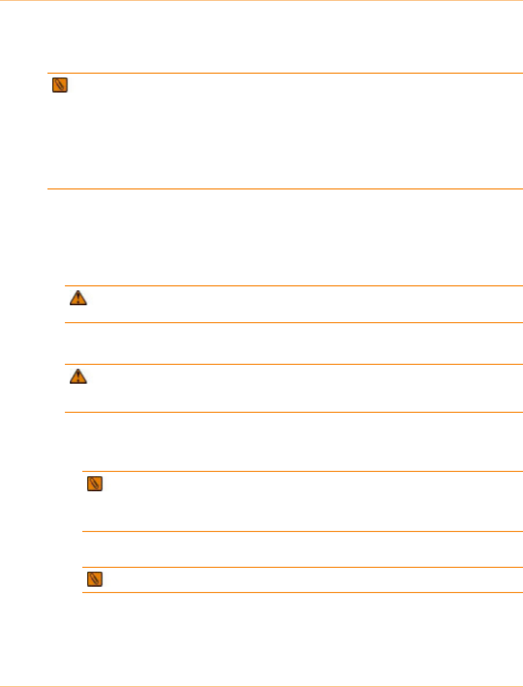
SANtricity_10.77 February 2011
LSI Corporation
- 886 -
Installing the Drives into the Destination Storage Array
When you complete this procedure, the drives come online automatically in the storage array.
IMPORTANT Volume group numbering on the destination storage array might change after all of the
drives in the volume group are installed. The controller automatically assigns volume group numbering for
current volume groups and relocated volume groups.
If you have created a snapshot volume of a base volume, in some cases, the snapshot repository volume
and the base volume might reside in different volume groups. If you want to keep the data in the snapshot
volume, you must locate and move all of the volume groups that contain the snapshot repository volumes that
associated with the snapshot volume. If you do not move all of the associated volumes, the snapshot volume
will become unusable in both storage arrays.
1. Open the Enterprise Management Window.
2. Select the destination storage array in the Device table, and start its Array Management Window.
If the Array Management Window for the selected storage array is already open on the storage
management station, a second Array Management Window does not open.
3. Make sure that empty drive slots are available in the Physical pane of the Array Management Window for
the destination storage array.
ATTENTION Possible hardware damage – To prevent electrostatic discharge damage to the
tray, use proper antistatic protection when handling tray components.
4. Put on antistatic protection.
5. Remove the blank drive canisters from the empty drive slots.
ATTENTION Possible damage to drives – If you bump drives against another surface, the drive
mechanism or connectors can be damaged. To avoid damage when you remove or install a drive, always
put your hand under the drive canister to support its weight. Do not touch the electronics on the drive.
6. Install the drive canisters, one at a time, into the destination storage array.
a. Install each drive in one complete motion by inserting it all the way into the slot.
b. Lower (close) the lever to lock the drive securely into place.
IMPORTANT Wait at least two minutes for the controller to write information before you
reinstall the next drive. If you install more than one drive and the controller is not given enough time to
recognize each drive, the storage array can enter into an Unstable status. If time is not available, you
must restart both controllers, which forces the controllers to write the information.
The volume group and its associated volumes will show an Offline status in the Array Management
Window until all the drives in the volume group are replaced.
IMPORTANT Snapshot volumes do not have an Offline status indicator.
These entities show an Offline status:
•The volume group, the volume, and the snapshot repository volume – If you move the
mouse pointer over the volume group or the volume in the Logical pane of the Array Management
Window, a message shows the status as Offline.
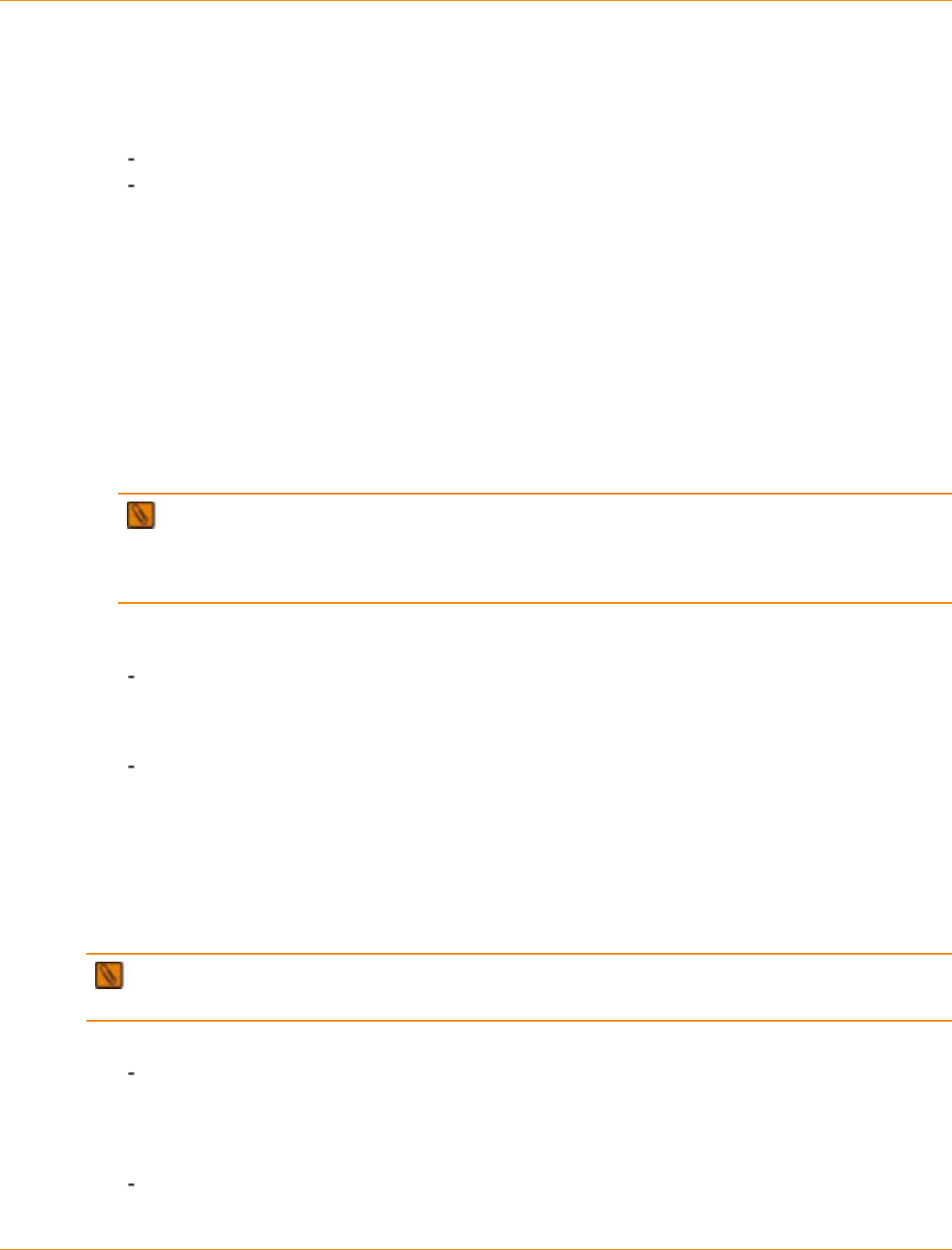
SANtricity_10.77 February 2011
LSI Corporation
- 887 -
•The drive needs attention – If you move the mouse pointer over the drives in the Physical pane
of the Array Management Window, a message shows the status as Offline.
7. Depending on whether the drive appears in the Physical pane of the Array Management Window, perform
one of these actions:
The drive appears in the Physical pane – The drive shows a Needs Attention status. Go to step 9.
The drive does not appear in the Physical pane – Go to step 8.
8. Reinstall the drive.
a. Open the lever, and pull the drive out of the drive tray approximately 5 cm (2 in.).
b. Wait at least two minutes for the drive to spin down.
c. Install the drive in one complete motion by inserting it all the way into the slot.
d. Lower (close) the lever to lock the drive securely in place.
e. Wait another two minutes until the drive appears in the Array Management Window before you install
the next drive.
The drives show a Needs Attention status in the Physical pane of the Array Management Window
until all of the drives from the volume group are installed.
9. Repeat step 5 through step 7 until all of the drives from the volume group are installed.
IMPORTANT The volume group shows an Offline status until all of the drives are installed. When
you install the last drive in the volume group, the volume can show a Failed status temporarily while the
controller is updating. When the update is completed, the volume group comes back online automatically
with an Optimal status.
10. When all of the drives have been installed, make sure that the volume group is back online by checking
the status indicators in the Array Management Window.
The volume group, the volume, and the snapshot repository volume show Optimal status
– If you move the mouse pointer on the volume group or volume in the Logical pane of the Array
Management Window, a message shows the status. A snapshot volume has an Optimal status
indicator or a Contingent status indicator.
The drive shows Assigned status and Optimal status – If you move the mouse pointer on the
drive in the Physical pane of the Array Management Window, a message shows the status.
11. When the volume group is back online, go to “Defining New Storage Partitions.”
Defining New Storage Partitions
Perform these steps if you had used Storage Partitioning to define volume-to-LUN mappings for a volume that
has been moved to the destination storage array.
IMPORTANT Storage Partitioning is a premium feature that you must enable before you create or
change volume-to-LUN mappings.
1. Based on the status of storage partitions, perform one of these actions:
Storage partitions were deleted – If storage partitions were deleted while the volume group resided
in the source storage array, you must create new storage partitions when the volume group is
relocated to the destination storage array. If new storage partitions are not defined, hosts connected
to the destination storage array are not able to detect the volumes in the new volume group. Go to
step 3.
Volume-to-LUN mappings were changed to the Default Group – Go to step 2.

SANtricity_10.77 February 2011
LSI Corporation
- 888 -
2. If you changed the host group for specific volume-to-LUN mappings to the Default Group while the
volume group resided in the source storage array, perform one of these actions:
You will use default mappings – The Default Group for the destination storage array detects the
volumes when you install the volume group in the destination storage array. Any hosts or host groups
in the Default Group of the destination storage array can access the volumes. Go to “Completing the
Volume Group Relocation.”
You will use Storage Partitioning – You can map a specific host or hosts to the volumes in the
destination storage array. Go to step 3.
3. To define a new storage partition, perform these actions:
a. Select a volume in the Topology pane of the Mappings tab.
b. To create a new volume-to-LUN mapping, select Mappings >> Define >> Storage Partitioning.
c. Follow the instructions on each dialog, and click Next when you are ready to move to the next dialog.
d. To complete the volume-to-LUN mapping, click Finish.
A dialog shows the progress of the processing.
e. To return to the Mappings tab, click OK.
4. Depending on whether you have additional volumes to map to hosts or host groups, perform one of these
actions:
You have additional volumes to map to hosts or host groups – Repeat step 3.
You are finished mapping volumes to hosts or host groups – Go to step 5.
5. Run the host hot_add utility, if applicable for your operating system.
6. Go to “Completing the Volume Group Relocation.”
Completing the Volume Group Relocation
1. Mount any file systems, if applicable, for the operating system.
2. Start the host applications that are associated with the volumes.
3. Create a storage array all support data collection for the source storage array that is affected by the
procedure.
a. Save the storage array all support data collection.
b. Open and view the storage array all support data collection files.
For information about creating a storage array all support data collection, see “Creating Storage Array All
Support Data Collections.”
4. Repeat step 3 for the destination storage array.

SANtricity_10.77 February 2011
LSI Corporation
- 889 -
Failover Drivers
This topic describes how to use the various failover drivers for the Windows operating system, the Linux
operating system, and Solaris operating system with SANtricity ES Storage Manager Version 10.75.

SANtricity_10.77 February 2011
LSI Corporation
- 890 -
Overview of Failover Drivers
Failover drivers provide redundant path management for storage devices and cables in the data path from the
host bus adapter to the controller. For example, you can connect two host bus adapters in the system to the
redundant controller pair in a storage array, with different buses for each controller. If one host bus adapter,
one bus cable, or one controller fails, the failover driver automatically reroutes input/output (I/O) to the good
path, which permits the storage array to continue operating without interruption.
Failover drivers provide these functions:
They automatically identify redundant I/O paths.
They automatically reroute I/O to an alternate controller when a controller fails or all of the data paths to a
controller fail.
They check the state of known paths to the storage array.
They provide status information on the controller and the bus.
They check to see if the Service mode is enabled and if the modes have switched between Redundant
Dual Active Controller (RDAC) and Auto-Volume Transfer (AVT).
Supported Failover Drivers Matrix
Matrix of Supported Failover Drivers by Operating System (OS)
Windows OS Red Hat
Enterprise Linux
(RHEL) 4 OS
Update 8 and
RHEL 5 OS
Update 4
SUSE Linux
Enterprise
(SLES) 10 OS
Service Pack 3
and SLES 11 OS
Solaris 9 OS
and Solaris 10
OS
Failover
driver type MPIO RDAC RDAC MPxIO
Storage array
mode Either Mode
Select or AVT Either Mode
Select or AVT Either Mode
Select or AVT Mode Select
Number
of paths
supported
4 (default), 32
maximum 4 (default), 32
maximum 4 (default), 32
maximum 4
Number of
volumes
supported
255 256 for the Linux
2.4 OS
256 – 1 for the
Linux 2.6 OS
256 for the Linux
2.4 OS
256 – 1 for the
Linux 2.6 OS
255
Failover
through
single host
bus adapter
(HBA)
support?*
Yes, as long
as at least one
good path to
each controller is
detected
Yes, as long
as at least one
good path to
each controller is
detected
Yes, as long
as at least one
good path to
each controller is
detected
Yes
Cluster
support? Yes Yes Yes Yes

SANtricity_10.77 February 2011
LSI Corporation
- 891 -
Windows OS Red Hat
Enterprise Linux
(RHEL) 4 OS
Update 8 and
RHEL 5 OS
Update 4
SUSE Linux
Enterprise
(SLES) 10 OS
Service Pack 3
and SLES 11 OS
Solaris 9 OS
and Solaris 10
OS
* Using failover through a single HBA support is not recommended.
Failover Driver Setup Considerations
Most storage arrays contain two controllers that are set up as redundant controllers. If one controller fails, the
other controller in the pair takes over the functions of the failed controller, and the storage array continues to
process data. You can then replace the failed controller and resume normal operation. You do not need to
shut down the storage array to perform this task.
The redundant controller feature is managed by the failover driver software, which controls data flow to the
controller pairs independent of the operating system (OS). This software tracks the current status of the
connections and can perform the switch-over without any changes in the OS.
Whether your storage arrays have the redundant controller feature depends on a number of items:
Whether the hardware supports it. Refer to the hardware documentation for your storage arrays to
determine whether the hardware supports redundant controllers.
Whether your OS supports certain failover drivers. Refer to the installation and support guide for your OS
to determine if your OS supports redundant controllers.
How the storage arrays are connected. The storage array must have two controllers installed in a
redundant configuration. Redundant controllers can be configured only as an active/active pair. In an
active/active pair, you can have multiple paths from the hosts to the active controller, and you perform
load balancing on all of the active paths. Each controller has specific volumes assigned to it automatically.
If one of the active controllers fails, the software automatically switches its assigned volumes to the other
active controller.

SANtricity_10.77 February 2011
LSI Corporation
- 892 -
Failover Configuration Diagrams
You can configure failover in several ways. Each configuration has its own advantages and disadvantages.
This section describes these configurations:
Single-host configuration
Multi-host configuration
This section also describes how the storage management software supports redundant controllers.
NOTE For best results, use the multi-host configuration. It provides the fullest failover protection and
functionality in the event that a problem exists with the connection.
Single-Host Configuration
In a single-host configuration, the host system contains two host bus adapters (HBAs), with each HBA
connected to one of the controllers in the storage array. The storage management software is installed on the
host. The two connections are required for maximum failover support for redundant controllers.
Although you can have a single controller in a storage array or a host that has only one HBA port, you
do not have complete failover data path protection with either of those configurations. The cable and the
HBA become a single point of failure, and any data path failure could result in unpredictable effects on the
host system. For the greatest level of I/O protection, provide each controller in a storage array with its own
connection to a separate HBA in the host system.
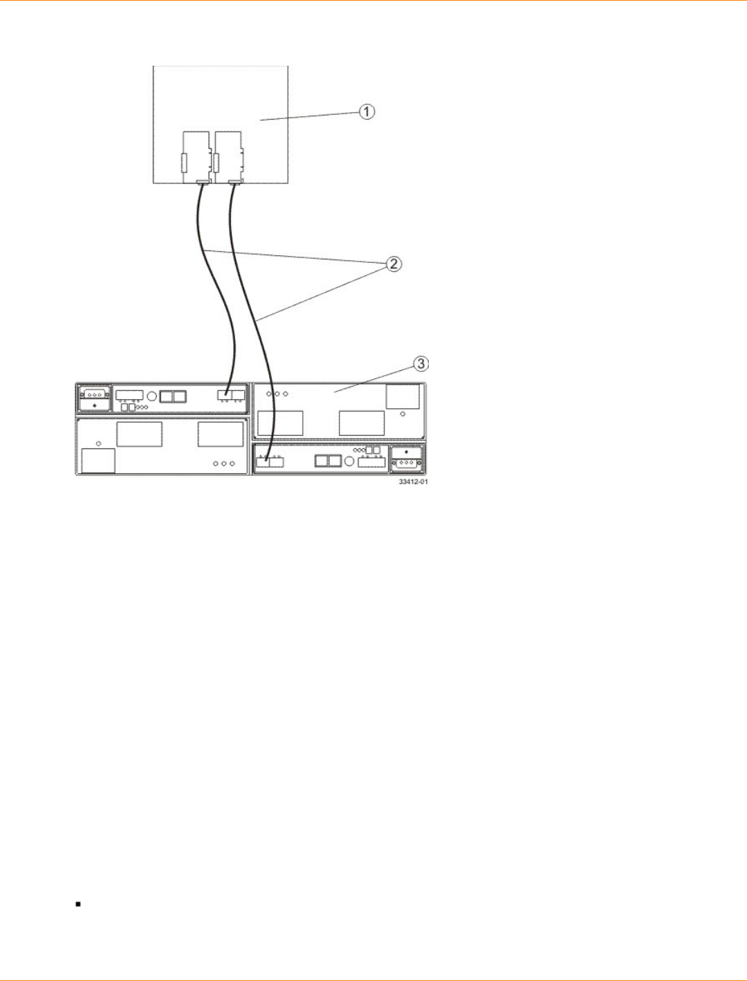
SANtricity_10.77 February 2011
LSI Corporation
- 893 -
Single-Host-to-Storage Array Configuration
1. Host System with Two Fibre Channel Host Bus Adapters
2. Fibre Channel Connection – Fibre Channel Connection Might Contain One or More Switches
3. Storage Array with Two Fibre Channel Controllers
Multi-Host Configuration
For best results, use the multi-host configuration. It provides the best failover protection and functionality in
the event that a problem exists with the connection.
In a multi-host configuration, two host systems are each connected by two connections to both of the
controllers in a storage array. SANtricity ES Storage Manager, including failover driver support, is installed on
each host.
Not every operating system supports this configuration. Consult the restrictions in the installation and support
guide specific to your operating system for more information. Also, the host systems must be able to handle
the multi-host configuration. Refer to the applicable hardware documentation.
Both hosts have complete visibility of both controllers, all data connections, and all configured volumes in a
storage array, plus failover support for the redundant controllers. However, in this configuration, you must use
caution when you perform storage management tasks (especially deleting and creating volumes) to make
sure that the two hosts do not send conflicting commands to the controllers in the storage arrays.
These items are unique to this configuration:
Both hosts must have the same operating system version and SANtricity ES Storage Manager version
installed.
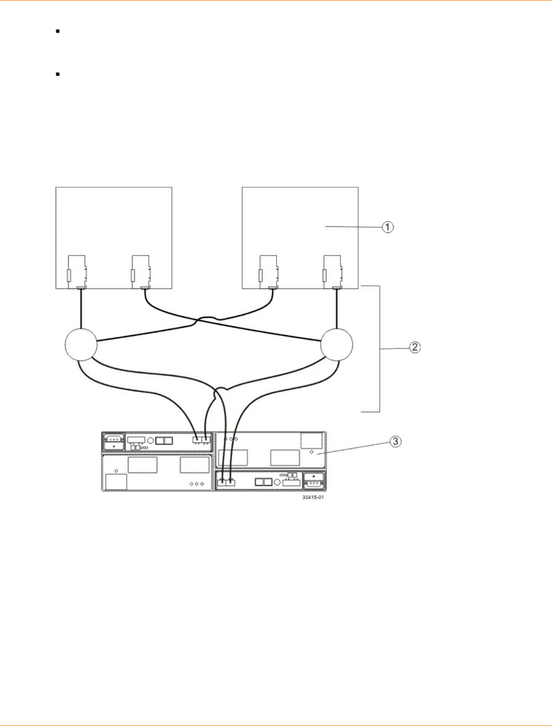
SANtricity_10.77 February 2011
LSI Corporation
- 894 -
Both host systems must have the same volumes-per-host bus adapter capacity. This capacity is important
for failover situations so that each controller can take over for the other and show all of the configured
volume groups and volumes.
If the operating system on the host system can create reservations, the storage management software
honors them. This concept means that each host could have reservations to specified volume groups and
volumes, and only the software on that host can perform operations on the reserved volume group and
volume. Without reservations, the software on either host system is able to start any operation. Therefore,
you must use caution when you perform certain tasks that need exclusive access. Especially when you
create and delete volumes, make sure that you have only one configuration session open at a time (from
only one host), or the operations that you perform could fail.
Multi-Host-to-Storage Array Configuration
1. Two Host Systems, Each with Two Fibre Channel Host Bus Adapters
2. Fibre Channel Connections with Two Switches (Might Contain Different Switch Configurations)
3. Storage Array with Two Fibre Channel Controllers
Supporting Redundant Controllers
The following figure shows how failover drivers provide redundancy when the host application generates a
request for I/O to controller A, but controller A fails. Use the numbered information to trace the I/O data path.
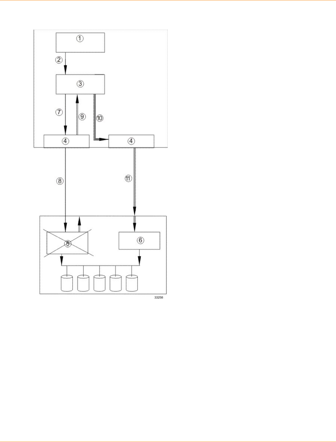
SANtricity_10.77 February 2011
LSI Corporation
- 895 -
Example of Failover I/O Data Path Redundancy
1. Host Application
2. I/O Request
3. Failover Driver
4. Host Bus Adapters
5. Controller A Failure
6. Controller B
7. Initial Request to the HBA
8. Initial Request to the Controller Failed
9. Request Returns to the Failover Driver
10. Failover Occurs and I/O Transfers to Another Controller
11. I/O Request Re-sent to Controller B

SANtricity_10.77 February 2011
LSI Corporation
- 896 -
How a Failover Driver Responds to a Data Path Failure
One of the primary functions of the failover feature is to provide path management. Failover drivers monitor
the data path for devices that are not working correctly or for multiple link errors. If a failover driver detects
either of these conditions, the driver automatically performs these steps:
The failover driver checks the pair table for the redundant controller.
The failover driver forces volumes to the other controller and routes all I/O to the remaining active
controller.
The older version of RDAC notifies you that an error has occurred with the Service Action Required LEDs
on the storage array, and with a message that was sent to the error logs. The newer versions of RDAC
and MPIO only send a message to the error logs.
The failover driver performs a path failure if alternate paths to the same controller are available. If all of
the paths to a controller fail, RDAC performs a controller failure.
A drive failure plus a controller failure are considered a double failure. The storage management software
provides data integrity as long as all drive failures and controller failures are detected and fixed before more
failures occur.

SANtricity_10.77 February 2011
LSI Corporation
- 897 -
Responding to a Data Path Failure
Use the Major Event Log (MEL) to respond to a data path failure. The information in the MEL provides the
answers to these questions:
What is the source of the error?
What is required to fix the error, such as replacement parts or diagnostics?
The next step depends on whether you are a system administrator or a Customer and Technical Support
representative.
Responding to a Data Path Failure When You Are a System Administrator
Under most circumstances, contact your Customer and Technical Support representative any time a path
fails and the storage array notifies you of the failure. If your controller has failed and your storage array has
customer-replaceable controllers, replace the failed controller. Follow the manufacturer’s instructions for how
to replace a failed controller.
Responding to a Data Path Failure When You Are a Customer and Technical
Support Representative
Use the Recovery Guru in the storage management software to diagnose and fix the problem, if possible. If
you cannot fix the problem with the Recovery Guru, follow the manufacturer’s instructions for how to replace a
failed controller.
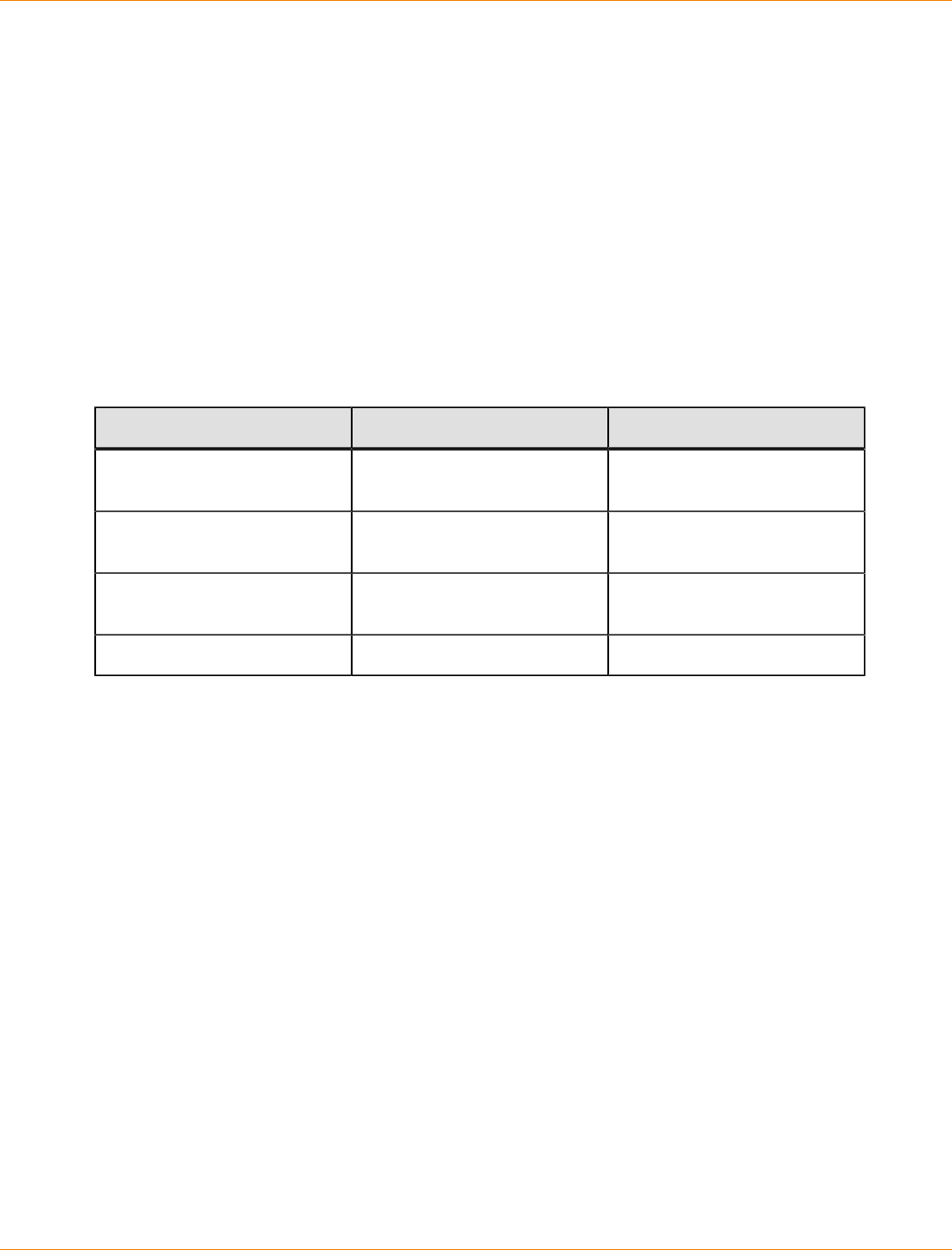
SANtricity_10.77 February 2011
LSI Corporation
- 898 -
Load-Balancing Policies
Load balancing is the redistribution of read/write requests to maximize throughput between the server and the
storage array. Load balancing is very important in high workload settings or other settings where consistent
service levels are critical. The multi-path driver transparently balances I/O workload without administrator
intervention. Without multi-path software, a server sending I/O requests down several paths might operate
with very heavy workloads on some paths, while other paths are not used efficiently.
The multi-path driver determines which paths to a device are in an active state and can be used for load
balancing. The load-balancing policy uses one of three algorithms: round robin, least queue depth, or least
path weight. Multiple options for setting the load-balancing policies let you optimize I/O performance when
mixed host interfaces are configured. The load-balancing policies that you can choose depend on your
operating system. Load balancing is performed on multiple paths to the same controller but not across both
controllers.
Load-Balancing Policies That Are Supported by the Operating Systems
Operating System Multi-Path Driver Load-Balancing Policy
Windows MPIO DSM Round robin with subset, least
queue depth, weighted paths
Red Hat Enterprise Linux
(RHEL) RDAC Round robin with subset, least
queue depth
SUSE Linux Enterprise
(SLES) RDAC Round robin with subset, least
queue depth
Solaris MPxIO Round robin with subset
Least Queue Depth
The least queue depth policy is also known as the least I/Os policy or the least requests policy. This policy
routes the next I/O request to the data path on the controller that owns the volume that has the least
outstanding I/O requests queued. For this policy, an I/O request is simply a command in the queue. The type
of command or the number of blocks that are associated with the command is not considered. The least
queue depth policy treats large block requests and small block requests equally. The data path selected is
one of the paths in the path group of the controller that owns the volume.
Round Robin with Subset I/O
The round robin with subset I/O load-balancing policy routes I/O requests, in rotation, to each available
data path to the controller that owns the volumes. This policy treats all paths to the controller that owns the
volume equally for I/O activity. Paths to the secondary controller are ignored until ownership changes. The
basic assumption for the round robin with subset I/O policy is that the data paths are equal. With mixed host
support, the data paths might have different bandwidths or different data transfer speeds.
Least Weighted Paths
The least weighted paths policy assigns a weight factor to each data path to a volume. An I/O request is
routed to the path with the lowest weight value to the controller that owns the volume. If more than one data
path to the volume has the same weight value, the round-robin with subset path selection policy is used to
route I/O requests between the paths with the same weight value.
SANtricity_10.77 February 2011
LSI Corporation
- 899 -
Configuring Failover Drivers for the Windows OS and the Linux
OS
NOTE This topic applies to both the Windows OS and the Linux OS.
Dividing I/O Activity Between Two RAID Controllers to Obtain the Best
Performance
For the best performance of a redundant controller system, use the storage management software to divide
I/O activity between the two RAID controllers in the storage array. You can use either the graphical user
interface (GUI) or the command line interface (CLI).
To use the GUI to divide I/O activity between two RAID controllers, perform one of these steps:
Specify the owner of the preferred controller of an existing volume – Select Volume >> Change >>
Ownership/Preferred Path in the Array Management Window.
NOTE You can also use this method to change the preferred path and ownship of all volumes in a
volume group at the same time.
Specify the owner of the preferred controller of a volume when you are creating the volume –
Select Volume >> Create in the Array Management Window.
To use the CLI, go to theCreate RAID Volume (Free Extent Based Select) online help topic for the command
syntax and description.
Changing the Preferred Path Online Without Stopping the Applications
You can change the preferred path setting for a volume or a set of volumes online and without stopping the
applications. If AVT is not enabled, the driver uses the new preferred path immediately. However, if AVT is
enabled, the driver does not recognize that the preferred path has changed until the next cycle of the state
change monitor. Therefore, the driver might continue to use the old preferred path for up to 60 seconds,
or for the period to which the ScanInterval parameter is set. Because the driver continues to use the
non-preferred path for a short period of time,the driver might trigger a volume not on preferred path Needs
Attention condition in the storage management software. This condition is removed as soon as the state
change monitor is run. A MEL event and an associated alert notification are delivered for the volume that
is not on preferred path condition. If the driver needs some time to recognize that the preferred path has
changed, you can configure the AVT alert delay period with the storage management software. The Needs
Attention reporting is postponed until the driver failback task has had a chance to run.
NOTE The newer versions of the RDAC driver and the DSM driver do not recognize any AVT status
change (enabled or disabled) until the next cycle of the state change monitor.
SANtricity_10.77 February 2011
LSI Corporation
- 900 -
Failover Drivers for the Windows Operating System
The failover driver for hosts with Microsoft Windows operating systems is Microsoft Multipath I/O (MPIO) with
a Device Specific Module (DSM) for SANtricity ES Storage Manager.
Microsft Multipath Input/Output
Microsoft Multipath I/O (MPIO) provides an infrastructure to build highly available solutions for Windows
operating systems (OSs). MPIO uses Device Specific Modules (DSMs) to provide I/O routing decisions, error
analysis, and failover.
NOTE You can use MPIO for all controllers that run controller firmware version 6.19 or later. MPIO
is not supported for any earlier versions of the controller firmware, and MPIO cannot coexist on a server
with RDAC. If you have legacy systems that run controller firmware versions earlier than 6.19, you must use
RDAC for your failover driver. For SANtricity ES Storage Manager Version 10.10 and later and all versions of
SANtricity Storage Manager, the Windows OS supports only MPIO.
Windows OS Restrictions
The MPIO DSM failover driver comes in these versions:
32-bit (x86)
64-bit Intel (Itanium or IA64)
64-bit AMD/EM64T (x64)
These versions are not compatible with each other. Because multiple copies of the driver cannot run on the
same system, each subsequent release is backward compatible. In other words, a SANtricity ES Storage
Manager Version 10.60 failover driver supports storage management software version 9.23.
You can use the DSM driver for all of the controllers that run controller firmware version 6.19 or later. The
DSM driver is not supported for any earlier versions of the controller firmware, and it cannot coexist on a
server with RDAC. If you have legacy systems that run controller firmware versions earlier than 6.19, you
must use RDAC for your failover driver.
Native SCSI-2 Release/Reservation Commands in a Multipath Environment
If multiple paths exist to a single controller and a SCSI-2 release/reservation (R/R) is received for a volume,
the DSM driver selects one path to each controller and repeats the request (called a reservation path). This
function is necessary because the controllers cannot accept SCSI-2 R/R requests through multiple paths for
a given volume. After the reservation path has been established, subsequent I/O requests for a volume are
restricted to that path until a SCSI-2 release command is received. The DSM driver distributes the reservation
paths if multiple volumes are mapped to the host, which distributes the load across multiple paths to the same
controller.
Translating SCSI-2 Reservation/Release Commands to SCSI-3 Persistent
Reservations
The DSM driver also supports the ability to translate the SCSI-2 R/R commands into SCSI-3 persistent
reservations. This function allows a volume to use one of the previously mentioned load-balancing policies
across all of the available controller paths rather than being restricted to a single reservation path. This

SANtricity_10.77 February 2011
LSI Corporation
- 901 -
feature requires the DSM driver to establish a unique “reservation key” for each host. This key is stored in
the Registry and is named S2toS3Key. If this key is present, translations are performed, or else the “cloning”
method is used.
Per-Protocol I/O Timeout Values
The timeout value associated with a non-passthrough I/O requests, such as read/write requests, is based
on the MS driver's TimeOutValue parameter, as defined in the Registry. A feature within the DSM allows a
customized timeout value to be applied based on the protocol, such as Fibre Channel, SAS, or iSCSI, that a
path uses. Per-protocol timout values provide these benefits:
Without per-protocol timeout values, the TimeOutValue setting is global and affects all storage.
The TimeOutValue is typically reset when an HBA driver is upgraded.
For Windows Server 2003, the default disk timeout value may be adjusted based on the size of the I/O
request. Adjusting the default disk timeout value helps support legacy SCSI devices.
The DSM feature allows a more predictable timeout setting for Windows Server 2003 environments. For
information about the configurable parameters associated with this feature, go to Configuration Settings
for Windows DSM and Linux RDAC.
The per-protocol timeout values feature slightly modifies the way in which the SynchTimeout parameter is
evaluated. The SynchTimeout parameter determines the I/O timeout for synchronous requests generated
by the DSM driver. Examples include the SCSI-2 to SCSI-3 PR translations and inquiry commands used
during device discovery. It is important that the timeout value for the requests from the DSM driver be at least
as large as the per-protocol I/O timeout value. When a host boots, the DSM driver performs these actions:
If the value of the SynchTimeout parameter is defined in the Registry key of the DSM driver, record the
current value.
If the value of the TimeOutValue parameter of the MS driver is defined in the Registry, record the
current value.
Use the higher of the two values as the initial value of the SynchTimeout parameter.
If neither value is defined, use a default value of 10 seconds.
For each synchronous I/O request, the higher value of either the per-protocol I/O timeout or the
SynchTimeout parameter is used. For example:
If the value of the SynchTimeout parameter is 120 seconds, and the value of the TimeOutValue
parameter is 60 seconds, 120 seconds is used for the initial value.
If the value of the SynchTimeout parameter is 120 seconds, and the value of the TimeOutValue
parameter is 180 seconds, 180 seconds is used for the initial value of the synchronous I/O requests
for the DSM driver.
If the I/O timeout value for a different protocol (for example, SAS) is 60 seconds and the initial value
is 120 seconds, the I/O will be sent using a 120-second timeout.
Selective LUN Transfer
This feature limits the conditions under which the DSM will move a LUN to the alternative controller to three
cases:
1. When a DSM with a path to only one controller, the non-preferred path, discovers a path to the alternate
controller.
2. When an I/O request is directed to a LUN that is owned by the preferred path, but the DSM is attached to
only the non-preferred path.

SANtricity_10.77 February 2011
LSI Corporation
- 902 -
3. When an I/O request is directed to a LUN that is owned by the non-preferred path, but the DSM is
attached to only the preferred path.
Cases 2 and 3 have these user-configurable parameters that can be set to tune the behavior of this feature.
The maximum number of times that the LUN transfer will be issued. This parameter setting prevents a
continual ownership thrashing condition from occurring in cases where the controller tray or the controller-
drive tray is attached to another host that requires the LUN be owned by the current controller.
A time delay before LUN transfers are attempted. This parameter is used to de-bounce intermittent I/
O path link errors. During the time delay, I/O requests will be retried on the current controller to take
advantage of the possibility that another host might transition the LUN to the current controller.
For further information on these two parameters, go to Configuration Settings for Windows DSM and Linux
RDAC.
In the case where the host system is connected to both controllers and an I/O is returned with a 94/01 status
(the LUN is not owned and can be owned), the DSM will modify its internal data on which controller to use for
that LUN and reissue the command to the other controller. The DSM will not issue a LUN transfer command
to the controller tray or controller-drive tray to avoid interfering with other hosts that might be attached to that
controller tray or the controller-drive tray.
When the DSM detects that a volume-transfer operation is required, the DSM will not immediately issue the
command. It will delay for three seconds before sending the command to the controller tray or the controller-
drive tray. This delay is to attempt to batch together as many volume-transfer operations for other LUNs as
possible. This batching method is used because the controller single-threads volume transfer operations and
will reject additional transfer commands until the controller has completed the operation it is currently working
on. This single-threading behavior extends the period of time that I/Os are not being successfully serviced by
the controller tray or the controller-drive tray.
This feature will be enabled if these conditions exist:
The controller tray or the controller-drive tray does not have AVT enabled.
The DSM configurable parameter ClassicModeFailover is set to 1.
The DSM configurable parameter DisableLunRebalance is set to 4.
Windows Failover Cluster
Clustering for the Windows Server 2008 OS and the Windows Server 2008 R2 OS uses SCSI-3 persistent
reservations natively. As a result, the DSM driver does not perform translations for any SCSI-2 R/R
commands, and you can use one of the previously mentioned load-balancing policies across all controller
paths. Translations still occur if the DSM driver is running in a Windows Server 2003 OS-based environment.
When using clustering, set the DisableLunRebalance parameter to 3. For information about this
parameter, go to Configuration Settings for Windows DSM and Linux RDAC.
Reduced Failover Timing
Settings related to drive I/O timeout and HBA connection loss timeout are adjusted in the host operating
system so that failover does not occur when a controller is restarted. These settings provide protection from
exception conditions that might occur when both controllers in a controller tray or a controller-drive tray are
restarted at the same time, but they have the unfortunate side-effect of causing longer failover times than may
be tolerated by some application or clustered environments. Support for the reduced failover timing feature
includes support for reduced timeout settings, which result in faster failover response times.
The following restrictions apply to this feature:

SANtricity_10.77 February 2011
LSI Corporation
- 903 -
Only the Windows Server 2008 OS and the Windows Server 2008 R2 OS support this feature.
Non-enterprise products attached to a host must use controller firmware release 7.35 or higher.
Enterprise products attached to a host must use controller firmware release 7.6 or higher. For
configurations where a mix of earlier releases is installed, older versions are not supported.
When this feature is used with Windows Server Failover Cluster (WSFC) on the Windows Server 2008
OS, MPIO HotFix 970525 is required. The required HotFix is a standard feature for the Windows Server
2008 R2 OS.
Additional restrictions apply to storage array brownout conditions. Depending on how long the brownout
condition lasts, PR registration information for volumes might be lost. By design, WSFC periodically polls the
cluster storage to determine the overall health and availability of the resources. One action performed during
this polling is a PRIN READ_KEYS request, which returns registration information. Because a brownout
condition can cause blank information to be returned, WSFC interprets this as a loss of access to the drive
resource and attempts recovery by first failing that drive resource, and then performing a new arbitration.
NOTE Any condition that causes blank registration information to be returned, where previous requests
returned valid registration information, can cause the drive resource to fail. If the arbitration succeeds, the
resource is brought online. Otherwise, the resource remains in a failed state. One reason for an arbitration
failure is the combination of brownout condition and PnP timing issues if the HBA timeout period expires.
When the timeout period expires, the OS is notified of an HBA change and must re-enumerate the HBAs to
determine which devices no longer exist or, in the case where a connection is re-established, what devices
are now present.
The arbitration recovery process happens almost immediately after the resource is failed. This situation, along
with the PnP timing issue, can result in a failed recovery attempt. Fortunately, you can modify the timing of
the recovery process by using the cluster. exe command-line tool. Microsoft recommends changing the
following, where resource_name is a cluster disk resource, such as Cluster Disk 1:
cluster.exe resource “resource_name” /prop RestartDelay=4000
cluster.exe resource “resource_name” /prop RestartThreshold=5
The previous example changes the disk-online delay to four seconds and the number of online restarts to five.
The changes must be repeated for each drive resource. The changes will persist across reboots. To display
the current (or changed) settings, use the following command:
cluster.exe resource “resource_name” /prop
Another option exists to prevent the storage array from returning blank registration information. This option
takes advantage of the Active Persist Through Power Loss (APTPL) feature found in Persistent Reservations,
which ensures that the registration information persists through brownout or other conditions related to a
power failure. APTPL is enabled when a registration is initially made to the drive resource. WSFC does
not use the APTPL feature, but an option is provided in the LSI DSM to set this feature when a registration
request is made.
IMPORTANT Because the APTPL feature is not supported in WSFC, Microsoft does not recommend
its use. The APTPL feature should be considered as an option of last resort when the cluster. exe
options cannot meet the tolerances needed. If a cluster setup cannot be brought online successfully after
this option is used, the controller shell or SYMbol commands might be required to clear existing persistent
reservations.
SANtricity_10.77 February 2011
LSI Corporation
- 904 -
NOTE The APTPL feature within the DSM is enabled using the DSM utility with the - o (feature) option
by setting the SetAPTPLForPR option to 1. According to the SCSI specification, you must this option before
PR registration occurs. If you set this option after a PR registration occurs, take the disk resource offline, and
then bring the disk resource back online. If the DSM has set the APTPL option during registration, an internal
flag is set, and the DSM utility output from the -g option indicates this condition. The SCSI specification does
not provide a means for the initiator to query the storage array to determine the current APTPL setting. As a
result, the -g output from one node might show the option set, but another node might not. Interpret output
from the -g option with caution. By default, the DSM is released without this option enabled.
Wait Time Settings
When the failover driver receives an I/O request for the first time, the failover driver logs timestamp
information for the request. If a request returns an error and the failover driver decides to retry the request,
the current time is compared with the original timestamp information. Depending on the error and the amount
of time that has elapsed, the request is retried to the current owning controller for the LUN, or a failover
is performed and the request sent to the alternate controller. This process is known as a wait time. If the
NotReadyWaitTime value, the BusyWaitTime value, and the QuiescenceWaitTime value are greater
than the ControllerIoWaitTime value, they will have no effect.
For the Linux OS, the configuration settings can be found in the /etc/mpp.conf file. For the Windows OS,
the configuration settings can be found in the Registry under:
HKEY_LOCAL_MACHINE\System\CurrentControlSet\ Services\<DSM_Driver>
In the preceding setting, <DSM_Driver> is the name of the OEM-specific driver. The default driver is named
mppdsm.sys. Any changes to the settings take effect the next time the host is restarted.
ATTENTION Possible loss of data access – If you change these settings from their configured
values, you might lose access to the storage array.
Configuration Settings for the Path Congestion Detection Feature
Parameter Name Default Value
(Operating
System)
Description
NotReadyWaitTime 300 (Windows)
270 (Linux) The time, in seconds, a Not Ready condition (SK
0x06, ASC/ASCQ 0x04/0x01) is allowed before
failover is performed.
Valid values range from 0x1 to 0xFFFFFFFF.
BusyWaitTime 600 (Windows)
270 (Linux) The time, in seconds, a Busy condition is
allowed before a failover is performed.
Valid values range from 0x1 to 0xFFFFFFFF.
QuiescenceWaitTime600 (Windows)
270 (Linux) The time, in seconds, a Busy condition is
allowed before a failover is performed.
Valid values range from 0x1 to 0xFFFFFFFF.
ControllerIoWaitTime600 (Windows)
120 (Linux) Provides an upper-bound limit, in seconds, that
an I/O is retried on a controller regardless of
retry status before a failover is performed. If the
limit is exceeded on the alternate controller, the
SANtricity_10.77 February 2011
LSI Corporation
- 905 -
Parameter Name Default Value
(Operating
System)
Description
I/O is again attempted on the original controller.
This process continues until the value of the
ArrayIoWaitTime limit is reached.
Valid values range from 0x1 to 0xFFFFFFFF.
ArrayIoWaitTime 600 (Windows
DSM)
600 (Linux RDAC)
Provides an upper-bound limit, in seconds, that
an I/O is retried to the storage array regardless
of to which controller the request is attempted.
After this limit is exceeded, the I/O is returned
with a failure status.
Valid values range from 0x1 to 0xFFFFFFFF.
Path Congestion Detection and Online/Offline Path States
The path congestion detection feature allows the DSM driver to place a path offline based on the path I/
O latency. The DSM will automatically set a path offline when I/O response times exceed user-definable
congestion criteria. An administrator can manually place a path into the Admin Offline state. When a path is
either set offline by the DSM or by an administrator, I/O will be routed to a different path. The offline or admin
offline path will not be used for I/O until the system administrator sets the path online.
For more information on path congestion configurable parameters, go to Configuration Settings for Windows
DSM and Linux RDAC.
Configuration Settings for Windows DSM and Linux RDAC
This topic applies to both the Windows OS and the Linux OS. The failover driver that is provided with the
storage management software contains configuration settings that can modify the behavior of the driver.
For the Linux OS, the configuration settings are in the /etc/mpp.conf file.
For the Windows OS, the configuration settings are in the HKEY_LOCAL_MACHINE\System
\CurrentControlSet\ Services\<DSM_Driver>\Parameters registry key, where
<DSM_Driver> is the name of the OEM-specific driver.
The default driver is mppdsm.sys. Any changes to the settings take effect on the next reboot of the host.
The default values listed in the following table apply to both the Windows OS and the Linux OS unless the OS
is specified in parentheses. Many of these values are overridden by the failover installer for the Linux OS or
the Windows OS.
ATTENTION Possible loss of data access – If you change these settings from their configured
values, you might lose access to the storage array.
SANtricity_10.77 February 2011
LSI Corporation
- 906 -
Configuration Settings for Windows DSM and Linux RDAC
Parmeter Name Default
Value
(Operating
System)
Description
MaxPathsPerController 4The maximum number of paths (logical
endpoints) that are supported per controller.
The total number of paths to the storage
array is the MaxPathsPerController
value multiplied by the number of
controllers. The allowed values range from
0x1 (1) to 0x20 (32) for Windows, and from
0x1 (1) to 0xFF (255) for Linux RDAC.
For use by Customer and Technical Support
representatives only.
ScanInterval 1
(Windows)
60
(Linux)
The interval time, in seconds, that
the failover driver will check for these
conditions:
A change in preferred ownership for a
LUN
An attempt to rebalance LUNs to their
preferred paths
A change in AVT enabled status or
disabled status
For the Windows OSs, the allowed values
range from 0x1 to 0xFFFFFFFF and must
be specified in minutes.
For the Linux OSs, the allowed values range
from 0x1 to 0xFFFFFFFF and must be
specified in seconds.
For use by Customer and Technical Support
representatives only.
ErrorLevel 3This setting determines which errors to log.
These values are valid:
0 – Display all errors
1 – Display path failover errors,
controller failover errors, retryable
errors, fatal errors, and recovered errors
2 – Display path failover errors,
controller failover errors, retryable
errors, and fatal errors
3 – Display path failover errors,
controller failover errors, and fatal errors
4 – Display controller failover errors,
and fatal errors

SANtricity_10.77 February 2011
LSI Corporation
- 907 -
Parmeter Name Default
Value
(Operating
System)
Description
For use by Customer and Technical Support
representatives only.
SelectionTimeoutRetryCount 0The number of times a selection timeout is
retried for an I/O request before the path
fails. If another path to the same controller
exists, the I/O is retried. If no other path to
the same controller exists, a failover takes
place. If no valid paths exist to the alternate
controller, the I/O is failed.
The allowed values range from 0x0 to
0xFFFFFFFF.
For use by Customer and Technical Support
representatives only.
CommandTimeoutRetryCount 1The number of times a command timeout
is retried for an I/O request before the path
fails. If another path to the same controller
exists, the I/O is retried. If another path to
the same controller does not exist, a failover
takes place. If no valid paths exist to the
alternate controller, the I/O is failed.
The allowed values range from 0x0 to
0xa (10) for Windows, and from 0x0 to
0xFFFFFFFF for Linux RDAC.
For use by Customer and Technical Support
representatives only.
UaRetryCount 10 The number of times a Unit Attention (UA)
status from a LUN is retried. This parameter
does not apply to UA conditions due to
Quiescence In Progress.
The allowed values range from 0x0 to
0x64 (100) for Windows, and from 0x0 to
0xFFFFFFFF for Linux RDAC.
For use by Customer and Technical Support
representatives only.
SynchTimeout 120 The timeout, in seconds, for synchronous
I/O requests that are generated internally
by the failover driver. Examples of
internal requests include those related to
rebalancing, path validation, and issuing of
failover commands.
The allowed values range from 0x1 to
0xFFFFFFFF.
For use by Customer and Technical Support
representatives only.
SANtricity_10.77 February 2011
LSI Corporation
- 908 -
Parmeter Name Default
Value
(Operating
System)
Description
DisableLunRebalance 0This parameter provides control over the
LUN failback behavior of rebalancing LUNs
to their preferred paths. These values are
possible:
0 – LUN rebalance is enabled for both
AVT and non-AVT modes.
1 – LUN rebalance is disabled for AVT
mode and enabled for non-AVT mode.
2 – LUN rebalance is enabled for AVT
mode and disabled for non-AVT mode.
3 – LUN rebalance is disabled for both
AVT and non-AVT modes.
4 – The selective LUN Transfer feature
is enabled if AVT mode is off and
ClassicModeFailover is set to LUN
level 1.
S2ToS3Key Unique
key This value is the SCSI-3 reservation key
generated during failover driver installation.
NOTE For use by Customer and
Technical Support representatives only.
LoadBalancePolicy 1This parameter determines the load-
balancing policy used by all volumes
managed by the Windows DSM and Linux
RDAC failover drivers. These values are
valid:
0 – round robin with subset.
1 – Least queue depth with subset.
2 – Least path weight with subset
(Windows OS only).
ClassicModeFailover 0This parameter provides control over how
the DSM handles failover situations. These
values are valid:
0 – Perform controller-level failover
(all LUNs are moved to the alternate
controller).
1 – Perform LUN-level failover (only the
LUNs indicating errors are transferred to
the alternate controller).
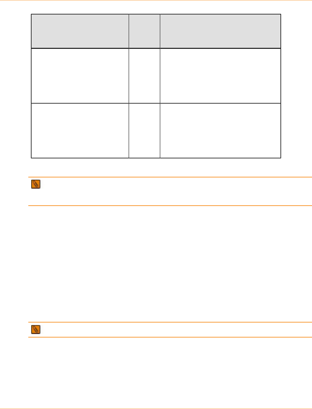
SANtricity_10.77 February 2011
LSI Corporation
- 909 -
Parmeter Name Default
Value
(Operating
System)
Description
SelectiveTransferMaxTransferAttempts3This parameter sets the maximum
number of times that a host will transfer
the ownership of a LUN to the alternate
controller when the Selective LUN Transfer
mode is enabled. This setting prevents
multiple hosts from continually transferring
LUNs between controllers.
SelectiveTransferMinIOWaitTime5This parameter sets the minimum wait time
(in seconds) that the DSM will wait before
transferring a LUN to the alternate controller
when the Selective LUN Transfer mode
is enabled. This parameter tries to stop
excessive LUN transfers due to intermittent
link errors.
Example Configuration Settings for the Path Congestion Detection Feature
IMPORTANT Before path congestion detection can be enabled, you must set the
CongestionResponseTime, CongestionTimeFrame, and CongestionSamplingInterval parameters
to valid values.
To set the path congestion IO response time to 10 seconds:
dsmUtil -o CongestionResponseTime=10,SaveSettings
To set the path congestion sampling interval to one minute:
dsmUtil -o CongestionSamplingInterval=60
To enable path congestion detection:
dsmUtil -o CongestionDetectionEnabled=0x1,SaveSettings
To use the dsmUtil -o command to set a path to Admin Offline:
dsmUtil -o SetPathOffline=0x77070001
NOTE The path ID (in this example 0x77070001) is found using the dsmUtil -g command.
To use the dsmUtil -o command to set a path to online:
dsmUtil -o SetPathOnline=0x77070001

SANtricity_10.77 February 2011
LSI Corporation
- 910 -
Device Specific Module for the Microsoft MPIO Solution
The DSM driver is the hardware-specific part of Microsoft’s MPIO solution. This release supports Microsoft’s
Windows Server 2003 OS, Windows Server 2008 OS, and Windows Server 2008 R2 OS. The Hyper-V role
is also supported when running the DSM within the parent partition. The DSM provides these features for
SANtricity ES Storage Manager Version 10.75.
The directory structures concerning the DSM driver include these paths:
\Device\MPPDSM – This structure contains information that is maintained by the DSM driver.
\Device\Scsi – This structure contains information that is maintained by the ScsiPort driver.
The name MPPDSM might be different if a non-LSI generic solution is installed.
Object Path and Descriptions of the WinObj DSM
Object Path Description
\Device\MPPDSM The root directory for all named objects that
are created by the DSM driver.
\Device\MPPDSM\< storage array >The root directory for all named objects that
are created by the storage array named
<storage array>.
\Device\MPPDSM\< storage array >\<
ctlr >
The root directory for all named objects
that are created for a given controller. The
<ctlr> value can either be A or B.
\Device\MPPDSM\< storage array>
\<ctlr>\ P<port>P<path>I<id>
The root directory for all named objects that
are created for a given path to a controller.
The <port> value, the <path> value, and
the <id> value represent a SCSI address
from a given HBA port.
\Device\Scsi The root directory for all of the named objects
created by the ScsiPort driver. Each object
represents a physical path found by a given
HBA.
\Device\Scsi\< adapter >Port< port
>\ Path< path >Target< target >Lun<
lun >
ScsiPort-based HBA drivers.
A named device object that represents a
drive. The <adapter> value represents the
HBA vendor. For QLogic, this value is based
on the HBA model number (for example,
ql2300). The <port> value, the <path>
value, and the <target> value represent the
location of the volume on the HBA.
\Device\< auto-generated id >StorPort-based HBA drivers. An auto-
generated named device object representing
a drive.
With this information, you can reach these conclusions:

SANtricity_10.77 February 2011
LSI Corporation
- 911 -
The objects shown in the \Device\Scsi directory show the physical volumes that are identified by the
HBAs. If a specific volume is not in this list, the DSM driver cannot detect the volumes.
The objects shown in the \Device\MPPDSM directory show the items that are reported by MPIO to the
DSM driver. If a device is not in this list, MPIO has not notified the DSM driver.
Device Specific Module Driver Directory Structures
NOTE The name MPPDSM in the directory structures might be different based on your network
configuration.
The directory structures for the DSM driver include these paths:
\Device\MPPDSM – This structure contains information that is maintained by the DSM driver. The
objects shown in the \Device\MPPDSM directory in the following table show the items that are reported
by MPIO to the DSM driver. If a device is not in this list, MPIO has not notified the DSM driver.
\Device\Scsi – This structure contains information that is maintained by the ScsiPort driver. The
objects shown in the\Device\Scsi directory in the following table show the physical volumes that are
identified by the HBAs. If a specific volume is not in this list, the DSM driver cannot detect the volumes.
Object Path and Descriptions of the WinObj DSM
Object Path Description
Device\MPPDSM The root directory for all named objects that
are created by the DSM driver.
\Device\MPPDSM\< storage array >The root directory for all named objects that
are created by the storage array named
<storage array>.
\Device\MPPDSM\< storage array >The root directory for all named objects that
are created by the storage array named
<storage array>.
\Device\MPPDSM\< storage array >\<
ctlr >
The root directory for all named objects
that are created for a given controller. The
<ctlr> value can either be A or B.
\Device\MPPDSM\< storage array >\<
ctlr >\ P< port >P< path >I< id >
The root directory for all named objects that
are created for a given path to a controller.
The <port> value, the <path> value, and
the <id> value represent a SCSI address
from a given HBA port.
\Device\MPPDSM\<storage array>\<
ctlr >\ P< port >P< path >I< id >\<
lun >
The <lun> value represents the volume
number assigned to the device for a given
controller/path combination.
\Device\Scsi The root directory for all of the named objects
created by the ScsiPort driver. Each object
represents a physical path found by a given
HBA.
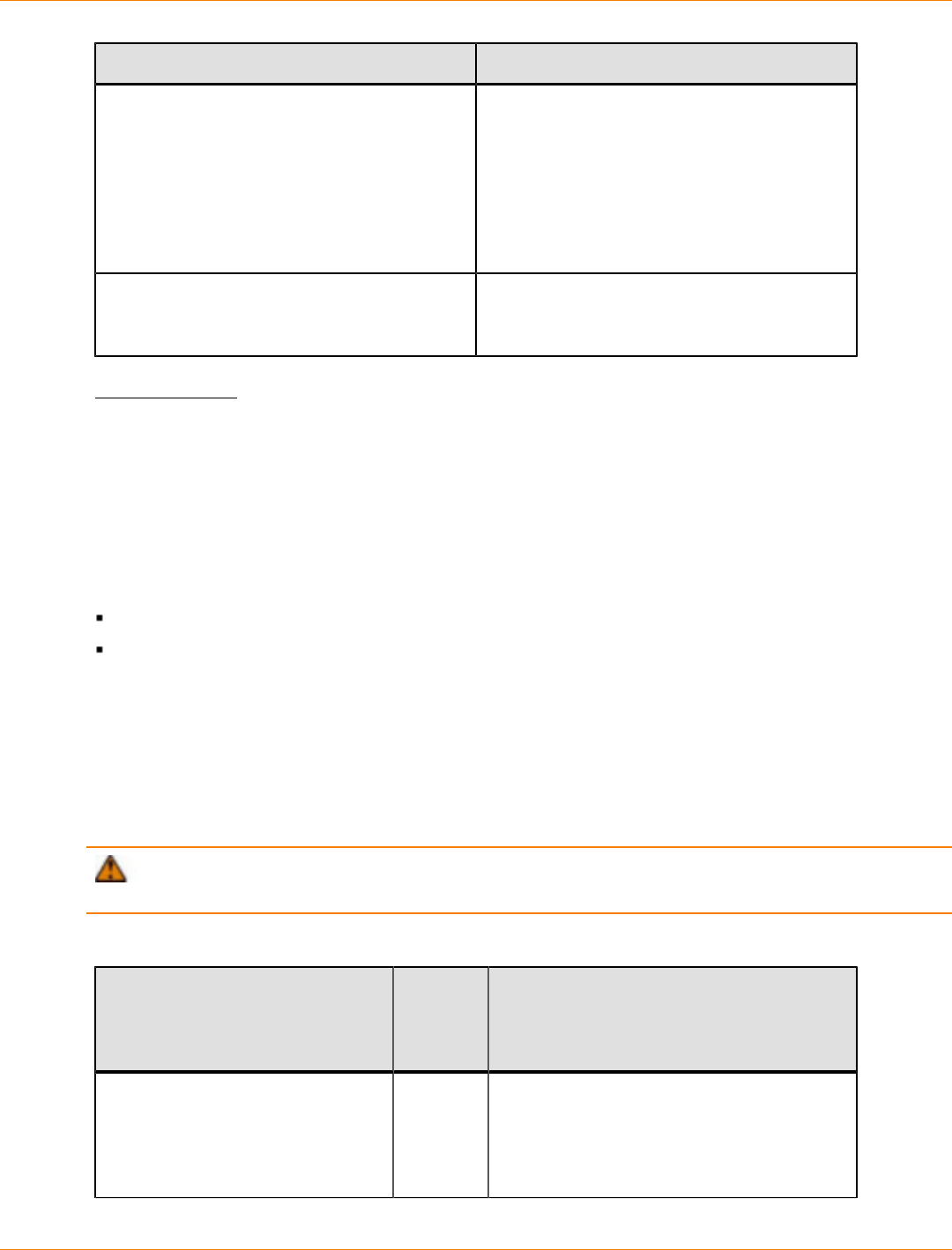
SANtricity_10.77 February 2011
LSI Corporation
- 912 -
Object Path Description
\Device\Scsi\< adapter >Port< port
>\ Path< path >Target< targe t>Lun<
lun >
ScsiPort-based HBA drivers.
A named device object that represents a
drive. The <adapter> value represents the
HBA vendor. For QLogic, this value is based
on the HBA model number (for example,
ql2300). The <port> value, the <path>
value, and the <target> value represent the
location of the volume on the HBA.
\Device\< auto-generated id >StorPort-based HBA drivers.
An auto-generated named device object
representing a drive.
dsmUtil Utility
The dsmUtil utility is a command-line driven utility that works only with the Multipath I/O (MPIO) Device
Specific Module (DSM) solution. The utility is used primarily as to tell the DSM driver to perform various
maintenance tasks, but the utility can also serve as a troubleshooting tool when necessary.
Configuration Settings for Windows DSM and Linux RDAC
This topic applies to both the Windows OS and the Linux OS. The failover driver that is provided with the
storage management software contains configuration settings that can modify the behavior of the driver.
For the Linux OS, the configuration settings are in the /etc/mpp.conf file.
For the Windows OS, the configuration settings are in the HKEY_LOCAL_MACHINE\System
\CurrentControlSet\ Services\<DSM_Driver>\Parameters registry key, where
<DSM_Driver> is the name of the OEM-specific driver.
The default driver is mppdsm.sys. Any changes to the settings take effect on the next reboot of the host.
The default values listed in the following table apply to both the Windows OS and the Linux OS unless the OS
is specified in parentheses. Many of these values are overridden by the failover installer for the Linux OS or
the Windows OS.
ATTENTION Possible loss of data access – If you change these settings from their configured
values, you might lose access to the storage array.
Configuration Settings for Windows DSM and Linux RDAC
Parmeter Name Default
Value
(Operating
System)
Description
MaxPathsPerController 4The maximum number of paths (logical
endpoints) that are supported per controller.
The total number of paths to the storage
array is the MaxPathsPerController
value multiplied by the number of

SANtricity_10.77 February 2011
LSI Corporation
- 913 -
Parmeter Name Default
Value
(Operating
System)
Description
controllers. The allowed values range from
0x1 (1) to 0x20 (32) for Windows, and from
0x1 (1) to 0xFF (255) for Linux RDAC.
For use by Customer and Technical Support
representatives only.
ScanInterval 1
(Windows)
60
(Linux)
The interval time, in seconds, that
the failover driver will check for these
conditions:
A change in preferred ownership for a
LUN
An attempt to rebalance LUNs to their
preferred paths
A change in AVT enabled status or
disabled status
For the Windows OSs, the allowed values
range from 0x1 to 0xFFFFFFFF and must
be specified in minutes.
For the Linux OSs, the allowed values range
from 0x1 to 0xFFFFFFFF and must be
specified in seconds.
For use by Customer and Technical Support
representatives only.
ErrorLevel 3This setting determines which errors to log.
These values are valid:
0 – Display all errors
1 – Display path failover errors,
controller failover errors, retryable
errors, fatal errors, and recovered errors
2 – Display path failover errors,
controller failover errors, retryable
errors, and fatal errors
3 – Display path failover errors,
controller failover errors, and fatal errors
4 – Display controller failover errors,
and fatal errors
For use by Customer and Technical Support
representatives only.
SelectionTimeoutRetryCount 0The number of times a selection timeout is
retried for an I/O request before the path
fails. If another path to the same controller
exists, the I/O is retried. If no other path to

SANtricity_10.77 February 2011
LSI Corporation
- 914 -
Parmeter Name Default
Value
(Operating
System)
Description
the same controller exists, a failover takes
place. If no valid paths exist to the alternate
controller, the I/O is failed.
The allowed values range from 0x0 to
0xFFFFFFFF.
For use by Customer and Technical Support
representatives only.
CommandTimeoutRetryCount 1The number of times a command timeout
is retried for an I/O request before the path
fails. If another path to the same controller
exists, the I/O is retried. If another path to
the same controller does not exist, a failover
takes place. If no valid paths exist to the
alternate controller, the I/O is failed.
The allowed values range from 0x0 to
0xa (10) for Windows, and from 0x0 to
0xFFFFFFFF for Linux RDAC.
For use by Customer and Technical Support
representatives only.
UaRetryCount 10 The number of times a Unit Attention (UA)
status from a LUN is retried. This parameter
does not apply to UA conditions due to
Quiescence In Progress.
The allowed values range from 0x0 to
0x64 (100) for Windows, and from 0x0 to
0xFFFFFFFF for Linux RDAC.
For use by Customer and Technical Support
representatives only.
SynchTimeout 120 The timeout, in seconds, for synchronous
I/O requests that are generated internally
by the failover driver. Examples of
internal requests include those related to
rebalancing, path validation, and issuing of
failover commands.
The allowed values range from 0x1 to
0xFFFFFFFF.
For use by Customer and Technical Support
representatives only.
DisableLunRebalance 0This parameter provides control over the
LUN failback behavior of rebalancing LUNs
to their preferred paths. These values are
possible:
0 – LUN rebalance is enabled for both
AVT and non-AVT modes.
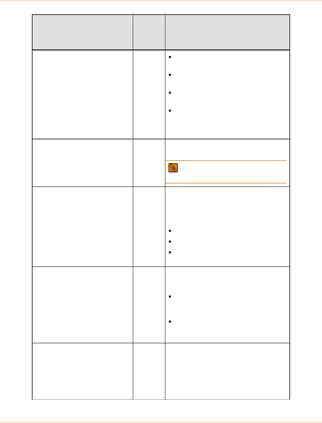
SANtricity_10.77 February 2011
LSI Corporation
- 915 -
Parmeter Name Default
Value
(Operating
System)
Description
1 – LUN rebalance is disabled for AVT
mode and enabled for non-AVT mode.
2 – LUN rebalance is enabled for AVT
mode and disabled for non-AVT mode.
3 – LUN rebalance is disabled for both
AVT and non-AVT modes.
4 – The selective LUN Transfer feature
is enabled if AVT mode is off and
ClassicModeFailover is set to LUN
level 1.
S2ToS3Key Unique
key This value is the SCSI-3 reservation key
generated during failover driver installation.
NOTE For use by Customer and
Technical Support representatives only.
LoadBalancePolicy 1This parameter determines the load-
balancing policy used by all volumes
managed by the Windows DSM and Linux
RDAC failover drivers. These values are
valid:
0 – round robin with subset.
1 – Least queue depth with subset.
2 – Least path weight with subset
(Windows OS only).
ClassicModeFailover 0This parameter provides control over how
the DSM handles failover situations. These
values are valid:
0 – Perform controller-level failover
(all LUNs are moved to the alternate
controller).
1 – Perform LUN-level failover (only the
LUNs indicating errors are transferred to
the alternate controller).
SelectiveTransferMaxTransferAttempts3This parameter sets the maximum
number of times that a host will transfer
the ownership of a LUN to the alternate
controller when the Selective LUN Transfer
mode is enabled. This setting prevents
multiple hosts from continually transferring
LUNs between controllers.
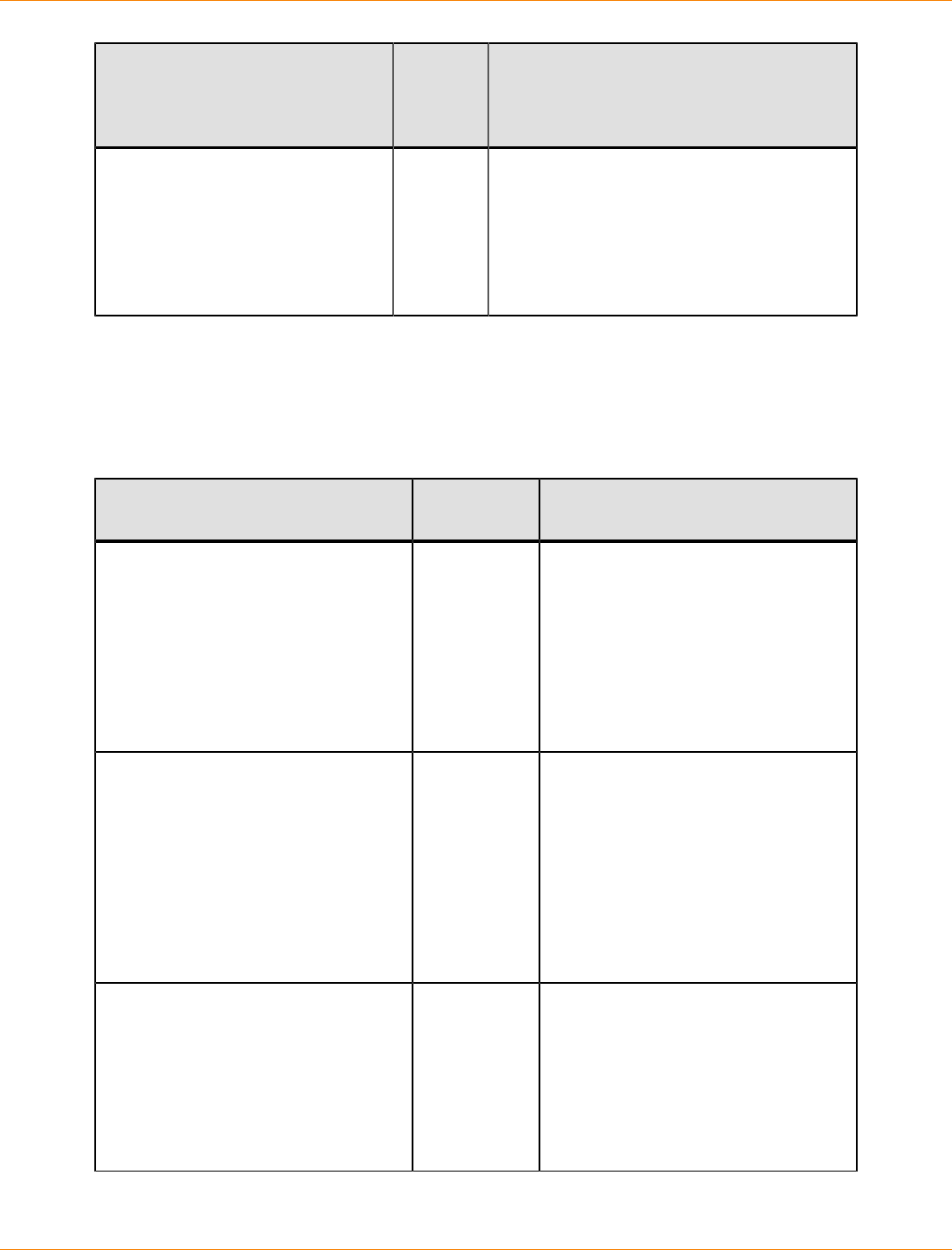
SANtricity_10.77 February 2011
LSI Corporation
- 916 -
Parmeter Name Default
Value
(Operating
System)
Description
SelectiveTransferMinIOWaitTime5This parameter sets the minimum wait time
(in seconds) that the DSM will wait before
transferring a LUN to the alternate controller
when the Selective LUN Transfer mode
is enabled. This parameter tries to stop
excessive LUN transfers due to intermittent
link errors.
Windows DSM Configuration Settings
The following configuration settings are applied using the utility dsmUtil -o option parameter. Go to dsmUtil
Utility.
Configuration Settings for the Path Congestion Detection Feature
Parameter Name Default
Value Description
CongestionDetectionEnabled 0x0 A Boolean value that indicates
whether the path congestion detection
is enabled. If this parameter is not
defined or is set to 0x0, the value
is false, the path congestion feature
is disabled, and all of the other
parameters are ignored. If set to
0x1, the path congestion feature is
enabled. Valid values are 0x0 or 0x1.
CongestionResponseTime 0x0 If CongestionIoCount is 0x0 or
not defined, this parameter represents
an average response time in seconds
allowed for an I/O request. If the
value of the CongestionIoCount
parameter is non-zero, then this
parameter is the absolute time
allowed for an I/O request. Valid
values range from 0x1 to 0x10000
(approximately 18 hours).
CongestionIoCount 0x0 The number of I/O requests that
have exceeded the value of the
CongestionResponseTime
parameter within the value of the
CongestionTimeFrame parameter.
Valid values range from 0x0 to
0x10000 (approximately 4000
requests).

SANtricity_10.77 February 2011
LSI Corporation
- 917 -
Parameter Name Default
Value Description
CongestionTimeFrame 0x0 A sliding window that defines the time
period that is evaluated in seconds. If
this parameter is not defined or is set
to 0x0, the path congestion feature is
disabled because no time frame has
been defined. Valid values range from
0x1 to 0x1C20 (approximately two
hours).
CongestionSamplingInterval 0x0 The number of I/O requests that
must be sent to a path before the
nth request is used in the average
response time calculation. For
example, if this parameter is set to
100, every 100th request sent to
a path will be used in the average
response time calculation. If this
parameter is set to 0x0 or not
defined, the path congestion feature
is disabled for performance reasons
—every I/O request would incur a
calculation. Valid values range from
0x1 to 0xFFFFFFFF (approximately 4
billion requests).
CongestionMinPopulationSize 0x0 The number of sampled I/O requests
that must be collected before the
average response time is calculated.
Valid values range from 0x1 to
0xFFFFFFFF (approximately 4 billion
requests).
CongestionTakeLastPathOffline 0x0 A Boolean value that indicates
whether the DSM driver will take the
last path available to the storage
array offline if the congestion
thresholds have been exceeded. If
this parameter is not defined or is set
to 0x0, the value is false. Valid values
are 0x0 or 0x1.
NOTE Setting a path offline
with the dsmUtil utility succeeds
regardless of the setting of this value.
dsmUtil Utility
The dsmUtil utility is a command-line driven utility that works only with the Multipath I/O (MPIO) Device
Specific Module (DSM) solution. The utility is used primarily as a way to instruct the DSM driver to perform
various maintenance tasks, but the utility can also serve as a troubleshooting tool when necessary.
SANtricity_10.77 February 2011
LSI Corporation
- 918 -
To use the dsmUtil utility, type this command, and press Enter:
dsmUtil [[-a [target_id]]
[-c array_name | missing]
[-d debug_level] [-e error_level] [-g virtual_target_id]
[-o [[feature_action_name[=value]] | [feature_variable_name=value]][, SaveSettings]] [-M]
[-P [GetMpioParameters | MpioParameter=value | ...]] [-R]
[-s "failback" | "avt" | "busscan" | "forcerebalance"]
[-w target_wwn, controller_index]
IMPORTANT The quotation marks must surround the parameters.
Typing dsmUtil without any parameters shows the usage information.
The following table shows the dsmUtil parameters.
dsmUtil Parameters
Parameter Description
-a [ target_id ]Shows a summary of all storage arrays seen by the DSM. The
summary shows the target_id, the storage array WWID, and the
storage array name. If target_id is specified, DSM point-in-time
state information appears for the storage array. On UNIX operating
systems, the virtual HBA specifies unique target IDs for each storage
array. The Windows MPIO virtual HBA driver does not use target IDs.
The parameter for this option can be viewed as an offset into the DSM
information structures, with each offset representing a different storage
array.
NOTE For use by Customer and Technical Support
representatives only.
-c array_name |
missing
Clears the WWN file entries. This file is located in the Program
Files\DSMDrivers\mppdsm\WWN_FILES directory with the
extension .wwn. If the array_name keyword is specified, the WWN
file for the specific storage array is deleted. If the missing keyword is
used, all WWN files for previously attached storage arrays are deleted.
If neither keyword is used, all of the WWN files, for both currently
attached and previously attached storage arrays, are deleted.
-d debug_level Sets the current debug reporting level. This option only works if the
RDAC driver has been compiled with debugging enabled. Debug
reporting is comprised of two segments. The first segment refers to
a specific area of functionality, and the second segment refers to the
level of reporting within that area. The debug_level is one of these
hexadecimal numbers:
0x20000000 – Shows messages from the RDAC driver’s
initialization routine.
0x10000000 – Shows messages from the RDAC driver’s device
discovery routine.
SANtricity_10.77 February 2011
LSI Corporation
- 919 -
Parameter Description
0x08000000 – Shows messages from the RDAC driver’s ioctl()
routine.
0x04000000 – Shows messages from the RDAC driver’s device
open routine (Linux platforms only).
0x02000000 – Shows messages from the RDAC driver’s device
read routine (Linux platforms only).
0x01000000 – Shows messages related to HBA commands.
0x00800000 – Shows messages related to aborted commands.
x00400000 – Shows messages related to panic dumps.
0x00200000 – Shows messages related to synchronous I/O
activity.
0x00100000 – Shows messages related to failover activity.
0x00080000 – Shows messages related to failback activity.
0x00040000 – Shows additional messages related to failback
activity.
0x00010000 – Shows messages related to device removals.
0x00001000 – Shows messages related to SCSI reservation
activity.
0x00000400 – Shows messages related to path validation
activity.
0x00000001 – Debug level 1.
0x00000002 – Debug level 2.
0x00000004 – Debug level 3.
0x00000008 – Debug level 4.
You can combine these options with the logical or operator to provide
multiple areas and levels of reporting as needed.
NOTE For use by Customer and Technical Support
representatives only.
-e error_level Sets the current error reporting level to error_level, which can
have one of these values:
0 – Show all errors.
1 – Show path failover, controller failover, retryable, fatal, and
recovered errors.
2 – Show path failover, controller failover, retryable, and fatal
errors.
3 – Show path failover, controller failover, and fatal errors. This is
the default setting.
4 – Show controller failover and fatal errors.
5 – Show fatal errors.
SANtricity_10.77 February 2011
LSI Corporation
- 920 -
Parameter Description
For use by Customer and Technical Support representatives only.
-g target_id Displays detailed information about the state of each controller,
path, and LUNs for for the specified storage array. You can find the
target_id by running the dsmUtil -a command.
-M Shows the MPIO disk-to-drive mappings for the DSM. The output is
similar to that found with the SMdevices utility.
For use by Customer and Technical Support representatives only.
-o [[
feature_action_name
[= value ]] | [
feature_variable_name
= value ]][,
SaveSettings]
Troubleshoots a feature or changes a configuration setting. Without
the SaveSettings keyword, the changes only affect the in-memory
state of the variable. The SaveSettings keyword changes both the
in-memory state and the persistent state. Some example commands
are:
dsmUtil -o – Displays all the available feature action names.
dsmUtil -o DisableLunRebalance=0x3 – Turns off the
DSM-initiated storage array LUN rebalance (affects only the in-
memory state).
-P
[GetMpioParameters
| MpioParameter=
value | ...]
Displays and sets MPIO parameters.
NOTE For use by Customer and Technical Support
representatives only.
-R Remove the load-balancing policy settings for inactive devices.
-s ["failback"
| "avt" |
"busscan" |
"forcerebalance"]
Manually initiates one of the DSM driver’s scan tasks. A “failback”
scan causes the DSM driver to reattempt communications with any
failed controllers. An “avt” scan causes the DSM driver to check
whether AVT has been enabled or disabled for an entire storage
array. A “busscan” scan causes the DSM driver to go through
its unconfigured devices list to see if any of them have become
configured. A “forcerebalance” scan causes the DSM driver to move
storage array volumes to their preferred controller and ignores the
value of the DisableLunRebalance configuration parameter of the
DSM driver.
-w target_wwn ,
controller_index
For use by Customer and Technical Support representatives only.
Device Manager
Device Manager is part of the Windows operating system. Select Control Panel from the Start menu. Then
select Administrative Tools >> Computer Management >> Device Manager.
The Device Manager tree for MPIO is similar to the one for RDAC. One difference is the names that are
associated with the volumes. In RDAC, the volumes are identified with a label, such as the RDAC Volume. In
MPIO, the volumes are named based on the vendor information and product ID information of the underlying
physical device, along with the text Multi-Path Disk Device.
SANtricity_10.77 February 2011
LSI Corporation
- 921 -
Scroll down to System Devices to view information about the DSM driver itself. This name might be different
based on your network configuration.
The Drives section shows both the drives identified with the HBA drivers and the volumes created by MPIO.
Select one of the MPIO volumes, and right-click it. Select Properties to open the Multi-Path Disk Device
Properties window.
This properties window shows if the device is working correctly. Select the Driver tab to view the driver
information.
Determining if a Path Has Failed
If a single path to a controller that has multiple paths fails, the failover driver makes an entry in the OS system
log that indicates a path failure. In the storage management software, the storage array shows a Degraded
status.
If all of the paths to a controller fail, the failover driver makes entries in the OS system log that indicate a
path failure and failover. In the storage management software, the storage array shows a Needs Attention
condition of Volume not on preferred path. The failover event is also written to the Major Event Log (MEL). In
addition, if the administrator has configured alert notifications, email messages, or SNMP traps, messages
are posted for this condition. The Recovery Guru in the storage management software provides more
information about the path failure, along with instructions about how to correct the problem.
NOTE Alert reporting for the Volume not on preferred path condition can be delayed if you set the
failover alert delay parameter through the storage management software. When you set this parameter, it
imposes a delay on the setting of the Needs Attention condition in the storage management software.
Frequently Asked Questions About Windows Failover Drivers
Frequently Asked Questions about Windows Failover Drivers
Question Answer
My disk devices or host bus adapters (HBAs)
show a yellow exclamation point. What does
this mean?
When you use Device Manager, you might
observe that a disk device icon or an HBA
icon has a yellow exclamation point on it. If
new volumes have been mapped to the host,
the exclamation point might appear on the
icon for a few seconds. This action occurs
because the PnP Manager is reconfiguring
the device, and, during this time, the device or
the HBA might not be used. If the exclamation
point stays for more than one minute, a
configuration error has occurred.
My disk devices or HBAs show a red X. What
does this mean? When you use Device Manager, you might
notice that a disk device icon or an HBA
icon has a red X on it. This X indicates that
the device has been disabled. A disabled
device cannot be used or communicated with
until it is re-enabled. If the disabled device

SANtricity_10.77 February 2011
LSI Corporation
- 922 -
Question Answer
is an adapter, any disk devices that were
connected to that adapter are removed from
Device Manager.
Why does the SMdevices utility not show any
volumes? If the SMdevices utility does not show any
volumes, perform these steps:
1. Make sure that all cables are seated
correctly. Make sure that all gigabit
interface converters (GBICs) are seated
correctly.
2. Determine the HBA BIOS and driver
versions that the system uses, and
make sure that the HBA BIOS and driver
versions are correct.
3. Make sure that your mappings are
correct. Do not use any HBA mapping
tools.
4. Use WinObj to determine if the host has
detected the volumes.
If the host has not detected the volumes,
an HBA problem or a controller problem
has occurred. Make sure that the HBAs are
logging into the switch or the controller. If they
are not logging in, the problem is probably
HBA related. If the HBAs have logged into
the controller, a controller issue might be the
problem.
The SMdevices utility shows duplicate entries
for some or all of my disks. You see that some of your disks show up
twice when you run the SMdevices utility.
For the Windows Server OS, something went
wrong with the device-claiming process.
I run the hot_add utility, but my disks do not
appear. See “Why does the SMdevices utility not
show any volumes?
I have mapped new volumes to my host, but I
cannot see them. Run the hot_add utility.
See “Why does the SMdevices utility not
show any volumes?”
How do I know if a host has detected my
volumes? Use WinObj to determine if the host can see
the volumes.
If the host cannot see the volumes, an
HBA problem or a controller problem has
occurred.
Make sure that the HBAs log into the
switch or the controller. If they are not
logging in correctly, the problem is
probably HBA related.

SANtricity_10.77 February 2011
LSI Corporation
- 923 -
Question Answer
If the HBAs have logged into the
controller, the problem might be a
controller issue.
When I boot my system, I get a “Registry
Corrupted” message. Refer to the Microsoft Knowledge Base article
277222 at http://support.microsoft.com/
kb/277222/en-us.
Registry limitations can result in devices and
paths that are not recognizable by the host
OS and the failover driver.
My controller failover test does not fail over. Make sure that you have looked through the
rest of this document for the problem. If you
think that the problem is still RDAC-related
or DSM-related, contact a Customer and
Technical Support representative.
After I install the DSM driver, my system takes
a long time to start. Why? You might still experience long start times
after you install the DSM driver because the
Windows OS is completing its configuration
for each device.
For example, you install the DSM driver on
a host with no storage array attached, and
you restart the host. Before the Windows
OS actually starts, you plug in a cable to a
storage array with 32 volumes. In the start-
up process, PnP detects the configuration
change and starts to process it. After the
configuration change has completed,
subsequent restarts do not experience
any delays unless additional configuration
changes are detected. The same process can
occur even if the host has already started.
What host type must I use for the MPIO
solution? If you use Microsoft Cluster Server, select
a host type of the Windows 2003/2008
Clustered OS. If you do not use Microsoft
Cluster Server, select a host type of the
Windows 2003/2008 Non-Clustered OS.
How can I tell if MPIO is installed? Perform these steps:
1. Go to the Control Panel on the Start
menu, and double-click Administrative
Tools.
2. Select Computer Management >>
Device Manager >> SCSI and RAID
controllers.
3. On Windows Server 2003, look for Multi-
Path Support. On Windows Server 2008,
look for Microsoft Multi-Path Bus Driver.
If one of these items is present, MPIO is
installed.

SANtricity_10.77 February 2011
LSI Corporation
- 924 -
Question Answer
How can I tell if the DSM driver is installed? Perform these steps:
1. Go to the Control Panel on the Start
menu, and double-click Administrative
Tools.
2. Select Computer Management >>
Device Manager >> System Devices.
3. Look for the LSI-supported DSM. The
name ends with the text Device-Specific
Module for Multi-Path. If it is present,
DSM is installed.
What is the default vendor ID string and the
product ID string? By default, the vendor ID string and the
product ID string configured for LSI storage
arrays are named LSI/INF-01-00. If not, the
PnP manager cannot choose the failover
driver to manage the volume. The driver takes
over, which causes delays. If you suspect that
this event has occurred, check the non-user
configuration region of the controller firmware
What should I do if I receive this message?
Warning: Changing the storage
array name can cause host
applications to lose access to
the storage array if the host
is running certain path failover
drivers.
If any of your hosts are running
path failover drivers, please
update the storage array name
in your path failover driver’s
configuration file before
rebooting the host machine to
insure uninterrupted access to the
storage array. Refer to your path
failover driver documentation for
more details.
You do not need to update files. The
information is dynamically created only when
the storage array is found initially. Use one of
these two options to correct this behavior:
Restart the host server.
Unplug the storage array from the host
server, and perform a rescan of all of the
devices. After the devices have been
removed from the storage array, you can
re-attach them. Another rescan takes
place, which rebuilds the information with
the updated names.
Installing or Upgrading SANtricity ES and DSM on the Windows OS
IMPORTANT For SANtricity ES Storage Manager 10.75 on the Windows OS, only the Microsoft
Multipath I/O (MPIO) Device Specific Module (DSM) failover driver is supported. You cannot install the DSM
driver and the RDAC driver on the same system at the same time.
Perform the steps in this task to install the SANtricity ES Storage Manager and DSM or to upgrade from
an earlier release of the SANtricity ES Storage Manager and DSM on a system with a Windows operating
system. For a clustered system, perform these steps on each node of the system, one node at a time.
1. Open the installation program on the SANtricity ES Storage Manager Installation DVD.
The SANtricity ES Storage Manager installation window appears.
SANtricity_10.77 February 2011
LSI Corporation
- 925 -
2. Click Next.
3. Accept the terms of the license agreement, and click Next.
4. Select Custom, and click Next.
5. Select the applications that you want to install.
a. Click the name of an application to see its description.
b. Select the check box next to an application to install it.
6. Click Next.
If you have a previous version of the software installed, you will receive a warning message:
Existing versions of the following software already reside on
this computer ... If you choose to continue, the existing
versions will be overwritten with new versions ....
7. If you receive this warning and want to update to SANtricity ES Storage Manager Version 10.75, click OK.
8. Select whether to automatically start the Event Monitor. Click Next.
Start the Event Monitor for the one I/O host on which you want to receive alert notifications.
Do not start the Event Monitor for all other I/O hosts attached to the storage array or for computers
that you use to manage the storage array.
9. Click Next.
10. If you receive a warning about antivirus or backup software that is installed, click Continue.
11. Read the pre-installation summary, and click Install.
12. Wait for installation to complete, and click Done.
Removing SANtricity ES and DSM from the Windows OS
IMPORTANT To prevent loss of data, the host from which you are removing SANtricity ES Storage
Manager and the DSM must have only one path to the storage array. Reconfigure the connections between
the host and the storage array to remove any redundant connections before you uninstall SANtricity ES
Storage Manager and the DSM.
1. From the Windows Start menu, select Control Panel.
The Control Panel window appears.
2. In the Control Panel window, double-click Add or Remove Programs.
The Add or Remove Programs window appears.
3. Select SANtricity ES Storage Manager.
4. Click the Remove button to the right of the SANtricity ES Storage Manager entry.
WinObj
You can use WinObj to view the Object Manager namespace that is maintained by the operating system.
Every Windows OS driver that creates objects in the system can associate a name with the object that can be
viewed from WinObj. With WinObj, you can view the volumes and paths that the host bus adapters (HBAs)
have identified. You can also view what the failover driver identifies from a storage array.

SANtricity_10.77 February 2011
LSI Corporation
- 926 -
Failover Drivers for the Linux Operating System
Redundant Dual Active Controller (RDAC) is the supported failover driver for SANtricity ES Storage Manager
with Linux operating systems.
Linux OS Restrictions
This version of the Linux OS RDAC does not support any Linux OS 2.4 kernels, such as the following:
SUSE SLES 8 OS
Red Hat 3 Linux OS
SLES 8 and Red Hat 3 Linux OSs on POWER (LoP) servers
The Linux OS RDAC driver cannot coexist with a Fibre Channel host bus adapter (HBA)-level multi-path
failover or failback driver, such as these:
The 8.00.00-fo or 8.00.02-fo Linux OS device driver for the IBM DS4000 fc2-133 host bus adapters driver
on servers with Intel architecture processors or AMD architecture processors
The QLA driver for the Fibre Channel expansion adapters on the IBM LoP blade servers
You might have to modify the makefile of the HBA driver for it to be compiled in the non-failover mode.
Auto-Volume Transfer (AVT) mode is automatically enabled in the SANshare Storage Partitioning host type in
the Linux OS. This mode causes contention when RDAC is installed, so you must disable it before you install
RDAC. Also, there is a separate Linux OS host type in which AVT is already disabled.
When the RDAC driver detects that all paths to a storage array have failed, it reports I/O failure immediately.
This behavior is different from the behavior of the failover device driver from IBM for the Fibre Channel HBA.
The Fibre Channel HBA failover device driver waits for a certain timeout or retry period before reporting an I/O
failure to the host application.
The cluster support feature in the Linux OS RDAC driver is only available for controller firmware version
5.4x.xx.xx or later. If a SCSI-2 reserve command or a SCSI-2 release command is addressed to a volume on
a storage array that runs a firmware version earlier than 5.40, a check condition is returned.
LoP servers do not support clustering with this Linux OS RDAC.
For LoP servers, the modprobe command is not supported with this Linux OS RDAC release on SUSE SLES
9 when the Linux OS RDAC driver is installed. Use the insmod command to remove and recover the device
driver stack. On LoP pSeries servers with more than three processors, if you use the modprobe command, it
might result in a hung server or panics.
Do not assign a universal access volume to LUN ID 0, especially with RDAC installed. If you place a universal
access volume at LUN ID 0, it might lead to loss of volume recognition of next sequence LUN IDs or a partial
list of virtual volumes reported with the RDAC driver. Assign these volumes to LUN ID 31.
For LoP servers, the HBA hot-swap procedure to remove a live, fully functioning Fibre Channel HBA causes
a system panic if the I/O is not diverted from that path first. This functionality is only supported on current 2.6
kernel versions. The work-around is to pull the Fibre Channel cable first, wait two minutes to five minutes for
failover to complete, and then run the drslot_chrp_pci -r -s slot-number command.
SANtricity_10.77 February 2011
LSI Corporation
- 927 -
The Linux operating system includes a new method of kernel dump (kdump/kexec) to replace the previous
LKCD (Linux Kernel Crash Dump) method for SUSE and diskdump method for RHEL. If kdump is configured,
kdump and kexec work together to capture kernel exceptions, save the kernel state/memory and start a
second kernel image for debugging the troubled kernel. The second kernel is called kdump kernel. Kexec
and kdump are useful for troubleshooting panic conditions. With the current installation and driver build
method, the RDAC driver modules are not included in the kdump kernel initrd image. An initrd image contains
all necessary device driver modules that are used after the kernel image is loaded and before user space
initialization is started. Because the RDAC driver modules are not included in the kdump initrd image, a user
experiences these problems when kdump is configured: long boot times and the inability to save vmcore
file in a SAN boot configuration. The RDAC driver installation will build a kdump kernel initrd image with the
RDAC driver modules inside. Also, when the RDAC driver is installed, it will detect that a kdump kernel is
configured, and update the initrd image with the RDAC drivers.
Unique Features of RDAC from LSI
Redundant Dual Active Controller is the failover driver for the Linux OS that is included in SANtricity ES
Storage Manager. The RDAC failover driver includes these unique features:
On-the-fly path validation.
Cluster support.
Automatic detection of path failure. The RDAC failover driver automatically routes I/O to another path in
the same controller or to an alternate controller, in case all paths to a particular controller fail.
Retry handling is improved, because the RDAC driver can better understand the controller-returned sense
key/ASC/ASCQ of vendor-specific statuses of LSI.
Automatic rebalance is handled. When the failed controller obtains Optimal status, storage array
rebalance is performed automatically without user intervention.
Three load-balancing policies are supported: round robin subset, least queue depth, and path weight.
Configuration Settings for Windows DSM and Linux RDAC
This topic applies to both the Windows OS and the Linux OS. The failover driver that is provided with the
storage management software contains configuration settings that can modify the behavior of the driver.
For the Linux OS, the configuration settings are in the /etc/mpp.conf file.
For the Windows OS, the configuration settings are in the HKEY_LOCAL_MACHINE\System
\CurrentControlSet\Services\<DSM_Driver>\Parameters registry key, where <DSM_Driver>
is the name of the OEM-specific driver
The default driver is mppdsm.sys. Any changes to the settings take effect on the next reboot of the host.
The default values listed in the following table apply to both Windows and Linux unless the OS is specified in
parentheses. Many of these values are overridden by the failover installer for the Linux OS or the Windows
OS.
ATTENTION Possible loss of data access – If you change these settings from their configured
values, you might lose access to the storage array.

SANtricity_10.77 February 2011
LSI Corporation
- 928 -
Configuration Settings for Windows DSM and Linux RDAC
Parmeter Name Default
Value
(Operating
System)
Description
MaxPathsPerController 4The maximum number of paths (logical
endpoints) that are supported per controller.
The total number of paths to the storage
array is the MaxPathsPerController
value multiplied by the number of
controllers. The allowed values range from
0x1 (1) to 0x20 (32) for Windows, and from
0x1 (1) to 0xFF (255) for Linux RDAC.
For use by Customer and Technical Support
representatives only.
ScanInterval 1
(Windows)
60
(Linux)
The interval time, in seconds, that
the failover driver will check for these
conditions:
A change in preferred ownership for a
LUN
An attempt to rebalance LUNs to their
preferred paths
A change in AVT enabled status or
disabled status
For the Windows OSs, the allowed values
range from 0x1 to 0xFFFFFFFF and must
be specified in minutes.
For the Linux OSs, the allowed values range
from 0x1 to 0xFFFFFFFF and must be
specified in seconds.
For use by Customer and Technical Support
representatives only.
ErrorLevel 3This setting determines which errors to log.
These values are valid:
0 – Display all errors
1 – Display path failover errors,
controller failover errors, retryable
errors, fatal errors, and recovered errors
2 – Display path failover errors,
controller failover errors, retryable
errors, and fatal errors
3 – Display path failover errors,
controller failover errors, and fatal errors
4 – Display controller failover errors,
and fatal errors

SANtricity_10.77 February 2011
LSI Corporation
- 929 -
Parmeter Name Default
Value
(Operating
System)
Description
For use by Customer and Technical Support
representatives only.
SelectionTimeoutRetryCount 0The number of times a selection timeout is
retried for an I/O request before the path
fails. If another path to the same controller
exists, the I/O is retried. If no other path to
the same controller exists, a failover takes
place. If no valid paths exist to the alternate
controller, the I/O is failed.
The allowed values range from 0x0 to
0xFFFFFFFF.
For use by Customer and Technical Support
representatives only.
CommandTimeoutRetryCount 1The number of times a command timeout
is retried for an I/O request before the path
fails. If another path to the same controller
exists, the I/O is retried. If another path to
the same controller does not exist, a failover
takes place. If no valid paths exist to the
alternate controller, the I/O is failed.
The allowed values range from 0x0 to
0xa (10) for Windows, and from 0x0 to
0xFFFFFFFF for Linux RDAC.
For use by Customer and Technical Support
representatives only.
UaRetryCount 10 The number of times a Unit Attention (UA)
status from a LUN is retried. This parameter
does not apply to UA conditions due to
Quiescence in Progress.
The allowed values range from 0x0 to
0x64 (100) for Windows, and from 0x0 to
0xFFFFFFFF for Linux RDAC.
For use by Customer and Technical Support
representatives only.
SynchTimeout 120 The timeout, in seconds, for synchronous
I/O requests that are generated internally
by the failover driver. Examples of
internal requests include those related to
rebalancing, path validation, and issuing of
failover commands.
The allowed values range from 0x1 to
0xFFFFFFFF.
For use by Customer and Technical Support
representatives only.

SANtricity_10.77 February 2011
LSI Corporation
- 930 -
Parmeter Name Default
Value
(Operating
System)
Description
DisableLunRebalance 0This parameter provides control over the
LUN failback behavior of rebalancing LUNs
to their preferred paths. These values are
possible:
0 – LUN rebalance is enabled for both
AVT and non-AVT modes.
1 – LUN rebalance is disabled for AVT
mode and enabled for non-AVT mode.
2 – LUN rebalance is enabled for AVT
mode and disabled for non-AVT mode.
3 – LUN rebalance is disabled for both
AVT mode and non-AVT mode.
4 – The selective LUN Transfer feature
is enabled if AVT mode is off and
ClassicModeFailover is set to LUN
level 1.
S2ToS3Key Unique
key This value is the SCSI-3 reservation key
generated during failover driver installation.
For use by Customer and Technical Support
representatives only.
LoadBalancePolicy 1This parameter determines the load-
balancing policy used by all volumes
managed by the Windows DSM and Linux
RDAC failover drivers. These values are
valid:
0 – Round robin with subset.
1 – Least queue depth with subset.
2 – Least path weight with subset
(Windows OS only).
ClassicModeFailover 0This parameter provides control over how
the DSM handles failover situations. These
values are valid:
0 – Perform controller-level failover
(all LUNs are moved to the alternate
controller).
1 – Perform LUN-level failover (only the
LUNs indicating errors are transferred to
the alternate controller).
SelectiveTransferMaxTransferAttempts3This parameter sets the maximum
number of times that a host will transfer
the ownership of a LUN to the alternate
controller when the Selective LUN Transfer
SANtricity_10.77 February 2011
LSI Corporation
- 931 -
Parmeter Name Default
Value
(Operating
System)
Description
mode is enabled. This setting prevents
multiple hosts from continually transferring
LUNs between controllers.
SelectiveTransferMinIOWaitTime5This parameter sets the minimum wait time
(in seconds) that the DSM will wait before
transferring a LUN to the alternate controller
when the Selective LUN Transfer mode
is enabled. This parameter tries to stop
excessive LUN transfers due to intermittent
link errors.
Prerequisites for Installing RDAC on the Linux OS
Before installing RDAC on the Linux operating system, make sure that your storage array meets these
conditions:
Make sure that the host system on which you want to install the RDAC driver has supported HBAs.
Refer to the installation electronic document topics for your controller tray or controller-drive tray for any
configuration settings that you need to make.
Although the system can have Fibre Channel HBAs from multiple vendors or multiple models of Fibre
Channel HBAs from the same vendor, you can connect only the same model of Fibre Channel HBAs to
each storage array.
Make sure that the low-level HBA driver has been correctly built and installed before RDAC driver
installation.
The standard HBA driver must be loaded before you install the RDAC driver. The HBA driver has to be a
non-failover driver.
For LSI HBAs, the port driver is named mptbase, and the host driver is named mptscsi or mptscsih,
although the name depends on the driver version. The Fibre Channel driver is named mptfc, the SAS
driver is named mptsas, and the SAS2 driver is named mpt2sas.
For QLogic HBAs, the base driver is named qla2xxx, and host driver is named qla2300. The 4-GB
HBA driver is named qla2400.
For IBM Emulex HBAs, the base driver is named lpfcdd or lpfc, although the name depends on the
driver version.
For Emulex HBAs, the base driver is named lpfcdd or lpfc, although the name depends on the driver
version.
Make sure that the kernel source tree for the kernel version to be built against is already installed. You
must install the kernel source rpm on the target system for the SUSE SLES operating system. You are
not required to install the kernel source for the Red Hat operating system.
Make sure that the necessary kernel packages are installed: source rpm for the SUSE Linux Enterprise
Server operating system and kernel headers/kernel devel for the Red Hat Enterprise Linux
operating system.
In SUSE operating systems, you must include these items for the HBAs mentioned as follows:
SANtricity_10.77 February 2011
LSI Corporation
- 932 -
For LSI HBAs, INITRD_MODULES includes mptbase and mptscsi (or mptscsih) in the /etc/
sysconfig/kernel file. The Fibre Channel driver is named mptfc, the SAS driver is named mptsas,
and the SAS2 driver is named mpt2sas.
For QLogic HBAs, INITRD_MODULES includes a qla2xxx driver and a qla2300 driver in the /etc/
sysconfig/kernel file.
For IBM Emulex HBAs, INITRD_MODULES includes an lpfcdd driver or an lpfc driver in the /etc/
sysconfig/kernel file.
For Emulex HBAs, INITRD_MODULES includes an lpfcdd driver or an lpfc driver in the /etc/
sysconfig/kernel file.
Installing SANtricity ES Storage Manager and RDAC on the Linux OS
IMPORTANT SANtricity ES Storage Manager requires that the different Linux OS kernels have
separate installation packages. Make sure that you are using the correct installation package for your
particular Linux OS kernel.
1. Open the installation program on the SANtricity ES Storage Manager Installation DVD.
The SANtricity ES Storage Manager installation window appears.
2. Click Next.
3. Accept the terms of the license agreement, and click Next.
4. Select one of the installation packages:
Typical – Select this option to install all of the available host software.
Management Station – Select this option to install software to configure, manage, and monitor a
storage array. This option does not include RDAC. This option only installs the client software.
Host – Select this option to install the storage array server software.
Custom – Select this option to customize the features to be installed.
NOTE For this procedure, Typical is selected. If the Host installation option is selected, the Agent,
the Utilities, and the RDAC driver will be installed.
You might receive a warning after you click Next. The warning states:
Existing versions of the following software already reside on
this computer ... If you choose to continue, the existing
versions will be overwritten with new versions ....
If you receive this warning and want to update to SANtricity ES Storage Manager Version 10.75, click OK.
5. Click Install.
You will receive a warning after you click Install. The warning tells you that the RDAC driver is not
automatically installed. You must manually install the RDAC driver.
The RDAC source code is copied to the specified directory in the warning message. Go to that directory,
and perform the steps in Installing RDAC Manually on the Linux OS.
6. Click Done.
Installing RDAC Manually on the Linux OS
1. To unzip the RDAC tar.gz file and untar the RDAC tar file, type this command, and press Enter:
tar -zxvf <filename>

SANtricity_10.77 February 2011
LSI Corporation
- 933 -
2. Go to the Linux RDAC directory.
3. Type this command, and press Enter.
make uninstall
4. To remove the old driver modules in that directory, type this command, and press Enter:
make clean
5. To compile all driver modules and utilities in a multiple CPU server (SMP kernel), type this command, and
press Enter:
make
6. Type this command, and press Enter:
make install
These actions result from running this command:
The driver modules are copied to the kernel module tree.
The new RAMdisk image (mpp-`uname -r`.img) is built, which includes the RDAC driver modules
and all driver modules that are needed at boot.
7. Follow the instructions shown at the end of the build process to add a new boot menu option that uses /
boot/mpp-`uname -r`.img as the initial RAMdisk image.
Making Sure that RDAC Is Installed Correctly on the Linux OS
1. Restart the system by using the new boot menu option.
2. Make sure that these driver stacks were loaded after restart:
scsi_mod
sd_mod
sg
mppUpper
The physical HBA driver module
mppVhba
3. Type this command, and press Enter:
/sbin/lsmod
4. To make sure that the RDAC driver discovered the available physical volumes and created virtual
volumes for them, type this command, and press Enter:
/opt/mpp/lsvdev
You can now send I/O to the volumes.
5. If you make any changes to the RDAC configuration file (/etc/mpp.conf) or the persistent binding file
(/var/mpp/devicemapping), run the mppUpdate command to rebuild the RAMdisk image to include
the new file. In this way, the new configuration file (or persistent binding file) can be used on the next
system restart.
6. To dynamically reload the driver stack (mppUpper, physical HBA driver modules, mppVhba) without
restarting the system, perform these steps:
a. To unload the mppVhba driver, type this command, and press Enter:
SANtricity_10.77 February 2011
LSI Corporation
- 934 -
rmmod mppVhba
b. To unload the physical HBA driver, type this command, and press Enter:
modprobe -r "physical hba driver modules"
c. To unload the mppUpper driver, type this command, and press Enter:
rmmod mppUpper
d. To reload the mppUpper driver, type this command, and press Enter:
modprobe mppUpper
e. To reload the physical HBA driver, type this command, and press Enter:
modprobe "physical hba driver modules"
f. To reload the mppVhba driver, type this command, and press Enter:
modprobe mppVhba
7. Restart the system whenever there is an occasion to unload the driver stack.
IMPORTANT Using the modprobe command with the RDAC driver stack or using the rmmod
command to remove all the drivers in the RDAC driver stack, in order, is not recommended nor
supported.
8. Disable Auto-Volume Transfer (AVT) by issuing a set controller command line interface (CLI) command.
For example, to disable AVT for host region 6 and controller A, use this command:
set controller[a] hostNVSRAMByte[0x6, 0x24]=0x00;
9. Use a utility, such as devlabel, to create user-defined device names that can map devices based on a
unique identifier, called a UUID.
10. Use the udev command for persistent device names. The udev command dynamically generates device
name links in the /dev/disk directory based on path, ID or UUID.
linux-kbx5:/dev/disk # ls /dev/disk by-id by-path by-uuid
For example, the /dev/disk/by-id directory links volumes that are identified by WWIDs of the
volumes to actual disk device nodes.
lrwxrwxrwx 1 root root 10 Feb 23 12:15
scsi-3600a0b80000c2df9000003b141417799 -> ../../sdda
lrwxrwxrwx 1 root root 9 Feb 23 12:15
scsi-3600a0b80000f27030000000d416b94fd -> ../../sdc
lrwxrwxrwx 1 root root 9 Feb 23 12:15
scsi-3600a0b80000f270300000015416b958f -> ../../sdg
Configuring Failover Drivers for the Linux OS
The Windows OS and the Linux OS share the same set of tunable parameters to enforce the same I/O
behaviors. For a description of these parameters, go to Configuration Settings for Windows DSM and Linux
RDAC.
SANtricity_10.77 February 2011
LSI Corporation
- 935 -
Parameter Name Default
Value Description
ImmediateVirtLunCreate 0This parameter determines whether to create the
virtual LUN immediately if the owning physical path
is not yet discovered. This parameter can take the
following values:
0 – Do not create the virtual LUN immediately if
the owning physical path is not yet discovered.
1 – Create the virtual LUN immediately if the
owning physical path is not yet discovered.
BusResetTimeout The time, in seconds, for the RDAC driver to delay
before retrying an I/O operation if the DID_RESET
status is received from the physical HBA. A typical
setting is 150.
AllowHBAsgDevs 0This parameter determines whether to create
individual SCSI generic (SG) devices for each I:T:L
for the end LUN through the physical HBA. This
parameter can take the following values:
0 – Do not allow creation of SG devices for each
I:T:L through the physical HBA.
1 – Allow creation of SG devices for each I:T:L
through the physical HBA.
Compatibility and Migration
Controller firmware – The Linux OS RDAC driver is compatible with the controller firmware. However,
the Linux OS RDAC driver does not support SCSI-2 to SCSI-3 reservation translation unless the release is
version 8.40.xx or later.
Linux OS distributions – The Linux OS RDAC driver is intended to work on any Linux OS distribution that
has the standard SCSI I/O storage array (SCSI middle-level and low-level interfaces). This release is targeted
specifically at SUSE Linux OS Enterprise Server and Red Hat Advanced Server.
mppUtil Utility
The mppUtil utility is a general-purpose command-line driven utility that works only with MPP-based
RDAC solutions. The utility instructs RDAC to perform various maintenance tasks but also serves as a
troubleshooting tool when necessary.
To use the mppUtil utility, type this command, and press Enter:
mppUtil [-a target_name] [-c wwn_file_name] [-d debug_level]
[-e error_level] [-g virtual_target_id] [-I host_num]
[-o feature_action_name[=value][, SaveSettings]]
[-s "failback" | "avt" | "busscan" | "forcerebalance"] [-S] [-U]
[-V] [-w target_wwn,controller_index]
NOTE The quotation marks must surround the parameters.
SANtricity_10.77 February 2011
LSI Corporation
- 936 -
The mppUtil utility is a cross-platform tool. Some parameters might not have a meaning in a particular
operating system environment. A description of each parameter follows.
mppUtil Parameters
Parameter Description
-a target_name Shows the RDAC driver’s internal information
for the specified virtual target_name
(storage array name). If a target_name
value is not included, the -a parameter shows
information about all of the storage arrays that
are currently detected by this host.
-c wwn_file_name Clears the WWN file entries. This file is
located at /var/mpp with the extension
.wwn.
-d debug_level Sets the current debug reporting level. This
option works only if the RDAC driver has been
compiled with debugging enabled. Debug
reporting is comprised of two segments.
The first segment refers to a specific area of
functionality, and the second segment refers
to the level of reporting within that area. The
debug_level is one of these hexadecimal
numbers:
0x20000000 – Shows messages from
the RDAC driver’s init() routine.
0x10000000 – Shows messages from
the RDAC driver’s attach() routine.
0x08000000 – Shows messages from
the RDAC driver’s ioctl() routine.
0x04000000 – Shows messages from
the RDAC driver’s open() routine.
0x02000000 – Shows messages from
the RDAC driver’s read() routine.
0x01000000 – Shows messages related
to HBA commands.
0x00800000 – Shows messages related
to aborted commands.
0x00400000 – Shows messages related
to panic dumps.
0x00200000 – Shows messages related
to synchronous I/O activity.
0x00000001 – Debug level 1.
0x00000002 – Debug level 2.
0x00000004 – Debug level 3.
0x00000008 – Debug level 4.

SANtricity_10.77 February 2011
LSI Corporation
- 937 -
Parameter Description
These options can be combined with the
logical and operator to provide multiple areas
and levels of reporting as needed.
For use by Customer and Technical Support
representatives only.
-e error_level Sets the current error reporting level to
error_level, which can have one of these
values:
0 – Show all errors.
1 – Show path failover, controller failover,
retryable, fatal, and recovered errors.
2 – Show path failover, controller failover,
retryable, and fatal errors.
3 – Show path failover, controller failover,
and fatal errors. This is the default setting.
4 – Show controller failover and fatal
errors.
5 – Show fatal errors.
For use by Customer and Technical Support
representatives only.
-g virtual_target_id Display the RDAC driver’s internal information
for the specified virtual_target_id.
-I host_num Prints the maximum number of targets that
can be handled by that host. Here, host
refers to the HBA drivers on the system and
includes the RDAC driver. The host number
of the HBA driver is given as an argument.
The host numbers assigned by the Linux
middle layer start from 0. If two ports are on
the HBA card, host numbers 0 and 1 would be
taken up by the low-level HBA driver, and the
RDAC driver would be at host number 2. Use
/proc/scsi to determine the host number.
-o feature_action_name [= value ][,
SaveSettings]
Troubleshoots a feature or changes
a configuration setting. Without the
SaveSettings keyword, the changes affect
only the in-memory state of the variable. The
SaveSettings keyword changes both the
in-memory state and the persistent state. You
must run mppUpdate to reflect these changes
in the inird image before rebooting the server.
Some example commands are:
mppUtil -o – Displays all the available
feature action names.

SANtricity_10.77 February 2011
LSI Corporation
- 938 -
Parameter Description
mppUtil -o ErrorLevel=0x2 –
Sets the ErrorLevel parameter to 0x2
(affects only the in-memory state).
-s ["failback" | "avt" | "busscan"
| "forcerebalance"]
Manually initiates one of the RDAC driver’s
scan tasks.
A “failback” scan causes the RDAC driver
to reattempt communications with any
failed controllers.
An “avt” scan causes the RDAC driver to
check whether AVT has been enabled or
disabled for an entire storage array.
A “busscan” scan causes the RDAC
driver to go through its unconfigured
devices list to see if any of them have
become configured.
A “forcerebalance” scan causes
the RDAC driver to move storage
array volumes to their preferred
controller and ignore the value of the
DisableLunRebalance configuration
parameter of the RDAC driver.
-S Reports the Up state or the Down state of the
controllers and paths for each LUN in real
time.
-U Refreshes the Universal Transport
Mechanism (UTM) LUN information in MPP
driver internal data structure for all the storage
arrays that have already been discovered.
-V Prints the version of the RDAC driver
currently running on the system.
-w target_wwn , controller_index For use by Customer and Technical Support
representatives only.
Frequently Asked Questions about Linux Failover Drivers
Frequently Asked Questions about Linux Failover Drivers
Question Answer
How do I get logs from RDAC in
the Linux OS? Use the mppSupport command to obtain
several logs related to RDAC. The mppSupport
command is found in the /opt/mpp/mppSupport
directory. The command creates a file named
mppSupportdata_hostname_RDAC
version_datetime.tar.gz in the /tmp directory.

SANtricity_10.77 February 2011
LSI Corporation
- 939 -
Question Answer
How does persistent naming
work? The Linux OS SCSI device names can change when the
host system restarts. Use a utility, such as devlabel, to
create user-defined device names that will map devices
based on a unique identifier. The udev method is the
preferred method for SLES 10 and RHEL.
What must I do after applying a
kernel update? After you apply the kernel update and start the new
kernel, perform these steps to build the RDAC Initial Ram
Disk image (initrd image) for the new kernel:
1. Change the directory to the Linux RDAC source code
directory.
2. Type make uninstall, and press Enter.
3. Reinstall RDAC.
What is the Initial Ram Disk
Image (initrd image), and how do
I create a new initrd image?
The initrd image is automatically created when the driver
is installed by using the make install command. The
boot loader configuration file must have an entry for this
newly created image.
The initrd image is located in the boot partition. The file is
named mpp‘-uname -r’.img.
For a driver update, if the system already has a previous
entry for RDAC, the system administrator must modify the
existing RDAC entry in the boot loader configuration file.
In most of the cases, no change is required if the kernel
version is the same.
To create a new initrd image, type mppUpdate, and press
Enter.
The old image file is overwritten with the new image file.
If third-party drivers are needed to be added to the
initrd image, change the /etc/sysconfig/ kernel
file (SUSE) with the third-party driver entries. Run the
mppUpdate command again to create a new initrd image.
How do I remove unmapped or
disconnected devices from the
existing host?
Run hot_add -d to remove all unmapped or
disconnected devices.
What if I remap a LUN from the
storage array? Run hot_add -u to update the host with the changed
LUN mapping.
What if I change the size of the
LUN on the storage array? Run hot_add -c to change the size of the LUN on the
host.
How do I make sure that RDAC
finds the available storage
arrays?
To make sure that the RDAC driver has found the
available storage arrays and created virtual storage arrays
for them, type these commands, and press Enter after
each command.
ls -lR /proc/mpp
mppUtil -a
/opt/mpp/lsvdev
To show all attached and discovered volumes, typecat /
proc/scsi/scsi, and press Enter.

SANtricity_10.77 February 2011
LSI Corporation
- 940 -
Question Answer
What should I do if I receive this
message?
Warning: Changing the
storage array name can
cause host applications
to lose access to the
storage array if the host
is running certain path
failover drivers.
If any of your hosts are
running path failover
drivers, please update
the storage array name
in your path failover
driver’s configuration
file before rebooting the
host machine to insure
uninterrupted access to
the storage array. Refer
to your path failover
driver documentation for
more details.
The path failover drivers that cause this warning are the
RDAC drivers on both the Linux OS and the Windows OS.
The storage array user label is used for storage array-to-
virtual target ID binding in the RDAC driver. For the Linux
OS, change this file to add the storage array user label
and its virtual target ID.
.~ # more /var/mpp/devicemapping
SANtricity_10.77 February 2011
LSI Corporation
- 941 -
Device Mapper Multipath for the Linux Operating System
Device Mapper (DM) is a generic framework for block devices provided by the Linux operating system. It
supports concatenation, striping, snapshots, mirroring, and multipathing. The multipath function is provided by
the combination of the kernel modules and user space tools.
The DMMP is supported on SUSE Linux Enterprise Server (SLES) Version 11. The SLES installation must
have components at or above the version levels shown in the following table before you install the DMMP.
Miimum Supported Configurations for the SLES 11 Operating System
Version Component
Kernel version kernel-default-2.6.27.29-0.1.1
Scsi_dh_rdac kmp lsi-scsi_dh_rdac-kmp-
default-0.0_2.6.27.19_5-1
Device Mapper library device-mapper-1.02.27-8.6
Multipath-tools multipath-tools-0.4.8-40.6.1
To update a component, download the appropriate package from the Novell website at http://
download.novell.com/patch/finder. The Novell publication, SUSE Linux Enterprise Server 11 Installation and
Administration Guide, describes how to install and upgrade the operating system.
Device Mapper Features
Provides a single block device node for a multipathed logical unit
Ensures that I/O is re-routed to available paths during a path failure
Ensures that the failed paths are revalidated as soon as possible
Configures the multipaths to maximize performance
Reconfigures the multipaths automatically when events occur
Provides DMMP features support to newly added logical unit
Provides device name persistency for DMMP devices under /dev/mapper/
Configures multipaths automatically at an early stage of rebooting to permit the OS to install and reboot
on a multipathed logical unit
Known Limitations and Issues of the Device Mapper
When storage is configured with AVT mode, delays in device discovery might occur. Delays in device
discovery might result in long delays when the operating system boots.
In certain error conditions with no_path_retry or queue_if_no_path feature set, applications might
hang forever. To overcome these conditions, you must enter the following command to all the affected
multipath devices: dmsetup message device 0 "fail_if_no_path", where device is the
multipath device name (for example, mpath2; do not specify the path).
An I/O hang might occur when a volume is unmapped without first deleting the DM device.
NOTE This limitation applies to only the SUSE 11 OS.

SANtricity_10.77 February 2011
LSI Corporation
- 942 -
Stale entries might not be noticed in multipath -ll output if the volumes are unmapped or deleted without
first deleting the DM device and its underlying paths.
NOTE This limitation applies to only the SUSE 11 OS.
Currently, the mode select command is issued synchronously for each LUN. With large LUN
configurations, slower failovers for DM multipath devices might occur if there is any delay in completing of
the mode select command.
NOTE This limitation applies to only the SUSE 11 OS.
If the scsi_dh_rdac module is not included in initrd, slower device discovery might occur, and the syslog
might get populated with buffer I/O error messages.
If the storage vendor and model are not included in scsi_dh_rdac device handler, slower device discovery
might be seen, and the syslog might get populated with buffer I/O error messages.
Use of the DMMP and RDAC failover solutions together on the same host is not supported. Use only one
solution at a time.
Installing the Device Mapper Multi-Path
1. Use the media supplied by your operating system vendor to install SLES 11.
2. Install the errata kernel 2.6.27.29-0.1.
Refer to the SUSE Linux Enterprise Server 11 Installation and Administration Guide for the installation
procedure.
3. To boot up to 2.6.27.29-0.1 kernel, reboot your system.
4. On the command line, enter rpm -qa |grep device-mapper, and check the system output to see if
the correct level of the device mapper component is installed.
The correct level of the device mapper component is installed – Go to step 5.
The correct level of the device mapper component is not installed – Install the correct level of
the device mapper component or update the existing component, and go to step 5.
5. On the command line, enter rpm -qa |grep multipath-tools, and check the system output to see
if the correct level of the multipath tools is installed.
The correct level of the multipath tools is installed – Go to step 6.
The correct level of the multipath tools is not installed – Install the correct level of the multipath tools
or update the existing multipath tools, and go to step 6.
6. Update the configuration file /etc/multipath.conf.
See Setting Up the multipath.conf File for detailed information about the /etc/multipath.conf file.
7. On the command line, enter chkconfig multipathd on.
This command enables multipathd daemon when the system boots.
8. Edit the /etc/sysconfig/kernel file to add directive scsi_dh_rdac to the INITRD_MODULES section
of the file.
9. Download the KMP package for scsi_dh_rdac for the SLES 11 architecture from the website http://
forgeftp.novell.com/driver-process/staging/pub/update/lsi/sle11/common/, and install the package on the
host.
10. Update the boot loader to point to the new initrd image, and reboot the host with the new initrd image.

SANtricity_10.77 February 2011
LSI Corporation
- 943 -
Setting Up the multipath.conf File
The multipath.conf file is the configuration file for the multipath daemon, multipathd. The
multipath.conf file overwrites the built-in configuration table for multipathd. Any line in the file whose first
non-white-space character is # is considered a comment line. Empty lines are ignored.
Installing the Device Mapper Multi-Path for SLES 11.1
All of the components required for DMMP are included in SUSE Linux Enterprise Server (SLES) version
11.1 installation media. However, users might need to select the specific component based on the storage
hardware type. By default, DMMP is disabled in SLES. You must follow the following steps to enable DMMP
components on the host.
1. On the command line, type chkconfig multipath on.
The multipathd daemon is enabled with the system starts again.
2. Edit the /etc/sysconfig/kernel file to add the directive scsi_dh_rdac to the INITRD_MODULES
section of the file.
3. Create a new initrd image using the following command to include scsi_dh_rdac into ram disk:
mkinitrd -i /boot/initrd-r -rdac -k /bootvmlinuz
4. Update the boot leader to point to the new initrd image, and reboot the host with the new initrd image.
Copy and Rename the Sample File
Copy and rename the sample file located at /usr/share/doc/packages/multipath-tools/
multipath.conf.synthetic to /etc/multipath.conf. Configuration changes are now accomplished
by editing the new /etc/multipath.conf file. All entries for multipath devices are commented out initially.
The configuration file is divided into five sections:
defaults – Specifies all default values.
blacklist – All devices are blacklisted for new installations. The default blacklist is listed in the
commented-out section of the /etc/multipath.conf file. Blacklist the device mapper multipath by
WWID if you do not want to use this functionality.
blacklist_exceptions – Specifies any exceptions to the items specified in the section blacklist
devices – Lists all multipath devices with their matching vendor and product values
multipaths – Lists the multipath device with their matching WWID values
Determine the Attributes of a MultiPath Device
To determine the attributes of a multipath device, check the multipaths section of the /etc/
multipath.conf file, then the devices section, then the defaults section. The model settings used for
multipath devices are listed for each storage array and include matching vendor and product values. Add
matching storage vendor and product values for each type of volume used in your storage array.
For each UTM LUN mapped to the host, include an entry in the blacklist section of the /etc/
multipath.conf file. The entries should follow the pattern of the following example.
blacklist {
device {
vendor "*"
product "Universal Xport"
}

SANtricity_10.77 February 2011
LSI Corporation
- 944 -
}
The following example shows the devices section for LSI storage from the sample /etc/multipath.conf
file. Update the vendor ID, which is LSI in the sample file, and the product ID, which is INF-01-00 in the
sample file, to match the equipment in the storage array.
devices {
device {
vendor "LSI"
product "INF-01-00"
path_grouping_policy group_by_prio
prio rdac
getuid_callout "/lib/udev/scsi_id -g -u -d /dev/%n"
polling_interval 5
path_checker rdac
path_selector "round-robin 0"
hardware_handler "1 rdac"
failback immediate
features "2 pg_init_retries 50"
no_path_retry 30
rr_min_io 100
}
}
The following table explains the attributes and values in the devices section of the /etc/multipath.conf
file.
Attributes and Values in the multipath.conf File
Attribute Parameter Value Description
path_grouping_policygroup_by_prio The path grouping policy to be applied to this
specific vendor and product storage.
prio rdac The program and arguments to determine
the path priority routine. The specified routine
should return a numeric value specifying the
relative priority of this path. Higher numbers
have a higher priority.
getuid_callout "/lib/udev/
scsi_id -g -u -
d /dev/%n"
The program and arguments to call out to
obtain a unique path identifier.
polling_interval 5The interval between two path checks, in
seconds.
path_checker rdac The method used to determine the state of
the path.
path_selector "round-robin 0" The path selector algorithm to use when there
is more than one path in a path group.
hardware_handler "1 rdac" The hardware handler to use for handling
device-specific knowledge.

SANtricity_10.77 February 2011
LSI Corporation
- 945 -
Attribute Parameter Value Description
failback 10 A parameter to tell the daemon how to
manage path group failback. In this example,
the parameter is set to 10 seconds, so
failback occurs 10 seconds after a device
comes online. To disable the failback, set this
parameter to manual. Set it to immediate to
force failback to occur immediately.
features "2
pg_init_retries
50"
Features to be enabled. This parameter sets
the kernel parameter pg_init_retries to
50. The pg_init_retries parameter is
used to retry the mode select commands.
no_path_retry 30 Specify the number of retries before queuing
is disabled. Set this parameter to fail for
immediate failure (no queuing). When this
parameter is set to queue, queuing continues
indefinitely.
rr_min_io 100 The number of I/Os to route to a path before
switching to the next path in the same path
group. This setting applies if there is more
than one path in a path group.
Using the Device Mapper Devices
Multipath devices are created under /dev/ directory with the prefix dm-. These devices are the same as
any other bock devices on the host. To list all of the multipath devices, run the multipath –ll command.
The following example shows system output from the multipath –ll command for one of the multipath
devices.
mpathp (3600a0b80005ab177000017544a8d6b92) dm-0 LSI,INF-01-00
[size=5.0G][features=3 queue_if_no_path
pg_init_retries 50][hwhandler=1 rdac][rw]
\_ round-robin 0 [prio=6][active] \_ 5:0:0:0
sdc 8:32 [active][ready] \_
round-robin 0 [prio=1][enabled] \_ 4:0:0:0 sdb 8:16
[active][ghost]
In this example, the multipath device node for this device is /dev/mapper/mpathp and /dev/dm-0. The
following table lists some basic options and parameters for the multipath command.
Options and Parameters for the multipath Comand
Command Description
multipath -h Prints usage information
multipath -ll Shows the current multipath topology from all available
information (sysfs, the device mapper, path checkers, and so
on)
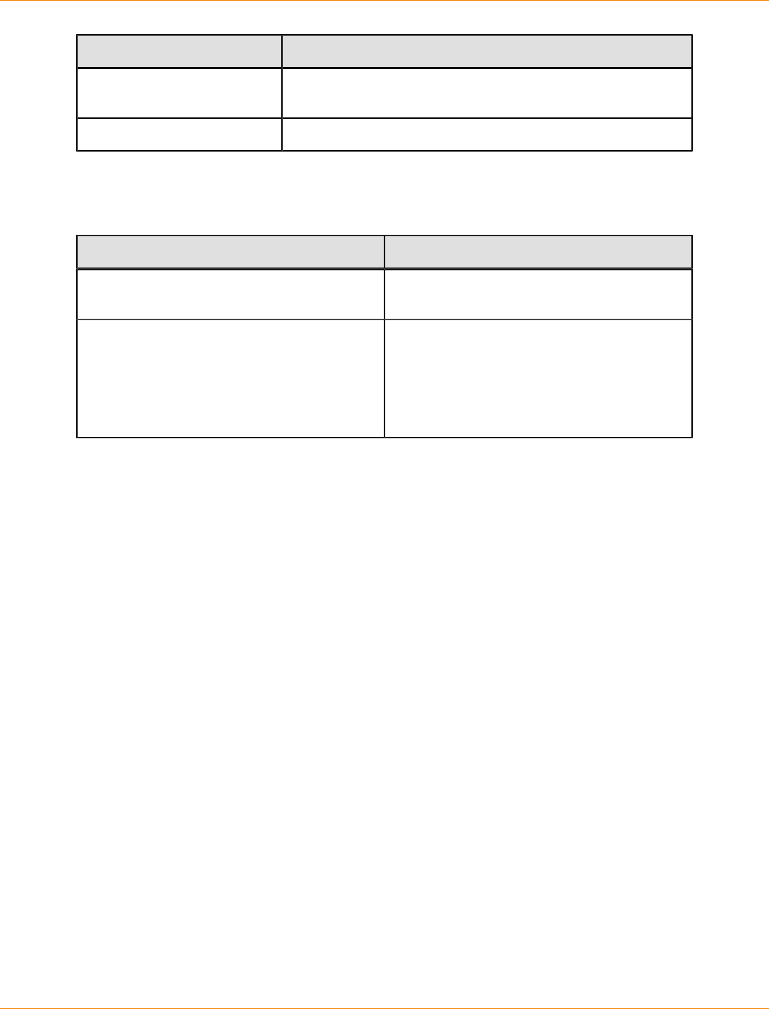
SANtricity_10.77 February 2011
LSI Corporation
- 946 -
Command Description
multipath -f map Flushes the multipath device map specified by the map option,
if the map is unused
multipath -F Flushes all unused multipath device maps
Troubleshooting the Device Mapper
Troubleshooting the Device Mapper
Situation Resolution
Is the multipath daemon, multipathd, running? At the command prompt, enter the command:
/etc/init.d/multipathd status.
Why are no devices listed when you run the
multipath -ll command? At the command prompt, enter the command:
#cat /proc/scsi/scsi. The system
output displays all of the devices that are
already discovered.
Verify that the multipath.conf file has
been updated with proper settings.
SANtricity_10.77 February 2011
LSI Corporation
- 947 -
Failover Drivers for the Solaris Operating System
MPxIO is the supported failover driver for the Solaris operating system.
Solaris OS Restrictions
SANtricity ES Storage Manager no longer supports or includes RDAC for these Solaris operating systems:
Solaris 10 OS
Solaris 9 OS
Solaris 8 OS
NOTE MPxIO is not included on the SANtricity ES Storage Manager Installation DVD.
Prerequisites for Installing MPxIO on the Solaris OS for the First Time
Perform these prerequisite tasks.
1. Install the hardware
2. Map the volumes.
3. Make sure that RDAC is not on the system, because you cannot run both RDAC and MPxIO.
IMPORTANT RDAC and MPxIO cannot run on the same system.
Prerequisites for Installing MPxIO on a Solaris OS That Previously Ran RDAC
Perform these prerequisite tasks:
1. Make sure that there are no major problems in the current RDAC.
ATTENTION Potential loss of data access – Some activities, such as adding and removing
storage arrays, can lead to stale information in the RDAC module name file. These activities might also
render data temporarily inaccessible.
2. To make sure that there are no leftover RDAC files, type this command, and press Enter:
ls -l /var/symsm/directory
3. To make sure that the RDAC directory does not exist, type this command, and press Enter:
ls -l /dev/rdsk/*s2 >>filename
4. Examine the /etc/symsm/mnf file. There should be one line for each currently connected storage array.
An example line is:
infiniti23/24~1T01610104~ 0 1 7~1T04110240~ 7~0~3~~c6t3d0~c4t2d7~
5. Make sure that there are no extra lines for disconnected storage arrays.
6. Make sure that two controllers are listed on each line. (The example shows c6t3 and c4t2.)
7. Make sure that these are the correct controllers.
SANtricity_10.77 February 2011
LSI Corporation
- 948 -
8. Make sure there are no identical cXtX combinations. For example, if you see c6t3d0 and c6t3d4, a
problem exists.
9. Make sure that no major problems exist in the Solaris OS.
When you reset or power-cycle a controller, it might take up to three minutes to come fully ready. Older
storage arrays might take longer. The default Solaris Not Ready retry timer is only 30 seconds long, so
spurious controller failovers might result. Sun Microsystems has already increased the timer for LSI-
branded storage arrays to two minutes.
10. Make sure that the VERITAS Volume Manager can handle the MPxIO upgrade.
11. Capture the current configuration by performing these steps:
a. Save this file.
/etc/symsm/mnf
b. Save this file.
/etc/raid/rdac_address
c. Type this command, and press Enter:
ls -l /dev/rdsk/*s2 >>rdsk.save
d. Type this command, and press Enter:
ls -l /dev/symsm/dev/rdsk/*s2 >>symsm.save
e. Type this command, and press Enter:
lad -y >>lad.save
12. To remove RDAC, type this command, and press Enter:
pkgrm RDAC
IMPORTANT Do not restart the system at this time.
Installing MPxIO on the Solaris 9 OS
MPxIO is not included in the Solaris 9 OS. To install MPxIO on the Solaris 9 OS, perform these steps.
1. Download and install the SAN 4.4x release Software/Firmware Upgrades and Documentation from this
website:
http://www.sun.com/storage/san/
2. Install recommended patches.
3. To enable MPxIO on the Solaris 9 OS, perform these steps:
a. Open this file:
/kernel/drv/scsi_vhci.conf
b. Change the last line in the script to this command:
mpxio-disable="no";
NOTE Make sure that "no" is enclosed in double quotation marks.
SANtricity_10.77 February 2011
LSI Corporation
- 949 -
4. Disable MPxIO on any Fibre Channel drives, such as internal drives, that should not be MPxIO enabled.
To disable MPxIO on specific drives, perform these steps:
a. Open the Fibre Channel port driver configuration file:
/kernel/drv/qlc.conf
b. Add a line similar to the following:
name="qlc" parent="/pci@8,600000" port=0 unit-address="2"
mpxio-disable="yes";
NOTE To find the correct parent and port numbers, look at the device entry for the internal
drives, found in /dev/dsk,
5. To update vfstab and the dump configuration, type this command:
stmsboot -u
6. Reboot the system.
Enabling MPxIO on the Solaris 10 OS
MPxIO is included in the Solaris 10 OS; therefore, it does not need to be installed. It only needs to be
enabled.
1. To enable MPxIO for all Fibre Channel drives, enter the command:
stmsboot -e
2. If there are any Fibre Channel drives for which you do not want MPxIO enabled, for example, internal
drives, disable MPxIO on those drives. To disable MPxIO on specific drives, perform these steps:
a. Edit the Fibre Channel port driver configuration file /kernel/drv/fp.conf.
b. Add a line similar to the following:
name="fp" parent="/pci@8,600000/SUNW,qlc@2" port=0
mpxio-disable="yes";
To find the correct parent and port numbers, look at the device entry for the internal drives, found in /
dev/dsk.
3. To update vfstab and the dump configuration, enter the command:
stmsboot -u
4. Reboot the system.
Configuring Failover Drivers for the Solaris OS
ATTENTION Possible loss of data – Create a backup of your configuration before you change any
configuration file.
Configure the host settings for these parameters in the /etc/ system file.
ssd_io_time – Add the line set ssd:ssd_io_time=0x78 to the system file.
ssd_max_throttle – Add the line set ssd:ssd_max_throttle=8 to the system file.
SANtricity_10.77 February 2011
LSI Corporation
- 950 -
Configure MPxIO multi-pathing in the /kernel/drv/scsi_vhci.conf file with these recommended
parameters.
mpxio-disable – Set to no.
load-balance – Set to none.
IMPORTANT For a symmetric storage array, you must specify round-robin so that the driver can
balance the I/O load between the two paths.
auto-failback – Set to enable.
To add a device, add these lines to the end of the scsi_vhci.conf file:
device-type-scsi-options-list="Acme MSU",
"symmetric-option";symmetric-option=0x1000000;
where Acme is the vendor ID, and MSU is the product ID.
IMPORTANT Make sure five spaces exist between the vendor ID and the product ID.
Frequently Asked Questions About Solaris Failover Drivers
Frequently Asked Questions about Solaris Failover Drivers
Question Answer
Where can I find MPxIO-related
files? You can find MPxIO-related files in these directories:
/etc/
/kernel/drv
Where can I find data files? You can find data files in these directories:
/etc/raid ==> /usr/lib/symsm
/var/symsm
/var/opt/SM
Where can I find the command
line interface (CLI) and bin files? You can find CLI and bin files in these directories:
etc/raid/bin ==> /usr/lib/symsm/bin
/usr/sbin/symsm ==> /usr/lib/symsm/bin
Where can I find device files? You can find device files in this directory:
/dev/[osa|symsm]/dev/[r]dsk ==>/dev/[r]dsk
Where can I find the SANtricity
ES Storage Manager files? You can find the SANtricity ES Storage Manager files in
these directories:
/opt/SM7[client, agent]
/opt/SM9
How can I get a list of
controllers and their volumes? Use the lad -y command. The command uses LUN 0
to get the information and is located in the /usr/lib/
symsm/bin directory. It can be reached through /etc/
raid/bin. This command updates the mnf file.
SANtricity_10.77 February 2011
LSI Corporation
- 951 -
Question Answer
Where can I get a list of storage
arrays, their volumes, LUNs,
WWPNs, preferred paths, and
owning controller?
Use the SMdevices utility.
This utility must be in the search path and is located in the /
opt/SM7util directory or the /opt/SM8/util directory.
How can I see if volumes have
been added? Use the hot_add utility. This utility asks the Solaris OS
target drivers to find new devices.
The hot_add utility works only after all of the potential
devnodes have been created in the OS. If not, run the
devfsadm command, and run the hot_add utility. If these
actions do not work, restart with the reconfiguration option.
What file holds the storage
array identification information? Go to the /etc/[osa|symsm]/mnf directory. The mnf
file identifies storage arrays in these ways:
Lists their ASCII names
Shows their controller serial numbers
Indicates the current LUN distribution
Lists controller system names
Lists the storage array numbers
Why might the rdriver fail to
attach and what can I do about
it?
The rdriver might not attach if there is no entry in the
rdriver.conf file to match the device, or if rdnexus runs
out of buses.
If no physical devnode exists:
The sd.conf file must specify LUNs explicitly.
The ssd.conf file with the itmpt HBA must specify
LUNs explicitly.
With Sun driver stacks, underlying HBA drivers
dynamically create devnodes for ssd.
You must restart the system with the reconfigure option
after you update the rdriver.conf file.
In the Solaris 9 OS, you can use the update_drv
command if the HBA driver supports it.
How can I determine if the
resolution daemon is working? Type this command, and press Enter:
ps -ef | grep rd

SANtricity_10.77 February 2011
LSI Corporation
- 952 -
System Upgrade for Hardware and Software
These topics describe a range for procedures for upgrading hardware, software, and firmware.
SANtricity_10.77 February 2011
LSI Corporation
- 953 -
Preparing to Upgrade Your Storage Management Software
The topics in this section include the procedure for upgrading the SANtricity ES Storage Manager. The topics
also cover background information about hardware and software configurations that you need to understand
for subsequent upgrade procedures.
Upgrading the Storage Array to SANtricity ES Storage Manager Version 10.75
Prerequisite: These steps are required for a successful upgrade from storage management software
Version 8.4x or later to Version 10.75 (controller firmware version 5.3x to version 7.75). Perform the steps in
order.
1. Make sure that the controller trays and the controller-drive trays in your storage array are compatible with
the software level and the firmware level to which you are upgrading.
See “Supported Trays and the Maximum Number of Drives and Volumes” for version information.
2. Check that the host bus adapters (HBAs), switches, driver versions, firmware levels, and specific
hardware restrictions are supported.
IMPORTANT Install all storage area network (SAN) hardware before you work with the storage
management software.
3. Start the existing storage management software with the procedure for your operating system.
4. Check that the storage array has Optimal status.
5. Save and print the storage array profile from the current Array Management Window of the storage
management software for each storage array.
a. In the Array Management Window, select Storage Array >> View >> Profile.
b. Click Save As.
c. Select the All sections radio button.
d. Type a file name in the File name text box.
e. Click Save.
The storage array profile is used for this information:
Configuration information that you might provide to your Customer and Technical Support
representative
The current NVSRAM and controller firmware versions
The current environmental services monitor (ESM) firmware version
6. Locate the cache and processor memory size (MB) in the storage array profile, and record the listed size
for later verification.
7. Locate the host interface in the storage array profile, and record the number listed in the Preferred ID
area for each Fibre Channel interface for later verification.
8. Make sure that your storage array has the minimum system requirements for your operating system.
See "Required Computing Environment."
9. Make sure that your failover driver is compatible with the new hardware, firmware, and software. Refer to
the topics under SANtricity ES Storage Manager Failover Drivers for Version 10.75 or to the SANtricity ES
Storage Manager Installation DVD for the corresponding PDF document.
NOTE Read the "dependence" section in the SANtricity ES Storage Manager readme.txt file.
SANtricity_10.77 February 2011
LSI Corporation
- 954 -
10. Make sure that the current version of the storage management software can be upgraded to SANtricity
ES Storage Manager Version 10.75.
11. Install SANtricity ES Storage Manager Version 10.75 for your operating system (OS). Use the procedure
for your OS to install the storage management software.
12. Make sure that the installation was successful. Use the procedure for your operating system to start the
storage management software.
13. Check that the storage array has an Optimal status. If one or more managed devices has a Needs
Attention status, contact your Customer and Technical Support representative.
14. If you determined from the storage array profile that the NVSRAM firmware, the controller firmware, or the
ESM firmware is not the current version, download the compatible firmware.
NOTE You can upgrade from RAID Core 1 to RAID Core 2, by using the Enterprise Management
Window. See “Upgrading the Firmware and the NVSRAM.”
Software Packages
All SANtricity ES Storage Manager software packages are generally installed in the same directory on the
same system, whether the system is a host or a separate storage management station.
SANtricity ES Storage Manager Software Packages
Software Package Description and Usage
SMclient This package contains the graphical user interface for
managing the storage array. This package also contains
an optional monitor service that sends alerts when a critical
problem exists with the storage array.
SMagent The storage management software that is installed only on a
host system to enable in-band management.*
SMruntime The operating system (OS) -specific storage management
software that installs the appropriate Java runtime
environment (JRE), which allows Java files to be displayed.
Redundant Dual Active
Controller (RDAC) A multi-path failover driver, proprietary to LSI, that is installed
on Linux hosts. This software package manages the I/O paths
into the controllers in the storage array. If a problem exists
on the path or a failure occurs on one of the controllers, the
driver automatically reroutes the request from the hosts to the
other controller in the storage array. For information about
other supported failover drivers for your operating system,
refer to the topics under SANtricity ES Storage Manager
Failover Drivers for Version 10.75 or to the SANtricity ES
Storage Manager Installation DVD for the corresponding PDF
document.
SMutil This package contains utilities that let the operating system
recognize the volumes that you create in the storage array
and to view the OS-specific device names for each volume.
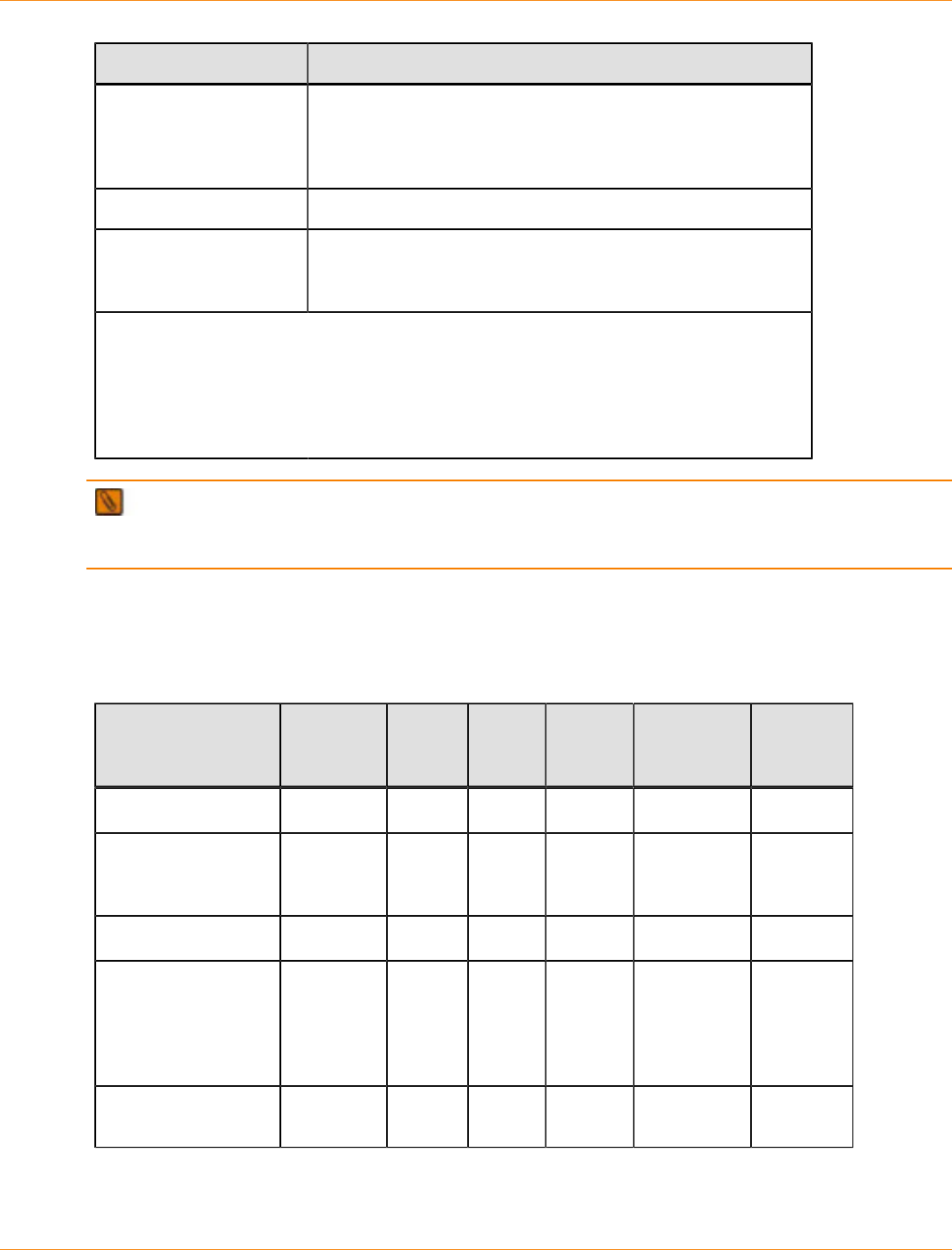
SANtricity_10.77 February 2011
LSI Corporation
- 955 -
Software Package Description and Usage
SMprovider The storage management software interface to the Volume
Shadow Copy Service (VSS) and Virtual Disk Service
(VDS) technologies (these technologies are included with
Microsoft’s .NET framework).
SMinstaller A package that installs the InstallAnywhere utility.
Support Monitor Profiler This package helps you to collect the support data and email
the support data to the Customer and Technical Support
representative.
* In-band management is a method for managing a storage array in which the controllers
are managed from a storage management station attached to a host that is running
host-agent software. The host-agent software receives communication from the storage
management client software and passes it to the storage array controllers along a Fibre
Channel input/output (I/O) path. The controllers also use the I/O connections to send
event information back to the storage management station through the host.
NOTE The Microsoft Virtual Disk Service (VDS) and Volume Shadow Copy Service (VSS) providers
are a part of the SANtricity ES Storage Manager package for the Windows Server 2003 OS and the Windows
Server 2008 OS.
Installation Options
Install only the packages that are required for the type of installation you are performing.
Installation Options and Related Software Packages
Installation Option SMruntime SMclient SMutil SMagent RDAC
Failover
Driver*
Support
Monitor
Profiler
Typical installation X X X X X
Storage
management
station**
X X X
Host station X X X
A host station
acting as a storage
management
station (out-of-band
management)***
X X X X
Host with in-band
management X X X X
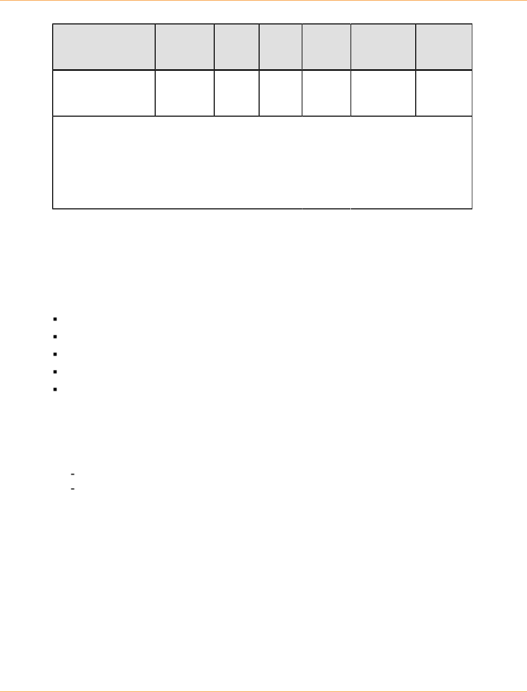
SANtricity_10.77 February 2011
LSI Corporation
- 956 -
Installation Option SMruntime SMclient SMutil SMagent RDAC
Failover
Driver*
Support
Monitor
Profiler
Custom (you can
select the software
packages)
* The RDAC failover driver is proprietary to LSI and is available for download to the Linux OS.
** The storage management station is a computer that runs storage management software
that adds, monitors, and manages the storage arrays on a network.
*** Out-of-band management is a method to manage a storage array directly over the network
through an Ethernet connection, from a storage management station that is attached to the
controllers. This management method lets you configure the maximum number of volumes
supported by your operating system and host adapters.
Checking the Current Version of the Storage Management Software
To check the level of the current storage management software, type the command that corresponds to your
operating system, and press Enter. The <package_name> placeholder refers to the name of the software
package that is installed.
Some operating system-specific commands are listed as follows:
In the HP-UX operating system, type swlist | grep SM*, and press Enter.
In the AIX operating system, type lslpp -L <package_name>, and press Enter.
In the Solaris operating system, type pkginfo -l <package_name>, and press Enter.
In the Linux operating system, type rpm -qi <package_name>, and press Enter.
In the Windows operating system, perform these tasks:
1. Select Start >> Run.
2. Type regedit, and press Enter.
The Register Editor window appears.
3. Perform one of these actions:
In Windows XP operating system, select HKEY_LOCAL_MACHINE >> SOFTWARE >> Storage.
In Windows Server 2003 and Windows Server 2008 operating systems, select
HKEY_LOCAL_MACHINE >> SOFTWARE >> Wow6432Node >> Storage.
4. Select a software package listed under the storage directory to view the version.
You can also check the version of the storage management software in the Enterprise Management Window
or the Array Management Window by selecting Help >> About.
Controller Trays and Controller-Drive Trays
This section describes the supported controller trays and controller-drive trays.

SANtricity_10.77 February 2011
LSI Corporation
- 957 -
Controller Trays and Controller-Drive Trays
Term Description
Controller tray A unit that contains one or two controllers, batteries (optional), and
redundant cooling fans and power supplies. Controller trays do not
contain environmental services monitors (ESMs).
Controller-drive tray A unit that contains drives, batteries (optional), redundant cooling
fans and power supplies, and (depending on the model) one or two
controllers. Controller-drive trays do not contain ESMs.
Supported Trays and the Maximum Number of Drives and Volumes
The following table shows the controller-drive trays, the controller trays, and the versions of the supported
storage management software. This table also shows the maximum number of drives and the total number of
volumes that are supported by each controller tray or controller-drive tray. The total numbers include drives
or volumes that are contained in the controller tray or the controller-drive tray and in additional attached drive
trays.
Supported Trays and the Maximum Number of Drives and Volumes
Tray Name Controller
Type Version of
the Storage
Management
Software
Maximum
Drives per
Storage
Array
Maximum
Volumes
per Storage
Array*
Controller-drive trays
SHV2200 or
SHV2500 2772 8.30 42 512
SHV2520 2880 (dual) 8.33, 8.40, 9.10,
9.12, 9.19, 9.23,
10.10
14** 1024
SHV2600 2882 8.33, 8.40, 9.10,
9.12, 9.19, 9.23,
10.10
112 1024
SAT2700 2820-SATA 8.42, 9.12 14** 512
SAT2800 2822-SATA 8.42, 9.12 112 512
AM1331and
AM1333 1331/1333 9.23, 9.30, 9.60,
9.70, 10.30,
10.35, 10.36,
10.50, 10.60
48 256
AM1532 1532 9.70, 10.30,
10.35, 10.36,
10.50, 10.60
48 256

SANtricity_10.77 February 2011
LSI Corporation
- 958 -
Tray Name Controller
Type Version of
the Storage
Management
Software
Maximum
Drives per
Storage
Array
Maximum
Volumes
per Storage
Array*
AM1932 1932 9.70, 10.30,
10.35, 10.36,
10.50, 10.60
48 256
CDE3994 3992 or
3994 9.16, 9.19, 9.23,
9.60, 10.10,
10.15, 10.36,
10.50, 10.60
112 1024
CDE4900 4900 10.50, 10.60,
10.75 112 1024
CDE2600 2600 10.70, 10.75 96 512
Controller trays
SYM1200 4774 8.30 224 512
FC1250 4884 8.30, 8.40, 9.10,
9.12 224 2048
FC1275 5884 8.30, 8.40, 8.41,
9.10, 9.12, 9.19,
9.23, 10.10
224 2048
SAT2600 2882-SATA 8.41 112 1024
CE6998 6091 9.14, 9.16, 9.19,
9.23, 9.60, 10.10,
10.15, 10.36,
10.50, 10.60
224 2048
CE7900 7091 10.30, 10.36,
10.50, 10.60,
10.75
448*** 2048
CE7922 7091 10.60 448*** 2048
* Snapshot repository volumes and Remote Volume Mirroring repository volumes
are included in the number of volumes supported.
** Additional drive trays are not supported.
*** A maximum of 480 drives are supported with the DE6900 drive tray.
Supported Drive Trays
The drive tray is a unit that contains up to 60 drives, redundant cooling fans and power supplies, and one or
two environmental services monitors (ESMs). Drive trays do not contain controllers.

SANtricity_10.77 February 2011
LSI Corporation
- 959 -
Supported Drive Trays
Drive Tray Version of the Storage
Management Software Drives per Tray Drive Technology
SYM2200 8.30 10 1-Gb/s Fibre Channel
FC2500 8.30 14 1-Gb/s Fibre Channel
FC2600 (JBOD) 8.30, 8.33, 8.40, 9.10,
9.12, 9.14, 9.16, 9.23,
10.10, 10.15, 10.36,
10.60
14 2-Gb/s Fibre Channel
FC2610 (SBOD) 9.10, 9.12, 9.14, 9.16,
9.19, 9.23, 10.10, 10.15,
10.36, 10.60
14 2-Gb/s Fibre Channel
AT2655 8.41, 8.42, 9.10, 9.12,
9.14, 9.19, 9.23, 10.10,
10.15, 10.60
14 2-Gb/s SATA
DM1300 9.17, 9.50, 9.70, 10.35,
10.60 12 3-Gb/s SAS and SATA
FC4600 (SBOD) 9.16, 9.19, 9.23, 9.60,
10.10, 10.15, 10.30,
10.36, 10.50, 10.60,
10.75
16 4-Gb/s Fibre Channel
DE6900 10.60, 10.75 60 4-Gb/s Fibre Channel
DE1600 10.70, 10.75 12 6-Gb/s SAS
DE5600 10.70, 10.75 24 6-Gb/s SAS
Software Compatibility for Controller-Drive Trays and Controller Trays
The following table shows the relationship between controller-drive trays, controller trays, and the versions of
the storage management software that are supported by each tray. The table also lists the drive trays that are
supported by controller-drive trays or controller trays.
Software Compatibility for Controller-Drive Trays and Controller Trays
Tray Version SYM2200
Drive
Tray
FC2500
Drive
Tray
FC2600
Drive
Tray
AT2655
Drive
Tray
FC2610
Drive
Tray
FC4600
Drive
Tray
DE6900
Drive
Tray
DM1300
Drive
Tray
DE1600
Drive
Tray
DE5600
Drive
Tray
SHV2200
or
SHV2500
controller-
drive
tray
8.30 X X X

SANtricity_10.77 February 2011
LSI Corporation
- 960 -
Tray Version SYM2200
Drive
Tray
FC2500
Drive
Tray
FC2600
Drive
Tray
AT2655
Drive
Tray
FC2610
Drive
Tray
FC4600
Drive
Tray
DE6900
Drive
Tray
DM1300
Drive
Tray
DE1600
Drive
Tray
DE5600
Drive
Tray
8.33
8.40
9.10
9.12
9.19
9.23
SHV2520
(dual)
controller-
drive
tray
10.10
Additional drive trays are not supported.
8.33 X
8.40 X
9.10 X X
9.12 X X
9.19 X X X X
9.23 X X X X
SHV2600
controller-
drive
tray
10.10 X X X X
8.42SAT2700
controller-
drive
tray
9.12
Additional drive trays are not supported.
8.42 X
SAT2800
controller-
drive
tray 9.12 X X X
9.23 X
9.30 X
9.60 X
9.70 X
10.30 X
AM1331
and
AM1333
controller-
drive
trays
10.35 X

SANtricity_10.77 February 2011
LSI Corporation
- 961 -
Tray Version SYM2200
Drive
Tray
FC2500
Drive
Tray
FC2600
Drive
Tray
AT2655
Drive
Tray
FC2610
Drive
Tray
FC4600
Drive
Tray
DE6900
Drive
Tray
DM1300
Drive
Tray
DE1600
Drive
Tray
DE5600
Drive
Tray
10.36 X
10.50 X
10.60 X
9.70 X
10.30 X
10.35 X
10.36 X
10.50 X
AM1532
controller-
drive
tray
10.60 X
9.70 X
10.30 X
10.35 X
10.36 X
10.50 X
AM1932
controller-
drive
tray
10.60 X
9.16 X X X X
9.19 X X X X
9.23 X X X X
9.60 X X X X
10.10 X X X X
10.15 X X X X
10.36 X X X X
10.50 X X
CDE3994
controller-
drive
tray
10.60 X X X X X

SANtricity_10.77 February 2011
LSI Corporation
- 962 -
Tray Version SYM2200
Drive
Tray
FC2500
Drive
Tray
FC2600
Drive
Tray
AT2655
Drive
Tray
FC2610
Drive
Tray
FC4600
Drive
Tray
DE6900
Drive
Tray
DM1300
Drive
Tray
DE1600
Drive
Tray
DE5600
Drive
Tray
10.60 X
CDE4900
controller-
drive
tray 10.75 X
10.70 X XCDE2600
controller-
drive
tray 10.75 X X
SAT2600
controller
tray
8.41 X
SYM1200
controller
tray
8.30 X X X
8.30 X X X
8.40 X X X
9.10 X X X
FC1250
controller
tray
9.12 X X X X X
8.30 X
8.40 X
8.41 X
9.10 X X
9.12 X X X
9.19 X X X X
9.23 X X X X
FC1275
controller
tray
10.10 X X X X
9.14 X X X
9.16 X X X X
9.19 X X X X
CE6998
controller
tray
9.23 X X X X
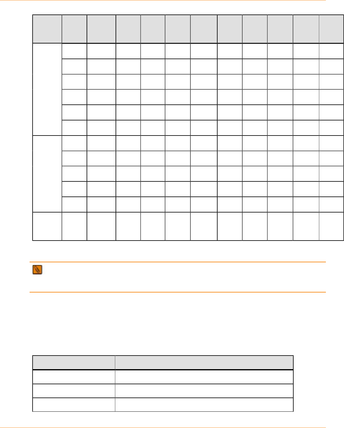
SANtricity_10.77 February 2011
LSI Corporation
- 963 -
Tray Version SYM2200
Drive
Tray
FC2500
Drive
Tray
FC2600
Drive
Tray
AT2655
Drive
Tray
FC2610
Drive
Tray
FC4600
Drive
Tray
DE6900
Drive
Tray
DM1300
Drive
Tray
DE1600
Drive
Tray
DE5600
Drive
Tray
9.60 X X X X
10.10 X X X X
10.15 X X X X
10.36 X X X X
10.50 X X X X
10.60 X X X X
10.30 X X X X
10.36 X X X X
10.50 X X X X
10.60 X X X X X
CE7900
controller
tray
10.75 X X X X X
CE7922
controller
tray
10.60 X X
HBAs and Driver Information
NOTE The SANtricity ES Storage Manager Installation DVD does not contain any drivers or
configuration files for the host bus adapters (HBAs) that were tested with this version of the storage
management software. Use the Internet download sites provided in this section to help you to find these files.
You can obtain information about supported HBAs from the Compatibility Matrix. To check for current
compatibility, refer to the Compatibility Matrix at http://www.lsi.com/compatibilitymatrix/.
Driver Information
The Compatibility Matrix contains information about the files that are needed to support the HBAs. Use these
Internet locations to obtain the drivers that are listed in the Compatibility Matrix.
HBA Driver Vendor Internet Location
Emulex http://www.emulex.com/downloads.html
JNI/AMCC http://www.amcc.com/drivers/notice.html
LSI http://www.lsi.com/cm/DownloadSearch.do

SANtricity_10.77 February 2011
LSI Corporation
- 964 -
HBA Driver Vendor Internet Location
IBM http://www.ibm.com/support/us
QLogic* http://www.qlogic.com/support/drivers_software.asp
Oracle (Sun) http://www.oracle.com/technetwork/indexes/downloads/
index.html
* URLs on the QLogic website are case sensitive.
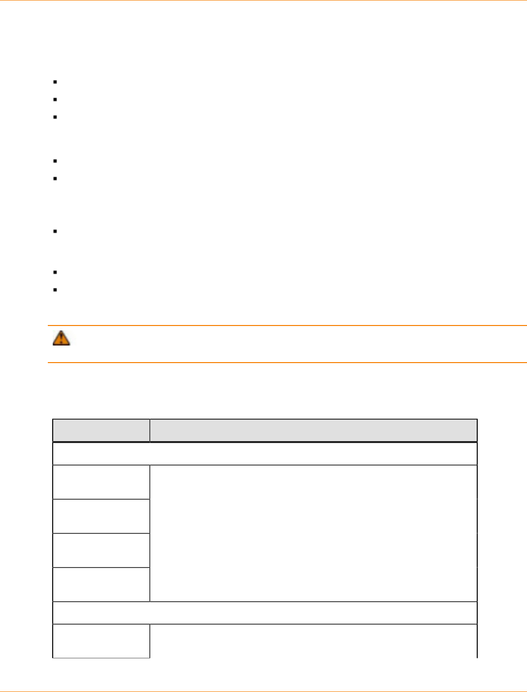
SANtricity_10.77 February 2011
LSI Corporation
- 965 -
Upgrading Trays in the Storage Array
To upgrade trays in the storage array, you can choose from these upgrade options:
Upgrade one model of a controller-drive tray to another model of a controller-drive tray.
Convert a controller-drive tray to a drive tray, and add a controller tray.
Upgrade one model of a controller tray to another model of a controller tray.
Before you upgrade trays in your storage array, keep these guidelines in mind:
Review “Upgrading Options for the Supported Trays” for a list of possible upgrade options.
Become familiar with the new components that you are installing into the existing trays and the
components that you are installing into an existing storage array. The tray connectors and switches
might be arranged differently than those on the tray that you are removing. Refer to the conversion kit
instructions for the tray that you want to upgrade.
Make sure that the new tray is compatible with the existing trays. For example, some drive trays might not
be supported with the new equipment. To check for compatibility, refer to the Compatibility Matrix at http://
www.lsi.com/compatibilitymatrix.
Make sure that the new firmware is compatible with the existing trays and the existing firmware.
Make sure that you know of any cabling issues with the new trays. For a complete description of various
cabling options, refer to the topics under Hardware Cabling or to the SANtricity ES Storage Manager
Installation DVD for the corresponding PDF document.
ATTENTION Possible loss of data access – Before you start any upgrade procedure, back up your
data to an external source.
Upgrading Options for the Supported Trays
Upgrading Options for Supported Trays
Tray Name Tray Upgrading Option
Upgrade a controller-drive tray to a different controller-drive tray
SHV2520
controller-drive tray
SHV2600
controller-drive tray
SAT2700
controller-drive tray
SAT2800
controller-drive tray
Use volume group relocation to migrate the drives to the CDE3994
controller-drive tray
Convert a controller-drive tray to a drive tray, and add a controller tray
SHV2200
controller-drive tray Convert to the FC2600 drive tray, and add the CE6998 controller tray or
the CE7900 controller tray

SANtricity_10.77 February 2011
LSI Corporation
- 966 -
Tray Name Tray Upgrading Option
SHV2500
controller-drive tray
SHV2520
controller-drive tray
SHV2600
controller-drive tray
SAT2600
controller-drive tray
SAT2700
controller-drive tray
SAT2800
controller-drive tray
Convert to the AT2655 drive tray, and add the CE6998 controller tray or
the CE7900 controller tray
CDE3994
controller-drive tray Convert to the FC4600 drive tray, and add the CE6998 controller tray or
the CE7900 controller tray
Replace a controller tray with a different controller tray
SYM1200 controller
tray Remove the SYM1200 controller tray, and add the CE6998 controller
tray or the CE7900 controller tray
FC1250 controller
tray Remove the FC1250 controller tray, and add the CE6998 controller tray
or the CE7900 controller tray
FC1275 controller
tray Remove the FC1275 controller tray, and add the CE6998 controller tray
or the CE7900 controller tray
CE6998 controller
tray Remove the CE6998 controller tray, and add the CE7900 controller tray
Upgrading the Controller-Drive Trays
If you want to upgrade from one model of controller-drive tray to the CDE3994 controller-drive tray, you can
use the import and export functions of the SANtricity ES Storage Manager software.
NOTE The import and export functions are only available if your controllers are running controller
firmware version 7.10 or later.
You will export the volume groups from the old controller-drive tray, and import those volume groups to the
CDE3994 controller-drive tray. For more information, refer to the online help topics in SANtricity ES Storage
Manager.

SANtricity_10.77 February 2011
LSI Corporation
- 967 -
Converting a Controller-Drive Tray to a Drive Tray and Adding a Controller
Tray
You can upgrade the storage array by converting the controller-drive tray to a drive tray and adding a
controller tray. Contact your Customer and Technical Support representative to order a tray conversion kit.
Refer to the tray conversion kit instructions for complete instructions about how to convert a controller-drive
tray to a drive tray. Use this procedure to add a new controller tray to your storage array.
NOTE If you are adding a new controller tray that has controllers running controller firmware version
7.10 or later, the controllers in your original storage array must also be running controller firmware version
7.10 or later.
Also, make sure that you can connect the tray and the drives to the new controller. For example, you cannot
connect a DM1300 drive tray to a CE6998 controller tray or a CE7900 controller tray.
NOTE Before starting this procedure, make sure that you have the removal and replacement procedure
instructions for the environmental services monitors (ESMs). For older hardware models, this documentation
is not included in documentation delivered with the current release of SANtricity ES Storage Manager.
1. Stop I/O, and turn off the power to the controller-drive tray and the drive trays.
2. Disconnect the host cables from the controllers.
3. If the storage array has drive trays connected to the controller-drive tray, disconnect the cables from the
controllers to the ESMs in the drive trays.
4. Remove the controllers from the controller-drive tray.
5. Insert the ESMs into the controller-drive tray to replace the controllers.
6. Connect the cables from the ESMs in the other drive trays to the new ESMs.
If the drive cable is connected to port 1 of the drive tray, connect the other end of the cable to port 2
of the new ESM.
If the drive cable is connected to port 2 of the drive tray, connect the other end of the cable to port 1
of the new ESM.
For a complete description of the various cabling options, refer to the topics under Hardware Cabling or to
the SANtricity ES Storage Manager Installation DVD for the corresponding PDF document.
NOTE Make sure that you have enough space in the cabinet for the new controller tray before you
perform the next step.
7. Insert the new controller tray into the cabinet. Refer to the topics under Installation for the controller tray
that you have chosen to upgrade for more details about how to secure the controller tray to the cabinet.
The Installation topics are also available as PDF documents on the SANtricity ES Storage Manager
Installation DVD.
8. Connect the host cables to the host ports on the controller tray.
9. Connect the cables from the controllers to the ESMs.
10. Update the labels on each cable that has changed its connections. The following table shows the
information that is recommended on the label.
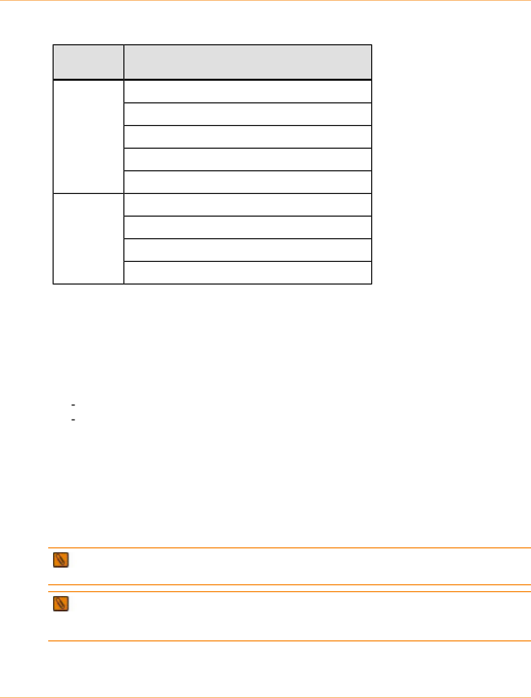
SANtricity_10.77 February 2011
LSI Corporation
- 968 -
Label Information for Cables
Type of
Cable Items to Label
Controller ID
Drive channel number and port ID in the controller
ESM ID
ESM port ID
Drive cable
Drive tray ID
Host name
HBA port
Controller ID
Host cable
Host channel ID
11. Connect the power cord or power cords to the new controller tray.
12. Turn on the power to the drive trays.
The drives might take several minutes to complete the power-on procedure.
13. Turn on the power to the new controller tray.
14. Use SANtricity ES Storage Manager to check that your configuration is correct.
15. Is your configuration correct?
Yes – Go to step 15.
No – If possible, correct your configuration. If the problem is not resolved, contact your Customer and
Technical Support representative.
16. If you want to expand the storage array, you can now add drive trays. For a complete description of
the various cabling options, refer to the topics under Hardware Cabling or to the SANtricity ES Storage
Manager Installation DVD for the corresponding PDF document.
Replacing an Existing Controller Tray with a CE7900 Controller Tray
You can replace an existing controller tray with a CE7900 controller tray to improve the capability of your
storage array. Use this procedure to replace your old controller tray with the CE7900 controller tray.
NOTE Controllers in the controller tray that you are removing must be running controller firmware 7.10
or later. If not, you must update the controller firmware to 7.10 or later.
NOTE If you are upgrading the controller tray to a CE7900 controller tray, you need additional vertical
space in the cabinet. The CE7900 controller tray is a 4U-high tray, while the CDE3994 controller-drive tray is
a 3U-high tray.
1. Turn off the power to the old controller tray, and disconnect the power cord.
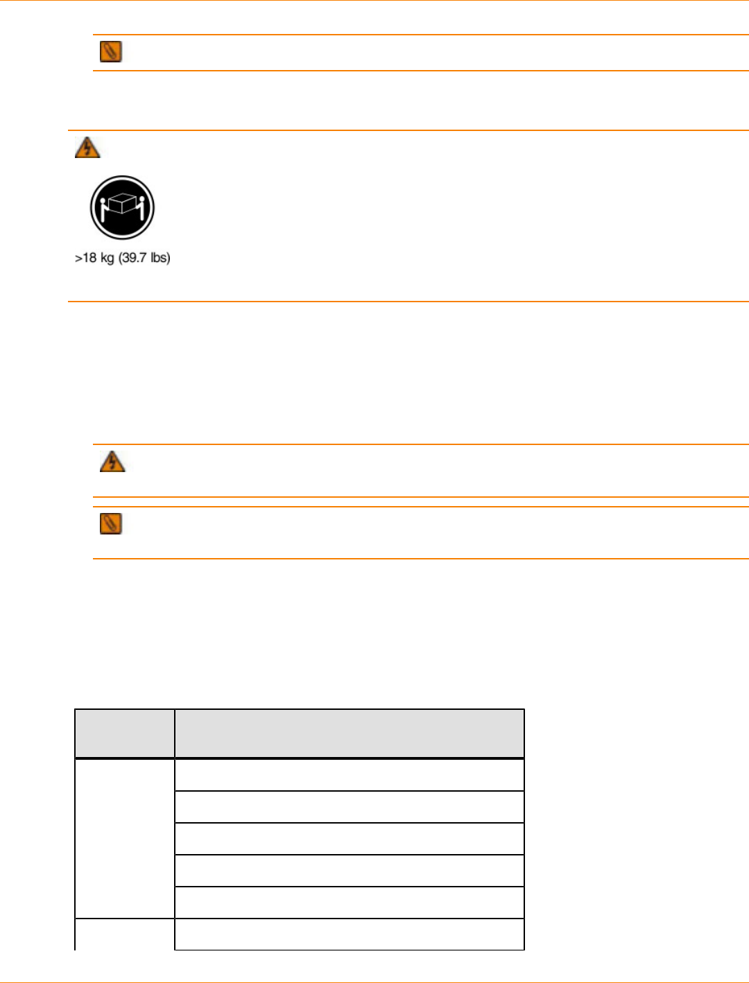
SANtricity_10.77 February 2011
LSI Corporation
- 969 -
NOTE Do not turn off the power to the drive trays that are connected to the old controller tray.
2. Disconnect all of the cables from the drive ports on the old controller tray.
3. Disconnect all of the cables from the host ports on the old controller tray.
WARNING (W08) Risk of bodily injury –
Two persons are required to safely lift the component.
4. If the old controller tray has Ethernet cables for out-of-band management, disconnect those cables.
5. Slide the old controller tray out of the cabinet.
6. Slide the CE7900 controller tray into the empty spot in the cabinet, and secure it firmly.
For information about how to secure the CE7900 controller tray to the cabinet, refer to the topics under
CE7900 controller tray Installation for the CE7900. A PDF version of the document is available on the
SANtricity ES Storage Manager Installation DVD.
WARNING (W03) Risk of exposure to laser radiation – Do not disassemble or remove any part
of a Small Form-factor Pluggable (SFP) transceiver because you might be exposed to laser radiation.
NOTE If you are using Fibre Channel cables, insert a Small Form-factor Pluggable (SFP)
transceiver into the interface port on the controllers in the controller tray and the ESMs in the drive trays.
7. Connect the drive trays that were previously used with the old controller tray to the CE7900 controller
tray.
8. Reattach the host cabling to the CE7900 controller tray.
9. Update the labels on each cable that has changed connections. The following table shows the information
that is recommended on the label.
Label Information for Cables
Type of
Cable Items to Label
Controller ID
Drive channel number and port ID in the controller
ESM ID
ESM port ID
Drive cable
Drive tray ID
Host cable Host name

SANtricity_10.77 February 2011
LSI Corporation
- 970 -
Type of
Cable Items to Label
HBA port
Controller ID
Host channel ID
10. If the old controller tray has Ethernet cables for out-of-band management, reattach those cables.
11. Connect the power cord to the CE7900 controller tray, and turn on the power to the new controller tray.
The CE7900 controller tray starts to communicate with the drive trays. Front panel LEDs blink during this
process.
12. Use SANtricity ES Storage Manager to add the CE7900 controller tray as a new storage array.
13. Launch the Array Management Window.
14. Make sure that all of the drive tray volume and mappings are still intact.
15. Does any component have a Needs Attention status?
Yes – Click the Recovery Guru toolbar button in the Array Management Window, and complete the
recovery procedure. If the problem is not resolved, contact your Customer and Technical Support
representative.
No – Go to step 16.
16. Create, save, and print a new storage array profile.

SANtricity_10.77 February 2011
LSI Corporation
- 971 -
Upgrading the Firmware and the NVSRAM
You can upgrade the firmware of the controllers and the NVSRAM in the storage array by using the storage
management software.
In the process of upgrading the firmware, the firmware file is downloaded from the host to the controller.
After downloading the firmware file, you can upgrade the controllers in the storage array to the new firmware
immediately. Optionally, you can download the firmware file to the controller and upgrade the firmware later at
a more convenient time.
Activating the Firmware
The process of upgrading the firmware after downloading the firmware file is known as activation. During
activation, the existing firmware file in the memory of the controller is replaced with the new firmware file.
You might want to activate the firmware or NVSRAM files at a later time because of the following reasons:
Time of day – Activating the firmware and the NVSRAM can take a long time, so you might want to wait
until I/O loads are lighter. The controllers will go offline briefly to load the new firmware.
Type of package – You might want to test the new firmware on one storage array before upgrading the
firmware in other storage arrays.
The firmware upgrade process requires that the controllers have enough free memory space in which the
firmware file resides until activation.
Firmware Version
A version number exists for each firmware file. For example, 06.60.08.00 is a version number for a firmware
file. The first two digits indicate the major revision of the firmware file. The remaining digits indicate the minor
revision of the firmware file. You can view the version number of a firmware file in the Upgrade Controller
Firmware window and the Download Firmware dialog.
The process of upgrading the firmware can be either a major upgrade or a minor upgrade depending on the
version of the firmware.
For example, the process of upgrading the firmware is major if the version of the current firmware is
06.60.08.00, and you want to upgrade the firmware to version 07.36.12.00. In this example, the first two digits
of the version numbers are different and indicate a major upgrade. In a minor upgrade, the first two digits
of the version numbers are the same. For example, the process of upgrading the firmware is minor, if the
version of the current firmware is 06.60.08.00, and you want to upgrade the firmware to version 06.60.18.00,
or any other minor revision of the firmware.
IMPORTANT The firmware versions from 05.xx.xx.xx through 06.12.xx.xx are versions before the
RAIDCore1. The firmware versions from 06.14.xx.xx through 06.60.xx.xx are RAIDCore1. The firmware
version starting from 07.xx.xx.xx are RAIDCore2.
You can use the Enterprise Management Window to perform both major upgrades and minor upgrades.
You can use the Enterprise Management Window to perform a major upgrade from firmware version number
05.40.xx.xx to any later version, such as 06.xx.xx.xx, and 07.xx.xx.xx, where xx represent the digits that
indicate the minor revision of the firmware.
You can use the Array Management Window to perform minor upgrades only.

SANtricity_10.77 February 2011
LSI Corporation
- 972 -
The storage management software checks for existing conditions in the storage array before upgrading the
firmware. Any of these conditions in the storage array can prevent the firmware upgrade:
An unsupported controller type or controllers of different types that are in the storage array and cannot be
upgraded
One or more failed drives
One or more hot spare drives that are in use
Two or more volume groups that are incomplete
Operations, such as defragmenting a volume group, downloading of drive firmware, and others that are in
progress
Missing volumes that are in the storage array
Controllers that have a status other than Optimal
The storage partitioning database is corrupt
A data validation error occurred in the storage array
The storage array is in the Needs Attention status
The storage array is unresponsive, and the storage management software cannot communicate with the
storage array
The Event Log entries are not cleared
For more information on downloading the firmware and NVSRAM, refer to the online help topics in SANtricity
ES Storage Manager.
You can correct some of these conditions by using the Array Management Window. However, for some of
the conditions, you might need to contact your Customer and Technical Support representative. The storage
management software saves the information about the firmware upgrade process in log files. This action
helps the Customer and Technical Support representative to understand the conditions that prevented the
firmware upgrade.
You also can use the command line interface (CLI) to download and activate firmware to several storage
arrays. For more information, refer to the online help topics in SANtricity ES Storage Manager.

SANtricity_10.77 February 2011
LSI Corporation
- 973 -
Upgrading from Limited High Availability (LHA) to Full High
Availability (FHA)
You can upgrade the environmental services monitors (ESMs) in the drive trays from LHA ESMs to FHA
ESMs by using SANtricity ES Storage Manager. The following sections describe the procedure for upgrading
from an LHA ESM to an FHA ESM.
Terms Applicable to LHA and FHA
Terms Applicable to LHA and FHA
Term Definition
LHA Limited high availability, also known as dSATA Phase 1. This specification
refers to each ESM that retains sole ownership of seven drives per drive
tray, without full failover capacity.
FHA Full high availability, also known as dSATA Phase 2. This specification
refers to each ESM that retains ownership of seven drives per drive tray.
The first version of FHA consists of firmware version level 9550 and
controller firmware level 05.41.50.xx. Anything prior to this version is LHA.
*.dl A download file in package format for the ESM.
This file contains header information and package
information. This file can contain more than one type
of firmware packaged to download together. This file
is downloadable through the storage management
software. This file is not downloadable serially.
*.s3r A raw “S” record file without header information and
wrapper information that is not downloadable through
the storage management software.
*.dlf A raw firmware file without header information and
wrapper information that is not downloadable through
the storage management software. The *.dlf file
is packaged into a *.dl file, and the *.dlf file is
downloadable serially.
*.dlp A download file in package format for the controller
firmware. This file contains header information and
package information, and it is downloadable through
the storage management software.
Controller
firmware Controller firmware for the controllers in the storage
array. The firmware is downloadable through the
storage management software.
File types
ESM firmware Environmental services monitor (ESM) firmware for the
drive tray:
SANtricity_10.77 February 2011
LSI Corporation
- 974 -
Term Definition
esm9566.dl (DSATA)
esm9728.dl (ISATA)
The firmware is downloadable through the storage
management software.
Customer-
specific behavior
(CSB) file
The CSB file (csb_xxx_xxxx.dl1).* The file is
downloadable through the storage management
software.
noReboot ESM firmware downgrade from FHA to LHA versions is wrapped in
this format (esm95xx_noReboot.dl). After the firmware completes
its download, it does not reboot the ESM to start running on the newly
downloaded firmware code. In this case, you must manually reboot the ESM
by cycling the power.
* The xxx noted in the CSB file name indicates an OEM-specific identifier.
ATTENTION Possible loss of data access – Downloading a customer-specific behavior (CSB) file
with a non-matching shared secret results in the loss of data on the drive.
Upgrading an LHA ESM to an FHA ESM
Use this procedure to check the current firmware versions and to download the ESM firmware, the full high
availability customer-specific behavior (FHA CSB) file, and the controller firmware. This procedure describes
the LHA-to-FHA upgrade only. Perform this procedure only if your controller firmware version is 05.41.12.00
or earlier.
FHA controller firmware versions have implemented a “lockout” mechanism to prohibit downloading firmware
to drive trays that contain LHA ESMs. This mechanism was implemented because the LHA controller
firmware stops all I/O, which includes background DACstore and data scrubbing I/O, during an ESM
download.
With FHA controller firmware, the I/O is no longer stopped during an ESM download, because the ESM can
fail over the I/O to the other ESM. The lockout mechanism prevents users from starting a download to an LHA
ESM, which cannot perform a failover.
Before you begin this procedure, verify these items:
Make sure that your hardware is compatible with the software levels and the firmware levels to which you
want to upgrade. Check the supported host bus adapters (HBAs), switches, tested driver levels, tested
firmware levels, and specific hardware restrictions.
Make sure that SANtricity ES Storage Manager Version 10.75 is installed and operating on your storage
array.
SANtricity_10.77 February 2011
LSI Corporation
- 975 -
NOTE Perform the steps of the procedure in order so that you download all FHA CSB and ESM
firmware packages before you upgrade the FHA controller firmware.
ATTENTION Possible I/O failure and loss of data – Before you start the download process, suspend
all I/O activity. If you do not suspend all I/O activity, I/O failure, data loss, and other serious problems could
result.
1. Stop all I/O activity and background operations. You must stop the controller before downloading the
firmware.
2. Check the current firmware levels from the storage array profile. Make sure that the controller firmware
version is 05.41.12.00 or earlier.
a. In the Array Management Window, select Storage Array >> View >> Profile.
The Storage Array Profile window appears.
b. To view the current firmware and NVSRAM versions, click the Controllers tab in the Storage Array
Profile window.
c. To save and print the configuration file, select Storage Array >> Configuration >> Save.
3. Do all of the managed devices in the storage array have an Optimal status?
Yes – Go to step 4.
No – Contact your Customer and Technical Support representative and work with this person to
resolve all issues related to any device with a Needs Attention status or a Failed status. When all
devices have an Optimal status, go to step 4.
4. Download the FHA ESM firmware package (esm955xx.dl) to all of the drive trays using the SANtricity
ES Storage Manager software.
a. Select Advanced >> Maintenance >> Download >> ESM Firmware.
The Download Environmental (ESM) Card Firmware window appears.
b. Perform one of these actions:
•To select the existing environmental (ESM) card firmware – Click Select All.
•To locate new firmware – Click Select File.
c. To view the ESM files, select All Files (*.*) in the Files of type drop-down list.
d. Select the esm955x.dl file, and click OK.
The ESM Firmware Compatibility Warning dialog might appear if the ESM file does not pass the
naming validation filter (for client versions prior to 08.41.xx.02).
e. Click OK.
The Confirm Download dialog appears.
f. To confirm the download, type yes in the space provided, and click OK.
5. Download the FHA CSB firmware package (esm9549_csb_xxx_0410.dl) to all of the drive trays using
the SANtricity ES Storage Manager software.
NOTE The procedure to download the FHA CSB firmware package is the same as downloading
FHA ESM firmware packages.
6. To make sure that the ESMs are at the correct firmware level, select Advanced >> Maintenance >>
Download >> ESM Firmware in the Array Management Window.
The Download Environmental (ESM) Card Firmware window appears.

SANtricity_10.77 February 2011
LSI Corporation
- 976 -
7. Start the download process for the most recent FHA and LHA firmware packages using the SANtricity ES
Storage Manager software.
8. Download the controller firmware that corresponds to the controller that you want to upgrade. For more
information about downloading the controller firmware, refer to the online help topics in SANtricity ES
Storage Manager.

SANtricity_10.77 February 2011
LSI Corporation
- 977 -
Required Computing Environment
The following sections describe the operating systems and system requirements for SANtricity ES Storage
Manager.
Supported Operating Systems for SANtricity ES Storage Manager
The following table lists the operating systems that have been tested for compatibility with all functions of
SANtricity ES Storage Manager Version 10.75.
Review the specifications for your operating system to make sure that your system meets the minimum
requirements. The versions listed in the table were current at the time of release, but it is possible that more
recent versions of the operating systems have been added since that time.
To check for current compatibility, refer to the Compatibility Matrix at http://www.lsi.com/compatibilitymatrix.
Supported Operating Systems for SANtricity ES Storage Manager
Operating System and Edition Version
Windows Server 2003 (Standard Server
Edition and Enterprise Server Edition) SP 2, R2
Windows Server 2008 SP 2, R2, Hyper-V
Solaris 10 (SPARC) Update 8
10 x86 Update 8
HP-UX
(For hosts with Fibre Channel
connections only)
11.31 (PA-RISC and IA64)
AIX
(For hosts with Fibre Channel
connections only)
5.3 TL12
6.1 TL6
7.1
Red Hat Enterprise Linux 5.5
SUSE Linux Enterprise Server 10, SP 3
11, SP1
VMware 3.5 U4 +P20
4.1
Supported Operating Systems for the Storage Management Station Only
The following table lists the operating systems that support the client-only version of SANtricity ES Storage
Manager Version 10.75 (for storage management stations), but do not support the full version of SANtricity
ES Storage Manager.

SANtricity_10.77 February 2011
LSI Corporation
- 978 -
Supported Operating Systems for the Storage Management Station Only
Operating System Version or Edition
Windows XP Professional, SP 3 or later
Windows 7
Windows Vista SP 1
Red Hat Enterprise Linux RH5 client
SUSE Linux Enterprise Server
(SLES) SLES 10 client
SLES 11 client
Failover Protection Using Multi-Path Drivers
The SANtricity ES Storage Manager software supports several types of failover protection that use multi-path
drivers. The following table shows an overview of the default failover drivers and settings that can be used
with SANtricity ES Storage Manager Version 10.75.
For information about multi-path drivers and how to install them, refer to the topics under SANtricity ES
Storage Manager Failover Drivers for Version 10.75 or the corresponding PDF document on the SANtricity
ES Storage Manager Installation DVD.
Default Failover Settings by Operating System
Operating System Multi-Path Driver Default Failover Setting
All Auto-Volume
Transfer (AVT)
default condition
AVT requires
mode select
Windows Server
2003 and Windows
Server 2008
Microsoft MPIO/DSM Disabled by
default
Solaris* Solaris MPxIO Disabled by
default
HP-UX HP Native MP using TPGS Enabled by
default
VMware VMware native failover driver Disabled by
default
Linux SANtricity ES Storage
Manager Redundant Dual
Active Controller (RDAC/MPP),
DMPP
Disabled by
default
* The default failover settings for MPxIO vary between versions of the Solaris OS. RDAC is not
supported on the Solaris 10 (SPARC) OS or the Solaris 10 x86 OS.
SANtricity_10.77 February 2011
LSI Corporation
- 979 -
Java Runtime Environment
If you chose to install the SMruntime package, the Java runtime environment (JRE) files are installed. The
folder where the files are installed varies according to the operating system. All operating systems require
version 1.6.x of the JRE.
System Requirements for the HP-UX Operating System
Review these specifications to make sure that your system meets the minimum installation requirements.
An HP 9000 series server with the following components is required:
A 180-MHz or faster microprocessor
A minimum of 128 MB of random access memory (RAM) (256 MB or more preferred)
A minimum of 175 MB of disk space must be available on the /opt directory
An Ethernet network interface card
A DVD-ROM drive
A mouse or similar pointing device
Make sure that the storage management station is running the HP-UX version 11.31.
The SANtricity ES Storage Manager software installation program does not verify the updates. Some
updates might be superseded by other updates. For information about the latest updates, refer to http://
www11.itrc.hp.com/service/home/home.do.
Make sure that the maximum kernel parameters are configured depending on the requirements shown in the
following table.
HP-UX Storage Management Station – Kernel Configuration Requirements
Parameter Description Configuration
max_thread_proc 64 Maximum threads per
process 1024
maxfiles Soft file limit per process 2048
maxuser Influences other parameters 256 or greater
ncallout Number of pending timeouts 4144
System Requirements for the AIX Operating System
Review these specifications to make sure that your system meets the minimum general requirements.
An IBM RISC System/6000 system with the following components is required:
A 43P 375-MHz PowerPC processor (minimum)
A minimum of 128 MB of random access memory (RAM) memory
A minimum of 60 MB of disk space must be available on the /usr directory and the /opt directory

SANtricity_10.77 February 2011
LSI Corporation
- 980 -
An Ethernet network interface card (NIC)
A DVD-ROM drive
A mouse or similar pointing device
A GXT110P or later peripheral component interconnect (PCI) video card
For host systems, the following updates are required:
A minimum of F50 (330-MHz 604e3 processor)
A Symmetrical Multi-Processing (SMP) system with two or more processors supported
Make sure that the AIX 5.3 TL12, AIX 6.1 TL6, or AIX 7.1 operating system is running.
For AIX version 5.3, the Java runtime environment of the operating system requires the following base level
file sets, or later, for all locales:
x11.adt.lib 5.3
xll.adt.motif 5.3
bos.adt.include 5.3
bos.adt.prof 5.3
bos.rte.libc 5.3
To check the current level of bos.rte.libc, type this command, and press Enter:
lslpp -ah bos.rte.libc
System Requirements for the Solaris Operating System
Review these specifications to make sure that your system meets the minimum general requirements.
A Solaris 10 SPARC-based system or a Solaris 10 x86 system with these components is required:
An S20 processor (minimum)
A minimum of 256 MB of random access memory (RAM)
A minimum of 66 MB of disk space must be available on the /opt directory with sufficient space for
temporary installation files
An Ethernet network interface card (NIC)
A DVD-ROM drive
A mouse or similar pointing device
Make sure that the system is running Solaris 10 Update 8 operating system.
System Requirements for the Linux Operating System
Review these specifications to make sure that your system meets the minimum general requirements.
NOTE The type of processor in your system determines whether you install the 32-bit package or the
64-bit package.

SANtricity_10.77 February 2011
LSI Corporation
- 981 -
A system with the following components is required:
An Intel 32-bit or 64-bit processor (excluding Itanium processors), or an Advanced Micro Devices (AMD)
Opteron 32-bit or 64-bit processor
A minimum of 256 MB of random access memory (RAM)
A minimum of 180 MB of disk space must be available on the /opt directory with sufficient space for
temporary installation files
An Ethernet network interface card (NIC)
A DVD-ROM drive
A mouse or similar pointing device
An advanced graphics port (AGP) video card (preferred) or a peripheral component interconnect (PCI)
video card (to run the storage management software)
Use these minimum recommendations for the optional use of laptop computers as storage management
stations:
A Pentium II CPU (350 MHz or faster)
A Celeron CPU (366 MHz or faster)
An AMD-K6-2 CPU (400 MHz or faster)
An AMD-K6-III (250 MHz or faster)
Make sure that the system is running with the appropriate Linux kernel: Red Hat Enterprise Linux 5.5 or
higher, SUSE Linux V10 SP3, or SUSE Linux V11 SP1.
System Requirements for the Windows Operating System
These sections describe the requirements for the following Windows operating systems:
Windows Server 2003
Windows XP
Windows Vista
Windows 7
Windows Server 2008
Hyper-V
System Requirements for the Windows Server 2003 Operating System
Review these specifications to make sure that your system meets the minimum general requirements.
An x86-based system with these components is required:
A Pentium or greater CPU, or equivalent (233 MHz or faster)
A minimum of 128 MB of system memory (256 MB is recommended)
One of the following disk space requirements:
For 32-bit systems, 120 MB of disk space must be available, with sufficient space for temporary
installation files
SANtricity_10.77 February 2011
LSI Corporation
- 982 -
For 64-bit systems, 135 MB of disk space must be available, with sufficient space for temporary
installation files
NOTE Typically, the Common Files directory is in the boot drive under the Program Files
directory. Although you can choose where to put the SMclient software, the Java runtime environment (JRE)
for the software is automatically installed in the Common Files directory.
Administrator or equivalent permission
An Ethernet network interface card (NIC)
A DVD-ROM drive
A mouse or similar pointing device
An advanced graphics port (AGP) video card (preferred) or a peripheral component interconnect (PCI)
video card
NOTE Many dedicated servers are not designed to run graphic-intensive software. If your system has
video problems while running the storage management software, you might need to upgrade the server video
card.
Computers that use system memory for video memory are not recommended for use with the storage
management software.
For host systems, the following updates are required:
A minimum of 70 MB of available disk space, which includes at least 40 MB of disk space on the drive on
which the Common Files directory resides
For 64-bit systems, a Xeon EM64T processor or an AMD Opteron 64 processor, minimum
Make sure that the systems are running the Windows Server 2003 Standard Server Edition or Enterprise
Server Edition (32-bit or 64-bit) Service Pack 2, R2.
Use these minimum recommendations for the optional use of laptop computers as storage management
stations:
A Pentium II CPU, a Pentium III CPU, or a Pentium 4 CPU (350 MHz or faster)
A Celeron CPU (366 MHz or faster)
An AMD K6-2 CPU, an AMD K6-III CPU, an AMD Duron CPU, or an AMD Athlon CPU (400 MHz or
faster)
System Requirements for the Windows XP Operating System
Review these specifications to make sure that your system meets the minimum general requirements.
An x86-based system with these components is required:
A Pentium CPU or a Pentium-equivalent CPU (233 MHz or faster)
A minimum of 64 MB of system memory (128 MB is recommended)
A minimum of 1.5 GB of disk space must be available, with sufficient space for temporary installation files
Administrator or equivalent privileges
An Ethernet network interface card (NIC)
SANtricity_10.77 February 2011
LSI Corporation
- 983 -
A DVD-ROM drive
A mouse or similar pointing device
An advanced graphics port (AGP) video card (preferred) or a peripheral component interconnect (PCI)
video card
NOTE Many dedicated servers are not designed to run graphic-intensive software. If your system has
video problems while running the storage management software, you might need to upgrade the server video
card.
Computers that use system memory for video memory are not recommended for use with the storage
management software.
Make sure that the system is running the Windows XP Professional SP3 or the latest operating system.
Use these minimum recommendations for the optional use of laptop computers as storage management
stations:
A Pentium II CPU, a Pentium III CPU, or a Pentium 4 CPU (350 MHz or faster)
A Celeron CPU (366 MHz or faster)
An AMD K6-2 CPU, an AMD K6-III CPU, an AMD Duron CPU, or an AMD Athlon CPU (400 MHz or
faster)
System Requirements for the Windows Server 2008 Operating System
Review these specifications to make sure that your system meets the minimum general requirements.
An x86-based system with the following components is required:
A Pentium or greater CPU, or equivalent (1 GHz or faster, 2 GHz recommended)
A minimum of 512 MB of system memory (1 GB is recommended)
A minimum of 8 GB of disk space must be available, with sufficient space for temporary installation files
(40 GB is recommended)
NOTE Typically, the Common Files directory is on the boot drive under the Program Files
directory. Although you can choose where to put the SMclient software, the Java runtime environment (JRE)
for the software is automatically installed in the Common Files directory.
Administrator or equivalent permission
An Ethernet network interface card (NIC)
A DVD-ROM drive
A mouse or similar pointing device
An advanced graphics port (AGP) video card (preferred) or a peripheral component interconnect (PCI)
video card
NOTE Many dedicated servers are not designed to run graphic-intensive software. If your system has
video problems while running the storage management software, you might need to upgrade the server video
card.
Computers that use system memory for video memory are not recommended for use with the storage
management software.
SANtricity_10.77 February 2011
LSI Corporation
- 984 -
For host systems, these updates are required:
A minimum of 16 GB of available disk space, which includes at least 8 GB disk space on the drive on
which the Common Files directory resides
For 64-bit systems, a Xeon 64 CPU or greater (2 GHz minimum)
Make sure that the systems are running the Enterprise Edition or Standard Edition (32-bit or 64-bit) version of
Windows Server 2008 SP 2 or Windows Server 2008 R2.
Use these minimum recommendations for the optional use of laptop computers as storage management
stations:
A Pentium 4 CPU (1 GHz or faster)
A Celeron CPU (1 GHz or faster)
An AMD K6-2 CPU, an AMD K6-III CPU, an AMD Duron CPU, or an AMD Athlon CPU (1 GHz or faster)
Server Virtualization with Hyper-V
Hyper-V implements server virtualization. Server virtualization enables you to run one or more virtual systems
on a single server. Hyper-V is available a feature of the Windows Server 2008 operating system or as a
stand-alone system.
NOTE The stand-alone version of Hyper-V requires a 64-bit (x64) server and either an AMD64
processor or an Intel IA-32e/EM64T (x64) processor with hardware-assisted virtualization support. Hyper-V
does not support Itanium (IA64) processors.
For the virtual systems, Hyper-V supports the following 32-bit and 64-bit guest operating systems:
Windows Server 2003 SP2
Windows Server 2008 SP2
SUSE Linux Enterprise Server Version 10.1
SUSE Linux Enterprise Server Version 10.2
System Requirements for the Windows Vista and Windows 7 Operating Systems
Review these specifications to make sure that your system meets the minimum general requirements.
An x86-based system with these components is required:
A Pentium CPU or a Pentium-equivalent CPU (1 GHz or faster)
A minimum of 1 GB of system memory (2 GB is recommended)
A minimum of 15 GB of disk space must be available, with sufficient space for temporary installation files
Administrator or equivalent privileges
An Ethernet network interface card (NIC)
A DVD-ROM drive
A mouse or similar pointing device
An advanced graphics port (AGP) video card (preferred) or a peripheral component interconnect (PCI)
video card
SANtricity_10.77 February 2011
LSI Corporation
- 985 -
NOTE Many dedicated servers are not designed to run graphic-intensive software. If your system has
video problems while running the storage management software, you might need to upgrade the server video
card.
Computers that use system memory for video memory are not recommended for use with the storage
management software.
Make sure that the system is running the Windows 7 operating system or the Windows Vista SP1 or later
operating system.
Use these minimum recommendations for the optional use of laptop computers as storage management
stations:
A Pentium 4 CPU (1 GHz or faster)
A Celeron CPU (1 GHz or faster)
An AMD K6-2 CPU, an AMD K6-III CPU, an AMD Duron CPU, or an AMD Athlon CPU (1 GHz or faster)
System Requirements for the VMware Operating System
Review these specifications to make sure that your system meets the minimum general requirements.
A 64-bit x86-based system with the following components is required:
A Xeon 64 or an AMD Opteron 64, or equivalent CPU (400 MHz or faster)
A minimum of 128 MB of system memory (256 MB is recommended)
An Ethernet network interface card (NIC)
A DVD-ROM drive
A mouse or similar pointing device
An advanced graphics port (AGP) video card (preferred) or a peripheral component interconnect (PCI)
video card
Make sure that the system is running VMware Version 3.5u5 +P20 or Version 4.1.
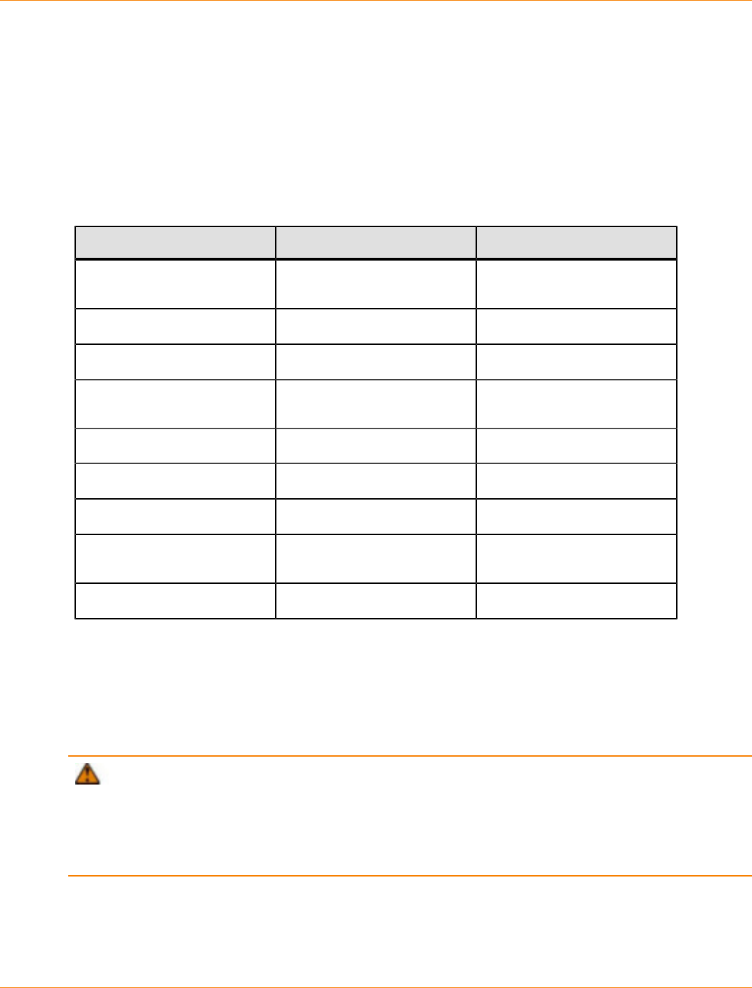
SANtricity_10.77 February 2011
LSI Corporation
- 986 -
Boot Device Installation
The following sections describe how you can configure the storage array for boot device installation.
Boot Device Support
Not all operating systems support the use of a storage array as a boot device. The following table shows
which operating systems support this configuration.
Operating System Support for Using a Storage Array as a Boot Device
Operating System Boot Device Support Comments
Windows Server 2003 Yes Where supported by the
installed HBAs.
Windows XP No
Windows Vista, Windows 7 No
Windows Server 2008 Yes Where supported by the
installed HBAs.
Solaris Yes
HP-UX Yes
AIX No
Linux Yes Where supported by the
installed HBAs.
VMware Yes
Installing the Boot Device
This section contains procedures to install a boot device in a storage array.
Before you install the storage management software components in the host, you must prepare the storage
array and the host.
ATTENTION Possible loss of data access – To make sure that you have failover protection, the
storage array that you want to assign as a boot device must have dual controllers connected to two host
bus adapters (HBAs). If the storage array has a single controller or dual controllers that are connected to the
same HBA (host path), you do not have failover protection and could lose access to the boot device when the
controller fails or has connection problems. For this reason, do not use this type of controller configuration
with a boot device installation.
You must have administrator privileges to access the software. You must use the volume mapped to LUN 0
as the boot device. Some operating systems support booting only from LUN 0.

SANtricity_10.77 February 2011
LSI Corporation
- 987 -
Before you proceed with the installation, make sure that you have installed SMclient from the SANtricity ES
Storage Manager software in a host or a storage management station that is attached to the storage array.
IMPORTANT Before you complete the installation of the storage management software components in
the host, perform the tasks in this section to install and configure of the storage array and the host to use the
storage array as a boot device. If you have questions or concerns about the installation procedures, contact
your Customer and Technical Support representative.
IMPORTANT On Itanium 64-bit hosts, the storage array can be successfully used as a boot device, but
only when the original, local boot disk remains in the host system. Do not remove the local disk from the host
system, or you will not be able to boot from the storage array.
Perform the following tasks in the order shown:
1. "Starting the Client Software"
2. "Configuring the Boot Volume on the Storage Array"
3. "Configuring the Boot Volume on an Unconfigured Capacity Node" or "Configuring the Boot Volume on a
Free Capacity Node," depending on your choices in "Configuring the Boot Volume on the Storage Array"
4. "Ensuring a Single Path to the Storage Array"
5. "Preparing the Host"
6. "Completing the Installation Process"
Starting the Client Software
1. Go to the storage management station on which you installed the client software.
2. Start the SANtricity ES Storage Manager software with the procedure for your operating system.
The Enterprise Management Window appears.
3. Select Edit >> Add Storage Array.
The Add New Storage Array dialog appears.
4. Add the Internet Protocol (IP) addresses or host names of the controllers in the storage array.
You must add the IP addresses or host names of the controllers one at a time. For more information, refer
to the online help topics in the Enterprise Management Window.
The storage array that you plan to use as the boot device appears in the Enterprise Management
Window.
5. Go to “Configuring the Boot Volume on the Storage Array.”
Configuring the Boot Volume on the Storage Array
1. In the Enterprise Management Window, select the Devices tab.
2. Select the storage array.
3. Select Tools >> Manage Storage Array.
The Array Management Window for the selected storage array appears.
4. Select the Logical tab.
5. To determine where you can create a boot volume for the host, examine the Free Capacity nodes and
Unconfigured Capacity nodes in the storage array.
Do you have 2 GB of capacity on either an Unconfigured Capacity node or a Free Capacity node?

SANtricity_10.77 February 2011
LSI Corporation
- 988 -
Yes – Go to step 11.
No – Go to step 6.
6. Determine how to create 2 GB of free capacity
Do you have multiple Free Capacity nodes that might total more than 2 GB on a volume group, although
no one node on that volume group is 2 GB or larger?
Yes – Go to step 7.
No – Go to step 10.
7. Select the volume group that contains the Free Capacity nodes.
8. Select Advanced >> Recovery >> Defragment Volume Group.
This operation consolidates all of the Free Capacity nodes in the volume group. For more information
about defragmenting a volume group, refer to the online help topics in SANtricity ES Storage Manager.
9. Is the Free Capacity node that results from the procedure 2 GB or larger?
Yes – Go to step 11.
No – Go to step 10.
10. Delete one or more volumes to create at least 2 GB of free capacity.
For additional information about how to delete volumes, refer to the online help topics in the Array
Management Window.
11. Decide which type of capacity you will use:
You should now have 2 GB of capacity as an Unconfigured Capacity node or a Free Capacity node (or
both).
Use the Unconfigured Capacity node – Go to “Configuring the Boot Volume on an Unconfigured
Capacity Node.”
Use the Free Capacity node – Go to “Configuring the Boot Volume on a Free Capacity Node.”
Configuring the Boot Volume on an Unconfigured Capacity Node
1. Right-click the Unconfigured Capacity node, and click Create Volume.
The Volume Group Required dialog appears.
2. Click Yes.
The Create Volume Group Wizard - Introduction dialog appears.
3. Click Next.
The Create Volume Group Wizard - Volume Group Name & Drive Selection dialog appears.
4. Type a name for the volume group in the Volume group name text box.
5. If you choose to create a secure volume group, select the Create a secure volume group check box.
The Create a secure volume group check box is active only when these conditions are met:
The SafeStore Drive Security premium feature is activated.
The security key is installed in the storage array.
At least one security capable drive is installed in the storage array.
ATTENTION Risk of data loss – After a volume group is secured, the only way to remove security
is to delete the volume group. Deleting the volume group deletes all of the data in the volumes that
comprise the volume group.
6. Select a method for defining which available drives to use in the volume group.
SANtricity_10.77 February 2011
LSI Corporation
- 989 -
NOTE The Automatic method is the default selection. Only experts who understand drive
configurations and optimal drive configurations should use the Manual method. It is recommended that
you select the Automatic method.
7. Click Next.
The Create Volume Group Wizard - RAID Level and Capacity dialog appears if you selected the
Automatic method. The Create Volume Group Wizard - Manual Drive Selection dialog appears if you
selected the Manual method.
8. Specify the RAID level and capacity that you want for the volume group.
9. Click Finish.
The Volume Group Created dialog appears.
10. Click OK.
The Create Volume Wizard - Introduction dialog appears.
11. Click Next.
The Create Volume Wizard - Specify Volume Capacity/Name dialog appears.
12. Specify the boot volume capacity.
A capacity of 4 GB is recommended. The capacity must be at least 2 GB.
13. Name the volume to identify it as the boot volume.
14. Select Customize settings in the Advanced Volume Parameters area.
15. Click Next.
The Create Volume Wizard - Specify Volume-to-LUN Mapping dialog appears.
16. Select Map later using the Mappings View radio button.
17. To create the volume, click Finish.
The Create Volume Wizard – Creation Successful dialog appears.
18. Click No.
19. Click OK.
20. Use the Storage Partitioning premium feature to map the volume to the host that uses LUN 0.
NOTE For additional information about how to map volumes that use Storage Partitioning, refer to
the online help topics in the Array Management Window.
21. Go to “Ensuring a Single Path to the Storage Array.”
Configuring the Boot Volume on a Free Capacity Node
1. Right-click the Free Capacity node that you want to use, and click Create Volume.
The Create Volume Wizard - Introduction dialog appears.
2. Click Next.
The Create Volume Wizard - Specify Volume Capacity/Name dialog appears.
3. Specify the boot volume capacity.
A capacity of 4 GB is recommended. The capacity must be at least 2 GB.
4. Name the volume to identify it as the boot volume.
5. Select Customize settings in the Advanced Volume Parameters area.
SANtricity_10.77 February 2011
LSI Corporation
- 990 -
6. Click Next.
The Create Volume Wizard - Specify Volume-to-LUN Mapping dialog appears.
7. Select Map later using the Mappings View radio button.
8. To create the volume, click Finish.
The Create Volume Wizard – Creation Successful dialog appears with a prompt to configure another
volume.
9. Click No.
10. Click OK.
11. Use the Storage Partitioning premium feature to map the volume to the host by using LUN 0.
NOTE For additional information about how to map volumes that use Storage Partitioning, refer to
the online help topics in the Array Management Window.
12. Go to “Ensuring a Single Path to the Storage Array.”
Ensuring a Single Path to the Storage Array
After you have configured a boot volume, make sure that only one path to the storage array exists. The path
must be configured to the controller that owns the boot volume (controller A).
NOTE If you removed a previously installed version of RDAC in a root-boot environment, you do not
need to remove the installed version of RDAC again.
1. Choose one of two methods to make sure that the alternate path to the storage array is removed:
Method 1 – Remove the host interface cable to the alternate path. Go to step 3.
Method 2 – Modify NVSRAM to temporarily disable RDAC multi-path functionality in the storage
array. Go to step 2.
2. Modify NVSRAM to temporarily disable RDAC multi-path functionality by performing these substeps:
a. Select the storage array in the Enterprise Management Window.
b. Select Tools >> Execute Script.
The Script Editor dialog appears.
c. In the upper half of the Script Editor dialog, type these commands at the prompt, and press Enter.
set controller[a] HostNVSRAMByte[1,0x16]=0xFF,0x20;
set controller[b] HostNVSRAMByte[1,0x16]=0xFF,0x20;
d. Select Tools >> Execute Only.
e. For the NVSRAM modifications to take effect, turn off the power to the controller tray, wait 30
seconds for the controller tray to turn off the power, and turn on the power again.
ATTENTION Possible data corruption – Only one path to the storage array must exist
when RDAC is removed. The path must be to the controller that owns the boot volume. If the host is
permitted to start without RDAC and still has dual paths to the storage array, the data might become
unusable.
3. Boot the host system.
4. Go to “Preparing the Host.”

SANtricity_10.77 February 2011
LSI Corporation
- 991 -
Preparing the Host
ATTENTION Possible loss of access to the boot device and the operating system – After you
install the boot device, do not delete the volume mapped to LUN 0 or reset the configuration. Performing
these actions causes loss of access to the boot device and the operating system.
In this procedure, the default boot path refers to controller A, which owns the boot volume. The alternate boot
path refers to controller B.
1. Enable the BIOS on the HBA that is connected to the default boot path.
For procedures about how to enable the HBA BIOS, refer to the host system documentation and the HBA
documentation. After the BIOS is enabled, the host reboots automatically.
2. Make sure that the HBA with enabled BIOS is connected to the default boot path (controller A), and the
HBA with disabled BIOS is connected to the alternate boot path (controller B).
3. Install the operating system on the host.
4. After the installation is complete, restart the operating system.
5. To enable the alternate path to the storage array, go to step 2 in “Completing the Installation Process.”
Completing the Installation Process
This procedure completes the root-boot environment setup. Use this procedure to restart the system or set
the path for the command line interface (CLI), if necessary.
1. Do you want to install the software in a root-boot environment?
Yes – Go to step 2.
No – Go to step 5.
2. Based on the method that you used to disable the alternate path in step 1 in “Ensuring a Single Path to
the Storage Array,“ perform one of these actions to enable the alternate path to the storage array:
You removed the host interface cable to the storage array – Reattach the host interface cable to
the alternate controller. Go to step 5.
You modified NVSRAM to temporarily disable RDAC multi-path functionality in the storage
array – Go to step 3.
3. Will you download new controller firmware and NVSRAM to the storage array after the host software
installation?
Yes – The new NVSRAM file is pre-configured to enable RDAC multi-path functionality. Go to step 5.
No – Go to step 4.
4. Open the command prompt window, and perform these substeps:
a. Type these commands, and press Enter.
“set controller[a] HostNVSRAMByte[1,0x16]=0xFF,0x20;”
“set controller[b] HostNVSRAMByte[1,0x16]=0xFF,0x20;”
b. For the NVSRAM modifications to take effect, turn off the power to the controllers, wait 30 seconds
for the controllers to power down, and turn on the power.
5. Restart the host system.
SANtricity_10.77 February 2011
LSI Corporation
- 992 -
IMPORTANT You can run the command line interface (CLI) from the installation target, or you can
set the path to run the CLI from any location.
6. Do you want to set the path for the CLI?
Yes – Go to step 7.
No – Go to step 8.
7. To set the path for the CLI, perform these substeps:
a. Select Start >> Settings >> Control Panel >> System.
The System Properties dialog appears.
b. Select the Advanced tab.
c. Click Environment Variables.
d. Select the Path entry, and click Edit in the System variables area of the Environment Variables
dialog.
e. In the Variable Value text box of the Edit System Variable dialog, type this command at the end of
the current value, and press Enter. In this command, <path> is the path to the SMclient installation
directory.
<path>
For example:
%SystemRoot%\system32;%SystemRoot%;C:\ProgramFiles\StorageManager\client;
f. Click OK. In the next dialog, click OK.
8. Based on your installation environment, perform one of these actions:
You are using a cluster environment – Go to step 9.
You are using a standard environment – Go to step 10.
9. Install the host software on each host in the server cluster.
IMPORTANT Do not configure the server cluster software at this time. You are instructed when to
configure the server cluster software after you complete the storage management software installation.
You cannot mix two architectures in the same server cluster. For example, a server cluster cannot contain
both the 32-bit version and the 64-bit version of the Windows OS.
10. Start the SANtricity ES Storage Manager software with the procedure for your operating system.
After the client software starts, the Enterprise Management Window appears.
Refer to the online help topics in SANtricity ES Storage Manager for more information about how to
manage the storage array.

SANtricity_10.77 February 2011
LSI Corporation
- 993 -
Command Line Interface and Script Commands for
Version 10.77
This document provides a complete listing of all of the commands and the syntax for those commands that
you need to configure and maintain a storage array. Information about how to configure and maintain a
storage array using a command line interface is in Configuring and Maintaining a Storage Array using the
Command Line Interface
This document supports host software version 10.77 and firmware version 7.77.

SANtricity_10.77 February 2011
LSI Corporation
- 994 -
Formatting the Commands
The command line interface (CLI) is a software application that provides a way to configure and monitor
storage arrays. Using the CLI, you can run commands from an operating system prompt, such as the DOS C:
prompt, a Linux operating system path, or a Solaris operating system path.
The CLI gives you direct access to a script engine that is a utility in the SANtricity ES Storage Manager
software (also referred to as the storage management software). The script engine runs commands that
configure and manage the storage arrays. The script engine reads the commands, or runs a script file, from
the command line and performs the operations instructed by the commands.
The script commands configure and manage a storage array. The script commands are distinct from the CLI
commands. You can enter individual script commands, or you can run a file of script commands. When you
enter an individual script command, you embed the script command in a CLI command. When you run a file
of script commands, you embed the file name in the CLI command.
Structure of a CLI Command
The CLI commands are in the form of a command wrapper and elements embedded into the wrapper. A CLI
command consists of these elements:
A command wrapper identified by the term SMcli
The storage array identifier
Terminals that define the operation to be performed
Script commands
The CLI command wrapper is a shell that identifies storage array controllers, embeds operational terminals,
embeds script commands, and passes these values to the script engine.
All CLI commands have the following structure:
SMcli storageArray terminal script-commands;
SMcli invokes the command line interface.
storageArray is the name or the IP address of the storage array.
terminal are CLI values that define the environment and the purpose for the command.
script-commands are one or more script commands or the name of a script file that contains script
commands. (The script commands configure and manage the storage array.)
If you enter an incomplete or inaccurate SMcli string that does not have the correct syntax, parameter
names, options, or terminals, the script engine returns usage information.
For an overview of the script commands, see "." For definitions, syntax, and parameters for the script
commands, refer to the Command Line Interface and Script Commands for Version 10.75.
Interactive Mode
If you enter SMcli and a storage array name but do not specify CLI parameters, script commands, or a script
file, the command line interface runs in interactive mode. Interactive mode lets you run individual commands
without prefixing the commands with SMcli.
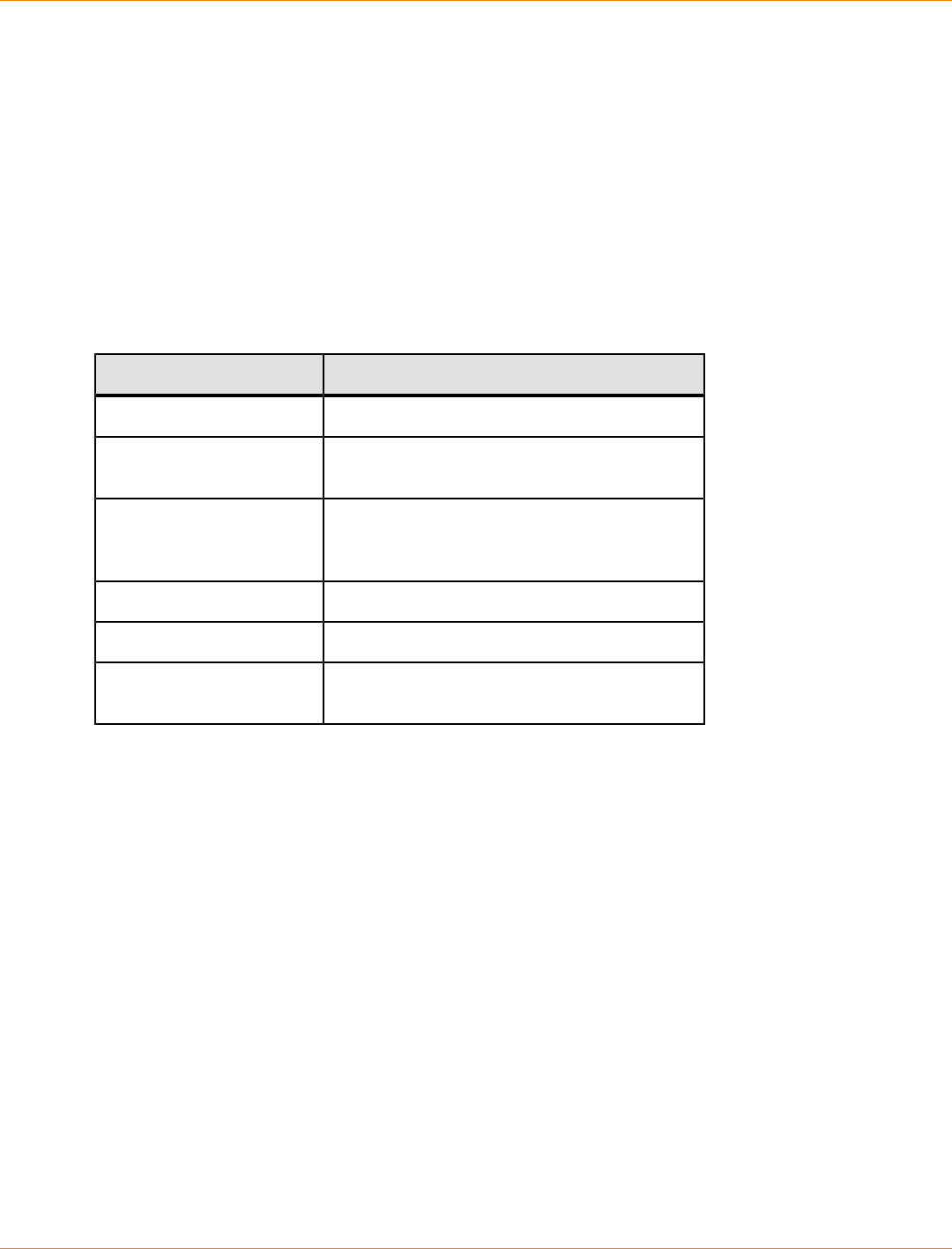
SANtricity_10.77 February 2011
LSI Corporation
- 995 -
In interactive mode, you can enter a single command, view the results, and enter the next command without
typing the complete SMcli string. Interactive mode is useful for determining configuration errors and quickly
testing configuration changes.
To end an interactive mode session, type the operating system-specific command for terminating a program,
such as Control-C on the UNIX operating system or the Windows operating system. Typing the termination
command (Control-C) while in interactive mode turns off interactive mode and returns operation of the
command prompt to an input mode that requires you to type the complete SMcli string.
CLI Command Wrapper Syntax
General syntax forms of the CLI command wrappers are listed in this section. The general syntax forms show
the terminals and the parameters that are used in each command wrapper. The conventions used in the CLI
command wrapper syntax are listed in the following table.
Convention Definition
a | b Alternative ("a" or "b")
italicized-words A terminal that needs user input to fulfill a
parameter (a response to a variable)
[ ... ] (square
brackets) Zero or one occurrence (square brackets are
also used as a delimiter for some command
parameters)
{ ... } (curly braces) Zero or more occurrences
(a | b | c) Choose only one of the alternatives
bold A terminal that needs a command parameter
entered to start an action
SMcli host-name-or-IP-address [host-name-or-IP-address]
[-c "command; {command2};"]
[-n storage-system-name | -w wwID]
[-o outputfile] [-p password] [-e ] [-S ] [-quick]
SMcli host-name-or-IP-address [hostname-or-IP-address]
[-fscriptfile]
[-nstorage-system-name | -wwwID]
[-ooutputfile] [-ppassword] [-e] [-S] [-quick]
SMcli (-n storage-system-name | -wwwID)
[-c "command; {command2};"]
[-ooutputfile] [-ppassword] [-e] [-S] [-quick]
SMcli (-nstorage-system-name -wwwID)
[-fscriptfile]
[-ooutputfile] [-ppassword] [-e] [-S] [-quick]
SMcli -aemail:email-address [host-name-or-IP-address1
[host-name-or-IP-address2]]
[-nstorage-system-name | -wwwID | -hhost-name]
[-Iinformation-to-include] [-qfrequency] [-S]
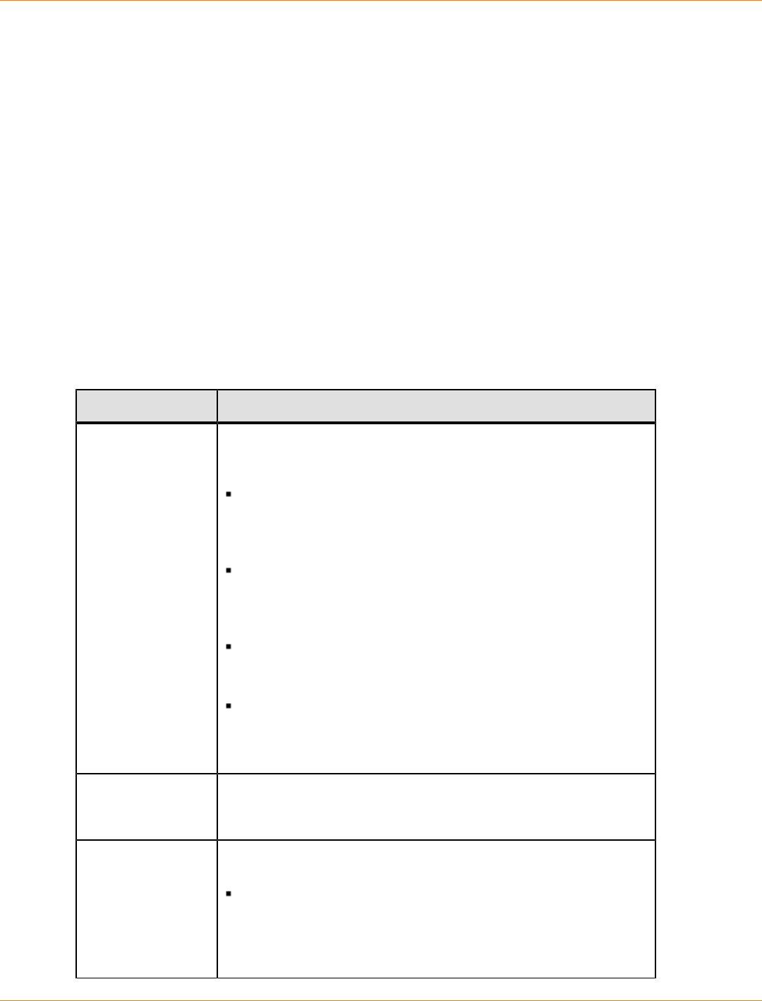
SANtricity_10.77 February 2011
LSI Corporation
- 996 -
SMcli -xemail:email-address [host-name-or-IP-address1
[host-name-or-IP-address2]]
[-nstorage-system-name | -wwwID | -hhost-name] [-S]
SMcli (-a | -x) trap:community, host-name-or-IP-address
[host-name-or-IP-address1 [host-name-or-IP-address2]]
[-nstorage-system-name | -wwwID | -hhost-name] [-S]
SMcli -d [-w] [-i] [-s] [-v] [-S]
SMcli -mhost-name-or-IP-address-Femail-address
[-gcontactInfoFile] [-S]
SMcli -A [host-name-or-IP-address [host-name-or-IP-address]]
[-S]
SMcli -X (-nstorage-system-name | -wwwID | -hhost-name)
SMcli -?
Command Line Terminals
Terminal Definition
host-name-or-
IP-address
Specifies either the host name or the Internet Protocol (IP) address
(xxx.xxx.xxx.xxx) of an in-band managed storage array or an
out-of-band managed storage array.
If you are managing a storage array by using a host through in-
band storage management, you must use the -n terminal or
the -w terminal if more than one storage array is connected to
the host.
If you are managing a storage array by using out-of-band
storage management through the Ethernet connection on each
controller, you must specify the host-name-or-IP-address
of the controllers.
If you have previously configured a storage array in the
Enterprise Management Window, you can specify the storage
array by its user-supplied name by using the -n terminal.
If you have previously configured a storage array in the
Enterprise Management Window, you can specify the storage
array by its World Wide Identifier (WWID) by using the -w
terminal.
-A Adds a storage array to the configuration file. If you do not follow
the -A terminal with a host-name-or-IP-address, auto-
discovery scans the local subnet for storage arrays.
-a Adds a Simple Network Management Protocol (SNMP) trap
destination or an email address alert destination.
When you add an SNMP trap destination, the SNMP
community is automatically defined as the community name
for the trap, and the host is the IP address or Domain Name
Server (DNS) host name of the system to which the trap should
be sent.

SANtricity_10.77 February 2011
LSI Corporation
- 997 -
Terminal Definition
When you add an email address for an alert destination, the
email-address is the email address to which you want the
alert message to be sent.
-c Indicates that you are entering one or more script commands to
run on the specified storage array. End each command with a
semicolon (;). You cannot place more than one -c terminal on
the same command line. You can include more than one script
command after the -c terminal.
-d Shows the contents of the script configuration file. The file content
has this format:
storage-system-name host-name1 host-name2
-e Runs the commands without performing a syntax check first.
-F (uppercase) Specifies the email address from which all alerts will be sent.
-f (lowercase) Specifies a file name that contains script commands that you want
to run on the specified storage array. The -f terminal is similar to
the -c terminal in that both terminals are intended for running script
commands. The -c terminal runs individual script commands. The
-f terminal runs a file of script commands.
By default, any errors that are encountered when running the
script commands in a file are ignored, and the file continues
to run. To override this behavior, use the set session
errorAction=stop command in the script file.
-g Specifies an ASCII file that contains email sender contact
information that will be included in all email alert notifications.
The CLI assumes that the ASCII file is text only, without
delimiters or any expected format. Do not use the -g terminal if a
userdata.txt file exists.
-h Specifies the host name that is running the SNMP agent to which
the storage array is connected. Use the -h terminal with these
terminals:
-a
-x
-I (uppercase) Specifies the type of information to be included in the email alert
notifications. You can select these values:
eventOnly – Only the event information is included in the
email.
profile – The event and array profile information is included
in the email.
supportBundle – The event and support bundle information
information is included in the email.
You can specify the frequency for the email deliveries using the -q
terminal.

SANtricity_10.77 February 2011
LSI Corporation
- 998 -
Terminal Definition
-i (lowercase) Shows the IP address of the known storage arrays. Use the -i
terminal with the -d terminal. The file contents has this format:
storage-system-name IP-address1 IPaddress2
-m Specifies the host name or the IP address of the email server from
which email alert notifications are sent.
-n Specifies the name of the storage array on which you want to run
the script commands. This name is optional when you use a host-
name-or-IP#address. If you are using the in-band method for
managing the storage array, you must use the -n terminal if more
than one storage array is connected to the host at the specified
address. The storage array name is required when the host-
name-or-IP-address is not used. The name of the storage array
that is configured for use in the Enterprise Management Window
(that is, the name is listed in the configuration file) must not be a
duplicate name of any other configured storage array.
-o Specifies a file name for all output text that is a result of running the
script commands. Use the -o terminal with these terminals:
-c
-f
If you do not specify an output file, the output text goes to standard
output (stdout). All output from commands that are not script
commands is sent to stdout, regardless of whether this terminal is
set.
-p Specifies the password for the storage array on which you want
to run commands. A password is not necessary under these
conditions:
A password has not been set on the storage array.
The password is specified in a script file that you are running.
You specify the password by using the -c terminal and this
command:
set session password=password
-q Specifies the frequency that you want to receive event notifications
and the type of information returned in the event notifications.
An email alert notification containing at least the basic event
information is always generated for every critical event.
These values are valid for the -q terminal:
everyEvent – Information is returned with every email alert
notification.
2 – Information is returned no more than once every two hours.
4 – Information is returned no more than once every four hours.
8 – Information is returned no more than once every eight
hours.
12 – Information is returned no more than once every 12 hours.

SANtricity_10.77 February 2011
LSI Corporation
- 999 -
Terminal Definition
24 – Information is returned no more than once every 24 hours.
Using the -I terminal you can specify the type of information in the
email alert notifications.
If you set the -I terminal to eventOnly, the only valid value
for the -q terminal is everyEvent.
If you set the -I terminal to either the profile value or the
supportBundle value, this information is included with the
emails with the frequency specified by the -q terminal.
-quick Reduces the amount of time that is required to run a single-line
operation. An example of a single-line operation is the recreate
snapshot volume command. This terminal reduces time by not
running background processes for the duration of the command.
Do not use this terminal for operations that involve more than
one single-line operation. Extensive use of this command can
overrun the controller with more commands than the controller can
process, which causes operational failure. Also, status updates and
configuration updates that are collected usually from background
processes will not be available to the CLI. This terminal causes
operations that depend on background information to fail.
-S (uppercase) Suppresses informational messages describing the command
progress that appear when you run script commands. (Suppressing
informational messages is also called silent mode.) This terminal
suppresses these messages:
Performing syntax check
Syntax check complete
Executing script
Script execution complete
SMcli completed successfully
-s (lowercase) Shows the alert settings in the configuration file when used with the
-d terminal.
-v Shows the current global status of the known devices in a
configuration file when used with the -d terminal.
-w Specifies the WWID of the storage array. This terminal is an
alternate to the -n terminal. Use the -w terminal with the -d
terminal to show the WWIDs of the known storage arrays. The file
content has this format:
storage-system-name world-wide-ID IP-address1 IP-
address2
-X (uppercase) Deletes a storage array from a configuration.
-x (lowercase) Removes an SNMP trap destination or an email address alert
destination. The community is the SNMP community name for
the trap, and the host is the IP address or DNS host name of the
system to which you want the trap sent.
SANtricity_10.77 February 2011
LSI Corporation
- 1000 -
Terminal Definition
-? Shows usage information about the CLI commands.
Structure of a Script Command
All script commands have the following structure:
command operand-data (statement-data)
command identifies the action to be performed.
operand-data represents the objects associated with a storage array that you want to configure or
manage.
statement-data provides the information needed to perform the command.
The syntax for operand-data has the following structure:
(object-type | allobject-types | [qualifier]
(object-type [identifier] {object-type [identifier]} |
object-types [identifier-list]))
An object can be identified in four ways:
Object type – Use when the command is not referencing a specific object.
all parameter prefix – Use when the command is referencing all of the objects of the specified type in
the storage array (for example, allVolumes).
Square brackets – Use when performing a command on a specific object to identify the object (for
example, volume [engineering]).
A list of identifiers – Use to specify a subset of objects. Enclose the object identifiers in square brackets
(for example, volumes [sales engineering marketing]).
A qualifier is required if you want to include additional information to describe the objects.
The object type and the identifiers that are associated with each object type are listed in this table.
Script Command Object Type Identifiers
Object Type Identifier
controller a or b
drive Tray ID and slot ID
replacementDrive Tray ID and slot ID
driveChannel Drive channel identifier
host User label
hostChannel Host channel identifier
hostGroup User label

SANtricity_10.77 February 2011
LSI Corporation
- 1001 -
Object Type Identifier
hostPort User label
iscsiInitiator User label or iSCSI Qualified Name (IQN)
iscsiTarget User label or IQN
remoteMirror Primary volume user label
snapshot Volume user label
storageArray Not applicable
tray Tray ID
volume Volume user label or volume World Wide
Identifier (WWID) (set command only)
volumeCopy Target volume user label and, optionally, the
source volume user label
volumeGroup User label
Valid characters are alphanumeric, a hyphen,
and an underscore.
Statement data is in the form of:
Parameter = value (such as raidLevel=5)
Parameter-name (such as batteryInstallDate)
Operation-name (such as redundancyCheck)
A user-defined entry (such as user label) is called a variable. In the syntax, it is shown in italic (such as
trayID or volumeGroupName).
Synopsis of the Script Commands
Because you can use the script commands to define and manage the different aspects of a storage array
(such as host topology, drive configuration, controller configuration, volume definitions, and volume group
definitions), the actual number of commands is extensive. The commands, however, fall into general
categories that are reused when you apply the commands to the different to configure or maintain a storage
array. The following table lists the general form of the script commands and a definition of each command.
General Form of the Script Commands
Syntax Description
activate object
{statement-data}
Sets up the environment so that an operation
can take place or performs the operation if the
environment is already set up correctly.
autoConfigure storageArray
{statement-data}
Automatically creates a configuration that is
based on the parameters that are specified in the
command.

SANtricity_10.77 February 2011
LSI Corporation
- 1002 -
Syntax Description
check object
{statement-data}
Starts an operation to report on errors in the
object, which is a synchronous operation.
clear object
{statement-data}
Discards the contents of some attributes of an
object. This operation is destructive and cannot
be reversed.
create object
{statement-data}
Creates an object of the specified type.
deactivate object
{statement-data}
Removes the environment for an operation.
delete object Deletes a previously created object.
diagnose object
{statement-data}
Runs a test and shows the results.
disable object {statement-data}
Prevents a feature from operating.
download object
{statement-data}
Transfers data to the storage array or to the
hardware that is associated with the storage
array.
enable object
{statement-data}
Sets a feature to operate.
load object
{statement-data}
Transfers data to the storage array or to the
hardware that is associated with the storage
array. This command is functionally similar to the
download command.
recopy object
{statement-data}
Restarts a volume copy operation by using an
existing volume copy pair. You can change the
parameters before the operation is restarted.
recover object
{statement-data}
Re-creates an object from saved configuration
data and the statement parameters. (This
command is similar to the create command.)
recreate object
{statement-data}
Restarts a snapshot operation by using an
existing snapshot volume. You can change the
parameters before the operation is restarted.
remove object
{statement-data}
Removes a relationship from between objects.
repair object
{statement-data}
Repairs errors found by the check command.
reset object
{statement-data}
Returns the hardware or an object to an initial
state.

SANtricity_10.77 February 2011
LSI Corporation
- 1003 -
Syntax Description
resume object Starts a suspended operation. The operation
starts where it left off when it was suspended.
revive object Forces the object from the Failed state to the
Optimal state. Use this command only as part of
an error recovery procedure.
save object
{statement-data}
Writes information about the object to a file.
set object
{statement-data}
Changes object attributes. All changes are
completed when the command returns.
show object
{statement-data}
Shows information about the object.
start object
{statement-data}
Starts an asynchronous operation. You can stop
some operations after they have started. You can
query the progress of some operations.
stop object
{statement-data}
Stops an asynchronous operation.
suspend object
{statement-data}
Stops an operation. You can then restart the
suspended operation, and it continues from the
point where it was suspended.
Recurring Syntax Elements
Recurring syntax elements are a general category of parameters and options that you can use in the script
commands. The Recurring Syntax Elements table lists the recurring syntax parameters and the values that
you can use with the recurring syntax parameters. The conventions used in the recurring syntax elements are
listed in the following table.
Convention Definition
a | b Alternative ("a" or "b")
italicized-words A terminal that needs user input to fulfill a
parameter (a response to a variable)
[ ... ] (square
brackets) Zero or one occurrence (square brackets are
also used as a delimiter for some command
parameters)
{ ... } (curly braces) Zero or more occurrences
(a | b | c) Choose only one of the alternatives
bold A terminal that needs a command parameter
entered to start an action

SANtricity_10.77 February 2011
LSI Corporation
- 1004 -
Recurring Syntax Elements
Recurring Syntax Syntax Value
raid-level (0 | 1 | 3 | 5 | 6)
repository-raid-level (1 | 3 | 5 | 6)
capacity-spec integer-literal [KB | MB | GB | TB |
Bytes]
segment-size-spec integer-literal
boolean (TRUE | FALSE)
user-label string-literal
Valid characters are alphanumeric, the dash, and the
underscore.
user-label-list user-label {user-label}
create-raid-vol-attr-
value-list
create-raid-volume-attribute-value-pair
{create-raid-volume-attribute-value-pair}
create-raid-volume-
attribute-value-pair
capacity=capacity-spec | owner=(a | b) |
cacheReadPrefetch=(TRUE | FALSE) |
segmentSize=integer-literal |
usageHint=usage-hint-spec
noncontroller-trayID (0-99)
slotID (1-32)
portID (0-127)
drive-spec trayID,slotID or trayID,drawerID,slotID
A drive is defined as two or three interger literal values
separated by a comma. Low-density trays require
two values. High-density trays, those trays that have
drawers, require three values.
drive-spec-list drive-spec drive-spec
trayID-list trayID {trayID}
esm-spec-list esm-spec {esm-spec}
esm-spec trayID, (left | right)
hex-literal 0xhexadecimal-literal
volumeGroup-number integer-literal
filename string-literal
error-action (stop | continue)

SANtricity_10.77 February 2011
LSI Corporation
- 1005 -
Recurring Syntax Syntax Value
drive-channel-identifier
(four drive ports per tray) (1 | 2 | 3 | 4)
drive-channel-identifier
(eight drive ports per tray) (1 | 2 | 3 | 4 | 5 | 6 | 7 | 8)
drive-channel-identifier-
list
drive-channel-identifier {drive-
channel#identifier}
host-channel-identifier
(four host ports per tray) (a1 | a2 | b1 | b2)
host-channel-identifier
(eight host ports per tray) (a1 | a2 | a3 | a4 | b1 | b2 | b3 | b4)
host-channel-identifier
(16 host ports per tray) (a1 | a2 | a3 | a4 | a5 | a6 | a7 | a8 |
b1 | b2 | b3 | b4 | b5 | b6 | b7 | b8)
drive-type (fibre | SATA | SAS)
drive-media-type (HDD | SSD | unknown| allMedia)
HDD means hard disk drive. SSD means solid state
disk.
feature-identifier (storagePartition2 |
storagePartition4 |
storagePartition8 |
storagePartition16 |
storagePartition64 |
storagePartition96 |
storagePartition128 |
storagePartition256 |
storagePartitionMax |
snapshot | snapshot2 | snapshot4 |
snapshot8 | snapshot16 |
remoteMirror8 | remoteMirror16 |
remoteMirror32 | remoteMirror64 |
remoteMirror128 | volumeCopy |
goldKey | mixedDriveTypes |
highPerformanceTier |
SSDSupport | safeStoreSecurity |
safeStoreExternalKeyMgr | dataAssurance)
To use the High Performance Tier premium feature,
you must configure a storage array as one of these:
SHIPPED_ENABLED
SHIPPED_ENABLED=FALSE;
KEY_ENABLED=TRUE
repository-spec instance-based-repository-spec | count-
based-repository-spec

SANtricity_10.77 February 2011
LSI Corporation
- 1006 -
Recurring Syntax Syntax Value
instance-based-
repository-spec
(repositoryRAIDLevel
=repository-raid-level
repositoryDrives=
(drive-spec-list)
[repositoryVolumeGroupUserLabel
=user-label]
[trayLossProtect=(TRUE | FALSE)1]) |
[drawerLossProtect=(TRUE | FALSE)2]) |
(repositoryVolumeGroup=user-label
[freeCapacityArea=integer-literal3])
Specify the repositoryRAIDLevel parameter with
the repositoryDrives parameter. Do not specify
the RAID level or the drives with the volume group. Do
not set a value for the trayLossProtect parameter
when you specify a volume group.
count-based-repository-
spec
repositoryRAIDLevel
=repository-raid-level
repositoryDriveCount=integer-literal
[repositoryVolumeGroupUserLabel
=user-label]
[driveType=drive-type4]
[trayLossProtect=(TRUE | FALSE)1] |
[drawerLossProtect=(TRUE | FALSE)2] |
[dataAssurance=(none | enabled)5] |
wwID string-literal
gid string-literal
host-type string-literal | integer-literal
host-card-identifier (1 | 2 | 3 | 4)
backup-device-identifier (1 | n | all)
n is a specific slot number.
Specifying all includes all of the cache backup
devices availble to the entire storage array.
nvsram-offset hex-literal
nvsram-byte-setting nvsram-value = 0xhexadecimal | integer-
literal
The 0xhexadecimal value is typically a value from
0x0000 to 0xFFFF.
nvsram-bit-setting nvsram-mask, nvsram-value =
0xhexadecimal, 0xhexadecimal | integer-
literal
The 0xhexadecimal value is typically a value from
0x0000 to 0xFFFF.

SANtricity_10.77 February 2011
LSI Corporation
- 1007 -
Recurring Syntax Syntax Value
ip-address (0-255).(0-255).(0-255).(0-255)
ipv6-address (0-FFFF):(0-FFFF):(0-FFFF):(0-FFFF): (0-
FFFF):(0-FFFF):(0-FFFF):(0-FFFF)
You must enter all 32 hexadecimal characters.
autoconfigure-vols-attr-
value-list
autoconfigure-vols-attr-value-pair
{autoconfigure-vols-attr-value-pair}
autoconfigure-vols-attr-
value-pair
driveType=drive-type |
driveMediaType=drive-media-type |
raidLevel=raid-level |
volumeGroupWidth=integer-literal |
volumeGroupCount=integer-literal |
volumesPerGroupCount=integer-literal6 |
hotSpareCount=integer-literal |
segmentSize=segment-size-spec |
cacheReadPrefetch=(TRUE | FALSE)
securityType=(none | capable |
enabled)7 |
dataAssurance=(none | enabled)5
create-volume-copy-attr-
value-list
create-volume-copy-attr-value-pair
{create-volume-copy-attr-value-pair}
create-volume-copy-attr-
value-pair
copyPriority=(highest | high | medium |
low | lowest) |
targetReadOnlyEnabled=(TRUE | FALSE) |
copyType=(offline | online) |
repositoryPercentOfBase=(20 | 40 | 60 |
120 | default) |
repositoryGroupPreference=(sameAsSource |
otherThanSource | default)
recover-raid-volume-attr-
value-list
recover-raid-volume-attr-value-pair
{recover-raid-volume-attr-value-pair}
recover-raid-volume-attr-
value-pair
owner=(a | b) |
cacheReadPrefetch=(TRUE | FALSE) |
dataAssurance=(none | enabled)
cache-flush-modifier-
setting
immediate, 0, .25, .5, .75, 1, 1.5, 2,
5, 10, 20, 60, 120, 300, 1200, 3600,
infinite
serial-number string-literal
usage-hint-spec usageHint=(multiMedia | database |
fileSystem)
iscsiSession [session-identifier]
iscsi-host-port (1 | 2 | 3 | 4)

SANtricity_10.77 February 2011
LSI Corporation
- 1008 -
Recurring Syntax Syntax Value
The host port number might be 2, 3, or 4 depending
on the type of controller you are using.
ethernet-port-options enableIPv4=(TRUE | FALSE) |
enableIPv6=(TRUE | FALSE) |
IPv6LocalAddress=ipv6-address |
IPv6RoutableAddress=ipv6-address |
IPv6RouterAddress=ipv6-address |
IPv4Address=ip-address |
IPv4ConfigurationMethod=
(static | dhcp) |
IPv4GatewayIP=ip-address |
IPv4SubnetMask=ip-address |
duplexMode=(TRUE | FALSE) |
portSpeed=(autoNegotiate | 10 | 100 |
1000)
iscsi-host-port-options IPv4Address=ip-address |
IPv6LocalAddress=ipv6-address |
IPv6RoutableAddress=ipv6-address |
IPv6RouterAddress=ipv6-address |
enableIPv4=(TRUE | FALSE) |
enableIPv6=(TRUE | FALSE) |
enableIPv4Priority=(TRUE | FALSE) |
enableIPv6Priority=(TRUE | FALSE) |
IPv4ConfigurationMethod=
(static | dhcp) |
IPv6ConfigurationMethod=
(static | auto) |
IPv4GatewayIP=ip-address |
IPv6HopLimit=integer |
IPv6NdDetectDuplicateAddress=integer |
IPv6NdReachableTime=time-interval |
IPv6NdRetransmitTime=time-interval |
IPv6NdTimeOut=time-interval |
IPv4Priority=integer |
IPv6Priority=integer |
IPv4SubnetMask=ip-address |
IPv4VlanId=integer |
IPv6VlanId=integer |
maxFramePayload=integer |
tcpListeningPort=tcp-port-id |
portSpeed=(autoNegotiate | 1 | 10)
test-devices-list test-devices {test-devices}
test-devices controller=(a | b)
esms=(esm-spec-list)
drives=(drive-spec-list)
snapshot-schedule-
attribute-value-list
snapshot-schedule-attribute-value-pair
{snapshot-schedule-attribute-value-pair}

SANtricity_10.77 February 2011
LSI Corporation
- 1009 -
Recurring Syntax Syntax Value
time-zone-spec (GMT+HH:MM | GMT-HH:MM)
[dayLightSaving=HH:MM]
snapshot-schedule-
attribute-value-pair
startDate=MM:DD:YY
scheduleDay=(dayOfWeek | all)
startTime=HH:MM
scheduleInterval=interger
endDate=(MM:DD:YY | noEndDate)
timesPerDay=interger
1For tray loss protection to work, each drive in a volume group must be in a separate tray. If you set the
trayLossProtect parameter to TRUE and you have selected more than one drive from any one tray, the
storage array returns an error. If you set trayLossProtect parameter to FALSE, the storage array performs
operations, but the volume group that you create might not have tray loss protection.
If you set the trayLossProtect parameter to TRUE, the storage array returns an error if the controller
firmware cannot find drives that will enable the new volume group to have tray loss protection. If you set the
trayLossProtect parameter to FALSE, the storage array performs the operation even if it means that the
volume group might not have tray loss protection.
2In trays that have drawers for holding the drives, drawer loss protection determines whether data on
a volume is accessible or inaccessible if a drawer fails. To help make sure that your data is accessible,
set the drawerLossProtect parameter to TRUE. For drawer loss protection to work, each drive in a
volume group must be in separate drawers. If you have a storage array configuration in which a volume
group spans several trays, you must make sure that the setting for drawer loss protection works with the
setting for tray loss protection. If you set the trayLossProtect parameter to TRUE, you must set the
drawerLossProtect parameter to TRUE. If you set the trayLossProtect parameter to TRUE, and
you set the drawerLossProtect parameter to FALSE, the storage array returns an error message and a
storage array configuration will not be created.
3To determine if a free capacity area exists, run the show volumeGroup command.
4The default drive (drive type) is fibre (Fibre Channel).
The driveType parameter is not required if only one type of drive is in the storage array. If you use the
driveType parameter, you also must use the hotSpareCount parameter and the volumeGroupWidth
parameter. If you do not use the driveType parameter, the configuration defaults to Fibre Channel drives.
5The dataAssurance parameter applies to the drives in a volume group. Using the dataAssurance
parameter, you can specify that protected drives must be selected for a volume group. If you want to set
the dataAssurance parameter to enabled, all of the drives in the volume group must be capable of data
assurance. You cannot have a mix of drives that are capable of data assurance and drives that are not
capable of data assurance in the volume group.
6The volumesPerGroupCount parameter is the number of equal-capacity volumes per volume group.
7The securityType parameter enables you to specify the security setting for a volume group that you are
creating. All of the volumes are also set to the security setting that you choose. Available options for setting
the security setting include:
none – The volume group is not secure.

SANtricity_10.77 February 2011
LSI Corporation
- 1010 -
capable – The volume group is security capable, but security has not been enabled.
enabled – The volume group is security enabled.
NOTE A storage array security key must already be created for the storage array if you want to set
securityType=enabled. (To create a storage array security key, use the create storageArray
securityKey command).
Naming Conventions
Names can have a maximum of 30 characters.
You can use any combination of alphanumeric characters, hyphens, and underscores for the names of
the following components:
Storage arrays
Host groups
Hosts
Volume groups
Volumes
HBA host ports
You must use unique names. If you do not use unique names, the controller firmware returns an error.
If the name contains more than one word, hyphens, or underscores, enclose the name in double
quotation marks (“ ”). In some usages, you must also surround the name with square brackets ([ ]). The
description of each parameter indicates whether you need to enclose a parameter in double quotation
marks, square brackets, or both.
The name character string cannot contain a new line.
On Windows operating systems, you must enclose the name between two back slashes (\\) in addition
to other delimiters. For example, the following name is used in a command that runs under a Windows
operating system:
[\“Engineering\”]
For a UNIX operating system and, when used in a script file, the name appears as in the following
example:
[“Engineering”]
When you enter a World Wide Identifier (WWID) of an HBA host port, some usages require that you
surround the WWID with double quotation marks. In other uses, you must surround the WWID with angle
brackets (<>). The description of the WWID parameter indicates whether you need to enclose the WWID
in double quotation marks or angle brackets.
Entering Numerical Names
When the storage management software automatically configures a storage array, the storage management
software assigns names that consist of numerical characters. Names that consist only of numerical characters
are valid names. Numerical character names, however, must be treated differently than names that start with
alphabetic characters.
When you enter a script command that requires a name, the script engine looks for a name that starts with an
alphabetic character. The Script Engine might not recognize the following names:
Names that are only numbers, such as 1 or 2

SANtricity_10.77 February 2011
LSI Corporation
- 1011 -
Names that start with a number, such as 1Disk or 32Volume
To enter a name that consists only of numerical characters so that the Script Engine will recognize the name,
use a combination of back slashes and double quotation marks. The following are examples of how you can
enter names that consist only of numerical characters or start with numerical characters:
[\“1\”]
[\“1Disk\”]
Formatting CLI Commands
Double quotation marks (" ") that are used as part of a name or label require special consideration when you
run the CLI commands and the script commands on a Microsoft Windows operating system.
When double quotation marks (" ") are part of a name or value, you must insert a backslash (\) before each
double quotation mark character. For example:
-c "set storageArray userLabel=\"Engineering\";"
In this example, "Engineering" is the storage array name. A second example is:
-n \"My\"_Array
In this example, "My"_Array is the name of the storage array.
You cannot use double quotation marks (" ") as part of a character string (also called string literal) within
a script command. For example, you cannot enter the following string to set the storage array name to
"Finance" Array:
-c "set storageArray userLabel=\"\"Finance\"Array\";"
In the Linux operating system and the Solaris operating system, the delimiters around names or labels are
single quotation marks (' '). The UNIX versions of the previous examples are as follows:
-c 'set storageArray userLabel="Engineering";'
-n "My"_Array
In a Windows operating system, if you do not use double quotation marks (" ") around a name, you must
insert a caret ( ^ ) before each special script character. Special characters are ^, | , <, and >.
Insert a caret before each special script character when used with the terminals -n, -o, -f, and -p. For
example, to specify storage array CLI>CLIENT, enter this string:
-n CLI^>CLIENT
Insert one caret (^) before each special script character when used within a string literal in a script command.
For example, to change the name of a storage array to FINANCE_|_PAYROLL, enter the following string:
-c "set storageArray userLabel=\"FINANCE_^|_PAYROLL\";"
Formatting Rules for Script Commands
Syntax unique to a specific script command is explained in the Notes section at the end of each script
command description.

SANtricity_10.77 February 2011
LSI Corporation
- 1012 -
Case sensitivity – The script commands are not case sensitive. You can type the script commands in
lowercase, uppercase, or mixed case. (In the following command descriptions, mixed case is used as an aid
to reading the command names and understanding the purpose of the command.)
Spaces – You must enter spaces in the script commands as they are shown in the command descriptions.
Square brackets – Square brackets are used in two ways:
As part of the command syntax.
To indicate that the parameters are optional. The description of each parameter tells you if you need to
enclose a parameter value in square brackets.
Parentheses – Parentheses shown in the command syntax enclose specific choices for a parameter. That is,
if you want to use the parameter, you must enter one of the values enclosed in parentheses. Generally, you
do not include parentheses in a script command; however, in some instances, when you enter lists, you must
enclose the list in parentheses. Such a list might be a list of tray ID values and slot ID values. The description
of each parameter tells you if you need to enclose a parameter value in parentheses.
Vertical bars – Vertical bars in a script command indicate “or” and separate the valid values for the
parameter. For example, the syntax for the raidLevel parameter in the command description appears as
follows:
raidLevel=(0 | 1 | 3 | 5 | 6)
To use the raidLevel parameter to set RAID Level 5, enter this value:
raidLevel=5
Drive locations – The CLI commands that identify drive locations support both high-capacity drive trays and
low-capacity drive trays. A high-capacity drive tray has drawers that hold the drives. The drawers slide out of
the drive tray to provide access to the drives. A low-capacity drive tray does not have drawers. For a high-
capacity drive tray, you must specify the identifier (ID) of the drive tray, the ID of the drawer, and the ID of the
slot in which a drive resides. For a low-capacity drive tray, you need only specify the ID of the drive tray and
the ID of the slot in which a drive resides. For a low-capacity drive tray, an alternative method for identifying
a location for a drive is to specify the ID of the drive tray, set the ID of the drawer to 0, and specify the ID of
the slot in which a drive resides. Separate the ID values with a comma. If you enter more than one set of ID
values, separate each set of values with a space. Enclose the set of values in parentheses. For example:
(1,1 1,2 1,3 1,4 2,1 2,2 2,3 2,4)
or, for a high-capacity drive tray, this example:
(1,1,1 1,2,2 1,3,3 1,4,4 2,1,1 2,2,2 2,3,3 2,4,4)
Italicized terms – Italicized terms in the command indicate a value or information that you need to provide.
For example, when you encounter the italicized term:
numberOfDrives
Replace the italicized term with a value for the number of drives that you want to include with the script
command.
Semicolon – Script commands must end with a semicolon (;). You can enter more than one script command
on the command line or in a script file. For example, a semicolon is used to separate each script command in
the following script file.

SANtricity_10.77 February 2011
LSI Corporation
- 1013 -
create volume drives=(0,2 0,3 1,4 1,5 2,6 2,7) raidLevel=5
userLabel=”v1” capacity=2gb owner=a;
create volume volumeGroup=2 userLabel=”v2” capacity=1gb owner=b;
create volume volumeGroup=2 userLabel=”v3” capacity=1gb owner=a;
create volume drives=(0,4 0,5 1,6 1,7 2,8 2,9) raidLevel=5
userLabel=”v4” capacity=2gb owner=b;
create volume volumeGroup=3 userLabel=”v5” capacity=1gb owner=a;
create volume volumeGroup=3 userLabel=”v6” capacity=1gb owner=b;
Usage Guidelines
This list provides guidelines for writing script commands on the command line:
You must end all commands with a semicolon (;).
You can enter more than one command on a line, but you must separate each command with a
semicolon (;).
You must separate each base command and its associated primary parameters and secondary
parameters with a space.
The script engine is not case sensitive. You can enter commands by using uppercase letters, lowercase
letters, or mixed-case letters.
Add comments to your scripts to make it easier for you and future users to understand the purpose of the
script commands. (For information about how to add comments, see "Adding Comments to a Script File.")
NOTE While the CLI commands and the script commands are not case sensitive, user labels (such as
for volumes, hosts, or host ports) are case sensitive. If you try to map to an object that is identified by a user
label, you must enter the user label exactly as it is defined, or the CLI commands and the script commands
will fail.
Detailed Error Reporting
Data collected from an error encountered by the CLI is written to a file. Detailed error reporting under the CLI
works as follows:
If the CLI must abnormally end running CLI commands and script commands, error data is collected and
saved before the CLI finishes.
The CLI saves the error data by writing the data to a standard file name.
The CLI automatically saves the data to a file. Special command line options are not required to save the
error data.
You are not required to perform any action to save the error data to a file.
The CLI does not have any provision to avoid over-writing an existing version of the file that contains error
data.
For error processing, errors appear as two types:
Terminal errors or syntax errors that you might enter
Exceptions that occur as a result of an operational error

SANtricity_10.77 February 2011
LSI Corporation
- 1014 -
When the CLI encounters either type of error, the CLI writes information that describes the error directly to
the command line and sets a return code. Depending on the return code, the CLI also might write additional
information about which terminal caused the error. The CLI also writes information about what it was
expecting in the command syntax to help you identify any syntax errors that you might have entered.
When an exception occurs while a command is running, the CLI captures the error. At the end of processing
the command (after the command processing information has been written to the command line), the CLI
automatically saves the error information to a file.
The name of the file to which error information is saved is excprpt.txt. The CLI tries to place the
excprpt.txt file in the directory that is specified by the system property devmgr.datadir. If for any
reason the CLI cannot place the file in the directory specified by devmgr.datadir, the CLI saves the
excprpt.txt file in the same directory from which the CLI is running. You cannot change the file name or
the location. The excprpt.txt file is overwritten every time that an exception occurs. If you want to save the
information in the excprpt.txt file, you must copy the information to a new file or a new directory.
Exit Status
This table lists the exit statuses that might be returned and the meaning of each status.
Status
Value Meaning
0 The command terminated without an error.
1 The command terminated with an error. Information about the
error also appears.
2 The script file does not exist.
3 An error occurred while opening an output file.
4 A storage array was not at the specified address.
5 Addresses specify different storage arrays.
6 A storage array name does not exist for the host agent that is
connected.
7 The storage array name was not at the specified address.
8 The storage array name was not unique.
9 The storage array name was not in the configuration file.
10 A management class does not exist for the storage array.
11 A storage array was not found in the configuration file.
12 An internal error occurred.
13 Invalid script syntax was found.
14 The controller was unable to communicate with the storage array.
15 A duplicate argument was entered.

SANtricity_10.77 February 2011
LSI Corporation
- 1015 -
Status
Value Meaning
16 An execution error occurred.
17 A host was not at the specified address.
18 The WWID was not in the configuration file.
19 The WWID was not at the address.
20 An unknown IP address was specified.
21 The Event Monitor configuration file was corrupted.
22 The storage array was unable to communicate with the Event
Monitor.
23 The controller was unable to write alert settings.
24 The wrong organizer node was specified.
25 The command was not available.
26 The device was not in the configuration file.
27 An error occurred while updating the configuration file.
28 An unknown host error occurred.
29 The sender contact information file was not found.
30 The sender contact information file could not be read.
31 The userdata.txt file exists.
32 An invalid -I value in the email alert notification was specified.
33 An invalid -f value in the email alert notification was specified.
Adding Comments to a Script File
The script engine looks for certain characters or a command to show comments. You can add comments to a
script file in three ways:
1. Add text after two forward slashes (//) as a comment until an end-of-line character is reached. If the
script engine does not find an end-of-line character in the script after processing a comment, an error
message appears, and the script operation is terminated. This error usually occurs when a comment is
placed at the end of a script and you have forgotten to press the Enter key.
// Deletes the existing configuration.
set storageArray resetConfiguration=true;
2. Add text between /* and */ as a comment. If the script engine does not find both a starting comment
notation and an ending comment notation, an error message appears, and the script operation is
terminated.
SANtricity_10.77 February 2011
LSI Corporation
- 1016 -
/* Deletes the existing configuration */
set storageArray resetConfiguration=true;
3. Use the show statement to embed comments in a script file that you want to appear while the script file is
running. Enclose the text that you want to appear by using double quotation marks (“ ”).
show “Deletes the existing configuration”;
set storageArray resetConfiguration=true;
Firmware Compatibility Levels
The script commands and the command parameters do not run under all versions of the controller firmware.
The script commands in the following sections list the minimum firmware levels under which the script
commands can run. In the script commands, the firmware levels are listed under the heading “Minimum
Firmware Level.” This list describes how to interpret the information about the firmware levels.
If a script command does not list a minimum controller firmware level, the script command and all of the
parameters associated with that script command can run under any level of controller firmware.
A controller firmware number without any explanatory information indicates that the controller firmware
level applies to the entire script command and all of the parameters for that script command.
A controller firmware number that is associated with a parameter indicates the minimum controller
firmware level under which the parameter can run.
NOTE The minimum controller firmware level indicates support by the software that releases the
command, as well as support by all storage management software that picks up usage. CLI support
capabilities depend on the hardware used. When an unsupported command is entered, an error message
appears.
Examples of Firmware Compatibility Levels
The create hostGroup command has the following section.
Minimum Firmware Level
5.20
This level indicates that the entire script command runs under a minimum of controller firmware version 5.20.
The show volume command has the following section.
Minimum Firmware Level
5.00
5.43 adds the summary parameter
These notations indicate that the script command and all of the parameters except summary run under a
minimum of controller firmware version 5.00. The summary parameter runs under a minimum of controller
firmware version 5.43.
SANtricity_10.77 February 2011
LSI Corporation
- 1017 -
Script Commands
ATTENTION The script commands are capable of damaging a configuration and causing loss of
data access if not used correctly – Command operations are performed as soon as you run the commands.
Some commands can immediately delete configurations or data. Before using the script commands, make
sure that you have backed up all data, and have saved the current configuration so that you can reinstall it if
the changes you make do not work.
The description of each scriptcommand is intended to provide all of the information that you need to be
able to use the command. If, however, you have questions about command usage, these sections provide
additional information that can help you use the script commands:
“Naming Conventions” lists the general rules for entering the names of storage array entities, such as
volumes or drives, with the script commands.
“Formatting CLI Commands” lists the general formatting rules that apply to the CLI command wrapper.
“Formatting Rules for Script Commands” lists the general formatting rules that apply to the script
command syntax.
“Firmware Compatibility Levels” explains how to interpret the firmware level information.
“Commands Listed by Function” lists the script commands organized into groups related to the physical
features, the logical features, and the operational features of the storage array.
“Commands Listed Alphabetically” lists the script commands alphabetically and, for each script command,
includes script command name, syntax, and parameters.
IMPORTANT Terminology differences – The names of components and features change from time
to time; however, the command syntax does not change at the same time. You will notice minor differences
between the terminology used to describe components and features and the terminology used in the syntax to
describe those same items when used in a command name, a parameter, or a variable.
Commands Listed by Function
Controller Commands
Clear Drive Channel Statistics
Diagnose Controller
Diagnose Controller iSCSI Host Cable
Enable Controller Data Transfer
Reset Controller
Save Controller NVSRAM
Save Drive Channel Fault Isolation Diagnostic Status
Set Controller
Set Controller Service Action Allowed Indicator
Set Drive Channel Status

SANtricity_10.77 February 2011
LSI Corporation
- 1018 -
Set Host Channel
Show Cache Backup Device Diagnostic Status
Show Cache Memory Diagnostic Status
Show Controller
Show Controller Diagnostic Status
Show Controller NVSRAM
Show Drive Channel Statistics
Show Host Interface Card Diagnostic Status
Start Cache Backup Device Diagnostic
Start Cache Memory Diagnostic
Start Configuration Database Diagnostic
Start Controller Diagnostic
Start Controller Trace
Start Drive Channel Fault Isolation Diagnostics
Start Drive Channel Locate
Start Host Interface Card Diagnostic
Stop Cache Backup Device Diagnostic
Stop Cache Memory Diagnostic
Stop Configuration Database Diagnostic
Stop Cache Memory Diagnostic
Stop Controller Diagnostic
Stop Drive Channel Fault Isolation Diagnostics
Stop Drive Channel Locate
Stop Host Interface Card Diagnostic
Drive Commands
Download Drive Firmware
Replace Drive
Revive Drive

SANtricity_10.77 February 2011
LSI Corporation
- 1019 -
Save Drive Channel Fault Isolation Diagnostic Status
Save Drive Log
Set Drive Hot Spare
Set Drive Service Action Allowed Indicator
Set Drive State
Set Foreign Drive to Native
Show Drive
Show Drive Download Progress
Start Drive Channel Fault Isolation Diagnostics
Start Drive Initialize
Start Drive Locate
Start Drive Reconstruction
Start Secure Drive Erase
Stop Drive Channel Fault Isolation Diagnostics
Stop Drive Locate
Host Topology Commands
Activate Host Port
Activate iSCSI Initiator
Create Host Group
Create Host Port
Create iSCSI Initiator
Delete Host
Delete Host Group
Delete Host Port
Delete iSCSI Initiator
Set Host Channel
Set Host Group
Set Host Port

SANtricity_10.77 February 2011
LSI Corporation
- 1020 -
Set iSCSI Initiator
Set iSCSI Target Properties
Show Current iSCSI Sessions
Show Host Ports
iSCSI Commands
Create iSCSI Initiator
Delete iSCSI Initiator
Reset Storage Array iSCSI Baseline
Save Storage Array iSCSI Statistics
Set iSCSI Initiator
Set iSCSI Target Properties
Show Current iSCSI Sessions
Show Storage Array Negotiation Defaults
Show Storage Array Unconfigured iSCSI Initiators
Start iSCSI DHCP Refresh
Stop Storage Array iSCSI Session
Remote Volume Mirroring Commands
Activate Remote Volume Mirroring Feature
Check Remote Mirror Status
Create Remote Mirror
Deactivate Remote Mirror
Diagnose Remote Mirror
Re-create Remote Volume Mirroring Repository Volume
Remove Remote Mirror
Resume Remote Mirror
Set Remote Mirror
Show Remote Volume Mirroring Volume Candidates
Show Remote Volume Mirroring Volume Synchronization Progress

SANtricity_10.77 February 2011
LSI Corporation
- 1021 -
Start Remote Volume Mirroring Synchronization
Suspend Remote Mirror
Session Command
Set Session
Snapshot Commands
Create Snapshot Volume
Delete Snapshot Volume
Re-create Snapshot
Re-create Snapshot Collection
Set Snapshot Volume
Stop Snapshot
Storage Array Commands
Activate Storage Array Firmware
Autoconfigure Storage Array
Autoconfigure Storage Array Hot Spares
Clear Storage Array Configuration
Clear Storage Array Event Log
Clear Storage Array Firmware Pending Area
Create Storage Array Security Key
Disable External Security Key Management
Disable Storage Array Feature
Download Storage Array Drive Firmware
Download Storage Array Firmware/NVSRAM
Download Storage Array NVSRAM
Enable External Security Key Management
Enable Storage Array Feature
Export Storage Array Security Key
Import Storage Array Security Key

SANtricity_10.77 February 2011
LSI Corporation
- 1022 -
Load Storage Array DBM Database "
Re-create External Security Key
Reset Storage Array Battery Install Date
Reset Storage Array Diagnostic Data
Reset Storage Array Infiniband Statistics Baseline
Reset Storage Array iSCSI Baseline
Reset Storage Array RLS Baseline
Reset Storage Array SAS PHY Baseline
Reset Storage Array SOC Baseline
Reset Storage Array Volume Distribution
Save Storage Array Configuration
Save Storage Array DBM Database
Save Storage Array DBM Validator
Save Storage Array Diagnostic Data
Save Storage Array Firmware Inventory
Save Storage Array InfiniBand Statistics
Save Storage Array iSCSI Statistics
Save Storage Array Performance Statistics
Save Storage Array RLS Counts
Save Storage Array SAS PHY Counts
Save Storage Array SOC Counts
Save Storage Array State Capture
Save Storage Array Support Data
Set Storage Array ICMP Response
Set Storage Array iSNS Server IPv4 Address
Set Storage Array iSNS Server IPv6 Address
Set Storage Array iSNS Server Listening Port
Set Storage Array iSNS Server Refresh

SANtricity_10.77 February 2011
LSI Corporation
- 1023 -
Set Storage Array Learn Cycle
Set Storage Array Redundancy Mode
Set Storage Array Security Key
Set Storage Array Time
Set Storage Array Tray Positions
Show Storage Array
Show Storage Array Auto Configure
Show Storage Array Host Topology
Show Storage Array LUN Mappings
Show Storage Array Negotiation Defaults
Show Storage Array Unreadable Sectors
Show Storage Array Unconfigured iSCSI Initiators
Start Secure Drive Erase
Start Storage Array iSNS Server Refresh
Start Storage Array Locate
Stop Storage Array Drive Firmware Download
Stop Storage Array iSCSI Session
Stop Storage Array Locate
Validate Storage Array Security Key
Tray Commands
Download Environmental Card Firmware
Download Power Supply Firmware
Download Tray Configuration Settings
Save Tray Log
Set Drawer Service Action Allowed Indicator
Set Tray Alarm
Set Tray Identification
Set Tray Service Action Allowed Indicator

SANtricity_10.77 February 2011
LSI Corporation
- 1024 -
Start Tray Locate
Stop Tray Locate
Uncategorized Commands
Set Storage Array ICMP Response
Set Storage Array iSNS Server IPv4 Address
Set Storage Array iSNS Server IPv6 Address
Set Storage Array iSNS Server Listening Port
Set Storage Array iSNS Server Refresh
Set Storage Array Unnamed Discovery Session
Show Storage Array Negotiation Defaults
Show String
Volume Commands
Check Volume Parity
Clear Volume Reservations
Clear Volume Unreadable Sectors
Create RAID Volume (Automatic Drive Select)
Create RAID Volume (Free Extent Based Select)
Create RAID Volume (Manual Drive Select)
Recover RAID Volume
Remove Volume LUN Mapping
Repair Volume Parity
Set Volume
Show Volume
Show Volume Action Progress
Show Volume Performance Statistics
Show Volume Reservations
Start Volume Initialization

SANtricity_10.77 February 2011
LSI Corporation
- 1025 -
Volume Copy Commands
Show Volume Copy
Show Volume Copy Source Candidates
Show Volume Copy Target Candidates
Stop Volume Copy
Volume Group Commands
Create Volume Group
Enable Volume Group Security
Revive Volume Group
Set Volume Group
Set Volume Group Forced State
Show Volume Group
Show Volume Group Export Dependencies
Show Volume Group Import Dependencies
Start Volume Group Defragment
Start Volume Group Export
Start Volume Group Import
Start Volume Group Locate
Stop Volume Group Locate
Commands Listed Alphabetically
Activate Host Port
This command activates an inactive host port that was created when the Host Context Agent (HCA)
registered the host port to a host.
Syntax
activate hostPort "userLabel"
Parameters
Parameter Description
userLabel The name of the HCA host port. Enclose the host port name in
double quotation marks (" ").
SANtricity_10.77 February 2011
LSI Corporation
- 1026 -
Minimum Firmware Level
7.50
Activate iSCSI Initiator
This command activates an inactive iSCSI initiator that was created when the Host Context Agent (HCA)
registered the iSCSI initator to a host.
Syntax
activate iscsiInitiator "iscsiID"
Parameters
Parameter Description
iscsiInitiator The name of the iSCSI initiator. Enclose the name in double
quotation marks (" ").
Minimum Firmware Level
7.50
Activate Remote Volume Mirroring Feature
This command creates the mirror repository volume and activates the Remote Volume Mirroring premium
feature. When you use this command, you can define the mirror repository volume in one of three ways:
User-defined drives
User-defined volume group
User-defined number of drives
If you choose to define a number of drives, the controller firmware chooses which drives to use for the mirror
repository volume.
Syntax (User-Defined Drives)
activate storageArray feature=remoteMirror
repositoryRAIDLevel=(1 | 3 | 5 | 6)
repositoryDrives=(trayID1,drawerID1,slotID1 ... trayIDn,drawerIDn,slotIDn)
repositoryVolumeGroupUserLabel=[volumeGroupName]
driveMediaType=(HDD | SSD | unknown | allMedia)
driveType=(fibre | SATA | SAS)
[trayLossProtect=(TRUE | FALSE)
drawerLossProtect=(TRUE | FALSE)
dataAssurance=(none | enabled)]
Syntax (User-Defined Volume Group)
activate storageArray feature=remoteMirror
repositoryVolumeGroup=volumeGroupName
[freeCapacityArea=freeCapacityIndexNumber]

SANtricity_10.77 February 2011
LSI Corporation
- 1027 -
Syntax (User-Defined Number of Drives)
activate storageArray feature=remoteMirror
repositoryRAIDLevel=(1 | 3 | 5 | 6)
repositoryDriveCount=numberOfDrives
repositoryVolumeGroupUserLabel=[volumeGroupName]
driveMediaType=(HDD | SSD | unknown | allMedia)
driveType=(fibre | SATA | SAS)]
[trayLossProtect=(TRUE | FALSE)
drawerLossProtect=(TRUE | FALSE)
dataAssurance=(none | enabled)]
Parameters
Parameter Description
repositoryRAIDLevel The RAID level for the mirror repository volume. Valid
values are 1, 3, 5, or 6.
repositoryDrives The drives for the mirror repository volume. For high-
capacity drive trays, specify the tray ID value, the drawer ID
value, and the slot ID value for each drive that you assign to
the mirror repository volume. For low-capacity drive trays,
specify the tray ID value and the slot ID value for each drive
that you assign to the mirror repository volume. Tray ID
values are 0 to 99. Drawer ID values are 1 to 5. Slot ID
values are 1 to 32. Enclose the tray ID values, the drawer
ID values, and the slot ID values in parentheses.
repositoryVolumeGroup
userLabel
The alphanumeric identifier (including - and _) that you
want to give the new volume group in which the mirror
repository volume will be loacated. Enclose the volume
group identifier in square brackets ([ ]).
repositoryVolumeGroup The name of the mirror repository volume group where
the mirror repository volume is located. (To determine the
names of the volume groups in your storage array, run the
show storageArray profile command.)
driveMediaType The type of drive media that you want to use for the mirror
repository volume group. Valid drive media are these:
HDD – Use this option when you have hard drives in the
drive tray.
SSD – Use this option when you have solid state drives
in the drive tray.
unknown – Use if you are not sure what types of drive
media are in the drive tray.
allMedia – Use this option when you want to use all
types of drive media that are in the drive tray.
Use this parameter when you use the
repositoryDriveCount parameter.
You must use this parameter when you have more than one
type of drive media in your storage array.

SANtricity_10.77 February 2011
LSI Corporation
- 1028 -
Parameter Description
driveType The type of drive that you want to use in the mirror volume.
You cannot mix drive types.
You must use this parameter when you have more than one
type of drive in your storage array.
Valid drive types are :
fibre
SATA
SAS
If you do not specify a drive type, the command defaults to
fibre.
Use this parameter when you use the
repositoryDriveCount parameter.
freeCapacityArea The index number of the free space in an existing volume
group that you want to use to create the mirror repository
volume. Free capacity is defined as the free capacity
between existing volumes in a volume group. For example,
a volume group might have the following areas: volume
1, free capacity, volume 2, free capacity, volume 3, free
capacity. To use the free capacity following volume 2, you
would specify:
freeCapacityArea=2
Run the show volumeGroup command to determine if a
free capacity area exists.
repositoryDriveCount The number of unassigned drives that you want to use for
the mirror repository volume.
trayLossProtect The setting to enforce tray loss protection when you
create the mirror repository volume. To enforce tray loss
protection, set this parameter to TRUE. The default value is
FALSE.
drawerLossProtect The setting to enforce drawer loss protection when you
create the mirror repository volume. To enforce drawer loss
protection, set this parameter to TRUE. The default value is
FALSE.
dataAssurance The setting to specify that a volume group, and the volumes
within the volume group, has data assurance protection to
make sure that the data maintains its integrity. When you
use this parameter, only protected drives can be used for
the volume group. These settings are valid:
none – The volume group does not have data
assurance protection.
enabled – The volume group has data assurance
protection. The volume group supports protected
information and is formatted with protection information
enabled.

SANtricity_10.77 February 2011
LSI Corporation
- 1029 -
Notes
The repositoryDrives parameter supports both high-capacity drive trays and low-capacity drive trays.
A high-capacity drive tray has drawers that hold the drives. The drawers slide out of the drive tray to provide
access to the drives. A low-capacity drive tray does not have drawers. For a high-capacity drive tray, you
must specify the identifier (ID) of the drive tray, the ID of the drawer, and the ID of the slot in which a drive
resides. For a low-capacity drive tray, you need only specify the ID of the drive tray and the ID of the slot in
which a drive resides. For a low-capacity drive tray, an alternative method for identifying a location for a drive
is to specify the ID of the drive tray, set the ID of the drawer to 0, and specify the ID of the slot in which a
drive resides.
If the drives that you select for the repositoryDrives parameter are not compatible with other parameters
(such as the repositoryRAIDLevel parameter), the script command returns an error, and Remote Volume
Mirroring is not activated. The error returns the amount of space that is needed for the mirror repository
volume. You can then re-enter the command, and specify the appropriate amount of space.
If you enter a value for the repository storage space that is too small for the mirror repository volumes, the
controller firmware returns an error message that provides the amount of space that is needed for the mirror
repository volumes. The command does not try to activate Remote Volume Mirroring. You can re-enter the
command by using the value from the error message for the repository storage space value.
When you assign the drives, if you set the trayLossProtect parameter to TRUE and have selected more
than one drive from any one tray, the storage array returns an error. If you set the trayLossProtect
parameter to FALSE, the storage array performs operations, but the volume group that you create might not
have tray loss protection.
When the controller firmware assigns the drives, if you set the trayLossProtect parameter to TRUE, the
storage array returns an error if the controller firmware cannot provide drives that result in the new volume
group having tray loss protection. If you set the trayLossProtect parameter to FALSE, the storage array
performs the operation even if it means that the volume group might not have tray loss protection.
The drawerLossProtect parameter defines if data on a volume is accessible if a drawer fails. When you
assign the drives, if you set the drawerLossProtect parameter to TRUE and select more than one drive
from any one drawer, the storage array returns an error. If you set the drawerLossProtect parameter to
FALSE, the storage array performs operations, but the volume group that you create might not have drawer
loss protection.
You must set the trayLossProtect parameter and the drawerLossProtect parameter to the same
value. Both of the parameters must be either TRUE or FALSE. If the trayLossProtect parameter and the
drawerLossProtect parameter are set to different values, the storage array returns an error.
Minimum Firmware Level
6.10
7.10 adds RAID Level 6 capability.
7.60 adds the drawerID user input, the driveMediaType parameter, and the drawerLossProtect
parameter.
7.75 adds the dataAssurance parameter.

SANtricity_10.77 February 2011
LSI Corporation
- 1030 -
Activate Storage Array Firmware
This command activates firmware that you have previously downloaded to the pending configuration area on
the controllers in the storage array.
Syntax
activate storageArray firmware
Parameters
None.
Minimum Firmware Level
6.10
Autoconfigure Storage Array
This command automatically configures a storage array. Before you enter the autoConfigure
storageArray command, run the show storageArray autoConfiguration command. The show
storageArray autoConfiguration command returns configuration information in the form of a list of
valid drive types, RAID levels, volume information, and hot spare information. (This list corresponds to the
parameters for the autoConfigure storageArray command.) The controllers audit the storage array
and then determine the highest RAID level that the storage array can support and the most efficient volume
definition for the RAID level. If the configuration that is described by the returned list is acceptable, you can
enter the autoConfigure storageArray command without any parameters. If you want to modify the
configuration, you can change the parameters to meet your configuration requirements. You can change a
single parameter or all of the parameters. After you enter the autoConfigure storageArray command,
the controllers set up the storage array by using either the default parameters or those you selected.
Syntax
autoConfigure storageArray
driveType=(fibre | SATA | SAS)
raidLevel=(0 | 1 | 3 | 5 | 6)
volumeGroupWidth=numberOfDrives
volumeGroupCount=numberOfVolumeGroups
volumesPerGroupCount=numberOfVolumesPerGroup
hotSpareCount=numberOfHotSpares
segmentSize=segmentSizeValue
cacheReadPrefetch=(TRUE | FALSE)
securityType=(none | capable | enabled)
dataAssurance=(none | enabled)]
Parameters
Parameter Description
driveType The type of drives that you want to use for the storage
array.
You must use this parameter when you have more
than one type of drive in your storage array.
Valid drive types are :
fibre

SANtricity_10.77 February 2011
LSI Corporation
- 1031 -
Parameter Description
SATA
SAS
If you do not specify a drive type, the command
defaults to fibre.
raidLevel The RAID level of the volume group that contains the
drives in the storage array. Valid RAID levels are 0, 1,
3, 5, or 6.
volumeGroupWidth The number of drives in a volume group in the storage
array.
volumeGroupCount The number of volume groups in the storage array.
Use integer values.
volumesPerGroupCount The number of equal-capacity volumes per volume
group. Use integer values.
hotSpareCount The number of hot spares that you want in the storage
array. Use integer values.
segmentSize The amount of data (in KB) that the controller writes
on a single drive in a volume before writing data on
the next drive. Valid values are 8, 16, 32, 64, 128,
256, or 512.
cacheReadPrefetch The setting to turn on or turn off cache read prefetch.
To turn off cache read prefetch, set this parameter
to FALSE. To turn on cache read prefetch, set this
parameter to TRUE.
securityType The setting to specify the security level when creating
the volume groups and all associated volumes. These
settings are valid:
none – The volume group and volumes are not
secure.
capable – The volume group and volumes are
capable of having security set, but security has
not been enabled.
enabled – The volume group and volumes have
security enabled.
dataAssurance The setting to specify that a volume group, and the
volumes within the volume group, has data assurance
protection to make sure that the data maintains its
integrity. When you use this parameter, only protected
drives can be used for the volume group. These
settings are valid:
none – The volume group does not have data
assurance protection.

SANtricity_10.77 February 2011
LSI Corporation
- 1032 -
Parameter Description
enabled – The volume group has data
assurance protection. The volume group supports
protected information and is formatted with
protection information enabled.
Notes
Drives and Volume Group
A volume group is a set of drives that are logically grouped together by the controllers in the storage array.
The number of drives in a volume group is a limitation of the RAID level and the controller firmware. When
you create a volume group, follow these guidelines:
Beginning with firmware version 7.10, you can create an empty volume group so that you can reserve the
capacity for later use.
You cannot mix drive types, such as SAS, SATA and Fibre Channel, within a single volume group.
The maximum number of drives in a volume group depends on these conditions:
The type of controller
The RAID level
RAID levels include: 0, 1, 10, 3, 5, and 6.
In a CDE3992 or a CDE3994 storage array, a volume group with RAID level 0 and a volume group
with RAID level 10 can have a maximum of 112 drives.
In a CE6998 storage array, a volume group with RAID level 0 and a volume group with RAID level 10
can have a maximum of 224 drives.
A volume group with RAID level 3, RAID level 5, or RAID level 6 cannot have more than 30 drives.
A volume group with RAID level 6 must have a minimum of five drives.
If a volume group with RAID level 1 has four or more drives, the storage management software
automatically converts the volume group to a RAID level 10, which is RAID level 1 + RAID level 0.
If a volume group contains drives that have different capacities, the overall capacity of the volume group
is based on the smallest capacity drive.
To enable tray loss protection, you must create a volume group that uses drives located in at least three
drive trays.
Hot Spares
Hot spare drives can replace any failed drive in the storage array. The hot spare must be the same type of
drive as the drive that failed (that is, a SAS hot spare cannot replace a Fibre Channel drive). A hot spare must
have capacity greater than or equal to any drive that can fail. If a hot spare is smaller than a failed drive, you
cannot use the hot spare to rebuild the data from the failed drive. Hot spares are available only for RAID Level
1, RAID Level 3, RAID Level 5, or RAID Level 6.
Segment Size
The size of a segment determines how many data blocks that the controller writes on a single drive in a
volume before writing data on the next drive. Each data block stores 512 bytes of data. A data block is
the smallest unit of storage. The size of a segment determines how many data blocks that it contains. For
example, an 8-KB segment holds 16 data blocks. A 64-KB segment holds 128 data blocks.

SANtricity_10.77 February 2011
LSI Corporation
- 1033 -
When you enter a value for the segment size, the value is checked against the supported values that are
provided by the controller at run time. If the value that you entered is not valid, the controller returns a list of
valid values. Using a single drive for a single request leaves other drives available to simultaneously service
other requests.
If the volume is in an environment where a single user is transferring large units of data (such as multimedia),
performance is maximized when a single data transfer request is serviced with a single data stripe. (A data
stripe is the segment size that is multiplied by the number of drives in the volume group that are used for data
transfers.) In this case, multiple drives are used for the same request, but each drive is accessed only once.
For optimal performance in a multiuser database or file system storage environment, set your segment size to
minimize the number of drives that are required to satisfy a data transfer request.
Cache Read Prefetch
Cache read prefetch lets the controller copy additional data blocks into cache while the controller reads and
copies data blocks that are requested by the host from the drive into cache. This action increases the chance
that a future request for data can be fulfilled from cache. Cache read prefetch is important for multimedia
applications that use sequential data transfers. The configuration settings for the storage array that you
use determine the number of additional data blocks that the controller reads into cache. Valid values for the
cacheReadPrefetch parameter are TRUE or FALSE.
Security Type
The securityType parameter is valid for drives that are capable of full disk encryption (FDE). With FDE,
the controller firmware can create a key and activate the drive security feature. The drive security feature
encrypts data as the data is written to the drive and decrypts the data as the data is read from the drive.
Without the key created by the controller, the data written to the drive is inaccessible.
Before you can set the securityType parameter to capable or enabled, you must create a storage array
security key. Use the create storageArray securityKey command to create a storage array security
key. These commands are related to the security key:
create storageArray securityKey
set storageArray securityKey
import storageArray securityKey
export storageArray securityKey
start secureErase (drive | drives)
enable volumeGroup [volumeGroupName] security
Minimum Firmware Level
6.10
7.10 adds RAID Level 6 capability and removes hot spare limits.
7.50 adds the securityType parameter.
7.75 adds the dataAssurance parameter.
Autoconfigure Storage Array Hot Spares
This command automatically defines and configures the hot spares in a storage array. You can run this
command at any time. This command provides the best hot spare coverage for a storage array.
SANtricity_10.77 February 2011
LSI Corporation
- 1034 -
Syntax
autoConfigure storageArray hotSpares
Parameters
None.
Notes
When you run the autoconfigure storageArray hotSpares command, the controller firmware
determines the number of hot spares to create based on the total number and type of drives in the storage
array. For Fibre Channel drives, SATA drives, and SAS drives, the controller firmware creates one hot spare
for the storage array and one additional hot spare for every 60 drives in the storage array.
Minimum Firmware Level
6.10
Check Remote Mirror Status
This command returns the status of a remote-mirror volume. Use this command to determine when the status
of the remote-mirror volume becomes Optimal.
Syntax
check remoteMirror localVolume [volumeName] optimalStatus timeout=timeoutValue
Parameters
Parameter Description
localVolume The name of any remote-mirror volume. The remote-mirror
volume can be the primary volume or the secondary volume
of a remote-mirror pair. Enclose the volume name in square
brackets ([ ]). If the volume name has special characters, you
also must enclose the volume name in double quotation marks
(" ").
timeout The time interval within which the software can return the
remote-mirror volume status. The timeout value is in minutes.
Notes
This command waits until the status becomes Optimal or the timeout interval expires. Use this command
when you run the Asynchronous Remote Volume Mirroring utility.
For more information, see the topic "Asynchronous Remote Volume Mirroring Utility."
Minimum Firmware Level
6.10

SANtricity_10.77 February 2011
LSI Corporation
- 1035 -
Check Volume Parity
This command checks a volume for parity and media errors and writes the results of the check to a file.
Syntax
check volume [volumeName]
parity [parityErrorFile=filename]
[mediaErrorFile=filename]
[priority=(highest | high | medium | low | lowest)]
[startingLBA=LBAvalue] [endingLBA=LBAvalue]
[verbose=(TRUE | FALSE)]
Parameters
Parameter Description
volume The name of the specific volume for which you want to check
parity. Enclose the volume name in square brackets ([ ]). If the
volume name has special characters, you also must enclose
the volume name in double quotation marks (" ").
parityErrorFile The file path and the file name to which you want to save
the parity error information. Enclose the file name in double
quotation marks (" "). For example:
file="C:\Program Files\CLI\logs\parerr.txt"
This command does not automatically append a file extension
to the saved file. You must specify a file extension when
entering the file name.
mediaErrorFile The file path and the file name to which you want to save
the media error information. Enclose the file name in double
quotation marks (" "). For example:
file="C:\Program Files\CLI\logs\mederr.txt"
This command does not automatically append a file extension
to the saved file. You must specify a file extension when
entering the file name.
priority The priority that the parity check has relative to host I/O
activity. Valid values are highest, high, medium, low, or
lowest.
startingLBA The starting logical block address. Use integer values.
endingLBA The ending logical block address. Use integer values.
verbose The setting to capture progress details, such as percent
complete, and to show the information as the volume parity is
being repaired. To capture progress details, set this parameter
to TRUE. To prevent capturing progress details, set this
parameter to FALSE.
SANtricity_10.77 February 2011
LSI Corporation
- 1036 -
Notes
The starting logical block address and the ending logical block address are useful for very large single-volume
LUNs. Running a volume parity check on a very large single volume LUN can take a long time. By defining
the beginning address and ending address of the data blocks, you can reduce the time that a volume parity
check takes to complete.
Minimum Firmware Level
6.10
Clear Drive Channel Statistics
This command resets the statistics for all of the drive channels.
Syntax
clear all DriveChannels stats
Parameters
None.
Minimum Firmware Level
6.10
Clear Storage Array Configuration
Use this command to perform one of these operations:
Clear the entire storage array configuration, and return it back to the initial installation state
Clear the configuration except for security information and identification information
Clear volume group configuration information and volume configuration information only
ATTENTION Possible damage to the storage array configuration – As soon as you run this
command, the existing storage array configuration is deleted.
Syntax
clear storageArray configuration [all | volumeGroups]
Parameters
Parameter Description
None If you do not enter a parameter, this command removes all
configuration information for the storage array, except for
information related to security and identification.
all The setting to remove the entire configuration of the storage
array, including security information and identification information.
Removing all configuration information returns the storage array to
its initial state.
SANtricity_10.77 February 2011
LSI Corporation
- 1037 -
Parameter Description
volumeGroups The setting to remove the volume configuration and the volume
group configuration. The rest of the configuration stays intact.
Notes
When you run this command, the storage array becomes unresponsive, and all script processing is canceled.
You must remove and re-add the storage array to resume communication with the host. To remove an
unresponsive storage array, access the Enterprise Management Window, and select Edit >> Remove. To re-
add the storage array, access the Enterprise Management Window, select Edit >> Add Storage Array, and
enter the appropriate IP addresses.
Minimum Firmware Level
6.10
7.10 adds these parameters:
all
volumeGroups
Clear Storage Array Event Log
This command clears the Event Log in the storage array by deleting the data in the Event Log buffer.
ATTENTION Possible damage to the storage array configuration – As soon as you run this
command, the existing Event Log in the storage array is deleted.
Syntax
clear storageArray eventLog
Parameters
None.
Minimum Firmware Level
6.10
Clear Storage Array Firmware Pending Area
This command deletes a firmware image or NVSRAM values that you have previously downloaded from the
pending area buffer.
ATTENTION Possible damage to the storage array configuration – As soon as you run this
command, the contents of the existing pending area in the storage array are deleted.
Syntax
clear storageArray firmwarePendingArea
SANtricity_10.77 February 2011
LSI Corporation
- 1038 -
Parameters
None.
Minimum Firmware Level
6.10
Clear Volume Reservations
This command clears persistent volume reservations.
Syntax
clear (allVolumes | volume [volumeName] |
volumes [volumeName1 ... volumeNameN]) reservations
Parameters
Parameter Description
allVolumes The setting to clear persistent volume reservations on all of
the volumes in the storage array.
volume or volumes The name of the specific volume for which you want to clear
persistent volume reservations. You can enter more than one
volume name. Enclose the volume name in square brackets
([ ]). If the volume name has special characters, you also must
enclose the volume name in double quotation marks (" ").
Notes
You can use any combination of alphanumeric characters, hyphens, and underscores for the names. Names
can have a maximum of 30 characters.
Minimum Firmware Level
5.40
Clear Volume Unreadable Sectors
This command clears unreadable sector information from one or more volumes.
Syntax
clear (allVolumes | volume [volumeName] |
volumes [volumeName1 ... volumeNameN]) unreadableSectors
Parameters
Parameter Description
allVolumes The setting to clear unreadable sector information from all of
the volumes in the storage array.
SANtricity_10.77 February 2011
LSI Corporation
- 1039 -
Parameter Description
volume or volumes The name of the specific volume for which you want to clear
unreadable sector information. You can enter more than one
volume name. Enclose the volume name in square brackets
([ ]). If the volume name has special characters, you also must
enclose the volume name in double quotation marks (" ").
Notes
You can use any combination of alphanumeric characters, hyphens, and underscores for the names. Names
can have a maximum of 30 characters.
Minimum Firmware Level
6.10
Create Host
This command creates a new host. If you do not specify a host group in which to create the new host, the new
host is created in the Default Group.
Syntax
create host userLabel="hostName"
[hostGroup=("hostGroupName" | defaultGroup)]
[hostType=(hostTypeIndexLabel | hostTypeIndexNumber)]
Parameters
Parameter Description
userLabel The name that you want to give the host that you are creating.
Enclose the host name in double quotation marks (" ").
hostGroup The name of the host group in which you want to create a new
host. Enclose the host group name in double quotation marks (" ").
(If a host group does not exist, you can create a new host group by
using the create hostGroup command.) The defaultGroup
option is the host group that contains the host to which the volume
is mapped.
hostType The index label or the index number that identifies the host type.
Use the show storageArray hostTypeTable command to
generate a list of available host type identifiers. If the host type has
special characters, enclose the host type in double quotation marks
(" ").
Notes
You can use any combination of alphanumeric characters, hyphens, and underscores for the names. Names
can have a maximum of 30 characters.
SANtricity_10.77 February 2011
LSI Corporation
- 1040 -
A host is a computer that is attached to the storage array and accesses the volumes on the storage array
through the host ports. You can define specific mappings to an individual host. You also can assign the host
to a host group that shares access to one or more volumes.
A host group is an optional topological element that you can define if you want to designate a collection of
hosts that share access to the same volumes. The host group is a logical entity. Define a host group only if
you have two or more hosts that share access to the same volumes.
If you do not specify a host group in which to place the host that you are creating, the newly defined host
belongs to the default host group.
Minimum Firmware Level
5.20
7.10 adds the hostType parameter.
Create Host Group
This command creates a new host group.
Syntax
create hostGroup userLabel="hostGroupName"
Parameter
Parameter Description
userLabel The name that you want to give the host group that you are
creating. Enclose the host name in double quotation marks
(" ").
Notes
A host group is an optional topological element that you can define if you want to designate a collection of
hosts that share access to the same volumes. The host group is a logical entity. Define a host group only if
you have two or more hosts that can share access to the same volumes.
You can use any combination of alphanumeric characters, hyphens, and underscores for the names. Names
can have a maximum of 30 characters.
Minimum Firmware Level
5.20
Create Host Port
This command creates a new host port identification on a host bus adapter (HBA) or on a host channel
adapter (HCA). The identification is a software value that represents the physical HBA or HCA host port to the
controller. Without the correct host port identification, the controller cannot receive instructions or data from
the host port.
Syntax
create hostPort identifier=("wwID" | "gid")
SANtricity_10.77 February 2011
LSI Corporation
- 1041 -
userLabel="portLabel"
host="hostName"
interfaceType=(FC | SAS | IB)
Parameters
Parameter Description
identifier The 8-byte World Wide Identifier (WWID) or the 16-byte group
identifier (GID) of the HBA or HCA host port. Enclose the
WWID or the GID in double quotation marks (" ").
userLabel The name that you want to give to the new HBA or HCA host
port. Enclose the host port label in double quotation marks
(" ").
host The name of the host for which you are defining an HBA or
HCA host port. Enclose the host name in double quotation
marks (" ").
interfaceType The identifier of the type of interface for the host port.
The choices for the types of host port interfaces are:
FC – Fibre Channel
SAS – Serial-Attached SCSI
IB – Infiniband
An FC or a SAS selection requires an 8-byte WWID. An IB
selection requires a 16-byte group identifier (gid).
If you do not specify the type of interface, FC is used as the
default interface for the host port.
Notes
An HBA host port or an HCA host port is a physical connection on a host bus adapter or on a host channel
adapter that resides in a host computer. An HBA host port or an HCA host port provides host access to the
volumes in a storage array. If the HBA or the HCA has only one physical connection (one host port), the terms
host port and host bus adapter or host channel adapter are synonymous.
You can use any combination of alphanumeric characters, hyphens, and underscores for the names. Names
can have a maximum of 30 characters.
Minimum Firmware Level
5.20
7.10 deprecates the hostType parameter. The hostType parameter has been added to the create host
command.
7.32 adds the interfaceType parameter.
Create iSCSI Initiator
This command creates a new iSCSI initiator object.
SANtricity_10.77 February 2011
LSI Corporation
- 1042 -
Syntax
create iscsiInitiator iscsiName="iscsiID"
userLabel="name"
host="hostName"
[chapSecret="securityKey"]
Parameters
Parameters Description
iscsiName The default identifier of the iSCSI initiator. Enclose the identier in
double quotation marks (" ").
userLabel The name that you want to use for the iSCSI initiator. Enclose the
name in double quotation marks (" ").
host The name of the host in which the iSCSI initiator is installed.
Enclose the name in double quotation marks (" ").
chapSecret The security key that you want to use to authenticate a peer
connection. Enclose the security key in double quotation marks
(" ").
Notes
Challenge Handshake Authentication Protocol (CHAP) is a protocol that authenticates the peer of a
connection. CHAP is based upon the peers sharing a secret. A secret is a security key that is similar to a
password.
Use the chapSecret parameter to set up the security keys for initiators that require a mutual authentication.
Minimum Firmware Level
7.10
Create RAID Volume (Automatic Drive Select)
This command creates a volume group across the drives in the storage array and a new volume in the
volume group. The storage array controllers choose the drives to be included in the volume.
NOTE If you have drives with different capacities, you cannot automatically create volumes by
specifying the driveCount parameter. If you want to create volumes with drives of different capacities, see
"Create RAID Volume (Manual Drive Select)."
Syntax
create volume driveCount=numberOfDrives
volumeGroupUserLabel="volumeGroupName"
raidLevel=(0 | 1 | 3 | 5 | 6)
userLabel="volumeName"
driveMediaType=(HDD | SSD | unknown | allMedia)
[driveType=(fibre | SATA | SAS)
capacity=volumeCapacity
SANtricity_10.77 February 2011
LSI Corporation
- 1043 -
owner=(a | b)
cacheReadPrefetch=(TRUE | FALSE)
segmentSize=segmentSizeValue
usageHint=(fileSystem | dataBase | multiMedia)
trayLossProtect=(TRUE | FALSE)
drawerLossProtect=(TRUE | FALSE)
dssPreAllocate=(TRUE | FALSE)
securityType=(none | capable | enabled)
dataAssurance=(none | enabled)]
Parameters
Parameter Description
driveCount The number of unassigned drives that you want to use in
the volume group.
volumeGroupUserLabel The alphanumeric identifier (including – and _) that you
want to give the new volume group. Enclose the new
volume group name in double quotation marks (" ").
raidLevel The RAID level of the volume group that contains the
volume. Valid values are 0, 1, 3, 5, or 6.
userLabel The name that you want to give to the new volume.
Enclose the new volume name in double quotation marks
(" ").
driveMediaType The type of drive media that you want to use for the
volume group. Valid drive media are these:
HDD – Use this option when you have hard drives in
the drive tray.
SSD – Use this option when you have solid state
drives in the drive tray.
unknown – Use if you are not sure what types of drive
media are in the drive tray.
allMedia – Use this option when you want to use all
types of drive media that are in the drive tray.
driveType The type of drive that you want to use in the volume. You
cannot mix drive types.
You must use this parameter when you have more than
one type of drive in your storage array.
Valid drive types are :
fibre
SATA
SAS
If you do not specify a drive type, the command defaults to
fibre.
capacity The size of the volume that you are adding to the storage
array. Size is defined in units of bytes, KB, MB, GB, or TB.

SANtricity_10.77 February 2011
LSI Corporation
- 1044 -
Parameter Description
owner The controller that owns the volume. Valid controller
identifiers are a or b, where a is the controller in slot A,
and b is the controller in slot B. If you do not specify an
owner, the controller firmware determines the owner.
cacheReadPrefetch The setting to turn on or turn off cache read prefetch. To
turn off cache read prefetch, set this parameter to FALSE.
To turn on cache read prefetch, set this parameter to
TRUE.
segmentSize The amount of data (in KB) that the controller writes on
a single drive in a volume before writing data on the next
drive. Valid values are 8, 16, 32, 64, 128, 256, or 512.
usageHint The setting for both cacheReadPrefetch parameter and
the segmentSize parameter to be default values. The
default values are based on the typical I/O usage pattern
of the application that is using the volume. Valid values
are fileSystem, dataBase, or multiMedia.
trayLossProtect The setting to enforce tray loss protection when you
create the volume group. To enforce tray loss protection,
set this parameter to TRUE. The default value is FALSE.
drawerLossProtect The setting to enforce drawer loss protection when you
create the mirror repository volume group. To enforce
drawer loss protection, set this parameter to TRUE. The
default value is FALSE.
dssPreAllocate The setting to make sure that reserve capacity is allocated
for future segment size increases. The default value is
TRUE.
securityType The setting to specify the security level when creating the
volume groups and all associated volumes. These settings
are valid:
none – The volume group and volumes are not
secure.
capable – The volume group and volumes are
capable of having security set, but security has not
been enabled.
enabled – The volume group and volumes have
security enabled.
dataAssurance The setting to specify that a volume group, and the
volumes within the volume group, has data assurance
protection to make sure that the data maintains its
integrity. When you use this parameter, only protected
drives can be used for the volume group. These settings
are valid:
none – The volume group does not have data
assurance protection.

SANtricity_10.77 February 2011
LSI Corporation
- 1045 -
Parameter Description
enabled – The volume group has data assurance
protection. The volume group supports protected
information and is formatted with protection
information enabled.
Notes
You can use any combination of alphanumeric characters, hyphens, and underscores for the names. Names
can have a maximum of 30 characters.
The driveCount parameter lets you choose the number of drives that you want to use in the volume group.
You do not need to specify the drives by tray ID and slot ID. The controllers choose the specific drives to use
for the volume group.
The owner parameter defines which controller owns the volume.
If you do not specify a capacity using the capacity parameter, all of the drive capacity that is available in the
volume group is used. If you do not specify capacity units, bytes is used as the default value.
Cache Read Prefetch
Cache read prefetch lets the controller copy additional data blocks into cache while the controller reads
and copies data blocks that are requested by the host from the drives into cache. This action increases
the chance that a future request for data can be fulfilled from cache. Cache read prefetch is important for
multimedia applications that use sequential data transfers. The configuration settings for the storage array
that you use determine the number of additional data blocks that the controller reads into cache. Valid values
for the cacheReadPrefetch parameter are TRUE or FALSE.
Segment Size
The size of a segment determines how many data blocks that the controller writes on a single drive in a
volume before writing data on the next drive. Each data block stores 512 bytes of data. A data block is
the smallest unit of storage. The size of a segment determines how many data blocks that it contains. For
example, an 8-KB segment holds 16 data blocks. A 64-KB segment holds 128 data blocks.
When you enter a value for the segment size, the value is checked against the supported values that are
provided by the controller at run time. If the value that you entered is not valid, the controller returns a list of
valid values. Using a single drive for a single request leaves other drives available to simultaneously service
other requests.
If the volume is in an environment where a single user is transferring large units of data (such as multimedia),
performance is maximized when a single data transfer request is serviced with a single data stripe. A data
stripe is the segment size that is multiplied by the number of drives in the volume group that are used for data
transfers. In this case, multiple drives are used for the same request, but each drive is accessed only once.
For optimal performance in a multiuser database or file system storage environment, set your segment size to
minimize the number of drives that are required to satisfy a data transfer request.
You do not need to enter a value for the cacheReadPrefetch parameter or the segmentSize parameter.
If you do not enter a value, the controller firmware uses the usageHint parameter with fileSystem as
the default value. Entering a value for the usageHint parameter and a value for the cacheReadPrefetch

SANtricity_10.77 February 2011
LSI Corporation
- 1046 -
parameter or a value for the segmentSize parameter does not cause an error. The value that you enter for
the cacheReadPrefetch parameter or the segmentSize parameter takes priority over the value for the
usageHint parameter.
Tray Loss Protection and Drawer Loss Protection
For tray loss protection to work, each drive in a volume group must be on a separate tray. If you set the
trayLossProtect parameter to TRUE and have selected more than one drive from any one tray, the
storage array returns an error. If you set the trayLossProtect parameter to FALSE, the storage array
performs operations, but the volume group that you create might not have tray loss protection.
Tray loss protection is not valid when you create volumes on existing volume groups.
The drawerLossProtect parameter defines if data on a volume is accessible if a drawer fails. When you
assign the drives, if you set the the drawerLossProtect parameter to TRUE and select more than one
drive from any one drawer, the storage array returns an error. If you set the drawerLossProtect parameter
to FALSE, the storage array performs operations, but the volume group that you create might not have drawer
loss protection.
You must set the trayLossProtect parameter and the drawerLossProtect parameter to the same
value. Both of the parameters must be either TRUE or FALSE. If the trayLossProtect parameter and the
drawerLossProtect parameter are set to different values, the storage array returns an error.
Security Type
The securityType parameter is valid for drives that are capable of full disk encryption (FDE). With FDE,
the controller firmware can create a key and activate the drive security feature. The drive security feature
encrypts data as the data is written to the drive and decrypts the data as the data is read from the drive.
Without the key created by the controller, the data written to the drive is inaccessible.
Before you can set the securityType parameter to capable or enabled, you must create a storage array
security key. Use the create storageArray securityKey command to create a storage array security
key. These commands are related to the security key:
create storageArray securityKey
set storageArray securityKey
import storageArray securityKey
export storageArray securityKey
start secureErase (drive | drives)
enable volumeGroup [volumeGroupName] security
Minimum Firmware Level
5.20
7.10 adds RAID Level 6 capability and the dssPreAllocate parameter.
7.50 adds the securityType parameter.
7.60 adds the drawerLossProtect parameter.
7.75 adds the dataAssurance parameter.

SANtricity_10.77 February 2011
LSI Corporation
- 1047 -
Create RAID Volume (Free Extent Based Select)
This command creates a volume in the free space of a volume group.
Syntax
create volume volumeGroup="volumeGroupName"
userLabel="volumeName"
[freeCapacityArea=freeCapacityIndexNumber
capacity=volumeCapacity
owner=(a | b)
cacheReadPrefetch=(TRUE | FALSE)
segmentSize=segmentSizeValue
usageHint=(fileSystem | dataBase | multiMedia)]
[dssPreAllocate=(TRUE | FALSE)
securityType=(none | capable | enabled)
dataAssurance=(none | enabled)]
Parameters
Parameter Description
volumeGroup The alphanumeric identifier (including - and _) for a
specific volume group in your storage array. Enclose the
volume group name in double quotation marks (" ").
userLabel The name that you want to give the new volume. Enclose
the new volume name in double quotation marks (" ").
freeCapacityArea The index number of the free space in an existing volume
group that you want to use to create the new volume. Free
capacity is defined as the free capacity between existing
volumes in a volume group. For example, a volume group
might have the following areas: volume 1, free capacity,
volume 2, free capacity, volume 3, free capacity. To use
the free capacity following volume 2, you would enter this
index number:
freeCapacityArea=2
Run the show volumeGroup command to determine
whether the free capacity area exists.
capacity The size of the volume that you are adding to the storage
array. Size is defined in units of bytes, KB, MB, GB, or TB.
owner The controller that owns the volume. Valid controller
identifiers are a or b, where a is the controller in slot A,
and b is the controller in slot B. If you do not specify an
owner, the controller firmware determines the owner.
cacheReadPrefetch The setting to turn on or turn off cache read prefetch. To
turn on cache read prefetch, set this parameter to TRUE.
To turn off cache read prefetch, set this parameter to
FALSE.

SANtricity_10.77 February 2011
LSI Corporation
- 1048 -
Parameter Description
segmentSize The amount of data (in KB) that the controller writes on
a single drive in a volume before writing data on the next
drive. Valid values are 8, 16, 32, 64, 128, 256, or 512.
usageHint The settings for both the cacheReadPrefetch
parameter and the segmentSize parameter to be default
values. The default values are based on the typical
I/O usage pattern of the application that is using the
volume. Valid values are fileSystem, dataBase, or
multiMedia.
dssPreAllocate The setting to make sure that reserve capacity is allocated
for future segment size increases. The default value is
TRUE.
securityType The setting to specify the security level when creating the
volume groups and all associated volumes. These settings
are valid:
none – The volume group and volumes are not secure.
capable – The volume group and volumes are capable
of having security set, but security has not been enabled.
enabled – The volume group and volumes have security
enabled.
dataAssurance The setting to specify that a volume group, and the
volumes within the volume group, has data assurance
protection to make sure that the data maintains its
integrity. When you use this parameter, only protected
drives can be used for the volume group. These settings
are valid:
none – The volume group does not have data
assurance protection.
enabled – The volume group has data assurance
protection. The volume group supports protected
information and is formatted with protection
information enabled.
Notes
You can use any combination of alphanumeric characters, hyphens, and underscores for the names. Names
can have a maximum of 30 characters.
The owner parameter defines which controller owns the volume. The preferred controller ownership of a
volume is the controller that currently owns the volume group.
If you do not specify a capacity using the capacity parameter, all of the available capacity in the free
capacity area of the volume group is used. If you do not specify capacity units, bytes is used as the default
value.

SANtricity_10.77 February 2011
LSI Corporation
- 1049 -
Segment Size
The size of a segment determines how many data blocks that the controller writes on a single drive in a
volume before writing data on the next drive. Each data block stores 512 bytes of data. A data block is
the smallest unit of storage. The size of a segment determines how many data blocks that it contains. For
example, an 8-KB segment holds 16 data blocks. A 64-KB segment holds 128 data blocks.
When you enter a value for the segment size, the value is checked against the supported values that are
provided by the controller at run time. If the value that you entered is not valid, the controller returns a list of
valid values. Using a single drive for a single request leaves other drives available to simultaneously service
other requests.
If the volume is in an environment where a single user is transferring large units of data (such as multimedia),
performance is maximized when a single data transfer request is serviced with a single data stripe. A data
stripe is the segment size that is multiplied by the number of drives in the volume group that are used for data
transfers. In this case, multiple drives are used for the same request, but each drive is accessed only once.
For optimal performance in a multiuser database or file system storage environment, set your segment size to
minimize the number of drives that are required to satisfy a data transfer request.
Cache Read Prefetch
Cache read prefetch lets the controller copy additional data blocks into cache while the controller reads
and copies data blocks that are requested by the host from the drives into cache. This action increases
the chance that a future request for data can be fulfilled from cache. Cache read prefetch is important for
multimedia applications that use sequential data transfers. The configuration settings for the storage array
that you use determine the number of additional data blocks that the controller reads into cache. Valid values
for the cacheReadPrefetch parameter are TRUE or FALSE. You do not need to enter a value for the
cacheReadPrefetch parameter or the segmentSize parameter. If you do not enter a value, the controller
firmware uses the usageHint parameter with fileSystem as the default value.
Entering a value for the usageHint parameter and a value for the cacheReadPrefetch parameter
or a value for the segmentSize parameter does not cause an error. The value that you enter for the
cacheReadPrefetch parameter or the segmentSize parameter takes priority over the value for the
usageHint parameter.
Security Type
The securityType parameter is valid for drives that are capable of full disk encryption (FDE). With FDE,
the controller firmware can create a key and activate the drive security feature. The drive security feature
encrypts data as the data is written to the drive and decrypts the data as the data is read from the drive.
Without the key created by the controller, the data written to the drive is inaccessible.
Before you can set the securityType parameter to capable or enabled, you must create a storage array
security key. Use the create storageArray securityKey command to create a storage array security
key. These commands are related to the security key:
create storageArray securityKey
set storageArray securityKey
import storageArray securityKey
export storageArray securityKey
start secureErase (drive | drives)
enable volumeGroup [volumeGroupName] security
SANtricity_10.77 February 2011
LSI Corporation
- 1050 -
create hostPort identifier
Minimum Firmware Level
5.20
7.10 adds the dssPreAllocate parameter.
7.50 adds the securityType parameter.
7.75 adds the dataAssurance parameter.
Create RAID Volume (Manual Drive Select)
This command creates a new volume group and volume and lets you specify the drives for the volume.
NOTE You cannot use mixed drive types in the same volume group and volume. This command fails if
you specify different types of drives for the RAID volume.
Syntax
create volume drives=(trayID1,drawerID1,slotID1 ... trayIDn,drawerIDn,slotIDn)
volumeGroupUserLabel="volumeGroupName"
raidLevel=(0 | 1 | 3 | 5 | 6)
userLabel="volumeName"
[capacity=volumeCapacity
owner=(a | b)
cacheReadPrefetch=(TRUE | FALSE)
segmentSize=segmentSizeValue
usageHint=(fileSystem | dataBase | multiMedia)
trayLossProtect=(TRUE | FALSE)
drawerLossProtect=(TRUE | FALSE)
dssPreAllocate=(TRUE | FALSE)
securityType=(none | capable | enabled)
dataAssurance=(none | enabled)]
Parameters
Parameter Description
drives The drives that you want to assign to the volume that you
want to create. For high-capacity drive trays, specify the
tray ID value, the drawer ID value, and the slot ID value
for each drive that you assign to the volume. For low-
capacity drive trays, specify the tray ID value and the slot
ID value for each drive that you assign to the volume.
Tray ID values are 0 to 99. Drawer ID values are 1 to 5.
Slot ID values are 1 to 32. Enclose the tray ID values, the
drawer ID values, and the slot ID values in parentheses.
volumeGroupUserLabel The alphanumeric identifier (including – and _) that you
want to give the new volume group. Enclose the volume
group identifier in double quotation marks (" ").

SANtricity_10.77 February 2011
LSI Corporation
- 1051 -
Parameter Description
raidLevel The RAID level of the volume group that contains the
volume. Valid values are 0, 1, 3, 5, or 6.
userLabel The name that you want to give the new volume. Enclose
the new volume name in double quotation marks (" ").
capacity The size of the volume that you are adding to the storage
array. Size is defined in units of bytes, KB, MB, GB, or
TB.
owner The controller that owns the volume. Valid controller
identifiers are a or b, where a is the controller in slot A,
and b is the controller in slot B. If you do not specify an
owner, the controller firmware determines the owner.
cacheReadPrefetch The setting to turn on or turn off cache read prefetch. To
turn off cache read prefetch, set this parameter to FALSE.
To turn on cache read prefetch, set this parameter to
TRUE.
segmentSize The amount of data (in KB) that the controller writes on
a single drive in a volume before writing data on the next
drive. Valid values are 8, 16, 32, 64, 128, 256, or 512.
usageHint The settings for both the cachReadPrefetch parameter
and the segmentSize parameter to be default values.
The default values are based on the typical I/O usage
pattern of the application that is using the volume. Valid
values are fileSystem, dataBase, or multiMedia.
trayLossProtect The setting to enforce tray loss protection when you
create the repository. To enforce tray loss protection, set
this parameter to TRUE. The default value is FALSE.
drawerLossProtect The setting to enforce drawer loss protection when you
create the mirror repository volume. To enforce drawer
loss protection, set this parameter to TRUE. The default
value is FALSE.
dssPreAllocate The setting to make sure that reserve capacity is
allocated for future segment size increases. This default
value is TRUE.
securityType The setting to specify the security level when creating
the volume groups and all associated volumes. These
settings are valid:
none – The volume group and volumes are not
secure.
capable – The volume group and volumes are
capable of having security set, but security has not
been enabled.
SANtricity_10.77 February 2011
LSI Corporation
- 1052 -
Parameter Description
enabled – The volume group and volumes have
security enabled.
dataAssurance The setting to specify that a volume group, and the
volumes within the volume group, has data assurance
protection to make sure that the data maintains its
integrity. When you use this parameter, only protected
drives can be used for the volume group. These settings
are valid:
none – The volume group does not have data
assurance protection.
enabled – The volume group has data assurance
protection. The volume group supports protected
information and is formatted with protection
information enabled.
Notes
The drives parameter supports both high-capacity drive trays and low-capacity drive trays. A high-capacity
drive tray has drawers that hold the drives. The drawers slide out of the drive tray to provide access to the
drives. A low-capacity drive tray does not have drawers. For a high-capacity drive tray, you must specify
the identifier (ID) of the drive tray, the ID of the drawer, and the ID of the slot in which a drive resides. For a
low-capacity drive tray, you need only specify the ID of the drive tray and the ID of the slot in which a drive
resides. For a low-capacity drive tray, an alternative method for identifying a location for a drive is to specify
the ID of the drive tray, set the ID of the drawer to 0, and specify the ID of the slot in which a drive resides.
If you set the raidLevel parameter to RAID 1, the controller firmware takes the list of drives and pairs them
by using this algorithm:
Data
drive = X
Parity
drive = N/2 +
X
In this algorithm X is 1 to N/2, and N is the number of drives in the list. For example, if you have six drives, the
mirror pairs are as follows:
Data Parity
1 N/2 + 1 = 4
2 N/2 + 2 = 5
3 N/2 + 3 = 6
You can use any combination of alphanumeric characters, underscore (_), hyphen (-), and pound (#) for the
names. Names can have a maximum of 30 characters.
The owner parameter defines which controller owns the volume. The preferred controller ownership of a
volume is the controller that currently owns the volume group.

SANtricity_10.77 February 2011
LSI Corporation
- 1053 -
If you do not specify a capacity using the capacity parameter, all of the drive capacity that is available in the
volume group is used. If you do not specify capacity units, bytes is used as the default value.
Segment Size
The size of a segment determines how many data blocks that the controller writes on a single drive in a
volume before writing data on the next drive. Each data block stores 512 bytes of data. A data block is
the smallest unit of storage. The size of a segment determines how many data blocks that it contains. For
example, an 8-KB segment holds 16 data blocks. A 64-KB segment holds 128 data blocks.
When you enter a value for the segment size, the value is checked against the supported values that are
provided by the controller at run time. If the value that you entered is not valid, the controller returns a list of
valid values. Using a single drive for a single request leaves other drives available to simultaneously service
other requests.
If the volume is in an environment where a single user is transferring large units of data (such as multimedia),
performance is maximized when a single data transfer request is serviced with a single data stripe. A data
stripe is the segment size that is multiplied by the number of drives in the volume group that are used for data
transfers. In this case, multiple drives are used for the same request, but each drive is accessed only once.
For optimal performance in a multiuser database or file system storage environment, set your segment size to
minimize the number of drives that are required to satisfy a data transfer request.
Cache Read Prefetch
Cache read prefetch lets the controller copy additional data blocks into cache while the controller reads and
copies data blocks that are requested by the host from the drive into cache. This action increases the chance
that a future request for data can be fulfilled from cache. Cache read prefetch is important for multimedia
applications that use sequential data transfers. The configuration settings for the storage array that you
use determine the number of additional data blocks that the controller reads into cache. Valid values for the
cacheReadPrefetch parameter are TRUE or FALSE.
You do not need to enter a value for the cacheReadPrefetch parameter or the segmentSize parameter.
If you do not enter a value, the controller firmware uses the usageHint parameter with fileSystem as
the default value. Entering a value for the usageHint parameter and a value for the cacheReadPrefetch
parameter or a value for the segmentSize parameter does not cause an error. The value that you enter for
the cacheReadPrefetch parameter or the segmentSize parameter takes priority over the value for the
usageHint parameter.
Tray Loss Protection and Drawer Loss Protection
For tray loss protection to work, each drive in a volume group must be on a separate tray. If you set the
trayLossProtect parameter to TRUE and have selected more than one drive from any one tray, the
storage array returns an error. If you set the trayLossProtect parameter to FALSE, the storage array
performs operations, but the volume group that you create might not have tray loss protection.
Tray loss protection is not valid when you create volumes on existing volume groups.
The drawerLossProtect parameter defines if data on a volume is accessible if a drawer fails. When you
assign the drives, if you set the the drawerLossProtect parameter to TRUE and select more than one
drive from any one drawer, the storage array returns an error. If you set the drawerLossProtect parameter
to FALSE, the storage array performs operations, but the volume group that you create might not have drawer
loss protection.

SANtricity_10.77 February 2011
LSI Corporation
- 1054 -
You must set the trayLossProtect parameter and the drawerLossProtect parameter to the same
value. Both of the parameters must be either TRUE or FALSE. If the trayLossProtect parameter and the
drawerLossProtect parameter are set to different values, the storage array returns an error.
Security Type
The securityType parameter is valid for drives that are capable of full disk encryption (FDE). With FDE,
the controller firmware can create a key and activate the drive security feature. The drive security feature
encrypts data as the data is written to the drive and decrypts the data as the data is read from the drive.
Without the key created by the controller, the data written to the drive is inaccessible.
Before you can set the securityType parameter to capable or enabled, you must create a storage array
security key. Use the create storageArray securityKey command to create a storage array security
key. These commands are related to the security key:
create storageArray securityKey
enable volumeGroup [volumeGroupName] security
export storageArray securityKey
import storageArray securityKey
set storageArray securityKey
start secureErase (drive | drives)
Minimum Firmware Level
5.20
7.10 adds RAID Level 6 capability and the dssPreAllocate parameter.
7.60 adds the drawerID user input and the drawerLossProtect parameter.
7.75 adds the dataAssurance parameter.
Create Remote Mirror
This command creates both the primary volume and the secondary volume for a remote-mirror pair.
This command also sets the write mode (synchronous write mode or asynchronous write mode) and the
synchronization priority.
Syntax
create remoteMirror primary="primaryVolumeName"
secondary="secondaryVolumeName"
(remoteStorageArrayName="storageArrayName" |
remoteStorageArrayWwn="wwID")
[remotePassword="password"
syncPriority=(highest | high | medium | low | lowest)
autoResync=(enabled | disabled)
writeOrder=(preserved | notPreserved)
writeMode=(synchronous | asynchronous)]

SANtricity_10.77 February 2011
LSI Corporation
- 1055 -
Parameters
Parameter Description
primary The name of an existing volume on the local storage array that
you want to use for the primary volume. Enclose the primary
volume name in double quotation marks (" ").
secondary The name of an existing volume on the remote storage array
that you want to use for the secondary volume. Enclose the
secondary volume name in double quotation marks (" ").
remoteStorageArrayNameThe name of the remote storage array. Enclose the remote
storage array name in double quotation marks (" ").
remoteStorageArrayWwnThe World Wide Identifier (WWID) of the remote storage
array. Enclose the WWID in double quotation marks (" ").
remotePassword The password for the remote storage array. Use this
parameter when the remote storage array is password
protected. Enclose the password in double quotation marks
(" ").
syncPriority The priority that full synchronization has relative to host I/O
activity. Valid values are highest, high, medium, low, or
lowest.
autoResync The settings for automatic resynchronization between the
primary volumes and the secondary volumes of a remote-
mirror pair. This parameter has these values:
enabled– Automatic resynchronization is turned on. You
do not need to do anything further to resynchronize the
primary volume and the secondary volume.
disabled– Automatic resynchronization is turned off.
To resynchronize the primary volume and the secondary
volume, you must run the resume remoteMirror
command.
writeOrder The write order for data transmission between the primary
volume and the secondary volume. Valid values are
preserved or notPreserved.
writeMode How the primary volume writes to the secondary volume. Valid
values are synchronous or asynchronous.
Notes
You can use any combination of alphanumeric characters, hyphens, and underscores for the names. Names
can have a maximum of 30 characters.
When you choose the primary volume and the secondary volume, the secondary volume must be of equal or
greater size than the primary volume. The RAID level of the secondary volume does not have to be the same
as the primary volume.

SANtricity_10.77 February 2011
LSI Corporation
- 1056 -
Product shipments using the CE6998 or CE7900 controller define a maximum of 128 remote mirrors. The
CDE3992 and CDE3994 controllers can define a maximum of 64 remote mirrors.
Passwords are stored on each storage array in a management domain. If a password was not previously
set, you do not need a password. The password can be any combination of a alphanumeric characters with
a maximum of 30 characters. (You can define a storage array password by using the set storageArray
command.)
Synchronization priority defines the amount of system resources that are used to synchronize the data
between the primary volume and the secondary volume of a mirror relationship. If you select the highest
priority level, the data synchronization uses the most system resources to perform the full synchronization,
which decreases performance for host data transfers.
The writeOrder parameter applies only to asynchronous mirrors and makes them become part of a
consistency group. Setting the writeOrder parameter to preserved causes the remote-mirror pair to
transmit data from the primary volume to the secondary volume in the same order as the host writes to the
primary volume. In the event of a transmission link failure, the data is buffered until a full synchronization
can occur. This action can require additional system overhead to maintain the buffered data, which slows
operations. Setting the writeOrder parameter to notPreserved frees the system from having to maintain
data in a buffer, but it requires forcing a full synchronization to make sure that the secondary volume has the
same data as the primary volume.
Minimum Firmware Level
6.10
Create Snapshot Volume
This command creates a snapshot volume of a base volume. You can also use this command to create a
new repository volume group if one does not already exist, or if you would prefer a different repository volume
group. This command defines three ways to create a snapshot volume:
In a new repository volume group created from user-defined drives
In a new repository volume group created from a user-defined number of drives
In an existing repository volume group
If you choose to define a number of drives, the controller firmware chooses which drives to use for the
snapshot volume.
Syntax (User-Defined Drives)
create snapshotVolume baseVolume="baseVolumeName"
(repositoryRAIDLevel=(1 | 3 | 5 | 6)
repositoryDrives=(trayID1,drawerID1,slotID1 ... trayIDn,drawerIDn,slotIDn))
[repositoryVolumeGroupUserLabel="repositoryVolumeGroupName"
trayLossProtect=(TRUE | FALSE)
drawerLossProtect=(TRUE | FALSE)
freeCapacityArea=freeCapacityIndexNumber
userLabel="snapshotVolumeName"
warningThresholdPercent=percentValue
repositoryPercentOfBase=percentValue
repositoryUserLabel="repositoryName"
repositoryFullPolicy=(failBaseWrites | failSnapshot) |
enableSchedule=(TRUE | FALSE) |
schedule=(immediate | snapshotSchedule)]
SANtricity_10.77 February 2011
LSI Corporation
- 1057 -
Syntax (User-Defined Number of Drives)
create snapshotVolume baseVolume="baseVolumeName"
repositoryRAIDLevel=(1 | 3 | 5 | 6)
repositoryDriveCount=numberOfDrives
[repositoryVolumeGroupUserLabel="repositoryVolumeGroupName"
driveMediaType=(HDD | SSD | unknown | allMedia)]
driveType=(fibre | SATA | SAS)
trayLossProtect=(TRUE | FALSE)
drawerLossProtect=(TRUE | FALSE)
userLabel="snapshotVolumeName"
warningThresholdPercent=percentValue
repositoryPercentOfBase=percentValue
repositoryUserLabel="repositoryName"
repositoryFullPolicy=(failBaseWrites | failSnapshot) | enableSchedule=(TRUE | FALSE) |
schedule=(immediate | snapshotSchedule)]
Syntax (Existing Repository Volume Group)
create snapshotVolume baseVolume="baseVolumeName"
[repositoryVolumeGroup="repositoryVolumeGroupName"
repositoryUserLabel="repositoryName"
freeCapacityArea=freeCapacityIndexNumber
userLabel="snapshotVolumeName"
warningThresholdPercent=percentValue
repositoryPercentOfBase=percentValue
repositoryFullPolicy=(failBaseWrites | failSnapshot) |
enableSchedule=(TRUE | FALSE) |
schedule=(immediate | snapshotSchedule)]
Parameters
Parameter Description
baseVolume The name of the base volume from which you
want to take a snapshot. Enclose the base volume
name in double quotation marks (" ").
repositoryRAIDLevel Use this parameter when you create a new
volume group.
The RAID level for the snapshot repository
volume group. Valid values are 1, 3, 5, or 6.
repositoryDrives Use this parameter when you create a new
volume group.
The drives that you want to assign to the snapshot
repository volume group. For high-capacity drive
trays, specify the tray ID value, the drawer ID
value, and the slot ID value for each drive that
you assign to the snapshot repository volume.
For low-capacity drive trays, specify the tray ID
value and the slot ID value for each drive that you
assign to the snapshot repository volume. Tray
ID values are 0 to 99. Drawer ID values are 1 to

SANtricity_10.77 February 2011
LSI Corporation
- 1058 -
Parameter Description
5. Slot ID values are 1 to 32. Enclose the tray
ID values, the drawer ID values, and the slot ID
values in parentheses.
repositoryDriveCount Use this parameter when you create a new
volume group.
The number of unassigned drives that you want to
use for the snapshot repository volume group.
repositoryVolumeGroupUserLabelUse this parameter when you create a new
volume group.
The name of a new volume group to be used for
the repository volume. Enclose the repository
volume group name in double quotation marks
(" ").
repositoryVolumeGroup The name of an existing volume group where
you want to place the repository volume. Use this
parameter if you do not want to put the repository
volume in the same volume group as the base
volume. The default is to use the same volume
group for both the base volume and the repository
volume. Enclose the name of the repository
volume group in double quotation marks (" ").
userLabel The name that you want to give to the snapshots
volume. If you do not want to provide a name, the
CLI creates a name using the base volume user
label that you provide.
trayLossProtect The setting to enforce tray loss protection when
you create the snapshot repository volume. To
enforce tray loss protection, set this parameter to
TRUE. The default value is FALSE.
drawerLossProtect The setting to enforce drawer loss protection
when you create the mirror repository volume. To
enforce drawer loss protection, set this parameter
to TRUE. The default value is FALSE.
driveMediaType The type of drive medium that you want to use for
the mirror repository volume. Valid drive media
are these:
HDD – Use this option when you have hard
drives in the drive tray.
SSD – Use this option when you have solid
state drives in the drive tray.
unknown – Use if you are not sure what types
of drive media are in the drive tray.

SANtricity_10.77 February 2011
LSI Corporation
- 1059 -
Parameter Description
allMedia – Use this option when you want
to use all types of drive media that are in the
drive tray.
Use this parameter when you use the
repositoryDriveCount parameter.
You must use this parameter when you have
more than one type of drive media in your storage
array.
driveType The type of drive that you want to use in the
volume. You cannot mix drive types.
You must use this parameter when you have
more than one type of drive in your storage array.
Valid drive types are :
fibre
SATA
SAS
If you do not specify a drive type, the command
defaults to fibre.
Use this parameter when you use the
repositoryDriveCount parameter.
freeCapacityArea The index number of the free space in an existing
volume group that you want to use to create the
snapshot repository volume. Free capacity is
defined as the free capacity between existing
volumes in a volume group. For example, a
volume group might have these areas: volume 1,
free capacity, volume 2, free capacity, volume 3,
free capacity. To use the free capacity following
volume 2, you would specify:
freeCapacityArea=2
Run the show volumeGroup command to
determine if a free capacity area exists.
warningThresholdPercent The percentage of repository capacity at
which you receive a warning that the snapshot
repository volume is nearing full. Use integer
values. For example, a value of 70 means 70
percent. The default value is 50.
repositoryPercentOfBase The size of the snapshot repository volume as
a percentage of the base volume. Use integer
values. For example, a value of 40 means 40
percent. The default value is 20.
SANtricity_10.77 February 2011
LSI Corporation
- 1060 -
Parameter Description
repositoryUserLabel The name that you want to give to the snapshot
repository volume. Enclose the snapshot
repository volume name in double quotation
marks (" ").
repositoryFullPolicy How you want snapshot processing to continue
if the snapshot repository volume is full. You
can choose to fail writes to the base volume
(failBaseWrites) or fail the snapshot
volume (failSnapshot). The default value is
failSnapshot.
enableSchedule Use this parameter to turn on or to turn off the
ability to schedule a snapshot operation. To turn
on snapshot scheduling, set this parameter to
TRUE. To turn off snapshot scheduling, set this
parameter toFALSE.
schedule Use this parameter to schedule a snapshot
operation.
You can use one of these options for setting a
schedule for a snapshot operation:
immediate
startDate
scheduleDay
startTime
scheduleInterval
endDate
noEndDate
timesPerDay
See the "Notes" section for information explaining
how to use these options.
Notes
The volume that you are taking a snapshot of must be a standard volume in the storage array. The maximum
number of snapshot volumes that you can create is one-half of the total number of volumes that are
supported by a controller.
You can use any combination of alphanumeric characters, underscore (_), hyphen (-), and pound (#) for the
names. Names can have a maximum of 30 characters.
One technique for naming the snapshot volume and the snapshot repository volume is to add a hyphenated
suffix to the original base volume name. The suffix distinguishes between the snapshot volume and the
snapshot repository volume. For example, if you have a base volume with a name of Engineering Data, the
snapshot volume can have a name of Engineering Data-S1, and the snapshot repository volume can have a
name of EngineeringData-R1.

SANtricity_10.77 February 2011
LSI Corporation
- 1061 -
If you do not choose a name for either the snapshot volume or the snapshot repository volume, the storage
management software creates a default name by using the base volume name. An example of the snapshot
volume name that the controllers might create is, if the base volume name is aaa and does not have a
snapshot volume, the default snapshot volume name is aaa-1. If the base volume already has n-1 number
of snapshot volumes, the default name is aaa-n. An example of the snapshot repository volume name that
the controller might create is, if the base volume name is aaa and does not have a snapshot repository
volume, the default snapshot repository volume name is aaa-R1. If the base volume already has n-1 number
of snapshot repository volumes, the default name is aaa-Rn.
If you do not specify the unconfigured space or free space, the snapshot repository volume is placed in the
same volume group as the base volume. If the volume group where the base volume resides does not have
enough space, this command fails.
The repositoryDrives parameter supports both high-capacity drive trays and low-capacity drive trays.
A high-capacity drive tray has drawers that hold the drives. The drawers slide out of the drive tray to provide
access to the drives. A low-capacity drive tray does not have drawers. For a high-capacity drive tray, you
must specify the identifier (ID) of the drive tray, the ID of the drawer, and the ID of the slot in which a drive
resides. For a low-capacity drive tray, you need only specify the ID of the drive tray and the ID of the slot in
which a drive resides. For a low-capacity drive tray, an alternative method for identifying a location for a drive
is to specify the ID of the drive tray, set the ID of the drawer to 0, and specify the ID of the slot in which a
drive resides.
Tray Loss Protection and Drawer Loss Protection
When you assign the drives, if you set the trayLossProtect parameter to TRUE and have selected more
than one drive from any one tray, the storage array returns an error. If you set the trayLossProtect
parameter to FALSE, the storage array performs operations, but the volume group that you create might not
have tray loss protection.
When the controller firmware assigns the drives, if you set the trayLossProtect parameter to TRUE, the
storage array returns an error if the controller firmware cannot provide drives that result in the new volume
group having tray loss protection. If you set the trayLossProtect parameter to FALSE, the storage array
performs the operation even if it means the volume group might not have tray loss protection.
The drawerLossProtect parameter defines if data on a volume is accessible if a drawer fails. When you
assign the drives, if you set the drawerLossProtect parameter to TRUE and select more than one drive
from any one drawer, the storage array returns an error. If you set the drawerLossProtect parameter to
FALSE, the storage array performs operations, but the volume group that you create might not have drawer
loss protection.
If you have a storage configuration that includes a drive tray that has drawers to hold the drives, follow these
guidelines when configuring tray loss protection:
If you set trayLossProtect to TRUE, then you must set drawerLossProtect to TRUE.
If you set trayLossProtect to FALSE, then you can set drawerLossProtect to either TRUE or
FALSE.
If you set trayLossProtect to TRUE and drawerLossProtect to FALSE, the storage array returns an
error.

SANtricity_10.77 February 2011
LSI Corporation
- 1062 -
Scheduling Snapshots
The enableSchedule parameter and the schedule parameter provide a way for you to schedule automatic
snapshots. Using these parameters, you can schedule snapshots daily, weekly, or monthly (by day or by
date). The enableSchedule parameter turns on or turns off the ability to schedule snapshots. When you
enable scheduling, you use the schedule parameter to define when you want the snapshots to occur.
This list explains how to use the options for the schedule parameter:
immediate – As soon as you enter the command, a snapshot volume is created and a copy-on-write
operation begins.
startDate – A specific date on which you want to create a snapshot volume and perform a copy-on-
write operation. The format for entering the date is MM:DD:YY. If you do not provide a start date, the
current date is used. An example of this option is startDate=06:27:11.
scheduleDay - A day of the week on which you want to create a snapshot volume and perform a copy-
on-write operation. The values that you can enter are: monday, tuesday, wednesday, thursday,
friday, saturday, sunday, and all. An example of this option is scheduleDay=wednesday.
startTime – The time of a day that you want to create a snapshot volume and start performing a copy-
on-write operation. The format for entering the time is HH:MM, where HH is the hour and MM is the minute
past the hour. Use a 24-hour clock. For example, 2:00 in the afternoon is 14:00. An example of this option
is startTime=14:27.
scheduleInterval – An amount of time, in minutes, that you want to have as a minimum between
copy-on-write operation. It is possible for you to create a schedule in which you have overlapping copy-
on-write operations because of the duration a copy operation. You can make sure that you have time
between copy-on-write operations by using this option. The maximum value for the scheduleInterval
option is 1440 minutes. An example of this option is scheduleInterval=180.
endDate – A specific date on which you want to stop creating a snapshot volume and end the copy-
on-write operations. The format for entering the date is MM:DD:YY. An example of this option is
endDate=11:26:11.
noEndDate – Use this option if you do not want your scheduled copy-on-write operation to end. If you
later decide to end the copy-on-write operations you must re-enter the create snapshotVolume
command and specify an end date.
timesPerDay – The number of times that you want the schedule to run in a day. An example of this
option is timesPerDay=4.
If you also use the scheduleInterval option, the firmware will choose between the timesPerDay option
and the scheduleInterval option by selecting the lowest value of the two options. The firmware calculates
an integer value for the scheduleInterval option by dividing 1440 by a the scheduleInterval option
value that you set. For example, 1440/180 = 8. The firmware then compares the timesPerDay integer value
with the calculated scheduleInterval integer value and uses the smaller value.
To remove a schedule, use the delete snapshot command with the schedule parameter. The delete
snapshot command with the schedule parameter deletes only the schedule, not the snapshot volume.
Minimum Firmware Level
5.00
7.10 adds RAID 6 Level capability.
7.60 adds the drawerID user input, the driveMediaType parameter, and the drawerLossProtect
parameter.
SANtricity_10.77 February 2011
LSI Corporation
- 1063 -
7.77 adds scheduling.
Create Storage Array Security Key
This command creates a new security key for a storage array that has full disk encryption (FDE) drives. This
command also sets the security definitions and sets the state to Security Enabled.
NOTE Before you create a storage array security key, you must set the password for the storage array.
Use the set storageArray command to set the password for the storage array.
Syntax
create storageArray securityKey
[keyIdentifier="keyIdentifierString"] |
passPhrase="passPhraseString" |
file="fileName" |
commitSecurityKey=(TRUE | FALSE)
Parameters
Parameter Description
keyIdentifier A character string that you can read that is a wrapper
around a security key. Enclose the key identifier in double
quotation marks (" ").
passPhrase A character string that encrypts the security key so that
you can store the security key in an external file. Enclose
the pass phrase in double quotation marks (" ").
For information about the correct form for creating a
valid pass phrase, refer to the Notes in this command
description.
file The file path and the file name to which you want to save
the security key. For example:
file="C:\Program Files\CLI\sup\seckey.slk"
IMPORTANT – You must add a file extension of .slk to
the end of the file name.
Enclose the file path and name in double quotation marks
(" ").
commitSecurityKey This parameter commits the security key identifier to the
storage array for all FDE drives as well as the controllers.
After the security key identifier is committed, a key is
required to read data or write data. The data can only be
read or changed by using a key, and the drive can never
be used in a non-secure mode without rendering the data
useless or totally erasing the drive.
Notes
Use this command for local key management only.
To use this command successfully, you need to have enough FDE drives to create at least one volume group.
SANtricity_10.77 February 2011
LSI Corporation
- 1064 -
The controller firmware creates a lock that restricts access to the FDE drives. FDE drives have a state called
Security Capable. When you create a security key, the state is set to Security Enabled, which restricts access
to all FDE drives that exist within the storage array.
You can have a storage array configuration with more than one set of encrypted volume groups. Each volume
group can have a unique security key. The character string generated by the keyIdentifier parameter is
a string that you can read and that enables you to identify the security key that you need. You can create a
keyIdentifer by using one of these methods:
You can enter up to 189 alphanumeric characters for a key identifier. The key identifier cannot have these
characters:
White spaces
Punctuation
Symbols
If you do not enter the keyIdentifer parameter, the controller automatically generates the
keyIdentifer parameter.
Additional characters are automatically generated and appended to the end of the string that you enter for the
key identifier. If you do not enter any string for the keyIdentifier parameter, the key identifier consists of
only the characters that are automatically generated.
Your pass phrase must meet these criteria:
The pass phrase must be between eight and 32 characters long.
The pass phrase must contain at least one uppercase letter.
The pass phrase must contain at least one lowercase letter.
The pass phrase must contain at least one number.
The pass phrase must contain at least one non-alphanumeric character, for example, < > @ +.
NOTE If your pass phrase does not meet these criteria, you will receive an error message and will be
asked to retry the command.
Minimum Firmware Level
7.40
Create Volume Copy
This command creates a volume copy and starts the volume copy operation.
ATTENTION Starting a volume copy operation overwrites all existing data on the target volume, makes
the target volume read-only to hosts, and fails all snapshot volumes associated with the target volume, if any
exist. If you have used the target volume as a copy before, be sure you no longer need the data or have it
backed up.
This command creates volume copies in two ways:
Volume copy without snapshot
Volume copy with snapshot
SANtricity_10.77 February 2011
LSI Corporation
- 1065 -
If you use volume copy without snapshot you cannot write to the source volume until the copy operation is
complete. If you want to be able to write to the source volume before the copy operation is complete, use
volume copy with snapshot. You can select volume copy with snapshot through the optional parameters in the
command syntax.
After completion of the volume copy with snapshot operation, the snapshot is disabled.
NOTE You can have a maximum of eight volume copies in progress at one time. If you try to create
more than eight volume copies at one time, the controllers return a status of Pending until one of the volume
copies that is in progress finishes and returns a status of Complete.
Syntax
create volumeCopy source="sourceName"
target="targetName"
[copyPriority=(highest | high | medium | low | lowest)
targetReadOnlyEnabled=(TRUE | FALSE)
copyType=(offline | online)
repositoryPercentOfBase=(20 |40 | 60 | 120 | default) |
repositoryGroupPreference=(sameAsSource | otherThanSource |
... default)]
Parameters
Parameter Description
source The name of an existing volume that you want to
use as the source volume. Enclose the source
volume name in double quotation marks (" ").
target The name of an existing volume that you want
to use as the target volume. Enclose the target
volume name in double quotation marks (" ").
copyPriority The priority that volume copy has relative to host
I/O activity. Valid values are highest, high,
medium, low, or lowest.
targetReadOnlyEnabled The setting so that you can write to the target
volume or only read from the target volume. To
write to the target volume, set this parameter to
FALSE. To prevent writing to the target volume, set
this parameter to TRUE.
copyType Use this parameter to create a volume copy with a
snapshot. Creating a volume copy with a snapshot
enables you to continue to write to the source
volume while creating the volume copy. To create
a volume copy with a snapshot, set this parameter
to online. To create a volume copy without a
snapshot, set this parameter to offline.
If you do not use this parameter, the volume copy
is created without a snapshot.
SANtricity_10.77 February 2011
LSI Corporation
- 1066 -
Parameter Description
repositoryPercentOfBase This parameter determines the size of the
repository volume for the snapshot when you
are creating a volume copy with a snapshot.
The size of the repository volume is expressed
as a percentage of the source volume, which is
also called the base volume. Valid values for this
parameter are 20, 40, 60, 120, and default.
The default value is 20. If you do not use this
parameter, the firmware uses a value of 20
percent.
You must use the copyType parameter with the
repositoryPercentOfBase parameter.
repositoryGroupPreference This parameter determines to whichvolume group
the snapshot repository volume is written. You
have these choices:
sameAsSource – The snapshot repository
volume is written to the same volume group as
the source volume if space is available.
otherThanSource – The snapshot repository
volume is written to a different volume group.
Firmware determines which volume group
based on available space on the volume
groups.
default – The snapshot repository volume is
written to any volume group that has space.
For best performance, use the sameAsSource
option.
You must use the copyType parameter with the
repositoryGroupPreference parameter.
Notes
You can use any combination of alphanumeric characters, happens, and underscores for the names. Names
can have a maximum of 30 characters.
Copy priority defines the amount of system resources that are used to copy the data between the source
volume and the target volume of a volume copy pair. If you select the highest priority level, the volume
copy uses the most system resources to perform volume copy, which decreases performance for host data
transfers.
Minimum Firmware Level
5.40
7.77 adds creating a volume copy with snapshot.
Create Volume Group
This command creates either a free-capacity volume group or a volume group with one volume when you
enter a set of unassigned drives.
SANtricity_10.77 February 2011
LSI Corporation
- 1067 -
Syntax
create volumeGroup
drives=(trayID1,drawerID1,slotID1 ... trayIDn,drawerIDn,slotIDn)
raidLevel=(0 | 1 | 3 | 5 | 6)
userLabel="volumeGroupName"
[driveMediaType=(HDD | SSD | unknown | allMedia)
driveType=(fibre | SATA | SAS)
trayLossProtect=(TRUE | FALSE)
drawerLossProtect=(TRUE | FALSE)
securityType=(none | capable | enabled)
dataAssurance=(none | enabled)]
Parameters
Parameter Description
drives The drives that you want to assign to the volume group
that you want to create. For high-capacity drive trays,
specify the tray ID value, the drawer ID value, and the
slot ID value for each drive that you assign to the volume
group. For low-capacity drive trays, specify the tray ID
value and the slot ID value for each drive that you assign
to the volume group. Tray ID values are 0 to 99. Drawer
ID values are 1 to 5. Slot ID values are 1 to 32. Enclose
the tray ID values, the drawer ID values, and the slot ID
values in parentheses.
raidLevel The RAID level of the volume group that contains the
volume. Valid values are 0, 1, 3, 5, or 6.
userLabel The alphanumeric identifier (including - and _) that you
want to give the new volume group. Enclose the volume
group identifier in double quotation marks (" ").
driveMediaType The type of drive media that you want to use for the
volume group
You must use this parameter when you have more than
one type of drive media in your storage array.
Valid drive media are:
HDD – Use this option when you have hard drives in
the drive tray.
SSD – Use this option when you have solid state
drives in the drive tray.
unknown – Use if you are not sure what types of drive
media are in the drive tray.
allMedia – Use this option when you want to use all
types of drive media that are in the drive tray.
driveType The type of drive that you want to use in the volume. You
cannot mix drive types.
You must use this parameter when you have more than
one type of drive in your storage array.
SANtricity_10.77 February 2011
LSI Corporation
- 1068 -
Parameter Description
Valid drive types are :
fibre
SATA
SAS
If you do not specify a drive type, the command defaults to
fibre.
trayLossProtect The setting to enforce tray loss protection when you
create the volume group. To enforce tray loss protection,
set this parameter to TRUE. The default value is FALSE.
drawerLossProtect The setting to enforce drawer loss protection when
you create the volume group. To enforce drawer loss
protection, set this parameter to TRUE. The default value
is FALSE.
securityType The setting to specify the security level when creating the
volume groups and all associated volumes. These settings
are valid:
none – The volume group and volumes are not
secure.
capable – The volume group and volumes are
capable of having security set, but security has not
been enabled.
enabled – The volume group and volumes have
security enabled.
dataAssurance The setting to specify that a volume group, and the
volumes within the volume group, has data assurance
protection to make sure that the data maintains its
integrity. When you use this parameter, only protected
drives can be used for the volume group. These settings
are valid:
none – The volume group does not have data
assurance protection.
enabled – The volume group has data assurance
protection. The volume group supports protected
information and is formatted with protection
information enabled.
Notes
The drives parameter supports both high-capacity drive trays and low-capacity drive trays. A high-capacity
drive tray has drawers that hold the drives. The drawers slide out of the drive tray to provide access to the
drives. A low-capacity drive tray does not have drawers. For a high-capacity drive tray, you must specify
the identifier (ID) of the drive tray, the ID of the drawer, and the ID of the slot in which a drive resides. For a
low-capacity drive tray, you need only specify the ID of the drive tray and the ID of the slot in which a drive
resides. For a low-capacity drive tray, an alternative method for identifying a location for a drive is to specify
the ID of the drive tray, set the ID of the drawer to 0, and specify the ID of the slot in which a drive resides.

SANtricity_10.77 February 2011
LSI Corporation
- 1069 -
If you do not specify a capacity by using the capacity parameter, all of the drive capacity that is available in
the volume group is used. If you do not specify capacity units, bytes is used as the default value.
Cache Read Prefetch
The cacheReadPrefetch command lets the controller copy additional data blocks into cache while the
controller reads and copies data blocks that are requested by the host from the drives into cache. This
action increases the chance that a future request for data can be fulfilled from cache. Cache read prefetch
is important for multimedia applications that use sequential data transfers. The configuration settings for the
storage array that you use determine the number of additional data blocks that the controller reads into cache.
Valid values for the cacheReadPrefetch parameter are TRUE or FALSE.
You do not need to enter a value for the cacheReadPrefetch parameter or the segmentSize parameter.
If you do not enter a value, the controller firmware uses the usageHint parameter with fileSystem as
the default value. Entering a value for the usageHint parameter and a value for the cacheReadPrefetch
parameter or a value for the segmentSize parameter does not cause an error. The value that you enter for
the cacheReadPrefetch parameter or the segmentSize parameter takes priority over the value for the
usageHint parameter.
Segment Size
The size of a segment determines how many data blocks that the controller writes on a single drive in a
volume before writing data on the next drive. Each data block stores 512 bytes of data. A data block is
the smallest unit of storage. The size of a segment determines how many data blocks that it contains. For
example, an 8-KB segment holds 16 data blocks. A 64-KB segment holds 128 data blocks.
When you enter a value for the segment size, the value is checked against the supported values that are
provided by the controller at run time. If the value that you entered is not valid, the controller returns a list of
valid values. Using a single drive for a single request leaves other drives available to simultaneously service
other requests.
If the volume is in an environment where a single user is transferring large units of data (such as multimedia),
performance is maximized when a single data transfer request is serviced with a single data stripe. A data
stripe is the segment size that is multiplied by the number of drives in the volume group that are used for data
transfers. In this case, multiple drives are used for the same request, but each drive is accessed only once.
For optimal performance in a multiuser database or file system storage environment, set your segment size to
minimize the number of drives that are required to satisfy a data transfer request.
Security Type
The securityType parameter is valid for drives that are capable of full disk encryption (FDE). With FDE,
the controller firmware can create a key and activate the drive security feature. The drive security feature
encrypts data as the data is written to the drive and decrypts the data as the data is read from the drive.
Without the key created by the controller, the data written to the drive is inaccessible.
Before you can set the securityType parameter to capable or enabled, you must create a storage array
security key. Use the create storageArray securityKey command to create a storage array security
key. These commands are related to the security key:
create storageArray securityKey
enable volumeGroup [volumeGroupName] security
export storageArray securityKey
import storageArray securityKey

SANtricity_10.77 February 2011
LSI Corporation
- 1070 -
set storageArray securityKey
start secureErase (drive | drives)
Tray Loss Protection and Drawer Loss Protection
For tray loss protection to work, each drive in a volume group must be on a separate tray. If you set the
trayLossProtect parameter to TRUE and have selected more than one drive from any one tray, the
storage array returns an error. If you set the trayLossProtect parameter to FALSE, the storage array
performs operations, but the volume group that you create might not have tray loss protection.
Tray loss protection is not valid when you create volumes on existing volume groups.
The drawerLossProtect parameter defines if data on a volume is accessible if a drawer fails. When you
assign the drives, if you set the the drawerLossProtect parameter to TRUE and select more than one drive
from any one drawer, the storage array returns an error. If you set the drawerLossProtect parameter to
FALSE, the storage array performs operations, but the volume group that you create might not have drawer
loss protection.
You must set the trayLossProtect parameter and the drawerLossProtect parameter to the same
value. Both of the parameters must be either TRUE or FALSE. If the trayLossProtect parameter and the
drawerLossProtect parameter are set to different values, the storage array returns an error.
Minimum Firmware Level
7.10
7.50 adds the securityType parameter.
7.60 adds the drawerID user input, the driveMediaType parameter, and the drawerLossProtect
parameter.
7.75 adds the dataAssurance parameter.
Deactivate Remote Mirror
This command deactivates the Remote Volume Mirroring premium feature, disassembles the mirror
repository volume, and releases the controller owner of the secondary volume. The controller host port that is
dedicated to the secondary volume is available for host data transfers.
Syntax
deactivate storageArray feature=remoteMirror
Parameters
None.
Minimum Firmware Level
6.10
Delete Host
This command deletes one or more hosts.
SANtricity_10.77 February 2011
LSI Corporation
- 1071 -
Syntax
delete (host [hostName] |
hosts ["hostName1" ... "hostNameN"])
Parameters
Parameter Description
host The name of the host that you want to delete. Enclose the
host name in square brackets ([ ]). If the host name has
special characters, you also must enclose the host name in
double quotation marks (" ").
hosts The names of several hosts that you want to delete. Enter the
names of the hosts using these rules:
Enclose all of the names in square brackets ([ ]).
Enclose each of the names in double quotation marks
(" ").
Separate each of the names with a space.
Notes
A host is a computer that is attached to the storage array and accesses the volumes on the storage array
through the host ports on the host.
Minimum Firmware Level
5.20
Delete Host Group
This command deletes a host group.
ATTENTION Possible damage to the storage array configuration – This command deletes all of
the host definitions in the host group.
Syntax
delete hostGroup [hostGroupName]
Parameter
Parameter Description
hostGroup The name of the host group that you want to delete. Enclose
the host group name in square brackets ([ ]). If the host group
name has special characters, you also must enclose the host
group name in double quotation marks (" ").
SANtricity_10.77 February 2011
LSI Corporation
- 1072 -
Notes
A host group is an optional topological element that is a collection of hosts that share access to the same
volumes. The host group is a logical entity.
Minimum Firmware Level
5.20
Delete Host Port
This command deletes a host port identification. The identification is a software value that represents
the physical host port to the controller. By deleting the identification, the controller no longer recognizes
instructions and data from the host port.
Syntax
delete hostPort [hostPortName]
Parameter
Parameter Description
hostPort The name of the host port that you want to delete. Enclose the
name of the host port in square brackets ([ ]).
Notes
A host port is a physical connection on a host adapter that resides within a host computer. A host port
provides a host access to the volumes in a storage array.
Minimum Firmware Level
5.20
Delete iSCSI Initiator
This command deletes a specific iSCSI initiator object.
Syntax
delete iscsiInitiator (["iscsiID"] | ["name"])
Parameters
Parameter Description
iscsiInitiator The identifier of the iSCSI initiator that you want to delete.
The identifier of the iSCSI initiator can be either an iSCSI ID
or a unique name. Enclose the identifier in double quotation
marks (" "). You must also enclose the iscsiID in either square
brackets ([ ]) or angle brackets (< >).
SANtricity_10.77 February 2011
LSI Corporation
- 1073 -
Minimum Firmware Level
7.10
Delete Snapshot Volume
This command deletes one or more snapshot volumes or snapshot repository volumes. You can also use this
command to remove schedules for creating snapshots.
ATTENTION Possible damage to the storage array configuration – All of the data in the volume is
lost as soon as you run this command.
Syntax
delete snapshot (volume [volumeName] |
volumes [volumeName1 ... volumeNameN])
[schedule]
Parameters
Parameter Description
volume or volumes The name of the snapshot volume that you want to delete.
You can enter more than one snapshot volume name.
Enclose the snapshot volume name in square brackets
([ ]). If the snapshot volume name has special characters,
you also must enclose the snapshot volume name in
double quotation marks (" ").
schedule This parameter deletes the schedule for a specific
snapshot volume. Only the schedule is deleted, the
snapshot volume remains.
Minimum Firmware Level
7.77
Delete Volume
This command deletes one or more standard volumes, snapshot volumes, or snapshot repository volumes.
ATTENTION Possible damage to the storage array configuration – All of the data in the volume is
lost as soon as you run this command.
Syntax
delete (allVolumes |
volume [volumeName] |
volumes [volumeName1 ... volumeNameN])
removeVolumeGroup=(TRUE | FALSE)
SANtricity_10.77 February 2011
LSI Corporation
- 1074 -
Parameters
Parameter Description
allVolumes This parameter deletes all of the volumes in a storage
array.
volume or volumes The name of the volume that you want to delete. You can
enter more than one volume name. Enclose the volume
name in square brackets ([ ]). If the volume name has
special characters, you also must enclose the volume
name in double quotation marks (" ").
removeVolumeGroup Deleting the last volume in a volume group does not
delete the volume group. You can have a standalone
volume group (minus any volumes). To remove the
standalone volume group, set this parameter to TRUE. To
keep standalone volume groups intact, set this parameter
to FALSE.
Notes
When you use the allVolumes parameter, this command deletes volumes until all of the volumes are
removed or until an error is encountered. If an error is encountered, this command does not try to delete the
remaining volumes. Deleting volumes from different volume groups is possible. All of the volume groups that
become empty are deleted if you set the removeVolumeGroup parameter to TRUE.
If you want to delete an entire volume group, you can also use the delete volumeGroup command.
Minimum Firmware Level
6.10
7.10 adds the removeVolumeGroup parameter.
Delete Volume Group
ATTENTION Possible damage to the storage array configuration – All of the data in the volume
group is lost as soon as you run this command.
This command deletes an entire volume group and its associated volumes.
Syntax
delete volumeGroup [volumeGroupName]
Parameter
Parameter Description
volumeGroup The alphanumeric identifier (including - and _) of the volume
group that you want to delete. Enclose the volume group
identifier in square brackets ([ ]).
SANtricity_10.77 February 2011
LSI Corporation
- 1075 -
Minimum Firmware Level
6.10
Diagnose Controller
This command runs diagnostic tests on the controller. The diagnostic tests consist of loopback tests in which
data is written to the drives and read from the drives.
Syntax
diagnose controller [(a | b)]
loopbackDriveChannel=(allchannels | (1 | 2 | 3 | 4 | 5 | 6 | 7 | 8))
testID=(1 | 2 | 3 | discreteLines)
[patternFile="filename"]
Parameters
Parameter Description
controller The controller on which you want to run the diagnostic
tests. Valid controller identifiers are a or b, where a is the
controller in slot A, and b is the controller in slot B. Enclose
the controller identifier in square brackets ([ ]). If you do
not specify a controller, the storage management software
returns a syntax error.
loopbackDriveChannel The drive channels on which you want to run the diagnostic
tests. You can either choose to run the diagnostics on
all channels or select a specific channel on which to run
diagnostics. If you select a specific channel, valid values
for the drive channels are 1, 2, 3, 4, 5, 6, 7, or 8.
testID The identifier for the diagnostic test you want to run. The
identifier and corresponding tests are as follows:
1 – Read test
2 – Write test
3 – Data loop-back test
discreteLines – Discrete lines diagnostic test
patternFile The file path and the file name that contains a data pattern
that you want to use as test data. Enclose the file name
of the data pattern in double quotation marks (" "). For
example:
file="C:\Program Files\CLI\sup\patfile.txt"
Notes
When you run a data loop-back test, you can optionally specify a file that contains a data pattern. If you do not
specify a file, the controller firmware provides a default pattern.
SANtricity_10.77 February 2011
LSI Corporation
- 1076 -
Discrete lines are control lines and status lines that are connected between two controllers in a controller tray.
The discrete lines diagnostic test lets each controller check that control signal transitions can be observed at
the control inputs of the alternate controller. The discrete lines diagnostic test automatically runs after each
power-cycle or each controller-reset. You can run the discrete lines diagnostic test after you have replaced a
component that failed the initial discrete lines diagnostic test. This test applies only to the CE6998 controller
tray and the CE7900 controller tray. The discrete lines diagnostic test returns one of these messages:
When the discrete lines diagnostic test runs successfully, this message appears:
The controller discrete lines successfully passed the diagnostic
test. No failures were detected.
If the discrete lines diagnostic test fails, this message appears:
One or more controller discrete lines failed the diagnostic test.
If the CLI cannot run the discrete lines diagnostic test, the CLI returns Error 270, which means that the
discrete lines diagnostic test could not start nor complete.
Minimum Firmware Level
6.10 adds the read test, the write test, and the data loop-back test.
6.14 adds the discrete lines diagnostic test.
7.30 adds the updated drive channel identifier.
Diagnose Controller iSCSI Host Cable
This command runs diagnostic tests on the copper cables between iSCSI Host interface cards and a
controller. You can run diagnostics on a selected port or all ports. The ports must be able to support the cable
diagnostics. If the ports do not support cable diagnostics an error is returned.
Syntax
diagnose controller [(a | b)]
iscsiHostPorts=(all | ("wwID" | "gID")
testID=cableDiagnostics
Parameters
Parameter Description
controller The controller on which you want to run the cable
diagnostic test. Valid controller identifiers are a or b, where
a is the controller in slot A, and b is the controller in slot B.
Enclose the controller identifier in square brackets ([ ]). If
you do not specify a controller, the storage management
software returns a syntax error.
iscsiHostPorts The 8-byte World Wide Identifier (WWID) or the 16-
byte group identifier (GID) of the HBA or HCA host port.
Enclose the WWID or the GID in double quotation marks
(" ").

SANtricity_10.77 February 2011
LSI Corporation
- 1077 -
Parameter Description
testID The identifier for the diagnostic test that you want
to run. For this diagnostic test, the only choice is
cableDiagnostics.
Notes
When you run the cable diagnostic test, the firmware returns the following information:
Host Port: The port on which the diagnostic test was run.
HIC: The host interface card associated with this port.
The date and time the test was run.
Status:
OK: All of the pairs of cables are good and do not have any faults.
Open: One or more of the four pairs of cables are open.
Short: One or more of the four pairs of cables are shorted.
Incomplete: One or more of the four pairs returned incomplete or invalid test results.
Length – The Length of the cables are listed in meters and the following information about the cables is
returned:
When the cable status is OK, the approximate lengths of the cable pairs are returned. The lengths of
the cable paris are shown as a range (L1-L2), which are the shortest and the longest lengths of the
cable pairs.
If the cable status is Open or Short, the approximate distance to the failure in the cable pairs. If
there is one failure, the length is reported for that cable pair. If there is more than one failure, the
information returned is both the shortest and longest lengths to the failures. The lengths are listed as
a range (L1-L2) where L1<L2.
If the cable status is Incomplete, the information returned are the lengths for the shortest and longest
cable pairs that the firmware can successfully test. The lengths are listed for the valid cable pairs as a
range (L1-L2) where L1<L2.
Register values for the cable diagnostic registers. The values are in a hexadecimal format:
Two bytes show the combined cable status (four bits per port).
Four two-byte numbers show the length of each channel.
Minimum Firmware Level
7.77
Diagnose Remote Mirror
This command tests the connection between the specified primary volumes and the mirror volumes on a
storage array with the Remote Volume Mirroring premium feature enabled.
Syntax
diagnose remoteMirror (primary [primaryVolumeName] |
primaries [primaryVolumeName1 ... primaryVolumeNameN])
testID=connectivity
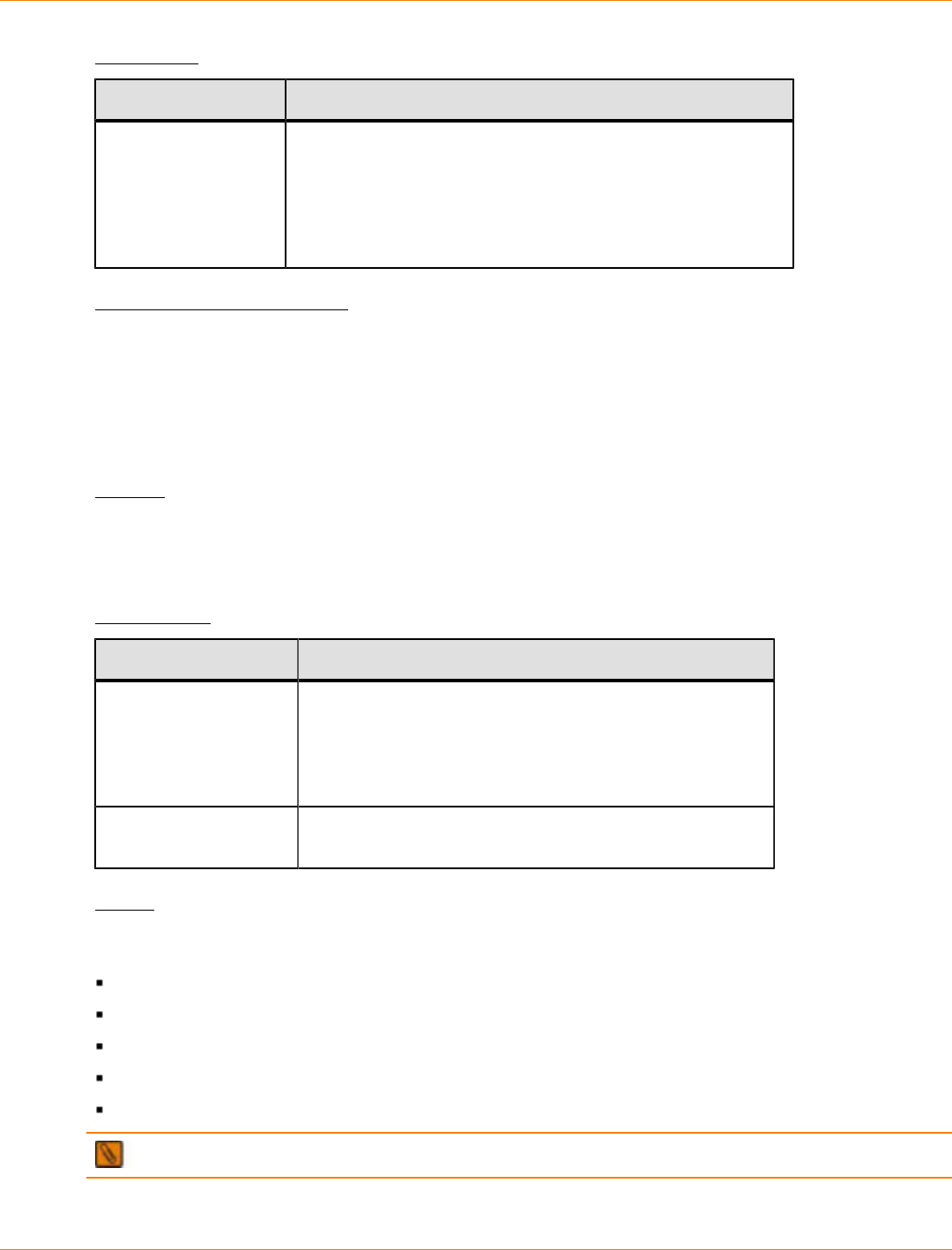
SANtricity_10.77 February 2011
LSI Corporation
- 1078 -
Parameter
Parameter Description
primary or
primaries
The name of the primary volume of the remote mirror pair that
you want to test. You can enter more than one primary volume
name. Enclose the primary volume names in square brackets
([ ]). If the primary volume name has special characters,
you also must enclose the primary volume name in double
quotation marks (" ").
Minimum Firmware Level
6.10
Disable External Security Key Management
This command disables external security key management for a storage array that has full disk encryption
drives.
Syntax
disable storageArray externalKeyManagement
file="fileName"
passPhrase="passPhraseString"
Parameters
Parameter Description
file The file path and the file name that has the security key.
For example:
file="C:\Program Files\CLI\sup\seckey.slk"
IMPORTANT – The file name must have an extension of
.slk.
passPhrase A character string that encrypts the security key so that
you can store the security key in an external file.
Notes
Your pass phrase must meet these criteria:
The pass phrase must be between eight and 32 characters long.
The pass phrase must contain at least one uppercase letter.
The pass phrase must contain at least one lowercase letter.
The pass phrase must contain at least one number.
The pass phrase must contain at least one non-alphanumeric character, for example, < > @ +.
NOTE If your pass phrase does not meet these criteria, you will receive an error message.

SANtricity_10.77 February 2011
LSI Corporation
- 1079 -
Minimum Firmware Level
7.70
Disable Storage Array Feature
This command disables a storage array premium feature. Run the show storageArray command to show
a list of the feature identifiers for all enabled premium features in the storage array.
Syntax
disable storageArray [featurePack |
feature=(storagePartition2 | storagePartition4 |
storagePartition8 | storagePartition16 | storagePartition32 |
storagePartition64 | storagePartition96 | storagePartition128 |
storagePartition256 | storagePartitionMax |
snapshot2 | snapshot4 | snapshot8 | snapshot16 |
remoteMirror8 | remoteMirror16 | remoteMirror32 |
remoteMirror64 | remoteMirror128 | volumeCopy | goldKey |
mixedDriveTypes | highPerformanceTier | SSDSupport |
safeStoreSecurity | safeStoreExternalKeyMgr)]
Parameters
None.
Notes
If you specify the remoteMirror parameter, this command disables the Remote Volume Mirroring premium
feature and takes away the structure of the mirror repository volume.
To use the High Performance Tier premium feature, you must configure a storage array as one of these:
SHIPPED_ENABLED
SHIPPED_ENABLED=FALSE; KEY_ENABLED=TRUE
Minimum Firmware Level
5.00
6.50 adds the goldKey parameter and the mixedDriveTypes parameter.
7.60 adds the SSDSupport parameter.
7.70 adds the remoteMirror8 parameter. Firmware version 7.70 supports a maximum of eight remote
mirror pairs.
Disable Storage Array Remote Status Notification
This command turns off the remote status notification feature. The remote status notification feature enables
the periodic collection of the storage array profile and the support bundle information by the persistent
monitor. The storage array profile and the support bundle information are automatically sent to a support data
collection web server. To turn on the remote status notification feature, use the enable storageArray
remoteStatusNotification command.
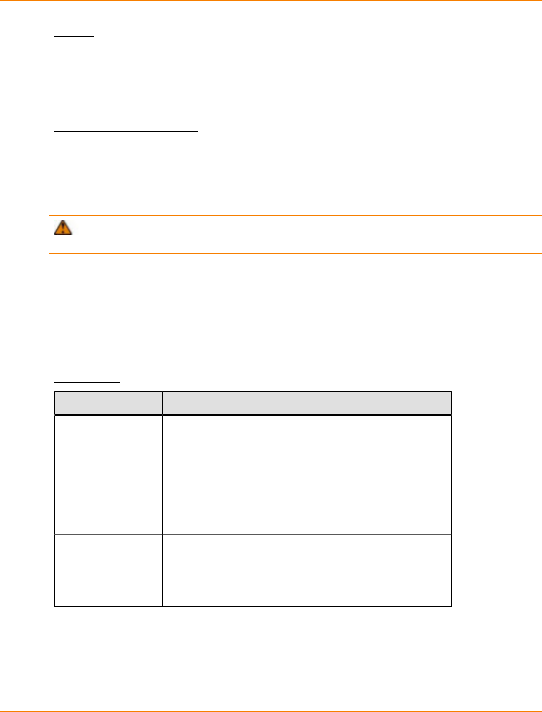
SANtricity_10.77 February 2011
LSI Corporation
- 1080 -
Syntax
disable storageArray remoteStatusNotification
Parameter
None.
Minimum Firmware Level
7.70
Download Drive Firmware
This command downloads a firmware image to a drive.
ATTENTION Possible damage to the storage array configuration – Downloading drive firmware
incorrectly can result in damage to the drives or a loss of data access.
This command is intended for downloading a firmware image to only one drive at a time. If you use this
command in a script, make sure that you use this command only once. If you use this command more than
once, the operation can fail. You can download firmware images to all of the drives in a storage array at one
time by using the download storageArray driveFirmware command.
Syntax
download drive [trayID,drawerID,slotID] firmware file="filename"
Parameters
Parameter Description
drive The drive to which you want to download the firmware image.
For high-capacity drive trays, specify the tray ID value, the
drawer ID value, and the slot ID value for each drive to which
you want to download firmware. For low-capacity drive trays,
specify the tray ID value and the slot ID value for each drive
to which you want to download firmware. Tray ID values are 0
to 99. Drawer ID values are 1 to 5. Slot ID values are 1 to 32.
Enclose the tray ID values, the drawer ID values, and the slot
ID values in brackets ([ ]).
file The file path and the file name of the file that contains the
firmware image. Enclose the file path and the file name of the
firmware image in double quotation marks (" "). For example:
file="C:\Program Files\CLI\dnld\drvfrm.dlp"
Valid file names have a .dlp extension.
Notes
Before trying to download drive firmware, take these precautions:

SANtricity_10.77 February 2011
LSI Corporation
- 1081 -
Stop all I/O activity to the storage array before you download the firmware image. The download drive
command blocks all I/O activity until the download finishes or fails; however, as a precaution, make sure
that all I/O activity that might affect the drive is stopped.
Make sure that the firmware image file is compatible with the drive tray. If you download a firmware
image file that is not compatible with the drive tray that you have selected, the drive tray might become
unusable.
Do not make any configuration changes to the storage array while you download drive firmware. Trying
to make a configuration change can cause the firmware download to fail and make the selected drives
unusable.
When you download the firmware to the drives, you must provide the full path and file name to the firmware
image that is stored on your system.
You can use download drive command to test the firmware on one drive before you install the firmware on
all of the drives in a storage array. The download returns one of these statuses:
Successful
Unsuccessful With Reason
Never Attempted With Reason
The drive parameter supports both high-capacity drive trays and low-capacity drive trays. A high-capacity
drive tray has drawers that hold the drives. The drawers slide out of the drive tray to provide access to the
drives. A low-capacity drive tray does not have drawers. For a high-capacity drive tray, you must specify
the identifier (ID) of the drive tray, the ID of the drawer, and the ID of the slot in which a drive resides. For a
low-capacity drive tray, you need only specify the ID of the drive tray and the ID of the slot in which a drive
resides. For a low-capacity drive tray, an alternative method for identifying a location for a drive is to specify
the ID of the drive tray, set the ID of the drawer to 0, and specify the ID of the slot in which a drive resides.
Minimum Firmware Level
6.10
7.60 adds the drawerID user input.
Download Environmental Card Firmware
This command downloads environmental services monitor (ESM) firmware.
Syntax
download (allTrays | tray [trayID])
firmware file="filename"
Parameters
Parameter Description
allTray This parameter downloads new firmware to all of the trays in the
storage array.
tray The drive tray that contains the ESM card to which you want to
load new firmware. Tray ID values are 0 to 99. Enclose the tray ID
value in square brackets ([ ]).
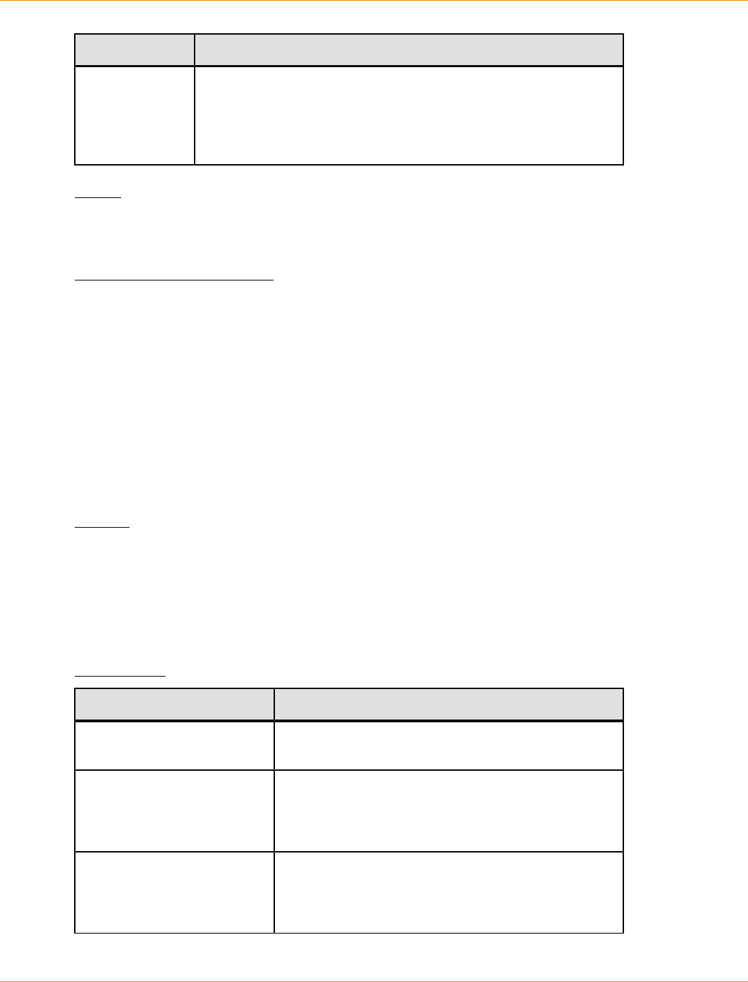
SANtricity_10.77 February 2011
LSI Corporation
- 1082 -
Parameter Description
file The file path and the file name of the file that contains the firmware
image. Enclose the file path and the file name of the firmware
image in double quotation marks (" "). For example:
file="C:\Program Files\CLI\dnld\esmfrm.esm"
Valid file names have an .esm extension.
Notes
The tray parameter downloads new firmware to a specific drive tray. If you need to download new firmware
to more than one drive tray, but not all drive trays, you must enter this command for each drive tray.
Minimum Firmware Level
5.20
Download Power Supply Firmware
This command downloads firmware updates to the power supplies. You can schedule simultaneous firmware
updates for several power supplies, and the power supplies can be in different trays. A single firmware
file can contain updates for several different power supplies. Matching firmware updates are automatically
chosen for the power supplies. Firmware download occurs only if the new firmware version is not the same as
the version of the power supplies on the trays. A download succeeds only if the power supply is in an Optimal
state and there is a redundant power supply that is in an Optimal state.
To bypass these checks ‘forceUpdate’ can be used.
Syntax
download (allTrays |
...tray [trayID1]...[trayIDn] |
...tray [trayID])
powerSupplyUpdate file="filename"
powerSupplyUnit [(left | right) | (top | bottom)] |
[forceUpdate]
Parameters
Parameter Description
allTrays This parameter downloads new power supply
firmware to all of the trays in the storage array.
tray or trays The tray that contains the power supply to which you
want to download new firmware. Tray ID values are
0 to 99. Enclose the tray ID value in square brackets
([ ]).
powerSupplyUpdate file The file path and the file name of the file that contains
the firmware image. Enclose the file path and the
file name of the firmware image in double quotation
marks (" "). For example:
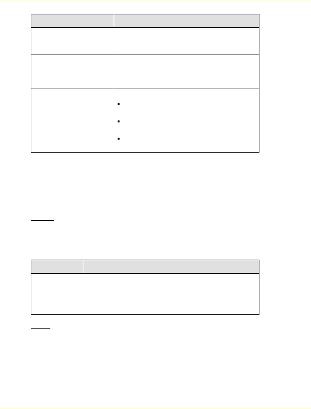
SANtricity_10.77 February 2011
LSI Corporation
- 1083 -
Parameter Description
file="C:\Program Files\CLI\dnld
\esmfrm.esm"
Valid file names have an .esm extension.
powerSupplyUnit The power supply to which you want to download new
firmware. Valid power supply identifiers are left,
right, top, or bottom. Enclose the power-fan
canister identifier in square brackets ([ ])
forceUpdate This parameter bypasses these checks:
To determine if the new firmware version is the
same as the existing firmware version.
To determine if the power supply is in an Optimal
state.
To determine if there is a redundant power supply
that is in an Optimal state.
Minimum Firmware Level
7.77
Download Storage Array Drive Firmware
This command downloads firmware images to all of the drives in the storage array.
Syntax
download storageArray driveFirmware file="filename"
[file="filename2"... file="filenameN"]
Parameter
Parameter Description
file The file path and the file name of the file that contains the
firmware image. Enclose the file path and the file name of the
firmware image in double quotation marks (" "). For example:
file="C:\Program Files\CLI\dnld\sadrvfrm.dlp"
Valid file names have a .dlp extension.
Notes
When you run this command, you can download more than one firmware image file to the drives in a storage
array. The number of firmware image files that you can download depends on the storage array. The storage
management software returns an error if you try to download more firmware image files than the storage array
can accept.
You can schedule downloads for multiple drives at the same time, including multiple drives in a redundant
volume group. Each firmware image file contains information about the drive types on which the firmware
image runs. The specified firmware images can be downloaded only to a compatible drive. Use the
download drive firmware command to download a firmware image to a specific drive.
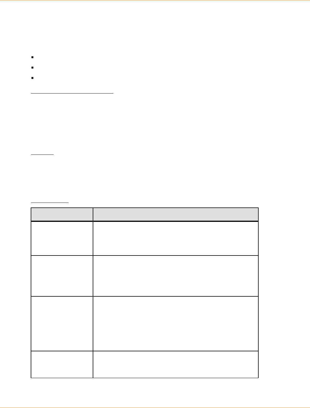
SANtricity_10.77 February 2011
LSI Corporation
- 1084 -
The download storageArray driveFirmware command blocks all I/O activity until either download try
has been made for each candidate drive or you run the stop storageArray downloadDriveFirmware
command. When the download storageArray driveFirmware command finishes downloading the
firmware image, each candidate drive shows the download status for each drive. One of these statuses is
returned:
Successful
Unsuccessful With Reason
Never Attempted With Reason
Minimum Firmware Level
5.20
Download Storage Array Firmware/NVSRAM
This command downloads firmware and, optionally, NVSRAM values for the storage array controller. If you
want to download only NVSRAM values, use the downLoad storageArray NVSRAM command.
Syntax
download storageArray firmware [, NVSRAM ]
file="filename" [, "NVSRAM-filename"]
[downgrade=(TRUE | FALSE)]
[activateNow=(TRUE | FALSE)]
Parameters
Parameter Description
NVSRAM The setting to download a file with NVSRAM values when
you download a firmware file. Do not include square brackets
with this parameter. Include a comma after the firmware
parameter.
file The file path and the file name that contains the firmware.
Enclose the file path and the file name in double quotation
marks (" "). For example:
file="C:\Program Files\CLI\dnld\safrm.dlp"
Valid file names have a .dlp extension.
NVSRAM-filename The file path and the file name that contains the NVSRAM
values. Enclose the NVSRAM file name in double quotation
marks (" "). For example:
file="C:\Program Files\CLI\dnld\safrm.dlp"
Valid file names have a .dlp extension.
Include a comma before the file name downloading both
firmware and NVSRAM.
downgrade The setting to load firmware that is a previous version. The
default value is FALSE. Set the downgrade parameter to
TRUE if you want to download an earlier version of firmware.
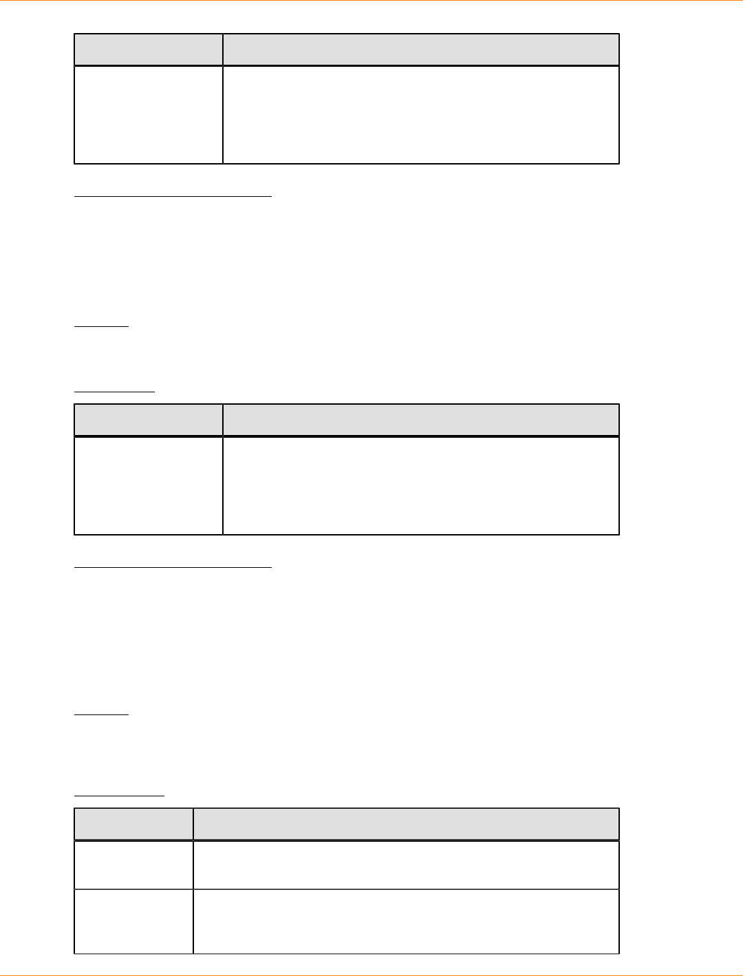
SANtricity_10.77 February 2011
LSI Corporation
- 1085 -
Parameter Description
activateNow The setting to activate the firmware image and the
NVSRAM image. The default value is TRUE. If you set the
activateNow parameter to FALSE, you must run the
activate storageArray firmware command to activate
the firmware values and the NVSRAM values at a later time.
Minimum Firmware Level
5.00
Download Storage Array NVSRAM
This command downloads the NVSRAM values for the storage array controller.
Syntax
download storageArray NVSRAM file="filename"
Parameter
Parameter Description
file The file path and the file name that contains the NVSRAM
values. Enclose the NVSRAM file name in double quotation
marks (" "). For example:
file="C:\Program Files\CLI\dnld\afrm.dlp"
Valid file names have a .dlp extension.
Minimum Firmware Level
6.10
Download Tray Configuration Settings
This command downloads the factory default settings to all of the drive trays in a storage array or to a specific
drive tray in a storage array.
Syntax
download (allTrays | tray [trayID]) configurationSettings
firmware file="filename"
Parameters
Parameter Description
allTray This parameter downloads new firmware to all of the trays in the
storage array.
tray The drive tray that contains the ESM card to which you want to
load new firmware. Tray ID values are 0 to 99. Enclose the tray ID
value in square brackets ([ ]).
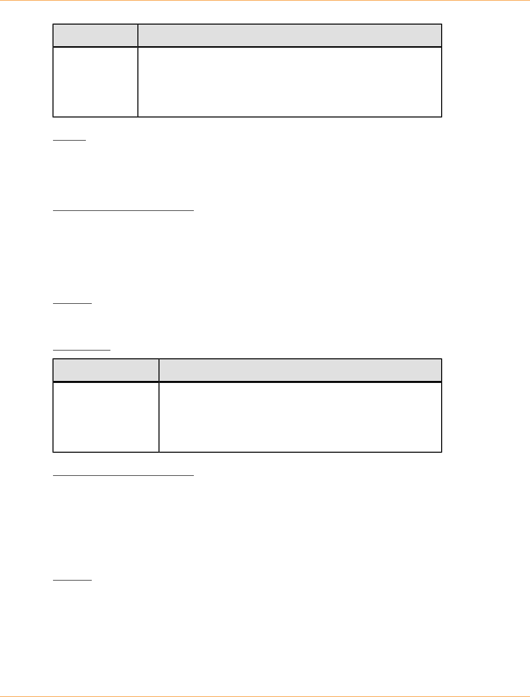
SANtricity_10.77 February 2011
LSI Corporation
- 1086 -
Parameter Description
file The file path and the file name of the file that contains the firmware
image. Enclose the file path and the file name of the firmware
image in double quotation marks (" "). For example:
file="C:\Program Files\CLI\dnld\trayset.dlp"
Valid file names have a .dlp extension.
Notes
The tray parameter downloads the factory default configuration settings to a specific drive tray. If you need
to download the factory default configuration settings to more than one drive tray, but not all drive trays, you
must enter this command for each drive tray.
Minimum Firmware Level
7.75
Enable Controller Data Transfer
This command revives a controller that has become quiesced while running diagnostics.
Syntax
enable controller [(a | b)] dataTransfer
Parameter
Parameter Description
controller The controller that you want to revive. Valid controller
identifiers are a or b, where a is the controller in slot A, and
b is the controller in slot B. Enclose the controller identifier
in square brackets ([ ]). If you do not specify a controller, the
storage management software returns a syntax error.
Minimum Firmware Level
6.10
Enable External Security Key Management
This command enables external security key management for a storage array that has full disk encryption
drives.
Syntax
enable storageArray externalKeyManagement
file="fileName" |
passPhrase="passPhraseString"
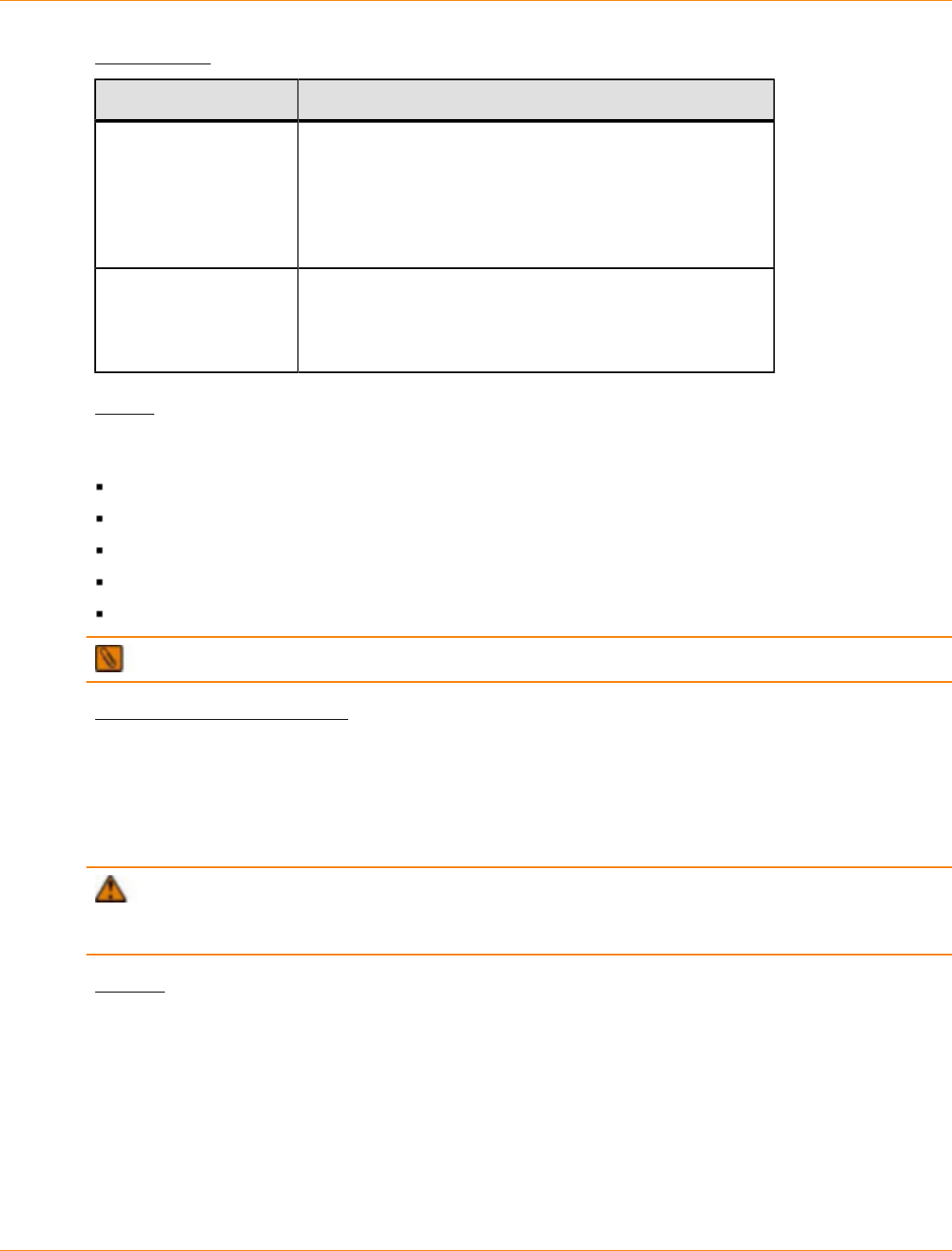
SANtricity_10.77 February 2011
LSI Corporation
- 1087 -
Parameters
Parameter Description
file The file path and the file name that has the security
key. Enclose the file path and the file name that has the
security key in double quotation marks (" "). For example:
file="C:\Program Files\CLI\sup\seckey.slk"
IMPORTANT – The file name must have an extension of
.slk.
passPhrase A character string that encrypts the security key so that
you can store the security key in an external file. Enclose
the pass phrase character string in double quotation
marks (" ").
Notes
Your pass phrase must meet these criteria:
The pass phrase must be between eight and 32 characters long.
The pass phrase must contain at least one uppercase letter.
The pass phrase must contain at least one lowercase letter.
The pass phrase must contain at least one number.
The pass phrase must contain at least one non-alphanumeric character, for example, < > @ +.
NOTE If your pass phrase does not meet these criteria, you will receive an error message.
Minimum Firmware Level
7.70
Enable Storage Array Feature
This command enables a premium feature by using a feature key file.
ATTENTION Before you enable the High Performance Tier premium feature, stop all host I/O
operations to the storage array. When you enable the High Performance Tier premium feature, both
controllers in the storage array will immediately reboot.
Syntax
enable storageArray [featurePack | feature]
file="filename"

SANtricity_10.77 February 2011
LSI Corporation
- 1088 -
Parameter
Parameter Description
file The file path and the file name of a valid feature key file. Enclose
the file path and the file name in double quotation marks (" "). For
example:
file="C:\Program Files\CLI\dnld\ftrkey.key"
Valid file names for feature key files end with a .key extension.
Notes
A premium feature is an additional application to enhance the capabilities of a storage array. The premium
features are these:
Storage partitioning
Snapshots
Remote Volume Mirroring
Mixed drive types
High performance tier
SSD support
SafeStore Drive Security
A feature pack is a predefined set of premium features, such as Storage Partitioning and Remote Volume
Mirroring. These premium features are combined for the convenience of the users.
Minimum Firmware Level
6.10
6.50 adds the featurePack parameter.
7.50 adds the highPerformanceTier parameter.
7.70 adds the remoteMirror8 parameter. Firmware version 7.70 supports a maximum of eight remote
mirror pairs.
Enable Storage Array Remote Status Notification
This command turns on the remote status notification feature. The remote status notification feature enables
the periodic collection of the storage array profile and the support bundle information by the persistent
monitor. The storage array profile and the support bundle information are automatically sent to a support data
collection web server. To turn off the remote status notification feature, use the disable storageArray
remoteStatusNotification command.
Syntax
enable storageArray remoteStatusNotification
Parameter
None.
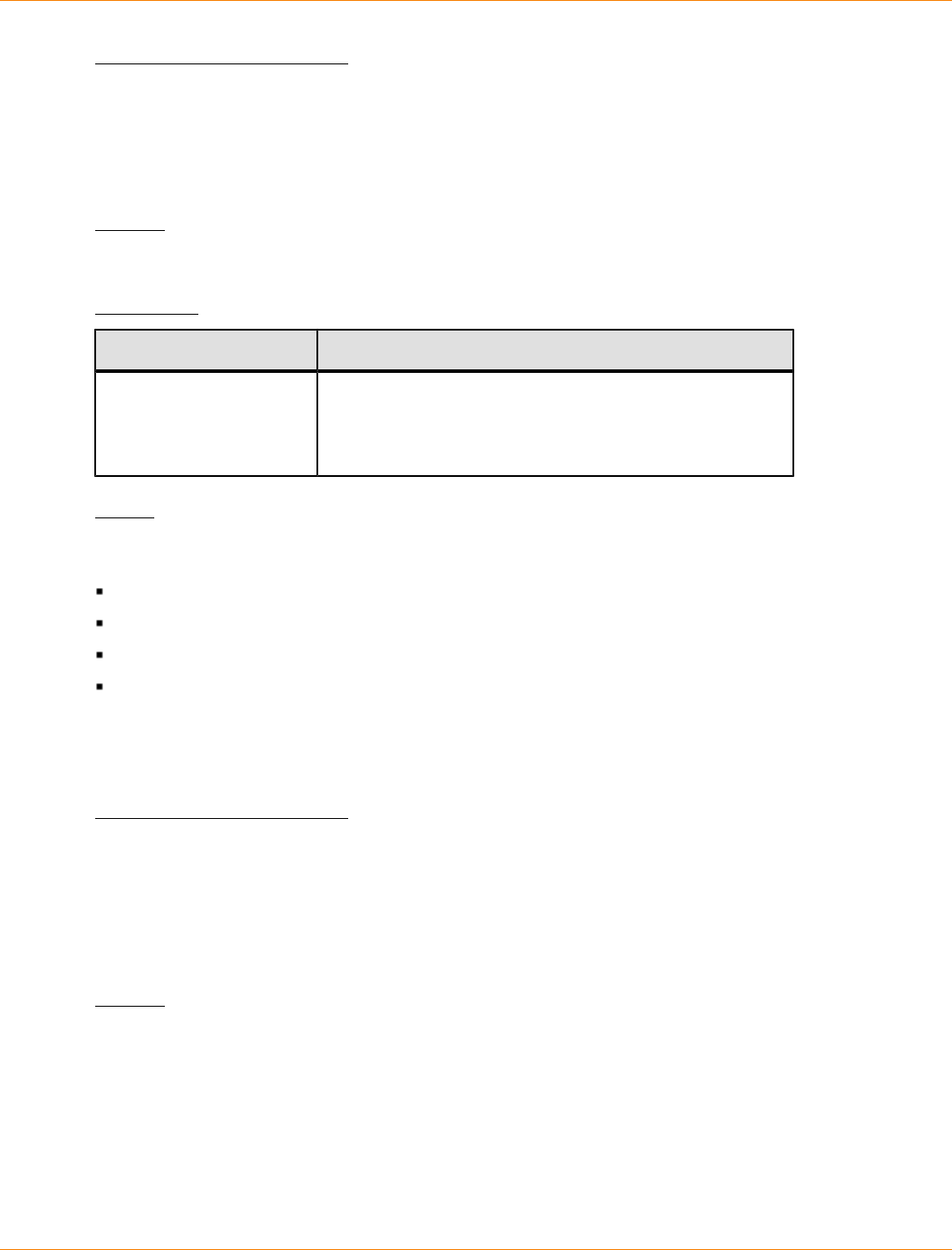
SANtricity_10.77 February 2011
LSI Corporation
- 1089 -
Minimum Firmware Level
7.70
Enable Volume Group Security
This command converts a non-secure volume group to a secure volume group.
Syntax
enable volumeGroup [volumeGroupName] security
Parameter
Parameter Description
volumeGroup The alphanumeric identifier (including - and _) of the
volume group that you want to place in the Security
Enabled state. Enclose the volume group identifier in
square brackets ([ ]).
Notes
These conditions must be met to successfully run this command.
All drives in the volume group must be full disk encryption drives.
The SafeStore Drive Security premium feature must be enabled.
The storage array security key has to be set.
The volume group is Optimal, and it does not have snapshot volumes or repository volumes.
The controller firmware creates a lock that restricts access to the FDE drives. FDE drives have a state called
Security Capable. When you create a security key, the state is set to Security Enabled, which restricts access
to all FDE drives that exist within the storage array.
Minimum Firmware Level
7.40
Export Storage Array Security Key
This command saves a full disk encryption (FDE) security key to a file. You can transfer the file from one
storage array to another storage array. The file enables you to move FDE drives between storage arrays.
Syntax
export storageArray securityKey
passPhrase="passPhraseString"
file="fileName"
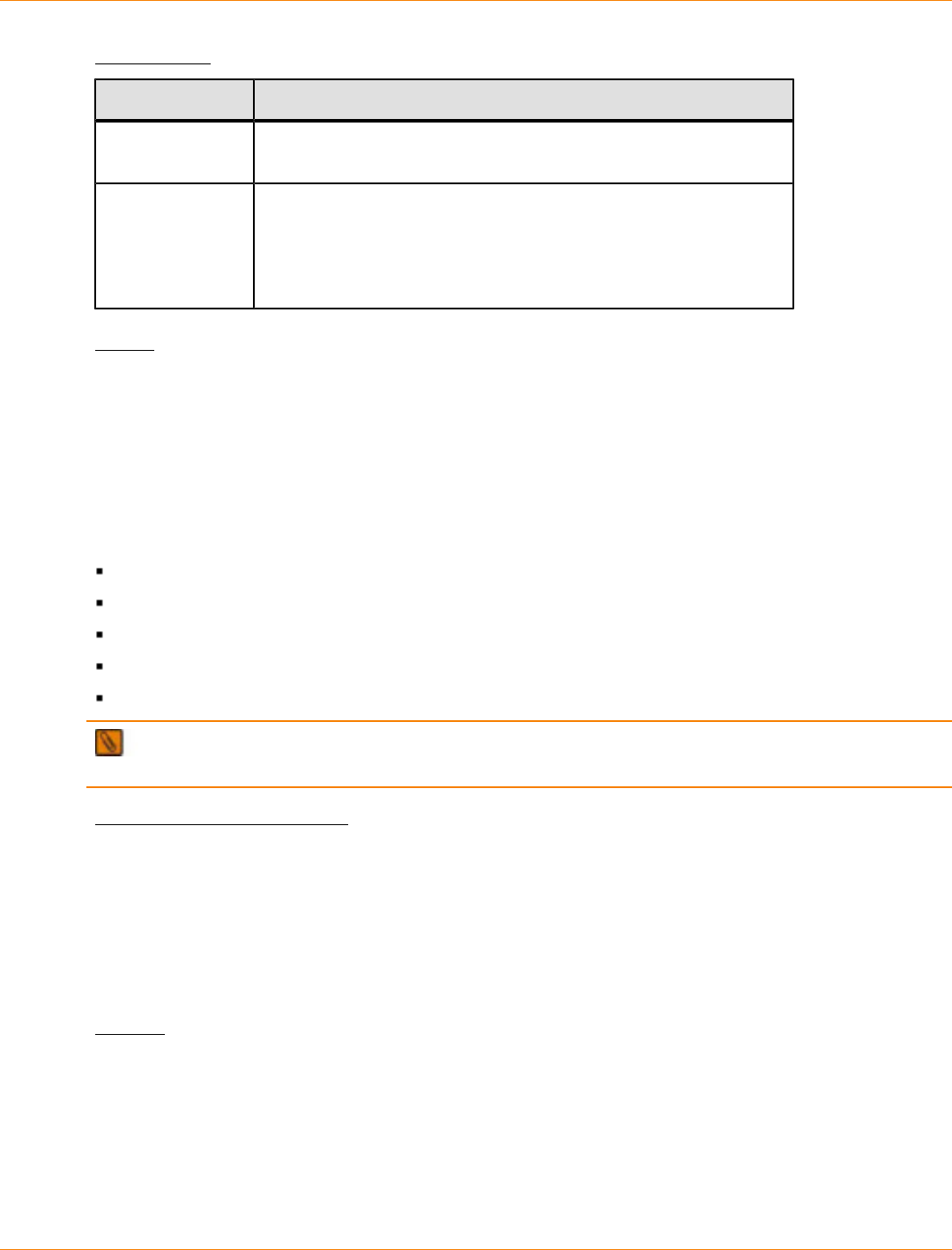
SANtricity_10.77 February 2011
LSI Corporation
- 1090 -
Parameters
Parameter Description
passPhrase A character string that encrypts the security key so that you can
store the security key in an external file.
file The file path and the file name to which you want to save the
security key. For example:
file="C:\Program Files\CLI\sup\seckey.slk"
IMPORTANT – You must add a file extension of .slk to the end
of the file name.
Notes
The storage array to which you will be moving drives must have drives with a capacity that is equal to or
greater than the drives that you are importing.
The controller firmware creates a lock that restricts access to the full disk encryption (FDE) drives. FDE drives
have a state called Security Capable. When you create a security key, the state is set to Security Enabled,
which restricts access to all FDE drives that exist within the storage array.
Your pass phrase must meet these criteria:
The pass phrase must be between eight and 32 characters long.
The pass phrase must contain at least one uppercase letter.
The pass phrase must contain at least one lowercase letter.
The pass phrase must contain at least one number.
The pass phrase must contain at least one non-alphanumeric character, for example, < > @ +.
NOTE If your pass phrase does not meet these criteria, you will receive an error message and will be
asked to retry the command.
Minimum Firmware Level
7.40
Import Storage Array Security Key
This command unlocks one or more full disk encryption (FDE) drives that you have imported from one storage
array to another storage array. Only the FDE drives with the matching security key from the imported storage
array are unlocked. After they are unlocked, the security key for the new storage array is applied.
Syntax
import storageArray securityKey file="fileName"
passPhrase="passPhraseString"
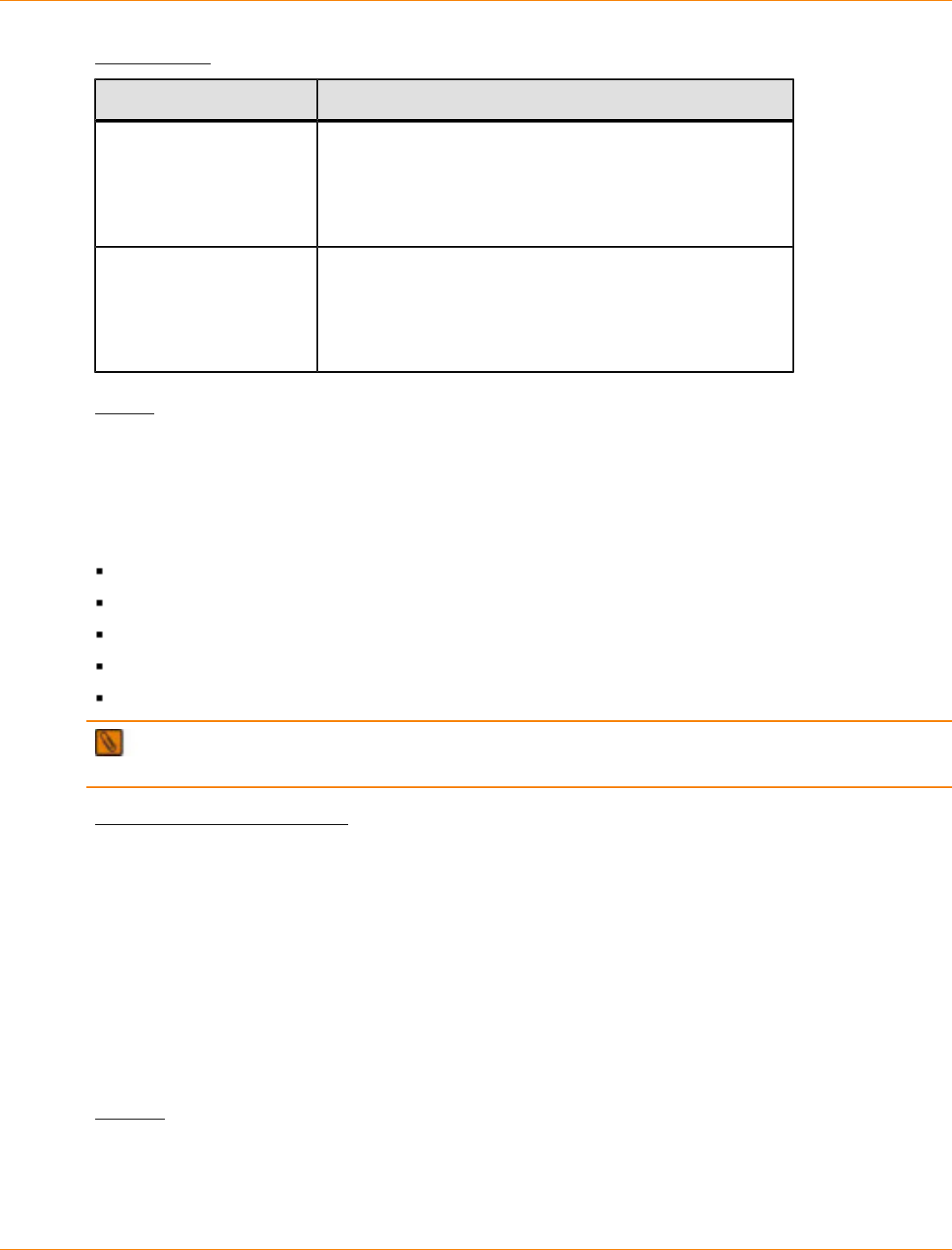
SANtricity_10.77 February 2011
LSI Corporation
- 1091 -
Parameters
Parameter Description
file The file path and the file name that has the original
security key of the imported FDE drives. For example:
file="C:\Program Files\CLI\sup\seckey.slk"
IMPORTANT – The file that has the security key must
have a file extension of .slk.
passPhrase The character string that provides authentication for the
security key. The pass phrase is 8 to 32 characters in
length. You must use at least one number, one lowercase
letter, one uppercase letter, and one non-alphanumeric
character in the pass phrase. A space is not permitted.
Notes
The controller firmware creates a lock that restricts access to the FDE drives. FDE drives have a state called
Security Capable. When you create a security key, the state is set to Security Enabled, which restricts access
to all FDE drives that exist within the storage array.
Your pass phrase must meet these criteria:
The pass phrase must be between eight and 32 characters long.
The pass phrase must contain at least one uppercase letter.
The pass phrase must contain at least one lowercase letter.
The pass phrase must contain at least one number.
The pass phrase must contain at least one non-alphanumeric character, for example, < > @ +.
NOTE If your pass phrase does not meet these criteria, you will receive an error message and will be
asked to retry the command.
Minimum Firmware Level
7.40
Load Storage Array DBM Database
This command uploads a Database Management (DBM) database image from a file. This command restores
a storage array to the exact configuration that existed when the DBM database image was captured to a
file using the save storageArray dbmDatabase command. Before using this command, you must first
obtain a validator or a security code from your Customer and Technical Support representative. To obtain a
validator, use the save storageArray dbmValidator command to generate an XML file that contains
validator information. Your Customer and Technical Support representative uses the XML file to generate the
validator required for this command.
Syntax
load storageArray dbmDatabase
file="filename" validator=validatorValue
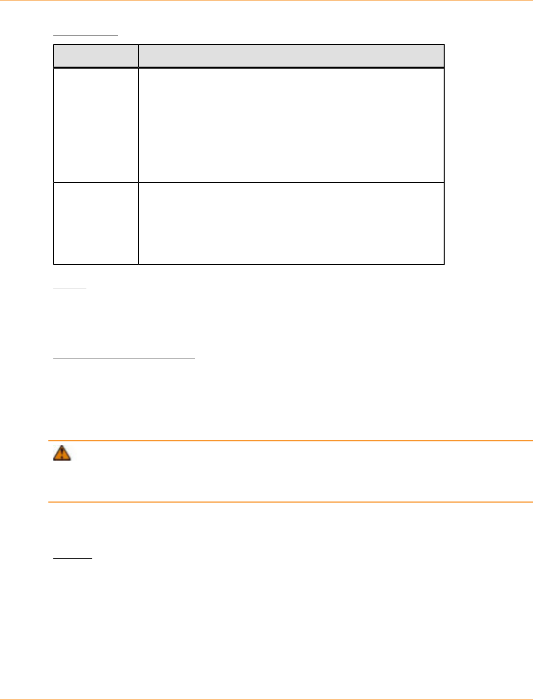
SANtricity_10.77 February 2011
LSI Corporation
- 1092 -
Parameters
Parameter Description
file The file path and the file name of the DBM database you want to
upload. Enclose the file name in double quotation marks (" "). For
example:
file="C:\Array Backups\DBMbackup_03302010.dbm"
This command does not automatically append a file extension to
the saved file. You must specify a file extension when entering the
file name.
validator The alphanumeric security code required to restore a storage
array to an existing configuration. Use the save storageArray
dbmValidator command to generate the required validation
information XML file. After the validation information XML file
is available, contact your Customer and Technical Support
representative to obtain the Validator.
Notes
It might take up to 30 minutes to restore controller functionality. Depending on the size of the database image,
restoring the database might take up as much as 30 minutes. The host software will not show the controllers
in an Optimal state until after all actions for loading the database image are completed on the controllers.
Minimum Firmware Level
7.75
Recopy Volume Copy
This command reinitiates a volume copy operation using an existing volume copy pair.
ATTENTION Starting a volume copy operation overwrites all existing data on the target volume, makes
the target volume read-only to hosts, and fails all snapshot volumes associated with the target volume, if any
exist. If you have used the target volume as a copy before, be sure you no longer need the data or have it
backed up.
This command works with volume copy pairs that you created with a snapshot volume or without a snapshot
volume.
Syntax
recopy volumeCopy target [targetName]
[source [sourceName]]
[copyPriority=(highest | high | medium | low | lowest)
targetReadOnlyEnabled=(TRUE | FALSE)
copyType=(online | offline)]

SANtricity_10.77 February 2011
LSI Corporation
- 1093 -
Parameters
Parameter Description
target The name of the target volume for which you want to
reinitiate a volume copy operation. Enclose the target
volume name in square brackets ([ ]). If the target
volume name has special characters, you also must
enclose the target volume name in double quotation
marks (" ").
source The name of the source volume for which you want to
reinitiate a volume copy operation. Enclose the source
volume name in square brackets ([ ]). If the source
volume name has special characters, you also must
enclose the source volume name in double quotation
marks (" ").
copyPriority The priority that the volume copy has relative to host I/
O activity. Valid values are highest, high, medium,
low, or lowest.
targetReadOnlyEnabled The setting so that you can write to the target volume
or only read from the target volume. To write to
the target volume, set this parameter to FALSE.
To prevent writing to the target volume, set this
parameter to TRUE.
copyType Use this parameter to create a volume copy with a
snapshot. Creating a volume copy with a snapshot
enables you to continue to write to the source volume
while creating the volume copy. To reinitiate a volume
copy with a snapshot, set this parameter to online.
To reinitiate a volume copy with out a snapshot, set
this parameter to offline.
Notes
Copy priority defines the amount of system resources that are used to copy the data between the source
volume and the target volume of a volume copy pair. If you select the highest priority level, the volume copy
uses the most system resources to perform the volume copy, which decreases performance for host data
transfers.
Minimum Firmware Level
6.10
7.77 adds recopying a volume copy with snapshot.
Recover RAID Volume
This command creates a RAID volume with the given properties without initializing any of the user data areas
on the drives. Parameter values are derived from the Recovery Profile data file (recoveryProfile.csv)
for the storage array. You can create the recover volume in an existing volume group or create a new volume
group by using this command.
SANtricity_10.77 February 2011
LSI Corporation
- 1094 -
NOTE You can run this command only from a command line. You cannot run this command from the
GUI script editor. You cannot use the storage managment GUI to recover a volume.
Syntax
recover volume (drive=(trayID,drawerID,slotID) |
drives=(trayID1,drawerID1,slotID1
... trayIDn,drawerIDn,slotIDn) |
volumeGroup=volumeGroupName))
[newVolumeGroup=volumeGroupName]
userLabel=("volumeName"
volumeWWN="volumeWWN")
capacity=volumeCapacity
offset=offsetValue
raidLevel=(0 | 1 | 3 | 5 | 6)
segmentSize=segmentSizeValue
dssPreallocate=(TRUE | FALSE)
SSID=volumeCapacity
owner=(a | b)
cacheReadPrefetch=(TRUE | FALSE)
dataAssurance=(none | enabled)]
Parameters
Parameter Description
drive or drives The drives that you want to assign to the volume
group that will contain the volume that you want to
recover. For high-capacity drive trays, specify the tray
ID value, the drawer ID value, and the slot ID value
for each drive that you assign to the volume. For low-
capacity drive trays, specify the tray ID value and
the slot ID value for each drive that you assign to the
volume. Tray ID values are 0 to 99. Drawer ID values
are 1 to 5. Slot ID values are 1 to 32. Enclose the tray
ID values, the drawer ID values, and the slot ID values
insqurare brackets ([ ]).
volumeGroup The name of an existing volume group in which you
want to create the volume. (To determine the names
of the volume groups in your storage array, run the
show storageArray profile command.)
newVolumeGroup The name that you want to give a new volume group.
Enclose the new volume group name in double
quotation marks (" ").
userLabel The name of the volume that you want to recover.
Enclose the volume name in double quotation marks
(" ").

SANtricity_10.77 February 2011
LSI Corporation
- 1095 -
Parameter Description
volumeWWN The world wide name of the volume that you want to
recover. The name is a 16 byte identifier, for example,
60080E500017B4320000000049887D77. Enclose the
identifier in double quotation marks (" ").
capacity The size of the volume that you are adding to the
storage array. Size is defined in units of bytes, KB,
MB, GB, or TB.
offset The number of blocks from the start of the volume
group to the start of the referenced volume.
raidLevel The RAID level of the volume group that contains the
drives. Valid values are 0, 1, 3, 5, or 6.
segmentSize The amount of data (in KB) that the controller writes
on a single drive in a volume group before writing data
on the next drive. Valid values are 8, 16, 32, 64, 128,
256, or 512.
dssPreallocate The setting to turn on or turn off allocating volume
storage capacity for future segment size changes. To
turn on allocation, set this parameter to TRUE. To turn
off allocation, set this parameter to FALSE.
SSID The storage array subsystem identifier of a volume.
owner The controller that owns the volume. Valid controller
identifiers are a or b, where a is the controller in
slot A, and b is the controller in slot B. If you do not
specify an owner, the controller firmware determines
the owner.
cacheReadPrefetch The setting to turn on or turn off cache read prefetch.
To turn off cache read prefetch, set this parameter
to FALSE. To turn on cache read prefetch, set this
parameter to TRUE.
dataAssurance The setting to specify that a volume group, and the
volumes within the volume group, has data assurance
protection to make sure that the data maintains its
integrity. When you use this parameter, only protected
drives can be used for the volume group. These
settings are valid:
none – The volume group does not have data
assurance protection.
enabled – The volume group has data
assurance protection. The volume group supports
protected information and is formatted with
protection information enabled.

SANtricity_10.77 February 2011
LSI Corporation
- 1096 -
Notes
The storage management software collects recovery profiles of the monitored storage arrays and saves the
profiles on a storage management station.
The drive parameter supports both high-capacity drive trays and low-capacity drive trays. A high-capacity
drive tray has drawers that hold the drives. The drawers slide out of the drive tray to provide access to the
drives. A low-capacity drive tray does not have drawers. For a high-capacity drive tray, you must specify
the identifier (ID) of the drive tray, the ID of the drawer, and the ID of the slot in which a drive resides. For a
low-capacity drive tray, you need only specify the ID of the drive tray and the ID of the slot in which a drive
resides. For a low-capacity drive tray, an alternative method for identifying a location for a drive is to specify
the ID of the drive tray, set the ID of the drawer to 0, and specify the ID of the slot in which a drive resides.
If you attempt to recover a volume using the drive parameter or the drives parameter and the drives are
in an unassigned state, the controller automatically creates a new volume group. Use the newVolumeGroup
parameter to specify a name for the new volume group.
You can use any combination of alphanumeric characters,underscore (_), hyphen(-), and pound (#) for the
names. Names can have a maximum of 30 characters.
The owner parameter defines which controller owns the volume. The preferred controller ownership of a
volume is the controller that currently owns the volume group.
Preallocating Storage Capacity
The dssPreallocate parameter enables you to assign capacity in a volume for storing information that
is used to rebuild a volume. When you set the dssPreallocate parameter to TRUE, the storage space
allocation logic in the controller firmware preallocates the space in a volume for future segment size changes.
The preallocated space is the maximum allowable segment size. The dssPreallocate parameter is
necessary for properly recovering volume configurations that are not retievable from the controller data base.
To turn off the preallocation capability, setdssPreallocate to FALSE.
Segment Size
The size of a segment determines how many data blocks that the controller writes on a single drive in a
volume before writing data on the next drive. Each data block stores 512 bytes of data. A data block is
the smallest unit of storage. The size of a segment determines how many data blocks that it contains. For
example, an 8-KB segment holds 16 data blocks. A 64-KB segment holds 128 data blocks.
When you enter a value for the segment size, the value is checked against the supported values that are
provided by the controller at run time. If the value that you entered is not valid, the controller returns a list of
valid values. Using a single drive for a single request leaves other drives available to simultaneously service
other requests.
If the volume is in an environment where a single user is transferring large units of data (such as multimedia),
performance is maximized when a single data transfer request is serviced with a single data stripe. (A data
stripe is the segment size that is multiplied by the number of drives in the volume group that are used for data
transfers.) In this case, multiple drives are used for the same request, but each drive is accessed only once.
For optimal performance in a multiuser database or file system storage environment, set your segment size to
minimize the number of drives that are required to satisfy a data transfer request.
SANtricity_10.77 February 2011
LSI Corporation
- 1097 -
Cache Read Prefetch
Cache read prefetch lets the controller copy additional data blocks into cache while the controller reads and
copies data blocks that are requested by the host from disk into cache. This action increases the chance
that a future request for data can be fulfilled from cache. Cache read prefetch is important for multimedia
applications that use sequential data transfers. The configuration settings for the storage array that you
use determine the number of additional data blocks that the controller reads into cache. Valid values for the
cacheReadPrefetch parameter are TRUE or FALSE.
Minimum Firmware Level
5.43
7.10 adds RAID 6 Level capability and the newVolumeGroup parameter.
7.60 adds the drawerID user input.
7.75 adds the dataAssurance parameter.
Re-create External Security Key
This command regenerates a storage array security key for use with the external security key management
feature.
Syntax
recreate storageArray securityKey
passPhrase="passPhraseString"
file="fileName"
Parameters
Parameter Description
passPhrase A character string that encrypts the security key so that
you can store the security key in an external file.
file The file path and the file name that has the security key.
For example:
file="C:\Program Files\CLI\sup\seckey.slk"
IMPORTANT – The file name must have an extension of
.slk.
Notes
Your pass phrase must meet these criteria:
The pass phrase must be between eight and 32 characters long.
The pass phrase must contain at least one uppercase letter.
The pass phrase must contain at least one lowercase letter.
The pass phrase must contain at least one number.
The pass phrase must contain at least one non-alphanumeric character, for example, < > @ +.
SANtricity_10.77 February 2011
LSI Corporation
- 1098 -
NOTE If your pass phrase does not meet these criteria, you will receive an error message.
Minimum Firmware Level
7.70
Re-create Remote Volume Mirroring Repository Volume
This command creates a new Remote Volume Mirroring repository volume (also called a mirror repository
volume) by using the parameters defined for a previous mirror repository volume. The underlying requirement
is that you have previously created a mirror repository volume. When you use this command, you can define
the mirror repository volume in one of three ways: user-defined drives, user-defined volume group, or user-
defined number of drives for the mirror repository volume. If you choose to define a number of drives, the
controller firmware chooses which drives to use for the mirror repository volume.
Syntax (User-Defined Drives)
recreate storageArray mirrorRepository
repositoryRAIDLevel=(1 | 3 | 5 | 6)
repositoryDrives=(trayID1,slotID1 ... trayIDn,slotIDn)
[trayLossProtect=(TRUE | FALSE)
dataAssurance=(none | enabled)]
Syntax (User-Defined Volume Group)
recreate storageArray mirrorRepository
repositoryVolumeGroup=volumeGroupName [freeCapacityArea=freeCapacityIndexNumber]
Syntax (User-Defined Number of Drives)
recreate storageArray mirrorRepository
repositoryRAIDLevel=(1 | 3 | 5 | 6)
repositoryDriveCount=numberOfDrives
[driveType=(fibre | SATA | SAS)]
[trayLossProtect=(TRUE | FALSE)
dataAssurance=(none | enabled)]
Parameters
Parameter Description
repositoryRAIDLevel The RAID level for the mirror repository volume. Valid
values are 1, 3, 5, or 6.
repositoryDrives The drives for the mirror repository volume. Specify
the tray ID and slot ID for each drive that you assign
to the mirror repository volume. Tray ID values are 0
to 99. Slot ID values are 1 to 32. Enclose the tray ID
values and the slot ID values in parentheses.
repositoryVolumeGroup The name of the volume group where the mirror
repository volume is located.

SANtricity_10.77 February 2011
LSI Corporation
- 1099 -
Parameter Description
freeCapacityArea The index number of the free space in an existing
volume group that you want to use to re-create the
mirror repository volume. Free capacity is defined
as the free capacity between existing volumes in a
volume group. For example, a volume group might
have the following areas: volume 1, free capacity,
volume 2, free capacity, volume 3, free capacity. To
use the free capacity following volume 2, you would
specify:
freeCapacityArea=2
Run the show volumeGroup command to determine
if a free capacity area exists.
repositoryDriveCount The number of unassigned drives that you want to use
for the mirror repository volume.
driveType The type of drive that you want to use for the mirror
repository volume. You cannot mix drive types.
You must use this parameter when you have more
than one type of drive in your storage array.
Valid drive types are :
fibre
SATA
SAS
If you do not specify a drive type, the command
defaults to fibre.
trayLossProtect The setting to enforce tray loss protection when you
create the mirror repository volume. To enforce tray
loss protection, set this parameter to TRUE. The
default value is FALSE.
dataAssurance The setting to specify that a volume group, and the
volumes within the volume group, has data assurance
protection to make sure that the data maintains its
integrity. When you use this parameter, only protected
drives can be used for the volume group. These
settings are valid:
none – The volume group does not have data
assurance protection.
enabled – The volume group has data
assurance protection. The volume group supports
protected information and is formatted with
protection information enabled.

SANtricity_10.77 February 2011
LSI Corporation
- 1100 -
Notes
If you enter a value for the storage space of the mirror repository volume that is too small, the controller
firmware returns an error message, which states the amount of space that is needed for the mirror repository
volume. The command does not try to change the mirror repository volume. You can re-enter the command
by using the value from the error message for the storage space value of the mirror repository volume.
When you assign the drives, if you set the trayLossProtect parameter to TRUE and have selected more
than one drive from any one tray, the storage array returns an error. If you set the trayLossProtect
parameter to FALSE, the storage array performs operations, but the mirror repository volume that you create
might not have tray loss protection.
When the controller firmware assigns the drives, if you set the trayLossProtect parameter to TRUE, the
storage array returns an error if the controller firmware cannot provide drives that result in the new mirror
repository volume having tray loss protection. If you set the trayLossProtect parameter to FALSE, the
storage array performs the operation even if it means that the mirror repository volume might not have tray
loss protection.
Minimum Firmware Level
6.10
7.10 adds RAID Level 6 capability
7.75 adds the dataAssurance parameter.
Re-create Snapshot
This command starts a fresh copy-on-write operation by using an existing snapshot volume. You can re-
create a single snapshot volume or re-create multiple snapshot volumes. If you choose to re-create multiple
snapshot volumes, you can re-create from two to the maximum number of snapshot volumes that your
storage array can support.
Syntax
recreate snapshot (volume [volumeName] |
volumes [volumeName1 ... volumeNameN])
[userLabel="snapshotVolumeName"
warningThresholdPercent=percentValue
repositoryFullPolicy (failBaseWrites | failSnapshot)]
Parameters
Parameter Description
volume or volumes The name of the specific volume for which
you want to start a fresh copy-on-write
operation. You can enter more than one
volume name. Enclose the volume name in
square brackets ([ ]). If the volume name has
special characters, you must also enclose the
volume name in double quotation marks (" ").

SANtricity_10.77 February 2011
LSI Corporation
- 1101 -
Parameter Description
userLabel The name of the snapshot volume. Enclose
the snapshot volume name in double
quotation marks (" "). If you enter more than
one snapshot volume name, this command
fails.
warningThresholdPercent The percentage of repository capacity
at which you receive a warning that the
snapshot repository volume is nearing full.
Use integer values. For example, a value of
70 means 70 percent. The default value is 50.
repositoryFullPolicy The type of processing that you want to
continue if the snapshot repository volume is
full. You can choose to fail writes to the base
volume (failBaseWrites) or fail writes to
the snapshot volume (failSnapshot). The
default value is failSnapshot.
Notes
You can use any combination of alphanumeric characters, underscore (_), hyphen (-), and pound (#) for the
names. Names can have a maximum of 30 characters.
If you do not specify a value for the warningThresholdPercent parameter or the
repositoryFullPolicy parameter, the previously set value is used.
Recreating a Single Snapshot Volume or Multiple Snapshot Volumes with Optional Parameters
If you specify one or more of the optional parameters, the re-create operation processes each snapshot
volume separately.
If you try to use the same user label for more than one volume, the command will fail.
If you do not set the warningThresholdPercent parameter or the repositoryFullPolicy
parameter, values that you previously set are used.
Recreating Multiple Snapshot Volumes without Optional Parameters
If you list multiple snapshot volumes to be re-created but do not specify any of the optional parameters,
the re-create operation processes the snapshot volumes as a "batch" process.
Validation checks for the necessary snapshot-restarted preconditions are performed before restarting
any snapshot. If any of the listed snapshot volumes fail the validation, the entire command fails and the
snapshot volumes are not re#created. If the validation is successful for all of the snapshot volumes in the
list, but one or more of the snapshots in the list fails to restart, the entire command fails and none of the
snapshots are re-created.
During snapshot re-creation, all affected volumes (snapshots, base, and repository) are appropriately
quiesced and I/O operations are resumed to all affected volumes after all snapshots have been
successfully re-created.
Minimum Firmware Level
5.00
SANtricity_10.77 February 2011
LSI Corporation
- 1102 -
Re-create Snapshot Collection
This command restarts multiple snapshot volumes in one batch operation. This command makes sure that all
of the snapshot volumes specified in the value are valid, and then restarts each snapshot volume. You can
specify a single snapshot volume or a list of snapshot volumes.
Syntax
recreate snapshot collection (snapshotVolume [volumeName] |
snapshotVolumes [volumeName1 ... volumeNameN])
Parameter
Parameter Description
snapshotVolume or
snapshotVolumes
The name of the specific snapshot volume or snapshot
volumes for which you want to initiate a restart. Enclose
the snapshot volume name in square brackets ([ ]). If
the snapshot volume name has special characters, you
must also enclose the snapshot volume name in double
quotation marks (" ").
Notes
If any one of the snapshot volumes does not pass the validation check, the command fails, and the snapshot
volumes are not re-created.
Minimum Firmware Level
7.10
Remove Remote Mirror
This command removes the mirror relationship between the primary volume and the secondary volume in a
remote-mirror pair.
Syntax
remove remoteMirror (localVolume [volumeName] |
localVolumes [volumeName1 ... volumeNameN])
Parameter
Parameter Description
localVolume or
localVolumes
The name of the primary volume (the volume on the local
storage array) that you want to remove. You can enter more
than one volume name. Enclose the volume name in square
brackets ([ ]). If the volume name has special characters, you
also must enclose the volume name in double quotation marks
(" ").
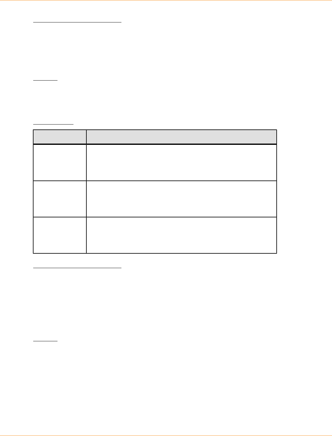
SANtricity_10.77 February 2011
LSI Corporation
- 1103 -
Minimum Firmware Level
6.10
Remove Volume Copy
This command removes a volume copy pair.
Syntax
remove volumeCopy target [targetName]
[source [sourceName]
copyType=(online | offline)]
Parameters
Parameter Description
target The name of the target volume that you want to remove. Enclose
the target volume name in square brackets ([ ]). If the target volume
name has special characters, you also must enclose the target
volume name in double quotation marks (" ").
source The name of the source volume that you want to remove. Enclose
the source volume name in square brackets ([ ]). If the source
volume name has special characters, you also must enclose the
source volume name in double quotation marks (" ").
copyType Use this parameter to identify that a volume copy has a snapshot.
If the volume copy has a snapshot, set this parameter to online.
If the volume copy does not have a snapshot, set this parameter to
offline.
Minimum Firmware Level
5.40
7.77 adds creating a volume copy with snapshot.
Remove Volume LUN Mapping
This command removes the logical unit number (LUN) mapping from one or more volumes.
Syntax
remove (allVolumes | volume [volumeName] |
volumes [volumeName1 ... volumeNameN] | accessVolume)
lunMapping (host="hostName" |
hostGroup=("hostGroupName" | defaultGroup))
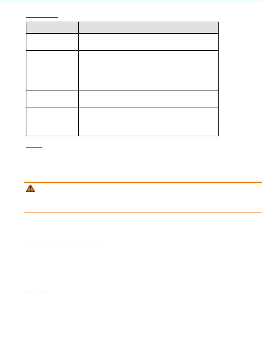
SANtricity_10.77 February 2011
LSI Corporation
- 1104 -
Parameters
Parameter Description
allVolumes This parameter removes the LUN mapping from all of the
volumes.
volume or volumes The name of the specific volume that you want to remove
from the LUN mapping. You can enter more than one volume
name. Enclose the volume name in double quotation marks
(" ") inside of square brackets ([ ]).
accessVolume This parameter removes the access volume.
host The name of the host to which the volume is mapped. Enclose
the host name in double quotation marks (" ").
hostGroup The name of the host group that contains the host to which
the volume is mapped. Enclose the host group name in double
quotation marks (" "). The defaultGroup value is the host
group that contains the host to which the volume is mapped.
Notes
The access volume is the volume in a SAN environment that is used for communication between the storage
management software and the storage array controller. The access volume uses a LUN address and
consumes 20 MB of storage space that is not available for application data storage. An access volume is
required only for in-band managed storage arrays.
ATTENTION Removing an access volume can damage your configuration – The agent uses
the access volumes to communicate with a storage array. If you remove an access volume mapping for a
storage array from a host that has an agent running on it, the storage management software is no longer able
to manage the storage array through the agent.
You must use the host parameter and the hostGroup parameter when you specify a non-access volume or
an access volume. The Script Engine ignores the host parameter or the hostGroup parameter when you
use the allVolumes parameter or the volumes parameter.
Minimum Firmware Level
6.10
Repair Volume Parity
This command repairs the parity errors on a volume.
Syntax
repair volume [volumeName] parity
parityErrorFile="filename"
[verbose=(TRUE | FALSE)]
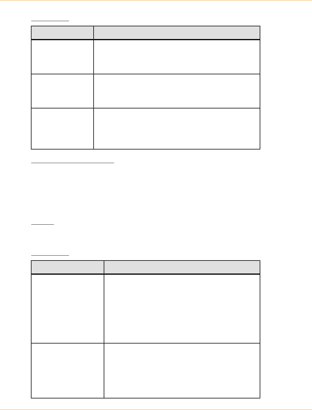
SANtricity_10.77 February 2011
LSI Corporation
- 1105 -
Parameters
Parameter Description
volume The name of the specific volume for which you want to repair
parity. Enclose the volume name in square brackets ([ ]). If the
volume name has special characters, you also must enclose
the volume name in double quotation marks (" ").
parityErrorFile The file path and the file name that contains the parity error
information that you use to repair the errors. Enclose the file
name in double quotation marks (" "). For example:
file="C:\Program Files\CLI\sup\parfile.txt"
verbose The setting to capture progress details, such as percent
complete, and to show the information as the volume parity is
being repaired. To capture progress details, set this parameter
to TRUE. To prevent capturing progress details, set this
parameter to FALSE.
Minimum Firmware Level
6.10
Replace Drive
This command redefines the composition of a volume group. You can use this command to replace a drive
with either an unassigned drive or a fully integrated hot spare.
Syntax
replace drive([trayID,drawerID,slotID] | <"wwID">)
replacementDrive=trayID,drawerID,slotID
Parameters
Parameter Description
drive The location of the drive that you want to reconstruct. For
high-capacity drive trays, specify the tray ID value, the
drawer ID value, and the slot ID value of the drive that
you want to revive. For low-capacity drive trays, specify
the tray ID value and the slot ID value of the drive that
you want to revive. Tray ID values are 0 to 99. Drawer ID
values are 1 to 5. Slot ID values are 1 to 32. Enclose the
tray ID value, the drawer ID value, and the slot ID value in
square brackets ([ ]).
replacementDrive The location of the drive that you want to use for a
replacement. For high-capacity drive trays, specify the tray
ID value, the drawer ID value, and the slot ID value for
the drive. For low-capacity drive trays, specify the tray ID
value and the slot ID value for the drive. Tray ID values
are 0 to 99. Drawer ID values are 1 to 5. Slot ID values
are 1 to 32.
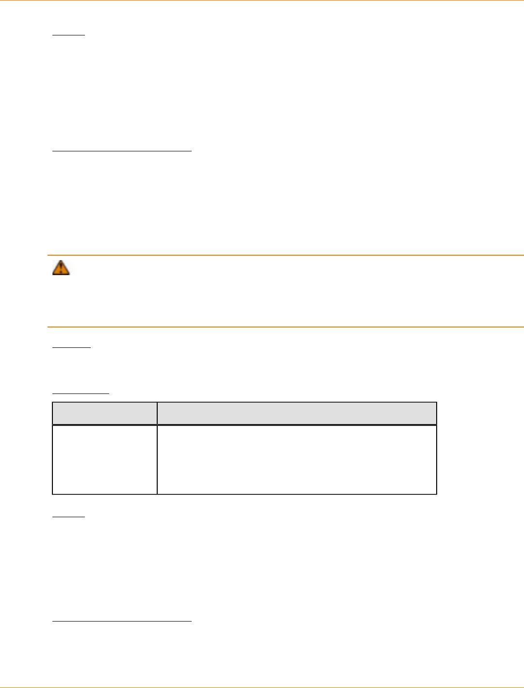
SANtricity_10.77 February 2011
LSI Corporation
- 1106 -
Notes
The drive parameter supports both high-capacity drive trays and low-capacity drive trays. A high-capacity
drive tray has drawers that hold the drives. The drawers slide out of the drive tray to provide access to the
drives. A low-capacity drive tray does not have drawers. For a high-capacity drive tray, you must specify
the identifier (ID) of the drive tray, the ID of the drawer, and the ID of the slot in which a drive resides. For a
low-capacity drive tray, you need only specify the ID of the drive tray and the ID of the slot in which a drive
resides. For a low-capacity drive tray, an alternative method for identifying a location for a drive is to specify
the ID of the drive tray, set the ID of the drawer to 0, and specify the ID of the slot in which a drive resides.
Minimum Firmware Level
7.10
7.60 adds the drawerID user input.
Reset Controller
This command resets a controller, and it is disruptive to I/O operations.
ATTENTION When you reset a controller, the controller is removed from the data path and is not
available for I/O operations until the reset operation is complete. If a host is using volumes that are owned by
the controller being reset, the I/O directed to the controller is rejected. Before resetting the controller, either
make sure that the volumes that are owned by the controller are not in use or make sure that a multi-path
driver is installed on all of the hosts that use these volumes.
Syntax
reset controller [(a | b)]
Parameter
Parameter Description
controller The controller that you want to reset. Valid controller identifiers
are a or b, where a is the controller in slot A, and b is the
controller in slot B. Enclose the controller identifier in square
brackets ([ ]). If you do not specify a controller owner, the
controller firmware returns a syntax error.
Notes
The controller that receives the reset controller command resets the controller specified. For example, if the
reset controller command is sent to controller A to request a reset of controller A, then controller A reboots
itself by doing a soft reboot. If the reset controller command is sent to controller A to request a reset of
controller B, then controller A holds controller B in reset and then releases controller B from reset, which is a
hard reboot. A soft reboot in some products only resets the IOC chip. A hard reboot resets both the IOC and
the expander chips in the controller.
Minimum Firmware Level
5.20
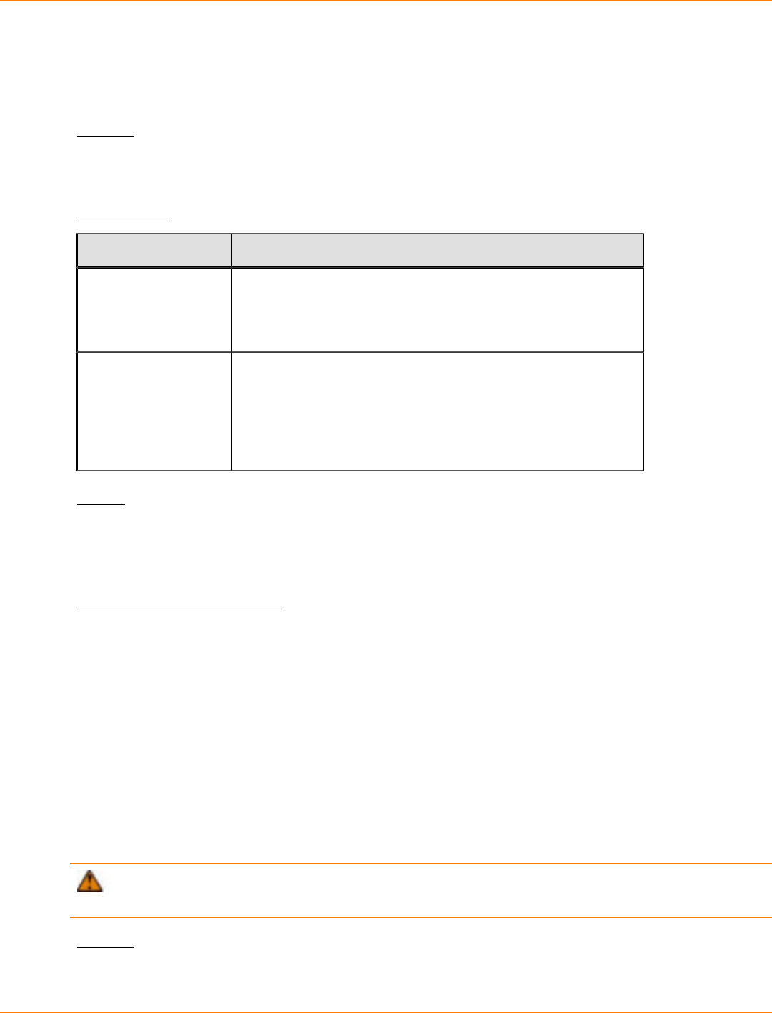
SANtricity_10.77 February 2011
LSI Corporation
- 1107 -
Reset Storage Array Battery Install Date
This command resets the age of the batteries in a storage array to zero days. You can reset the age of the
batteries for an entire storage array or the age of a battery in a specific controller or in a specific battery pack.
Syntax
reset storageArray batteryInstallDate
(controller=[(a | b)] | batteryPack [left | right])
Parameters
Parameter Description
controller The controller that contains the battery for which you want to
reset the age. Valid controller identifiers are a or b, where a is
the controller in slot A, and b is the controller in slot B. Use the
controller parameter only for controllers with batteries.
batteryPack The battery pack contains both a left battery and a right
battery. Valid identifiers are left or right, where left is
the battery that supports the controller in slot A, and right
is the battery that supports the controller in slot B. Use the
batteryPack parameter only for controller trays with battery
packs.
Notes
A controller might have a battery associated with it, so the controller is identified as either a or b. With the
release of the CE7900 controller tray, battery packs inside the interconnect-battery canister are identified as
either left or right. If the command statement uses the wrong parameter, an error appears.
Minimum Firmware Level
6.10
7.15 adds the ability to reset the battery installation dates on the left battery or the right battery in the CE6998-
series controllers or the CE7900-series controllers.
Reset Storage Array Diagnostic Data
This command resets the NVSRAM that contains the diagnostic data for the storage array. This command
does not delete the diagnostic data. This command replaces the Needs Attention status with the Diagnostic
Data Available status. The old diagnostic data is written over automatically when new data is captured. The
memory that contains the diagnostic data is also cleared when the controllers reboot. Before you reset the
diagnostic data, use the save storageArray diagnosticData command to save the diagnostic data to
a file.
ATTENTION Run this command only with the assistance of your Customer and Technical Support
representative.
Syntax
reset storageArray diagnosticData

SANtricity_10.77 February 2011
LSI Corporation
- 1108 -
Parameters
None.
Minimum Firmware Level
6.16
Reset Storage Array Infiniband Statistics Baseline
This command resets the Infiniband statistics baseline to 0 for the storage array.
Syntax
reset storageArray ibStatsBaseline
Parameters
None.
Notes
This command does not actually reset the raw counts maintained in the hardware and firmware. Instead,
the firmware creates a snapshot of the current counter values and uses these values to report differences
in the counts when the statistics are retrieved. The new baseline time is applied to both controllers so that
the controller counts are synchronized with each other. If one controller resets without the other controller
resetting, the counters are no longer synchronized. The client becomes aware that the controllers are
not synchronized because the timestamp data reported along with the statistics is not the same for both
controllers.
Minimum Firmware Level
7.10
Reset Storage Array iSCSI Baseline
This command resets the iSCSI baseline to 0 for the storage array.
Syntax
reset storageArray iscsiStatsBaseline
Parameters
None.
Notes
This command resets the baseline to 0 for both controllers in the storage array. The purpose of resetting
both of the controller baselines is to help make sure that the controller counts are synchronized between
the controllers. If one controller resets but the second controller does not reset, the host is informed that the
controllers are out of synchronization. The host is informed by the time stamps that are reported with the
statistics.

SANtricity_10.77 February 2011
LSI Corporation
- 1109 -
Minimum Firmware Level
7.10
Reset Storage Array RLS Baseline
This command resets the read link status (RLS) baseline for all devices by setting all of the RLS counts to 0.
Syntax
reset storageArray RLSBaseline
Parameters
None.
Minimum Firmware Level
5.00
Reset Storage Array SAS PHY Baseline
This command resets the SAS physical layer (SAS PHY) baseline for all devices execpt the drives,
and removes the list of errors from the .csv file. The .csv file is generated when you run the save
storageArray SASPHYCounts command.
NOTE The reset storageArray SASPHYBaseline command clears error counts for all devices
except the drives. After you run this command, the .csv file will continue to list the DrivePHY errors. All
other errors are deleted from the .csv file.
Syntax
reset storageArray SASPHYBaseline
Parameters
None.
Minimum Firmware Level
6.10
Reset Storage Array SOC Baseline
This command resets the baseline for all switch-on-a-chip (SOC) devices that are accessed through the
controllers. This command resets the baseline by setting all of the SOC counts to 0. This command is valid
only for Fibre Channel devices in an arbitrated loop topology.
Syntax
reset storageArray SOCBaseline
Parameters
None.
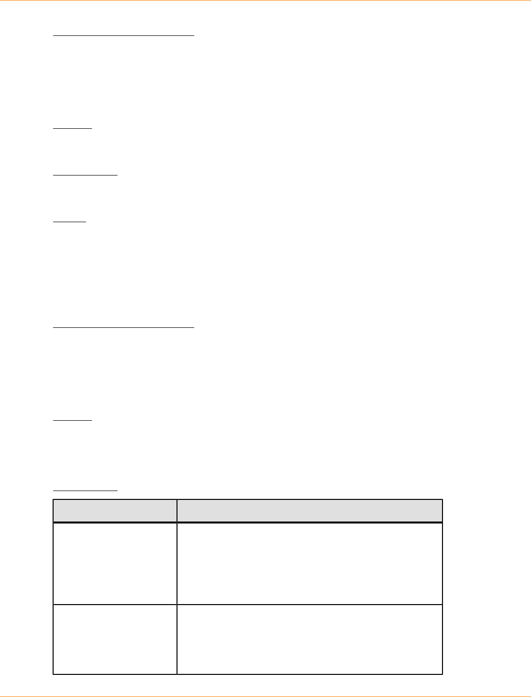
SANtricity_10.77 February 2011
LSI Corporation
- 1110 -
Minimum Firmware Level
6.16
Reset Storage Array Volume Distribution
This command reassigns (moves) all of the volumes to their preferred controller.
Syntax
reset storageArray volumeDistribution
Parameters
None.
Notes
If you use this command on a host without a multi-path driver, you must stop I/O operations to the volumes
until this command has completed to prevent application errors.
Under certain host operating system environments, you might be required to reconfigure the multi-path host
driver. You might also need to make operating system modifications to recognize the new I/O path to the
volumes.
Minimum Firmware Level
5.20
Resume Remote Mirror
This command resumes a suspended Remote Volume Mirroring operation.
Syntax
resume remoteMirror (primary [volumeName] |
primaries [volumeName1 ... volumeNameN])
[writeConsistency=(TRUE | FALSE)}
Parameters
Parameter Description
primary or primaries The name of the primary volume for which you want to
resume operation. You can enter more than one primary
volume name. Enclose the primary volume name in
square brackets ([ ]). If the primary volume name has
special characters, you also must enclose the primary
volume name in double quotation marks (" ").
writeConsistency The setting to identify the volumes in this command that
are in a write-consistency group or are separate. For the
volumes to be in the same write-consistency group, set
this parameter to TRUE. For the volumes to be separate,
set this parameter to FALSE.
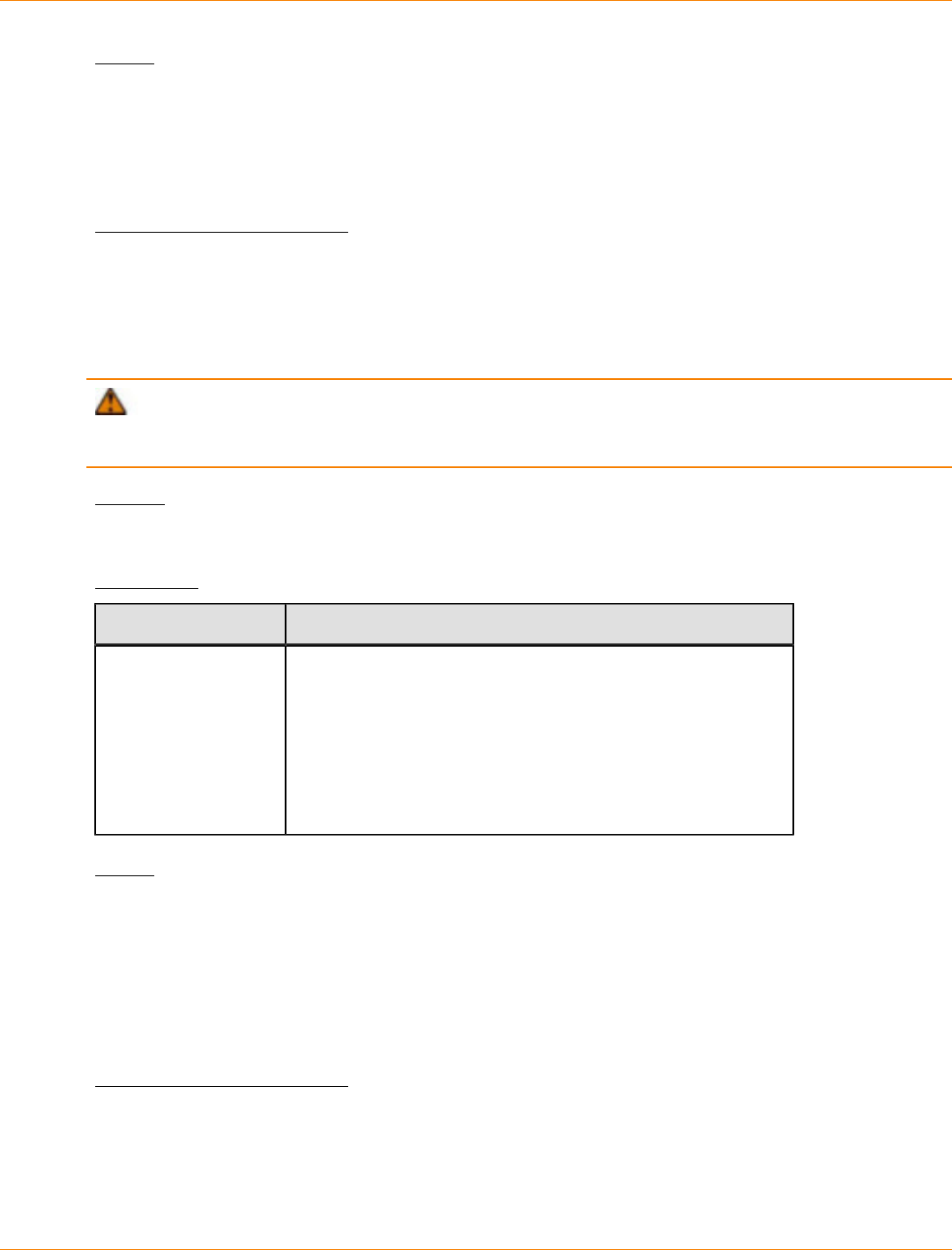
SANtricity_10.77 February 2011
LSI Corporation
- 1111 -
Notes
If you set the writeConsistency parameter to TRUE, the volumes must be in a write-consistency group
(or groups). This command resumes all write-consistency groups that contain the volumes. For example, if
volumes A, B, and C are in a write-consistency group and they have remote counterparts A’, B’, and C’, the
resume remoteMirror volume ["A"] writeConsistency=TRUE command resumes A-A’, B-B’, and
C-C’.
Minimum Firmware Level
6.10
Revive Drive
This command forces the specified drive to the Optimal state.
ATTENTION Possible loss of data access – Correct use of this command depends on the data
configuration on all of the drives in the volume group. Never try to revive a drive unless you are supervised by
your Customer and Technical Support representative.
Syntax
revive drive [trayID,drawerID,slotID]
Parameter
Parameter Description
drive The location of the drive that you want to revive. For high-
capacity drive trays, specify the tray ID value, the drawer
ID value, and the slot ID value of the drive that you want to
revive. For low-capacity drive trays, specify the tray ID value
and the slot ID value of the drive that you want to revive. Tray
ID values are 0 to 99. Drawer ID values are 1 to 5. Slot ID
values are 1 to 32. Enclose the tray ID value, drawer ID value,
and the slot ID value in square brackets ([ ]).
Notes
The drive parameter supports both high-capacity drive trays and low-capacity drive trays. A high-capacity
drive tray has drawers that hold the drives. The drawers slide out of the drive tray to provide access to the
drives. A low-capacity drive tray does not have drawers. For a high-capacity drive tray, you must specify
the identifier (ID) of the drive tray, the ID of the drawer, and the ID of the slot in which a drive resides. For a
low-capacity drive tray, you need only specify the ID of the drive tray and the ID of the slot in which a drive
resides. For a low-capacity drive tray, an alternative method for identifying a location for a drive is to specify
the ID of the drive tray, set the ID of the drawer to 0, and specify the ID of the slot in which a drive resides.
Minimum Firmware Level
5.43
7.60 adds the drawerID user input.
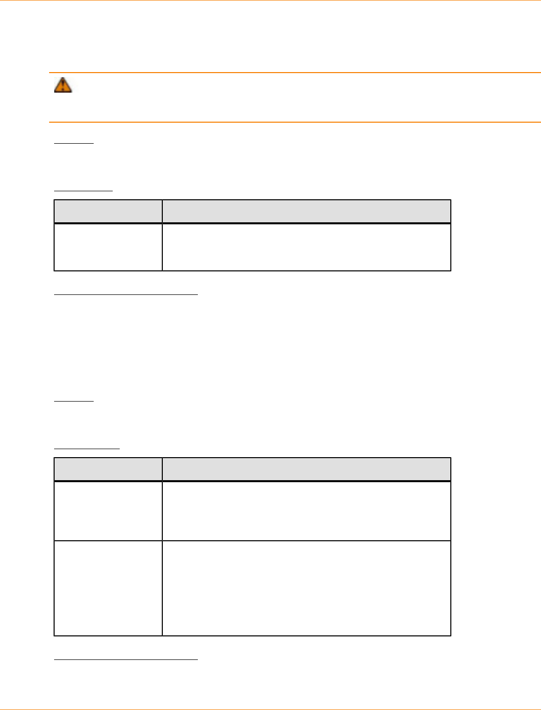
SANtricity_10.77 February 2011
LSI Corporation
- 1112 -
Revive Volume Group
This command forces the specified volume group and its associated failed drives to the Optimal state.
ATTENTION Possible loss of data access – Correct use of this command depends on the data
configuration on all of the drives in the volume group. Never try to revive a drive unless you are supervised by
your Customer and Technical Support representative.
Syntax
revive volumeGroup [volumeGroupName]
Parameter
Parameter Description
volumeGroup The alphanumeric identifier (including - and _) of the volume
group to be set to the Optimal state. Enclose the volume
group identifier in square brackets ([ ]).
Minimum Firmware Level
6.10
Save Controller NVSRAM
This command saves a copy of the controller NVSRAM values to a file. This command saves all of the
regions.
Syntax
save controller [(a | b)] NVSRAM file="filename"
Parameters
Parameter Description
controller The controller with the NVSRAM values that you want to
save. Valid controller identifiers are a or b, where a is the
controller in slot A, and b is the controller in slot B. Enclose
the controller identifier in square brackets ([ ]).
file The file path and the file name to which you want to save the
NVSRAM values. Enclose the NVSRAM file name in double
quotation marks (" "). For example:
file="C:\Program Files\CLI\logs\nvsramb.txt"
This command does not automatically append a file extension
to the saved file. You must specify a file extension when
entering the file name.
Minimum Firmware Level
6.10
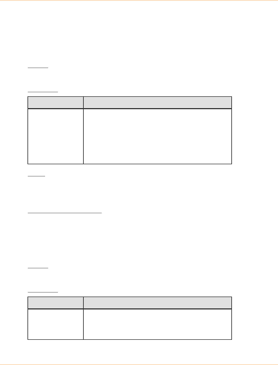
SANtricity_10.77 February 2011
LSI Corporation
- 1113 -
Save Drive Channel Fault Isolation Diagnostic Status
This command saves the drive channel fault isolation diagnostic data that is returned from the start
driveChannel faultDiagnostics command. You can save the diagnostic data to a file as standard text
or as XML.
See "Start Drive Channel Fault Isolation Diagnostics" for more information.
Syntax
save driveChannel faultDiagnostics file="filename"
Parameter
Parameter Description
file The file path and the file name to which you want to save
the results of the fault isolation diagnostics test on the drive
channel. Enclose the file name in double quotation marks (" ").
For example:
file="C:\Program Files\CLI\sup\fltdiag.bin"
This command does not automatically append a file extension
to the saved file. You must specify a file extension when
entering the file name.
Notes
A file extension is not automatically appended to the saved file. You must specify the applicable format file
extension for the file. If you specify a file extension of .txt, the output will be in a text file format. If you
specify a file extension of .xml, the output will be in an XML file format.
Minimum Firmware Level
7.15 introduces this new capability for the CE7900 controller tray.
Save Drive Log
This command saves the log sense data to a file. Log sense data is maintained by the storage array for each
drive.
Syntax
save allDrives logFile="filename"
Parameter
Parameter Description
logFile The file path and the file name to which you want to save the
log sense data. Enclose the file name in double quotation
marks (" "). For example:
file="C:\Program Files\CLI\logs\lgsendat.txt"

SANtricity_10.77 February 2011
LSI Corporation
- 1114 -
Parameter Description
This command does not automatically append a file extension
to the saved file. You must specify a file extension when
entering the file name.
Minimum Firmware Level
6.10
Save Storage Array Configuration
This command creates a script file that you can use to re-create the current storage array volume
configuration.
Syntax
save storageArray configuration file="filename"
[(allconfig | globalSettings=(TRUE | FALSE)
volumeConfigAndSettings=(TRUE | FALSE)
hostTopology=(TRUE | FALSE)
lunMappings=(TRUE | FALSE))]
Parameters
Parameter Description
file The file path and the file name to which you want
to save the configuration settings. Enclose the
file name in double quotation marks (" "). For
example:
file="C:\Program Files\CLI\logs
\saconf.cfg"
This command does not automatically append a
file extension to the saved file. You must specify a
file extension when entering the file name.
allConfig The setting to save all of the configuration values
to the file. (If you choose this parameter, all of the
configuration parameters are set to TRUE.)
globalSettings The setting to save the global settings to the file.
To save the global settings, set this parameter
to TRUE. To prevent saving the global settings,
set this parameter to FALSE. The default value is
TRUE.
volumeConfigAndSettings The setting to save the volume configuration
settings and all of the global settings to the file.
To save the volume configuration settings and
global settings, set this parameter to TRUE. To
prevent saving the volume configuration settings
and global settings, set this parameter to FALSE.
The default value is TRUE.
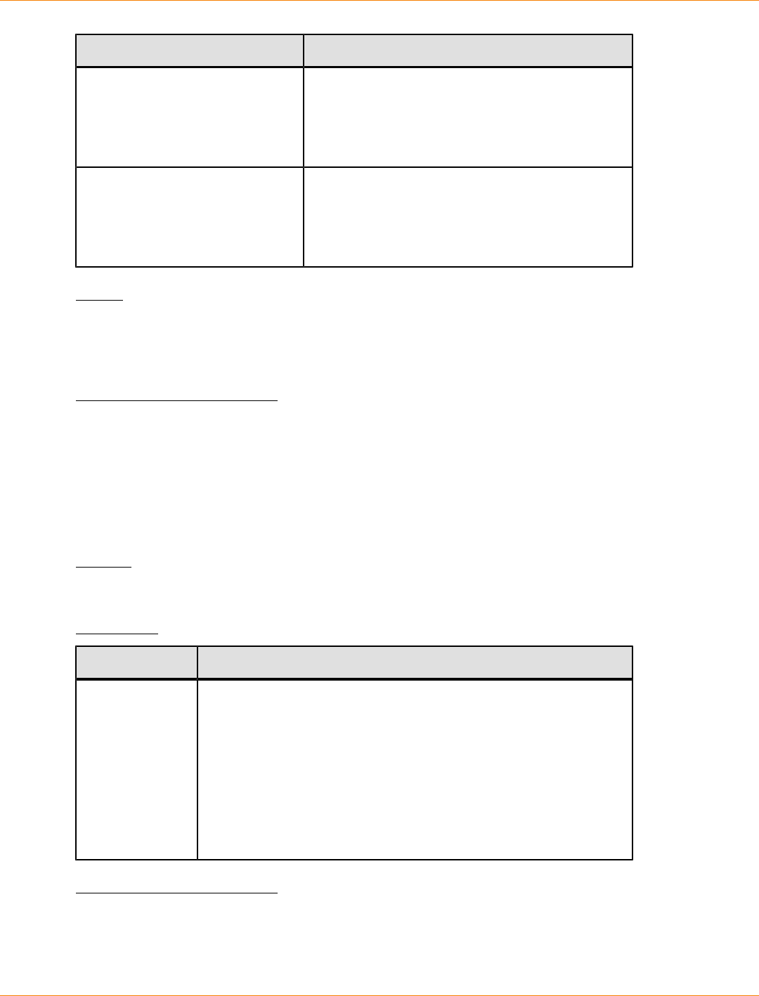
SANtricity_10.77 February 2011
LSI Corporation
- 1115 -
Parameter Description
hostTopology The setting to save the host topology to the file.
To save the host topology, set this parameter to
TRUE. To prevent saving the host topology, set
this parameter to FALSE. The default value is
FALSE.
lunMappings The setting to save the LUN mapping to the file.
To save the LUN mapping, set this parameter
to TRUE. To prevent saving the LUN mapping,
set this parameter to FALSE. The default value is
FALSE.
Notes
When you use this command, you can specify any combination of the parameters for the global setting, the
volume configuration setting, the host topology, or the LUN mapping. If you want to enter all settings, use the
allConfig parameter. The parameters are all optional.
Minimum Firmware Level
6.10
Save Storage Array DBM Database
This command saves the current state of the storage array's Database Management (DBM) database into
a local file. The output file that is produced can be used as the input file for the save storageArray
dbmValidator and the load storageArray dbmDatabase commands.
Syntax
save storageArray dbmDatabase file="filename"
Parameter
Parameter Description
file The file path and the file name of the DBM database you want to
save. Enclose the file name in double quotation marks (" "). For
example:
file="C:\Array Backups
\DBMbackup_03302010.dbm"
This command does not automatically append a file extension to
the saved file. You must specify a file extension when entering the
file name.
Minimum Firmware Level
7.75
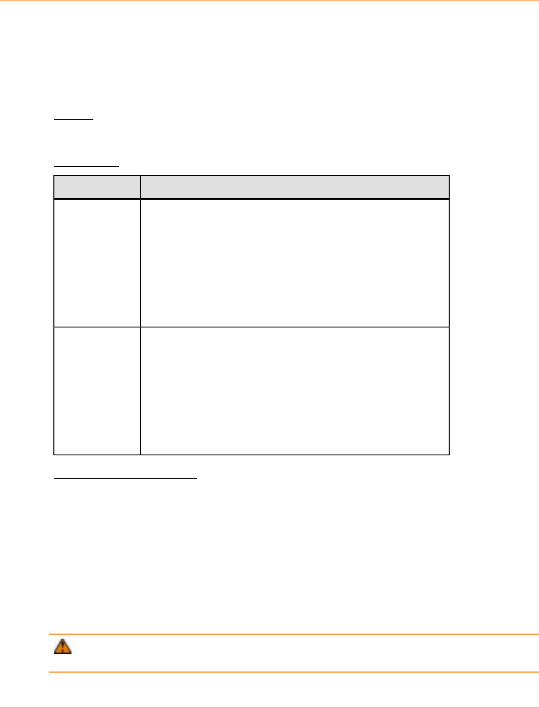
SANtricity_10.77 February 2011
LSI Corporation
- 1116 -
Save Storage Array DBM Validator
This command saves a storage array's Database Management (DBM) validation information in an XML
file, which can be used by a Customer and Technical Support representative to generate a security code
or Validator. The Validator must be included in the load storageArray dbmDatabase command when
restoring a storage array back to a pre-existing configuration.
Syntax
save storageArray dbmValidatorInfo file="filename" dbmDatabase="filename"
Parameters
Parameter Description
file The file path and the file name of the DBM Validator required for
Customer and Technical Support. Enclose the file name in double
quotation marks (" "). For example:
file="C:\Array Backups
\DBMvalidator.xml"
This command does not automatically append a file extension to
the saved file. You must specify a file extension when entering the
file name.
dbmDatabase The file path and the file name of the DBM database you want to
use to restore a storage array. Enclose the file name in double
quotation marks (" "). For example:
dbmDatabase="C:\Array Backups
\DBMbackup_03302010.dbm"
This command does not automatically append a file extension to
the saved file. You must specify a file extension when entering the
file name.
Minimum Firmware Level
7.75
Save Storage Array Diagnostic Data
This command saves the storage array diagnostic data from either the controllers or the environmental
services monitors (ESMs) to a file. You can review the file contents at a later time. You can also send the file
to your Customer and Technical Support representative for further review.
After you have saved the diagnostic data, you can reset the NVSRAM registers that contain the diagnostic
data so that the old data can be overwritten. Use the reset storageArray diagnosticData command
to reset the diagnostic data registers.
ATTENTION Run this command only with the assistance of your Customer and Technical Support
representative.
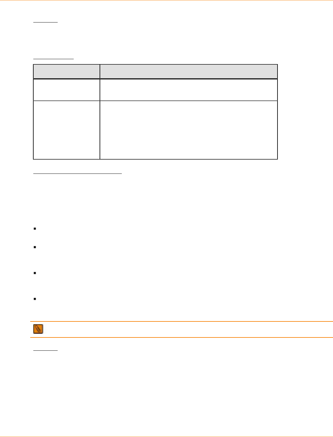
SANtricity_10.77 February 2011
LSI Corporation
- 1117 -
Syntax
save storageArray diagnosticData [(controller | esm)]
file="filename"
Parameters
Parameter Description
diagnosticData This parameter allows you to downloads the diagnostic data
from either the controllers or the ESMs.
file The file path and the file name to which you want to save the
storage array diagnostic data. Enclose the file name in double
quotation marks (" "). For example:
file="C:\Program Files\CLI\logs\sadiag.txt"
This command does not automatically append a file extension
to the saved file. You must specify a file extension when
entering the file name.
Minimum Firmware Level
6.16
Save Storage Array Events
This command saves events from the Major Event Log to a file. You can save these events:
Critical events – An error occurred on the storage array that needs to be addressed immediately. Loss of
data access might occur if you do not immediately correct the error.
Warning events – An error occurred on the storage array that results in degraded performance or
reduced ability to recover from another error. Access to data has not been lost, but you must correct the
error to prevent possible loss of data access if another error would occur.
Informational events – An event occurred on the storage array that does not impact normal operations.
The event is reporting a change in configuration or other information that might be useful in evaluating
how well the storage array is performing.
Debug events – An event occurred on the storage array that provides information that you can use to
help determine the steps or states that led to an error. You can send a file with this information to your
Customer and Technical Support representative to help determine the cause of an error.
NOTE Some storage arrays might not be able to support all four types of events.
Syntax
save storageArray (allEvents | criticalEvents |
warningEvents | infoEvents | debugEvents)
file="filename"
[count=numberOfEvents
forceSave=(TRUE | FALSE)]

SANtricity_10.77 February 2011
LSI Corporation
- 1118 -
Parameters
Parameter Description
allEvents The parameter to save all of the events to a file.
criticalEvents The parameter to save only the critical events to a file.
warningEvents The parameter to save only the warning events to a file.
infoEvents The parameter to save only the informational events to a file.
debugEvents The parameter to save only the debut events to a file.
file The file path and the file name to which you want to save the
events. Enclose the file name in double quotation marks (" "). For
example:
file="C:\Program Files\CLI\logs\events.txt"
This command does not automatically append a file extension to
the saved file. You must specify a file extension when entering
the file name.
count The number of events or critical events that you want to save to
a file. If you do not enter a value for the count, all events or all
critical events are saved to the file. If you enter a value for the
count, only that number of events or critical events (starting with
the last event entered) are saved to the file. Use integer values.
forceSave The parameter to force saving the critical events to a file. To force
saving the events, set this parameter to TRUE. The default value
is FALSE.
Notes
You have the option to save all events (allEvents) or only the critical events (criticalEvents).
Minimum Firmware Level
6.10
7.77 add these parameters:
warningEvents
infoEvents
debugEvents
forceSave
Save Storage Array Firmware Inventory
This command saves a report to a file of all of the firmware currently running on the storage array. The report
lists the firmware for these components:
Controllers
Drives
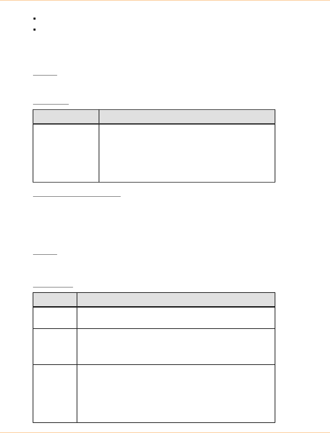
SANtricity_10.77 February 2011
LSI Corporation
- 1119 -
Drawers (if applicable)
Environmental services monitors (ESMs)
You can use the information to help identify out-of-date firmware or firmware that does not match the other
firmware in your storage array. You can also send the report to your Customer and Technical Support
representative for further review.
Syntax
save storageArray firmwareInventory file="filename"
Parameter
Parameter Description
file The file path and the file name to which you want to save the
firmware inventory. Enclose the file name in double quotation
marks (" "). For example:
file="C:\Program Files\CLI\logs\fwinvent.txt"
This command does not automatically append a file extension
to the saved file. You must specify a file extension when
entering the file name.
Minimum Firmware Level
7.70
Save Storage Array InfiniBand Statistics
This command saves the InfiniBand performance statistics of the storage array to a file.
Syntax
save storageArray ibStats [raw | baseline]
file="filename"
Parameters
Parameter Description
raw The statistics that are collected are all statistics from the controller
start-of-day. Enclose the parameter in square brackets ([ ]).
baseline The statistics that are collected are all statistics from the time the
controllers were reset to zero using the reset storageArray
ibStatsBaseline command. Enclose the parameter in square
brackets ([ ]).
file The file path and the file name to which you want to save the
performance statistics. Enclose the file name in double quotation
marks (" "). For example:
file="C:\Program Files\CLI\sup\ibstat.txt"
This command does not automatically append a file extension to the
saved file. You must specify a file extension when entering the file
name.
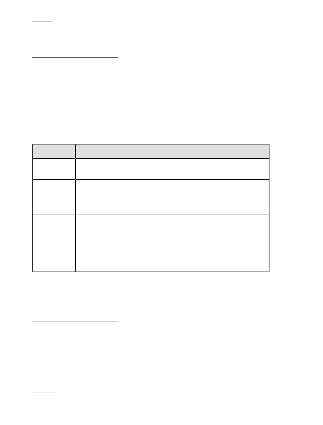
SANtricity_10.77 February 2011
LSI Corporation
- 1120 -
Notes
If you have not reset the InfiniBand baseline statistics since the controller start-of-day, the time at the start-of-
day is the default baseline time.
Minimum Firmware Level
7.32
Save Storage Array iSCSI Statistics
This command saves the iSCSI performance of the storage array to a file.
Syntax
save storageArray iscsiStatistics [raw | baseline] file="filename"
Parameters
Parameter Description
raw The statistics collected are all statistics from the controller start-of-day.
Enclose the parameter in square brackets ([ ]).
baseline The statistics that are collected are all statistics from the time the
controllers were reset to zero using the reset storageArray
ibStatsBaseline command. Enclose the parameter in square
brackets ([ ]).
file The file path and the file name to which you want to save the
performance statistics. Enclose the file name in double quotation
marks (" "). For example:
file="C:\Program Files\CLI\logs\iscsistat.csv"
This command does not automatically append a file extension to the
saved file. You can use any file name but you must use the .csv
extension.
Notes
If you have not reset the iSCSI baseline statistics since the controller start-of-day, the time at the start-of-day
is the default baseline time.
Minimum Firmware Level
7.10
Save Storage Array Performance Statistics
This command saves the performance statistics to a file. Before you use this command, run
the set session performanceMonitorInterval command and the set session
performanceMonitorIterations command to specify how often statistics are collected.
Syntax
save storageArray performanceStats file="filename"
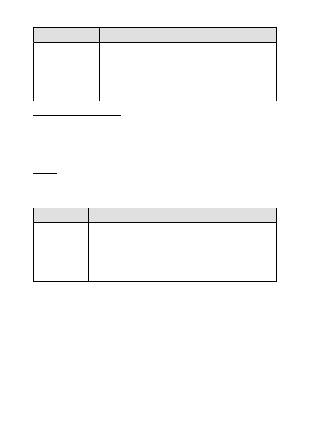
SANtricity_10.77 February 2011
LSI Corporation
- 1121 -
Parameter
Parameter Description
file The file path and the file name to which you want to save
the performance statistics. Enclose the file name in double
quotation marks (" "). For example:
file="C:\Program Files\CLI\logs\sastat.csv"
This command does not automatically append a file extension
to the saved file. You can use any file name, but you must use
the .csv extension.
Minimum Firmware Level
6.10
Save Storage Array RLS Counts
This command saves the read link status (RLS) counters to a file.
Syntax
save storageArray RLSCounts file="filename"
Parameter
Parameter Description
file The file path and the file name to which you want to save the RLS
counters. Enclose the file name in double quotation marks (" ").
For example:
file="C:\Program Files\CLI\logs\rlscnt.csv"
The default name of the file that contains the RLS counts is
readLinkStatus.csv. You can use any file name, but you must
use the .csv extension.
Notes
To more effectively save RLS counters to a file, perform these steps:
1. Run the reset storageArray RLSBaseline command to set all of the RLS counters to 0.
2. Run the storage array for a predetermined amount of time (for instance, two hours).
3. Run the save storageArray RLSCounts file="filename" command.
Minimum Firmware Level
6.10
Save Storage Array SAS PHY Counts
This command saves the SAS physical layer (SAS PHY) counters to a file. To reset the SAS PHY counters,
run the reset storageArray SASPHYBaseline command.
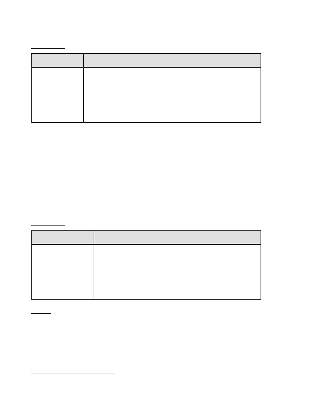
SANtricity_10.77 February 2011
LSI Corporation
- 1122 -
Syntax
save storageArray SASPHYCounts file="filename"
Parameter
Parameter Description
file The file path and the file name to which you want to save the SYS
PHY counters. Enclose the file path and the file name in double
quotation marks (" "). For example:
file="C:\Program Files\CLI\logs\sasphy.csv"
This command does not automatically append a file extension to
the saved file. You can use any file name but you must use the
.csv extension.
Minimum Firmware Level
6.10
Save Storage Array SOC Counts
This command saves the SOC error statistics to a file. This command is valid only for Fibre Channel devices
in an arbitrated loop topology.
Syntax
save storageArray SOCCounts file="filename"
Parameter
Parameter Description
file The file path and the file name to which you want to save the
SOC error statistics. Enclose the file name in double quotation
marks (" "). For example:
file="C:\Program Files\CLI\logs\socstat.csv"
The default name of the file that contains the SOC error
statistics is socStatistics.csv. You can use any file name
but you must use the .csv extension.
Notes
To more effectively save SOC error statistics to a file, perform these steps:
1. Run the reset storageArray SOCBaseline command to set all of the SOC counters to 0.
2. Run the storage array for a predetermined amount of time (for example, two hours).
3. Run the save storageArray SOCCounts file="filename" command.
Minimum Firmware Level
6.16
SANtricity_10.77 February 2011
LSI Corporation
- 1123 -
Save Storage Array State Capture
This command saves the state capture of a storage array to a file.
Syntax
save storageArray stateCapture file="filename"
Parameter
Parameter Description
file The file path and the file name to which you want to save the
state capture. Enclose the file name in double quotation marks
(" "). For example:
file="C:\Program Files\CLI\logs\state.zip"
This command does not automatically append a file extension
to the saved file. You must specify a file extension when
entering the file name.
Minimum Firmware Level
6.10
Save Storage Array Support Data
This command saves the support-related information of the storage array to a file. Support-related information
includes these items:
The storage array profile
The Major Event Log information
The read link status (RLS) data
The NVSRAM data
Current problems and associated recovery information
The performance statistics for the entire storage array
The persistent registration information and the persistent reservation information
Detailed information about the current status of the storage array
The diagnostic data for the drive
A recovery profile for the storage array
The unreadable sectors that are detected on the storage array
The state capture data
An inventory of the versions of the firmware running on the controllers, the drives, the drawers, and the
environmental services monitors (ESMs)
Syntax
save storageArray supportData file="filename"
SANtricity_10.77 February 2011
LSI Corporation
- 1124 -
Parameter
Parameter Description
file The file path and the file name to which you want to save the support-
related data for the storage array. Enclose the file path and the file
name in double quotation marks (" "). For example:
file="C:\Program Files\CLI\logs\supdat.zip"
This command does not automatically append a file extension to the
saved file. You must specify a file extension when entering the file
name.
Minimum Firmware Level
6.10
Save Tray Log
This command saves the log sense data to a file. Log sense data is maintained by the environmental cards
for each tray. Not all of the environmental cards contain log sense data.
Syntax
save allTrays logFile="filename"
Parameter
Parameter Description
logFile The file path and the file name to which you want to save the
log sense data. Enclose the file name in double quotation
marks (" "). For example:
file="C:\Program Files\CLI\logs
\traylogdat.txt"
This command does not automatically append a file extension
to the saved file. You must specify a file extension when
entering the file name.
Minimum Firmware Level
6.50
Set Controller
This command defines the attributes for the controllers.
Syntax
set controller [(a | b)]
availability=(online | offline | serviceMode) |
ethernetPort [(1 | 2)] ethernetPortOptions |
globalNVSRAMByte [nvsramOffset]=(nvsramByteSetting | nvsramBitSetting) |
hostNVSRAMByte [hostType, nvsramOffset]=(nvsramByteSetting | nvsramBitSetting) |
IPv4GatewayIP=ipAddress |
IPv6RouterAddress=ipv6Address |

SANtricity_10.77 February 2011
LSI Corporation
- 1125 -
iscsiHostPort [(1 | 2 | 3 | 4)] iscsiHostPortOptions
rloginEnabled=(TRUE | FALSE) |
serviceAllowedIndicator=(on | off)
Parameters
Parameter Description
controller The controller for which you want to define properties.
Valid identifiers for the controller are a or b, where a
is the controller in slot A, and b is the controller in slot
B. Enclose the identifier for the controller in square
brackets ([ ]). If you do not specify a controller, the
firmware for the controller returns a syntax error.
availability The mode for the controller, which you can set to
online, offline, or serviceMode (service).
ethernetPort The attributes (options) for the management Ethernet
ports. The entries to support this parameter are listed in
the Syntax Element Statement Data table that follows.
Many settings are possible, including setting the IP
address, the gateway address, and the subnet mask
address.
globalNVSRAMByte A portion of the controller NVSRAM. Specify the region
to be modified using the starting byte offset within the
region and the byte value or bit value of the new data to
be stored into the NVSRAM.
hostNVSRAMByte The NVSRAM for the host-specific region. The setting
specifies the host index for the specific host, the starting
offset within the region, the number of bytes, and the the
byte value or bit value of the new data to be stored into
the NVSRAM.
IPv4GatewayIP The IP address of the node that provides the interface to
the network. The address format for the IPv4 gateway is
(0–255).(0–255).(0–255).(0–255)
IPv6RouterAddress The IP address of IPv6 router that connects two or more
logical subnets. The address format for the IPv6 router
is (0–FFFF):(0–FFFF):(0–FFFF):(0–FFFF): (0–
FFFF):(0–FFFF):(0–FFFF):(0–FFFF).
iscsiHostPort The values that support this parameter are listed in the
Syntax Element Statement Data table that follows. Many
settings are possible, including setting the IP address,
the gateway address, the subnet mask address, the IPv4
priority, and the IPv6 priority.
rloginEnabled The setting for whether the remote login feature is turned
on or turned off. To turn on the remote login feature,
set this parameter to TRUE. To turn off the remote login
feature, set this parameter to FALSE.
SANtricity_10.77 February 2011
LSI Corporation
- 1126 -
Parameter Description
serviceAllowedIndicator The setting for whether the Service Action Allowed
indicator light is turned on or turned off. To turn on the
Service Action Allowed indicator light, set this parameter
to on. To turn off the Service Action Allowed indicator
light, set this parameter to off.
Syntax Element Statement Data
Options for the ethernetPort Parameter
enableIPv4=(TRUE | FALSE) |
enableIPv6=(TRUE | FALSE) |
IPv6LocalAddress=(0-FFFF):(0-FFFF):(0-FFFF):(0-FFFF):
(0-FFFF):(0-FFFF):(0-FFFF):(0-FFFF) |
IPv6RoutableAddress=(0-FFFF):(0-FFFF):(0-FFFF):(0-FFFF):
(0-FFFF):(0-FFFF):(0-FFFF):(0-FFFF) |
IPv4Address=(0-255).(0-255).(0-255).(0-255) |
IPv4ConfigurationMethod=[(static | dhcp)] |
IPv4SubnetMask=(0-255).(0-255).(0-255).(0-255) |
duplexMode=(TRUE | FALSE) |
portSpeed=(autoNegotiate | 10 | 100 | 1000)
Options for the iscsiHostPort Parameter
IPv4Address=(0-255).(0-255).(0-255).(0-255) |
IPv6LocalAddress=(0-FFFF):(0-FFFF):(0-FFFF):(0-FFFF):
(0-FFFF):(0-FFFF):(0-FFFF):(0-FFFF) |
IPv6RoutableAddress=(0-FFFF):(0-FFFF):(0-FFFF):(0-FFFF):
(0-FFFF):(0-FFFF):(0-FFFF):(0-FFFF) |
IPv6RouterAddress=(0-FFFF):(0-FFFF):(0-FFFF):(0-FFFF):
(0-FFFF):(0-FFFF):(0-FFFF):(0-FFFF) |
enableIPv4=(TRUE | FALSE) |
enableIPv6=(TRUE | FALSE) |
enableIPv4Vlan=(TRUE | FALSE) |
enableIPv6Vlan=(TRUE | FALSE) |
SANtricity_10.77 February 2011
LSI Corporation
- 1127 -
Options for the iscsiHostPort Parameter
enableIPv4Priority=(TRUE | FALSE) |
enableIPv6Priority=(TRUE | FALSE) |
IPv4ConfigurationMethod=(static | dhcp) |
IPv6ConfigurationMethod=(static | auto) |
IPv4GatewayIP=(TRUE | FALSE) |
IPv6HopLimit=[0-255] |
IPv6NdDetectDuplicateAddress=[0-256] |
IPv6NdReachableTime=[0-65535] |
IPv6NdRetransmitTime=[0-65535] |
IPv6NdTimeOut=[0-65535] |
IPv4Priority=[0-7] |
IPv6Priority=[0-7] |
IPv4SubnetMask=(0-255).(0-255).(0-255).(0-255) |
IPv4VlanId=[1-4094] |
IPv6VlanId=[1-4094] |
maxFramePayload=[frameSize] |
tcpListeningPort=[3260, 49152-65536] |
portSpeed=(autoNegotiate | 1 | 10)
Notes
NOTE Before firmware version 7.75, the set controller command supported an NVSRAMByte
parameter. The NVSRAMByte parameter is deprecated and must be replaced with either the
hostNVSRAMByte parameter or the globalNVSRAMByte parameter.
When you use this command, you can specify one or more of the parameters. You do not need to use all of
the parameters.
Setting the availability parameter to serviceMode causes the alternate controller to take ownership of
all of the volumes. The specified controller no longer has any volumes and refuses to take ownership of any
more volumes. Service mode is persistent across reset cycles and power cycles until the availability
parameter is set to online.

SANtricity_10.77 February 2011
LSI Corporation
- 1128 -
Use the show controller NVSRAM command to show the NVSRAM information. Before making any
changes to the NVSRAM, contact your Customer and Technical Support representative to learn what regions
of the NVSRAM you can modify.
When the duplexMode option is set to TRUE, the selected Ethernet port is set to full duplex. The default
value is half duplex (the duplexMode parameter is set to FALSE).
To make sure that the IPv4 settings or the IPv6 settings are applied, you must set these iscsiHostPort
options:
enableIPV4= TRUE
enableIPV6= TRUE
The IPv6 address space is 128 bits. It is represented by eight 16-bit hexadecimal blocks separated by colons.
The maxFramePayload option is shared between IPv4 and IPv6. The payload portion of a standard Ethernet
frame is set to 1500, and a jumbo Ethernet frame is set to 9000. When using jumbo frames, all of the devices
that are in the network path should be capable of handling the larger frame size.
The portSpeed option is expressed as megabits per second (Mb/s).
Values for the portSpeed option of the iscsiHostPort parameter are in megabits per second (Mb/s).
The following values are the default values for the iscsiHostOptions:
The IPv6HopLimit option is 64.
The IPv6NdReachableTime option is 30000 milliseconds.
The IPv6NdRetransmitTime option is 1000 milliseconds.
The IPv6NdTimeOut option is 30000 milliseconds.
The tcpListeningPort option is 3260.
Minimum Firmware Level
7.15 removed the bootp parameter, and added the new Ethernet port options and the new iSCSI host port
options.
7.50 moved the IPV4Gateway parameter and the IPV6RouterAddress parameter from the iSCSI host port
options to the command.
7.60 adds the portSpeed option of the iscsiHostPort parameter.
7.75 deprecates the NVSRAMByte parameter.
Set Controller Service Action Allowed Indicator
This command turns on or turns off the Service Action Allowed indicator light on a controller in a controller
tray or a controller-drive tray. If the storage array does not support the Service Action Allowed indicator light
feature, this command returns an error. If the storage array supports the command but is unable to turn
on or turn off the indicator light, this command returns an error. (To turn on or turn off the Service Action
Allowed indicator light on the power-fan canister or the interconnect-battery canister, use the set tray
serviceAllowedIndicator command.)
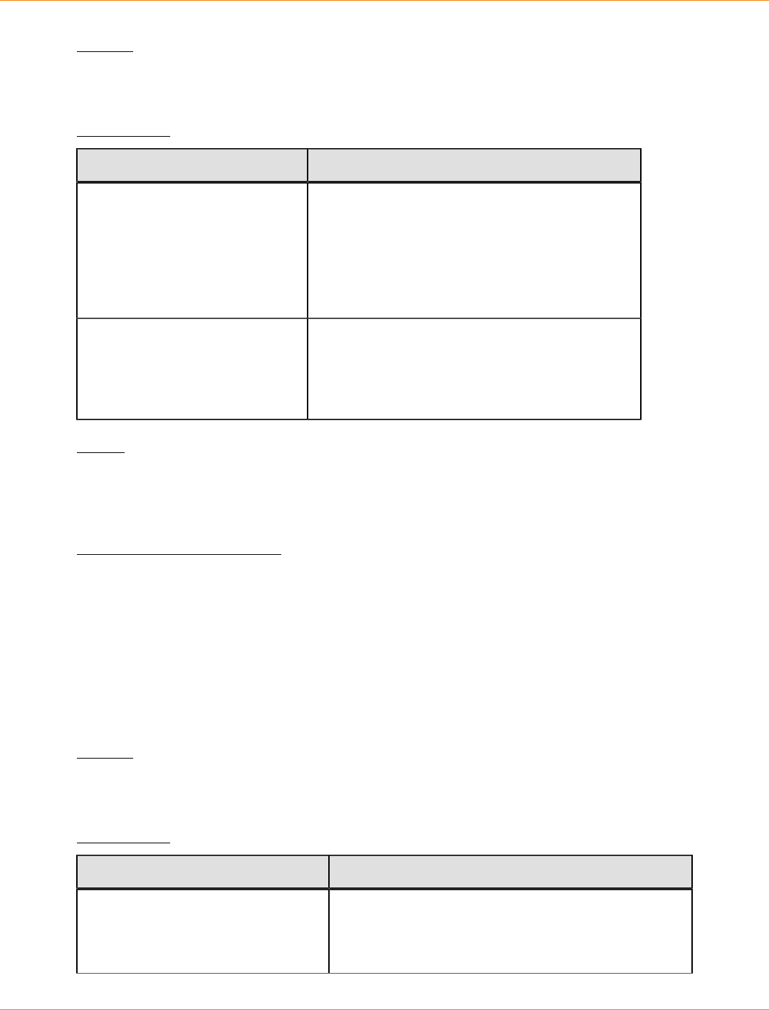
SANtricity_10.77 February 2011
LSI Corporation
- 1129 -
Syntax
set controller=[(a | b)]
serviceAllowedIndicator=(on | off)
Parameters
Parameter Description
controller The controller that has the Service Action Allowed
indicator light that you want to turn on or turn off.
Valid controller identifiers are a or b, where a is
the controller in slot A, and b is the controller in
slot B. Enclose the controller identifier in square
brackets ([ ]). If you do not specify a controller, the
controller firmware returns a syntax error.
serviceAllowedIndicator The setting to turn on or turn off the Service
Action Allowed indicator light. To turn on the
Service Action Allowed indicator light, set this
parameter to on. To turn off the Service Action
Allowed indicator light, set this parameter to off.
Notes
This command was originally defined for use with the CE6998 controller tray. This command is not supported
by controller trays that were shipped before the introduction of the CE6998 controller tray. The 3992 and 3994
controllers also support this command.
Minimum Firmware Level
6.14
Set Drawer Service Action Allowed Indicator
This command turns on or turns off the Service Action Allowed indicator light on a drawer that holds drives.
Drawers are used in high-capacity drive trays. The drawers slide out of the drive tray to provide access to
the drives. Use this command only for drive trays that use drawers. If the storage array does not support the
Service Action Allowed indicator light feature, this command returns an error. If the storage array supports the
command but is unable to turn on or turn off the indicator light, this command returns an error.
Syntax
set tray [trayID] drawer [drawerID]
serviceAllowedIndicator=(on | off | forceOnWarning)
Parameters
Parameter Description
tray The tray where the drawer resides. Tray ID values are
0 to 99. Enclose the tray ID value in square brackets
([ ]). If you do not enter a tray ID value, the tray ID of
the controller tray is the default value.
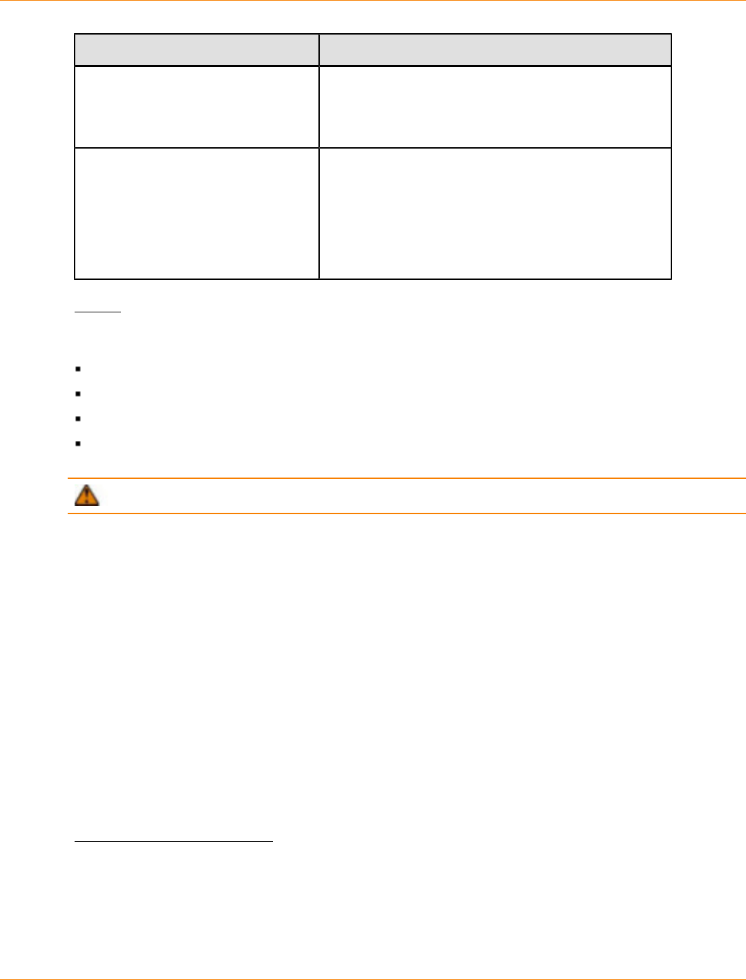
SANtricity_10.77 February 2011
LSI Corporation
- 1130 -
Parameter Description
drawer The location of the drawer for which you want to turn
on or turn off the Service Action Allowed Indicator light.
Drawer ID values are 1 to 5. Enclose the drawer ID
value in square brackets ([ ]).
serviceAllowedIndicator The setting to turn on or turn off the Service Action
Allowed indicator light. To turn on the Service Action
Allowed indicator light, set this parameter to on. To
turn off the Service Action Allowed indicator light, set
this parameter to off.
For information about using forceOnWarning, see
the Notes.
Notes
Before you can enter this command, the drive tray must meet these conditions:
The drive tray cannot be over temperature.
The fans must have a status of Optimal.
All drive tray components must be in place.
The volumes in the drive drawer cannot be in a Degraded state. If you remove drives from the drive
drawer and a volume is already in a Degraded state, the volume can fail.
ATTENTION Do not issue this command if you cannot meet any of these conditions.
All volumes with drives in the affected drive drawer are checked to make sure that the volumes have drawer
loss protection before the command is sent. If the volumes have drawer loss protection, the Set Service
Action Allowed command proceeds without stopping I/O activity to the volume.
If any volumes in the affected drawer do not have drawer loss protection, you must stop I/O activity to those
volumes. A warning appears, which indicates that this command should not be completed.
If you are preparing a component for removal and want to override the warning that the volumes do not have
drawer loss protection, enter this parameter:
serviceAllowedIndicator=forceOnWarning
forceOnWarning sends the request to prepare to remove a component to the controller firmware, and
forces the set drawer serviceAllowedIndicator command to proceed.
To turn on or turn off the Service Action Allowed indicator light for the entire high-capacity drive tray, use the
set tray serviceAllowedIndicator command.
Minimum Firmware Level
7.60
Set Drive Channel Status
This command defines how the drive channel performs.
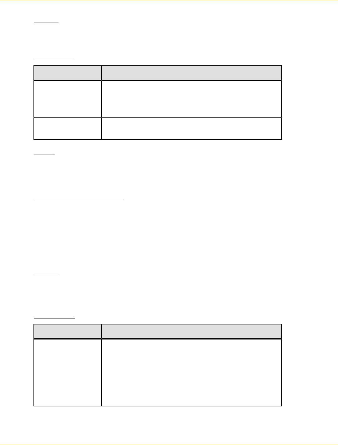
SANtricity_10.77 February 2011
LSI Corporation
- 1131 -
Syntax
set driveChannel [(1 | 2 | 3 | 4 | 5 | 6 | 7 | 8)]
status=(optimal | degraded)
Parameters
Parameter Description
driveChannel The identifier number of the drive channel for which you want
to set the status. Valid drive channel values are 1, 2, 3, 4,
5, 6, 7, or 8. Enclose the drive channel number in square
brackets ([ ]).
status The condition of the drive channel. You can set the drive
channel status to optimal or degraded.
Notes
Use the optimal option to move a degraded drive channel back to the Optimal state. Use the degraded
option when the drive channel is experiencing problems, and the storage array requires additional time for
data transfers.
Minimum Firmware Level
6.10
7.15 adds the update to the drive channel identifier.
Set Drive Hot Spare
This command assigns or unassigns one or more drives as a hot spare.
Syntax
set (drive [trayID,drawerID,slotID] |
drives [trayID1,drawerID1,slotID1 ... trayIDn,drawerIDn,slotIDn])
hotSpare=(TRUE | FALSE)
Parameters
Parameter Description
drive or drives The location of the drive that you want to use for a hot spare.
For high-capacity drive trays, specify the tray ID value, the
drawer ID value, and the slot ID value for the drive. For low-
capacity drive trays, specify the tray ID value and the slot
ID value for the drive. Tray ID values are 0 to 99. Drawer ID
values are 1 to 5. Slot ID values are 1 to 32. Enclose the tray
ID value, the drawer ID value, and the slot ID value in square
brackets ([ ]).
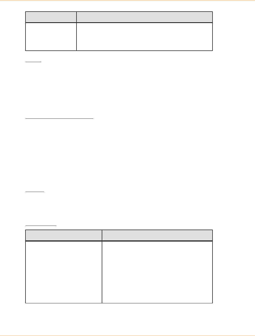
SANtricity_10.77 February 2011
LSI Corporation
- 1132 -
Parameter Description
hotSpare The setting to assign the drive as the hot spare. To assign the
drive as the hot spare, set this parameter to TRUE. To remove
a hot spare assignment from a drive, set this parameter to
FALSE.
Notes
The drive parameter supports both high-capacity drive trays and low-capacity drive trays. A high-capacity
drive tray has drawers that hold the drives. The drawers slide out of the drive tray to provide access to the
drives. A low-capacity drive tray does not have drawers. For a high-capacity drive tray, you must specify
the identifier (ID) of the drive tray, the ID of the drawer, and the ID of the slot in which a drive resides. For a
low-capacity drive tray, you need only specify the ID of the drive tray and the ID of the slot in which a drive
resides. For a low-capacity drive tray, an alternative method for identifying a location for a drive is to specify
the ID of the drive tray, set the ID of the drawer to 0, and specify the ID of the slot in which a drive resides.
Minimum Firmware Level
6.10
7.60 adds the drawerID user input.
Set Drive Service Action Allowed Indicator
This command turns on or turns off the Service Action Allowed indicator light on a drive in drive trays that
support the Service Action Allowed indicator light feature. If the storage array does not support the Service
Action Allowed indicator light feature, this command returns an error. If the storage array supports the
command but is unable to turn on or turn off the indicator light, this command returns an error.
Syntax
set (drive [trayID,drawerID,slotID] |
drives [trayID1,drawerID1,slotID1 ... trayIDn,drawerIDn,slotIDn])
serviceAllowedIndicator=(on | off)
Parameters
Parameter Description
drive or drives The location of the drive that you want to turn on
or turn off the service action allowed indicator. For
high-capacity drive trays, specify the tray ID value,
the drawer ID value, and the slot ID value for the
drive. For low-capacity drive trays, specify the tray
ID value and the slot ID value for the drive. Tray
ID values are 0 to 99. Drawer ID values are 1 to
5. Slot ID values are 1 to 32. Enclose the tray ID
value, the drawer ID value, and the slot ID value
in square brackets ([ ]).
SANtricity_10.77 February 2011
LSI Corporation
- 1133 -
Parameter Description
serviceAllowedIndicator The setting to turn on or turn off the Service
Action Allowed indicator light. To turn on the
Service Action Allowed indicator light, set this
parameter to on. To turn off the Service Action
Allowed indicator light, set this parameter to off.
Notes
The drive parameter supports both high-capacity drive trays and low-capacity drive trays. A high-capacity
drive tray has drawers that hold the drives. The drawers slide out of the drive tray to provide access to the
drives. A low-capacity drive tray does not have drawers. For a high-capacity drive tray, you must specify
the identifier (ID) of the drive tray, the ID of the drawer, and the ID of the slot in which a drive resides. For a
low-capacity drive tray, you need only specify the ID of the drive tray and the ID of the slot in which a drive
resides. For a low-capacity drive tray, an alternative method for identifying a location for a drive is to specify
the ID of the drive tray, set the ID of the drawer to 0, and specify the ID of the slot in which a drive resides.
Minimum Firmware Level
6.16
7.60 adds the drawerID user input.
Set Drive State
This command sets a drive to the Failed state. (To return a drive to the Optimal state, use the revive
drive command.)
Syntax
set (drive [trayID,drawerID,slotID] |
operationalState=failed
set (drive [trayID,slotID] |
operationalState=failed
Parameter
Parameter Description
drive The location of the drive that you want to set to the Failed state. For
high-capacity drive trays, specify the tray ID value, the drawer ID
value, and the slot ID value for the drive. For low-capacity drive trays,
specify the tray ID value and the slot ID value for the drive. Tray ID
values are 0 to 99. Drawer ID values are 1 to 5. Slot ID values are 1
to 32. Enclose the tray ID value, the drawer ID value, and the slot ID
value in square brackets ([ ]).
Notes
The drive parameter supports both high-capacity drive trays and low-capacity drive trays. A high-capacity
drive tray has drawers that hold the drives. The drawers slide out of the drive tray to provide access to the
drives. A low-capacity drive tray does not have drawers. For a high-capacity drive tray, you must specify
SANtricity_10.77 February 2011
LSI Corporation
- 1134 -
the identifier (ID) of the drive tray, the ID of the drawer, and the ID of the slot in which a drive resides. For a
low-capacity drive tray, you need only specify the ID of the drive tray and the ID of the slot in which a drive
resides. For a low-capacity drive tray, an alternative method for identifying a location for a drive is to specify
the ID of the drive tray, set the ID of the drawer to 0, and specify the ID of the slot in which a drive resides.
Minimum Firmware Level
5.20
7.60 adds the drawerID user input.
Set Foreign Drive to Native
A drive is considered to be native when it is a part of a volume group in a storage array. A drive is considered
to be foreign when it does not belong to a volume group in a storage array or when it fails to be imported
with the drives of a volume group that are transferred to a new storage array. The latter failure creates an
incomplete volume group on the new storage array.
Run this command to add the missing (foreign) drives back into their original volume group and to make them
part of the volume groupin the new storage array.
Use this operation for emergency recovery only: when one or more drives need to be changed from a foreign
drive status and returned to a native status within their original volume group.
ATTENTION Possible data corruption or data loss – Using this command for reasons other than
what is stated previously might result in data loss without notification.
Syntax
set (drive [trayID,drawerID,slotID] |
drives [trayID1,drawerID1,slotID1 ... trayIDn,drawerIDn,slotIDn] | allDrives) nativeState
Parameters
Parameter Description
drive or drives The location of the foreign drive that you want to add to the
volume group in a storage array. For high-capacity drive trays,
specify the tray ID value, the drawer ID value, and the slot ID
value for the drive. For low-capacity drive trays, specify the tray
ID value and the slot ID value for the drive. Tray ID values are
0 to 99. Drawer ID values are 1 to 5. Slot ID values are 1 to 32.
Enclose the tray ID value, the drawer ID value, and the slot ID
value in square brackets ([ ]).
allDrives The setting to select all of the drives.
Notes
The drive parameter supports both high-capacity drive trays and low-capacity drive trays. A high-capacity
drive tray has drawers that hold the drives. The drawers slide out of the drive tray to provide access to the
drives. A low-capacity drive tray does not have drawers. For a high-capacity drive tray, you must specify
the identifier (ID) of the drive tray, the ID of the drawer, and the ID of the slot in which a drive resides. For a
SANtricity_10.77 February 2011
LSI Corporation
- 1135 -
low-capacity drive tray, you need only specify the ID of the drive tray and the ID of the slot in which a drive
resides. For a low-capacity drive tray, an alternative method for identifying a location for a drive is to specify
the ID of the drive tray, set the ID of the drawer to 0, and specify the ID of the slot in which a drive resides.
Minimum Firmware Level
7.10
7.60 adds the drawerID user input.
Set Host
This command assigns a host to a host group or moves a host to a different host group. You can also create
a new host group and assign the host to the new host group with this command. The actions performed by
this command depend on whether the host has individual mappings or does not have individual mappings.
Syntax
set host [hostName]
hostGroup=("hostGroupName" | none | defaultGroup)
userLabel="newHostName"
hostType=(hostTypeIndexLabel | hostTypeIndexNumber)
Parameters
Parameter Description
host The name of the host that you want to assign to a host group. Enclose
the host name in square brackets ([ ]). If the host name has special
characters, you also must enclose the host name in double quotation
marks (" ").
hostGroup The name of the host group to which you want to assign the host. (The
following table defines how the command runs if the host does or does
not have individual mappings.) Enclose the host group name in double
quotation marks (" "). The defaultGroup option is the host group
that contains the host to which the volume is mapped.
userLabel The new host name. Enclose the host name in double quotation marks
(" ").
hostType The index label or number of the host type for the host port. Use the
show storageArray hostTypeTable command to generate
a list of available host type identifiers. If the host type has special
characters, enclose the host type in double quotation marks (" ").
Host Group
Parameter Host Has Individual Mappings Host Does Not Have
Individual Mappings
hostGroupName The host is removed from the
present host group and is placed
under the new host group defined
by hostGroupName.
The host is removed from
the present host group
and is placed under the
new host group defined by
hostGroupName.
SANtricity_10.77 February 2011
LSI Corporation
- 1136 -
Host Group
Parameter Host Has Individual Mappings Host Does Not Have
Individual Mappings
none The host is removed from the
host group as an independent
partition and is placed under the
root node.
The host is removed from
the present host group and
is placed under the default
group.
defaultGroup The command fails. The host is removed from
the present host group and
is placed under the default
group.
Notes
When you use this command, you can specify one or more of the optional parameters.
For the names, you can use any combination of alphanumeric characters, hyphens, and underscores. Names
can have a maximum of 30 characters.
Minimum Firmware Level
6.10
Set Host Channel
This command defines the loop ID for the host channel.
Syntax
set hostChannel [hostChannelNumber]
preferredID=portID
Parameters
Parameter Description
hostChannel The identifier number of the host channel for which you want
to set the loop ID. Enclose the host channel identifier number
in square brackets ([ ]).
Use a host channel value that is appropriate for your particular
controller model. A controller tray might support one host
channel or as many as eight host channels. Valid host channel
values are a1, a2, a3, a4, a5, a6, a7, a8, b1, b2, b3, b4, b5,
b6, b7, or b8.
preferredID The port identifier for the specified host channel. Port ID
values are 0 to 127.
Minimum Firmware Level
6.10
6.14 adds an update to the host channel identifier.
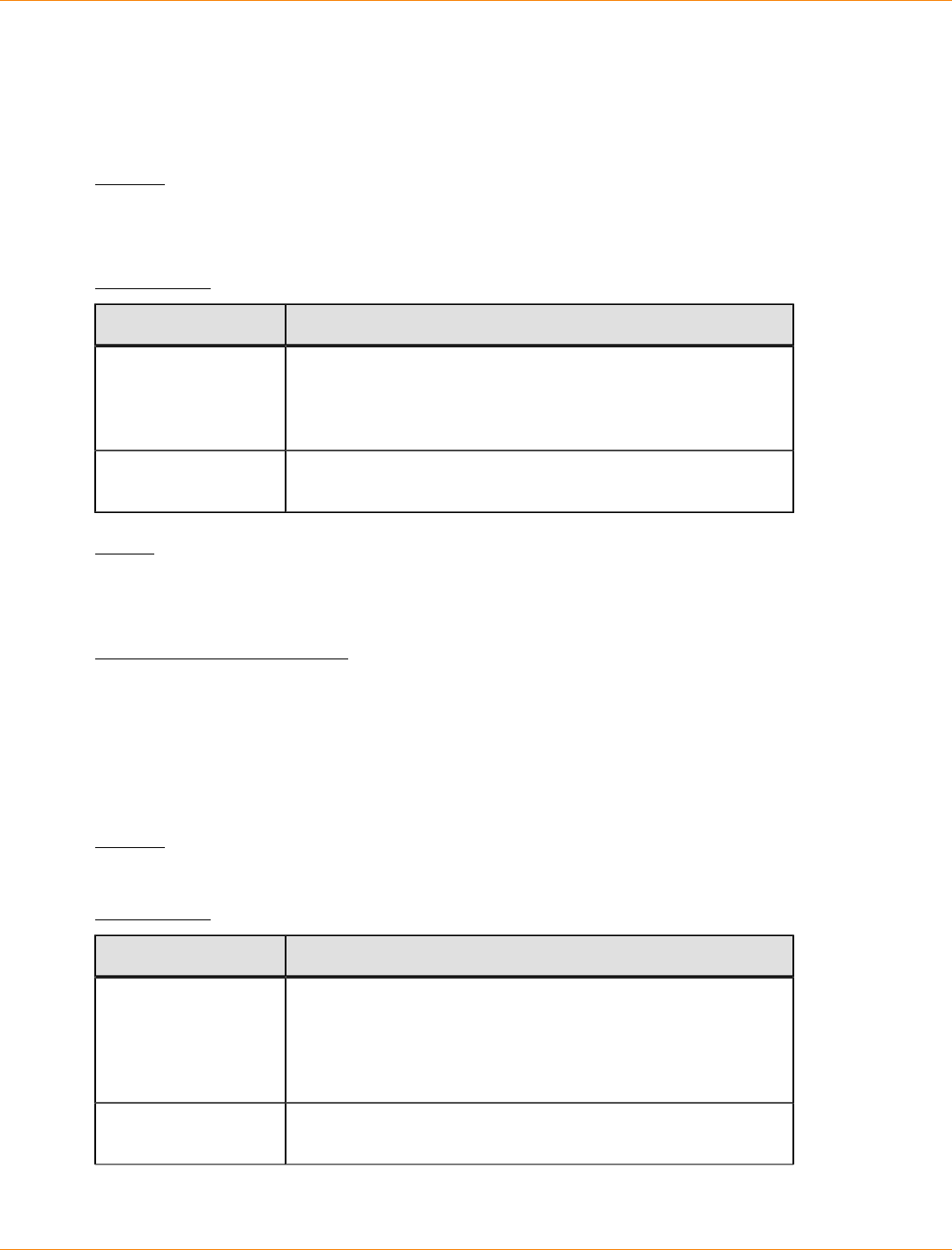
SANtricity_10.77 February 2011
LSI Corporation
- 1137 -
7.15 adds an update to the host channel identifier.
Set Host Group
This command renames a host group.
Syntax
set hostGroup [hostGroupName]
userLabel="newHostGroupName"
Parameters
Parameter Description
hostGroup The name of the host group that you want to rename. Enclose
the host group name in square brackets ([ ]). If the host group
name has special characters, you also must enclose the host
group name in double quotation marks (" ").
userLabel The new name for the host group. Enclose the new host group
name in double quotation marks (" ").
Notes
You can use any combination of alphanumeric characters, hyphens, and underscores for the names. Names
can have a maximum of 30 characters.
Minimum Firmware Level
6.10
Set Host Port
This command changes the host type for a host port. You can also change a host port label with this
command.
Syntax
set hostPort [portLabel] host="hostName" userLabel="newPortLabel"
Parameters
Parameter Description
hostPort The name of the host port for which you want to change
the host type, or for which you want to create a new name.
Enclose the host port name in square brackets ([ ]). If the host
port label has special characters, enclose the host port label in
double quotation marks (" ").
host The name of the host to which the host port is connected.
Enclose the host name in double quotation marks (" ").
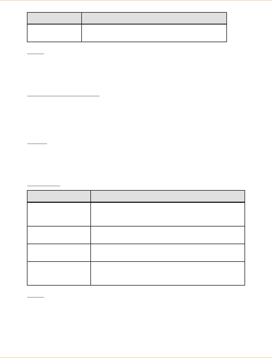
SANtricity_10.77 February 2011
LSI Corporation
- 1138 -
Parameter Description
userLabel The new name that you want to give to the host port. Enclose
the new name of the host port in double quotation marks (" ").
Notes
When you use this command, you can specify one or more of the optional parameters.
You can use any combination of alphanumeric characters, hyphens, and underscores for the names. Names
can have a maximum of 30 characters.
Minimum Firmware Level
6.10
Set iSCSI Initiator
This command sets the attributes for an iSCSI initiator.
Syntax
set iscsiInitiator (["iscsiID"] |
userLabel="newName" |
host="newHostName" |
chapSecret="newSecurityKey")
Parameters
Parameter Description
iscsiInitiator The name of the iSCSI initiator for which you want to set
attributes. Enclose the iSCSI initiator name in double quotation
marks (" ") and square brackets ([ ]).
userLabel The new name that you want to use for the iSCSI initiator. Enclose
the new name in double quotation marks (" ").
host The name of the new host to which the host port is connected.
Enclose the host name in double quotation marks (" ").
chapSecret The security key that you want to use to authenticate a peer
connection. Enclose the security key in double quotation marks
(" ").
Notes
You can use any combination of alphanumeric characters, hyphens, and underscores for the names. Names
can have a maximum of 30 characters.
Challenge Handshake Authentication Protocol (CHAP) is a protocol that authenticates the peer of a
connection. CHAP is based upon the peers sharing a secret. A secret is a security key that is similar to a
password.
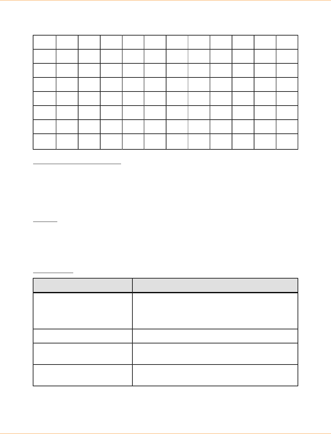
SANtricity_10.77 February 2011
LSI Corporation
- 1139 -
Use the chapSecret parameter to set up the security keys for initiators that require a mutual authentication.
The CHAP secret must be between 12 characters and 57 characters. This table lists the valid characters.
Space ! " # $ % & ' ( ) * +
, - . / 0 1 2 3 4 5 6 7
8 9 : ; < = > ? @ A B C
D E F G H I J K L M N O
P Q R S T U V W X Y Z [
\ ] ^ _ ' a b c d e f g
h i j k l m n o p q r s
t u v w x y z { | } ~
Minimum Firmware Level
7.10
Set iSCSI Target Properties
This command defines properties for an iSCSI target.
Syntax
set iscsiTarget ["userLabel"]
authenticationMethod=(none | chap) |
chapSecret=securityKey |
targetAlias="userLabel"
Parameters
Parameter Description
iscsiTarget The iSCSI target for which you want to set properties.
Enclose the userLabel in double quotation marks (" ").
You must also enclose the userLabel in either square
brackets ([ ]) or angle brackets (< >).
authenticationMethod The means of authenticating your iSCSI session.
chapSecret The security key that you want to use to authenticate a
peer connection.
targetAlias The new name that you want to use for the target.
Enclose the name in double quotation marks (" ").

SANtricity_10.77 February 2011
LSI Corporation
- 1140 -
Notes
Challenge Handshake Authentication Protocol (CHAP) is a protocol that authenticates the peer of a
connection. CHAP is based upon the peers sharing a secret. A secret is a security key that is similar to a
password.
Use the chapSecret parameter to set up the security keys for initiators that require a mutual authentication.
The CHAP secret must be between 12 characters and 57 characters. This table lists the valid characters.
Space ! " # $ % & ' ( ) * +
, - . / 0 1 2 3 4 5 6 7
8 9 : ; < = > ? @ A B C
D E F G H I J K L M N O
P Q R S T U V W X Y Z [
\ ] ^ _ ' a b c d e f g
h i j k l m n o p q r s
t u v w x y z { | } ~
Minimum Firmware Level
7.10
Set Remote Mirror
This command defines the properties for a remote-mirror pair.
Syntax
set remoteMirror (localVolume [volumeName] |
localVolumes [volumeName1 ... volumeNameN])
role=(primary | secondary)
[force=(TRUE | FALSE)]
syncPriority=(highest | high | medium | low | lowest)
autoResync=(enabled | disabled)
writeOrder=(preserved | notPreserved)
writeMode=(synchronous | asynchronous)
Parameters
Parameter Description
localVolume or
localVolumes
The name of the primary volume for which you want to define
properties. You can enter more than one primary volume
name. Enclose the primary volume name in square brackets
([ ]). If the primary volume name has special characters,
you also must enclose the primary volume name in double
quotation marks (" ").

SANtricity_10.77 February 2011
LSI Corporation
- 1141 -
Parameter Description
role The setting for the volume to act as the primary volume or
the secondary volume. To define the volume as the primary
volume, set this parameter to primary. To define the volume
as the secondary volume, set this parameter to secondary.
This parameter applies only when the volume is part of a
mirror relationship.
force The role reversal is forced if the communications link between
the storage arrays is down and promotion or demotion
on the local side results in a dual-primary condition or a
dual-secondary condition. To force a role reversal, set this
parameter to TRUE. The default value is FALSE.
syncPriority The priority that full synchronization has relative to host I/O
activity. Valid values are highest, high, medium, low, or
lowest.
autoResync The settings for automatic resynchronization between the
primary volumes and the secondary volumes of a remote-
mirror pair. This parameter has these values:
enabled – Automatic resynchronization is turned on. You
do not need to do anything further to resynchronize the
primary volume and the secondary volume.
disabled – Automatic resynchronization is turned off.
To resynchronize the primary volumes and the secondary
volume, you must run the resume remoteMirror
command.
writeOrder This parameter defines write order for data transmission
between the primary volume and the secondary volume. Valid
values are preserved or notPreserved.
writeMode This parameter defines how the primary volume writes to
the secondary volume. Valid values are synchronous or
asynchronous.
Notes
When you use this command, you can specify one or more of the optional parameters.
Synchronization priority defines the amount of system resources that are used to synchronize the data
between the primary volumes and the secondary volumes of a mirror relationship. If you select the highest
priority level, the data synchronization uses the most system resources to perform the full synchronization,
which decreases the performance for host data transfers.
The writeOrder parameter applies only to asynchronous mirrors and makes them become part of a
consistency group. Setting the writeOrder parameter to preserved causes the remote-mirror pair to
transmit data from the primary volume to the secondary volume in the same order as the host writes to the
primary volume. In the event of a transmission link failure, the data is buffered until a full synchronization
can occur. This action can require additional system overhead to maintain the buffered data, which slows

SANtricity_10.77 February 2011
LSI Corporation
- 1142 -
operations. Setting the writeOrderparameter to notPreserved frees the system from having to maintain
data in a buffer, but it requires forcing a full synchronization to make sure that the secondary volume has the
same data as the primary volume.
Minimum Firmware Level
6.10
Set Session
This command defines how you want the current script engine session to run.
Syntax
set session errorAction=(stop | continue)
password="storageArrayPassword"
performanceMonitorInterval=intervalValue
performanceMonitorIterations=iterationValue
Parameters
Parameter Description
errorAction How the session responds if an error is
encountered during processing. You can
choose to stop the session if an error is
encountered, or you can continue the
session after encountering an error. The
default value is stop. (This parameter
defines the action for execution errors,
not syntax errors. Some error conditions
might override the continue value.)
password The password for the storage array.
Enclose the password in double quotation
marks (" ").
performanceMonitorInterval The frequency of gathering performance
data. Enter an integer value for the polling
interval, in seconds, for which you want
to capture data. The range of values is 3
to 3600 seconds. The default value is 5
seconds.
performanceMonitorIterations The number of samples to capture. Enter
an integer value. The range of values
for samples captured is 1 to 3600. The
default value is 5.
Notes
When you use this command, you can specify one or more of the optional parameters.

SANtricity_10.77 February 2011
LSI Corporation
- 1143 -
Passwords are stored on each storage array in a management domain. If a password was not previously
set, you do not need a password. The password can be any combination of alphanumeric characters with
a maximum of 30 characters. (You can define a storage array password by using the set storageArray
command.)
The polling interval and the number of iterations that you specify remain in effect until you end the session.
After you end the session, the polling interval and the number of iterations return to their default values.
Minimum Firmware Level
5.20
Set Snapshot Volume
This command defines the properties for a snapshot volume and lets you rename a snapshot volume.
Syntax
set (volume [volumeName] |
volumes [volumeName1 ... volumeNameN])
userLabel="snapshotVolumeName"
warningThresholdPercent=percentValue
repositoryFullPolicy=(failBaseWrites | failSnapshot) |
enableSchedule=(TRUE | FALSE) |
schedule=(immediate | snapshotSchedule)
Parameters
Parameter Description
volume or volumes The name of the specific snapshot volume for
which you want to define properties. (You can
enter more than one volume name if you use
the volumes parameter). Enclose the snapshot
volume name in double quotation marks (" ")
inside of square brackets ([ ]).
userLabel A new name that you want to give to a snapshot
volume. Enclose the new snapshot volume name
in double quotation marks (" ").
warningThresholdPercent The percentage of repository capacity at
which you receive a warning that the snapshot
repository is nearing full. Use integer values. For
example, a value of 70 means 70 percent. The
default value is 50.
repositoryFullPolicy How you want snapshot processing to continue
if the snapshot repository volume is full. You
can choose to fail writes to the base volume
(failBaseWrites) or fail writes to the snapshot
volume (failSnapshot). The default value is
failSnapshot.
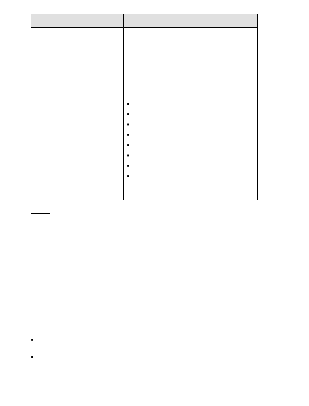
SANtricity_10.77 February 2011
LSI Corporation
- 1144 -
Parameter Description
enableSchedule Use this parameter to turn on or to turn off the
ability to schedule a snapshot operation. To turn
on snapshot scheduling, set this parameter to
TRUE. To turn off snapshot scheduling, set this
parameter toFALSE.
schedule Use this parameter to schedule a snapshot
operation.
You can use one of these options for setting a
schedule for a snapshot operation:
immediate
startDate
scheduleDay
startTime
scheduleInterval
endDate
noEndDate
timesPerDay
See the "Notes" section for information explaining
how to use these options.
Notes
When you use this command, you can specify one or more of the optional parameters.
You can use any combination of alphanumeric characters, hyphens, and underscores for the names. Names
can have a maximum of 30 characters.
You can set the warningThresholdPercent parameter and the repositoryFullPolicy parameter for
both the snapshot repository volume or the snapshot volume.
Scheduling Snapshots
The enableSchedule parameter and the schedule parameter provide a way for you to schedule automatic
snapshots. Using these parameters, you can schedule snapshots daily, weekly, or monthly (by day or by
date). The enableSchedule parameter turns on or turns off the ability to schedule snapshots. When you
enable scheduling, you use the schedule parameter to define when you want the snapshots to occur.
This list explains how to use the options for the schedule parameter:
immediate – As soon as you enter the command, a snapshot volume is created and a copy-on-write
operation begins.
startDate – A specific date on which you want to create a snapshot volume and perform a copy-on-
write operation. The format for entering the date is MM:DD:YY. If you do not provide a start date, the
current date is used. An example of this option is startDate=06:27:11.

SANtricity_10.77 February 2011
LSI Corporation
- 1145 -
scheduleDay - A day of the week on which you want to create a snapshot volume and perform a copy-
on-write operation. You can enter these values: monday, tuesday, wednesday, thursday, friday,
saturday, sunday, and all. An example of this option is scheduleDay=wednesday.
startTime – The time of a day that you want to create a snapshot volume and start performing a copy-
on-write operation. The format for entering the time is HH:MM, where HH is the hour and MM is the minute
past the hour. Use a 24-hour clock. For example, 2:00 in the afternoon is 14:00. An example of this option
is startTime=14:27.
scheduleInterval – An amount of time, in minutes, that you want to have as a minimum between
copy-on-write operation.You can possibly create a schedule in which you have overlapping copy-on-write
operations because of the duration a copy operation. You can make sure that you have time between
copy-on-write operations by using this option. The maximum value for the scheduleInterval option is
1440 minutes. An example of this option is scheduleInterval=180.
endDate – A specific date on which you want to stop creating a snapshot volume and end the copy-
on-write operations. The format for entering the date is MM:DD:YY. An example of this option is
endDate=11:26:11.
noEndDate – Use this option if you do not want your scheduled copy-on-write operation to end. If you
later decide to end the copy-on-write operations you must re-enter the create snapshotVolume
command and specify an end date.
timesPerDay – The number of times that you want the schedule to run in a day. An example of this
option is timesPerDay=4.
If you also use the scheduleInterval option, the firmware chooses between the timesPerDay option
and the scheduleInterval option by selecting the lowest value of the two options. The firmware calculates
an integer value for the scheduleInterval option by dividing 1440 by a the scheduleInterval option
value that you set. For example, 1440/180 = 8. The firmware then compares the timesPerDay integer value
with the calculated scheduleInterval integer value and uses the smaller value.
To remove a schedule, use the delete snapshot command with the schedule parameter. The delete
snapshot command with the schedule parameter deletes only the schedule, not the snapshot volume.
Minimum Firmware Level
6.10
7.77 adds scheduling.
Set Storage Array
This command defines the properties of the storage array.
Syntax
set storageArray {alarm=(enable | disable | mute) |
{autoSupportConfig (enable | disable) |
cacheBlockSize=cacheBlockSizeValue |
cacheFlushStart=cacheFlushStartSize |
cacheFlushStop=cacheFlushStopSize |
defaultHostType=("hostTypeName" | hostTypeIdentifier)
failoverAlertDelay=delayValue |
mediaScanRate=(disabled | 1-30) |
password="password" |
userLabel="storageArrayName"
isnsRegistration=(TRUE | FALSE))

SANtricity_10.77 February 2011
LSI Corporation
- 1146 -
Parameters
Parameter Description
alarm The setting for the audible alarm. This parameter has
these values:
enable – The audible alarm is turned on and sounds
if a fault occurs.
disable – The audible alarm is turned off and does
not sound if a fault occurs.
mute – The audible alarm is turned off if it is
sounding.
If another fault occurs after you set the audible alarm to
mute, the audible alarm sounds again.
autoSupportConfig The setting for automatically collecting support data
each time the firmware detects a critical MEL event. This
parameter has these values:
enable – Turns on the collection of support data
disable – Turns off the collection of support data
cacheBlockSize The cache block size that is used by the controller for
managing the cache. Valid values are 4 (4 KB), 8 (8 KB),
16 (16 KB), or 32 (32 KB).
cacheFlushStart The percentage of unwritten data in the cache that causes
a cache flush. Use integer values from 0 to 100 to define
the percentage. The default value is 80.
cacheFlushStop The percentage of unwritten data in the cache that stops a
cache flush in progress. Use integer values from 0 to 100
to define the percentage. This value must be less than the
value of the cacheFlushStart parameter.
defaultHostType The default host type of any unconfigured host port to
which the controllers are connected. To generate a list
of valid host types for the storage array, run the show
storageArray hostTypeTable command. Host types
are identified by a name or a numerical index. Enclose
the host type name in double quotation marks (" "). Do
not enclose the host type numerical identifier in double
quotation marks.
failoverAlertDelay The failover alert delay time in minutes. The valid values
for the delay time are 0 to 60 minutes. The default value is
5.
mediaScanRate The number of days over which the media scan runs.
Valid values are disabled, which turns off the media
scan, or 1 day to 30 days, where 1 day is the fastest scan
rate, and 30 days is the slowest scan rate. A value other
than disabled or 1 to 30 does not allow the media scan
to function.

SANtricity_10.77 February 2011
LSI Corporation
- 1147 -
Parameter Description
password The password for the storage array. Enclose the password
in double quotation marks (" ").
userLabel The name for the storage array. Enclose the storage array
name in double quotation marks (" ").
isnsRegistration The means of listing the iSCSI target on the iSNS server.
Set the parameter to TRUE to list it.
Notes
When you use this command, you can specify one or more of the optional parameters.
Auto Support Data
When enabled, the set storageArray autoSupportConfig command causes all configuration and
state information for the storage array to be returned each time a critical Major Event Log (MEL) event is
detected. The configuration and state information is returned in the form of an object graph. The object graph
contains all relevant logical and physical objects and their associated state information for the storage array.
The set storageArray autoSupportConfig command collects configuration and state information in
this way:
Automatic collection of the configuration and state information occurs every 72 hours. The configuration
and state information is saved to the storage array zip archive file. The archive file has a time stamp that
is used to manage the archive files.
Two storage array zip archive files are maintained for each storage array. The zip archive files are kept on
a drive. After the 72-hour time period is exceeded, the oldest archive file is always overwritten during the
new cycle.
After you enable automatic collection of the configuration and state information using this command, an
initial collection of information starts. Collecting information after the you issue the command makes sure
that one archive file is available and starts the time stamp cycle.
You can run the set storageArray autoSupportConfig command on more than one storage array.
Cache Block Size
When you define cache block sizes, use the 4-KB cache block size for storage arrays that require I/O streams
that are typically small and random. Use the 8-KB cache block size when the majority of your I/O streams are
larger than 4 KB but smaller than 8 KB. Use the 16-KB cache block size or the 32-KB cache block size for
storage arrays that require large data transfer, sequential, or high-bandwidth applications.
The cacheBlockSize parameter defines the supported cache block size for all of the volumes in the storage
array. Not all controller types support all cache block sizes. For redundant configurations, this parameter
includes all of the volumes that are owned by both controllers within the storage array.
Cache Flush Start and Cache Flush Stop
When you define values to start a cache flush, a value that is too low increases the chance that data needed
for a host read is not in the cache. A low value also increases the number of drive writes that are necessary to
maintain the cache level, which increases system overhead and decreases performance.
SANtricity_10.77 February 2011
LSI Corporation
- 1148 -
When setting storage array cache settings, the value of the cacheFlushStart parameter must always
be greater than or equal to the value of the cacheFlushStop parameter. For example, if the value of the
cacheFlushStart parameter is set to 80, you may set the value of the cacheFlushStop parameter within
the range of 0 to 80.
When you define values to stop a cache flush, the lower the value, the higher the chance that the data for a
host read requires a drive read rather than reading from the cache.
Default Host Type
When you define host types, if Storage Partitioning is enabled, the default host type affects only those
volumes that are mapped in the default group. If Storage Partitioning is not enabled, all of the hosts that are
attached to the storage array must run the same operating system and be compatible with the default host
type.
Media Scan Rate
Media scan runs on all of the volumes in the storage array that have Optimal status, do not have modification
operations in progress, and have the mediaScanRate parameter enabled. Use the set volume command
to enable or disable the mediaScanRate parameter.
Password
Passwords are stored on each storage array. For best protection, the password must meet these criteria:
The password must be between eight and 32 characters long.
The password must contain at least one uppercase letter.
The password must contain at least one lowercase letter.
The password must contain at least one number.
The password must contain at least one non-alphanumeric character, for example, < > @ +.
NOTE If you are using full disk encryption drives in your storage array, you must use these criteria for
your storage array password.
NOTE You must set a password for your storage array before you can create a security key for
encrypted full disk encryption drives.
Minimum Firmware Level
5.00 adds the defaultHostType parameter.
5.40 adds the failoverAlertDelay parameter.
6.14 adds the alarm parameter.
7.15 adds more cache block sizes.
Set Storage Array ICMP Response
This command returns the default values for negotiable settings for sessions and connections, which
represent the starting point for the storage array for negotiations.
SANtricity_10.77 February 2011
LSI Corporation
- 1149 -
Syntax
set storageArray icmpPingResponse=(TRUE | FALSE)
Parameter
Parameter Description
icmpPingResponse This parameter turns on or turns off Echo Request
messages. Set the parameter to TRUE to turn on Echo
Request messages. Set the parameter to FALSE to turn
off Echo Request messages.
Notes
The Internet Control Message Protocol (ICMP) is used by operating systems in a network to send error
messages, test packets, and informational messages related to the IP, such as a requested service is not
available or that a host or router could not be reached. The ICMP response command sends ICMP Echo
Request messages and receives ICMP Echo Response messages to determine if a host is reachable and the
time it takes for packets to get to and from that host.
Minimum Firmware Level
7.10
Set Storage Array iSNS Server IPv4 Address
This command sets the configuration method and address for an IPv4 Internet Storage Name Service (iSNS).
Syntax
set storageArray isnsIPv4ConfigurationMethod=[static | dhcp]
isnsIPv4Address=ipAddress
Parameters
Parameters Description
isnsIPv4ConfigurationMethod The method that you want to use to define
the iSNS server configuration. You can
enter the IP address for the IPv4 iSNS
servers by selecting static. For IPv4,
you can choose to have a Dynamic Host
Configuration Protocol (DHCP) server select
the iSNS server IP address by entering
dhcp. To enable DCHP, you must set the
isnsIPv4Address parameter to 0.0.0.0.
isnsIPv4Address The IP address that you want to use for the
iSNS server. Use this parameter with the
static value for IPv4 configurations. If you
choose to have a DHCP server set the IP
address for an IPv4 Internet iSNS server, you
must set the isnsIPv4Address parameter
to 0.0.0.0.
SANtricity_10.77 February 2011
LSI Corporation
- 1150 -
Notes
The iSNS protocol facilitates the automated discovery, management, and configuration of iSCSI devices and
Fibre Channel devices on a TCP/IP network. iSNS provides intelligent storage discovery and management
services comparable to those found in Fibre Channel networks, which allow a commodity IP network to
function in a similar capacity as a storage area network. iSNS also facilitates a seamless integration of IP
networks and Fibre Channel networks, due to its ability to emulate Fibre Channel fabric services and manage
both iSCSI devices and Fibre Channel devices.
The DHCP server passes configuration parameters, such as network addresses, to IP nodes. DHCP enables
a client to acquire all of the IP configuration parameters that it needs to operate. DHCP lets you automatically
allocate reusable network addresses.
Minimum Firmware Level
7.10
Set Storage Array iSNS Server IPv6 Address
This command sets the IPv6 address for the iSNS server.
Syntax
set storageArray isnsIPv6Address=ipAddress
Parameter
Parameters Description
isnsIPv6Address The IPv6 address that you want to use for the iSNS
server.
Notes
The iSNS protocol facilitates the automated discovery, management, and configuration of iSCSI devices and
Fibre Channel devices on a TCP/IP network. iSNS provides intelligent storage discovery and management
services comparable to those found in Fibre Channel networks, which permits a commodity IP network to
function in a similar capacity as a storage area network. iSNS also facilitates a seamless integration of IP
networks and Fibre Channel networks, due to its ability to emulate Fibre Channel fabric services, and manage
both iSCSI devices and Fibre Channel devices. iSNS provides value in any storage network that has iSCSI
devices, Fibre Channel devices, or any combination.
Minimum Firmware Level
7.10
Set Storage Array iSNS Server Listening Port
This command sets the iSNS server listening port.
Syntax
set storageArray isnsListeningPort=listeningPortIPAddress

SANtricity_10.77 February 2011
LSI Corporation
- 1151 -
Parameter
Parameter Description
isnsListeningPort The IP address that you want to use for the iSNS server
listening port. The range of values for the listening port is
49152 to 65535. The default value is 3205.
Notes
A listening port resides on the database server and is responsible for these activities:
Listening (monitoring) for incoming client connection requests
Managing the traffic to the server
When a client requests a network session with a server, a listener receives the actual request. If the client
information matches the listener information, then the listener grants a connection to the database server.
Minimum Firmware Level
7.10
Set Storage Array iSNS Server Refresh
This command refreshes the network address information for the iSNS server. This command is valid for only
IPv4.
Syntax
set storageArray isnsServerRefresh
Parameters
None.
Notes
If the DHCP server is not operating at full capability, or if the DHCP server is unresponsive, the refresh
operation can take between two and three minutes to complete.
The set storageArray isnsServerRefresh command returns an error if you did not set the
configuration method to DHCP. To set the configuration method to DHCP, use the set storageArray
isnsIPV4ConfigurationMethod command.
Minimum Firmware Level
7.10
Set Storage Array Learn Cycle
This command sets the learn cycle for the battery backup unit. The learn cycle enables the storage
management software to predict the remaining battery life. Learn cycles run at set intervals and store the
results for software analysis.
SANtricity_10.77 February 2011
LSI Corporation
- 1152 -
Syntax
set storageArray learnCycleDate
(daysToNextLearnCycle=numberOfDays |
day=dayOfTheWeek) time=HH:MM
Parameters
Parameter Description
daysToNextLearnCycle Valid values are 0 through 7, where 0 is
immediately and 7 is in seven days. The
daysToNextLearnCycle parameter takes place up
to seven days after the next scheduled learn cycle.
day Valid values for the day parameter include the days of
the week (Sunday, Monday, Tuesday, Wednesday,
Thursday, Friday, and Saturday). Setting the
day causes the next learn cycle to be scheduled on
the specified day, after the currently scheduled learn
cycle.
time The time in 24-hour format; for example 8:00 a.m. is
entered as 08:00. Nine o'clock p.m. is entered as
21:00, and 9:30 p.m. is entered as 21:30.
Notes
You can set the learn cycle to occur only once during a seven-day period.
The time parameter selects a specific time that you want to run the learn cycle. If a value is not entered, the
command uses a default value of 00:00 (midnight).
If the day and time specified are in the past, the next learn cycle takes place on the next possible day
specified.
Minimum Firmware Level
7.15
Set Storage Array Redundancy Mode
This command sets the redundancy mode of the storage array to either simplex or duplex.
Syntax
set storageArray redundancyMode=(simplex | duplex)
Parameter
Parameter Description
redundancyMode Use simplex mode when you have a single controller. Use
duplex mode when you have two controllers.
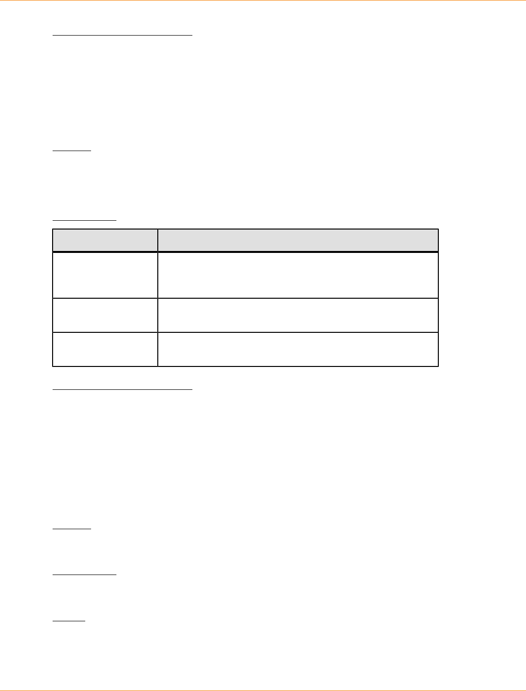
SANtricity_10.77 February 2011
LSI Corporation
- 1153 -
Minimum Firmware Level
6.10
Set Storage Array Remote Status Notification
This command sets or changes the proxy configuration settings for the remote status notification
feature. The proxy configuration settings are saved in the devmgr.datadir\monitor\EMRSstate
\EMRSRuntimeConfig.xml file on the storage management station.
Syntax
set remoteStatusNotification proxyConfig
(PACProxy=proxyLocationURL | [proxyHost=hostURL] |
[proxyPort=hostPort])
Parameters
Parameter Description
PACProxy The URL for the location of a proxy auto-config (PAC) file.
The file defines the proxy server to be used for remote status
notification.
proxyHost The URL for a host that is to be used for remote status
notification.
proxyPort The port number of a host that is to be used for remote status
notification.
Minimum Firmware Level
7.70
Set Storage Array Security Key
Use this command to set the security key that is used throughout the storage array to implement the
SafeStore Drive Security premium feature. When any security-capable drive in the storage array is assigned
to a secured volume group, that drive will be security-enabled using the security key. Before you can set the
security key, you must use the create storageArray securityKey command to create the security
key.
Syntax
set storageArray securityKey
Parameters
None.
Notes
Security-capable drives have hardware to accelerate cryptographic processing and each has a unique drive
key. A security-capable drive behaves like any other drive until it is added to a secured volume group, at
which time the security-capable drive becomes security-enabled.
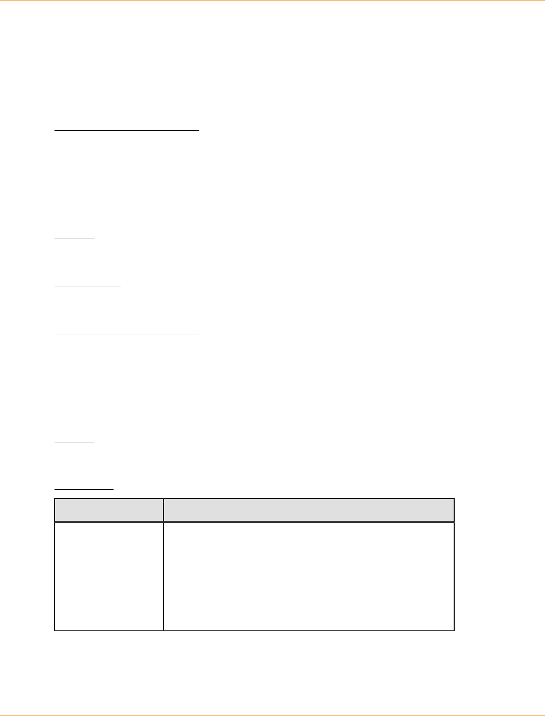
SANtricity_10.77 February 2011
LSI Corporation
- 1154 -
Whenever a security-enabled drive is powered on, it requires the correct security key from the controller
before it can read or write data. So, a security-enabled drive uses two keys: the drive key that encrypts and
decrypts the data and the security key that authorizes the encryption and decryption processes. The set
storageArray securityKey command commits the security key to all of the controllers and security-
enabled drives in the storage array. The full disk encryption feature ensures that if a security-enabled drive is
physically removed from a storage array, its data cannot be read by any other device unless the security key
is known.
Minimum Firmware Level
7.50
Set Storage Array Time
This command sets the clocks on both controllers in a storage array by synchronizing the controller clocks
with the clock of the host from which you run this command.
Syntax
set storageArray time
Parameters
None.
Minimum Firmware Level
6.10
Set Storage Array Tray Positions
This command defines the position of the trays in a storage array. You must include all of the trays in the
storage array when you enter this command.
Syntax
set storageArray trayPositions=(controller | trayID ... trayIDn)
Parameter
Parameter Description
trayPositions A list of all of the tray IDs. The sequence of the tray IDs in
the list defines the positions for the controller tray and the
drive trays in a storage array. Valid values are 0 to 99. Enter
the tray ID values separated with a space. Enclose the list
of tray ID values in parentheses. For storage arrays where
the controller tray has a predefined identifier that is not in
the range of valid tray position values, use the controller
value.
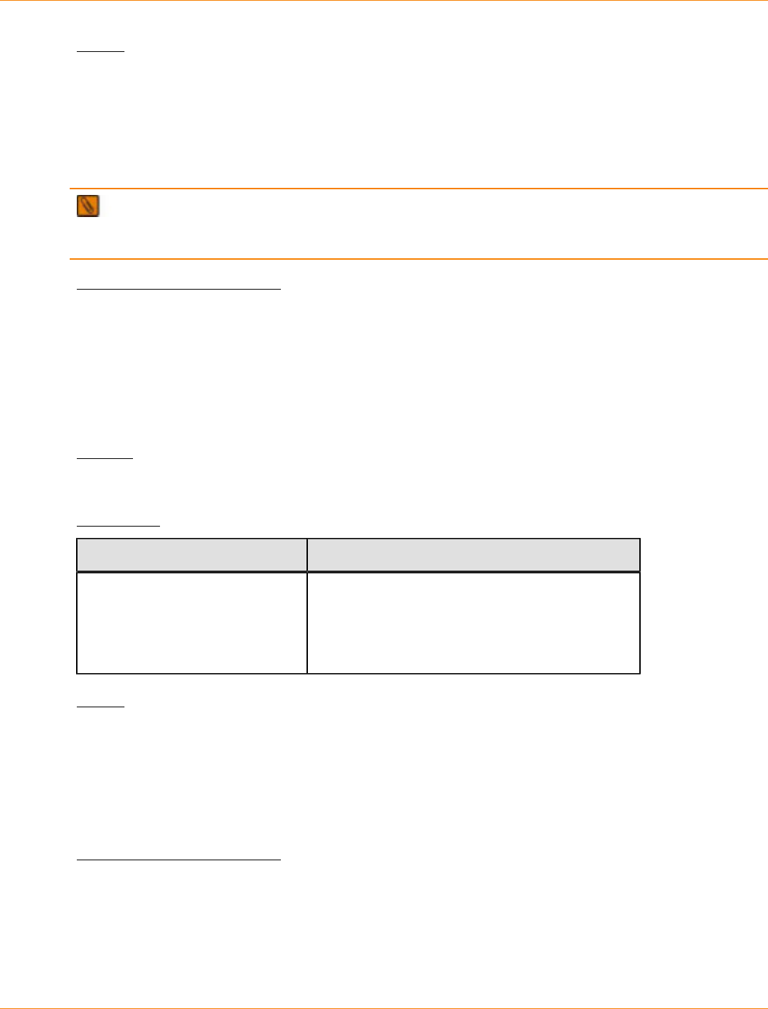
SANtricity_10.77 February 2011
LSI Corporation
- 1155 -
Notes
This command defines the position of a tray in a storage array by the position of the tray ID in the
trayPositions list. For example, if you have a controller tray with an ID set to 84 and drive trays with IDs
set to 1, 12, and 50, the trayPositions sequence (84 1 12 50) places the controller tray in the first
position, drive tray 1 in the second position, drive tray 12 in the third position, and drive tray 50 in the fourth
position. The trayPositions sequence (1 84 50 12) places the controller tray in the second position,
drive tray 1 in the first position, drive tray 50 in the third position, and drive tray 12 in the fourth position.
NOTE You must include all of the trays in the storage array in the list defined by the trayPositions
parameter. If the number of trays in the list does not match the total number of trays in the storage array, an
error message appears.
Minimum Firmware Level
6.10
For 6.14 and 6.16, controller is not a valid value.
Set Storage Array Unnamed Discovery Session
This command enables the storage array to participate in unnamed discovery sessions.
Syntax
set storageArray unnamedDiscoverySession=(TRUE | FALSE)
Parameter
Parameter Description
unnamedDiscoverySession This parameter turns on or turns off unnamed
discovery sessions. Set the parameter to TRUE
to turn on unnamed discovery sessions. Set
the parameter to FALSE to turn off unnamed
discovery sessions.
Notes
Discovery is the process where initiators determine the targets that are available. Discovery occurs at power-
on/initialization and also if the bus topology changes, for example, if an extra device is added.
An unnamed discovery session is a discovery session that is established without specifying a target ID in
the login request. For unnamed discovery sessions, neither the target ID nor the target portal group ID are
available to the targets.
Minimum Firmware Level
7.10
Set Tray Alarm
This command turns on, turns off, or mutes the audible alarm for a specific tray or all of the trays in a storage
array.
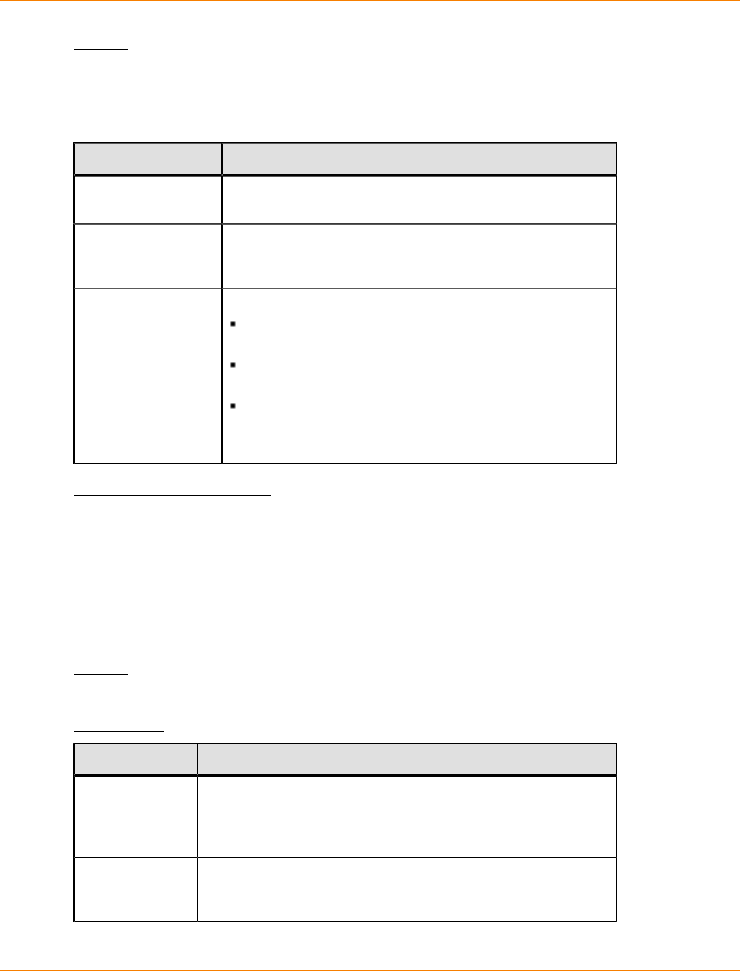
SANtricity_10.77 February 2011
LSI Corporation
- 1156 -
Syntax
set (allTrays | tray [trayID]
alarm=(enable | disable | mute))
Parameters
Parameter Description
allTrays The setting to select all of the trays in a storage array that
have audible alarms that you want to turn on, turn off, or mute.
tray The specific tray that has the audible alarm that you want to
turn on, turn off, or mute. Tray ID values are 0 to 99. Enclose
the tray ID value in square brackets ([ ]).
alarm The setting for the audible alarm. This alarm has these values:
enable – The audible alarm is turned on and sounds if a
fault occurs.
disable – The audible alarm is turned off and does not
sound if a fault occurs.
mute – The audible alarm is turned off if it is sounding.
(If another fault occurs after you set the audible alarm to
mute, the audible alarm sounds again.)
Minimum Firmware Level
6.16
Set Tray Identification
This command sets the tray ID of a controller tray, a controller-drive tray, or a drive tray in a storage array.
This command is valid only for controller trays, controller-drive trays, or drive trays that have tray IDs that you
can set through the controller firmware. You cannot use this command for controller trays, controller-drive
trays, or drive trays that have a tray ID that you set with a switch.
Syntax
set tray ["serialNumber"] id=trayID
Parameters
Parameter Description
tray The serial number of the controller tray, controller-drive tray, or the
drive tray for which you are setting the tray ID. Serial numbers can
be any combination of alphanumeric characters and any length.
Enclose the serial number in double quotation marks (" ").
id The value for the controller tray tray ID, controller-drive tray tray
ID, or the drive tray tray ID. Tray ID values are 00 through 99. You
do not need to enclose the tray ID value in parentheses.
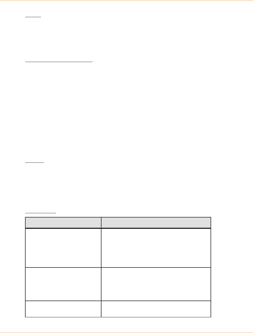
SANtricity_10.77 February 2011
LSI Corporation
- 1157 -
Notes
This command originally supported the CE6998 controller tray. The CE6998-series controller trays can
connect to a variety of drive trays, including those whose tray IDs are set by switches. When connecting a
CE6998-series controller tray to drive trays whose tray IDs are set by switches, valid values for tray IDs for
the controller tray are 80 through 99. This range avoids conflicts with tray IDs that are used for attached drive
trays.
Minimum Firmware Level
6.14 adds support for the CE6998 controller tray.
6.16 adds support for controller trays, controller-drive trays, and drive trays that have tray IDs set through the
controller firmware.
Set Tray Service Action Allowed Indicator
This command turns on or turns off the Service Action Allowed indicator light on a power-fan canister, an
interconnect-battery canister, or an environmental services monitor (ESM) canister. If the storage array does
not support the Service Action Allowed indicator light feature, this command returns an error. If the storage
array supports the command but is unable to turn on or turn off the indicator light, this command returns an
error.
To turn on or turn off the Service Action Allowed indicator light on the controller canister, use the set
controller serviceAllowedIndicator command.
Syntax
set tray [trayID]
(powerFan [(left | right | top | bottom)] |
interconnect |
esm [(left | right | top | bottom)]) |
battery [(left | right)] |
serviceAllowedIndicator=(on | off)
Parameters
Parameter Description
tray The tray where the power-fan canister, the
interconnect canister, the ESM canister, or the
battery canister resides. Tray ID values are 0 to
99. Enclose the tray ID value in square brackets
([ ]). If you do not enter a tray ID value, the tray ID
of the controller tray is the default value.
powerFan The Service Action Allowed indicator light on the
power-fan canister that you want to turn on or turn
off. Valid power-fan canister identifiers are left,
right, top, or bottom. Enclose the power-fan
canister identifier in square brackets ([ ]).
interconnect The Service Action Allowed indicator light for the
interconnect-battery canister.
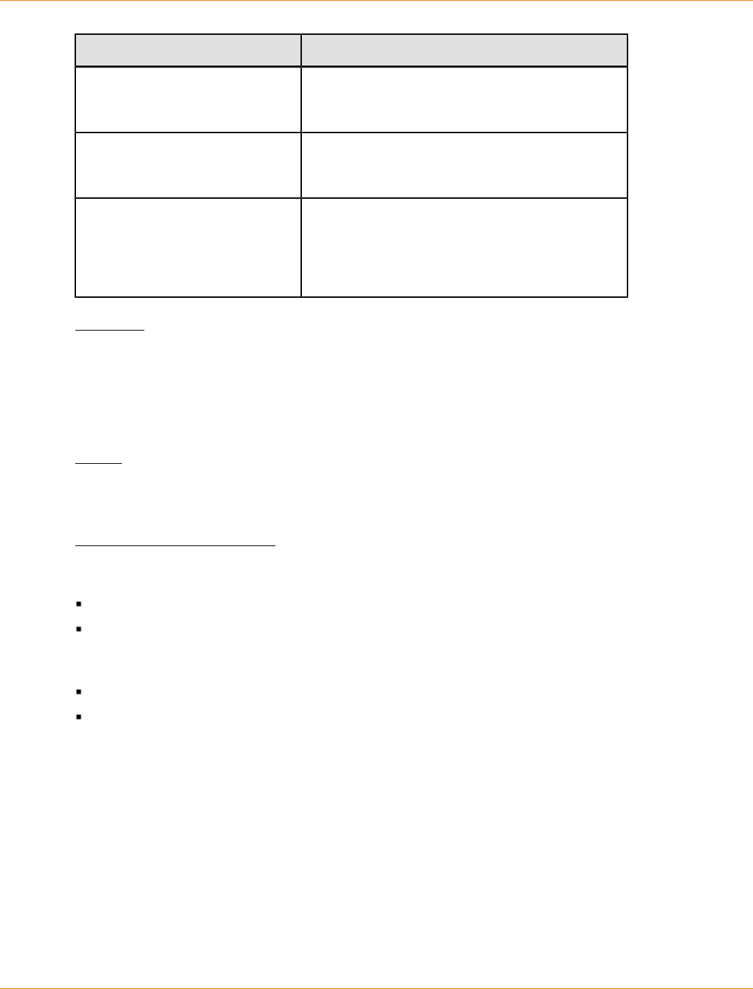
SANtricity_10.77 February 2011
LSI Corporation
- 1158 -
Parameter Description
esm The Service Action Allowed indicator light for an
ESM canister. Valid ESM canister identifiers are
left, right, top, or bottom.
battery The Service Action Allowed indicator light for
a battery. Valid battery identifiers are left or
right.
serviceAllowedIndicator The setting to turn on or turn off the Service
Action Allowed indicator light. To turn on the
Service Action Allowed indicator light, set this
parameter to on. To turn off the Service Action
Allowed indicator light, set this parameter to off.
Example
This command turns on the Service Action Allowed indicator light for the left ESM in tray 5 with the IP address
of 155.155.155.155.
SMcli 123.145.167.214 123.145.167.215 -c "set tray [5]
ESM [left] serviceAllowedIndicator=on;"
Notes
This command was originally defined for use with the CE6998 controller tray. This command is not supported
by controller trays that were shipped before the introduction of the CE6998 controller tray.
Minimum Firmware Level
6.14 adds these parameters:
powerFan
interconnect
6.16 adds these parameters:
tray
esm
7.60 adds the identifiers top and bottom.
Set Volume
This command defines the properties for a volume. You can use most parameters to define properties for one
or more volumes. You also can use some parameters to define properties for only one volume. The syntax
definitions are separated to show which parameters apply to several volumes and which apply to only one
volume. Also, the syntax for volume mapping is listed separately.
SANtricity_10.77 February 2011
LSI Corporation
- 1159 -
NOTE In configurations where volume groups consist of more than 32 volumes, the operation can
result in host I/O errors or internal controller reboots due to the expiration of the timeout period before the
operation completes. If you experience host I/O errors or internal controller reboots, quiesce the host I/O and
try the operation again.
Syntax Applicable to One or More Volumes
set (allVolumes | volume ["volumeName"] |
volumes ["volumeName1" ... "volumeNameN"] | volume <wwID>)
cacheFlushModifier=cacheFlushModifierValue
cacheWithoutBatteryEnabled=(TRUE | FALSE)
mediaScanEnabled=(TRUE | FALSE)
mirrorCacheEnabled=(TRUE | FALSE)
modificationPriority=(highest | high | medium | low | lowest)
owner=(a | b)
preReadRedundancyCheck=(TRUE | FALSE)
readCacheEnabled=(TRUE | FALSE)
writeCacheEnabled=(TRUE | FALSE)
cacheReadPrefetch=(TRUE | FALSE)
dataAssuranceDisabled=(TRUE | FALSE)
Syntax Applicable to Only One Volume
set (volume ["volumeName"] | volume <wwID>)
addCapacity=volumeCapacity
[addDrives=(trayID1,drawerID1,slotID1 ... trayIDn,drawerIDn,slotIDn)]
redundancyCheckEnabled=(TRUE | FALSE)
segmentSize=segmentSizeValue
userLabel=volumeName
preReadRedundancyCheck=(TRUE | FALSE)
Syntax Applicable to Volume Mapping
set (volume ["volumeName"] | volume <wwID> | accessVolume)
logicalUnitNumber=LUN
(host="hostName" |
hostGroup=("hostGroupName" | defaultGroup)
Parameters
Parameter Description
allVolumes The properties for all volumes in the storage
array.
volume or volumes The name of the specific volume for which
you want to define properties. (You can enter
more than one volume name if you use the
volumes parameter.) Enclose the volume
name in double quotation marks (" ") inside of
square brackets ([ ]).

SANtricity_10.77 February 2011
LSI Corporation
- 1160 -
Parameter Description
volume The World Wide Identifier (WWID) of the
volume for which you are setting properties.
You can use the WWID instead of the volume
name to identify the volume. Enclose the
WWID in angle brackets (< >).
cacheFlushModifier The maximum amount of time that data for
the volume stays in cache before the data is
flushed to physical storage. Valid values are
listed in the Notes section.
cacheWithoutBatteryEnabled The setting to turn on or turn off caching
without batteries. To turn on caching without
batteries, set this parameter to TRUE. To
turn off caching without batteries, set this
parameter to FALSE.
mediaScanEnabled The setting to turn on or turn off media scan
for the volume. To turn on media scan, set
this parameter to TRUE. To turn off media
scan, set this parameter to FALSE. (If media
scan is disabled at the storage array level,
this parameter has no effect.)
mirrorCacheEnabled The setting to turn on or turn off the mirror
cache. To turn on the mirror cache, set this
parameter to TRUE. To turn off the mirror
cache, set this parameter to FALSE.
modificationPriority The priority for volume modifications while the
storage array is operational. Valid values are
highest, high, medium, low, or lowest.
owner The controller that owns the volume. Valid
controller identifiers are a or b, where a is the
controller in slot A, and b is the controller in
slot B. Use this parameter only if you want to
change the volume owner.
preReadRedundancyCheck The setting to turn on or turn off preread
redundancy checking. Turning on preread
redundancy checking verifies the consistency
of RAID redundancy data for the stripes
containing the read data. Preread redundancy
checking is performed on read operations
only. To turn on preread redundancy
checking, set this parameter to TRUE. To turn
off preread redundancy checking, set this
parameter to FALSE.
SANtricity_10.77 February 2011
LSI Corporation
- 1161 -
Parameter Description
NOTE Do not use this parameter on
non-redundant volumes, such as RAID 0
volumes.
readCacheEnabled The setting to turn on or turn off the read
cache. To turn on the read cache, set this
parameter to TRUE. To turn off the read
cache, set this parameter to FALSE.
writeCacheEnabled The setting to turn on or turn off the write
cache. To turn on the write cache, set this
parameter to TRUE. To turn off the write
cache, set this parameter to FALSE.
cacheReadPrefetch The setting to turn on or turn off cache read
prefetch. To turn off cache read prefetch, set
this parameter to FALSE. To turn on cache
read prefetch, set this parameter to TRUE.
dataAssuranceDisabled The setting to turn on or turn off data
assurance for a specific volume.
For this parameter to have meaning, your
volume must be capable of data assurance.
This parameter changes a volume from one
that supports data assurance to a volume that
cannot support data assurance.
To remove data assurance from a volume that
supports data assurance, set this parameter
to TRUE. To return a volume to supporting
data assurance, set this parameter to FALSE.
NOTE If you remove data assurance
from a volume, you cannot reset data
assurance for that volume.
To reset data assurance for the data on
a volume, from which you removed data
assurance, perform these steps:
1. Remove the data from the volume.
2. Delete the volume.
3. Recreate a new volume with the
properties of the deleted volume.
4. Set data assurance for the new volume.
5. Move the data to the new volume.

SANtricity_10.77 February 2011
LSI Corporation
- 1162 -
Parameter Description
addCapacity The setting to increase the storage size
(capacity) of the volume for which you are
defining properties. Size is defined in units of
bytes, KB, MB, GB, or TB. The default value is
bytes.
addDrives The setting to add new drives to the volume.
For high-capacity drive trays, specify the tray
ID value, the drawer ID value, and the slot
ID value for the drive. For low-capacity drive
trays, specify the tray ID value and the slot ID
value for the drive. Tray ID values are 0 to 99.
Drawer ID values are 1 to 5. Slot ID values
are 1 to 32. Enclose the tray ID value, drawer
ID value, and the slot ID value in parentheses.
Use this parameter with the addCapacity
parameter if you need to specify additional
drives to accommodate the new size.
redundancyCheckEnabled The setting to turn on or turn off redundancy
checking during a media scan. To turn on
redundancy checking, set this parameter to
TRUE. To turn off redundancy checking, set
this parameter to FALSE.
segmentSize The amount of data (in KB) that the controller
writes on a single drive in a volume before
writing data on the next drive. Valid values are
8, 16, 32, 64, 128, 256, or 512.
userLabel The new name that you want to give an
existing volume. Enclose the new volume
name in double quotation marks (" ").
preReadRedundancyCheck The setting to check the consistency of RAID
redundancy data on the stripes during read
operations. Do not use this operation for non-
redundant volumes, for example RAID Level
0. To check redundancy consistency, set this
parameter to TRUE. For no stripe checking,
set this parameter to FALSE.
accessVolume The logical unit number for the access
volume. The logical unit number is the only
property that you can set for the access
volume.
logicalUnitNumber The logical unit number that you want to use
to map to a specific host. This parameter also
assigns the host to a host group.
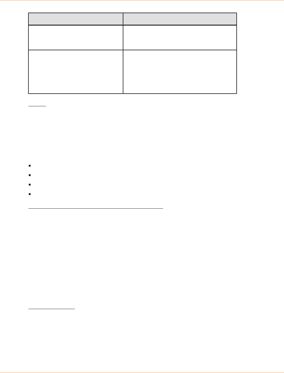
SANtricity_10.77 February 2011
LSI Corporation
- 1163 -
Parameter Description
host The name of the host to which the volume is
mapped. Enclose the host name in double
quotation marks (" ").
hostGroup The name of the host group to which the
volume is mapped. Enclose the host group
name in double quotation marks (" ").
defaultGroup is the host group that
contains the host to which the volume is
mapped.
Notes
Host I/O errors might result in volume groups with more than 32 volumes. This operation might also result in
internal controller reboots due to the expiration of the timeout period before the operation completes. If you
experience this issue, quiesce host I/O, and try the operation again.
When you use this command, you can specify one or more of the optional parameters.
You can apply these parameters to only one volume at a time:
addCapacity
segmentSize
userLabel
logicalUnitNumber
Add Capacity, Add Drives, and Segment Size
Setting the addCapacity parameter, the addDrives parameter, or the segmentSize parameter starts a
long-running operation that you cannot stop. These long-running operations are performed in the background
and do not prevent you from running other commands. To show the progress of long-running operations, use
the show volume actionProgress command.
The addDrives parameter supports both high-capacity drive trays and low-capacity drive trays. A high-
capacity drive tray has drawers that hold the drives. The drawers slide out of the drive tray to provide access
to the drives. A low-capacity drive tray does not have drawers. For a high-capacity drive tray, you must
specify the identifier (ID) of the drive tray, the ID of the drawer, and the ID of the slot in which a drive resides.
For a low-capacity drive tray, you need only specify the ID of the drive tray and the ID of the slot in which a
drive resides. For a low-capacity drive tray, an alternative method for identifying a location for a drive is to
specify the ID of the drive tray, set the ID of the drawer to 0, and specify the ID of the slot in which a drive
resides.
Access Volume
The access volume is the volume in a SAN environment that is used for in-band communication between
the storage management software and the storage array controller. This volume uses a LUN address and
consumes 20 MB of storage space that is not available for application data storage. An access volume is
required only for in-band managed storage arrays. If you specify the accessVolume parameter, the only
property you can set is the logicalUnitNumber parameter.

SANtricity_10.77 February 2011
LSI Corporation
- 1164 -
Cache Flush Modifier
Valid values for the cache flush modifier are listed in this table.
Value Description
Immediate Data is flushed as soon as it is placed into the cache.
250 Data is flushed after 250 ms.
500 Data is flushed after 500 ms.
750 Data is flushed after 750 ms.
1Data is flushed after 1 s.
1500 Data is flushed after 1500 ms.
2Data is flushed after 2 s.
5Data is flushed after 5 s.
10 Data is flushed after 10 s.
20 Data is flushed after 20 s.
60 Data is flushed after 60 s (1 min.).
120 Data is flushed after 120 s (2 min.).
300 Data is flushed after 300 s (5 min.).
1200 Data is flushed after 1200 s (20 min.).
3600 Data is flushed after 3600 s (1 hr).
Infinite Data in cache is not subject to any age or time
constraints. The data is flushed based on other criteria
that are managed by the controller.
Cache Without Battery Enabled
Write caching without batteries enables write caching to continue if the controller batteries are completely
discharged, not fully charged, or not present. If you set this parameter to TRUE without an uninterruptible
power supply (UPS) or other backup power source, you can lose data if the power to the storage array fails.
This parameter has no effect if write caching is disabled.
Modification Priority
Modification priority defines the amount of system resources that are used when modifying volume properties.
If you select the highest priority level, the volume modification uses the most system resources, which
decreases the performance for host data transfers.

SANtricity_10.77 February 2011
LSI Corporation
- 1165 -
Cache Read Prefetch
The cacheReadPrefetch parameter enables the controller to copy additional data blocks into cache while
the controller reads and copies data blocks that are requested by the host from the drive into cache. This
action increases the chance that a future request for data can be fulfilled from cache. Cache read prefetch
is important for multimedia applications that use sequential data transfers. The configuration settings for the
storage array that you use determine the number of additional data blocks that the controller reads into cache.
Valid values for the cacheReadPrefetch parameter are TRUE or FALSE.
Segment Size
The size of a segment determines how many data blocks that the controller writes on a single drive in a
volume before writing data on the next drive. Each data block stores 512 bytes of data. A data block is
the smallest unit of storage. The size of a segment determines how many data blocks that it contains. For
example, an 8-KB segment holds 16 data blocks. A 64-KB segment holds 128 data blocks.
When you enter a value for the segment size, the value is checked against the supported values that are
provided by the controller at run time. If the value that you entered is not valid, the controller returns a list of
valid values. Using a single drive for a single request leaves other drives available to simultaneously service
other requests.
If the volume is in an environment where a single user is transferring large units of data (such as multimedia),
performance is maximized when a single data transfer request is serviced with a single data stripe. (A data
stripe is the segment size that is multiplied by the number of drives in the volume group that are used for data
transfers.) In this case, multiple drives are used for the same request, but each drive is accessed only once.
For optimal performance in a multiuser database or file system storage environment, set your segment size to
minimize the number of drives that are required to satisfy a data transfer request.
Minimum Firmware Level
5.00 adds the addCapacity parameter.
7.10 adds the preReadRedundancyCheck parameter.
7.60 adds the drawerID user input.
7.75 adds the dataAssuranceDisabled parameter.
Set Volume Copy
This command defines the properties for a volume copy pair.
Syntax
set volumeCopy target [targetName]
[source [sourceName]]
copyPriority=(highest | high | medium | low | lowest)
targetReadOnlyEnabled=(TRUE | FALSE)
copyType=(online | offline)

SANtricity_10.77 February 2011
LSI Corporation
- 1166 -
Parameters
Parameter Description
target The name of the target volume for which you want to
define properties. Enclose the target volume name in
square brackets ([ ]). If the target volume name has
special characters, you also must enclose the target
volume name in double quotation marks (" ").
source The name of the source volume for which you want to
define properties. Enclose the source volume name in
square brackets ([ ]). If the source volume name has
special characters, you also must enclose the source
volume name in double quotation marks (" ").
copyPriority The priority that the volume copy has relative to host I/
O activity. Valid values are highest, high, medium,
low, or lowest.
targetReadOnlyEnabled The setting so that you can write to the target volume
or only read from the target volume. To write to
the target volume, set this parameter to FALSE.
To prevent writing to the target volume, set this
parameter to TRUE.
copyType Use this parameter to identify that a volume copy has
a snapshot. If the volume copy has a snapshot, set
this parameter to online. If the volume copy does
not have a snapshot, set this parameter to offline.
Notes
When you use this command, you can specify one or more of the optional parameters.
Minimum Firmware Level
5.40
7.77 adds creating a volume copy with snapshot.
Set Volume Group
This command defines the properties for a volume group.
Syntax
set volumeGroup [volumeGroupName]
addDrives=(trayID1,drawerID1,slotID1 ... trayIDn,drawerIDn,slotIDn)
raidLevel=(0 | 1 | 3 | 5 | 6)
owner=(a | b)
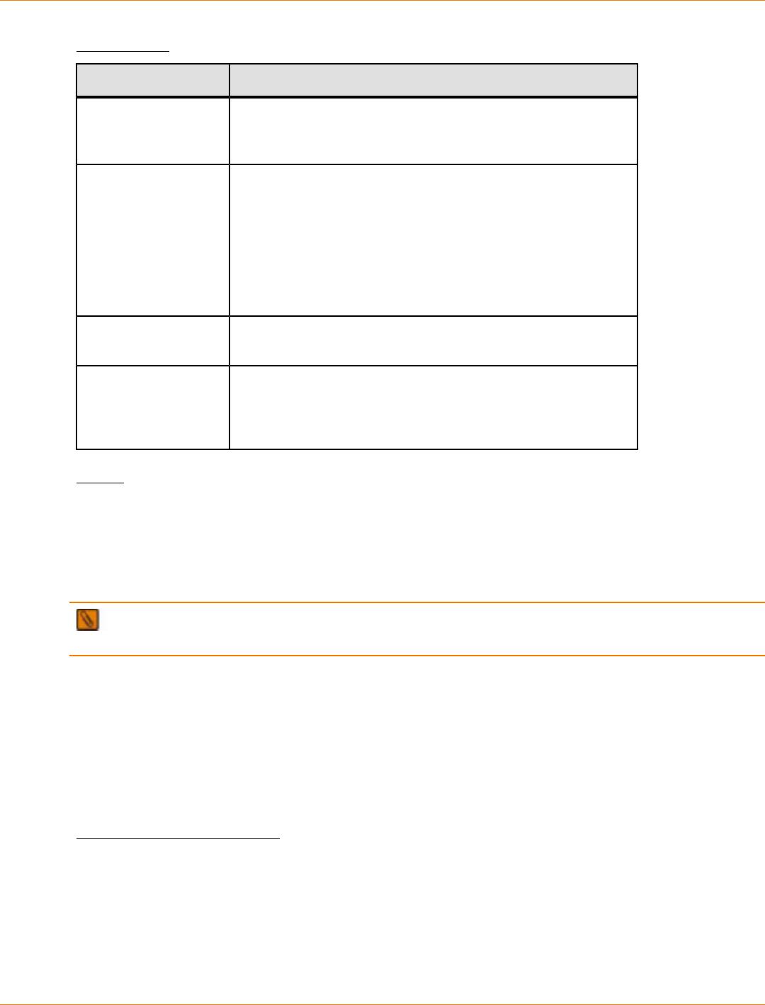
SANtricity_10.77 February 2011
LSI Corporation
- 1167 -
Parameters
Parameter Description
volumeGroup The alphanumeric identifier (including - and _) of the volume
group for which you want to set properties. Enclose the
volume group identifier in square brackets ([ ]).
addDrives The location of the drive that you want to add to the volume
group. For high-capacity drive trays, specify the tray ID value,
the drawer ID value, and the slot ID value for the drive. For
low-capacity drive trays, specify the tray ID value and the
slot ID value for the drive. Tray ID values are 0 to 99. Drawer
ID values are 1 to 5. Slot ID values are 1 to 32. Enclose the
tray ID value, the drawer ID value, and the slot ID value in
parentheses.
raidLevel The RAID level for the volume group. Valid values are 0, 1, 3,
5, or 6.
owner The controller that owns the volume group. Valid controller
identifiers are a or b, where a is the controller in slot A, and b
is the controller in slot B. Use this parameter only if you want
to change the volume group owner.
Notes
Host I/O errors might result in volume groups with more than 32 volumes. This operation also might result in
internal controller reboots because the timeout period ends before the volume group definition is set. If you
experience this issue, quiesce the host I/O operations, and try the command again.
When you use this command, you can specify one or more of the parameters.
NOTE Specifying the addDrives parameter or the raidLevel parameter starts a long-running
operation that you cannot stop.
The addDrives parameter supports both high-capacity drive trays and low-capacity drive trays. A high-
capacity drive tray has drawers that hold the drives. The drawers slide out of the drive tray to provide access
to the drives. A low-capacity drive tray does not have drawers. For a high-capacity drive tray, you must
specify the identifier (ID) of the drive tray, the ID of the drawer, and the ID of the slot in which a drive resides.
For a low-capacity drive tray, you need only specify the ID of the drive tray and the ID of the slot in which a
drive resides. For a low-capacity drive tray, an alternative method for identifying a location for a drive is to
specify the ID of the drive tray, set the ID of the drawer to 0, and specify the ID of the slot in which a drive
resides.
Minimum Firmware Level
6.10
7.10 adds RAID 6 capability.
7.30 removes the availability parameter.
7.60 adds the drawerID user input.
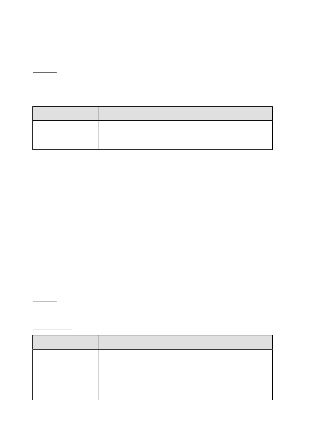
SANtricity_10.77 February 2011
LSI Corporation
- 1168 -
Set Volume Group Forced State
This command moves a volume group into a Forced state. Use this command if the start volumeGroup
import command does not move the volume group to an Imported state or if the import operation does not
work because of hardware errors. In a Forced state, the volume group can be imported, and you can then
identify the hardware errors.
Syntax
set volumeGroup [volumeGroupName] forcedState
Parameter
Parameter Description
volumeGroup The alphanumeric identifier (including - and _) of the volume
group that you want to place in a Forced state. Enclose the
volume group identifier in square brackets ([ ]).
Notes
You can move the drives that comprise a volume group from one storage array to another storage array.
The CLI provides three commands that let you move the drives. The commands are start volumeGroup
export, start volumeGroup import, and set volumeGroup forcedState.
In the Forced state, you can perform an import operation on the volume group.
Minimum Firmware Level
7.10
Show Cache Backup Device Diagnostic Status
This command returns the status of backup device diagnostic tests started by the start
cacheBackupDevice diagnostic command. If the diagnostics have finished, all of the results of the
diagnostic tests are shown. If the diagnostics have not finished, only the results of the diagnostic tests that
finished are shown. The results of the test are shown on the terminal, or you can write the results to a file.
Syntax
show cacheBackupDevice controller [(a | b)] diagnosticStatus [file="fileName"]
Parameters
Parameter Description
controller The controller that has the cache backup device on which you
are running the diagnostic tests. Valid controller identifiers
are a or b, where a is the controller in slot A, and b is the
controller in slot B. Enclose the controller identifier in square
brackets ([ ]). If you do not specify a controller, the storage
management software returns a syntax error.
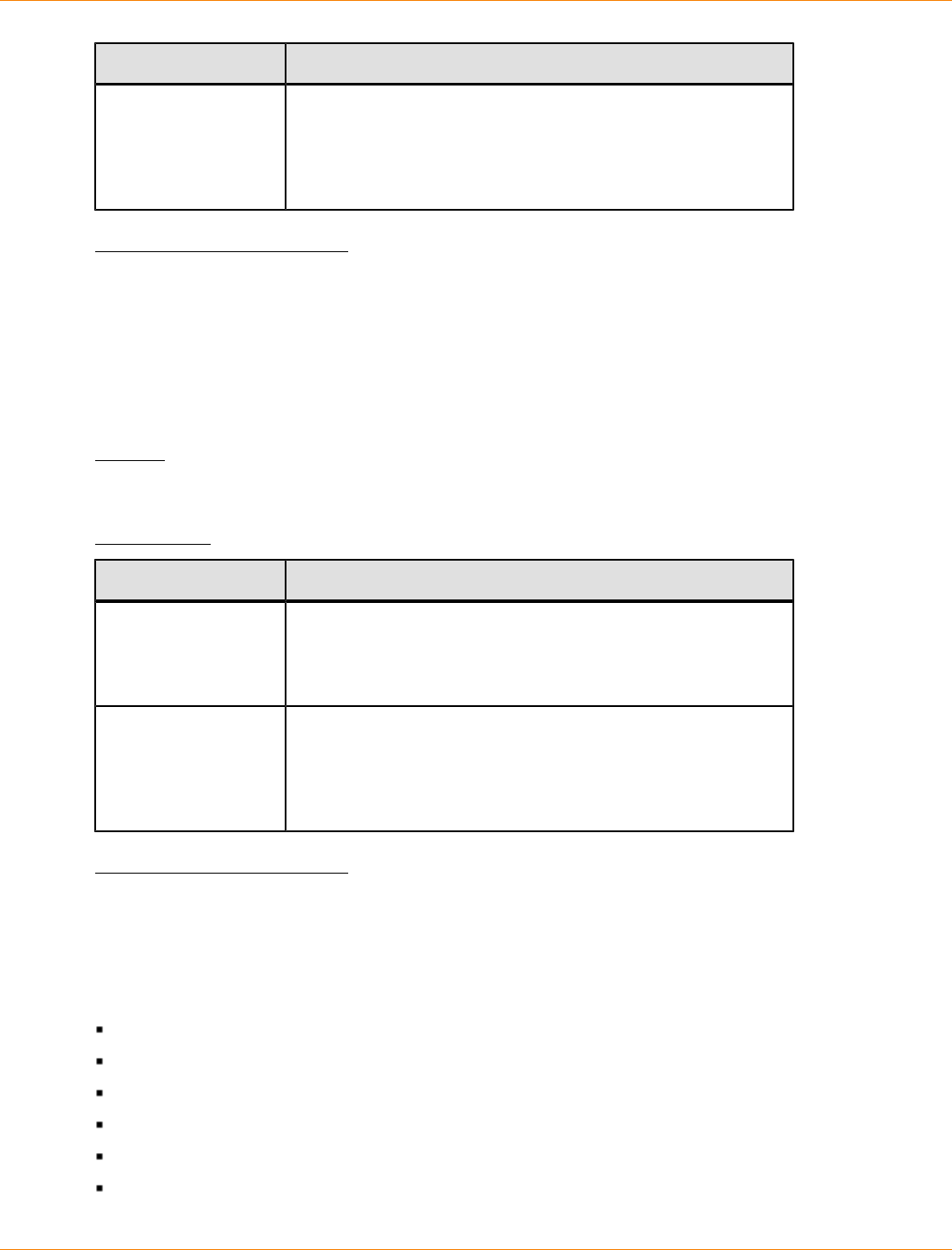
SANtricity_10.77 February 2011
LSI Corporation
- 1169 -
Parameter Description
file The name of the file that contains the result of the diagnostic
tests. Enclose the file name in double quotation marks (" ").
This command does not automatically append a file extension
to the file name. You must add an extension when you enter
the file name.
Minimum Firmware Level
7.60 adds the capability for cache backup device diagnostics.
Show Cache Memory Diagnostic Status
This command returns the status of cache memory diagnostics started by the start controller
diagnostic command. If the diagnostics have finished, all of the results of the diagnostic tests are shown. If
all of the diagnostics have not finished, only the results of the diagnostic tests that finished are shown.
Syntax
show cacheMemory controller [(a | b)] diagnosticStatus file="fileName"
Parameters
Parameter Description
controller The controller that has the cache memory on which you are
running the diagnostic tests. Valid controller identifiers are a or
b, where a is the controller in slot A, and b is the controller in
slot B. Enclose the controller identifier in square brackets ([ ]).
file The name of the file that contains the result of the diagnostic
tests. Enclose the file name in double quotation marks (" ").
This command does not automatically append a file extension
to the file name. You must add an extension when you enter
the file name.
Minimum Firmware Level
7.60 adds the capability for the cache memory diagnostics.
Show Controller
For each controller in a storage array, this command returns the following information:
The status (Online or Offline)
The current firmware and NVSRAM configuration
The pending firmware configuration and NVSRAM configuration (if any)
The board ID
The product ID
The product revision
SANtricity_10.77 February 2011
LSI Corporation
- 1170 -
The serial number
The date of manufacture
The cache size or the processor size
The date and the time to which the controller is set
The associated volumes (including the preferred owner)
The Ethernet port
The physical disk interface
The host interface, which applies only to Fibre Channel host interfaces
Syntax
show (allControllers | controller [(a | b)]) [summary]
Parameters
Parameter Description
allControllers The setting to return information about both controllers in the
storage array.
controller The setting to return information about a specific controller in
the storage array. Valid controller identifiers are a or b, where
a is the controller in slot A, and b is the controller in slot B.
Enclose the controller identifier in square brackets ([ ]).
summary The setting to return a concise list of information about both
controllers in the storage array.
Notes
The following list is an example of the information that is returned by the show controller command.
This example only shows how the information is presented and should not be considered to represent best
practice for a storage array configuration.
Controller in slot A
Status: Online
Current configuration
Firmware version: 96.10.21.00
Appware version: 96.10.21.00
Bootware version: 96.10.21.00
NVSRAM version: N4884-610800-001
Pending configuration
Firmware version: Not applicable
Appware version: Not applicable
Bootware version: Not applicable
NVSRAM version: Not applicable
Transferred on: Not applicable
Board ID: 4884
Product ID: INF-01-00
Product revision: 9610
Serial number: 1T14148766
Date of manufacture: October 14, 2006

SANtricity_10.77 February 2011
LSI Corporation
- 1171 -
Cache/processor size (MB): 1024/128
Date/Time: Wed Feb 18 13:55:53 MST 2008
Associated Volumes (* = Preferred Owner):
1*, 2*, CTL 0 Mirror Repository*, Mirror Repository 1*,
JCG_Remote_MirrorMenuTests*
Ethernet port: 1
MAC address: 00:a0:b8:0c:c3:f5
Host name: ausctlr9
Network configuration: Static
IP address: 172.22.4.249
Subnet mask: 255.255.255.0
Gateway: 172.22.4.1
Remote login: Enabled
Drive interface: Fibre
Channel: 1
Current ID: 125/0x1
Maximum data rate: 2 Gbps
Current data rate: 1 Gbps
Data rate control: Switch
Link status: Up
Drive interface: Fibre
Channel: 2
Current ID: 125/0x1
Maximum data rate: 2 Gbps
Current data rate: 1 Gbps
Data rate control: Switch
Link status: Up
Drive interface: Fibre
Channel: 3
Current ID: 125/0x1
Maximum data rate: 2 Gbps
Current data rate: 1 Gbps
Data rate control: Switch
Link status: Up
Drive interface: Fibre
Channel: 4
Current ID: 125/0x1
Maximum data rate: 2 Gbps
Current data rate: 1 Gbps
Data rate control: Switch
Link status: Up
Host interface: Fibre
Port: 1
Current ID: Not applicable/0xFFFFFFFF
Preferred ID: 126/0x0
NL-Port ID: 0x011100
Maximum data rate: 2 Gbps
Current data rate: 1 Gbps
Data rate control: Switch
Link status: Up
Topology: Fabric Attach
World-wide port name: 20:2c:00:a0:b8:0c:c3:f6
World-wide node name: 20:2c:00:a0:b8:0c:c3:f5
Part type: HPFC-5200 revision 10
Host interface: Fibre
SANtricity_10.77 February 2011
LSI Corporation
- 1172 -
Port: 2
Current ID: Not applicable/0xFFFFFFFF
Preferred ID: 126/0x0
NL-Port ID: 0x011100
Maximum data rate: 2 Gbps
Current data rate: 1 Gbps
Data rate control: Switch
Link status: Up
Topology: Fabric Attach
World-wide port name: 20:2c:00:a0:b8:0c:c3:f7
World-wide node name: 20:2c:00:a0:b8:0c:c3:f5
Part type: HPFC-5200 revision 10
When you use the summary parameter, the command returns the list of information without the drive channel
information and the host channel information.
The show storageArray command also returns detailed information about the controller.
Minimum Firmware Level
5.43 adds the summary parameter.
Show Controller Diagnostic Status
This command returns the status of controller diagnostics started by the start controller diagnostic
command. If the diagnostics have finished, the entire results of the diagnostic tests are shown. If the
diagnostic tests have not finished, only the results of the of the tests that are finished are shown. The results
of the test are shown on the terminal, or you can write the results to a file.
Syntax
show controller [(a | b)] diagnosticStatus [file=filename]
Parameters
Parameter Description
controller The setting to return information about a specific controller in
the storage array. Valid controller identifiers are a or b, where
a is the controller in slot A, and b is the controller in slot B.
Enclose the controller identifier in square brackets ([ ]).
file The name of the file that contains the results of the diagnostic
tests. This command does not automatically append a file
extension to the file name. You must add an extension when
you enter the file name.
Minimum Firmware Level
7.70 adds the capability for controller diagnostic status.

SANtricity_10.77 February 2011
LSI Corporation
- 1173 -
Show Controller NVSRAM
This command returns a list of the NVSRAM byte values for the specified host type. If you do not enter the
optional parameters, this command returns a list of all of the NVSRAM byte values. To view an example of a
table of NVSRAM values that are returned by this command, see "" on page .
Syntax
show (allControllers | controller [(a | b)])
NVSRAM [hostType=hostTypeIndexLabel | host="hostName"]
Parameters
Parameter Description
allControllers The setting to return information about both controllers in the
storage array.
controller The setting to return information about a specific controller in the
storage array. Valid controller identifiers are a or b, where a is the
controller in slot A, and b is the controller in slot B. Enclose the
controller identifier in square brackets ([ ]).
hostType The index label or number of the host type. Use the show
storageArray hostTypeTable command to generate a list of
available host type identifiers.
host The name of the host that is connected to the controllers. Enclose
the host name in double quotation marks (" ").
Notes
Use the show controller NVSRAM command to show parts of or all of the NVSRAM before using the
set controller command to change the NVSRAM values. Before making any changes to the NVSRAM,
contact your Customer and Technical Support representative to learn what regions of the NVSRAM you can
modify.
Minimum Firmware Level
6.10
Show Current iSCSI Sessions
This command returns information about an iSCSI session for either an iSCSI initiator or an iSCSI target.
Syntax
show iscsiInitiator ["initiatorName"] iscsiSessions
show iscsiTarget ["targetName"] iscsiSessions
SANtricity_10.77 February 2011
LSI Corporation
- 1174 -
Parameters
Parameter Description
iscsiInitiator The name of the iSCSI initiator for which you want to obtain
session information. Enclose the iSCSI initiator name in
double quotation marks (" "). You must also enclose the name
in either square brackets ([ ]) or angle brackets (< >).
iscsiTarget The name of the iSCSI target for which you want to obtain
session information. Enclose the iSCSI target name in double
quotation marks (" "). You must also enclose the name in
either square brackets ([ ]) or angle brackets (< >).
Notes
If you enter this command without defining any arguments, this command returns information about all of the
iSCSI sessions that are currently running. The following command returns information about all of the current
iSCSI sessions:
show iscsiSessions
To limit the information that is returned, enter a specific iSCSI initiator or a specific iSCSI target. This
command then returns information about the session for only the iSCSI initiator or the iSCSI target that you
named.
Minimum Firmware Level
7.10
Show Drive
For each drive in the storage array, this command returns the following information:
The total number of drives
The type of drive (Fibre Channel, SATA, or SAS)
Information about the basic drive:
The tray location and the slot location
The status
The capacity
The data transfer rate
The product ID
The firmware level
Information about the drive channel:
The tray location and the slot location
The preferred channel
The redundant channel
Hot spare coverage
Details for each drive
SANtricity_10.77 February 2011
LSI Corporation
- 1175 -
Depending on the size of your storage array, this information can be several pages long. To view an
example of the drive information that is returned by the show drives command, refer to the "Examples of
Information Returned by the Show Commands" topic in "Configuring and Maintaining a Storage Array Using
the Command Line Interface." In addition, the drive information is returned for the show storageArray
profile command.
Syntax
show (allDrives
[driveMediaType=(HDD | SSD | unknown | allMedia)] |
[driveType=(fibre | SATA | SAS)]) |
drive [trayID,drawerID,slotID] |
drives [trayID1,drawerID1,slotID1 ... trayIDn,drawerIDn,slotIDn])
summary
Parameters
Parameter Description
allDrives The setting to return information about all of the drives in the
storage array.
driveMediaType The type of drive media for which you want to retrieve
information. The following values are valid types of drive
media:
HDD – Use this option when you have hard drives in the
drive tray.
SSD – Use this option when you have solid state drives in
the drive tray.
unknown – Use this option if you are not sure what types
of drive media are in the drive tray.
allMedia – Use this option when you want to use all
types of drive media that are in the drive tray.
driveType The type of drive for which you want to retrieve information.
You cannot mix drive types.
Valid drive types are :
fibre
SATA
SAS
If you do not specify a drive type, the command defaults to
fibre.
drive or drives The location of the drive for which you want to retrieve
information. For high-capacity drive trays, specify the tray
ID value, the drawer ID value, and the slot ID value for each
drive. For low-capacity drive trays, specify the tray ID value
and the slot ID value for each drive. Tray ID values are 0 to
99. Drawer ID values are 1 to 5. Slot ID values are 1 to 32.
Enclose the tray ID values, the drawer ID values, and the slot
ID values in parentheses.
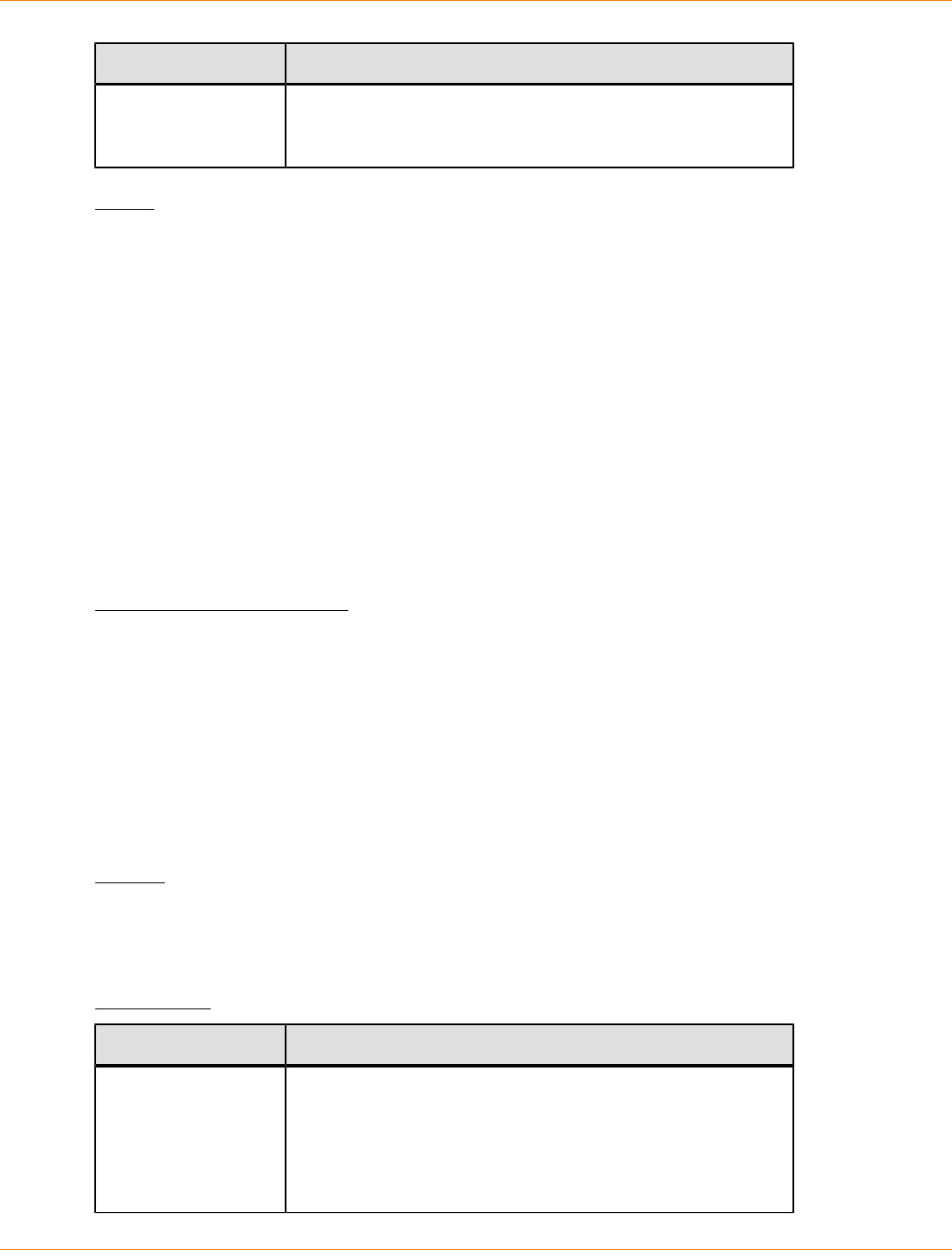
SANtricity_10.77 February 2011
LSI Corporation
- 1176 -
Parameter Description
summary The setting to return the status, the capacity, the data transfer
rate, the product ID, and the firmware version for the specified
drives.
Notes
To determine information about the type and location of all of the drives in the storage array, use the
allDrives parameter.
To determine the information about the Fibre Channel, SATA, or SAS drives in the storage array, use the
driveType parameter.
To determine the type of drive in a specific location, use the drive parameter, and enter the tray ID and the
slot ID for the drive.
The drive parameter supports both high-capacity drive trays and low-capacity drive trays. A high-capacity
drive tray has drawers that hold the drives. The drawers slide out of the drive tray to provide access to the
drives. A low-capacity drive tray does not have drawers. For a high-capacity drive tray, you must specify
the identifier (ID) of the drive tray, the ID of the drawer, and the ID of the slot in which a drive resides. For a
low-capacity drive tray, you need only specify the ID of the drive tray and the ID of the slot in which a drive
resides. For a low-capacity drive tray, an alternative method for identifying a location for a drive is to specify
the ID of the drive tray, set the ID of the drawer to 0, and specify the ID of the slot in which a drive resides.
Minimum Firmware Level
5.43
7.60 adds the drawerID user input and the driveMediaType parameter.
Show Drive Channel Statistics
This command shows the cumulative data transfer for the drive channel and error information. If the controller
has automatically degraded a drive channel, this command also shows interval statistics. When you use this
command, you can show information about one specific drive channel, several drive channels, or all drive
channels.
Syntax
show (driveChannel [(1 | 2 | 3 | 4 | 5 | 6 | 7 | 8)] |
driveChannels [1 2 3 4 5 6 7 8] |
allDriveChannels) stats
Parameters
Parameter Description
driveChannel The identifier number of a specific drive channel for which
you want to show information. Valid drive channel values are
1, 2, 3, 4, 5, 6, 7, or 8. Enclose the drive channel in square
brackets ([ ]).
Use this parameter when you want to show the statistics for
only one drive channel.
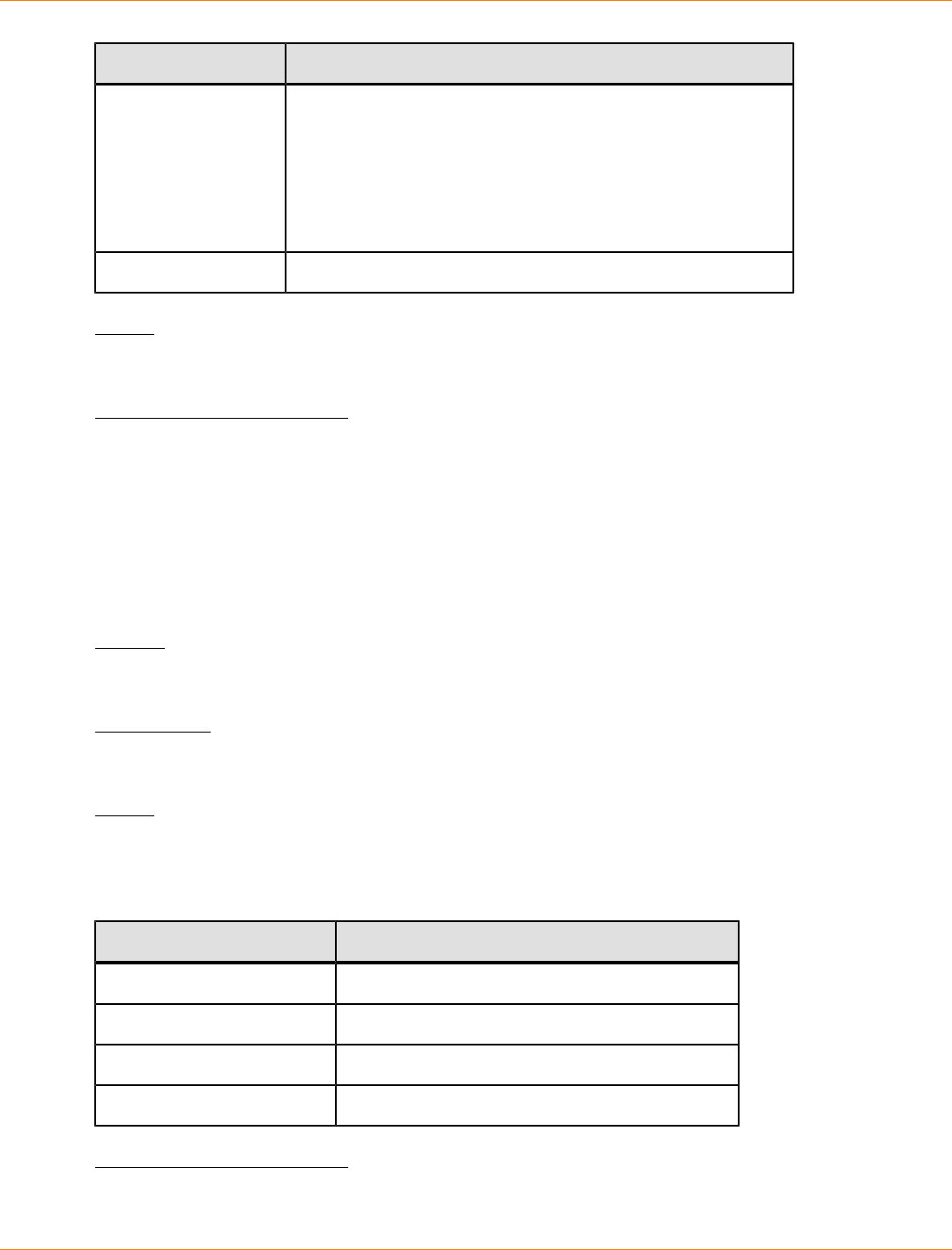
SANtricity_10.77 February 2011
LSI Corporation
- 1177 -
Parameter Description
driveChannels The identifier numbers of several drive channels for which
you want to show information. Valid drive channel values are
1, 2, 3, 4, 5, 6, 7, or 8. Enclose the drive channels in square
brackets ([ ]) with the drive channel value separated with a
space.
Use this parameter when you want to show the statistics for
more than one drive channel.
allDriveChannels The identifier that selects all of the drive channels.
Notes
None.
Minimum Firmware Level
6.10
7.15 adds an update to the drive channel identifier.
Show Drive Download Progress
This command returns the status of firmware downloads for the drives that are targeted by the download
drive firmware command or the download storageArray driveFirmware command.
Syntax
show allDrives downloadProgress
Parameters
None.
Notes
When all of the firmware downloads have successfully completed, this command returns good status. If any
firmware downloads fail, this command shows the firmware download status of each drive that was targeted.
This command returns the statuses shown in this table.
Status Definition
Successful The downloads completed without errors.
Not Attempted The downloads did not start.
Partial Download The downloads are in progress.
Failed The downloads completed with errors.
Minimum Firmware Level
6.10
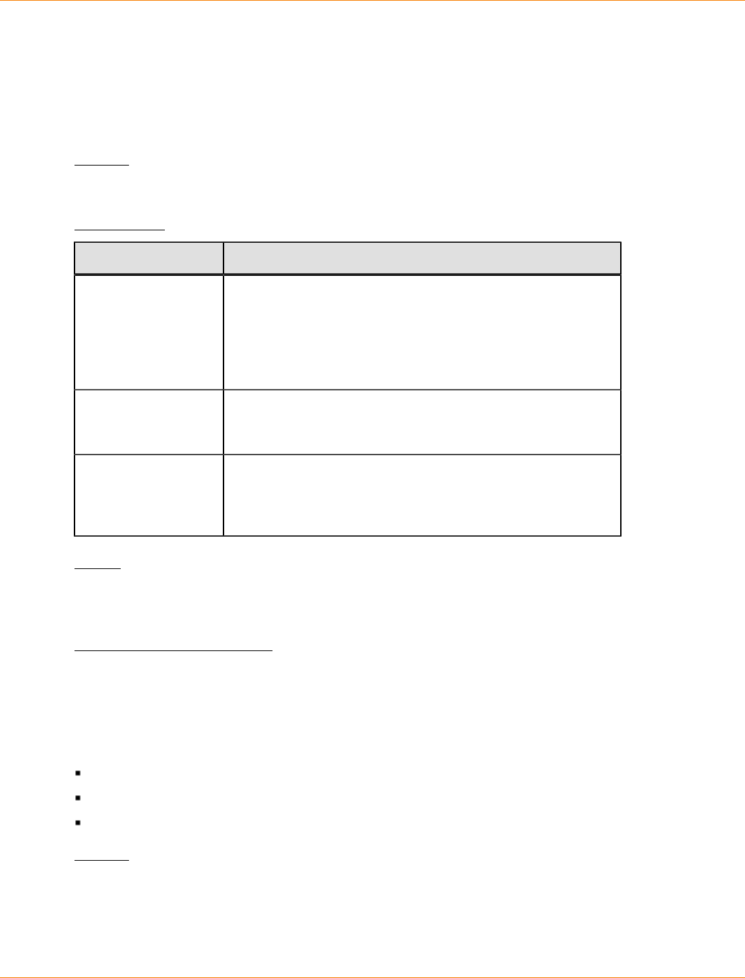
SANtricity_10.77 February 2011
LSI Corporation
- 1178 -
Show Host Interface Card Diagnostic Status
This command returns the status of running, interrupted, or completed host interface card diagnostics started
by the start hostCard diagnostic command. If the diagnostics have finished, the entire results of the
diagnostic tests are shown. If the diagnostics have not finished, only the results of the tests that are finished
are shown. The results of the test are shown on the terminal, or you can write the results to a file.
Syntax
show hostCard controller [(a | b)] diagnosticStatus [progressOnly] [file=filename]
Parameters
Parameter Description
controller The controller that has the host interface card on which you
are running the diagnostic tests. Valid controller identifiers
are a or b, where a is the controller in slot A, and b is the
controller in slot B. Enclose the controller identifier in square
brackets ([ ]). If you do not specify a controller, the storage
management software returns a syntax error.
progressOnly The progressOnly parameter, shows the progress of the
diagnostic test without waiting for the diagnostic tests to
completely finish.
file The name of the file that contains the results of the diagnostic
tests. This command does not automatically append a file
extension to the file name. You must add an extension when
you enter the file name.
Notes
The progressOnly parameter is useful for seeing the progress of command scripts that need to sequentially
complete operations.
Minimum Firmware Level
7.70 adds the capability for controller host interface card diagnostics.
Show Host Ports
For all of the host ports that are connected to a storage array, this command returns this information:
The host port identifier
The host port name
The host type
Syntax
show allHostPorts
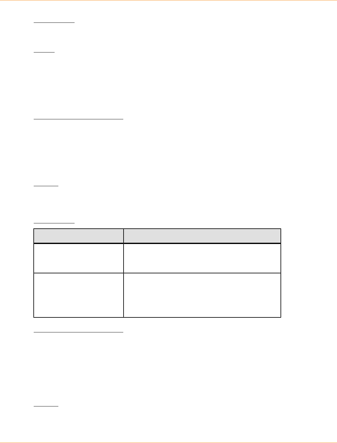
SANtricity_10.77 February 2011
LSI Corporation
- 1179 -
Parameters
None.
Notes
This command returns HBA host port information similar to this example.
HOST PORT IDENTIFIER HOST PORT NAME HOST TYPE
12:34:56:54:33:22:22:22 Jupiter1 Solaris
12:34:56:78:98:98:88:88 Pluto1 Windows 2000/Server 2003 Clustered
54:32:12:34:34:55:65:66 Undefined Undefined
Minimum Firmware Level
5.40
Show Remote Volume Mirroring Volume Candidates
This command returns information about the candidate volumes on a remote storage array that you can use
as secondary volumes in a Remote Volume Mirroring configuration.
Syntax
show remoteMirror candidates primary="volumeName"
remoteStorageArrayName="storageArrayName"
Parameters
Parameter Description
primary The name of the local volume that you want for the
primary volume in the remote-mirror pair. Enclose the
primary volume name in double quotation marks (" ").
remoteStorageArrayName The remote storage array that contains possible
volumes for a secondary volume. If the remote
storage array name has special characters, you must
also enclose the remote storage array name in double
quotation marks (" ").
Minimum Firmware Level
5.40
Show Remote Volume Mirroring Volume Synchronization Progress
This command returns the progress of data synchronization between the primary volume and the secondary
volume in a Remote Volume Mirroring configuration. This command shows the progress as a percentage of
data synchronization that has been completed.
Syntax
show remoteMirror (localVolume ["volumeName"] |
localVolumes ["volumeName1" ... "volumeNameN"])
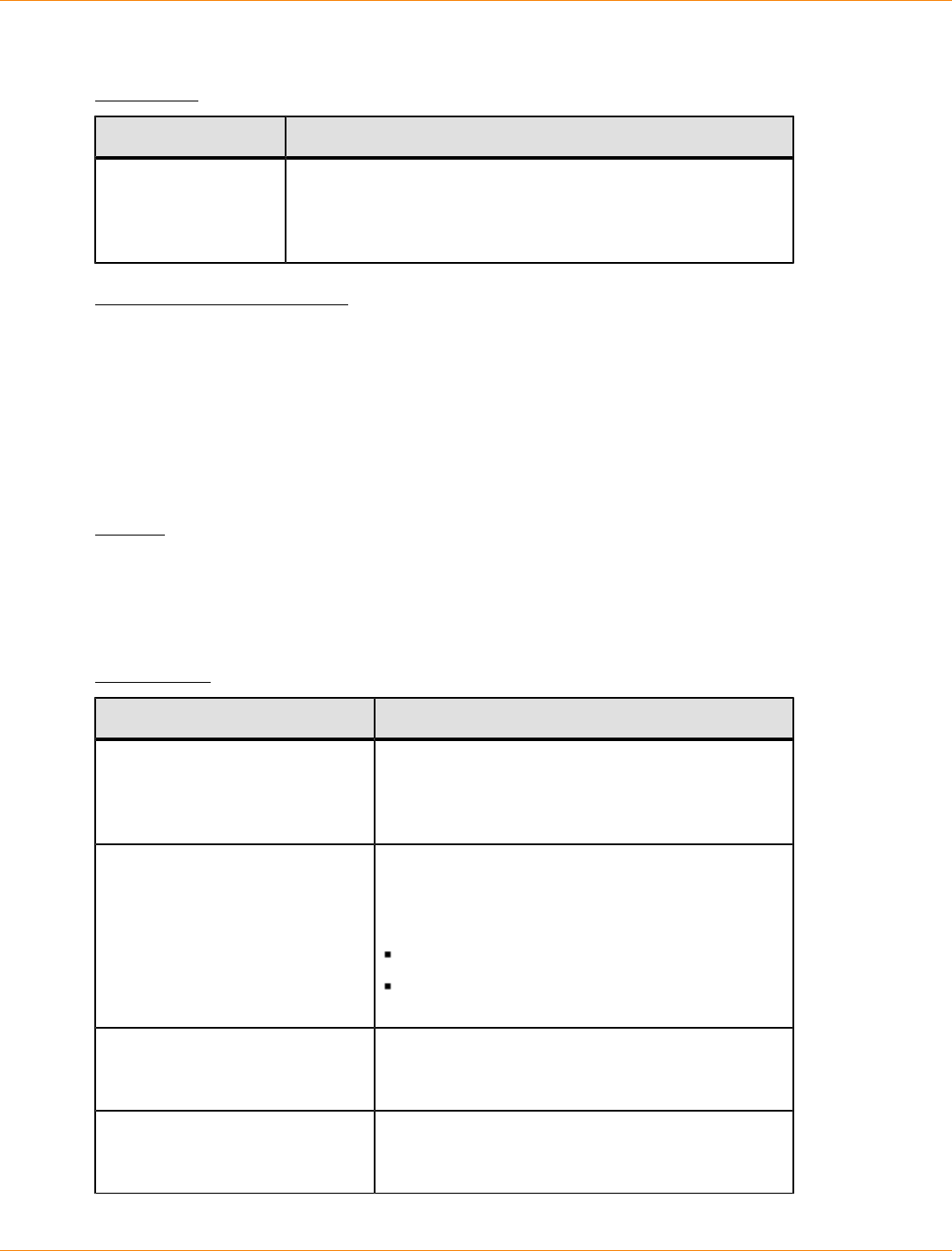
SANtricity_10.77 February 2011
LSI Corporation
- 1180 -
synchronizationProgress
Parameter
Parameter Description
localVolume or
localVolumes
The name of the primary volume of the remote mirror pair for
which you want to check synchronization progress. Enclose
the primary volume name in double quotation marks (" ")
inside of square brackets ([ ]).
Minimum Firmware Level
5.40
Show Storage Array
This command returns configuration information about the storage array. The parameters return lists of values
for the components and features in the storage array. You can enter the command with a single parameter or
more than one parameter. If you enter the command without any parameters, the entire storage array profile
is shown (which is the same information as if you entered the profile parameter).
Syntax
show storageArray | autoSupportConfig | profile |
batteryAge | connections | defaultHostType | healthStatus |
hostTypeTable | hotSpareCoverage | features | time |
volumeDistribution | longRunningOperations | summary
Parameters
Parameter Description
profile The parameter to show all of the properties of the
logical components and the physical components
that comprise the storage array. The information
appears in several screens.
autoSupportConfig The parameter to return information about the
current state of the operation to automatically
collect support data. The following information is
returned:
Whether the operation is enabled or disabled
The location of the folder where the support
data file is located
batteryAge The parameter to show the status, the age of the
battery in days, and the number of days until the
battery needs to be replaced.
connections The parameter to show a list of where the drive
channel ports are located and where the drive
channels are connected.

SANtricity_10.77 February 2011
LSI Corporation
- 1181 -
Parameter Description
defaultHostType The parameter to show the default host type and
the host type index.
healthStatus The parameter to show the health, logical
properties, and physical component properties of
the storage array.
hostTypeTable The parameter to show a table of all of the host
types that are known to the controller. Each row in
the table shows a host type index and the platform
that the host type index represents.
hotSpareCoverage The parameter to show information about which
volumes of the storage array have hot spare
coverage and which volumes do not.
features The parameter to show a list of the feature
identifiers for all enabled premium features in the
storage array.
time The parameter to show the current time to which
both controllers in the storage array are set.
volumeDistribution The parameter to show the current controller
owner for each volume in the storage array.
longRunningOperations The parameter to show the long running
operations for each volume group and each
volume in the storage array.
The longRunningOperation parameter returns
this information:
Name of the volume group or volume
Long running operation
Status
% complete
Time left
summary The parameter to show a concise list of information
about the storage array configuration.
Notes
The profile parameter shows detailed information about the storage array. The information appears on
several screens on a display monitor. You might need to increase the size of your display buffer to see all of
the information. Because this information is so detailed, you might want to save the output of this parameter
to a file. To save the output to a file, run the show storageArray command that looks like this example.
-c "show storageArray profile;" -o "c:\\folder\\storageArrayProfile.txt"
The previous command syntax is for a host that is running a Windows operating system. The actual syntax
varies depending on your operating system.

SANtricity_10.77 February 2011
LSI Corporation
- 1182 -
The profile parameter also returns information about the power supplies if the storage array has that
capability.
"*** UNDEFINED CROSS-REF FORMAT [Heading] ***" shows the type of information that is returned. When
you save the information to a file, you can use the information as a record of your configuration and as an aid
during recovery.
The batteryAge parameter returns information in this form.
Battery status: Optimal
Age: 1 day(s)
Days until replacement: 718 day(s)
The newer controller trays do not support the batteryAge parameter.
The defaultHostType parameter returns information in this form.
Default host type: Linux (Host type index 6)
The healthStatus parameter returns information in this form.
Storage array health status = optimal.
The hostTypeTable parameter returns information in this form.
NVSRAM HOST TYPE INDEX DEFINITIONS
INDEX AVT STATUS TYPE
0 Disabled Windows NT Non-Clustered (SP5 or higher)
1 (Default) Disabled Windows 2000/Server 2003 Non-Clustered
2 Disabled Solaris
3 Enabled HP-UX
4 Disabled AIX
5 Disabled Irix
6 Enabled Linux
7 Disabled Windows NT Clustered (SP5 or higher)
8 Disabled Windows 2000/Server 2003 Clustered
9 Enabled Netware Non-Failover
10 Enabled PTX
11 Enabled Netware Failover
12 Enabled Solaris (with Veritas DMP)
The hotSpareCoverage parameter returns information in this form.
The following volume groups are not protected: 2, 1
Total hot spare drives: 0
Standby: 0
In use: 0
The features parameter returns information in this form.
storagePartitionMax
snapshot
remoteMirror
volumeCopy

SANtricity_10.77 February 2011
LSI Corporation
- 1183 -
The time parameter returns information in this form.
Controller in Slot A
Date/Time: Thu Jun 03 14:54:55 MDT 2004
Controller in Slot B
Date/Time: Thu Jun 03 14:54:55 MDT 2004
The longRunningOperations parameter returns information in this form:
LOGICAL DEVICES OPERATION STATUS TIME REMAINING
Volume-2 Volume Disk Copy 10% COMPLETED 5 min
The information fields returned by the longRunningOperations parameter have these meanings:
NAME is the name of a volume that is currently in a long running operation. The volume name must have
the "Volume" as a prefix.
OPERATION lists the operation being performed on the volume group or volume.
% COMPLETE shows how much of the long running operation has been performed.
STATUS can have one of these meaings:
Pending – The long running operation has not started but will start after the current operation is
completed.
In Progress – The long running operation has started and will run until completed or stopped by user
request.
TIME LEFT indicates the duration remaining to completing the current long running operation. The time
is in an "hours minute" format. If less than an hour remains, only the minutes are shown. If less than a
minute remains, the message "less than a minute" is shown.
The volumeDistribution parameter returns information in this form.
volume name: 10
Current owner is controller in slot: A
volume name: CTL 0 Mirror Repository
Current owner is controller in slot: A
volume name: Mirror Repository 1
Current owner is controller in slot:A
volume name: 20
Current owner is controller in slot:A
volume name: JCG_Remote_MirrorMenuTests
Current owner is controller in slot:A
Minimum Firmware Level
5.00 adds the defaultHostType parameter.
5.43 adds the summary parameter.
6.10 adds the volumeDistribution parameter.
6.14 adds the connections parameter.
7.10 adds the autoSupportConfig parameter.
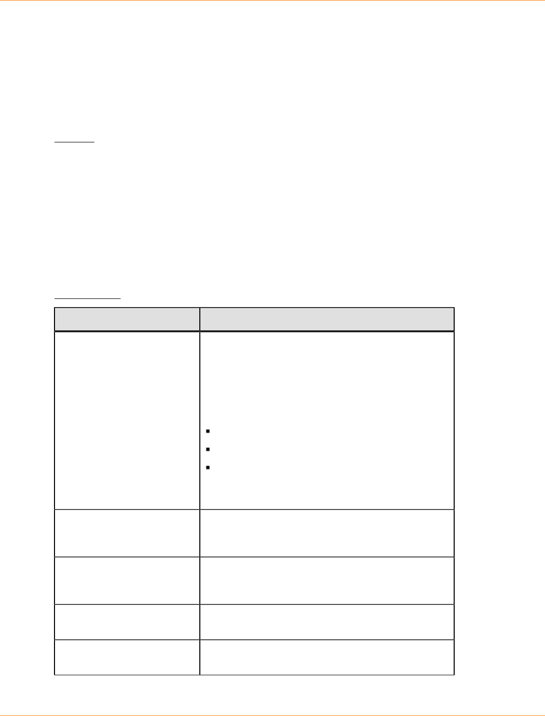
SANtricity_10.77 February 2011
LSI Corporation
- 1184 -
7.77 adds the longRunningOperations parameter.
Show Storage Array Auto Configure
This command shows the default auto-configuration that the storage array creates if you run the
autoConfigure storageArray command. If you want to determine whether the storage array can
support specific properties, enter the parameter for the properties when you run this command. You do not
need to enter any parameters for this command to return configuration information.
Syntax
show storageArray autoConfiguration
[driveType=(fibre | SATA | SAS)
raidLevel=(0 | 1 | 3 | 5 | 6)
volumeGroupWidth=numberOfDrives
volumeGroupCount=numberOfVolumeGroups
volumesPerGroupCount=numberOfVolumesPerGroup
hotSpareCount=numberOfHotspares
segmentSize=segmentSizeValue
cacheReadPrefetch=(TRUE | FALSE)
securityType=(none | capable | enabled)]
Parameters
Parameter Description
driveType The type of drives that you want to use for the storage
array.
The driveType parameter is not required if only one
type of drive is in the storage array. You must use this
parameter when you have more than one type of drive
in your storage array.
Valid drive types are :
fibre
SATA
SAS
If you do not specify a drive type, the command
defaults to fibre.
raidLevel The RAID level of the volume group that contains the
drives in the storage array. Valid RAID levels are 0, 1,
3, 5, or 6.
volumeGroupWidth The number of drives in a volume group in the storage
array, which depends on the capacity of the drives.
Use integer values.
volumeGroupCount The number of volume groups in the storage array.
Use integer values.
volumesPerGroupCount The number of equal-capacity volumes per volume
group. Use integer values.
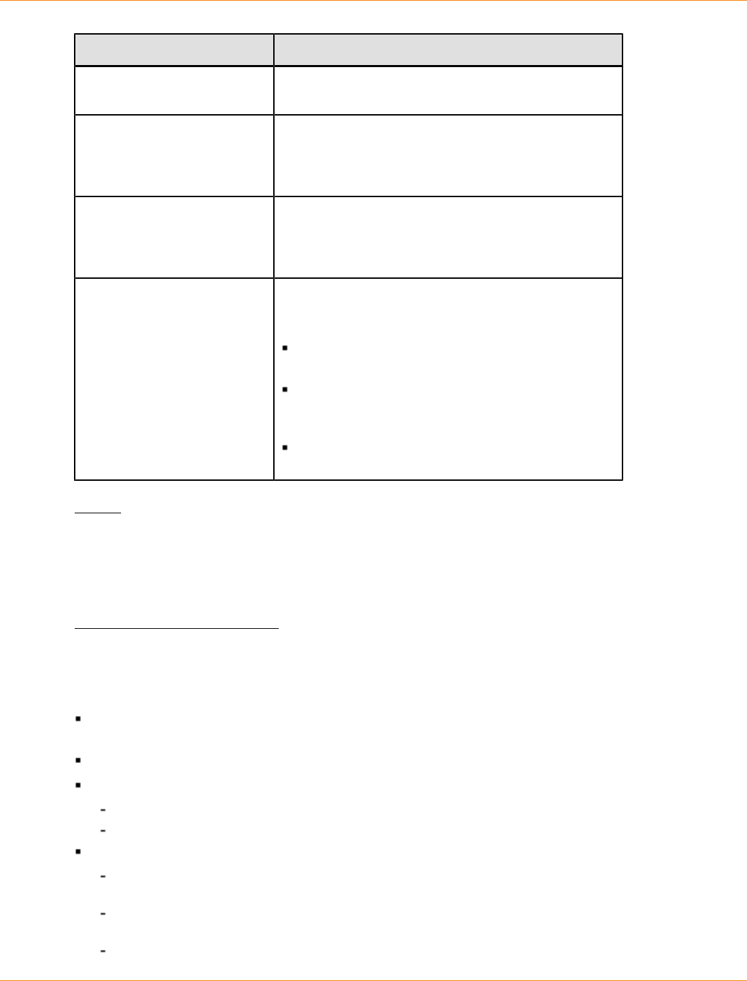
SANtricity_10.77 February 2011
LSI Corporation
- 1185 -
Parameter Description
hotSpareCount The number of hot spares that you want in the storage
array. Use integer values.
segmentSize The amount of data (in KB) that the controller writes
on a single drive in a volume before writing data on
the next drive. Valid values are 8, 16, 32, 64, 128,
256, or 512.
cacheReadPrefetch The setting to turn on or turn off cache read prefetch.
To turn off cache read prefetch, set this parameter
to FALSE. To turn on cache read prefetch, set this
parameter to TRUE.
securityType The setting to specify the security level when creating
the volume groups and all associated volumes. These
settings are valid:
none – The volume group and volumes are not
secure.
capable – The volume group and volumes are
capable of having security set, but security has
not been enabled.
enabled – The volume group and volumes have
security enabled.
Notes
If you do not specify any properties, this command returns the RAID Level 5 candidates for each drive type. If
RAID Level 5 candidates are not available, this command returns candidates for RAID Level 6, RAID Level 3,
RAID Level 1, or RAID Level 0. When you specify auto configuration properties, the controllers validate that
the firmware can support the properties.
Drives and Volume Group
A volume group is a set of drives that are logically grouped together by the controllers in the storage array.
The number of drives in a volume group is a limitation of the RAID level and the controller firmware. When
you create a volume group, follow these guidelines:
Beginning with firmware version 7.10, you can create an empty volume group so that you can reserve the
capacity for later use.
You cannot mix drive types, such as SAS and Fibre Channel, within a single volume group.
The maximum number of drives in a volume group depends on these conditions:
The type of controller
The RAID level
RAID levels include: 0, 1, 10, 3, 5, and 6.
In a CDE3992 or a CDE3994 storage array, a volume group with RAID level 0 and a volume group
with RAID level 10 can have a maximum of 112 drives.
In a CE6998 storage array, a volume group with RAID level 0 and a volume group with RAID level 10
can have a maximum of 224 drives.
A volume group with RAID level 3, RAID level 5, or RAID level 6 cannot have more than 30 drives.

SANtricity_10.77 February 2011
LSI Corporation
- 1186 -
A volume group with RAID level 6 must have a minimum of five drives.
If a volume group with RAID level 1 has four or more drives, the storage management software
automatically converts the volume group to a RAID level 10, which is RAID level 1 + RAID level 0.
If a volume group contains drives that have different capacities, the overall capacity of the volume group
is based on the smallest capacity drive.
To enable tray loss protection, you must create a volume group that uses drives located in at least three
drive trays.
Hot Spares
Hot spare drives can replace any failed drive in the storage array. A hot spare drive must have capacity
greater than or equal to any drive that can fail. If a hot spare drive is smaller than a failed drive, you cannot
use the hot spare drive to rebuild the data from the failed drive. Hot spare drives are available only for RAID
Level 1, RAID Level 3, RAID Level 5, or RAID Level 6.
Segment Size
The size of a segment determines how many data blocks that the controller writes on a single drive in a
volume before writing data on the next drive. Each data block stores 512 bytes of data. A data block is
the smallest unit of storage. The size of a segment determines how many data blocks that it contains. For
example, an 8-KB segment holds 16 data blocks. A 64-KB segment holds 128 data blocks.
When you enter a value for the segment size, the value is checked against the supported values that are
provided by the controller at run time. If the value that you entered is not valid, the controller returns a list of
valid values. Using a single drive for a single request leaves other drives available to simultaneously service
other requests. If the volume is in an environment where a single user is transferring large units of data (such
as multimedia), performance is maximized when a single data transfer request is serviced with a single data
stripe. (A data stripe is the segment size that is multiplied by the number of drives in the volume group that
are used for data transfers.) In this case, multiple drives are used for the same request, but each drive is
accessed only once.
For optimal performance in a multiuser database or file system storage environment, set your segment size to
minimize the number of drives that are required to satisfy a data transfer request.
Cache Read Prefetch
Cache read prefetch lets the controller copy additional data blocks into cache while the controller reads and
copies data blocks that are requested by the host from the drive into cache. This action increases the chance
that a future request for data can be fulfilled from cache. Cache read prefetch is important for multimedia
applications that use sequential data transfers. The configuration settings for the storage array that you
use determine the number of additional data blocks that the controller reads into cache. Valid values for the
cacheReadPrefetch parameter are TRUE or FALSE.
Minimum Firmware Level
6.10
7.10 adds RAID Level 6 capability and removes hot spare limits.
Show Storage Array Host Topology
This command returns the storage partition topology, the host type labels, and the host type index for the host
storage array.

SANtricity_10.77 February 2011
LSI Corporation
- 1187 -
Syntax
show storageArray hostTopology
Parameters
None.
Notes
This command returns the host topology information similar to this example.
TOPOLOGY DEFINITIONS
DEFAULT GROUP
Default type: Windows 2000/Server 2003 Non-Clustered
Host Group: scott
Host: scott1
Host Port: 28:37:48:55:55:55:55:55
Alias: scott11
Type: Windows 2000/Server 2003 Clustered
Host: scott2
Host Port: 98:77:66:55:44:33:21:23
Alias: scott21
Type: Windows 2000/Server 2003 Clustered
Host: Bill
Host Port: 12:34:55:67:89:88:88:88
Alias: Bill1
Type: Windows 2000/Server 2003 Non-Clustered
NVSRAM HOST TYPE INDEX DEFINITIONS
INDEX AVT STATUS TYPE
0 Disabled Windows NT Non-Clustered (SP5 or higher)
1 (Default) Disabled Windows 2000/Server 2003 Non-Clustered
2 Disabled Solaris
3 Enabled HP-UX
4 Disabled AIX
5 Disabled Irix
6 Enabled Linux
7 Disabled Windows NT Clustered (SP5 or higher)
8 Disabled Windows 2000/Server 2003 Clustered
9 Enabled Netware Non-Failover
10 Enabled PTX
11 Enabled Netware Failover
12 Enabled Solaris (with Veritas DMP)
Minimum Firmware Level
5.20
Show Storage Array LUN Mappings
This command returns information from the storage array profile about the logical unit number (LUN)
mappings in the storage array. Default group LUN mappings are always shown. If you run this command
without any parameters, this command returns all of the LUN mappings.
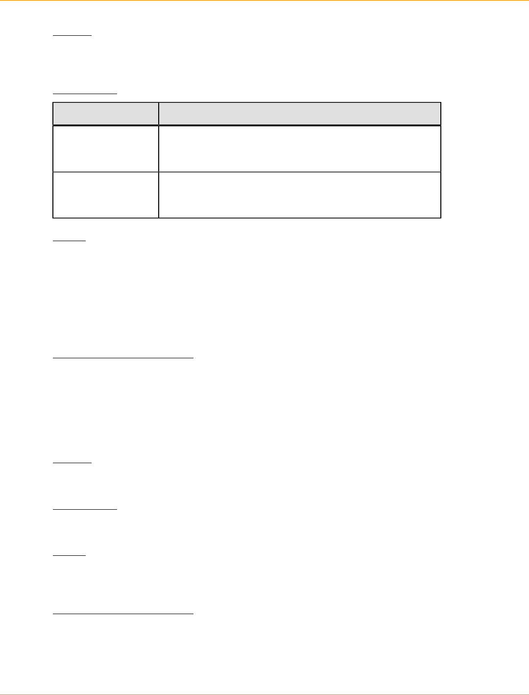
SANtricity_10.77 February 2011
LSI Corporation
- 1188 -
Syntax
show storageArray lunMappings [host ["hostName"] |
hostgroup ["hostGroupName"]]
Parameters
Parameter Description
host The name of a specific host for which you want to see the
LUN mappings. Enclose the host name in double quotation
marks (" ") inside of square brackets ([ ]).
hostGroup The name of a specific host group for which you want to see
the LUN mappings. Enclose the host group name in double
quotation marks (" ") inside of square brackets ([ ]).
Notes
This command returns host topology information similar to this example.
MAPPINGS (Storage Partitioning - Enabled (0 of 16 used))
VOLUME NAME LUN CONTROLLER ACCESSIBLE BY VOLUME STATUS
Access Volume 7 A,B Default Group Optimal
21 21 B Default Group Optimal
22 22 B Default Group Optimal
Minimum Firmware Level
6.10
Show Storage Array Negotiation Defaults
This statement returns information about connection-level settings that are subject to initiator-target
negotiation.
Syntax
show storageArray iscsiNegotiationDefaults
Parameters
None.
Notes
Information returned includes RAID controller tray default settings (that is, those settings that are the starting
point for negotiation) and the current active settings.
Minimum Firmware Level
7.10

SANtricity_10.77 February 2011
LSI Corporation
- 1189 -
Show Storage Array Remote Status Notification
This command shows the proxy configuration settings for the remote status notification feature that were
defined by the set remoteStatusNotification proxyConfig command. The remote status
proxy configuration settings apply to all of the storage arrays managed by the storage management
station. The storage arrays must be capable of supporting the storage array profile and the support
bundle. The proxy configuration settings are saved in the devmgr.datadir\monitor\EMRSstate
\EMRSRuntimeConfig.xml file on the storage management station.
Syntax
show remoteStatusNotification proxyConfig
Parameter
None.
Minimum Firmware Level
7.70
Show Storage Array Unconfigured iSCSI Initiators
This command returns a list of initiators that have been detected by the storage array but are not yet
configured into the storage array topology.
Syntax
show storageArray unconfiguredIscsiInitiators
Parameters
None.
Minimum Firmware Level
7.10
Show Storage Array Unreadable Sectors
This command returns a table of the addresses of all of the sectors in the storage array that cannot be read.
The table is organized with column headings for the following information:
1. Volume user label
2. Logical unit number (LUN)
3. Accessible by (host or host group)
4. Date/time
5. Volume-relative logical block address (hexadecimal format – 0xnnnnnnnn)
6. Drive location (tray t, slot s)
7. Drive-relative logical block address (hexadecimal format – 0xnnnnnnnn)
8. Failure type

SANtricity_10.77 February 2011
LSI Corporation
- 1190 -
The data is sorted first by the volume user label and second by the logical block address (LBA). Each entry in
the table corresponds to a single sector.
Syntax
show storageArray unreadableSectors
Parameters
None.
Minimum Firmware Level
6.10
Show String
This command shows a string of text from a script file. This command is similar to the echo command in MS-
DOS and UNIX.
Syntax
show "textString"
Parameters
None.
Notes
Enclose the string in double quotation marks (" ").
Minimum Firmware Level
6.10
Show Volume
For the volumes in a storage array, this command returns the following information:
The number of volumes
The name
The status
The capacity
The RAID level
The volume group where the volume is located
Details:
The volume ID
The subsystem ID
The drive type (Fibre Channel, SATA, or SAS)
Tray loss protection
The preferred owner
SANtricity_10.77 February 2011
LSI Corporation
- 1191 -
The current owner
The segment size
The modification priority
The read cache status (enabled or disabled)
The write cache status (enabled or disabled)
The write cache without batteries status (enabled or disabled)
The write cache with mirroring status (enabled or disabled)
The flush write cache after time
The cache read prefetch setting (TRUE or FALSE)
The enable background media scan status (enabled or disabled)
The media scan with redundancy check status (enabled or disabled)
The snapshot repository volumes
The mirror repository volumes
The snapshot volumes
The snapshot copies
To view an example of the information returned by this command, refer to the topic "Examples of Information
Returned by the Show Commands" in Configuring and Maintaining a Storage Array Using the Command Line
Interface.
Syntax
show (allVolumes | volume [volumeName] |
volumes [volumeName1 ... volumeNameN]) summary
Parameters
Parameter Description
allVolumes The setting to return information about all of the volumes in
the storage array.
volume or volumes The name of the specific volume for which you are retrieving
information. You can enter more than one volume name.
Enclose the volume name in square brackets ([ ]). If the
volume name has special characters, you also must enclose
the volume name in double quotation marks (" ").
summary The setting to return a concise list of information about the
volumes.
Notes
For snapshot volume copies, the show volume command returns information about the schedules for the
snapshot volume copies. The schedule information is in this form:
Schedule State: “Active” | “Disabled” | “Completed”
Last Run Time: <mm/dd/yyyy> <hh:mm a.m. | p.m.>
Next Run Time: <mm/dd/yyyy> <hh:mm a.m. | p.m.>
Start Date: <mm/dd/yyyy>End Date: <mm/dd/yyyy> | "No End Date"
Days of Week: <Sunday - Saturday>, <Sunday - Saturday>, ….
SANtricity_10.77 February 2011
LSI Corporation
- 1192 -
Times for snapshot recreate: <hh:mm a.m. | p.m.>, <hh:mm a.m. | p.m.>
Minimum Firmware Level
5.00
5.43 adds the summary parameter.
7.77 adds the schedule information for the snapshot volume copies.
Show Volume Action Progress
NOTE With firmware version 7.77, the show volume actionProgress command is deprecated.
Replace this command with show storageArray longRunningOperations.
For a long-running operation that is currently running on a volume, this command returns information about
the volume action and amount of the long-running operation that is completed. The amount of the long-
running operation that is completed is shown as a percentage (for example, 25 means that 25 percent of the
long-running operation is completed).
Syntax
show volume ["volumeName"] actionProgress
Parameter
Parameter Description
volume The name of the volume that is running the long-running
operation. Enclose the volume name in double quotation
marks (" ") inside of square brackets ([ ]).
Minimum Firmware Level
5.43
7.77 deprecates this command.
Show Volume Copy
This command returns this information about volume copy operations:
The copy status
The start time stamp
The completion time stamp
The copy priority
The source volume World Wide Identifier (WWID) or the target volume WWID
The target volume Read-Only attribute setting
You can retrieve information about a specific volume copy pair or all of the volume copy pairs in the storage
array.
SANtricity_10.77 February 2011
LSI Corporation
- 1193 -
Syntax
show volumeCopy (allVolumes | source ["sourceName"] |
target ["targetName"])
Parameters
Parameter Description
allVolumes The setting to return information about volume copy
operations for all of the volume copy pairs.
source The name of the source volume about which you want to
retrieve information. Enclose the source volume name in
double quotation marks (" ") inside of square brackets ([ ]).
target The name of the target volume about which you want to
retrieve information. Enclose the target volume name in
double quotation marks (" ") inside of square brackets ([ ]).
Minimum Firmware Level
5.40
Show Volume Copy Source Candidates
This command returns information about the candidate volumes that you can use as the source for a volume
copy operation.
Syntax
show volumeCopy sourceCandidates
Parameters
None.
Notes
This command returns volume copy source information as shown in this example.
Volume Name: finance
Capacity: 4.0 GB
Volume Group: 1
Volume Name: engineering
Capacity: 4.0 GB
Volume Group: 2
Minimum Firmware Level
6.10
SANtricity_10.77 February 2011
LSI Corporation
- 1194 -
Show Volume Copy Target Candidates
This command returns information about the candidate volumes that you can use as the target for a volume
copy operation.
Syntax
show volumeCopy source ["sourceName"] targetCandidates
Parameter
Parameter Description
source The name of the source volume for which you are trying to find
a candidate target volume. Enclose the source volume name
in double quotation marks (" ") inside of square brackets ([ ]).
Minimum Firmware Level
6.10
Show Volume Group
This command returns this information about a volume group:
The status (Online or Offline)
The drive type (Fibre Channel, SATA, or SAS)
Tray loss protection (yes or no)
The current owner (the controller in slot A or the controller in slot B)
The associated volumes and free capacity
The associated drives
Syntax
show volumeGroup [volumeGroupName]
Parameter
Parameter Description
volumeGroup The alphanumeric identifier of the volume group (including -
and _) for which you want to show information. Enclose the
volume group identifier in square brackets ([ ]).
Notes
This command returns volume group information as shown in this example:
Volume Group 1 (RAID 5)
Status: Online
Drive type: Fibre Channel
Tray loss protection: No
SANtricity_10.77 February 2011
LSI Corporation
- 1195 -
Current owner: Controller in slot A
Associated volumes and free capacities:
1 (1 GB), 1R1 (0.2 GB), Free Capacity (134.533 GB)
Associated drives (in piece order):
Drive at Tray 1, Slot 14
Drive at Tray 1, Slot 13
Drive at Tray 1, Slot 12
Minimum Firmware Level
6.10
Show Volume Group Export Dependencies
This command shows a list of dependencies for the drives in a volume group that you want to move from one
storage array to a second storage array.
Syntax
show volumeGroup [volumeGroupName] exportDependencies
Parameter
Parameter Description
volumeGroup The alphanumeric identifier (including - and _) of the volume
group for which you want to show export dependencies.
Enclose the volume group identifier in square brackets ([ ]).
Notes
This command spins up the drives in a volume group, reads the DACstore, and shows a list of import
dependencies for the volume group. The volume group must be in an Exported state or a Forced state.
Minimum Firmware Level
7.10
Show Volume Group Import Dependencies
This command shows a list of dependencies for the drives in a volume group that you want to move from one
storage array to a second storage array.
Syntax
show volumeGroup [volumeGroupName] importDependencies
[cancelImport=(TRUE | FALSE)]
Parameters
Parameter Description
volumeGroup The alphanumeric identifier (including - and _) of the volume
group for which you want to show import dependencies.
Enclose the volume group identifier in square brackets ([ ]).
SANtricity_10.77 February 2011
LSI Corporation
- 1196 -
Parameter Description
cancelImport The setting to spin the drives back down after the volume
group dependencies have been read. To spin down the drives,
set this parameter to TRUE. To let the drives stay spinning, set
this parameter to FALSE.
Notes
This command returns the dependencies of a specific volume group, which must be in an Exported state or a
Forced state. If a decision is made to retain the listed dependencies, then the cancelImport parameter can
be enforced to spin the drives back down.
You must run the show volumeGroup importDependencies command before you run the start
volumeGroup import command.
Minimum Firmware Level
7.10
Show Volume Performance Statistics
This command returns information about the performance of the volumes in a storage array.
Syntax
show (allVolumes | volume [volumeName]
volumes [volumeName1 ... volumeNameN]) performanceStats
Parameters
Parameter Description
allVolumes The setting to return performance statistics about all of the
volumes in the storage array.
volume or volumes The name of the specific volume for which you are retrieving
performance statistics. You can enter more than one volume
name. Enclose the volume name in square brackets ([ ]). If the
volume name has special characters, you also must enclose
the volume name in double quotation marks (" ").
Notes
Before you run the show volume performanceStat command, run the set session
performanceMonitorInterval command and the set session performanceMonitorIterations
command to define how often you collect the statistics.
The show volume command returns volume performance statistics as shown in this example:
Performance Monitor Statistics for Storage Array: ausctrl9
Date/Time: 2/19/09 4:03:09 PM
Polling Interval in seconds: 10
Devices, Total, Read, Cache, Hit, Current, Maximum,
SANtricity_10.77 February 2011
LSI Corporation
- 1197 -
Current, Maximum, IOs, Percentage, Percentage,
KB/second, KB/second, IO/second, IO/second
Capture Interation: 1
Date/Time: 2/19/04 4:03:09 PM
Controller in slot A,0.0,0.0,0.0,0.0,0.0,0.0,0.0,
Volume 1,0.0,0.0,0.0,0.0,0.0,0.0,0.0,
Volume 2,0.0,0.0,0.0,0.0,0.0,0.0,0.0,
Volume 3,0.0,0.0,0.0,0.0,0.0,0.0,0.0,
Storage Array totals,0.0,0.0,0.0,0.0,0.0,0.0,0.0,
Minimum Firmware Level
6.10
Show Volume Reservations
This command returns information about the volumes that have persistent reservations.
Syntax
show (allVolumes | volume [volumeName] |
volumes [volumeName1 ... volumeNameN]) reservations
Parameters
Parameter Description
allVolumes The setting to return persistent reservation information about
all of the volumes in the storage array.
volume or volumes The name of the specific volume for which you are retrieving
persistent reservation information. You can enter more than
one volume name. Enclose the volume name in square
brackets ([ ]). If the volume name has special characters, you
also must enclose the volume name in double quotation marks
(" ").
Minimum Firmware Level
5.40
Start Cache Backup Device Diagnostic
ATTENTION Before you run this diagnostic test, make sure that the cache backup device has a status
of Optimal.
This command runs diagnostic tests to evaluate the functionality of the device that you use to backup the data
in the cache if you lose power to the controller. The diagnostic tests are specific to the backup device that is in
the controller. Before you run these tests, make these changes to the controller that has the backup device on
which you want to run diagnostics:
Place the controller into service mode (use the set controller [(a | b)]
availability=serviceMode command).
Attach the management client directly to the controller through the management Ethernet port.
SANtricity_10.77 February 2011
LSI Corporation
- 1198 -
NOTE In a dual-controller configuration, you must run these diagnostic tests through the controller that
you want to evaluate. You cannot run these diagnostic tests through the partner controller.
Syntax
start cacheBackupDevice [(1 | n | all)]
controller [(a | b)]
diagnostic diagnosticType=(basic | extended)
[extendedTestID=(writePatterns | random)]
Parameters
Parameter Description
cacheBackupDevice The identifier for the cache backup device on which
you want to run the diagnostic tests. Valid cache
backup device identifiers are 1, 2, 3, 4 or all.
1 for USB1 on the controller circuit board
2 for USB2 on the controller circuit board
3 for USB3 on the controller circuit board
4 for USB4 on the controller circuit board
all for all of the USBs on the controller circuit
board
NOTE – If you have only one cache backup device,
the all identifier does not work.
Enclose the identifier for the cache backup device in
square brackets ([ ]).
controller The controller that has the cache backup device
on which you want to run the diagnostic tests.
Valid controller identifiers are a or b, where a is the
controller in slot A, and b is the controller in slot B.
Enclose the controller identifier in square brackets
([ ]). If you do not specify a controller, the storage
management software returns a syntax error.
diagnosticType The level of diagnostic testing that you want to run on
the cache backup device. You can run one of these
levels of testing:
basic – This option validates the basic operation of
the ability of the cache backup device to store cache
data. This option determines these capabilities of the
cache backup device:
Whether the cache backup device is write
protected or the cache can write data to the
device.
If the cache backup device is approaching its write
cycle limit.
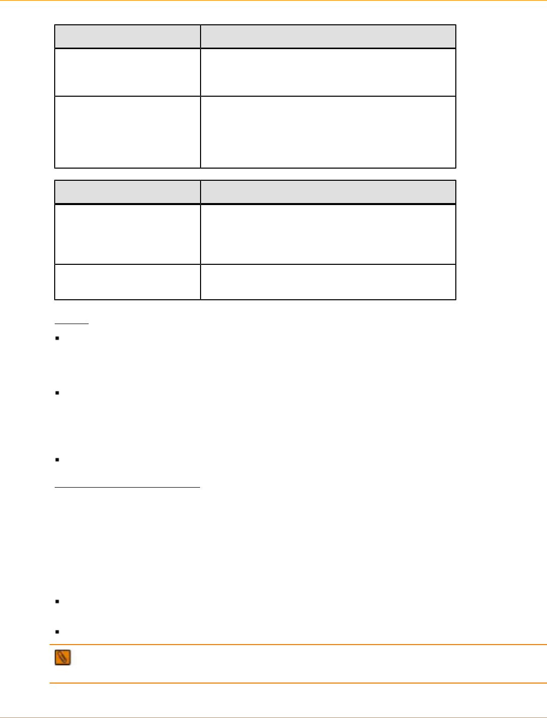
SANtricity_10.77 February 2011
LSI Corporation
- 1199 -
Parameter Description
extended – This option enables you to run more
comprehensive diagnostic tests on the host interface
card.
extendedTestID This parameter selects the extended test option that
you want to run.
If you choose the extended parameter, you also
must also use the extendedTestID parameter and
one of the extended test options.
Extended Test Option Description
writePatterns This option writes a predefined pattern of data in
blocks to the entire cache backup device. Each block
that was written is then read back, and the data is
verified for integrity and accuracy.
random This option writes a random pattern to each flash
block in the cache backup device.
Notes
When an unexpected power loss occurs, cache memory can have data that has not been written to the
drives. This data must be preserved so that it can be written to the drives when power is restored. The
contents of the cache memory are backed up to a persistent storage device, such as a USB flash drive, a
SATA drive, or a solid state device (SSD).
The total storage capacity of the flash drives must be equal to the total cache memory, considering that all
storage space in a flash drive is not always usable. For example, in a 1-GB flash drive, approximately 968
MB is usable. Also, in some flash drives, the Cyclic Redundancy Check (CRC) needs to be stored along
with the data. Because the metadata region is persisted in these flash drives, the storage capacity for the
flash drives must be greater than the size of the cache memory.
You can run the diagnostic test on only one controller in the storage array at any one time.
Minimum Firmware Level
7.60 adds the capability for cache backup device diagnostics.
Start Cache Memory Diagnostic
This command runs extended diagnostic tests to evaluate the functionality of the cache memory in a
controller. Before you run these tests, you must make these changes to the controller on which you want to
run diagnostics:
Place the controller into Service mode (use the set controller [(a | b)]
availability=serviceMode command).
Attach the management client directly to the controller through the management Ethernet port.
NOTE In a dual controller configuration, you must run these diagnostic tests through the controller that
you want to evaluate. You cannot run these diagnostic tests through the partner controller.

SANtricity_10.77 February 2011
LSI Corporation
- 1200 -
Syntax
start cacheMemory controller [(a | b)] diagnostic
diagnosticType=(basic | extended)
[extendedTestID=(marchC | patterns | psuedoRndm| DMACopy)]
Parameters
Parameter Description
controller The controller that has the cache memory on which
you want to run the diagnostic tests. Valid controller
identifiers are a or b, where a is the controller in
slot A, and b is the controller in slot B. Enclose the
controller identifier in square brackets ([ ]). If you do
not specify a controller, the storage management
software returns a syntax error.
diagnosticType The level of diagnostic testing that you want to run
on the host interface card. You can run one of these
levels of testing:
basic – This option validates the ability of the cache
memory to address and access data.
extended – This option enables you to run more
comprehensive diagnostic tests on the host interface
card.
extendedTestID This parameter selects the extended test option that
you want to run.
If you choose the extended parameter, you also
must use the extendedTestID parameter and one
of the extended test options.
Extended Test Option Description
marchC This option performs a March C test on specific
regions of the Reconfigurable Processor Assembly
(RPA) memory. This option tests for only one set of
inverse patterns.
patterns This option performs a word pattern test where the
test sequence proceeds with a series of read/write
operations for all locations in the specified memory
region. The test uses a set of special patterns. The
test writes and verifies several patterns at 32-bit
widths.
pseudoRndm This option generates a non-repetitive pattern for
double word length, writes the pattern to the entire
region, and reads back the pattern for verification.

SANtricity_10.77 February 2011
LSI Corporation
- 1201 -
Extended Test Option Description
DMAcopy This option tests the capability of Direct Memory
Access (DMA) copy operations across regions in the
cache memory. This options uses the RPA hardware
capabilities to move the data from one region to
another region.
Notes
You can run the diagnostic test on only one controller in the storage array at any one time.
Minimum Firmware Level
7.60 adds the capability for cache memory diagnostics.
Start Configuration Database Diagnostic
This command starts a diagnostic test to validate the configuration database in the controller firmware.
Syntax
start storageArray configDbDiagnostic
Parameters
None.
Notes
Upon completion of the diagnostic test, the controller firmware returns one of these results:
Diagnosis completed without errors. No ZIP file created.
Diagnosis completed with errors. Refer to the ZIP file created at:
...\Install_dir\data\FirmwareUpgradeReports\timestamp_buildNo.zip
If the diagnostic test detects an inconsistency in the configuration database, the controller firmware performs
these actions:
Returns a description of the inconsistency
Saves a ZIP file containing raw binary data
The controller firmware saves the ZIP file to this location:
...\Install_dir\data\FirmwareUpgradeReports\timestamp_buildNo.zip
You can use the binary data to help determine the cause of the problem, or you can send the file containing
the binary data to a Customer and Technical Support representative.
To stop the database configuration diagnostic test, use the stop storageArray configDbDiagnostic
command.
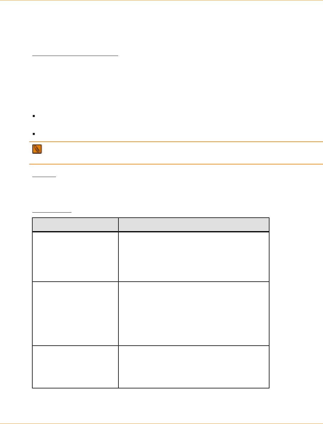
SANtricity_10.77 February 2011
LSI Corporation
- 1202 -
In addition, you can start the database configuration diagnostic test through the storage management
software GUI; however, you cannot stop the database configuration diagnostic test through the storage
management software GUI. If you want to stop a running diagnostic test, you must use the stop
storageArray configDbDiagnostic command.
Minimum Firmware Level
7.75
Start Controller Diagnostic
This command runs diagnostic tests to evaluate the functionality of the controller card. Before you run these
tests, you must make these changes to the controller on which you want to run diagnostics:
Place the controller into Service Mode (use the set controller [(a | b)]
availability=serviceMode command).
Attach the management client directly to the controller through the management Ethernet port.
NOTE In a dual controller configuration, you must run these diagnostic tests through the controller that
you want to evaluate. You cannot run these diagnostic tests through the partner controller.
Syntax
start controller [(a | b)] diagnostic diagnosticType=(basic | extended)
[extendedTestID=(SRAM | FIFO | dataCopy| RAID5Parity | RAID6Parity)]
Parameters
Parameter Description
controller The controller on which you want to run the diagnostic
tests. Valid controller identifiers are a or b, where a is
the controller in slot A, and b is the controller in slot
B. Enclose the controller identifier in square brackets
([ ]). If you do not specify a controller, the storage
management software returns a syntax error.
diagnostic The level of diagnostic testing that you want to run
on the host interface card. You can run one of these
levels of testing:
basic – This option validates the ability of the base
controller to address and access data.
extended – This option enables you to run more
comprehensive diagnostic tests on the base controller
card.
extendedTestID This parameter selects the extended test option that
you want to run.
If you choose the extended parameter, you must
also used the extendedTestID parameter and one
of the extended test options.

SANtricity_10.77 February 2011
LSI Corporation
- 1203 -
Extended Test Option Description
SRAM This option tests for address, data, and data retention.
The address test attempts to write to specific address
offsets. The data test attempts to write several data
patterns to the address offsets. The data retention
test attempts to write a data pattern and then read
the data pattern back after a delay. The purpose
of the SRAM option is to find memory parity or error
correcting code (ECC) errors.
FIFO This option tests the active processor chip (APC)
first in, first out (FIFO) data transmission of the Zip
chip. The APC FIFO channels are tested concurrently
by writing and verifying different patterns to each
channel.
dataCopy This option tests the ability of the Zip chip to support
data copy operations that can copy data from one
area of the Zip SDRAM to another area of the Zip
SDRAM. This test is performed on any available
section of the Zip chip that is not busy.
RAID5Parity This option tests the ability of the Zip APC to generate
and verify RAID 5 parity data. Data buffers are set
up in processor memory and parity is generated in
processor memory. Some data buffers are set up
in parallel architecture (RPA) memory and parity is
generated for the data within the RPA memory. The
parity that is generated within processor memory is
then compared with the parity in the Zip APC.
RAID6Parity This option tests the ability of the Zip APC to generate
and verify RAID 6 parity data. Data buffers are set
up in processor memory and parity is generated in
processor memory. Some data buffers are set up
in redundant parallel architecture (RPA) memory
and parity is generated for the data within the RPA
memory. The parity that is generated within processor
memory is then compared with the parity in the Zip
APC.
Notes
You can run the diagnostic test on only one controller in the storage array at any one time.
Minimum Firmware Level
7.60 adds the capability for controller card diagnostics.
Start Controller Trace
This command starts an operation that saves debug trace information to a compressed file. The debug trace
information can be used by a Customer and Technical Support representative to help analyze how well a
storage array is running.
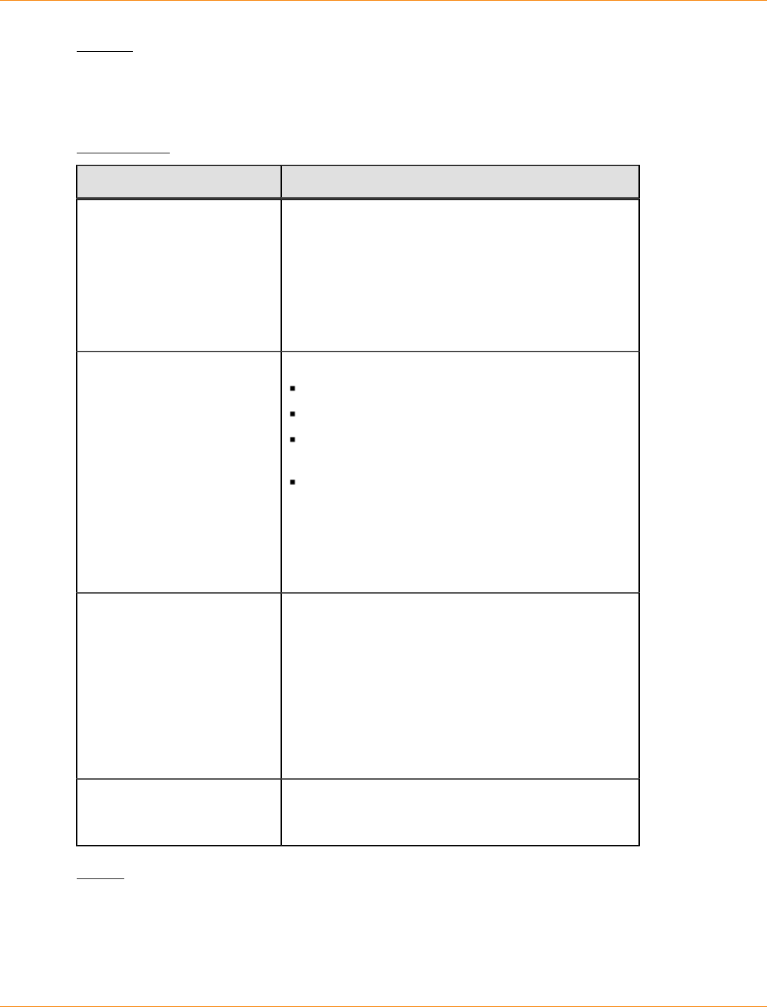
SANtricity_10.77 February 2011
LSI Corporation
- 1204 -
Syntax
start controller [(a | b | both)] trace
dataType=(current | flushed | currentFlushed | all)
[forceFlush=(TRUE | FALSE)]
Parameters
Parameter Description
controller The controller for which you want to collect the trace
debug information. Valid controller identifiers are
a or b, where a is the controller in slot A, and b is
the controller in slot B. You can also simultaneously
collect debug for both controllers by entering both.
Enclose the controller identifier in square brackets
([ ]). If you do not specify a controller, the storage
management software returns a syntax error.
dataType The type of data that you want to collect:
current – Retrieves the current DQ traces
flushed – Retrieves all flushed DQ traces
currentFlushed – Retrieves both the current
DQ trace and the flushed DQ trace
all – Retrieves the current DQ trace, flushed DQ
trace, and all platform DQ traces
NOTE – If dataType=flushed and
forceFlush=True, an error message is returned
indicating that only active traces can be flushed to the
buffer on retrieval.
forceFlush The setting to move the DQ information in the current
buffer to the flushed buffer when the DQ trace
information defined by the dataType parameter is
retrieved. To enable force flush, set this parameter
to TRUE. To disable force flush, set this parameter to
FALSE.
NOTE – If dataType=flushed and
forceFlush=True, an error message is returned
indicating that only active traces can be flushed to the
buffer on retrieval.
file The file path and the file name to which you want to
save the DQ trace information. Refer to the Notes
section for information about naming the files.
Notes
The DQ trace information is written to a compressed file with an extension of .zip. The file name is a
combination of a user-defined file name and the storage array identifier (SAID). A constant of "dq" is also
added to the file name. The complete file name has this form:
user_defined_file_name-SAID-dq.zip
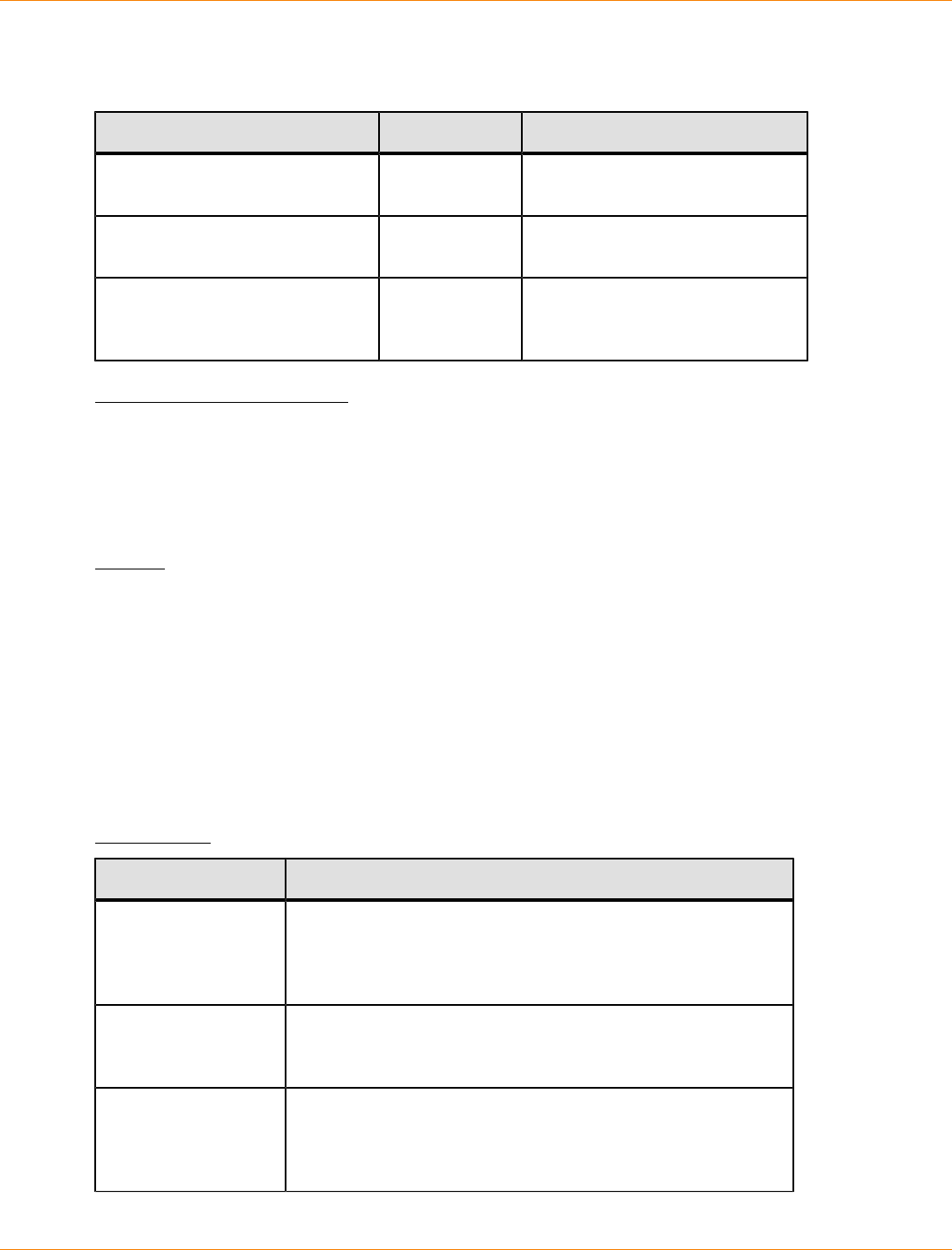
SANtricity_10.77 February 2011
LSI Corporation
- 1205 -
The compressed file contains the information listed in this table.
File Name Directory Comments
user_provided_file_name-SAID-
A.dq SAID/
timestamp/ The DQ trace data retrieved from
controller A.
user_provided_file_name-SAID-
B.dq SAID/
timestamp/ The DQ trace data retrieved from
controller B.
user_provided_file_name-SAID-
trace_description.xm. SAID/
timestamp/ The description file in an xml
format that describes the DQ file
attributes for future data mining.
Minimum Firmware Level
7.75
Start Drive Channel Fault Isolation Diagnostics
This command runs the drive channel fault isolation diagnostics and stores the results.
Syntax
start driveChannel [(1 | 2 | 3 | 4 | 5 | 6 | 7 | 8)]
controller [(a | b)] faultDiagnostics
(testDevices=[all | controller=(a | b) |
esms=[trayID1 (left | right), ... , trayIDn (left | right)] |
drives=[trayID1, slotID1, ... , trayIDn, slotIDn]] |
dataPattern=(fixed | pseudoRandom) |
patternNumber=[(0xhexadecimal | number)] |
maxErrorCount=integer |
testIterations=integer |
timeout=timeInterval)
Parameters
Parameter Description
driveChannel The identifier number of the drive channel that you want to
locate. Valid values for the identifier number for the drive
channel are 1, 2, 3, 4, 5, 6, 7, or 8. Enclose the drive channel
identifier number in square brackets ([ ]).
controller The identifier letter of the controller that you want to test. Valid
controller identifier values are a or b, where a is the controller
in slot A, and b is the controller in slot B.
testDevices The identifiers of the devices (controllers, environmental
services monitor [ESMs], or drives) that you want to test. You
can specify all or enter the specific identifiers for the devices
that you want to diagnose.
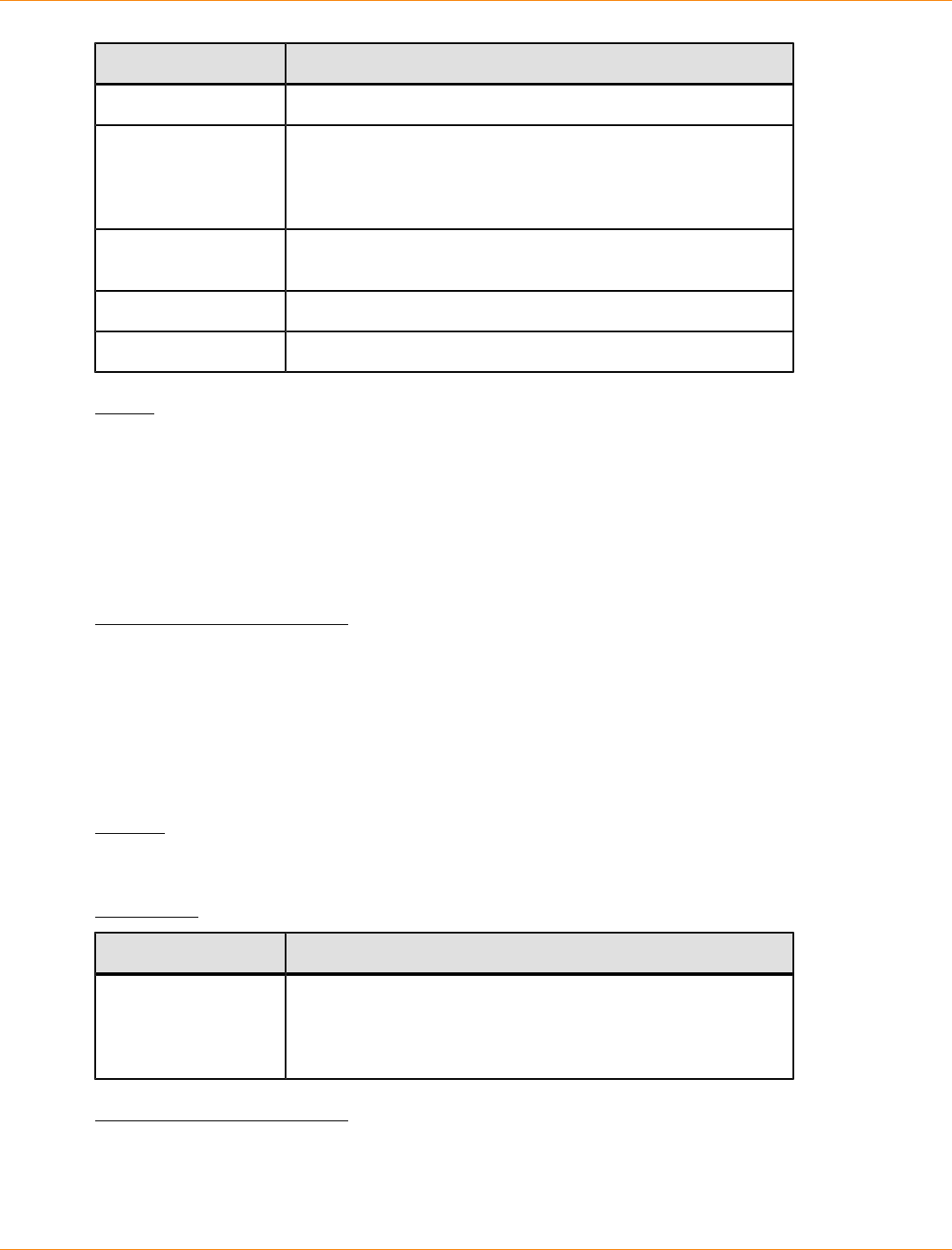
SANtricity_10.77 February 2011
LSI Corporation
- 1206 -
Parameter Description
dataPattern The method of repeatability that you want to test.
patternNumber The hexadecimal data pattern that you want to use to run the
test. This number can be any hexadecimal number between
0000 to FFFF. You must place 0x in front to indicate a
hexadecimal number.
maxErrorCount The number of errors that you want to accept before
terminating the test.
testIterations The number of times that you want to repeat the test.
timeout The length of time in minutes that you want to run the test.
Notes
Use the save driveChannel faultDiagnostics command and the stop driveChannel
faultDiagnostics command with the start driveChannel faultDiagnostics command. These
commands are needed to save diagnostic test results to a file and to stop the diagnostic test.
Examples of valid patternNumber entries are 0xA5A5, 0x3C3C, 8787, and 1234.
You can also stop this command at any time by pressing Ctrl+C.
Minimum Firmware Level
7.15
Start Drive Channel Locate
This command identifies the drive trays that are connected to a specific drive channel by turning on the
indicator lights for the drive tray that is connected to the drive channel. (Use the stop driveChannel
locate command to turn off the indicator lights on the drive tray.)
Syntax
start driveChannel [(1 | 2 | 3 | 4 | 5 | 6 | 7 | 8)] locate
Parameter
Parameter Description
driveChannel The identifier number of the drive channel that you want to
locate. Valid values for the identifier number for the drive
channel are 1, 2, 3, 4, 5, 6, 7, or 8. Enclose the drive channel
identifier number in square brackets ([ ]).
Minimum Firmware Level
6.10
7.15 adds an update to the drive channel identifier.
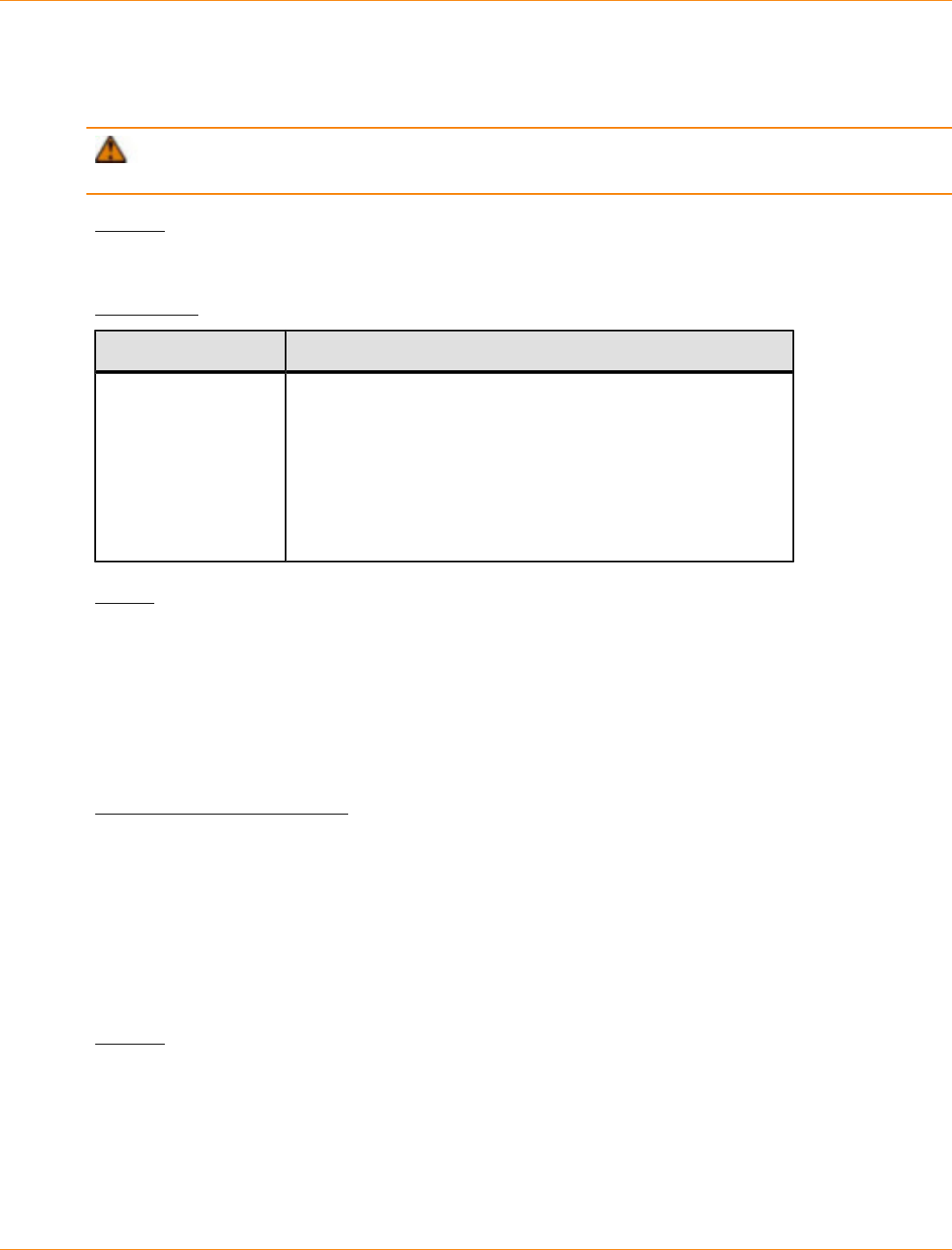
SANtricity_10.77 February 2011
LSI Corporation
- 1207 -
Start Drive Initialize
This command starts drive initialization.
ATTENTION Possible damage to the storage array configuration – As soon as you enter this
command, all user data is destroyed.
Syntax
start drive [trayID,drawerID,slotID] initialize
Parameter
Parameter Description
drive The location of the drive that you want to reconstruct. For
high-capacity drive trays, specify the tray ID value, the drawer
ID value, and the slot ID value of the drive that you want to
revive. For low-capacity drive trays, specify the tray ID value
and the slot ID value of the drive that you want to revive. Tray
ID values are 0 to 99. Drawer ID values are 1 to 5. Slot ID
values are 1 to 32. Enclose the tray ID value, the drawer ID
value, and the slot ID value in square brackets ([ ]).
Notes
The drive parameter supports both high-capacity drive trays and low-capacity drive trays. A high-capacity
drive tray has drawers that hold the drives. The drawers slide out of the drive tray to provide access to the
drives. A low-capacity drive tray does not have drawers. For a high-capacity drive tray, you must specify
the identifier (ID) of the drive tray, the ID of the drawer, and the ID of the slot in which a drive resides. For a
low-capacity drive tray, you need only specify the ID of the drive tray and the ID of the slot in which a drive
resides. For a low-capacity drive tray, an alternative method for identifying a location for a drive is to specify
the ID of the drive tray, set the ID of the drawer to 0, and specify the ID of the slot in which a drive resides.
Minimum Firmware Level
6.10
7.60 adds the drawerID user input.
Start Drive Locate
This command locates a drive by turning on an indicator light on the drive. (Run the stop drive locate
command to turn off the indicator light on the drive.)
Syntax
start drive [trayID,drawerID,slotID] locate
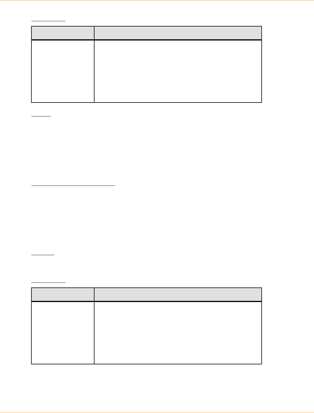
SANtricity_10.77 February 2011
LSI Corporation
- 1208 -
Parameter
Parameter Description
drive The location of the drive that you want to reconstruct. For
high#capacity drive trays, specify the tray ID value, the drawer
ID value, and the slot ID value of the drive that you want to
revive. For low#capacity drive trays, specify the tray ID value
and the slot ID value of the drive that you want to revive. Tray
ID values are 0 to 99. Drawer ID values are 1 to 5. Slot ID
values are 1 to 32. Enclose the tray ID value, the drawer ID
value, and the slot ID value in square brackets ([ ]).
Notes
The drive parameter supports both high-capacity drive trays and low#capacity drive trays. A high-capacity
drive tray has drawers that hold the drives. The drawers slide out of the drive tray to provide access to the
drives. A low#capacity drive tray does not have drawers. For a high-capacity drive tray, you must specify
the identifier (ID) of the drive tray, the ID of the drawer, and the ID of the slot in which a drive resides. For a
low#capacity drive tray, you need only specify the ID of the drive tray and the ID of the slot in which a drive
resides. For a low#capacity drive tray, an alternative method for identifying a location for a drive is to specify
the ID of the drive tray, set the ID of the drawer to 0, and specify the ID of the slot in which a drive resides.
Minimum Firmware Level
6.10
7.60 adds the drawerID user input.
Start Drive Reconstruction
This command starts reconstructing a drive.
Syntax
start drive [trayID,drawerID,slotID] reconstruct
Parameter
Parameter Description
drive The location of the drive that you want to reconstruct. For
high-capacity drive trays, specify the tray ID value, the drawer
ID value, and the slot ID value of the drive that you want to
revive. For low-capacity drive trays, specify the tray ID value
and the slot ID value of the drive that you want to revive. Tray
ID values are 0 to 99. Drawer ID values are 1 to 5. Slot ID
values are 1 to 32. Enclose the tray ID value, the drawer ID
value, and the slot ID value in square brackets ([ ]).
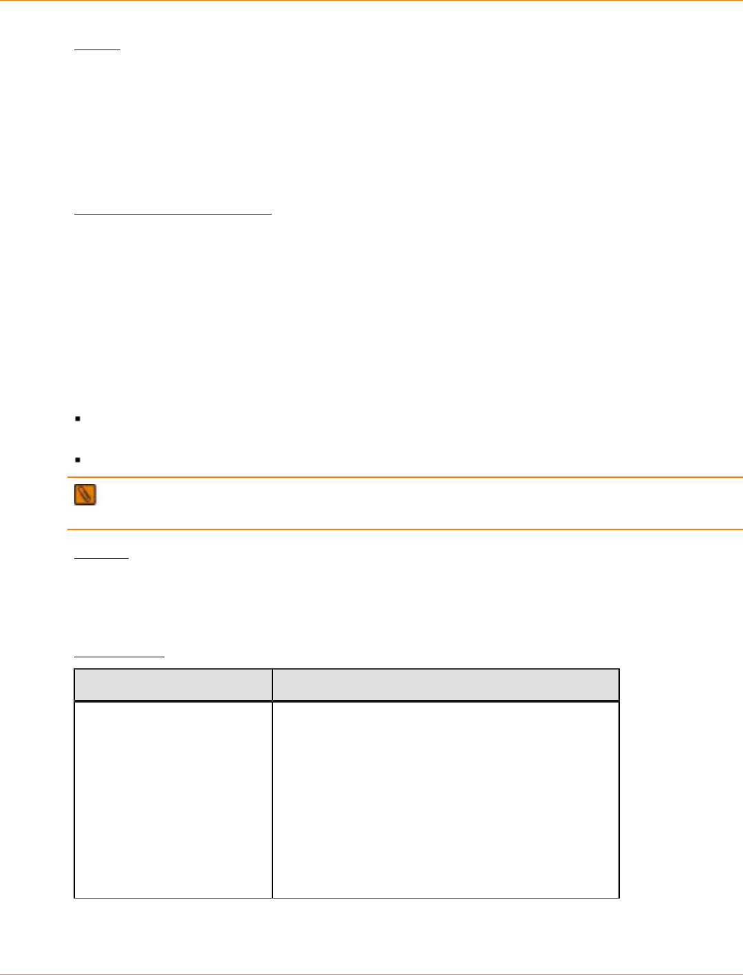
SANtricity_10.77 February 2011
LSI Corporation
- 1209 -
Notes
The drive parameter supports both high-capacity drive trays and low-capacity drive trays. A high-capacity
drive tray has drawers that hold the drives. The drawers slide out of the drive tray to provide access to the
drives. A low-capacity drive tray does not have drawers. For a high-capacity drive tray, you must specify
the identifier (ID) of the drive tray, the ID of the drawer, and the ID of the slot in which a drive resides. For a
low-capacity drive tray, you need only specify the ID of the drive tray and the ID of the slot in which a drive
resides. For a low-capacity drive tray, an alternative method for identifying a location for a drive is to specify
the ID of the drive tray, set the ID of the drawer to 0, and specify the ID of the slot in which a drive resides.
Minimum Firmware Level
5.43
7.60 adds the drawerID user input.
Start Host Interface Card Diagnostic
This command runs diagnostic tests to evaluate the functionality of the controller host interface card. The
diagnostic tests that this command runs are specific to the host interface card that is in the controller. Before
you run these tests, you must make these changes to the controller that has the host interface card on which
you want to run diagnostics:
Place the controller into service mode (use the set controller [(a | b)]
availability=serviceMode command).
Attach the management client directly to the controller through the management Ethernet port.
NOTE In a dual controller configuration, you must run these diagnostic tests through the controller that
you want to evaluate. You cannot run these diagnostic tests through the partner controller.
Syntax
start hostCard [(1 | 2 | 3 | 4)] controller [(a | b)] diagnostic
diagnosticType=(basic | extended)
[extendedTestID=(EDC | DMA | RAM | internalLoopback)]
Parameters
Parameter Description
hostCard The identifier for host interface card on which you
want to run the diagnostic tests. Valid host interface
card identifiers are 1, 2, 3, or 4. The value of the
identifier is for the position of the host interface card in
the controller tray or controller-drive tray. The position
of the host interface card depends on the type of
controller tray or controller-drive tray in your storage
array. See the Notes for more information about the
host interface card identifier and the position of the
host interface cards in a controller tray. Enclose the
controller identifier in square brackets ([ ]).

SANtricity_10.77 February 2011
LSI Corporation
- 1210 -
Parameter Description
controller The controller that has the host interface card on
which you want to run the diagnostic tests. Valid
controller identifiers are a or b, where a is the
controller in slot A, and b is the controller in slot B.
Enclose the controller identifier in square brackets
([ ]). If you do not specify a controller, the storage
management software returns a syntax error.
diagnosticType The level of diagnostic testing that you want to run
on the host interface card. You can run one of these
levels of testing:
basic – This option validates the ability of the host
interface card to transport I/O data. This option takes
approximately 30 seconds to complete.
extended – This option enables you to run more
comprehensive diagnostic tests on the host interface
card.
extendedTestID This parameter selects the extended test option that
you want to run.
If you choose the extended parameter, you also
must use the extendedTestID parameter and one
of the extended test options.
Extended Test Option for
Fibre Channel Description
EDC This option tests the Error Detection and Correction
(EDC) generation, verification, and deletion
functionality of the QE4 chip. This option tests all
modes of the EDC operation, such as, insert, verify,
and delete EDC data.
DMA This option tests the capability of the QE4 chip to take
part in a Direct Memory Access (DMA) operation.
The DMA can be internal to the chip or can be
performed using the services of the raw pool within
the Reconfigurable Processor Assembly (RPA)
memory.
Extended Test Option for
iSCSI Description
RAM This option performs a read/write test for the local
RAM, the SRAM, and also performs a checksum test
for the NVRAM. This option performs the read/write
test for the RAM and SRAM by writing data to the
memory, reading back the data, and comparing the
read data to the written data.
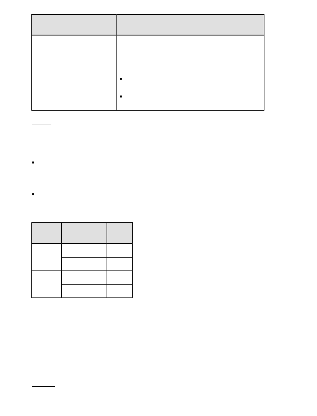
SANtricity_10.77 February 2011
LSI Corporation
- 1211 -
Extended Test Option for
iSCSI Description
internalLoopBack This option tests the ability of the physical layer (PHY)
to transmit data packets over the physical link. For
this test, the PHY is set to an internal loopback mode.
Data is then transmitted, received, and compared with
the original data. The test is run in two passes:
For the first pass, the data is predefined by the
firmware.
For the second pass, the data is generated
externally and then transmitted.
Notes
You can run the diagnostic test on only one controller in the storage array at any one time.
A controller can have either one or two host interface cards.
If a controller has one host interface card, the value for the position of each host interface card depends
on the position of the controller in the controller tray. The host interface card in the controller in controller
tray slot A has a position value of 1. The host interface card in the controller in controller tray slot B has a
position value of 2.
If a controller has two host interface cards, the value for the position of each host interface card depends
on the position of the host interface card in the controller and the position of the controller in the controller
tray. In most cases the position of the host interface card is identified with labels such as Host Card 1 and
Host Card 2 on each controller. The position value of the host interface cards are listed in this table.
Controller Host Card
Label Position
Host Card 1 1A
Host Card 2 2
Host Card 1 3B
Host Card 2 4
You cannot use a loopback connection for the host interface card that you are testing.
Minimum Firmware Level
7.70 adds the capability for controller host interface card diagnostics.
Start iSCSI DHCP Refresh
This command initiates a refresh of the DHCP parameters for the iSCSI interface. If the configuration method
for the interface is not set to DHCP, the procedure returns an error.
Syntax
start controller [(a | b)] iscsiHostPort [(1 | 2 | 3 | 4)] dhcpRefresh
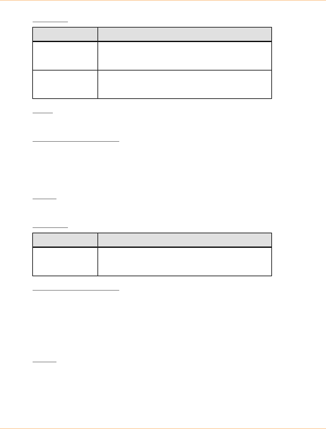
SANtricity_10.77 February 2011
LSI Corporation
- 1212 -
Parameter
Parameter Description
controller The identifier letter of the controller that has the iSCSI host
ports. Valid controller identifier values are a or b, where a is
the controller in slot A, and b is the controller in slot B.
iscsiHostPort The identifier of the iSCSI port for which you want to refresh
the DHCP parameters. Enclose the iSCSI host port identifier
in square brackets ([ ]).
Notes
This operation ends the iSCSI connections for the portal and temporarily brings down the portal.
Minimum Firmware Level
7.10
Start Remote Volume Mirroring Synchronization
This command starts Remote Volume Mirroring synchronization.
Syntax
start remoteMirror primary ["volumeName"] synchronize
Parameter
Parameter Description
primary The name of the primary volume for which you want to start
synchronization. Enclose the primary volume name in double
quotation marks (" ") inside of square brackets ([ ]).
Minimum Firmware Level
6.10
Start Secure Drive Erase
This command erases all of the data from one or more full disk encryption (FDE) drives so that they can be
reused as FDE drives. Run this command only when the FDE drives are no longer part of a secure volume
group, or when the security key is unknown.
Syntax
start secureErase (drive [trayID,slotID] |
drives [trayID1,slotID1 ... trayIDn,slotIDn])
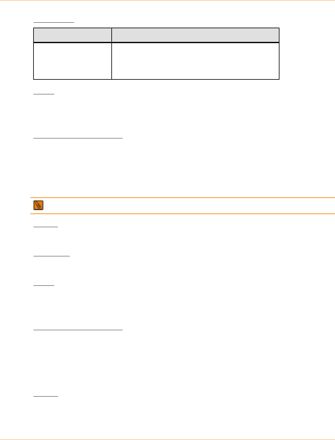
SANtricity_10.77 February 2011
LSI Corporation
- 1213 -
Parameters
Parameter Description
drive or drives The tray and the slot where the drive resides. Tray ID
values are 0 to 99. Slot ID values are 1 to 32. Enclose the
tray ID values and the slot ID values in square brackets
([ ]).
Notes
The controller firmware creates a lock that restricts access to the FDE drives. FDE drives have a state called
Security Capable. When you create a security key, the state is set to Security Enabled, which restricts access
to all FDE drives that exist within the storage array.
Minimum Firmware Level
7.40
Start Storage Array iSNS Server Refresh
This command initiates a refresh of the network address information for the iSNS server. If the DHCP server
is marginal or unresponsive, the refresh operation can take from two to three minutes to complete.
NOTE This command is for IPv4 only.
Syntax
start storageArray isnsServerRefresh
Parameter
None.
Notes
If you used the set storageArray isnsIPv4ConfigurationMethod command to set the configuration
but did not set the configuration to DHCP, running the start storageArray isnsServerRefresh
returns an error.
Minimum Firmware Level
7.10
Start Storage Array Locate
This command locates a storage array by turning on the indicator lights for the storage array. (Use the stop
storageArray locate command to turn off the indicator lights for the storage array.)
Syntax
start storageArray locate
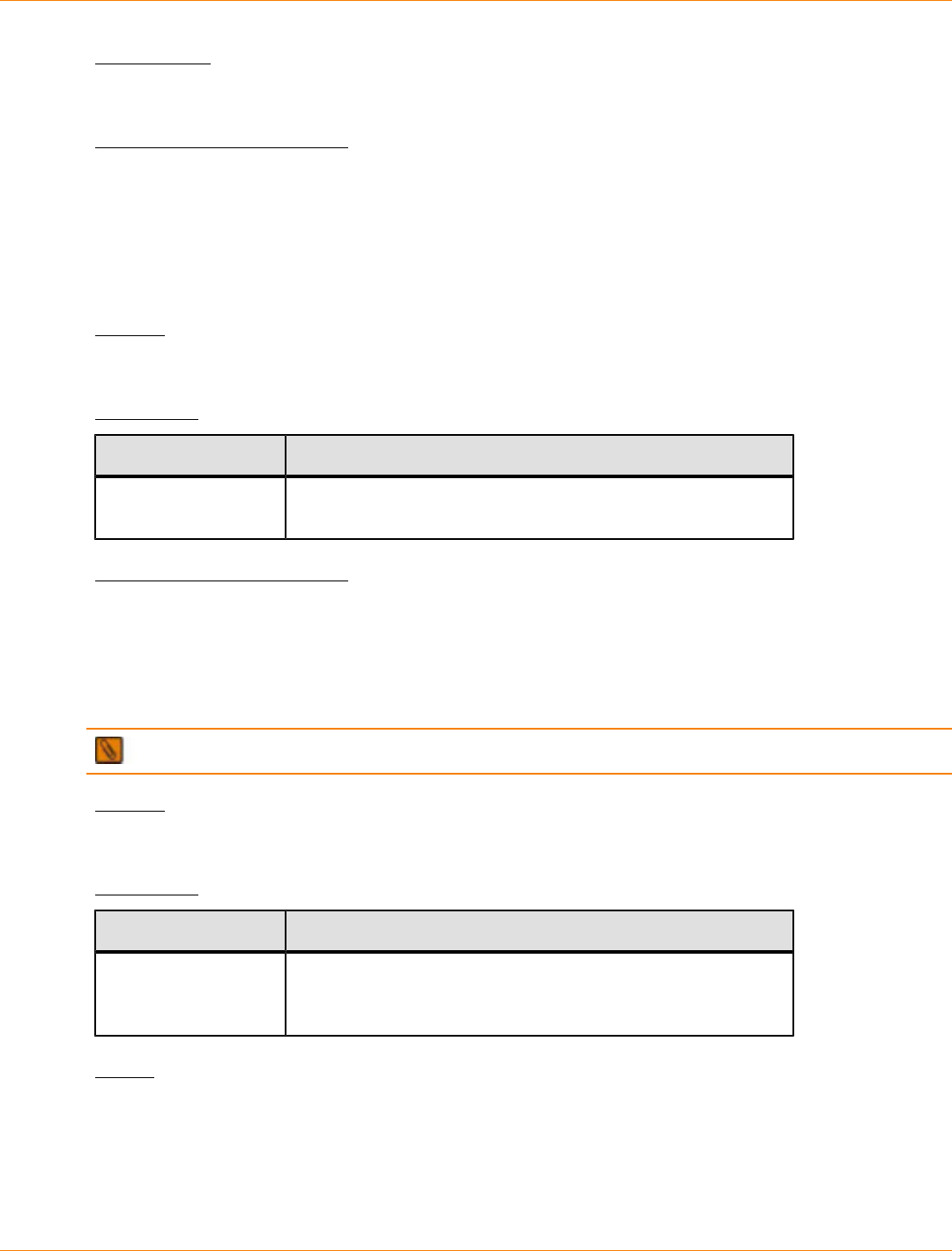
SANtricity_10.77 February 2011
LSI Corporation
- 1214 -
Parameters
None.
Minimum Firmware Level
6.10
Start Tray Locate
This command locates a tray by turning on the indicator light. (Use the stop tray locate command to
turn off the indicator light for the tray.)
Syntax
start tray [trayID] locate
Parameter
Parameter Description
tray The tray that you want to locate. Tray ID values are 0 to 99.
Enclose the tray ID value in square brackets ([ ]).
Minimum Firmware Level
6.10
Start Volume Group Defragment
This command starts a defragment operation on the specified volume group.
NOTE Defragmenting a volume group starts a long-running operation that you cannot stop.
Syntax
start volumeGroup [volumeGroupName] defragment
Parameter
Parameter Description
volumeGroup The alphanumeric identifier of the volume group (including -
and _) that you want to defragment. Enclose the volume group
identifier in square brackets ([ ]).
Notes
Host I/O errors might result in the volume groups with more than 32 volumes. This operation also might result
in internal controller reboots because the timeout period ends before the volume group definition is set. If you
experience this issue, quiesce the host I/O operations, and try the command again.
SANtricity_10.77 February 2011
LSI Corporation
- 1215 -
Minimum Firmware Level
6.10
Start Volume Group Export
This command moves a volume group into an Exported state. Then you can remove the drives that comprise
the volume group and reinstall the drives in a different storage array.
NOTE Within the volume group, you cannot move volumes that are associated with the premium
features from one storage array to another storage array.
Syntax
start volumeGroup [volumeGroupName] export
Parameter
Parameter Description
volumeGroup The alphanumeric identifier of the volume group (including
- and _) that you want to export. Enclose the volume group
identifier in square brackets ([ ]).
Notes
When this command is successful, you can run the start volumeGroup import command to finish
moving the volume group to a Complete state, which makes the volume group available to the new storage
array.
If this command is unsuccessful because hardware problems prevented the completion of the export, use the
set volumeGroup forceState command. The set volumeGroup forceState command lets you
use the start volumeGroup import command to import a volume group.
After the volume group is in an Exported state or a Forced state, you can remove the drives that comprise the
volume group from the storage array. You can reinstall the drives in a different storage array.
Minimum Firmware Level
7.10
Start Volume Group Import
This command moves a volume group into a Complete state to make a newly introduced volume group
available to its new storage array. The volume group must be in an Exported state or a Forced state before
you run this command. Upon successfully running the command, the volume group is operational.
NOTE Within the volume group, you cannot move volumes that are associated with the premium
features from one storage array to another storage array.
Syntax
start volumeGroup [volumeGroupName] import
SANtricity_10.77 February 2011
LSI Corporation
- 1216 -
Parameter
Parameter Description
volumeGroup The alphanumeric identifier of the volume group (including
- and _) that you want to import. Enclose the volume group
identifier in square brackets ([ ]).
Notes
Higher-level volumes that are specifically related to premium features (Snapshot, Remote Volume Mirroring,
Volume Copy, mapping, and persistent reservations) are removed as part of the import operation.
You must run the show volumeGroup importDependencies command before you run the start
volumeGroup import command.
Minimum Firmware Level
7.10
Start Volume Group Locate
This command identifies the drives that are logically grouped together to form the specified volume group by
blinking the indicator lights on the drives. (Use the stop volumeGroup locate command to turn off the
indicator lights on the drives.)
Syntax
start volumeGroup [volumeGroupName] locate
Parameter
Parameter Description
volumeGroup The alphanumeric identifier of the volume group (including
- and _) for which you want to locate the drives that belong
to that volume group. Enclose the volume group identifier in
square brackets ([ ]).
Minimum Firmware Level
6.16
Start Volume Initialization
This command starts the formatting of a volume in a storage array.
NOTE Formatting a volume starts a long-running operation that you cannot stop.
Syntax
start volume [volumeName] initialize
SANtricity_10.77 February 2011
LSI Corporation
- 1217 -
Parameter
Parameter Description
volume The name of the volume for which you are starting the
formatting. Enclose the volume name in square brackets ([ ]).
If the volume name has special characters, you also must
enclose the volume name in double quotation marks (" ").
Minimum Firmware Level
6.10
Stop Cache Backup Device Diagnostic
This command stops the cache backup device diagnostic tests that were started by the start
cacheBackupDevice diagnostic command.
Syntax
stop cacheBackupDevice controller [(a | b)] diagnostic
Parameters
Parameter Description
controller The controller that has the cache backup device on which you
are running the diagnostic tests. Valid controller identifiers
are a or b, where a is the controller in slot A, and b is the
controller in slot B. Enclose the controller identifier in square
brackets ([ ]). If you do not specify a controller, the storage
management software returns a syntax error.
Minimum Firmware Level
7.60 adds the capability for cache backup device diagnostics.
Stop Cache Memory Diagnostic
This command stops the cache memory diagnostic tests that were started by the start cacheMemory
diagnostic command.
Syntax
stop cacheMemory controller [(a | b)] diagnostic
Parameter
Parameter Description
controller The controller that has the cache memory on which you are
running the diagnostic tests. Valid controller identifiers are a or
b, where a is the controller in slot A, and b is the controller in

SANtricity_10.77 February 2011
LSI Corporation
- 1218 -
Parameter Description
slot B. Enclose the controller identifier in square brackets ([ ]).
If you do not specify a controller, the storage management
software returns a syntax error.
Minimum Firmware Level
7.60 adds the capability for cache memory diagnostics.
Stop Configuration Database Diagnostic
This command stops the diagnostic test to validate the configuration database in the controller firmware that
was started by the start storageArray configDbDiagnostic command.
Syntax
stop storageArray configDbDiagnostic
Parameters
None.
Notes
The controller firmware returns a confirmation that the diagnostic test was cancelled.
In addition, you can start the database configuration diagnostic test through the storage management
software GUI; however, you cannot stop the database configuration diagnostic test through the storage
management software GUI. If you want to stop a running diagnostic test, you must use the stop
storageArray configDbDiagnostic command.
If you try to use the stop storageArray configDbDiagnostic command after validation of the storage
array configuration has finished, you do not receive any message that the validation has finished. This
behavior is expected.
Minimum Firmware Level
7.75
7.77 refines usage.
Stop Controller Diagnostic
This command stops the controller diagnostic tests that were started by the start controller
diagnostic command.
Syntax
stop controller [(a | b)] diagnostic

SANtricity_10.77 February 2011
LSI Corporation
- 1219 -
Parameters
Parameter Description
controller The setting to return information about a specific controller in
the storage array. Valid controller identifiers are a or b, where
a is the controller in slot A, and b is the controller in slot B.
Enclose the controller identifier in square brackets ([ ]). If you
do not specify a controller, the storage management software
returns a syntax error.
Minimum Firmware Level
7.70
Stop Drive Channel Fault Isolation Diagnostics
This command stops the drive channel fault isolation diagnostics, which stops the start drive channel
fault isolation diagnostics command before it completes.
Syntax
stop driveChannel faultDiagnostics
Parameters
None.
Notes
Use the start driveChannel faultDiagnostics command and the save driveChannel
faultDiagnostics command with the stop driveChannel faultDiagnostics command. These
commands are needed to start the diagnostic test and save diagnostic test results to a file.
You can also stop the start driveChannel faultDiagnostics command at any time by pressing Ctrl
+C.
Minimum Firmware Level
7.15
Stop Drive Channel Locate
This command turns off the indicator lights on the drive trays that were turned on by the start
driveChannel locate command.
Syntax
stop driveChannel locate
Parameters
None.
SANtricity_10.77 February 2011
LSI Corporation
- 1220 -
Minimum Firmware Level
6.10
Stop Drive Locate
This command turns off the indicator light on the drive that was turned on by the start drive locate
command.
Syntax
stop drive locate
Parameters
None.
Minimum Firmware Level
6.10
Stop Host Interface Card Diagnostic
This command stops the host interface card diagnostic tests that were started by the start host card
diagnostic command.
Syntax
stop host card controller [(a | b)] diagnostic
Parameters
Parameter Description
controller The controller that has the host interface card on which you
are running the diagnostic tests. Valid controller identifiers
are a or b, where a is the controller in slot A, and b is the
controller in slot B. Enclose the controller identifier in square
brackets ([ ]). If you do not specify a controller, the storage
management software returns a syntax error.
Minimum Firmware Level
7.70 adds the capability for controller host interface card diagnostics.
Stop Snapshot
This command stops a copy-on-write operation.
Syntax
stop snapshot (volume [volumeName] |
volumes [volumeName1 ... volumeNameN])

SANtricity_10.77 February 2011
LSI Corporation
- 1221 -
Parameter
Parameter Description
volume or volumes The name of the specific volume for which you want to stop a
copy-on-write operation. You can enter more than one volume
name.
Enclose the volume names using one of these forms:
On a Windows command line: \"volumeName\"
In a Windows script engine window: ["volumeName"]
On a Linux command line: \"volumeName\"
In a Linux script engine window: [\"volumeName\"]
Notes
Names can be any combination of alphanumeric characters, underscore (_), hyphen (-), and pound (#).
Names can have a maximum of 30 characters.
One technique for naming the snapshot volume and the snapshot repository volume is to add a hyphenated
suffix to the original base volume name. The suffix distinguishes between the snapshot volume and the
snapshot repository volume. For example, if you have a base volume with a name of Engineering Data, the
snapshot volume can have a name of Engineering Data-S1, and the snapshot repository volume can have a
name of EngineeringData-R1.
If you do not choose a name for either the snapshot volume or the snapshot repository volume, the storage
management software creates a default name by using the base volume name. An example of the snapshot
volume name that the controllers might create is, if the base volume name is aaa and does not have a
snapshot volume, the default snapshot volume name is aaa-1. If the base volume already has n-1 number
of snapshot volumes, the default name is aaa-n. An example of the snapshot repository volume name that
the controller might create is, if the base volume name is aaa and does not have a snapshot repository
volume, the default snapshot repository volume name is aaa-R1. If the base volume already has n-1 number
of snapshot repository volumes, the default name is aaa-Rn.
Minimum Firmware Level
6.10
Stop Storage Array Drive Firmware Download
This command stops a firmware download to the drives in a storage array that was started with the
download storageArray driveFirmware command. This command does not stop a firmware download
that is already in progress to a drive. This command stops all firmware downloads to drives that are waiting
for the download.
Syntax
stop storageArray driveFirmwareDownload
Parameters
None.
SANtricity_10.77 February 2011
LSI Corporation
- 1222 -
Minimum Firmware Level
6.10
Stop Storage Array iSCSI Session
This command forces the termination of a storage array iSCSI session.
Syntax
stop storageArray iscsiSession [sessionNumber]
Parameter
Parameter Description
iscsiSession The identifier number of the iSCSI session. Enclose the
identifier number of the iSCSI session in square brackets ([ ]).
Minimum Firmware Level
7.10
Stop Storage Array Locate
This command turns off the indicator lights on the storage array that were turned on by the start
storageArray locate command.
Syntax
stop storageArray locate
Parameters
None.
Minimum Firmware Level
6.10
Stop Tray Locate
This command turns off the indicator light on the tray that was turned on by the start tray locate
command.
Syntax
stop tray locate
Parameters
None.
SANtricity_10.77 February 2011
LSI Corporation
- 1223 -
Minimum Firmware Level
6.10
Stop Volume Copy
This command stops a volume copy operation.
Syntax
stop volumeCopy target [targetName] source [sourceName]
Parameters
Parameter Description
target The name of the target volume for which you want to stop a
volume copy operation. Enclose the target volume name in
square brackets ([ ]). If the target volume name has special
characters, you also must enclose the target volume name in
double quotation marks (" ").
source The name of the source volume for which you want to stop a
volume copy operation. Enclose the source volume name in
square brackets ([ ]). If the source volume name has special
characters, you also must enclose the source volume name in
double quotation marks (" ").
Minimum Firmware Level
5.40
Stop Volume Group Locate
This command turns off the indicator lights on the drives that were turned on by the start volumeGroup
locate command.
Syntax
stop volumeGroup locate
Parameters
None.
Minimum Firmware Level
6.16
Suspend Remote Mirror
This command suspends a Remote Volume Mirroring operation.
Syntax
suspend remoteMirror (primary [primaryVolumeName]
SANtricity_10.77 February 2011
LSI Corporation
- 1224 -
primaries [primaryVolumeName1 ... primaryVolumeNameN])
writeConsistency=(TRUE | FALSE)
Parameters
Parameter Description
primary or primaries The name of the volume for which you want to suspend
operation. Enclose the volume name in square brackets
([ ]). If the volume name has special characters, you must
also enclose the volume name in double quotation marks
(" ").
writeConsistency This parameter defines whether the volumes identified
in this command are in a write-consistency group or are
separate. For the volumes in the same write-consistency
group, set this parameter to TRUE. For the volumes that
are separate, set this parameter to FALSE.
Notes
If you set the writeConsistency parameter to TRUE, the volumes must be in a write-consistency group
(or groups). This command suspends all write-consistency groups that contain the volumes. For example, if
volumes A, B, and C are in a write-consistency group and they have remote counterparts A’, B’, and C’, the
command:
suspend remoteMirror volume ["A"] writeConsistency=TRUE
suspends A-A’, B-B’, and C-C’. If you have a write-consistency group 1={A, B, C} and write-consistency group
2={D, E, F}, the command:
suspend remoteMirror volumes=["A", "D"] writeConsistency=TRUE
suspends both write-consistency groups.
Minimum Firmware Level
6.10
Validate Storage Array Security Key
This command validates the security key for a storage array that has full disk encryption (FDE) drives to make
sure that the security key is not corrupt.
Syntax
validate storageArray securityKey
file="fileName"
passPhrase="passPhraseString"
SANtricity_10.77 February 2011
LSI Corporation
- 1225 -
Parameters
Parameter Description
file The file path and the file name that has the security key.
Enclose file path and the file name in double quotation
marks (" "). For example:
file="C:\Program Files\CLI\sup\seckey.slk"
IMPORTANT – The file name must have an extension of
.slk.
passPhrase A character string that encrypts the security key so that
you can store the security key in an external file. Enclose
the pass phrase in double quotation marks (" ").
Notes
Your pass phrase must meet these criteria:
The pass phrase must be between eight and 32 characters long.
The pass phrase must contain at least one uppercase letter.
The pass phrase must contain at least one lowercase letter.
The pass phrase must contain at least one number.
The pass phrase must contain at least one non-alphanumeric character, for example, < > @ +.
NOTE If your pass phrase does not meet these criteria, you will receive an error message.
Minimum Firmware Level
7.70

SANtricity_10.77 February 2011
LSI Corporation
- 1226 -
Deprecated Commands and Parameters
This appendix lists the commands, the command formats, and the parameters that are no longer supported
by this level of software. The information is presented in two tables. “Deprecated Commands” lists commands
that are no longer supported in this level of software and the new commands that replaced them. “Deprecated
Parameters” lists the parameters that are no longer supported in this level of software and the new
parameters that replaced them.
Deprecated Commands
Commands Deprecated in Firmware Release 10.70
Deprecated Command New Command
accept storageArray pendingTopology
(allHosts | host [user-label] |
hosts [user-label])
Removed.
create hostPort
The requirement to set the host type has been
removed. The hostType parameter is used with
the create host command.
Deprecated Commands
Deprecated Command New Command
create hostPort
The requirement to set the host type has been
removed. The hostType parameter is used with
the create host command.
create mapping volume=userLabel
logicalGroupNumber=logicalGroupNumber
[host | hostGroup]= hostName
| hostGroupName
Use the set volume command to define the
volume-to-LUN mapping.
create volume (drive | drives)
[trayID1,slotID1
... trayIDn,slotIDn]
create volume drives=(trayID1,slotID1
... trayIDn,slotIDn)
The new syntax for specifying drives requires an
equal sign (=) after the drives parameter.
create volume driveCount
[numberOfDrives]
create volume driveCount=numberOfDrives
The new syntax for specifying the number
of drives requires an equal sign (=) after the
driveCount parameter.
create volume volumeGroup
[numberOfDrives]
create volume
volumeGroup=volumeGroupName
The new syntax for specifying the volume
group name requires an equal sign (=) after the
volumeGroup parameter.
delete mapping volume=userLabel
[host | hostGroup]=hostName
Use the remove volume LUNMapping
command to remove a volume-to-LUN mapping.

SANtricity_10.77 February 2011
LSI Corporation
- 1227 -
Deprecated Command New Command
| hostGroupName
disableSnapshot volume
Use the stop snapshot command to stop a
copy-on-write operation.
download drive [trayID,slotID]
file=filenamecontent=(firmware |
modePage)
Use the download storageArray
driveFirmware command to download the
firmware images to all of the drives in the storage
array.
download storageArray
(firmwareFile | NVSRAMFile)=filename
download drive [trayID,slotID]
firmware file=”filename”
download storageArray firmware
[, NVSRAM]
file=”filename” [, “NVSRAM-filename”]
[downgrade=(TRUE | FALSE)]
[activateNow=(TRUE | FALSE)]
The new version of the storage management
software provides unique commands to perform
these functions.
download storageArray
file=filename content=firmware
[downgrade=(TRUE | FALSE)]
Use the download storageArray firmware
command to download the firmware.
download storageArray
file=filename content=NVSRAM
Use the download storageArray NVSRAM
command to download the NVSRAM values.
download storageArray
file=filename content=featureKey
Use the enable storageArray feature
command to enable a premium feature.
download (allTrays | tray [trayID])
file=filename content=firmware
Use the download (environmental card)
firmware command to download the tray
firmware.
download tray [0]
download allTrays firmware
file=”filename”
When you download ESM firmware to all of the
drive trays, in the previous command “all trays”
was defined by entering [0]. The new command
uses the allTrays parameter.
recreate storageArray mirrorRepository
The functionality is no longer supported.
recreateSnapshot volume
Use the recreate snapshot command to
start a fresh copy-on-write operation by using an
existing snapshot volume.
remove copyEntry
target [targetName]
[source [sourceName]]
Use the remove volumeCopy command to
remove volume copy entries.

SANtricity_10.77 February 2011
LSI Corporation
- 1228 -
Deprecated Command New Command
remove volumeReservations
(allVolumes | volume [volumeName]
Use the clear volume command to clear
persistent volume reservations.
set controller [(a | b)]
batteryInstallDate=(TRUE | FALSE)
Use the reset storageArray
batteryInstallDate command to reset the
battery date.
set controller [(a | b)] NVSRAMByte
[nvsram-offset]=
(nvsramByteSetting | nvsramBitSetting)
set controller [(a | b)]
globalNVSRAMByte [nvsramOffset=
(nvsramByteSetting | nvsramBitSetting)
This new command provides additional
parameters for setting the NVSRAM values.
set controller [(a | b)]
serviceMode=(TRUE | FALSE)
Use the set controller
availability=serviceMode command to
place the storage array in Service mode.
set drive [trayID,slotID]
operationalState=(optimal | failed)
Use the set drive
operationalState=failed command to
place a drive in the storage array in Failed mode.
To return a drive to the Optimal state, use the
revive drive command.
set hostPort
The requirement to set the host type has been
removed. The hostType parameter is used with
the Create Host statement.
set performanceMonitor
interval=intervalValue
iterations=iterationValue
Use the set sessions command to define
values for the performance monitor interval and
iterations.
set storageArray
batteryInstallDate=(TRUE | FALSE)
Use the reset storageArray
batteryInstallDate command to reset the
battery date.
set storageArray
clearEventLog=(TRUE | FALSE)
Use the clear storageArray eventLog
command to clear the Event Log for the storage
array.
set storageArray
resetConfiguration=(TRUE | FALSE)
Use the clear storageArray
configuration command to clear the entire
configuration from the controllers in a storage
array.
set storageArray
RLSBaseline=currentTime
Use the reset storageArray RLSBaseline
command to reset the read link status (RLS)
baseline for all of the devices.
set storageArray dayOfTime=
(TRUE | FALSE)
Use the set storageArray time command
to set the clocks on both of the controllers in a
storage array to the clock of the host.

SANtricity_10.77 February 2011
LSI Corporation
- 1229 -
Deprecated Command New Command
set volume [volumeName]
mirrorEnabled=(TRUE | FALSE)
Use the set volume command with mirror
cache enabled.
set volumeCopy
target [targetName]
[source [sourceName]]
priority=(lower | low | medium |
high | highest)
Use the set volumeCopy command to define
the volume copy pair.
set volumeLabel ID [hexValue]
userLabel=volumeName Use the set volume command to define a user
name for a volume.
show hostTopology
Use the show storageArray hostTopology
command to show all of the mappings, the
storage partition topology, the host type labels,
and the host type index for the host storage
array.
show storageArray pendingTopology
Removed.
show storageArray
preferredVolumeOwners
show storageArray profile
This command, with the profile parameter,
returns information about the preferred volume
owner.
show volumes volume [userLabel]
show storageArray profile
This command, with the profile parameter,
returns information about the volume.
start increaseVolCapacity
volume=volumeName
incrementalCapacity= capacityValue
drives=(trayID1,slotID1
... trayIDn,slotIDn)
Use the set volume command to define values
for increasing the capacity of a volume.
start volumeCopy
source=”sourceName”
target=”targetName”
copyPriority=(lowest | low |
medium | high | highest)
Use the create volumeCopy command to
create a volume copy pair and to start the volume
copy.
upload storageArray file=filename
content=configuration
Use the save configuration command to
save a storage array configuration.
upload storageArray file=filename
content=(allEvents |
criticalEvents)
Use the save storageArray (allEvents |
criticalEvents) command to save events to
a file.
upload storageArray file=filename
content=performanceStats
Use the save storageArray
performanceStats command to save the
performance statistics to a file.

SANtricity_10.77 February 2011
LSI Corporation
- 1230 -
Deprecated Command New Command
upload storageArray file=filename
content=RLSCounts
Use the save storageArray RLSCounts
command to save the RLS counters to a file.
upload storageArray file=filename
content=stateDump
Use the save storageArray stateCapture
command to save state dumps to a file.
show volume actionProgress Use the show storageArray
longRunningOperations command to return
information about the amount of a volume related
long-running operation that is completed.
For information on how to handle errors and on how to define a password, use the set session command.
See the “Set Session” command.
Deprecated Parameters
Deprecated Parameters
Old Syntax New Syntax
availability Removed from the set volumeGroup
command
bootp Removed
clearEventLog clear storageArray eventLog
copyEntry volumeCopy
database Removed
disableSnapshot stop snapshot
enforceSoftLimit Removed
featureKey feature
filesystem Removed
gatewayIPAddress IPv4GatewayIP
hostType Removed from the create hostPort
command and the set hostPort command.
id[] volume<>
increaseVolCapacity set volume addCapacity
incrementalCapacity addCapacity
ipAddress IPv4Address or IPv6Address
mapping lunMapping

SANtricity_10.77 February 2011
LSI Corporation
- 1231 -
Old Syntax New Syntax
modePage Removed
multimedia Removed
on error set session errorAction
performanceMonitor interval performanceMonitorInterval
performanceMonitor iterations performanceMonitorIterations
priority copyPriority
-r The -r terminal made a distinction between
inband storage management and out-of-band
storage management. the -r terminal is no
longer required.
readAheadMultiplier cacheReadPrefetch
recreateSnapshot recreate snapshot
resetConfiguration reset storageArray configuration
stateDump stateCapture
subnetMask IPv4SubnetMask
timeOfDay time
upload save
use password set session password
volumeLabel Removed
volumeReservations show volume reservations or
reservations

SANtricity_10.77 February 2011
LSI Corporation
- 1232 -
Configuring and Maintaining a Storage Array Using
the Command Line Interface
This document provides information about configuring and maintaining a storage array using a command line
interface. The information explains how to format the commands and provides examples such as creating
volume groups and volumes, configuring host, and troubleshooting if problems occur. This document also
explains how to use commands to run premium features such as Remote Volume Mirroring. A complete
listing of all of the commands and the syntax for those commands is in the Command Line Interface and
Script Commands document.
This document supports host software version 10.75 and firmware version 7.75.
SANtricity_10.77 February 2011
LSI Corporation
- 1233 -
About the Command Line Interface
The command line interface (CLI) is a software application that provides a way for installers, developers, and
engineers to configure and monitor storage arrays. Using the CLI, you can run commands from an operating
system prompt, such as the DOS C: prompt, a Linux operating system path, or a Solaris operating system
path.
Each command performs a specific action for managing a storage array or returning information about the
status of a storage array. You can enter individual commands, or you can run script files when you need to
perform operations more than once. For example, you can run script files when you want to install the same
configuration on several storage arrays. The CLI enables you to load a script file from a disk and run the script
file. The CLI provides a way to run storage management commands on more than one network storage array.
You can use the CLI both in installation sites and in development environments.
The CLI gives you direct access to a script engine that is a utility in the SANtricity ES Storage Manager
software (also referred to as the storage management software). The script engine runs commands that
configure and manage the storage arrays. The script engine reads the commands, or runs a script file, from
the command line and performs the operations instructed by the commands.
NOTE You can also access the script engine by using the Enterprise Management Window in the
storage management software. If you access the script engine by using the Enterprise Management Window,
you can edit or run script commands on only one storage array in the script window. You can open a script
window for each storage array in your configuration and run commands in each window. By using the CLI,
you can run commands on more than one storage array from a single command line.
You can use the command line interface to perform these actions:
Directly access the script engine and run script commands
Create script command batch files to be run on multiple storage arrays when you need to install the same
configuration on different storage arrays
Run script commands on an in-band managed storage array, an out-of-band managed storage array, or a
combination of both
Show configuration information about the network storage arrays
Add storage arrays to and remove storage arrays from the management domain
Perform automatic discovery of all of the storage arrays that are attached to the local subnet
Add or delete Simple Network Management Protocol (SNMP) trap destinations and email alert
notifications
Specify the mail server and sender email address or SNMP server for alert notifications
Show the alert notification settings for storage arrays that are currently configured in the Enterprise
Management Window
Direct the output to a standard command line display or to a named file
Structure of a CLI Command
The CLI commands are in the form of a command wrapper and elements embedded into the wrapper. A CLI
command consists of these elements:
A command wrapper identified by the term SMcli
The storage array identifier
SANtricity_10.77 February 2011
LSI Corporation
- 1234 -
Terminals that define the operation to be performed
Script commands
The CLI command wrapper is a shell that identifies storage array controllers, embeds operational terminals,
embeds script commands, and passes these values to the script engine.
All CLI commands have the following structure:
SMcli storageArray terminal script-commands;
SMcli invokes the command line interface.
storageArray is the name or the IP address of the storage array.
terminal are CLI values that define the environment and the purpose for the command.
script-commands are one or more script commands or the name of a script file that contains script
commands. (The script commands configure and manage the storage array.)
If you enter an incomplete or inaccurate SMcli string that does not have the correct syntax, parameter
names, options, or terminals, the script engine returns usage information.
For an overview of the script commands, see "About the Script Commands." For definitions, syntax, and
parameters for the script commands, refer to the Command Line Interface and Script Commands for Version
10.75.
Interactive Mode
If you enter SMcli and a storage array name but do not specify CLI parameters, script commands, or a script
file, the command line interface runs in interactive mode. Interactive mode lets you run individual commands
without prefixing the commands with SMcli.
In interactive mode, you can enter a single command, view the results, and enter the next command without
typing the complete SMcli string. Interactive mode is useful for determining configuration errors and quickly
testing configuration changes.
To end an interactive mode session, type the operating system-specific command for terminating a program,
such as Control-C on the UNIX operating system or the Windows operating system. Typing the termination
command (Control-C) while in interactive mode turns off interactive mode and returns operation of the
command prompt to an input mode that requires you to type the complete SMcli string.
CLI Command Wrapper Syntax
General syntax forms of the CLI command wrappers are listed in this section. The general syntax forms show
the terminals and the parameters that are used in each command wrapper. The conventions used in the CLI
command wrapper syntax are listed in the following table.
Convention Definition
a | b Alternative ("a" or "b")
italicized-words A terminal that needs user input to fulfill a
parameter (a response to a variable)

SANtricity_10.77 February 2011
LSI Corporation
- 1235 -
Convention Definition
[ ... ] (square
brackets) Zero or one occurrence (square brackets are
also used as a delimiter for some command
parameters)
{ ... } (curly braces) Zero or more occurrences
(a | b | c) Choose only one of the alternatives
bold A terminal that needs a command parameter
entered to start an action
SMcli host-name-or-IP-address [host-name-or-IP-address]
[-c "command; {command2};"]
[-n storage-system-name | -w wwID]
[-o outputfile] [-p password] [-e ] [-S ] [-quick]
SMcli host-name-or-IP-address [hostname-or-IP-address]
[-fscriptfile]
[-nstorage-system-name | -wwwID]
[-ooutputfile] [-ppassword] [-e] [-S] [-quick]
SMcli (-n storage-system-name | -wwwID)
[-c "command; {command2};"]
[-ooutputfile] [-ppassword] [-e] [-S] [-quick]
SMcli (-nstorage-system-name -wwwID)
[-fscriptfile]
[-ooutputfile] [-ppassword] [-e] [-S] [-quick]
SMcli -aemail:email-address [host-name-or-IP-address1
[host-name-or-IP-address2]]
[-nstorage-system-name | -wwwID | -hhost-name]
[-Iinformation-to-include] [-qfrequency] [-S]
SMcli -xemail:email-address [host-name-or-IP-address1
[host-name-or-IP-address2]]
[-nstorage-system-name | -wwwID | -hhost-name] [-S]
SMcli (-a | -x) trap:community, host-name-or-IP-address
[host-name-or-IP-address1 [host-name-or-IP-address2]]
[-nstorage-system-name | -wwwID | -hhost-name] [-S]
SMcli -d [-w] [-i] [-s] [-v] [-S]
SMcli -mhost-name-or-IP-address-Femail-address
[-gcontactInfoFile] [-S]
SMcli -A [host-name-or-IP-address [host-name-or-IP-address]]
[-S]
SMcli -X (-nstorage-system-name | -wwwID | -hhost-name)
SMcli -?

SANtricity_10.77 February 2011
LSI Corporation
- 1236 -
Command Line Terminals
Terminal Definition
host-name-or-
IP-address
Specifies either the host name or the Internet Protocol (IP) address
(xxx.xxx.xxx.xxx) of an in-band managed storage array or an
out-of-band managed storage array.
If you are managing a storage array by using a host through in-
band storage management, you must use the -n terminal or
the -w terminal if more than one storage array is connected to
the host.
If you are managing a storage array by using out-of-band
storage management through the Ethernet connection on each
controller, you must specify the host-name-or-IP-address
of the controllers.
If you have previously configured a storage array in the
Enterprise Management Window, you can specify the storage
array by its user-supplied name by using the -n terminal.
If you have previously configured a storage array in the
Enterprise Management Window, you can specify the storage
array by its World Wide Identifier (WWID) by using the -w
terminal.
-A Adds a storage array to the configuration file. If you do not follow
the -A terminal with a host-name-or-IP-address, auto-
discovery scans the local subnet for storage arrays.
-a Adds a Simple Network Management Protocol (SNMP) trap
destination or an email address alert destination.
When you add an SNMP trap destination, the SNMP
community is automatically defined as the community name
for the trap, and the host is the IP address or Domain Name
Server (DNS) host name of the system to which the trap should
be sent.
When you add an email address for an alert destination, the
email-address is the email address to which you want the
alert message to be sent.
-c Indicates that you are entering one or more script commands to
run on the specified storage array. End each command with a
semicolon (;). You cannot place more than one -c terminal on
the same command line. You can include more than one script
command after the -c terminal.
-d Shows the contents of the script configuration file. The file content
has this format:
storage-system-name host-name1 host-name2
-e Runs the commands without performing a syntax check first.
-F (uppercase) Specifies the email address from which all alerts will be sent.

SANtricity_10.77 February 2011
LSI Corporation
- 1237 -
Terminal Definition
-f (lowercase) Specifies a file name that contains script commands that you want
to run on the specified storage array. The -f terminal is similar to
the -c terminal in that both terminals are intended for running script
commands. The -c terminal runs individual script commands. The
-f terminal runs a file of script commands.
By default, any errors that are encountered when running the
script commands in a file are ignored, and the file continues
to run. To override this behavior, use the set session
errorAction=stop command in the script file.
-g Specifies an ASCII file that contains email sender contact
information that will be included in all email alert notifications.
The CLI assumes that the ASCII file is text only, without
delimiters or any expected format. Do not use the -g terminal if a
userdata.txt file exists.
-h Specifies the host name that is running the SNMP agent to which
the storage array is connected. Use the -h terminal with these
terminals:
-a
-x
-I (uppercase) Specifies the type of information to be included in the email alert
notifications. You can select these values:
eventOnly – Only the event information is included in the
email.
profile – The event and array profile information is included
in the email.
supportBundle – The event and support bundle information
information is included in the email.
You can specify the frequency for the email deliveries using the -q
terminal.
-i (lowercase) Shows the IP address of the known storage arrays. Use the -i
terminal with the -d terminal. The file contents has this format:
storage-system-name IP-address1 IPaddress2
-m Specifies the host name or the IP address of the email server from
which email alert notifications are sent.
-n Specifies the name of the storage array on which you want to run
the script commands. This name is optional when you use a host-
name-or-IP#address. If you are using the in-band method for
managing the storage array, you must use the -n terminal if more
than one storage array is connected to the host at the specified
address. The storage array name is required when the host-
name-or-IP-address is not used. The name of the storage array
that is configured for use in the Enterprise Management Window
(that is, the name is listed in the configuration file) must not be a
duplicate name of any other configured storage array.

SANtricity_10.77 February 2011
LSI Corporation
- 1238 -
Terminal Definition
-o Specifies a file name for all output text that is a result of running the
script commands. Use the -o terminal with these terminals:
-c
-f
If you do not specify an output file, the output text goes to standard
output (stdout). All output from commands that are not script
commands is sent to stdout, regardless of whether this terminal is
set.
-p Specifies the password for the storage array on which you want
to run commands. A password is not necessary under these
conditions:
A password has not been set on the storage array.
The password is specified in a script file that you are running.
You specify the password by using the -c terminal and this
command:
set session password=password
-q Specifies the frequency that you want to receive event notifications
and the type of information returned in the event notifications.
An email alert notification containing at least the basic event
information is always generated for every critical event.
These values are valid for the -q terminal:
everyEvent – Information is returned with every email alert
notification.
2 – Information is returned no more than once every two hours.
4 – Information is returned no more than once every four hours.
8 – Information is returned no more than once every eight
hours.
12 – Information is returned no more than once every 12 hours.
24 – Information is returned no more than once every 24 hours.
Using the -I terminal you can specify the type of information in the
email alert notifications.
If you set the -I terminal to eventOnly, the only valid value
for the -q terminal is everyEvent.
If you set the -I terminal to either the profile value or the
supportBundle value, this information is included with the
emails with the frequency specified by the -q terminal.
-quick Reduces the amount of time that is required to run a single-line
operation. An example of a single-line operation is the recreate
snapshot volume command. This terminal reduces time by not
running background processes for the duration of the command.
Do not use this terminal for operations that involve more than
one single-line operation. Extensive use of this command can
overrun the controller with more commands than the controller can

SANtricity_10.77 February 2011
LSI Corporation
- 1239 -
Terminal Definition
process, which causes operational failure. Also, status updates and
configuration updates that are collected usually from background
processes will not be available to the CLI. This terminal causes
operations that depend on background information to fail.
-S (uppercase) Suppresses informational messages describing the command
progress that appear when you run script commands. (Suppressing
informational messages is also called silent mode.) This terminal
suppresses these messages:
Performing syntax check
Syntax check complete
Executing script
Script execution complete
SMcli completed successfully
-s (lowercase) Shows the alert settings in the configuration file when used with the
-d terminal.
-v Shows the current global status of the known devices in a
configuration file when used with the -d terminal.
-w Specifies the WWID of the storage array. This terminal is an
alternate to the -n terminal. Use the -w terminal with the -d
terminal to show the WWIDs of the known storage arrays. The file
content has this format:
storage-system-name world-wide-ID IP-address1 IP-
address2
-X (uppercase) Deletes a storage array from a configuration.
-x (lowercase) Removes an SNMP trap destination or an email address alert
destination. The community is the SNMP community name for
the trap, and the host is the IP address or DNS host name of the
system to which you want the trap sent.
-? Shows usage information about the CLI commands.
Formatting CLI Commands
Double quotation marks (" ") that are used as part of a name or label require special consideration when you
run the CLI commands and the script commands on a Microsoft Windows operating system.
When double quotation marks (" ") are part of a name or value, you must insert a backslash (\) before each
double quotation mark character. For example:
-c "set storageArray userLabel=\"Engineering\";"
In this example, "Engineering" is the storage array name. A second example is:
-n \"My\"_Array

SANtricity_10.77 February 2011
LSI Corporation
- 1240 -
In this example, "My"_Array is the name of the storage array.
You cannot use double quotation marks (" ") as part of a character string (also called string literal) within
a script command. For example, you cannot enter the following string to set the storage array name to
"Finance" Array:
-c "set storageArray userLabel=\"\"Finance\"Array\";"
In the Linux operating system and the Solaris operating system, the delimiters around names or labels are
single quotation marks (' '). The UNIX versions of the previous examples are as follows:
-c 'set storageArray userLabel="Engineering";'
-n "My"_Array
In a Windows operating system, if you do not use double quotation marks (" ") around a name, you must
insert a caret ( ^ ) before each special script character. Special characters are ^, | , <, and >.
Insert a caret before each special script character when used with the terminals -n, -o, -f, and -p. For
example, to specify storage array CLI>CLIENT, enter this string:
-n CLI^>CLIENT
Insert one caret (^) before each special script character when used within a string literal in a script command.
For example, to change the name of a storage array to FINANCE_|_PAYROLL, enter the following string:
-c "set storageArray userLabel=\"FINANCE_^|_PAYROLL\";"
Usage Examples
The following examples show how to enter CLI commands on a command line. The examples show the
syntax, the form, and, in some examples, script commands. Examples are shown for both the Windows
operating system and the UNIX operating system. Note that the usage for the -c terminal varies depending
on your operating system. On Windows operating systems, enclose the script command following the
-c terminal in double quotation marks (" "). On UNIX operating systems, enclose the script command
following the -c terminal in single quotation marks (' '). For descriptions of the script commands used in these
examples, refer to the Command Line Interface and Script Commands for Version 10.75.
This example shows how to change the name of a storage array. The original name of the storage array is
Payroll_Array. The new name is Finance_Array.
Windows operating system:
SMcli ICTSANT -n "Payroll_Array" -c "set storageArray userLabel=\"Finance_Array\";"
UNIX operating system:
SMcli ICTSANT -n 'Payroll_Array' -c 'set storageArray userLabel="Finance_Array";'
This example shows how to delete an existing volume and create a new volume on a storage array. The
existing volume name is Stocks_<_Bonds. The new volume name is Finance. The controller host names are
finance1 and finance2. The storage array is protected, requiring the password TestArray.
Windows operating system:
SMcli finance1 finance2 -c "set session password=\"TestArray\";

SANtricity_10.77 February 2011
LSI Corporation
- 1241 -
delete volume [\"Stocks_^<_Bonds\"];
create volume driveCount[3] RAIDLEVEL=3 capacity=10GB userLabel=\"Finance\";
show storageArray healthStatus;"
UNIX operating system:
SMcli finance1 finance2 -c 'set session password="TestArray";
delete volume ["Stocks_<Bonds"];
create volume driveCount[3] RAIDLEVEL=3 capacity=10GB userLabel="Finance";
show storageArray healthStatus;'
This example shows how to run commands in a script file named scriptfile.scr on a storage array
named Example. The -e terminal causes the file to run without checking the syntax. Running a script file
without checking the syntax lets the file run more quickly; however, the file might not run correctly because
the syntax for a command might be incorrect.
SMcli -n Example -f scriptfile.scr -e
This example shows how to run commands in a script file named scriptfile.scr on a storage array
named Example. In this example, the storage array is protected by the password MyArray. Output, as a result
of commands in the script file, goes to file output.txt.
Windows operating system:
SMcli -n Example -f scriptfile.scr -p "My_Array" -o output.txt
UNIX operating system:
SMcli -n Example -f scriptfile.scr -p 'My_Array' -o output.txt
This example shows how to show all of the storage arrays in the current configuration. The command in this
example returns the host name of each storage array.
SMcli -d
If you want to know the IP address of each storage array in the configuration, add the #i terminal to the
command.
SMcli -d -i
Exit Status
This table lists the exit statuses that might be returned and the meaning of each status.
Status
Value Meaning
0 The command terminated without an error.
1 The command terminated with an error. Information about the
error also appears.
2 The script file does not exist.

SANtricity_10.77 February 2011
LSI Corporation
- 1242 -
Status
Value Meaning
3 An error occurred while opening an output file.
4 A storage array was not at the specified address.
5 Addresses specify different storage arrays.
6 A storage array name does not exist for the host agent that is
connected.
7 The storage array name was not at the specified address.
8 The storage array name was not unique.
9 The storage array name was not in the configuration file.
10 A management class does not exist for the storage array.
11 A storage array was not found in the configuration file.
12 An internal error occurred.
13 Invalid script syntax was found.
14 The controller was unable to communicate with the storage array.
15 A duplicate argument was entered.
16 An execution error occurred.
17 A host was not at the specified address.
18 The WWID was not in the configuration file.
19 The WWID was not at the address.
20 An unknown IP address was specified.
21 The Event Monitor configuration file was corrupted.
22 The storage array was unable to communicate with the Event
Monitor.
23 The controller was unable to write alert settings.
24 The wrong organizer node was specified.
25 The command was not available.
26 The device was not in the configuration file.
27 An error occurred while updating the configuration file.
28 An unknown host error occurred.

SANtricity_10.77 February 2011
LSI Corporation
- 1243 -
Status
Value Meaning
29 The sender contact information file was not found.
30 The sender contact information file could not be read.
31 The userdata.txt file exists.
32 An invalid -I value in the email alert notification was specified.
33 An invalid -f value in the email alert notification was specified.

SANtricity_10.77 February 2011
LSI Corporation
- 1244 -
About the Script Commands
You can use the script commands to configure and manage a storage array. The script commands are
distinct from the command line interface (CLI) command wrappers. You can enter individual script commands,
or you can run a file of script commands. When you enter an individual script command, you embed the
script command in a CLI command wrapper. When you run a file of script commands, you embed the file
name in the CLI command wrapper. The script commands are processed by a script engine that performs the
following functions:
Verifies the command syntax
Interprets the commands
Converts the commands to the appropriate protocol-compliant commands
Passes the commands to the storage array
At the storage array, the storage array controllers run the script commands.
The script engine and the script commands support the storage array configuration and management
operations that are listed in the following table.
Configuration and Management Operations
Operation Activities
General storage array
configuration Resetting a configuration to defaults, labeling, checking the
health status, setting the time of day, clearing the Event Log, and
setting the media scan rate
Volume configuration
and volume group
configuration
Creating, deleting, and setting the reconstruction priority control;
labeling; setting drive composition when creating volumes;
setting the segment size; and setting the media scan control
Drive configuration Assigning hot spares
Controller
configuration Defining volume ownership, changing mode settings, defining
network settings, and setting host channel IDs
Firmware
management Downloading controller firmware, the environmental services
monitor (ESM) firmware, and the drive firmware
NVSRAM
configuration Downloading and modifying the user configuration region at the
bit level and the byte level, showing nonvolatile static random
access memory (NVSRAM) values
Cache configuration Controlling all cache parameters, both at the storage array level
and the individual volume level
Product identification Retrieving the tray profile display data
Battery management Setting the battery installation date
Structure of a Script Command
All script commands have the following structure:
SANtricity_10.77 February 2011
LSI Corporation
- 1245 -
command operand-data (statement-data)
command identifies the action to be performed.
operand-data represents the objects associated with a storage array that you want to configure or
manage.
statement-data provides the information needed to perform the command.
The syntax for operand-data has the following structure:
(object-type | allobject-types | [qualifier]
(object-type [identifier] {object-type [identifier]} |
object-types [identifier-list]))
An object can be identified in four ways:
Object type – Use when the command is not referencing a specific object.
all parameter prefix – Use when the command is referencing all of the objects of the specified type in
the storage array (for example, allVolumes).
Square brackets – Use when performing a command on a specific object to identify the object (for
example, volume [engineering]).
A list of identifiers – Use to specify a subset of objects. Enclose the object identifiers in square brackets
(for example, volumes [sales engineering marketing]).
A qualifier is required if you want to include additional information to describe the objects.
The object type and the identifiers that are associated with each object type are listed in this table.
Script Command Object Type Identifiers
Object Type Identifier
controller a or b
drive Tray ID and slot ID
replacementDrive Tray ID and slot ID
driveChannel Drive channel identifier
host User label
hostChannel Host channel identifier
hostGroup User label
hostPort User label
iscsiInitiator User label or iSCSI Qualified Name (IQN)
iscsiTarget User label or IQN
remoteMirror Primary volume user label
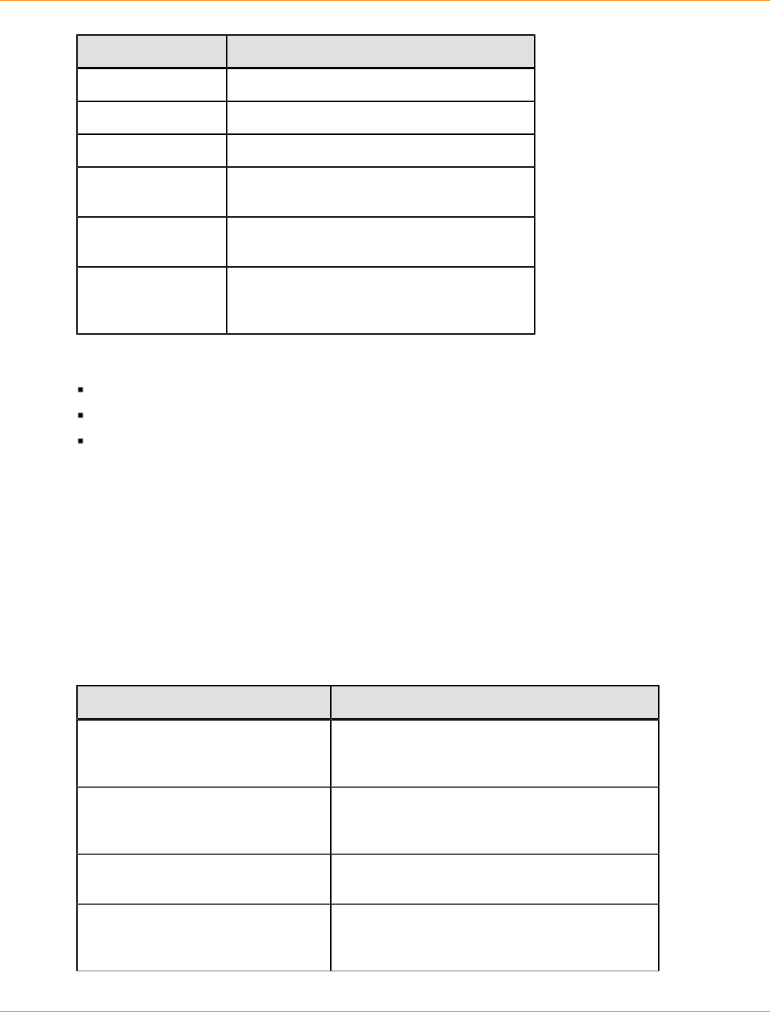
SANtricity_10.77 February 2011
LSI Corporation
- 1246 -
Object Type Identifier
snapshot Volume user label
storageArray Not applicable
tray Tray ID
volume Volume user label or volume World Wide
Identifier (WWID) (set command only)
volumeCopy Target volume user label and, optionally, the
source volume user label
volumeGroup User label
Valid characters are alphanumeric, a hyphen,
and an underscore.
Statement data is in the form of:
Parameter = value (such as raidLevel=5)
Parameter-name (such as batteryInstallDate)
Operation-name (such as redundancyCheck)
A user-defined entry (such as user label) is called a variable. In the syntax, it is shown in italic (such as
trayID or volumeGroupName).
Synopsis of the Script Commands
Because you can use the script commands to define and manage the different aspects of a storage array
(such as host topology, drive configuration, controller configuration, volume definitions, and volume group
definitions), the actual number of commands is extensive. The commands, however, fall into general
categories that are reused when you apply the commands to the different to configure or maintain a storage
array. The following table lists the general form of the script commands and a definition of each command.
General Form of the Script Commands
Syntax Description
activate object
{statement-data}
Sets up the environment so that an operation
can take place or performs the operation if the
environment is already set up correctly.
autoConfigure storageArray
{statement-data}
Automatically creates a configuration that is
based on the parameters that are specified in the
command.
check object
{statement-data}
Starts an operation to report on errors in the
object, which is a synchronous operation.
clear object
{statement-data}
Discards the contents of some attributes of an
object. This operation is destructive and cannot
be reversed.

SANtricity_10.77 February 2011
LSI Corporation
- 1247 -
Syntax Description
create object
{statement-data}
Creates an object of the specified type.
deactivate object
{statement-data}
Removes the environment for an operation.
delete object Deletes a previously created object.
diagnose object
{statement-data}
Runs a test and shows the results.
disable object {statement-data}
Prevents a feature from operating.
download object
{statement-data}
Transfers data to the storage array or to the
hardware that is associated with the storage
array.
enable object
{statement-data}
Sets a feature to operate.
load object
{statement-data}
Transfers data to the storage array or to the
hardware that is associated with the storage
array. This command is functionally similar to the
download command.
recopy object
{statement-data}
Restarts a volume copy operation by using an
existing volume copy pair. You can change the
parameters before the operation is restarted.
recover object
{statement-data}
Re-creates an object from saved configuration
data and the statement parameters. (This
command is similar to the create command.)
recreate object
{statement-data}
Restarts a snapshot operation by using an
existing snapshot volume. You can change the
parameters before the operation is restarted.
remove object
{statement-data}
Removes a relationship from between objects.
repair object
{statement-data}
Repairs errors found by the check command.
reset object
{statement-data}
Returns the hardware or an object to an initial
state.
resume object Starts a suspended operation. The operation
starts where it left off when it was suspended.
revive object Forces the object from the Failed state to the
Optimal state. Use this command only as part of
an error recovery procedure.
save object
Writes information about the object to a file.

SANtricity_10.77 February 2011
LSI Corporation
- 1248 -
Syntax Description
{statement-data}
set object
{statement-data}
Changes object attributes. All changes are
completed when the command returns.
show object
{statement-data}
Shows information about the object.
start object
{statement-data}
Starts an asynchronous operation. You can stop
some operations after they have started. You can
query the progress of some operations.
stop object
{statement-data}
Stops an asynchronous operation.
suspend object
{statement-data}
Stops an operation. You can then restart the
suspended operation, and it continues from the
point where it was suspended.
Recurring Syntax Elements
Recurring syntax elements are a general category of parameters and options that you can use in the script
commands. The Recurring Syntax Elements table lists the recurring syntax parameters and the values that
you can use with the recurring syntax parameters. The conventions used in the recurring syntax elements are
listed in the following table.
Convention Definition
a | b Alternative ("a" or "b")
italicized-words A terminal that needs user input to fulfill a
parameter (a response to a variable)
[ ... ] (square
brackets) Zero or one occurrence (square brackets are
also used as a delimiter for some command
parameters)
{ ... } (curly braces) Zero or more occurrences
(a | b | c) Choose only one of the alternatives
bold A terminal that needs a command parameter
entered to start an action
Recurring Syntax Elements
Recurring Syntax Syntax Value
raid-level (0 | 1 | 3 | 5 | 6)
repository-raid-level (1 | 3 | 5 | 6)

SANtricity_10.77 February 2011
LSI Corporation
- 1249 -
Recurring Syntax Syntax Value
capacity-spec integer-literal [KB | MB | GB | TB |
Bytes]
segment-size-spec integer-literal
boolean (TRUE | FALSE)
user-label string-literal
Valid characters are alphanumeric, the dash, and the
underscore.
user-label-list user-label {user-label}
create-raid-vol-attr-
value-list
create-raid-volume-attribute-value-pair
{create-raid-volume-attribute-value-pair}
create-raid-volume-
attribute-value-pair
capacity=capacity-spec | owner=(a | b) |
cacheReadPrefetch=(TRUE | FALSE) |
segmentSize=integer-literal |
usageHint=usage-hint-spec
noncontroller-trayID (0-99)
slotID (1-32)
portID (0-127)
drive-spec trayID,slotID or trayID,drawerID,slotID
A drive is defined as two or three interger literal values
separated by a comma. Low-density trays require
two values. High-density trays, those trays that have
drawers, require three values.
drive-spec-list drive-spec drive-spec
trayID-list trayID {trayID}
esm-spec-list esm-spec {esm-spec}
esm-spec trayID, (left | right)
hex-literal 0xhexadecimal-literal
volumeGroup-number integer-literal
filename string-literal
error-action (stop | continue)
drive-channel-identifier
(four drive ports per tray) (1 | 2 | 3 | 4)
drive-channel-identifier
(eight drive ports per tray) (1 | 2 | 3 | 4 | 5 | 6 | 7 | 8)

SANtricity_10.77 February 2011
LSI Corporation
- 1250 -
Recurring Syntax Syntax Value
drive-channel-identifier-
list
drive-channel-identifier {drive-
channel#identifier}
host-channel-identifier
(four host ports per tray) (a1 | a2 | b1 | b2)
host-channel-identifier
(eight host ports per tray) (a1 | a2 | a3 | a4 | b1 | b2 | b3 | b4)
host-channel-identifier
(16 host ports per tray) (a1 | a2 | a3 | a4 | a5 | a6 | a7 | a8 |
b1 | b2 | b3 | b4 | b5 | b6 | b7 | b8)
drive-type (fibre | SATA | SAS)
drive-media-type (HDD | SSD | unknown| allMedia)
HDD means hard disk drive. SSD means solid state
disk.
feature-identifier (storagePartition2 |
storagePartition4 |
storagePartition8 |
storagePartition16 |
storagePartition64 |
storagePartition96 |
storagePartition128 |
storagePartition256 |
storagePartitionMax |
snapshot | snapshot2 | snapshot4 |
snapshot8 | snapshot16 |
remoteMirror8 | remoteMirror16 |
remoteMirror32 | remoteMirror64 |
remoteMirror128 | volumeCopy |
goldKey | mixedDriveTypes |
highPerformanceTier |
SSDSupport | safeStoreSecurity |
safeStoreExternalKeyMgr | dataAssurance)
To use the High Performance Tier premium feature,
you must configure a storage array as one of these:
SHIPPED_ENABLED
SHIPPED_ENABLED=FALSE;
KEY_ENABLED=TRUE
repository-spec instance-based-repository-spec | count-
based-repository-spec
instance-based-
repository-spec
(repositoryRAIDLevel
=repository-raid-level
repositoryDrives=
(drive-spec-list)
[repositoryVolumeGroupUserLabel
=user-label]
[trayLossProtect=(TRUE | FALSE)1]) |

SANtricity_10.77 February 2011
LSI Corporation
- 1251 -
Recurring Syntax Syntax Value
[drawerLossProtect=(TRUE | FALSE)2]) |
(repositoryVolumeGroup=user-label
[freeCapacityArea=integer-literal3])
Specify the repositoryRAIDLevel parameter with
the repositoryDrives parameter. Do not specify
the RAID level or the drives with the volume group. Do
not set a value for the trayLossProtect parameter
when you specify a volume group.
count-based-repository-
spec
repositoryRAIDLevel
=repository-raid-level
repositoryDriveCount=integer-literal
[repositoryVolumeGroupUserLabel
=user-label]
[driveType=drive-type4]
[trayLossProtect=(TRUE | FALSE)1] |
[drawerLossProtect=(TRUE | FALSE)2] |
[dataAssurance=(none | enabled)5] |
wwID string-literal
gid string-literal
host-type string-literal | integer-literal
host-card-identifier (1 | 2 | 3 | 4)
backup-device-identifier (1 | n | all)
n is a specific slot number.
Specifying all includes all of the cache backup
devices availble to the entire storage array.
nvsram-offset hex-literal
nvsram-byte-setting nvsram-value = 0xhexadecimal | integer-
literal
The 0xhexadecimal value is typically a value from
0x0000 to 0xFFFF.
nvsram-bit-setting nvsram-mask, nvsram-value =
0xhexadecimal, 0xhexadecimal | integer-
literal
The 0xhexadecimal value is typically a value from
0x0000 to 0xFFFF.
ip-address (0-255).(0-255).(0-255).(0-255)
ipv6-address (0-FFFF):(0-FFFF):(0-FFFF):(0-FFFF): (0-
FFFF):(0-FFFF):(0-FFFF):(0-FFFF)
You must enter all 32 hexadecimal characters.

SANtricity_10.77 February 2011
LSI Corporation
- 1252 -
Recurring Syntax Syntax Value
autoconfigure-vols-attr-
value-list
autoconfigure-vols-attr-value-pair
{autoconfigure-vols-attr-value-pair}
autoconfigure-vols-attr-
value-pair
driveType=drive-type |
driveMediaType=drive-media-type |
raidLevel=raid-level |
volumeGroupWidth=integer-literal |
volumeGroupCount=integer-literal |
volumesPerGroupCount=integer-literal6 |
hotSpareCount=integer-literal |
segmentSize=segment-size-spec |
cacheReadPrefetch=(TRUE | FALSE)
securityType=(none | capable |
enabled)7 |
dataAssurance=(none | enabled)5
create-volume-copy-attr-
value-list
create-volume-copy-attr-value-pair
{create-volume-copy-attr-value-pair}
create-volume-copy-attr-
value-pair
copyPriority=(highest | high | medium |
low | lowest) |
targetReadOnlyEnabled=(TRUE | FALSE) |
copyType=(offline | online) |
repositoryPercentOfBase=(20 | 40 | 60 |
120 | default) |
repositoryGroupPreference=(sameAsSource |
otherThanSource | default)
recover-raid-volume-attr-
value-list
recover-raid-volume-attr-value-pair
{recover-raid-volume-attr-value-pair}
recover-raid-volume-attr-
value-pair
owner=(a | b) |
cacheReadPrefetch=(TRUE | FALSE) |
dataAssurance=(none | enabled)
cache-flush-modifier-
setting
immediate, 0, .25, .5, .75, 1, 1.5, 2,
5, 10, 20, 60, 120, 300, 1200, 3600,
infinite
serial-number string-literal
usage-hint-spec usageHint=(multiMedia | database |
fileSystem)
iscsiSession [session-identifier]
iscsi-host-port (1 | 2 | 3 | 4)
The host port number might be 2, 3, or 4 depending
on the type of controller you are using.
ethernet-port-options enableIPv4=(TRUE | FALSE) |
enableIPv6=(TRUE | FALSE) |
IPv6LocalAddress=ipv6-address |

SANtricity_10.77 February 2011
LSI Corporation
- 1253 -
Recurring Syntax Syntax Value
IPv6RoutableAddress=ipv6-address |
IPv6RouterAddress=ipv6-address |
IPv4Address=ip-address |
IPv4ConfigurationMethod=
(static | dhcp) |
IPv4GatewayIP=ip-address |
IPv4SubnetMask=ip-address |
duplexMode=(TRUE | FALSE) |
portSpeed=(autoNegotiate | 10 | 100 |
1000)
iscsi-host-port-options IPv4Address=ip-address |
IPv6LocalAddress=ipv6-address |
IPv6RoutableAddress=ipv6-address |
IPv6RouterAddress=ipv6-address |
enableIPv4=(TRUE | FALSE) |
enableIPv6=(TRUE | FALSE) |
enableIPv4Priority=(TRUE | FALSE) |
enableIPv6Priority=(TRUE | FALSE) |
IPv4ConfigurationMethod=
(static | dhcp) |
IPv6ConfigurationMethod=
(static | auto) |
IPv4GatewayIP=ip-address |
IPv6HopLimit=integer |
IPv6NdDetectDuplicateAddress=integer |
IPv6NdReachableTime=time-interval |
IPv6NdRetransmitTime=time-interval |
IPv6NdTimeOut=time-interval |
IPv4Priority=integer |
IPv6Priority=integer |
IPv4SubnetMask=ip-address |
IPv4VlanId=integer |
IPv6VlanId=integer |
maxFramePayload=integer |
tcpListeningPort=tcp-port-id |
portSpeed=(autoNegotiate | 1 | 10)
test-devices-list test-devices {test-devices}
test-devices controller=(a | b)
esms=(esm-spec-list)
drives=(drive-spec-list)
snapshot-schedule-
attribute-value-list
snapshot-schedule-attribute-value-pair
{snapshot-schedule-attribute-value-pair}
time-zone-spec (GMT+HH:MM | GMT-HH:MM)
[dayLightSaving=HH:MM]
snapshot-schedule-
attribute-value-pair
startDate=MM:DD:YY
scheduleDay=(dayOfWeek | all)
startTime=HH:MM

SANtricity_10.77 February 2011
LSI Corporation
- 1254 -
Recurring Syntax Syntax Value
scheduleInterval=interger
endDate=(MM:DD:YY | noEndDate)
timesPerDay=interger
1For tray loss protection to work, each drive in a volume group must be in a separate tray. If you set the
trayLossProtect parameter to TRUE and you have selected more than one drive from any one tray, the
storage array returns an error. If you set trayLossProtect parameter to FALSE, the storage array performs
operations, but the volume group that you create might not have tray loss protection.
If you set the trayLossProtect parameter to TRUE, the storage array returns an error if the controller
firmware cannot find drives that will enable the new volume group to have tray loss protection. If you set the
trayLossProtect parameter to FALSE, the storage array performs the operation even if it means that the
volume group might not have tray loss protection.
2In trays that have drawers for holding the drives, drawer loss protection determines whether data on
a volume is accessible or inaccessible if a drawer fails. To help make sure that your data is accessible,
set the drawerLossProtect parameter to TRUE. For drawer loss protection to work, each drive in a
volume group must be in separate drawers. If you have a storage array configuration in which a volume
group spans several trays, you must make sure that the setting for drawer loss protection works with the
setting for tray loss protection. If you set the trayLossProtect parameter to TRUE, you must set the
drawerLossProtect parameter to TRUE. If you set the trayLossProtect parameter to TRUE, and
you set the drawerLossProtect parameter to FALSE, the storage array returns an error message and a
storage array configuration will not be created.
3To determine if a free capacity area exists, run the show volumeGroup command.
4The default drive (drive type) is fibre (Fibre Channel).
The driveType parameter is not required if only one type of drive is in the storage array. If you use the
driveType parameter, you also must use the hotSpareCount parameter and the volumeGroupWidth
parameter. If you do not use the driveType parameter, the configuration defaults to Fibre Channel drives.
5The dataAssurance parameter applies to the drives in a volume group. Using the dataAssurance
parameter, you can specify that protected drives must be selected for a volume group. If you want to set
the dataAssurance parameter to enabled, all of the drives in the volume group must be capable of data
assurance. You cannot have a mix of drives that are capable of data assurance and drives that are not
capable of data assurance in the volume group.
6The volumesPerGroupCount parameter is the number of equal-capacity volumes per volume group.
7The securityType parameter enables you to specify the security setting for a volume group that you are
creating. All of the volumes are also set to the security setting that you choose. Available options for setting
the security setting include:
none – The volume group is not secure.
capable – The volume group is security capable, but security has not been enabled.
enabled – The volume group is security enabled.
SANtricity_10.77 February 2011
LSI Corporation
- 1255 -
NOTE A storage array security key must already be created for the storage array if you want to set
securityType=enabled. (To create a storage array security key, use the create storageArray
securityKey command).
Usage Guidelines
This list provides guidelines for writing script commands on the command line:
You must end all commands with a semicolon (;).
You can enter more than one command on a line, but you must separate each command with a
semicolon (;).
You must separate each base command and its associated primary parameters and secondary
parameters with a space.
The script engine is not case sensitive. You can enter commands by using uppercase letters, lowercase
letters, or mixed-case letters.
Add comments to your scripts to make it easier for you and future users to understand the purpose of the
script commands. (For information about how to add comments, see "Adding Comments to a Script File.")
NOTE While the CLI commands and the script commands are not case sensitive, user labels (such as
for volumes, hosts, or host ports) are case sensitive. If you try to map to an object that is identified by a user
label, you must enter the user label exactly as it is defined, or the CLI commands and the script commands
will fail.
Adding Comments to a Script File
The script engine looks for certain characters or a command to show comments. You can add comments to a
script file in three ways:
1. Add text after two forward slashes (//) as a comment until an end-of-line character is reached. If the
script engine does not find an end-of-line character in the script after processing a comment, an error
message appears, and the script operation is terminated. This error usually occurs when a comment is
placed at the end of a script and you have forgotten to press the Enter key.
// Deletes the existing configuration.
set storageArray resetConfiguration=true;
2. Add text between /* and */ as a comment. If the script engine does not find both a starting comment
notation and an ending comment notation, an error message appears, and the script operation is
terminated.
/* Deletes the existing configuration */
set storageArray resetConfiguration=true;
3. Use the show statement to embed comments in a script file that you want to appear while the script file is
running. Enclose the text that you want to appear by using double quotation marks (“ ”).
show “Deletes the existing configuration”;
set storageArray resetConfiguration=true;
SANtricity_10.77 February 2011
LSI Corporation
- 1256 -
Configuring a Storage Array
This chapter explains how to run script commands from the command line to create a volume from a
collection of drives and to configure a RAID storage array. This chapter assumes that you have a basic
understanding of RAID concepts and terminology. Before you begin to configure your storage array, become
familiar with these concepts:
Controllers
Drives
Hot spares
Volume groups
Volumes
RAID technology
Hosts
Host groups
Host bus adapter (HBA) host ports
Logical unit numbers (LUNs)
Configuring a RAID storage array requires caution and planning to make sure that you define the correct
RAID level and configuration for your storage array. The main purpose in configuring a storage array is to
create volumes, which are addressable by the hosts, from a collection of drives. The commands described in
this chapter enable you to set up and run a RAID storage array. Additional commands are also available to
provide you with more control and flexibility in managing and maintaining your storage array.
NOTE Many of these commands require a thorough understanding of the firmware as well as an
understanding of the network components that need to be mapped. Use the CLI commands and the script
commands with caution.
The sections in this chapter show some, but not all, of the CLI wrapper commands and the script commands.
The commands in this chapter show how you can use the commands to configure a storage array. These
presentations do not describe all possible usage and syntax for the commands. For complete definitions of
the commands, including syntax, parameters, and usage notes, refer to the Command Line Interface and
Script Commands.
This chapter contains examples of CLI command usage and script command usage. The command syntax
that is used in the examples is for a host running a Microsoft operating system. As part of the examples, the
complete C:\ prompt and the DOS path for the commands are shown. Depending on your operating system,
the prompt and path construct will vary.
For most commands, the syntax is the same for all Windows operating systems and UNIX operating systems,
as well as for a script file. Windows operating systems, however, have an additional requirement when
entering names on a command line. On Windows operating systems, you must enclose the name between
two back slashes (\ \) in addition to other delimiters. For example, the following name is used in a command
running under a Windows operating system:
[\”Engineering\”]
For a UNIX operating system, and when used in a script file, the name appears as follows:
[“Engineering”]

SANtricity_10.77 February 2011
LSI Corporation
- 1257 -
Configuration Concepts
When you configure a storage array, you organize drives into a logical structure that provides storage
capacity and data protection so that one or more hosts can safely store data in the storage array. This section
provides definitions of the physical and logical components required to organize the physical disks into a
storage array configuration. This section also describes how the components relate to each other.
Controllers
All storage arrays have one or two controllers. The controllers are circuit-board assemblies that manage data
and communication between the hosts and the storage array. The controller manages the data flow between
the hosts and the drives, keeping track of the logical address of where the data resides. In general, each
controller has a processor for performing control operations, NVSRAM for storing the firmware code that
operates the storage array, and the buses along which the data flows.
The controllers are located in a controller tray or a controller-drive tray. The controller tray or a controller-drive
tray has two positions for controllers: slot A and slot B. The script commands identify each controller by the
slot in which the controller is installed. If controller tray or a controller-drive tray has only one controller, the
controller must be in slot A. A controller tray or a controller-drive tray with two controllers is called a duplex
tray. A controller tray or a controller-drive tray with one controller is called a simplex tray.
Early controller models FC1250 and FC1275 used minihubs; two connected to each controller. When viewed
from the rear of the controller tray, the host-side minihubs are numbered from left-to-right a1, b1, a2, and
b2. The script commands identify the host channels by using these identifiers. Minihubs also support the
drive-side, where each minihub represents a single channel to the drives. When viewed from the rear of the
controller tray, the drive minihubs are numbered from left to right 4, 3, 2, and 1. The script commands use
these numbers to identify the drive channels.
Controller models SAT2700 and SHV2600 are used in an early controller-drive tray that has a slot where
either a controller or an environmental services monitor (ESM) can be used. When an ESM is used, the tray is
called a drive tray.
Controllers manage the interface by running controller firmware to transmit and receive commands between
the hosts and the drives. Host bus adapters facilitate the communication through whichever interface is
selected. Typically, two host bus adapters and two paths are used to optimize redundancy.
The controller-drive trays and controller trays incorporate all host connections and drive tray connections
into each controller. The host ports must be identified in your command statements to let you complete their
network configurations.
The more recent models of controllers do not use minihubs. These controllers have host ports that are
integrated into the controller circuit boards or auxiliary circuit boards that are directly connected to the
controller circuit boards.
The following table lists the controller-drive trays that do not use minihubs, the type of host port, and the
number of host ports.
Host Ports and Host Interfaces for Controllers
Model Available
Host Ports Type of Host Interface
AM1331 controller-drive tray 1 SAS

SANtricity_10.77 February 2011
LSI Corporation
- 1258 -
Model Available
Host Ports Type of Host Interface
AM1333 controller-drive tray 3 SAS
AM1532 controller-drive tray 2 iSCSI
AM1932 controller-drive tray 2 Fibre Channel
2 or 4 SAS
4 Fibre Channel
CDE2600 controller-drive tray
4 iSCSI
CDE3992 controller-drive tray 2 Fibre Channel
CDE3994 controller-drive tray 4 Fibre Channel
CE6998 controller tray 4 Fibre Channel
16 Fibre ChannelCE7900 controller tray
4 iSCSI
The four iSCSI host connections are
used with eight Fibre Channel host
connections.
The AM1333 controller-drive tray has three host ports that are numbered from left to right: host port 1, host
port 2, and host port 3 as seen from the rear of the controller-drive tray.
The AM1532 and AM1932 controller-drive trays have two host ports on each controller, which are numbered
from left to right: host port 1 and host port 2 as seen from the rear of the controller-drive tray.
The host ports on the CDE3994 controller-drive tray are numbered from left-to-right on controller B as Ch 1,
Ch 2, Ch 3, and Ch 4. Controller A, which is installed upside-down in the controller-drive tray, is numbered
from right-to-left in the same sequence.
The controller in the CE6998 controller tray can have up to four host channels with one port for each channel;
up to two drive channels with two ports per channel (for a total of four drive ports); and up to two Ethernet
ports. In the CE6998 controller tray, the controllers are stacked one above the other. The top controller is A.
The bottom controller is B.
For controller A, the host channel identifiers are a1, a2, a3, and a4, and the host bus adapter (HBA) host
ports are labeled 1, 2, 3, and 4. For controller B, the host channel identifiers are b1, b2, b3, and b4, and the
HBA host ports are labeled 1, 2, 3, and 4.
Controller A has drive channels 1 and 2. Drive ports labeled 3 and 4 connect to drive channel 1. Drive ports
labeled 1 and 2 connect to Drive Channel 2. Controller B has drive channels 3 and 4. Drive ports labeled
1 and 2 connect to drive channel 3. Drive ports labeled 3 and 4 connect to drive channel 4. Each Ethernet
port on a controller can have a unique IP address; however, both Ethernet ports share the same gateway IP
address, subnet mask, and remote login settings.
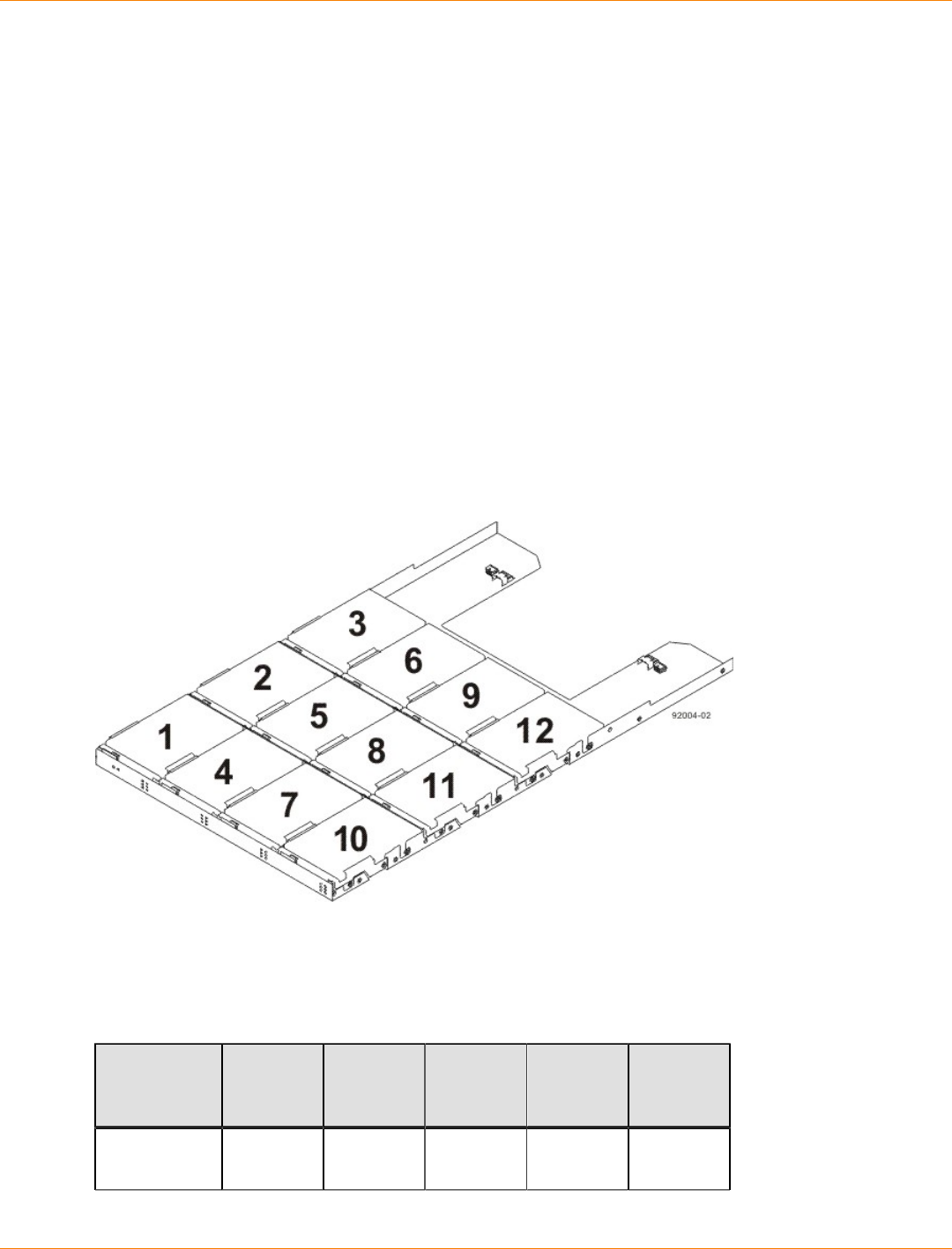
SANtricity_10.77 February 2011
LSI Corporation
- 1259 -
Each of the two controllers in the CE7900 controller tray can have two host cards with four host ports on
each card. Some CE7900 controller trays can have controllers with only one host card each. Controller A is
inverted from controller B, which means that its host channels are upside-down.
Drives
The drives store the data that is sent to the storage array. The drives are mounted in either a controller-
drive tray or a drive tray. The controller-drive tray has drives and controllers in one tray. A drive tray has
only drives, and is connected to a controller through an environmental services monitor (ESM). In addition to
the drives and ESMs, the drive tray contains power supplies an fans. These components support drive tray
operation and can be maintained through the CLI.
Drives are located in a storage array by tray ID and slot ID. Tray ID values are 0 to 99. In older trays, tray ID
values are set during installation by switches on the rear of the trays. In newer trays, tray ID values are set
automatically when the power is applied.
The slot ID is the drive position in the drive tray. A drive tray can contain 12, 14, 16, 24, or 60 drives. In drive
trays with fewer than 60 drives, slot ID values range from 1 to 32. In drive trays with 60 drives, slot ID values
are defined by the drawer number and the position of the drive in the drawer. The drawer numbers range from
1 to 5, counting from top to bottom. The position of each drive in a drawer is shown in the following figure.
Drive Drawer with Drives
The total number of drives in a storage array depends on the model of the controller tray or controller-drive
tray and the capacity of the drives. The following table lists, by controller tray or controller-drive tray model
and drive tray capacity, the maximum number of drives in a storage array.
Maximum Number of Drives Supported
Controller
Model 12-Drive
Drive
Tray
14-Drive
Drive
Tray
16-Drive
Drive
Tray
24-Drive
Drive
Tray
60-Drive
Drive
Tray
AM1331
AM1333 48
SANtricity_10.77 February 2011
LSI Corporation
- 1260 -
Controller
Model 12-Drive
Drive
Tray
14-Drive
Drive
Tray
16-Drive
Drive
Tray
24-Drive
Drive
Tray
60-Drive
Drive
Tray
AM1532 48
AM1932 48
CDE2600
(simplex
controller)
96 96
CDE2600
(duplex
controller)
192 192
CDE3992 112 112
CDE3994 112 112
CDE4900 112 112
CE6998 224 224
CE7900 256 480
NOTE A maximum of seven drive trays can be on a channel when mixing 14-slot drive trays and 16-slot
drive trays.
The maximum capacity in a storage array depends on the number of the drives in the and storage array the
capacity of each drive in the storage array. The following table lists the maximum storage for each controller
model based on the capacity of the drives.
Maximum Capacity with Supported Drives
Drive
Capacity AM1331
AM1333
AM1532
AM1932
CDE2600 CDE3992/
CDE3994 CDE4900 CE6998 CE7900
73#GB FC 8.0 TB 16.4 TB
73#GB
SAS 3.5 TB
146#GB
FC 16.0 TB 32.7 TB
146#GB
SAS 7.0 TB 28.0 TB

SANtricity_10.77 February 2011
LSI Corporation
- 1261 -
Drive
Capacity AM1331
AM1333
AM1532
AM1932
CDE2600 CDE3992/
CDE3994 CDE4900 CE6998 CE7900
150#GB
SAS 28.8 TB
300#GB
FC 34.0 TB 67.2 TB
300#GB
SAS 14.4 TB 57.6 TB
450#GB
FC 50.0 TB 201.0 TB
450#GB
SAS 86.4 TB
500#GB
SATA 24.0 TB 56.0 TB 112.0 TB
500#GB
SAS 96.0 TB
600#GB
SAS 115.2 TB
750#GB
SATA 36.0 TB
1.0#TB
SAS 192.0 TB
1.0#TB
SATA 48.0 TB 112.0 TB 480.0 TB
Hot Spare Drives
A hot spare is a drive that acts as a standby in the event that a drive containing data fails. The hot spare is
a drive that has not been assigned to a particular volume group and, as such, can be used in any volume
group. You can use the hot spare feature with RAID Level 1, RAID Level 3, RAID Level 5, or RAID Level 6.
If a drive in a volume group fails, the controllers automatically replace the failed drive with a hot spare. The
controllers use redundancy data to reconstruct the data from the failed drive onto the hot spare. To be most
effective, the drive that you assign as a hot spare must have a capacity equal to or greater than the capacity
of the largest drive in the storage array. The hot spare must be the same type of drive as the drive that failed
(for example, a Serial Advanced Technology Attachment [SATA] hot spare cannot replace a Fibre Channel
hot spare).
You can assign drives to act as hot spares manually or have the script commands automatically assign hot
spares. If you manually assign a drive to be a hot spare, you must identify the drive by tray ID and slot ID.
When you let the script commands automatically assign hot spares, you must enter the number of hot spares
that you want in the storage array.
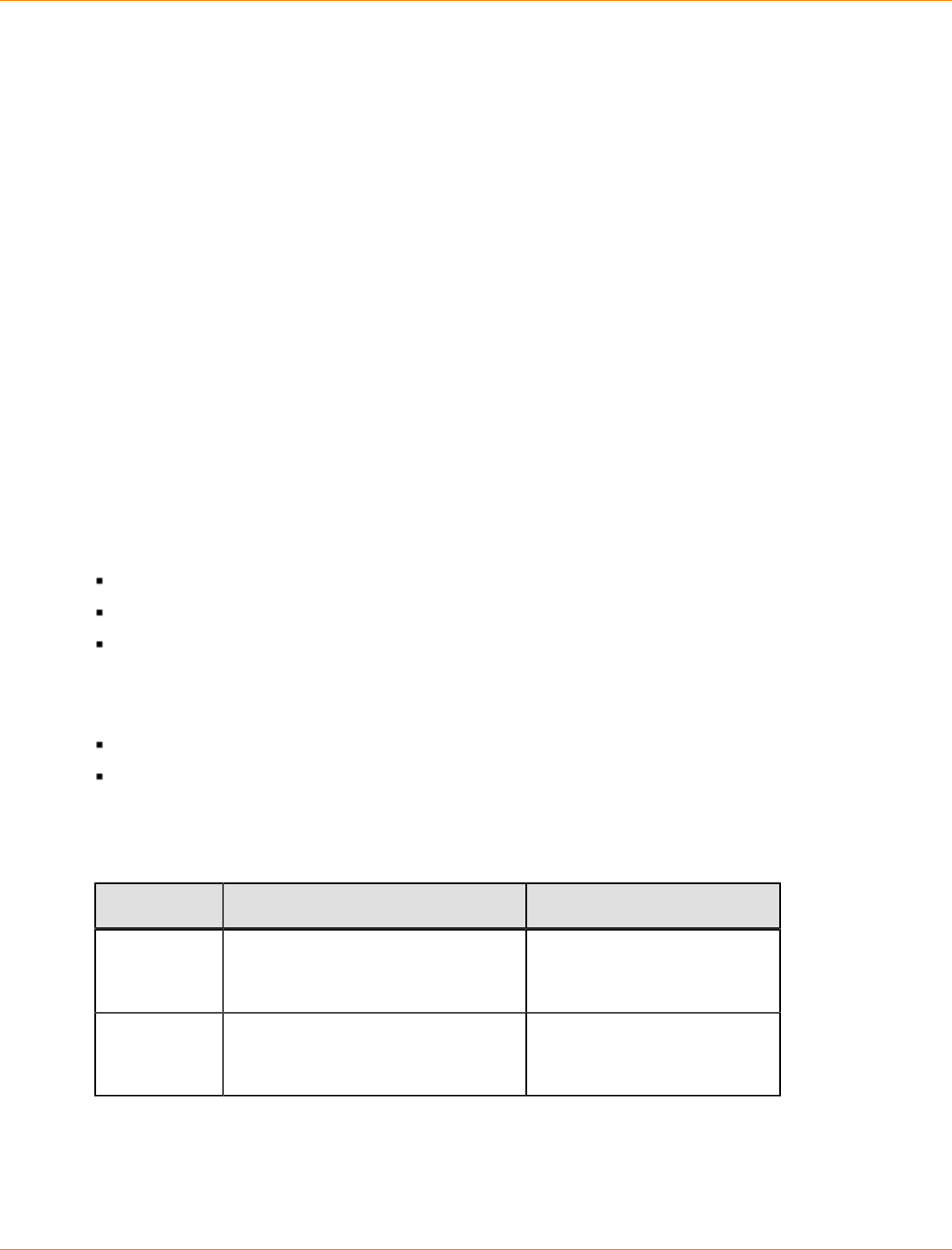
SANtricity_10.77 February 2011
LSI Corporation
- 1262 -
SafeStore Drive Security with Full Disk Encryption
SafeStore Drive Security is a premium feature that prevents unauthorized access to the data on a drive that is
physically removed from the storage array. Controllers in the storage array have a security key. Secure drives
provide access to data only through a controller that has the correct security key. SafeStore Drive Security is
a premium feature of the storage management software and must be enabled either by you or your storage
vendor.
The SafeStore Drive Security premium feature requires security capable drives. A security capable drive
encrypts data during writes and decrypts data during reads. Each security capable drive has a unique drive
encryption key.
When you create a secure volume group from security capable drives, the drives in that volume group
become security enabled. When a security capable drive has been security enabled, the drive requires the
correct security key from a controller to read or write the data. All of the drives and controllers in a storage
array share the same security key. The shared security key provides read and write access to the drives,
while the drive encryption key on each drive is used to encrypt the data. A security capable drive works like
any other drive until it is security enabled.
Whenever the power is turned off and turned on again, all of the security-enabled drives change to a security
locked state. In this state, the data is inaccessible until the correct security key is provided by a controller.
You can view the SafeStore Drive Security status of any drive in the storage array from the Drive Properties
dialog. The drive can have one of these capabilities:
Security Capable
Secure – Security enabled or disabled
Read/Write Accessible – Security locked or unlocked
You can view the SafeStore Drive Security status of any volume group in the storage array by using the show
volume group command. The volume group can have one of these capabilities:
Security Capable
Secure
The following table shows how to interpret the security properties status of a volume group.
Volume Group Security Properties
Security Capable – yes Security Capable – no
Secure – yes The volume group is composed of
all full disk encryption (FDE) drives
and is in a Secure state.
Not applicable. Only FDE
drives can be in a Secure
state.
Secure – no The volume group is composed
of all FDE drives and is in a Non-
Secure state.
The volume group is not
entirely composed of FDE
drives.
You can erase security-enabled drives so that you can reuse the drives in another volume group or in another
storage array. Use the start secure erase command to completely erase any data on a security-enabled
drive. Using the start secure erase command results in the loss of all of the data on a drive, and is
irreversible. You can never recover the data.
SANtricity_10.77 February 2011
LSI Corporation
- 1263 -
The storage array password protects a storage array from potentially destructive operations by unauthorized
users. The storage array password is independent from the SafeStore Drive Security premium feature and
should not be confused with the pass phrase that is used to protect copies of a security key. However, it is
good practice to set a storage array password before you create, change, or save a security key or unlock
secure drives.
Commands for FDE Drives
You can use these commands to enable security in the FDE drives and manage the drives.
activate hostPort
activate iscsiInitiator
create volume – Automatic drive select
create volume – Free extent based select
create volume – Manual drive select
create storageArray securityKey
create volumeGroup
enable volumeGroup security
export storageArray securityKey
import storageArray securityKey
set controller
set storageArray securityKey
show drive
start secure erase
Volume Groups
A volume group is a set of drives that are logically grouped together by the controllers in a storage array.
After you create a volume group, you can create one or more volumes in the volume group. A volume group
is identified by a sequence number that is defined by the controller firmware when you created the volume
group.
NOTE Some storage arrays permit different drive types in the same tray; however, you cannot have a
combination of different drives in the same volume group.
To create a volume group, you must define the capacity and the RAID level.
Capacity is the size of the volume group. Capacity is determined by the number of drives that you assign to
the volume group. You can use only unassigned drives to create a volume group. (In this programming guide,
the storage space on unassigned drives constitutes the unconfigured capacity of a storage array.)
Free capacity is a contiguous region of unassigned capacity in a designated volume group. Before you create
a new volume in a volume group, you need to know the free capacity space so that you can determine the
size of the volume.
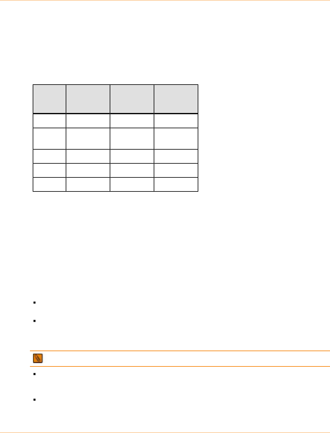
SANtricity_10.77 February 2011
LSI Corporation
- 1264 -
The RAID level is the level of data protection that you want to define for your storage array. The RAID level
that you choose affects storage capacity. When you configure your storage array, you must consider this
compromise between data protection and storage capacity. In general, the more protection that you need, the
less storage capacity is available in your storage array.
The following table lists the minimum number of drives and the maximum number of drives that you can use
in a volume group based on the RAID level that you want to assign to the volume group.
Maximum Number of Drives in a Volume Group Based on RAID Level
RAID
Level Minimum
Number of
Drives
Maximum
Number of
Drives
Redundancy
0 1 All None
1 1 All Mirrored
pairs
3 3 30 1 drive
5 3 30 1 drive
6 5 30 2 drives
You can determine the size of the volume group by multiplying the maximum number of drives in the volume
group by the capacity of the smallest drive in the volume group.
Volumes
A volume is a logical component (object) that is the basic structure that is created on the storage array to
store data. A volume is a contiguous subsection of a volume group that is configured to meet application
needs for data availability and I/O performance. The storage management software administers a volume as
if the volume is one “drive” for data storage. Volumes are identified by names or labels that users choose. The
volume names can be any combination of alphanumeric characters, hyphens (-), and underscores (_). The
maximum length of a volume name is 30 characters.
The script commands support the following types of volumes:
Standard volume – A logical structure that is the principal type of volume for data storage. A standard
volume is the most common type of volume in a storage array.
Access volume – A factory-configured volume in a storage area network (SAN) environment that is used
for communication between the storage management software and the storage array controller. The
access volume uses a logical unit number (LUN) address and consumes 20 MB of storage space. The 20
MB of access volume storage space is not available for data storage.
NOTE Use the access volume only for in-band-managed storage arrays.
Snapshot volume – A logical point-in-time image of another volume. A snapshot volume is the logical
equivalent of a complete physical copy; however, it is not an actual, physical copy. Instead, the firmware
tracks only the data blocks that are overwritten and copies those blocks to a snapshot repository volume.
Snapshot repository volume – A special volume in the storage array that is created as a resource for
a snapshot volume. A snapshot repository volume contains snapshot data and copy-on-write data for a
particular snapshot volume.
SANtricity_10.77 February 2011
LSI Corporation
- 1265 -
Base volume – A standard volume from which you create a snapshot volume. The term “base volume” is
used only to show the relationship between a standard volume from which you are taking the point-in-time
image and a snapshot volume.
Primary volume – A standard volume in a Remote Volume Mirroring relationship. The primary volume
accepts host data transfers and stores application data. When you first create the mirror relationship, data
from the primary volume is copied in its entirety to the associated secondary volume.
Secondary volume – A standard volume in a Remote Volume Mirroring relationship that maintains
a mirror (or copy) of the data from its associated primary volume. The secondary volume remains
unavailable to host applications while mirroring is underway. In the event of a disaster or a catastrophic
failure of the primary site, a system administrator can promote the secondary volume to a primary role.
Mirror repository volume – A special volume in a Remote Volume Mirroring configuration that is created
as a resource for each controller in both the local storage array and the remote storage array. The
controller stores mirroring information on this volume, including information about remote writes that are
not yet complete. A controller can use this information to recover from controller resets and accidental
power shutdown of the storage arrays.
NOTE Snapshot Volume and Remote Volume Mirroring are premium features that you must activate
before you can use them. For more information about snapshot volumes, see “Using the Snapshot Premium
Feature.” For more information about Remote Volume Mirroring, see “Using the Remote Volume Mirroring
Premium Feature.”
The number and capacity of the volumes in your storage array depends on the type of controller in the
storage array. The following table lists the maximum number of volumes in a storage array that each
controller model supports.
Maximum Number of Volumes Each Controller Model Supports
Specification AM1331
AM1333
AM1532
AM1932
CDE2600 CDE3992
or
CDE3994
CDE4900 CE6998
or
CE7900
Maximum number of volumes
per storage array 256 256 1024 1024 2048
Maximum number of volumes
per volume group 256 256 256 256 256
Maximum volume size Number of drives supported by array x (capacity of
largest supported drive by array – 512 MB)
Maximum number of drives
per volume group using RAID
Level 5
30 30 30 30 30
Maximum number of remote
mirrors 16 16 64 64 128
NOTE The maximum volume size is limited by the size of the drives and the configuration of the
storage array. The last 512 MB on each drive is reserved for storage array configuration database and
potential future expansion. For practical considerations, you want to constrain the maximum volume size so
that drive replacement and volume reconstruction does not take an excessive amount of time.

SANtricity_10.77 February 2011
LSI Corporation
- 1266 -
RAID Levels
The RAID level defines a storage architecture in which the storage capacity on the drives in a volume group
is separated into two parts: part of the capacity stores the user data, and the remainder stores redundant or
parity information about the user data. The RAID level that you choose determines how user data is written
to and retrieved from the drives. Using the script commands, you can define five RAID levels: RAID Level 0,
RAID Level 1, RAID Level 3, RAID Level 5, and RAID Level 6. Each level provides different performance and
protection features.
RAID Level 0 provides the fastest storage access but does not provide any redundant information about
the stored data. RAID Level 1, RAID Level 3, RAID Level 5, and RAID Level 6 write redundancy information
to the drives to provide fault tolerance. The redundancy information might be a copy of the data or an
error-correcting code that is derived from the data. In RAID Level 1, RAID Level 3, RAID Level 5, or RAID
Level 6 configurations, if a drive fails, the redundancy information can be used to reconstruct the lost data.
Regardless of the RAID level that you choose, you can configure only one RAID level across each volume
group. All redundancy information for a volume group is stored within the volume group. The following table
lists the RAID levels and describes the configuration capabilities of each level.
RAID Level Configurations
RAID
Level Configuration
0Non-redundant striping mode – Use this level for high-performance needs.
RAID Level 0 does not provide any data redundancy. RAID Level 0 stripes
data across all of the drives in the volume group. If a single drive fails, all
of the associated volumes fail and all data is lost. RAID Level 0 is suited for
noncritical data. It is not recommended for high-availability needs.
1Striping mirroring mode – RAID Level 1 uses drive mirroring to create an
exact copy from one drive to another drive. A minimum of two drives are
required; one for the user data, and one for the mirrored data. RAID Level 1
offers high performance and the best data availability.
Data is written to two drives simultaneously. If one drive in a drive pair fails,
the system can instantly switch to the other drive without any loss of data or
service. Only half of the drives in the volume group are available for user data.
If a single drive fails in a RAID Level 1 volume group, all of the associated
volumes become degraded, but the mirror drive provides access to the data.
RAID Level 1 can survive multiple drive failures as long as no more than
one failure occurs per mirrored pair. If a drive pair fails, all of the associated
volumes fail, and all data is lost.
3High-bandwidth mode – RAID Level 3 stripes both user data and redundancy
data (in the form of parity) across the drives. The equivalent of the capacity of
one drive is used for the redundancy data. RAID Level 3 works well for large
data transfers in applications, such as multimedia or medical imaging, that
write and read large sequential chunks of data.
If a single drive fails in a RAID Level 3 volume group, all of the associated
volumes become degraded, but the redundancy data lets the data be
reconstructed. If two or more drives fail, all of the associated volumes fail, and
all data is lost.
SANtricity_10.77 February 2011
LSI Corporation
- 1267 -
RAID
Level Configuration
5High I/O mode – RAID Level 5 stripes both user data and redundancy data
(in the form of parity) across the drives. The equivalent of the capacity of one
drive is used for the redundancy data. RAID Level 5 works well for multiuser
environments, such as databases or file system storage, where typical I/O size
is small, and a high proportion of read activity exists.
If a single drive fails in a RAID Level 5 volume group, all of the associated
volumes become degraded, and the redundancy data permits the data to be
reconstructed. If two or more drives fail, all of the associated volumes fail, and
all data is lost.
6Data protection or continuous access mode – RAID Level 6 stripes both
user data and redundancy data (in the form of parity) across the drives.
A minimum of five drives are required for a RAID Level 6 volume group.
The equivalent capacity of two drives is used for the redundancy data. Two
different algorithms calculate redundancy data, which are in the form of both a
P parity and a Q parity.
RAID Level 6 works well for larger drive sizes. Recovery from a second drive
failure in the same volume group is possible. If two drives fail in a RAID Level
6 volume group, all of the associated volumes become degraded, but the
redundancy data permits the data to be reconstructed. If three or more drives
fail, all of the associated volumes fail, and all data is lost.
NOTE RAID Level 6 is only available to those controllers that are capable of supporting the P+Q
calculation. The model CE6998 controller does not support RAID Level 6. The CDE2600, CDE3992,
CDE3994, CDE4900, and CE7900, controllers support RAID Level 6. A premium feature key enables
customers to use RAID Level 6 and to use dynamic RAID-level migration. Refer to the "Set Volume Group"
command in Command Line Interface and Script Commands for Version 10.75 for information explaining how
to set your volume group to RAID Level 6.
Hosts
A host is a computer that is attached to the storage array for accessing the volumes in the storage array.
The host is attached to the storage array through HBA host ports, which are connectors on host bus adapter
circuit boards. You can define specific volume-to-LUN mappings to an individual host or assign the host to
a host group that shares access to one or more volumes. Hosts are identified by names or labels that users
choose. The host name can be any combination of alphanumeric characters, hyphens, and underscores. The
maximum length of the host name is 30 characters.
In addition to a host name, some script commands require you to identify a host by its A host type identifies
the operating system under which the host is running (such as Windows, Solaris, or Linux). Specifying the
host type lets the controllers in the storage array adapt their behavior (such as LUN reporting and error
conditions) to the operating system of the host that is sending the information. Host types are identified by a
label or an index number that is generated by the controller firmware.
Host Groups
A host group is a topological element that you can define if you want to designate a collection of hosts that
will share access to the same volumes. A host group is a logical entity. Host groups are identified by names
or labels that users choose. The host group name can be any combination of alphanumeric characters with a
maximum length of 30 characters.
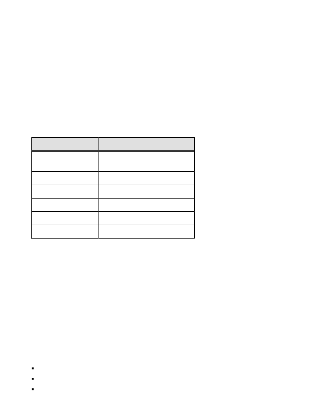
SANtricity_10.77 February 2011
LSI Corporation
- 1268 -
Host Bus Adapter Host Ports
A host bus adapter (HBA) provides the physical connection from the host to the storage array. The host port
is a physical connector on an HBA. The HBA is a circuit board that is installed in the host. The HBA can have
one or more host ports. Each host port is identified by a unique, 16-byte World Wide Identifier (WWID). If the
HBA has more than one host port, each host port has a unique ID.
When you first turn on the power to a storage array, the storage management software automatically detects
the HBA host ports. Initially, all detected host ports belong to a default group. You can use script commands
to identify the WWIDs on a storage array and, if you choose, change them. If you move an HBA host port, you
must remap any volume-to-LUN mappings. Access to your data is lost until you remap the volumes.
The maximum number of HBA host ports that you can logically define for your storage array depends on the
type of controller in the storage array. The following table lists the maximum number of HBA host ports that
you can define.
Maximum Number of HBA Host Ports per Controller
Controller Models Maximum Number of Host Ports
1331, 1333, 1532,
1932 256
CDE2600 256
CDE3992 or CDE3994 256
CDE4900 256
CE6998 512
CE7900 1024
Logical Unit Numbers
In the context of the CLI commands and the script commands, a logical unit number (LUN) is a unique value
that identifies the volumes in a storage array. The hosts identify the volumes that they want to access using
the LUN values. When you create a volume, the firmware assigns the LUN values, or you can assign LUN
values when you enable the SANshare Storage Partitioning premium feature. A volume can have only one
LUN and can be mapped to only one host or host group. Each host has unique addressing capability. That is,
when more than one host accesses a storage array, each host might use the same LUN to access different
volumes. The LUNs might be the same, but the volumes are different. If you are mapping to a host group, the
LUN that you specify must be available on every host in the host group.
Configuring a Storage Array
When you configure a storage array, you want to maximize the data availability by making sure that the data
is quickly accessible while maintaining the highest level of data protection possible. The speed by which a
host can access data is affected by these items:
The RAID level for the volume group
The settings for the segment size and the cache size
Whether the cache read prefetch capability is turned on or turned off

SANtricity_10.77 February 2011
LSI Corporation
- 1269 -
Data protection is determined by the RAID level, hardware redundancy (such as global hot spares), and
software redundancy (such as the Remote Volume Mirroring premium feature and the Snapshot Volume
premium feature).
In general, you configure a storage array by defining a volume group and its associated RAID level, defining
the volumes, and defining which hosts have access to the volumes. This section explains how to use the
script commands to perform the general steps to create a configuration from an array of drives.
Determining What Is on Your Storage Array
Even when you create a configuration on a storage array that has never been configured, you still need
to determine the hardware features and software features that are to be included with the storage array.
When you configure a storage array that has an existing configuration, you must make sure that your
new configuration does not inadvertently alter the existing configuration, unless you are reconfiguring the
entire storage array. For example, consider the case where you want to create a new volume group on
unassigned drives. Before you create a new volume group, you must determine which drives are available.
The commands that are described in this section help you to determine the components and the features in
your storage array.
The command that returns general information about the storage array is the show storageArray
command. This command returns information about the components and properties of your storage array,
including these items:
A detailed profile of the components and features in the storage array
The age of the battery
The default host type (which is the current host type)
Other host types that you can select
The hot spare locations
The identifiers for enabled premium features
The logical component profiles and the physical component profiles
The time to which both controllers are set
The controller that currently owns each volume in the storage array
To return the most information about the storage array, run the show storageArray command with the
profile parameter. This example shows the complete CLI command and script command running on a
Windows operating system:
c:\...\smX\client>smcli 123.45.67.88 123.45.67.89
-c “show storageArray profile;”
This example identifies the storage array by the IP addresses 123.45.67.88123.45.67.89. These
addresses are the IP addresses of the controllers in the storage array. You can also identify the storage array
by name.
The show storageArray profile command returns detailed information about the storage array. The
information appears in several display screens. You might need to increase the size of your display buffer to
see all of the information. Because this information is so detailed, you might want to save the output to a file.
To save the output to a file, enter the command as shown in this example:
c:\...\smX\client>smcli 123.45.67.88 123.45.67.89
-c “show storageArray profile;” -o
c:\folder\storagearrayprofile.txt

SANtricity_10.77 February 2011
LSI Corporation
- 1270 -
In this example, the name folder is the folder in which you choose to place the profile file, and
storagearrayprofile.txt is the name of the file. You can choose any folder and any file name.
ATTENTION Possible loss of data – When you write information to a file, the script engine does not
check to determine if the file name already exists. If you choose the name of a file that already exists, the
script engine writes over the information in the file without warning.
The topic "Examples of Information Returned by the Show Commands," shows the type of information
returned. When you save the information to a file, you can use the information as a record of your
configuration and as an aid during recovery.
To return a brief list of the storage array features and components, use the summary parameter. The
command looks like this example:
c:\...\smX\client>smcli 123.45.67.88 123.45.67.89
-c “show storageArray summary;”
Following is the type of information that is returned by the show storageArray command with the
summary parameter.
SUMMARY_ _ _ _ _ _ _ _ _ _ _ _ _
Number of controllers: 1
Number of volume groups: 2
Total number of volumes (includes access volume): 3 of 2048 used
Number of standard volumes: 5
Number of access volumes: 1
Number of snapshot repositories:0
Number of snapshot volmes: 0
Number of copies: 0
Number of drives: 9
Supported drive types: Fibre (9)
Total hotspare drives: 1
Standby: 1
In use: 0
Access volume: LUN 7 (see Mappings section for details)
Default host type: Linux (host type index 6)
Current configuration
Firmware version: PkgInfo ww.xx.yy.zz
NVSRAM version: N1111-234567-001
Pending configuration
Staged firmware download supported: Yes
Firmware version: Not applicable
NVSRAM version: Not applicable
Transferred on: Not applicable
NVSRAM configured for batteries: Yes
Start cache flushing at (in percentage): 80
Stop cache flushing at (in percentage): 80
Cache block size (in KB): 4
Media scan frequency (in days): Disabled
Failover alert delay (in minutes): 5
Feature enable identifier: 1234567891011121314151617181ABCD
The summary information is also returned as the first section of information when you use the profile
parameter.
SANtricity_10.77 February 2011
LSI Corporation
- 1271 -
The show commands return information about the specific components of a storage array. The
information returned by each of the show commands is the same as the information returned by the show
storageArray profile command, but the information is constrained to the specific component. Following
is a list of the show commands.
show controller
show drive
show driveChannels stats
show storageArray hostTopology
show storageArray lunMappings
show allVolumes
show volumeGroup
show volume reservations
show controller NVSRAM
show remoteMirror candidates
show storageArray autoConfigure
show storageArray unreadableSectors
show volumeCopy sourceCandidates
show volumeCopy targetCandidates
show volume performanceStat
Clearing the Configuration
If you want to create a completely new configuration on a storage array that already has an existing
configuration, use the clear storageArray configuration command. This command deletes all of the
existing configuration information, including all of the volume groups, volumes, and hot spare definitions from
the controller memory.
ATTENTION Possible damage to the storage array configuration – As soon as you run this
command, the existing storage array configuration is deleted.
The command has this form:
c:\...\smX\client>smcli 123.45.67.88 123.45.67.89
-c “clear storageArray configuration;”
This command has two parameters that you can use to limit the amount of configuration information removed:
all – Removes the entire configuration of the storage array, including security information and
identification information. Removing all of the configuration information returns the storage array to its
initial state.
volumeGroups – Removes the volume configuration and the volume group configuration, but leaves the
rest of the configuration intact.

SANtricity_10.77 February 2011
LSI Corporation
- 1272 -
If you want to create new volume groups and volumes within the storage array, you can use the clear
storageArray configuration command with the volumeGroups parameter to remove existing volume
groups in a pre-existing configuration. This action destroys the pre-existing configuration. Use the clear
storageArray configuration command only when you create a new configuration.
Using the Auto Configure Command
The autoConfigure storageArray command creates the volume groups on a storage array, the
volumes in the volume groups, and the hot spares for the storage array. When you use the autoConfigure
storageArray command, you define these parameters:
The type of drives (Fibre, SATA, or SAS)
The RAID level
The number of drives in a volume group
The number of volume groups
The number of volumes in each volume group
The number of hot spares
The size of each segment on the drives
A read ahead multiplier
After you define these parameters, the SANtricity ES Storage Manager software creates the volume groups,
the volumes, and the hot spares. The controllers assign volume group numbers and volume numbers as they
are created. After the SANtricity ES Storage Manager software creates the initial configuration, you can use
the set volume command to define volume labels.
Before you run the autoConfigure storageArray command, run the show storageArray
autoConfigure command. The latter command returns a list of parameter values that the SANtricity
ES Storage Manager software uses to automatically create a storage array. If you would like to change
any of the parameter values, you can do so by entering new values for the parameters when you run the
autoConfigure storageArray command. If you are satisfied with the parameter values that the show
storageArray autoConfiguration command returns, run the autoConfigure storageArray
command without new parameter values.
The autoConfigure storageArray command has this form:
When you use the autoConfigure storageArray command, two symbol functions
(getAutoConfigCandidates and createAutoConfig) are used that let the client retrieve default
settings for the various automatic configuration parameters, change the settings, query what the results
of those changes would be and, finally, apply the desired parameters to create a configuration. The
configurability portion of this feature provides enhancements to the automatic volume group creation
algorithms, which produce volume groups with improved performance and more information about drive and
volume attributes so the user can make better choices when configuring volumes manually.
The volumeGroupWidth parameter defines the number of unassigned drives that you want to use for each
new volume group.
The volumeGroupCount parameter defines the number of new volume groups that you want in the storage
array.
The volumesPerGroupCount parameter defines the number of volumes that you want in each volume
group.
SANtricity_10.77 February 2011
LSI Corporation
- 1273 -
The hotSpareCount parameter defines the number of hot spares that you want in each volume group.
The segmentSize parameter defines the amount of data, in KB, that the controller writes on a single drive
in a volume before writing data on the next drive. The smallest units of storage are data blocks. A data block
stores 512 bytes of data. The size of a segment determines how many data blocks that it contains. An 8-KB
segment holds 16 data blocks. A 64-KB segment holds 128 data blocks.
IMPORTANT For optimal performance in a multiuser database or file system storage environment, set
the segment size to minimize the number of drives that are needed to satisfy an I/O request.
Using a single drive for a single request leaves other drives available to simultaneously service other
requests. Valid segment size values are 8, 16, 32, 64, 128, 256, and 512.
NOTE If you set the cache block size to 16, you cannot create a volume with a segment size of 8.
If the volume is for a single user with large I/O requests (such as multimedia), performance is maximized
when a single I/O request can be serviced with a single data stripe. A data stripe is the segment size
multiplied by the number of drives in the volume group that are used for data storage. In this environment,
multiple drives are used for the same request, but each drive is accessed only once.
The cacheReadPrefetch parameter turns on or turns off the ability of the controller to read additional data
blocks into the cache. When you turn on cache read prefetch, the controller copies additional data blocks
into the cache while it is reading requested data blocks from a drive into the cache. This action increases
the chance that a future request for data can be fulfilled from the cache, which improves the speed with
which data is accessed. The number of additional data blocks that the controller reads into the cache is
determined by the configuration settings for the storage array that you use. Cache read prefetch is important
for applications that use sequential I/O, such as multimedia applications.
Valid values for the cacheReadPrefetch parameter are TRUE or FALSE. If you want to turn on cache read
prefetch, set the cacheReadPrefetch parameter to TRUE. If you want to turn off cache read prefetch, set
the cacheReadPrefetch parameter to FALSE.
The following table lists the default values for the segment size and cache read prefetch settings for different
storage array uses.
Default Values for Segment Size and Cache Read Prefetch
Storage Array Use Segment Size (KB) Cache Read
Prefetch
File system 128 TRUE
Database 128 TRUE
Multimedia 256 TRUE
Use the securityType parameter when you have security#capable drives that can support the SafeStore
Drive Security premium feature. This parameter enables you to specify the security level when you create the
volume group that uses the security#capable drives. The settings for the securityType parameter are:
none – The volume group and volumes are not secure.
capable – The volume group and volumes are capable of having security set, but security has not been
enabled.

SANtricity_10.77 February 2011
LSI Corporation
- 1274 -
enabled – The volume group and volumes have security enabled.
After you have finished creating the volume groups and the volumes by using the autoConfigure
storageArray command, you can further define the properties of the volumes in a configuration by using
the set volume command.
Example of the Auto Configuration Command
c:\...\smX\client>smcli 123.45.67.88 123.45.67.89
-c “autoConfigure storageArray driveType=fibre
raidLevel=5 volumeGroupWidth=8 volumeGroupCount=3
volumesPerGroupCount=4 hotSpareCount=2
segmentSize=8 cacheReadPrefetch=TRUE;”
The command in this example creates a storage array configuration by using Fibre Channel drives set to
RAID Level 5. Three volume groups are created, and each volume group consists of eight drives, which are
configured into four volumes. The storage array has two hot spares. The segment size for each volume is 8
KB. The cache read prefetch is turned on, which causes additional data blocks to be written into the cache.
Using the Create Volume Command
Use the create volume command to create new storage array volumes in three ways:
Create a new volume while simultaneously creating a new volume group to which you assign the drives
Create a new volume while simultaneously creating a new volume group to which the storage
management software assigns the drives
Create a new volume in an existing volume group
You must have unassigned drives in the volume group. You do not need to assign the entire capacity of the
volume group to a volume.
Creating Volumes with User-Assigned Drives
When you create a new volume and assign the drives you want to use, the storage management software
creates a new volume group. The controller firmware assigns a volume group number to the new volume
group. The command has this form:
create volume drives=(trayID1, slotID1... trayIDn, slotIDn)
raidLevel=(0 | 1 | 3 | 5 | 6) userLabel=”volumeName”
[volumeGroup=[volumeGroupName]
capacity=volumeCapacity owner=(a | b)
cacheReadPrefetch=(TRUE | FALSE)
segmentSize=segmentSizeValue
trayLossProtect=(TRUE | FALSE)]
NOTE The capacity parameter, the owner parameter, the cacheReadPrefetch parameter, the
segmentSize parameter, the trayLossProtect parameter, the drawerLossProtect parameter, the
dssPreAllocate parameter, and the securityType parameter are optional parameters (indicated by
the placement inside the square brackets). You can use one or all of the optional parameters as needed to
define your configuration. If you choose not to use any of the optional parameters, the default values of the
parameters are used for your configuration.

SANtricity_10.77 February 2011
LSI Corporation
- 1275 -
The userLabel parameter is the name that you want to give to the volume. The volume name can be any
combination of alphanumeric characters, hyphens, and underscores. The maximum length of the volume
name is 30 characters. You must enclose the volume name with double quotation marks (“ ”).
The drives parameter is a list of the drives that you want to use for the volume group. Enter the tray ID
and the slot ID of each drive that you want to use. Enclose the list in parentheses, separate the tray ID value
and the slot ID value of a drive with a comma, and separate each tray ID and slot ID pair with a space. This
example shows you how to enter tray ID values and slot ID values:
(1,1 1,2 1,3 1,4 1,5)
The capacity parameter defines the size of the volume. You do not need to assign the entire capacity of the
drives to the volume. Later, you can assign any unused space to another volume.
The owner parameter defines the controller to which you want to assign the volume. If you do not specify a
controller, the controller firmware determines the volume owner.
The cacheReadPrefetch parameter and the segmentSize parameter are the same as those described for
the autoConfigure storageArray command.
The trayLossProtect parameter turns on or turns off tray loss protection for the volume group. (For a
description of how tray loss protection works, see the topic “Tray Loss Protection.” )
Example of Creating Volumes with User-Assigned Drives
c:\...\smX\client>smcli 123.45.67.88 123.45.67.89
-c “create volume drives=(1,1 1,2 1,3 2,1 2,2 2,3)
raidLevel=5 userLabel=\”Engineering_1\” capacity=20GB
owner=a cacheReadPrefetch=TRUE segmentSize=128;”
The command in this example automatically creates a new volume group and a volume with the name
Engineering_1. The volume group uses RAID Level 5. The command uses six drives to construct the volume
group. The capacity of the volume will be 20 GB, which is distributed across all six drives. If each drive has a
capacity of 73 GB, the total capacity of all the assigned disks is 438 GB.
73 GB x 6 drives = 438 GB
Because only 20 GB is assigned to the volume, 418 GB remains available (as unconfigured capacity) for
other volumes that a user can add to this volume group later.
438 GB - 20 GB volume group size = 418 GB
Cache read prefetch is turned on, which causes additional data blocks to be written into the cache. The
segment size for each volume is 128 KB. Tray loss protection is set to TRUE, which prevents any operation to
drives in the drive tray if the drive tray fails. Hot spares are not created for this new volume group. You must
create hot spares after you run this command.
Creating Volumes with Software-Assigned Drives
If you choose to let the storage management software assign the drives when you create the volume, you
need only to specify the number of drives that you want to use. The storage management software then
assigns the drives. The controller firmware assigns a volume group number to the new volume group. To
manually create volume groups and volumes, use the create volume command:
create volume driveCount=numberOfDrives
raidLevel=(0 | 1 | 3 | 5 | 6) userLabel=volumeName

SANtricity_10.77 February 2011
LSI Corporation
- 1276 -
[driveType=(fibre | SATA | SAS | PATA)]
[capacity=volumeCapacity | owner=(a | b) |
cacheReadPrefetch=(TRUE | FALSE) |
segmentSize=segmentSizeValue]
[trayLossProtect=(TRUE | FALSE)]
This command is similar to the previous create volume command in which users assign the drives. The
difference between this command and the previous one is that this version of the command requires only the
number and the type of drives you want to use in the volume group. You do not need to enter a list of drives.
All of the other parameters are the same. Tray loss protection is performed differently when the storage
management software assigns the drives than when a user assigns the drives. (For a description of the
difference, see the topic “Tray Loss Protection.”)
Example of Creating Volumes with Software-Assigned Drives
c:\...\smX\client>smcli 123.45.67.88 123.45.67.89
-c “create volume driveCount=6 raidLevel=5
userLabel=\”Engineering_1\”
capacity=20GB owner=a cacheReadPrefetch=TRUE segmentSize=128;”
The command in this example creates the same volume as the example for the previous create volume
command in which a user assigns the drives. The difference is that a user does not know which drives are
assigned to this volume group.
Creating Volumes in an Existing Volume Group
If you want to add a new volume to an existing volume group, use this command:
create volume volumeGroup=volumeGroupNumber
userLabel=volumeName
[freeCapacityArea=freeCapacityIndexNumber |
capacity=volumeCapacity | owner=(a | b) |
cacheReadPrefetch=(TRUE | FALSE) |
segmentSize=segmentSizeValue]
NOTE Parameters wrapped in square brackets or curly brackets are optional. You can use one or all of
the optional parameters as needed to define your configuration. If you choose not to use any of the optional
parameters, the default values of the parameter are provided for your configuration.
The volumeGroup parameter is the number of the volume group in which you want to create a new volume.
If you do not know the volume group numbers on the storage array, you can use the show allVolumes
summary command to get a list of the volumes and the volume groups to which the volumes belong.
The userLabel parameter is the name that you want to give to the volume. The volume name can be any
combination of alphanumeric characters, hyphens, and underscores. The maximum length of the volume
name is 30 characters. You must enclose the volume name with double quotation marks (“ ”).
The freeCapacityArea parameter defines the free capacity area to use for the volume. If a volume group
has several free capacity areas, you can use this parameter to identify which free capacity area to use for
volume creation. You do not have to assign the entire capacity of the drives to the volume. Later, you can
assign any unused space to another volume.

SANtricity_10.77 February 2011
LSI Corporation
- 1277 -
The usage of the capacity parameter, the owner parameter, the cacheReadPrefetch parameter, and
the segmentSize parameter is the same as described in the previous examples of the create volume
command.
Tray Loss Protection
The trayLossProtect parameter is a boolean switch that you set to turn on or turn off tray loss protection.
For tray loss protection to work, each drive in a volume group must be on a separate tray. The way in which
tray loss protection works depends on the method that you choose to assign the drives for a volume group.
When you assign the drives, if you set trayLossProtect=TRUE and have selected more than one drive
from any one tray, the storage array returns an error. If you set trayLossProtect=FALSE, the storage
array performs operations, but the volume group that you create does not have tray loss protection.
When the controller firmware assigns the drives, if trayLossProtect=TRUE, the storage array posts an
error if the controller firmware cannot provide drives that result in the new volume group having tray loss
protection. If trayLossProtect=FALSE, the storage array performs the operation even if it means that the
volume group might not have tray loss protection.
Tray loss protection is not valid when creating volumes on existing volume groups.
Modifying Your Configuration
For most configurations, after you have created your initial configuration by using the autoConfigure
storageArray command or the create volume command, you must modify the properties of your
configuration to make sure that it performs to meet the requirements for data storage. Use the set
commands to modify a storage array configuration. This section describes how to modify these properties:
The controller clocks
The storage array password
The storage array host type
The storage array cache
The global hot spares
Setting the Controller Clocks
To synchronize the clocks on the controllers with the host, use the set storageArray time command.
Run this command to make sure that event time stamps that are written by the controllers to the Event
Log match the event time stamps that are written to the host log files. The controllers stay available during
synchronization. This example shows the command:
c:\...\smX\client>smcli 123.45.67.88 123.45.67.89
-c “set storageArray time;”
Setting the Storage Array Password
Use the set storageArray command to define a password for a storage array. The command has this
form:
set storageArray password=”password”
The password parameter defines a password for the storage array. Passwords provide added security to a
storage array to help reduce the possibility of implementing destructive commands.

SANtricity_10.77 February 2011
LSI Corporation
- 1278 -
ATTENTION Possible data corruption or data loss – Implementing destructive commands can
cause serious damage, including data loss.
Unless you define a password for the storage array, you can run all of the script commands. A password
protects the storage array from any command that the controllers consider destructive. A destructive
command is any command that can change the state of the storage array, such as volume creation; cache
modification; or reset, delete, rename, or change commands.
If you have more than one storage array in a storage configuration, each storage array has a separate
password. Passwords can have a maximum length of 30 alphanumeric characters. You must enclose
the password in double quotation marks (“ ”). This example shows how to use the set storageArray
command to define a password:
c:\...\smX\client>smcli 123.45.67.88 123.45.67.89
-c “set storageArray password=”1a2b3c4d5e”;”
Setting the Storage Array Host Type
Use the set storageArray command to define the default host type. The command has this form:
set storageArray defaultHostType=(hostTypeName | hostTypeIdentifier)
The defaultHostType parameter defines how the controllers in the storage array will communicate with the
operating system on undefined hosts that are connected to the storage array SAN. This parameter defines
the host type only for data I/O activities of the storage array. This parameter does not define the host type for
the management station. The operating system can be Windows, Linux, or Solaris.
For example, if you set the defaultHostType parameter to Linux, the controller communicates with any
undefined host if the undefined host is running a Linux operating system. Typically, you would need to change
the host type only when you are setting up the storage array. The only time that you might need to use this
parameter is if you need to change how the storage array behaves relative to the hosts that are connected to
it.
Before you can define the default host type, you need to determine what host types are connected to the
storage array. To return information about host types that are connected to the storage array, use the show
storageArray command with the defaultHostType parameter or the hostTypeTable parameter. This
command returns a list of the host types with which the controllers can communicate. This command does not
return a list of the hosts. These examples show the use of the show storageArray command:
c:\...\smX\client>smcli 123.45.67.88 123.45.67.89
-c “show storageArray defaultHostType;”
c:\...\smX\client>smcli 123.45.67.88 123.45.67.89
-c “show storageArray hostTypeTable;”
This example shows how to define a specific default host type:
c:\...\smX\client>smcli 123.45.67.88 123.45.67.89
-c “set storageArray defaultHostType=11;”
The value 11 is the host type index value from the host type table that appears after entering the previous
command.

SANtricity_10.77 February 2011
LSI Corporation
- 1279 -
Setting the Storage Array Cache
The cache is high-speed memory that holds data that is either written to the drives or read by the host. A
controller has two memory areas that are used for intermediate storage of read data and write data. The read
cache contains data that has been read from the drives but not yet transferred to the host. The write cache
contains data from the host but not yet written to the drives.
The cache acts as a buffer so that data transfers between the host and the drive do not need to be
synchronized. In read caching, the data for a read operation from the host might already be in the cache from
a previous operation, which eliminates the need to access the drives. The data stays in the read cache until it
is flushed. For write caching, a write operation stores data from the host in cache until it can be written to the
drives.
The script command set provides two commands to define cache properties:
set storageArray
set volume
Use the set storageArray command to change the cache block size, the cache flush start value, and the
cache stop value. The command has this form:
set storageArray cacheBlockSize=cacheBlockSizeValue |
cacheFlushStart=cacheFlushStartSize |
cacheFlushStop=cacheFlushStopSize
You can enter one, two, or all three of the parameters on the command line.
The cache block size value defines the size of the data block that is used by the controller in transferring data
into or out of the cache. You can set the cache block size to either 4KB, 8KB, or 16KB. The value that you
use applies to the entire storage array and all of the volumes in the storage array. For redundant controller
configurations, this value includes all volumes owned by both controllers. Use smaller cache block sizes for
systems that require transaction processing requests or I/O streams that are typically small and random.
Use larger cache block sizes for large I/O, sequential, high#bandwidth applications. The choice of block size
affects read/write performance. Large data transfers take longer in 4-KB block sizes than 16-KB block sizes.
This example shows how to set the cacheBlockSize parameter:
c:\...\smX\client>smcli 123.45.67.88 123.45.67.89
-c “set storageArray cacheBlockSize=16;”
To prevent data loss or corruption, the controller periodically writes cache data to the drives (flushes the
cache) when the amount of unwritten data in the cache reaches a predefined level, called a start percentage.
The controller also writes cache data to the drives when data has been in the cache for a predetermined
amount of time. The controller writes data to the drives until the amount of data in the cache drops to a
stop percentage level. Use the set storageArray command to set the start value and the stop value as
percentages of the filled capacity of the cache. For example, you can specify that the controller start flushing
the cache when it reaches 80-percent full and stop flushing the cache when it reaches 16-percent full. This
example shows how to set these parameters:
c:\...\smX\client>smcli 123.45.67.88 123.45.67.89
-c “set storageArray cacheFlushStart=80 cacheFlushStop=16;”
Low start percentages and low stop percentages provide for maximum data protection. For both low start
percentages and low stop percentages, the chance that data requested by a read command is not in the
cache is increased. When the data is not in the cache, the cache hit percentage for writes and I/O requests

SANtricity_10.77 February 2011
LSI Corporation
- 1280 -
decreases. Low start values and low stop values also increase the number of writes that are necessary
to maintain the cache level. Increasing the number of writes increases the system overhead and further
decreases performance.
Use the set volume command to change settings for the cache flush modifier, cache without batteries
enabled, mirror cache enabled, the read ahead multiplier, read cache enabled, and write cache enabled.
Use this command to set properties for all of the volumes or for a specific volume in a volume group. The
command has this form:
set (allVolumes | volume [volumeName] |
volumes [volumeName1 ... volumeNameN]
volume <wwID>) |
cacheFlushModifier=cacheFlushModifierValue |
cacheWithoutBatteryEnabled=(TRUE | FALSE) |
mirrorCacheEnabled=(TRUE | FALSE) |
readCacheEnabled=(TRUE | FALSE) |
writeCacheEnabled=(TRUE | FALSE) |
cacheReadPrefetch=(TRUE | FALSE)
The cacheFlushModifier parameter defines the amount of time that data stays in the cache before it is
written to the drives. The following table lists the values for the cacheFlushModifier parameter.
Values for the cacheFlushModifier Parameter
Value Meaning
Immediate Data is flushed as soon as it is placed into the cache.
250 Data is flushed after 250 ms.
500 Data is flushed after 500 ms.
750 Data is flushed after 750 ms.
1Data is flushed after 1 s.
1500 Data is flushed after 1500 ms.
2Data is flushed after 2 s.
5Data is flushed after 5 s.
10 Data is flushed after 10 s.
20 Data is flushed after 20 s.
60 Data is flushed after 60 s (1 min.).
120 Data is flushed after 120 s (2 min.).
300 Data is flushed after 300 s (5 min.).
1200 Data is flushed after 1200 s (20 min.).
3600 Data is flushed after 3600 s (1 hr.).
SANtricity_10.77 February 2011
LSI Corporation
- 1281 -
Value Meaning
Infinite Data in cache is not subject to any age or time
constraints. The data is flushed based on other criteria
managed by the controller.
This example shows how to set this parameter value for all of the volumes in the storage array:
c:\...\smX\client>smcli 123.45.67.88 123.45.67.89
-c “set allvolumes cacheFlushModifier=10;”
IMPORTANT Do not set the value of the cacheFlushModifier parameter above 10 seconds.
An exception is for testing purposes. After running any tests in which you have set the values of the
cacheFlushModifier parameter above 10 seconds, return the value of the cacheFlushModifier
parameter to 10 or fewer seconds.
The cacheWithoutBatteryEnabled parameter turns on or turns off the ability of a host to perform
write caching without backup batteries in a controller. To enable write caching without batteries, set this
parameter to TRUE. To disable write caching without batteries, set this parameter to FALSE. If you set this
parameter to TRUE, write caching continues, even when the controller batteries are completely discharged,
not fully charged, or not present. If you do not have an uninterruptible power supply (UPS) and you enable
this parameter, you can lose data if power to the storage array fails. This example shows how to set this
parameter value:
c:\...\smX\client>smcli 123.45.67.88 123.45.67.89
-c “set volume [\”Engineering\”]
cacheWithoutBatteryEnabled=FALSE;”
The mirrorCacheEnabled parameter turns on or turns off write caching with mirroring. Write caching
with mirroring permits cached data to be mirrored across redundant controllers that have the same cache
size. Data written to the cache memory of one controller also is written to the cache memory of the second
controller. If one controller fails, the second controller can complete all outstanding write operations. To use
this option, these conditions must exist:
The controller pair must be an active/active pair.
The controllers must have the same size cache.
To enable write caching with mirroring, set this parameter to TRUE. To disable write caching with mirroring,
set this parameter to FALSE. This example shows how to set this parameter:
c:\...\smX\client>smcli 123.45.67.88 123.45.67.89
-c “set volume [\”Accounting\”] mirrorCacheEnabled=TRUE;”
The readCacheEnabled parameter turns on or turns off the ability of the host to read data from the cache.
Read caching enables read operations from the host to be stored in controller cache memory. If a host
requests data that is not in the cache, the controller reads the needed data blocks from the drives and places
them in the cache. Until the cache is flushed, all of the other requests for this data are fulfilled with cache data
rather than from a read, which increases throughput. To enable read caching, set this parameter to TRUE. To
disable read caching, set this parameter to FALSE. This example shows how to set this parameter:
c:\...\sm9\client>smcli 123.45.67.88 123.45.67.89
-c “set volume [\”Balance_04\”] readCacheEnabled=TRUE;”

SANtricity_10.77 February 2011
LSI Corporation
- 1282 -
The writeCacheEnabled parameter turns on or turns off the ability of the host to write data to the cache.
Write caching enables write operations from the host to be stored in cache memory. The volume data in the
cache is automatically written to the drives every 10 seconds. To enable write caching, set this parameter to
TRUE. To disable write caching, set this parameter to FALSE. This example shows how to set this parameter:
c:\...\smX\client>smcli 123.45.67.88 123.45.67.89
-c “set allVolumes writeCacheEnabled=TRUE;”
The cacheReadPrefetch parameter turns on or turns off the ability of the controller to read additional data
blocks into cache. When you turn on cache read prefetch, the controller copies additional data blocks into
cache while it is reading requested data blocks from a drive into cache. This action increases the chance
that a future request for data can be fulfilled from the cache, which improves the speed with which data is
accessed. The number of additional data blocks that the controller reads into cache is determined by the
storage array configuration settings that you use. Cache read prefetch is important for applications that use
sequential I/O, such as multimedia applications.
Valid values for the cacheReadPrefetch parameter are TRUE or FALSE. If you want to turn on cache read
prefetch, set the cacheReadPrefetch parameter to TRUE. If you want to turn off cache read prefetch, set
the cacheReadPrefetch parameter to FALSE. This example shows how to set this parameter:
c:\...\smX\client>smcli 123.45.67.88 123.45.67.89
-c “set volume [\”Engineering_1\” \”Engineering_2\”]
cacheReadPrefetch=TRUE;”
Setting the Modification Priority
Modification priority defines how much processing time is allocated for volume modification operations. Time
allocated for volume modification operations affects system performance. Increases in volume modification
priority can reduce read/write performance. The modification priority affects these operations:
Copyback
Reconstruction
Initialization
Changing the segment size
Defragmentation of a volume group
Adding free capacity to a volume group
Changing the RAID level of a volume group
The lowest priority rate favors system performance, but the modification operation takes longer. The highest
priority rate favors the modification operation, but the system performance might be degraded.
Use the set volume command to define the modification priority for a volume. The command has this form:
set (allVolumes | volume [volumeName] |
volumes [volumeName1 ... volumeNameN] volume <wwID> |
accessVolume)
modificationPriority=(highest | high | medium | low | lowest)
This example shows how to use this command to set the modification priority for volumes named
Engineering_1 and Engineering_2:
c:\...\smX\client>smcli 123.45.67.88 123.45.67.89
-c “set volume [\”Engineering_1\” \”Engineering_2\”]
SANtricity_10.77 February 2011
LSI Corporation
- 1283 -
modificationPriority=lowest;”
The modification rate is set to lowest so that system performance is not significantly reduced by modification
operations.
Assigning Global Hot Spares
You can assign or unassign global hot spares by using the set drive command. To use this command, you
must identify the location of the drives by the tray ID and the slot ID. Then, you set the hotSpare parameter
to TRUE to enable the hot spare or FALSE to disable an existing hot spare. The command has this form:
set (drive [trayID,slotID] | drives
[trayID1,slotID1 ... trayIDn,slotIDn]) hotSpare=(TRUE | FALSE)
This example shows how to set hot spare drives:
c:\...\smX\client>smcli 123.45.67.88 123.45.67.89
-c “set drives [1,2 1,3] hotSpare=TRUE;”
Enter the tray ID and the slot ID of each drive that you want to use. Enclose the list in square brackets,
separate the tray ID value and the slot ID value of a drive with a comma, and separate each tray ID and slot
ID pair with a space.
Saving a Configuration to a File
After you have created a new configuration or if you want to copy an existing configuration for use on other
storage arrays, you can save the configuration to a file by using the save storageArray configuration
command. Saving the configuration creates a script file that you can run on the command line. The command
has this form:
save storageArray configuration file=”filename”
[(allconfig | globalSettings=(TRUE | FALSE)) |
volumeConfigAndSettings=(TRUE | FALSE) |
hostTopology=(TRUE | FALSE) | lunMappings=(TRUE | FALSE)]
ATTENTION Possible loss of data – When information is written to a file, the script engine does not
check to determine if the file name already exists. If you choose the name of a file that already exists, the
script engine writes over the information in the file without warning.
You can choose to save the entire configuration or specific configuration features. This example shows how
to set this parameter value:
c:\...\smX\client>smcli 123.45.67.88 123.45.67.89
-c “save storagearray configuration
file=\”c:\\folder\\storagearrayconfig1.scr\”;”
In this example, the name folder is the folder in which you want to place the profile file and
storagearrayconfig1.scr is the name of the file. You can choose any folder and any file name. The
file extension for a configuration file is .scr. The storage management software uses this extension when it
creates the configuration file.
SANtricity_10.77 February 2011
LSI Corporation
- 1284 -
Using the Snapshot Premium Feature
The Snapshot premium feature creates a snapshot volume that you can use as a backup of your data. A
snapshot volume is a logical point-in-time image of a standard volume. Because it is not a physical copy, a
snapshot volume is created more quickly than a physical copy and requires less storage space on the drive.
Typically, you create a snapshot volume so that an application, such as a backup application, can access the
snapshot volume and read the data while the base volume stays online and user accessible. You can also
create several snapshot volumes of a base volume and write data to the snapshot volumes to perform testing
and analysis.
Snapshot volumes provide these capabilities:
Create a complete image of the data on a base volume at a particular point in time
Use only a small amount of storage space
Provide for quick, frequent, non-disruptive backups, or testing new versions of a database system without
affecting real data
Provide for snapshot volumes to be read, written, and copied
Use the same availability characteristics of the base volume (such as RAID protection and redundant path
failover)
Map the snapshot volume and make it accessible to any host on a storage area network (SAN). You
can make snapshot data available to secondary hosts for read access and write access by mapping the
snapshot to the hosts
Create up to 16 snapshots per volume and up to 1024 snapshots per storage array. The maximum
number of snapshots depends on the model of the controller. The maximum number of snapshot volumes
is one-half of the total number of volumes that are supported by the controller.
Increase the capacity of a snapshot volume
How Snapshot Works
Three components comprise a snapshot volume: the base volume, the snapshot volume, and the snapshot
repository volume. The following table lists the components and briefly describes what they do.
Components of a Snapshot Volume
Component Description
Base volume A standard volume from which the snapshot is
created
Snapshot volume A logical point-in-time image of a standard volume
Snapshot repository volume A volume that contains snapshot metadata and
copy#on-write data for a particular snapshot
volume
Based on information that you provide through the script commands, the storage management software
creates an empty snapshot repository volume and defines the mapping from a base volume to the snapshot
repository volume. The snapshot repository volume holds changed data that a host writes to the base volume.
When the snapshot repository volume is first created, it holds only the metadata about the snapshot volume
with which it is associated.
SANtricity_10.77 February 2011
LSI Corporation
- 1285 -
NOTE When you first create a snapshot repository volume, briefly stop all of the write operations to the
base volume so that a stable image of the base volume is available.
When the host writes to the base volume, the new data is also copied to the snapshot repository volume.
This action is called copy-on-write. A snapshot is constructed by combining the updated data in the snapshot
repository volume with data in the base volume that has not been altered. This action creates a complete
copy of the base volume at a specific point in time. The snapshot appears as a volume that contains the
original data at the time of creation, but the snapshot is actually an image that is the combination of the
snapshot repository volume and the original base volume. The snapshot repository volume, which houses
original data that has been changed, is the only additional drive space that is needed for the snapshot
volume. The additional drive space is typically 10 percent to 20 percent of the drive space of the base volume
and varies depending on the amount of changes to the data. The longer a snapshot volume is active, the
larger the snapshot repository volume must be. The default size of the snapshot repository volume is 20
percent of the base volume; however, you can set the size of the snapshot repository volume to other values.
You can read, write, and copy a snapshot volume. Data written by a host to the snapshot volume is handled
in the snapshot repository volume. When a write occurs to the base volume of a snapshot volume, the new
data also overwrites the appropriate snapshot repository volume data.
Snapshot Volume Commands
Command Description
create snapshotVolume This command creates a snapshot volume.
recreate snapshot This command starts a fresh copy-on-write
operation by using an existing snapshot
volume.
recreate snapshot
collection
This command restarts multiple snapshot
volumes as one batch operation by using one
or many existing snapshot volumes.
set (snapshotVolume) This command defines the properties for
a snapshot volume and lets you rename a
snapshot volume.
stop snapshot This command stops a copy-on-write
operation.
Creating a Snapshot Volume
The create snapshotVolume command provides three methods for defining the drives for your snapshot
repository volume:
Defining the drives for the snapshot repository volume by their tray IDs and their slot IDs.
Defining a volume group in which the snapshot repository volume resides. In addition, you can define the
capacity of the snapshot repository volume.
Defining the number of drives, but not specific drives, for the snapshot repository volume.

SANtricity_10.77 February 2011
LSI Corporation
- 1286 -
When you use the create snapshotVolume command to create a snapshot volume, the minimum
information that you need to provide is the standard volume that you want to use for the base volume. When
you create a snapshot volume by using minimum information, the storage management software provides
default values for the other property parameters that are required for a completely defined snapshot volume.
Creating a Snapshot Volume with User-Assigned Drives
Creating a snapshot volume by assigning the drives provides flexibility in defining your configuration by letting
you choose from the available drives in your storage array. When you choose the drives for your snapshot
volume, you automatically create a new volume group. You can specify which drives to use and the RAID
level for the new volume group. The command has this form:
create snapshotVolume baseVolume=”baseVolumeName”
[repositoryRAIDLevel=(1 | 3 | 5 | 6)
(repositoryDrives=(trayID1,slotID1 ... trayIDn,slotIDn)
userLabel=”snapshotVolumeName”
warningThresholdPercent=percentValue
repositoryPercentOfBase=percentValue
repositoryUserLabel=”repositoryName”
repositoryFullPolicy=(failBaseWrites | failSnapShot)]
[trayLossProtect=(TRUE | FALSE)]
This example shows a command in which users assign the drives:
c:\...\smX\client>smcli 123.45.67.88 123.45.67.89
-c “create snapshotVolume baseVolume=\”Mars_Spirit_4\”
repositoryRAIDLevel=5 repositoryDrives=(1,1 1,2 1,3 1,4 1,5);”
The command in this example creates a new snapshot of the base volume Mars_Spirit_4. The snapshot
repository volume consists of five drives that form a new volume group. The new volume group has RAID
Level 5. This command also takes a snapshot of the base volume, which starts the copy-on-write operation.
This example shows how to use the command in a script file:
create snapshotVolume baseVolume=”Mars_Spirit_4” repositoryRAIDLevel=5
repositoryDrives=(1,1 1,2 1,3 1,4 1,5);
This example shows a minimal version of the command:
c:\...\smX\client>smcli 123.45.67.88 123.45.67.89
-c “create snapshotVolume baseVolume=\”Mars_Spirit_4\”;”
The command in this example creates a new snapshot for the base volume Mars_Spirit_4. The snapshot
repository volume is created in the same volume group as the base volume, which means that the snapshot
repository volume has the same RAID level as the base volume. This command starts the copy-on-write
operation.
This example shows how to use the command in a script file:
create snapshotVolume baseVolume=“Mars_Spirit_4”;

SANtricity_10.77 February 2011
LSI Corporation
- 1287 -
Creating a Snapshot Volume with Software-Assigned Drives
With this version of the create snapshotVolume command, you choose an existing volume group in
which to place the snapshot repository volume. The storage management software determines which drives
to use. You can also define how much space to assign to the snapshot repository volume. Because you are
using an existing volume group, the RAID level for the snapshot volume defaults to the RAID level of the
volume group in which you place it. You cannot define the RAID level for the snapshot volume. The command
has this form:
create snapshotVolume baseVolume=”baseVolumeName”
[repositoryVolumeGroup=volumeGroupNumber
freeCapacityArea=freeCapacityIndexNumber
userLabel=”snapshotVolumeName”
warningThresholdPercent=percentValue
repositoryPercentOfBase=percentValue
repositoryUserLabel=repositoryName
repositoryFullPolicy=(failBaseWrites | failSnapShot)]
[trayLossProtect=(TRUE | FALSE)]
This example shows a command in which the storage management software assigns the drives:
c:\...\smX\client>smcli 123.45.67.88 123.45.67.89
-c “create snapshotVolume baseVolume=\”Mars_Spirit_4\”
repositoryVolumeGroup=2 freeCapacityArea=2;”
The command in this example creates a new snapshot repository volume in volume group 2. The base
volume is Mars_Spirit_4. The size of the snapshot repository volume is 4 GB. This command also takes a
snapshot of the base volume, starting the copy-on-write operation.
When you define the capacity of a snapshot repository volume, specify a size that is 20 percent of the size
of the base volume. In the previous example, the size of the snapshot repository volume is set to 4 GB. The
underlying assumption is that the base volume size is 20 GB (0.2 x 20 GB= 4 GB).
This example shows how to use the command in a script file:
create snapshotVolume baseVolume=”Mars_Spirit_4”
repositoryVolumeGroup=2 freeCapacityArea=2;
Creating a Snapshot Volume by Specifying a Number of Drives
With this version of the create snapshotVolume command, you must specify the number of drives
and the RAID level that you want for the snapshot repository volume. This version of the create
snapshotVolume command creates a new volume group. You must have drives in the storage array that
are not assigned to a volume group for this command to work.
create snapshotVolume baseVolume=”baseVolumeName”
[repositoryRAIDLevel=(1 | 3 | 5 | 6)
repositoryDriveCount=numberOfDrives
driveType=(fibre | SATA | SAS)
userLabel=”snapshotVolumeName”
warningThresholdPercent=percentValue
repositoryPercentOfBase=percentValue
repositoryUserLabel=”repositoryName”
repositoryFullPolicy=(failBaseWrites | failSnapShot)]
[trayLossProtect=(TRUE | FALSE)]

SANtricity_10.77 February 2011
LSI Corporation
- 1288 -
This example shows how to use a command in which users specify the number of drives:
c:\...\smX\client>smcli 123.45.67.88 123.45.67.89
-c “create snapshotVolume baseVolume=\”Mars_Spirit_4\”
repositoryRAIDLevel=5 repositoryDriveCount=3;”
The command in this example creates a new snapshot repository volume that consists of three drives. Three
drives comprise a new volume group that has RAID Level 5. This command also takes a snapshot of the base
volume, which starts the copy-on-write operation.
This example shows how to use the command in a script file:
create snapshotVolume baseVolume= “Mars_Spirit_4”
repositoryRAIDLevel=5 repositoryDriveCount=3;
User-Defined Parameters
Use the parameters in the create snapshotVolume command to define the snapshot volume to suit the
requirements of your storage array. The following table lists the parameters and briefly describes what the
parameters do.
Snapshot Volume Parameters
Parameter Description
driveType The type of drive that you want to use for the
snapshot repository volume. The choice is fibre
(Fibre Channel), SATA, or SAS. This parameter works
only with the count-based repository method of
defining a snapshot volume.
repositoryVolumeGroup The volume group in which you want to build the
snapshot repository volume. The default value is to
build the snapshot repository volume in the same
volume group as the base volume.
freeCapacityArea The amount of storage space that you want to use for
the snapshot repository volume. Free storage space
is defined in units of bytes, KB, MB, GB, or TB.
userLabel The name that you want to give to the snapshot
volume. If you do not choose a name for the snapshot
volume, the software creates a default name by using
the base volume name. For example, with a base
volume name of Mars_Spirit_4:
When the base volume does not have a snapshot
volume, the default snapshot volume name is
Mars_Spirit_4-1.
When the base volume already has n-1 number
of snapshot volumes, the default name is
Mars_Spirit_4-n.
repositoryUserLabel The name that you want to give to the snapshot
repository volume. If you do not choose a name for
the snapshot repository volume, the software creates

SANtricity_10.77 February 2011
LSI Corporation
- 1289 -
Parameter Description
a default name by using the base volume name. For
example, if the base volume name is Mars_Spirit_4
and does not have an associated snapshot repository
volume, the default snapshot repository volume name
is Mars_Spirit_4-R1. If the base volume already has
n-1 number of snapshot repository volumes, the
default name is Mars_Spirit_4-Rn.
warningThresholdPercent The percentage of the capacity that you will permit
the snapshot repository volume to get before you
receive a warning that the snapshot repository volume
is nearing full. The warning value is a percentage of
the total capacity of the snapshot repository volume.
The default value is 50, which represents 50 percent
of the total capacity. (You can change this value later
by using the set snapshotVolume command.)
repositoryPercentOfBase The size of the snapshot repository volume as a
percentage of the base volume size. The default value
is 20, which represents 20 percent of the base volume
size.
repositoryFullPolicy The type of snapshot processing that you want to
continue if the snapshot repository volume is full.
You can choose to fail writes to the base volume
(failBaseWrites) or fail writes to the snapshot
volume (failSnapshot). The default value is
failSnapshot.
This example shows the create snapshotVolume command that includes user-defined parameters:
c:\...\smX\client>smcli 123.45.67.88 123.45.67.89
-c “create snapshotVolume baseVolume=\”Mars_Spirit_4\”
repositoryRAIDLevel=5 repositoryDriveCount=5
driveType=fibre userLabel=\”Mars_Spirit_4_snap1\”
repositoryUserLabel=\”Mars_Spirit_4rep1\”
warningThresholdPercent=75 repositoryPercentOfBase=40
repositoryFullPolicy=failSnapshot;”
This example shows how to use the command in a script file:
create snapshotVolume baseVolume=”Mars_Spirit_4”
repositoryRAIDLevel=5 repositoryDriveCount=5 driveType=fibre
userLabel=”Mars_Spirit_4_snap1”
repositoryUserLabel=”Mars_Spirit_4_rep1”
warningThresholdPercent=75 repositoryPercentOfBase=40
repositoryFullPolicy=failSnapshot;

SANtricity_10.77 February 2011
LSI Corporation
- 1290 -
Snapshot Volume Names and Snapshot Repository Volume Names
The snapshot volume names and the snapshot repository volume names can be any combination of
alphanumeric characters, hyphens, and underscores. The maximum length of the volume names is 30
characters. You must enclose the volume name in double quotation marks. The character string cannot
contain a new line. Make sure that you use unique names; if you do not use unique names, the controller
firmware returns an error.
One technique for naming the snapshot volume and the snapshot repository volume is to add a hyphenated
suffix to the original base volume name. The suffix distinguishes between the snapshot volume and the
snapshot repository volume. For example, if you have a base volume with a name of Engineering Data, the
snapshot volume can have a name of Engineering Data-S1, and the snapshot repository volume can have a
name of Engineering Data-R1.
If you do not choose a unique name for either the snapshot volume or the snapshot repository volume, the
controllers create a default name by using the base volume name. These examples are snapshot volume
names that the controllers might create:
If the base volume name is aaa and does not have a snapshot volume, the default snapshot volume
name is aaa1.
If the base volume already has n-1 number of snapshot volumes, the default name is aaa-n.
If the base volume name is aaa and does not have a snapshot repository volume, the default snapshot
repository volume name is aaa-R1.
If the base volume already has n-1 number of snapshot repository volumes, the default name is aaa-Rn.
In the examples from the previous section, the user-defined snapshot volume name was
Mars_Spirit_4_snap1, and the user-defined snapshot repository volume name was Mars_Spirit_4_rep1. The
default name that was provided by the controller for the snapshot volume was Mars_Spirit_4-1. The default
name that was provided by the controller for the snapshot repository volume was Mars_Spirit_4-R1.
Changing Snapshot Volume Settings
Use the set (snapshot) volume command to change these property settings for a snapshot volume:
The snapshot volume name
The warning threshold percent
The snapshot repository full policy
This example shows how to change a snapshot volume name.
c:\...\smX\client>smcli 123.45.67.88 123.45.67.89
-c “set volume [\”Mars_Spirit_4-1\”]
userLabel=\”Mars_Odyssey_3-2\”;”
This example shows how to use the command in a script file:
set volume [“Mars_Spirit_4-1”] userLabel=”Mars_Odyssey_3-2”;
When you change the warning threshold percent and the snapshot repository full policy, you can apply the
changes to one or several snapshot volumes with this command. This example shows how to use the set
(snapshot) volume command to change these properties on more than one snapshot volume:
c:\...\smX\client>smcli 123.45.67.88 123.45.67.89
SANtricity_10.77 February 2011
LSI Corporation
- 1291 -
-c “set volume
[\”Mars_Spirit_4-1\” \”Mars_Spirit_4-2\” \”Mars_Spirit_4-3\”
warningThresholdPercent=50
repositoryFullPolicy=failBaseWrites;”
This example shows how to use the command in a script file:
set volume [“Mars_Spirit_4-1” “Mars_Spirit_4-2”
“Mars_Spirit_4-3”] warningThresholdPercent=50
repositoryFullPolicy=failBaseWrites;
Stopping, Restarting, and Deleting a Snapshot Volume
When you create a snapshot volume, copy-on-write starts running immediately. As long as a snapshot
volume is enabled, storage array performance is impacted by the copy-on-write operations to the associated
snapshot repository volume.
If you no longer want copy-on-write operations to run, you can use the stop snapshot volume command
to stop the copy-on-write operations. When you stop a snapshot volume, the snapshot volume and the
snapshot repository volume are still defined for the base volume. Only copy-on-write has stopped. This
example shows how to stop a snapshot volume:
c:\...\smX\client>smcli 123.45.67.88 123.45.67.89
-c “stop snapshot volumes
[\”Mars_Spirit_4-2\” \”Mars_Spirit_4-3\”];”
This example shows how to use the command in a script file:
stop snapshot volumes
[“Mars_Spirit_4-2” “Mars_Spirit_4-3”];
When you stop the copy-on-write operations for a specific snapshot volume, only that snapshot volume is
disabled. All of the other snapshot volumes stay in operation.
When you want to restart a copy-on-write operation, use the recreate snapshot volume command or
the recreate snapshot collection command. The recreate snapshot volume command starts a
fresh copy-on-write operation by using an existing snapshot volume.
NOTE The snapshot volume must be in either an Optimal state or a Disabled state.
When you restart a snapshot volume, these actions occur:
All copy-on-write data previously on the snapshot repository volume is overwritten.
Snapshot volume parameters and snapshot repository volume parameters stay the same as the
previously disabled snapshot volume and the previously disabled snapshot repository volume. You
can also change the userLabel parameter, the warningThresholdPercent parameter, and the
repositoryFullPolicy parameter when you restart the snapshot volume.
The original names for the snapshot repository volume are retained.
This example shows how to restart a snapshot volume:
c:\...\smX\client>smcli 123.45.67.88 123.45.67.89
-c “recreate snapshot volumes
[\”Mars_Spirit_4-2\” \”Mars_Spirit_4-3\”];”

SANtricity_10.77 February 2011
LSI Corporation
- 1292 -
This example shows how to use the command in a script file:
recreate snapshot volumes
[“Mars_Spirit_4-2” “Mars_Spirit_4-3”];
If you do not intend to use a snapshot volume again, you can delete the snapshot volume by using the
delete volume command. When you delete a snapshot volume, the associated snapshot repository
volume also is deleted.
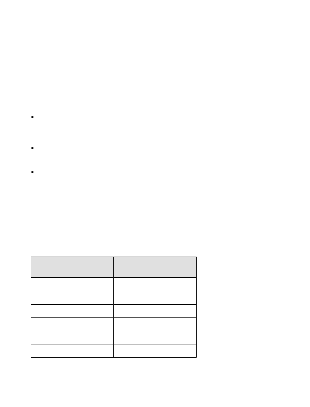
SANtricity_10.77 February 2011
LSI Corporation
- 1293 -
Using the Remote Volume Mirroring Premium Feature
The Remote Volume Mirroring premium feature provides for online, real-time replication of data between
storage arrays over a remote distance. In the event of a disaster or a catastrophic failure on one storage
array, you can promote the second storage array to take over responsibility for computing services. Remote
Volume Mirroring is designed for extended storage environments in which the storage arrays that are used
for Remote Volume Mirroring are maintained at separate sites. Volumes on one storage array are mirrored to
volumes on another storage array across a fabric SAN. Data transfers can be synchronous or asynchronous.
You choose the method when you set up the remote-mirror pair. The data transfers occur at Fibre Channel
speeds to maintain data on the different storage arrays. Because Remote Volume Mirroring is storage based,
it does not require any server overhead or application overhead.
You can use Remote Volume Mirroring for these functions:
Disaster recovery – Remote Volume Mirroring lets you replicate data from one site to another site, which
provides an exact mirror duplicate at the remote (secondary) site. If the primary site fails, you can use
mirrored data at the remote site for failover and recovery. You can then shift storage operations to the
remote site for continued operation of all of the services that are usually provided by the primary site.
Data vaulting and data availability – Remote Volume Mirroring lets you send data off site where it can
be protected. You can then use the off#site copy for testing or to act as a source for a full backup to avoid
interrupting operations at the primary site.
Two-way data protection – Remote Volume Mirroring provides the ability to have two storage arrays
back up each other by mirroring critical volumes on each storage array to volumes on the other storage
array. This action lets each storage array recover data from the other storage array in the event of any
service interruptions.
How Remote Volume Mirroring Works
When you create a remote-mirror pair, the remote-mirror pair consists of a primary volume on a local storage
array and a secondary volume on a storage array at another site. A standard volume might only be included
in one mirrored volume pair.
Maximum Number of Defined Mirrors per Storage Array
Controller Model Maximum Number of
Defined Mirrors
AM1331, AM1333, AM1532,
AM1932 Only supported in a
co-existence storage
environment
CDE2600 16
CDE3992, CDE3994 64
CDE4900 64
CE6998, CE7900 128
The primary volume is the volume that accepts host I/O activity and stores application data. When the mirror
relationship is first created, data from the primary volume is copied in its entirety to the secondary volume.
This process is known as a full synchronization and is directed by the controller owner of the primary volume.
During a full synchronization, the primary volume remains fully accessible for all normal I/O operations.

SANtricity_10.77 February 2011
LSI Corporation
- 1294 -
The controller owner of the primary volume initiates remote writes to the secondary volume to keep the data
on the two volumes synchronized.
The secondary volume maintains a mirror (or copy) of the data on its associated primary volume. The
controller owner of the secondary volume receives remote writes from the controller owner of the primary
volume but will not accept host write requests. Hosts are able to read from the secondary volume, which
appears as read-only.
In the event of a disaster or a catastrophic failure at the primary site, you can perform a role reversal to
promote the secondary volume to a primary role. Hosts then are able to read from and write to the newly
promoted volume, and business operations can continue.
Mirror Repository Volumes
A mirror repository volume is a special volume in the storage array that is created as a resource for the
controller owner of the primary volume in a remote-mirror pair. The controller stores mirroring information on
this volume, including information about remote writes that are not yet complete. The controller can use this
information to recover from controller resets and the accidental powering down of the storage arrays.
When you activate the Remote Volume Mirroring premium feature on the storage array, you create two mirror
repository volumes, one for each controller in the storage array. An individual mirror repository volume is not
needed for each remote mirror.
When you create the mirror repository volumes, you specify the location of the volumes. You can either use
existing free capacity, or you can create a volume group for the volumes from unconfigured capacity and then
specify the RAID level.
Because of the critical nature of the data being stored, do not use RAID Level 0 as the RAID level of mirror
repository volumes. The required size of each volume is 128 MB, or 256 MB total for both mirror repository
volumes of a dual-controller storage array. In previous versions of the Remote Volume Mirroring premium
feature, the mirror repository volumes required less disk storage space and needed to be upgraded to use the
maximum amount of mirror relationships.
Mirror Relationships
Before you create a mirror relationship, you must enable the Remote Volume Mirroring premium feature on
both the primary storage array and the secondary storage array. You must also create a secondary volume
on the secondary site if one does not already exist. The secondary volume must be a standard volume of
equal or greater capacity than the associated primary volume.
When secondary volumes are available, you can establish a mirror relationship in the storage management
software by identifying the primary volume and the storage array that contains the secondary volume.
When you first create the mirror relationship, a full synchronization automatically occurs, with data from the
primary volume copied in its entirety to the secondary volume.
Data Replication
The controllers manage data replication between the primary volume and the secondary volume. This
process is transparent to host machines and applications. This section describes how data is replicated
between the storage arrays that are participating in Remote Volume Mirroring. This section also describes
the actions taken by the controller owner of the primary volume if a link interruption occurs between storage
arrays.

SANtricity_10.77 February 2011
LSI Corporation
- 1295 -
Write Modes
When the controller owner of the primary volume receives a write request from a host, the controller first logs
information about the write to a mirror repository volume, and then writes the data to the primary volume. The
controller then initiates a remote write operation to copy the affected data blocks to the secondary volume at
the secondary storage array.
The Remote Volume Mirroring premium feature provides two write mode options that affect when the I/O
completion indication is sent back to the host: Synchronous and Asynchronous.
Synchronous Write Mode
Synchronous write mode provides the highest level security for full data recovery from the secondary
storage array in the event of a disaster. Synchronous write mode does reduce host I/O performance. When
this write mode is selected, host write requests are written to the primary volume and then copied to the
secondary volume. After the host write request has been written to the primary volume and the data has been
successfully copied to the secondary volume, the controller removes the log record on the mirror repository
volume. The controller then sends an I/O completion indication back to the host system. Synchronous write
mode is selected as the default value and is the recommended write mode.
Asynchronous Write Mode
Asynchronous write mode offers faster host I/O performance but does not guarantee that a copy operation
has successfully completed before processing the next write request. When you use Asynchronous write
mode, host write requests are written to the primary volume. The controller then sends an “I/O complete”
indication back to the host system, without acknowledging that the data has been successfully copied to the
secondary (remote) storage array.
When using Asynchronous write mode, write requests are not guaranteed to be completed in the same order
on the secondary volume as they are on the primary volume. If the order of write requests is not retained,
data on the secondary volume might become inconsistent with the data on the primary volume. This event
could jeopardize any attempt to recover data if a disaster occurs on the primary storage array.
Write Consistency Mode
When multiple mirror relationships exist on a single storage array and have been configured to use
Asynchronous write mode and to preserve consistent write order, they are considered to be an
interdependent group that is in the Write consistency mode. The data on the secondary, remote storage array
cannot be considered fully synchronized until all of the remote mirrors that are in the Write consistency mode
are synchronized.
If one mirror relationship in the group becomes unsynchronized, all of the mirror relationships in the group
become unsynchronized. Any write activity to the remote, secondary storage arrays is prevented to protect
the consistency of the remote data set.
Link Interruptions or Secondary Volume Errors
When processing write requests, the primary controller might be able to write to the primary volume, but a link
interruption might prevent communication with the remote (secondary) controller.
In this case, the remote write operation cannot be completed to the secondary volume, and the primary
volume and the secondary volume are no longer correctly mirrored. The primary controller transitions the
mirrored pair into an Unsynchronized state and sends an I/O completion to the primary host. The primary host
can continue to write to the primary volume, but remote writes do not take place.
SANtricity_10.77 February 2011
LSI Corporation
- 1296 -
When communication is restored between the controller owner of the primary volume and the controller owner
of the secondary volume, a resynchronization takes place. This resynchronization happens automatically, or it
must be started manually, depending on which write mode you chose when setting up the mirror relationship.
During the resynchronization, only the blocks of data that have changed on the primary volume during the
link interruption are copied to the secondary volume. After the resynchronization starts, the mirrored pair
transitions from an Unsynchronized status to a Synchronization in Progress status.
The primary controller also marks the mirrored pair as unsynchronized when a volume error on the secondary
side prevents the remote write from completing. For example, an offline secondary volume or a failed
secondary volume can cause the remote mirror to become unsynchronized. When the volume error is
corrected (the secondary volume is placed online or recovered to an Optimal status), then synchronization is
required. The mirrored pair then transitions to a Synchronization in Progress status.
Resynchronization
Data replication between the primary volume and the secondary volume in a mirror relationship is managed
by the controllers and is transparent to host machines and applications. When the controller owner of the
primary volume receives a write request from a host, the controller first logs information about the write to
a mirror repository volume. The controller then writes the data to the primary volume. The controller then
initiates a write operation to copy the affected data to the secondary volume on the remote storage array.
If a link interruption or a volume error prevents communication with the secondary storage array, the controller
owner of the primary volume transitions the mirrored pair into an Unsynchronized status. The controller owner
then sends an I/O completion to the host sending the write request. The host can continue to issue write
requests to the primary volume, but remote writes to the secondary volume do not take place.
When connectivity is restored between the controller owner of the primary volume and the controller owner
of the secondary volume, the volumes must be resynchronized by copying the blocks of data that changed
during the interruption to the secondary volume. Only the blocks of data that have changed on the primary
volume during the link interruption are copied to the secondary volume.
ATTENTION Possible loss of data access – Any communication disruptions between the primary
storage array and the secondary storage array while resynchronization is underway could result in a mix of
new data and old data on the secondary volume. This condition would render the data unusable in a disaster
recovery situation.
Creating a Remote-Mirror Pair
Before you create any mirror relationships, volumes must exist at both the primary site and the secondary
site. The volume that resides on the local storage array is the primary volume. Similarly, the volume that
resides on the remote storage array is the secondary volume. If neither the primary volume nor the secondary
volume exist, you must create these volumes. Keep these guidelines in mind when you create the secondary
volume:
The secondary volume must be of equal or greater size than the primary volume.
The RAID level of the secondary volume does not have to be the same as the primary volume.
Use these steps to create the volume.
1. Enable the Remote Volume Mirroring premium feature.
2. Activate the Remote Volume Mirroring premium feature.
3. Determine candidates for a remote-mirror pair.
4. Create the remote-mirror relationship.

SANtricity_10.77 February 2011
LSI Corporation
- 1297 -
Performance Considerations
Keep these performance issues in mind when you create mirror relationships:
The controller owner of a primary volume performs a full synchronization in the background while
processing local I/O writes to the primary volume and associated remote writes to the secondary
volume. Because the full synchronization diverts controller processing resources from I/O writes, full
synchronization can have a performance impact to the host application.
To reduce the performance impact, you can set the synchronization priority level to determine how
the controller owner will prioritize the full synchronization relative to other I/O activity. To set the
synchronization priority level, consider these guidelines:
A full synchronization at the lowest synchronization priority level takes approximately eight times as
long as a full synchronization at the highest synchronization priority level.
A full synchronization at the low synchronization priority level takes approximately six times as long
as a full synchronization at the highest synchronization priority level.
A full synchronization at the medium synchronization priority level takes approximately three-and-a-
half times as long as a full synchronization at the highest synchronization priority level.
A full synchronization at the high synchronization priority level takes approximately twice as long as a
full synchronization at the highest synchronization priority level.
When the mirrored volume pair is in a Synchronization in Progress state, all host write data is copied to
the remote system. Both controller I/O bandwidth and I/O latency can affect host write performance. Host
read performance is not affected by the mirroring relationship.
The time that it takes for data to be copied from the primary volume to the secondary volume might
impact overall performance. This impact is primarily caused by the delay and system resource required
for copying data to the remote mirror. Some delay might also occur because of the limit to the number of
simultaneous writes.
Enabling the Remote Volume Mirroring Premium Feature
The first step in creating a remote mirror is to make sure that the Remote Volume Mirroring premium feature
is enabled on both storage arrays. Because Remote Volume Mirroring is a premium feature, you need a
feature key file to enable the premium feature. The command for enabling the feature key file is as follows:
enable storageArray feature file=”filename”
In this command, the file parameter is the complete file path and file name of a valid feature key file.
Enclose the file path and the file name in double quotation marks (“ ”). Valid file names for feature key files
end with a .key extension.
Activating the Remote Volume Mirroring Premium Feature
Activating the Remote Volume Mirroring premium feature prepares the storage arrays to create and configure
mirror relationships. After you activate the premium feature, the secondary ports for each controller are
reserved and dedicated to remote mirror use. In addition, a mirror repository volume is automatically created
for each controller in the storage array. As part of the activation process, you can decide where the mirror
repository volumes will reside, free capacity on an existing volume group or in a newly created volume group,
and the RAID level for the mirror repository volumes.
The free capacity that you select for the mirror repository volume must have a total of 256 MB of capacity
available. Two mirror repository volumes are created on this capacity, one for each controller. If you enter a
value for the repository storage space that is too small for the mirror repository volumes, the firmware returns

SANtricity_10.77 February 2011
LSI Corporation
- 1298 -
an error message that gives the amount of space needed for the mirror repository volumes. The command
does not try to activate the Remote Volume Mirroring premium feature. You can re-enter the command using
the value from the error message for the repository storage space value.
The RAID level that you choose for the mirror repository volume has these constraints:
RAID Level 0 – You cannot use RAID Level 0.
RAID Level 1 – The number of drives must be an even number. If you select an odd number of drives,
the controller firmware returns an error.
RAID Level 3 or RAID Level 5 – You must have a minimum of three drives in the volume group.
RAID Level 6 – You must have a minimum of five drives in the volume group.
To activate the Remote Volume Mirroring premium feature, use this command:
activate storageArray feature=remoteMirror
The activate storageArray feature=remoteMirror command provides three methods for defining
the drives for your mirror repository volume:
You define each drive for the mirror repository volume by its tray ID and its slot ID.
You define a volume group in which the mirror repository volume resides. You can optionally define the
capacity of the mirror repository volume.
You define the number of drives, but not specific drives, for the mirror repository volume.
Activating the Remote Volume Mirroring Premium Feature with User-Assigned
Drives
Activating the Remote Volume Mirroring premium feature by assigning the drives provides flexibility in
defining your configuration by letting you choose from the available drives in your storage array. Choosing the
drives for your remote mirror automatically creates a new volume group. You can specify which drives to use
and the RAID level for the new volume group.
The command takes this form:
activate storageArray feature=remoteMirror
repositoryRAIDLevel=(1 | 3 | 5 | 6)
repositoryDrives=(trayID1,slotID1 ... trayIDn,slotIDn)
trayLossProtect=(TRUE | FALSE)
This example shows a command in which you assign the drives:
c:\...\smX\client>smcli 123.45.67.89
-c “activate storageArray feature=remoteMirror
repositoryRAIDLevel=5
repositoryDrives=(1,1 1,2 1,3 1,4 1,5);”
The command in this example creates a new mirror repository volume consisting of five drives that form a
new volume group. The new volume group has RAID Level 5.
This example shows how to use the command in a script file:
activate storageArray feature=remoteMirror
repositoryRAIDLevel=5
repositoryDrives=(1,1 1,2 1,3 1,4 1,5);

SANtricity_10.77 February 2011
LSI Corporation
- 1299 -
Activating the Remote Volume Mirroring Premium Feature with Software-Assigned
Drives
With this version of the activate storageArray feature=remoteMirror command, you choose an
existing volume group in which to place the mirror repository volume. The storage management software
then determines which drives to use. You can also define how much space to assign to the mirror repository
volume. Because you are using an existing volume group, the RAID level for the mirror repository volume
defaults to the RAID level of the volume group in which you place it. You cannot define the RAID level for the
mirror repository volume.
The command takes this form:
activate storageArray feature=remoteMirror
repositoryVolumeGroup=volumeGroupNumber
[freeCapacityArea=freeCapacityIndexNumber]
This example shows a command in which the software assigns the drives:
c:\...\smX\client>smcli 123.45.67.88 123.45.67.89
-c “activate storageArray feature=remoteMirror
repositoryVolumeGroup=2 freeCapacityArea=2;”
The command in this example creates a new mirror repository volume in volume group 2 using the second
free capacity area.
This example shows how to use the command in a script file:
activate storageArray feature=remoteMirror
repositoryVolumeGroup=2 freeCapacityArea=2;
Activating the Remote Volume Mirroring Premium Feature by Specifying a Number of
Drives
With this version of the activate storageArray feature=remoteMirror command, you must specify
the number of drives and the RAID level that you want for the mirror repository volume. This version of the
command creates a new volume group. For this command to work, you must have drives in the storage array
that are not assigned to a volume group.
activate storageArray feature=remoteMirror
repositoryRAIDLevel=(1 | 3 | 5 | 6)
repositoryDriveCount=numberOfDrives
[driveType=(fibre | SATA | SAS)]
[trayLossProtect=(TRUE | FALSE)]
This example shows a command in which you specify the number of drives:
c:\...\smX\client>smcli 123.45.67.88 123.45.67.89
-c “activate storageArray feature=remoteMirror
repositoryRAIDLevel=5 repositoryDriveCount=5
driveType=fibre;”
The command in this example creates a new mirror repository volume by using five software#selected drives
for the mirror repository volume. The mirror repository volume has RAID Level 5. The type of drive for the
mirror repository volume is Fibre Channel.

SANtricity_10.77 February 2011
LSI Corporation
- 1300 -
This example shows how to use the command in a script file:
activate storageArray feature=remoteMirror
repositoryRAIDLevel=5 repositoryDriveCount=5
driveType=fibre;
Determining Candidates for a Remote-Mirror Pair
All of the volumes and drives on the remote storage array might not be available for use as secondary
volumes. To determine which volumes on a remote storage array that you can use as candidates for
secondary volumes, use the show remoteMirror candidates command. This command returns a list of
the volumes that you can use when creating a remote mirror.
The command takes this form:
c:\...\sm9\client>smcli 123.45.67.89 -c “show
remoteMirror candidates primary=\“volumeName\”
remoteStorageArrayName=\“storageArrayName\”;”
where volumeName is the name of the volume that you want to use for the primary volume, and
storageArrayName is the remote storage array that contains possible candidates for the secondary
volume. Enclose both the volume name and the storage array name in double quotation marks (“ ”).
Creating a Remote-Mirror Pair
When you create a new remote mirror, you must define which volumes that you want to use for the primary
(local) volume and the secondary (remote) volume. You define the primary volume by the name of the
volume. You define the secondary volume by name with either the name or the World Wide Identifier (WWID)
of the storage array on which the secondary volume resides. The primary volume name, the secondary
volume name, and the remote storage array name (or WWID) are the minimum information that you need to
provide. Using this command, you can also define synchronization priority, write order, and write mode.
The command takes this form:
create remoteMirror primary=“primaryVolumeName”
secondary=“secondaryVolumeName”
(remoteStorageArrayName=“storageArrayName” |
remoteStorageArrayWwn=“wwID”) remotePassword=password
syncPriority=(highest | high | medium | low | lowest)
writeOrder=(preserved | notPreserved)
writeMode=(synchronous | asynchronous)
NOTE You can use the optional parameters as needed to help define your configuration.
This example shows the create remoteMirror command:
c:\...\smX\client>smcli 123.45.67.88 123.45.67.89
-c “create remoteMirror primary=\”Jan_04_Account\”
secondary=\”Jan_04_Account_B\” remoteStorageArrayName=\”Tabor\”
remotePassword=\”jdw2ga05\” syncPriority=highest
writeMode=synchronous;”

SANtricity_10.77 February 2011
LSI Corporation
- 1301 -
The command in this example creates a remote mirror in which the primary volume is named
Jan_04_Account on the local storage array. The secondary volume is named Jan_04_Account_B on the
remote storage array that is named Tabor. The names used in this example are similar, but that is not a
requirement for the volume names in a remote-mirror pair. In this example, the remote storage array has a
password that you must enter when making any change to the storage array configuration. Creating a remote-
mirror pair is a significant change to a storage array configuration. Setting the write mode to synchronous
and the synchronization priority to highest means that host write requests are written to the primary volume
and then immediately copied to the secondary volume. These actions help to make sure that the data on
the secondary volume is as accurate a copy of the data on the primary volume as possible. The highest
synchronization priority does, however, use more system resources, which can reduce system performance.
This example shows how to use the command in a script file:
create remoteMirror primary=”Jan_04_Account”
secondary=”Jan_04_Account_B” remoteStorageArrayName=”Tabor”
remotePassword=”jdw2ga05” syncPriority=highest
writeMode=synchronous;
After you have created a remote mirror, you can see the progress of data synchronization
between the primary volume and the secondary volume by running the show remoteMirror
synchronizationProgress command. This command shows the progress as a percentage of data
synchronization that has completed.
Changing Remote Volume Mirroring Settings
The set remoteMirror command lets you change the property settings for a remote-mirror pair. Use this
command to change these property settings:
The volume role (either primary or secondary)
The synchronization priority
The write order
The write mode
You can apply the changes to one or several remote-mirror pairs by using this command. Use the primary
volume name to identify the remote-mirror pairs for which you are changing the properties.
This example shows how to use the set remoteMirror command:
c:\...\smX\client>smcli 123.45.67.88 123.45.67.89
-c “set remoteMirror localVolume [Jan_04_Account]
syncPriority=medium
writeOrder=notpreserved
writeMode=asynchronous;”
This example shows how to use the command in a script file:
set remoteMirror localVolume [Jan_04_Account]
syncPriority=medium
writeOrder=notpreserved
writeMode=asynchronous;

SANtricity_10.77 February 2011
LSI Corporation
- 1302 -
Suspending and Resuming a Mirror Relationship
Use the suspend remoteMirror command to stop data transfer between a primary volume and a
secondary volume in a mirror relationship without disabling the mirror relationship. Suspending a mirror
relationship lets you control when the data on the primary volume and data on the secondary volume
are synchronized. Suspending a mirror relationship helps to reduce any performance impact to the host
application that might occur while any changed data on the primary volume is copied to the secondary
volume. Suspending a mirror relationship is particularly useful when you want to run a backup of the data on
the secondary volume.
When a mirror relationship is in a suspended state, the primary volume does not make any attempt to contact
the secondary volume. Any writes to the primary volume are persistently logged in the mirror repository
volumes. After the mirror relationship resumes, any data that is written to the primary volume is automatically
written to the secondary volume. Only the modified data blocks on the primary volume are written to the
secondary volume. Full synchronization is not required.
IMPORTANT If you suspend a remote mirror that is set up in the Write consistency mode, you suspend
all remote-mirror pairs within the group. You can then resume mirror operations for any of the individual
remote-mirror pairs that are in the group.
This example shows the suspend remoteMirror command:
c:\...\smX\client>smcli 123.45.67.88 123.45.67.89
-c “suspend remoteMirror primary Jan_04_Account
writeConsistency=false;”
The writeConsistency parameter defines whether the volumes identified in this command are in a write-
consistency group or are separate. For the volumes in a write#consistency group, set this parameter to TRUE.
For the volumes that are not in a write-consistency group, set this parameter to FALSE.
This example shows how to use the command in a script file:
suspend remoteMirror volume Jan_04_Account writeConsistency=false;
The mirror relationship remains suspended until you use the resume remoteMirror command to restart
synchronization activities. This command restarts data transfers between a primary volume and a secondary
volume in a mirror relationship after the mirror has been suspended or unsynchronized.
This example shows the resume remoteMirror command:
c:\...\smX\client>smcli 123.45.67.88 123.45.67.89
-c “resume remoteMirror volume Jan_04_Account
writeConsistency=false;”
The writeConsistency parameter in this command operates the same as in the previous command.
This example shows how to use the command in a script file:
resume remoteMirror volume Jan_04_Account
writeConsistency=false;
SANtricity_10.77 February 2011
LSI Corporation
- 1303 -
Removing a Mirror Relationship
Use the remove remoteMirror command to remove the link between a primary volume and a secondary
volume. (Removing a mirror relationship is similar to deleting a mirror relationship.) Removing the link
between a primary volume and a secondary volume does not affect any of the existing data on either volume.
The link between the volumes is removed, but the primary volume still continues normal I/O operations. Later,
you can establish the mirror relationship between the two volumes and resume normal mirror operations. You
can remove the mirror relationship for one or several remote-mirror pairs with this command.
This example shows the remove remoteMirror command:
c:\...\smX\client>smcli 123.45.67.88 123.45.67.89
-c “remove remoteMirror localVolume [Jan_04_Account];”
When you run this command, use the name of the primary volume of the remote#mirror pair.
This example shows how to use the command in a script file:
remove remoteMirror localVolume [Jan_04_Account];
To re-establish the link between a primary volume and a secondary volume, use the create
remoteMirror command.
Deleting a Primary Volume or a Secondary Volume
Use the delete volume command to remove a primary volume or a secondary volume from a storage
array. Deleting a volume in a mirror relationship removes the mirror relationship and completely deletes the
volume from the storage array. You cannot redefine the mirror relationship until you create a new volume or
choose an alternate volume to replace the deleted volume.
ATTENTION Possible loss of data access – Deleting a primary volume or a secondary volume
permanently removes the data from the storage array.
Disabling the Remote Volume Mirroring Premium Feature
You disable the Remote Volume Mirroring premium feature to prevent the new mirror relationship from
being created. When you disable the Remote Volume Mirroring premium feature, the premium feature is in
a Disabled/Active state. In this state, you can maintain and manage previously existing mirror relationships;
however, you cannot create new relationships. To disable the Remote Volume Mirroring premium feature, use
this command:
disable storageArray feature=remoteMirror
Deactivating the Remote Volume Mirroring Premium Feature
If you no longer require the Remote Volume Mirroring premium feature and you have removed all of the mirror
relationships, you can deactivate the premium feature. Deactivating the premium feature re#establishes
the normal use of dedicated ports on both storage arrays and deletes both mirror repository volumes. To
deactivate the Remote Volume Mirroring premium feature, use this command:
deactivate storageArray feature=remoteMirror
SANtricity_10.77 February 2011
LSI Corporation
- 1304 -
Interaction with Other Premium Features
You can run the Remote Volume Mirroring premium feature while running these premium features:
Storage Partitioning
Snapshot
Volume Copy
When you run the Remote Volume Mirroring premium feature with other premium features, you must consider
the requirements of the other premium features to help make sure that you set up a stable storage array
configuration.
In addition to running with the premium features, you can also run the Remote Volume Mirroring premium
feature while running Dynamic Volume Expansion (DVE).
Storage Partitioning
Storage Partitioning is a premium feature that lets hosts share access to volumes in a storage array. You
create a storage partition when you define any of these logical components in a storage array:
A host
A host group
A volume-to-LUN mapping
The volume-to-LUN mapping lets you define which host group or host has access to a particular volume in the
storage array.
When you create storage partitions, define the storage partitions after you have created the primary volume
and the secondary volume in a Remote Volume Mirroring configuration. The storage partition definitions for
the primary storage array and the secondary storage array are independent of each other. If these definitions
are put in place while the volume is in a secondary role, the administrative effort associated with the site
recovery is reduced if it becomes necessary to promote the volume to a primary role.
Volume Copy
The Volume Copy premium feature copies data from one volume (the source volume) to another volume (the
target volume) within a single storage array. You can use this premium feature to perform these functions:
Copy data from volume groups that use smaller-capacity drives to volume groups that use larger-capacity
drives
Back up data
Restore snapshot volume data to the base volume.
You can use a primary volume in a remote mirror as a source volume or a target volume in a volume copy.
You cannot use a secondary volume as a source volume or a target volume.
NOTE If you start a role reversal during a copy-in-progress, the copy fails and cannot be restarted.

SANtricity_10.77 February 2011
LSI Corporation
- 1305 -
Dynamic Volume Expansion
A Dynamic Volume Expansion (DVE) is a modification operation that increases the capacity of a standard
volume or a snapshot repository volume. The increase in capacity is achieved by using the free capacity that
is available in the volume group of the standard volume or the snapshot repository volume.
This modification operation is considered to be “dynamic” because you can continually access data on
volume groups, volumes, and drives throughout the entire operation.
A DVE operation can be performed on a primary volume or a secondary volume of a mirror relationship.
NOTE Although the storage management software indicates that the volume has increased capacity, its
usable capacity is the size of the smaller of the primary volume or the secondary volume.
You cannot perform a DVE operation on a mirror repository volume.

SANtricity_10.77 February 2011
LSI Corporation
- 1306 -
Using the Volume Copy Premium Feature
The Volume Copy premium feature lets you copy data from one volume (the source) to another volume (the
target) in a single storage array. You can use this premium feature to perform these tasks:
Back up data
Copy data from volume groups that use smaller-capacity drives to volume groups using greater-capacity
drives
Restore snapshot volume data to the associated base volume
How Volume Copy Works
When you create a volume copy, you create a copy pair that consists of a source volume and a target
volume. Both the source volume and the target volume are located on the same storage array. During a
volume copy, the controllers manage copying the data from the source volume to the target volume. The
volume copy is transparent to the host machines and applications, except that users cannot write to the
source volume during a volume copy.
While a volume copy is In Progress, the same controller must own both the source volume and the target
volume. If one controller does not own both the source volume and the target volume before creating the
volume copy, ownership of the target volume is automatically transferred to the controller that owns the
source volume. When the volume copy is finished or stopped, ownership of the target volume is restored to its
preferred controller. If ownership of the source volume changes while a volume copy is running, ownership of
the target volume also changes.
Source Volume
The source volume is the volume that accepts host I/O and stores data. When you start a volume copy, data
from the source volume is copied in its entirety to the target volume. While a volume copy has a status of In
Progress, Pending, or Failed, the source volume is available only for read activity.
After the volume copy completes, the source volume becomes available to host applications for write
requests. The target volume automatically becomes read only to hosts, and write requests to the target
volume are rejected.
The following are valid source volumes:
A standard volume
A snapshot volume
The base volume of a snapshot volume
A primary volume that is participating in a remote-mirror pair
The following are not valid source volumes:
A secondary volume that is participating in a remote-mirror pair
A snapshot repository volume
A mirror repository volume
A failed volume
A missing volume
A volume currently in a modification operation
SANtricity_10.77 February 2011
LSI Corporation
- 1307 -
A volume that is holding a Small Computer System Interface-2 (SCSI-2) reservation or a persistent
reservation
A volume that is a source volume or a target volume in another volume copy that has a status of In
Progress, Pending, or Failed
Target Volume
A target volume contains a copy of the data from the source volume. When a volume copy is started, data
from the source volume is copied in its entirety to the target volume.
ATTENTION Possible loss of data access – A volume copy overwrites data on the target volume.
Before you start a new operation, make sure that you no longer need the old data, or you have backed up the
old data on the target volume.
While the volume copy has a status of In Progress, Pending, or Failed, the controllers reject read and write
requests to the target volume. After the volume copy operation is finished, the target volume automatically
becomes read only to the hosts, and write requests to the target volume are rejected. You can change the
Read-Only attribute after the volume copy has completed or has been stopped. (For more information about
the Read-Only attribute, see “Viewing Volume Copy Properties.”
The following volumes are valid target volumes:
A standard volume
The base volume of a disabled snapshot volume or failed snapshot volume
A primary volume that is participating in a remote-mirror pair
The following volumes are not valid target volumes:
The base volume of an active snapshot volume
A snapshot volume
A mirror repository volume
A snapshot repository volume
A secondary volume in a remote-mirror pair
A failed volume
A missing volume
A volume with a status of Degraded
A volume that is currently in a modification operation
A volume that is holding a SCSI-2 reservation or a persistent reservation
A volume that is a source volume or a target volume in another volume copy that has a status of In
Progress, Pending, or Failed
Volume Copy and Persistent Reservations
You cannot use volumes that hold persistent reservations for either a source volume or a target volume.
Persistent reservations are configured and managed through the server cluster software and prevent other
hosts from accessing the reserved volume. Unlike other types of reservations, a persistent reservation
reserves host access to the volume across multiple HBA host ports, which provides various levels of access
control.

SANtricity_10.77 February 2011
LSI Corporation
- 1308 -
To determine which volumes have reservations, run the show (volume) reservations command. To
remove a reservation, run the clear (volume) reservations command.
Storage Array Performance
During a volume copy operation, the resources of the storage array might be diverted from processing I/O
activity to completing a volume copy, which might affect the overall performance of the storage array.
These factors contribute to the performance of the storage array:
The I/O activity
The volume RAID level
The volume configuration (number of drives in the volume groups and cache parameters)
The volume type (snapshot volumes might take more time to copy than standard volumes)
When you create a new volume copy, you define the copy priority to determine how much controller
processing time is allocated for a volume copy compared with I/O activity.
Copy priority has five relative settings ranging from highest to lowest. The highest priority rate supports the
volume copy, but I/O activity might be affected. The lowest priority rate supports I/O activity, but the volume
copy takes longer. You define the copy priority when you create the volume copy pair. You can redefine the
copy priority later by using the set volumeCopy command. You can also redefine the volume copy priority
when you recopy a volume.
Restrictions
These restrictions apply to the source volume, the target volume, and the storage array:
While a volume copy operation has a status of In Progress, Pending, or Failed, the source volume is
available for read activity only. After the volume copy finishes, read activity from and write activity to the
source volume is permitted.
A volume can be selected as a target volume for only one volume copy at a time.
The maximum allowable number of volume copies per storage array depends upon the storage array
configuration.
A volume that is reserved by the host cannot be selected as a source volume or as a target volume.
A volume with a status of Failed cannot be used as a source volume or as a target volume.
A volume with a status of Degraded cannot be used as a target volume.
You cannot select a volume that is participating in a modification operation as a source volume or as
a target volume. Modification operations include Dynamic Capacity Expansion (DCE), Dynamic RAID
Level Migration (DRM), Dynamic Segment Sizing (DSS), Dynamic Volume Expansion (DVE), and
defragmenting a volume group.
Volume Copy Commands
The following table lists the Volume Copy commands and briefly describes what the commands do.

SANtricity_10.77 February 2011
LSI Corporation
- 1309 -
Volume Copy Commands
Command Description
create volumeCopy Creates a volume copy and starts the volume
copy operation.
disable storageArray
featurevolumeCopy
Turns off the current volume copy operation.
enable storageArray
feature
Activates the Volume Copy premium feature.
recopy volumeCopy Re-initiates a volume copy operation using an
existing volume copy pair.
remove volumeCopy Removes a volume copy pair.
set volumeCopy Defines the properties for a volume copy pair.
show volumeCopy Returns information about volume copy
operations. You can retrieve information
about a specific volume copy pair, or all of the
volume copy pairs in the storage array.
show volumeCopy
sourceCandidates
Returns information about the candidate
volumes that you can use as the source for a
volume copy operation.
show volumeCopy
targetCandidates
Returns information about the candidate
volumes that you can use as the target for a
volume copy operation.
stop volumeCopy Stops a volume copy operation.
Creating a Volume Copy
Before you create a volume copy, make sure that a suitable target volume exists on the storage array, or
create a new target volume specifically for the volume copy. The target volume that you use must have a
capacity equal to or greater than the source volume.
You can have a maximum of eight volume copies with a status of In Progress at one time. Any volume copy
greater than eight has a status of Pending until one of the volume copies with a status of In Progress has
completed the volume copy process.
To create a volume copy, perform these general steps:
1. Enable the Volume Copy premium feature.
2. Determine the candidates for a volume copy.
3. Create the target volume and the source volume for the volume copy.
SANtricity_10.77 February 2011
LSI Corporation
- 1310 -
Enabling the Volume Copy Premium Feature
The first step in creating a volume copy is to make sure that the feature is enabled on the storage array.
Because Volume Copy is a premium feature, you need a Feature Key file to enable the feature. This
command enables the Feature Key file:
enable storageArray feature file=”filename”
where the file parameter is the complete file path and file name of a valid Feature Key file. Enclose the file
path and file name in double quotation marks (“ ”). Valid file names for Feature Key files usually end with a
.key extension.
Determining Volume Copy Candidates
All volumes and drives might not be available for use in volume copy operations. To determine which
candidate volumes on the storage array that you can use as a source volume, use the commands in the
following table.
Action Use This CLI Command
Determine which candidate volumes
on the storage array you can use as a
source volume
show volumeCopy
sourceCandidates
Determine which candidate volumes
on the storage array you can use as a
target volume
show volumeCopy
targetCandidates
The show volumeCopy sourceCandidates command and the show volumeCopy
targetCandidates command return a list of the drive tray, slot, and capacity information for the source
volume candidates and the target volume candidates.
You can use the show volumeCopy sourceCandidates command and the show volumeCopy
targetCandidates command only after you have enabled the Volume Copy premium feature.
Creating a Volume Copy
ATTENTION Possible loss of data access – A volume copy overwrites data on the target volume.
Make sure that you no longer need the data or have backed up the data on the target volume before you start
a volume copy operation.
When you create a volume copy, you must define which volumes that you want to use for the source volume
and the target volume. You define the source volume and the target volume by the name of each volume.
You can also define the copy priority and choose whether you want the target volume to be read only after the
data is copied from the source volume.
The command has this form:
create volumeCopy
source=”sourceName” target=”targetName”
[copyPriority=(highest | high | medium | low | lowest)
targetReadOnlyEnabled=(TRUE | FALSE)]
Before you run the create volumeCopy command, perform these actions:

SANtricity_10.77 February 2011
LSI Corporation
- 1311 -
Stop all I/O activity to the source volume and the target volume.
Dismount any file systems on the source volume and the target volume, if applicable.
This example shows the create volumeCopy command:
c:\...\smX\client>smcli 123.45.67.88 123.45.67.89
-c “create volumeCopy source=\”Jaba_Hut\” target=\”Obi_1\”
copyPriority=medium targetrReadOnlyEnabled=TRUE;”
The command in this example copies the data from the source volume named Jaba_Hut to the target volume
named Obi_1. Setting the copy priority to medium provides a compromise between how quickly the data is
copied from the source volume to the target volume and the amount of processing resources that are required
for data transfers to other volumes in the storage array. Setting the targetReadOnlyEnabled parameter to
TRUE means that write requests cannot be made to the target volume, making sure that the data on the target
volume stays unaltered.
This example shows how to use the command in a script file:
create volumeCopy source=”Jaba_Hut” target=”Obi_1”
copyPriority=medium targetReadOnlyEnabled=TRUE;
After the volume copy operation is completed, the target volume automatically becomes read only to hosts.
Any write requests to the target volume are rejected, unless you disable the Read-Only attribute by using the
set volumeCopy command.
To view the progress of a volume copy, use the show volume actionProgress command. This
command returns information about the volume action, the percentage completed, and the time remaining
until the volume copy is complete.
Viewing Volume Copy Properties
Use the show volumeCopy command to view information about one or more selected source volumes or
target volumes. This command returns these values:
The role
The copy status
The start time stamp
The completion time stamp
The copy priority
The Read-Only attribute setting for the target volume
The source volume World Wide Identifier (WWID) or the target volume WWID
If a volume is participating in more than one volume copy (it can be a source volume for one volume
copy operation and a target volume for another volume copy operation), the details are repeated for each
associated copy pair.
The command has this form:
show volumeCopy (allVolumes | source [sourceName] |
target [targetName])
This example shows the show volumeCopy command:

SANtricity_10.77 February 2011
LSI Corporation
- 1312 -
c:\...\smX\client>smcli 123.45.67.88 123.45.67.89
-c “show volumeCopy source [\”JabaHut\”];”
The command in this example is requesting information about the source volume Jaba_Hut. If you wanted
information about all of the volumes, you would use the allVolumes parameter. You can also request
information about a specific target volume.
This example shows how to use the command in a script file:
show volumeCopy source [“Jaba_Hut”];
Changing Volume Copy Settings
The set volumeCopy command lets you change these property settings for a volume copy pair:
The copy priority
The target volume read/write permission
Copy priority has five relative settings ranging from highest to lowest. The highest priority supports the volume
copy, but I/O activity might be affected. The lowest priority supports I/O activity, but the volume copy takes
longer. You can change the copy priority at these times:
Before the volume copy operation starts
While the volume copy operation has a status of In Progress
After the volume copy operation has completed when re-creating a volume copy operation by using the
recopy volumeCopy command
When you create a volume copy pair and after the original volume copy has completed, the target volume is
automatically defined as read-only to the hosts. The read-only status of the target volume helps to make sure
that the copied data on the target volume is not corrupted by additional writes to the target volume after the
volume copy is created. You want to maintain the read-only status when you are performing these tasks:
Using the target volume for backup purposes
Copying data from one volume group to a larger volume group for greater accessibility
Planning to use the data on the target volume to copy back to the base volume in case of a disabled
snapshot volume or failed snapshot volume
At other times, you might want to write additional data to the target volume. You can use the set
volumeCopy command to reset the read/write permission for the target volume.
NOTE If you have set the volume copy parameters to enable host writes to the target volume, the read
request and the write request to the target volume are rejected while the volume copy operation has a status
of In Progress, Pending, or Failed.
The command has this form:
set volumeCopy target [targetName] [source [sourceName]]
copyPriority=(highest | high | medium | low | lowest)
targetReadOnlyEnabled=(TRUE | FALSE)
NOTE You can use the parameters as needed to help define your configuration.
SANtricity_10.77 February 2011
LSI Corporation
- 1313 -
This example shows the set volumeCopy command:
c:\...\smX\client>smcli 123.45.67.88 123.45.67.89
-c “set volumeCopy target [\”Obi_1\”]
copyPriority=highest
targetReadOnlyEnabled=FALSE;”
This example shows how to use the command in a script file:
set volumeCopy target [“Obi_1”] copyPriority=highest
targetReadOnlyEnabled=FALSE;
Recopying a Volume
Use the recopy volumeCopy command to create a new volume copy for a previously defined copy pair that
has a status of Stopped, Failed, or Completed. You can use the recopy volumeCopy command to create
backups of the target volume. Then, you can copy the backup to tape for off-site storage. When you use the
recopy volumeCopy command to make a backup, you cannot write to the source volume while the recopy
operation is running. The recopy operation might take a long time.
When you run the recopy volumeCopy command, the data on the source volume is copied in its entirety to
the target volume.
ATTENTION Possible loss of data access – The recopy volumeCopy command overwrites
existing data on the target volume and makes the target volume read-only to hosts. The recopy
volumeCopy command fails all of the snapshot volumes that are associated with the target volume, if any
exist.
You can also reset the copy priority by using the recopy volumeCopy command if you want to change the
copy priority for the recopy operation. The higher priorities allocate storage array resources to the volume
copy at the expense of storage array performance.
The command has this form:
recopy volumeCopy target [targetName] [source [sourceName]
copyPriority=(highest | high | medium | low | lowest)
targetReadOnlyEnabled=(TRUE | FALSE)]
NOTE You can use the optional parameters as needed to help define your configuration.
This example shows the show volumeCopy command:
c:\...\smX\client>smcli 123.45.67.88 123.45.67.89
-c “recopy volumeCopy target [\”Obi_1\”] copyPriority=highest;”
The command in this example copies data from the source volume that is associated with the target volume
Obi_1 to the target volume again. The copy priority is set to the highest value to complete the volume copy as
quickly as possible. The underlying consideration for using this command is that you have already created the
volume copy pair, which has already created one volume copy. By using this command, you are copying the
data from the source volume to the target volume with the assumption that the data on the source volume has
changed since the previous copy was made.
This example shows you how to use the command in a script file:
SANtricity_10.77 February 2011
LSI Corporation
- 1314 -
recopy volumeCopy target [“Obi_1”] copyPriority=highest;
Stopping a Volume Copy
The stop volumeCopy command lets you stop a volume copy that has a status of In Progress, Pending, or
Failed. After you have stopped a volume copy, you can use the recopy volumeCopy command to create
a new volume copy by using the original volume copy pair. After you stop a volume copy operation, all of the
mapped hosts will have write access to the source volume.
The command has this form:
stop volumeCopy target [targetName] [source [sourceName]]
This example shows the show volumeCopy command:
c:\...\smX\client>smcli 123.45.67.88 123.45.67.89
-c “stop volumeCopy target [\”Obi_1\”];”
This example shows how to use the command in a script file:
stop volumeCopy target [“Obi_1”];
Removing Copy Pairs
The remove volumeCopy command lets you remove a volume copy pair from the storage array
configuration. All of the volume copy-related information for the source volume and the target volume is
removed from the storage array configuration. The data on the source volume or the target volume is not
deleted. Removing a volume copy from the storage array configuration also removes the Read-Only attribute
for the target volume.
IMPORTANT If the volume copy has a status of In Progress, you must stop the volume copy before
you can remove the volume copy pair from the storage array configuration.
The command has this form:
remove volumeCopy target [targetName] [source [sourceName]]
This example shows the remove volumeCopy command:
c:\...\smX\client>smcli 123.45.67.88 123.45.67.89
-c “remove volumeCopy target [\”Obi_1\”];”
This example shows how to use the command in a script file:
remove volumeCopy target [“Obi_1”];
Interaction with Other Premium Features
You can run the Volume Copy premium feature while running the following premium features:
Storage Partitioning
Snapshot
Remote Volume Mirroring
SANtricity_10.77 February 2011
LSI Corporation
- 1315 -
When you are running the Volume Copy premium feature with other premium features, you must consider
the requirements of other premium features to help make sure that you set up a stable storage array
configuration.
In addition to the premium features, you also can run the Volume Copy premium feature while running
Dynamic Volume Expansion (DVE).
Storage Partitioning
Storage Partitioning is a premium feature that lets hosts share access to volumes in a storage array. You
create a storage partition when you define any of these logical components in a storage array:
A host
A host group
A volume-to-LUN mapping
The volume-to-LUN mapping lets you define which host group or host has access to a particular volume in the
storage array.
After you create a volume copy, the target volume automatically becomes read only to hosts to make sure
that the data is preserved. Hosts that have been mapped to a target volume do not have write access to the
volume, and any attempt to write to the read-only target volume results in a host I/O error.
If you want hosts to have write access to the data on the target volume, use the set volumeCopy command
to disable the Read-Only attribute for the target volume.
Snapshot Volumes
A snapshot is a point-in-time image of a volume. It is usually created so that an application, such as a backup
application, can access the snapshot volume and read the data while the base volume stays online and is
accessible to hosts.
The volume for which the point-in-time image is created is known as the base volume and must be a standard
volume in the storage array. The snapshot repository volume stores information about all of the data that
changed since the snapshot was created.
You can select snapshot volumes as the source volumes for a volume copy. This selection is a good use of
this premium feature, because it performs complete backups without significant impact to the storage array I/
O. Some I/O processing resources are lost to the copy operation.
IMPORTANT If you choose the base volume of a snapshot volume as your target volume, you must
disable all of the snapshot volumes that are associated with the base volume before you can select it as a
target volume.
When you create a snapshot volume, a snapshot repository volume is automatically created. The snapshot
repository volume stores information about the data that has changed since the snapshot volume was
created. You cannot select a snapshot repository volume as a source volume or a target volume in a volume
copy.
You can use the Snapshot Volume premium feature with the Volume Copy premium feature to back up data
on the same storage array and to restore the data on the snapshot volume back to its original base volume.

SANtricity_10.77 February 2011
LSI Corporation
- 1316 -
Remote Volume Mirroring
The Remote Volume Mirroring premium feature provides for online, real-time replication of data between
storage arrays over a remote distance. In the event of a disaster or a catastrophic failure of one storage array,
you can promote a secondary storage array to take over responsibility for data storage.
When you create a remote mirror, a remote-mirror pair is created, which consists of a primary volume at the
primary storage array and a secondary volume at a remote storage array.
The primary volume is the volume that accepts host I/O and stores data. When the mirror relationship is
initially created, data from the primary volume is copied in its entirety to the secondary volume. This process
is known as a full synchronization and is directed by the controller owner of the primary volume. During a full
synchronization, the primary volume remains fully accessible for all normal I/O activity.
The controller owner of the primary volume starts remote writes to the secondary volume to keep the data
on the two volumes synchronized. Whenever the data on the primary volume and the secondary volume
becomes unsynchronized, the controller owner of the primary volume starts a resynchronization, where only
the data that changed during the interruption is copied.
The secondary volume maintains a mirror of the data on its associated primary volume. The controller owner
of the secondary volume receives remote writes from the controller owner of the primary volume but does not
accept host write requests.
The secondary volume stays available to host applications as read-only while mirroring is underway. In the
event of a disaster or a catastrophic failure at the primary site, you can perform a role reversal to promote the
secondary volume to a primary role. Hosts are then able to access the newly promoted volume, and business
operations can continue.
You can select a primary volume that is participating in a remote-mirror pair to be used as the source volume
or a target volume for a volume copy. A secondary volume that is participating in a remote-mirror pair cannot
be selected as a source volume or a target volume.
Role Reversals
A role reversal is the act of promoting the secondary volume to be the primary volume of the remote-mirror
pair, and demoting the primary volume to be the secondary volume.
In the event of a disaster at the storage array that contains the primary volume, you can fail over to the
secondary site by performing a role reversal to promote the secondary volume to the primary volume role.
This action lets hosts continue to access data, and business operations can continue.
Trying a role reversal in which the original primary volume is the source volume for an active volume copy
(the status is In Progress or Pending) causes the volume copy to fail. The failure occurs when the original
primary volume becomes the new secondary volume. You cannot restart the volume copy until you return the
roles of the volumes back to their original state; that is, the volume that was originally the primary volume is
set once again to be the primary volume.
If the primary storage array is recovered but is unreachable due to a link failure, a forced promotion of the
secondary volume will result in both the primary volume and the secondary volume viewing themselves in the
primary volume role (dual-primary condition). If this condition occurs, the volume copy in which the primary
volume is participating is unaffected by the role change.
You can perform a role reversal by using the set remoteMirror command.

SANtricity_10.77 February 2011
LSI Corporation
- 1317 -
To change a secondary volume to a primary volume, use this command, which promotes the selected
secondary volume to become the primary volume of the remote-mirror pair. Use this command after a
catastrophic failure has occurred.
set remoteMirror role=primary
To change a primary volume to a secondary volume, use this command, which demotes the selected
primary volume to become the secondary volume. Use this command after a catastrophic failure has
occurred.
set remoteMirror role=secondary

SANtricity_10.77 February 2011
LSI Corporation
- 1318 -
Maintaining a Storage Array
Maintenance covers a broad spectrum of activity with the goal of keeping a storage array operational and
available to all hosts. This chapter provides descriptions of commands you can use to perform storage array
maintenance. The commands are organized into four sections:
Routine maintenance
Performance tuning
Troubleshooting and diagnostics
Recovery operations
The organization is not a rigid approach, and you can use the commands as appropriate for your storage
array. The commands listed in this chapter do not cover the entire array of commands you can use for
maintenance. Other commands, particularly the set commands, can provide diagnostic or maintenance
capabilities.
Routine Maintenance
Routine maintenance involves those tasks that you might perform periodically to make sure that the storage
array is running as well as possible or to detect conditions before they become problems.
Running a Media Scan
Media scan provides a way of detecting drive media errors before they are found during a normal read from
or write to the drives. Any media scan errors that are detected are reported to the Event Log. The Event Log
provides an early indication of an impending drive failure and reduces the possibility of encountering a media
error during host operations. A media scan is performed as a background operation and scans all data and
redundancy information in defined user volumes.
A media scan runs on all of the volumes in the storage array that have these conditions:
Has Optimal status
Has no modification operations in progress
Has media scan enabled
Errors that are detected during a scan of a user volume are reported to the Major Event Log (MEL) and
handled as follows:
Unrecovered media error – The drive could not read the requested data on its first try or on any
subsequent retries. The result of this action is that for volumes with redundancy protection, the data is
reconstructed, rewritten to the drive, and verified, and the error is reported to the Event Log. For volumes
without redundancy protection, the error is not corrected, but it is reported to the Event Log.
Recovered media error – The drive could not read the requested data on its first attempt. The result of
this action is that the data is rewritten to the drive and verified. The error is reported to the Event Log.
Redundancy mismatches – Redundancy errors are found, and a media error is forced on the block
stripe so that it is found when the drive is scanned again. If redundancy is repaired, this forced media
error is removed. The result of this action is that the first 10 redundancy mismatches found on a volume
are reported to the Event Log.
Unfixable error – The data could not be read, and parity information or redundancy information could not
be used to regenerate it. For example, redundancy information cannot be used to reconstruct data on a
degraded volume. The result of this action is that the error is reported to the Event Log.

SANtricity_10.77 February 2011
LSI Corporation
- 1319 -
The script command set provides two commands to define media scan properties:
set volume
set storageArray
The set volume command enables a media scan for the volume. The command has this form:
set (allVolumes | volume [volumeName] |
volumes [volumeName1 ... volumeNameN] |
volume <wwID>)
mediaScanEnabled=(TRUE | FALSE)
The set storageArray command defines how frequently a media scan is run on a storage array. The
command has this form:
set storageArray mediaScanRate=(disabled | 1-30)
The mediaScanRate values define the number of days over which the media scan runs. Valid values are
disabled, which turns off the media scan; or 1 day to 30 days, where 1 day is the fastest scan rate, and 30
days is the slowest. A value other than what is shown will not allow the media scan to function.
Running a Redundancy Check
Redundancy checks are performed when media scans are run. (For a description about how to set up and run
media scans, see “Running a Media Scan.“) During a redundancy check, all of the data blocks in a volume
are scanned, and, depending on the RAID level, deteriorated data is corrected. Correction is performed as
follows:
For RAID Level 3, RAID Level 5, or RAID Level 6 volumes, redundancy is checked and repaired.
For RAID Level 1 volumes, the data is compared between the mirrored drives and data inconsistencies
are repaired.
RAID Level 0 volumes have no redundancy.
Before you can run a redundancy check, you must enable redundancy checking by using the set volume
command. The command has this form:
set (allVolumes | volume [volumeName] |
volumes [volumeName1 ... volumeNameN] |
volume <wwID>)
redundancyCheckEnabled=(TRUE | FALSE)
Resetting a Controller
IMPORTANT When you reset a controller, the controller is no longer available for I/O operations until
the reset is complete. If a host is using volumes that are owned by the controller being reset, the I/O that is
directed to the controller is rejected. Before resetting the controller, either make sure that the volumes that are
owned by the controller are not in use, or make sure that a multi-path driver is installed on all of the hosts that
are using these volumes.
Resetting a controller is the same as rebooting the controller processors. To reset a controller, use this
command:
reset controller [(a | b)]
SANtricity_10.77 February 2011
LSI Corporation
- 1320 -
Enabling a Controller Data Transfer
At times, a controller might become quiescent while running diagnostics. If this condition occurs, the controller
might become unresponsive. To revive a controller that has become quiescent while running diagnostics, use
this command:
enable controller [(a | b)] dataTransfer
Resetting the Battery Age
After you have replaced the batteries in the storage array, you must reset the age of the battery. You can
reset either the batteries for an entire storage array or a battery in a specific controller. To reset the age of the
batteries to zero days, use this command:
reset storageArray batteryInstallDate [controller=(a | b)]
NOTE This command is supported only by controller trays and controller-drive trays released before the
CE6998 controller tray. The batteries in controller trays and controller-drive trays released after the CE6998
controller tray do not require that you reset the battery age after you have replaced the batteries.
Removing Persistent Reservations
Persistent reservations preserve volume registrations, and they prevent hosts, other than the host defined
for the volume, from accessing the volume. You must remove persistent reservations before you make these
changes to your configuration:
Change or delete LUN mappings on a volume holding a reservation
Delete volume groups or volumes that have any reservations
To determine which volumes have reservations, use this command:
show (allVolumes | volume [volumeName] |
volumes [volumeName1 ... volumeNameN]) reservations
To clear persistent volume reservations, use this command:
clear (allVolumes | volume [volumeName] |
volumes [volumeName1 ... volumeNameN]) reservations
Synchronizing the Controller Clocks
To synchronize the clocks on both controllers in a storage array with the host clock, use this command:
set storageArray time
Locating Drives
At times, you might need to locate a specific drive. In very large storage array configurations, this task can
sometimes be awkward. If you need to locate a specific drive, you can do so by turning on the indicator light
on the front of the drive. To locate a drive, use this command:
start drive [trayID,slotID] locate
To turn off the indicator light after locating the drive, use this command:
SANtricity_10.77 February 2011
LSI Corporation
- 1321 -
stop drive locate
Relocating a Volume Group
Volume group relocation describes the action of moving drives within the same storage array. This is a
supported capability; however, any relocation of storage array components must be completed under the
guidance of your Customer and Technical Support representative.
This section describes the commands that you use to remove a set of drives and then reinstall them into a
different storage array.
Hot and Cold Volume Group Relocation
There are two methods you can use to move volume groups: hot volume group relocation and cold volume
group relocation.
Hot volume group relocation lets you add or move storage without reconfiguring the storage array and, in
some cases, without rebooting. During hot volume group relocation, the storage array power is not turned
off.
Cold volume group relocation requires that the power to the source storage array and the destination
storage array be turned off before moving the volume groups from one storage array to another. Then the
power to the storage arrays can be turned on.
To make sure that any volume group being moved to a different destination storage array is correctly
recognized and managed by the new storage array, use hot volume group relocation whenever possible.
ATTENTION Possible loss of data access – You must move a single volume group at a time, and it
must go into a storage array with the same level of controller firmware.
Basic Process Steps
Relocating a volume group includes these procedures:
1. Verifying the status of the storage array
2. Locating the drives in the volume group
3. Placing the volume group offline
4. Removing drives from the storage array
5. Replacing a volume group into the new storage array
To perform these steps, you must be familiar with the following CLI commands. The command syntax is
provided to assist in your use of these new commands.
Volume Group Relocation Commands
Use the following command to place a specific storage array into an exported state so that its drives can be
removed.
start volumeGroup [volumeGroupName] export
At this point you are allowed to remove the drives that comprise the volume group, and physically reinstall
them into a different storage array.
SANtricity_10.77 February 2011
LSI Corporation
- 1322 -
Use the following command to logically move a specific storage array from an exported state to the complete
state.
start volumeGroup [volumeGroupName] import
Your relocated volume group is now available for use.
For additional information, refer to these commands in the Command Line Interface and Script Commands
for Version 10.75:
show volumeGroup exportDependencies
show volumeGroup importDependencies
show volumeGroup export
show volumeGroup import
Performance Tuning
Over time, as a storage array exchanges data between the hosts and the drives, its performance can
degrade. You can monitor the performance of a storage array and make adjustments to the operational
settings on the storage array to help improve performance.
Monitoring the Performance
You can monitor the performance of a storage array by using the save storageArray
performanceStats command. This command saves performance information to a file that you can review
to help determine how well the storage array is running. The following table lists the performance information
that is saved to the file.
Information About Storage Array Performance
Type of Information Description
Devices These devices are included in the file:
Controllers – The controller in slot A or slot B and a list of
the volumes that are owned by the controller
Volumes – A list of the volume names
Storage array totals – A list of the totals for both
controllers in an active/active controller pair, regardless if
one, both, or neither are selected for monitoring
Total I/Os The number of total I/Os performed since the storage array
was started
Read Percentage The percentage of total I/Os that are read operations
(calculate the write percentage by subtracting the read
percentage from 100 percent)
Cache Hit
Percentage The percentage of reads that are fulfilled by data from the
cache rather than requiring an actual read from a drive
SANtricity_10.77 February 2011
LSI Corporation
- 1323 -
Type of Information Description
Current KB per
second The current transfer rate in kilobytes per second (current
means that the number of kilobytes per second since the last
time that the polling interval elapsed, causing an update to
occur)
Maximum KB per
second The highest data transfer value that is achieved in the current
kilobyte-per-second statistic block
Current I/O per
second (IOPS) The current number of I/Os per second (current means the
number of I/Os per second since the last time that the polling
interval elapsed, causing an update to occur)
Maximum I/O per
second The highest number of I/Os achieved in the current I/O-per-
second statistic block
The command takes this form:
save storageArray performanceStats file=”filename”
where filename is the name of the file in which you want to save the performance statistics. You can
use any file name that your operating system can support. The default file type is .csv. The performance
information is saved as a comma-delimited file.
Before you use the save storageArray performanceStats command, run these commands to specify
how often statistics are collected.
set session performanceMonitorInterval
set session performanceMonitorIterations
Changing the RAID Levels
When you create a volume group, you can define the RAID level for the volumes in that volume group. You
can change the RAID level later to improve performance or provide more secure protection for your data.
NOTE RAID Level 6 is a premium feature for the CDE3992 controller-drive tray, CDE3994 controller-
drive tray, and the CDE4900 controller-drive tray. You must enable RAID Level 6 with the feature key file
before you can use the Dynamic RAID-level Migration feature.
To change the RAID level, use this command:
set volumeGroup [volumeGroupNumber]
raidLevel=(0 | 1 | 3 | 5 | 6)
In this command, volumeGroupNumber is the number of the volume group for which you want to change the
RAID level.
Changing the Segment Size
When you create a new volume, you can define the segment size for that volume. In addition, you can change
the segment size later to optimize performance. In a multiuser database or file system storage environment,
set your segment size to minimize the number of drives that are needed to satisfy an I/O request. Use
larger values for the segment size. Using a single drive for a single request leaves other drives available to

SANtricity_10.77 February 2011
LSI Corporation
- 1324 -
simultaneously service other requests. If the volume is in a single-user large I/O environment, performance is
maximized when a single I/O request is serviced with a single data stripe; use smaller values for the segment
size. To change the segment size, use this command:
set volume ([volumeName] | <wwID>) segmentSize=segmentSizeValue
where segmentSizeValue is the new segment size that you want to set. Valid segment size values are 8,
16, 32, 64, 128, 256, and 512. You can identify the volume by name or by WWID. (For usage information,
refer to the set volume command in the Command Line Interface and Script Commands for Version 10.75.)
Changing the Cache Parameters
The script command set provides two commands that you can use to change cache parameter settings:
set storageArray
set volume
The set storageArray command lets you change settings for these items:
The cache block size
The cache flush start percentage
The cache flush stop percentage
The set volume command lets you change settings for these items:
The cache flush modifier
The cache without batteries enabled or disabled
The mirror cache enabled or disabled
The read cache enabled or disabled
The write cache enabled or disabled
The read ahead multiplier
The redundancy check enabled or disabled
Defragmenting a Volume Group
When you defragment a volume group, you consolidate the free capacity in the volume group into one
contiguous area. Defragmentation does not change the way in which the data is stored on the volumes. As
an example, consider a volume group with five volumes. If you delete volume 1 and volume 3, your volume
group is configured as follows:
space, volume 2, space, volume 4, volume 5, original unused space
When you defragment this volume group, the space (free capacity) is consolidated into one contiguous
location after the volumes. After being defragmented, the volume group appears as follows:
volume 2, volume 4, volume 5, consolidated unused space
To defragment a volume group, use this command:
start volumeGroup [volumeGroupNumber] defragment
where volumeGroupNumber is the identifier for the volume group.

SANtricity_10.77 February 2011
LSI Corporation
- 1325 -
Troubleshooting and Diagnostics
If a storage array exhibits abnormal operation or failures, you can use the commands that are described in
this section to help determine the cause of the problem.
Detailed Error Reporting
Data collected from an error encountered by the CLI is written to a file. Detailed error reporting under the CLI
works as follows:
If the CLI must abnormally end running CLI commands and script commands, error data is collected and
saved before the CLI finishes.
The CLI saves the error data by writing the data to a standard file name.
The CLI automatically saves the data to a file. Special command line options are not required to save the
error data.
You are not required to perform any action to save the error data to a file.
The CLI does not have any provision to avoid over-writing an existing version of the file that contains error
data.
For error processing, errors appear as two types:
Terminal errors or syntax errors that you might enter
Exceptions that occur as a result of an operational error
When the CLI encounters either type of error, the CLI writes information that describes the error directly to
the command line and sets a return code. Depending on the return code, the CLI also might write additional
information about which terminal caused the error. The CLI also writes information about what it was
expecting in the command syntax to help you identify any syntax errors that you might have entered.
When an exception occurs while a command is running, the CLI captures the error. At the end of processing
the command (after the command processing information has been written to the command line), the CLI
automatically saves the error information to a file.
The name of the file to which error information is saved is excprpt.txt. The CLI tries to place the
excprpt.txt file in the directory that is specified by the system property devmgr.datadir. If for any
reason the CLI cannot place the file in the directory specified by devmgr.datadir, the CLI saves the
excprpt.txt file in the same directory from which the CLI is running. You cannot change the file name or
the location. The excprpt.txt file is overwritten every time that an exception occurs. If you want to save the
information in the excprpt.txt file, you must copy the information to a new file or a new directory.
Collecting All Support Data
To gather the most comprehensive information about a storage array, run the save storageArray
supportData command. This command collects data for remote troubleshooting and analysis of problems
with the storage management software. All of the files gathered are compressed into a single archive in a
zipped file format. The following table lists the type of support data that is collected.
Support Data for the Storage Array
Type of Data Description and File Name
Storage array support data A collection of all of the current support files for a
storage array.

SANtricity_10.77 February 2011
LSI Corporation
- 1326 -
Type of Data Description and File Name
storageArraySupportData.zip
This file is not automatically generated. Create
this file using the save storageArray
supportData command.
Storage array profile A list of all components and properties of a storage
array.
storageArrayProfile.txt
Major Event Log A detailed list of errors that occur on the storage
array. The list is stored in reserved areas on
the drives in the storage array. The list records
configuration events and failures with storage array
components.
majorEventLog.txt
NVSRAM A controller file that specifies the default settings for
the controllers.
NVSRAMdata.txt
Object bundle A detailed description of the status of the storage
array and its components, which was valid at the
time that the file was generated. The object bundle
file is a binary file and does not contain human-
readable information.
objectBundle
Performance statistics A detailed description of how a storage array is
performing. Collected data includes the I/O activity
of specific controllers or volumes, the transfer rate
of the controller, the current I/Os per second, and
the maximum I/Os per second.
performanceStatistics.csv
Persistent reservations and
persistent registrations A detailed list of volumes on the storage array and
persistent reservations and persistent registrations.
persistentRegistrations.txt
Read link status A detailed list of errors that have been detected in
the traffic flow between the devices on the Fibre
Channel loop. A file of historical read link status
data might also be included in the archive.
readLinkStatus.csv
SAS physical layer (SAS PHY) A detailed list of errors that have been detected
in the traffic flow between the devices on the SAS
loop. A file of historical SAS PHY status data might
also be included in the archive.
sasPHYStatus.csv
Recovery profile A detailed description of the latest recovery profile
record and historical data.
recoveryProfile.csv

SANtricity_10.77 February 2011
LSI Corporation
- 1327 -
Type of Data Description and File Name
Switch-on-a-chip (SOC) error
statistics Information from the loop-switch ports that are
connected to Fibre Channel devices.
socStatistics.csv
Drive diagnostic data A detailed list of log sense data from all of the
drives in the storage array.
driveDiagnosticData.txt
State capture data A detailed description of the current state of the
storage array.
stateCaptureData.txt
Environmental services
monitor (ESM) state capture A detailed description of the current state of the
ESMs in a storage array.
ESMStateCaptureData.zip
Storage array A detailed listing of the hardware components and
the software components that comprise the storage
array configuration.
storageArrayConfiguration.cfg
Unreadable sectors A detailed list of all of the unreadable sectors that
have been logged to the storage array.
badBlocksData.txt
Firmware inventory A detailed list of all of the firmware running on
the controllers, the drives, the drawers, and the
environmental services monitors (ESMs) in the
storage array.
firmwareInventory.txt
Collecting Drive Data
To gather information about all of the drives in a storage array, use the save allDrives command. This
command collects sense data and saves the data to a file. The sense data consists of statistical information
that is maintained by each of the drives in the storage array.
Diagnosing a Controller
The diagnose controller command provides these tests that help you make sure that a controller is
functioning correctly:
The read test
The write test
The data-loopback test
The read test initiates a read command as it would be sent over an I/O data path. The read test compares
data with a known, specific data pattern, and the read test checks for data integrity and errors. If the read
command is unsuccessful or the data compared is not correct, the controller is considered to be in error and
is placed offline.

SANtricity_10.77 February 2011
LSI Corporation
- 1328 -
The write test initiates a write command as it would be sent over an I/O data path to the diagnostics region
on a specified drive. This diagnostics region is then read and compared to a specific data pattern. If the write
fails or the data compared is not correct, the controller is considered to be in error, and it is failed and placed
offline.
Run the data-loopback test only on controllers that have connections between the controller and the drives.
The test passes data through each controller drive-side channel, out onto the loop, and back again. Enough
data is transferred to determine error conditions on the channel. If the test fails on any channel, this status is
saved so that it can be returned if all of the other tests pass.
For best results, run all three tests after you first install the storage array and any time that you that have
made changes to the storage array or the components that are connected to the storage array (such as hubs,
switches, and host adapters).
A custom data pattern file called diagnosticsDataPattern.dpf is included in the root directory of the
installation CD. You can modify this file, but the file must have these properties to work correctly for the tests:
The file values must be entered in hexadecimal format (00 to FF) with only one space between the
values.
The file must be no larger than 64 bytes in size. Smaller files will work, but larger files can cause an error.
The test results contain a generic, overall status message and a set of specific test results. Each test result
contains these items:
Test (read, write, or data loopback)
Port (read or write)
Level (internal or external)
Status (pass or fail)
Events are written to the Event Log when the diagnostics are started and when testing is completed. These
events help you to evaluate whether diagnostics testing was successful or failed and the reason for the
failure.
Running Read Link Status Diagnostics
Read link status (RLS) error counts refer to link errors that have been detected in the traffic flow of a Fibre
Channel loop. The errors detected are represented as a count (32-bit field) of error occurrences that are
accumulated over time. The counts provide coarse measure of the integrity of the components and devices
on the loop. By analyzing the error counts that are retrieved, you can determine the components or devices
within the Fibre Channel loop that might be experiencing problems communicating with the other devices
on the loop. A high error count for a particular component or device indicates that it might be experiencing
problems and should be given immediate attention.
Error counts are calculated from the current baseline. The baseline describes the error count values for each
type of device in the Fibre Channel loop, either when the controller goes through its start-of-day sequence or
when you reset the baseline. The baseline indicates the difference in error counts from the time the baseline
was established to the time you request the read link status data.
The script command set provides two commands for running RLS diagnostics:
reset storageArray RLSBaseline – Resets the RLS baseline for all devices by setting all of the
counts to 0.
save storageArray RLSCounts – Saves the RLS counters to a file that you can review later. The
default file name is readLinkStatus.csv.

SANtricity_10.77 February 2011
LSI Corporation
- 1329 -
Run the reset storageArray RLSBaseline command before you run the save storageArray
RLSBaseline command.
The following table lists the type of data contained by the file that is generated by the save storageArray
RLSBaseline command.
RLS Baseline Data for the Storage Array
Type of Data Description
Devices A list of all devices on the Fibre Channel loop.
The devices appear in channel order. Within each channel,
the devices are sorted according to the device position in the
loop.
Baseline time The date and time when the baseline was set.
Elapsed time The time that has elapsed from when the baseline time was
set to when the read link status was gathered.
Invalid transmission
word (ITW) The total number of ITW errors that were detected on the
Fibre Channel loop from the baseline time to the current date
and time. ITW might also be referred to as the Received Bad
Character Count.
ITW counts indicate that in decoding a read/write
transmission, the mapping did not exist and the running
disparity of the transmission word is invalid. This data is the
key error count to be used when analyzing the error count
data.
Link failure (LF) The total number of LF errors that were detected on the Fibre
Channel loop from the baseline time to the current date and
time.
An LF condition is either a link fault signal, a loss of signal, or
a loss of synchronization condition. The LF signal indicates a
failure with the media module laser operation.
Loss of
synchronization
(LOS)
The total number of LOS errors that were detected on the
Fibre Channel loop from the baseline time to the current date
and time.
LOS errors indicate that the receiver cannot acquire symbol
lock with the incoming data stream due to a degraded input
signal. If this condition persists, the number of LOS errors
increases.
Loss of signal
(LOSG) The total number of LOSG errors that were detected on the
Fibre Channel loop from the baseline date to the current date
and time.
LOSG errors typically indicate a loss of signal from the
transmitting node or the physical component within the Fibre
Channel loop. Physical components where a loss of signal
typically occurs include the gigabit interface converters
(GBICs), the Small Form-factor Pluggable (SFP) transceivers,
and the Fibre Channel fiber-optic cable.
SANtricity_10.77 February 2011
LSI Corporation
- 1330 -
Type of Data Description
Primitive sequence
protocol (PSP) The total number of PSP errors that were detected on the
Fibre Channel loop from the baseline date to the current date
and time. PSP refers to the number of N_Port protocol errors
that were detected and Link Reset Response (LRR) primitive
sequences that were received while the link is up. An LRR is
issued by another N_Port in response to a link reset.
An N_Port is a Fibre Channel-defined port at the end of a link,
such as a server or a workstation. Each port can act as an
originator or a responder (or both) and contains a transmitter
and receiver. Each port is given a unique name, called an
N_Port or an N_Port identifier. If an N_Port is connected to a
loop, it becomes an NL_Port. An NL_Port is a Fibre Channel
controller ID in a hexadecimal number. The hexadecimal
number varies depending on the topology:
For a private arbitrated loop, the ID is a 1-byte arbitrated
loop physical address (ALPA).
For all other arbitrated loops, it appears as a single 24-bit
hexadecimal number (a triplet of domain, area, and ALPA
where each field is 1 byte).
For fabric and point-to-point, the ID is a 3-byte
hexadecimal number used in the DID and SID (destination
identifier and source identifier) fields of Fibre Channel
frames.
Invalid cyclic
redundancy check
(ICRC)
The total number of ICRC errors that were detected on the
Fibre Channel loop from the baseline date to the current date
and time.
An ICRC count indicates that a frame has been received with
an invalid cyclic redundancy check value. A cyclic redundancy
check reads the data, calculates the cyclic redundancy check
character, and compares the calculated cyclic redundancy
check character with a cyclic check character already present
in the data. If they are equal, the new data is presumed to be
the same as the old data. If the calculated characters and the
old characters do not match, an error is posted, and the data
is re-sent.
Interpreting the RLS Results
The way that you interpret the RLS results is based on the concept that the device immediately following the
problematic component will have the largest number of invalid transition word (ITW) error counts. The process
is to obtain the ITW count for every component and device on the loop, analyze the data in loop order, and
identify any large increases in the ITW counts.
IMPORTANT The current error counting standard for when to calculate the ITW error count is not well
defined. Different vendor devices calculate at different rates. Analysis of the data must take this discrepancy
into consideration.

SANtricity_10.77 February 2011
LSI Corporation
- 1331 -
Collecting Switch-on-a-Chip Error Statistics
Switch-on-a-chip (SOC) error statistics provide information about the loop-switch ports that are connected
to the Fibre Channel devices in a storage array. (RLS counts provide information about the Fibre Channel
devices.) Reporting SOC error statistics is available only on storage arrays that have SOC loop-switch
devices that are incorporated into the controller drive channel or the ESM circuitry. SOC devices are
integrated circuits that join together Fibre Channel devices in arbitrated loop topologies. SOC devices
automatically collect statistical information for each SOC port that is connected to a controller port, an ESM
port, a drive port, or an expansion connector. Your Customer and Technical Support representative can use
the statistical information with RLS counts to identify problems with Fibre Channel devices that are attached
to the loop.
SOC error statics include this information:
The port state
The port insertion count
The loop state
The loop up count
The CRC error count
The relative frequency drift error average
The loop cycle count
The operating system (OS) error count
The port connections attempted count
The port connections held off count
The port utilization
The method for collecting error statistics starts by establishing a baseline for the SOC error statistics. The
baseline consists of SOC error statistics that are established at a set time for each SOC device on the loop.
The baseline is set by clearing the error counters in each SOC device. You can set a device baseline by
performing one of these actions:
Turning on the power to the device or resetting the device
Running the reset storageArray SOCBaseline command
In addition, each controller also initializes the SOC error counters in all of the drive trays that are attached
to the controller following a cold boot (power-on or hot insertion). If you add a drive tray while the power is
turned on to the storage array, a new baseline is established for any device on the drive tray.
After you have established the baseline for the SOC devices, you run the storage array for a predetermined
amount of time (for example, two hours). At the end of the run time, you collect the SOC error statistics
by saving the information to a file. To save the information, run the save storageArray SOCCounts
file filename command. The default name of the file that contains the SOC error statistics is
socStatistics.csv. You can use any file name that has the .csv extension.
Analyzing the SOC error statistics is beyond the scope of normal storage array management. After you
have collected the SOC error statistics in a file, send the file to your Customer and Technical Support
representative.
SANtricity_10.77 February 2011
LSI Corporation
- 1332 -
Recovery Operations
Recovery operations include repairing the storage array and returning it to an operational state. This might
involve replacing a failed canister, a failed controller, or a drive or restoring data or the storage array to
operation. For information about when it is appropriate to replace a canister, see “Routine Maintenance.”
Setting the Controller Operational Mode
A controller has three operational modes:
Online
Offline
Service
Placing a controller online sets it to the Optimal state and makes it active and available for I/O operations.
Placing a controller offline makes it unavailable for I/O operations and moves its volume groups to the other
controller if failover protection is enabled.
Taking a controller offline can seriously impact data integrity and storage array operation.
If you do not use write cache mirroring, data in the cache of the controller you place offline is lost.
If you take a controller offline and you have controller failover protection through a host multi-path
driver, the other controller in the pair takes over. Volume groups and their associated volumes that
were assigned to the offline controller are automatically reassigned to the remaining controller. If you do
not have a multi-path driver installed on the application host and you take a controller offline while the
application is using associated volumes, application errors will occur.
ATTENTION Possible loss of data access – Placing a controller offline can cause loss of data.
Use Service mode to replace canisters, such as a controller. Placing a controller in Service mode makes it
unavailable for I/O operations and moves its volume groups to the second controller without affecting the
preferred path of the volume group. This action might significantly reduce performance. The volume groups
are automatically transferred back to the preferred controller when it is placed back online.
If you change a controller to Service mode while an application is using the associated volumes on the
controller, the change causes I/O errors unless a multi-path driver is installed on the host. Before you place a
controller in Service mode, make sure that the volumes are not in use, or a multi-path driver is installed on all
of the hosts that are using these volumes.
In addition, if you do not have a multi-path driver, you must make appropriate operating system-specific
modifications to make sure that the volume groups moved are accessed on the new path when you change to
Service mode.
IMPORTANT Place a controller in Service mode only under the direction of a Customer and Technical
Support representative.
To change the operational mode of a controller, use this command:
set controller [(a | b)] availability=(online | offline | serviceMode)
SANtricity_10.77 February 2011
LSI Corporation
- 1333 -
Changing the Controller Ownership
You can change which controller is the owner of a volume by using the set volume command. The
command takes this form:
set (allVolumes | volume [volumeName] |
volumes [volumeName1 ... volumeNameN] |
volume <wwID>) owner=(a | b)
Initializing a Drive
ATTENTION Possible loss of data access – When you initialize a drive, all data on the drive is lost.
You must initialize a drive when you have moved a drive that was previously part of a multidisk volume group
from one storage array to another. If you do not move the entire set of drives, the volume group information
and the volume information on the drives that you move are incomplete. Each drive that you move contains
only part of the information that is defined for the volume and the volume group. To be able to reuse the
drives to create a new volume group and volume, you must delete all of the old information from the drives by
initializing the drive.
When you initialize a drive, all of the old volume group information and volume information are deleted, and
the drive is returned to an unassigned state. Returning a drive to an unassigned state adds unconfigured
capacity to a storage array. You can use this capacity to create additional volume groups and volumes.
To initialize a drive, use this command:
start drive [trayID,slotID] initialize
In this command, trayID and slotID are the identifiers for the drive.
Reconstructing a Drive
If two or more of the drives in a volume group have failed, the volume shows a status of Failed. All of the
volumes in the volume group are no longer operating. To return the volume group to an Optimal status, you
must replace the failed drives. Then, you must reconstruct the data on the new drives. The data that you
reconstruct is the data as it would appear on the failed drives.
IMPORTANT You can use this command only when the drive is assigned to a RAID Level 1, RAID
Level 3, RAID Level 5, or RAID Level 6 volume group.
To reconstruct a drive, use this command:
start drive [trayID,slotID] reconstruct
In this command, trayID and slotID are the identifiers for the drive.
Initializing a Volume
ATTENTION Possible loss of data access – When you initialize a volume, all data on the volume
and all of the information about the volume are destroyed.
A volume is automatically initialized when you first create it. If the volume starts showing failures, you might
be required to re-initialize the volume to correct the failure condition.
SANtricity_10.77 February 2011
LSI Corporation
- 1334 -
Consider these restrictions when you initialize a volume:
You cannot cancel the operation after it begins.
You cannot use this option if any modification operations are in progress on the volume or the volume
group.
You cannot change the cache parameters of the volume while the initialization operation is in progress.
To initialize a volume, use this command:
start volume [volumeName] initialize
where volumeName is the identifier for the volume.
Redistributing Volumes
When you redistribute volumes, you return the volumes to their preferred controller owners. The preferred
controller ownership of a volume or a volume group is the controller of an active-active pair that is designated
to own the volumes. The preferred owner for a volume is initially designated when the volume is created. If
the preferred controller is being replaced or undergoing a firmware download, ownership of the volumes is
automatically shifted to the other controller. That controller becomes the current owner of the volumes. This
change is considered to be a routine ownership change and is reported in the Event Log.
To redistribute volumes to their preferred controllers, use this command:
reset storageArray volumeDistribution
IMPORTANT If you run this command without a multi-path driver on the hosts, stop I/O activity to the
volumes to prevent application errors.
IMPORTANT You cannot run this command if all of the volumes are currently owned by their preferred
controller, or the storage array does not have defined volumes.
Under some host operating systems, you must reconfigure the multi-path host driver. You might also need to
make operating system modifications to recognize the new I/O path to the volume.
Replacing Canisters
Beginning with the CE6998 controller tray, components, such as the controller canisters, the power-fan
canisters, and the interconnect-battery canisters, have a Service Action Allowed indicator light. This indicator
light is a blue LED. The Service Action Allowed indicator light helps to make sure that you do not remove a
canister before it is safe to do so.
ATTENTION Possible loss of data access – Never remove a component that has a Service Action
Required indicator light on unless the Service Action Allowed indicator light is on.
If a component fails and must be replaced, the Service Action Required indicator light on that canister comes
on to indicate that service action is required, provided no data availability dependencies or other conditions
exist that dictate the canister should not be removed. The Service Action Allowed indicator light automatically
comes on or goes off when conditions change. In most cases, the Service Action Allowed indicator light
comes on steadily when the Service Action Required indicator light comes on for the canister.
SANtricity_10.77 February 2011
LSI Corporation
- 1335 -
If the interconnect-battery canister must be replaced, the Service Action Allowed indicator light does not come
on automatically. Before the Service Action Allowed indicator light on the interconnect-battery canister can
come on, you must place controller canister in slot B into Service mode. This action routes all control and I/O
activity through one controller to help make sure that data access is maintained while the interconnect-battery
canister is removed. The Service Action Allowed indicator light comes on after the new canister has been
installed.
The ability to remove a canister depends on the data availability dependencies of the controller tray or the
controller-drive tray. The Service Action Allowed indicator light does not come on if removing a canister
jeopardizes data on the drive trays or current I/O activity. An example of limiting when you can remove a
canister is when one controller canister has a Service Action Required indicator light on. You cannot remove
the other controller canister (the Service Action Allowed indicator light does not come on), because doing so
would jeopardize the data either on the drive trays or transitioning through the controllers.
A less obvious example is when the power supply for the controller canister in slot A has failed, and the
controller canister in slot B has failed. Removing the controller canister in slot B before replacing the failed
power-fan canister causes the controller canister in slot A to lose power, which results in a loss of data
access. This action occurs because power distribution from each power-fan canister is through the controller
canister that is physically connected to that power-fan canister.
So, in the preceding example, these actions occur:
The power-fan canister has both its Service Action Required indicator light and its Service Action Allowed
indicator light on.
The controller canister in slot B has only its Service Action Required indicator light on, but its Service
Action Allowed indicator light is off.
After the failed power-fan canister has been replaced, the Service Action Allowed indicator light comes on
for the controller canister in slot B.
The following table shows when the Service Action Allowed indicator light does not come on for each canister
(the indicator light is suppressed). An X in a table cell indicates that service is not allowed, therefore the
Service Action Allowed light does not come on. For example, if the power supply in the power-fan canister in
slot A has failed, then replacement of the controller canister in slot B, the interconnect-battery canister, or the
power-fan canister in slot B is not allowed, which is indicated when the Service Action Allowed indicator light
stays off for those canisters.
Service Action Not Allowed
Canister DescriptionDescription of Failure or
Circumstance Controller
in Slot A Controller
in Slot B Intercon-
nect
Battery
Power-
Fan in
Slot A
Power-
Fan in
Slot B
The controller canister in slot A has
failed or is locked down X X
The controller canister in slot B has
failed or is locked down X
The controller canister in the slot A
drive path is unavailable X X

SANtricity_10.77 February 2011
LSI Corporation
- 1336 -
Canister DescriptionDescription of Failure or
Circumstance Controller
in Slot A Controller
in Slot B Intercon-
nect
Battery
Power-
Fan in
Slot A
Power-
Fan in
Slot B
The controller canister in the slot B
drive path is unavailable X X
The power supply in the power-fan
canister in slot A has failed X X X
A fan in the power-fan canister in slot
A has failed
The power supply in the power-fan
canister in slot B has failed X X X
A fan in the power-fan canister in slot
B has failed
The interconnect-battery canister has
been removed X X
The controller canister in slot A has
been removed X X X
The controller canister in slot B has
been removed X X
The power-fan canister in slot A has
been removed X X X
The power-fan canister in slot B has
been removed X X X
The battery pack has failed
The battery pack has been removed
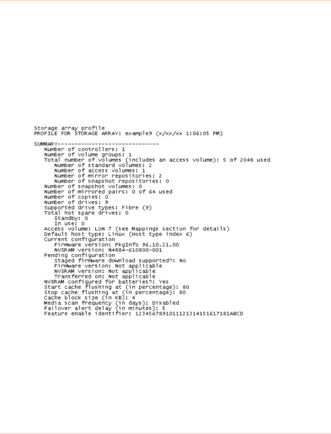
SANtricity_10.77 February 2011
LSI Corporation
- 1337 -
Examples of Information Returned by the Show Commands
This appendix provides examples of information that is returned by the show commands. These examples
show the type of information and the information detail. This information is useful in determining the
components, features, and identifiers that you might need when you configure or maintain a storage array.
Show Storage Array
The show storageArray command returns information about the components and the features in a
storage array. If you run the command with the profile parameter, the command returns information in
the form shown by this example. This information is the most detailed report that you can receive about the
storage array. After you have configured a storage array, save the configuration description to a file as a
reference.
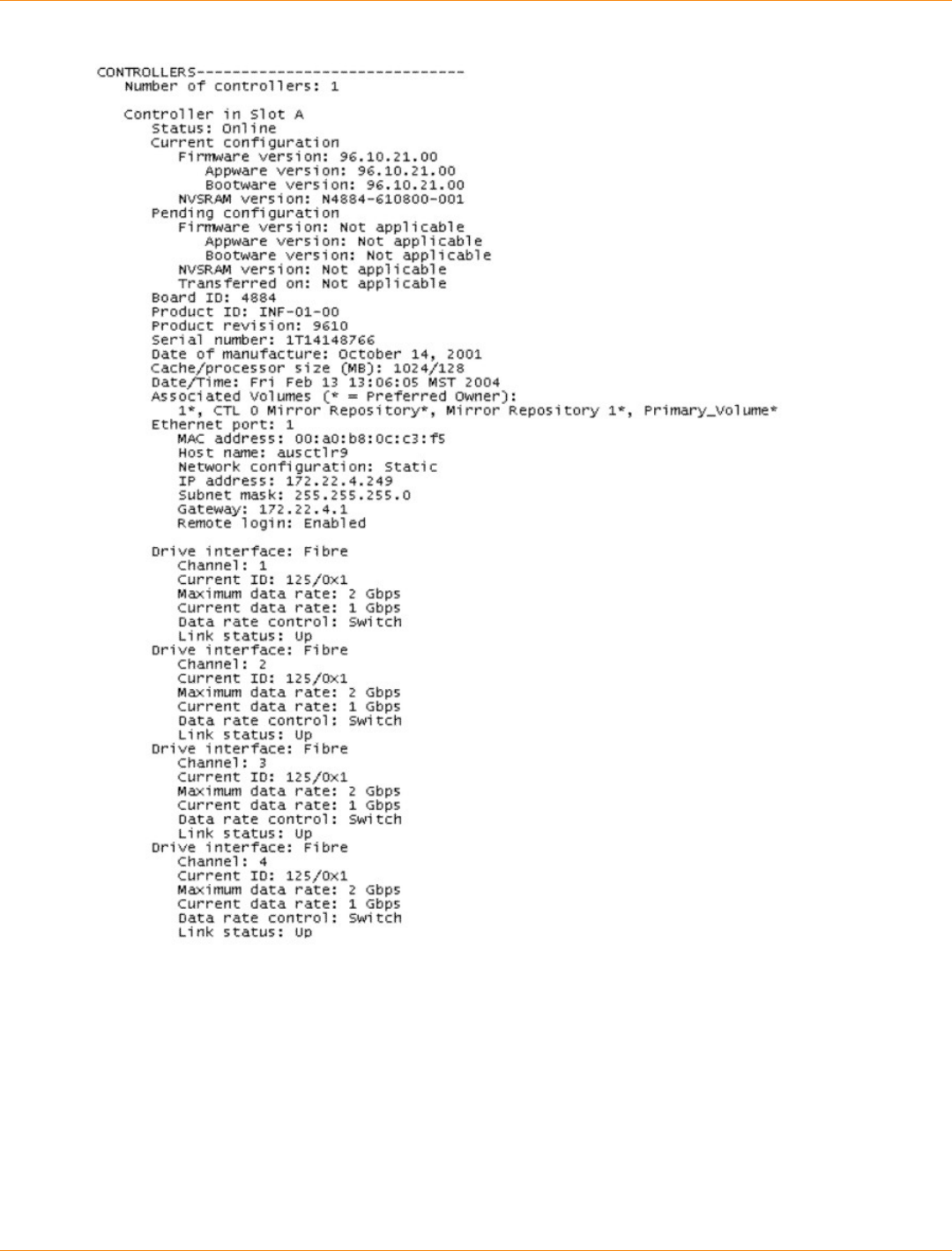
SANtricity_10.77 February 2011
LSI Corporation
- 1338 -
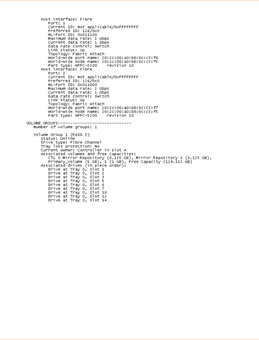
SANtricity_10.77 February 2011
LSI Corporation
- 1339 -
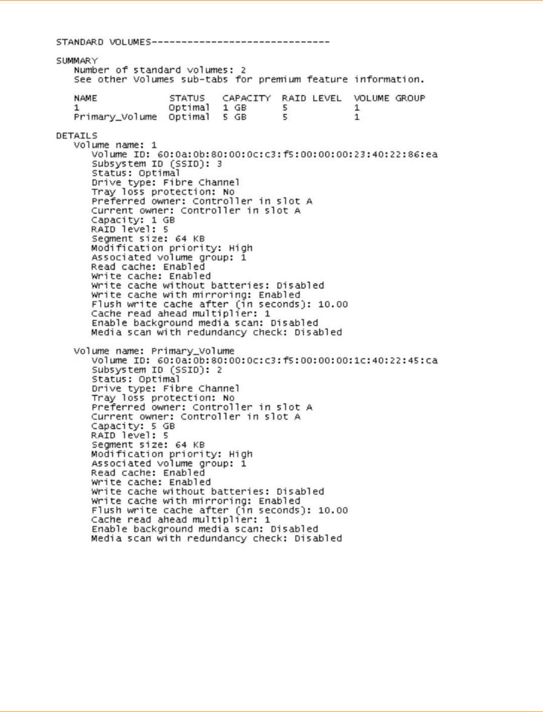
SANtricity_10.77 February 2011
LSI Corporation
- 1340 -
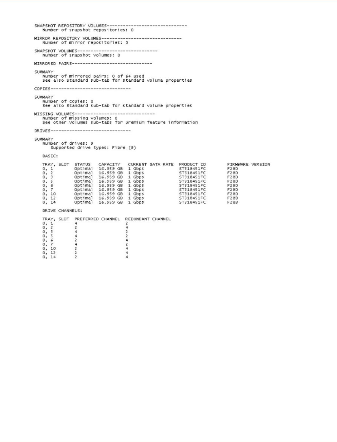
SANtricity_10.77 February 2011
LSI Corporation
- 1341 -
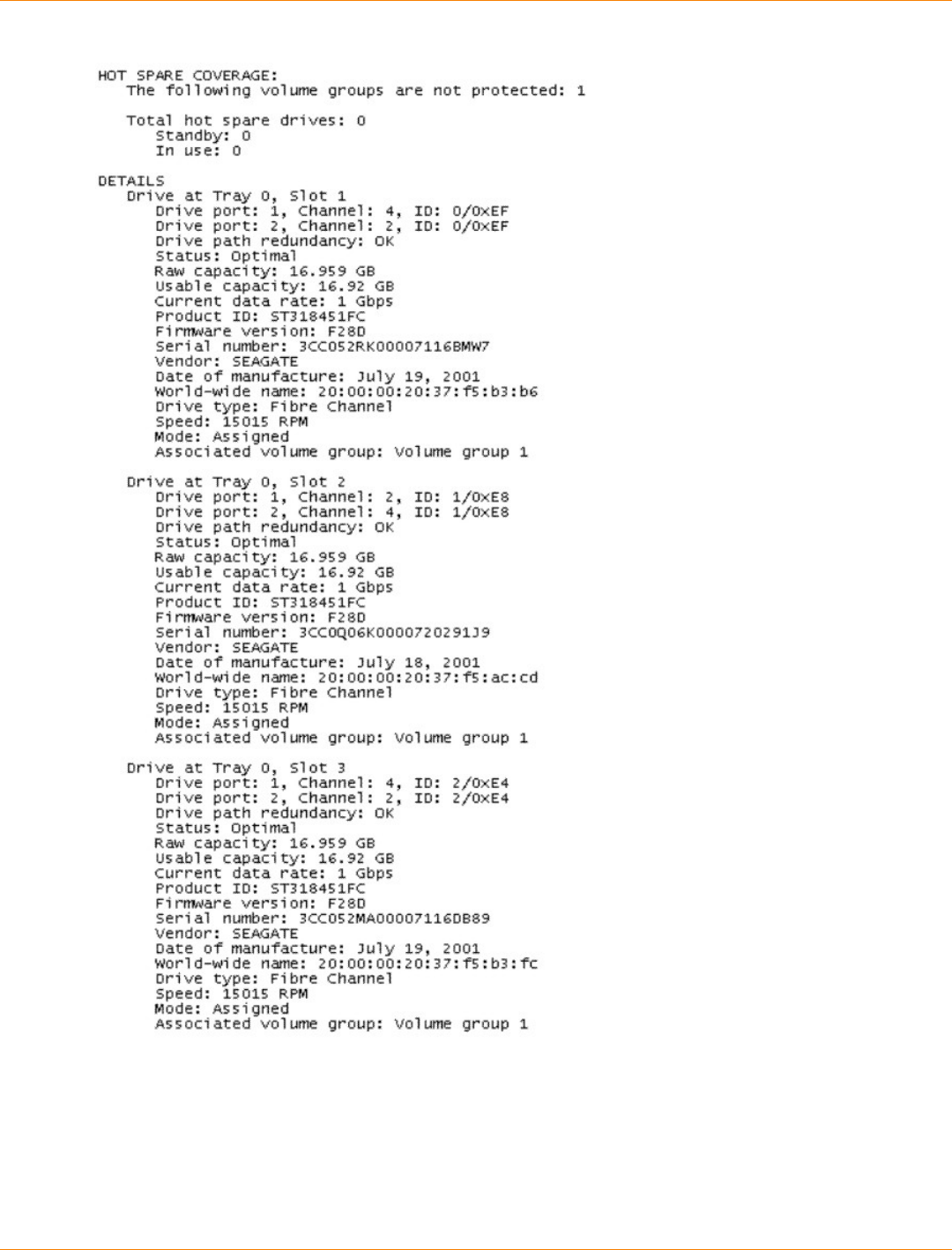
SANtricity_10.77 February 2011
LSI Corporation
- 1342 -
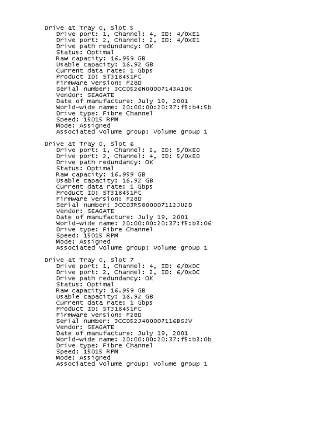
SANtricity_10.77 February 2011
LSI Corporation
- 1343 -
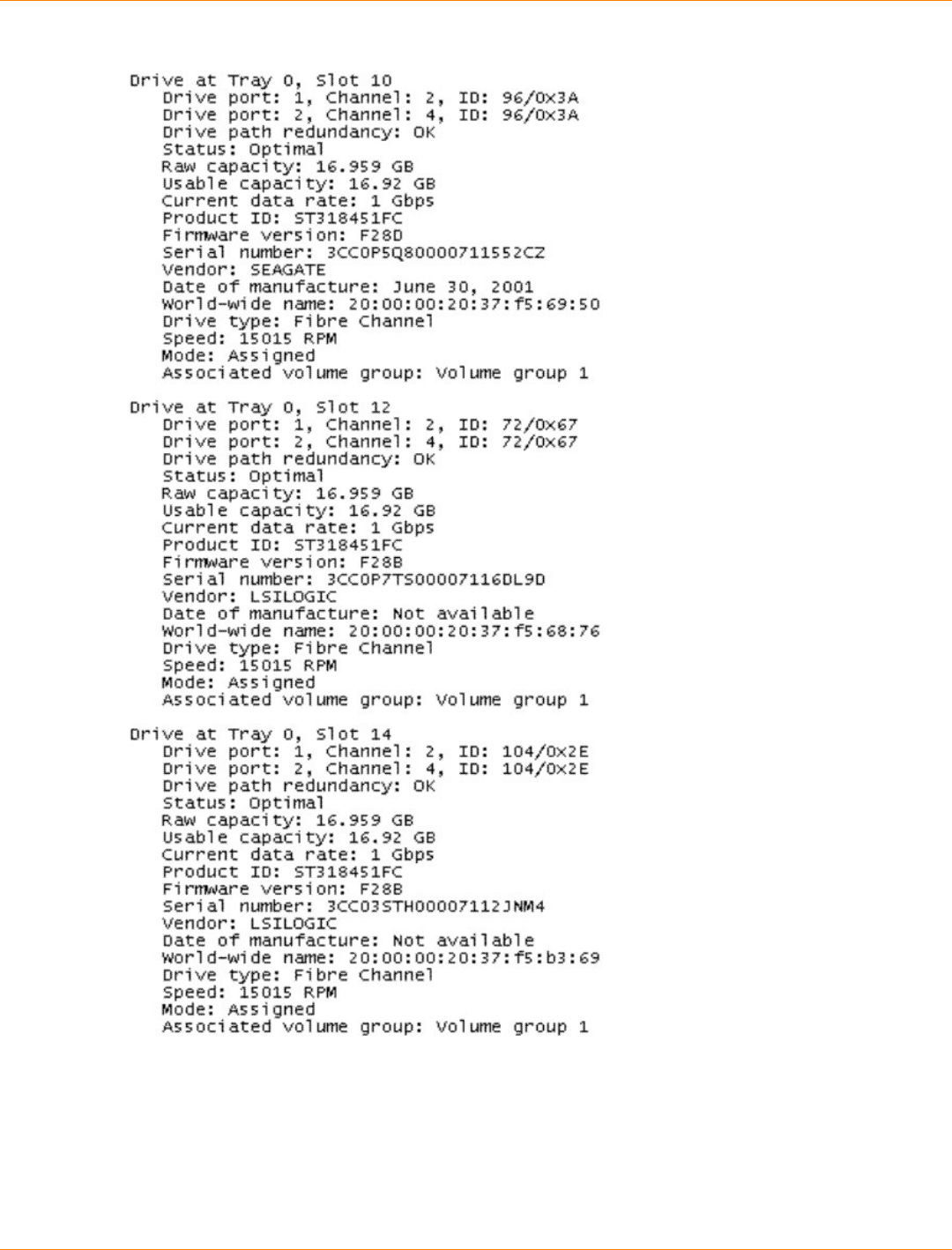
SANtricity_10.77 February 2011
LSI Corporation
- 1344 -
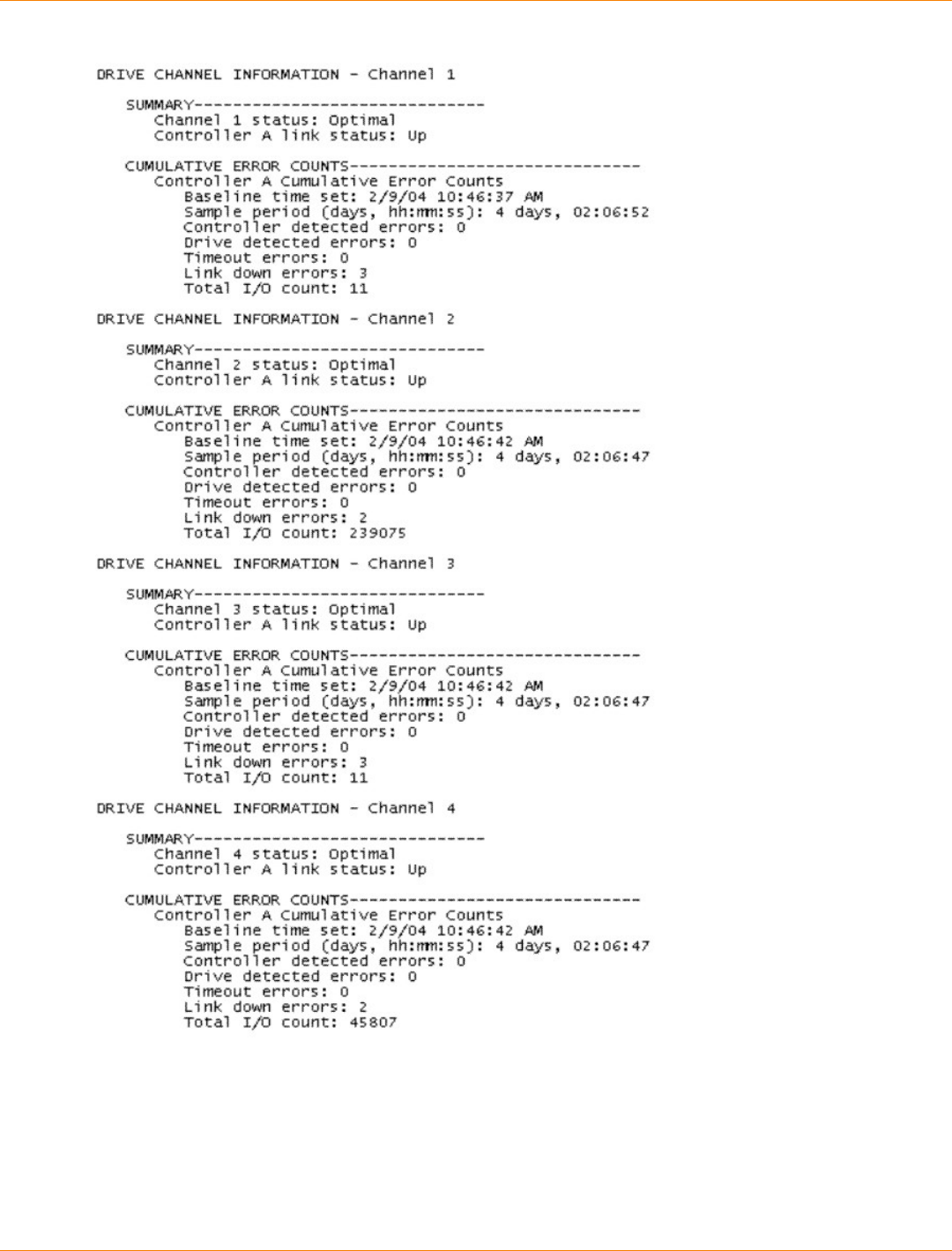
SANtricity_10.77 February 2011
LSI Corporation
- 1345 -
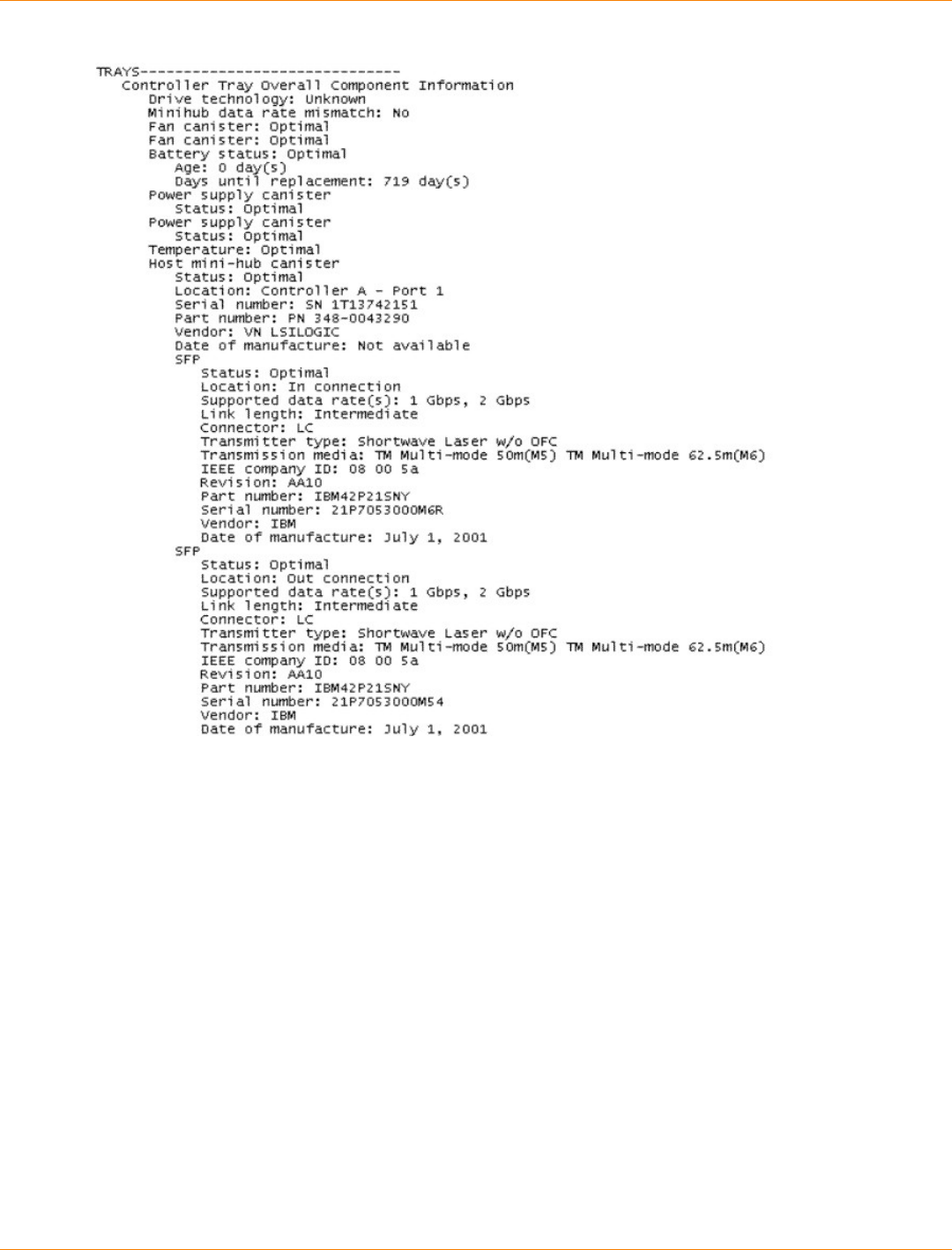
SANtricity_10.77 February 2011
LSI Corporation
- 1346 -
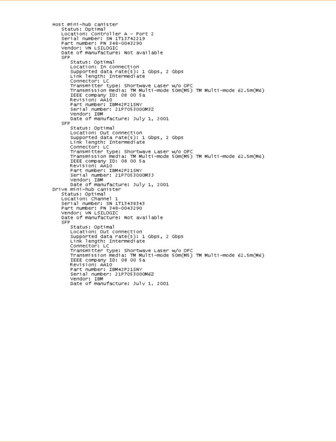
SANtricity_10.77 February 2011
LSI Corporation
- 1347 -
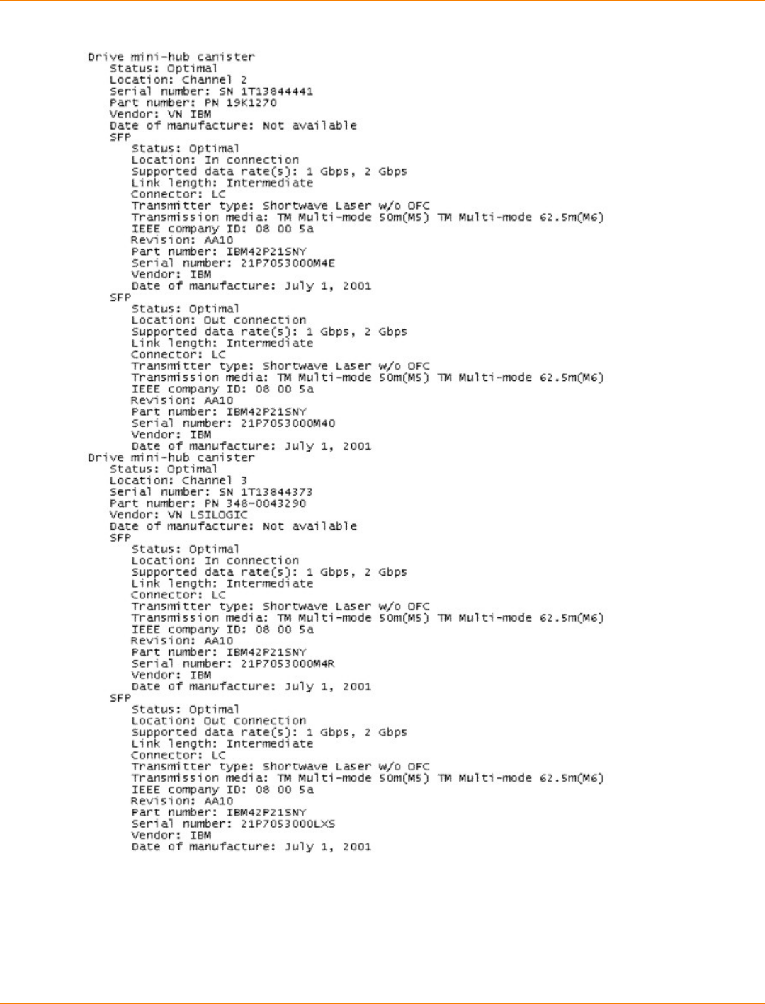
SANtricity_10.77 February 2011
LSI Corporation
- 1348 -
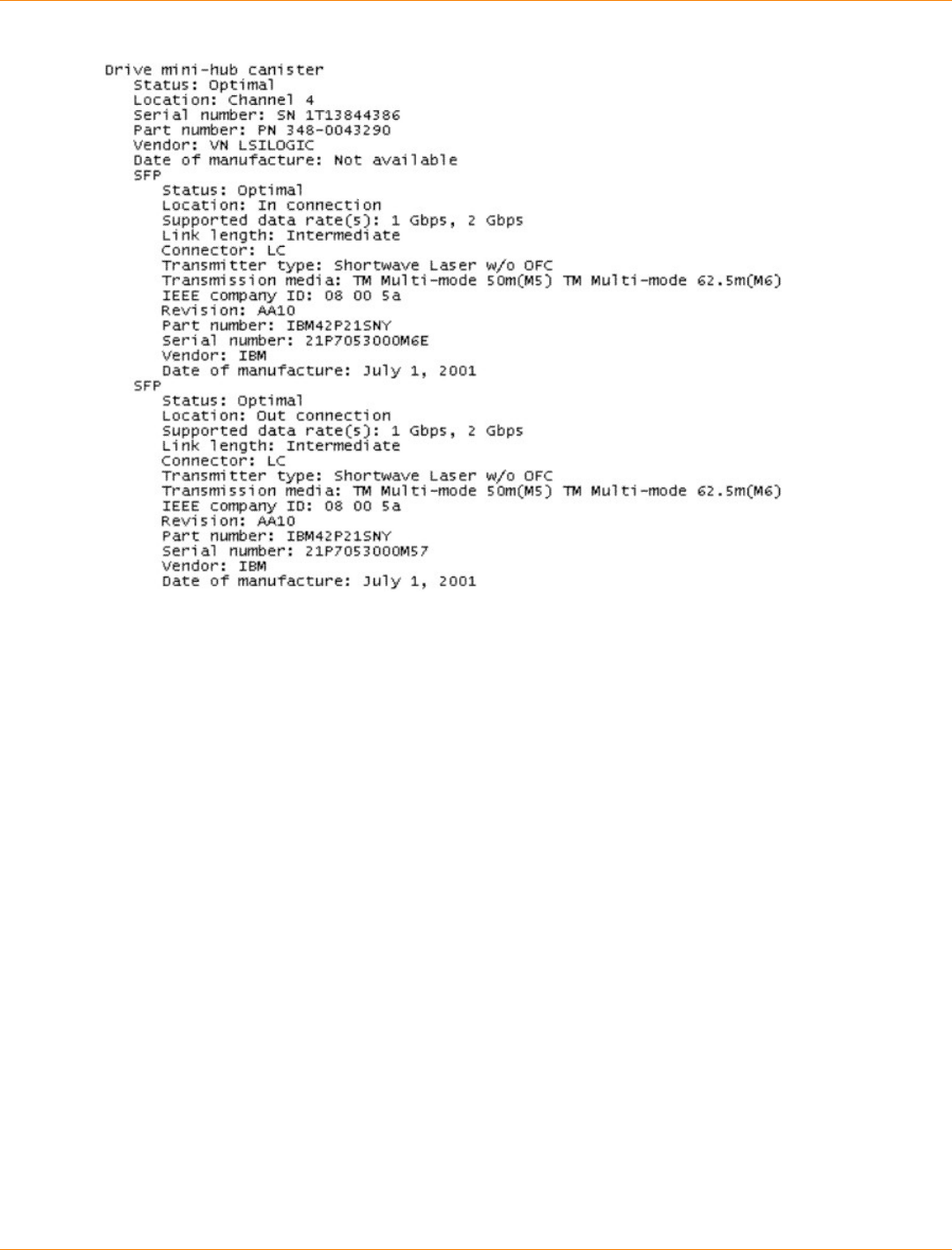
SANtricity_10.77 February 2011
LSI Corporation
- 1349 -
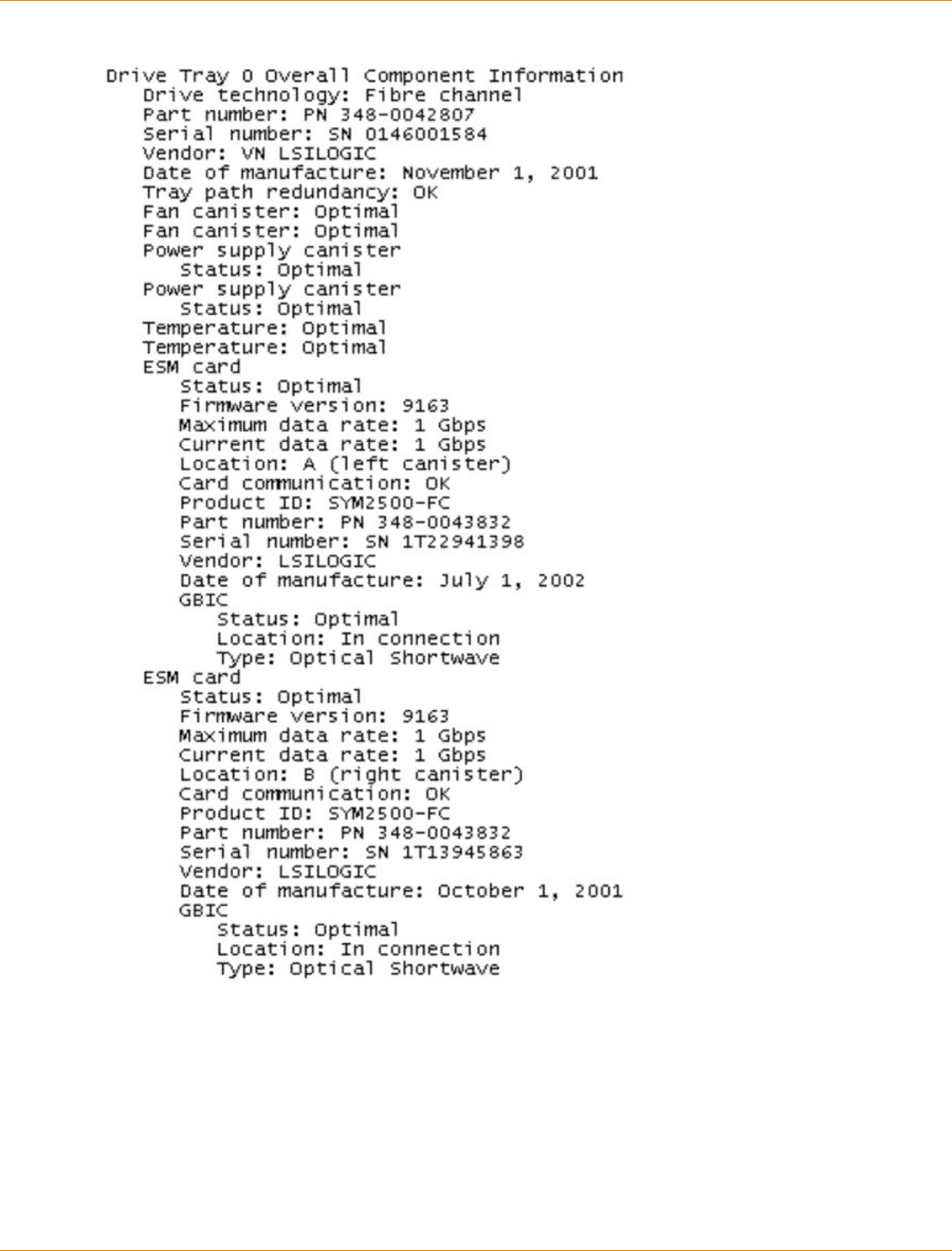
SANtricity_10.77 February 2011
LSI Corporation
- 1350 -
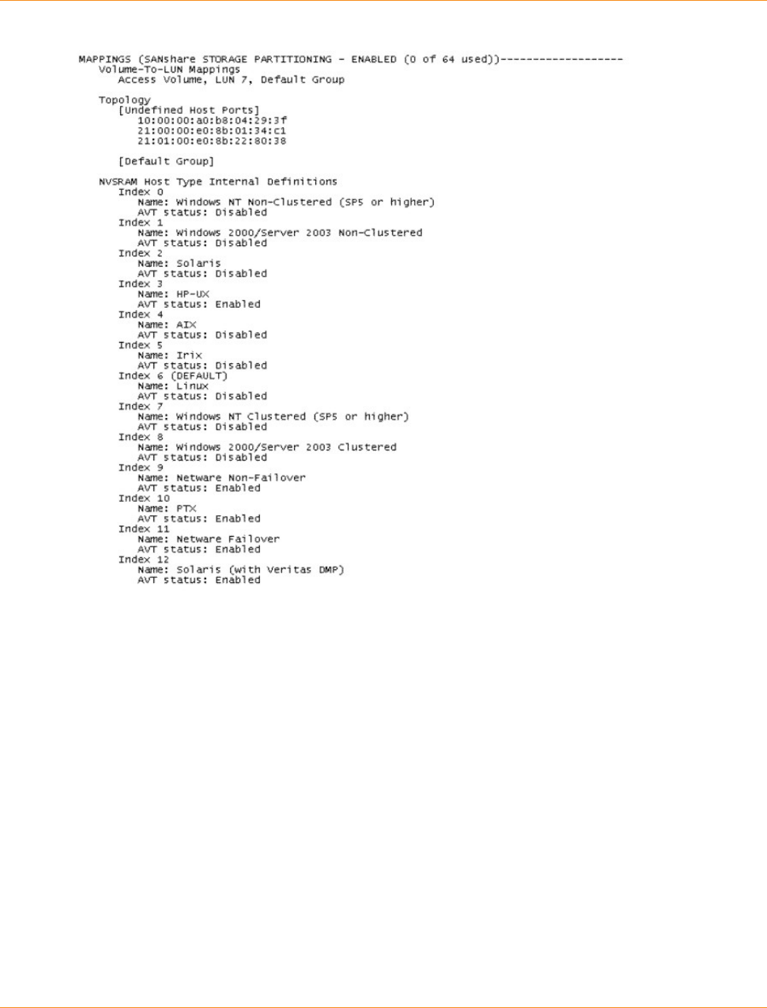
SANtricity_10.77 February 2011
LSI Corporation
- 1351 -
Show Controller NVSRAM
The show controller NVSRAM command returns a table of values in the controller NVSRAM that is
similar to that shown in this example. With the information from the table, you can modify the contents of the
NVSRAM by using the set controller command. This example shows information for a controller in slot
A in a controller tray. You can produce a similar table for a controller in slot B, or you can produce a table for
both controllers.
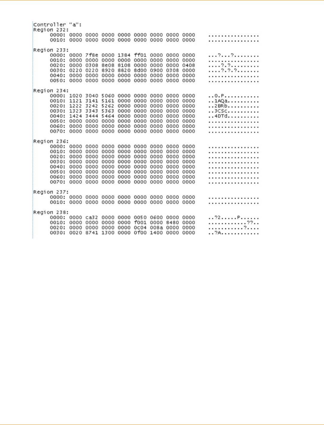
SANtricity_10.77 February 2011
LSI Corporation
- 1352 -
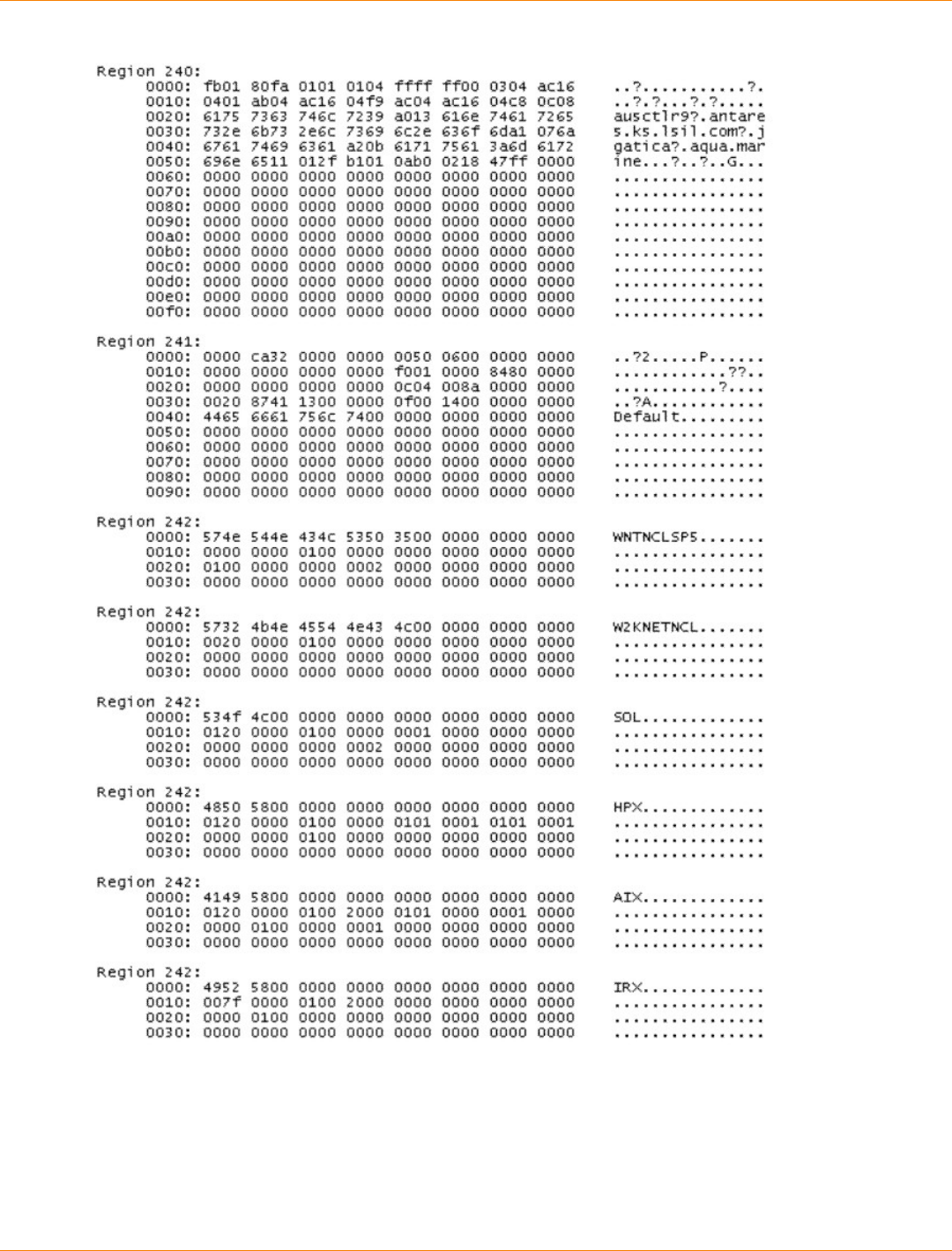
SANtricity_10.77 February 2011
LSI Corporation
- 1353 -
SANtricity_10.77 February 2011
LSI Corporation
- 1354 -
Show Volume
The show volume command returns information about the volumes in a storage array.
STANDARD VOLUMES------------------------------
SUMMARY
Number of standard volumes: 5
See other Volumes sub-tabs for premium feature information.
NAME STATUS CAPACITY RAID LEVEL VOLUME GROUP LUN

SANtricity_10.77 February 2011
LSI Corporation
- 1355 -
1 Optimal 5,120.000 GB 10 6 13
2 Optimal 1.000 GB 1 Volume-Group-2 14
3 Optimal 10.000 GB 1 Volume-Group-2 15
4 Optimal 3.000 GB 1 Volume-Group-2 16
Unnamed Optimal 100.004 MB 0 Volume-Group-1 0
DETAILS
Volume name: 1
Volume status: Optimal
Capacity: 5,120.000 GB
Volume world-wide identifier: 60:0a:0b:80:00:29:ed:12:00:00
Subsystem ID (SSID): 14
Associated volume group: 6
RAID level: 10
LUN: 13
Accessible By: Default Group
Media type: Hard Disk Drive
Interface type: Serial ATA (SATA)
Tray loss protection: Yes
Secure: No
Preferred owner: Controller in slot A
Current owner: Controller in slot A
Segment size: 128 KB
Capacity reserved for future segment size changes: Yes
Maximum future segment size: 2,048 KB
Modification priority: High
Read cache: Enabled
Write cache: Enabled
Write cache without batteries: Disabled
Write cache with mirroring: Enabled
Flush write cache after (in seconds): 10.00
Dynamic cache read prefetch: Enabled
Enable background media scan: Disabled
Media scan with redundancy check: Disabled
Pre-Read redundancy check: Disabled
Volume name: 2
Volume status: Optimal
Capacity: 1.000 GB
Volume world-wide identifier: 60:0a:0b:80:00:29:ed:12:00:00
Subsystem ID (SSID): 15
Associated volume group: Volume-Group-2
RAID level: 1
LUN: 14
Accessible By: Default Group
Media type: Hard Disk Drive
Interface type: Fibre Channel
Tray loss protection: Yes
Secure: No
Preferred owner: Controller in slot B
Current owner: Controller in slot B
Segment size: 128 KB
Capacity reserved for future segment size changes: Yes
Maximum future segment size: 2,048 KB
Modification priority: High
Read cache: Enabled
Write cache: Enabled

SANtricity_10.77 February 2011
LSI Corporation
- 1356 -
Write cache without batteries: Disabled
Write cache with mirroring: Enabled
Flush write cache after (in seconds): 10.00
Dynamic cache read prefetch: Enabled
Enable background media scan: Disabled
Media scan with redundancy check: Disabled
Pre-Read redundancy check: Disabled
Volume name: 3
Volume status: Optimal
Capacity: 10.000 GB
Volume world-wide identifier: 60:0a:0b:80:00:29:ed:12:00:00
Subsystem ID (SSID): 16
Associated volume group: Volume-Group-2
RAID level: 1
LUN: 15
Accessible By: Default Group
Media type: Hard Disk Drive
Interface type: Fibre Channel
Tray loss protection: Yes
Secure: No
Preferred owner: Controller in slot A
Current owner: Controller in slot A
Segment size: 128 KB
Capacity reserved for future segment size changes: Yes
Maximum future segment size: 2,048 KB
Modification priority: High
Read cache: Enabled
Write cache: Enabled
Write cache without batteries: Disabled
Write cache with mirroring: Enabled
Flush write cache after (in seconds): 10.00
Dynamic cache read prefetch: Enabled
Enable background media scan: Disabled
Media scan with redundancy check: Disabled
Pre-Read redundancy check: Disabled
Volume name: 4
Volume status: Optimal
Capacity: 3.000 GB
Volume world-wide identifier: 60:0a:0b:80:00:29:ed:12:00:00
Subsystem ID (SSID): 17
Associated volume group: Volume-Group-2
RAID level: 1
LUN: 16
Accessible By: Default Group
Media type: Hard Disk Drive
Interface type: Fibre Channel
Tray loss protection: Yes
Secure: No
Preferred owner: Controller in slot B
Current owner: Controller in slot B
Segment size: 128 KB
Capacity reserved for future segment size changes: Yes
Maximum future segment size: 2,048 KB
Modification priority: High
Read cache: Enabled
Write cache: Enabled

SANtricity_10.77 February 2011
LSI Corporation
- 1357 -
Write cache without batteries: Disabled
Write cache with mirroring: Enabled
Flush write cache after (in seconds): 10.00
Dynamic cache read prefetch: Enabled
Enable background media scan: Disabled
Media scan with redundancy check: Disabled
Pre-Read redundancy check: Disabled
Volume name: Unamed
Volume status: Optimal
Capacity: 100.004 GB
Volume world-wide identifier: 60:0a:0b:80:00:29:ed:12:00:00
Subsystem ID (SSID): 0
Associated volume group: Volume-Group-1
RAID level: 0
LUN: 0
Accessible By: Default Group
Media type: Hard Disk Drive
Interface type: Serial ATA (SATA)
Tray loss protection: No
Secure: No
Preferred owner: Controller in slot B
Current owner: Controller in slot B
Segment size: 16 KB
Capacity reserved for future segment size changes: Yes
Maximum future segment size: Not Appl
Modification priority: Low
Read cache: Enabled
Write cache: Disabled
Write cache without batteries: Disabled
Write cache with mirroring: Disabled
Flush write cache after (in seconds): 10.00
Dynamic cache read prefetch: Disabled
Enable background media scan: Enabled
Media scan with redundancy check: Enabled
SNAPSHOT REPOSITORY VOLUMES------------------------------
SUMMARY
Number of snapshot repositories: 1
NAME CAPACITY USAGE(%) THRESHOLD WARNING FULL POLICY
DAE1-1 0 50% full Fail snapshot
DETAILS
SNAPSHOT REPOSITORY VOLUME NAME: DAE1-1
Snapshot repository volume status: Optimal
Capacity usage (%): 0
Notify when capacity reaches: 50% full
Snapshot repository full policy: Fail snapshot volume
Associated base volume (standard): Unnamed
Associated snapshot volume: DAE1
Volume name: DAE1-1
Volume status: Optimal
Capacity: 20.000 MB
Volume world-wide identifier: 60:0a:0b:80:00:29:ed:12
Subsystem ID (SSID): 11
RAID level: 0
Media type: Hard Disk Drive
Interface type: Serial ATA (SATA)

SANtricity_10.77 February 2011
LSI Corporation
- 1358 -
Tray loss protection: No
Secure: No
Preferred owner: Controller in slot B
Current owner: Controller in slot B
Segment size: 64 KB
Capacity reserved for future segment size changes: No
Maximum future segment size: Not ap
Modification priority: High
Read cache: Enabled
Write cache: Enabled
Write cache without batteries: Disabled
Write cache with mirroring: Enabled
Flush write cache after (in seconds): 10.00
Dynamic cache read prefetch: Disabled
Enable background media scan: Disabled
Media scan with redundancy check: Disabled
MIRROR REPOSITORY VOLUMES------------------------------
SUMMARY
Number of mirror repositories: 2
NAME STATUS CAPACITY RAID LEVEL VOLUME
Mirror Repository 2 Optimal 129.093 MB 10 6
Mirror Repository 1 Optimal 129.093 MB 10 6
DETAILS
MIRROR REPOSITORY VOLUME NAME: Mirror Repository 2
Mirror repository volume status: Optimal
Volume name: Mirror Repository 2
Volume status: Optimal
Capacity: 129.093 MB
Volume world-wide identifier: 60:0a:0b:80:00:29:ed
Subsystem ID (SSID): 12
Associated volume group: 6
RAID level: 10
Media type: Hard Disk Drive
Interface type: Serial ATA (SATA)
Tray loss protection: Yes
Secure: No
Preferred owner: Controller in slot B
Current owner: Controller in slot B
Segment size: 32 KB
Capacity reserved for future segment size changes: No
Maximum future segment size: Not applicable
Modification priority: High
MIRROR REPOSITORY VOLUME NAME: Mirror Repository 1
Mirror repository volume status: Optimal
Volume name: Mirror Repository 1
Volume status: Optimal
Capacity: 129.093 MB
Volume world-wide identifier: 60:0a:0b:80:00:29:ed
Subsystem ID (SSID): 13
Associated volume group: 6
RAID level: 10
Media type: Hard Disk Drive
Interface type: Serial ATA (SATA)
Tray loss protection: Yes
Secure: No

SANtricity_10.77 February 2011
LSI Corporation
- 1359 -
Preferred owner: Controller in slot A
Current owner: Controller in slot A
Segment size: 32 KB
Capacity reserved for future segment size changes: No
Maximum future segment size: Not applicable
Modification priority: High
SNAPSHOT VOLUMES------------------------------
SUMMARY
Number of snapshot volumes: 1
NAME STATUS CREATION TIMESTAMP
DAE1 Optimal 9/24/10 8:54 AM
DETAILS
SNAPSHOT VOLUME NAME: DAE1
Snapshot status: Optimal
Creation timestamp: 9/24/10 8:54 AM
Associated base volume (standard): Unnamed
Associated snapshot repository volume: DAE1-1
Volume world-wide identifier: 60:0a:0b:80:00:29:ed:12:00
Capacity: 100.004 MB
Preferred owner: Controller in slot B
Current owner: Controller in slot B
COPIES------------------------------
SUMMARY
Number of copies: 10
S = Source volume
T = Target volume
COPY PAIR STATUS COMPLETION TIMESTAMP
5 (S), 10 (T) Completed 10/14/10 3:16:27 PM
5 (S), 8 (T) Completed 10/18/10 9:46:45 AM
10 (S), 9 (T) Stopped None
(S), 7 (T) Completed 10/14/10 3:13:37 PM
5 (S), 4 (T) Completed 10/14/10 3:18:23 PM
1 (S), 3 (T) Completed 10/14/10 3:22:56 PM
Unnamed (S), 5 (T) Completed 9/16/10 2:30:06 PM
Unnamed (S), 11 (T) Stopped None
Unnamed (S), 6 (T) Completed 9/2/10 10:03:56 AM
Unnamed (S), 1 (T) Completed 9/16/10 12:41:14 PM
DETAILS
Copy pair: Unnamed and 4
Copy status: Copy pair: Unnamed and 4
Copy status: Completed
Start timestamp: 9/16/10 2:29:23 PM
Completion timestamp: 9/16/10 2:30:06 PM
Copy priority: Lowest
Source volume: Unnamed
Volume world-wide identifier: 60:0a:0b:80:00:29:ed:12
Target volume: 5
Volume world-wide identifier: 60:0a:0b:80:00:47:5b:8a
Read-only: Disabled
Copy pair: Unnamed and 3
Copy status: Stopped
Start timestamp: None
Completion timestamp: None
Copy priority: Lowest

SANtricity_10.77 February 2011
LSI Corporation
- 1360 -
Source volume: Unnamed
Volume world-wide identifier: 60:0a:0b:80:00:29:ed:12
Target volume: 11
Volume world-wide identifier: 60:0a:0b:80:00:29:ed:12
Read-only: Enabled
Copy pair: Unnamed and 2
Copy status: Completed
Start timestamp: 9/2/10 10:03:41 AM
Completion timestamp: 9/2/10 10:03:56 AM
Copy priority: Medium
Source volume: Unnamed
Volume world-wide identifier: 60:0a:0b:80:00:29:ed:12
Target volume: 6
Volume world-wide identifier: 60:0a:0b:80:00:29:ed:12
Read-only: Enabled
Copy pair: Unnamed and 1
Copy status: Completed
Start timestamp: 9/16/10 12:40:58 PM
Completion timestamp: 9/16/10 12:41:14 PM
Copy priority: Medium
Source volume: Unnamed
Volume world-wide identifier: 60:0a:0b:80:00:29:ed:1
Target volume: 1
Volume world-wide identifier: 60:0a:0b:80:00:47:5b:8
Read-only: Enabled
MIRRORED PAIRS------------------------------
Number of mirrored pairs: 0 of 64 used
MISSING VOLUMES------------------------------
Number of missing volumes: 0
Show Drive Channel Stat
The show drive channel stat command returns information about the drive channels in a storage array.
Use this information to determine how well the channels are running and errors that might be occurring on the
channels.
DRIVE CHANNELS----------------------------
SUMMARY
CHANNEL PORT STATUS
1 8,7,ESM A 1A,ESM A 1B,ESM A 1A,ESM A 1B,ESM A 1B Optimal
2 6,5 Optimal
3 4,3 Optimal
4 2,1 Optimal
5 1,2,ESM B 1B,ESM B 1A,ESM B 1B,ESM B 1A,ESM B 1B Optimal
6 3,4 Optimal
7 5,6 Optimal
8 7,8 Optimal
DETAILS
DRIVE CHANNEL 1
Port: 8, 7, ESM A 1A, ESM A 1B, ESM A 1A, ESM A 1B, ESM A 1B
Status: Optimal

SANtricity_10.77 February 2011
LSI Corporation
- 1361 -
Max. Rate: 4 Gbps
Current Rate: 4 Gbps
Rate Control: Auto
Controller A link status: Up
Controller B link status: Up
Trunking active: No
DRIVE COUNTS
Total # of attached drives: 44
Connected to: Controller A, Port 8
Attached drives: 44
Drive tray: 3 (14 drives)
Drive tray: 1 (15 drives)
Drive tray: 2 (15 drives)
CUMULATIVE ERROR COUNTS
Controller A
Baseline time set: 10/30/10 1:15:59 PM
Sample period (days, hh:mm:ss): 32 days, 00:55:04
Controller detected errors: 0
Drive detected errors: 48
Timeout errors: 1
Link down errors: N/A
Total I/O count: 199070838
Controller B
Baseline time set: 10/30/10 1:15:59 PM
Sample period (days, hh:mm:ss): 32 days, 00:53:22
Controller detected errors: 0
Drive detected errors: 52
Timeout errors: 0
Link down errors: N/A
Total I/O count: 198778804
DRIVE CHANNEL 2
Port: 6, 5
Status: Optimal
Max. Rate: 4 Gbps
Current Rate: 4 Gbps
Rate Control: Auto
Controller A link status: Up
Controller B link status: Up
Trunking active: No
DRIVE COUNTS
Total # of attached drives: 0
CUMULATIVE ERROR COUNTS
Controller A
Baseline time set: 10/30/10 1:15:59 PM
Sample period (days, hh:mm:ss): 32 days, 00:55:04
Controller detected errors: 0
Drive detected errors: 0
Timeout errors: 2
Link down errors: N/A
Total I/O count: 14238433
Controller B

SANtricity_10.77 February 2011
LSI Corporation
- 1362 -
Baseline time set: 10/30/10 1:15:59 PM
Sample period (days, hh:mm:ss): 32 days, 00:53:22
Controller detected errors: 0
Drive detected errors: 0
Timeout errors: 0
Link down errors: N/A
Total I/O count: 13470436
DRIVE CHANNEL 3
Port: 6, 5
Status: Optimal
Max. Rate: 4 Gbps
Current Rate: 4 Gbps
Rate Control: Auto
Controller A link status: Up
Controller B link status: Up
Trunking active: No
DRIVE COUNTS
Total # of attached drives: 0
CUMULATIVE ERROR COUNTS
Controller A
Baseline time set: 10/30/10 1:15:59 PM
Sample period (days, hh:mm:ss): 32 days, 00:55:04
Controller detected errors: 0
Drive detected errors: 0
Timeout errors: 0
Link down errors: N/A
Total I/O count: 13414513
Controller B
Baseline time set: 10/30/10 1:15:59 PM
Sample period (days, hh:mm:ss): 32 days, 00:53:22
Controller detected errors: 0
Drive detected errors: 0
Timeout errors: 0
Link down errors: N/A
Total I/O count: 13201515
DRIVE CHANNEL 4
Port: 2, 1
Status: Optimal
Max. Rate: 4 Gbps
Current Rate: 2 Gbps
Rate Control: Auto
Controller A link status: Up
Controller B link status: Up
Trunking active: No
DRIVE COUNTS
Total # of attached drives: 0
CUMULATIVE ERROR COUNTS
Controller A
Baseline time set: 10/30/10 1:15:59 PM
Sample period (days, hh:mm:ss): 32 days, 00:55:04
Controller detected errors: 111

SANtricity_10.77 February 2011
LSI Corporation
- 1363 -
Drive detected errors: 0
Timeout errors: 0
Link down errors: N/A
Total I/O count: 13093814
Controller B
Baseline time set: 10/30/10 1:15:59 PM
Sample period (days, hh:mm:ss): 32 days, 00:53:22
Controller detected errors: 54
Drive detected errors: 0
Timeout errors: 0
Link down errors: N/A
Total I/O count: 13039285
DRIVE CHANNEL 5
Port: 1, 2, ESM B 1B, ESM B 1A, ESM B 1B, ESM B 1A, ESM B 1B
Status: Optimal
Max. Rate: 4 Gbps
Current Rate: 4 Gbps
Rate Control: Auto
Controller A link status: Up
Controller B link status: Up
Trunking active: No
DRIVE COUNTS
Total # of attached drives: 44
Connected to: Controller B, Port 1
Attached drives: 44
Drive tray: 3 (14 drives)
Drive tray: 1 (15 drives)
Drive tray: 2 (15 drives)
CUMULATIVE ERROR COUNTS
Controller A
Baseline time set: 10/30/10 1:15:59 PM
Sample period (days, hh:mm:ss): 32 days, 00:55:04
Controller detected errors: 0
Drive detected errors: 49
Timeout errors: 1
Link down errors: N/A
Total I/O count: 183366503
Controller B
Baseline time set: 10/30/10 1:15:59 PM
Sample period (days, hh:mm:ss): 32 days, 00:53:22
Controller detected errors: 1
Drive detected errors: 52
Timeout errors: 0
Link down errors: N/A
Total I/O count: 182512319
DRIVE CHANNEL 6
Port: 3, 4
Status: Optimal
Max. Rate: 4 Gbps
Current Rate: 2 Gbps
Rate Control: Auto
Controller A link status: Up

SANtricity_10.77 February 2011
LSI Corporation
- 1364 -
Controller B link status: Up
Trunking active: No
DRIVE COUNTS
Total # of attached drives: 0
CUMULATIVE ERROR COUNTS
Controller A
Baseline time set: 10/30/10 1:15:59 PM
Sample period (days, hh:mm:ss): 32 days, 00:55:04
Controller detected errors: 0
Drive detected errors: 0
Timeout errors: 0
Link down errors: 0
Total I/O count: 13296480
Controller B
Baseline time set: 10/30/10 1:15:59 PM
Sample period (days, hh:mm:ss): 32 days, 00:53:22
Controller detected errors: 0
Drive detected errors: 0
Timeout errors: 0
Link down errors: N/A
Total I/O count: 13275865
DRIVE CHANNEL 7
Port: 5, 6
Status: Optimal
Max. Rate: 4 Gbps
Current Rate: 2 Gbps
Rate Control: Auto
Controller A link status: Up
Controller B link status: Up
Trunking active: No
DRIVE COUNTS
Total # of attached drives: 0
CUMULATIVE ERROR COUNTS
Controller A
Baseline time set: 10/30/10 1:15:59 PM
Sample period (days, hh:mm:ss): 32 days, 00:55:04
Controller detected errors: 0
Drive detected errors: 0
Timeout errors: 0
Link down errors: 0
Total I/O count: 131818784
Controller B
Baseline time set: 10/30/10 1:15:59 PM
Sample period (days, hh:mm:ss): 32 days, 00:53:22
Controller detected errors: 0
Drive detected errors: 0
Timeout errors: 0
Link down errors: N/A
Total I/O count: 13171844
DRIVE CHANNEL 8

SANtricity_10.77 February 2011
LSI Corporation
- 1365 -
Port: 7, 8
Status: Optimal
Max. Rate: 4 Gbps
Current Rate: 4 Gbps
Rate Control: Auto
Controller A link status: Up
Controller B link status: Up
Trunking active: No
DRIVE COUNTS
Total # of attached drives: 0
CUMULATIVE ERROR COUNTS
Controller A
Baseline time set: 10/30/10 1:15:59 PM
Sample period (days, hh:mm:ss): 32 days, 00:55:04
Controller detected errors: 44
Drive detected errors: 0
Timeout errors: 0
Link down errors: 0
Total I/O count: 13067464
Controller B
Baseline time set: 10/30/10 1:15:59 PM
Sample period (days, hh:mm:ss): 32 days, 00:53:22
Controller detected errors: 25
Drive detected errors: 0
Timeout errors: 0
Link down errors: N/A
Total I/O count: 12987004
Show Drive
The show drive command returns information about the drives in a storage array.
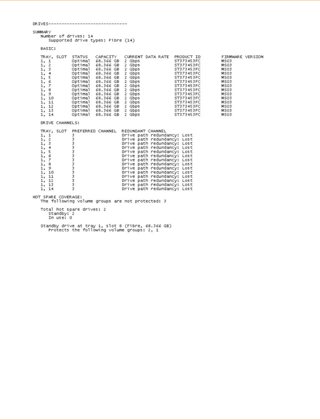
SANtricity_10.77 February 2011
LSI Corporation
- 1366 -
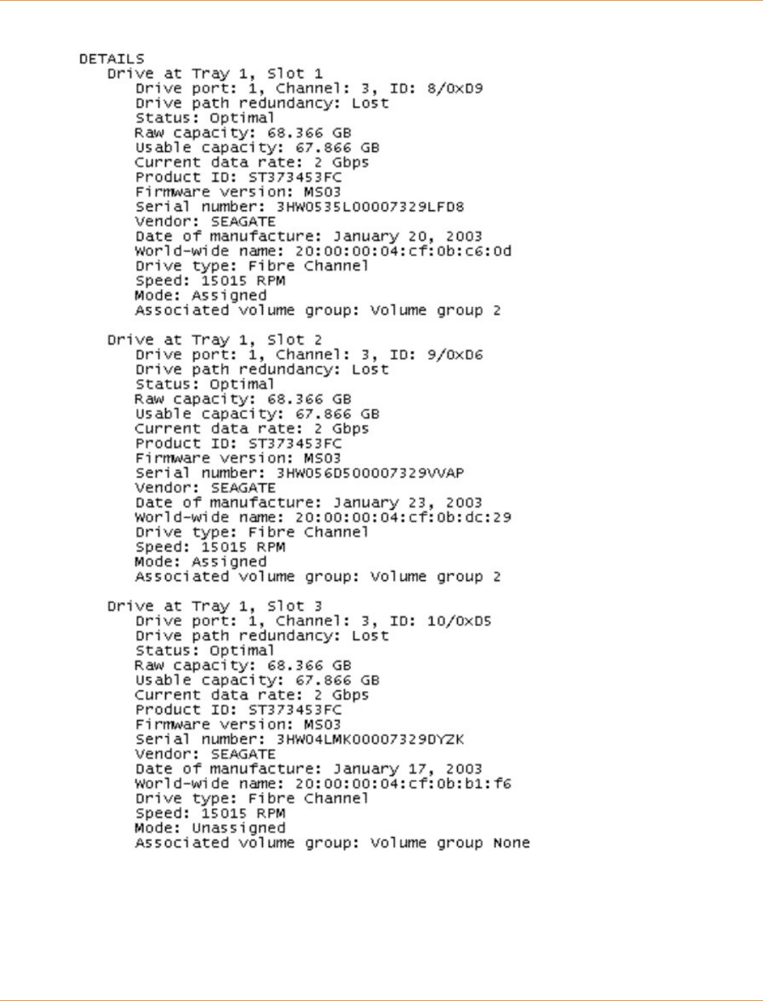
SANtricity_10.77 February 2011
LSI Corporation
- 1367 -
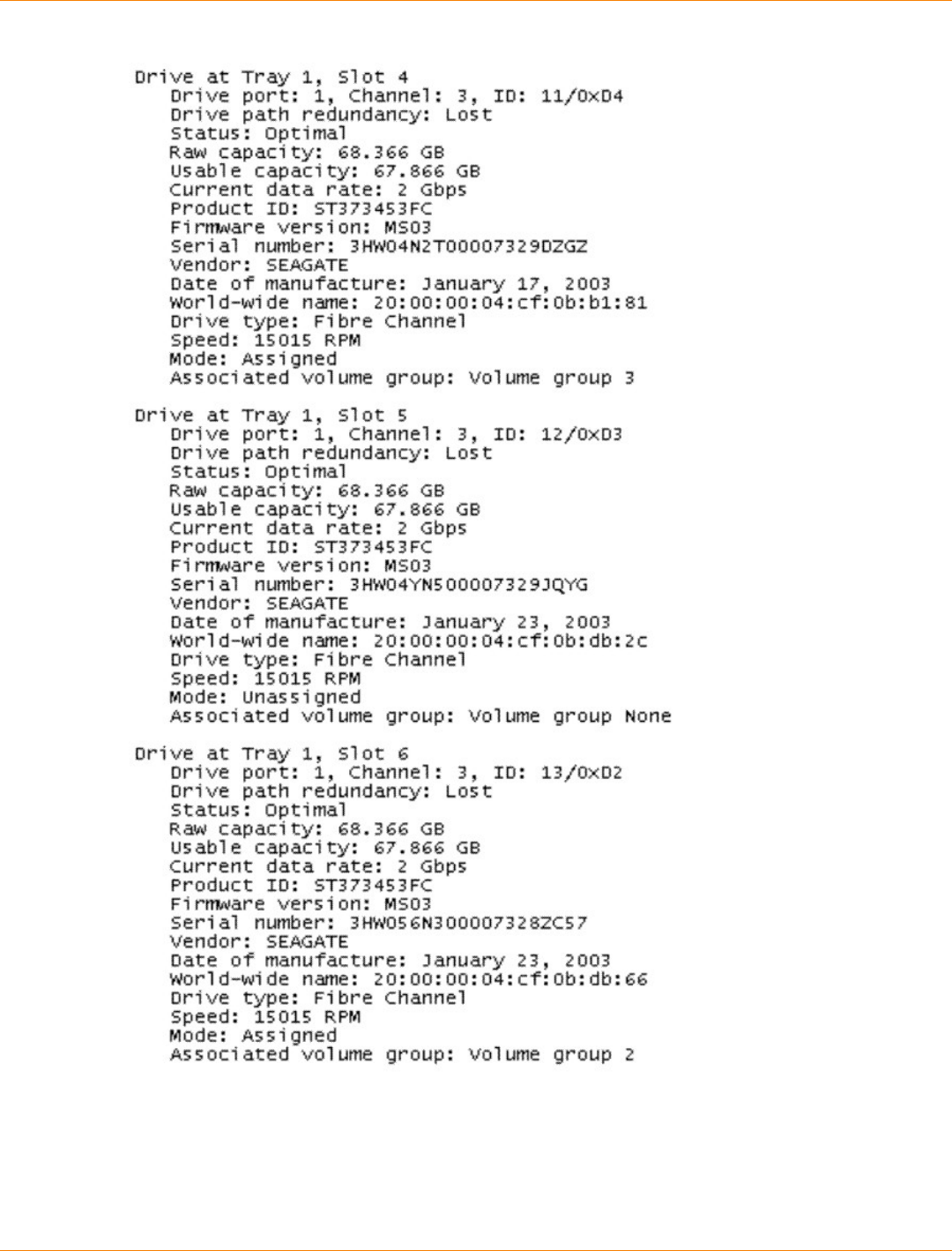
SANtricity_10.77 February 2011
LSI Corporation
- 1368 -
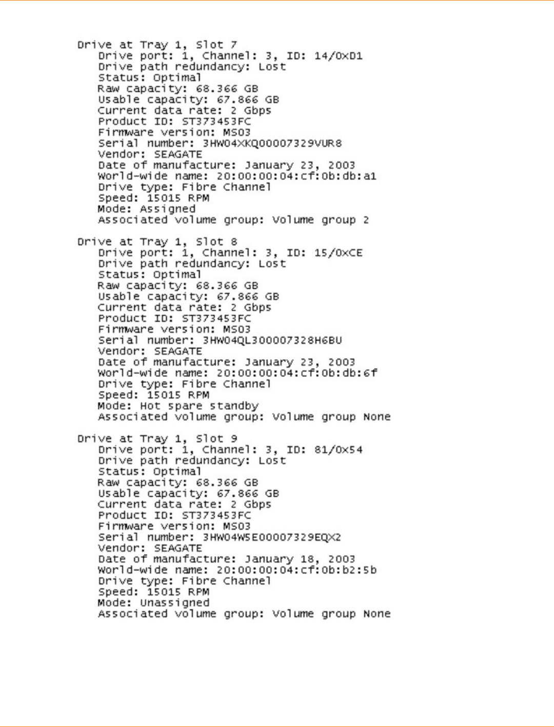
SANtricity_10.77 February 2011
LSI Corporation
- 1369 -
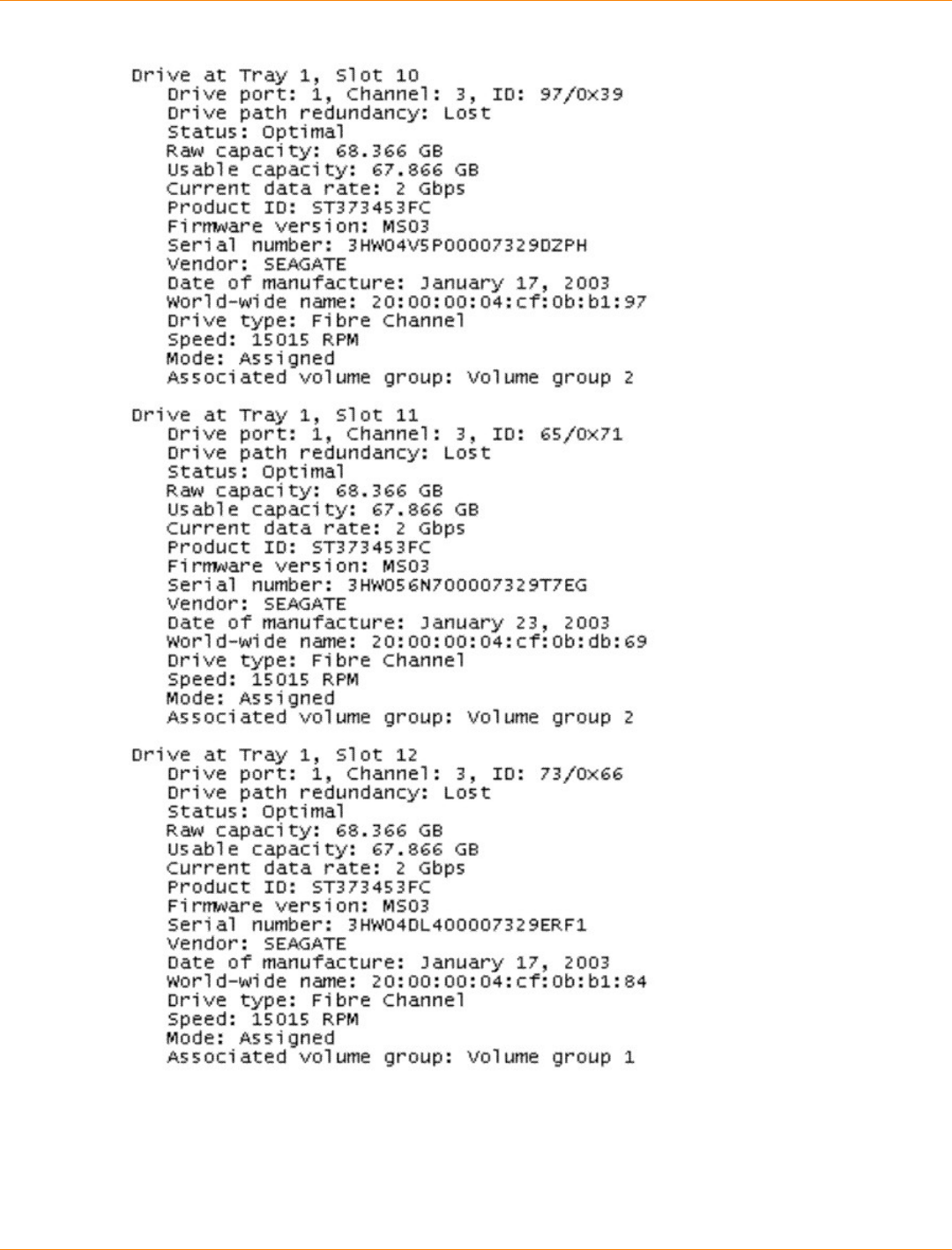
SANtricity_10.77 February 2011
LSI Corporation
- 1370 -
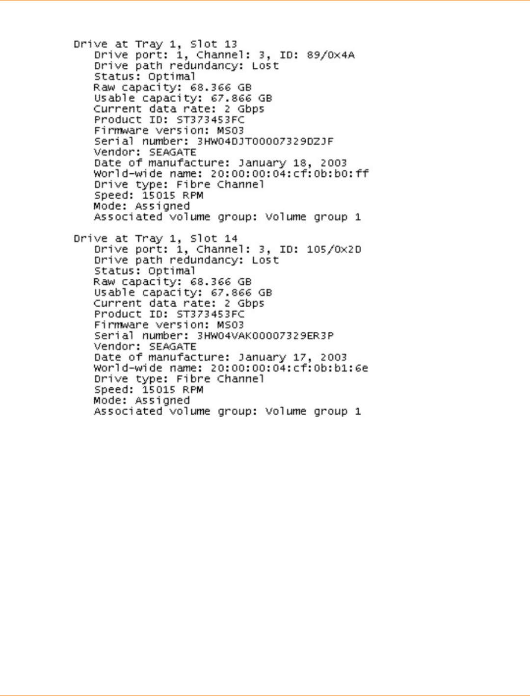
SANtricity_10.77 February 2011
LSI Corporation
- 1371 -

SANtricity_10.77 February 2011
LSI Corporation
- 1372 -
Example Script Files
This appendix provides example scripts for configuring a storage array. These examples show how the script
commands appear in a complete script file. Also, you can copy these scripts and modify them to create a
configuration unique to your storage array.
You can create a script file in two ways:
Using the save storageArray configuration command
Writing a script
By using the save storageArray configuration command, you can create a file that you can use
to copy an existing configuration from one storage array to other storage arrays. You can also use this file
to restore an existing configuration that has become corrupted. You also can copy an existing file to serve
as a pattern from which you create a new script file by modifying portions of the original file. The default file
extension is .scr.
You can create a new script file by using a text editor, such as Microsoft Notepad. The maximum line length is
256 characters. The command syntax must conform to the guidelines in the topic "About the Command Line
Interface" and the topic "About the Script Commands. When you create a new script file, you can use any file
name and extension that will run on the host operating system.
This example shows how to run a script file from the command line.
c:\...\smX\client>smcli 123.45.67.88 123.45.67.89
-f scriptfile.scr;
Configuration Script Example 1
This example creates a new volume by using the create volume command in the free space of a volume
group.
Show “Create RAID 5 Volume 7 on existing Volume Group 1”;
//Create volume on volume group created by the create
volume drives command
//Note: For volume groups that use all available
capacity, the last volume on the group is created using
all remaining capacity by omitting the capacity=volume
creation parameter
create volume volumeGroup=1 RAIDLevel=5 userLabel=”7”
owner=A segmentSize=16 cacheReadPrefetch=TRUE capacity=2GB;
show “Setting additional attributes for volume 7”;
//Configuration settings that cannot be set during volume
creation
set volume[“7”] cacheFlushModifier=10;
set volume[“7”] cacheWithoutBatteryEnabled=false;
set volume[“7”] mirrorEnabled=true;
set volume[“7”] readCacheEnabled=true;
set volume[“7”] writeCacheEnabled=true;
set volume[“7”] mediaScanEnabled=false;
set volume[“7”] redundancyCheckEnabled=false;

SANtricity_10.77 February 2011
LSI Corporation
- 1373 -
set volume[“7”] modificationPriority=high;
This example shows blank lines between the lines beginning with Show, Create, //Note, and create. The
blank lines are included in this example only for clarity. Each command is actually written on one line in the
script file; however, the size of this page has caused the command text to wrap. You might want to include
blank lines in your script files to separate blocks of commands or make a comment that stands out. To include
a comment, enter two forward slashes (//), which causes the Script Engine to treat the line as a comment.
The first line of text is the show string command. This command shows text that is bounded by double
quotation marks (“ ”) on a display monitor when the script file runs. In this example, the text Create RAID
5 Volume 7 on existing Volume Group 1 serves as a title that describes the expected results of
running this script file.
The line beginning with //Create is a comment that explains that the purpose of this script file is to create a
new volume by using the create volume command on an existing volume group.
The line beginning //Note: is a comment in the script file that explains that the size of the last volume
created that uses all of the available capacity because the capacity parameter is not used.
The command in this example creates a new volume in volume group 1. The volume has RAID Level 5.
The volume name (user label) is 7. (Note the double quotation marks around the 7. The double quotation
marks define that the information in the double quotation marks is a label.) The new volume is assigned to
the controller in slot A in the controller tray. The segment size is set to 16. The volume has a read ahead
multiplier value of 256. The capacity of the volume is 2 GB.
The command takes this form:
create volume volumeGroup=volumeGroupNumber
userLabel=volumeName
[freeCapacityArea=freeCapacityIndexNumber]
[capacity=volumeCapacity | owner=(a | b) |
cacheReadPrefetch=(TRUE | FALSE) |
segmentSize=segmentSizeValue]
[trayLossProtect=(TRUE | FALSE)]
The general form of the command shows the optional parameters in a different sequence than the optional
parameters in the example command. You can enter optional parameters in any sequence. You must enter
the required parameters in the sequence shown in the command descriptions.
The line showing “Setting additional attributes for volume 7” is another example of using the
show “string” command. The reason for placing this command here is to tell the user that the create
volume command ran successfully and that properties that could not be set by the create volume
command are now set.
The set volume parameters are shown on separate lines. You do not need to use separate lines for each
parameter. You can enter more than one parameter with the set volume command by leaving a space
between the parameters, as in this example:
set volume[“7”] cacheFlushModifier=10
cacheWithoutBatteryEnabled=false
modificationPriority=high;
By using separate lines, you can see more clearly the parameters that you are setting and the values to which
you are setting the parameters. Blocking the parameters in this manner makes it easier to either edit the file
or copy specific parameter settings for use in another script file.

SANtricity_10.77 February 2011
LSI Corporation
- 1374 -
Configuration Script Example 2
This example creates a new volume by using the create volume command with user-defined drives in the
storage array.
Show “Create RAID3 Volume 2 on existing Volume Group 2”;
//This command creates the volume group and the initial volume on that group.
//Note: For volume groups that use all available capacity, the last volume
on the volume group is created using all remaining capacity by omitting the
capacity=volume creation parameter
create volume RAIDLevel=3 userLabel=”2” drives=[0,1 0,6 1,7 1,3 2,3 2,6]
owner=B segmentSize=16 capacity=2GB;
show “Setting additional attributes for voluem 7”’
//Configuration settings that cannot be set during volume creation
set volume [“7”] cacheFlushModifier=10;
set volume [“7”] cacheWithoutBatteryEnabled=false;
set volume [“7”] mirrorEnabled=true;
set volume [“7”] readCacheEnabled=true;
set volume [“7”] writeCacheEnabled=true;
set volume [“7”] mediaScanEnabled=false;
set volume [“7”] redundantCheckEnabled=false;
set volume [“7”] modificationPriority=high;
The command in this example, like the create volume command in the previous example, creates a new
volume. The significant difference between these two examples is that this example shows how you can
define specific drives to include in the volume. Use the show storageArray profile command to find
out what drives are available in a storage array.
The create volume command takes this form:
create volume raidLevel=(0 | 1 | 3 | 5 | 6) userLabel=volumeName
drives=(trayID1,slotID1...trayIDn,slotIDn)
[capacity=volumeCapacity | owner=(a | b) |
cacheReadPrefetch=(TRUE | FALSE) |
segmentSize=segmentSizeValue]
[trayLossProtect=(TRUE | FALSE)]
SANtricity_10.77 February 2011
LSI Corporation
- 1375 -
Asynchronous Remote Volume Mirroring Utility
This appendix describes the host utility to achieve periodic consistency with Asynchronous Remote Volume
Mirroring configurations. This appendix also describes how to run the Asynchronous Remote Volume
Mirroring utility.
Description of the Asynchronous Remote Volume Mirroring Utility
The Asynchronous Remote Volume Mirroring utility lets you periodically synchronize the Remote Volume
Mirroring pairs in your storage array. When defining a Remote Volume Mirroring configuration, you have the
option to set the write modes to either Synchronous or Asynchronous. Synchronous write mode provides
the highest level security for full data recovery from the secondary storage array in the event of a disaster.
Synchronous write mode does, however, reduce host I/O performance. Asynchronous write mode offers
faster host I/O performance, but it does not guarantee that a copy operation has successfully completed
before processing the next write request. With Asynchronous write mode, you cannot make sure that a
volume, or collection of volumes, at a secondary site ever reach a consistent, recoverable state.
The Asynchronous Remote Volume Mirroring utility enables you to bring a collection of asynchronous
remote volumes into a mutually consistent and recoverable state. You can choose to run the utility based on
application demands, link state and speed, and other factors that are relevant to your environment.
The Asynchronous Remote Volume Mirroring utility has these characteristics:
The utility is implemented as a command line-invoked Java-based application.
The utility is bundled as part of the SANtricity ES Storage Manager installation package.
The utility accepts a command line argument that lets you specify the name of a configuration file that
contains a complete specification of the work to be carried out by the utility.
More than one instance of the utility can run concurrently, as long as the utilities do not try to process any
of the same volumes and mirrors.
NOTE The Asynchronous Remote Volume Mirroring utility does not check to make sure that
concurrently running instances of the utility are not trying to process the same volumes and mirrors. If you
choose to simultaneously run more than one instance of the Asynchronous Remote Volume Mirroring utility,
you must make sure that the configuration files that you choose to run do not list the same volumes and
mirrors.
Operation of the Asynchronous Remote Volume Mirroring Utility
The Asynchronous Remote Volume Mirroring utility performs steps that generate a recoverable state for
multiple mirror volumes at a secondary site. The utility runs these steps to create consistent, recoverable
images of a set of volumes:
1. On the primary storage array – The utility reconfigures all of the participating volumes from
asynchronous mirroring to synchronous mirroring. This action makes sure that the stream of write
operations becomes recoverable on the secondary side.
2. On the primary storage array – The utility polls all of the participating volumes until the associated
mirror states all have the Optimal state. In cases where the remote link is slow or the primary host I/O
activity is high, one or more mirrors are likely to be in the Unsynchronized state before they transition to
the Synchronized state. By waiting until all of the mirrors have Optimal status, the utility makes sure that
all of the delta logs for the affected volumes are cleared, and the secondary volumes are recoverable.
SANtricity_10.77 February 2011
LSI Corporation
- 1376 -
3. On the primary storage array – The utility suspends the mirrored pairs for all of the participating
volumes. This action causes updates to stop on the secondary side, leaving the secondary volumes in
a recoverable state because they were being updated in Synchronous mode immediately before the
suspension. By separating the mirrors in this manner, the primary-side applications run faster, while
leaving the secondary volumes in a recoverable state. The delta log tracks changes made because of
application writes on the primary side while in this state.
4. On the secondary storage array – The utility generates a snapshot of each participating volume on the
secondary side, which creates point-in-time images that are recoverable.
5. On the primary storage array – The utility resumes the mirroring operations for all of the participating
volumes. This action causes the mirrors to transition to the Synchronized state and start the process of
restoring coherency between the primary site and the secondary site.
6. On the primary storage array – The utility reconfigures all of the affected volumes for Asynchronous
mode.
Running the Asynchronous Remote Volume Mirroring Utility
The Asynchronous Remote Volume Mirroring utility uses a command line argument that lets you specify the
name of a configuration file. The configuration file contains a complete specification of the input parameters
that are needed by the utility. To run the utility, enter this syntax:
asyncRVMUtil configuration_file -d debug_file
In this command, configuration_file is the file that you provide as input. The configuration file specifies
the Remote Volume Mirroring volumes that you want to synchronize by using the utility. When you create the
configuration file, use these conditions to define the volumes in the file:
All the primary volumes in a volume set must belong to the same storage array.
The maximum number of volume sets that you can specify in the file is four.
The maximum number of mirrored pairs that you can specify as part of a consistency group is eight.
The optional parameter, -d, lets you specify a file to which you can send information regarding how the utility
runs. In this example, the file name is debug_file. The debug file contains trace information that can be
reviewed by your Customer and Technical Support representative to determine how well the Asynchronous
Remote Volume Mirroring utility has run.
NOTE Depending on the location of the configuration file and the debug file, you must specify the
complete path with the file name.
To run the Asynchronous Remote Volume Mirroring utility, you must enter the asyncRVMUtil command
from the command line. Because UNIX operating systems are case sensitive, you must type the command
exactly as shown. On Windows operating systems, you can type the command in all uppercase, in all
lowercase, or in mixed case.
NOTE To use the Asynchronous Remote Volume Mirroring utility, you must be managing the storage
array by using the command line interface, not the graphical user interface of SANtricity ES Storage Manager.
Configuration Utility
The configuration file is an ASCII flat text file that provides the information for the Remote Volume Mirroring
synchronization used by the Asynchronous Remote Volume Mirroring utility. The file defines the mirror
volume sets to be synchronized. All of the mirror volumes in the volume sets defined in the configuration

SANtricity_10.77 February 2011
LSI Corporation
- 1377 -
file are run collectively to create a recoverable image. If any one of the mirrors in the volume set fails, the
operation is stopped for this volume set and carried on to the next volume set that is listed in the configuration
file.
The configuration file supports this syntax:
content ::= {spec}
spec ::= logSpec | volumeSetSpec
logSpec ::= "Log" "{" {logAttribute} "}"
logAttribute ::= fileSpec
fileSpec ::= "file" "=" fileName
volumeSetSpec ::= "VolumeSet" volumeSetName
"{" {volumeSetAttribute} "}"
volumeSetAttribute ::= timeoutSpec | mirrorSpec
timeoutSpec ::= "OptimalWaitTimeLimit" "=" integer
mirrorSpec ::= "Mirror" "{" {mirrorAttribute} "}"
mirrorAttribute ::= primarySpec | secondarySpec |
snapshotSpec
primarySpec ::= "Primary" "=" volumeSpec
secondarySpec ::= "Secondary" "=" volumeSpec
snapshotSpec ::= "Copy" "=" volumeSpec
volumeSpec ::= storageArrayName"."volumeUserLabel
In this syntax, items enclosed in double quotation marks (“ ”) are terminal symbols. Items separated by a
vertical bar (|) are alternative values (enter one or the other, but not both). Items enclosed in curly braces ({ })
are optional (you can use the item zero or more times).
These definitions are provided for non-terminals in the syntax:
integer – The timeout value must be an integer (decimal digits from 0–9).
volumeSetName – The name of the set of volumes on which you want to run the Asynchronous Remote
Volume Mirroring utility.
fileName – The name of a file, using characters and conventions that are appropriate for the system on
which the application is running.
storageArrayName – The label that you have assigned for a storage array, as would be used in the CLI
to specify the name of the storage array.
volumeUserLabel – The label that you have assigned for a volume that uniquely identifies the volume
within the storage array.
NOTE Names and labels can be any characters that are defined as appropriate for your operating
system. The maximum length for a name or label is 30 characters. If the name or label contains special
characters (as defined by the operating system) or period characters, you must enclose the name or label in
double quotation marks (“ ”). You can, optionally, enclose the name or label in double quotation marks at any
time.
These items are considered syntax errors:
More than one logSpec command in the input file

SANtricity_10.77 February 2011
LSI Corporation
- 1378 -
Zero or more than one fileSpec attribute in a logSpec command (you must include exactly one
fileSpec attribute in the logSpec command)
More than one timeoutSpec attribute in a volumeSetSpec command
Zero or more than one primarySpec attribute in a mirrorSpec command (you must include exactly
one primarySpec attribute in the mirrorSpec command)
Zero or more than one secondarySpec attribute in a mirrorSpec command (you must include exactly
one secondarySpec attribute in the mirrorSpec command)
Zero or more than one snapshotSpec attribute in a mirrorSpec command (you must include exactly
one snapshotSpec attribute in the mirrorSpec command)
IMPORTANT In the Asynchronous Remote Volume Mirroring utility configuration file, you must specify
the primary volume, the secondary volume, and the copy (snapshot) volume. The utility does not make sure
that the secondary volume is correct for the Remote Volume Mirroring relationship. The utility also does not
make sure that the snapshot volume is actually a snapshot for the secondary volume. You must make sure
that these volumes are correct. If the volumes are not correct, the utility will run, but the volumes will not be
consistent. For each mirror, the secondary volume and the copy volume must reside on the same storage
array.
This example shows a configuration file for the Asynchronous Remote Volume Mirroring utility.
Log{ file="d:\rvm-consistency.log" }
VolumeSet "set1" {
optimalWaitTimeLimit = 15
Mirror {
Primary = LosAngelesArray.PayrollVolume
Secondary = NewYorkArray.PayrollVolume
Copy = NewYorkArray.PayrollVolumeImage
}
Mirror {
Primary = LosAngelesArray.PayrollVolume
Secondary = BostonArray.PayrollVolume
Copy = BostonArray.PayrollVolumeImage
}
}
VolumeSet "set2" {
Mirror {
Primary = BostonArray.HRVolume
Secondary = LosAngelesArray.HRVolume
Copy = LosAngelesArray.HRVolumeImage
}
}
SANtricity_10.77 February 2011
LSI Corporation
- 1379 -
Simplex-to-Duplex Conversion
Some models of controller trays and controller-drive trays are available in either a simplex configuration
(one controller) or a duplex configuration (two controllers). You can convert a simplex configuration to a
duplex configuration by installing new nonvolatile static random access memory (NVSRAM) and a second
controller. This appendix explains how to convert a simplex configuration to a duplex configuration by using
CLI commands or by using the storage management software.
General Steps
You can upgrade a controller tray or a controller-drive tray that has a simplex configuration to a duplex
configuration by performing these tasks:
1. Install new NVSRAM on the existing controller in your controller tray or controller-drive tray.
2. Revise the controller tray configuration or the controller-drive tray configuration to run with two controllers.
3. Install a second controller.
4. Connect the host cables.
5. Connect the drive tray cables.
6. Run diagnostics to make sure that your new configuration is running correctly.
Tools and Equipment
The procedures in this appendix require these items:
Antistatic protection
A No. 2 Phillips screwdriver
A second controller
Small Form-factor Pluggable (SFP) transceivers (for Fibre Channel configurations)
Host-to-controller cables
Controller-to-environmental services monitor (ESM) cables
Step 1 – Installing the Duplex NVSRAM
IMPORTANT Before trying to download NVSRAM, you must contact your Customer and Technical
Support representative to make sure that you are downloading the NVSRAM that is appropriate for the
controller in your storage array.
NVSRAM files specify the default settings for the controller tray controllers or controller-drive tray controllers.
Follow the instructions in this step to upgrade the NVSRAM on the controller in your controller tray or your
controller-drive tray.
To get a copy of the latest NVSRAM, perform one of these tasks:
Download the duplex NVSRAM by using the command line interface.
Download the duplex NVSRAM by using the graphical user interface (GUI) of the storage management
software.
Copy the duplex NVSRAM from the installation CD in the conversion kit.

SANtricity_10.77 February 2011
LSI Corporation
- 1380 -
Make sure that the controller tray or the controller-drive tray has an Optimal status. If one or more managed
devices has a Needs Attention status, determine and correct the condition that created the Needs Attention
status before proceeding with this conversion instruction.
Downloading the NVSRAM by Using the Command Line Interface
1. Make a copy of your storage array profile, and save it in the event that you might need to restore the
storage array.
2. Start the command line interface.
3. On the command line, type this command, and press Enter. In this command, ctlr-A_IP_address is
the IP address of the of the original simplex controller and filename is the complete file path and name
of the file that contains the new NVSRAM. Valid file names must end with a .dlp extension. Enclose the
file name in double quotation marks (“ ”).
smcli ctlr-A_IP_address -c “download storageArray NVSRAM file=“filename”;”
Downloading the NVSRAM by Using the GUI
1. Make a copy of your storage array profile, and save it in the event that you might need to restore the
storage array.
2. At the storage management station, start the SMclient software.
3. In the Array Management Window, select Advanced >> Maintenance >> Download >> Controller
NVSRAM.
4. In the Download NVSRAM dialog, enter the NVSRAM file name in the Selected NVSRAM text box. If you
do not know the file name, click Browse, and navigate to a folder with the NVSRAM files.
5. Select the file that corresponds to your storage array type.
6. Click OK.
The Confirm Download dialog appears.
7. To start the download, click Yes.
8. Based on the dialog that appears after the download has completed, perform one of these actions:
Download Successful dialog – Click Done.
Error dialog – Read the information in the dialog, and take the appropriate action.
Copying NVSRAM from the Installation CD
1. Make a copy of your storage array profile, and save it in the event that you might need to restore the
storage array.
2. Insert the Installation CD into the CD-ROM drive.
3. At the storage management station, start the SMclient software.
4. In the Array Management Window, select Advanced >> Maintenance >> Download >> Controller
NVSRAM.
5. In the Download NVSRAM dialog, select the CD-ROM drive and the /nvsram folder. Either double-click
the folder or type the folder name in the Selected NVSRAM file text box.
6. Select the file that corresponds to your storage array type.
7. Click OK.
The Confirm Download dialog appears.
8. To start the download, click Yes.
SANtricity_10.77 February 2011
LSI Corporation
- 1381 -
9. Based on the dialog that appears after the download is completed, perform one of these actions:
Download Successful dialog – Click Done.
Error dialog – Read the information in the dialog, and take the appropriate action.
Step 2 – Setting the Configuration to Duplex
After rebooting the controller tray or the controller-drive tray, an “alternate controller missing” error message
appears. This message indicates that the controller in slot A has successfully converted to Duplex mode. This
message persists until you have completed the tasks to install the second controller, installed the host cables,
and installed the drive tray cables.
1. Start the command line interface.
2. On the command line, type this command, and press Enter. In this command, ctlr-A_IP_address is
the IP address of the of the original simplex controller.
smcli ctlr-A_IP_address -c “set storageArray redundancyMode=duplex;”
3. Reboot the controller tray or the controller-drive tray.
Step 3 – Installing the Second Controller
ATTENTION Possible hardware damage – To prevent electrostatic discharge damage to the tray,
use proper antistatic protection when handling tray components.
IMPORTANT For best operation, the new controller must have a part number identical to the existing
controller, or the new controller must be a certified substitute. The part number is on a label on the controller.
To provide full functionality in dual#controller configurations, make sure that both controllers in the controller
tray or the controller-drive tray have the same memory capacity. Although you can install two controllers of
different memories in a controller tray or a controller-drive tray, the mismatch disables some functions, such
as cache mirroring.
1. Put on antistatic protection.
ATTENTION Possible damage to the controller – Do not remove the electrostatic protection
until you have finished installing the controller and you have connected the host cables and the drive tray
cables.
2. Unpack the new controller.
ATTENTION Possible damage to the controller – Bumping the controller against another
surface might damage the data connectors on the rear of the controller. Use caution when handling the
controller.
3. Remove the blank controller canister from the tray by releasing the handle, and pulling the blank
controller canister out of the tray.
4. Slide the new controller canister into the empty slot by pushing the controller canister until it snaps into
place, and locking the handle into the closed position.
SANtricity_10.77 February 2011
LSI Corporation
- 1382 -
Step 4 – Connecting the Host Cables
The steps in this procedure describe how to attach Fibre Channel host cables. The steps for connecting other
types of host cables are similar, but they do not require the installation of Small Form-factor Pluggable (SFP)
transceivers.
1. If there is a black plastic plug in the host port, remove it.
2. Install an SFP transceiver into the controller by pushing the SFP transceiver into the host port until it
snaps into place.
ATTENTION Possible degraded performance – To prevent degraded performance, do not twist,
fold, pinch, or step on fiber-optic cables. Do not bend fiber-optic cables tighter than a 5#cm (2-in.) radius.
3. Plug one end of the fiber-optic cable into the SFP transceiver in the host port.
4. Plug the other end of the fiber-optic cable into one of the HBAs in the host (direct topology) or into a
switch (switch topology).
5. Attach a label to each end of the cable by using this scheme. A label is very important if you need to
disconnect the cables later to service a controller.
The host name and the host bus adapter (HBA) port (if direct topology)
The switch name and port (if switch topology)
The controller ID (for example, controller A)
The host channel ID (for example, host channel 1)
Example label abbreviation – Assume that a cable is connected between port 1 in HBA 1 of a host
named Engineering and host channel 1 of controller A. A label abbreviation could be as follows:
Heng-ABA1/P1, CtA-Hch1
6. Repeat step 1 through step 5 for each host channel that you intend to use.
Step 5 – Connecting the Controller to a Drive Tray
The steps in this procedure describe how to attach Fibre Channel cables to a drive tray. The steps for
connecting other types of drive tray cables are similar, but they do not require the installation of SFP
transceivers.
1. If there is a black plastic plug in the drive port of the new controller canister, remove it.
2. Insert an SFP transceiver into the drive port on a controller canister.
3. Plug one end of the cable into the SFP transceiver.
4. Plug the other end of the cable into the appropriate in port or out port on the environmental services
monitor (ESM) in the drive tray as applicable for your cabling configuration.
5. Attach a label to each end of the cable by using this scheme. A label is very important if you need to
disconnect the cables later to service a controller.
The controller ID (for example, controller A)
The drive channel number and port ID (for example, drive channel 1, port 2)
The ESM ID (for example, ESM A)
The ESM port ID (for example, In, Out, 1A, or 1B)
The drive tray ID

SANtricity_10.77 February 2011
LSI Corporation
- 1383 -
Example label abbreviation – Assume that a cable is connected between drive channel 1, port 2 of
controller A to the out port of the left ESM (A) in drive tray 1. A label abbreviation could be as follows:
CtA-Dch1/P2, Dm1-ESM_A (left), Out
6. Repeat step 1 through step 5 for each drive tray.
7. Remove the antistatic protection.
Step 6 – Running Diagnostics
1. Using the LEDs on the storage array and information provided by the storage management software,
check the status of all trays in the storage array.
2. Does any component have a Needs Attention status?
Yes – Click the Recovery Guru toolbar button in the Array Management Window, and complete
the recovery procedure. If a problem is still indicated, contact your Customer and Technical Support
representative.
No – Go to step 3.
3. Create, save, and print a new storage array profile.
