Manual 3051S 00809 0100 4803
User Manual: 3051S
Open the PDF directly: View PDF ![]() .
.
Page Count: 190 [warning: Documents this large are best viewed by clicking the View PDF Link!]
Reference Manual
00809-0100-4803, Rev GA
September 2017
Rosemount™ 3051S MultiVariable™ Transmitter

i
Reference Manual
00809-0100-4803, Rev GA
Contents
September 2017
Contents
1Section 1: Introduction
1.1 Using this manual. . . . . . . . . . . . . . . . . . . . . . . . . . . . . . . . . . . . . . . . . . . . . . . . . . . . . . 1
1.2 Product recycling/disposal . . . . . . . . . . . . . . . . . . . . . . . . . . . . . . . . . . . . . . . . . . . . . . 2
2Section 2: Configuration
2.1 Overview . . . . . . . . . . . . . . . . . . . . . . . . . . . . . . . . . . . . . . . . . . . . . . . . . . . . . . . . . . . . . 3
2.2 Safety messages. . . . . . . . . . . . . . . . . . . . . . . . . . . . . . . . . . . . . . . . . . . . . . . . . . . . . . . 4
2.3 Engineering Assistant installation . . . . . . . . . . . . . . . . . . . . . . . . . . . . . . . . . . . . . . . . 4
2.3.1 Engineering Assistant version 6.3 or later . . . . . . . . . . . . . . . . . . . . . . . . . . . 4
2.3.2 Installation and initial setup . . . . . . . . . . . . . . . . . . . . . . . . . . . . . . . . . . . . . . . 5
2.4 Flow configuration. . . . . . . . . . . . . . . . . . . . . . . . . . . . . . . . . . . . . . . . . . . . . . . . . . . . . 7
2.4.1 Rosemount 3051SMV Engineering Assistant 6.3 or later . . . . . . . . . . . . . . 7
2.4.2 Basic navigation overview . . . . . . . . . . . . . . . . . . . . . . . . . . . . . . . . . . . . . . . . . 8
2.4.3 Launching Engineering Assistant. . . . . . . . . . . . . . . . . . . . . . . . . . . . . . . . . . . 9
2.4.4 Preferences . . . . . . . . . . . . . . . . . . . . . . . . . . . . . . . . . . . . . . . . . . . . . . . . . . . . . 9
2.4.5 Fluid selection for database liquid/gas . . . . . . . . . . . . . . . . . . . . . . . . . . . . . 10
2.4.6 Fluid properties . . . . . . . . . . . . . . . . . . . . . . . . . . . . . . . . . . . . . . . . . . . . . . . . . 13
2.4.7 Primary element selection . . . . . . . . . . . . . . . . . . . . . . . . . . . . . . . . . . . . . . . 13
2.4.8 Save/send. . . . . . . . . . . . . . . . . . . . . . . . . . . . . . . . . . . . . . . . . . . . . . . . . . . . . . 15
2.4.9 Other fluid configurations. . . . . . . . . . . . . . . . . . . . . . . . . . . . . . . . . . . . . . . . 18
2.5 Basic device configuration . . . . . . . . . . . . . . . . . . . . . . . . . . . . . . . . . . . . . . . . . . . . . 24
2.6 Detailed device configuration . . . . . . . . . . . . . . . . . . . . . . . . . . . . . . . . . . . . . . . . . . 27
2.6.1 Model identification . . . . . . . . . . . . . . . . . . . . . . . . . . . . . . . . . . . . . . . . . . . . . 27
2.6.2 Alarm and saturation . . . . . . . . . . . . . . . . . . . . . . . . . . . . . . . . . . . . . . . . . . . . 27
2.6.3 Variable mapping . . . . . . . . . . . . . . . . . . . . . . . . . . . . . . . . . . . . . . . . . . . . . . . 31
2.6.4 LCD display. . . . . . . . . . . . . . . . . . . . . . . . . . . . . . . . . . . . . . . . . . . . . . . . . . . . . 32
2.6.5 Communication setup . . . . . . . . . . . . . . . . . . . . . . . . . . . . . . . . . . . . . . . . . . . 33
2.6.6 Materials of construction. . . . . . . . . . . . . . . . . . . . . . . . . . . . . . . . . . . . . . . . . 35
2.6.7 Flow configuration parameters . . . . . . . . . . . . . . . . . . . . . . . . . . . . . . . . . . . 36
2.7 Variable configuration. . . . . . . . . . . . . . . . . . . . . . . . . . . . . . . . . . . . . . . . . . . . . . . . . 38
2.7.1 Flow rate. . . . . . . . . . . . . . . . . . . . . . . . . . . . . . . . . . . . . . . . . . . . . . . . . . . . . . . 38
2.7.2 Energy rate. . . . . . . . . . . . . . . . . . . . . . . . . . . . . . . . . . . . . . . . . . . . . . . . . . . . . 44
2.7.3 Totalizer . . . . . . . . . . . . . . . . . . . . . . . . . . . . . . . . . . . . . . . . . . . . . . . . . . . . . . . 49
2.7.4 Differential pressure. . . . . . . . . . . . . . . . . . . . . . . . . . . . . . . . . . . . . . . . . . . . . 52
2.7.5 Static pressure. . . . . . . . . . . . . . . . . . . . . . . . . . . . . . . . . . . . . . . . . . . . . . . . . . 53
2.7.6 Process temperature . . . . . . . . . . . . . . . . . . . . . . . . . . . . . . . . . . . . . . . . . . . . 54
2.7.7 Module temperature . . . . . . . . . . . . . . . . . . . . . . . . . . . . . . . . . . . . . . . . . . . . 55
2.7.8 Analog output . . . . . . . . . . . . . . . . . . . . . . . . . . . . . . . . . . . . . . . . . . . . . . . . . . 56

ii
Reference Manual
00809-0100-4803, Rev GA
Contents
September 2017
Contents
2.8 Menu trees and Field Communicator Fast Keys . . . . . . . . . . . . . . . . . . . . . . . . . . . 57
2.8.1 Field Communicator Fast Keys . . . . . . . . . . . . . . . . . . . . . . . . . . . . . . . . . . . . 62
3Section 3: Installation
3.1 Overview . . . . . . . . . . . . . . . . . . . . . . . . . . . . . . . . . . . . . . . . . . . . . . . . . . . . . . . . . . . . 65
3.2 Safety messages. . . . . . . . . . . . . . . . . . . . . . . . . . . . . . . . . . . . . . . . . . . . . . . . . . . . . . 65
3.3 Installation considerations . . . . . . . . . . . . . . . . . . . . . . . . . . . . . . . . . . . . . . . . . . . . . 67
3.3.1 General . . . . . . . . . . . . . . . . . . . . . . . . . . . . . . . . . . . . . . . . . . . . . . . . . . . . . . . . 67
3.3.2 Mechanical . . . . . . . . . . . . . . . . . . . . . . . . . . . . . . . . . . . . . . . . . . . . . . . . . . . . 67
3.3.3 Environmental . . . . . . . . . . . . . . . . . . . . . . . . . . . . . . . . . . . . . . . . . . . . . . . . . 67
3.4 Installation procedures . . . . . . . . . . . . . . . . . . . . . . . . . . . . . . . . . . . . . . . . . . . . . . . . 67
3.4.1 Configure security (write protect) . . . . . . . . . . . . . . . . . . . . . . . . . . . . . . . . . 67
3.4.2 Configure alarm direction . . . . . . . . . . . . . . . . . . . . . . . . . . . . . . . . . . . . . . . . 68
3.4.2 Mounting considerations . . . . . . . . . . . . . . . . . . . . . . . . . . . . . . . . . . . . . . . . 68
3.4.3 Mount the transmitter . . . . . . . . . . . . . . . . . . . . . . . . . . . . . . . . . . . . . . . . . . . 70
3.4.4 Process connections. . . . . . . . . . . . . . . . . . . . . . . . . . . . . . . . . . . . . . . . . . . . . 73
3.4.5 Connect wiring and power up . . . . . . . . . . . . . . . . . . . . . . . . . . . . . . . . . . . . 75
3.4.6 Conduit electrical connector wiring (option GE or GM). . . . . . . . . . . . . . . 79
3.4.7 Grounding . . . . . . . . . . . . . . . . . . . . . . . . . . . . . . . . . . . . . . . . . . . . . . . . . . . . . 79
3.5 Rosemount 305 and 304 Manifolds . . . . . . . . . . . . . . . . . . . . . . . . . . . . . . . . . . . . . 80
3.5.1 Rosemount 305 Integral Manifold installation procedure . . . . . . . . . . . . 81
3.5.2 Rosemount 304 Conventional Manifold installation procedure . . . . . . . 81
3.5.3 Manifold operation. . . . . . . . . . . . . . . . . . . . . . . . . . . . . . . . . . . . . . . . . . . . . . 81
4Section 4: Operation and Maintenance
4.1 Overview . . . . . . . . . . . . . . . . . . . . . . . . . . . . . . . . . . . . . . . . . . . . . . . . . . . . . . . . . . . . 87
4.2 Safety messages. . . . . . . . . . . . . . . . . . . . . . . . . . . . . . . . . . . . . . . . . . . . . . . . . . . . . . 88
4.3 Transmitter calibration . . . . . . . . . . . . . . . . . . . . . . . . . . . . . . . . . . . . . . . . . . . . . . . . 89
4.3.1 Calibration overview. . . . . . . . . . . . . . . . . . . . . . . . . . . . . . . . . . . . . . . . . . . . . 89
4.3.2 Sensor trim overview . . . . . . . . . . . . . . . . . . . . . . . . . . . . . . . . . . . . . . . . . . . . 90
4.3.3 Differential pressure sensor calibration . . . . . . . . . . . . . . . . . . . . . . . . . . . . 90
4.3.4 Static pressure sensor calibration . . . . . . . . . . . . . . . . . . . . . . . . . . . . . . . . . 92
4.3.5 Process temperature sensor calibration . . . . . . . . . . . . . . . . . . . . . . . . . . . 93
4.3.6 Analog calibration. . . . . . . . . . . . . . . . . . . . . . . . . . . . . . . . . . . . . . . . . . . . . . . 95
4.4 Transmitter functional tests. . . . . . . . . . . . . . . . . . . . . . . . . . . . . . . . . . . . . . . . . . . . 96
4.4.1 Flow/energy calculation verification (test calculation) . . . . . . . . . . . . . . . 97
4.4.2 Configuring fixed process variables. . . . . . . . . . . . . . . . . . . . . . . . . . . . . . . . 97
4.4.3 Analog output loop test. . . . . . . . . . . . . . . . . . . . . . . . . . . . . . . . . . . . . . . . . . 97

iii
Reference Manual
00809-0100-4803, Rev GA
Contents
September 2017
Contents
4.5 Process variables . . . . . . . . . . . . . . . . . . . . . . . . . . . . . . . . . . . . . . . . . . . . . . . . . . . . . 98
4.5.1 Process variable tabs . . . . . . . . . . . . . . . . . . . . . . . . . . . . . . . . . . . . . . . . . . . . 98
4.5.2 All variables tab . . . . . . . . . . . . . . . . . . . . . . . . . . . . . . . . . . . . . . . . . . . . . . . . . 99
4.6 Field upgrades and replacements . . . . . . . . . . . . . . . . . . . . . . . . . . . . . . . . . . . . . . . 99
4.6.1 Disassembly considerations . . . . . . . . . . . . . . . . . . . . . . . . . . . . . . . . . . . . . . 99
4.6.2 Housing assembly including feature board electronics. . . . . . . . . . . . . . 100
4.6.3 Terminal block. . . . . . . . . . . . . . . . . . . . . . . . . . . . . . . . . . . . . . . . . . . . . . . . . 102
4.6.4 LCD display. . . . . . . . . . . . . . . . . . . . . . . . . . . . . . . . . . . . . . . . . . . . . . . . . . . . 103
4.6.5 Flange and drain vent. . . . . . . . . . . . . . . . . . . . . . . . . . . . . . . . . . . . . . . . . . . 103
4.6.6 SuperModule assembly . . . . . . . . . . . . . . . . . . . . . . . . . . . . . . . . . . . . . . . . . 105
5Section 5: Troubleshooting
5.1 Overview . . . . . . . . . . . . . . . . . . . . . . . . . . . . . . . . . . . . . . . . . . . . . . . . . . . . . . . . . . . 107
5.2 Device diagnostics . . . . . . . . . . . . . . . . . . . . . . . . . . . . . . . . . . . . . . . . . . . . . . . . . . . 107
5.2.1 HART host diagnostics . . . . . . . . . . . . . . . . . . . . . . . . . . . . . . . . . . . . . . . . . . 107
5.2.2 LCD display diagnostics . . . . . . . . . . . . . . . . . . . . . . . . . . . . . . . . . . . . . . . . . 107
5.3 Measurement quality and limit status . . . . . . . . . . . . . . . . . . . . . . . . . . . . . . . . . . 112
5.4 Engineering Assistant communication troubleshooting . . . . . . . . . . . . . . . . . . 113
5.5 Measurement troubleshooting . . . . . . . . . . . . . . . . . . . . . . . . . . . . . . . . . . . . . . . . 114
5.6 Service support. . . . . . . . . . . . . . . . . . . . . . . . . . . . . . . . . . . . . . . . . . . . . . . . . . . . . . 117
6Section 6: Safety Instrumented Systems Requirements
6.1 Safety Instrumented Systems (SIS) Certification . . . . . . . . . . . . . . . . . . . . . . . . . 119
6.2 Rosemount 3051SMV safety certified identification. . . . . . . . . . . . . . . . . . . . . . 119
6.3 Installation in SIS applications . . . . . . . . . . . . . . . . . . . . . . . . . . . . . . . . . . . . . . . . . 119
6.4 Configuring in SIS applications . . . . . . . . . . . . . . . . . . . . . . . . . . . . . . . . . . . . . . . . 120
6.4.1 Damping. . . . . . . . . . . . . . . . . . . . . . . . . . . . . . . . . . . . . . . . . . . . . . . . . . . . . . 120
6.4.2 Alarm and saturation levels. . . . . . . . . . . . . . . . . . . . . . . . . . . . . . . . . . . . . . 120
6.5 Rosemount 3051SMV SIS operation and maintenance . . . . . . . . . . . . . . . . . . . 121
6.5.1 Proof test . . . . . . . . . . . . . . . . . . . . . . . . . . . . . . . . . . . . . . . . . . . . . . . . . . . . . 121
6.5.2 Partial proof test . . . . . . . . . . . . . . . . . . . . . . . . . . . . . . . . . . . . . . . . . . . . . . . 121
6.5.3 Comprehensive proof test . . . . . . . . . . . . . . . . . . . . . . . . . . . . . . . . . . . . . . 122
6.6 Inspection . . . . . . . . . . . . . . . . . . . . . . . . . . . . . . . . . . . . . . . . . . . . . . . . . . . . . . . . . . 123
6.6.1 Visual inspection. . . . . . . . . . . . . . . . . . . . . . . . . . . . . . . . . . . . . . . . . . . . . . . 123
6.6.2 Special tools. . . . . . . . . . . . . . . . . . . . . . . . . . . . . . . . . . . . . . . . . . . . . . . . . . . 123
6.6.3 Product repair . . . . . . . . . . . . . . . . . . . . . . . . . . . . . . . . . . . . . . . . . . . . . . . . . 123
6.6.4 Rosemount 3051SMV SIS reference . . . . . . . . . . . . . . . . . . . . . . . . . . . . . . 123
6.6.5 Failure rate data . . . . . . . . . . . . . . . . . . . . . . . . . . . . . . . . . . . . . . . . . . . . . . . 123

iv
Reference Manual
00809-0100-4803, Rev GA
Contents
September 2017
Contents
6.6.6 Failure values . . . . . . . . . . . . . . . . . . . . . . . . . . . . . . . . . . . . . . . . . . . . . . . . . . 123
6.6.7 Product life. . . . . . . . . . . . . . . . . . . . . . . . . . . . . . . . . . . . . . . . . . . . . . . . . . . . 123
AAppendix A: Specifications and Reference Data
A.1 Specifications . . . . . . . . . . . . . . . . . . . . . . . . . . . . . . . . . . . . . . . . . . . . . . . . . . . . . . . 125
A.1.1 Performance specifications. . . . . . . . . . . . . . . . . . . . . . . . . . . . . . . . . . . . . . 125
A.1.2 Functional specifications . . . . . . . . . . . . . . . . . . . . . . . . . . . . . . . . . . . . . . . . 129
A.1.3 Physical specifications . . . . . . . . . . . . . . . . . . . . . . . . . . . . . . . . . . . . . . . . . . 132
A.2 Dimensional drawings. . . . . . . . . . . . . . . . . . . . . . . . . . . . . . . . . . . . . . . . . . . . . . . . 135
A.3 Ordering information . . . . . . . . . . . . . . . . . . . . . . . . . . . . . . . . . . . . . . . . . . . . . . . . 138
A.3.1 Rosemount 3051S MultiVariable Transmitter. . . . . . . . . . . . . . . . . . . . . . 138
A.3.2 Rosemount 300SMV housing kit . . . . . . . . . . . . . . . . . . . . . . . . . . . . . . . . . 144
A.4 Accessories . . . . . . . . . . . . . . . . . . . . . . . . . . . . . . . . . . . . . . . . . . . . . . . . . . . . . . . . . 147
A.4.1 Rosemount Engineering Assistant (EA) software packages . . . . . . . . . . 147
A.5 Spare parts. . . . . . . . . . . . . . . . . . . . . . . . . . . . . . . . . . . . . . . . . . . . . . . . . . . . . . . . . . 150
BAppendix B: Product Certifications
B.1 European Directive Information . . . . . . . . . . . . . . . . . . . . . . . . . . . . . . . . . . . . . . . 155
B.2 Ordinary Location Certification . . . . . . . . . . . . . . . . . . . . . . . . . . . . . . . . . . . . . . . . 155
B.3 Installing Equipment in North America . . . . . . . . . . . . . . . . . . . . . . . . . . . . . . . . . 155
B.4 USA . . . . . . . . . . . . . . . . . . . . . . . . . . . . . . . . . . . . . . . . . . . . . . . . . . . . . . . . . . . . . . . . 155
B.5 Canada . . . . . . . . . . . . . . . . . . . . . . . . . . . . . . . . . . . . . . . . . . . . . . . . . . . . . . . . . . . . . 156
B.6 Europe . . . . . . . . . . . . . . . . . . . . . . . . . . . . . . . . . . . . . . . . . . . . . . . . . . . . . . . . . . . . . 156
B.7 International . . . . . . . . . . . . . . . . . . . . . . . . . . . . . . . . . . . . . . . . . . . . . . . . . . . . . . . . 157
B.8 Brazil . . . . . . . . . . . . . . . . . . . . . . . . . . . . . . . . . . . . . . . . . . . . . . . . . . . . . . . . . . . . . . . 158
B.9 China. . . . . . . . . . . . . . . . . . . . . . . . . . . . . . . . . . . . . . . . . . . . . . . . . . . . . . . . . . . . . . . 159
B.10EAC – Belarus, Kazakhstan, Russia . . . . . . . . . . . . . . . . . . . . . . . . . . . . . . . . . . . . . 160
B.11Japan . . . . . . . . . . . . . . . . . . . . . . . . . . . . . . . . . . . . . . . . . . . . . . . . . . . . . . . . . . . . . . 161
B.12Republic of Korea. . . . . . . . . . . . . . . . . . . . . . . . . . . . . . . . . . . . . . . . . . . . . . . . . . . . 161
B.13Combinations. . . . . . . . . . . . . . . . . . . . . . . . . . . . . . . . . . . . . . . . . . . . . . . . . . . . . . . 161
B.14Additional Certifications. . . . . . . . . . . . . . . . . . . . . . . . . . . . . . . . . . . . . . . . . . . . . . 161
B.15Installation drawings. . . . . . . . . . . . . . . . . . . . . . . . . . . . . . . . . . . . . . . . . . . . . . . . . 162

v
Reference Manual
00809-0100-4803, Rev GA
Title Page
September 2017
Title Page
Rosemount™ 3051S MultiVariable™
Transmitter
NOTICE
Read this manual before working with the product. For personal and system safety, and for optimum
product performance, make sure the contents are fully understood installing, using, or maintaining this
product.
For technical assistance, contacts are listed below:
Customer Central
Technical support, quoting, and order-related questions
United States: 1-800-999-9307 (7:00 am to 7:00 pm CST)
Asia Pacific: 65-777-8211
Europe/Middle East/Africa: 49-(8153)-9390
North American Response Center
Equipment service needs
1-800-654-7768 (24 hours—includes Canada)
Outside of these areas, contact your local Emerson™ representative.

vi
Reference Manual
00809-0100-4803, Rev GA
Title Page
September 2017
Title Page
Failure to follow these installation guidelines could result in death or serious injury.
Make sure only qualified personnel perform the installation.
Explosions could result in death or serious injury.
Do not remove the transmitter cover in explosive atmospheres when the circuit is live.
Before connecting a Field Communicator in an explosive atmosphere, make sure the instruments in
the loop are installed in accordance with intrinsically safe or non-incendive field wiring practices.
Both transmitter covers must be fully engaged to meet flameproof/explosion-proof requirements.
Verify the operating atmosphere of the transmitter is consistent with the appropriate hazardous
locations certifications.
Electrical shock could cause death or serious injury.
If the sensor is installed in a high-voltage environment and a fault or installation error occurs, high
voltage may be present on the transmitter leads and terminals.
Use extreme caution when making contact with the leads and terminals.
Process leaks could result in death or serious injury.
Install and tighten all four flange bolts before applying pressure.
Do not attempt to loosen or remove flange bolts while the transmitter is in service.
Replacement equipment or spare parts not approved by Emerson for use as spare parts could reduce
the pressure retaining capabilities of the transmitter and may render the instrument dangerous.
Use only bolts supplied or sold by Emerson as spare parts.
Improper assembly of manifolds to traditional flange can damage the device.
For safe assembly of manifold to traditional flange, bolts must break back plane of flange web
(i.e., bolt hole) but must not contact the sensor module.
Improper installation or repair of the SuperModule™ assembly with high pressure option (P0)
could result in death or serious injury.
For safe assembly, the high pressure SuperModule assembly must be installed with ASTM A193 Class 2
Grade B8M bolts and either a Rosemount 305 Manifold or a DIN-compliant traditional flange.
Static electricity can damage sensitive components.
Observe safe handling precautions for static-sensitive components.
The products described in this document are NOT designed for nuclear-qualified applications. Using
non-nuclear qualified products in applications that require nuclear-qualified hardware or products may
cause inaccurate readings.
For information on Rosemount nuclear-qualified products, contact your local Emerson Sales
Representative.

1
Reference Manual
00809-0100-4803, Rev GA
Introduction
September 2017
Introduction
Section 1 Introduction
1.1 Using this manual
The sections in this manual provide information on installing, operating, and maintaining the
Rosemount™ 3051S MultiVariable™ Transmitter (Rosemount 3051SMV). The sections are organized as
follows:
Section 2: Configuration provides instruction on commissioning and operating Rosemount 3051SMV.
Information on software functions, configuration parameters, and online variables is also included.
Section 3: Installation contains mechanical and electrical installation instructions.
Section 4: Operation and Maintenance contains operation and maintenance techniques.
Section 5: Troubleshooting provides troubleshooting techniques for the most common operating
problems.
Section 6: Safety Instrumented Systems Requirements contains identification, commissioning,
maintenance, and operations information for the Rosemount 3051S MultiVariable Safety
Instrumented System (SIS) Safety Transmitter.
Appendix A: Specifications and Reference Data supplies reference and specification data, as well as
ordering information.
Appendix B: Product Certifications contains intrinsic safety approval information, European ATEX
directive information, and approval drawings.
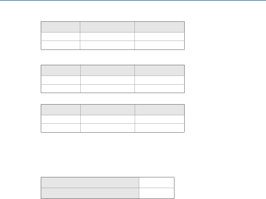
Models covered
The following Rosemount 3051SMV Transmitters are covered in this manual:
Table 1-1. Rosemount 3051SMV Measurement with Fully Compensated Mass and Energy Flow
Output
Measurement type Multivariable type - M
1Differential pressure, static pressure, temperature
2Differential pressure and static pressure
3Differential pressure and temperature
4Differential pressure
Table 1-2. Rosemount 3051SMV Measurement with Direct Process Variable Output
Measurement type Multivariable type - P
1Differential pressure, static pressure, temperature
2Differential pressure and static pressure
3Differential pressure and temperature
5Coplanar static pressure and temperature
6In-line static pressure and temperature

2
Reference Manual
00809-0100-4803, Rev GA
Introduction
September 2017
Introduction
1.2 Product recycling/disposal
Recycling of equipment and packaging should be taken into consideration and disposed of in accordance
with local and national legislation/regulations.

3
Reference Manual
00809-0100-4803, Rev GA
Configuration
September 2017
Configuration
Section 2 Configuration
Overview . . . . . . . . . . . . . . . . . . . . . . . . . . . . . . . . . . . . . . . . . . . . . . . . . . . . . . . . . . . . . . . . . . . . . . . . . . . . page 3
Safety messages . . . . . . . . . . . . . . . . . . . . . . . . . . . . . . . . . . . . . . . . . . . . . . . . . . . . . . . . . . . . . . . . . . . . . . page 4
Engineering Assistant installation . . . . . . . . . . . . . . . . . . . . . . . . . . . . . . . . . . . . . . . . . . . . . . . . . . . . . . . page 4
Flow configuration . . . . . . . . . . . . . . . . . . . . . . . . . . . . . . . . . . . . . . . . . . . . . . . . . . . . . . . . . . . . . . . . . . . . page 7
Basic device configuration . . . . . . . . . . . . . . . . . . . . . . . . . . . . . . . . . . . . . . . . . . . . . . . . . . . . . . . . . . . . . page 24
Detailed device configuration . . . . . . . . . . . . . . . . . . . . . . . . . . . . . . . . . . . . . . . . . . . . . . . . . . . . . . . . . . page 27
Variable configuration . . . . . . . . . . . . . . . . . . . . . . . . . . . . . . . . . . . . . . . . . . . . . . . . . . . . . . . . . . . . . . . . . page 38
Menu trees and Field Communicator Fast Keys . . . . . . . . . . . . . . . . . . . . . . . . . . . . . . . . . . . . . . . . . . . page 57
2.1 Overview
This section contains information for configuring the flow and device configuration for the Rosemount™
3051S MultiVariable™ Transmitter (Rosemount 3051SMV). Engineering Assistant installation and Flow
configuration instructions apply to Engineering Assistant version 6.3 or later. Basic device configuration,
Detailed device configuration, and Variable configuration are shown for AMS Device Manager version 9.0
or later, but also include Fast Key sequences for Field Communicator version 2.0 or later. Engineering
Assistant and AMS Device Manager screens are similar and follow the same instructions for use and
navigation. For convenience, Field Communicator Fast Key sequences are labeled “Fast Keys” for each
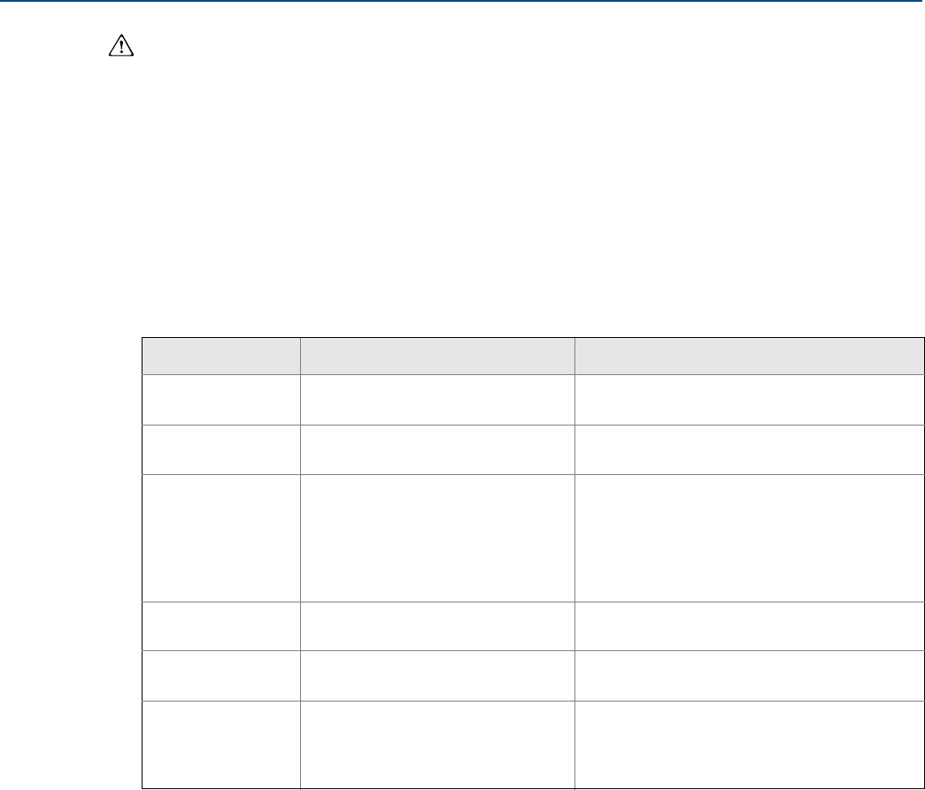
software function below the appropriate headings. The functionality of each host as show in Table 2-1:
Note
Coplanar transmitter configurations measuring gage pressure and process temperature (measurement
5) will report as the pressure as differential pressure. This will be reflected on the LCD display, nameplate,
digital interfaces, and other user interfaces.
Table 2-1. Host Functionality
• Available
— Not available
Multivariable
type Functionality
Rosemount 3051SMV
Engineering Assistant
AMS Device
Manager
Field
Communicator
Fully
compensated
mass and energy
flow (M)
Flow Configuration • • —
Device Configuration • • •
Test Calculation • • •
Calibration • • •
Diagnostics • • •
Direct process
variable output
(P)
Device Configuration — • •
Calibration — • •
Diagnostics — • •
4
Reference Manual
00809-0100-4803, Rev GA
Configuration
September 2017
Configuration
2.2 Safety messages
Procedures and instructions in this section may require special precautions to ensure the safety of the
personnel performing the operation. Information that raises potential safety issues is indicated with a
warning symbol ( ). Refer to the following safety messages before performing an operation preceded
by this symbol.
2.3 Engineering Assistant installation
2.3.1 Engineering Assistant version 6.3 or later
The Rosemount 3051SMV Engineering Assistant 6.3 or later is PC-based software that performs
configuration, maintenance, diagnostic functions, and serves as the primary communication interface to
the Rosemount 3051SMV with the fully compensated mass and energy flow feature board.
Failure to follow these installation guidelines could result in death or serious injury.
Make sure only qualified personnel perform the installation.
Explosions could result in death or serious injury.
Do not remove the transmitter cover in explosive atmospheres when the circuit is live.
Before connecting a Field Communicator in an explosive atmosphere, make sure the instruments in
the loop are installed in accordance with intrinsically safe or non-incendive field wiring practices.
Both transmitter covers must be fully engaged to meet flameproof/explosion-proof requirements.
Verify the operating atmosphere of the transmitter is consistent with the appropriate hazardous
locations certifications.
Electrical shock could cause death or serious injury.
If the sensor is installed in a high-voltage environment and a fault or installation error occurs, high
voltage may be present on the transmitter leads and terminals.
Use extreme caution when making contact with the leads and terminals.
Process leaks could result in death or serious injury.
Install and tighten all four flange bolts before applying pressure.
Do not attempt to loosen or remove flange bolts while the transmitter is in service.
Replacement equipment or spare parts not approved by Emerson™ for use as spare parts could
reduce the pressure retaining capabilities of the transmitter and may render the instrument
dangerous.
Use only bolts supplied or sold by Emerson as spare parts.
Improper assembly of manifolds to traditional flange can damage the device.
For safe assembly of manifold to traditional flange, bolts must break back plane of flange web
(i.e., bolt hole) but must not contact the sensor module.
Improper installation or repair of the SuperModule™ assembly with high pressure option (P0)
could result in death or serious injury.
For safe assembly, the high pressure SuperModule assembly must be installed with ASTM A193
Class 2 Grade B8M bolts and either a Rosemount 305 Manifold or a DIN-compliant traditional flange.
Static electricity can damage sensitive components.
Observe safe handling precautions for static-sensitive components.

5
Reference Manual
00809-0100-4803, Rev GA
Configuration
September 2017
Configuration
The Rosemount 3051SMV Engineering Assistant software is required to complete the flow
configuration.
2.3.2 Installation and initial setup
The following are the minimum system requirements to install the Rosemount 3051SMV Engineering
Assistant software:
Pentium-grade Processor: 500 MHz or faster
Operating system: Windows™ Professional 7, 8.1, 10
–32-bit
–64-bit
256 MB RAM
100 MB free hard disk space
RS232 serial port or USB port (for use with HART® modem)
CD-ROM
Installing the Rosemount 3051SMV Engineering Assistant version 6.3
or later
Engineering Assistant is available with or without the HART modem and connecting cables. The
complete Engineering Assistant package contains the software CD and one HART modem with cables
for connecting the computer to the Rosemount 3051SMV (See “Ordering information” on page 138.)
1. Uninstall any existing versions of Engineering Assistant 6 currently installed on the PC.
2. Insert the new Engineering Assistant disk into the CD-ROM.
3. Windows should detect the presence of a CD and start the installation program. Follow the on-screen
prompts to finish the installation. If Windows does not detect the CD, use Windows Explorer or My
Computer to view the contents of the CD-ROM, and then double select the SETUP.EXE program.
4. A series of screens (Installation Wizard) will appear and assist in the installation process. Follow the
on-screen prompts. It is recommended the default installation settings are used.
Note
Engineering Assistant version 6.3 or later requires the use of Microsoft® .NET Framework version 4.0 or
later. If .NET version 4.0 is not currently installed, the software will be automatically installed during the
Engineering Assistant installation. Microsoft .NET version 4.0 requires an additional 200 MB of disk
space.
6
Reference Manual
00809-0100-4803, Rev GA
Configuration
September 2017
Configuration
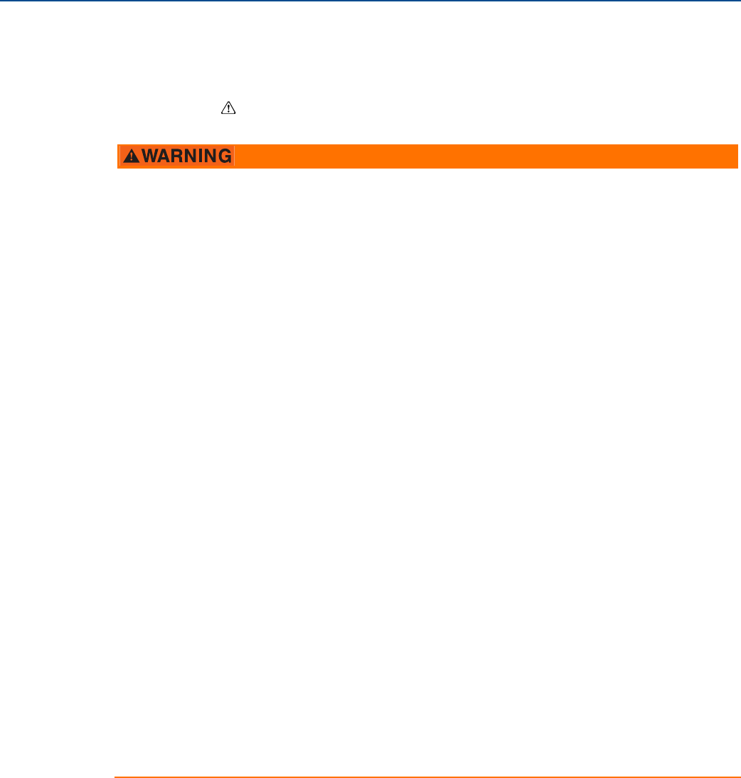
Connecting to a PC
Figure 2-1 shows how to connect a computer to a Rosemount 3051SMV.
Figure 2-1. Connecting a PC to the Rosemount 3051SMV
A. Power supply
B. HART modem
1. Remove the cover from the field terminals side of the housing.
2. Power the device as outlined in “Connect wiring and power up” on page 75.
3. Connect the HART modem cable to the PC.
4. On the side marked “Field Terminals,” connect the modem mini-grabbers to the two terminals
marked “PWR/COMM.”
5. Launch the Rosemount 3051SMV Engineering Assistant. For more information on launching
Engineering Assistant, see “Launching Engineering Assistant” on page 9.
6. Once the configuration is complete, replace cover and tighten until metal contacts metal to meet
flameproof/explosion-proof requirements. See “Cover installation” on page 69 for more information.
Rosemount 3051SMV without
optional process temperature
connection
Rosemount 3051SMV with optional
process temperature connection
A
RL ≥ 250Ω
B
A
RL ≥ 250Ω
B
7
Reference Manual
00809-0100-4803, Rev GA
Configuration
September 2017
Configuration
2.4 Flow configuration
2.4.1 Rosemount 3051SMV Engineering Assistant 6.3 or later
The Rosemount 3051SMV Engineering Assistant is designed to guide the user through the setup of the
flow configuration of a Rosemount 3051SMV. The flow configuration screens allow the user to specify
the fluid, operating conditions, and information about the primary element including the inside pipe
diameter. This information will be used by the Rosemount 3051SMV Engineering Assistant to create the
flow configuration parameters that can be sent to the transmitter or saved for future use.
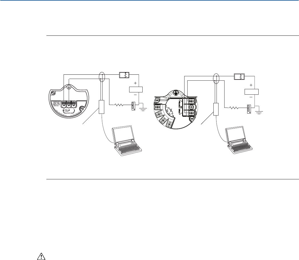
Figure 2-2 shows the path in which the Rosemount 3051SMV Engineering Assistant will guide the user
through a flow configuration. If a natural gas, custom liquid, or custom gas option is chosen, an extra
screen will be provided to specify the gas composition or fluid properties.
Figure 2-2. Flow Configuration Flowchart
NOTICE
To ensure correct operation, download the most current version of the Engineering Assistant software
at Emerson.com/Rosemount-Engineering-Assistant-6.
Start
Process fluid
selection
Natural gas Custom liquid
Custom gas
Custom gas or
custom liquid
fluid properties
Natural gas
composition
Fluid properties
(optional)
Database liquid
Database gas or
steam
Primary
element
selection
Save/Send
flow
configuration
Ideal gas
8
Reference Manual
00809-0100-4803, Rev GA
Configuration
September 2017
Configuration
Online and offline mode
The Engineering Assistant software can be used in two modes: online and offline. In online mode, the
user can receive the configuration from the transmitter, edit the configuration, send the changed
configuration to the transmitter, or save the configuration to a file. In offline mode, the user may create a
new flow configuration and save the configuration to a file or open and modify an existing file.
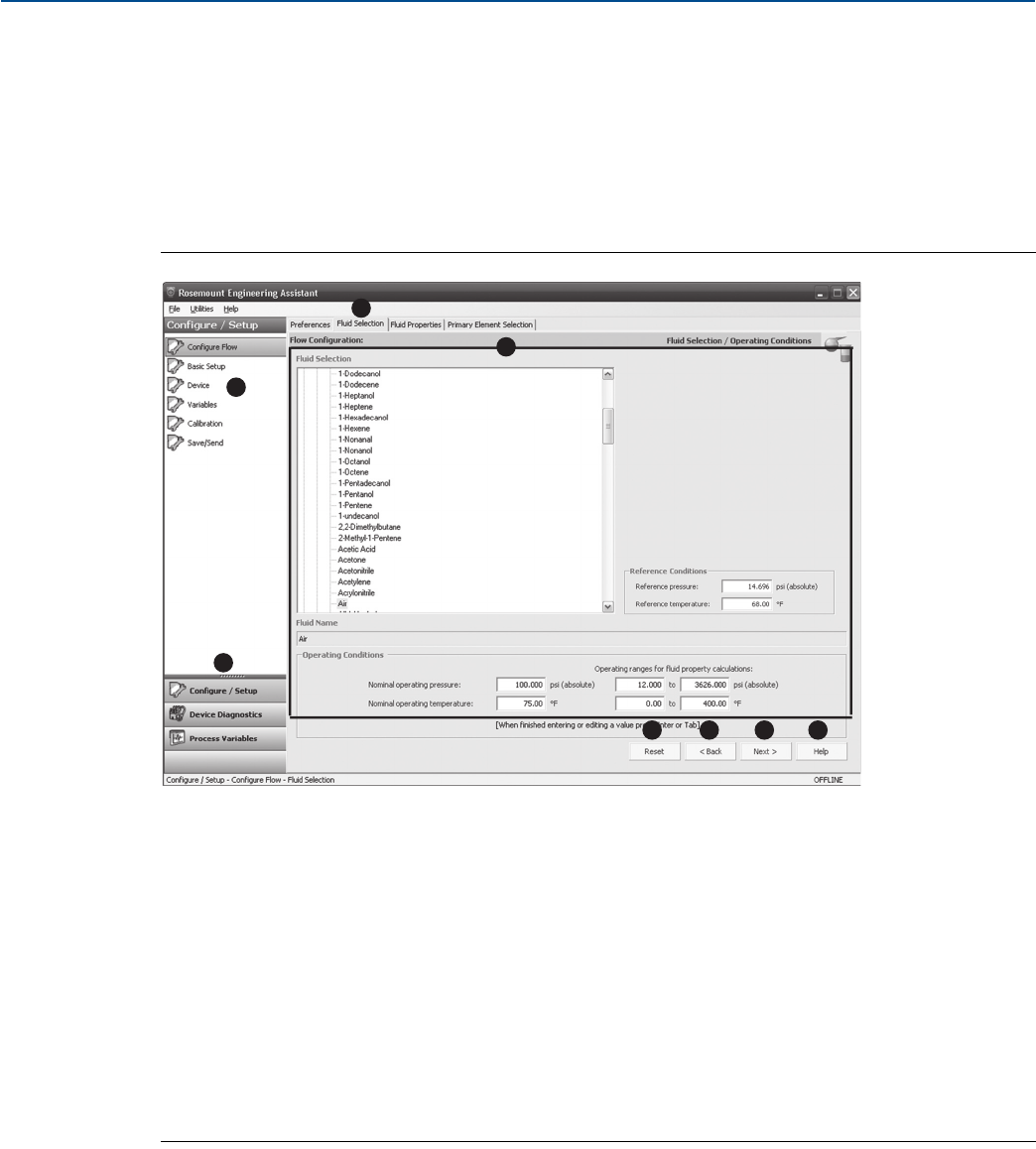
2.4.2 Basic navigation overview
Figure 2-3. Engineering Assistant Basic Navigation Overview
The Engineering Assistant software can be navigated in a variety of ways. The numbers below correspond to the numbers shown in
Figure 2-3.
A. The navigation tabs contain the flow configuration information. In offline mode, each tab will not become active until the
required fields on the previous tab are completed. In online mode, these tabs will be functional unless a change on a preceding
tab is made.
B. The Reset button will return each field within all of the flow configuration tabs (Fluid Selection, Fluid Properties, and Primary
Element Selection) to the values initially displayed at the start of the configuration.
a. If editing a previously saved flow configuration, the values will return to those that were last saved.
b. If starting a new flow configuration, all entered values will be erased.
C. The Back button is used to step backward through the flow configuration tabs.
D. The Next button is used to step forward through the flow configuration tabs. The Next button will not become active until all
required fields on the current page are completed.
E. The Help button may be selected at any time to get a detailed explanation of the information required on the current
configuration tab.
F. Any configuration information that needs to be entered or reviewed will appear in this portion of the screen.
G. These menus navigate to the Configure Flow, Basic Setup, Device, Variables, Calibration, and Save/Send tabs.
H. These buttons navigate to Config/Setup, Device Diagnostics, or Process Variables sections.
A
BCDE
G
H
F
9
Reference Manual
00809-0100-4803, Rev GA
Configuration
September 2017
Configuration
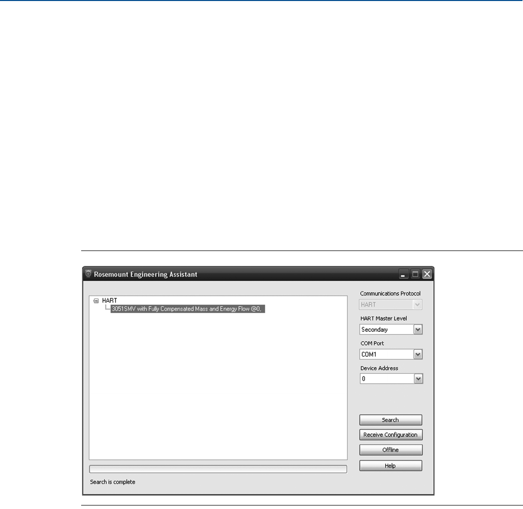
2.4.3 Launching Engineering Assistant
Flow configuration for the Rosemount 3051SMV is achieved by launching the Engineering Assistant
Software from the START menu. The following steps show how to open the Engineering Assistant
Software, and connect to a device:
1. Select the Start menu > All Programs > Engineering Assistant. Engineering Assistant will open to
screen as shown in Figure 2-4.
2. If working offline, select the Offline button located on the bottom of the screen as shown in
Figure 2-4.
OR
If working online, select the Search button located on the lower right corner of the screen as shown in
Figure 2-4. Engineering Assistant will begin to search for online devices. When the search is
completed, select the device to communicate with and select Receive Configuration button.
The HART Master Level can be set to either primary or secondary. Secondary is the default and should be
used when the transmitter is on the same segment as another HART communication device. The COM
Port and device address may also be edited as needed.
Figure 2-4. Engineering Assistant Device Connection Screen
2.4.4 Preferences
The Preferences tab, shown in Figure 2-5 on page 10, allows the user to select the preferred engineering
units to display and specify flow configuration information.
Select the preferred engineering units. If units are needed other than the default U.S. or S.I. units, use
the Custom Units setting. If Custom Units are selected, configure the Individual Parameters using the
drop-down menus.
Unit preferences selected will be retained for future Engineering Assistant sessions. Check the box to
prevent the Preferences tab from being automatically shown in future sessions. The Preferences are
always available by select the Preferences tab.

11
Reference Manual
00809-0100-4803, Rev GA
Configuration
September 2017
Configuration
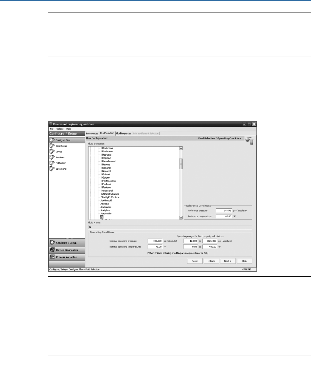
Note
The following example will show a flow configuration for an application with database gas air as the
process fluid and a Rosemount 405C Conditioning Orifice Plate as the primary element. The procedure
to configure an application with other fluids and other primary elements will be similar to this example.
Natural gases, custom liquids, and custom gases require additional steps during the configuration. See
“Other fluid configurations” on page 18 for more information.
1. Engineering Assistant may open to the Preferences tab. Using the tabs at the top of the screen,
navigate to the Fluid Selection tab.
2. Expand the Gas category (select the + icon).
3. Expand the Database Gas category.
4. Select the appropriate fluid (Air for this example) from the list of database fluids.
Figure 2-7. Fluid Selection Tab - Database Gas Air
5. Enter the Nominal Operating Pressure, select the Enter or Tab key.
Note
The nominal operating pressure must be entered in absolute pressure units.
6. Enter the Nominal Operating Temperature, select the Enter or Tab key. Engineering Assistant will
automatically fill in suggested operating ranges, as shown in . These values may be edited as needed
by the user.
7. Verify the Reference Conditions are correct for the application. These values may be edited as needed.
Note
Reference pressure and temperature values are used by Engineering Assistant to convert the flow rate
from mass units to mass units expressed as standard or normal volumetric units.
8. Select Next > to proceed to the Fluid Properties tab.

12
Reference Manual
00809-0100-4803, Rev GA
Configuration
September 2017
Configuration
Table 2-2. Liquids and Gases Database
1,1,2,2–Tetrafluoroethane Acrylonitrile Formaldehyde Nitrous Oxide
1,1,2–Trichloroethane Air Formic Acid Nonanal
1,2,4–Trichlorobenzene Allyl Alcohol Furan n–Butane
1,2–Butadiene Ammonia Helium–4 n–Butanol
1,2–Propylene Glycol Aniline Hydrazine n–Butyraldehyde
1,3–Propylene Glycol Argon Hydrogen n–Butyronitrile
1,3,5–Trichlorobenzene Benzene Hydrogen Chloride n–Decane
1,3–Butadiene Benzaldehyde Hydrogen Cyanide n–Dodecane
1,4–Dioxane Benzyl Alcohol Hydrogen Peroxide n–Heptadecane
1,4–Hexadiene Biphenyl Hydrogen Sulfide n-Heptane
1–Butene Bromine Isobutane n–Hexane
1–Decanol Carbon Dioxide Isobutylbenzene n-Nonane
1–Decene Carbon Monoxide Isohexane n–Octane
1–Dodecanol Carbon Tetrachloride Isoprene n–Pentane
1–Dodecene Chlorine Isopropanol Oxygen
1–Heptanol Chlorotrifluoroethylene Melamine Pentafluoroethane
1–Heptene Chloroprene Methane Phenol
1–Hexadecanol Cycloheptane Methanol Propane
1–Hexene Cyclohexane Methyl Acrylate Propadiene
1–Octanol Cyclopentane Methyl Ethyl Ketone Pyrene
1–Octene Cyclopentene Methyl Vinyl Ether Propylene
1–Nonanol Cyclopropane m–Chloronitrobenzene p-Nitroaniline
1–Pentadecanol Decanal m–Dichlorobenzene Sorbitol
1–Pentanol Divinyl Ether Neon Styrene
1–Pentene Ethane Neopentane Sulfur Dioxide
1–Undecanol Ethanol Nitric Acid Toluene
2,2–Dimethylbutane Ethylamine Nitric Oxide Trichloroethylene
2–Methyl–1–Pentene Ethylbenzene Nitrobenzene Vinyl Acetate
Acetic Acid Ethylene Nitroethane Vinyl Chloride
Acetone Ethylene Glycol Nitrogen Vinyl Cyclohexane
Acetonitrile Ethylene Oxide Nitrogen Trifluoride Vinylacetylene
Acetylene Fluorene Nitromethane Water
13
Reference Manual
00809-0100-4803, Rev GA
Configuration
September 2017
Configuration
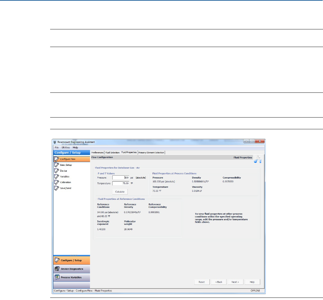
2.4.6 Fluid properties
Note
The Fluid Properties tab is an optional step and is not required to complete a flow configuration.
The Fluid Properties tab for the database gas air is shown in Figure 2-8. The user may view the properties
of the chosen fluid. The fluid properties are initially shown at nominal conditions. To view density, com-
pressibility, and viscosity of the selected fluid at other pressure and temperature values, enter a Pressure
and Temperature and select Calculate.
Note
Changing the pressure and temperature values on the Fluid Properties tab does not affect the flow
configuration.
Figure 2-8. Fluid Properties Tab
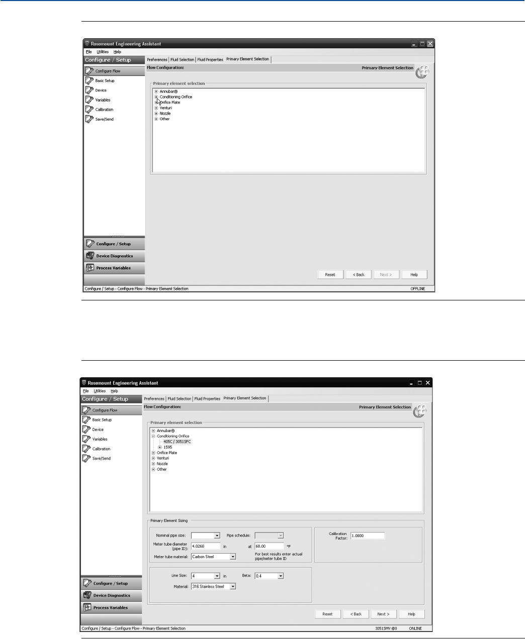
2.4.7 Primary element selection
The Primary Element Selection tab shown in Figure 2-9 on page 14 allows the user to select the primary
element that will be used with the Rosemount 3051SMV. This database of primary elements includes:
Rosemount proprietary elements such as the Rosemount Annubar™ and the conditioning orifice plate
Standardized primary elements such as ASME, ISO, and AGA primary elements
Other proprietary primary elements
14
Reference Manual
00809-0100-4803, Rev GA
Configuration
September 2017
Configuration
Figure 2-9. Primary Element Selection Tab
Continuing with the example configuration:
1. Expand the Conditioning Orifice category.
Figure 2-10. Primary Element Selection Tab - 405C/3051SFC

15
Reference Manual
00809-0100-4803, Rev GA
Configuration
September 2017
Configuration
2. Select 405C/3051SFC.
3. Enter the Measured Meter Tube Diameter (pipe ID) at a Reference Temperature. If the meter tube
diameter cannot be measured, select a Nominal Pipe Size and Pipe Schedule to input an estimated
value for the meter tube diameter (U.S. units only).
4. If necessary, edit the Meter Tube Material.
5. Enter the Line Size and select the Beta of the Conditioning Orifice Plate. The required primary element
sizing parameters will be different depending on what primary element is selected.
6. If necessary, select a Primary Element Material from the drop-down menu.
7. A calibration factor may be entered if a calibrated primary element is being used.
Note
A Joule-Thomson Coefficient can be enabled to compensate for the difference in process temperature
between the orifice plate location and the process temperature measurement point. The Joule-Thomson
Coefficient is available with ASME MFC-3M-2 (2004) or ISO 5167-2.2003 (E) orifice plates used with
Database Gases, Superheated Steam, or AGA DCM/ISO Molar Composition Natural Gas. For more
information on the Joule-Thomson Coefficient, reference the appropriate orifice plate standard.
8. Select Next > to advance to the Save/Send Configuration tab.
Note
To be in compliance with appropriate national or international standards, beta ratios and differential
producer diameters should be within the limits as listed in the applicable standards. The Engineering
Assistant software will alert the user if a primary element value exceeds these limits, but will allow the
user to proceed with the flow configuration.
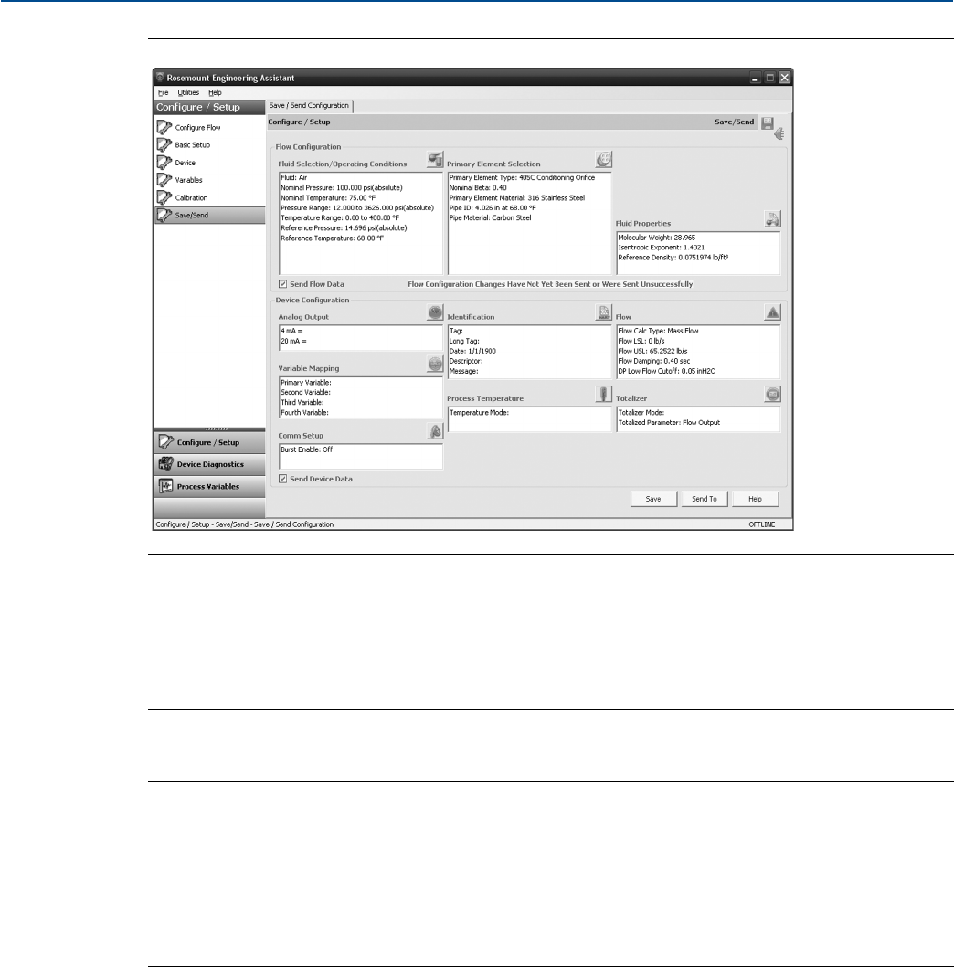
2.4.8 Save/send
The Save/Send Configuration tab shown in Figure 2-11 on page 16 allows the user to view, save, and send
the configuration information to the Rosemount 3051SMV with the fully compensated mass and energy
flow feature board.
1. Review the information under the Flow Configuration heading and Device Configuration heading.
Note
For more information on device configuration, see “Basic device configuration” on page 24.
16
Reference Manual
00809-0100-4803, Rev GA
Configuration
September 2017
Configuration
Figure 2-11. Save/Send Configuration Tab (Offline Mode)
2. Select the icon above each window to be taken to the appropriate screen to edit the configuration
information. To return to the Save/Send tab, select Save/Send in the left menu.
3. When all information is correct, see “Sending a configuration in offline mode” on page 16 or “Sending
a configuration in online mode” on page 17.
Note
The user will be notified if the configuration has been modified since it was last sent to the transmitter. A
warning message will be shown to the right of the Send Flow Data and/or Send Device Data check boxes.
Sending a configuration in offline mode
1. To send the configuration, select the Send To button.
Note
The Send Flow Data and/or Send Device Data check boxes can be used to select what configuration data is
sent to the transmitter. If the check box is unselected, the corresponding data will not be sent.
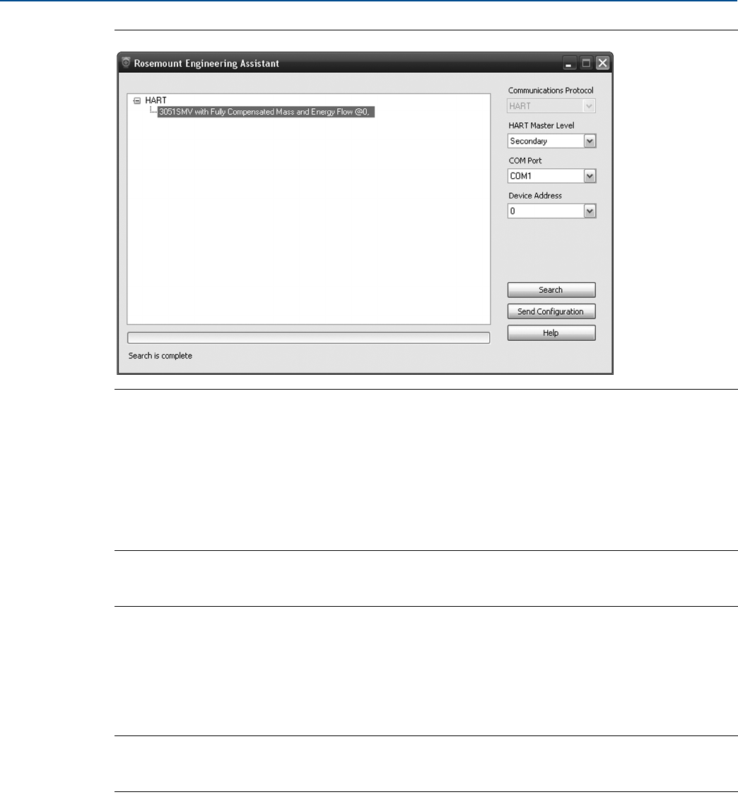
2. The Engineering Assistant Device Connection screen will appear, see Figure 2-12 on page 17.
17
Reference Manual
00809-0100-4803, Rev GA
Configuration
September 2017
Configuration
Figure 2-12. Engineering Assistant Device Connection Screen
3. Select the Search button located in the lower right corner of the screen. Engineering Assistant will
begin to search for connected devices.
4. When the search is completed, select the device to communicate with and select Send
Configuration button.
5. Once the configuration is finished being sent to the device, a notification appears.
6. If finished with the configuration process, close Engineering Assistant.
Note
After the configuration is sent to the device, saving the configuration file is recommended. For more
information on saving a configuration file, see “Saving a configuration” on page 17.
Sending a configuration in online mode
1. To send the configuration, select the Send button. Once the configuration is finished being sent to
the device, a notification appears.
2. If finished with the configuration process, close Engineering Assistant.
Note
After the configuration is sent to the device, saving the configuration file is recommended. For more
information on saving a configuration file, see “Saving a configuration”.
Saving a configuration
1. To save the configuration, select the Save button.
2. Navigate to the save location for the configuration file, give the file a name, and select Save. The
configuration will be saved as a “.smv” file type.
18
Reference Manual
00809-0100-4803, Rev GA
Configuration
September 2017
Configuration
Sending a saved configuration
1. To send a saved configuration, open Engineering Assistant in offline mode and select File>Open.
2. Navigate to the saved .smv file to be sent. Select Open.
3. The Engineering Assistant Device Connection screen will appear, see Figure 2-12 on page 17.
4. Select the Search button located in the lower right corner of the screen. Engineering Assistant will
begin to search for connected devices.
5. When the search is completed, select the device to communicate with and select Send
Configuration button.
6. Once the configuration is finished being sent to the device, a notification appears.
7. If finished with the configuration process, close Engineering Assistant.
2.4.9 Other fluid configurations
Natural gas AGA No. 8 detail characterization or ISO 12213, molar
composition flow configuration
1. Expand the Gas category.
2. Expand the Natural Gas category.
3. Select AGA Report No. 8 Detail Characterization Method or ISO 12213, Molar Composition
Method.
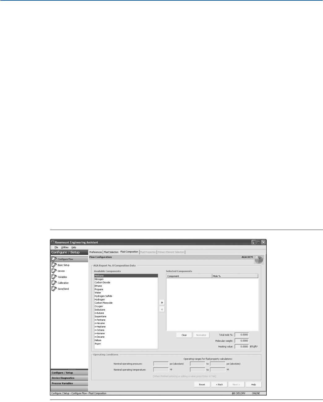
4. Select Next > to proceed to the Fluid Composition tab. Figure 2-13 shows an example of the Fluid
Composition tab for AGA Report No. 8 Detail Characterization Method. The ISO 12213, Molar
Composition Method Fluid Composition tab will require the same information.
Figure 2-13. Fluid Composition Tab
19
Reference Manual
00809-0100-4803, Rev GA
Configuration
September 2017
Configuration
5. In the Available Components window, select the required components and move them into the
Selected Components window using the >> button. The << button moves the components back to the
Available Components window. The Clear button moves all components back to the Available
Components window.
6. After all required components are in the Selected Components window, begin assigning the percent
composition of each component in the Mole % column.
Note
These percent composition values should add to 100 percent. If they do not, select the Normalize
button. This will adjust the mole percentages proportionally to a total of 100 percent.
7. Enter the Nominal Operating Pressure, then the Nominal Operating Temperature as the entry blanks
become available. Engineering Assistant will automatically fill in suggested operating ranges. These
values may be edited by the user.
Note
In order to comply with the AGA requirements the calculation accuracy must be within ±50 ppm
(±0.005%). This is stated in AGA Report No. 3, Part 4, Section 4.3.1. The pressure and temperature
operating ranges will be autofilled to comply with the standard.
8. Select Next >. This will bring the user to the Fluid Properties tab.
9. Proceed with the steps in “Fluid properties” on page 13.
Natural gas AGA No. 8 gross characterization flow configuration
method 1, method 2, and natural gas ISO 12213, physical properties
(SGERG 88) flow configuration
1. Expand the Gas category.
2. Select AGA No. 8 Gross Characterization Method 1, AGA No. 8 Gross Characterization Method 2,
or ISO 12213, Physical Properties (SGERG 88).
3. Select Next to proceed to the Fluid Composition tab.
4. Enter the required data for the Natural Gas Characterization Method that was selected in Step 2.
Required data for each method is listed in Table 2-3.
Table 2-3. Required and Optional Data for Natural Gas Characterization Methods
Characterization method Required data Optional data
AGA Report No. 8 Gross
Characterization Method 1
Relative Density(1)
Mole Percent CO2
Volumetric Gross Heating Value(2)
1. Reference conditions for the relative density are 60 °F (15.56 °C) and 14.73 psia (101.56 kPa).
2. Reference conditions for the molar gross heating value are 60 °F (15.56 °C) and 14.73 psia (101.56 kPa) and reference conditions for molar
density are 60 °F (15.56 °C) and 14.73 psia (101.56 kPa).
Mole Percent CO
Mole Percent Hydrogen
AGA Report No. 8 Gross
Characterization Method 2
Relative Density(1)
Mole Percent CO2
Mole Percent Nitrogen
Mole Percent CO
Mole Percent Hydrogen
ISO 12213,
Physical Properties (SGERG 88)
Relative Density(1)
Mole Percent CO2
Volumetric Gross Heating Value(2)
Mole Percent CO
Mole Percent Hydrogen
20
Reference Manual
00809-0100-4803, Rev GA
Configuration
September 2017
Configuration
5. If appropriate, enter the optional data for the Natural Gas Characterization Method that was selected
in Step 2. Optional data for each method is listed in Table 2-3 on page 19.
6. Enter the Nominal Operating Pressure, then the Nominal Operating Temperature as the entry blanks
come available. Engineering Assistant will automatically fill in suggested operating ranges. Note that
these values may be edited by the user.
7. Select Next. This will open the Fluid Properties tab.
8. Proceed with the steps in “Fluid properties” on page 13.
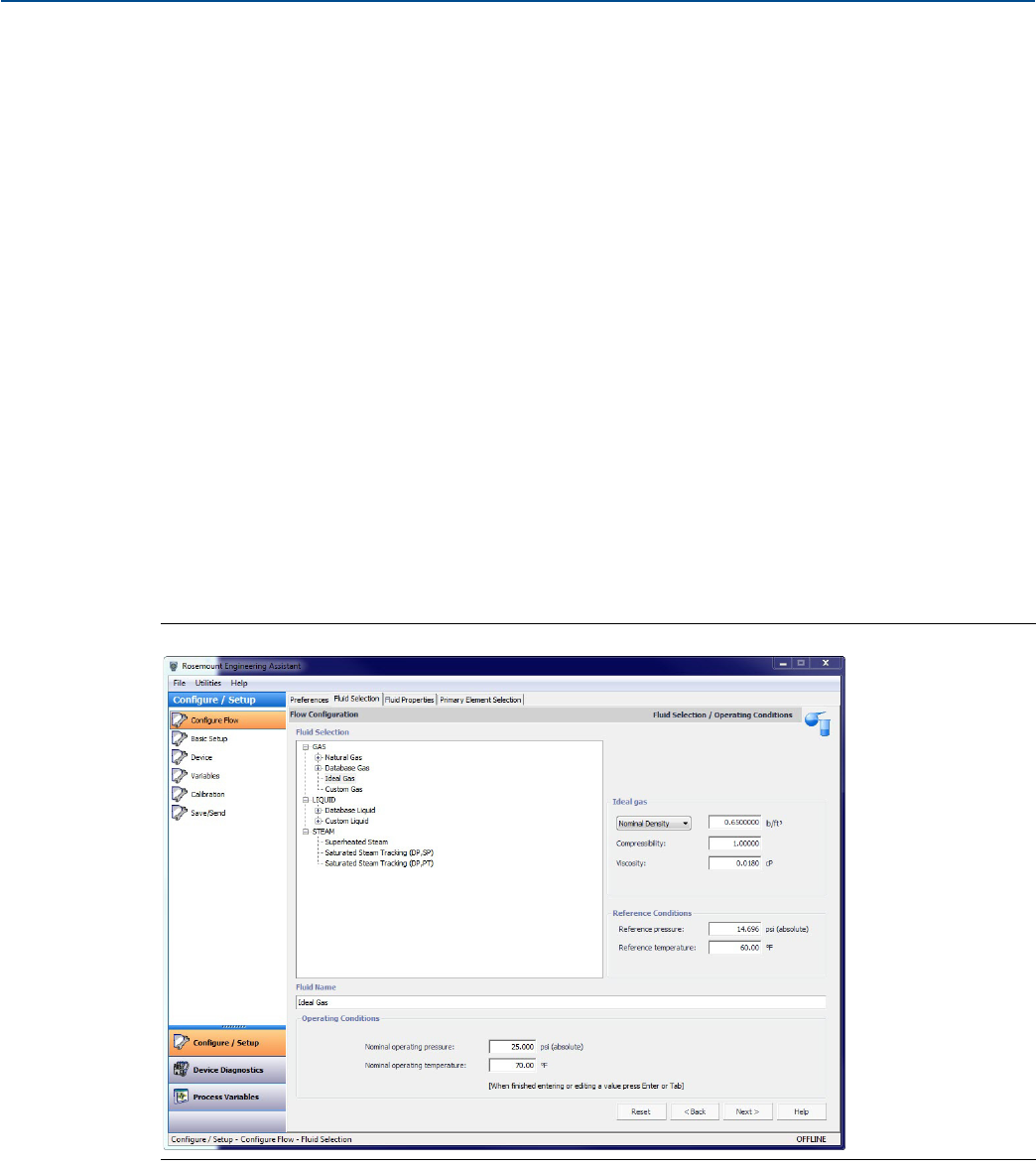
Ideal gas
The ideal gas option should be used when the fluid behavior can be modeled by the ideal gas law. This
option uses a modified version of the ideal gas law with a constant value of compressibility. The default
value for compressibility is 1.00 but it may be edited by the user. To use an ideal gas enter in the
operating pressure and temperature followed by either the density, specific gravity, or molecular weight.
1. Expand the GAS category.
2. Select the Ideal Gas option.
3. Enter the Nominal Operating Pressure and Temperature Ranges. Engineering Assistant will use these
ranges to identify the pressure and temperature values at which the fluid properties are required.
For the ideal gas being used the nominal density, specific gravity, or molecular weight must now be
entered using the drop-down menu. Once these are entered the other data entry fields, compressibility
and viscosity, are enabled as shown on Figure 2-14.
Figure 2-14. Fluid Selection Ideal Gas
4. Adjust the compressibility and viscosity to fit the ideal gas of the process.
5. Select Next to proceed to the Fluid Properties tab.
21
Reference Manual
00809-0100-4803, Rev GA
Configuration
September 2017
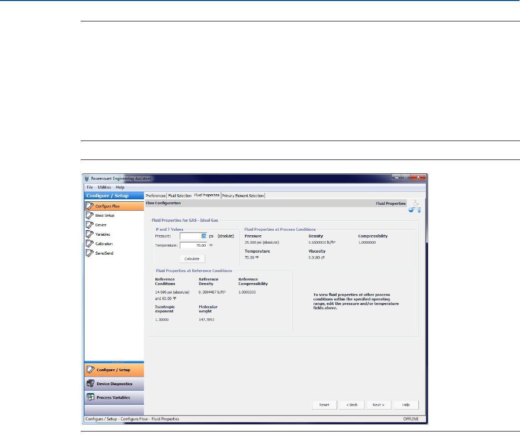
Configuration
Note
The Fluid Properties tab is an optional step and is not required to complete a flow configuration.
The Fluid Properties tab for the database gas air is shown in Figure 2-15. The user may view the
properties of the chosen fluid. The fluid properties are initially shown at nominal conditions. To view
density, compressibility, and viscosity of the selected fluid at other pressure and temperature values,
enter a Pressure and Temperature and select Calculate.
Changing the pressure and temperature values on the Fluid Properties tab does not affect the flow
configuration.
Figure 2-15. Fluid Properties Tab
6. Select Next to continue with the flow configuration on the Primary Element Selection tab.
7. Proceed with the steps in “Primary element selection” on page 13.
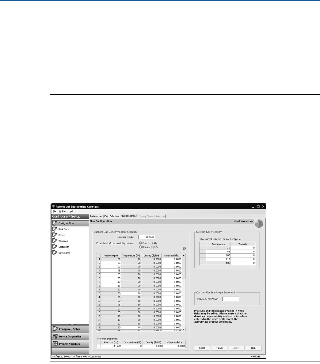
Custom gas
The custom gas option should be used for fluids not in the database such as proprietary fluids or gas
mixtures. To properly calculate the fluid properties, the compressibility factor or density needs to be
entered at specific pressure and temperature values based on the operating ranges entered by the user.
The pressure and temperature values may be edited as needed. The editable values are shown in fields
with white backgrounds. For best performance, it is recommended that, whenever possible, the com-
pressibility or density values be entered at the suggested pressure and temperature values.
To ease entering the compressibility/density or viscosity values, data can be copied from a spreadsheet
and pasted into the grid. The recommended process is to copy the pressure and temperature values
from the table on the Engineering Assistant screen to assist in computing the density or compressibility
values. Once the compressibility or density values are computed, they may then be copied from the
spreadsheet and pasted into the grid on the Custom Gas Fluid Properties tab.
22
Reference Manual
00809-0100-4803, Rev GA
Configuration
September 2017
Configuration
1. Expand the Gas category.
2. Select the Custom Gas option.
3. Enter the Nominal Operating Pressure and Temperature Ranges. Engineering Assistant will use these
ranges to identify the pressure and temperature values at which the fluid properties are required.
4. Select Next to proceed to the Custom Gas Fluid Properties tab.
5. Enter the Molecular Weight of the Custom Gas. When the molecular weight of the gas is entered, the
other data entry fields on the tab are enabled as shown in Figure 2-16 on page 22.
6. Select either Density or Compressibility and enter data.
Note
All pressure and temperature values may be edited except the minimum and maximum values. The
minimum and maximum values were set on the Fluid Selection tab.
7. Enter the Density or Compressibility at reference conditions.
8. Enter the Custom Gas Viscosity at the given temperatures. Note that all temperature values may be
edited except the minimum and maximum temperatures.
9. Enter the Custom Gas Isentropic Exponent.
10.Select Next to continue with the flow configuration on the Primary Element Selection tab.
11.Proceed with the steps in “Primary element selection” on page 13.
Figure 2-16. Custom Gas Fluid Properties Tab
23
Reference Manual
00809-0100-4803, Rev GA
Configuration
September 2017
Configuration
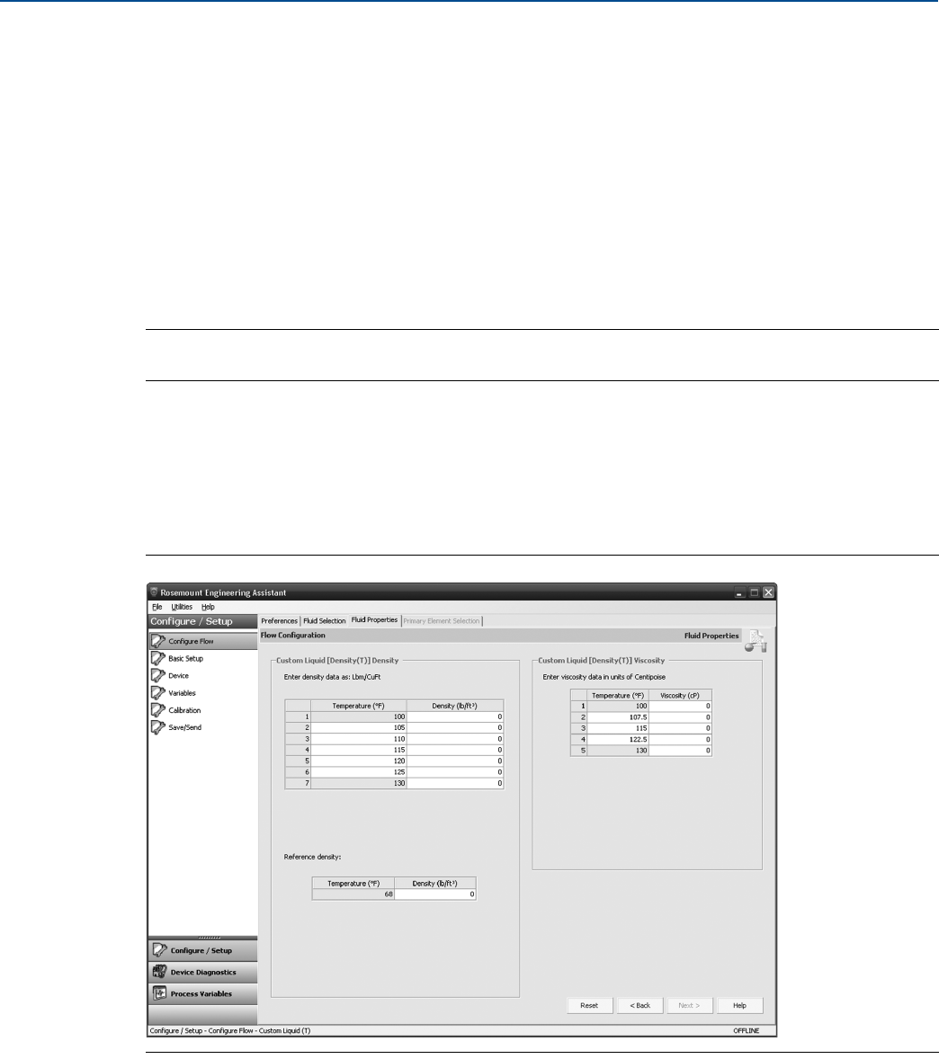
Custom liquid (Density [T])
The Custom Liquid option should be used for fluids not in the database such as proprietary fluids.
1. Expand the Liquid category.
2. Expand the Custom Liquid category.
3. Select the Custom Liquid (Density [T]) option.
4. Enter the Nominal and Operating Temperature Range. Engineering Assistant will use this range to
identify the temperature values at which the fluid properties are required.
5. Select Next to continue the flow configuration on the Fluid Properties tab.
6. Enter the Custom Liquid Density at the given temperatures.
Note
All temperature values may be edited except the minimum and maximum temperatures.
7. Enter the Reference Density at the reference temperature.
8. Enter the Custom Liquid Viscosity at the given temperatures. Note that all temperature values may be
edited except the minimum and maximum temperatures. The minimum and maximum values were
set on the Fluid Selection tab.
9. Proceed with the steps in “Primary element selection” on page 13.
Figure 2-17. Custom Liquid (Density [T]) Fluid Properties Tab
24
Reference Manual
00809-0100-4803, Rev GA
Configuration
September 2017
Configuration
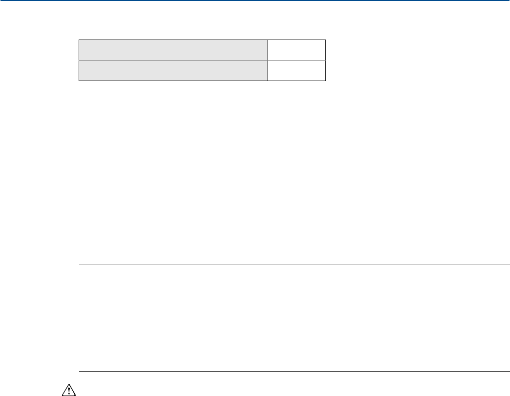
2.5 Basic device configuration
This section provides procedures for configuring the basic requirements to commission the Rosemount
3051SMV. The Basic Setup tab, shown in Figure 2-18 on page 25, can be used to perform all of the
required transmitter configuration. The complete list of Field Communicator Fast Keys for basic setup are
shown in Table 2-13 on page 62 and Table 2-14 on page 63.
Based on the configuration ordered, some measurements (i.e. static pressure, process temperature)
and/or calculation types (i.e. mass, volumetric, and energy flow) may not be available for all fluid types.
Available measurements and/or calculation types are determined by the multivariable type and
measurement type codes ordered. See “Ordering information” on page 138 for more information.
All screens in this section are shown for multivariable type M (fully compensated mass and energy flow)
with measurement type 1 (differential pressure, static pressure, and process temperature). Field
Communicator Fast Keys are given for both multivariable type M and P (direct process variable output)
with measurement type 1. Field Communicator Fast Keys and screens for other multivariable types and
measurement types may vary.
Note
All screen shots in this section will be shown using AMS Device Manager. Engineering Assistant screens
are similar and the instructions shown here apply to both AMS Device Manager and Engineering
Assistant.
When using Engineering Assistant, a Reset Page button will be shown. In online mode, the Reset Page
button will return all values on tab to the initial values received from the device before the start of the
configuration. If editing a previously saved configuration, the Reset Page button will return all values on
tab to those that were last saved. If starting a new configuration, all entered values on tab will be erased.
When information is edited on any AMS Device Manager tab, it will be highlighted in yellow. Edited
information is not sent to the transmitter until the Apply or OK button is selected.
Units of measure
If a unit of measure is edited and the Apply button is selected, the unit of measure will be changed in the
device memory and on screen, but the value may take up to 30 seconds to be updated on the AMS
Device Manager screen.
Mass and energy flow Fast Keys 1, 3
Direct process variable output Fast Keys 1, 3
25
Reference Manual
00809-0100-4803, Rev GA
Configuration
September 2017
Configuration
Figure 2-18. Basic Setup Tab
Verify the Device Tag information. The tag information is used to identify specific transmitters on the
4–20 mA loop. This tag information may be edited.
Under the Flow Rate heading (fully compensated mass and energy flow feature board only), the type of
flow calculation (mass or volumetric) is displayed by the indicators on the right side of the box. The
Flow Calculation Type may be edited by selecting the Configure Flow Calculation Type button. The
Damping and Units of the Flow Rate may also be edited under this heading.
Note
The flow calculation within the device uses undamped process variables. Flow rate damping is set
independently of measured process variables.

26
Reference Manual
00809-0100-4803, Rev GA
Configuration
September 2017
Configuration
Under the Energy Rate heading (fully compensated mass and energy flow feature board only), the Units
and Damping for the Energy Rate may be edited.
Note
Energy rate calculations are only available for steam and natural gas.
The energy rate calculation within the device uses undamped process variables. Energy rate damping is
set independently of flow rate damping or measured process variables.
Under the Differential Pressure heading, the Units and Damping for the Differential Pressure may be
edited.
Under the Static Pressure heading, the Units for both absolute and gage pressure and static pressure
Damping may be edited.
Note
Both absolute and gage pressure are available as variables. The type of transmitter ordered will
determine which variable is measured and which is calculated based on the user defined atmospheric
pressure. For more information on configuring the atmospheric pressure, see “Static pressure” on
page 53. Since only one of the static pressures is actually being measured, there is a single damping
setting for both variables which may be edited under the Static Pressure heading.
Under the Process Temperature heading, the Units and Damping for the Process Temperature may be
edited.
Under the Module Temperature heading, the Units for the sensor module temperature may be set. The
sensor module temperature measurement is taken within the module, near the differential pressure
and/or static pressure sensors and can be used to control heat tracing or diagnose device overheating.
Under the Analog Output heading, the primary variable can be selected from the drop down menu and
the upper and lower range values (4 and 20 mA points) for the primary variable may be edited.
Under the Totalizer heading (fully compensated mass and energy flow feature board only), the Totalizer
can be configured by selecting the Configure Totalizer button. This button allows the user to select
the variable to be totalized. The Totalizer Units may also be edited under this heading.
27
Reference Manual
00809-0100-4803, Rev GA
Configuration
September 2017
Configuration
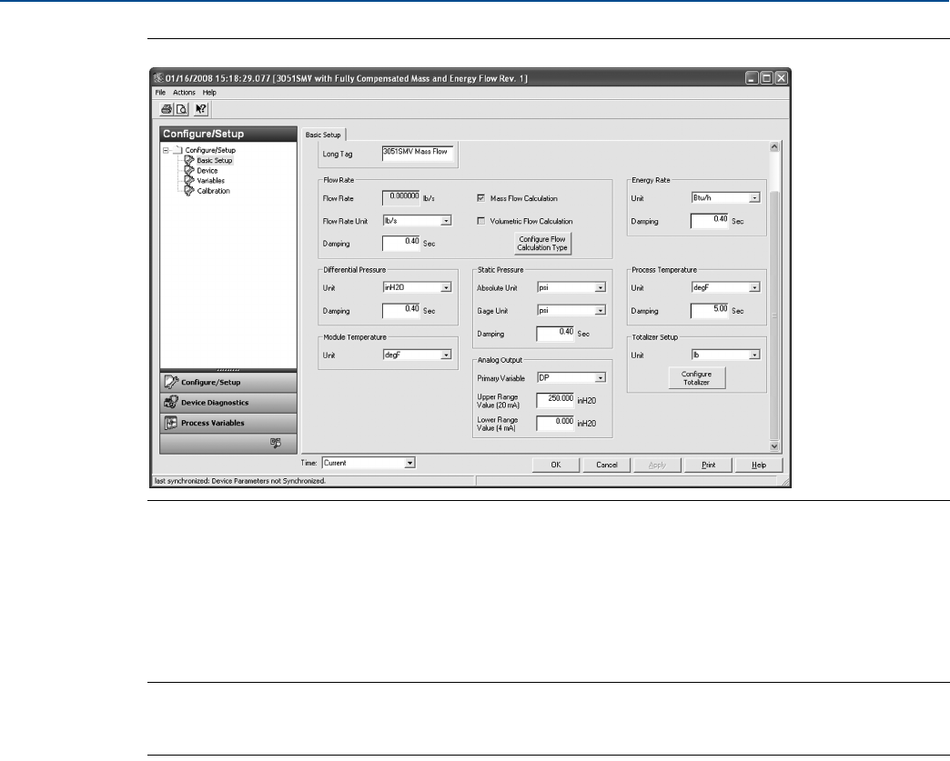
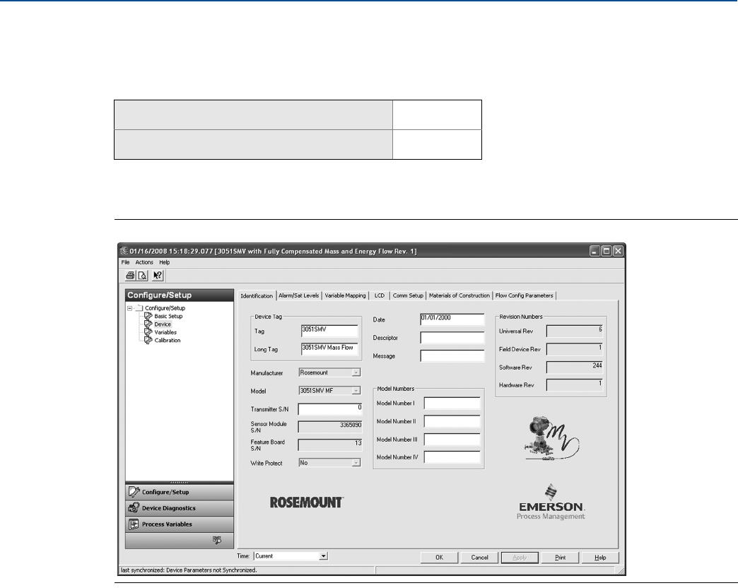
2.6 Detailed device configuration
2.6.1 Model identification
The Identification tab displays the device identification information on one screen. The fields with white
backgrounds may be edited by the user.
Figure 2-19. Device - Identification Tab
2.6.2 Alarm and saturation
The Rosemount 3051SMV automatically and continuously performs self-diagnostic routines. If the
self-diagnostic routines detect a failure, the transmitter drives the output to the configured alarm value.
The transmitter will also drive the output to configured saturation values if the primary variable goes
outside the 4–20 mA range values.
The alarm and saturation settings can be configured using Engineering Assistant, AMS Device Manager,
or a Field Communicator. See “Alarm and saturation level configuration” on page 28 for more
information. The alarm direction can be configured using the hardware switch on the feature board. See
“Configure security (write protect)” on page 67 for more information on the hardware switch.
The Rosemount 3051SMV has three options for alarm and saturation levels:
Rosemount (Standard), see Table 2-4 on page 28
NAMUR, see Table 2-5 on page 28
Custom (user-defined), see Table 2-6 on page 28
Mass and energy flow Fast Keys 1, 3, 5
Direct process variable output Fast Keys 1, 3, 5
28
Reference Manual
00809-0100-4803, Rev GA
Configuration
September 2017
Configuration
The following limitations exist for custom levels:
Low alarm level must be less than the low saturation level
High alarm level must be higher than the high saturation level
Alarm and saturation levels must be separated by at least 0.1 mA
Alarm and saturation level configuration
The Alarm/Sat Levels tab allows the Alarm and Saturation Levels to be configured. To change alarm/satu-
ration level settings, select the Config Alarm/Sat Levels button.
Table 2-4. Rosemount (Standard) Alarm and Saturation Values
Level Saturation Alarm
Low 3.9 mA ≤ 3.75 mA
High 20.8 mA ≥ 21.75 mA
Table 2-5. NAMUR-Compliant Alarm and Saturation Values
Level Saturation Alarm
Low 3.8 mA ≤ 3.6 mA
High 20.5 mA ≥ 22.5 mA
Table 2-6. Custom Alarm and Saturation Values
Level Saturation Alarm
Low 3.7 mA — 3.9 mA 3.6 mA — 3.8 mA
High 20.1 mA — 22.9 mA 20.2 mA — 23.0 mA
Mass and energy flow Fast Keys 1, 4, 2, 6, 6
Direct process variable output Fast Keys 1, 4, 2, 6, 6

29
Reference Manual
00809-0100-4803, Rev GA
Configuration
September 2017
Configuration
Figure 2-20. Device - Alarm/Sat Levels Tab
30
Reference Manual
00809-0100-4803, Rev GA
Configuration
September 2017
Configuration
Alarm level verification
The transmitter alarm level should be verified before returning the transmitter to service if alarm and
saturation levels are changed.
This feature is also useful in testing the reaction of the control system to a transmitter in an alarm state.
To verify the transmitter alarm values, perform a loop test and set the transmitter output to the alarm
value (see Table 2-4, Table 2-5, and Table 2-6 on page 28, and “Analog output loop test” on page 96).
Variable saturation behavior
The analog output of the Rosemount 3051SMV may respond differently based on which measurement
goes outside the sensor limits. This response will also depend on the device configuration. Table 2-7 lists
the behaviors of the analog output under different conditions.
Table 2-7. Variable Saturation Behavior
Primary variable Action Analog output behavior
Flow or Energy Flow Differential Pressure goes outside
the sensor limits Analog output goes to high or low saturation
Flow or Energy Flow Absolute Pressure or Gage Pressure
goes outside the sensor limits Analog output does not saturate
Flow or Energy Flow Process Temperature goes outside
the user defined sensor limits
Temperature mode is Normal:
Analog output goes into high or low alarm.
Temperature Mode is Backup:
The Process Temp will go into backup mode and
be fixed at the user defined value. Analog
output will not saturate or go into alarm.
DP Differential Pressure goes outside
the sensor limits Analog output goes to high or low saturation
AP or GP Absolute Pressure or Gage Pressure
goes outside the sensor limits Analog output goes to high or low saturation
Process Temp Process Temperature goes outside
the user defined sensor limits
Direct process variable output:
Analog output goes to high or low saturation
Mass and Energy Flow:
Analog output goes to high or low alarm
31
Reference Manual
00809-0100-4803, Rev GA
Configuration
September 2017
Configuration
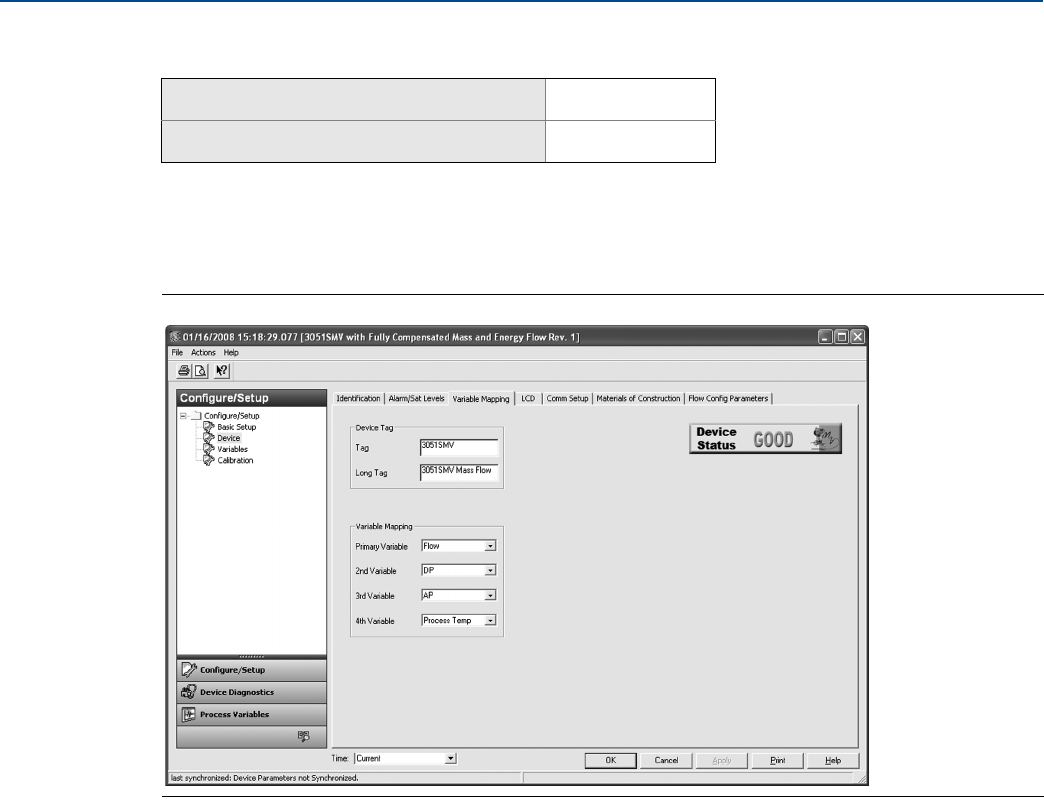
2.6.3 Variable mapping
The Variable Mapping tab is used to define which process variable will be mapped to each HART variable.
The primary variable represents the 4–20 mA analog output signal while the 2nd, 3rd, and 4th variables
are digital. To edit the variable assignments, select the appropriate process variables from the
drop-down menus and select Apply.
Figure 2-21. Device - Variable Mapping Tab
Mass and energy flow Fast Keys 1, 4, 3, 4
Direct process variable output Fast Keys 1, 4, 3, 4
32
Reference Manual
00809-0100-4803, Rev GA
Configuration
September 2017
Configuration
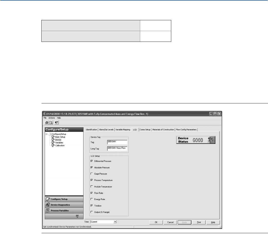
2.6.4 LCD display
The LCD display features a four-line display and a 0–100 percent scaled bar graph. The first line of five
characters displays the output description, the second line of seven digits displays the actual value, and
the third line of six characters displays engineering units. The fourth line displays “Error” when there is a
problem detected with the transmitter. The LCD display can also show diagnostic messages. These
diagnostic messages are listed in Table 5-1 on page 108.
The LCD tab allows the user to configure which variables will be shown on the LCD display. Select the
check box next to each variable to select a variable for display. The transmitter will scroll through the
selected variables, showing each for three seconds.
Figure 2-22. Device - LCD Tab
Mass and energy flow Fast Keys 1, 3, 8
Direct process variable output Fast Keys 1, 3, 8
33
Reference Manual
00809-0100-4803, Rev GA
Configuration
September 2017
Configuration
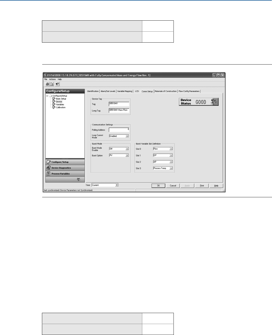
2.6.5 Communication setup
The Comm Setup tab allows the settings for burst mode and multidrop communications to be
configured.
Figure 2-23. Device - Comm Setup Tab
Burst mode
When Burst Mode Enable is set to on, the Rosemount 3051SMV sends up to four HART variables to the
control system without the control system polling for information from the transmitter.
When operating with Burst Mode Enable set to on, the transmitter will continue to output a 4–20 mA
analog signal. Because the HART protocol features simultaneous digital and analog data transmission,
the analog value can drive other equipment in the loop while the control system is receiving the digital
information. Burst mode applies only to the transmission of dynamic data (process variables in
engineering units, primary variable in percent of range, and/or analog output), and does not affect the
way other transmitter data is accessed.
Access to information that is not burst can be obtained through the normal poll/response method of
HART communication. A Field Communicator, AMS Device Manager, Engineering Assistant, or the
control system may request any of the information that is normally available while the transmitter is in
burst mode.
Enabling burst mode
To enable burst mode, select On from the Burst Mode Enable drop-down menu under the Burst Mode
heading.
Mass and energy flow Fast Keys 1, 4, 3, 3
Direct process variable output Fast Keys 1, 4, 3, 3
Mass and energy flow Fast Keys 1, 4, 3, 3, 3
Direct process variable output Fast Keys 1, 4, 3, 3, 3
34
Reference Manual
00809-0100-4803, Rev GA
Configuration
September 2017
Configuration
Choosing a burst option
This parameter selects the information to be burst. Make a selection from the Burst Option drop-down
menu under the Burst Mode heading. The Dyn vars/current option is the most common, because it is used
to communicate with the Rosemount 333 HART Tri-Loop™.
Choosing burst variable slot definition
If the burst option Device vars w/ status or Device variables is selected, the user may select the four
variables that will be burst. These are defined in slots 1–4 under the Burst Variable Slot Definitions
heading. The variables defined in slots 1–4 can be different than the variables mapped to the primary,
2nd, 3rd, and 4th variable outputs.
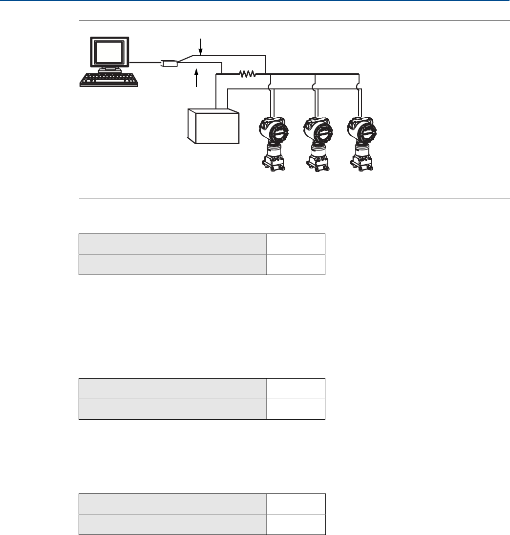
Multidrop communication
Multidropping transmitters refers to the connection of several transmitters to a single communications
transmission line.
Note
Figure 2-24 on page 35 shows a typical multidrop network. This figure is not intended as an installation
diagram.
Communication between the host and the transmitters takes place digitally with the analog output of
the transmitters deactivated.
Note
A transmitter in multidrop mode with Loop Current Mode disabled has the analog output fixed at 4 mA.
Mass and energy flow Fast Keys 1, 4, 3, 3, 4
Direct process variable output Fast Keys 1, 4, 3, 3, 4
Table 2-8. Burst Options
HART command Burst option Description
1PV Primary variable
2% range/current Percent of range and milliamp output
3Dyn vars/current All process variables and milliamp output
9Device vars w/ status Burst variables and status information
33 Device variables Burst variables
Mass and energy flow Fast Keys 1, 4, 3, 3, 5
Direct process variable output Fast Keys 1, 4, 3, 3, 5
35
Reference Manual
00809-0100-4803, Rev GA
Configuration
September 2017
Configuration
Figure 2-24. Typical Multidrop Network
A. Power supply
B. HART modem
Enable multidrop communication
The Rosemount 3051SMV is set to address zero (0) at the factory, which allows operation in the standard
point-to-point manner with a 4–20 mA output signal. To activate multidrop communication, the
transmitter address must be changed to 1–15 for HART 5 hosts or 1–63 for HART 6 hosts. This change
deactivates the 4–20 mA analog output, sending it to a fixed value of 4 mA. It also disables the failure
alarm signal, which is controlled by the HI/LO alarm switch position on the feature board. Failure signals
in multidropped transmitters are communicated through HART messages.
Loop current mode
When using multidrop communication, the loop current mode drop-down menu defines how the 4–20
mA analog output behaves. When loop current mode is disabled, the analog output will be fixed at
4 mA. When the loop current mode is enabled, the analog output will follow the primary variable.
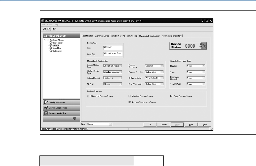
2.6.6 Materials of construction
The Materials of Construction tab allows the materials of construction, remote seal, and equipped sensor
information to be viewed. The parameters shown in white boxes may be edited by the user, but do not
affect the operation of the device.
Mass and energy flow Fast Keys 1, 4, 3, 3, 1
Direct process variable output Fast Keys 1, 4, 3, 3, 1
Mass and energy flow Fast Keys 1, 4, 3, 3, 2
Direct process variable output Fast Keys 1, 4, 3, 3, 2
Mass and energy flow Fast Keys 1, 4, 4, 2
Direct process variable output Fast Keys 1, 4, 4, 2
A
B
36
Reference Manual
00809-0100-4803, Rev GA
Configuration
September 2017
Configuration
Figure 2-25. Device - Materials of Construction Tab
2.6.7 Flow configuration parameters
(Fully compensated mass and energy flow feature board only)
The Flow Config Parameters tab allows the Process Fluid, Primary Element type and Pipe Diameter used in
the flow configuration to be viewed. These values may only be edited using Engineering Assistant
version 6.3 or later.
Mass and energy flow Fast Keys 1, 4, 4, 3
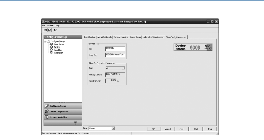
37
Reference Manual
00809-0100-4803, Rev GA
Configuration
September 2017
Configuration
Figure 2-26. Device - Flow Config Parameters Tab
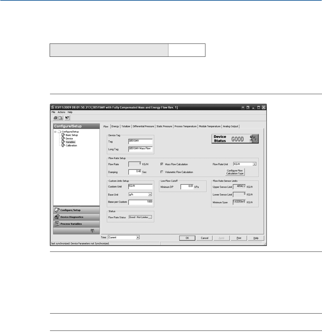
38
Reference Manual
00809-0100-4803, Rev GA
Configuration
September 2017
Configuration
2.7 Variable configuration
2.7.1 Flow rate
(Fully compensated mass and energy flow feature board only)
The Flow tab is used to configure the settings associated with the Flow Variable. Fluid and primary
element information which defines the flow calculation is configured using Engineering Assistant.
Figure 2-27. Variables - Flow Tab
Under the Flow Rate Setup heading, the type of flow calculation is indicated by the check boxes next to
either Mass Flow Calculation or Volumetric Flow Calculation. To edit the flow calculation type, select the
Configure Flow Calculation Type button.
Edit the Flow Rate Units and Damping value as needed. The flow calculation within the device uses
undamped process variables. Flow rate damping is set independently of the measured process
variables.
Note
If the flow calculation type is changed, the totalizer will be stopped and reset automatically.
Under the Low Flow Cutoff heading, edit the current Minimum DP Value as needed. The unit for this
value is the user-selected DP unit. If the measured DP value is less than the minimum DP value, the
transmitter will calculate the Flow Rate value to be zero.
The Sensor Limits and Minimum Span can be viewed under the Flow Rate Sensor Limits heading.
Mass and energy flow Fast Keys 1, 4, 1, 1

39
Reference Manual
00809-0100-4803, Rev GA
Configuration
September 2017
Configuration
Note
If the flow rate is configured as the primary variable and is being output via the 4–20 mA signal, verify the
4–20 mA range (LRV and URV) after completing the custom unit configuration. For more information on
verifying the 4–20 mA range, see “Basic device configuration” on page 24.
Follow these steps to configure a custom unit:
a. Custom Unit: Enter the desired custom unit label to be displayed for the flow rate. Up to five
characters including letters, numbers, and symbols can be entered in the custom unit field.
Note
It is recommended that the Custom Unit be entered in upper case letters. If lower case letters are
entered, the LCD display will show upper case letters. Additionally, the following special characters are
recognized by the LCD display: hyphens (“-”), percent symbols (“%”), asterisks (“*”), forward slashes (“/”)
and spaces. Any other character entered for the Custom Unit will be displayed as an asterisk (“*”) on the
LCD display. The following warning will be returned indicating these changes: “Custom Unit contains
characters that will display in upper case or asterisks on LCD display. The DCS will display as entered.”
b. Base Unit: From the drop-down menu, select a base unit to be used for the custom unit
relationship.
c. Base per Custom: Enter a numeric value that represents the number of base units per one
custom unit. The Rosemount 3051SMV uses the following convention:
Base per Custom =
Example
Custom Unit: kg
Base Unit: g
Because:
1 kg (Kilogram) = 1000 g (Grams)
Base per Custom = = = 1000
The values of Base per Custom for common flow units are shown in Table 2-9.
d. Select Apply.
e. Flow Rate Unit: From the drop-down menu, select the custom unit that was created in Step b.
Note
The custom unit may not be available as a selection in the Flow Rate Unit drop-down menu until the
drop-down menu is refreshed. To refresh the drop-down menu, navigate to the Basic Setup tab and then
return to the Variables - Flow tab.
Table 2-9. Common Custom Units - Flow
Custom unit Base unit Base per custom
Barrels per Minute (BBL/M) bbl/h 60
Cubic Meters per Day (CUM/D) Cum/h 0.041667
Millions of Cubic Meters per Day (MMCMD) Cum/h 41666.7
Number of Base Units
1xCustomxUnit
----------------------------------------------------------------------
Number of Base Units
1xCustomxUnit
----------------------------------------------------------------------
1000 g⋅
1kg⋅
---------------------
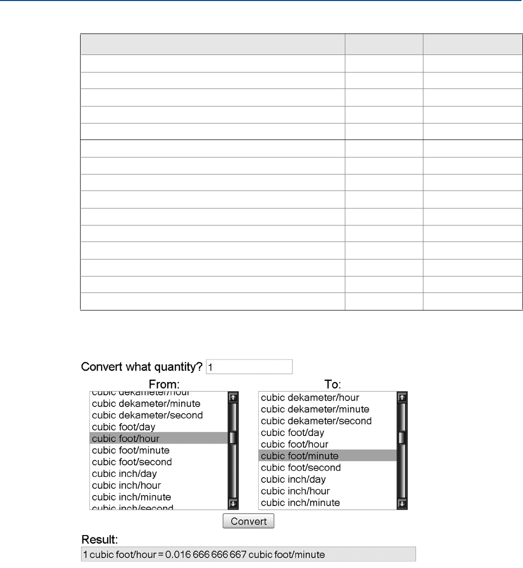
40
Reference Manual
00809-0100-4803, Rev GA
Configuration
September 2017
Configuration
If conversion factor tables or internet search engines are used to determine the Base per Custom value, it
is important to enter the Custom Unit in the “From” field and the Base Unit in the “To” Field. An example
of this is shown below:
To calculate the Base per Custom value for a custom unit not shown in Table 2-9 on page 39, see one of
the following examples:
Mass/volume conversion example: page 41
Time conversion example: page 42
Mass/volume and time conversion example: page 43
Millions of Gallons per Day (MGD) gal/d 1000000
Millions of Liters per Day (MML/D) L/h 41666.7
Millions of Standard Cubic Feet per Day (MMCFD) StdCuft/min 694.444
Normal Cubic Meters per Day (NCM/D) NmlCum/h 0.041667
Normal Cubic Meters per Minute (NCM/M) NmlCum/h 60
Short Tons per Day (STOND) lb/d 2000
Short Tons per Hour (STONH) lb/h 2000
Standard Cubic Feet per Day (SCF/D) StdCuft/min 0.000694
Standard Cubic Feet per Hour (SCF/H) StdCuft/min 0.016667
Standard Cubic Feet per Second (SCF/S) StdCuft/min 60
Standard Cubic Meters per Day (SCM/D) StdCum/h 0.041667
Thousands of Gallons per Day (KGD) gal/d 1000
Thousands of Pounds per Hour (KLB/H) lb/h 1000
Thousands of Standard Cubic Feet per Day (KSCFD) StdCuft/min 0.694444
Thousands of Standard Cubic Feet per Hour (KSCFH) StdCuft/min 16.6666
Table 2-9. Common Custom Units - Flow
Custom unit Base unit Base per custom
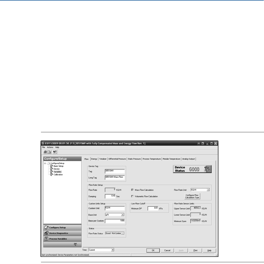
41
Reference Manual
00809-0100-4803, Rev GA
Configuration
September 2017
Configuration
Mass/volume conversion example
To find the Base per Custom relationship for a custom unit of kilograms per hour (kg/h) and a base unit of
grams per hour (g/h), input the following:
Custom Unit = kg/h
Base Unit = g/h
Because:
1 kg (Kilogram) = 1000 g (Grams)
Then:
1 kg/h = ⫻ = 1000 g/h
1 kg/h = 1000 g/h
Therefore:
Base per Custom = = = 1000
Figure 2-28. Flow Rate Custom Units - Mass/Volume Conversion Example
1kg⋅
1h⋅
--------------
1000 g⋅
1kg⋅
---------------------
Number of Base Units
1xCustomxUnit
----------------------------------------------------------------------
1000 g h⁄⋅
1kgh⁄⋅
----------------------------

42
Reference Manual
00809-0100-4803, Rev GA
Configuration
September 2017
Configuration
Time conversion example
To find the Base per Custom relationship for a custom unit of standard cubic feet per hour (scf/h) and a
base unit of standard cubic feet per minute (StdCuft/min), input the following:
Custom Unit = scf/h
Base Unit = StdCuft/min
Because:
1 h (Hour) = 60 min (Minutes)
Then:
1 scf/h = ⫻ = 0.016667 StdCuft/min
1 scf/h = 0.016667 StdCuft/min
Therefore:
Base per Custom = = = 0.016667
Figure 2-29. Flow Rate Custom Units - Time Conversion Example
1scf⋅
1h⋅
---------------
1h⋅
60 min⋅
---------------------
Number of Base Units
1xCustomxUnit
----------------------------------------------------------------------
0.016667 StdCuft min⁄⋅
1scfh⁄⋅
------------------------------------------------------------------

43
Reference Manual
00809-0100-4803, Rev GA
Configuration
September 2017
Configuration
Mass/volume and time conversion example
To find the Base per Custom relationship for a custom unit of standard millions of standard cubic feet per
day (mmcfd) and a base unit of standard cubic feet per minute (StdCuft/min), input the following:
Custom Unit = mmcfd
Base Unit = StdCuft/min
Because:
1 mmcf (Millions of Standard Cubic Feet) = 1000000 StdCuft (Standard Cubic Feet) and
1 d (Day) = 1440 min (Minutes)
Then:
1 mmcfd = ⫻ ⫻ = 694.444 StdCuft/min
1 mmcfd = 694.444 StdCuft/min
Therefore:
Base per Custom = = = 694.444
Figure 2-30. Flow Rate Custom Units - Mass/Volume and Time Conversion Example
Under the Custom Units Setup heading, the user may configure a custom unit for the flow rate
measurement. Custom units allow the flow rate to be displayed in units of measure that are not standard
in the Rosemount 3051SMV.
1 mmcf⋅
1d⋅
------------------------
1000000 StdCuft⋅
1mmcf⋅
-------------------------------------------------
1d⋅
1440 min⋅
----------------------------
Number of Base Units
1xCustomxUnit
----------------------------------------------------------------------
694.444 StdCuft min⁄⋅
1 mmcfd⋅
--------------------------------------------------------------
44
Reference Manual
00809-0100-4803, Rev GA
Configuration
September 2017
Configuration
2.7.2 Energy rate
(Fully compensated mass and energy flow feature board only)
Note
Energy Rate calculations are only available for certain fluid types.
The Energy tab allows the user to configure the settings associated with the energy flow.
Under the Energy Rate Setup heading, edit the Energy Rate Units and Damping values as needed. The
energy rate calculation within the device uses undamped process variables. Energy rate damping is set
independently of flow rate damping and measured process variables.
Under the Custom Units Setup heading, the user may configure a custom unit for the energy rate
measurement. Custom units allow the energy rate to be displayed in units of measure that are not
standard in the Rosemount 3051SMV.
Note
If the energy rate is configured as the primary variable and is being output via the 4-20 mA signal, verify
the 4–20 mA range (LRV and URV) after completing the custom unit configuration. For more
information on verifying the 4–20 mA range, see “Basic device configuration” on page 24.
Follow these steps to configure a custom unit:
a. Custom Unit: Enter the desired custom unit label to be displayed for the energy rate. Up to five
characters including letters, numbers, and symbols can be entered in the custom unit field.
Note
It is recommended that the Custom Unit be entered in upper case letters If lower case letters are entered,
the LCD display will show upper case letters. Additionally, the following special characters are recognized
by the LCD display: hyphens (“-”), percent symbols (“%”), asterisks (“*”), forward slashes (“/”) and
spaces. Any other character entered for the Custom Unit will be displayed as an asterisk (“*”) on the LCD
display. The following warning will be returned indicating these changes: “Custom Unit contains
characters that will display in upper case or asterisks on LCD display. The DCS will display as entered.”
b. Base Unit: From the drop-down menu, select a base unit to be used for the custom unit
relationship.
c. Base per Custom: Enter a numeric value that represents the number of base units per one
custom unit. The Rosemount 3051SMV uses the following convention:
Base per Custom =
Example
Custom Unit: kg
Base Unit: g
Because:
1 kg (Kilogram) = 1000 g (Grams)
Base per Custom = = = 1000
The values of Base per Custom for common energy units are shown in Table 2-10 on page 45.
Mass and energy flow Fast Keys 1, 4, 1, 2
Number of Base Units
1xCustomxUnit
----------------------------------------------------------------------
Number of Base Units
1xCustomxUnit
----------------------------------------------------------------------
1000 g⋅
1kg⋅
---------------------
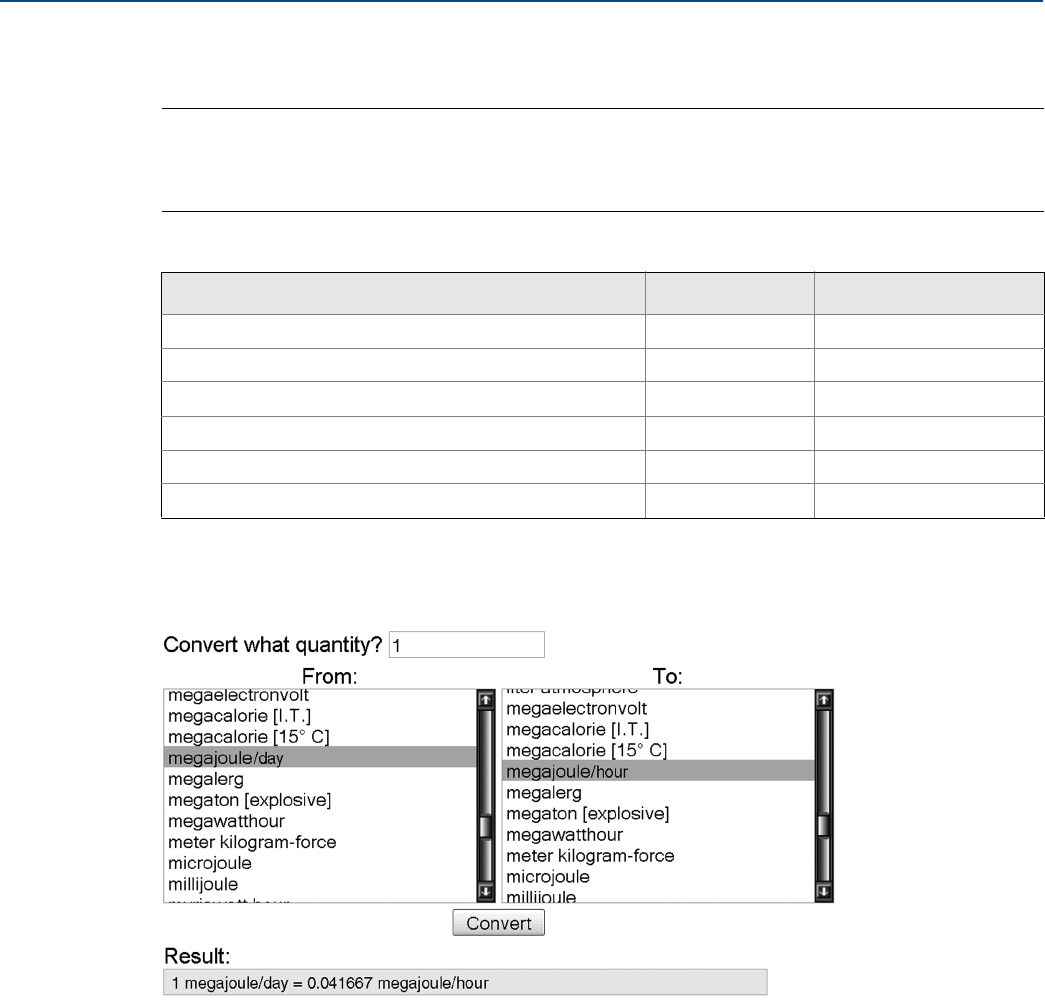
45
Reference Manual
00809-0100-4803, Rev GA
Configuration
September 2017
Configuration
d. Select Apply.
e. Energy Rate Unit: From the drop-down menu, select the custom unit that was created in Step b.
Note
The custom unit may not be available as a selection in the Energy Rate Unit drop-down menu until the
drop-down menu is refreshed. To refresh the drop-down menu, navigate to the Basic Setup tab and then
return to the Variables - Energy tab.
If conversion factor tables or internet search engines are used to determine the Base per Custom value, it
is important to enter the Custom Unit in the “From” field and the Base Unit in the “To” Field. An example
of this is shown below:
To calculate the Base per Custom value for a custom unit not shown in Table 2-10 on page 45, see one of
the following examples:
Energy conversion example: page 46
Time conversion example: page 47
Energy and time conversion example: page 47
Table 2-10. Common Custom Units - Energy Flow
Custom unit Base unit Base per custom
BTU per Day (BTU/D) Btu/h 0.041667
BTU per Minute (BTU/M) Btu/h 60
Megajoules per Day (MJ/D) MJ/h 0.041667
Megajoules per Minute (MJ/M) MJ/h 60
Thousands of BTU per Day (KBTUD) Btu/h 41.6667
Thousands of BTU per Hour (KBTUH) Btu/h 1000
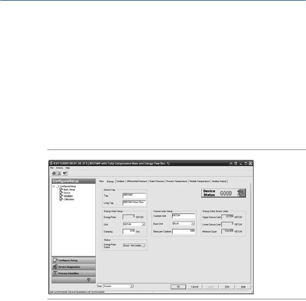
46
Reference Manual
00809-0100-4803, Rev GA
Configuration
September 2017
Configuration
Energy conversion example
To find the Base per Custom relationship for a custom unit of thousands of BTU per hour (kBtuh) and a
base unit of BTU per hour (Btu/h), input the following:
Custom Unit = kBtuh
Base Unit = Btu/h
Because:
1 kBtu (Thousands of BTU) = 1000 Btu
Then:
1 kBtuh = ⫻ = 1000 Btu/h
1 kBtuh = 1000 Btu/h
Therefore:
Base per Custom = = = 1000
Figure 2-31. Energy Rate Custom Units - Energy Conversion Example
1kBtu⋅
1h⋅
--------------------
1000 Btu⋅
1h⋅
---------------------------
Number of Base Units
1xCustomxUnit
----------------------------------------------------------------------
1000 Btu h⁄⋅
1kBtuh⋅
----------------------------------

47
Reference Manual
00809-0100-4803, Rev GA
Configuration
September 2017
Configuration
Time conversion example
To find the Base per Custom relationship for a custom unit of BTU per day (Btu/d) and a base unit of BTU
per hour (Btu/h), input the following:
Custom Unit = Btu/d
Base Unit = Btu/h
Because:
1 d (Day) = 24 h (Hours)
Then:
1 Btu/d = ⫻ = 0.041667 Btu/h
1 Btu/d = 0.041667 Btu/h
Therefore:
Base per Custom = = = 0.041667
Figure 2-32. Energy Rate Custom Units - Time Conversion Example
1Btu⋅
1d⋅
-----------------
1d⋅
24 h⋅
--------------
Number of Base Units
1xCustomxUnit
----------------------------------------------------------------------
0.041667 Btu h⁄⋅
1Btud⁄⋅
----------------------------------------------
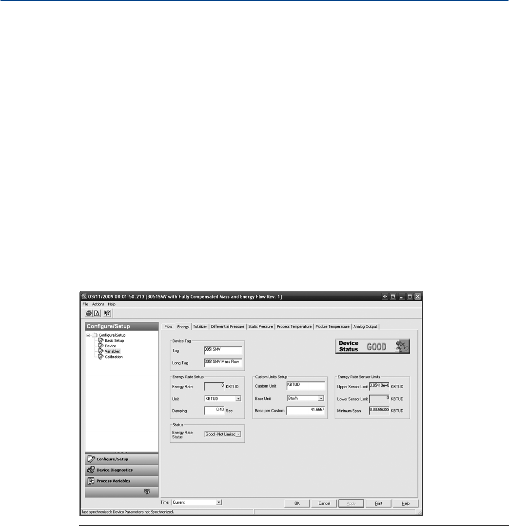
48
Reference Manual
00809-0100-4803, Rev GA
Configuration
September 2017
Configuration
Energy and time conversion example
To find the Base per Custom relationship for a custom unit of thousands of BTU per day (kBtud) and a
base unit of BTU per hour (Btu/h), input the following:
Custom Unit = kBtud
Base Unit = Btu/h
Because:
1 kBtu (Thousands of BTU)= 1000 Btu and
1 d (Day) = 24 h (Hours)
Then:
1 kBtud = ⫻ ⫻ = 41.6667 Btu/h
1 kBtud = 41.6667 Btu/h
Therefore:
Base per Custom = = = 41.6667
Figure 2-33. Energy Rate Custom Units - Energy and Time Conversion Example
Under the Low Flow Cutoff heading, edit the current Minimum DP Value as needed. The unit for this
value is the user-selected DP unit. If the measured DP value is less than the minimum DP value, the
transmitter will calculate the energy value to be zero.
The Sensor Limits and Minimum Span can be viewed under the Energy Rate Sensor Limits heading.
1kBtu⋅
1d⋅
--------------------
1000 Btu⋅
1kBtu⋅
---------------------------
1d⋅
24 h⋅
--------------
Number of Base Units
1xCustomxUnit
----------------------------------------------------------------------
41.6667 Btu h⁄⋅
1kBtud⋅
-------------------------------------------
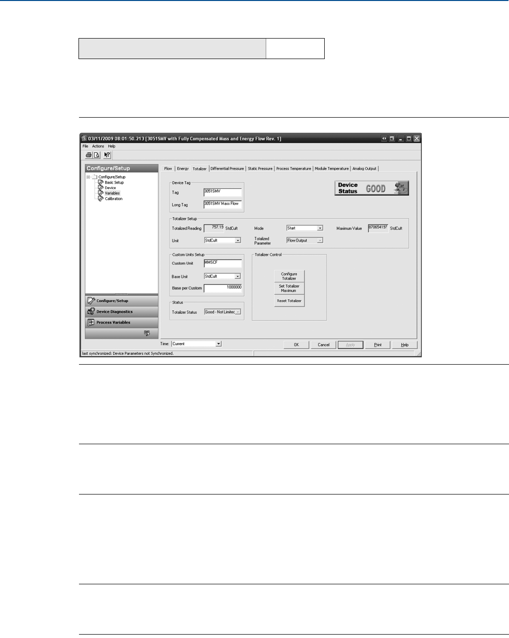
49
Reference Manual
00809-0100-4803, Rev GA
Configuration
September 2017
Configuration
2.7.3 Totalizer
(Fully compensated mass and energy flow feature board only)
The Totalizer tab is used to configure the settings associated with the totalizer functionality within the
transmitter.
Figure 2-34. Variables - Totalizer Tab
1. To turn the totalizer functionality on or off, select Start or Stop from the Mode drop down menu
under the Totalizer Setup heading. The totalizer Units may also be edited under this heading.
2. Verify the Totalized Parameter and the Totalizer Maximum value. To edit the Totalized Parameter, select
the Configure Totalizer button under the Totalizer Control heading.
Note
When the totalizer reaches its maximum value, it automatically resets to zero and continues totalizing.
The default maximum is a value equivalent to 4.29 billion pounds, actual cubic feet, or BTU. To edit the
Totalizer Maximum value, select the Set Totalizer Maximum button under the Totalizer Control heading.
3. To reset the Totalized Reading to zero, select the Reset Totalizer button under the Totalizer Control
heading.
4. Under the Custom Units Setup heading, the user may configure a custom unit for the Totalized Reading.
Custom units allow the totalizer rate to be displayed in units of measure that are not standard in the
Rosemount 3051SMV.
Note
If the totalizer rate is configured as the primary variable and is being output via the 4–20 mA signal, verify
the 4–20 mA range (LRV and URV) after completing the custom unit configuration. For more
information on verifying the 4–20 mA range, see “Basic device configuration” on page 24.
Mass and energy flow Fast Keys 1, 4, 1, 3

50
Reference Manual
00809-0100-4803, Rev GA
Configuration
September 2017
Configuration
Follow these steps to configure a custom unit:
a. Custom Unit: Enter the desired custom unit label to be displayed for the Totalized Reading. Up to
five characters including letters, numbers, and symbols can be entered in the custom unit field.
Note
It is recommended that the Custom Unit be entered in upper case letters. If lower case letters are
entered, the LCD display will show upper case letters. Additionally, the following special characters are
recognized by the LCD display: hyphens (“-”), percent symbols (“%”), asterisks (“*”), forward slashes (“/”)
and spaces. Any other character entered for the Custom Unit will be displayed as an asterisk (“*”) on the
LCD display. The following warning will be returned indicating these changes: “Custom Unit contains
characters that will display in upper case or asterisks on LCD display. The DCS will display as entered.”
b. Base Unit: From the drop-down menu, select a base unit to be used for the custom unit
relationship.
c. Base per Custom: Enter a numeric value that represents the number of base units per one
custom unit. The Rosemount 3051SMV uses the following convention:
Base per Custom =
Example
Custom Unit: kg
Base Unit: g
Because:
1 kg (Kilogram) = 1000 g (Grams)
Base per Custom = = = 1000
The values of Base per Custom for common totalizer units are shown in Table 2-11.
d. Select Apply.
e. Totalizer Unit: From the drop-down menu, select the custom unit that was created in Step b.
Note
The custom unit may not be available as a selection in the Totalizer Unit drop-down menu until the
drop-down menu is refreshed. To refresh the drop-down menu, navigate to the Basic Setup tab and then
return to the Variables - Totalizer tab.
Table 2-11. Common Custom Units - Totalizer
Custom unit Base unit Base per custom
Millions of Normal Cubic Meters (MMNCM) NmlCum 1000000
Millions of Standard Cubic Feet (MMSCF) StdCuft 1000000
Millions of Standard Cubic Meters (MMSCM) StdCum 1000000
Thousands of Metric Tons (KMTON) MetTon 1000
Thousands of Normal Cubic Meters (KNCM) NmlCum 1000
Thousands of Short Tons (KSTON) STon 1000
Thousands of Standard Cubic Feet (KSCF) StdCuft 1000
Thousands of Standard Cubic Meters (KSCM) StdCum 1000
Number of Base Units
1xCustomxUnit
----------------------------------------------------------------------
Number of Base Units
1xCustomxUnit
----------------------------------------------------------------------
1000 g⋅
1kg⋅
---------------------
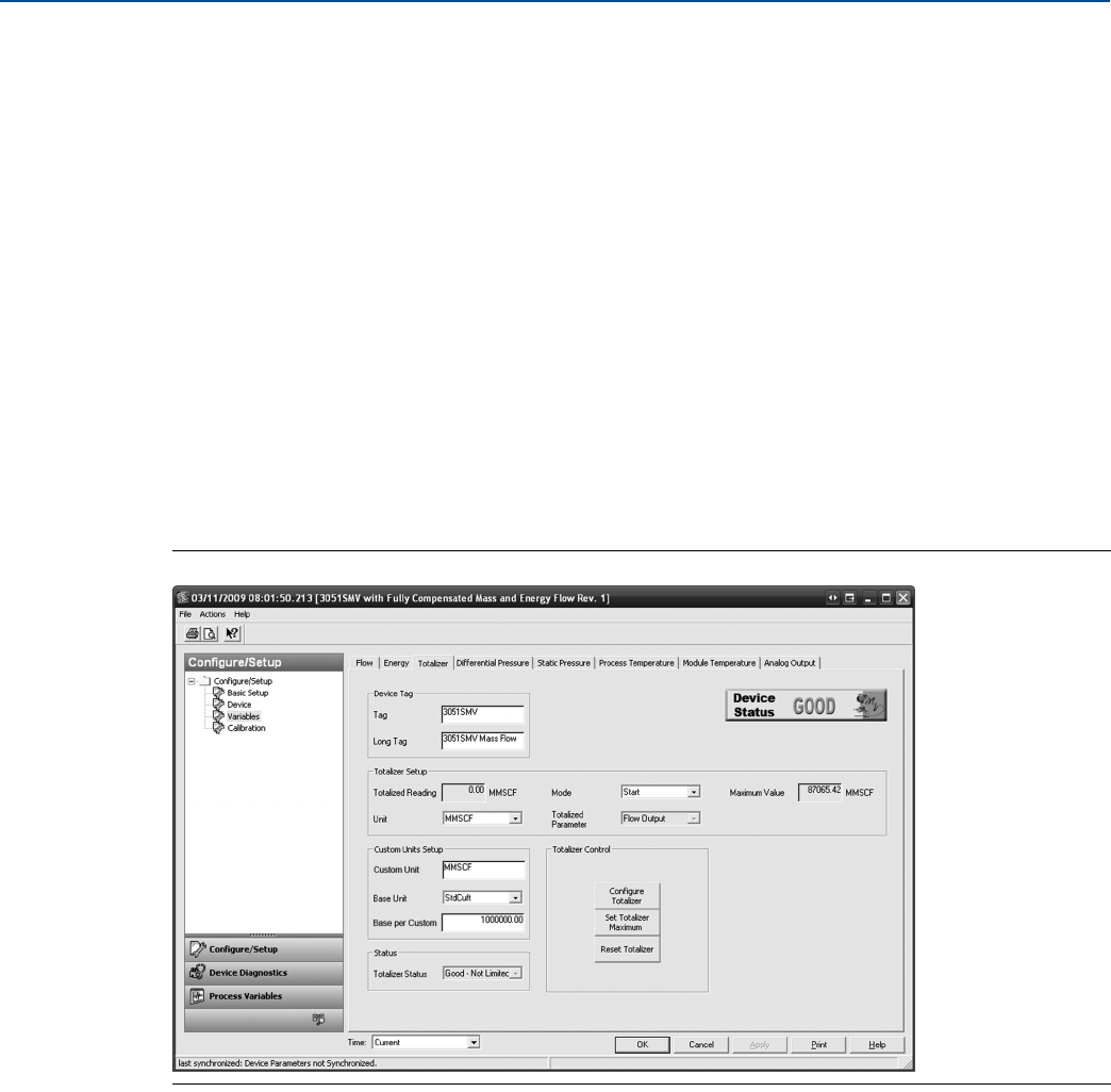
51
Reference Manual
00809-0100-4803, Rev GA
Configuration
September 2017
Configuration
If conversion factor tables or internet search engines are used to determine the Base per Custom value, it
is important to enter the Custom Unit in the “From” field and the Base Unit in the “To” Field.
To calculate the Base per Custom value for a custom unit not shown in Table 2-9 on page 39, see the
example:
Totalizer conversion example
To find the Base per Custom relationship for a custom unit of millions of standard cubic feet (mmscf) and
a base unit of standard cubic feet (StdCuft), input the following:
Custom Unit = mmscf
Base Unit = StdCuft
Because:
1 mmscf (Millions of Standard Cubic Feet) = 1000000 StdCuft (Standard Cubic Feet)
Therefore:
Base per Custom = = = 1000000
Figure 2-35. Totalizer Custom Units - Totalizer Example
Number of Base Units
1xCustomxUnit
----------------------------------------------------------------------
1000000 StdCuft⋅
1mmscf⋅
-------------------------------------------------
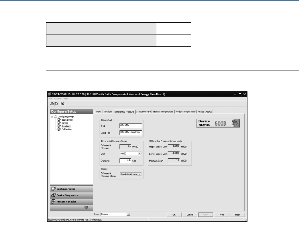
52
Reference Manual
00809-0100-4803, Rev GA
Configuration
September 2017
Configuration
2.7.4 Differential pressure
Note
For Differential pressure sensor calibration, see page 90.
Figure 2-36. Variables - Differential Pressure Tab
Under the Differential Pressure Setup heading, edit the DP Units and Damping value as needed.
The Sensor Limits and Minimum Span can be viewed under the Differential Pressure Sensor Limits
heading.
Mass and energy flow Fast Keys 1, 4, 1, 4
Direct process variable output Fast Keys 1, 4, 1, 1
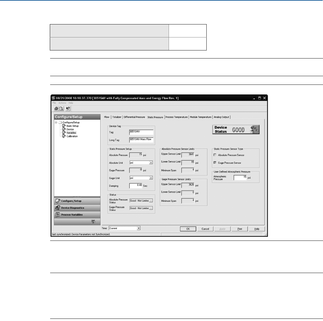
53
Reference Manual
00809-0100-4803, Rev GA
Configuration
September 2017
Configuration
2.7.5 Static pressure
Note
For Static pressure sensor calibration, see page 92.
Figure 2-37. Variables - Static Pressure Tab
Under the Static Pressure Setup heading, edit the Absolute Pressure Units and Gage Pressure Units as
needed. The static pressure Damping may also be edited.
Note
The transmitter may be equipped with either an absolute or gage static pressure sensor type depending
on specified model code. The type of static pressure sensor equipped in the transmitter can be
determined by referring to the Static Pressure Sensor Type heading. The static pressure type not being
measured is a calculated value using the atmospheric pressure value as specified under the User-Defined
Atmospheric Pressure heading.
The Sensor Limits and Minimum Span for the absolute and gage static pressure can be viewed under the
Sensor Limit headings.
Mass and energy flow Fast Keys 1, 4, 1, 5
Direct process variable output Fast Keys 1, 4, 1, 2
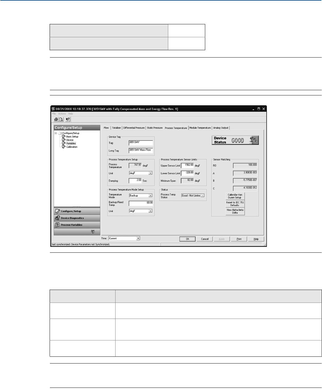
54
Reference Manual
00809-0100-4803, Rev GA
Configuration
September 2017
Configuration
2.7.6 Process temperature
Note
For Process temperature sensor calibration, see page 93.
If a transmitter was ordered with Fixed Process Temperature Only, the Fixed Temperature Value and
Units can be edited on the Fixed Temperature tab.
Figure 2-38. Variables - Process Temperature Tab
Under the Process Temperature Setup heading, edit the Units and Damping value as needed.
Select the Temperature Mode under the Process Temperature Setup heading. See Table 2-12.
Note
Process Temperature Mode Setup only applies to transmitters with fully compensated mass and energy
flow feature board.
Mass and energy flow Fast Keys 1, 4, 1, 6
Direct process variable output Fast Keys 1, 4, 1, 3
Table 2-12. Temperature Modes
Temperature mode Description
Normal The transmitter will only use the actual measured Process Temperature value. If the
temperature sensor fails, the transmitter will put the analog signal into Alarm.
Backup The transmitter will use the actual measured Process Temperature value. If the
temperature sensor fails, the transmitter will use the value shown in the Fixed/Backup
Temperature field.
Fixed The transmitter will always use the temperature value shown in the Fixed/Backup
Temperature field.
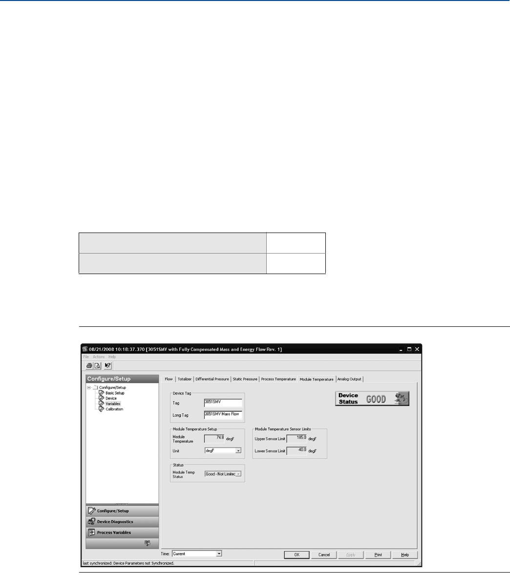
55
Reference Manual
00809-0100-4803, Rev GA
Configuration
September 2017
Configuration
The Sensor Limits and Minimum Span can be viewed under the Process Temperature Sensor Limits
heading. The upper and lower sensor limits may be edited as needed.
The Rosemount 3051SMV accepts Callendar-Van Dusen constants from a calibrated RTD schedule and
generates a special custom curve to match that specific sensor Resistance vs. Temperature performance.
Matching the specific sensor curve with the transmitter configuration enhances the temperature
measurement accuracy.
Under the Sensor Matching heading, the Callendar-Van Dusen constants R0, A, B, and C can be viewed.
If the Callendar-Van Dusen constants are known for the user’s specific Pt 100 RTD sensor, the constants
R0, A, B, and C may be edited by selecting the Callendar-Van Dusen Setup button and following the
on-screen prompts.
The user may also view the α, β, and δ coefficients by selecting the View Alpha, Beta, Delta button.
The constants R0, α, β, and δ may be edited by selecting the Callendar-Van Dusen Setup button and
following the on-screen prompts. To reset the transmitter to the IEC 751 Defaults, select the Reset to
IEC 751 Defaults button.
2.7.7 Module temperature
The sensor module temperature variable is the measured temperature of the sensors and electronics
within the SuperModule assembly. The module temperature can be used to control heat tracing or
diagnose device overheating.
Figure 2-39. Variables - Module Temperature Tab
Under the Module Temperature Setup heading, edit the Units as needed.
The Sensor Limits can be viewed under the Module Temperature Sensor Limits heading.
Mass and energy flow Fast Keys 1, 4, 1, 7
Direct process variable output Fast Keys 1, 4, 1, 4
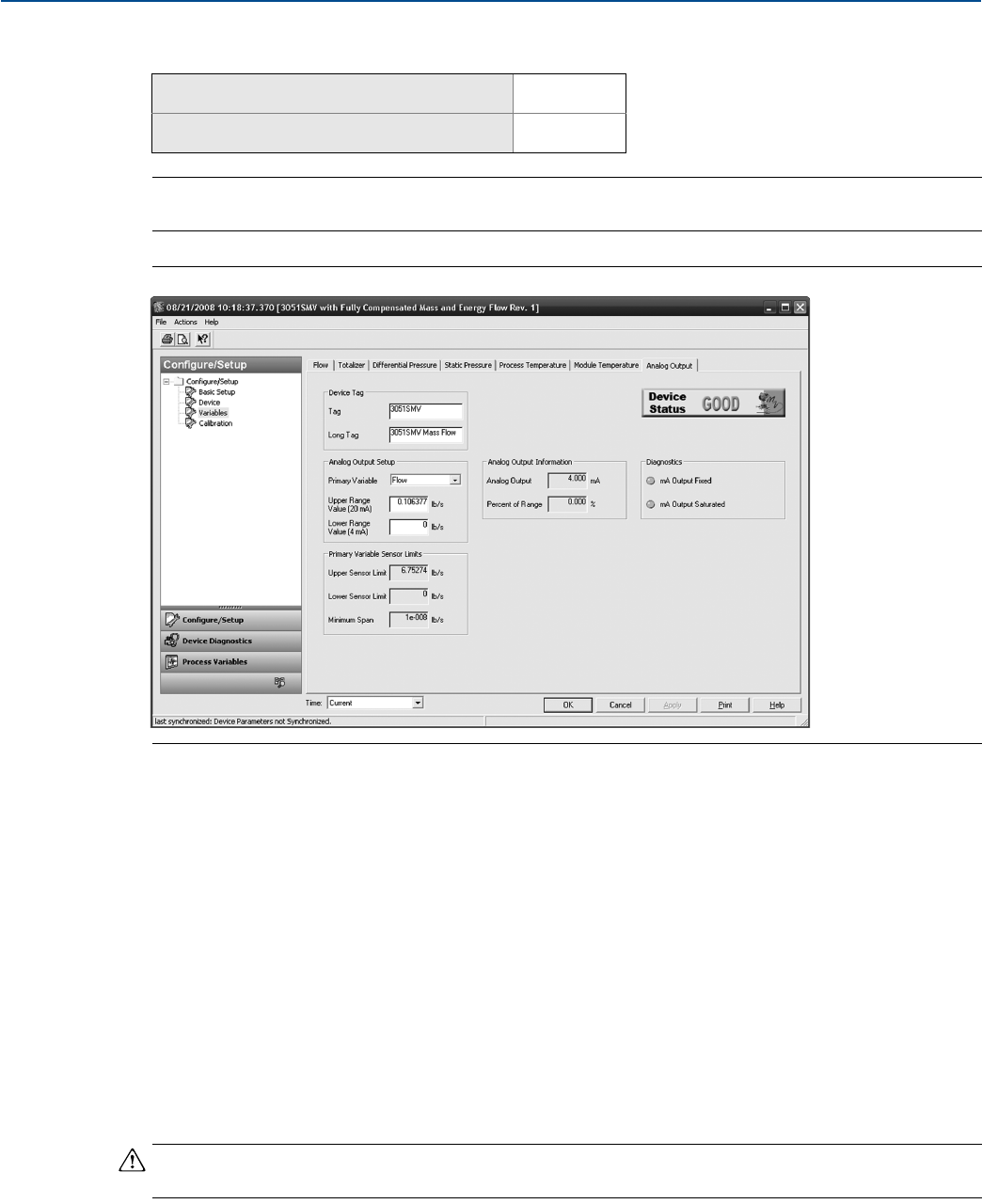
56
Reference Manual
00809-0100-4803, Rev GA
Configuration
September 2017
Configuration
2.7.8 Analog output
Note
For Analog calibration, see page 95.
Figure 2-40. Variables - Analog Output Tab
1. Select the Primary Variable under the Analog Output Setup heading. The Upper Range Value and Lower
Range Value may also be edited under this heading.
2. Verify the Upper Sensor Limit and Lower Sensor Limit and minimum span under the Primary Variable
Sensor Limits heading.
Transfer function (direct process variable output feature board only)
The Rosemount 3051SMV with direct process variable output feature board has two analog output
settings: Linear and Square Root. Activate the square root output option to make analog output
proportional to flow. As input approaches zero, the Rosemount 3051SMV automatically switches to
linear output in order to ensure a smooth, stable output near zero (see Figure 2-41 on page 57).
From 0 to 0.6 percent of the ranged pressure input, the slope of the curve is unity (y = x). This allows
accurate calibration near zero. Greater slopes would cause large changes in output (for small changes at
input). From 0.6 to 0.8 percent, curve slope equals 41.72 (y = 41.72x) to achieve continuous transition
from linear to square root at the transition point.
Note
Do not set both the analog output of the device and the control system to square root.
Mass and energy flow Fast Keys 1, 4, 3, 2
Direct process variable output Fast Keys 1, 4, 3, 2
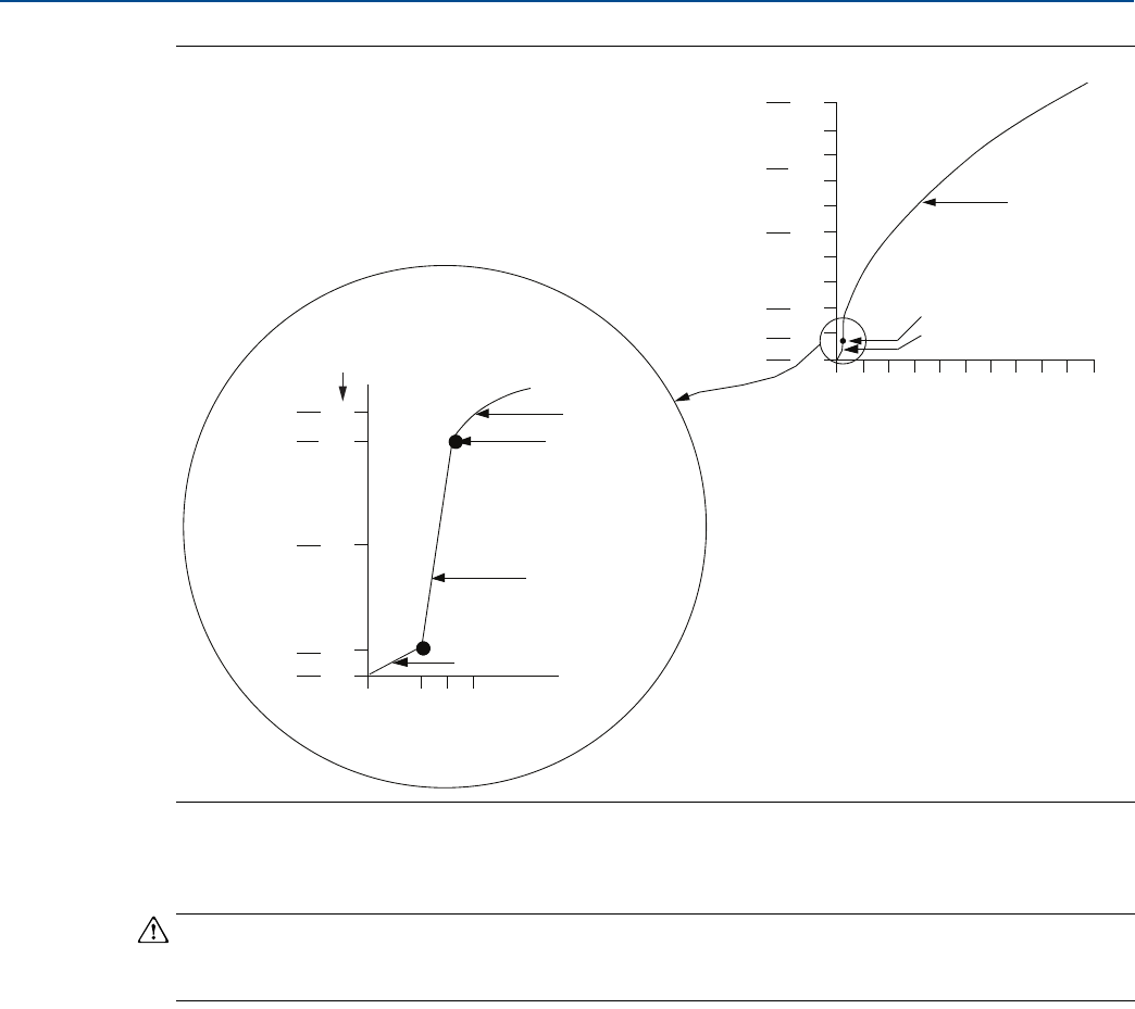
57
Reference Manual
00809-0100-4803, Rev GA
Configuration
September 2017
Configuration
Figure 2-41. Square Root Output Transition Point
Figure 2-41 only applies to the square root output for the Rosemount 3051SMV with the direct process
variable output feature board.
Note
For a flow turndown of greater than 10:1, it is not recommended to perform a square root transfer
function in the transmitter. Instead, perform the square root transfer function in the control system.
2.8 Menu trees and Field Communicator Fast Keys
Based on the configuration ordered, some measurements (i.e. static pressure, process temperature)
and/or calculation types (i.e. mass, volumetric, and energy flow) may not be available for all fluid types.
Available measurements and/or calculation types are determined by the multivariable type and
measurement type codes ordered. See “Ordering information” on page 138 for more information.
The menu trees and Field Communicator Fast Keys in this section are shown for the following model
codes:
Multivariable type M (fully compensated mass and energy flow) with measurement type 1 (differential
pressure, static pressure, and process temperature)
Multivariable type P (direct process variable output) with measurement type 1 (differential pressure,
static pressure, and process temperature)
The menu trees and 475 Field Communicator Fast Keys for other model codes will vary.
5.6
5.424
4.8
4.096
4
10
Full scale
flow (%)
Full scale output (mA dc)
8.9
5
0.6
0
0 0.6 0.8 1
Sq. root curve
Transition point
Slope = 41.72
Slope = 1
% Pressure input
20
16
12
7.2
5.4
4
100
90
80
70
60
50
40
30
20
10
0
0 20 40 60 80 100
Sq. root curve
Transition point
Linear section
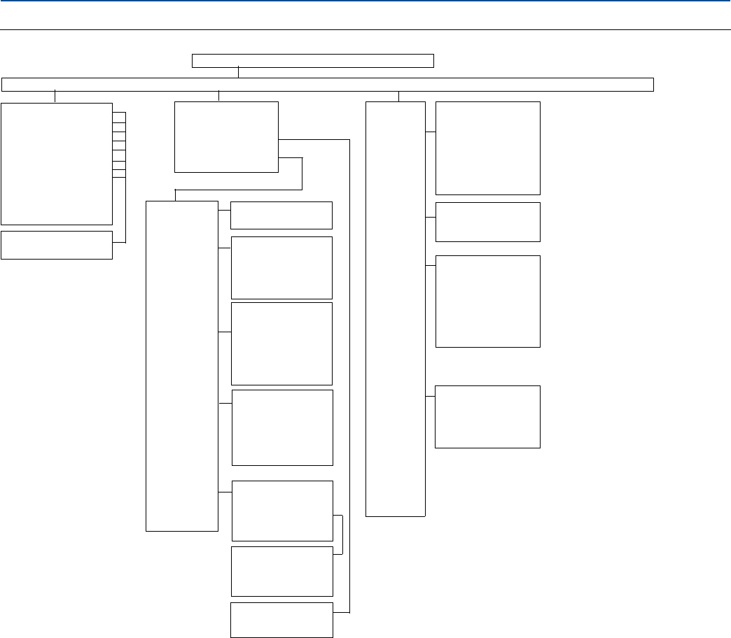
58
Reference Manual
00809-0100-4803, Rev GA
Configuration
September 2017
Configuration
Figure 2-42. Menu Tree for Fully Compensated Mass and Energy Flow
1. Device Setup 2. PV 3. AO 4. PV LRV 5. PV URV
1. Process Variables...........................2. Diagnostics and Service............................... 3. Basic Setup....................4. Detailed Setup........... 5. Review
1. Flow Rate
2. Energy Rate
3. Totalizer
4. Diff. Pressure
5. Absolute Pressure
6. Gage Pressure
7. Process Temp.
8. Module Temp.
9. Analog Output
10.Percent of Range
11.Primary Variable is
1. Reading
2. Status
1. Status
2. Loop Test
3. Test Flow Calc
4. Configure Fixed
Variables
5. Calibration
1. Diff. Pressure
2. Static Pressure
3. Process Temp.
1. Rerange
2. Analog
Output
Trim
3. Diff.
Pressure
Trim
4. Static
Pressure
Trim
5. Process
Temp.
Trim
1. Upper Range Value
2. Lower Range Value
1. Digital-to-Analog
Trim
2. Scaled
Digital-to-Analog
Trim
3. Recall Factory Trim
1. Zero Trim
2. Lower Sensor Trim
3. Upper Sensor Trim
4. Sensor Trim
Calibration Type
5. Sensor Trim Points
6. Recall Factory Trim
1. Lower Sensor Trim
2. Upper Sensor Trim
3. Sensor Trim Points
4. Callendar Van
Dusen
5. Recall Factory Trim
1. Configure
Coefficients
2. Reset Coefficients
3. Process Temp.
1. Tag
2. Long Tag
3. Units
4. Range
Value
5. Device
Info
6. Transfer
Function
7. Damping
8. LCD
Display
Config.
1. Flow Rate
2. Energy Rate
3. Totalizer
4. Differential
Pressure
5. Absolute Pressure
6. Gage Pressure
7. Process Temp.
8. Module Temp.
1. Upper Range
Value
2. Lower Range Value
1. Date
2. Descriptor
3. Message
4. Write Protect
5. Model
6. Model Number I
7. Model Number II
8. Model Number III
9. Model Number IV
1. Flow Rate
2. Energy Rate
3. Differential
Pressure
4. Static Pressure
5. Process
1. Zero Trim
2. Lower Sensor Trim
3. Upper Sensor Trim
4. Sensor Trim
Calibration Type
5. Sensor Trim Points
6. Recall Factory Trim
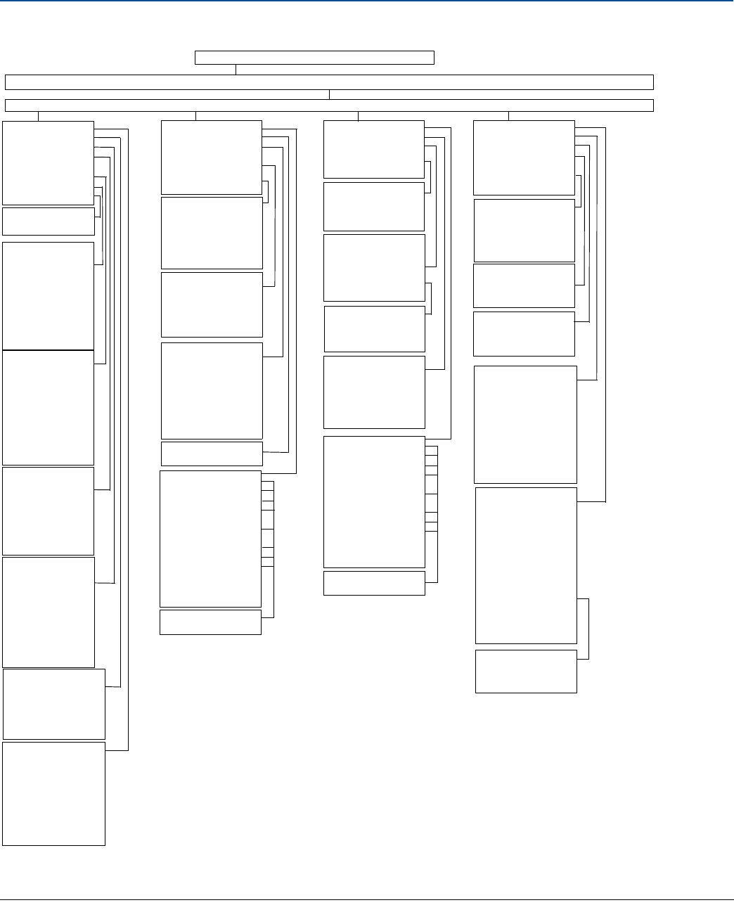
59
Reference Manual
00809-0100-4803, Rev GA
Configuration
September 2017
Configuration
1. Flow Rate
2. Energy Rate
3. Totalizer
4. Differential
Pressure
5. Static Pressure
6. Process Temp.
7. Module Temp.
1. Reading
2. Unit
1. Reading
2. Unit
3. Damping
4. Sensor Service
5. Lower Sensor
Limit
6. Upper Sensor
Limit
7. Min Span
8. Process Temp
1. Absolute
Reading
2. Absolute Unit
3. Gage Reading
4. Gage Unit
5. Damping
6. Atmospheric
Pressure
7. Sensor Service
8. Absolute Sensor
Limit
1. Reading
2. Unit
3. Damping
4. Sensor Service
5. Upper Sensor
Limit
6. Lower Sensor
Limit
1. Reading
2. Totalized
Parameter
3. Unit
4. Mode
5. Max Value
6. Configure
Totalizer
7. Set Max Value
8. Reset Totalizer
9. Custom Unit
1. Reading
2. Unit
3. Damping
4. Custom Unit
5. Upper Sensor Limit
6. Lower Sensor Limit
7. Min. Span
1. Reading
2. Calculation Type
3. Config. Flow Calc
4. Unit
5. Damping
6. Low Flow Cutoff
7. Custom Unit
8. Upper Sensor Limit
9. Lower Sensor Limit
10.Min. Span
1. Device Setup 2. PV 3. AO 4. PV LRV 5. PV
1. Process Variables. 22. Diagnostics and Service 3. Basic Setup..........4. Detailed Setup....>>.......................5. Review
1. Sensors.................................. _2. Signal Condition............................3. Output Condition............................4. Device Info...........................
1. Process Variables
2. Range Values
3. Units
4. Transfer Function
5. Damping
6. Alarm/Saturation
Levels
1. Alarm Direction
2. High Alarm
3. Low Alarm
4. High Saturation
5. Low Saturation
6. Config Alarm &
Saturation Levels
1. Flow Rate
2. Energy Rate
3. Differential
Pressure
4. Static Pressure
1. Flow Rate
2. Energy Rate
3. Totalizer
4. Differential
Pressure
5. Absolute Pressure
6. Gage Pressure
7. Process Temp.
8. Module Temp.
1. Upper Range Value
2. Lower Range Value
1. Flow Rate
2. Energy Rate
3. Totalizer
4. Differential
Pressure
5. Absolute Pressure
6. Gage Pressure
7. Process Temp.
8. Module Temp.
9. Analog Output
10.Percent of Range
11.Primary Variable is
1. Reading
2. Status
1. Process Variables
2. Analog Output
3. HART Output
4. Variable
Remapping
1. Primary Variable
2. 2nd Variable
3. 3rd Variable
4. 4th Variable
1. Poll Address
2. Loop Current Mode
3. Burst Mode
4. Burst Option
5. Burst Slot
Definition
1. Slot 0
2. Slot 1
3. Slot 2
4. Slot 3
1. Loop Test
2. Digital-to-Analog
Trim
3. Scaled
Digital-to-Analog
Trim
4. Alarm Direction
1. Flow Rate
2. Energy Rate
3. Totalizer
4. Differential
Pressure
5. Absolute Pressure
6. Gage Pressure
7. Process Temp.
8. Module Temp.
9. Analog Output
10.Percent of Range
11.Primary Variable is
1. Reading
2. Status
1. Field Device Info
2. Sensor Info
3. Flow Config
4. Equipped Sensors
5. Diaphragm Seals
Info
1. # of Diaphragm
Seals
2. Seal Type
3. Seal Fill Fluid
4. Remote Seal
Isolator Material
1. Sensor Module Type
2. Module Config Type
3. Isolator Material
4. Fill Fluid
5. Process Connector
6. Process Connector
Material
7. O-Ring Material
8. Drain Vent Material
1. Tag
2. Long Tag
3. Date
4. Descriptor
5. Write Protect
6. Message
7. Model
8. Model Number I
9. Model Number II
10.Model Number III
11.Model Number IV
12.Revision #s
13.Transmitter S/N
14.Sensor Module S/N
15.Feature board S/N
1. Universal Rev
2. Field Device Rev
3. Software Rev
4. Hardware Rev
1. DP Sensor
2. AP Sensor
3. GP Sensor
4. PT Sensor
1. Fluid
2. Primary Element
3. Pipe Diameter
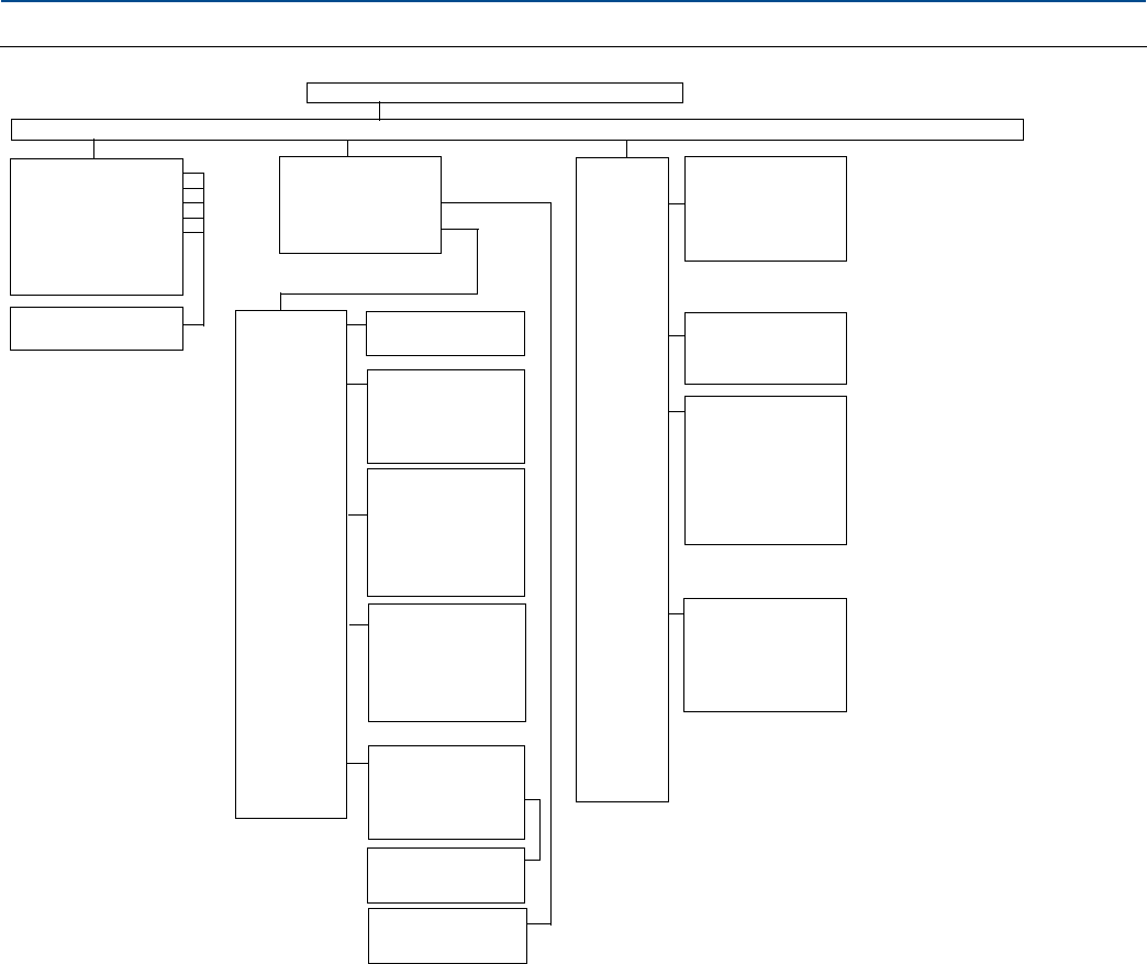
60
Reference Manual
00809-0100-4803, Rev GA
Configuration
September 2017
Configuration
Figure 2-43. Menu Tree for Direct Process Variable Output
1. Device Setup 2. PV 3. AO 4. PV LRV 5. PV
1. Process Variables...........................2. Diagnostics and Service............................. 3. Basic Setup......................4. Detailed Setup..........5. Review
1. Diff. Pressure
2. Absolute Pressure
3. Gage Pressure
4. Process Temp.
5. Module Temp.
6. Analog Output
7. Percent of Range
8. Primary Variable is
1. Reading
2. Status
1. Status
2. Loop Test
3. Configure Fixed
Variables
4. Calibration
1. Diff. Pressure
2. Static Pressure
3. Process Temp.
1. Rerange
2. Analog
Output
Trim
3. Diff.
Pressure
Trim
4. Static
Pressure
Trim
5. Process
Temp.
Trim
1. Upper Range Value
2. Lower Range Value
1. Digital-to-Analog
Trim
2. Scaled
Digital-to-Analog
Trim
1. Zero Trim
2. Lower Sensor Trim
3. Upper Sensor Trim
4. Sensor Trim
Calibration Type
5. Sensor Trim Points
6. Recall Factory Trim
1. Lower Sensor Trim
2. Upper Sensor Trim
3. Sensor Trim Points
4. Callendar Van
Dusen
1. Configure
Coefficients
2. Reset Coefficients
1. Tag
2. Long Tag
3. Units
4. Range
Value
5. Device
Info
6. Transfer
Function
7. Damping
8. LCD
Display
Config.
1. Differential
Pressure
2. Absolute Pressure
3. Gage Pressure
4. Process Temp.
5. Module Temp.
1. Upper Range
Value
2. Lower Range Value
1. Date
2. Descriptor
3. Message
4. Write Protect
5. Model
6. Model Number I
7. Model Number II
8. Model Number III
9. Model Number IV
1. Differential
Pressure
2. Static Pressure
3. Process
Temperature
1. Zero Trim
2. Lower Sensor Trim
3. Upper Sensor Trim
4. Sensor Trim
Calibration Type
5. Sensor Trim Points
6. Recall Factory Trim
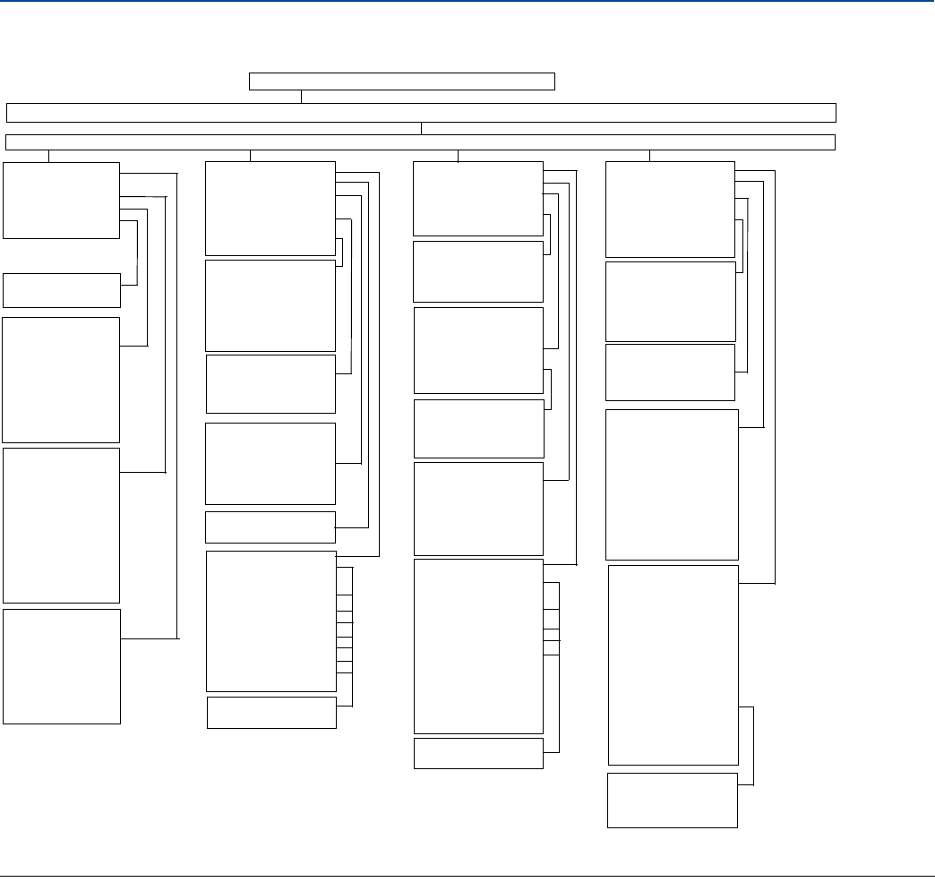
61
Reference Manual
00809-0100-4803, Rev GA
Configuration
September 2017
Configuration
1. Differential
Pressure
2. Static Pressure
3. Process Temp.
4. Module Temp.
1. Reading
2. Unit
1. Reading
2. Unit
3. Damping
4. Sensor Service
5. Lower Sensor
Limit
6. Upper Sensor
Limit
7. Min Span
1. Absolute
Reading
2. Absolute Unit
3. Gage Reading
4. Gage Unit
5. Damping
6. Atmospheric
Pressure
7. Sensor Service
8. Absolute Sensor
Limits
1. Reading
2. Unit
3. Damping
4. Sensor Service
5. Upper Sensor
Limit
6. Lower Sensor
Limit
1. Device Setup 2. PV 3. AO 4. PV LRV 5. PV URV
1. Process Variables.22. Diagnostics and Service. 3. Basic Setup..........4. Detailed Setup....>>.......................5. Review
1. Sensors.....................................2. Signal Condition...........................3. Output Condition................................4. Device Info...........................
1. Process Variables
2. Range Values
3. Units
4. Transfer Function
5. Damping
6. Alarm/Saturation
Levels
1. Alarm Direction
2. High Alarm
3. Low Alarm
4. High Saturation
5. Low Saturation
6. Config Alarm &
Saturation Levels
1. Differential
Pressure
2. Static Pressure
3. Process Temp.
1. Differential
Pressure
2. Absolute Pressure
3. Gage Pressure
4. Process Temp.
5. Module Temp.
1. Upper Range Value
2. Lower Range Value
1. Differential
Pressure
2. Absolute
Pressure
3. Gage Pressure
4. Process Temp.
5. Module Temp.
6. Analog Output
7. Percent of Range
8. Primary Variable
1. Reading
2. Status
1. Process Variables
2. Analog Output
3. HART Output
4. Variable
Remapping
1. Primary Variable
2. 2nd Variable
3. 3rd Variable
4. 4th Variable
1. Poll Address
2. Loop Current Mode
3. Burst Mode
4. Burst Option
5. Burst Slot
Definition
1. Slot 0
2. Slot 1
3. Slot 2
4. Slot 3
1. Loop Test
2. Digital-to-Analog
Trim
3. Scaled
Digital-to-Analog
Trim
4. Alarm Direction
1. Differential
Pressure
2. Absolute
Pressure
3. Gage Pressure
4. Process Temp.
5. Module Temp.
6. Analog Output
7. Percent of Range
8. Primary Variable
is
1. Reading
2. Status
1. Field Device Info
2. Sensor Info
3. Equipped Sensors
4. Diaphragm Seals
Info
1. # of Diaphragm
Seals
2. Seal Type
3. Seal Fill Fluid
4. Remote Seal
Isolator Material
1. Sensor Module Type
2. Module Config Type
3. Isolator Material
4. Fill Fluid
5. Process Connector
6. Process Connector
Material
7. O-ring Material
8. Drain Vent Material
1. Tag
2. Long Tag
3. Date
4. Descriptor
5. Write Protect
6. Message
7. Model
8. Model Number I
9. Model Number II
10.Model Number III
11.Model Number IV
12.Revision #s
13.Transmitter S/N
14.Sensor Module S/N
15.Feature board S/N
1. Universal Rev
2. Field Device Rev
3. Software Rev
4. Hardware Rev
1. DP Sensor
2. AP Sensor
3. GP Sensor
4. PT Sensor

62
Reference Manual
00809-0100-4803, Rev GA
Configuration
September 2017
Configuration
2.8.1 Field Communicator Fast Keys
Use Rosemount 3051SMV Engineering Assistant or any HART-compliant master to communicate with
and verify configuration of the Rosemount 3051SMV.
Table 2-13 shows the Field Communicator Fast Keys for the fully compensated mass and energy flow.
Table 2-14 on page 63 shows the Fast Keys for the direct process variable output.
A check (⻫) indicates the basic configuration parameters. At a minimum, these parameters should be
verified as part of the configuration and startup procedure.
Table 2-13. Fast Keys for Fully Compensated Mass and Energy Flow Output
Function Fast Key sequence
Absolute Pressure Reading and Status 1, 4, 2, 1, 5
Absolute Pressure Sensor Limits 1, 4, 1, 5, 8
Absolute Pressure Units 1, 3, 3, 5
Alarm and Saturation Level Configuration 1, 4, 2, 6, 6
Alarm and Saturation Levels 1, 4, 2, 6
Analog Output Trim Options 1, 2, 5, 2
Burst Mode Setup 1, 4, 3, 3, 3
Burst Mode Options 1, 4, 3, 3, 4
Callendar-van Dusen Sensor Matching 1, 2, 5, 5, 4
Configure Fixed Variables 1, 2, 4
Damping 1, 3, 7
Diaphragm Seals Information 1, 4, 4, 5
⻫Differential Pressure Low Flow Cutoff 1, 4, 1, 1, 6
Differential Pressure Reading and Status 1, 4, 2, 1, 4
Differential Pressure Sensor Trim Options 1, 2, 5, 3
⻫Differential Pressure Zero Trim 1, 2, 5, 3, 1
Differential Pressure Units 1, 3, 3, 4
Energy Rate Units 1, 3, 3, 2
Energy Reading and Status 1, 4, 2, 1, 2
Equipped Sensors 1, 4, 4, 4
Field Device Information 1, 4, 4, 1
Flow Calculation Type 1, 4, 1, 1, 2
⻫Flow Rate Units 1, 3, 3, 1
Flow Reading and Status 1, 4, 2, 1, 1
Gage Pressure Reading and Status 1, 4, 2, 1, 6
Gage Pressure Sensor Limits 1, 4, 1, 5, 9
Gage Pressure Units 1, 3, 3, 6
LCD Display Configuration 1, 3, 8
Loop Test 1, 2, 2
63
Reference Manual
00809-0100-4803, Rev GA
Configuration
September 2017
Configuration
Module Temperature Reading and Status 1, 4, 2, 1, 8
Module Temperature Units 1, 3, 3, 8
Poll Address 1, 4, 3, 3, 1
Process Temperature Reading and Status 1, 4, 2, 1, 7
⻫Process Temperature Sensor Mode 1, 4, 1, 6, 8
Process Temperature Sensor Trim Options 1, 2, 5, 5
Process Temperature Unit 1, 3, 3, 7
⻫Ranging the Analog Output 1, 2, 5, 1
Recall Factory Trim Settings 1, 2, 5, 2, 3
Sensor Information 1, 4, 4, 2
⻫Static Pressure Sensor Lower Trim (AP Sensor) 1, 2, 5, 4, 2
Static Pressure Sensor Trim Options 1, 2, 5, 4
⻫Static Pressure Sensor Zero Trim (GP Sensor) 1, 2, 5, 4, 1
⻫Status 1, 2, 1
⻫Tag 1, 3, 1
Test Flow Calculation 1, 2, 3
Totalizer Configuration 1, 4, 1, 3
Totalizer Reading and Status 1, 4, 2, 1, 3
Totalizer Units 1, 3, 3, 3
Variable Mapping 1, 4, 3, 4
Write Protect 1, 3, 5, 4
Table 2-14. Fast Keys for Direct Process Variable Measurement
Function Fast Key sequence
Absolute Pressure Reading and Status 1, 4, 2, 1, 2
Absolute Pressure Sensor Limits 1, 4, 1, 2, 8
⻫Absolute Pressure Units 1, 3, 3, 2
Alarm and Saturation Level Configuration 1, 4, 2, 6, 6
Alarm and Saturation Levels 1, 4, 2, 6
Analog Output Trim Options 1, 2, 4, 2
Burst Mode Setup 1, 4, 3, 3, 3
Burst Mode Options 1, 4, 3, 3, 4
Callendar-van Dusen Sensor Matching 1, 2, 4, 5, 4
Damping 1, 3, 7
Diaphragm Seals Information 1, 4, 4, 4
Table 2-13. Fast Keys for Fully Compensated Mass and Energy Flow Output
Function Fast Key sequence

64
Reference Manual
00809-0100-4803, Rev GA
Configuration
September 2017
Configuration
Differential Pressure Reading and Status 1, 4, 2, 1, 1
Differential Pressure Sensor Trim Options 1, 2, 4, 3
⻫Differential Pressure Zero Trim 1, 2, 4, 3, 1
⻫Differential Pressure Units 1, 3, 3, 1
Equipped Sensors 1, 4, 4, 3
Field Device Information 1, 4, 4, 1
Gage Pressure Reading and Status 1, 4, 2, 1, 3
Gage Pressure Sensor Limits 1, 4, 1, 2, 9
⻫Gage Pressure Units 1, 3, 3, 3
LCD Display Configuration 1, 3, 8
Loop Test 1, 2, 2
Module Temperature Reading and Status 1, 4, 2, 1, 5
Module Temperature Units 1, 3, 3, 5
Poll Address 1, 4, 3, 3, 1
Process Temperature Reading and Status 1, 4, 2, 1, 4
Process Temperature Sensor Trim Options 1, 2, 4, 5
⻫Process Temperature Unit 1, 3, 3, 4
⻫Ranging the Analog Output 1, 2, 4, 1
Recall Factory Trim Settings 1, 2, 4, 2, 3
Sensor Information 1, 4, 4, 2
⻫Static Pressure Sensor Lower Trim (AP Sensor) 1, 2, 4, 4, 2
Static Pressure Sensor Trim Options 1, 2, 4, 4
⻫Static Pressure Sensor Zero Trim (GP Sensor) 1, 2, 4, 4, 1
⻫Status 1, 2, 1
⻫Tag 1, 3, 1
⻫Transfer Function 1, 3, 6
Variable Mapping 1, 4, 3, 4
Write Protect 1, 3, 5, 4
Table 2-14. Fast Keys for Direct Process Variable Measurement
Function Fast Key sequence

65
Reference Manual
00809-0100-4803, Rev GA
Installation
September 2017
Installation
Section 3 Installation
Overview . . . . . . . . . . . . . . . . . . . . . . . . . . . . . . . . . . . . . . . . . . . . . . . . . . . . . . . . . . . . . . . . . . . . . . . . . . . . page 65
Safety messages . . . . . . . . . . . . . . . . . . . . . . . . . . . . . . . . . . . . . . . . . . . . . . . . . . . . . . . . . . . . . . . . . . . . . . page 65
Installation considerations . . . . . . . . . . . . . . . . . . . . . . . . . . . . . . . . . . . . . . . . . . . . . . . . . . . . . . . . . . . . . page 67
Installation procedures . . . . . . . . . . . . . . . . . . . . . . . . . . . . . . . . . . . . . . . . . . . . . . . . . . . . . . . . . . . . . . . . page 67
Rosemount 305 and 304 Manifolds . . . . . . . . . . . . . . . . . . . . . . . . . . . . . . . . . . . . . . . . . . . . . . . . . . . . . page 80
3.1 Overview
This section contains information that covers installation considerations for Rosemount™ 3051S
MultiVariable™ Transmitter (Rosemount 3051SMV). The Rosemount 3051SMV Quick Start Guide is
shipped with every transmitter to describe basic installation, wiring, configuration, and startup
procedures. Dimensional drawings for each Rosemount 3051SMV type and mounting configuration are
included in “Specifications and Reference Data” on page 125.
3.2 Safety messages
Procedures and instructions in this section may require special precautions to ensure the safety of the
personnel performing the operation. Information that raises potential safety issues is indicated with a
warning symbol ( ). Refer to the following safety messages before performing an operation preceded
by this symbol.

66
Reference Manual
00809-0100-4803, Rev GA
Installation
September 2017
Installation
Failure to follow these installation guidelines could result in death or serious injury.
Make sure only qualified personnel perform the installation.
Explosions could result in death or serious injury.
Do not remove the transmitter cover in explosive atmospheres when the circuit is live.
Before connecting a Field Communicator in an explosive atmosphere, make sure the instruments in
the loop are installed in accordance with intrinsically safe or non-incendive field wiring practices.
Both transmitter covers must be fully engaged to meet flameproof/explosion-proof requirements.
Verify the operating atmosphere of the transmitter is consistent with the appropriate hazardous
locations certifications.
Electrical shock could cause death or serious injury.
If the sensor is installed in a high-voltage environment and a fault or installation error occurs, high
voltage may be present on the transmitter leads and terminals.
Use extreme caution when making contact with the leads and terminals.
Process leaks could result in death or serious injury.
Install and tighten all four flange bolts before applying pressure.
Do not attempt to loosen or remove flange bolts while the transmitter is in service.
Replacement equipment or spare parts not approved by Emerson™ for use as spare parts could
reduce the pressure retaining capabilities of the transmitter and may render the instrument
dangerous.
Use only bolts supplied or sold by Emerson as spare parts.
Improper assembly of manifolds to traditional flange can damage the device.
For safe assembly of manifold to traditional flange, bolts must break back plane of flange web
(i.e., bolt hole) but must not contact the sensor module.
Improper installation or repair of the SuperModule™ assembly with high pressure option (P0)
could result in death or serious injury.
For safe assembly, the high pressure SuperModule assembly must be installed with ASTM A193
Class 2 Grade B8M bolts and either a Rosemount 305 Manifold or a DIN-compliant traditional flange.
Static electricity can damage sensitive components.
Observe safe handling precautions for static-sensitive components.

67
Reference Manual
00809-0100-4803, Rev GA
Installation
September 2017
Installation
3.3 Installation considerations
3.3.1 General
Measurement performance depends upon proper installation of the transmitter, impulse piping, and
process temperature sensor. Mount the transmitter close to the process and use minimum piping to
achieve best performance. Also, consider the need for easy access, personnel safety, practical field
calibration, and a suitable transmitter environment. Install the transmitter to minimize vibration, shock,
and temperature fluctuation.
Note
Install the enclosed pipe plug (found in the box) in the unused conduit opening if optional process
temperature input is not used. For proper straight and tapered thread engagement requirements, see
the appropriate approvals drawings in Appendix B: Product Certifications.
For material compatibility considerations, see Material Selection Technical Note.
3.3.2 Mechanical
For steam service or for applications with process temperatures greater than the limits of the
transmitter, do not blow down impulse piping through the transmitter. Flush lines with the blocking
valves closed and refill lines with water before resuming measurement.
When the transmitter is mounted on its side, position the coplanar flange to ensure proper venting or
draining. Mount the flange as shown in Figure 3-5 on page 72, keeping drain/vent connections on the
bottom for gas service and on the top for liquid service.
3.3.3 Environmental
Access requirements and “Cover installation” on page 69 can help optimize transmitter performance.
Mount the transmitter to minimize ambient temperature changes, vibration, mechanical shock, and to
avoid external contact with corrosive materials. “Specifications and Reference Data” on page 125 lists
temperature operating limits.
3.4 Installation procedures
3.4.1 Configure security (write protect)
Changes to the transmitter configuration data can be prevented with the security (write protect) switch
located on the feature board. See Figure 3-1 on page 68 for the location of the switch. Position the
switch in the ON position to prevent accidental or deliberate change of configuration data.
If the transmitter write protection switch is in the ON position, the transmitter will not accept any
“writes” to its memory. Configuration changes, such as digital trim and reranging, cannot take place
when the transmitter security is on.
To reposition the switches, follow the procedure described below:
1. Do not remove the transmitter covers in explosive atmospheres when the circuit is live. If the
transmitter is live, set the loop to manual and remove power.
2. Remove the housing cover opposite the field terminal side of the housing.
3. To reposition the switches as desired, slide the security and alarm switches into the preferred position
using a small screwdriver. See Figure 3-1 on page 68.
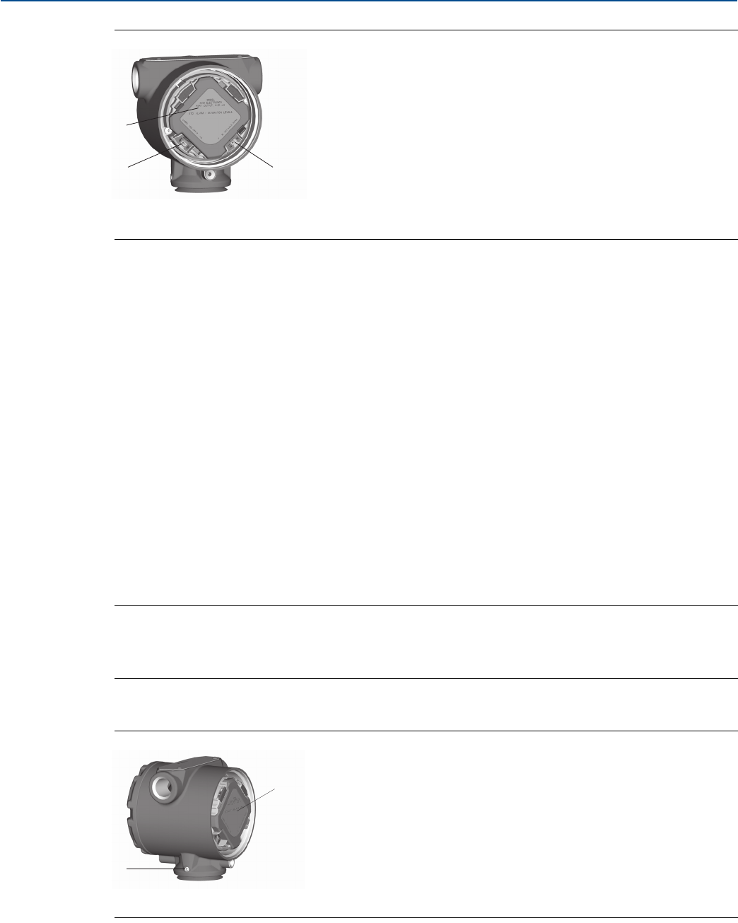
68
Reference Manual
00809-0100-4803, Rev GA
Installation
September 2017
Installation
Figure 3-1. Switch Configuration
A. Feature board
B. Security
C. Alarm
4. Re-install the transmitter cover. Transmitter covers must be fully engaged so that metal contacts
metal in order to meet flameproof/explosion-proof requirements.
3.4.2 Configure alarm direction
The transmitter alarm direction is set by repositioning the alarm switch. Position the switch in the HI
position for fail high and in the LO position for fail low. See “Alarm and saturation” on page 27 for more
information on alarm and saturation levels.
3.4.2 Mounting considerations
For dimensional drawing information refer to “Specifications and Reference Data” on page 125.
Housing rotation
The housing can be rotated to improve field access to wiring or to better view the optional LCD display.
To rotate the housing, perform the following procedure:
1. Loosen the housing rotation set screw.
2. Turn the housing up to 180° to the left or right of its original (as shipped) position.
Note
Do not rotate the housing more than 180° without first performing a disassembly procedure (see
“Housing assembly including feature board electronics” on page 100). Over-rotation may sever the
electrical connection between the sensor module and the feature board.
3. Retighten the housing rotation set screw.
Figure 3-2. Housing
A. Feature board
B. 3/32-in. housing rotation set screw
A
BC
A
B

69
Reference Manual
00809-0100-4803, Rev GA
Installation
September 2017
Installation
LCD display rotation
In addition to housing rotation, the optional LCD display can be rotated in 90° increments by squeezing
the two tabs, pulling out, rotating and snapping back into place.
Note
If LCD display pins are inadvertently removed from the feature board, re-insert the pins before snapping
the LCD display back into place.
Field terminal side of housing
Mount the transmitter so the terminal side is accessible. Clearance of 0.75-in. (19 mm) is required for
cover removal. Use a conduit plug in the unused conduit opening if the optional Process Temperature
Input is not installed.
Feature board side of housing
Provide 0.75-in. (19 mm) of clearance for units without an LCD display. Three inches of clearance is
required for cover removal if an LCD display is installed.
Cover installation
Always ensure a proper seal by installing the housing covers so that metal contacts metal in order to
prevent performance degradation due to environmental effects. For replacement cover O-rings, use
Rosemount O-rings (part number 03151-9040-0001).
Conduit entry threads
For NEMA® 4X, IP66, and IP68 requirements, use thread seal (PTFE) tape or paste on male threads to
provide a watertight seal.
Cover jam screw
For transmitter housings shipped with a cover jam screw, as shown in Figure 3-3 on page 70, the screw
should be properly installed once the transmitter has been wired and powered up. The cover jam screw is
intended to prevent the removal of the transmitter cover in flameproof environments without the use of
tools. Follow these steps to install the cover jam screw:
1. Verify the cover jam screw is completely threaded into the housing.
2. Install the transmitter housing covers and verify that metal contacts metal in order to meet
flameproof/explosion-proof requirements.
3. Using an M4 hex wrench, turn the jam screw counterclockwise until it contacts the transmitter cover.
4. Turn the jam screw an additional 1/2 turn counterclockwise to secure the cover. Application of
excessive torque may strip the threads.
5. Verify the covers cannot be removed.
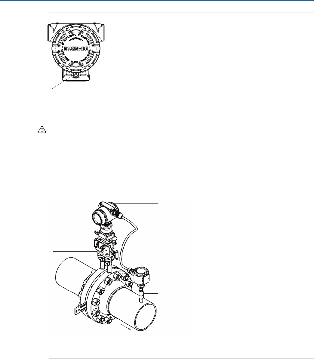
70
Reference Manual
00809-0100-4803, Rev GA
Installation
September 2017
Installation
Figure 3-3. Cover Jam Screw
A. Cover jam screw (one per side)
Process flange orientation
Mount the process flanges with sufficient clearance for process connections. For safety reasons, place
the drain/vent valves so the process fluid is directed away from possible human contact when the vents
are used. In addition, consider the need for a testing or calibration input.
3.4.3 Mount the transmitter
Figure 3-4 illustrates a typical Rosemount 3051SMV installation site measuring dry gas with an orifice
plate.
Figure 3-4. Typical Rosemount 3051SMV Installation Site
A. Rosemount 3051SMV
B. RTD cable
C. Pt 100 RTD sensor
D. Process connections
A
Flow
A
B
C
D
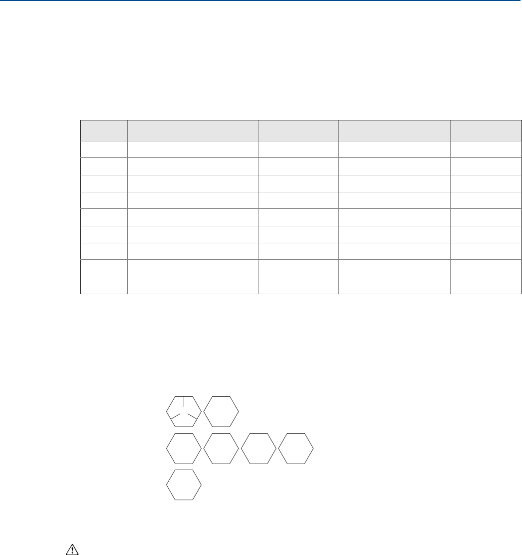
71
Reference Manual
00809-0100-4803, Rev GA
Installation
September 2017
Installation
Mounting brackets
The Rosemount 3051SMV can be mounted to a 2-in. pipe or to a panel using an optional mounting
bracket. The B4 Bracket (SST [Stainless steel]) option is for use with the coplanar flange process
connection. “Coplanar Flange Mounting Configurations” on page 135 shows bracket dimensions and
mounting configurations for the B4 option. Other bracket options are listed in Table 3-1. When installing
the transmitter to one of the optional mounting brackets, torque the bolts to 125 in-lb (0,9 N-m).
Flange bolts
The Rosemount 3051SMV can be shipped with a coplanar flange or a traditional flange installed with four
1.75-in. flange bolts. Mounting bolts and bolting configurations for the coplanar and traditional flanges
can be found in Figure 3-5 on page 72. SST bolts supplied by Emerson are coated with a lubricant to ease
installation. CS bolts do not require lubrication. No additional lubricant should be applied when installing
either type of bolt. Bolts supplied by Emerson are identified by their head markings:
Bolt installation
Only use bolts supplied with the Rosemount 3051SMV or sold by Emerson as spare parts. Use the
following bolt installation procedure to:
1. Finger-tighten the bolts.
2. Torque the bolts to the initial torque value using a crossing pattern. For initial torque values, see Tabl e
3-2 on page 72.
3. Torque the bolts to the final torque value using the same crossing pattern. For final torque values, see
Table 3-2 on page 72.
Table 3-1. Mounting Brackets
Options Description Mounting type Bracket material Bolt material
B4 Coplanar flange bracket 2-in. pipe/panel SST SST
B1 Traditional flange bracket 2-in. pipe Painted CS (Carbon steel) CS
B2 Traditional flange bracket Panel Painted CS CS
B3 Traditional flange flat bracket 2-in. pipe Painted CS CS
B7 Traditional flange bracket 2-in. pipe Painted CS SST
B8 Traditional flange bracket Panel Painted CS SST
B9 Traditional flange flat bracket 2-in. pipe Painted CS SST
BA Traditional flange bracket 2-in. pipe SST SST
BC Traditional flange flat bracket 2-in. pipe SST SST
Carbon Steel (CS)
Head Markings
Stainless Steel (SST)
Head Markings
Alloy K-500 Head
Marking
1.The last digit in the F593_ head marking may be any letter between A and M.
B7M
316 B8M 660
CL A F593_
(1)
KM
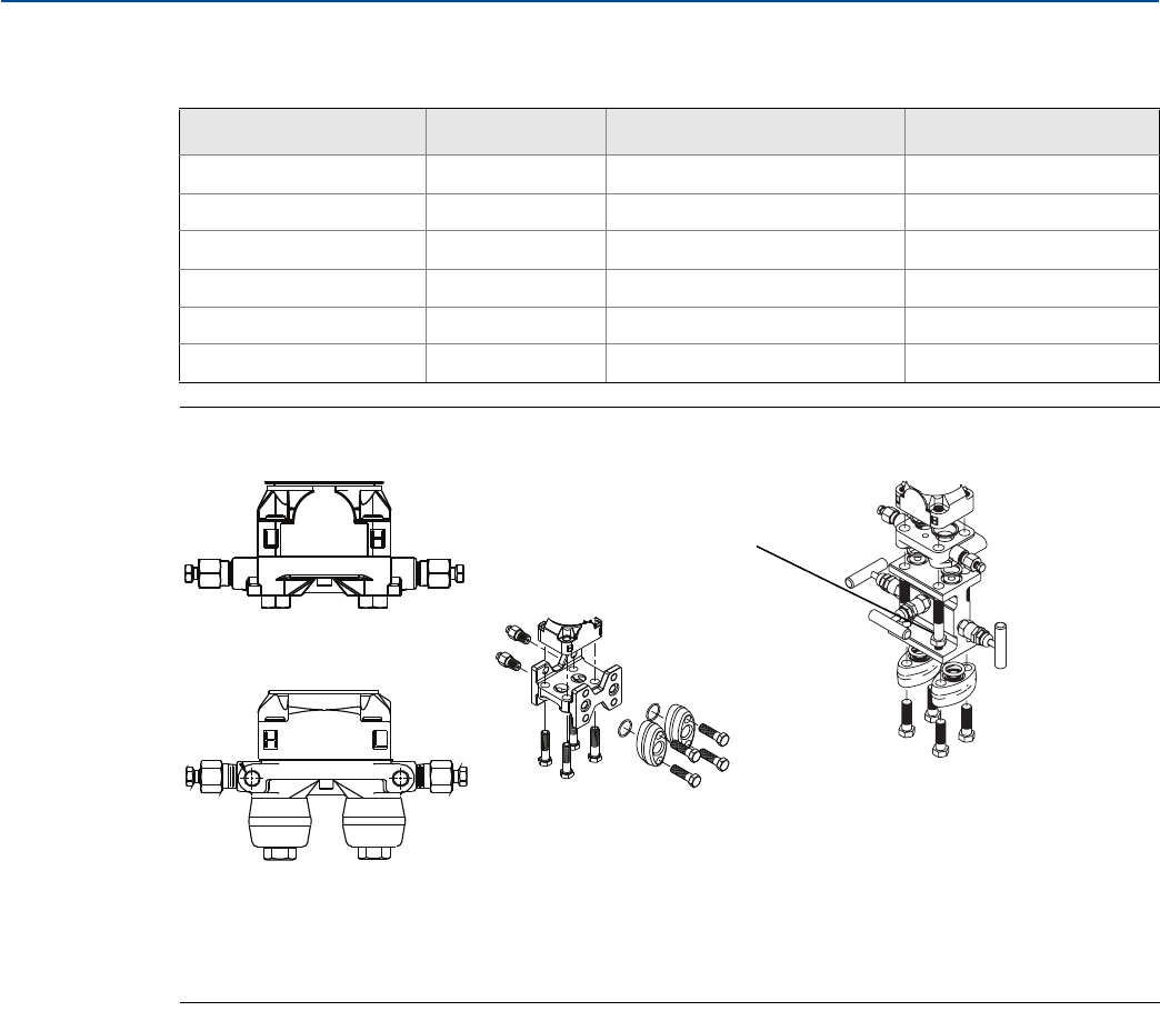
72
Reference Manual
00809-0100-4803, Rev GA
Installation
September 2017
Installation
Torque values for the flange and manifold adapter bolts are as follows:
Figure 3-5. Common Transmitter Assemblies
A. Transmitter with coplanar flange
B. Transmitter with coplanar flange and optional flange adapters
C. Transmitter with traditional flange and optional flange adapters
D. Transmitter with coplanar flange and optional manifold and flange adapters
Mounting requirements
Impulse piping configurations depend on specific measurement conditions. Refer to Figure 3-6 on
page 73 for examples of the following mounting configurations:
Liquid flow measurement
Place taps to the side of the line to prevent sediment deposits on the process isolators.
Mount the transmitter beside or below the taps so gases vent into the process line.
Mount drain/vent valve upward to allow gases to vent.
Gas flow measurement
Place taps in the top or side of the line.
Mount the transmitter beside or above the taps so to drain liquid into the process line.
Table 3-2. Bolt Installation Torque Values
Bolt material Option code Initial torque value Final torque value
CS-ASTM-A449 Standard 300 in-lb (34 N-m) 650 in-lb (73 N-m)
316 SST Option L4 150 in-lb (17 N-m) 300 in-lb (34 N-m)
ASTM-A-193-B7M Option L5 300 in-lb (34 N-m) 650 in-lb (73 N-m)
Alloy K-500 Option L6 300 in-lb (34 N-m) 650 in-lb (73 N-m)
ASTM-A-453-660 Option L7 150 in-lb (17 N-m) 300 in-lb (34 N-m)
ASTM-A-193-B8M Option L8 150 in-lb (17 N-m) 300 in-lb (34 N-m)
A
4 × 1.75-in. (44 mm)
B
4 × 2.88-in. (73 mm)
D
4 × 1.75-in. (44 mm)
4 × 2.25-in. (57 mm)
C
4 × 1.75-in.
(44 mm) 4 × 1.50-in.
(38 mm)
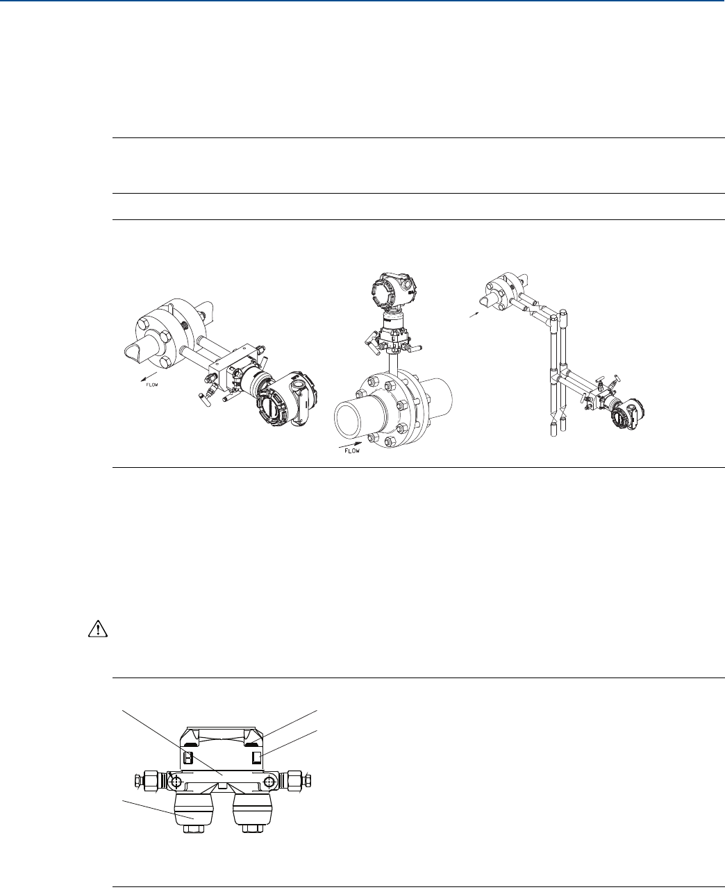
73
Reference Manual
00809-0100-4803, Rev GA
Installation
September 2017
Installation
Steam flow measurement
Place taps to the side of the line.
Mount the transmitter below the taps to ensure that impulse piping will remain filled with condensate.
In steam service above 250 °F (121 °C), fill impulse lines with water to prevent steam from contacting
the transmitter directly and to ensure accurate measurement start-up.
Note
For steam or other elevated temperature services, it is important that temperatures at the transmitter
process connection do not exceed the transmitter’s operating limits.
Figure 3-6. Installation Examples
3.4.4 Process connections
The Rosemount 3051SMV flange process connection size is 1/4–18 NPT. Flange adapters with a 1/4–18
NPT to 1/2–14 NPT connection are available with the D2 option. Use a plant-approved lubricant or sealant
when making the process connections. The process connections on the transmitter flange are on 21/8-in.
(54 mm) centers to allow direct mounting to a 3- or 5-valve manifold. Rotate one or both of the flange
adapters to attain connection centers of 2-in. (51 mm), 21/8-in. (54 mm), or 21/4-in. (57 mm).
Install and tighten all four flange bolts before applying pressure to avoid leakage. When properly
installed, the flange bolts will protrude through the top of the SuperModule isolator plate. See
Figure 3-7. Do not attempt to loosen or remove the flange bolts while the transmitter is in service.
Figure 3-7. SuperModule Isolator Plate
A. Bolt
B. SuperModule isolator plate
C. Coplanar flange
D. Flange adapters
Liquid service Gas service Steam service
FLOW
A
B
C
D
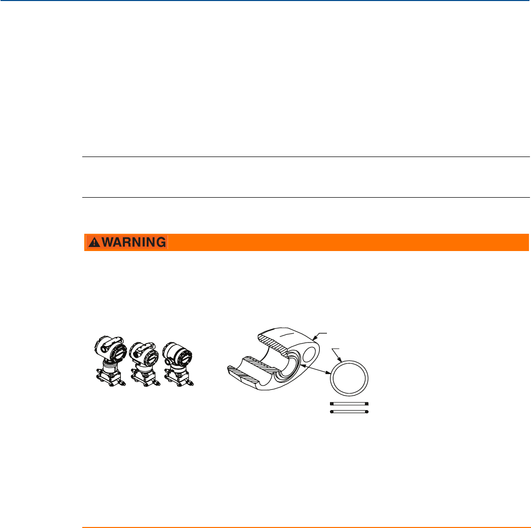
74
Reference Manual
00809-0100-4803, Rev GA
Installation
September 2017
Installation
To install adapters to a coplanar flange, perform the following procedure:
1. Remove the flange bolts.
2. Leaving the flange in place, move the adapters into position with the O-rings installed.
3. Attach the adapters and the coplanar flange to the transmitter SuperModule assembly using the
longer of the bolts supplied.
4. Tighten the bolts. Refer to Table 3-2 on page 72 for torque specifications.
Refer to “Service support” on page 117 for the correct part numbers of the flange adapters and O-rings
designed for the Rosemount 3051SMV.
Note
The two styles of Rosemount flange adapters (Rosemount 3051S/3051/2051) each require a unique
O-ring . Use only the O-ring designed for the corresponding flange adaptor.
O-ring
Impulse piping considerations
The piping between the process and the transmitter must accurately transfer the pressure to obtain
accurate measurements. There are many possible sources of error: pressure transfer, leaks, friction loss
(particularly if purging is used), trapped gas in a liquid line, liquid in a gas line, density variations between
the legs, and plugged impulse piping.
The best location for the transmitter in relation to the process pipe depends on the process itself. Use the
following guidelines to determine transmitter location and placement of impulse piping:
Keep impulse piping as short as possible.
For liquid service, slope the impulse piping at least 1 in. per ft. (8 cm per m) upward from the
transmitter toward the process connection.
Failure to install proper flange adapter O-rings may cause process leaks, which can result in death or
serious injury. The two flange adapters are distinguished by unique O-ring grooves. Only use the O-ring
designed for its specific flange adapter, as shown below:
A. Flange adapter
B. O-ring
C. PTFE-based profile (square)
D. Elastomer profile (round)
When removing flanges or adapters, visually inspect the PTFE O-rings. Replace them if there are any
signs of damage, such as nicks or cuts. If replacing the O-rings, re-torque the flange bolts after
installation to compensate for seating of the PTFE O-ring. Refer to “Flange and drain vent” on page 103.
A
B
C
Rosemount 3051S/3051/2051
D
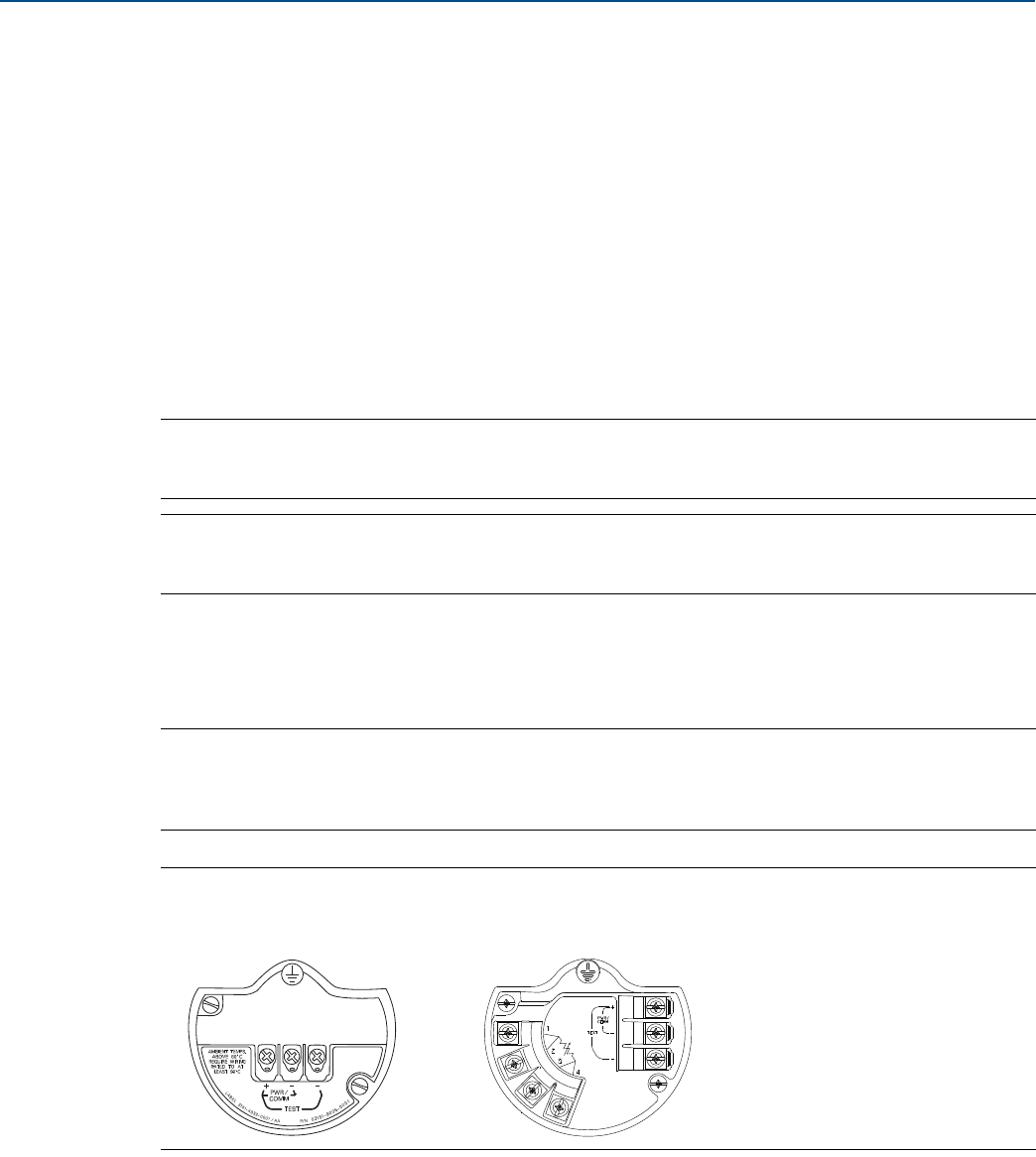
75
Reference Manual
00809-0100-4803, Rev GA
Installation
September 2017
Installation
For gas service, slope the impulse piping at least 1 in. per ft. (8 cm per m) downward from the
transmitter toward the process connection.
Avoid high points in liquid lines and low points in gas lines.
Make sure both impulse legs are the same temperature.
Use impulse piping large enough to avoid friction effects and blockage.
Vent all gas from liquid piping legs.
When using a sealing fluid, fill both piping legs to the same level.
When purging, make the purge connection close to the process taps and purge through equal lengths
of the same size pipe. Avoid purging through the transmitter.
Keep corrosive or hot, above 250 °F (121 °C), process material out of direct contact with the
SuperModule process connection and flanges.
Prevent sediment deposits in the impulse piping.
Keep the liquid head balanced on both legs of the impulse piping.
Note
Take necessary steps to prevent process fluid from freezing within the process flange to avoid damage to
the transmitter.
Note
Verify transmitter zero point after installation. To reset zero point, refer to “Sensor trim overview” on
page 90.
3.4.5 Connect wiring and power up
It is recommended to use twisted pair wiring. To ensure proper communication, use 24 to 14 AWG wire,
and do not exceed 5000 ft. (1500 m).
Note
Proper electrical installation is necessary to prevent errors due to improper grounding and electrical
noise. Shielded wiring is recommended for environments with high EMI/RFI levels. Shielded wiring is
required in order to comply with NAMUR requirements.
Figure 3-8. Terminal Blocks
To make connections, perform the following procedure:
1. Remove the cover on the field terminals side of the housing.
2. Connect the positive lead to the “PWR/COMM +” terminal, and the negative lead to the “PWR/COMM
–” terminal.
Without optional process
temperature connection
With optional process
temperature connection
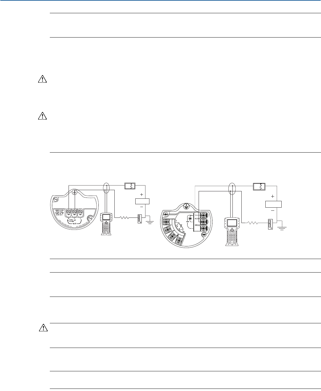
76
Reference Manual
00809-0100-4803, Rev GA
Installation
September 2017
Installation
Note
Do not connect the power across the test terminals. Power could damage the test diode in the test
connection.
3. If the optional process temperature input is not installed, plug and seal the unused conduit
connection. If the optional process temperature input is being utilized, see “Install optional process
temperature input (Pt 100 RTD sensor)” on page 76 for more information.
When the enclosed pipe plug is utilized in the conduit opening, it must be installed with a minimum
engagement of five threads in order to comply with flameproof/explosion-proof requirements.
4. If applicable, install wiring with a drip loop. Arrange the drip loop so the bottom is lower than the
conduit connections and the transmitter housing.
5. Reinstall the housing cover and tighten so that metal contacts metal to meet
flameproof/explosion-proof requirements.
Figure 3-9 shows the wiring connections necessary to power a Rosemount 3051SMV and enable
communications with a Hand-held Field Communicator.
Figure 3-9. Transmitter Wiring
A. Power supply
Note
Installation of the transient protection terminal block does not provide transient protection unless the
Rosemount 3051SMV housing is properly grounded. See “Grounding” on page 79 for more information.
Install optional process temperature input (Pt 100 RTD sensor)
Note
To meet ATEX/IECEx Flameproof certification, only ATEX/IECEx Flameproof cables (temperature input
code C30, C32, C33, C34 or customer supplied equivalent) may be used.
1. Mount the Pt 100 RTD Sensor in the appropriate location.
Note
Use shielded four-wire cable for the process temperature connection.
Without optional process temperature
connection
With optional process temperature
connection
A
RL ≥ 250Ω
A
RL ≥ 250Ω
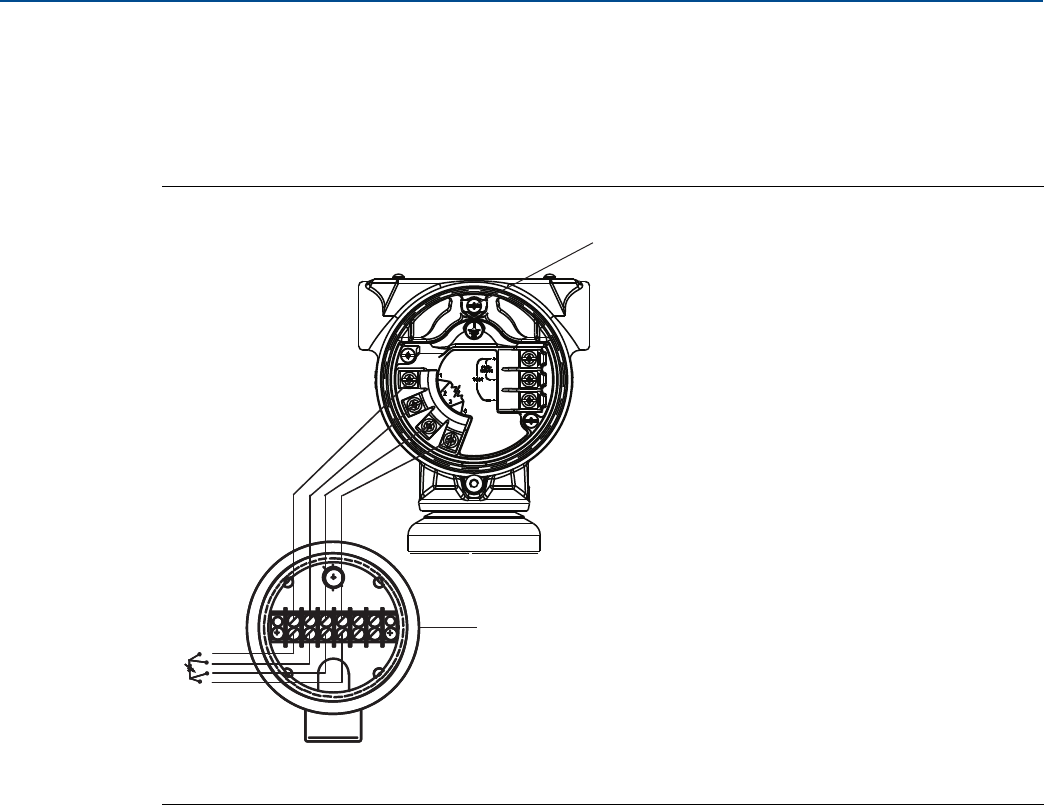
77
Reference Manual
00809-0100-4803, Rev GA
Installation
September 2017
Installation
2. Connect the RTD cable to the Rosemount 3051SMV by inserting the cable wires through the unused
housing conduit connection and connect to the four screws on the transmitter terminal block. An
appropriate cable gland should be used to seal the conduit opening around the cable. See Figure 3-10
on page 77.
3. Connect the RTD cable shield wire to the ground lug in the housing.
Figure 3-10. RTD Wiring Connection
Three-wire RTD
A four-wire Pt 100 RTD is required to maintain published performance specifications. A three-wire Pt 100
RTD may be used with degraded performance. If connecting to a three-wire RTD, use a four-wire cable to
connect the Rosemount 3051SMV terminal block to the RTD connection head. Within the RTD
connection head, connect two of the same colored wires from the Rosemount 3051SMV to the single
colored wire of the RTD sensor.
Surges/transients
The transmitter will withstand electrical transients of the energy level usually encountered in static
discharges or induced switching transients. However, high-energy transients, such as those induced in
wiring from nearby lightning strikes, can damage the transmitter.
Optional transient protection terminal block
The transient protection terminal block can be ordered as an installed option (code T1 in the transmitter
model number) or as a spare part to retrofit existing Rosemount 3051SMV in the field. For a complete
listing of spare part numbers for transient protection terminal blocks, refer to “Service support” on
page 117. A lightning bolt symbol on a terminal block identifies it as having transient protection.
A. Ground lug
B. RTD connection head
C. Pt 100 RTD sensor
D. RTD cable assembly wires
A
B
C
D
Red
Red
White
White
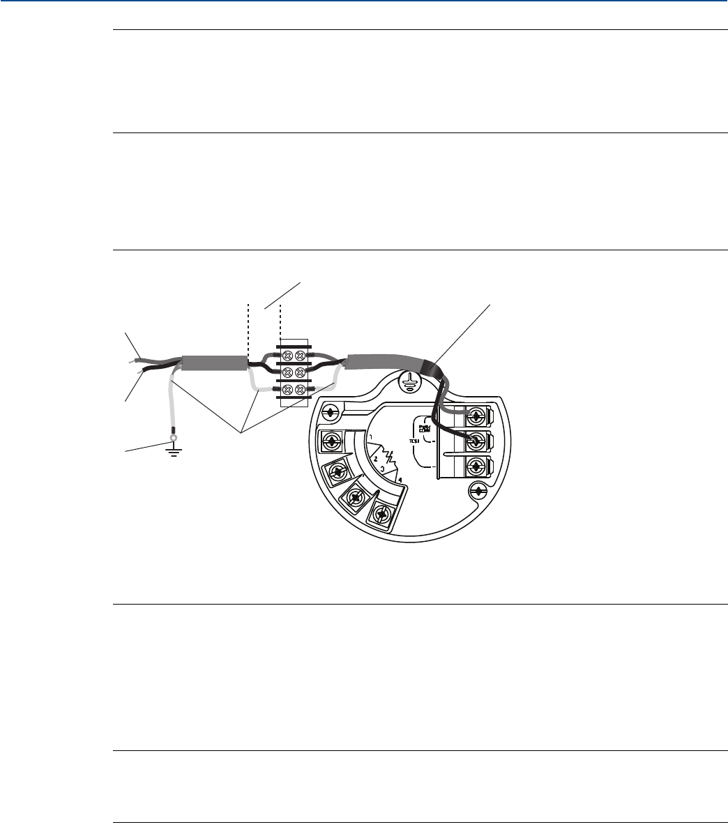
78
Reference Manual
00809-0100-4803, Rev GA
Installation
September 2017
Installation
Note
Grounding the transmitter case using the threaded conduit connection may not provide a sufficient
ground. The transient protection terminal block (option code T1) will not provide transient protection
unless the transmitter case is properly grounded. See “Grounding” on page 79 to ground the transmitter
case. Do not run transient protection ground wire with signal wiring; the ground wire may carry
excessive current if a lightning strike occurs.
Signal wire grounding
Do not run signal wiring in conduit or open trays with power wiring, or near heavy electrical equipment.
Ground the shield of the signal wiring at any one point on the signal loop. See Figure 3-11. The negative
terminal of the power supply is a recommended grounding point.
Figure 3-11. Signal Wire Grounding
Power supply 4–20 mA transmitters
The DC power supply should provide power with less than two percent ripple. Total resistance load is the
sum of resistance from signal leads and the load resistance of the controller, indicator, and related
pieces. Note that the resistance of intrinsic safety barriers, if used, must be included.
See “Load limitations” on page 131 for transmitter resistance load limits.
Note
A minimum loop resistance of 250 ohms is required to communicate with a Field Communicator. If a
single power supply is used to power more than one Rosemount 3051SMV, the power supply used and
circuitry common to the transmitters should not have more than 20 ohms of impedance at 1200 Hz.
A. Positive
B. Negative
C. Connect shield back to the power supply negative terminal
D. Insulate shield
E. Minimize distance
F. Trim shield and insulate
DP
A
E
B
CD
F
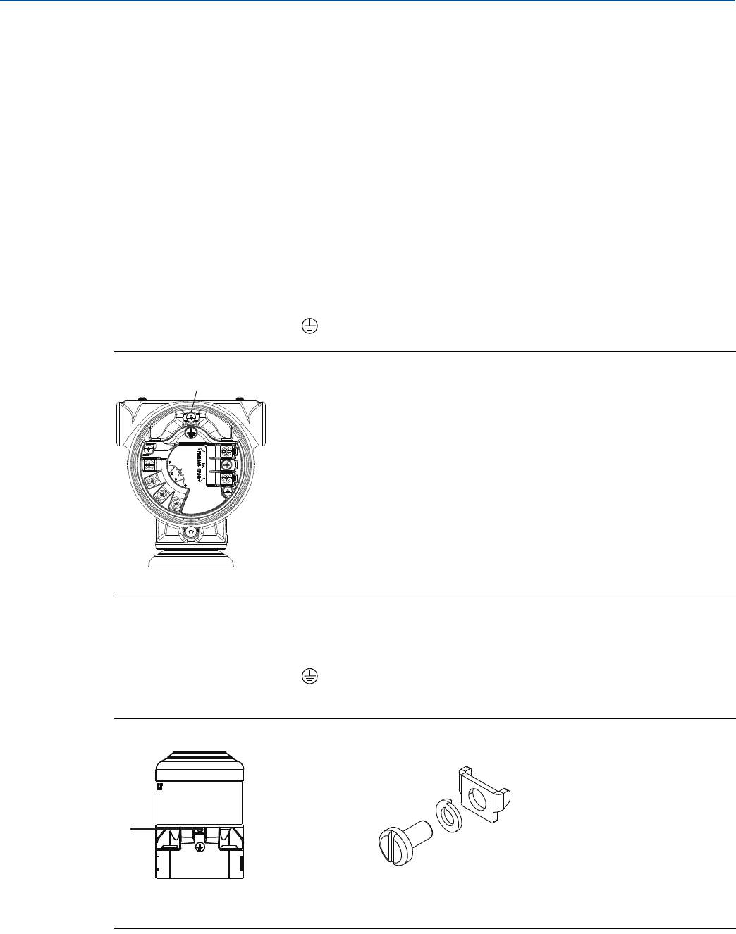
79
Reference Manual
00809-0100-4803, Rev GA
Installation
September 2017
Installation
3.4.6 Conduit electrical connector wiring (option GE or GM)
For Rosemount 3051SMV with conduit electrical connectors GE or GM, refer to the cordset
manufacturer’s installation instructions for wiring details. For FM Intrinsically Safe, non-incendive
hazardous locations, install in accordance with Rosemount drawing 03151-1009 to maintain outdoor
rating (NEMA® 4X and IP66.) For more information, see “Product Certifications” on page 155.
3.4.7 Grounding
Transmitter case
Always ground the transmitter case in accordance with national and local electrical codes. The most
effective transmitter case grounding method is a direct connection to earth ground with minimal
impedance (< 1Ω). Methods for grounding the transmitter case include:
Internal ground connection
The internal ground connection screw is inside the terminal side of the electronics housing. The screw is
identified by a ground symbol ( ), and is standard on all Rosemount 3051SMV.
Figure 3-12. Internal Ground Connection
A. Ground lug
External ground connection
The external ground connection is on the outside of the SuperModule housing. The connection is
identified by a ground symbol ( ). An external ground assembly is included with the option codes
shown in Table 3-3 on page 80 or is available as a spare part (03151-9060-0001).
Figure 3-13. External Ground Connection
A. External ground lug
B. External ground assembly (03151-9060-0001)
A
A
B
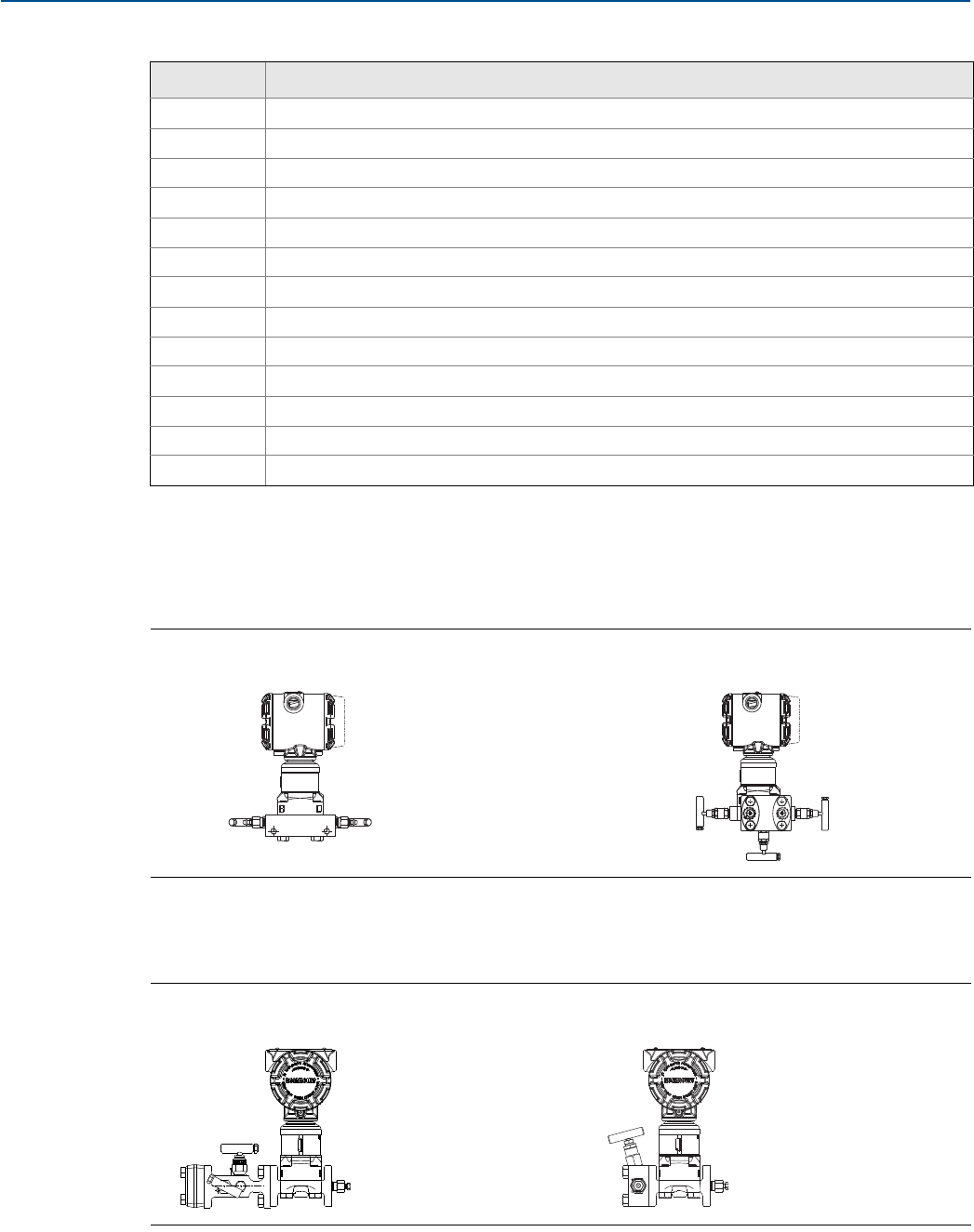
80
Reference Manual
00809-0100-4803, Rev GA
Installation
September 2017
Installation
3.5 Rosemount 305 and 304 Manifolds
The Rosemount 305 Integral Manifold is available in two designs: coplanar and traditional. The
traditional Rosemount 305 can be mounted to most primary elements with mounting adapters.
Figure 3-14. Rosemount 305 Manifold Styles
The Rosemount 304 comes in two basic styles: traditional (flange ⫻ flange and flange ⫻ pipe) and wafer.
The Rosemount 304 Traditional Manifold comes in 2-, 3-, and 5-valve configurations. The Rosemount
304 Wafer Manifold comes in 3- and 5-valve configurations.
Figure 3-15. Rosemount 304 Manifold Styles
Table 3-3. External Ground Screw Approval Option Codes
Option code Description
E1 ATEX Flameproof
I1 ATEX Intrinsic Safety
N1 ATEX Type n
ND ATEX Dust
E4 TIIS Flameproof
K1 ATEX Flameproof, Intrinsic Safety, Type n, Dust (combination of E1, I1, N1, and ND)
E7 IECEx Flameproof, Dust Ignition-proof
N7 IECEx Type n
K7 IECEx Flameproof, Dust Ignition-proof, Intrinsic Safety, and Type n (combination of E7, I7, and N7)
KA ATEX and CSA Explosion-proof, Intrinsically Safe, Division 2 (combination of E1, E6, I1, and I6)
KC FM and ATEX Explosion-proof, Intrinsically Safe, Division 2 (combination of E5, E1, I5, and I1)
T1 Transient terminal block
D4 External ground screw assembly
Rosemount 305 Integral Coplanar Rosemount305 Integral Traditional
Rosemount 304 Traditional Rosemount 304 Wafer
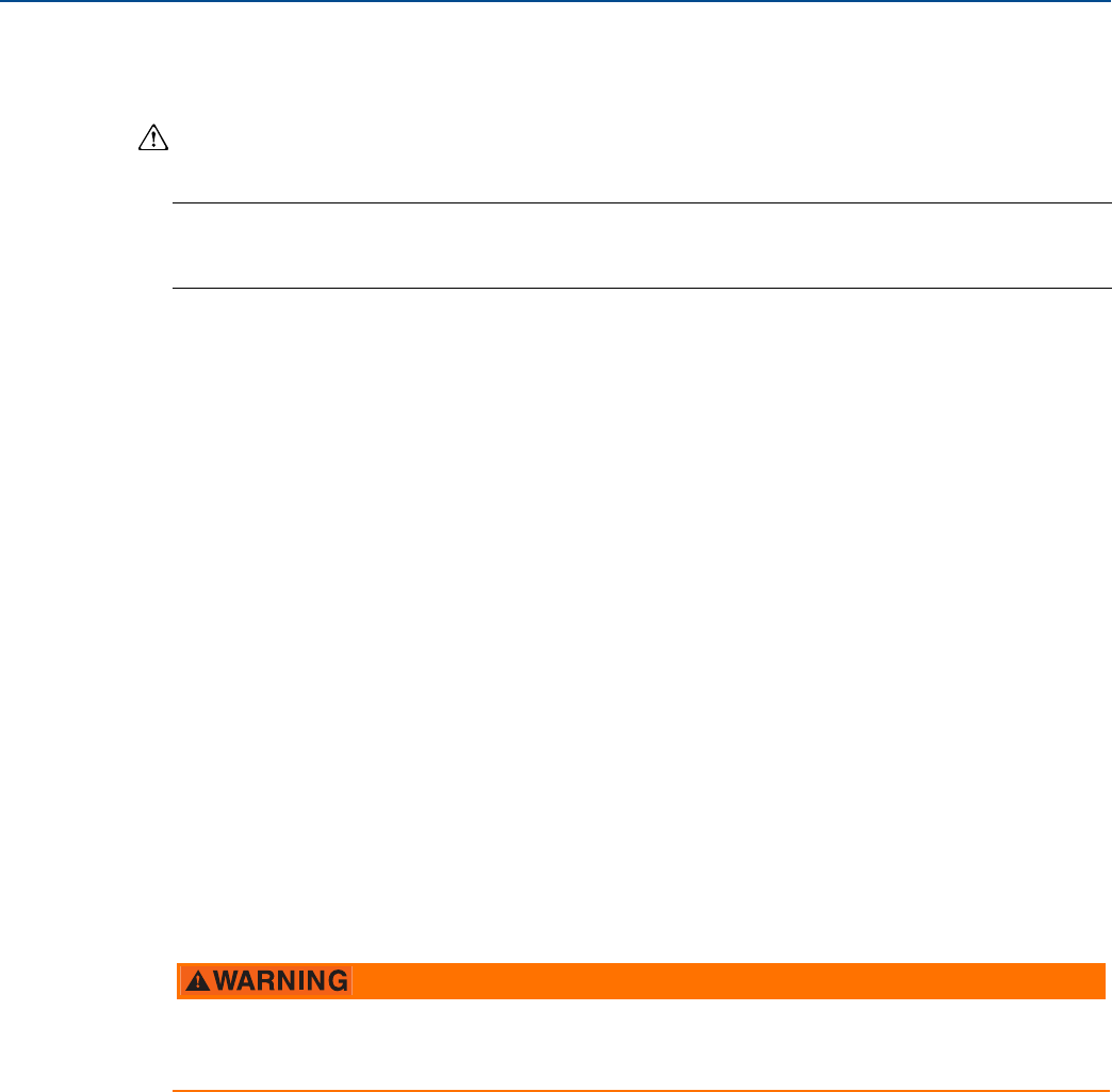
81
Reference Manual
00809-0100-4803, Rev GA
Installation
September 2017
Installation
3.5.1 Rosemount 305 Integral Manifold installation procedure
To install a Rosemount 305 Integral Manifold to a Rosemount 3051SMV:
1. Inspect the PTFE SuperModule O-rings. If the O-rings are undamaged, reusing them is recommended.
If the O-rings are damaged (e.g. nicks), replace them with new O-rings.
Note
If replacing the O-rings, be careful not to scratch or deface the O-ring grooves or the surface of the
isolating diaphragm when removing the damaged O-rings.
2. Install the Integral manifold on the SuperModule process connection. Use the four manifold bolts for
alignment. Finger tighten the bolts, then tighten the bolts incrementally in a cross pattern to final
torque value. See “Flange bolts” on page 71 for complete bolt installation information and torque
values. When fully tightened, the bolts should extend through the top of the SuperModule housing.
3. If the PTFE SuperModule O-rings have been replaced, the flange bolts should be re-tightened after
installation to compensate for seating of the O-rings.
4. If applicable, install flange adapters on the process end of the manifold using the 1.75-in. flange bolts
supplied with the transmitter.
3.5.2 Rosemount 304 Conventional Manifold installation procedure
To install a Rosemount 304 Conventional Manifold to a Rosemount 3051SMV:
1. Align the conventional manifold with the transmitter flange. Use the four manifold bolts for
alignment.
2. Finger tighten the bolts, then tighten the bolts incrementally in a cross pattern to final torque value.
See “Flange bolts” on page 71 for complete bolt installation information and torque values. When
fully tightened, the bolts should extend through the top of the SuperModule assembly bolt hole but
must not contact the SuperModule housing.
3. If applicable, install flange adapters on the process end of the manifold using the 1.75-in. flange bolts
supplied with the transmitter.
3.5.3 Manifold operation
Always perform a zero trim on the transmitter/manifold assembly after installation to eliminate any shift
due to mounting effects. See “Sensor trim overview” on page 90.
Improper installation or operation of manifolds may result in process leaks, which may cause death or
serious injury.
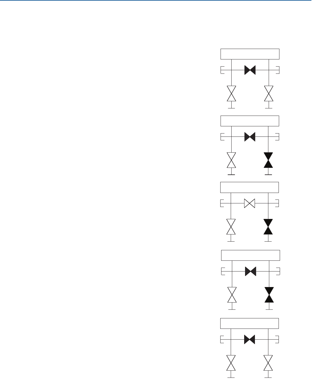
82
Reference Manual
00809-0100-4803, Rev GA
Installation
September 2017
Installation
Coplanar transmitters
3-valve and 5-valve manifolds
Performing zero trim at static line pressure
In normal operation the two isolate (block) valves
between the process ports and transmitter will be open
and the equalize valve will be closed.
1. To zero trim the transmitter, close the isolate valve
on the low side (downstream) side of the
transmitter.
2. Open the equalize valve to equalize the pressure on
both sides of the transmitter. The manifold is now in
the proper configuration for performing a zero trim
on the transmitter.
3. After performing a zero trim on the transmitter,
close the equalize valve.
4. Finally, to return the transmitter to service, open the
low side isolate valve.
HL
Drain/Vent
valve
Drain/Vent
valve
Isolate
(open)
Isolate
(open)
Process
Equalize
(closed)
HL
Drain/Vent
valve
Isolate
(open)
Drain/Vent
valve
Isolate
(closed)
Process
Equalize
(closed)
HL
Drain/Vent
valve
Isolate
(open)
Drain/Vent
valve
Isolate
(closed)
Process
Equalize
(open)
HL
Drain/Vent
valve
Isolate
(open)
Drain/Vent
valve
Isolate
(closed)
Process
Equalize
(closed)
HL
Drain/Vent
valve
Drain/Vent
valve
Isolate
(open)
Isolate
(open)
Process
Equalize
(closed)
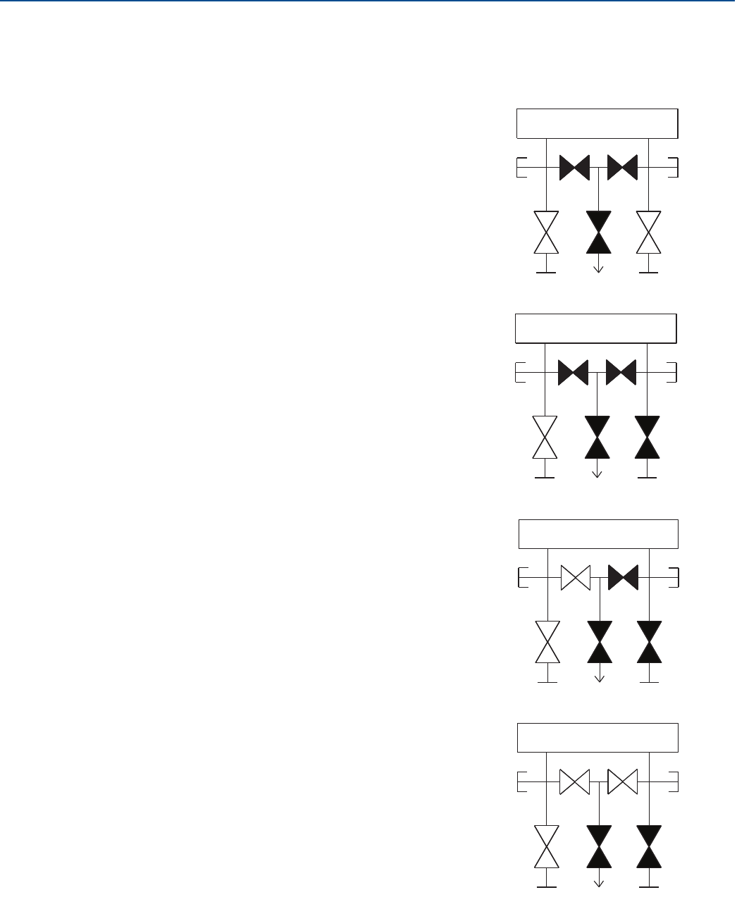
83
Reference Manual
00809-0100-4803, Rev GA
Installation
September 2017
Installation
5-valve natural gas manifold
Performing zero trim at static line pressure
5-valve natural gas configurations shown:
In normal operation, the two isolate (block) valves
between the process ports and transmitter will be open,
and the equalize valves will be closed. Vent valves may be
opened or closed.
1. To zero trim the transmitter, first close the isolate
valve on the low pressure (downstream) side of the
transmitter and the vent valve.
2. Open the equalize valve on the high pressure
(upstream) side of the transmitter.
3. Open the equalize valve on the low pressure
(downstream) side of the transmitter. The manifold is
now in the proper configuration for performing a zero
trim on the transmitter.
HL
(Plugged)
Isolate
(open)
Isolate
(open)
(Plugged)
Equalize
(closed)
Equalize
(closed)
Process ProcessDrain vent
(closed)
HL
(Plugged)
Isolate
(open)
Isolate
(closed)
(Plugged)
Process ProcessDrain vent
(closed)
Equalize
(closed)
Equalize
(closed)
(Plugged)
Isolate
(open)
Equalize
(open)
Equalize
(closed)
Process ProcessDrain vent
(closed)
Isolate
(closed)
(Plugged)
HL
(Plugged)
Isolate
(open)
Equalize
(open)
Equalize
(open)
Process ProcessDrain vent
(closed)
Isolate
(closed)
(Plugged)
HL
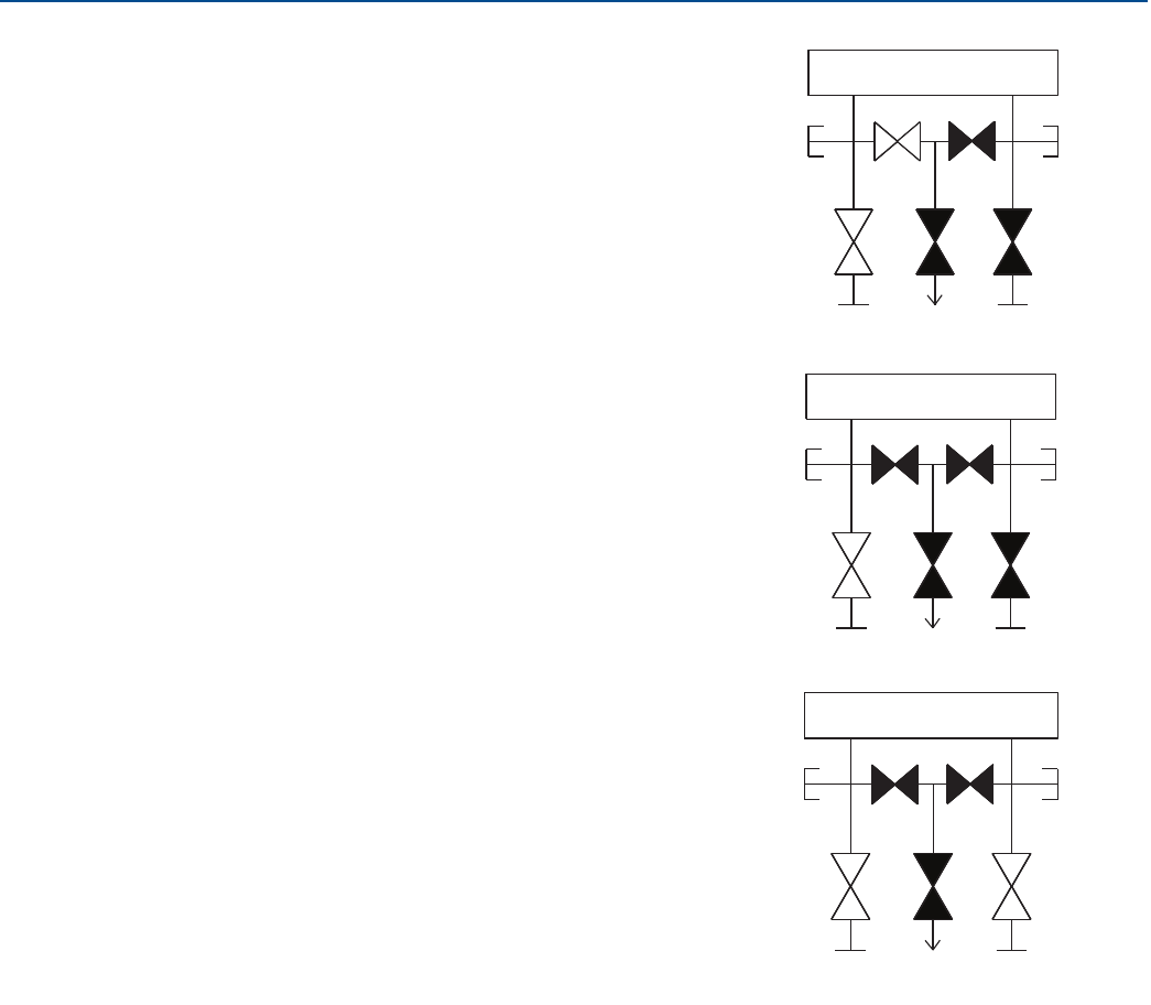
84
Reference Manual
00809-0100-4803, Rev GA
Installation
September 2017
Installation
4. After performing a zero trim on the transmitter, close
the equalize valve on the low pressure (downstream)
side of the transmitter.
5. Close the equalize valve on the high pressure
(upstream) side.
6. Finally, to return the transmitter to service, open the
low side isolate valve and vent valve. The vent valve
can remain open or closed during operation.
(Plugged)
Isolate
(open)
Equalize
(open)
Equalize
(closed)
Process ProcessDrain vent
(closed)
Isolate
(closed)
(Plugged)
HL
HL
(Plugged)
Isolate
(open)
Isolate
(closed)
(Plugged)
Process ProcessDrain vent
(closed)
Equalize
(closed)
Equalize
(closed)
HL
(Plugged)
Isolate
(open)
Isolate
(open)
(Plugged)
Equalize
(closed)
Equalize
(closed)
Process ProcessDrain vent
(closed)
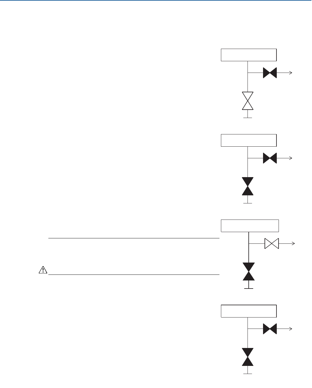
85
Reference Manual
00809-0100-4803, Rev GA
Installation
September 2017
Installation
In-line transmitters
2-valve and block and bleed style manifolds
Isolating the transmitter
In normal operation the isolate (block) valve between the process
port and transmitter will be open and the test/vent valve will be
closed. On a block and bleed style manifold, a single block valve
provides transmitter isolation and a bleed screw provides drain/vent
capabilities.
1. To isolate the transmitter, close the isolate valve.
2. To bring the transmitter to atmospheric pressure, open the vent
valve or bleed screw.
Note
A 1/4-in. male NPT pipe plug may be installed in the test/vent port
and will need to be removed with a wrench in order to vent the
manifold properly.
Always use caution when venting directly to atmosphere.
3. After venting to atmosphere, perform any required calibration
and then close the test/vent valve or replace the bleed screw.
Transmitter
Isolate
Vent
(closed)
Process
(open)
Transmitter
Isolate
Vent
(closed)
Process
(closed)
Transmitter
Isolate
Vent
(open)
Process
(closed)
Transmitter
Isolate
Vent
(closed)
Process
(closed)
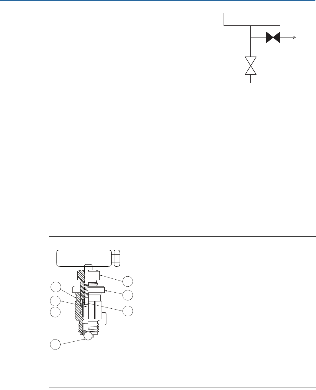
86
Reference Manual
00809-0100-4803, Rev GA
Installation
September 2017
Installation
Adjusting valve packing
Over time, the packing material inside a Rosemount manifold may require adjustment in order to
continue to provide proper pressure retention. Not all manifolds have this adjustment capability. The
manifold model number will indicate what type of stem seal or packing material has been used.
The following steps are provided as a procedure to adjust valve packing:
1. Remove all pressure from device.
2. Loosen manifold valve jam nut.
3. Tighten manifold valve packing adjuster nut 1/4 turn.
4. Tighten manifold valve jam nut.
5. Re-apply pressure and check for leaks.
6. Above steps can be repeated, if necessary.
If the above procedure does not result in proper pressure retention, the complete manifold should be
replaced.
Figure 3-16. Adjusting Valve Packing
4. Open the Isolate (block) valve to return the transmitter to
service.
A. Bonnet
B. Ball seat
C. Packing
D. Stem
E. Packing adjuster
F. Jam nut
G. Packing follower
Transmitter
Isolate
Vent
(closed)
Process
(open)
A
D
C
B
E
F
G

87
Reference Manual
00809-0100-4803, Rev GA
Operation and Maintenance
September 2017
Operation and Maintenance
Section 4 Operation and Maintenance
Overview . . . . . . . . . . . . . . . . . . . . . . . . . . . . . . . . . . . . . . . . . . . . . . . . . . . . . . . . . . . . . . . . . . . . . . . . . . . page 87
Safety messages . . . . . . . . . . . . . . . . . . . . . . . . . . . . . . . . . . . . . . . . . . . . . . . . . . . . . . . . . . . . . . . . . . . . . page 88
Transmitter calibration . . . . . . . . . . . . . . . . . . . . . . . . . . . . . . . . . . . . . . . . . . . . . . . . . . . . . . . . . . . . . . .page 89
Transmitter functional tests . . . . . . . . . . . . . . . . . . . . . . . . . . . . . . . . . . . . . . . . . . . . . . . . . . . . . . . . . . . page 96
Process variables . . . . . . . . . . . . . . . . . . . . . . . . . . . . . . . . . . . . . . . . . . . . . . . . . . . . . . . . . . . . . . . . . . . . page 98
Field upgrades and replacements . . . . . . . . . . . . . . . . . . . . . . . . . . . . . . . . . . . . . . . . . . . . . . . . . . . . . . page 99
4.1 Overview
This section contains information on operating and maintaining Rosemount™ 3051S MultiVariable™
Transmitters (Rosemount 3051SMV). Instructions for performing configuration and calibration
procedures are given for Field Communicator version 2.0 or later, AMS Device Manager version 9.0 or
later, and Engineering Assistant version 6.3 or later. Screen shots for this section are taken from AMS
Device Manager version 9.0; Engineering Assistant screens will look similar and follow the same
instructions for use and navigation. For convenience, Field Communicator Fast Key sequences are labeled
“Fast Keys” for each software function below the appropriate headings.
Based on the configuration ordered, some measurements (i.e. static pressure, process temperature)
and/or calculation types (i.e. mass, volumetric, and energy flow) may not be available for all fluid types.
Available measurements and/or calculation types are determined by the multivariable type and
measurement type codes ordered. See “Ordering information” on page 138 for more information.
All screens in this section are shown for multivariable type M (fully compensated mass and energy flow),
measurement type 1 (differential pressure, static pressure, and process temperature). Field
Communicator Fast Keys are given for both multivariable type M and P (direct process variable output)
with measurement type 1. Field Communicator Fast Keys and screens for other multivariable types and
measurement types may vary.

88
Reference Manual
00809-0100-4803, Rev GA
Operation and Maintenance
September 2017
Operation and Maintenance
4.2 Safety messages
Procedures and instructions in this section may require special precautions to ensure the safety of the
personnel performing the operation. Information that raises potential safety issues is indicated with a
warning symbol ( ). Refer to the following safety messages before performing an operation preceded
by this symbol.
Failure to follow these installation guidelines could result in death or serious injury.
Make sure only qualified personnel perform the installation.
Explosions could result in death or serious injury.
Do not remove the transmitter cover in explosive atmospheres when the circuit is live.
Before connecting a Field Communicator in an explosive atmosphere, make sure the instruments in
the loop are installed in accordance with intrinsically safe or non-incendive field wiring practices.
Both transmitter covers must be fully engaged to meet flameproof/explosion-proof requirements.
Verify the operating atmosphere of the transmitter is consistent with the appropriate hazardous
locations certifications.
Electrical shock could cause death or serious injury.
If the sensor is installed in a high-voltage environment and a fault or installation error occurs, high
voltage may be present on the transmitter leads and terminals.
Use extreme caution when making contact with the leads and terminals.
Process leaks could result in death or serious injury.
Install and tighten all four flange bolts before applying pressure.
Do not attempt to loosen or remove flange bolts while the transmitter is in service.
Replacement equipment or spare parts not approved by Emerson™ for use as spare parts could
reduce the pressure retaining capabilities of the transmitter and may render the instrument
dangerous.
Use only bolts supplied or sold by Emerson as spare parts.
Improper assembly of manifolds to traditional flange can damage the device.
For safe assembly of manifold to traditional flange, bolts must break back plane of flange web
(i.e., bolt hole) but must not contact the sensor module.
Improper installation or repair of the SuperModule™ assembly with high pressure option (P0)
could result in death or serious injury.
For safe assembly, the high pressure SuperModule assembly must be installed with ASTM A193
Class 2 Grade B8M Bolts and either a Rosemount 305 Manifold or a DIN-compliant traditional flange.
Static electricity can damage sensitive components.
Observe safe handling precautions for static-sensitive components.
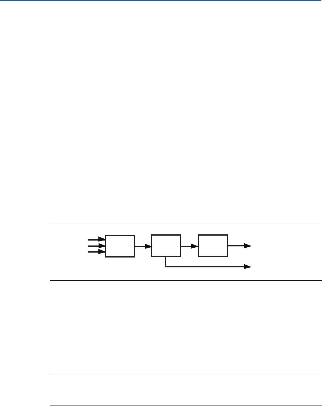
89
Reference Manual
00809-0100-4803, Rev GA
Operation and Maintenance
September 2017
Operation and Maintenance
4.3 Transmitter calibration
4.3.1 Calibration overview
Complete configuration and calibration of the Rosemount 3051SMV involves the following tasks:
Configure the output parameters
Basic setup screen
Set process variable units
Set primary variable
Rerange
Set transfer function (direct process variable feature board only)
Set damping
Calibrate the sensor (DP, P, and/or T)
For each sensor, perform:
Sensor trim (page 90)
Zero or lower sensor trim (page 91)
Calibrate the 4–20 mA output
4–20 mA analog trim (page 95); or
4–20 mA scaled output trim (page 95)
Figure 4-1 summarizes the data flow for the Rosemount 3051SMV. Data flows from left to right, and a
parameter change affects all values to the right of the changed parameter.
Figure 4-1. Transmitter Data Flow
Data flow can be summarized in four major steps:
1. A change in a process variable (DP, P, and/or T) corresponds to a change in the sensor output
(Sensor Signal).
2. The sensor signal is converted to a digital format that is understood by the microprocessor
(Analog-to-Digital Signal Conversion).
3. Corrections and flow calculations are performed in the microprocessor to obtain a digital
representation of the process output variables.
4. The Digital Primary Variable (PV) is converted to an analog value (Digital-to-Analog Signal
Conversion).
Note
Coplanar transmitter configurations measuring gage pressure and process temperature (measurement
5) will report as the pressure as differential pressure. This will be reflected on the LCD display, nameplate,
digital interfaces, and other user interfaces.
Measured
process
inputs
DP
P
T
A/D Micro D/A Analog mA output
(primary variable)
Digital HART variables
(primary, 2nd, 3rd, and 4th)
90
Reference Manual
00809-0100-4803, Rev GA
Operation and Maintenance
September 2017
Operation and Maintenance
4.3.2 Sensor trim overview
Trim the sensors using either sensor or zero trim functions. Trim functions vary in complexity and are
application-dependent. Both trim functions alter the transmitter’s interpretation of the input signal.
Zero trim
Zero trim is a single-point offset adjustment. It is useful for compensating for mounting position effects
and is most effective when performed with the transmitter installed in its final mounting position. Since
this correction maintains the slope of the characterization curve, it should not be used in place of a
sensor trim over the full sensor range.
When performing a zero trim with a manifold, refer to “Rosemount 305 and 304 Manifolds” on page 80.
Note
The transmitter must be within five percent or less of the maximum span of true zero (zero-based) in
order to calibrate with zero trim function.
The transmitter will not allow the user to perform a zero trim on an absolute static pressure sensor. To
correct mounting position effects on the absolute static pressure sensor, perform a lower sensor trim.
The lower sensor trim function provides an offset correction similar to the zero trim function, but it does
not require zero-based input.
Upper and lower sensor trim
Sensor trim is a two-point sensor calibration where two end-point pressures are applied, and all output is
linearized between them. Always adjust the lower sensor trim value first to establish the correct offset.
Adjustment of the upper sensor trim value provides a slope correction to the characterization curve
based on the lower sensor trim value. The trim values allow the user to optimize performance over a
specified measuring range at the calibration temperature.
4.3.3 Differential pressure sensor calibration
The Differential Pressure Calibration tab allows the user to complete a zero trim procedure or a full DP
sensor trim, see Figure 4-2 on page 91.
Mass and energy flow Fast Keys 1, 2, 5, 3
Direct process variable output Fast Keys 1, 2, 4, 3
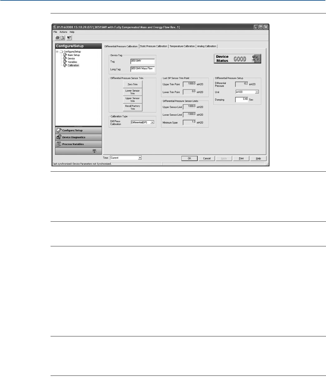
91
Reference Manual
00809-0100-4803, Rev GA
Operation and Maintenance
September 2017
Operation and Maintenance
Figure 4-2. Calibration - Differential Pressure Calibration Tab
Zero trim
To perform a DP sensor zero trim, select the Zero Trim button under the Differential Pressure Sensor Trim
heading and follow the on-screen prompts. The transmitter must be within five percent or less of the
maximum span of true zero (zero-based) in order to calibrate with zero trim function.
Note
When performing a DP sensor zero trim, ensure the equalizing valve is open and all wet legs are filled to
the correct levels.
Upper and lower sensor trim
A reference pressure device is required to perform a full sensor trim. Use a reference pressure device that
is at least three times more accurate than the transmitter and allow the pressure input to stabilize for ten
seconds before entering any values. It is possible to degrade the performance of the transmitter if the full
sensor trim is done improperly or with inaccurate calibration equipment.
To perform a DP full trim, perform the following procedure:
1. Select the Lower Sensor Trim button and follow the on-screen prompts.
2. Select the Upper Sensor Trim button and follow the on-screen prompts.
Note
Select process variable calibration input values so that low and high values are equal to or outside the
upper and lower range limits. Do not attempt to obtain reverse output by reversing the high and low
points. The transmitter allows approximately five percent URL deviation from the characterized curve
established at the factory.
Calibration type
The calibration type drop-down menu allows the user to note the type of device last used to calibrate the
sensor (either Differential, Gage, or Absolute). This field does not affect the calibration of the device.
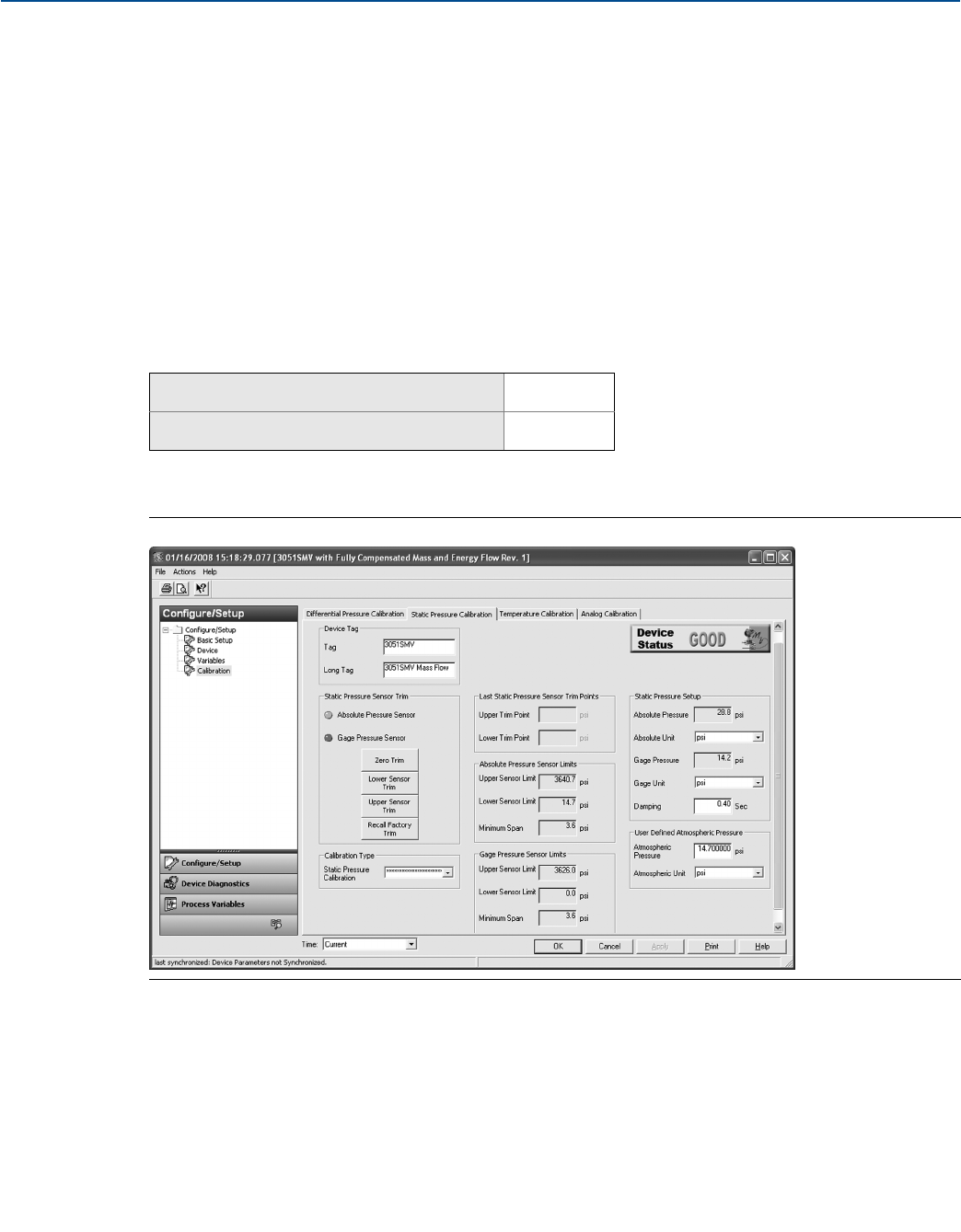
92
Reference Manual
00809-0100-4803, Rev GA
Operation and Maintenance
September 2017
Operation and Maintenance
Recall factory trim
The Recall Factory Trim button will restore the transmitter to the original factory characterization
curve. The Recall Factory Trim button can be useful for recovering from an inadvertent zero trim or
inaccurate pressure source.
When the recall factory trim function is used, the transmitter’s upper and lower trim values are set to the
values configured at the factory. If custom trim values were specified when the transmitter was ordered,
the device will recall those values. If custom trim values were not specified, the device will recall the
upper and lower sensor limits.
Last DP sensor trim point
The current upper and lower trim points can be seen under the Last DP Sensor Trim Point heading.
4.3.4 Static pressure sensor calibration
The Static Pressure Calibration tab allows the user to complete either a zero trim procedure or a full SP
sensor trim, see Figure 4-3.
Figure 4-3. Calibration - Static Pressure Calibration Tab
Zero trim and lower sensor trim
The type of static pressure sensor equipped in the transmitter can be determined by referring to the
Static Pressure Sensor Type heading. This determines whether a zero trim (gage sensor) or lower sensor
trim (absolute sensor) required to correct for mounting position effects.
To perform a zero trim on a gage static pressure sensor, select the Zero Trim button under the Static
Pressure Sensor Trim heading and follow the on-screen prompts. The transmitter must be within five
percent or less of the maximum span of true zero (zero-based) in order to calibrate with zero trim
function.
Mass and energy flow Fast Keys 1, 2, 5, 4
Direct process variable output Fast Keys 1, 2, 4, 4
93
Reference Manual
00809-0100-4803, Rev GA
Operation and Maintenance
September 2017
Operation and Maintenance
To correct for mounting position effects on transmitters equipped with an absolute static pressure
sensor, perform a lower sensor trim. This is accomplished by selecting the Lower Sensor Trim button
and following the on-screen prompts. The lower sensor trim function provides an offset correction
similar to the zero trim function, but it does not require a zero-based input.
Upper and lower sensor trim
To perform a Static Pressure Full Sensor Trim, perform the following procedure:
1. Select the Lower Sensor Trim button and follow the on-screen prompts.
2. Select the Upper Sensor Trim button and follow the on-screen prompts.
Note
It is possible to degrade the performance of the transmitter if the full sensor trim is done improperly or
with inaccurate calibration equipment. Use a pressure input source that is at least three times more
accurate than the transmitter and allow the pressure input to stabilize for ten seconds before entering
any values.
Recall factory trim
The Recall Factory Trim button will restore the transmitter to the original factory characterization
curve. The Recall Factory Trim button can be useful for recovering from an inadvertent zero trim or
inaccurate pressure source.
When the recall factory trim function is used, the transmitter’s upper and lower trim values are set to the
values configured at the factory. If custom trim values were specified when the transmitter was ordered,
the device will recall those values. If custom trim values were not specified, the device will recall the
upper and lower sensor limits.
Last static pressure sensor trim
The current upper and lower trim points can be seen under the Last Static Pressure Sensor Trim Points
heading.
Calibration type
The calibration type drop-down menu allows the user to note the type of device last used to calibrate the
sensor (either Differential, Gage, or Absolute). This field does not affect the calibration of the device.
4.3.5 Process temperature sensor calibration
The Temperature Calibration tab allows the user to perform a sensor trim and configure the sensor
matching of a process temperature sensor, see Figure 4-4 on page 94.
Mass and energy flow Fast Keys 1, 2, 5, 5
Direct process variable output Fast Keys 1, 2, 4, 5
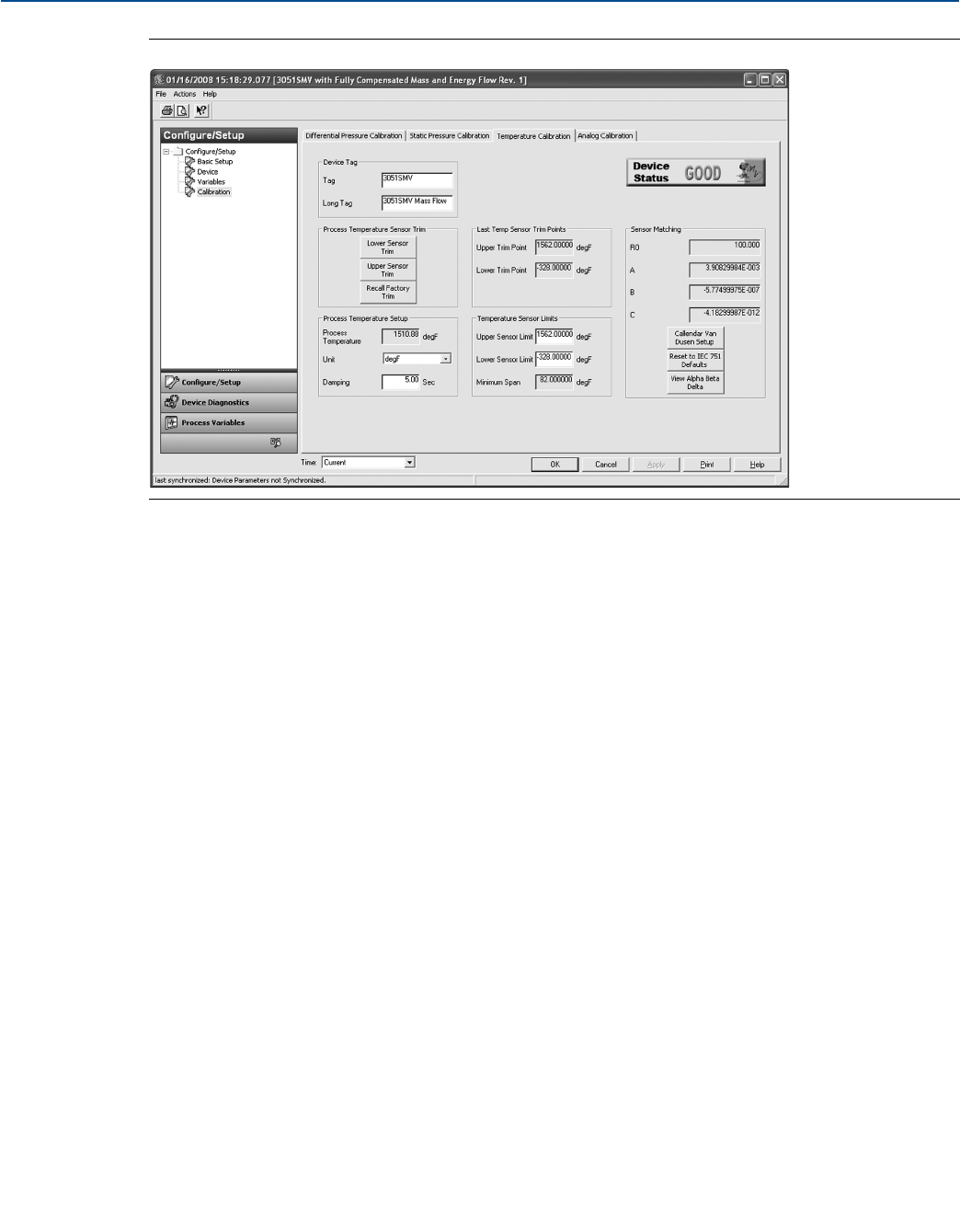
94
Reference Manual
00809-0100-4803, Rev GA
Operation and Maintenance
September 2017
Operation and Maintenance
Figure 4-4. Calibration - Temperature Calibration Tab
Process temperature upper and lower sensor trim
To calibrate the Process Temperature Input using the sensor trim, follow the procedure shown below:
1. Set up a Temperature Calibrator to simulate a Pt 100 (100-ohm platinum, alpha 385 RTD). Wire the
two red wires from the Rosemount 3051SMV terminal block to one connection, and the two white
wires to the other connection. See “Install optional process temperature input (Pt 100 RTD sensor)”
on page 76 for more information.
2. Adjust the calibrator/RTD simulator to a test point temperature value that represents a minimum
process temperature (for example, 32 °F or 0 °C). Select the Lower Sensor Trim button under the
Process Temperature Sensor Trim heading and follow the on-screen prompts.
3. Adjust the calibrator/RTD simulator to a test point temperature value that represents the maximum
process temperature (for example, 140 °F or 60 °C). Select the Upper Sensor Trim button under the
Process Temperature Sensor Trim heading and follow the on-screen prompts.
Recall factory trim
The Recall Factory Trim button will restore the transmitter to the original factory calibration settings.
When the recall factory trim function is used, the transmitter’s upper and lower trim values are set to the
values configured at the factory. If custom trim values were specified when the transmitter was ordered,
the device will recall those values. If custom trim values were not specified, the device will recall the
upper and lower sensor limits.
Transmitter RTD sensor matching using Callendar-Van Dusen
constants
The Rosemount 3051SMV accepts Callendar-Van Dusen constants from a calibrated RTD schedule and
generates a special custom curve to match that specific sensor Resistance vs. Temperature performance.
Matching the specific sensor curve with the transmitter configuration enhances the temperature
measurement accuracy.
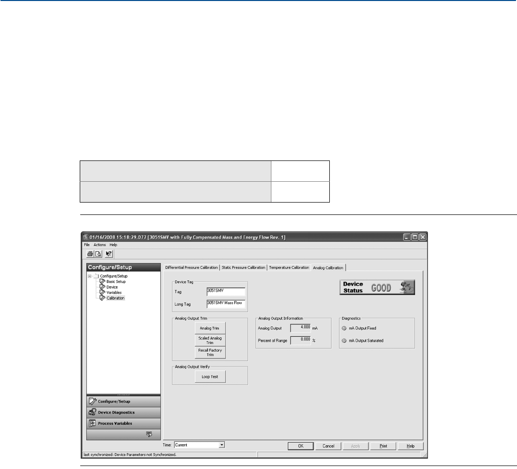
95
Reference Manual
00809-0100-4803, Rev GA
Operation and Maintenance
September 2017
Operation and Maintenance
Under the Sensor Matching heading, the Callendar-Van Dusen constants R0, A, B, and C can be viewed. If
the Callendar-Van Dusen constants are known for the user’s specific Pt 100 RTD sensor, the constants R0,
A, B, and C may be edited by selecting the Callendar-Van Dusen Setup button and following the
on-screen prompts.
The user may also view the α, β, and δ Coefficients by selecting the View Alpha, Beta, Delta button. The
constants R0, α, β, and δ may be edited by selecting the Callendar-Van Dusen Setup button and
following the on-screen prompts. To reset the transmitter to the IEC 751 Defaults, select the Reset to IEC
751 Defaults button.
4.3.6 Analog calibration
Figure 4-5. Calibration - Analog Calibration Tab
Analog output trim
The Analog Output Trim commands allow the user to adjust the transmitter’s current output at the 4 and
20 mA points to match the plant standards. This command adjusts the digital to analog signal
conversion, see Figure 4-5.
To perform an analog trim, select the Analog Trim button and follow the on-screen prompts.
Scaled analog output trim
The scaled analog trim command matches the 4 and 20 mA points to a user selectable reference scale
other than 4 and 20 mA (for example, 1 to 5 volts if measuring across a 250 ohm load, or 0 to 100 percent
if measuring from a Distributed Control System [DCS]). To perform a scaled analog trim, connect an
accurate reference meter, select the Scaled Analog Trim button, and follow the on-screen prompts.
Mass and energy flow Fast Keys 1, 2, 5, 2
Direct process variable output Fast Keys 1, 2, 4, 5
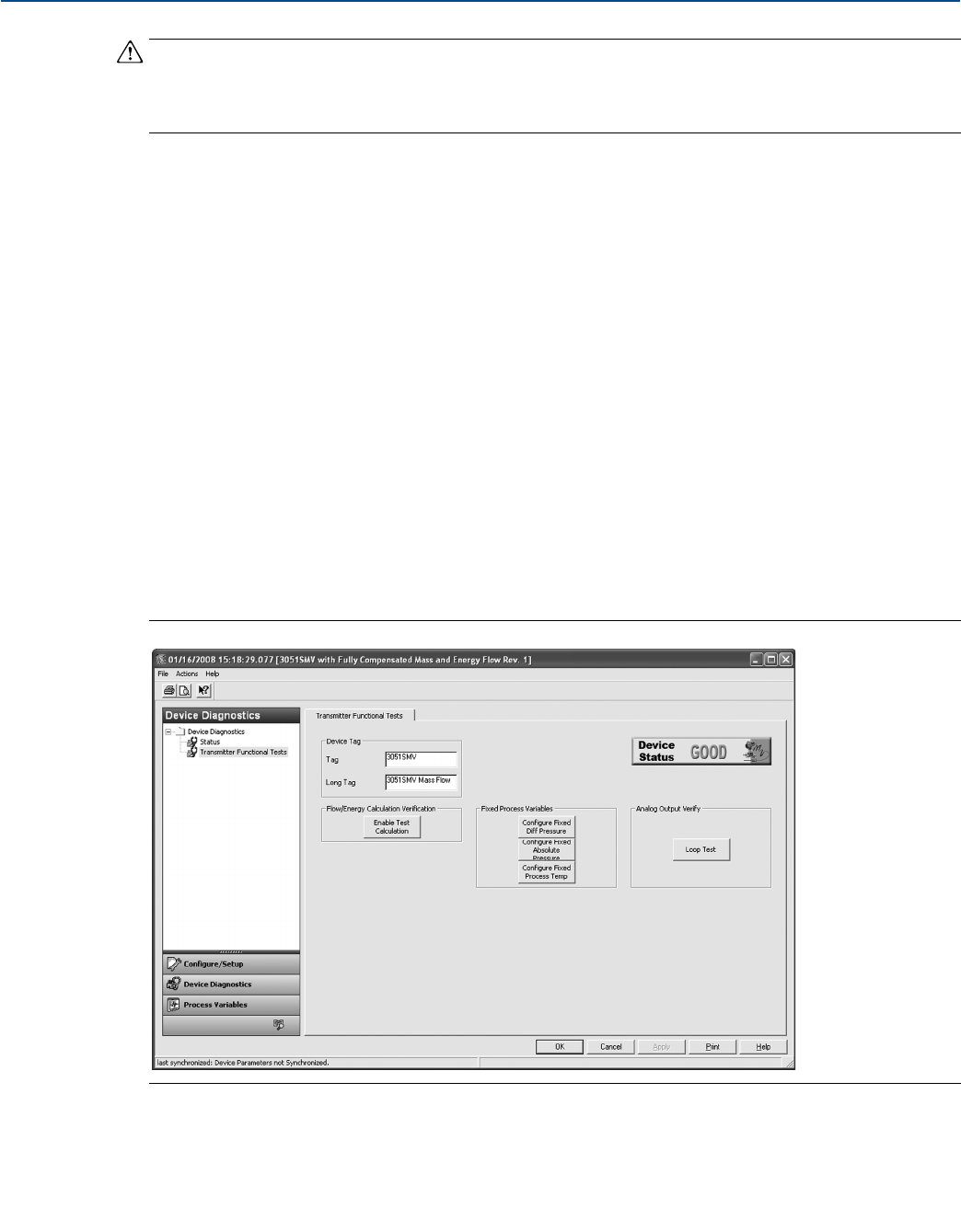
96
Reference Manual
00809-0100-4803, Rev GA
Operation and Maintenance
September 2017
Operation and Maintenance
Note
Use a precision resistor for optimum accuracy. When adding a resistor to the loop, ensure that the power
supply is sufficient to power the transmitter to a 23 mA (maximum high alarm) output with the
additional loop resistance.
Analog output loop test
Under the Analog Output Verify heading, a loop test can be performed by selecting the Loop Test button.
The loop test command verifies the output of the transmitter, the integrity of the loop, and the
operations of any recorders or similar devices installed in the loop.
Analog output diagnostic alerts
Two diagnostic alerts are shown under the Diagnostics heading.
The first is mA Output Fixed. This alerts the user that the 4–20 mA analog output signal is fixed at a
constant value and is not representative of the HART Primary Variable. This diagnostic alert may also be
triggered if “Loop Current Mode” is disabled, the device is in alarm, or if “Test Calculation” is running.
The second diagnostic is mA Output Saturated. This alerts the user that the measured Primary Variable
has exceeded the range points defined for the 4–20 mA analog output signal. The analog output is fixed
at the user-defined high or low saturation point and is not representative of the current HART Primary
Variable.
4.4 Transmitter functional tests
Figure 4-6. Transmitter Functional Tests Screen
97
Reference Manual
00809-0100-4803, Rev GA
Operation and Maintenance
September 2017
Operation and Maintenance
4.4.1 Flow/energy calculation verification (test calculation)
(Fully compensated mass and energy flow feature board only):
The Flow and Energy Calculation Verification Test allows the user to verify the flow configuration of the
Rosemount 3051SMV by entering expected values for the differential pressure, static pressure, and
process temperature variables. Under the Flow/Energy Calculation Verification heading, perform the
following steps:
1. Select the Enable Test Calculation button.
2. Select Simulate DP option. Select Next.
3. Select DP Units from the drop-down menu. Select Next.
4. Enter the DP Value corresponding to the desired flow rate simulation. Select Next.
5. Repeat steps 1–3 for static pressure (Simulate AP/GP) and process temperature (Simulate PT), if
applicable.
6. Select View Results. Select Next. The simulated flow rate and corresponding flow properties will be
shown. Select Next.
7. Select Exit. Select Next. Leaving the Enable Test Calculation window automatically returns all process
variables fixed by the test calculation method to live process variable measurements.
4.4.2 Configuring fixed process variables
Under the Fixed Process Variables heading, the user may temporarily set the differential pressure, static
pressure or process temperature to a user defined fixed value for testing purposes. Once the user leaves
the Configure Fixed Variable method, the fixed process variable will be automatically returned to a live
process variable measurement.
4.4.3 Analog output loop test
Under the Analog Output Verify heading, a Loop Test can be performed by selecting the Loop Test button.
The loop test command verifies the output of the transmitter, the integrity of the loop, and the
operations of any recorders or similar devices installed in the loop.
Mass and energy flow Fast Keys 1, 2, 3
Mass and energy flow Fast Keys 1, 2, 4
Direct process variable output Fast Keys 1, 2, 3
Mass and energy flow Fast Keys 1, 2, 2
Direct process variable output Fast Keys 1, 2, 2
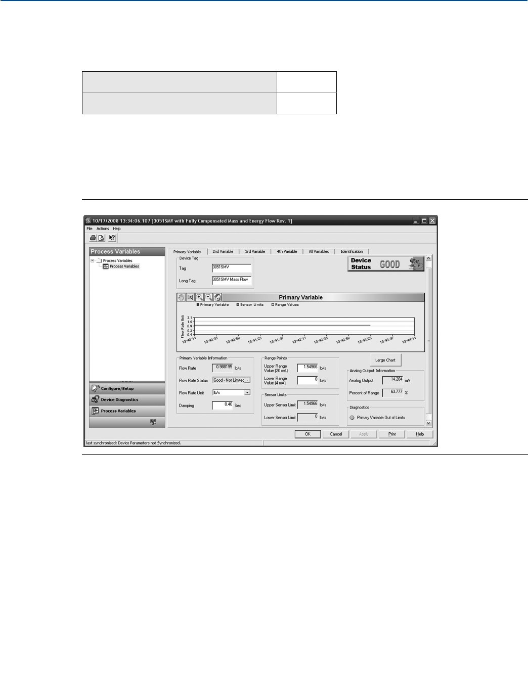
98
Reference Manual
00809-0100-4803, Rev GA
Operation and Maintenance
September 2017
Operation and Maintenance
4.5 Process variables
4.5.1 Process variable tabs
The Process Variables screen shows a graphical representation of the respective variable. An example of
the Primary Variable tab (as shown in Figure 4-7). The chart on these Process Variables tabs will begin
plotting when the user first navigates to the screen, and will only continue plotting while the user is
viewing this tab. The user may view a larger version of the chart by selecting the Large Chart button.
Each of the four digital output variables has a screen similar to the one shown in Figure 4-7.
Figure 4-7. Process Variables - Primary Variable Tab
Mass and energy flow Fast Keys 1, 1
Direct process variable output Fast Keys 1, 1
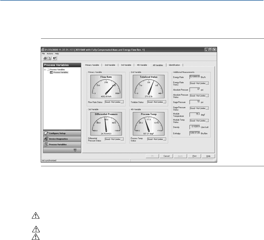
99
Reference Manual
00809-0100-4803, Rev GA
Operation and Maintenance
September 2017
Operation and Maintenance
4.5.2 All variables tab
The All Variables tab allows the user to view a complete overview of all variables available within the
device.
Figure 4-8. Process Variables - All Variables Tab
4.6 Field upgrades and replacements
4.6.1 Disassembly considerations
During disassembly, do not remove the instrument cover in explosive atmospheres when the circuit is
live as this may result in serious injury or death. Also, be aware of the following:
Follow all plant safety rules and procedures.
Isolate and vent the process from the transmitter before removing the transmitter from service.
Disconnect optional process temperature sensor leads and cable.
Remove all other electrical leads and conduit.
Detach the process flange by removing the four flange bolts and two alignment screws that secure it.
Do not scratch, puncture, or depress the isolating diaphragms.
Clean isolating diaphragms with a soft rag and a mild cleaning solution, then rinse with clear water.
Whenever the process flange or flange adapters are removed, visually inspect the PTFE O-rings.
Emerson recommends reusing O-rings if possible. If the O-rings show any signs of damage, such as
nicks or cuts, they should be replaced.
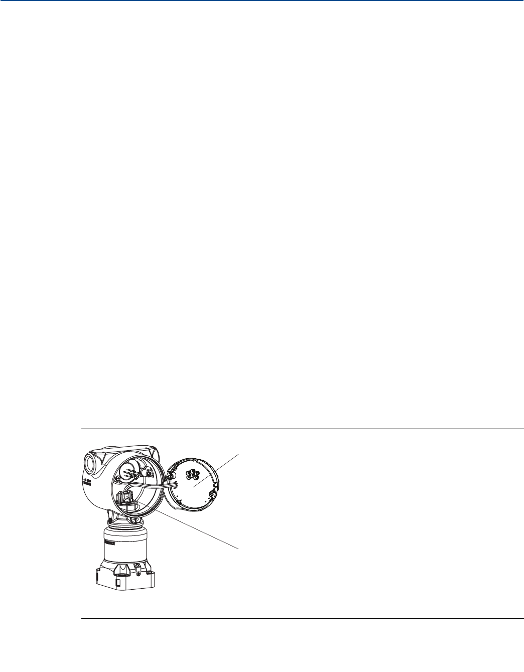
100
Reference Manual
00809-0100-4803, Rev GA
Operation and Maintenance
September 2017
Operation and Maintenance
4.6.2 Housing assembly including feature board electronics
Field device labels
The SuperModule label reflects the replacement model code for reordering a complete transmitter,
including both the SuperModule assembly and Plantweb™ housing. The Rosemount 3051SMV model
code stamped on the Plantweb housing nameplate can be used to reorder the Plantweb housing
assembly.
Upgrading feature board electronics
The Rosemount 3051SMV allows feature board electronics upgrades. Different feature board electronics
assemblies provide new functionality and are easily interchanged for upgrade. When replacing or
upgrading the feature board electronics, use the “Rosemount 300SMV housing kit” on page 144 which
also includes the appropriate Plantweb housing.
Upgrading or replacing the housing assembly including feature board
electronics
Remove the feature board
The Rosemount 3051SMV feature board is located opposite the field terminal side in the Plantweb
housing. To remove the feature board, perform the following procedure:
1. Remove the housing cover opposite the field terminal side.
2. Remove the LCD display, if applicable. To do this, hold in the two clips and pull outward. This will
provide better access to the two screws located on the feature board.
3. Loosen the two captive screws located on the feature board.
4. Pull out the feature board to expose and locate the SuperModule connector, see Figure 4-10 on
page 101.
5. Press the locking tabs and pull the SuperModule connector upwards (avoid pulling wires). Housing
rotation may be required to access locking tabs. See “Housing rotation” on page 68 for more
information.
Figure 4-9. SuperModule Connector View
A. Feature board
B. SuperModule connector
A
B
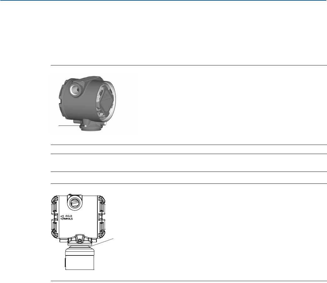
101
Reference Manual
00809-0100-4803, Rev GA
Operation and Maintenance
September 2017
Operation and Maintenance
Separate the SuperModule assembly from the housing
1. To prevent damage to the SuperModule connector, remove the feature board from the SuperModule
assembly and remove the connector before separating the SuperModule assembly from the housing.
2. Loosen the housing rotation set screw by one full turn with a 3/32-in. hex wrench.
3. Unscrew the housing from the SuperModule threads.
Figure 4-10. SuperModule Connector
A. 3/32-in. housing rotation set screw
Note
The V-Seal (03151-9061-0001) must be installed at the bottom of the housing.
Figure 4-11. V-Seal
A. Black rubber V-seal
Attach the SuperModule assembly to the Plantweb housing
1. Apply a light coat of low temperature silicon grease to the SuperModule threads and O-ring.
2. Thread the housing completely onto the SuperModule assembly. The housing must be no more than
one full turn from flush with the SuperModule assembly to comply with flameproof/explosion-proof
requirements.
3. Tighten the housing rotation set screw using a 3/32-in. hex wrench to a recommended torque of
30 in-lb (3.4 N-m).
A
A
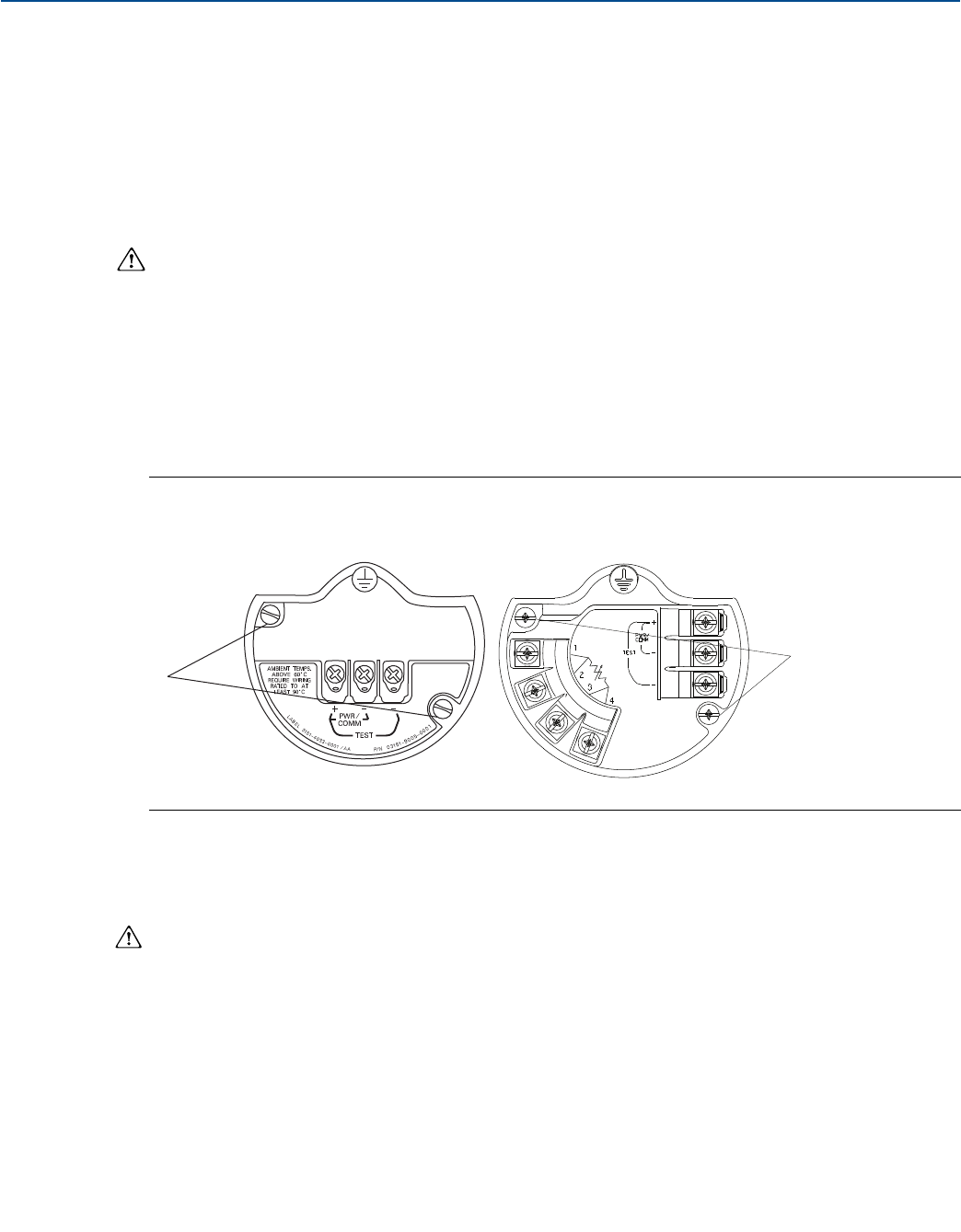
102
Reference Manual
00809-0100-4803, Rev GA
Operation and Maintenance
September 2017
Operation and Maintenance
Install feature board in the Plantweb housing
1. Apply a light coat of low temperature silicon grease to the SuperModule connector O-ring.
2. Insert the SuperModule connector into the top of the SuperModule assembly. Ensure the locking tabs
are fully engaged.
3. Gently slide the feature board into the housing, making sure the pins from the Plantweb housing
properly engage the receptacles on the feature board.
4. Tighten the captive screws.
5. Attach the Plantweb housing cover and tighten so that metal contacts metal to meet
flameproof/explosion-proof requirements.
4.6.3 Terminal block
Electrical connections are located on the terminal block in the compartment labeled “FIELD
TERMINALS.” The terminal block may be replaced or upgraded to add transient protection. Part numbers
can be found in “Service support” on page 117.
Loosen the two captive screws (see Figure 4-12), and pull the entire terminal block out.
Figure 4-12. Terminal Blocks
A. Captive screws
1. Gently slide the terminal block into the housing, making sure the pins from the Plantweb housing
properly engage the receptacles on the terminal block.
2. Tighten the captive screws on the terminal block.
3. Attach the Plantweb housing cover and tighten so that metal contacts metal to meet
flameproof/explosion-proof requirements.
Without optional
process temperature connections
With optional
process temperature connections
A
A

103
Reference Manual
00809-0100-4803, Rev GA
Operation and Maintenance
September 2017
Operation and Maintenance
4.6.4 LCD display
Transmitters ordered with the LCD display will be shipped with the display installed. Installing the display
on an existing Rosemount 3051SMV requires the LCD display kit (part number 03151-9193-0001 for
aluminum housing and 03151-9193-0004 for stainless steel (SST) housing).
Use the following procedure and Figure 4-13 to install the LCD display:
1. If the transmitter is installed in a loop, then secure the loop and disconnect power.
2. Remove the transmitter cover on the feature board side (opposite the field terminals side). Do not
remove the instrument covers in explosive environments when the circuit is live.
3. Engage the four-pin connector into the feature board and snap the LCD display into place.
4. Install the display cover and tighten to ensure metal to metal contact in order to meet
flameproof/explosion-proof requirements.
Figure 4-13. Optional LCD Display
A. Feature board
B. LCD display
C. Display cover
4.6.5 Flange and drain vent
The Rosemount 3051SMV is attached to the process connection flange by four bolts and two alignment
cap screws.
1. Remove the two alignment cap screws.
Figure 4-14. Alignment Cap Screws
A. Alignment cap screw
2. Remove the four bolts and separate the transmitter from the process connection, but leave the
process connection flange in place and ready for re-installation.
A
BC
A
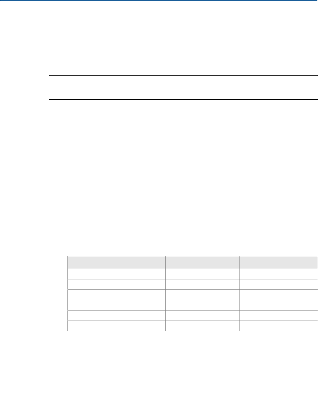
104
Reference Manual
00809-0100-4803, Rev GA
Operation and Maintenance
September 2017
Operation and Maintenance
Note
If the installation uses a manifold, see “Manifold operation” on page 81.
3. Inspect the SuperModule PTFE O-rings. If the O-rings are undamaged, they may be reused. Emerson
recommends reusing O-rings if possible. If the O-rings show any signs of damage, such as nicks or
cuts, they should be replaced (part number 03151-9042-0001 for glass-filled PTFE and part number
03151-9042-0002 for graphite-filled PTFE).
Note
If replacing the O-rings, be careful not to scratch or deface the O-ring grooves or the surface of the
isolating diaphragm when removing the damaged O-rings.
4. Install the process flange on the SuperModule process connection. To hold the process flange in
place, install the two alignment cap screws finger tight (these screws are not pressure retaining). Do
not overtighten; this will affect module-to-flange alignment.
5. Install the appropriate flange bolts.
a. If the installation requires a 1/4–18 NPT connection(s), use four 1.75-in. flange bolts.
Finger tighten the bolts. Go to Step d.
b. If the installation requires a 1/2–14 NPT connection(s), use flange adapters and four 2.88-in.
process flange/adapter bolts.
c. Hold the flange adapters and adapter O-rings in place while finger-tightening the bolts.
d. Tighten the bolts to the initial torque value using a crossed pattern. See Table 4-1 for appropriate
torque values.
e. Tighten the bolts to the final torque value using a crossed pattern. See Table 4-1 for appropriate
torque values. When fully tightened, the bolts should extend through the top of the module
housing.
f. Torque alignment screws to 30 in-lb (3.4 N-m). If the installation uses a conventional manifold,
then install flange adapters on the process end of the manifold using the 1.75-in. flange bolts
supplied with the transmitter.
6. If the SuperModule PTFE O-rings are replaced, re-torque the flange bolts and alignment cap screws
after installation to compensate for seating of the PTFE O-ring.
7. Install the drain/vent valve.
a. Apply sealing tape to the threads on the seat. Starting at the base of the valve with the threaded
end pointing toward the installer, apply two clockwise turns of sealing tape.
b. Take care to place the opening on the valve so that process fluid will drain toward the ground and
away from human contact when the valve is opened.
c. Tighten the drain/vent valve to 250 in-lb (28.25 N-m).
d. Tighten the stem to 70 in-lb (8 N-m).
Table 4-1. Bolt Installation Torque Values
Bolt material Initial torque value Final torque value
CS-ASTM-A449 Standard 300 in-lb (34 N-m) 650 in-lb (73 N-m)
316 SST—Option L4 150 in-lb (17 N-m) 300 in-lb (34 N-m)
ASTM-A-193-B7M—Option L5 300 in-l (34 N-m) 650 in-lb (73 N-m)
Alloy K-500—Option L6 300 in-lb (34 N-m) 650 in-lb (73 N-m)
ASTM-A-453-660—Option L7 150 in-lb (17 N-m) 300 in-lb (34 N-m)
ASTM-A-193-B8M—Option L8 150 in-lb (17 N-m) 300 in-lb (34 N-m)

105
Reference Manual
00809-0100-4803, Rev GA
Operation and Maintenance
September 2017
Operation and Maintenance
Note
Due to the sensitivity of the Range 1 DP Sensor, extra steps are required to optimize performance. It is
necessary to temperature soak the assembly using the following procedure.
1. After replacing O-rings on DP Range 1 transmitters and re-installing the process flange, expose the
transmitter to a temperature of 185 °F (85 °C) for two hours.
2. Re-tighten the flange bolts in a cross pattern.
3. Again, expose the transmitter to a temperature of 185 °F (85 °C) for two hours before calibration.
4.6.6 SuperModule assembly
To reorder an upgrade or replacement SuperModule assembly, use the Rosemount 3051SMV “Ordering
information” on page 138 but replace the housing option code with ‘00’.
1. Remove the housing assembly per “Upgrading or replacing the housing assembly including feature
board electronics” on page 100.
2. Remove currently installed SuperModule assembly from process flange per “Flange and drain vent”
on page 103.
3. Reassemble replacement or upgraded SuperModule assembly to process flange per “Flange and drain
vent” on page 103.
4. Reassemble the housing assembly per “Upgrading or replacing the housing assembly including
feature board electronics” on page 100.

106
Reference Manual
00809-0100-4803, Rev GA
Operation and Maintenance
September 2017
Operation and Maintenance

107
Reference Manual
00809-0100-4803, Rev GA
Troubleshooting
September 2017
Troubleshooting
Section 5 Troubleshooting
Overview . . . . . . . . . . . . . . . . . . . . . . . . . . . . . . . . . . . . . . . . . . . . . . . . . . . . . . . . . . . . . . . . . . . . . . . . . . . page 107
Device diagnostics . . . . . . . . . . . . . . . . . . . . . . . . . . . . . . . . . . . . . . . . . . . . . . . . . . . . . . . . . . . . . . . . . . . page 107
Measurement quality and limit status . . . . . . . . . . . . . . . . . . . . . . . . . . . . . . . . . . . . . . . . . . . . . . . . . .page 112
Engineering Assistant communication troubleshooting . . . . . . . . . . . . . . . . . . . . . . . . . . . . . . . . . . page 113
Measurement troubleshooting . . . . . . . . . . . . . . . . . . . . . . . . . . . . . . . . . . . . . . . . . . . . . . . . . . . . . . . . page 114
Service support . . . . . . . . . . . . . . . . . . . . . . . . . . . . . . . . . . . . . . . . . . . . . . . . . . . . . . . . . . . . . . . . . . . . . . page 117
5.1 Overview
This section contains information for troubleshooting the Rosemount™ 3051S MultiVariable™
Transmitter (Rosemount 3051SMV). Diagnostic messages are communicated via the LCD display or a
HART® host.
5.2 Device diagnostics
5.2.1 HART host diagnostics
The Rosemount 3051SMV provides numerous diagnostic alerts via a HART host. These alerts can be
viewed in Engineering Assistant 6.3 or later, Field Communicator, or AMS Device Manager.
Table 5-1 on page 108 lists the possible diagnostic alerts that may be shown with the Rosemount
3051SMV. The tables also give a brief description of what each alert indicates and the recommended
actions.
Table 5-2 on page 111 provides summarized maintenance and troubleshooting suggestions for the most
common operating problems. If a malfunction is suspected despite the absence of any diagnostic
messages on the Field Communicator or host, follow the procedures described here to verify that
transmitter hardware and process connections are in good working order.
5.2.2 LCD display diagnostics
In addition to output, the LCD display shows abbreviated operation, error, and warning messages for
troubleshooting. Messages appear according to their priority; normal operating messages appear last.
To determine the cause of a message, use a HART host to further interrogate the transmitter.
A description of each LCD display diagnostic message follows.
Error messages
An error indicator message appears on the LCD display to warn of serious problems affecting the
operation of the transmitter. The LCD display shows an error message until the error condition is
corrected; ERROR appears at the bottom of the display.

108
Reference Manual
00809-0100-4803, Rev GA
Troubleshooting
September 2017
Troubleshooting
Warning messages
Warning messages appear on the LCD display to alert the user of user-repairable problems with the
transmitter, or current transmitter operations. Warning messages appear alternately with other
transmitter information until the warning condition is corrected or the transmitter completes the
operation that warrants the warning message.
Table 5-1. Diagnostic Message Troubleshooting
LCD display messages Host diagnostic message Possible problems Recommended actions
AP GP LIMIT Static Pressure Out of Limits The static pressure is exceeding
the sensor limits.
Verify process conditions are
within the sensor limits.
BOARD COMM ERROR Feature Board
Communication Error
The feature board electronics
are experiencing
communication problems. This
problem may be temporary and
could clear automatically.
Cycle power to the device. If the
problem persists, replace the
feature board electronics.
CURR SAT Primary Variable Analog
Output Saturated
The primary variable has
exceeded the range points
defined for the
4–20 mA analog output signal.
The analog output is fixed at the
high or low saturation point and
is not representative of the
current process conditions.
Verify the process conditions and
modify the analog range values if
necessary.
DP LIMIT Differential Pressure Out of
Limits
The Differential Pressure is
exceeding the sensor limits.
Verify that the process conditions
are within the sensor limits.
FAIL BOARD ERROR Feature Board Error
The feature board electronics
have detected an unrecoverable
failure.
Replace the feature board
electronics.
FAIL PT ERROR Process Temperature Sensor
Failure
The process temperature sensor
has failed or is incorrectly wired.
Check the sensor wiring and fix
any shorts or open connections.
If the sensor wiring is correct,
check the PT sensor and replace if
necessary. If the problems
persists, replace the feature board
electronics.
FAIL SENSOR ERROR Sensor Module Failure
The SuperModule™ assembly is
providing measurements that
may no longer be valid.
Verify the sensor module
temperature is within the
operating limits of the transmitter.
Replace SuperModule assembly if
necessary.
FLOW CONFIG Updating Flow Configuration
- Flow Values Constant
A flow configuration is currently
being downloaded to the
transmitter. During the
download, the flow output will
be fixed at the last calculated
value. Once the download is
complete the transmitter will
resume live calculations.
No action is required. Wait until
the flow configuration download is
complete before performing other
configuration tasks.

109
Reference Manual
00809-0100-4803, Rev GA
Troubleshooting
September 2017
Troubleshooting
FLOW INCOMP ERROR Energy Invalid for Flow
Configuration
The energy flow variable is not
compatible with the current
flow configuration but is
mapped to the totalizer, a
process variable, or a burst
variable.
These discrepancies can be fixed
with the following actions:
Verify configuration for the fluid
type supports Energy Flow
calculation.
Do not specify energy flow for the
totalizer, process variables or burst
variables unless the transmitter
has a compatible flow
configuration.
FLOW INCOMP ERROR Static Pressure Sensor
Missing
A static pressure sensor is
needed for the current flow
configuration.
Download a flow configuration
that is compatible with the sensors
equipped in the device or replace
the module with a model that
includes a static pressure sensor.
FLOW INCOMP ERROR Flow Configuration
Download Error
The flow configuration did not
successfully download to the
transmitter.
Re-download the flow
configuration using the
Engineering Assistant software.
FLOW LIMIT Flow Output Out of Limits
The flow output value is
exceeding the flow rate
operating limits.
Verify the process conditions, and
modify the flow configuration
parameters and operating ranges
as needed.
FLOW LIMIT Energy Flow Out of Limits
The energy flow value is
exceeding the flow rate
operating limits.
Verify the process conditions, and
modify the flow configuration
parameters and operating ranges
as needed.
LCD UPDATE ERROR LCD Update Error
The LCD display is not receiving
updates from the feature board
electronics.
Examine the LCD display
Connector and reset the LCD
display. If the problem persists,
first replace the LCD display then
replace the feature board
electronics if necessary.
(LCD is blank) LCD Update Error The LCD display is no longer
powered.
Examine the LCD display
connector and reset the LCD
display. If the problem persists,
first replace the LCD display then
replace the feature board
electronics if necessary.
PT LIMIT Process Temperature Out of
Limits
The process temperature sensor
is exceeding the user defined
sensor limits.
Verify the process conditions and
adjust limits if necessary. Check
the process temperature sensor
and replace if necessary.
RVRSE FLOW Reverse Flow Detected The transmitter is measuring a
negative differential pressure.
Verify the process conditions and
the transmitter installation.
Table 5-1. Diagnostic Message Troubleshooting
LCD display messages Host diagnostic message Possible problems Recommended actions

110
Reference Manual
00809-0100-4803, Rev GA
Troubleshooting
September 2017
Troubleshooting
SNSR COMM ERROR Module Communication
Failure
Communication between the
sensor module and the feature
board electronics have been
lost.
Verify the connection between the
sensor module and the feature
board electronics. Replace the
SuperModule assembly and/or
feature board electronics if
necessary.
SNSR INCOMP ERROR Sensor Module
Incompatibility
The SuperModule assembly is
not compatible with the feature
board electronics. The
SuperModule assembly is not
equipped with a differential
pressure sensor or it is an older
revision of the sensor module.
Replace the SuperModule
assembly with one that is
compatible with the Rosemount
3051SMV Plantweb™ Housing.
SNSR MISSING ERROR Sensor Missing The sensor mapped to the
primary variable is not present.
Remap the primary variable to a
sensor that is present.
SNSRT LIMIT Sensor Temperature Out of
Limits
The Sensor Module
Temperature is exceeding the
sensor limits.
Verify ambient conditions are
within the sensor limits.
XMTR Info Non-Volatile Memory
Warning
Transmitter information data is
incomplete. Transmitter
operation will not be affected.
Replace the feature board
electronics at next maintenance
shutdown.
XMTR Info Error Non-Volatile Memory Error Non-volatile data of the device is
corrupted. Replace the feature board
electronics.
(Other message)(1) Maintenance Required The transmitter may not be
operating properly and requires
attention. Check other warning messages.
(Other message)(1) mA Output Fixed
The 4–20 mA analog output
signal is fixed at a constant value
and is not representative of the
HART primary variable.
Disable loop current mode.
(Other message)(1) Primary variable out of limits The primary variable is outside
the range of the transmitter.
View other diagnostic messages to
determine which variable is out of
limits.
(Other message)(1) Non-primary variable out of
limits
A variable other than the
primary variable is outside the
range of the transmitter.
View other diagnostic messages to
determine which variable is out of
limits.
(LCD is reading normally) Configuration changed
A modification has been made
to the device configuration
using a host other than AMS
Device Manager.
No action is required; message will
clear after a change is made using
AMS.
(LCD is reading normally) Cold start Transmitter was restarted. No action is required; message will
clear automatically.
1. LCD display messages will vary as it is specific to the possible problem.
Table 5-1. Diagnostic Message Troubleshooting
LCD display messages Host diagnostic message Possible problems Recommended actions

111
Reference Manual
00809-0100-4803, Rev GA
Troubleshooting
September 2017
Troubleshooting
Table 5-2. Transmitter Troubleshooting
Symptom Corrective actions
Transmitter milliamp output is zero
Verify power is applied to signal terminals.
Check power wires for reversed polarity.
Verify terminal voltage is 12 to 42.4 Vdc.
Check for open diode across test terminal on Rosemount 3051SMV terminal block.
Transmitter not communicating with Field
Communicator, AMS Device Manager, or
Engineering Assistant
Verify the output is between 4 and 20 mA or saturation levels.
Verify clean DC Power to transmitter (Max AC noise 0.2 volts peak to peak).
Check loop resistance, 250–1321 Ω.
Loop Resistance = (Power supply voltage - transmitter voltage)/loop current
Check if unit is at an alternate HART address.
Transmitter milliamp output is low or high
Verify applied process variables.
Verify 4 and 20 mA range points and flow configuration.
Verify output is not in alarm or saturation condition.
An analog output trim or sensor trim may be required.
Transmitter will not respond to changes in
measured process variables
Check to ensure that the equalization valve is closed.
Check test equipment.
Check impulse piping or manifold for blockage.
Verify primary variable measurement is between the 4 and 20 mA set points.
Verify output is not in alarm or saturation condition.
Verify transmitter is not in Loop Test, Multidrop, Test Calculation,
or Fixed Variable mode.
Digital Variable output is low or high
Check test equipment (verify accuracy).
Check impulse piping for blockage or low fill in wet leg.
Verify transmitter sensor trim.
Verify measured variables are within transmitter limits.
Digital Variable output is erratic
Check application for faulty equipment in process line.
Verify transmitter is not reacting directly to equipment turning on/off.
Verify damping is set properly for application.
Milliamp output is erratic
Verify power source to transmitter has adequate voltage and current.
Check for external electrical interference.
Verify transmitter is properly grounded.
Verify shield for twisted pair is only grounded at one end.
Transmitter output is normal, but LCD
display is off and diagnostics indicate an
LCD display problem
Verify LCD display is installed correctly.
Replace LCD display.
Transmitter indicating a flow value and/or
DP value during no flow condition
Zero DP sensor
Verify DP Low Flow Cutoff setting.
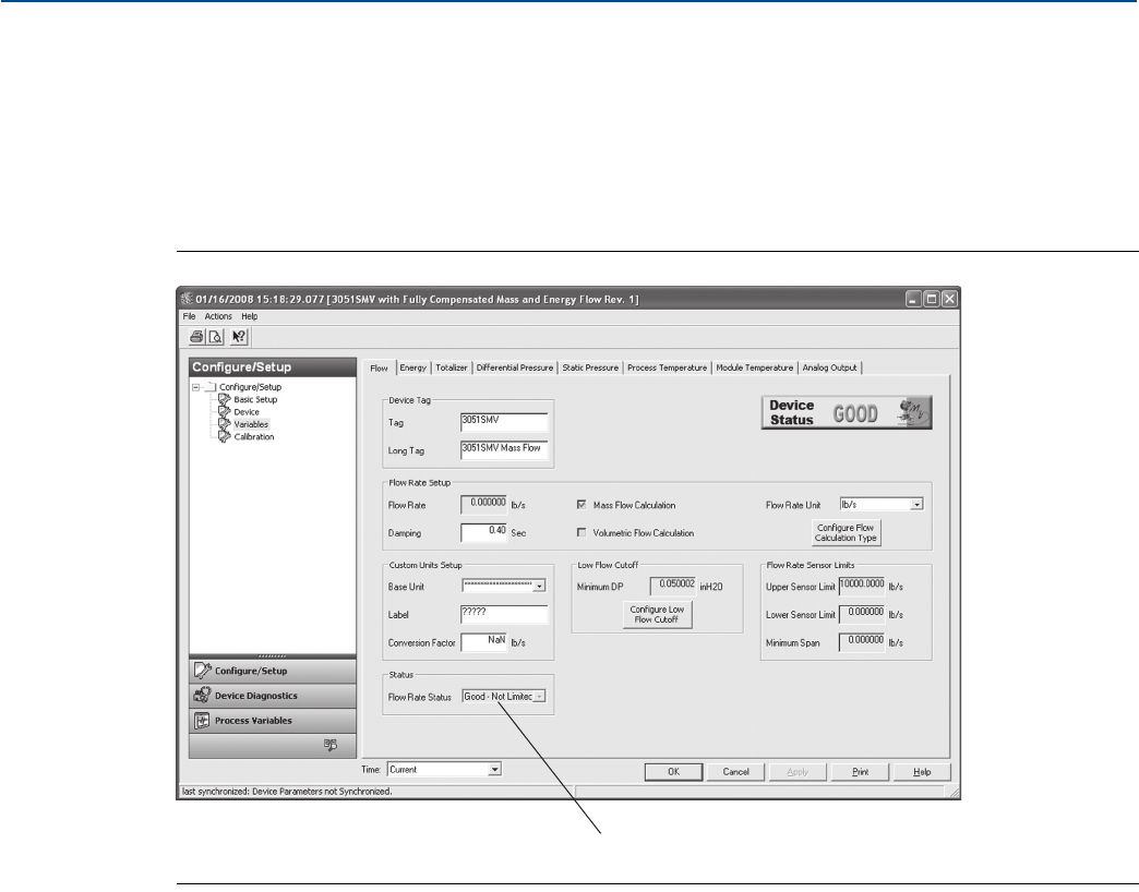
112
Reference Manual
00809-0100-4803, Rev GA
Troubleshooting
September 2017
Troubleshooting
5.3 Measurement quality and limit status
The Rosemount 3051SMV is compliant with the HART Revision 6 Standard. One of the most noticeable
enhancements available with the HART 6 standard is that each variable has a measurement quality and
limit status. These statuses can be viewed in AMS Device Manager, on a Field Communicator, or with any
HART 6 compatible host system. In AMS Device Manager, variable statuses can be viewed by selecting
Variables in the upper left menu tree under the Configure/Setup heading.
Figure 5-1. Quality and Limit Status
A. Measurement quality and limit status
Each variable status reading consists of two parts separated by a hyphen; Measurement Quality and Limit
Status.
Possible measurement quality readings
Good – Displayed during normal device operation.
Poor Accuracy – Indicates the accuracy of the variable measurement has been compromised.
Example: The module temperature sensor failed and is no longer compensating the differential pressure
and status pressure measurements.
Bad – Indicates the variable has failed. Example: A differential pressure, static pressure, or process
temperature sensor failure.
Possible limit status readings
Not Limited – Displayed during normal device operation.
High Limited – Indicates the current variable reading has gone above the transmitter’s maximum possible
reading and is no longer representative of the actual variable measurement.
Low Limited – Indicates the current variable reading has gone below the transmitter’s minimum possible
reading and is no longer representative of the actual variable measurement.
Constant – Indicates the variable reading is set to a fixed value. Example: The totalizer has been stopped.
A

113
Reference Manual
00809-0100-4803, Rev GA
Troubleshooting
September 2017
Troubleshooting
5.4 Engineering Assistant communication
troubleshooting
Table 5-3 identifies the most common communication issues between the Engineering Assistant
software and the Rosemount 3051SMV.
Table 5-3. Corrective Action for Engineering Assistant Communication Problems
Symptom Corrective action
No Communication
between the
Engineering Assistant
software and the
Rosemount 3051SMV
Loop wiring (HART)
•HART protocol communication requires a loop resistance value between 250 to 1321 ohms, inclusive.
•Check for adequate voltage to the transmitter. See “Load limitations” on page 131.
•Check for intermittent shorts, open circuits, and multiple grounds.
•Check for capacitance across the load resistor. Capacitance should be less than 0.1 microfarad.
Engineering Assistant
•Verify correct COM port selected.
•Verify laptop computer is not in low energy mode (certain laptops disable all COM ports in low energy mode).
•Check if HART modem is properly connected.
•Check if HART driver is loaded and installed. If using a HART USB port modem, install drivers from CD-ROM provided
with USB modem.
•Check if another HART configuration program, such as AMS Device Manager, is currently open. Only one HART
configuration program may be opened at a time.
•Verify the COM port buffer setting is set to the lowest setting (1) in the advanced COM port settings and re-boot the
computer.
•Set the Device Address to search All.

114
Reference Manual
00809-0100-4803, Rev GA
Troubleshooting
September 2017
Troubleshooting
5.5 Measurement troubleshooting
The transmitter provides a means to display the current process variables and flow calculations. If the
process variable reading is unexpected, this section provides the symptoms and possible corrective
actions.
Table 5-4. Unexpected Process Variable (PV) Readings
Symptom Corrective action
High PV Reading
Primary element
•Check for restrictions at the primary element.
•Check the installation and condition of the primary element.
•Note any changes in process fluid properties that may affect output.
Impulse piping
•Check to ensure the pressure connection is correct.
•Check for leaks or blockage.
•Check to ensure that blocking valves are fully open.
•Check for entrapped gas in liquid lines or for liquid in gas lines.
•Check to ensure the density of fluid in impulse lines is unchanged.
•Check for sediment in the transmitter process flange.
•Make sure that process fluid has not frozen within the process flange.
Power supply
•Check the output voltage of the power supply at the transmitter. It should be 12 to 42.4 V dc for HART with no load at
the transmitter terminals.
Note
Do not use higher than the specified voltage to check the loop, or damage to the transmitter may result.
Feature board electronics
•Connect a personal computer and use AMS Device Manager, Engineering Assistant Software, or the Field
Communicator to check the sensor limits to ensure calibration adjustments are within the sensor range and that
calibration is correct for the pressure being applied.
•Confirm the electronics housing is properly sealed against moisture.
•If the feature board electronics are still not functioning properly, substitute new feature board electronics.
Flow configuration (fully compensated mass and energy flow feature board only)
•Verify flow configuration is correct for current application
Process temperature RTD input
•Verify all wire terminations
•Verify sensor is a Pt 100 RTD
•Replace Pt 100 sensor
Sensor module
•The sensor module is not field repairable and must be replaced if found to be defective. Check for obvious defects,
such as a punctured isolating diaphragm or fill fluid loss, and contact your nearest Emerson™ Service Center.

115
Reference Manual
00809-0100-4803, Rev GA
Troubleshooting
September 2017
Troubleshooting
Symptom Corrective action
Erratic PV Reading
Primary element
•Check the installation and condition of the primary element.
Loop wiring
•Check for adequate voltage to the transmitter. It should be 12 to 42.4 Vdc for HART with no load at the transmitter
terminals.
•Check for intermittent shorts, open circuits, and multiple grounds.
Process pulsation
•Adjust the damping.
Feature board electronics
•Connect a personal computer and use AMS Device Manager, Engineering Assistant Software, or the Field
Communicator to check the sensor limits to ensure calibration adjustments are within the sensor range and that
calibration is correct for the pressure being applied.
•Confirm the electronics housing is properly sealed against moisture.
•If the feature board electronics are still not functioning properly, substitute new feature board electronics.
Impulse piping
•Check for entrapped gas in liquid lines or for liquid in gas lines.
•Make sure that process fluid has not frozen within the process flange.
•Ensure that block valves are fully open and equalize valves are fully and tightly closed.
Sensor module
•The sensor module is not field repairable and must be replaced if found to be defective. Check for obvious defects,
such as a punctured isolating diaphragm or fill fluid loss, and contact your nearest Emerson Service Center.
Low PV Reading or No
PV Reading
Primary element
•Check the installation and condition of the primary element.
Note any changes in process fluid properties that may affect output.
Loop wiring
•Check for adequate voltage to the transmitter. It should be 12 to 42.4 Vdc for HART with no load at the transmitter
terminals.
•Check the milliamp rating of the power supply against the total current being drawn for all transmitters being
powered.
•Check for shorts and multiple grounds.
•Check for proper polarity at the signal terminal.
•Check loop impedance.
•Check the wire insulation to detect possible shorts to ground.
Impulse piping
•Check to ensure the pressure connection is correct.
•Check for leaks or blockage.
•Check to ensure blocking valves are fully open and that bypass valves are tightly closed.
•Check for entrapped gas in liquid lines or for liquid in gas lines.
•Check for sediment in the transmitter process flange.
•Make sure process fluid has not frozen within the process flange.
Table 5-4. Unexpected Process Variable (PV) Readings

116
Reference Manual
00809-0100-4803, Rev GA
Troubleshooting
September 2017
Troubleshooting
Symptom Corrective action
Low PV Reading or No
PV Reading
Feature board electronics
•Check the sensor limits to ensure calibration adjustments are within the sensor range and that calibration is correct for
the pressure being applied.
•Confirm the electronics housing is properly sealed against moisture.
•If the feature board electronics are still not functioning properly, substitute new feature board electronics.
Flow configuration (fully compensated mass and energy flow feature board only)
•Verify flow configuration is correct for current application.
Process temperature RTD input
•Verify all wire terminations
•Verify sensor is a Pt 100 RTD
•Replace Pt 100 sensor
Sensor module
•The sensor module is not field repairable and must be replaced if found to be defective. Check for obvious defects,
such as a punctured isolating diaphragm or fill fluid loss, and contact your nearest Emerson Service Center.
Sluggish Output
Response/Drift
Primary element
•Check for restrictions at the primary element.
Impulse piping
•Check for leaks or blockage.
•Ensure blocking valves are fully open.
•Check for sediment in the transmitter process flange.
•Check for entrapped gas in liquid lines and for liquid in gas lines.
•Ensure the density of fluid in impulse lines is unchanged.
•Make sure process fluid has not frozen within the process flange.
Feature board electronics
•Confirm damping is correctly set.
•Confirm the electronics housing is properly sealed against moisture.
Sensor module
•The sensor module is not field repairable and must be replaced if found to be defective. Check for obvious defects,
such as a punctured isolating diaphragm or fill fluid loss, and contact your nearest Emerson Process Management
Service Center.
•Confirm the electronics housing is properly sealed against moisture.
Table 5-4. Unexpected Process Variable (PV) Readings
117
Reference Manual
00809-0100-4803, Rev GA
Troubleshooting
September 2017
Troubleshooting
Note
The following performance limitations may inhibit efficient or safe operation. Critical applications should
have appropriate diagnostic and backup systems in place.
Pressure transmitters contain an internal fill fluid. It is used to transmit the process pressure through the
isolating diaphragms to the pressure sensor module. In rare cases, oil loss paths in oil-filled pressure
transmitters can be created. Possible causes include: physical damage to the isolator diaphragms,
process fluid freezing, isolator corrosion due to an incompatible process fluid, etc.
A transmitter with oil fill fluid loss may continue to perform normally for a period of time. Sustained oil
loss will eventually cause one or more of the operating parameters to exceed published specifications as
the operating point output continues to drift. Symptoms of advanced oil loss and other unrelated
problems include:
Sustained drift rate in true zero and span or operating point output or both
Sluggish response to increasing or decreasing pressure or both
Limited output rate or very nonlinear output or both
Change in output process noise
Noticeable drift in operating point output
Abrupt increase in drift rate of true zero or span or both
Unstable output
Output saturated high or low
5.6 Service support
To expedite the return process outside of the United States, contact the nearest Emerson representative.
Within the United States, call the Emerson Instrument and Valves Response Center using the
1-800-654-RSMT (7768) toll-free number. This center, available 24 hours a day, will assist with any
needed information or materials.
The center will ask for product model and serial numbers, and will provide a Return Material
Authorization (RMA) number. The center will also ask for the process material to which the product was
last exposed.
Emerson Instrument and Valves Response Center representatives will explain the additional information
and procedures necessary to return goods exposed to hazardous substances.
Individuals who handle products exposed to a hazardous substance can avoid injury if they are informed
of and understand the hazard. If the product being returned was exposed to a hazardous substance as
defined by OSHA, a copy of the required Material Safety Data Sheet (MSDS) for each hazardous
substance identified must be included with the returned goods.

118
Reference Manual
00809-0100-4803, Rev GA
Troubleshooting
September 2017
Troubleshooting

Reference Manual
00809-0100-4803, Rev GA
Safety Instrumented Systems Requirements
September 2017
119
Safety Instrumented Systems Requirements
Section 6 Safety Instrumented Systems
Requirements
Safety Instrumented Systems (SIS) Certification . . . . . . . . . . . . . . . . . . . . . . . . . . . . . . . . . . . . . . . . .page 119
Rosemount 3051SMV safety certified identification . . . . . . . . . . . . . . . . . . . . . . . . . . . . . . . . . . . . . .page 119
Installation in SIS applications . . . . . . . . . . . . . . . . . . . . . . . . . . . . . . . . . . . . . . . . . . . . . . . . . . . . . . . . .page 119
Configuring in SIS applications . . . . . . . . . . . . . . . . . . . . . . . . . . . . . . . . . . . . . . . . . . . . . . . . . . . . . . . .page 120
Rosemount 3051SMV SIS operation and maintenance . . . . . . . . . . . . . . . . . . . . . . . . . . . . . . . . . . . .page 121
Inspection . . . . . . . . . . . . . . . . . . . . . . . . . . . . . . . . . . . . . . . . . . . . . . . . . . . . . . . . . . . . . . . . . . . . . . . . . .page 122
6.1 Safety Instrumented Systems (SIS) Certification
The safety-critical output of the Rosemount 3051SMV is provided through a two-wire, 4–20 mA signal
representing pressure. The Rosemount 3051SMV safety certified pressure transmitter is certified to: Low
Demand; Type B.
SIL 2 for random integrity @ HFT=0
SIL 3 for random integrity @ HFT=1
SIL 3 for systematic integrity
The Rosemount 3051SMV must be installed per manufacturer’s instructions, specifications and the
materials must be compatible with process conditions.
The HART® Protocol is only used for setup, calibration, and diagnostic purposes and is not for safety
critical operation.
6.2 Rosemount 3051SMV safety certified identification
All Rosemount 3051SMV Transmitters must be identified as safety certified before installing into SIS
systems.
To identify a safety certified Rosemount 3051SMV:
1. Verify the model string contains Rosemount 3051SMV and QT.
–If the transmitter was ordered as part of a flowmeter, verify the model string reads Rosemount
3051SFx(1–7) and QT.
2. Verify software revision is 3.
6.3 Installation in SIS applications
Installations are to be performed by qualified personnel. No special installation is required in addition to
the standard installation practices outlined in this document. Always ensure a proper seal by installing
the electronics housing cover(s) so that metal contacts metal.
Environmental and operational limits are available in Appendix A: Specifications and Reference Data
The loop should be designed so the terminal voltage does not drop below 12.0 Vdc when the
transmitter output is set to 23 mA.
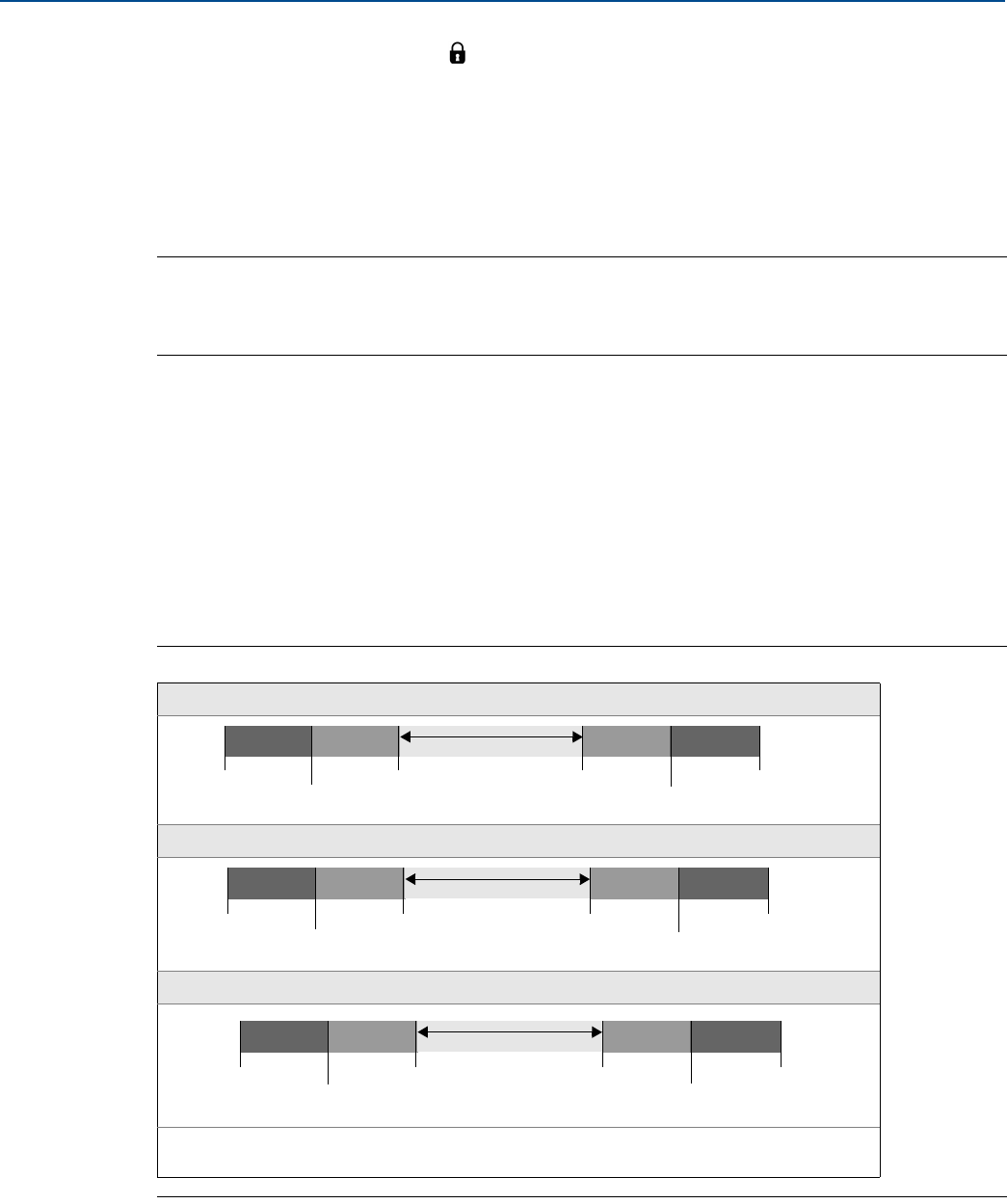
120
Reference Manual
00809-0100-4803, Rev GA
Safety Instrumented Systems Requirements
September 2017
Safety Instrumented Systems Requirements
Position the security switch to the ( ) position to prevent accidental or deliberate change of
configuration data during normal operation.
6.4 Configuring in SIS applications
Use any HART capable configuration tool to communicate with and verify configuration of the
Rosemount 3051SMV.
Note
Transmitter output is not safety-rated during the following: configuration changes, multidrop, and loop
test. Alternative means should be used to ensure process safety during transmitter configuration and
maintenance activities.
6.4.1 Damping
User-selected damping will affect the transmitters ability to respond to changes in the applied process.
The damping value + response time must not exceed the loop requirements.
Reference “Damping” on page 132 to change damping value.
6.4.2 Alarm and saturation levels
DCS or safety logic solver should be configured to match transmitter configuration.
Figure 6-1
identifies
the three alarm levels available and their operation values.
Figure 6-1. Alarm Levels
Rosemount alarm level
Namur alarm level
Custom alarm level
1. Transmitter Failure, hardware or software alarm in LO position.
2. Transmitter Failure, hardware or software alarm in HI position.
Normal Operation
4 mA 20 mA
20.8 mA
high saturation
21.75(2)
3.9 mA
low saturation
3.75 mA(1)
Normal Operation
4 mA 20 mA
20.5 mA
high saturation
22.5(2)
3.8 mA
low saturation
3.6 mA(1)
Normal Operation
4 mA 20 mA
20.1 - 22.9 mA
high saturation
20.2 - 23.0(2)
3.7 - 3.9 mA
low saturation
3.6 - 3.8 mA(1)

121
Reference Manual
00809-0100-4803, Rev GA
Safety Instrumented Systems Requirements
September 2017
Safety Instrumented Systems Requirements
6.5 Rosemount 3051SMV SIS operation and maintenance
6.5.1 Proof test
The following proof tests are recommended.
All proof test procedures must be carried out by qualified personnel.
Use “Field Communicator Fast Keys” on page 62 to perform a loop test, analog output trim, or sensor
trim. security switch should be in the ( ) position during proof test execution and repositioned in the
( ) position after execution.
6.5.2 Partial proof test
The partial suggested proof test consists of a power cycle plus reasonability checks of the transmitter
output. This test will detect ~48% of possible DU failures in the device.
FMEDA report can be found at Emerson.com/Automation-Solutions/Pressure/Rosemount-3051SMV
and look at the certificates and approvals documentation.
Required tools: Field Communicator and mA meter.
1. Bypass the safety function and take appropriate action to avoid a false trip.
2. Use HART communications to retrieve any diagnostics and take appropriate action.
3. Send a HART command to the transmitter to go to the high alarm current output and verify that the
analog current reaches that value.(1) See “Alarm level verification” on page 30.
4. Send a HART command to the transmitter to go to the low alarm current output and verify that the
analog current reaches that value.(2)
5. Perform a “reasonability check” on the pressure sensor reading and the sensor temperature reading
and if applicable the process temperature reading.(3)
6. Remove the bypass and otherwise restore the normal operation.
7. Place the Security switch in the ( ) position.
6.5.3 Comprehensive proof test
The comprehensive proof test consists of performing the same steps as the simple suggested proof test
but with a two point calibration of the pressure and temperature sensors in place of the reasonability
check of the sensors. This test will detect ~90% of possible DU failures in the device.
Required tools: Field Communicator and pressure calibration equipment.
1. Bypass the safety function and take appropriate action to avoid a false trip.
2. Use HART communications to retrieve any diagnostics and take appropriate action.
3. Send a HART command to the transmitter to go to the high alarm current output and verify that the
analog current reaches that value.(1) See “Alarm level verification” on page 30.
4. Send a HART command to the transmitter to go to the low alarm current output and verify that the
analog current reaches that value.(2)
1. This tests for compliance voltage problems such as a low loop power supply voltage or increased wiring resistance. This also tests for other possible
failures.
2. This tests for possible quiescent current related failures.
3. This tests for faults in the input multiplexer and A to D converter.

122
Reference Manual
00809-0100-4803, Rev GA
Safety Instrumented Systems Requirements
September 2017
Safety Instrumented Systems Requirements
5. Perform a two-point verification(1) of the transmitter pressure over the full working range (and
process temperature where applicable).
6. Remove the bypass and otherwise restore the normal operation.
7. Place the Security switch in the ( ) position.
Note
The user determines the proof test requirements for impulse piping.
Automatic diagnostics are defined for the corrected % DU: The tests performed internally by the
device during runtime without requiring enabling or programming by the user.
6.6 Inspection
6.6.1 Visual inspection
Not required
6.6.2 Special tools
Not required
6.6.3 Product repair
The Rosemount 3051SMV is repairable with limited replacement options.
All failures detected by the transmitter diagnostics or by the proof-test must be reported. Feedback can
be submitted electronically at Emerson.com/Rosemount/Report-A-Failure
All product repair and part replacement should be performed by qualified personnel.
6.6.4 Rosemount 3051SMV SIS reference
The Rosemount 3051SMV must be operated in accordance to the functional and performance
specifications provided in “Specifications and Reference Data” on page 125.
6.6.5 Failure rate data
The FMEDA report includes failure rates and the assumptions for how these failure rates were derived.
The report is available under Certificates and Approvals at
Emerson.com/Automation-Solutions/Pressure/Rosemount-3051SMV
6.6.6 Failure values
Safety Deviation (defines what is dangerous in a FMEDA): ±2.0% of analog output span
Transmitter response time: provided in “Dynamic performance ambient temperature effect” on
page 127.
Self-diagnostics Test Interval: At least once every 60 minutes
1. If the two-point process temperature verification is performed with electrical instrumentation, this proof test will not detect any failures of the sensor.

123
Reference Manual
00809-0100-4803, Rev GA
Safety Instrumented Systems Requirements
September 2017
Safety Instrumented Systems Requirements
6.6.7 Product life
50 years - based on worst case component wear-out mechanisms - not based on wear-out of process
wetted materials

124
Reference Manual
00809-0100-4803, Rev GA
Safety Instrumented Systems Requirements
September 2017
Safety Instrumented Systems Requirements
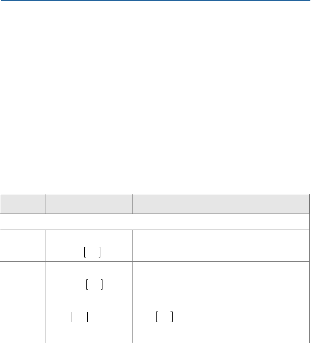
Specifications and Reference Data
125
Specifications and Reference Data
September 2017
Reference Manual
00809-0100-4803, Rev GA
Appendix A Specifications and Reference Data
Specifications . . . . . . . . . . . . . . . . . . . . . . . . . . . . . . . . . . . . . . . . . . . . . . . . . . . . . . . . . . . . . . . . . . . . . . . page 125
Dimensional drawings . . . . . . . . . . . . . . . . . . . . . . . . . . . . . . . . . . . . . . . . . . . . . . . . . . . . . . . . . . . . . . . . page 135
Ordering information . . . . . . . . . . . . . . . . . . . . . . . . . . . . . . . . . . . . . . . . . . . . . . . . . . . . . . . . . . . . . . . . page 138
Accessories . . . . . . . . . . . . . . . . . . . . . . . . . . . . . . . . . . . . . . . . . . . . . . . . . . . . . . . . . . . . . . . . . . . . . . . . . page 147
Spare parts . . . . . . . . . . . . . . . . . . . . . . . . . . . . . . . . . . . . . . . . . . . . . . . . . . . . . . . . . . . . . . . . . . . . . . . . . page 150
A.1 Specifications
A.1.1 Performance specifications
For zero-based spans, reference conditions, silicone oil fill, glass-filled PTFE O-rings, Stainless steel (SST) materials, or
coplanar flange digital trim values set to equal range points.
Conformance to specification (±3σ [Sigma])
Technology leadership, advanced manufacturing techniques, and statistical process control ensure measurement
specification conformance to ±3σ or better.
Reference accuracy(1)
Rosemount
models Classic MV Ultra for Flow
3051SMV_ _1: Differential pressure, static pressure, and temperature
3051SMV_ _2: Differential pressure and static pressure
DP Ranges 2–3 ±0.04% of span;
For spans less than 10:1,
±0.04% of reading up to 8:1
DP turndown from URL;
±(0.04 + 0.0023[URL/RDG(2)])% reading to 200:1
DP turndown from URL(3)
DP Range 1 ±0.10% of span;
For spans less than 15:1,
N/A
AP and GP
Ranges 3–4
±0.055% of span;
For spans less than 10:1,
±0.025% of span;
For spans less than 10:1,
Process Temp.
RTD Interface(4)
±0.67 °F (0.37 °C) ±0.67 °F (0.37 °C)
0.01 0.004+URL
span
-------------
% of span±
0.025 0.005+URL
span
-------------
% of span±
0.0065 URL
span
-------------
% of span±
0.004 URL
span
-------------
% of span±
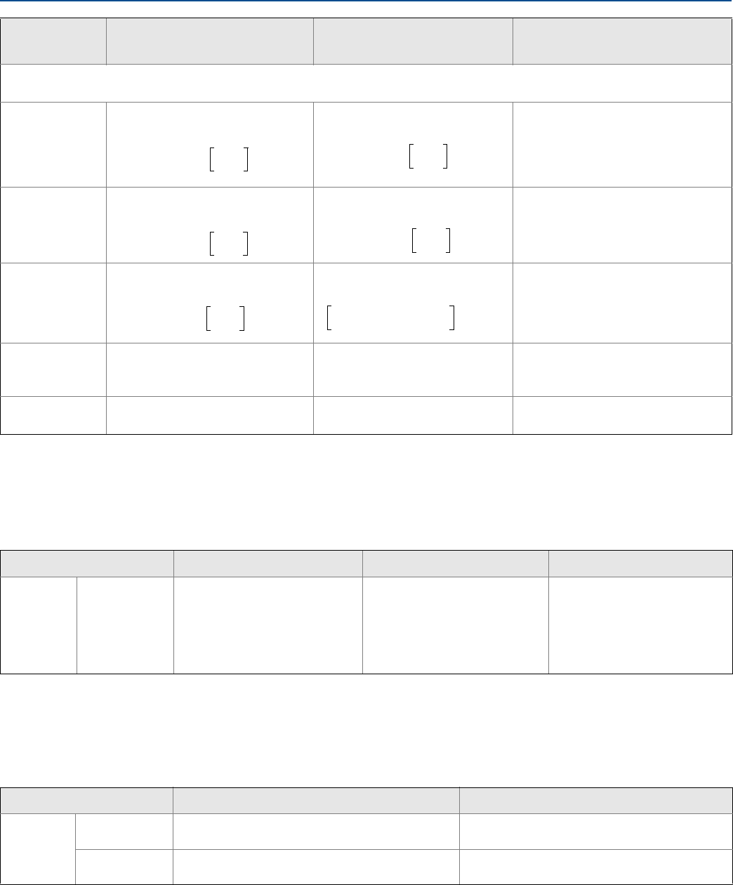
Specifications and Reference Data
September 2017
Reference Manual
00809-0100-4803, Rev GA
Specifications and Reference Data 126
Rosemount
models Ultra Classic Ultra for Flow
3051SMV_ _3: Differential pressure and temperature
3051SMV_ _4: Differential pressure
Ranges 2–4 ±0.025% of span;
For spans less than 10:1,
±0.055% of span;
For spans less than 10:1,
±0.04% of reading up to 8:1
DP turndown from URL;
±(0.04 + 0.0023[URL/RDG(2)])%
reading to 200:1 DP turndown
from URL(3)
Range 5 ±0.05% of span;
For spans less than 10:1,
±0.065% of span;
For spans less than 10:1,
N/A
Range 1 ±0.09% of span;
For spans less than 15:1,
±0.10% of span;
For spans less than 15:1,
N/A
Range 0 ±0.09% of span;
For spans less than 2:1,
±0.045% of URL
±0.10% of span;
For spans less than 2:1,
±0.05% of URL
N/A
Process Temp.
RTD Interface(4)
±0.67 °F (0.37 °C) ±0.67 °F (0.37 °C) ±0.67 °F (0.37 °C)
1. Stated reference accuracy equations include terminal based linearity, hysteresis, and repeatability, but does not include analog only reference accuracy of ±0.005% of
span.
2. RDG refers to transmitter DP reading.
3. Ultra for Flow is only available for Rosemount™ 3051SMV DP Ranges 2–3. For calibrated spans from 1:1 to 2:1 of URL, add ±0.005% of span analog output error.
4. Specifications for process temperature are for the transmitter portion only. The transmitter is compatible with any Pt 100 (100 ohm platinum) RTD. Examples of
compatible RTDs include Rosemount Series 68 and 78 RTD Temperature Sensors.
0.005 0.0035+URL
span
-------------
% of span±
0.015 0.005+URL
span
-------------
% of span±
0.005 0.0045+URL
span
-------------
% of span±
0.015 0.005+URL
span
-------------
% of span±
0.015 0.005+URL
span
-------------
% of span±
0.025 0.005+URL
span
-------------
% of span±
Total performance(1)
Models Ultra(1) Classic and Classic MV Ultra for Flow(2)
Rosemount
3051SMV
DP Ranges 2–3 ±0.1% of span;
for ±50 °F (28 °C) temperature
changes; 0-100% relative
humidity, up to 740 psi (51 bar)
line pressure (DP only),
from 1:1 to 5:1 rangedown
±0.15% of span;
for ±50 °F (28 °C) temperature
changes; 0-100% relative
humidity, up to 740 psi (51 bar)
line pressure (DP only),
from 1:1 to 5:1 rangedown
±0.1% of reading;
for ±50 °F (28 °C) temperature
changes; 0-100% relative
humidity, up to 740 psi (51 bar)
line pressure,
over 8:1 DP turndown from URL
1. Total performance is based on combined errors of reference accuracy, ambient temperature effect, and line pressure effect. Specifications apply only to differential
pressure measurement.
2. Ultra for Flow is only available for Rosemount 3051SMV DP Ranges 2–3.
Multivariable flow performance(1)
Mass, energy, actual volumetric, and totalized flow reference accuracy(2)
Models(1)(2) Ultra for Flow Classic MV
Rosemount
3051SMV
DP Ranges 2–3 ±0.65% of flow rate over a 14:1 flow range
(200:1 DP range)
±0.70% of flow rate over 8:1 flow range
(64:1 DP range)
DP Range 1 N/A ±0.90% of flow rate over 8:1 flow range
(64:1 DP range)
1. Applies to the 3051SMV_M Multivariable™ type only. Flow performance specifications assume device is configured for full compensation of static pressure, process
temperature, density, viscosity, gas expansion, discharge coefficient, and thermal correction variances over a specified operating range.
2. Uncalibrated differential producer (0.2 < beta < 0.6 Orifice) installed per ASME MFC 3M or ISO 5167-1. Uncertainties for discharge coefficient, producer bore, tube
diameter, and gas expansion factor as defined in ASME MFC 3M or ISO 5167-1. Reference accuracy does not include RTD sensor accuracy.
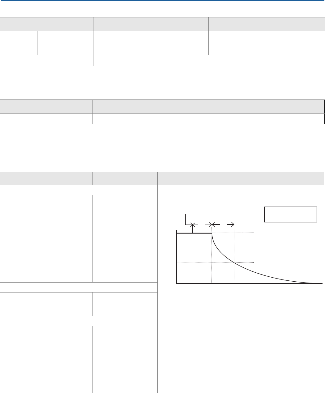
Specifications and Reference Data
127
Specifications and Reference Data
September 2017
Reference Manual
00809-0100-4803, Rev GA
Long term stability
Dynamic performance ambient temperature effect
Models Ultra and Ultra for Flow(1)
1. Ultra is only available for Rosemount 3051SMV_ _3, 4. Ultra for Flow is only available for Rosemount 3051SMV DP Ranges 2-3.
Classic and Classic MV
Rosemount
3051SMV
DP Ranges 2–5 AP
and GP Ranges 3–4
±0.15% of URL for 15 years;
for ±50 °F (28 °C) temperature changes,
up to 1000 psi (68,9 bar) line pressure
±0.20% of URL for 15 years;
for ±50 °F (28 °C) temperature changes,
up to 1000 psi (68,9 bar) line pressure
Process Temperature RTD Interface(2)
2. Specifications for process temperature are for the transmitter portion only. The transmitter is compatible with any Pt 100 (100 ohm platinum) RTD. Examples of
compatible RTDs include Rosemount Series 68 and 78 RTD Temperature Sensors.
The greater of ±0.185 °F (0.103 °C) or 0.1% of reading per year (excludes RTD sensor stability).
Warranty(1)
1. Warranty details can be found in Emerson™ Terms & Conditions of Sale, Document 63445, Rev G (10/06).
Models Ultra and Ultra for Flow Classic and Classic MV
Rosemount 3051S Scalable Products 12-year limited warranty(2)
2. Rosemount Ultra and Ultra for Flow transmitters have a limited warranty of twelve (12) years from date of shipment. All other provisions of Emerson standard limited
warranty remain the same.
1-year limited warranty(3)
3. Goods are warranted for twelve (12) months from the date of initial installation or eighteen (18) months from the date of shipment by seller, whichever period expires
first.
4–20 mA (HART®)(1)
1. Dead time and update rate apply to all models and ranges; analog output only.
Typical transmitter response time
Total response time (Td + Tc)(2)
2. Nominal total response time at 75 °F (24 °C) reference conditions.
3051SMV_ _1: DP, SP, & T
3051SMV_ _2: DP & SP:
DP Range 1:
DP Range 2:
DP Range 3:
AP and GP:
310 milliseconds
170 milliseconds
155 milliseconds
240 milliseconds
3051SMV_ _3: DP & T
3051SMV_ _4: DP:
DP Ranges 2–5:
DP Range 1:
DP Range 0:
145 milliseconds
300 milliseconds
745 milliseconds
Dead time (Td)
DP:
AP and GP:
Process Temp. RTD Interface:
100 milliseconds
140 milliseconds
1 second
Update rate
Measured Variables:
DP:
AP and GP:
Process Temp. RTD Interface:
22 updates per second
11 updates per second
1 update per second
Calculated Variables:
Mass or Volumetric Flow Rate:
Energy Flow Rate:
Totalized Flow:
22 updates per second
22 updates per second
1 update per second
Pressure released
TdTc
Transmitter Output vs. Time
100%
36.8%
0% Time
63.2% of total
step change
= Dead time
= Time constant
Td
Tc
Response time = Td+Tc
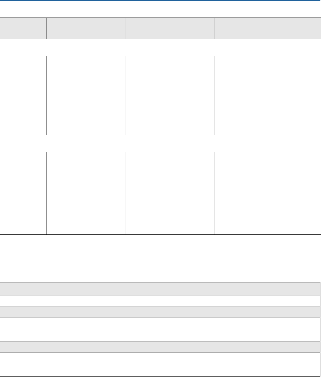
Specifications and Reference Data
September 2017
Reference Manual
00809-0100-4803, Rev GA
Specifications and Reference Data 128
Ambient temperature effect
Rosemount
models
Ultra
per 50 °F (28 °C)
Classic or Classic MV
per 50 °F (28 °C)
Ultra for Flow(1)
–40 to 185 °F (–40 to 85 °C)
3051SMV_ _1: Differential pressure, static pressure, and temperature
3051SMV_ _2: Differential pressure and static pressure
DP Ranges 2–3 N/A ± (0.0125% URL + 0.0625% span)
from 1:1 to 5:1;
± (0.025% URL + 0.125% span) for
> 5:1
±0.13% reading up to 8:1 DP turndown
from URL;
±(0.13 + 0.0187 [URL/RDG(3)])% reading
to 100:1 DP turndown from URL
DP Range 1 N/A ± (0.1% URL + 0.25% Span)
from 1:1 to 50:1
N/A
AP and GP N/A ± (0.0125% URL + 0.0625% span)
from 1:1 to 10:1;
± (0.025% URL + 0.125% span) for
>10:1
± (0.009% URL + 0.025% span)
from 1:1 to 10:1;
± (0.018% URL + 0.08% span)
for > 10:1
3051SMV_ _ 3: Differential pressure and temperature
3051SMV_ _ 4: Differential pressure
Range 2–5(2) ± (0.009% URL + 0.025% span)
from 1:1 to 10:1;
± (0.018% URL + 0.08% span)
from >10:1 to 200:1
± (0.0125% URL + 0.0625% span)
from 1:1 to 5:1;
± (0.025% URL + 0.125% span)
from >5:1 to 100:1
±0.13% reading up to 8:1 DP turndown
from URL;
±(0.13 + 0.0187 [URL/RDG(3)])% reading
to 100:1 DP turndown from URL
Range 0 ± (0.25% URL + 0.05% span)
from 1:1 to 30:1
± (0.25% URL + 0.05% span)
from 1:1 to 30:1
N/A
Range 1 ± (0.1% URL + 0.25% span)
from 1:1 to 50:1
± (0.1% URL + 0.25% span)
from 1:1 to 50:1
N/A
Process Temp.
RTD Interface(4)
N/A ±0.39 °F (0,216 °C)
per 50 °F (28 °C)
±0.39 °F (0,216 °C)
per 50 °F (28 °C)
1. Ultra for Flow is only available for Rosemount 3051SMV DP Ranges 2–3.
2. Use classic specification for Rosemount 3051SMV DP Range 5 Ultra.
3. RDG refers to transmitter reading.
4. Specifications for process temperature are for the transmitter portion only. The transmitter is compatible with any Pt 100 (100 ohm platinum) RTD. Examples of
compatible RTDs include Rosemount Series 68 and 78 RTD Temperature Sensors.
Line Pressure effect(1)
Models(1) Ultra and Ultra for Flow Classic and Classic MV
Rosemount 3051SMV: Differential pressure measurement only
Zero error(2)
Range 2–3
Range 0
Range 1
± 0.025% URL per 1000 psi (69 bar)
± 0.125% URL per 100 psi (6,89 bar)
± 0.25% URL per 1000 psi (69 bar)
± 0.05% URL per 1000 psi (69 bar)
± 0.125% URL per 100 psi (6,89 bar)
± 0.25% URL per 1000 psi (69 bar)
Span error(3)
Range 2–3
Range 0
Range 1
± 0.1% of reading per 1000 psi (69 bar)
± 0.15% of reading per 100 psi (6,89 bar)
± 0.4% of reading per 1000 psi (69 bar)
± 0.1% of reading per 1000 psi (69 bar)
± 0.15% of reading per 100 psi (6,89 bar)
± 0.4% of reading per 1000 psi (69 bar)
1. For zero error specifications for line pressures above 2000 psi (137,9 bar) or line pressure effect specifications for DP Ranges 4–5, see the Rosemount 3051SMV
Reference Manual.
2. Zero error can be zeroed.
3. Specifications for option code P0 are two times those shown above.
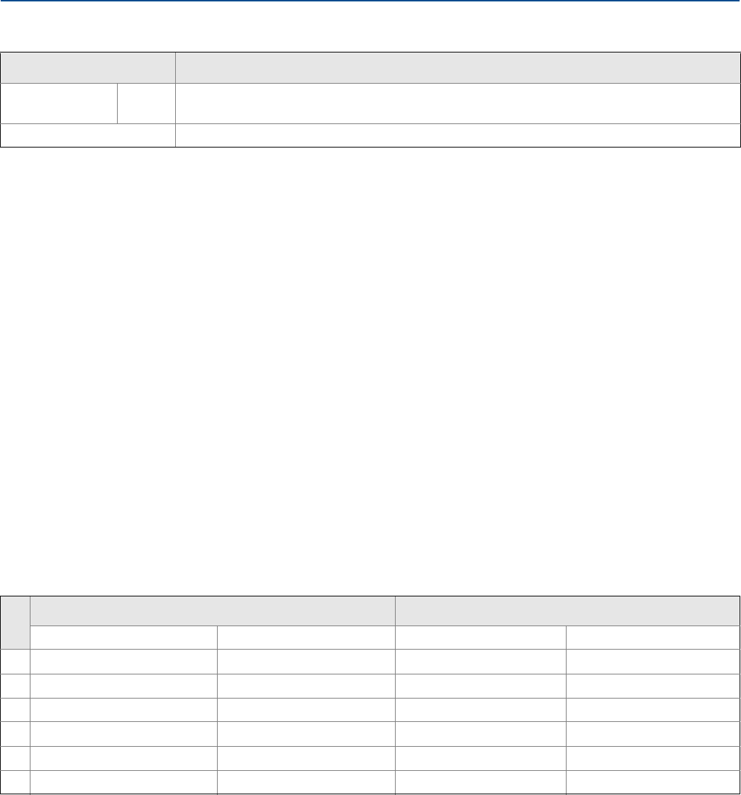
Specifications and Reference Data
129
Specifications and Reference Data
September 2017
Reference Manual
00809-0100-4803, Rev GA
Mounting position effects
Vibration effect
Less than ±0.1% of URL when tested per the requirements of
IEC60770-1 field or pipeline with high vibration level(10–60
Hz 0.21mm displacement peak amplitude/60–2000 Hz 3g).
For housing style codes 1J, 1K, and 1L:
Less than ±0.1% of URL when tested per the requirements of
IEC60770-1 field with general application or pipeline with
low vibration level (10–60 Hz 0.15mm displacement peak
amplitude/
60–500 Hz 2g).
Power supply effect
Less than ±0.005% of calibrated span per volt change in
voltage at the transmitter terminals
Transient protection (Option T1)
Meets IEEE C62.41.2-2002, location category B
6 kV crest (0.5 μs - 100 kHz)
3 kA crest (8 ⫻ 20 microseconds)
6 kV crest (1.2 ⫻ 50 microseconds)
Meets IEEE C37.90.1-2002 surge withstand capability
SWC 2.5 kV crest, 1.0 MHz wave form
A.1.2 Functional specifications
Range and sensor limits
Rosemount models Ultra, Ultra for Flow, Classic, and Classic MV
3051SMV_ _ 1, 2 DP:
AP/GP:
Zero shifts up to ±1.25 inH2O (3,11 mbar), which can be zeroed; no span effect
Zero shifts to ±2.5 inH2O (6,22 mbar), which can be zeroed; no span effect
3051SMV_ _ 3, 4 Zero shifts up to ±1.25 inH2O (3,11 mbar), which can be zeroed; no span effect
Electro Magnetic Compatibility (EMC)(1)
Meets all relevant requirements of EN 61326 and NAMUR NE-21.
1. Requires shielded cable for both temperature and loop wiring.
Table A-1. Rosemount 3051SMV Differential Pressure Range and Sensor Limits
Range
Minimum span Range limits
Ultra and Ultra for Flow Classic and classic MV Upper (URL) Lower (LRL)(1)
1. Lower (LRL) is 0 inH2O (0 mbar) for Ultra for Flow.
00.1 inH2O (0,25 mbar) 0.1 inH2O (0,25 mbar) 3.0 inH2O (7,5 mbar) –3.0 inH2O (–7,5 mbar)
10.5 inH2O (1,24 mbar) 0.5 inH2O (1,24 mbar) 25.0 inH2O (62,3 mbar) –25.0 inH2O (–62,3 mbar)
21.3 inH2O (3,11 mbar) 2.5 inH2O (6,23 mbar) 250.0 inH2O (0,62 bar) –250.0 inH2O (–0,62 bar)
35.0 inH2O (12,4 mbar) 10.0 inH2O (24,9 mbar) 1000.0 inH2O (2,49 bar) –1000.0 inH2O (–2,49 bar)
41.5 psi (103,4 mbar) 3.0 psi (206,8 mbar) 300.0 psi (20,7 bar)(2)
2. For measurement type 1 and 2, URL = 150.0 psi (10,34 bar) and LRL = –150.0 psi (10,34 bar).
–300.0 psi (–20,7 bar)(2)
510.0 psi (689,5 mbar) 20.0 psi (1,38 bar) 2000.0 psi (137,9 bar) – 2000.0 psi (–137,9 bar)
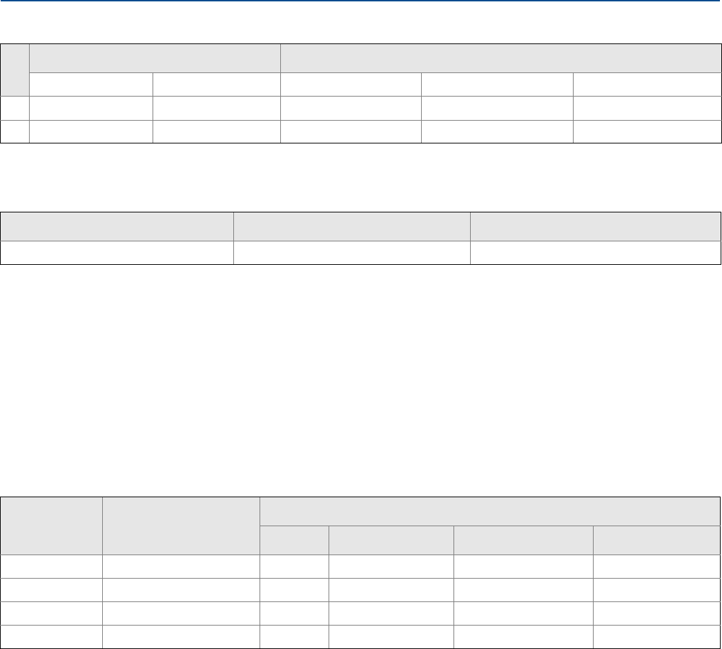
Specifications and Reference Data
September 2017
Reference Manual
00809-0100-4803, Rev GA
Specifications and Reference Data 130
Service
Rosemount 3051SMV_P (direct process variable output)
Liquid, gas, and vapor applications
Rosemount 3051SMV_M (mass and energy flow output)
Some fluid types are only supported by certain measurement types
4–20 mA/HART
Zero and span adjustment
Zero and span values can be set anywhere within the
range.
Span must be greater than or equal to the minimum
span.
Output
Two-wire 4–20 mA is user-selectable for linear or square
root output. Digital process variable superimposed on
4–20 mA signal, available to any host that conforms to
the HART Protocol.
Power supply
External power supply required.
Rosemount 3051SMV: 12 to 42.4 Vdc with no load
Table A-2. Rosemount 3051SMV Static Pressure Range and Sensor Limits
Range
Minimum span Range limits
Ultra for Flow Classic MV Upper (URL) Lower (LRL) (Absolute) Lower (LRL)(Gage)(1)(2)
34.0 psi (276 mbar) 8.0 psi (552 mbar) 800 psi (55,16 bar) 0.5 psia (34,5 mbar) –14.2 psig (–0,98 bar)
418.13 psi (1,25 bar) 36.26 psi (2,50 bar) 3626 psi (250.0 bar)(3) 0.5 psia (34,5 mbar) –14.2 psig (–0,98 bar)
1. Assumes atmospheric pressure of 14.7 psig (1 bar).
2. Inert fill: Minimum pressure = 1.5 psia (0,10 bar) or -13.2 psig (-0,91 bar).
3. For SP Range 4 and DP Range 1, the URL is 2000 psi (137,9 bar).
Table A-3. Process Temperature RTD Interface Range Limits(1)
Minimum Span Upper (URL) Lower (LRL)
50 °F (28 °C) 1562 °F (850 °C) –328 °F (–200 °C)
1. Designed to accommodate a Pt 100 RTD sensor. Examples of compatible RTDs include Rosemount Series 68 and 78 RTD Temperature Sensors.
Fluid compatibility with pressure and temperature
compensation • Available — Not available
Ordering code Measurement type
Fluid types
Liquids Saturated steam Superheated steam Gas and natural gas
1DP/P/T (full compensation) • • • •
2DP/P • • • •
3DP/T • • — —
4DP only • • — —
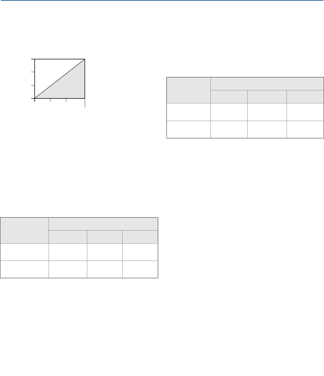
Specifications and Reference Data
131
Specifications and Reference Data
September 2017
Reference Manual
00809-0100-4803, Rev GA
Load limitations
Maximum loop resistance is determined by the voltage
level of the external power supply, as described by:
Overpressure limits
Transmitters withstand the following limits without
damage:
Static pressure limit
Rosemount 3051SMV_ _1: Differential and
Static Pressure, temperature
Rosemount 3051SMV_ _2: Differential
Pressure and Static Pressure
Operates within 0.5 psia (0,03 bar) and the values in the
table below:
Rosemount 3051SMV_ _ 3: Differential
Pressure and temperature
Rosemount 3051SMV_ _ 4: Differential
Pressure
Operates within specifications between static line pressures
of 0.5 psia and 3626 psig;
Burst pressure limits
Rosemount 3051SMV with coplanar or
traditional process flange
10000 psig (689,5 bar)
Rosemount 3051SMV Transmitter
Maximum loop resistance = 43.5 ⫻ (Power supply voltage – 12.0)
The Field Communicator requires a minimum loop resistance of 250Ω
for communication.
Rosemount 3051SMV_ _1: Differential and
Static Pressure, temperature
Rosemount 3051SMV_ _2: Differential
Pressure and Static Pressure
Static Pressure
Differential Pressure
Range 1 Range 2 Range 3
Range 3 GP/AP 1600 psi
(110,3 bar)
1600 psi
(110,3 bar)
1600 psi
(110,3 bar)
Range 4 GP/AP 2000 psi
(137,9 bar)
3626 psi
(250 bar)
3626 psi
(250 bar)
Rosemount 3051SMV_ _ 3: Differential
Pressure and temperature
Rosemount 3051SMV_ _ 4: Differential
Pressure
Range 0 750 psi (51,7 bar)
Range 1 2000 psig (137,9 bar)
Ranges 2–5 3626 psig (250,0 bar)
Option code P9 4500 psig (310,3 bar)
Option code P0 (classic only) 6092 psig (420 bar)
1322
1000
500
0
12.0 20 30 42.4
Voltage (Vdc)
Load (Ohms)
Operating
Region
Static Pressure
Differential Pressure
Range 1 Range 2 Range 3
Range 3 GP/AP 800 psi
(57,91 bar)
800 psi
(57,91 bar)
800 psi
(57,91 bar)
Range 4 GP/AP 2000 psi
(137,9 bar)
3626 psi
(250 bar)
3626 psi
(250 bar)
Option code P9 4500 psig (310,3 bar)
Option code P0 (classic only) 6092 psig (420 bar)
Range 0 0.5 psia to 750 psig
(0,03 to 51,71 bar)
Range 1 0.5 psia to 2000 psig
(0,03 to 137,9 bar)
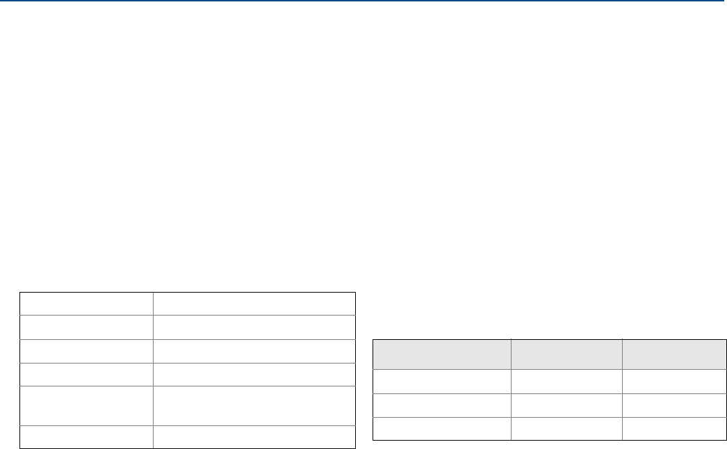
Specifications and Reference Data
September 2017
Reference Manual
00809-0100-4803, Rev GA
Specifications and Reference Data 132
Temperature limits
Humidity limits
0–100 percent relative humidity
Turn-on time
Performance within specifications less than five seconds for
Rosemount 3051SMV (typical) after power is applied to the
transmitter.
Volumetric displacement
Less than 0.005 in3 (0,08 cm3)
Damping
Analog output response to a step change is user-selectable
from 0 to 60 seconds for one time constant. Each variable
can be individually adjusted. This software damping is in
addition to sensor module response time.
Failure mode alarm
If self-diagnostics detect a gross transmitter failure, the
analog signal will be driven offscale to alert the user.
Rosemount standard (default), NAMUR, and custom alarm
levels are available (see Table A-4).
High or low alarm signal is software-selectable or
hardware-selectable via the optional switch (option D1).
A.1.3 Physical specifications
Electrical connections
1/2–14 NPT, G1/2, and M20 ⫻ 1.5 (CM20) conduit. HART
interface connections fixed to terminal block.
Process connections
1/4–18 NPT on 21/8-in. centers
1/2–14 NPT and RC 1/2 on 2-in.(50.8 mm),
21/8-in. (54.0 mm), or 21/4-in. (57.2 mm) centers (process
adapters)
Ambient
–40 to 185 °F (–40 to 85 °C)
with LCD display (1): –40 to 175 °F (–40 to 80 °C)
with option code P0: –20 to 185 °F (–29 to 85 °C)
1. CD display may not be readable and LCD display updates will be slower at
temperatures below –4 °F (–20 °C).
Storage
–50 to 185 °F (–46 to 85 °C)
with LCD display: –40 to 185 °F (–40 to 85 °C)
with wireless output: –40 to 185 °F (–40 to 85 °C)
Process temperature limits
At atmospheric pressures and above:
Silicone fill sensor(2)(3)
2. Process temperatures above 185 °F (85 °C) require derating the ambient
limits by a 1.5:1 ratio. For example, for process temperature of 195 °F
(91 °C), new ambient temperature limit is equal to 170 °F (77 °C). This can be
determined as follows:
(195 °F –185 °F) ⫻ 1.5 = 15 °F,
185 °F–15 °F = 170 °F
3. 212 °F (100 °C) is the upper process temperature limit for DP Range 0.
with coplanar flange –40 to 250 °F (–40 to 121 °C)(4)
4. 220 °F (104 °C) limit in vacuum service; 130 °F (54 °C) for pressures below 0.5
psia.
with traditional flange –40 to 300 °F (–40 to 149 °C)(4)(5)
5. –20 °F (–29 °C) is the lower process temperature limit with option code P0.
with level flange –40 to 300 °F (–40 to 149 °C)(4)
with Rosemount 305
Integral Manifold –40 to 300 °F (–40 to 149 °C)(4)(5)
Inert fill sensor(2)(6)
6. 32 °F (0 °C) is the lower process temperature limit for DP Range 0.
–40 to 185 °F (–40 to 85 °C)(7)
7. For Rosemount 3051SMV_ _ 1, 2, 140 ° F (60 °C) limit in vacuum service.
Table A-4. Alarm Configuration
High alarm Low alarm
Default ≥ 21.75 mA ≤ 3.75 mA
NAMUR compliant(1)
1. Analog output levels are compliant with NAMUR recommendation NE 43,
see option codes C4 or C5.
≥ 22.5 mA ≤ 3.6 mA
Custom levels(2)
2. Low alarm must be 0.1 mA less than low saturation and high alarm must be
0.1 mA greater than high saturation.
20.2–23.0 mA 3.6–3.8 mA

Specifications and Reference Data
133
Specifications and Reference Data
September 2017
Reference Manual
00809-0100-4803, Rev GA
Process-wetted parts
Process isolating diaphragms
316L SST (UNS S31603)
Alloy C-276 (UNS N10276)
Alloy 400 (UNS N04400)
Tantalum (UNS R05440)
Gold-plated Alloy 400
Gold-plated 316L SST
Drain/vent valves
316 SST, Alloy C-276, or Alloy 400/K-500 material
(Drain vent seat: alloy 400, drain vent stem: Alloy K-500)
Process flanges and adapters
Plated carbon steel
SST: CF-8M (Cast 316 SST) per ASTM A743
Cast C-276: CW-12MW per ASTM A494
Cast Alloy 400: M-30C per ASTM A494
Wetted O-rings
Glass-filled PTFE
(Graphite-filled PTFE with isolating diaphragm code 6)
Non-wetted parts
Electronics housing
Low-copper aluminum alloy or SST: CF-3M (Cast 316L SST)
or CF-8M (Cast 316 SST)
NEMA® 4X, IP 66, IP 68 (66 ft. [20 m] for 168 hours)
Coplanar sensor module housing
SST: CF-3M (Cast 316L SST)
Bolts
Plated carbon steel per ASTM A449, Type 1
Austenitic 316 SST per ASTM F593
ASTM A453, Class D, Grade 660 SST
ASTM A193, Grade B7M alloy steel
ASTM A193, Class 2, Grade B8M SST
Alloy K-500
Sensor module fill fluid
Silicone or inert halocarbon
Paint
Polyurethane
Cover O-rings
Buna-N
Shipping weights for Rosemount 3051S
MultiVariable Transmitter (3051SMV)
Rosemount 3051SMV with Plantweb™ housing: 6.7 lb
(3,1 kg)
Table A-5. Transmitter Option Weights
Option
code Option Add
lb (kg)
1J, 1K, 1L SST Plantweb housing 3.5 (1,6)
1A, 1B, 1C Aluminum Plantweb housing 1.1 (0,5)
M5(1)
1. Includes LCD display and display cover.
LCD display for Aluminum Plantweb
housing 0.8 (0,4)
LCD display for SST Plantweb housing 1.6 (0,7)
B4 SST mounting bracket for coplanar
flange 1.2 (0,5)
B1, B2, B3 Mounting bracket for traditional flange 1.7 (0,8)
B7, B8, B9 Mounting bracket for traditional flange
with SST bolts 1.7 (0,8)
BA, BC SST bracket for traditional flange 1.6 (0,7)
B4 SST mounting bracket for In-Line 1.3 (0,6)
F12, F22(2)
2. Includes mounting bolts.
SST traditional flange with SST drain
vents 3.2 (1,5)
F13, F23(2) Cast C-276 traditional flange with alloy
C-276 drain vents 3.6 (1,6)
E12, E22(2) SST coplanar flange with SST drain
vents 1.9 (0,9)
F14, F24(2) Cast alloy 400 traditional flange with
alloy 400/K-500 drain vents 3.6 (1,6)
F15, F25(2) SST traditional flange with alloy C-276
drain vents 3.2 (1,5)
G21 Level flange—3-in., 150 12.6 (5,7)
G22 Level flange—3-in., 300 15.9 (7,2)
G11 Level flange—2-in., 150 6.8 (3,1)
G12 Level flange—2-in., 300 8.2 (3,7)
G31 DIN Level flange, SST, DN 50, PN 40 7.8 (3,5)
G41 DIN Level flange, SST, DN 80, PN 40 13.0 (5,9)

Specifications and Reference Data
September 2017
Reference Manual
00809-0100-4803, Rev GA
Specifications and Reference Data 134
Item Weight in lb (kg)
Aluminum standard cover 0.4 (0,2)
SST standard cover 1.3 (0,6)
Aluminum display cover 0.7 (0,3)
SST display cover 1.5 (0,7)
LCD display(1)
1. Display only.
0.1 (0,04)
Plantweb terminal block 0.2 (0,1)
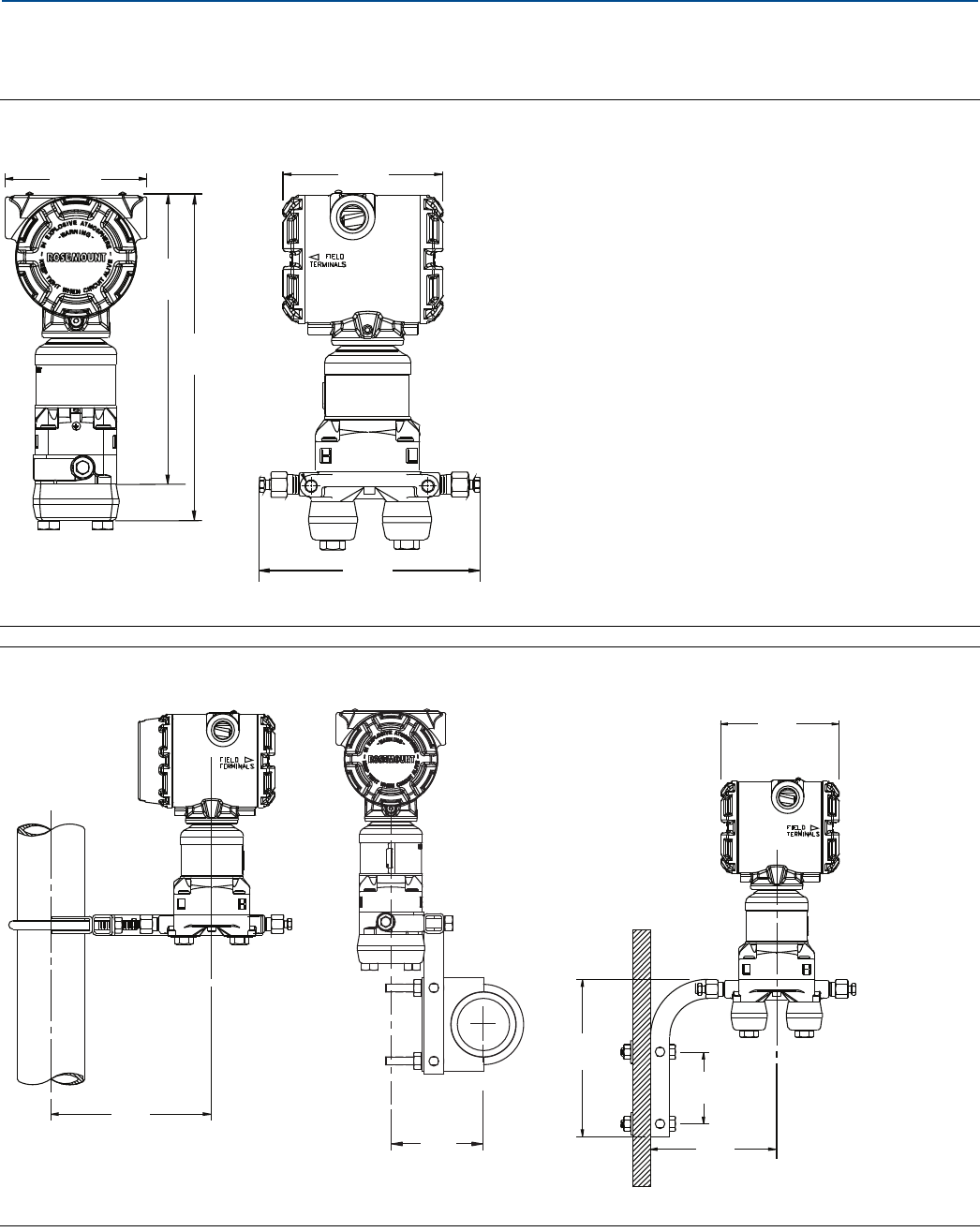
Specifications and Reference Data
135
Specifications and Reference Data
September 2017
Reference Manual
00809-0100-4803, Rev GA
A.2 Dimensional drawings
Process adapters (option D2) and Rosemount 305 integral manifolds must be ordered with the transmitter.
Figure A-1. Plantweb Housing with Coplanar™ SuperModule™ Platform and Rosemount 305 Coplanar Integral
Manifold
Dimensions are in inches (millimeters).
Figure A-2. Coplanar Flange Mounting Configurations
Dimensions are in inches (millimeters).
4.51
(115)
6.55
(
166
)
4.20
(107)
8.57
(218)
9.67
(246)
Pipe mount Panel mount
6.25
(159)
3.54
(90)
4.51
(115)
6.15
(156)
2.81
(71)
4.73
(120)
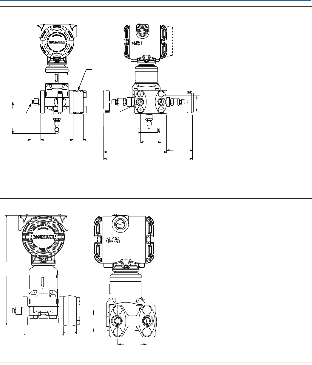
Specifications and Reference Data
September 2017
Reference Manual
00809-0100-4803, Rev GA
Specifications and Reference Data 136
Figure A-3. Plantweb Housing with Coplanar SuperModule Platform and Rosemount 305 Traditional Integral
Manifold
A. 1/2–14 NPT on mounting adapters
B. Drain vent valve
C. 1/4–18 NPT
Dimensions are in inches (millimeters).
Figure A-4. Plantweb Housing with Coplanar SuperModule Platform and Traditional Flange
Dimensions are in inches (millimeters).
C
1.63
(41)
2.13
(54)
6.80 (173)
max open 9.72 (247)
max open
2.70
(69)
1.10
(28)
3.40
(86)
1.16
(29)
3.56
(90)
max open
A
B
1.63
(41)
2.13
(54)
9.30
(236)
3.40
(86)
1.10
(28)
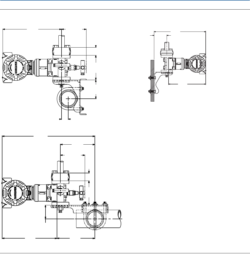
Specifications and Reference Data
137
Specifications and Reference Data
September 2017
Reference Manual
00809-0100-4803, Rev GA
Figure A-5. Traditional Flange Mounting Configurations
Dimensions are in inches (millimeters).
Pipe mount Rosemount 305 Integral manifold Panel mount
8.10
(206)
3.56 (90)
max open
1.10
(28)
3.42
(87)
2.62
(67)
0.93
(24)
13.03
(331) 4.85
(123)
3.56 (90)
max open 1.10
(28)
3.40
(86)
1.94
(49)
7.70
(196)
5.32
(135)
10.71
(272)
2.62
(67)
7.70
(196)

Specifications and Reference Data
September 2017
Reference Manual
00809-0100-4803, Rev GA
Specifications and Reference Data 138
A.3 Ordering information
A.3.1 Rosemount 3051S MultiVariable Transmitter
Table A-6. Rosemount 3051S Scalable MultiVariable Transmitter Ordering Information
The starred offerings (★) represent the most common options and should be selected for best delivery. The non-starred offerings are subject to
additional delivery lead time.
Rosemount
model Transmitter type
3051SMV Scalable MultiVariable Transmitter
Performance class
Rosemount 3051SMV multivariable SuperModule, measurement types 1 and 2
3(1) Ultra for Flow: 0.04% reading DP accuracy, 200:1 rangedown,15-year stability, 12-year limited warranty ★
5Classic MV: 0.04% span DP accuracy, 100:1 rangedown, 15-year stability ★
Rosemount 3051SMV single variable SuperModule, measurement types 3 and 4
1(2) Ultra: 0.025% span DP accuracy, 200:1 rangedown, 10-year stability, 12-year limited warranty ★
2Classic: 0.055% span DP accuracy, 100:1 rangedown, 5-year stability ★
3(1) Ultra for Flow: 0.04% reading DP accuracy, 200:1 rangedown,10-year stability, 12-year limited warranty ★
Multivariable type
MMultivariable measurement with fully compensated mass and energy flow ★
PMultivariable measurement with direct process variable output ★
Measurement type
1Differential pressure, static pressure, and temperature ★
2Differential pressure and static pressure ★
3Differential pressure and temperature ★
4Differential pressure ★
Differential pressure range
0(2)(3) –3 to 3 inH2O (–7,47 to 7,47 mbar) ★
1–25 to 25 inH2O (–62,2 to 62,2 mbar) ★
2–250 to 250 inH2O (–623 to 623 mbar) ★
3–1000 to 1000 inH2O (–2,5 to 2,5 bar) ★
4–300 to 300 psi (–20,7 to 20,7 bar) ★
5–2000 to 2000 psi (–137,9 to 137,9 bar) ★
Static pressure type
N(4) None ★
AAbsolute ★
GGage ★
Static pressure range Absolute Gage
N(4) None N/A N/A ★
3Range 3 0.5 to 800 psia (0,03 to 55,2 bar) –14.2 to 800 psig (–0,98 to 55,2 bar) ★
4(5) Range 4 0.5 to 3626 psia (0,03 to 250 bar) –14.2 to 3626 psig (–0,98 to 250 bar) ★
Temperature input
N(6) None ★
R(7) RTD input (type Pt 100, –328 to 1562 °F [–200 to 850 °C]) ★

Specifications and Reference Data
139
Specifications and Reference Data
September 2017
Reference Manual
00809-0100-4803, Rev GA
Isolating diaphragm
2(8) 316L SST ★
3(8) Alloy C-276 ★
5(9) Tantalum
7Gold-Plated 316L SST
Process connection Size Material type
Flange material Drain vent Bolting
000 None ★
A11(10) Assemble to Rosemount 305/306 Integral Manifold ★
A12(10) Assemble to Rosemount 304 or AMF Manifold with SST traditional flange ★
B11(10)(11) Assemble to one Rosemount 1199 Seal ★
B12(10)(11) Assemble to two Rosemount 1199 Seals ★
C11(10) Assemble to Rosemount 405 Primary Element ★
D11(10) Assemble to Rosemount 1195 Integral orifice and Rosemount 305 Integral Manifold ★
EA2(10) Assemble to Rosemount Annubar™ Primary Element
with coplanar flange SST 316 SST N/A ★
EA3(10) Assemble to Rosemount Annubar Primary Element
with coplanar flange Cast C-276 Alloy C-276 N/A ★
EA5(10) Assemble to Rosemount Annubar Primary Element
with coplanar flange SST Alloy C-276 N/A ★
E11 Coplanar flange 1/4–18 NPT Carbon Steel (CS) 316 SST N/A ★
E12 Coplanar flange 1/4–18 NPT SST 316 SST N/A ★
E13(8) Coplanar flange 1/4–18 NPT Cast C-276 Alloy C-276 N/A ★
E14 Coplanar flange 1/4–18 NPT Cast alloy 400 Alloy 400/K-500 N/A ★
E15(8) Coplanar flange 1/4–18 NPT SST Alloy C-276 N/A ★
E16(8) Coplanar flange 1/4–18 NPT CS Alloy C-276 N/A ★
E21 Coplanar flange RC 1/4CS 316 SST N/A ★
E22 Coplanar flange RC 1/4SST 316 SST N/A ★
E23(8) Coplanar flange RC 1/4Cast C-276 Alloy C-276 N/A ★
E24 Coplanar flange RC 1/4Cast alloy 400 Alloy 400/K-500 N/A ★
E25(8) Coplanar flange RC 1/4SST Alloy C-276 N/A ★
E26(8) Coplanar flange RC 1/4CS Alloy C-276 N/A ★
F12 Traditional flange 1/4–18 NPT SST 316 SST N/A ★
F13(8) Traditional flange 1/4–18 NPT Cast C-276 Alloy C-276 N/A ★
F14 Traditional flange 1/4–18 NPT Cast alloy 400 Alloy 400/K-500 N/A ★
F15(8) Traditional flange 1/4–18 NPT SST Alloy C-276 N/A ★
F22 Traditional flange RC 1/4SST 316 SST N/A ★
F23(8) Traditional flange RC 1/4Cast C-276 Alloy C-276 N/A ★
F24 Traditional flange RC 1/4Cast alloy 400 Alloy 400/K-500 N/A ★
F25(8) Traditional flange RC 1/4SST Alloy C-276 N/A ★
F52 DIN-compliant traditional
flange 1/4–18 NPT SST 316 SST 7/16-in. bolting ★
G11 Vertical mount level flange 2-in. ANSI class 150 SST N/A N/A ★
Table A-6. Rosemount 3051S Scalable MultiVariable Transmitter Ordering Information
The starred offerings (★) represent the most common options and should be selected for best delivery. The non-starred offerings are subject to
additional delivery lead time.

Specifications and Reference Data
September 2017
Reference Manual
00809-0100-4803, Rev GA
Specifications and Reference Data 140
G12 Vertical mount level flange 2-in. ANSI class 300 SST N/A N/A ★
G14(8) Vertical mount level flange 2-in. ANSI class 150 Cast C-276 N/A N/A ★
G15(8) Vertical mount level flange 2-in. ANSI class 300 Cast C-276 N/A N/A ★
G21 Vertical mount level flange 3-in. ANSI class 150 SST N/A N/A ★
G22 Vertical mount level flange 3-in. ANSI class 300 SST N/A N/A ★
G31 Vertical mount level flange DIN- DN 50 PN 40 SST N/A N/A ★
EB6 Assemble to primary element with manifold and coplanar flange, CS, Alloy C-276
F32 Bottom vent traditional
flange 1/4–18 NPT SST 316 SST N/A
F42 Bottom vent traditional
flange RC 1/4SST 316 SST N/A
F62 DIN-compliant traditional
flange 1/4–18 NPT SST 316 SST M10 bolting
F72 DIN-compliant traditional
flange 1/4–18 NPT SST 316 SST M12 bolting
G41 Vertical mount level flange DIN- DN 80 PN 40 SST N/A N/A
Transmitter output
A4–20 mA with digital signal based on HART Protocol ★
Housing style Material Conduit entry size
1A Plantweb housing Aluminum 1/2–14 NPT ★
1B Plantweb housing Aluminum M20 ⫻ 1.5 ★
1J Plantweb housing SST 1/2–14 NPT ★
1K Plantweb housing SST M20 ⫻ 1.5 ★
1C Plantweb housing Aluminum G1/2
1L Plantweb housing SST G1/2
Options (include with selected model number)
RTD cable (RTD sensor must be ordered separately)
C12 RTD input with 12 ft. (3,66 m) of shielded cable ★
C13 RTD input with 24 ft. (7,32 m) of shielded cable ★
C14 RTD input with 75 ft. (22,86 m) of shielded cable ★
C20(12) RTD input with 27-in. (69 cm) of armored shielded cable ★
C21 RTD input with 4 ft. (1,22 m) of armored shielded cable ★
C22 RTD input with 12 ft. (3,66 m) of armored shielded cable ★
C23 RTD input with 24 ft. (7,32 m) of armored shielded cable ★
C24 RTD input with 75 ft. (22,86 m) of armored shielded cable ★
C30(12) RTD input with 25-in. (64 cm) of ATEX/IECEx Flameproof cable ★
C32 RTD input with 12 ft. (3,66 m) of ATEX/IECEx Flameproof cable ★
C33 RTD input with 24 ft. (7,32 m) of ATEX/IECEx Flameproof cable ★
C34 RTD input with 75 ft. (22,86 m) of ATEX/IECEx Flameproof cable ★
C40(12) RTD input with 34-in. (86,36 cm) shielded cable and 24-in. (60,96 cm) FM Approved coupling flex ★
C41(12) RTD input with 40-in. (101,60 cm) shielded cable and 30-in. (76,20 cm) FM Approved coupling flex ★
Table A-6. Rosemount 3051S Scalable MultiVariable Transmitter Ordering Information
The starred offerings (★) represent the most common options and should be selected for best delivery. The non-starred offerings are subject to
additional delivery lead time.

Specifications and Reference Data
141
Specifications and Reference Data
September 2017
Reference Manual
00809-0100-4803, Rev GA
Mounting brackets(13)
B4 Coplanar flange bracket, all SST, 2-in. pipe and panel ★
B1 Traditional flange bracket, CS, 2-in. pipe ★
B2 Traditional flange bracket, CS, panel ★
B3 Traditional flange flat bracket, CS, 2-in. pipe ★
B7 Traditional flange bracket, B1 with SST bolts ★
B8 Traditional flange bracket, B2 with SST bolts ★
B9 Traditional flange bracket, B3 with SST bolts ★
BA Traditional flange bracket, B1, all SST ★
BC Traditional flange bracket, B3, all SST ★
Software configuration
C1 Custom software configuration (Rosemount 3051SMV Configuration Data Sheet required.) ★
C2 Custom flow configuration (Rosemount 3051SMV Configuration Data Sheet required.) ★
C4 NAMUR alarm and saturation levels, high alarm ★
C5 NAMUR alarm and saturation levels, low alarm ★
C6 Custom alarm and saturation signal levels, high alarm ★
C7 Custom alarm and saturation signal levels, low alarm ★
C8 Low alarm (standard Rosemount alarm and saturation levels) ★
Flange adapter(13)
D2 1/2–14 NPT flange adapter ★
D9 RC 1/2 SST flange adapter
Ground screw
D4 External ground screw assembly ★
Drain/vent valve(13)
D5 Delete transmitter drain/vent valves (install plugs) ★
D7 Coplanar flange without drain/vent ports
Conduit plug(14)
DO 316 SST Conduit Plug ★
Product certifications
E1 ATEX Flameproof ★
I1 ATEX Intrinsic Safety ★
N1 ATEX Type n ★
ND ATEX Dust ★
K1 ATEX Flameproof, Intrinsic Safety, Type n, Dust (combination of E1, I1, N1, and ND) ★
E4 TIIS Flameproof ★
E5 FM Explosion-proof, Dust Ignition-proof ★
I5 FM Intrinsically Safe, Division 2 ★
K5 FM Explosion-proof, Dust Ignition-proof, Intrinsically Safe, Division 2 (combination of E5 and I5) ★
E6(15) CSA Explosion-proof, Dust Ignition-proof, Division 2 ★
I6 CSA Intrinsically Safe ★
K6(15) CSA Explosion-proof, Dust Ignition-proof, Intrinsically Safe, Division 2 (combination of E6 and I6) ★
Table A-6. Rosemount 3051S Scalable MultiVariable Transmitter Ordering Information
The starred offerings (★) represent the most common options and should be selected for best delivery. The non-starred offerings are subject to
additional delivery lead time.

Specifications and Reference Data
September 2017
Reference Manual
00809-0100-4803, Rev GA
Specifications and Reference Data 142
E7 IECEx Flameproof, Dust Ignition-proof ★
I7 IECEx Intrinsic Safety ★
N7 IECEx Type n ★
K7 IECEx Flameproof, Dust Ignition-proof, Intrinsic Safety, and Type n (combination of E7, I7, and N7) ★
E2 INMETRO Flameproof ★
I2 INMETRO Intrinsic Safety ★
E3 China Flameproof ★
I3 China Intrinsic Safety ★
KA(15)(16) ATEX and CSA Explosion-proof, Intrinsically Safe, Division 2 (combination of E1, E6, I1, and I6) ★
KB(15)(16) FM and CSA Explosion-proof, Dust Ignition-proof, Intrinsically Safe, Division 2 (combination of E5, E6, I5, and I6) ★
KC FM and ATEX Explosion-proof, Intrinsically Safe, Division 2 (combination of E5, E1, I5, and I1) ★
KD(15)(16) FM, CSA, and ATEX Explosion-proof, Intrinsically Safe (combination of E5, E6, E1, I5, I6, and I1) ★
DW(17) NSF Drinking Water Certification ★
Alternate materials of construction
L1(18) Inert sensor fill fluid (differential and gage sensors only) ★
L2 Graphite-filled PTFE O-ring ★
L4(13) Austenitic 316 SST bolts ★
L5(8)(13) ASTM A193, Grade B7M bolts ★
L6(13) Alloy K-500 bolts ★
L7(8)(13) ASTM A453, Class D, Grade 660 bolts ★
L8(13) ASTM A193, Class 2, Grade B8M bolts ★
Digital display
M5 Plantweb LCD display ★
Special procedures
P1(19) Hydrostatic testing with certificate ★
P9(2) 4500 psig (310 bar) static pressure limit ★
P0(2)(20) 6092 psig (420 bar) static pressure limit ★
P2(13) Cleaning for special services
P3(13) Cleaning for less than 1PPM chlorine/fluorine
Special certifications
Q4 Calibration Certificate ★
QP Calibration Certificate and Tamper Evident Seal ★
Q8 Material Traceability Certification per EN 10204 3.1B ★
Q16 Surface Finish Certification for Sanitary Remote Seals ★
QZ Remote Seal System Performance Calculation Report ★
Quality Certification for Safety(21)
QS Prior-use certificate of FMEDA data ★
QT Safety certified to IEC 61508 with certificate of FMEDA data ★
Transient protection
T1 Transient terminal block ★
Table A-6. Rosemount 3051S Scalable MultiVariable Transmitter Ordering Information
The starred offerings (★) represent the most common options and should be selected for best delivery. The non-starred offerings are subject to
additional delivery lead time.

Specifications and Reference Data
143
Specifications and Reference Data
September 2017
Reference Manual
00809-0100-4803, Rev GA
Conduit electrical connector(22)
GE M12, 4-pin, male connector (eurofast®) ★
GM A size Mini, 4-pin, male connector (minifast®)★
Cold temperature
BRR –60 °F (–51 °C) cold temperature start-up ★
Typical model number: 3051SMV 3 M 1 2 G 4 R 2 E12 A 1A B4 C2 M5
1. Only available with DP range codes 2 and 3, 316L SST or Alloy C-276 isolating diaphragm and silicone fill fluid.
2. Only available with measurement type codes 3 and 4.
3. DP Range 0 is only available with traditional flange, 316L SST diaphragm material, and bolting option L4.
4. Required for measurement type codes 3 and 4.
5. For measurement type 1 and 2 with DP range 1, absolute limits are 0.5 to 2000 psi (0,03 to 137,9 bar) and gage limits are –14.2 to 2000 psig (–0,98 to 137,9 bar).
6. Required for measurement type codes 2 and 4.
7. Required for measurement type codes 1 and 3. RTD Sensor must be ordered separately.
8. Materials of Construction comply with metallurgical requirements highlighted within NACE® MR0175/ISO 15156 for sour oil field production environments.
Environmental limits apply to certain materials. Consult latest standard for details. Selected materials also conform to NACE MR0103 for sour refining environments.
9. Tantalum diaphragm material is only available for DP ranges 2–5.
10. “Assemble to” items are specified separately and require a completed model number.
11. Consult an Emerson representative for performance specifications.
12. For use with Flowmeters with integral RTDs.
13. Not available with process connection option code A11.
14. Transmitter is shipped with 316 SST conduit plug (uninstalled) in place of standard carbon steel conduit plug.
15. Not available with M20 or G 1/2 conduit entry size.
16. RTD cable not available with this option.
17. Requires 316L SST diaphragm material, glass-filled PTFE O-ring (standard), and process connection code E12 or F12.
18. Silicone fill fluid is standard.
19. Not available with DP range 0.
20. Requires 316L SST or Alloy C-276 diaphragm material, assemble to Rosemount 305 Integral Manifold or DIN-compliant traditional flange process connection, and
bolting option L8. Limited to differential pressure ranges 2–5.
21. Not available with output code F or X.
22. Available with Intrinsically Safe approvals only. For FM Intrinsically Safe, Non-Incendive approval (option code I5), install in accordance with Rosemount drawing
03151-1009 to maintain outdoor rating (NEMA 4X and IP66).
Table A-6. Rosemount 3051S Scalable MultiVariable Transmitter Ordering Information
The starred offerings (★) represent the most common options and should be selected for best delivery. The non-starred offerings are subject to
additional delivery lead time.

Specifications and Reference Data
September 2017
Reference Manual
00809-0100-4803, Rev GA
Specifications and Reference Data 144
A.3.2 Rosemount 300SMV housing kit
Table A-7. Ordering Information
Rosemount
model
300SMV Housing kit for Rosemount 3051SMV
Multivariable type
MMultivariable measurement with fully compensated mass and energy flow ★
PMultivariable measurement with direct process variable output ★
Temperature input
NNone ★
R(1) RTD input (type Pt 100, –328 to 1562 °F [–200 to 850 °C]) ★
Transmitter output
A4–20 mA with digital signal based on HART Protocol ★
Housing style Material(2) Conduit entry
1A Plantweb housing Aluminum 1/2–14 NPT ★
1B Plantweb housing Aluminum M20 ⫻ 1.5 (CM20) ★
1J Plantweb housing SST 1/2–14 NPT ★
1K Plantweb housing SST M20 ⫻ 1.5 (CM20) ★
1C Plantweb housing Aluminum G1/2
1L Plantweb housing SST G1/2
Options (include with selected model number)
RTD cable (RTD sensor must be ordered separately)
C12 RTD input with 12 ft. (3,66 m) of shielded cable ★
C13 RTD input with 24 ft. (7,32 m) of shielded cable ★
C14 RTD input with 75 ft. (22,86 m) of shielded cable ★
C20(3) RTD input with 27-in. (69 cm) of armored shielded cable ★
C21 RTD input with 4 ft. (1,22 m) of armored shielded cable ★
C22 RTD input with 12 ft. (3,66 m) of armored shielded cable ★
C23 RTD input with 24 ft. (7,32 m) of armored shielded cable ★
C24 RTD input with 75 ft. (22,86 m) of armored shielded cable ★
C30(3) RTD input with 25-in. (64 cm) of ATEX/IECEx Flameproof cable ★
C32 RTD input with 12 ft. (3,66 m) of ATEX/IECEx Flameproof cable ★
C33 RTD input with 24 ft. (7,32 m) of ATEX/IECEx Flameproof cable ★
C34 RTD input with 75 ft. (22,86 m) of ATEX/IECEx Flameproof cable ★
C40(3) RTD input with 34-in. (86,36 cm) shielded cable and 24-in. (60,96 cm) FM Approved coupling flex ★
C41(3) RTD input with 40-in. (101,60 cm) shielded cable and 30-in. (76,20 cm) FM Approved coupling flex ★

Specifications and Reference Data
145
Specifications and Reference Data
September 2017
Reference Manual
00809-0100-4803, Rev GA
Alarm limit
C4 NAMUR alarm and saturation levels, high alarm ★
C5 NAMUR alarm and saturation levels, low alarm ★
C8 Low alarm (standard Rosemount alarm and saturation levels) ★
External ground screw assembly
D4 External ground screw assembly ★
Product certifications
E1 ATEX Flameproof ★
I1 ATEX Intrinsic Safety ★
N1 ATEX Type n ★
ND ATEX Dust ★
K1 ATEX Flameproof, Intrinsic Safety, Type n, Dust (combination of E1, I1, N1, and ND) ★
E4 TIIS Flameproof ★
I4 TIIS Intrinsic Safety ★
K4 TIIS Flameproof and Intrinsic Safety (combination E4 and I4) ★
E5 FM Explosion-proof, Dust Ignition-proof ★
I5 FM Intrinsically Safe, Division 2 ★
K5 FM Explosion-proof, Dust Ignition-proof, Intrinsically Safe, Division 2 (combination of E5 and I5) ★
E6 CSA Explosion-proof, Dust Ignition-proof, Division 2 ★
I6 CSA Intrinsically Safe ★
K6 CSA Explosion-proof, Dust Ignition-proof, Intrinsically Safe, Division 2 (combination of E6 and I6) ★
E7 IECEx Flameproof, Dust Ignition-proof ★
I7 IECEx Intrinsic Safety ★
N7 IECEx Type n ★
K7 IECEx Flameproof, Dust Ignition-proof, Intrinsic Safety, Type n (combination of E7, I7, and N7) ★
E2(4) INMETRO Flameproof ★
I2(4) INMETRO Intrinsic Safety ★
K2(4) INMETRO Flameproof, Intrinsic Safety (combination of E2 and I2) ★
E3(4) China Flameproof ★
I3(4) China Intrinsic Safety ★
KA(5) ATEX and CSA Explosion-proof, Intrinsically Safe, Division 2 (combination of E1, E6, I1, and I6) ★
KB FM and CSA Explosion-proof, Dust Ignition-proof, Intrinsically Safe, Division 2 (combination of E5, E6, I5, and I6) ★
KC(5) FM and ATEX Explosion-proof, Intrinsically Safe, Division 2 (combination of E5, E1, I5, and I1) ★
KD(5) FM, CSA, and ATEX Explosion-proof, Intrinsically Safe (combination of E5, E6, E1, I5, I6, and I1) ★
Digital display
M5 Plantweb LCD display ★
Table A-7. Ordering Information

Specifications and Reference Data
September 2017
Reference Manual
00809-0100-4803, Rev GA
Specifications and Reference Data 146
Terminal blocks
T1 Transient terminal block ★
Conduit electrical connector(6)
GE M12, 4-pin, male connector (eurofast) ★
GM A size mini, 4-pin, male connector (minifast) ★
Typical model number: 300SMV M R 1A C22 M5
1. RTD Sensor must be ordered separately.
2. Material specified is cast as follows: CF-8M is the cast version of 316 SST, CF-3M is the cast version of 316L SST, CW-12MW is the cast version of Alloy C-276, M-30C is the
cast version of alloy 400. For housing, material is aluminum with polyurethane paint.
3. For use with Flowmeters with integral RTDs.
4. Contact an Emerson representative for availability.
5. RTD cable not available with this option.
6. Available with Intrinsically Safe approvals only. For FM Intrinsically Safe, Non-Incendive approval (option code I5), install in accordance with Rosemount drawing
03151-1206 to maintain outdoor rating (NEMA 4X and IP66).
Table A-7. Ordering Information

Specifications and Reference Data
147
Specifications and Reference Data
September 2017
Reference Manual
00809-0100-4803, Rev GA
A.4 Accessories
A.4.1 Rosemount Engineering Assistant (EA) software packages
The Rosemount Engineering Assistant software supports flow configuration for the Rosemount 3051SMV. The package is
available with or without modem and connecting cables. All configurations are packaged separately.
For best performance of the EA Software, the following computer hardware and software is recommended:
Pentium-grade Processor: 500 MHz or faster
Operating system: Windows™ Professional 7, 8.1, or 10.
–32-bit
–64-bit
256 MB RAM
100 MB of available hard disk space
RS232 serial port or USB port (for use with HART modem)
CD-ROM
Engineering Assistant software packages
Accessories
Code Product description
EA Engineering Assistant software program
Software media
3EA Rev. 6 (compatible with Rosemount 3051SMV only)
Language
EEnglish
Modem and connecting cables
ONone
HSerial Port HART modem and cables
BUSB Port HART modem and cables
License
N1 Single PC license
N2 Site license
Typical model number: EA 3 E O N1
Item description Part number
Serial Port HART modem and cables only 03095-5105-0001
USB Port HART modem and cables only(1)
1. Supported by SNAP-ON™ EA with AMS Device Manager version 6.2 or higher.
03095-5105-0002
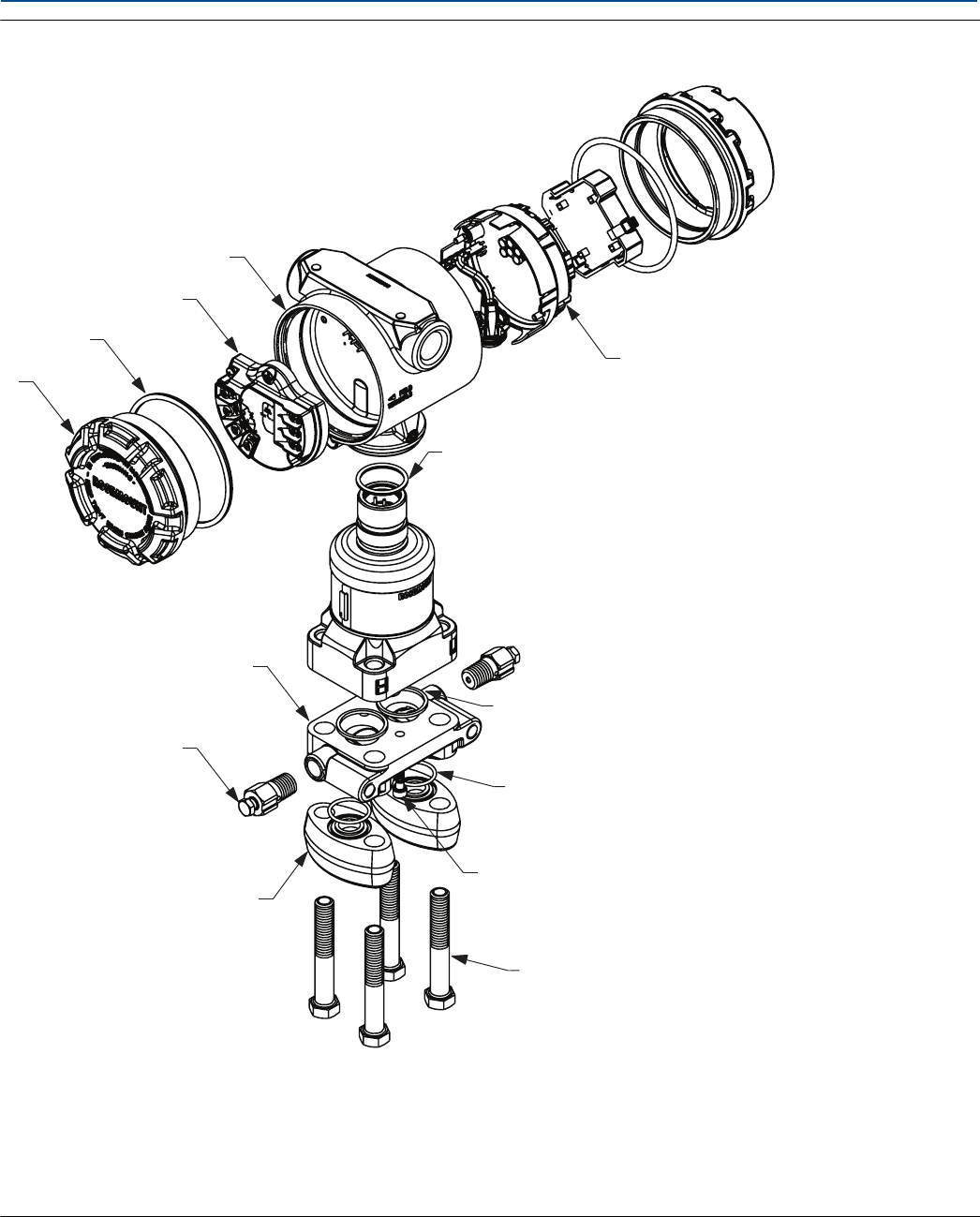
Specifications and Reference Data
September 2017
Reference Manual
00809-0100-4803, Rev GA
Specifications and Reference Data 148
Figure A-6. Exploded View Diagram
The following drawing shows the name and location for commonly ordered spare parts:
A
B
C
D
E
F
G
H
I
J
K
L
M
A. Cover
B. Cover O-ring
C. Terminal block
D. Plantweb housing
E. Feature board
F. Module O-ring
G. Coplanar flange
H. Process flange O-ring
I. Drain/vent valve
J. Flange adapter O-ring
K. Flange adapters
L. Flange alignment screw (not pressure retaining)
M. Flange/adapters bolts

Specifications and Reference Data
149
Specifications and Reference Data
September 2017
Reference Manual
00809-0100-4803, Rev GA

Specifications and Reference Data
September 2017
Reference Manual
00809-0100-4803, Rev GA
Specifications and Reference Data 150
A.5 Spare parts
Sensor modules
See “Rosemount 3051S Scalable MultiVariable Transmitter Ordering Information” on page 138 for ordering spare sensor modules. Use
housing style code 00 within the Rosemount 3051SMV model number.
Typical model number: 3051SMV 3 M 1 2 G 3 R 2 E11 A 00 C21
Feature board electronics and housing assembly
See “Rosemount 300SMV housing kit” on page 144 for ordering spare housings or feature boards.
Typical model number: 300SMV M R A 1A C21
LCD display Part number
Aluminum Plantweb housing
LCD display kit: LCD display assembly, 4-pin interconnection header and aluminum cover assembly 03151-9193-0001
LCD display only: LCD display assembly, 4-pin interconnection header 03151-9193-0002
Cover assembly kit: Aluminum cover assembly 03151-9193-0003
Rosemount 316L SST Plantweb housing
LCD display kit: LCD display assembly, 4-pin interconnection header, 316L SST cover assembly 03151-9193-0004
LCD display only: LCD display assembly, 4-pin interconnection header 03151-9193-0002
Cover assembly kit: 316L SST cover assembly 03151-9193-0005
Electrical housing, terminal blocks
Plantweb housing terminal block, HART (4–20 mA)
Standard terminal block assembly with Temperature input 03151-9006-0001
Standard terminal block assembly without Temperature input 03151-9005-0001
Transient protection terminal block assembly with Temperature input 03151-9006-0002
Transient protection terminal block assembly without Temperature input 03151-9005-0002
Covers
Aluminum electronics cover; cover and O-ring 03151-9030-0001
316L SST electronics cover; cover and O-ring 03151-9030-0002
Housing miscellaneous
External ground screw assembly (option D4): screw, clamp, washer 03151-9060-0001
Housing V-seal for both Plantweb and Junction Box housings 03151-9061-0001
Plantweb housing header cable O-ring (package of 12) 03151-9011-0001

Specifications and Reference Data
151
Specifications and Reference Data
September 2017
Reference Manual
00809-0100-4803, Rev GA
Flanges Part number
Differential coplanar flange
Nickel-plated CS 03151-9200-0025
SST 03151-9200-0022
Cast C-276 03151-9200-0023
Cast alloy 400 03151-9200-0024
Gage/absolute coplanar flange
Nickel-plated CS 03151-9200-1025
SST 03151-9200-1022
Cast C-276 03151-9200-1023
Cast alloy 400 03151-9200-1024
Coplanar flange alignment screw (package of 12) 03151-9202-0001
Traditional flange
SST 03151-9203-0002
Cast C-276 03151-9203-0003
Cast Alloy 400 03151-9203-0004
Flange adapter kits
(each kit contains adapters, bolts, and O-ring for one DP transmitter or two GP/AP transmitters)
CS bolts, glass-filled PTFE O-rings
SST adapters 03031-1300-0002
Cast C-276 adapters 03031-1300-0003
Cast alloy 400 adapters 03031-1300-0004
Nickel-plated CS adapters 03031-1300-0005
SST bolts, glass-filled PTFE O-rings
SST adapters 03031-1300-0012
Cast C-276 adapters 03031-1300-0013
Cast Alloy 400 adapters 03031-1300-0014
Ni-plated CS adapters 03031-1300-0015
CS bolts, Graphite PTFE O-rings
SST adapters 03031-1300-0102
Cast C-276 adapters 03031-1300-0103
Cast alloy 400 adapters 03031-1300-0104
Ni-plated CS adapters 03031-1300-0105
SST bolts, Graphite PTFE O-rings
SST adapters 03031-1300-0112
Cast C-276 adapters 03031-1300-0113
Cast Alloy 400 adapters 03031-1300-0114
Ni-plated CS adapters 03031-1300-0115

Specifications and Reference Data
September 2017
Reference Manual
00809-0100-4803, Rev GA
Specifications and Reference Data 152
Flange adapter Part number
Nickel-plated CS 03151-9259-0005
SST 03151-9259-0002
Cast C-276 03151-9259-0003
Cast alloy 400 03151-9259-0004
Drain/vent valve kits (each kit contains parts for one transmitter)
Differential drain/vent kits
SST valve stem and seat kit 03151-9268-0022
Alloy C-276 valve stem and seat kit 03151-9268-0023
Alloy K-500 valve stem and alloy 400 seat kit 03151-9268-0024
SST Ceramic ball drain/vent kit 03151-9268-0122
Alloy C-276 ceramic ball drain/vent kit 03151-9268-0123
Alloy 400/K-500 ceramic ball drain/vent kit 03151-9268-0124
Gage/absolute drain/vent kits
SST valve stem and seat kit 03151-9268-0012
Alloy C-276 valve stem and seat kit 03151-9268-0013
Alloy K-500 valve stem and Alloy 400 Seat Kit 03151-9268-0014
SST ceramic ball drain/vent kit 03151-9268-0112
Alloy C-276 ceramic ball drain/vent kit 03151-9268-0113
Alloy 400 ceramic ball drain/vent kit 03151-9268-0114
O-ring packages (package of 12)
Electronic housing, cover (Standard and LCD display) 03151-9040-0001
Electronics housing, module 03151-9041-0001
Process flange, glass-filled PTFE 03151-9042-0001
Process flange, Graphite-filled PTFE 03151-9042-0002
Flange adapter, glass-filled PTFE 03151-9043-0001
Flange adapter, graphite-filled PTFE 03151-9043-0002
Gland and collar kits
Gland and collar kits 03151-9250-0001
Mounting brackets
Coplanar flange bracket kit
B4 bracket, SST, 2-in. pipe mount, SST bolts 03151-9270-0001
Traditional flange bracket kits
B1 bracket, 2-in. pipe mount, CS bolts 03151-9272-0001
B2 bracket, panel mount, CS bolts 03151-9272-0002
B3 Flat bracket for 2-in. pipe mount, CS bolts 03151-9272-0003

Specifications and Reference Data
153
Specifications and Reference Data
September 2017
Reference Manual
00809-0100-4803, Rev GA
B7 (B1 style bracket with SST bolts) 03151-9272-0007
B8 (B2 style bracket with SST bolts) 03151-9272-0008
B9 (B3 style bracket with SST bolts) 03151-9272-0009
BA (SST B1 bracket with SST bolts) 03151-9272-0011
BC (SST B3 bracket with SST bolts) 03151-9272-0013
DIN compliant traditional flange bracket kits – M10 threads (F62 process connection)
B1 bracket, 2-in. pipe mount, CS bolts 03151-9272-0101
B2 bracket, panel mount, CS bolts 03151-9272-0101
B3 flat bracket for 2-in. pipe mount, CS bolts 03151-9272-0103
B7 (B1 style bracket with SST bolts) 03151-9272-0107
B8 (B2 style bracket with SST bolts) 03151-9272-0108
B9 (B3 style bracket with SST bolts) 03151-9272-0109
BA (SST B1 bracket with SST bolts) 03151-9272-0111
BC (SST B3 bracket with SST bolts) 03151-9272-0113
DIN compliant traditional flange bracket kits – M12 threads (F72 process connection)
B1 bracket, 2-in. pipe mount, CS bolts 03151-9272-0201
B2 bracket, panel mount, CS bolts 03151-9272-0202
B3 flat bracket for 2-in. pipe mount, CS bolts 03151-9272-0203
B7 (B1 style bracket with SST bolts) 03151-9272-0207
B8 (B2 style bracket with SST bolts) 03151-9272-0208
B9 (B3 style bracket with SST bolts) 03151-9272-0209
BA (SST B1 bracket with SST bolts) 03151-9272-0211
BC (SST B3 bracket with SST bolts) 03151-9272-0213
Bolt kits
Coplanar flange
Flange bolt kit (44 mm [1.75-in.])
CS (set of four) 03151-9280-0001
316 SST (set of four) 03151-9280-0002
ANSI/ASTM-A-193-B7M (set of four) 03151-9280-0003
Alloy K-500 (set of four) 03151-9280-0004
ASTM A 453, Class D Grade 660 (set of four) 03151-9280-0005
ASTM A193, Grade B8M, Class 2 (set of four) 03151-9280-0006
Flange/adapter bolt kit (73 mm [2.88-in.])
CS (set of four) 03151-9281-0001
316 SST (set of four) 03151-9281-0002
ANSI/ASTM-A-193-B7M (set of four) 03151-9281-0003
Alloy K-500 (set of four) 03151-9281-0004

Specifications and Reference Data
September 2017
Reference Manual
00809-0100-4803, Rev GA
Specifications and Reference Data 154
ASTM A 453, Class D Grade 660 (set of four) 03151-9281-0005
ASTM A193, Grade B8M, Class 2 (set of four) 03151-9281-0006
Manifold/flange kit (57 mm [2.25-in.])
CS (set of four) 03151-9282-0001
316 SST (set of four) 03151-9282-0002
ANSI/ASTM-A-193-B7M (set of four) 03151-9282-0003
Alloy K-500 (set of four) 03151-9282-0004
ASTM A 453, Class D, Grade 660 (set of four) 03151-9282-0005
ASTM A193, Grade B8M, Class 2 (set of four) 03151-9282-0006
Traditional flange
Differential flange and adapter bolt kit
CS (set of eight) 03151-9283-0001
316 SST (set of eight) 03151-9283-0002
ANSI/ASTM-A-193-B7M (set of eight) 03151-9283-0003
Alloy K-500 (set of eight) 03151-9283-0004
ASTM A 453, Class D, Grade 660 (set of eight) 03151-9283-0005
ASTM A193, Grade B8M, Class 2 (set of eight) 03151-9283-0006
Gage/absolute flange and adapter bolt kit
Carbon Steel (set of six) 03151-9283-1001
316 SST (set of six) 03151-9283-1002
ANSI/ASTM-A-193-B7M (set of six) 03151-9283-1003
Alloy K-500 (set of six) 03151-9283-1004
ASTM A 453, Class D, Grade 660 (set of six) 03151-9283-1005
ASTM A193, Grade B8M, Class 2 (set of six) 03151-9283-1006
Manifold/traditional flange bolts
CS Use bolts supplied with manifold
316 SST Use bolts supplied with manifold

Product Certifications
September 2017
Reference Manual
00809-0100-4803, Rev GA
155
Product Certifications
Appendix B Product Certifications
Rev 1.19
European Directive Information . . . . . . . . . . . . . . . . . . . . . . . . . . . . . . . . . . . . . . . . . . . . . . . . . . . . . . . page 155
Ordinary Location Certification . . . . . . . . . . . . . . . . . . . . . . . . . . . . . . . . . . . . . . . . . . . . . . . . . . . . . . . .page 155
Installing Equipment in North America . . . . . . . . . . . . . . . . . . . . . . . . . . . . . . . . . . . . . . . . . . . . . . . . .page 155
USA . . . . . . . . . . . . . . . . . . . . . . . . . . . . . . . . . . . . . . . . . . . . . . . . . . . . . . . . . . . . . . . . . . . . . . . . . . . . . . . .page 155
Canada . . . . . . . . . . . . . . . . . . . . . . . . . . . . . . . . . . . . . . . . . . . . . . . . . . . . . . . . . . . . . . . . . . . . . . . . . . . . .page 156
Europe . . . . . . . . . . . . . . . . . . . . . . . . . . . . . . . . . . . . . . . . . . . . . . . . . . . . . . . . . . . . . . . . . . . . . . . . . . . . .page 156
International . . . . . . . . . . . . . . . . . . . . . . . . . . . . . . . . . . . . . . . . . . . . . . . . . . . . . . . . . . . . . . . . . . . . . . . .page 157
Brazil . . . . . . . . . . . . . . . . . . . . . . . . . . . . . . . . . . . . . . . . . . . . . . . . . . . . . . . . . . . . . . . . . . . . . . . . . . . . . . .page 158
China . . . . . . . . . . . . . . . . . . . . . . . . . . . . . . . . . . . . . . . . . . . . . . . . . . . . . . . . . . . . . . . . . . . . . . . . . . . . . .page 159
EAC – Belarus, Kazakhstan, Russia . . . . . . . . . . . . . . . . . . . . . . . . . . . . . . . . . . . . . . . . . . . . . . . . . . . . .page 160
Japan . . . . . . . . . . . . . . . . . . . . . . . . . . . . . . . . . . . . . . . . . . . . . . . . . . . . . . . . . . . . . . . . . . . . . . . . . . . . . . .page 161
Republic of Korea . . . . . . . . . . . . . . . . . . . . . . . . . . . . . . . . . . . . . . . . . . . . . . . . . . . . . . . . . . . . . . . . . . . .page 161
Combinations . . . . . . . . . . . . . . . . . . . . . . . . . . . . . . . . . . . . . . . . . . . . . . . . . . . . . . . . . . . . . . . . . . . . . . .page 161
Additional Certifications . . . . . . . . . . . . . . . . . . . . . . . . . . . . . . . . . . . . . . . . . . . . . . . . . . . . . . . . . . . . . .page 161
Installation drawings . . . . . . . . . . . . . . . . . . . . . . . . . . . . . . . . . . . . . . . . . . . . . . . . . . . . . . . . . . . . . . . . .page 162
B.1 European Directive Information
A copy of the EU Declaration of Conformity can be found at the end
of the Quick Start Guide. The most recent revision of the EU
Declaration of Conformity can be found at
Emerson.com/Rosemount.
B.2 Ordinary Location Certification
As standard, the transmitter has been examined and tested to
determine that the design meets the basic electrical, mechanical,
and fire protection requirements by a nationally recognized test
laboratory (NRTL) as accredited by the Federal Occupational Safety
and Health Administration (OSHA).
B.3 Installing Equipment in North
America
The US National Electrical Code® (NEC) and the Canadian Electrical
Code (CEC) permit the use of Division marked equipment in Zones
and Zone marked equipment in Divisions. The markings must be
suitable for the area classification, gas, and temperature class. This
information is clearly defined in the respective codes.
B.4 USA
E5 US Explosionproof (XP) and Dust-Ignitionproof (DIP)
Certificate: FM16US0089X
Standards: FM Class 3600 – 2011, FM Class 3615 – 2006,
FM Class 3616 – 2011, FM Class 3810 – 2005,
ANSI/NEMA 250 – 2003
Markings: XP CL I, DIV 1, GP B, C, D; T5; DIP CL II, DIV 1, GP
E, F, G; CL III; T5(–50 °C ≤ Ta ≤ +85 °C); Factory
Sealed; Type 4X
I5 US Intrinsic Safety (IS) and Nonincendive (NI)
Certificate: FM16US0233
Standards: FM Class 3600 – 2011, FM Class 3610 – 2007,
FM Class 3611 – 2004, FM CLASS 3616 - 2006,
FM Class 3810 – 2005, NEMA 250 – 1991
Markings: IS CL I, DIV 1, GP A, B, C, D; CL II, DIV 1, GP E, F, G;
Class III; Class 1, Zone 0 AEx ia IIC T4; NI CL 1,
DIV 2, GP A, B, C, D; T4(–50 °C ≤ Ta ≤ +70 °C)
when connected per Rosemount™ drawing
03151-1206; Type 4X
Note
Transmitters marked with NI CL 1, DIV 2 can be installed in
Division 2 locations using general Division 2 wiring methods or
Nonincendive Field Wiring (NIFW). See Drawing 03151-1206.
IE US FISCO Intrinsically Safe
Certificate: FM16US0233
Standards: FM Class 3600 – 2011, FM Class 3610 – 2010,
FM Class 3611 – 2004, FM Class 3616 – 2006,
FM Class 3810 – 2005, NEMA 250 – 1991
Markings: IS CL I, DIV 1, GP A, B, C, D;
T4(–50 °C ≤ Ta ≤ +70 °C); when connected per
Rosemount drawing 03151-1006; Type 4X
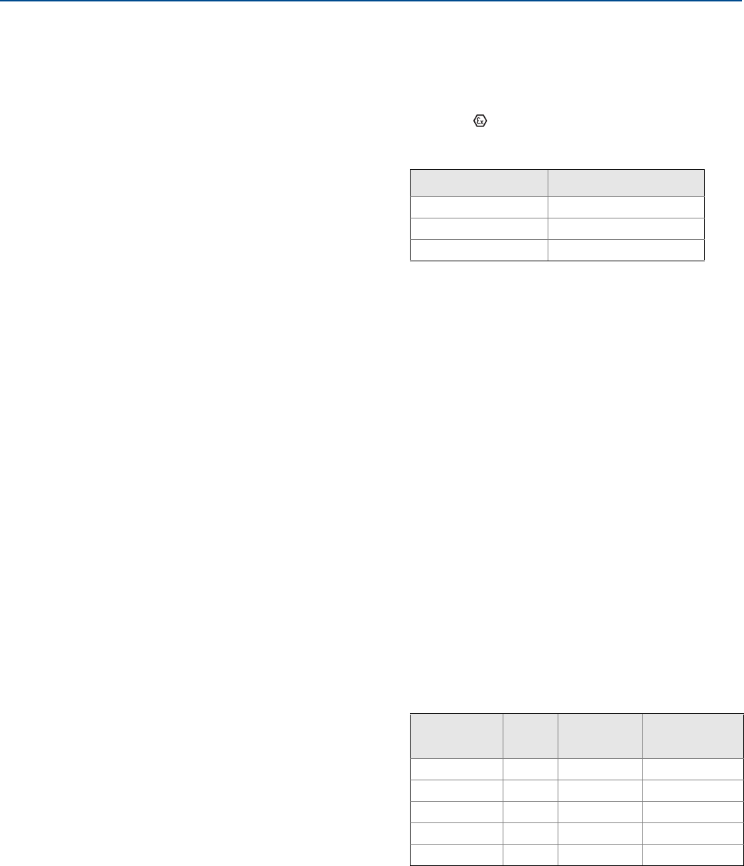
156 Product Certifications
Product Certifications
September 2017
Reference Manual
00809-0100-4803, Rev GA
B.5 Canada
E6 Canada Explosionproof, Dust-Ignitionproof, Division 2
Certificate: 1143113
Standards: CAN/CSA C22.2 No. 0-10,
CSA Std C22.2 No. 25-1966,
CSA Std C22.2 No. 30-M1986,
CSA C22.2 No. 94.2-07,
CSA Std C22.2 No. 213-M1987,
CAN/CSA C22.2 60079-11:14,
CAN/CSA-C22.2 No. 61010-1-12,
ANSI/ISA 12.27.01-2003,
CSA Std C22.2 No. 60529:05 (R2010)
Markings: Explosionproof Class I, Division 1, Groups B, C, D;
Dust-Ignitionproof Class II, Division 1, Groups E,
F, G; Class III; suitable for Class I, Division 2,
Groups A, B, C, D; Type 4X
I6 Canada Intrinsically Safe
Certificate: 1143113
Standards: CAN/CSA C22.2 No. 0-10,
CSA Std C22.2 No. 25-1966,
CSA Std C22.2 No. 30-M1986,
CSA C22.2 No. 94.2-07,
CSA Std C22.2 No. 213-M1987,
CAN/CSA C22.2 60079-11:14,
CAN/CSA-C22.2 No. 61010-1-12,
ANSI/ISA 12.27.01-2003,
CSA Std C22.2 No. 60529:05 (R2010)
Markings: Intrinsically Safe Class I, Division 1; Groups A, B, C,
D; suitable for Class 1, Zone 0, IIC, T3C, Ta = 70 °C;
when connected per Rosemount drawing
03151-1207; Type 4X
IF Canada FISCO Intrinsically Safe
Certificate: 1143113
Standards: CAN/CSA C22.2 No. 0-10,
CSA Std C22.2 No. 25-1966,
CSA Std C22.2 No. 30-M1986,
CSA C22.2 No. 94.2-07,
CSA Std C22.2 No. 213-M1987,
CAN/CSA C22.2 60079-11:14,
CAN/CSA-C22.2 No. 61010-1-12,
ANSI/ISA 12.27.01-2003,
CSA Std C22.2 No. 60529:05 (R2010)
Markings: FISCO Intrinsically Safe Class I, Division 1; Groups
A, B, C, D; suitable for Class I, Zone 0; T3C,
Ta = 70 °C; when installed per Rosemount
drawing 03151-1207; Type 4X
B.6 Europe
E1 ATEX Flameproof
Certificate: KEMA 00ATEX2143X
Standards: EN 60079-0:2012+A11:2013, EN 60079-1: 2014,
EN 60079-26:2015
Markings: II 1/2 G Ex db IIC T6…T4 Ga/Gb,
T6(–60 °C ≤ Ta ≤ +70 °C),
T5/T4(–60 °C ≤ Ta ≤ +80 °C)
Special Conditions for Safe Use (X):
1. This device contains a thin wall diaphragm less than 1 mm
thickness that forms a boundary between EPL Ga (process
connection) and EPL Gb (all other parts of the equipment).
The model code and datasheet are to be consulted for details
of the diaphragm material. Installation, maintenance and use
shall take into account the environmental conditions to
which the diaphragm will be subjected. The manufacturer's
instructions for installation and maintenance shall be
followed in detail to assure safety during its expected
lifetime.
2. Flameproof joints are not intended for repair.
3. Non-standard paint options may cause risk from
electrostatic discharge. Avoid installations that could cause
electrostatic build-up on painted surfaces, and only clean the
painted surfaces with a damp cloth. If paint is ordered
through a special option code, contact the manufacturer for
more information.
4. Appropriate cable, glands and plugs need to be suitable for a
temperature of 5 °C greater than maximum specified
temperature for location where installed.
I1 ATEX Intrinsic Safety
Certificate: Baseefa08ATEX0064X
Standards: EN 60079-0: 2012, EN 60079-11: 2012
Markings: Ex II 1 G Ex ia IIC T4 Ga, T4(–60 °C ≤ Ta ≤ +70 °C)
Temperature class Process temperature
T6 –60 °C to +70 °C
T5 –60 °C to +80 °C
T4 –60 °C to +120 °C
Parameter HART®FOUNDATION™
Fieldbus
SuperModule™
only
Voltage Ui30 V 30 V 7.14 V
Current Ii300 mA 300 mA 300 mA
Power Pi1 W 1.3 W 887 mW
Capacitance Ci14.8 nF 00.11 μF
Inductance Li0 0 0

Product Certifications
September 2017
Reference Manual
00809-0100-4803, Rev GA
157
Product Certifications
Special Conditions for Safe Use (X):
1. If the equipment is fitted with the optional 90 V transient
suppressor, it is incapable of withstanding the 500 V isolation
from earth test and this must be taken into account during
installation.
2. The enclosure may be made of aluminum alloy and given a
protective polyurethane paint finish; however, care should
be taken to protect it from impact or abrasion if located in a
Zone 0 environment.
IA ATEX FISCO
Certificate: Baseefa08ATEX0064X
Standards: EN 60079-0: 2012, EN 60079-11: 2012
Markings: Ex II 1 G Ex ia IIC T4 Ga, T4(–60 °C ≤ Ta ≤ +70 °C)
ND ATEX Dust
Certificate: BAS01ATEX1374X
Standards: EN 60079-0: 2012+A11:2013,
EN 60079-31:2009
Markings: Ex II 1 D Ex ta IIIC T105 °C T500 95 °C Da,
(–20 °C ≤ Ta ≤ +85 °C), Vmax = 42.4 V
Special Conditions for Safe Use (X):
1. Cable entries must be used which maintain the ingress
protection of the enclosure to at least IP66.
2. Unused cable entries must be filled with suitable blanking
plugs which maintain the ingress protection of the enclosure
to at least IP66.
3. Cable entries and blanking plugs must be suitable for the
ambient temperature range of the apparatus and capable of
withstanding a 7J impact test.
4. The SuperModule(s) must be securely screwed in place to
maintain the ingress protection of the enclosure(s).
N1 ATEX Type n
Certificate: Baseefa08ATEX0065X
Standards: EN 60079-0: 2012, EN 60079-15: 2010
Markings: Ex II 3 G Ex nA IIC T4 Gc, (-40 °C ≤ Ta ≤ 70 °C),
Vmax = 45 V
Special Condition for Safe Use (X):
1. If fitted with a 90 V transient suppressor, the equipment is
not capable of withstanding the 500 V electrical strength
test as defined in Clause 6.5.1 of EN 60079-15:2010. This
must be taken into account during installation.
B.7 International
E7 IECEx Flameproof and Dust
Certificate: IECEx KEM 08.0010X (Flameproof)
Standards: IEC 60079-0:2011, IEC 60079-1:2014,
IEC 60079-26:2014
Markings: Ex db IIC T6…T4 Ga/Gb, T6(–60 °C ≤ Ta ≤ +70 °C),
T5/T4(–60 °C ≤ Ta ≤ +80 °C)
Special Conditions for Safe Use (X):
1. This device contains a thin wall diaphragm less than 1 mm
thickness that forms a boundary between EPL Ga (process
connection) and EPL Gb (all other parts of the equipment).
The model code and datasheet are to be consulted for details
of the diaphragm material. Installation, maintenance and use
shall take into account the environmental conditions to
which the diaphragm will be subjected. The manufacturer's
instructions for installation and maintenance shall be
followed in detail to assure safety during its expected
lifetime.
2. Flameproof joints are not intended for repair.
3. Non-standard paint options may cause risk from electrostatic
discharge. Avoid installations that could cause electrostatic
build-up on painted surfaces, and only clean the painted
surfaces with a damp cloth. If paint is ordered through a
special option code, contact the manufacturer for more
information.
4. Appropriate cable, glands and plugs need to be suitable for a
temperature of 5 °C greater than maximum specified
temperature for location where installed.
Certificate: IECEx BAS 09.0014X (Dust)
Standards: IEC 60079-0:2011, IEC 60079-31:2008
Markings: Ex ta IIIC T105 °C T500 95 °C Da,
(–20 °C ≤ Ta ≤ +85 °C), Vmax = 42.4 V
Parameter RTD (for 3051SFx)
(HART)
RTD (for 3051SFx)
(Fieldbus)
Voltage Ui30 V 30 V
Current Ii2.31 mA 18.24 mA
Power Pi17.32 mW 137 mA
Capacitance Ci00.8 nF
Inductance Li01.33 mH
Parameter FISCO
Voltage Ui17.5 V
Current Ii380 mA
Power Pi5.32 W
Capacitance Ci0
Inductance Li0
Temperature class Process temperature
T6 –60 °C to +70 °C
T5 –60 °C to +80 °C
T4 –60 °C to +120 °C
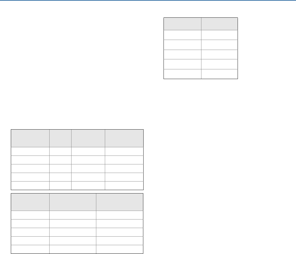
158 Product Certifications
Product Certifications
September 2017
Reference Manual
00809-0100-4803, Rev GA
Special Conditions for Safe Use (X):
1. Cable entries must be used which maintain the ingress
protection of the enclosure to at least IP66.
2. Unused cable entries must be filled with suitable blanking
plugs which maintain the ingress protection of the enclosure
to at least IP66.
3. Cable entries and blanking plugs must be suitable for the
ambient temperature range of the apparatus and capable of
withstanding a 7J impact test.
4. The Rosemount 3051S - SuperModule must be securely
screwed in place to maintain the ingress protection of the
enclosure.
I7 IECEx Intrinsic Safety
Certificate: IECEx BAS 08.0025X
Standards: IEC 60079-0: 2011, IEC 60079-11: 2011
Markings: Ex ia IIC T4 Ga, T4(–60 °C ≤ Ta ≤ +70 °C)
Special Conditions for Safe Use (X):
1. If the equipment is fitted with the optional 90 V transient
suppressor, it is incapable of withstanding the 500 V isolation
from earth test and this must be taken into account during
installation.
2. The enclosure may be made of aluminum alloy and given a
protective polyurethane paint finish; however, care should
be taken to protect it from impact or abrasion if located in a
Zone 0 environment.
IG IECEx FISCO
Certificate: IECEx BAS 08.0025X
Standards: IEC 60079-0: 2011, IEC 60079-11: 2011
Markings: Ex ia IIC T4 Ga, T4(–60 °C ≤ Ta ≤ +70 °C)
N7 IECEx Type n
Certificate: IECEx BAS 08.0026X
Standards: IEC 60079-0: 2011, IEC 60079-15: 2010
Markings: Ex nA IIC T5 Gc, (–40 °C ≤ Ta ≤ 70 °C)
Special Condition for Safe Use (X):
1. If fitted with a 90 V transient suppressor, the equipment is
not capable of withstanding the 500 V electrical strength
test as defined in Clause 6.5.1 of IEC 60079-15:2010. This
must be taken into account during installation.
B.8 Brazil
E2 INMETRO Flameproof
Certificate: UL-BR 15.0393X
Standards: ABNT NBR IEC 60079-0:2008 + Corrigendum
1:2011,
ABNT NBR IEC 60079-1:2009 + Corrigendum
1:2011,
ABNT NBR IEC 60079-26:2008 + Corrigendum 1:
2008
Markings: Ex d IIC T* Ga/Gb, T6(–60 °C ≤ Ta ≤ +70 °C),
T5/T4(-60 °C ≤ Ta ≤ +80 °C), IP66
Special Conditions for Safe Use (X):
1. The device contains a thin wall diaphragm. Installation,
maintenance and use shall take into account the
environmental conditions to which the diaphragm will be
subjected. The manufacturer's instructions for installation
and maintenance shall be followed in detail to assure safety
during its expected lifetime.
2. For information on the dimensions of the flameproof joints,
the manufacturer shall be contacted.
I2 INMETRO Intrinsic Safety
Certificate: UL-BR 15.0357X
Standards: ABNT NBR IEC 60079-0:2008 + Addendum
1:2011, ABNT NBR IEC 60079-11:2009
Markings: Ex ia IIC T4 Ga (–60 °C ≤ Ta ≤ +70 °C)
Parameter HART FOUNDATION
Fieldbus
SuperModule
only
Voltage Ui30 V 30 V 7.14 V
Current Ii300 mA 300 mA 300 mA
Power Pi1 W 1.3 W 887 mW
Capacitance Ci14.8 nF 00.11 μF
Inductance Li0 0 0
Parameter RTD (for 3051SFx)
(HART)
RTD (for 3051SFx)
(Fieldbus)
Voltage Ui30 V 30 V
Current Ii2.31 mA 18.24 mA
Power Pi17.32 mW 137 mA
Capacitance Ci00.8 nF
Inductance Li01.33 mH
Parameter FISCO
Voltage Ui17.5 V
Current Ii380 mA
Power Pi5.32 W
Capacitance Ci0
Inductance Li0
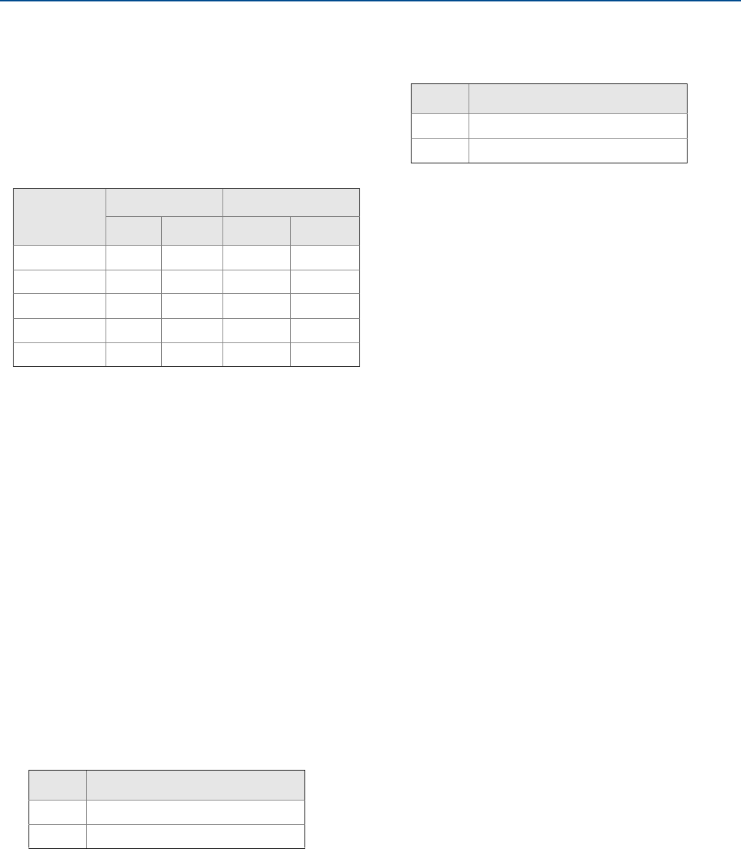
Product Certifications
September 2017
Reference Manual
00809-0100-4803, Rev GA
159
Product Certifications
Special Conditions for Safe Use (X):
1. If the equipment is fitted with the optional 90 V transient
suppressor, it is incapable of withstanding the 500 V isolation
from earth test and this must be taken into account during
installation.
2. For processes with temperatures above 135 °C, the user must
assess whether the SuperModule temperature class is
suitable for such applications, because in this situation there
is a risk of the SuperModule temperature being above T4.
B.9 China
E3 China Flameproof and Dust Ignition-proof
Certificate: 3051SMV: GYJ14.1039X
[Mfg USA, China, Singapore]
3051SFx: GYJ11.1466X
[Mfg USA, China, Singapore]
Standards: 3051SMV: GB3836.1-2010, GB3836.2-2010,
GB3836.20-2010
3051SFx: GB3836.1-2010, GB3836.2-2010,
GB3836.20-2010, GB12476.1-2013,
GB12476.5-2013
Markings: 3051SMV: Ex d IIC T6/T5 Ga/Gb
3051SFx: Ex d IIC T4…T6 Ga/Gb; Ex tD A20 TA
105 °C T50095 °C; IP66
Special Conditions for Safe Use (X):
1. Symbol “X” is used to denote specific conditions of use: For
information on the dimensions of the flameproof joints the
manufacturer shall be contacted.
2. The relationship between T code and ambient temperature
range for the Rosemount 3051SMV are as follows:
3. The relationship between T code and ambient temperature
range for the Rosemount 3051SFx are as follows:
4. The earth connection facility in the enclosure should be
connected reliably.
5. During installation, use and maintenance of the product in
explosive atmosphere, observe the warning “Do not open
cover when circuit is alive”. During installation, use, and
maintenance in explosive dust atmosphere, observe the
warning “Do not open when an explosive dust atmosphere is
present”.
6. During installation there should be no mixture harmful to the
housing.
7. During installation, use and maintenance in explosive dust
atmosphere, product enclosure should be cleaned to avoid
dust accumulation, but compressed air should not be used.
8. During installation in a hazardous location, cable glands and
blanking plugs certified by state appointed inspection bodies
with Ex d II C Gb or Ex d IIC Gb DIP A20 [Flowmeters] IP66
type of protection should be used. Redundant cable entries
should be blocked with blanking plugs.
9. End users are not permitted to change any components, but
to contact the manufacturer to avoid damage to the
product.
10. Maintenance should be done when no explosive gas and dust
atmosphere is present.
11. During installation, use and maintenance of this product,
observe following standards:
GB3836.13-1997 “Electrical apparatus for explosive gas
atmospheres Part 13: Repair and overhaul for apparatus used
in explosive gas atmospheres”
GB3836.15-2000 “Electrical apparatus for explosive gas
atmospheres Part 15: Electrical installations in hazardous
area (other than mines)”
GB3836.16-2006 “Electrical apparatus for explosive gas
atmospheres Part 16: Inspection and maintenance of
electrical installation (other than mines)”
GB50257-1996 “Code for construction and acceptance of
electric device for explosion atmospheres and fire hazard
electrical equipment installation engineering”
GB15577-2007 “Safety regulations for dust explosion
prevention and protection”
GB12476.2-2010 “Electrical apparatus for use in the
presence of combustible dust”
Parameter
HART FOUNDATION Fieldbus
Input RTD Input RTD
Voltage Ui30 V 30 V 30 V 30 V
Current Ii300 mA 2.31 mA 300 mA 18.24 mA
Power Pi1 W 17.32 W 1.3 W 137 mW
Capacitance Ci14.8 nF 0 0 0.8 nF
Inductance Li0 0 0 1.33 mH
T code Ambient temperature range
T6 –50 °C ~ +65 °C
T5 –50 °C ~ +80 °C
T code Ambient temperature range
T6 –60 °C ~ +70 °C
T4/T5 –60 °C ~ +80 °C

160 Product Certifications
Product Certifications
September 2017
Reference Manual
00809-0100-4803, Rev GA
I3 China Intrinsic Safety
Certificate: 3051SMV: GYJ14.1040X
[Mfg USA, China, Singapore]
3051SFx: GYJ16.14
[Mfg USA, China, Singapore]
Standards: 3051SMV: GB3836.1-2010, GB3836.4-2010,
GB3836.20-2010
3051SFx: GB3836.1/4-2010, GB3836.20-2010,
GB12476.1-2000
Markings: 3051SMV: Ex ia IIC T4 Ga
3051SFx: Ex ia IIC T4 Ga, Ex tD A20 TA105 °C
T500 95 °C; IP66
Special Conditions for Safe Use (X):
1. The enclosure may contain light metal, attention should be
taken to avoid ignition hazard due to impact or friction.
2. The apparatus is not capable of withstanding the 500 V
electrical strength test defined in Clause 6.3.12 of
GB3836.4-2010.
3. Ambient temperature range: –60 °C ~ +70 °C.
4. Intrinsically safe electric parameters:
5. The cables between this product and associated apparatus
should be shielded cables. The shield should be grounded
reliably in non-hazardous area.
6. The product should be used with Ex certified associated
apparatus to establish explosion protection system that can
be used in explosive gas atmospheres. Wiring and terminals
should comply with the instruction manual of the product
and associated apparatus.
7. End users are not permitted to change any components,
contact the manufacturer to avoid damage to the product.
8. During installation in hazardous location, cable glands,
conduit, and blanking plugs certified by state-appointed
inspection bodies with DIP A20 IP66 type of protection
should be used. Redundant cable entries should be blocked
with blanking plugs.
9. During installation, use, and maintenance in explosive dust
atmosphere, observe the warning “Do not open when an
explosive dust atmosphere is present”.
10. Maintenance should be done when no explosive dust
atmosphere is present.
11. During installation, use and maintenance of this product,
observe following standards:
GB3836.13-2013 “Electrical apparatus for explosive gas
atmospheres Part 13: Repair and overhaul for apparatus used
in explosive gas atmospheres”
GB3836.15-2000 “Electrical apparatus for explosive gas
atmospheres Part 15: Electrical installations in hazardous
area (other than mines)”
GB3836.16-2006 “Electrical apparatus for explosive gas
atmospheres Part 16: Inspection and maintenance of
electrical installation (other than mines)”
GB3836.18-2010 “Intrinsically Safe System”
GB50257-1996” - Code for construction and acceptance of
electric device for explosion atmospheres and fire hazard
electrical equipment installation engineering”
GB15577-2007 Safety regulations for dust explosion
prevention and protection
GB12476.2-2010 “Electrical apparatus for use in the
presence of combustible dust”
B.10 EAC – Belarus, Kazakhstan, Russia
EM Technical Regulation Customs Union (EAC) Flameproof and
Dust Ignition-proof
Certificate: RU C-US.AA87.B.00378
Markings: Ga/Gb Ex d IIC T6…T4 X
Ex tb IIIC T105 °C T50095 °C Db X
Ex ta IIIC T105 °C T50095 °C Da X
IM Technical Regulation Customs Union (EAC) Intrinsic Safety
Certificate: RU C-US.AA87.B.00378
Markings: 0Ex ia IIC T4 Ga X
Maximum
input voltage:
Ui (V)
Maximum
input current:
Ii (mA)
Maximum
input power:
Pi (W)
Maximum internal
parameters:
Ci (nF) Li (μH)
30 300 1.0 14.8 0
Model
Maximum
output
voltage:
Ui (V)
Maximum
output
current:
Ii (mA)
Maximum
output
power:
Pi (W)
Maximum
external
parameters:
Ci (nF) Li (μH)
RTD 30 2.31 17.32 0 0
SuperModule 7.14 300 8871.0 110 0

Product Certifications
September 2017
Reference Manual
00809-0100-4803, Rev GA
161
Product Certifications
B.11 Japan
E4 Japan Flameproof
Certificate:TC19070, TC19071, TC19072, TC19073
Markings: Ex ia IIC T4
B.12 Republic of Korea
EP Republic of Korea Flameproof
Certificate: 12-KB4BO-0180X [Mfg USA],
11-KB4BO-0068X [Mfg Singapore]
Markings: Ex d IIC T5 or T6
IP Republic of Korea Intrinsic Safety [HART Only]
Certificate: 10-KB4BO-0021X [Mfg USA, SMMC]
Markings: Ex ia IIC T4
B.13 Combinations
K1 Combination of E1, I1, N1, and ND
K2 Combination of E2 and I2
K5 Combination of E5 and I5
K6 Combination of E6 and I6
K7 Combination of E7, I7, and N7
KA Combination of E1, I1, E6, and I6
KB Combination of E5, I5, E6, and I6
KC Combination of E1, I1, E5, and I5
KD Combination of E1, I1, E5, I5, E6, and I6
KM Combination of EM and IM
KP Combination of EP and IP
B.14 Additional Certifications
SBS American Bureau of Shipping (ABS) Type Approval
Certificate: 00-HS145383
Intended Use: Measure gauge or absolute pressure of liquid,
gas or vapor applications on ABS classed
vessels, marine, and offshore installations.
[HART Only]
SBV Bureau Veritas (BV) Type Approval
Certificate: 31910 BV
Requirements: Bureau Veritas Rules for the Classification of
Steel Ships
Application: Class Notations: AUT-UMS, AUT-CCS,
AUT-PORT and AUT-IMS. [HART Only]
SDN Det Norske Veritas (DNV) Type Approval
Certificate: A-14186
Intended Use: Det Norske Veritas' Rules for Classification of
Ships, High Speed & Light Craft, and Det
Norske Veritas' Offshore Standards. [HART
Only]
Application:
SLL Lloyds Register (LR) Type Approval
Certificate: 11/60002
Application: Environmental categories ENV1, ENV2, ENV3,
and ENV5. [HART Only]
Location classes
Type Rosemount 3051S
Temperature D
Humidity B
Vibration A
EMC A
Enclosure D/IP66/IP68

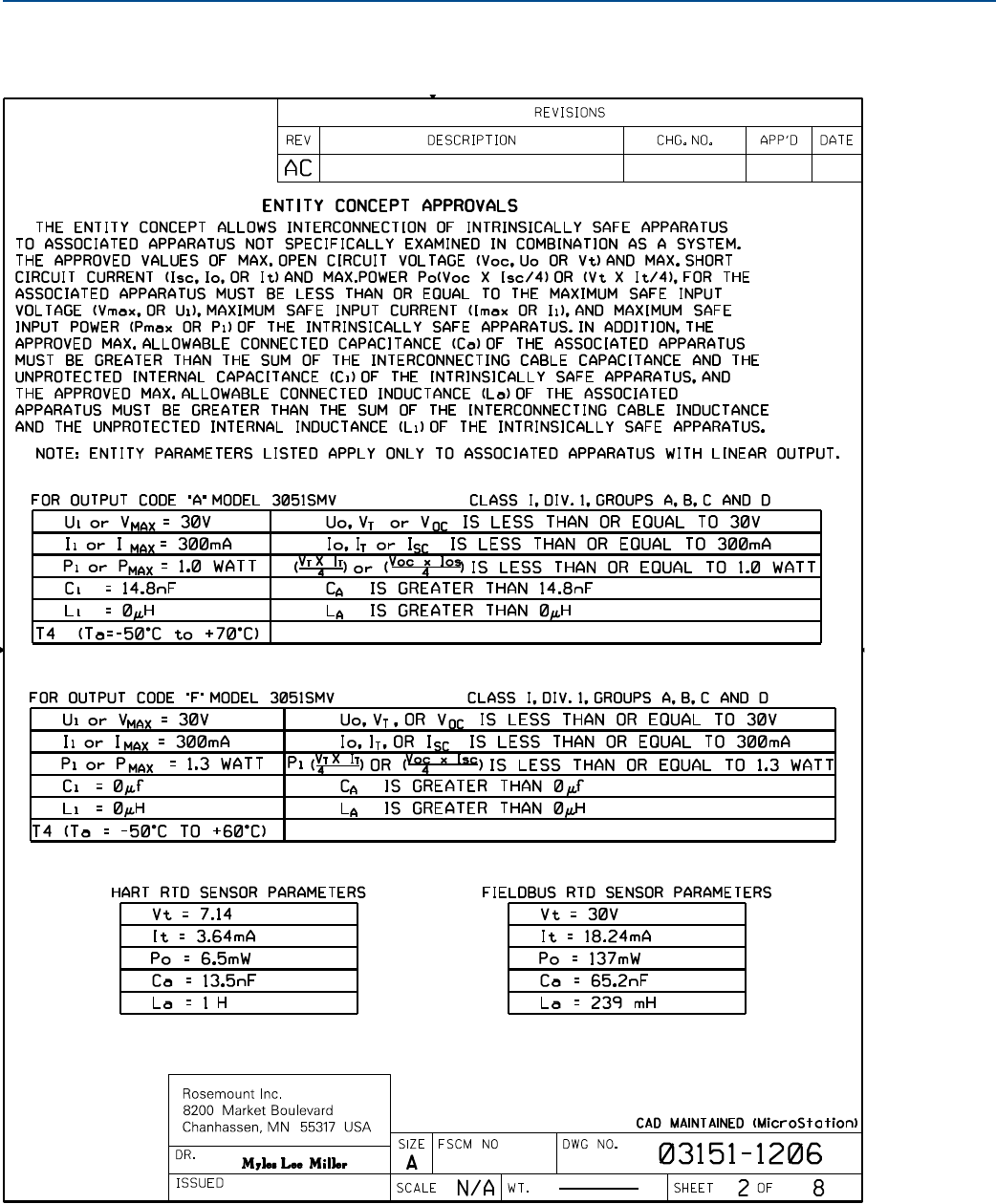

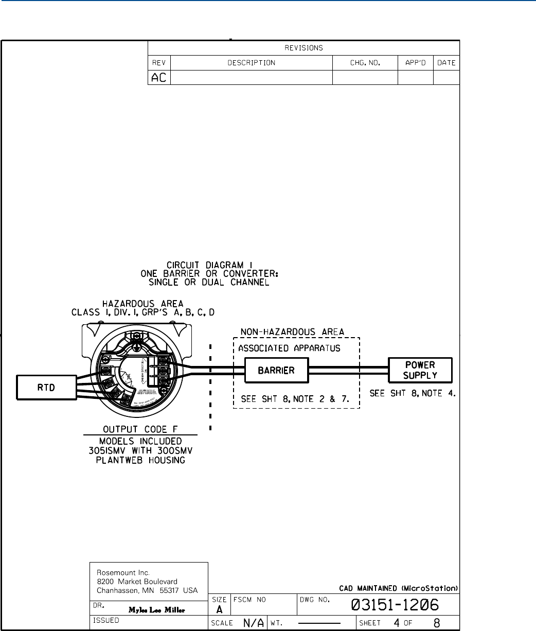

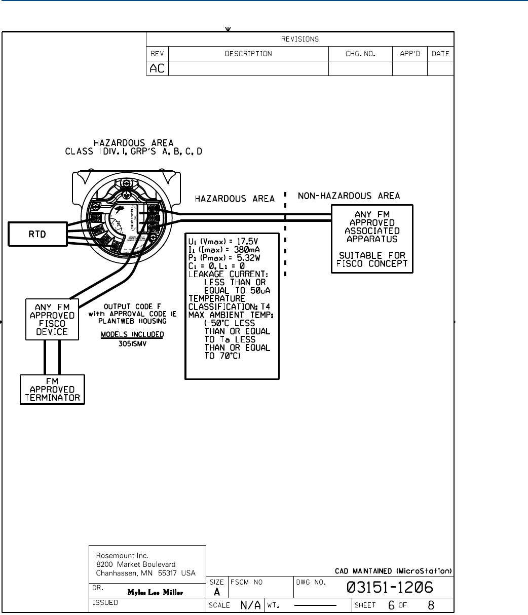
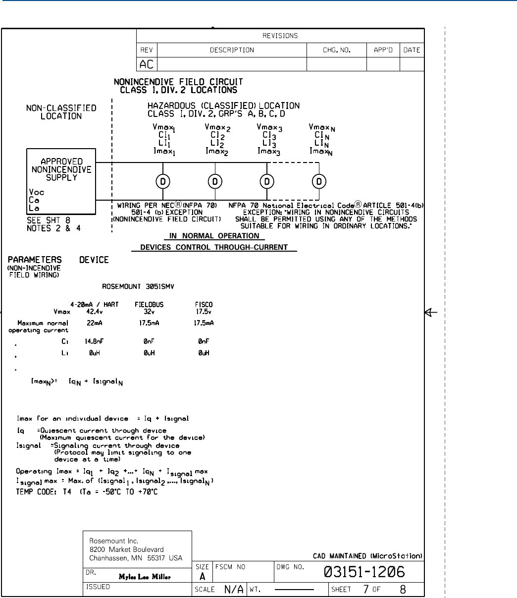
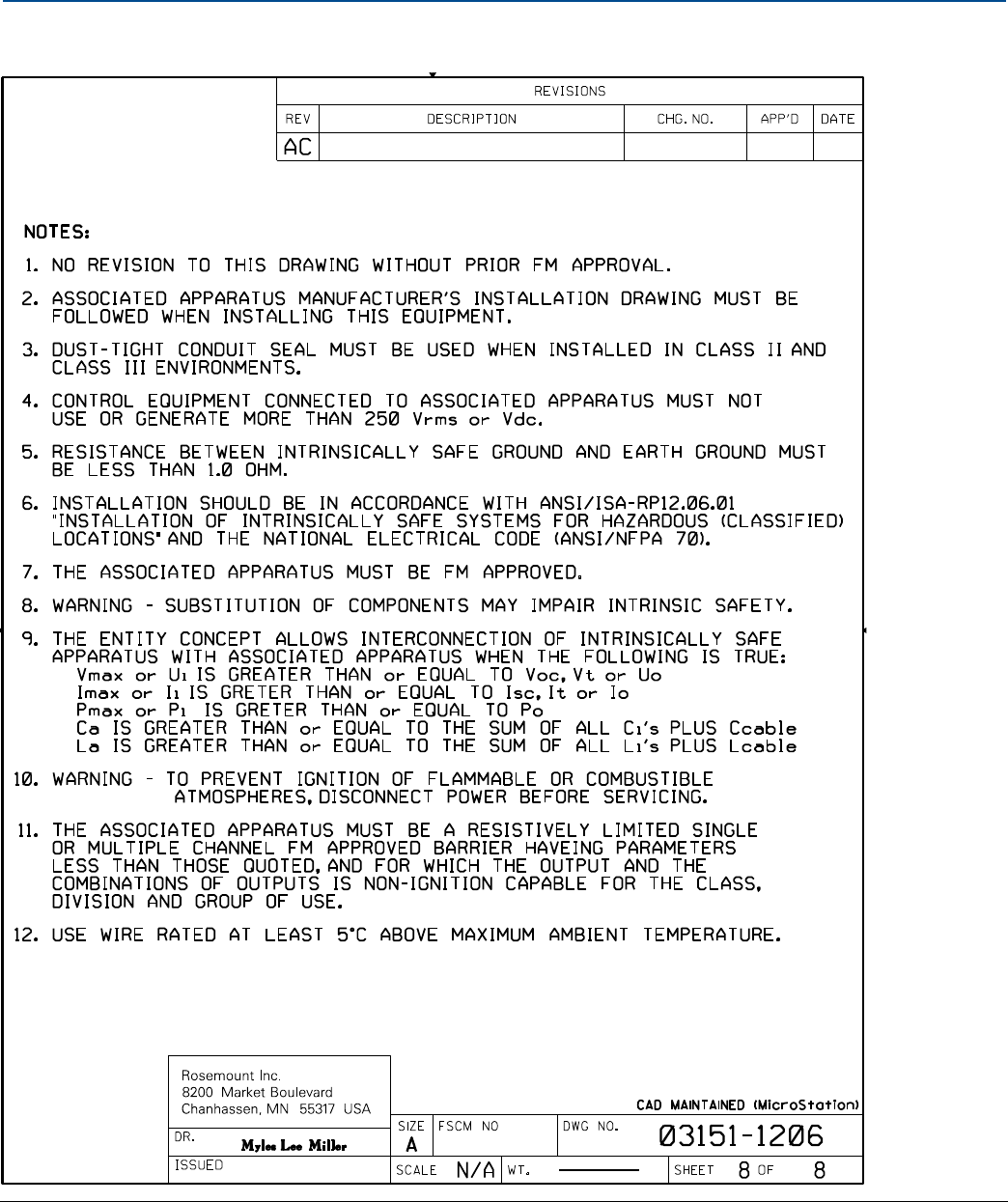
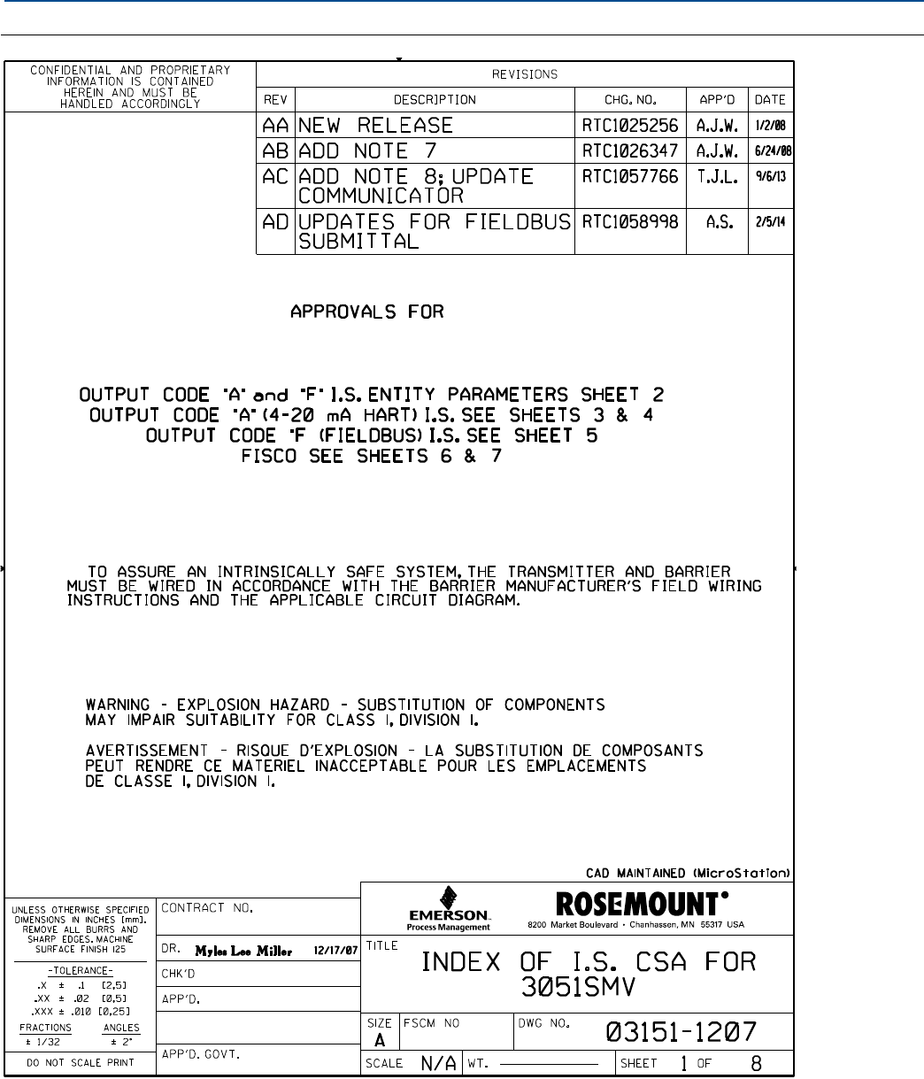
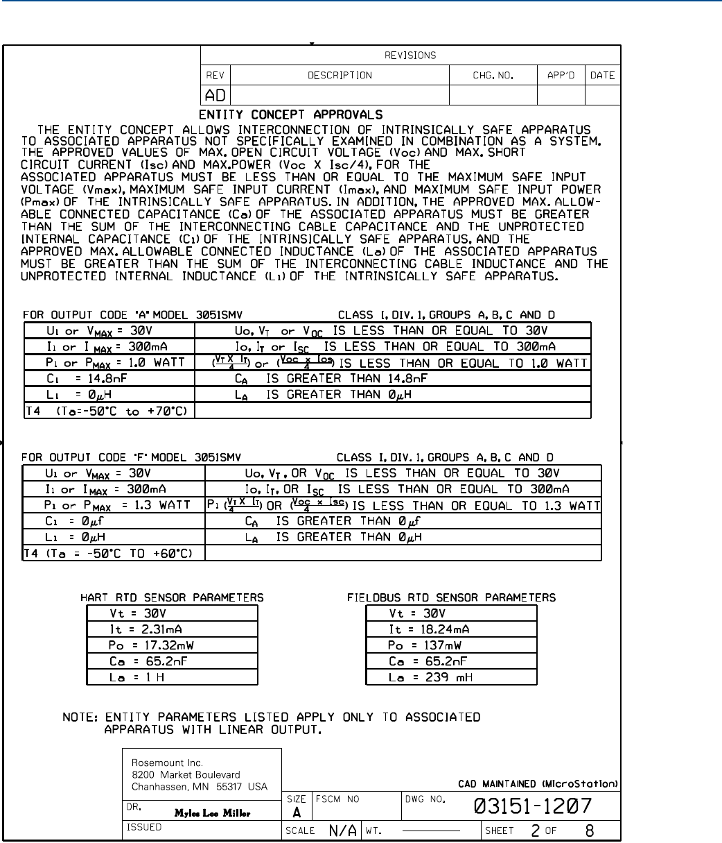
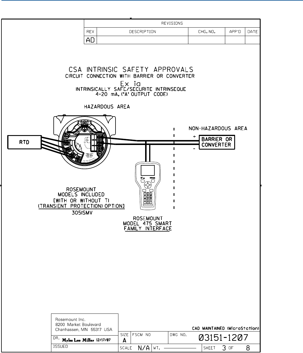
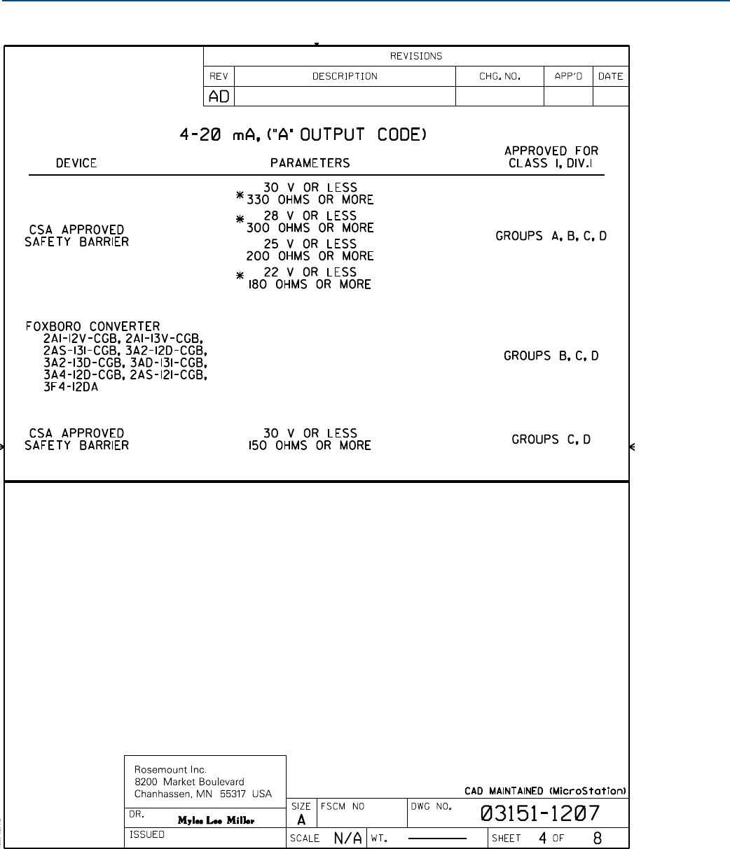
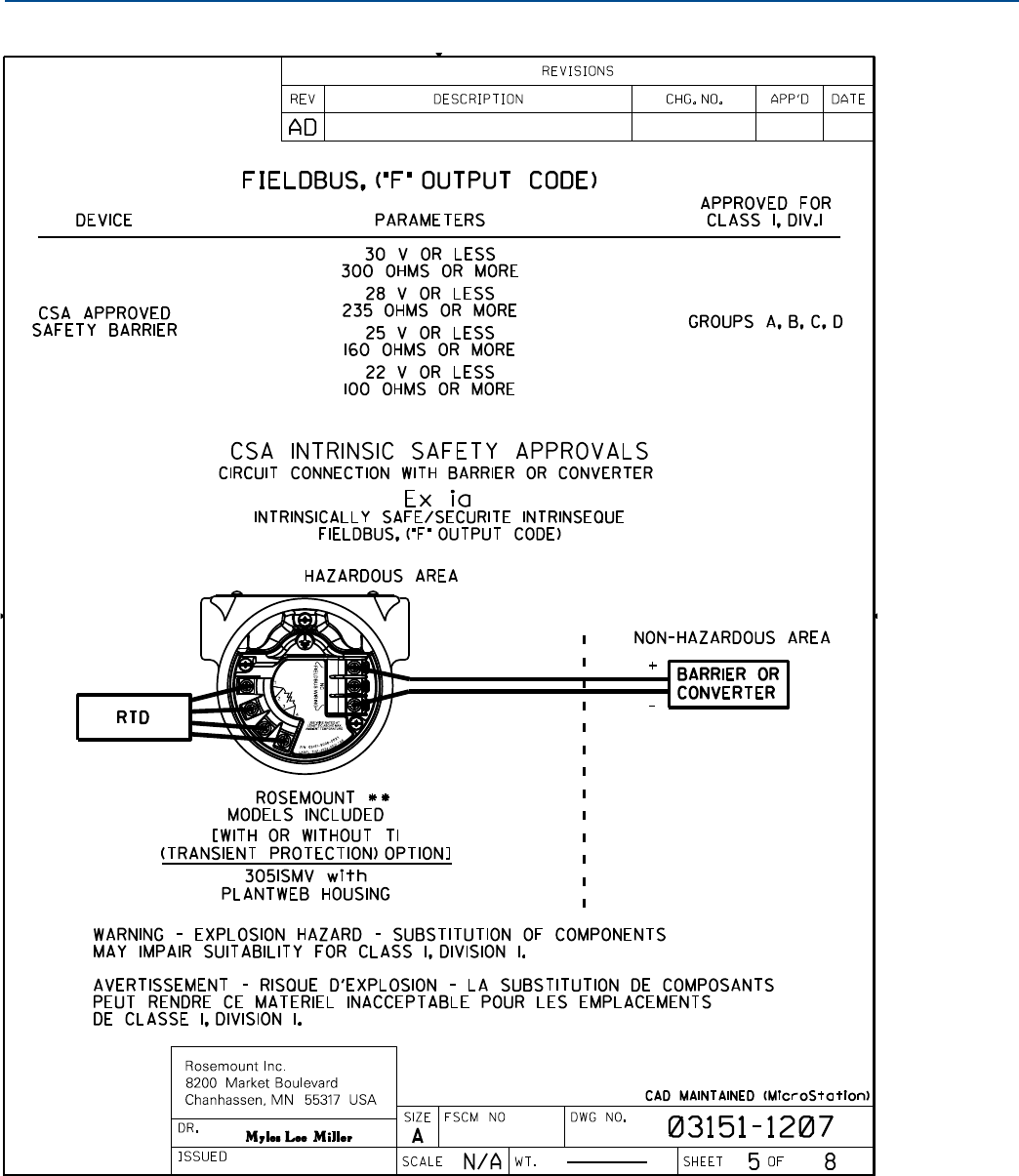
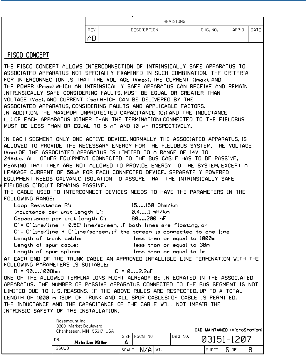
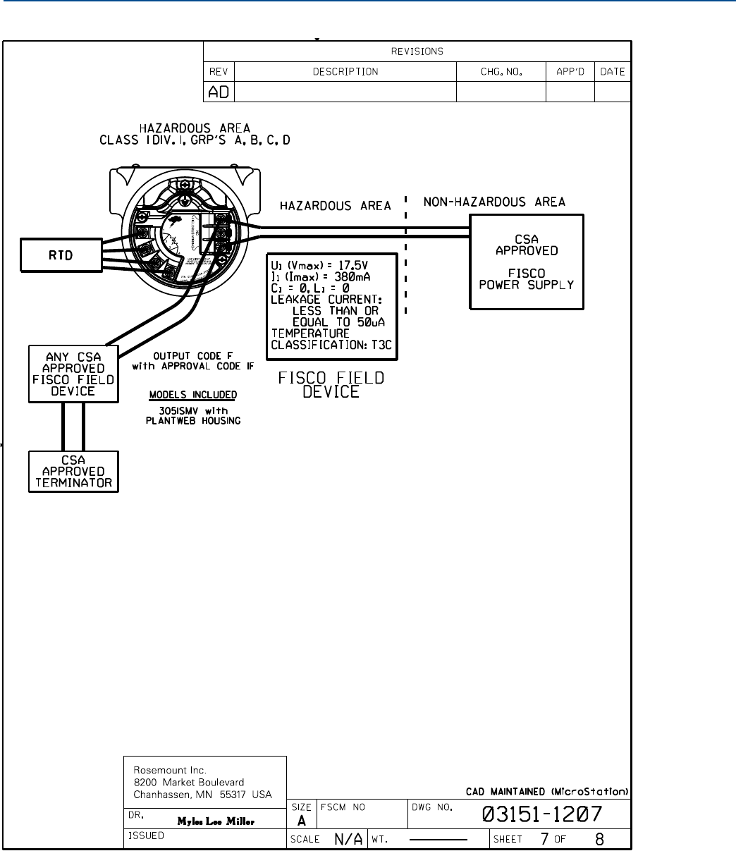
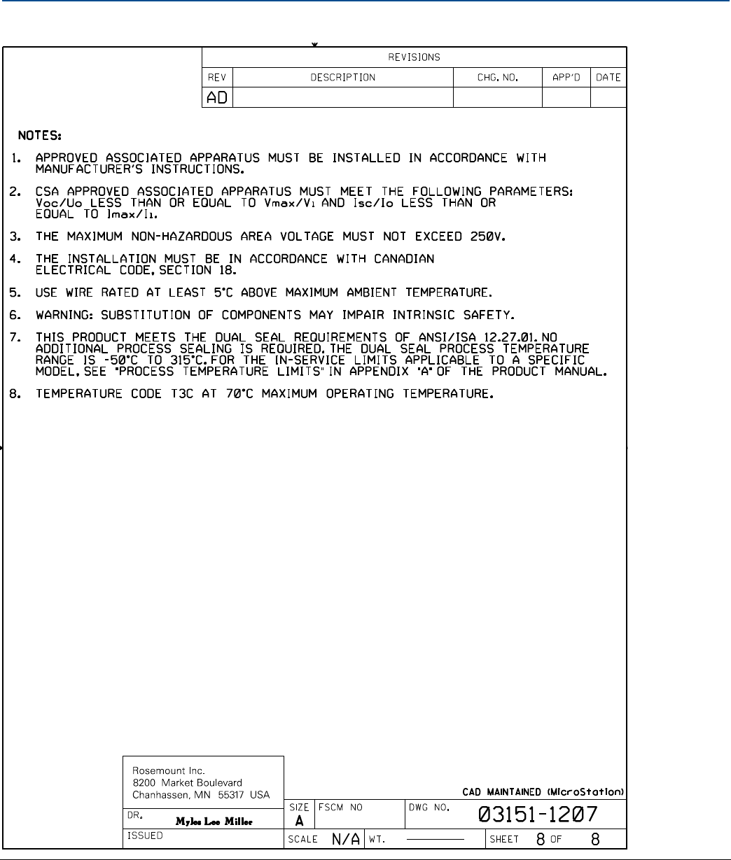


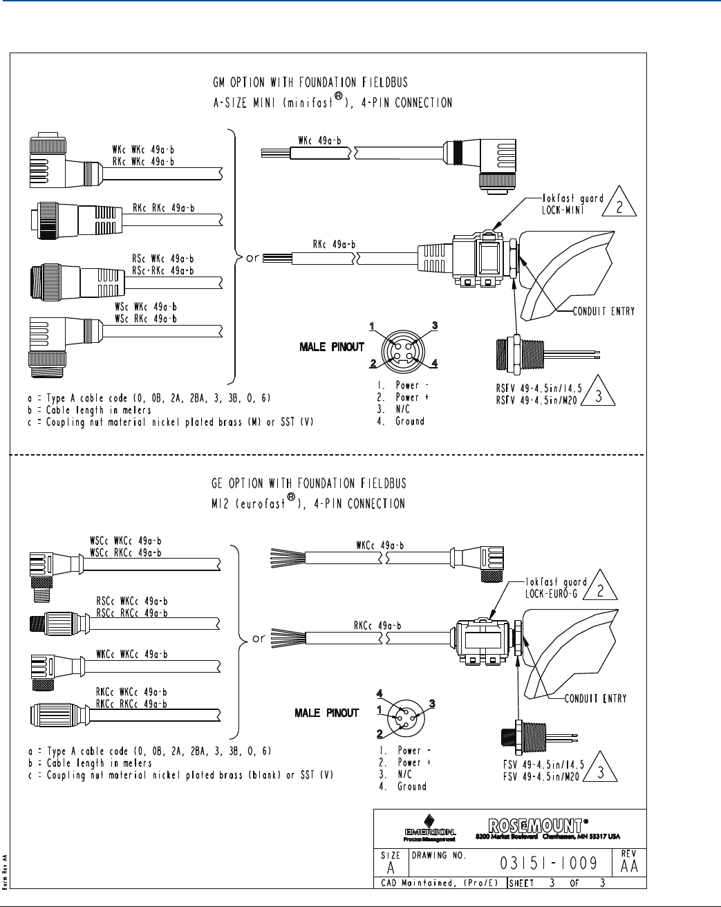

Reference Manual
00809-0100-4803, Rev GA
September 2017
Global Headquarters
Emerson Automation Solutions
6021 Innovation Blvd.
Shakopee, MN 55379, USA
+1 800 999 9307 or +1 952 906 8888
+1 952 949 7001
RFQ.RMD-RCC@Emerson.com
North America Regional Office
Emerson Automation Solutions
8200 Market Blvd.
Chanhassen, MN 55317, USA
+1 800 999 9307 or +1 952 906 8888
+1 952 949 7001
RMT-NA.RCCRFQ@Emerson.com
Latin America Regional Office
Emerson Automation Solutions
1300 Concord Terrace, Suite 400
Sunrise, FL 33323, USA
+1 954 846 5030
+1 954 846 5121
RFQ.RMD-RCC@Emerson.com
Europe Regional Office
Emerson Automation Solutions Europe GmbH
Neuhofstrasse 19a P.O. Box 1046
CH 6340 Baar
Switzerland
+41 (0) 41 768 6111
+41 (0) 41 768 6300
RFQ.RMD-RCC@Emerson.com
Asia Pacific Regional Office
Emerson Automation Solutions Asia Pacific Pte Ltd
1 Pandan Crescent
Singapore 128461
+65 6777 8211
+65 6777 0947
Enquiries@AP.Emerson.com
Middle East and Africa Regional Office
Emerson Automation Solutions
Emerson FZE P.O. Box 17033
Jebel Ali Free Zone - South 2
Dubai, United Arab Emirates
+971 4 8118100
+971 4 8865465
RFQ.RMTMEA@Emerson.com
Linkedin.com/company/Emerson-Automation-Solutions
Twitter.com/Rosemount_News
Facebook.com/Rosemount
Youtube.com/user/RosemountMeasurement
Google.com/+RosemountMeasurement
Standard Terms and Conditions of Sale can be found on the Terms and Conditions of
Sale page.
The Emerson logo is a trademark and service mark of Emerson Electric Co.
Annubar, Coplanar, MultiVariable, Plantweb, Scalable, SNAP-ON, SuperModule,
Tri-Loop, Rosemount, and Rosemount logotype are trademarks of Emerson.
HART is a registered trademark of the FieldComm Group.
FOUNDATION Fieldbus is a trademark of the FieldComm Group.
Microsoft is a registered trademark of Microsoft Corporation in the United States and
other countries.
Windows is a trademark of Microsoft Corporation in the United States and other
countries.
NACE is a registered trademark of NACE International.
NEMA is a registered trademark and service mark of the National Electrical
Manufacturers Association.
National Electrical Code is a registered trademark of National Fire Protection
Association, Inc.
eurofast and minifast are registered trademarks of TURCK.
All other marks are the property of their respective owners.
© 2017 Emerson. All rights reserved.
