0117 0256 10_K105 D_Logic_Analyzer_Addendum_Disk_Storage_System_Sep83 10 K105 D Logic Analyzer Addendum Disk Storage System Sep83
User Manual: 0117-0256-10_K105-D_Logic_Analyzer_Addendum_Disk_Storage_System_Sep83
Open the PDF directly: View PDF ![]() .
.
Page Count: 31
P-9/83
lK
Publication
Number
0117-0256-10
September 1983
Kl05-D
LOGIC
ANALYZER
USERS
MANUAL
ADDENDUM
DISK
ST<RAGE
SYSTEM
Gould
Inc.,
Design &
Test
Systems
Division
4600 Old
Ironsides
Drive
Santa
Clara,
CA
95050-1279
Telephone:
(408) 988-6800
TWX/TELEX
# 910-338-0509
Copyright
© 1983.
No
part
of
this
publication
may
be
reproduced
without
written
permission
from Gould
Inc.,
Design &
Test
Systems
Division.
Printed
in U.S.A.

CONTENTS
Chapter Page
INTRODUCTION
INTRODUCTION
•••••••••••••••••••••••••
1-1
2
SPECIFICATIONS
3
Figure
INTRODUCTION
•••••••••••••••••••••••••
2-1
PHYSICAL
CHARACTERISTICS
•••••••••••••••••••
2-1
CONTROLS,
I
NO
ICATORS
AND
CONNECTCRS
• • • • • • • • • • •
••
2-1
Front-Panel
Indicators
•••••••••••••••••
2-2
CONTROL
KEYS
•••••••••••••••••••••••••
2-3
OPERAT
ION
INTRODUCTION
•••••••••
OPERATING
PROCEDURES
•••••
• • • • • • •
• • • • • • •
•••••••••
3-1
•••••••••
3-1
Loading
the
DSS
SofTware
••••••••••••••••
3-1
DSS
Commands
Operation
•••••••••••••••••
3-2
STORAGE
SYSTEM
MENU
•••••••••••••••••••••
3-3
SYSTEM
FILES.
• • • • • • • • •
••
•
•••••••••••
3-4
Fi
Ie
Name
••••••••••••••••••••••••
3-4
CREATING
FILES
••••••••••••••••••••••••
3-7
AUTO
DIRECTORY
MODE
•••••••••••••••••••••
3-7
SYSTEM
COMMANDS
• • • • • • • • • • • • • • • • • • • • • • •
3-8
Save
Command
• • • • • • • • • • • • • • • • • • • • • •
3-9
Reca
I I
Command
• • • • • • • • • • • • • • • • • • • • •
3-12
Delete
Command
•••••••••••••••••••••
3-15
Copy
Command
••••••••••••••••••••••
3-15
Rename
Command
•••••••••••••••••••••
3-16
Lock
Command
••••••••••••••••••••••
3-17
Unlock
Command
•••••••••••••••••••••
3-17
Directory
Command
••••••••••••••••••••
3-18
Format
Command
• • • • • • • • • • • • • • • • • • • • •
3-20
Reboot
Command
•••••••••••••••••••••
3-21
Sysgen
Command
•••••••••••••••••••••
3-21
2-1 Front-Panel
Indicators
••••••••••••••••••••••
2-2
3-1
Directory
with a
Selected
Save
Command
••••••••••••••
3-8
3-2
Quick
Mode
Display
••••••••••••••••••••••••
3-9
3-3
Typical Screen Display of
an
Executed
Directory
Command
•••••
3-19
iii

INTRODUCTION
INTRODUCTION
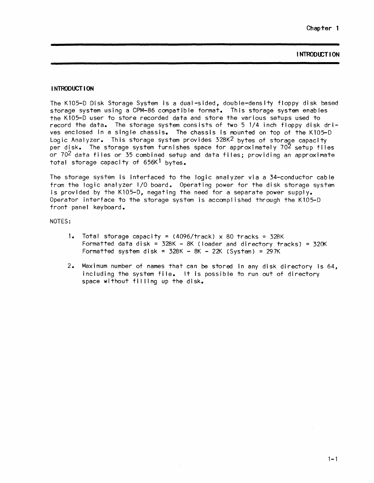
The
K105-D
Disk
Storage
System
is
a
dual-sided,
double-density
floppy
disk
based
storage
system
using
a
CPM-86
compatible
format.
This
storage
system
enables
the
K105-D
user
to
store
recorded
data
and
store
the
various
setups
used
to
record
the
data.
The
storage
system
consists
of
two 5 1/4 inch floppy
disk
dri-
ves
enclosed
in a
single
chassis.
The
chassis
is
mounted
on
top
of
the
K105-D
Logic
Analyzer.
This
storage
system
provides
328K2
bytes
of
storage
capacity
per
disk.
The
storage
system
furnishes
space
for
approximately
702
setup
files
or
702
data
fi
les
or
35 combined
setup
and
data
files;
providing
an
approximate
total
storage
capacity
of
656K1
bytes.
The
storage
system
is
interfaced
to
the
logic
analyzer
via
a
34-conductor
cable
from
the
logic
analyzer
I/O
board.
Operating
power
for
the
disk
storage
system
is
provided
by
the
K105-D,
negating
the
need
for
a
separate
power
supply.
Operator
interface
to
the
storage
system
is
accomplished
through
the
K105-D
front
panel
keyboard.
NOTES:
1. Total
storage
capacity
=
(4096/track)
x 80
tracks
=
328K
Formatted
data
disk
=
328K
-
8K
(loader
and
directory
tracks)
=
320K
Formatted system
disk
=
328K
-
8K
-
22K
(System) =
297K
2.
Maximum
number
of
names
that
can be
stored
in any
disk
directory
is
64,
including
the
system
file.
It
is
possible
to
run
out
of
directory
space
without
fil
ling
up
the
disk.
1-1

Chapter 2
SPEC
I FICATI
ONS
INTRODUCTION
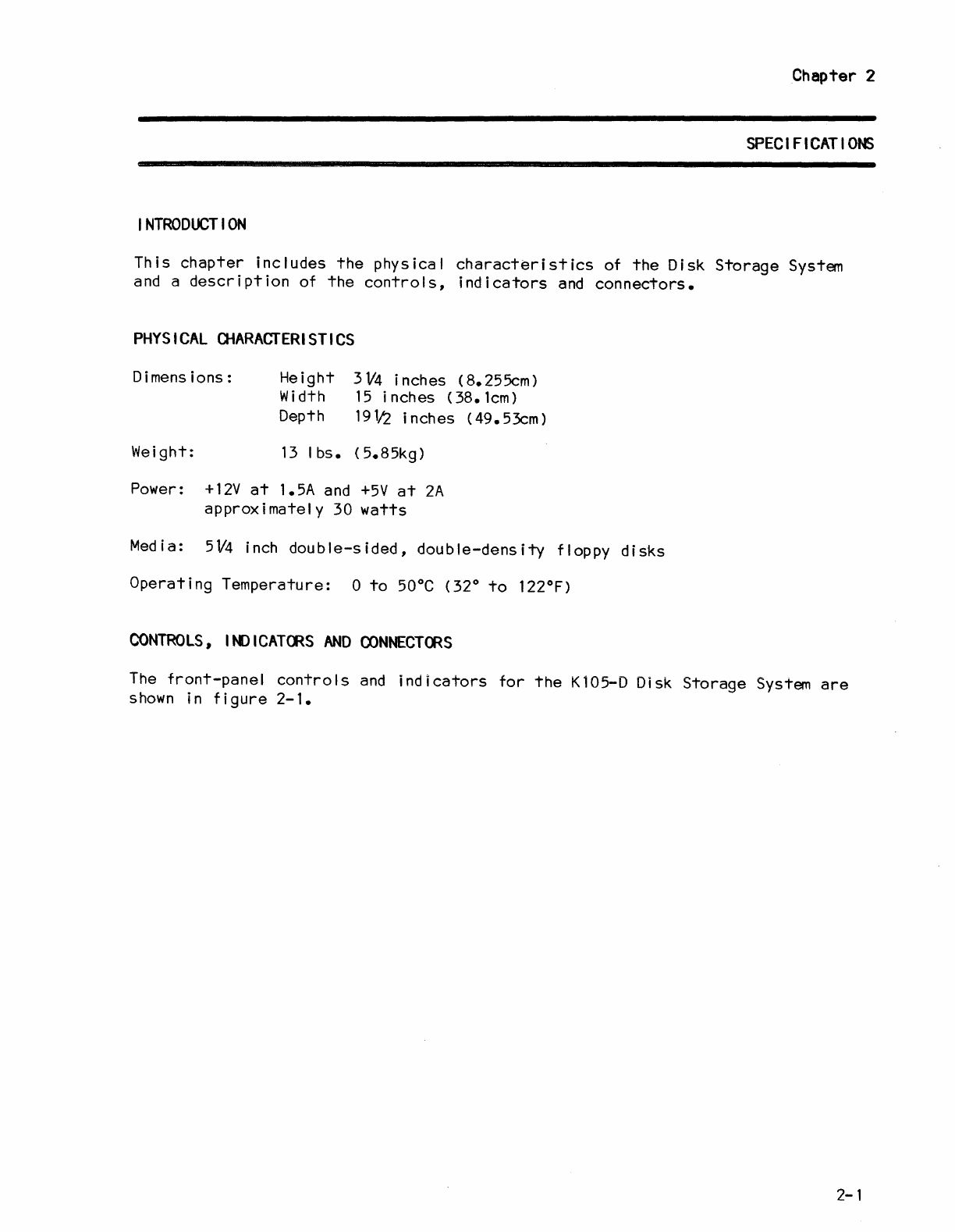
This
chapter
includes
the
physical
characteristics
of
the
Disk
Storage
System
and a
description
of
the
controls,
indicators
and
connectors.
PHYSICAL
CHARACTERISTICS
Dimensions:
Weight:
He
i
ght
3
V4
inches
(8.
255cm)
Wid
t h 1 5 inch
es
(38.
1
cm
)
Depth
19112
inches
(49.53cm)
13
I
bs.
(5.85kg)
Power:
+12V
at
1.5A and
+5V
at
2A
approximately
30
watts
Media: 5V4 inch
double-sided,
double-density
floppy
disks
Operating
Temperature:
0
to
50°C
(32°
to
122°F)
CONTROLS,
I
N)
I
CATeRS
AND
OONNECTeRS
The
front-panel
controls
and
indicators
for
the
Kl05-D Disk
Storage
System
are
shown
in
figure
2-1.
2-1
SPEC
I F I
CAT
IONS
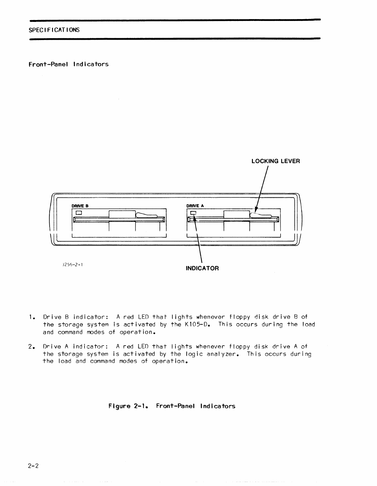
Front-Panel
Indicators
LOCKING LEVER
II
DRIVE
B
DRIVE
A
firy
laD
HI
R
Ul
)
JV
l
\
)2%-2-1
INDICATOR
1.
Dr
i ve
Bind
i
cator:
A
red
LED
tha
t
lights
whenever
floppy
di
sk dr i ve B of
the
storage
system
is
act
i
vated
by
the
K
105-0.
Th
i s occu
rs
dur i
ng
the
load
and
command
modes
of
operation.
2.
Drive
A
indicator:
A
red
LEO
that
lights
whenever
floppy
disk
drive
A
of
the
storage
system
is
activated
by
the
logic
analyzer.
This
occurs
during
the
load and
command
modes
of
operation.
Figure
2-1.
Front-Panel
Indicators
2-2
SPECIFICATIONS
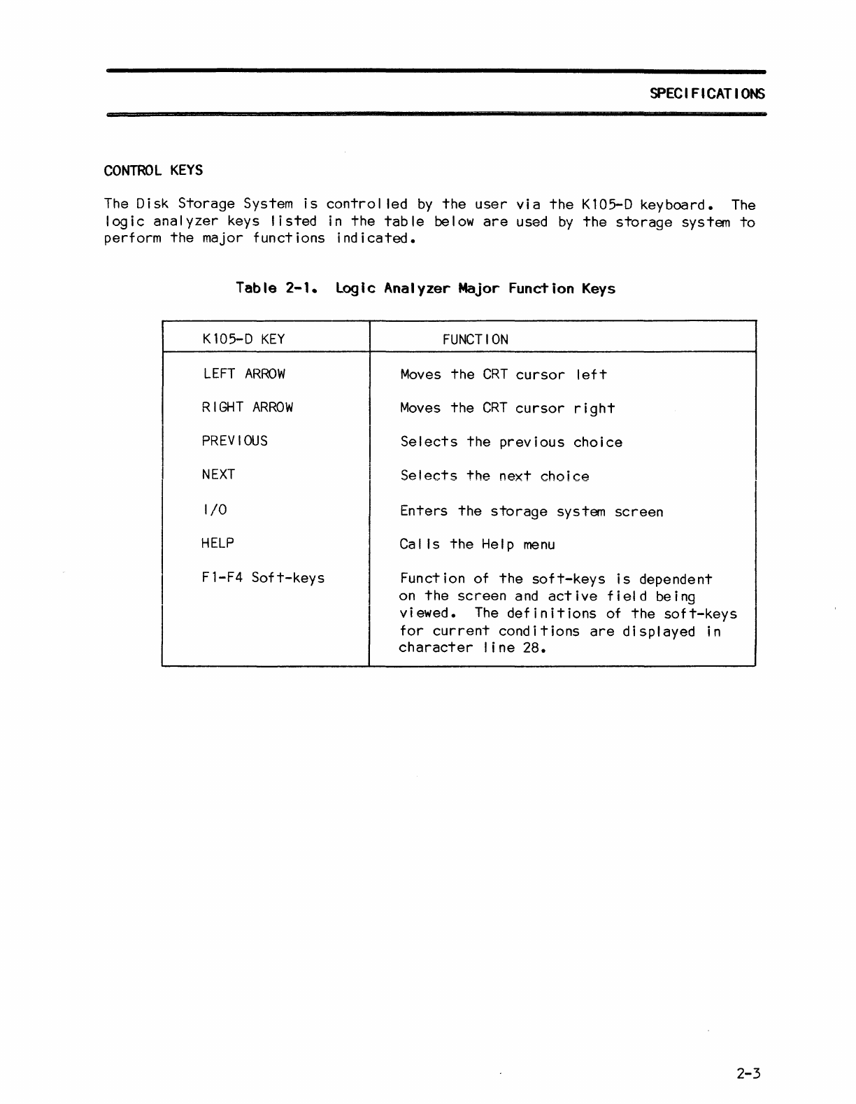
CONTROL
KEYS
The
Disk
Storage
System
is
control
led
by
the
user
via
the
Kl05-D
keyboard.
The
logic
analyzer
keys
listed
in
the
table
below
are
used
by
the
storage
system
to
perform
the
major
functions
indicated.
I
I
Table
2-1.
logic
Analyzer
Major
Function
Keys
Kl05-D
KEY
LEFT
ARROW
RIGHT
ARROW
PREVIOUS
NEXT
I/O
HELP
Fl-F4
Soft-keys
FUNCTION
Moves
the
CRT
cursor
left
Moves
the
CRT
cursor
right
Selects
the
previous
choice
Selects
the
next
choice
Enters
the
storage
system
screen
Calls
the
Help
menu
Function of
the
soft-keys
is
dependent
on
the
screen
and
active
field
being
viewed.
The
definitions
of
the
50ft-keys
for
current
conditions
are
displayed
in
character
line
28.
2-3


Chapter
3
OPERATION
I
NTRODUCT
I
ON
This
chapter
includes
descriptions
of
files
and
commands,
and
step-by-step
operating
procedures.
OPERATING
PROCEDURES
The fol lowing
paragraphs
provide
the
user
with
step-by-step
operating
procedures
for
the
K105-D
Disk
Storage
System.
Loading
the
DSS
Software
The
disk
storage
system
(DSS)
software
of
the
Kl05-D Disk
Storage
System can be
loaded
into
the
logic
analyzer
RAM
using
either
of
the
two methods
outlined
below.
1.
Warm
Start
--
Th
is
load i
ng
method
is
performed
with
power
ap
pi
i
ed
to
the
K105-D
Disk
Storage
System and
with
no
system
disk
instal
led.
To
warm
start,
load
the
DSS
software
into
the
logic
analyzer
RAM,
proceed
as
follows:
a.
Gently
insert
the
system floppy
disk
into
disk
drive
A
or
B, with
the
disk
slot
toward
the
rear
of
the
unit
and
the
label
up. Then, lock
the
disk
in
place
with
the
drive
latch
handle.
* * * * * * * * * * * * * * * * * * * * * * * * * * *
*
CAUTION
*
* *
*
It
is
considered
good
practice
to
completely
*
* remove
the
disk
from
the
drive,
or
to
unlock *
*
the
drive
latch
handle
(if
the
disk
is
instal
led)
*
*
before
removing
and
applying
AC
power
to
the
*
*
system.
This
avoids
possible
disruption
of
*
*
recorded
data
which might
occur
if
the
disk
is
*
* in
contact
with
the
drive
spindle
during
the
power*
* up/shutdown
operation.
*
* * * * * * * * * * * * * * * * * * * * * * * * * * *
b.
Depress
the
I/O key.
An
I/O
menu
appears
and
prompts
the
user
for
a
depression
of
either
the
0
or
1
key.
c.
Observe
that
the
red
LED
of
the
selected
disk
drive
is
illuminated
during
the
time
(5
seconds
nom.)
that
the
software
is
being loaded
into
the
logic
analyzer
RAM;
and
that
after
boot
loading;
the
fol
lowing messages
are
displayed:
BOOT
COMPLETE
and
Kl05
DOS
Loader,
Version
1.0.
3-1
OPERATION
d.
Observe
that
the
disk
storage
system
directory
is
displayed
on
the
screen
after
a
depression
of
the
1 key.
The
quick
mode
field
is
displayed
after
a
depression
of
the
0
key.
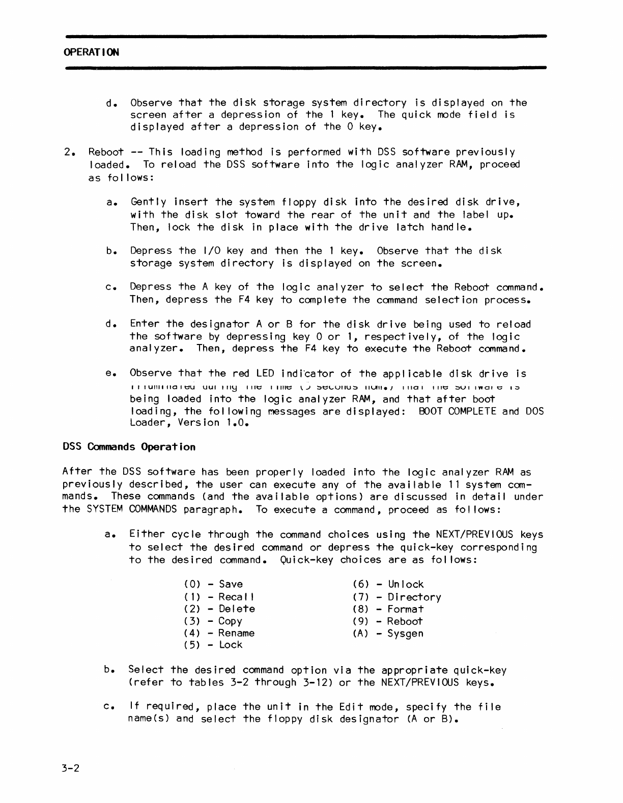
2.
Reboot
--
This
loading method
is
performed with
DSS
software
previously
loaded.
To
reload
the
DSS
software
into
the
logic
analyzer
RAM,
proceed
as
follows:
a.
Gently
insert
the
system floppy
disk
into
the
desired
disk
drive,
with
the
disk
slot
toward
the
rear
of
the
unit
and
the
label up.
Then, lock
the
disk
in
place
with
the
drive
latch
handle.
b.
Depress
the
I/O
key
and
then
the
1 key. Observe
that
the
disk
storage
system
directory
is
displayed
on
the
screen.
c.
Depress
the
A
key
of
the
logic
analyzer
to
select
the
Reboot
command.
Then,
depress
the
F4
key
to
complete
the
command
selection
process.
d.
Enter
the
designator
A
or
B
for
the
disk
drive
being used
to
reload
the
software
by
depressing
key
0
or
1,
respectively,
of
the
logic
analyzer.
Then,
depress
the
F4
key
to
execute
the
Reboot
command.
e.
Observe
that
the
red
LED
i
nd
i'cator
of
the
app I i cab
Ie
di
sk dr i ve
is
IIIUIlIIIIOIt::U
UUI
"I~
lilt::
I I
lilt::
\J
~t::\"'VIIU~
IIUII.,
11101
lilt::
~VI
InOI
t::
I~
being loaded
into
the
logic
analyzer
RAM,
and
that
after
boot
loading,
the
fol lowing messages
are
displayed:
BOOT
COMPLETE
and
DOS
Loader, Version
1.0.
DSS
Commands
Operation
After
the
DSS
software
has been
properly
loaded
into
the
logic
analyzer
RAM
as
previously
described,
the
user
can
execute
any of
the
available
11
system com-
mands. These
commands
(and
the
available
options)
are
discussed
in
detail
under
the
SYSTEM
COMMANDS
paragraph.
To
execute
a
command,
proceed as fol lows:
3-2
a.
Either
cycle
through
the
command
choices
using
the
NEXT/PREVIOUS
keys
to
select
the
desired
command
or
depress
the
quick-key
corresponding
to
the
desired
command.
Quick-key
choices
are
as
fol lows:
(0)
-Save
(6)
-Unlock
(1)
-Reca I I
(7)
-
Directory
(
2)
-
Delete
(
8)
-Format
(3
) -
Copy
(
9)
-Reboot
(4)
-
Rename
(A)
-Sysgen
(
5)
-
Lock
b.
Select
the
desired
command
option
via
the
appropriate
quick-key
(refer
to
tables
3-2
through
3-12)
or
the
NEXT/PREVIOUS
keys.
c.
If
required,
place
the
unit
in
the
Edit
mode,
specify
the
file
name(s) and
select
the
floppy
disk
designator
(A
or
B).
d.
Depress
the
F4
key
(as
directed
by
the
messages
on
the
bottom
portion
of
the
display)
to
execute
the
system
command.
NOTE:
Refer
to
the
two
lines
near
the
bottom
of
the
screen.
The
two
lines,
command
and
message, help guide
the
user
through
the
command
selection
and
execution
process.
In
addition,
character
line
2
displays
any
error
encountered
by
the
system.
The
user
does not have
to
decipher
any
error
codes.
OPERATION
SYSTEM
FI
LES
Each
K105-D
Disk
Storage
System
file
is
a
collection
of
related
information
that
is
stored
on
a floppy
disk.
Numerous
files
can
be
created
on
the
disk,
each
with
a unique name.
The
K105-D
Disk
Storage
System
uses
the
category
of
files
described
below
to
fulfil
I
its
various
intended
functions
in
the
logic
analyzer
environment.
1. Setup
File:
contains
setup
parameters
for
the
clock
select,
data
for-
mat,
input
mode,
logic
polarity
and
trace
control
specifications;
it
also
contains
the
timing-display
labels.
Whenever a
setup
file
is
created,
it
always
contains
setup
parameters
for
al I
the
K105-D
setup
menus.
2.
Data
File:
contains
recorded
data
from
the
logic
analyzer
trace
memories A
or
B
and
the
active
trigger
levels
for
the
recorded samples.
The
data
from
location
0
through
1023
is
stored
in a
data
file.
3.
Uti I
ity
Fi
Ie:
contains
executable
code
for
the
logic
analyzer.
These
files
are
provided
for
future
use.
Storing
any
information
in
these
files
may
create
invalid
data.
11It::~t:
111t::~
CHt::
~IUIt::U
UII
Ird(';l\~
,
IIIIUUyll
I~
U1
Ille
:.J1/4-lncn
TIOPPY
OISKS
OT
the
storage
system.
The
file
directory
is
stored
on
disk
track
1.
Every time
that
a
file
is
created
or
updated,
the
appropriate
entries
(filename,
location
and length>
are
made
in
the
directory.
The
disk
storage
system can exchange
files
within
some
categories
(setup
file
A
with
setup
file
B); however,
the
disk
storage
system
cannot
exchange
files
bet-
ween
categories
(i.e.,
between a
setup
file
and
a
data
file).
If
illegal
file
exchanges
are
attempted,
an
il
legal message
is
displayed
on
the
message
line.
This
feature
prevents
the
user
from
inadvertently
locking
up
the
logic
analyzer
by
reca
I
ling
i I lega I
setu
ps.
Fi
Ie
Name
Each
fi
Ie must
be
assigned
a unique name, which
consists
of a
label,
version
and
file
type.
The
fi
Ie label
is
six
characters
in
length.
The
letters
A through
Z,
numbers 0
through
9 a
nd
the
"space"
character
can be used
for
the
f i I e I abe I •
AI
I
other
characters
are
invalid.
NOTE:
3-4
The
file
label cannot
start
with
a
space
nor can
spaces
be
interspersed
with
alphanumeric
characters.
In
other
words, spaces can
be
used
as
fil
I
characters
fol lowing
file
labels
of
less
than
six
contiguous
alpha-
numeric
characters.
OPERATION
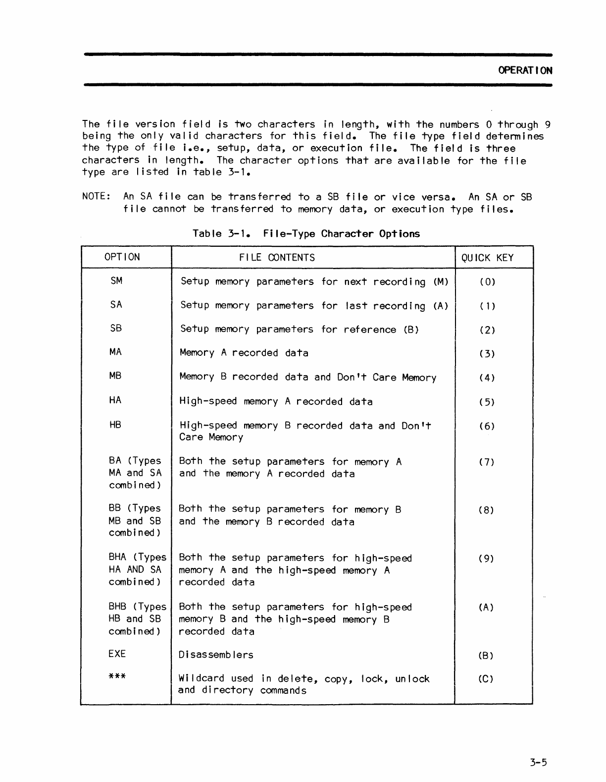
The
tile
version
tield
is
two
characters
in
lenqth,
with
the
numbers 0
through
9
being
the
only
valid
characters
tor
this
tield.-
The
tile
type
field
determines
the
type
ot
tile
i.e.,
setup,
data,
or
execution
tile.
The
field
is
three
characters
in
length.
The
character
options
that
are
available
tor
the
file
type
are
listed
in
table
3-1.
NOTE:
An
SA
tile
can
be
transferred
to
a
SB
file
or
vice
versa.
An
SA
or
SB
file
cannot
be
transferred
to
memory
data,
or
execution
type
files.
OPTION
SM
SA
SB
MA
MB
HA
HB
BA
(Types
MA
and
SA
combi
ned)
BB
(Types
MB
and
SB
combi
ned)
BHA
(Types
HA
AND
SA
combi
ned)
BHB
(Types
HB
and
SB
combi
ned)
EXE
***
Table
3-1.
File-Type
Character
Options
FILE
CONTENTS
Setup
memory
parameters
tor
next
record
i
ng
(M)
Setup
memory
parameters
for
last
recording
(A)
Setup
memory
parameters
for
reference
(B)
Memory
A recorded
data
Memory
B recorded
data
and
Don't
Care
Memory
High-speed
memory
A
recorded
data
High-speed
memory
B recorded
data
and
Don't
Care
Memory
Both
the
setup
parameters
tor
memory
A
and
the
memory
A
recorded
data
Both
the
setup
parameters
for
memory
B
and
the
memory
B
recorded
data
Both
the
setup
parameters
for
high-speed
memory
A
and
the
high-speed
memory
A
recorded
data
Both
the
setup
parameters
for
high-speed
memory
B
and
the
high-speed
memory
B
recorded
data
Disassemblers
Wildcard used in
delete,
copy,
lock,
unlock
and
directory
commands
QUICK
KEY
(
0)
(1)
(2)
(
3)
(4)
(
5)
(
6)
(7)
(8)
(
9)
(A)
(B)
(C)
3-5
OPERATION
The
user
should
note
that
as
the
Save
or
Recal I
command
option
fields
are
changed,
the
file
type
option
field
changes
to
coincide;
however,
when
the
file
type
option
field
is
changed,
the
Save
and
Recal I
command
option
fields
do
not
change.
This
dissimi
larity
in
operation
al
lows
the
user
to
exchange
files
within
a
catagory.
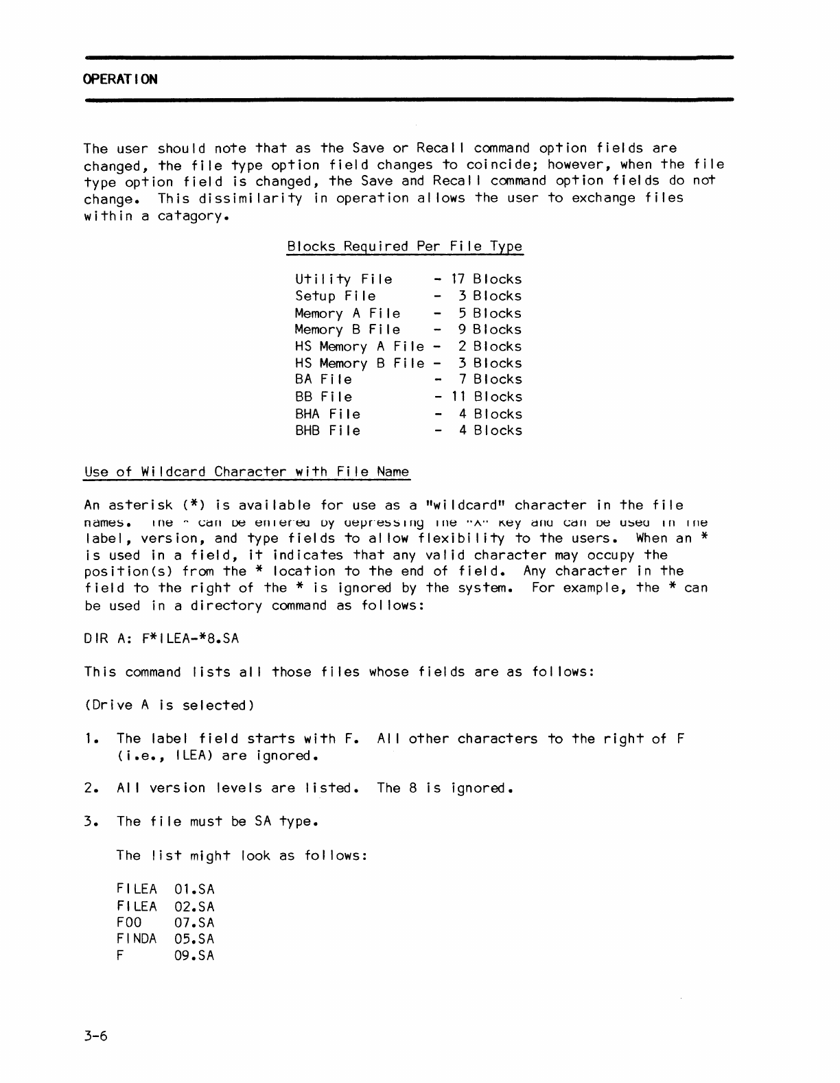
Blocks Required Per
Fi
Ie Type
Ut
iii
ty
F i I e
Setup
Fi
Ie
Memory
A
Fi
Ie
Memory
B
Fi
Ie
-
17
Blocks
3 Blocks
HS
Memory
A
File
-
HS
Memory
B
File
-
BA
Fi
Ie
5 Blocks
9 Blocks
2 Blocks
3 Blocks
7 Blocks
BB
Fi
Ie
BHA
Fi
Ie -
11
Blocks
BHB
Fi
Ie 4 Blocks
4 Blocks
Use
of
Wi
Idcard
Character
with
Fi
Ie
Name
An
asterisk
(*)
is
available
for
use
as
a
"wildcard"
character
in
the
file
names.
I
ne
"
(;d
n
De
en
I
en~J
oy
UelJn~!:)!:)
I
ny
Ille
..
"..
K.ey
drlU
(;d
n
ue
u!:)eu
I
nine
label,
version,
and
type
fields
to
al
low
flexibi
lity
to
the
users.
When
an *
is
used in a
field,
it
indicates
that
any
valid
character
may
occupy
the
position(s)
from
the
*
location
to
the
end
of
field.
Any
character
in
the
field
to
the
right
of
the
*
is
ignored
by
the
system.
For example,
the
* can
be used in a
directory
command
as
fol lows:
DIR
A:
F*ILEA-*8.SA
This
command
lists
al I
those
files
whose
fields
are
as
fol lows:
(Drive
A
is
selected)
1.
The label
field
starts
with
F.
AI
I
other
characters
to
the
right
of F
(
i.e.,
I
LEA)
are
ignored.
2.
AI
I
version
levels
are
listed.
The
8
is
ignored.
3.
The
file
must
be
SA
type.
3-6
The
list
might look
as
fol lows:
FI
LEA
FI
LEA
FOO
FINDA
F
Ol.SA
02.SA
07.SA
05.SA
09.SA
OPERATION
Default
Fi
lename
From
an
initial
ized
condition,
the
fiiename
dispiayed
is
File-Ol.SM.
From
another
command
function,
the
filename
displayed
reflects
the
filename
used
in
the
last
Save
or
Recal I command. The
drive
number
(A
or
B)
of
the
default
filename
is
used
as
the
default
option
for
commands
requiring
only
a
drive
number.
CREAT
IN;
FI
LES
When
the
K105-D
is
turned
on,
it
looks
for
a system
disk
in
drive
A.
If
the
disk
is
not
available
in
drive
A
it
goes
to
drive
B
to
load
the
operating
soft-
ware.
The
system
creates
a
filename:
"A:FILE
-Ol.S~1".
This
file
is
called
the
default
file.
Whenever a
file
name
is
required
by
a command,
the
system
starts
with
the
default
file
name.
The
user
changes
the
name
to
select
a
file
of
their
choice.
The
default
name, however,
is
always
displayed
first
even
if
other
fi
les
are
stored
on
the
disk.
Creating
files
from
the
default
filename
is
simple.
Of
the
three
fields
in a
filename,
the
user
can
input
valid
characters
from
the
keyboard (0
through
9,
A
through
z
and
space
characters)
in
the
label
field.
To
erase
a
character,
replace
it
with
a
space
character.
The
version
field
can
be
incremented
or
decremented
by
using
the
F1
or
F2
soft-key
or
a
version
number can
be
entered
directly
from
the
keyboard.
The
third
field
(i.e.,
file
type
(field)
is
control
led
by
the
system.
To
avoid
an
il
legal
entry,
keyboard
entries
are
not
permitted
in
this
field.
The
user
may
press
a
quick-key
which
is
defined
in
Table
3-1.
Alternatively,
press
the
NEXT
or
PREVIOUS
key
to
select
the
file
type
of
your
choice.
NOTE:
As
another
safeguard
against
il
legal
entries,
the
drive
name
in
the
com-
mand
option
cannot
be
entered
directly
from
the
keyboard.
Like
the
file
type
field,
use
the
quick-keys:
0
for
the
drive
A
and
1
for
the
drive
B.
Alternatively,
use
the
NEXT
or
PREVIOUS
key
to
select
a
drive
of your
choice.
AUTO
DIRECTORY
OPERATION
Auto
Directory
operation
al
lows
the
user
to
select
filenames
already
entered
in
the
directory
of
the
current
disk
for
use in
the
command
line
of
the
DSS.
Successive
depressions
of
the
F3
key (DIR)
alternately
display
the
A
drive
and
B
drive
directories,
thus
Simplifying
Copy
and
Rename
operations.
The
user
should
note
that
when
the
selection
cursor
is
progressively
moved
through
the
Directory
filenames,
the
Directory
scrol
Is
when
the
cursor
reaches
the
last
filename
on
the
screen.
The
cursor
may
be
aligned
to
any
of
the
first
16
filenames
via
the
quick-keys.
Quick-key
(0)
corresponds
to
the
first
file-
name,
and
quick-key
(F)
corresponds
to
the
sixteenth
filename.
3-7
OPERATION
When
working
with
those
commands
requiring
filename
entries,
the
user
should
note
that
as
the
A:
filename
block
is
selected
for
entry,
the
filename
block
changes
to
display
the
first
filename
shown
in
the
Directory.
When
working
with
the
Rename
and
Copy
commands
in
the
edit
mode,
the
information
in
the
two
file-
name
blocks
changes
to
coincide
with
each
other
as
the
blocks
are
alternately
sel
ected.
SYSTEM
COMMANDS
As
soon
as
a
command
is
selected,
the
command
and
the
default
option
are
displayed
near
the
bottom
of
the
screen.
Each
command
has
options
that
can
be
immediately
selected
by
the
depression
of
the
associated
quick-key.
The
NEXT
or
PREVIOUS
keys can
also
be
used
to
select
an
option.
For most
command
options,
the
user
must
also
specify
the
filename
and
select
the
floppy
disk
drive
(A
or
B)
via
the
analyzer
keyboard,
after
selecting
the
desired
command
option.
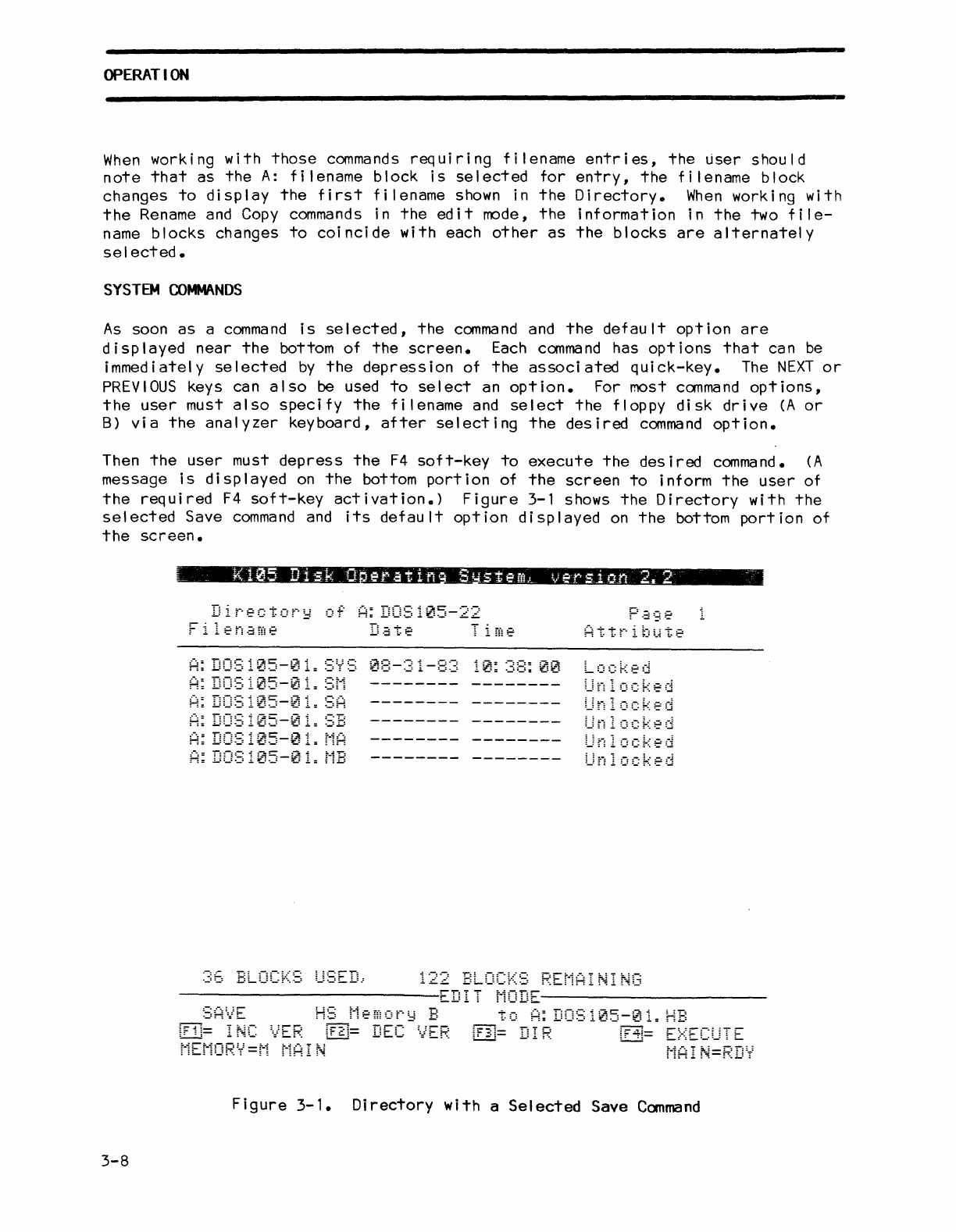
Then
the
user
must
depress
the
F4
soft-key
to
execute
the
desired
command.
(A
message
is
displayed
on
the
bottom
portion
of
the
screen
to
inform
the
user
of
the
required
F4
soft-key
activation.)
Figure
3-1 shows
the
Directory
with
the
selected
Save
command
and
its
default
option
displayed
on
the
bottom
portion
of
the
screen.
3-8
Directory
of
A:
DOS105-22
05-0
~5-0
05-0
05-0
05-16
122
BLOCKS
REMAINING
-------------------------EDIT
MODE----------------------
to
A:
DOS105-01.
HB
:.,:
~,
',
••
E,_-
-_,E
,~._
...
~
.:
••
-_..
E
•••••
:
.c-
.....
:_.r.,.
~-
r:
arr-
:-..
=.
J
_:
C:
r;::-:::'1_::
:-
::
...
L!....::,j-
:-':-:-"
..
:
..
:....:.....
~-
L=i
r:;.
MEMORY=M
MAiN
MAIN=RDY
Figure
3-1.
Directory
with
a
Selected
Save
Command
OPERATION
SYSTBM
CO~NDS
(cont'd)
The
fol lowing
paragraphs
describe
the
functions
of
the
11
system
commands
and
their
associated
options.
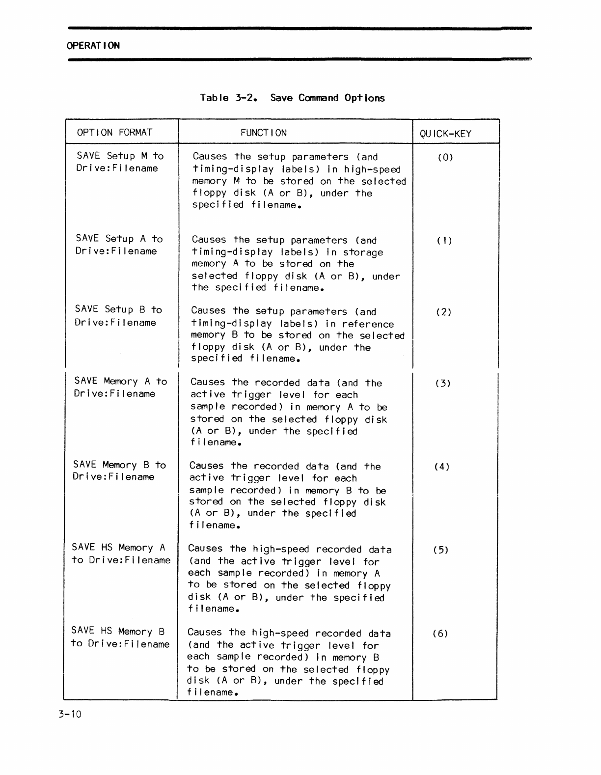
Save
Canmand
The Save
command
al lows
the
user
to
store
logic
analyzer
information
(setup
parameters,
recorded
data,
etc.)
on
floppy
disk
A
or
B.
The
Save
command
has
the
eleven
options
described
in
table
3-2.
Each
command
option,
in
turn,
can
be
selected
in
the
Save
command
mode
by
pressing
the
quick-key
indicated
in
the
quick-key
column,
or
alternatively
using
the
NEXT
or
PREVIOUS
keys.
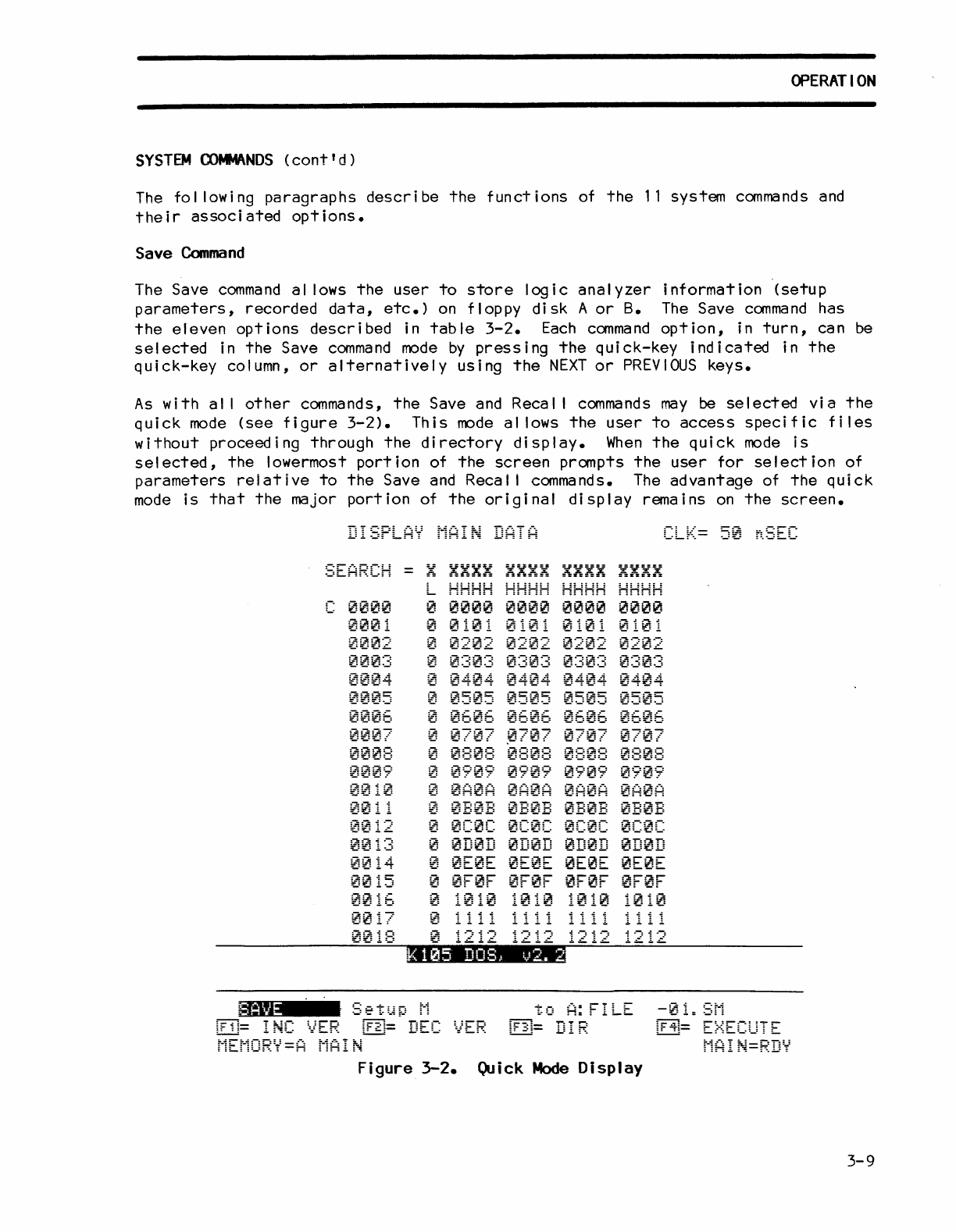
As
with
al I
other
commands,
the
Save and Recal I
commands
may
be
selected
via
the
quick
mode
(see
figure
3-2).
This
mode
al lows
the
user
to
access
specific
files
without
proceeding
through
the
directory
display.
When
the
quick
mode
is
selected,
the
lowermost
portion
of
the
screen
prompts
the
user
for
selection
of
parameters
relative
to
the
Save
and
Recal I commands.
The
advantage
of
the
quick
mode
is
that
the
major
portion
of
the
original
display
remains
on
the
screen.
DISPLAY
MAI~
DATA
0002
00~:3
:-:::-:::~.oi
:f.,=:f.:=!.:"=-t
0005
000E:
0010
~~
11
0014
0~15
0~16
0017
~
HHHH
HH::::
HHHH
HHHH
~
0~00
~000
~~~0
0000
o
~~02
~20~
0202
~202
o
0~0~
0~03
000~
0:3~3
o
04~~
0~~:4
0404
~404
~
0505
0505
050~
0505
~
06~w
0606
~606
0606
o
~
~7
~~0~
e 0
0707
~
0808
0808
0~0w
0808
~
0909
0909
0709
0909
~
0A0A 0A0A
0A~A
~A0A
~
0b0B
~:0B
0~0B
~B~B
o
0~0C
0C0:
0C0C 0C0C
~
0D0~
0D~D
~D~D
0D0D
o
~E0E
0E0E
0E~E
0E0E
o
0F0F
~~0F
0F0F
0F0F
0018
~
1212 1212
1212
1212
~=
Figure
3-2.
Quick
Mode
Display
3-9
OPERATION
OPTION
FORMAT
SAVE
Setup M
to
Dri ve:
Fi
lename
SAVE
Setup A
to
Drive:Filename
SAVE
Setup B
to
Dr
i ve : F i len
ame
SAVE
Memory
A
to
Orive:Filename
SAVE
Memory
B
to
Dr
i
ve:
F i I ename
SAVE
HS
Memory
A
to
Orive:Filename
SAVE
HS
Memory
B
to
Orive:Filename
3-10
Table
3-2.
Save
Command
Options
FUNCTION
Causes
the
setup
parameters
(and
timing-display
labels)
in
high-speed
memory
M
to
be
stored
on
the
se
I
ected
floppy
disk
(A
or
B), under
the
spec
i
fi
ed
f i I e name.
Causes
the
setup
parameters
(and
timing-display
labels)
in
storage
memory
A
to
be
stored
on
the
selected
floppy
disk
(A
or
B),
under
the
specified
filename.
Causes
the
setup
parameters
(and
timing-display
labels)
in
reference
memory
B
to
be
stored
on
the
se
I
ected
floppy
disk
(A
or
B),
under
the
speci
f i
ed
f i I ename.
Causes
the
recorded
data
(and
the
active
trigger
level
for
each
samp
I e
recorded)
i n
memory
A
to
be
stored
on
the
selected
floppy
disk
(A
or
B),
under
the
specified
f i I enarne.
Causes
the
recorded
data
(and
the
active
trigger
level
for
each
I
samp
I e
recorded)
i n
memory
B
to
be
stored
on
the
selected
floppy
disk
(A
or
B),
under
the
specified
f i I ename.
Causes
the
high-speed
recorded
data
(and
the
active
trigger
level
for
each sample
recorded)
in
memory
A
to
be
stored
on
the
selected
floppy
disk
(A
or
B),
under
the
specified
f i I ename.
Causes
the
high-speed
recorded
data
(and
the
active
trigger
level
for
each sample
recorded)
in
memory
B
to
be
stored
on
the
se
I
ected
flop
py
disk
(A
or
B),
under
the
specified
f i I ename.
.8
QU
ICK-KEY
I
(0)
I
I
I
(1)
(2)
(3)
(4)
(
5)
(6
)
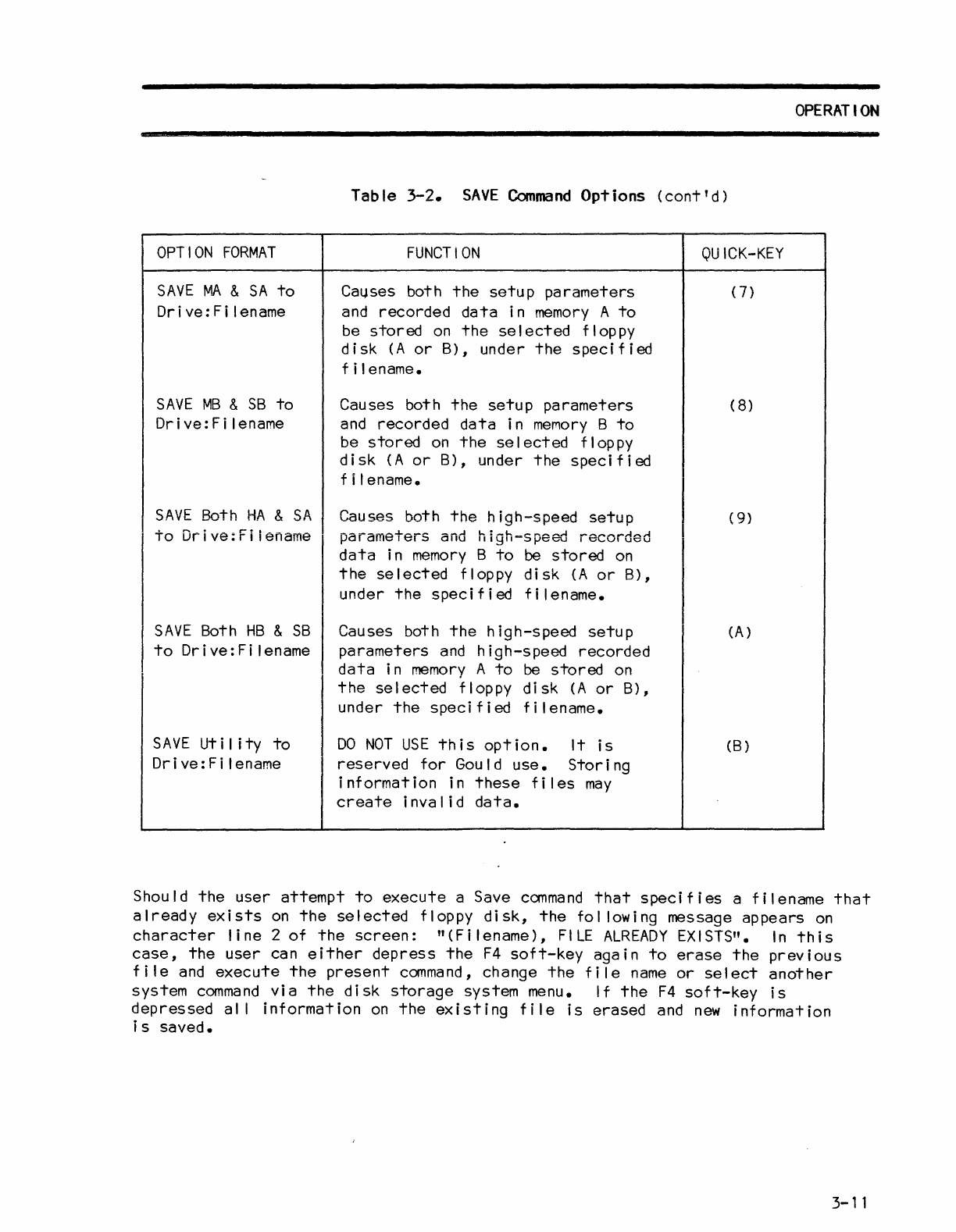
Table
3-2.
SAVE
Command
Options
(cont'd)
OPTION
FORMAT
SAVE
MA
&
SA
to
Drive:Filename
SAVE
MB
&
SB
to
Drive:Filename
FUNCTION
Ca~ses
both
the
setup
parameters
and
recorded
data
in
memory
A
to
be
stored
on
the
selected
floppy
disk
(A
or
B),
under
the
specified
f i I ename.
Causes both
the
setup
parameters
and
recorded
data
in
memory
B
to
be
stored
on
the
se
I
ected
flop
py
disk
(A
or
B),
under
the
specified
f i I ename.
SAVE
Both
HA
&
SA
Causes both
the
high-speed
setup
to
Drive:Filename
parameters
and
high-sPeed
recorded
data
in
memory
B
to
be
stored
on
the
selected
floppy
disk
(A
or
B),
under
the
specified
filename.
SAVE
Both
HB
&
SB
to
Drive:Filename
SAVE
Ut
iii
ty
to
Drive:Filename
Causes both
the
high-speed
setup
parameters
and
hi
gh-s
peed
recorded
data
in
memory
A
to
be
stored
on
the
selected
floppy
disk
(A
or
B),
under
the
specified
filename.
DO
NOT
USE
this
option.
It
is
reserved
for
Gould
use.
Storing
information
in
these
files
may
create
invalid
data.
QUICK-KEY
(7)
(
8)
(
9)
(A)
(B)
OPERATION
Should
the
user
attempt
to
execute
a Save
command
that
specifies
a
filename
that
already
exists
on
the
selected
floppy
disk,
the
fol lowing message
appears
on
character
line
2
of
the
screen:
"
(F
i I ename),
FILE
ALREADY
EX
I STS".
In
th
i s
case,
the
user
can
either
depress
the
F4
soft-key
again
to
erase
the
previous
file
and
execute
the
present
command,
change
the
file
name
or
select
another
system
command
via
the
disk
storage
system menu.
If
the
F4
soft-key
is
depressed
al I
information
on
the
existing
file
is
erased
and
new
information
is
saved.
3-11

OPERATION
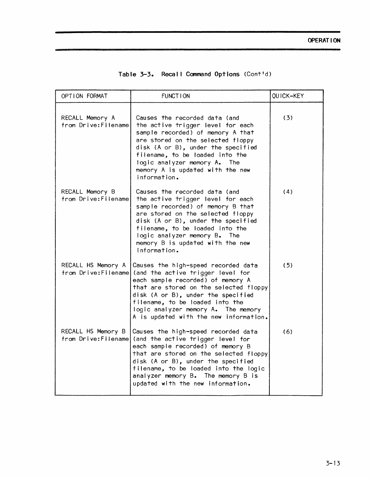
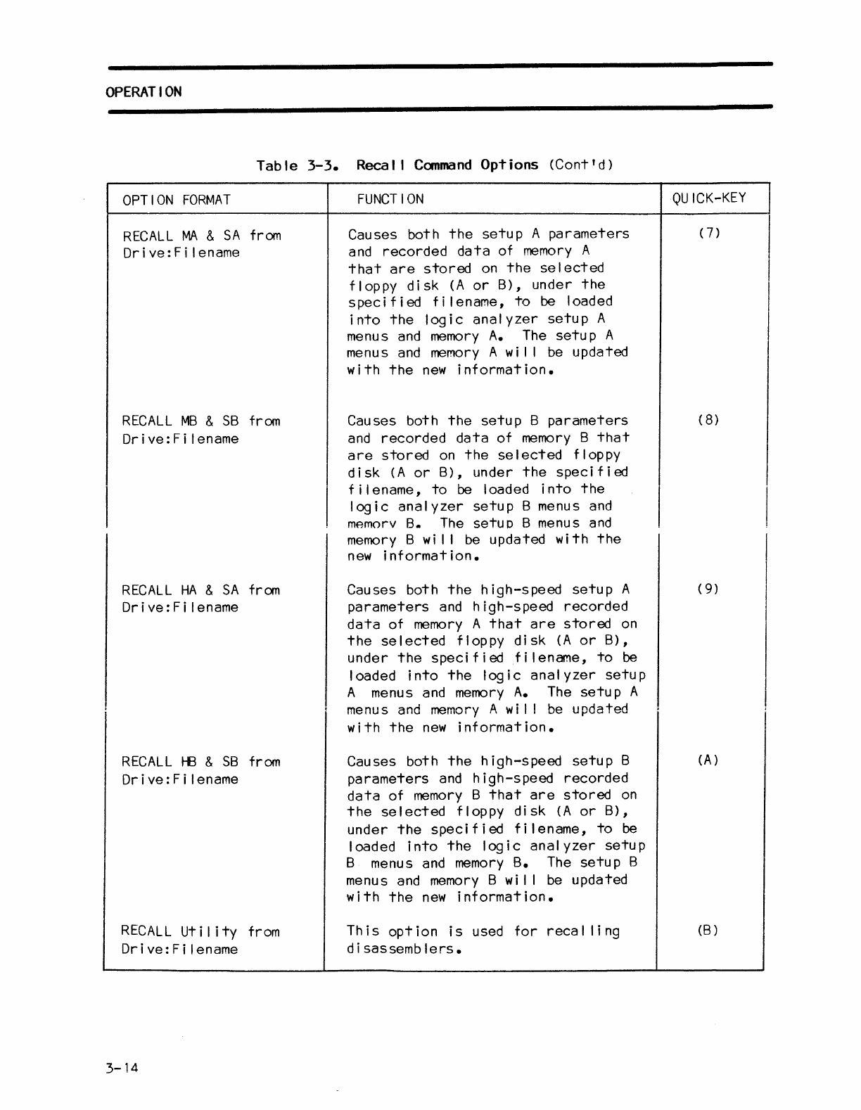
Reca I I
Command
The Recal I
command
al lows
the
user
to
load
information
files
(setup
parameters,
setup
menus,
recorded
data,
etc.)
from
floppy
disk
A
or
B
into
the
logic
analyzer
memory
A
or
memory
B.
The
Recal I
command
has
the
eleven
options
described
in
table
3-3.
Each
option
can in
turn,
be
immediately
selected
in
the
Recal I
command
mode
by
pressing
the
quick
key
indicated.
OPTION
FORMAT
RECALL
Setup M from
Drive:Fi
lename
Table
3-3.
Recal I
Command
Options
FUNCTION
Causes
the
setup
parameters
(and
timing-display
labels)
of
high-speed
memory
M
that
are
stored
on
the
selected
floppy
disk
(A
or
B),
under
the
speci
f i
ed
f i I ename,
to
be
loaded
into
the
logic
analyzer
Setup
M menus.
The
setup
M menus
QU
ICK-KEY
(0)
I
are
updated
with
the
new
information·1
RJ="r'AI
I <:;0+',1'" A f,..I'"'\ryI.
r.~"c:,:::.c:
+h,:::.
c:,:::.+"n
n~,..~,.",:::.+o,..c
(;::uvl (
1,
Drive:Filename
timing-display
labels)
of
storage
memory
A
that
are
stored
on
the
selected
floppy
disk
(A
or
B),
under
the
specified
filename,
to
be
loaded
into
the
logic
analyzer
setup
A menus. The
setup
A menus
are
updated
with
the
new
information.
RECALL
Setup B from Causes
the
setup
parameters
(and (2)
Drive:Filename
timing-display
labels)
of
reference
memory
B
that
are
stored
on
the
selected
floppy
disk
(A
or
B),
under
the
spec i f i
ed
f i I ename,
to
be
loaded
into
the
logic
analyzer
setup
B
menus.
The
setup
B menus
are
updated
with
the
new
information.
3-12
Table
3-3.
Recal I
Command
Options
(Cont'd)
OPTION
FORMAT
RECALL
Memory
A
from
Drive:Filename
RECALL
Memory
B
from
Drive:Filename
RECALL
HS
Memory
A
from
Drive:Filename
RECALL
HS
Memory
B
from
Drive:Filename
FUNCTION
Causes
the
recorded
data
(and
the
active
trigger
level
for
each
sample
recorded)
of
memory
A
that
are
stored
on
the
selected
floppy
disk
(A
or
B),
under
the
specified
filename,
to
be loaded
into
the
logic
analyzer
memory
A.
The
memory
A
is
updated
with
the
new
information.
Causes
the
recorded
data
(and
the
active
trigger
level
for
each
sample
recorded)
of
memory
8
that
are
stored
on
the
selected
floppy
disk
(A
or
B),
under
the
specified
filename,
to
be
loaded
into
the
logic
analyzer
memory
B.
The
memory
B
is
updated
with
the
new
information.
Causes
the
high-speed
recorded
data
(and
the
active
trigger
level
for
each sample
recorded)
of
memory
A
that
are
stored
on
the
selected
floppy
disk
(A
or
B),
under
the
specified
filename,
to
be
loaded
into
the
logic
analyzer
memory
A.
The
memory
A
is
updated
with
the
new
information.
Causes
the
high-speed
recorded
data
(and
the
active
trigger
level
for
each sample
recorded)
of
memory
B
that
are
stored
on
the
selected
floppy
disk
(A
or
B),
under
the
specified
filename,
to
be loaded
into
the
logic
analyzer
memory
B.
The
memory
B
is
updated
with
the
new
information.
OPERATION
QUICK-KEY
(3)
(4)
(5)
(6)
3-13
OPERATION
Table
3-3.
Recal I
Command
Options
(Cont'd)
OPTION
FORMAT
RECALL
MA
&
SA
from
Dr
i ve: F i I ename
RECALL
MB
&
SB
from
Drive:Fi
lename
RECALL
HA
&
SA
from
Drive:Fi
lename
RECALL
HB
&
SB
from
Drive:Fi
lename
RECALL
Utility
from
Drive:Fi
lename
3-14
FUNCTION
Causes both
the
setup
A
parameters
and
recorded
data
of
memory
A
that
are
stored
on
the
se
I
ected
floppy
disk
(A
or
B),
under
the
specified
filename,
to
be loaded
into
the
logic
analyzer
setup
A
menus
and
memory
A.
The
setup
A
menus
and
memory
A
wi
I I
be
updated
with
the
new
information.
Causes both
the
setup
B
parameters
and
recorded
data
of
memory
B
that
are
stored
on
the
selected
floppy
disk
(A
or
B),
under
the
specified
filename,
to
be loaded
into
the
logic
analyzer
setup
B menus
and
mAmorv
8.
The
setuD B menus
and
memory
B
wi
I I
be
updated
with
the
new
information.
Causes both
the
high-speed
setup
A
parameters
and
high-speed
recorded
data
of
memory
A
that
are
stored
on
the
selected
floppy
disk
(A
or
B),
under
the
speci f i
edf
i I ename,
to
be
loaded
into
the
logic
analyzer
setup
A menus
and
memory
A.
The
setup
A
menus
and
memory
A
wi
I I
be
updated
with
the
new
information.
Causes both
the
high-speed
setup
B
parameters
and
high-speed
recorded
data
of
memory
B
that
are
stored
on
the
selected
floppy
disk
(A
or
B),
under
the
spec
if
i
ed
f i I ename,
to
be
loaded
into
the
logic
analyzer
setup
B menus
and
memory
B.
The
setup
B
menus
and
memory
B wil I
be
updated
with
the
new
information.
This
option
is
used
for
recal
ling
d i sassemb
lers.
QUICK-KEY
(7)
(8
)
(9)
(A)
(B)
OPERATION
Should
the
user
attempt
to
execute
a Recal I
command
that
specifies
a
filename
that
does not
exist
on
the
selected
floppy
disk,
the
fol
lowing message
appears
on
the
screen:
"
(Dr
i
ve:
F i I ename),
NO
FILE
FOUND".
In
th
is
case,
the
user
should
then
select
the
Directory
command
via
the
disk
storage
system
menu
to
ascertain
which
files
are
available
on
the
floppy
disks.
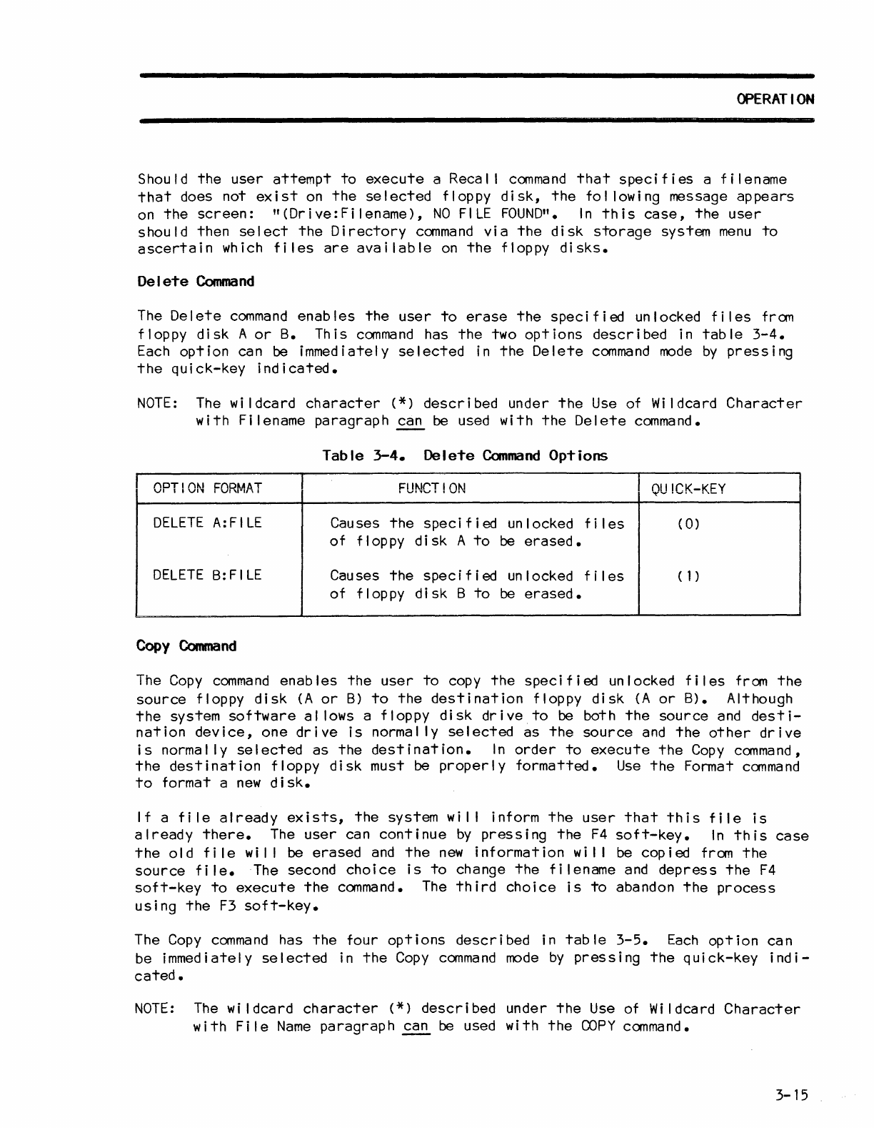
Delete
Command
The
Delete
command
enables
the
user
to
erase
the
specified
unlocked
files
from
floppy
disk
A
or
B.
This
command
has
the
two
options
described
in
table
3-4.
Each
option
can be immediately
selected
in
the
Delete
command
mode
by
pressing
the
quick-key
indicated.
NOTE:
The
wi
Idcard
character
(*)
described
under
the
Use
of Wildcard
Character
with
Filename
paragraph
~
be used
with
the
Delete
command.
Table
3-4.
Delete
Command
Options
OPTION
FORMAT
FUNCT!ON
QU
ICK-KEY
DELETE
A:FILE
Causes
the
specified
unlocked
fi
les
(
0)
of
floppy
disk
A
to
be
erased.
DELETE
B:FILE Causes
the
specified
un
locked f i I
es
(1)
of
floppy
di
sk B
to
be
erased.
Copy
Command
The
Copy
command
enables
the
user
to
copy
the
specified
unlocked
files
from
the
source
floppy
disk
(A
or
B)
to
the
destination
floppy
disk
(A
or
B). Although
the
system
software
al
lows a
floppy
disk
drive
to
be both
the
source
and
desti-
nation
device,
one
drive
is
normally
selected
as
the
source
and
the
other
drive
is
normally
selected
as
the
destination.
In
order
to
execute
the
Copy
command,
the
destination
floppy
disk
must be
properly
formatted.
Use
the
Format
command
to
format a
new
disk.
If
a
file
already
exists,
the
system
wi
I I inform
the
user
that
this
file
is
already
there.
The
user
can
continue
by
pressing
the
F4
soft-key.
In
this
case
the
old
fi
Ie
wi
I I
be
erased
and
the
new
information
wi
I I
be
copied
from
the
source
file.
The second
choice
is
to
change
the
filename
and
depress
the
F4
soft-key
to
execute
the
command.
The
third
choice
is
to
abandon
the
process
using
the
F3
soft-key.
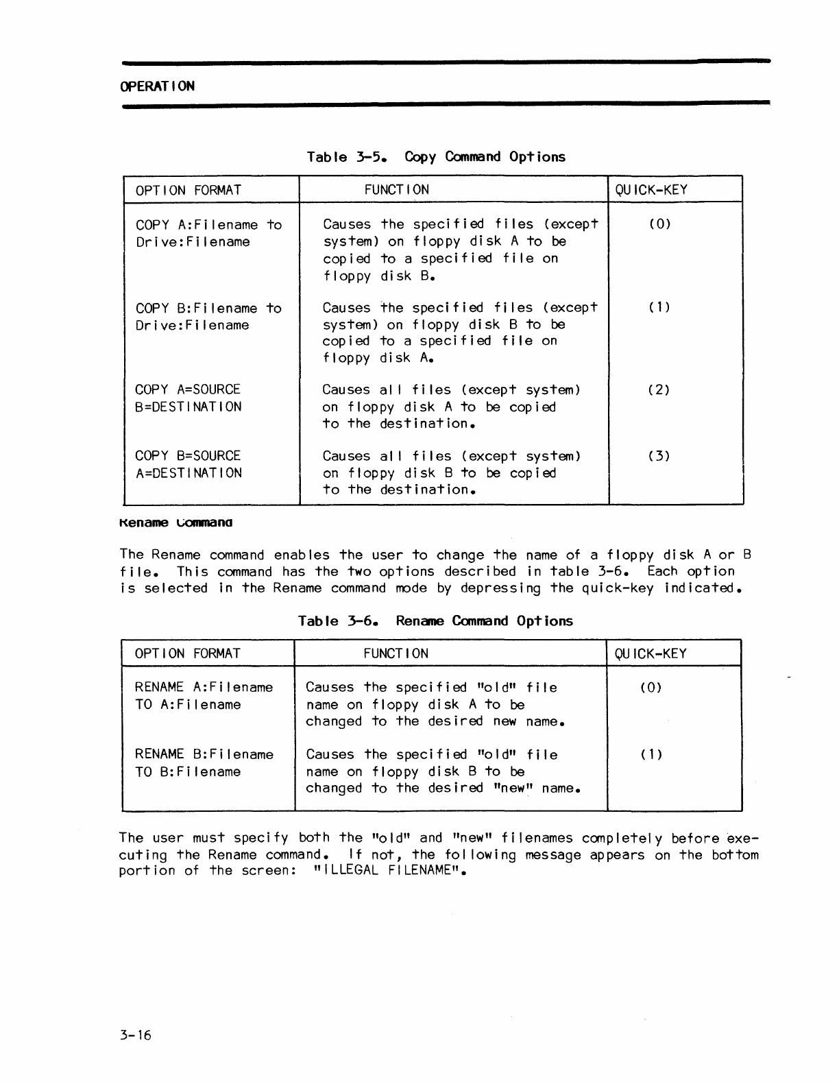
The
Copy
command
has
the
four
options
described
in
table
3-5.
Each
option
can
be immediately
selected
in
the
Copy
command
mode
by
pressing
the
quick-key
indi-
cated.
NOTE:
The
wi
Idcard
character
(*)
described
under
the
Use
of Wildcard
Character
with
File
Name
paragraph
~
be used
with
the
COPY
command.
3-15
OPERATION
Table
3-5.
Copy
Command
Options
OPTION
FORMAT
FUNCTION
QUICK-KEY
COpy
A:
F i I ename
to
Causes
the
specified
fi
les
(except
(
0)
Dr
i
ve:
F i I ename system)
on
floppy
disk
A
to
be
copied
to
a
specified
file
on
flop
py
disk
B.
COpy
B:
F i I ename
to
Causes
the
specified
fi
les
(except
(1)
Dr
i
ve:
F i I ename system)
on
floppy
disk
B
to
be
cop i
ed
to
a
spec
i f i
ed
fi
Ie
on
flop
py
disk
A.
COpy
A=SOURCE
Causes al I
fi
les
(except
system)
(2)
B=DESTINATION
on
floppy
disk
A
to
be
cop
ied
to
the
destination.
COPY
B=SOURCE
Causes al I
fi
les
(except
system)
(3)
A=DESTINATION
on
floppy
di
sk B
to
be
cop
i ed
to
the
destination.
Kename
\.,;()IIID(Ino
The
Rename
command
enables
the
user
to
change
the
name
of a floppy
disk
A
or
B
file.
This
command
has
the
two
options
described
in
table
3-6.
Each
option
is
selected
in
the
Rename
command
mode
by
depressing
the
quick-key
indicated.
Table
3-6.
Rename
Command
Options
OPTION
FORMAT
FUNCTION
QUICK-KEY
RENAME
A:Filename Causes
the
speci f i
ed
"0
I
d"
f i I e
CO)
TO
A:
F i len
arne
name
on
floppy
disk
A
to
be
changed
to
the
desired
new
name.
RENAME
B:Filename Causes
the
specified
"0
I
d"
fi
Ie ( 1 )
TO
B:Filename
name
on
floppy
disk
B
to
be
changed
to
the
desired
"new" name.
The
user
must speci fy both
the
"a
I
d"
and
"new" f i I enames canp I
etel
y
before
exe-
cuting
the
Rename
command.
If
not,
the
fol lowing message
appears
on
the
bottom
port
i on of
the
screen:
"
ILLEGAL
FILENAME".
3-16
OPERATION
Should
the
user
attempt
to
execute
a
Rename
command
that
specifies
a
filename
that
already
exists
on
the
selected
floppy
disk,
the
fol lowing message
appears
on
the
screen:
n(Drive:Filename),
FILE
ALREADY
EXISTS".
In
this
case,
the
user
can
either
depress
the
F4
soft-key
again
to
erase
the
previous
file
and
execute
the
present
command,
select
another
filename,
or
select
another
system
command
via
the
storage
operating
system
menu.
NOTE:
A
file
cannot
be
renamed
from
drive
A
to
drive
B
or
vice-versa.
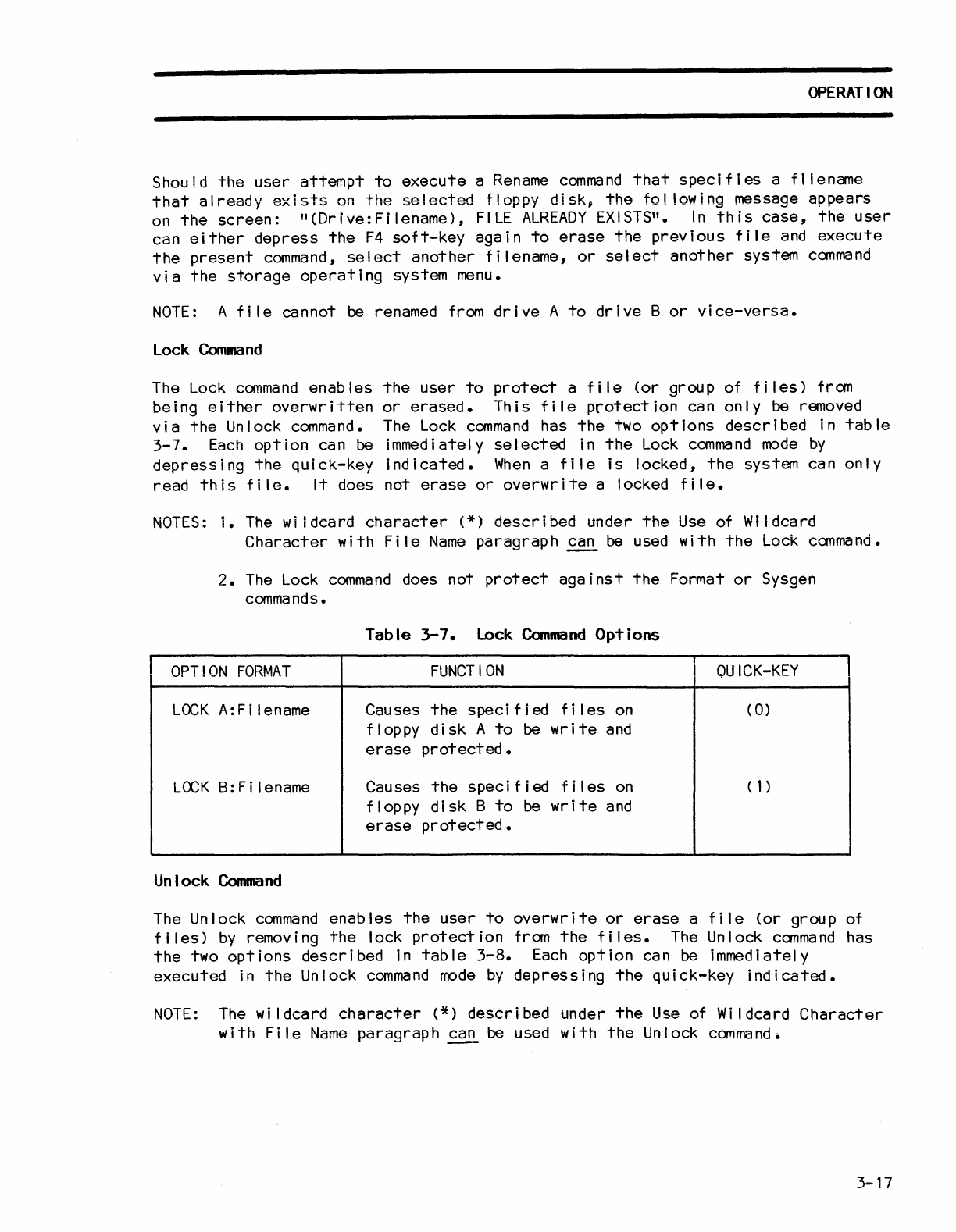
Lock
Command
The
Lock
command
enables
the
user
to
protect
a
file
(or
group of
files)
from
being
either
overwritten
or
erased.
This
file
protection
can
only
be
removed
via
the
Unlock
command.
The
Lock
command
has
the
two
options
described
in
table
3-7.
Each
option
can
be
immediately
selected
in
the
Lock
command
mode
by
depressing
the
quick-key
indicated.
When
a
file
is
locked,
the
system can
only
read
this
file.
It
does not
erase
or
overwrite
a locked
file.
NOTES:
1.
The
wi
tdcard
character
(*)
described
under
the
Use
of Wildcard
Character
with
File
Name
paragraph
~
be
used
with
the
Lock
command.
2.
The
Lock
command
does not
protect
against
the
Format
or
Sysgen
commands.
Table
3-7.
Lock
Command
Options
OPTION
FORMAT
FUNCTION
OU
ICK-KEY
LOCK
A:
F i I ename Causes
the
speci f i
ed
f i I
es
on
(
0)
floppy
disk
A
to
be
write
and
erase
protected.
LOCK
B:
F i I
ename
Causes
the
specified
f i I
es
on
(1)
floppy
disk
B
to
be
write
and
erase
protected.
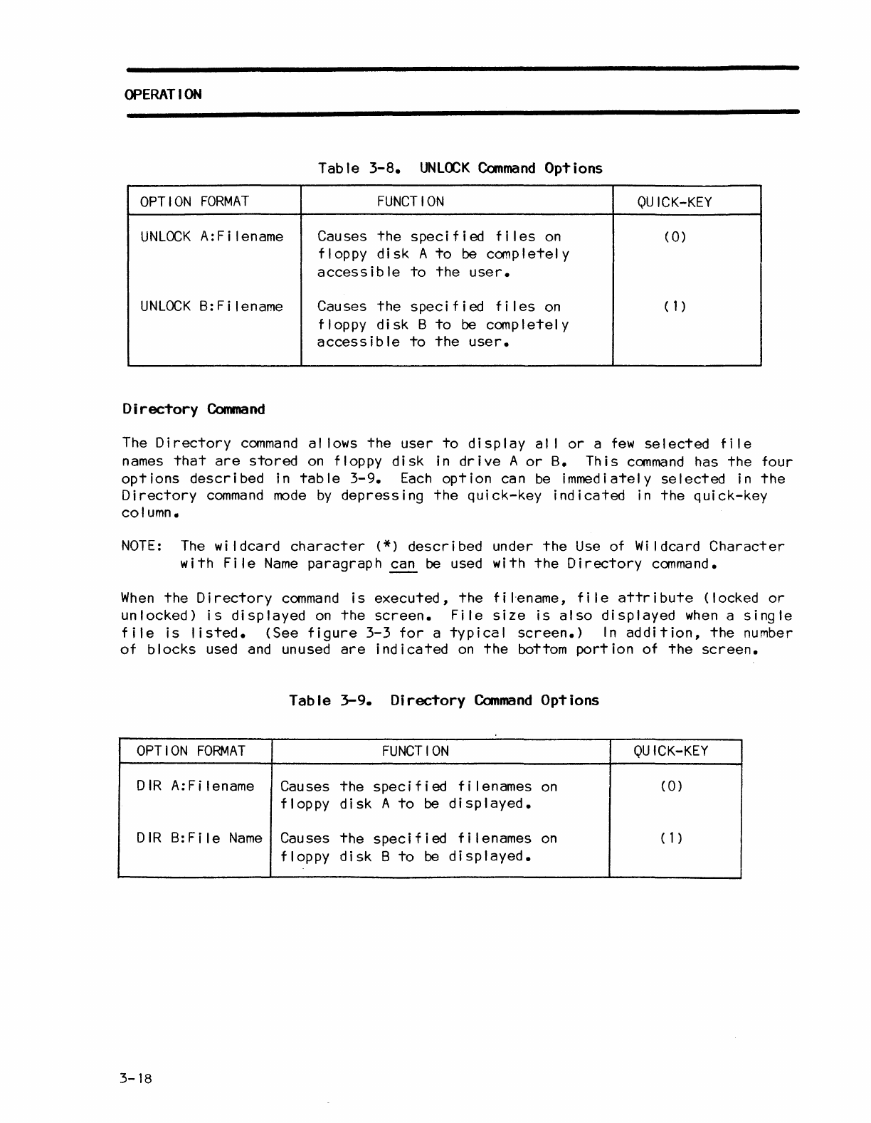
Unlock
Command
The Unlock
command
enables
the
user
to
overwrite
or
erase
a
file
(or
group of
files)
by
removing
the
lock
protection
from
the
files.
The
Unlock
command
has
the
two
options
described
in
table
3-8.
Each
option
can
be
immediately
executed
in
the
Unlock
command
mode
by
depressing
the
quick-key
indicated.
NOTE:
The
wildcard
character
(*)
described
under
the
Use
of Wildcard
Character
with
File
Name
paragraph
~
be
used
with
the
Unlock
command.
3-17
OPERATION
Table
3-8.
UNLOCK
Command
Options
OPTION
FORMAT
FUNCTION
OU
ICK-KEY
UNLOCK
A:
Fi
lename Causes
the
speci
f i
ed
f i I
es
on
(0)
floppy
disk
A
to
be
completely
access
i b
Ie
to
the
user.
UNLOCK
B:Filename Causes
the
specified
fi
les
on
(1)
floppy
disk
B
to
be
completely
accessible
to
the
user.
Directory
Command
The
Directory
command
al lows
the
user
to
display
al I
or
a
few
selected
file
names
that
are
stored
on
floppy
disk
in
drive
A
or
B.
This
command
has
the
four
options
described
in
table
3-9.
Each
option
can
be
immediately
selected
in
the
Directory
command
mode
by
depressing
the
quick-key
indicated
in
the
quick-key
column.
NOTE:
The
wi
Idcard
character
(*)
described
under
the
Use
of
Wi
Idcard
Character
with
File
Name
paragraph
~
be used with
the
Directory
command.
When
the
Directory
command
is
executed,
the
f i I'ename, f i Ie
attr
i
bute
(locked
or
unlocked)
is
displayed
on
the
screen.
File
size
is
also
displayed
when
a
single
file
is
listed.
(See
figure
3-3
for
a
typical
screen.)
In
addition,
the
number
of
blocks
used
and
unused
are
indicated
on
the
bottom
portion
of
the
screen.
Table
3-9.
Directory
Command
Options
OPTION
FORMAT
FUNCTION
OU
ICK-KEY
D
IR
A:
F i I ename Causes
the
speci
f i ed f i I enames
on
(0)
floppy
disk
A
to
be
displayed.
D I R
B:
F i I e
Name
Causes
the
speci
f jed f i I enames
on
(1)
floppy
dis
k B
to
be
dis
P I a yed •
3-18
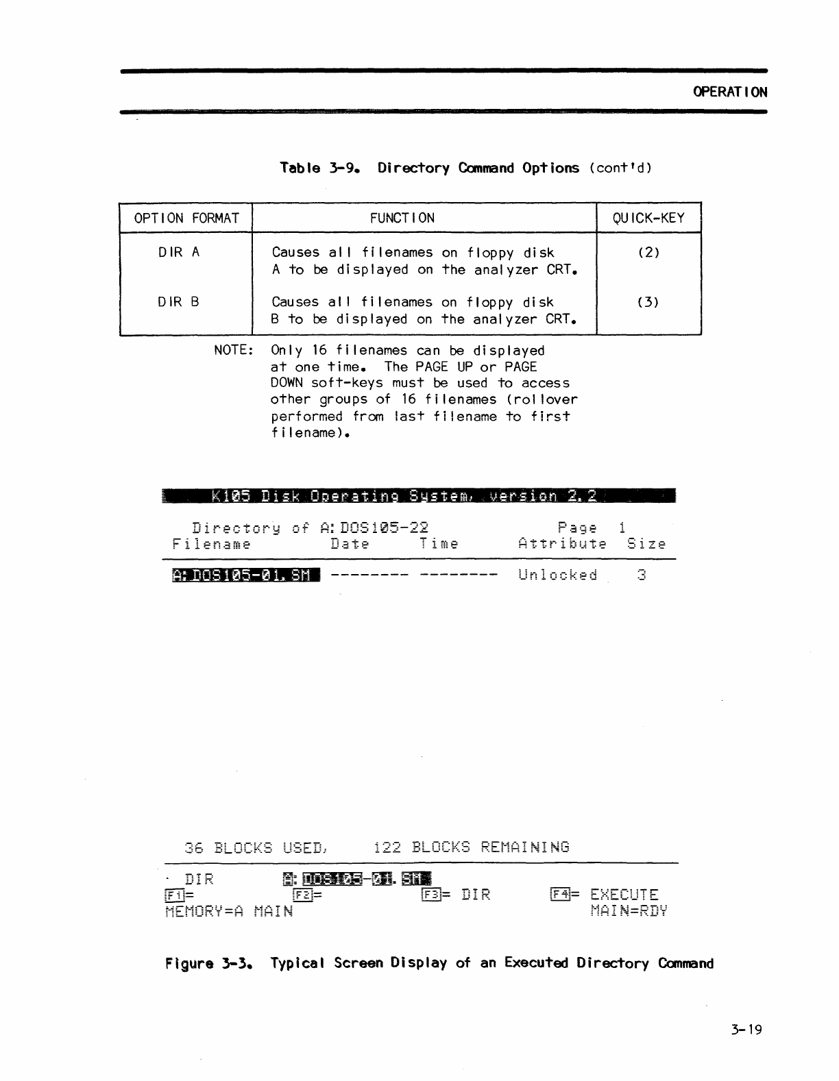
Table
3-9.
Directory
Command
Options
(cont'd)
OPTION
FORMAT
FUNCTION
DIR
A
DIR
B
Causes a I I f i I enames
on
flop
py
disk
A
to
be d i sp I ayed
on
the
analyzer
CRT.
Causes a I I
filenames
on
floppy
disk
B
to
be
displayed
on
the
analyzer
CRT.
NOTE:
Only
16
filenames
can
be
displayed
at
one
time.
The
PAGE
UP
or
PAGE
DOWN
soft-keys
must be used
to
access
other
groups of
16
filenames
(rol
lover
performed
from
last
filename
to
first
f i I ename).
K105
Disk
0
er"at
i n
Sr
steml
ve-rs
ion
2.
2
Directory
of
A:
DOS105-22
; ItOS
105-0
L
8M
-------- --------
Unlocked
122
BLOCKS
REMAINING
~F
i
~=
QU
ICK-KEY
(2)
(3)
OPERATION
Figure 3-3. Typical Screen Display
of
an
Executed Directory
Command
3-19
OPERATION
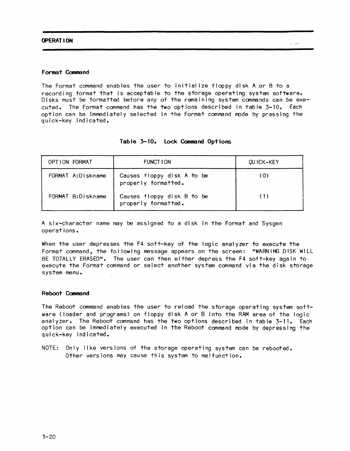
Format
Command
The Format
command
enables
the
user
to
initial
ize
floppy
disk
A
or
B
to
a
recording
format
that
is
acceptable
to
the
storage
operating
system
software.
Disks must be
formatted
before
any
of
the
remaining system
commands
can
be
exe-
cuted.
The
Format
command
has
the
two
options
described
in
table
3-10.
Each
option
can
be
immediately
selected
in
the
Format
command
mode
by
pressing
the
quick-key
indicated.
Table
3-10.
Lock
Canmand
Options
OPTION
FORMAT
FUNCTION
QUICK-KEY
FORMAT
A:Diskname Causes floppy
disk
A
to
be
(
0)
properly
formatted.
FORMAT
B:Diskname Causes floppy
disk
B
to
be
(1)
properly
formatted.
A
six-character
name
may
be
assigned
to
a
disk
in
the
Format
and
Sysgen
operations.
When
the
user
depresses
the
F4
soft-key
of
the
logic
analyzer
to
execute
the
Format
command,
the
following
message
appears
on
the
screen:
"WARNING
DISK
WILL
BE
TOTALLY
ERASED".
The
user
can
then
either
depress
the
F4
soft-key
again
to
execute
the
Format
command
or
select
another
system
command
via
the
disk
storage
system menu.
Reboot
Command
The Reboot
command
enables
the
user
to
reload
the
storage
operating
system
soft-
ware
(loader
and programs)
on
floppy
disk
A
or
B
into
the
RAM
area
of
the
logic
analyzer.
The Reboot
command
has
the
two
options
described
in
table
3-11.
Each
option
can
be
immediately
executed
in
the
Reboot
command
mode
by
depressing
the
quick-key
indicated.
NOTE:
On
I y
like
vers
ions of
the
storage
operati
ng
system can
be
rebooted.
Other
versions
may
cause
this
system
to
malfunction.
3-20
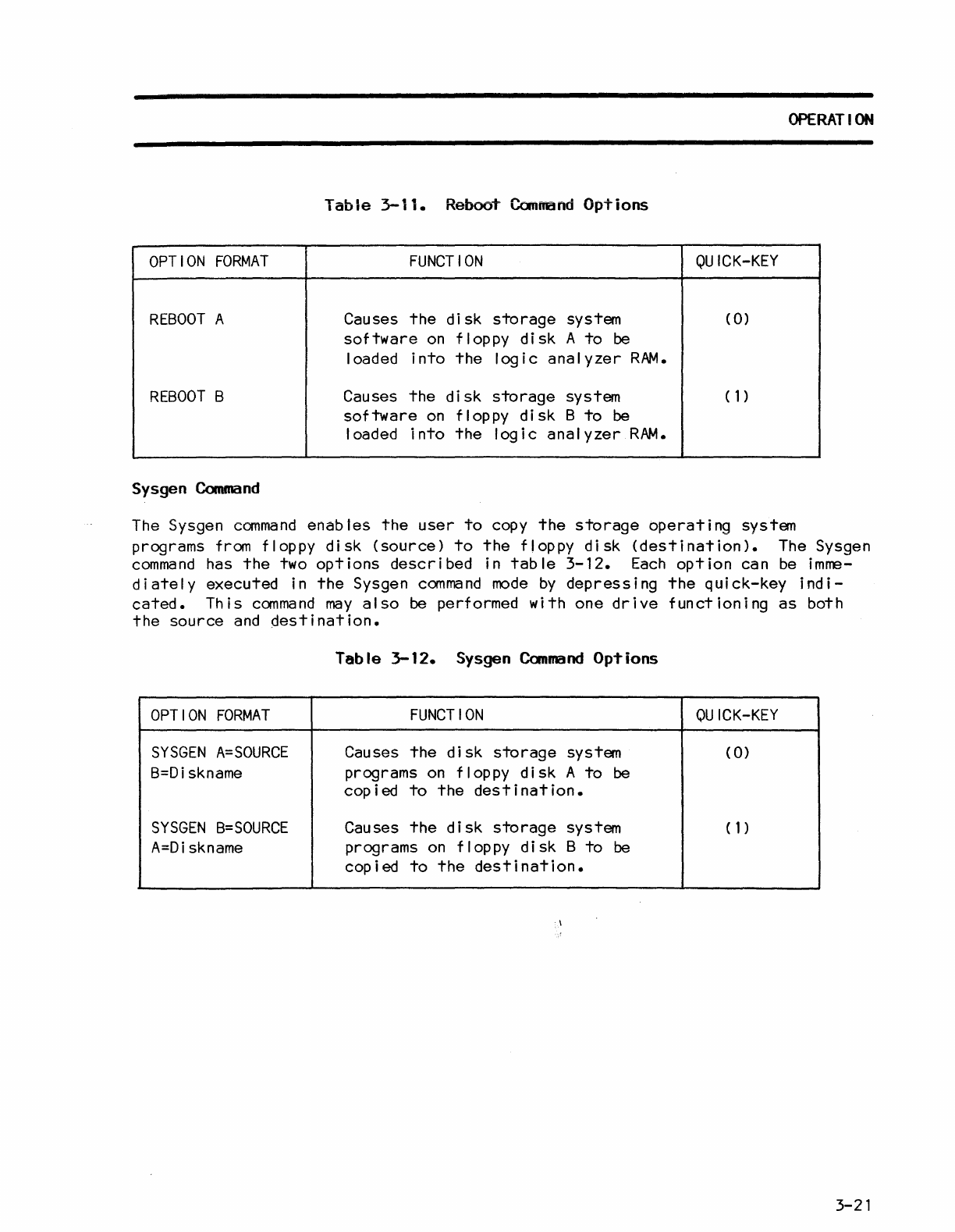
OPERATION
Table
3-11.
Reboo~
Command
Options
OPTION
FORMAT
FUNCTION
QUICK-KEY
REBOOT
A Causes
the
disk
storage
system (
0)
software
on
floppy
disk
A
to
be
loaded
into
the
logic
analyzer
RAM.
REBOOT
B Causes
the
disk
storage
system
(1)
software
on
floppy
disk
B
to
be
loaded
into
the
logic
analyzer
RAM.
Sysgen
Command
The
Sysgen
command
enables
the
user
to
copy
the
storage
operating
system
programs from floppy
disk
(source)
to
the
floppy
disk
(destination).
The Sysgen
command
has
the
two
options
described
in
table
3-12.
Each
option
can
be
imme-
diately
executed in
the
Sysgen
command
mode
by
depressing
the
quick-key
indi-
cated.
This
command
may
also
be performed
with
one
drive
functioning
as
both
the
source
and
Oestination.
Table
3-12.
Sysgen
Canmand
OpTions
OPTION
FORMAT
FUNCTION
OU
ICK-KEY
SYSGEN
A=SOURCE
Causes
the
disk
storage
system (
0)
B=Diskname programs
on
floppy
disk
A
to
be
copied
to
the
destination.
SYSGEN
B=SOURCE
Causes
the
disk
storage
system
(1)
A=Diskname
programs
on
floppy
disk
B
to
be
copied
to
the
destination.
-\
3-21
