019_Analyzer_C 019 Analyzer C
019_Analyzer_C 019_Analyzer_C
User Manual: 019_Analyzer_C
Open the PDF directly: View PDF ![]() .
.
Page Count: 36
J
GENERAL
SYSTEM:
SUBJECT:
SPECIAL
INSTRUCTIONS:
DATE:
November
15,
1965
8530
41165
Printed
in
U.
S.
A.
SERIES
200
ANALYZER
C
Series
200/0perating
SYSTEM-MOD
1
Analyzer
C:
A
Program
for
Producing
a
Printed
Listing
of
the
Cross
References
of
Symbolic
Tags
Appearing
in
an
Easycoder
Program.
This
software
bulletin
completely
supersedes
the
information
bulletin
entitled
Easycoder
Analyzer,
DSI-358,
dated
February
11,
1965
FILE
NO.:
122.2305.001
C.
0-019
FOREWORD
This
bulletin
describes
the
capabilities
of
the
Analyzer
C,
a
program
which
produces
a
printed
listing
that
identifies
cross
references
of
symbolic
tags
appearing
in
an
Easycoder
symbolic
program.
Section
I
of
this
bulletin
provides
a
general
description
of
the
program's
capabilities.
The
various
operations
of
Analyzer
C
are
described
in
Section
II,
while
Section
III
describes
the
format
for
the
various
directors.
The
format
of
the
Analyzer
C
data
listing
is
described
in
Section
IV.
Finally,
Section
V
presents
the
operating
procedures
for
loading
Analyzer
C
from
magnetic
tape
or
punched
cards.
The
reader
is
assumed
to
be
familiar
with
the
operating
procedures
for
the
control
panel
and
the
various
peripheral
devices
as
presented
in
the
Honeywell
Series
200
Equipment
Operators'
Manual
(Model
200)
(DSI-294).
In
addition,
the
reader
should
be
familiar
with
the
Honeywell
Series
200
Programmers'
Reference
Manual
(Models
200/1200/2200),
File
No.
113.
0005.0000.00.00,
and
(where
applicable)
the
bulletin
Models
209/210
Paper
Tape
Equipment
(DSI-322).
Copyright
1965
Honeywell Inc.
Electronic
Data
Processi ng
Division
Wellesley Hills, Massachusetts 02181
ii
rl
Section
I
Section
II
Section
III
,Section
IV
Section
V
Appendix
A
Appendix
B
TABLE
OF
CONTENTS
Page
General
Description
......................................
1-1
Introduction.
. . . . . . . . • . . . . . • • • . . . . . . . . . . . . . . • . . . . • . . .
..
1-
1
Equipment
Requirements.
• . . • . • . . . . . . . . . . . . . . . . . . . . . .
..
1-1
Analyzer
C
Operations.
. . . . . . . . . . • . • • . . . . • . • . . • . . . . . . . . .
•.
2-1
Analyzing
a
Symbolic
Program
Tape
(SPT).
. . . . . • • . .
.•
. .
•.
2-1
Analyzing
a
Card-Image
Tape...
. . . . . . . • . .
•.
. • . . . . . . . .
.•
2-2
Analyzing
Programs
Contained
on
Cards.
. . . . .
.•
. . •
..
. .
..
2-
3
The
Input
File
....•..•.•.••••••..••••.•..•.••.•••••.•••...
Equipment
Configuration
Descriptor
...........••....•...
Methods
of
Specifying
the
Configuration
.•..•......•..••
Standard
ECD
Number
Residing
in
Tape
or
Card
Loader-Monitor
...•.••••..•..•.•.•..••.•.••
Standard
ECD
Number
Obtained
from
ECD
Image
...•
Full
Equipment
Configuration
Descriptor
as
ECD
Image
.•..•..••.•....•..•.•..•...••.••••...
The
Director
Deck
.•..•.•..••••.••••.•.••••.••....••...
System
Header
Card
..•.......•.•..•.........•...•
Director
Cards
.....••••••..•••.•.•.••..•.••••.•.••....
System
End
Card
......•...••••••••..•••.•••.•••.•.•..•
3-1
3-1
3-1
3-2
3-3
3-4
3-7
3-7
3-8
3-8
Analyzer
C
Listing.
. . . . • . • • • • • • • . • . . . . . . • . . . . . • . • • . • • . •
••
4-1
Header
Lines.
•
.•
••
• . . • . • . • • . • • • .
••
. •
••
. .
.•
.
•.
• . .
.•
. .
•.
4-1
First
Header
Line.
• . . •
••
. . • . • . . . . • . • • .
..
. . . . . .
••
. •
.•
4-1
Second
Header
Line.
• • • . • . • • • • • • • • • • • • • • • . • • • . • • . .
•.
4-
1
Data
Lines.
• • • • .
••
.•
••
••
•• ••
. •
••
•. •.
. • . .
•.
• .
.•
. •
•.
• •
.•
4-2
Definition
Line.
• . . • • . • • • • • • • • • • • . • • • • • • • • • . • • . • . • .
..
4-
2
Reference
Line.
. • . •
••
•.
••
. • . . • . • .
.•
. . • . • . • • . • • . • .
••
4-4
Analyzer
C
Operating
Procedures.
. . • • • • . . . . . . • . • . . • •
••
. •
••
5-1
Loading
with
Tape
Loader-Monitor
C
or
Floating
Tape
Loader-Monitor
C......
.. ..
. .
..
.. ..
. . . .
..
..
. . . . . . . .
..
5-1
Console
Call
Card.
. • • . • .
•••
• • •
•••••
••
•
••
• . • • • • • • • •
••
5-2
Loading
with
Card
Loader-Monitor
B . . . . . .
.•
. . . . • .
••
. •
..
5-2
Error
Conditions......................................
5-3
Options
Available
with
Paper
Tape.
• • • • • . • • • • • • • • • • . • • • •
•••
A-I
Parity
Che
ck
• • . • • • • . • . • . • • • • • • • . . • • • . • . . . . . . . . . • • • • •
.•
A-I
Punctuation.
. . . . . . . . . . . . . . . . . . . . . . . . . . . . . . . . . . . . . . . .
..
A-
1
Six-Level
Tape
with
Two
Translation
Tables.
• • • • • . •
••
• •
••
A-I
Seven-Level
Tape
•••.••••••••••••••••.•.••••.••.•.•••••
A-I
Five-Level
Tape
•••••••••••••••.•••..•..•..•...•..•....
A-2
Procedure
for
Changing
Standard
Equipment
Configurations.
.•
B-1
iii
Figure
2-l.
Figure
2-2.
Figure
2-3.
Figure
3-1.
Figure
3-2.
Figure
3-3.
Figure
3-4.
Figure
4-1.
Figure
4-2.
Figure
4-3.
Figure
4-4.
Figure
5-1.
Figure
B-1.
Table
1-1.
Table
3-1.
Table
3-2.
Table
3-3.
Table
3-4.
Table
3-5.
Table
5-1.
LIST
OF
ILLUSTRATIONS
Configuration
for
Analyzing
a
Sym
bolic
Program
Tape
......
.
Configuration
for
Analyzing
a
Card-Image
Tape
........•....
Configuration
for
Analyzing
Programs
Contained
on
Cards
•..
Equipment
Configuration
Descriptor
Card
..•..•.•..••.•.••.
System
Header
Card
..••.•.....•••....•.••.•••••••.•.•...
Director
Card
.•.••••..•.•..••.•....•....•....••••..•.•.•
System
End
Card
.•.....•.••.•.•.••.......•.••.•....••••.
Header
Line
s
.•••••••...••••••••••.••••.••••..•••.••.•..•
Definition
Line
.........................................
.
Reference
Line
.••••..••••••.•••••••••..••••••.•••••••.•.
Sample
Analyze
r C
Listing
.•.••••••••.•.•••••••••••••••••
Console
Call
Card
for
Analyzer
C
.•.•.••...•••••.••..••...
Coding
for
Analyzer
C
Standard
Configurations
5
and
7
...•••
LIST
OF
TABLES
Equipment
Requirements
for
Analyzer
c
..................
.
ECD
Field
with
Standard
ECD
Number
Page
2-1
2-2
2-4
3-5
3-7
3-8
3-8
4-2
4-3
4-4
4-5
5-2
B-1
1-2
3-2
Standard
Configurations
for
Analyzer
C . • . . . . . •
••
. •
•.
• . . •
••
3-3
ECD
Field
to
Obtain
ECD
Number
from
Input
Device.
. . • • .
••
3-4
Standard
ECD
Image.
• . • • • • • • • • • • • • • • • • • . • . . • • • • . • • . • • • • •
3-4
Format
for
Analyzer
C
File
Media
Fields.
. • . • . • • . • . . • . . • • •
3-6
Analyzer
C
Error
Conditions
••.•.•••••••.•••••.••••••.•••
5-4
iv
•
INTRODUCTION
SECTION
I
GENERAL
DESCRIPTION
Analyzer
C
is
a
powerful
prograInIning
aid
which
the
prograInIner
Inay
use
to
siInplify
the
task
of
analyzing
any
Series
200
prograIn
that
is
coded
in
the
Easycoder
sYInbolic
language.
FroIn
the
input
prograIn(s),
Analyzer
C
extracts
sYInbolic
tags,
references
(to
each
tag,
to
in-
dex
registers,
and
to
absolute
addresses),
and
calls
to
library
routines
and
processes
this
in-
forInation
to
produce
the
Analyzer
C
printed
listing.
The
Analyzer
C
listing
is
arranged
in
alphanuIneric
order
so
that
all
inforInation
about
a
particular
tag,
absolute
location,
or
library
routine
appears
grouped
in
one
place
on
the
printed
listing.
Pro
graIns
to
be
analyzed
Inay
be
taken
froIn
an
Easycoder
C
or
D
sYInbolic
prograIn
tape
(SPT),
froIn
a
card-iInage
Inagnetic
tape,
froIn
punched
cards,
or
froIn
paper
tape.
A
InaxiInuIn
of
30
pro
graIns
Inay
be
analyzed
in
anyone
run
of
Analyzer
C.
The
Analyzer
C
processing
is
accoInplished
in
three
phases
by
two
Analyzer
C
prograIn
segInents
and
the
Tape
Sort
C
prograIn
as
follows:
Phase
1 -
The
first
segInent
of
Analyzer
C
(AAJANAOl)
extracts
the
pertinent
inforInation
froIn
the
pro
graIns
being
analyzed
and
prepares
an
interInediate
file
which
contains
the
extracted
inforInation.
Phase
2 -
The
interInediate
file
which
was
built
during
phase
1
is
sorted
into
the
proper
order
for
printing
during
phase
3.
The
processing
of
this
phase
is
accoInplished
by
the
Tape
Sort
C
pro
graIn,
which
is
described
in
detail
in
the
software
bulletin
Tape
Sort
C
and
Collate
C.
File
No.
122.6005.021
C.
00. 01.
Phase
3 -
The
second
segInent
of
Analyzer
C
(AAJANA02),
reads
the
sorted
inforInation
file
and
produces
the
Analyzer
C
listing.
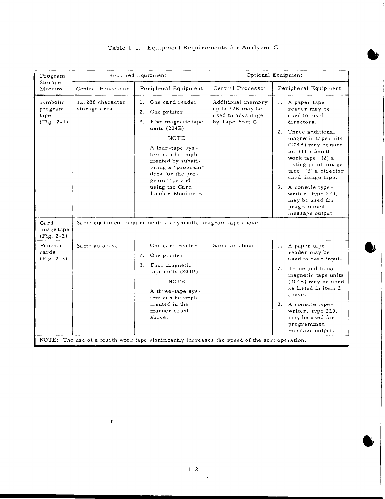
EQUIPMENT
REQUIREMENTS
Because
of
Analyzer
C's
adaptability,
there
is
an
extensive
variety
of
equipInent
COIn-
binations
which
Inay
be
used.
However,
once
the
storage
Inedia
of
the
prograIn(s)
to
be
analyzed
has
been
established
in
one
of
the
three
categories
indicated
in
Table
1-1,
the
nUInber
of
equip-
Inent
cOInbinations
is
reduced
to
those
of
its
applicable
equipInent
configuration
as
shown
in
its
referenced
illustration.
It
should
be
noted
that
although
the
peripheral
equipInent
requireInents
Inay
differ,
the
IneInory
storage
requireInents
reInain
the
saIne.
Additionally,
Analyzer
C
....,
requires
that
the
systeIn
has
the
Advanced
PrograInIning
Instructions
feature
(011)
or
(010).
1-1
Program
Storage
Medium
Symbolic
program
tape
(Fig.
2-1)
Card-
image
tape
(Fig.
2-2)
Punched
cards
(Fig.
2-3)
Table
1
-1.
Equipment
Requirements
for
Analyzer
C
Required
Equipment
Central
Processor
12,288
character
storage
area
Peripheral
Equipment
1.
One
card
reader
2.
One
printer
3.
Five
magnetic
tape
units
(204B)
NOTE
A
four
-tape
sys-
tern
can
be
imp
Ie
-
mented
by
substi-
tuting
a
"program"
deck
for
the
pro-
gram
tape
and
using
the
Card
Loader-Monitor
B
Optional
Equipment
Central
Processor
Additional
memory
up
to
32K
may
be
used
to
advantage
by
Tape
Sort
C
Peripheral
Equipment
1.
A
paper
tape
reader
may
be
used
to
read
directors.
2.
Three
additional
magnetic
tape
units
(204B)
may
be
used
for
(1)
a
fourth
work
tape,
(2)
a
lis
ting
print
-image
tape,
(3)
a
director
card-image
tape.
3.
A
console
type-
writer,
type
220,
may
be
used
for
programmed
message
output.
Same
equipment
requirements
as
symbolic
program
tape
above
Same
as
above
1.
One
card
reader
2.
One
printer
3.
Four
magnetic
tape
units
(204B)
NOTE
A
three-tape
sys-
tem
can
be
imple-
mented
in
the
manner
noted
above.
Same
as
above
1.
A
paper
tape
reader
may
be
used
to
read
input.
2.
Three
additional
magnetic
tape
uni
ts
(204B)
may
be
used
as
listed
in
item
2
above.
3.
A
console
type-
writer,
type
220,
may
be
used
for
programmed
message
output.
NOTE:
The
use
of
a
fourth
work
tape
significantly
increases
the
speed
of
the
sort
operation.
1-2
SECTION
II
ANALY
ZER
C
OPERATIONS
As
previously
stated,
the
programs
to
be
analyzed
may
be
contained
on
anyone
of
the
following:
1.
Easycoder
C
or
D
symbolic
program
tape
(SPT),
2.
Card-image
tape,
3.
Card
deck,
or
4.
Paper
tape.
Depending
upon
the
format
of
the
program
to
be
analyzed,
one
or
more
of
three
possible
configurations
may
be
used.
As
may
be
observed
from
Figures
2-1
through
2-3,
the
use
of
a
particular
configuration
is
dependent
upon
both
the
hardware
system
and
the
software
system
available.
For
example,
the
configuration
shown
in
Figure
2-1
is
applicable
only
when
Easy-
coder
Assembly
C
or
D
program
is
used
(to
produce
the
SPT)
and
the
system
has
a
minimum
of
four
(preferably
five)
magnetic
tape
drives.
The
configuration
shown
in
Figure
2-3,
however,
is
applicable
for
any
of
the
Easycoder
assemblers
and
can
be
implemented
on
a
system
with
a
minimum
of
three
magnetic
tape
drives.
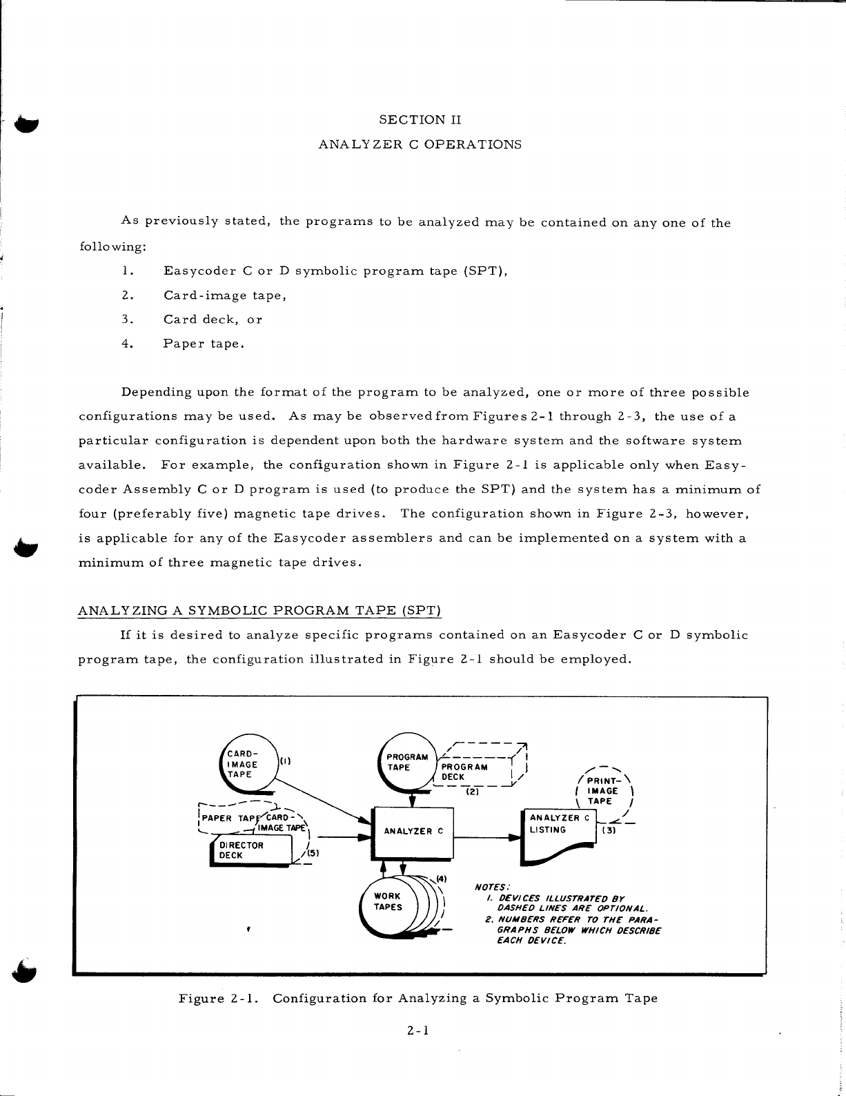
ANALYZING
A
SYMBOLIC
PROGRAM
TAPE
(SPT)
If
it
is
desired
to
analyze
specific
programs
contained
on
an
Easycoder
C
or
D
symbolic
program
tape,
the
configuration
illustrated
in
Figure
2-1
should
be
employed.
/r--
-
--71
;ROGRAM--',
1
/'--..
DECK / !
PRINT-
\
~-~~-(2T----Y
I
IMAGE
\
.r-
__
--->.\_T.....,APE
I
/
ANALYZER
C
NOTES:
I.
DEVICES
ILLUSTRATED
BY
DASHED
LINES
ARE
OPTIONAL.
2.
NUMBERS
REFER
TO
THE
PARA-
GRAPHS
BELOW WHICH DESCRIBE
EACH
DEVICE.
Figure
2
-1.
Configuration
for
Analyzing
a
Symbolic
Program
Tape
2-1
1.
SYITlbolic
prograITl
tape:
In
this
configuration,
the
priITlary
input
is
the
sYITlbolic
prograITl
tape.
Under
the
control
of
the
director
deck,
specified
prograITls
are
located
on
the
SPT
and
placed,
in
their
analyzed
forITl,
on
the
listing.
PrograITls
on
the
SPT
which
are
not
to
be
analyzed
are
siITlply
bypassed.
2.
PrograITl
tape:
This
tape
(a
ITlachine
-language
tape
in
the
standard
BRT
forITlat)
contains
Tape
Loader
-Monitor
C
or
Floating
Tape
Loader
-Monitor
C,
the
two
Analyzer
C
prograITl
segITlents,
and
Tape
Sort
C.
OPTION:
The
above
inforITlation
ITlay
alternatively
be
contained
in
the
prograITl
card
deck.
3.
Analyzer
C
listing:
The
output
of
Analyzer
C
is
the
listing
which
in-
clude
s
all
sYITlbolic
tags
defined
in
the
prograITl,
the
references
to
each
tag,
references
to
absolute
addresses,
and
calls
to
library
routines.
A
cOITlplete
description
of
the
Analyzer
C
listing
ITlay
be
found
in
Section
IV.
OPTION:
The
Analyzer
C
listing
ITlay
be
recorded
on
tape
for
off-line
printing.
4.
Work
tapes:
The
three
work
tapes
ITlust
be
included
in
the
configuration
to
enable
the
three
operational
phases
of
Analyzer
C
(described
on
page
1
-1)
to
be
perforITled.
5.
Director
deck:
The
director
deck
sRecifies
the
prograITls
on
the
SPT
that
are
to
be
analyzed.
The
systeITl
header
card
precedes
and
the
systeITl
end
card
follows
the
directors.
A
director
card
ITlust
be
included
for
each
prograITl
(on
the
SPT)
which
it
is
desired
to
process.
(The
director
cards
ITlust
ap-
pear
in
the
deck
in
the
saITle
order
in
which
the
prograITls
appear
on
the
sYITlbolic
prograITl
tape.)
All
cards
are
described
in
Section
III.
OPTION:
The
contents
of
the
director
deck
ITlay
optionally
appear
on
either
a
card-iITlage
ITlagnetic
tape
or
a
paper
tape.
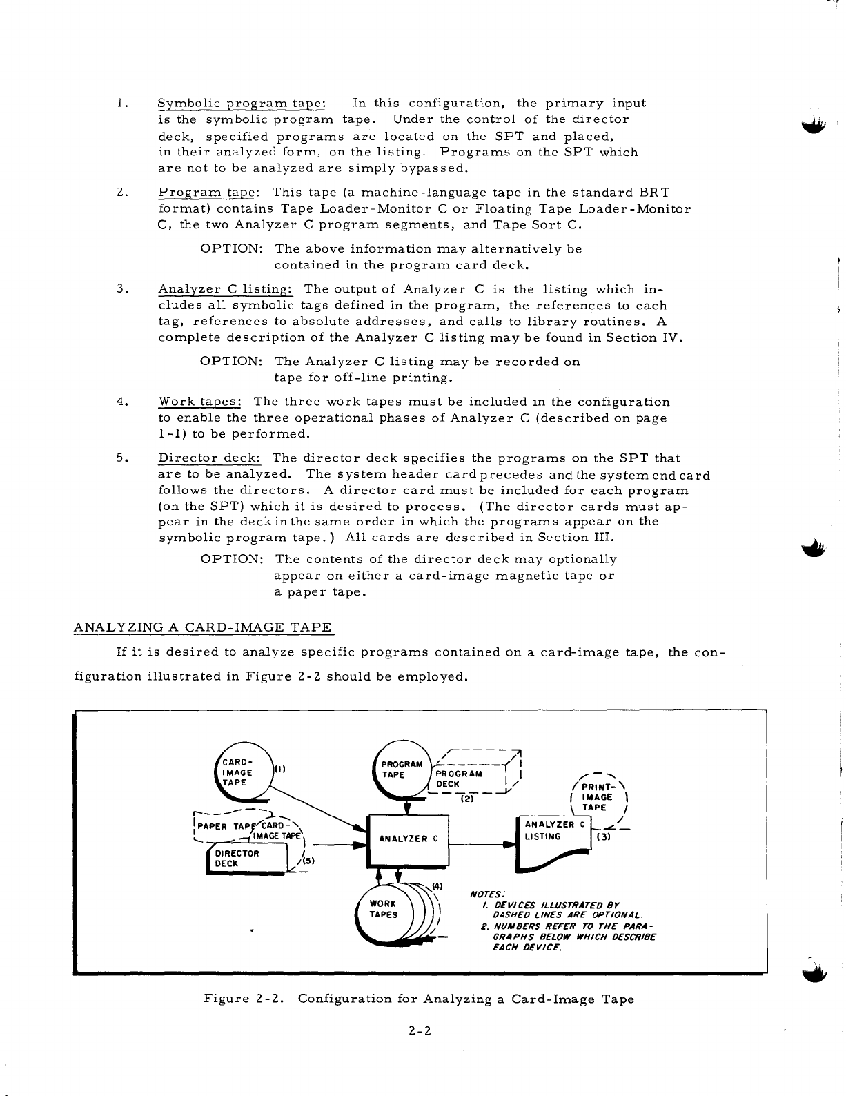
ANALYZING
A
CARD-IMAGE
TAPE
If
it
is
desired
to
analyze
specific
prograITls
contained
on
a
card-iITlage
tape,
the
con-
figuration
illustrated
in
Figure
2-2
should
be
eITlployed.
/-
......
I
PRINT-
\
I
IMAGE
\
~
__
---,-\
_T...,APE
I
ANALYZER
C
-=:.~
(3)
NOTES:
I.
DEVICES
ILLUSTRATED
BY
DASHED
LINES
ARE
OPTIONAL.
2.
NUMBERS
REFER
TO
THE
PARA-
GRAPHS
BELOW WHICH DESCRIBE
EACH
DEVICE.
Figure
2-2.
Configuration
for
Analyzing
a
Card-IITlage
Tape
2-2
Ef
1.
Card-image
tape:
The
primary
input
in
this
configuration
is
the
card-
image
tape.
Under
the
control
of
the
director
deck,
programs
are
lo-
cated
on
the
card-image
tape
and
placed,
in
their
analyzed
form,
on
the
listing.
Programs
on
the
card-image
tape
which
are
not
to
be
analyzed
are
simply
bypassed.
(Refer
to
the
note
under
"Director
Cards"
on
page
3-13).
2.
Program
tape:
This
tape
(a
machine-language
tape
in
the
standard
BR
T
format)
contains
Tape
Loader
-Monitor
C
or
Floating
Tape
Loader-Monitor
C,
the
two
Analyzer
C
program
segments,
and
Tape
Sort
C.
OPTION:
The
above
information
may
be
contained
in
the
program
card
deck.
3.
Analyzer
C
listing:
The
output
of
Analyzer
C
is
the
listing
which
includes
all
symbolic
tags
defined
in
the
program,
the
references
to
each
tag,
references
to
absolute
addresses,
and
calls
to
library
routines.
Acompletede-
scription
of
the
Analyzer
C
listing
may
be
found
in
Section
IV.
OPTION:
The
Analyzer
C
listing
may
be
placed
on
a
print-image
tape
for
off-line
printing.
4.
Work
tapes:
The
three
work
tapes
must
be
included
in
the
configuration
to
enable
the
three
operational
phases
of
Analyzer
C
(described
on
page
1
-1)
to
be
perfo
rmed.
5.
OPTION:
A
fourth
work
tape
may
also
be
specified.
Director
deck:
The
director
deck
specifies
the
programs
on
the
card-
image
tape
that
are
to
be
analyzed.
The
system
header
card
is
the
first
entry
in
the
director
deck.
It
is
followed
by
the
director
cards,
while
the
system
end
card
forms
the
final
entry.
A
director
card
must
appear
for
each
program
to
be
analyzed,
and
these
cards
must
be
positioned
in
the
deck
in
the
same
order
in
which
the
programs
are
stored
on
the
card-
image
tape.
(The
one
exception
to
this
is
explained
below.)
All
cards
are
described
in
Section
III.
OPTION:
(1)
The
contents
of
the
director
deck
may
optionally
appear
on
either
a
card-image
magnetic
tape
or
on
a
paper
tape.
(2)
If
director
cards
are
omitted,
all
programs
on
the
card-image
tape
are
processed.
ANALYZING
PROGRAMS
CONTAINED
ON
CARDS
If
it
is
desired
to
analyze
programs
contained
on
punched
cards,
the
configuration
il-
lustrated
in
Figure
2-3
should
be
employed.
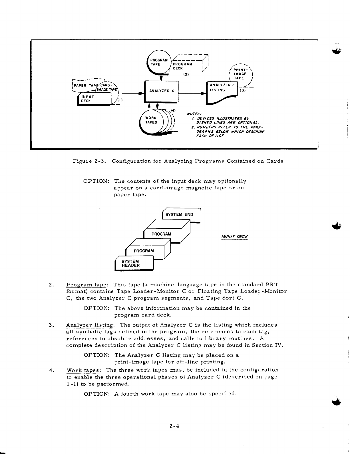
1.
Input
deck:
A
sample
input
deck
is
illustrated
below.
The
input
deck
is
composed
of
the
system
header
card
followed
by
the
programs
to
be
analyzed,
while
the
system
end
card
forms
the
final
entry.
Note
that
director
cards
are
not
employed
with
this
configuration.
Rather,
only
those
programs
to
be
analyzed
are
1
placed
in
the
deck
-
immediately
following
the,
system
header
card.
All
cards
are
described
in
Section
III.
1
Director
cards
must
never
be
employed
when
the
programs
to
be
analyzed
are
read
from
the
same
device
as
the
system
header
card.
2-3
r-------:J-
I PAPER
TAPP""CAR[)::"
I
T.
:-.
'-
.....
=-j
IMAGE
TAPE
\
~INPUT
L I
DECK/:.!
I
ANALYZER C
NOTES:
I.
DEVICES
ILLUSTRATED
BY
DASHED
LINES
ARE
OPTIONAL.
2.
NUMBERS
REFER
TO
THE
PARA-
GRAPHS
BELOW WHICH DESCRIBE.
EACH
DEVICE.
Figure
2-3.
Configuration
for
Analyzing
Programs
Contained
on
Cards
OPTION:
The
contents
of
the
input
deck
may
optionally
appear
on
a
card-image
magnetic
tape
or
on
paper
tape.
INPUT
DECK
2.
Program
tape:
This
tape
(a
machine
-language
tape
in
the
standard
BR
T
format)
contains
Tape
Loader-Monitor
C
or
Floating
Tape
Loader-Monitor
C,
the
two
Analyzer
C
program
segments,
and
Tape
Sort
C.
OPTION:
The
above
information
may
be
contained
in
the
program
card
deck.
3.
Analyzer
listing:
The
output
of
Analyzer
C
is
the
listing
which
includes
all
symbolic
tags
defined
in
the
program,
the
references
to
each
tag,
references
to
absolute
addresses,
and
calls
to
library
routines.
A
complete
description
of
the
Analyzer
C
listing
may
be
found
in
Section
IV.
OPTION:
The
Analyzer
C
listing
may
be
placed
on
a
print-image
tape
for
off-line
printing.
4.
Work
tapes:
The
three
work
tapes
must
be
included
in
the
configuration
to
enable
the
three
operational
phases
of
Analyzer
C
(described
on
page
1
-1)
to
be
p~rformed.
OPTION:
A
fourth
work
tape
may
also
be
specified.
2-4
SECTION
III
THE
INPUT
FILE
The
Input
File
is
composed
of
the
Equipment
Configuration
Descriptor
(ECD)
and
the
director
deck.
If
an
ECD
card
is
used,
it
should
precede
the
director
deck.
This
section
de-
scribes
the
ECD
and
the
three
types
of
cards
which
may
be
included
in
the
Analyzer
C
director
deck.
Note
that
the
directors
are
described
in
punched-card
format
only.
If
the
director
entries
are
to
appear
on
card-image
tape
or
paper
tape,
the
coding
format
for
the
various
director
entries
remains
the
same
(assuming
normal
use
of
control
frames
with
paper
tape).
EQUIPMENT
CONFIGURATION
DESCRIPTOR
The
Equipment
Configuration
Descriptor
specifies,
among
other
things,
the
input
and
out-
put
devices
and
the
number
of
memory
locations
to
be
used
for
a
system
program.
Analyzer
C,
like
all
system
programs,
contains
10
standard
equipment
configurations
assembled
within
it-
self.
Each
standard
configuration
is
identified
by
a
number
from
0
through
9.
Based
on
the
equipment
he
wishes
to
make
available,
the
user
may
specify
one
of
these
numbers
and
so
obtain
a
smooth
flow
between
system
programs
without
the
necessity
of
constructing
his
own
ECD
card
each
time.
In
cases
of
unusual
run
sequences,
or
where
limited
equipment
is
available,
configuration
numbers
may
be
specified
for
each
program
on
an
individual,
one-at-a-time
basis.
If
the
de-
sired
configuration
has
not
been
included
among
the
standard
equipment
configurations,
a
full
Equipment
Configuration
Descriptor
card
may
be
constructed.
The
standard
configurations
supplied
may
be
changed
at
each
installation
by
reassembling
the
system
program
see
(Appendix
B).
Specification
of
memory
size
is
independent
of
the
standard
configurations
(see
below).
Methods
of
Specifying
the
Configuration
A
four-character
area,
called
the
ECD
field,
has
been
set
aside
within
the
Loader
com-
munication
area
to
contain
information
pertaining
to
the
Equipment
Configuration
Descriptor
for
,
the
run.
This
field,
locations
2278
through
232
8,
contains
either
of
the
following:
1.
A
standard
equipment
configuration
number
which
will
be
used
for
all
system
program
runs
including
Analyzer
C
(method
#1).
3-1
2.
A
device
address.
The
system
program
will
read
one
record
from
that
device.
(There
is
no
anticipatory
read
-
one
and
only
one
record
will
be
read.)
This
record
must
be
an
Equipment
Configuration
Descriptor
image
and
may
specify
either:
a.
A
standard
configuration
number
(method
#2)
or
b.
A
full
ECD
(method
#3).
METHOD
#1
-
STANDARD
ECD
NUMBER
RESIDING
IN
TAPE
OR
CARD
LOADER-MONITOR
Locations
227
-2328
of
the
Loader
communication
area
contain:
ILIXltitl
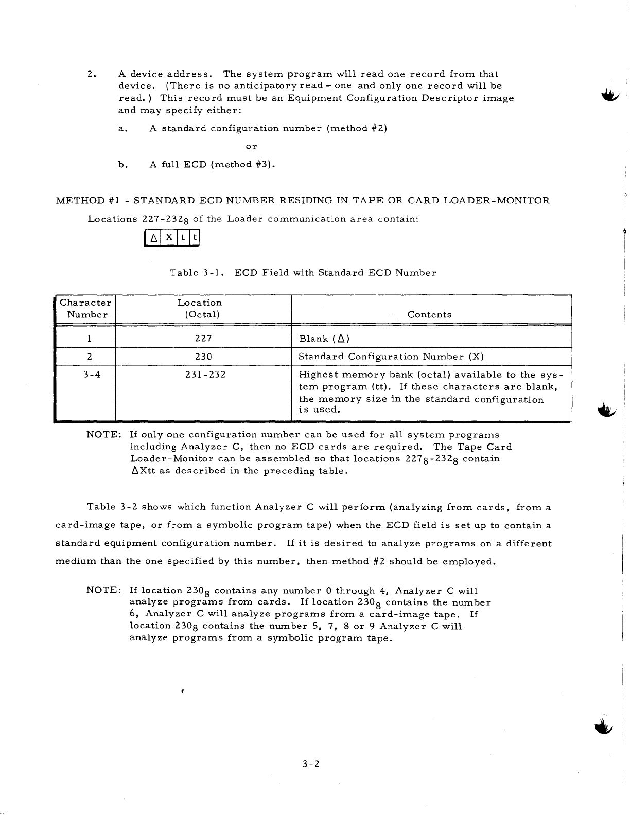
Table
3
-1.
ECD
Field
with
Standard
ECD
Number
Character
Location
Number
(Octal)
Contents
1
227
Blank
(L)
2
230
Standard
Configuration
Number
(X)
3-4
231-232
Highest
memory
bank
(octal)
available
to
the
sys-
tern
program
(tt).
If
these
characters
are
blank,
the
memo
ry
size
in
the
standard
configuration
is
used.
NOTE:
If
only
one
configuration
number
can
be
used
for
all
system
programs
including
Analyzer
C,
then
no
ECD
cards
are
required.
The
Tape
Card
Loader-Monitor
can
be
assembled
so
that
locations
2278-2328
contain
LXtt
as
described
in
the
preceding
table.
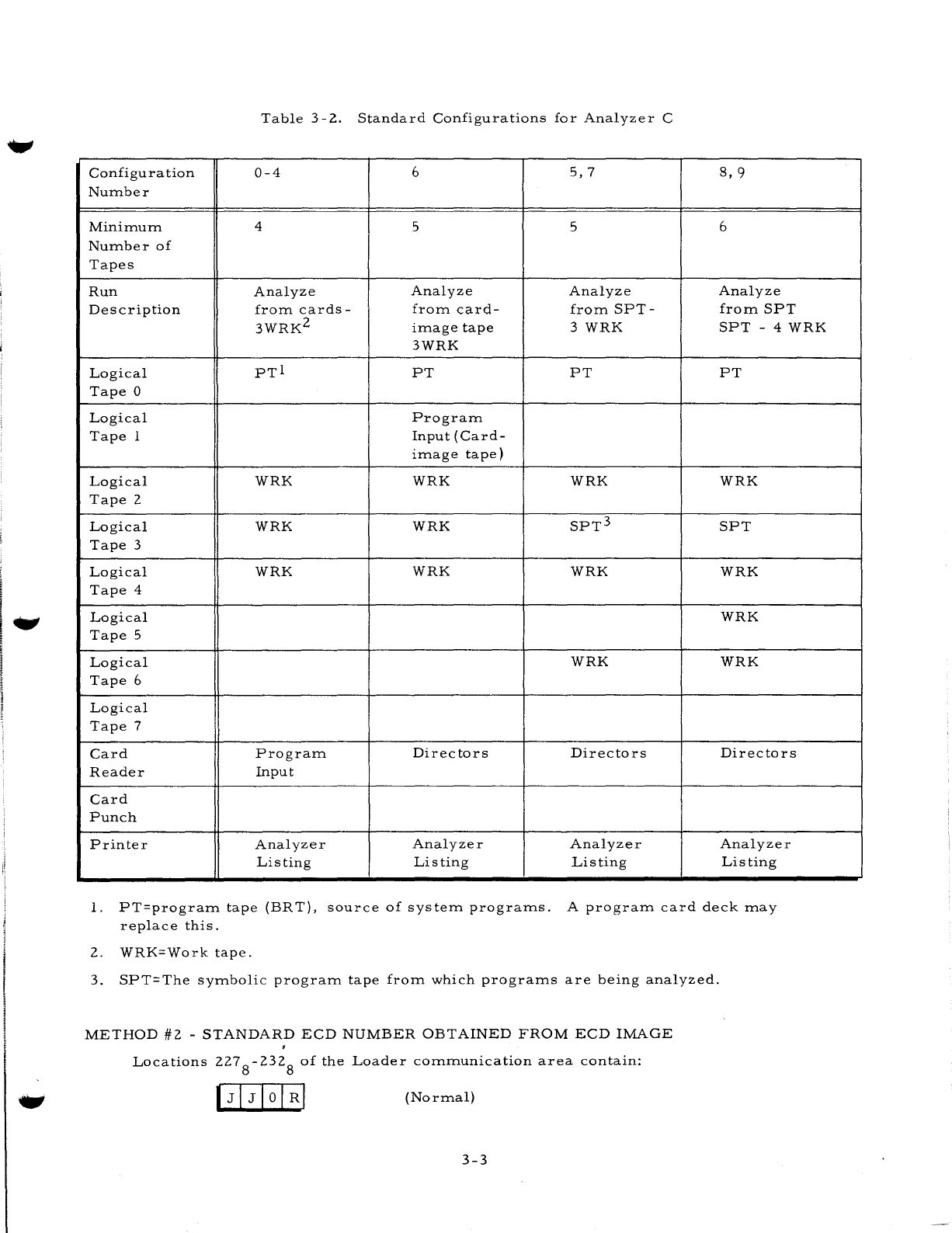
Table
3-2
shows
which
function
Analyzer
C
will
perform
(analyzing
from
cards,
from
a
card-image
tape,
or
from
a
symbolic
program
tape)
when
the
ECD
field
is
set
up
to
contain
a
standard
equipment
configuration
number.
If
it
is
desired
to
analyze
programs
on
a
different
medium
than
the
one
specified
by
this
number,
then
method
#2
should
be
employed.
NOTE:
If
location
2308
contains
any
number
°
through
4,
Analyzer
C
will
analyze
programs
from
cards.
If
location
2308
contains
the
number
6,
Analyzer
C
will
analyze
programs
from
a
card-image
tape.
If
location
2308
contains
the
number
5,
7,
8
or
9
Analyzer
C
will
analyze
programs
from
a
symbolic
program
tape.
3-2
Table
3-2.
Standard
Configurations
for
Analyzer
C
Configuration
0-4
6
5,7
8,
9
Number
Minimum
4 5 5 6
Number
of
Tapes
Run
Analyze
Analyze Analyze Analyze
Description
from
cards-
from
card-
from
SPT-
from
SPT
3WRK
2
image
tape
3
WRK
SPT
- 4
WRK
3WRK
Logical
PTI
PT PT PT
Tape
0
Logical
Program
Tape
1
Input
(Card-
image
tape)
Logical
WRK WRK
WRK WRK
Tape
2
Logical
WRK
WRK
SPT
3
SPT
Tape
3
Logical
WRK
WRK WRK WRK
Tape
4
Logical
WRK
Tape
5
Logical
WRK
WRK
Tape
6
Logical
Tape
7
Card
Program
Directors Directors Directors
Reader
Input
Card
Punch
Printer
Analyzer Analyzer
Analyzer
Analyzer
Listing Listing
Listing
Listing
1.
PT=program
tape
(BRT),
source
of
system
programs.
A
program
card
deck
may
replace
this.
2.
WRK=Work
tape.
3.
SPT=The
symbolic
program
tape
from
which
programs
are
being
analyzed.
METHOD
#2
-
STANDARD
ECD
NUMBER
OBTAINED
FROM
ECD
IMAGE
Locations
227
8
-232
8
of
the
Loader
communication
area
contain:
(Normal)
3-3

Table
3-3.
ECD
Field
to
Obtain
ECD
Number
from
Input
Device
Character
Location
Number
(Octal)
Contents
1
227
Device
Type
(J)
2-3
230-231
Control
Unit
and
Device
(JO)
4
232
Read/Write
Channel
(R)
NOTE:
Under
this
method,
the
standard
code
of
JJOR
assembled
in
locations
227
-2328
means
that
the
ECD
image
will
be
read
from
a
card
reader
having
a
peripheral
address
of
41
via
read/write
channell.
The
con-
tents
of
these
locations
may
be
changed
by
reassembling
the
Loader-
Monitor
or
by
manual
entry
from
the
console.
The
Equipment
Configuration
Descriptor
image
read
in
must
be
constructed
as
shown
in
Table
3-4.
Table
3-4.
Standard
ECD
Image
Character
Contents
Explanation
5
0-9
The
standard
configuration
which
corresponds
to
this
number
will
be
used.
If
this
column
is
blank,
the
image
is
assumed
to
be
a
full
ECD
image
(see
method
#3).
6 E
Identifies
an
Equipment
Configuration
De
s
criptor.
19-20
tt
or
66
tt
is
the
highest
memory
bank
(octal)
available
to
the
system
program.
If
these
characters
are
blank,
the
memory
size
included
in
the
standard
configuration
is
used.
NOTE:
Since
Analyzer
C
processes
input
in
various
forms
(e.
g.,
analyzing
from
a
symbolic
program
tape,
from
a
card-image
tape,
or
from
cards),
method
#2
of
specifying
the
Equipment
Configuration
De-
scriptor
will
probably
be
the
most
used.
METHOD
#3
-
FULL
EQUIPMENT
CONFIGURATION
DESCRIPTOR
AS
ECD
IMAGE
The
format
of
the
Full
Equipment
Configuration
Descriptor
is
described
below.
Note
that
column
5
must
be
blank
to
distinguish
this
from
an
Equipment
Configuration
Descriptor
speci-
fying
a
standard
equipment
configuration.
f
The
ECD
Field
of
the
Loader
communication
area
is
the
same
as
In
Table
3-3.
3-4
-.,
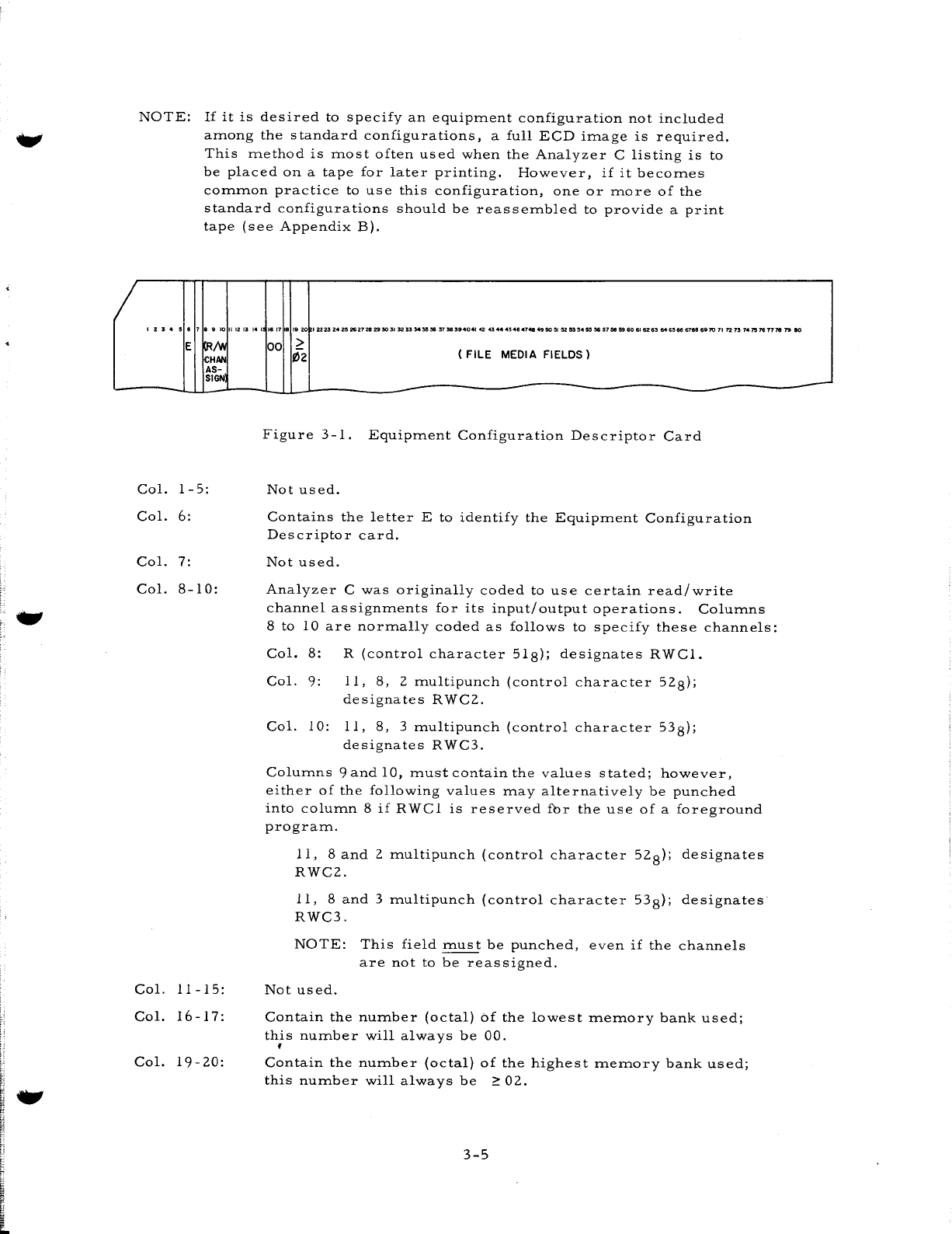
NOTE:
If
it
is
desired
to
specify
an
equipment
configuration
not
included
among
the
standard
configurations,
a
full
ECD
image
is
required.
This
method
is
most
often
used
when
the
Analyzer
C
listing
is
to
be
placed
on
a
tape
for
later
printing.
However,
if
it
becomes
common
practice
to
use
this
configuration,
one
or
more
of
the
standard
configurations
should
be
reas
sembled
to
provide
a
print
tape
(see
Appendix
B).
I 2
;,
..
5 • 7 8 9
10
II
12
13 14
I
E
~/v.
CHAN
AS-
SIGN
Col.
1 -
5:
Col.
6:
Col.
7:
Col.
8-10:
Col.
11-15:
Col.
16
-17:
Col.
19-20:
.617
81920
I
U~
Z4
2!1
ZS272e"
30
31
32
33
S4'5e
38 37
58
39404.
42
43
....
4!14.
4748
4950
~
:l2
53
54"
~
51"
59
60
61
62 63
646!166
6788
691Q
11
72
73
747'576177$
1'9
eo
00
>
02
( FILE MEDIA FIELDS)
Figure
3
-1.
Equipment
Configuration
Descriptor
Card
Not
used.
Contains
the
letter
E
to
identify
the
Equipment
Configuration
Descriptor
card.
Not
used.
Analyzer
C
was
originally
coded
to
use
certain
read/write
channel
assignments
for
its
input/output
operations.
Columns
8
to
10
are
normally
coded
as
follows
to
specify
these
channels:
Col.
8:
R
(control
character
518);
designates
RWCl.
Col.
9:
11,
8,
2
multipunch
(control
character
528);
designates
RWC2.
Col.
10:
11,
8,
3
multipunch
(control
character
538);
designates
RWC3.
Columns
9
and
10,
must
conta.in
the
values
stated;
however,
either
of
the
following
values
may
alternatively
be
punched
into
column
8
if
RWCl
is
reserved
fur
the
use
of
a
foreground
program.
11,
8
and
2
multipunch
(control
character
52
8);
designates
RWC2.
11,
8
and
3
multipunch
(control
character
538);
designates
RWC3.
NOTE:
This
field
must
be
punched,
even
if
the
channels
are
not
to
be
reassigned.
Not
used.
Contain
the
number
(octal)
of
the
lowest
memory
bank
used;
this
number
will
always
be
00
.
•
Contain
the
number
(octal)
of
the
highest
memory
bank
used;
this
number
will
always
be
~
02.
3-5
-
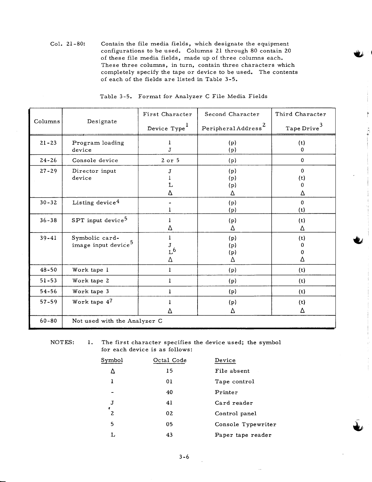
Col.
21-80:
Contain
the
file
media
fields,
which
designate
the
equipment
configurations
to
be
used.
Columns
21
through
80
contain
20
of
thes
e
file
media
fields,
made
up
of
three
columns
each.
These
three
columns,
in
turn,
contain
three
characters
which
completely
specify
the
tape
or
device
to
be
used.
The
contents
of
each
of
the
fields
are
lis
ted
in
Table
3 -
5.
Table
3-5.
Format
for
Analyzer
C
File
Media
Fields
First
Character
Second
Character
Third
Character
Columns
Designate
1 2
Device
Type
Peripheral
Addres
s
21-23
Program
loading
1
(p)
device
J
(p)
24-26
Console
device
2
or
5
(p)
27-29
Director
input
J
(p)
device
1
(p)
L
(p)
6. 6.
30-32
Listing
device
4 -
(p)
1
(p)
36-38
SPT
input
device
5 1
(p)
6. 6.
39-41
Symbolic
card-
1
(p)
image
input
deviCe
5 J
(p)
L6
(p)
6. 6.
48-50
Work
tape
1 1
(p)
51-53
Work
tape
2 1
(p)
54-56
Work
tape
3 1
(p)
57-59
Work
tape
47
1
(p)
6. 6.
60-80
Not
used
with
the
Analyzer
C
NOTES:
1.
The
first
character
specifies
the
device
used;
the
symbol
for
each
device
is
as
follows:
Symbol
Octal
Code
Device
6.
15
File
absent
1
01
Tape
control
40
Printer
J
41
Card
reader
f 2
02
Control
panel
5
05
Console
Typewriter
L
43
Paper
tape
reader
3-6
Tape
Drive
3
(t)
0
0
0
(t)
0
6.
0
(t)
(t)
6.
(t)
0
0
6.
(t)
(t)
(t)
(
t)
6.
2.
The
second
character
specifies
the
peripheral
address.
This
is
control
character
C2
of
the
PDT
instruction.
For
tape
files,
Analyzer
C
sets
bit
1
(I/O
bit).
For
card
and
print
files,
this
bit
must
be
set
correctly
in
the
character
as
it
is
punched
in
the
card.
In
the
case
of
the
control
panel,
this
character
is
O.
For
the
console
typewriter
it
is
7.
3.
The
third
character
specifies
the
number
of
the
tape
drive
to
be
used.
This
is
the
low-order
octal
digit
of
control
character
C3
of
the
PDT
instruction.
If
a
tape
drive
is
not
required
for
a
particular
device,
this
third
character
is
O.
4.
If
a
print-image
tape
is
desired,
work
tape
1,
3,
or
4
may
be
used
for
the
print
file.
In
this
case,
columns
30-32
should
have
the
same
contents
as
the
columns
which
designate
the
applicable
work
tape
(48-50,
54-56,
or
57-59).
5.
One
(but
not
both)
of
these
fields
must
be
specified.
If
the
programs
to
be
analyzed
are
located
on
an
SPT,
columns
36-38
must
be
punched
while
columns
39-41
must
be
blank.
However,
if
they
are
contained
on
cards,
paper
tape,
or
on
a
card-image
tape,
columns
39-41
must
be
appropriately
punched
and
columns
36-38
must
be
blank.
6.
For
paper
tape
files,
columns
27
-29
must
be
blank.
7.
If
blank,
there
is
no
fourth
work
tape
and
Analyzer
C
uses
three
tape
s.
THE
DIRECTOR
DECK
The
director
deck
is
composed
of
the
system
header
card,
director
cards,
and
the
system
end
card.
These
cards
are
described
in
detail
below.
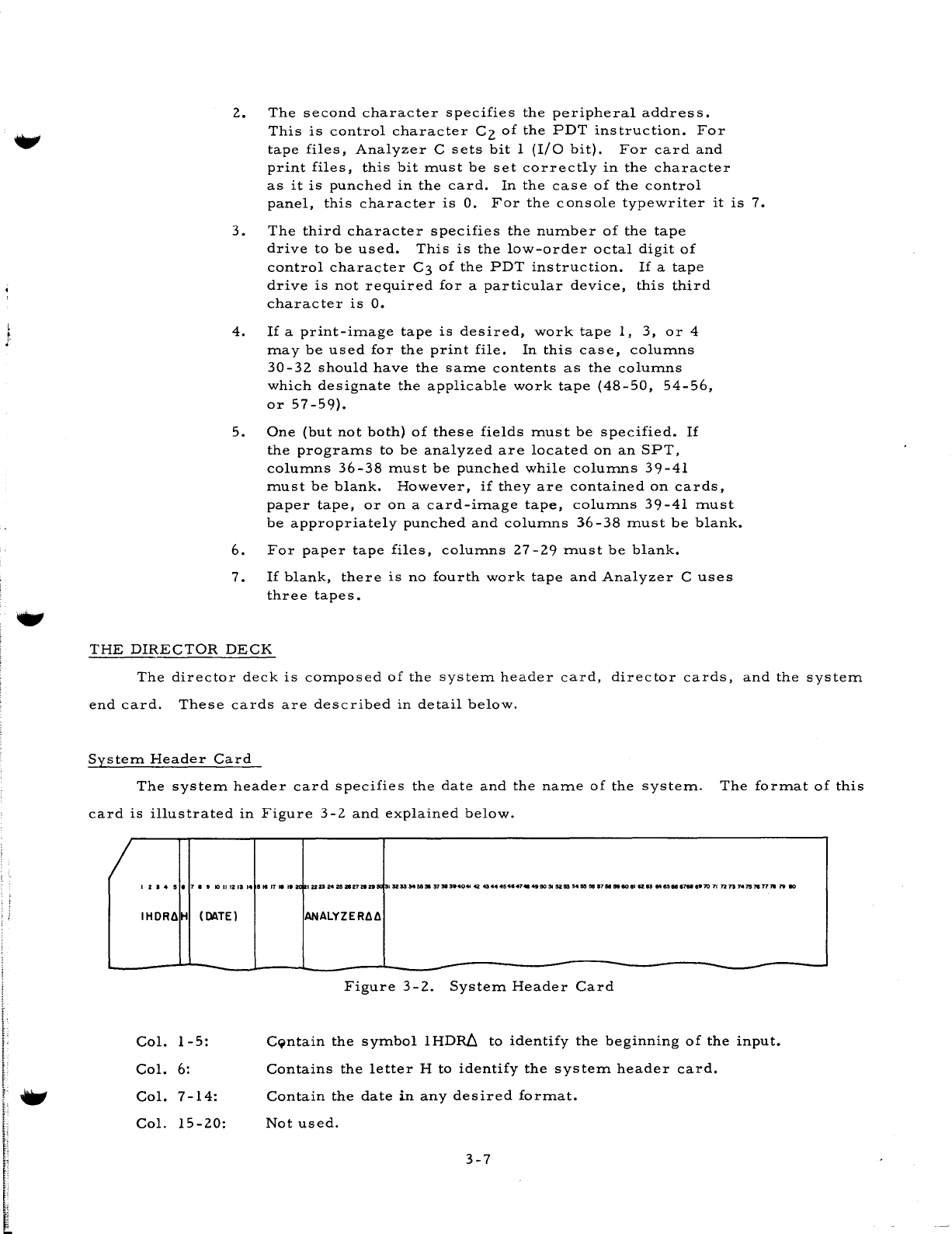
System
Header
Card
The
system
header
card
specifies
the
date
and
the
name
of
the
system.
The
format
of
this
card
is
illustrated
in
Figure
3-2
and
explained
below.
I 2 I
..
!5
.1
••
1011121114
IHDRdH
(DUE)
Col.
1-5:
Col.
6:
Col.
7-14:
Col.
15-20:
11
..
11.
,e
2Cl
IUP242&2tV2IztlJCl
I SZS3
545531
~"'.404I
42
4344454847414S1IO:5I
SlIS!l 5455!5f1
1151.eo
I'
a:
13
Me,.
87M
._10
71
n
13
14
7S'N
T178
19
80
ANALYZERdd
Figure
3-2.
System
Header
Card
C9ntain
the
symbol
IHDRb.
to
identify
the
beginning
of
the
input.
Contains
the
letter
H
to
identify
the
system
header
card.
Contain
the
date
in
any
desired
format.
Not
used.
3-7
Col.
21-30:
Contain
the
systelTI
nalTIe
which,
in
this
case,
is
ANALYZERllll
Col.
31-80:
Not
used.
.,
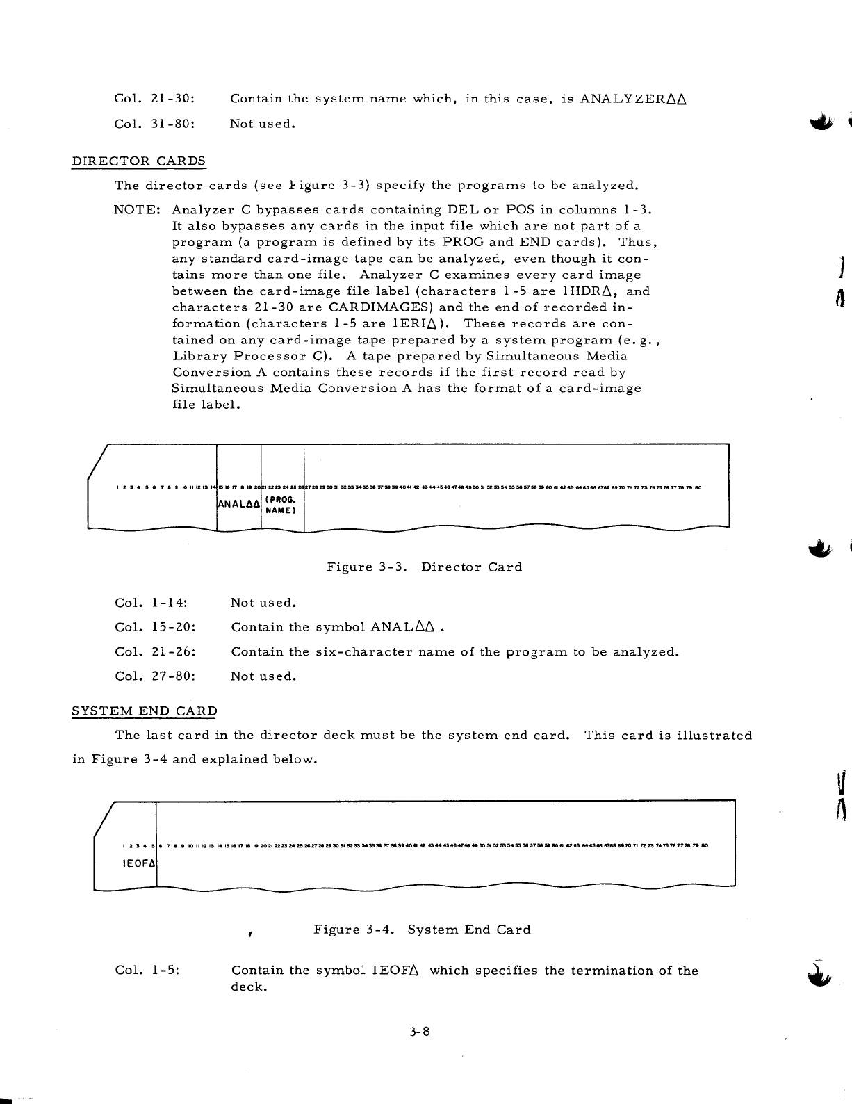
DIRECTOR
CARDS
The
director
cards
(see
Figure
3-3)
specify
the
progralTIs
to
be
analyzed.
NOTE:
Analyzer
C
bypasses
cards
containing
DEL
or
POS
in
colulTIns
1-3.
rt
also
bypasses
any
cards
in
the
input
file
which
are
not
part
of
a
progralTI
(a
progralTI
is
defined
by
its
PROG
and
END
cards).
Thus,
any
standard
card-ilTIage
tape
can
be
analyzed,
even
though
it
con-
tains
lTIore
than
one
file.
Analyzer
C
exalTIines
every
card
ilTIage
between
the
card-ilTIage
file
label
(characters
1-5
are
1HDRll,
and
characters
21-30
are
CARDlMAGES)
and
the
end
of
recorded
in-
forlTIation
(characters
1-5
are
1ERIll).
These
records
are
con-
tained
on
any
card-ilTIage
tape
prepared
by
a
systelTI
progralTI
(e.
g.
,
Library
Processor
C).
A
tape
prepared
by
SilTIultaneous
Media
Conversion
A
contains
these
records
if
the
first
record
read
by
SilTIultaneous
Media
Conversion
A
has
the
forlTIat
of
a
card-ilTIage
file
label.
12S415.7
••
tollt2ISI
115.11711
'82
IU23242ezt
2728
29
50
51
5253
'54""
'5751
514041
42
4344415484748
49
50,.
~
53
154
~ ~
5758
59
60
81
UU
648566
6788
.970
71
n
73
7475
7S
7778
19
eo
Col.
1-14:
Col.
15-20:
Col.
21-26:
Col.
27
-80:
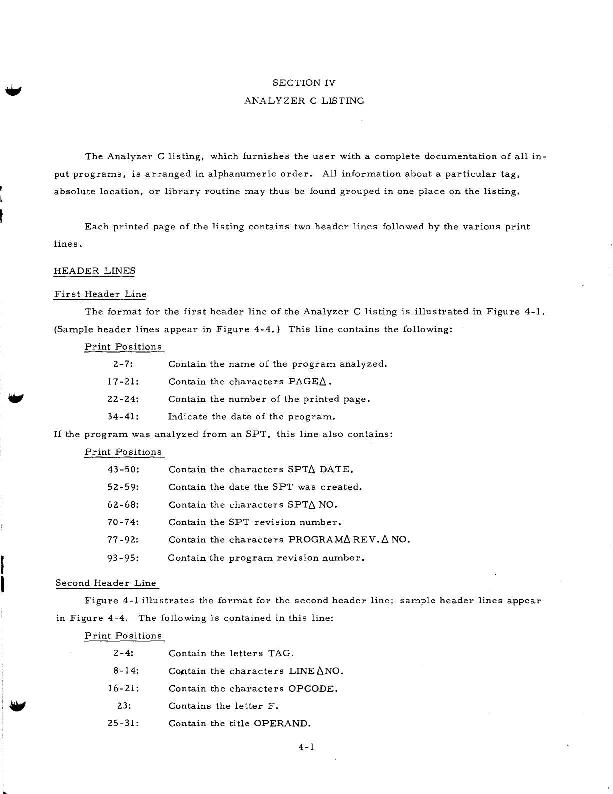
SYSTEM
END
CARD
ANAL~~
(PROG.
NAMEl
Figure
3-3.
Director
Card
Not
used.
Contain
the
sYlTIbol
ANALllll
.
Contain
the
six-character
nalTIe
of
the
progralTI
to
be
analyzed.
Not
used.
-
The
last
card
in
the
director
deck
lTIust
be
the
systelTI
end
card.
This
card
is
illustrated
in
Figure
3-4
and
explained
below.
123
..
15.7.
9
IOIl12ISI415~17181'20212223:M25.27212930SI52"M"!l37.S'4041424344"54847'"4e15O"~5354"~157585180.111283M6S8&67"6'70717Z131475'N777819eo
IEOF~
Col.
1-5:
Figure
3
-4.
SystelTI
End
Card
Contain
the
sYlTIbol
1EOFll
which
specifies
the
terlTIination
of
the
deck.
3-8
r.
I
,
I
SECTION
IV
ANALYZER
C
LISTING
The
Analyzer
C
listing,
which
furnishes
the
user
with
a
complete
documentation
of
all
in-
put
programs,
is
arranged
in
alphanumeric
order.
All
information
about
a
particular
tag,
absolute
location,
or
library
routine
may
thus
be
found
grouped
in
one
place
on
the
listing.
Each
printed
page
of
the
listing
contains
two
header
lines
followed
by
the
various
print
lines.
HEADER
LINES
First
Header
Line
The
format
for
the
first
header
line
of
the
Analyzer
C
listing
is
illustrated
in
Figure
4-1.
(Sample
header
lines
appear
in
Figure
4-4.)
This
line
contains
the
following:
Print
Positions
2-7:
17-21:
22-24:
34-41
:
Contain
the
name
of
the
program
analyzed.
Contain
the
characters
PAGEL1.
Contain
the
number
of
the
printed
page.
Indicate
the
date
of
the
program.
If
the
program
was
analyzed
from
an
SPT,
this
line
also
contains:
Print
Positions
43-50:
52-59:
62-68:
70-74:
77-92:
Contain
the
characters
SPTL1
DATE.
Contain
the
date
the
SPT
was
created.
Contain
the
characters
SPTL1
NO.
Contain
the
SPT
revision
number.
Contain
the
characters
PROGRAML1
REV.
L1
NO.
93-95:
Contain
the
program
revision
number.
Second
Header
Line
Figure
4-1
illustrates
the
format
for
the
second
header
line;
sample
header
lines
appear
in
Figure
4-4.
The
following
is
contained
in
this
line:
Print
Positions
2-4:
8-14:
16-21:
23:
25
-31:
Contain
the
letters
TAG.
Coptain
the
characters
LINE~NO.
Contain
the
characters
OPCODE.
Contains
the
letter
F.
Contain
the
title
OPERAND.
4-1
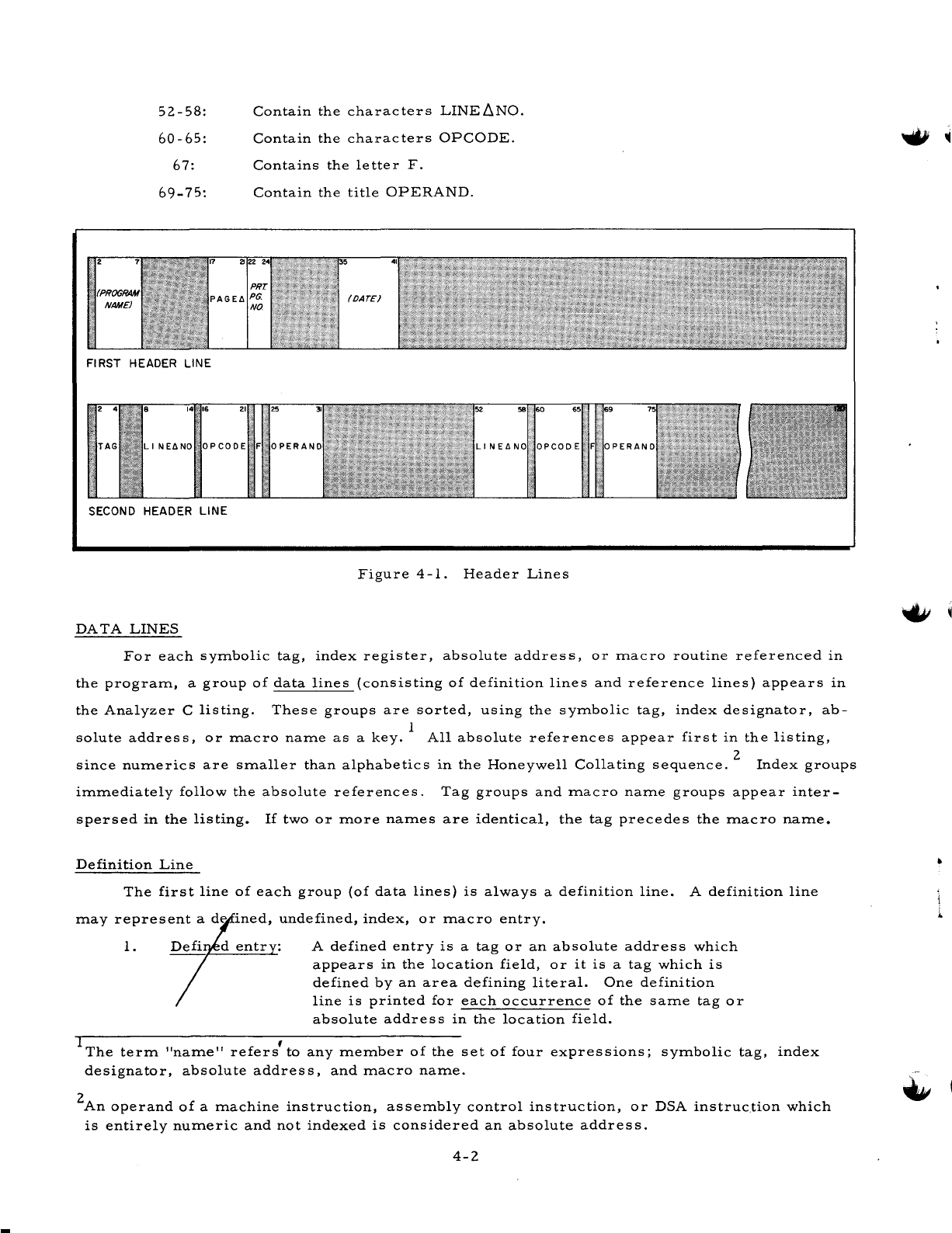
52-58:
60-65:
67:
69-75:
SECOND
HEADER
LINE
Contain
the
characters
LINE
LlNO.
Contain
the
characters
OPCODE.
Contains
the
Ie
tte
r
F.
Contain
the
title
OPERAND.
Figure
4
-1.
Header
Lines
DATA
LINES
For
each
symbolic
tag,
index
register,
absolute
address,
or
macro
routine
referenced
in
the
program,
a
group
of
data
lines
(consisting
of
definition
lines
and
reference
lines)
appears
in
the
Analyzer
C
listing.
These
groups
are
sorted,
using
the
symbolic
tag,
index
designator,
ab-
solute
address,
or
macro
name
as
a
key.
1
All
absolute
references
appear
first
in
the
listing,
since
numerics
are
smaller
than
alphabetics
in
the
Honeywell
Collating
sequence.
2
Index
groups
immediately
follow
the
absolute
references.
Tag
groups
and
macro
name
groups
appear
inter-
spersed
in
the
listing.
If
two
or
more
names
are
identical,
the tag
precedes
the
macro
name.
Definition
Line
The
first
line
of
each
group
(of
data
lines)
is
always
a
definition
line.
A
definition
line
may
represent
a
de
ined,
undefined,
index,
or
macro
entry.
1.
A
defined
entry
is
a
tag
or
an
absolute
address
which
appears
in
the
location
field,
or
it
is
a
tag
which
is
defined
by
an
area
defining
literal.
One
definition
line
is
printed
for
each
occurrence
of
the
same
tag
or
absolute
address
in
the
location
field.
IThe
term
"name"
refers'to
any
member
of
the
set
of
four
expressions;
symbolic
tag,
index
designator,
absolute
address,
and
macro
name.
2
An
operand
of
a
machine
instruction,
assembly
control
instruction,
or
DSA
instruc.tion
which
is
entirely
numeric
and
not
indexed
is
considered
an
absolute
address.
4-2
i.
2.
3.
4.
Undefined
entry:
An
undefined
entry
is
a
tag
or
absolute
address
which
Index
entry:
is
referenced
but
does
not
appear
in
the
location
field.
Only
one
definition
line
is
printed
for
the
tag
or
address,
regardless
of
how
many
times
it
is
referenced.
An
index
entry
is
an
index
designator
which
is
refer-
enced
in
the
program.
Only
one
definition
line
is
printed
for
the
index
designator,
regardless
of
how
many
times
it
is
referenced.
NOTE:
An
expression
of
the
form
Xi
may
represent
either
an
index
designator
or
a
tag,
depending
upon
its
use.
Thus,
such
an
expression
may
appear
in
two
groups
in
the
listing,
once
as
a
defined
or
undefined
tag
entry
and
once
as
an
index
entry.
Macro
entry:
A
macro
entry
is
the
name
of
a
macro
routine
refer-
enced
in
one
or
more
macro
instructions.
Only
one
definition
line
is
printed
for
each
routi1'le,
regardless
of
how
many
times
it
is
called.
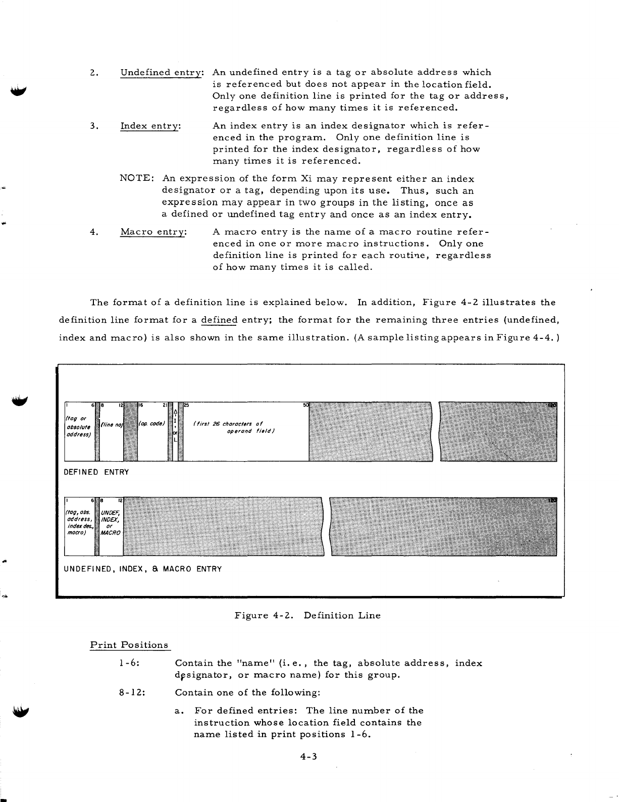
The
format
of
a
definition
line
is
explained
below.
In
addition,
Figure
4-2
illustrates
the
definition
line
format
for
a
defined
entry;
the
format
for
the
remaining
three
entries
(undefined,
index
and
macro)
is
also
shown
in
the
same
illustration.
(A
sample
listing
appears
in
Figure
4-4.
)
or
oosolu/.
address)
(line
DEFI N
ED
ENTRY
6'8
(/og,
005.
•
UNOEF,
address,
INDEX,
index
des"
or
macro)
'MACRO
code)
(first
26
characters 0 f
operand
'1.ld)
UNDEFINED,
INDEX,
a.
MACRO ENTRY
Print
Positions
1-6:
8-12:
Figure
4-2.
Definition
Line
Contain
the
"name"
(i.
e.,
the
tag,
absolute
address,
index
drsignator,
or
macro
name)
for
this
group.
Contain
one
of
the
following:
a.
For
defined
entries:
The
line
number
of
the
instruction
whose
location
field
contains
the
name
listed
in
print
positions
1-6.
4-3
-
16-21:
23:
25-50:
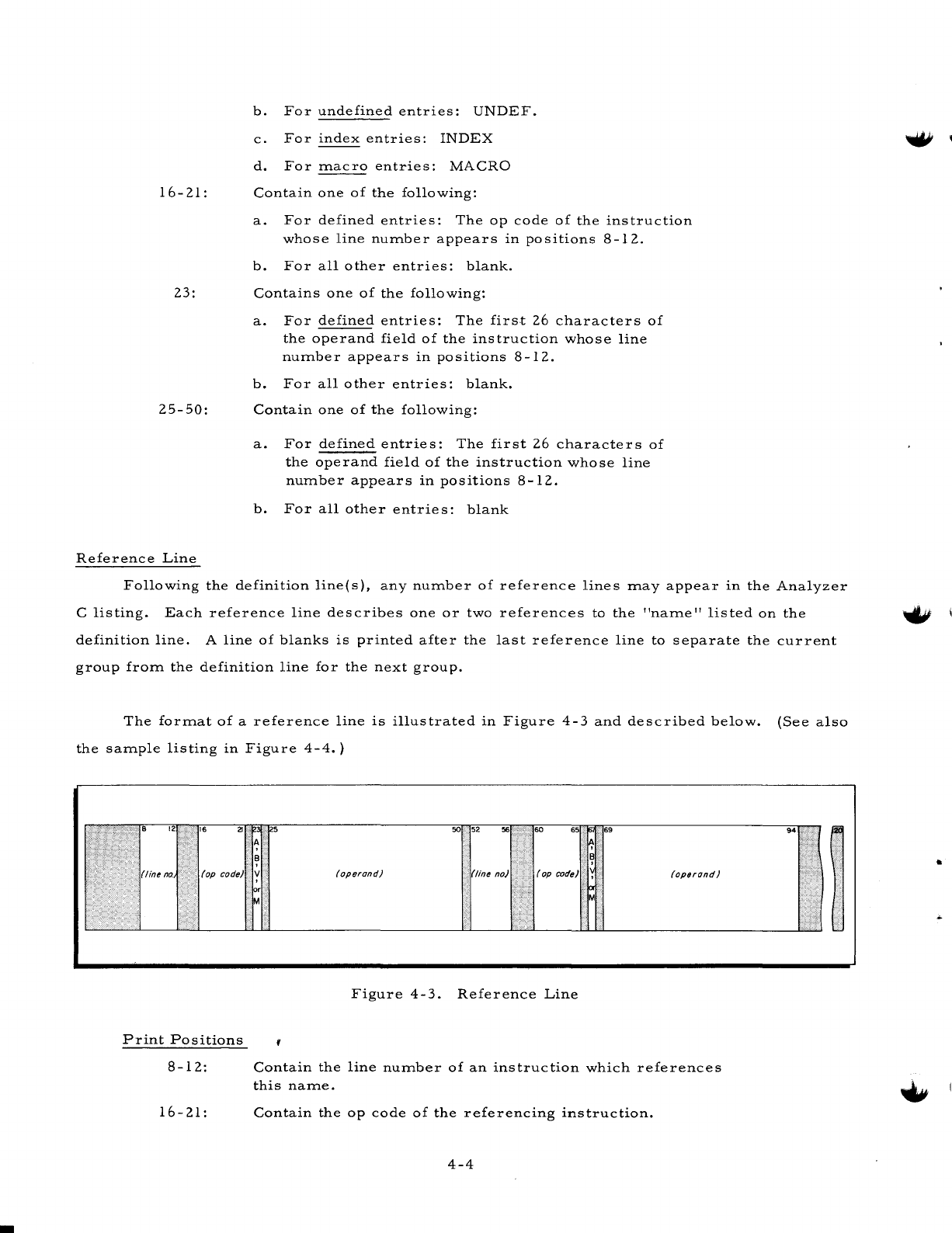
Reference
Line
b.
For
undefined
entries:
UNDEF.
c.
For
index
entries:
INDEX
d.
For
ITlacro
entries:
MACRO
Contain
one
of
the
following:
a.
For
defined
entries:
The
op
code
of
the
instruction
whose
line
nUITlber
appears
in
positions
8-12.
b.
For
all
other
entries:
blank.
Contains
one
of
the
following:
a.
For
defined
entries:
The
first
26
characters
of
the
operand
field
of
the
instruction
whose
line
nUITlber
appears
in
positions
8-12.
b.
For
all
other
entries:
blank.
Contain
one
of
the
following:
a.
For
defined
entries:
The
first
26
characters
of
the
operand
field
of
the
instruction
whose
line
nUITlber
appears
in
positions
8-12.
b.
For
all
other
entries:
blank
Following
the
definition
line(s),
any
nUITlber
of
reference
lines
ITlay
appear
in
the
Analyzer
C
listing.
Each
reference
line
describes
one
or
two
references
to
the
"naITle"
listed
on
the
definition
line.
A
line
of
blanks
is
printed
after
the
last
reference
line
to
separate
the
current
group
froITl
the
definition
line
for
the
next
group.
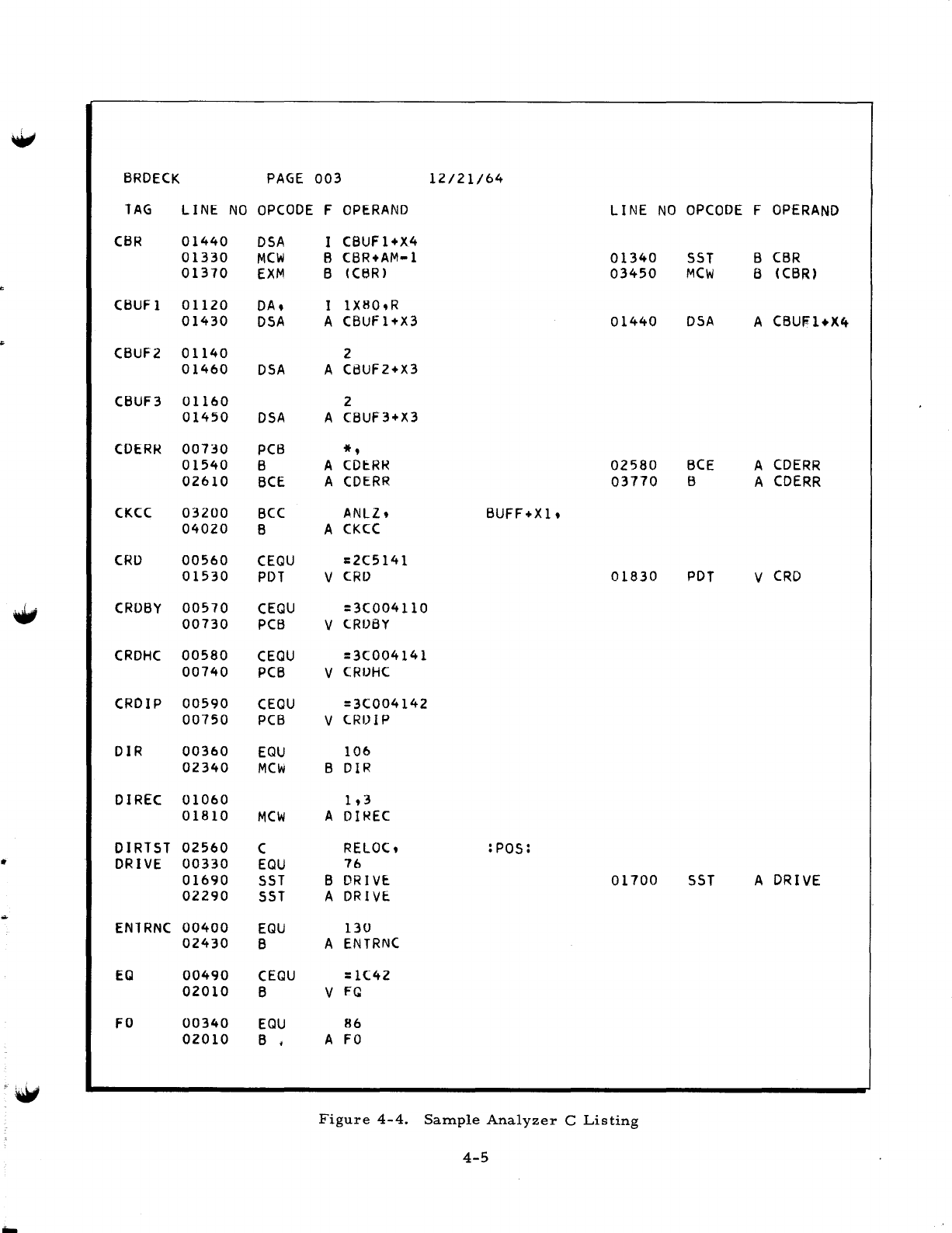
The
forITlat
of
a
reference
line
is
illustrated
in
Figure
4-3
and
described
below.
(See
also
the
saITlple
listing
in
Figure
4-4.
)
.•
:
•..•.
::.:
••
8
12
16
2l
.'.
(line
no
(op
code)
Print
Positions
8-12:
16-21:
5
50
52
56
60
.,
69
A ·
B B
·
V
(operand)
(line
no)
.
(op
code ·
(operand)
or
M M
Figure
4-3.
Reference
Line
Contain
the
line
nUITlber
of
an
instruction
which
references
this
naITle.
Contain
the
op
code
of
the
referencing
instruction.
4-4
94
"
Ii!
..,:.
,.1
i'
"
::
•
W
BRDECK
PAGE
003
12/21/64
TAG
LINE
NO
opeODE
F
OPERAND
LINE
NO
OPCODE
F
OPERAND
CSR
01440
DSA
I caUF1+X4
01330
MCW
B
CBR+AM
.. 1
01340
SST
B
CBR
01310
EXM
B (CeR)
03450
MCW
B
(CBR)
CSUF1
01120
DA,
I
lX80,R
01430
DSA
A
CBUF1+X3
01440
DSA
A CBUFl+X4
..
CBUF2
01140
2
01460
DSA
A
C8UF2+X3
CSUF3
01160
2
01450
DSA
A
CBUF3+X3
CDER~
00730
PCB
*,
01540 B A
(DERR
02580
BCE
A
CDERR
02610
BCE
A
CDERR
03770
B A
CDERR
CKec
03200
Bee
ANLZ,
BUFF+X1,
04020 B A eKeC
eRD
00560
CEQU
=2C5141
01530
PDT
V
CRD
01830
PDT
V
CRD
W
CRDBY
00510
CEQU
=3(004110
00130
PCB
V
CRIJ6Y
CRDHC
00580
CEQU
=3(004141
00140
PCB
V
CRIJHC
CRDIP
00590
CEQU
=3(004142
00150
PCB
V (RIJIP
DIR
00360
EQU
106
02340
MCW
B
DIR
DIREC
01060
1,3
01810
MCW
A DIREe
DIRlSl
02560
C RELoe, :POS:
DRIVE
00330
EQU
76
01690
SST
B
DRIVE
01700
SST
A
DRIVE
02290
SST
A DRIVE
ENIRNC
00400
EQU
130
02430
B A
ENTRNC
EO
00490
CEQU
=1C42
02010
B V
FQ
FO
00340
EQU
86
02010
B # A
FO
W
Figure
4-4.
Sample
Analyzer
C
Listing
4-5
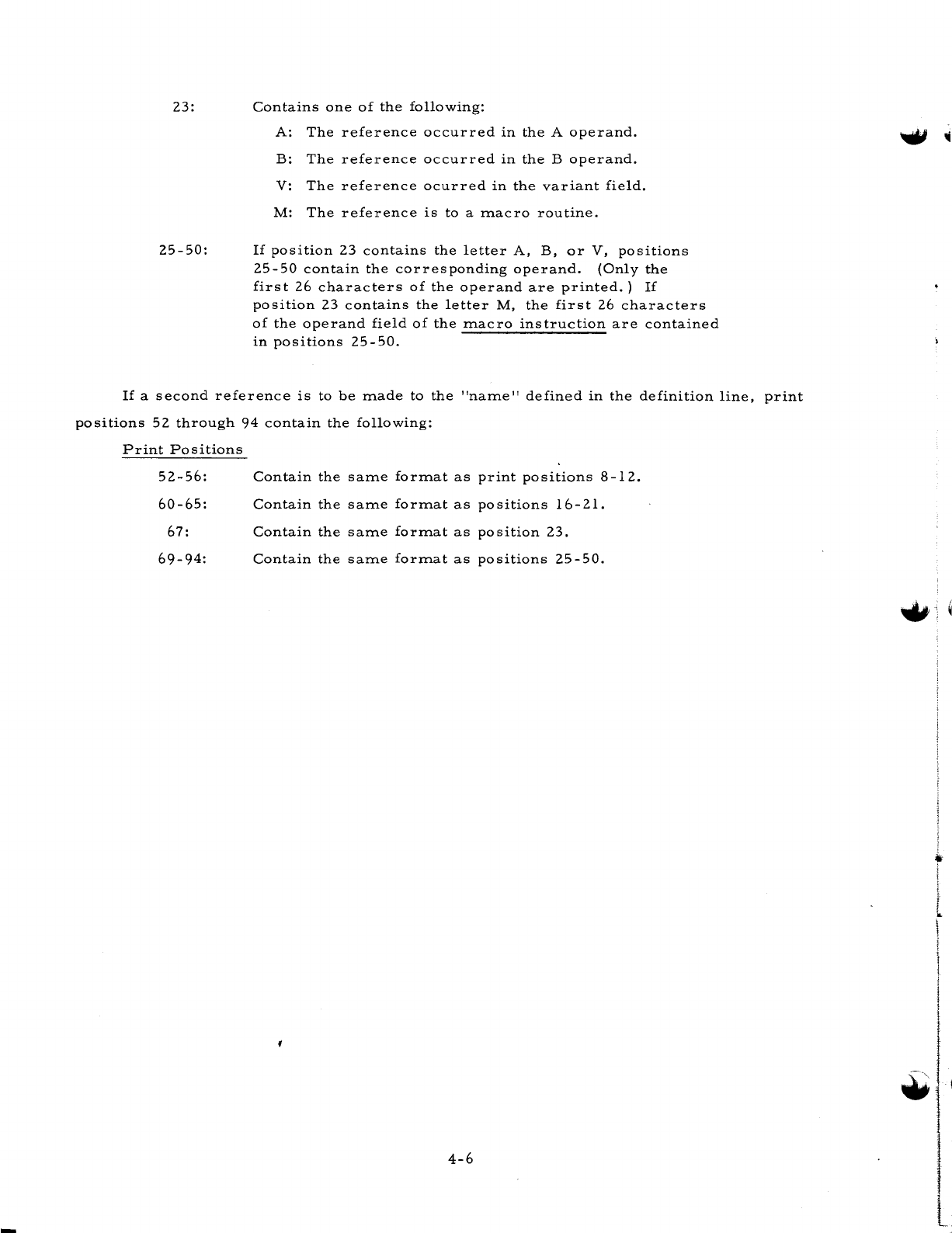
23:
25-50:
Contains
one
of
the
following:
A:
The
reference
occurred
in
the
A
operand.
B:
The
reference
occurred
in
the
B
operand.
V:
The
reference
ocurred
in
the
variant
field.
M:
The
reference
is
to
a
macro
routine.
If
position
23
contains
the
letter
A,
B,
or
V,
positions
25-50
contain
the
corresponding
operand.
(Only
the
first
26
characters
of
the
operand
are
printed.)
If
position
23
contains
the
letter
M,
the
first
26
characters
of
the
operand
field
of
the
macro
instruction
are
contained
in
positions
25-50.
If
a
second
reference
is
to
be
made
to
the
"name"
defined
in
the
definition
line,
print
positions
52
through
94
contain
the
following:
Print
Positions
52-56:
Contain
the
same
format
as
print
positions
8-12.
60-65:
Contain
the
same
format
as
po
sitions
16
-
2l.
67:
Contain
the
same
format
as
position
23.
69-94:
Contain
the
same
format
as
positions
25-50.
4-6
..
~
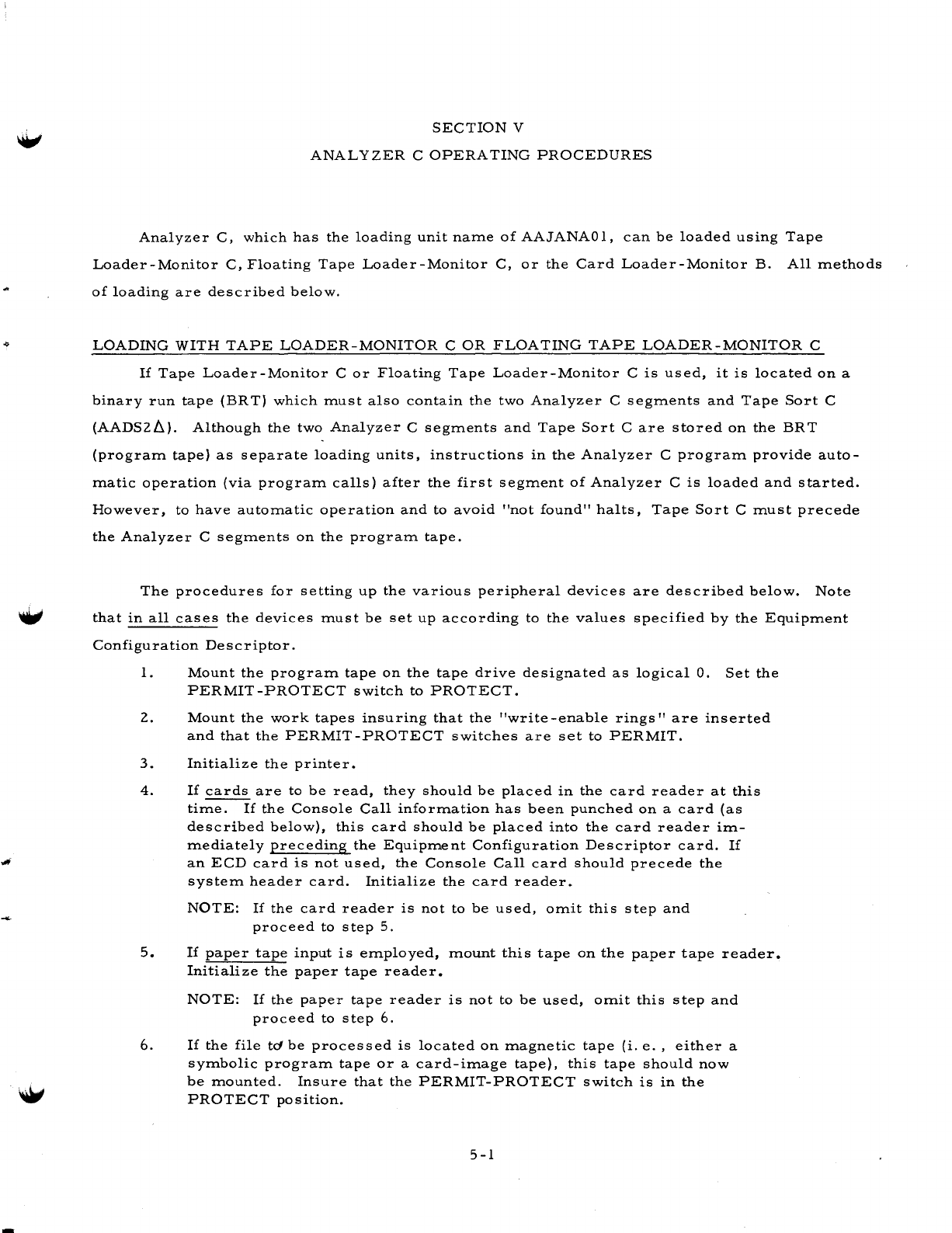
SECTION
V
ANAL
Y
ZER
C
OPERATING
PROCEDURES
Analyzer
C,
which
has
the
loading
unit
name
of
AAJANA01,
can
be
loaded
using
Tape
Loader-Monitor
C,
Floating
Tape
Loader-Monitor
C,
or
the
Card
Loader-Monitor
B.
All
methods
of
loading
are
described
below.
LOADING
WITH
TAPE
LOADER-MONITOR
C
OR
FLOATING
TAPE
LOADER-MONITOR
C
If
Tape
Loader-Monitor
C
or
Floating
Tape
Loader-Monitor
C
is
used,
it
is
located
on
a
binary
run
tape
(BRTJ
which
must
also
contain
the
two
Analyzer
C
segments
and
Tape
Sort
C
(AADS2t.).
Although
the
two
Analyzer
C
segments
and
Tape
Sort
C
are
stored
on
the
BRT
(program
tape)
as
separate
loading
units,
instructions
in
the
Analyzer
C
program
provide
auto-
matic
operation
(via
program
calls)
after
the
first
segment
of
Analyzer
C
is
loaded
and
started.
However,
to
have
automatic
operation
and
to
avoid
"not
found"
halts,
Tape
Sort
C
must
precede
the
Analyzer
C
segments
on
the
program
tape.
The
procedures
for
setting
up
the
various
peripheral
devices
are
described
below.
Note
that
in
all
cases
the
devices
must
be
set
up
according
to
the
values
specified
by
the
Equipment
Configuration
Descriptor.
1.
Mount
the
program
tape
on
the
tape
drive
designated
as
logical
O.
Set
the
PERMIT
-PROTECT
switch
to
PROTECT.
2.
Mount
the
work
tapes
insuring
that
the
"write
-enable
rings"
are
inserted
and
that
the
PERMIT-PROTECT
switches
are
set
to
PERMIT.
3.
Initialize
the
printer.
4.
If
cards
are
to
be
read,
they
should
be
placed
in
the
card
reader
at
this
time.
If
the
Console
Call
information
has
been
punched
on
a
card
(as
described
below),
this
card
should
be
placed
into
the
card
reader
im-
mediately
preceding
the
Equipment
Configuration
Descriptor
card.
If
an
ECD
card
is
not
used,
the
Console
Call
card
should
precede
the
system
header
card.
Initialize
the
card
reader.
NOTE:
If
the
card
reader
is
not
to
be
used,
omit
this
step
and
proceed
to
step
5.
5.
If
paper
tape
input
is
employed,
mount
this
tape
on
the
paper
tape
reader.
Initialize
the
paper
tape
reader.
NOTE:
If
the
paper
tape
reader
is
not
to
be
used,
omit
this
step
and
proceed
to
step
6.
6.
If
the
file
td
be
processed
is
located
on
magnetic
tape
(i.
e.,
either
a
symbolic
program
tape
or
a
card-image
tape),
this
tape
should
now
be
mounted.
Insure
that
the
PERMIT-PROTECT
switch
is
in
the
PROTECT
position.
5
-1
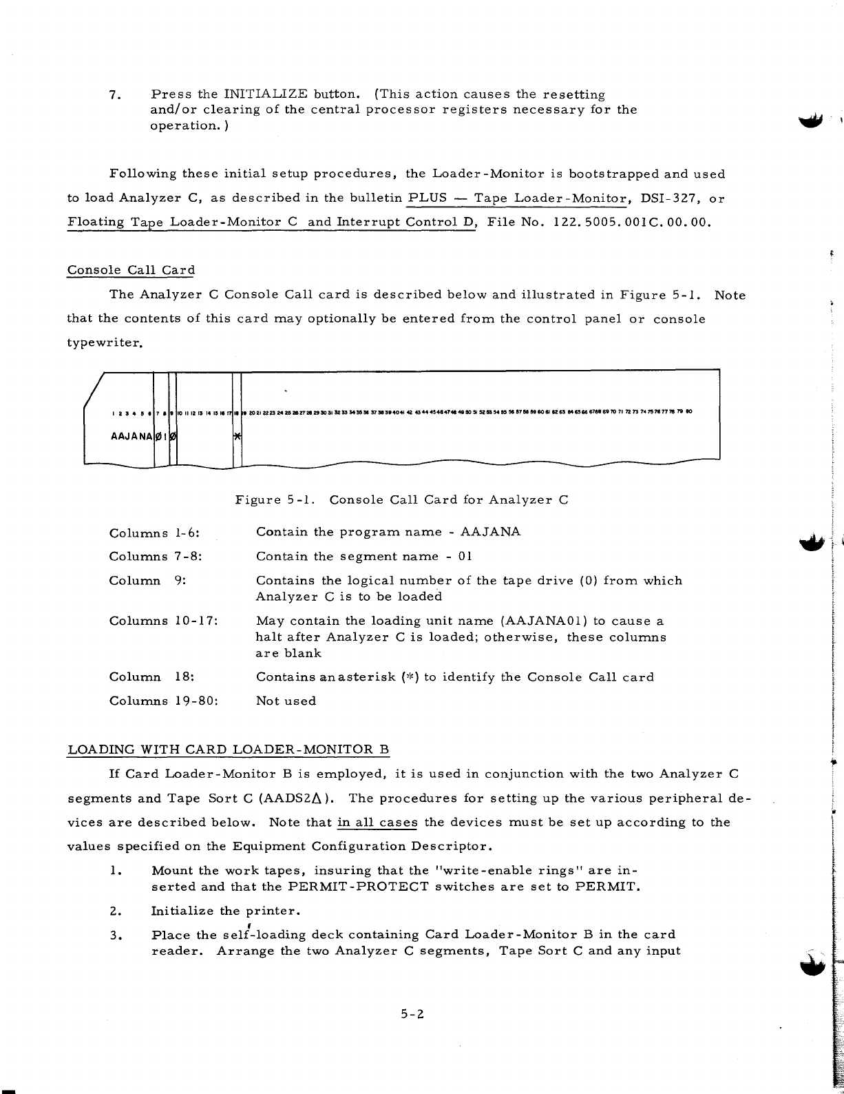
7.
Press
the
INITIALIZE
button.
(This
action
causes
the
resetting
and/or
clearing
of
the
central
processor
registers
necessary
for
the
operation.
)
Following
these
initial
setup
procedures,
the
Loader-Monitor
is
bootstrapped
and
used
to
load
Analyzer
C,
as
described
in
the
bulletin
PLUS
-
Tape
Loader
-Monitor,
DSI-327,
or
Floating
Tape
Loader-Monitor
C
and
Interrupt
Control
D,
File
No.
122.5005.
OOIC.
00. 00.
Console
Call
Card
The
Analyzer
C
Console
Call
card
is
described
below
and
illustrated
in
Figure
5-1.
Note
that
the
contents
of
this
card
may
optionally
be
entered
from
the
control
panel
or
console
typewriter.
I 2 I
..
5 • 7
••
10
111211
14
Ie
"'
AAJANA
!Ill
Columns
1-6:
Columns
7
-8:
Column
9:
Columns
10
-1
7:
Column
18:
Columns
19-80:
" •
2021222514
za
2112721293011
5233
545558
5151
n40'N
42
43444'.8.'""
49110:51
:sz
5154
~
56
5751
59
60
6I1tS3
Me66
6788
69
70
11
7213
74157«17778
19
eo
~
Figure
5
-1.
Console
Call
Card
for
Analyzer
C
Contain
the
program
name
-
AAJANA
Contain
the
segment
name
-01
Contains
the
logical
number
of
the
tape
drive
(0)
from
which
Analyzer
C
is
to
be
loaded
May
contain
the
loading
unit
name
(AAJANAOl)
to
cause
a
halt
after
Analyzer
C
is
loaded;
otherwise,
these
columns
are
blank
Contains
an
asterisk
(,~)
to
identify
the
Console
Call
card
Not
used
LOADING
WITH
CARD
LOADER-MONITOR
B
-
If
Card
Loader-Monitor
B
is
employed,
it
is
used
in
conjunction
with
the
two
Analyzer
C
segments
and
Tape
Sort
C
(AADS2~).
The
procedures
for
setting
up
the
various
peripheral
de-
vices
are
described
below.
Note
that
in
all
cases
the
devices
must
be
set
up
according
to
the
values
specified
on
the
Equipment
Configuration
Descriptor.
1.
Mount
the
work
tapes,
insuring
that
the
"write-enable
rings"
are
in-
serted
and
that
the
PERMIT-PROTECT
switches
are
set
to
PERMIT.
2.
Initialize
the
printer.
,
3.
Place
the
self-loading
deck
containing
Card
Loader-Monitor
B
in
the
card
reader.
Arrange
the
two
Analyzer
C
segments,
Tape
Sort
C
and
any
input
5-2
...
cards
in
the
following
order,
placing
these
cards
into
the
reader
im-
mediately
after
Card
Loader-Monitor
B.
AAJANAOI
Inpu
t
cards
(if
any)
AADS2tl
AAJANA02
NOTE:
Optionally,
the
Analyzer
C
segments,
input
cards,
and
Tape
Sort
C
may
be
placed
in
the
card
reader
following
the
17002
halt
of
Card
Loader-Monitor
B.
Initialize
the
card
reader.
4.
If
paper
tape
input
is
employed,
mount
this
tape
on
the
paper
tape
reader.
Initialize
the
paper
tape
reader.
NOTE:
If
the
paper
tape
reader
is
not
to
be
used,
omit
this
step
and
proceed
to
step
5.
5.
If
the
file
to
be
processed
is
located
on
magnetic
tape
(i.
e.,
either
a
sym-
bolic
program
tape
or
a
card-image
tape),
this
tape
should
now
be
mounted.
Insure
that
the
PERMIT-PROTECT
switch
is
in
the
PROTECT
position.
6.
Depress
the
INITIALIZE
button.
(This
action
causes
the
resetting
and/or
clearing
of
the
central
processor
registers
necessary
for
the
operation.
)
Following
these
initial
setup
procedures,
the
Loader-Monitor
is
bootstrapped
and
used
to
~
load
Analyzer
C,
as
described
in
the
software
bulletin
Card
Loader-Monitor
B,
File
No.
122.5105.040B.00.00.
ERROR
CONDITIONS
For
all
halts,
the
B-address
register
(which
indicates
the
reason
for
the
halt)
should
be
displayed
first.
In
some
cases,
the
A-address
register
contains
supplementary
information.
The
Analyzer
C
error
conditions
are
listed
in
Table
5-1,
below.
For
the
error
conditions
as-
sociated
with
the
Tape
Sort
C
and
Collate
C,
File
No.
122.6005.
021C.
00.
01.
If
Analyzer
C
is
using
the
control
panel,
the
following
conditions
occur:
1.
Analyzer
C
halts.
2.
Displaying
the
B
address
gives
the
reason
for
the
halt.
3.
If
the
run
is
to
be
continued,
the
RUN
button
is
pressed.
If
Analyzer
C
is
using
the
console
typewriter,
the
following
conditions
occur:
1.
The
console
warning
bell
rings.
2.
The
error
fi1.essage
is
typed.
3.
The
TYPE
light
is
illuminated.
4.
Analyzer
C
stalls.
5.
If
the
run
is
to
be
continued,
the
G
key
is
pressed.
5-3
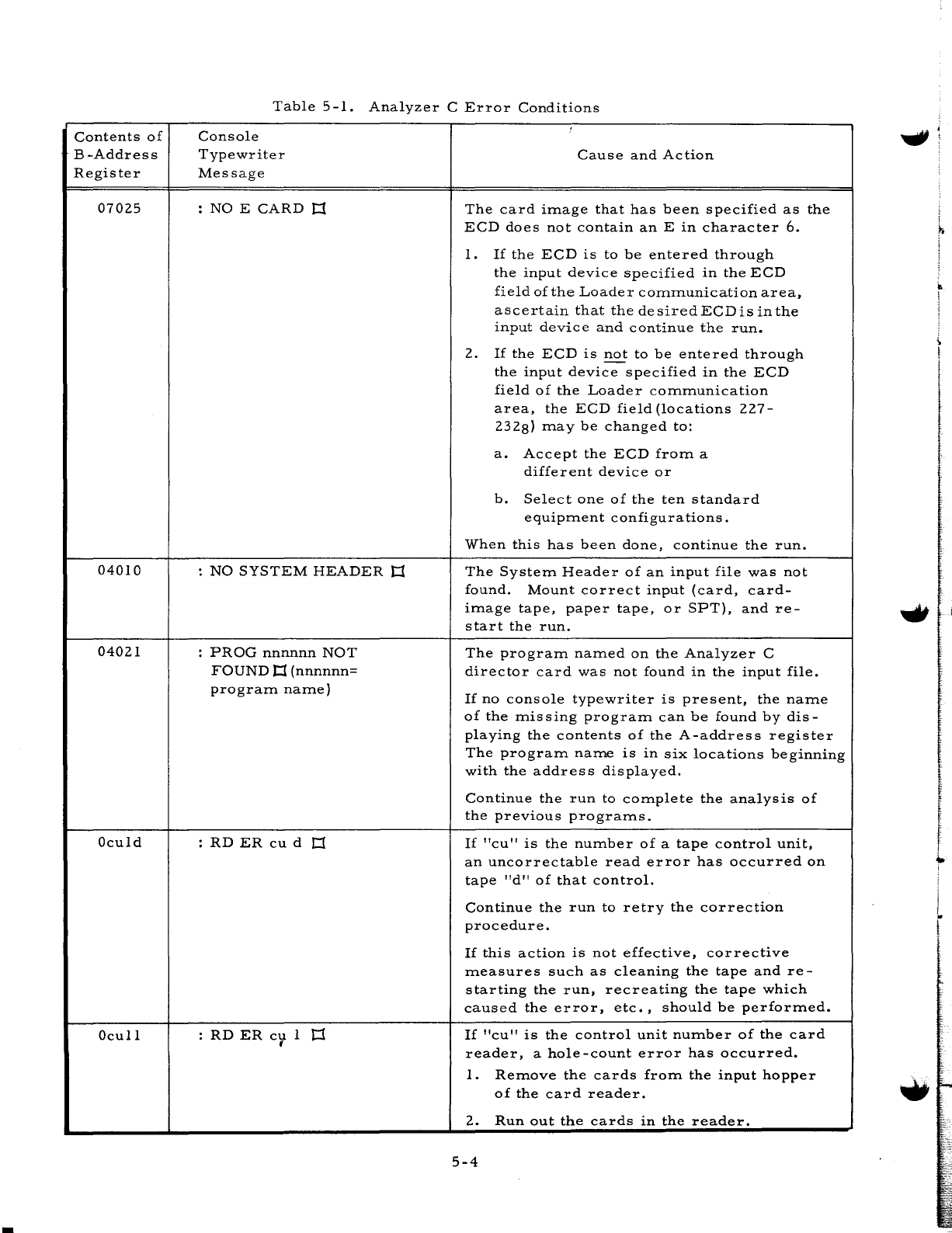
Contents
of
B-Address
Register
07025
04010
04021
Oculd
OculI
Table
5
-1.
Analyzer
C
Error
Conditions
Console
Typewriter
Message
:
NO
E
CARD
J:l
:
NO
SYSTEM
HEADER
J:l
:
PROG
nnnnnn
NOT
FOUND
J:l
(nnnnnn=
prograITl
naITle)
:
RD
ER
cu
d
J:l
:
RD
ER
c'l
1
t:1
Cause
and
Action
The
card
iITlage
that
has
been
specified
as
the
ECD
does
not
contain
an
E
in
character
6.
1.
If
the
ECD
is
to
be
entered
through
the
input
device
specified
in
the
ECD
field
of
the
Loade
r
cOITlITlunication
area,
ascertain
that
thedesiredECDisinthe
input
device
and
continue
the
run.
2.
If
the
ECD
is
not
to
be
entered
through
the
input
device
specified
in
the
ECD
field
of
the
Loader
cOITlITlunication
area,
the
ECD
field
(locations
227-
2328)
ITla y
be
changed
to:
a.
Accept
the
ECD
froITl
a
different
device
or
b.
Select
one
of
the
ten
standard
equipITlent
configurations.
When
this
has
been
done,
continue
the
run.
The
SysteITl
Header
of
an
input
file
was
not
found.
Mount
correct
input
(card,
card-
iITlage
tape,
paper
tape,
or
SPT),
and
re-
s
tart
the
run.
The
prograITl
naITled
on
the
Analyzer
C
director
card
was
not
found
in
the
input
file.
If
no
console
typewriter
is
present,
the
naITle
of
the
ITlissing
prograITl
can
be
found
by
dis-
playing
the
contents
of
the
A-address
register
The
prograITl
naITle
is
in
six
locations
beginning
with
the
address
displayed.
Continue
the
run
to
cOITlplete
the
analysis
of
the
previous
prograITls.
If
"cu"
is
the
nUITlber
of
a
tape
control
unit,
an
uncorrectable
read
error
has
occurred
on
tape
"d"
of
that
control.
Continue
the
run
to
retry
the
correction
procedure.
If
this
action
is
not
effective,
corrective
ITleasures
such
as
cleaning
the
tape
and
re-
starting
the
run,
recreating
the
tape
which
caused
the
error,
etc.,
should
be
perforITled.
If
"cu"
is
the
control
unit
nUITlber
of
the
card
reader,
a
hole-count
error
has
occurred.
1.
ReITlove
the
cards
froITl
the
input
hopper
of
the
card
reader.
2.
Run
out
the
cards
in
the
reader.
5-4
j
i
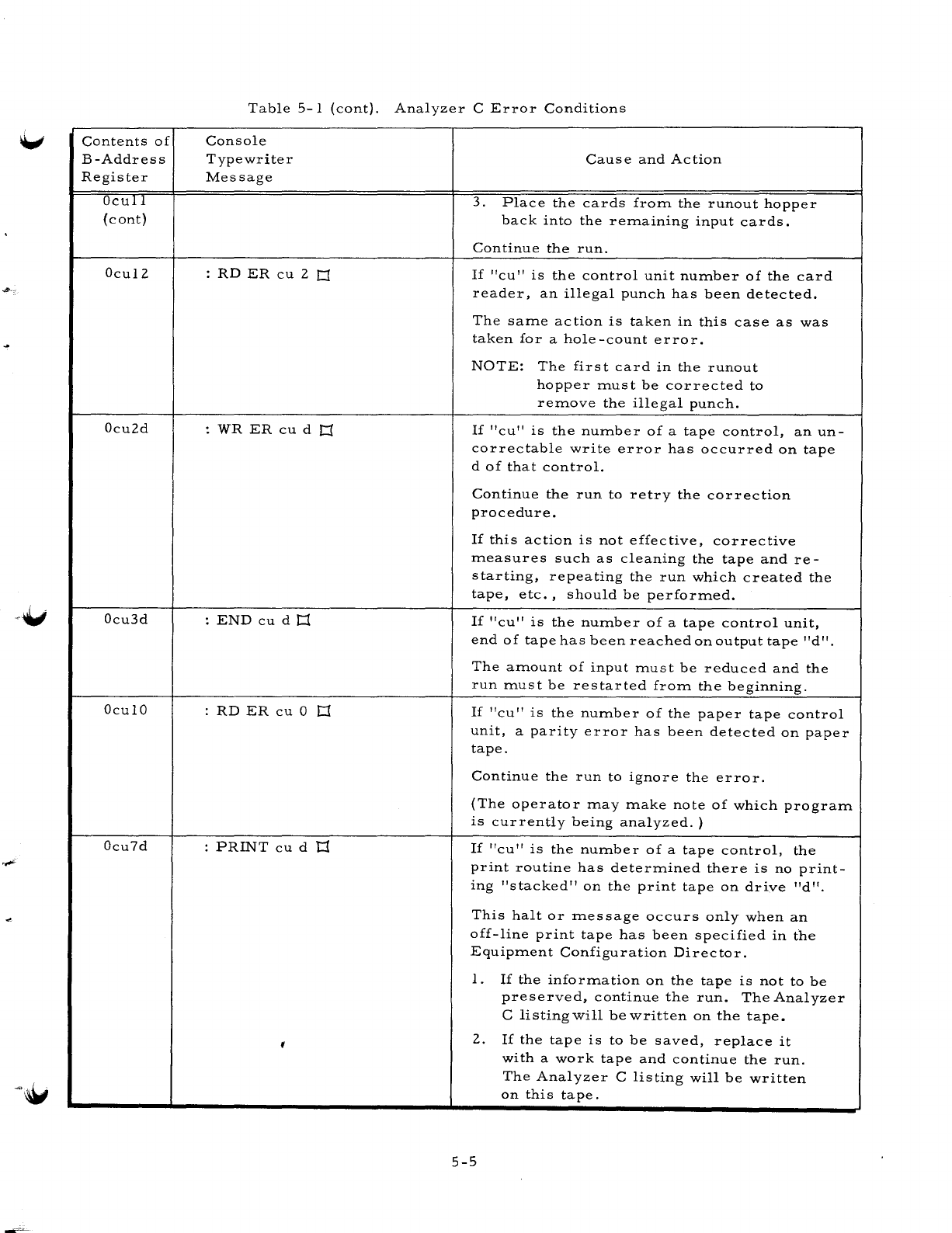
Contents
of
B-Address
Register
OcuTl
(cont)
Ocu12
Ocu2d
Ocu3d
Ocul0
Ocu7d
Table
5-1
(cont).
Analyzer
C
Error
Conditions
Console
Typewriter
Message
:
RD
ER
cu
2
r::r
:
WR
ER
cu
d
r::r
:
END
cu
d
r::r
:
RD
ER
cu
0
r::r
:
PRINT
cu
d
1:1
Cause
and
Action
3.
Place
the
cards
from
the
runout
hopper
back
into
the
remaining
input
cards.
Continue
the
run.
If
"cu"
is
the
control
unit
number
of
the
card
reader,
an
illegal
punch
has
been
detected.
The
same
action
is
taken
in
this
case
as
was
taken
for
a
hole
-count
error.
NOTE:
The
first
card
in
the
runout
hopper
must
be
corrected
to
remove
the
illegal
punch.
If
"cu"
is
the
number
of
a
tape
control,
an
un-
correctable
write
error
has
occurred
on
tape
d
of
that
control.
Continue
the
run
to
retry
the
correction
procedure.
If
this
action
is
not
effective,
corrective
measures
such
as
cleaning
the
tape
and
re-
starting,
repeating
the
run
which
created
the
tape,
etc.,
should
be
performed.
If
"cu"
is
the
number
of
a
tape
control
unit,
end
of
tape
has
been
reached
on
output
tape
"d".
The
amount
of
input
must
be
reduced
and
the
run
must
be
restarted
from
the
beginning.
If
"cu"
is
the
number
of
the
paper
tape
control
unit,
a
parity
error
has
been
detected
on
paper
tape.
Continue
the
run
to
ignore
the
error.
(The
operator
may
make
note
of
which
program
is
currently
being
analyzed.
)
If
"cu"
is
the
number
of
a
tape
control,
the
print
routine
has
determined
there
is
no
print-
ing
"stacked"
on
the
print
tape
on
drive
"d".
This
halt
or
message
occurs
only
when
an
off-line
print
tape
has
been
specified
in
the
Equipment
Configuration
Director.
1.
If
the
information
on
the
tape
is
not
to
be
preserved,
continue
the
run.
The
Analyzer
C
listing
will
be
written
on
the
tape.
2.
If
the
tape
is
to
be
saved,
replace
it
with
a
work
tape
and
continue
the
run.
The
Analyzer
C
listing
will
be
written
on
this
tape.
5-5
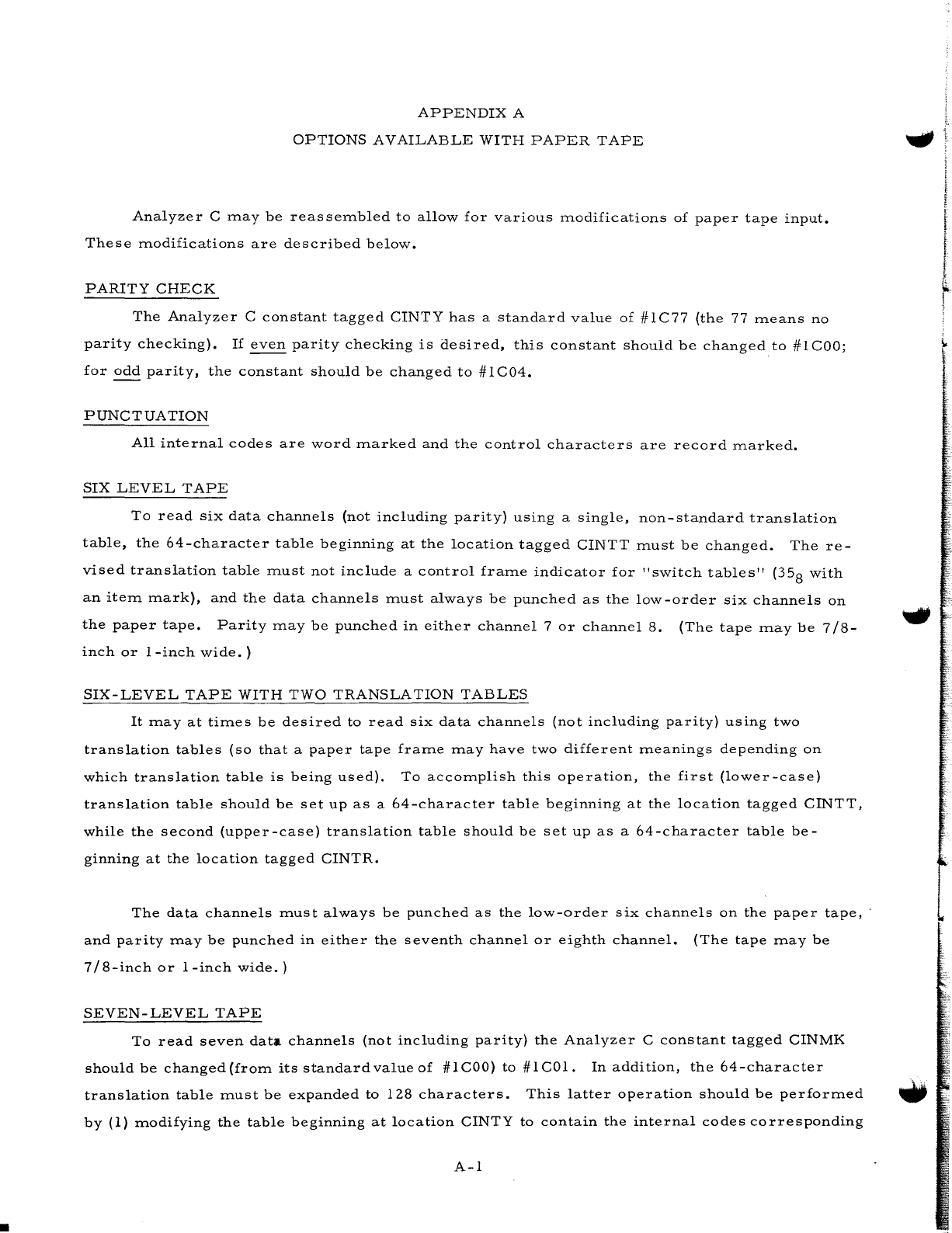
•
APPENDIX
A
OPTIONS
AVAILABLE
WITH
PAPER
TAPE
Analyzer
C
may
be
reassembled
to
allow
for
various
modifications
of
paper
tape
input.
These
modifications
are
described
below.
PARITY
CHECK
The
Analyzer
C
constant
tagged
CINTY
has
a
standard
value
of
#lC77
(the
77
means
no
parity
checking).
If
even
parity
checking
is
desired,
this
constant
should
be
changed
to
#lCOO;
for
odd
parity,
the
constant
should
be
changed
to
#lC04.
PUNCTUATION
All
internal
codes
are
word
marked
and
the
control
characters
are
record
marked.
SIX
LEVEL
TAPE
To
read
six
data
channels
(not
including
parity)
using
a
single,
non-standard
translation
table,
the
64-character
table
beginning
at
the
location
tagged
CINTT
must
be
changed.
The
re-
vised
translation
table
must
not
include
a
control
frame
indicator
for
"switch
tables"
(35
8
with
an
item
mark),
and
the
data
channels
must
always
be
punched
as
the
low-order
six
channels
on
the
paper
tape.
Parity
may
be
punched
in
either
channel
7
or
channel
8.
(The
tape
may
be
7/8-
inch
or
1
-inch
wide.
)
SIX-LEVEL
TAPE
WITH
TWO
TRANSLATION
TABLES
It
may
at
times
be
desired
to
read
six
data
channels
(not
including
parity)
using
two
translation
tables
(so
that
a
paper
tape
frame
may
have
two
different
meanings
depending
on
which
translation
table
is
being
used).
To
accomplish
this
operation,
the
first
(lower-case)
translation
table
should
be
set
up
as
a
64-character
table
beginning
at
the
location
tagged
CINTT,
while
the
second
(upper-case)
translation
table
should
be
set
up
as
a
64-character
table
be-
ginning
at
the
location
tagged
CINTR.
The
data
channels
must
always
be
punched
as
the
low-order
six
channels
on
the
paper
tape,
-
and
parity
may
be
punched
in
either
the
seventh
channel
or
eighth
channel.
(The
tape
may
be
7/8-inch
or
I-inch
wide.)
SEVEN-LEVEL
TAPE
To
read
seven
data
channels
(not
including
parity)
the
Analyzer
C
constant
tagged
CINMK
should
be
changed
{from
its
standard
value
of
#ICOO)
to
#ICOl.
In
addition,
the
64-character
translation
table
must
be
expanded
to
128
characters.
This
latter
operation
should
be
performed
•
by
(1)
modifying
the
table
beginning
at
location
CINTY
to
contain
the
internal
codes
corresponding
A-I
I
I
v.
!
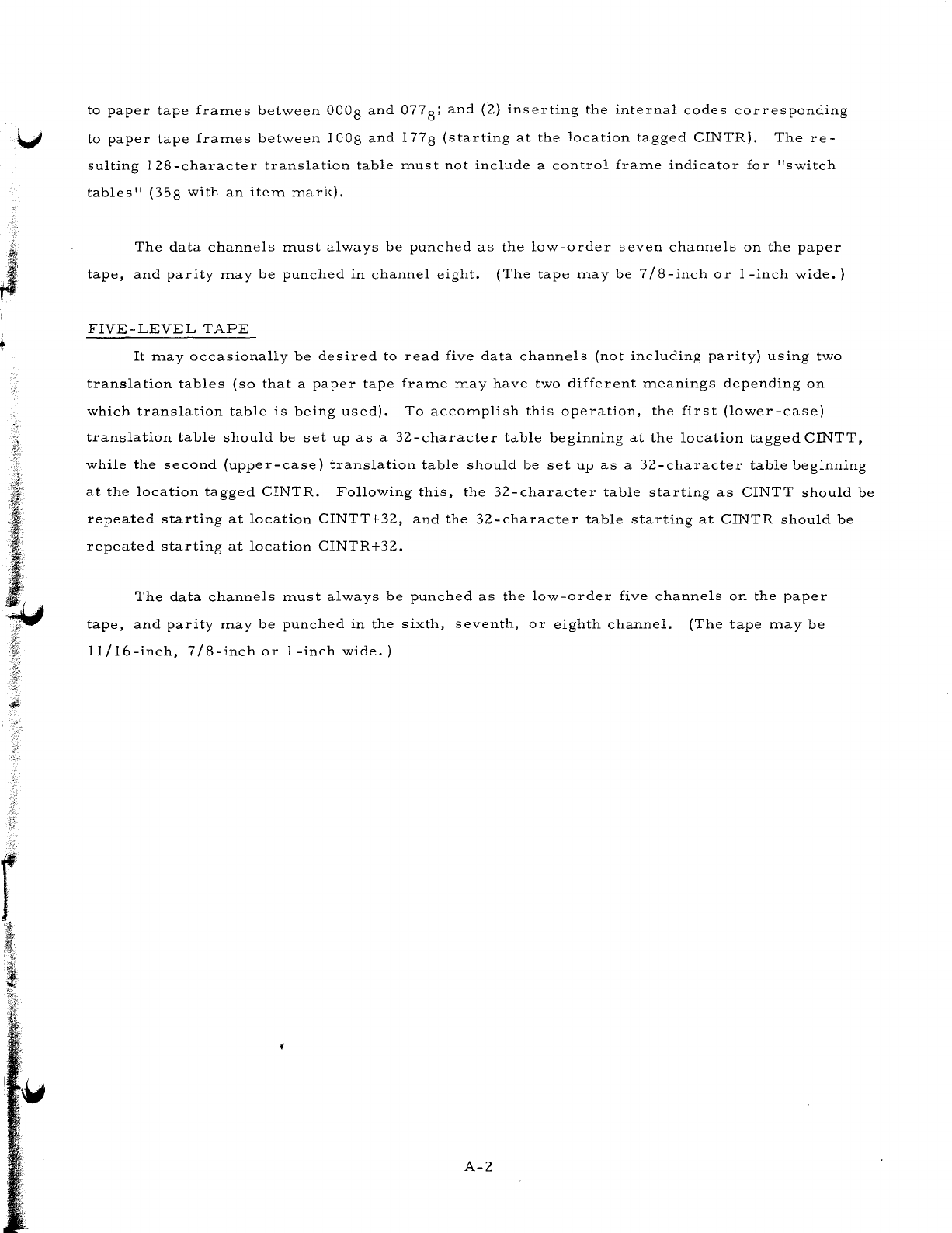
to
paper
tape
fraITles
between
0008
and
077
8;
and
(2)
inserting
the
internal
codes
corresponding
'v
to
paper
tape
fraITles
between
1008
and
1778
(starting
at
the
location
tagged
CINTR).
The
re-
sulting
I28-character
translation
table
ITlust
not
include
a
control
fraITle
indicator
for
"switch
tables"
(358
with
an
iteITl
ITlark).
J
The
data
channels
ITlust
always
be
punched
as
the
low-order
seven
channels
on
the
paper
tape,
and
parity
ITlay
be
punched
in
channel
eight.
(The
tape
ITlay
be
7/8-inch
or
I-inch
wide.)
FIVE-LEVEL
TAPE
It
ITlay
occasionally
be
desired
to
read
five
data
channels
(not
including
parity)
using
two
translation
tables
(so
that
a
paper
tape
fraITle
ITlay
have
two
different
ITleanings
depending
on
which
translation
table
is
being
used).
To
accoITlplish
this
operation,
the
first
(lower-case)
translation
table
should
be
set
up
as
a
32-character
table
beginning
at
the
location
tagged
CINTT,
while
the
second
(upper-case)
translation
table
should
be
set
up
as
a
32-character
table
beginning
at
the
location
tagged
CINTR.
Following
this,
the
32-character
table
starting
as
CINTT
should
be
repeated
starting
at
location
CINTT+32,
and
the
32-character
table
starting
at
CINTR
should
be
repeated
starting
at
location
CINTR+32.
The
data
channels
ITlust
always
be
punched
as
the
low-order
five
channels
on
the
paper
tape,
and
parity
ITlay
be
punched
in
the
sixth,
seventh,
or
eighth
channel.
(The
tape
ITlay
be
11
I
16-inch,
7
18-inch
or
1
-inch
wide.
)
A-2
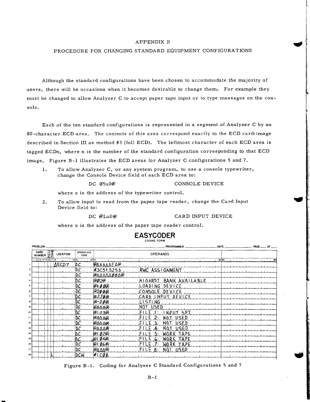
APPENDIX
B
PROCEDURE
FOR
CHANGING
STANDARD
EQUIPMENT
CONFIGURATIONS
Although
the
standard
configurations
have
been
chosen
to
accommodate
the
majority
of
users,
there
will
be
occasions
when
it
becomes
desirable
to
change
them.
For
example
they
must
be
changed
to
allow
Analyzer
C
to
accept
paper
tape
input
or
to
type
messages
on
the
con-
sole.
Each
of
the
ten
standard
configurations
is
represented
in
a
segment
of
Analyzer
C
by
an
80-character
ECD
area.
The
contents
of
this
area
correspond
exactly
to
the
ECD
card-image
described
in
Section
III
as
method
#3
(full
ECD).
The
leftmost
character
of
each
ECD
area
is
tagged
ECDn,
where
n
is
the
number
of
the
standard
configuration
corresponding
to
that
ECD
image.
Figure
B-1
illustrates
the
ECD
areas
for
Analyzer
C
configurations
5
and
7.
10
I
12
"
"
I.
,7
,.
1.
To
allow
Analyzer
C,
or
any
system
program,
to
use
a
console
typewriter,
change
the
Console
Device
field
of
each
ECD
area
to:
DC
@5uO@
CONSOLE
DEVICE
where
u
is
the
addres
s
of
the
typewriter
control.
2.
To
allow
input
to
read
from
the
paper
tape
reader,
change
the
Card
Input
Device
field
to:
DC
@LuO@
CARD
INPUT
DEVICE
where
u
is
the
address
of
the
paper
tape
reader
control.
EASYCODER
CODING
FORM
PROBLEM
PROGR
AMMER
DATE
CARD
!I~
LOCATION
OPERATION OPERANDS
NUMBER
CODE
I Z 3
..
5 • 7 •
1415
2021
6263
I i if,ECD7
DC
'@1lt:.b.M,
U,@
I I
DC
#3C51
525~
RWC
ASSIGNMENT
I I
DC
'@AAMll0'1;t:.@
I I
DC
KaJ{lI2@
HI
GHE,5T
BAN.K
AVA
I LABLE
I 1
DC
~~
~.f/;@
LOADI,NG
DEVICE
I I
DC
~2ia~
CONSOLE
DEV
I
CE
I.
I
1t>,C
'@JJ~@
CARD
INPUT
DEVICE
i I
Dc
(iJ-2d@ LI STI
NG
I I
Dc
@MA(I)
NOT
USED
I : Itt
~I03@
IFI
LEI:
\
N;PUT
SPT
I I
I~c
~MA~
F I L E
2:
NOT
USED
I i
I~C
~M./Y!i.
IFI L£
,?!:
NOT
USED
I I
I~c
'(e:JMAfil
fl
LE
4:
!-len
USED
1 I
ID,e
~102~
FILE
5-
WORK
1
APE
1 I
DC
k!vl
~4«<l,
F I L E
,t,:
WQ,R
K
TA,PE
I :
DC
~10.6Et?
FI
LE
7:
WO,RK
TAPE
I I
DC
fiJIJ.
6./:/ii~
FI
L t
,8.:
N()1
U~ED
! I L
Dew
II
ca0,
Figure
B-1.
Coding
for
Analyzer
C
Standard
Configurations
5
and
7
B-1
PAGE
OF
80
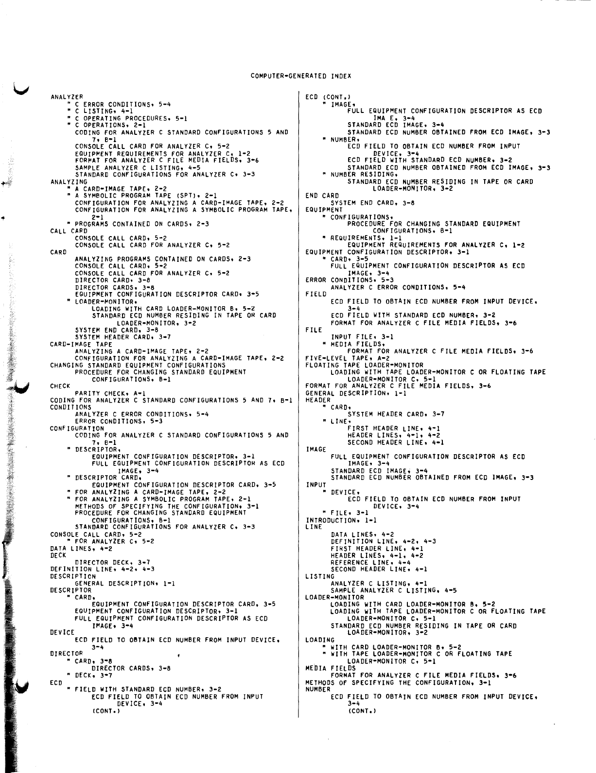
~-
COMPUTER-GENERATED
I~DEX
ANALYZER
• C
ERROR
CONDITIONS.
5-4
• C LISTING.
4-1
• C
OPERATING
PROCEDURES.
5-1
• C
OPERATIONS.
2-1
CODING
FOR
ANALYZER
C
STANDARD
CONFIGURATIONS
5
AND
7.
B-1
CONSOLE
CALL
CARD
FOR
ANALYZER
C.
5-2
EQUIPMENT
REQUIREMENTS
FOR
ANALYZER
C.
1-2
FORMAT
FOR
ANALYZER
C
FILE
MEDIA
FIELDS.
3-6
SAMPLE
ANALYZER
C LISTING.
4-5
STANDARD
CONFIGURATIONS
FOR
ANALYZER
C.
3-3
ANALYZING
• A
CARD-IMAGE
TAPE.
2-2
• A
SYMBOLIC
PROGRAM
TAPE
(SPT). 2-1
CONFIGURATION
FOR
ANALYZING
A
CARD-IMAGE
TAPE.
2-2
CONFIGURATION
FOR
ANALYZING
A
SYMBOLIC
PROGRAM
TAPE.
2-1
•
PROGRAMS
CONTAINED
ON
CARDS.
2-3
CALL
CARD
CARD
CONSOLE
CALL
CARD.
5-2
CONSOLE
CALL
CARD
FOR
ANALYZER
C.
5-2
ANALYZING
PROGRAMS
CONTAINED
ON
CARDS.
2-3
CONSOLE
CALL
CARD.
5-2
CONSOLE
CALL
CARD
FOR
ANALYZER
C.
5-2
DIRECTOR
CARD.
3-8
DIRECTOR
CARDS.
3-8
EQUIPMENT
CONFIGURATION
DESCRIPTOR
CARD.
3-5
•
LOADER-MONITOR.
LOADING
WITH
CARD
LOADER-MONITOR
B.
5-2
STANDARD
ECD
NUMBER
RESIDING
IN
TAPE
OR
CARD
LOADER-MONITOR.
3-2
SYSTEM
END
CARD.
3-8
SYSTEM
HEADER
CARD.
3-7
CARD-IMAGE
TAPE
ANALYZING
A
CARD-IMAGE
TAPE.
2-2
CONFIGURATION
FOR
ANALYZING
A
CARD-IMAGE
TAPE.
2-2
CHANGING
STANDARD
EQUIPMENT
CONFIGURATIONS
PROCEDURE
FOR
CHANGING
STANDARD
EQUIPMENT
CONFIGURATIONS.
B-1
CHECK
PARITY
CHECK.
A-I
CODING
FOR
ANALYZER
C
STANDARD
CONFIGURATIONS
5
AND
7.
B-1
CONDIT
IONS
ANALYZER
C
ERROR
CONDITIONS.
5-4
ERROR
CONDITIONS.
5-3
CONf
IGURATION
CODING
FOR
ANALYZER
C
STANDARD
CONFIGURATIONS
5
AND
7.
6-1
•
DESCRIPTOR.
EQUIPMENT
CONFIGURATION
DESCRIPTOR.
3-1
FULL
EQUIPMENT
CONFIGURATION
DESCRIPTOR
AS
ECD
IMAGE.
3-4
•
DESCRIPTOR
CARD.
EQUIPMENT
CONFIGURATION
DESCRIPTOR
CARD.
3-5
•
FOR
ANALYZING
A
CARD-IMAGE
TAPE.
2-2
•
FOR
ANALYZING
A
SYMBOLIC
PROGRAM
TAPE.
2-1
MfTHODS
OF
SPECIFYING
THE
CONFIGURATION.
3-1
PROCEDURE
FOR
CHANGING
STANDARD
EQUIPMENT
CONFIGURATIONS.
B-1
STANDARD
CONfIGURATIONS
FOR
ANALYZER
C.
3-3
CONSOLE
CALL
CARD.
5-2
•
FOR
ANALYZER
C.
5-2
DATA
LINES.
4-2
DECK
DIRECTOR
DECK.
3-7
DEFINITION
LINE.
4-2.
4-3
DESCRIPTION
GENERAL
DESCRIPTION.
1-1
DESCRIPTOR
•
CARD.
EQUIPMENT
CONFIGURATION
DESCRIPTOR
CARD.
3-5
EQUIPMENT
CONFIGURATION
DESCRIPTOR.
3-1
FULL
EQUIPMENT
CONFIGURATION
DESCRIPTOR
AS
ECD
IMAGE.
3-4
DEViCE
ECD
FIELD
TO
oeTAIN
ECD
NUMBER
FROM
INPUT
DEVICE.
3-4
DIRECTOR
ECD
•
CARD.
3-8
DIRECTOR
CARDS.
3-8
•
DECK.
3-7
•
FIELD
WITH
STANDARD
ECD
NUMBER.
3-2
ECD
FIELD
TO
OBTAIN
ECD
NUMBER
FROM
INPUT
DEVICE.
3-4
(CONT.
)
ECD
(CONT.)
•
IMAGE.
FULL
EQUIPMENT
CONFIGURATION
DESCRIPTOR
AS
ECD
IMA
E.
3-4
STANDARD
ECD
IMAGE.
3-4
STANDARD
ECD
NUMBER
OBTAINED
FROM
ECD
IMAGE.
3-3
•
NUMBER.
ECD
FIELD
TO
OBTAIN
ECD
NUMBER
FROM
INPUT
DEVICE.
3-4
ECD
FIELD
WITH
STANDARD
ECD
NUMBER.
3-2
STANDARD
ECD
NUMBER
OBTAINED
FROM
ECD
IMAGE.
3-3
•
NUMBER
RESIDING.
STANDARD
ECD
NUMBER
RESIDING
IN
TAPE
OR
CARD
LOADER-MONITOR.
3-2
END
CARD
SYSTEM
END
CARD.
3-8
EQUIPMENT
•
CONFIGURATIONS.
PROCEDURE
FOR
CHANGING
STANDARD
EQUIPMENT
CONFIGURATIONS.
B-1
•
REQUIREMENTS.
1-1
EQUIPMENT
REQUIREMENTS
FOR
ANALYZER
C.
1-2
EQUIPMENT
CONFIGURATION
DESCRIPTOR.
3-1
•
CARD.
3-5
FULL
EQUIPMENT
CONFIGURATION
DESCRIPTOR
AS
ECD
IMAGE.
3-4
ERROR
CONDITIONS.
5-3
ANALYZER
C
ERROR
CONDITIONS.
5-4
FIELD
FILE
ECD
FIELD
TO
OBTAIN
ECD
NUMBER
FROM
INPUT
DEVICE.
3-4
ECD
FIELD
WITH
STANDARD
ECD
NUMBER.
3-2
FORMAT
FOR
ANALYZER
C FILE
MEDIA
FIELDS.
3-6
INPUT
FILE. 3-1
•
MEDIA
FIELDS.
FORMAT
FOR
ANALYZER
C FILE
MEDIA
FIELDS.
3-6
FIVE-LEVEL
TAPE.
A-2
FLOATING
TAPE
LOADER-MONITOR
LOADING
WITH
TAPE
LOADER-MONITOR
C
OR
FLOATING
TAPE
LOADER-MONITOR
C.
5-1
FORMAT
FOR
ANALYZER
C
FILE
MEDIA
FIELDS.
3-6
GENERAL
DESCRIPTION.
1-1
HEADER
•
CARD.
SYSTEM
HEADER
CARD.
3-7
• LINE.
IMAGE
INPUT
FIRST
HEADER
LINE.
4·1
HEADER
LINES.
4-1.
4-2
SECOND
HEADER
LINE.
4-1
FULL
EQUIPMENT
CONFIGURATION
DESCRIPTOR
AS
ECD
IMAGEt
3-4
STANDARD
ECD
IMAGE.
3-4
STANDARD
ECD
NUMBER
OBTAINED
FROM
ECD
IMAGE.
3-3
•
DEVICE.
ECD
FIELD
TO
OBTAIN
ECD
NUMBER
FROM
INPUT
DEVICE.
3-4
• FILE.
3-1
INTRODUCTION.
1-1
LINE
DATA
LINES.
4-2
DEFINITION
LINE.
4·2.
4-3
FIRST
HEADER
LINE.
4-1
HEADER
LINES.
4-1.
4-2
REFERENCE
LINE.
4-4
SECOND
HEADER
LINE.
4-1
LISTING
ANALYZER
C LISTING.
4-1
SAMPLE
ANALYZER
C LISTING.
4-5
LOADER-"10NITOR
LOADING
WITH
CARD
LOADER-MONITOR
B.
5-2
LOADING
WITH
TAPE
LOADER-MONITOR
C
OR
FLOATING
TAPE
LOADER-MONITOR
C.
5-1
STANDARD
ECD
NUMBER
RESIDING
IN
TAPE
OR
CARD
LOADER-MONITOR.
3-2
LOADING
•
WITH
CARD
LOADER-MONITOR
B.
5-2
•
WITH
TAPE
LOADER-MONITOR
C
OR
FLOATING
TAPE
LOADER-MONITOR
C. 5-1
MEDIA
FIELDS
FORMAT
FOR
ANALYZER
C
FILE
MEDIA
FIELDS.
3-6
METHODS
OF
SPECIFYING
THE
CONFIGURATION.
3-1
NUMBER
ECD
FIELD
TO
OBTAIN
ECD
NUMBER
FROM
INPUT
DEVICE.
3-4
(CONT.)
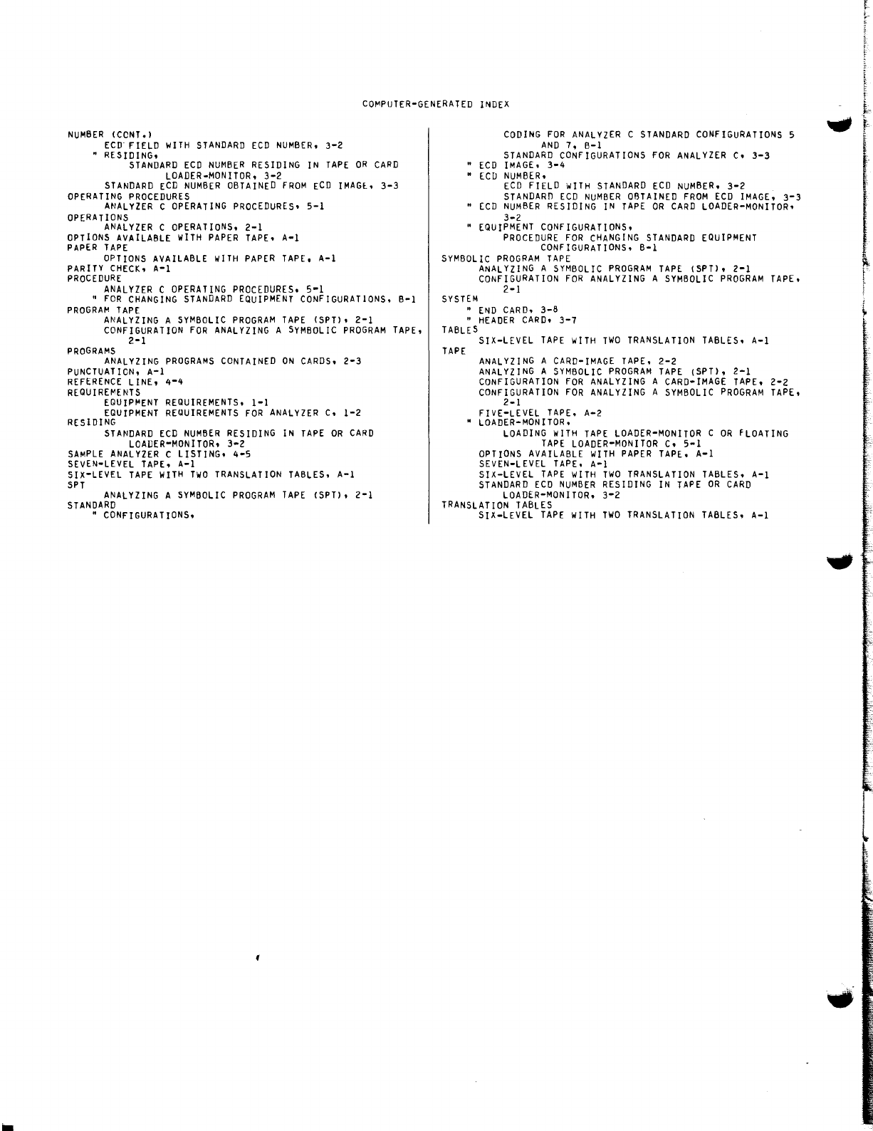
CO~PUTER-GENERATED
INDEX
NUMBER
(CCNT.)
ECD"
FIELD
WITH
STANDARD
ECD
NUMBER.
3-2
"
RESIDING.
STANDARD
ECD
NUMBER
RESIDING
IN
TAPE
OR
CARD
LOADER-MONITOR.
3-2
STANDARD
ECD
NUMBER
OBTAINED
FROM
ECD
IMAGl.
3-3
OPERATING
PROCEDURES
ANALYZER
C
OPERATING
PROCEDURES.
5-1
OPERATIONS
ANALYZER
C
OPERATIONS.
2-1
OPTIONS
AVAILABLE
WITH
PAPER
TAPE.
A-I
PAPER
TAPE
OPTIONS
AVAILABLE
WITH
PAPER
TAPE.
A-I
PARITY
CHECK.
A-I
PROCEDURE
ANALYZER
C
OPERATING
PROCEDURES.
5-1
•
FOR
CHANGING
STANDARD
EQUIPMENT
CONFIGURATIONS.
B-1
PROGRAM
TAPE
ANALYZING
A
SYMBOLIC
PROGRAM
TAPE
(SPT).
2-1
CONFIGURATION
FOR
ANALYZING
A
SYMBOLIC
PROGRAM
TAPE.
2-1
PROGRAMS
ANALYZING
PROGRAMS
CONTAINED
ON
CARDS.
2-3
PUNCTUATION.
A-I
REFERENCE
LINE.
4-4
REQUIRE~ENTS
EQUIPMENT
REQUIREMENTS.
1-1
EQUIPMENT
REQUIREMENTS
FOR
ANALYZER
C.
1-2
RESIDING
STANDARD
ECD
NUMBER
RESIDING
IN
TAPE
OR
CARD
LOADER-MONITOR.
3-2
SAMPLE
ANALYZER
C LISTING.
4-5
SEVEN-LEVEL
TAPE.
A-I
SIX-LEVEL
TAPE
WITH
TWO
TRANSLATION
TABLES.
A-I
SPT
ANALYZING
A
SYMBOLIC
PROGRAM
TAPE
(SPT).
2-1
STANDARD
"
CONFIGURATIONS.
CODING
FOR
ANALYZER
C
STANDARD
CONFIGURATIONS
5
AND
7.
B-1
STANDARD
CONFIGURATIONS
FOR
ANALYZER
C.
3-3
"
ECD
IMAGE.
3-4
"
ECD
NUMBER.
ECD
FIELD
WITH
STANDARD
ECD
NUMBER.
3-2
STANDARD
ECD
NUMBER
OBTAINED
FROM
ECD
IMAGE.
3-3
"
[CD
NUMBER
RESIDING
IN
TAPE
OR
CARD
LOADER-MONITOR.
3-2
•
EQUIPMENT
CONFIGURATIONS.
PROCEDURE
FOR
CHANGING
STANDARD
EQUIPMENT
CONFIGURATIONS.
B-1
SYMBOLIC
PROGRAM
TAPE
ANALYZING
A
SYMBOLIC
PROGRAM
TAPE
(SPT).
2-1
CONFIGURATION
FOR
ANALYZING
A
SYMBOLIC
PROGRAM
TAPE.
2-1
SYSTEM
•
END
CARD.
3-8
•
HEADER
CARD.
3-7
TABLES
TAPE
SIX-LEVEL
TAPE
wITH
TWO
TRANSLATION
TABLES.
A-I
ANALYZING
A
CARD-IMAGE
TAPE.
2-2
ANALYZING
A
SYMBOLIC
PROGRAM
TAPE
(SPT).
2-1
CONFIGURATION
FOR
ANALYZING
A
CARD-IMAGE
TAPE.
2-2
CONFIGURATION
FOR
ANALYZING
A
SYMBOLIC
PROGRAM
TAPE.
2-1
FIVE-LEVEL
TAPE.
A-2
•
LOADER-MONITOR.
LOADING
WITH
TAPE
LOADER-MONITOR
C
OR
FLOATING
TAPE
LOADER-MONITOR
C.
5-1
OPTIONS
AVAILABLE
WITH
PAPER
TAPE.
A-I
SEVEN-LEVEL
TAPE.
A-I
SIX-LEVEL
TAPE
WITH
TWO
TRANSLATION
TABLES.
A-I
STANDARD
ECD
NUMBER
RESIDING
IN
TAPE
OR
CARD
LOADER-MONITOR.
3-2
TRANSLATION
TABLES
SIX-LEVEL
TAPE
WITH
TWO
TRANSLATION
TABLES.
A-I
l
~-
1
I
CIl
c:
:J
bO
c:
o
C(
HONEYWELL
EDP
TECHNICAL
PUBLICATIONS
USERS'
REMARKS
FORM
TITLE:
SERIES
200
ANALYZER
C
DATED:
November
15,
1965
FILE
NO:
122.2305.
001C.
0-019
ERRORS
NOTED:
Fold
~
SUGGESTIONS
FOR
IMPROVEMENT:
(.)
Fold
FROM:
NAME
__________________
_
DATE
______
_
COMPANY
__________________
__
TITLE
__________________
_
ADDRESS
__________________
___
ATT'N: PUBLICATIONS AND WRITING
SERVICES
DEPARTMENT
,
Honey1tVell
ELECTRONIC
DATA
PROCESSING
FIRST CLASS
PERMIT NO,
39531
WELLESLEY HILLS
MASS,
(')
c:
....
>
"
,
~
g Wi'
(JQ
r
:;'
ID
.'
