PartsManual 660 020416 1
User Manual: 660
Open the PDF directly: View PDF ![]() .
.
Page Count: 8
Not for
Reproduction
Illustrated Parts List
Pressure Washer / Lavadora de Presión
This pressure washer is rated in accordance to the Pressure Washer Manufacture Association (PWMA)
Standard PW101 (Testing and Rating Performance of Pressure Washers).
Questions? Help is just a moment away!
Preguntas? La ayuda es justa un momento lejos!
Call: Pressure Washer Helpline
Llame: Línnea Directa del Lavadora a Presión - 1-888-611-6708 M-F 8-5 CT
Troy-Bilt® is a registered trademark of MTD Products Inc and is used under license to Briggs & Stratton Power Products, LLC.
Troy-Bilt® es una marca de MTD y se usa abajo licencia a Briggs & Stratton Power Porducts, LLC.
Revision A
Manual Part No. 312650
Rev. Date: 10/4/2010
Mf
g
. No. Descri
p
tion / Descri
p
ción
Model
/
Modelo
020416-1 3,000 PSI Troy-Bilt
Not for
Reproduction

Not for
Reproduction
Table Of Content
s
Torque Specification Chart ..................................................................... Inside Back Cover
PRODUCT COMPONENTS PAGES
Main Unit .............................................................................................................................................................. 4
Pump .................................................................................................................................................................... 5
Not for
Reproduction
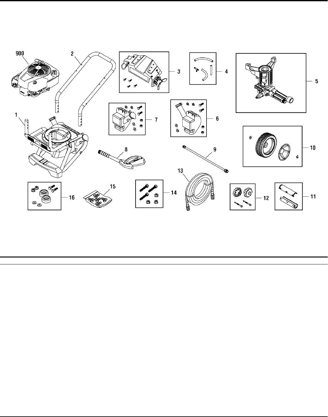
Main Unit
312345S
NOTE: Unless noted otherwise,
use the standard hardware torque
specification chart.
PART NO. DESCRIPTIONREF.
Footnotes
PART NO. DESCRIPTIONREF.
BASE 1 312100GS
HANDLE 2 310628BWGS
BILLBOARD 3 310857GS
KIT, Tree Clips -- 195964GS
HOSE, Chemical 4 208728GS
PUMP 5 311882GS
TANK, Chemical 6 310821GS
CAP, Chemical Tank -- 310806GS
KIT, Fuel Valve -- 310333GS
TANK, Chemical 7 310820GS
CAP, Chemical Tank -- 310805GS
KIT, Fuel Valve -- 310333GS
GUN 8 209094GS
EXTENSION, QC 9 200595GS
KIT, Wheel 10 202477GS
HUBCAP -- 200519GS
E-RING -- 192050GS
GRIP 11 311969GS
KIT, Hardware, Handle 12 312099GS
HOSE 13 311528GS
KIT, Hardware, Pump Mounting 14 200199GS
KIT, QC Nozzles 15 311311GS
NOZZLE, QC, Red -- 195983ANGS
NOZZLE, QC, Green -- 195983QGS
NOZZLE, QC, White -- 195983RGS
NOZZLE, QC, Cyan -- 195983APGS
NOZZLE, QC, Magenta -- 195983AQGS
MOUNT, Vibration 16 192310GS
* ENGINE 900 -----
MANUAL, Operator's (Not Illustrated) -- 312336GS
OIL BOTTLE (Not Illustrated) -- 199272GS
DECAL, Unit (Not Illustrated) -- 310983GS
DECAL, Shroud (Not Illustrated) -- 310865GS
DECAL, Gun (Not Illustrated) -- 311247GS
*Contact Engine Manufacturer for parts and service.
4
2010
Milwaukee, WI, USA. All rights reserved
Briggs & Stratton Power Products Group
Copyright © by Briggs & Stratton Corporation
The above parts group applies to the following Mfg. Nos.:
312650
020416-1 - 3,000 PSI Tro
y
-Bilt
Not for
Reproduction
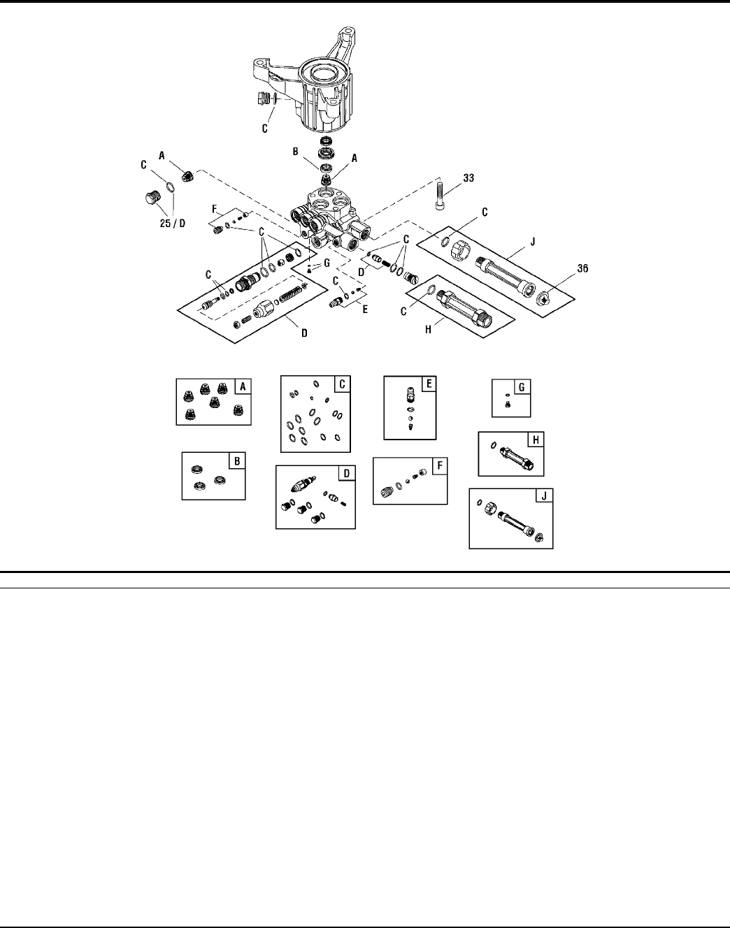
Pump
311882SRV
NOTE: Unless noted otherwise,
use the standard hardware torque
specification chart.
PART NO. DESCRIPTIONREF.
Footnotes
PART NO. DESCRIPTIONREF.
PLUG 25 201495GS
SCREW 33 200275GS
FILTER, Garden Hose 36 B2384GS
KIT, Check Valve A 200344GS
KIT, Water Seal B 200345GS
KIT, O-Ring C 200346GS
KIT, Unloader D 202328GS
KIT, Chemical Injection E 192914GS
KIT, Easy Start F 200349GS
SCREW, Grub G 200350GS
FITTING H 201497GS
KIT, Water Inlet J 201496GS
VALVE, Thermo Relief (Not Illustrated) -- 208673GS
PUMP SAVER (Optional Accessory) -- 6039
OIL BOTTLE (Optional Accessory) -- 6033
5
2010
Milwaukee, WI, USA. All rights reserved
Briggs & Stratton Power Products Group
Copyright © by Briggs & Stratton Corporation
The above parts group applies to the following Mfg. Nos.:
312650
020416-1 - 3,000 PSI Tro
y
-Bilt
Not for
Reproduction
Not for
Reproduction
in/lbs
ft/lbs
3
Torque Specification Chart
FOR STANDARD METRIC MACHINE HARDWARE (Tolerance ± 20%)
Property
Class
Class 8.8 Class 10.9 Class 12.9
Size Of
Hardware Nm. Nm. Nm. Nm.
M3
1.28
2.90
5.75
9.9
16.5
24
48
83
132
200
275
390
530
375
995
1350
1830
2360
3050
13.44 1.80
4.10
8.10
14
23
34
67
117
185
285
390
550
745
960
1400
1900
2580
3310
4290
19.2 22.92
2.15
M4
30.72 43.44 52.56
4.95
M5
60.96
5.97 7.15
16.5
9.7
M6 7.3 10.3 12.1
M7 12.1 16.9 19.9 27
M8 17.7 25 29 40
M10 35 50 59 81
M12 61 86.2 103 140
M14 101 136 162 220
M16 147 210 250 340
M18 202 287 346 470
M20 290 405 486 660
M22 390 559 656 890
M24 497 708 840 1140
M27 733 1032 1239 1680
M30 995 1401 1681 2280
M33 1349 1902 2278 3090
M36 1740 2441
3798
2935 3980
M39 2249 3163
Torque Specification Chart
FOR STANDARD MACHINE HARDWARE (Tolerance ± 20%)
Hardware
Grade
SAE Grade 2 SAE Grade 5 SAE Grade 8
Size Of
in/lbs
ft/lbs
in/lbs
ft/lbs
in/lbs
ft/lbs
in/lbs in/lbs
Hardware ft/lbs Nm. ft/lbs Nm. ft/lbs Nm.
8-32
19
2.1
30
3.4
41
4.6
8-36
20
2.3
31
3.5
43
4.9
10-24
27
3.1
43
4.9
60
6.8
10-32
31
3.5
49
5.5
68
7.7
1/4-20
66
7.6 810.9 12 16.3
1/4-28
76
8.6 10 13.6 14 19.0
5/16-18 11 15.0 17 23.1 25 34.0
5/16-24 12 16.3 19 25.8 29 34.0
3/8-16 20 27.2 30 40.8 45 61.2
3/8-24 23 31.3 35 47.6 50 68.0
7/16-14 30 40.8 50 68.0 70 95.2
7/16-20 35 47.6 55 74.8 80 108.8
1/2-13 50 68.0 75 102.0 110 149.6
1/2-20 55 74.8 90 122.4 120 163.2
9/16-12 65 88.4 110 149.6 150 204.0
9/16-18 75 102.0 120 163.2 170 231.2
5/8-11 90 122.4 150 204.0 220 299.2
5/8-18 100 136 180 244.8 240 326.4
3/4-10 160 217.6 260 353.6 386 525.0
3/4-16 180 244.8 300 408.0 420 571.2
7/8-9 140 190.4 400 544.0 600 816.0
7/8-14 155 210.8 440 598.4 660 897.6
1-8 220 299.2 580 788.8 900 1,244.0
1-12 240 326.4 640 870.4 1,000 1,360.0
Hex Head Capscrew
Hex Nut
Lockwasher
Washer
Carriage Bolt
NOTES
1. These torque values are to be used for all hardware
excluding: locknuts, self-tapping screws, thread forming
screws, sheet metal screws and socket head setscrews.
2. Recommended seating torque values for locknuts:
a. for prevailing torque locknuts - use 65% of grade 5
torques.
b. for flange whizlock nuts and screws - use 135% of
grade 5 torques.
3. Unless otherwise noted on assembly drawings, all torque
values must meet this specification.
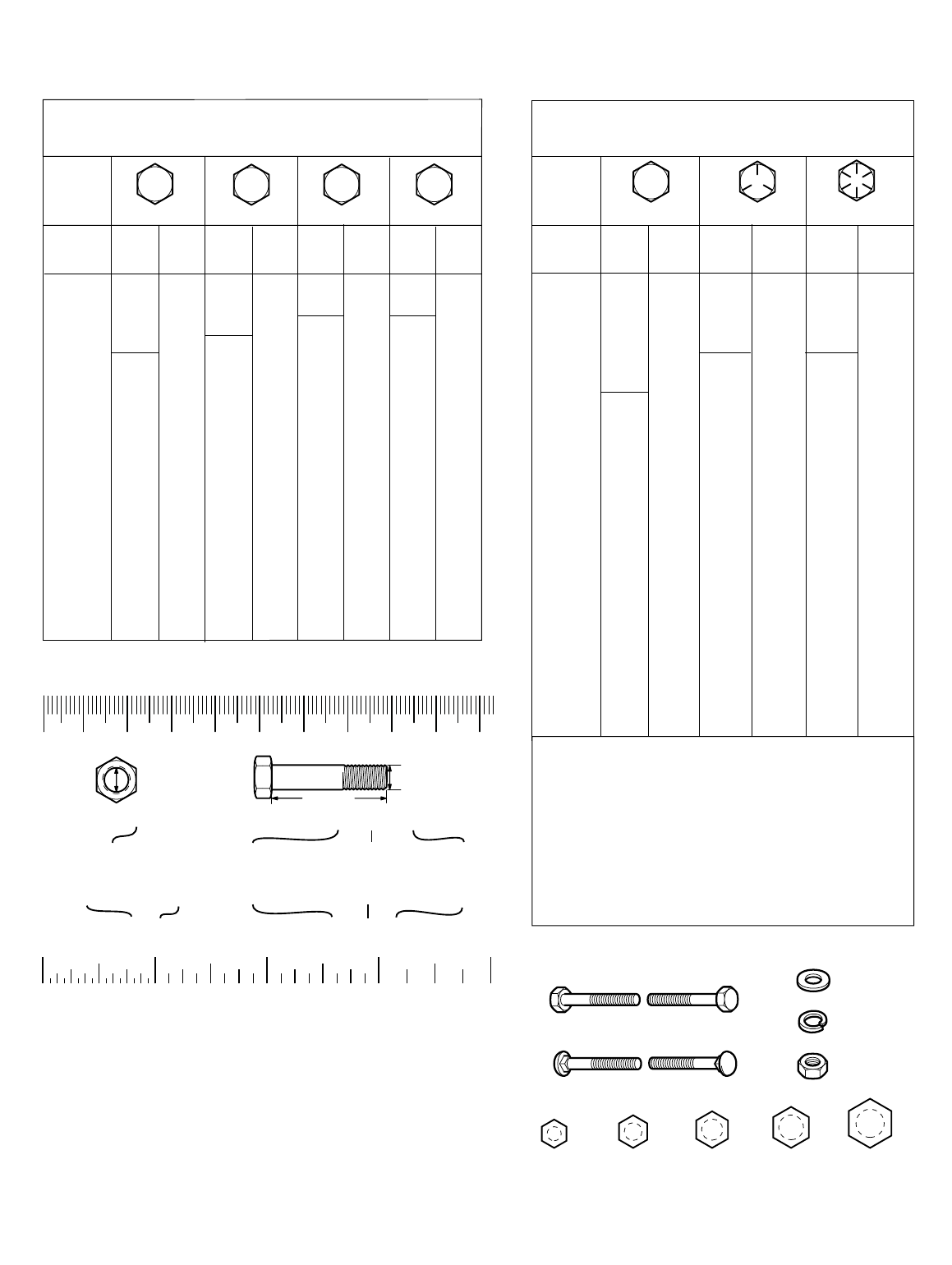
Hardware Identification & Torque Specifications
Common Hardware Types
No
Marks
The guides and ruler furnished below are designed to
help you select the appropriate hardware.
8.8 10.9 12.9
Class 5.6
5.6
5150
13.44 1.28
5.88
26.4 2.50
44.64 4.3
5.2
7.1
7.7
10.5
15
21
988
1340
759
1030
590
800
435
590
320
435
217
295
169
230
126
171
89
121
64
88
42
58
26
36
.56
Thread
Diameter (mm)
Screw, 1/2- 16 x 2
Body
Diameter
Diameter
Inside
Diameter (in)
Nut, 1/2-16
0
1/4 3/4
1/2
21
1/4 3/4
1/2 1/4 3/4
1/2 1/4 3/4
1/2
4
90 10070 80
50 60
30 40
01020
Thread
Diameter (mm)
Nut, M8 Screw, M8- 1.25 x 25
Distance between
threads (mm)
Body
Length (in)
Body
Length (mm)
3/8” Bolt or Nut
Wrench—9/16”
5/16” Bolt or Nut
Wrench—1/2”
1/4” Bolt or Nut
Wrench—7/16”
1/2” Bolt or Nut
Wrench—3/4”
7/16” Bolt or Nut
Wrench (Bolt)—5/8”
Wrench (Nut)—11/16”
in/lbs
Threads
per inch
Threads
per inch
Body Length
Body
When a washer or nut is identified as 1/2” (M8), this is
the
Nominal size
, meaning the
inside diameter
is 1/2 inch
(8mm metric thread diameter); if a second number is present
it represents the
threads per inch
(distance between threads).
When bolt or capscrew is identified as 1/2 - 16 x 2” (M8 - 1.25 x 50 ),
this means the
Nominal size
, or body diameter is 1/2 inch (8mm
metric thread diameter), the second number,16, represents the
threads per inch, (1.25 thread diameter).
The final number is the
body length of the bolt or screw, 2 inches (50mm).
Standard Hardware Sizing
M6 Bolt or Nut
Wrench—10mm
M8 Bolt or Nut
Wrench—13mm
M10 Bolt or Nut
Wrench—17mm
M12 Bolt or Nut
Wrench—19mm
M14 Bolt or Nut
Wrench—22 mm
Wrench & Fastener Size Guide

Not for
Reproduction
2010
Briggs & Stratton Power Products Group, LLC
Copyright© Briggs & Stratton Power Products Group, LLC. All rights reserved. No part of this page can be
reproduced or transmitted in any form by any means without the express written permission of Briggs & Stratton
Power Products Group, LLC.
