RN2483 LoRa Technology Module Command Reference User Guide 02 Lo Ra User's 40001784F
02%20RN2483%20LoRa%20Technology%20Module%20Command%20Reference%20User's%20Guide%20--%2040001784F
02%20RN2483%20LoRa%20Technology%20Module%20Command%20Reference%20User's%20Guide%20--%2040001784F
02%20RN2483%20LoRa%20Technology%20Module%20Command%20Reference%20User's%20Guide%20--%2040001784F
02%20RN2483%20LoRa%20Technology%20Module%20Command%20Reference%20User's%20Guide%20--%2040001784F
02%20RN2483%20LoRa%20Technology%20Module%20Command%20Reference%20User's%20Guide%20--%2040001784F
User Manual:
Open the PDF directly: View PDF ![]() .
.
Page Count: 63
- Table of Contents
- Preface
- Revision History
- Chapter 1. Introduction
- 1.1 Overview
- 1.2 Features
- 1.3 Configuration
- 1.4 UART Interface
- Chapter 2. Command Reference
- 2.1 Command Syntax
- 2.2 Command Organization
- 2.3 System Commands
- 2.4 MAC Commands
- Table 2-5: MAC Commands
- 2.4.1 mac reset <band>
- 2.4.2 mac tx <type> <portno> <data>
- 2.4.3 mac join <mode>
- 2.4.4 mac save
- 2.4.5 mac forceENABLE
- 2.4.6 mac pause
- 2.4.7 mac resume
- 2.4.8 MAC Set Commands
- Table 2-6: MAC Set Commands
- 2.4.8.1 mac set devaddr <address>
- 2.4.8.2 mac set deveui <devEUI>
- 2.4.8.3 mac set appeui <appEUI>
- 2.4.8.4 mac set nwkskey <nwkSessKey>
- 2.4.8.5 mac set appskey <appSessKey>
- 2.4.8.6 mac set appkey <appKey>
- 2.4.8.7 mac set pwridx <pwrIndex>
- 2.4.8.8 mac set dr <dataRate>
- 2.4.8.9 mac set adr <state>
- 2.4.8.10 mac set bat <level>
- 2.4.8.11 mac set retx <reTxNb>
- 2.4.8.12 mac set linkchk <linkCheck>
- 2.4.8.13 mac set rxdelay1 <rxDelay>
- 2.4.8.14 mac set ar <state>
- 2.4.8.15 mac set rx2 <dataRate> <frequency>
- 2.4.8.16 mac set sync <synchWord>
- 2.4.8.17 mac set upctr <fCntUp>
- 2.4.8.18 mac set dnctr <FCntDown>
- 2.4.8.19 MAC Set Channel Commands
- 2.4.9 MAC Get Commands
- Table 2-8: MAC Get Commands
- 2.4.9.1 mac get devaddr
- 2.4.9.2 mac get deveui
- 2.4.9.3 mac get appeui
- 2.4.9.4 mac get dr
- 2.4.9.5 mac get band
- 2.4.9.6 mac get pwridx
- 2.4.9.7 mac get adr
- 2.4.9.8 mac get retx
- 2.4.9.9 mac get rxdelay1
- 2.4.9.10 mac get rxdelay2
- 2.4.9.11 mac get ar
- 2.4.9.12 mac get rx2 <freqband>
- 2.4.9.13 mac get dcycleps
- 2.4.9.14 mac get mrgn
- 2.4.9.15 mac get gwnb
- 2.4.9.16 mac get status
- 2.4.9.17 mac get sync
- 2.4.9.18 mac get upctr
- 2.4.9.19 mac get dnctr
- 2.4.9.20 MAC Get Channel Commands
- 2.5 Radio Commands
- Table 2-11: Radio Commands(1)
- Table 2-12: Radio Parameters Availability for Different Operations
- 2.5.1 radio rx <rxWindowSize>
- 2.5.2 radio tx <data>
- 2.5.3 radio cw <state>
- 2.5.4 Radio Set Commands
- Table 2-13: Radio Set Commands
- 2.5.4.1 radio set bt <gfBT>
- 2.5.4.2 radio set mod <mode>
- 2.5.4.3 radio set freq <frequency>
- 2.5.4.4 radio set pwr <pwrOut>
- 2.5.4.5 radio set sf <spreadingFactor>
- 2.5.4.6 radio set afcbw <autoFreqBand>
- 2.5.4.7 radio set rxbw <rxBandwidth>
- 2.5.4.8 radio set bitrate <fskBitrate>
- 2.5.4.9 radio set fdev <freqDev>
- 2.5.4.10 radio set prlen <preamble>
- 2.5.4.11 radio set crc < crcHeader >
- 2.5.4.12 radio set iqi <iqInvert>
- 2.5.4.13 radio set cr <codingRate>
- 2.5.4.14 radio set wdt <watchDog>
- 2.5.4.15 radio set sync <syncWord>
- 2.5.4.16 radio set bw <bandWidth>
- 2.5.5 Radio Get Commands
- Table 2-14: Radio Get Commands
- 2.5.5.1 radio get bt
- 2.5.5.2 radio get mod
- 2.5.5.3 radio get freq
- 2.5.5.4 radio get pwr
- 2.5.5.5 radio get sf
- 2.5.5.6 radio get afcbw
- 2.5.5.7 radio get rxbw
- 2.5.5.8 radio get bitrate
- 2.5.5.9 radio get fdev
- 2.5.5.10 radio get prlen
- 2.5.5.11 radio get crc
- 2.5.5.12 radio get iqi
- 2.5.5.13 radio get cr
- 2.5.5.14 radio get wdt
- 2.5.5.15 radio get bw
- 2.5.5.16 radio get snr
- 2.5.5.17 radio get sync
- Chapter 3. Bootloader Usage
- 3.1 Protocol
- 3.2 RN Module Bootloader Commands
- 3.3 Command Details
- Appendix A. Current Firmware Features and Fixes
- Worldwide Sales

2015-2017 Microchip Technology Inc. DS40001784F
RN2483 LoRa® Technology Module
Command Reference User’s Guide

DS40001784F-page 2 2015-2017 Microchip Technology Inc.
Information contained in this publication regarding device
applications and the like is provided only for your convenience
and may be superseded by updates. It is your responsibility to
ensure that your application meets with your specifications.
MICROCHIP MAKES NO REPRESENTATIONS OR
WARRANTIES OF ANY KIND WHETHER EXPRESS OR
IMPLIED, WRITTEN OR ORAL, STATUTORY OR
OTHERWISE, RELATED TO THE INFORMATION,
INCLUDING BUT NOT LIMITED TO ITS CONDITION,
QUALITY, PERFORMANCE, MERCHANTABILITY OR
FITNESS FOR PURPOSE. Microchip disclaims all liability
arising from this information and its use. Use of Microchip
devices in life support and/or safety applications is entirely at
the buyer’s risk, and the buyer agrees to defend, indemnify and
hold harmless Microchip from any and all damages, claims,
suits, or expenses resulting from such use. No licenses are
conveyed, implicitly or otherwise, under any Microchip
intellectual property rights unless otherwise stated.
Note the following details of the code protection feature on Microchip devices:
• Microchip products meet the specification contained in their particular Microchip Data Sheet.
• Microchip believes that its family of products is one of the most secure families of its kind on the market today, when used in the
intended manner and under normal conditions.
• There are dishonest and possibly illegal methods used to breach the code protection feature. All of these methods, to our
knowledge, require using the Microchip products in a manner outside the operating specifications contained in Microchip’s Data
Sheets. Most likely, the person doing so is engaged in theft of intellectual property.
• Microchip is willing to work with the customer who is concerned about the integrity of their code.
• Neither Microchip nor any other semiconductor manufacturer can guarantee the security of their code. Code protection does not
mean that we are guaranteeing the product as “unbreakable.”
Code protection is constantly evolving. We at Microchip are committed to continuously improving the code protection features of our
products. Attempts to break Microchip’s code protection feature may be a violation of the Digital Millennium Copyright Act. If such acts
allow unauthorized access to your software or other copyrighted work, you may have a right to sue for relief under that Act.
Microchip received ISO/TS-16949:2009 certification for its worldwide
headquarters, design and wafer fabrication facilities in Chandler and
Tempe, Arizona; Gresham, Oregon and design centers in California
and India. The Company’s quality system processes and procedures
are for its PIC® MCUs and dsPIC® DSCs, KEELOQ® code hopping
devices, Serial EEPROMs, microperipherals, nonvolatile memory and
analog products. In addition, Microchip’s quality system for the design
and manufacture of development systems is ISO 9001:2000 certified.
QUALITY MANAGEMENT S
YSTEM
CERTIFIED BY DNV
== ISO/TS 16949 ==
Trademarks
The Microchip name and logo, the Microchip logo, AnyRate, AVR,
AVR logo, AVR Freaks, BeaconThings, BitCloud, chipKIT, chipKIT
logo, CryptoMemory, CryptoRF, dsPIC, FlashFlex, flexPWR,
Heldo, JukeBlox, KEELOQ, KEELOQ logo, Kleer, LANCheck, LINK
MD, maXStylus, maXTouch, MediaLB, megaAVR, MOST, MOST
logo, MPLAB, OptoLyzer, PIC, picoPower, PICSTART, PIC32
logo, Prochip Designer, QTouch, RightTouch, SAM-BA, SpyNIC,
SST, SST Logo, SuperFlash, tinyAVR, UNI/O, and XMEGA are
registered trademarks of Microchip Technology Incorporated in
the U.S.A. and other countries.
ClockWorks, The Embedded Control Solutions Company,
EtherSynch, Hyper Speed Control, HyperLight Load, IntelliMOS,
mTouch, Precision Edge, and Quiet-Wire are registered
trademarks of Microchip Technology Incorporated in the U.S.A.
Adjacent Key Suppression, AKS, Analog-for-the-Digital Age, Any
Capacitor, AnyIn, AnyOut, BodyCom, CodeGuard,
CryptoAuthentication, CryptoCompanion, CryptoController,
dsPICDEM, dsPICDEM.net, Dynamic Average Matching, DAM,
ECAN, EtherGREEN, In-Circuit Serial Programming, ICSP, Inter-
Chip Connectivity, JitterBlocker, KleerNet, KleerNet logo, Mindi,
MiWi, motorBench, MPASM, MPF, MPLAB Certified logo, MPLIB,
MPLINK, MultiTRAK, NetDetach, Omniscient Code Generation,
PICDEM, PICDEM.net, PICkit, PICtail, PureSilicon, QMatrix,
RightTouch logo, REAL ICE, Ripple Blocker, SAM-ICE, Serial
Quad I/O, SMART-I.S., SQI, SuperSwitcher, SuperSwitcher II,
Total Endurance, TSHARC, USBCheck, VariSense, ViewSpan,
WiperLock, Wireless DNA, and ZENA are trademarks of Microchip
Technology Incorporated in the U.S.A. and other countries.
SQTP is a service mark of Microchip Technology Incorporated in
the U.S.A.
Silicon Storage Technology is a registered trademark of Microchip
Technology Inc. in other countries.
GestIC is a registered trademark of Microchip Technology
Germany II GmbH & Co. KG, a subsidiary of Microchip Technology
Inc., in other countries.
All other trademarks mentioned herein are property of their
respective companies.
© 2015-2017, Microchip Technology Incorporated, All Rights
Reserved.
ISBN: 978-1-5224-1484-1

RN2483 LoRa® TECHNOLOGY MODULE
COMMAND REFERENCE USER’S GUIDE
2015-2017 Microchip Technology Inc. DS40001784F-page 3
Table of Contents
Preface ........................................................................................................................... 7
Chapter 1. Introduction
1.1 Overview ...................................................................................................... 13
1.2 Features ....................................................................................................... 14
1.3 Configuration ................................................................................................ 14
1.4 UART Interface ............................................................................................. 15
Chapter 2. Command Reference
2.1 Command Syntax ......................................................................................... 17
2.2 Command Organization ............................................................................... 17
2.3 System Commands ...................................................................................... 18
2.3.1 sys sleep <length> ................................................................................... 18
2.3.2 sys reset ................................................................................................... 18
2.3.3 sys eraseFW ............................................................................................ 18
2.3.4 sys factoryRESET .................................................................................... 19
2.3.5 System Set Commands ............................................................................ 19
2.3.5.1 sys set nvm <address> <data> ................................................ 19
2.3.5.2 sys set pinmode <pinname> <pinFunc> .................................... 19
2.3.5.3 sys set pindig <pinName> <pinState> ...................................... 20
2.3.6 System Get Commands ........................................................................... 20
2.3.6.1 sys get ver ................................................................................ 20
2.3.6.2 sys get nvm <address> ............................................................ 21
2.3.6.3 sys get vdd ................................................................................ 21
2.3.6.4 sys get hweui ............................................................................ 21
2.3.6.5 sys get pindig <pinname> .......................................................... 21
2.3.6.6 sys get pinana <pinName> ........................................................ 21
2.4 MAC Commands .......................................................................................... 22
2.4.1 mac reset <band> .................................................................................... 22
2.4.2 mac tx <type> <portno> <data> ............................................................... 23
2.4.3 mac join <mode> ...................................................................................... 25
2.4.4 mac save .................................................................................................. 26
2.4.5 mac forceENABLE ................................................................................... 26
2.4.6 mac pause ................................................................................................ 27
2.4.7 mac resume .............................................................................................. 27
2.4.8 MAC Set Commands ............................................................................... 28
2.4.8.1 mac set devaddr <address> ..................................................... 28
2.4.8.2 mac set deveui <devEUI> ........................................................ 29
2.4.8.3 mac set appeui <appEUI> ........................................................ 29
2.4.8.4 mac set nwkskey <nwkSessKey> ............................................ 29
2.4.8.5 mac set appskey <appSessKey> ............................................. 30
2.4.8.6 mac set appkey <appKey> ....................................................... 30
2.4.8.7 mac set pwridx <pwrIndex> ...................................................... 30

RN2483 LoRa® Technology Module Command Reference User’s Guide
DS40001784F-page 4 2015-2017 Microchip Technology Inc.
2.4.8.8 mac set dr <dataRate> .............................................................31
2.4.8.9 mac set adr <state> ..................................................................31
2.4.8.10 mac set bat <level> .................................................................31
2.4.8.11 mac set retx <reTxNb> ...........................................................31
2.4.8.12 mac set linkchk <linkCheck> ...................................................32
2.4.8.13 mac set rxdelay1 <rxDelay> ...................................................32
2.4.8.14 mac set ar <state> ..................................................................32
2.4.8.15 mac set rx2 <dataRate> <frequency> .....................................33
2.4.8.16 mac set sync <synchWord> ....................................................33
2.4.8.17 mac set upctr <fCntUp> ..........................................................33
2.4.8.18 mac set dnctr <FCntDown> ....................................................34
2.4.8.19 MAC Set Channel Commands ................................................34
2.4.9 MAC Get Commands .................................................................................36
2.4.9.1 mac get devaddr .......................................................................37
2.4.9.2 mac get deveui ..........................................................................37
2.4.9.3 mac get appeui .........................................................................37
2.4.9.4 mac get dr .................................................................................37
2.4.9.5 mac get band ............................................................................37
2.4.9.6 mac get pwridx ..........................................................................37
2.4.9.7 mac get adr ...............................................................................38
2.4.9.8 mac get retx ..............................................................................38
2.4.9.9 mac get rxdelay1 .......................................................................38
2.4.9.10 mac get rxdelay2 .....................................................................38
2.4.9.11 mac get ar ...............................................................................38
2.4.9.12 mac get rx2 <freqband> ..........................................................39
2.4.9.13 mac get dcycleps ....................................................................39
2.4.9.14 mac get mrgn ..........................................................................39
2.4.9.15 mac get gwnb ..........................................................................39
2.4.9.16 mac get status .........................................................................40
2.4.9.17 mac get sync ............................................................................40
2.4.9.18 mac get upctr ...........................................................................40
2.4.9.19 mac get dnctr ...........................................................................40
2.4.9.20 MAC Get Channel Commands ...............................................42
2.5 Radio Commands ......................................................................................... 44
2.5.1 radio rx <rxWindowSize> ..........................................................................45
2.5.2 radio tx <data> ..........................................................................................46
2.5.3 radio cw <state> ........................................................................................46
2.5.4 Radio Set Commands ...............................................................................47
2.5.4.1 radio set bt <gfBT> ...................................................................47
2.5.4.2 radio set mod <mode> ..............................................................47
2.5.4.3 radio set freq <frequency> ........................................................47
2.5.4.4 radio set pwr <pwrOut> .............................................................48
2.5.4.5 radio set sf <spreadingFactor> .................................................48
2.5.4.6 radio set afcbw <autoFreqBand> ..............................................48
2.5.4.7 radio set rxbw <rxBandwidth> ...................................................48
2.5.4.8 radio set bitrate <fskBitrate> .....................................................48
2.5.4.9 radio set fdev <freqDev> ...........................................................49
2.5.4.10 radio set prlen <preamble> .....................................................49
2.5.4.11 radio set crc < crcHeader > .....................................................49
2.5.4.12 radio set iqi <iqInvert> .............................................................49
2.5.4.13 radio set cr <codingRate> .......................................................49

2015-2017 Microchip Technology Inc. DS40001784F-page 5
2.5.4.14 radio set wdt <watchDog> ...................................................... 50
2.5.4.15 radio set sync <syncWord> .................................................... 50
2.5.4.16 radio set bw <bandWidth> ...................................................... 50
2.5.5 Radio Get Commands ............................................................................... 51
2.5.5.1 radio get bt ................................................................................ 51
2.5.5.2 radio get mod ............................................................................ 51
2.5.5.3 radio get freq ............................................................................ 52
2.5.5.4 radio get pwr ............................................................................. 52
2.5.5.5 radio get sf ................................................................................ 52
2.5.5.6 radio get afcbw ......................................................................... 52
2.5.5.7 radio get rxbw ........................................................................... 52
2.5.5.8 radio get bitrate ......................................................................... 53
2.5.5.9 radio get fdev ............................................................................ 53
2.5.5.10 radio get prlen ......................................................................... 53
2.5.5.11 radio get crc ............................................................................ 53
2.5.5.12 radio get iqi ............................................................................. 53
2.5.5.13 radio get cr .............................................................................. 53
2.5.5.14 radio get wdt ........................................................................... 54
2.5.5.15 radio get bw ............................................................................ 54
2.5.5.16 radio get snr ............................................................................ 54
2.5.5.17 radio get sync .......................................................................... 54
Chapter 3. Bootloader Usage
3.1 Protocol ........................................................................................................ 55
3.2 RN Module Bootloader Commands .............................................................. 56
3.3 Command Details ......................................................................................... 56
Appendix A. Current Firmware Features and Fixes
Worldwide Sales and Service .................................................................................... 63

RN2483 LoRa® Technology Module Command Reference User’s Guide
DS40001784F-page 6 2015-2017 Microchip Technology Inc.
NOTES:

2015-2017 Microchip Technology Inc. DS40001784F-page 7
RN2483 LoRa® TECHNOLOGY MODULE
COMMAND REFERENCE USER’S GUIDE
Preface
INTRODUCTION
This chapter contains general information that will be useful to know before using the
RN2483 module. Topics discussed in this chapter include:
•Document Layout
•Conventions Used in this Guide
•Recommended Reading
•The Microchip Website
• Development Systems Customer Change Notification Service
•Customer Support
•Revision History
DOCUMENT LAYOUT
This command reference user’s guide provides information for configuring the RN2483
low-power long-range LoRa® technology transceiver module, including a description of
communication and command references. The document is organized as follows:
•Chapter 1. “Introduction” – This chapter introduces the RN2483 module and
provides a brief overview of its features.
•Chapter 2. “Command Reference” – This chapter provides information on the
commands used to configure the RN2483 module with examples.
•Chapter 3. “Bootloader Usage” - This chapter gives further information on the
bootloader usage and protocol commands.
•Appendix A. “Current Firmware Features and Fixes ” – This chapter provides
information on the release notes for each revision of the firmware.
NOTICE TO CUSTOMERS
All documentation becomes dated, and this manual is no exception. Microchip tools and
documentation are constantly evolving to meet customer needs, so some actual dialogs and/
or tool descriptions may differ from those in this document. Please refer to our website
(www.microchip.com) to obtain the latest documentation available.
Documents are identified with a “DS” number. This number is located on the bottom of each
page, in front of the page number. The numbering convention for the DS number is
“DSXXXXXA”, where “XXXXX” is the document number and “A” is the revision level of the
document.
For the most up-to-date information on development tools, see the MPLAB® IDE online help.
Select the Help menu, and then Topics to open a list of available online help files.
DS40001784F-page 8 2015-2017 Microchip Technology Inc.
RN2483 LoRa
®
Technology Module Command Reference User’s Guide
CONVENTIONS USED IN THIS GUIDE
This manual uses the following documentation conventions:
DOCUMENTATION CONVENTIONS
Description Represents Examples
Arial font:
Italic characters Referenced books MPLAB® IDE User’s Guide
Emphasized text ...is the only compiler...
Initial caps A window the Output window
A dialog the Settings dialog
A menu selection select Enable Programmer
Quotes A field name in a window or
dialog
“Save project before build”
Underlined, italic text with
right angle bracket
A menu path File>Save
Bold characters A dialog button Click OK
A tab Click the Power tab
N‘Rnnnn A number in verilog format,
where N is the total number of
digits, R is the radix and n is a
digit.
4‘b0010, 2‘hF1
Text in angle brackets < > A key on the keyboard Press <Enter>, <F1>
Courier New font:
Plain Courier New Sample source code #define START
Filenames autoexec.bat
File paths c:\mcc18\h
Keywords _asm, _endasm, static
Command-line options -Opa+, -Opa-
Bit values 0, 1
Constants 0xFF, ‘A’
Italic Courier New A variable argument file.o, where file can be
any valid filename
Square brackets [ ] Optional arguments mcc18 [options] file
[options]
Curly brackets and pipe
character: { | }
Choice of mutually exclusive
arguments; an OR selection
errorlevel {0|1}
Ellipses... Replaces repeated text var_name [,
var_name...]
Represents code supplied by
user
void main (void)
{ ...
}

Preface
2015-2017 Microchip Technology Inc. DS40001784F-page 9
RECOMMENDED READING
This command reference user’s guide describes how to configure the RN2483 module.
The module-specific data sheet contains current information on the module specifications.
Other useful documents are listed below. The following documents are available and
recommended as supplemental reference resources:
RN2483 Low-Power Long-Range LoRa® Technology Transceiver Module
Data Sheet (DS50002346)
This data sheet provides detailed specifications for the RN2483 module.
LoRa® Alliance: LoRaWAN™ Specification
This document describes the LoRaWAN Class A protocol, which is optimized for
battery-powered end devices. This specification is available from the LoRa Alliance at
http://www.lora-alliance.org.
To obtain any of Microchip’s documents, visit the Microchip website at
www.microchip.com.
THE MICROCHIP WEBSITE
Microchip provides online support via our website at www.microchip.com. This website
is used as a means to make files and information easily available to customers. Acces-
sible by using your favorite Internet browser, the website contains the following infor-
mation:
•Product Support – Data sheets and errata, application notes and sample
programs, design resources, user’s guides and hardware support documents,
latest software releases and archived software
•General Technical Support – Frequently Asked Questions (FAQs), technical
support requests, online discussion groups, Microchip consultant program
member listing
•Business of Microchip – Product selector and ordering guides, latest Microchip
press releases, listing of seminars and events, listings of Microchip sales offices,
distributors and factory representatives

DS40001784F-page 10 2015-2017 Microchip Technology Inc.
RN2483 LoRa
®
Technology Module Command Reference User’s Guide
DEVELOPMENT SYSTEMS CUSTOMER CHANGE NOTIFICATION SERVICE
Microchip’s customer notification service helps keep customers current on Microchip
products. Subscribers will receive e-mail notification whenever there are changes,
updates, revisions or errata related to a specified product family or development tool of
interest.
To register, access the Microchip website at www.microchip.com, click on Customer
Change Notification and follow the registration instructions.
The Development Systems product group categories are:
•Compilers – The latest information on Microchip C compilers, assemblers, linkers
and other language tools. These include all MPLAB C compilers; all MPLAB
assemblers (including MPASM™ assembler); all MPLAB linkers (including
MPLINK™ object linker); and all MPLAB librarians (including MPLIB™ object
librarian).
•Emulators – The latest information on Microchip in-circuit emulators.This
includes the MPLAB REAL ICE™ and MPLAB ICE 2000 in-circuit emulators.
•In-Circuit Debuggers – The latest information on the Microchip in-circuit
debuggers. This includes MPLAB ICD 3 in-circuit debuggers and PICkit™ 3
debug express.
•MPLAB® IDE – The latest information on Microchip MPLAB IDE, the Windows®
Integrated Development Environment for development systems tools. This list is
focused on the MPLAB IDE, MPLAB IDE Project Manager, MPLAB Editor and
MPLAB SIM simulator, as well as general editing and debugging features.
•Programmers – The latest information on Microchip programmers. These include
production programmers such as MPLAB REAL ICE in-circuit emulator, MPLAB
ICD 3 in-circuit debugger and MPLAB PM3 device programmers. Also included
are non-production development programmers such as PICSTART® Plus and
PICkit 2 and 3.
CUSTOMER SUPPORT
Users of Microchip products can receive assistance through several channels:
• Distributor or Representative
• Local Sales Office
• Field Application Engineer (FAE)
• Technical Support
Customers should contact their distributor, representative or field application engineer
(FAE) for support. Local sales offices are also available to help customers. A listing of
sales offices and locations is included in the back of this document.
Technical support is available through the website at:
http://www.microchip.com/support.

Preface
2015-2017 Microchip Technology Inc. DS40001784F-page 11
REVISION HISTORY
Revision A (March 2015)
Initial release of the document.
Revision B (March 2015)
Update to Section 1.4.
Revision C (November 2015)
Added 2.3.6.5, 2.3.6.6, 2.3.6.7, 2.4.8.16, 2.4.8.17 sections; Updated 2-4, 2-6, 2-8 and
2-14 Tables, Updated 2.3.5.2, 2.4.4, 2.4.9.7, 2.4.9.18, and 2.5.5.17 sections; Other
minor corrections.
Revision D (February 2016)
Added a new Note box in section 2.4.9.2, updated section 2.4.9.16 and Figure 2-1,
added A.3 section; Other minor corrections.
Revision E (February 2016)
Removed Version 1.0.2 in section A.4; Other minor corrections.
Revision F (March 2017)
Added Chapter 3 (Bootloader Usage); Other minor corrections.

DS40001784F-page 12 2015-2017 Microchip Technology Inc.
RN2483 LoRa
®
Technology Module Command Reference User’s Guide
NOTES:
RN2483 LoRa® TECHNOLOGY MODULE
COMMAND REFERENCE USER’S GUIDE
2015-2017 Microchip Technology Inc. DS40001784F-page 13
Chapter 1. Introduction
1.1 OVERVIEW
The Microchip RN2483 module provides LoRaWAN™ protocol connectivity using a
simple UART interface. This module handles the LoRaWAN Class A protocol and
provides an optimized text command/response interface to the host system. This
document is intended to describe an implementation of the LoRaWAN Class A
protocol. LoRaWAN protocol terms are described in more detail in the LoRaWAN
Specification available from the LoRa Alliance (http://www.lora-alliance.org). Thus, it is
recommended to review the LoRaWAN Specification before using the RN2483 module.
The required configuration for accessing a LoRa technology network is minimal and
can be stored in the module’s EEPROM, allowing for factory configuration of these
parameters, lowering the requirements for the host system while also increasing
system security. The module also features GPIO pins that can be configured through
the UART interface.
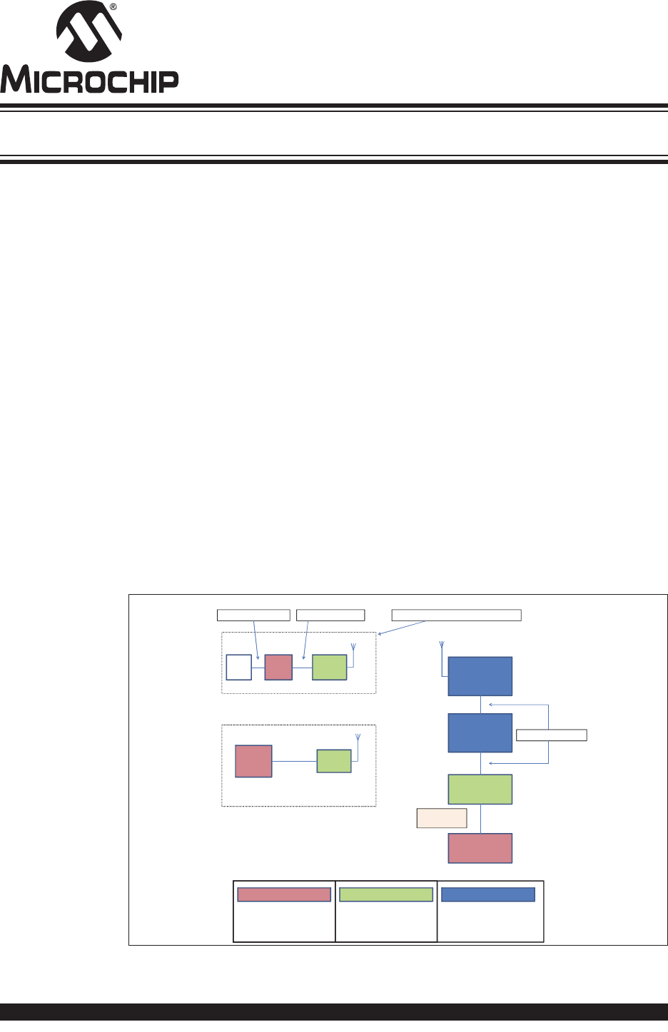
A simple use case is described in Figure 1-1 where an end device, containing a host
MCU which reads a sensor, commands the RN2483 to transmit the sensor reading
over the LoRa network. Data are encrypted by the RN2483 and the radio packet is
received by one or multiple gateways which forward it to the network server. The
network server sends the data to the application server which has the key to decrypt
the application data. Similarly, a development platform may consist of an RN2483
directly connected over UART to a PC which becomes the host system in this case.
Users can then type commands into the module using a terminal program.
FIGURE 1-1: SIMPLE LoRa® TECHNOLOGY NETWORK DIAGRAM
The flow of data can be followed as it gets generated by an end device and transported
on the network.
Network Server
RN2483
UART
LoRaTM end device
UART
PC with
terminal
software
Sensor
Sensor reading: 0x23A5 mac tx uncnf 30 23A5 40340120030000001EADBCE2ABFFDA
Encryp ted data
IP Connection
Application Server
[…]1E[…]ADBC[…]
IP Connection
Application
Port: 30
Data: 23A5
Development platform
These devices deal with
plaintext application data
These entities hold secret keys
that can encrypt/decrypt
application data
These devices relay encrypted
application data without being
able to decrypt it
)))
LoRaTM Gateway
(((
RN2483
Host
MCU
)))
RN2483 LoRa® TECHNOLOGY MODULE COMMAND REFERENCE USER’S GUIDE
DS40001784F-page 14 2015-2017 Microchip Technology Inc.
1.2 FEATURES
• LoRaWAN Class A protocol compliance
• Integrated FSK, GFSK and LoRa technology transceiver allowing the user to
transmit custom packets using these protocols
• Globally unique 64-bit identifier (EUI-64™)
• Configurable GPIOs
• Intelligent Low-Power mode with programmable/on-demand wake-up
• Bootloader for firmware upgrade
• All configuration and control done over UART using simple ASCII commands
Refer to the RN2483, Low-Power Long-Range LoRa® Technology Transceiver Module
Data Sheet (DS50002346) for details on the hardware specifications of the module.
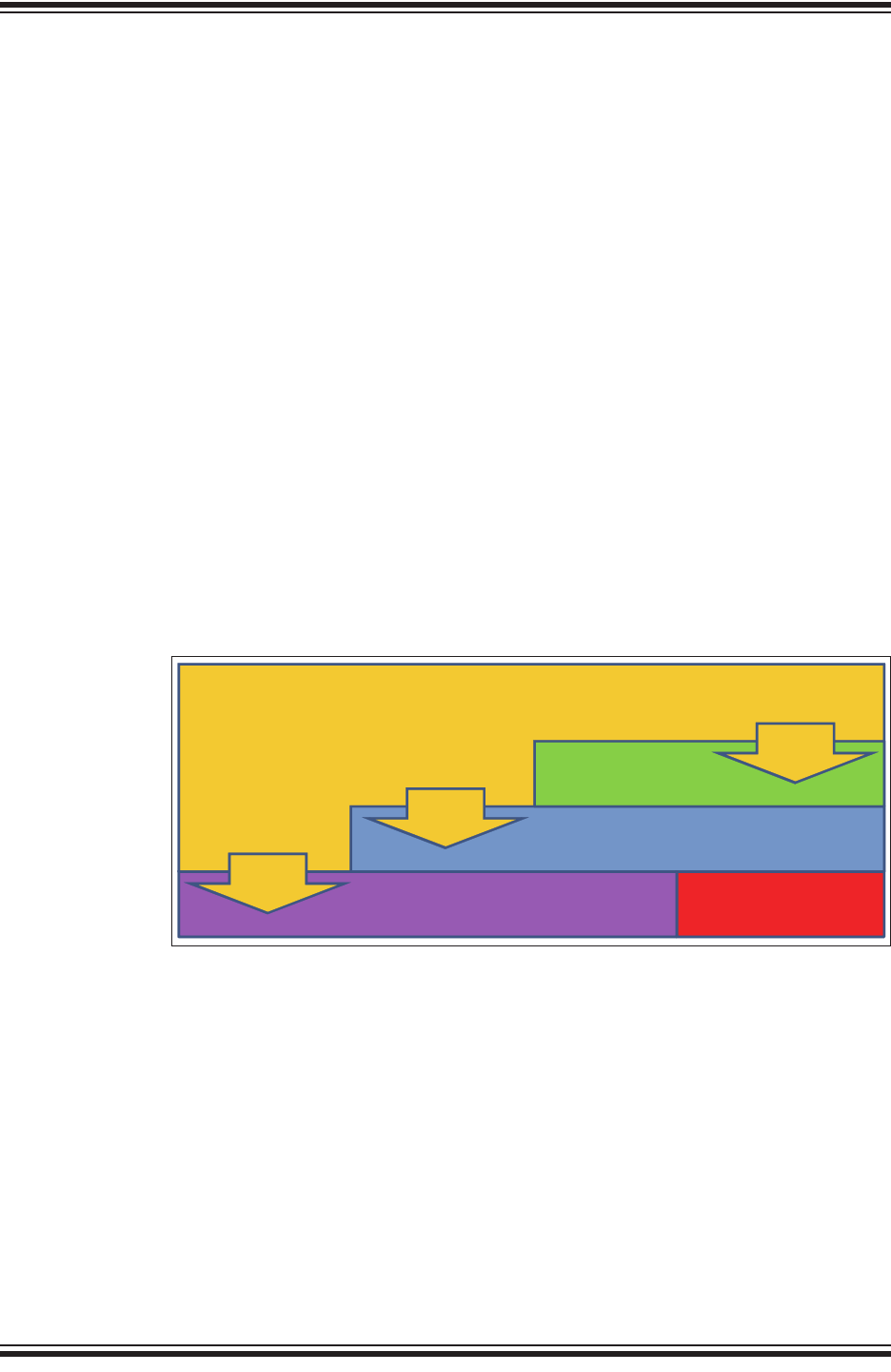
1.3 CONFIGURATION
The RN2483 module’s architecture is described in Figure 1-2 from the command
interface point of view. There are three types of commands that can be used, and each
allows access to different module functions:
• LoRaWAN Class A configuration and control, using the mac group of commands
• Radio configuration and control, using the radio group of commands
• Other module functions, using the sys group of commands
FIGURE 1-2: RN2483 COMMAND INTERFACE (YELLOW) AND ITS
RELATIONSHIP TO THE MODULE’S INTERNAL
COMPONENTS
The available commands can be used to configure and control the LoRaWAN protocol
layer, the radio driver and some system peripherals.
In order to communicate with a LoRa network, a specific number of parameters need
to be configured. Since two distinctive methods are offered for a device to become part
of the network, each of these requires different parameters:
• Over-the-Air Activation (OTAA), where a device negotiates network encryption
keys at the time it joins the network. For this, the device EUI, application EUI and
application key need to be configured and then the OTAA procedure can start.
• Activation by Personalization (ABP) where the device already contains the
network keys and can directly start communication with the network. Configuring
the device address, network session key and application session key is sufficient
for this type of initialization.
Command Interface
Radio driver
LoRaWANTM Protocol
mac
commands
radio
commands
Hardware (GPIO, System timer, etc.)
sys
commands
Radio hardware

Introduction
2015-2017 Microchip Technology Inc. DS40001784F-page 15
For increased security, these parameters can be configured and stored in the module’s
EEPROM during manufacturing of devices requiring LoRaWAN connectivity. Thus, the
keys do not need to be sent over the UART interface by the host system every time the
device powers up.
1.4 UART INTERFACE
All of the RN2483 module’s settings and commands are transmitted over UART using
the ASCII interface.
All commands need to be terminated with <CR><LF> and any replies they generate will
also be terminated by the same sequence.
The default settings for the UART interface are 57600 bps, 8 bits, no parity, 1 Stop bit,
no flow control. The baud rate can be changed by triggering the auto-baud detection
sequence of the module. To do this, the host system needs to transmit to the module
a break condition followed by a 0x55 character at the new baud rate. The auto-baud
detection mechanism can also be triggered during Sleep to wake the module up before
the predetermined time has expired.
Note: A break condition is signaled to the module by keeping the UART_RX pin
low for longer than the time to transmit a complete character. For example,
at the default baud rate of 57600 bps keeping the UART_RX pin low for 938
s is a valid break condition, whereas at 9600 bps this would be interpreted
as a 0x00 character. Thus, the break condition needs to be long enough
to still be interpreted as such at the baud rate that is currently in use.

RN2483 LoRa® TECHNOLOGY MODULE COMMAND REFERENCE USER’S GUIDE
DS40001784F-page 16 2015-2017 Microchip Technology Inc.
NOTES:
RN2483 LoRa® TECHNOLOGY MODULE
COMMAND REFERENCE USER’S GUIDE
2015-2017 Microchip Technology Inc. DS40001784F-page 17
Chapter 2. Command Reference
The RN2483 LoRa technology module supports a variety of commands for
configuration. This section describes these commands in detail and provides
examples.
2.1 COMMAND SYNTAX
To issue commands to the RN2483 module, the user sends keywords followed by
optional parameters. Commands (keywords) are case sensitive, and spaces must not
be used in parameters. Hex input data can be uppercase or lowercase. String text data,
such as OTAA used for the join procedure, is case-insensitive.
The use of shorthand for parameters is NOT supported.
Depending on the command, the parameter may expect values in either decimal or
hexadecimal form; refer to the command description for the expected form. For
example, when configuring the frequency, the command expects a decimal value in
Hertz such as 868100000 (868.1 MHz). Alternatively, when configuring the LoRaWAN
device address, the hex value is entered into the parameter as aabbccdd. To enter a
number in hex form, use the value directly. For example, the hex value 0xFF would be
entered as FF.
2.2 COMMAND ORGANIZATION
There are three general command categories, as shown in Table 2-1.
Once the LoRaWAN Class A protocol configuration is complete, the user must save the
settings to store the configuration data, otherwise it will not take effect upon reboot or
Reset.
TABLE 2-1: COMMAND TYPES
Command Type Keyword Description
System <sys> Issues system level behavior actions, gathers status information on the
firmware and hardware version, or accesses the module user EEPROM
memory.
LoRaWAN™ Class A Protocol <mac> Issues LoRaWAN Class A protocol network communication behaviors,
actions and configurations commands.
Transceiver commands <radio> Issues radio specific configurations, directly accessing and updating the
transceiver setup.
Note: Upon successful reception of commands, the module will respond with one
of the following:
•ok
•invalid_param
• Requested Information
• Descriptive Error Message
RN2483 LoRa® TECHNOLOGY MODULE COMMAND REFERENCE USER’S GUIDE
DS40001784F-page 18 2015-2017 Microchip Technology Inc.
2.3 SYSTEM COMMANDS
System commands begin with the system keyword <sys> and include the categories
shown in Ta b l e 2- 2 , Tab l e 2- 3 and Tabl e 2- 4.
2.3.1 sys sleep <length>
<length>: decimal number representing the number of milliseconds the system is
put to Sleep, from 100 to 4294967296.
Response: ok after the system gets back from Sleep mode
invalid_param if the length is not valid
This command puts the system to Sleep for the specified number of milliseconds. The
module can be forced to exit from Sleep by sending a break condition followed by a
0x55 character at the new baud rate. Note that the break condition needs to be long
enough not to be interpreted as a valid character at the current baud rate.
Example: sys sleep 120 // Puts the system to Sleep for 120 ms.
2.3.2 sys reset
Response: RN2483 X.Y.Z MMM DD YYYY HH:MM:SS, where X.Y.Z is firmware
version, MMM is month, DD is day, HH:MM:SS is hour, minutes, seconds (format: [HW]
[FW] [Date] [Time]). [Date] and [Time] refer to the release of the firmware.
This command resets and restarts the RN2483 module; stored internal configurations
will be loaded automatically upon reboot.
Example: sys reset // Resets and restarts the RN2483 module.
2.3.3 sys eraseFW
Response: no response
This command deletes the current RN2483 module application firmware and prepares
it for firmware upgrade. The RN2483 module bootloader is ready to receive new
firmware.
Example: sys eraseFW // Deletes the current RN2483 module
application firmware.
Note: To facilitate the sharing of the radio between user custom applications and
the LoRaWAN MAC, please refer to the mac pause and mac resume
commands. Since no sharing exists between sys and other types of
commands, there is no need for additional pause commands.
TABLE 2-2: SYSTEM COMMANDS
Parameter Description
sleep Puts the system in Sleep for a finite number of milliseconds.
reset Resets and restarts the RN2483 module.
eraseFW Deletes the current RN2483 module application firmware and prepares it for
firmware upgrade. The RN2483 module bootloader is ready to receive new
firmware.
factoryRESET Resets the RN2483 module’s configuration data and user EEPROM to
factory default values and restarts the RN2483 module.
set(1) Sets specified system parameter values.
get(1) Gets specified system parameter values.
Note 1: Refer to Table 2-3 for system <set> and Table 2-4 for system <get> command
summaries.
Command Reference
2015-2017 Microchip Technology Inc. DS40001784F-page 19
2.3.4 sys factoryRESET
Response: RN2483 X.Y.Z MMM DD YYYY HH:MM:SS, where X.Y.Z is firmware
version, MMM is month, DD is day, HH:MM:SS is hour, minutes, seconds (format: [HW]
[FW] [Date] [Time]). [Date] and [Time] refer to the release of the firmware.
This command resets the module’s configuration data and user EEPROM to factory
default values and restarts the module. After factoryRESET, the RN2483 module will
automatically reset and all configuration parameters are restored to factory default
values.
Example: sys factoryRESET // Restores factory default values.
2.3.5 System Set Commands
2.3.5.1 sys set nvm <address> <data>
<address>: hexadecimal number representing user EEPROM address, from 300 to
3FF
<data>: hexadecimal number representing data, from 00 to FF
Response: ok if the parameters (address and data) are valid
invalid_param if the parameters (address and data) are not valid
This command allows the user to modify the user EEPROM at <address> with the
value supplied by <data>. Both <address> and <data> must be entered as hex
values. The user EEPROM memory is located inside the MCU on the module.
Example: sys set nvm 300 A5 // Stores the value 0xA5 at user EEPROM
address 0x300.
2.3.5.2 sys set pinmode <pinname> <pinFunc>
<pinname>: string representing the pin. Parameters can be: GPIO0 - GPIO13,
UART_CTS, UART_RTS, TEST0, TEST1
<pinFunc>: string representing the function of the pin. Parameters can be: digout,
digin or ana.
Response: ok if the parameters are valid
invalid_param if the parameters are not valid
This command allows the user to configure the function on a pin. A pin can be
configured as digital output by using the digout parameter. A pin can be configured
as digital input by using the digin parameter. A pin can be configured as analog
input by using the ana parameter.
TABLE 2-3: SYSTEM SET COMMANDS
Parameter Description
nvm Stores <data> to a location <address> of user EEPROM.
pindig Allows user to set and clear available digital pins.
pinmode Allows user to set the functionality of a pin to either digital input, digital output
or analog input (if available).
Note: Not all pins have analog input functionality.
RN2483 LoRa® TECHNOLOGY MODULE COMMAND REFERENCE USER’S GUIDE
DS40001784F-page 20 2015-2017 Microchip Technology Inc.
Example: sys set pinmode GPIO0 ana //Configures GPIO0 as analog input
2.3.5.3 sys set pindig <pinname> <pinstate>
<pinname>: string representing the pin. Parameter values can be:
GPIO0 - GPIO13, UART_CTS, UART_RTS, TEST0, TEST1
<pinstate>: decimal number representing the state. Parameter values can be: 0 or
1.
Response: ok if the parameters (<pinname>, <pinstate>) are valid
invalid_param if the parameters (<pinname>, <pinstate>) are not
valid
This command allows the user to modify the unused pins available for use by the
module. The selected <pinname> is driven high or low depending on the desired
<pinstate>.
Default: GPIO0-GPIO13, UART_CTS, UART_RTS, TEST0 and TEST1 are driven low
(value 0).
Example: sys set pindig GPIO5 1 // Drives GPIO5 high 1, VDD.
2.3.6 System Get Commands
2.3.6.1 sys get ver
Response: RN2483 X.Y.Z MMM DD YYYY HH:MM:SS, where X.Y.Z is firmware
version, MMM is month, DD is day, HH:MM:SS is hour, minutes, seconds (format: [HW]
[FW] [Date] [Time]). [Date] and [Time] refer to the release of the firmware.
This command returns the information related to the hardware platform, firmware
version, release date and time stamp on firmware creation.
Example: sys get ver // Returns version-related information.
Note: This command must be called prior to reading or setting the value of a pin
in order to have correct behavior.
Note: In order for the pin to be driven to a value, make sure you have first
configured the pin to be a digital output using the command sys set
pinmode <pinname> digout.
TABLE 2-4: SYSTEM GET COMMANDS
Parameter Description
ver Returns the information on hardware platform, firmware version, release
date.
nvm Returns data from the requested user EEPROM <address>.
vdd Returns measured voltage in mV.
hweui Returns the preprogrammed EUI node address.
pindig Returns the state of a digital input.
pinana Returns the state of an analog input.

Command Reference
2015-2017 Microchip Technology Inc. DS40001784F-page 21
2.3.6.2 sys get nvm <address>
<address>: hexadecimal number representing user EEPROM address, from 300 to
3FF
Response: 00 – FF (hexadecimal value from 00 to FF) if the address is valid
invalid_param if the address is not valid
This command returns the data stored in the user EEPROM of the RN2483 module at
the requested <address> location.
Example: sys get nvm 300 // Returns the 8-bit hex value stored at
300.
2.3.6.3 sys get vdd
Response: 0–3600 (decimal value from 0 to 3600)
This command informs the RN2483 module to do an ADC conversion on the VDD. The
measurement is converted and returned as a voltage (mV).
Example: sys get vdd // Returns mV measured on the VDD
module.
2.3.6.4 sys get hweui
Response: hexadecimal number representing the preprogrammed EUI node address
This command reads the preprogrammed EUI node address from the RN2483 module.
The value returned by this command is a globally unique number provided by
Microchip.
Example: sys get hweui // Reads the preprogrammed EUI node
address.
2.3.6.5 sys get pindig <pinname>
<pinname>: string representing the pin. Parameters can be: GPIO0 - GPIO13,
UART_CTS, UART_RTS, TEST0, TEST1
Response: decimal number representing the state (either 0 or 1).
This command allows the user to read the state of a digital input. To be used as a
digital input, a pin needs to be configured using the sys set pinmode command.
Example: sys get pindig GPIO0 //Reads the state of the GPIO0 digital input
2.3.6.6 sys get pinana <pinname>
<pinname>: string representing the pin. Parameters can be: GPIO0 - GPIO3,
GPIO5 - GPIO13
Response: decimal number representing the result of the conversion, from 0 to 1023,
where 0 represents 0V and 1023 is VDD, the supply voltage of the module.
This command allows the user to read the state of an analog input. To be used as an
analog input, a pin needs to be configured using the sys set pinmode command.
Example: sys get pinana GPIO0 //Reads the state of the GPIO0 analog input
Note: The preprogrammed EUI node address is a read-only value and cannot be
changed or erased. This value can be used to configure the device EUI
using the mac set deveui command (see Section 2.4.8.2).
Note: The sys set pinmode <pinname> digin command must be called to
configure the function of the pin prior to reading its digital input value.
RN2483 LoRa® TECHNOLOGY MODULE COMMAND REFERENCE USER’S GUIDE
DS40001784F-page 22 2015-2017 Microchip Technology Inc.
2.4 MAC COMMANDS
LoRaWAN Class A protocol commands begin with the system keyword mac and
include the categories shown in Table 2-5 through Tab le 2 -9 .
2.4.1 mac reset <band>
<band>: decimal number representing the frequency band, either 868 or 433
Response: ok if band is valid
invalid_param if band is not valid
This command will automatically reset the software LoRaWAN stack and initialize it
with the parameters for the selected band.
Example: mac reset 868 // Sets the default values and selects the 868
default band.
Note: The sys set pinmode <pinname> ana command must be called to
configure the function of the pin prior to reading its analog input value.
TABLE 2-5: MAC COMMANDS
Parameter Description
reset Resets the RN2483 module to a specific frequency band.
tx Sends the data string on a specified port number and sets default values for
most of the LoRaWAN™ parameters.
join Informs the RN2483 module to join the configured network.
save Saves LoRaWAN Class A configuration parameters to the user EEPROM.
forceENABLE Enables the RN2483 module after the LoRaWAN network server
commanded the end device to become silent immediately.
pause Pauses LoRaWAN stack functionality to allow transceiver (radio)
configuration.
resume Restores the LoRaWAN stack functionality.
set Accesses and modifies specific MAC related parameters.
get Reads back current MAC related parameters from the module.
Note: This command will set default values for most of the LoRaWAN™
parameters. Everything set prior to this command will lose its set value.

Command Reference
2015-2017 Microchip Technology Inc. DS40001784F-page 23
2.4.2 mac tx <type> <portno> <data>
<type>: string representing the uplink payload type, either cnf or uncnf
(cnf – confirmed, uncnf – unconfirmed)
<portno>: decimal number representing the port number, from 1 to 223
<data>: hexadecimal value. The length of <data> bytes capable of being
transmitted are dependent upon the set data rate (please refer to the LoRaWAN™
Specification for further details).
Response: this command may reply with two responses. The first response will be
received immediately after entering the command. In case the command is valid (ok
reply received), a second reply will be received after the end of the uplink transmission.
Please refer to the LoRaWAN™ Specification for further details.
Response after entering the command:
•ok – if parameters and configurations are valid and the packet was forwarded to
the radio transceiver for transmission
•invalid_param – if parameters (<type> <portno> <data>) are not valid
•not_joined – if the network is not joined
•no_free_ch – if all channels are busy
•silent – if the module is in a Silent Immediately state
•frame_counter_err_rejoin_needed – if the frame counter rolled over
•busy – if MAC state is not in an Idle state
•mac_paused – if MAC was paused and not resumed back
•invalid_data_len if application payload length is greater than the maximum
application payload length corresponding to the current data rate
Response after the uplink transmission:
•mac_tx_ok if uplink transmission was successful and no downlink data was
received back from the server;
•mac_rx <portno> <data> if transmission was successful, <portno>: port
number, from 1 to 223; <data>: hexadecimal value that was received from the
server;
•mac_err if transmission was unsuccessful, ACK not received back from the
server
•invalid_data_len if application payload length is greater than the maximum
application payload length corresponding to the current data rate
A confirmed message will expect an acknowledgment from the server; otherwise, the
message will be retransmitted by the number indicated by the command mac set
retx <value>, whereas an unconfirmed message will not expect any
acknowledgment back from the server. Please refer to the LoRaWAN™ Specification
for further details.

RN2483 LoRa® TECHNOLOGY MODULE COMMAND REFERENCE USER’S GUIDE
DS40001784F-page 24 2015-2017 Microchip Technology Inc.
If the automatic reply feature is enabled and the server sets the Frame Pending bit or
initiates downlink confirmed transmissions, multiple responses will be displayed after
each downlink packet is received by the module. A typical scenario for this case would
be (prerequisites: free LoRaWAN channels available and automatic reply enabled):
• The module sends a packet on port 4 with application payload 0xAB
• Radio transmission is successful and the module will display the first response:
ok
• The server needs to send two separate downlink confirmed packets back on port
1 with the following data: 0xAC, then 0xAF. First it will transmit the first one (0xAC)
and will set the Frame Pending bit. The module will display the second response
mac_rx 1 AC
• The module will initiate an automatic uplink unconfirmed transmission with no
application payload on the first free channel because the Frame Pending bit was
set in the downlink transmission
• The server will send back the second confirmed packet (0xAF). The module will
display a third response mac_rx 1 AF
• The module will initiate an automatic unconfirmed transmission with no application
payload on the first free channel because the last downlink transmission was
confirmed, so the server needs an ACK
• If no reply is received back from the server, the module will display the fourth
response after the end of the second Receive window: mac_tx_ok
• After this scenario, the user is allowed to send packets when at least one enabled
channel is free
Based on this scenario, the following responses will be displayed by the module:
•mac tx cnf 4 AB
•ok
•mac_rx 1 AC
• mac_rx 1 AF
•mac_tx_ok
Example: mac tx cnf 4 5A5B5B // Sends a confirmed frame on port 4 with
application payload 5A5B5B.

Command Reference
2015-2017 Microchip Technology Inc. DS40001784F-page 25
2.4.3 mac join <mode>
<mode>: string representing the join procedure type (case-insensitive), either otaa
or abp (otaa – over-the-air activation, abp – activation by
personalization).
Response: this command may reply with two responses. The first response will be
received immediately after entering the command. In case the command is valid (ok
reply received) a second reply will be received after the end of the join procedure.
Please refer to the LoRaWAN™ Specification for further details.
Response after entering the command:
•ok – if parameters and configurations are valid and the join request packet was
forwarded to the radio transceiver for transmission
•invalid_param – if <mode> is not valid
•keys_not_init – if the keys corresponding to the Join mode (otaa or abp)
were not configured
•no_free_ch – if all channels are busy
•silent – if the device is in a Silent Immediately state
•busy – if MAC state is not in an Idle state
•mac_paused – if MAC was paused and not resumed back
Response after the join procedure:
•denied if the join procedure was unsuccessful (the module attempted to join the
network, but was rejected);
•accepted if the join procedure was successful;
This command informs the RN2483 module it should attempt to join the configured
network. Module activation type is selected with <mode>. Parameter values can be
otaa (over-the-air activation) or abp (activation by personalization). The <mode>
parameter is not case sensitive. Before joining the network, the specific parameters for
each activation type should be configured (for over the air activation: device EUI,
application EUI, application key; for activation by personalization: device address,
network session key, application session key).
Example: mac join otaa // Attempts to join the network using
over-the-air activation.

RN2483 LoRa® TECHNOLOGY MODULE COMMAND REFERENCE USER’S GUIDE
DS40001784F-page 26 2015-2017 Microchip Technology Inc.
2.4.4 mac save
Response: ok
The mac save command must be issued after configuration parameters have been
appropriately entered from the mac set <cmd> commands. This command will save
LoRaWAN Class A protocol configuration parameters to the user EEPROM. When the
next sys reset command is issued, the LoRaWAN Class A protocol configuration will
be initialized with the last saved parameters.
The LoRaWAN Class A protocol configuration savable parameters are:
• band: Band
• fcntup: Uplink Frame Counter
• fcntdown: Downlink Frame Counter
• dr: Data Rate
• rx2dr: Data Rate parameter for the second receive window
• rx2freq: Frequency parameter for the second receive window
• adr: Adaptive Data Rate state
• deveui: End-Device Identifier
• appeui: Application Identifier
• appkey: Application Key
• nwkskey: Network Session Key
• appskey: Application Session Key
• devaddr: End Device Address
• ch: All Channel Parameter
-freq: Frequency
-dcycle: Duty Cycle
-drrange: Data Rate Range
-status: Status
Example: mac save // Saves the LoRaWAN Class A protocol
configuration parameters to the user
EEPROM.
2.4.5 mac forceENABLE
Response: ok
The network can issue a certain command (Duty Cycle Request frame with parameter
255) that would require the RN2483 module to go silent immediately. This mechanism
disables any further communication of the module, effectively isolating it from the
network. Using mac forceENABLE, after this network command has been received,
restores the module’s connectivity by allowing it to send data.
Example: mac forceENABLE // Disables the Silent Immediately state.
Command Reference
2015-2017 Microchip Technology Inc. DS40001784F-page 27
2.4.6 mac pause
Response: 0 – 4294967295 (decimal number representing the number of milliseconds
the mac can be paused)
This command pauses the LoRaWAN stack functionality to allow transceiver (radio)
configuration. Through the use of mac pause, radio commands can be generated
between a LoRaWAN Class A protocol uplink application (mac tx command), and the
LoRaWAN Class A protocol Receive windows (second response for the mac tx
command). This command will reply with the time interval in milliseconds that the
transceiver can be used without affecting the LoRaWAN functionality. The maximum
value (4294967295) is returned whenever the LoRaWAN stack functionality is in Idle
state and the transceiver can be used without restrictions. ‘0’ is returned when the
LoRaWAN stack functionality cannot be paused. After the radio configuration is
complete, the mac resume command should be used to return to LoRaWAN Class A
protocol commands.
Example: mac pause // Pauses the LoRaWAN stack
functionality if the response is different
from 0.
2.4.7 mac resume
Response: ok
This command resumes LoRaWAN stack functionality, in order to continue normal
functionality after being paused.
Example: mac resume // Resumes the LoRaWAN stack functionality.
Note: If already joined to a network, this command MUST be called BEFORE
configuring the radio parameters, initiating radio reception, or transmission.
Note: This command MUST be called AFTER all radio commands have been
issued and all the corresponding asynchronous messages have been
replied.

RN2483 LoRa® TECHNOLOGY MODULE COMMAND REFERENCE USER’S GUIDE
DS40001784F-page 28 2015-2017 Microchip Technology Inc.
2.4.8 MAC Set Commands
2.4.8.1 mac set devaddr <address>
<address>: 4-byte hexadecimal number representing the device address, from
00000000 – FFFFFFFF
Response: ok if address is valid
invalid_param if address is not valid
This command configures the module with a 4-byte unique network device address
<address>. The <address> MUST be UNIQUE to the current network. This must be
directly set solely for activation by personalization devices. This parameter must not be
set before attempting to join using over-the-air activation because it will be overwritten
once the join process is over.
Example: mac set devaddr ABCDEF01
TABLE 2-6: MAC SET COMMANDS
Parameter Description
devaddr Sets the unique network device address for the RN2483 module.
deveui Sets the globally unique identifier for the RN2483 module.
appeui Sets the application identifier for the RN2483 module.
nwkskey Sets the network session key for the RN2483 module.
appskey Sets the application session key for the RN2483 module.
appkey Sets the application key for the RN2483 module.
pwridx Sets the output power to be used on the next transmissions.
dr Sets the data rate to be used for the next transmissions.
adr Sets if the adaptive data rate is to be enabled, or disabled.
bat Sets the battery level needed for Device Status Answer frame command
response.
retx Sets the number of retransmissions to be used for an uplink confirmed
packet.
linkchk Sets the time interval for the link check process to be triggered.
rxdelay1 Sets the value used for the first Receive window delay.
ar Sets the state of the automatic reply.
rx2 Sets the data rate and frequency used for the second Receive window.
sync Sets the synchronization word for the LoRaWAN™ communication.
upctr Sets the value of the uplink frame counter that will be used for the next uplink
transmission.
dnctr Sets the value of the downlink frame counter that will be used for the next
downlink reception.
ch Allows modification of channel related parameters.
Note: If this parameter had previously been saved to user EEPROM by issuing
the mac save command, after modifying its value, the mac save
command should be called again.
Command Reference
2015-2017 Microchip Technology Inc. DS40001784F-page 29
2.4.8.2 mac set deveui <devEUI>
<devEUI>: 8-byte hexadecimal number representing the device EUI
Response: ok if address is valid
invalid_param if address is not valid
This command sets the globally unique device identifier for the module. The identifier
must be set by the host MCU. The module contains a pre-programmed unique EUI and
can be retrieved using the sys get hweui command (see Section 2.3.6.4) or user
provided EUI can be configured using the mac set deveui command.
Example: mac set deveui 0004A30B001A55ED
2.4.8.3 mac set appeui <appEUI>
<appEUI>: 8-byte hexadecimal number representing the application EUI
Response: ok if EUI is valid
invalid_param if EUI is not valid
This command sets the application identifier for the module. The application identifier
should be used to identify device types (sensor device, lighting device, etc.) within the
network.
Example: mac set appeui FEDCBA9876543210
2.4.8.4 mac set nwkskey <nwksesskey>
<nwkSessKey>: 16-byte hexadecimal number representing the network session key
Response: ok if key is valid
invalid_param if key is not valid
This command sets the network session key for the module. This key is 16 bytes in
length, and provides security for communication between the module and network
server.
Example: mac set nwkskey 1029384756AFBECD5647382910DACFEB
Note: If this parameter was previously saved to user EEPROM by issuing the
mac save command, after modifying its value, the mac save command
should be called again.
Note: If this parameter was previously saved to user EEPROM by issuing the
mac save command, after modifying its value, the mac save command
should be called again.
Note: If this parameter was previously saved to user EEPROM by issuing the
mac save command, after modifying its value, the mac save command
should be called again.

RN2483 LoRa® TECHNOLOGY MODULE COMMAND REFERENCE USER’S GUIDE
DS40001784F-page 30 2015-2017 Microchip Technology Inc.
2.4.8.5 mac set appskey <appSesskey>
<appSessKey>: 16-byte hexadecimal number representing the application session
key
Response: ok if key is valid
invalid_param if key is not valid
This command sets the application session key for the module. This key provides
security for communication between module and application server.
Example: mac set appskey AFBECD56473829100192837465FAEBDC
2.4.8.6 mac set appkey <appKey>
<appKey>: 16-byte hexadecimal number representing the application key
Response: ok if key is valid
invalid_param if key is not valid
This command sets the application key for the module. The application key is used to
derive the security credentials for communication during over-the-air activation.
Example: mac set appkey 00112233445566778899AABBCCDDEEFF
2.4.8.7 mac set pwridx <pwrIndex>
<pwrIndex>: decimal number representing the index value for the output power,
from 0 to 5 for 433 MHz frequency band and from 1 to 5 for 868 MHz
frequency band.
Response: ok if power index is valid
invalid_param if power index is not valid
This command sets the output power to be used on the next transmissions. Refer to
the LoRaWAN™ Specification for the output power corresponding to the <pwrIndex>
and also to the RN2483 Low-Power Long-Range LoRa® Technology Transceiver
Module Data Sheet (DS50002346) for the actual radio power capabilities.
Example: mac set pwridx 1 // Sets the TX output power to 14 dBm on the
next transmission for a 868 MHz EU module.
Note: If this parameter was previously saved to user EEPROM by issuing the
mac save command, after modifying its value, the mac save command
should be called again.
Note: If this parameter was previously saved to user EEPROM by issuing the
mac save command, after modifying its value, the mac save command
should be called again.

Command Reference
2015-2017 Microchip Technology Inc. DS40001784F-page 31
2.4.8.8 mac set dr <dataRate>
<dataRate>: decimal number representing the data rate, from 0 and 7, but within the
limits of the data rate range for the defined channels.
Response: ok if data rate is valid
invalid_param if data rate is not valid
This command sets the data rate to be used for the next transmission. Please refer to
the LoRaWAN™ Specification for the description of data rates and the corresponding
spreading factors.
Example: mac set dr 5 // On EU863-870; SF7/125 kHz.
2.4.8.9 mac set adr <state>
<state>: string value representing the state, either on or off.
Response: ok if state is valid
invalid_param if state is not valid
This command sets if the adaptive data rate (ADR) is to be enabled, or disabled. The
server is informed about the status of the module’s ADR in every uplink frame it
receives from the ADR field in uplink data packet. If ADR is enabled, the server will
optimize the data rate and the transmission power of the module based on the
information collected from the network.
Example: mac set adr on // This will enable the ADR mechanism.
2.4.8.10 mac set bat <level>
<level>: decimal number representing the level of the battery, from 0 to 255. ‘0’
means external power, ‘1’ means low level, 254 means high level, 255
means the end device was not able to measure the battery level.
Response: ok if the battery level is valid
invalid_param if the battery level is not valid
This command sets the battery level required for Device Status Answer frame in use
with the LoRaWAN Class A protocol.
Example: mac set bat 127 // Battery is set to ~50%.
2.4.8.11 mac set retx <reTxNb>
<reTxNb>: decimal number representing the number of retransmissions for an uplink
confirmed packet, from 0 to 255.
Response: ok if <retx> is valid
invalid_param if <retx> is not valid
This command sets the number of retransmissions to be used for an uplink confirmed
packet, if no downlink acknowledgment is received from the server.
Example: mac set retx 5 // The number of retransmissions made
for an uplink confirmed packet is set to 5.
Note: If this parameter had previously been saved to user EEPROM by issuing
the mac save command, after modifying its value, the mac save
command should be called again.
Note: If this parameter had previously been saved to user EEPROM by issuing
the mac save command, after modifying its value, the mac save
command should be called again.

RN2483 LoRa® TECHNOLOGY MODULE COMMAND REFERENCE USER’S GUIDE
DS40001784F-page 32 2015-2017 Microchip Technology Inc.
2.4.8.12 mac set linkchk <linkCheck>
<linkCheck>: decimal number that sets the time interval in seconds for the link check
process, from 0 to 65535
Response: ok if the time interval is valid
invalid_param if the time interval is not valid
This command sets the time interval for the link check process to be triggered
periodically. A <value> of ‘0’ will disable the link check process. When the time
interval expires, the next application packet that will be sent to the server will include
also a link check MAC command. Please refer to the LoRaWAN™ Specification for
more information on the Link Check MAC command.
Example: mac set linkchk 600 // The module will attempt a link check
process at 600-second intervals.
2.4.8.13 mac set rxdelay1 <rxDelay>
<rxDelay>: decimal number representing the delay between the transmission and
the first Reception window in milliseconds, from 0 to 65535.
Response: ok if <rxDelay> is valid
invalid_param if <rxDelay> is not valid
This command will set the delay between the transmission and the first Reception
window to the <rxDelay> in milliseconds. The delay between the transmission and
the second Reception window is calculated in software as the delay between the
transmission and the first Reception window + 1000 (ms).
Example: mac set rxdelay1 1000 // Set the delay between the transmission
and the first Receive window to 1000 ms.
2.4.8.14 mac set ar <state>
<state>: string value representing the state, either on or off.
Response: ok if state is valid
invalid_param if state is not valid
This command sets the state of the automatic reply. By enabling the automatic reply,
the module will transmit a packet without a payload immediately after a confirmed
downlink is received, or when the Frame Pending bit has been set by the server. If set
to OFF, no automatic reply will be transmitted.
Example: mac set ar on // Enables the automatic reply process
inside the module.
Note: If the command mac reset is issued, the link check process will be set as
disabled.
Note: The RN2483 module implementation will initiate automatic transmissions
with no application payload if the automatic reply feature is enabled and the
server sets the Frame Pending bit or initiates a confirmed downlink
transmission. In this case, if all enabled channels are busy due to duty cycle
limitations, the stack will wait for the first channel that will become free to
transmit. The user will not be able to initiate uplink transmissions until the
automatic transmissions are done.

Command Reference
2015-2017 Microchip Technology Inc. DS40001784F-page 33
2.4.8.15 mac set rx2 <dataRate> <frequency>
<dataRate>: decimal number representing the data rate, from 0 to 7.
<frequency>: decimal number representing the frequency, from 863000000 to
870000000 or from 433050000 to 434790000, in Hz.
Response: ok if parameters are valid
invalid_param if parameters are not valid
This command sets the data rate and frequency used for the second Receive window.
The configuration of the Receive window parameters should be in concordance with
the server configuration.
Example: mac set rx2 3 865000000 // Receive window 2 is configured with
SF9/125 kHz data rate with a center
frequency of 865 MHz.
2.4.8.16 mac set sync <synchWord>
<synchWord>: one byte long hexadecimal number representing the synchronization
word for the LoRaWAN communication
Response: ok if parameters are valid
invalid_param if parameter is not valid
This command sets the synchronization word for the LoRaWAN communication. The
configuration of the synchronization word should be in concordance with the Gateway
configuration.
Example: mac set sync 34 //Synchronization word is configured to
use the 0x34 value
2.4.8.17 mac set upctr <fCntUp>
<fCntUp>: decimal number representing the value of the uplink frame counter that
will be used for the next uplink transmission, from 0 to 4294967295.
Response: ok if parameter is valid
invalid_param if parameter is not valid
This command sets the value of the uplink frame counter that will be used for the next
uplink transmission.
Example: mac set upctr 10
Note: If this parameter had previously been saved to user EEPROM by issuing
the mac save command, after modifying its value, the mac save
command should be called again.
Note: If this parameter had previously been saved to user EEPROM by issuing
the mac save command, after modifying its value, the mac save
command should be called again.
RN2483 LoRa® TECHNOLOGY MODULE COMMAND REFERENCE USER’S GUIDE
DS40001784F-page 34 2015-2017 Microchip Technology Inc.
2.4.8.18 mac set dnctr <fCntDown>
<fCntDown>: decimal number representing the value of the downlink frame counter
that will be used for the next downlink reception, from 0 to 4294967295.
Response: ok if parameter is valid
invalid_param if parameter is not valid
This command sets the value of the downlink frame counter that will be used for the
next downlink reception.
Example: mac set dnctr 30
2.4.8.19 MAC SET CHANNEL COMMANDS
2.4.8.19.1 mac set ch freq <channelID> <frequency>
<channelId>: decimal number representing the channel number, from 3 to 15.
<frequency>: decimal number representing the frequency, from 863000000 to
870000000 or from 433050000 to 434790000, in Hz.
Response: ok if parameters are valid
invalid_param if parameters are not valid
This command sets the operational frequency on the given channel ID. The default
channels (0-2) cannot be modified in terms of frequency.
Example: mac set ch freq 13 864000000 // Define frequency for channel
13 to be 864 MHz.
Note: If this parameter had previously been saved to user EEPROM by issuing
the mac save command, after modifying its value, the mac save
command should be called again.
TABLE 2-7: MAC SET CHANNEL COMMANDS
Parameter Description
freq Sets the module operation frequency on a given channel ID.
dcycle Sets the module operation duty cycle on a given channel ID.
drrange Sets the module allowed data rate range (min.- max.) allowed on a given
channel ID.
status Sets the use of the specified channel ID.
Note: If this parameter was previously saved to user EEPROM by issuing the
mac save command, after modifying its value, the mac save command
should be called again.

Command Reference
2015-2017 Microchip Technology Inc. DS40001784F-page 35
2.4.8.19.2 mac set ch dcycle <channelID> <dutyCycle>
<channelId>: decimal number representing the channel number, from 0 to 15.
<dutyCycle>: decimal number representing the duty cycle, from 0 to 65535.
Response: ok if parameters are valid
invalid_param if parameters are not valid
This command sets the duty cycle used on the given channel ID on the module. The
<dutyCycle> value that needs to be configured can be obtained from the actual duty
cycle X (in percentage) using the following formula: <dutyCycle> = (100/X) – 1. The
default settings consider only the three default channels (0-2), and their default duty
cycle is 0.33%. If a new channel is created either by the server or by the user, all the
channels (including the default ones) must be updated by the user in terms of duty
cycle to comply with the ETSI regulations.
Example: mac set ch dcycle 13 9 // Defines duty cycle for channel 13 to be
10%. Since (100/10) – 1 = 9, the
parameter that gets configured is 9.
2.4.8.19.3 mac set ch drrange <channelID> <minRange> <maxRange>
<channelId>: decimal number representing the channel number, from 0 to 15
<minRange>:
decimal number representing the minimum data rate, from 0 to 7
<maxRange>:
decimal number representing the maximum data rate, from 0 to 7
Response: ok if parameters are valid
invalid_param if parameters are not valid
This command sets the operating data rate range, min. to max., for the given
<channelId>. By doing this the module can vary data rates between the
<minRange> and <maxRange> on the specified <channelId>. Please refer to the
LoRaWAN™ Specification for the actual values of the data rates and the corresponding
spreading factors (SF).
Example: mac set ch drrange 13 0 2 // Using EU863-870 band: on channel
13 the data rate can range from 0
(SF12/125 kHz) to 2 (SF10/125 kHz)
as required.
Note: If this parameter was previously saved to user EEPROM by issuing the
mac save command, after modifying its value, the mac save command
should be called again.
Note: If this parameter was previously saved to user EEPROM by issuing the
mac save command, after modifying its value, the mac save command
should be called again.
RN2483 LoRa® TECHNOLOGY MODULE COMMAND REFERENCE USER’S GUIDE
DS40001784F-page 36 2015-2017 Microchip Technology Inc.
2.4.8.19.4 mac set ch status <channel ID> <status>
<channelId>: decimal number representing the channel number, from 0 to 15.
<status>: string value representing the state, either on or off.
Response: ok if parameters are valid
invalid_param if parameters are not valid
This command sets the operation of the given <channelId>.
Example: mac set ch status 4 off // Channel ID 4 is disabled from use.
2.4.9 MAC Get Commands
WARNING
<ChannelId> parameters (frequency, data range, duty cycle) must be issued prior
to enabling the status of that channel.
Note: If this parameter was previously saved to user EEPROM by issuing the
mac save command, after modifying its value, the mac save command
should be called again.
TABLE 2-8: MAC GET COMMANDS
Parameter Description
devaddr Gets the current stored unique network device address for that specific end
device.
deveui Gets the current stored globally unique identifier for that specific end device.
appeui Gets the application identifier for the end device.
dr Gets the data rate to be used for the next transmission.
band Gets the current frequency band in operation.
pwridx Gets the output power index value.
adr Gets the state of adaptive data rate for the device.
retx Gets the number of retransmissions to be used for an uplink confirmed packet.
rxdelay1 Gets the interval value stored for rxdelay1.
rxdelay2 Gets the interval value stored for rxdelay2.
ar Gets the state of the automatic reply.
rx2 Gets the data rate and frequency used for the second Receive window.
dcycleps Gets the duty cycle prescaler which can only be configured by the server.
mrgn Gets the demodulation margin as received in the last Link Check Answer frame.
gwnb Gets the number of gateways that successfully received the last Link Check
Request frame.
status Gets the current status of the RN2483 module.
sync Gets the synchronization word for the LoRaWAN communication.
upctr Gets the value of the uplink frame counter that will be used for the next uplink
transmission.
dnctr Gets the value of the downlink frame counter that will be used for the next
downlink reception.
ch Gets parameters related information which pertains to channel operation and
behaviors.

Command Reference
2015-2017 Microchip Technology Inc. DS40001784F-page 37
2.4.9.1 mac get devaddr
Response: 4-byte hexadecimal number representing the device address, from
00000000 to FFFFFFFF.
This command will return the current end-device address of the module.
Default: 00000000
Example: mac get devaddr
2.4.9.2 mac get deveui
Response: 8-byte hexadecimal number representing the device EUI.
This command returns the globally unique end-device identifier, as set in the module.
Default: pre-programmed EUI node address
Example: mac get deveui
2.4.9.3 mac get appeui
Response: 8-byte hexadecimal number representing the application EUI.
This command will return the application identifier for the module. The application
identifier is a value given to the device by the network.
Default: 0000000000000000
Example: mac get appeui
2.4.9.4 mac get dr
Response: decimal number representing the current data rate.
This command will return the current data rate.
Default: 5
Example: mac get dr
2.4.9.5 mac get band
Response: decimal number representing the frequency band, either 868 or 433.
This command returns the current frequency band of operation. The band reflects the
module’s operation types.
Default: 868
Example: mac get band
2.4.9.6 mac get pwridx
Response:
decimal number representing the current output power index value, from 0 to 5.
This command returns the current output power index value.
Default: 1
Example: mac get pwridx
Note: After the mac reset <band> command is explicitly called, the device EUI
value will be set to all zeros. Make certain that a valid value is given to the
device EUI.

RN2483 LoRa® TECHNOLOGY MODULE COMMAND REFERENCE USER’S GUIDE
DS40001784F-page 38 2015-2017 Microchip Technology Inc.
2.4.9.7 mac get adr
Response: string representing the state of the adaptive data rate mechanism, either
on or off.
This command will return the state of the adaptive data rate mechanism. It will reflect
if the ADR is on or off on the requested device.
Default: off
Example: mac get adr
2.4.9.8 mac get retx
Response: decimal number representing the number of retransmissions, from 0 to 255.
This command will return the currently configured number of retransmissions which are
attempted for a confirmed uplink communication when no downlink response has been
received.
Default: 7
Example: mac get retx
2.4.9.9 mac get rxdelay1
Response: decimal number representing the interval, in milliseconds, for rxdelay1,
from 0 to 65535.
This command will return the interval, in milliseconds, for rxdelay1.
Default: 1000
Example: mac get rxdelay1
2.4.9.10 mac get rxdelay2
Response: decimal number representing the interval, in milliseconds, for rxdelay2,
from 0 to 65535.
This command will return the interval, in milliseconds, for rxdelay2.
Default: 2000
Example: mac get rxdelay2
2.4.9.11 mac get ar
Response: string representing the state of the automatic reply, either on or off.
This command will return the current state for the automatic reply (AR) parameter. The
response will indicate if the AR is on or off.
Default: off
Example: mac get ar

Command Reference
2015-2017 Microchip Technology Inc. DS40001784F-page 39
2.4.9.12 mac get rx2 <freqBand>
<freqBand>: decimal number representing the frequency band, either 868 or 433.
Response: decimal number representing the data rate configured for the second
Receive window, from 0 to 7 and a decimal number for the frequency configured for the
second Receive window, from 863000000 to 870000000 or from 433050000 to
434790000, in Hz.
This command will return the current data rate and frequency configured to be used
during the second Receive window.
Default: 0 869525000 // for 868 band
0 434665000 // for 433 band
Example: mac get rx2 868
2.4.9.13 mac get dcycleps
Response: decimal number representing the prescaler value, from 0 to 65535.
This command returns the duty cycle prescaler. The value of the prescaler can be
configured ONLY by the SERVER through use of the Duty Cycle Request frame. Upon
reception of this command from the server, the duty cycle prescaler is changed for all
enabled channels.
Default: 1
Example: mac get dcycleps
2.4.9.14 mac get mrgn
Response: decimal number representing the demodulation margin, from 0 to 255.
This command will return the demodulation margin as received in the last Link Check
Answer frame. Please refer to the LoRaWAN™ Specification for the description of the
values.
Default: 255
Example: mac get mrgn
2.4.9.15 mac get gwnb
Response: decimal number representing the number of gateways, from 0 to 255.
This command will return the number of gateways that successfully received the last
Link Check Request frame command, as received in the last Link Check Answer.
Default: 0
Example: mac get gwnb

RN2483 LoRa® TECHNOLOGY MODULE COMMAND REFERENCE USER’S GUIDE
DS40001784F-page 40 2015-2017 Microchip Technology Inc.
2.4.9.16 mac get status
Response: 4-byte hexadecimal number representing the current status of the module.
This command will return the current status of the module. The value returned is a bit
mask represented in hexadecimal form. Please refer to Figure 2-1 for the significance
of the bit mask.
Default: 00000000
Example: mac get status
2.4.9.17 mac get sync
Response: one byte long hexadecimal number representing the synchronization word
for the LoRaWAN communication.
This command will return the synchronization word for the LoRaWAN communication.
Default: 34
Example: mac get sync
2.4.9.18 mac get upctr
Response: decimal number representing the value of the uplink frame counter that will
be used for the next uplink transmission, from 0 to 4294967295.
This command will return the value of the uplink frame counter that will be used for the
next uplink transmission.
Default: 0
Example: mac get upctr
2.4.9.19 mac get dnctr
Response: decimal number representing the value of the downlink frame counter that
will be used for the next downlink reception, from 0 to 4294967295.
This command will return the value of the downlink frame counter that will be used for
the next downlink reception.
Default: 0
Example: mac get dnctr

Command Reference
2015-2017 Microchip Technology Inc. DS40001784F-page 41
FIGURE 2-1: MAC STATUS BIT-MAPPED REGISTER (1)
0
15 14 13 12 11 10 12345
6
7
8
9
Join status (‘
0
’ – network not joined, ‘
1
’ – network joined)
Mac state
(2)
Automatic reply status (‘
0
’ – disabled, ‘
1
’ – enabled)
ADR status (‘
0
’ – ADR is disabled, ‘
1
’ – ADR is disabled)
Silent immediately status (‘
0
’ – disabled, ‘
1
’ – enabled)
Mac pause status (
‘
0
’
– mac is not paused,
‘
1
’
– mac is paused)
RFU
Link check status (
‘
0
’
– link check is disabled,
‘
1
’
– link check is enabled)
Channels updated (
‘
0
’
– not updated,
‘
1
’
– updated via CFList or NewChannelReq MAC command)
Output power updated (
‘
0
’
– not updated,
‘
1
’
– updated via LinkADRReq MAC command)
NbRep updated (
‘
0
’
– not updated,
‘
1
’
– updated via LinkADRReq MAC command)(3)
Prescaler updated (‘0’ – not updated, ‘1’ – updated via DutyCycleReq MAC command)
Second Receive window parameters updated (
‘
0
’
– not updated, ‘1’ – updated RX ParamSetupReq command)
TX timing setup updated (
‘
0
’
– not updated, ‘1’ – updated via RX TimingSetupReq MAC command)
Note 1: Bits 10 (Channels updated), 11 (Output power updated), 12 (NbRep updated), 13 (Prescaler updated),
14 (Second Receive window parameters updated) and 15 (TX timing setup updated) are cleared after
issuing a “mac get status” command.
2: Mac state:
0 – Idle (transmissions are possible)
1 – Transmission occurring
2 – Before the opening of Receive window 1
3 – Receive window 1 is open
4 – Between Receive window 1 and Receive window 2
5 – Receive window 2 is open
6 – Ack_timeout (Ack_timeout is described in more detail in the LoRaWAN™ specification)
3: NbRep is the number of repetitions for unconfirmed packets (please refer to the LoRaWAN™
Specification for more details).
16
31-17
Rejoin needed (‘
0
’ – end device functional, ‘
1
’ – end device not functional and rejoin is needed)
RFU
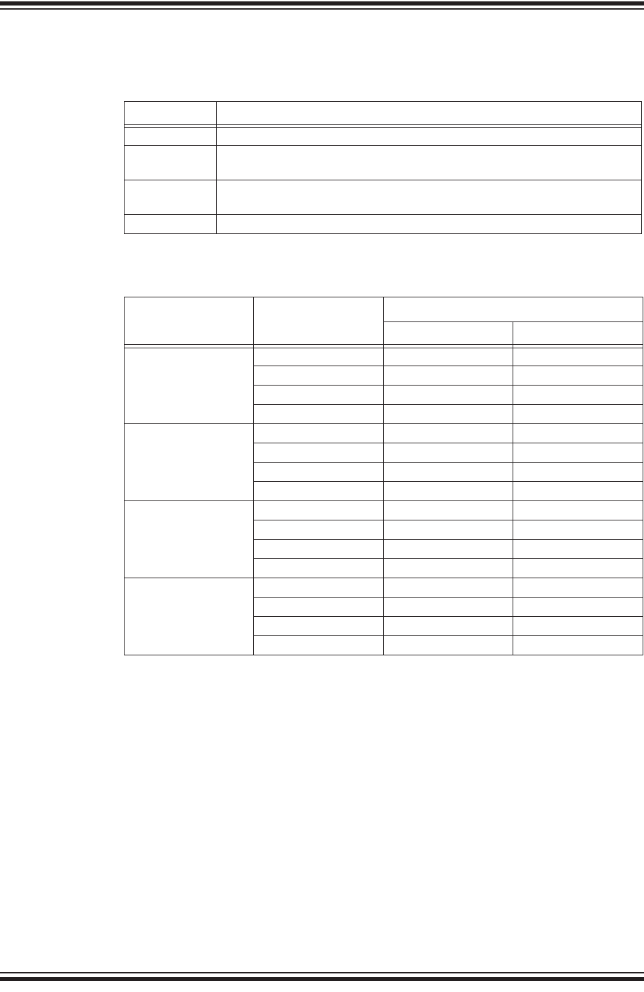
RN2483 LoRa® TECHNOLOGY MODULE COMMAND REFERENCE USER’S GUIDE
DS40001784F-page 42 2015-2017 Microchip Technology Inc.
2.4.9.20 MAC GET CHANNEL COMMANDS
2.4.9.20.1 mac get ch freq <ChannelId>
<channelId>: decimal number representing the channel number, from 0 to 15.
Response: decimal number representing the frequency of the channel, from
863000000 to 870000000 or from 433050000 to 434790000, in Hz, depending on the
frequency band selected.
This command returns the frequency on the requested <channelId>, entered in
decimal form.
Default: see Tab le 2 - 10
Example: mac get ch freq 0
TABLE 2-9: MAC GET CHANNEL COMMANDS
Parameter Description
freq Gets the module operation frequency for the specified channel ID.
dcycle Gets the module duty cycle used for transmission on the specified channel
ID.
drrange Gets the valid data rate range (min. to max.) allowed for the module on the
specified channel ID
status Gets the status for the specified channel ID to indicate if it is enabled for use.
TABLE 2-10: DEFAULT PARAMETERS FOR CHANNELS
Channel Number Parameters
Frequency band
868 433
Channel 0 Frequency (Hz) 868100000 433175000
Duty cycle (1) 302 302
Data rate range 0-5 0-5
Status On On
Channel 1 Frequency (Hz) 868300000 433375000
Duty cycle(1) 302 302
Data rate range 0-5 0-5
Status On On
Channel 2 Frequency (Hz) 868500000 433575000
Duty cycle(1) 302 302
Data rate range 0-5 0-5
Status On On
Channels 3-15 Frequency (Hz) 0 0
Duty cycle(1) 65535 65535
Data rate range 15 15 15 15
Status Off Off
Note 1: The default settings consider only the three default channels (0-2), and their default
duty cycle is 0.33%. If a new channel is created either by the server or by the user,
all the channels (including the default ones) must be updated by the user in terms
of duty cycle to comply with the ETSI regulations.

Command Reference
2015-2017 Microchip Technology Inc. DS40001784F-page 43
2.4.9.20.2 mac get ch dcycle <channelId>
<channelId>: decimal number representing the channel number, from 0 to 15.
Response: decimal number representing the duty cycle of the channel, from 0 to
65535.
This command returns the duty cycle on the requested <channelId>. The duty cycle
is returned in decimal value. The actual duty cycle (in percentage) can be obtained
using the returned value V as: percent = 100/(V + 1).
Default: see Tab le 2 - 10
Example: mac get ch dcycle 0 // Reads back duty cycle setting on Channel
ID 0. If the value reported back is 99, the
actual duty cycle on the channel (in
percentage) is 100/(99 + 1) = 1.
2.4.9.20.3 mac get ch drrange <channelId>
<channelId>: decimal number representing the channel number, from 0 to 15.
Response: decimal number representing the minimum data rate of the channel, from 0
to 7 and a decimal number representing the maximum data rate of the channel, from 0
to 7
This command returns the allowed data rate index range on the requested
<channelId>, entered in decimal form. The <minRate> and <maxRate> index
values are returned in decimal form and reflect index values. Please refer to the
LoRaWAN™ Specification for the description of data rates and the corresponding
spreading factors.
Default: see Tab le 2 - 10
Example: mac get ch drrange 0
2.4.9.20.4 mac get ch status <channelId>
<channelId>: decimal number representing the channel number, from 0 to 15.
Response: string representing the state of the channel, either on or off.
This command returns if <channelId> is currently enabled for use. <channelId> is
entered in decimal form and the response will be on or off reflecting the channel is
enabled or disabled appropriately.
Default: see Tab le 2 - 10
Example: mac get ch status 2
Note: <ChannelId> parameters must be issued prior to enabling the status of
that channel. If a channel is disabled through the <status>, all channel
parameters must be reconfigured prior to enabling.
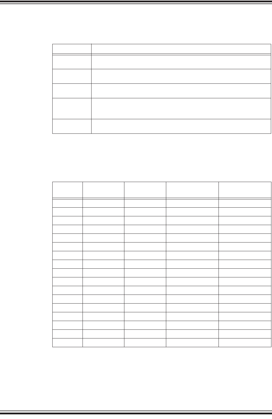
RN2483 LoRa® TECHNOLOGY MODULE COMMAND REFERENCE USER’S GUIDE
DS40001784F-page 44 2015-2017 Microchip Technology Inc.
2.5 RADIO COMMANDS
TABLE 2-11: RADIO COMMANDS(1)
Parameter Description
rx This command configures the radio to receive simple radio packets
according to prior configuration settings.
tx This command configures a simple radio packet transmission according to
prior configuration settings.
cw This command will put the module into a Continuous Wave (cw)
Transmission for system tuning or certification use.
set This command allows modification to the radio setting directly. This
command allows for the user to change the method of radio operation within
module type band limits.
get This command grants the ability to read out radio settings as they are
currently configured.
Note 1: The mac pause command must be called before any radio transmission or
reception, even if no MAC operations have been initiated before.
TABLE 2-12: RADIO PARAMETERS AVAILABILITY FOR DIFFERENT
OPERATIONS
Command radio get radio set Availability for
LoRa® Modulation
Availability for FSK
Modulation
bt √√ —√
mod √√ √ √
freq √√ √ √
pwr √√ √ √
sf √√ √ —
afcbw √√ —√
rxbw √√ —√
bitrate √√ —√
fdev √√ —√
prlen √√ —√
crc √√ √ √
iqi √√ √ —
cr √√ √ —
wdt √√ √ √
sync √√ √ √
bw √√ √ —
snr √—√—
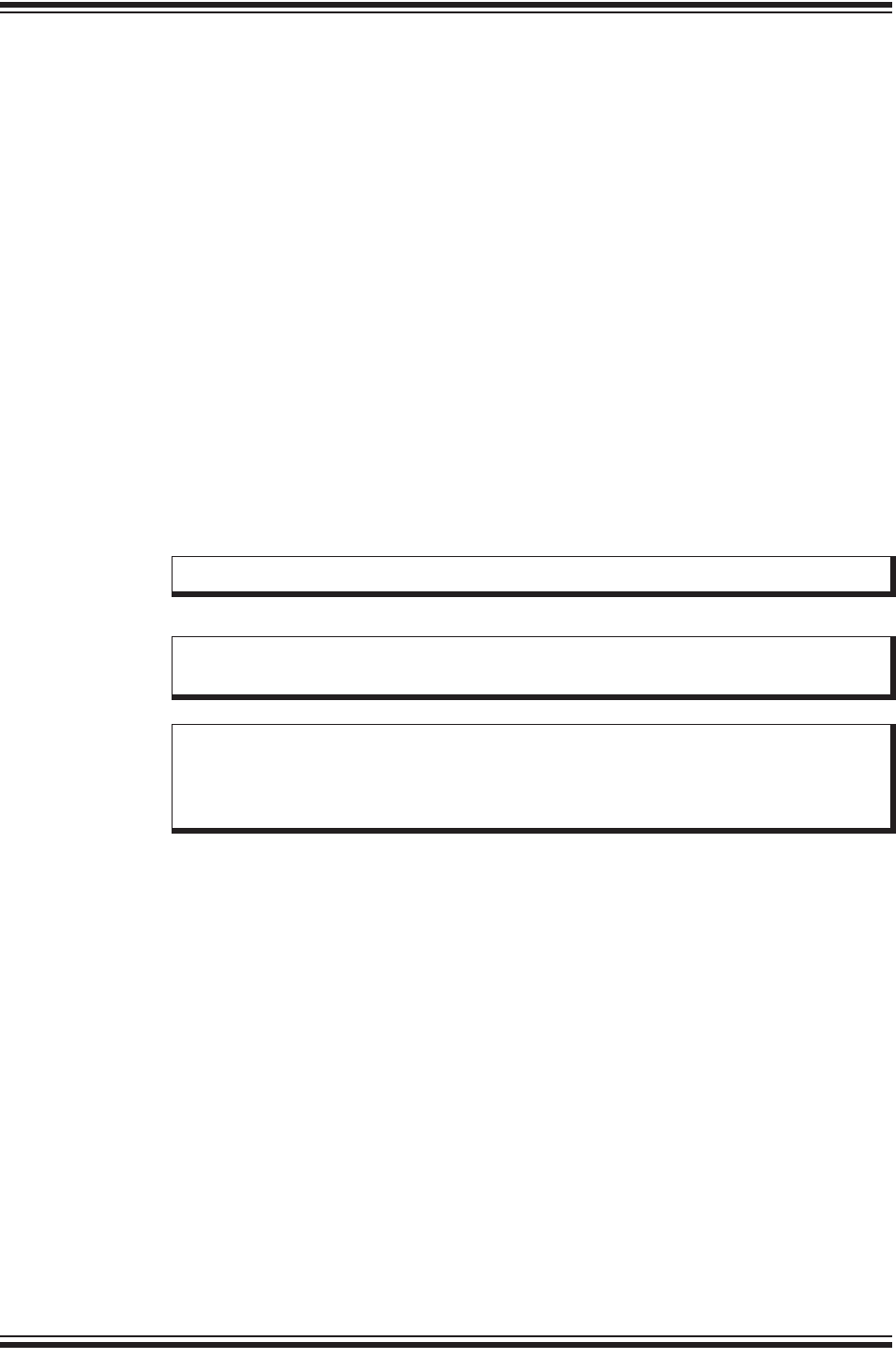
Command Reference
2015-2017 Microchip Technology Inc. DS40001784F-page 45
2.5.1 radio rx <rxWindowSize>
<rxWindowSize>: decimal number representing the number of symbols (for LoRa
modulation) or time-out (in milliseconds, for FSK modulation) that the receiver will be
opened, from 0 to 65535. Set <rxWindowSize> to ‘0’ in order to enable the
Continuous Reception mode. Continuous Reception mode will be exited once a valid
packet is received.
Response: this command may reply with two responses. The first response will be
received immediately after entering the command. If the command is valid (ok reply
received), a second reply will be received after the reception of a packet or after the
time-out occurred.
Response after entering the command:
•ok – if parameter is valid and the transceiver is configured in Receive mode
•invalid_param – if parameter is not valid
•busy – if the transceiver is currently busy
Response after the receive process:
•radio_rx <data> – if reception was successful, <data>: hexadecimal value
that was received;
•radio_err – if reception was not successful, reception time-out occurred
Example: radio rx 0 // Puts the radio into continuous Receive mode.
Ensure the radio Watchdog Timer time-out is higher than the Receive window size.
Note: The mac pause command must be called before any radio transmission
or reception, even if no MAC operations have been initiated before.
Note: When transmitting FSK packets, the payload and the 2-byte CRC is
whitened by being XORed with a pseudorandom sequence generated by
an LFSR with the polynomial X9 + X5 + 1. This process is automatically
reverted on reception so that it is transparent to the user.
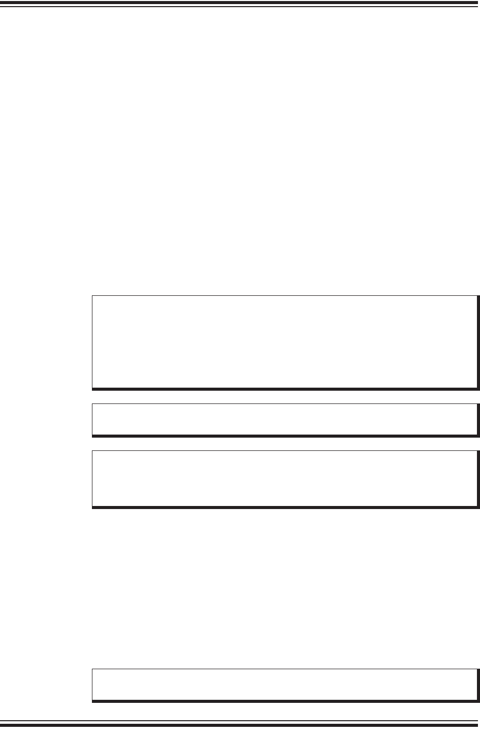
RN2483 LoRa® TECHNOLOGY MODULE COMMAND REFERENCE USER’S GUIDE
DS40001784F-page 46 2015-2017 Microchip Technology Inc.
2.5.2 radio tx <data>
<data>: hexadecimal value representing the data to be transmitted, from 0 to 255
bytes for LoRa modulation and from 0 to 64 bytes for FSK modulation.
Response: this command may reply with two responses. The first response will be
received immediately after entering the command. If the command is valid (ok reply
received), a second reply will be received after the effective transmission.
Response after entering the command:
•ok – if parameter is valid and the transceiver is configured in Transmit mode
•invalid_param – if parameter is not valid
•busy – if the transceiver is currently busy
Response after the effective transmission:
•radio_tx_ok – if transmission was successful
•radio_err – if transmission was unsuccessful (interrupted by radio Watchdog
Timer time-out)
This command transmits the <data> passed.
Example: radio tx 48656c6C6F // Transmits a packet of
[0x48][0x65][0x6c][0x6C][0x6F];
Hello.
2.5.3 radio cw <state>
<state>: string representing the state of the Continuous Wave (CW) mode, either on
or off.
Response: ok if state is valid
invalid_param if state is not valid
This command will enable or disable the CW mode on the module. CW mode allows
the user to put the transceiver into Transmission mode to observe the generated signal.
By altering the settings for the radio the user can observe the changes in transmissions
levels.
Example: radio cw on
Note: In order to meet ETSI regulations in the given frequency bands, the radio
has to use either Listen Before Talk (LBT) + Adaptive Frequency Agility
(AFA) or duty cycle limitations. By issuing the radio tx <data>
command the module does not perform LBT before transmission, thus the
user has to make sure that duty cycle limits are not violated. For more
information on duty cycle limits please check the EN 300 220-2 v2.4.1
standard.
Note: The mac pause command must be called before any radio transmission
or reception, even if no MAC operations have been initiated before.
Note: When transmitting FSK packets, the payload and the 2-byte CRC is
whitened by being XORed with a pseudorandom sequence generated by
an LFSR with the polynomial X9 + X5 + 1. This process is automatically
reverted on reception so that it is transparent to the user.
Note: Please note that using radio cw off resets the module, this command
being semantically identical to sys reset.
Command Reference
2015-2017 Microchip Technology Inc. DS40001784F-page 47
2.5.4 Radio Set Commands
2.5.4.1 radio set bt <gfBT>
<gfBT>: string representing the Gaussian baseband data shaping, enabling GFSK
modulation. Parameter values can be: none, 1.0, 0.5, 0.3.
Response: ok if the data shaping is valid
invalid_param if the data shaping is not valid
This command modifies the data shaping applied to FSK transmissions. Entering any
<gfBT> other than none will result in a Gaussian Filter BT being applied to
transmissions in FSK mode.
Example: radio set bt none // Data shaping in FSK mode is disabled or null.
2.5.4.2 radio set mod <mode>
<mode>: string representing the modulation method, either lora or fsk.
Response: ok if the modulation is valid
invalid_param if the modulation is not valid
This command changes the modulation method being used by the module. Altering the
mode of operation does not affect previously set parameters, variables or registers.
FSK mode also allows GFSK transmissions when data shaping is enabled.
Example: radio set mod lora
2.5.4.3 radio set freq <frequency>
<frequency>: decimal representing the frequency, from 433050000 to 434790000 or
from 863000000 to 870000000, in Hz.
Response: ok if the frequency is valid
invalid_param if the frequency is not valid
This command changes the communication frequency of the radio transceiver.
Example: radio set freq 868000000
TABLE 2-13: RADIO SET COMMANDS
Parameter Description
bt Set the data shaping for frequency shift keying (FSK) modulation type.
mod Set the module Modulation mode.
freq Set the current operation frequency for the radio.
pwr Set the output power level used by the radio during transmission.
sf Set the requested spreading factor (SF) to be used during transmission.
afcbw Set the value used by the automatic frequency correction bandwidth.
rxbw Set the operational receive bandwidth.
bitrate Set the frequency shift keying (FSK) bit rate.
fdev Set the frequency deviation allowed by the end device.
prlen Set the preamble length used during transmissions.
crc Set if a CRC header is to be used.
iqi Set if IQ inversion is used.
cr Set the coding rate used by the radio.
wdt Set the time-out limit for the radio Watchdog Timer.
sync Set the sync word used.
bw Set the value used for the radio bandwidth.

RN2483 LoRa® TECHNOLOGY MODULE COMMAND REFERENCE USER’S GUIDE
DS40001784F-page 48 2015-2017 Microchip Technology Inc.
2.5.4.4 radio set pwr <pwrout>
<pwrOut>: signed decimal number representing the transceiver output power, from -3
to 15.
Response: ok if the output power is valid
invalid_param if the output power is not valid
This command changes the transceiver output power. However, note that the
transceiver is designed to transmit a maximum of +14 dBm. It is possible to set the
output power above the regulatory limits. This power setting allows some
compensation on the cable or transmission line loss. For more details on output power
please check the RN2483 Low-Power Long-Range LoRa® Technology Transceiver
Module Data Sheet.
Example: radio set pwr 14
2.5.4.5 radio set sf <spreadingfactor>
<spreadingFactor>: string representing the spreading factor. Parameter values
can be: sf7, sf8, sf9, sf10, sf11 or sf12.
Response: ok if the spreading factor is valid
invalid_param if the spreading factor is not valid
This command sets the spreading factor used during transmission.
Example: radio set sf sf7
2.5.4.6 radio set afcbw <autoFreqBand>
<autoFreqBand>: float representing the automatic frequency correction, in kHz.
Parameter values can be: 250, 125, 62.5, 31.3, 15.6, 7.8, 3.9, 200,
100, 50, 25, 12.5, 6.3, 3.1, 166.7, 83.3, 41.7, 20.8, 10.4, 5.2, 2.6.
Response: ok if the automatic frequency correction is valid
invalid_param if the automatic frequency correction is not valid
This command modifies the automatic frequency correction bandwidth for
receiving/transmitting.
Example: radio set afcbw 125
2.5.4.7 radio set rxbw <rxbandwidth>
<rxBandwidth>: float representing the signal bandwidth, in kHz. Parameter values
can be: 250, 125, 62.5, 31.3, 15.6, 7.8, 3.9, 200, 100, 50, 25, 12.5,
6.3, 3.1, 166.7, 83.3, 41.7, 20.8, 10.4, 5.2, 2.6.
Response: ok if the signal bandwidth is valid
invalid_param if signal bandwidth is not valid
This command sets the signal bandwidth when receiving.
Example: radio set rxbw 250 // Signal bandwidth for receiving is 250
kHz.
2.5.4.8 radio set bitrate <fskBitRate>
<fskBitRate>: decimal number representing the FSK bit rate value, from 1 to
300000.
Response: ok if the bit rate value is valid
invalid_param if the bit rate value is not valid
This command sets the FSK bit rate value.

Command Reference
2015-2017 Microchip Technology Inc. DS40001784F-page 49
Example: radio set bitrate 5000 // FSK bit rate is set to 5 kb/s.
2.5.4.9 radio set fdev <freqdev>
<freqDev>: decimal number representing the frequency deviation, from 0 to 200000.
Response: ok if the frequency deviation is valid
invalid_param if frequency deviation is not valid
This command sets the frequency deviation during operation.
Example: radio set fdev 5000 // Frequency deviation is 5 kHz.
2.5.4.10 radio set prlen <preamble>
<preamble>: decimal number representing the preamble length, from 0 to 65535.
Response: ok if the preamble length is valid
invalid_param if the preamble length is not valid
This command sets the preamble length for transmit/receive.
Example: radio set prlen 8 // Preamble length is 8.
2.5.4.11 radio set crc < crcHeader >
<crcHeader>: string representing the state of the CRC header, either on or off.
Response: ok if the state is valid
invalid_param if the state is not valid
This command enables or disables the CRC header for communications.
Example: radio set crc on // Enables the CRC header.
2.5.4.12 radio set iqi <iqInvert>
<iqInvert>: string representing the state of the invert IQ, either on or off.
Response: ok if the state is valid
invalid_param if the state is not valid
This command enables or disables the Invert IQ for communications.
Example: radio set iqi on // Invert IQ is enabled.
2.5.4.13 radio set cr <codingRate>
<codingRate>: string representing the coding rate. Parameter values can be: 4/5,
4/6, 4/7, 4/8.
Response: ok if the coding rate is valid
invalid_param if the coding rate is not valid
This command modifies the coding rate currently being used by the radio.
Example: radio set cr 4/7 // The coding rate is set to 4/7.

RN2483 LoRa® TECHNOLOGY MODULE COMMAND REFERENCE USER’S GUIDE
DS40001784F-page 50 2015-2017 Microchip Technology Inc.
2.5.4.14 radio set wdt <watchDog>
<watchDog>: decimal number representing the time-out length for the Watchdog
Timer, from 0 to 4294967295. Set to ‘0’ to disable this functionality.
Response: ok if the watchdog time-out is valid
invalid_param if the watchdog time-out is not valid
This command updates the time-out length, in milliseconds, applied to the radio
Watchdog Timer. If this functionality is enabled, then the Watchdog Timer is started for
every transceiver reception or transmission. The Watchdog Timer is stopped when the
operation in progress in finished.
Example: radio set wdt 2000 // The Watchdog Timer is configured for
2000 ms.
2.5.4.15 radio set sync <syncWord>
<syncWord>: hexadecimal value representing the Sync word used during
communication. For LoRa modulation one byte is used, for FSK up to
eight bytes can be entered.
Response: ok if the sync word is valid
invalid_param if the sync word is not valid
This command configures the sync word used during communication.
Example: radio set sync 12 // Set the sync word to a single byte with the
value 0x12.
2.5.4.16 radio set bw <bandWidth>
<bandWidth>: decimal representing the operating radio bandwidth, in kHz.
Parameter values can be: 125, 250, 500.
Response: ok if the bandwidth is valid
invalid_param if the bandwidth is not valid
This command sets the operating radio bandwidth for LoRa operation.
Example: radio set bw 250 // The operating bandwidth is 250 kHz.
Note: Ensure the value configured for the Watchdog Timer matches the radio
configurations. For example, set the <watchDog> value to ‘0’ in order to
disable this functionality during the radio continuous reception.
Command Reference
2015-2017 Microchip Technology Inc. DS40001784F-page 51
2.5.5 Radio Get Commands
2.5.5.1 radio get bt
Response: string representing the configuration for data shaping. Parameter values
can be: none, 1.0, 0.5, 0.3.
This command reads back the current configuration for data shaping applied to FSK
transmissions.
Default: 0.5
Example: radio get bt // Reads the current data shaping FSK
configuration.
2.5.5.2 radio get mod
Response: string representing the current mode of operation of the module, either
lora or fsk.
This command reads back the current mode of operation of the module.
Default: lora
Example: radio get mod // Reads if module is modulating in LoRa or
FSK.
TABLE 2-14: RADIO GET COMMANDS
Parameter Description
bt Get the data shaping for frequency shift keying (FSK) modulation type.
mod Get the module Modulation mode.
freq Get the current operation frequency for the radio.
pwr Get the output power level used by the radio during transmission.
sf Get the requested spreading factor (SF) to be used during transmission.
afcbw Get the value used by the automatic frequency correction bandwidth.
rxbw Get the operational receive bandwidth.
bitrate Get the frequency shift keying (FSK) bit rate.
fdev Get the frequency deviation allowed by the end device.
prlen Get the preamble length used during transmissions.
crc Get if a CRC header is to be used.
iqi Get if IQ inversion is used.
cr Get the coding rate used by the radio.
wdt Get the time-out limit for the Watchdog Timer.
bw Get the value used for the radio bandwidth.
snr Get the signal noise ratio (SNR) of the last received packet.
sync Get the synchronization word used for communication.

RN2483 LoRa® TECHNOLOGY MODULE COMMAND REFERENCE USER’S GUIDE
DS40001784F-page 52 2015-2017 Microchip Technology Inc.
2.5.5.3 radio get freq
Response: decimal number representing the frequency, from 433050000 to
434790000 or from 863000000 to 870000000, in Hz.
This command reads back the current operation frequency of the module.
Default: 868100000
Example: radio get freq // Reads back the current frequency the
transceiver communicates on.
2.5.5.4 radio get pwr
Response: signed decimal representing the current power level, from -3 to 15.
This command reads back the current power level settings used in operation.
Default: 1
Example: radio get pwr // Reads back the current transmit output
power.
2.5.5.5 radio get sf
Response: string representing the current spreading factor.
This command reads back the current spreading factor being used by the transceiver.
Parameter values can be: sf7, sf8, sf9, sf10, sf11, sf12”
Default: sf12
Example: radio get sf // Reads back the current spreading factor
settings.
2.5.5.6 radio get afcbw
Response: float representing the automatic frequency correction band, in kHz.
Parameter values can be: 250, 125, 62.5, 31.3, 15.6, 7.8, 3.9, 200, 100, 50, 25, 12.5,
6.3, 3.1, 166.7, 83.3, 41.7, 20.8, 10.4, 5.2, 2.6.
This command reads back the status of the Automatic Frequency Correction
Bandwidth.
Default: 41.7
Example: radio get afcbw // Reads back the current automatic
frequency correction bandwidth.
2.5.5.7 radio get rxbw
Response: float representing the signal bandwidth, in kHz. Parameter values can be:
250, 125, 62.5, 31.3, 15.6, 7.8, 3.9, 200, 100, 50, 25, 12.5, 6.3, 3.1, 166.7, 83.3, 41.7,
20.8, 10.4, 5.2, 2.6.
This command reads back the signal bandwidth used for receiving.
Default: 25
Example: radio get rxbw // Reads back the receive signal bandwidth.

Command Reference
2015-2017 Microchip Technology Inc. DS40001784F-page 53
2.5.5.8 radio get bitrate
Response: signed decimal representing the configured bit rate, from 1 to 300000.
This command reads back the configured bit rate for FSK communications.
Default: 50000
Example: radio get bitrate // Reads back the current FSK bit rate
setting.
2.5.5.9 radio get fdev
Response: signed decimal representing the frequency deviation setting, from 0 to
200000.
This command reads frequency deviation setting on the transceiver.
Default: 25000
Example: radio get fdev // Reads back current configured frequency
deviation setting.
2.5.5.10 radio get prlen
Response: signed decimal representing the preamble length, from 0 to 65535.
This command reads the current preamble length used for communication.
Default: 8
Example: radio get prlen // Reads back the preamble length used by
the transceiver.
2.5.5.11 radio get crc
Response: string representing the status of the CRC header, either on or off
This command reads back the status of the CRC header, to determine if it is to be
included during operation.
Default: on
Example: radio get crc // Reads back if the CRC header is enabled
for use.
2.5.5.12 radio get iqi
Response: string representing the status of the Invert IQ functionality, either on or off.
This command reads back the status of the Invert IQ functionality.
Default: off
Example: radio get iqi // Reads back the status of the Invert IQ
functionality.
2.5.5.13 radio get cr
Response: string representing the current value settings used for the coding rate.
Parameter values can be: 4/5, 4/6, 4/7, 4/8.
This command reads back the current value settings used for the coding rate during
communication.
Default: 4/5
Example: radio get cr // Reads back the current coding rate
transceiver settings.

RN2483 LoRa® TECHNOLOGY MODULE COMMAND REFERENCE USER’S GUIDE
DS40001784F-page 54 2015-2017 Microchip Technology Inc.
2.5.5.14 radio get wdt
Response: decimal number representing the length used for the watchdog time-out,
from 0 to 4294967295.
This command reads back, in milliseconds, the length used for the watchdog time-out.
Default: 15000
Example: radio get wdt // Reads back the current time-out value
applied to the Watchdog Timer
2.5.5.15 radio get bw
Response: decimal representing the current operating radio bandwidth, in kHz.
Parameter values can be: 125, 250 or 500.
This command reads back the current operating radio bandwidth used by the
transceiver.
Default: 125
Example: radio get bw // Reads back the current operational
bandwidth applied to transmissions.
2.5.5.16 radio get snr
Response: signed decimal number representing the signal to noise ratio (SNR), from
-128 to 127.
This command reads back the Signal Noise Ratio (SNR) for the last received packet.
Default: -128
Example: radio get snr // Reads back the measured SNR for the
previously packet reception.
2.5.5.17 radio get sync
Response: hexadecimal number representing the synchronization word used for radio
communication.
This command reads back the configured synchronization word used for radio
communication. One byte long synchronization word is used for the LoRa modulation
while up to eight bytes can be entered for FSK.
Default: 34
Example: radio get sync
RN2483 LoRa® TECHNOLOGY MODULE
COMMAND REFERENCE USER’S GUIDE
2015-2017 Microchip Technology Inc. DS40001784F-page 55
Chapter 3. Bootloader Usage
Introduction
This chapter describes the operation of the bootloader that exists on Microchip RN2483
LoRa modules and the process to upgrade the firmware using this bootloader. This
paper assumes that there is a microcontroller or other similar device attached to the
UART lines of the RN2483 module, and that this microcontroller has enough storage
to hold the image that is to be programmed into the module.
The bootloader on the RN2483 module is based on the standard 8-bit UART
bootloader which can be found on Microchip's website at
http://www.microchip.com/bootloader.
In the Protocol section of the bootloader generator user's guide, there is a table of
supported commands. The RN2483 bootloader supports each of these commands;
however, there are some subtle nuances that need to be followed for successful
operation.
3.1 PROTOCOL
The standard 8-bit UART bootloader has a common command protocol for all
commands.
<Command><LenLSB><LenMSB><Key1><Key2><address(4 bytes)LSB..MSB>
TABLE 3-1: SUPPORTED COMMANDS
Command Description
0x00 Get Version and other info
0x01 Read Flash
0x02 Write Flash
0x03 Erase Flash
0x04 Read EE Data
0x05 Write EE Data
0x06 Read Configuration Words
0x07 Write Configuration Words
0x08 Calculate and return Flash checksum
0x09 Reset Device
TABLE 3-2: COMMAND PROTOCOL
Byte: 012 3 4 5 6 7 8
Fields: CMD Length(LSB..MSB) Key 1 Key 2 Address (LSB..MSB)
RN2483 LoRa® TECHNOLOGY MODULE COMMAND REFERENCE USER’S GUIDE
DS40001784F-page 56 2015-2017 Microchip Technology Inc.
Byte Order
There are two multi-byte fields common to all commands. These are the Length field,
and the Address field. These values are sent in little-endian format. This means that
the low-order byte (Least Significant Byte) is sent first, and the high-order byte (Most
Significant Byte) is sent last.
Write Operations
When an Erase or Write command is issued, the two key fields must be supplied with
correct values. For read operations, they key fields are not used. The values of the keys
are always:
• Key1 = 0x55
• Key2 = 0xaa
General Differences from 8-Bit Bootloader
• Module bootloader only uses the first-length byte and ignores the second-length
byte in all commands. The protocol still requires that the second length-byte be
sent, but the bootloader ignores this value.
• Each command is preceded by 0x55 (ASCII ‘U’); this is used for auto-baud
detection.
3.2 RN MODULE BOOTLOADER COMMANDS
Because of the differences between the normal Microchip 8-bit bootloader and the
bootloader in the RN2483 module, the command format has an initial byte of 0x55, and
the second byte of the length field (MSB) is always 0x00.
<0x55><Command><Len><0x00><Key1><Key2><address(4 bytes)LSB..MSB>
3.3 COMMAND DETAILS
This command returns bootloader version and memory information.
Response:
<0x55><0x01><Len><0x00><0x00><0x00><address(4 bytes)LSB..MSB>
TABLE 3-3: RN MODULE BOOTLOADER COMMANDS
Byte: 012 3 4 5 6 7 8 9
Fields: 0x55 CMD Len 0x00 Key1 Key2 Address (LSB..MSB)
TABLE 3-4: GET VERSION INFO
Byte: 012 3 4 5 6 7 8 9
Values: 0x55 0x00 0x00 0x00 0x00 0x00 0x00 0x00 0x00 0x00
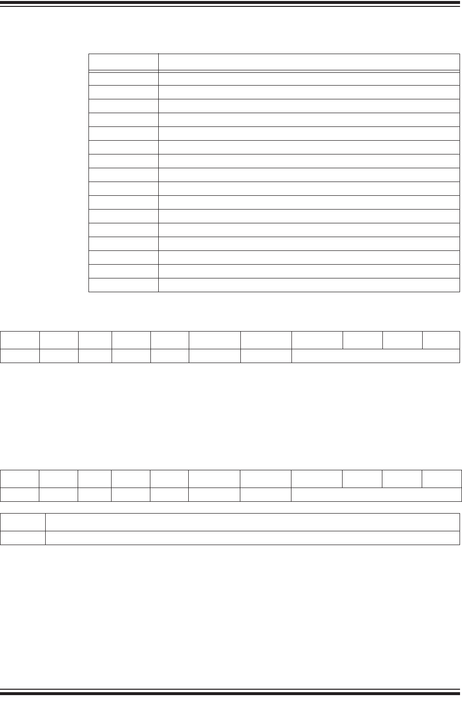
Bootloader Usage
2015-2017 Microchip Technology Inc. DS40001784F-page 57
Len bytes of information follow the address field.
This command returns data read from the Flash memory. The length field can range
from 0 to 255. This determines the number of bytes read from Flash and returned by
the bootloader in the response.
Response:
<0x55><0x01><Len><0x00><0x00><0x00><address(4 bytes)LSB..MSB><byte0><byte1>...<byteN>
Len bytes are returned after the address field.
This command writes data into the Flash memory. The length field can range from 0 to
255. This determines the number of bytes written to Flash. The Write Flash command
does not erase any Flash memory before writing data; therefore, this command should
be preceded by an Erase Flash command for proper operation.
Response:
<0x55><0x02><Len><0x00><Key1><Key2><address(4 bytes)LSB..MSB><Status>
Status is either a ‘0’ indicating that the command failed, or a ‘1’ indicating the
command was successful
TABLE 3-5:
Byte Value
0Bootloader version – low byte
1Bootloader version – high byte
2Max. packet size – low byte (not used)
3Max. packet size – high byte (not used)
4ACK packet size – low byte (not used)
5ACK packet size – high byte (not used)
6Device ID – low byte
7Device ID – high byte
8(not used)
9(not used)
10 Erase Row size
11 Write Latch size
12 User ID 1
13 User ID 2
14 User ID 3
15 User ID 4
TABLE 3-6: READ FLASH
Byte: 012 3 4 5 6 7 8 9
Values: 0x55 0x01 Len 0x00 0x00 0x00 Address
TABLE 3-7: WRITE FLASH
Byte: 012 3 4 5 6 7 8 9
Values: 0x55 0x02 Len 0x00 Key1 Key2 Address
Byte: Len Number of bytes (9 through 8+Len)
Values: Data[0]-Data[Len-1]
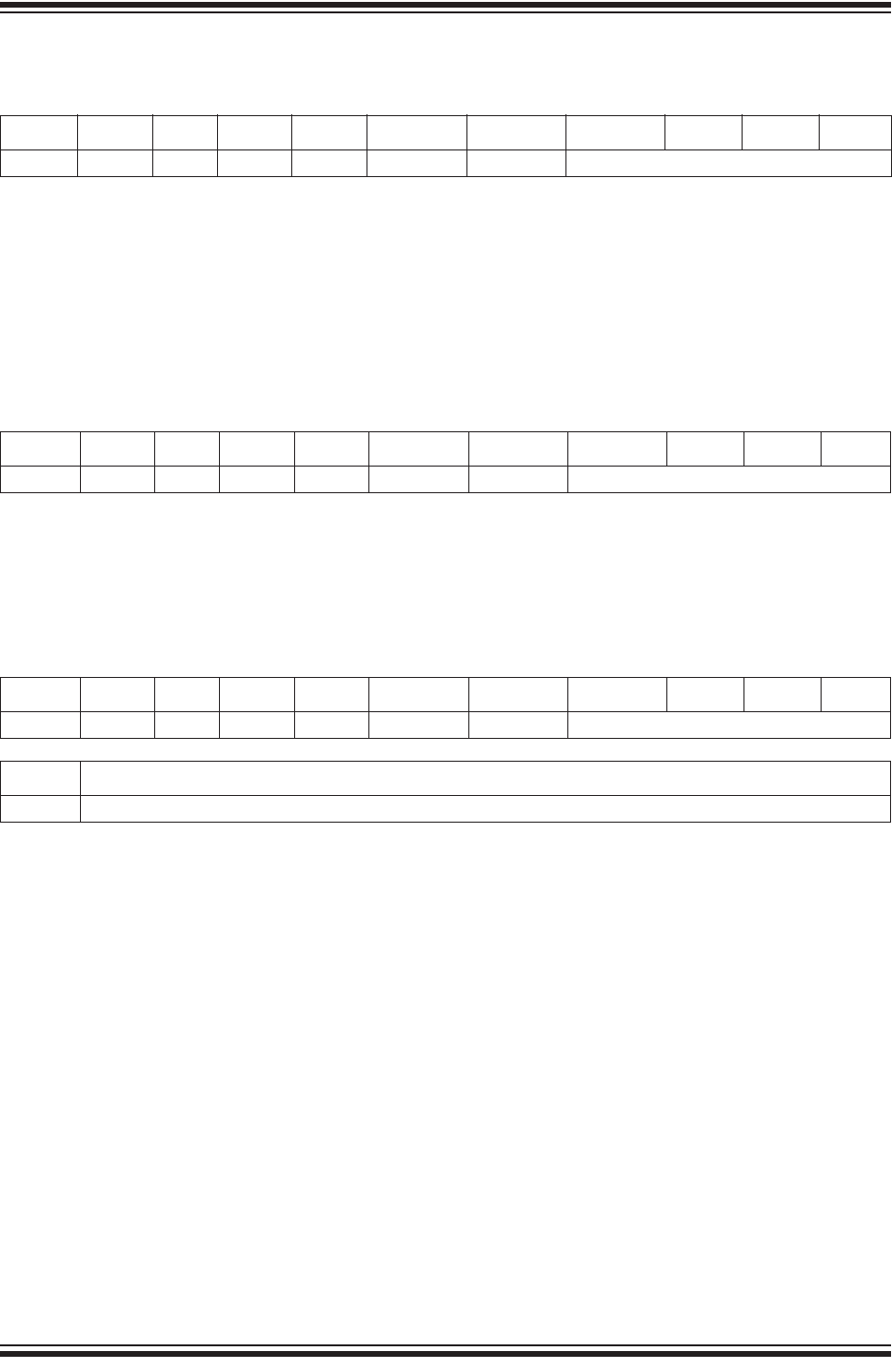
RN2483 LoRa® TECHNOLOGY MODULE COMMAND REFERENCE USER’S GUIDE
DS40001784F-page 58 2015-2017 Microchip Technology Inc.
.
This command erases one or more blocks of Flash memory, starting at address
Address. The Blocks field can range from 0 to 255. The 1-255 value of the Blocks field
represents the number of blocks to erase. If the Blocks field is ‘0’, the bootloader will
erase 256 blocks.
Response:
<0x55><0x03><Blocks><0x00><Key1><Key2><address(4 bytes)LSB..MSB><Status>
Status is either a ‘0’ indicating that the command failed, or a ‘1’ indicating the
command was successful.
This command reads data from the EEPROM memory located on the embedded PIC®
device in the module beginning at address Address. Len can range from 0 to 255.
Response:
<0x55><0x04><Len><0x00><0x00><0x00><address(4 bytes)LSB..MSB><byte0><byte1>...<byteN>
Len bytes are returned after the Address field.
This command writes data into the EEPROM memory of the embedded PIC device.
The Len field can range from 0 to 255. This determines the number of bytes written to
EEPROM. The Write EE command does not require any form of Erase command to be
issued prior to writing data into the EEPROM.
Response:
<0x55><0x05><Len><0x00><Key1><Key2><address(4 bytes)LSB..MSB><Status>
Status is either a ‘0’ indicating that the command failed, or a ‘1’ indicating the
command was successful.
TABLE 3-8: ERASE FLASH
Byte: 0123456789
Values: 0x55 0x03 Blocks 0x00 Key1 Key2 Address
TABLE 3-9: READ EE
Byte: 012 3 4 5 6 7 8 9
Values: 0x55 0x04 Len 0x00 0x00 0x00 Address
TABLE 3-10: WRITE EE
Byte: 012 3 4 5 6 7 8 9
Values: 0x55 0x05 Len 0x00 Key1 Key2 Address
Byte: Len Number of bytes (9 through 8+Len)
Values: Data[0]-Data[Len-1]
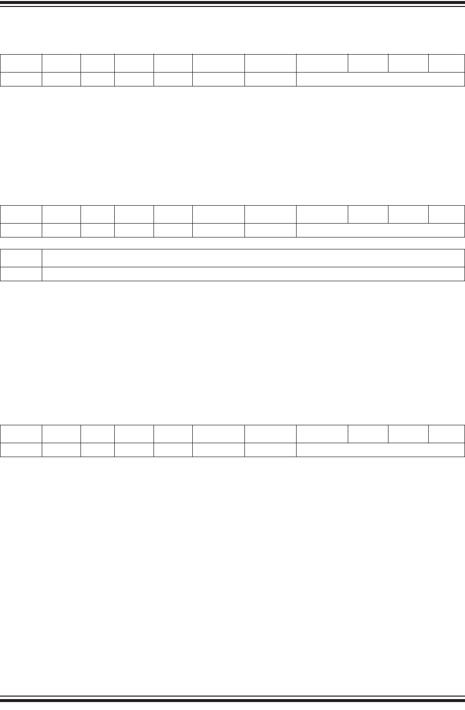
Bootloader Usage
2015-2017 Microchip Technology Inc. DS40001784F-page 59
This command reads data from the Configuration memory located on the embedded
microcontroller in the module beginning at address Address. The Len field can range
from 0 to 255. There are only 14 Configuration Words, and data repeats if the Len(gth)
is greater than the number of Configuration Words.
Response:
<0x55><0x06><Len><0x00><0x00><0x00><address(4 bytes)LSB..MSB><byte0><byte1>...<byteN>
Len bytes are returned after the Address field.
This command writes data into the Configuration memory. The Length field can range
from 0 to 255. This determines the number of bytes written to the Configuration
memory. The Write Configuration Words command does not erase any Flash memory
before writing data; therefore, this command should be preceded by an Erase Flash
command for proper operation.
Response:
<0x55><0x07><Len><0x00><Key1><Key2><address(4 bytes)LSB..MSB><Status>
Status is either a ‘0’ indicating that the command failed, or a ‘1’ indicating the
command was successful.
This command returns the checksum calculated over the Flash memory range
beginning at Address for a length of Len bytes. If Len is odd, 1 is added to make Len
even.
The checksum algorithm treats the Flash memory as an array of 16-bit values during
the calculation, which is not performed byte by byte. In MPLAB® X, this is known as
Checksum Algorithm 2.
Response:
<0x55><0x08><Len><0x00><Key1><Key2><address(4 bytes)LSB..MSB><CSumLSB><CSumMSB>
Status is either a ‘0’ indicating that the command failed, or a ‘1’ indicating the
command was successful.
TABLE 3-11: READ CONFIGURATION WORDS
Byte: 012 3 4 5 6 7 8 9
Values: 0x55 0x06 Len 0x00 0x00 0x00 Address
TABLE 3-12: WRITE CONFIGURATION WORDS
Byte: 012 3 4 5 6 7 8 9
Values: 0x55 0x07 Len 0x00 Key1 Key2 Address
Byte: Len Number of bytes (9 through 8+Len)
Values: Data[0]-Data[Len-1]
TABLE 3-13: CALCULATE AND RETURN CHECKSUM
Byte: 012 3 4 5 6 7 8 9
Values: 0x55 0x08 Len 0x00 0x00 0x00 Address

RN2483 LoRa® TECHNOLOGY MODULE COMMAND REFERENCE USER’S GUIDE
DS40001784F-page 60 2015-2017 Microchip Technology Inc.
This command does not generate a response and immediately performs a software
reset of the module.
TABLE 3-14: RESET DEVICE
Byte: 012 3 4 5 6 7 8 9
Values: 0x55 0x09 0x00 0x00 0x00 0x00 0x00000000

RN2483 LoRa® TECHNOLOGY MODULE
COMMAND REFERENCE USER’S GUIDE
2015-2017 Microchip Technology Inc. DS40001784F-page 61
Appendix A. Current Firmware Features and Fixes
Please check the product web page for the current RN2483 firmware version at
www.microchip.com/lora.
A.1. Version 0.9.5
Initial release of the firmware.
A.2. Version 1.0.0
Release for LoRaWAN™ specification V1.0
• Added support for additional RN2483 commands:
mac set sync
mac get sync
mac set upctr
mac get upctr
mac set dnctr
mac get dnctr
sys set pinmode
sys get pindig
sys get pinana
radio get sync
• Added new parameters to be saved in nonvolatile memory whenever a mac save
command is triggered
LoRaWAN current data rate
LoRaWAN RX2 window parameters (data rate and frequency)
Adaptive Data Rate status
LoRaWAN uplink frame counter
LoRaWAN downlink frame counter
• Changed the default value for the LoRaWAN End-Device Identifier (deveui)
• Changed the valid range for the radio set fdev parameter to [0.. 200000]
• Changed the valid range for the radio set bitrate parameter to [1.. 300000]
• Changed sys sleep command behavior to not influence the GPIO configuration
• Changed the 433 MHz radio frequency band to [433050000 .. 434790000]
• Fixed an issue that may have caused the RN2483 module to mishandle data on
LoRaWAN port 0
• Fixed an issue that may have caused the module to fail joining
• Fixed radio get snr command to display correct value

RN2483 LoRa® Technology Module Command Reference User’s Guide
DS40001784F-page 62 2015-2017 Microchip Technology Inc.
A.3. Version 1.0.1
Release containing modifications needed to successfully pass the LoRaWAN
Certification Program testing in 868 MHz band.
• Added support for usage of the reserved ports, from 224 to 255 for transmitting
and receiving Application Data
• Increased the size of the value returned by the mac get status command from
2 bytes to 4 bytes
• Updated the size of the LoRaWAN receive windows and the moment in time at
which these are opened
• Fixed an issue that may have caused the RN2483 module to mishandle packets
received with DR = 7
• Fixed an issue that may have caused the RN2483 module to mishandle the
LoRaWAN RXParamSetupReq command
• Fixed an issue that may have caused the RN2483 module to mishandle the usage
of LoraWAN ADRACKReq in packets

2015-2017 Microchip Technology Inc. DS40001784F-page 63
AMERICAS
Corporate Office
2355 West Chandler Blvd.
Chandler, AZ 85224-6199
Tel: 480-792-7200
Fax: 480-792-7277
Technical Support:
http://www.microchip.com/
support
Web Address:
www.microchip.com
Atlanta
Duluth, GA
Tel: 678-957-9614
Fax: 678-957-1455
Austin, TX
Tel: 512-257-3370
Boston
Westborough, MA
Tel: 774-760-0087
Fax: 774-760-0088
Chicago
Itasca, IL
Tel: 630-285-0071
Fax: 630-285-0075
Dallas
Addison, TX
Tel: 972-818-7423
Fax: 972-818-2924
Detroit
Novi, MI
Tel: 248-848-4000
Houston, TX
Tel: 281-894-5983
Indianapolis
Noblesville, IN
Tel: 317-773-8323
Fax: 317-773-5453
Tel: 317-536-2380
Los Angeles
Mission Viejo, CA
Tel: 949-462-9523
Fax: 949-462-9608
Tel: 951-273-7800
Raleigh, NC
Tel: 919-844-7510
New York, NY
Tel: 631-435-6000
San Jose, CA
Tel: 408-735-9110
Tel: 408-436-4270
Canada - Toronto
Tel: 905-695-1980
Fax: 905-695-2078
ASIA/PACIFIC
Asia Pacific Office
Suites 3707-14, 37th Floor
Tower 6, The Gateway
Harbour City, Kowloon
Hong Kong
Tel: 852-2943-5100
Fax: 852-2401-3431
Australia - Sydney
Tel: 61-2-9868-6733
Fax: 61-2-9868-6755
China - Beijing
Tel: 86-10-8569-7000
Fax: 86-10-8528-2104
China - Chengdu
Tel: 86-28-8665-5511
Fax: 86-28-8665-7889
China - Chongqing
Tel: 86-23-8980-9588
Fax: 86-23-8980-9500
China - Dongguan
Tel: 86-769-8702-9880
China - Guangzhou
Tel: 86-20-8755-8029
China - Hangzhou
Tel: 86-571-8792-8115
Fax: 86-571-8792-8116
China - Hong Kong SAR
Tel: 852-2943-5100
Fax: 852-2401-3431
China - Nanjing
Tel: 86-25-8473-2460
Fax: 86-25-8473-2470
China - Qingdao
Tel: 86-532-8502-7355
Fax: 86-532-8502-7205
China - Shanghai
Tel: 86-21-3326-8000
Fax: 86-21-3326-8021
China - Shenyang
Tel: 86-24-2334-2829
Fax: 86-24-2334-2393
China - Shenzhen
Tel: 86-755-8864-2200
Fax: 86-755-8203-1760
China - Wuhan
Tel: 86-27-5980-5300
Fax: 86-27-5980-5118
China - Xian
Tel: 86-29-8833-7252
Fax: 86-29-8833-7256
ASIA/PACIFIC
China - Xiamen
Tel: 86-592-2388138
Fax: 86-592-2388130
China - Zhuhai
Tel: 86-756-3210040
Fax: 86-756-3210049
India - Bangalore
Tel: 91-80-3090-4444
Fax: 91-80-3090-4123
India - New Delhi
Tel: 91-11-4160-8631
Fax: 91-11-4160-8632
India - Pune
Tel: 91-20-3019-1500
Japan - Osaka
Tel: 81-6-6152-7160
Fax: 81-6-6152-9310
Japan - Tokyo
Tel: 81-3-6880- 3770
Fax: 81-3-6880-3771
Korea - Daegu
Tel: 82-53-744-4301
Fax: 82-53-744-4302
Korea - Seoul
Tel: 82-2-554-7200
Fax: 82-2-558-5932 or
82-2-558-5934
Malaysia - Kuala Lumpur
Tel: 60-3-6201-9857
Fax: 60-3-6201-9859
Malaysia - Penang
Tel: 60-4-227-8870
Fax: 60-4-227-4068
Philippines - Manila
Tel: 63-2-634-9065
Fax: 63-2-634-9069
Singapore
Tel: 65-6334-8870
Fax: 65-6334-8850
Taiwan - Hsin Chu
Tel: 886-3-5778-366
Fax: 886-3-5770-955
Taiwan - Kaohsiung
Tel: 886-7-213-7830
Taiwan - Taipei
Tel: 886-2-2508-8600
Fax: 886-2-2508-0102
Thailand - Bangkok
Tel: 66-2-694-1351
Fax: 66-2-694-1350
EUROPE
Austria - Wels
Tel: 43-7242-2244-39
Fax: 43-7242-2244-393
Denmark - Copenhagen
Tel: 45-4450-2828
Fax: 45-4485-2829
Finland - Espoo
Tel: 358-9-4520-820
France - Paris
Tel: 33-1-69-53-63-20
Fax: 33-1-69-30-90-79
France - Saint Cloud
Tel: 33-1-30-60-70-00
Germany - Garching
Tel: 49-8931-9700
Germany - Haan
Tel: 49-2129-3766400
Germany - Heilbronn
Tel: 49-7131-67-3636
Germany - Karlsruhe
Tel: 49-721-625370
Germany - Munich
Tel: 49-89-627-144-0
Fax: 49-89-627-144-44
Germany - Rosenheim
Tel: 49-8031-354-560
Israel - Ra’anana
Tel: 972-9-744-7705
Italy - Milan
Tel: 39-0331-742611
Fax: 39-0331-466781
Italy - Padova
Tel: 39-049-7625286
Netherlands - Drunen
Tel: 31-416-690399
Fax: 31-416-690340
Norway - Trondheim
Tel: 47-7289-7561
Poland - Warsaw
Tel: 48-22-3325737
Romania - Bucharest
Tel: 40-21-407-87-50
Spain - Madrid
Tel: 34-91-708-08-90
Fax: 34-91-708-08-91
Sweden - Gothenberg
Tel: 46-31-704-60-40
Sweden - Stockholm
Tel: 46-8-5090-4654
UK - Wokingham
Tel: 44-118-921-5800
Fax: 44-118-921-5820
Worldwide Sales and Service
11/07/16
