03 318004ad1 Graco Wheelchair 225
User Manual: Graco Wheelchair 225
Open the PDF directly: View PDF ![]() .
.
Page Count: 30

STATE OF CALIFORNIA-BUSINESS, TRANSPORTATION AND HOUSING AGENCY ARNOLD SCHWARZENEGGER, Governor
DEPARTMENT OF TRANSPORTATION
DIVISION OF ENGINEERING SERVICES
OFFICE ENGINEER, MS 43
1727 30TH STREET
P.O. BOX 168041
SACRAMENTO, CA 95816-8041
FAX (916) 227-6214
TTY 711
Flex your power!
Be energy efficient!
March 24, 2010
03-Nev-L5717
03-318004
Addendum No. 1
Dear Contractor:
This addendum is being issued to the contract for CONSTRUCTION ON STATE HIGHWAY IN NEVADA COUNTY IN
NEVADA CITY AT THE NEVADA CITY MAINTENANCE STATION AT 10057 GOLD FLAT ROAD.
Submit bids for this work with the understanding and full consideration of this addendum. The revisions declared in this
addendum are an essential part of the contract.
Bids for this work will be opened on Tuesday, March 30, 2010.
This addendum is being issued to revise the Project Plans, the Notice to Bidders and Special Provisions.
Project Plan Sheets 31, 32 and 54 are revised. Copies of the revised sheets are attached for substitution for the like-numbered
sheets.
"In the Notice to Bidders and Special Provisions, in the "STANDARD PLANS LIST," the following Standard
Plans are added :
ES-7N Electrical Systems (Signal and Lighting Standards – Details No. 2)
ES-11 Electrical Systems (Foundation Installations)
ES-13A Electrical Systems (Splicing Details)
ES-13B Electrical Systems (Wiring details and Fuse Ratings)"
In the Special Provisions, Section 5-1.07, "COMPENSATION ADJUSTMENTS FOR PRICE INDEX FLUCTUATIONS,"
is deleted.
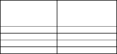
In the Special Provisions, Section 5-1.09, "SUPPLEMENTAL PROJECT INFORMATION," the table is revised as follows:
Supplemental Project Information
Means Description
Included in the Information Handout Foundation Report for the Resident Mechanic Building at the
Nevada City Maintenance Station, dated July 26, 2007
CA Laboratory Service Analysis dated October 24,2008
Available for inspection at the District Office Cross sections
Available for inspection at the Transportation
Laboratory Borehole core samples for all boreholes
Addendum No. 2
Page 2
March 24, 2010
03-Nev-L5717
03-318004
In the Special Provisions, Section 11, "BLANK," Section 12, "BUILDING WORK," delete duplicates.
In the Special Provisions, Section 12-2.07, "MINOR HOT MIX ASPHALT," is deleted.
In the Special Provisions, Section 12-8.04, "FINISH HARDWARE," subsection "PART 1 - GENERAL,"
Subsection "KEYING INSTRUCTIONS," the second paragraph is deleted.
In the Special Provisions, Section 12-11.01, "LUBRICATION AND COMPRESSED AIR SYSTEMS," is replaced as
attached.
In the Special Provisions, Section 12-15.01, "MECHANICAL WORK," is replaced as attached.
In the Special Provisions, Section 12-15.02, "PIPE, FITTINGS AND VALVES," is replaced as attached.
In the Special Provisions, Section 12-15.03, "MECHANICAL INSULATION," is replaced as attached.
In the Special Provisions, Section 12-15.04, "PLUMBING FIXTURES," is replaced as attached.
In the Special Provisions, Section 12-15.05, "WHEELCHAIR ACCESSIBLE SHOWER UNIT," is replaced as attached.
In the Special Provisions, Section 12-15.06, "HEATING, VENTILATING AND AIR CONDITIONING EQUIPMENT AND
SYSTEMS," is replaced as attached.
To Bid book holders:
Inquiries or questions in regard to this addendum must be communicated as a bidder inquiry and must be made
as noted in the Notice to Bidders section of the Notice to Bidders and Special Provisions.
Indicate receipt of this addendum by filling in the number of this addendum in the space provided on the
signature page of the Bid book.
Submit bids in the Bid book you now possess. Holders who have already mailed their book will be contacted to
arrange for the return of their book.
Inform subcontractors and suppliers as necessary.
This addendum, and attachments are available for the Contractors' download on the Web site:
http://www.dot.ca.gov/hq/esc/oe/project_ads_addenda/03/03-318004
If you are not a Bid book holder, but request a book to bid on this project, you must comply with the requirements of this
letter before submitting your bid.
Sincerely,
ORIGINAL SIGNED BY
REBECCA D. HARNAGEL
Chief, Office of Plans, Specifications & Estimates
Office Engineer
Division of Engineering Services
Attachments
12-11.01 LUBRICATION AND COMPRESSED AIR SYSTEMS
PART 1 - GENERAL
SUMMARY
Scope: This work shall consist of furnishing and installing lubrication and compressed air systems in accordance with
the details shown on the plans and these special provisions.
The lubrication system shall include spill containment drum dollies and T-bar handles; overhead hose reels and
pneumatic pumps for dispensing chassis lubricant, motor oil, automatic transmission fluid, gear lubricant and anti-freeze;
overhead electric light; and all connecting pipelines, hoses, accessories and mounting assemblies.
The compressed air system shall include a compressor, regulators, gauges and compressed air piping.
Pipes and fittings shall be in accordance with the requirements specified under "Pipes, Fittings, and Valves," in Section
12-15, "Mechanical," of these special provisions.
Permits to Operate:
Attention is directed to the latest Division of Industrial Safety (DIS) regulations regarding tank mounted air
compressors.
The Contractor shall provide all permits to operate pressure vessels in accordance with the requirements of the DIS
and shall pay all costs for such permits. Such permits shall be posted under glass at the work site.
SUBMITTALS
Product Data:
Manufacturer's descriptive data shall be submitted for approval.
Manufacturer's descriptive data shall include a complete description, performance data and installation instructions
for the materials and equipment specified herein. Performance data shall include the product delivery rate and
discharge pressure for each type of pump assembly.
CLOSEOUT SUBMITTALS
Operation and Maintenance Manuals: Prior to the completion of the contract, 3 identified copies of the operation and
maintenance instructions with parts lists for the equipment specified herein shall be delivered to the Engineer at the
jobsite. The instructions and parts lists shall be in a bound manual form and shall be complete and adequate for the
equipment installed. Inadequate or incomplete material shall be returned. The Contractor shall resubmit adequate and
complete manuals at no expense to the State.
WARRANTY
Warranties and Guarantees: Manufacturer's warranties and guarantees for materials or equipment used in the work shall
be delivered to the Engineer at the jobsite prior to acceptance of the contract.
PART 2 - PRODUCTS
OVERHEAD HOSE REEL ASSEMBLIES
Overhead hose reel assemblies shall be heavy duty assemblies of steel construction with connecting hoses, locking
automatic ratchets, guide rollers and heavy duty spring activated hose pickups. Reels shall have bushings, swivels, ball
stops, delivery hoses and control valves. The reels shall have a baked enamel finish. Manufacturers reel mounting
brackets shall be supplied with reels. CONTRACT NO. 03-318004
REPLACED PER ADDENDUM NO. 1 DATED MARCH 24, 2010
Chassis Lubrication Reel Assembly: The chassis lubricant reel assembly shall have a 40-foot minimum length,
minimum ¼-inch outside diameter, high pressure delivery hose and outlet control valve. The delivery hose shall be rated
for 5,000 psi working pressure and 20,000 psi bursting pressure. The chassis lubricant reel assembly shall be Lincoln,
85051; Graco, 224-363, 224-417, and 202-577; or equal.
Motor Oil Reel Assembly: The motor oil reel assembly shall have a 16-quart metering shutoff valve assembly with
totalizer, non-drip nozzle extension, strainer and a 40-foot minimum length of ½-inch inside diameter, medium pressure
delivery hose. The delivery hose shall be rated for 800 psi working pressure and 4,000 psi bursting pressure. The motor
oil reel assembly shall be Lincoln, 83464 and 899; Graco, 224-057, 218-549, 222-648, 203-265, 157-958, and 108-478;
or equal.
Automatic Transmission Fluid and Hydraulic Fluid Reel Assembly: Automatic transmission fluid (ATF) and hydraulic
fluid reel assembly shall have a volume control valve, non-drip nozzle and 40-foot minimum length of ½-inch outside
diameter, medium pressure delivery hose. The delivery hose shall be rated for 800 psi working pressure and 4,000 psi
bursting pressure. The ATF reel assembly shall be a Lincoln, 83464 and 776; Graco, 224-057, 218-549, and 222-413; or
equal.
Gear Lubricant Reel Assembly: Gear lubricant reel assembly shall have an 10-quart metering shut-off valve assembly
with totalizer, non-drip nozzle and a 40-foot minimum length of ½-inch outside diameter, medium pressure delivery
hose. The delivery hose shall be rated for 800 psi working pressure and 4,000 psi bursting pressure. The gear lubricant
reel assembly shall be Lincoln, 83464 and 881; Graco, 224-057, 218-549,222-648, 201-701, 157-958 and 108-478; or
equal.
PUMP ASSEMBLIES
Pump assemblies shall be lubricant and oil type pump assemblies with air driven motors and shall be suitable for
operation with stationary, exposed drums. Pump assemblies shall include pressure relief kits. Air connector hose shall
be rated for 250 psi minimum working pressure. Product connector hose shall be as specified for the individual reel
assembly. Pump assemblies shall produce the flowrates and pressures as specified under "Testing".
Chassis Lubricant Pump Assembly: Chassis lubricant pump assembly shall be suitable for use with stationary, exposed
120-pound drums, complete with drum cover, air coupler and follower plate, and shall have a minimum pressure ratio of
45:l and a maximum pressure ratio of 50:l. The chassis lubricant pump assembly shall be Lincoln, 918; Alemite, 8550;
Graco, 225-014; or equal.
Motor Oil, ATF, hydraulic fluid and Gear Oil Pump Assemblies: Chassis lubricant pump assembly Motor oil, ATF,
hydraulic fluid and gear oil pump assemblies shall be suitable for use with stationary, exposed 55-gallon drums and
equipped with a bung bushing and an air expeller in the pump tube and shall have a 3-inch air motor. The motor oil
pump assembly shall be equipped with a flow compensator. Pump assemblies shall be Lincoln, 424; Alemite, 8569;
Graco, 225-640; or equal.
MISCELLANEOUS COMPONENTS
Light Reel Assembly: Light reel assembly shall be overhead type light reel with a positive reel latch cord lock
mechanism, release mechanism, reel cord retractor, 30-foot minimum length of 3-wire cord, 2-foot pigtail, ball stop,
vapor-tight high impact phenolic plastic holder without switch or receptacle with heavy duty lamp guard and 100-watt
incandescent bulb or l5-watt fluorescent tube. The incandescent light reel assembly shall be Alemite, 330005C; or equal.
The fluorescent light reel assembly shall be Hi Reel, 3005-AFL; Woodhead, 945-3SW-1003-3S; or equal.
Air Compressor: Air compressor shall be 2-stage, 175 psig design, 125 psi output, mounted on an ASME code
horizontal type receiver. The air compressor shall be complete with unloader, V-belt drive, belt guard, oil and air
pressure gauges, automatic pressure controller, outlet valve, ASME relief valve, air intake filter, ball valve drain and an
automatic tank drain operated by either the compressor unloader or a governor. Motor shall be high efficiency type,
open dripproof with class B insulation. Air compressor shall be Champion, Ingersol Rand, Kellogg, or equal.
CONTRACT NO. 03-318004
REPLACED PER ADDENDUM NO. 1 DATED MARCH 24, 2010
Pressure Regulator:
Pressure regulator shall be combination type with filter, bowl, pressure regulator and pressure gauge.
The filter bowl shall be the quick disconnect type, plastic with metal guard, manual drain, and 5-micron filter.
Pressure regulator shall be diaphragm controlled, balanced valve type, rated for 0 to 160 psig operation and shall be
equipped with pressure gage, bottom clean-out plugs and internal strainers. Regulator shall be Wilkerson, Lincoln,
Wabco, or equal.
Flexible Coupling: Flexible coupling shall be brass flexible metal hose with threaded union ends and a minimum
working pressure of 200 psig.
Pressure Gage: Pressure gage shall be rotary type ANSI Standard: B40.1, Grade A, with 3½-inch dial, liquid filled with
cover, plain case, reset screw and bottom inlet. Pressure gage movement shall be phosphor bronze bushed. Gage shall
read from 0 psi to 160 psi. Each gage shall be equipped with a gage cock. Pressure gage shall be Marsh, Ashcroft, US
Gage, or equal.
Spill Scooter Drum Dolly: Spill Scooter Drum dolly shall have 100% polyethylene construction with 4 ball bearing
caster wheels and a metal T-Handle. Spill Scooter Drum dolly shall be sized for 500-pound drums or 55-gallon drums as
applicable.
PART 3 - EXECUTION
INSTALLATION
The hose reels shall be installed rigidly and securely to the reel mounting bracket. The mounting bracket shall be
attached to the overhead structure as shown on the plans.
Pipelines shall be cleaned and flushed immediately prior to connecting the control valves.
Pressure relief kits shall be installed on the discharge side of the recyclable oil, gear lube, ATF and motor oil pumps as
recommended by the pump manufacturer.
Air compressor shall be installed with drain piping, vibration isolation pads and expansion anchors.
Unions shall be installed before and after the pressure regulator/ball valve assembly.
Each pump assembly drum shall be supplied with a spill scooter drum dolly and T-handle.
FIELD QUALITY CONTROL
Testing:
All tests, including general performance tests to demonstrate the proper operation of the lubrication systems and the
air compressor, shall be performed by the Contractor in the presence of the Engineer.
The air compressor system shall be tested for the operational range, the cut-off pressure and the operation of air
drops and system components.
The lubrication system, including piping and hoses, shall be tested for leaks and the rates of delivery specified
herein. The lubrication connections shall show no visible signs of leaks when the system is filled with the specified
lubricant and tested at 150 psi lubricant pump inlet air pressure.
The Contractor shall demonstrate that the completed lubrication system will deliver the given product at the flowrate
and discharge pressure specified by the pump assembly manufacturer. If no specification is given the lubricants
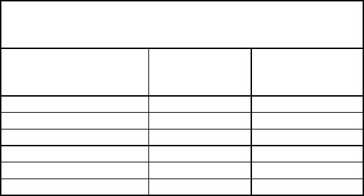
shall be delivered at the following rates at 150 psi lubricant pump inlet air pressure:
CONTRACT NO. 03-318004
REPLACED PER ADDENDUM NO. 1 DATED MARCH 24, 2010

Lubricant Material
Delivery Rate
Chassis lubricant NLGI No. 2 grease 25 ounces per minute
Motor oil (10W/40) 8 quarts per minute
Gear oil (85W/140) 7 quarts per minute
ATF (SAE 10) 9 quarts per minute
Hydraulic fluid 9 quarts per minute
The required delivery rate values may be adjusted, as determined by the Engineer, when testing for delivery rates
with different materials or at temperatures other than 70°F.
The drums and lubricating material for testing the lubrication system will be State-furnished as provided under
"State-Furnished Materials" in Section 8, "Materials," of these special provisions.
CONTRACT NO. 03-318004
REPLACED PER ADDENDUM NO. 1 DATED MARCH 24, 2010
12-15.01 MECHANICAL WORK
PART 1 - GENERAL
Scope: This work shall consist of performing mechanical work in accordance with the details shown on the plans and
these special provisions.
Mechanical work shall include furnishing all labor, materials, equipment and services required for providing heating,
ventilating, air conditioning, plumbing and natural gas distribution systems.
Earthwork, foundations, sheet metal, painting, electrical, and such other work incidental and necessary to the proper
installation and operation of the mechanical work shall be in accordance with the requirements specified for similar type
work elsewhere in these special provisions.
System layouts are generally diagrammatic and location of equipment is approximate. Exact routing of pipes, ducts, etc.,
and location of equipment is to be governed by structural conditions and obstructions. Equipment requiring maintenance
and inspection is to be readily accessible.
Roof penetrations shall be flashed and sealed watertight in accordance with the requirements specified under "Sheet
Metal Flashing" in Section 12-7, "Thermal and Moisture Protection," of these special provisions.
SUBMITTALS
Product Data:
A list of materials and equipment to be installed, manufacturer's descriptive data, and such other data as may be
requested by the Engineer shall be submitted for approval.
Manufacturer's descriptive data shall include complete description, performance data and installation instructions for
the materials and equipment specified herein. Control and wiring diagrams, rough-in dimensions for plumbing
fixtures, and component layout shall be included where applicable.
Manufacturer's descriptive data shall be submitted for the following:
Water hammer arrestor
Hose faucet
Pipe insulation
Valve boxes
Plumbing fixtures
Tankless water heaters
Dual height electric water cooler
Emergency shower and eyewash
Unit heater
Heat-vent-light combination
Fans
Evaporative coolers
Check valve
Heat pump
Fire hydrant
Lubrication system
Backflow Preventer
CONTRACT NO. 03-318004
REPLACED PER ADDENDUM NO. 1 DATED MARCH 24, 2010
CLOSEOUT SUBMITTALS
Operation and Maintenance Manuals:
Prior to the completion of the contract, 3 identified copies of the operation and maintenance instructions with parts
lists for the equipment specified herein shall be delivered to the Engineer at the jobsite. The instructions and parts
lists shall be indexed and bound in a manual form and shall be complete and adequate for the equipment installed.
Inadequate or incomplete material shall be returned. The Contractor shall resubmit adequate and complete manuals
at no expense to the State.
Operation and maintenance manuals shall be submitted for the following equipment:
Heat pump
Evaporative coolers
Exhaust fans
Electric water cooler
Unit heaters
Thermostats
Tankless water heater
Air compressor
QUALITY ASSURANCE
Codes and Standards: Mechanical work, including equipment, materials and installation, shall conform to the CBC,
CMC, and to the California Code of Regulations, Title 8, Chapter 4, Division of Industrial Safety (DIS).
WARRANTY
Warranties and Guarantees: Manufacturer's warranties and guarantees for materials or equipment used in the work shall
be delivered to the Engineer at the jobsite prior to acceptance of the contract.
CONTRACT NO. 03-318004
REPLACED PER ADDENDUM NO. 1 DATED MARCH 24, 2010
12-15.02 PIPE, FITTINGS AND VALVES
PART 1 - GENERAL
SUMMARY
Scope: This work shall consist of furnishing and installing pipes, fittings and valves in accordance with the details
shown on the plans and these special provisions. Pipe, fittings and valves shall include such plumbing and piping
accessories and appurtenances, not mentioned, that are required for the proper installation and operation of the plumbing
and piping systems.
All piping insulation and wrapping material shall be in accordance with the requirements specified under "Mechanical
Insulation," in this Section 12-15.
The pipe sizes shown on the plans are nominal inside diameter. No change in the pipe size shown on the plans shall be
permitted without written permission from the Engineer.
The pipe and fitting classes and material descriptions shall be as specified herein. No change in class or description shall
be permitted without written permission from the Engineer.
QUALITY ASSURANCE
Codes and Standards: Pipe, fittings and valves shall be installed in accordance with the requirements in the CPC, the
manufacturer's recommendations and the requirements specified herein.
PART 2 - PRODUCTS
MATERIALS
PIPE AND FITTINGS (Class and Description)
A1: Schedule 40 galvanized steel pipe conforming to ASTM Designation: A 53, with 150 psi galvanized malleable iron
banded screwed fittings and galvanized steel couplings. The weight of the zinc coating shall be not less than 90 percent
of that specified in ASTM Designation: A 53.
A2: Schedule 40 galvanized steel pipe conforming to ASTM Designation: A 53, with black cast iron recessed drainage
fittings. For rainwater leaders, neoprene-gasket compression couplings, Smith Blair, Dresser, or equal, may be used.
The weight of the zinc coating shall be not less than 90 percent of that specified in ASTM Designation: A 53.
B2: Schedule 40 black steel pipe conforming to ASTM Designation: A 53, with 150 psi black malleable iron banded
screwed fittings and black steel couplings.
Steel pipe coating, where required, shall be factory applied plastic. Pipe coating shall be Standard Pipe Protection,
X-Tru-Coat (20-mil thickness); Pipe Line Service Corporation, Republic; 3M Company, Scotchkote 205 (12-mil
thickness); or equal.
C1: Hub and plain end cast iron soil pipe with neoprene gaskets conforming to Cast Iron Soil Pipe Institute's Standard
301. Pipe, fittings and gaskets shall be of one manufacturer.
C2: Hubless cast iron soil pipe with neoprene gaskets, corrugated stainless steel shields and stainless steel clamps
conforming to Cast Iron Soil Pipe Institute's Standard 301. Joint materials shall be furnished by pipe manufacturer.
D1: Ductile iron push on joint pipe conforming to AWWA Designation: C151. Fittings shall be push on ductile iron
conforming to AWWA Designation: C153. Joints shall be rubber gasketed and designed for a working pressure of
350 psi. Pipe and fittings shall be supplied with bituminous outer coating and cement lining. Pipe shall be listed for fire
protection.
CONTRACT NO. 03-318004
REPLACED PER ADDENDUM NO. 1 DATED MARCH 24, 2010
H1: Type DWV hard copper tubing conforming to ASTM Designation: B 306, with DWV drainage fittings, stop type
couplings and threaded adapters.
H2: Type K hard copper tubing conforming to ASTM Designation: B 88, with wrought copper or cast bronze solder
joint pressure fittings, stop type couplings and threaded adapters. Solder shall be lead-free.
H3: Type L hard copper tubing conforming to ASTM Designation: B 88, with wrought copper or cast bronze solder
joint pressure fittings, stop type couplings and threaded adapters. Solder shall be lead-free.
LP1: 0.083-inch thick seamless steel tubing with high pressure flareless steel tube fittings. Bends, if required, shall be
made with tube bender on 4½-inch minimum radius.
LP2: 0.035-inch thick seamless steel tubing with high pressure flareless steel tube fittings. Bends, if required, shall be
made with tube bender on 4½-inch minimum radius.
P1: Polyvinyl chloride (PVC) gravity sewer plastic pipe and fittings conforming to ASTM Designation: D 3034,
Standard Dimension Ratio (SDR) 35, with integral bell and bell and spigot rubber gasketed joints or conforming to
ASTM Designation: D2665 with solvent welded fittings. Rubber gaskets shall conform to ASTM Designation: F 477.
Stainless steel clamps with rubber boots shall not be used.
P2: Polyvinyl chloride (PVC) plastic pipe and fittings conforming to ASTM Designation: D 2241, Type I, Grade 1,
Standard Dimension Ratio (SDR) 21, rated for 200 psi working pressure at 73°F, National Sanitation Foundation
approved. Pipe shall have bell ends conforming to ASTM Designation: D 3139 with triple edge rubber sealing ring.
For pipe sizes 2-inch diameter and smaller, plain end pipe with solvent welded fittings ASTM Designation: D 2241,
Type I, Grade 1, Standard Dimension Ratio (SDR) 21, rated for 200 psi may be used.
P3: Polyvinyl chloride (PVC) standard weight pipe and fittings, Schedule 40, conforming to ASTM Designation:
D 1785. Pipe shall meet or exceed requirements of National Sanitation Foundation Standard No. 14. Pipe shall have
bell ends conforming to ASTM Designation: D 2672. For pipe sizes 3 inches and smaller, plain end pipe with solvent
welded fittings conforming to ASTM Designation: D 2241, may be used.
P4: Polyvinyl chloride (PVC) plastic pipe and fittings shall conform to AWWA Designation: C900, Class 150,
Standard Dimension Ratio (SDR) 18. Pipe shall have bell end with a solid cross section elastomeric ring conforming to
ASTM Designation: D 1869. Pipe shall be listed for fire protection.
P5: Polyethylene plastic gas pipe and fittings conforming to ASTM Designation: D 1248 and D 2513 with Standard
Dimension Ratio (SDR) 11, rated for 60 psi working pressure at 73°F, socket type fittings, joined by heat fusion.
P6: Polyvinyl chloride (PVC) natural gas pipe, Class 315, conforming to ASTM Designation: D 2513. Fittings shall be
Schedule 40 conforming to ASTM Designation: D 2513, and shall be primed and glued. Primer shall conform to ASTM
Designation: F656. Solvent cement shall conform to ASTM Designation: D2564. Approved adapters shall be used for
transition to other pipe materials.
Unions (for Steel Pipe): Unions (for steel pipe) shall be 250 psi, threaded malleable iron, ground joint, brass to iron seat,
galvanized or black to match piping.
Unions (for Copper or Brass Pipe): Unions (for copper or brass pipe) shall be 150 psi cast bronze, ground joint, bronze
to bronze seat with silver brazing threadless ends or 125 psi cast brass, ground joint, brass to brass seat with threaded
ends.
Unions (for Brass Waste and Flush Pipes): Unions (for brass waste and flush pipes) shall be slip or flange joint unions
with soft rubber or leather gaskets. Unions shall be placed on the fixture side of the traps.
Dielectric Waterway: Dielectric waterway shall be a premanufactured unit that incorporates an insulated interior lining
at least 3 inches in length between the 2 pipes being connected while maintaining metal to metal contact on the exterior
surface. Dielectric water way shall be listed by IAPMO (International Association of Plumbing and Mechanical
Officials).
CONTRACT NO. 03-318004
REPLACED PER ADDENDUM NO. 1 DATED MARCH 24, 2010
Insulating Union: Insulating union or flange as applicable shall be suitable for the service on which used. Connections
shall be constructed such that the 2 pipes being connected are completely insulated from each other with no metal to
metal contact. Insulating couplings shall not be used. Insulating union shall be F. H. Maloney; Central Plastics; EPCO;
or equal.
Insulating Connection (to Hot Water Tanks): Insulating connection (to hot water tanks) shall be 6-inch minimum,
flexible copper tubing with dielectric union at each end and designed to withstand a pressure of 150 psi and a
temperature of 200°F.
VALVES
Gate Valve (2½-inch and smaller):
Gate valve (2½-inch and smaller) shall be bronze body and trim, removable bonnet and non rising stem, Class 125
and same size as pipe in which installed. Gate valve shall be Crane, 438; Nibco Scott, T-113; Jenkins, 370; or
equal.
Gate valve in nonferrous water piping systems may be solder joint type with bronze body and trim. Valve shall be
Kitz, 59; Nibco Scott, S-113; Jenkins, 1240; or equal.
Gate Valve (3-inch and larger, above ground): Gate valve (3-inch and larger, above ground) shall be iron body with
bronze trim, removable bonnet and non-rising stem, Class 125 and same size as pipe in which installed. Gate valve shall
be Crane, 461; Nibco Scott, F-619; Jenkins, 326; or equal.
Gate Valve (3-inch and larger, below ground): Gate valve (3-inch and larger, below ground) shall be AWWA double
disc, hub or rubber ring type, removable bonnet and non-rising stem, equipped with operating nuts, 200 psi working
pressure, and Tee handle wrench for each valve. Valve shall be Mueller, A-2380; American Valve, Model 28; or equal.
Ball Valve: Ball valve shall be two piece, minimum 400 psi WOG, bronze body and chrome plated or brass ball with
full size port. Valve shall be Nibco Scott, T-580; Watts, B-6000; Kitz, 56; or equal.
Gas Valve: Gas valve shall be natural gas service type, bronze body, quarter turn, flathead and rated for 125 psi. Gas
valve shall be Crane, American or equal.
Check Valve (1½-inch and smaller): Check valve (1½-inch and smaller) shall be silent spring loaded type, threaded
bronze body, nylon or teflon disc, beryllium or stainless steel helical spring and shaft, Class 125 and same size as pipe in
which installed. Check valve shall be Nibco/Scott, T-480; CPV, 36; Kitz, 26; or equal.
Check Valve (2-inch and larger): Check valve (2-inch and larger) shall be silent wafer type, full faced for installation
between 125 psi flanges, iron body with bronze trim, nylon or teflon disc, stainless steel helical spring and shaft,
Class 125 and same size as pipe in which installed. Check valve shall be APCO, Series 300; CPV, 10D; Metraflex,
Series 900; or equal.
Pressure Reducing Valve (PRV): Pressure reducing valve (PRV) shall be direct acting, spring loaded diaphragm type
control valve with balanced single seat, bronze body, bronze trim and screwed connection. PRV shall be completely
self-contained and shall require no external sending pipes or outside control medium. The outlet pressure of the PRV
shall be adjustable within a range of 25 psi to 60 psi.
FAUCET AND HYDRANTS
Wall hydrant shall be ¾-inch, non-freeze type, exposed, nickel bronze head with bronze casing, and integral vacuum
breaker. Operating key shall be provided. Wall hydrant shall be J. R. Smith Model 5609 QT, Josam Model 71050,
Zurn, Model 1310; or equal.
Wharf Hydrant:
Wharf hydrant shall be bronze, 300 psi working pressure, operating nut, lug type reducer and hose cap, and chain.
Wharf hydrant shall have standard threads on inlet and National Standard Hose Threads on outlet. Lug type reducer
shall have National Standard Hose Threads. Wharf hydrant shall be James Jones; Powhatan; John W. Moon Inc.; or
equal. CONTRACT NO. 03-318004
REPLACED PER ADDENDUM NO. 1 DATED MARCH 24, 2010
A wharf hydrant operating nut wrench and hose spanner wrench or the combination type shall be provided for each
wharf hydrant.
Fire Hydrant: Fire hydrant shall conform to the requirements of AWWA Designation: C503. Fire hydrant shall have
6-inch inlet, and have one 4-inch outlet steamer hose and two 2½-inch outlets. Fire hydrant shall be Jones,
Model J-3765; Rich, Model 960; American Cast, Darling Division, Mark-73; or equal.
CLEANOUTS
Cleanout Through Wall: Cleanout through wall shall be cast iron cleanout tee type with polished stainless access plates.
Plug shall be countersunk brass or bronze with tapered threads. Cleanout shall be Wade, No. W-8460; Smith, No. 4532;
Zurn, No. 1445; or equal.
Cleanout Through Floor:
Cleanout through floor shall have nonslip scoriated nickel bronze access plate and adjustable frame with square
pattern top for ceramic tile and round pattern top for other finishes. Where floors are constructed with a membrane,
access frame shall be provided with membrane clamping flange. Plug shall be countersunk brass or bronze with
tapered threads. Cleanout shall be Wade, W-7000 Series; Smith, 4023 Series; Zurn, No. 1400; or equal.
Cleanout through floors in exterior locations shall be heavy duty, floating pipe type with cast iron cover. Cleanouts
shall be Wade, No. W-8300-HF; Smith, No. 4253; Zurn, No. 1474; or equal.
Cleanout to Grade: Cleanout to grade shall be cast iron ferrule type. Plug shall be countersunk brass or bronze with
tapered threads. Cleanout to grade shall be Wade, No. W-8450; Smith, 4420; Zurn, No 1440; or equal.
MISCELLANEOUS ITEMS
Water Hammer Arrestor: Water hammer arrestor shall be stainless steel body with bellows or piston. Arrestor
compression chambers shall be pneumatically charged. Water hammer arrestors shall be tested and certified in
accordance with the Plumbing and Drainage Institute Standard: PDI-WH201 and sized as shown on the plans.
Access Door: Access door shall be 16-gage prime coated steel, face mounting square frame, minimum 12” x 12” door
with concealed hinge and screwdriver latch.
Compression Stop (Exposed): Compression stop (exposed) shall be metal full free waterway, angle type, ground joint
union, non-rising stem, molded rubber seat and wheel handle.
Pressure Gages (for PRV) : Pressure gages (for PRV) shall have 0 to 100 psi scale with 3½-inch minimum diameter dial.
Gages shall be installed within 6 inches of the inlet and outlet sides of the pressure reducing valve. Pressure gages shall
be provided with a brass gage cock.
Gas Regulator: Gas regulator shall be listed as suitable for gas and equipped with full capacity relief valve, low pressure
safety shut-off and weatherproof and insect proof vent for outside installation. Capacity shall be as shown on the plans.
Gas regulator shall be Fisher; Reliance; Rockwell; or equal.
Wye Strainer: Wye strainer shall be wye pattern, cast iron body and Type 304 stainless steel or monel strainer screen.
The strainer screen shall have an open area equal to at least 3 times the cross sectional area of the pipe in which it is
installed and shall be woven wire fabric with 20 mesh or perforated sheet with 0.032-inch maximum diameter holes.
CONTRACT NO. 03-318004
REPLACED PER ADDENDUM NO. 1 DATED MARCH 24, 2010
Backflow Preventer (Tank Truck Filler): Backflow preventer shall be factory assembled with 2 check valves, one
pressure differential relief valve, 2 ball valves and 4 test cocks. Backflow preventers shall be reduced pressure principle type.
Double Check Detector Assembly (Fire water supply): Double check detector assembly shall consist of 300 series
stainless steel valve body, 100% lead free. Assembly shall consist of two, independently operating spring loaded check
valves, two UL, FM listed non-rising stem, resilient seated gate valves, and bypass assembly. Bypass assembly shall
consist of utility-provided meter (NIC) and a double check including shutoff valves and test cocks. Cam-checks shall be
internally loaded to provide a positive drip tight closure against reverse flow. Cam-check shall include stainless steel
cam arm and spring, rubber faced disc and replaceable seat, and shall not include any brass or bronzer parts. Check
valve seats shall be molded thermoplastic construction, without the use of seat screws. All parts shall be accessible
through a single cover on the valve assembly. The bypass line shall be hydraulically sized to accurately measure low
flow, shall have a single access cover and two independently operating modular poppet check valves.
Double check detector assembly shall be installed in a precast concrete vault, sized according to the plans. Vault lid
shall be 2-piece aluminum diamond plate, reinforced for 150 pounds/square foot live load with recessed-type plate handles
for lid handling. Vault lid shall recess flush into precast vault top. Vault shall include a galvanized steel ladder (hot dipped
after fabrication) as shown on the plans. A pop-up telescoping post shall be attached to the vault ladder. Telescoping post
shall be hot dipped galvanized, lock in the fully raised position and include a release lever for retraction.
Pipe Hanger (for piping supported from overhead): Pipe hanger (for piping supported from overhead) shall be Grinnell,
Model 269; Super Struct, C711; or equal.
Pipe Wrapping Tape and Primer:
Pipe wrapping tape shall be pressure sensitive polyvinyl chloride or pressure sensitive polyethylene tape having
nominal thickness of 20 mils. Wrapping tape shall be Polyken, 922; Manville, Trantex VID-20; Scotchrap, 51; or
equal.
Pipe wrapping primer shall be compatible with the pipe wrapping tape used.
Floor, Wall, and Ceiling Plates: Floor, wall, and ceiling plates shall be chromium plated steel or plastic plates having
screw or spring clamping devices and concealed hinges. Plates shall be sized to completely cover the hole.
Valve Box: Valve box shall be precast high density concrete with polyethylene face and cast iron traffic rated cover
marked "WATER," "GAS" or "CO-SS" as applicable. Extension shall be provided as required. Valve box shall be
Christy, B3; Brooks Products Company, 3TL; Frazer, 3; or equal.
PART 3 - EXECUTION
INSTALLATION
INSTALLATION OF PIPES AND FITTINGS
Pipe and Fittings: Pipe and fittings shall be installed in accordance with the following designated uses:
CONTRACT NO. 03-318004
REPLACED PER ADDENDUM NO. 1 DATED MARCH 24, 2010

Designated Use Pipe and Fitting Class
Domestic water (CW and HW) in buildings H3 or A1
Domestic water underground within 5 feet of the building A1 or H2
Domestic water underground 5 feet beyond the building P2, P3, P4, A1 or H2
Fire protection water, underground B1,D1 or P4
Sanitary drain piping above ground in building H1, C1, or C2
Sanitary drain and vent piping underground within 5 feet of the
building J1, C1 or C2
Sanitary vent piping above ground in building A2, H1, C1, or C2
Sanitary drain pipe, 5 feet beyond the building C1, C2, or P1
Natural gas, above ground A1 or B2
Natural gas, underground B2 (plastic coated), P5 or P6
Lubrication piping, less than 100 feet in length LP1 (5/8” outside diameter)
Lubrication piping, over 100 feet in length LP1 (7/8” outside diameter)
Gear oil, motor oil, and automatic transmission fluid (ATF)
piping; less than 25 feet in length LP2 or H3 (5/8” outside
diameter)
Gear oil, motor oil, and ATF piping; over 25 feet in length LP2 or H3 (7/8” outside
diameter)
Compressed air A1
Equipment drains and relief valve discharge H3 or A1
Installing Piping:
Water piping shall be installed generally level, free of traps and bends, and arranged to conform to the building
requirements.
Piping installed underground shall be tested as specified elsewhere in these special provisions before backfilling.
Public use areas, offices, rest rooms, locker rooms, crew rooms, training rooms, storage rooms in office areas,
hallway type rooms, and similar type use areas shall have concealed piping.
Warehouse rooms, equipment bays, and loft areas shall have exposed piping.
Piping shall not be run in floor fill, except as shown on the plans.
Piping shall be installed parallel to walls. All obstructions shall be cleared, headroom preserved and openings and
passageways kept clear whether shown or not. Piping shall not interfere with other work.
Where pipes pass through exterior walls, a clear space around pipe shall be provided. Space shall be caulked water
tight with silicone caulk.
Underground copper pipe shall have brazed joints. Underground plastic pipe shall be buried with No. 14 solid bare
copper wire. Wire ends at pipe ends shall be brought up 8 inches and looped around pipe.
Exposed supply and drain piping in rest rooms shall be chrome finished.
Compressed air piping shall be pitched to low point. Ball valved drips shall be provided at all low points. Branches
shall be taken off top of main.
CONTRACT NO. 03-318004
REPLACED PER ADDENDUM NO. 1 DATED MARCH 24, 2010
Gas piping shall not be installed under building concrete slabs or structure. An insulating connection and valve shall
be installed above ground at each building supply.
Gas piping shall be pitched to equipment or to low point and provided with an 8-inch minimum dirt leg.
Plastic pipe used for natural gas shall be below grade outside of building only. Transition to Class B2 plastic coated
shall be before meter, regulator, or building wall with approved metal to plastic transition fitting. PVC natural gas
pipe shall be installed in accordance with International Association of Plumbing and Mechanical Officials (IAPMO)
Standard: IS10.
Forty-five degree bends shall be used where offsets are required in venting. Vent pipe headers shall be sloped to
eliminate any water or condensation.
Vent piping shall extend a minimum of 8 inches above the roof.
Horizontal sanitary sewer pipe inside buildings shall be installed on a uniform grade of not less than ¼ inch per foot
unless shown otherwise on the plans.
Drainage pipe shall be run as straight as possible and shall have easy bends with long turns.
Wye fittings and 1/8 or 1/16 bends shall be used where possible. Long sweep bends and combination Wye and
1/8 bends may be used only for the connection of branch pipes to fixtures and on vertical runs of pipe.
Water pipe near sewers:
Water pipe shall not be installed below sewer pipe in the same trench or at any crossing, or below sewer pipe in
parallel trenches less than 10 feet apart.
When a water pipe crosses above a sewer pipe, a vertical separation of at least 12 inches between the top of the
sewer and the bottom of the water pipe shall be maintained.
When water and sewer pipe is installed in the same trench, the water pipe shall be on a solid shelf at least 12 inches
above the top of the sewer pipe and 12 inches to one side.
Pipe Sleeves:
The Contractor shall provide sleeves, inserts and openings necessary for the installation of pipe, fittings and valves.
Damage to surrounding surfaces shall be patched to match existing.
PVC pipe sleeves shall be provided where each pipe passes through concrete floors, footings, walls or ceilings.
Inside diameter of sleeves shall be at least ¾ inch larger than outside diameter of pipe. Sleeves shall be installed to
provide at least 3/8-inch space all around pipe the full depth of concrete. Space between pipes and pipe sleeves shall
be caulked watertight.
Cutting Pipe: Pipe shall be cut straight and true and the ends shall be reamed to the full inside diameter of the pipe after
cutting.
Damaged Pipe: Pipe that is cracked, bent or otherwise damaged shall be removed from the work.
Pipe Joints and Connections:
Joints in threaded steel pipe shall be made with teflon tape or a pipe joint compound that is nonhardening and
noncorrosive, placed on the pipe and not in the fittings.
The use of thread cement or caulking on threaded joints will not be permitted. Threaded joints shall be made tight.
Long screw or other packed joints will not be permitted. Any leaky joints shall be remade with new material.
CONTRACT NO. 03-318004
REPLACED PER ADDENDUM NO. 1 DATED MARCH 24, 2010
Exposed polished or enameled connections to fixtures or equipment shall be made with special care, showing no
tool marks or threads.
Cleaning and Closing Pipe: The interior of all pipe shall be cleaned before installation. All openings shall be capped or
plugged as soon as the pipe is installed to prevent the entrance of any materials. The caps or plugs shall remain in place
until their removal is necessary for completion of the installation.
Securing Pipe: Pipe in the buildings shall be held in place by iron hangers, supports, pipe rests, anchors, sway braces,
guides or other special hangers. Material for hangers and supports shall be compatible with the piping or neoprene
isolators shall be used. Allowances shall be made for expansion and contraction. Steel pipe shall have hangers or
supports every 10 feet. Copper pipe one inch or less in diameter smaller shall have hangers or supports every 6 feet and
sizes larger than one inch shall have hangers or supports every 10 feet. Plastic pipe shall have hangers or supports every
3 feet. Cast iron soil pipe with neoprene gaskets shall be supported at each joint. Vertical pipes shall be supported with
clamps or straps. Horizontal and vertical piping shall be securely supported and braced to prevent swaying, sagging or
flexing of joints.
Hangers and Supports:
Hangers and supports shall be selected to withstand all conditions of loading to which the piping and associated
equipment may be subjected and within the manufacturer's load ratings. Hangers and supports shall be spaced and
distributed so as to avoid load concentrations and to minimize the loading effect on the building structure.
Hangers and supports shall be sized to fit the outside diameter of pipe or pipe insulation. Hangers shall be
removable from around pipe and shall have provisions for vertical adjustment after erection. Turnbuckles may be
used.
Materials for holding pipe in place shall be compatible with piping material.
Hanger rods shall be provided with locknuts at all threaded connections. Hanger rods shall be sized as follows:
Pipe Size Minimum Hanger Rod
Diameter
½” to 2” 3/8”
2½” to 3½” 1/2"
4” to 5” 5/8”
6” 3/4"
Wrapping and Coating Steel Pipe:
Steel pipe buried in the ground shall be wrapped or shall be plastic coated as specified herein:
1. Wrapped steel pipe shall be thoroughly cleaned and primed as recommended by the tape manufacturer.
2. Tapes shall be tightly applied with 1/2 uniform lap, free from wrinkles and voids with approved wrapping
machines and experienced operators to provide not less than 40-mil thickness.
3. Plastic coating on steel pipe shall be factory applied. Coating imperfections and damage shall be repaired to the
satisfaction of the Engineer.
4. Field joints, fittings and valves for wrapped and plastic coated steel pipe shall be covered to provide continuous
protection by puttying and double wrapping with 20-mil thick tape. Wrapping at joints shall extend a minimum
of 6 inches over the adjacent pipe covering. Width of tape for wrapping fittings shall not exceed 2 inches.
Adequate tension shall be applied so tape will conform closely to contours of fittings. Putty tape insulation
compounds approved by the Engineer shall be used to fill voids and provide a smooth even surface for the
application of the tape wrap.
Wrapped or coated pipe, fittings, and filed joints shall be approved by the Engineer after assembly. Piping shall be
placed on temporary blocks to allow for inspection. Deficiencies shall be repaired to the satisfaction of the Engineer
before backfilling or closing in.
CONTRACT NO. 03-318004
REPLACED PER ADDENDUM NO. 1 DATED MARCH 24, 2010
Thrust Blocks:
Thrust blocks shall be formed by pouring concrete between pipe and trench wall. Thrust blocks shall be sized and
so placed as to take all thrusts created by maximum internal water pressure.
Plastic pipe underground shall be provided with thrust blocks and clamps at changes in direction of piping,
connections or branches from mains 2 inches and larger, and all capped connections.
Union: Unions shall be installed where shown and at each threaded or soldered connection to equipment and tanks.
Unions shall be located so piping can be easily disconnected for removal of equipment or tanks. Unions shall be omitted
at compression stops.
Dielectric Waterway: Dielectric waterway shall be provided between metal pipes of different material, and between
brass or bronze valves and steel piping.
Insulating Union and Insulating Connection:
Insulating union and insulating connection shall be provided where shown and at the following locations:
1. In metallic water, gas and air service connections into each. Insulating connections shall be installed on the
exterior of the building, above ground and after shut-off valve.
2. In water, gas and air service connections in ground at point where new metallic pipes connect to existing
metallic pipes. Install valve box above insulating connection.
3. At points of connections of copper or steel water pipes to steel domestic water heaters and tanks.
4. At each end of buried ferrous pipe protected by cathodic protection.
Bonding at Insulating Connections: Interior water piping and other interior piping that may be electrically energized and
are connected with insulating connections shall be bonded in accordance with the CEC. Bonding shall all be coordinated
with electrical work.
Compression Stop: Each fixture, including hose faucets, shall be equipped with a compression stop installed on water
supply pipes to permit repairs without shutting off water mains. Ball valves may be installed where shown on the plans
or otherwise permitted by the Engineer.
INSTALLATION OF VALVES
Pressure Reducing Valve: A capped tee connection and strainer shall be installed ahead of the pressure reducing valve.
Exterior Valves: Exterior valves located underground shall be installed in a valve box marked "Water." Extensions shall
be provided as required.
INSTALLATION OF FAUCETS AND HYDRANTS
Hose Faucet and Hydrants: Faucets and hydrants shall be installed with outlets 18 inches above finished grade.
CONTRACT NO. 03-318004
REPLACED PER ADDENDUM NO. 1 DATED MARCH 24, 2010
INSTALLATION OF CLEANOUTS
Cleanouts:
A concrete pad 18 inches long and 4 inches thick shall be placed across the full width of trench under cleanout Wye
or 1/8 bend. Cast iron soil pipe (C1 or C2) and fittings shall be used from Wye to surface. Required clearance
around cleanouts shall be maintained.
Cleanout risers outside of a building installed in a surface other than concrete shall terminate in a cleanout to grade.
Cleanout to grade shall terminate in a valve box with cover marked "CO-SS". Top of box shall be set flush with
finished grade. Cleanout plug shall be 4 inches below grade and shall be located in the box to provide sufficient
room for rodding.
Cleanout risers installed in tile and concrete floors, including building aprons and sidewalks, shall terminate in a
cleanout through floor.
INSTALLATION OF MISCELLANEOUS ITEMS
Water Hammer Arrestor: Water hammer arrestor shall be installed so that they are vertical and accessible for
replacement. Water hammer arrestor shall be installed with access door when in walls or there is no access to ceiling
crawl spaces. Access door location shall be where shown on the plans or as approved by the Engineer.
Gas Appliance Connection: Gas valve and flexible connector shall be provided for gas piping at each appliance.
Appropriately rated gas cocks may be used in ½-inch gas pipe. Cock or valve shall be within 3 feet of the appliance.
Gas Regulator: Gas regulator shall be installed complete with dirt leg, capped test tee, union, insulating union, gas valve
and fittings.
Backflow Preventer:
Backflow preventer assembly shall include a wye strainer, backflow preventer, fittings and pipe. Assembly
components shall be the same size as the pipe in which they are installed unless otherwise shown on the plans.
Backflow preventer shall be installed a minimum of 12 inches above ground and shall be the same size as the pipe in
which it is installed unless otherwise shown on the plans.
Flushing Completed Systems: All completed systems shall be flushed and blown out.
Chlorination:
The Contractor shall flush and chlorinate all domestic water piping and fixtures.
Calcium hypochlorite granules or tablets, if used, shall not be applied in the dry form, but shall first be dissolved
into a solution before application.
The Contractor shall take adequate precautions in handling chlorine so as not to endanger workmen or damage
materials. All pipes and fittings shall be completely filled with water containing a minimum of 50 ppm available
chlorine. Each outlet in the system shall be opened and water run to waste until a strong chlorine test is obtained.
The line shall then be closed and the chlorine solution allowed to remain in the system for a minimum of 24 hours so
that the line shall contain no less than 25 ppm chlorine throughout. After the retention period, the system shall be
drained, flushed and refilled with fresh water.
CONTRACT NO. 03-318004
REPLACED PER ADDENDUM NO. 1 DATED MARCH 24, 2010
FIELD QUALITY CONTROL
Testing:
The Contractor shall test piping at completion of roughing in, before backfilling, and at other times as directed by
the Engineer.
The system shall be tested as a single unit, or in sections as approved by the Engineer. The Contractor shall furnish
necessary materials, test pumps, instruments and labor and notify the Engineer at least 3 working days in advance of
testing. After testing, the Contractor shall repair all leaks and retest to determine that leaks have been stopped.
Surplus water shall be disposed of after testing as directed by the Engineer.
The Contractor shall take precautions to prevent joints from drawing while pipes and appurtenances are being tested.
The Contractor shall repair damage to pipes and appurtenances or to other structures resulting from or caused by
tests.
General Tests:
All piping shall be tested after assembly and prior to backfill, pipe wrapping, connecting fixtures, wrapping joints
and covering the pipe. Systems shall show no loss in pressure or visible leaks.
The Contractor shall test systems according to the following schedule for a period of not less than 4 hours:
Test Schedule
Piping System
Test Pressure Test Media
Sanitary sewer and vent 10-foot head Water
Water 125 psig Water
Gas (except P6) 100 psig Air
Gas (P6) 50 psig Air
Air 125 psig Air
Lubrication piping 125 psig Air and Product
During testing of water systems, valves shall be closed and pipeline filled with water. Provisions shall be made for
release of air.
Sanitary sewers shall be cleared of obstructions before testing for leakage. The pipe shall be proved clear of
obstructions by pulling an appropriate size inflatable plug through the pipe. The plug shall be moved slowly through
the pipe with a tag line. The Contractor shall remove or repair any obstructions or irregularities.
Sanitary sewer pipes beyond 5 feet perpendicular to the building shall be tested for leakage for a period of not less
than 4 hours by filling with water to an elevation of 4 feet above average invert of sewer or to top of manholes
where less than 4 feet deep. The system shall show no visible leaks The sewer may be tested in sections with
testing water progressively passed down the sewer as feasible. Water shall be released at a rate that will not create
water hammer or surge in plugged sections of sewer.
CONTRACT NO. 03-318004
REPLACED PER ADDENDUM NO. 1 DATED MARCH 24, 2010
Testing Backflow Preventers:
Backflow preventers installed by the Contractor shall be tested at the completion of the supply system installation
for proper operation by a certified Backflow Preventer Tester.
The tester shall hold a valid certificate as a Backflow Preventer Tester from the county in which the device to be
tested is located or, if the county does not have a certification program for Backflow Preventer Testers, the tester
shall have a certificate from one of the following:
1. The American Water Works Association.
2. A county which has a certification program for Backflow Preventer Testers. The certification under which the
tester has been certified shall be acceptable to the water purveyor and the local agency having jurisdiction.
Testing for proper operation shall conform to the procedures of the county in which the testing is being performed,
or, if such procedures are not available in the county, such tests shall conform to the provisions in the latest edition
of the Guidance Manual For Cross Connection Control Program, which is available from the California Department
of Health Services, Division of Drinking Water and Environmental Management, 601 N 7th Street, P.O. Box
942732, Sacramento, CA 94234.
The Contractor shall notify the Engineer at least 5 days prior to testing backflow preventers. Such tests shall be
satisfactorily completed after installation of the backflow preventer assemblies and before operation of the systems.
One copy of all test results for each backflow preventer shall be furnished to the Engineer.
Full compensation for providing the certified Backflow Preventer Tester and for testing the backflow preventers
shall be considered as included in the lump sum price paid for building work and no additional compensation will be
allowed therefor.
CONTRACT NO. 03-318004
REPLACED PER ADDENDUM NO. 1 DATED MARCH 24, 2010
12-15.03 MECHANICAL INSULATION
PART 1 - GENERAL
SUMMARY
Scope: This work shall consist of furnishing and installing mechanical insulation in accordance with the details shown
on the plans and these special provisions.
Piping insulation shall be installed on all water piping, above grade, in non-conditioned spaces.
Piping insulation shall be installed on all hydronic supply and return piping, above and below grade unless shown
otherwise on the plans.
P-trap, hot water supply pipes and angle valves for lavatories and sinks, except in janitor closets or similar enclosed
spaces, shall be insulated.
QUALITY ASSURANCE
Codes and Standards:
Mechanical insulation shall conform to California State Energy Commission regulations and, where applicable, shall
meet American Society of Testing and Materials (ASTM) standards.
All materials shall bear the label of the Underwriters Laboratory (UL) or other approved testing laboratory
indicating that the materials proposed for use conform to the required fire hazard ratings.
Pipe safety insulation shall conform to Section 1504(b) of the CPC.
PART 2 - PRODUCTS
MATERIAL
All pipe insulation and wrapping material, including adhesives and jackets, located within buildings shall be certified to
have a composite flame spread rating of not more than 25 and smoke development rating of not more than 450 when
tested in accordance with ASTM Designation: E 84.
Domestic Water and Interior Hydronic Piping Insulation: Piping insulation shall be glass fiber molded pipe insulation
with factory applied jacket suitable for service temperatures up to 350°F. Covering jacket shall have pressure sealing lap
adhesive joints. Pipe insulation shall have a minimum thermal resistance of R-3. Insulation and jackets shall be
Owens-Corning, Fiberglass 25 with ASJ/SSL All Service Jacket; Manville, Micro-Lok 650ML with AP-T All Purpose
Jacket; or equal.
Piping Insulation Cement: Insulation cement shall be Fenco, All Purpose Cement; Manville, JM375; or equal.
PVC Jacket: PVC jacket shall be rated for a service temperature of 175°F. PVC jacket shall include covers specifically
designed to cover pipe fittings.
Alternative Pipe Insulation: Alternative pipe insulation shall be closed cell, elastomeric material in a flexible tubular
form. Insulation shall have a service temperature range between -40°F and 200°F, a minimum vapor transmission rating
of 0.20 perm-inch, and a minimum thermal resistance of R-3.
Pipe Safety Insulation: Pipe safety insulation for P-traps, hot water supply pipes and angle valves shall be molded closed
cell vinyl or closed cell foam with exterior vinyl surface. Pipe safety insulation shall be configured to protect against
contact. Pipe safety insulation shall be Truebro Inc., Handi Lav-guard; Plumberex Specialty Products, Handy Shield; or
equal.
CONTRACT NO. 03-318004
REPLACED PER ADDENDUM NO. 1 DATED MARCH 24, 2010
PART 3 - EXECUTION
INSTALLATION
Insulation materials shall be neatly installed with smooth and even surfaces, jackets drawn tight and smoothly cemented
down.
Insulation material shall not be installed until all pipes or surfaces to be covered are tested for leaks, cleaned and dried,
and foreign materials, such as rust, have been removed.
Piping Insulation:
Piping insulation shall be in accordance with the following, except that unions, unless integral with valves, and
flexible connections shall not be insulated:
1. Where insulation butts against flanges or is discontinued, insulation shall be tapered to pipe to allow for
covering jacket to completely seal off end of insulation.
Insulation shall be extended on the valve bodies up to the valve bonnet.
Extend insulation continuous through pipe hangers and pipe sleeves. At hangers where pipe is supported,
provide an insulated protection shield.
Insulating cement shall be applied to fittings, valves, and strainers and troweled smooth to thickness of adjacent
covering. Strainer cleanout plugs shall remain accessible. Covers fabricated from molded pipe covering may
be used in lieu of cement, provided covers are neat and well secured.
2. Jacket flap shall be sealed down with factory applied self-sealing lap. Seams shall be lapped not less than
1½ inches. Jacket shall be secured with aluminum bands installed at 12-inch centers.
3. Exposed outdoor insulation shall have an additional 0.016-inch minimum thickness aluminum jacket applied
over the completed insulation. The jacket shall have a factory applied moisture barrier and shall be Childers;
Smith; or equal.
End joints shall be lapped with aluminum holding traps located directly over the lap. Additional aluminum
holding straps shall be placed at 8-inch centers. Jacket at ells and tees shall be mitered, or premanufactured
fitting jackets shall be provided, with additional aluminum holding bands, as required. All joints shall be sealed
watertight using silicon type, heat resistant sealant.
Alternate pipe insulation, where used, shall be installed on hot water piping before connections are made or the
insulation may be slit lengthwise, applied to pipe and sealed with adhesive.
Pipe Safety Insulation: Pipe safety insulation shall be installed in accordance with the manufacturer’s recommendations.
CONTRACT NO. 03-318004
REPLACED PER ADDENDUM NO. 1 DATED MARCH 24, 2010

12-15.04 PLUMBING FIXTURES
PART 1 - GENERAL
SUMMARY
Scope: This work shall consist of furnishing and installing plumbing fixtures in accordance with the details shown on
the plans and these special provisions.
PART 2 - PRODUCTS
General: Plumbing fixtures shall be white in color and shall meet the following requirements:
Water Closet (Disabled Accessible, 1.6 gallons per flush, Floor Mounted with Tank): Disabled accessible water closet
shall be 1.6 gallons per flush maximum, vitreous china, siphonable jet, 16-inch to 17½-inch high elongated bowl, close
coupled tank, floor mounted, with solid plastic open front elongated seat with check hinges. Water closet shall meet or
exceed Americans with Disabilities Accessibility Act Guidelines (ADAAG) and ANSI Standards: A117.1 and
A112.19.2. Closet and accessories shall be of the following types or equal:
American Standard
Crane Universal Rundle
Closet “Cadet 17 EL1.6/PA"
2168.100
or
4086.800
"Hymont”
3-154E
or 3-152 with3-655
“Atlas 1.5”
UR 4078-341
or
UR 4078-342
Seat Church
5321.070 Olsonite
95 Benke
527
Lavatory (Wall-mounted): Lavatory shall be vitreous china, with back, integral perforated grid drain, drilled for 4-inch
centers, size 20” x 18”, with single extra long lever mixing faucet and chair carrier with concealed arms. Lavatory and
accessories shall be of the following types or equal:
Eljer
Crane Kohler
Lavatory "Lucerne"
0355.012 "Norwich"
1-194-V "Greenwich"
K-2032
Drain -- C-1065-G
or Moen
52659
K-7715
Supplies Brass Craft
FR1711C C-1151
or Moen
52664
K-7605
Faucet 2385.130 Moen
8400 K-15592-5
Trap 1¼-inch chromium plated brass exposed bent tube adjustable
17-gage minimum thickness.
Carrier Concealed wall mounted carrier with leveling screws and locking
devices; Zurn, J.R. Smith, Josam, Wade, Jonespec, or equal.
Service Sink: Service sink shall be acid resisting enameled cast iron, plain undrilled back, stainless steel strainer,
stainless steel or chrome plated sheet brass rim guard on three sides, size approximately 28” x 28” with 3-inch trap with
cleanout and floor mounting flange. Sink and accessories shall be of the following types or equal:
CONTRACT NO. 03-318004
REPLACED PER ADDENDUM NO. 1 DATED MARCH 24, 2010

American Standard
Eljer Kohler
Service sink "Lakewell"
7692.023 242-0120 "Bannon"
K-6718
Strainer 8301.061 ----- -----
Trap 7798.176 804-1060 w/strainer K-6673 w/strainer
Faucet Bucket hook, vacuum breaker, integral stops, top brace, long spout
with hose threads.
8344.111 749-1200 K8907
Tankless Water Heater (Gas):
Tankless Water heater shall be minimum capacity as shown on plans, equipped with gas pressure regulator .
Tankless Water heater shall meet the requirements of the California Energy Commission.
Tankless Water heater shall be equipped with an ASME labeled, tank mounted, pressure and temperature relief
valve sized for maximum input.
Electric Water Cooler (Disabled accessible, Bi-level, Wall Mounted):
Electric water cooler shall be wall mounted, Bi-level, wheelchair accessible, and shall produce a minimum of
28 liters of 10°C water per hour based upon an inlet water temperature of 27°C and an ambient room temperature of
32°C. Cooler shall have self closing, front mounted pushbar actuators, shielded bubbler, automatic stream regulator,
loose key stop, adjustable thermostat and cast brass P-trap. Compressor shall be hermetically sealed, positive start
with fan cooled condenser. Electric water cooler shall be provided with 3-wire grounded cord and plug.
Electric water cooler shall have stainless steel top and steel cabinet with baked enamel finish.
Electric water cooler shall be Haws, HWBFA8L; Sunroc, NWCA-8F-BL; Elkay, EBFATLR-8, or equal.
Emergency Eyewash and Shower:
Emergency eyewash and shower shall be separate drench shower and eye bath, 1¼-inch minimum, galvanized steel
pipe stand with 9-inch floor mounting flange and equipped with 8½” x 11” pictorial and worded emergency
identification sign.
Shower head shall have a 10-inch diameter ABS plastic head with a stay-open ball valve operated by a rigid pullrod
with triangular handle.
Eyewash shall have a 10-inch diameter stainless steel bowl, anti-surge heads and circular chrome plated spray ring
to bathe the entire face, dust cover assembly, and a stay-open ball valve operated by a flag handle. Eyewash unit
shall be mounted on the shower pipe stand.
Emergency eyewash and shower shall be Haws, 8346; Speakman, SE-607; Western, 9231; or equal.
PART 3 - EXECUTION
INSTALLATION
All finish for exposed metal on any fixture, including wall flanges, bolts, nuts and washer, shall be polished chrome
plated.
Fixtures shall be sealed to wall or floor with silicone caulk bead.
All exposed metal surfaces on fixture supports shall be enameled to harmonize with fixtures.
CONTRACT NO. 03-318004
REPLACED PER ADDENDUM NO. 1 DATED MARCH 24, 2010
Wall mounted fixtures shall be installed on concealed chair carriers designed to support weight of fixture from the floor,
made for the specific fixture to be supported and for the particular installation conditions.
All fixtures, including showers, shall be provided with accessible metal stop valves.
Hot water supply, trap and tailpiece on lavatories shall be wrapped with insulating material.
Flush valves for fixtures designated on the plans as disabled accessible shall be installed so that the valve handle is on
the widest side of the toilet space.
FIXTURE MOUNTING HEIGHTS
Unless otherwise noted, fixtures shall be mounted at the heights shown on the plans.
Service Sink: Service sink double faucet shall be mounted on wall above sink back with spout outlet face 16 inches
above service sink rim.
Tankless Water Heater: Tankless Water heater shall be installed per manufacturer recommendation.
Emergency Eyewash and Shower: Emergency eyewash and shower shall be installed with a rigid bracket located
48 inches above the floor. Bracket shall be minimum 16-gage steel and shall be braced to the wall.
FIELD QUALITY CONTROL
Testing:
The Contractor shall test piping in accordance with the requirements specified elsewhere in these special provisions.
All installed fixtures shall be tested for proper operation after all plumbing work has been completed.
CONTRACT NO. 03-318004
REPLACED PER ADDENDUM NO. 1 DATED MARCH 24, 2010
12-15.05 WHEELCHAIR ACCESSIBLE SHOWER UNIT
PART 1 - GENERAL
SUMMARY
Scope: This work shall consist of furnishing and installing a wheelchair accessible shower unit and fittings in
accordance with the details shown on the plans and these special provisions.
SUBMITTALS
Product Data: Manufacturer's descriptive data, installation instructions and color palette shall be submitted for approval.
The color shall be selected from the manufacturer's standard product line by the Engineer after approval of the contract.
QUALITY ASSURANCE
Codes and Standards: Shower units shall conform to the requirements of the California State Accessibility Standards
contained in the CBC.
PART 2 - PRODUCTS
Shower Stall:
Shower stall shall be single unit, single piece construction with clear interior dimensions of 60 inches wide and 30
inches deep, and no obstruction at the threshold. Shower stall shall be fabricated from gel-coated fiberglass or
acrylic with a Class I Flame Spread. Shower unit shall be reinforced to accommodate the grab bars and seat.
Shower unit shall have a threshold or recessed drop, a maximum of ½ inch in height, sloped at an angle not
exceeding 45 degrees from the horizontal. The floor shall be slip-resistant, sloping a maximum of ½ inch per foot to
a drain located near the rear wall.
Shower unit shall be provided with the following fittings and accessories: stainless steel corner grab bar and folding
phenolic wheelchair transfer seat, each capable of resisting 250 pounds of lateral, vertical and tensile load, stainless
steel soap dish, chromium plated or stainless steel curtain rod, chromium plated steel hand-held shower head with
ball joint, chromium plated 60-inch long flexible shower spray hose, chromium plated fixed shower head, chromium
plated metal outlet drain with removable strainer, chromium plated single lever control thermostatic mixing valve
with control cartridge with no metal to metal wearing surface, a lever operated shower head selector, and vinyl
shower curtain with corrosion resistant hooks.
Shower stall units shall be Crane; Florestone; or equal.
PART 3 - EXECUTION
INSTALLATION
Shower shall be installed with the manufacturer's instructions. All joints shall be sealed and caulked watertight.
CONTRACT NO. 03-318004
REPLACED PER ADDENDUM NO. 1 DATED MARCH 24, 2010
12-15.06 HEATING, VENTILATING AND AIR CONDITIONING EQUIPMENT AND SYSTEMS
PART 1 - GENERAL
Scope: This work shall consist of furnishing, installing and testing heating, ventilating and air conditioning (HVAC)
equipment and systems in accordance with the details shown on the plans and these special provisions.
The performance rating and electric service of the HVAC equipment shall be as shown on the plans.
Temperature Controls: Thermostats, relays, timer switches, and other sensor type control devices required for this work
shall be furnished and installed by the supplier of the heating, ventilating and air conditioning equipment. All
temperature control wiring shall be furnished and installed in accordance with the requirements specified in Section 12-
16, "Electrical," of these special provisions.
Codes and Standards:
Equipment and systems shall conform to California State Energy Commission Regulations and, where applicable,
shall be American Refrigeration Institute (ARI), American Gas Association (AGA), Sheet Metal and Air
Conditioning Contractors National Association, Inc. (SMACNA), and Air Movement and Control Association
(AMCA) approved for performance ratings and application shown on the plans.
Any appliance for which there is a California standard established in the Appliance Efficiency Standards may be
installed only if the manufacturer has certified to the Commission, as specified in those regulations, that the
appliance complies with the applicable standards for that appliance. Space conditioning equipment may be installed
only if the manufacturer has certified that the equipment meets or exceeds all applicable efficiency requirements
listed in the Energy Efficiency Standards.
PART 2 - PRODUCTS
HEATING AND COOLING UNITS
Evaporative Cooler:
Evaporative cooler shall be a factory assembled unit having removable side panels with filters and a bottom drain.
The cabinet shall be fabricated from galvanized steel sheet metal with a baked-on enamel finish. Interior surfaces of
the cabinet bottom shall be asphalt coated. The drain fitting shall be threaded for connection to drain piping.
All parts of the float valve and recirculating pump, which come into contact with water, shall be of stainless steel or
other corrosion resistant material.
The evaporative cooler shall be Williams; Essick; Universal; or equal.
Unit Heater:
Unit heater shall be gas-fired, propeller fan type, AGA approved for natural gas and shall be equipped with
aluminized steel heat exchanger, built in backdraft diverter, fan switch marked "SUMMER"-"WINTER," adjustable
discharge louvers, gas pressure regulator, intermittent ignition device, gas main and pilot shutoff valves, automatic
gas valve, high limit shutoff, 24-volt transformer, and fan motor local disconnect. All components shall be factory
assembled. Unit heater shall be Reznor; Modine; Hastings; or equal.
Unit heater fan motor shall have integral thermal overload protection.
CONTRACT NO. 03-318004
REPLACED PER ADDENDUM NO. 1 DATED MARCH 24, 2010
Packaged Terminal Heat Pump: Packaged terminal heat pump shall be wall mounted, through-the-wall type with
factory-installed, open coil type electrical resistance heating, rotary type hermetic compressor with internal and external
vibratuion isolation, and shall include slide-out chassis design, thermostat, adjustable discharge grilles, multi-speed fan
(up to 320 cfm), and integral thermal overload protection. Condenser and evaporator coils shall be constructed of hig-
efficiency, 11-element lance sine wave enhanced aluminum fins and seamless axial grooved copper tubing. EER shall
be 10.1 and COP shall be 3.0. Heat pump shall include industry standard 42” x 16” wall sleeve, exterior architectural,
painted aluminum louvered grille (color to be determined by Engineer) and interior polymer front panel with bi-
directional discharge grille, louvered front intake panel with air filters and integrated control door. The chassis shall
have a manual fresh air vent with concealed control to allow a maximum of 50 cfm outside air. Chassis shall have a
high-efficiency condensate removal system including a condensate suction port, atomizer and sling ring integrated in the
outdoor fan to disperse condensate onto the condenser coil. Heat pump shall also include condensate removal kit, snow
baffle and wall sleeve molding trim.
FANS AND VENTILATORS
Exhaust Fan (EF-1, Ceiling Mounted): Exhaust fan shall be ceiling mounted, AMCA certified and shall be equipped with
grille, backdraft damper and metal housing. Exhaust fan motor shall have integral thermal overload protection. Ceiling
exhaust fan shall be Breidert, ILG, Penn, or equal.
Fume Exhaust Fan: Fume exhaust fan shall be roof mounted, AMCA certified and shall be equipped with grille, metal
housing, backdraft damper, centrifugal fan wheel and bird screen. Fan motor and fan assembly shall be isolated from
base with rubber vibration isolators. Fan shall be belt driven with the motor located out of the air stream. Fan shall be
completely weatherproof and shall have a disconnect means under the hood and fan motor shall have integral thermal
overload protection. Wall exhaust fan shall be Greenheck; Carnes; Penn; or equal.
Declassification Fan:
Declassification fan shall be roof mounted, centrifugal type, AMCA certified, belt driven, and have spark-resistant
fan wheel, aluminum housing, venturi orifice, and safety grills. Declassification fan shall be constructed in
accordance with the requirements of the latest of AMCA Publication 99, "Standards Handbook."
Fan motor and fan assembly shall be isolated from base with rubber vibration isolators. Fan motor shall be single
phase, continuous duty, and explosion proof with integral thermal overload protection.
Declassification fan shall be supplied with roof mount curb, motor side guard, backdraft damper and weatherhood.
Weatherhood shall be galvanized steel with bird screen. All parts shall be supplied by the fan manufacturer.
Declassification fan shall be Greenheck; Carnes or equal.
Combination Heat Lamp/Light/Fan: Combination heat lamp/light/fan shall be ceiling mounted, recessed type unit with
metal housing, grille and backdraft damper. Ducting size shall be as required by the manufacturer. Combination heat
lamp/light/fan shall be Broan, No. 164; Nutone, No. 9427; or equal.
Wall Fan (EF-2): Wall fan shall be AMCA certified and shall be equipped with metal housing, centrifugal fan wheel,
backdraft damper and bird screen. Fan motor and fan assembly shall be isolated from base with rubber vibration
isolators. Fan motor shall have integral thermal overload protection. Wall fan shall be completely weatherproof and
shall have a disconnect means under the hood. Wall collar shall be insulated and shall be supplied by the fan
manufacturer. Wall fan shall be Penn; Jenn-Air; Cook; or equal.
HVAC CONTROLS
Unit Heater Thermostat: Unit heater thermostat shall be low voltage type, single set point range internally adjustable
from 40°F to 80°F, and provided with a blank cover.
Time Switch: Time switch shall be one-hour, spring-wound, "OFF" type time switch without a "HOLD" feature. Time
switch shall be Intermatic, Type F60M; Tork, A500 Series; or equal.
CONTRACT NO. 03-318004
REPLACED PER ADDENDUM NO. 1 DATED MARCH 24, 2010
AUXILIARY HVAC COMPONENTS
Unless specified herein, all components shall be sized and have the characteristics as shown on the plans.
Rigid Ductwork: Rigid ductwork shall be galvanized steel sheet metal conforming to the latest edition of the SMACNA
"Low Velocity Duct Construction Standards." Galvanized steel shall be cleaned by washing with mineral spirit solvent
sufficient to remove any oil, grease or other materials foreign to the galvanized coating.
Flexible Connection: Flexible connection shall be prefabricated type and shall be commercial quality flexible glass
fabric coated on both sides with neoprene or hypalon.
Wall Transfer Grille: Wall transfer grille shall be inverted “Y” type grille bar, vision proof, steel with oven baked-on
enamel bone white finish or extruded aluminum, flanged frame with sponge or felt gasket; Hart and Cooley, T70; Air
Mate, 200-HO; or equal.
Vents and Flues (for Heaters): Vents and flues for heaters shall be approved Type B or approved plastic vents for
condensing furnaces.
Refrigerant and Condensate Drain Piping: Refrigerant and condensate drain piping shall be rigid, Type L copper tubing
with brazed solder fittings. The suction line shall be insulated, with vapor barrier and shall be weatherproofed for
exterior installation. Factory sealed tubing shall not be used.
PART 3 - EXECUTION
INSTALLATION
Ventilators:
Exhaust ducts connected to exhaust fans shall be routed as shown on the plans and shall terminate in a weatherproof
cap. Duct sizes shall be as shown on the plans or as recommended by the manufacturer, whichever is larger.
Roof fans shall be curb mounted.
Condensate Drains: Air conditioning units and heat pumps shall be provided with condensate drain trap and piping.
Outdoor piping shall extend to the nearest roof drain, gutter or as shown on the plans. Air gap shall be installed where
required by code. Interior condensate drain piping shall be insulated with foam insulation.
Evaporative Cooler: Wall mounted evaporative cooler shall be provided with drain piping routed to within 6 inches of
the ground.
Mounting Heights: Thermostats and time switches shall be installed as shown on the plans.
Temperature Controls:
Temperature control for each unit heater shall be provided by 2 low voltage thermostats and a time switch. One
thermostat shall be set at 45°F. for low-limit temperature control and the second thermostat shall be set at 70°F. The
first thermostat shall energize the heater whenever the temperature is below the setpoint. The second thermostat
shall be wired in series with the time switch and shall de-energize the heater above the setpoint.
Each thermostat shall be insulated from the outside walls, and shall be provided with an aluminum radiation shield
above the thermostat.
The time switch shall be installed beside the thermostat or where shown on the plans.
Vents and Flues: Vents and flues shall be securely fastened to the building construction, shall be provided with a collar
at all ceiling penetrations and shall terminate with a weather cap fabricated of the same material.
CONTRACT NO. 03-318004
REPLACED PER ADDENDUM NO. 1 DATED MARCH 24, 2010
Ducts and Vents:
Ductwork within the building shall be installed to clear lighting fixtures, doors, windows and other obstructions.
Ductwork shall preserve head room and shall keep openings and passageways clear whether shown on plans or not.
Ductwork shall be installed and braced according to the latest edition of the SMACNA "HVAC Duct Construction
Standards."
Slopes in sides at transitions shall be approximately one to five. The ductwork system shall not contain abrupt
changes or offsets of any kind unless otherwise shown on the plans.
Where ducts pass through walls, floors or ceilings, galvanized sheet metal or steel angle collars shall be installed
around the ducts.
Duct sections shall be connected by beaded sleeve-type couplings using joint sealer as recommended by the duct
manufacturer. Duct sections shall be mechanically fastened with pop rivets or sheet metal screws and sealed with
mastic or insulated, reinforced silver tape.
Flexible connections shall be provided at ventilating units.
Sheet metal plenums shall be adequately braced and supported from the floor or structure with structural steel angles
to prevent sagging, flexing and vibration.
All standing seams and transverse joints of supply, return and exhaust ducts and seams around plenums, fan and coil
housings shall be sealed with sealant and taped.
FIELD QUALITY CONTROL
Pre-test Requirements:
Before starting or operating systems, equipment shall be cleaned and checked for proper installation, lubrication and
servicing.
In each system, at least one air path, from fan to final outlet, shall have all balance dampers open. The final air
quantities shall be achieved by adjusting the volume dampers or the fan RPM.
Final adjustments and balancing of the systems shall be performed in such a manner that the systems will operate as
specified and as shown on the plans.
The Contractor shall replace or revise any equipment, systems or work found deficient during tests.
All automatic operating devices which are pertinent to the adjustment of the aforementioned air systems shall be set
and adjusted to deliver the required quantities of air and at temperatures specified by the Engineer. All control work
shall be done in collaboration with the control manufacturer's representative.
Project Completion Tests:
The Engineer shall be notified at least 3 working days in advance of starting project completion tests.
Upon completion of mechanical work and pre-test requirements, or at such time prior to completion as determined
by the Engineer, the Contractor shall operate and test installed mechanical systems for at least 3 consecutive 8-hour
days to demonstrate satisfactory overall operation.
CONTRACT NO. 03-318004
REPLACED PER ADDENDUM NO. 1 DATED MARCH 24, 2010
