Administration For The Avaya G450 Media Gateway 2121 03 602055 1
User Manual: 2121
Open the PDF directly: View PDF ![]() .
.
Page Count: 736 [warning: Documents this large are best viewed by clicking the View PDF Link!]
- Administration for the Avaya G450 Media Gateway
- Contents
- About this book
- Chapter 1: Introduction
- Chapter 2: Supported LAN deployments
- Chapter 3: Configuration overview
- Chapter 4: Accessing the Avaya G450 Media Gateway
- Accessing the CLI
- Accessing the CLI via modem
- Accessing Avaya IW
- Accessing GIW
- Accessing PIM
- Accessing Avaya Communication Manager
- Managing login permissions
- Special security features
- Chapter 5: Basic device configuration
- Defining an interface
- Configuring the Primary Management Interface (PMI)
- Defining the default gateway
- Configuring the Media Gateway Controller (MGC)
- DNS resolver
- Viewing the status of the device
- Software and firmware management
- File transfer
- Software and firmware upgrades
- Backing up and restoring the G450 using a USB mass storage device
- Backing up administration and configuration files using a USB mass storage device
- Restoring backed up configuration and administration files to a gateway using a USB mass storage device
- Replicating a G450 using a USB mass storage device
- Replacing/adding/upgrading media modules using a USB mass storage device
- Additional USB commands
- Summary of USB backup, restore, and replication commands
- Backing up and restoring configuration files
- Listing the files on the Avaya G450 Media Gateway
- Chapter 6: Configuring Standard Local Survivability (SLS)
- Media module compatibility with SLS
- SLS service
- Avaya phones supported in SLS
- Call processing in SLS mode
- Call processing not supported by SLS
- Provisioning data
- PIM configuration data
- Entering SLS mode
- SLS interaction with specific G450 features
- SLS logging activities
- Configuring SLS
- Configuring Communication Manager for SLS
- Using PIM to manage SLS administration on the gateway
- Enabling and disabling SLS
- Activating changes in SLS
- Using the CLI to manually configure SLS administration on the gateway
- Prerequisites
- Planning and preparing the SLS data set
- Configuring the SLS data through the CLI
- Administering Station parameters
- Administering DS1 parameters
- Administering BRI parameters
- Administering trunk-group parameters
- Administering signaling-group parameters
- Administering dial-pattern parameters
- Administering incoming-routing parameters
- Summary of SLS configuration commands
- Chapter 7: Configuring Ethernet ports
- Chapter 8: Configuring logging
- Chapter 9: Configuring VoIP QoS
- Chapter 10: Configuring the G450 for modem use
- Chapter 11: Configuring WAN interfaces
- Serial interface overview
- Initial WAN configuration
- Backup interfaces
- Modem dial backup
- ICMP keepalive
- Dynamic CAC
- Object tracking
- Frame relay encapsulation features
- Priority DLCI
- Chapter 12: Configuring Emergency Transfer Relay (ETR)
- Chapter 13: Configuring SNMP
- Chapter 14: Configuring contact closure
- Chapter 15: Transferring and managing announcement files
- Chapter 16: Configuring advanced switching
- Chapter 17: Configuring monitoring applications
- Configuring RMON
- Configuring and analyzing RTP statistics
- Configuring and analyzing packet sniffing
- Reporting on interface status
- Configuring and monitoring CNA test plugs
- Chapter 18: Configuring the router
- Configuring interfaces
- Configuring unnumbered IP interfaces
- Routing sources
- Configuring the routing table
- Configuring GRE tunneling
- Configuring DHCP and BOOTP relay
- Configuring DHCP server
- Configuring broadcast relay
- Configuring the ARP table
- Enabling proxy ARP
- Configuring ICMP errors
- Configuring RIP
- Configuring OSPF
- Route redistribution
- Configuring VRRP
- Configuring fragmentation
- Chapter 19: Configuring IPSec VPN
- Overview of IPSec VPN configuration
- Overview of IPSec VPN components
- Summary of configuration steps
- Configuring a site-to-site IPSec VPN
- Installing the VPN license file
- Configuring IPSec VPN
- Coordinating with the VPN peer
- Configuring ISAKMP policies
- Configuring transform-sets
- Configuring ISAKMP peer information
- Configuring an ISAKMP peer-group
- Configuring crypto maps
- Configuring crypto lists
- Configuring and assigning an access control list
- Configuring global parameters
- Assigning a crypto list to an interface
- IPSec VPN maintenance
- Typical installations
- Checklist for configuring site-to-site IPSec VPN
- Summary of VPN commands
- Chapter 20: Configuring policy
- Chapter 21: Configuring policy-based routing
- Chapter 22: Setting synchronization
- Appendix A: Traps and MIBs
- G450 traps
- G450 MIB files
- MIB files in the Load.MIB file
- MIB files in the RFC1315-MIB.my file
- MIB files in the Q-BRIDGE-MIB.my file
- MIB files in the ENTITY-MIB.my file
- MIB files in the IP-FORWARD-MIB.my file
- MIB files in the VRRP-MIB.my file
- MIB files in the UTILIZATION-MANAGEMENT-MIB.my file
- MIB files in the ENTITY-SENSOR-MIB.my file
- MIB files in the RSTP-MIB.my file
- MIB files in the APPLIC-MIB.my file
- MIB files in the DS1-MIB.my file
- MIB files in the PPP-IP-NCP-MIB.my file
- MIB files in the RFC1213-MIB.my file
- MIB files in the AVAYA-ENTITY-MIB.my file
- MIB files in the Rnd-MIB.my file
- MIB files in the XSWITCH-MIB.my file
- MIB files in the CROUTE-MIB.my file
- MIB files in the RS-232-MIB.my file
- MIB files in the RIPv2-MIB.my file
- MIB files in the IF-MIB.my file
- MIB files in the DS0BUNDLE-MIB.my file
- MIB files in the RFC1406-MIB.my file
- MIB files in the DS0-MIB.my file
- MIB files in the POLICY-MIB.my file
- MIB files in the BRIDGE-MIB.my file
- MIB files in the CONFIG-MIB.my file
- MIB files in the G700-MG-MIB.my file
- MIB files in the FRAME-RELAY-DTE-MIB.my file
- MIB files in the IP-MIB.my file
- MIB files in the Load12-MIB.my file
- MIB files in the PPP-LCP-MIB.my file
- MIB files in the WAN-MIB.my file
- MIB files in the SNMPv2-MIB.my file
- MIB files in the OSPF-MIB.my file
- MIB files in the TUNNEL-MIB.my file
- Index

Administration for the Avaya G450
Media Gateway
03-602055
Issue 1
January 2008

© 2008 Avaya Inc.
All Rights Reserved.
Notice
While reasonable efforts were made to ensure that the information in this
document was complete and accurate at the time of printing, Avaya Inc. can
assume no liability for any errors. Changes and corrections to the information
in this document may be incorporated in future releases.
For full legal page information, please see the complete document,
Avaya Legal Page for Software Documentation,
Document number 03-600758.
To locate this document on the website, simply go to
http://www.avaya.com/support and search for the document number in
the search box.
Documentation disclaimer
Avaya Inc. is not responsible for any modifications, additions, or deletions to
the original published version of this documentation unless such modifications,
additions, or deletions were performed by Avaya. Customer and/or End User
agree to indemnify and hold harmless Avaya, Avaya's agents, servants and
employees against all claims, lawsuits, demands and judgments arising out of,
or in connection with, subsequent modifications, additions or deletions to this
documentation to the extent made by the Customer or End User.
Link disclaimer
Avaya Inc. is not responsible for the contents or reliability of any linked
websites referenced elsewhere within this documentation, and Avaya does not
necessarily endorse the products, services, or information described or offered
within them. We cannot guarantee that these links will work all of the time and
we have no control over the availability of the linked pages.
Warranty
Avaya Inc. provides a limited warranty on this product. Refer to your sales
agreement to establish the terms of the limited warranty. In addition, Avaya’s
standard warranty language, as well as information regarding support for this
product, while under warranty, is available through the following website:
http://www.avaya.com/support
Copyright
Except where expressly stated otherwise, the Product is protected by copyright
and other laws respecting proprietary rights. Unauthorized reproduction,
transfer, and or use can be a criminal, as well as a civil, offense under the
applicable law.
Avaya support
Avaya provides a telephone number for you to use to report problems or to ask
questions about your product. The support telephone number
is 1-800-242-2121 in the United States. For additional support telephone
numbers, see the Avaya website:
http://www.avaya.com/support

Issue 1 January 2008 3
About this book . . . . . . . . . . . . . . . . . . . . . . . . . . . . . . . 23
Overview . . . . . . . . . . . . . . . . . . . . . . . . . . . . . . . . . . . . . . . . 23
Audience . . . . . . . . . . . . . . . . . . . . . . . . . . . . . . . . . . . . . . . . 23
Downloading this book and updates from the web . . . . . . . . . . . . . . . . . 23
Downloading this book . . . . . . . . . . . . . . . . . . . . . . . . . . . . . . 23
Related resources . . . . . . . . . . . . . . . . . . . . . . . . . . . . . . . . . . . 24
Technical assistance . . . . . . . . . . . . . . . . . . . . . . . . . . . . . . . . . 25
Within the US. . . . . . . . . . . . . . . . . . . . . . . . . . . . . . . . . . . . 25
International . . . . . . . . . . . . . . . . . . . . . . . . . . . . . . . . . . . . 25
Trademarks. . . . . . . . . . . . . . . . . . . . . . . . . . . . . . . . . . . . . . . 25
Sending us comments. . . . . . . . . . . . . . . . . . . . . . . . . . . . . . . . . 26
Chapter 1: Introduction . . . . . . . . . . . . . . . . . . . . . . . . . . . 27
G450 contents . . . . . . . . . . . . . . . . . . . . . . . . . . . . . . . . . . . . . 28
G450 support information. . . . . . . . . . . . . . . . . . . . . . . . . . . . . . . 28
G450 with media modules. . . . . . . . . . . . . . . . . . . . . . . . . . . . . 28
Chapter 2: Supported LAN deployments . . . . . . . . . . . . . . . . . 31
Basic configuration . . . . . . . . . . . . . . . . . . . . . . . . . . . . . . . . . . 31
Port redundancy configuration . . . . . . . . . . . . . . . . . . . . . . . . . . . . 32
Port and switch redundancy configuration . . . . . . . . . . . . . . . . . . . . . 33
STP configuration . . . . . . . . . . . . . . . . . . . . . . . . . . . . . . . . . . . 34
STP and switch redundancy configuration . . . . . . . . . . . . . . . . . . . . . 35
Chapter 3: Configuration overview. . . . . . . . . . . . . . . . . . . . . 37
Defining the Console interface . . . . . . . . . . . . . . . . . . . . . . . . . . . . 37
Defining the Services interface . . . . . . . . . . . . . . . . . . . . . . . . . . . . 37
Defining the USB-modem interface. . . . . . . . . . . . . . . . . . . . . . . . . . 38
Defining other interfaces . . . . . . . . . . . . . . . . . . . . . . . . . . . . . . . 38
Configuration using CLI. . . . . . . . . . . . . . . . . . . . . . . . . . . . . . . . 39
Configuration using GUI applications . . . . . . . . . . . . . . . . . . . . . . . . 39
Saving configuration changes . . . . . . . . . . . . . . . . . . . . . . . . . . . . 40
Summary of configuration changes CLI commands . . . . . . . . . . . . 40
Firmware version control . . . . . . . . . . . . . . . . . . . . . . . . . . . . . . . 41
Chapter 4: Accessing the Avaya G450 Media Gateway . . . . . . . . . 43
Accessing the CLI . . . . . . . . . . . . . . . . . . . . . . . . . . . . . . . . . . . 43
Contents

Contents
4 Administration for the Avaya G450 Media Gateway
Logging into the CLI. . . . . . . . . . . . . . . . . . . . . . . . . . . . . . . . 43
CLI contexts . . . . . . . . . . . . . . . . . . . . . . . . . . . . . . . . . . . . 44
CLI help. . . . . . . . . . . . . . . . . . . . . . . . . . . . . . . . . . . . . . . 44
Accessing CLI via local network . . . . . . . . . . . . . . . . . . . . . . . . . 45
Accessing CLI with a console device . . . . . . . . . . . . . . . . . . . . . . 45
Connecting a console device to the Services port . . . . . . . . . . . . . 45
Accessing the CLI via modem . . . . . . . . . . . . . . . . . . . . . . . . . . . . 46
Accessing the CLI via a USB modem . . . . . . . . . . . . . . . . . . . . . . 46
Accessing the CLI via a serial modem . . . . . . . . . . . . . . . . . . . . . . 47
G450 serial modems . . . . . . . . . . . . . . . . . . . . . . . . . . . . . . 47
Accessing the CLI via a modem connection to the S8300 . . . . . . . . . . . 48
Accessing Avaya IW . . . . . . . . . . . . . . . . . . . . . . . . . . . . . . . . . . 48
Access and run the Avaya IW using a laptop computer . . . . . . . . . . . . 49
Accessing GIW. . . . . . . . . . . . . . . . . . . . . . . . . . . . . . . . . . . . . 51
Access the GIW . . . . . . . . . . . . . . . . . . . . . . . . . . . . . . . . . . 51
Accessing PIM . . . . . . . . . . . . . . . . . . . . . . . . . . . . . . . . . . . . . 52
Accessing Avaya Communication Manager . . . . . . . . . . . . . . . . . . . . . 53
Managing login permissions . . . . . . . . . . . . . . . . . . . . . . . . . . . . . 53
Security overview . . . . . . . . . . . . . . . . . . . . . . . . . . . . . . . . . 53
Managing users and passwords . . . . . . . . . . . . . . . . . . . . . . . . . 54
Privilege level . . . . . . . . . . . . . . . . . . . . . . . . . . . . . . . . . 54
Configuring usernames . . . . . . . . . . . . . . . . . . . . . . . . . . . . 54
Authenticating service logins with Access Security Gateway
(ASG) authentication . . . . . . . . . . . . . . . . . . . . . . . . . . . . . . . 55
Enabling ASG authentication . . . . . . . . . . . . . . . . . . . . . . . . . 56
Replacing the ASG authentication file . . . . . . . . . . . . . . . . . . . . 56
Configuring ASG authentication . . . . . . . . . . . . . . . . . . . . . . . 58
Displaying ASG authentication information . . . . . . . . . . . . . . . . . 59
Summary of ASG authentication CLI Commands . . . . . . . . . . . . . . 60
SSH protocol support . . . . . . . . . . . . . . . . . . . . . . . . . . . . . . . 61
RSA authentication process . . . . . . . . . . . . . . . . . . . . . . . . . 61
Password authentication process . . . . . . . . . . . . . . . . . . . . . . 62
SSH configuration . . . . . . . . . . . . . . . . . . . . . . . . . . . . . . . 62
Summary of SSH configuration commands . . . . . . . . . . . . . . . . . 63
SCP protocol support . . . . . . . . . . . . . . . . . . . . . . . . . . . . . . . 63
SCP configuration . . . . . . . . . . . . . . . . . . . . . . . . . . . . . . . 64
Summary of SCP configuration commands . . . . . . . . . . . . . . . . . 64
RADIUS authentication . . . . . . . . . . . . . . . . . . . . . . . . . . . . . . 64
Using RADIUS authentication. . . . . . . . . . . . . . . . . . . . . . . . . 64
Configuring RADIUS authentication . . . . . . . . . . . . . . . . . . . . . 64

Contents
Issue 1 January 2008 5
Changing RADIUS parameters . . . . . . . . . . . . . . . . . . . . . . . . 65
Disabling RADIUS authentication. . . . . . . . . . . . . . . . . . . . . . . 65
Displaying RADIUS parameters. . . . . . . . . . . . . . . . . . . . . . . . 65
Summary of RADIUS authentication configuration commands . . . . . . 66
Special security features . . . . . . . . . . . . . . . . . . . . . . . . . . . . . . . 66
Enabling and disabling recovery password . . . . . . . . . . . . . . . . . . . 67
Summary of recovery password commands. . . . . . . . . . . . . . . . . 67
Enabling and disabling telnet access . . . . . . . . . . . . . . . . . . . . . . 67
Summary of Telnet access configuration commands. . . . . . . . . . . . 68
Managing gateway secrets . . . . . . . . . . . . . . . . . . . . . . . . . . . . 68
Configuring the Master Configuration Key. . . . . . . . . . . . . . . . . . 69
Summary of Master Configuration Key configuration commands . . . . . 69
Enabling SYN cookies. . . . . . . . . . . . . . . . . . . . . . . . . . . . . . . 69
Configuring SYN cookies . . . . . . . . . . . . . . . . . . . . . . . . . . . 70
Maintaining SYN cookies . . . . . . . . . . . . . . . . . . . . . . . . . . . 71
Summary of SYN cookies configuration commands . . . . . . . . . . . . 71
Managed Security Services (MSS) . . . . . . . . . . . . . . . . . . . . . . . . 71
MSS reporting mechanism . . . . . . . . . . . . . . . . . . . . . . . . . . 72
Configuring MSS. . . . . . . . . . . . . . . . . . . . . . . . . . . . . . . . 72
DoS attack classifications. . . . . . . . . . . . . . . . . . . . . . . . . . . 74
Defining custom DoS classifications. . . . . . . . . . . . . . . . . . . . . 75
Example . . . . . . . . . . . . . . . . . . . . . . . . . . . . . . . . . . . . 77
Summary of MSS configuration CLI commands. . . . . . . . . . . . . . . 78
Chapter 5: Basic device configuration. . . . . . . . . . . . . . . . . . . 79
Defining an interface . . . . . . . . . . . . . . . . . . . . . . . . . . . . . . . . . 79
Configuring the Primary Management Interface (PMI) . . . . . . . . . . . . . . . 80
Setting the PMI of the G450 . . . . . . . . . . . . . . . . . . . . . . . . . . . . 80
Summary of PMI configuration CLI commands . . . . . . . . . . . . . . . . . 81
Defining the default gateway . . . . . . . . . . . . . . . . . . . . . . . . . . . . . 82
Summary of default gateway configuration CLI commands . . . . . . . . . . 82
Configuring the Media Gateway Controller (MGC) . . . . . . . . . . . . . . . . . 82
Survivability and migration options . . . . . . . . . . . . . . . . . . . . . . . 83
Configuring the MGC list . . . . . . . . . . . . . . . . . . . . . . . . . . . . . 84
Setting the G450’s MGC . . . . . . . . . . . . . . . . . . . . . . . . . . . . 84
Determining results . . . . . . . . . . . . . . . . . . . . . . . . . . . . . . 85
Showing the current MGC list. . . . . . . . . . . . . . . . . . . . . . . . . 85
Removing one or more MGCs. . . . . . . . . . . . . . . . . . . . . . . . . 86
Changing the MGC list. . . . . . . . . . . . . . . . . . . . . . . . . . . . . 86
Setting reset times. . . . . . . . . . . . . . . . . . . . . . . . . . . . . . . . . 86

Contents
6 Administration for the Avaya G450 Media Gateway
Accessing the registered MGC . . . . . . . . . . . . . . . . . . . . . . . . . . 87
Monitoring the ICC or LSP . . . . . . . . . . . . . . . . . . . . . . . . . . . . 87
Summary of MGC list configuration commands. . . . . . . . . . . . . . . . . 88
DNS resolver . . . . . . . . . . . . . . . . . . . . . . . . . . . . . . . . . . . . . . 88
DNS resolver features . . . . . . . . . . . . . . . . . . . . . . . . . . . . . . . 89
Typical DNS resolver application – VPN failover . . . . . . . . . . . . . . . . 89
Configuring DNS resolver. . . . . . . . . . . . . . . . . . . . . . . . . . . . . 90
DNS resolver configuration example . . . . . . . . . . . . . . . . . . . . . 93
Using DNS resolver to resolve a hostname . . . . . . . . . . . . . . . . . . . 93
Maintaining DNS resolver . . . . . . . . . . . . . . . . . . . . . . . . . . . . . 93
Showing DNS resolver information. . . . . . . . . . . . . . . . . . . . . . 93
Clearing DNS resolver counters . . . . . . . . . . . . . . . . . . . . . . . 94
Viewing DNS resolver logging . . . . . . . . . . . . . . . . . . . . . . . . 94
Summary of DNS resolver configuration commands . . . . . . . . . . . . . . 94
Viewing the status of the device . . . . . . . . . . . . . . . . . . . . . . . . . . . 95
Summary of device status commands . . . . . . . . . . . . . . . . . . . . . . 97
Software and firmware management . . . . . . . . . . . . . . . . . . . . . . . . . 98
File transfer . . . . . . . . . . . . . . . . . . . . . . . . . . . . . . . . . . . . 98
Software and firmware upgrades . . . . . . . . . . . . . . . . . . . . . . . . . 98
Managing the firmware banks. . . . . . . . . . . . . . . . . . . . . . . . . 99
Upgrading software and firmware using FTP/TFTP . . . . . . . . . . . . . 100
Upgrading software and firmware using a USB mass storage device . . . 101
Uploading software and firmware from the gateway . . . . . . . . . . . . 102
Summary of software and firmware management commands . . . . . . . 104
Backing up and restoring the G450 using a USB mass storage device . . . . 105
Backing up administration and configuration files using a USB mass
storage device . . . . . . . . . . . . . . . . . . . . . . . . . . . . . . . . 106
Restoring backed up configuration and administration files to a gateway
using a USB mass storage device. . . . . . . . . . . . . . . . . . . . . . 108
Replicating a G450 using a USB mass storage device . . . . . . . . . . . 108
Replacing/adding/upgrading media modules using a USB mass storage
device . . . . . . . . . . . . . . . . . . . . . . . . . . . . . . . . . . . . . 111
Additional USB commands . . . . . . . . . . . . . . . . . . . . . . . . . . 112
Summary of USB backup, restore, and replication commands . . . . . . 112
Backing up and restoring configuration files . . . . . . . . . . . . . . . . . . 113
Backing up/restoring a configuration file using FTP/TFTP/SCP . . . . . . 114
Backing up/restoring a configuration file using a USB mass storage device 114
Summary of configuration file backup and restore commands . . . . . . 115
Listing the files on the Avaya G450 Media Gateway . . . . . . . . . . . . . . 116
Summary of file listing commands . . . . . . . . . . . . . . . . . . . . . . 116

Contents
Issue 1 January 2008 7
Chapter 6: Configuring Standard Local Survivability (SLS) . . . . . . . 117
Media module compatibility with SLS . . . . . . . . . . . . . . . . . . . . . . 117
SLS service. . . . . . . . . . . . . . . . . . . . . . . . . . . . . . . . . . . . . 118
Avaya phones supported in SLS . . . . . . . . . . . . . . . . . . . . . . . . . 119
Call processing in SLS mode . . . . . . . . . . . . . . . . . . . . . . . . . . . 120
Call processing not supported by SLS. . . . . . . . . . . . . . . . . . . . . . 121
Provisioning data . . . . . . . . . . . . . . . . . . . . . . . . . . . . . . . . . 122
PIM configuration data . . . . . . . . . . . . . . . . . . . . . . . . . . . . . . 123
Entering SLS mode . . . . . . . . . . . . . . . . . . . . . . . . . . . . . . . . 123
Unregistered state . . . . . . . . . . . . . . . . . . . . . . . . . . . . . . . 123
Setup state . . . . . . . . . . . . . . . . . . . . . . . . . . . . . . . . . . . 124
Registered state . . . . . . . . . . . . . . . . . . . . . . . . . . . . . . . . 124
Teardown . . . . . . . . . . . . . . . . . . . . . . . . . . . . . . . . . . . . 124
SLS interaction with specific G450 features . . . . . . . . . . . . . . . . . . . 125
Direct Inward Dialing in SLS mode . . . . . . . . . . . . . . . . . . . . . . 125
Multiple call appearances in SLS mode . . . . . . . . . . . . . . . . . . . 125
Hold in SLS mode . . . . . . . . . . . . . . . . . . . . . . . . . . . . . . . 126
Call Transfer in SLS mode . . . . . . . . . . . . . . . . . . . . . . . . . . 127
Using contact closure in SLS mode . . . . . . . . . . . . . . . . . . . . . 129
IP Softphone shared administrative identity in SLS mode . . . . . . . . . 130
SLS logging activities . . . . . . . . . . . . . . . . . . . . . . . . . . . . . . . 130
Example of CDR log entries and format . . . . . . . . . . . . . . . . . . . 131
Example of CDR log with contact closure . . . . . . . . . . . . . . . . . . 132
Configuring SLS . . . . . . . . . . . . . . . . . . . . . . . . . . . . . . . . . . . . 132
Configuring Communication Manager for SLS . . . . . . . . . . . . . . . 133
Using PIM to manage SLS administration on the gateway . . . . . . . . . . . 138
Enabling and disabling SLS. . . . . . . . . . . . . . . . . . . . . . . . . . . . 143
Activating changes in SLS . . . . . . . . . . . . . . . . . . . . . . . . . . . . 144
Using the CLI to manually configure SLS administration on the gateway. . . 144
Prerequisites . . . . . . . . . . . . . . . . . . . . . . . . . . . . . . . . . . 144
Planning and preparing the SLS data set . . . . . . . . . . . . . . . . . . 144
Configuring the SLS data through the CLI . . . . . . . . . . . . . . . . . . 159
Administering Station parameters . . . . . . . . . . . . . . . . . . . . . . 163
Administering DS1 parameters . . . . . . . . . . . . . . . . . . . . . . . . 166
Administering BRI parameters . . . . . . . . . . . . . . . . . . . . . . . . 171
Administering trunk-group parameters . . . . . . . . . . . . . . . . . . . 173
Administering signaling-group parameters . . . . . . . . . . . . . . . . . 180
Administering dial-pattern parameters. . . . . . . . . . . . . . . . . . . . 181
Administering incoming-routing parameters . . . . . . . . . . . . . . . . 182
Summary of SLS configuration commands . . . . . . . . . . . . . . . . . 184

Contents
8 Administration for the Avaya G450 Media Gateway
Chapter 7: Configuring Ethernet ports. . . . . . . . . . . . . . . . . . . 193
Ethernet ports on the G450. . . . . . . . . . . . . . . . . . . . . . . . . . . . . . 193
Ethernet ports on the G450 Media Gateway switch . . . . . . . . . . . . . . . 193
Ethernet ports on the G450 Media Gateway router . . . . . . . . . . . . . . . 193
Cables used for connecting devices to the fixed router . . . . . . . . . . . . 193
Configuring switch Ethernet ports . . . . . . . . . . . . . . . . . . . . . . . . . . 194
Switch Ethernet port commands . . . . . . . . . . . . . . . . . . . . . . . . . 194
Summary of switch Ethernet port configuration CLI commands. . . . . . . . 195
Configuring the WAN Ethernet port . . . . . . . . . . . . . . . . . . . . . . . . . 196
Configuring additional features on the WAN Ethernet port. . . . . . . . . . . 196
WAN Ethernet port traffic shaping . . . . . . . . . . . . . . . . . . . . . . . . 197
Backup interfaces . . . . . . . . . . . . . . . . . . . . . . . . . . . . . . . . . 197
WAN Ethernet port commands . . . . . . . . . . . . . . . . . . . . . . . . . . 197
Summary of WAN Ethernet port configuration CLI commands . . . . . . . . 198
Configuring DHCP client . . . . . . . . . . . . . . . . . . . . . . . . . . . . . . . 199
DHCP client applications . . . . . . . . . . . . . . . . . . . . . . . . . . . . . 199
DHCP client configuration . . . . . . . . . . . . . . . . . . . . . . . . . . . . 200
Releasing and renewing a DHCP lease. . . . . . . . . . . . . . . . . . . . . . 202
Maintaining DHCP client . . . . . . . . . . . . . . . . . . . . . . . . . . . . . 203
Configuring DHCP client logging messages. . . . . . . . . . . . . . . . . . . 203
Summary of DHCP client configuration CLI commands . . . . . . . . . . . . 204
Configuring LLDP . . . . . . . . . . . . . . . . . . . . . . . . . . . . . . . . . . . 205
Supported TLVs . . . . . . . . . . . . . . . . . . . . . . . . . . . . . . . . . . 206
Mandatory TLVs . . . . . . . . . . . . . . . . . . . . . . . . . . . . . . . . 206
Optional TLVs . . . . . . . . . . . . . . . . . . . . . . . . . . . . . . . . . 206
802.1 TLVs (optional) . . . . . . . . . . . . . . . . . . . . . . . . . . . . . 206
LLDP configuration . . . . . . . . . . . . . . . . . . . . . . . . . . . . . . . . 206
Displaying LLDP configuration . . . . . . . . . . . . . . . . . . . . . . . . 207
Supported ports for LLDP. . . . . . . . . . . . . . . . . . . . . . . . . . . 207
Summary of LLDP configuration CLI commands . . . . . . . . . . . . . . . . 208
Chapter 8: Configuring logging . . . . . . . . . . . . . . . . . . . . . . 209
Configuring a Syslog server . . . . . . . . . . . . . . . . . . . . . . . . . . . . . 210
Defining Syslog servers . . . . . . . . . . . . . . . . . . . . . . . . . . . . 210
Disabling Syslog servers . . . . . . . . . . . . . . . . . . . . . . . . . . . 211
Deleting Syslog servers . . . . . . . . . . . . . . . . . . . . . . . . . . . . 211
Displaying the status of the Syslog server. . . . . . . . . . . . . . . . . . 212
Syslog sink default settings. . . . . . . . . . . . . . . . . . . . . . . . . . 212
Syslog message format . . . . . . . . . . . . . . . . . . . . . . . . . . . . . . 212
Configuring a log file . . . . . . . . . . . . . . . . . . . . . . . . . . . . . . . . . 213

Contents
Issue 1 January 2008 9
Disabling logging system messages to a log file . . . . . . . . . . . . . . 213
Deleting current log file and opening an empty log file . . . . . . . . . . . 213
Displaying log file messages . . . . . . . . . . . . . . . . . . . . . . . . . 214
Displaying conditions defined for the file output sink . . . . . . . . . . . 214
Log file message format. . . . . . . . . . . . . . . . . . . . . . . . . . . . . . 215
Configuring a session log. . . . . . . . . . . . . . . . . . . . . . . . . . . . . . . 215
Discontinuing the display of system messages . . . . . . . . . . . . . . . 215
Displaying how the session logging is configured . . . . . . . . . . . . . 216
Session logging message format. . . . . . . . . . . . . . . . . . . . . . . . . 216
Configuring logging filters . . . . . . . . . . . . . . . . . . . . . . . . . . . . . . 217
Setting the logging filters . . . . . . . . . . . . . . . . . . . . . . . . . . . 217
Severity levels . . . . . . . . . . . . . . . . . . . . . . . . . . . . . . . . . 218
Sinks default severity levels . . . . . . . . . . . . . . . . . . . . . . . . . 218
Applications to be filtered. . . . . . . . . . . . . . . . . . . . . . . . . . . 219
Syslog server example . . . . . . . . . . . . . . . . . . . . . . . . . . . . 220
Log file example . . . . . . . . . . . . . . . . . . . . . . . . . . . . . . . . 221
Session log example. . . . . . . . . . . . . . . . . . . . . . . . . . . . . . 222
Summary of Logging configuration CLI commands . . . . . . . . . . . . . . . . 222
Chapter 9: Configuring VoIP QoS . . . . . . . . . . . . . . . . . . . . . 225
Configuring RTP and RTCP . . . . . . . . . . . . . . . . . . . . . . . . . . . . . . 225
Configuring header compression . . . . . . . . . . . . . . . . . . . . . . . . . . 225
Header compression configuration options . . . . . . . . . . . . . . . . . . . 226
Configuring IPHC . . . . . . . . . . . . . . . . . . . . . . . . . . . . . . . . . 227
Summary of IPHC header compression CLI commands . . . . . . . . . . 228
Configuring VJ header compression . . . . . . . . . . . . . . . . . . . . . . . 229
Summary of Van Jacobson header compression CLI commands . . . . . 231
Displaying and clearing header compression statistics . . . . . . . . . . . . 231
Configuring QoS parameters . . . . . . . . . . . . . . . . . . . . . . . . . . . . . 232
Configuring RTCP QoS parameters . . . . . . . . . . . . . . . . . . . . . . . 232
RSVP parameters . . . . . . . . . . . . . . . . . . . . . . . . . . . . . . . . . 233
Summary of QoS, RSVP, and RTCP configuration CLI commands . . . . . . 233
Weighted Fair VoIP Queuing (WFVQ). . . . . . . . . . . . . . . . . . . . . . . . . 234
Configuring Weighted Fair VoIP Queueing (WFVQ). . . . . . . . . . . . . . . 234
Summary of WFVQ configuration CLI commands. . . . . . . . . . . . . . . . 235
Priority queueing . . . . . . . . . . . . . . . . . . . . . . . . . . . . . . . . . . . 235
Configuring priority queuing . . . . . . . . . . . . . . . . . . . . . . . . . . . 236
Summary of priority queueing configuration CLI commands . . . . . . . . . 237

Contents
10 Administration for the Avaya G450 Media Gateway
Chapter 10: Configuring the G450 for modem use . . . . . . . . . . . . 239
Configuring the USB-modem interface. . . . . . . . . . . . . . . . . . . . . . . . 239
Configuring the USB port for modem use . . . . . . . . . . . . . . . . . . . . . . 239
Summary of CLI commands for configuring the USB port for modem use . . 241
Configuring the Console port for modem use . . . . . . . . . . . . . . . . . . . . 242
Summary of CLI commands for configuring the Console port
for modem use . . . . . . . . . . . . . . . . . . . . . . . . . . . . . . . . . . 243
Configuring the console device to connect to the Console port . . . . . . . . 244
Chapter 11: Configuring WAN interfaces . . . . . . . . . . . . . . . . . 245
Serial interface overview . . . . . . . . . . . . . . . . . . . . . . . . . . . . . . . 246
Layer 1 T1 port with two channel groups . . . . . . . . . . . . . . . . . . 246
E1/T1 port channel group . . . . . . . . . . . . . . . . . . . . . . . . . . . 247
USP port using PPP protocol . . . . . . . . . . . . . . . . . . . . . . . . . 247
USP port using frame relay protocol . . . . . . . . . . . . . . . . . . . . . 247
Frame Relay multipoint topology support . . . . . . . . . . . . . . . . . . . . 248
Initial WAN configuration . . . . . . . . . . . . . . . . . . . . . . . . . . . . . . . 248
Configuring the Avaya MM340 E1/T1 WAN media module . . . . . . . . . . . 249
E1/T1 default settings . . . . . . . . . . . . . . . . . . . . . . . . . . . . . 252
Resetting and displaying controller counters . . . . . . . . . . . . . . . . 252
Activating loopback mode on an E1/T1 line . . . . . . . . . . . . . . . . . 252
Summary of E1/T1 ports configuration commands . . . . . . . . . . . . . 253
Configuring the Avaya MM342 USP WAN media module . . . . . . . . . . . . 254
USP default settings . . . . . . . . . . . . . . . . . . . . . . . . . . . . . . 256
Summary of USP port configuration commands . . . . . . . . . . . . . . 256
Configuring PPP . . . . . . . . . . . . . . . . . . . . . . . . . . . . . . . . . . 257
Summary of PPP configuration commands . . . . . . . . . . . . . . . . . 258
PPPoE overview . . . . . . . . . . . . . . . . . . . . . . . . . . . . . . . . . . 258
Configuring PPPoE . . . . . . . . . . . . . . . . . . . . . . . . . . . . . . 259
Summary of PPPoE commands. . . . . . . . . . . . . . . . . . . . . . . . 262
Configuring frame relay . . . . . . . . . . . . . . . . . . . . . . . . . . . . . . 263
Resetting and displaying frame relay interface counters . . . . . . . . . . 265
Summary of frame relay commands . . . . . . . . . . . . . . . . . . . . . 265
Verifying the WAN configuration and testing connectivity . . . . . . . . . . . 266
Summary of WAN configuration verification commands . . . . . . . . . . 267
Backup interfaces . . . . . . . . . . . . . . . . . . . . . . . . . . . . . . . . . . . 268
Configuring backup delays . . . . . . . . . . . . . . . . . . . . . . . . . . . . 269
Interface backup relations rules . . . . . . . . . . . . . . . . . . . . . . . . . 269
Backup commands . . . . . . . . . . . . . . . . . . . . . . . . . . . . . . . . 270
Summary of backup interfaces commands . . . . . . . . . . . . . . . . . . . 270

Contents
Issue 1 January 2008 11
Modem dial backup . . . . . . . . . . . . . . . . . . . . . . . . . . . . . . . . . . 271
Typical installations . . . . . . . . . . . . . . . . . . . . . . . . . . . . . . . . 273
Prerequisites for configuring modem dial backup . . . . . . . . . . . . . . . 273
Configuring modem dial backup . . . . . . . . . . . . . . . . . . . . . . . . . 274
Modem dial backup interactions with other features . . . . . . . . . . . . . . 278
Configuration example . . . . . . . . . . . . . . . . . . . . . . . . . . . . . . 279
Command sequence. . . . . . . . . . . . . . . . . . . . . . . . . . . . . . 281
Command sequence explanation. . . . . . . . . . . . . . . . . . . . . . . 282
Modem dial backup maintenance. . . . . . . . . . . . . . . . . . . . . . . . . 284
Activating session logging . . . . . . . . . . . . . . . . . . . . . . . . . . 284
Setting the severity level of the logging session . . . . . . . . . . . . . . 284
Summary of modem dial backup commands . . . . . . . . . . . . . . . . . . 291
ICMP keepalive. . . . . . . . . . . . . . . . . . . . . . . . . . . . . . . . . . . . . 292
Enabling the ICMP keepalive feature . . . . . . . . . . . . . . . . . . . . . . . 294
Defining the ICMP keepalive parameters. . . . . . . . . . . . . . . . . . . . . 294
Example of configuring ICMP keepalive . . . . . . . . . . . . . . . . . . . . . 295
Summary of ICMP keepalive configuration commands. . . . . . . . . . . . . 295
Dynamic CAC . . . . . . . . . . . . . . . . . . . . . . . . . . . . . . . . . . . . . 296
Enabling dynamic CAC and setting maximum bandwidth . . . . . . . . . . . 297
Displaying bandwidth information . . . . . . . . . . . . . . . . . . . . . . . . 297
Summary of dynamic CAC configuration commands. . . . . . . . . . . . . . 298
Object tracking. . . . . . . . . . . . . . . . . . . . . . . . . . . . . . . . . . . . . 298
Object tracking configuration. . . . . . . . . . . . . . . . . . . . . . . . . . . 299
Configuring RTR . . . . . . . . . . . . . . . . . . . . . . . . . . . . . . . . 300
Configuring object tracking . . . . . . . . . . . . . . . . . . . . . . . . . . 302
Object tracking maintenance . . . . . . . . . . . . . . . . . . . . . . . . . . . 304
Viewing RTR and object trackers logging . . . . . . . . . . . . . . . . . . 305
Example of tracking a single remote device . . . . . . . . . . . . . . . . . 306
Example of tracking a group of devices . . . . . . . . . . . . . . . . . . . 307
Typical object tracking applications . . . . . . . . . . . . . . . . . . . . . . . 308
Typical application – VPN failover using object tracking . . . . . . . . . . 309
Typical application – backup for a WAN FastEthernet interface . . . . . . 309
Typical application – interface backup via policy-based routing. . . . . . 312
Typical application – tracking the DHCP client default route. . . . . . . . 313
Summary of object tracking configuration commands . . . . . . . . . . . . . 314
Frame relay encapsulation features . . . . . . . . . . . . . . . . . . . . . . . . . 316
Frame relay traffic shaping and FRF.12 fragmentation . . . . . . . . . . . . . 316
Configuring map classes . . . . . . . . . . . . . . . . . . . . . . . . . . . 317
Displaying configured map classes . . . . . . . . . . . . . . . . . . . . . 317
Summary of frame relay traffic shaping commands . . . . . . . . . . . . 317

Contents
12 Administration for the Avaya G450 Media Gateway
Priority DLCI . . . . . . . . . . . . . . . . . . . . . . . . . . . . . . . . . . . . . . 318
Summary of priority DLCI commands . . . . . . . . . . . . . . . . . . . . . . 319
PPP VoIP configuration . . . . . . . . . . . . . . . . . . . . . . . . . . . . . . 319
Site A connection details . . . . . . . . . . . . . . . . . . . . . . . . . . . 320
Site B connection details . . . . . . . . . . . . . . . . . . . . . . . . . . . 320
Configuration Example for Site A. . . . . . . . . . . . . . . . . . . . . . . 321
Configuration Example for Site B. . . . . . . . . . . . . . . . . . . . . . . 322
Chapter 12: Configuring Emergency Transfer Relay (ETR). . . . . . . . 325
Setting ETR state . . . . . . . . . . . . . . . . . . . . . . . . . . . . . . . . . . . 325
Viewing ETR state . . . . . . . . . . . . . . . . . . . . . . . . . . . . . . . . . . . 326
Summary of ETR commands . . . . . . . . . . . . . . . . . . . . . . . . . . . . . 326
Chapter 13: Configuring SNMP. . . . . . . . . . . . . . . . . . . . . . . 327
Agent and manager communication . . . . . . . . . . . . . . . . . . . . . . . . . 327
SNMP versions. . . . . . . . . . . . . . . . . . . . . . . . . . . . . . . . . . . . . 328
SNMPv1. . . . . . . . . . . . . . . . . . . . . . . . . . . . . . . . . . . . . . . 329
SNMPv2c . . . . . . . . . . . . . . . . . . . . . . . . . . . . . . . . . . . . . . 329
SNMPv3. . . . . . . . . . . . . . . . . . . . . . . . . . . . . . . . . . . . . . . 329
Users . . . . . . . . . . . . . . . . . . . . . . . . . . . . . . . . . . . . . . . . 330
SNMP security levels . . . . . . . . . . . . . . . . . . . . . . . . . . . . . 330
SNMP-server user command . . . . . . . . . . . . . . . . . . . . . . . . . 330
Groups . . . . . . . . . . . . . . . . . . . . . . . . . . . . . . . . . . . . . . . 331
Creating an SNMPv3 group . . . . . . . . . . . . . . . . . . . . . . . . . . 332
Views . . . . . . . . . . . . . . . . . . . . . . . . . . . . . . . . . . . . . . . . 332
Creating an SNMPv3 view . . . . . . . . . . . . . . . . . . . . . . . . . . . 332
Configuring SNMP traps . . . . . . . . . . . . . . . . . . . . . . . . . . . . . . . 333
Notification types . . . . . . . . . . . . . . . . . . . . . . . . . . . . . . . . . 334
Summary of SNMP trap configuration commands . . . . . . . . . . . . . . . 335
Configuring SNMP access . . . . . . . . . . . . . . . . . . . . . . . . . . . . . . 336
Summary of SNMP access configuration commands. . . . . . . . . . . . . . 337
Configuring dynamic trap manager . . . . . . . . . . . . . . . . . . . . . . . . . 338
Summary of dynamic trap manager configuration commands. . . . . . . . . 339
SNMP configuration examples . . . . . . . . . . . . . . . . . . . . . . . . . . . . 340
Chapter 14: Configuring contact closure . . . . . . . . . . . . . . . . . 343
Contact closure hardware configuration. . . . . . . . . . . . . . . . . . . . . . . 343
Contact closure software configuration . . . . . . . . . . . . . . . . . . . . . . . 344
Showing contact closure status . . . . . . . . . . . . . . . . . . . . . . . . . . . 345

Contents
Issue 1 January 2008 13
Summary of contact closure commands. . . . . . . . . . . . . . . . . . . . . . . 345
Chapter 15: Transferring and managing announcement files . . . . . . 347
Announcement file operations . . . . . . . . . . . . . . . . . . . . . . . . . . . . 347
Summary of announcement files commands . . . . . . . . . . . . . . . . . . . . 350
Chapter 16: Configuring advanced switching . . . . . . . . . . . . . . . 351
Configuring VLANs . . . . . . . . . . . . . . . . . . . . . . . . . . . . . . . . . . 351
VLAN Tagging . . . . . . . . . . . . . . . . . . . . . . . . . . . . . . . . . . . 351
Multi VLAN binding . . . . . . . . . . . . . . . . . . . . . . . . . . . . . . . . 352
G450 VLAN table. . . . . . . . . . . . . . . . . . . . . . . . . . . . . . . . . . 353
Ingress VLAN Security . . . . . . . . . . . . . . . . . . . . . . . . . . . . . . 353
ICC-VLAN. . . . . . . . . . . . . . . . . . . . . . . . . . . . . . . . . . . . . . 353
VLAN CLI commands . . . . . . . . . . . . . . . . . . . . . . . . . . . . . . . 354
VLAN configuration examples . . . . . . . . . . . . . . . . . . . . . . . . . . 354
Summary of VLAN commands . . . . . . . . . . . . . . . . . . . . . . . . . . 357
Configuring port redundancy . . . . . . . . . . . . . . . . . . . . . . . . . . . . . 358
Secondary port activation. . . . . . . . . . . . . . . . . . . . . . . . . . . . . 358
Switchback . . . . . . . . . . . . . . . . . . . . . . . . . . . . . . . . . . . . . 359
Port redundancy CLI commands . . . . . . . . . . . . . . . . . . . . . . . . . 359
Port redundancy configuration examples . . . . . . . . . . . . . . . . . . . . 359
Summary of port redundancy commands . . . . . . . . . . . . . . . . . . . . 360
Configuring port mirroring . . . . . . . . . . . . . . . . . . . . . . . . . . . . . . 361
Port mirroring constraints . . . . . . . . . . . . . . . . . . . . . . . . . . . . 361
Port mirroring CLI commands . . . . . . . . . . . . . . . . . . . . . . . . . . 361
Port mirroring configuration examples . . . . . . . . . . . . . . . . . . . . . 361
Summary of port mirroring commands . . . . . . . . . . . . . . . . . . . . . 362
Configuring spanning tree . . . . . . . . . . . . . . . . . . . . . . . . . . . . . . 362
Spanning tree protocol . . . . . . . . . . . . . . . . . . . . . . . . . . . . 362
Spanning tree per port. . . . . . . . . . . . . . . . . . . . . . . . . . . . . 363
Rapid Spanning Tree Protocol (RSTP) . . . . . . . . . . . . . . . . . . . . 363
Spanning tree CLI commands . . . . . . . . . . . . . . . . . . . . . . . . . . 365
Spanning tree configuration examples. . . . . . . . . . . . . . . . . . . . . . 366
Summary of spanning tree commands. . . . . . . . . . . . . . . . . . . . . . 368
Port classification . . . . . . . . . . . . . . . . . . . . . . . . . . . . . . . . . . . 369
Port classification CLI commands . . . . . . . . . . . . . . . . . . . . . . . . 369
Port classification configuration examples . . . . . . . . . . . . . . . . . . . 369
Summary of port classification commands . . . . . . . . . . . . . . . . . . . 370

Contents
14 Administration for the Avaya G450 Media Gateway
Chapter 17: Configuring monitoring applications. . . . . . . . . . . . . 371
Configuring RMON. . . . . . . . . . . . . . . . . . . . . . . . . . . . . . . . . . . 371
RMON CLI commands . . . . . . . . . . . . . . . . . . . . . . . . . . . . . . . 372
RMON configuration examples . . . . . . . . . . . . . . . . . . . . . . . . . . 372
Summary of RMON commands . . . . . . . . . . . . . . . . . . . . . . . . . . 374
Configuring and analyzing RTP statistics . . . . . . . . . . . . . . . . . . . . . . 374
Configuring the RTP statistics application . . . . . . . . . . . . . . . . . . . 375
Viewing RTP statistics thresholds . . . . . . . . . . . . . . . . . . . . . . 376
Configuring RTP statistics thresholds . . . . . . . . . . . . . . . . . . . . 378
Enabling and resetting the RTP statistics application . . . . . . . . . . . 379
Viewing application configuration . . . . . . . . . . . . . . . . . . . . . . 380
Configuring QoS traps. . . . . . . . . . . . . . . . . . . . . . . . . . . . . 382
Configuring QoS fault and clear traps . . . . . . . . . . . . . . . . . . . . 383
Configuring the trap rate limiter . . . . . . . . . . . . . . . . . . . . . . . 384
Analyzing RTP statistics output . . . . . . . . . . . . . . . . . . . . . . . . . 384
Viewing RTP statistics summary reports . . . . . . . . . . . . . . . . . . 384
Viewing RTP session statistics . . . . . . . . . . . . . . . . . . . . . . . . 385
Viewing QoS traps, QoS fault traps, and QoS clear traps. . . . . . . . . . 392
Analyzing QoS trap output . . . . . . . . . . . . . . . . . . . . . . . . . . 393
Analyzing QoS fault and clear trap output . . . . . . . . . . . . . . . . . . 396
Viewing automatic traceroute results . . . . . . . . . . . . . . . . . . . . 398
RTP statistics examples. . . . . . . . . . . . . . . . . . . . . . . . . . . . . . 399
Configuring the RTP statistics application for a sample network . . . . . 399
A call over the WAN from an analog phone to an IP phone. . . . . . . . . 403
A local call between an IP and an analog phone . . . . . . . . . . . . . . 405
A remote call over the WAN from an IP phone to an IP phone . . . . . . . 407
A conference call . . . . . . . . . . . . . . . . . . . . . . . . . . . . . . . 410
Summary of RTP statistics commands . . . . . . . . . . . . . . . . . . . . . 412
Configuring and analyzing packet sniffing . . . . . . . . . . . . . . . . . . . . . 413
What can be captured . . . . . . . . . . . . . . . . . . . . . . . . . . . . . . . 414
Streams that can always be captured . . . . . . . . . . . . . . . . . . . . 414
Streams that can never be captured . . . . . . . . . . . . . . . . . . . . . 414
Streams that can sometimes be captured . . . . . . . . . . . . . . . . . . 414
Configuring packet sniffing . . . . . . . . . . . . . . . . . . . . . . . . . . . . 415
Enabling packet sniffing. . . . . . . . . . . . . . . . . . . . . . . . . . . . 415
Limiting packet sniffing to specific interfaces. . . . . . . . . . . . . . . . 415
Creating a capture list . . . . . . . . . . . . . . . . . . . . . . . . . . . . . 416
Defining rule criteria for a capture list . . . . . . . . . . . . . . . . . . . . 416
Viewing the capture list . . . . . . . . . . . . . . . . . . . . . . . . . . . . 423
Applying a capture list. . . . . . . . . . . . . . . . . . . . . . . . . . . . . 423

Contents
Issue 1 January 2008 15
Configuring packet sniffing settings . . . . . . . . . . . . . . . . . . . . . 424
Starting the packet sniffing service . . . . . . . . . . . . . . . . . . . . . 425
Analyzing captured packets . . . . . . . . . . . . . . . . . . . . . . . . . . . 426
Stopping the packet sniffing service . . . . . . . . . . . . . . . . . . . . . 426
Viewing packet sniffing information . . . . . . . . . . . . . . . . . . . . . 426
Uploading the capture file. . . . . . . . . . . . . . . . . . . . . . . . . . . 427
Analyzing the capture file . . . . . . . . . . . . . . . . . . . . . . . . . . . 429
Simulating packets . . . . . . . . . . . . . . . . . . . . . . . . . . . . . . . . 431
Summary of packet sniffing commands . . . . . . . . . . . . . . . . . . . . . 432
Reporting on interface status . . . . . . . . . . . . . . . . . . . . . . . . . . . . . 434
Summary of interface status commands. . . . . . . . . . . . . . . . . . . . . 435
Configuring and monitoring CNA test plugs. . . . . . . . . . . . . . . . . . . . . 436
CNA test plug functionality . . . . . . . . . . . . . . . . . . . . . . . . . . . . 436
Test plug actions. . . . . . . . . . . . . . . . . . . . . . . . . . . . . . . . 436
CNA tests. . . . . . . . . . . . . . . . . . . . . . . . . . . . . . . . . . . . 437
Configuring the G450 test plug for registration . . . . . . . . . . . . . . . . . 437
CNA test plug configuration example . . . . . . . . . . . . . . . . . . . . . . 439
Resetting the CNA test plug counters . . . . . . . . . . . . . . . . . . . . . . 441
Summary of CNA test plug commands . . . . . . . . . . . . . . . . . . . . . 441
Chapter 18: Configuring the router. . . . . . . . . . . . . . . . . . . . . 443
Configuring interfaces. . . . . . . . . . . . . . . . . . . . . . . . . . . . . . . . . 443
Router interface concepts. . . . . . . . . . . . . . . . . . . . . . . . . . . . . 444
Physical router interfaces . . . . . . . . . . . . . . . . . . . . . . . . . . . 444
Layer 2 virtual interfaces . . . . . . . . . . . . . . . . . . . . . . . . . . . 444
Layer 2 logical interfaces . . . . . . . . . . . . . . . . . . . . . . . . . . . 445
IP Interface configuration commands . . . . . . . . . . . . . . . . . . . . . . 445
Configuring interface parameter commands . . . . . . . . . . . . . . . . 445
Interface configuration examples. . . . . . . . . . . . . . . . . . . . . . . . . 446
Displaying interface configuration . . . . . . . . . . . . . . . . . . . . . . . . 446
Summary of basic interface configuration commands . . . . . . . . . . . . . 446
Configuring unnumbered IP interfaces . . . . . . . . . . . . . . . . . . . . . . . 448
Configuring unnumbered IP on an interface. . . . . . . . . . . . . . . . . . . 449
Unnumbered IP examples. . . . . . . . . . . . . . . . . . . . . . . . . . . . . 449
Summary of unnumbered IP interface configuration commands . . . . . . . 450
Routing sources . . . . . . . . . . . . . . . . . . . . . . . . . . . . . . . . . . . . 451
Configuring the routing table . . . . . . . . . . . . . . . . . . . . . . . . . . . . . 451
Configuring next hops. . . . . . . . . . . . . . . . . . . . . . . . . . . . . 452
Static route types . . . . . . . . . . . . . . . . . . . . . . . . . . . . . . . 452
Configuring multiple next hops. . . . . . . . . . . . . . . . . . . . . . . . 452

Contents
16 Administration for the Avaya G450 Media Gateway
Deleting a route and its next hops . . . . . . . . . . . . . . . . . . . . . . 453
Via-interface static route . . . . . . . . . . . . . . . . . . . . . . . . . . . . . 453
Permanent static route . . . . . . . . . . . . . . . . . . . . . . . . . . . . . . 454
Discard route. . . . . . . . . . . . . . . . . . . . . . . . . . . . . . . . . . . . 454
Routing table commands . . . . . . . . . . . . . . . . . . . . . . . . . . . . . 455
Summary of routing table commands . . . . . . . . . . . . . . . . . . . . . . 456
Configuring GRE tunneling . . . . . . . . . . . . . . . . . . . . . . . . . . . . . . 456
Routing packets to a GRE tunnel. . . . . . . . . . . . . . . . . . . . . . . . . 457
Preventing nested tunneling in GRE tunnels . . . . . . . . . . . . . . . . . . 458
Reasons for nested tunneling in a GRE tunnel . . . . . . . . . . . . . . . 458
Recommendations on avoiding nested tunneling. . . . . . . . . . . . . . 459
Optional GRE tunnel features. . . . . . . . . . . . . . . . . . . . . . . . . . . 460
Keepalive . . . . . . . . . . . . . . . . . . . . . . . . . . . . . . . . . . . . 460
Dynamic MTU discovery. . . . . . . . . . . . . . . . . . . . . . . . . . . . 461
Setting up a GRE tunnel. . . . . . . . . . . . . . . . . . . . . . . . . . . . . . 462
Additional GRE tunnel parameters . . . . . . . . . . . . . . . . . . . . . . . . 463
GRE tunnel application example . . . . . . . . . . . . . . . . . . . . . . . . . 464
Summary of GRE tunneling commands . . . . . . . . . . . . . . . . . . . . . 466
Configuring DHCP and BOOTP relay. . . . . . . . . . . . . . . . . . . . . . . . . 467
DHCP . . . . . . . . . . . . . . . . . . . . . . . . . . . . . . . . . . . . . . . . 467
BOOTP . . . . . . . . . . . . . . . . . . . . . . . . . . . . . . . . . . . . . . . 467
DHCP/BOOTP relay . . . . . . . . . . . . . . . . . . . . . . . . . . . . . . . . 468
DHCP/BOOTP relay commands. . . . . . . . . . . . . . . . . . . . . . . . . . 469
Summary of DHCP and BOOTP relay commands . . . . . . . . . . . . . . . . 469
Configuring DHCP server . . . . . . . . . . . . . . . . . . . . . . . . . . . . . . . 470
Typical DHCP server application . . . . . . . . . . . . . . . . . . . . . . . . . 471
DHCP server CLI configuration . . . . . . . . . . . . . . . . . . . . . . . . . . 472
Configuring Options . . . . . . . . . . . . . . . . . . . . . . . . . . . . . . 473
Configuring vendor-specific options . . . . . . . . . . . . . . . . . . . . . 474
Optional DHCP server CLI commands . . . . . . . . . . . . . . . . . . . . . . 474
DHCP pool configuration examples . . . . . . . . . . . . . . . . . . . . . . . 475
Displaying DHCP server information. . . . . . . . . . . . . . . . . . . . . . . 477
Summary of DHCP Server commands . . . . . . . . . . . . . . . . . . . . . . 478
Configuring broadcast relay . . . . . . . . . . . . . . . . . . . . . . . . . . . . . 480
Directed broadcast forwarding . . . . . . . . . . . . . . . . . . . . . . . . . . 480
NetBIOS rebroadcast . . . . . . . . . . . . . . . . . . . . . . . . . . . . . . . 481
Summary of broadcast relay commands. . . . . . . . . . . . . . . . . . . . . 481
Configuring the ARP table . . . . . . . . . . . . . . . . . . . . . . . . . . . . . . 482
Overview of ARP. . . . . . . . . . . . . . . . . . . . . . . . . . . . . . . . . . 482
The ARP table . . . . . . . . . . . . . . . . . . . . . . . . . . . . . . . . . . . 482

Contents
Issue 1 January 2008 17
ARP table commands . . . . . . . . . . . . . . . . . . . . . . . . . . . . . . . 484
Summary of ARP table commands . . . . . . . . . . . . . . . . . . . . . . . . 484
Enabling proxy ARP . . . . . . . . . . . . . . . . . . . . . . . . . . . . . . . . . . 485
Summary of Proxy ARP commands . . . . . . . . . . . . . . . . . . . . . . . 485
Configuring ICMP errors . . . . . . . . . . . . . . . . . . . . . . . . . . . . . . . 486
Summary of ICMP errors commands. . . . . . . . . . . . . . . . . . . . . . . 486
Configuring RIP . . . . . . . . . . . . . . . . . . . . . . . . . . . . . . . . . . . . 486
RIPv1 . . . . . . . . . . . . . . . . . . . . . . . . . . . . . . . . . . . . . . 487
RIPv2 . . . . . . . . . . . . . . . . . . . . . . . . . . . . . . . . . . . . . . 487
Preventing routing loops in RIP . . . . . . . . . . . . . . . . . . . . . . . . . 487
RIP distribution access lists . . . . . . . . . . . . . . . . . . . . . . . . . . . 488
RIP limitations . . . . . . . . . . . . . . . . . . . . . . . . . . . . . . . . . . . 489
RIP commands. . . . . . . . . . . . . . . . . . . . . . . . . . . . . . . . . . . 489
Summary of RIP commands . . . . . . . . . . . . . . . . . . . . . . . . . . . 490
Configuring OSPF . . . . . . . . . . . . . . . . . . . . . . . . . . . . . . . . . . . 492
OSPF dynamic Cost . . . . . . . . . . . . . . . . . . . . . . . . . . . . . . . . 493
OSPF limitations . . . . . . . . . . . . . . . . . . . . . . . . . . . . . . . . . . 493
OSPF commands . . . . . . . . . . . . . . . . . . . . . . . . . . . . . . . . . 493
Summary of OSPF commands . . . . . . . . . . . . . . . . . . . . . . . . . . 495
Route redistribution . . . . . . . . . . . . . . . . . . . . . . . . . . . . . . . . . . 497
Export default metric . . . . . . . . . . . . . . . . . . . . . . . . . . . . . . . 497
Summary of route redistribution commands . . . . . . . . . . . . . . . . . . 498
Configuring VRRP . . . . . . . . . . . . . . . . . . . . . . . . . . . . . . . . . . . 498
VRRP configuration example . . . . . . . . . . . . . . . . . . . . . . . . . . . 499
VRRP commands . . . . . . . . . . . . . . . . . . . . . . . . . . . . . . . . . 500
Summary of VRRP commands . . . . . . . . . . . . . . . . . . . . . . . . . . 501
Configuring fragmentation . . . . . . . . . . . . . . . . . . . . . . . . . . . . . . 502
Fragmentation commands . . . . . . . . . . . . . . . . . . . . . . . . . . . . 503
Summary of fragmentation commands . . . . . . . . . . . . . . . . . . . . . 503
Chapter 19: Configuring IPSec VPN . . . . . . . . . . . . . . . . . . . . 505
Overview of IPSec VPN configuration . . . . . . . . . . . . . . . . . . . . . . 506
Overview of IPSec VPN components. . . . . . . . . . . . . . . . . . . . . . . 506
Summary of configuration steps . . . . . . . . . . . . . . . . . . . . . . . . . 508
Configuring a site-to-site IPSec VPN . . . . . . . . . . . . . . . . . . . . . . . . . 510
Installing the VPN license file. . . . . . . . . . . . . . . . . . . . . . . . . . . 510
Configuring IPSec VPN . . . . . . . . . . . . . . . . . . . . . . . . . . . . . . 510
Prerequisites . . . . . . . . . . . . . . . . . . . . . . . . . . . . . . . . . . 510
IPSec VPN configuration overview . . . . . . . . . . . . . . . . . . . . . . 511

Contents
18 Administration for the Avaya G450 Media Gateway
Coordinating with the VPN peer . . . . . . . . . . . . . . . . . . . . . . . . . 511
Configuring ISAKMP policies . . . . . . . . . . . . . . . . . . . . . . . . . . . 512
Configuring transform-sets . . . . . . . . . . . . . . . . . . . . . . . . . . . . 513
Configuring ISAKMP peer information . . . . . . . . . . . . . . . . . . . . . . 514
Configuring an ISAKMP peer-group . . . . . . . . . . . . . . . . . . . . . . . 518
Configuring crypto maps . . . . . . . . . . . . . . . . . . . . . . . . . . . . . 519
Configuring crypto lists . . . . . . . . . . . . . . . . . . . . . . . . . . . . . . 520
Deactivating crypto lists to modify IPSec VPN parameters. . . . . . . . . 523
Configuring and assigning an access control list. . . . . . . . . . . . . . . . 524
Configuring global parameters . . . . . . . . . . . . . . . . . . . . . . . . . . 524
Configuring NAT Traversal . . . . . . . . . . . . . . . . . . . . . . . . . . 524
Assigning a crypto list to an interface . . . . . . . . . . . . . . . . . . . . . . 525
IPSec VPN maintenance. . . . . . . . . . . . . . . . . . . . . . . . . . . . . . . . 527
Displaying IPSec VPN configuration . . . . . . . . . . . . . . . . . . . . . . . 527
Displaying IPSec VPN status . . . . . . . . . . . . . . . . . . . . . . . . . . . 527
IPSec VPN intervention . . . . . . . . . . . . . . . . . . . . . . . . . . . . . . 528
IPSec VPN logging. . . . . . . . . . . . . . . . . . . . . . . . . . . . . . . . . 528
Typical installations . . . . . . . . . . . . . . . . . . . . . . . . . . . . . . . . . . 530
Simple VPN topology – VPN hub and spokes . . . . . . . . . . . . . . . . . . 530
Configuring the simple VPN topology . . . . . . . . . . . . . . . . . . . . 531
Configuration example . . . . . . . . . . . . . . . . . . . . . . . . . . . . 533
Using dynamic local peer IP . . . . . . . . . . . . . . . . . . . . . . . . . 536
Enabling continuous channel. . . . . . . . . . . . . . . . . . . . . . . . . 539
Full or partial mesh . . . . . . . . . . . . . . . . . . . . . . . . . . . . . . . . 540
Full solution: hub and spoke with VPN . . . . . . . . . . . . . . . . . . . . . 552
Typical failover applications . . . . . . . . . . . . . . . . . . . . . . . . . . . 559
Introduction to the failover mechanism . . . . . . . . . . . . . . . . . . . 559
Failover using GRE . . . . . . . . . . . . . . . . . . . . . . . . . . . . . . 560
Failover using DNS . . . . . . . . . . . . . . . . . . . . . . . . . . . . . . 567
Failover using a peer-group. . . . . . . . . . . . . . . . . . . . . . . . . . 575
Checklist for configuring site-to-site IPSec VPN . . . . . . . . . . . . . . . . . . 583
Summary of VPN commands . . . . . . . . . . . . . . . . . . . . . . . . . . . . . 586
Chapter 20: Configuring policy. . . . . . . . . . . . . . . . . . . . . . . 591
Types of policy lists . . . . . . . . . . . . . . . . . . . . . . . . . . . . . . . . . . 591
Access control lists . . . . . . . . . . . . . . . . . . . . . . . . . . . . . . . . 591
Access control list rule specifications . . . . . . . . . . . . . . . . . . . . 591
Network security using access control lists . . . . . . . . . . . . . . . . . 592
QoS lists . . . . . . . . . . . . . . . . . . . . . . . . . . . . . . . . . . . . . . 593
Policy-based routing . . . . . . . . . . . . . . . . . . . . . . . . . . . . . . . 593

Contents
Issue 1 January 2008 19
Managing policy lists . . . . . . . . . . . . . . . . . . . . . . . . . . . . . . . . . 594
Defining policy lists . . . . . . . . . . . . . . . . . . . . . . . . . . . . . . . . . . 594
Creating and editing a policy list . . . . . . . . . . . . . . . . . . . . . . . . . 594
Defining list identification attributes . . . . . . . . . . . . . . . . . . . . . . . 595
Default actions . . . . . . . . . . . . . . . . . . . . . . . . . . . . . . . . . . . 596
Deleting a policy list . . . . . . . . . . . . . . . . . . . . . . . . . . . . . . . . 596
Attaching policy lists to an interface . . . . . . . . . . . . . . . . . . . . . . . . . 596
Packets entering the interface . . . . . . . . . . . . . . . . . . . . . . . . . . 596
Packets exiting the interface . . . . . . . . . . . . . . . . . . . . . . . . . . . 597
Device-wide policy lists . . . . . . . . . . . . . . . . . . . . . . . . . . . . . . . . 598
Defining global rules . . . . . . . . . . . . . . . . . . . . . . . . . . . . . . . . . 599
Defining rules . . . . . . . . . . . . . . . . . . . . . . . . . . . . . . . . . . . . . 599
Editing and creating rules. . . . . . . . . . . . . . . . . . . . . . . . . . . . . 600
Policy lists rule criteria . . . . . . . . . . . . . . . . . . . . . . . . . . . . . . 600
IP protocol . . . . . . . . . . . . . . . . . . . . . . . . . . . . . . . . . . . 601
Source and destination IP address . . . . . . . . . . . . . . . . . . . . . . 601
Source and destination port range . . . . . . . . . . . . . . . . . . . . . . 602
ICMP type and code . . . . . . . . . . . . . . . . . . . . . . . . . . . . . . 603
TCP establish bit (access control lists only). . . . . . . . . . . . . . . . . 604
Fragments . . . . . . . . . . . . . . . . . . . . . . . . . . . . . . . . . . . 604
DSCP . . . . . . . . . . . . . . . . . . . . . . . . . . . . . . . . . . . . . . 604
Composite Operation . . . . . . . . . . . . . . . . . . . . . . . . . . . . . 604
Composite operations. . . . . . . . . . . . . . . . . . . . . . . . . . . . . . . . . 605
Pre-configured composite operations for access control lists. . . . . . . . . 605
Pre-configured composite operations for QoS lists. . . . . . . . . . . . . . . 606
Configuring composite operations . . . . . . . . . . . . . . . . . . . . . . . . 607
Adding composite operation to an ip rule . . . . . . . . . . . . . . . . . . . . 607
Composite operation example . . . . . . . . . . . . . . . . . . . . . . . . . . 608
DSCP table . . . . . . . . . . . . . . . . . . . . . . . . . . . . . . . . . . . . . . . 608
Changing an entry in the DSCP table . . . . . . . . . . . . . . . . . . . . . . 609
Displaying and testing policy lists . . . . . . . . . . . . . . . . . . . . . . . . . . 610
Displaying policy lists . . . . . . . . . . . . . . . . . . . . . . . . . . . . . . . 610
Simulating packets . . . . . . . . . . . . . . . . . . . . . . . . . . . . . . . . 611
Summary of access control list commands . . . . . . . . . . . . . . . . . . . . . 612
Summary of QoS list commands . . . . . . . . . . . . . . . . . . . . . . . . . . . 615
Chapter 21: Configuring policy-based routing . . . . . . . . . . . . . . 619
Applications . . . . . . . . . . . . . . . . . . . . . . . . . . . . . . . . . . . . . . 620
Separate routing of voice and data traffic . . . . . . . . . . . . . . . . . . . . 620

Contents
20 Administration for the Avaya G450 Media Gateway
Backup . . . . . . . . . . . . . . . . . . . . . . . . . . . . . . . . . . . . . . . 620
Configuring policy-based routing . . . . . . . . . . . . . . . . . . . . . . . . . . 621
PBR rules. . . . . . . . . . . . . . . . . . . . . . . . . . . . . . . . . . . . . . . . 624
Modifying rules . . . . . . . . . . . . . . . . . . . . . . . . . . . . . . . . . . 625
PBR rule criteria . . . . . . . . . . . . . . . . . . . . . . . . . . . . . . . . . . 625
Next hop lists . . . . . . . . . . . . . . . . . . . . . . . . . . . . . . . . . . . . . 625
Modifying next hop lists. . . . . . . . . . . . . . . . . . . . . . . . . . . . . . 626
Adding entries to a next hop list . . . . . . . . . . . . . . . . . . . . . . . 626
Deleting an entry from a next hop list . . . . . . . . . . . . . . . . . . . . 626
Canceling tracking and keeping the next hop . . . . . . . . . . . . . . . . 626
Changing the object tracker and keeping the next hop . . . . . . . . . . . 627
Editing and deleting PBR lists . . . . . . . . . . . . . . . . . . . . . . . . . . . . 627
Displaying PBR lists . . . . . . . . . . . . . . . . . . . . . . . . . . . . . . . . . . 627
Application example. . . . . . . . . . . . . . . . . . . . . . . . . . . . . . . . . . 628
Configuration for the sample policy-based routing application . . . . . . . . 630
Simulating packets in PBR . . . . . . . . . . . . . . . . . . . . . . . . . . . . 633
Summary of policy-based routing commands. . . . . . . . . . . . . . . . . . . . 633
Chapter 22: Setting synchronization. . . . . . . . . . . . . . . . . . . . 637
Synchronization status . . . . . . . . . . . . . . . . . . . . . . . . . . . . . . . . 638
Displaying synchronization status . . . . . . . . . . . . . . . . . . . . . . . . 639
Summary of synchronization commands . . . . . . . . . . . . . . . . . . . . 639
Appendix A: Traps and MIBs . . . . . . . . . . . . . . . . . . . . . . . . 641
G450 traps . . . . . . . . . . . . . . . . . . . . . . . . . . . . . . . . . . . . . . . 641
G450 MIB files . . . . . . . . . . . . . . . . . . . . . . . . . . . . . . . . . . . . . 649
MIB files in the Load.MIB file . . . . . . . . . . . . . . . . . . . . . . . . . . . 651
MIB files in the RFC1315-MIB.my file. . . . . . . . . . . . . . . . . . . . . . . 652
MIB files in the Q-BRIDGE-MIB.my file . . . . . . . . . . . . . . . . . . . . . . 654
MIB files in the ENTITY-MIB.my file. . . . . . . . . . . . . . . . . . . . . . . . 655
MIB files in the IP-FORWARD-MIB.my file . . . . . . . . . . . . . . . . . . . . 656
MIB files in the VRRP-MIB.my file . . . . . . . . . . . . . . . . . . . . . . . . 657
MIB files in the UTILIZATION-MANAGEMENT-MIB.my file . . . . . . . . . . . 658
MIB files in the ENTITY-SENSOR-MIB.my file . . . . . . . . . . . . . . . . . . 659
MIB files in the RSTP-MIB.my file. . . . . . . . . . . . . . . . . . . . . . . . . 659
MIB files in the APPLIC-MIB.my file . . . . . . . . . . . . . . . . . . . . . . . 660
MIB files in the DS1-MIB.my file . . . . . . . . . . . . . . . . . . . . . . . . . 660
MIB files in the PPP-IP-NCP-MIB.my file . . . . . . . . . . . . . . . . . . . . . 663
MIB files in the RFC1213-MIB.my file. . . . . . . . . . . . . . . . . . . . . . . 664

Contents
Issue 1 January 2008 21
MIB files in the AVAYA-ENTITY-MIB.my file . . . . . . . . . . . . . . . . . . . 668
MIB files in the Rnd-MIB.my file . . . . . . . . . . . . . . . . . . . . . . . . . 668
MIB files in the XSWITCH-MIB.my file . . . . . . . . . . . . . . . . . . . . . . 669
MIB files in the CROUTE-MIB.my file . . . . . . . . . . . . . . . . . . . . . . . 670
MIB files in the RS-232-MIB.my file . . . . . . . . . . . . . . . . . . . . . . . . 673
MIB files in the RIPv2-MIB.my file . . . . . . . . . . . . . . . . . . . . . . . . 675
MIB files in the IF-MIB.my file . . . . . . . . . . . . . . . . . . . . . . . . . . . 676
MIB files in the DS0BUNDLE-MIB.my file . . . . . . . . . . . . . . . . . . . . 678
MIB files in the RFC1406-MIB.my file. . . . . . . . . . . . . . . . . . . . . . . 678
MIB files in the DS0-MIB.my file . . . . . . . . . . . . . . . . . . . . . . . . . 680
MIB files in the POLICY-MIB.my file . . . . . . . . . . . . . . . . . . . . . . . 681
MIB files in the BRIDGE-MIB.my file . . . . . . . . . . . . . . . . . . . . . . . 687
MIB files in the CONFIG-MIB.my file . . . . . . . . . . . . . . . . . . . . . . . 689
MIB files in the G700-MG-MIB.my file. . . . . . . . . . . . . . . . . . . . . . . 693
MIB files in the FRAME-RELAY-DTE-MIB.my file . . . . . . . . . . . . . . . . 697
MIB files in the IP-MIB.my file. . . . . . . . . . . . . . . . . . . . . . . . . . . 699
MIB files in the Load12-MIB.my file. . . . . . . . . . . . . . . . . . . . . . . . 700
MIB files in the PPP-LCP-MIB.my file. . . . . . . . . . . . . . . . . . . . . . . 702
MIB files in the WAN-MIB.my file . . . . . . . . . . . . . . . . . . . . . . . . . 703
MIB files in the SNMPv2-MIB.my file . . . . . . . . . . . . . . . . . . . . . . . 705
MIB files in the OSPF-MIB.my file. . . . . . . . . . . . . . . . . . . . . . . . . 706
MIB files in the TUNNEL-MIB.my file . . . . . . . . . . . . . . . . . . . . . . . 709
Index . . . . . . . . . . . . . . . . . . . . . . . . . . . . . . . . . . 711

Contents
22 Administration for the Avaya G450 Media Gateway

Issue 1 January 2008 23
About this book
Overview
Administration for the Avaya G450 Media Gateway describes how to configure and manage the
Avaya G450 Media Gateway after it is already installed. For installation instructions, see
Installing and Upgrading the Avaya G450 Media Gateway, 03-602054.
Audience
The information in this book is intended for use by Avaya technicians, provisioning specialists,
business partners, and customers.
Downloading this book and updates from the web
You can download the latest version of the Administration for the Avaya G450 Media Gateway
from the Avaya website. You must have access to the Internet, and a copy of Acrobat Reader
must be installed on your personal computer.
Avaya makes every effort to ensure that the information in this book is complete and accurate.
However, information can change after we publish this book. Therefore, the Avaya website
might contain new product information and updates to the information in this book. You can also
download these updates from the Avaya website.
Downloading this book
1. Access the Avaya website at http://www.avaya.com/support/.
2. Click FIND DOCUMENTATION and TECHNICAL INFORMATION by PRODUCT NAME.
3. Type this book’s document number (03-602055) in the Search box.
4. Click GO.
The search results appear.

About this book
24 Administration for the Avaya G450 Media Gateway
5. Locate the latest version of the book.
6. Click the book title. Your browser downloads the book.
Related resources
Title Number
Overview for the Avaya G450 Media Gateway 03-602058
Quick Start for Hardware Installation for the Avaya G450 Media
Gateway 03-602053
Installing and Upgrading the Avaya G450 Media Gateway 03-602054
Avaya G450 CLI Reference 03-602056
Maintenance Alarms for Avaya Communication Manager,
Media Gateways and Servers 03-300430
Maintenance Commands for Avaya Communication Manager,
Media Gateways and Servers 03-300431
Maintenance Procedures for Avaya Communication Manager,
Media Gateways and Servers 03-300432

Technical assistance
Issue 1 January 2008 25
Technical assistance
Avaya provides the following resources for technical assistance.
Within the US
For help with:
●Feature administration and system applications, call the Avaya DEFINITY Helpline at
1-800-225-7585
●Maintenance and repair, call the Avaya National Customer Care Support Line at
1-800-242-2121
●Toll fraud, call Avaya Toll Fraud Intervention at 1-800-643-2353
International
For all international resources, contact your local Avaya authorized dealer for additional help.
Trademarks
All trademarks identified by the ® or ™ are registered trademarks or trademarks, respectively,
of Avaya Inc. All other trademarks are the property of their respective owners.

About this book
26 Administration for the Avaya G450 Media Gateway
Sending us comments
Avaya welcomes your comments about this book. To reach us by:
●Mail, send your comments to:
Avaya Inc.
Product Documentation Group
Room B3-H13
1300 W. 120th Ave.
Westminster, CO 80234 USA
●E-mail, send your comments to:
document@avaya.com
●Fax, send your comments to:
1-303-538-1741
Mention the name and number of this book, Administration for the Avaya G450 Media Gateway,
03-602055.

Issue 1 January 2008 27
Chapter 1: Introduction
The Avaya G450 Media Gateway is a multipurpose media gateway that can be deployed in
medium to large sized branch locations or in wiring-closets servicing buildings and floors, in a
campus environment. It works in conjunction with Avaya Communication Manager IP telephony
software running on Avaya S8XXX Servers to help deliver intelligent communications to
enterprises of all sizes.
The G450 combines telephone exchange and data networking, by providing PSTN toll bypass
and routing data and VoIP traffic over the WAN. The G450 features a VoIP engine, an optional
WAN router, and Ethernet LAN connectivity. The G450 provides full support for Avaya IP and
digital telephones, as well as analog devices such as modems, fax machines, and telephones.
The G450 can support up to 450 users when deployed as a branch gateway in a mid to large
branch office of a large enterprise or a call center, and can serve up to 2400 users when
deployed as a campus gateway. Both configurations require Avaya Communication Manager IP
telephony software running on one or more Avaya S8XXX Servers. The 450 user capacity is
reached when the Avaya S8300 server is used and the 2400 user capacity is reached when the
Avaya S8500 Server is used.
Telephone services on a G450 are controlled by an Avaya S8XXX Server operating either as an
External Call Controller (ECC) or as an Internal Call Controller (ICC). The G450 supports the
Avaya S8300 Server as an ICC, or as an ECC when the S8300 is installed in another media
gateway. The G450 also supports the Avaya S8710, S8720, S8730, S8500, and S8400 Servers
as ECCs.
An ICC can be used in addition to an ECC with the ICC installed as a Local Survivable
Processor (LSP) designed to take over call control in the event that the ECC fails or the WAN
link between the branch office and main location breaks. The LSP provides full featured
telephone service survivability for the branch office. The G450 itself also features Standard
Local Survivability (SLS), which provides basic telephone services in the event that the
connection with the primary ECC is lost.
The G450 is a scalable device with a basic configuration consisting of 1 power supply unit
(PSU), 256 MB RAM, and a single DSP childboard supporting either 20 or 80 VoIP channels.
This configuration can be enhanced by adding a redundant PSU, up to two RAM modules of
1 GB each, and up to three additional DSP childboards, increasing the number of VoIP
channels to 240 channels.

Introduction
28 Administration for the Avaya G450 Media Gateway
The G450 is a modular device, adaptable to support different combinations of endpoint devices.
While fixed front panel ports support the connection of external LAN switches, network data
ports, Ethernet WAN lines and external routers, eight slots are provided for plugging in optional
media modules. Pluggable media modules provide interfaces for different types of telephones,
trunks, and WAN links. A combination is selected to suit the needs of the branch. A range of
telephony modules provides full support for legacy equipment such as analog and digital
telephones. A range of WAN modules provide support for Universal Serial Port and E1/T1 WAN
links. IP phones are supported via an external LAN switch.
The G450 chassis features field replaceable RAM, DSPs, PSUs, fan tray, and main board
module for enhanced reliability.
G450 contents
●An advanced router
●A Voice over IP (VoIP) engine
●A fax and modem over IP engine
●Preservation of calls in progress when switching from one server to another (applicable to
all connections except ISDN BRI)
●Support for contact closure
●Virtual Private Networks (VPN)
●Emergency Transfer Relay (ETR)
G450 support information
The G450 device supports various telephones, trunks, and ports. You can add plug-in media
modules to the G450 for additional support.
G450 with media modules
When you add plug-in media modules to the G450, the G450 also supports:
●IP telephones via an external LAN switch
●DCP digital telephones
●Analog telephones and trunks

G450 support information
Issue 1 January 2008 29
●E1/T1 trunks
●ISDN PRI trunks
●ISDN BRI trunks
●E1/T1 and USP WAN data lines
●On board ports

Introduction
30 Administration for the Avaya G450 Media Gateway
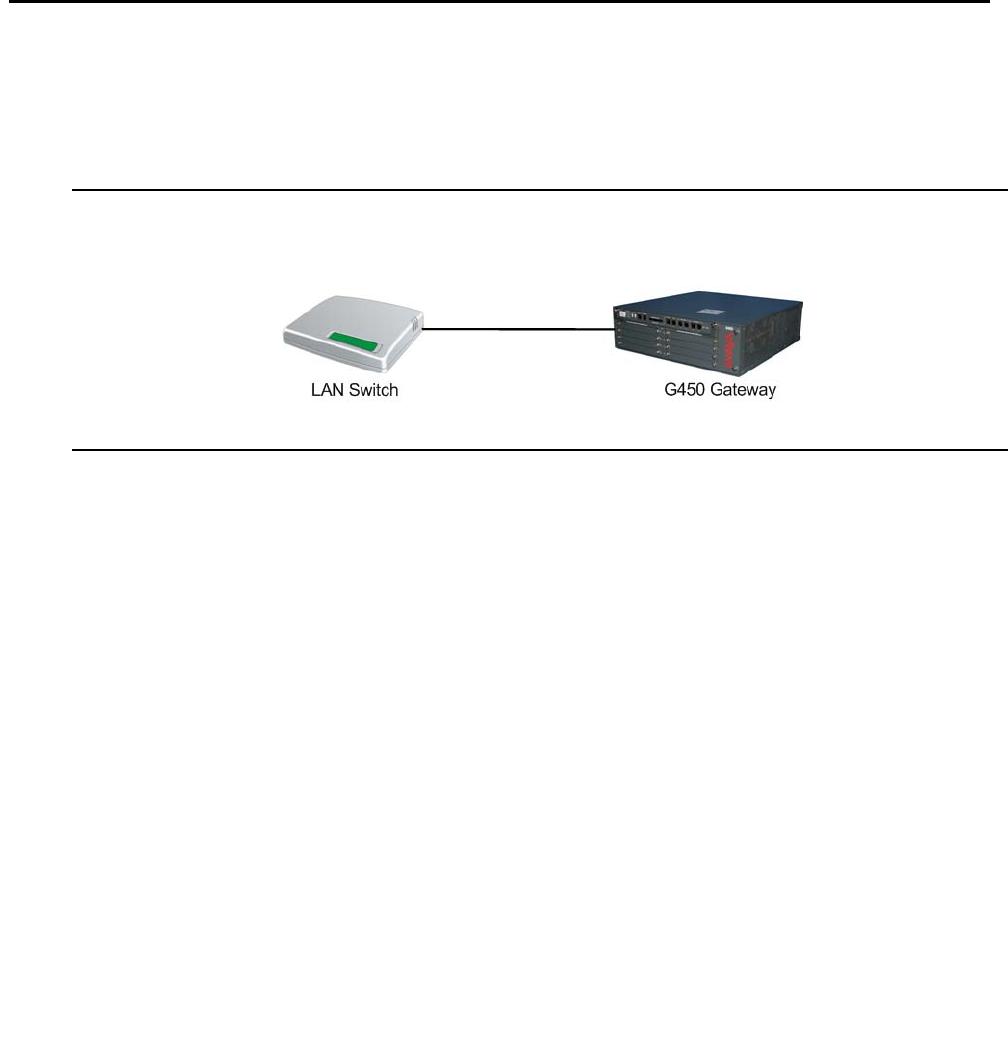
Issue 1 January 2008 31
Chapter 2: Supported LAN deployments
There are five supported LAN configurations for the Avaya G450 Media Gateway.
Basic configuration
The G450 can be deployed in the LAN with a basic configuration that includes no redundancy.
The G450 is connected to an external LAN switch using one of the two Ethernet LAN ports
located on the G450’s front panel.
Figure 1: Basic LAN deployment
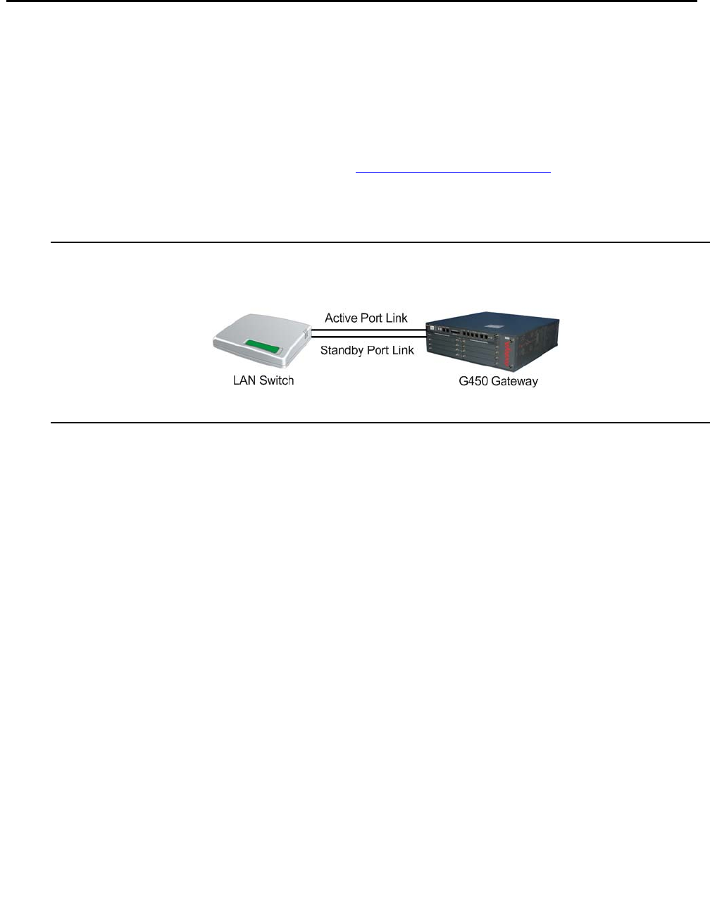
Supported LAN deployments
32 Administration for the Avaya G450 Media Gateway
Port redundancy configuration
The G450 can be deployed in the LAN using port redundancy to provide redundancy. The G450
is connected to an external LAN switch using both of the Ethernet LAN ports located on the
G450’s front panel.
One of the Ethernet LAN ports is configured to be the active primary link, and the other Ethernet
LAN port is configured to be on standby (disabled). For information on configuring the Ethernet
LAN ports in a port redundancy pair, refer to Configuring port redundancy on page 358.
When the G450 senses a link down failure on the primary port, it automatically enables the
secondary link. Both ports need to be administratively enabled on the LAN switch peer.
Figure 2: Port redundancy LAN deployment
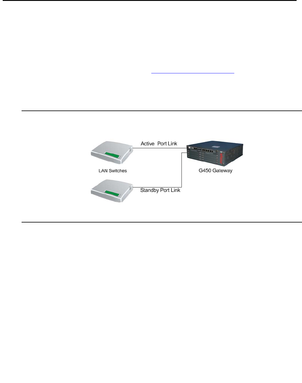
Port and switch redundancy configuration
Issue 1 January 2008 33
Port and switch redundancy configuration
The G450 can be deployed in the LAN using port and switch redundancy to provide
redundancy. The G450 is connected to two external LAN switches. Each of the Ethernet LAN
ports located on the G450’s front panel is connected to one of the switches.
One of the Ethernet LAN ports is configured to be the active primary link, and the other Ethernet
LAN port is configured to be on standby (disabled). For information on configuring the Ethernet
LAN ports in a port redundancy pair, refer to Configuring port redundancy on page 358.
When the G450 senses a link down failure on the primary port or failure of the switch to which
the primary link is attached, it automatically enables the secondary link to the backup switch.
Both ports need to be administratively enabled on their respective LAN switch peers.
Figure 3: Port and switch redundancy LAN deployment
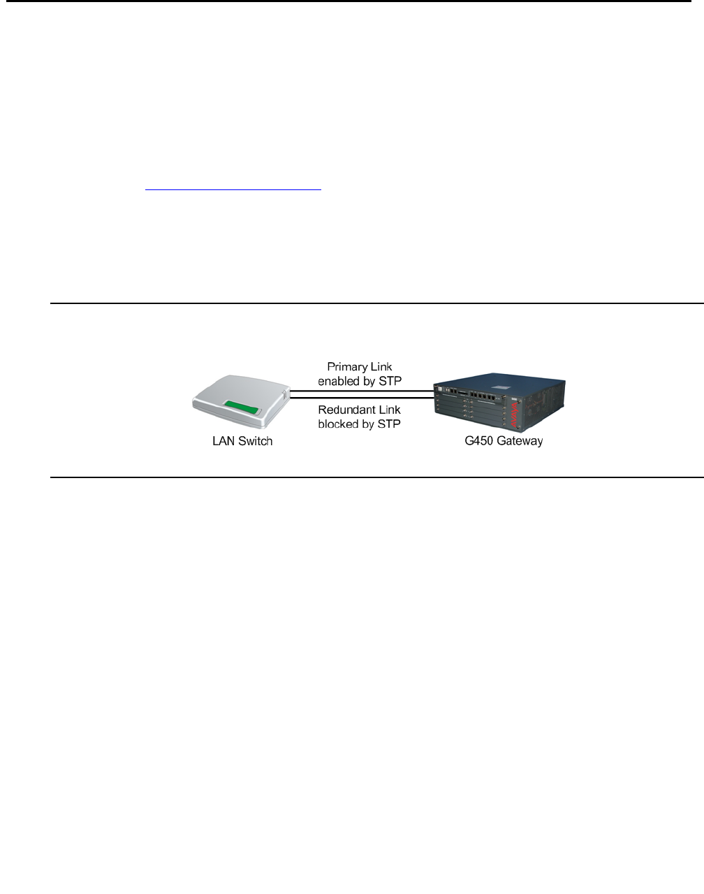
Supported LAN deployments
34 Administration for the Avaya G450 Media Gateway
STP configuration
The G450 can be deployed in the LAN using STP to provide redundancy. The G450 is
connected to an external LAN switch using both of the Ethernet LAN ports located on the
G450’s front panel.
Spanning tree protocol blocks one of the links from the G450 to the external LAN switch.
Spanning tree protocol must be configured on both the external LAN switch and the Ethernet
LAN ports on the G450. For information on configuring spanning tree on the Ethernet LAN
ports, refer to Configuring spanning tree on page 362.
When the G450 senses a link down failure on the active port, it automatically enables the
second link. Both ports need to be administratively enabled on the LAN switch peer.
The advantage of fast STP over port redundancy is that it controls the link state based on the
best LAN topology using the links’ cost. However, an STP convergence time penalty is incurred.
Figure 4: STP LAN deployment
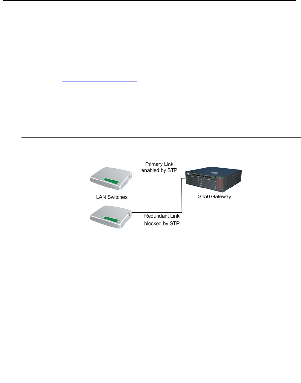
STP and switch redundancy configuration
Issue 1 January 2008 35
STP and switch redundancy configuration
The G450 can be deployed in the LAN using STP and switch redundancy to provide
redundancy. The G450 is connected to two external LAN switches. Each of the Ethernet LAN
ports located on the G450’s front panel is connected to one of the switches.
Spanning tree protocol blocks one of the links from the G450 to the external LAN switch.
Spanning tree protocol must be configured on both the external LAN switch and the Ethernet
LAN ports on the G450. For information on configuring spanning tree on the Ethernet LAN
ports, refer to Configuring spanning tree on page 362.
When the G450 senses a link down failure on the active port or failure of the switch to which the
active link is attached, it automatically enables the blocked link to the backup switch. Both ports
need to be administratively enabled on the LAN switch peer.
The advantage of fast STP over port redundancy is that it controls the link state based on the
best LAN topology using the links’ cost. However, an STP convergence time penalty is incurred.
Figure 5: STP and switch redundancy LAN deployment

Supported LAN deployments
36 Administration for the Avaya G450 Media Gateway

Issue 1 January 2008 37
Chapter 3: Configuration overview
A new Avaya G450 Media Gateway comes with default configuration settings. There are certain
items that you must configure, according to your system specifications, before using the G450.
Configuration of other items depends on the specifications of your network.
A new G450 has three IP interfaces for management (SNMP, telnet). These are the Console
interface, the Services interface, and the USB-modem interface.
You must also ensure that the G450 is properly configured for whichever methods you intend to
use for accessing the G450. For information on accessing the G450, see Accessing the Avaya
G450 Media Gateway on page 43.
Defining the Console interface
The first thing you should do when configuring a new G450 is to assign an IP address to the
Console interface. It is not necessary to include a subnet mask.
1. Enter interface console to enter the Console context.
2. Use the ip address command to define an IP address for the Console interface.
Note:
Note: For more detailed installation instructions, including information on obtaining IP
addresses, refer to Installing and Upgrading the Avaya G450 Media Gateway,
03-602054.
The following example assigns an IP address of 10.3.3.1 to the Console interface:
Defining the Services interface
No configuration of the Services interface is necessary. The Services interface has the fixed IP
address 192.11.13.6. However, the console device you connect to the Services port requires a
specific configuration of its network settings, as explained in Connecting a console device to the
Services port on page 45.
G450-001(super)# interface console
G450-001(super-if:Console)# ip address 10.3.3.1
Done!

Configuration overview
38 Administration for the Avaya G450 Media Gateway
Defining the USB-modem interface
If you intend to use a USB modem to connect to the G450, you should also assign an IP
address to the USB-modem interface. It is not necessary to include a subnet mask.
1. Enter interface usb-modem to enter the USB-modem context.
2. Use the ip address command to define a new IP address for the USB-modem interface.
The following example assigns an IP address of 10.3.3.2 to the USB-modem interface:
Defining other interfaces
Your next step should be to define the other interfaces required by your system specifications.
See Defining an interface on page 79.
Once you have defined your interfaces, you can define a Primary Management IP address
(PMI). The PMI is the IP address which the G450 uses to identify itself when communicating
with other devices, particularly the Media Gateway Controller (MGC). Management data
intended for the G450 is routed to the interface defined as the PMI. You can use any interface
as the PMI. For instructions on how to define the PMI, see Configuring the Primary
Management Interface (PMI) on page 80.
Once you have defined a PMI, you must register the G450 with an MGC. The MGC is a call
controller server that controls telephone services on the G450. The MGC can be internal or
external. See Configuring the Media Gateway Controller (MGC) on page 82.
Once you have performed these steps, the G450 is ready for use. Other configuration tasks
may also have to be performed, but these steps depend on the individual specifications of your
G450 and your network.
Most G450 configuration tasks are performed using the G450 CLI. Avaya also provides several
GUI applications that are designed to perform the basic configuration tasks described in this
section. See Configuration using GUI applications on page 39.
G450-001(super)# interface usb-modem
G450-001(super-if:USB-modem)# ip address 10.3.3.2
Done!

Configuration using CLI
Issue 1 January 2008 39
Configuration using CLI
You can use the Avaya G450 Media Gateway CLI to manage the G450. The CLI is a command
prompt interface that enables you to type commands and view responses. For instructions on
how to access the G450 CLI, see Accessing the CLI on page 43.
This guide contains information and examples about how to use CLI commands to configure the
Avaya G450 Media Gateway. For more information about the G450 CLI and a complete
description of each CLI command, see the Avaya G450 CLI Reference, 03-602056.
Configuration using GUI applications
Several Avaya GUI applications enable you to perform some configuration tasks on the Avaya
G450 Media Gateway. It is recommended to use these applications whenever possible,
particularly for initial installation and provisioning.
The Avaya Installation Wizard (Avaya IW) is a web-based installation wizard that leads the user
through the key configuration steps of a G450 installation. The Avaya IW can be used for initial
configuration of a G450 with an S8300 installed as the G450’s primary (ICC) or backup (LSP)
call controller. For instructions on how to access the Avaya IW, see Accessing Avaya IW on
page 48. For step-by-step instructions on how to configure the G450 using the Avaya IW, see
Installing and Upgrading the Avaya G450 Media Gateway, 03-602054.
The Gateway Installation Wizard (GIW) is a standalone application that allows the user to
perform certain basic G450 configuration tasks. The GIW can be used for initial configuration of
a G450 that does not have an S8300 installed as either the G450’s primary (ICC) or backup
(LSP) call controller. For instructions on how to access the GIW, see Accessing GIW on
page 51. For step-by-step instructions on how to configure the G450 using the GIW, see
Installing and Upgrading the Avaya G450 Media Gateway, 03-602054.
The Avaya Provisioning and Installation Manager (PIM) is an application that allows the user to
perform initial installation and provisioning of multiple gateways. It provides integrated network
system views that ease centralized configuration tasks, especially provisioning and installing
large numbers of gateways simultaneously. One of the primary functions of PIM is to provision
and configure Standard Local Survivability (SLS). For instructions on how to access PIM, see
Accessing PIM on page 52. For instructions on configuring SLS, see Configuring Standard
Local Survivability (SLS) on page 117.
You can also use the Avaya G450 Manager to configure most features of the G450. The Avaya
G450 Manager is a GUI application. You can access the Avaya G450 Manager from Avaya
Integrated Management software or from a web browser. Most of the commands that are
available through the G450 CLI are also available through the Avaya G450 Manager. For more
information about the Avaya G450 Manager, see the Avaya G450 Manager User Guide,
650-100-709.

Configuration overview
40 Administration for the Avaya G450 Media Gateway
Saving configuration changes
When you make changes to the configuration of the Avaya G450 Media Gateway, you must
save your changes to make them permanent. The G450 has two sets of configuration
information:
●Running configuration
●Startup configuration
The G450 operates according to the running configuration. When the G450 is reset, the G450
erases the running configuration and loads the startup configuration as the new running
configuration. When you change the configuration of the G450, your changes affect only the
running configuration. Your changes are lost when the G450 resets if you do not save your
changes.
Enter copy running-config startup-config to save changes to the configuration of the
G450. A copy of the running configuration becomes the new startup configuration.
You can back up either the running configuration or the startup configuration to an FTP or TFTP
server on your network, or to a USB flash drive. You can restore a backup copy of the
configuration from the FTP or TFTP server or the USB flash drive. When you restore the backup
copy of the configuration, the backup copy becomes the new running configuration on the
G450. For more information, see Backing up and restoring configuration files on page 113.
Summary of configuration changes CLI commands
Table 1: Configuration changes CLI commands
Command Description
copy running-config
startup-config Commit the current configuration, including Standard
Local Survivability (SLS) data, to NVRAM

Firmware version control
Issue 1 January 2008 41
Firmware version control
Firmware is the software that runs the Avaya G450 Media Gateway. The Avaya G450 Media
Gateway has two firmware banks:
●Bank A
●Bank B
Each firmware bank contains a version of the G450 firmware. These may be different versions.
The purpose of this feature is to provide redundancy of firmware. You can save an old version of
the firmware in case you need to use it later. If it becomes necessary to use the older version,
you can enter set boot bank bank-x and then reset the G450 to use the older version. This
is particularly important when uploading new versions.
For more information on firmware version control, see Software and firmware upgrades on
page 98.

Configuration overview
42 Administration for the Avaya G450 Media Gateway

Issue 1 January 2008 43
Chapter 4: Accessing the Avaya G450
Media Gateway
You can access the Avaya G450 Media Gateway using the CLI, the IW, the GIW, the PIM, and
the Avaya Communication Manager. You can manage login permissions by using and
configuring usernames and passwords, and by configuring the G450 to use SSH, SCP, RADIUS
authentication. There are special security features that enable and disable the recovery
password, establish incoming and outgoing telnet connections, and configure SYN cookies for
preventing SYN attacks.
Accessing the CLI
The CLI is a textual command prompt interface that you can use to configure the Avaya G450
Media Gateway and media modules. You can access the CLI with any of the following:
●Telnet through the network
●A console device
●Telnet through dialup:
-
Telnet through a serial modem
-
Telnet through a USB modem
-
Telnet through a USB modem via the S8300
If the G450 is under service contract with Avaya Services, remote service providers can
connect remotely to service the G450 with telnet and SSH sessions. You can configure the
G450 to authenticate remote service logins using Access Security Gateway (ASG)
authentication instead of password authentication, for higher security.
Logging into the CLI
Log in to the CLI with a username and password that your system administrator provides. Use
RADIUS authentication if your network has a RADIUS server. For more information, see
Managing login permissions on page 53.
Note:
Note: Disconnect a telnet session by typing <Ctrl>+]. This is particularly useful if the
normal telnet logout does not work.

Accessing the Avaya G450 Media Gateway
44 Administration for the Avaya G450 Media Gateway
CLI contexts
The CLI is divided into various contexts from which sets of related commands can be entered.
Contexts are nested in a hierarchy, with each context accessible from another context, called
the parent context. The top level of the CLI tree is called the general context. Each command
has a context in which the command must be used. You can only use a command in its proper
context.
For example, in order to configure the Loopback interface, you must first enter the Loopback
interface context from general context. You can enter the Loopback interface context using the
interface loopback 1 command. Once you are in the Loopback interface context, you
can enter Loopback interface commands.
You can use the tree command to view the available commands in each context.
CLI help
You can display a list of commands for the context you are in by typing help or ?. The help
command displays a list of all CLI commands that you can use within the current context, with a
short explanation of each command.
If you type help or ? before or after the first word or words of a command, the CLI displays a
list of all commands in the current context that begin with this word or words. For example, to
display a list of IP commands available in general context, enter help ip, ip help, ? ip, or
ip ?.
If you type help or ? before or after a full command, the CLI displays the command’s syntax
and parameters, and an example of the command. You must be in the command’s context in
order to use the help command to display information about the command.
In the following example, the user enters the vlan 1 interface context and displays help for the
bandwidth command.
G450-001(super)# interface vlan 1
G450-001(super-if:VLAN 1)# bandwidth ?
Bandwidth commands:
----------------------------------------------------------------------
Syntax: bandwidth <kilobytes size>
<kilobytes size> : integer (1-10000000)
Example: bandwidth 1000

Accessing the CLI
Issue 1 January 2008 45
Accessing CLI via local network
Access the CLI from a computer on the same local network as the Avaya G450 Media Gateway
by using SSH or, if telnet is active, any standard telnet program. Use the IP address of any
G450 interface for the host address.
Accessing CLI with a console device
Use any of the following types of console devices to access the CLI:
●Serial terminal
●Laptop with serial cable and terminal emulator software
Connect the console device to the CONSOLE or the SERVICES port on the front panel of the
Avaya G450 Media Gateway. Use only an approved Avaya serial cable. For more information
about approved Avaya serial cables, see Overview for the Avaya G450 Media Gateway,
03-602058.
For more information about the Console port, see Configuring the Console port for modem
use on page 242. For more information about the Services port, see Connecting a console
device to the Services port on page 45.
Connecting a console device to the Services port
A console device connected directly to the Services port of the G450 or S8300 Server requires
a specific configuration of its network settings.
Note:
Note: Make a record of any IP addresses, DNS servers, or WINS entries that you
change when you configure your services laptop. Unless you use the NetSwitcher
program or an equivalent, you will need to restore these entries to connect to
other networks.
●Configure TCP/IP properties. Set the TCP/IP properties of the console device as follows:
-
IP address = 192.11.13.5
-
Subnet mask = 255.255.255.252
-
Disable DNS service
-
Disable WINS Resolution
●Configure browser settings. Configure the browser of the console device for a direct
connection to the Internet. Either disable/bypass proxy servers, or enter 192.11.13.6 in
the Exceptions box.

Accessing the Avaya G450 Media Gateway
46 Administration for the Avaya G450 Media Gateway
●Server address. Access the G450 or S8300 Server using the URL
http://192.11.13.6.
Note:
Note: The names of the dialog boxes and buttons vary on different operating systems
and browser releases. Use your computer's help system if needed to locate the
correct place to enter the configuration information.
Accessing the CLI via modem
You can use any standard telnet program to access the CLI from a remote location. This is done
by using a dialup PPP network connection from a modem at the remote location. You can use
either a USB modem connected to the USB port on the front panel of the G450 or a serial
modem connected to the Console port on the front panel of the G450. You must only use an
approved Avaya serial cable. For more information about approved Avaya serial cables, see
Overview for the Avaya G450 Media Gateway, 03-602058.
Note:
Note: You can disconnect a telnet session by typing <Ctrl>+]. This is particularly useful
if the normal telnet logout does not work.
Accessing the CLI via a USB modem
1. Connect a modem to the USB port on the front panel of the Avaya G450 Media Gateway.
Use a USB cable to connect the modem. The G450 supports the Multitech MultiModem
USB, MT5634ZBA-USB-V92.
2. Make sure the USB port is properly configured for modem use. For details, see
Configuring the USB port for modem use on page 239.
3. From the remote computer, create a dialup network connection to the Avaya G450 Media
Gateway. Use the TCP/IP and PPP protocols to create the connection. Configure the
connection according to the configuration of the COM port of the remote computer. By
default, the G450 uses PAP authentication. If your network has a RADIUS server, you can
use RADIUS authentication for the PPP connection. For more information, see Managing
login permissions on page 53.
4. Open any standard telnet program on the remote computer.
5. Open a telnet session to the IP address of the USB port on the G450. For instructions on
how to set the IP address of the USB port (i.e., the USB-modem interface), see
Configuring the USB port for modem use on page 239.

Accessing the CLI via modem
Issue 1 January 2008 47
6. Configure the serial connection on the remote computer to match the configuration of the
USB port on the G450 (see Table 2).
Accessing the CLI via a serial modem
1. Connect a modem to the Console port on the front panel of the Avaya G450 Media
Gateway. Use an RJ-45 serial cable to connect the modem.
2. Make sure the Console port is properly configured for modem use.
3. From the remote computer, create a dialup network connection to the Avaya G450 Media
Gateway. Use the TCP/IP and PPP protocols to create the connection. Configure the
connection according to the configuration of the COM port of the remote computer. By
default, the G450 uses PAP authentication. If your network has a RADIUS server, you can
use RADIUS authentication for the PPP connection.
4. Open any standard telnet program on the remote computer.
5. Open a telnet session to the IP address of the Console port on the G450.
6. Configure the serial connection on the remote computer to match the configuration of the
Console port on the G450. The Console settings are the same as the USB port settings in
Table 2 except for the baud parameter, which uses the highest possible setting.
G450 serial modems
The G450 supports the following serial modems:
●Multitech MultiModem ZBA, MT5634ZBA-V92.
●Multitech BRI-NT1 ISDN Modem w/ POTS, MTA128NT, for use in US/Canada.
●Multitech ISDN Modem w/ POTS, MTA128STBRI, for use in Europe and the rest of the
world. The ISDN modems require DB-25 termination as well as the RJ-45 cable.
Table 2: The USB port settings
Port setting Value
Baud -
Data bits 8
Parity none
Stop bits 1
flow control hardware

Accessing the Avaya G450 Media Gateway
48 Administration for the Avaya G450 Media Gateway
Accessing the CLI via a modem connection to the S8300
If the Avaya G450 Media Gateway includes an S8300 Server, you can access the CLI from a
remote location. This is done by establishing a PPP network connection from a modem at the
remote location to a USB modem connected to one of the USB ports on the front panel of the
S8300. The G450 supports the Multitech MultiModem USB, MT5634ZBA-USB-V92.
Note:
Note: In order to access the CLI via the S8300, the PMI of the G450 must be
configured. See Configuring the Primary Management Interface (PMI) on
page 80.
1. Connect a USB modem to either of the two USB ports on the Avaya S8300 Server.
2. Use the Avaya Maintenance Web Interface (MWI) to configure the USB port on the S8300
for modem use. For instructions, see Installing and Upgrading the Avaya G450 Media
Gateway, 03-602054.
3. From a remote computer, create a dialup network connection to the S8300. Use the
TCP/IP and PPP protocols to create the connection.
4. Open any standard telnet program on the remote computer.
5. Enter the command telnet, followed by the IP address of the S8300 USB port to which
the modem is connected.
6. Enter the command telnet, followed by the PMI of the G450.
Accessing Avaya IW
The Avaya Installation Wizard (Avaya IW) is a web-based installation wizard that is used with
the Avaya G450 Media Gateway to perform initial configuration tasks and to upgrade software
and firmware. The Avaya IW is designed for use with systems that include an S8300 Server,
operating in either ICC or LSP mode. See Configuring the Media Gateway Controller (MGC) on
page 82.
Specifically, you can perform the following tasks with the Avaya IW:
●Configure PMI and SNMP information, Ethernet interfaces, primary and secondary Media
Gateway Controllers, G450 telephony and trunk parameters, and alarms
●Install license and password files, software, and firmware upgrades
●Enable and configure the USB ports of the S8300 and G450 for modem use
●Change your password

Accessing Avaya IW
Issue 1 January 2008 49
Access and run the Avaya IW using a laptop computer
1. Connect a laptop computer to the Services port of the S8300, using a crossover cable.
2. Make sure the laptop is configured as described in Connecting a console device to the
Services port on page 45.
3. Launch Internet Explorer on the laptop and enter the following URL to access the S8300
Server Home Page: http://192.11.13.6.
The welcome screen for Avaya Integrated Management appears.
4. Click Continue. The Logon screen for Integrated Management appears.
5. Enter the appropriate login name and password.
6. Ask a customer representative for a login name and password that the customer would like
for the superuser login. If you are a business partner, you can also repeat this procedure to
add the dadmin login.
Note:
Note: Make sure the customer can change this login, its password, or its permissions
later.
7. From the Integrated Management main menu, select Launch Maintenance Web Interface.
8. From the navigation menu of the Maintenance Web Pages, select Security >
Administrator Accounts.
The Administrator Accounts screen appears.
9. Select Add Login.
10. Select Privileged Administrator and click Submit.
The Administrator Logins -- Add Login: Privileged Administrator screen appears.
11. Type a login name for the account in the Login name field.
12. Verify the following:
●susers appears in the Primary group field.
●prof18 appears in the Additional groups (profile) field. prof18 is the code for the
customer superuser.
●/bin/bash appears in the Linux shell field.
●/var/home/login name appears in the Home directory field, where login name is the
name you entered in step 11.
13. Skip the fields Lock this account and Date on which account is disabled-blank to
ignore.
14. For the Select type of authentication option, select password.
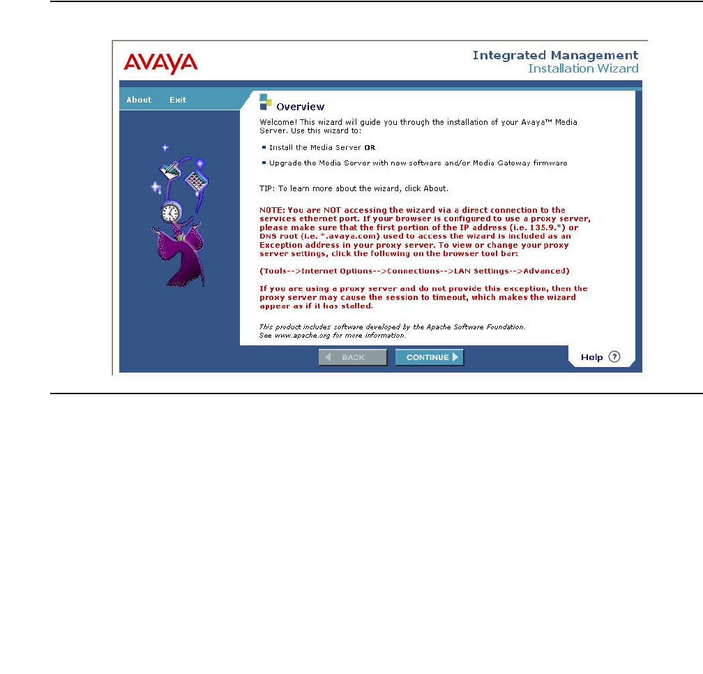
Accessing the Avaya G450 Media Gateway
50 Administration for the Avaya G450 Media Gateway
Note:
Note: Do not lock the account or set the password to be disabled.
15. Enter the password in the Enter password or key field and the Re-enter password or
key field.
16. In the section Force password/key change on next login select no.
17. Click Submit.
The system informs you the login is added successfully.
18. Click the Launch Installation Wizard link on the home page. The Avaya IW Overview
screen appears.
Figure 6: Avaya IW Overview screen
For step-by-step instructions on how to configure the G450 using the Avaya IW, see Installing
and Upgrading the Avaya G450 Media Gateway, 03-602054.

Accessing GIW
Issue 1 January 2008 51
Accessing GIW
The Gateway Installation Wizard (GIW) is an automated tool that allows you to perform a
streamlined installation and configuration of a G450 that does not include an S8300 Server. You
can use the GIW to perform initial configuration of the G450 and to upgrade software and
firmware. Specifically, you can perform the following tasks with the GIW:
●Configure PMI information (see Configuring the Primary Management Interface (PMI) on
page 80)
●Configure SNMP information (see Configuring SNMP on page 327)
●Configure primary and secondary Media Gateway Controllers (see Configuring the Media
Gateway Controller (MGC) on page 82)
●Check connectivity between the G450 and its Media Gateway Controller
●Display information on the G450 and media modules installed on the G450
●Enable the G450 for modem use (see Configuring the G450 for modem use on page 239)
●Install software and firmware upgrades (see Software and firmware upgrades on page 98)
Access the GIW
1. Install GIW on a laptop computer from the CD provided by Avaya. The laptop should be
running Windows 2000 or Windows XP.
2. Plug one end of an RJ-45 to RJ-45 cable into a DB-9 adapter.
3. Plug the RJ-45 connector at the other end of the cable into the Console port or Services
port of the G450.
4. Plug the DB-9 end of the cable into the COM port of the laptop computer.
5. From your laptop computer, double-click the GIW icon to run GIW.
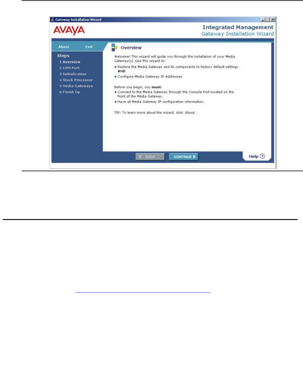
Accessing the Avaya G450 Media Gateway
52 Administration for the Avaya G450 Media Gateway
Figure 7: GIW Overview screen
For step-by-step instructions on how to configure the G450 using the GIW, see Installing and
Upgrading the Avaya G450 Media Gateway, 03-602054.
Accessing PIM
The Provisioning and Installation Manager (PIM) enables you to remotely configure devices,
primarily Avaya media gateways, on a network-wide basis. PIM provides integrated network
system views that ease centralized configuration tasks, especially provisioning and installing
large numbers of gateways simultaneously.
One of PIM’s primary functions is to provision and configure Standard Local Survivability (SLS)
on the G450. See Configuring Standard Local Survivability (SLS) on page 117.
PIM is launched from the Avaya Network Management Console. The Avaya Network
Management Console is the central infrastructure application that discovers and monitors
enabled network devices and runs Avaya Integrated Management applications.
PIM must be installed on the same Windows server as Avaya Network Management Console
with System View and Avaya Secure Access Administration.
For detailed information about installing and launching PIM, see Avaya Integrated Management
Enterprise Network Management Installation and Upgrade, 14-300444.

Accessing Avaya Communication Manager
Issue 1 January 2008 53
Accessing Avaya Communication Manager
Use Avaya Communication Manager software to control telephone services that the Avaya
G450 Media Gateway provides. Run the Avaya Communication Manager software on a server.
There might be several servers on your network that can control the Avaya G450 Media
Gateway. Access Avaya Communication Manager on any server that is a Media Gateway
Controller (MGC) for the Avaya G450 Media Gateway. For more information, see Configuring
the Media Gateway Controller (MGC) on page 82.
Access Avaya Communication Manager with any of the following:
●Avaya Site Administration (ASA). ASA provides wizards and other tools that help you to
use Avaya Communication Manager effectively. For more information, see Administrator
Guide for Avaya Communication Manager, 03-300509.
●SSH to port 5023 on the MGC. For more information, see Administrator Guide for Avaya
Communication Manager, 03-300509.
●Avaya G450 Media Gateway CLI. See Accessing the registered MGC on page 87.
Managing login permissions
You can manage login permissions to enable different privilege levels for each user and to
operate the security mechanism.
Security overview
The Avaya G450 Media Gateway includes a security mechanism through which the system
administrator defines users and assigns each user a username and password. Each user is
assigned a privilege level. The user’s privilege level determines which commands the user can
perform.
In addition to its basic security mechanism, the G450 supports secure data transfer via SSH
and SCP.
The G450 can be configured to work with an external RADIUS server to provide user
authentication. When RADIUS authentication is enabled on the G450, the RADIUS server
operates in conjunction with the G450 security mechanism. When the user enters a username,
the G450 first searches its own database for the username. If the G450 does not find the
username in its own database, it establishes a connection with the RADIUS server, and the
RADIUS server provides the necessary authentication services.

Accessing the Avaya G450 Media Gateway
54 Administration for the Avaya G450 Media Gateway
Managing users and passwords
You must provide a username and password when you perform any of the following actions:
●When you access the CLI. For more information, see Accessing the CLI on page 43.
●When you connect a modem with dialup PPP. For more information, see Accessing the
CLI via modem on page 46.
●When you open Avaya G450 Managerr.
When you use Avaya G450 Manager or the CLI, your username determines your privilege level.
The commands that are available to you during the session depend on your privilege level.
If your network has a RADIUS server, you can use RADIUS authentication instead of a
username and password. A RADIUS server provides centralized authentication service for
many devices on a network.
Privilege level
When you start to use Avaya G450 Manager or the CLI, you must enter a username. The
username that you enter sets your privilege level. The commands that are available to you
during the session depend on your privilege level. If you use RADIUS authentication, the
RADIUS server sets your privilege level.
The G450 provides the following three privilege levels:
●Read-only. You can use Read-only privilege level to view configuration parameters.
●Read-write.You can use Read-write privilege level to view and change all configuration
parameters except those related to security. For example, you cannot change a password
with Read-write privilege level.
●Admin.You can use Admin privilege level to view and change all configuration parameters,
including parameters related to security. Use Admin privilege level only when you need to
change configuration that is related to security, such as adding new user accounts and
setting the device policy manager source.
The default username has Admin privilege level. For security reasons, the network
administrator usually changes the password of the default username. For more information
about privilege levels, see Avaya G450 CLI Reference, 03-602056.
Configuring usernames
To create a username, use the username command. To remove a username, use the no
username command. To change the password or the privilege level for a username, remove
the username and add it again. You need an Admin privilege level to use the username and no
username commands.

Managing login permissions
Issue 1 January 2008 55
Note:
Note: When ASG authentication is enabled on the gateway, all password user accounts
with usernames similar to the reserved Avaya Services logins are deactivated.
The logins are "rasaccess", “sroot”, “init”, “inads”, and “craft”. The login "dadmin"
is reserved for an Avaya business partner remote services account, which can be
defined for ASG authentication. For information about ASG authentication, refer
to Authenticating service logins with Access Security Gateway (ASG)
authentication on page 55.
When you create a new user, you must define the user’s password and privilege level.
The following example creates a user named John with the password johnny69 and a
Read-write privilege level:
Authenticating service logins with Access Security Gateway
(ASG) authentication
The gateway supports ASG authentication for remote service logins. Direct remote connection
of services to the gateway is needed for gateways that are under service contract, do not have
LSPs, and are controlled by external MGCs. ASG is a more secure authentication method than
password authentication and does not require a static password.
ASG uses one-time tokens for authentication, in which a unique secret key is associated with
each login. ASG authentication is a challenge-response system, in which the remote user
receives a challenge from the gateway and returns an ASG authenticated response, which the
gateway verifies before permitting access. A new challenge is used for each access attempt.
ASG authentication is supported for remote services connecting to the gateway using telnet or
SSH protocols via any of the following:
●Dial-up modem connected to the USB, Console, or Services port
●Frame relay or leased line
●Secure gateway VPN
●Direct connection to the front panel Console port or Services port using the "craft" login
When ASG authentication is enabled on the G450, the G450 recognizes any login attempts
using Avaya Services reserved usernames as service logins, and requests ASG authentication
from the user, instead of a static user password.
The following usernames are reserved for Avaya Services usage: rasaccess, sroot, init,
inads, and craft.
G450-001(super)# username john password johnny69 access-type
read-write

Accessing the Avaya G450 Media Gateway
56 Administration for the Avaya G450 Media Gateway
When ASG authentication is enabled on the G450, all password user accounts with usernames
similar to the reserved service logins are deactivated.
Enabling ASG authentication
ASG authentication can be enabled and disabled on the gateway and requires an ASG
authentication file. The ASG authentication file contains Avaya Services accounts for
authenticating users at login as members of Avaya Services. The G450 is shipped with an ASG
authentication file. For information about replacing the authentication file, refer to Replacing the
ASG authentication file on page 56.
●For connection to Avaya Services via modem dial-up, enable the RASaccess operation
mode for modem operation, using ppp authentication ras. The G450 must also be
configured for remote modem access and enabled, as described in Installing and
Upgrading the Avaya G450 Media Gateway, 03-602054.
●For connection to Avaya Services via embedded VPN service, set up the VPN service for
Services to connect.
Note:
Note: By default, Avaya Services login access is enabled. If Avaya Services login
access was blocked using no login authentication services-logins,
you can reactivate it using login authentication services-logins.
Replacing the ASG authentication file
In case of any problems with the ASG authentication file, you can download a newer
authentication file from the Authentication File System (AFS). You cannot install an
authentication file with a different authentication file ID to that of the authentication file currently
installed in the gateway.
Note:
Note: If there is a need to install an authentication file with a different ID, you must first
delete the current authentication file using the command erase auth-file.
This command requires Supervisor level access and can only be used when
directly connecting to the Console or Services port. If you do delete the
authentication file and replace it with an authentication file with a new ID, the
authentication file label on the gateway chassis must also be replaced.
1. Optionally display the current ASG authentication file version, using the show
auth-file info command. For example:
G450-001(super)# show auth-file info
Authentication File (AF) information:
AF-ID :7000012345
Date/time : 15:02:27 27-SEP-2005
Major release : 4

Managing login permissions
Issue 1 January 2008 57
2. Use Windows File Explorer or another file management program to create a directory on
an FTP, SCP or TFTP server for storing authentication files (for example, C:\licenses).
3. Access the Internet and go to rfa.avaya.com.
4. Login using your SSO login and password. The AFS and RFA information home page
appears.
5. Start the AFS application from the RFA information page. Follow the instructions outlined
in the Authentication File System (AFS) Guide, 03-601703 to create and download the
authentication file.
6. Download the authentication file from an FTP, SCP or TFTP server or USB mass storage
device to the G450. To install the authentication file, use one of the following commands:
●To download an authentication file from a remote FTP server: copy ftp auth-file
filename ip, where filename is the name of the authentication file, including the
full path and ip is the IP address of the host. The G450 prompts you for a username
and password after you enter the command.
●To download an authentication file from a remote SCP server:copy scp auth-file
filename ip, where filename is the name of the authentication file, including the
full path and ip is the IP address of the host. The G450 prompts you for a username
and password after you enter the command.
●To download an authentication file from a remote TFTP server: copy tftp
auth-file filename ip, where filename is the name of the authentication file,
including the full path and ip is the IP address of the host. The G450 prompts you for
a username and password after you enter the command.
●To download an authentication file from a USB mass storage device:copy usb
auth-file source-usb-device source-filename, where
source-usb-device is the source USB mass storage device and
source-filename is the full name and path of the authentication file.
The authentication file is downloaded. You can view the download status using show
download auth-file status.
Note:
Note: You can also upload the authentication file from the gateway for troubleshooting.
To upload the authentication file, use copy auth-file ftp to upload it to an
FTP server, copy auth-file scp to upload it to an SCP server, copy
auth-file tftp to upload it to a TFTP server, or copy auth-file USB to
upload it to a USB mass storage device. To display the upload status, use show
upload auth-file status.

Accessing the Avaya G450 Media Gateway
58 Administration for the Avaya G450 Media Gateway
Configuring ASG authentication
You can perform the following ASG configurations:
●Block Avaya Services login access, using no login authentication
services-logins. This deactivates all Avaya Services logins, including local craft
password-based authenticated login. To reactivate, use login authentication
services-logins.
●Set the time the gateway waits for user response to authentication requests before timing
out a connection, using login authentication response-time time, where time
is the time, in seconds, after which the gateway aborts the connection if no response is
received.
For example, to timeout connections if no response arrives within 180 seconds after an
authentication request:
Use no login authentication response-time to return the response time value
to the factory default of 120 seconds. The time value you enter is used for both:
●The response time interval between the username prompt and the username entry
●The response time interval between the challenge prompt and the challenge response
●Deactivate password authentication and activate ASG authentication of Avaya Services
local connections to the Console port and Services port. To do this, use no login
authentication local-craft-password. To enable password authentication of
Avaya Services local connections to the Console port and Services port, use login
authentication local-craft-password (default).
●Set a policy for locking out access to the gateway after successive failed login attempts. To
do this, use login authentication lockout time attempt count, where time
is the interval of time for which lockout is enforced and count is a number of failed
attempts after which lockout is enforced. Use no login authentication lockout to
return the lockout time and lockout attempt threshold to their default values (180 and 3).
For example, to lockout Avaya Services access to the device for 360 seconds following
five failed login attempts:
This lockout affects all users locally stored in the gateway, including locally defined user
accounts and Avaya Services logins defined in the ASG authentication file. Remote users
maintained centrally in a Radius server are not subject to the lockout sanction.
G450-001(super)# login authentication response-time 180
G450-001(super)# login authentication lockout 360 attempt 5

Managing login permissions
Issue 1 January 2008 59
●Switch between modem operation modes, including rasaccess and ppp modes, using ppp
authentication {pap|chap|none|ras}. ASG authentication is enabled when ras
is selected. For example:
Displaying ASG authentication information
●Display login authentication settings and information, using show login
authentication. For example:
●Display ASG authentication file information, using show auth-file info. For example:
●Display all locally defined user accounts, including services accounts and account type
information such as authentication method, using show username. For example:
G450-001(super)# ppp authentication ras
G450-001(super)# show login authentication
Services logins: On
Local craft: On
Lockout time: 180 seconds
Lockout attempt threshold: 3
Authentication response time: 120 seconds
CLI logout timeout: Off
G450-001(super)# show auth-file info
Authentication File (AF) information:
AF-ID :7000012345
Date/time : 15:02:27 27-SEP-2005
Major release : 4
G450-001(super)# show username
User account Access level Account type Active Authent. method
----------- ----------- ---------- ----- --------------
sroot dev Services yes challenge
init dev Services yes challenge
inads tech Services yes challenge
craft admin Services yes challenge
dadmin admin local yes challenge
rasaccess read-only Services yes challenge
root admin local yes password
Accessing the Avaya G450 Media Gateway
60 Administration for the Avaya G450 Media Gateway
Summary of ASG authentication CLI Commands
For more information about these commands, see Avaya G450 CLI Reference, 03-300437.
Table 3: ASG authentication CLI command
Command Description
copy auth-file ftp Upload the authentication file from the gateway to an
FTP server
copy auth-file scp Upload the authentication file from the gateway to an
SCP server
copy auth-file tftp Upload the authentication file from the gateway to a
TFTP server
copy auth-file usb Upload the authentication file from the gateway to a
USB mass storage device
copy ftp auth-file Download an ASG authentication file from a remote
FTP server
copy scp auth-file Download an ASG authentication file from a remote
SCP server
copy tftp auth-file Download an ASG authentication file from a remote
TFTP server
copy usb auth-file Download an ASG authentication file from a USB mass
storage device
erase auth-file Erase the gateway’s ASG authentication file
login authentication
local-craft-password Enable password authentication of Avaya Services
local connections to the Console port and Services port
with the "craft" login. Use the no form to disable
password authentication for Avaya Services local
connections to the Console port and Services port.
When password authentication is disabled, ASG
authentication is activated.
login authentication
response-time Set the time the gateway waits for user response to
authentication requests before timing out a connection
login authentication
lockout Set a policy for locking out access to the gateway after
successive failed login attempts
1 of 2
Managing login permissions
Issue 1 January 2008 61
SSH protocol support
Secure Shell (SSH) protocol is a security protocol that enables you to establish a remote
session over a secured tunnel, also called a remote shell. SSH accomplishes this by creating a
transparent, encrypted channel between the local and remote devices. In addition to the remote
shell, SSH provides secure file transfer between the local and remote devices. SSH is used for
telnet file transfers. The G450 supports two concurrent SSH users.
Establishing an SSH session can be done by RSA authentication, or password authentication.
To determine which of these ways is used on your G450, enter show ip ssh.
RSA authentication process
●The G450 generates a key of variable length (512-2048 bits) using the DSA encryption
method. This is the private key.
●The G450 calculates an MD5 hash of the private key, called the public key (also called a
fingerprint). The public key is always 16 bytes long. This public key is displayed.
●The G450 sends the public key to the client computer. This public key is used by the client
to encrypt the data it sends to the G450. The G450 decrypts the data using the private key.
login authentication
services-logins Activate all Avaya Services logins, including local login
to Console port and Services port with "craft" login. Use
the no form to deactivate all Avaya Services logins.
ppp authentication Set modem operation mode. Setting the mode to ras
enables ASG authentication for Avaya Services remote
logins through dial-up modem connection.
show auth-file info Display ASG authentication file information
show download auth-file
status Display download status of ASG authentication file,
after using copy ftp|scp|tftp|usb auth-file to
download an authentication file to the gateway
show login authentication Display login authentication settings and information
show upload auth-file
status Display upload status of ASG authentication file, after
using copy auth-file ftp|scp|tftp to upload an
authentication file from the gateway
Table 3: ASG authentication CLI command (continued)
Command Description
2 of 2

Accessing the Avaya G450 Media Gateway
62 Administration for the Avaya G450 Media Gateway
●Both sides negotiate and must agree on the same chipper type. The G450 only supports
3DES-CBC encryption. The user on the client side accepts the public key. The client
maintains a cache containing a list of fingerprints per server IP address. If the information
in this cache changes, the client notifies the user.
●The client chooses a random number that is used to encrypt and decrypt the information
sent.
●This random number is sent to the G450, after encryption based on the G450’s public key.
●When the G450 receives the encrypted random number, it decrypts it using the private
key. This random number is now used with the 3DES-CBC encryption method for all
encryption and decryption of data. The public and private keys are no longer used.
Password authentication process
Before any data is transferred, the G450 requires the client to supply a username and
password. This authenticates the user on the client side to the G450.
SSH configuration
●To enable SSH on the G450:
a. To execute the SSH protocol, the G450 must first be assigned hostname identification.
Use the hostname command to assign hostname identification.
b. To enable SSH to be used, you must also configure the server host key. Use the
crypto key generate dsa command to generate an SSH host key pair.
c. Enter ip ssh to enable SSH authentication. Note that SSH is enabled by default.
●To disable SSH on the G450:
-
Use the disconnect ssh command to disconnect an existing SSH session.
-
Enter no ip ssh to disable the SSH server which disconnects all active SSH
sessions.
●Enter show ip ssh to display SSH configuration information and information about any
active SSH sessions.

Managing login permissions
Issue 1 January 2008 63
Summary of SSH configuration commands
For more information about these commands, see Avaya G450 CLI Reference, 03-300437.
SCP protocol support
In addition to data transfer via an SSH session, the SSH protocol is used to support SCP for
secure file transfer. When using SCP, the G450 is the client, and an SCP server must be
installed on the management station. After users are defined on the SCP server, the G450 acts
as an SCP client.
The process of establishing an SCP session is the same process as described in SSH protocol
support on page 61, except that the roles of the G450 and the client computer are reversed.
To perform file transfers secured by SCP, the G450 launches a local SSH client via the CLI. This
establishes a secured channel to the secured file server. The G450 authenticates itself to the
server by providing a username and password. With a Windows-based SSH server
(WinSSHD), the username provided must be a defined user on the Windows machine with
read/write privileges. The files transferred via SCP are saved in the C:\Documents and
Settings\username directory.
The network element performs file transfer in unattended mode.
Table 4: SSH configuration commands
Command Description
crypto key generate
dsa Generate an SSH host key pair
disconnect ssh Disconnect an existing SSH session
hostname Assign hostname identification to the G450
ip ssh Enable or disable the Secure Shell (SSH) service
show ip ssh Display general SSH information and information about the
currently active connections that are using SSH

Accessing the Avaya G450 Media Gateway
64 Administration for the Avaya G450 Media Gateway
SCP configuration
Enter clear ssh-client known-hosts to clear the client’s list of SCP server fingerprints.
Each SCP client maintains a list of server fingerprints. If a key changes, the client’s verification
of the server’s fingerprint will fail, thereby preventing the client’s access to the SCP server. If
this happens, you can enter clear ssh-client known-hosts to erase the client’s server
fingerprint list. This enables the client to access the server and begin to recreate its list of
fingerprints with the SCP server’s new fingerprint.
Summary of SCP configuration commands
For more information about these commands, see Avaya G450 CLI Reference, 03-300437.
RADIUS authentication
If your network has a RADIUS server, you can configure the G450 to use RADIUS
authentication. A RADIUS server provides centralized authentication service for many devices
on a network. When you use RADIUS authentication, you do not need to configure usernames
and passwords on the G450. When you try to access the G450, the G450 searches for your
username and password in its own database first. If it does not find them, it activates RADIUS
authentication.
For additional information on RADIUS configuration and authentication, go to the Avaya website
at http://www.avaya.com/support, and perform a search for the document Avaya G700/G350
RADIUS Configuration Overview, 104207.
Using RADIUS authentication
1. Configure your RADIUS server with the usernames, passwords, and privilege levels that
you want to use on the G450.
2. Configure RADIUS authentication on the G450.
Configuring RADIUS authentication
1. Enter set radius authentication enable to enable RADIUS authentication.
Table 5: SCP configuration commands
Command Description
clear ssh-client known-hosts Clear the SSH known-host file content

Managing login permissions
Issue 1 January 2008 65
2. Use the set radius authentication secret command to set the shared secret for
the authentication. This command must be followed by a text string. For example:
3. Use the set radius authentication server command to set the IP address of the
primary or secondary RADIUS Authentication server.
For more information about these commands, see Avaya G450 CLI Reference, 03-602056.
Changing RADIUS parameters
The following commands are optional:
●Use the set radius authentication retry-number command to set the number
of times to resend an access request when there is no response.
●Use the set radius authentication retry-time command to set the time to wait
before resending an access request.
●Use the set radius authentication udp-port command to set the RFC 2138
approved UDP port number. Normally, the UDP port number should be set to its default
value of 1812. Some early implementations of the RADIUS server used port number 1645.
Disabling RADIUS authentication
Enter set radius authentication disable to disable RADIUS authentication on the
G450.
Displaying RADIUS parameters
Enter show radius authentication. Shared secrets are not displayed.
set radius authentication secret hush

Accessing the Avaya G450 Media Gateway
66 Administration for the Avaya G450 Media Gateway
Summary of RADIUS authentication configuration commands
For more information about these commands, see Avaya G450 CLI Reference, 03-300437.
Special security features
Special security features allow you to enable and disable the recovery password, establish
incoming and outgoing telnet connections, copy gateway configurations while keeping
configuration secrets, and configure SYN cookies for preventing SYN attacks.
Table 6: RADIUS authentication configuration command
Command Description
clear radius
authentication server Clear the primary or secondary RADIUS server IP address
set radius
authentication Enable or disable RADIUS authentication
set radius
authentication
retry-number
Set the number of times to resend an access request when
there is no response
set radius
authentication
retry-time
Set the time to wait before resending an access request
set radius
authentication secret Set the shared secret for RADIUS authentication
set radius
authentication server Set the IP address of the primary or secondary RADIUS
authentication server
set radius
authentication
udp-port
Set the RFC 2138 approved UDP port number
show radius
authentication Display all RADIUS authentication configurations (shared
secrets are not displayed)

Special security features
Issue 1 January 2008 67
Enabling and disabling recovery password
The G450 includes a special recovery password. The purpose of the recovery password is to
enable the system administrator to access the G450 in the event that the regular password is
forgotten. You can only use the recovery password when accessing the G450 via a direct
connection to the Console port or Services port.
Use the set terminal recovery password command to enable or disable the recovery
password. Use this command only when accessing the G450 via a direct connection to the
Console port or Services port.
Summary of recovery password commands
For more information about these commands, see Avaya G450 CLI Reference, 03-300437.
Enabling and disabling telnet access
You can enable and disable the G450’s ability to establish incoming and outgoing telnet
connections, using the following commands. You can only use these commands when
accessing the G450 via a direct connection to the Console port.
●Use the ip telnet command to enable the G450 to establish an incoming telnet
connection. Use the no form of this command to disable the G450’s ability to establish an
incoming telnet connection.
●Enter ip telnet-client to enable the G450 to establish an outgoing telnet connection.
Use the no form of this command to disable the G450’s ability to establish an outgoing
telnet connection.
●Use the ip telnet-services command to enable the telnet server on the Services
interface.
Note:
Note: These commands are secured commands and are not displayed together with
the running configuration (using the show running-config command). To see
the status of these commands, use the show protocol command.
Table 7: Master Configuration Key configuration commands
Command Description
set terminal recovery
password Enable or disable the recovery password

Accessing the Avaya G450 Media Gateway
68 Administration for the Avaya G450 Media Gateway
●Use the show ip telnet command to display the status of the Telnet server and the
current Telnet connections.
Summary of Telnet access configuration commands
For more information about these commands, see Avaya G450 CLI Reference, 03-300437.
Managing gateway secrets
The G450 provides a mechanism for storage, backup, and restore of sensitive materials
(passwords and keys) maintained in the Media Gateways.
All sensitive materials are encrypted using a Master Configuration Key (MCK), derived from a
passphrase entered by an administrator. The secrets are then stored in the configuration file in
an encrypted format. This enables copying configurations, including secrets, from one device to
another. The only requirement is that the administrator must generate an identical MCK (by
using the same passphrase) in the target device before executing the copy operation.
Note:
Note: All gateways have the same default MCK. For security reasons, it is
recommended to configure a new MCK immediately upon gateway installation.
Table 8: Telnet access configuration commands
Command Description
ip telnet Enable the G450 to establish an incoming telnet connection,
or disable its ability to establish an incoming telnet connection
ip telnet-client Enable the G450 to establish an outgoing telnet connection, or
disable its ability to establish an outgoing telnet connection
ip telnet-services Enable the telnet server on the Services interface
show ip telnet Display the status of the Telnet server and the current Telnet
connections
show protocol Display the status of the telnet or telnet-client protocol
telnet Initiate a login session via telnet to a network host
Special security features
Issue 1 January 2008 69
Configuring the Master Configuration Key
1. Enter key config-key password-encryption followed by a phrase of 13-64
printable ASCII characters.
2. Copy the running configuration to the start-up configuration using the copy
running-config startup-config command.
The new MCK is now in effect.
Summary of Master Configuration Key configuration commands
For more information about these commands, see Avaya G450 CLI Reference, 03-300437.
Enabling SYN cookies
The G450 provides various TCP/IP services and is therefore exposed to a myriad of TCP/IP
based DoS attacks.
DoS (Denial of Service) attacks refers to a wide range of malicious attacks that can cause a
denial of one or more services provided by a targeted host. Specifically, a SYN attack is a
well-known TCP/IP attack in which a malicious attacker targets a vulnerable device and
effectively denies it from establishing new TCP connections.
SYN cookies refers to a well-known method of protection against a SYN attack.
SYN attack (SYN flood attack)
The SYN (TCP connection request) attack is a common DoS attack characterized by the
following pattern:
Using a spoofed IP address, an attacker sends multiple SYN packets to a listening TCP port on
the target machine (the victim). For each SYN packet received, the target machine allocates
resources and sends an acknowledgement (SYN-ACK) to the source IP address. The TCP
connection is called a “half-open” connection at this point since the initiating side did not yet
send back an acknowledgment (termed the 3rd ACK).
Table 9: Master Configuration Key configuration commands
Command Description
key config-key
password-encryption Set the default Master Configuration Key of the gateway

Accessing the Avaya G450 Media Gateway
70 Administration for the Avaya G450 Media Gateway
Because the target machine does not receive a response from the attacking machine, it
attempts to resend the SYN-ACK, typically five times, at 3-, 6-, 12-, 24-, and 48-second
intervals, before de-allocating the resources, 96 seconds after attempting the last resend.
Altogether, the target machine typically allocates resources for over three minutes to respond to
a single SYN attack.
When an attacker uses this technique repeatedly, the target machine eventually runs out of
memory resources since it holds numerous half-open connections. It is unable to handle any
more connections, thereby denying service to legitimate users.
Moreover, flooding the victim with TCP SYN at a high rate can cause the internal queues to fill
up, also causing a denial of service.
SYN cookies
SYN cookies protect against SYN attacks by employing the following strategies:
●Not maintaining any state for half-open inbound TCP sessions, thus preventing the SYN
attack from depleting memory resources.
SYN cookies are able to maintain no state for half-open connections by responding to SYN
requests with a SYN-ACK that contains a specially crafted initial sequence number (ISN),
called a cookie. The value of the cookie is not a pseudo-random number generated by the
system, but the result of a hash function. The hash result is generated from the source IP,
source port, destination IP, destination port, and some secret values. The cookie can be
verified when receiving a valid 3rd ACK that establishes the connection. The verification
ensures that the connection is a legitimate connection and that the source IP address was
not spoofed.
●Employing the SYN cookies method at a lower point in the network stack then regular TCP
handling, closer to the start point of packet handling. This reduces the chances that a SYN
attack will fill up the internal queues.
●Performing SYN attack fingerprinting and alerting an administrator about a SYN attack as
it occurs. This is implemented by keeping track of the rate at which half-open TCP
connections are created, and sending an alert when the rate exceeds a certain threshold.
In addition, when the SYN cookies mechanism is active, a hostile port scan might be misled into
concluding that all TCP ports are open.
Configuring SYN cookies
1. Enter tcp syn-cookies.
2. Copy the running configuration to the start-up configuration using the copy
running-config startup-config command.
3. Reset the device using the reset command.
SYN cookies are now enabled on the device.

Special security features
Issue 1 January 2008 71
SYN attack notification
When the SYN cookies feature is enabled, the G450 alerts the administrator to a suspected
SYN attack as it occurs by sending the following syslog message:
Maintaining SYN cookies
Use the following commands to show and clear SYN cookies statistics:
●Enter show tcp syn-cookies to show SYN cookies statistics.
Note:
Note: For an example and explanation of SYN cookies statistics, see Avaya G450 CLI
Reference, 03-602056.
●Enter clear tcp syn-cookies counters to clear the SYN cookies counters.
Summary of SYN cookies configuration commands
For more information about these commands, see Avaya G450 CLI Reference, 03-300437.
Managed Security Services (MSS)
Media Gateway IP interfaces and gateway applications such as WAN routers, PoE switches,
and VPN devices can be at risk for DoS attacks. The G450 identifies predefined or
custom-defined traffic patterns as suspected attacks and generates SNMP notifications,
referred to as Managed Security Services (MSS) notifications.
SYN attack suspected! Number of unanswered SYN requests is greater
than 20 in last 10 seconds.
Table 10: Master Configuration Key configuration commands
Command Description
clear tcp syn-cookies
counters Clear the SYN cookies counters
show tcp syn-cookies Show SYN cookies statistics for inbound TCP connections
tcp syn-cookies Enable or disable the TCP SYN cookies defense mechanism
against SYN attacks

Accessing the Avaya G450 Media Gateway
72 Administration for the Avaya G450 Media Gateway
MSS reporting mechanism
MSS notifications are sent to the active MGC by the dynamic trap manager. MSS notifications
sent to the active MGC by the dynamic trap manager are converted to syslog messages by the
SNMP trap manager on the MGC. For general information about configuring and enabling
syslog messages and syslog message format, refer to Configuring a Syslog server on
page 210.
MSS notifications are intercepted and, if certain conditions are met, may be forwarded to the
Avaya Security Operations Center (SOC) as INADS alarms. The SOC is an Avaya service
group that handles DoS alerts, responding as necessary to any DoS attack or related security
issue.
Note:
Note: The syslog messages on the active MGC are stored in the messages file on the
MGC hard disk. You can view the syslog messages through the Avaya
Maintenance Web Interface (MWI) if you want to debug security issues directly.
For information about how to view syslog messages, see Viewing QoS traps,
QoS fault traps, and QoS clear traps on page 392.
Note:
Note: Any additional SNMP recipients defined with the security notification group
enabled also receive the MSS notifications.
Configuring MSS
The MSS feature is automatically enabled and monitors all IP interfaces, including WAN data
interfaces, IPSEC tunnels, Ethernet LAN and WAN ports, VoIP engine interfaces, and Dialer
and Serial PPP interfaces.
1. Verify that the dynamic trap manager, which automatically sets the IP address of the active
MGC SNMP trap manager, is configured so that security notifications are sent to the active
MGC. By default, all types of notifications are enabled. You can enter show snmp to check
which notification groups are configured to be sent to the active MGC. You can modify the
dynamic trap manager configuration using the snmp-server dynamic-trap-manager
command, setting the notification type to all or security.

Special security features
Issue 1 January 2008 73
2. If required, define additional notification recipients using the snmp-server group,
snmp-server host, and snmp-server user commands, and activating the security
notification filter. For example:
3. Use the set mss-notification rate command to modify the MSS reporting rate, if
necessary. The default is 300 seconds. The G450 counts events for each DoS class for
the duration of the interval. At the end of each interval, if the count of each class of DoS
events surpasses a defined threshold, the G450 generates an MSS notification, reporting
on the event type, event parameters, and the number of occurrences. To display the
current MSS reporting rate, use the show mss-notification rate command.
4. Ensure that INADS reporting is configured on the active MGC. For information about
configuring INADS reporting in Avaya Communication Manager, see Avaya
Communication Manager documentation.
//define an SNMP group:
G450-001(super)# snmp-server group MSS_group v3 noauth read iso write iso
notify iso
Done!
//create a new snmp user belonging to the SNMP group:
G450-001(super)# snmp-server user MSS MSS_group v3
Done!
//identify an SNMP trap recipient, activating the security notification
filter:
G450-001(super)# snmp-server host 5.5.5.2 traps v3 noauth MSS security
Done!
//view the SNMP configuration
G450-001(super)# show snmp
Authentication trap disabled
Community-Access Community-String
---------------- ----------------
read-only *****
read-write *****
SNMPv3 Notifications Status
-----------------------------
Traps: Enabled
Informs: Enabled Retries: 3 Timeout: 3 seconds
SNMP-Rec-Address Model Level Notification Trap/Inform User name
---------------- ----- ------- --------------- ----------- -------------------
5.5.5.2 v3 noauth all trap MSS
UDP port: 162

Accessing the Avaya G450 Media Gateway
74 Administration for the Avaya G450 Media Gateway
DoS attack classifications
Traffic patterns meeting the DoS attack classifications are automatically reported in MSS
notifications.
Table 11: DoS attack classifications
DoS Attack Description
LAND_ATTACK Land attack packets with the source IP the
same as an IP address
TCP_URGENT_ATTACK TCP packets with the URGENT option set
ICMP_RATE_LIMIT ICMP (echo) requests exceeding a pre-defined
rate
SMURF_ATTACK ICMP echo packets with limited broadcast
destination address
FRAGGLE_ATTACK UDP packets with limited broadcast destination
address
SYN-FLOOD The number of unacknowledged TCP SYN-ACK
exceeds a predefined rate
UNREACHABLE_PORT_ ATTACK TCP/UDP IP packets sent to unreachable ports
MALFRAGMENTED_IP Malfragmented IP packets on TO-ME interfaces
MALFORMED_IP Malformed IP packets.
The G450 reports malformed IP packets when:
●The IP version in the IP header is a value
other than 4
●The IP header length is smaller than 20
●The total length is smaller than the header
length
MALFORMED_ARP ARP messages with bad opcode
SPOOFED_IP For all routable packets, the Gateway report
reception of IP spoofed packets
UNKNOW_L4_IP_PROTOCOL Packets with unknown (unsupported or
administratively closed) protocol in IP packet
with TO-ME interface as a destination
UNATHENTICATED_ACCESS Failure to authenticate services

Special security features
Issue 1 January 2008 75
Defining custom DoS classifications
You can define custom DoS attack classifications using access control list (ACL) rules. ACL
rules control which packets are authorized to pass through an interface. A custom DoS class is
defined by configuring criteria for an ACL rule and tagging the ACL with a DoS classification
label.
Note:
Note: For general information about configuring policy rules, refer to Configuring
policy on page 591.
Defining a DoS class using ACLs
1. Use the ip access-control-list command to enter the configuration mode of an
ACL. For example:
2. Use the ip-rule command to enter the configuration mode of an ACL rule. For example:
3. Use the dos-classification command to configure the name of the DoS attack
classification. Possible values are: fraggle, smurf, ip-spoofing,
other-attack-100, other-attack-101, other-attack-102,
other-attack-103, other-attack-104, and other-attack-105. For example:
4. Define the packet criteria to which the ACL rule should apply. See Policy lists rule
criteria on page 600.
For example, you can use destination-ip to specify that the rule applies to packets
with a specific destination address and you can use ip-protocol to specify that the rule
applies to packets with a specific protocol:
5. Use the composite-operation command to associate the ACL rule with the predefined
operation “deny-notify,” which tells the gateway to drop any packet received that matches
the ACL rule, and send a trap upon dropping the packet. For example:
G450-001(super)# ip access-control-list 301
G450-001(super)# ip-rule 1
G450-001(super-ACL 301/ip rule 1)# dos-classification smurf
Done!
G450-001(super-ACL 301/ip rule 1)# destination-ip 255.255.255.255 0.0.0.0
Done!
G450-001(super-ACL 301/ip rule 1)# ip-protocol icmp
Done!
G450-001(super-ACL 301/ip rule 1)# composite-operation deny-notify
Done!

Accessing the Avaya G450 Media Gateway
76 Administration for the Avaya G450 Media Gateway
6. Exit the ACL rule. For example:
7. Exit the ACL. For example:
8. Enter the configuration mode of the interface on which you want to activate the ACL. For
example:
9. Activate the configured ACL for incoming packets on the desired interface. For example:
G450-001(super-ACL 301/ip rule 1)# exit
G450-001(super-ACL 301)# exit
G450-001(super)# interface vlan 203
G450-001(super-if:vlan 203)# ip access-group 301 in
Done!

Special security features
Issue 1 January 2008 77
Example
The following example demonstrates the configuration of MSS notifications using ACL rules. In
this example, smurf packets (ICMP packets that are sent to a limited broadcast destination)
arriving at interface VLAN 203 are defined as a DoS attack to be reported in MSS notifications.
//create and enter the configuration mode of access control list 301:
G450-001(super)# ip access-control-list 301
//create and enter the configuration mode of ip rule 1:
G450-001(super-ACL 301/ip rule 1)# ip-rule 1
//set the rule criteria for the custom DoS classification:
//use dos-classification command to specify to report on receiving smurf
//packets (ICMP echo packets with limited broadcast destination address )
G450-001(super-ACL 301/ip rule 1)# dos-classification smurf
Done!
//apply predefined composite-operation deny-notify, which drops the packet and
//causes the gateway to send a trap when it drops the packet
G450-001(super-ACL 301)# composite-operation Deny-Notify
Done!
//specify that the ip rule applies to packets with this destination ip address.
G450-001(super-ACL 301/ip rule 1)# destination-ip 255.255.255.255 0.0.0.0
Done!
//Specify that the ip rule applies to ICMP packets
G450-001(super-ACL 301/ip rule 1)# ip-protocol icmp
Done!
G450-001(super-ACL 301/ip rule 1)# exit
G450-001(super-ACL 301)# show ip-rule
Index Protocol IP Wildcard Port Operation
DSCP Fragment rule
----- -------- --- ---------------- ----------- ------------ --------------
1 icmp Src Any Any Type Deny-Notify
Any Dst 255.255.255.255 Host Any Code No
Dos classification: smurf
Deflt Any Src Any Any Permit
Any Dst Any Any No
G450-001(super-ACL 301)# exit
G450-001(super)# interface vlan 203
//activate Access Control list 301 for incoming packets on interface vlan 203:
G450-001(super-if:VLAN 203)# ip access-group 301 in
Done!
Accessing the Avaya G450 Media Gateway
78 Administration for the Avaya G450 Media Gateway
Summary of MSS configuration CLI commands
For more information about these commands, see Avaya G450 CLI Reference, 03-300437.
Table 12: MSS configuration CLI commands
Command Description
composite-operation Edit the specified composite operation. If the composite
operation does not exist, it is created
destination-ip Specify the destination IP address of packets to which
the current rule applies
dos-classification Set a label for a user-defined DoS attack classification
to be reported in MSS notifications
ip access-control-list Enter configuration mode for the specified policy access
control list. If the specified list does not exist, the
system creates it and enters its configuration mode.
ip-rule Enter configuration mode for the specified rule. If the
specified rule does not exist, the system creates it and
enters its configuration mode.
ip-protocol Specify that the current rule applies to packets having
the specified IP protocol
set mss-notification rate Set the rate at which the gateway sends Managed
Security Services (MSS) notifications
show mss-notification rate Show the interval time, in seconds, between MSS
notifications
show snmp Display SNMP configuration information
snmp-server
dynamic-trap-manager Modify the SNMP settings of the dynamic trap manager
snmp-server group Define a new SNMPv3 group, or configure settings for
the group
snmp-server host Identify an SNMP management server, and specify the
kind of messages it receives
snmp-server user Configure settings for an SNMPv3 user

Issue 1 January 2008 79
Chapter 5: Basic device configuration
Basic device configuration lets you:
●Define a new interface and its IP address
●Configure parameters that identify the G450 to other devices
●Define a G450 interface as the G450’s default gateway
●Configure an MGC to work with the G450
●Configure DNS resolver for resolving hostnames to IP addresses
●View the status of the G450
●Manage and upgrade software, firmware, configuration, and other files on the G450
●Backup and restore the G450
Defining an interface
All interfaces on the G450 must be defined by the administrator, after installation of the G450.
1. Use the interface command to enter the interface context. Some types of interfaces
require an identifier as a parameter. Other types of interfaces require the interface’s
module and port number as a parameter. For example:
For more information on the various types of interfaces, see Router interface concepts on
page 444.
2. Use the ip address command, followed by an IP address and subnet mask, to assign
an IP address to the interface.
3. Use the load-interval command to set the load calculation interval for the interface.
For a list and descriptions of other interface configuration commands, see Configuring
interfaces on page 443. For interface configuration examples, see Configuration example on
page 279.
interface vlan 1
interface serial 3/1
interface fastethernet 10/2.0

Basic device configuration
80 Administration for the Avaya G450 Media Gateway
Configuring the Primary Management Interface (PMI)
The Primary Management Interface (PMI) address is the IP address of an interface that you can
specify on the Avaya G450 Media Gateway. The first IP address you configure on the G450
automatically becomes the PMI. You can subsequently assign any IP interface to be the PMI.
The PMI is used as the IP address of the G450 for the following management functions:
●Registration of the G450 to an MGC
●Sending SNMP traps
●Opening telnet sessions from the G450
●Sending messages from the G450 using FTP and TFTP protocol
You can designate any of the G450’s interfaces to serve as the G450’s PMI. The PMI must be
an IP address that the MGC recognizes. If you are not sure which interface to use as the PMI,
check with your system administrator.
Setting the PMI of the G450
1. Use the interface command to enter the context of the interface to which you want to
set the PMI. For example, to use the VLAN 1 interface as the PMI, enter interface
vlan 1.
Note:
Note: If the interface has not been defined, you must define it now.
2. Enter pmi.
3. Enter exit to return to general context.
4. Enter copy running-config startup-config. This saves the new PMI in the
startup configuration file.
5. Use the reset command to reset the G450.
Note:
Note: Most configuration changes take effect as soon as you make the change, but
must be saved to the startup configuration file in order to remain in effect after you
reset the G450. The PMI address is an exception. A change to the PMI does not
take effect at all until you reset the G450.
6. To verify the new PMI, enter show pmi in general context. If you use this command before
you reset the G450, it displays two different PMIs:
●Active PMI. The PMI that the G450 is currently using, as defined in the running
configuration file
Configuring the Primary Management Interface (PMI)
Issue 1 January 2008 81
●Configured PMI. The PMI that the G450 is configured to use after reset, as defined in
the startup configuration file
If you use this command after you reset the G450, both the Active and the Configured PMI
should be the same IP address.
7. Use the following commands to configure other identification information:
●Use the set system contact command to set the contact information for the G450
●Use the set system location command to set the location information for the
G450
●Use the set system name command to specify the name of the G450
Summary of PMI configuration CLI commands
For more information about these commands, see Avaya G450 CLI Reference, 03-300437.
Table 13: PMI configuration CLI commands
Root level
command Command Description
interface
(fastethernet|
serial|tunnel|
vlan|loopback|
dialer)
Enter configuration mode for the
FastEthernet, Serial, Tunnel,
VLAN, Loopback, or Dialer
interface
pmi Set the current interface as the
Primary Management Interface
for the system
set system
contact Set the contact information for
this media gateway system
set system
location Set the location information for
this media gateway system
set system
name Set the name of the media
gateway system
show pmi Display the current Primary
Management Interface

Basic device configuration
82 Administration for the Avaya G450 Media Gateway
Defining the default gateway
The G450 uses a default gateway to connect to outside networks that are not listed on the
G450’s routing table. To define a default gateway, use the ip default-gateway command,
followed by either the IP address or name (type and number) of the interface you want to define
as the default gateway.
The following example defines the interface with the IP address 132.55.4.45 as the default
gateway:
ip default-gateway 132.55.4.45
The following example defines Serial interface 3/1:1 as the default gateway:
ip default-gateway serial 3/1:1
Summary of default gateway configuration CLI commands
For more information about these commands, see Avaya G450 CLI Reference, 03-300437.
Configuring the Media Gateway Controller (MGC)
The Media Gateway Controller (MGC) controls telephone services on the Avaya G450 Media
Gateway. You can use a server with Avaya Communication Manager software as an MGC. The
G450 supports both External Call Controllers (ECC) and Internal Call Controllers (ICC). An ICC
is an Avaya S8300 Server that you install in the G450 as a media module. An ECC is an
external server that communicates with the G450 over the network.
When the G450 uses an ECC, it can use a local S8300 as a backup controller for Enhanced
Local Survivability (ELS). The S8300 functions in Local Survivable Processor (LSP) mode. If the
ECC stops serving the G450, the S8300 takes over the service.
To register the G450 with an MGC, you need the G450’s serial number. You can find this serial
number in either of the following ways:
●Use the show system command
Table 14: PMI configuration CLI commands
Command Description
ip default-gateway Set a default gateway for connecting to outside
networks that are not listed on the G450’s routing table

Configuring the Media Gateway Controller (MGC)
Issue 1 January 2008 83
●Look for a 12-character string located on a label on the back panel of the G450
Survivability and migration options
Several options exist to minimize network disruption in the event that connectivity between the
G450 and the server or media gateway controller (MGC) is lost.
●MGC list. You must register the G450 with at least one, and up to four, MGCs. The first
MGC on the list is the primary MGC. If the G450 cannot connect with, or loses its
connection with, the primary MGC, it attempts to connect with the other MGCs on the list.
See Configuring the MGC list on page 84.
Note:
Note: When Standard Local Survivability (SLS) is enabled, the MGC list includes the
SLS module as a fifth entry in the MGC list. For details about SLS, see
Configuring Standard Local Survivability (SLS) on page 117.
●Standard Local Survivability (SLS). SLS consists of a module built into the G450 to
provide partial backup MGC functionality in the event that the connection with the primary
MGC is lost. This feature allows a local G450 to provide a degree of MGC functionality
when no link is available to an external MGC. It is configured on a system-wide basis using
the Provisioning and Installation Manager (PIM) (see Accessing PIM on page 52).
Alternatively, it can be configured on an individual G450 using the CLI. For more
information and instructions on configuring SLS, see Configuring Standard Local
Survivability (SLS) on page 117.
●Enhanced Local Survivability (ELS). ELS is available for the G450 using a local S8300
or S8500 functioning in LSP mode. If the ECC stops serving the G450, the S8300 takes
over the service.
Table 15: Servers supported by the Avaya G450 Media Gateway
Server Type Usage
Avaya S8300 Server Media module ECC, ICC, or LSP
Avaya S8400 Server External ECC
Avaya S8500 Server External ECC or LSP
Avaya S8710 Server External ECC
Avaya S8720 Server External ECC
Avaya S8730 Server External ECC

Basic device configuration
84 Administration for the Avaya G450 Media Gateway
●Auto fallback to primary MGC. This feature provides a means by which a G450 being
serviced by its LSP can return to its primary MGC automatically when the connection is
restored between the G450 and the MGC. By migrating the G450 to the MGC
automatically, a fragmented network can be made whole faster, without the need for
human intervention. Auto fallback is configured via the Avaya Communication Manager.
For details, see the Administrator Guide for Avaya Communication Manager, 03-300509.
Note:
Note: Auto fallback does not include survivability. Therefore, there is a short period
during registration with the MGC during which calls are dropped and service is
not available. This problem can be minimized using the connection preservation
feature described below.
●Connection preservation. This feature enables the G450 to preserve the bearer paths of
stable calls in the event that the G450 migrates to another MGC (including an LSP),
including migration back from an LSP to the primary MGC. A call for which the talk path
between parties in the call has been established is considered stable. A call consisting of a
user listening to announcements or music is not considered stable and is not preserved.
Any change of state in the call prevents the call from being preserved. For example,
putting a call on hold during MGC migration will cause the call to be dropped. Special
features, such as conference and transfer, are not available on preserved calls.
Connection preservation preserves all types of bearer connections except BRI. PRI trunk
connections are also preserved. Connection preservation is configured via the Avaya
Communication Manager. For details, see the Administrator Guide for Avaya
Communication Manager, 03-300509.
●Modem dial-backup. This feature can be used to provide redundant WAN connectivity
between a G450 and its primary MGC using a serial modem. This connection uses a
virtual interface called the Dialer interface. This feature recognizes that even if the G450 is
configured for survivability via SLS or ELS, the best solution is to maintain the gateway’s
connection with its primary MGC whenever possible. For details on configuring a backup
Dialer interface, see Modem dial backup on page 271.
Configuring the MGC list
The G450 must be registered with an MGC in order to provide telephone service. You can set
the G450’s MGC, and show the current MGC list used to determine the results.
Setting the G450’s MGC
Use the set mgc list command to set the G450’s MGC. You can enter the IP addresses of
up to four MGCs with the set mgc list command. The first MGC on the list is the primary
MGC. The G450 searches for the primary MGC first. If it cannot connect to the primary MGC, it
searches for the next MGC on the list, and so on.

Configuring the Media Gateway Controller (MGC)
Issue 1 January 2008 85
When SLS is enabled, the MGC list includes the SLS module as a fifth entry on the MGC list.
For details about SLS, see Configuring Standard Local Survivability (SLS) on page 117.
Note:
Note: If the MGC is an S8700-series server, the first server on the list will normally be
the primary C-LAN board connected to the server. If the MGC is an S8400 or
S8500, the first server on the list will be either the primary C-LAN board
connected to the server, or an Ethernet port on the server that has been enabled
for processor Ethernet connections. If the MGC is an S8300, the first server on
the list will be the IP address of the S8300. The remaining servers will be either
alternate C-LAN boards connected to the S8400, S8500, or S8700-series
servers, or an S8300 configured as an LSP, or the port enabled as the Ethernet
processor port on an S8500 configured as an LSP.
In the following example of the set mgc list command, if the MGC with the IP address
132.236.73.2 is available, that MGC becomes the G450’s MGC. If that server is not available,
the G450 searches for the next MGC on the list, and so on.
Determining results
To determine the result of the set mgc list command, use the show mgc command. This
command has the following output:
●Registered. Indicates whether or not the G450 is registered with an MGC (YES or NO)
●Active Controller. Displays the IP address of the active MGC. If there is no active MGC
(that is, if the set mgc list command failed to configure an MGC), this field displays
255.255.255.255.
●H248 Link Status. Indicates whether the communication link between the G450 and the
MGC is up or down
●H248 Link Error Code. If there is a communication failure between the G450 and the
MGC, this field displays the error code
Showing the current MGC list
To show the current MGC list, use the show mgc list command. This command shows the
IP addresses of the MGCs on the MGC list. It also shows whether or not SLS is enabled.
G450-001(super)# set mgc list 132.236.73.2, 132.236.73.3,
132.236.73.4, 132.236.73.5
Done!

Basic device configuration
86 Administration for the Avaya G450 Media Gateway
Removing one or more MGCs
To remove one or more MGCs from the MGC list, use the clear mgc list command. Type
the IP address of the MGC you want to remove as an argument to remove that MGC. You can
remove more than one MGC with one command by typing the IP addresses of all the MGCs you
want to remove, separated by commas. To remove all the MGCs on the list, enter clear mgc
list with no arguments.
Changing the MGC list
1. Enter clear mgc list with no arguments to clear the MGC list.
2. Enter set mgc list with a different set of IP addresses.
Note:
Note: If you use the set mgc list command without first clearing the MGC list, the
G450 simply adds the new MGCs to the end of the MGC list.
Setting reset times
If the connection between the G450 and its registered MGC is lost, the G450 attempts to
recover the connection. Use the set reset-times primary-search command and the
set reset-times total-search command to set the timeout for the G450’s search for
the primary MGC and the other MGCs on its MGC list, respectively. Use the set
reset-times transition-point command to configure the point at which the primary
MGCs in the list end and the LSPs begin. For example, if there are three IP addresses in the
MGC list and the third address is the LSP, the transition point should be 2.
The default time for the primary search is one minute. The default time for the total search is 30
minutes. The default transition point is 1.
For example:
In this example, in the event of a connection loss with the registered MGC, the G450 searches
for the primary MGC on its MGC list for 20 minutes. If the G450 does not establish a connection
with the primary MGC within this time, it searches for the other MGCs on the list for a total of 40
minutes.
Use the show recovery command to display the reset times.
G450-001(super)# set reset-times primary-search 20
Done!
G450-001(super)# set reset-times total-search 40
Done!
G450-001(super)# set reset-times transition-point 1
Done!

Configuring the Media Gateway Controller (MGC)
Issue 1 January 2008 87
Accessing the registered MGC
Access the MGC according to the following:
●If the MGC is an S8300 Server, enter session mgc
●If the MGC is an S8400, S8500, or S8700-series server, use the set mediaserver
command to manually define the MGC’s IP address, and then enter session mgc to
access the MGC
If the G450 includes a local S8300, enter session icc to access the S8300. You can use this
command whether or not the local S8300 is the G450’s registered MGC.
Note:
Note: Both the session mgc command and the session icc command open a
telnet connection to the MGC.
To open a connection directly to the Avaya Communication Manager System Access Terminal
(SAT) application in the MGC, add sat to the command. For example:
To open a connection to the MGC’s LINUX operating system, do not add sat to the command.
For example:
Monitoring the ICC or LSP
When a local MGC controls telephone services on the Avaya G450 Media Gateway in ICC or
LSP mode, the G450 monitors the connection with the MGC. If the connection with the MGC is
lost, the G450 starts a recovery process.
●Use the set icc-monitoring command to control heartbeat monitoring of an ICC or
LSP. The enable parameter enables heartbeat monitoring. The disable parameter
disables heartbeat monitoring.
●Use the show icc-monitoring command to display the status of the ICC/LSP
monitoring process.
G450-001(super)# session mgc sat
G450-001(super)# session mgc

Basic device configuration
88 Administration for the Avaya G450 Media Gateway
Summary of MGC list configuration commands
For more information about these commands, see Avaya G450 CLI Reference, 03-300437.
DNS resolver
A DNS resolver resolves hostnames to IP addresses by querying DNS servers according to an
ordered list. The list of DNS servers is compiled using either DNS servers entered manually by
the user, or DNS servers gathered automatically by means of DHCP or PPP protocols, or both.
The user can also optionally aid the DNS resolver by specifying a list of domain names that the
DNS resolver adds as a suffix to non-Fully Qualified Domain Name (FQDN) names, to help
resolve them to an IP address.
Table 16: MGC list configuration commands
Command Description
clear mgc list Remove one or more MGCs from the MGC list
session Open a telnet connection to the MGC
set icc-monitoring Enable or disable heartbeat monitoring of an MGC in ICC or LSP
mode
set mediaserver Set the MGC management address and ports
set mgc list Create a list of valid Media Gateway Controller(s)
set reset-times Set the timeout for the G450’s search for the primary MGC, or
search for the other MGC’s on the MGC list, or configure the
point at which the primary MGCs in the list end and the LSPs
begin
show icc-monitoring Display the status of the ICC/LSP monitoring process
show mediaserver Display MGC configuration information
show mgc Display the state and setup parameters of the currently active
MGC
show mgc list Display the IP addresses of the MGCs on the MGC list
show recovery Show the media gateway connection recovery setup

DNS resolver
Issue 1 January 2008 89
The DNS resolver feature is intended to provide a backup mechanism for VPN hubs using DNS.
For more information about VPNs on the G450, see Configuring IPSec VPN on page 505.
DNS resolver features
The G450 supports the following DNS resolver features:
●Fully compliant with RFC1034, RFC1035, and RFC1123
●Maintains a global DNS database for all interfaces. The database is compiled using:
●Static (user-defined) DNS servers
●Automatically-learned DNS servers. DNS servers can be automatically learned by the
FastEthernet 10/2 interface when it is configured as a DHCP client or configured for
PPP. For more information on DHCP Client, see Configuring DHCP client on
page 199.
Note:
Note: The following PPP interfaces can be configured to automatically learn the DNS
servers in the system:
-
FastEthernet with PPPoE
-
Dialer interface
-
Serial interface
The most common application of this configuration is for connecting the G450 to the
Internet and getting the DNS server information from the ISP. Therefore, interfaces
configured to automatically learn the DNS servers in the system are usually the
FastEthernet with PPPoE interface and the Dialer interface.
Typical DNS resolver application – VPN failover
In this typical application, the DNS resolver feature is used to provide a VPN failover
mechanism between two main offices. The failover mechanism is implemented as follows.
The VPN branch office(s) connect to two main offices (the VPN remote peers) that are
configured with the same FQDN name, but have different IP addresses. When a branch office
makes a DNS query to resolve the VPN remote peer name to an IP address, it receives a list
with the IP addresses of both main offices, selects the first one, and builds a VPN tunnel with it.
If the first main office fails, the branch office sends another DNS query, and receives the IP
address of the second main office in reply. It will then start a VPN tunnel with the second main
office.
This typical application is described in full in Failover using DNS on page 567.
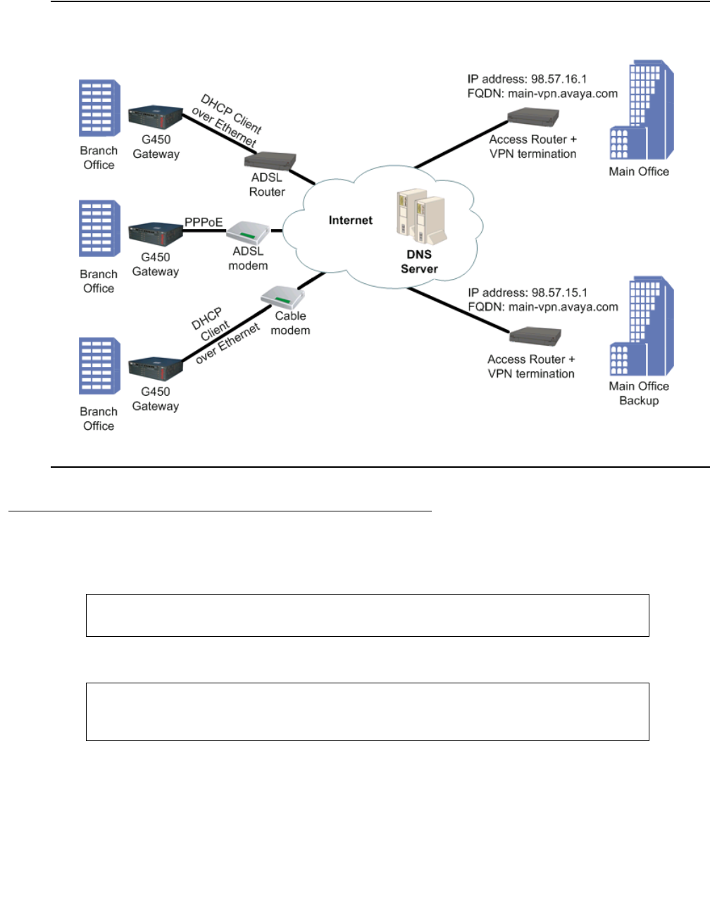
Basic device configuration
90 Administration for the Avaya G450 Media Gateway
Figure 8: VPN DNS topology
Configuring DNS resolver
1. Enter ip domain name-server-list 1 to create the DNS servers list.
2. Use the description command to specify a description for the list.
3. Add a DNS server to the DNS servers list using the name-server command. Configure
the following:
●Assign an index number that ranks the DNS server by priority
●Specify the IP address of the DNS server
G450-001(config)# ip domain name-server-list 1
G450-001(config-name-server-list:1)#
G450-001(config-name-server-list:1)# description "All DNS servers"
Done!
G450-001(config-name-server-list:1)#

DNS resolver
Issue 1 January 2008 91
4. Repeat Step 3 to configure additional DNS servers in the list. You can configure up to six
DNS servers.
5. Use the ip domain list command to configure a domain name. This domain name will
be used as a suffix to complete non-FQDN names (hostnames that do not end with a dot).
Configure the following:
●Assign an index number that ranks the domain name by priority
●Specify the domain name
6. Repeat Step 5 to configure additional domain names. You can configure up to six domain
names.
7. Optionally, configure the number of DNS query retries, using the ip domain retry
command. The default value is 2.
8. Optionally, configure the timeout for a DNS query using the ip domain timeout
command. The default value is 3 seconds.
9. The DNS resolver is enabled by default. If it was disabled and you wish to re-enable it,
enter ip domain lookup.
G450-001(config-name-server-list:1)# name-server 1 1.1.1.1
Done!
G450-001(config-name-server-list:1)# name-server 2 192.100.106.101
Done!
G450-001(config)# ip domain list 1 avaya.com
Done!
G450-001(config)# ip domain list 2 emea.avaya.com
Done!
G450-001(config)# ip domain retry 4
Done!
G450-001(config)# ip domain timeout 4
Done!
G450-001(config)# ip domain lookup
Done!

Basic device configuration
92 Administration for the Avaya G450 Media Gateway
!Important:
Important: If either DHCP Client or PPP are configured in the G450, you do not need to
configure DNS resolver because the DNS resolver is enabled by default. In
addition, the DHCP Client and PPP discover DNS servers automatically, so the
list of DNS servers will include the automatically-learned DNS servers.
Instead:
-
For DHCP Client, enable DHCP Client by entering ip address dhcp. For
information about DHCP Client see Configuring DHCP client on page 199.
-
For PPP, enable automatic discovery of DNS servers by entering ppp ipcp dns
request.
Figure 9: DNS resolver configuration workflow
ip domain name-server-list
description
name-server 1
.
.
name-server 6
ip domain list 1
.
.
ip domain list 6
ip domain retry
ip domain timeout
show ip domain
ip domain lookup

DNS resolver
Issue 1 January 2008 93
DNS resolver configuration example
The following example defines three DNS servers for the list of DNS servers, three domain
names to add as suffixes to hostnames, a DNS query retry value, and a DNS query timeout
value. The final command in the example enables the DNS resolver.
Using DNS resolver to resolve a hostname
Use the nslookup command, followed by a hostname, to resolve the hostname to an IP
address.
Maintaining DNS resolver
There are various commands you can use to display DNS resolver information, clear DNS
resolver counters, and display DNS resolver log messages.
Showing DNS resolver information
You can use the following commands to display information about DNS resolver:
●Enter show ip domain to display the DNS resolver’s configuration. The output shows
the DNS servers that were statically configured and those which were gathered using
DHCP or PPP protocols, as well as the list of domain suffixes.
G450-001(config)# ip domain name-server-list 1
G450-001(config-name-server-list:1)# description "All DNS servers"
Done!
G450-001(config-name-server-list:1)# name-server 1 1.1.1.1
Done!
G450-001(config-name-server-list:1)# name-server 2 2.2.2.2
Done!
G450-001(config-name-server-list:1)# name-server 3 3.3.3.3
Done!
G450-001(config-name-server-list:1)# exit
G450-001(config)# ip domain list 1 support.avaya.com
Done!
G450-001(config)# ip domain list 2 global.avaya.com
Done!
G450-001(config)# ip domain list 3 avaya.com
Done!
G450-001(config)# ip domain retry 4
Done!
G450-001(config)# ip domain timeout 5
Done!
G450-001(config)# ip domain lookup
Done!
Basic device configuration
94 Administration for the Avaya G450 Media Gateway
●Enter show ip domain statistics to display the DNS resolver’s statistics counters
●Use the show protocol command to display the status of the DNS-client protocol
Clearing DNS resolver counters
Enter clear ip domain statistics to clear the DNS resolver’s statistics counters.
Viewing DNS resolver logging
1. Enter set logging session enable to enable session logging to the terminal.
2. Enter set logging session condition DNSC to view all DNS resolver messages of
level Info and above.
Note:
Note: You can also enable logging messages to a log file or a Syslog server. For a full
description of logging on the G450, see Configuring logging on page 209.
Summary of DNS resolver configuration commands
For more information about these commands, see Avaya G450 CLI Reference, 03-300437.
G450-001# set logging session enable
Done!
CLI-Notification: write: set logging session enable
G450-001# set logging session condition DNSC Info
Done!
CLI-Notification: write: set logging session condition DNSC Info
Table 17: DNS resolver configuration commands
Root level
command Command Description
clear ip domain
statistics Clear the DNS resolver’s statistics counters
interface
{dialer|serial
console|
FastEthernet|
USB-modem}
Enter the interface configuration mode for a
Dialer, Serial, Console, FastEthernet, or
USB-modem interface
1 of 2
Viewing the status of the device
Issue 1 January 2008 95
Viewing the status of the device
To view the status of the Avaya G450 Media Gateway, use the following commands:For more
information about these commands, see Avaya G450 CLI Reference, 03-300437.
●Enter show faults to view information about currently active faults.
●Use the show image version command to display the software version of the image on
both memory banks of the device.
●Enter show mgc to view information about the Media Gateway Controller with which the
G450 is registered. For more information, see Configuring the Media Gateway Controller
(MGC) on page 82.
ppp ipcp dns
request Enable or disable requesting DNS information from
the remote peer during the PPP/IPCP session
ip domain list Specify static domain names (suffixes) to complete
non-FQDN names (hostnames that do not end with
a dot)
ip domain lookup Enable or disable the DNS resolver
ip domain
name-server-list Enter the context of the DNS servers list, or set up
the list
description Set a name for the DNS servers list
name-server Add a DNS server to the list of up DNS servers
ip domain retry Set the number of retries for a DNS query
ip domain
timeout Set the timeout for a DNS query
nslookup Resolve a hostname to an IP address
show ip domain Display the DNS resolver’s configuration
show ip domain
statistics Display the DNS resolver’s statistics counters
show protocol Display the status of a specific management
protocol, or all protocols
Table 17: DNS resolver configuration commands (continued)
Root level
command Command Description
2 of 2

Basic device configuration
96 Administration for the Avaya G450 Media Gateway
●Use the show mm command to view information about media modules that are installed on
the G450. To view information about a specific media module, include the slot number of
the media module as an argument. For example, to view information about the media
module in slot 2, enter show mm v2. The output of the command shows the following
information:
-
Slot number
-
Uptime
-
Type of media module
-
Description
-
Serial number and other hardware identification numbers
-
Firmware version
-
Number of ports
-
Fault messages
●Use the show module command or enter show mg list_config to view brief
information about media modules that are installed in the G450. To view brief information
about a specific media module, include the slot number of the media module as an
argument. For example, to view information about the media module in slot 2, enter show
module v2. The output of the command shows the following information:
-
Slot number
-
Firmware version
-
Type of media module
-
Media module code
●Enter show system to display the serial number of the G450, the G450’s uptime, the
firmware version number, MAC addresses, and other system information.
●Enter show restart-log to view information about the last time the G450 was reset.
●Enter show temp to view the temperature of the G450 CPU. This command also displays
the high and low temperatures that will trigger a temperature warning.
●Use the show timeout command to display the amount of time in minutes the terminal
remains idle before timing out.
●Enter show voltages to view the power supply voltages of the G450.
●Use the show utilization command to display information about CPU and memory
usage on the G450.
Note:
Note: Before using this command, you must first use the set utilization cpu
command to enable CPU utilization measurements.
●Enter test led to test the system ALM, MDM and CPU LEDs on the front panel of the
G450. The CPU and media module LEDs blink for five seconds.

Viewing the status of the device
Issue 1 January 2008 97
Summary of device status commands
For more information about these commands, see Avaya G450 CLI Reference, 03-300437.
Table 18: Device status commands
Command Description
set utilization
cpu Enable CPU utilization measurements
show faults Display information about currently active faults
show image
version Display the software version of the image on both memory banks of
the device
show mg
list_config Display the current hardware and firmware configurations for the
installed media gateway equipment
show mgc Display information about the Media Gateway Controller with which
the G450 is registered
show mm Display information about media modules that are installed on the
G450
show module Display brief information about the media modules installed in the
G450
show restart-log Display information about the last time the G450 was reset
show system Display information about the G450
show temp Display the device temperature
show timeout Display the amount of time in minutes the terminal remains idle
before timing out
show utilization Display information about CPU and memory usage on the G450
show voltages Display power supply voltages
test led Test the system ALM, MDM and CPU LEDs on the front panel of the
G450

Basic device configuration
98 Administration for the Avaya G450 Media Gateway
Software and firmware management
You can manage G450 software and firmware, either:
●Remotely, using an FTP, TFTP, or SCP server
Or
●Locally, using a USB mass storage device connected to the G450 USB port
File transfer
The Avaya G450 Media Gateway can be a client for the FTP and TFTP protocols. Use either a
USB device or the FTP or TFTP protocols to transfer files between the Avaya G450 Media
Gateway and other devices. You can use file transfer to:
●Install software and firmware upgrades on the G450
●Install firmware upgrades on media modules
●Back up and restore configuration settings
To use FTP/TFTP file transfer, you need to have an FTP server or TFTP server on your
network.
Note:
Note: If you use an FTP server, the G450 prompts you for a username and password
when you enter a command to transfer a file. Also, when opening an FTP
connection to the S8300, all anonymous FTP file transfers are restricted to the
/pub directory. Permission for anonymous FTP users to create files in other
directories is denied.
Software and firmware upgrades
You can upgrade software on the Avaya G450 Media Gateway. Software used to control the
Avaya G450 Media Gateway itself and media modules installed on the G450 is called firmware.
Use a USB device or the FTP or TFTP protocol to download a new version of software or
firmware. You can upgrade the following types of software and firmware:
●Firmware for the Avaya G450 Media Gateway
●Java applet for Avaya G450 Manager
●Firmware for media modules

Software and firmware management
Issue 1 January 2008 99
Note:
Note: You can also use the G450 to upgrade the firmware and configuration files for IP
phones. For details, see Installing and Upgrading the Avaya G450 Media
Gateway, 03-602054.
Managing the firmware banks
The G450 has two firmware banks:
●Bank A
●Bank B
Each firmware bank contains a version of the G450 firmware. These may be different versions.
The purpose of this feature is to provide software redundancy. If one of the versions becomes
corrupted, you can reset the G450 using the other version. This is particularly important when
downloading new versions.
Displaying firmware versions in the banks
Use the show image version command to display the firmware version of the image on both
memory banks of the device.
Changing the default bank
By default, when you turn on or reset the G450, the G450 loads firmware from Bank B. To
change the default bank from which firmware is loaded during startup, use the set boot bank
command. For example, to configure the G450 to load firmware from Bank A on startup, enter
set boot bank bank-A. Now, when you reset the G450, it will load firmware from Bank A.
To display the bank from which the G450 is currently set to load its firmware upon startup or
reset, use the show boot bank command.
Loading firmware from the non-default bank
You can use the ASB button on the G450 front panel to load firmware from a bank other than
the default bank during startup:
1. Press and hold the reset button.
2. Press and hold the ASB button.
3. Release the reset button.
4. Release the ASB button.
For example, if the G450 is configured to load firmware from Bank B, use the steps listed above
to reset the G450 to load the firmware from Bank A instead.

Basic device configuration
100 Administration for the Avaya G450 Media Gateway
Upgrading software and firmware using FTP/TFTP
To upgrade software or firmware, you must obtain an upgrade file from Avaya. Place the file on
your FTP or TFTP server. Then, use one of the following commands to upload the file to the
G450. For each of these commands, include the full path of the file and the IP address of the
FTP or TFTP host as parameters. When you enter the command, the CLI prompts you for a
username and password.
Note:
Note: In addition to using the CLI to upgrade software and firmware, you can use the
Avaya IW and the GIW. See Accessing Avaya IW on page 48 and Accessing
GIW on page 51.
●Use the copy ftp module command, followed by the module number of the module you
want to upgrade, to upgrade the firmware on a media module from an FTP server.
●Use the copy ftp SW_imageA command to upgrade the G450 firmware into Bank A
from an FTP server.
●Use the copy ftp SW_imageB command to upgrade the G450 firmware into Bank B
from an FTP server.
●Use the copy ftp EW_archive command to upgrade the Java applet for Avaya G450
Manager software from an FTP server.
●Use the copy tftp module command, followed by the module number of the module
you want to upgrade, to upgrade the firmware on a media module from a TFTP server.
●Use the copy tftp SW_imageA command to upgrade the G450 firmware into Bank A
from a TFTP server.
●Use the copy tftp SW_imageB command to upgrade the G450 firmware into Bank B
from a TFTP server.
●Use the copy tftp EW_archive command to upgrade the Java applet for Avaya G450
Manager software from a TFTP server.
When using FTP or TFTP commands, you must use the specific path of the file on the FTP or
TFTP server according to the home directory of the service (FTP or TFTP) that you are using.
For example, to upgrade the firmware of an MM710 media module in slot 2 from a TFTP server
with the IP address 192.1.1.10, where the home directory is c:\home\ftp\ and the upgrade
file is located in the directory c:\home\ftp\version, use the following command:
copy tftp module \version\mm710v3.fdl 192.1.1.10 2

Software and firmware management
Issue 1 January 2008 101
Note:
Note: When downloading firmware from the S8300, use only the file name, without the
directory path, in the command line. Otherwise, the procedure will fail. For
instance, in the example above, you must use the following command:
When downloading firmware from the S8300 using TFTP, you may need to
enable the TFTP service in the Set LAN Security parameters of your web server.
The following example downloads a firmware version with the path and file name
C:\g450.net from an FTP server with the IP address 149.49.134.153 to Bank A of the G450:
Upgrading software and firmware using a USB mass storage device
You can upgrade software and firmware using a USB mass storage device.
1. Obtain an upgrade file from Avaya and place it on your PC.
2. Insert the USB mass storage device into the PC’s USB port, and copy the software or
firmware file(s) to the USB mass storage device.
3. Remove the USB storage device from the PC, and insert it in the G450 USB port.
4. Copy the software or firmware file(s) to the G450 using one of the following commands:
●Use the copy usb SW_imageA command to upgrade the G450 firmware into Bank A
from the USB mass storage device.
●Use the copy usb SW_imageB command to upgrade the G450 firmware into Bank B
from the USB mass storage device.
●Use the copy usb EW_archive command to upgrade the Java applet for Avaya
G450 Manager software from the USB mass storage device.
●Use the copy usb module command, followed by the slot number of the module you
want to upgrade, to upgrade the firmware on a media module from the USB mass
storage device.
●Use the copy usb phone-imageA (or imageB, or imageC, or imageD) to upgrade
IP phone firmware from the USB mass storage device.
●Use the copy usb phone-scriptA (or phone-scriptB) to upgrade IP phone
scripts from the USB mass storage device.
●Use the copy usb announcement-file to upgrade announcements files from the
USB mass storage device.
●Use the copy usb auth-file to upgrade the authentication file from the USB mass
storage device.
copy tftp module mm710v3.fdl 192.1.1.10 2
copy ftp SW_imageA C:\g450.net 149.49.134.153

Basic device configuration
102 Administration for the Avaya G450 Media Gateway
●Use the copy usb license-file to upgrade the VPN license file from the USB
mass storage device.
●Use the copy usb startup-config to upgrade the startup configuration file from
the USB mass storage device.
5. Use the show download software status command to display the status of the
firmware download process.
Upgrading firmware using the USB mass storage device "restore" command
The primary use of the restore usb command is to restore the entire gateway. If you use the
command to upgrade firmware, take care to follow instructions carefully.
1. Back up the gateway by entering backup config usb usbdevice0 backup-name,
where backup-name is the backup directory path and file name you are creating on the
USB mass storage device.
A backup directory is created on the USB mass storage device, with a directory structure
as detailed in Table 20.
2. Obtain the firmware upgrade file(s) from Avaya and place them on your PC.
3. Insert the USB mass storage device into the PC’s USB port, and copy the firmware file(s)
to the USB mass storage device as follows:
a. Copy G450 firmware files to the root directory.
b. Copy the G450 Device Manager firmware file to the root directory.
c. Copy media modules’ firmware files to the MM subdirectory.
d. Copy IP phone firmware files to the IPPHONE subdirectory.
4. Remove the USB mass storage device from the PC, and insert it in the G450 USB port.
5. Enter restore usb usbdevice0 backup-name, where backup-name is the root
directory path and name on the USB mass storage device.
6. Enter show restore status to check the status of the restore operation. The report
lists the upgraded files.
Uploading software and firmware from the gateway
Copying files to a USB mass storage device
You can use a USB mass storage device inserted into the G450 USB port to copy individual
files to a USB mass storage device.
Use the copy file usb command to upload a specific file from the gateway to the USB mass
storage device, where file can be any of the following:
●announcement-file. Announcements files
●auth-file. Authentication file

Software and firmware management
Issue 1 January 2008 103
●phone-scriptA. Phone script bank A in the gateway’s TFTP directory
●phone-scriptB. Phone script bank B in the gateway’s TFTP directory
●license-file. The VPN license file
●startup-config. The startup configuration file
●capture-file. The packet sniffing buffer
●dhcp-binding. The DHCP binding file
●syslog-file. The syslog file
●cdr-file. A Call Detail Recording (CDR) file
Copying files to an FTP/SCP/TFTP server
●Use the copy file ftp command to upload a specific file from the gateway to an FTP
server, where file can be any of the following:
●announcement-file. Announcements files
●auth-file. Authentication file
●capture-file. The packet sniffing buffer
●cdr-file. A Call Detail Recording (CDR) file
●dhcp-binding. The DHCP binding file
●Use the copy file scp command to upload a specific file from the gateway to an SCP
server, where file can be any of the following:
●announcement-file. Announcements files
●auth-file. Authentication file
●capture-file. The packet sniffing buffer
●capture-file. The packet sniffing buffer
●cdr-file. A Call Detail Recording (CDR) file
●dhcp-binding. The DHCP binding file
●Use the copy file tftp command to upload a specific file from the gateway to a TFTP
server, where file can be any of the following:
●announcement-file. Announcements files
●capture-file. The packet sniffing buffer
●auth-file. Authentication file
●capture-file. The packet sniffing buffer
●cdr-file. A Call Detail Recording (CDR) file
●dhcp-binding. The DHCP binding file

Basic device configuration
104 Administration for the Avaya G450 Media Gateway
Summary of software and firmware management commands
For more information about these commands, see Avaya G450 CLI Reference, 03-300437.
Table 19: Software and firmware management CLI commands
Command Description
copy file ftp Upload a specific file from the gateway to an FTP server
copy file scp Upload a specific file from the gateway to an SCP server
copy file tftp Upload a specific file from the gateway to a TFTP server
copy file usb Upload a specific file from the gateway to the USB mass
storage device
copy ftp EW_archive Upgrade the Java applet for Avaya G450 Manager software
from an FTP server
copy ftp module Upgrade the firmware on a media module from an FTP server
copy ftp SW_imageA Upgrade the G450 firmware into Bank A from an FTP server
copy ftp SW_imageB Upgrade the G450 firmware into Bank B from an FTP server
copy tftp EW_archive Upgrade the Java applet for Avaya G450 Manager software
from a TFTP server
copy tftp module Upgrade the firmware on a media module from a TFTP server
copy tftp SW_imageA Upgrade the G450 firmware into Bank A from a TFTP server
copy tftp SW_imageB Upgrade the G450 firmware into Bank B from a TFTP server
copy usb
announcement-file Upgrade announcements files from the USB mass storage
device
copy usb auth-file Upgrade the authorization file from the USB mass storage
device
copy usb EW_archive Upgrade the Java applet for Avaya G450 Manager software
from the USB mass storage device
copy usb license-file Upgrade the VPN license file from the USB mass storage
device
copy usb module Upgrade the firmware on a media module from the USB mass
storage device
copy usb phone-image Upgrade phone images from the USB mass storage device
copy usb phone-script Upgrade phone scripts from the USB mass storage device
1 of 2

Software and firmware management
Issue 1 January 2008 105
Backing up and restoring the G450 using a USB mass storage
device
The G450 USB ports support a USB flash drive and a USB externally powered hub. The ports
also support USB 2.0 high speed (480 Mbits/sec) for faster file transfer between the media
gateway and USB mass storage devices.
Note:
Note: An external USB hub is supported on G450 gateways with hardware
suffix.vintage C.1 or above.
To check the hardware suffix and vintage, enter show system and check the HW
suffix and HW vintage values.
CLI commands for backing up and restoring files to or from a USB mass storage device enable
you to use a USB port for efficient restoration or replication of a G450 media gateway and for
replacing and upgrading media modules. Using the USB port you can back up or restore
multiple files with one CLI command, which is simpler than the alternative TFTP/FTP/SCP
method, in which files are copied and restored individually.
copy usb
startup-config Upgrade the startup configuration file from the USB mass
storage device
copy usb SW_image Upgrade the G450 firmware into Bank A or into Bank B, from
the USB mass storage device
dir List all files in the USB mass storage device connected to the
G450
set boot bank Set the default bank from which firmware is loaded during
startup
show boot bank Display the bank from which the G450 is currently set to load
its firmware upon startup or reset
show download software
status Display the status of the firmware download process
show image version Display the firmware version of the image on both memory
banks of the device
Table 19: Software and firmware management CLI commands (continued)
Command Description
2 of 2

Basic device configuration
106 Administration for the Avaya G450 Media Gateway
A single CLI command backs up all the administration and configuration files of a gateway onto
a USB mass storage device. Another single command restores all of the backed up files. If you
need to completely replicate a media gateway, you can also download the G450 firmware,
media modules’ firmware, IP phone firmware, and Device Manager firmware to the USB mass
storage device, and use the restore usb command to restore these files as well as the
administration and configuration files.
Note:
Note: The CLI backup config usb and restore usb commands (for efficient
backup/restore via a USB mass storage device) only run on gateways R4.0 and
higher.
You can also use the USB mass storage device to copy individual gateway files to or from the
gateway. Refer to Upgrading software and firmware using a USB mass storage device on
page 101 and Uploading software and firmware from the gateway on page 102.
Tip:
Tip: It is recommended to use a USB mass storage device with LED indication.
Backing up administration and configuration files using a USB mass
storage device
The following procedure backs up all the gateway configuration and administration files, but
does not back up any firmware files.
Back up the gateway regularly to a USB mass storage device. This backup can be very helpful
in restoring the gateway’s configuration if it becomes faulty, or in restoring the entire gateway.
1. Connect a USB mass storage device to a G450 USB port.
2. Type s to commit the current configuration to NVRAM.
3. Enter backup config usb usbdevice0 backup-name, where backup-name is the
backup directory path and file name you are creating on the USB mass storage device.
Software and firmware management
Issue 1 January 2008 107
Note:
Note: Before unplugging the USB mass storage device, use the safe-removal usb
command to safely remove the USB mass storage device.
A backup directory is created on the USB mass storage device, with the following sample
structure and file types:
Note:
Note: It is recommended to use at least a 128MB USB mass storage device since it can
hold two full backup directories with all images and configuration files. You can
create multiple backup directories as long as there is space in the USB mass
storage device.
Table 20: Backup file and directory structure on a USB mass storage device
Root directory Sub-directory Files Comments
backup-25-Nov-2005 Backup directory name
readme.txt File with backup
information
startup_config.cfg Configuration file
audio.bin Customer-specific VoIP
parameters
vpn_license.cfg VPN license file
auth-file.cfg Authentication file
IPPHONE IP phone scripts and
images directory
46xxupgrade.scr
46xxsettings.txt
MM Media modules file
directory
GWANNC Gateway
announcements and
music-on-hold file
GeorgeAnnouncement.wav
GeorgiaAnnouncement.wav

Basic device configuration
108 Administration for the Avaya G450 Media Gateway
Note:
Note: You can use the show backup status command to display information
regarding the status of a backup of the gateway configuration to a USB mass
storage device.
Restoring backed up configuration and administration files to a gateway
using a USB mass storage device
1. Make sure you have a backup of the G450 on a USB mass storage device. Refer to
Backing up administration and configuration files using a USB mass storage device on
page 106.
2. Connect the USB mass storage device to a G450 USB port.
3. Enter restore usb usbdevice0 backup-name, where backup-name is the backup
directory path and file name on the USB mass storage device.
Note:
Note: Before unplugging the USB mass storage device, use the safe-removal usb
command to safely remove the USB mass storage device.
Replicating a G450 using a USB mass storage device
The following procedure is useful for replicating a G450 that has become faulty. Since the
backup command backs up all the gateway configuration files, but does not back up any
firmware files, the main task is to add the various firmware files before running restore.
!Important:
Important: When adding files to a backup directory on a USB mass storage device, follow
the file and directory naming convention, detailed in Table 21, to enable a
successful restore.
1. Make sure you have a backup of the faulty G450 on a USB mass storage device. Refer to
Backing up administration and configuration files using a USB mass storage device on
page 106.
2. Transfer the media modules, including the S8300 if installed, from the faulty G450 into the
corresponding slots of the new G450.
3. Connect the new G450 to a power source.
4. In the new G450, enter show image version to find out which of the two image banks
holds the older gateway firmware version, and what version it is.
5. If the new G450 firmware version is below 26.x.y, you must replace it with firmware version
26.x.y or higher, in order to enable the restore option. To do so:
a. Download the G450 firmware from the Avaya support website
(http://www.avaya.com/support) to an FTP/TFTP server.

Software and firmware management
Issue 1 January 2008 109
b. Download the G450 firmware from the FTP/TFTP server to the new G450. Assuming
that Bank A holds the older firmware version, enter copy ftp sw_imageA
filename ip, where filename is the full path and file name of the firmware file, and
ip is the IP address of the FTP server. Alternatively, enter copy tftp sw_imageA
filename ip if you are downloading from a TFTP server.
6. If the new G450 firmware version is 26.x.y or above, add a G450 firmware to the USB
mass storage device, as follows:
a. From the Avaya support website, download to your PC the same version of G450
firmware as was running in the faulty G450.
b. Insert the USB mass storage device into the PC’s USB port.
c. Copy the G450 firmware file to the root backup directory in the USB mass storage
device.
7. Add the firmware files of the media modules to the USB mass storage device, as follows:
a. From the Avaya support website, download to your PC the firmware files of the media
modules installed in the gateway. For each media module, download all firmware
corresponding to the various hardware vintage/suffix versions available for that
module. If you are not sure which media modules you have, you can download the
firmware files of all media modules. The restore operation uses only the files needed.
b. Insert the USB mass storage device into the PC’s USB port.
c. Copy the firmware files from the PC to the MM subdirectory in the USB mass storage
device. Do not change the firmware file names.
8. You can optionally add the firmware files of the IP phones to the USB mass storage
device, as follows:
a. From the Avaya support website, download to your PC the firmware files (booter and
application) of up to two supported IP phones, as well as the 46xxupgrade.txt or
46xxupgrade.scr file.
b. Insert the USB mass storage device into the PC’s USB port.
c. Copy the IP phone files from the PC to the USB mass storage device. Place them in
the IPPHONE subdirectory under the root backup directory. Do not change the names
of the downloaded files.
Note:
Note: You will need to reset the IP phones after the restore operation on the gateway.
9. You can optionally restore or add the G450 Device Manager, as follows:
a. From the Avaya support website, download to your PC the firmware file of the Device
Manager.
b. Insert the USB mass storage device into the PC’s USB port.
c. Copy the Device Manager firmware file from the PC to the USB mass storage device.
Place it in the root backup directory. Do not change the name of the firmware file.

Basic device configuration
110 Administration for the Avaya G450 Media Gateway
10. View the backup directory on the USB mass storage device. The file types and directory
structure should match the following convention:
Table 21: Backup file and directory naming convention on a USB mass storage device
Root directory Sub-directory Files Comments
backup-25-Nov-2005 Backup directory name
readme.txt File with backup info
startup_config.cfg Configuration file
audio.bin Customer-specific VoIP
parameters
vpn_license.cfg VPN license file
auth-file.cfg Authentication file
g450_sw_24_21_1.bin Gateway image
g450_emweb_3_0_5.bin Embedded web image
IPPHONE IP phone scripts and
images directory
46xxupgrade.scr
46xxsettings.txt
4601dape1_82.bin
4601dbte1_82.bin
MM Media modules file
directory
mm722v2.fdl
mm714v67.fdl
mm711h20v67.fdl
mmanalogv67.fdl
GWANNC Gateway announcements
and music-on-hold file
directory
DanAnncouncement.wav
DanaAnncouncement.wav

Software and firmware management
Issue 1 January 2008 111
11. Delete the vpn_license.cfg file from the root backup directory. Since you are restoring
the files from one gateway to another, and the VPN license is granted per gateway serial
number, the restore operation will fail if you do not delete it.
12. Enter key config-key password-encryption followed by the same passphrase
that was used to create the Master Configuration Key (MCK) in the faulty gateway. This
creates on the new gateway an MCK identical to the MCK in the faulty gateway, which
enables the restore operation to decrypt the secrets in the configuration file.
The restored configuration file will include all the configuration of the gateway, including
user’s names and passwords, IKE pre-shared keys, etc.
13. Insert the USB mass storage device in the new G450 USB port.
14. Enter restore usb usbdevice0 backup-name, where backup-name is the backup
directory path and file name on the USB mass storage device.
15. Enter show restore status to check the status of the restore operation. The report
lists the files restored.
16. Obtain and install a VPN license. For information on obtaining a VPN license, see
Installing and Upgrading the Avaya G450 Media Gateway, 03-602054.
17. Update the S8300 on the new G450 with the serial number of the new gateway, otherwise
the gateway is not able to register in the Avaya Communication Manager. See
Administrator’s Guide for Avaya Communication Manager, 555-233-506.
The new G450 is now a restored, fully-operational G450.
Note:
Note: Before unplugging the USB mass storage device, use the safe-removal usb
command to safely remove the USB mass storage device.
Replacing/adding/upgrading media modules using a USB mass storage
device
1. Backup the gateway by entering backup config usb usbdevice0 backup-name,
where backup-name is the backup directory path and file name you are creating on the
USB mass storage device.
A backup directory is created on the USB mass storage device, with a directory structure
as detailed in Table 20.
2. From the Avaya support website, download to your PC the firmware files of the media
modules you are adding or upgrading. For each media module, download all firmware
corresponding to the various hardware vintage/suffix versions available for that module. If
you are not sure which files you need, you can download the firmware files of all media
modules. The restore operation uses only the files needed.
3. Insert the USB mass storage device into the PC’s USB port, and copy the media modules’
firmware files to the MM subdirectory under the root backup directory.

Basic device configuration
112 Administration for the Avaya G450 Media Gateway
!Important:
Important: When adding files to a backup directory on a USB mass storage device, it is
important to follow the file and directory naming convention, in order to enable a
successful restore.
4. Insert the USB mass storage device into a G450 USB port.
5. Enter restore usb usbdevice0 backup-name, where backup-name is the backup
directory path and file name on the USB mass storage device.
6. If you changed the placement of media modules in the slots, update the MGC managing
the media gateway. See Administrator’s Guide for Avaya Communication Manager,
555-233-506.
Note:
Note: Before unplugging the USB mass storage device, use the safe-removal usb
command to safely remove the USB mass storage device.
Additional USB commands
The following USB commands are available:
●Use the erase usb command to erase a file or directory on the USB mass storage
device.
●Use the show usb command to display the USB devices connected to the gateway.
Summary of USB backup, restore, and replication commands
For more information about these commands, see Avaya G450 CLI Reference, 03-300437.
Table 22: USB backup, restore, and replication CLI commands
Command Description
backup config usb Back up the gateway configuration to a USB mass storage
copy ftp sw_imageA Download a software image from an FTP server into Bank A
copy tftp sw_imageA Download a software image from a TFTP server into Bank A
dir Display information regarding the status of a restore operation of
gateway files from a USB mass storage device
erase usb Erase a file or directory on the USB mass storage device
key config-key
password-encryption Change the default Master Key of the gateway, which is used to
encrypt gateway secrets in the gateway configuration file
1 of 2

Software and firmware management
Issue 1 January 2008 113
Backing up and restoring configuration files
A configuration file is a data file that contains a complete set of configuration settings for the
Avaya G450 Media Gateway. You can use configuration files to back up and restore the
configuration of the G450. You can back up either the running configuration or the startup
configuration to the server as a configuration file. When you restore a configuration file from a
server, it becomes the startup configuration on the G450. For more information about running
configuration and startup configuration, see Saving configuration changes on page 40.
Note:
Note: The startup configuration file stores gateway secrets (passwords, etc.) in an
encrypted format. Thus, secrets do not have to be re-entered if you are copying a
configuration file from one G450 to another. For more information, see Managing
gateway secrets on page 68.
You can:
●Use the FTP/TFTP/SCP copy commands to transfer a configuration file between the G450
and a server on the network.
●Use a USB mass storage device connected to a G450 USB port to upload or download the
startup configuration file of the G450. You can use either the USB copy commands, or use
the USB backup and restore commands for a full backup and restore of the gateway (refer
to Backing up and restoring the G450 using a USB mass storage device on page 105).
restore usb Restore gateway files from a USB mass storage device
safe-removal usb Safely remove the USB mass storage device
show backup status Display information regarding the status of a backup of the
gateway configuration to a USB mass storage device
show image version Display the software version of the image on both memory banks
of the device
show system Display information about the device
show usb Display the USB devices connected to the gateway
Table 22: USB backup, restore, and replication CLI commands (continued)
Command Description
2 of 2

Basic device configuration
114 Administration for the Avaya G450 Media Gateway
Backing up/restoring a configuration file using FTP/TFTP/SCP
●Use the copy ftp startup-config command to restore a configuration file from an
FTP server. The configuration file becomes the startup configuration on the G450.
●Use the copy tftp startup-config command to restore a configuration file from a
TFTP server. The configuration file becomes the startup configuration on the G450.
●Use the copy scp startup-config command to restore a configuration file from an
SCP server. The configuration file becomes the startup configuration on the G450.
Note:
Note: You can use the show download status command to display the status of the
current configuration file download process, as the file is being loaded into the
device.
●Use the copy running-config ftp command to back up the running configuration
on the G450 to an FTP server.
●Use the copy running-config tftp command to back up the running configuration
on the G450 to a TFTP server.
●Use the copy running-config scp command to back up the running configuration on
the G450 to a SCP server.
●Use the copy startup-config ftp command to back up the startup configuration on
the G450 to an FTP server.
●Use the copy startup-config tftp command to back up the startup configuration
on the G450 to a TFTP server.
●Use the copy startup-config scp command to back up the startup configuration on
the G450 to a SCP server.
Backing up/restoring a configuration file using a USB mass storage device
●Use the copy startup-config usb command to back up the startup configuration
from the G450 to the USB mass storage device.
●Use the copy usb startup-config command to restore the startup configuration from
the USB mass storage device to the G450.
Note:
Note: You can use the show download status command to display the status of the
current configuration file download process, as the file is being loaded into the
device.
Software and firmware management
Issue 1 January 2008 115
Summary of configuration file backup and restore commands
For more information about these commands, see Avaya G450 CLI Reference, 03-300437.
Table 23: Configuration file backup and restore CLI commands
Command Description
copy ftp
startup-config Download a G450 configuration file from an FTP server to the
Startup Configuration NVRAM
copy scp
startup-config Download a G450 configuration from an SCP server to the Startup
Configuration NVRAM
copy tftp
startup-config Download a G450 configuration file from a TFTP server to the
Startup Configuration NVRAM
copy usb
startup-config Download a G450 configuration file from a USB mass storage
device to the Startup Configuration NVRAM
copy running-config
ftp Upload the current G450 running configuration to a file on an FTP
server
copy running-config
scp Upload the current G450 running configuration to a file on an SCP
server
copy running-config
tftp Upload the current G450 running configuration to a file on a TFTP
server
copy startup-config
ftp Upload the current G450 startup configuration to a file on an FTP
server
copy startup-config
scp Upload the current G450 startup configuration to a file on a SCP
server
copy startup-config
tftp Upload the current G450 startup configuration to a file on a TFTP
server
copy startup-config
usb Upload the current G450 startup configuration to a file on a USB
mass storage device
show download
status Display the status of the current G450 configuration file download
process, as the file is being loaded into the device

Basic device configuration
116 Administration for the Avaya G450 Media Gateway
Listing the files on the Avaya G450 Media Gateway
Use the dir command to list all G450 files. When you list the files, you can see the version
numbers of the software components. The dir command also shows the booter file, which
cannot be changed.
You can also use the dir command to list all files in the USB mass storage device connected to
the G450.
Summary of file listing commands
For more information about these commands, see Avaya G450 CLI Reference, 03-300437.
Table 24: File listing CLI commands
Command Description
dir List all G450 files or display files on the USB mass storage device

Issue 1 January 2008 117
Chapter 6: Configuring Standard Local
Survivability (SLS)
Standard Local Survivability (SLS) provides a local G450 with a limited subset of MGC
functionality when there is no IP-routed WAN link available to an MGC, or no MGC is available.
SLS is not a replacement for ELS or LSP survivability, which offer full call-feature functionality
and full translations in the survivable mode. Instead, SLS is a cost-effective survivability
alternative offering limited call processing in survivable mode. Although the G450 can host an
S8300 Server in ICC or LSP mode, SLS offers both local survivability and call control.
In contrast to the server-based survivability features, SLS operates entirely from the media
gateway and requires a data set comprised of Avaya Communication Manager translations
(survivable ARS analysis and configuration data). This data set is compiled and distributed to a
group of devices using the Provisioning and Installation Manager (PIM). In the absence of the
PIM, the data set can be configured manually from individual media gateways using CLI
commands. For instructions on configuring SLS, see Configuring SLS on page 132.
Media module compatibility with SLS
SLS works on the G450 and its media modules only if they satisfy the minimum hardware
vintage and firmware version requirements listed in Table 25.
Table 25: G450 media module firmware version required
Media module Minimum firmware
version required
MM710 Vintage 16
MM711, hw v20+ Vintage 69
MM711, hw v30+ Vintage 84
MM712 Vintage 8
MM714, hw v1-v5 Vintage 69
MM714, hw v10+ Vintage 84
MM716 Vintage 84
1 of 2

Configuring Standard Local Survivability (SLS)
118 Administration for the Avaya G450 Media Gateway
SLS service
●Call capability for analog, DCP, and IP phones
●ISDN BRI/PRI trunk interfaces
●Non-ISDN digital DS1 trunk interfaces
●Outbound dialing through the local PSTN (local trunk gateway) from analog, DCP, and IP
phones
●Inbound calls from each trunk to pre-configured local analog or IP phones that have
registered
●Direct inward dialing
●Multiple call appearances
●Hold and call transfer functions
●Contact closure feature
●Local call progress tones (dial tone, busy, etc.)
●Emergency Transfer Relay (ETR) in cases of power loss
●Auto fallback to primary MGC
●IP station registration
MM717 Vintage 8
MM720 Vintage 7
MM722 Vintage 7
G450 gateway MG 4.1, build 27_x
Table 25: G450 media module firmware version required (continued)
Media module Minimum firmware
version required
2 of 2

Issue 1 January 2008 119
Avaya phones supported in SLS
Table 26: Avaya phones supported in SLS
Analog DCP IP
2500 2402 4601
2410 4602
2420 4602sw
6402 4610sw
6402D 4612
6408 4620
6408+ 4620sw (default)
6408D (default) 4621
6408D+ 4622
6416D+ 4624
6424D+ 4625
8403B
8405B
8405B+
8405D
8405D+
8410B
8410D
8411B
8411D
8434D

Configuring Standard Local Survivability (SLS)
120 Administration for the Avaya G450 Media Gateway
The new Avaya 96xx IP phone family is not directly referenced in the G450 CLI. When you
administer these phones via the CLI, use the following mapping:
Call processing in SLS mode
In survivable mode, SLS provides only a limited subset of Avaya Communication Manager call
processing functionality:
●Limited call routing through a Survivable ARS Analysis Table (in the PIM application or
through the CLI) and COR calling permissions
●Inbound calls are directed in one of three ways:
- Using the Incoming-Routing form
- Using the Set Incoming-Destination on the Trunk group form, which enables
mapping to a given station
- Inbound calls are directed to a previously-administered pool of available stations (the
Survivable Trunk Dest? field is y on the Station form). The search algorithm is
circular so that the incoming calls are fairly distributed.
!Important:
Important: SLS permits 911 calls, but the specific location information is not transmitted to
the Public Service Answering Point (PSAP). Only the general trunk-identifying
information is transmitted. Emergency personnel will have a general location
associated with the trunk (for example, a building address), but nothing more
specific (for example, a room or office number). Also, if a 911 call disconnects for
any reason, emergency personnel cannot reliably call the originator back.
A small business office’s address is sufficient from the perspective of emergency
routing.
●Communication Manager Feature Access Codes for ARS, contact closure, and Hold
Table 27: Mapping Avaya 96xx IP phones for CLI administration
Module name CLI interface name
9610 4606
9620 4610
9630 4620
9640 4620
9650 4620

Issue 1 January 2008 121
●Acts as an H.323 Gatekeeper that enables IP endpoints to register simultaneously
●Direct Inward Dialing
●Multiple call appearances
●Hold and Call Transfer functions
●Contact closure feature
●Call Detail Recording (CDR, see SLS logging activities on page 130)
●Trunk Access Code (TAC) dialing
●Non-ISDN DS1 trunks (with in-band signaling)
●ISDN PRI/BRI trunks:
-T1 robbed-bit. All 24 channels serve as trunks without full 64 kbps transmission
-E1 CAS. All 31 channels serve as trunks with full 64 kbps transmission
Call processing not supported by SLS
●Many small business customers employ custom calling features such as call waiting, from
the BOC/LEC, attempting a more PBX-like capability. These features are not supported by
SLS.
●Non-ISDN signaling:
- DMI BOS signaling for T1 and E1
- R2-MFC signaling for E1
●Calling party name/number information to digital station displays
●Caller ID on outgoing analog station calls
●Caller ID on incoming analog loop-start trunk calls
●Three party conferences
●Last Number Redial
●Call Forwarding-Busy/Don’t Answer
●No Music On Hold source or announcement playback
●Call Center features, including ASAI
●Connection Preserving Failover/Failback for H.248 Gateways
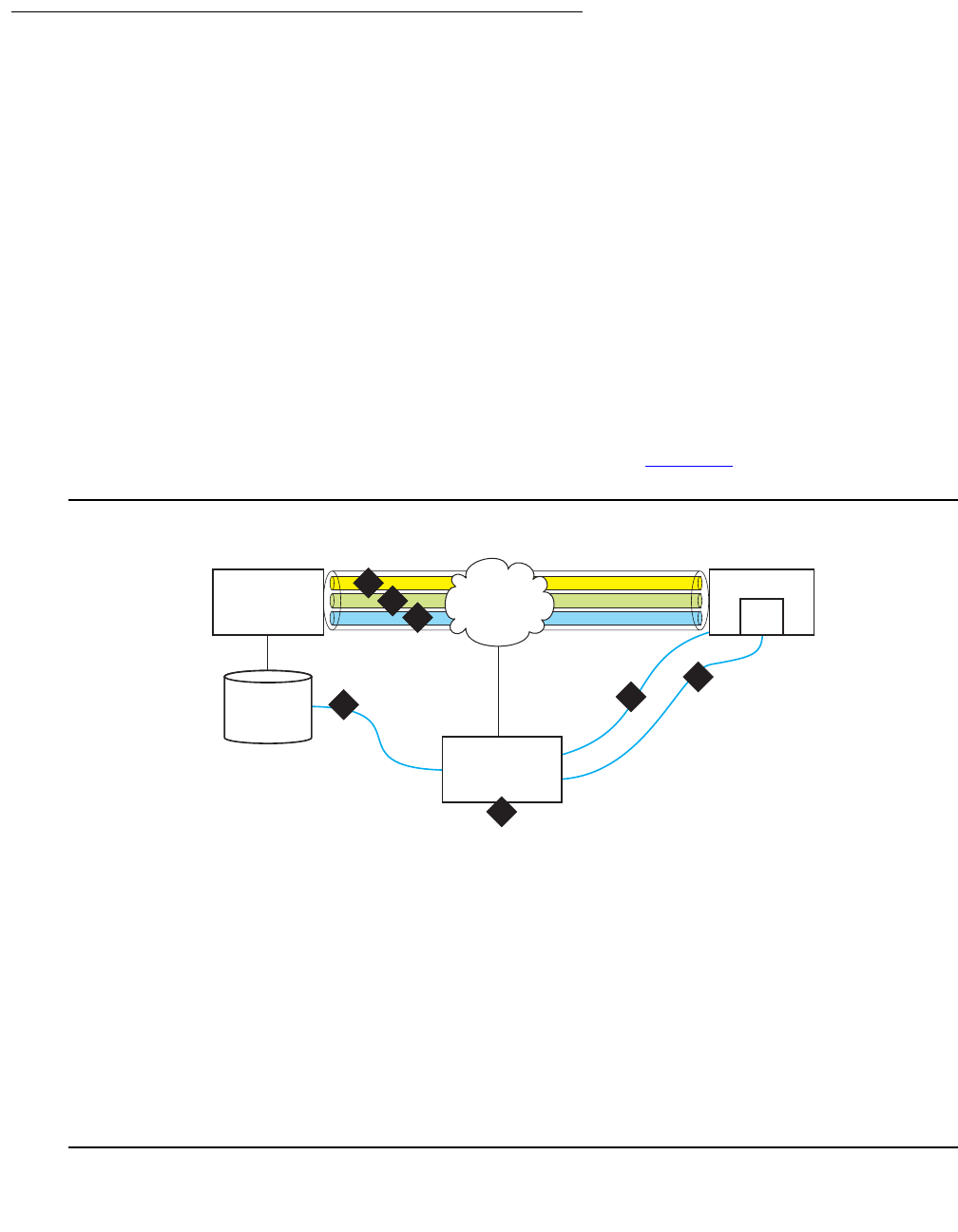
Configuring Standard Local Survivability (SLS)
122 Administration for the Avaya G450 Media Gateway
Provisioning data
SLS requires that the G450 has connected to an MGC at least once and has received
provisioning information, including:
●Avaya Communication Manager port information sent through the H.248 control channel:
- Tone sources, including a distinctly different dial tone to inform users that the system is
operating in survivable mode
- Loss plan
●Avaya Communication Manager provisioning information for the options in the station and
trunk media modules is sent through the CCMS channel
●Provisioning and Installation Manager (PIM) queries Avaya Communication Manager for
station/trunk configuration and dial plan routing administration data through SNMP.
Alternatively, the provisioning may be entered manually via an SNMP MIB browser or via
the local gateway’s CLI interface.
These data sources and communication links are illustrated in Figure 10.
Figure 10: Standard Local Survivability data sources and communication paths
Figure notes:
1. H.248 call signaling and configuration
data
2. CCMS messages through Clear
Channel
3. Media Gateway Maintenance Channel
4. PIM extracts Communication Manager
translation subset through OSSI
NOTE: The SLS data must be
configured manually in the gateway if
the PIM is not available.
5. PIM data set and SLS MIB delivered to the
gateway through SNMP
6. Security codes (passwords) sent over
SSH connection to CLI
7. Provisioning and Installation Manager
(PIM) for remotely provisioning gateways,
network-wide. PIM is installed on an
enterprise management server, not on the
primary Communication Manager server.
cydscomm LAO 071106
H.248 Control Channel
Provisioning and
Installation
Manager (PIM)
Gateway
IP
5
7
4
Communication
Manager
Communication
Manager
Translations
1
2
3
6
CLI
CCMS Channel
MGM Channel
H.248 Control Link

Issue 1 January 2008 123
The required Communication Manager translations for SLS include fields on the Station and
Media Gateway forms. See Configuring Communication Manager for SLS on page 133 for
more information about the information types and how to administer Communication Manager
for SLS.
PIM configuration data
SLS also requires PIM configuration data, some of which the G450 extracts from the Avaya
Communication Manager translations. PIM aggregates the required data and copies the
provisioning data over a secure communication path to non-volatile RAM (NVRAM) on the
G450. After the initial data collection, PIM retains a copy of the data set for each G450. This set
is compared with subsequent data sets to determine if anything has changed:
●If the data set changes, the newer data set is pushed down to the media gateway
●If the data set does not change, the data set in NVRAM remains unchanged
Users can schedule when to collect and push data, perform scheduled and manual backups,
and enable and disable SLS, as well as display (but not change) the data to ensure correct
information. See Using PIM to manage SLS administration on the gateway on page 138.
If PIM is unavailable, the SLS data set can be manually configured in the G450 CLI. For
information on configuring SLS, both manually and via PIM, see Configuring SLS on page 132.
Entering SLS mode
When SLS is enabled, the MGC list displays a fifth element called SLS. This element is always
past the Transition Point. After the Link Recovery search concludes for the primary MGC list
(entries above the Transition Point), it searches the alternate MGC list (entries below the
Transition Point), ending with SLS, the last choice for the G450.
When the Link Recovery search settles on the SLS entry in the MGC list, the G450 registers
with SLS (resident on the G450) for its call control.
SLS transitions between four possible SLS states: Unregistered, Setup, Registered, and
Teardown.
Unregistered state
This is the normal state in which SLS waits for an H.248 registration request from the G450.
When SLS receives the request, it registers the G450 and transitions to the Setup state.

Configuring Standard Local Survivability (SLS)
124 Administration for the Avaya G450 Media Gateway
Setup state
In this transitional state, SLS performs the following activities:
1. Checks for proper provisioning data. If there is insufficient provisioning, the registration
request is denied, and SLS returns to the Unregistered state.
2. Initializes SLS components, such as gatekeeper data (for example, IP endpoint’s E.164
addresses and passwords), dial plan, and ARS routing.
3. Registers with the media gateway.
4. Creates the H.323 Gatekeeper socket after successful registration.
When Setup is complete, SLS transitions to the Registered state.
Registered state
SLS can only process calls while it is in the Registered state in which it performs the following:
1. Constructs endpoint objects based on board insertion and IP registration.
2. Tears down endpoint objects based on board removal and IP unregistration.
3. Handles registration requests from H.323 endpoints that properly authenticate by using
their extension number as a 'terminal alias', and the password as the registration
encryption key.
4. Handles stimuli from all interfaces to establish and remove calls.
SLS remains in the Registered state as long as the socket to SLS is open.
Teardown
SLS transitions to the Teardown state whenever the following occur:
●The G450 administrator uses the set sls disable command from the G450 CLI or
manual MIB browser using the SNMP read/write attribute avSurvAdminState.
●The G450 closes the SLS socket after maintenance determines that it has completed an
H.248 registration with the primary MGC.
●SLS determines that it needs to unregister with the G450 due to internal error conditions.
Teardown state activities
1. Tears down endpoint objects.
2. Sends unregistration requests to IP endpoints that are not on active calls. IP endpoints
lose registration with SLS and display the discovered IP address during re-registration with
an MGC.
3. Closes the H.323 Gatekeeper socket.

Issue 1 January 2008 125
After Teardown is complete, SLS transitions to the Unregistered state and starts searching at
the top of the MGC list for a controller.
SLS interaction with specific G450 features
SLS interacts differently with the various G450 features.
Direct Inward Dialing in SLS mode
Direct Inward Dial (DID) is a service offered by telephone companies that enables callers to dial
directly into an extension on a PBX without the assistance of an operator or automated call
attendant.
Note:
Note: DID is a method of routing calls that applies to both analog and digital (T1/E1)
lines. However, while the method is typically referred to as DID in the analog
world, it is usually called Dialed Number Identification Service (DNIS) in the digital
world. Despite the difference in names, the concept is the same.
The gateways support DID central office trunk interfaces, and the digit transmission from the
central office is configurable when ordering the service:
●Immediate. The DID signaling starts immediately after the central office seizes the analog
DID trunk by closing the loop (across tip and ring). In addition, analog DID trunk lines only
support inbound calls. For this reason, Customer Premise Equipment (CPE) utilizing DID
trunk lines for inbound routing may utilize loop-start lines for outbound transmission.
●Wink. The DID signaling starts after the gateway’s analog trunk interface reverses the
battery polarity and sends a “wink” to the central office.
!WARNING:
WARNING: An analog two-wire DID trunk line is different from a standard analog loop-start
line. With analog DID trunk lines, the battery (power feed) to the line is supplied
by the gateway’s analog trunk interface. With a standard loop-start line, the power
is supplied by the central office, which is why damage can occur from connecting
a loop-start PSTN trunk to the DID port.
The number of sent digits (3-4 typically) and signaling type (Pulse/DTMF) are also configurable
at ordering time.
Multiple call appearances in SLS mode
When a gateway is in SLS mode, three call appearances, each with limitations, are supported:
●The first two call appearances are for incoming or outgoing calls. The first call appearance
is the default.

Configuring Standard Local Survivability (SLS)
126 Administration for the Avaya G450 Media Gateway
●The third call appearance is for outgoing calls only.
Note:
Note: “First", "second", and "third", refer to the order in which you use call appearances,
not the order of the Call Appearance buttons on your phone.
For example, User A chooses the third call appearance to dial User B, and then User C calls
User A, which is sent to the first call appearance. In this situation, a subsequent inbound call to
User A will be denied (busy) because the first and third call appearances are in use, and the
second call appearance is only available for outbound calls.
Hold in SLS mode
Using the Hold feature differs by user and by phone type, and the same is true of the Hold
feature in Standard Local Survivability (SLS) mode. Some users return to a call on Hold by
pressing the Call Appearance button, however, Communication Manager has an administrable
parameter that allows users to release a call on hold by pressing the Hold button a second time
(if only one call is held). The Hold feature also works differently in DCP and IP phones and
Analog phones in the survivable mode.
The Hold feature in SLS does not support:
●Music on Hold
●Local mute on analog phones
●Specialized treatment of E-911 calls
●Call Hold indicator tones
DCP and IP phones
When a media gateway is in the survivable mode, you can release calls on Hold on all DCP and
IP phones by either:
●Pressing the Hold button a second time (if only one call is held)
●Pressing the held Call Appearance button
Analog phones
Newer analog phones (for example, Avaya 62xx series) have buttons with specific functions for
placing a call on Hold:
●Hold button. A hold function that is local to the phone
Pressing the Hold button causes the analog station to place a hold bridge in both
directions at the telephone set. No signaling notification is sent to the SLS call-engine and,
therefore, there is no ability to notify the other party that they have been placed on hold.
Pressing the Hold button a second time causes the analog phone to remove the hold
bridge and the call path is restored. In essence, this hold operation is equivalent to using
the Mute button on station sets.
●Flash button. A function that sends a switchhook signal to the server
●Switchhook (receiver on/off hook). A function that sends a disconnect signal to the server

Issue 1 January 2008 127
Using the Flash button
1. Press the Flash button on the analog phone.
You hear a dial tone; the other party hears nothing.
You can leave the call on Hold or transfer the call. Press the Flash button twice to return to
the call.
2. Dial the Feature Access Code (FAC) for Hold.
At this point you can leave the call on Hold or transfer the call.
3. To return to the call, press the Flash button again.
The call is re-established.
Note:
Note: Either party can put the call on Hold or return to the call.
Using the switchhook button
1. Press the switchhook once.
You hear a dial tone.
2. Dial the FAC for Hold.
This places the call on Hard Hold which prevents you from transferring the call. To return to
the call, dial the FAC for Hold.
3. Do one of the following:
●Return to the call by dialing the FAC for Hold.
The call is re-established.
●Dial a third party by dialing the number and flashing the switchhook once (you will hear
a stutter dial tone). Dial the FAC for Hold (the second call is now on Hold and the first
call is re-established). If you want to toggle between the first and second calls, press
the switchhook and dial the FAC for Hold once each time you want to change calls.
●Hang up.
Your phone will ring to notify you that you have a call on Hold. When you lift the
receiver you will hear a dial tone and can perform any of the activities listed in Step 3.
Call Transfer in SLS mode
Using the Call Transfer feature differs by user and by phone type. The same is true of the Hold
feature in Standard Local Survivability (SLS) mode. Call Transfer also works differently in
DCP/IP phones and analog phones in the survivable mode. Some limitations of the Call
Transfer feature are:
●The established call must be initiated from a local station (administered on this gateway) or
from an incoming trunk. You can make only point-to-point call transfers to a phone that is
local to the same gateway.

Configuring Standard Local Survivability (SLS)
128 Administration for the Avaya G450 Media Gateway
●Does not support E-911 calls
●Does not support the Conference button on any phone
●Does not support trunk-to-trunk transfer (for example, for voice messaging)
Transferring a call on DCP and IP phones
1. While talking on a call or while you have a call on Hold, press the Transfer button on your
phone.
You hear a dial tone; the other party hears nothing.
2. Dial the third party’s number on your phone.
3. You can either:
●Wait for the third party to answer and announce the call, then either press the Transfer
button again or hang up.
●Transfer the call before the third party answers by pressing the Transfer button again.
The person you were talking to is transferred to the third party.
A message appears on your phone display to indicate that the call transfer is complete.
Note:
Note: If you do not completely dial the string or if you hear a fast-busy or re-order
(French siren) tone, only a Hard Hold call connection (if present) remains at the
station.
If the third party does not answer, the call does not ring back to the originating party. If a
transfer does not complete, the event is logged.
Transferring an established call from an analog phone
Newer analog phones (for example, Avaya 62xx series) have buttons with specific functions for
transferring a call. The switchhook (receiver on/off hook) sends a disconnect signal to the
server, and the Transfer/Flash button sends a transfer message to the server.
1. While on a call, press the switchhook once or press the Transfer/Flash button.
You hear a dial tone; the other party will hear nothing.
2. Dial the third party’s number on your phone.
3. You can either:
●Wait for the third party to answer and announce the call, then hang up.
●Transfer the call before the third party answers by hanging up.
The person you were talking to is transferred to the third party.
A message appears on your phone display to indicate that the call transfer is complete. If
the necessary call processing resources are not available, the transfer does not complete
and the event is logged.

Issue 1 January 2008 129
Note:
Note: Displays are not supported on analog phones unless they are supported locally
by an analog phone.
Using contact closure in SLS mode
When the media gateway is in survivable mode, contact closure works as follows:
1. Lift the phone receiver and listen for the survivability dial tone.
2. Dial the appropriate contact closure FAC (open, close, or pulse) on the phone.
●If you dial an invalid FAC code, then SLS plays an intercept tone and terminates the
session.
●If you dial a valid FAC code, then you will hear a standard dial tone and can proceed to
Step 3.
3. Dial the media gateway number (three digits).
●If you enter fewer than three digits, then SLS times out and you must restart this
procedure from the beginning.
●If the media gateway number matches the local media gateway number, then SLS
plays a standard dial tone and you can proceed to Step 4.
●If the media gateway number does not match the local media gateway number, SLS
plays an intercept tone and terminates the session.
4. Dial the contact closure code, for example 1 for contact pair #1, and 2 for contact pair #2.
You hear stutter tone and then silence, confirming these valid codes. If you dial an invalid
contact closure number, you will hear an intercept tone.
●Contact closure feature activations appear in the CDR log (see Figure 12).
Note:
Note: If the contact closures are set to manual operation, the FAC operation will not
work even though the confirmation tone is heard. However, an event will be
logged.
Contact closure / SLS feature interactions
●There is no screening to authorize the use of the contact closure feature in SLS mode.
Security is provided by limiting the number of users who know the correct key sequence
required for the contact closure feature.
●You cannot use the Hold or Transfer features while dialing the contact closure FAC key
sequence.
●Contact closure will not work until you dial the full digit sequence and it is processed.
●If two users try to simultaneously use contact closure, whoever dials the full FAC key
sequence first gets precedence.

Configuring Standard Local Survivability (SLS)
130 Administration for the Avaya G450 Media Gateway
●Interdigit timing rules apply to the contact closure feature, so if you pause too long during
the FAC key sequence, the feature times out.
●Call appearances are not released (available for calls) until you hang up.
●You cannot use the contact closure feature from outside trunk lines.
Note:
Note: For more information on contact closure, refer to Configuring contact closure on
page 343.
IP Softphone shared administrative identity in SLS mode
The SLS mode supports shared administrative identity with the Avaya Softphone application,
but requires specific station administration.
1. Access the CM administrative SAT interface. For instructions on accessing the Avaya
Communication Manager through the G450, see Accessing the registered MGC on
page 87.
2. At the SAT interface, enter change station extension to display the Station form.
3. Set the Terminal Type field to a 46xx IP phone.
4. Save the changes.
Note:
Note: If you administer the Terminal Type field as a DCP phone, shared administrative
identity functionality in SLS mode is not supported.
SLS logging activities
SLS exports call-recording data in survivability mode. The Call Detail Record (CDR) log
contains detailed information about each outgoing call that uses a trunk. This information can be
stored in flash NVRAM or directed to an external server for later processing. It includes data for:
●Merged outgoing Trunk Access Codes (TACs), indicating successfully completed dialing
●Successfully completed ARS calls, as shown in Figure 11
●Contact closure, as shown in Figure 12

Issue 1 January 2008 131
Example of CDR log entries and format
Figure 11: CDR log example
An interpretation of the first entry in Figure 11 is:
●02/18/2005 is the date of the log entry
●10:46:35 is the time of the log entry
●CDR-Informational is the category (to aid sorting)
●10:46 is the time the call was placed
●00:00 is the duration of the call in hours and minutes or 99:99 if the duration is greater than
99 hours
●A is the condition code. Possible values are:
-7. Outgoing call
-9. Incoming call
-A. Outgoing TAC call or emergency call
-B. Used for contact closure
●700 is the FAC or TAC number
●50029555 is the dialed number
●52001 is the extension that originated the call
●v301 indicates the port through which the call was routed
G450-SLS(super)# show logging cdr file content
02/18/2005,10:46:35:CDR-Informational: 10:46 00:00 A 700 50029555 52001 v301
02/18/2005,10:45:46:CDR-Informational: 10:45 00:00 A 700 50029 52001 v301
02/18/2005,10:45:14:CDR-Informational: 10:45 00:00 A 700 52 52001 v301
02/18/2005,10:44:35:CDR-Informational: 10:44 00:00 A 700 445200 52001 v301
02/10/2005,13:20:23:CDR-Informational: 13:20 00:00 A 700 50029 52001 v301
02/10/2005,13:20:15:CDR-Informational: 13:20 00:00 A 700 50029 52000 v301
02/10/2005,13:20:05:CDR-Informational: 13:20 00:00 A 700 44 52000 v301
02/10/2005,13:19:59:CDR-Informational: 13:19 00:00 A 700 44500 52000 v301

Configuring Standard Local Survivability (SLS)
132 Administration for the Avaya G450 Media Gateway
Example of CDR log with contact closure
Figure 12: CDR log example, contact closure
An interpretation of the entry in Figure 12 is:
●Date (07/27/2005) and time (03:59:24) record when the feature was activated
●B is the condition code. Possible values are:
-7. Outgoing call
-A. Outgoing TAC call or emergency call
-B. Used for contact closure
●15840 is the extension that activated the feature
●PULSE indicates the contact closure operation (could also be OPEN or CLOSE)
●003 is the media gateway number
●2 is the contact closure number
Configuring SLS
SLS is included as part of the resident gateway firmware package that is installed as part of the
G450 gateway firmware upgrade. However, for SLS to function correctly, the following
conditions must be met:
●Avaya Communication Manager must be configured for SLS and Auto Fallback. For
instructions on configuring SLS in Avaya Communication Manager, see Configuring
Communication Manager for SLS on page 133.
●Provisioning data from the PIM tool must be gathered from Avaya Communication
Manager and delivered to the G450 using PIM. For instructions on gathering and
delivering the provisioning data, see Using PIM to manage SLS administration on the
gateway on page 138.
If PIM is not available, the G450 can be manually configured for SLS and Auto Fallback via
the CLI. See Using the CLI to manually configure SLS administration on the gateway on
page 144.
●SLS must be enabled on the G450. See Enabling and disabling SLS on page 143.
G450-SLS(super)# show logging cdr file content
07/27/2005,03:59:24:(0 0 0:15:5)CDR-Informational: July 27 03:59 B 15840 PULSE 003 2

Configuring SLS
Issue 1 January 2008 133
●To activate any saved changes within SLS, the disable and enable SLS commands must
be used together. See Activating changes in SLS on page 144.
Note:
Note: Exercise caution when using a CLI session and an SNMP manual browser
session concurrently. Specifically, if the administrator has entered as SLS second
level context for trunk-group to view command settings, then performs an SNMP
write operation to change a give attribute, this will get overwritten back with the
present CLI values in the process of exiting the second level CLI command area
for trunk-group. It is recommended that a single admin interface be used for a
given administration parameter update session.
Configuring Communication Manager for SLS
You must configure the Avaya Communication Manager for SLS whether you will be using PIM
provisioning or manual CLI entry of SLS administration. Perform the configuration during the
initial administration of the host CM server.
1. Access the CM administrative SAT interface. For instructions on accessing the Avaya
Communication Manager through the G450, see Accessing the registered MGC on
page 87.
2. At the SAT, enter change node-names ip to display the IP Node Names form. For
example:
3. In the Name field, type the gateway name; that is, the name of the survivable gatekeeper
node that corresponds to the IP address in Step 4.
Note:
Note: Set the name of the media gateway consistently with the Name field on the
Media Gateway Administration form in Communication Manager (add
media-gateway) and with the name used in the set system name command
(gateway CLI).
4. Type the IP address of the gateway in the IP Address field.
5. Submit the form.
change node-names ip Page 1 of 1
IP NODE NAMES
Name IP Address Name IP Address
Denver Gateway1 192.168.1 .200 . . .
procr 192.168.1 .201 . . .
(X of X administered node-names were displayed )
Use 'list node-names' command to see all the administered node-names
Use 'change node-names ip xxx' to change a node-name 'xxx' or add a node-name

Configuring Standard Local Survivability (SLS)
134 Administration for the Avaya G450 Media Gateway
6. At the SAT, enter change system-parameters mg-recovery-rule 1 to display the
System Parameters Media Gateway Automatic Recovery Rule form. For example:
7. Type a description of the rule in the Rule Name field.
8. Set the Migrate H.248 MG to primary field to immediately.
Note:
Note: The immediately field value is only one of the four possible choices. See the
Administrator Guide for Avaya Communication Manager, 03-300509 for more
information on the values for this field.
9. Submit the form.
change system-parameters mg-recovery-rule 1 Page 1 of 1
SYSTEM PARAMETERS MEDIA GATEWAY AUTOMATIC RECOVERY RULE
Recovery Rule Number: 1
Rule Name: _____________
Migrate H.248 MG to primary: immediately
Minimum time of network stability: 3
WARNING: The MG shall be migrated at the first possible opportunity. The MG may
be migrated with a number of active calls. These calls shall have their talk
paths preserved, but no additional processing of features shall be honored. The
user must hang up in order to regain access to all features.
NOTE: set 'Migrate H.248 MG to primary' to Blank to disable rule.

Configuring SLS
Issue 1 January 2008 135
10. At the SAT, enter display media-gateway 1 to display the Media Gateway form. For
example:
11. Verify the following fields:
●Name field (20 characters maximum) must match the administered name of the
gateway (see Step 2 of Configuring the SLS data through the CLI on page 159).
●Max Survivable IP Ext field only appears when the Type field is G450. The current
maximum product limits enforced by the SLS gateway’s firmware module is 240.
These limits are enforced due to resource considerations in the given gateway.
!Important:
Important: Since the VoIP resources on the gateway are limited, the Max Survivable IP Ext
field should not exceed these values.
display media-gateway 1
MEDIA GATEWAY
Number: 1 Registered? y
Type: g450 FW Version/HW Vintage: 27 .4 .0 /0
Name: hardy-gw MGP IP Address: 135.9 .78 .201
Serial No: 06IS60111112 Controller IP Address: 135.9 .78 .202
Encrypt Link? y MAC Address: 00:04:0d:ea:a9:f0
Network Region: 1
Location: 1 Site Data:
Recovery Rule: 1
DSP Type FW/HW version
Slot Module Type Name DAR1 1 0
V1: S8300 ICC MM DAR1 1 0
V2: DAR1 1 0
V3: MM714 ANA MM DAR1 1 0
V4: MM710 DS1 MM
V5:
V6:
V7: MM712 DCP MM Max Survivable IP Ext: 8
V8: MM711 ANA MM
V9: gateway-announcements ANN VMM
Announcement board must also be enabled; use 'enable announcement-board'
Command:
F1=Cancel F2=Refresh F3=Submit F4=Clr Fld F5=Help F6=Update F7=Nxt Pg F8=Prv Pg

Configuring Standard Local Survivability (SLS)
136 Administration for the Avaya G450 Media Gateway
12. At the SAT, enter change station extension to display the Station form. For
example:
13. Verify the following fields:
●Survivable GK Node Name. Names the gatekeeper to register with when the
gateway unregisters (loses call control) with the main server. The media gateway
delivers the gatekeeper list to IP endpoints, allowing them to register and subsequently
originate/receive calls from other endpoints in this survivable calling zone. This field
must be set equal to the IP Node Name of the media gateway that will support this
station in survivable mode.
●Survivable COR. Places a restriction level for stations to limit certain users to only
certain types of calls:
-Emergency. This station can only be used to place emergency calls which are
defined
-Internal. This station can only make intra-switch calls (default)
-Local. This station can only make calls that are defined as locl, op, svc, or hnpa
on the Survivable ARS Analysis Table
-Toll. This station can place any national toll call which are defined as fnpa or natl
on the Survivable ARS Analysis Table
-Unrestricted. This station can place a call to any number defined in the
Survivable ARS Analysis Table. Those strings administered as deny are also
denied to these users as well.
change station 8003 Page 1 of 4
STATION
Extension: 8003 Lock Messages? n BCC: 1
Type: 4620 Security Code: TN: 1
Port: IP Coverage Path 1: COR: 1
Name: Coverage Path 2: COS: 1
Hunt-to Station:
STATION OPTIONS
Loss Group: 19 Personalized Ringing Pattern: 1
Message Lamp Ext: 8003
Speakerphone: 2-way Mute button enabled? y
Display Language? English Expansion Module? n
Survivable GK Node Name: Media Complex Ext:
Survivable COR: internal IP SoftPhone? N
Survivable Trunk Dest? y

Configuring SLS
Issue 1 January 2008 137
Figure 13 shows the hierarchical relationship among the calling-restriction categories.
Figure 13: Inherited Class of Restriction (COR) permissions
●Survivable Trunk Dest? Enables stations to receive/not receive incoming trunk calls
in survivable mode (default is receive). PIM extracts the Communication Manager
information, pushes it to the media gateway, and stores it in NVRAM. This feature is an
alternative technique for answering central office trunks (analog and digital non-ISDN)
by routing directly to a station upon the action of inward trunk seizure. This operates
equivalently to analog DID or ISDN trunk calls that have the ability to forward digit
information regarding the called party.
14. Submit the form.
Figure notes:
1. Unrestricted: Users can dial any
valid routable number, except an
ARS pattern specifically administered
as deny (see Figure 14). ETR
functionality and calls through the CO
are permitted in this class.
3. Local: Users can only dial these call
types:
-locl (public-network local number call)
-op (operator)
-svc (service)
-hnpa (7-digit NANP call)
2. Toll: Users can only dial these call
types:
-fnpa (10-digit NANP call)
-natl (non-NANP call)
4. Internal: Users can only dial other
stations within the media gateway and the
emergency external number (default)
5. Emergency: Users can only dial the
emergency external number
cydsetru LAO 031405
Internal
Local
Toll
Unrestricted
Emergency
5
4
1
2
3

Configuring Standard Local Survivability (SLS)
138 Administration for the Avaya G450 Media Gateway
Using PIM to manage SLS administration on the gateway
Before enabling SLS, you must gather provisioning data from PIM and deliver it to the G450.
Run PIM’s Device Profile Wizard to perform this task. The Device Profile Wizard gathers a
subset of the Communication Manager translations (dial plan analysis and destination routing
instructions) and delivers them to the G450. If PIM is not available, this translation subset (the
SLS data set) can be created manually, using the procedure described in Using the CLI to
manually configure SLS administration on the gateway on page 144.
PIM must be installed on and launched from the Avaya Network Management Console. For
information about PIM, see Accessing PIM on page 52.
1. Ensure that the Network Management Console (NMC) has discovered the media gateway.
2. Before PIM’s automatic scheduled SLS updates will work as expected, set the device
parameters for both the server and the gateway in the NMC:
●Server. Communication Manager login and password
Note:
Note: The server must be the first listing in NMC’s discovery output. If an ESS node is
discovered and listed prior to the main server, the main server’s login/password
will not permit access to the ESS node.
●Gateway. SNMPv1/v3 access parameters
●Gateway. NMC has discovered the gateway’s IP address
3. Make sure the Communication Manager has been configured for SLS as described in
Configuring Communication Manager for SLS on page 133.
4. Click the Device Profiles icon/link in the top-level toolbar of the main PIM window.
Alternatively, select PIM Objects > Device Profiles from the left panel.
5. Click the New icon on the Device Profile list page that appears in the right panel of the
main PIM window. If this is not a new profile, open the existing profile from the left panel or
from the Device Profile list page.
6. Proceed through the Device Profile Wizard to the Details page. Set the CM version field
to 4.0.
7. Proceed through the Device Profile Wizard to the SLS / ARS page (Figure 14) and
perform the following:
a. Select the Enable the SLS feature on this device? checkbox to enable SLS on the
G450. A cleared checkbox means that SLS is disabled.
b. Select the Perform scheduled SLS updates on this device? checkbox to send the
SLS administration data set to the gateway according to the settings on the SLS
Update Schedule form (Figure 16).
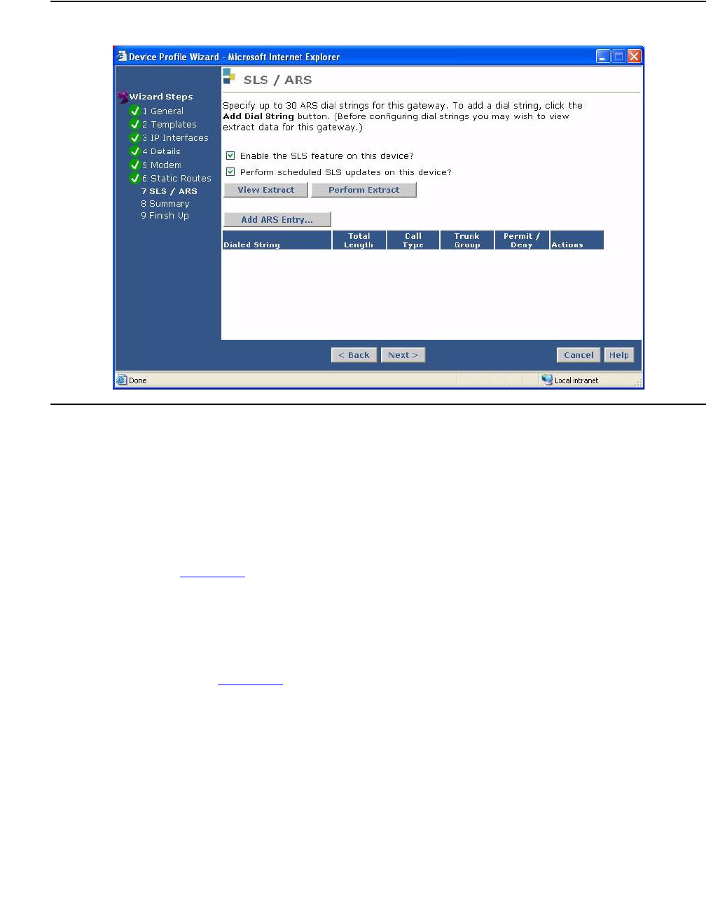
Configuring SLS
Issue 1 January 2008 139
Figure 14: SLS / ARS page
8. Optionally click the following buttons:
●View Extract displays the current SLS administration data set for this gateway.
●Perform Extract extracts the SLS information from the controlling Communication
Manager server for this Media Gateway.
●Actions enables you to edit or delete a previously-administered entry:
- The paper/pencil icon is the edit icon, which opens the ARS Entry page
(Figure 15).
- The trash can icon is the delete icon, which removes the ARS Entry from the
table. The Add ARS Entry option may be used to create/edit a maximum of 30
ARS dial pattern entries.
9. If this gateway has not been previously provisioned, click Add ARS Entry to open the
ARS Entry page (Figure 15).
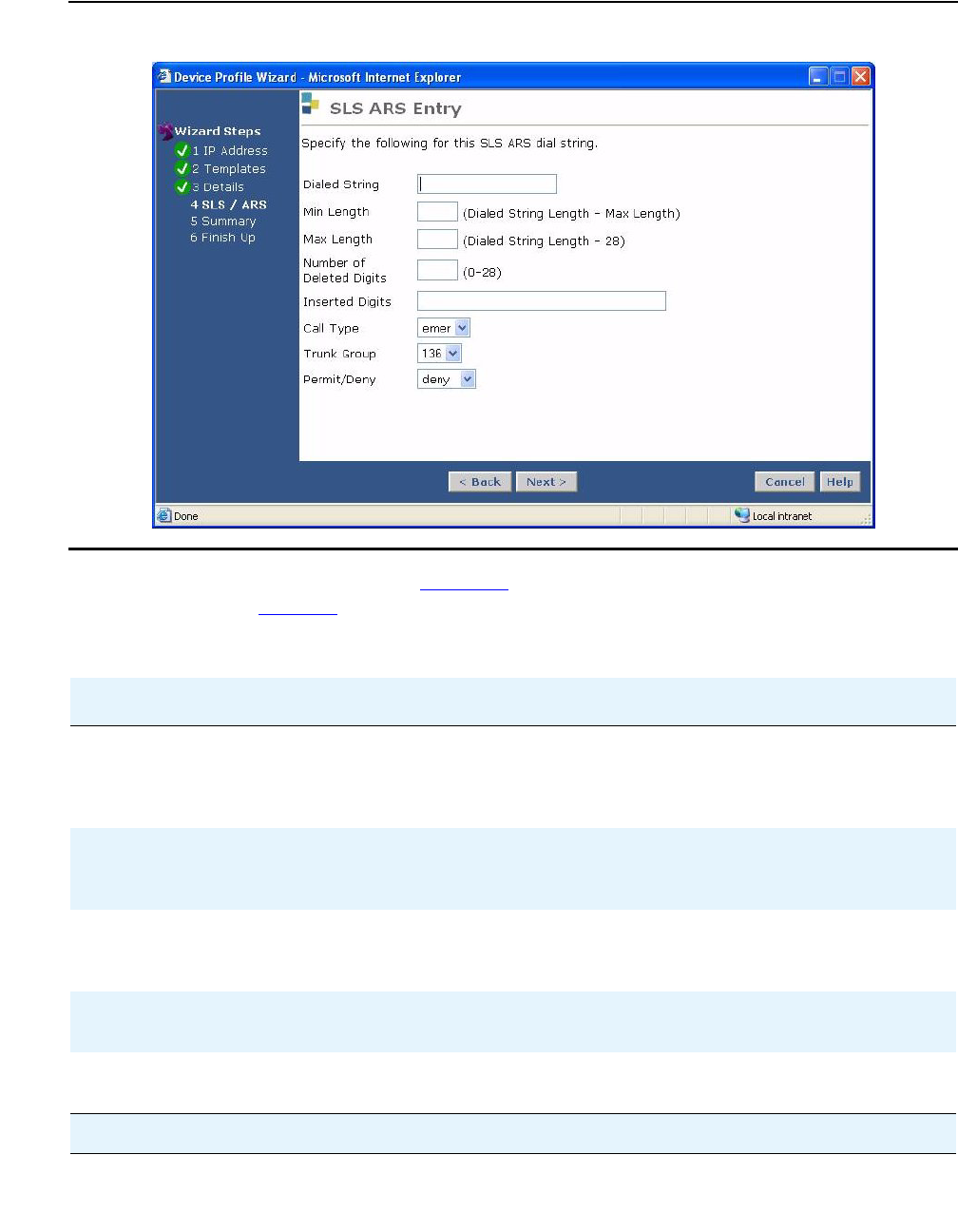
Configuring Standard Local Survivability (SLS)
140 Administration for the Avaya G450 Media Gateway
Figure 15: SLS ARS Entry page
10. Use the SLS ARS Entry page (Figure 15) to administer an Automatic Route Selection in
SLS. Refer to Table 29.
Table 29: SLS ARS Entry page field options
Field Description
Dialed String The maximum length of the dialed string is 18 characters. The
allowed characters include 0-9, '*' and 'X' or 'x' as a pre-string or
mid-string replacement. 'X' cannot be at the end of a dialed
string.
Min Length The minimum length of the user-dialed number that the SLS call
engine collects to match to the dialed-string. The default is the
length of the specified dialed-string element.
Max Length The maximum length of the user-dialed number that the SLS call
engine collects to match to the dialed-string. The default is the
length of the specified dialed-string element.
Number of Deleted Digits The number of dialed digits to be deleted from the beginning of
the dialed string. Default: 0.
Inserted Digits The digit string to be inserted at the beginning of the dialed
string. Default: blank.
1 of 2

Configuring SLS
Issue 1 January 2008 141
!Important:
Important: SLS permits 911 calls, but the specific location information is not transmitted to
the Public Service Answering Point (PSAP). Only the general trunk-identifying
information is transmitted. Emergency personnel will have a general location
associated with the trunk (for example, a building address), but nothing more
specific (for example, a room or office number). Also, if a 911 call disconnects for
any reason, emergency personnel cannot reliably call the originator back.
Call Type Can be one of the following:
emer (emergency call)*
fnpa (10-digit NANP call)
hnpa (7-digit NANP call)
intl (public-network international number call)
iop (international operator call)
locl (public-network local number call)
natl (non-NANP call)
op (operator)
svc (service)
Trunk Group Trunk-group number (1-2000), which you can select from the
drop-down choices of trunk groups found in the SLS extract from
the controlling Communication Manager server
Permit / Deny Indicates whether the call should be permitted or denied
* Any active, in-service station can dial the emergency access number while in survivable mode. Define the
emergency access number on the SLS / ARS page (Figure 14).
Table 29: SLS ARS Entry page field options (continued)
Field Description
2 of 2
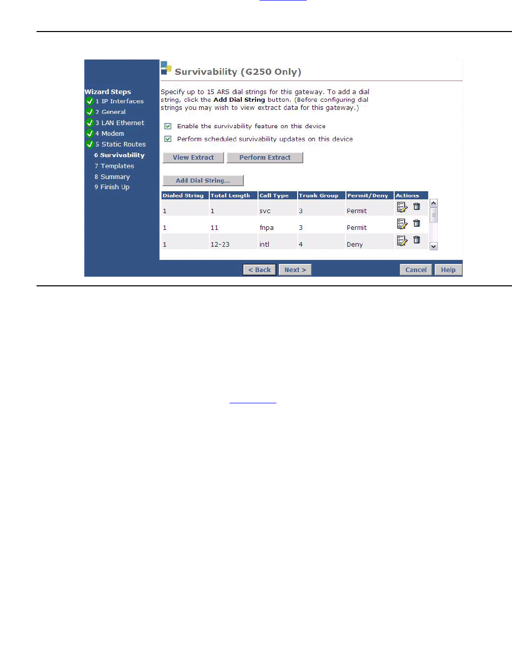
Configuring Standard Local Survivability (SLS)
142 Administration for the Avaya G450 Media Gateway
11. Use the SLS Update Schedule page (Figure 16) to administer up to six SLS updates per
day.
Figure 16: SLS Update Schedule page
a. Check the Enable SLS Updates box.
b. Set as many as six Daily Updates.
Note:
Note: The Daily Updates must be at least four hours apart.
c. Click Submit.
12. Use the Backup/Restore page (Figure 17) to backup the PIM database backup schedule.
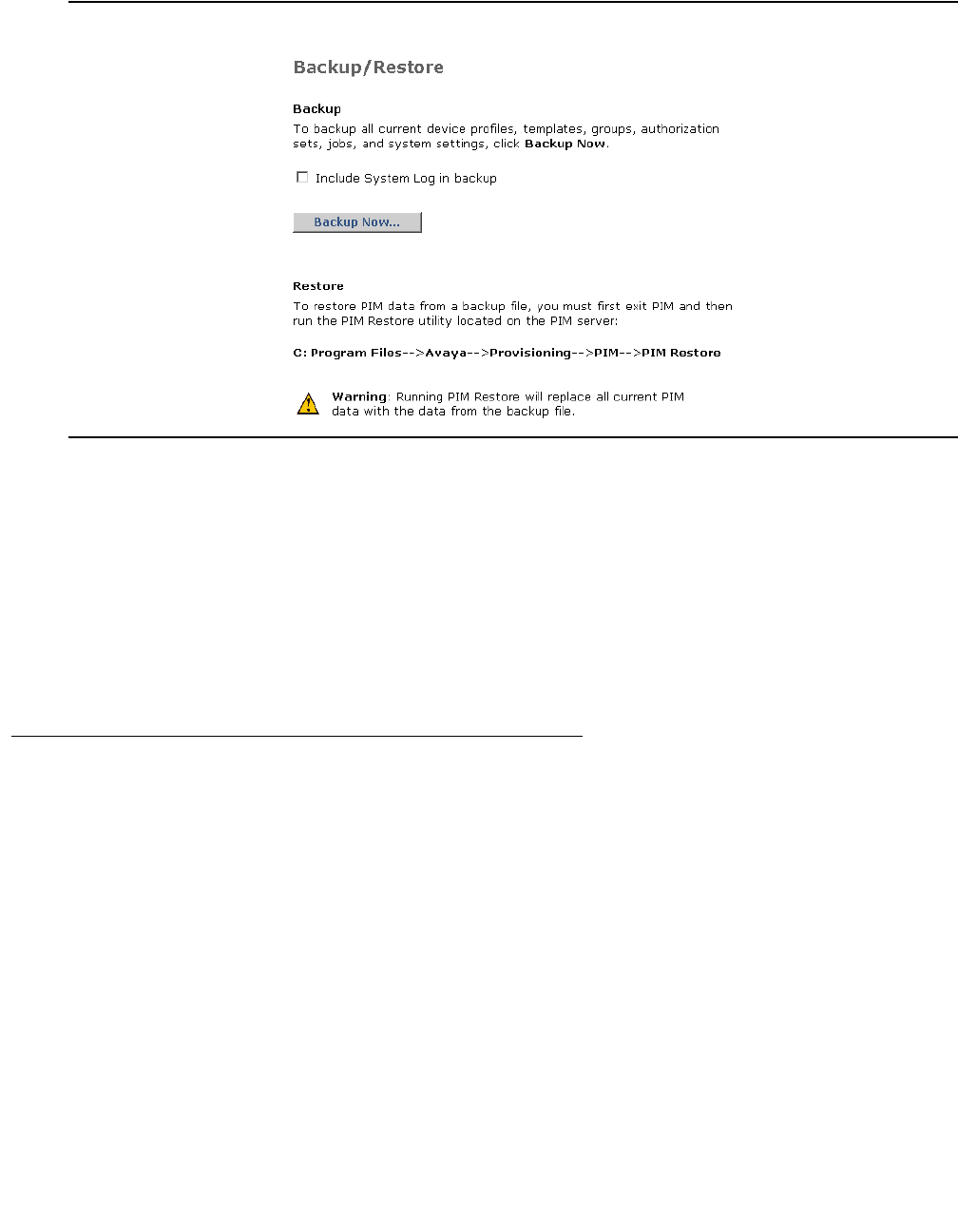
Configuring SLS
Issue 1 January 2008 143
Figure 17: Backup/Restore page
Note:
Note: Step 12 backs up the PIM database. Avaya encourages users to set a PIM
backup schedule/policy independent of the SLS implementation.
Note:
Note: If you require the use of the Incoming Call Handling Treatment option for
adding/deleting the incoming dial pattern on incoming trunk calls, this route
pattern must be modified using the CLI. There are NO equivalent commands in
the PIM wizard screens.
Enabling and disabling SLS
To enable SLS on the G450, enter set sls enable. The G450 responds with the message
Survivable Call Engine is enabled.
To disable SLS on the G450, enter set sls disable. The G450 responds with the message
Survivable Call Engine is disabled.
Note:
Note: If you enable SLS and then performed additional administration, you must first
disable SLS and then re-enable it. This will cause the SLS application to
resynchronize its administrative database with the gateway's global CLI
command database.

Configuring Standard Local Survivability (SLS)
144 Administration for the Avaya G450 Media Gateway
Activating changes in SLS
To activate changes you make in SLS, you must use the disable and enable SLS commands
together. Thus, to activate changes in SLS, perform the following steps:
1. Make any changes to SLS administration desired.
2. While still in SLS mode, enter set sls disable.
The G450 responds with the message Survivable Call Engine is disabled.
3. Enter set sls enable.
The G450 responds with the message Survivable Call Engine is enabled.
Using the CLI to manually configure SLS administration on the
gateway
It is recommended to use PIM to configure the SLS data. However, if PIM is unavailable, you
can also configure the SLS data from the G450 itself.
Prerequisites
●The Communication Manager Release 4.1 is running on the host server
●PIM or configuration of the G450 through its CLI
●The G450 is registered with Avaya Communication Manager
●The SLS is enabled on the G450 through its CLI
●S8300 is not serving as an LSP
●G450 is not subtending to another external server (including ESS or another LSP in
another gateway)
Planning and preparing the SLS data set
It is recommended to plan the SLS coverage and gather information from Avaya
Communication Manager before creating the SLS administration data set at the gateway
command line. Strategic selection of the stations and trunks that participate in SLS can ensure
that vital communications are spared interruptions caused by network outages.

Configuring SLS
Issue 1 January 2008 145
!Important:
Important: Since you can administer your system for SLS either from the SAT or from the
gateway CLI, the two administration tasks must be synchronized with common
data and port usage as well as system-defined capacities. For example, if a
physical DCP station port number 10 is not administered on the Communication
Manager server, even though the gateway’s SLS engine has that port
administered, the port is unusable during SLS operation on the gateway. This is
because the hardware port configuration on the media modules is initially
configured by CM in subtending gateway mode, by using the H.248 control
channel to push information down to the gateway.
SLS capacities
The following table lists the SLS capacities:
You can collect the Communication Manager data using the CM administrative SAT interface.
For instructions on accessing the Avaya Communication Manager through the G450, see
Accessing the registered MGC on page 87.
Collecting analog stations data
1. At the SAT, enter list media-gateway to display a list of administered gateways.
2. Look for supported gateways in the Type field.
3. Once you know the media gateway of interest, match the gateway model with the analog
station ports:
Table 30: SLS capacities
Gateway
model IP
stations Analog
stations DCP
stations Analog
trunks BRI
trunks DS1
trunks
G450*
* 340 stations maximum (all types)
240 The maximum number of legacy stations/trunks that may
be supported is dependent upon the slot-module
configuration of what is installed.
Table 31: Matching the gateway with the analog station ports
Gateway
model Media module
(if applicable) Slot configuration
G450 MM711
MM714
MM716

Configuring Standard Local Survivability (SLS)
146 Administration for the Avaya G450 Media Gateway
4. At the SAT, enter display port port-number, where port-number is the analog
station port on the gateway.
The system displays the extension number assigned to the port.
5. Once you know the extension, enter display station extension to display the
Station form for this extension.
6. Gather the necessary information from Table 32.
Collecting DCP stations data
1. At the SAT, enter list media-gateway to display a list of administered gateways.
2. Look for supported gateways in the Type field.
3. Once you know the media gateway of interest, match the gateway model with the digital
station ports:
4. At the SAT, enter display port port-number, where port-number is the DCP
station port on the gateway.
The system displays the extension number assigned to the port.
Table 32: Analog station form data to assemble for SLS
Page*
* Page numbers might vary for your system.
Field Name Notes
1 Extension
1Port The port address correlates the analog stations that belong
to a particular media gateway. If the port ID includes the
media gateway number, then it is accepted. A new station
slot/port entry must include the "V", as in "V305".
1 Type Only 2500 is the accepted Type
1Survivable COR Class of Restriction while in SLS mode
1 Survivable Trunk Dest Trunk destination while in SLS mode
2Switchhook Flash This field appears when Type is 2500
1 Name This is the user’s name
Table 33: Matching the gateway with the digital station ports
Gateway
model Media module
(if applicable) Slot
configuration
G450 MM712
MM717

Configuring SLS
Issue 1 January 2008 147
5. Once you know the extension, enter display station extension to display the
Station form for this extension.
6. Gather the necessary information from Table 34.
Table 34: DCP station form data to assemble for SLS
Page*Field Name Notes
1 Extension
1Port The port address correlates the DCP stations that belong
to a particular media gateway. If the port ID includes the
media gateway number, then it is accepted. A new station
slot/port entry must include the "V", as in "V401".
1 Security Code (Optional) This value is the shared secret between Communication
Manager and the media gateway, and is used for the
registration of an IP Softphone (RoadWarrior)
1Type 2402
2410
2420
6402
6402D
6408
6408+
6408D
6408D+
6416D+
6424D+
8403B
8405B
8405B+
8405D
8405D+
8410B
8410D
8411B
8411D
8434D
1 Survivable COR Class of Restriction while in SLS mode
1Survivable Trunk Dest Trunk destination while in SLS mode
1 of 2

Configuring Standard Local Survivability (SLS)
148 Administration for the Avaya G450 Media Gateway
Collecting IP stations data
1. At the SAT, enter list media-gateway to display a list of administered gateways.
2. Look for supported gateways in the Type field.
3. Enter display media-gateway.
4. Read the reported IP address for this gateway.
5. Enter list node-name and compare the IP address of the media gateway in the list
with the IP address of the gateway that you are administering for SLS. When you find a
match in the node-name form, read the assigned node-name. This will be used to do a
pattern match with a field on the IP Station form in Step 6.
6. Enter list station type type, where type is one of the supported IP stations.
The report lists all IP phones that could have the Survivable GK Node-Name
administered to the target media gateway. The Survivable GK Node-Name uniquely
associates an IP phone with a particular media gateway.
7. Once a match is made between the station form's Survivable GK Node-Name and the
target gateway's Node-Name, gather the values for the given IP station per Table 35.
1 Expansion Module Determines if optional CA module is connected to this
phone model
1Name This is the user’s name
* Page numbers might vary for your system.
Table 35: IP station form data to assemble for SLS
Page*Field Name Notes
1 Extension
1Security Code (IP only) This value is the shared secret between
Communication Manager and the media gateway
used for the registration of the IP endpoint
1 of 2
Table 34: DCP station form data to assemble for SLS (continued)
Page*Field Name Notes
2 of 2

Configuring SLS
Issue 1 January 2008 149
Collecting trunk groups data
1. At the SAT, enter list media-gateway to display a list of administered gateways.
2. Look for supported gateways in the Type field.
3. At the SAT, enter display media gateway to view the media modules that are
assigned to the various slots. Use Table 49 as a reference to identify how the particular
media module has been configured for serving as a trunk port, and then use the various
list commands on CM to look for physical port matches in the various trunk SAT forms in
order to discover what translation information is needed.
4. Identify the analog trunk ports. Refer to Table 50.
5. Identify the BRI trunk ports. Refer to Table 51.
6. Identify the digital DS1 trunk ports. Refer to Table 51.
7. Identify the G450 modules and check for provisioned trunk ports.
1 Type 4601
4602
4602SW
4606
4610SW
4612
4620
4620SW
4621
4622
4624
4625
1Survivable COR Class of Restriction while in SLS mode
1 Survivable Trunk Dest Trunk destination while in SLS mode
1Expansion Module Determines if optional CA module is connected to this
phone model
1 Name This is the user’s name
* Page numbers might vary for your system.
Table 35: IP station form data to assemble for SLS (continued)
Page*Field Name Notes
2 of 2

Configuring Standard Local Survivability (SLS)
150 Administration for the Avaya G450 Media Gateway
8. At the SAT, enter display port portid, where portid is the trunks port on the target
gateway.
The system reports the Trunk Group Number/Member Number for this particular port.
9. Once you know the Trunk Group Number, gather trunk-group information according to
Table 36.
Table 36: Trunk group data to assemble for SLS
Page*Field Name Notes
1 Group Type This field specifies the type of trunks associated with this
trunk group
1Outgoing Dial
Type The only acceptable values are tone and rotary. If the
field is set to automatic or mf, then the value of tone is
used instead.
Note that this does not apply to DS1 PRI links.
1 Trunk Group
Number This value is used in the routing table
1TAC This value is only necessary if the Dial Access? field is
set to y. If that field is set to n, the TAC value is not
pushed down to the media gateway.
4 Port There may be more than one port within a trunk group
definition that pertains to a given media gateway
1Digit Treatment This only applies for DID analog trunks or for DS1 tie
trunks.
Note that this does not apply to DS1 PRI tie trunks.
1 Digits This field contains a value only when the Digit Treatment
field is set to insert1, insert2, insert3, or insert4
1 of 3

Configuring SLS
Issue 1 January 2008 151
1Trunk Type Depends on trunk signaling type:
●Analog trunks:
- Loop-start
- Ground-start
-DID
●In-Band DS1 trunks with CO Group-Type:
- Loop-start
- Ground-start
●In-Band DS1 trunks with Tie Group-Type:
-Wink/wink
- Wink/immediate
- Wink/auto
- Immediate/Immediate
- Auto/auto
- Auto/wink
1 Group Name Customer identification of trunk group
1Codeset to
Send Display Describes which Q.931 code-sets are allowed to send
Display IEs
1 Codeset to
Send National
IEs
Describes which Q.931 code-sets are allowed to send
National supported IEs
2Outgoing
Channel ID
Encoding
Used for encoding Channel ID IE
1 Digit Handling
(in/out) Defines overlap receiving and transmitting rules
2Network
(Japan) Needs
Connect
Before
Disconnect
Sends a CONNECT message before sending a
DISCONNECT message, if enabled
2 Send Name Specifies whether the Group Name is to be specified with
the message sent while connecting to the network
2Send Calling
Number Specifies whether the Trunk Group Number is to be
specified with the message sent while connecting to the
network
Table 36: Trunk group data to assemble for SLS (continued)
Page*Field Name Notes
2 of 3

Configuring Standard Local Survivability (SLS)
152 Administration for the Avaya G450 Media Gateway
Collecting DS1 trunks data
1. At the SAT, enter display ds1 location to display the DS1 administration for a
particular circuit pack location.
2. Gather DS1 information according to Table 37 for each DS1 facility.
2 Incoming
Calling Number
- Format
Specifies how to fill the Calling Party Number and Called
Party Number IEs
1Incoming
Destination Sets a destination station for routing incoming trunk group
calls
1 Trunk Hunt Determines the method in which the
survivable-call-engine selects an available trunk from the
trunk group pool
6Sig Grp Specifies the Signaling Group Number that is the
manager of this ISDN trunk member
* Page numbers might vary for your system.
Table 37: DS1 circuit pack data to assemble for SLS
Page*Field Name Notes
1 Name Descriptive name often of the Service Provider or
destination of the DS1 facility
1Bit-Rate Selects the maximum transmission rate of the DS1 facility
1 Signaling Mode Selects the signaling method deployed on the given DS1
facility
1Channel
Numbering E1 interface for ETSI and QSIG require sequential
encoding from 1 to 30
This field appears when
Signaling Mode = isdn-pri
Bit Rate = 2.048
Connect = pbx
1 Connect Specifies what is connected at the far-end of the DS1
facility
1Interface Determines glare handling
1 of 2
Table 36: Trunk group data to assemble for SLS (continued)
Page*Field Name Notes
3 of 3

Configuring SLS
Issue 1 January 2008 153
3. Repeat the display ds1 location command and press Enter for each circuit pack
that you want to included in the SLS data set.
Collecting signaling groups data
Collect the information from the Communication Manager Signaling Group form (Table 38)
for ISDN-PRI administration only.
1 Side Specifies QSIG glare handling when the Interface field is
set to peerslave
1Country Protocol Specifies the Layer 3 signaling protocol used by the
country-specific service provider
1 Protocol Version Used in countries whose public networks allow multiple
Layer 3 signaling protocols for ISDN PRI service
1DCP/Analog
Bearer Capability Sets the Information Transfer capability in the Bearer
Capability IE of the SETUP message
1Interface
Companding Specifies the companding mode used by the far-end
switch
1ITN-C7 Long
Timers Specifies whether the duration of Q.931 timers (T302 and
T302) is to be extended. This is only required for Russian
telecom applications or if Signaling Mode = isdn-pri.
* Page numbers might vary for your system.
Table 38: ISDN-PRI administration data to assemble for SLS
Page*Field Name Notes
1 Trunk Group for
Channel Selection Trunk group reference number association with trunk
group table
1Associated Signaling Specifies whether the D-channel is physically
associated in the DS1 facility. The ‘enabled’ setting is
when there is a D-channel present.
1 Primary D-channel Specifies the gateway port ID where the D-channel is
located. For the gateways, the first component is the
three digit gateway number, followed by a ‘v’, the slot
number, and 24 (T1) or 16 (E1).
1 of 2
Table 37: DS1 circuit pack data to assemble for SLS (continued)
Page*Field Name Notes
2 of 2

Configuring Standard Local Survivability (SLS)
154 Administration for the Avaya G450 Media Gateway
Collecting administered ISDN-BRI trunks data
1. At the SAT, enter display bri-trunk-board location to display the DS1
administration for a particular circuit pack location.
2. Gather ISDN-BRI administration information in Table 39 for each location.
1Trunk Board This is needed only if the Associated Signaling is set to
no. Specifies the gateway port ID where the D-channel
is located. For the gateways, the first component is the
three digit gateway number, followed by a ‘v’, and one
numeric character for the slot number.
1 Interface Id This is needed only if the Associated Signaling is set to
no. Specifies the channel of the DS1 circuit that carries
the D-channel for ISDN signaling. This is an integer
from 0 through 31.
* Page numbers might vary for your system.
Table 39: ISDN-BRI administration data to assemble for SLS
Page*Field Name Notes
1 Name Descriptive name often of the Service Provider or
destination of BRI facility
1Interface Determines glare handling
1 Side QSIG glare handling, when the interface field is
peerSlave
1Country Protocol Specifies the Layer 3 signaling protocol used by
the country-specific service provider
1 DCP/Analog Bearer
Capability Sets the Information Transfer capability in the
Bearer Capability IE of the SETUP message
2Companding Mode Specifies the companding mode used by the far
end switch
1 TEI LAPD address assignment for the TEI field
2Directory Number A Channel B1’s directory number
2 Directory Number B Channel B2’s directory number
1 of 2
Table 38: ISDN-PRI administration data to assemble for SLS (continued)
Page*Field Name Notes
2 of 2

Configuring SLS
Issue 1 January 2008 155
Collecting Feature Access Codes data
1. At the SAT, enter display system-parameters customer-options to display the
Customer Options form.
2. Scroll to page 5 and determine how the Multinational Locations or Multiple Locations
fields are set:
●If either of these fields is set to y (enabled), then proceed to Step 3.
●If these fields are set to n (disabled), at the SAT, enter display
feature-access-codes and gather the FAC information listed in Table 40.
3. Look up the location of the gateway, as follows:
a. At the SAT, enter list media-gateway to get the gateway’s number.
b. At the SAT, enter display media gateway number, where number is the gateway
number you obtained in Step a. This provides you with the location field value.
●If the gateway has an administered location, at the SAT, enter display
locations number, where number is the administered location number. If there
is an ARS entry for the given location, you must use this value exclusively in the
SLS data set.
●If there is no administered location, at the SAT, enter display
feature-access-codes and gather the FAC information listed in Table 40.
2SPID-A Service Profile Identifier required for Country Code
(USA)
2 SPID-B Service Profile Identifier required for Country Code
(USA)
2Endpt Init Determines whether the far end supports endpoint
initialization
1 Layer 1 Stable Determines whether to expect the network to drop
BRI Layer 1 when no calls are active
* Page numbers might vary for your system.
Table 39: ISDN-BRI administration data to assemble for SLS (continued)
Page*Field Name Notes
2 of 2

Configuring Standard Local Survivability (SLS)
156 Administration for the Avaya G450 Media Gateway
Collecting System parameters data
1. At the SAT, enter list media-gateway to display a list of administered gateways.
2. Look for supported gateways in the Type field.
3. Once you have determined the media gateway of interest, note its IP-Network-Region.
4. At the SAT, enter display ip-network-region n, where n is the gateway’s
administered IP-Network-Region.
Read the Codec-set field value from the IP Network Region form.
5. At the SAT, enter display ip-codec-set n, where n is the Codec-set field value from
the IP Network Region form.
The report lists the supported codes in the Audio Codec field (summarized in Table 41).
Note:
Note: SLS only supports G.711 mu/A-law.
6. At the SAT, enter display system-parameters features to display the Feature
Related System Parameters form.
7. Scroll to page 10 and read the value of the Date Format on Terminals field (summarized
in Table 41).
Table 40: Feature Access Codes to assemble for SLS
Page Field Name Notes
1 Contact Closure Open Code Used to open a contact closure relay
1Contact Closure Close Code Used to close a contact closure relay
1 Contact Closure Pulse Code Used to pulse a contact closure relay
1Auto Route Selection
(ARS) Access Code1 Specifies the first access code for ARS table
routing
1 Auto Route Selection
(ARS) Access Code2 Specifies the second access code for ARS table
routing
1-16 ARS FAC This is used instead of the Features form ARS
FAC entry if the “Loc No.” that correlates to the
gateway has an entry in this form, which
overrides the general ARS FAC(s)
1 CAS Remote Hold/ Answer
Hold-Unhold Access Code Specifies the dial access code to provision a
hold bridge on the call involving this station user.
Successive access to this dial code causes the
feature to toggle between the Hold and the
Unhold states

Configuring SLS
Issue 1 January 2008 157
8. At the SAT, enter display media-gateway n, where n is the administered number of
the media gateway of interest, to display the Media Gateway form.
9. Read the Max Survivable IP Ext field value (summarized in Table 41).
Collecting ARS dial patterns data
To gather the route patterns and ARS analysis in Communication Manager, you must first know
which trunk groups are assigned to the gateway of interest. After verifying this information,
perform the following steps:
1. At the SAT, enter list route-pattern trunk-group n, where n is an administered
trunk group, to display the administered route pattern(s).
2. For the first preference for this route-pattern entry, read the values of the following fields
(described in Table 42):
●No Deleted Digits
●Inserted Digits
3. At the SAT, enter list ars analysis to search the ARS Analysis table for row entries
whose Route Pattern field matches the route-pattern value(s) that were obtained in Step
1. Once you discover a match with Route Pattern, use the entries from this row in the
ARS Analysis table to complete the following three entries for the SLS Dial-Pattern table
(see Table 42):
●Min
●Max
Table 41: General system parameters data to assemble for SLS
CM Form Page Field Name Notes
Ip-codec-set All All fields There can be up to 7 distinct
codec-sets in use in the system.
However, only one codec set is
active for the network region in
which the gateway is located.
SLS only supports two codecs:
●G.711 A-law
●G.711 U-law
System-parameter features 10 Date Format on
Terminals Applies to 64xx and 24xx DCP
terminals, and to 46xx IP
terminals
Media Gateway 1 Max Survivable IP
Ext Maximum IP phone registrations
allowed

Configuring Standard Local Survivability (SLS)
158 Administration for the Avaya G450 Media Gateway
●Dialed String
Collecting Incoming Call Handling data
To gather the Incoming Call Handling Treatment and ARS Digit Conversion information in
Communication Manager, you must first know which trunk groups are assigned to the gateway
of interest. After verifying this information, perform the following steps:
1. At the SAT, enter display inc-call-handling-trmt trunk-group n, where n is
an administered trunk group.
2. For each entry, read the values of the following fields (see Table 43):
●Called Number
●Called Length
●Del
●Insert
Table 42: ARS Dial Patterns for SLS
CM Form Page Field Name Notes
Route-Pattern 1 No. Del Digits Specifies the number of dialed digits to be
deleted from the beginning of the dialed
string. The default is 0.
Route-Pattern 1Inserted Digits Specifies the digit string to be inserted at
the beginning of the dialed string. The
default is blank.
ARS Analysis 1 Dialed String Dial string entry that is used to match a
pattern within the user-dialed number
ARS Analysis 1Min Minimum length of the user-dialed number
that the SLS call engine collects to match
to the dialed-string. The default is the
length of the specified dialed-string
element.
ARS Analysis 1 Max Maximum length of the user-dialed number
that the SLS call engine collects to match
to the dialed-string. The default is the
length of the dialed-string element.

Configuring SLS
Issue 1 January 2008 159
Configuring the SLS data through the CLI
The command line interface (CLI) has a root-level context of sls for administering the SLS data
set. After you enter sls at the CLI prompt, the prompt changes to indicate that you are in the
sls context. Once in this context, seven additional sub-contexts provide for station and trunk
administration, minimizing the need to type in a long command string:
●station context that is invoked by entering station extension class to enter a
second-level sub-context for administering stations
●trunk-group context that is invoked by entering trunk-group tgnum group-type
to enter the second-level sub-context for administering trunk groups
●ds1 context that is invoked by entering ds1 port-address to enter the second-level
sub-context for administering DS1 trunks
●sig-group context that is invoked by entering sig-group sgnum to enter the
second-level sub-context for administering signaling groups
Table 43: Incoming call handling data to gather for SLS
CM Form Page Field Name Notes
Incoming Call
Handling Treatment 1 Called Number Dial string entry that is used to
match a pattern on inbound
trunk calls
Incoming Call
Handling Treatment 1Called Len Maximum length of the
user-dialed number that the SLS
call engine collects to match to
the dialed string. The default is
that the minimum length is
defined to be equal to the length
of the dialed string.
Incoming Call
Handling Treatment 1 Del Specifies the number of dialed
digits to be deleted from the
beginning of the string. The
default is 0.
Incoming Call
Handling Treatment 1Insert Specifies the digit string to be
inserted at the beginning of the
dialed string. The default is
blank.
Trunk Group 1 Digit Handling (In/Out) Defines the overlap receiving
rules. Needed to set the mode
field in the IncomingRouting
table. The default is enbloc.

Configuring Standard Local Survivability (SLS)
160 Administration for the Avaya G450 Media Gateway
●bri context that is invoked by entering bri port-address to enter the second-level
sub-context for administering ISDN BRI links
●dial-pattern context that is invoked by entering dial-pattern dialed-string to
enter the second-level sub-context for administering dial pattern strings
●incoming-routing context that is invoked by entering incoming-routing
tgnum mode pattern length to enter the second-level sub-context for administering
incoming routing
Enter exit to leave the second-level sub-contexts and return to the (super-sls)# context.
See Table 52 for a complete hierarchical listing of all SLS CLI commands.
Note:
Note: Review Table 52 in its entirety before proceeding with SLS administration. This
summary of SLS commands guides you in understanding the various
sub-commands of each sub-context.
Creating the SLS administration data set on the media gateway
1. Log on to the gateway.
2. To administer the name, enter set system name name, where name is typed inside
quotation marks(""). To remove the administered name, enter set system name, and
then rename the gateway using the set system name command.
Note:
Note: The gateway’s administered name must match the name in the Communication
Manager administration.
3. At the gateway command prompt, enter sls to begin entering SLS data.
The command line prompt changes to (super-sls)# to indicate that you are in SLS data
entry mode. Entering exit ends the SLS data entry mode session, and the command line
prompt returns to its original state.
4. Enter set pim-lockout yes to prevent Provisioning and Installation Manager (PIM)
updates while you are working on SLS administration of the gateway.
5. If you want to change the maximum allowable IP registrations from the default, enter set
max-ip-registrations n, where n is from 1 to 240.
6. Use the set date-format command to set a date format for the SLS data set.
7. Use the set ip-codec-set command to select the country-specific G.711 codec set
within the SLS data set: g.711mu or g.711a.

Configuring SLS
Issue 1 January 2008 161
8. Administer the slot configuration information by entering set slot-config
slot-number board-type, where slot-number is the slot where the Media Module is
located and board-type is the Media Module type (see Table 44).
9. Administer the station information. Refer to Administering Station parameters on
page 163.
10. Administer DS1 trunks as required. Refer to Administering DS1 parameters on page 166.
11. Administer BRI links as required. Refer to Administering BRI parameters on page 171.
12. Administer the trunk groups. Refer to Administering trunk-group parameters on page 173.
Note that you can add members to the trunk group only after you administer the signaling
group information.
13. Administer the signaling groups. Refer to Administering signaling-group parameters on
page 180.
14. Administer ARS dial patterns for outgoing calls. Refer to Administering dial-pattern
parameters on page 181.
15. Administer digit treatment for incoming routed calls. Refer to Administering
incoming-routing parameters on page 182.
16. Optionally administer the attendant feature for the purpose of call routing by entering set
attendant access-code extension, where access-code specifies the dial access
code for the attendant feature, and extension specifies the station which serves as the
branch office attendant position. Incoming trunk calls that have dialed strings that cannot
be completely routed, will now be routed by SLS to this attendant position. In addition,
stations in the branch office may directly dial the attendant using the access-code.
Table 44: Media Modules supporting SLS for the G450
Media Module Description Permitted Slots
MM710 One T1/E1 trunk port v1, v2, v3, v4, v5, v6, v7, v8
MM711 Eight universal analog ports v1, v2, v3, v4, v5, v6, v7, v8
MM712 Eight DCP telephone ports v1, v2, v3, v4, v5, v6, v7, v8
MM714 Four analog trunk ports and four
analog station ports v1, v2, v3, v4, v5, v6, v7, v8
MM716 24 analog telephone/DID trunk
ports v1, v2, v3, v4, v5, v6, v7, v8
MM717 24 high-density DCP telephone
ports v1, v2, v3, v4, v5, v6, v7, v8
MM720 Eight BRI trunk ports v1, v2, v3, v4, v5, v6, v7, v8
MM722 Two BRI trunk ports v1, v2, v3, v4, v5, v6, v7, v8

Configuring Standard Local Survivability (SLS)
162 Administration for the Avaya G450 Media Gateway
17. Administer the Feature Access Codes (FACs) by entering set fac feature fac,
where feature is one of the following:
●ars1
●ars2
●hold
●contact-open
●contact-close
●contact-pulse
and fac is a 1-4 digit string that includes the digits 0 through 9 (excluding * and # for
analog rotary phones). The fac string must be unique and must not conflict with station
extension numbers and Trunk Access Codes (TACs).
Examples
●set fac ars2 *9
●set fac contact-close 8
Note:
Note: The "*" and "#" characters are not available on rotary-dial, analog phones.
18. Enter set pim-lockout no to allow Provisioning and Installation Manager (PIM)
updates, since you finished SLS administration of the gateway.
19. At the gateway command prompt, enter exit to leave the sls context.
The gateway command prompt reverts to that of the original login.
20. After all of the SLS features are administered, at the gateway command prompt enter set
sls enable to enable SLS on the gateway.
Note:
Note: If you enabled SLS and then entered additional administration, you must first
disable SLS by entering set sls disable, and then re-enable it by entering
set sls enable. This will cause the SLS application to resynchronize its
administrative database with the gateway's CLI command database.
21. At the gateway command prompt, enter copy running-config startup-config to
save the changes.

Configuring SLS
Issue 1 January 2008 163
Administering Station parameters
1. At the gateway command prompt, enter station extension class to enter a
second-level sub-context to administer each phone that you want covered by SLS. In this
command, extension is a 1-13 digit numeric string that may begin with 0, and class is
analog, dcp, or ip.
The command line prompt changes to sls-station <extension> to indicate that you
are in the station context for SLS administration. Entering exit ends the station
configuration mode, and the command line prompt returns to its original state. If you want
to remove the station from the SLS administration, enter clear extension extension
at the command line interface. Enter exit to leave the second-level station context to
return to the (super-sls)# context.
Example
●station 1234567 ip administers an IP phone with the extension "1234567".
2. Depending on the class (analog, dcp, or ip, set in Step 1), enter set type model,
where model is a value from Table 45.
Table 45: Class values in SLS station context
analog dcp ip
analog2500*dcp2402 ip4601
dcp2410 ip4602
dcp2420 ip4602sw
dcp6402 ip4610sw
dcp6402D ip4612
dcp6408 ip4620
dcp6408+ ip4620sw (default)
dcp6408D (default) ip4621
dcp6408D+ ip4622
dcp6416D+ ip4624
dcp6424D+ ip4625
dcp8403B
dcp8405B
dcp8405B+
1 of 2

Configuring Standard Local Survivability (SLS)
164 Administration for the Avaya G450 Media Gateway
Example
●set type ip4620 sets the previously-administered extension "1234567" as an
Avaya 4620 IP phone.
3. For analog and dcp classes only (set in Step 1), enter set port module-port for this
station, where module-port is a value in Table 46.
Note:
Note: This command is only required for stations that support physical media module
ports.
If the class is ip (set in Step 1), you cannot run this command.
dcp8405D
dcp8405D+
dcp8410B
dcp8410D
dcp8434D
* Since there is just one entry, the model is optional; analog2500
is the default value.
Table 46: Module-port values in SLS station configuration mode
Gateway Media
module Analog station
ports*
* You cannot select these modules/ports if they are already assigned as
DID trunks.
DCP
G450
MM711 8 possible ports
MM712 8 possible ports
MM714 4 possible ports
(ports 1-4)
MM716 24 possible ports
MM717 24 possible ports
Table 45: Class values in SLS station context (continued)
analog dcp ip
2 of 2

Configuring SLS
Issue 1 January 2008 165
Examples
●If an MM711 is inserted into slot V3 and an analog station is to be administered for
port #5, then set port v305 sets the previously-administered analog station
"1234567" to the fifth physical analog station port on the gateway’s media module.
●If an MM712 is inserted into slot V4 and a DCP station is to be administered for
port #1, then set port v401 sets the previously-administered dcp station
"1234567" to the first physical DCP station port on the gateway’s media module.
4. Enter set cor cor to set the class of restriction (COR) for this extension, where cor is
one of the following:
●emergency
●internal (default)
●local
●toll
●unrestricted
There exists a hierarchical relationship among the calling-restriction categories. As you
move from the most restricted COR (emergency) to the least restricted (unrestricted),
each level increases the range of dialing abilities. For example, toll includes the dialing
privileges of local, internal, and emergency. See Figure 13 for the hierarchical
relationship among the COR permissions.
Example
●set cor unrestricted gives a station unrestricted dialing.
5. If this station is administered to be included into a pool of stations that are allowed to
receive incoming analog loop-start trunk calls, enter set trunk-destination yes.
6. If this is an IP phone (set in Step 1), enter set password password, where password
is from four to eight digits in length, to administer a password. The phone will automatically
register to the gateway upon failure if the password and the extension number are the
same as those administered in the CM.
Note:
Note: Passwords are not required for analog or DCP phones unless an IP Softphone is
using the administrative identity of a DCP phone, in which case the password is
required.
Example
●set password 53136 establishes the password "53136" on a
previously-administered IP phone.
7. To enable DCP or IP phones (set in Step 1) to have an expansion module, enter set
expansion-module yes.
8. For analog phones (set in Step 1) that you want SLS to recognize the switchhook flash
signal (which offers subsequent transfer features), enter set swhook-flash yes.

Configuring Standard Local Survivability (SLS)
166 Administration for the Avaya G450 Media Gateway
9. Enter set name name to identify the user name for the station. Use the 1-27 character
name as specified on the Communication Manager form. Type the name string inside
double quotes.
10. Enter show to check the station administration of the station being programmed.
The report lists the station parameters. For example:
Note:
Note: For currently-registered IP phones or IP Softphones, the IP address is displayed.
11. Enter exit to leave the station context in SLS.
Administering DS1 parameters
1. Enter ds1 slot-address, where slot-address is any permitted port.
The command line prompt changes to super-sls/ds1-<port-address>. If you want
to remove the ds1 trunk from the SLS administration, enter exit to leave the second-level
ds1 context and return to the (super-sls)# context, and then enter clear ds1
slot-address.
Note:
Note: If configuration changes affecting trunk provisioning (such as, signaling and
bit-rate) are made to a DS1 trunk where the trunk and its associated signaling
group have already been provisioned, an error message instructs you that the
"Administrative change is in violation with existing trunk member provisioning",
and the configuration change is rejected.
2. Enter set name name to identify the user name for the DS1 trunk. Use the 1-27 character
name as specified on the Communication Manager form (add trunk-group n). Type
the name string inside double quotes.
3. Enter set bit-rate rate to set the maximum transmission rate in Mbps for the DS1
facility. The rate can be either 1544 (T1) or 2048 (E1).
4. Enter set signaling-mode mode-type to set the signaling mode for the DS1 facility,
where mode-type is one of the following values:
●cas. Out-of-band signaling for E1 service, yielding thirty 64 kbps B-channels for voice
transmission
●robbed bit. In-band signaling for T1 service, yielding twenty-four 56 kbps
B-channels for voice transmission
●isdnpri. T1 or E1 ISDN Primary Rate service (supports both FAS and NFAS)
Extension Type Port Cor Trunk-Des Exp-Mod Flash Password
--------- ---- ---- ----- --------- ------- ------- --------
49139 ip4620 IPaddr local y n - ********
ip station registered at address ‘aaa.bbb.ccc.ddd’

Configuring SLS
Issue 1 January 2008 167
●isdnext. NFAS T1 or E1 ISDN service for:
●T1 facility, in which all 24 channels are for bearer transport
●E1 facility, in which all 31 channels are for bearer transport
5. Enter set channel-numbering method to select the channel-numbering method for
B-channels on an E1 interface, where method is one of the following values:
●seq. Sequential codes of B-channels 1-30 in the ISDN Channel Identification IE
●tslot. Timeslot method
6. Enter set connect far-end to specify the equipment at the far-end of the DS1 link,
where far-end is one of the following values:
●host. Data application (computer or server)
●lineside. Terminal equipment (video multiplexer)
●network. Central office
●pbx. Private communication system (another pbx)
7. If the far-end equipment is specified as pbx (set in Step 6), enter set interface
glare-mode to specify the glare-handling convention, where glare-mode can be one of
the following values:
●For non-QSIG calls:
-network. If the gateway is connected to a host computer and encounters glare, it
overrides the far-end
-user. If the gateway is connected to a public network and encounters glare, it
releases the circuit
●For QSIG calls:
-peerMaster. SLS overrides the other end when glare occurs
-peerSlave. SLS releases the circuit when glare occurs
8. If the DS1 link is employed with ISDN, and the glare-handling convention is specified as
peerMaster or peerSlave for the ISDN link (set in Step 7), enter set side side to
specify the glare mode: either a or b.

Configuring Standard Local Survivability (SLS)
168 Administration for the Avaya G450 Media Gateway
9. If the DS1 link is employed with ISDN, enter set country-protocol country-code
to specify the ISDN Layer 3 country protocol type, where country-code is one of the
values in Table 47:
Table 47: ISDN Layer 3 country codes
Country
Code Country
1United States (AT&T mode, also known as 5ESS)
2 Australia (Australia National PRI)
3 Japan
4 Italy
5 Netherlands
6 Singapore
7 Mexico
8 Belgium
9 Saudi Arabia
10 United Kingdom (ETSI)
11 Spain
12 France (ETSI)
13 Germany (ETSI)
14 Czech Republic
15 Russia
16 Argentina
17 Greece
18 China
19 Hong Kong
20 Thailand
21 Macedonia
22 Poland
23 Brazil
1 of 2

Configuring SLS
Issue 1 January 2008 169
10. For countries whose public networks allow for multiple ISDN Layer 3 country protocols for
ISDN Primary Rate service, enter set protocol-version option to specify the
mode (see Table 48). Verify that the protocol version matches the country specified in set
country-protocol (set in Step 9).
24 Nordic countries
25 South Africa
etsi ETSI (no use of RESTART message)
qsig QSIG
Table 48: ISDN Layer 3 country protocols for ISDN Primary Rate service
Country code Description Possible
Values
Country 1
(United States) AT&T mode (also known as 5ESS)
National ISDN-1
Nortel mode (also known as DMS)
Telecordia (NI-2)
a
b
c
d
Country 2
(Australia) Australia National PRI
ETSI
invalid
invalid
a
b
c
d
Country 10
(United Kingdom) DASS
ETSI
invalid
invalid
a
b
c
d
Country 12
(France) French National PRI
ETSI
invalid
invalid
a
b
c
d
1 of 2
Table 47: ISDN Layer 3 country codes (continued)
Country
Code Country
2 of 2
Configuring Standard Local Survivability (SLS)
170 Administration for the Avaya G450 Media Gateway
11. If the DS1 link is employed with ISDN, enter set bearer-capability bearer to set
the Information Transfer Rate field of the Bearer Capability IE, where bearer is one of
the following values:
●3khz. 3.1 kHz audio encoding
●speech. Speech encoding
12. Enter set interface-companding type to set the interface to agree with the
companding method used by the far-end of the DS1 circuit for SLS mode, where type is
one of the following values:
●alaw. A-law companding
●ulaw. U-law companding
13. Enter set long-timer yes | no to increase the duration of the T303 (call
establishment) timer, where:
●yes. The T303 timer is extended from 4 seconds to 13 seconds
●no. The T303 timer remains at 4 seconds
14. Enter show to check the DS1 administration.
The report lists the DS1 parameters. For example:
15. Enter exit to leave the ds1 context in SLS.
Country 13
(Germany) German National PRI
ETSI
invalid
invalid
a
b
c
d
ETSI Full message set, including RESTART
No RESTART message
invalid
invalid
a
b
c
d
Name = ‘Willow Steet 2’
DS1 Rate Signaling Channel Connect Interface Side Protocol Ver Bearer Cmpd Ltm
---- ---- --------- ------- ------- --------- ---- -------- --- ------ ---- ---
v4 1544 isdnpri seq network user a country1 a speech ulaw no
Table 48: ISDN Layer 3 country protocols for ISDN Primary Rate service (continued)
Country code Description Possible
Values
2 of 2

Configuring SLS
Issue 1 January 2008 171
Administering BRI parameters
1. Enter bri slot-address, where slot-address is any permitted port.
The command line prompt changes to sls-bri <slot-address>. If you want to
remove the BRI link from the SLS administration, enter exit to leave the second-level
bri context and return to the (super-sls)# context, and then enter clear bri
slot-address.
2. Enter set name name to identify the user name for the DS1 trunk. Use the 1-27 character
name, as specified on the Communication Manager form (add trunk-group n). Type
the name string inside double quotes.
3. Enter set interface glare-mode to specify the glare-handling convention.
glare-mode can be one of the following values:
●For non-QSIG calls:
-network. If the gateway is connected to a host computer and encounters glare, it
overrides the far-end
-user. If the gateway is connected to a public network and encounters glare, it
releases the circuit
●For QSIG calls:
-peerMaster. SLS overrides the other end when glare occurs
-peerSlave. SLS releases the circuit when glare occurs
4. If the BRI link is employed with ISDN, and the glare-handling convention is specified as
peerMaster or peerSlave for the ISDN link (set in Step 3), enter set side side to
specify the glare mode: either a or b.
5. If the BRI link is employed with ISDN, enter set country-protocol country-code
to specify the ISDN Layer 3 country protocol type, where country-code is any the
values listed in Table 47.
6. If the BRI link is employed with ISDN, enter set bearer-capability bearer to set
the Information Transfer Rate field of the Bearer Capability IE, where bearer is one of
the following values:
●3khz. 3.1 kHz audio encoding
●speech. Speech encoding
7. Enter set interface-companding type to set the far-end companding method,
where type is one of the following values:
●alaw. A-law companding
●ulaw. U-law companding

Configuring Standard Local Survivability (SLS)
172 Administration for the Avaya G450 Media Gateway
8. If the BRI link is employed with ISDN, enter set tei-assignment tei to select the
method by which the Layer 2 (LAPD) protocol obtains its Terminal Endpoint Identification
(TEI) address. tei is one of the following values:
●auto. TEI is assigned by the network provider
●zero. TEI is fixed administratively
9. Enter set directory-number-a number to assign a directory number to the B1
channel of the BRI link. number is the provisioned number received from the network
provider. The number value must be identical to the number the network provider has
assigned to the circuit.
10. Enter set directory-number-b number to assign a directory number to the B2
channel of the BRI link. number is the provisioned number received from the network
provider. The number value must be identical to the number the network provider has
assigned to the circuit.
11. Enter set spid-a number to assign an SPID to the B1 channel of the BRI link.
12. Enter set spid-b number to assign an SPID to the B2 channel of the BRI link.
Note:
Note: All BRI links must have SPIDs properly configured for the link to function. SPIDs
are received from the network service provider.
13. If the BRI link is employed with ISDN, enter set-endpoint-init {yes | no} to
determine whether or not the far-end supports endpoint initialization.
14. If the BRI link is employed with ISDN, enter set layer1-stable {yes | no}
to determine whether or not to keep the physical layer active (stable) between calls. Some
European countries require that the physical layer is deactivated when there is no active
call.
15. Enter show to check the BRI administration.
The report lists the BRI parameters. For example:
16. Enter exit to leave the bri context in SLS.
Name = BRI-SLS1
BRI Interface Side Country Bearer Compand Endpt-Init Layer1-Stable
--- --------- ---- -------- ------ ------- ---------- -------------
v401 user a country1 speech ulaw yes yes
Dir-NumberA Dir-NumberB Spid-A Spid-B
----------- ----------- -------------- --------------
3033234567 3033234568 30332345671111 30332345681111
Configuring SLS
Issue 1 January 2008 173
Administering trunk-group parameters
1. Enter trunk-group tgnum group-type, where tgnum is any number from 1 to 2000
and group-type can be one of the following:
●loop-start (analog)
●did (analog)
●ground-start (analog)
●bri (ISDN basic rate)
●t1-isdn (ISDN primary rate on 1.544 Mbps facility)
●e1-isdn (ISDN primary rate on 2.048 Mbps facility)
●t1-inband (non-ISDN rate on 1.544 Mbps facility)
●e1-inband (non-ISDN rate on 2.048 Mbps facility)
The command line prompt changes to super-sls/trunk-group-<tgnum>. If you want
to remove the trunk group from the SLS administration, enter exit to leave the
second-level trunk-group context and return to the (super-sls)# context, and then
enter clear trunk-group tgnum.
You can create a trunk group that does not have any assigned members. Once a valid port
is assigned as a trunk group member, this trunk group then becomes active and may be
employed by SLS call processing for incoming/outgoing trunk operation. The
slot-configuration table is used, together with the port capacity for the given module, to
determine the validity of a port assignment at administration time.
As a result, there may not be more active trunk groups than there are physical trunk
members within a given gateway. In addition, a combo-port may only be used for one
active assignment. For example, the analog station/DID trunk ports may be either
allocated to serve as an analog station or as an analog DID trunk, but not both.
The maximum limits for a given trunk type are defined by the slot-configuration assignment
for the G450. The maximum number of ports allowed per interface module is defined in
Table 49.
Table 49: G450 SLS group type assignments
Group type Media module Number of
ports/channels Description of trunks that may be
assigned
loop-start
ground-start
did
MM711 8 Ports 1-8
1 of 2

Configuring Standard Local Survivability (SLS)
174 Administration for the Avaya G450 Media Gateway
Example
●trunk-group 1 loop-start establishes an analog loop-start trunk group
number 1.
2. Enter set dial dial-type, where dial-type is either rotary or dtmf.
Example
●set dial dtmf establishes that the trunk group uses DTMF signaling.
3. Enter set tac tac, where tac is a 1-4 digit numeric value (plus initial # and * on all but
rotary dial phones) for this trunk’s access code (TAC). The TAC value must be unique
among all trunk groups, extension numbers, and ARS Feature Access Code (FAC) strings.
Example
●set tac 88 establishes access to this trunk group by dialing "88".
loop-start
ground-start MM714 4Ports 5, 6, 7, 8
did MM714 4 Ports 1, 2, 3, 4
did MM716 24 Ports 1-24
bri MM720 16 Eight physical ports, each offering B1
and B2 channels
bri MM722 4Two physical ports, each offering B1
and B2 channels
t1-isdn MM710 23 D-channel is associated with this
facility (FAS)
t1-isdn MM710 24 D-channel is not associated with this
facility (NFAS), and the DS1’s
signaling-mode is set to isdnext
e1-isdn MM710 30 D-channel is associated with this
facility (FAS)
e1-isdn MM710 31 D-channel is not associated with this
facility (NFAS), and the DS1’s
signaling-mode is set to isdnext
t1-inband MM710 24 T1 Robbed-bit signaling application
e1-inband MM710 30 E1 CAS signaling application
Table 49: G450 SLS group type assignments (continued)
Group type Media module Number of
ports/channels Description of trunks that may be
assigned
2 of 2

Configuring SLS
Issue 1 January 2008 175
4. Enter add port module port sig-group to specify the G450 port or media module
port that is compatible with the device and/or media module (see Table 50 for G450 analog
trunks, and Table 51 for G450 digital trunks).
The sig-group argument is necessary for a digital ISDN-PRI trunk. It is an integer
number from 1 to 650 that specifies the signaling group associated with the management
of this trunk member.
Note:
Note: You must administer the signaling group and DS1 information before you can add
any ports to the trunk group.
Note:
Note: You can assign the following maximum number of members to a trunk group:
-G450 analog trunks = 255 members
-G450 digital trunks = 255 members
Table 50: Media Module-port values in SLS trunk-group context for the G450
(Analog Trunks)
Group Type Media Module Number of
Ports/Channels Description
loop-start
did
ground-start
MM711 8 ports 1-8
loop-start
ground-start MM714 4ports 5,6,7,8
did MM714 4 ports 1,2,3,4
did MM716 24 ports 1-24
Table 51: Trunk port values in SLS trunk-group context for the G450
(Digital Trunks)
Group Type Media Module Maximum Ports/Channels
bri MM720 16
bri MM722 4
t1-isdn MM710 23 (FAS)
24 (NFAS)
1 of 2

Configuring Standard Local Survivability (SLS)
176 Administration for the Avaya G450 Media Gateway
Example
●If an MM711 is inserted into slot V3 and an analog loop-start trunk is to be
administered for port 4, then add port V304 administers an analog loop-start trunk
through port V304.
Example
●If an MM722 is inserted into slot V4 and an ISDN BRI trunk is to be administered for
port 1, then add port v401 adds a BRI trunk for the first physical port of the
gateway’s media module to a trunk group using one B-channel of the BRI link.
Note:
Note: You cannot mix BRI and PRI trunks within the same trunk group. If you attempt to
assign more than the maximum number of trunks to a trunk group, an error
message instructs you to delete a trunk member before adding a new trunk. A
physical trunk can be a member of only one trunk group.
5. For an analog DID trunk group, enter set supervision sup-type to set the incoming
signaling supervision mode. sup-type can be either immediate or wink.
Example
●set supervision wink assigns wink-start incoming signaling supervision to a DID
trunk group
6. For a non-ISDN digital trunk (t1-inband or e1-inband), enter set supervision
sup-type to set the incoming signaling supervision mode, where sup-type can be one
of the following:
●loop-start
●ground-start
●wink-wink
●wink-immediate
●wink-auto
●immediate-immediate
e1-isdn MM710 30 (FAS)
31 (NFAS)
t1-inband MM710 24
e1-inband MM710 30
Table 51: Trunk port values in SLS trunk-group context for the G450
(Digital Trunks) (continued)
Group Type Media Module Maximum Ports/Channels
2 of 2

Configuring SLS
Issue 1 January 2008 177
●auto-auto
●auto-wink
7. For an analog DID trunk group or DS1 non-ISDN tie trunk group, enter set
digit-treatment digit-treat, where digit-treat can be one of the following
values:
●blank (use this value to prevent any absorb or insert digit treatment from being
applied)
●absorb1
●absorb2
●absorb3
●absorb4
●absorb5
●insert1
●insert2
●insert3
●insert4
Examples
●set digit-treatment absorb1 removes the first digit from the incoming DID
trunk
●set digit-treatment blank removes any digit treatment from the trunk group
8. For analog DID trunk groups or DS1 tie trunk groups, enter set digits digits to
define the inserted digit string, where digits is the number of digits.
Note:
Note: The number of digits must comply with the digit-treat parameter in the set
digit-treatment command. If the digit-treat parameter is insert3, then the
digits parameter for this command must be three digits in length.
9. Enter set name name to identify the user name for the trunk group. Use the 1-27
character name as specified on the Communication Manager form (add
trunk-group n). Type the name string inside double quotes.
10. For ISDN trunks, enter set codeset-display codeset to identify which Q.931
codesets are allowed to send display information to the user phone: codeset0,
codeset6, or codeset7.
11. For ISDN trunks, enter set codeset-national codeset to identify which Q.931
codesets are allowed to send National Information Elements (IEs, or display information)
to the user phone: codeset6 or codeset7.
12. For ISDN trunks, enter set channel-preference type to define how the Channel
Identification IE field is encoded, where type can be one of the following:

Configuring Standard Local Survivability (SLS)
178 Administration for the Avaya G450 Media Gateway
●exclusive. The central office must have the ability to grant a call on this channel or
reject the call attempt
●preferred. The central office might offer the call request on another available
channel
13. For ISDN trunks, enter set digit-handling method to define the order of
reception/transmission to be considered with the flow of inbound/outbound:
●enbloc-enbloc
●enbloc-overlap
●overlap-enbloc
●overlap-overlap
Enbloc requires sending the entire collected digit string in one block. Overlap sends the
digits one at a time as they are collected.
14. For ISDN trunks, enter set japan-disconnect yes | no to specify whether to
perform a disconnect sequence (CONNECT message followed by a DISCONNECT
message).
15. For ISDN trunks, enter set send-name method to define whether or not the calling,
connected, called, or busy party’s administered name is sent to the network on outgoing or
incoming calls. method can be one of the following:
●no. The name is not sent to the network for incoming or outgoing calls
●yes. The name is sent to the network for incoming or outgoing calls
●restricted. The name is sent to the network as “Presentation restricted”
Note:
Note: For this release, specify method as no, since sending a Calling Party Name is a
future feature.
16. For ISDN trunks, enter set send-number method to define whether or not the calling,
connected, called, or busy party’s administered number is sent to the network on outgoing
or incoming calls. method can be one of the following:
●no. The number is not sent to the network for incoming or outgoing calls
●yes. The number is sent to the network for incoming or outgoing calls
●restricted. The number is sent to the network as ”Presentation restricted”
Note:
Note: For this release, specify method as no, since sending a Calling Party Number is
a future feature.

Configuring SLS
Issue 1 January 2008 179
17. For ISDN trunks, enter set numbering-format type to specify the numbering plan
for this trunk in Standard Local Survivability (SLS). The numbering plan encodes the
Numbering Plan Indicator and Type of Number fields in the Calling/Connected Party
Number IE in the ISDN protocol. type can be one of the following:
●unknown. Both the Numbering Plan Indicator and Type of Number are unknown
●public. The Numbering Plan Indicator meets the E.164 standard and the Type of
Number is national
Note:
Note: The SLS application is intended to operate into PSTN trunk interfaces. For this
reason, the only two choices for network numbering plans identification are
public (E.464) and unknown (no particular plan).
For this release, specify type as unknown since SLS does not currently support
an administrative table to calculate the Calling Party Number that is consistent
with the numbering plan of the PSTN service provider.
18. For non-ISDN digital trunks, analog loop-start and analog ground-start trunks, enter set
incoming-destination extension to identify an extension to directly receive an
incoming trunk call, for example, an attendant or a voice response/recording system.
19. For non-ISDN digital trunks, enter set incoming-dialtone yes | no to specify
whether to provide a dial tone in response to far-end trunk group seizures.
20. For a DS1 circuit, enter set trunk-hunt type to specify the trunk-hunting search within
a facility in an ISDN trunk group or through a non-ISDN digital trunk group, where type is
one of the following:
●ascend. A linear search from the lowest to the highest numbered available channels
●circular. A circular search beginning with the point at which the search previously
ended. When the search has reached the top of the channel list, it resumes at the
bottom of the list in wrap-around fashion
●descend. A linear search from the highest to the lowest numbered available channels
21. Enter show to check the trunk-group administration.
The report lists the trunk-group parameters.
●The following example shows a gateway that has all four trunk members assigned to
one trunk-group:
Group Type Dial Tac Supervision Treat Insert
----- ---------- ------ ---- ------------------- ------- ------
1 bri - *99 - - -
Name = Willow Street 2
Ports = v401,v402,v417,v418
Codeset Codeset Channel Digit Japan Send Send Number Trunk
Display National Preference Handling Discon Name Number Format Hunt
-------- -------- ---------- --------------- ------ ---- ------ ------ --------
codeset6 codeset6 exclusive enbloc-enbloc no yes yes public ascend

Configuring Standard Local Survivability (SLS)
180 Administration for the Avaya G450 Media Gateway
●The following example shows a gateway that has twelve port members assigned as
t1-inband signaling:
22. Enter exit to leave the trunk-group context in SLS.
Administering signaling-group parameters
1. Enter sig-group sgnum, where sgnum is any number from 1 to 650.
The command line prompt changes to sls-sig-group <sgnum>. If you want to remove
the signaling group from the SLS administration, enter exit to leave the second-level
sig-group context and return to the (super-sls)# context, and then enter clear
sig-group sgnum.
2. Enter set trunk-group-chan-select tgnum to specify the trunk-group number that
accepts incoming calls where the Information Channel Selection field does not specify a
preferred channel for bearer transport. This is useful if the signaling group controls more
than one trunk group (in cases where you wish to manage a DS1 facility with more than
one trunk group).
3. Enter set primary-dchannel circuit-number, where circuit-number is an
identifier for a gateway, slot, or T1/E1 circuit, to select the primary D-channel number. For
the value of circuit-number, you can use a 3-digit gateway identifier (for example,
005), a 2-character slot identifier (for example, v4), or a 2-digit circuit number (24 for
T1-ISDN, 16 for E1-ISDN).
4. If your trunk is provisioned without a D-channel for signaling, enter set
associated-signaling no to use Non-Facility Associated Signaling (NFAS).
Note:
Note: NFAS is primarily a feature for ISDN-T1 connections offered by service providers
in North America and Hong Kong. However, it can also be used on
private-network connections, and in that context it is possible to set up NFAS
using ISDN-E1 interfaces.
If you are using NFAS, enter add nfas-interface gateway module
interface-id, where gateway is the 3-digit gateway identifier, module is the
2-character slot identifier, and interface-id is the DS1 circuit number
associated with the NFAS group. The value of interface-id is received from
the network service provider.
Group Type Dial Tac Supervision Treat Insert
----- ---------- ------ ---- ------------------- ------- ------
1 t1inband dtmf *96 wink/immediate - -
Name = Willow Street 2
Ports = v401,v402,v403,v404,v405,v406,v407,v408,v409,v410,v411,v412
Incoming-Dest Incoming-Dial Trunk-Hunt
------------- ------------- ----------
- no ascend

Configuring SLS
Issue 1 January 2008 181
Note:
Note: The North American Public Network Service Providers do not allow any part of a
T1 to be shared outside of this NFAS-trunk group. In other words, they do not
allow one of the T1 interfaces (of this NFAS group) to be fractionalized into two or
more uses. It must be dedicated to this given customer. Therefore, the following
usage rules apply:
- All members of an NFAS DS1 (that are administered) must belong to the same
trunk-group
- All members of this trunk-group must belong to a single signaling group
5. Enter show to check the signaling groups administration.
The report lists the signaling groups parameters. For example:
6. Enter exit to leave the sig-group context in SLS.
Administering dial-pattern parameters
1. Enter dial-pattern dialed-string, where dialed-string is a dial pattern to be
used on outgoing calls.
The command line prompt changes to super-sls/dial-pattern
<dialed-string>. If you want to remove the incoming routing treatment from the SLS
administration, enter exit to leave the second-level dial-pattern context and return to
the (super-sls)# context, and then enter clear dial-pattern dialed-string.
2. Enter set type dial-type, where dial-type specifies the type of outbound call and
the dialing privileges available for outbound calls. The following call types are available:
●emer. Emergency calls only
●fnpa. 10-digit North American Numbering Plan calls
●hnpa. 7-digit North American Numbering Plan calls
●intl. Public-network international number calls
●iop. International operator calls
●locl. Public-network local number calls
●natl. Non-North American Numbering Plan calls
●op. Operator calls
●svc. Service calls
Sig-group Tg-Select Assoc-Sig Prime-Dchan Nfas-Modules/Nfas-Id
--------- --------- --------- ----------- -------------------------------------
10 98 yes 005v424 -

Configuring Standard Local Survivability (SLS)
182 Administration for the Avaya G450 Media Gateway
Note:
Note: Each level of call includes the previous level’s dialing privileges. For example,
locl has the calling privileges of iop, intl, etc. See Figure 13 for an illustration
of the relationship between the various dial types and the COR permissions.
3. Enter set max-length length to define the maximum length of the dialed string. This
must be set prior to the minimum length if the minimum length is larger than the default
value.
4. Enter set min-length length to define the minimum length of the dialed string.
5. Enter set tgnum tgnum to designate a trunk-group for which this dialed string is
assigned.
6. Enter set deny no to permit stations to originate outgoing trunk calls.
7. At the command-line enter set insert-digits digits to define the digits to insert
into a dialed string, if required.
8. Enter set delete-digits digits to define the number of digits to be deleted from a
dialed string, if required.
Note:
Note: You may either insert or delete digits, but not both.
9. Enter show to check the outbound dial-pattern string administration.
The report lists the dial-pattern parameters. For example:
10. Enter exit to leave the dial-pattern context in SLS.
Administering incoming-routing parameters
The incoming-routing parameters are useful for mapping DNIS numbers directly into the station
extension numbers when the Service Provider's DNIS plan does not directly reflect the station
extension number length used in the gateway’s dial plan.
Note:
Note: Since the PIM application does not automatically extract this information from the
CM's SAT screen for Incoming-Digit-Treatment-Handling, you must enter this
SLS information via the gateway CLI interface.
Min/Max Trunk Delete/Insert
Dialed-String/Deny Length Type Group Digits
------------------ ------ ---- ----- ----------------------
5381000/n 9/9 locl 2 1/303
5385000/n 9/9 locl 3 1/720

Configuring SLS
Issue 1 January 2008 183
1. Enter incoming-routing tgnum mode, where tgnum is an existing ISDN trunk group
number and mode is the protocol used for receiving incoming digits. mode can be either
enbloc or overlap.
The command line prompt changes to sls-incoming-routing <tgnum>. If you want
to remove the incoming routing treatment from the SLS administration, enter exit to
leave the second-level incoming-routing context and return to the (super-sls)#
context, and then enter clear internal-routing tgnum mode.
2. Enter set match-pattern pattern to define the beginning digit pattern of an incoming
alphanumeric dial string to be matched against.
3. Enter set length length to define the length of the dialed string.
4. If the mode is set to enbloc (in Step 1), you must:
●Enter set delete-digits digits to define the number of digits to be deleted
from a dialed string.
●Enter set insert-digits digits to define the number of digits to be inserted at
the beginning of a dialed string.
5. (Optional) If the mode is set to overlap (in Step 1), you may configure only one of the
following options:
●Enter set delete-digits digits to define the number of digits to be deleted
from a dialed string.
Or
●Enter set insert-digits digits to define the number of digits to be inserted at
the beginning of a dialed string.
Note that this action takes place after the deletion task has been completed for the
enbloc-receiving mode.
6. Enter exit to leave the incoming-routing context in SLS.
7. Enter show to check the incoming-routing administration.
The report lists the incoming-routing parameters for all dial patterns that have been
administered. For example:
Match_pattern Length Del Insert-digits Mode tgnum
------------- ------ --- ------------- ------ -----
234 7 3 5381000 enbloc 98
235 7 3 5381001 enbloc 99

Configuring Standard Local Survivability (SLS)
184 Administration for the Avaya G450 Media Gateway
Summary of SLS configuration commands
For more information about these commands, see Avaya G450 CLI Reference, 03-300437.
Table 52: SLS CLI command hierarchy
Root Level
Commands First Level Context
Commands Second Level Context
Commands
Description
set sls Enable or disable SLS
show sls Display SLS status: enabled or
disabled
sls Enter the sls context
bri Administer an ISDN Basic Rate
Interface (BRI) port for SLS
set bearer-capability Set the Information Transfer Rate
field of the Bearer Capability IE in
SLS
set country-protocol Specify the ISDN Layer 3 country
protocol type in SLS
set directory-number-a Assign a directory number to the B1
channel of the BRI interface in SLS
set directory-number-b Assign a directory number to the B2
channel of the BRI interface in SLS
set endpoint-init Determine whether or not the far-end
supports endpoint initialization in
SLS
set interface Specify the glare-handling
convention for a BRI link in SLS
set interface-companding Set the interface to agree with the
companding method used by the
far-end of the DS1 circuit for SLS
mode
set layer1-stable Determine whether or not to keep
the physical layer active (stable)
between calls in SLS
set name Identify the user name for an ISDN
facility in SLS
set side Specify the glare-handling conditions
when the set interface command
has been administered as
peerMaster or peerSlave for the
ISDN link in SLS
set spid-a Assign a Service Profile Identifier
(SPID) to the B1 channel of the BRI
link in SLS
1 of 8

Configuring SLS
Issue 1 January 2008 185
set spid-b Assign a Service Profile Identifier
(SPID) to the B2 channel of the BRI
link in SLS
set tei-assignment Select the method by which the
Layer 2 (LAPD) protocol obtains its
Terminal Endpoint Identification
(TEI) address in SLS
show List all BRI SLS parameters for this
BRI port
clear attendant Delete the administered attendant
provisioning in SLS
clear bri Delete the administration for a given
BRI channel in SLS
clear dial-pattern Delete a single dialed string pattern
entry in the SLS data set
clear ds1 Delete the administration for a
specific DS1 channel in SLS
clear extension Delete a particular extension number
in the SLS data set.
Note: It is preferable to use the
clear station command.
clear fac Delete an administered Feature
Access Code for SLS
clear incoming-routing Delete an entry for a particular
incoming routed string that is
associated with a given trunk group
in SLS
clear sig-group Delete the administration for a given
ISDN signaling group in SLS
clear slot-config Delete the slot and the board
administration in the G450 for SLS
clear survivable-config Set the SLS parameters to their
default values
clear station Delete a particular extension number
in the SLS data set
clear trunk-group Delete a trunk group entry from the
SLS data set
dial-pattern Administer ARS dial patterns for SLS
Table 52: SLS CLI command hierarchy (continued)
Root Level
Commands First Level Context
Commands Second Level Context
Commands
Description
2 of 8

Configuring Standard Local Survivability (SLS)
186 Administration for the Avaya G450 Media Gateway
set delete-digits Specify the number of digits to be
deleted from the beginning of the
dialed string for an outbound call in
SLS
set deny Permit or deny access to an
outbound trunk in SLS
set insert-digits Specify the number of digits to be
inserted at the beginning of the
dialed string for an outbound call in
SLS
set max-length Establish the maximum length of the
dialed string in SLS
set min-length Establish the minimum length of the
dialed string in SLS
set tgnum Designate the trunk-group number in
SLS
set type Administer the type of outbound call
in SLS
show List all dial-pattern SLS parameters
ds1 Administer DS1 trunks for SLS
set bearer-capability Set the Information Transfer Rate
field of the Bearer Capability IE in
SLS
set bit-rate Set the maximum transmission rate
for the DS1 facility in SLS
set channel-numbering Select the channel-numbering
method for B-channels on an E1
interface in SLS
set connect Specify the equipment at the far-end
of the DS1 link in SLS
set country-protocol Specify the ISDN Layer 3 country
protocol type in SLS
set interface Specify the glare-handling
convention for a DS1 link in SLS
set interface-companding Set the interface to agree with the
companding method used by the
far-end of the DS1 circuit for SLS
mode
set long-timer Increase the duration of the T303
(call establishment) timer in SLS
Table 52: SLS CLI command hierarchy (continued)
Root Level
Commands First Level Context
Commands Second Level Context
Commands
Description
3 of 8

Configuring SLS
Issue 1 January 2008 187
set name Identify the user name for a DS1
facility in SLS
set protocol-version Specify country protocol for
countries whose public networks
allow for multiple ISDN Layer 3
country protocols for ISDN Primary
Rate service in SLS
set side Specify the glare-handling conditions
when the set interface command
has been administered as
peerMaster or peerSlave for the
ISDN link in SLS
set signaling-mode Set the signaling mode for the DS1
facility in SLS
show List all SLS parameters for this DS1
interface
Incoming-routing Administer digit-treatment for
incoming routed calls in SLS
set delete-digits Specify number of digits to be
deleted from the beginning of the
dialed string for an inbound trunk call
in SLS
set insert-digits Specify number of digits to be
inserted at the beginning of the
dialed string for an inbound trunk call
in SLS
set length Specify the length of the dialed string
in SLS
set match-pattern Specify the beginning digit pattern of
the incoming alphanumeric dial
string to be matched against in SLS
show List all incoming-routing SLS
parameters
set attendant Specify the dial access code for the
attendant feature, and specify the
station which serves as the branch
office attendant position
set date-format Set a date format for the SLS data
set
set fac Administer the Feature Access Code
for SLS
set ip-codec-set Configure an IP codec set within the
SLS data set
Table 52: SLS CLI command hierarchy (continued)
Root Level
Commands First Level Context
Commands Second Level Context
Commands
Description
4 of 8

Configuring Standard Local Survivability (SLS)
188 Administration for the Avaya G450 Media Gateway
set max-ip-registrations Configure the maximum number of
IP registrations allowed in the SLS
data set
set pim-lockout Prevent or enable PIM updates while
working on SLS administration of the
G450
set slot-config Define the slot and the board type in
the G450 for SLS
show attendant Display the administered attendant
provisioning
show bri List the administered BRI
parameters for SLS
show date-format Display the current date format for
the SLS data set
show dial-pattern List all dial-pattern strings in the SLS
data set
show ds1 List the administered DS1
parameters for SLS
show extension Display extension-specific SLS data
parameters.
Note: It is preferable to use the show
station command
show fac List the administered Feature
Access Codes for SLS
show incoming-routing Show all of the administered dial
patterns in SLS for trunk groups
show ip-codec-set List the codec set entries for SLS
show last-pim-update Display when the last PIM update of
SLS data occurred
show
max-ip-registrations Display the maximum IP registration
administration in the SLS data set
show pim-lockout Display the current status of the
setting for the PIM lockout feature
show sig-group List all administered signaling groups
in SLS
show slot-config Define the slot and the board
administration in the G450 for SLS
show station Display extension-specific SLS data
parameters
Table 52: SLS CLI command hierarchy (continued)
Root Level
Commands First Level Context
Commands Second Level Context
Commands
Description
5 of 8

Configuring SLS
Issue 1 January 2008 189
show trunk-group Display trunk group administration in
SLS
sig-group Administer signaling groups for SLS
add nfas-interface Identify a list of DS1 modules that
are controlled by the primary
D-channel in SLS
remove nfas-interface Remove a member from a
NFAS-managed DS1 group in SLS
set associated-signaling Specify whether the D-channel is
physically present in the DS1
interface in SLS
set primary-dchannel Identify the D-channel number in
SLS
set
trunk-group-chan-select Specify the trunk-group number that
can accept incoming calls in cases
where the Information Channel
Selection field does not specify a
preferred channel for bearer
transport in SLS
show List all SLS parameters for this
signaling-group
station Administer stations for SLS
set cor Administer the class-of-restriction
values for each station that uses
SLS
set expansion-module Administer a DCP or IP station for an
expansion module in SLS
set name Identify the user name for a station in
SLS
set password Administer a station password in
SLS for DCP and IP station sets
set port Administer the port on a station for
SLS
set swhook-flash Enable SLS to recognize the
switchhook flash signal from a
particular analog station and to
provide a subsequent transfer
service
set trunk-destination Administer a station extension to be
included in a pool of stations that can
receive incoming analog loop-start
trunk calls in circular queuing in SLS
Table 52: SLS CLI command hierarchy (continued)
Root Level
Commands First Level Context
Commands Second Level Context
Commands
Description
6 of 8

Configuring Standard Local Survivability (SLS)
190 Administration for the Avaya G450 Media Gateway
set type Administer specific phone models for
SLS
show List all Station SLS parameters for
this station
trunk-group Administer trunks for SLS
add port Administer the port appropriate for
SLS
clear tac Remove a trunk access code (TAC)
assignment from a trunk group in
SLS
remove port Remove the port assignment from a
trunk group in SLS
set cbc Specify whether the ISDN trunk
group will operate by declaring the
service type explicitly on a
call-by-call basis
set cbc-parameter Specify the type of service or feature
being declared in the Network
Services Facility information element
set cbc-service-feature Define what class of service is being
specified, as part of the scocs
service declared in the Network
Services Facility information element
set channel-preference Define how the Channel
Identification IE field is encoded in
SLS
set codeset-display Specify which Q.931 codesets are
allowed to send display information
to the user phone in SLS
set codeset-national Specify which Q.931 codesets are
allowed to send National Information
Elements to the user phone in SLS
set dial Define the method for sending
outbound digits in SLS
set digit-handling Define how the inbound/outbound
calls handle the
transmission/reception of the dialed
pattern in SLS
Table 52: SLS CLI command hierarchy (continued)
Root Level
Commands First Level Context
Commands Second Level Context
Commands
Description
7 of 8

Configuring SLS
Issue 1 January 2008 191
set digits Define the inserted dial string that is
added to the beginning of the
received DID incoming dial string for
analog DID trunks or for DS1 TIE
trunks using in-band signaling in
SLS
set digit-treatment Define the incoming digit treatment
for analog DID trunks or for DS1 TIE
trunks using in-band signaling in
SLS
set incoming-destination Identify an extension to directly
receive an incoming trunk call in SLS
set incoming-dialtone Provide a dial tone in response to
far-end trunk group seizures in SLS
set japan-disconnect Perform a disconnect sequence
(CONNECT message followed by a
DISCONNECT message) in SLS
set name Identify the user name for a trunk
group in SLS
set numbering-format Specify the numbering plan for this
trunk in SLS
set send-name Define whether or not the calling,
connected, called, or busy party’s
administered name is sent to the
network on outgoing or incoming
calls in SLS
set send-number Define whether or not the calling,
connected, called, or busy party’s
administered number is sent to the
network on outgoing or incoming
calls in SLS
set supervision Define the incoming signaling
supervision mode for analog DID
trunks or DS1 tie trunks only in SLS
set tac Administer the trunk-access codes
for SLS
set trunk-hunt Specify the trunk-hunting search
within a facility in an ISDN trunk
group or through a non-ISDN digital
trunk group in SLS
show List all trunk-group SLS parameters
for this trunk-group
Table 52: SLS CLI command hierarchy (continued)
Root Level
Commands First Level Context
Commands Second Level Context
Commands
Description
8 of 8

Configuring Standard Local Survivability (SLS)
192 Administration for the Avaya G450 Media Gateway

Issue 1 January 2008 193
Chapter 7: Configuring Ethernet ports
This chapter provides information about configuring Ethernet ports on the Avaya G450 Media
Gateway.
Ethernet ports on the G450
The switch and router on the Avaya G450 Media Gateway have various Ethernet ports.
Ethernet ports on the G450 Media Gateway switch
●The 10/100/1000 Mbps fixed switch ports on the front panel (ports 10/5 and 10/6)
Ethernet ports on the G450 Media Gateway router
●The 10/100 Mbps fixed router ports on the front panel (ports 10/2 and 10/4)
Cables used for connecting devices to the fixed router
Use a standard network cable when you connect one of the following devices to the fixed router
port:
●WAN endpoint device
●Switch
●Router
Use a crossover network cable when you connect a computer or other endpoint device to the
fixed router port. For all other Ethernet ports on the G450, you can use either a standard
network cable or a crossover network cable to connect any device.

Configuring Ethernet ports
194 Administration for the Avaya G450 Media Gateway
Configuring switch Ethernet ports
For basic configuration of a switch Ethernet port, use the commands listed below. You can also
configure the following features on a switch Ethernet port:
●Advanced switching features, including VLANs. For more information, see Configuring
advanced switching on page 351.
●VoIP queuing. To configure VoIP queuing on a switch port, configure a VLAN for the port.
Then configure VoIP queuing on the VLAN. For more information about VoIP queuing, see
Configuring QoS parameters on page 232.
●Access control policy lists and QoS policy lists. To configure policy lists on a switch port,
configure a VLAN for the port. Then configure policy on the VLAN. For more information
on policy lists, see Configuring policy on page 591.
●SNMP Link Up and Link Down traps. For more information, see Configuring SNMP
traps on page 333.
Switch Ethernet port commands
Use the following commands for basic configuration of switch Ethernet ports. For more
information about these commands, see Avaya G450 CLI Reference, 03-300437.
●Use the set port auto-negotiation-flowcontrol-advertisement command
to set the flow control advertisement for the specified port when performing
auto-negotiation. This command is only applicable to the Gigabit Ethernet ports. Use the
show port auto-negotiation-flowcontrol-advertisement command to
display the flow control advertisement for a Gigabit port.
●Use the set port disable command to disable a port or range of ports.
●Use the set port duplex command to configure the duplex type of an Ethernet or Fast
Ethernet port or range of ports.You can configure Ethernet and FastEthernet interfaces to
either full-duplex or half-duplex. The duplex status of a port in auto-negotiation mode is
determined by auto-negotiation. When auto-negotiation is enabled, an error message is
generated if you attempt to set the transmission type of auto-negotiation Fast Ethernet
ports to half-duplex or full-duplex mode.
●Use the set port edge admin state command to determine whether or not the port
is an edge port. Edge port is a treatment assigned to ports for the purposes of RSTP
(Rapid Spanning Tree Protocol). For more information about using this command and
RSTP configuration in general, see Rapid Spanning Tree Protocol (RSTP) on page 363.
Use the show port edge state command to display the edge state of one or all ports.
●Use the set port enable command to enable a port or a range of ports.
Configuring switch Ethernet ports
Issue 1 January 2008 195
●Use the set port flowcontrol command to set the send/receive mode for flow
control frames (IEEE 802.3x or proprietary) for a full-duplex port. Each direction (send or
receive) can be configured separately. Use the show port flowcontrol command to
display port flow control information.
●Use the set port level command to determine the default packet priority level for
untagged packets. Packets traveling through a port set at normal priority should be served
only after packets traveling through a port set at high priority are served.
●Use the set port name command to configure a name for a port.
●Use the set port negotiation command to enable or disable the link negotiation
protocol on the specified port. This command applies to Fast Ethernet or Gigabit Ethernet
ports. When negotiation is enabled, the speed and duplex of the Fast Ethernet ports are
determined by auto-negotiation. If negotiation is disabled, the user can set the speed and
duplex of the Fast Ethernet ports.
●Use the set port point-to-point admin status command, followed by the
module and port number of the port, to manage the connection type of the port. Use one of
the following arguments with this command:
-
force-true. The port is treated as if it were connected point-to-point
-
force-false. The port is treated as if it were connected to shared media
-
auto. The G450 tries to automatically detect the connection type of the port
●Use the set port speed command to configure the speed of a port or range of ports. In
auto-negotiation mode, the port’s speed is determined by auto-negotiation. An error
message is generated if you attempt to set the speed when auto-negotiation is enabled.
Summary of switch Ethernet port configuration CLI commands
For more information about these commands, see Avaya G450 CLI Reference, 03-300437.
Table 53: Switch Ethernet port configuration CLI commands
Command Description
set port auto-negotiation-
flowcontrol-advertisement Set the flow control advertisement for the specified
Gigabit Ethernet ports when performing
auto-negotiation
set port duplex Configure the duplex type (full or half-duplex) of an
Ethernet or Fast Ethernet port or range of ports
set port edge admin state Determine whether the port is an edge port, for the
purposes of RSTP (Rapid Spanning Tree Protocol)
1 of 2

Configuring Ethernet ports
196 Administration for the Avaya G450 Media Gateway
Configuring the WAN Ethernet port
1. Use the interface fastethernet 10/2 or interface fastethernet 10/4
command to enter the context of the port interface.
2. Perform basic configuration of the interface. For more information, see Configuring
interfaces on page 443.
3. Use the Ethernet WAN port configuration commands in the context of the port interface.
See WAN Ethernet port commands on page 197.
Configuring additional features on the WAN Ethernet port
●Primary Management Interface (PMI). For more information, see Configuring the Primary
Management Interface (PMI) on page 80.
●Advanced router features. For more information, see Configuring the router on page 443.
set port enable | disable Enable or disable a port or a range of ports
set port flowcontrol Set the send/receive mode for flow control frames
(IEEE 802.3x or proprietary) for a full-duplex port
set port level Set the default packet priority level for untagged
packets
set port name Configure a name for a port
set port negotiation Enable or disable auto-negotiation on the port
set port point-to-point
admin status Set the connection type of the port: force-true,
force-false, or auto
set port speed Set the speed of a port or range of ports
show port auto-negotiation-
flowcontrol-advertisement Display the flow control advertisement for a Gigabit port
used to perform auto-negotiation
show port edge state Display the edge state of a port
show port flowcontrol Display port flow control information
Table 53: Switch Ethernet port configuration CLI commands (continued)
Command Description
2 of 2

Configuring the WAN Ethernet port
Issue 1 January 2008 197
●VoIP queuing. For more information, see Configuring QoS parameters on page 232.
●Access control policy lists and QoS policy lists. For more information, see Configuring
policy on page 591.
●SNMP Link Up and Link Down traps. For more information, see Configuring SNMP
traps on page 333.
WAN Ethernet port traffic shaping
You can use traffic shaping to determine the data transfer rate on the WAN Ethernet port. To set
traffic shaping, use the traffic-shape rate command in the interface context. To disable
traffic shaping, use the no form of the traffic-shape rate command. Traffic shaping works
in tandem with the configured bandwidth. If you change the traffic shape rate, this automatically
changes the bandwidth. Similarly, if you change the bandwidth, this automatically changes the
traffic shape rate.
Note:
Note: The traffic shape rate is determined in bits. The bandwidth is determined in
kilobytes.
For information on traffic shaping in general, see Configuring QoS parameters on page 232.
Backup interfaces
You can configure backup relations between a pair of any Layer 2 serial interfaces, including the
FastEthernet interface. For instructions on how to configure backup interfaces, see Backup
interfaces on page 268.
WAN Ethernet port commands
Use the following commands in FastEthernet 10/2 or 10/4 context for basic Ethernet
configuration of the WAN Ethernet port:
●Enter autoneg to set the port speed and duplex to auto-negotiation mode for the external
Fast Ethernet port. Use the no form of this command to disable the auto-negotiation mode.
●Use the duplex command to control the duplex setting for the interface.
Configuring Ethernet ports
198 Administration for the Avaya G450 Media Gateway
●Use the keepalive-track command to bind the interface status to an object tracker.
When activated, the object tracker sends health check packets at defined intervals to the
other side of the interface. If the configured number of consecutive keepalive requests are
not answered, the interface track state changes to down. The object tracker continues
monitoring the interface, and when its track state changes to up, the interface state
changes to up.
●Enter shutdown to set the administrative status of the current interface to down. Use the
no form of this command to restore the administrative status of the interface to up.
●Use the speed command to set the port speed.
Summary of WAN Ethernet port configuration CLI commands
For more information about these commands, see Avaya G450 CLI Reference, 03-300437.
Table 54: WAN Ethernet port configuration CLI commands
Root level command Command Description
interface
fastethernet Enter interface fastethernet configuration mode
autoneg Set the port speed and duplex to
auto-negotiation mode
duplex Set the duplex setting (full or half) for the
interface
keepalive-track Bind an object tracker to the interface to check
whether it is up
shutdown Set the administrative status of the current
interface to down or up
speed Set the speed for the interface
traffic-shape
rate Configure traffic shaping for outbound traffic on
the current interface

Configuring DHCP client
Issue 1 January 2008 199
Configuring DHCP client
The Avaya G450 Media Gateway can be configured to function as a DHCP (Dynamic Host
Configuration Protocol) client.
DHCP client enables the G450 to receive an IP address from a DHCP server, according to the
DHCP client-server protocol. The DHCP server grants the G450 DHCP client an IP address for
a fixed amount of time, called the lease. After the lease expires, the G450 DHCP client is
required to stop using the IP address. The G450 DHCP client periodically sends requests to the
server to renew or extend the lease.
In addition to receiving an IP address, a G450 DHCP client can optionally request to receive a
domain name, a list of default routers, and a list of available DNS servers.
Note:
Note: The Avaya G450 Media Gateway can function as both a DHCP server and a
DHCP client simultaneously. That is, you can connect a cable modem for an
Internet connection to the WAN Fast Ethernet in order to use the G450 as a
DHCP client. At the same time, you can activate the DHCP server on the G450
for use by clients, such as, IP phones and PCs connected to the LAN ports. The
DHCP server on the G450 does not serve Internet devices connected over the
WAN Fast Ethernet ports.
For information on configuring the G450 as a DHCP server, see Configuring
DHCP server on page 470.
DHCP client applications
The typical application of DHCP client in the G450 involves requesting and receiving an IP
address from the service provider’s DHCP server, to enable a broadband Internet connection
via cable modem.
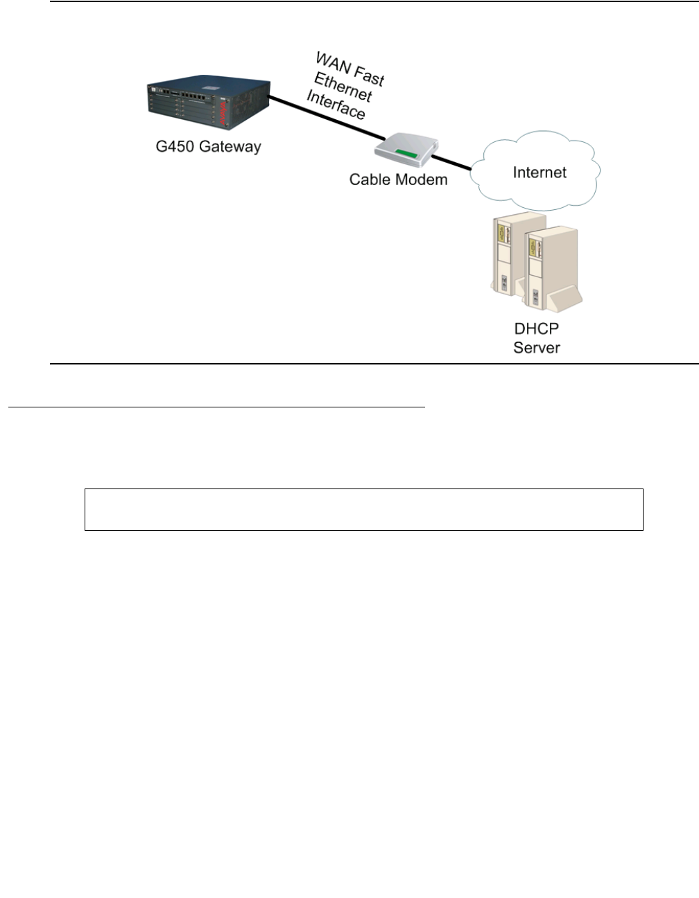
Configuring Ethernet ports
200 Administration for the Avaya G450 Media Gateway
Figure 18: Fixed connection to broadband Internet using G450 as DHCP client
DHCP client configuration
1. Enter the context of the FastEthernet interface. For example:
2. Optionally, configure DHCP client parameters. If you do not configure these parameters,
their default values are used:
●Use the ip dhcp client client-id command to set the client identifier for the
DHCP client. By default, the client identifier is usually the MAC address of the G450
FastEthernet interface.
●Use the ip dhcp client hostname command to set the hostname for the DHCP
client. By default, the DHCP client uses the G450’s hostname.
●Use the ip dhcp client lease command to set the lease requested by the DHCP
client. The lease is the length of time that the IP address provided by the DHCP server
remains in effect. By default, the client does not request a specific lease from the
DHCP server and uses the lease set by the DHCP server.
G450-001# interface fastethernet 10/2
G450-001(config-if:FastEthernet 10/2)#

Configuring DHCP client
Issue 1 January 2008 201
●Use the ip dhcp client request command to determine which DHCP options
the DHCP client requests from the DHCP server. By default, the DHCP client requests
all DHCP options. For information on the specific options, see Table 117.
For example:
3. Optionally, use the ip dhcp client route track command to apply an object tracker
to monitor the DHCP client’s default route. The object tracker continuously checks the
validity of the default route, that is, whether data can be transmitted over the default route.
Whenever the object tracker determines that the default route has become invalid, the
route is dropped from the routing table and traffic is routed to alternate routes. If the default
route becomes valid again, it is added back to the routing table.
To define an object tracker, see Object tracking configuration on page 299.
For an example of how to track the DHCP client default route, see Typical application –
tracking the DHCP client default route on page 313.
Note that if several default routers are learned from a specific interface, the object tracker
tracks only the first one.
For example:
4. Enable the DHCP client by entering ip address dhcp.
A message appears, displaying the IP address and mask assigned by the DHCP server.
For example:
Note:
Note: Whenever you change the value of a DHCP client parameter (such as, client-id,
or client hostname), enter ip address dhcp again to re-initiate DHCP address
negotiation using the new values.
G450-001(config-if:FastEthernet 10/2)# ip dhcp client client-id hex
01:00:04:0D:29:DC:68
Done!
G450-001(config-if:FastEthernet 10/2)# ip dhcp client hostname “G450-A“
Done!
G450-001(config-if:FastEthernet 10/2)# ip dhcp client lease 1 4 15
Done!
G450-001(config-if:FastEthernet 10/2)# no ip dhcp client request domain-name
Done!
G450-001(config-if:FastEthernet 10/2)#ip dhcp client route track 3
Done!
G450-001(config-if:FastEthernet 10/2)# ip address dhcp
Done!
Interface FastEthernet 10/2 assigned DHCP address 193.172.104.161, mask
255.255.255.0

Configuring Ethernet ports
202 Administration for the Avaya G450 Media Gateway
5. You can use the show ip dhcp-client command to view the DHCP client parameters.
For example:
Releasing and renewing a DHCP lease
●Use the release dhcp command to release a DHCP lease for an interface. This
effectively releases the client IP address, and no IP address is allocated to the specified
interface. For example:
●Use the renew dhcp command to renew a DHCP lease for an interface. This is
effectively a request to renew an existing IP address, or the start of a new process of
allocating a new IP address. For example:
G450-001(config-if:FastEthernet 10/2)# show ip dhcp-client
DHCP Client Mode : Enable
Status : Bound
IP Address : 193.172.104.161
Subnet Mask : 255.255.255.0
Default Router : 193.172.104.162
DHCP Server : 192.100.106.163
DNS Server : 192.100.106.101
Domain Name : avaya.com
Lease Received (D:H:M:S) : 0:0:10:0
Lease Remains (D:H:M:S) : 0:0:9:32
Lease Rebind (D:H:M:S) : 0:0:8:45
Lease Renew (D:H:M:S) : 0:0:5:0
Lease Requested (D:H:M:S) : 1:3:4:0
Host Name : G450-A
Client Identifier : 01:00:04:0D:29:DC:68
Requested Options :
subnet-mask (1)
routers (3)
domain-name (15)
domain-name-servers (6)
Track-id : 3
G450-001(super)# release dhcp FastEthernet 10/2
Done!
G450-001(super)# renew dhcp FastEthernet 10/2
Done!

Configuring DHCP client
Issue 1 January 2008 203
A message appears displaying the IP address and mask assigned by the DHCP server.
For example:
Maintaining DHCP client
For a full description of the commands and their output fields see Avaya G450 CLI Reference,
03-602056.
●Use the show ip dhcp-client command to show the configuration of the DHCP
client.
●Enter show ip dhcp-client statistics to show the DHCP client statistics
counters.
●Enter clear ip dhcp-client statistics to clear the DHCP client statistics
counters.
Configuring DHCP client logging messages
1. Enter set logging session enable to enable logging to the CLI terminal.
2. Use the set logging session condition dhcpc command to view all DHCP client
messages of level Info and above. For example:
Note:
Note: You can also enable logging messages to a log file or a Syslog server. For a full
description of logging on the G450, see Configuring logging on page 209.
Interface FastEthernet 10/2 assigned DHCP address 193.172.104.161, mask
255.255.255.0
G450-001# set logging session enable
Done!
CLI-Notification: write: set logging session enable
G450-001# set logging session condition dhcpc Info
Done!
CLI-Notification: write: set logging session condition dhcpc Info
Configuring Ethernet ports
204 Administration for the Avaya G450 Media Gateway
Summary of DHCP client configuration CLI commands
For more information about these commands, see Avaya G450 CLI Reference, 03-300437.
Table 55: DHCP client configuration CLI commands
Root level
command Command Description
clear ip
dhcp-client
statistics
Clear the DHCP client statistics counters
interface
fastethernet Enter interface fastethernet configuration mode
clear ip dhcp-client
statistics Clear the DHCP client statistics counters
ip address dhcp Enable or disable IP address negotiation via
DHCP (applies to WAN FastEthernet interfaces
only)
ip dhcp client
client-id Set the client identifier for the DHCP client
ip dhcp client
hostname Set the client hostname for the DHCP client
ip dhcp client lease Set the lease requested by the DHCP client
ip dhcp client
request Specify which DHCP options the DHCP client
requests from the DHCP server
ip dhcp client route
track Apply object tracking in order to monitor the
DHCP client’s default route
show ip dhcp-client Display the configuration of the DHCP client
show ip dhcp-client
statistics Display the DHCP client statistics counters
release dhcp Release a DHCP lease for an interface
renew dhcp Renew a DHCP lease for an interface
1 of 2

Configuring LLDP
Issue 1 January 2008 205
Configuring LLDP
IEEE 802.1AB Link Layer Discovery Protocol (LLDP) simplifies troubleshooting of enterprise
networks and enhances the ability of network management tools to discover and maintain
accurate network topologies in multi-vendor environments. It defines a set of advertisement
messages, called TLVs, a protocol for transmitting and receiving the advertisements, and a
method for storing the information contained in the received advertisements.
The LLDP protocol allows stations attached to a LAN to advertise information about the system
(such as, its major capabilities and its management address) and information regarding the
station’s point of attachment to the LAN (port ID and VLAN information) to other stations
attached to the same LAN. These can all be reported to management stations via IEEE-defined
SNMP MIBs.
LLDP information is transmitted periodically. The IEEE has defined a recommended
transmission rate of 30 seconds, but the transmission rate is adjustable. An LLDP device, after
receiving an LLDP message from a neighboring network device, stores the LLDP information in
an SNMP MIB. This information is valid only for a finite period of time after TLV reception. This
time is defined by the LLDP “Time to Live” (TTL) TLV value that is contained within the received
packet unless refreshed by a newly received TLV. The IEEE recommends a TTL value of 120
seconds, but you can change it if necessary. This ensures that only valid LLDP information is
stored in the network devices and is available to network management systems.
LLDP information is associated with the specific device that sends it. The device itself is
uniquely identified by the receiving party port via chassis ID and port ID values. Multiple LLDP
devices can reside on a single port, using a hub for example, and all of the devices are reported
via MIB. You can enable (Rx-only, TX-only, and Rx or Tx) or disable LLDP mode of operation on
a per-port basis.
show ip
dhcp-client Display the configuration of the DHCP client
show ip
dhcp-client
statistics
Display the DHCP client statistics counters
Table 55: DHCP client configuration CLI commands (continued)
Root level
command Command Description
2 of 2

Configuring Ethernet ports
206 Administration for the Avaya G450 Media Gateway
Supported TLVs
Mandatory TLVs
●End-of-LDPDU
●Chassis ID
●Port ID
●Time to Live
Optional TLVs
●Port description
●System description
●System name
●System capabilities
●Management address
802.1 TLVs (optional)
●VLAN name
●Port VLAN
LLDP configuration
1. Enable the LLDP agent globally using the set lldp system-control command. For
example:
The device’s global topology information, including all mandatory TLVs, is now available to
neighboring devices supporting LLDP.
G450-001(super)# set lldp system-control enable
Done!

Configuring LLDP
Issue 1 January 2008 207
2. Optionally, configure the administrative LLDP port status using the set port lldp
command. The default value is rx-and-tx. For example:
The device now sends LLDP TLVs and accepts LLDP TLVs from neighboring devices
supporting LLDP on the specified port.
3. Optionally, configure additional TLVs transmission using the set port lldp tlv
command. This allows you to advertise additional data about the device’s and port’s VLAN
information, VLANs, and system capabilities. Additional TLVs are disabled by default. For
example:
The device now advertises all mandatory and optional TLVs to neighboring network
devices supporting LLDP.
4. If required, change any of the following timing parameters:
●The interval at which the device transmits LLDP frames, using the command set
lldp tx-interval. The default is 30 seconds.
●The value of TxHoldMultiplier, using the command set lldp
tx-hold-multiplier. TxHoldMultiplier is a multiplier on the interval configured by
set lldp tx-interval that determines the actual TTL value sent in an LLDP
frame. The default value is 30. The time-to-live value transmitted in TTL TLV is
expressed by: TTL = min(65535, TxInterval * TxHoldMultiplier).
●The minimal delay between successive LLDP frame transmissions, on each port,
using the command set lldp tx-delay. The default is 30 seconds.
●The delay from when a port is set to LLDP “disable” until re-initialization is attempted,
using the command set lldp re-init-delay. The default is 2 seconds.
5. Verify LLDP advertisements using the show lldp command.
Displaying LLDP configuration
●Use the show lldp config command to display the global LLDP configuration.
●Use the show port lldp config command to display port-level LLDP configuration.
●Use the show port lldp vlan-name config command to show the statically bound
VLANs that the port transmits in the VLAN Name TLV.
Supported ports for LLDP
Only ports 10/5 and 10/6 can be configured to support LLDP.
G450-001(super)# set port lldp 10/3 rx-and-tx
Done!
G450-001(super)# set port lldp tlv 10/3 enable all
Done!
Configuring Ethernet ports
208 Administration for the Avaya G450 Media Gateway
Summary of LLDP configuration CLI commands
For more information about these commands, see Avaya G450 CLI Reference, 03-300437.
Table 56: LLDP configuration CLI commands
Command Description
set lldp re-init-delay Set the delay from when a port is set to LLDP "disable"
until re-initialization is attempted
set lldp system-control Enable or disable the LLDP application globally per
device or stack
set lldp tx-delay Set the TxDelay, which is the minimal delay in seconds
between successive LLDP frame transmissions, on
each port
set lldp tx-hold-multiplier Set the TxHoldMultiplier, which is a multiplier on
the TxInterval that determines the actual TTL value
sent in an LLDP frame
set lldp tx-interval Set the TxInterval, the interval at which the device
transmits LLDP frames
set port lldp Change the administrative LLDP status of a port
set port lldp tlv Enable or disable the transmission of the optional TLVs
on a per port basis
show lldp Display the LLDP information received on each port
show lldp config Display the global LLDP configuration
show port lldp config Display port-level LLDP configuration
show port lldp vlan-name
config Show the VLANs that are being transmitted on a
specific port

Issue 1 January 2008 209
Chapter 8: Configuring logging
System logging is a method of collecting system messages generated by system events. The
Avaya G450 Media Gateway includes a logging package that collects system messages in
several output types. Each of these types is called a sink. When the system generates a logging
message, the message can be sent to each sink that you have enabled.
System messages do not always indicate problems. Some messages are informational, while
others may help to diagnose problems with communications lines, internal hardware, and
system software.
By default, all sinks are disabled. When enabled, log file and Syslog sink settings can be saved
by entering copy running-config startup-config to save the running configuration to
the startup configuration. However, the Session sink and its settings are deleted when the
session is terminated.
You can define filters for each sink to limit the types of messages the sink receives (see
Configuring logging filters on page 217).
The logging facility logs configuration commands entered through the CLI or via SNMP, as well
as system traps and informative messages concerning the behavior of various processes.
However, a user enabling the log will only see entered commands with a user-level no higher
than the user’s privileges. For example, a user with read-only privileges will not see entered
commands having a read-write user level. In addition, the log does not display entered
information of a confidential nature, such as, passwords and VPN pre-shared-keys.
Table 57: Logging sinks
Sink Description
Syslog Logging messages are sent to up to three configured servers, using
Syslog protocol as defined in RFC 3164. Messages sent to the Syslog
server are sent as UDP messages.
Log file Logging data is saved in the flash memory. These compressed, cyclic files
serve as the system logging database.
Session Logging messages are sent to the terminal screen as follows:
●For a local connection, messages appear online on the local terminal.
●For a remote Telnet/SSH connection, messages appear online on the
remote terminal.
This sink is deleted whenever a session ends.

Configuring logging
210 Administration for the Avaya G450 Media Gateway
Configuring a Syslog server
A Syslog server is a remote server that receives logging messages using the Syslog protocol.
This enables storage of large log files, which you can use to generate reports.
Defining Syslog servers
You can define up to three Syslog servers.
1. Define the Syslog server by entering set logging server followed by the IP address
of the server. For example:
2. Enable the Syslog server by entering set logging server enable followed by the IP
address of the Syslog server. When you define a new Syslog server, it is defined as
disabled, so you must use this command in order to enable the server. For example:
3. Optionally, define an output facility for the Syslog server by typing the set logging
server facility command, followed by the name of the output facility and the IP
address of the Syslog server. If you do not define an output facility, the default local7
facility is used. For example:
The following is a list of possible facilities:
●auth. Authorization
●daemon. Background system process
●clkd. Clock daemon
●clkd2. Clock daemon
●mail. Electronic mail
●local0 – local7. For local use
●ftpd. FTP daemon
●kern. kernel
●alert. Log alert
●audi. Log audit
G450-001(super)# set logging server 147.2.3.66
Done!
G450-001(super)# set logging server enable 147.2.3.66
Done!
G450-001(super)# set logging server facility auth 147.2.3.66
Done!

Configuring a Syslog server
Issue 1 January 2008 211
●ntp. NTP subsystem
●lpr. Printing
●sec. Security
●syslog. System logging
●uucp. Unix-to-Unix copy program
●news. Usenet news
●user. User process
4. Optionally, limit access to the Syslog server output by typing the set logging server
access-level command, followed by an access level (read-only, read-write, or
admin) and the IP address of the Syslog server. If you do not define an access level, the
default read-write level is used. For example:
Only messages with the appropriate access level are sent to the Syslog output.
5. Optionally, define filters to limit the types of messages received (see Configuring logging
filters on page 217).
Disabling Syslog servers
Enter set logging server disable followed by the IP address of the Syslog server. For
example:
Deleting Syslog servers
You can delete a Syslog server from the Syslog server table. Enter clear logging server
followed by the IP address of the Syslog server you want to delete. For example:
G450-001(super)# set logging server access-level read-only 147.2.3.66
Done!
G450-001(super)# set logging server disable 147.2.3.66
Done!
G450-001(super)# clear logging server 147.2.3.66
Done!

Configuring logging
212 Administration for the Avaya G450 Media Gateway
Displaying the status of the Syslog server
Enter show logging server condition followed by the IP address of the Syslog server. If
you do not specify an IP address, the command displays the status of all Syslog servers defined
for the G450.
As the following example illustrates, the command displays whether the server is enabled or
disabled, and lists all filters defined on the server:
Syslog sink default settings
●Severity. Warning
●Facility. Local 7
●Access level. Read-write
Syslog message format
Syslog messages are arranged chronologically and have the following format:
The message provides the following information:
●A priority (<34> in this example), which is calculated based on the syslog facility and
the severity level.
●A header (Oct 11 22:14:15 host LINKDOWN in this example), providing the date
and time, the hostname, and a message mnemonic.
●A message (SWICHFABRIC-Notification: Port 10/3 Link in this example),
detailing the application being logged, the severity level, and the message text.
G450-001(super)# show logging server condition 147.2.3.66
******************************************************
*** Message logging configuration of SYSLOG sink ***
Sink Is Enabled
Sink default severity: Warning
Server name: 147.2.3.66
Server facility: auth
Server access level: read-only
<34> Oct 11 22:14:15 host LINKDOWN SWICHFABRIC-Notification:Port 10/3 Link

Configuring a log file
Issue 1 January 2008 213
Configuring a log file
A log file is a file of data concerning a system event, saved in the flash memory. The log files
serve as the system logging database, keeping an internal record of system events.
1. Enter set logging file enable.
2. Optionally, define filters to limit the types of messages received (see Configuring logging
filters on page 217).
Disabling logging system messages to a log file
Enter set logging file disable.
Deleting current log file and opening an empty log file
Enter clear logging file.
G450-001(super)# set logging file enable
Done!
G450-001(super)# set logging file disable
Done!
G450-001(super)# clear logging file
Done!

Configuring logging
214 Administration for the Avaya G450 Media Gateway
Displaying log file messages
Use the show logging file content command. Note that the user enabling the log will
only see entered commands with a user-level no higher than the user’s privileges. A user with
read-only privileges will not see entered commands having a read-write user level. For
example:
Displaying conditions defined for the file output sink
Enter show logging file condition. For example:
G450-001(super)# show logging file content
11/21/2004,15:45:43:CLI-Notification: root: nvram initialize
11/21/2004,15:43:08:CLI-Notification: root: exit
11/21/2004,15:42:20:ROUTER-Warning: Duplicate IP address: 3.3.3.1 from 00:00:021
11/18/2004,16:48:21:CLI-Notification: root: no track 20
11/18/2004,16:48:18:SAA-Debug: Response for ipIcmpEcho timed-out on rtr 6, echo.
11/18/2004,16:48:18:CLI-Notification: root: no rtr-schedule 6
11/18/2004,16:48:18:SAA-Informational: rtr 6 state changed to pending.
11/18/2004,16:48:18:TRACKER-Informational: track 6 state changed to pending.
G450-001(super)# show logging file condition
******************************************************
*** Message logging configuration of FILE sink ***
Sink Is Enabled
Sink default severity: Informational

Configuring a session log
Issue 1 January 2008 215
Log file message format
Log file messages appear in first-in, last-out order. They have the following format:
Each message provides the following information:
●The date and time (if available)
●The logging application
●The severity level
●The message text
Configuring a session log
A session log is the display of system messages on the terminal screen. It is automatically
deleted when a session ends.
1. Enter set logging session enable.
Note:
Note: If the device is connected to several terminals, a separate session log is
established for each terminal.
2. Optionally, define filters to limit the types of messages received (see Configuring logging
filters on page 217).
Discontinuing the display of system messages
To discontinue the display of system messages to the terminal screen, enter set logging
session disable.
01/18/2005,10:55:09:CLI-Notification: root: set port disable 10/6
01/18/2005,10:49:03:SWITCHFABRIC-Notification: Port Connection Lost on Module 10
port 5
G450-001(super)# set logging session enable
Done!
G450-001(super)# set logging session disable
Done!

Configuring logging
216 Administration for the Avaya G450 Media Gateway
Displaying how the session logging is configured
Enter show logging session condition. This command displays whether session
logging is enabled or disabled, and lists all filters defined for session logging. For example:
Session logging message format
Session logging messages are arranged chronologically and have the format shown in the
following example:
Each message provides the following information:
●The date and time (if available)
●The logging application
●The severity level
●The message text
Note:
Note: The user enabling the log will only see entered commands with a user-level no
higher than the user’s own privileges. For example, a user with read-write
privileges will not see entered commands having an admin user level.
G450-001(super)# show logging session condition
******************************************************
*** Message logging configuration of SESSION sink ***
Sink Is Enabled
Sink default severity: Warning
Session source ip: 172.16.1.231
01/18/2005,10:49:03:SWITCHFABRIC-Notification: Port Connection Lost on Module 10
port 5 was cleared
01/18/2005,10:55:09:CLI-Notification: root: set port disable 10/6

Configuring logging filters
Issue 1 January 2008 217
Configuring logging filters
You can use filters to reduce the number of collected and transmitted messages. The filtering
options are based on message classification by severity for each application. For a specified
sink, you can define the threshold severity level for message output for each application.
Messages pertaining to the specified applications, that have a severity level stronger than or
equal to the defined threshold, are sent to the specified sink. Messages with a severity level
weaker than the defined threshold are not sent.
Setting the logging filters
For each sink, you can set logging filters by specifying a severity level per application, as
follows:
●To create a filter for messages sent to a specified Syslog server, enter set logging
server condition application severity ip address.
●To create a filter for messages sent to a log file, enter set logging file condition
application severity.
●To create a filter for messages sent to a session log on a terminal screen, enter set
logging session condition application severity.
where:
●application is the application for which to view messages (use all to specify all
applications). For the list of applications see Applications to be filtered on page 219.
●severity is the minimum severity to log for the specified application (use none to
disable logging messages for the specified application). For a list of the severity levels
and the default severity settings, see Severity levels on page 218.
●ip address is the IP address of the Syslog server.
For example:
You can also filter the show logging file content command by severity for each
application, using the same variables as in the set logging file condition command. In
addition, you can limit the number of messages to display.
G450-001(super)# set logging server condition dialer critical 147.2.3.66
Done!
G450-001(super)# set logging file condition dhcps warning
Done!
G450-001(super)# set logging session condition ISAKMP Information
Done!

Configuring logging
218 Administration for the Avaya G450 Media Gateway
For example, to display the 50 most recent messages from the QoS application with a severity
level of critical or higher, enter the following command:
Severity levels
Sinks default severity levels
●Syslog. Warning
●Log file. Informational
●Session
-
Session from terminal. Informational
-
Session from telnet/ssh. Warning
G450-001(super)# show logging file content critical qos 50
Table 58: Severity levels
Severity level Code Description
emergency 0 System is unusable
alert 1Immediate action required
critical 2 Critical condition
error 3Error condition
warning 4 Warning condition
notification 5Normal but significant condition
informational 6 Informational message only
debugging 7Message that only appears during debugging

Configuring logging filters
Issue 1 January 2008 219
Applications to be filtered
Filters can be defined for any application listed in Table 59.
Table 59: Logging applications
Application Description
boot System startup failures
cascade Stack CASCADE mechanism
cdr Call Detail Recording. Registers the active calls in SLS
mode.
cli CLI
aan Application Assurance Networking. CNA test plugs report
to AAN.
config Configuration changes
console Serial modem messages
dhcpc DHCP client package
dhcps DHCP server package
dialer Dialer interface messages
dnsc DNS client package
fan Cooling system
filesys File system problem (flash)
ids IDS events, specifically a SYN attack heuristic employed
by the SYN cookies feature
ipsec VPN IPSEC package
isakmp VPN IKE package
lag Link Aggregation package
policy Policy package
ppp PPP protocol
pppoe PPP over Ethernet
qos QoS messages
router Core routing system failures
1 of 2

Configuring logging
220 Administration for the Avaya G450 Media Gateway
Syslog server example
The following example defines a Syslog server with the following properties:
●IP address 147.2.3.66
●Logging of messages enabled
●Output to the Kernel facility
●Only messages that can be viewed by read-write level users are received
rtp-stat RTP MIB statistics
saa RTR-probes messages
security Secure logging (authentication failure)
snmp SNMP agent
stp Spanning tree package
supply Power supply system
switchfabric Switch fabric failures
system Operating system failures
tftp Internal TFTP server
threshold RMON alarms
tracker Object tracker messages
usb-modem USB modem messages
vlan VLAN package
voice Voice failures
wan WAN plugged-in expansion
Table 59: Logging applications (continued)
Application Description
2 of 2

Configuring logging filters
Issue 1 January 2008 221
●Filter restricts receipt of messages from all applications to those less severe than error
Log file example
The following example enables the logging of system messages to a log file in the flash memory
and creates a filter to restrict the receipt of messages from the boot application to those with
severity level of informational or more severe, and messages from the cascade application to
those with severity level of alert or more severe.
G450-001(super)# set logging server 147.2.3.66
Done!
G450-001(super)# set logging server enable 147.2.3.66
Done!
G450-001(super)# set logging server facility kern 147.2.3.66
Done!
G450-001(super)# set logging server access-level read-write 147.2.3.66
Done!
G450-001(super)# set logging server condition all error 147.2.3.66
Done!
G450-001(super)# set logging file enable
Done!
G450-001(super)# set logging file condition boot informational
Done!
G450-001(super)# set logging file condition cascade alert
Done!

Configuring logging
222 Administration for the Avaya G450 Media Gateway
Session log example
The following example enables a session log for a user wishing to debug the ISAKMP
application, while only receiving messages of severity level error or stronger for all other
applications. Therefore, the user sets the default severity level for all applications to error, and
then sets the severity of the ISAKMP application to informational. Finally, the user displays the
filter settings.
Summary of Logging configuration CLI commands
For more information about these commands, see Avaya G450 CLI Reference, 03-300437.
G450-001(super)# set logging session enable
Done!
G450-001(super)# set logging session condition all Error
Done!
G450-001(super)# set logging session condition ISAKMP Informational
Done!
G450-001(super)# show logging session condition
******************************************************
*** Message logging configuration of CLI sink ***
Sink Is Enabled
Sink default severity: Error
Application ! Severity Override
-------------------------------------------
ISAKMP ! Informational
Table 60: Logging configuration CLI commands
Command Description
clear logging file Delete the message log file being stored in non-volatile
memory (NVRAM), including the history log, and open a
new, empty log file
clear logging server Delete the specified Syslog message server from the
Syslog server table
set logging file Manage the logging of system messages to non-volatile
memory (NVRAM)
1 of 2
Summary of Logging configuration CLI commands
Issue 1 January 2008 223
set logging server Define a new Syslog output server for remote logging of
system messages
set logging server
access-level Set the access level associated with a Syslog server
sink
set logging server
condition Set a filter for messages sent to the specified Syslog
server. Messages can be filtered by source system,
severity, or both.
set logging server enable |
disable Enable or disable a specific Syslog server
set logging server facility Define an output facility for the specified Syslog server
set logging session Manage message logging for the current console
session
show logging file condition Display all conditions that have been defined for the file
output sink
show logging file content Output the messages in the log file to the CLI console
show logging server
condition Display the filter conditions defined for the Syslog
output sink
show logging session
condition Display the filter conditions defined for message logging
to the current console session
Table 60: Logging configuration CLI commands (continued)
Command Description
2 of 2

Configuring logging
224 Administration for the Avaya G450 Media Gateway

Issue 1 January 2008 225
Chapter 9: Configuring VoIP QoS
The Avaya G450 Media Gateway provides voice services over IP data networks using VoIP.
VoIP is a group of protocols for transmitting and receiving various types of voice data over an IP
network. VoIP includes protocols for transmitting and receiving the following types of
information:
●Digitally encoded voice data
●Call signalling information
●Call routing information
●QoS information
VoIP uses the RTP and RTCP protocols to transmit and receive digitally encoded voice data.
For more information about configuring RTP and RTCP on the Avaya G450 Media Gateway,
see Configuring RTP and RTCP on page 225.
You can use many types of telephones and trunks that do not directly support VoIP. The Avaya
G450 Media Gateway translates voice and signalling data between VoIP and the system used
by the telephones and trunks.
Configuring RTP and RTCP
VoIP uses the RTP and RTCP protocols to transmit and receive digitally encoded voice data.
RTP and RTCP are the basis of common VoIP traffic. RTP and RTCP run over UDP and incur a
12-byte header on top of other (IP, UDP) headers. Running on PPP or frame relay, these
protocols can be compressed.
Configuring header compression
Header compression reduces the size of packet headers, thus reducing the amount of
bandwidth needed for data. The header compression method is based on the fact that most of
the header fields remain constant or change in predictable ways throughout the session. Thus,
instead of constantly retransmitting the header, each side keeps a context table of the sessions
(the normal headers), and while sending and receiving packets it replaces the full-length
headers with one or two bytes CID (context-id) plus unpredictable deltas from the last packet.
Configuring VoIP QoS
226 Administration for the Avaya G450 Media Gateway
The G450 offers both RTP header compression, for reducing the amount of bandwidth needed
for voice traffic, and TCP and UDP header compression, for reducing the amount of bandwidth
needed for non-voice traffic.
For header compression purposes, any UDP packet with an even destination port within a
user-configurable range of ports, is considered an RTP packet.
The G450 enables decompression whenever compression is enabled. However, when enabling
header compression on a Frame Relay interface, you must first verify that the remote host is
also employing header compression. Header compression on a Frame Relay interface does not
check what the remote host is employing. Thus, it may compress headers even when the
remote host is not configured to decompress headers.
You can configure how often a full header is transmitted, either as a function of time or of
transmitted compressed packets.
Header compression configuration options
The G450 offers two options for configuring header compression:
●IP Header compression (IPHC) method, as defined by RFC 2507. IPHC-type compression
applies to RTP, TCP, and UDP headers.
●Van Jacobson (VJ) method, as defined in RFC 1144. VJ compression applies to TCP
headers only.
Note:
Note: VJ compression and IPHC cannot co-exist on an interface, and IPHC always
overrides VJ compression. Thus, if you define both VJ compression and IPHC,
only IPHC is enabled on the interface regardless of the order of definition.
Table 61: Header compression support by interface
Interface type Supported compression methods
Serial
PPP IPHC and VJ
Sub-Frame-Relay with IETF
encapsulation IPHC only
Sub-Frame-Relay with non-IETF
encapsulation RTP header compression using the IPHC
method, and TCP header compression using
the VJ method
Dialer IPHC and VJ

Configuring header compression
Issue 1 January 2008 227
Note:
Note: Non-IETF encapsulation is compatible with other vendors.
Configuring IPHC
IHPC applies to RTP, TCP, and UDP headers.
Note:
Note: You cannot specify IPHC for a Frame Relay non-IETF interface.
1. Optionally, configure header compression parameters. If you do not configure these
parameters, their default values are used.
●Use the ip rtp compression-connections command to control the number of
RTP header compression connections supported on the interface. Use the no form of
this command to restore the default value of 16. This command also sets the number
of connections in the non-TCP space, not just RTP.
●Use the ip tcp compression-connections command to control the number of
TCP header compression connections supported on the interface. Use the no form of
this command to restore the default value of 16.
●Use the ip rtp max-period command to set the maximum number of compressed
RTP headers that can be sent between full headers.
●Use the ip rtp max-time command to set the maximum number of seconds
between full RTP headers.
●Use the ip rtp non-tcp-mode command to set the header compression mode.
When set to ietf, the command performs IP header compression according to IPHC
RFCs. When set to non-ietf, the command performs IP header compression
compatible with other vendors, which do not strictly follow the RFCs. The default
header compression mode is non-ietf.
Note:
Note: IETF mode is not compatible with non-IETF mode.
Configuring VoIP QoS
228 Administration for the Avaya G450 Media Gateway
●Use the ip rtp port-range command to configure the range of UDP ports for
RTP. For example:
2. Use the ip rtp header-compression command if you want to enable RTP, TCP, and
UDP header compression on the current interface. The compression method employed is
IPHC. Alternatively, you can use the following equivalent command:
ip tcp header-compression iphc-format
For example:
Note:
Note: Once header compression is enabled, any change to a header compression
parameter is effective immediately.
To disable IPHC on an interface, use the no form of the command you employed (in the
interface context): no ip rtp header-compression or no ip tcp
header-compression.
Summary of IPHC header compression CLI commands
For more information about these commands, see Avaya G450 CLI Reference, 03-300437.
G450-001(config-if:Serial 4/1:1)# ip rtp compression-connections 48
Done!
G450-001(config-if:Serial 4/1:1)# ip tcp compression-connections 48
Done!
G450-001(config-if:Serial 4/1:1)# ip rtp max-period 512
Done!
G450-001(config-if:Serial 4/1:1)# ip rtp max-time 20
Done!
G450-001(config-if:Serial 4/1:1)# ip rtp non-tcp-mode ietf
Done!
G450-001(config-if:Serial 4/1:1)# ip rtp port-range 40000 50000
Done!
G450-001# interface dialer 1
G450-001(config-if:Serial 4/1:1)# ip rtp header-compression
Done
Table 62: IPHC configuration CLI commands
Root level command First level command Description
clear ip rtp
header-compression Clear IP RTP header compression statistics for
all enabled interfaces or for a specific interface
clear ip tcp
header-compression Clear TCP header compression statistics for
all enabled interfaces or for a specific interface
1 of 2
Configuring header compression
Issue 1 January 2008 229
Configuring VJ header compression
VJ header compression applies to TCP headers only.
Note:
Note: You cannot specify VJ header compression for a Frame Relay IETF interface.
interface
(dialer|serial) Enter the Dialer or Serial interface context
ip rtp
compression-
connections
Control the number of Real-Time Transport
Protocol (RTP) connections supported on the
current interface
ip rtp
header-compression Enable both RTP and TCP header
compression on the current interface
ip rtp max-period Set the maximum number of compressed
headers that can be sent between full headers
ip rtp max-time Set the maximum number of seconds between
full headers
ip rtp
non-tcp-mode Set the type of IP header compression: ietf
or non-ietf
ip rtp port-range Set the range of UDP ports considered as RTP
on the current interface
ip tcp
compression-
connections
Set the total number of TCP header
compression connections supported on the
current interface
show ip rtp
header-compression Display header compression statistics for a
specific interface
show ip rtp
header-compression
brief
Display a subset of header compression
statistics in the form of a table
show ip tcp
header-compression Display TCP header compression statistics for
a specific interface
show ip tcp
header-compression
brief
Display a subset of TCP header compression
statistics in the form of a table
Table 62: IPHC configuration CLI commands (continued)
Root level command First level command Description
2 of 2

Configuring VoIP QoS
230 Administration for the Avaya G450 Media Gateway
1. Optionally, use the ip tcp compression-connections command to control the
number of TCP header compression connections supported on the interface. Use the no
form of this command to restore the default value of 16 connections.
For example:
2. Use the ip tcp header-compression command to enable TCP header compression
on the current interface. The compression method employed is the VJ compression.
Note:
Note: The ip rtp header-compression command always overrides the ip tcp
header-compression command. Both commands enable TCP header
compression, but they differ in the methods employed.
Note:
Note: The ip tcp header-compression iphc-format command always
overrides the ip tcp header-compression command, and activates
IPHC-type compression.
For example:
Note:
Note: Once header compression is enabled, any change to a header compression
parameter is effective immediately.
3. To disable VJ TCP header compression on an interface, use the no ip tcp
header-compression command in the interface context.
G450-001(config-if:Dialer 1)# ip tcp compression-connections 24
Done!
G450-001# interface dialer 1
G450-001(config-if:Dialer 1)# ip tcp header-compression
Done!
Configuring header compression
Issue 1 January 2008 231
Summary of Van Jacobson header compression CLI commands
For more information about these commands, see Avaya G450 CLI Reference, 03-300437.
Displaying and clearing header compression statistics
For a full description of the commands and their output fields, see Avaya G450 CLI Reference,
03-602056.
●Use the show ip rtp header-compression command to display the RTP header
compression statistics for a specific interface. If no interface is specified, statistics for all
interfaces are displayed.
●Use the show ip tcp header-compression command to display the TCP header
compression statistics for a specific interface. If no interface is specified, statistics for all
interfaces are displayed. Use this command regardless of which compression method is
employed.
●Use the clear ip rtp header-compression command to clear RTP header
compression statistics either for all enabled interfaces or for a specific interface. To clear
RTP compression statistics for all enabled interfaces, do not enter an interface type and
number. Clearing the statistics does not cause renegotiation of parameters.
Table 63: Van Jacobson header compression CLI commands
Root level command First level command Description
clear ip tcp
header-compression Clear TCP header compression statistics for
all enabled interfaces or for a specific
interface
interface
(dialer|serial) Enter the Dialer or Serial interface
context
ip tcp
compression-
connections
Set the total number of TCP header
compression connections supported on the
current interface
ip tcp
header-compression Enable TCP header compression on the
current interface
show ip tcp
header-compression Display TCP header compression statistics
for a specific interface
show ip tcp
header-compression
brief
Display a subset of TCP header
compression statistics in the form of a table

Configuring VoIP QoS
232 Administration for the Avaya G450 Media Gateway
●Use the clear ip tcp header-compression command to clear TCP header
compression statistics either for all enabled interfaces or for a specific interface. To clear
TCP compression statistics for all enabled interfaces, do not enter an interface type and
number. Clearing the statistics does not cause renegotiation of parameters.
Use this command regardless of which compression method is employed.
Configuring QoS parameters
The G450 uses MGCP (H.248) protocol for call signalling and call routing information. Use the
following commands to configure QoS for signalling and VoIP traffic.
●Use the set qos control command to define the source for QoS control parameters.
The source can be either local, in which case the user configures the values locally on
the G450, or remote, in which case the values are obtained from the G450’s registered
MGC.
●Use the set qos signal command to provide the means to set up QoS parameters for
MGCP (H.248) communication with the MGC.
●Use the show qos-rtcp command to display the local and downloaded QoS
parameters.
●Use the set qos bearer command to provide the means to set up QoS parameters for
the VoIP bearer.
The parameters you define using the set qos bearer command may conflict with the
default QoS list (400).
For more information about these commands, including parameters and default settings, see
Avaya G450 CLI Reference, 03-602056.
Configuring RTCP QoS parameters
Use the following commands to set the RTCP QoS parameters.
●Use the set qos rtcp command to permit the setup of RTCP parameters. The
parameters that can be set are enabling or disabling RTCP reporting capability, setting the
IP address of the monitor, setting the reporting period (the default is five seconds), and
defining the listening port number.
●Use the show qos-rtcp command to display QoS, RSVP, and RTCP parameters.

Configuring QoS parameters
Issue 1 January 2008 233
RSVP parameters
VoIP can use the RSVP protocol to reserve network resources for voice data while
communicating with other media gateways and other VoIP entities, such as, IP phones and
Softphones.
●Use the set qos rsvp command to set the current values for the RSVP parameters of
the VoIP engines. The parameters that can be set are enabled/disabled, refresh rate
(seconds), failure retry (y or n), and service profile (Guaranteed or Controlled).
●Use the show qos-rtcp command to display QoS, RSVP, and RTCP parameters.
Summary of QoS, RSVP, and RTCP configuration CLI commands
For more information about these commands, see Avaya G450 CLI Reference, 03-300437.
Table 64: QoS, RSVP and RTCP configuration CLI commands
Command Description
set qos bearer Permit the setting of VoIP QoS-bearer related parameters for the Media
Gateway Processor and VoIP engines
set qos control Define the source for QoS control parameters: local or remote
set qos rsvp Set values for the RSVP parameters of the VoIP engines
set qos rtcp Set values for RTCP parameters
set qos signal Set QoS signaling parameters (DSCP or 802.1Q) for the Media
Gateway Processor
show qos-rtcp Display QoS, RSVP, and RTCP parameters

Configuring VoIP QoS
234 Administration for the Avaya G450 Media Gateway
Weighted Fair VoIP Queuing (WFVQ)
Weighted Fair VoIP Queuing (WFVQ) combines weighted fair queuing (WFQ) for data streams
and priority VoIP queuing to provide the real-time response time that is required for VoIP.
WFQ is applied to data streams to provide fair bandwidth distribution among different data
streams, with faster response times for shorter packets that are typical for interactive
applications, such as, telnet. Priority VoIP queuing is applied to VoIP bearer and signaling
traffic.
WFVQ is the default queuing mode for all serial interfaces for which frame relay traffic-shaping
is not enabled, and all FastEthernet interfaces for which traffic-shaping is enabled. It is also the
only queueing mode available on a per-PVC basis for serial interfaces when frame relay traffic
shaping is enabled.
Configuring Weighted Fair VoIP Queueing (WFVQ)
●Use the fair-queue-limit command to specify the maximum number of packets that
can be queued in the weighted fair queue. The upper and lower limits of this command
depend on the amount of bandwidth configured for the interface.
Note:
Note: This command should generally be used only for troubleshooting.
●Use either the voip-queue or the priority-queue command in interface context to
disable WFVQ on an interface, by enabling another queuing mode.
●Use the fair-voip-queue command in interface context to re-enable WFVQ on an
interface. WFVQ is the recommended queuing mode for interfaces.
Note:
Note: The no form of the fair-voip-queue command does not exist. If you enter the
command no fair-voip-queue, it will actually enable WFVQ if WFVQ is not
already enabled.
●Use the show queueing command to display WFVQ configuration.
●Use the show queue command to display information about the real-time status of output
queues for the current interface.

Priority queueing
Issue 1 January 2008 235
Summary of WFVQ configuration CLI commands
For more information about these commands, see Avaya G450 CLI Reference, 03-300437.
Priority queueing
Priority queuing enables you to queue packets according to the priority of each packet. There
are four levels of priority. The total number of packets in all queues cannot exceed 5000.
You can enable priority queueing on the following interfaces:
●Serial (DS1 PPP L2-L3, DS1 PPP L2, USP PPP L2, USP PPP L2-L3)
●FastEthernet (L2, L2-L3) - when Frame Relay Traffic Shaping is configured
●Serial (DS1 FR L2, USP FR L2) - when Frame Relay Traffic Shaping is not configured
●Dialer (L2, L2-L3)
Table 65: WFVQ configuration CLI commands
Root level
command Command Description
interface
(serial|
fastethernet|
dialer)
Enter the Serial, FastEthernet, or
Dialer interface configuration context
fair-queue-limit Set the maximum number of packets that can
be queued in the weighted fair queue
fair-voip-queue Enable Weighted Fair VoIP Queuing (WFVQ)
on the current interface
priority-queue Enable or disable priority queuing mode in a
Serial or FastEthernet interface. If you
disable priority queuing, WFVQ is re-enabled.
show queue Display information about the real-time status
of output queues for the current interface
voip-queue Enable or disable custom queueing for VoIP
traffic. If you disable custom queueing,
WFVQ is re-enabled.
show queueing Display the WFVG configuration

Configuring VoIP QoS
236 Administration for the Avaya G450 Media Gateway
Priority queueing is disabled by default, since the default and recommended queueing method
is WFVQ.
The high priority queue can be further split into two parts for voice traffic: control packets and
bearer packets. This is called VoIP queueing. When VoIP queuing is enabled, the bearer queue
size is calculated to meet the estimated queueing delay, which is 20 ms by default. You can
reestimate the queueing delay, which results in a change in the bearer queue size.
Configuring priority queuing
●Use the priority-queue command to enable priority queuing mode in a serial or
FastEthernet interface. By default, priority queuing is off, and Weighted Fair VoIP Queuing
(WFVQ) is enabled on all Serial interfaces and all FastEthernet interfaces for which
traffic-shaping is enabled. If you disable priority queuing by using the no form of the
priority-queue command, WFVQ is re-enabled.
●Use the queue-limit command to set the size of any of the four priority queues, in
packets, for a given interface or interface type. The default sizes depend on the bandwidth
of the interface. Use the no form of the command to restore the packet size to its default
value, using the interface bandwidth.
●Use the voip-queue command to enable VoIP queueing. If you disable VoIP queueing
by using the no form of the voip-queue command, WFVQ is re-enabled.
●Use the voip-queue-delay command to set the maximum queue delay for which to
estimate the high priority queue size necessary to meet the queuing delay for a specific
VoIP codec.
●Use the show queueing command to display the queueing configuration.
Priority queueing
Issue 1 January 2008 237
Summary of priority queueing configuration CLI commands
For more information about these commands, see Avaya G450 CLI Reference, 03-300437.
Table 66: Priority queueing configuration CLI commands
Root level
command Command Description
interface
(serial|
fastethernet|
dialer)
Enter the Serial, FastEthernet, or
Dialer interface configuration context
priority-queue Enable or disable priority queuing mode in a
Serial or FastEthernet interface. If you
disable priority queuing, WFVQ is re-enabled.
queue-limit Set the size of any of the four priority queues,
in packets, for a given interface or interface
type
voip-queue Enable or disable custom queueing for VoIP
traffic. If you disable custom queueing,
WFVQ is re-enabled.
voip-queue-delay Set the maximum query delay for which to
estimate the high priority queue size
necessary to meet the queuing delay
show queueing Display the priority queue configuration

Configuring VoIP QoS
238 Administration for the Avaya G450 Media Gateway

Issue 1 January 2008 239
Chapter 10: Configuring the G450 for
modem use
You can connect either a USB or a serial modem to the Avaya G450 Media Gateway. A USB
modem must be connected to the USB port on the G450 chassis. A serial modem must be
connected to the Console port (CONSOLE) on the G450 chassis.
Both the USB port and the Console port require configuration for modem use. You can
configure the ports for modem use via the Avaya IW or the GIW. For details on using a modem
with the G450, see Installing and Upgrading the Avaya G450 Media Gateway, 03-602054.
Configuring the USB-modem interface
By default, the USB port is not enabled. To enable the USB port, you must enable the
USB-modem interface. Enter interface usb-modem to enable the USB-modem interface.
Use the no form of this command to disable the USB-modem interface. The no form of the
interface usb-modem command also resets the interface to its default parameter values.
These values are:
●Interface status = down
●PPP timeout absolute = 0
Configuring the USB port for modem use
To set the USB port’s parameters, use the following commands in the USB-modem interface
context:
●Enter async reset-modem to reset the connected modem. You can use this command
from within an active PPP session over the USB modem.
●Use the async modem-init-string command to change the default modem
initialization string.

Configuring the G450 for modem use
240 Administration for the Avaya G450 Media Gateway
●Use the ip address command to assign an IP address to the USB port. This is the IP
address to which a remote user can connect using telnet.
For example, to assign the IP address 192.168.22.33 to the USB port, use the following
command:
There is no default IP address for the USB port.
●Use the ppp authentication command to configure the authentication method used
when starting a client session on the PPP server. Use this command with any of the
following parameters:
-
pap. Password Authentication Protocol. An unencrypted password is sent for
authentication.
-
chap. Challenge Handshake Authentication Protocol. An encrypted password is sent
for authentication. To configure this password, use the ppp chap-secret command.
Note:
Note: If the G450 firmware is replaced by an earlier firmware version, the ppp
chap-secret is erased, and must be re-configured.
-
ras. Remote Access Service mode is being used for authentication
-
none. No password is sent
Note:
Note: The ppp authentication command changes the PPP authentication
parameters of the Console port as well as the USB port, even if you use the
command in USB-modem interface context.
●Use the ppp timeout authentication command to set the maximum time to wait for
an authentication response.
●Use the speed command to set the PPP baud rate to be used by the USB port.
●Enter shutdown to disconnect an active PPP session and shut down the modem.
●Use the timeout absolute command to set the number of minutes until the system
automatically disconnects an idle PPP incoming session. By default, there is no timeout.
●Use the ip peer address command to change the IP address offered to a requesting
calling host during PPP/IPCP connection establishment. By default, the interface offers its
own IP address plus one.
●Use the show interfaces usb-modem command to display the USB-modem interface
parameters, the current status of the USB port, and the identity of any USB modem
connected to the USB port.
G450-001(if:USB)# ip address 192.168.22.33 255.255.255.0
Configuring the USB port for modem use
Issue 1 January 2008 241
Summary of CLI commands for configuring the USB port for
modem use
For more information about these commands, see Avaya G450 CLI Reference, 03-300437.
Table 67: USB port configuration for modem use, CLI commands
Root level
command Command Description
interface
usb-modem Enter USB-modem interface configuration context
async
modem-init-string Change the default modem initialization string
async reset-modem Reset the connected modem
ip address Assign an IP address and mask to an interface
ip peer address Change the IP address offered to a requesting calling
host during PPP/IPCP connection establishment
ppp
authentication Configure the authentication method used when
starting a client session on the PPP server
ppp chap-secret Configure the shared secret used in PPP sessions
with CHAP authentication
ppp timeout
authentication Set the maximum time to wait for an authentication
response
show ppp
authentication Display PPP authentication status
shutdown Disconnect an active PPP session and shut down the
modem
speed Set the PPP baud rate to be used by the USB port
show
interfaces Display interface configuration and statistics for a
particular interface or all interfaces

Configuring the G450 for modem use
242 Administration for the Avaya G450 Media Gateway
Configuring the Console port for modem use
The Console port is labeled CONSOLE. The Console port is an RJ-45 socket that functions as a
serial port. You can connect a console device or serial modem to the Console port to access the
CLI. For more information, see Accessing the CLI on page 43.
You can set the Console port so that it automatically detects whether a console device or a
modem is connected to it. Enter async mode interactive to set the Console port to use
modem mode every time an Avaya proprietary modem cable is plugged into the Console port. If
you do not want the Console port to automatically detect when a modem is connected to it,
enter async mode terminal to disable interactive mode.
Note:
Note: By default, async mode is set to terminal.
●Enter interface console to enter the Console interface configuration mode. Use the
no form of this command to set the console parameters to their default values.
●Enter async reset-modem to reset the connected modem.
●Use the async modem-init-string command to change the default modem
initialization string.
●Use the speed command to set the PPP baud rate to be used by the Console port when
connected to a modem (in bps). Options are 9600, 19200, 38400, 57600, and 115200. The
default baud rate is 38400.
●Use the ip address command to assign an IP address to the Console port. This is the IP
address to which a remote user can connect using telnet. For example, to assign the IP
address 192.168.22.33 to the Console port, use the following command:
There is no default IP address for the Console port.
●Use the ppp authentication command to decide the authentication method used
when starting a client session on the PPP server. Use this command with any of the
following parameters:
-
pap. Password Authentication Protocol. An unencrypted password is sent for
authentication.
-
chap. Challenge Handshake Authentication Protocol. An encrypted password is sent
for authentication. To configure this password, use the ppp chap-secret command.
Note:
Note: If the G450 firmware is replaced by an earlier firmware version, the ppp
chap-secret is erased, and must be re-configured.
-
ras. Remote Access Service mode is being used for authentication
-
none. No password is sent
G450-001(if:Console)# ip address 192.168.22.33 255.255.255.0
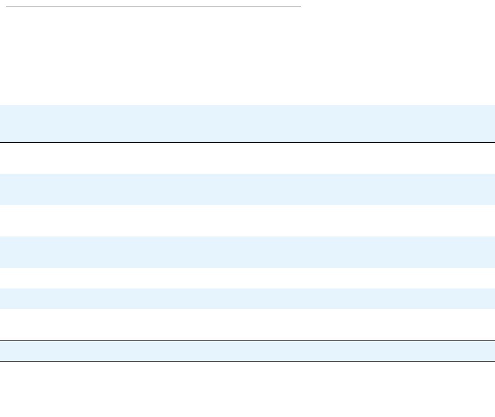
Configuring the Console port for modem use
Issue 1 January 2008 243
Note:
Note: This command changes the PPP authentication parameters of the USB port as
well as the Console port, even if you use the command in the Console interface
context.
●Use the ppp timeout authentication command to set the maximum time to wait for
an authentication response.
●Use the timeout absolute command to set the number of minutes until the system
automatically disconnects an idle PPP incoming session. By default, there is no timeout.
●Use the ip peer address command to change the IP address offered to a requesting
calling host during PPP/IPCP connection establishment. By default, the interface offers its
own IP address plus one.
●Enter shutdown to disconnect an active PPP session and shut down the modem.
●Use the load-interval command to set the load calculation interval for the interface.
Summary of CLI commands for configuring the Console port
for modem use
For more information about these commands, see Avaya G450 CLI Reference, 03-300437.
Table 68: Console port configuration for modem use, CLI commands
Root level
command Command Description
interface
console Enter Console interface configuration context
async mode
interactive Enter modem mode every time the proprietary
modem cable is plugged into the Console port
async mode
terminal Disable interactive mode on the Console
async
modem-init-string Change the default modem initialization string
async reset-modem Reset the connected modem
ip address Assign an IP address and mask to an interface
ip peer address Change the IP address offered to a requesting calling
host during PPP/IPCP connection establishment
1 of 2
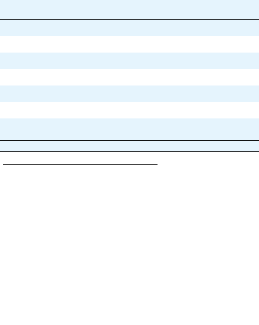
Configuring the G450 for modem use
244 Administration for the Avaya G450 Media Gateway
Configuring the console device to connect to the Console port
When you use a console device to access the CLI through the Console port, you must configure
the serial connection on the console device to match the configuration of the Console port. The
Console port uses the following settings:
●baud = 9600
●data bits = 8
●parity = none
●stop bits = 1
●flow control = hardware
ppp
authentication Configure the authentication method used when
starting a client session on the PPP server
ppp chap-secret Configure the shared secret used in PPP sessions
with CHAP authentication
ppp timeout
authentication Set the maximum time to wait for an authentication
response
show ppp
authentication Display PPP authentication status
shutdown Disconnect an active PPP session and shut down the
modem
speed Set the PPP baud rate to be used by asynchronous
PPP ports
timeout absolute Set the number of minutes until the system
automatically disconnects an idle PPP incoming
session
Table 68: Console port configuration for modem use, CLI commands (continued)
Root level
command Command Description
2 of 2

Issue 1 January 2008 245
Chapter 11: Configuring WAN interfaces
You can use an MM340 E1/T1 media module or an MM342 USP media module as an endpoint
for a WAN line on the G450. You can also use a Fast Ethernet port on the G450 chassis as the
endpoint for a WAN line by configuring the FastEthernet interface for PPP over Ethernet
(PPPoE). The G450 serves as a router, as well as the endpoint, for the WAN line. For more
information about routing, see Configuring the router on page 443.
The G450 supports the following WAN features:
●PPP over channeled and fractional E1/T1. The G450 has the ability to map several PPP
sessions to a single E1/T1 interface
●PPP over USP
●PPPoE
●Unframed E1. For enabling full 2.048 Mbps bandwidth usage
●Point-to-Point frame relay encapsulation. Over channelized, fractional, or unframed
E1/T1 ports, or over a USP interface
●Frame relay. The G450 supports the following LMI types:
-
ANSI (Annex D)
-
ITU-T:Q-933 (Annex A0)
-
LMI-Rev1
-
No LMI
●Backup functionality. Supported between any type of Serial Layer 2 interface. For more
information, see Backup interfaces on page 268.
●Dynamic CAC. For FastEthernet, Serial, and GRE Tunnel interfaces. For more
information, see Dynamic CAC on page 296.
●Quality of Service (QoS). The G450 uses Weighted Fair VoIP Queuing (WFVQ) as the
default queuing mode for WAN interfaces. WFVQ combines weighted fair queuing (WFQ)
for data streams and priority VoIP queuing to provide the real-time response time that is
required for VoIP. The G450 also supports the VoIP Queue and Priority Queue legacy
queuing methods. For more information, see Configuring Weighted Fair VoIP Queueing
(WFVQ) on page 234.
●Policy. Each interface on the G450 can have four active policy lists:
-
Ingress access control list
-
Ingress QoS list
-
Egress access control list
-
Egress QoS list
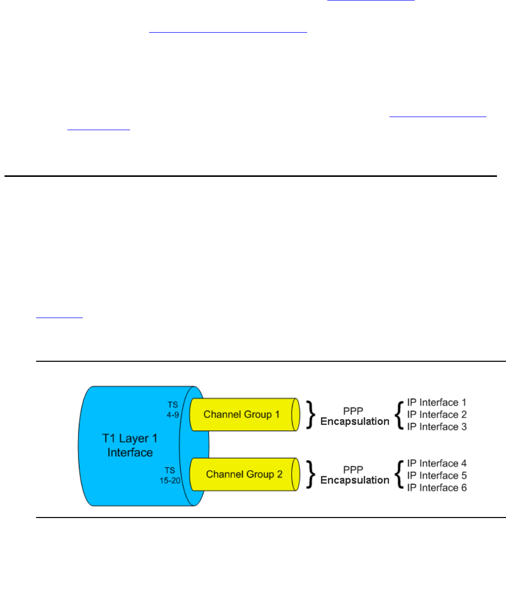
Configuring WAN interfaces
246 Administration for the Avaya G450 Media Gateway
Access control lists define which packets should be forwarded or denied access to the
network. QoS lists change the DSCP and 802.1p priority of routed packets according to
the packet characteristics. For more information, see Configuring policy on page 591.
Each interface on the G450 can also have an active policy-based routing list. For more
information, see Configuring policy-based routing on page 619.
●Header Compression. Use of header compression reduces the size of packet headers,
thus reducing the amount of bandwidth needed for data. RTP header compression
enhances the efficiency of voice transmission over the network by compressing the
headers of Real Time Protocol (RTP) packets, thereby minimizing the overhead and
delays involved in RTP implementation. TCP header compression reduces the amount of
bandwidth needed for non-voice traffic. For more information, see Configuring header
compression on page 225.
Serial interface overview
A Serial interface is a virtual interface that is created over a portion of an E1/T1 or USP port on
a WAN media module. Serial interfaces support PPP and frame relay encapsulation protocols.
The G450 supports multiple channel groups on the same E1/T1 interface.
Layer 1 T1 port with two channel groups
Figure 19 illustrates a Layer 1 T1 port with two channel groups defined. All data from each
channel group is encapsulated using PPP protocol, and is distributed over the multiple IP
interfaces defined for each channel group.
Figure 19: Layer 1 T1 Port
Serial interface overview
Issue 1 January 2008 247
E1/T1 port channel group
Figure 20 illustrates an E1/T1 port channel group. All data from the channel group is
encapsulated using frame relay protocol. The data is sent via a frame relay Serial interface and
sub-interfaces over the multiple IP interfaces defined using Data Link Connection Identifier
(DLCI).
Figure 20: E1/T1 Port Channel Group
USP port using PPP protocol
Figure 21 illustrates a USP port. All data from the USP port is encapsulated using the PPP
protocol, and is sent via a Serial interface over the multiple IP interfaces defined for the Serial
interface.
Figure 21: USP Port – PPP Protocol
USP port using frame relay protocol
Figure 22 illustrates a USP port. All data from the USP port is encapsulated using the frame
relay protocol, and is sent via a frame relay Serial interface and sub-interfaces over the single
IP interfaces defined using DLCI.
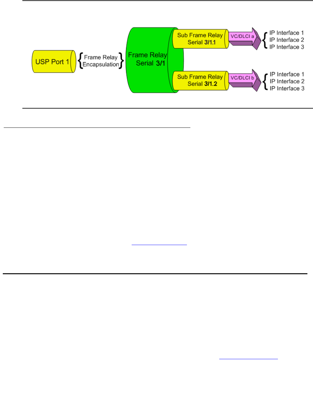
Configuring WAN interfaces
248 Administration for the Avaya G450 Media Gateway
Figure 22: USP Port – Frame Relay Protocol
Frame Relay multipoint topology support
The Avaya G450 Media Gateway supports point-to-point frame relay connections. To enable
you to use the G450 as an endpoint in a Point to Multi-Point (PTMP) topology, the G450
supports inverse ARP replies. The G450 responds to inverse ARP queries received on frame
relay sub-interfaces with the proper inverse ARP replies.
When you connect the G450 as an endpoint in a PTMP configuration, you need to increase the
OSPF timers manually. Use the ip ospf network point-to-multipoint command in
Serial interface context to increase the OSPF timers with the following values:
●Increase the OSPF Hello Interval to 30 seconds
●Increase the OSPF Dead Interval to 120 seconds
For more information on OSPF, see Configuring OSPF on page 492.
Initial WAN configuration
1. Add one of the following WAN media modules:
-
Avaya MM340 E1/T1 media module
-
Avaya MM342 USP media module
Note:
Note: You can also use a Fast Ethernet port on the G450 chassis as the endpoint for a
WAN line by configuring this interface for PPPoE. See Configuring PPPoE on
page 259.

Initial WAN configuration
Issue 1 January 2008 249
2. Connect the WAN line to the media module. For more information, see Installing and
Upgrading the Avaya G450 Media Gateway, 03-602054.
3. Configure the WAN interface on the WAN media module.
-
For the MM340, see Configuring the Avaya MM340 E1/T1 WAN media module on
page 249.
-
For the MM342, see Configuring the Avaya MM342 USP WAN media module on
page 254.
4. By default, a G450 WAN interface uses Point-to-Point Protocol (PPP). For instructions on
changing the default PPP parameters, see Configuring PPP on page 257.
5. If you want frame relay encapsulation on the WAN, configure frame relay. See Configuring
frame relay on page 263.
6. Test the WAN configuration. See Verifying the WAN configuration and testing
connectivity on page 266.
7. Enter copy running-config startup-config to save the configuration.
Configuring the Avaya MM340 E1/T1 WAN media module
For a list of G450 default settings, see Table 69.
1. Optionally, use the show controllers command to display the current settings.
2. Enter show ds-mode to check whether the G450 is configured for E1 or T1 operation.
3. Use the ds-mode command to set the mode of the G450 to E1 or T1. Changing the line
type requires resetting the module. The default value is T1.
4. Use the controller {e1 | t1} module_number/port_number command to enter
Controller context for the port to be configured. The prompt changes
to:(super-if:Serial s/p)#, where s is the slot number of the media module, and p is the
port number.
5. Use the following commands to change the clock source, frame type, linecode, or cable
length parameters from the default settings:
-
For T1 mode:
●clock source line|internal (default is line)
●framing sf|esf (default is sf)
●linecode ami|b8zs (default is ami)
●cablelength long|short (default is long, gain26, 0db)

Configuring WAN interfaces
250 Administration for the Avaya G450 Media Gateway
Note:
Note: Use the cablelength command to configure the cable’s transmit and receive
levels. If the cable is longer than 655 feet, use the command cablelength
long gain26|gain36 -15db|-22.5db|-7.5db|0db (default is gain26,
0db). If the cable is 655 feet or less, use the command cablelength short
133ft|266ft|399ft|533ft|655ft (default is 133ft). When using the
cablelength short form of the command, the transmit attenuation is
configured using the loop length.
●fdl ansi|att|both (default is both)
Note:
Note: The fdl command defines the type of Facility Data Link loopback that the
remote line is requested to enter. This command can only be used when ESF
framing is defined.
-
For E1 mode:
●clock source line|internal (default is line)
●framing crc4|no-crc4|unframed (default is crc4)
●linecode ami|hdb3 (default is hdb3)
6. Use the channel-group command to specify the channel group and time slots to be
mapped, as well as the DS0 speed. For example:
-
For T1 mode:
channel-group 1 timeslots 1,3-5,7 speed 64
configures time slots numbered 1, 3-5, and 7 to be mapped in channel-group number
1, and sets the DS0 speed to 64 kbps. The default DS0 speed for T1 mode is 56.
-
For E1 mode:
channel-group 1 timeslots 1,3-5,7 speed 64
configures time slots numbered 1, 3-5, and 7 to be mapped in channel-group number
1, and sets the DS0 speed to 64 kbps. The default DS0 speed for E1 mode is 64.
7. Enter exit to return to general context. The prompt returns to:
8. Use the interface serial command to enter the Serial interface context. Specify
the slot number of the media module, the port number, the channel group number, and
optionally, the IP interface number.
G450-001(super)#

Initial WAN configuration
Issue 1 January 2008 251
If you do not specify an IP interface number for the first Serial interface that you define on a
channel group, the G450 automatically assigns IP interface number 0. For each additional
Serial interface that you define on the channel group, use a different IP interface number.
For example:
-
interface serial 3/1:1. Enter a serial interface on the media module in slot
number 3, on port number 1, with channel group number 1.
-
interface serial 4/1:2.3. Enter a serial interface on the media module in slot
number 4, on port number 1, with channel group number 2, and with IP interface
number 3.
Note:
Note: If you use the framing unframed command in Step 5 for an E1 port, a channel
group is automatically created on the entire E1 bandwidth. The channel group
has the number 0. In Step 8, enter interface serial s/p:0, where s is the
slot number and p is the port number.
Note:
Note: After the Serial interface is created, its default encapsulation is PPP.
9. Configure the interface encapsulation. By default, the Serial interface uses PPP
encapsulation.
10. Use the ip address command to configure the IP address and subnet mask of the
interface.
11. Enter exit to return to general context. The prompt returns to:
12. If needed, repeat Step 8 through Step 10 to configure additional IP interfaces on the same
channel group.
13. If needed, repeat Step 6 through Step 10 to configure additional channel groups on the
same E1 or T1 port.
14. Test the WAN configuration. See Verifying the WAN configuration and testing
connectivity on page 266.
15. Enter copy running-config startup-config to save the configuration.
G450-001(super)#

Configuring WAN interfaces
252 Administration for the Avaya G450 Media Gateway
E1/T1 default settings
Resetting and displaying controller counters
You can use the following commands to reset counters on a controller interface:
●Use the clear controller counters command to reset a specific controller’s
counters.
●Use the remote command to reset the far end counters on a T1 controller interface.
You can use the following commands to display counters on a controller interface:
●Use the show controllers command to display a specific controller’s status and
counters.
●Use the show controllers remote command to display controller counters from a
peer station.
Activating loopback mode on an E1/T1 line
You can use the loopback command to activate or deactivate loopback mode for an E1 or T1 line.
●Use the loopback diag command to activate or deactivate an inward diagnostic
loopback signal on the controller interface.
●Use the loopback local command to activate or deactivate a local line or payload
loopback signal on the controller interface.
Table 69: E1/T1 default settings
Function Default setting
DS mode T1
E1 framing CRC4
T1 framing SF
E1 linecode HDB3
T1 linecode AMI
Clock source Line
T1 cable length Long, Gain 26,0 db
Speed E1: 64kbps
T1: 56kbps
Initial WAN configuration
Issue 1 January 2008 253
●Use the loopback remote command to request a remote station to activate or
deactivate a line or payload loopback signal on the controller interface. This command is
applicable only to a T1 line.
Summary of E1/T1 ports configuration commands
For more information about these commands, see Avaya G450 CLI Reference, 03-300437.
Table 70: E1/T1 port configuration CLI commands
Root level
command Command Description
clear
controller
counters
Reset the controller counters
controller Enter configuration mode for a specific
controller
cablelength long (T1) Set transmit and receive levels for a cable
longer than 655 feet
cablelength short (T1) Set transmit levels for a cable of length 655
feet or shorter
channel-group Create a channel group logical interface for a
PPP or Frame Relay session
clock source Set the clock source for an E1 or T1
controller
fdl Define the type of Facility Data Link
loopback that the remote line is requested to
enter
framing Set the frame type for an E1 or T1 data line
linecode Set the type of line-code transmission for the
E1 or T1 line
loopback Put a T1 or E1 line into loopback mode or
disable loopback mode
loopback remote Reset the far end counters on a T1 line
ds-mode Set the mode of the controller: e1 or t1
interface
serial Enter Serial interface or sub interface
configuration context
1 of 2
Configuring WAN interfaces
254 Administration for the Avaya G450 Media Gateway
Configuring the Avaya MM342 USP WAN media module
1. Use the interface serial command to enter the context of the interface. Specify the
slot number of the media module, the port number, and optionally the IP interface number.
If you do not specify an IP interface number for the first Serial interface that you define on
a port, the G450 automatically assigns IP interface number 0. For each additional Serial
interface that you define on the port, use a different IP interface number. For example:
-
interface serial 3/1. Enter a serial interface on the media module in slot
number 3, on port number 1.
-
interface serial 4/1.2. Enter a serial interface on the media module in slot
number 4, on port number 1, with IP interface number 2.
For example:
The prompt changes to:
2. Use the following commands to change the idle characters, transmitter delay, encoding
type, bandwidth parameters, line monitoring, and from their default settings:
-
idle character flags|marks. Set the bit pattern used to indicate an idle line.
Use the no form of this command to restore the default value (flags).
ip address Configure the IP address and subnet mask
of the interface
show
controllers Display status information about a controller
interface
show
controllers
remote
Display controller statistics from a peer
station
show ds-mode Display the current mode of the controller
Table 70: E1/T1 port configuration CLI commands (continued)
Root level
command Command Description
2 of 2
G450-001(super)# interface serial 3/1
G450-001(super-if:serial 3/1)#

Initial WAN configuration
Issue 1 January 2008 255
-
transmitter-delay number. Set the minimum number of flags to be sent between
successive packets. Use the no form of the command to restore the transmitter-delay
value to the default (0).
Note:
Note: The transmitter-delay command is usually used when the DCE equipment
that is connected directly to the G450, or the router on the WAN have a receive
buffer that is not large enough to hold the traffic sent by the G450. In this case,
configure transmitter-delay on the DCE equipment or the remote router in
order to preserve the high performance that you had when
transmitter-delay was configured to 0 on the G450.
-
nrzi-encoding. Enable the non-return-to-zero inverted (NRZI) line coding format on
the specified interface. Use the no form of the command to disable NRZI encoding.
-
bandwidth kbps. Set the bandwidth parameter manually for the interface. Use the
no form of this command to restore the bandwidth parameter to its default value
(2,048). The manually specified bandwidth value overrides the dynamically calculated
bandwidth during route cost calculations.
Note:
Note: If you are using the USP port as a clock source, configure the port’s bandwidth to
match the DCE clock rate.
-
ignore dcd. Specify how the system monitors the line to determine if it is up or
down. Specify ignore dcd to ignore DCD signals, and instead use DSR/CTS signals
to determine the line’s status. Use the no form of the command to specify that DCD
signals are used to determine line status.
-
invert txclock. Invert the transmit clock signal from the data communications
equipment (DCE). Use the no form of the command to restore the signal to not
inverted.
3. Configure the interface encapsulation. See Configuring frame relay on page 263.
4. Enter exit to return to general context. The prompt returns to:
5. Repeat Step 1 to configure additional Serial interfaces on the USP port.
6. Test the WAN configuration. See Verifying the WAN configuration and testing
connectivity on page 266.
7. Enter copy running-config startup-config to save the configuration.
G450-001(super)#
Configuring WAN interfaces
256 Administration for the Avaya G450 Media Gateway
USP default settings
Summary of USP port configuration commands
For more information about these commands, see Avaya G450 CLI Reference, 03-300437.
Table 71: USP default settings
Function Default setting
Encoding NRZ
Bandwidth 2,048 kbps
Line-up indicator signal DCD
Table 72: USP port configuration CLI commands
Root level command Command Description
interface serial Enter Serial interface or sub interface
configuration context
bandwidth Set the bandwidth parameter manually for
this interface
idle-character Set the bit pattern used to indicate an idle
line
ignore dcd Specify how the system monitors the line
to determine if it is up or down
invert txclock Invert the transmit clock signal from the
data communications equipment (DCE)
ip address Configure the IP address and subnet
mask of the interface
nrzi-encoding Enable or disable the non-return-to-zero
inverted (NRZI) line coding format on the
interface
transmitter-delay Set the minimum number of flags to be
sent between successive packets

Initial WAN configuration
Issue 1 January 2008 257
Configuring PPP
PPP is the default encapsulation on a WAN port. If the encapsulation has been changed to
frame relay and you want to restore PPP encapsulation, or to change the PPP parameters:
1. Ensure that you are in the context of a serial interface that is defined on the port. If you are
not in the context of a serial interface, use the interface serial command. To view
all Serial interfaces that are defined, use the show interfaces serial command.
2. If the interface is not already configured to use PPP encapsulation, enter
encapsulation ppp to change the encapsulation to PPP.
3. If you want to change the queuing mode of the interface, see Weighted Fair VoIP Queuing
(WFVQ) on page 234 for instructions.
4. Use the following commands to change the interface parameters:
-
ip address. Configure the IP address and subnet mask of the interface.
-
ppp timeout ncp. Set the maximum time to wait for the network layer to negotiate.
If this time is exceeded, the G450 restarts the PPP session.
-
ppp timeout retry. Set the maximum time to wait for a response during PPP
negotiation.
-
keepalive. Enable keepalive or change the interval to which keepalive is set. When
activated, keepalive performs the initial negotiation and sends health checks at
defined intervals to the other side of the interface. To deactivate keepalive, use the no
form of the command or set the health check interval to 0.
5. Enter exit to return to general context. The prompt returns to:
6. Test the WAN configuration. See Verifying the WAN configuration and testing
connectivity on page 266.
7. Enter copy running-config startup-config to save the configuration.
G450-001(super)#

Configuring WAN interfaces
258 Administration for the Avaya G450 Media Gateway
Summary of PPP configuration commands
For more information about these commands, see Avaya G450 CLI Reference, 03-300437.
PPPoE overview
You can configure each ETH WAN Fast Ethernet port as a WAN port using PPPoE (PPP over
Ethernet). PPPoE offers dialup style authentication and accounting and allows subscribers to
dynamically select their ISP.
PPPoE is a client-server protocol used for carrying PPP-encapsulated data over Ethernet
frames. A PPPoE client can establish a tunnel that carries PPP frames between a dialing host
(the G450) and an access concentrator. This enables the use of PPP authentication protocols
(CHAP and PAP). Unlike other tunneling protocols such as L2TP and PPTP, PPPoE works
directly over Ethernet rather than IP.
Table 73: PPP configuration CLI commands
Root level command Command Description
interface serial Enter Serial interface or sub interface
configuration context
encapsulation Set the encapsulation mode for a Serial
interface: PPP or frame relay
ip address Configure the IP address and subnet
mask of the interface
keepalive Enable PPP keepalive, in order to
maintain a persistent connection
ppp timeout ncp Set the maximum time, in seconds, that
PPP allows for negotiation of a network
layer protocol
ppp timeout retry Set the maximum time to wait for a
response during PPP negotiation
show interfaces Display interface configuration and
statistics for a particular interface or all
interfaces
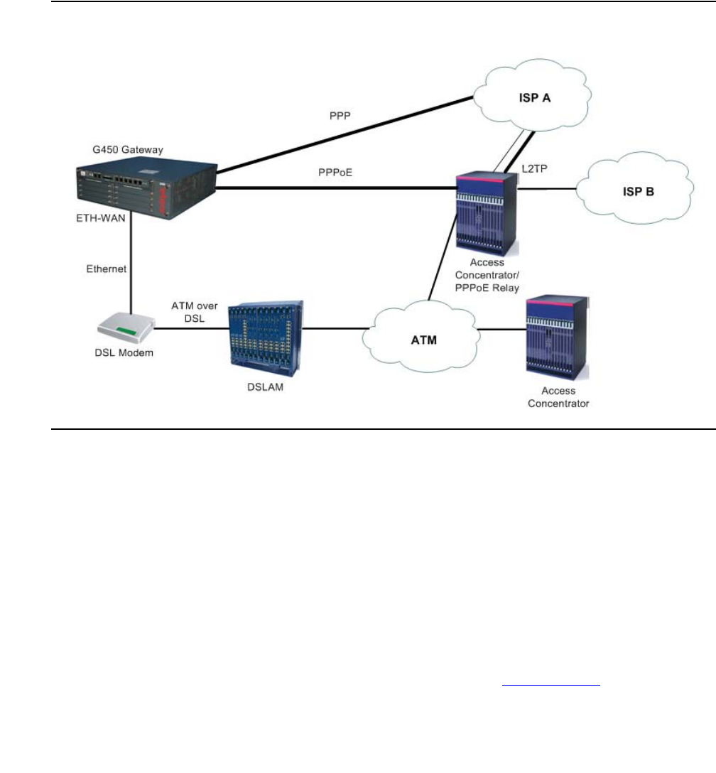
Initial WAN configuration
Issue 1 January 2008 259
A typical broadband access network is based on ADSL modems configured as transparent
Ethernet bridges. ADSL modems use ATM protocol, and the transparent bridging is done to a
well known ATM VC. On the other side of the telephone line is a device called a DSLAM. The
DSLAM terminates the ADSL physical layer, collects the ATM cells from the various ADSL
subscribers, and places them on the SP ATM infrastructure. The Ethernet frames from the
customer’s host device can reach one or more access concentrators, which are the remote
access servers.
Figure 23: Typical PPPoE Network Topology
Configuring PPPoE
1. Enter the FastEthernet interface context with the interface fastethernet 10/2
command.
2. Enter encapsulation pppoe to change the encapsulation to PPPoE. You must change
the encapsulation to PPPoE before configuring an IP address on the interface.
Note:
Note: You cannot use PPPoE if:
-
An IP address must not be configured on the interface
-
Dynamic CAC is not enabled on the interface. See Dynamic CAC on page 296.

Configuring WAN interfaces
260 Administration for the Avaya G450 Media Gateway
-
The interface is not part of a primary-backup interface pair. See Backup
interfaces on page 268.
3. Use the ip address command to configure an IP address and subnet mask for the
interface. In most cases, PPPoE tunnels require a 32-bit subnet mask.
Alternatively, you can enter ip address negotiated to obtain an IP address via
PPP/IPCP negotiation.
Note:
Note: You cannot configure PPP/IPCP address negotiation if DHCP address
negotiation is already configured on the interface (see Configuring DHCP
client on page 199).
4. Configure an authentication method and parameters:
-
For PAP authenticating, enter ppp pap-sent username followed by a user name
and password. For example:
-
For CHAP authentication, enter ppp chap hostname followed by a hostname, and
ppp chap password followed by a password. For example:
5. You can use the following commands to change the interface parameters:
-
pppoe-client service-name. Force the PPPoE client to connect only to access
concentrators that support a specific service name.
Use the no form of this command to deactivate connection to a specific service name.
When connection to a specific service name is deactivated, the PPPoe client attempts
to automatically discover the service name by initiating PADI frames with a blank
service name.
-
mtu. Set the interface’s MTU to 1492 which ensures that overall packet size for the
PPPoE interface does not exceed 1500, which is the MTU for Ethernet.
-
pppoe-client wait-for-ipcp. Set the amount of time (in seconds) between
establishment of the PPPoE tunnel and establishment of the IPCP tunnel. If this time is
exceeded, the PPPoE client terminates the PPPoE tunnel.
-
pppoe-client persistent delay. Set the interval between pppoe-client dial
attempts.
-
pppoe-client persistent max-attempts. Limit the number of consecutive
connection establishment retires
G450-001(super-if:FastEthernet 10/2)# ppp pap-sent username avaya32 password 123456
Done!
G450-001(super-if:FastEthernet 10/2)# ppp chap hostname avaya32
Done!
G450-001(super-if:FastEthernet 10/2)# ppp chap password 123456
Done!

Initial WAN configuration
Issue 1 January 2008 261
-
ppp chap refuse. Prevent authentication with CHAP, even when a chap secret is
configured.
-
ppp pap refuse. Prevent authentication with PAP, even when a pap-sent secret is
configured.
-
keepalive-track. Bind the interface status to an object tracker. When activated,
the object tracker sends health check packets at defined intervals to the other side of
the interface. If the configured number of consecutive keepalive requests are not
answered, the interface track state changes to down. The object tracker continues
monitoring the interface, and when its track state changes to up, the interface state
changes to up.
-
shutdown followed by no shutdown. Resume trying to establish connections by
shutting down and reopening the interface.
For example:
For more information on the PPoE commands, see Table 74.
6. If the G450 is connected to the Internet via the FastEthernet interface configured for
PPPoE, and you define a VPN tunnel which specifies remote hosts by name, it is
recommended to use the ppp ipcp dns request command. The command requests
the list of available DNS servers from the remote peer during the PPP/IPCP session. The
DNS servers are used by the DNS resolver to resolve hostnames to IP addresses.
7. Enter exit to return to general context. The prompt returns to:
8. Test the configuration. See Verifying the WAN configuration and testing connectivity on
page 266.
9. Enter copy running-config startup-config to save the configuration.
10. Optionally, shut down the port and the PPPoE client (if configured) with the shutdown
command in the interface context.
G450-001(super)# interface fastethernet 10/2
G450-001(super-if:FastEthernet 10/2)#
G450-001(super-if:FastEthernet 10/2)# shutdown
interface fastethernet 10/2, changed state to administratively down
Line protocol on FastEthernet 10/2, changed state to down
Done!
G450-001(super)#
Configuring WAN interfaces
262 Administration for the Avaya G450 Media Gateway
Summary of PPPoE commands
For more information about these commands, see Avaya G450 CLI Reference, 03-300437.
Table 74: PPPoE CLI commands
Root level command Command Description
interface
fastethernet Enter the FastEthernet interface
context
encapsulation pppoe Change the encapsulation to PPPoE
ip address Configure an IP address and subnet
mask for the interface
ip address
negotiated Obtain an IP address via PPP/IPCP
negotiation
keepalive-track Bind interface status to an object tracker
to check whether the interface is up
mtu Set the interface’s MTU to 1492, which
ensures that overall packet size for the
PPPoE interface does not exceed 1500,
which is the MTU for Ethernet
ppp chap hostname Override the device hostname for PPP
CHAP authentication
ppp chap password Set the CHAP password for
authentication with a remote peer
ppp chap refuse Prevent the device from authenticating
with CHAP after the device is requested
by the remote peer
ppp ipcp dns
request Enable or disable requesting the list of
available DNS servers from the remote
peer during the PPP/IPCP session
ppp pap refuse Prevent the device from authenticating
with PAP after the device is requested by
the remote peer
ppp pap-sent
username Set the Password Authentication
Protocol (PAP) password for
authentication with the remote peer
pppoe-client
persistent delay Set the interval between pppoe-client
dial attempts
1 of 2

Initial WAN configuration
Issue 1 January 2008 263
Configuring frame relay
1. Ensure that the port is configured on the media module:
-
For an E1/T1 port, see Configuring the Avaya MM340 E1/T1 WAN media module on
page 249
-
For a USP port, see Configuring the Avaya MM342 USP WAN media module on
page 254
2. Ensure that you are in the context of a serial interface that is defined on the port. If you are
not in the context of a serial interface, use the interface serial command. To view
all Serial interfaces that are defined, use the show interfaces serial command.
3. Use the encapsulation frame-relay command to change the encapsulation to
frame relay. You can optionally specify the encapsulation type: IETF (RFC1490/RFC2427)
or non-IETF. The default encapsulation type is IETF.
Note:
Note: Non-IETF encapsulation is compatible with other vendors.
4. If needed, use the frame-relay lmi commands to change the Local Management
Interface (LMI) parameters from their default values, or enter frame-relay
traffic-shaping to activate traffic shaping on the frame relay interface. For more
information on traffic shaping, see Frame relay traffic shaping and FRF.12
fragmentation on page 316.
pppoe-client
persistent
max-attempts
Limit the number of consecutive
connection establishment retries
pppoe-client
service-name Set the PPPoE Client service-name
pppoe-client
wait-for-ipcp Set the amount of time (in seconds)
between establishment of the PPPoE
tunnel and establishment of the IPCP
tunnel. If this time is exceeded, the
PPPoE client terminates the PPPoE
tunnel.
shutdown Shut down the port, and the PPPoE
client, if configured
Table 74: PPPoE CLI commands (continued)
Root level command Command Description
2 of 2

Configuring WAN interfaces
264 Administration for the Avaya G450 Media Gateway
5. Optionally, change the queuing mode of the interface. See Weighted Fair VoIP Queuing
(WFVQ) on page 234 for instructions.
6. Enter exit to return to general context. The prompt returns to:
7. Enter interface serial if.fr-sub-if point-to-point to create a frame relay
sub-interface and enter the context of the interface. For example:
-
interface serial 3/1:2.1 point-to-point. Create frame relay
sub-interface number 1 on the E1/T1 media module in slot number 3, on port number
1, with channel group number 2
-
interface serial 4/1:2.3.2 point-to-point. Create frame relay
sub-interface number 3 on the E1/T1 media module in slot number 4, on port number
1, with channel group number 2, and with IP interface number 2
-
interface serial 3/1.2 point-to-point. Create frame relay sub-interface
number 2 on the USP media module in slot number 3, on port number 1
-
interface serial 4/1.2.1 point-to-point. Create frame relay
sub-interface number 2 on the USP media module in slot number 4, on port number 1,
with IP interface number 1
Note:
Note: Currently only point-to-point frame relay sub-interfaces are supported.
8. Enter frame-relay interface-dlci DLCI-number to configure a Data Link
Connection Identifier (DLCI) for the frame relay sub-interface. You can optionally specify
the encapsulation type: IETF (RFC1490/RFC2427) or non-IETF. The default
encapsulation type is IETF.
Note:
Note: Non-IETF encapsulation is compatible with other vendors.
9. If required, use the frame-relay priority-dlci-group command to configure a
Priority DLCI group. The arguments for this command are the DLCIs you want to assign to
high, medium, normal, and low priority traffic, respectively. For example, the command
frame-relay priority-dlci-group 17 18 19 assigns DLCI 17 to high priority
traffic, DLCI 18 to medium priority traffic, and DLCI 19 to normal and low priority traffic. For
more information, see Frame relay traffic shaping and FRF.12 fragmentation on page 316.
10. Use the ip address command to configure an IP address and subnet mask for the frame
relay sub-interface.
11. Enter exit to return to general context. The prompt returns to:
12. If needed, repeat Step 7 through Step 11 to configure additional frame relay sub-interfaces
on the same Serial interface.
G450-001(super)#
G450-001(super)#

Initial WAN configuration
Issue 1 January 2008 265
13. If needed, repeat Step 2 through Step 12 to configure frame relay encapsulation for other
Serial interfaces on the same WAN port.
14. Test the WAN configuration. See Verifying the WAN configuration and testing
connectivity on page 266.
15. Enter copy running-config startup-config to save the configuration.
Resetting and displaying frame relay interface counters
Use the clear frame-relay counters command to reset counters on a specific frame
relay interface.
Use the show interfaces command to display interface configuration and statistics for a
specific interface or for all interfaces.
Summary of frame relay commands
For more information about these commands, see Avaya G450 CLI Reference, 03-300437.
Table 75: Frame relay CLI commands
Root level command Command Description
clear
frame-relay
counters
Clear the frame relay counters
interface serial Enter Serial interface or sub interface
configuration mode
encapsulation Set the encapsulation mode for a Serial
interface
frame-relay
class-dlci Associate a Virtual Channel with a
named QoS or Traffic shaping template
(map-class)
frame-relay
interface-dlci Associate a frame relay Virtual Channel
with the current interface
frame-relay
lmi-n391dte Set the number of status enquiry
intervals that pass before issuing a full
status enquiry message
frame-relay
lmi-n392dte Set the maximum number of
unanswered status enquiries the
equipment accepts before declaring the
interface down
1 of 2

Configuring WAN interfaces
266 Administration for the Avaya G450 Media Gateway
Verifying the WAN configuration and testing connectivity
After configuring the new interface, you can perform the following tests to verify that the new
interface is operating correctly.
●For E1/T1 interfaces, use the show controllers command to view the status of the
interface’s controller. Verify that the controller is up, and that all error counters do not
increase.
For all serial interfaces (E1/T1 and USB-modem), use the show interfaces serial
command to verify that the interface and line protocol are both up. For example:
●For USB-modem interfaces only, use the show interfaces serial command to verify
that all line signals are up. For example:
●Use the show frame-relay pvc command to view detailed PVC information, or show
frame-relay pvc brief for a brief summary of PVC configuration.
frame-relay
lmi-n393dte Set the number of status polling intervals
over which the error threshold is counted
(the monitored event count)
frame-relay
lmi-type Manually define the type of the Local
Management Interface (LMI) to use
frame-relay
priority-dlci-group Assign Virtual Channels to priority
classifications, for supporting traffic
separation
frame-relay
traffic-shaping Turn on or off traffic shaping and frame
relay fragmentation
ip address Configure an IP address and mask for
the interface
show interfaces Display interface configuration and
statistics for a particular interface or all
interfaces
Table 75: Frame relay CLI commands (continued)
Root level command Command Description
2 of 2
Serial x/y:z is up, line protocol is up
DCD = up DSR = up DTR = up RTS = up CTS = up
Initial WAN configuration
Issue 1 January 2008 267
●Use the following commands for more information about frame relay configuration:
-
show frame-relay fragment. Display frame relay fragmentation statistics and
configuration on all PVCs associated with the interface.
-
show frame-relay lmi. Display LMI statistics for the interface.
-
show frame-relay map. Display a summary table of frame relay sub-interfaces
and DLCIs associated with the sub-interfaces.
-
show frame-relay traffic. Display frame relay protocol statistics, including ARP
requests and replies sent and received over the interface.
-
show map-class frame-relay. Display the map-class Frame Relay table.
●Use the show traffic-shape command to view traffic shaping and frame relay traffic
shaping configuration parameters for all interfaces.
●Use the show ip interface command to display information about IP interfaces. To
display information about a specific interface, include the name of the interface as an
argument. To display information about the interface of a specific IP address, include the
IP address as an argument.
●Enter show running-config to display the configuration running on the device.
●Enter show startup-config to display the configuration loaded at startup.
●Use the ping command to send ICMP echo request packets from the G450 to the
interface Serial peer IP address and verify that it responds.
●Use the ping command to send ICMP echo request packets to another node on the
network. Each node is periodically pinged and checked if an answer was received. This
checks host reachability and network connectivity.
Summary of WAN configuration verification commands
For more information about these commands, see Avaya G450 CLI Reference, 03-300437.
Table 76: WAN configuration verification CLI commands
Command Description
ping Check host reachability and network connectivity
show controllers Display status information about a controller interface
show frame-relay
fragment Display frame relay fragmentation statistics and configuration
on all PVCs, all PVCs associated with an interface, or a
specific PVC
show frame-relay lmi Display LMI statistics for a particular interface or for all
interfaces. The output displayed differs depending on the
type of interface.
1 of 2

Configuring WAN interfaces
268 Administration for the Avaya G450 Media Gateway
Backup interfaces
You can configure backup relations between a pair of any Layer 2 Serial interfaces. A backup
interface is activated when the primary interface fails. The backup interface is deactivated when
the primary interface is restored. A PPP session, frame relay interface, frame relay
sub-interface, Dialer interface, FastEthernet interface, or Loopback interface can serve as a
backup interface to any other Serial interface on the same module, including interfaces on
different serial ports.
Note:
Note: A frame relay interface in a primary or backup role overrides the role of its
sub-interfaces.
show frame-relay map Display a summary table of Frame Relay sub-interfaces and
DLCIs associated with the sub-interfaces
show frame-relay pvc Display detailed PVC information
show frame-relay pvc
brief Display brief PVC information
show frame-relay
traffic Display frame relay protocol statistics, including ARP
requests and replies sent and received over Frame Relay
interfaces
show interfaces Display interface configuration and statistics for a particular
interface or all interfaces
show ip interface Display information about an IP interface
show map-class
frame-relay Display the map-class Frame Relay table
show traffic-shape Display traffic shaping and frame relay traffic shaping
configuration information
Table 76: WAN configuration verification CLI commands (continued)
Command Description
2 of 2

Backup interfaces
Issue 1 January 2008 269
Note:
Note: If the FastEthernet interface serving as a backup interface is configured as a
DHCP client, it sends no DHCP packets. Therefore, its IP address is not renewed
until it becomes the primary interface.
If the FastEthernet interface serving as a primary interface is configured as a
DHCP client, the expiration of the leases on its IP address or no reception of an
IP address does not cause activation of the backup interface.
Configuring backup delays
Configurable activation and deactivation delays provide a damping effect on the backup
interface pair. This eliminates primary-to-backup switching in case of fluctuating underlying
Layer 2 interfaces. You can configure the following backup delays with the backup delay
command:
●failure delay. The time in seconds between the primary interface going down and the
backup interface activation. The default is 0 seconds. The maximum is 3600 seconds.
●secondary disable delay. The time in seconds between the primary interface
restoration and the backup interface deactivation. The default is 0 seconds. The maximum
is 3600 seconds. Both interfaces are active during this time to enable a smooth transition
for the routing protocols. To keep the backup interface active indefinitely, use never as the
secondary disable delay.
For example, you can use the following command to switch over immediately to the backup
interface in case of failure, and pause 60 seconds before reverting to the primary interface:
Interface backup relations rules
●Each interface can have only one backup interface.
●A backup interface can serve as a backup for only one other interface.
●Only one member of a primary and backup pair is active at any given time. An interface is
automatically deactivated when configured as backup.
●The backup implementation does not protect against the failure of both interfaces.
Therefore, if a backup interface fails while active, no switch to the primary interface is
attempted.
G450-001(super)# interface fastethernet 10/2
G450-001(super-if:FastEthernet 10/2)# backup delay 0 60
Done!
G450-001(super-if:FastEthernet 10/2)#

Configuring WAN interfaces
270 Administration for the Avaya G450 Media Gateway
When using frame relay encapsulation, the frame relay interface is considered down when its
primary DLCI is down. The switchover back to the main interface occurs when the primary Data
Link Connection Identifier (DLCI) is restored.
Note:
Note: The backup interface is not activated when the primary interface is
administratively disabled.
Backup commands
●Enter backup interface, followed by the interface type and number, to set a backup
interface. You must use this command from the context of the interface for which you are
setting a backup interface.
●Use the backup delay command to set the time to wait before switching over to the
backup interface, in case of failure. You can also use this command to set a delay before
reverting back to the primary interface.
For example, the following command causes the G450 to switch immediately to the
backup interface in the event of primary interface failure, and to delay 60 seconds before
reverting back to the primary interface once the primary interface is restored to service:
Summary of backup interfaces commands
For more information about these commands, see Avaya G450 CLI Reference, 03-300437.
G450-001(super-if:FastEthernet 10/2)# backup delay 0 60
Table 77: Backup interfaces CLI commands
Root level
command Command Description
interface
(fastethernet
|loopback|
serial|
tunnel)
Enter FastEthernet, Loopback, Serial, or
Tunnel interface configuration context
backup delay Set the time to wait before switching to the backup
interface, in case of failure
backup
interface Set a backup interface for the current interface

Modem dial backup
Issue 1 January 2008 271
Modem dial backup
The modem dial backup feature allows the Avaya G450 Media Gateway to utilize a modem to
provide redundant connectivity between a G450 and IP phones in a small branch office and
their primary Media Gateway Controller (MGC) at the headquarters or a regional branch office.
Even if the gateway has Standard Local Survivability (SLS), or Enhanced Local Survivability
(ELS) using a local S8300 in LSP mode, it is always preferable to continue working with the
primary MGC, since features are lost when the system is fragmented.
Analog modems have limited bandwidth and high latency, and are therefore unfit for carrying
VoIP traffic. However, using Dynamic Call Admission Control (CAC), the G450 can be
configured to report zero bandwidth for bearer traffic to the MGC when the primary WAN link
fails. A matching configuration on the MGC allows it to block new calls, if their bearer is about to
go over the modem dial backup interface, and to alert the user with a busy tone. In this case, the
user is still able to place external calls manually if local PSTN trunks are available. Furthermore,
Avaya Communication Manager 3.0 Inter-Gateway Alternate Routing (IGAR) may be
configured to become active in such a case and to use the PSTN for transporting the voice
bearer transparently between the sites, transparently to the user. For information about
Dynamic CAC in the G450, see Dynamic CAC on page 296. For information about IGAR, see
Administrator Guide for Avaya Communication Manager, 03-300509.
Modem dial backup is a generic data dial backup feature that can carry not only signalling but
every type of IP traffic. However, the low bandwidth of an analog modem would be likely to
cause congestion. The administrator must therefore ensure that VoIP signaling has priority over
the Dialer interface. This can be performed using access control lists (ACL), QoS lists, and
Weighted Fair Queuing (WFQ) priority schemes. The administrator should apply these tools in
both the G450 and the Remote Access Server (RAS). For information on ACL and QoS lists,
see Configuring policy on page 591. For information on WFQ, see Weighted Fair VoIP Queuing
(WFVQ) on page 234.
You can configure modem dial backup to dial to an enterprise-owned RAS or to the Internet via
an Internet Service Provider (ISP). Most ISPs mandate the use of the internal IPSec VPN
gateway process to encrypt the traffic as it goes over the Internet.
Note:
Note: IPSec VPN adds overhead to each packet, further reducing available bandwidth.
Under ideal conditions, the bandwidth of the analog modem can reach 56 kbps for downlink
(53 kbps in the US) and 33.6 kbps for uplink. However, sub-optimal PSTN quality may
degrade the downlink bandwidth to 33.6 kbps, or even 28 kbps. This may not be enough to
carry a single ISDN-PRI 64 kbps D-Channel for signalling over H.248 to and from the MGC,
even without considering the need to support IP phones and/or analog or DCP trunks.
VoIP signaling consumes bandwidth when setting up and tearing down calls. However,
calculations, testing, and field experience show that an analog modem can easily support a
small branch office when the expected Busy Hour Call Completion (BHCC) is limited.

Configuring WAN interfaces
272 Administration for the Avaya G450 Media Gateway
Note:
Note: The low bandwidth and high Round-Trip-Time (RTT) of analog modems
(~100 ms) may lead to acceptable changes in Post-Dial-Delay (PDD) and
offhook-to-dialtone delays.
Modem dial backup uses the G450’s backup interface functionality to activate the Dialer
interface for modem dial backup when the primary interface fails and to deactivate the Dialer
interface when the primary interface is up again. Currently, modem dial backup does not
support such features as Dial On Demand Routing (DDR), callbacks, or RAS. Modem dial
backup cannot receive backup calls. For more information about backup interfaces, see Backup
interfaces on page 268.
Note:
Note: You can only backup one interface with modem dialer backup.
Using the G450’s backup interface functionality, you can designate the Dialer interface as the
backup for the main WAN link. However, this method is not always available, since an 'up' WAN
link status does not ensure connectivity, and the main WAN link may not even be directly
connected to the G450.
The workaround is to use the G450’s object tracking feature to verify connectivity to the primary
MGC using Respond Time Reports (RTRs) and object trackers. Configure object tracking to
change the state of the Loopback interface accordingly, and configure the Dialer interface as a
backup to the Loopback interface. For more information about object tracking, see Object
tracking on page 298.
Modem dial backup uses a modem connected directly to the G450’s USB or Console port. The
modem can also be used to access the G450 CLI from a remote location. The modem cannot
do both at the same time. For information about remote access to the G450 via modem, see
Accessing the CLI via modem on page 46.
Finally, IP routing must be configured so that traffic to and from the site uses the Dialer interface
when the primary interface is down. The Dialer interface can work both with static and dynamic
routing (OSPF and RIP). Note that the latter mandates the use of unnumbered IP interfaces.
For information about unnumbered IP interfaces, see Configuring unnumbered IP interfaces on
page 448.
Note:
Note: Modem dial backup has complex interactions with other configuration modules
within the G450 and on your network. Before configuring modem dial-backup,
Avaya recommends reading Application Note - VoIP Network Resiliency. This
document discusses the issues of network design for maximum resiliency,
capacity planning for optimum performance, configuration options for network
devices, strategies for implementing routing across the network, and security
concerns. Based on your existing network design, several redundancy scenarios
featuring modem dial backup are available. See Modem dial backup interactions
with other features on page 278 for brief discussions of the various features
required for an effective backup scenario for your VoIP installation.

Modem dial backup
Issue 1 January 2008 273
Note:
Note: Modem dial backup does not support backup dial-ins or callbacks. Some backup
configurations require the remote host to receive a request for connection,
acknowledge, end the connection, and dial back the requester. This configuration
is not supported.
Typical installations
The Avaya G450 Media Gateway was designed for small branch offices of a larger enterprise.
Consequently, the same RAS may serve many branch offices, and, therefore, many G450s. A
reasonable assumption is that not all branch offices would need modem dial backup at the
same time. Therefore, the ratio of modem channels at the RAS to G450s at branch offices can
be less than 1:1. There are several practical ways to configure the RAS server for use with
modem dial backup Dialer interfaces:
●The RAS can assign an IP address to the calling G450. This requires the RAS to identify
the call gateway using the PAP/CHAP username, and install an appropriate static route to
the branch office subnets accordingly. The username, password, and static route can be
configured in an external RADIUS/TACACS+ server.
●The RAS server can use OSPF to learn the branch office subnets. This is much simpler to
configure as all branch offices can share the same username and password. The G450 is
configured to advertise the branch office subnets with OSPF. This feature requires the use
of unnumbered IP addresses at the G450 and the RAS. Since the Dialer and the primary
interfaces are not expected to be up at the same time, the RAS server can use
passive-OSPF-interface and the G450 can use static via routes.
●The G450 can call an ISP RAS (which is likely to assign it a dynamic IP address) and open
an IPSec VPN tunnel to an enterprise-owned VPN gateway.
While using OSPF and calling an ISP RAS are expected to be the most common scenarios,
they involve complex interaction with IP routing and the remote RAS server. For more detailed
configuration examples, see Application Note - VoIP Network Resiliency.
Prerequisites for configuring modem dial backup
●At least one dialer string, which determines the phone number(s) of the remote modem(s)
dialed by the Dialer interface
●A configured interface to be backed up
●Read/write or admin access level
●A Multitech MultiModem ZBA (MT5634ZBA) or MultimodemUSB (MT5634ZBA-USB)
modem
●RAS properties:

Configuring WAN interfaces
274 Administration for the Avaya G450 Media Gateway
-
A dialer string
-
Authentication parameters (username, password, PAP/CHAP)
-
IP addressing (static, dynamic, or unnumbered)
-
Routing (static, RIP, or OSPF)
-
IPSec VPN, with all necessary parameters configured
Note:
Note: Make sure policy is configured properly at the RAS server to ensure that signaling
has priority over regular traffic.
For modem configuration instructions, see Configuring the G450 for modem use on page 239.
Note:
Note: It is recommended to use the maximum UART speed for the serial modem
(115400 BAUD).
Configuring modem dial backup
1. From the general context, use the show interfaces console or show interfaces
USB-modem command to verify that the modem is connected. You may be required to
enable the modem.
2. Enter interface dialer, followed by the identifier, to create the Dialer interface. For
example:
The Dialer interface is created and can now be defined as a backup interface for an
existing WAN interface.
3. Enter up to five dialer strings, using the dialer string command. For example:
When the Dialer interface is activated, the Dialer first attempts to dial the number
associated with dialer string 1. If that attempt fails, the Dialer attempts to connect to the
number associated with the next dialer string, and so on.
G450-001(super)# interface dialer 1
G450-001(if:dialer 1)#
G450-001(if:dialer 1)# dialer string 1 5555555
Done!
G450-001(if:dialer 1)# dialer string 2 1234567
Done!

Modem dial backup
Issue 1 January 2008 275
4. Set the IP address of the Dialer interface with the ip address command.
There are three options:
●Manually set the IP address and subnet mask. Use this option when you know to
which server the dialed string is going to connect. For example:
●Enter ip address negotiated.
●Enter ip unnumbered interface, where interface is the name of another
interface in the media gateway (for example, the WAN interface) from which an IP
address for the Dialer interface is borrowed. Use this command when you do not know
who will eventually be your peer and you want to run dynamic routing protocols (for
example, OSPF or RIP) over the dialup link.
5. Enter dialer persistent initial delay, with the value 30 seconds, to prevent
dialup after boot, before the WAN link is fully functional. For example:
6. If needed, set any of the following parameters:
●Use the dialer persistent max-attempts command to set the maximum
number of dial attempts. For example:
The Dialer interface dials each number associated with a dialer string, in order, until
either a connection is made, or the number configured in the dialer persistent
max-attempts command is reached.
●Use the dialer persistent re-enable command to enable and configure a
timer to re-enable dial attempts after the maximum number of dial attempts has been
reached. For example:
●Use the dialer order command to set which dial strings are used upon a new dial
trigger event. The default is to restart from the beginning of the dial list. For example:
G450-001(if:dialer 1)# ip address 4.5.6.7 255.255.255.0
Done!
G450-001(if:dialer 1)# dialer persistant initial delay 30
Done!
G450-001(if:dialer 1)# dialer persistent max-attempts 10
Done!
G450-001(if:dialer 1)# dialer persistent re-enable 3600
Done!
G450-001(if:dialer 1)# dialer order last-successful
Done!

Configuring WAN interfaces
276 Administration for the Avaya G450 Media Gateway
●Use the dialer persistent command to force the dialer to attempt to reconnect
every second, or at another redial interval, which you can configure using the dialer
persistent delay command. By default, redialing is disabled. For example:
●Use the dialer wait-for-ipcp command to set the maximum time the dialer
waits between dialing a number to successfully establishing PPP/IPCP. The default is
45 seconds. For example:
7. Configure an authentication method and parameters (if required):
-
For PAP authenticating, enter ppp pap sent-username followed by a username
and password. For example:
-
For CHAP authentication, enter ppp chap hostname followed by a hostname, and
ppp chap password followed by a password. For example:
G450-001(if:dialer 1)# dialer persistent
Done!
G450-001(if:dialer 1)# dialer persistent delay 10
Done!
G450-001(if:dialer 1)# dialer wait-for-ipcp 100
Done!
G450-001(if:dialer 1)# ppp pap sent-username avaya32 password 123456
Done!
G450-001(if:dialer 1)# ppp chap hostname avaya32
Done!
G450-001(if:dialer 1)# ppp chap password 123456
Done!

Modem dial backup
Issue 1 January 2008 277
8. From the general context, use show interfaces dialer 1 to verify that the Dialer
interface has connected to the remote peer. For example:
This command shows the interface status, including a summary of its definitions and
settings. The status also tells you whether the interface is up and the dialup succeeded. In
the example status, the interface is down and inactive.
9. Enter the context of the interface which the Dialer is to back up, and use the backup
interface command to configure the Dialer interface as the backup interface. For
example:
Interface Dialer 1 is now selected as the backup interface to the selected interface. The
Dialer interface is activated in the event of a failure of the primary interface. Upon
activation, the Dialer interface dials the number associated with the first dialer string.
10. From the general context, use the ip default-gateway dialer command to
configure backup routing.
The following example configures a simple low priority via static route:
G450-001(super)# show interfaces dialer 1
Dialer 1 is down, line protocol is down
Internet address is 4.5.6.7, mask is 255.255.255.0
MTU 1500 bytes, Bandwidth 28 kbit
IPSec PMTU: copy df-bit, Min PMTU is 300
Reliability 1/255 txLoad 255/255 rxLoad 255/255
Encapsulation PPP
Link status trap disabled
Keepalive track not set
Keepalive set (10 sec)
LCP Starting
IPCP Starting
Last dialed string:
Dial strings:
1: 5555555
2: 1234567
Dialing order is sequential
Persistent initial delay 5 sec
Wait 45 sec for IPCP
Weighted Fair VoIP queueing mode
Last input never, Last output never
Last clearing of 'show interface' counters never
5 minute input rate 0 bits/sec, 0 packets/sec
G450-001(if:serial 3/1:1)# backup interface dialer 1
Done!
G450-001(super)# ip default-gateway dialer 1 1 low
Done!

Configuring WAN interfaces
278 Administration for the Avaya G450 Media Gateway
Note:
Note: It is recommended that you define multiple routes to ensure that traffic reaches
the Dialer interface.
Modem dial backup interactions with other features
Optimal modem dial backup configuration is a complex undertaking, dependent on a large
number of factors. For an extensive discussion of network design, capacity planning, routing
configuration, device configuration, and security considerations, see Application Note - VoIP
Network Resiliency. Device and network configuration features that need to be taken into
account include:
●The backup interface command allows you to designate the Dialer interface as the
backup to an existing WAN interface on the G450. When the G450 reports the primary
WAN interface down for a specified period of time, the Dialer interface is automatically
activated and the modem dials. For more information on the backup interface
command, see Backup interfaces on page 268.
●The G450’s Console port is an RJ-45 asynchronous port that can be used to support the
modem for dial backup. Thus, the Dialer can utilize the same serial modem that is used for
remote access to the device. Asynchronous dialing and modem recognition options must
be set on the Console port to support creation of the Dialer interface. For more information
on configuring the Console port, see Configuring the Console port for modem use on
page 242.
●The Dialer interface supports PAP and CHAP authentication for PPP connections. In
addition, the Dialer interface can be configured to be a member of a VPN, allowing
encryption of the modem traffic. Van Jacobsen compression is available for encrypted
traffic over the Dialer interface, allowing optimal use of bandwidth. For more information on
configuring PPP authentication and encryption, see PPPoE overview on page 258. For
more information on heading compression, see Configuring header compression on
page 225.
●It is recommended to filter traffic through the Dialer interface to permit only those packets
necessary for continued interaction with the Avaya Communication Manager server.
Filtering can be accomplished using access control lists, which specify traffic permissible
through a selected interface. For more information on configuring access control lists, see
Configuring policy on page 591.

Modem dial backup
Issue 1 January 2008 279
●Dynamic CAC can be used in conjunction with IGAR to provide a stable backup path for
continued IP phone function in the event of a dial backup scenario. Dynamic CAC notifies
the Avaya Communication Manager server that no bandwidth is available for bearer traffic,
keeping the dial circuit from becoming fully congested. IGAR provides a path for
gateway-to-gateway traffic destined for a remote Avaya Communication Manager server
by forcing voice calls to and from the branch office to use the PSTN for bearer traffic. For
more information on configuring Dynamic CAC, see Dynamic CAC on page 296. For more
information on configuring IGAR, see Administrator Guide for Avaya Communication
Manager, 03-300509.
●Static IP addressing for the Dialer interface may not be feasible. Dynamic IP addressing is
available to enable you to connect to the remote network through an ISP. ISPs commonly
provide IP addressing for connected ports on an as-needed basis. IP unnumbered links
are available to supply addressing in situations where you wish to run routing over your
network link without committing a subnet. For information on configuring dynamic IP
addressing, see Using dynamic local peer IP on page 536. For information on configuring
unnumbered IP, see Configuring unnumbered IP interfaces on page 448.
●Object tracking can be used with the Loopback interface to provide an alternative method
for activating the Dialer interface when connectivity with the main office is lost. This is
useful in configurations where the WAN interface is not connected directly to the G450.
Use object tracking to configure RTRs to verify connectivity with the main office. If the RTR
fails, the object tracker can be configured to change the status of the Loopback interface to
down. If the Dialer interface is configured as the backup for the Loopback interface, the
Dialer interface will automatically dial when connectivity fails. For more information about
object tracking, see Object tracking on page 298.
Note:
Note: In a situation where the same modem is used for inbound Avaya Service calls
and outbound dial backup calls, only one call can be active at any time.
Note:
Note: Refer to www.multitech.com for a listing of modem AT commands used to
configure the modem directly.
●You must disable modem dial backup before configuring FIPS.
Configuration example
This example sets up a modem dial backup for the WAN link between a branch office and the
headquarters data center. The branch office is connected to the corporate network using a
G450. IP phone users in the branch office connect to an MGC located in the headquarters data
center, and an RAS is located in the headquarters data center, with multiple phone lines
available for dial access. The primary WAN connection is a PPP link connected to the port serial
3/1. The Dialer PPP session uses CHAP encryption. The corporate network is routed using
OSPF. An analog trunk connects the branch office to the PSTN for non-corporate bearer traffic.
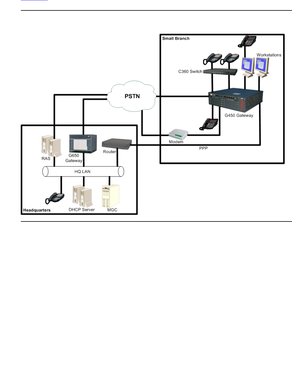

Modem dial backup
Issue 1 January 2008 281
Command sequence
!Step 1
G450-001(super-if:Loopback 1)# exit
G450-001(super)# interface loopback 1
G450-001(super-if:Loopback 1)# ip address 149.49.4.5 255.255.255.252
Done!
G450-001(super-if:Loopback 1)# exit
G450-001(super)#
!Step 2
G450-001(super)# ip access-control-list 305
G450-001(super-ACL 305)# name "Block-RTP-to_Modem-bkp"
Done!
G450-001(super-ACL 305)# ip-rule 20
G450-001(super-ACL 305/ip rule 20)# composite-operation "Deny"
Done!
G450-001(super-ACL 305/ip rule 20)# ip-protocol udp
Done!
G450-001(super-ACL 305/ip rule 20)# dscp 46
Done!
G450-001(super-ACL 305/ip rule 20)# description "Block-VoIP-Bearer"
Done!
G450-001(super-ACL 305/ip rule 20)# exit
G450-001(super-ACL 305)# exit
G450-001(super)#
!Steps 3-10 (Each command is an individual step)
G450-001(super)# interface dialer 1
G450-001(super-if:Dialer 1)# ppp chap hostname "area5"
Done!
G450-001(super-if:Dialer 1)# dialer persistent initial delay 5
Done!
G450-001(super-if:Dialer 1)# dialer persistent delay 5
Done!
G450-001(super-if:Dialer 1)# dialer string 1 3035384867
Done!
G450-001(super-if:Dialer 1)# dialer string 2 7325213412
Done!
G450-001(super-if:Dialer 1)# dialer modem-interface console
Done!
G450-001(super-if:Dialer 1)# ip unnumbered 1 Loopback 1
Done!
G450-001(super-if:Dialer 1)# ip access-group 305 out
Done!
G450-001(super-if:Dialer 1)# exit
G450-001(super)#

Configuring WAN interfaces
282 Administration for the Avaya G450 Media Gateway
Command sequence explanation
1. Assign an IP address to the Loopback interface for use with modem dial backup using the
interface loopback command. This step allows the Dialer interface to be configured
as an IP unnumbered link and still participate in OSPF routing.
2. Create an access control list with the ip access-control-list command. The
access control list determines which traffic is permitted to use the interface. In this
example, access control list 305 is configured to block all traffic other than VoIP signalling
traffic. The primary purpose of the access control list is to block bearer traffic from using
the Dialer interface. The Dialer interface generally has insufficient bandwidth to support
bearer traffic. For more information on configuring access control lists, see Configuring
policy on page 591.
3. Create the Dialer interface using the interface dialer command. The Dialer interface
is created and is available as a backup link for a WAN interface. Only one Dialer interface
can be created on the G450.
4. Assign a PPP authentication method with the ppp chap hostname command. The
Dialer interface authenticates its PPP sessions to the remote RAS server using CHAP
authentication and a username of area5. The username area5 must be configured on the
RAS as a legitimate user.
5. Assign an initial delay for dialing with the dialer persistent initial delay
command. The initial delay prevents the Dialer from dialing out unnecessarily on reboot.
The primary WAN interface often requires a few moments to register itself as up, and
during that period, the initial delay prevents the device from activating the Dialer.
!Step 11
G450-001(super)# interface console
G450-001(super-if:Console)# async mode interactive
Done!
G450-001(super-if:Console)# async modem-type MultiTech-ZBA
Done!
G450-001(super-if:Console)# exit
G450-001(super)#
Step 12
G450-001(super)# interface serial 3/1:1
G450-001(if:serial 3/1:1)# backup interface Dialer 1
Done!
G450-001(if:serial 3/1:1)# exit
G450-001(super)#
Step 13
G450-001(super)# router ospf
G450-001(super router:ospf)# network 149.49.4.4 0.0.0.3 area 0.0.0.5
Done
G450-001(super router:ospf)# exit
G450-001(super)#

Modem dial backup
Issue 1 January 2008 283
6. Assign a reset delay for the dialer string list using the dialer persistent delay
command. The reset delay determines the amount of time between cycles of call attempts,
once all dialer strings have been attempted.
7. Enter up to five dialer strings using the dialer string command. When the Dialer
interface is activated, the Dialer first attempts to connect to the number associated with
dialer string 1. If the connection attempt fails, the Dialer attempts to connect to the number
associated with the next dialer string. These strings represent hunt group phone numbers
configured on the RAS server in the headquarters data center.
8. Associate the Dialer interface with its physical port with the dialer modem-interface
command. The Dialer interface must be configured to use a physical interface on the
device to which the modem is connected. Modem dial backup is supported on both the
Console port and the USB port.
9. Configure the modem to participate in network routing with the ip unnumbered
command. An unnumbered interface uses the IP address of the interface configured in the
command. In this example, the Loopback interface has been created for the Dialer
interface to use its IP information. This IP information allows the unnumbered interface to
forward and receive IP traffic without actually assigning a static IP address to the Dialer
interface.
10. Assign an access control list to the Dialer interface using the ip access-group
command. All traffic passing through the Dialer interface must meet the conditions of the
access control list associated with this access group or be rejected. In this example, the
access-group references access control list 305, which is created to block all outgoing
traffic across the Dialer interface other than the VoIP signalling traffic between the branch
office gateway and the MGC in the headquarters data center.
11. Configure the Console port to support the modem with the interface console
command. The physical interface must be configured to use the attached modem. Each
modem type has different initialization requirements. The only modems supporting modem
dial backup are the MultiTech ZBA series modems. For more information on configuring
the Console and USB-modem interfaces to support modems, see Configuring the G450
for modem use on page 239.
12. Assign the Dialer interface to the interface you want to back up with the
backup interface dialer command. In this example, interface Dialer 1 is selected
as the backup interface to interface Serial 3/1:1, the primary WAN connection to the
headquarters network. The Dialer activates in the event of a failure of the serial port and all
permitted traffic transverses the Dialer interface. For more information on backing up WAN
interfaces, see Backup interfaces on page 268.
13. Configure the Loopback interface to participate in the OSPF network using the
router ospf command. In this example, a group of branch offices are assigned to
OSPF area 5. This configuration allows filtering to take place at the border points and
minimizes topology updates on the headquarters data center routers. For more information
on configuring OSPF routing, see Configuring OSPF on page 492.

Configuring WAN interfaces
284 Administration for the Avaya G450 Media Gateway
Modem dial backup maintenance
The G450 generates specific log messages for Dialer interface activity when configured to do
so. Certain dialer-related log messages are generated to aid you in troubleshooting problems
with modem dial backup. In addition, messages generated by the modem and the PPP session
are available to help with troubleshooting modem dial backup issues.
Activating session logging
To activate session logging for modem dial backup functions, type the following commands.
Logging messages will be sent to the terminal screen.
●set logging session condition dialer information
●set logging session condition console information
●set logging session condition usb-modem information
●set logging session condition ppp information
Note:
Note: Not all logging messages indicate problems. Some are generated to provide
information on normal working activity of the Dialer interface. For more
information on logging configuration, see Configuring logging on page 209.
Note:
Note: Syslog and log file logging are also available. See Configuring logging on
page 209.
Setting the severity level of the logging session
The set logging commands must include a severity level. All logging messages with the
specified severity and higher are displayed. The following are the available severity levels:
●Information. This message is for informational purposes and requires no action on your
part.
●Debug. This message provides information that can be useful in debugging certain
problems, but requires no action itself.
●Warning. This message indicates a condition requiring user intervention and
troubleshooting.

Modem dial backup
Issue 1 January 2008 285
Table 78: Modem dial backup logging messages
Log Message Severity Possible cause Action
Dialer Messages – Messages generated by the Dialer interface
Dialer 1 state is
<state>Debug The Dialer interface generates a
message when a change in its
operational state has been
detected. The default state for
the Dialer interface when it is
used as a backup interface for a
WAN link is Standby. When the
primary WAN link has failed and
the backup interface mechanism
is invoked, the state of the
Dialer interface changes to Up.
None required.
Dialer 1 trigger
is <on/off>Informational In a modem dial backup
scenario, the event triggering
the Dialer interface is a failure of
the primary WAN interface for
which the Dialer interface has
been configured as the backup
interface. When the primary
WAN interface has been
determined to be down, a
message is sent indicating the
occurrence of the triggering
event for the Dialer. When the
primary WAN interface is
returned to an operational state,
a message is generated
indicating that the conditions for
triggering the Dialer are no
longer being met, and that the
Dialer can be brought down.
None required.
1 of 6

Configuring WAN interfaces
286 Administration for the Avaya G450 Media Gateway
Dialer 1 string
<string_ID>
<dialer_string>
Informational The value of <string_ID> is
equal to the ID of the string
configured using the dialer
string command. The value of
<dialer_string> is equal to the
phone number associated with
the dialer string. For example, if
you configured dialer string 3 to
associate with the phone
number 5551314, and the
modem is attempting to connect
using dialer string 3, the
message received would be
Dialer 1 string 3
5551314.
None required.
Dialer 1 timer
expired Debug When the Dialer interface is
configured with the dialer
persistent re-enable command,
a timer is created. This timer
determines when the Dialer
interface attempts to begin
dialing again after a failure to
connect in as many attempts as
were configured in the dialer
persistent max-attempts
command. For example, if you
configured the value of dialer
persistent max-attempts as 10,
and dialer persistent re-enable
is configured for the Dialer
interface, after the Dialer has
made ten unsuccessful attempts
to connect to the remote
modem, the timer begins. When
the timer expires, the Dialer 1
timer expired message is sent,
and the Dialer begins attempting
to connect to the remote modem
again.
None required.
Table 78: Modem dial backup logging messages (continued)
Log Message Severity Possible cause Action
2 of 6

Modem dial backup
Issue 1 January 2008 287
Dialer 1 Modem
is not ready Warning This message is generated
when the Dialer interface has
been triggered and the
operational state of the Dialer is
up, but the Dialer is unable to
communicate with the modem.
Troubleshooting steps:
●Check modem
cable connection
to serial port.
●Check modem
cable connection
to modem.
●Check power to
modem.
Console Messages – Messages generated by a serial modem attached to the Console
port
Modem cable
detected. Port
speed <speed>
baud.
Informational When a modem cable is
determined to be connected to
the serial port, a message is
generated indicating the
successful connection of the
modem cable and advertising
the capabilities of the serial port
for potential modem
connections.
None required.
Modem
Detection
Failed
Warning This message is generated
when a modem cable is
connected to the serial port, but
no modem is detected. This
message is generated every 30
minutes until the modem is
detected.
Troubleshooting steps:
●Check modem
cable connection
to modem.
●Ensure that
modem is powered
on.
●Check modem
lights for an alarm.
Modem Ready Informational When the modem is discovered
by the device and the
initialization string is successful,
a message is generated
indicating that the device is
ready to dial.
None required.
Init string error Warning This message is generated
when the USB modem attempts
to dial and has an incorrect
initialization string. The attempt
to dial fails.
Troubleshooting steps:
●Check modem
configuration for
proper initialization
string.
Table 78: Modem dial backup logging messages (continued)
Log Message Severity Possible cause Action
3 of 6

Configuring WAN interfaces
288 Administration for the Avaya G450 Media Gateway
Modem cable
unplugged Warning This message is generated
when a Dialer interface is
defined, but no modem cable is
detected as being connected to
the serial port.
Troubleshooting steps:
●Check modem
cable connection
to serial port and
reseat cable if
necessary.
Connection
established Informational When the modem successfully
connects to a remote modem
and a PPP session is fully
established, a message is sent
indicating that the PPP is ready
to transmit and receive traffic.
None required.
USB Modem Messages – Messages generated by a USB modem
USB modem
was detected Informational When the USB modem is
discovered by the device and
the initialization string is
successful, a message is
generated indicating that the
device is ready to dial.
None required.
USB modem -
Connection
established
Informational When the USB modem
successfully connects to a
remote modem and a PPP
session is fully established, a
message is sent indicating that
the PPP is ready to transmit and
receive traffic.
None required.
USB modem -
Unplugged Warning This message is generated
when a modem cable is
connected to the USB port, but
no modem is detected.
Troubleshooting steps:
●Check modem
cable connection
to modem and to
USB port and
reseat if
necessary.
USB modem -
Initialization
string error
Warning This message is generated
when the USB modem attempts
to dial and has an incorrect
initialization string. The attempt
to dial fails.
Troubleshooting steps:
●Check modem
configuration for
proper initialization
string.
Table 78: Modem dial backup logging messages (continued)
Log Message Severity Possible cause Action
4 of 6

Modem dial backup
Issue 1 January 2008 289
PPP Messages – Messages generated by the PPP session
LCP Up/Down Informational LCP is used by PPP to initiate
and manage sessions. LCP is
responsible for the initial
establishment of the link, the
configuration of the session, the
maintenance of the session
while in use, and the termination
of the link. LCP is considered
Up when the link is being
established and configured, and
is considered down once the
session is fully established and
passing traffic. LCP then comes
up to pass Link Maintenance
packets during the session, and
goes down after the
maintenance is complete. LCP
comes up when a termination
request is sent, and goes down
when the link is terminated.
None required.
PAP
passed/failed Debug This message is sent when the
authenticating station responds
to the PAP authentication
request.
None required.
CHAP
passed/failed Debug This message is sent when the
authenticating station responds
to the CHAP authentication
request.
None required.
Table 78: Modem dial backup logging messages (continued)
Log Message Severity Possible cause Action
5 of 6

Configuring WAN interfaces
290 Administration for the Avaya G450 Media Gateway
IPCP Up/Down Debug PPP uses IPCP to define the IP
characteristics of the session. IP
packets cannot be exchanged
until IPCP is in the Up state.
None required.
IPCP IP reject Warning This message is generated
when IPCP attempts to define
the IP characteristics for a PPP
session, but does not have the
IP address of the local interface
to define the session. Without IP
address information on both
sides of the session, the PPP
session cannot begin passing IP
traffic.
Troubleshooting steps:
●Check Dialer
interface
configuration to
ensure an IP
address is
configured, either
as a static address
or through
Dynamic IP
addressing or
through IP
unnumbered.
Table 78: Modem dial backup logging messages (continued)
Log Message Severity Possible cause Action
6 of 6
Modem dial backup
Issue 1 January 2008 291
Summary of modem dial backup commands
For more information about these commands, see Avaya G450 CLI Reference, 03-300437.
Table 79: Modem dial backup CLI commands
Root level
command Command Description
interface
dialer Enter the Dialer interface configuration
context
dialer
modem-interface Associate a Dialer with a modem interface
dialer order Set which dial strings are used upon a new dial
trigger event
dialer
persistent Force the Dialer to attempt to reconnect every
second
dialer
persistent delay Set the redial interval
dialer
persistent
initial delay
Set the minimum delay from boot to persistent
dialing
dialer
persistent
max-attempts
Set the number of consecutive dial attempts for
the dial list
dialer
persistent
re-enable
Set the persistent re-enable timer after the
maximum number of dial attempts has been
reached
dialer string Add a phone number to the dial list
dialer
wait-for-ipcp Set the maximum time the Dialer waits
between dialing a number to successfully
establishing PPP/IPCP
ip address Assign an IP address and mask to an interface
ip address
negotiated Enable obtaining an IP address via PPP/IPCP
negotiation
ip unnumbered Configure an interface to borrow an IP address
from another interface
1 of 2

Configuring WAN interfaces
292 Administration for the Avaya G450 Media Gateway
ICMP keepalive
The ICMP keepalive feature, formerly known as extended keepalive, is available for WAN
FastEthernet interfaces. ICMP keepalive is a mechanism for determining if a certain IP address
is reachable. The source interface sends test packets (ping) and waits for a response. If no
response is received after a certain number of tries, the connection is declared to be down.
This feature provides a quick means to determine whether the interface is up or down. This is
especially important for policy-based routing, in which it is important to determine as quickly as
possible whether the next hop is available. See Configuring policy-based routing on page 619.
Note:
Note: ICMP keepalive has been replaced by the object tracking feature, which supports
keepalive probes over WAN, FastEthernet, Loopback, PPPoE, and Dialer PPP
interfaces and Frame relay sub-interfaces. ICMP keepalive is still supported for
backward compatibility. For information about object tracking, see Object
tracking on page 298.
ppp ipcp dns
request Enable requesting DNS information from the
remote peer during the PPP/IPCP session
interface
(fastethernet|
loopback|
serial|tunnel)
Enter the Console, FastEthernet,
Loopback, Serial, or Tunnel interface
configuration context
backup interface
dialer Set the Dialer interface as the backup interface
for the current interface
ip default-
gateway diale Define a default gateway (router)
router ospf Enable OSPF protocol on the system and to
enter the Router configuration context
set logging
session Manage message logging for the current
console session
show
interfaces Display interface configuration and statistics for
a particular interface or all interfaces
Table 79: Modem dial backup CLI commands (continued)
Root level
command Command Description
2 of 2
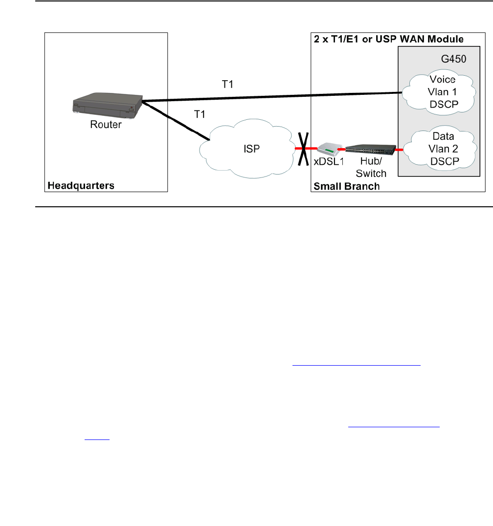
ICMP keepalive
Issue 1 January 2008 293
Normal keepalive is sufficient for testing the status of a direct connection between two points.
However, in many situations, the system needs to know the status of an entire path in order to
ensure that packets can safely traverse it.
ICMP keepalive is a mechanism that reports on the status of an IP address and its next hop.
The destination interface is only declared to be alive if the next hop is also reachable. This
feature is critical for mechanisms such as policy-based routing that must guarantee service on a
particular path.
Figure 25: G450 with T1 and xDSL lines
For example, your branch office may have a G450 that connects to the Headquarters over a T1
line and via an xDSL connection to the Internet. The T1 line is used for voice traffic, while data
packets are sent over the xDSL line. Normal keepalive cannot report on the status of the entire
WAN path. If the Fast Ethernet line protocol is up but the xDSL connected to it is down, normal
keepalive reports that the FastEthernet interface is up. Only ICMP keepalive, which checks the
next hop, correctly reports that the WAN path is down. Policy-based routing, which relies on the
interface status to determine how packets are routed, can use ICMP keepalive to know the
status of the interfaces on its next hop list.
Note:
Note: ICMP keepalive is not used with a GRE Tunnel interface. The GRE tunnel has its
own keepalive mechanism. For details, see Configuring GRE tunneling on
page 456.
Note:
Note: You cannot configure both DHCP Client and ICMP keepalive on the same WAN
FastEthernet interface. For details on DHCP Client see Configuring DHCP
client on page 199.

Configuring WAN interfaces
294 Administration for the Avaya G450 Media Gateway
Enabling the ICMP keepalive feature
Use the keepalive-icmp command in the context of the interface to enable the ICMP
keepalive feature. Use the no form of this command to deactivate the feature.
The keepalive-icmp command includes the following parameters:
●destination ip address. The destination IP address for the keepalive packets.
●next hop MAC address. The next hop MAC address for the keepalive packets. This
parameter is only relevant for the WAN Fast Ethernet ports.
Defining the ICMP keepalive parameters
Use the following commands to define the ICMP keepalive parameters. For more information
about these commands, see Avaya G450 CLI Reference, 03-300437.
●Use the keepalive-icmp timeout command to set the timeout (in seconds) for
receiving the keepalive response. The default value is 1.
●Use the keepalive-icmp success-retries command to set the number of
consecutive successful keepalive packets necessary to set the interface’s keepalive status
as up. The default value is 1.
●Use the keepalive-icmp failure-retries command to set the number of
consecutive failed keepalive packets necessary to set the interface’s keepalive status as
down. The default value is 4.
●Use the keepalive-icmp interval command to set the interval (in seconds) between
keepalive packets. The default value is 5.
●Use the keepalive-icmp source-address command to set the source IP address of
the keepalive packets. The default value is the interface’s primary IP address.
●Enter show keepalive-icmp to display the interface’s ICMP keepalive status and
parameters.

ICMP keepalive
Issue 1 January 2008 295
Example of configuring ICMP keepalive
The following example configures ICMP keepalive on interface fastethernet 10/2 to send
keepalive packets to IP address 135.64.2.12 using MAC address 11.22.33.44.55.66, at five
second intervals. If a response is not received within one second, the keepalive packet is
considered to have failed. After three consecutive failed packets, the interface is declared to be
down. After two consecutive successful packets, the interface is declared to be up.
Summary of ICMP keepalive configuration commands
For more information about these commands, see Avaya G450 CLI Reference, 03-300437.
G450-001# interface fastethernet 10/2
G450-001(super-if:FastEthernet 10/2)# keepalive-icmp 135.64.2.12
11.22.33.44.55.66
G450-001(super-if:FastEthernet 10/2)# keepalive-icmp interval 5
G450-001(super-if:FastEthernet 10/2)# keepalive-icmp timeout 1
G450-001(super-if:FastEthernet 10/2)# keepalive-icmp failure-retries 3
G450-001(super-if:FastEthernet 10/2)# keepalive-icmp success-retries 2
Done!
Table 80: ICMP keepalive CLI commands
Root level
command Command Description
interface
fastethernet Enter the FastEthernet interface
configuration context
keepalive-icmp Enable the ICMP keepalive mechanism on an
interface
keepalive-icmp
failure-retries Set the number of consecutive failed keepalive
packets necessary to set the interface’s
keepalive status as down
keepalive-icmp
interval Set the interval (in seconds) between
keepalive packets
keepalive-icmp
source-address Set the source IP address of the keepalive
packets
keepalive-icmp
success-retries Set the number of consecutive successful
keepalive packets necessary to set the
interface’s keepalive status as up
1 of 2

Configuring WAN interfaces
296 Administration for the Avaya G450 Media Gateway
Dynamic CAC
Dynamic Call Admission Control (CAC) provides enhanced control over WAN bandwidth. When
Dynamic CAC is enabled on an interface, the G450 informs the MGC of the actual bandwidth of
the interface and instructs the MGC to block calls when the bandwidth is exhausted.
Dynamic CAC is especially useful in situations where a primary link is down and a backup link
with less bandwidth than the primary link is active in its place. Without dynamic CAC, the MGC
is unaware that the interface has switched over to the backup link. Thus, the MGC is unaware of
the resulting changes in network topology and bandwidth available for the interface.
Consequently, the MGC might allow calls through the interface that require more than the
currently available bandwidth.
Note:
Note: Dynamic CAC works in conjunction with the Avaya Communication Manager Call
Admission Control: Bandwidth Limitation (CAC-BL) feature. A related feature is
Inter-Gateway Alternate Routing (IGAR), which provides a mechanism to re-route
bearer traffic from the WAN to the PSTN under certain configurable conditions.
For more information on CAC-BL and IGAR, see Administrator Guide for Avaya
Communication Manager, 03-300509.
You can enable dynamic CAC on the following interface types:
●FastEthernet
●Serial (PPP or frame relay)
●GRE Tunnel
●VLAN
Note:
Note: Since VLAN interfaces are always up, configuring dynamic CAC on a VLAN
interface provides a means to have a default dynamic CAC bandwidth.
keepalive-icmp
timeout Set the timeout (in seconds) for receiving the
keepalive response
show
keepalive-icmp Display information about the extended
keepalive settings
Table 80: ICMP keepalive CLI commands (continued)
Root level
command Command Description
2 of 2

Dynamic CAC
Issue 1 January 2008 297
Enabling dynamic CAC and setting maximum bandwidth
Use the dynamic-cac bbl command in interface context to enable dynamic CAC on the
interface and set the maximum bandwidth for the interface. The dynamic-cac bbl command
includes the following parameters:
●bbl. The bearer bandwidth limit (kbps). The MGC enforces this as the maximum
bandwidth for the interface. If you set the bbl to 0, the interface can only be used for
signalling.
●activation priority (optional). If dynamic CAC is activated on more than one active
interface, the G450 reports the bearer bandwidth limit of the interface with the highest
activation priority. You can set the activation priority to any number from 1 to 255. The
default activation priority is 50.
The following example sets dynamic CAC on FastEthernet interface 10/2, with a bearer
bandwidth limit of 128 and an activation priority of 100:
Displaying bandwidth information
Use the show dynamic-cac command to display bandwidth information about the interface.
The show dynamic-cac command displays the following information:
●Current RBBL. The current actual bandwidth available on the interface.
●Last event. The amount of time since the most recent update by the CAC process.
●Last event BBL. The interface’s bandwidth at the time of the most recent update by the
CAC process.
Note:
Note: Dynamic CAC also requires configuration of the Avaya Communication Manager.
For details, see Administrator Guide for Avaya Communication Manager,
03-300509.
G450-001# interface fastethernet 10/2
G450-001(super-if:FastEthernet 10/2)# dynamic-cac 128 100

Configuring WAN interfaces
298 Administration for the Avaya G450 Media Gateway
Summary of dynamic CAC configuration commands
For more information about these commands, see Avaya G450 CLI Reference, 03-300437.
Object tracking
With the Object tracking feature, you can track the state (up/down) of various objects in the
system using keepalive probes, and notify registered applications when the state changes. In
particular, object tracking is used to monitor Interface states and routes states, where routes
can be static routes, the DHCP client default route, or PBR next hops.
The purpose of object tracking is to track the state (up/down) of various objects in the system
using keepalive probes, and notify registered applications when the state changes. Configuring
object tracking is a two-stage operation:
●The first stage is to define Respond Time Reports (RTRs), the basic building blocks of
object tracking. RTRs actively monitor the reachability state of remote devices by
generating probes at regular intervals. Each RTR, identified by a unique number, monitors
one remote device, and learns the state of the device: up or down. The state of the RTR
reflects the state of the device it is monitoring – either up or down.
Table 81: Dynamic CAC CLI commands
Root level
command Command Description
interface
(dialer|serial
|loopback|
fastethernet|
tunnel|vlan)
Enter the Dialer, Serial, Loopback,
FastEthernet, Tunnel, or VLAN interface
configuration context
dynamic-cac Enable the ICMP keepalive mechanism on the
current interface
show
dynamic-cac Display information about the most recent
dynamic CAC event

Object tracking
Issue 1 January 2008 299
●The second stage consists of defining Object Trackers using RTRs. The definition of object
trackers is recursive. A simple object tracker monitors a single RTR, and its state directly
reflects the state of the RTR. A more advanced object tracker is a track list, which is
composed of multiple simple object trackers. The state of the track list is calculated based
on the states of the objects in the list. Because a track list is itself an object tracker, the
objects in a track list can be previously-defined track lists.
You can view a track list as monitoring the “health” of an entire group of remote devices.
You can define how to calculate the overall health of the group based on the health
(up/down) state of each individual device. For example, you can specify that the overall
state is up only if all remote devices are up, or if at least one device is up. Alternatively, you
can base the overall state on a threshold calculation.
Using object tracking, different applications can register with the tracking process, track the
same remote device(s), and each take different action when the state of the remote device(s)
changes.
Object tracking configuration
1. Configure RTRs to monitor remote devices and learn their state (up or down). Each RTR
has a state: inactive (not running), up (the remote device is considered up), or down (the
remote device is considered down).
2. Configure object trackers to track the states of RTRs. Each object tracker calculates its
own state (up or down) based on the states of the elements it is tracking.
Whenever the state of an object tracker changes, it notifies the applications registered with
it.
An object tracker calculates its own state as follows:
●For an object tracker tracking a single RTR:
-
If the state of the RTR is up, the state of the object tracker is up.
-
If the state of the RTR is inactive or down, the state of the object tracker is down.
●A track list applies a configurable formula (using a Boolean or a Threshold calculation)
to the states of the objects comprising the list, and the result (up/down) is the state of
the track list. For example, if the configured formula is the Boolean AND argument,
then the state of the list is up if the state of all its objects is up, and down if the state of
one or more of its objects is down.
Note:
Note: You can register either a VPN tunnel or an interface with an object tracker. For
more information see the definition of the keepalive-track command in the
Avaya G450 CLI Reference, 03-602056.

Configuring WAN interfaces
300 Administration for the Avaya G450 Media Gateway
Note:
Note: You cannot configure both DHCP Client and object tracking on the same WAN
FastEthernet interface. You can however configure tracking on the DHCP client
default route. For more information on DHCP Client see Configuring DHCP
client on page 199.
Configuring RTR
For each remote device whose state you wish to monitor:
1. Enter rtr, followed by a number from 1 to 30, to create the RTR. For example:
2. Use the type command to specify the remote device by address, and specify the probing
method to be employed by the RTR probe: ICMP Echo or TCP Connection.
If you specify a TCP Connection operation, specify also which port to probe in the remote
device. For example:
Or
3. Optionally, use the frequency command to specify the frequency at which RTR probes
are sent. If you do not configure this parameter, the default value of five seconds is used.
For example:
4. Optionally, use the dscp command to set the DSCP value in the IP header of the probe
packet, thus setting the packets’ priority. If you do not configure this parameter, the default
value of 48 is used. For example:
G450-001(config)# rtr 5
G450-001(config-rtr 5)#
G450-001(config-rtr 5)# type echo protocol ipIcmpEcho 10.0.0.1
G450-001(config-rtr icmp 5)#
G450-001(config-rtr 5)# type tcpConnect dest-ipaddr 147.42.11.1 dest-port
80
G450-001(config-rtr tcp 5)#
G450-001(config-rtr icmp 5)# frequency 2 seconds
Done!
G450-001(config-rtr icmp 5)# dscp 43
Done!
Object tracking
Issue 1 January 2008 301
5. Optionally, use the next-hop command to specify the next-hop for the RTR probe, and
bypass normal routing. The next-hop command is disabled by default.
Use the next-hop command when the G450 is connected to a remote device via more
than one interface, and you wish to monitor the state of one specific interface. When you
specify the next-hop as the interface you wish to monitor, you ensure that the RTR will
probe that interface.
When the RTR is used to monitor a static route, a PBR next hop, or the DHCP client
default route, you must specify the same next-hop for the RTR. This ensures it will be sent
over the next hop it should monitor.
If the interface is an Ethernet interface (FastEthernet not running PPPoE) or VLAN
interface, specify also the interface’s MAC address. For example:
6. Optionally, use the source-address command to specify a source IP address, instead
of using the output interface’s address. By default, the source-address command is
disabled, and RTR probes use the output interface’s address.
Use the source-address command when you are probing a device located on the
Internet, and specify as the source-address the G450 public IP address. For example:
7. Optionally, configure the RTR parameters that determine when the state of the remote
device is considered up or down. If you do not configure these characteristics, their default
values are used:
●Use the wait-interval command to specify how long to wait for a response from
the device. When the wait-interval is exceeded, the probe is considered an
unanswered probe. The default value is the current value of frequency.
●Use the fail-retries command to specify how many consecutive unanswered
probes change the state of an RTR from up to down. The default value is 5.
Note:
Note: When an RTR starts running, its state is considered up.
G450-001(config-rtr icmp 5)# next-hop interface fastethernet 10/2
mac-address 00:01:02:03:04:05
Done!
G450-001(config-rtr icmp 5)# source-address 135.64.102.5
Done!

Configuring WAN interfaces
302 Administration for the Avaya G450 Media Gateway
●Use the success-retries command to specify how many consecutive answered
probes change the state of an RTR from down to up. The default value is 5.
For example:
8. Exit the RTR type context, and activate the RTR with the rtr-schedule command.
Note:
Note: To deactivate the RTR, use the no rtr-schedule command. For example:
Note:
Note: Once an RTR’s probing method and remote device address is configured, you
cannot change them. If you exit the RTR type context and you want to modify the
configuration of the RTR, you can enter the RTR context using the rtr command
and specifying the RTR ID. From the RTR context, you can run the various
modification commands described in steps 3 to 7.
Configuring object tracking
To configure object tracking, you must first configure at least one simple object tracker, that is,
an object tracker that tracks a single RTR. If you wish, you can then configure a track list which
contains multiple simple object trackers and specifies how to calculate the overall state of the
list. Note that a track list is itself an object tracker. Therefore, you can configure track lists
containing object trackers which are either simple object trackers, or other track lists.
Configuring a simple object tracker
1. Use the track id rtr command to specify the RTR to be tracked. Enter a number from 1
to 50 as the unique ID for this object tracker. For example:
2. Use the description command to enter a description for the object tracker. For
example:
G450-001(config-rtr icmp 5)# wait-interval 2 seconds
Done!
G450-001(config-rtr icmp 5)# fail-retries 3
Done!
G450-001(config-rtr icmp 5)# success-retries 1
Done!
G450-001(config-rtr icmp 5)# exit
G450-001(config)# rtr-schedule 5 start-time now life forever
G450-001(config)# track 1 rtr 5
G450-001(config-track rtr 1)#
G450-001(config-track rtr 1)# description "track rtr-5"
Done!

Object tracking
Issue 1 January 2008 303
Configuring a track list
1. Use the track id list command to enter track list configuration mode, to specify the
unique ID of the track list (from 1 to 50), and to specify how to calculate the state of the
track list. The calculation can be either a Boolean or a Threshold calculation.
For example:
Or
Note:
Note: If you do not specify how to calculate the state of the track list, it is calculated by
default using the Boolean AND argument. This means that the list is up if all
objects are up, and down if one or more of the objects are down.
2. Use the description command to enter a description for the track list. For example:
3. Use the object command to add an object tracker to the list.
Note:
Note: The object tracker can be a simple one tracking a single RTR, or a track list. For
example:
4. Repeat step 3 to add as many object trackers as you require, up to a maximum of 50.
5. If you specified a Threshold method of calculation in step 1, use the threshold count
command to enter the threshold values. For example, use the following command to
specify that:
●The state of the object tracker will change from down to up if 2 or more hosts are up,
and
●The state of the object tracker will change from up to down if 1 or less hosts are up
G450-001(config)# track 10 list boolean or
G450-001(config-track list 10)#
G450-001(config)# track 10 list threshold count
G450-001(config-track list 10)#
G450-001(config-track list 10)# description "track list rtr-5 and rtr-6"
Done!
G450-001(config-track list 10)# object 1
Done!
G450-001(config-track list 10)# threshold count up 2 down 1
Done!

Configuring WAN interfaces
304 Administration for the Avaya G450 Media Gateway
Note:
Note: Object trackers operate indefinitely once they are defined. To stop the operation
of an object tracker, use the no track command to delete the object tracker.
Figure 26: Object tracking configuration workflow
Object tracking maintenance
Using the show commands, you can display RTR and Object Tracking configuration, and
enable RTR and object tracking logging to a CLI terminal.
●Use the show rtr configuration command to display RTR configuration values,
including all defaults, for a specific RTR operation or for all RTR operations.
●Use the show rtr operational-state command to display the global operational
status of the RTR feature, for a specific RTR operation or for all RTR operations.
●Use the show track command to display tracking information.
rtr
type
frequency
dscp
next-hop
source-address
wait-interval
fail-retries
success-retries
rtr-schedule
track id rtr
description
track id list
description
object 1
.
.
object n
threshold count

Object tracking
Issue 1 January 2008 305
Viewing RTR and object trackers logging
1. Enter set logging session enable to enable logging to the CLI terminal. For
example:
2. Use the set logging session condition saa to view all RTR messages of level
Info and above. For example:
3. Use the set logging session condition tracker command to view all object
tracker messages of level Info and above. For example:
G450-001# set logging session enable
Done!
CLI-Notification: write: set logging session enable
G450-001# set logging session condition saa Info
Done!
CLI-Notification: write: set logging session condition saa Info
G450-001# set logging session condition tracker Info
Done!
CLI-Notification: write: set logging session condition tracker Info
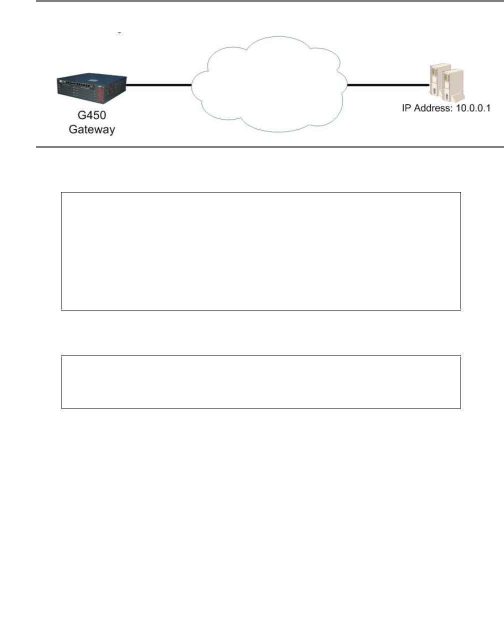
Configuring WAN interfaces
306 Administration for the Avaya G450 Media Gateway
Example of tracking a single remote device
Figure 27: Tracking a single remote device
1. The first step is to configure an RTR which tracks a remote device. In this case, RTR 5 is
configured to track the device at IP address 10.0.0.1. For example:
2. The second step is to configure an object tracker which tracks the state of RTR 5. For
example:
G450-001(config)# rtr 5
G450-001(config-rtr 5)# type echo protocol ipIcmpEcho 10.0.0.1
G450-001(config-rtr icmp 5)# wait-interval 2 seconds
Done!
G450-001(config-rtr icmp 5)# fail-retries 3
Done!
G450-001(config-rtr icmp 5)# success-retries 1
Done!
G450-001(config-rtr icmp 5)# exit
G450-001(config)# rtr-schedule 5 start-time now life forever
G450-001(config)# track 1 rtr 5
G450-001(config-track rtr 1)# description "track rtr-5"
Done!
G450-001(config-track rtr 1)# exit
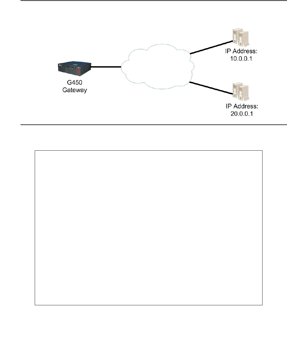
Object tracking
Issue 1 January 2008 307
Example of tracking a group of devices
Figure 28: Tracking multiple remote devices
1. The first step is to configure several RTRs. In this case, RTR 5 tracks the device at IP
address 10.0.0.1, and RTR 6 tracks the device at IP address 20.0.0.1. For example:
G450-001(config)# rtr 5
G450-001(config-rtr 5)# type echo protocol ipIcmpEcho 10.0.0.1
G450-001(config-rtr icmp 5)# wait-interval 2 seconds
Done!
G450-001(config-rtr icmp 5)# fail-retries 3
Done!
G450-001(config-rtr icmp 5)# success-retries 1
Done!
G450-001(config-rtr icmp 5)# exit
G450-001(config)# rtr-schedule 5 start-time now life forever
G450-001(config)# rtr 6
G450-001(config-rtr 6)# type tcpConnect dest-address 20.0.0.1 dest-port
80
G450-001(config-rtr tcp 6)# frequency 500 milliseconds
Done!
G450-001(config-rtr tcp 6)# dscp 34
Done!
G450-001(config-rtr tcp 6)# next-hop interface fastethernet 10/2
mac-address 00:01:02:03:04:05
Done!
G450-001(config)# rtr-schedule 6 start-time now life forever
G450-001(config-rtr tcp 6)# exit

Configuring WAN interfaces
308 Administration for the Avaya G450 Media Gateway
2. The second step is to configure several object trackers. In this case, object tracker 1 tracks
the state of RTR 5, and object tracker 2 tracks the state of RTR 6. For example:
3. The third step is to configure a track list object tracker which tracks the states of object
trackers 1 and 2, and calculates its own state using a boolean or threshold calculation.
In this case, a Boolean OR argument is used. This means that the track list is up if either
object tracker 1 or object tracker 2 is up. For example:
Typical object tracking applications
●Trigger the failover mechanism for VPN. See Typical application – VPN failover using
object tracking on page 309.
●Trigger the failover mechanism for interfaces. See Typical application – backup for a WAN
FastEthernet interface on page 309, and Typical application – interface backup via
policy-based routing on page 312.
●Track the state of a route: a static route, a PBR next hop, or the DHCP client default route.
For an example of how to track the DHCP client default route, see Typical application –
tracking the DHCP client default route on page 313.
G450-001(config)# track 1 rtr 5
G450-001(config-track rtr 1)# description "track rtr-5"
Done!
G450-001(config-track rtr 1)# exit
G450-001(config)# track 2 rtr 6
G450-001(config-track rtr 2)# description "track rtr-6"
Done!
G450-001(config-track rtr 2)# exit
G450-001(config)# track 10 list boolean or
G450-001(config-track list 10)# description "track list rtr-5 and rtr-6"
Done!
G450-001(config-track list 10)# object 1
Done!
G450-001(config-track list 10)# object 2
Done!
G450-001(config-track list 10)# exit
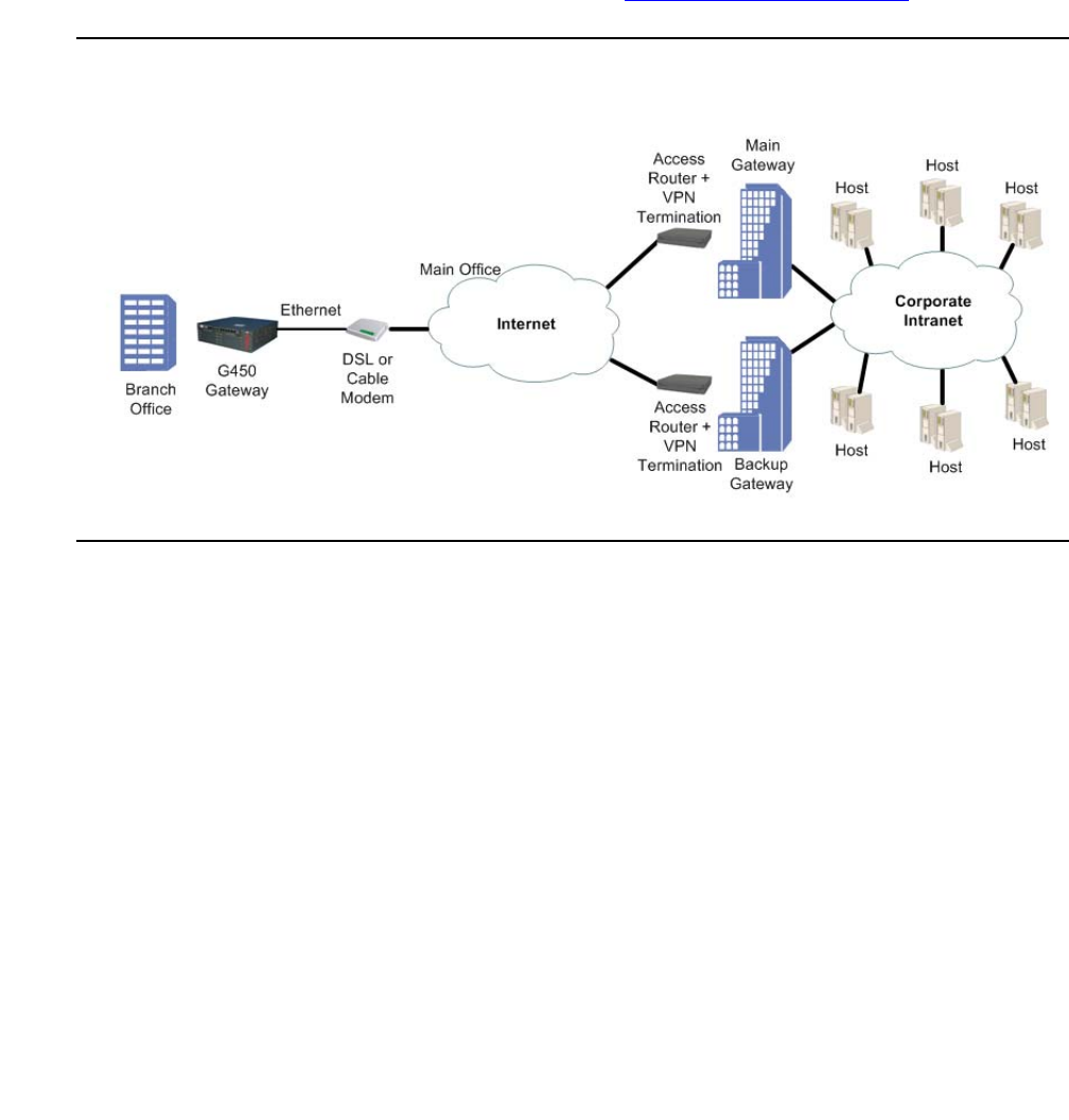
Object tracking
Issue 1 January 2008 309
Typical application – VPN failover using object tracking
In this application, the G450 is connected to a remote site through an IPSec VPN tunnel. The
remote site can be reached through two or more VPN gateways that can back each other up,
such as a main gateway and a backup gateway. Object tracking can monitor the state of the
current VPN connection, by monitoring one or more hosts that reside within the remote site's
network. If the current connection is lost, the G450 can failover to a backup gateway, and
attempt to establish a VPN connection to it.
A typical application of this type is described in full in Failover using a peer-group on page 575.
Figure 29: Failover VPN topology using object tracking
Typical application – backup for a WAN FastEthernet interface
This typical application illustrates the use of object tracking as a backup mechanism for PPPoE
configured on a WAN FastEthernet interface. A track list monitors the state of the connection. If
the WAN FastEthernet interface is down, another connection is used.
In this application, the G450 is connected to an xDSL modem via PPPoE encapsulation
configured on interface WAN FastEthernet 10/2. The G450 is connected to the Internet via the
xDSL modem.
Configuring the backup mechanism
1. Define four RTRs to probe the four entrances to the main office. Configure each RTR to
run immediately and forever.
2. Define four object trackers to track the four RTRs.

Configuring WAN interfaces
310 Administration for the Avaya G450 Media Gateway
3. Define a track list consisting of all four object trackers, and configure it so that if all object
trackers are up, the track list is up, and if two or less of the object trackers are up, the track
list is down.
4. Register the WAN FastEthernet interface with the track list.
5. Define the Serial 3/1:1 as a backup interface for the WAN FastEthernet interface.
Thus, when the track list is down the Serial interface will be up until the track list is up again.
Note:
Note: Note that RTR packets continue to be sent over the PPPoE interface as long as
the PPP-IPCP connection status is up.
! Define four RTRs to probe the four entrances to the Main Offices.
! Configure each one to run immediately and forever.
!
rtr 1
type echo protocol ipIcmpEcho 6.0.0.200
next-hop interface fastethernet 10/2
exit
rtr-schedule 1 start-time now life forever
rtr 2
type echo protocol ipIcmpEcho 6.0.0.201
next-hop interface fastethernet 10/2
exit
rtr-schedule 2 start-time now life forever
rtr 3
type echo protocol ipIcmpEcho 6.0.0.202
next-hop interface fastethernet 10/2
exit
rtr-schedule 3 start-time now life forever
rtr 4
type echo protocol ipIcmpEcho 6.0.0.203
next-hop interface fastethernet 10/2
exit
rtr-schedule 4 start-time now life forever

Object tracking
Issue 1 January 2008 311
! Define four object trackers to track the four RTRs.
!
track 1 rtr 1
exit
track 2 rtr 2
exit
track 3 rtr 3
exit
track 4 rtr 4
exit
!
! Define a track list consisting of the four object trackers.
! Define a threshold calculation such that if all four object trackers
! are up, the list is up, and if 2 or less are up, the list is down.
!
track 50 list threshold count
threshold count up 4 down 2
object 1
object 2
object 3
object 4
exit
!
! Configure PPPoE encapsulation on interface WAN FastEthernet 10/2, and
! register the interface with the track list.
!
interface fastethernet 10/2
bandwidth 96
encapsulation pppoe
traffic-shape rate 96000
ip address negotiated
keepalive-track 50
exit
!
! Configure the serial 3/1:1 interface
!
interface serial 3/1:1
encapsulation ppp
ip address 10.0.0.1 255.0.0.0
exit
!
! Assign the serial 3/1:1 interface to be the backup interface for
! interface WAN FastEthernet 10/2.
!
interface fastethernet 10/2
backup interface Serial 3/1:1
backup delay 0 60
exit

Configuring WAN interfaces
312 Administration for the Avaya G450 Media Gateway
Typical application – interface backup via policy-based routing
In the previous typical application (see Typical application – backup for a WAN FastEthernet
interface on page 309), the backup interface command is used to specify a backup
interface. This typical application illustrates an alternative to the backup interface
command, using policy-based routing (PBR) which configures a routing scheme for specified
traffic based on configured characteristics of the traffic. Thus, PBR can be used in combination
with object tracking to configure a backup mechanism for interfaces.
For an example that uses policy-based routing as an alternative to the backup interface
command, replace the last four lines of the previous typical application with the example below.
The example creates a next hop list that sends the specified traffic to the WAN FastEthernet
interface, which is running PPPoE encapsulation. If the WAN FastEthernet interface becomes
unavailable, the next hop list routes the traffic to the Serial interface 3/1:1. PBR list 801 is
created and assigned to interface VLAN 1, so that traffic defined in PBR list 801 passing
through interface VLAN 1 is routed according to the next hop list.
Note:
Note: You can define a static route over the WAN FastEthernet interface running DHCP
client. In such a case, the static route uses as the next hop the default router
learned from the DHCP server. This is useful for GRE tunnels which are defined
over the WAN Fast Ethernet running DHCP client. It is necessary to define static
routes in order to prevent loops. Therefore, the IP route command allows
configuration of static routes over WAN Fast Ethernet running DHCP client.

Object tracking
Issue 1 January 2008 313
When the WAN Fast Ethernet is up, policy-based routing routes this traffic via the WAN
FastEthernet interface. When the track list defined in the previous typical application is down,
policy-based routing routes this traffic through the Serial interface 3/1:1. When the track list is
up again, the traffic is again routed through the WAN FastEthernet interface.
Typical application – tracking the DHCP client default route
This typical application demonstrates a case where a user configures DHCP client on the
device to enable cable modem connection to a WAN FastEthernet interface. The user wishes to
know whether the DHCP client default route can be used for routing decisions –that is, whether
traffic can be routed over this default route. To do so, the user activates tracking to monitor the
remote HQ peer. When the object tracker is up, the DHCP default route may be used. When the
object tracker is down, the DHCP default route is not used for routing and traffic is routed to
alternate routes.
! Create PBR list 801. This list routes traffic from IP address
! 149.49.42.1 to IP address 149.49.43.1 according to next hop list 10.
!
ip pbr-list 801
name "list #801"
ip-rule 10
next-hop list 10
source-ip host 149.49.42.1
destination-ip host 149.49.43.1
exit
exit
!
! Assign PBR list 801 to interface Vlan 1.
!
interface Vlan 1
icc-vlan
ip pbr-group 801
ip address 149.49.42.254 255.255.255.0
exit
!
! Configure next hop list 10 with interface fastethernet 10/2 as the
! first next hop, and interface Serial 3/1:1 as the second next hop.
!
ip next-hop-list 10
next-hop-interface 5 FastEthernet 10/2
next-hop-interface 10 Serial 3/1:1
exit
Configuring WAN interfaces
314 Administration for the Avaya G450 Media Gateway
Note:
Note: If several default routers are learned from a specific interface, the object tracker
tracks only the first one.
Summary of object tracking configuration commands
For more information about these commands, see Avaya G450 CLI Reference, 03-300437.
! Apply DHCP client on a WAN Fast Ethernet
!
interface fastethernet 10/2
ip address dhcp
exit
!
! Configure the RTRs and object trackers.
! Use the next-hop command to ensure that the RTR is sent over the
! next hop it is monitoring, which is the WAN Fast Ethernet running
! DHCP client.
!
! 192.30.3.1 is the remote HQ peer IP address.
!
rtr 2
type echo protocol ipIcmpEcho 192.30.3.1
next-hop interface fastethernet 10/2
exit
track 2 rtr 2
exit
!
! Apply object tracking on the DHCP client.
!
interface fastethernet 10/2
ip dhcp client route track 2
exit
Table 82: Object tracking CLI commands
Root level
command First level
command Second level
command Description
rtr Enter Respond Time Reports (RTR)
configuration mode. RTRs are the
basic building blocks of object tracking.
type Set the type of operation an RTR
should employ in its probes, and
specify the address of the remote
device being probed
1 of 2

Object tracking
Issue 1 January 2008 315
dscp Set the DSCP value for the packets of
the RTR probes
fail-retries Set how many consecutive
unanswered probes change the status
of an RTR operation device from up to
down
frequency Set the frequency of the RTR probes
next-hop Specify the next hop for the RTR
probes, bypassing normal routing
source-address Set the source IP address for RTR
operations
success-retries Set how many consecutive answered
probes change the status of an RTR
operation device from down to up
wait-interval Set how long to wait for a device to
answer an RTR probe
rtr-schedule Activate or stop an RTR operation
show rtr
configuration Display RTR configuration values
show rtr
operational-
state
Display the global operational status of
the RTR feature
show track Display tracking information
track Configure an object tracker
description Set a description for the object tracker
object Add an object tracker to a track list
threshold
count Set the upper and lower thresholds for
the threshold in the track list command
Table 82: Object tracking CLI commands (continued)
Root level
command First level
command Second level
command Description
2 of 2

Configuring WAN interfaces
316 Administration for the Avaya G450 Media Gateway
Frame relay encapsulation features
The Avaya G450 Media Gateway supports the following frame relay encapsulation features:
●Frame relay traffic shaping and FRF.12 fragmentation
●Priority DLCI
Note:
Note: The terms PVC (Permanent Virtual Circuit) and DLCI (Data Link Connection
Identifier) describe the same entity and are interchangeable.
To improve voice quality using RTP, see Configuring header compression on page 225.
Frame relay traffic shaping and FRF.12 fragmentation
Frame relay traffic shaping regulates the outgoing traffic rate on a per-DLCI basis. Each DLCI
maintains a weighted fair VoIP queue scheduler to buffer the packets.
FRF.12 fragmentation allows for link fragmentation and interleaving (LFI), which reduces the
serialization delay on narrow bandwidth PVCs. This is required for VoIP traffic.
You can configure the traffic shaping and fragmentation parameters within traffic shaping
templates called map classes. A map class is comprised of the following parameters:
●CIR. Default = 56,000 bps
●Committed Burst (BC) size. Default =7,000 bits
●Excess Burst (BE) size. Default = 0 bits
●Fragmentation. Fragment size, in bytes. Default = No Fragmentation.
You can configure up to 128 different map classes using different combinations of traffic shaping
parameters. You then apply these map classes to a PVC.
Note:
Note: For a Priority DLCI group you must configure the Primary VC before associating a
DLCI map class to the Priority DLCI group VCs. Removing the Primary VC after
associating a DLCI map class to the Priority LCI group VCs, removes their map
class configuration.
You can enable traffic shaping on a frame relay interface with the frame-relay
traffic-shaping command. After you enable traffic shaping, a default map class is applied
to all currently configured PVCs.
Frame relay encapsulation features
Issue 1 January 2008 317
Configuring map classes
Use the map-class frame-relay command to create a map class, and to enter the
configuration context of the map class.
Use the cir out command to configure the CIR, in bits per second, for the outbound direction.
Use the bc out command to configure the BC size, in bits, for the outbound direction.
Use the be out command to configure the BE size, in bits, for the outbound direction.
Use the fragment command to turn FRF.12 fragmentation on or off and to configure the
fragment size.
Displaying configured map classes
Use the show map-class frame-relay command to display a table of all configured
map-classes.
Summary of frame relay traffic shaping commands
For more information about these commands, see Avaya G450 CLI Reference, 03-300437.
Table 83: Frame relay traffic shaping CLI commands
Root level command Command Description
interface serial Enter the Serial interface or sub
interface configuration context
frame-relay
traffic-shaping Turn on/off traffic shaping and frame relay
fragmentation
map-class
frame-relay Create a map class, a QoS template
which can later be assigned to DLCIs, and
enter the configuration context of the map
class
bc out Configure the committed burst size in bIts,
for the outbound direction
be out Configure the excess burst size in bits, for
the outbound direction
cir out Configure the Committed Information
Rate in bits per second, for the outbound
direction
1 of 2

Configuring WAN interfaces
318 Administration for the Avaya G450 Media Gateway
Priority DLCI
To implement new priority mechanisms, ISPs rely on new classes of service. Traffic types and
users are divided into these classes and treated differently during peak periods. A premium, or
first class user or traffic stream receives higher priority than a general user. This rating system
ensures that the critical Internet user maintains peak performance. It also provides a means for
ISPs to enhance the cost structure of network operations.
The G450 supports class-based traffic assignment (priority DLCI). Priority DLCI is a means for
implementing QoS on frame relay circuits. The G450 separates traffic with different QoS levels
to up to four different VCs on the same frame relay sub-interface. This feature enables you to
assign unique Permanent VCs (PVC) for VoIP and non-VoIP traffic. You can set and adjust the
priority using policy. For more information, see Configuring policy on page 591.
Configure Priority DLCI using the frame-relay priority-dlci-group command in the
Serial sub-interface context. Specify the DLCIs in this command from the highest to lowest
priority. If you specify less than four DLCIs, the last DLCI specified is automatically used for the
missing priorities.
When using Priority DLCI, the primary DLCI is used to determine the state of the sub frame
relay interface. When the primary DLCI is up, the sub frame relay interface is up. When the
primary DLCI is down, the sub frame relay interface is down. Therefore, when using Priority
DLCI, it is recommended to verify that the primary DLCI is set as the High Priority DLCI in the
Priority DLCI group.
On the Avaya G450 Media Gateway, OSPF is mapped by default to the High Priority DLCI. For
better network reliability, it is recommended to verify that the same configuration exists on the
other side of the frame relay connection.
If one of the Priority DLCIs is down, its traffic is dropped.
Map the PVC control protocol on the routers at all ends of a multi-VC point-to-point link. Map
this VC to the highest priority DLCI.
fragment Turn FRF.12 fragmentation on or off and
configure the fragment size
show map-class
frame-relay Display the map class table
Table 83: Frame relay traffic shaping CLI commands (continued)
Root level command Command Description
2 of 2
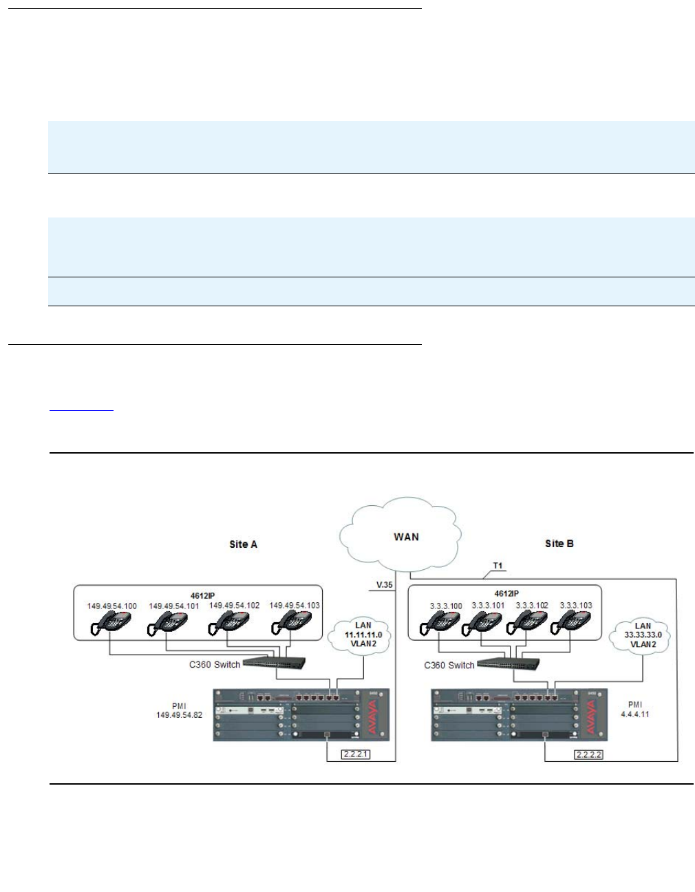
Priority DLCI
Issue 1 January 2008 319
Summary of priority DLCI commands
For more information about these commands, see Avaya G450 CLI Reference, 03-300437.
PPP VoIP configuration
Figure 30 illustrates a common PPP VoIP configuration between two sites connected over a
WAN:
Figure 30: PPP VoIP configuration over WAN
Table 84: Priority DLCI CLI commands
Root level
command Command Description
interface
serial Enter the Serial interface or sub
interface configuration context
frame-relay
priority-dlci-group Assign Virtual Channels to priority
classifications, for the purpose of traffic
separation

Configuring WAN interfaces
320 Administration for the Avaya G450 Media Gateway
Site A connection details
Site A contains four IP phones and a G450 with S8300 and one MM342 media module. The
MM342 media module connects the G450 to the WAN via a USP 128 Kbps V.35 interface. The
following are the connection details for Site A:
●The IP phones are configured with the following DSCP tagging:
-
Voice = DSCP 46
-
Voice control = DSCP 34
Note:
Note: The policy list in the next configuration is based on the assumption that the Media
Gateway, S8300, and the IP phones send VoIP control packets with a DSCP
value of 34 and voice with a DSCP value of 46. If any of the components of the
topology are sending control or voice packets with other DSCP values, you must
make changes in the policy list.
●The default RTP UDP port range is 2048 to 3028
●Network IPs (24 bit subnet masks):
-
IP phones = 149.49.54.0 (VLAN 1)
-
Data = 11.11.11.0 (VLAN 2)
-
Serial = 2.2.2.1
-
S8300 = 149.49.54.81
-
G450 PMI = 149.49.54.82
Site B connection details
Site B contains four IP phones and a G450 with S8300 and one MM340 media module. The
MM340 media module connects the G450 to the WAN via a two-timeslot (128 Kbps) T1
interface. The following are the connection details for Site B:
●IP phone are configured with DSCP tagging:
-
Voice = DSCP 46
-
Voice control = DSCP 34
●The default RTP UDP port range is 2048 to 3028
●Network IPs (24 bit subnet masks):
-
IP phones = 3.3.3.0 (VLAN 1)
-
Data = 33.33.33.0 (VLAN 2)
-
Serial = 2.2.2.2
-
S8300 = 4.4.4.10
-
G450 PMI = 4.4.4.11

Priority DLCI
Issue 1 January 2008 321
Configuration Example for Site A
You can configure PPP VoIP on the G450 at Site A. Commands with footnotes are described at
the end of the configuration procedure.
●Loopback and PMI interfaces configuration:
●VLAN interface configuration:
●Serial interface configuration:
Note:
Note: Some LAN data applications do not support fragmented packets. In this case, do
not change the MTU from its default of 1500.
●VoIP configuration:
●Static routes configuration:
G450-001# interface loopback 1
G450-001(if:Loopback 1)# ip address 149.49.54.82 24
Done!
G450-001(if:Loopback 1)# pmi
The Primary management interface has changed. Please copy the running configuration
to the start-up configuration file, and reset the device.
G450-001(if:Loopback 1)# exit
G450-001# copy running-config startup-config
G450-001# reset
G450-001# interface Vlan 1
G450-001(if:Vlan 1)# ip address 149.49.54.24
Done!
G450-001(if:Vlan 1)# exit
G450-001# interface Vlan 2
G450-001(if:Vlan 2)# ip address 11.11.11.1 24
Done!
G450-001(if:Vlan 2)# exit
G450-001# interface serial 4/1
G450-001(if:Serial 4/1)# ip address 2.2.2.1 24
G450-001(if:Serial 4/1)# mtu 300
G450-001(if:Serial 4/1)# bandwidth 128
G450-001(if:Serial 4/1)# ip rtp header-compression
G450-001(if:Serial 4/1)# ip rtp compression-connections 20 (4)
G450-001(if:Serial 4/1)# ip rtp port-range 2048 3028 (5)
G450-001(if:Serial 4/1)# exit
G450-001# ip default-gateway 4/1

Configuring WAN interfaces
322 Administration for the Avaya G450 Media Gateway
* Description of footnoted commands (also applies to identical stages in configuring Site B):
(1) At this stage you apply Priority 7 to Voice Control traffic.
(2) At this stage you apply Priority 6 to RTP traffic.
(3) At this stage you apply maximum trust between 802.1p priority and DSCP.
(4) At this stage the number of connections (20) depends on the number of phones.
(5) At this stage you are matching the RTP port range to that of the G450.
(6) At this stage the default queue size is 6, and since RTP is enabled you can double the VoIP
queue size.
Configuration Example for Site B
You can configure PPP VoIP on the G450 at Site B.
●Loopback and PMI interfaces configuration:
●VLAN interface configuration:
●Serial interface configuration:
Note:
Note: Some LAN data applications do not support fragmented packets. In this case, do
not change the MTU from its default of 1500.
G450-001# interface loopback 1
G450-001(if:Loopback1)# ip address 4.4.4.11 32
Done!
G450-001(if:Loopback 1)# pmi
The Primary management interface has changed. Please copy the running configuration
to the start-up configuration file, and reset the device.
G450-001(if:Loopback1)# exit
G450-001# copy running-config startup-config
G450-001# reset
G450-001# interface Vlan 1
G450-001(if:Vlan 1)# ip address 3.3.3.1 24
G450-001(if:Vlan 1)# exit
G450-001# interface Vlan 2
G450-001(if:Vlan 1:2)# ip address 33.33.33.1 24
G450-001(if:Vlan 1:2)# exit
G450-001# controller t1 4/1
G450-001(controller:4/1)# channel-group 1 timeslots 1-2 speed 64
G450-001(controller:4/1)# exit
G450-001# interface serial 4/1:1
G450-001(if:Serial 4/1:1)# ip address 2.2.2.2 24
G450-001(if:Serial 4/1:1)# mtu 300

Priority DLCI
Issue 1 January 2008 323
●VoIP configuration:
●Static routes configuration:
G450-001(if:Serial 4/1:1)# ip rtp header-compression
G450-001(if:Serial 4/1:1)# ip rtp compression-connections 20
G450-001(if:Serial 4/1:1)# ip rtp port-range 2048 3028
G450-001(if:Serial 4/1:1)# exit
G450-001# ip route 1.1.1.0 24 serial 4/1:1
G450-001# ip route 11.11.11.0 24 serial 4/1:1

Configuring WAN interfaces
324 Administration for the Avaya G450 Media Gateway
Issue 1 January 2008 325
Chapter 12: Configuring Emergency
Transfer Relay (ETR)
The ETR feature provides basic telephone services in the event of system failure, such as a
power outage or a failed connection to the MGC. The ETR feature can be used in conjunction
with an analog media module (MM711, MM714, or MM716). The ETR panel provides up to five
incoming Central Office (CO) trunk loops to 5 selected G450 analog lines. Thus, one ETR panel
supports up to five emergency lines. You can cascade a second ETR panel, providing support
for up to 10 emergency analog phones. ETR is activated automatically upon system failure by
closing the tip/ring contacts between the analog lines and the analog trunks. When ETR is
activated, all calls are directed by the analog relays between the outside lines and the analog
telephones. A current-loop detection circuit prevents ongoing calls from being disconnected
when normal functioning resumes. If a call is in progress on an outside line when the problem
ends, the call continues. The trunk port and analog line port passing through the ETR panel do
not start to operate until the active call ends.
!CAUTION:
CAUTION: The analog ports connected to the ETR panel must be configured as DID.
When ETR is active and the G450 has power, the ETR front panel LED is lit.
Setting ETR state
By default, ETR is set to go into effect automatically in the event of power outage or a failed
connection to the MGC. You can activate ETR manually via the CLI.
●To activate ETR manually in the G450, use the following command:
Generally, you should only use this command for testing.
●To restore ETR to automatic activation in the G450, use the following command:
If the system fails, the analog line connections and analog trunk connections passing through
the ETR panel are automatically latched.
set etr 7 manual-on
set etr 7 auto

Configuring Emergency Transfer Relay (ETR)
326 Administration for the Avaya G450 Media Gateway
Note:
Note: A call in progress will be terminated when ETR is activated either automatically or
manually.
Viewing ETR state
You can enter show etr to display ETR information. This information includes the following:
●Admin state (auto or manual-on)
●Module status (in service, out of service, or out of service waiting for off-hook)
●Trunk number of the trunk connected to ETR
●Line number of the line connected to ETR
●Line status (off hook or on hook)
Summary of ETR commands
For more information about these commands, see Avaya G450 CLI Reference, 03-300437.
Table 85: ETR configuration CLI commands
Command Description
set etr Enable Emergency Transfer Relay (ETR) mode, or allow the
gateway to control ETR mode automatically
show etr Display the status of Emergency Transfer Relay (ETR) mode

Issue 1 January 2008 327
Chapter 13: Configuring SNMP
SNMP uses software entities called managers and agents to manage network devices. The
manager monitors and controls all other SNMP-managed devices or network nodes on the
network. There must be at least one SNMP Manager in a managed network. The manager is
installed on a workstation located on the network.
An agent resides in a managed device or network node. The agent receives instructions from
the SNMP Manager, generates reports in response to requests from the SNMP Manager, and
sends management information back to the SNMP Manager as events occur. The agent can
reside on:
●Routers
●Bridges
●Hubs
●Workstations
●Printers
●Other network devices
There are many SNMP management applications, but all these applications perform the same
basic task. They allow SNMP managers to communicate with agents to configure, get statistics
and information, and receive alerts from network devices. You can use any SNMP-compatible
network management system to monitor and control a G450.
Agent and manager communication
There are several ways that the SNMP manager and the agent communicate. The manager
can:
●Retrieve a value (get). The SNMP manager requests information from the agent, such as
the number of users logged on to the agent device or the status of a critical process on that
device. The agent gets the value of the requested Management Information Base (MIB)
variable and sends the value back to the manager.
●Retrieve the value immediately after the variable you name (get-next). The SNMP
manager retrieves different instances of MIB variables. The SNMP manager takes the
variable you name and then uses a sequential search to find the desired variable.
●Retrieve a number of values (get-bulk). The SNMP manager retrieves the specified
number of instances of the requested MIB variable. This minimizes the number of protocol
exchanges required to retrieve a large amount of data.

Configuring SNMP
328 Administration for the Avaya G450 Media Gateway
Note:
Note: Get-bulk is not supported in SNMPv1.
●Change a configuration on the agent (set). The SNMP manager requests the agent to
change the value of the MIB variable. For example, you can run a script or an application
on a remote device with a set action.
●Receive an unsolicited message (notification). The SNMP manager receives an
unsolicited message from an agent at any time if a significant, predetermined event takes
place on that agent. When a notification condition occurs, the SNMP agent sends an
SNMP notification to the device specified as the trap receiver or trap host. The SNMP
Administrator configures the trap host, usually the SNMP management station, to perform
the action needed when a trap is detected.
Note:
Note: For a list of traps and MIBS, see Traps and MIBs on page 641.
SNMP versions
There are currently three versions of SNMP:
●SNMPv1
●SNMPv2c
●SNMPv3
The G450 supports all three versions. The implementation of SNMPv3 on the G450 is
backwards compatible. That is, an agent that supports SNMPv3 will also support SNMPv1 and
SNMPv2c.

SNMP versions
Issue 1 January 2008 329
SNMPv1
SNMPv1 uses community strings to limit access rights. Each SNMP device is assigned to a
read community and a write community. To communicate with a device, you must send an
SNMP packet with the relevant community name.
By default, if you communicate with a device using only the read community, you are assigned
the security name ReadCommN. This security name is mapped to the ReadCommG group by
default. This allows you to view the agent’s MIB tree, but you cannot change any of the values
in the MIB tree.
If you communicate with a device using the write community, you are assigned the security
name WriteCommN. This security name is mapped to the WriteCommG group by default. This
allows you to view the agent’s MIB tree and change any of the values in the MIB tree.
Note:
Note: If you delete the ReadCommN or WriteCommN users, the ReadCommG or
WriteCommG groups, or the snmpv1WriteView or snmpv1View, you may not be
able to access the device using SNMPv1 or SNMPv2c.
In addition, traps are sent to designated trap receivers. Packets with trap information also
contain a trap community string.
SNMPv2c
SNMPv2c is very similar to SNMPv1. However, SNMPv2c adds support for the get-bulk action
and supports a different trap format.
SNMPv3
SNMPv3 enables the following features over SNMPv1 or v2c:
●User authentication with a username and password
●Communication encryption between the Network Management Station (NMS) and the
SNMP agent at the application level
●Access control definition for specific MIB items available on the SNMP agent
●Notification of specified network events directed toward specified users
●Definition of roles using access control, each with unique access permissions and
authentication and encryption requirements
The basic components in SNMPv3 access control are users, groups, and views. In addition,
SNMPv3 uses an SNMP engine ID to identify SNMP identity. An SNMP engine ID is assigned to
each MAC address of each device in the network. Each SNMP engine ID should be unique in
the network.

Configuring SNMP
330 Administration for the Avaya G450 Media Gateway
Users
SNMPv3 uses the User-based Security Model (USM) for security, and the View-based Access
Control Model (VACM) for access control. USM uses the HMAC-MD5-96 and HMAC-SHA-96
protocols for user authentication, and the CBC-DES56 protocol for encryption or privacy.
An unlimited number of users can access SNMPv3 at the same time.
SNMP security levels
●NoAuthNoPriv. This is the lowest level of SNMPv3 security. No MAC is provided with the
message, and no encryption is performed. This method maintains the same security level
as SNMPv1, but provides a method for limiting the access rights of the user.
●AuthNoPriv. User authentication is performed based on MD5 or SHA algorithms. The
message is sent with an HMAC that is calculated with the user key. The data part is sent
unencrypted.
●AuthPriv. User authentication is performed based on MD5 or SHA algorithms. The
message is sent in encrypted MAC that is calculated with the user key, and the data part is
sent with DES56 encryption using the user key.
SNMP-server user command
Use the snmp-server user command to create a user or to change the parameters of an
existing user. This command includes the following parameters:
●A user name for the user
●The name of the SNMP group with which to associate the user
●The SNMP version functionality that the user is authorized to use. Possible values are: v1
(SNMPv1), v2c (SNMPv2c), and v3 (SNMPv3).
●For an SNMPv3 user, which authentication protocol to use, if any. Possible values are:
md5 (HMAC MD5), and sha (HMAC SHA-1). If you specify an authentication protocol, you
must also configure an authentication password for the user. The authentication password
is transformed using the authentication protocol and the SNMP engine ID to create an
authentication key.
●For an SNMPv3 user, whether or not to use the DES privacy protocol, and the user’s
privacy password if you enable DES privacy
Use the no form of the snmp-server user command to remove a user and its mapping to a
specified group. If you do not specify a group, the no form of the snmp-server user
command removes the user from all groups.

SNMP versions
Issue 1 January 2008 331
Groups
In SNMPv3, each user is mapped to a group. The group maps its users to defined views. These
views define sets of access rights, including read, write, and trap or inform notifications the
users can receive.
The group maps its users to views based on the security model and level with which the user is
communicating with the G450. Within a group, the following combinations of security model and
level can be mapped to views:
●SNMPv1 security model and NoAuthNoPriv security level
●SNMPv2c security model and NoAuthNoPriv security level
●SNMPv3 security model and NoAuthNoPriv security level
●SNMPv3 security model and AuthNoPriv security level
●SNMPv3 security model and AuthPriv security level
If views are not defined for all security models and levels, a user can access the highest level
view below the user’s security level. For example, if the SNMPv1 and SNMPv2c views are
undefined for a group, anyone logging in using SNMPv1 and SNMPv2c cannot access the
device. If the NoAuthNoPriv view is not defined for a group, SNMPv3 users with a
NoAuthNoPriv security level can access the SNMPv2c view.
The G450 includes the following pre-configured groups:
Table 86: Pre-configured SNMP groups
Group name Security
model Security level Read view
name Write view
name Notify view
name
initial v3 (USM) NoAuthNoPriv restricted restricted restricted
ReadCommG v1 NoAuthNoPriv snmpv1View snmpv1View
ReadCommG v2c NoAuthNoPriv snmpv1View snmpv1View
WriteCommG v1 NoAuthNoPriv snmpv1
WriteView snmpv1
WriteView snmpv1
WriteView
WriteCommG v2c NoAuthNoPriv snmpv1
WriteView snmpv1
WriteView snmpv1
WriteView
v3ReadOnlyG v3 (USM) AuthNoPriv v3configView v3configView
v3AdminViewG v3 (USM) AuthPriv iso iso iso
v3ReadWriteG v3 (USM) AuthNoPriv v3configView v3configView v3configView

Configuring SNMP
332 Administration for the Avaya G450 Media Gateway
Creating an SNMPv3 group
●Use the snmp-server group command to create an SNMPv3 group. Use the no form of
the command to remove the specified group. You can define the following parameters with
this command:
-
The name of the group
-
The SNMP security model
-
The security level, for a group with the SNMPv3 security model
-
The name of a read view to which the group maps users
-
The name of a write view to which the group maps users
-
The name of a notify view to which the group maps users
Views
There are three types of views:
●Read Views. Allow read-only access to a specified list of Object IDs (OIDs) in the MIB tree
●Write Views. Allow read-write access to a specified list of OIDs in the MIB tree
●Notify Views. Allow SNMP notifications from a specified list of OIDs to be sent
Each view consists of a list of OIDs in the MIB tree. This list can be created using multiple
snmp-server view commands to either add OIDs to the list or exclude OIDs from a list of all
of the OIDs in the G450’s MIB tree. You can use wildcards to include or exclude an entire
branch of OIDs in the MIB tree, using an asterisk instead of the specific node. For a list of MIBs
and their OIDs, see G450 MIB files on page 649.
Creating an SNMPv3 view
To create an SNMPv3 view, the following information must be provided:
●ViewName. A string of up to 32 characters representing the name of the view
●ViewType. Indicates whether the specified OID is included or excluded from the view
●OIDs. A list of the OIDs accessible using the view

Configuring SNMP traps
Issue 1 January 2008 333
Configuring SNMP traps
When SNMP traps are enabled on the device, SNMP traps are sent to all IP addresses listed in
the trap receivers table. You can add and remove addresses from the trap receivers table. In
addition, you can limit the traps sent to specified receivers. You can also enable and disable link
up/down traps on specified G450 interfaces. Use the following commands to configure the trap
receivers table:
Note:
Note: You need an Admin privilege level to use the SNMP commands.
●Enter snmp-server enable notifications to enable SNMP traps and notifications.
Use the no form of this command to disable SNMP traps and notifications.
●Use the set port trap command to enable and disable Link Up and Link Down
notifications and traps.
●Use the set snmp trap enable/disable auth command to enable or disable
authentication failure traps for all managers.
●Enter set snmp trap enable/disable frame-relay to enable or disable frame
relay traps for all managers.
●Enter show snmp to display SNMP information.
●Use the show port trap command to display information on SNMP generic Link Up
and Link Down traps sent for a specific port or for all ports.
●Use the snmp-server informs command to configure the SNMPv3 timeout and retries
for notifications.
●Use the snmp-server host command to define an SNMP notification host. Use the no
form of this command to remove an SNMP notification host and to remove notification filter
groups from a specific host. You can define the following parameters with this command:
-
The IP address of the recipient.
-
Whether to send traps or informs to the recipient.
-
The SNMP security model (v1, v2c, v3). For SNMPv1 and SNMPv2c, you must also
specify the community name. For SNMPv3, you must specify the level of
authentication and a username to use in notifications. Authentication levels are:
●auth. Authentication without encryption
●noauth. No authentication
●priv. authentication with encryption

Configuring SNMP
334 Administration for the Avaya G450 Media Gateway
-
The UDP port of the target host to use as the destination UDP port when sending a
notification to this manager. Optional. The default is 162.
-
Notification filter groups, to modify the types of traps that are sent to the recipient.
Optional. If not specified, all notification groups are sent. For a list of possible
notification types, see Notification types on page 334.
●Enter snmp trap link-status to enable Link Up and Link Down traps on an interface.
You must use this command from an interface context.
●Enter no snmp trap link-status to disable Link Up and Link Down traps on an
interface. You must use this command from an interface context.
Notification types
Various types of SNMP traps can be sent. You can modify the type of trap by setting the
notification-list parameter of the snmp-server host command to one of the
following:
●all. All traps. This is the default.
●generic. Generic traps
●hardware. Hardware faults
●rmon. RMON rising/falling alarm
●dhcp server. DHCP server error, such as a DHCP IP conflict detection or notification of
no IP address left for specific network
●dhcp-clients. DHCP client error, such as a DHCP client conflict detection
●rtp-stat-faults. RTP statistics: QoS fault/clear traps
●rtp-stat-qos. RTP statistics: end-of-call QoS traps
●wan. WAN router traps
●media-gateway. Media gateway traps (equivalent to G700 MGP traps)
●security. Security traps, such as unAuthAccess, macSecurity, unknownHostCopy, and
accountLockout
●config. Configuration change notifications
●eth-port-faults. Ethernet port fault notifications
●sw-redundancy. Software redundancy notifications
●temperature. Temperature warning notifications
●cam-change. Changes in CAM notifications
●13-events. Duplicate IP, VLAN violations
●policy. Policy change notifications
Configuring SNMP traps
Issue 1 January 2008 335
●link-faults. ITC proprietary link down notifications
●supply. Main and backup power supply notifications
Summary of SNMP trap configuration commands
For more information about these commands, see Avaya G450 CLI Reference, 03-300437.
Table 87: SNMP trap configuration CLI commands
Root level command Command Description
interface
(console|dialer|
fastethernet|
serial|tunnel|
usb-modem)
Enter the context of the Console,
Dialer, Fast Ethernet, Serial,
Tunnel, or USB-modem interface
snmp trap
link-status Enable or disable Link Up and Link Down
traps on an interface
set port trap Enable or disable SNMP Link Up and
Link Down traps notifications and traps
on a port
set snmp trap
enable | disable
auth
Enable or disable authentication failure
traps for all managers
set snmp trap
enable | disable
frame-relay
Enable or disable frame relay traps for all
managers
show port trap Display information on SNMP generic
Link Up and Link Down traps sent for a
specific port or for all ports
show snmp Display SNMP configuration information
snmp-server
enable
notifications
Enable or disable the sending of all traps
and notifications from the G450
1 of 2

Configuring SNMP
336 Administration for the Avaya G450 Media Gateway
Configuring SNMP access
●Use the ip snmp command to enable SNMP access to the G450. Use the no form of this
command to disable SNMP access to the G450.
●Use the set snmp retries command to set the number of times to attempt to
communicate with a particular node.
●Use the set snmp timeout command to specify the time to wait for a response before
retrying the communication.
●Enter snmp-server community to enable SNMPv1 access to the G450. Use the no
form of this command to disable SNMPv1 access to the G450.
●Use the snmp-server user command to create an SNMPv3 user. Use the no form of
this command to remove an SNMPv3 user.
●Use the snmp-server group command to create an SNMPv3 group. Use the no form of
this command to remove an SNMPv3 group.
●Use the snmp-server remote-user command to create an SNMPv3 remote user for
SNMP notifications. Use the no form of this command to remove an SNMPv3 remote user
for SNMP notifications.
●Use the set snmp community command to create or modify an SNMPv1 community.
●Use the snmp-server engineID command to configure the SNMPv3 engine ID. Use
the no form of this command to configure the engine ID to its default value. The SNMP
engine ID is set automatically by a calculation based on the MAC address of the host
device, but you can change the engine ID using this command. If the SNMP engine ID
changes, all users other than the default user are invalid and must be redefined.
●Use the snmp-server view command to add or exclude OIDs from a view and to create
the view if it does not exist. Use the no form of this command to delete an SNMPv3 view.
snmp-server host Identify an SNMP management server,
and specify the kind of messages it
receives. Use the no form of the
command to remove the specified
server, or to disable a particular set of
notification types.
snmp-server
informs Configure the SNMPv3 timeout and
retries for notifications
Table 87: SNMP trap configuration CLI commands (continued)
Root level command Command Description
2 of 2
Configuring SNMP access
Issue 1 January 2008 337
●Enter show snmp view to display a list of SNMPv3 views or to display information about
a specific SNMPv3 view.
●Use the show snmp userToGroup command to display a table of SNMPv3 users and
the groups to which they are mapped.
●Enter show snmp engineID to display the SNMPv3 engine ID.
●Enter show snmp group to display a list of SNMPv3 groups.
●Use the show snmp user command to display configuration information for all SNMP
users or for a specific SNMP user.
●Use the show snmp retries command to display the number of retry attempts to make
when attempting to communicate with a node.
●Use the show snmp timeout command to display the time to wait before resending a
communication.
●Enter show snmp to display a list of SNMP notification receivers.
Note:
Note: You need an Admin privilege level to use the SNMP commands.
Summary of SNMP access configuration commands
For more information about these commands, see Avaya G450 CLI Reference, 03-300437.
Table 88: SNMP access configuration CLI commands
Command Description
ip snmp Enable or disable the SNMP agent for the G450
set snmp
community Create or modify an SNMPv1 community
set snmp retries Set the number of times to attempt to communicate with a particular
node
set snmp timeout Specify the time to wait for a response before retrying the
communication
show snmp Display SNMP configuration information, including a list of SNMP
notification receivers
show snmp
engineID Display the SNMPv3 engine ID for the G450
show snmp group Display a list of SNMPv3 groups
1 of 2

Configuring SNMP
338 Administration for the Avaya G450 Media Gateway
Configuring dynamic trap manager
Dynamic trap manager is a special feature that ensures that the G450 sends traps directly to
the currently active MGC. If the MGC fails, dynamic trap manager ensures that traps are sent to
the backup MGC.
Note:
Note: The dynamic trap manager is created by default and cannot be removed.
Use the snmp-server dynamic-trap-manager command to specify the parameters of the
dynamic trap manager feature. You can configure the following parameters:
●Whether to send traps or informs to the recipient
show snmp
retries Display the number of retry attempts to make when attempting to
communicate with a node
show snmp
timeout Display the time to wait before resending a communication
show snmp user Display configuration information for a specified SNMP user
show snmp
usertogroup Display a table of SNMPv3 users and the groups to which they are
mapped
show snmp view Display configuration information for all SNMP views
snmp-server
community Enable or disable SNMP access to the G450
snmp-server
engineID Specify the SNMP Engine ID for the G450
snmp-server
group Define a new SNMPv3 group, or configure settings for the group
snmp-server
remote-user Configure settings for a remote SNMPv3 user. If the user does not
exist, it is created.
snmp-server user Configure settings for an SNMPv3 user. If the user does not exist, it
is created.
snmp-server view Configure settings for an SNMP MIB view. If the view does not exist,
it is created.
Table 88: SNMP access configuration CLI commands (continued)
Command Description
2 of 2
Configuring dynamic trap manager
Issue 1 January 2008 339
●The SNMP security model (v1 or v2c)
●The SNMP community name
●The UDP port of the target host to use as the destination UDP port when sending a
notification to this manager. Optional.
●The types of traps to be sent. Optional. The default is to send all types of traps. For a list of
possible notification types, see Notification types on page 334. The following example
configures dynamic trap manager to send all traps:
Use the clear dynamic-trap-manager command to remove administration of the dynamic
trap manager.
Summary of dynamic trap manager configuration commands
For more information about these commands, see Avaya G450 CLI Reference, 03-300437.
G450-001(super)# snmp-server dynamic-trap-manager traps v1 public
udp-port 162 all
Table 89: Dynamic trap manager configuration CLI commands
Command Description
clear
dynamic-trap-manager Remove administration of the dynamic trap manager
snmp-server
dynamic-trap-manager
Specify the parameters of the dynamic trap manager feature

Configuring SNMP
340 Administration for the Avaya G450 Media Gateway
SNMP configuration examples
The following example enables link up/down traps on an Ethernet interface:
The following example displays SNMP information:
The following example disables Link Up and Link Down traps on an Ethernet interface:
The following example creates a read-only user:
The following example creates a read-write user:
The following example creates an admin user:
G450-001(super)# interface fastethernet 10/2
G450-001(super-if:FastEthernet 10/2)# snmp trap link-status
Done!
G450-001(super)# show snmp
Authentication trap disabled
Community-Access Community-String
---------------- ----------------
read-only *****
read-write *****
SNMPv3 Notification Status
----------------------------
Traps: Enabled
Informs: Enabled Retries: 3 Timeout: 3 seconds
SNMP-Rec-Address Model Level Notification Trap/Inform User name
---------------- ----- ------ ------------ ----------- ----------
149.49.70.137 v1 noauth all trap ReadCommN
UDP port: 162 DM
G450-001(super-if:FastEthernet 10/2)# no snmp trap link-status
Done!
G450-001# snmp-server user joseph ReadOnlyG v3 auth md5 katmandu priv des56 ktamatan
G450-001# snmp-server user johnny ReadWriteG v3 auth md5 katmandu priv des56
ktamatan
G450-001# snmp-server user johnny v3AdminG v3 auth md5 katmandu priv des56 ktamatan
SNMP configuration examples
Issue 1 January 2008 341
The following example sets the SNMPv1 read-only community:
The following example sets the SNMPv1 read-write community:
The following example enables Link Up and Link Down traps on a LAN port on the G450:
The following example disables Link Up and Link Down traps on a LAN port on the G450:
G450-001(super)# set snmp community read-only read
SNMP read-only community string set.
G450-001(super)# set snmp community read-write write
SNMP read-write community string set.
G450-001(super)# set port trap 6/5 enable
Port 6/5 up/down trap enabled
G450-001(super)# set port trap 6/5 disable
Port 6/5 up/down trap disabled

Configuring SNMP
342 Administration for the Avaya G450 Media Gateway

Issue 1 January 2008 343
Chapter 14: Configuring contact closure
You can use contact closure to control up to two electrical devices remotely. With contact
closure, you can dial feature access codes on a telephone to activate, deactivate, or pulse
electrical devices such as electrical door locks. You can also activate and deactivate contact
closure using CLI commands. You can only use feature access codes if you configure the
Avaya G450 Media Gateway to use a server with Avaya Communication Manager software. For
more information, see Configuring the Media Gateway Controller (MGC) on page 82.
It is recommended that you use an Avaya Partner Contact Closure Adjunct™ for contact
closure. For more information, see Overview for the Avaya G450 Media Gateway, 03-602058.
An Avaya Partner Contact Closure Adjunct™ contains two relays, one for each electrical
device. You can control each relay in any of the following ways:
●When you dial the contact closure open access code, the relay opens (no contact)
●When you dial the contact closure close access code, the relay closes (contact)
●When you dial the contact closure pulse access code, the relay closes (contact) for the
pulse duration and then opens (no contact)
●You can control each contact closure relay manually with CLI commands or with Avaya
G450 Manager
Note:
Note: Configuration of the feature access code is performed through the Avaya
Communication Manager. For more information, see Administrator Guide for
Avaya Communication Manager, 03-300509.
Contact closure hardware configuration
1. Connect an Avaya Partner Contact Closure Adjunct™ to the Contact Closure port on the
Avaya G450 Media Gateway front panel. The Contact Closure port is labeled CCA on the
G450 front panel. Use a telephone cable with standard RJ-11 connectors.
2. A qualified electrician should connect the electrical devices to the relays on the Avaya
Partner Contact Closure Adjunct™. For information on contact closure specifications, see
Overview for the Avaya G450 Media Gateway, 03-602058.

Configuring contact closure
344 Administration for the Avaya G450 Media Gateway
Contact closure software configuration
You can specify the following contact closure modes:
To configure the Avaya G450 Media Gateway to activate contact closure when the feature
access code is dialed:
1. Enter the set contact-closure admin command.
In the following example, the command sets contact closure to work in relay 1 of the Avaya
Partner Contact Closure Adjunct™ when activated by the call controller.
2. Use the set contact-closure pulse-duration command to set the length of time
for the relay to return to normal after the call controller triggers it.
In the following example, the command sets relay 2 of the Avaya Partner Contact Closure
Adjunct™ to return to normal five seconds after the call controller triggers contact closure
in the relay.
To activate contact closure manually, use the set contact-closure admin command with
the parameter manual-trigger.
In the following example, the command activates contact closure in relay 1 of the Avaya Partner
Contact Closure Adjunct™. Contact closure remains active until you deactivate it by using the
set contact-closure admin command with the parameter manual-off or mgc.
To deactivate contact closure manually, use the set contact-closure admin command
with the parameter manual-off.
Table 90: Contact closure modes
Mode Description
mgc The MGC controls contact closure. In mgc mode, the user
dials feature access codes to activate and deactivate contact
closure.
manual-trigger Activates contact closure for the specified relay
manual-off Deactivates contact closure for the specified relay
set contact-closure admin 10/1:1 mgc
set contact-closure pulse-duration 10/1:2 5
set contact-closure admin 10/1:1 manual-trigger

Showing contact closure status
Issue 1 January 2008 345
In the following example, the command deactivates contact closure in relay 2 of the Avaya
Partner Contact Closure Adjunct™. Contact closure will not operate, even automatically, until
you use the set contact-closure admin command to change the status of contact
closure to mgc or manual-trigger.
Showing contact closure status
Use the show contact-closure command to display the status of one or more contact
closure relays.
The following example displays the contact closure status of relay 1 of the Avaya Partner
Contact Closure Adjunct™ box.
Summary of contact closure commands
For more information about these commands, see Avaya G450 CLI Reference, 03-300437.
set contact-closure admin 10/1:2 manual-off
G450-001(super)# show contact-closure
MODULE PORT RELAY ADMIN PULSE DURATION (secs) STATUS
------- ----- ------ ---------------- --------------------- ------
10 2 1 mgc 5 secs off
10 2 2 mgc 3 secs off
Table 91: Contact closure CLI commands
Command Description
set
contact-closure
admin
Specify how the contact closure relay is controlled
set
contact-closure
pulse-duration
Set the length of time for the relay to return to normal after the call
controller triggers the relay
show
contact-closure Display the status of one or all contact closure relays

Configuring contact closure
346 Administration for the Avaya G450 Media Gateway

Issue 1 January 2008 347
Chapter 15: Transferring and managing
announcement files
The G450 stores announcement files in an internal announcement directory. The G450
supports up to 256 announcement files, totalling up to 45 minutes of audio for announcements
and music on hold. A total of 63 announcements can be played simultaneously, and one port
may be used at a time for recording. Recording, storing, and playing announcement files is
controlled by Avaya CM.
Avaya Voice Announcement Manager (VAM) can be used to centrally manage announcement
files for multiple voice systems, including G450 media gateways. VAM is designed to be
installed on a customer-provided platform at a remote location. For information about VAM, see
Avaya Voice Announcement Manager Reference, 14-300613.
The G450 supports:
●Secure transfer of announcement files to and from VAM using SCP
●Simple management operations for the announcement files stored in the announcement
directory
Announcement file operations
●Upload an announcement file to a remote SCP server, using the copy
announcement-file scp command. Specify the file name of the announcement file in
the G450 announcement directory, followed by the IP address of the remote SCP server,
and, optionally, a destination file name, including the full path. For example:
●Download an announcement file from a remote SCP server to the G450 announcement
directory, using the copy scp announcement-file command. Specify the file name of
the announcement file on the remote SCP server, followed by the IP address of the remote
SCP server, and, optionally, a destination file name, including the full path. For example:
G450-001(super)# copy announcement-file scp local_announcement2.wav
192.168.49.10 remote_announcement2.wav
G450-001(super)# copy scp announcement-file announcement_file1.wav
192.168.49.10

Transferring and managing announcement files
348 Administration for the Avaya G450 Media Gateway
●Upload an announcement file to a remote FTP server, using the copy
announcement-file ftp command. Specify the file name of the announcement file in
the G450 announcement directory, followed by the IP address of the remote FTP server,
and, optionally, a destination file name, including the full path. For example:
●Download an announcement file from an FTP server to the G450 announcement directory,
using the copy ftp announcement-file command. Specify the file name of the
announcement file on the FTP server, followed by the IP address of the FTP server, and,
optionally, a destination file name, including the full path. For example:
●Upload an announcement file to a USB mass storage device, using the copy
announcement-file usb command. Specify the file name of the announcement file in
the G450 announcement directory, followed by the name of the USB device, and,
optionally, a destination file name, including the full path. For example:
●Download an announcement file from a USB mass storage device to the G450
announcement directory, using the copy usb announcement-file command. Specify
the name of the USB device, followed by the file name of the announcement file on the
USB device, and, optionally, a destination file name, including the full path. For example:
●Erase an announcement file from the G450 announcement directory, using the erase
announcement-file command. Specify the name of the file. For example:
●Rename an announcement file in the G450 announcement directory, using the rename
announcement-file command. Specify the current name of the file followed by the new
name. For example:
G450-001(super)# copy announcement-file ftp local_announcement2.wav
192.168.49.10 remote_announcement2.wav
G450-001(super)# copy ftp announcement-file announcement_file1.wav
192.168.49.10
G450-001(super)# copy announcement-file usb local_announcement2.wav
usb-device0 remote_announcement2.wav
G450-001(super)# copy usb announcement-file usb-device0 \temp\
announcement_file1.wav local_announcement_file2.wav
G450-001# erase announcement-file local_announcement1.wav
G450-001# rename announcement-file from_local_announcement1.wav
to_local_announcement1.wav

Announcement file operations
Issue 1 January 2008 349
●Display the announcements files stored in the G450 announcement directory, using the
show announcements-files command. Optionally add the keyword brief to display
less detail. For example:
●Display the status of a download process of announcement files from the remote SCP
server, using the show download announcement-file status command. For
example:
●Display the status of an upload process of announcement files to the remote SCP server,
using the show upload announcement-file status command. For example:
G450-001(super)# show announcements files
Mode: FTP-SERVER/SCP-CLIENT
ID File Description Size (Bytes) Date
---- ---------------- ------------- ------------ -----------------
5 46xxupgrade.scr Announcement1 4000 09:54:55 04 APR 2005
8 4601dbte1_82.bin Announcement2 8000 09:55:55 04 APR 2005
9 4602dbte1_82.bin Announcement3 16000 09:56:55 04 APR 2005
Nv-Ram:
Total bytes used: 28000
Total bytes free: 7344800
Total bytes capacity(fixed) 7372800
G450-001(super)# show download announcement-file status
Module #9
===========
Module : 9
Source file : hellosource.wav
Destination file : hellodestination.wav
Host : 135.64.102.64
Running state : Idle
Failure display : (null)
Last warning : No-warning
Bytes Downloaded : 7825
===========
G450-001(super)# show upload announcement-file status
Module #9
===========
Module : 9
Source file : hellosource.wav
Destination file : d:\hellodestination.wav
Host : 135.64.102.64
Running state : Idle
Failure display : (null)
Last warning : No-warning
===========

Transferring and managing announcement files
350 Administration for the Avaya G450 Media Gateway
Summary of announcement files commands
For more information about these commands, see Avaya G450 CLI Reference, 03-300437.
Table 92: Announcement file CLI commands
Command Description
copy announcement-file ftp Upload an announcement file to a remote FTP
server
copy announcement-file scp Upload an announcement file to a remote SCP
server
copy announcement-file usb Upload an announcement file to a USB mass
storage device
copy ftp announcement-file Download an announcement file from an FTP
server to the G450 announcement directory
copy scp announcement-file Download an announcement file from a remote
SCP server to the G450 announcement directory
copy usb announcement-file Download an announcement file from a USB mass
storage device to the G450 announcement
directory
erase announcement-file Erase an announcement file from the G450
announcement directory
rename announcement-file Rename an announcement file in the G450
announcement directory
show announcements files Display the announcements files stored in the
G450 announcement directory
show download
announcement-file status Display the status of a download process of
announcement files from the remote SCP server
show upload announcement-file
status Display the status of an upload process of
announcement files to the remote SCP server

Issue 1 January 2008 351
Chapter 16: Configuring advanced
switching
You can configure advanced switching on the switch ports of the Avaya G450 Media Gateway.
These are the ETH LAN ports located on the front panel.
Configuring VLANs
A VLAN is made up of a group of devices on one or more LANs that are configured so the
devices operate as if they form an independent LAN. These devices can, in fact, be located on
several different LAN segments. VLANs can be used to group together departments and other
logical groups, thereby reducing network traffic flow and increasing security within the VLAN.
VLAN Tagging
VLAN Tagging is a method of controlling the distribution of information on the network. The
ports on devices supporting VLAN Tagging are configured with the Port VLAN ID and Tagging
Mode parameters.
The Port VLAN ID is the number of the VLAN to which the port is assigned.
Note:
Note: You need to create a VLAN with the set vlan command before you can assign
it to a port. You can also create a VLAN by using the interface vlan
command, followed by the number of the VLAN (e.g., enter interface vlan 2
to create VLAN 2).
Untagged frames and frames tagged with VLAN 0 entering the port are assigned the port’s
VLAN ID. Tagged frames are unaffected by the port’s VLAN ID.
The Tagging Mode determines the behavior of the port that processes outgoing frames:
●If Tagging Mode is set to clear, the port transmits frames that belong to the port’s VLAN
table. These frames leave the device untagged.
●If Tagging Mode is set to IEEE-802.1Q, all frames keep their tags when they leave the
device. Frames that enter the switch without a VLAN tag are tagged with the VLAN ID of
the port through which they entered.
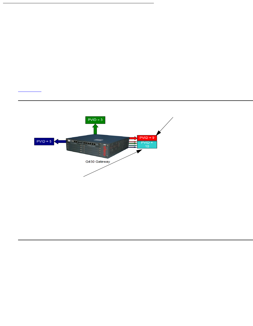
Configuring advanced switching
352 Administration for the Avaya G450 Media Gateway
Multi VLAN binding
Multi VLAN binding, also known as Multiple VLANs per port, allows access to shared resources
by stations that belong to different VLANs through the same port. This is useful in applications
such as multi-tenant networks, where each user has a personal VLAN for privacy. The whole
building has a shared high-speed connection to the ISP.
In order to accomplish this, the G450 enables multiple VLANs per port. The available Port
Multi-VLAN binding modes are:
●Bound to Configured. The port supports all the VLANs configured in the switch
●Statically Bound. The port supports VLANs manually configured on the port
Figure 31 shows these binding modes.
Figure 31: Multi VLAN Binding
Static Binding
●The user manually
specifies the list of
VLAN IDs to be
bound to the port, up
to 64 VLANs
●Default mode for all
ports
●Only VLAN 9, and
any other VLANs
statically configured
on the port will be
allowed to access this
port
Bind to Configured
●The VLAN table of the port supports all the Static
VLAN entries and all the ports’ VLAN IDs (PVIDs)
present in the switch
●VLANs 1, 3, 5, 9, 10 coming from the bus are
allowed access through this port
●All the ports in Bound to Configured mode support
the same list of VLANs

Configuring VLANs
Issue 1 January 2008 353
G450 VLAN table
The G450 VLAN table lists all VLANs configured on the G450. You can configure up to 64
VLANs. To display a list of VLANs, use the show vlan command.
When the VLAN table reaches its maximum capacity, you cannot configure any more VLANs. If
this occurs, use the clear vlan command, followed by the name or number of the VLAN you
want to delete, to free space in the VLAN table. Any new VLANs configured by you are made
known to all the modules in the system.
Ingress VLAN Security
Ingress VLAN Security enables easy implementation of security, and is always active. A port
that is assigned to a VLAN allows packets tagged for that VLAN only to enter through that port.
Unassigned packets receive the PVID of the port and are therefore allowed to enter.
ICC-VLAN
When the G450 includes an ICC, the ICC connects to the G450 via an internal switch. By
default, the ICC is connected on Vlan 1. The VLAN to which the ICC connects is called the
ICC-VLAN.
You can use the icc-vlan command to attach the ICC to a different VLAN. Enter the context
of the VLAN interface to which you want to attach the ICC switch, and enter icc-vlan.
To show the current ICC-VLAN, enter show icc-vlan from the general context.
The following example sets Vlan 2 as the ICC-VLAN:
G450-001(super)# interface vlan 2
G450-001(super-if:Vlan 2)# icc-vlan
Done!
G450-001(super-if:Vlan 2)# exit
G450-001(super)# show icc-vlan
VLAN 2
G450-001(super)#

Configuring advanced switching
354 Administration for the Avaya G450 Media Gateway
VLAN CLI commands
The following commands are used to configure VLANs. For more information about these
commands, see Avaya G450 CLI Reference, 03-300437.
●Use the clear port static-vlan command to delete VLANs statically configured on
a port
●Use the clear vlan command to delete an existing VLAN and its interface, remove the
entry from the VLAN table, and return ports from this VLAN to the default VLAN 1. When
you clear a VLAN, all ports assigned to that VLAN are assigned to the default VLAN 1.
●Use the interface vlan command to create a VLAN interface, enter it into the VLAN
table, and enter the Interface VLAN configuration mode
●Use the no interface vlan command to delete a VLAN interface and remove the
entry from the VLAN table
●Use the set port static-vlan command to assign static VLANs to ports
●Use the set port vlan command to set the port VLAN ID (PVID)
●Use the set port vlan-binding-mode command to define the binding method used
by ports
●Use the set trunk command to configure the VLAN tagging mode of a port
●Use the set vlan command to configure VLANs
●Use the show cam vlan command to display all mac entries in the CAM table for a
specific vlan
●Use the show interfaces vlan command to display interface configuration and
statistics for a particular VLAN or all VLANs
●Use the show port vlan-binding-mode command to display port VLAN binding
mode information. If no module number is specified then information for all ports on all
modules is displayed. If no port number is specified, information for all ports on the
specified module is displayed.
●Use the show trunk command to display VLAN tagging information for the switch
●Use the show vlan command to display the VLANs configured in the switch
VLAN configuration examples
The following example deletes a statically bound VLAN from a port:
G450-001(super)# clear port static-vlan 10/3 34
VLAN 34 is unbound from port 10/3

Configuring VLANs
Issue 1 January 2008 355
The following example deletes a VLAN and its interface:
The following example sets the current VLAN as the ICC-VLAN:
The following example enters configuration mode for a VLAN interface:
The following example deletes a VLAN interface:
The following example statically binds a VLAN to a port:
The following example sets a port’s VLAN ID:
The following example sets a port’s VLAN binding mode:
The following example configures the VLAN tagging mode of a port:
The following example creates a VLAN:
G450-001(super)# clear vlan 34
This command will assign all ports on VLAN 34 to their default in the entire
management domain – do you want to continue (Y/N)? y
All ports on VLAN-id assigned to default VLAN.
VLAN 34 was deleted successfully.
G450-001(super)# interface Vlan 66
G450-001(super-if:Vlan 66)# icc-vlan
Done!
G450-001(super)# interface Vlan 66
G450-001(super-if:Vlan 66)#
G450-001(super)# no interface vlan 66
Done!
G450-001(super)# set port vlan-binding-mode 10/3 static
Set Port vlan binding method:10/3
G450-001(super)# set port vlan 54 10/3
Port 10/3 added to VLAN 54
G450-001(super)# set port vlan-binding-mode 10/3 bind-to-configured
Set Port vlan binding method:10/3
G450-001(super)# set trunk 10/3 dot1q
Dot1Q VLAN tagging set on port 10/3.
G450-001(super)# set vlan 2121 name Training
VLAN id 2121, vlan-name Training created.

Configuring advanced switching
356 Administration for the Avaya G450 Media Gateway
The following example displays a list of the MAC addresses in the CAM of a VLAN:
The following example displays the ICC-VLAN:
The following example displays interface configuration and statistics for a VLAN:
The following example displays port VLAN binding information:
The following example displays VLAN tagging information:
G450-001(super)# show cam vlan 54
Total Matching CAM Entries Displayed = 3
Dest MAC/Route Dest VLAN Destination Ports
------------------- ---- -----------------
00:01:02:dd:2f:9f 54 6/13
00:02:2d:47:00:6f 54 10/2
00:02:4b:5b:28:40 54 6/13
G450-001(super)# show icc-vlan
VLAN 1
G450-001(super)# show interfaces Vlan 1
VLAN 1 is up, line protocol is up
Physical address is 00.04.0d.29.c6.bd.
MTU 1500 bytes. Bandwidth 100000 kbit.
Reliability 255/255 txLoad 1/255 rxLoad 1/255
Encapsulation ARPA, ICC-VLAN
Link status trap disabled
Full-duplex, 100Mb/s
ARP type: ARPA, ARP Timeout 04:00:00
Last input never, Last output never
Last clearing of 'show interface' counters never.
5 minute input rate 0 bits/sec, 0 packets/sec
5 minute output rate 0 bits/sec, 0 packets/sec
0 input drops, 0 output drops, 0 unknown protocols
0 packets input, 0 bytes
0 broadcasts received, 0 giants
0 input errors, 0 CRC
0 packets output, 0 bytes
0 output errors, 0 collisions
G450-001(super)# show port vlan-binding-mode 10
port 10/3 is bind to all configured VLANs
G450-001(super)# show trunk
Port Mode Binding mode Native VLAN
------ ----- ------------------------- -----------
10/3 dot1q bound to configured VLANs 54
Configuring VLANs
Issue 1 January 2008 357
The following example displays the VLANs configured on the device:
Summary of VLAN commands
For more information about these commands, see Avaya G450 CLI Reference, 03-300437.
G50-001(super)# show vlan
VLAN ID VLAN-name
------- --------------------------------
1 V1
54 Marketing
66 V66
2121 Training
Total number of VLANs: 4
Table 93: VLAN CLI commands
Root level
command First level
Command Description
clear port
static-vlan Delete statically configured VLANs from the port
clear vlan Delete an existing VLAN and its interface, remove
the entry from the VLAN table, and return ports from
this VLAN to the default VLAN 1
interface vlan Create a VLAN interface, enter interface VLAN
configuration mode, or delete a VLAN interface
icc-vlan Set the current VLAN as the ICC-VLAN
set port
static-vlan Assign a static VLAN to a port
set port vlan Set the port VLAN ID (PVID)
set port
vlan-binding-mode Define the binding method used by ports
set trunk Configure the VLAN tagging mode of a port
set vlan Create or modify a VLAN
show cam vlan Display all MAC entries in the CAM table for a
specific VLAN
show icc-vlan Display the current ICC VLAN
1 of 2

Configuring advanced switching
358 Administration for the Avaya G450 Media Gateway
Configuring port redundancy
Redundancy involves the duplication of devices, services, or connections, so that in the event of
a failure, the redundant duplicate can take over for the one that failed.
Since computer networks are critical for business operations, it is vital to ensure that the
network continues to function even if a piece of equipment fails. Even the most reliable
equipment might fail on occasion, but a redundant component can ensure that the network
continues to operate despite such failure.
To achieve port redundancy, you can define a redundancy relationship between any two ports in
a switch. One port is defined as the primary port and the other as the secondary port. If the
primary port fails, the secondary port takes over.
Secondary port activation
The secondary port takes over within one second and is activated when the primary port link
stops functioning. Subsequent switchovers take place after the minimum time between
switchovers has elapsed. To set the minimum time between switchovers, use the set port
redundancy-intervals command.
show interfaces Display interface configuration and statistics for a
particular interface or all interfaces
show port
vlan-binding-mode Display port VLAN binding mode information
show trunk Display VLAN tagging information for all or some
ports
show vlan Display the VLANs configured in the media gateway
Table 93: VLAN CLI commands (continued)
Root level
command First level
Command Description
2 of 2

Configuring port redundancy
Issue 1 January 2008 359
Switchback
If switchback is enabled and the primary port recovers, a switchback takes place. Use the set
port redundancy-intervals command to set the following switchback parameters:
●min-time-between-switchovers. The minimum time that is allowed to elapse before a
primary-backup switchover
●switchback-interval. The minimum time the primary port link has to be up before a
switchback to the primary port takes place. If you set this to none, there is no switchback
to the primary port when it recovers. In this case, switchback to the primary port only takes
place if the secondary port fails.
Port redundancy CLI commands
The following commands are used to configure port redundancy. For more information about
these commands, see Avaya G450 CLI Reference, 03-300437.
●Use the set port redundancy enable/disable command to globally enable or
disable the redundancy pairs you have defined. Using this command will not delete
existing redundancy entries.
●Use the set port redundancy command to define or remove redundancy pairs. Enter
show port redundancy to ensure that there is no redundancy scheme already defined
on any of the links.
●Use the set port redundancy-intervals command to configure the two time
constants that determine redundancy switchover parameters.
●Enter show port redundancy to display information about software port redundancy
schemes defined for the switch.
Port redundancy configuration examples
The following example creates a port redundancy pair:
The following example deletes a port redundancy pair:
G450-001(super)# set port redundancy 10/5 10/6 on 1
Monitor: Port 10/6 is redundant to port 10/5.
Port redundancy is active - entry is effective immediately
G450-001(super)# set port redundancy 10/5 10/6 off
Entry Monitor removed: Port 10/6 is not redundant to port 10/5
Configuring advanced switching
360 Administration for the Avaya G450 Media Gateway
The following example enables all configured port redundancies:
The following example disables all configured port redundancies:
The following example configures the switchback interval for all configured port redundancies:
The following example displays port redundancy information:
Summary of port redundancy commands
For more information about these commands, see Avaya G450 CLI Reference, 03-300437.
G450-001(super)# set port redundancy enable
All redundancy schemes are now enabled
G450-001(super)# set port redundancy disable
All redundancy schemes are disabled but not removed
G450-001(super)# set port redundancy-intervals 60 30
Done!
G450-001(super)# show port redundancy
Redundancy Name Primary Port Secondary Port Status
----------------- -------------- ---------------- --------
Monitor 10/5 10/6 primary
Minimum Time between Switchovers: 60
Switchback interval: 30
Table 94: Port redundancy CLI commands
Command Description
set port redundancy Define or remove redundancy pairs
set port redundancy
enable|disable Globally enable or disable port redundancy pairs defined
on the media gateway
set port
redundancy-intervals Configure the two time constants that determine
redundancy switchover parameters
show port redundancy Display information about software port redundancy pairs
defined on the media gateway

Configuring port mirroring
Issue 1 January 2008 361
Configuring port mirroring
Port mirroring copies all received and transmitted packets (including local traffic) from a source
port to a predefined destination port, in addition to the normal destination port of the packets.
Port mirroring, also known as “sniffing,” is useful in debugging network problems.
Port mirroring allows you to define a source port and a destination port, regardless of port type.
For example, a 10 Mbps and a 100 Mbps port can form a valid source/destination pair. You
cannot, however, define the port mirroring source and destination ports as the same source and
destination ports.
You can define one source port and one destination port on each G450 for received (Rx),
transmitted (Tx), or transmitted and received (both) traffic.
Port mirroring constraints
You cannot use the LAN port on the G450 front panel or the WAN Fast Ethernet port on the
G450 front panels in port mirroring.
Port mirroring CLI commands
The following commands are used to configure port mirroring on the G450. For more
information about these commands, see Avaya G450 CLI Reference, 03-300437.
●Use the set port mirror command to define a port mirroring pair in the switch
●Use the show port mirror command to display mirroring information for the switch
●Use the clear port mirror command to cancel port mirroring
Port mirroring configuration examples
The following example creates a port mirroring pair in the G450:
G450-001(super)# set port mirror source-port 10/5 mirror-port 010/6 sampling always
direction rx
Mirroring rx packets from port 10/5 to port 010/6 is enabled

Configuring advanced switching
362 Administration for the Avaya G450 Media Gateway
The following example displays port mirroring information for the G450:
The following example disables port mirroring:
Summary of port mirroring commands
For more information about these commands, see Avaya G450 CLI Reference, 03-300437.
Configuring spanning tree
G450 devices support the enhanced Rapid Spanning Tree Protocol (802.1w). The 802.1w
standard is a faster and more sophisticated version of the 802.1d (STP) standard, and includes
backward compatibility with 802.1d. Spanning tree makes it possible to recover connectivity
after an outage within approximately a minute. RSTP, with its “rapid” algorithm, can usually
restore connectivity to a network where a backbone link has failed in much less time.
Spanning tree protocol
The spanning tree algorithm ensures the existence of a loop-free topology in networks that
contain parallel bridges. A loop occurs when there are alternate routes between hosts. If there is
a loop in an extended network, bridges may forward traffic indefinitely, which can result in
increased traffic and degradation in network performance.
G450-001(super)# show port mirror
port mirroring
Mirroring both Rx and Tx packets from port 10/5 to port 010/6 is enabled
G450-001(super)# clear port mirror
Table 95: Port mirroring CLI commands
Command Description
clear port mirror Delete a port mirroring pair
set port mirror Define a port mirroring source-destination pair
show port mirror Display mirroring information for a specified port or for all
ports

Configuring spanning tree
Issue 1 January 2008 363
The spanning tree algorithm produces a logical tree topology out of any arrangement of bridges.
The result is a single path between any two end stations on an extended network. In addition,
the spanning tree algorithm provides a high degree of fault tolerance. It allows the network to
automatically reconfigure the spanning tree topology if there is a bridge or data-path failure.
The spanning tree algorithm requires five values to derive the spanning tree topology. These
are:
●A multicast address specifying all bridges on the extended network. This address is
media-dependent and is automatically determined by the software.
●A network-unique identifier for each bridge on the extended network
●A unique identifier for each bridge/LAN interface (a port)
●The relative priority of each port
●The cost of each port
After these values are assigned, bridges multicast and process the formatted frames (called
Bridge Protocol Data Units, or BPDUs) to derive a single, loop-free topology throughout the
extended network. The bridges exchange BPDU frames quickly, minimizing the time that
service is unavailable between hosts.
Spanning tree per port
Spanning tree can take up to 30 seconds to open traffic on a port. This delay can cause
problems on ports carrying time-sensitive traffic. You can, therefore, enable or disable spanning
tree in the G450 on a per-port basis to minimize this effect.
Rapid Spanning Tree Protocol (RSTP)
The enhanced feature set of the 802.1w standard includes:
●Bridge Protocol Data Unit (BPDU) type 2
●New port roles: Alternate port, Backup port
●Direct handshaking between adjacent bridges regarding a desired topology change (TC).
This eliminates the need to wait for the timer to expire.
●Improvement in the time it takes to propagate TC information. Specifically, TC information
does not have to be propagated all the way back to the Root Bridge (and back) to be
changed.
●Origination of BPDUs on a port-by-port basis
Port roles
At the center of RSTP – specifically as an improvement over STP (802.1d) – are the roles that
are assigned to the ports. There are four port roles:
●Root port. The port closest to the root bridge
Configuring advanced switching
364 Administration for the Avaya G450 Media Gateway
●Designated port. The corresponding port on the remote bridge of the local root port
●Alternate port. An alternate route to the root
●Backup port. An alternate route to the network segment
The RSTP algorithm usually makes it possible to change port roles rapidly through its fast
topology change propagation mechanism. For example, a port in the blocking state can be
assigned the role of alternate port. When the backbone of the network fails, the port can rapidly
be changed to forwarding.
Whereas the STA passively waited for the network to converge before turning a port into the
forwarding state, RSTP actively confirms that a port can safely transition to forwarding without
relying on any specific, programmed timer configuration.
RSTP port types
RSTP provides a means of fast network convergence after a topology change. It does this by
assigning different treatments to different port types.
●Edge ports. Setting a port to edge-port admin state indicates that this port is connected
directly to end stations that cannot create bridging loops in the network. These ports
transition quickly to forwarding state. However, if BPDUs are received on an edge port, its
operational state will be changed to non-edge-port and bridging loops will be avoided by
the RSTP algorithm. The default admin state of 10/100 M ports is edge-port.
Enter set port edge admin state, followed by the module and port number – or a
range of port numbers – to specify whether or not a port is considered an edge port.
For example, the following command specifies that ports 10/5 and 10/6 are edge ports:
The following command specifies that port 10/5 is not an edge port:
Enter show port edge state, followed by the module and port number, to display the
edge state of the specified port. Use this command without specifying a module number or
port to display the edge state of all ports.
●Non-edge ports. You must manually configure uplink and backbone ports to be non-edge
ports, using the set port edge admin state command.
G450-001(super)# set port edge admin state 10/5-6 edge-port
G450-001(super)# set port edge admin state 10/5 non-edge-port

Configuring spanning tree
Issue 1 January 2008 365
●Point-to-point link ports. This port type applies only to ports interconnecting RSTP
compliant switches and is used to define whether the devices are interconnected using
shared Ethernet segment or point-to-point Ethernet link. RSTP convergence may be faster
when switches are connected using point-to-point links. The default setting for all ports –
automatic detection of point-to-point link – is sufficient for most networks.
Enter set port point-to-point admin status, followed by the module and port
number or a range of port numbers, and an admin status parameter, to specify the port’s
connection type. Admin status parameter values are:
-
force-true. Treats the port as if it is connected point-to-point
-
force-false. Treats the port as if it is connected to shared media
-
auto. Attmepts to automatically detect the port’s connection type
For example, the following command specifies that ports 10/5 and 10/6 are treated as if
they were connected point-to-point:
●All ports. Enter show port point-to-point status, followed by the module and
port number, to display the point-to-point status of the specified point-to-point status of all
ports
Spanning tree CLI commands
Use the following commands to configure spanning tree. For more information about these
commands, see Avaya G450 CLI Reference, 03-300437.
●Use the set port spantree command to enable or disable the spanning tree mode for
specific switch ports.
●Use the set port spantree cost command to set the spanning tree cost of a port.
This value defines which port will be allowed to forward traffic if two ports with different
costs cause a loop.
●Use the set port spantree force-protocol-migration command to force a port
to send a rapid spanning tree hello packet (Bridge Protocol Data Unit).
●Use the set port spantree priority command to set the spanning tree priority
level of a port. This value defines the priority of a port to be blocked in case two ports with
the same cost cause a loop.
●Use the set spantree default-path-cost command to set the version of the
spanning tree default path cost used by this bridge.
●Use the set spantree enable/disable command to enable or disable the spanning
tree algorithm.
G450-001(super)# set port point-to-point admin status 10/5-6 force-true

Configuring advanced switching
366 Administration for the Avaya G450 Media Gateway
●Use the set spantree forward-delay command to specify the time used when
transferring the state of a port to the forwarding state.
●Use the set spantree hello-time command to specify the time interval between the
generation of configuration BPDUs by the root.
●Use the set spantree max-age command to specify the time to keep an information
message before it is discarded.
●Use the set spantree priority command to set the bridge priority for STP.
●Use the set spantree tx-hold-count command to set the value in packets used by
the spanning tree in order to limit the maximum number of BPDUs transmitted during a
hello-time period.
●Use the set spantree version command to set the version of the spanning tree
protocol.
●Use the show spantree command to display spanning-tree information.
Spanning tree configuration examples
The following example enables spanning tree on a port:
The following example disables spanning tree on a port:
The following example sets the spanning tree cost of port 10/5 to 4096:
The following example configures the version of the spanning tree default path cost used by this
bridge:
The following example configures the time used when transferring the port to the forwarding
state:
G450-001(super)# set port spantree enable 6/5
port 6/5 was enabled on spantree
G450-001(super)# set port spantree disable 6/5
port 6/5 was disabled on spantree
G450-001(super)# set port spantree cost 6/5 4096
port 6/5 spantree cost is 4096
G450-001(super)# set spantree default-path-cost common-spanning-tree
Spanning tree default path costs is set to common spanning tree.
G450-001(super)# set spantree forward-delay 16
bridge forward delay is set to 16.

Configuring spanning tree
Issue 1 January 2008 367
The following example configures the time interval between the generation of configuration
BPDUs by the root:
The following example configures the amount of time an information message is kept before
being discarded:
The following example configures the bridge priority for spanning tree:
The following example sets the value in packets used by spanning tree in order to limit the
maximum number of BPDUs transmitted during a hello-time period:
The following example configures the version of spanning tree to use on the device:
The following example displays spanning tree information:
G450-001(super)# set spantree hello-time 2
bridge hello time is set to 2.
G450-001(super)# set spantree max-age 21
bridge max age is set to 21.
G450-001(super)# set spantree priority 36864
Bridge priority set to 36864.
G450-001(super)# set spantree tx-hold-count 4
tx hold count is set to 4.
G450-001(super)# set spantree version rapid-spanning-tree
Spanning tree version is set to rapid spanning tree.
Spanning tree state is enabled
Designated Root: 00-04-0d-ea-b0-2d
Designated Root Priority: 32768
Designated Root Cost: 0
Designated Root Port: No root port, Bridge is Designated root
Root Max Age: 20 Hello Time: 2
Root Forward Delay: 15
Bridge ID MAC ADDR: 00-04-0d-ea-b0-2d
Bridge ID priority: 32768
Bridge Max Age: 20 Bridge Hello Time: 2
Bridge Forward Delay: 15 Tx Hold Count 3
Spanning Tree Version is rapid spanning tree
Spanning Tree Default Path Costs is according to common spanning tree
Port State Cost Priority
------ ------------- ---------- ------------
10/5 not-connected 4 128
10/6 not-connected 4 128

Configuring advanced switching
368 Administration for the Avaya G450 Media Gateway
Summary of spanning tree commands
For more information about these commands, see Avaya G450 CLI Reference, 03-300437.
Table 96: Spanning tree CLI commands
Command Description
set port edge admin state Assign or de-assign RSTP edge-port admin state to a
port for Rapid Spanning Tree Protocol (RSTP) treatment
set port point-to-point
admin status Specify a port’s connection type
set port spantree Enable or disable spanning tree for specific ports
set port spantree cost Set the spanning tree cost of a port
set port spantree
force-protocol-migration Force the port to send a rapid spanning tree hello packet
(Bridge Protocol Data Unit)
set port spantree priority Set the spanning tree priority level of a port
set spantree
default-path-cost Set the version of the spanning tree default path cost
used by the current bridge
set spantree
enable|disable Enable or disable the spanning-tree algorithm for the
media gateway
set spantree forward-delay Specify the time used when transferring the state of a
port to the forwarding state
set spantree hello-time Specify the time interval between the generation of
configuration BPDUs by the root
set spantree max-age Specify the time to keep an information message before
it is discarded
set spantree priority Set the bridge priority for the spanning tree
set spantree tx-hold-count Set the value in packets used by the spanning tree in
order to limit the maximum number of BPDUs
transmitted during a hello-time period
set spantree version Set the version of the spanning tree protocol used by the
device
show port edge state Display the edge state of a specified port
1 of 2

Port classification
Issue 1 January 2008 369
Port classification
With the G450, you can classify any port as either regular or valuable. Classifying a port as
valuable means that a link fault trap is sent in the event of a link failure. The trap is sent even
when the port is disabled. This feature is particularly useful for the port redundancy application,
where you need to be informed about a link failure on the dormant port.
Note:
Note: The 1 GB ports are classified as valuable by default.
Port classification CLI commands
Use the following commands to configure port classification. For more information about these
commands, see Avaya G450 CLI Reference, 03-300437.
●Use the set port classification command to set the port classification to either
regular or valuable. Any change in the spanning tree state from forwarding for a valuable
port will erase all learned MAC addresses in the switch.
●Use the show port classification command to display a port’s classification.
Port classification configuration examples
The following example classifies a port as a valuable port:
show port point-to-point
status
Display the point-to-point status of a specific port or all
ports
show spantree Display spanning-tree information
Table 96: Spanning tree CLI commands (continued)
Command Description
2 of 2
G450-001(super)# set port classification 6/5 valuable
Port 6/5 classification has been changed.
Configuring advanced switching
370 Administration for the Avaya G450 Media Gateway
The following example displays the port classification of all ports on the G450:
Summary of port classification commands
For more information about these commands, see Avaya G450 CLI Reference, 03-300437.
G450-001(super)# show port classification
Port Port Classification
-------- -------------------------
10/5 valuable
10/6 regular
Table 97: Port classification CLI commands
Command Description
set port classification Set the port classification to either regular or valuable
(any change in the spanning tree state from forwarding for
a valuable port will erase all learned MAC addresses in
the switch)
show port classification Display port classification for a specified port or all ports

Issue 1 January 2008 371
Chapter 17: Configuring monitoring
applications
The Avaya G450 Media Gateway provides several software tools for monitoring and diagnosing
your network. Use these tools to monitor the status of your network operations, and to analyze
the flow of information.
Configuring RMON
Remote Monitoring (RMON), the internationally recognized network monitoring standard, is a
network management protocol that allows network information to be gathered at a single
workstation. You can use RMON probes to monitor and analyze a single segment only. When
you deploy a switch on the network, there are additional components in the network that cannot
be monitored using RMON. These components include the switch fabric, VLAN, and statistics
for all ports.
RMON is the internationally recognized and approved standard for detailed analysis of shared
Ethernet media. It ensures consistency in the monitoring and display of statistics between
different vendors.
RMON's advanced remote networking capabilities provide the tools needed to monitor and
analyze the behavior of segments on a network. In conjunction with an RMON agent, RMON
gathers details and logical information about network status, performance, and users running
applications on the network.
An RMON agent is a probe that collects information about segments, hosts, and traffic, and
sends the information to a management station. You use specific software tools to view the
information collected by the RMON agent on the management station.
You can configure RMON for switching on the Avaya G450 Media Gateway. The G450 uses
RMON I, which analyzes the MAC layer (Layer 2 in the OSI seven-layer model). You can also
configure a port to raise an SNMP trap whenever the port fails.

Configuring monitoring applications
372 Administration for the Avaya G450 Media Gateway
RMON CLI commands
Use the following commands to configure RMON. For more information about these
commands, see Avaya G450 CLI Reference, 03-300437.
●Use the clear rmon statistics command to clear RMON statistics.
●Use the rmon alarm command to create an RMON alarm entry.
●Use the rmon event command to create an RMON event entry.
●Use the rmon history command to create an RMON history entry.
●Use the show rmon alarm command to display all RMON alarm entries.
●Use the show rmon event command to display RMON event entries.
●Use the show rmon history command to display RMON alarm entries.
●Use the show rmon statistics command to display RMON statistics.
RMON configuration examples
The following example creates an RMON alarm entry:
The following example creates an RMON event entry:
The following example creates an RMON history entry with an index of 80 on port 10/2,
recording activity over 60 intervals (buckets) of 20 seconds each.
G450-001(super)# rmon alarm 1 1.3.6.1.2.1.16.1.1.1.5.16777216 20 delta
rising-threshold 10000 32 falling-threshold 1000 32 risingOrFalling root
alarm 1 was created successfully
G450-001(super)# rmon event 32 log description “Change of device” owner root
event 32 was created successfully
G450-001(super)# rmon history 80 10/2 interval 20 buckets 60 owner root
history index 80 was created successfully

Configuring RMON
Issue 1 January 2008 373
The following example displays information about an RMON alarm entry:
The following example displays information about an RMON event entry:
The following example displays information about an RMON history entry:
The following example displays RMON statistics for a port:
G450-001(super)# show rmon alarm 1
alarm
alarm 1 is active, owned by root
Monitors ifEntry.1.16777216 every 20 seconds
Taking delta samples, last value was 0
Rising threshold is 10000, assigned to event # 32
Falling threshold is 1000, assigned to event # 32
On startup enable rising or_falling alarms
G450-001(super)# show rmon event 32
event
Event 32 is active, owned by root
Description is Change of device
Event firing causes log,last fired 12:36:04
G450-001(super)# show rmon history 80
history
Entry 80 is active, owned by root
Monitors the port 10/2 every 20 seconds
Requested # of time intervals, ie buckets, is 60
Granted # of time intervals, ie buckets, is 60
Sample # 2 began measuring at 0:21:16
Received 4081 octets, 41 packets,
0 broadcast and 10 multicast packets,
0 undersize and 0 oversize packets,
0 fragments and 0 jabbers,
0 CRC alignment errors and 0 collisions,
# of dropped packet events (due to a lack of resources): 0
Network utilization is estimated at 0
G450-001(super)# show rmon statistics 10/2
Statistics for port 10/2 is active, owned by Monitor
Received 6952909 octets, 78136 packets,
26 broadcast and 257 multicast packets,
0 undersize and 0 oversize packets,
0 fragments and 0 jabbers,
0 CRC alignment errors and 0 collisions,
# of dropped packet events (due to a lack of resources): 0
# of packets received of length (in octets):
64:18965, 65-127:295657, 128-255:4033,
256-511:137, 512-1023:156, 1024-1518:0,

Configuring monitoring applications
374 Administration for the Avaya G450 Media Gateway
Summary of RMON commands
For more information about these commands, see Avaya G450 CLI Reference, 03-300437.
Configuring and analyzing RTP statistics
The RTP statistics application collects data and statistics for RTP sessions (streams) from the
gateway VoIP engine. You can view the data and configure SNMP traps to be generated when
the QoS level falls below a configured level.
Note:
Note: An alternative tool available from Avaya for debugging QoS problems is VMON.
VMON is an RTCP QoS reports collector. VMON support, available in all Avaya
devices, is the capability of a VoIP device to send a copy of an RTCP message to
the IP address of a VMON server. VMON can collect RTCP reports, store them
on its host hard disk, and analyze and generate graphic reports. However, VMON
requires a dedicated Windows server. The RTP statistics application runs on the
G450’s firmware, and does not require any dedicated hardware. For information
about configuring VMON in Avaya Communication Manager, see Administrator
Guide for Avaya Communication Manager, 03-300509.
Table 98: RMON CLI commands
Command Description
clear rmon
statistics Clear RMON statistics
rmon alarm Create or delete an RMON alarm entry
rmon event Create or delete an RMON event entry
rmon history Create or delete an RMON history entry
show rmon alarm Display information about a specific RMON alarm entry or all existing
RMON alarm entries
show rmon event Display a specific RMON event entry or all RMON event entries
show rmon history Display a specific RMON history entry or all RMON history entries
show rmon
statistics Display RMON statistics for a specific interface or for all interfaces

Configuring and analyzing RTP statistics
Issue 1 January 2008 375
Note:
Note: The gateway performs traceroutes whenever RTP statistics is enabled.
The RTP statistics application provides the following functionality:
●Collects QoS data from the gateway VoIP engine(s), including Real-Time Control Protocol
(RTCP) data, traceroute reports, and information from the DSP regarding jitter buffer,
internal delays, and so on
Note:
Note: RTCP is a standard QoS report companion protocol to RTP. RTP endpoints
periodically send RTCP report packets to their remote peer (or peers in
multicast). RTCP reports include QoS data such as delay, jitter, and loss.
●Collects call data from the gateway, such as duration, start-time, and end-time
●Displays the RTP statistics in CLI and MIB formats
●Displays summary reports for the VoIP engine(s)
●Assesses QoS status based on configurable thresholds on an extensive set of QoS
metrics
●Generates QoS traps. QoS traps are notifications sent via SNMP upon termination of an
RTP stream that suffers from bad QoS. These notifications include extensive data about
the session that enables offline troubleshooting of QoS problems.The trap rate is
controlled by a configurable trap rate limiter.
Note:
Note: QoS trap generation is an especially convenient troubleshooting tool for large
installations, since all devices that support the RTP statistics application can be
configured to send traps to a single SNMP trap manager.
●Generates QoS fault and clear traps. QoS fault traps are notifications that are sent when
more than a configurable number of active sessions have QoS indicators over the
configured thresholds. A QoS clear trap is a notification that is sent after a QoS fault trap
when the number of active RTP sessions with QoS indicators over the configured
thresholds reduces to a specified number.
Configuring the RTP statistics application
To configure the RTP statistics application, work through the following sections, in order:
●Viewing RTP statistics thresholds
●Configuring RTP statistics thresholds
●Enabling and resetting the RTP statistics application
●Viewing application configuration
●Configuring QoS traps

Configuring monitoring applications
376 Administration for the Avaya G450 Media Gateway
●Configuring QoS fault and clear traps
●Configuring the trap rate limiter
Viewing RTP statistics thresholds
The RTP statistics application uses a system of thresholds to evaluate levels of QoS during
RTP sessions. The thresholds are configured on several QoS metrics. Your configuration of the
thresholds determines when the application evaluates a session as having bad QoS conditions.
This section describes the thresholds that you can configure, how you can view the thresholds
that are currently configured, and the metrics on which you can configure them.
The RTP statistics application samples the VoIP engine every RTCP interval, which is
configured in Avaya Communication Manager, where it is called “RTCP Report Period”. The
RTCP interval is typically 5 to 8 seconds. For information about configuring the RTCP interval
(RTCP report period), see Administrator Guide for Avaya Communication Manager, 03-300509.
Thresholds types
●A threshold on a metric. For example, you can configure a threshold on the metric
‘packet loss’. The application samples the metric every RTP interval and increments a
counter (event counter) if the sampled value is over the threshold. Hence, the
'event-counter' represents the number of times the metric was sampled over its threshold.
●An event threshold. An event threshold is a threshold on an event counter. If QoS traps
are configured, the application generates a QoS trap when, at the end of a session, one or
more event counters are over their event thresholds. For example, if the event threshold
for packet loss is 2, the application generates a QoS trap if packet loss is sampled over its
threshold two or more times.
●Thresholds on metric averages. The application calculates averages of some of the
metrics. When an RTP session terminates, the application evaluates the average metrics
and generates a QoS trap (if QoS traps are configured) if one of them is over its
corresponding threshold.
Note:
Note: All CLI commands described in this section are available in the general context of
the CLI.
Configuring and analyzing RTP statistics
Issue 1 January 2008 377
Viewing the configured thresholds
1. Enter show rtp-stat thresholds. For example:
Table 99 describes the QoS metrics on which thresholds are configured, and the time at which
each metric is evaluated.
G450-001(super)# show rtp-stat thresholds
Item Threshold Event Threshold
-------------------- ------------- -----------------
Codec Loss 6.0% 1
Average Codec Loss 3.0% N/A
Codec RTT 700mS 2
Echo Return Loss 0dB 1
Loss 6.0% 2
Average Loss 3.0% N/A
Remote Loss 6.0% 2
Average Remote Loss 3.0% N/A
RTT 500mS 2
Local Jitter 50mS 2
Remote Jitter 50mS 2
SSRC Changes N/A 2
Table 99: QoS metrics
Metric Description Evaluation time
Codec Loss The percentage of time the codec plays fill
frames due to lack of valid RTP frames.
Possible causes include jitter and packet loss.
Every RTCP interval
Average Codec Loss The average codec loss measurement since
the beginning of the RTP stream At the end of the
session
Codec RTT An estimation of the overall Round Trip Time
(RTT) on the voice-channel, including the
network delay and internal delays.
RTT is the time taken for a message to get to
the remote peer and back to the local receiver.
Each time an RTCP
packet is received
Echo Return Loss The echo cancellation loss on the TDM bus Every RTCP interval
Loss The estimated network RTP packet loss.
The VoIP engine evaluates the current received
packet loss every RTCP interval – usually 5 to 8
seconds. The VoIP engine postpones loss
estimation until the next interval if the number
of packets received is less than the minimum
statistic window. The minimum statistic window
is configured with the CLI command rtp-stat
min-stat-win.
Every RTCP interval
1 of 2

Configuring monitoring applications
378 Administration for the Avaya G450 Media Gateway
Configuring RTP statistics thresholds
RTP statistics thresholds should be configured so that incrementation of QoS event counters
coincides with real detectable bad QoS in your network. Optimal values are different for each
network. Configure any thresholds that are not already configured as you require them. See
Viewing RTP statistics thresholds on page 376.
For a description of each metric, see Table 99. The Codec metrics, Codec loss and Codec RTT
are useful for evaluating the actual user experience. The other metrics are useful for identifying
network problems that contribute to QoS problems experienced by the user. For example, the
Codec RTT metric indicates the overall delay experienced by the user. If you configure a
meaningful threshold on the Codec RTT metric, metrics such as Local Jitter, Remote Jitter, and
rtt metrics may help you identify causes when Codec RTT exceeds its threshold.
Average Loss The average packet loss evaluation since the
beginning of the RTP stream At the end of the
session
Remote Loss The network loss according to the remote RTP
receiver. The device learns of the remote
packet loss from received RTCP messages.
Each time an RTCP
packet is received
Average Remote
Loss The average remote network loss
measurement since the beginning of the RTP
stream
At the end of the
session
RTT The network RTT. This metric does not include
internal delay. The device learns of the RTT
from RTCP messages.
Each time an RTCP
packet is received
Local Jitter Variation in delay of packet delivery to the local
peer Every RTCP interval
Remote Jitter Variation in delay of packet delivery to the
remote peer. The device learns of the remote
jitter from RTCP messages.
Each time an RTCP
packet is received
SSRC Changes The number of times the RTP SSRC field in
received RTP packets has changed Every RTCP interval
Table 99: QoS metrics (continued)
Metric Description Evaluation time
2 of 2

Configuring and analyzing RTP statistics
Issue 1 January 2008 379
Configuring RTP statistics thresholds
1. Use the rtp-stat thresholds command to set thresholds on QoS indicators. For
example:
With this example configuration, if echo-return-loss is sampled higher than 5 dB during an
RTP session, the echo-return-loss event counter increments.
2. Use the rtp-stat event-threshold command to set thresholds on QoS events. For
example:
With this example configuration, if echo-return-loss is sampled over its threshold more
than twice during an RTP session, the application considers the session to have QoS
faults.
Enabling and resetting the RTP statistics application
When you enable the RTP statistics application on the gateway, the application starts to collect
QoS data from the VoIP engine(s) and stores the data in the gateway RAM, which holds a
limited history of RTP session entries. The VoIP engine also starts to perform and report UDP
traceroutes.
Session data and automatic session traceroute results can be viewed using the CLI.
Enabling the RTP statistics application
1. Enter rtp-stat-service. For example:
Note:
Note: Admin level access is required in order to use the rtp-stat-service
command.
Resetting the RTP statistics application
1. Enter rtp-stat clear.
All counters are reset and the RTP statistics history is erased.
G450-001(super)# rtp-stat thresholds echo-return-loss 5
Done!
G450-001(super)# rtp-stat event-threshold echo-return-loss 2
Done!
G450-001# rtp-stat-service
The RTP statistics service is enabled (default: disabled)

Configuring monitoring applications
380 Administration for the Avaya G450 Media Gateway
Viewing application configuration
Viewing the application configuration helps you see if the application is enabled, which types of
traps are enabled, and how the trap rate limiter and minimum statistics window are configured.
The minimum statistics window is the minimum number of observed RTP sequence increments
for which the application evaluates packet loss.
●Enter show rtp-stat config. For example:
Table 100 describes the output of the show rtp-stat config command.
G450-001(super)# show rtp-stat config
RTP Statistic: Enabled
QoS Trap: Enabled
QoS Fault Trap: Enabled
Fault: 2
Clear: 0
QoS Trap Rate Limiter:
Token Interval: 10.00 seconds
Bucket Size: 5
Session Table:
Size: 128
Reserved: 64
Min Stat Win: 50
Table 100: RTP statistics application configuration
Name Description
RTP Statistic Status of the RTP statistics application. Possible values:
●Enabled. The application is enabled.
●Disabled. The application is disabled.
QoS Trap QoS trap status. Possible values:
●Enabled. The RTP statistics application is configured to generate
QoS traps.
●Disabled. The RTP statistics application is not configured to
generate QoS traps.
QoS Fault Trap QoS fault trap status. Possible values:
●Enabled. The RTP statistics application is configured to generate
QoS fault and clear traps.
●Disabled. The RTP statistics application is not configured to
generate QoS fault and clear traps.
Fault The QoS fault trap boundary. That is, the minimum number of active
sessions with QoS faults that triggers a QoS fault trap.
1 of 2

Configuring and analyzing RTP statistics
Issue 1 January 2008 381
Clear The QoS clear trap boundary. That is, the reduced number of active
sessions with QoS faults that triggers a QoS clear trap to be sent
after a QoS fault trap was sent.
QoS Trap Rate Limiter:
Token Interval The displayed token interval is in seconds. The maximum long term
trap rate, expressed as an interval in seconds. In the example shown,
the maximum long term trap rate is one trap every 10 seconds.
Bucket Size The maximum number of tokens stored in the token bucket of the trap
rate limiter. This item limits the size of a QoS trap burst.
Session Table:
Size The maximum number of RTP session entries held in the session
table in the gateway RAM
Reserved The number of rows in the session table that are reserved for
sessions with QoS problems. In the example shown, the table size is
128 and the reserved number is 64. If, from 1000 sessions only 300
had QoS problems, the session table will hold at least the last 64
sessions that had QoS problems. Note that if the last 128 sessions all
had QoS problems, all rows in the session table will be filled with
sessions that had QoS problems.
Min Stat Win The minimum statistic window configured for the RTP statistics
application. That is, the minimum number of observed RTP
sequence increments for which the application evaluates packet
loss.
Table 100: RTP statistics application configuration (continued)
Name Description
2 of 2

Configuring monitoring applications
382 Administration for the Avaya G450 Media Gateway
Configuring QoS traps
You can configure the application to automatically generate QoS traps via SNMP at the
termination of RTP sessions that have QoS problems. SNMP traps are automatically sent to the
SNMP trap manager on the active Media Gateway Controller (MGC). You can also configure
SNMP traps to be sent to an external trap manager. The application generates a QoS trap
when, at the end of an RTP session, one or more event counters are over their event
thresholds. For example, if the event threshold for packet loss is 2, the application generates a
trap at the termination of any session in which packet-loss was sampled over its threshold twice
or more during the session.
!CAUTION:
CAUTION: If the thresholds for trap generation are set too low, a significant amount of trap
traffic will be generated and negatively impact network performance.
Enabling QoS traps
1. View the RTP statistic thresholds and modify their configurations as necessary. See
Viewing RTP statistics thresholds on page 376 and Configuring RTP statistics
thresholds on page 378.
2. If you need to modify the minimum statistic window, use the rtp-stat min-stat-win
command. For example:
The minimum statistic window is the minimum number of observed RTP sequence
increments for which the application evaluates packet loss. The VoIP engine evaluates the
current received packet loss every RTCP interval. The VoIP engine postpones loss
estimation to the next interval if the number of received packets is less than the minimum
statistic window. By modifying the minimum statistic window, you can prevent the
application from generating loss-events based on too few packets and safely configure a
low packet loss threshold.
3. To configure an additional trap destination, such as an external trap manager, use the
command snmp-server host. For example:
G450-001(super)# rtp-stat min-stat-win 50
Done!
G450-001(super)# snmp-server host 136.9.71.47 traps v1 public

Configuring and analyzing RTP statistics
Issue 1 January 2008 383
Note:
Note: When using the snmp-server host command, you can specify only to send
certain types of traps to the specified trap manager. For example, snmp-server
host 1.1.1.1 traps v1 public rtp-stat-qos rtp-stats-faults
configures only QoS traps and QoS fault and clear traps to be sent to host
1.1.1.1.
To check your current SNMP configurations, enter show snmp. Traps are automatically
sent to the active MGC by the dynamic trap manager feature. To configure the dynamic
trap manager, use the command snmp-server dynamic-trap-manager. For more
information about the dynamic trap manager, see Configuring dynamic trap manager on
page 338.
4. Enter rtp-stat qos-trap to enable the traps, if not already enabled. For example:
QoS traps are now enabled.
Configuring QoS fault and clear traps
You can configure the RTP statistics application to send QoS fault and clear traps. A QoS fault
trap is sent when a specified number of active RTP sessions have QoS indicators over the
configured thresholds. A QoS clear trap is sent after a QoS fault trap when the number of active
RTP sessions with QoS indicators over the configured thresholds reduces to a specified
number. Since some RTP sessions can be very long, and QoS traps are sent only after the
termination of the stream, QoS fault and clear traps are important for providing timely
information about QoS problems.
Note:
Note: QoS fault traps appear in the Network Management Console Event Log Browser,
indicating to the user that there are QoS problems in a specific network device.
See the Avaya Network Management Console User Guide, 14-300169.
●Use the rtp-stat fault command. For example:
With this example configuration, a QoS fault trap is sent if and when one active RTP
session has QoS problems. A QoS clear trap is then sent if and when the number of active
RTP sessions with QoS problems reaches 0.
G450-001# rtp-stat qos-trap
The RTP statistics QoS trap is enabled
G450-001(super)# rtp-stat fault 1 0
The fault trap boundary was set to 1 (default: 3)
The clear trap boundary was set to 0

Configuring monitoring applications
384 Administration for the Avaya G450 Media Gateway
Configuring the trap rate limiter
The application features a trap rate limiter. The trap rate limiter limits the rate at which QoS
traps are sent. The rate limiter protects against overloading the trap manager with bursts of
traps when a single event causes multiple RTP sessions to terminate simultaneously.
The trap rate limiter uses a token bucket scheme, in which traps are sent only if there are
tokens in a virtual bucket. Tokens are added to the bucket every 'token interval,' which sets the
maximum long term trap rate. Each time a trap is sent, the number of tokens in the bucket
decrements. The 'bucket size' is the maximum number of tokens that the bucket can hold. The
bucket size limits the trap burst size.
●Use the rtp-stat qos-trap-rate-limit command. For example:
In this example configuration, the token-interval is 2000 and the bucket-size is 10. This
means that a token is added to the bucket every 2000 hundredths of a second
(20 seconds) and the bucket is limited to a maximum size of 10 tokens.
Analyzing RTP statistics output
This section describes the reports, statistics, and traps you can view, how to view them, and
how to understand the output.
Viewing RTP statistics summary reports
RTP statistics summary reports display QoS trap statistics for the VoIP engine(s).
●Enter show rtp-stat summary. For example:
G450-001# rtp-stat qos-trap-rate-limit 2000 10
G450-001(super)# show rtp-stat summary
Total QoS traps: 23
QoS traps Drop : 0
Qos Fault
Engine Active Total Mean Tx
ID Description Uptime Session Session Duration TTL
--- -------------- ----------- ------- ------- -------- ----
000 internal 04,18:15:15 2/1 35/24 01:04:44 64

Configuring and analyzing RTP statistics
Issue 1 January 2008 385
Table 101 describes the fields in the summary report.
Viewing RTP session statistics
Using the CLI, you can view a summary of active and terminated sessions and you can view
RTP statistics for a given RTP session.
Table 101: RTP statistics summary reports output
Field Description
Total QoS traps The total number of QoS traps sent since the RTP statistics
application was enabled or since the last use of the rtp-stat
clear command
QoS traps Drop The number of QoS traps dropped by the rate limiter since the RTP
statistics application was enabled or since the last use of the
rtp-stat clear command
Qos Fault/QoS
Clear General QoS state: QoS Fault means that the number of active RTP
sessions with QoS faults is currently higher than the QoS fault
boundary. QoS Clear means that the number of active RTP sessions
with QoS faults is currently less than or equal to the QoS clear
boundary. You can configure the QoS fault and clear boundaries
using the rtp-stat fault command. See Configuring QoS fault
and clear traps on page 383.
Engine ID The ID of the VoIP engine. Since the G450 has one VoIP engine, one
line appears in the table.
Description Description of the VoIP engine
Uptime The uptime of the RTP statistics application. This is the time since the
RTP statistics application was enabled or since the last use of the
rtp-stat clear command.
Active Session The number of active sessions / number of active sessions with QoS
problems
Total Session The total number of sessions / number of sessions that had QoS
problems
Mean Duration The mean RTP session duration (calculated only for terminated calls)
Tx TTL The IP Time To Live (TTL) field for transmitted RTP packets

Configuring monitoring applications
386 Administration for the Avaya G450 Media Gateway
The show rtp-stat sessions command displays a summary of the active and/or
terminated RTP sessions in the session table. For example:
An asterisk (*) in the QoS column indicates that the session had QoS problems.
The show rtp-stat detailed command displays detailed information about a specified
active or terminated RTP session, including the QoS metrics reported by the RTP statistics
application. For example:
G450-001(super)# show rtp-stat sessions last 5
ID QoS Start date and time End Time Type Destination
----- --- ------------------- -------- ------- ---------------
00031 2004-10-20,10:51:36 10:59:07 G729 135.8.76.64
00032 * 2004-10-20,10:53:42 10:57:36 G723 135.8.76.107
00033 * 2004-10-20,10:58:21 10:59:06 G723 135.8.76.107
00034 2004-10-20,11:08:40 - G729 135.8.76.64
00035 * 2004-10-20,11:09:07 - G723 135.8.76.107
G450-001(super)# show rtp-stat detailed 35
Session-ID: 351
Status: Terminated2, QOS: Faulted3, EngineId: 04
Start-Time: 2004-10-205,11:09:076, End-Time: 2004-10-20,11:13:407
Duration: 00:04:338
CName: gwp@135.8.118.2529
Phone: 69:201110
Local-Address: 135.8.118.252:206111 SSRC 15461121212
Remote-Address: 135.8.76.107:206113 SSRC 2989801899 (0)14
Samples: 5415 (5 sec)16
Codec:
G72317 62B18 30mS19 Off20, Silence-suppression(Tx/Rx) Disabled21/Not-Supported22,
Play-Time 272.610sec23, Loss 0.0%24 #125, Avg-Loss 0.1%26, RTT 741mS27 #3828,
Avg-RTT 570mS29, JBuf-under/overruns 0.1%30/0.0%31, Jbuf-Delay 22mS32,
Max-Jbuf-Delay 60mS33
Received-RTP:
Packets 923634, Loss 0.0%35 #036, Avg-Loss 0.0%37, RTT 604mS38 #3839, Avg-RTT
376mS40, Jitter 0mS41 #042, Avg-Jitter 0mS43, TTL(last/min/max) 63/63/6344,
Duplicates 045, Seq-Fall 046, DSCP 4647, L2Pri 1248, RTCP 5449
Transmitted-RTP:
VLAN 150, DSCP 18451, L2Pri 652, RTCP 6253
Remote-Statistics:
Loss 0.0%54 #055, Avg-Loss 0.0%56, Jitter 0mS57 #058, Avg-Jitter 0mS59
Echo-Cancellation:
Loss 45dB60 #161, Len 32mS62
RSVP:
Status Disabled63, Failures 064

Configuring and analyzing RTP statistics
Issue 1 January 2008 387
Table 102 describes the fields in the show rtp-stat detailed command output according
to the numbered labels in the example.
Table 102: Detailed CLI output per RTP session
Field Label Description From the CLI
example
Session-ID 1An arbitrary index number for the
session in the session table
Session-ID: 35
Status 2The status of the session. Possible
values:
●Active. The session is still open.
●Terminated. The session is
finished.
Status: Terminated
QOS 3The QoS status of the session.
Possible values:
●OK. There are no QoS problems in
the session.
●Faulted. There are QoS
problems in the session.
QOS: Faulted
EngineId 4The ID of the VoIP engine. The G450
has one VoIP engine.
EngineId: 0
Start-Time 5The date of the RTP session 2004-10-20
6The start time of the RTP session Start-Time:
2004-10-20,11:09:07
End-Time 7The end time of the RTP session End-Time:
2004-10-20,11:13:40
Duration 8The duration of the RTP session Duration: 00:04:33
CName 9format: gwt@<MGP-address> CName:
gwp@135.8.118.252
1 of 6

Configuring monitoring applications
388 Administration for the Avaya G450 Media Gateway
Phone 10 The local extension number and
conference ID in format <conference
ID>:<extension number>.
Conference calls can involve more
than one entry in the session table.
Multiple sessions belonging to the
same conference call can usually be
identified by a common conference ID.
Notes:
●Phone data is received from Avaya
Communication Manager only if
VMON is configured.
●If you are not running VMON, you
can cause Avaya Communication
Manager to send the phone data
by configuring a dummy
RTCP-server for the region, with a
'localhost' IP address (127.x.x.x).
Phone: 69:2011
Local-Address 11 The PMI. The number after the colon is
the UDP port number.
Local-Address:
135.8.118.252:2061
Remote-Address 13 The remote VoIP engine, gateway PMI,
or IP phone address. The number after
the colon is the UDP port number.
Remote-Address:
135.8.76.107:2061
12,
14
SSRC ID. The number in parentheses
is the number of observed SSRC
changes during the session.
SSRC 2989801899 (0)
Samples 15 The number of times the application
has sampled the VoIP engine (RTP
receiver) statistics.
Samples: 5415 (5
sec)
16 The sampling interval Samples: 54 (5
sec)16
Codec: 17 The codec used for the session G723
18 The RTP packet size, in bytes 62B
19 The RTP packet interval, in ms 30mS
20 The encryption method Off
Table 102: Detailed CLI output per RTP session (continued)
Field Label Description From the CLI
example
2 of 6

Configuring and analyzing RTP statistics
Issue 1 January 2008 389
Silence
suppression
(Tx/Rx)
21 The received silence suppression
method
Silence-suppression
(Tx/Rx)
Disabled21/Not-Supp
orted
22 The transmitted silence suppression
method
Silence-suppression
(Tx/Rx)
Disabled/Not-Suppor
ted22
Play-Time 23 The overall time the codec played valid
received frames
Play-Time
272.610sec
Codec
Loss codec-loss%
24 The last value of codec loss sampled.
Codec loss is the percentage of time
the codec played fill frames due to lack
of valid RTP frames. Possible causes
include jitter and packet loss.
Loss 0.0%24 #1
#codec-loss-events 25 The codec loss event counter Loss 0.0% #125
Avg-Loss 26 The average of all codec loss values
sampled during the session
Avg-Loss 0.1%
RTT rtt ms 27 The last sampling of codec round trip
time (RTT), in ms. Codec RTT is the
round-trip delay experienced by the
user, including internal delay. This
value is not entirely accurate since
remote internal delays are not always
known.
RTT 741mS27 #38
#rtt-events 28 The codec RTT event counter RTT 741mS #3828
Avg-RTT 29 The average of all codec RTT values
sampled during the session
Avg-RTT 570mS
Jbuf-under/
overruns
30 The estimated percentage contribution
of jitter-buffer underruns to the average
codec loss
JBuf-under/overruns
0.1%30/0.0%
31 The estimated percentage contribution
of jitter-buffer overruns to the average
codec loss
JBuf-under/overruns
0.1%/0.0%31
Jbuf-delay 32 The last jitter buffer delay Jbuf-Delay 22mS
Max-Jbuf-Delay 33 The maximum jitter buffer delay during
the session
Max-Jbuf-Delay 60mS
Table 102: Detailed CLI output per RTP session (continued)
Field Label Description From the CLI
example
3 of 6

Configuring monitoring applications
390 Administration for the Avaya G450 Media Gateway
Received RTP:
Packets 34 The total number of received packets Packets 9236
Loss
loss%
35 The last sampled value of network RTP
packet loss
Loss 0.0%35 #0
#loss-events 36 The network RTP packet loss event
counter
Loss 0.0% #036
Avg-loss 37 The average of all network RTP packet
loss values during the session
Avg-Loss 0.0%
RTT
rtt ms
38 The network RTT. The RTT is
calculated upon RTCP packet
reception.
RTT 604mS38 #38
#rtt-events 39 The network RTT event counter RTT 604mS #3839
Avg-RTT 40 The average of all network RTT values
during the session
Avg-RTT 376mS
Jitter
jitter ms
41 The network jitter at the RTP receiver.
Combined with long RTT, a large jitter
value may indicate WAN congestion.
Jitter 0mS41 #0
#jitter-event 42 The RTP receiver network jitter event
counter
Jitter 0mS #042
Avg-Jitter 43 The average of all network jitter values
during the session
Avg-Jitter 0mS
TTL (last/min/max) 44 The last value of TTL, minimum value
of TTL, and maximum value of TTL
sampled during the session. TTL
changes during a session may indicate
route flaps in the IP network.
TTL(last/min/max)
63/63/63
Duplicates 45 This counter increments each time two
consecutive RTP packets with the
sample RTP sequence number are
received. A large number of duplicates
may indicate problems in the
Layer 2/Ethernet topology (for
example, loops).
Duplicates 0
Table 102: Detailed CLI output per RTP session (continued)
Field Label Description From the CLI
example
4 of 6

Configuring and analyzing RTP statistics
Issue 1 January 2008 391
Seq-Fall 46 This counter increments each time an
RTP packet with a sequence number
less than the last known sequence is
received. Packet resequencing may be
caused by switching to a backup WAN
interface or route flaps.
Seq-Fall 0
DSCP 47 The last received DSCP value of the
RTP packets
DSCP 46
L2Pri 48 The last received Layer 2 priority value
of an RTP packet (usually IEEE802.1p)
L2Pri 12
RTCP 49 The total number of received RTCP
packets
RTCP 54
Transmitted-RTP:
VLAN 50 The VLAN-ID on which the RTP
packets are transmitted
VLAN 1
DSCP 51 The DSCP of RTP packets DSCP 184
L2Pri 52 The Layer 2 priority of transmitted RTP
packets (usually 802.1p)
L2Pri 6
RTCP 53 The total number of transmitted RTCP
packets
RTCP 62
Remote-Statistics:
(Remote-Statistics items are calculated and evaluated upon reception of RTCP messages)
Loss
rem-loss%
54 The network loss experienced by the
remote RTP receiver. The local RTP
receiver learns about its remote peer
statistics from RTCP packets.
Loss 0.0%54 #0
#rem-loss-ev 55 The number of samples that were over
the rem-loss threshold
Loss 0.0% #055
Avg-Loss 56 The average network loss experienced
by the remote RTP receiver
Avg-Loss 0.0%
Jitter
rem-jitter
57 The network jitter experienced by the
remote RTP receiver
Jitter 0mS57 #0
#rem-jitter-ev 58 The number of samples that were over
the remote jitter threshold
Jitter 0mS #058
Table 102: Detailed CLI output per RTP session (continued)
Field Label Description From the CLI
example
5 of 6

Configuring monitoring applications
392 Administration for the Avaya G450 Media Gateway
Viewing QoS traps, QoS fault traps, and QoS clear traps
QoS traps, QoS fault traps, and QoS clear traps sent to the active MGC by the dynamic trap
manager are converted to syslog messages by the SNMP Trap manager on the MGC.
The syslog messages are stored in the messages file on the MGC hard disk. You can view the
syslog messages through the Avaya Maintenance Web Interface to debug the QoS problems.
1. In the Avaya Maintenance Web Interface, enter the Setup log viewing screen.
2. In the Select Log Types list, select Linux syslog.
3. Under Select Event Range, select the date range over which you want to view traps.
4. In the Match Pattern field, enter the string avrtp.
5. In the Number of Lines field, enter the maximum number of traps you want to view.
6. Click View Log. The View System Logs screen appears (Figure 32). Each line contains
one message.
Avg-jitter 59 The average remote jitter Avg-Jitter 0mS
Echo Cancellation:
Loss
loss dbm
60 The echo cancellation loss on the TDM
bus. A high value (that is, a low
absolute value) may indicate
impairment of DCP terminals.
Loss 45dB60 #1
#loss-ev 61 A counter that increments each time
the echo-cancellation loss is sampled
below its threshold
Loss 45dB #161
Len 62 The last echo-cancellation tail length
used for this session
Len 32mS
RSVP:
Status 63 The current (last) RSVP reservation
state at the end of the session
Status Disabled
Failures 64 The total number of reservation failures
during the session
Failures 0
Table 102: Detailed CLI output per RTP session (continued)
Field Label Description From the CLI
example
6 of 6
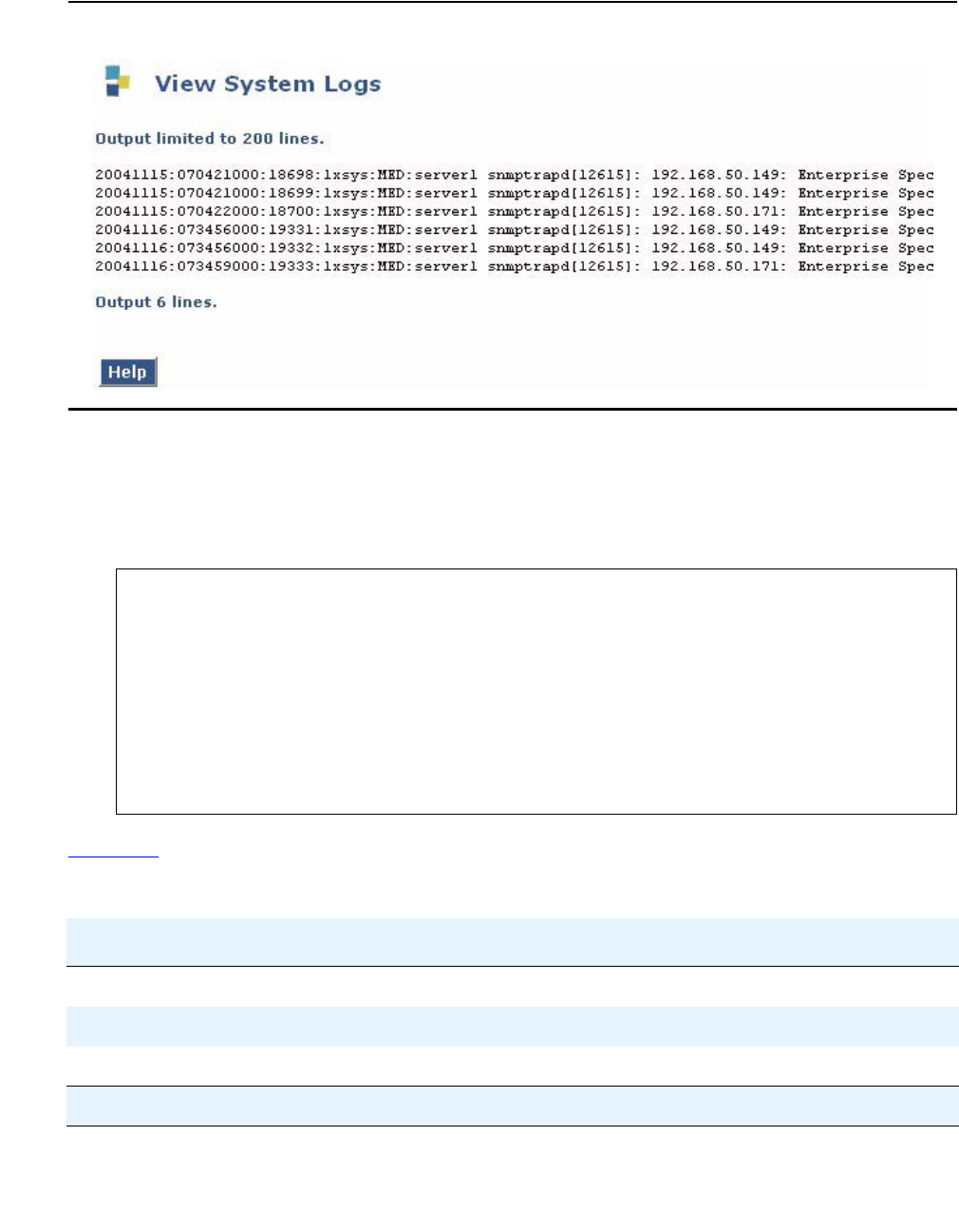
Configuring and analyzing RTP statistics
Issue 1 January 2008 393
Figure 32: Viewing syslog messages
Analyzing QoS trap output
The following is an example of the syslog message for the QoS trap sent upon termination of
RTP session 35 (see the session ID in bold), which terminated at 11:13:40 on Oct. 20:
Table 103 describes the fields in the QoS trap according to the numbered labels in the example.
Oct 201 11:13:402 LZ-SIT-SR1 snmptrapd[9407]: 135.8.118.2523 [135.8.118.252]: Trap
sysUpTime.0 = Timeticks: (43147723) 4 days, 23:51:17.234, snmpTrapOID.0 = OID: av
RtpQoSTrap5, avRtpSessionLocAddrV4.0 = IpAddress: 135.8.118.2526,
avRtpSessionRemAddrV4.0 = IpAddress: 135.8.76.1077, avRtpSessionDuration.0 =
INTEGER: 2738, avRtpSessionCname.0 = STRING: gwp@135.8.118.2529,
avRtpSessionPhone.0 = STRING: 69:201110, avRtpSessionSeverity.0 = INTEGER:
warning(4), avRtpSessionDebugStr.0 = STRING: Id{35}11;
Traps{2412/013};Stats{S 5414 RTCP 5415 RX 923616};Codec{g72317 62B18 encryptionOff19
SSup disabled20/disabled21 Loss 0.1%22 #123 RTT 570mS24 #3825 Jbuf
0.1%26/0.0%27};Net{Loss 0.0%28 #029 RTT 376mS30 #3831 Jtr #032 TTL 63-6333 Dup 034
Fall 035};Rem{Loss 0.0%36 #037 Jtr #038} EC{Loss 45dB39}
Table 103: QoS Trap output fields
Label Description From the trap example
1The date on which the trap was received Oct 20
2The time at which the trap was received 11:13:40
3The IP address of the local MGP 135.8.118.252
1 of 4

Configuring monitoring applications
394 Administration for the Avaya G450 Media Gateway
4The gateway up time sysUpTime.0 = Timeticks:
(43147723) 4 days,
23:51:17.23
5The trap name, which indicates that this is a QoS
trap
snmpTrapOID.0 = OID: av
RtpQoSTrap
6The local gateway PMI avRtpSessionLocAddrV4.0 =
IpAddress: 135.8.118.252
7The remote VoIP engine, gateway PMI, or IP phone
address
avRtpSessionRemAddrV4.0 =
IpAddress: 135.8.76.107
8The duration of the RTP session Duration: 00:04:33
9Format: gwt@<MGP-address> avRtpSessionCname.0 =
STRING: gwp@135.8.118.252
10 The local extension number and conference ID in
format <conference ID>:<extension number>.
Conference calls can involve more than one entry in
the session table. Multiple sessions belonging to the
same conference call can usually be identified by a
common conference ID.
Notes:
●The phone string data is received from Avaya
Communication Manager if VMON is
configured.
●If you are not running VMON, you can cause
Avaya Communication Manager to send the
phone string data by configuring a dummy
RTCP-server for the region, with a 'localhost' IP
address (127.x.x.x).
avRtpSessionPhone.0 =
STRING: 69:2011
11 An arbitrary index number for the session in the
session table
avRtpSessionDebugStr.0 =
STRING: Id{35}
12 The total number of sent traps since the application
was enabled
Traps{2411/0}
13 The number of traps that were dropped by the trap
rate limiter since the application was enabled. This
item can be used, when analyzing received traps
logs, to identify missing traps (due to network
conditions or the rate limiter). This is also displayed
by the show rtp-stat summary command.
Traps{24/012}
14 The number of times the application sampled the
VoIP engine (RTP receiver) statistics
Stats{S 54}
Table 103: QoS Trap output fields (continued)
Label Description From the trap example
2 of 4
Configuring and analyzing RTP statistics
Issue 1 January 2008 395
15 The total number of received RTCP packets Stats{S 54 RTCP 5414 RX
9236}
16 The total number of received RTP packets Stats{S 54 RTCP 54 RX
923615}
17 The codec used for the session g723
18 The codec packet size, in bytes 62B
19 The encryption method encryptionOff
20 The received silence suppression method SSup disabled19/disabled
21 The transmitted silence suppression method SSup disabled/disabled20
22 The average of all codec loss values sampled
during the session
Loss 0.1%21 #1
23 The codec loss event counter Loss 0.1% #122
24 The average of all codec round trip time values
sampled during the session
RTT 570mS23 #38
25 The codec round trip time event counter RTT 570mS #3824
26 The percentage contribution of jitter-buffer
underruns to the average codec loss
Jbuf 0.1%25/0.0%
27 The percentage contribution of jitter-buffer overruns
to the average codec loss
Jbuf 0.1%/0.0%26
28 The average of all network RTP packet loss values
sampled during the session
Loss 0.0%27 #0
29 The network RTP packet loss event counter Loss 0.0% #028
30 The average of all network RTT values during the
session
RTT 376mS29 #38
31 The network RTT event counter RTT 376mS #3830
32 The network jitter at the RTP receiver Jtr #0
33 The minimum and maximum TTL values sampled in
the session
TTL 63-63
34 A counter that increments each time two
consecutive RTP packets with the sample RTP
sequence number are received
Dup 0
Table 103: QoS Trap output fields (continued)
Label Description From the trap example
3 of 4
Configuring monitoring applications
396 Administration for the Avaya G450 Media Gateway
Analyzing QoS fault and clear trap output
The following is an example of the syslog message for the QoS fault and clear traps sent during
RTP session 35, which terminated at 11:13:40 on October 20:
35 A counter that increments each time an RTP packet
with a sequence number less than the last known
sequence is received
Fall 0
36 The average network loss experienced by the
remote RTP receiver
Rem{Loss 0.0%36 #0 Jtr #0}
37 A counter that increments each time the remote
loss is sampled over its threshold
Rem{Loss 0.0% #037 Jtr #0}
38 A counter that increments each time the network
jitter experienced by the remote RTP receiver is
sampled over its threshold
Rem{Loss 0.0% #0 Jtr #038}
39 The echo cancellation loss on the TDM bus. A high
value (that is, a low absolute value) may indicate
impairment of DCP terminals.
EC{Loss 45dB}
Table 103: QoS Trap output fields (continued)
Label Description From the trap example
4 of 4
Oct 201 11:10:542 LZ-SIT-SR1 snmptrapd[9407]: 135.8.118.252
[135.8.118.252]: TrapsysUpTime.0 = Timeticks: (43131114) 4 days,
23:48:31.143, snmpTrapOID.0 = OID: avRtpQoSFault4, avRtpQoSFaultTh.0 =
INTEGER: 15, avRtpQoSClearTh.0 = INTEGER: 06
Oct 201 11:13:402 LZ-SIT-SR1 snmptrapd[9407]: 135.8.118.252
[135.8.118.252]: TrapsysUpTime.0 = Timeticks: (43147723) 4 days,
23:51:17.233, snmpTrapOID.0 = OID: avRtpQoSClear4, avRtpQoSFaultTh.0 =
INTEGER: 15, avRtpQoSClearTh.0 = INTEGER: 06
Configuring and analyzing RTP statistics
Issue 1 January 2008 397
Table 104 describes the fields in the QoS fault and clear traps according to the numbered labels
on the example above.
Table 104: QoS fault and clear trap output fields
Label Description From the QoS fault trap
example From the QoS clear trap
example
1The date on which the trap
was received
Oct 20 Oct 20
2The time at which the trap
was received
11:10:54 11:13:40
3The gateway uptime sysUpTime.0 =
Timeticks: (43131114) 4
days, 23:48:31.14
sysUpTime.0 =
Timeticks: (43147723) 4
days, 23:51:17.23
4The trap name. Indicates
that this is a QoS fault trap
or a QoS clear trap.
snmpTrapOID.0 = OID:
avRtpQoSFault
snmpTrapOID.0 = OID:
avRtpQoSClear
5The QoS fault trap
boundary. That is, the
number of active sessions
with QoS faults that
causes a QoS fault trap to
be sent.
avRtpQoSFaultTh.0 =
INTEGER: 1
avRtpQoSFaultTh.0 =
INTEGER: 1
6The QoS clear trap
boundary. That is, the
reduced number of active
sessions with QoS faults
that causes a QoS clear
trap to be sent after a QoS
fault trap was sent.
avRtpQoSClearTh.0 =
INTEGER: 0
avRtpQoSClearTh.0 =
INTEGER: 0

Configuring monitoring applications
398 Administration for the Avaya G450 Media Gateway
Viewing automatic traceroute results
The VoIP engine automatically performs UDP traceroutes whenever the RTP statistics
application is enabled.
A traceroute is performed per RTP session, 10 seconds after the session begins. A traceroute is
not performed if there is another active session to the same destination for which a traceroute
was already performed within the last five seconds.
●Use the show rtp-stat traceroute command. You can filter the results according to
subnet address by adding destination-ip and specifying the remote subnet address
and subnet mask, or by specifying the rtp-statistics session index. For example:
Note:
Note: The traceroute results are displayed in reverse order (most recent first).
G450-001(super)# show rtp-stat traceroute destination-ip 10.2.5.0 255.255.255.0
Session ID: 1234
From: 123.21.11.5, To: 10.2.4.15, At: 2004-12-26,12:21:55
TTL HOP ADDRESS DELAY
--- --------------- --------
1 123.21.11.1 2ms
2 212.201.233.102 65ms
3 213.21.51.12 110ms
4 10.2.4.15 175ms
Session ID: 1234
From: 123.21.11.5, To: 10.2.4.5, At: 2004-12-26,13:30:15
Table 105: RTP traceroute results output
Field Description
Session ID The RTP statistics index for the RTP session
From The IP address of the G450
To The IP address of the session destination (in this case, a destination
within the specified subnet)
At The time the traceroute is performed
TTL The hop count and TTL field value of probe packets
HOP ADDRESS The hop IP address
DELAY The round trip time per probe packet. Three probe packets are sent
per hop address, and the displayed value is the average of the three
round-trip times. An asterisk (*) indicates that the probe packet timed
out.
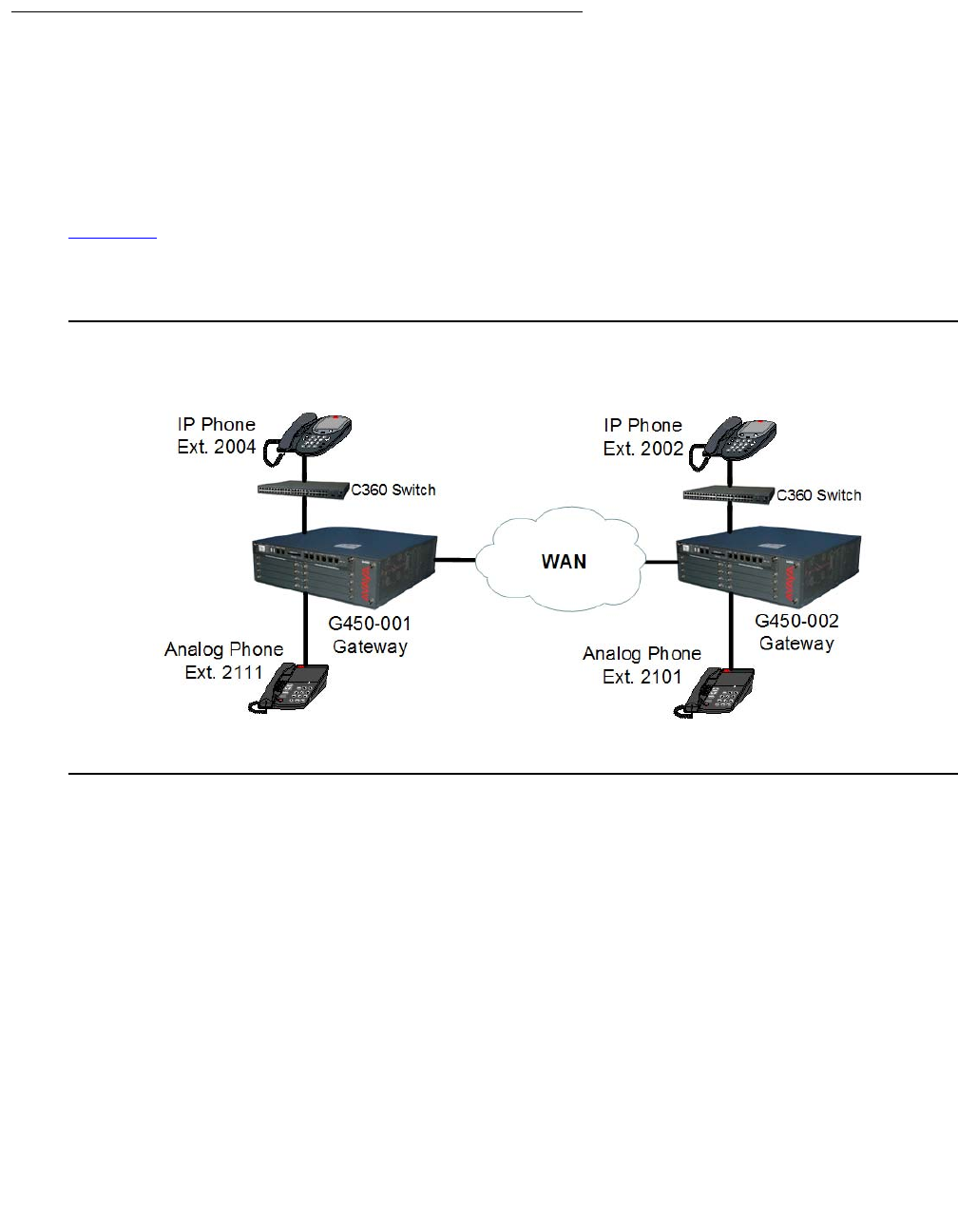
Configuring and analyzing RTP statistics
Issue 1 January 2008 399
RTP statistics examples
This section includes an example of configuring the RTP statistics application for a sample
network. In addition, there are some example calls between various types of phones.
Configuring the RTP statistics application for a sample network
Figure 33 shows the locations of four telephone extensions in an example network. Telephones
with extensions 2004 and 2111 are connected to the local gateway G450-001. Extensions 2002
and 2101 are connected to the remote gateway G450-002.
Figure 33: Four telephones in a sample network

Configuring monitoring applications
400 Administration for the Avaya G450 Media Gateway
At the site of the local gateway “G450-001”, the administrator enabled and configured the
RTP-MIB application as follows:
//to enable the RTP statistics application:
G450-001(super)# rtp-stat-service
//to view the configuration of the application:
G450-001(super)# show rtp-stat config
RTP Statistic: Enabled
QoS Trap: Disabled
QoS Fault Trap: Disabled
Fault: 0
Clear: 0
QoS Trap Rate Limiter:
Token Interval: 10.00 seconds
Bucket Size: 5
Session Table:
Size: 128
Reserved: 64
Min Stat Win: 1
//to view the thresholds:
G450-001(super)# show rtp-stat thresholds
Item Threshold Event Threshold
-------------------- ------------- -----------------
Codec Loss 0.0% 1
Average Codec Loss 1.0% N/A
Codec RTT 5 mS 1
Echo Return Loss 1 dB 1
Loss 1.0% 1
Average Loss 1.0% N/A
Remote Loss 1.0% 1
Average Remote Loss 1.0% N/A
RTT 13mS 1
Local Jitter 1mS 1
Remote Jitter 1mS 1
SSRC Changes N/A 1

Configuring and analyzing RTP statistics
Issue 1 January 2008 401
//to change the thresholds appropriately for the network:
G450-001(super)# rtp-stat thresholds codec-loss 6.0
G450-001(super)# rtp-stat thresholds average-codec-loss 0.0
G450-001(super)# rtp-stat thresholds codec-rtt 700
G450-001(super)# rtp-stat thresholds echo-return-loss 5
G450-001(super)# rtp-stat thresholds loss 6.0
G450-001(super)# rtp-stat thresholds remote-loss 6.0
G450-001(super)# rtp-stat thresholds average-loss 0.0
G450-001(super)# rtp-stat thresholds average-remote-loss 0.0
G450-001(super)# rtp-stat thresholds jitter 70
G450-001(super)# rtp-stat thresholds remote-jitter 70
G450-001(super)# rtp-stat thresholds rtt 500
G450-001(super)# rtp-stat event-threshold echo-return-loss 0
G450-001(super)# rtp-stat event-threshold loss 1
G450-001(super)# rtp-stat event-threshold remote-loss 0
G450-001(super)# rtp-stat event-threshold jitter 0
G450-001(super)# rtp-stat event-threshold remote-jitter 0
G450-001(super)# rtp-stat event-threshold rtt 0
G450-001(super)# rtp-stat event-threshold ssrc-change 0
//to review the threshold configuration again:
G450-001(super)# show rtp-stat thresholds
Item Threshold Event Threshold
-------------------- ------------- -----------------
Codec Loss 6.0% 1
Average Codec Loss 0.0% N/A
Codec RTT 700mS 1
Echo Return Loss 5dB 0
Loss 6.0% 0
Average Loss 0.0% N/A
Remote Loss 6.0% 0
Average Remote Loss 0.0% N/A
RTT 500mS 0
Local Jitter 70mS 0
Remote Jitter 70mS 0
SSRC Changes N/A 0
//to configure the minimum statistics window for evaluating packet loss:
G450-001(super)# rtp-stat min-stat-win 50
//to configure an external trap manager as a trap destination in addition to the
active MGC:
G450-001(super)# snmp-server host 136.9.71.47 traps v1 public

Configuring monitoring applications
402 Administration for the Avaya G450 Media Gateway
//to check SNMP configuration
G450-001(super)# show snmp
Authentication trap enabled
Community-Access Community-String
---------------- ----------------
read-only *****
read-write *****
SNMPv3 Notifications Status
-----------------------------
Traps: Enabled
Informs: Enabled Retries: 3 Timeout: 3 seconds
SNMP-Rec-Address Model Level Notification Trap/Inform User name
---------------- ----- ------- --------------- ----------- -------------------
135.9.77.47 v1 noauth all trap ReadCommN UDP port: 162 DM
136.9.71.47 v1 noauth all trap WriteCommN
UDP port: 162
//to enable the sending of QoS traps:
G450-001(super)# rtp-stat qos-trap
//to enable and configure the sending of fault and clear traps:
G450-001(super)# rtp-stat fault 2 0
//to view RTP statistics configuration again:
G450-001(super)# show rtp-stat config
RTP Statistic: Enabled
QoS Trap: Enabled
QoS Fault Trap: Enabled
Fault: 2
Clear: 0
QoS Trap Rate Limiter:
Token Interval: 10.00 seconds
Bucket Size: 5
Session Table:
Size: 128
Reserved: 64
Min Stat Win: 50
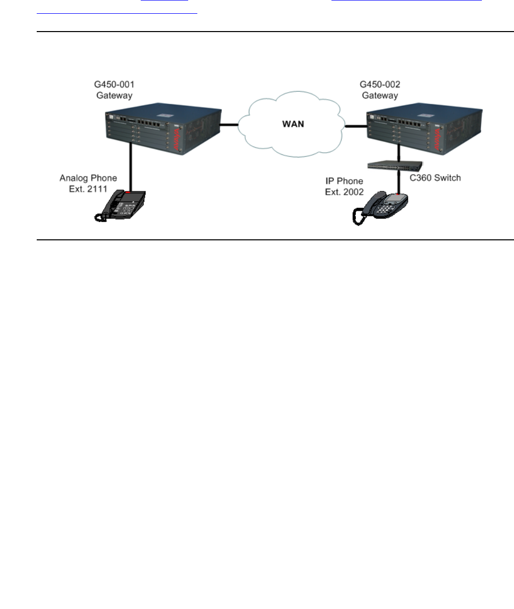
Configuring and analyzing RTP statistics
Issue 1 January 2008 403
A call over the WAN from an analog phone to an IP phone
At 00:39 on December 7, 2004, a call is placed from analog extension 2111 to IP phone
extension 2002 (see Figure 34) in the network described in Configuring the RTP statistics
application for a sample network on page 399.
Figure 34: Remote call from analog to IP phone

Configuring monitoring applications
404 Administration for the Avaya G450 Media Gateway
The RTP statistics application is configured as described in Configuring the RTP statistics
application for a sample network on page 399. The callers complain after the call that there
were QoS problems during the call. The administrator investigates as follows:
//to see if the RTP statistics application registered QoS problems for the call:
G450-001(super)# show rtp sessions
ID QoS Start date and time End Time Type Destination
----- --- ------------------- -------- ---------- ---------------
00001 *1 2004-12-07,00:39:26 00:41:01 G711U 20.20.20.2
//to display more details on the session:
G450-001(super)# show rtp-stat detailed 1
Session-ID: 1
Status: Terminated, QOS: Faulted2, EngineId: 0
Start-Time: 2004-12-07,00:39:26, End-Time: 2004-12-07,00:41:01
Duration: 00:01:35
CName: gwp@30.30.30.1
Phone: 199:2111
Local-Address: 30.30.30.1:2329 SSRC 2764463979
Remote-Address: 20.20.20.2:2329 SSRC 1260226 (0)
Samples: 19 (5 sec)
Codec:
G711U 200B 20mS Off, Silence-suppression(Tx/Rx) Disabled/Disabled, Play-Time 63.
916sec, Loss 11.0% #153, Avg-Loss 8.6%, RTT 201mS #0, Avg-RTT 210mS, JBuf-under/o
verruns 9.4%/0.0%, Jbuf-Delay 2mS, Max-Jbuf-Delay 35mS
Received-RTP:
Packets 3225, Loss 0.0% #94, Avg-Loss 8.4%, RTT 124mS #0, Avg-RTT 96mS, Jitter 11
mS #0, Avg-Jitter 9mS, TTL(last/min/max) 63/63/63, Duplicates 0, Seq-Fall 0, DSC
P 46, L2Pri 12, RTCP 9
Transmitted-RTP:
VLAN 1, DSCP 46, L2Pri 6, RTCP 17
Remote-Statistics:
Loss 11.6% #145, Avg-Loss 8.9%, Jitter 33mS #0, Avg-Jitter 26mS
Echo-Cancellation:
Loss 49dB #0, Len 32mS
RSVP:
Status Disabled, Failures 0
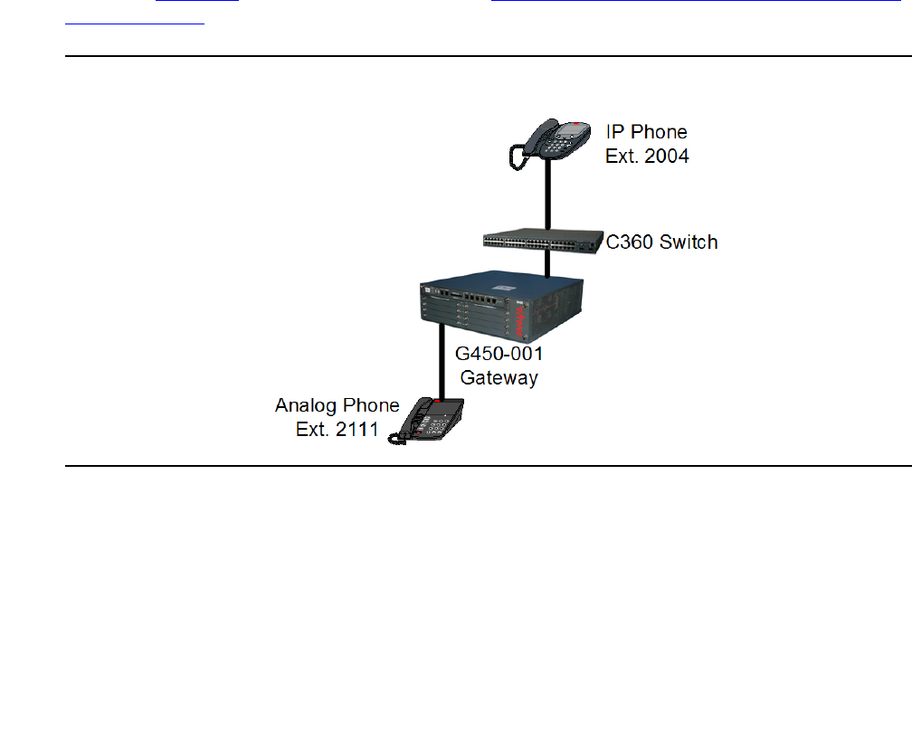
Configuring and analyzing RTP statistics
Issue 1 January 2008 405
A few points to note:
●The asterisk in the show rtp sessions output indicates that session 1 has QoS faults
[1]
●The QoS is described as Faulted because there were QoS faults [2]
●QoS faults that can be seen in the output are:
-
The codec loss event counter indicates that codec loss went over its threshold 15
times [3]
-
The received-RTP packet loss event counter indicates that packet loss went over its
threshold nine times [4]
-
The remote packet loss event counter indicates that remote packet loss went over its
threshold 14 times [5]
A local call between an IP and an analog phone
A local call is placed at 00:57 between IP phone extension 2004 and analog phone extension
2111 (see Figure 35) in the network described in Configuring the RTP statistics application for a
sample network on page 399. The call is finished at 00:59:19.
Figure 35: Local call from analog to IP phone

Configuring monitoring applications
406 Administration for the Avaya G450 Media Gateway
After the call is ended, the administrator uses the CLI to view the QoS statistics:
A few points to note:
●The QoS column in the show rtp sessions output has no asterisk (*), showing that no
metrics went over their event thresholds or average thresholds during the session [1]
●The QoS is described as “Ok” because there were no QoS problems [2]
●All average metric values are below the average thresholds [4] [5] [6] [8] [10] [12] [14] [16]
●All event counters are zero [3] [5] [7] [9] [11] [13] [15] [17]
//to see if there were QoS problems registered during the session
G450-001(super)# show rtp sessions last 1
ID QoS1 Start date and time End Time Type Destination
----- --- ------------------- -------- --------- ------------
00001 2004-12-07,00:57:13 00:59:19 G711U 30.30.30.2
//To display details of the session:
G450-001(super)# show rtp-stat detailed 1
Session-ID: 1
Status: Terminated, QOS: Ok2, EngineId: 0
Start-Time: 2004-12-07,00:57:13, End-Time: 2004-12-07,00:59:19
Duration: 00:02:06
CName: gwp@30.30.30.1
Phone: 200:2111
Local-Address: 30.30.30.1:2165 SSRC 2533871380
Remote-Address: 30.30.30.2:2165 SSRC 93269 (0) ip phone or another medi proc
Samples: 25 (5 sec)
Codec:
G711U 200B 20mS Off, Silence-suppression(Tx/Rx) Disabled/Disabled, Play-Time 130
.080sec, Loss 0.0% #03, Avg-Loss 0.0%4, RTT 83mS #05, Avg-RTT 108mS6,
JBuf-under/overruns 0.0%/0.0%, Jbuf-Delay 5mS, Max-Jbuf-Delay 27mS
Received-RTP:
Packets 6503, Loss 0.0% #07, Avg-Loss 0.0%8, RTT 0mS #09, Avg-RTT 0mS10, Jitter 0mS
#011, Avg-Jitter 0mS12, TTL(last/min/max) 64/64/64, Duplicates 0, Seq-Fall 0, DSCP
46, L2Pri 12, RTCP 26
Transmitted-RTP:
VLAN 1, DSCP 46, L2Pri 6, RTCP 31
Remote-Statistics:
Loss 0.0% #013, Avg-Loss 0.0%14, Jitter 10mS #015, Avg-Jitter 10mS16
Echo-Cancellation:
Loss 49dB #017, Len 32mS
RSVP:
Status Disabled, Failures 0
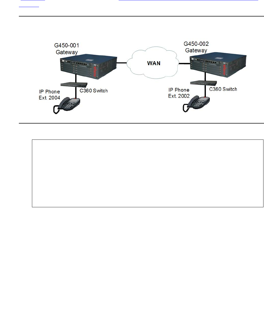
Configuring and analyzing RTP statistics
Issue 1 January 2008 407
A remote call over the WAN from an IP phone to an IP phone
An unshuffled call is placed from IP phone extension 2004 to IP phone extension 2002
(Figure 36) in the network described in Configuring the RTP statistics application for a sample
network on page 399.
Figure 36: Remote call from IP phone to IP phone
After the call is ended, the following commands are run:
Sessions 13 and 14 both belong to the call, since two VoIP channels are used by an unshuffled
call between two IP phones: one channel between each telephone and the G450 VoIP engine.
//to display the RTP sessions:
G450-001(super)# show rtp sessions
ID QoS Start date and time End Time Type Destination
----- --- ------------------- -------- ------------- --------------
00011 2004-12-07,00:57:13 00:59:19 G711U 30.30.30.2
00012 * 2004-12-07,00:39:26 00:41:01 G711U 20.20.20.2
00013 * 2004-12-07,01:02:45 01:05:15 G711U 20.20.20.2
00014 2004-12-07,01:02:50 01:05:15 G711U 30.30.30.2

Configuring monitoring applications
408 Administration for the Avaya G450 Media Gateway
Session 13 has QoS problems.
//to display details of session 13:
G450-001(super)# show rtp-stat detailed 13
Session-ID: 13
Status: Terminated, QOS: Faulted, EngineId: 0
Start-Time: 2004-12-07,01:02:45, End-Time: 2004-12-07,01:05:15
Duration: 00:02:30
CName: gwp@30.30.30.1
Phone: 202:2004
Local-Address: 30.30.30.1:2329 SSRC 3510756141
Remote-Address: 20.20.20.2:2329 SSRC 1372162 (0)
Samples: 30 (5 sec)
Codec:
G711U 200B 20mS Off, Silence-suppression(Tx/Rx) Disabled/Disabled, Play-Time 144
.540sec, Loss 0.0% #17, Avg-Loss 6.9%, RTT 99mS #0, Avg-RTT 208mS, JBuf-under/ov
erruns 7.4%/0.0%, Jbuf-Delay 9mS, Max-Jbuf-Delay 73mS
Received-RTP:
Packets 7279, Loss 0.0% #17 , Avg-Loss 6.8%, RTT 8mS #0, Avg-RTT 68mS, Jitter 0mS
#0, Avg-Jitter 6mS, TTL(last/min/max) 63/63/63, Duplicates 0, Seq-Fall 0, DSCP
46, L2Pri 12, RTCP 23
Transmitted-RTP:
VLAN 1, DSCP 46, L2Pri 6, RTCP 27
Remote-Statistics:
Loss 0.4% #17 , Avg-Loss 6.5%, Jitter 3mS #0, Avg-Jitter 22mS
Echo-Cancellation:
Loss 49dB #0, Len 32mS
RSVP:
Status Disabled, Failures 0

Configuring and analyzing RTP statistics
Issue 1 January 2008 409
Session 14 is free of QoS problems:
//to display details of session 14:
G450-001(super)# show rtp-stat detailed 14
Session-ID: 14
Status: Terminated, QOS: Ok, EngineId: 0
Start-Time: 2004-12-07,01:02:50, End-Time: 2004-12-07,01:05:15
Duration: 00:02:25
CName: gwp@30.30.30.1
Phone: 202:2002
Local-Address: 30.30.30.1:2165 SSRC 247950253
Remote-Address: 30.30.30.2:2165 SSRC 120077 (0)
Samples: 29 (5 sec)
Codec:
G711U 200B 20mS Off, Silence-suppression(Tx/Rx) Disabled/Disabled, Play-Time 151
.140sec, Loss 0.0% #0, Avg-Loss 0.0%, RTT 95mS #0, Avg-RTT 106mS, JBuf-under/ove
rruns 0.0%/0.0%, Jbuf-Delay 11mS, Max-Jbuf-Delay 27mS
Received-RTP:
Packets 7556, Loss 0.0% #0, Avg-Loss 0.0%, RTT 0mS #0, Avg-RTT 0mS, Jitter 0mS #
0, Avg-Jitter 0mS, TTL(last/min/max) 64/64/64, Duplicates 0, Seq-Fall 0, DSCP 46
, L2Pri 12, RTCP 31
Transmitted-RTP:
VLAN 1, DSCP 46, L2Pri 6, RTCP 25
--type q to quit or space key to continue--
Remote-Statistics:
Loss 0.0% #0, Avg-Loss 0.0%, Jitter 7mS #0, Avg-Jitter 7mS
Echo-Cancellation:
Loss 49dB #0, Len 32mS
RSVP:
Status Disabled, Failures 0
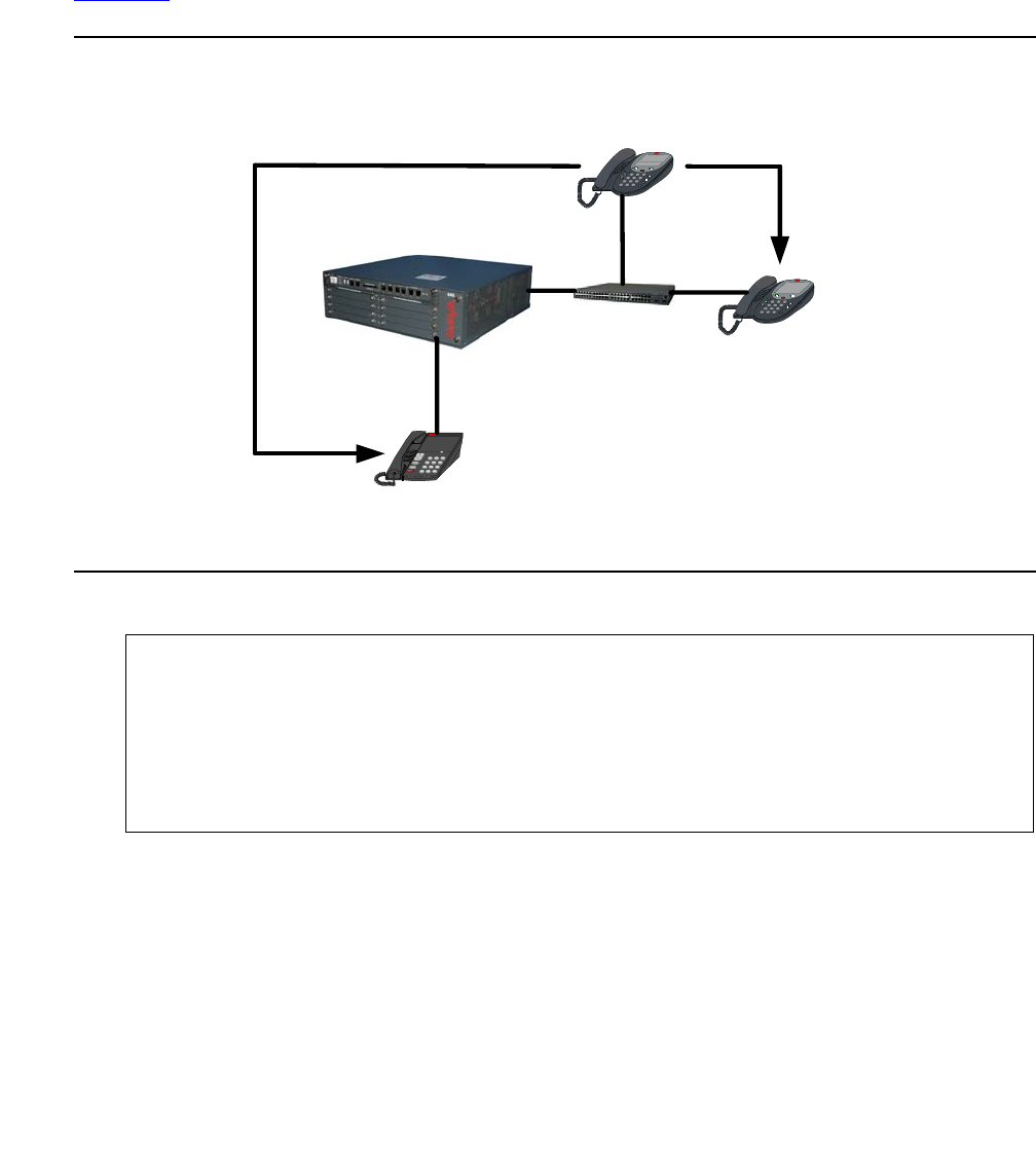
Configuring monitoring applications
410 Administration for the Avaya G450 Media Gateway
A conference call
A conference call is placed between IP phone extension 1003, analog phone extension 80900,
and IP phone extension 80886. The call is established by calling from extension 1003 to
extension 80900, and then using the conference function on extension 1003 to add 80886 (see
Figure 37).
Figure 37: A conference call
During the call, the following commands are run:
//to display the RTP sessions:
G450-001(super)# show rtp sessions
ID QoS Start date and time End Time Type Destination
----- --- ------------------- -------- --------------- ---------------
00001 2004-12-23,09:55:17 - G729 16.16.16.101
00002 2004-12-23,09:55:20 - G711U 149.49.41.50
C360
Switch
G450-001
Gateway
HOLDSpeaker
123
456
789
0
ABC DEF
GHI JLK MNO
PQRS TUV WXYZ
CONFERENCE
#
*
IP Phone
Ext. 80886
HOLDSpeaker
123
456
789
0
ABC DEF
GHI JLK MNO
PQRS TUV WXYZ
CONFERENCE
#
*
IP Phone
Ext. 1003
123
456
789
*0#
ABCDEF
GHI JKL MNO
PQRS TUV WXYZ
Analog Phone
Ext. 80900
1
2 (Conference)

Configuring and analyzing RTP statistics
Issue 1 January 2008 411
//to display details of session 1:
GG450-001(super)# show rtp detailed 1
Session-ID: 1
Status: Active, QOS: Ok, EngineId: 0
Start-Time: 2004-12-23,09:55:17, End-Time: -
Duration: 00:00:48
CName: gwp@33.33.33.33
Phone: 1401:80900:1003
Local-Address: 33.33.33.33:61999 SSRC 3585271811
Remote-Address: 16.16.16.101:61999 SSRC 1369159108 (0)
Samples: 9 (5 sec)
Codec:
G729 40B 0mS Off, Silence-suppression(Tx/Rx) No-RTP/No-RTP, Play-Time 4.760sec,
Loss 0.0% #0, Avg-Loss 0.8%, RTT 137mS #0, Avg-RTT 141mS, JBuf-under/overruns 0.
8%/0.0%, Jbuf-Delay 20mS, Max-Jbuf-Delay 30mS
Received-RTP:
Packets 238, Loss 0.0% #0, Avg-Loss 0.0%, RTT 24mS #0, Avg-RTT 21mS, Jitter 0mS
#0, Avg-Jitter 0mS, TTL(last/min/max) 0/61/61, Duplicates 0, Seq-Fall 0, DSCP 0,
L2Pri 6, RTCP 26
Transmitted-RTP:
VLAN 400, DSCP 46, L2Pri 6, RTCP 34
Remote-Statistics:
Loss 0.0% #0, Avg-Loss 0.0%, Jitter 2mS #0, Avg-Jitter 1mS
Echo-Cancellation:
Loss 49dB #0, Len 0mS
RSVP:
Status Reserved, Failures 0
//to display details of session 2:
G450-001(super)# show rtp detailed 2
Session-ID: 2
Status: Active, QOS: Ok, EngineId: 0
Start-Time: 2004-12-23,09:55:20, End-Time: -
Duration: 00:00:50
CName: gwp@33.33.33.33
Phone: 1402:80886:1003
Local-Address: 33.33.33.33:61175 SSRC 3702564610
Remote-Address: 149.49.41.50:61175 SSRC 15161893 (0)
Samples: 10 (5 sec)

Configuring monitoring applications
412 Administration for the Avaya G450 Media Gateway
The conference ID that appears in the Phone string for session 1 and for session 2 is identical,
which identifies the two sessions as belonging to the same conference call [1] [2].
Summary of RTP statistics commands
For more information about these commands, see Avaya G450 CLI Reference, 03-300437.
Codec:
G711U 40B 0mS Off, Silence-suppression(Tx/Rx) Disabled/Disabled, Play-Time 161.9
00sec, Loss 0.0% #0, Avg-Loss 0.0%, RTT 103mS #0, Avg-RTT 105mS, JBuf-under/over
runs 0.0%/0.0%, Jbuf-Delay 11mS, Max-Jbuf-Delay 13mS
Received-RTP:
Packets 8094, Loss 0.0% #0, Avg-Loss 0.0%, RTT 8mS #0, Avg-RTT 9mS, Jitter 0mS #
0, Avg-Jitter 0mS, TTL(last/min/max) 0/64/64, Duplicates 0, Seq-Fall 0, DSCP 0,
L2Pri 6, RTCP 30
Transmitted-RTP:
VLAN 400, DSCP 46, L2Pri 6, RTCP 30
Remote-Statistics:
Loss 0.0% #0, Avg-Loss 0.0%, Jitter 1mS #0, Avg-Jitter 0mS
Echo-Cancellation:
Loss 49dB #0, Len 0mS
RSVP:
Status Reserved, Failures 0
Table 106: RTP statistics application CLI commands
Command Description
rtp-stat clear Reset the RTP statistics application
rtp-stat event-threshold Set a QoS event-threshold for RTP streams
rtp-stat fault Configure the RTP statistics application to send QoS fault
and/or clear traps
rtp-stat min-stat-win Set the RTP statistics minimum statistic window
rtp-stat qos-trap Configure the RTP statistics application to automatically
send a QoS trap upon the termination of an RTP stream
in which one or more QoS event counters exceeded their
configured threshold
1 of 2

Configuring and analyzing packet sniffing
Issue 1 January 2008 413
Configuring and analyzing packet sniffing
The G450 packet sniffing service allows you to analyze packets that pass through the G450’s
interfaces. Packets are captured to a buffer based on criteria that you specify. The buffer is then
uploaded via FTP to a file that can be analyzed using the Ethereal analysis tool.
The packet sniffing service on the G450 offers several advantages to the network administrator.
Since the capture file is saved in the libpcap format, which is the industry standard, it is readable
both by the S8300’s Tethereal software, and by standard versions of Ethereal for Unix,
Windows, and Linux (see http://www.ethereal.com).
Note:
Note: Ethereal is an open source application.
In addition, the G450’s packet sniffing service is capable of capturing non-Ethernet packets,
such as frame-relay and PPP. Non-Ethernet packets are wrapped in a dummy Ethernet header
to allow them to be viewed in a libpcap format. Thus, the G450 allows you to analyze packets on
all the interfaces of the device.
rtp-stat
qos-trap-rate-limit
Configure the QoS trap rate limiter
rtp-stat-service Enable the RTP statistics application
rtp-stat thresholds Set thresholds for the RTP statistics applications
show rtp-stat config Display the RTP statistics application configuration
show rtp-stat detailed Display a detailed QoS log for a specific RTP session
show rtp-stat sessions Display RTP sessions QoS statistics
show rtp-stat summary Display a summary of the RTP statistics
show rtp-stat thresholds Display the configured RTP statistic thresholds
show rtp-stat traceroute Display the results of UDP traceroutes issued by the
media gateway VoIP engine per active RTP session
Table 106: RTP statistics application CLI commands (continued)
Command Description
2 of 2

Configuring monitoring applications
414 Administration for the Avaya G450 Media Gateway
The G450’s packet sniffing service gives you full control over the memory usage of the sniffer.
You can set a maximum limit for the capture buffer size, configure a circular buffer so that older
information is overwritten when the buffer fills up, and specify a maximum number of bytes to
capture for each packet.
What can be captured
The G450 packet sniffing service captures only the packets handled by the G450 and delivered
to the device CPU (“non-promiscuous” mode). This is unlike regular sniffer applications that pick
up all traffic on the network.
See Configuring packet sniffing on page 415 for a description of how to configure packet sniffing
and analyze the resulting capture file.
Streams that can always be captured
●H.248 registration
●RTP from the G450
●ARP on the LAN (broadcast)
●All packets that traverse the WAN
●All traffic to/from the G450
Streams that can never be captured
The following streams can never be captured because they are switched by the internal
Ethernet switch and not by the CPU:
●H.323 Signaling from an IP phone on the LAN to an ICC on the LAN
●RTP stream between IP phones on the LAN
Streams that can sometimes be captured
If the G450 is the WAN router of the following streams, they can be captured:
●H.323 Signaling from IP phones on the LAN to an ECC over the WAN
●DHCP when the DHCP server is behind the WAN (using the G450 DHCP relay capability)
●RTP stream on an IP phone on the LAN to a remote IP phone

Configuring and analyzing packet sniffing
Issue 1 January 2008 415
Configuring packet sniffing
Packet sniffing configuration consists of the following steps:
1. Enabling packet sniffing.
2. Limiting packet sniffing to specific interfaces (if necessary).
3. Creating a capture list that specifies which packets to capture.
4. Defining rule criteria for a capture list.
5. Viewing the capture list.
6. Applying a capture list.
7. Configuring packet sniffing settings.
8. Starting the packet sniffing service.
Enabling packet sniffing
Since the packet sniffing service presents a potential security breach, the administrator must
first enable the service on the G450 before a user can start capturing packets. Enter
capture-service to enable the packet sniffing service.
Note:
Note: The packet sniffing service can only be enabled by an administrator connecting
with a serial cable to the G450 Console port or Services port.
To disable packet sniffing, enter no capture-service.
Limiting packet sniffing to specific interfaces
By default, the packet sniffing service captures packets and Ethernet frames from all the
router’s interfaces. You can use the capture interface command to limit packet sniffing to
a specific interface.
For example, the following command limits packet sniffing to the FastEthernet Interface:
The following command enables packet sniffing on all available interfaces:
G450-001(super)# capture interface fastethernet 10/2
Done!
G450-001(super)#
G450-001(super)# capture interface any
Done!
G450-001(super)#

Configuring monitoring applications
416 Administration for the Avaya G450 Media Gateway
Creating a capture list
By default, the packet sniffing service captures all packets passing through the interfaces on
which it is enabled. Use a capture list to selectively filter the packets that are captured by the
service.
A capture list contains an ordered list of rules and actions. A rule specifies criteria against which
packets are tested. The action tells the G450 whether to capture or not capture packets
matching the rule criteria. Only packets that match the specified criteria and have an action of
capture are captured to the capture file. The rules are evaluated one by one, according to
their number. If none of the rules match the packet, the default action is executed. You can set
the default action as desired. Use the command ip-rule default to set the default action.
Note:
Note: ARP frames are not IP packets and therefore cannot be filtered by capture lists.
However, in a healthy network, the ARP frames rate is relatively low.
Use the ip capture-list command, followed by the list number, to enter the context of a
capture list (and to create the capture list if it does not exist). Capture lists are numbered from
500 to 599. For example:
You can use the following commands to set the parameters of the capture list:
●Use the name command to assign a name to the capture list.
●Use the owner command to record the name of the person that created the list.
●Use the ip-rule command to define rule criteria for the capture list. The following section
explains rule criteria in detail.
Note:
Note: You can use the cookie command to set the list cookie for the capture list.
However, capture list cookies are not currently used by any application.
Defining rule criteria for a capture list
Once in the capture list context, use the ip-rule command, followed by a number from 1 to
9999, to define a set of criteria against which to test packets. In addition to the rule criteria,
each rule must include a composite operation. The composite operation determines the action
the rule takes with respect to packets that match the rule criteria, and can be one of the
following:
●capture
●no-capture
G450-001(super)# ip capture-list 510
G450-001(super-Capture 510)#

Configuring and analyzing packet sniffing
Issue 1 January 2008 417
Use the composite-operation command to include a composite operation in a rule for a
capture list. For example, the following commands create a rule (rule 10 in capture list 510) that
determines that TCP packets are not captured:
Rule applications
Rules work in the following ways, depending on the type of information in the packet, and the
number of criteria in the rule:
●L4 rules with a Permit operation are applied to non-initial fragments
●L4 rules with a Deny operation are not applied to non-initial fragments, and the device
continues checking the next IP rule. This is to prevent cases in which fragments that
belong to other L4 sessions may be blocked by the other L4 session which is blocked.
●L3 rules apply to non-initial fragments
●L3 rules that include the fragment criteria do not apply to initial fragments or non-fragment
packets
●L3 rules that do not include the fragment criteria apply to initial fragments and
non-fragment packets
●L4 rules apply to initial fragments and non-fragment packets
Rule criteria commands
You can use the following rule criteria commands. These commands are described in more
detail below.
●dscp
●ip protocol
●source ip address
●destination ip address
●tcp source-port
●tcp destination-port
●udp source-port
●udp destination-port
G450-001(super)# ip capture-list 510
G450-001(super-Capture 510)# ip-rule 10
G450-001(super-Capture 510/ip rule 10)# composite-operation no-capture
Done!
G450-001(super-Capture 510/ip rule 10)# ip-protocol tcp
Done!
G450-001(super-Capture 510/ip rule 10)# composite-operation no-capture
Done!
G450-001(super-Capture 510/ip rule 10)# ip-protocol tcp
Done!
G450-001(super-Capture 510/ip rule 10)#

Configuring monitoring applications
418 Administration for the Avaya G450 Media Gateway
●icmp
●fragment
Note:
Note: You can also use the description command in the rule context to add a
description of the rule.
DSCP
Use the dscp command, followed by a DSCP value (from 0 to 63) to apply the rule to all
packets with the specified DSCP value. For example, the following rule is defined to capture all
VoIP Bearer packets (DSCP = 46):
IP protocol
Use the ip-protocol command, followed by the name of an IP protocol, to apply the rule to
all packets with the specified IP protocol. If you want the rule to apply to all protocols, use any
after the command (ip-protocol any).
For example, the following rule is defined to capture all TCP packets:
To apply the rule to all protocols except the specified protocol, use the no form of this command.
For example:
Source or destination IP address
Use the source-ip command to apply the rule to packets from the specified IP address or
range of addresses. Use the destination-ip command to apply the rule to packets going to
the specified IP address or range of addresses.
G450-001(super)# ip capture-list 520
G450-001(super-Capture 520)# ip-rule 20
G450-001(super-Capture 520/ip rule 20)# composite-operation capture
Done!
G450-001(super-Capture 520/ip rule 20)# dscp 46
Done!
G450-001(super-Capture 520/ip rule 20)#
G450-001(super)# ip capture-list 520
G450-001(super-Capture 520)# ip-rule 20
G450-001(super-Capture 520/ip rule 20)# composite-operation capture
Done!
G450-001(super-Capture 520/ip rule 20)# ip-protocol tcp
Done!
G450-001(super-Capture 520/ip rule 20)#
G450-001(super-Capture 520/ip rule 20)# no ip-protocol tcp
Done!
G450-001(super-Capture 520/ip rule 20)#

Configuring and analyzing packet sniffing
Issue 1 January 2008 419
The IP range criteria can be any of the following:
●Range. Type two IP addresses to set a range of IP addresses to which the rule applies.
You can use wildcards in setting the range. For example:
●Single address. Type host, by an IP address, to set a single IP address to which the rule
applies. For example:
●Wildcard. Type host, followed by an IP address using wildcards, to set a range of IP
addresses to which the rule applies. For example:
●Any. Type any to apply the rule to all IP addresses. For example:
To apply the rule to all source or destination IP addresses except the specified address or range
of addresses, use the not form of the applicable command. For example:
Source and destination port range
To specify a range of source and destination ports to which the rule applies, use the following
commands, followed by either port name or port number range criteria:
●tcp source-port. The rule applies to TCP packets from ports that match the defined
criteria
●tcp destination-port. The rule applies to TCP packets to ports that match the
defined criteria
●udp source-port. The rule applies to UDP packets from ports that match the defined
criteria
●udp destination-port. The rule applies to UDP packets to ports that match the
defined criteria
G450-001(super-Capture 520/ip rule 20)# source-ip 135.64.102.0 0.0.255.255
Done!
G450-001(super-Capture 520/ip rule 20)#
G450-001(super-Capture 520/ip rule 20)# destination-ip host 135.64.104.102
Done!
G450-001(super-Capture 520/ip rule 20)#
G450-001(super-Capture 520/ip rule 20)# source-ip host 135.0.0.0
Done!
G450-001(super-Capture 520/ip rule 20)#
G450-001(super-Capture 520/ip rule 20)# destination-ip any
Done!
G450-001(super-Capture 520/ip rule 20)#
G450-001(super-Capture 520/ip rule 20)# not destination-ip 135.64.102.0 0.0.255.255
Done!
G450-001(super-Capture 520/ip rule 20)#

Configuring monitoring applications
420 Administration for the Avaya G450 Media Gateway
Port name or number range criteria
The port name or number range criteria can be any of the following:
●Range. Type range, followed by two port numbers, to set a range of port numbers to
which the rule applies. For example:
●Equal. Type eq, followed by a port name or number, to set a port name or port number to
which the rule applies. For example:
●Greater than. Type gt, followed by a port name or port number, to apply the rule to all
ports with a name or number greater than the specified name or number. For example:
●Less than. Type lt, followed by a port name or port number, to apply the rule to all ports
with a name or number less than the specified name or number. For example:
●Any. Type any to apply the rule to all port names and port numbers. For example:
To apply the rule to all protocols except the specified protocol, use the not form of the
applicable command. For example:
G450-001(super-Capture 520/ip rule 20)# tcp destination-port range 1 3
Done!
G450-001(super-Capture 520/ip rule 20)#
G450-001(super-Capture 520/ip rule 20)# tcp source-port eq ftp
Done!
G450-001(super-Capture 520/ip rule 20)#
G450-001(super-Capture 520/ip rule 20)# udp destination-port gt 10
Done!
G450-001(super-Capture 520/ip rule 20)#
G450-001(super-Capture 520/ip rule 20)# udp source-port lt 10
Done!
G450-001(super-Capture 520/ip rule 20)#
G450-001(super-Capture 520/ip rule 20)# tcp source-port any
Done!
G450-001(super-Capture 520/ip rule 20)#
G450-001(super-Capture 520/ip rule 20)# not udp source-port lt 10
Done!
G450-001(super-Capture 520/ip rule 20)#

Configuring and analyzing packet sniffing
Issue 1 January 2008 421
ICMP type and code
To apply the rule to a specific type of ICMP packet, use the icmp command. This command
specifies an ICMP type and code to which the rule applies. You can specify the ICMP type and
code by integer or text string. For example:
To apply the rule to all ICMP packets except the specified type and code, use the not form of
this command. For example:
Fragment
To apply the rule to non-initial fragments, enter fragment. You cannot use the fragment
command in a rule that includes UDP or TCP source or destination ports.
G450-001(super-Capture 520/ip rule 20)# icmp Echo-Reply
Done!
G450-001(super-Capture 520/ip rule 20)#
G450-001(super-Capture 520/ip rule 20)# not icmp 1 2
Done!
G450-001(super-Capture 520/ip rule 20)#

Configuring monitoring applications
422 Administration for the Avaya G450 Media Gateway
Capture list example
The following commands create a capture list that captures all traffic from subnet
135.122.50.149 255.255.255.254 to an ECC at address 135.122.50.171, except telnet:
G450-001(super)# ip capture-list 511
G450-001(super-Capture 511)# name "list #511"
Done!
! Rules 10 and 15 provide that telnet packets are not captured.
G450-001(super-Capture 511)# ip-rule 10
G450-001(super-Capture 511/ip rule 10)# composite-operation no-capture
Done!
G450-001(super-Capture 511/ip rule 10)# ip-protocol tcp
Done!
! You can use a port number instead of "telenet" (23).
G450-001(super-Capture 511/ip rule 10)# tcp destination-port eq telnet
Done!
G450-001(super-Capture 511/ip rule 10)# exit
G450-001(super-Capture 511)#
G450-001(super-Capture 511)# ip-rule 15
G450-001(super-Capture 511/ip rule 15)# composite-operation no-capture
Done!
G450-001(super-Capture 511/ip rule 15)# ip-protocol tcp
Done!
! You can use a port number instead of "telenet" (23).
G450-001(super-Capture 511/ip rule 15)# tcp source-port eq telnet
Done!
G450-001(super-Capture 511/ip rule 15)# exit
! Rule 20 provides for capturing any packet coming from the host IP address
! 135.122.50.171 and going to the subnet 135.122.50.128, including packets going
! to any of the 30 possible hosts in that subnet.
G450-001(super-Capture 511)# ip-rule 20
G450-001(super-Capture 511/ip rule 20)# ip-protocol tcp
Done!
G450-001(super-Capture 511/ip rule 20)# source-ip host 135.122.50.171
Done!
G450-001(super-Capture 511/ip rule 20)# destination-ip 135.122.50.128 0.0.0.31
Done!
G450-001(super-Capture 511/ip rule 20)# exit
! Rule 30 provides for capturing any packet coming from the subnet
! 135.122.50.128 and going to the host IP address 135.122.50.171, including
! packets from any of the 30 possible hosts in that subnet.
G450-001(super-Capture 511)# ip-rule 30
G450-001(super-Capture 511/ip rule 30)# source-ip 135.122.50.128 0.0.0.31
Done!
G450-001(super-Capture 511/ip rule 30)# destination-ip host 135.122.50.171
Done!
G450-001(super-Capture 511/ip rule 30)# exit
G450-001(super-Capture 511)# ip-rule default
G450-001(super-Capture 511/ip rule default)# composite-operation no-capture
Done!
G450-001(super-Capture 511/ip rule default)# exit
G450-001(super-Capture 511)# exit
G450-001(super)#

Configuring and analyzing packet sniffing
Issue 1 January 2008 423
Viewing the capture list
Use the show ip capture-list command to display the capture list in an easy-to-read
format. For example:
Applying a capture list
To apply a capture list, use the capture filter-group command from the general context.
For example, to set the G450 to use capture list 511 on interfaces in which packet sniffing is
enabled, specify the following command:
If no capture list is applied, the packet sniffing service captures all packets.
G450-001# show ip capture-list 511
Index Name Owner
----- ------------------------------- --------------------------
511 list #511 other
Index Protocol IP Wildcard Port Operation
DSCP
----- -------- --- ---------------- --------------- ------------ -------------
10 tcp Src Any Any No-Capture
Any Dst Any eq Telnet
15 tcp Src Any eq Telnet No-Capture
Any Dst Any Any
20 tcp Src 135.122.50.171 Host Any Capture
Any Dst 135.122.50.128 0.0.0.31 Any
30 Any Src 135.122.50.128 0.0.0.31 Any
Any Dst 135.122.50.171 Host Any
Deflt Any Src Any Any No-Capture
Any Dst Any Any
Index Name Trust
----- -------------------- ------------
0 Capture No
1 No-Capture No
G450-001(super)# capture filter-group 511
Done!
G450-001(super)#

Configuring monitoring applications
424 Administration for the Avaya G450 Media Gateway
Configuring packet sniffing settings
The packet sniffing service provides several administrative settings you can use to control the
capture functionality. Use the following commands to configure packet sniffing settings. These
commands are all used from general context, and require read/write access.
●Use the capture buffer-mode command to specify the type of buffer to use. The
available parameters are:
-
cyclic. Circular buffer that overwrites the oldest records when it is filled up. Use a
cyclic buffer to store the most recent history of packet activity.
-
non-cyclic. Linear buffer that is used until it is filled up
For example:
●Use the capture buffer-size command to specify the maximum size of the capture
buffer. Available values are 56 to 10000 kb. The default value is 1000. To activate the
change in buffer size, you must enter copy running-config startup-config, and
reboot the G450. For example:
●Use the capture max-frame-size command to specify the maximum number of bytes
captured for each packet. This is useful, since in most cases, the packet headers contain
the relevant information. Available values are 14 to 4096. The default value is 128. For
example:
Note:
Note: When you change the maximum frame size, the G450 clears the capture buffer.
●Enter clear capture-buffer to clear the capture buffer.
G450-001(super)# capture buffer-mode cyclic
Done!
G450-001(super)#
G450-001(super)# capture buffer-size 2000
To change capture buffer size, copy the running
configuration to the start-up configuration file, and reset the device.
G450-001(super)# copy running-config startup-config
Beginning copy operation .................... Done!
G450-001(super)#
G450-001(super)# capture max-frame-size 4000
This command will clear the capture buffer
- do you want to continue (Y/N)? y
Done!
G450-001(super)#

Configuring and analyzing packet sniffing
Issue 1 January 2008 425
Tip:
Tip: To reduce the size of the capture file, use any combination of the following
methods:
-
Use the capture interface command to capture only from a specific
interface.
-
Use the capture max-frame-size to capture only the first N octets of each
frame. This is valuable since it is usually the packets headers that contain the
interesting information.
-
Use capture lists to select specific traffic.
Starting the packet sniffing service
Once you have defined and applied the packet capture lists, use the capture start
command in general context to instruct the packet sniffing service to start capturing packets.
Note:
Note: The capture start command resets the buffer before starting the sniffer.
Note:
Note: You must apply a capture list using the capture filter-group command in
order for the capture list to be active. If you do not use the capture
filter-group command, the packet sniffing service captures all packets.
If packet sniffing has been enabled by the administrator, the following appears:
If packet sniffing has not been enabled by the administrator, the following appears:
Capturing decrypted IPSec VPN packets
IPSec VPN packets are encrypted packets. The contents of encrypted packets cannot be
viewed when captured. However, you can use the capture ipsec command to specify that
IPSec VPN packets, handled by the internal VPN gateway process, should be captured in plain
text format.
G450-001(super)# capture start
Starting the packet sniffing process
G450-001(super)#
G450-001(super)# capture start
Capture service is disable
To enable, use the `capture-service` command in supervisor mode.
G450-001(super)#

Configuring monitoring applications
426 Administration for the Avaya G450 Media Gateway
Analyzing captured packets
Analyze the captured packets by stopping the packet sniffing service, uploading the capture file,
and analyzing the capture file.
Stopping the packet sniffing service
Enter capture stop to stop the packet sniffing service. You must stop the service in order to
upload a capture file.
Note:
Note: The capture stop command is not saved in the startup configuration file.
Viewing packet sniffing information
You can enter show capture to view information about the packet sniffing configuration and
the capture state. For example:
Note:
Note: The number of captured frames can be larger than the number of the frames in
the buffer because the capture file may be in cyclic mode.
You can use the show capture-buffer hex command to view a hex dump of the captured
packets. However, for a proper analysis of the captured packets, you should upload the capture
file and analyze it using a sniffer application, as described in the following sections.
G450-001> show capture
Capture service is enabled and inactive
Capture start time 19/06/2004-13:57:40
Capture stop time 19/06/2004-13:58:23
Current buffer size is 1024 KB
Buffer mode is cyclic
Maximum number of bytes captured from each frame: 1515
Capture list 527 on interface "FastEthernet 10/2"
Number of captured frames in file: 3596 (out of 3596 total captured frames)
Size of capture file: 266 KB (26.6 %)

Configuring and analyzing packet sniffing
Issue 1 January 2008 427
The following is an example of the show capture-buffer hex command:
Uploading the capture file
Once the packet sniffing service is stopped, upload the capture file to a server for viewing and
analysis.
Note:
Note: The capture file may contain sensitive information, such as usernames and
passwords of non-encrypted protocols. It is therefore advisable to upload the
capture file over a secure channel – via VPN or using SCP (Secure Copy).
In most cases, you can upload the capture file to a remote server. However, in cases where the
capture file is very large, or you encounter a WAN problem, you can upload the capture file to
an S8300 Server and view it using Tethereal, which is a command-line version of Ethereal.
G450-001> show capture-buffer hex
Frame number: 1
Time relative to first frame (D H:M:S:Micro-S): 0, 0:0:0.0
Packet time: 14/01/1970-13:24:55.583598
Frame length: 60 bytes
Capture Length: 60 bytes
00000000:ffff ffff ffff 0040 0da9 4201 0806 0001 .......@..B.....
00000010:0800 0604 0001 0040 0da9 4201 9531 4e7a .......@..B..1Nz
00000020:0000 0000 0000 9531 4e7a 0000 0000 0000 .......1Nz......
00000030:0000 0000 0000 0000 0000 0000 ............
Frame number: 2
Time relative to first frame (D H:M:S:Micro-S): 0, 0:0:0.76838
Packet time: 14/01/1970-13:24:55.660436
Frame length: 60 bytes
Capture Length: 60 bytes
00000000:ffff ffff ffff 0040 0d8a 5455 0806 0001 .......@..TU....
00000010:0800 0604 0001 0040 0d8a 5455 9531 4e6a .......@..TU.1Nj
00000020:0000 0000 0000 9531 4e6a 0000 0000 0000 .......1Nj......
00000030:0000 0000 0000 0000 0000 0000 ............

Configuring monitoring applications
428 Administration for the Avaya G450 Media Gateway
Uploading the capture file to a remote server or USB mass storage device
●Use one of the following commands to upload the capture file:
●copy capture-file ftp
●copy capture-file tftp
●copy capture-file scp
●coyy capture-file usb
Note:
Note: The use of the copy capture-file scp command is limited to uploading files
of 1 MB or less.
For example:
Uploading the capture file to an S8300 Server
1. Telnet into the S8300 Server, for example by entering session mgc.
2. Open the Avaya Maintenance Web Interface. For instructions on accessing the Avaya
Maintenance Web Interface, see Installing and Upgrading the Avaya G450 Media
Gateway, 03-602054.
3. In the Avaya Maintenance Web Interface, select FTP under Security in the main menu.
4. Click Start Server.
5. Log into the G450.
6. Use the copy capture file ftp command to upload the capture file. Specify that the
capture file should be placed in the ftp /pub subdirectory. For example:
7. At the FTP login prompt, enter anonymous.
8. At the FTP password prompt, enter your e-mail address.
G450-001(super)# copy capture-file ftp myCature.cap 135.64.103.66
This command will stop the capture if capturing is started
Confirmation - do you want to continue (Y/N)? y
Username: xxxx
Password: xxxx
Beginning upload operation ...
This operation may take up to 20 seconds.
Please refrain from any other operation during this time.
For more information , use 'show upload status 10' command
G450-001(super)#
G450-001(super)# copy capture-file ftp pub/capfile.cap 149.49.43.96

Configuring and analyzing packet sniffing
Issue 1 January 2008 429
9. Optionally, enter show upload status 10 to view upload status. For example:
Analyzing the capture file
The uploaded capture file is in libpcap format and can therefore be viewed by most sniffer
applications, including tcpdump, Ethereal and Tethereal.
If you uploaded the capture file to an S3800 server, view the file using Tethereal, a
command-line version of Ethereal available on the S3800. See the Tethereal man pages for
more information about the Tethereal application.
If you uploaded the capture file to a remote server, you can view the file using the industry
standard Ethereal application. The latest version of Ethereal for Windows, Linux, UNIX, and
other platforms can be downloaded from http://www.ethereal.com.
Note:
Note: Ethereal allows you to create filter expressions to filter the packets in the capture
file and display desired files only. For example, you can display only packets with
a specific source address, or only those received from a specific interface. See
Identifying the interface on page 430.
Figure 38 shows a sample Ethereal screen.
G450-001(super)# show upload status 10
Module #10
===========
Module : 10
Source file : sniffer
Destination file : pub/capfile.cap
Host : 149.49.43.96
Running state : Executing
Failure display : (null)
Last warning : No-warning
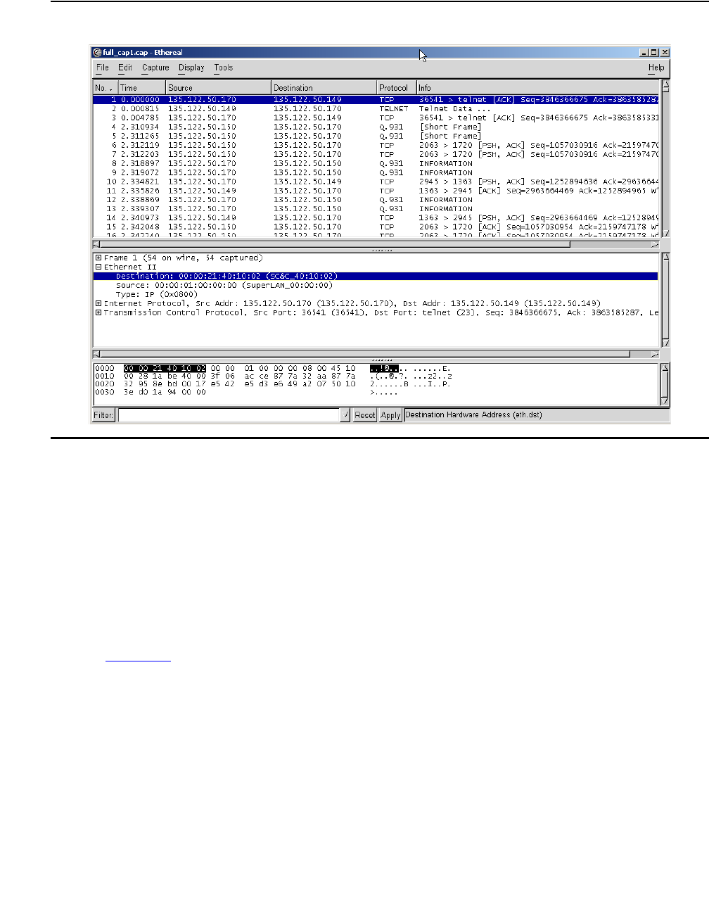
Configuring monitoring applications
430 Administration for the Avaya G450 Media Gateway
Figure 38: Sample Ethereal screen
Identifying the interface
The G450’s packet sniffing service can capture also non-Ethernet packets, such as frame-relay
and PPP, into the capture file. This is achieved by wrapping non-Ethernet packets in a dummy
Ethernet header to allow the packets to be stored in a libpcap format. This enables you to
analyze packets on all the device interfaces.
The dummy Ethernet headers are allocated according to the original packet type. Dummy
Ethernet headers start with 00:00. Therefore, if the source or destination address of a packet
you are viewing in Ethereal starts with 00:00, this indicates the packet is a non-Ethernet packet.
For example, see the highlighted destination address of the packet appearing in the middle
pane in Figure 38.
The dummy Ethernet header is identified by special MAC addresses. Packets sent from a
non-Ethernet interface are identified with an SA address in the format 00:01:00:00:xx and a DA
address which holds the interface index. Packets received over a non-Ethernet interface are
identified with DA address in the format 00:01:00:00:xx and an SA address which holds the
interface index. The show capture-dummy-headers command displays the dummy header
addresses and their meaning according to the current configuration.

Configuring and analyzing packet sniffing
Issue 1 January 2008 431
Note:
Note: Ethernet packets received on a VLAN interface are identified by their VLAN tag.
However, decrypted IPSec packets received on a VLAN interface are stored with
a dummy header.
Thus in the example appearing in Figure 38:
●The Source address of 00:00:01:00:00:00 indicates that the packet arrived from a
frame-relay or PPP interface
●The Destination address of 00:00:21:40:10:02 indicates that the packet is being sent to
the Serial interface on the media module in slot number 4, on port number 1, with channel
group number 2
Simulating packets
Capture lists support the IP simulate command. Refer to Simulating packets on page 611.
G450-001> show capture-dummy-headers
MAC Description
----------------- ----------------------------------------------------
00:00:01:00:00:00 Src/dst address of Packet to/from frame-relay or PPP
00:00:01:00:00:01 Decrypted IPSec packet
00:00:0a:00:0a:02 interface fastethernet 10/2
00:00:0c:a0:b0:01 interface vlan 1
00:00:21:20:10:01 interface serial 3/1:1
00:00:21:40:10:02 interface serial 4/1:2
00:00:31:00:00:01 interface dialer 1
Configuring monitoring applications
432 Administration for the Avaya G450 Media Gateway
Summary of packet sniffing commands
For more information about these commands, see Avaya G450 CLI Reference, 03-300437.
Table 107: Packet sniffing CLI commands
Root level
command First level
command Second level
command Description
capture
buffer-mode Set the capture buffer to cyclic
mode
capture
buffer-size Change the size of the capture file
capture
filter-group Activate a capture list
capture
interface Specify a capture interface (by
default, the service captures from
all interfaces simultaneously)
capture ipsec Set whether to capture IPSec VPN
packets, handled by the internal
VPN process, decrypted
(plaintext) or encrypted
(cyphertext)
capture
max-frame-size Set the maximum octets that are
captured from each frame
capture start Start capturing packets
capture stop Stop capturing packets
capture-service Enable or disable the capture
service
clear
capture-buffer Clear the capture buffer (useful in
case it holds sensitive information)
copy
capture-file
ftp
Upload the packet sniffing buffer to
a file on a remote FTP server
copy
capture-file
scp
Upload the packet sniffing buffer to
a file on a remote SCP server
1 of 3

Configuring and analyzing packet sniffing
Issue 1 January 2008 433
copy
capture-file
tftp
Upload the packet sniffing buffer to
a file on a remote TFTP server
copy
capture-file
usb
Upload the capture file to a USB
mass storage device
ip capture-list Enter the capture list configuration
context, create a capture list, or
delete a capture list
cookie Set a number to identify a list (used
by the rule-manager application)
ip-rule Enter an ip-rule context or erase an
ip-rule
composite-
operation Create or edit a composite
operation
destination-ip Define an equation on the
destination IP
dscp Specify the DSCP value to be set
by the current IP rule
fragment Apply the current rule to non-initial
fragments only
icmp Set 'ip-protocol' to ICMP and an
equation on the types of ICMP
messages
ip-protocol Set the IP protocol
source-ip Set the current rule to apply to
packets from the specified source
IP address
tcp
destination-
port
Set 'ip-protocol' to TCP and an
equation on the destination port
tcp
source-port Set 'ip-protocol' to TCP and an
equation on the source port
Table 107: Packet sniffing CLI commands (continued)
Root level
command First level
command Second level
command Description
2 of 3
Configuring monitoring applications
434 Administration for the Avaya G450 Media Gateway
Reporting on interface status
You report on the status of an interface using the show interfaces command. The command
reports on the administrative status of the interface, its operational status, and its extended
operational status (the ICMP keepalive status). For information about ICMP keepalive status,
refer to ICMP keepalive on page 292.
For example, if an interface is enabled but normal keepalive packets are failing, show interfaces
displays:
However, if normal keepalive reports that the connection is up but ICMP keepalive fails, the
following is displayed:
udp
destination-
port
Set 'ip-protocol' to UDP and an
equation on the destination port
udp
source-port Set 'ip-protocol' to UDP and an
equation on the source port
name Name a capture list
owner Set the name of the person or
application that has created the list
show capture Show the sniffer status
show
capture-buffer
hex
Show a hex-dump of the captured
frames
show ip
capture-list Show capture list(s)
show upload
status View capture file upload status
Table 107: Packet sniffing CLI commands (continued)
Root level
command First level
command Second level
command Description
3 of 3
FastEthernet 10/2 is up, line protocol is down
FastEthernet 10/2 is up, line protocol is down (no KeepAlive)
Reporting on interface status
Issue 1 January 2008 435
For detailed specifications of CLI commands, refer to Avaya G450 CLI Reference, 03-602056.
Summary of interface status commands
For more information about these commands, see Avaya G450 CLI Reference, 03-300437.
Table 108: Reporting of interface status
Port
status Keepalive
status Show interfaces
output Administrative
state Operational
state Extended
operational
state
Up No
Keepalive FastEthernet 10/2 is
up, line protocol is
up
Up Up Up
Up Keepalive
Up FastEthernet 10/2 is
up, line protocol is
up
Up Up Up
Up Keepalive
down FastEthernet 10/2 is
up, line protocol is
down (no keepalive)
Up Up KeepAlive-Down
Down N/A FastEthernet 10/2 is
up, line protocol is
down
Up Down FaultDown
Standby N/A FastEthernet 10/2 is
in standby mode,
line protocol is down
Up Dormant DormantDown
Shutdown N/A FastEthernet 10/2 is
administratively
down, line protocol
is down
Down Down AdminDown
Table 109: Interface status CLI commands
Command Description
show interfaces Display interface information

Configuring monitoring applications
436 Administration for the Avaya G450 Media Gateway
Configuring and monitoring CNA test plugs
The Converged Network Analyzer (CNA) is a distributed system for real-time monitoring of IP
networks, using active measurements. The CNA supports various network tests including
connectivity tests with pings, topology tests with traceroute, and QoS tests with synthetic RTP
streams. Within a CNA system, test plugs are the entities that execute the tests, according to
instructions from CNA schedulers, and return the results. For more information about
administrating the CNA system, see IM R3.0 Converged Network Analyzer (CNA)
Configuration, 14-300284.
CNA test plug functionality
When activated, test plugs present themselves to the CNA system in a process called
registration. During registration, a test plug publishes its IP address and active ports, and
authenticates and exchanges encryption keys with CNA schedulers.
The schedulers are software components running on single board computers called
chatterboxes. Schedulers are responsible for initiating tests, coordinating tests, and collecting
the test results.
For redundancy and load sharing, CNA systems usually include multiple chatterboxes and,
therefore, multiple schedulers. However, since the schedulers distribute test plug registration
parameters among themselves, a test plug only has to register with a single scheduler. Test
plug administrators typically configure multiple schedulers addresses, for redundancy.
You can configure a list of up to five scheduler IP addresses. The test plug attempts to register
with the first scheduler on the list first, and then moves down the list as necessary if the
registration is unsuccessful.
When the test plug registers with a scheduler, the test plug provides the scheduler with its IP
address, and two UDP port numbers, called the control port and the RTP echo port. The test
plug IP address is the IP address of the interface on which the PMI is configured.
Test plug actions
Once registered, the test plug listens for test requests on the control port. When the test plug
receives an authenticated and validly formatted test request from the scheduler, the test plug
performs the following:
●Injects any one of the tests specified in the test request into the network
●Performs the specified test using the parameter values passed in the test request
●Upon successful completion of the test, sends the test results to the analyzer of the
chatterbox whose IP address is designated in the test request
Configuring and monitoring CNA test plugs
Issue 1 January 2008 437
CNA tests
The G450 test plug supports all CNA tests, which are:
●Traceroute. Measures per-hop round-trip delays to a target IP address by sending a
sequence of hop-limited UDP messages, each with a Time To Live (TTL) value that is one
greater than that of the preceding message.
●Real Time Protocol (RTP). Measures delay, packet loss, and jitter to another test plug by
sending a simulated RTP stream that is echoed back.
●Ping. Sends an ICMP echo message to a target IP address, and reports whether or not a
response was returned.
●Transmission Control Protocol (TCP) Connect. Attempts to establish a TCP connection
to a specified port at a target IP address, and reports whether the attempt succeeded or
failed and the time taken by the TCP packet to reach its destination.
●Merge. Chatter test that is used, transparently to the user, to identify a single device with
multiple IP addresses and to merge its multiple appearances into one in the network
topology map.
When the test plug receives a request to run an RTP test, the test plug uses a UDP port called
the RTP test port to send an RTP stream to another test plug. The test plug listens on the RTP
echo port for RTP streams sent by other test plugs running RTP tests. All the UDP ports have
default values, which can be overridden using CLI commands. The defaults are:
Any changes you make to the test plug configuration, such as changing scheduler addresses or
port numbers, only take effect when you cause the test plug to disconnect from the scheduler
and register again.
Configuring the G450 test plug for registration
From the G450 CLI, you can configure the G450 test plug to register with a CNA scheduler.
1. Use the cna-testplug command to enter the testplug context. For example:
Table 110: Default UDP port values
UDP Port Default value
Control port 8889
RTP echo port 8888
RTP test port 8887
G450-001# cna-testplug 1
G450-001(cna-testplug 1)#

Configuring monitoring applications
438 Administration for the Avaya G450 Media Gateway
2. Use the scheduler command to configure one or more CNA scheduler IP addresses.
You can configure up to five scheduler addresses. The test plug attempts to register with a
scheduler according to its place on the list. By default, no schedulers are configured. At
least one scheduler must be configured for registration to be possible.
3. Perform the following configurations as necessary:
●Use the control-port command to configure the control port. The default control
port number is 8889.
●Use the rtp-echo-port command to configure the RTP echo port. The default RTP
echo port number is 8888.
●Use the rtp-test-port command to configure the RTP test port. The default RTP
test port number is 8887.
●Use the test-rate-limit command to configure the CNA test rate limiter. The
default test rate is 60 tests every 10 seconds.
4. If necessary, use the no shutdown command to enable the test plug. By default, the test
plug is enabled.
5. When the test plug configurations are complete, use the exit command to exit the
testplug context. From the general context, you can enter show cna testplug to
display the test plug configuration.
6. From the general context, enter cna-testplug-service to enable the test plug
service. For example:
Note:
Note: The cna-testplug-service command requires admin access level.
The test plug attempts to register with the first scheduler on the scheduler list. You can use
the show cna testplug command to see if the test plug is registered and to view test
plug statistics counters.
G450-001# cna-testplug-service
The Converged Network Analyzer test plug is enabled.

Configuring and monitoring CNA test plugs
Issue 1 January 2008 439
CNA test plug configuration example
The following example includes displaying default test plug configuration, configuring the test
plug, enabling the test plug service, and displaying test plug configuration and counters.
//to display default test plug configuration before performing any
//configuration:
G450-001(super)# show cna testplug
CNA testplug 1 is administratively down, test-plug status is unregistered
Address 149.49.75.178, bind to PMI, ID 00:04:0d:6d:30:48
Scheduler list:
Ports: Control 8889, RTP-test 8888, RTP-echo 8887
Test rate limiter: Maximum 60 tests in 10 seconds
Last Test: none
Test Count Failed Cancelled
---------- ------ ------ ---------
traceroute 0 0 0
rtp 0 0 0
ping 0 0 0
tcpconnect 0 0 0
merge 0 0 0
//to enter the test plug context:
G450-001(super)# cna testplug 1
//to configure entries 3 and 1 on the scheduler list:
G450-001(super-cna testplug 1)# scheduler 3 135.64.102.76
Done!
G450-001(super-cna testplug 1)# scheduler 1 1.1.1.1
Done!
//to change the configuration of scheduler 1:
G450-001(super-cna testplug 1)# scheduler 1 1.1.1.2
Done!
//to exit the test plug context:
G450-001(super-cna testplug 1)# exit
//to display test plug configuration:
G450-001(super)# show cna testplug
CNA testplug 1 is administratively down, test-plug status is unregistered
Address 149.49.75.178, bind to PMI, ID 00:04:0d:6d:30:48
Scheduler list:
1: 1.1.1.2:50002
3: 135.64.102.76:50002
Ports: Control 8889, RTP-test 8888, RTP-echo 8887
Test rate limiter: Maximum 60 tests in 10 seconds

Configuring monitoring applications
440 Administration for the Avaya G450 Media Gateway
Last Test: none
Test Count Failed Cancelled
---------- ------ ------ ---------
traceroute 0 0 0
rtp 0 0 0
ping 0 0 0
tcpconnect 0 0 0
merge 0 0 0//to reenter the test plug
context:
G450-001(super)# cna testplug 1
//to delete scheduler 1:
G450-001(super-cna testplug 1)# no scheduler 1
Done!
//to exit the test plug context:
G450-001(super-cna testplug 1)# exit
//to show that scheduler 1 is no longer configured:
G450-001(super)# show cna testplug
CNA testplug 1 is administratively down, test-plug status is unregistered
Address 149.49.75.178, bind to PMI, ID 00:04:0d:6d:30:48
Scheduler list:
3: 135.64.102.76:50002
Ports: Control 8889, RTP-test 8888, RTP-echo 8887
Test rate limiter: Maximum 60 tests in 10 seconds
Last Test: none
Test Count Failed Cancelled
---------- ------ ------ ---------
traceroute 0 0 0
rtp 0 0 0
ping 0 0 0
tcpconnect 0 0 0
merge 0 0 0
//to enable the test plug service:
G450-001(super)# cna testplug-service
Done!
//to display test plug configuration and counters after some running time:
G450-001(super)# show cna testplug
CNA testplug 1 is up, test-plug status is running a test
Address 149.49.75.178, bind to PMI, ID 00:04:0d:6d:30:48
Scheduler list:
3: 135.64.102.76:50002
Ports: Control 8889, RTP-test 8888, RTP-echo 8887
Test rate limiter: Maximum 60 tests in 10 seconds
Last Test: traceroute to 135.64.103.107
Result:
ip1=149.49.75.178 ip2=135.64.103.107 ttl_len = 4
Test Count Failed Cancelled
---------- ------ ------ ---------
traceroute 4 0 0
rtp 3 0 0
ping 2 0 0
tcpconnect 4 0 0
merge 0 0 0
Configuring and monitoring CNA test plugs
Issue 1 January 2008 441
Resetting the CNA test plug counters
1. In the CNA testplug context, enter clear counters.
All CNA test plug counters are cleared.
Summary of CNA test plug commands
For more information about these commands, see Avaya G450 CLI Reference, 03-300437.
G450-001(cna-testplug 1)# clear counters
Table 111: CNA test plug CLI commands
Root level command Command Description
cna testplug Enter the CNA testplug configuration context
clear counters Clear the CNA test plug counters
control-port Set or reset the UDP port on which the CNA test
plug listens for test requests from schedulers
rtp-echo-port Set or reset the UDP port used by the CNA test
plug to listen for RTP streams sent by other test
plugs running RTP tests
rtp-test-port Set or reset the UDP port used by the CNA test
plug to send an RTP stream to another test plug
in an RTP test
scheduler Add a scheduler’s IP address to the list of
schedulers with which the test plug can attempt
to register
shutdown Disable the CNA test plug
test-rate-limit Configure the CNA test rate limiter
cna-testplug-service Enable or disable the CNA test plug service on
the gateway
show cna testplug Display CNA test plug configuration and
statistics

Configuring monitoring applications
442 Administration for the Avaya G450 Media Gateway

Issue 1 January 2008 443
Chapter 18: Configuring the router
The Avaya G450 Media Gateway has an internal router. You can configure the following routing
features on the router:
●Interfaces
●Unnumbered IP interfaces
●Routing table
●GRE tunneling
●DHCP and BOOTP relay
●DHCP server
●Broadcast relay
●ARP table
●ICMP errors
●RIP
●OSPF
●Route redistribution
●VRRP
●Fragmentation
You can configure multiple routing schemes on the G450. See Routing sources on page 451 for
an explanation of the priority considerations employed by the G450 to determine the next hop
source.
Use the ip routing command to enable the router. Use the no form of this command to
disable the router.
Configuring interfaces
You can use the CLI to configure interfaces on the router.

Configuring the router
444 Administration for the Avaya G450 Media Gateway
Router interface concepts
The router in the Avaya G450 Media Gateway includes the following interface categories:
●Physical
●Layer 2 virtual
●Layer 3 routing
Physical router interfaces
The following are the physical interfaces of the G450 router:
●WAN Interfaces. When you add a WAN media module to the Avaya G450 Media
Gateway, the media module provides a WAN interface. You can add one of the following
types of WAN media modules:
- The Avaya MM340 media module provides an E1/T1 WAN interface
- The Avaya MM342 media module provides a USP WAN interface
●FastEthernet Interface. The 10/2 and 10/4 Fast Ethernet ports on the front panel of the
G450 provide a FastEthernet interface. This interface is an autosensing 10/100 Mbps Fast
Ethernet port. It can be used to connect to a LAN, an external firewall, an external Virtual
Private Network (VPN), or a DeMilitarized Zone (DMZ). This interface can also be used as
a WAN interface when configured for PPPoE. For more information, see Configuring
PPPoE on page 259.
●Switching Interface. An internal 100 Mbps connection to the G450 internal switch
provides a switching interface. The switching interface supports VLANs. By default, the
switching interface is associated with the first VLAN (Vlan 1).
When you configure the G450 without an external VPN or firewall, Vlan 1 is used to
connect the internal G450 router to the internal G450 switch. If an external firewall or VPN
is connected to the Fast Ethernet port, it is important to disable Vlan 1 to prevent a direct
flow of packets from the WAN to the LAN.
Layer 2 virtual interfaces
●Loopback. The Loopback interface is a virtual Layer 2 interface over which loopback IP
addresses are configured. The Loopback interface represents the router by an IP address
that is always available, a feature necessary mainly for network troubleshooting.
Since the Loopback interface is not connected to any physical interface, an entry in the
routing table can not have the Loopback interface’s subnet as its next hop.

Configuring interfaces
Issue 1 January 2008 445
●GRE tunnel. A GRE tunnel is a virtual point-to-point link using two routers at two ends of
an Internet cloud as its endpoints. GRE tunneling encapsulates packets and sends them
over a GRE tunnel. At the end of the GRE tunnel, the encapsulation is removed and the
packet is sent to its destination in the network at the far end of the GRE tunnel. For more
information, see Configuring GRE tunneling on page 456.
Layer 2 logical interfaces
●VLAN (on the Switching Interface). The G450 switch can have multiple VLANs defined
within its switching fabric. The G450 router supports up to 64 VLANs that can be
configured over their internal switching interface connections.
●Serial Interface. The Serial interface is a virtual interface that is created over a portion of
an E1/T1 or USP port. Serial interfaces support PPP and frame relay encapsulation
protocols. For more information about configuring Serial interfaces for a WAN, see Initial
WAN configuration on page 248.
●Dialer Interface. The Dialer interface is used for the modem dial-backup feature. Refer to
Modem dial backup on page 271.
Note:
Note: One or more IP interfaces can be defined over each Serial, FastEthernet,
switching, and Loopback interface.
IP Interface configuration commands
1. To create an interface, enter interface followed by the type of interface you want to
create. Some types of interfaces require an identifier as a parameter. Other types of
interfaces require the interface’s module and port number as a parameter. For example:
2. Enter ip address, followed by an IP address and subnet mask, to assign an IP address
to the interface. Use the no form of this command to delete the IP interface.
Configuring interface parameter commands
Use the following commands to configure the interface parameters. For more information about
these commands, see Avaya G450 CLI Reference, 03-300437.
●Use the ip admin-state command to set the administrative state of the IP interface.
The default state is up.
●Use the ip broadcast-address command to update the interface broadcast address.
interface vlan 1
interface serial 3/1
Configuring the router
446 Administration for the Avaya G450 Media Gateway
Interface configuration examples
Use the following commands to configure the fixed router port with IP address 10.20.30.40 and
subnet mask 255.255.0.0:
Use the following commands to create VLAN 2 on the switching interface and configure it with
IP address 10.30.50.70 and subnet mask 255.255.0.0:
Displaying interface configuration
Use the show interface brief command to display a summary of the configuration
information for a specific interface or for all of the interfaces.
Summary of basic interface configuration commands
For more information about these commands, see Avaya G450 CLI Reference, 03-300437.
G450-001# interface fastethernet 10/2
G450-001(if:FastEthernet 10/2)# ip address 10.20.30.40 255.255.0.0
Done!
G450-001# interface Vlan 2
G450-001(if:Vlan 2)# ip address 10.30.50.70 255.255.0.0
Done!
Table 112: Basic interface configuration CLI commands
Root level
command Command Description
interface
console Enter the Console interface configuration
context, create the interface if it does not exist,
or delete the Console interface
ip address Assign an IP address and mask to an interface
or delete an interface
interface
dialer Enter the Dialer interface context, create the
Dialer interface if it does not exist, or delete the
Dialer interface
1 of 3

Configuring interfaces
Issue 1 January 2008 447
ip address Assign an IP address and mask to an interface
or delete an interface
ip admin-state Set the administrative state of an IP interface
ip broadcast-
address Update the interface broadcast address
interface
fastethernet Enter FastEthernet interface
configuration context, create a FastEthernet
interface if it does not exist, or delete a
FastEthernet interface
ip address Assign an IP address and mask to an interface
or delete an interface
ip admin-state Set the administrative state of an IP interface
ip broadcast-
address Update the interface broadcast address
interface
loopback Enter loopback interface configuration
context, create a Loopback interface if it does
not exist, or delete a Loopback interface or
sub-interface
ip address Assign an IP address and mask to an interface
or delete an interface
ip admin-state Set the administrative state of an IP interface
interface
serial Enter Serial interface or sub-interface
configuration context, create a serial interface if
it does not exist, or delete a serial interface or
sub-interface
ip address Assign an IP address and mask to an interface
or delete an interface
ip admin-state Set the administrative state of an IP interface
ip
broadcast-address Update the interface broadcast address
interface
tunnel Enter tunnel interface configuration context,
create a tunnel interface if it does not exist, or
delete a tunnel interface or sub-interface
Table 112: Basic interface configuration CLI commands (continued)
Root level
command Command Description
2 of 3

Configuring the router
448 Administration for the Avaya G450 Media Gateway
Configuring unnumbered IP interfaces
Unnumbered IP is a feature that enables you to configure a point-to-point interface to borrow an
IP address from another interface. Unnumbered IP enables IP processing on a point-to-point
interface without assigning an explicit IP address to the interface.
Although unnumbered IP is supported on all point-to-point interfaces, the main use of the
feature is to enable dynamic routing on the Dialer interface. The Dialer interface is used for the
modem dial-backup feature. Refer to Modem dial backup on page 271. Modem dial-backup is a
feature that sets up a backup dialing destination for a branch gateway. Modem dial-backup
requires unnumbered IP to be configured on the Dialer interface of the branch gateway and at
both the default and the backup dialing destinations.
ip address Assign an IP address and mask to an interface
or delete an interface
ip admin-state Set the administrative state of an IP interface
interface
usb-modem Enter the USB-modem interface configuration
context, reset the USB-modem interface
settings to their factory defaults
ip address Assign an IP address and mask to an interface
or delete an interface
interface
vlan Enter VLAN interface configuration context,
create a VLAN interface if it does not exist, or
delete a VLAN interface
ip address Assign an IP address and mask to an interface
or delete an interface
ip admin-state Set the administrative state of an IP interface
ip
broadcast-address Update the interface broadcast address
show ip
interface
brief
Display a summary of the interface
configuration information for a specific interface
or for all of the interfaces
Table 112: Basic interface configuration CLI commands (continued)
Root level
command Command Description
3 of 3

Configuring unnumbered IP interfaces
Issue 1 January 2008 449
Configuring unnumbered IP on an interface
To configure unnumbered IP on an interface, you must specify the interface from which to
borrow the IP address. The borrowed interface must already exist and have an IP address
configured on it.
The status of an unnumbered IP interface is down whenever the borrowed interface is down.
Therefore, it is recommended to borrow the IP address from an interface that is always up, such
as the Loopback interface.
Routes discovered on an unnumbered interface by the RIP and OSPF routing protocols are
displayed as “via routes” in the routing table. The next hop is listed as “via” the IP unnumbered
interface instead of the source address of the routing update.
1. Decide which interface from which to borrow the IP address. If necessary, configure the
interface. You can use the show interfaces command to display existing interface
configuration.
2. Enter the context of the interface on which you want to configure an unnumbered IP
address (usually the Dialer interface).
3. Use the ip unnumbered command, specifying the interface from which to borrow the IP
address.
Unnumbered IP examples
In the following example, a VLAN interface is configured, and then the Dialer interface is
configured with an unnumbered IP address, borrowing the IP address from the VLAN interface.
//enter the context of vlan interface 1:
G450-001(super)# interface Vlan 1
//to configure the IP address of the vlan interface:
G450-001(super-if:Vlan 1)# ip address 180.0.0.1 255.255.255.0
G450-001(super-if:Vlan 1)# exit
G450-001# !
//enter the context of the Dialer interface:
G450-001(super)# interface dialer 1
G450-001(super-if:Dialer 1)# dialer string 1 3001
G450-001(super-if:Dialer 1)# dialer persistent delay 1
G450-001(super-if:Dialer 1)# dialer modem-interface USB-modem
//to configure IP unnumbered on the Dialer interface, borrowing the IP address
from vlan interface 1, configured above:
G450-001(super-if:Dialer 1)# ip unnumbered 1 Vlan 1
G450-001(super-if:Dialer 1)# exit
G450-001(super)# !
Configuring the router
450 Administration for the Avaya G450 Media Gateway
The following sample routing table shows how routes discovered on unnumbered interfaces by
routing protocols are listed as via routes in the Next-Hop column:
Summary of unnumbered IP interface configuration commands
For more information about these commands, see Avaya G450 CLI Reference, 03-300437.
Network Mask Interface Next-Hop Cost TTL Source
----------- ----- ------------- --------------- -------- ----- ---------
0.0.0.0 0 FastEth10/2 149.49.54.1 1 n/a STAT-HI
2.2.2.0 24 Vlan15 2.2.2.1 1 n/a LOCAL
10.0.0.0 8 Vlan1 0.0.0.40 1 n/a LOCAL
3.0.0.0 8 Tunnel1 Via Dia.1 2 172 RIP
4.0.0.0 8 Tunnel 1 Via Dia.1 2 172 RIP
20.0.0.0 8 Tunnel 1 Via Dia.1 11112 n/a OSPF
20.0.0.1 32 Tunnel 1 Via Dia.1 22222 n/a OSPF
26.0.0.0 8 Vlan 15 2.2.2.2 3 n/a STAT-LO
31.0.0.0 8 Serial 3/1:1.1 31.0.0.1 1 n/a LOCAL
32.0.0.0 8 Serial 3/1:1.2 32.0.0.1 1 n/a LOCAL
33.0.0.0 8 Serial 3/1:1.3 33.0.0.1 1 n/a LOCAL
99.0.0.0 8 Vlan 99 99.1.1.1 1 n/a LOCAL
135.64.0.0 16 FastEth 10/2 149.49.54.1 1 n/a STAT-HI
138.0.0.0 8 Serial 3/1:1.1 Via Ser.3/1:1.1 2 n/a STAT-LO
139.0.0.0 8 Serial 3/1:1.1 Via Ser.3/1:1.1 1 n/a STAT-LO
149.49.54.0 24 FastEth 10/2 149.49.54.112 1 n/a LOCAL
180.0.0.0 8 Loopback 1 180.0.0.1 1 n/a LOCAL
Table 113: Unnumbered IP interface configuration CLI commands
Root level
command Command Description
interface
(dialer|
fastethernet|
serial|tunnel)
Enter the Dialer, Serial, or Tunnel
interface context
ip unnumbered Configure an interface to borrow an IP address
from another interface or remove an
unnumbered IP configuration from an interface

Routing sources
Issue 1 January 2008 451
Routing sources
The G450 router supports both static and dynamic routing per interface. You can configure
static routes with two levels of priority, high and low, and you can enable and configure Open
Shortest Path First (OSPF) and Routing Information Protocol (RIP) dynamic routing protocols.
Additionally, when DHCP client is configured on an interface, you can configure DHCP client to
request a default router address from the DHCP server (DHCP option 3).
The actual source from which the router learns the next hop for any given interface is
determined as follows: The router seeks the best match to a packet’s destination IP address
from all enabled routing sources. If there is no best match, the next hop source is determined
according to the following priority order:
1. High priority static route (highest). If a high priority static route is configured on the
interface, this route overrides all other sources.
2. OSPF. If no high priority static route is configured on the interface, but OSPF is enabled,
then OSPF determines the next hop.
3. RIP. If no high priority static router is configured on a given interface, and OSPF is not
enabled, but RIP is enabled, RIP determines the next hop.
4. EXT OSPF.
5. DHCP. If no high priority static router is configured on a given interface, and neither OSPF
nor RIP are enabled, and DHCP client is configured on the interface with a default router
requested from the DHCP server (DHCP option 3), then the default router provided by
DHCP is used.
6. Low priority static route (lowest).
When more than one next hop is learned from the same source, the router uses an equal cost
multi path algorithm that performs load balancing between routes.
For information about configuring static routes, see Configuring the routing table on page 451.
For information about configuring OSPF, see Configuring OSPF on page 492. For information
about configuring RIP, see Configuring RIP on page 486. For information about configuring
DHCP client, see Configuring DHCP client on page 199.
Configuring the routing table
When you configure the routing table, you can:
●View information about the routing table
●Add entries to the routing table
●Delete entries from the routing table

Configuring the router
452 Administration for the Avaya G450 Media Gateway
Note:
Note: To change an entry in the routing table, delete the entry and then add it as a new
entry.
The routes in the routing table are static routes. They are never timed-out, and can only be
removed manually. If you delete the interface, all static routes on the interface are also deleted.
A static route becomes inactive whenever the underlying Layer 2 interface is down, except for
permanent static routes. You can disable the interface manually using the ip admin-state
down command. For more information, see Permanent static route on page 454. When the
underlying Layer 2 interface becomes active, the static route enters the routing table again.
You can monitor the status of non-permanent static routes by applying object tracking to the
route. Thus, if the track state is changed to down then the static route state is changed to
inactive, and if the track state is changed to up then the static route state is changed to active.
For more information on object tracking, see Object tracking on page 298.
Static routes can be advertised by routing protocols, such as RIP and OSPF. For more
information, see Route redistribution on page 497. Static routes also support load-balancing
similar to OSPF.
Configuring next hops
Static routes can be configured with the following as next hops:
●Via-interface route. Specifies a Serial interface as the next hop, without a specific next
hop IP address. See Via-interface static route on page 453.
●Next-hop IP address. Specifies the IP address of a router as a next hop. The next hop
router must belong to one of the directly attached networks for which the Avaya G450
Media Gateway has an IP interface.
Static route types
Two kinds of static routes can be configured:
●High Preference static routes. Preferred to routes learned from any routing protocol
●Low Preference static routes. Used temporarily until the route is learned from a routing
protocol
By default, a static route has low preference.
Configuring multiple next hops
You can configure up to three next hops for each static route in one of the following manners:
●Enter all of the next hops using a single ip route command. To add a new next hop to an
existing static route, enter the new next hop individually, as in the following option.
●Enter each next hop individually with its own ip route command

Configuring the routing table
Issue 1 January 2008 453
Note:
Note: If you apply tracking to a static route, you can only configure one next hop for the
route.
Next hops can only be added to an existing static route if they have the same preference and
metric as the currently defined next hops.
Note:
Note: Metrics are used to choose between routes of the same protocol. Preferences are
used to choose between routes of different protocols.
Deleting a route and its next hops
Using the no ip route command deletes the route including all of its next-hops, whether
entered individually or with a single command. For example, to specify next hops 149.49.54.1
and 149.49.75.1 as a static route to the network 10.1.1.0, do one of the following:
●Enter ip route 10.1.1.0 24 149.49.54.1 149.49.75.1, specifying all next hops
together
●Enter both ip route 10.1.1.0 24 149.49.54.1 and ip route 10.1.1.0 24
149.49.75.1
Via-interface static route
PPP and frame relay allow for a Layer 3 interface to be established without knowing in advance
the next-hop on the other side of a serial link. In this case, you can specify a Serial Layer 2
interface or a GRE tunnel as a next-hop instead of providing a specific next hop IP address.
This is equivalent to specifying the node on the other side of the serial link as the next hop when
its IP address is unknown. The via interface option is configured by specifying the type and the
number of the Serial interface using the ip route command.
Note:
Note: The interface used in the via route must have an IP address attached to it.
For example, the command ip route 193.168.10.0 24 serial 3/1:1 creates a static
route to the network 193.168.10.0 24 via the Serial 3/1:1 interface.
A static route can have both via interface and IP addressed next hops, with a maximum of three
next-hops. If such a combination is required, separate ip route commands should be used
for the via interface static route and the IP addressed next hop routes. Also, if more than one via
interface next hop is required, each must be configured by separate ip route commands.

Configuring the router
454 Administration for the Avaya G450 Media Gateway
Note:
Note: You cannot define a static route through the FastEthernet Interface unless the
interface was previously configured to use PPPoE encapsulation or was
configured as a DHCP Client. See Configuring PPPoE on page 259 and
Configuring DHCP client on page 199.
Permanent static route
The Avaya G450 Media Gateway enables you to configure a static route as a permanent route.
Configuring this option prevents the static route from becoming inactive when the underlying
Layer 2 interface is down. This prevents routing table updates from being sent each time an
interface goes up or down when there is a fluctuating Layer 2 interface on the static route.
Configure the permanent option using the ip route command.
For example, the command ip route 193.168.10.0 24 serial 3/1:1 permanent
creates a permanent static route to the network 193.168.10.0 24 via the Serial 3/1:1 interface.
Permanent static routes should not be configured over Serial Layer 2 interfaces that participate
in a Primary-Backup pair. For more information on Backup interfaces, see Backup interfaces on
page 268.
Note:
Note: You cannot configure tracking on a permanent static route.
Discard route
Discard route enables you to prevent forwarding traffic to specific networks. You can configure a
static route that drops all packets destined to the route. This is called a discard route, indicated
by the null0 parameter, and is configured using the ip route <network> <mask> null0
command.
For example, the command ip route 134.66.0.0 16 Null0 configures the network
134.66.0.0 16 as a discard route.
Note:
Note: You cannot configure tracking on a discard route.

Configuring the routing table
Issue 1 January 2008 455
Routing table commands
Use the following commands to configure the routing table. For more information about these
commands, see Avaya G450 CLI Reference, 03-300437.
●Enter clear ip route all to delete all dynamic routing entries from the routing table.
●Use the ip default-gateway command to define a default gateway for the router. Use
the no form of this command to remove the default gateway.
●Use the ip redirects command to enable the sending of redirect messages on the
current interface. Use the no form of this command to disable redirect messages. By
default, sending of redirect messages on the interface is enabled.
●Use the ip route command to establish a static route. Use the no form of this command
to remove a static route.
●Use the ip netmask-format command to specify the format of subnet masks in the
output of show commands that display subnet masks, such as the show ip route
command. Use the no form of this command to restore the format to the default format,
which is decimal.
●Use the show ip route command to display information about the IP routing table.
●Enter show ip route best-match, followed by an IP address, to display a routing
table for a destination address.
●Use the show ip route static command to display static routes.
●Enter show ip route summary to display the number of routes known to the device.
●Enter show ip route track-table to display all routes with configured object
trackers.
●Enter traceroute, followed by an IP address, to trace the route an IP packet would
follow to the specified IP address. The G450 traces the route by launching UDP probe
packets with a small TTL, then listening for an ICMP time exceeded reply from a gateway.
Note:
Note: Using the traceroute command, you can also trace the route inside a locally
terminated tunnel (GRE, VPN).

Configuring the router
456 Administration for the Avaya G450 Media Gateway
Summary of routing table commands
For more information about these commands, see Avaya G450 CLI Reference, 03-300437.
Configuring GRE tunneling
Generic Routing Encapsulation (GRE) is a multi-carrier protocol that encapsulates packets with
an IP header and enables them to pass through the Internet via a GRE tunnel. A GRE tunnel is
a virtual interface in which two routers serve as endpoints. The first router encapsulates the
packet and sends it over the Internet to a router at the far end of the GRE tunnel. The second
router removes the encapsulation and sends the packet towards its destination.
Table 114: Routing table CLI commands
Command Description
clear ip route Delete all the dynamic routing entries from the routing table
ip default-gateway Define a default gateway for the router
ip netmask-format Specify the format of subnet masks in the output of show
commands
ip redirects Enable the sending of redirect messages on the current interface
ip route Establish a static route
ip routing Enable IP routing
show ip route Display information about the IP routing table
show ip route
best-match Display a routing table for a destination address
show ip route
static Display static routes
show ip route
summary Display the number of routes known to the device
show ip route
track-table Display all routes with configured object trackers
traceroute Trace the route packets are taking to a particular IP address by
displaying the hops along the path

Configuring GRE tunneling
Issue 1 January 2008 457
A GRE tunnel is set up as an IP interface, which allows you to use the GRE tunnel as a routing
destination. A GRE tunnel can transport multicast packets, which allows it to work with routing
protocols such as RIP and OSPF.
To set up a GRE tunnel, you must create the interface and assign it an IP address, a tunnel
source address, and a tunnel destination address. GRE tunnels can be configured as next hops
on static routes and policy-based routing next hop lists. Packets can also be routed to GRE
tunnels dynamically.
Note:
Note: There may be cases in which the GRE tunnel is not used for routing. In such
cases, it may not be necessary to assign an IP address to the tunnel.
The main application for GRE tunneling is to allow packets that use protocols not supported on
the Internet, or packets that use private IP addresses that cannot be routed on the Internet, to
travel across the Internet. The following are examples of situations in which this can be useful:
●Providing multiprotocol local networks over a single-protocol backbone
●Providing workarounds for networks containing protocols that have limited hop counts,
such as AppleTalk
●Connecting discontinuous subnetworks
●Enabling virtual private networks (VPNs) over a WAN
You can also configure a GRE tunnel to serve as a backup interface. For information on
configuring backup interfaces, see Backup interfaces on page 268.
For an example of a GRE tunneling application, see GRE tunnel application example on
page 464.
Routing packets to a GRE tunnel
Packets can be routed to a GRE tunnel in the following ways:
●The Tunnel interface is configured as the next hop in a static route. See Configuring the
routing table on page 451.
●The packet is routed to the Tunnel interface dynamically by a routing protocol (RIP or
OSPF)
●The packet is routed to the Tunnel interface via policy-based routing. See Configuring
policy-based routing on page 619.

Configuring the router
458 Administration for the Avaya G450 Media Gateway
Preventing nested tunneling in GRE tunnels
Nested tunneling occurs when the tunnel’s next hop for its destination is another tunnel, or the
tunnel itself. When the next hop is the tunnel itself, a tunnel loop occurs. This is also known as
recursive routing.
When the G450 recognizes nested tunneling, it brings down the Tunnel interface and produces
a message that the interface is temporarily disabled due to nested tunneling. The tunnel
remains down until the tunnel is reconfigured to eliminate the nested tunneling.
In addition to checking for nested tunneling, the G450 prevents loops in connection with GRE
tunnels by preventing the same packet from being encapsulated more than once in the G450.
Reasons for nested tunneling in a GRE tunnel
●A static route exists on the source tunnel endpoint that tells the tunnel to route packets
addressed to the receiving tunnel endpoint via the tunnel itself
●The local endpoint of the tunnel learns the tunnel as a route to the tunnel’s remote
endpoint via OSPF or RIP
●A combination of static routes via parallel tunnels lead to a situation in which each tunnel is
routing packets via another tunnel. For example:
Using the network shown in Figure 39 as an illustration, if Router 1 has an entry in its routing
table regarding the tunnel’s receiving endpoint, this will cause an internal route in which all
packets exiting the tunnel will be redirected back into the tunnel itself.
G450-001(super)# interface tunnel 1
G450-001(super-if:Tunnel 1)# tunnel source x.x.x.x
G450-001(super-if:Tunnel 1)# tunnel destination 1.0.0.1
Done!
G450-001(super-if:Tunnel 1)# exit
G450-001(super)# interface tunnel 2
G450-001(super-if:Tunnel 2)# tunnel source x.x.x.x
G450-001(super-if:Tunnel 2)# tunnel destination 2.0.0.1
Done!
G450-001(super-if:Tunnel 2)# exit
G450-001(super)# interface tunnel 3
G450-001(super-if:Tunnel 3)# tunnel source x.x.x.x
G450-001(super-if:Tunnel 3)# tunnel destination 3.0.0.1
Done!
G450-001(super-if:Tunnel 3)# exit
G450-001(super)# ip route 1.0.0.1 tunnel 2
Done!
G450-001(super)# ip route 2.0.0.1 tunnel 3
Done!
G450-001(super)# ip route 3.0.0.1 tunnel 1
Done!
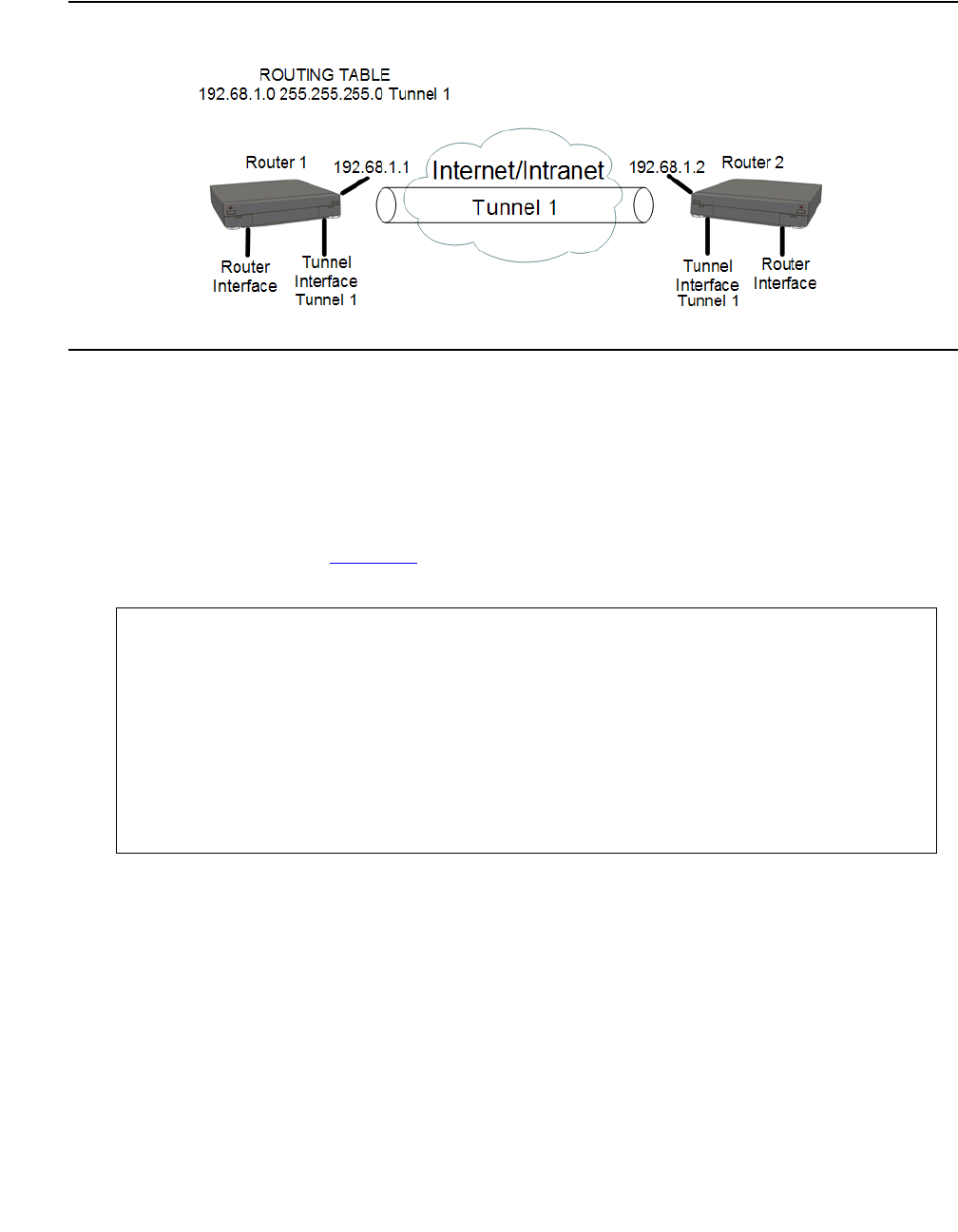
Configuring GRE tunneling
Issue 1 January 2008 459
Figure 39: Nested tunneling example
Recommendations on avoiding nested tunneling
●Announce policy. Configure a policy rule on the receiving tunnel endpoint (router 2) that
will cause the receiving endpoint to block advertisements of the source network
(192.68.1.0) in its routing updates. This will prevent the source endpoint (router 1) from
learning the route. This solution is for nested tunneling caused by RIP. For example, using
the network shown in Figure 39 as an illustration, you would configure the following policy
rule on router 2 and activate it on the router RIP with the matching interface:
G450-001(super)# ip distribution access-list-name 1 "list #1"
Done!
G450-001(super)# ip distribution access-default-action 1 default-action-permit
Done!
G450-001(super)# ip distribution access-list 1 10 "deny" 192.68.1.0 0.0.0.255
Done!
G450-001(super)# router rip
G450-001(super router:rip)# distribution-list 1 out FastEthernet 10/2
Done!
G450-001(super router:rip)# exit
G450-001(super)#

Configuring the router
460 Administration for the Avaya G450 Media Gateway
●Accept policy. Configure a policy rule on the source tunnel endpoint (router 1) that will
cause the source endpoint to not accept routing updates that include the source network
(192.68.1.0). This solution is for nested tunneling caused by RIP. For example, using the
network shown in Figure 39 as an illustration, you would configure the following policy rule
on router 1 and activate it on the router RIP with the matching interface:
●Static route. Configure a static rule on router 1 telling it the route for packets destined to
the tunnel’s receiving endpoint (192.68.1.2). This route should be configured with a high
route preference. For example:
Optional GRE tunnel features
You can configure optional features in GRE tunnels. The tunnel keepalive feature enables
periodic checking to determine if the tunnel is up or down. The dynamic MTU discovery feature
determines and updates the lowest MTU on the current route through the tunnel.
Keepalive
The tunnel keepalive feature sends keepalive packets through the Tunnel interface to determine
whether the tunnel is up or down. This feature enables the tunnel’s source interface to inform
the host if the tunnel is down. When the tunnel keepalive feature is not active, if the tunnel is
down, the tunnel’s local endpoint continues to attempt to send packets over the tunnel without
informing the host that the packets are failing to reach their destination.
Use the keepalive command in the GRE Tunnel interface context to enable the tunnel
keepalive feature. Use the no form of this command to deactivate the feature.
The keepalive command includes the following parameters:
●seconds. The length, in seconds, of the interval at which the source interface sends
keepalive packets. The default value is 10.
G450-001(super)# ip distribution access-list-name 1 "list #1"
Done!
G450-001(super)# ip distribution access-default-action 1 default-action-permit
Done!
G450-001(super)# ip distribution access-list 1 10 "deny" 192.68.1.0 0.0.0.255
Done!
G450-001(super)# router rip
G450-001(super router:rip)# distribution-list 1 in FastEthernet 10/2
Done!
G450-001(super router:rip)# exit
G450-001(super)#
G450-001(super)# ip route 192.68.1.2 255.255.0.0 192.68.1.3 high permanent
Done!
G450-001(super)#

Configuring GRE tunneling
Issue 1 January 2008 461
●retries. The number of retries after which the source interface declares that the tunnel is
down. The default value is 3.
The following example configures Tunnel 1 to send keepalive packets every 20 seconds. If the
tunnel’s destination interface fails to respond to three consecutive packets, the tunnel’s source
interface concludes that the tunnel is down. The source interface continues to send keepalive
packets, but until it receives a response from the tunnel’s destination interface, the tunnel
informs hosts that send packets to the tunnel that the tunnel is down.
Note:
Note: You do not have to configure tunnel keepalive on both sides of the tunnel.
Dynamic MTU discovery
The size of packets that can travel through a GRE tunnel is limited by the lowest MTU of any
router along the route through the tunnel. When dynamic MTU discovery is enabled, the tunnel
maintains an MTU limit.
When a large packet is sent from the host with the DF bit on, and a router in the tunnel path has
an MTU that is smaller than the size of the packet, since the DF bit is set, the router sends an
ICMP unreachable message back in the originator (in this case, the GRE router). The GRE
router then updates the tunnel’s MTU limit accordingly. When a packet larger than the MTU
arrives at the tunnel, if the packet is marked do not fragment, the tunnel’s source interface
sends the packet back to the host requesting the host to fragment the packet. When dynamic
MTU discovery is disabled, the tunnel’s source interface marks each packet as may be
fragmented, even if the packet’s original setting is do not fragment. For more information on
MTU and fragmentation, refer to Configuring fragmentation on page 502.
Use the tunnel path-mtu-discovery command in the GRE Tunnel interface context to
enable dynamic MTU discovery by the tunnel. Use the no form of this command to deactivate
the feature.
The tunnel path-mtu-discovery command includes the following parameters:
●age-timer. How long until the local tunnel endpoint returns the tunnel MTU to its default.
The default value of this parameter is 10 minutes.
●infinite. The tunnel does not update the MTU, and its value remains permanent
G450-001# interface tunnel 1
G450-001(if:Tunnel 1)# keepalive 20 3
Done!

Configuring the router
462 Administration for the Avaya G450 Media Gateway
Setting up a GRE tunnel
1. Enter interface tunnel, followed by a number identifying the tunnel, to create the new
Tunnel interface. If you are changing the parameters of an existing tunnel, enter
interface tunnel, followed by a number identifying the tunnel, to enter the Tunnel
context. For example:
2. In the Tunnel interface context, enter tunnel source, followed by the public IP address
of the local tunnel endpoint, to set the source address of the tunnel. For example:
3. In the Tunnel interface context, enter tunnel destination, followed by the IP
address of the remote tunnel endpoint, to set the destination address of the tunnel. For
example:
Note:
Note: The Avaya G450 Media Gateway does not check whether the configured tunnel
source IP address is an existing IP address registered with the G450 router.
4. In most cases, it is recommended to configure keepalive in the tunnel so that the tunnel’s
source interface can determine and inform the host if the tunnel is down. For more
information on keepalive, see Keepalive on page 460.
To configure keepalive for a Tunnel interface, enter keepalive in the Tunnel interface
context, followed by the length (in seconds) of the interval at which the source interface
sends keepalive packets, and the number of retries necessary in order to declare the
tunnel down.
The following example configures the tunnel to send a keepalive packet every 20 seconds,
and to declare the tunnel down if the source interface sends three consecutive keepalive
packets without a response.
G450-001(super)# interface tunnel 2
G450-001(super-if:Tunnel 2)#
G450-001(super-if:Tunnel 2)# tunnel source 70.70.70.2
Done!
G450-001(super-if:Tunnel 2)#
G450-001(super-if:Tunnel 2)# tunnel destination 20.0.1.1
Done!
G450-001(super-if:Tunnel 2)#
G450-001(super-if:Tunnel 2)# keepalive 20 3
Done!
G450-001(super-if:Tunnel 2)#

Configuring GRE tunneling
Issue 1 January 2008 463
5. In most cases, it is recommended to configure dynamic MTU discovery in the tunnel. This
prevents fragmentation of packets larger than the tunnel’s MTU. When dynamic MTU
discovery is not enabled, the tunnel fragments packets larger than the tunnel’s MTU, even
when the packet is marked do not fragment. For more information on dynamic MTU
discovery, see Dynamic MTU discovery on page 461.
The following example configures dynamic MTU discovery, with an age timer of 15
minutes.
6. Enter copy running-config startup-config. This saves the new Tunnel interface
configuration in the startup configuration file.
For a list of optional GRE tunnel features, refer to Optional GRE tunnel features on page 460.
For a list of additional GRE tunnel CLI commands, refer to Additional GRE tunnel
parameters on page 463.
Additional GRE tunnel parameters
Use the following commands to configure additional GRE tunnel parameters. For more
information about these commands, see Avaya G450 CLI Reference, 03-300437.
●Use the tunnel checksum command in the GRE Tunnel interface context to add a
checksum to the GRE header of packets traveling through the tunnel. When a checksum is
included on one endpoint, the receiving tunnel endpoint performs checksum validation on
incoming packets and packets without a valid checksum are discarded. Use the no form of
this command to disable checksums.
●Use the tunnel key command in the GRE Tunnel interface context to enable and set an
ID key for the tunnel. Tunnel ID keys are used as a security device. The key must be set to
the same value on the tunnel endpoints. Packets without the configured key must be
discarded. Use the no form of this command to disable key checking.
●Use the tunnel dscp command in the GRE Tunnel interface context to assign a DSCP
value to packets traveling through the tunnel. The DSCP value is placed in the packet’s
Carrier IP header. You can assign a DSCP value of from 0 to 63. If you do not assign a
DSCP value, the DSCP value is copied from the packet’s original IP header.
Note:
Note: The Carrier IP header identifies the source and destination IP address of the
tunnel.
G450-001(super-if:Tunnel 2)# tunnel path-mtu-discovery age-timer 15
Done!
G450-001(super-if:Tunnel 2)#
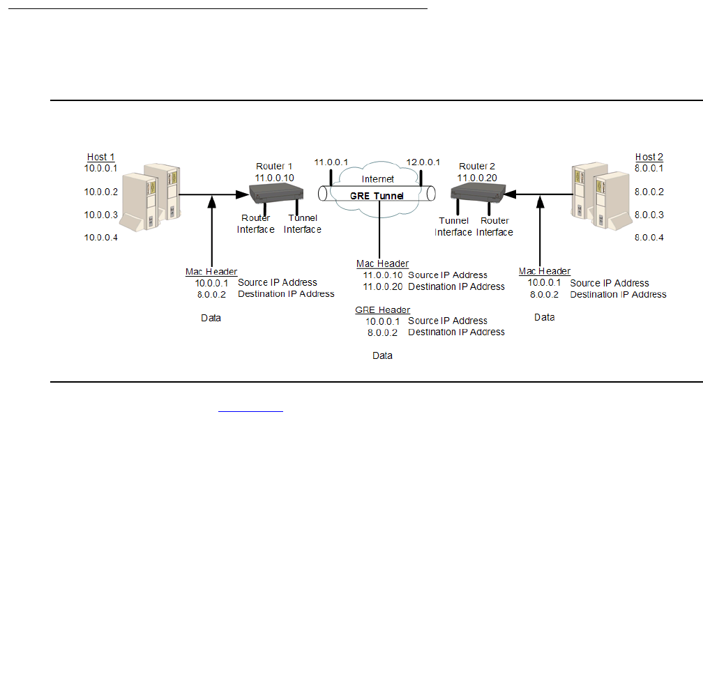
Configuring the router
464 Administration for the Avaya G450 Media Gateway
●Use the tunnel ttl command in the GRE Tunnel interface context to assign a TTL
value to packets traveling through the tunnel. The TTL value is placed in the packet’s
Carrier IP header. You can assign a TTL value of from 1 to 255. The default tunnel TTL
value is 255.
●Enter show interfaces tunnel to show interface configuration and statistics for a
particular tunnel or all GRE tunnels.
Note:
Note: If the Tunnel interface is down, the show interfaces tunnel command
displays the MTU value as not available.
GRE tunnel application example
This section provides an example of a GRE tunnel application and its configuration.
Figure 40: Simple GRE tunneling application example
In the example shown in Figure 40, Host 1 and Host 2 are private networks using a GRE tunnel
to connect them via the Internet. 11.0.0.10 are public IP addresses used by the GRE tunnel for
the tunnel encapsulation.
A packet originating from 10.0.0.1 on Host 1 is sent to the destination 8.0.0.2 on Host 2. Since
the destination IP address is a private IP address, the packet cannot be routed as is over the
Internet. Instead, Router 1 receives the packet from host 1, looks up the packet’s destination
address in its routing table, and determines that the next hop to the destination address is the
remote end of the GRE tunnel.

Configuring GRE tunneling
Issue 1 January 2008 465
Router 1 encapsulates the packet with a GRE header and a new IP header that assigns the IP
address of Router 2 (12.0.0.20) as the destination IP address and the IP address of Router 1
(11.0.0.10) as the source IP address. When the packet arrives at Router 2, which is the end
point of the GRE tunnel, Router 2 removes the outer IP header and the GRE header and sends
the packet to its original destination at IP address (8.0.0.2).
You can use the following commands to configure GRE tunneling (with OSPF) in this example:
Router 1 Configuration
Router 2 Configuration
G450-001(super)# interface fastethernet 10/2
G450-001(super-if:FastEthernet 10/2)# ip address 11.0.0.10 255.255.255.0
G450-001(super-if:FastEthernet 10/2)# exit
G450-001(super)# interface tunnel 1
G450-001(super-if:Tunnel 1)# keepalive 10 3
Done!
G450-001(super-if:Tunnel 1)# tunnel source 11.0.0.10
Done!
G450-001(super-if:Tunnel 1)# tunnel destination 12.0.0.20
Done!
G450-001(super-if:Tunnel 1)# ip address 1.1.1.1 255.255.255.0
Done!
G450-001(super-if:Tunnel 1)# exit
G450-001(super)# ip route 12.0.0.0 255.255.255.0 11.0.0.1 1 high
G450-001(super)# router ospf
G450-001(super router:ospf)# network 1.1.1.0 0.0.0.255 area 0.0.0.0
Done!
G450-001(super router:ospf)# exit
G450-001(super)#
G450-001(super)# interface vlan 1
G450-001(super-if:Vlan 1)# ip address 12.0.0.10 255.255.255.0
G450-001(super-if:Vlan 1)# exit
G450-001(super)# interface tunnel 1
G450-001(super-if:Tunnel 1)# tunnel source 12.0.0.20
Done!
G450-001(super-if:Tunnel 1)# tunnel destination 11.0.0.10
Done!
G450-001(super-if:Tunnel 1)# ip address 1.1.1.2 255.255.255.0
G450-001(super-if:Tunnel 1)# exit
G450-001(super)# ip route 11.0.0.0 255.255.255.0 12.0.0.1 1 high
G450-001(super)# router ospf
G450-001(super router:ospf)# network 1.1.1.0 0.0.0.255 area 0.0.0.0
Done!
G450-001(super router:ospf)# exit
G450-001(super)#

Configuring the router
466 Administration for the Avaya G450 Media Gateway
Summary of GRE tunneling commands
For more information about these commands, see Avaya G450 CLI Reference, 03-300437.
Table 115: GRE tunneling CLI commands
Root level
command Command Description
interface
tunnel Enter tunnel interface configuration context,
create a Tunnel interface if it does not exist, or
delete a Tunnel interface or sub-interface
keepalive Enable the tunnel keepalive feature
tunnel
checksum Add a checksum to the GRE header of packets
traveling through the tunnel
tunnel
destination Set the destination address of the tunnel
tunnel dscp Assign a DSCP value to packets traveling
through the tunnel
tunnel key Enable and set an ID key for the tunnel
tunnel path-
mtu-discovery Enable dynamic MTU discovery by the tunnel
tunnel source Set the source address of the tunnel
tunnel ttl Assign a TTL value to packets traveling
through the tunnel
show
interfaces
tunnel
Show interface configuration and statistics for
a particular tunnel or all GRE tunnels

Configuring DHCP and BOOTP relay
Issue 1 January 2008 467
Configuring DHCP and BOOTP relay
You can configure the router to relay Dynamic Host Configuration Protocol (DHCP) and
BOOTstrap Protocol (BOOTP) client broadcasts to a server on a different segment of the
network. When you configure DHCP and BOOTP relay, you can control how the router relays
DHCP and BOOTP packets. The router also relays replies from the server back to the client.
The G450 can alternatively function as a DHCP server, providing DHCP service to local
devices. For information about configuring DHCP server on the G450, see Configuring DHCP
server on page 470. For information about configuring DHCP client on the G450, see
Configuring DHCP client on page 199.
DHCP
DHCP assigns dynamic IP addresses to devices on a network. With dynamic addressing, a
device can have a different IP address whenever the device connects to the network. In some
systems, the device’s IP address can even change while it is still connected. DHCP also
supports a mix of static and dynamic IP addresses.
Dynamic addressing simplifies network administration because the software keeps track of IP
addresses rather than requiring an administrator to manage the task. This means you can add a
new computer to a network without needing to manually assign a unique IP address. Many ISPs
use dynamic IP addressing for dial-up users. However, dynamic addressing may not be
desirable for a network server.
BOOTP
BOOTP is an Internet protocol that allows a diskless workstation to discover the following:
●Its own IP address
●The IP address of a BOOTP server on the network
●A file to be loaded into memory to boot the workstation
BOOTP allows the workstation to boot without requiring a hard disk or floppy disk drive. It is
used when the user or station location changes frequently. The protocol is defined by RFC 951.

Configuring the router
468 Administration for the Avaya G450 Media Gateway
DHCP/BOOTP relay
The Avaya G450 Media Gateway supports the DHCP/BOOTP relay agent function. This is an
application that accepts DHCP/BOOTP requests that are broadcast on one VLAN. The
application sends them to a DHCP/BOOTP server. That server connects to another VLAN or a
server that might be located across one or more routers that might otherwise not get the
broadcast request. The relay agent handles the DHCP/BOOTP replies as well. The relay agent
transmits the replies to the client directly or as broadcast, according to a flag in the reply
message.
Note:
Note: The same DHCP/BOOTP relay agent serves both the BOOTP and DHCP
protocols.
When there is more than one IP interface on a VLAN, the G450 chooses the lowest IP address
on this VLAN when relaying DHCP/BOOTP requests. The DHCP/BOOTP server then uses this
address to decide the network from which to allocate the address. When there are multiple
networks configured, the G450 performs a round-robin selection process.
When the DHCP/BOOTP server is configured to allocate addresses only from a single
subnetwork among the different subnetworks defined on the VLAN, you might need to configure
the G450 with the relay address on that subnet so the DHCP/BOOTP server can accept the
request.
DHCP/BOOTP Relay in G450 is configurable per VLAN and allows for two DHCP/BOOTP
servers to be specified. In this case, the G450 duplicates each request, and sends it to both
servers. This duplication provides redundancy and prevents the failure of a single server from
blocking hosts from loading. You can enable or disable DHCP/BOOTP Relay in the G450.

Configuring DHCP and BOOTP relay
Issue 1 January 2008 469
DHCP/BOOTP relay commands
Use the following commands to configure DHCP relay and BOOTP relay:
●Use the ip bootp-dhcp network command to select the network from which the
BOOTP/DHCP server should allocate an address. This command is required only when
there are multiple IP interfaces over the VLAN. Use the no form of this command to
restore the default value. You must be in an interface context to use this command.
●Enter ip bootp-dhcp relay to enable relaying of BOOTP and DHCP requests to the
BOOTP/DHCP server. Use the no form of this command to disable relaying of BOOTP
and DHCP requests. You must be in general context to use this command.
●Use the ip bootp-dhcp server command to add a BOOTP/DHCP server to handle
BOOTP/DHCP requests received by this interface. A maximum of two servers can be
added to a single interface. Use the no form of this command to remove a server. You
must be in an interface context to use this command.
Summary of DHCP and BOOTP relay commands
For more information about these commands, see Avaya G450 CLI Reference, 03-300437.
Table 116: DHCP and BOOTP relay CLI commands
Root level
command Command Description
interface
(fastethernet|
VLAN)
Enter the FastEthernet or VLAN interface
configuration context
ip bootp-dhcp
network Select the network from which the
BOOTP/DHCP server should allocate an
address
ip bootp-dhcp
server Add or remove a BOOTP/DHCP server to
handle BOOTP/DHCP requests received by
the current interface
ip bootp-dhcp
relay Enable or disable relaying of BOOTP and
DHCP requests to the BOOTP/DHCP server

Configuring the router
470 Administration for the Avaya G450 Media Gateway
Configuring DHCP server
The G450 supports DHCP server. DHCP server is a protocol for automatically assigning IP
addresses and other configuration parameters to clients on a TCP/IP network. DHCP server
minimizes the maintenance of a network of, among other things, IP telephones and PCs, by
removing the need to assign and maintain IP addresses and other parameters for each device
on the network individually.
Since a DHCP server can be configured on the G450, local branch devices are not dependant
on receiving configuration parameters over the WAN from a remote DHCP server and,
therefore, can be assigned IP configuration parameters in case of WAN failure.
The G450 supports the following DHCP server features:
●Up to 32 DHCP pools
●Up to 120 users
●Up to 256 IP addresses for all DHCP pools together
●Automatic and reservation pools
●Standard DHCP options and IP phone and wireless special options
●Vendor specific information option
●DHCP relay packets
●Global statistics
●Syslog/traps for special events
The Avaya G450 Media Gateway can function as a DHCP server, as a DHCP relay, or both
simultaneously, with each interface configured in either DHCP server mode or DHCP relay
mode. For example, you can configure the G450 to provide DHCP service to voice devices
while DHCP requests by data devices are routed to a central remote DHCP server using DHCP
relay.
The Avaya G450 Media Gateway can function as a DHCP server or as a DHCP client, or both
simultaneously. For information about configuring DHCP client on the G450, see Configuring
DHCP client on page 199.
Configuring DHCP server
Issue 1 January 2008 471
Typical DHCP server application
In the typical application shown in Figure 41, the G450 is configured as a local DHCP server
and router for IP phones and PCs in the branch office. The remote DHCP server allocates IP
addresses for headquarters users. In case of WAN failure, the local DHCP server can still
allocate IP addresses in the branch offices. If there is a local ICC or LSP, calls can still be made.
If there is no ICC or LSP to control calls, the DHCP server can allocate IP addresses to all
devices, but, since no calls can be made, the IP address allocation effectively applies to PCs
only.
Figure 41: G450 as server and router
The branch DHCP server does not depend on the headquarters’ DHCP server. There is no
backup mechanism between the servers. The branch DHCP server operates continually
regardless of the status of the centralized DHCP server or the WAN link.
By default, the DHCP server is inactive. Before activating DHCP server, you configure DHCP
pools to define ranges of IP addresses and other network configuration information to be
assigned to clients. Create a minimum of two dynamic pools: at least one pool for data devices
(PCs) and at least one pool for voice devices (IP phones). The G450 also supports reservation
pools, which map hardware addresses/client identifiers to specific IP addresses. Reservation
pools may be required for security issues or VPN appliances.
Overlap between pools is not allowed. You cannot configure a reservation pool on an
IP address that falls within the range of another pool.

Configuring the router
472 Administration for the Avaya G450 Media Gateway
DHCP server CLI configuration
1. Enter ip dhcp pool, followed by a number from 1 to 32, to create a DHCP pool.
2. Use the name command to configure the pool’s name.
3. Configure a range of available IP addresses that the DHCP server may assign to clients,
using start-ip-addr to set the start IP address of the range and end-ip-addr to set
the end IP address of the range. Consider the following:
●For a manual/reservation pool, set identical IP addresses for the start and end IP
addresses
●The start IP address and end IP address must be on the same network according to
the subnet mask
●The start IP address must be lower than the end IP address
●The combined number of IP addresses in all pools must not exceed 256 addresses
●Both the start IP address and end IP address can be up to 223.255.255.255
●The start IP address and end IP address may not be network/broadcast addresses
according to the subnet mask
4. Use the subnet-mask command to configure the subnet mask of the pool.
5. Use the lease command to configure the lease period for IP address assignment. By
default, the lease is eight days.
6. For a manual/reservation pool, use the client identifier command to reserve the
pool’s IP address for assignment to a specific client. To configure a reservation, the start IP
address and end IP address must be identical. You cannot configure more than one
reservation on a single pool.
7. Configure DHCP options for the pool, if required. See Configuring Options on page 473
and, for vendor specific options, Configuring vendor-specific options on page 474.
8. Repeat steps 1-7 to configure as many DHCP pools as you require. You can configure up
to 32 DHCP pools. By default, all pools are inactive until you activate them. This enables
you to modify each pool’s configuration without affecting network devices.
9. Activate each of the DHCP pools you configured using the ip dhcp activate pool
command in general context, followed by the pool number.
10. Enter ip dhcp-server to activate DHCP server. DHCP server is now active. If you
change the pool configuration, it is recommended to do so while the pool is active.
Note:
Note: If you try to configure a new start and end IP address which is not part of the
current network and beyond the allowed maximum of 256 IP addresses, you must
first use the no start ip address and no end ip address commands
before configuring the new start and end IP addresses.

Configuring DHCP server
Issue 1 January 2008 473
Configuring Options
DHCP options are various types of network configuration information that the DHCP client can
receive from the DHCP server. The G450 supports all DHCP options. The most common
options used for IP phones are listed in Table 117. Some options are configured with specific
CLI commands, which are also listed in Table 117. Options 0, 50, 51, 52, 53, 54, 55, 56, and
255 are not configurable.
1. Use the option command to specify the option code and enter the context for the option.
Note:
Note: To configure an option that is listed in Table 117 with an entry in the Specific
command column, use the specific command instead of the option command.
2. Use the name command to set the name of the DHCP option (optional).
3. Use the value command to enter the option data type and the option data.
Table 117: Common user-configurable DHCP options
Option Description Specific command
1 Subnet Mask subnet-mask
3Router default-router
6 Domain name server dns_server
7Log Server
15 Domain Name domain-name
43 vendor-specific information vendor-specific-option
44 Wins/NBNS server
46 Wins/NBT Node Type
51 IP Address Lease Time lease
66 TFTP server name
69 SMTP server
176 Avaya IP phone private

Configuring the router
474 Administration for the Avaya G450 Media Gateway
Configuring vendor-specific options
You can configure an option unique to an individual vendor class. This is called a
vendor-specific option (option 43).
1. Use the vendor-specific-option command to create a vendor-specific option with a
unique index.
2. Use the name command to name the option (optional).
3. Use the class-identifier command to set a vendor-specific identifier.
4. Use the value command to set the data type and value of the vendor-specific option.
Optional DHCP server CLI commands
The following DHCP server commands are also available:
●Use the clear ip dhcp-server binding command to delete the allocation of a
specific IP address or of all IP addresses. When the DHCP server detects an IP address
conflict after attempting to allocate an IP address that is already in use, the server locks
the IP address for half an hour by marking the IP address with client identifier
00:00:00:00:00:00:00. If you have solved the conflict before half an hour, you can use this
command to free the IP address for reallocation.
●Use the clear ip dhcp-server statistics command to clear the statistics of the
DHCP server.
●Use the ip dhcp ping packets command to enable the sending of a ping packet by
the DHCP server to check if the IP address it is about to allocate is already in use by
another client.
●Use the ip dhcp ping timeout command to set the ping timeout for the DHCP server.
●Use the bootfile command to specify the file name for a DHCP client to use as a boot
file. This is DHCP option 67.
●Use the next-server command to specify the IP address of the next server in the boot
process of a DHCP client.
●Use the server-name command to specify the optional server name in the boot process
of a DHCP client.

Configuring DHCP server
Issue 1 January 2008 475
DHCP pool configuration examples
The following example defines a dynamic pool for voice devices:
G450-001(super)# ip dhcp pool 1
G450-001(super-DHCP 1)# name "IP phone Pool"
Done!
G450-001(super-DHCP 1)# start-ip-addr 135.64.20.2
Done!
G450-001(super-DHCP 1)# end-ip-addr 135.64.20.30
Done!
G450-001(super-DHCP 1)# subnet-mask 255.255.255.0
Done!
G450-001(super-DHCP 1)# default-router 135.64.20.1
Done!
G450-001(super-DHCP 1)# option 176
G450-001(super-DHCP 1/option 176)# name "Avaya IP phone option"
Done!
G450-001(super-DHCP 1/option 176)# value ascii "MCIPADD=10.10.2.140,
MCPORT=1719, TFTPSRVR=10.10.5.188"
Done!
G450-001(super-DHCP 1/option 176)# exit
G450-001(super-DHCP 1)# exit
G450-001(super)# ip dhcp activate pool 1
Done!
G450-001(super)# ip dhcp-server
Done!
G450-001(super)#

Configuring the router
476 Administration for the Avaya G450 Media Gateway
The following example defines a dynamic pool for data devices:
The following example configures a vendor-specific option for DHCP pool 5:
G450-001(super)# ip dhcp pool 2
G450-001(super-DHCP 2)# name "Data Pool"
Done!
G450-001(super-DHCP 2)# start-ip-addr 135.64.20.34
Done!
G450-001(super-DHCP 2)# end-ip-addr 135.64.20.60
Done!
G450-001(super-DHCP 2)# subnet-mask 255.255.255.0
Done!
G450-001(super-DHCP 2)# default-router 135.64.20.33
Done!
G450-001(super-DHCP 2)# dns-server 10.10.1.1
Done!
G450-001(super-DHCP 2)# domain-name my.domain.com
Done!
G450-001(super-DHCP 2)# option 176
G450-001(super-DHCP 2/option 176)# value ascii "MCIPADD=192.168.50.17,
192.168.50.15, MCPORT=1719, TFTPSRVR=192.168.50.1, TFTPDIR=/phonedir/"
Done!
G450-001(super-DHCP 2/option 176)# exit
G450-001(super-DHCP 2)# exit
G450-001(super)# ip dhcp activate pool 2
Done!
G450-001(super)# ip dhcp-server
Done!
G450-001(super)#
G450-001(super-DHCP 5)# vendor-specific-option 1
G450-001(super-DHCP 5/vendor specific 1)# class-identifier
"ccp.avaya.com"
Done!
G450-001(super-DHCP 5/vendor specific 1)# value raw ascii "gfdgfd"
Done!
G450-001(super-DHCP 5/vendor specific 1)# exit
G450-001(super-DHCP 5)#

Configuring DHCP server
Issue 1 January 2008 477
The following example defines a reservation pool for data devices:
Displaying DHCP server information
You can use the following show commands to display DHCP server information:
●Use the show ip dhcp-pool command to display DHCP pool configurations.
●Use the show ip dhcp-server bindings command to display the current allocations
of IP addresses to DHCP clients.
●Use the show ip dhcp-server statistics command to display DHCP server
statistics.
G450-001(super)# ip dhcp pool 3
G450-001(super-DHCP 3)# name "Data 1 Server"
Done!
G450-001(super-DHCP 3)# start-ip-addr 135.64.20.61
Done!
G450-001(super-DHCP 3)# end-ip-addr 135.64.20.61
Done!
G450-001(super-DHCP 3)# subnet-mask 27
Done!
G450-001(super-DHCP 3)# client identifier 01:11:22:33:44:55:66
Done!
G450-001(super-DHCP 3)# default-router 135.64.20.33
Done!
G450-001(super-DHCP 3)# dns-server 10.10.1.1
Done!
G450-001(super-DHCP 3)# exit
G450-001(super)# ip dhcp activate pool 3
Done!
G450-001(super)#
Configuring the router
478 Administration for the Avaya G450 Media Gateway
Summary of DHCP Server commands
For more information about these commands, see Avaya G450 CLI Reference, 03-300437.
Table 118: DHCP server CLI commands
Root level
command First level
command Second level
command Description
clear ip
dhcp-server
binding
Delete IP address binding
clear ip
dhcp-server
statistics
Clear the statistics of the DHCP
server
ip dhcp
activate pool Activate configured DHCP pools
ip dhcp ping
packets Enable the sending of a ping
packet by the DHCP server to
check if the IP address it is about
to allocate is already in use by
another client
ip dhcp ping
timeout Set the time the DHCP server
waits for a reply to a sent ping
packet before allocating an IP
address to a DHCP client
ip dhcp pool Create a DHCP pool
bootfile Provide startup parameters for
the DHCP client device
client-
identifier Reserve the pool’s IP address for
assignment to a specific client
default-
router Set up to eight default router IP
addresses in order of preference
dns-server Set up to eight Domain Name
Server (DNS) IP addresses
domain-name Set a domain name string for the
client
1 of 3

Configuring DHCP server
Issue 1 January 2008 479
end-ip-addr Set the end IP address of the
range of available IP addresses
that the DHCP server may assign
to clients
lease Configure the lease period for IP
address assignment
name Configure the pool’s name
next-server Specify the IP address of the
next server in the boot process of
a DHCP client
option Enter the context of a DHCP
option
name Configure a name for the DHCP
option
value Enter the option data type and
the option data
server-name Specify the optional server name
in the boot process of a DHCP
client
show ip
dhcp-pool Display DHCP pool
configurations
start-ip-addr Set the start IP address of the
range of available IP addresses
that the DHCP server may assign
to clients
subnet-mask Configure the subnet mask of the
pool
vendor-
specific-
option
Create a vendor-specific option
with a unique index
name Name the vendor-specific option
class-identifier Set a vendor-specific identifier
value Set the data type and value of
the vendor-specific option
Table 118: DHCP server CLI commands (continued)
Root level
command First level
command Second level
command Description
2 of 3

Configuring the router
480 Administration for the Avaya G450 Media Gateway
Configuring broadcast relay
When you configure broadcast relay, the router forwards broadcast packets across interfaces.
You can configure broadcast relay types including directed broadcast forwarding, NetBIOS
rebroadcast, and DHCP and BOOTP client broadcast.
For more information about DHCP and BOOTP client broadcast, see Configuring DHCP and
BOOTP relay on page 467.
Directed broadcast forwarding
A directed broadcast is an IP packet whose destination address is the broadcast address of a
network or subnet. A directed broadcast causes every host on the network to respond. You can
use directed broadcasts to obtain a list of all active hosts on the network. A hostile user can
exploit directed broadcasts to launch a denial-of-service attack on the network. For each
interface on the Avaya G450 Media Gateway, you can configure whether the G450 forwards
directed broadcast packets to the network address or subnet mask address of the interface.
Enter ip directed-broadcast to enable directed broadcast forwarding on an interface. Use
the no form of this command to disable directed broadcast forwarding on an interface.
ip dhcp-server Activate DHCP server
show ip
dhcp-server
bindings
Display bindings
show ip
dhcp-server
statistics
Display DHCP server statistic
Table 118: DHCP server CLI commands (continued)
Root level
command First level
command Second level
command Description
3 of 3

Configuring broadcast relay
Issue 1 January 2008 481
NetBIOS rebroadcast
Network Basic Input Output System (NetBIOS) is a protocol for sharing resources among
desktop computers on a LAN. You can configure the Avaya G450 Media Gateway to relay
NetBIOS UDP broadcast packets. This feature is used for applications such as WINS that use
broadcast but might need to communicate with stations on other subnetworks or VLANs.
Configuration is performed on a per-interface basis. A NetBIOS broadcast packet arrives from
an interface on which NetBIOS rebroadcast is enabled. The packet is distributed to all other
interfaces configured to rebroadcast NetBIOS.
If the NetBIOS packet is a net-directed broadcast, for example, 149.49.255.255, the packet is
relayed to all other interfaces on the list, and the IP destination of the packet is replaced by the
appropriate interface broadcast address.
If the NetBIOS broadcast packet is a limited broadcast, for example, 255.255.255.255, it is
relayed to all VLANs on which there are NetBIOS-enabled interfaces. In that case, the
destination IP address remains the limited broadcast address.
Enter ip netbios-rebroadcast both to enable NetBIOS rebroadcasts on an interface.
Enter ip netbios-rebroadcast disable to disable NetBIOS rebroadcasts on an
interface.
Summary of broadcast relay commands
For more information about these commands, see Avaya G450 CLI Reference, 03-300437.
Table 119: Broadcast relay CLI commands
Root level command Command Description
interface
(dialer|
fastethernet|
serial|tunnel|
vlan)
Enter the Dialer, FastEthernet, Serial,
Tunnel, or VLAN interface context
ip
directed-broadcast Enable or disable directed broadcast forwarding
on the interface
ip
netbios-rebroadcast Enable or disable NetBIOS rebroadcasts on the
interface

Configuring the router
482 Administration for the Avaya G450 Media Gateway
Configuring the ARP table
When you configure the Address Resolution Protocol (ARP) table, you can:
●View information about the ARP table
●Add entries to the ARP table
●Delete entries from the ARP table
●Configure the ARP timeout
Note:
Note: To change an entry in the ARP table, delete the entry and reinsert it with revised
parameters.
Overview of ARP
IP logical network addresses are independent of physical addresses. The physical address
must be used to convey data in the form of a frame from one device to another. Therefore, a
mechanism is required to acquire a destination device hardware address from its IP address.
This mechanism is called ARP.
The ARP table
The ARP table stores pairs of IP and MAC addresses. This storage saves time and
communication costs, since the host looks in the ARP table first when transmitting a packet. If
the information is not there, then the host sends an ARP Request.
There are two types of entries in the ARP table:
●Static ARP table entries
●Dynamic ARP table entries
Static ARP table entries do not expire. You add static ARP table entries manually using the arp
command. For example, to add a static ARP table entry for station 192.168.7.8 with MAC
address 00:40:0d:8c:2a:01, use the following command:
G450-001# arp 192.168.7.8 00:40:0d:8c:2a:01
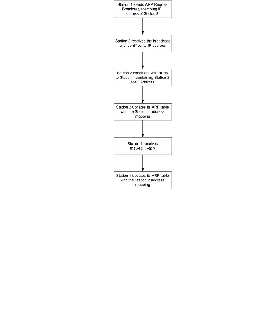
Configuring the ARP table
Issue 1 January 2008 483
Dynamic ARP table entries are mappings between IP addresses and MAC addresses that the
switch used recently. Dynamic ARP table entries expire after a configurable amount of time. The
following diagram shows how a switch adds dynamic ARP table entries:
Use the no arp command to remove static and dynamic entries from the ARP table. For
example, to remove the ARP table entry for the station 192.168.13.76:
G450-001# no arp 192.168.13.76

Configuring the router
484 Administration for the Avaya G450 Media Gateway
ARP table commands
Use the following commands to configure the ARP table. For more information about these
commands, see Avaya G450 CLI Reference, 03-300437.
●Use the arp command to add a permanent entry to the ARP table. Use the no form of this
command to remove either a static entry or a dynamically learned entry from the ARP
table.
●Use the arp timeout command to configure the amount of time, in seconds, that an
entry remains in the ARP table. Entering the arp timeout command without a time
parameter will display the current timeout value. Use the no form of this command to
restore the default value (four hours).
●Use the clear arp-cache command to delete all dynamic entries from the ARP table
and the IP route cache.
●Use the ip max-arp-entries command to specify the maximum number of ARP table
entries allowed in the ARP table. Use the no form of this command to restore the default
value.
●Use the show ip arp command to display a list of the ARP resolved MAC to IP
addresses in the ARP table.
●Use the show ip reverse-arp command to display the IP address of a host, based on
a known MAC address.
Summary of ARP table commands
For more information about these commands, see Avaya G450 CLI Reference, 03-300437.
Table 120: ARP table CLI commands
Command Description
arp Add a permanent entry to the ARP table
arp timeout Configure the amount of time, in seconds, that an entry remains in the
ARP table
clear arp-cache Delete all dynamic entries from the ARP table and the IP route cache
ip
max-arp-entries Specify the maximum number of ARP table entries allowed in the ARP
table
1 of 2

Enabling proxy ARP
Issue 1 January 2008 485
Enabling proxy ARP
The G450 supports proxy ARP. Proxy ARP is a technique by which a router provides a false
identity when answering ARP requests intended for another device. By falsifying its identify, the
router accepts responsibility for routing packets to their true destination.
Proxy ARP can help devices on a subnet to reach remote subnets without the need to configure
routing or a default gateway.
To enable proxy ARP on a G450 interface, enter ip proxy-arp. Use the no form of this
command to disable proxy ARP on an interface.
Summary of Proxy ARP commands
For more information about these commands, see Avaya G450 CLI Reference, 03-300437.
show ip arp Display a list of the ARP resolved MAC to IP addresses in the ARP
table
show ip
reverse-arp Display the IP address of a host, based on a known MAC address
Table 120: ARP table CLI commands (continued)
Command Description
2 of 2
Table 121: Proxy ARP CLI commands
Root level
command Command Description
interface
(fastethernet|
vlan)
Enter the FastEthernet or VLAN interface
context
ip proxy-arp Enable proxy ARP on a G450 interface

Configuring the router
486 Administration for the Avaya G450 Media Gateway
Configuring ICMP errors
You can control whether the router sends Internet Control Message Protocol (ICMP) error
messages. The router sends an ICMP error message to the source of a packet if the router
rejects the packet. Use the following commands to configure ICMP errors:
●Enter ip icmp-errors to set ICMP error messages to on. Use the no form of this
command to set ICMP error messages to off.
●Enter show ip icmp to display the status (enabled or disabled) of ICMP error messages.
Summary of ICMP errors commands
For more information about these commands, see Avaya G450 CLI Reference, 03-300437.
Configuring RIP
The Routing Information Protocol (RIP) enables routers to compute the path that an IP packet
should follow. Routers exchange routing information using RIP to determine routes that other
routers are connected to. OSPF is a newer protocol that serves a similar purpose. For more
information about OSPF, see Configuring OSPF on page 492.
You can configure route redistribution between OSPF, RIP, and static routes. With route
redistribution, you can configure the G450 to redistribute routes learned from one protocol into
the domain of the other routing protocol. For more information, see Route redistribution on
page 497.
Table 122: ICMP errors CLI commands
Command Description
ip icmp-errors Set ICMP error messages to ON or OFF
show ip icmp Display the status (enabled or disabled) of ICMP error messages

Configuring RIP
Issue 1 January 2008 487
RIP is a distance vector protocol. The router decides which path to use on distance or the
number of intermediate hops. In order for this protocol to work correctly, all the routers, and
possibly the nodes, need to gather information on how to reach each destination in the Internet.
However the very simplicity of RIP has a disadvantage. This protocol does not take into account
network bandwidth, physical cost, and data priority. The Avaya G450 Media Gateway supports
two versions of RIP:
●RIPv1
●RIPv2
RIPv1
RIPv1 is the original version of the RIP protocol. The RIPv1 protocol imposes some limitations
on the network design with regard to subnetting. When operating RIPv1, you must not configure
variable length subnetwork masks (VLMS). Each IP network must have a single mask, implying
that all subnetworks in a given IP network are of the same size. Also, when operating RIPv1,
you must not configure supernets. RIPv1 is defined in RFC 1058.
RIPv2
RIPv2 is a newer version of the RIP routing protocol. RIPv2 solves some of the problems
associated with RIPv1. The most important change in RIPv2 is the addition of a subnetwork
mask field which allows RIPv2 to support variable length subnetworks. RIPv2 also includes an
authentication mechanism similar to the one used in OSPF. RIPv2 is defined in RFC 2453.
Table 123 summarizes the differences between RIPv1 and RIPv2.
Preventing routing loops in RIP
You can use the following features in RIP to help avoid routing loops:
●Split-horizon
●Poison-reverse
Table 123: RIPv1 vs. RIPv2
RIPv1 RIPv2
Broadcast addressing Multicast addressing
Timer-based – updated every 30 seconds Timer-based – updated every 30 seconds
Fixed subnetwork masks VLSM support – subnet information transmitted
No security Security (authentication)
No provision for external protocols Provision for EGP/BGP (Route tag)

Configuring the router
488 Administration for the Avaya G450 Media Gateway
The split-horizon technique prevents information about routes from exiting the router interface
through which the information was received. This prevents small routing loops. Enter
ip rip split-horizon to enable the split-horizon mechanism. Use the no form of this
command to disable the split-horizon mechanism. By default, split-horizon is enabled.
Poison-reverse updates explicitly indicate that a network or subnet is unreachable.
Poison-reverse updates are sent to defeat large routing loops. Enter ip rip
poison-reverse to enable split-horizon with poison-reverse on an interface. Use the no form
of this command to disable the poison-reverse mechanism.
RIP distribution access lists
RIP distribution access lists consist of rules that specify how a router distributes and accepts
RIP routing information from other routers. Before sending an update, the router consults an
access list to determine if it should include specific routes in the update. When receiving an
update, the router first checks a set of rules which apply to incoming updates to determine if it
should insert those routes into its routing table. You can assign the rules per interface and per
direction.
Up to 99 RIP distribution access lists can be configured on the Avaya G450 Media Gateway.
For example, to configure RIP distribution access list number 10 permitting distribution and
learning of network 10.10.0.0, do the following:
1. Enter the command: ip distribution access-list 10 1 permit 10.10.0.0
0.0.255.255
The default action of the access list is deny and can be changed using the
ip distribution access-default-action command.
Note:
Note: Whenever at least one permit rule exists, distributing and learning of all the
remaining networks is denied, unless specifically permitted by another rule.
2. Apply the distribution access list created in Step 1 by performing the following procedure
within the Router RIP context:
- Enter the distribution-list 10 in command to apply list number 10 created in
Step 1 on all updates received on all interfaces.
- Enter the distribution-list 10 in FastEthernet 10/2 command to apply
Access List 10 on updates received on interface ‘FastEthernet 10/2’.
- Enter the distribution-list 10 out command to apply Access List 10 to all
advertised updates.
- Enter the distribution-list 10 out ospf command to apply Access List 10 to
all advertised updates that were learned from OSPF (redistributed from OSPF into
RIP).

Configuring RIP
Issue 1 January 2008 489
If no distribution access list is defined, learning and advertising is allowed for all of the routing
information. This is the default.
RIP limitations
Configuration of RIPv1 and RIPv2 is per IP interface. Configuration must be homogeneous on
all routers on each subnetwork. That is, RIPv1 and RIPv2 routers should not be configured on
the same subnetwork. However, you can configure different IP interfaces of the G450 with
different RIP versions. This configuration is valid as long as all routers on the subnet are
configured with the same version.
RIPv2 and RIPv1 are considered the same protocol with regard to redistribution to and from
OSPF and static route preferences.
RIP commands
Use the following commands to configure RIP. For more information about these commands,
see Avaya G450 CLI Reference, 03-300437.
●Use the default-metric command to set the interface RIP route metric value. Use the
no form of this command to restore the default value.
●Use the distribution-list command to apply a distribution access list for incoming
or outgoing routing information in route updates. Use the no form of this command to
deactivate the list.
●Use the ip rip authentication key command to set the authentication string used
on the interface. Use the no form of this command to clear the password.
●Use the ip rip authentication mode command to specify the type of authentication
used in RIP v2 packets. Use the no form of this command to restore the default value,
none.
●Use the ip rip default-route-mode command to enable learning of the default
route received by the RIP protocol. The default state is talk-listen. Use the no form of this
command to disable listening to default routes.
●Enter ip rip poison-reverse to enable split-horizon with poison-reverse on an
interface. Use the no form of this command to disable the poison-reverse mechanism.
●Use the ip rip rip-version command to specify the RIP version running on the
interface.
●Use the ip rip send-receive-mode command to set the RIP send and receive
modes on an interface. Use the no form of this command to set the RIP to talk, that is, to
send reports.
Configuring the router
490 Administration for the Avaya G450 Media Gateway
●Enter ip rip split-horizon to enable the split-horizon mechanism. Use the no form
of this command to disable the split-horizon mechanism. By default split-horizon is
enabled.
●Use the network command to specify a list of networks on which the RIP is running. Use
the no form of this command to remove an entry from the list of networks.
●Use the redistribute command to redistribute routing information from other protocols
into RIP. Use the no form of this command to restore the default value, disable
redistribution by RIP.
●Enter router rip to enable RIP and to enter the router configuration context. Use the no
form of this command to restore the default value, disabling RIP.
●Use the timers basic command to set RIP timers. Use the no form of this command to
set the RIP timers to their default values.
Summary of RIP commands
For more information about these commands, see Avaya G450 CLI Reference, 03-300437.
Table 124: RIP CLI commands
Root level command Command Description
ip distribution
access-default-action Set the default action for a specific
RIP distribution access list
ip distribution
access-list Create a RIP distribution access list
ip distribution
access-list-cookie Set the access list cookie
ip distribution
access-list-copy Copy the distribution access list
ip distribution
access-list-name Set the name of the distribution list
ip distribution
access-list-owner Set the owner of the distribution list
interface
(dialer|fastethernet|
loopback|serial|vlan|
tunnel)
Enter the Dialer, FastEthernet,
Loopback, Serial, Tunnel, or
VLAN interface context
1 of 3

Configuring RIP
Issue 1 January 2008 491
ip rip
authentication
key
Set the authentication string used
on the interface
ip rip
authentication
mode
Specify the type of authentication
used in RIP v2 packets
ip rip
default-route-mode Enable learning of the default route
received by the RIP protocol. The
default state is talk-listen.
ip rip
poison-reverse Enable or disable split-horizon
with poison-reverse on an
interface
ip rip rip-version Specify the RIP version running on
the interface
ip rip
send-receive-mode Set the RIP send and receive
modes on an interface
ip rip
split-horizon Enable or disable the split-horizon
mechanism
router rip Enable the RIP and enter the router
configuration context or disable the
RIP
default-metric Set or reset the interface RIP route
metric value
distribution-list Apply a distribution access list for
incoming or outgoing routing
information in route updates or
deactivate the list
network Specify a list of networks on which
the RIP is running
redistribute Redistribute routing information
from other protocols into RIP
timers basic Set RIP timers
Table 124: RIP CLI commands (continued)
Root level command Command Description
2 of 3

Configuring the router
492 Administration for the Avaya G450 Media Gateway
Configuring OSPF
The Open Shortest Path First (OSPF) protocol enables routers to compute the path that an IP
packet should follow. Routers exchange routing information with OSPF to determine where to
send each IP packet on its next hop. RIP is an older protocol that serves a similar purpose. For
more information about RIP, see Configuring RIP on page 486.
OSPF is based on the shortest-path-first or link-state algorithm. It was introduced to overcome
the limitations of RIP in increasingly complex network designs. OSPF uses the cost of a path as
the criterion for comparing paths. In contrast, RIP uses the number of hops as the criterion for
comparing paths. Also, updates are sent when there is a topological change in the network,
rather than every 30 seconds as with RIP.
The advantage of shortest-path-first algorithms is that under stable conditions, there are less
frequent updates (thereby saving bandwidth). They converge quickly, thus preventing such
problems as routing loops and Count-to-Infinity, when routers continuously increment the hop
count to a particular network. These algorithms make a stable network. The disadvantage of
shortest-path-first algorithms is that they require a lot of CPU power and memory.
In OSPF, routers use link-state updates to send routing information to all nodes in a network by
calculating the shortest path to each node. This calculation is based on a topography of the
network constructed by each node. Each router sends that portion of the routing table that
describes the state of its own links, and it also sends the complete routing structure
(topography).
You can configure route redistribution between OSPF, RIP, and static routes. With route
redistribution, you can configure the G450 to redistribute routes learned from one protocol into
the domain of the other routing protocol. For more information, see Route redistribution on
page 497.
show ip distribution
access-lists Display the contents of all current
distribution lists or of a specific list
show ip protocols Display parameters and statistics of
a given IP routing protocol
Table 124: RIP CLI commands (continued)
Root level command Command Description
3 of 3

Configuring OSPF
Issue 1 January 2008 493
OSPF dynamic Cost
An OSPF interface on the G450 can dynamically set a Cost. The Cost represents the price
assigned to each interface for purposes of determining the shortest path.
By default the OSPF interface Cost is calculated based on the interface bandwidth, according to
the following formula:
Cost = 100,000 / bandwidth (in kbps)
The result is that the higher the bandwidth, the lower the Cost.
To manually configure the Cost of an OSPF interface, use the ip ospf cost command from
the interface context. By using this option, dynamic bandwidth updates do not change the Cost.
Use the no ip ospf cost command to return to dynamic cost calculation on an interface.
Use the bandwidth command from the Interface context to manually adjust the interface’s
bandwidth. If Cost is being determined dynamically, it is this configured bandwidth and not the
actual interface bandwidth which is used to calculate Cost.
OSPF limitations
You can configure the G450 as an OSPF Autonomous System Boundary Router (ASBR) using
route redistribution. The G450 can be installed in the OSPF backbone area (area 0.0.0.0) or in
any OSPF area that is part of a multiple areas network. However, the G450 cannot be
configured to be an OSPF area border router itself.
The G450 supports the ECMP equal-cost multipath (ECMP) feature which allows load
balancing by splitting traffic between several equivalent paths.
While you can activate OSPF with default values for each interface using a single command,
you can configure many of the OSPF parameters.
OSPF commands
Use the following commands to configure OSPF. For more information about these commands,
see Avaya G450 CLI Reference, 03-300437.
●Use the area command to configure the OSPF area ID of the router. Use the no form of
the command to delete the OSPF area id.
●Use the default-metric command to set the interface OSPF route metric value. Use
the no form of this command to restore the default value.
●Use the ip ospf authentication command to specify the authentication type for an
interface. Use the no form of this command to remove the authentication type for an
interface.

Configuring the router
494 Administration for the Avaya G450 Media Gateway
●Use the ip ospf authentication-key command to configure the interface
authentication password. Use the no form of this command to remove the OSPF
password.
●Use the ip ospf cost command to configure the interface metric. Use the no form of
this command to set the cost to its default value.
●Use the ip ospf dead-interval command to configure the interval before declaring
the neighbor as dead. Use the no form of this command to set the dead-interval to its
default value.
●Use the ip ospf hello-interval command to specify the time interval between hello
packets sent by the router. Use the no form of this command to set the hello-interval to its
default value.
●Use the ip ospf message-digest-key command to specify the message-digest key
for an interface. This command enables OSPF MD5 authentication. Use the no form of the
command to remove an old MD5 key.
●Use the ip ospf network point-to-multipoint command to specify the network
type for the interface. Use the no form of the command to return the interface to the default
value.
●Use the ip ospf priority command to configure interface priority used in Designated
Router election. Use the no form of this command to set the OSPF priority to its default
value.
●Use the ip ospf router-id command to configure the router ID. Use the no form of
this command to return the router ID to its default value.
●Use the network command to enable OSPF in a network. Use the no form of this
command to disable OSPF in a network. The default value is disabled.
●Use the passive-interface command to suppress OSPF routing updates on an
interface. This is used to allow interfaces to be flooded into the OSPF domain as OSPF
routes rather than external routes.
Note:
Note: You must also use the network command, in conjunction with the
passive-interface command, to make the network passive.
●Use the redistribute command to redistribute routing information from other protocols
into OSPF. Use the no form of this command to disable redistribution by OSPF.
●Enter router ospf to enable OSPF protocol on the system and to enter the router
configuration context. Use the no form of this command to restore the default value,
disable OSPF globally.
●Enter show ip ospf to display general information about OSPF routing.
●Use the show ip ospf database command to display lists of information related to the
OSPF database for a specific router.
●Use the show ip ospf interface command to display the OSPF-related interface
information.
Configuring OSPF
Issue 1 January 2008 495
●Use the show ip ospf neighbor command to display OSPF neighbor information on a
per-interface basis.
●Use the show ip protocols command to display OSPF parameters and statistics.
●Use the timers spf command to configure the delay between runs of OSPFs (SPF)
calculation. Use the no form of this command to restore the default value.
Summary of OSPF commands
For more information about these commands, see Avaya G450 CLI Reference, 03-300437.
Table 125: OSPF CLI commands
Root level command Command Description
interface (dialer
fastethernet|
loopback|serial|
tunnel|vlan)
Enter the Dialer,
FastEthernet, Loopback,
Serial, Tunnel, or VLAN
interface context
bandwidth Set the bandwidth parameter
manually for this interface
ip ospf
authentication Specify the authentication type for
an interface
ip ospf
authentication-key Configure the interface
authentication password
ip ospf cost Configure the Cost of an OSPF
interface, for the purpose of
determining the shortest path
ip ospf
dead-interval Configure the interval before
declaring the neighbor as dead
ip ospf
hello-interval Specify the time interval between
hello packets sent by the router
ip ospf
message-digest-key Specify the message-digest key for
the interface and enable OSPF
MD5 authentication
ip ospf network
point-to-multipoint Specify the network type for the
interface
ip ospf priority Configure interface priority used in
Designated Router election
1 of 2

Configuring the router
496 Administration for the Avaya G450 Media Gateway
ip ospf router-id Configure the router ID
router ospf Enable OSPF protocol on the
system and to enter the router
configuration context
area Configure the OSPF area ID of the
router
default-metric Set the interface OSPF route
metric value
network Enable OSPF in a network
passive-interface Suppress OSPF routing updates
on an interface
redistribute Redistribute routing information
from other protocols into OSPF
timers spf Configure the delay between runs
of OSPFs (SPF) calculation
show ip ospf Display general information about
OSPF routing
show ip ospf
database Display lists of information related
to the OSPF database for a
specific router
show ip ospf
interface Display the OSPF-related interface
information
show ip ospf
neighbor Display OSPF neighbor
information on a per-interface
basis
show ip protocols Display OSPF parameters and
statistics
Table 125: OSPF CLI commands (continued)
Root level command Command Description
2 of 2

Route redistribution
Issue 1 January 2008 497
Route redistribution
Route redistribution is the interaction of multiple routing protocols. OSPF and RIP can be
operated concurrently in the G450. In this case, you can configure the G450 to redistribute
routes learned from one protocol into the domain of the other routing protocol. Similarly, static
routes can be redistributed to RIP and OSPF.
Note:
Note: Take care when you configure route redistribution. It involves metric changes and
might cause routing loops in the presence of other routes with incompatible
schemes for route redistribution and route preferences.
The G450 scheme for metric translation in route redistribution is as follows:
●Static to RIP metric configurable (default 1)
●OSPF internal metric N to RIP metric (default 1)
●OSPF external type 1 metric N to RIP metric (default 1)
●OSPF external type 2 metric N to RIP metric (default 1)
●Static to OSPF external type 2, metric configurable (default 20)
●RIP metric N to OSPF external type 2, metric (default 20)
●Direct to OSPF external type 2, metric (default 20)
By default, the G450 does not redistribute routes between OSPF and RIP. Redistribution from
one protocol to the other can be configured. Static routes are, by default, redistributed to RIP
and OSPF. The G450 allows the user to globally disable redistribution of static routes to RIP,
and separately to globally disable redistribution of static routes to OSPF. In addition you can
configure, on a per static route basis, whether the route is to be redistributed to RIP and OSPF,
and what metric to use (in the range of 1-15). The default state is to allow the route to be
redistributed at metric 1. When static routes are redistributed to OSPF, they are always
redistributed as external type 2.
Use the redistribute command in the Router RIP context to configure route redistribution
into RIP. Use the redistribute command in the Router OSPF context to configure route
redistribution into OSPF.
Export default metric
The Avaya G450 Media Gateway enables you to configure the metric to be used in updates that
are redistributed from one routing protocol to another.
In RIP, the default is 1 and the maximum value is 16. In OSPF, the default is 20.

Configuring the router
498 Administration for the Avaya G450 Media Gateway
Set the default metric value before redistribution, using the default-metric command from
within the Router RIP or Router OSPF contexts. This value is used for all types of redistributed
routes, regardless of the protocol from which the route was learned.
Summary of route redistribution commands
For more information about these commands, see Avaya G450 CLI Reference, 03-300437.
Configuring VRRP
Virtual Router Redundancy Protocol (VRRP) is an IETF protocol designed to support
redundancy of routers on the LAN and load balancing of traffic. VRRP is open to host stations,
making it an ideal option when redundancy, load balancing, and ease of configuration are
required.
Table 126: Route redistribution CLI commands
Root level
command Command Description
router ospf Enable OSPF and enter the router
configuration context
redistribute Redistribute routing information from other
protocols into OSPF
default-metric Configure the metric to be used in updates that
are redistributed from one routing protocol to
another
router rip Enable RIP and enter the router configuration
context
redistribute Redistribute routing information from other
protocols into RIP
default-metric Configure the metric to be used in updates that
are redistributed from one routing protocol to
another
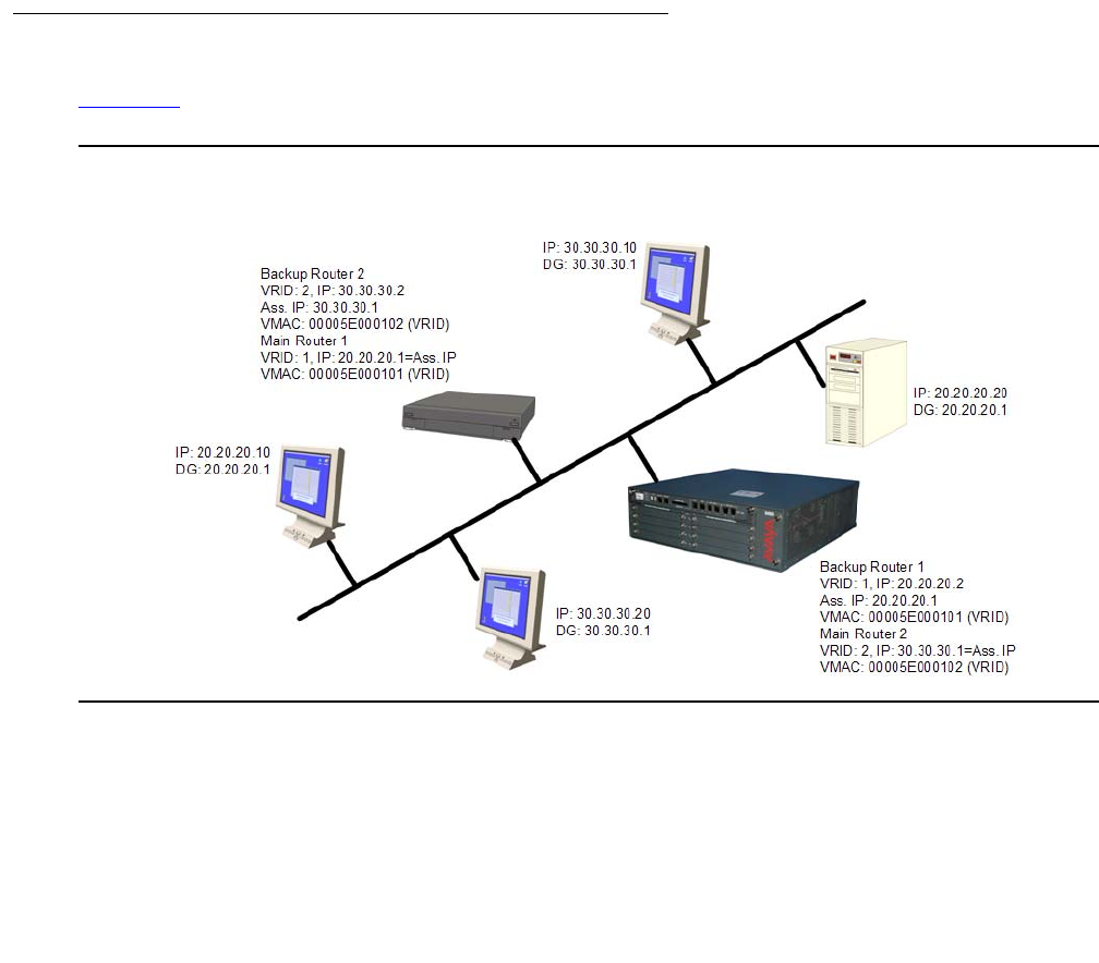
Configuring VRRP
Issue 1 January 2008 499
The concept underlying VRRP is that a router can back up other routers, in addition to
performing its primary routing functions. This redundancy is achieved by introducing the
concept of a virtual router. A virtual router is a routing entity associated with multiple physical
routers. One of the physical routers with which the virtual router is associated performs the
routing functions. This router is known as the master router. For each virtual router, VRRP
selects a master router. If the selected master router fails, another router is selected as master
router.
In VRRP, two or more physical routers can be associated with a virtual router, thus achieving
extreme reliability. In a VRRP environment, host stations interact with the virtual router. The
stations are not aware that this router is a virtual router, and are not affected when a new router
takes over the role of master router. Thus, VRRP is fully interoperable with any host station.
You can activate VRRP on an interface using a single command while allowing for the
necessary fine-tuning of the many VRRP parameters. For a detailed description of VRRP, see
VRRP standards and published literature.
VRRP configuration example
Figure 42 illustrates an example of a VRRP configuration:
Figure 42: VRRP configuration example

Configuring the router
500 Administration for the Avaya G450 Media Gateway
There is one main router on IP subnet 20.20.20.0, such as a G450, C363T, C364T, or any router
that supports VRRP, and a backup router. You can configure more backup routers.
●The G450 itself must have an interface on the IP subnetwork, for example, 20.20.20.2
●Configure all the routers under the same VRID, for example,1. You must configure the
routers per VLAN.
●An assigned VRID must not be used in the network, even in a different VLAN
●When router configuration is complete and the network is up, the main router for each
virtual router is selected according to the following order of preference:
- The virtual router IP address is also the router’s interface IP address
- It has the highest priority (you can configure this parameter)
- It has the highest IP address if the previous conditions do not apply
●The virtual router IP address needs to be configured as the default gateway on the stations
●The Main router advertises a six-byte Virtual MAC address, in the format
00.00.5E.00.01.02 VRID, as a response to the stations’ ARP requests
●The redundant router uses a VRRP polling protocol to check the Main router integrity at
one-second intervals (default). Otherwise, it is idle.
●If the Main router fails, the redundant router that does not receive a response from four
consecutive polling requests (default) takes over and starts to advertise the same Virtual
MAC for ARP requests. Therefore, the stations will not detect any change either in the
configured default gateway or at the MAC level.
●VRRP has no provisions for routing database synchronization among the redundant
routers. You must perform this manually, if needed.
VRRP commands
Use the following commands to configure VRRP. For more information about these commands,
see Avaya G450 CLI Reference, 03-300437.
●Use the ip vrrp command to create a virtual router on an interface. Use the no form of
this command to delete a virtual router.
●Use the ip vrrp address command to assign an IP address to a virtual router. Use the
no form of this command to remove an IP address from a virtual router.
●Use the ip vrrp auth-key command to set the virtual router simple password
authentication key for the virtual router ID. Use the no form of this command to disable
simple password authentication for the virtual router instance.
●Use the ip vrrp override addr owner command to accept packets addressed to
the IP addresses associated with the virtual router, such as ICMP, SNMP, and telnet (if it is
not the IP address owner). Use the no form of this command to discard these packets.
Configuring VRRP
Issue 1 January 2008 501
●Use the ip vrrp preempt command to configure a router to preempt a lower priority
master for the virtual router ID. Use the no form of this command to disable preemption for
a virtual router instance. By default, preemption is enabled.
●Use the ip vrrp primary command to set the primary address used as the source
address of VRRP packets for the virtual router ID. Use the no form of this command to
restore the default primary address for a virtual router instance. By default, the primary
address is selected automatically by the device.
●Use the ip vrrp priority command to set the virtual router priority value used when
selecting a master router. Use the no form of this command to restore the default value.
●Use the ip vrrp timer command to set the virtual router advertisement timer value for
the virtual router ID. Use the no form of this command to restore the default value.
●Enter router vrrp to enable VRRP routing. Use the no form of this command to disable
VRRP routing.
●Use the show ip vrrp command to display VRRP information.
Summary of VRRP commands
For more information about these commands, see Avaya G450 CLI Reference, 03-300437.
Table 127: VRRP CLI commands
Root level
command Command Description
interface
(fastethernet|
vlan)
Enter the FastEthernet or VLAN interface
configuration context
ip vrrp Create a virtual router on an interface
ip vrrp address Assign an IP address to a virtual router
ip vrrp auth-key Set the virtual router simple password
authentication key for the virtual router ID
ip vrrp override
addr owner Accept packets addressed to the IP addresses
associated with the virtual router, such as
ICMP, SNMP, and telnet (if it is not the
IP address owner)
ip vrrp preempt Configure a router to preempt a lower priority
master for the virtual router ID
1 of 2

Configuring the router
502 Administration for the Avaya G450 Media Gateway
Configuring fragmentation
The G450 supports IP fragmentation and reassembly. The G450 router can fragment and
reassemble IP packets according to RFC 791. This feature allows the router to send and
receive large IP packets where the underlying data link protocol constrains the Maximum
Transport Unit (MTU).
IP fragmentation involves breaking a datagram into a number of pieces that can be
reassembled later. The IP source, destination, identification, total length, and fragment offset
fields, along with the more fragment and don’t fragment flags in the IP header, are used for IP
fragmentation and reassembly.
IP fragmentation works as follows:
●Each IP packet is divided into fragments
●Each fragment becomes its own IP packet
●Each packet has same identifier, source, and destination address
Fragments are usually not reassembled until final destination. The G450 supports
fragmentation of IP packets according to RFC 791, and reassembly of IP packets destined only
to its interfaces.
ip vrrp primary Set the primary address used as the source
address of VRRP packets for the virtual router
ID
ip vrrp priority Set the virtual router priority value used when
selecting a master router
ip vrrp timer Set the virtual router advertisement timer value
for the virtual router ID
router vrrp Enable or disable VRRP routing globally
show ip vrrp Display VRRP information
Table 127: VRRP CLI commands (continued)
Root level
command Command Description
2 of 2

Configuring fragmentation
Issue 1 January 2008 503
Fragmentation commands
Use the following commands to configure fragmentation and reassembly. For more information
about these commands, see Avaya G450 CLI Reference, 03-300437.
●Enter clear fragment to clear the fragment database and restore its default values.
●Use the fragment chain command to set the maximum number of fragments that can
comprise a single IP packet destined to the router. Use the no form of this command to set
the fragment chain to its default value.
●Use the fragment size command to set the maximum number of fragmented IP
packets destined to the router to reassemble at any given time. Use the no form of this
command to set the fragment size to its default value.
●Use the fragment timeout command to set the maximum number of seconds to
reassemble a fragmented IP packet destined to the router. Use the no form of this
command to set the fragment timeout to its default value.
●Enter fragment to set the treatment for IP fragmentation packets entering on an
interface.
●Enter show fragment to display information regarding fragmented IP packets that are
destined to a router.
Summary of fragmentation commands
For more information about these commands, see Avaya G450 CLI Reference, 03-300437.
Table 128: Fragmentation CLI commands
Command Description
clear fragment Clear the fragment database and restore its default values
fragment chain Set the maximum number of fragments that can comprise a single IP
packet destined to the router
fragment size Set the maximum number of fragmented IP packets destined to the
router to reassemble at any given time
fragment
timeout Set the maximum number of seconds to reassemble a fragmented IP
packet destined to the router
show fragment Display information regarding fragmented IP packets that are destined
to a router

Configuring the router
504 Administration for the Avaya G450 Media Gateway

Issue 1 January 2008 505
Chapter 19: Configuring IPSec VPN
VPN (Virtual Private Network) defines a private secure connection between two nodes on a
public network such as the Internet. VPN at the IP level is deployed using IP Security (IPSec).
IPSec is a standards-based set of protocols defined by the IETF that provide privacy, integrity,
and authenticity to information transferred across IP networks.
The standard key exchange method employed by IPSec uses the Internet Key Exchange (IKE)
protocol to exchange key information between the two nodes (referred to as peers). Each peer
maintains Security Associations (SAs) to maintain the private secure connection. IKE operates
in two phases:
●The Phase-1 exchange negotiates an IKE SA
●The IKE SA created in Phase-1 secures the subsequent Phase-2 exchanges, which in turn
generate IPSec SAs
IPSec SAs secure the actual traffic between the protected networks behind the peers, while the
IKE SA only secures the key exchanges that generate the IPSec SAs between the peers.
The G450 IPSec VPN feature is designed to support site-to-site topologies, in which the two
peers are gateways.
Note:
Note: To configure IPSec VPN, you need at least a basic knowledge of IPSec. Refer to
the following guide for a suitable introduction:
http://www.tcpipguide.com/free/t_IPSecurityIPSecProtocols.htm
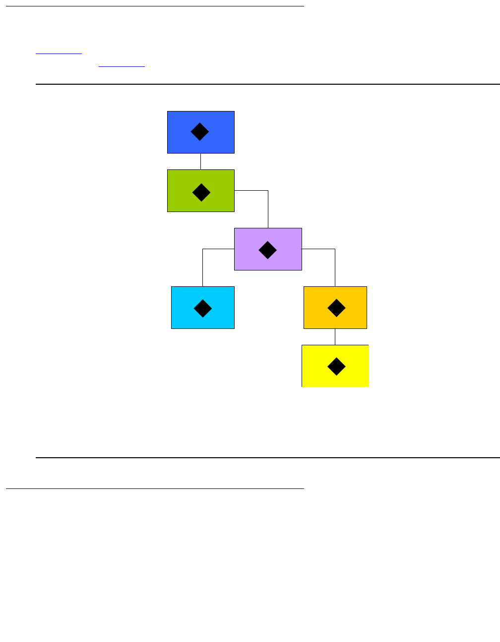
Configuring IPSec VPN
506 Administration for the Avaya G450 Media Gateway
Overview of IPSec VPN configuration
Figure 43 summarizes the components you need to define and the order in which you need to
define them. Figure 44 describes the relationships among the various VPN components.
Figure 43: IPSec VPN configuration model
Overview of IPSec VPN components
The basic IPSec VPN building blocks define how to secure packets, as follows:
●ISAKMP policies. Define parameters for IKE phase 1 negotiation
●Transform-sets. Define parameters for IKE phase 2 negotiation
Figure notes:
1. ISAKMP Policy
2. IPSEC Transform-set
3. ISAKMP Peer or Peer Group
4. Crypto Map
5. crypto list
6. Interface
2
1
3
4
5
6
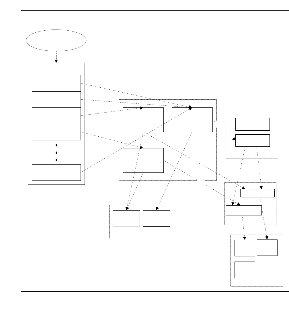
Issue 1 January 2008 507
Once the building blocks are defined, IPSec VPN is implemented using a crypto list. The crypto
list defines, for the interface to which it applies, which packets should be secured and how, as
follows:
Each rule in the crypto list points to a crypto-map. A crypto-map points to a transform-set, and to
a peer or peer-group. The peer or peer-group, in turn, point to an ISAKMP policy.
Figure 44 illustrates the relationships among the various IPSec VPN components:
Figure 44: IPSec VPN components
crypto map 2
crypto map 1 crypto map N
crypto maps pool
Rule 1
Rule 4
Rule 3
Rule 2
Rule N
crypto list
interface
isakmp
policy
N
isakmp
policy
2
isakmp
policy
1
isakmp policies pool
transform-
set 1
transform-sets pool
isakmp peer 1
isakmp peer N
transform-
set N
peer group
peer
isakmp peers pool
peer
isakmp peer-
group 1
isakmp peer-
group N
peer
peer
isakmp peer-groups
pool

Configuring IPSec VPN
508 Administration for the Avaya G450 Media Gateway
Summary of configuration steps
The commands required to configure a VPN are listed below. For a step-by-step description of
the VPN procedures, see Configuring a site-to-site IPSec VPN on page 510.
Note:
Note: You must configure VPN in the order shown in the summary. Commands
appearing in bold are mandatory.
●ISAKMP policy – crypto isakmp policy
-
description
-
authentication pre-share
-
encryption
-
hash
-
group
-
lifetime
●IPSEC transform-set – crypto ipsec transform-set
-
set pfs
-
set security-association lifetime seconds
-
set security-association lifetime kilobytes
-
mode (tunnel/transport)
●ISAKMP peer – crypto isakmp peer
-
description
-
isakmp-policy
-
pre-shared-key
-
initiate mode
-
self-identity
-
keepalive
-
keepalive-track
-
continuous-channel
●(Optional) ISAKMP peer group – crypto isakmp peer-group
-
description
-
set peer

Issue 1 January 2008 509
●Crypto map – crypto map
-
description
-
set transform-set
-
set peer or set peer-group
-
set dscp
-
continuous-channel
●IP crypto list – ip crypto-list
-
local-address
-
ip-rule
●description
●source-ip
●destination-ip
●protect crypto map
●ip-protocol
●tcp
●udp
●icmp
●dscp
●fragment
●Access control list – ip access-control-list
●global parameters
-
crypto isakmp invalid-spi-recovery
-
crypto ipsec nat-transparency udp-encapsulation
-
crypto isakmp nat keepalive
●assigning a crypto-list to an interface
-
crypto ipsec df-bit
-
crypto ipsec minimal-pmtu
-
ip crypto-group

Configuring IPSec VPN
510 Administration for the Avaya G450 Media Gateway
Configuring a site-to-site IPSec VPN
This section describes the procedures for VPN configuration.
Installing the VPN license file
To enable IPSec VPN you must obtain and install a VPN license. For information on obtaining a
VPN license, see Installing and Upgrading the Avaya G450 Media Gateway, 03-602054.
You can install the VPN license via FTP, TFTP, or SCP.
Note:
Note: You must have admin permissions to install a VPN license.
1. Use one of the following commands:
●copy ftp license-file filename ip
●copy tftp license-file filename ip
●copy scp license-file filename ip
where:
●filename is the filename, including the full path
●ip is the IP address of the ftp/tftp/scp server
For example:
2. Optionally, enter show download license-file status to view the status of the
download process.
3. Enter show license status to verify that the license was installed.
4. Enter copy running-config startup-config to save your current configuration.
5. Reset using the reset command.
Configuring IPSec VPN
Prerequisites
As a prerequisite to configuring IPSec VPN, a valid VPN license must be installed on the G450.
For details, see Installing the VPN license file on page 510.
copy tftp license-file my_license_file.xml 198.87.134.153

Configuring a site-to-site IPSec VPN
Issue 1 January 2008 511
IPSec VPN configuration overview
To configure a site-to-site IPSec VPN, two devices (the G450 and a peer Gateway) must be
configured symmetrically.
In some cases, you may wish to configure global VPN parameters (see Configuring global
parameters on page 524).
Note:
Note: In the following sections, all IPSec VPN parameters that you must configure are
indicated as mandatory parameters. Non-mandatory VPN parameters have default
values that are used unless otherwise set. Thus for example, although it is mandatory
to define at least one ISAKMP policy, it is not mandatory to set the values for that
ISAKMP policy since the G450 contains default ISAKMP policy settings.
Coordinating with the VPN peer
Before commencing IPSec VPN configuration, you must resolve jointly with your VPN peer the
basic parameters so that IPSec VPN can be set up symmetrically in the two peers. If the IPSec
VPN configuration in the two peers does not match, no VPN is created.
Note:
Note: If you will be defining a peer-group which maintains a list of redundant peers,
each of the peers in the group must be configured to match the G450.
The basic parameters include:
●The IKE phase 1 parameters (as defined in the ISAKMP policy, see Configuring ISAKMP
policies on page 512)
●The IKE phase 2 parameters (as defined in the transform-set, see Configuring
transform-sets on page 513)
●The ISAKMP peer parameters (see Configuring ISAKMP peer information on page 514)
●Which packets should be secured (as defined in the crypto list, see Configuring crypto
lists on page 520)
●The peer addresses. For each peer, the local address entered in the crypto list (see
Configuring crypto lists on page 520) should match the ISAKMP peer address in the other
peer (see Configuring ISAKMP peer information on page 514).
●NAT Traversal, if your installation includes one or more NAT devices between the local and
remote VPN peers. See Configuring global parameters on page 524.
See IPSec VPN logging on page 528 for information on how to view IPSec VPN configuration in
both peers so as to pinpoint the problem in case of a mismatch between the two peers.

Configuring IPSec VPN
512 Administration for the Avaya G450 Media Gateway
Configuring ISAKMP policies
An ISAKMP policy defines the IKE phase 1 parameters.
!Important:
Important: You must define at least one ISAKMP policy.
Note:
Note: You can configure up to 40 ISAKMP policies.
1. Enter crypto isakmp policy, followed by an index number from 1 to 20, to enter the
context of an ISAKMP policy list (and to create the list if it does not exist). For example:
2. You can use the following commands to set the parameters of the ISAKMP policy:
●Use the description command to assign a description to the ISAKMP policy.
●Use the authentication pre-share command to set the authentication of
ISAKMP policy to pre-shared secret.
●Use the encryption command to set the encryption algorithm for the ISAKMP policy.
Possible values are des (default), 3des, aes, aes-192 and aes-256.
●Use the hash command to set the hash (authentication) algorithm for the ISAKMP
policy. Possible values are md5 and sha (default).
●Use the group command to set the Diffie-Hellman group for the ISAKMP policy.
Possible values are 1 (default), 2, 5 and 14.
●Use the lifetime command to set the lifetime of the ISAKMP SA, in seconds. The
range of values is 60-86,400 seconds (default is 86,400). For example:
G450-001# crypto isakmp policy 1
G450-001(config-isakmp:1)#
G450-001(config-isakmp:1)# description "lincroft ike"
Done!
G450-001(config-isakmp:1)# authentication pre-share
Done!
G450-001(config-isakmp:1)# encryption des
Done!
G450-001(config-isakmp:1)# hash md5
Done!
G450-001(config-isakmp:1)# group 1
Done!
G450-001(config-isakmp:1)# lifetime 60000
Done!

Configuring a site-to-site IPSec VPN
Issue 1 January 2008 513
3. Exit the ISAKMP policy context with the exit command. For example:
Configuring transform-sets
A transform-set defines the IKE phase 2 parameters. It specifies the encryption and
authentication algorithms to be used, sets a security association lifetime, and specifies whether
PFS is enabled and which DH group it uses. In addition, it specifies the IPSec VPN mode
(tunnel or transport).
!Important:
Important: You must define at least one transform-set.
Note:
Note: You can define up to 40 transform-sets.
1. Use the crypto ipsec transform-set command to enter the context of a
transform-set (and to create the transform-set if it does not exist). The command variables
include:
●The name of the transform-set
●The encryption algorithm used by the transform-set. Possible values are esp-des,
esp-3des, esp-aes, esp-aes-192, esp-aes-256 and esp-null (no encryption).
●The authentication algorithm used by the transform-set. Possible values are
esp-md5-hmac and esp-sha-hmac.
●The IP compression algorithm used by the transform-set. The only possible value is
comp-lzs.
For example:
2. You can use the following commands to set the parameters of the transform-set:
●Use the set pfs command to specify whether each IKE phase 2 negotiation
employs Perfect Forward Secrecy (PFS), and if yes, which Diffie-Hellman group to
employ. PFS ensures that even if someone were to discover the long-term secret(s),
the attacker would not be able to recover the session keys, both past and present. In
addition, the discovery of a session key compromises neither the long-term secrets nor
the other session keys. The default setting is no set pfs.
●Use the set security-association lifetime seconds command to set the
security association lifetime in seconds.
G450-001(config-isakmp:1)# exit
G450-001#
G450-001# crypto ipsec transform-set ts1 esp-3des esp-md5-hmac comp-lzs
G450-001(config-transform:ts1)#

Configuring IPSec VPN
514 Administration for the Avaya G450 Media Gateway
●Use the set security-association lifetime kilobytes command to set
the security association lifetime in kilobytes.
●Use the mode command to set the IPSec mode (tunnel or transport).
Transport mode does not add an additional IP header (i.e., a tunnel header), but
rather uses the original packet’s header. However, it can be used only when the VPN
tunnel endpoints are equivalent to the original packet’s source and destination IP
addresses. This is generally the case when using GRE over IPSec. Note that
transport mode cannot be used unless the remote VPN peer supports that mode
and was configured to use it.
3. Exit the crypto transform-set context with the exit command.
Configuring ISAKMP peer information
ISAKMP peer information defines the remote peer identification, the pre-shared key used for
peer authentication, and the ISAKMP policy to be used for IKE phase 1 negotiations between
the peers.
!Important:
Important: It is mandatory to define at least one ISAKMP peer.
Note:
Note: You can define up to 100 ISAKMP peers.
1. Enter crypto isakmp peer, followed by the address of the ISAKMP peer or its Fully
Qualified Domain Name (FQDN), to enter the context of an ISAKMP peer (and to create
the peer if it does not exist).
Note:
Note: If you wish to specify the ISAKMP peer by its FQDN name, you must configure
the G450 as a DNS client (see DNS resolver on page 88), and verify that the
peer’s name is listed in a DNS server.
G450-001001(config-transform:ts1ts1)# set pfs group2
Done!
G450-001(config-transform:ts1)# set security-association lifetime seconds
7200
Done!
G450-001(config-transform:ts1)# set security-association lifetime
kilobytes 268435456
G450-001(config-transform:ts1)# mode tunnel
Done!
G450-001(config-transform:ts1)# exit
G450-001#
Configuring a site-to-site IPSec VPN
Issue 1 January 2008 515
Note:
Note: Do not specify an ambiguous ISAKMP peer; that is, do not configure an FQDN
that translates to an IP address which is already associated with another ISAKMP
peer. For example:
Or
2. Use the description command to enter a description for the peer. For example:
3. Specify an ISAKMP policy to be used with the peer, using the isakmp policy command.
!Important:
Important: isakmp policy is a mandatory command.
For example:
4. Enter the preshared key for peer authentication using the pre-shared-key command.
G450-001# crypto isakmp peer address 149.49.70.1
G450-001(config-peer:149.49.70.1)#
G450-001# crypto isakmp peer fqdn vpn.lnd.ny.avaya.com
G450-001(config-peer:vpn.lnd.ny.avaya.com)#
G450-001(config-peer:149.49.70.1)# description "New York office"
Done!
G450-001(config-peer:149.49.70.1)# isakmp-policy 1
Done!

Configuring IPSec VPN
516 Administration for the Avaya G450 Media Gateway
!Important:
Important: pre-shared-key is a mandatory command.
For example:
Alternatively, you can obtain a cryptographic-grade random key from the G450 with the
suggest-key command, and then enter it using the pre-shared-key command. The
suggested key-length can vary from 8-127 alphanumeric characters, or from 8-64 bytes
represented in hexadecimal notation. The default length is 32 characters.
For example:
5. If you wish to work in IKE aggressive mode, use the initiate mode aggressive
command.
Note:
Note: Aggressive mode is one of the prerequisites for working with dynamic local peer
IP addresses. For more information about working with dynamic local peer IP
addresses, see Using dynamic local peer IP on page 536.
For example:
6. If you wish to listen in to communication from a remote peer that has a dynamic IP
address, use the initiate mode none command. In this mode, the device can only
accept inbound IKE Aggressive Mode connections from the peer, and is not able to initiate
IKE phase-1 (Main Mode or Aggressive Mode) to the peer, nor is the peer able to
participate as part of a peer-group. In addition, specifying the continuous-channel
command when configuring the crypto ISAKMP peer information has no effect in this mode
(for more information on continuous-channel see Enabling continuous channel on
page 539).
G450-001(config-peer:149.49.70.1)# pre-shared-key GNpi1odGNBrB5z4GJL
Done!
G450-001(config-peer:149.49.70.1)# suggest-key 24
The suggest key: yjsYIz9ikcwaq0FUPTF3CIrw
G450-001(config-peer:149.49.70.1) pre-shared-key yjsYIz9ikcwaq0FUPTF3CIrw
Done!
G450-001(config-peer:149.49.70.1)# initiate mode aggressive
Done!

Configuring a site-to-site IPSec VPN
Issue 1 January 2008 517
7. Specify the branch device (G450) by its address or by the FQDN name that identifies the
G450 in the remote peer, using the self-identity command. For example:
Or
Note:
Note: Specifying self-identity as a name is one of the prerequisites for working with
dynamic local peer IP addresses. For more information about working with
dynamic local peer IP addresses, see Using dynamic local peer IP on page 536.
8. Enable Dead Peer Detection (DPD) keepalives that check whether the remote peer is up
using the keepalive command, followed by the number of seconds between DPD
keepalive probes, and the number of seconds between retries if keepalive fails.
The following example sets DPD keepalive to send probes every 10 seconds, and to send
retries every two seconds if DPD keepalive fails.
9. Bind peer status to an object tracker, which can monitor hosts inside the remote peer’s
protected network. To do so, use the keepalive-track command. For more
information on object trackers, see Object tracking on page 298.
For example:
Note:
Note: DPD and object tracking can coexist and augment each other. However, object
tracking does not impose any requirements on the remote peer. You can,
therefore, use object tracking rather than DPD keepalives if the remote peer does
not support DPD.
10. Specify whether to enable continuous-channel IKE phase 1, with the
continuous-channel command. The default setting is no continuous-channel,
which disables continuous-channel IKE phase 1. For more information on
continuous-channel see Enabling continuous channel on page 539. For example:
G450-001(config-peer:149.49.70.1)# self-identity address
Done!
G450-001(config-peer:149.49.70.1)# self-identity fqdn vpn.avaya.com
Done!
G450-001(config-peer:149.49.70.1)# keepalive 10 retry 2
Done!
G450-001(config-peer:149.49.70.1)# keepalive-track 5
Done!
G450-001(config-peer:149.49.70.1)# continuous-channel
Done!

Configuring IPSec VPN
518 Administration for the Avaya G450 Media Gateway
11. Exit the peer context with the exit command. For example:
Configuring an ISAKMP peer-group
An ISAKMP peer-group maintains an ordered list of redundant peers. The purpose of the
peer-group is to provide a backup in the case of remote peer failure. At any point in time, only
one peer is active and acting as the remote peer. If the active peer is presumed dead, the next
peer in the peer-group becomes the active remote peer. For a full explanation of the
redundancy mechanism see Introduction to the failover mechanism on page 559.
Note:
Note: You can define up to 50 peer-groups.
Note:
Note: A peer configured as initiate mode none cannot be a member of a
peer-group.
1. Use the crypto isakmp peer-group command, followed by the name of a
peer-group (a string of up to 110 characters), to enter the context of an ISAKMP
peer-group (and to create the peer-group if it does not exist). For example:
2. Use the description command to enter a description for the ISAKMP peer-group. For
example:
3. Add a peer to the list of peers in the group, using the set peer command:
●Specify the peer’s name or address.
●Optionally enter an index number, specifying the relative position of the peer within the
peer-group. If you do not enter an index number, the peer is added at the end of the
peer-group list, and is assigned an index following the last peer’s index.
For example:
4. Repeat Step 3 for every peer you want to add to the list.
G450-001(config-peer:149.49.70.1)# exit
G450-001#
G450-001# crypto isakmp peer-group NY-VPN-group
G450-001(config-peer-grp:NY-VPN-group)#
G450-001(config-peer-grp:NY-VPN-group)# description “Avaya peer group”
Done!
G450-001(config-peer-grp:NY-VPN-group)# set peer 149.49.52.135 1
Done!

Configuring a site-to-site IPSec VPN
Issue 1 January 2008 519
Note:
Note: You can define up to a maximum of five peers in a peer-group.
!Important:
Important: Each of the peers listed in the peer-group must be configured as an ISAKMP peer
(see Configuring ISAKMP peer information on page 514).
Configuring crypto maps
A crypto map points to a transform-set and to a peer (which in turn points to an ISAKMP policy).
If you defined a peer-group, the crypto map can point to the peer-group.
The transform-set and ISAKMP policy define how to secure the traffic that matches the ip-rule
that points to this crypto map.
!Important:
Important: It is mandatory to create at least one crypto map.
Note:
Note: You can configure up to 100 crypto maps.
1. Use the crypto map command, followed by an index number from 1 to 50, to enter the
context of a crypto map (and to create the crypto map if it does not exist). For example:
2. Use the description command to enter a description for the crypto map. For example:
3. Specify the remote peer, using the set peer command. For example:
Or
Specify a peer-group, using the set peer-group command. For example:
!Important:
Important: It is mandatory to specify either set peer or set peer-group, but not both.
G450-001# crypto map 1
G450-001(config-crypto:1)#
G450-001(config-crypto:1)# description "vpn lincroft branch"
Done!
G450-001(config-crypto:1)# set peer 149.49.60.60
Done!
G450-001(config-crypto:1)# set peer-group NY-VPN-group
Done!

Configuring IPSec VPN
520 Administration for the Avaya G450 Media Gateway
4. Specify the specific transform-set to which this crypto map points, using the set
transform-set command.
!Important:
Important: set transform-set is a mandatory command.
For example:
5. Set the static DSCP value in the DS field of the tunneled packet by using the set dscp
command, followed by a value from 0 to 63. The default setting is no set dscp, which
specifies that the DSCP is copied from the DS field of the original packet.
For example:
6. Specify whether to enable continuous-channel IPSec (IKE phase 2) with the
continuous-channel command. The default setting is no continuous-channel,
which disables continuous-channel IPSec. For more information on continuous-channel
see Enabling continuous channel on page 539. For example:
7. Exit crypto map context with the exit command. For example:
Configuring crypto lists
A crypto list is an ordered list of ip-rules that control which traffic requires IPSec protection and
which does not, based on IP groups (source and destination IP addresses and wildcard). A
crypto list is activated on an interface. The G450 can have multiple crypto lists activated on
different interfaces.
!Important:
Important: It is mandatory to create at least one crypto list.
Note:
Note: You can configure up to 100 crypto lists.
G450-001(config-crypto:1)# set transform-set ts1
Done!
G450-001(config-crypto:1)# set dscp 38
Done!
G450-001(config-crypto:1)# continuous-channel
Done!
G450-001(config-crypto:1)# exit
G450-001#

Configuring a site-to-site IPSec VPN
Issue 1 January 2008 521
1. Use the ip crypto-list command, followed by an index number from 901 to 999, to
enter the context of a crypto list (and to create the list if it does not exist). For example:
2. Specify the local IP address for the IPSec tunnels derived from this crypto list, using the
local-address command. The local address can be either the IP address or the name
of an IP interface of the device.
!Important:
Important: local-address is a mandatory command.
For example:
Or
Note:
Note: Specifying the interface as a name is one of the prerequisites for working with
dynamic local peer IP addresses. For more information about working with
dynamic local peer IP addresses, see Using dynamic local peer IP on page 536.
3. Specify the name of the crypto list using the name command. For example:
4. Use the ip-rule command, followed by an index number from 1 to 1000, to enter the
context of an ip-rule (and to create the ip-rule if it does not exist).
!Important:
Important: It is mandatory to create at least one ip-rule.
For example:
G450-001# ip crypto-list 901
G450-001(Crypto 901)#
G450-001(Crypto 901)# local-address 192.168.49.1
Done!
G450-001(Crypto 901)# local-address FastEthernet 10/2
Done!
G450-001(Crypto 901)# name “Public Network via ADSL”
Done!
G450-001(Crypto 901)# ip-rule 10
G450-001(Crypto 901/ip rule 10)#

Configuring IPSec VPN
522 Administration for the Avaya G450 Media Gateway
5. Configure ip-rule parameters as follows:
●Use the description command to assign a description to the ip-rule.
●To specify a range of source and destination IP addresses to which the rule applies,
use the source-ip and destination-ip commands, followed by the IP range
criteria. The IP range criteria can be one of the following:
-
A single address. Type host, followed by an IP address, to set a single IP
address to which the rule applies.
-
A wildcard. Type host, followed by an IP address using wildcards, to set a range
of IP addresses to which the rule applies.
-
All addresses. Type any to apply the rule to all IP addresses.
Use the no form of the appropriate command to return to the default value, any.
●Define the action by specifying whether to protect traffic that matches the source and
destination addresses, using one of the following commands:
-
no protect. Do not protect traffic that matches the source and destination
addresses.
-
protect crypto map crypto-map-id. Protect traffic that matches the source
and destination addresses. The specified crypto map specifies how to secure the
traffic. For instructions on configuring crytpo maps, see Configuring crypto
maps on page 519.
For example:
●For rules whose action is no protect, you can fine-tune the definition of packets that
match this rule by using the following commands. For a full description of the
commands see Avaya G450 CLI Reference, 03-602056. Note that this fine-tuning is
not applicable for rules whose action is protect crypto map.
-
ip-protocol. Specify the IP protocol to match.
-
tcp. Specify the TCP settings to match.
-
udp. Specify the UDP settings to match.
-
icmp. Specify the ICMP protocol settings to match.
-
dscp. Specify the DSCP to match.
-
fragment. Specify whether this rule applies to non-initial fragments only.
G450-001(Crypto 901/ip rule 10)# description “vpn tunnel to uk main
office”
Done!
G450-001(Crypto 901/ip rule 10)# source-ip 10.1.0.0 0.0.255.255
Done!
G450-001(Crypto 901/ip rule 10)# destination-ip any
Done!
G450-001(Crypto 901/ip rule 10)# protect crypto map 1
Done!

Configuring a site-to-site IPSec VPN
Issue 1 January 2008 523
6. Exit ip-rule context with the exit command. For example:
7. Repeat Steps 4 to 6 for every ip-rule you wish to define in the crypto list.
8. Exit crypto list context with the exit command. For example:
Deactivating crypto lists to modify IPSec VPN parameters
Most IPSec VPN parameters cannot be modified if they are linked to an active crypto list. To
modify a parameter linked to an active crypto list, you must first deactivate the list using the
no ip crypto-group command in the context of the interface on which the crypto list is
activated.
Note:
Note: If the crypto list is activated on more than one interface, deactivate the crypto list
for each of the interfaces on which it is activated.
For example:
After modifying IPSec VPN parameters as desired, re-activate the crypto list on the interface
using the ip crypto-group crypto-list-id command. For example:
Tip:
Tip: If you wish to change the parameters of a crypto list, you can use the ip
policy-list-copy old list new list command, edit the new list, and
activate it on the interface. Note that activating the new list will cause all the
current IPSec tunnels to close.
G450-001(Crypto 901/ip rule 10)# exit
G450-001(Crypto 901)#
G450-001(Crypto 901)# exit
G450-001#
G450-001# interface serial 3/1
G450-001(if: Serial 3/1)# no ip crypto-group
Done!
G450-001# interface serial 3/1
G450-001(if: Serial 3/1)# ip crypto-group 901
Done!

Configuring IPSec VPN
524 Administration for the Avaya G450 Media Gateway
Configuring and assigning an access control list
Since VPN is intended for a public network such as the Internet, it is recommended to define an
access control list using the ip access-control-list command, to avoid traffic that
should not enter the device. You should, therefore, define an ingress access control list that
allows only IKE, ESP, and ICMP traffic to enter the device from the public interface. For a
configuration example see the access control list in Simple VPN topology – VPN hub and
spokes on page 530.
Configuring global parameters
●Enable invalid SPI recovery with the crypto isakmp invalid-spi-recovery
command. Invalid SPI Recovery enables an IKE SA to be established when an invalid
security parameter index error occurs during packet processing. A notification of the
invalid SPI error is sent to the originating peer so that the SA databases can be
re-synchronized, and successful packet processing can be resumed. For example:
Note:
Note: Invalid SPI recovery is enabled by default. Configure invalid SPI recovery only if
you wish to re-enable it after it was disabled, using the no crypto isakmp
invalid-spi-recovery command.
●Configure NAT Traversal global parameters as described in Configuring NAT Traversal on
page 524
Configuring NAT Traversal
Network Address Translation (NAT) is a solution to the problem of the scarcity and cost of public
IP addresses. An organization with a single public IP address can use a NAT device to connect
multiple computers to the Internet sharing a single public IP address. However, NAT causes
compatibility problems for many types of network applications, including VPN.
NAT Traversal enables detecting the presence of NAT devices along the path of the VPN
tunnel. Once detected, the two peers tunnel IKE and IPSEC traffic through an agreed-upon
UDP port, allowing the NAT device to work seamlessly with VPN. The standard UDP port used
is port 4500; to find out the port number, use the show crypto ipsec sa command.
The G450 IPSec VPN feature supports NAT Traversal. If your installation includes one or more
NAT devices between the local and remote VPN peers, NAT Traversal should be enabled,
although in some rare cases it may not be required.
G450-001# crypto isakmp invalid-spi-recovery
Done!

Configuring a site-to-site IPSec VPN
Issue 1 January 2008 525
Note:
Note: NAT Traversal is enabled by default. Configure NAT Traversal only if you need to
re-enable it after it was disabled, using the no crypto ipsec
nat-transparency udp-encapsulation command.
NAT Traversal keepalive is also enabled by default (with a default value of 20
seconds). Configure NAT Traversal keepalive only if you need to re-enable it after
it was disabled, using the no crypto isakmp nat keepalive command.
Configure NAT Traversal
1. Enable NAT Traversal by entering crypto ipsec nat-transparency
udp-encapsulation. For example:
2. Enable NAT Traversal keepalives and configure the keepalive interval (in seconds) by
entering crypto isakmp nat keepalive, followed by a number from 5 to 3600.
NAT Traversal keepalives are empty UDP packets that the device sends on a periodic
basis at times of inactivity when a dynamic NAT is detected along the way. These
keepalives are intended to maintain the NAT translation alive in the NAT device, and not let
it age-out due to periods of inactivity. Set the NAT Traversal keepalive interval on the G450
to be less than the NAT translation aging time on the NAT device. For example:
Assigning a crypto list to an interface
A crypto list is activated on an interface. You can assign multiple crypto lists to different
interfaces on the G450.
1. Enter interface context using the interface command. For example:
2. Configure the IP address of the interface. You can configure either a static or a dynamic IP
address.
●To configure a static IP address:
-
Be sure to specify an IP address (not an interface name) as the local-address
in the crypto list (see Configuring crypto lists on page 520)
G450-001# crypto ipsec nat-tranparency udp-encapsulation
Done!
G450-001# crypto isakmp nat keepalive 60
Done!
G450-001# interface fastethernet 10/2
G450-001(config-if:FastEthernet 10/2)#
Configuring IPSec VPN
526 Administration for the Avaya G450 Media Gateway
-
Within the interface context, specify the IP address and mask using the ip
address command
For example:
●To configure a dynamic IP address, see Using dynamic local peer IP on page 536
3. Use the ip crypto-group command, followed by the index of the crypto-group, to
assign a crypto-group to the interface.
!Important:
Important: ip crypto-group is a mandatory command.
4. Optionally, you can set the following parameters:
●The crypto ipsec minimal-pmtu command is intended for advanced users only.
It sets the minimal PMTU value which can be applied to an SA when the G450
participates in Path MTU Discovery (PMTUD) for the tunnel pertaining to that SA.
●The crypto ipsec df-bit command is intended for advanced users only. It sets
the Do Not Fragment (DF) bit to either clear or copy mode:
-
copy. The DF bit of the encapsulated packet is copied from the original packet,
and PMTUD is maintained for the IPSec tunnel.
-
clear. The DF bit of the encapsulated packet is never set, and PMTUD is not
maintained for the IPSec tunnel. Packets traversing an IPSec tunnel are
pre-fragmented according to the MTU of the SA, regardless of their DF bit. In case
packets are fragmented, the DF bit is copied to every fragment of the original
packet.
For example:
5. Exit the interface context with the exit command. For example:
G450-001(config-if:FastEthernet 10/2)# ip address 192.168.49.1
25.255.255.0
G450-001(config-if:FastEthernet 10/2)# ip crypto-group 901
Done!
G450-001(config-if:FastEthernet 10/2)# crypto ipsec minimal pmtu 500
Done!
G450-001(config-if:FastEthernet 10/2)# crypto ipsec df-bit copy
Done!
G450-001(config-if:FastEthernet 10/2)# exit
G450-001#

IPSec VPN maintenance
Issue 1 January 2008 527
IPSec VPN maintenance
You can display IPSec VPN configuration and status, and clear IPSec VPN data, using certain
show and clear commands. In addition, you can display the IPSec VPN log to verify the
success or failure of IPSec VPN operations, and to view the actual configuration of both peers
for a successful debug in case of a problem.
Displaying IPSec VPN configuration
You can use the following show commands to display IPSec VPN configuration. For a full
description of the commands and their output fields see Avaya G450 CLI Reference,
03-602056.
●Use the show crypto ipsec transform-set command to display configuration for a
specified transform-set or all transform-sets.
●Use the show crypto isakmp policy command to display ISAKMP policy
configuration.
●Use the show crypto isakmp peer command to display crypto ISAKMP peer
configuration.
●Use the show crypto isakmp peer-group command to display crypto ISAKMP
peer-group configuration.
●Use the show crypto map command to display all or specific crypto map
configurations.
●Use the show ip crypto-list list# command to display the configuration of a
specific crypto list.
●Use the show ip crypto-list command to display all crypto lists.
●Use the show ip active-lists command to display the crypto lists active on each
interface.
Displaying IPSec VPN status
You can use the following show commands to show runtime IPSec VPN database status and
statistics, and clear runtime statistics. For a full description of the commands and their output
fields see Avaya G450 CLI Reference, 03-602056.
●Use the show crypto isakmp sa command to display ISAKMP SA database status.
●Use the show crypto ipsec sa command to display the IPsec SA database status.

Configuring IPSec VPN
528 Administration for the Avaya G450 Media Gateway
●Use the show crypto ipsec sa address command to display the IPsec SA
configuration by peer IP address.
●Use the show crypto ipsec sa list command to display the IPsec SA runtime
database by list ID and rule ID.
Tip:
Tip: The detail option in the various show crypto ipsec sa commands,
provides detailed counters information on each IPSec SA. To pinpoint the source
of a problem, it is useful to check for a counter whose value grows with time.
●Use the clear crypto sa counters command to clear the crypto SA counters
IPSec VPN intervention
You can use the following clear commands to clear the IPSec VPN runtime database:
●Use the clear crypto sa command to clear all or specific IPSec SAs.
●Use the clear crypto isakmp command to flush a specific entry in the ISAKMP
database or the entire ISAKMP database.
Note:
Note: If you wish to clear both an ISAKMP connection and the IPSec SAs, the
recommended order of operations is:
First clear the IPSec SAs with the clear crypto sa all command,
then clear the ISAKMP SA with the clear crypto isakmp command.
IPSec VPN logging
IPSec VPN logging allows you to view the start and finish of IKE phase 1 and IKE phase 2
negotiations. Most importantly, it displays the configuration of both peers, so that you can
pinpoint the problem in case of a mismatch between the IPSec VPN configuration of the peers.
Note:
Note: For more information about logging, see Configuring logging on page 209.
1. Use the set logging session enable command to enable session logging.
G450-001# set logging session enable
Done!
CLI-Notification: write: set logging session enable

IPSec VPN maintenance
Issue 1 January 2008 529
2. Use the set logging session condition ISAKMP command to view all ISAKMP
messages of Info level and above. For example:
3. Use the set logging session condition IPSEC command to view all IPSec
messages of Info level and above. For example:
4. Initiate a session by pinging the peer device. For example.
The logging information will detail the IKE negotiations, including the ISAKMP SA and IPSec SA
configuration of the peers. For example:
G450-001# set logging session condition ISAKMP Info
Done!
CLI-Notification: write: set logging session condition ISAKMP Info
G450-001# set logging session condition IPSEC Info
Done!
CLI-Notification: write: set logging session condition IPSEC Info
G450-001# ping 135.64.102.109
IPSEC-Informational: Call IKE negotiation for outgoing SPD entry 901_20:
Peers 149.49.77.202<->135.64.102.109
ISAKMP-Informational: Initiating IKE phase 1 negotiation:
Peers 149.49.77.202<->135.64.102.109
ISAKMP-Informational: Finished IKE phase 1 negotiation, creating ISAKMP
SA:
Peers 149.49.77.202<->135.64.102.109
Icookie - 0e2fb5ac12ec04b2, Rcookie - 541b912b0a30085d
esp-des, esp-sha-hmac, DH group 1, Lifetime 86400 seconds
ISAKMP-Informational: Initiating IKE phase 2 negotiation:
Peers 149.49.77.202<->135.64.102.109
ISAKMP-Informational: Finished IKE phase 2, creating outbound IPSEC SA:
SPI 0x4d706e3, Peers 149.49.77.202<->135.64.102.109
Identities: 149.49.77.0/255.255.255.0->135.64.102.0/255.255.255.0
esp-des, esp-md5-hmac, 3600 seconds, 4608000 KB
ISAKMP-Informational: Finished IKE phase 2, creating inbound IPSEC SA:
SPI 0x6798, Peers 135.64.102.109<->149.49.77.202
Identities: 135.64.102.0/255.255.255.0->149.49.77.0/255.255.255.0
esp-des, esp-md5-hmac, 3600 seconds, 4608000 KB
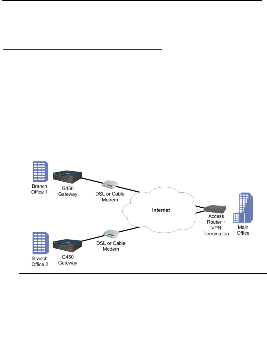
Configuring IPSec VPN
530 Administration for the Avaya G450 Media Gateway
Typical installations
Included in the typical installations, are examples of installing VPN hub and spokes, full or
partial mesh, and a hub-and-spoke with VPN for data and VoIP control backup.
Simple VPN topology – VPN hub and spokes
The simple VPN topology consists of several VPN spokes (branch offices) connected via the
Internet to the VPN hub (Main Office).
In this topology:
●The Broadband Internet connection uses cable or DSL modem, with a static public IP
address
●There is a VPN tunnel from each spoke to the VPN hub over the Internet
●Only VPN traffic is allowed via the Internet connection
Figure 45: Simple VPN topology: VPN hub and spokes

Typical installations
Issue 1 January 2008 531
Configuring the simple VPN topology
1. Configure each branch as follows:
●The default gateway is the Internet interface
●VPN policy is configured on the Internet interface egress as follows:
●Traffic from the local subnets to any IP address is encrypted, using tunnel mode
IPSec
●The remote peer is the Main Office (the VPN Hub)
●An access control list (ACL) is configured on the Internet interface to allow only the
VPN / ICMP traffic. See Table 129 for configuration settings.
2. Configure the VPN Hub (Main Office) as follows:
●Static routing: Branch subnets -> Internet interface
●The VPN policy portion for the branch is configured as a mirror image of the branch, as
follows:
●Traffic from any to branch local subnets -> encrypt, using tunnel mode IPSec
●The remote peer is the VPN spoke (Branch Internet address)
Note:
Note: For information about using access control lists, see Configuring policy on
page 591.
Table 129: Configuring simple VPN topology
Traffic direction ACL parameter ACL value Description
Ingress IKE Permit -
Ingress ESP Permit -
Ingress ICMP Permit This enables the PMTUD
application to work
Ingress All allowed services
from any IP address
to any local subnet
Permit Due to the definition of
the VPN Policy, this will
be allowed only if traffic
comes over ESP
Ingress Default VPN policy Deny -
Egress IKE Permit -
Egress ESP Permit -
1 of 2

Configuring IPSec VPN
532 Administration for the Avaya G450 Media Gateway
Egress ICMP Permit This enables the PMTUD
application to work
Egress All allowed services
from any IP address
to any local subnet
Permit This traffic is tunnelled
using VPN
Egress Default Deny -
Table 129: Configuring simple VPN topology (continued)
Traffic direction ACL parameter ACL value Description
2 of 2

Typical installations
Issue 1 January 2008 533
Configuration example
crypto isakmp policy 1
encryption aes
hash sha
group 2
exit
crypto isakmp peer address <Main Office Public Internet Static IP Address>
pre-shared-key <secret key>
isakmp-policy 1
exit
crypto ipsec transform-set ts1 esp-3des esp-sha-hmac
set pfs 2
exit
crypto map 1
set peer <Main OfficeMain Office Public Internet Static IP
Address>
set transform-set ts1
exit
ip crypto-list 901
local-address <Branch Office Public Internet Static IP Address>
ip-rule 10
source-ip <Branch Subnet1> <Branch Subnet1 Mask>
destination-ip any
protect crypto map 1
exit
ip-rule 20
source-ip <Branch Subnet2> <Branch Subnet2 Mask>
destination-ip any
protect crypto map 1
exit
exit
ip access-control-list 301
ip-rule 10
source-ip any
destination-ip any
ip-protocol udp
udp destination-port eq Ike
composite-operation Permit
exit
ip-rule 11
source-ip any
destination-ip any
ip-protocol udp
udp destination-port eq Ike-nat-t
composite-operation permit
exit

Configuring IPSec VPN
534 Administration for the Avaya G450 Media Gateway
ip-rule 12
source-ip any
destination-ip any
ip-protocol udp
udp destination-port eq Ike-nat-t-vsu
composite-operation permit
exit
ip-rule 20
source-ip any
destination-ip any
ip-protocol esp
composite-operation Permit
exit
ip-rule 30
source-ip any
destination-ip any
ip-protocol icmp
composite-operation Permit
exit
ip-rule 40
source-ip any
destination-ip host <Branch Subnet1> <Branch Subnet1 Mask>
composite-operation Permit
exit
ip-rule 50
source-ip any
destination-ip host <Branch Subnet2> <Branch Subnet2 Mask>
composite-operation Permit
exit
ip-rule default
composite-operation deny
exit
exit
ip access-control-list 302
ip-rule 10
source-ip any
destination-ip any
ip-protocol udp
udp destination-port eq Ike
composite-operation Permit
exit
ip-rule 11
source-ip any
destination-ip any
ip-protocol udp
udp destination-port eq Ike-nat-t
composite-operation permit
exit
ip-rule 12
source-ip any
destination-ip any
ip-protocol udp
udp destination-port eq Ike-nat-t-vsu
composite-operation permit
exit

Typical installations
Issue 1 January 2008 535
ip-rule 20
source-ip any
destination-ip any
ip-protocol esp
composite-operation Permit
exit
ip-rule 30
source-ip any
destination-ip any
ip-protocol icmp
composite-operation Permit
exit
ip-rule 40
desintation-ip any
source-ip host <Branch Subnet1> <Branch Subnet1 Mask>
composite-operation Permit
exit
ip-rule 50
destination-ip any
source-ip host <Branch Subnet2> <Branch Subnet2 Mask>
composite-operation Permit
exit
ip-rule default
composite-operation deny
exit
exit
interface vlan 1.1
ip-address <Branch Subnet1> <Branch Subnet1 Mask>
pmi
icc-vlan
exit
interface vlan 1.2
ip-address <Branch Subnet2> <Branch Subnet2 Mask>
exit
interface FastEthernet 10/2
encapsulation PPPoE
traffic-shape rate 256000
ip Address <Branch Office Public Internet Static IP Address>
<Branch Office Public Internet network mask>
ip crypto-group 901
ip access-group 301 in
ip access-group 302 out
exit
ip default-gateway FastEthernet 10/2 high

Configuring IPSec VPN
536 Administration for the Avaya G450 Media Gateway
Using dynamic local peer IP
When the number of static IP addresses in an organization is limited, the ISP allocates
temporary IP addresses to computers wishing to communicate over IP. These temporary
addresses are called dynamic IP addresses.
The G450 IPSec VPN feature provides dynamic local peer IP address support. To work with
dynamic local peer IP, you must first configure some prerequisites and then instruct the G450 to
learn the IP address dynamically using either PPPoE or DHCP client.
Note:
Note: When working with dynamic local peer IP, you must verify that it is the G450 that
initiates the VPN connection. The VPN peer cannot initiate the connection since it
does not know the G450’s IP address. To maintain the G450 as the initiator, do
one of the following:
●Specify continuous channel in the context of the VPN peer, to maintain the
IKE phase 1 connection even when no traffic is sent (see Enabling continuous
channel on page 539).
●Maintain a steady transmission of traffic by sending GRE keepalives or employing
object tracking.
Prerequisites for dynamic local peer IP
●Specify IKE aggressive mode with the initiate mode aggressive command when
entering the ISAKMP peer information (see Configuring ISAKMP peer information on
page 514).
●Specify the local device by its FQDN name, using the self-identity command, when
entering the ISAKMP peer information (see Configuring ISAKMP peer information on
page 514). For example:
●Specify the local address by name in the ip crypto lists, using the local-address
command (see Configuring crypto lists on page 520). You must specify the local address
by interface name. For example:
G450-001(config-peer:149.49.70.1)# initiate mode aggressive
Done!
G450-001(config-peer:149.49.70.1)# self-identity fqdn vpn.avaya.com
Done!
G450-001(Crypto 901)# local-address FastEthernet 10/2
Done!

Typical installations
Issue 1 January 2008 537
Configuring dynamic local peer IP on a PPPoE interface
1. Enter the context of the FastEthernet interface. For example:
2. Enter the following commands in the context of the interface: no ip address,
encapsulation pppoe, and ip address negotiated.
3. Exit the context of the interface, and set the interface name as the next hop. For example:
Note:
Note: PPP over Ethernet (PPPoE) is a client-server protocol used for carrying
PPP-encapsulated data over Ethernet frames. You can configure PPPoE on the
G450’s ETH WAN Fast Ethernet port. For more information about PPPoE on the
G450, see Configuring PPPoE on page 259.
Configuring dynamic local peer IP for a DHCP Client
1. Permit DHCP packets in the ingress access control list (ACL) and the egress ACL. To do
so, perform the following:
a. Use the no ip access-group command to deactivate both the ingress ACL and the
egress ACL on the FastEthernet interface.
b. Add a rule to the ingress ACL and to the egress ACL, permitting DHCP packets to
pass (for information on defining ACL policy rules, see Defining rules on page 599).
c. Use the ip access-group command to activate the ingress ACL and the egress
ACL on the FastEthernet interface.
For example:
G450-001(config)# interface fastethernet 10/2
G450-001(config-if:FastEthernet 10/2)#
G450-001(config-if:FastEthernet 10/2)# no ip address
Done!
G450-001(config-if:FastEthernet 10/2)# encapsulation pppoe
Done!
G450-001(config-if:FastEthernet 10/2)# ip address negotiated
Done!
G450-001(config-if:FastEthernet 10/2)# exit
G450-001(config)# ip default-gateway FastEthernet 10/2
Done!

Configuring IPSec VPN
538 Administration for the Avaya G450 Media Gateway
! Deactivate the Ingress and Egress ACLs on the FastEthernet Interface
!
G450-001(config)# interface fastethernet 10/2
G450-001(config-if:FastEthernet 10/2)# no ip access-group in
Done!
G450-001(config-if:FastEthernet 10/2)# no ip access-group out
Done!
G450-001(config-if:FastEthernet 10/2)# exit
!
! Add a Permit rule to the Ingress ACL for DHCP
!
G450-001(config)# ip access-control-list 301
G450-001(config-ACL 301)# ip-rule 25
G450-001(config-ACL 301/ip rule 25)# source-ip any
Done!
G450-001(config-ACL 301/ip rule 25)# destination-ip any
Done!
G450-001(config-ACL 301/ip rule 25)# ip-protocol udp
Done!
G450-001(config-ACL 301/ip rule 25)# udp source-port eq bootps
Done!
G450-001(config-ACL 301/ip rule 25)# udp destination-port eq bootpc
Done!
G450-001(config-ACL 301/ip rule 25)# composite-operation permit
Done!
G450-001(config-ACL 301/ip rule 25)# exit
G450-001(config-ACL 301)# exit
!
! Add a Permit rule to the Egress ACL for DHCP
!
G450-001(config)# ip access-control-list 302
G450-001(config-ACL 302)# ip-rule 25
G450-001(config-ACL 302/ip rule 25)# source-ip any
Done!
G450-001(config-ACL 302/ip rule 25)# destination-ip any
Done!
G450-001(config-ACL 302/ip rule 25)# ip-protocol udp
Done!
G450-001(config-ACL 302/ip rule 25)# udp source-port eq bootpc
Done!
G450-001(config-ACL 302/ip rule 25)# udp destination-port eq bootps
Done!
G450-001(config-ACL 302/ip rule 25)# composite-operation permit
Done!
G450-001(config-ACL 302/ip rule 25)# exit
G450-001(config-ACL 302)# exit
!
! Activate the Ingress and Egress ACLs on the FastEthernet Interface
!
G450-001(config)# interface fastethernet 10/2
G450-001(config-if:FastEthernet 10/2)# ip access-group 301 in
Done!
G450-001(config-if:FastEthernet 10/2)# ip access-group 302 out
Done!

Typical installations
Issue 1 January 2008 539
2. Specify no ip address and then ip address dhcp in the context of the FastEthernet
Interface. For example:
3. Exit the context of the interface, and set the interface name as the next hop. For example:
Note:
Note: For more information on DHCP client in the G450, see Configuring DHCP
client on page 199.
Enabling continuous channel
An IPSec VPN connection exists as long as traffic is traversing the connection, or the timeouts
have not expired. However, there are advantages to keeping the connection continuously alive,
such as eliminating the waiting time necessary to construct a new IPSec VPN connection.
The G450 IPSec VPN feature supports continuous channel, which maintains a continuous
IPSec VPN connection. That means that when you activate the ip crypto-group command
on the defined interface, the IPSec VPN tunnel is immediately started, even if no traffic is
traversing the interface and the timeouts have expired.
You can set continuous channel for either or both IKE phase 1 and IKE phase 2, as follows:
●To set continuous channel for IKE phase 1, enter continuous-channel when
configuring the crypto ISAKMP peer information (see Configuring ISAKMP peer
information on page 514). For example:
●To set continuous channel for IKE phase 2, enter continuous-channel when
configuring the crypto map (see Configuring crypto maps on page 519). For example:
G450-001(config-if:FastEthernet 10/2)# no ip address
no ip address defined on this interface
G450-001(config-if:FastEthernet 10/2)# ip address dhcp
Done!
G450-001(config-if:FastEthernet 10/2)#exit
G450-001(config)# ip route 5.0.0.0 255.0.0.0 FastEthernet 10/2
Done!
G450-001# crypto isakmp peer address 149.49.70.1
G450-001(config-peer:149.49.70.1)# continuous-channel
Done!
G450-001# crypto map 1
G450-001(config-crypto:1)# continuous-channel
Done!
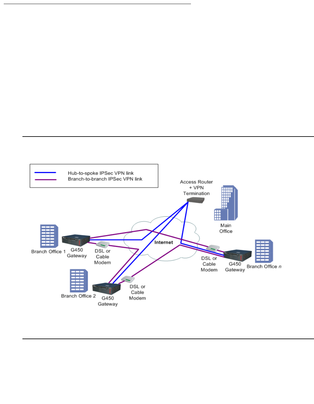
Configuring IPSec VPN
540 Administration for the Avaya G450 Media Gateway
Full or partial mesh
This installation is very similar to the simple hub and spokes installation, but instead of
connecting to a single central site, the branch is also connected to several other branch sites by
direct IPSec VPN tunnels. The configuration is therefore very similar to the previous one,
duplicated several times.
In this topology:
●The Broadband Internet connection uses cable or DSL modem, with a static public IP
address
●There is a VPN tunnel from each spoke to the VPN hub over the Internet
●There is a VPN tunnel from one spoke to another spoke
●Only VPN traffic is allowed via the Internet connection
Figure 46: Full or partial mesh

Typical installations
Issue 1 January 2008 541
Configuring the mesh VPN topology
1. Configure Branch Office 1 as follows:
●The default gateway is the Internet interface
●VPN policy is configured on the Internet interface egress as follows:
●Traffic from the local subnets to the second spoke subnets -> encrypt, using tunnel
mode IPSec, with the remote peer being the second spoke
●Traffic from the local subnets to any IP address -> encrypt, using tunnel mode
IPSec, with the remote peer being the main office (VPN hub)
●An access control list (ACL) is configured on the Internet interface to allow only the
VPN / ICMP traffic. See Table 130 for configuration settings.
Note:
Note: For information about using access control lists, see Configuring policy on
page 591.
Table 130: Configuring the mesh VPN topology – Branch Office 1
Traffic
direction ACL parameter ACL
value Description
Ingress IKE from Main Office IP to
Branch IP Permit -
Ingress ESP from Main Office IP
to Branch IP Permit -
Ingress IKE from Second Branch
IP to Branch IP Permit -
Ingress ESP from Second Branch
IP to Branch IP Permit -
Ingress ICMP from any IP address
to local tunnel endpoint Permit This enables the PMTUD
application to work
Ingress All allowed services from
any IP address to any
local subnet
Permit Due to the definition of the VPN
Policy, this will be allowed only if
traffic comes over ESP
Ingress Default Deny -
Egress IKE from Branch IP to
Main Office IP Permit -
Egress ESP from Branch IP to
Main Office IP Permit -
1 of 2

Configuring IPSec VPN
542 Administration for the Avaya G450 Media Gateway
2. Configure Branch Office 2 as follows:
●The default gateway is the Internet interface
●VPN policy is configured on the Internet interface egress as follows:
●Traffic from the local subnets to the First Spoke subnets -> encrypt, using tunnel
mode IPSec, with the remote peer being the First Spoke
●Traffic from the local subnets to any IP address -> encrypt, using tunnel mode
IPSec, with the remote peer being the Main Office (VPN hub)
●An ACL is configured on the Internet interface to allow only the VPN / ICMP traffic. See
Table 131 for configuration settings.
Note:
Note: For information about using access control lists, see Configuring policy on
page 591.
Egress IKE from Branch IP to
Second Branch IP Permit This enables the PMTUD
application to work
Egress ESP from Branch IP to
Second Branch IP Permit This traffic is tunnelled using
VPN
Egress ICMP from local tunnel
endpoint to any IP
address
Permit This enables the PMTUD
application to work
Egress All allowed services from
any local subnet to any IP
address
Permit This traffic is tunnelled using
VPN
Egress Default Deny -
Table 131: Configuring the mesh VPN topology – Branch Office 2
Traffic
direction ACL parameter ACL
value Description
Ingress IKE from Main Office IP to
Branch IP Permit -
Ingress ESP from Main Office IP to
Branch IP Permit -
1 of 2
Table 130: Configuring the mesh VPN topology – Branch Office 1 (continued)
Traffic
direction ACL parameter ACL
value Description
2 of 2

Typical installations
Issue 1 January 2008 543
3. Configure the VPN Hub (Main Office) as follows:
●Static routing: Branch subnets -> Internet interface
●The VPN policy portion for the branch is configured as a mirror image of the branch, as
follows:
●Traffic from any IP address to branch local subnets -> encrypt, using tunnel mode
IPSec
●The remote peer is the VPN Spoke (Branch Internet address)
Ingress IKE from First Branch IP to
Branch IP Permit -
Ingress ESP from First Branch IP to
Branch IP Permit -
Ingress ICMP from any IP address to
local tunnel endpoint Permit This enables the PMTUD
application to work
Ingress All allowed services from any IP
address to any local subnet Permit Due to the definition of the VPN
Policy, this will be allowed only if
traffic comes over ESP
Ingress Default Deny -
Egress IKE from Branch IP to Main
Office IP Permit -
Egress ESP from Branch IP to Main
Office IP Permit -
Egress IKE from Branch IP to First
Branch IP Permit This enables the PMTUD
application to work
Egress ESP from Branch IP to First
Branch IP Permit This traffic is tunnelled using
VPN
Egress ICMP from local tunnel endpoint
to any IP address Permit This enables the PMTUD
application to work
Egress All allowed services from any
local subnet to any IP address Permit This traffic is tunnelled using
VPN
Egress Default Deny -
Table 131: Configuring the mesh VPN topology – Branch Office 2 (continued)
Traffic
direction ACL parameter ACL
value Description
2 of 2

Configuring IPSec VPN
544 Administration for the Avaya G450 Media Gateway
Configuration example
1. Configure Branch Office 1:
crypto isakmp policy 1
encryption aes
hash sha
group 2
exit
crypto isakmp peer address <Main Office Public Internet Static IP
Address>
pre-shared-key <secret key>
isakmp-policy 1
exit
crypto isakmp peer address <Second Branch Office Public Internet Static
IP Address>
pre-shared-key <secret key 2>
isakmp-policy 1
exit
crypto ipsec transform-set ts1 esp-3des esp-sha-hmac
set pfs 2
exit
crypto map 1
set peer <Main Office Public Internet Static IP Address>
set transform-set ts1
exit
crypto map 2
set peer <Second Branch Office Public Internet Static IP Address>
set transform-set ts1
exit
ip crypto-list 901
local-address <Branch Office Public Internet Static IP Address>
ip-rule 1
source-ip <Branch Subnet1> <Branch Subnet1 Mask>
destination-ip <Second Branch Subnet1> <Second Branch
Subnet1 Mask>
protect crypto map 2
exit
ip-rule 2
source-ip <Branch Subnet2> <Branch Subnet2 Mask>
destination-ip <Second Branch Subnet1> <Second Branch
Subnet1 Mask>
protect crypto map 2
exit
ip-rule 3
source-ip <Branch Subnet1> <Branch Subnet1 Mask>
destination-ip <Second Branch Subnet2> <Second Branch
Subnet2 Mask>
protect crypto map 2
exit

Typical installations
Issue 1 January 2008 545
ip-rule 4
source-ip <Branch Subnet2> <Branch Subnet2 Mask>
destination-ip <Second Branch Subnet2> <Second Branch
Subnet2 Mask>
protect crypto map 2
exit
ip-rule 10
source-ip <Branch Subnet1> <Branch Subnet1 Mask>
destination-ip any
protect crypto map 1
exit
ip-rule 20
source-ip <Branch Subnet2> <Branch Subnet2 Mask>
destination-ip any
protect crypto map 1
exit
exit
ip access-control-list 301
ip-rule 10
source-ip any
destination-ip any
ip-protocol udp
udp destination-port eq Ike
composite-operation Permit
exit
ip-rule 11
source-ip any
destination-ip any
ip-protocol udp
udp destination-port eq Ike-nat-t
composite-operation permit
exit
ip-rule 12
source-ip any
destination-ip any
ip-protocol udp
udp destination-port eq Ike-nat-t-vsu
composite-operation permit
exit
ip-rule 20
source-ip any
destination-ip any
ip-protocol esp
composite-operation Permit
exit

Configuring IPSec VPN
546 Administration for the Avaya G450 Media Gateway
ip-rule 30
source-ip any
destination-ip any
ip-protocol icmp
composite-operation Permit
exit
ip-rule 40
source-ip any
destination-ip host <Branch Subnet1> <Branch Subnet1 Mask>
composite-operation Permit
exit
ip-rule 50
source-ip any
destination-ip host <Branch Subnet2> <Branch Subnet2 Mask>
composite-operation Permit
exit
ip-rule default
composite-operation deny
exit
exit
ip access-control-list 302
ip-rule 10
source-ip any
destination-ip any
ip-protocol udp
udp destination-port eq Ike
composite-operation Permit
exit
ip-rule 11
source-ip any
destination-ip any
ip-protocol udp
udp destination-port eq Ike-nat-t
composite-operation permit
exit
ip-rule 12
source-ip any
destination-ip any
ip-protocol udp
udp destination-port eq Ike-nat-t-vsu
composite-operation permit
exit
ip-rule 20
source-ip any
destination-ip any
ip-protocol esp
composite-operation Permit
exit

Typical installations
Issue 1 January 2008 547
Note:
Note: The commands appearing in bold are the CLI commands that add the mesh
capabilities to the simple hub and spokes configuration.
ip-rule 30
source-ip any
destination-ip any
ip-protocol icmp
composite-operation Permit
exit
ip-rule 40
desintation-ip any
source-ip host <Branch Subnet1> <Branch Subnet1 Mask>
composite-operation Permit
exit
ip-rule 50
destination-ip any
source-ip host <Branch Subnet2> <Branch Subnet2 Mask>
composite-operation Permit
exit
ip-rule default
composite-operation deny
exit
exit
interface vlan 1.1
ip-address <Branch Subnet1> <Branch Subnet1 Mask>
pmi
icc-vlan
exit
interface vlan 1.2
ip-address <Branch Subnet2> <Branch Subnet2 Mask>
exit
interface fastethernet 10/2
encapsulation PPPoE
traffic-shape rate 256000
ip Address <Branch Office Public Internet Static IP Address>
<Branch Office Public Internet network mask>
ip crypto-group 901
ip access-group 301 in
ip access-group 302 out
exit
ip default-gateway FastEthernet 10/2 high

Configuring IPSec VPN
548 Administration for the Avaya G450 Media Gateway
2. Configure Branch Office 2:
crypto isakmp policy 1
encryption aes
hash sha
group 2
exit
crypto isakmp peer address <Main Office Public Internet Static IP
Address>
pre-shared-key <secret key>
isakmp-policy 1
exit
crypto isakmp peer address <First Branch Office Public Internet Static IP
Address>
pre-shared-key <secret key 2>
isakmp-policy 1
exit
crypto ipsec transform-set ts1 esp-3des esp-sha-hmac
set pfs 2
exit
crypto map 1
set peer <Main Office Public Internet Static IP Address>
set transform-set ts1
exit
crypto map 2
set peer <First Branch Office Public Internet Static IP Address>
set transform-set ts1
exit
ip crypto-list 901
local-address <Branch Office Public Internet Static IP Address>
ip-rule 1
source-ip <Branch Subnet1> <Branch Subnet1 Mask>
destination-ip <First Branch Subnet1> <Second Branch
Subnet1 Mask>
protect crypto map 2
exit
ip-rule 2
source-ip <Branch Subnet2> <Branch Subnet2 Mask>
destination-ip <First Branch Subnet1> <Second Branch
Subnet1 Mask>
protect crypto map 2
exit
ip-rule 3
source-ip <Branch Subnet1> <Branch Subnet1 Mask>
destination-ip <First Branch Subnet2> <Second Branch
Subnet2 Mask>
protect crypto map 2
exit

Typical installations
Issue 1 January 2008 549
ip-rule 4
source-ip <Branch Subnet2> <Branch Subnet2 Mask>
destination-ip <First Branch Subnet2> <Second Branch
Subnet2 Mask>
protect crypto map 2
exit
ip-rule 10
source-ip <Branch Subnet1> <Branch Subnet1 Mask>
destination-ip any
protect crypto map 1
exit
ip-rule 20
source-ip <Branch Subnet2> <Branch Subnet2 Mask>
destination-ip any
protect crypto map 1
exit
exit
ip access-control-list 301
ip-rule 10
source-ip any
destination-ip any
ip-protocol udp
udp destination-port eq Ike
composite-operation Permit
exit
ip-rule 11
source-ip any
destination-ip any
ip-protocol udp
udp destination-port eq Ike-nat-t
composite-operation permit
exit
ip-rule 12
source-ip any
destination-ip any
ip-protocol udp
udp destination-port eq Ike-nat-t-vsu
composite-operation permit
exit

Configuring IPSec VPN
550 Administration for the Avaya G450 Media Gateway
ip-rule 20
source-ip any
destination-ip any
ip-protocol esp
composite-operation Permit
exit
ip-rule 30
source-ip any
destination-ip any
ip-protocol icmp
composite-operation Permit
exit
ip-rule 40
source-ip any
destination-ip host <Branch Subnet1> <Branch Subnet1 Mask>
composite-operation Permit
exit
ip-rule 50
source-ip any
destination-ip host <Branch Subnet2> <Branch Subnet2 Mask>
composite-operation Permit
exit
ip-rule default
composite-operation deny
exit
exit
ip access-control-list 302
ip-rule 10
source-ip any
destination-ip any
ip-protocol udp
udp destination-port eq Ike
composite-operation Permit
exit
ip-rule 11
source-ip any
destination-ip any
ip-protocol udp
udp destination-port eq Ike-nat-t
composite-operation permit
exit
ip-rule 12
source-ip any
destination-ip any
ip-protocol udp
udp destination-port eq Ike-nat-t-vsu
composite-operation permit
exit
ip-rule 20
source-ip any
destination-ip any
ip-protocol esp
composite-operation Permit
exit

Typical installations
Issue 1 January 2008 551
Note:
Note: The commands appearing in bold are the CLI commands that add the mesh
capabilities to the simple hub and spokes configuration.
ip-rule 30
source-ip any
destination-ip any
ip-protocol icmp
composite-operation Permit
exit
ip-rule 40
desintation-ip any
source-ip host <Branch Subnet1> <Branch Subnet1 Mask>
composite-operation Permit
exit
ip-rule 50
destination-ip any
source-ip host <Branch Subnet2> <Branch Subnet2 Mask>
composite-operation Permit
exit
ip-rule default
composite-operation deny
exit
exit
interface vlan 1.1
ip-address <Branch Subnet1> <Branch Subnet1 Mask>
pmi
icc-vlan
exit
interface vlan 1.2
ip-address <Branch Subnet2> <Branch Subnet2 Mask>
exit
interface fastethernet 10/2
encapsulation PPPoE
traffic-shape rate 256000
ip Address <Branch Office Public Internet Static IP Address>
<Branch Office Public Internet network mask>
ip crypto-group 901
ip access-group 301 in
ip access-group 302 out
exit
ip default-gateway FastEthernet 10/2 high
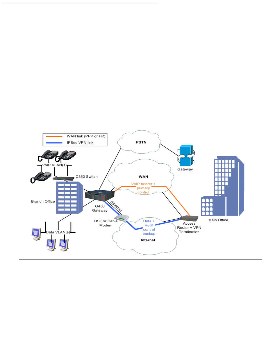
Configuring IPSec VPN
552 Administration for the Avaya G450 Media Gateway
Full solution: hub and spoke with VPN
The full solution consists of a hub-and-spoke with VPN for data and VoIP control backup.
In this topology:
●There is a direct WAN connection to the Main Office for VoIP bearer and as primary VoIP
control connection
●The Broadband Internet connection uses cable or DSL modem, with a static public IP
address
●There is a VPN tunnel to the hub over the Internet for intranet data, and as backup
connection for VoIP control
●The local hosts access the Internet directly through the local broadband connection
●The PSTN connection backs up the voice bearer
Figure 47: Full solution: hub-and-spoke with VPN for data and VoIP control backup

Typical installations
Issue 1 January 2008 553
Configuring hub-and-spoke with VPN for data and VoIP control backup
1. Configure the Branch Office as follows:
●The default gateway is the Internet interface
●VPN policy is configured on the Internet interface egress as follows:
Traffic from the local GRE tunnel endpoint to the remote GRE tunnel endpoint ->
encrypt, using IPSec tunnel mode, with the remote peer being the Main Office.
●An access control list (ACL) is configured on the Internet interface to allow only the
VPN tunnel and ICMP traffic. See Table 132 for configuration settings.
Note:
Note: For information about using access control lists, see Configuring policy on
page 591.
●Policy Based Routing (PBR) is configured as follows on VoIP VLAN and loopback
interfaces:
●Destination IP = local subnets -> Route: DBR
●DSCP = bearer -> Route: WAN
●DSCP = control -> Route: 1. WAN 2. DBR
Table 132: Configuring hub-and-spoke with VPN
Traffic
direction ACL parameter ACL
value
Ingress IKE (UDP/500) from remote tunnel endpoint to local tunnel
endpoint Permit
Ingress ESP/AH from remote tunnel endpoint to local tunnel endpoint Permit
Ingress Remote GRE tunnel endpoint to local GRE tunnel endpoint Permit
Ingress Allowed ICMP from any IP address to local tunnel endpoint Permit
Ingress Default Deny
Egress IKE (UDP/500) from local tunnel endpoint to remote tunnel
endpoint Permit
Egress Local GRE tunnel endpoint to remote GRE tunnel endpoint Permit
Egress All allowed services from any local subnet to any IP address Permit
Egress Allowed ICMP from local tunnel endpoint to any IP address Permit
Egress Default Deny

Configuring IPSec VPN
554 Administration for the Avaya G450 Media Gateway
Note:
Note: For information about PBR, see Configuring policy-based routing on page 619.
2. Configure the VPN Hub (Main Office) as follows:
●The VPN policy portion for the branch is configured as a mirror image of the branch
●The ACL portion for the branch is a mirror image of the branch, with some minor
modifications
●Static routing is configured as follows:
-
Branch subnets -> Internet interface
●The PBR portion for the branch is configured as follows, on most interfaces:
-
Destination IP = branch VoIP subnet(s) or GW address (PMI), DSCP = bearer ->
Route: WAN
-
Destination IP = branch VoIP subnet(s) or GW address (PMI), DSCP = control ->
Route: 1. WAN 2. DBR
●ACM is configured to route voice calls through PSTN when the main VoIP trunk is
down

Typical installations
Issue 1 January 2008 555
Configuration example
crypto isakmp policy 1
encryption aes
hash sha
group 2
authentication pre-share
exit
crypto isakmp peer address <Main Office Internet public Static IP
Address>
pre-shared-key <key1>
isakmp-policy 1
exit
crypto ipsec transform-set ts1 esp-3des esp-sha-hmac
exit
crypto map 1
set peer <Main Office Internet public Static IP Address>
set transform-set ts1
exit
ip crypto-list 901
local-address <Branch Office Public Internet Static IP Address>
ip-rule 10
source-ip <Branch data Subnet> <Branch data Subnet Mask>
destination-ip any
protect crypto map 1
exit
ip-rule 20
source-ip <Branch voice Subnet> <Branch voice Subnet Mask>
destination-ip any
protect crypto map 1
exit
exit
ip access-control-list 301
ip-rule 10
source-ip any
destination-ip any
ip-protocol udp
udp destination-port eq Ike
composite-operation Permit
exit

Configuring IPSec VPN
556 Administration for the Avaya G450 Media Gateway
ip-rule 11
source-ip any
destination-ip any
ip-protocol udp
udp destination-port eq Ike-nat-t
composite-operation permit
exit
ip-rule 12
source-ip any
destination-ip any
ip-protocol udp
udp destination-port eq Ike-nat-t-vsu
composite-operation permit
exit
ip-rule 20
source-ip any
destination-ip any
ip-protocol esp
composite-operation Permit
exit
ip-rule 30
source-ip any
destination-ip any
ip-protocol icmp
composite-operation Permit
exit
ip-rule 40
source-ip any
destination-ip <Branch data Subnet> <Branch data Subnet
Mask>
composite-operation Permit
exit
ip-rule 50
source-ip any
destination-ip <Branch voice Subnet> <Branch voice Subnet
Mask>
composite-operation Permit
exit
ip-rule default
composite-operation deny
exit
exit
ip access-control-list 302
ip-rule 10
source-ip any
destination-ip any
ip-protocol udp
udp destination-port eq Ike
composite-operation Permit
exit

Typical installations
Issue 1 January 2008 557
ip-rule 11
source-ip any
destination-ip any
ip-protocol udp
udp destination-port eq Ike-nat-t
composite-operation permit
exit
ip-rule 12
source-ip any
destination-ip any
ip-protocol udp
udp destination-port eq Ike-nat-t-vsu
composite-operation permit
exit
ip-rule 20
source-ip any
destination-ip any
ip-protocol esp
composite-operation Permit
exit
ip-rule 30
source-ip any
destination-ip any
ip-protocol icmp
exit
ip-rule 40
source-ip <Branch data Subnet> <Branch data Subnet Mask>
destination-ip any
composite-operation Permit
exit
ip-rule 50
source-ip <Branch voice Subnet> <Branch voice Subnet Mask>
destination-ip any
composite-operation Permit
exit
ip-rule default
composite-operation deny
exit
exit
interface vlan 1
description "VoIP_VLAN"
ip address <branch voice subnet IP address> <branch voice subnet mask>
icc-vlan
pmi
exit
interface vlan 2
description "DATA_VLAN"
ip address <branch data subnet IP address> <branch data subnet mask>
exit

Configuring IPSec VPN
558 Administration for the Avaya G450 Media Gateway
interface fastethernet 10/2
encapsulation pppoe
traffic-shape rate 256000
ip address <Branch Office Internet public Static IP Address> <Branch
Office Internet public net mask>
ip crypto-group 901
ip access-group 301 in
ip access-group 302 out
exit
interface serial 3/1
ip address <Branch Office serial IP address> <Branch Office serial
net mask>
exit
ip next-hop-list 1
next-hop-interface 1 serial 3/1
exit
ip next-hop-list 2
next-hop-interface 1 serial 3/1
next-hop-interface 2 FastEthernet 10/2
exit
ip pbr-list 801
ip-rule 10
!
! The following command specifies the Voice bearer
!
dscp 46
next-hop list 1
exit
ip-rule 20
!
! The following command specifies the Voice Control
!
dscp 34
next-hop list 2
exit
ip-rule default
next-hop PBR
exit
exit

Typical installations
Issue 1 January 2008 559
Typical failover applications
Introduction to the failover mechanism
The failover mechanism provides switchover to backup peers in case of remote peer failure. To
enable the failover mechanism, you must:
●Configure VPN keepalives, which check the remote peer periodically and announce when
the remote peer is dead
●Provide backup peers and a mechanism for switching to a backup in case of remote peer
failure
In addition to the GRE failover mechanism (see Failover using GRE on page 560), the G450
supports several additional failover mechanisms, as described below.
Configuring VPN keepalives
VPN keepalives can dramatically improve the speed with which the G450 detects loss of
connectivity with the remote VPN peer. Two types of VPN keepalives are available. You can use
either or both methods:
●Enable DPD keepalives, a standard VPN keepalive, that check whether the remote peer is
up. This type of detection can be used only if it is supported also by the remote peer.
●Bind peer status to an object tracker. Object trackers track the state (up/down) of remote
devices using keepalive probes, and notify registered applications such as VPN when the
state changes. Object tracking allows monitoring of hosts inside the remote peer’s
protected network, not just of the remote peer itself as in DPD.
Backup peer mechanism
You can use any one of these alternate backup peer mechanisms:
●DNS server (see Failover using DNS on page 567). This method utilizes the G450’s DNS
resolver capability for dynamically resolving a remote peer’s IP address via a DNS query.
Use this feature when your DNS server supports failover through health-checking of
redundant hosts. On your DNS server, configure a hostname to translate to two or more
redundant hosts, which act as redundant VPN peers. On the G450, configure that
hostname as your remote peer. The G450 will perform a DNS query in order to resolve the
hostname to an IP address before establishing an IKE connection. Your DNS server
should be able to provide an IP address of a living host. The G450 will perform a new DNS
query and try to re-establish the VPN connection to the newly provided IP address
whenever it senses that the currently active remote peer stops responding. The G450 can
sense that a peer is dead when IKE negotiation times-out, through DPD keepalives, and
through object tracking.

Configuring IPSec VPN
560 Administration for the Avaya G450 Media Gateway
●Using the G450’s peer-group entity (see Failover using a peer-group on page 575):
●Define a peer-group. A peer-group is an ordered list of redundant remote peers, only
one of which is active at any time. When the active peer is considered dead, the next
peer in the list becomes the active remote peer.
●When configuring a crypto map, point to the peer-group instead of to a single peer
Failover using GRE
A branch with a G450 can connect to two or more VPN hub sites, in a way that will provide
either redundancy or load sharing.
In this topology, the G450 is connected through its 10/100 WAN Ethernet port to a DSL modem.
●Define two GRE Tunnel interfaces:
●GRE1 that leads to a Primary Main Office GRE End Point behind the VPN Hub
Gateway
●GRE2 that leads to a Backup Main Office GRE End Point behind the VPN Hub
Gateway
●Define two VPNs
●Connectivity to the networks in Primary/Backup Main Office is determined through GRE
keepalives. If network connectivity is lost due to failures in the WAN, in the Primary Main
Office, the GRE keep-alive will fail and the GRE interface will transition to a “down” state.
Redundancy and load sharing modes
The two GRE tunnels can then be used for branch to Primary/Backup Main Office in either
Redundancy or Load sharing mode:
●Redundancy. GRE2 is configured as a backup interface for GRE1, and is activated only
when GRE1 is down
●Load sharing. Both Tunnel interfaces are active. Routing protocols (RIP or OSPF) route
traffic to destinations based on route cost and availability, as follows:
For two routes of equal cost to the same destination, one through the Primary Main Office
and one through the Backup Main Office, OSPF will automatically distribute traffic through
both routes, effectively sharing the load between routes.
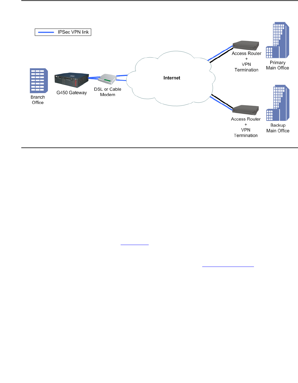
Typical installations
Issue 1 January 2008 561
Figure 48: Hub and spoke with hub redundancy/load sharing using GRE
Configuring VPN hub redundancy and load sharing topologies using GRE
1. Configure the Branch Office as follows:
●VPN policy is configured on the Internet interface egress as follows:
●GRE Traffic from the local tunnel endpoint to remote tunnel endpoint 1 -> encrypt,
using IPSec tunnel mode, with the remote peer being tunnel endpoint 1
●GRE Traffic from the local tunnel endpoint to remote tunnel endpoint 2 -> encrypt,
using IPSec tunnel mode, with the remote peer being tunnel endpoint 2
●An access control list (ACL) is configured on the Internet interface to allow only the
VPN / ICMP traffic. See Table 133 for configuration settings.
Note:
Note: For information about using access control lists, see Configuring policy on
page 591.

Configuring IPSec VPN
562 Administration for the Avaya G450 Media Gateway
●Configure dynamic routing (OSPF or RIP) to run over local data interfaces (data
VLANs) and on the GRE interfaces
2. Configure the VPN Hubs (Main Offices) as follows:
●The VPN policy portion for the branch is configured as a mirror image of the branch
●The ACL portion for the branch is a mirror image of the branch, with some minor
modifications
●The GRE Tunnel interface is configured for the branch
●Dynamic routing (OSPF or RIP) is configured to run over the GRE interface to the
branch
Table 133: Configuring VPN hub redundancy and load sharing topologies
Traffic
direction ACL parameter ACL
value
Ingress IKE (UDP/500) from remote tunnel endpoint to local tunnel
endpoint Permit
Ingress ESP/AH from remote tunnel endpoint to local tunnel endpoint Permit
Ingress Allowed ICMP from any IP address to local tunnel endpoint Permit
Ingress Default Deny
Egress IKE (UDP/500) from local tunnel endpoint to remote tunnel
endpoint Permit
Egress All allowed services from any local subnet to any IP address Permit
Egress Allowed ICMP from local tunnel endpoint to any IP address Permit
Egress Default Deny

Typical installations
Issue 1 January 2008 563
Configuration example
crypto isakmp policy 1
encryption aes
hash sha
group 2
authentication pre-share
exit
crypto isakmp peer address <Primary Main Office Internet public Static IP
Address>
pre-shared-key <key1>
isakmp-policy 1
exit
crypto isakmp peer address <Backup Main Office Internet public Static
IP Address>
pre-shared-key <key2>
isakmp-policy 1
exit
crypto ipsec transform-set ts1 esp-3des esp-sha-hmac
exit
crypto map 1
set peer <Primary Main Office Internet public Static IP Address>
set transform-set ts1
exit
crypto map 2
set peer <Backup Main Office Internet public Static IP Address>
set transform-set ts1
exit
ip crypto-list 901
local-address <Branch Office Internet public Static IP Address>
ip-rule 1
source-ip host <Branch GRE Tunnel end point IP Address>
destination-ip host <Primary Main Office GRE Tunnel end point IP
Address>
protect crypto map 1
exit
ip-rule 2
source-ip host <Branch GRE Tunnel end point IP Address>
destination-ip host <Backup Main Office GRE Tunnel end point
IP Address>
protect crypto map 2
exit
exit

Configuring IPSec VPN
564 Administration for the Avaya G450 Media Gateway
ip access-control-list 301
ip-rule 30
source-ip any
destination-ip any
ip-protocol udp
udp destination-port eq Ike
composite-operation Permit
exit
ip-rule 31
source-ip any
destination-ip any
ip-protocol udp
udp destination-port eq Ike-nat-t
composite-operation permit
exit
ip-rule 32
source-ip any
destination-ip any
ip-protocol udp
udp destination-port eq Ike-nat-t-vsu
composite-operation permit
exit
ip-rule 40
source-ip any
destination-ip any
ip-protocol esp
composite-operation Permit
exit
ip-rule 50
source-ip any
destination-ip host <Branch Office Public Internet Static
IP Address>
ip-protocol icmp
composite-operation Permit
exit
ip-rule 60
source-ip any
destination-ip any
composite-operation Permit
exit

Typical installations
Issue 1 January 2008 565
ip-rule 70
source-ip host <Backup Main Office GRE Tunnel end point
IP Address>
destination-ip host <Branch GRE Tunnel end point IP
Address>
composite-operation Permit
exit
ip-rule default
composite-operation deny
exit
exit
ip access-control-list 302
ip-rule 30
source-ip any
destination-ip any
ip-protocol udp
udp destination-port eq Ike
composite-operation Permit
exit
ip-rule 31
source-ip any
destination-ip any
ip-protocol udp
udp destination-port eq Ike-nat-t
composite-operation permit
exit
ip-rule 32
source-ip any
destination-ip any
ip-protocol udp
udp destination-port eq Ike-nat-t-vsu
composite-operation permit
exit
ip-rule 40
source-ip any
destination-ip any
ip-protocol esp
composite-operation Permit
exit
ip-rule 50
source-ip any
destination-ip any
ip-protocol icmp
exit
ip-rule 60
source-ip host <Branch GRE Tunnel end point IP Address>
destination-ip host <Primary Main Office GRE Tunnel end
point IP Address>
composite-operation Permit
exit

Configuring IPSec VPN
566 Administration for the Avaya G450 Media Gateway
ip-rule 70
source-ip host <Branch GRE Tunnel end point IP Address>
destination-ip host <Backup Main Office GRE Tunnel end
point IP Address>
composite-operation Permit
exit
ip-rule default
composite-operation deny
exit
exit
interface vlan 1
description "VoIP_VLAN"
ip address <branch voice subnet IP address> <branch voice subnet mask>
icc-vlan
pmi
exit
interface vlan 2
description "DATA_VLAN"
ip address <branch data subnet IP address> <branch data subnet mask>
exit
interface fastethernet 10/2
encapsulation pppoe
traffic-shape rate 256000
ip address <Branch Office Internet public Static IP Address> <Branch
Office Internet public net mask>
ip crypto-group 901
ip access-group 301 in
ip access-group 302 out
exit
interface Tunnel 1
!
! The following two backup commands specify redundant mode.
! To specify load-sharing mode, omit them.
!
backup interface tunnel 2
backup delay 20 15
keepalive 10 3
tunnel source <Branch GRE Tunnel end point IP Address>
tunnel destination <Primary MainPrimary Main Office GRE Tunnel end
point IP Address>
ip address 10.10.10.1 255.255.255.252
exit
interface Tunnel 2
keepalive 10 3
tunnel source <Branch GRE Tunnel end point IP Address>
tunnel destination <Backup Main Office GRE Tunnel end point IP
Address>
ip address 20.20.20.1 255.255.255.252
exit
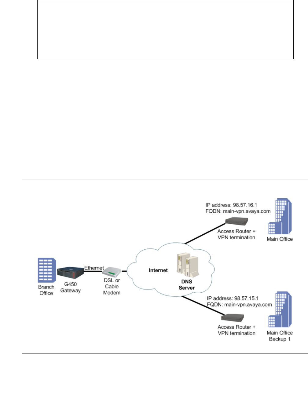
Typical installations
Issue 1 January 2008 567
Failover using DNS
The VPN DNS topology provides failover by utilizing the DNS resolver feature.
Use this feature when your DNS server supports failover through health-checking of redundant
hosts. On your DNS server configure a hostname to translate to two or more redundant hosts,
which act as redundant VPN peers. On the G450 configure that hostname as your remote peer.
The G450 will perform a DNS query in order to resolve the hostname to an IP address before
establishing an IKE connection. Your DNS server should be able to provide an IP address of a
living host. The G450 will perform a new DNS query and try to re-establish the VPN connection
to the newly provided IP address whenever it senses that the currently active remote peer stops
responding. The G450 can sense that a peer is dead when IKE negotiation times-out through
DPD keepalives and through object tracking.
Figure 49: VPN DNS topology
ip route <Primary Main Offfice GRE Tunnel end point IP Address>
255.255.255.255 FastEthernet 10/2 high
ip route <Backup Main Offfice GRE Tunnel end point IP Address>
255.255.255.255 FastEthernet 10/2 high
router ospf
network 10.10.10.0 0.0.0.3 area 0.0.0.0
network 20.20.20.0 0.0.0.3 area 0.0.0.0
exit

Configuring IPSec VPN
568 Administration for the Avaya G450 Media Gateway
Note:
Note: For an explanation of DNS resolver, see DNS resolver on page 88.
Configuring the VPN DNS topology
1. Define the private VLAN1 and VLAN2 interfaces (IP address and mask), and define one of
them as the PMI and ICC-VLAN.
2. Define the public FastEthernet10/2 interface (IP address and mask).
3. Define the default gateway (the IP of the next router).
4. Define the DNS name-server-list and the IP address of the DNS server.
Note:
Note: Alternatively, you can use DHCP Client or PPPoE to dynamically learn the DNS
server’s IP address. Use the ip dhcp client request command when using
DHCP client, or use the ppp ipcp dns request command when using
PPPoE.
5. Define the ISAKMP policy, using the crypto isakmp policy command.
6. Define the remote peer with FQDN, using the crypto isakmp peer address
command, including:
●the pre-shared key
●the ISAKMP policy
7. Define the IPSEC transform-set, using the crypto ipsec transform-set command.
8. Define the crypto map, using the crypto map command.
9. Define the crypto list as follows:
●Set the local address to the public interface name (for example, FastEthernet 10/2.0)
●For each private interface, define an ip-rule using the following format:
●source-ip <private subnet> <private subnet wild card mast>.
For example, 10.10.10.0 0.0.0.255
●destination-ip any
●protect crypto map 1
10. Define the ingress access control list (ACL) to protect the device from Incoming traffic from
the public interface, as follows:
●Permit DNS traffic to allow clear (unencrypted) DNS traffic
●Permit IKE Traffic (UDP port 500) for VPN control traffic (IKE)
●Permit ESP traffic (IP Protocol ESP) for VPN data traffic (IPSEC)
●Permit ICMP traffic, to support PMTU application support, for a better fragmentation
process

Typical installations
Issue 1 January 2008 569
●For each private subnet, add a permit rule, with the destination being the private
subnet and the source being any. This traffic will be allowed only if it tunnels under the
VPN, because of the crypto list.
●Define all other traffic (default rule) as deny in order to protect the device from
non-secure traffic
11. Define the egress access control list to protect the device from sending traffic that is not
allowed to the public interface (optional):
●Permit DNS traffic to allow clear (unencrypted) DNS traffic
●Permit IKE Traffic (UDP port 500) for VPN control traffic (IKE)
●Permit ESP traffic (IP Protocol ESP) for VPN data traffic (IPSEC)
●Permit ICMP traffic, to support PMTU application support, for a better fragmentation
process
●For each private subnet, add a permit rule, with the source being the private subnet,
and the destination being any
●Define all other traffic (default rule) as deny in order to protect the device from sending
non-secure traffic
12. Activate the crypto list, the ingress access control list, and the egress access control list,
on the public interface.

Configuring IPSec VPN
570 Administration for the Avaya G450 Media Gateway
Configuration example
!
! Define the Private Subnet1
!
interface vlan 1
description "Branch Subnet1"
ip address 10.0.10.1 255.255.255.0
icc-vlan
pmi
exit
!
! Define the Private Subnet2
!
interface vlan 2
description "Branch Subnet2"
ip address 10.0.20.1 255.255.255.0
exit
!
! Define the Public Subnet
!
interface fastethernet 10/2
ip address 100.0.0.2 255.255.255.0
exit
!
! Define the default gateway to be on the public subnet
!
ip default-gateway 100.0.0.1
!
! Define the DNS name server
! that is accessible without VPN.
!
ip domain name-server-list 1
name-server 1 123.124.125.126
exit
!
! Define the IKE Entity
!
crypto isakmp policy 1
encryption aes
hash sha
group 2
authentication pre-share
exit

Typical installations
Issue 1 January 2008 571
!
! Define the remote peer as FQDN (DNS Name)
!
crypto isakmp peer fqdn main-vpn.avaya.com
pre-shared-key <key1>
isakmp-policy 1
exit
!
! Define the IPSEC Entity
!
crypto ipsec transform-set ts1 esp-3des esp-sha-hmac
exit
!
! Define the VPN Tunnel
!
crypto map 1
set peer main-vpn.avaya.com
set transform-set ts1
exit
!
! Define the crypto list for the public interface
!
ip crypto-list 901
local-address "Fast Ethernet 10/2.0"
!
! ip-rule 5 allows un-encrypted traffic for DNS
!
ip-rule 5
source-ip any
destination-ip 123.124.125.126
no protect
exit
ip-rule 10
source-ip 10.0.10.0 0.0.0.255
destination-ip any
protect crypto map 1
exit
ip-rule 20
source-ip 10.0.20.0 0.0.0.255
destination-ip any
protect crypto map 1
exit
exit

Configuring IPSec VPN
572 Administration for the Avaya G450 Media Gateway
!
! Define the Ingress access control list for the public interface
!
ip access-control-list 301
ip-rule 5
source-ip any
destination-ip any
ip-protocol udp
udp destination-port eq Dns
composite-operation Permit
exit
ip-rule 10
source-ip any
destination-ip any
ip-protocol udp
udp destination-port eq Ike
composite-operation Permit
exit
ip-rule 11
source-ip any
destination-ip any
ip-protocol udp
udp destination-port eq Ike-nat-t
composite-operation permit
exit
ip-rule 12
source-ip any
destination-ip any
ip-protocol udp
udp destination-port eq Ike-nat-t-vsu
composite-operation permit
exit
ip-rule 20
source-ip any
destination-ip any
ip-protocol esp
composite-operation Permit
exit
ip-rule 30
source-ip any
destination-ip any
ip-protocol icmp
composite-operation Permit
exit
ip-rule 40
source-ip any
destination-ip 10.0.10.0 0.0.0.255
composite-operation Permit
exit
ip-rule 50
source-ip any
destination-ip 10.0.20.0 0.0.0.255
composite-operation Permit
exit

Typical installations
Issue 1 January 2008 573
ip-rule default
composite-operation deny
exit
exit
!
! Define the Egress access control list for the public interface
!
ip access-control-list 302
ip-rule 5
source-ip any
destination-ip any
ip-protocol udp
udp destination-port eq dns
composite-operation Permit
exit
ip-rule 10
source-ip any
destination-ip any
ip-protocol udp
udp destination-port eq Ike
composite-operation Permit
exit
ip-rule 11
source-ip any
destination-ip any
ip-protocol udp
udp destination-port eq Ike-nat-t
composite-operation permit
exit
ip-rule 12
source-ip any
destination-ip any
ip-protocol udp
udp destination-port eq Ike-nat-t-vsu
composite-operation permit
exit
ip-rule 20
source-ip any
destination-ip any
ip-protocol esp
composite-operation Permit
exit
ip-rule 30
source-ip any
destination-ip any
ip-protocol icmp
composite-operation Permit
exit
ip-rule 40
source-ip 10.0.10.0 0.0.0.255
destination-ip any
composite-operation Permit
exit

Configuring IPSec VPN
574 Administration for the Avaya G450 Media Gateway
ip-rule 50
source-ip 10.0.20.0 0.0.0.255
destination-ip any
composite-operation Permit
exit
ip-rule default
composite-operation deny
exit
exit
!
! Activate the crypto list and the access control list on the public
interface
!
interface fastethernet 10/2
ip crypto-group 901
ip access-group 301 in
ip access-group 302 out
exit
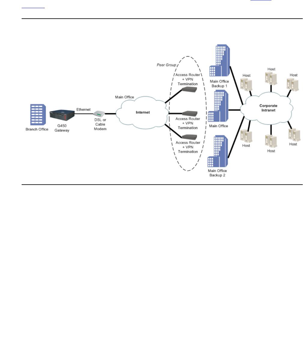
Typical installations
Issue 1 January 2008 575
Failover using a peer-group
The failover VPN topology utilizes a peer-group which lists a group of redundant peers. At any
point in time, only one peer is active and acting as the remote peer. An object tracker monitors
the state of the active peer. If the active peer is presumed dead, the next peer in the peer-group
becomes the active remote peer. For more information on object trackers, see Object
tracking on page 298.
Figure 50: Failover VPN topology using a peer-group

Configuring IPSec VPN
576 Administration for the Avaya G450 Media Gateway
Configuring the failover VPN topology using a peer-group
1. Define the private VLAN1 and VLAN2 interfaces (IP address and mask), and define one of
them as the PMI and ICC-VLAN.
2. Define the public FastEthernet 10/2 interface (IP address and mask).
3. Define the default gateway (the IP address of the next router).
4. Define the object tracking configuration, and define when an object tracker is considered
down, as follows:
Define a track list that will monitor (by ICMP) five hosts behind the specific peer. If two or
more hosts are not working then the object tracker is down. The G450 will then pass on to
the next peer in the peer group list.
5. Define the ISAKMP policy, using the crypto isakmp policy command.
6. Define the 3 remote peers, using the crypto isakmp peer address command, and
specify for each one:
●the pre-shared key
●the ISAKMP policy
●keepalive track. This track is the object tracker that checks if the peer is still alive. If an
active peer is considered dead, the next peer in the peer group becomes the active
peer.
7. Define a peer group that include all three remote peers, using the crypto isakmp
peer-group command.
8. Define the IPSEC transform-set, using the crypto ipsec transform-set command.
9. Define the Crypto map entity, using the crypto map command.
10. Define the crypto list as follows:
●Set the local address to the public interface name (for example, FastEthernet 10/2.0).
●For each private interface, define an ip-rule using the following format:
●source-ip <private subnet> <private subnet wild card mast>.
For example, 10.10.10.0 0.0.0.255
●destination-ip any
●protect crypto map 1
11. Define the ingress access control list to protect the device from incoming traffic from the
public interface, as follows:
●Permit IKE Traffic (UDP port 500) for VPN control traffic (IKE)
Note:
Note: If you are using NAT Traversal, you must also open UDP port 4500 and 2070.
●Permit ESP traffic (IP Protocol ESP) for VPN data traffic (IPSEC)

Typical installations
Issue 1 January 2008 577
●Permit ICMP traffic, to support PMTU application support, for a better fragmentation
process
●For each private subnet, add a permit rule, with the destination being the private
subnet, and the source being any. This traffic will be allowed only if it tunnels under the
VPN, because of the crypto list.
●Define all other traffic (default rule) as deny in order to protect the device from
non-secure traffic
12. Optionally, define the egress access control list to protect the device from sending traffic
that is not allowed to the public interface:
●Permit IKE Traffic (UDP port 500) for VPN control traffic (IKE)
Note:
Note: If you are using NAT Traversal, you also need to open UDP port 4500 and 2070.
●Permit ESP traffic (IP Protocol ESP) for VPN data traffic (IPSEC)
●Permit ICMP traffic, to support the PMTU application, for a better fragmentation
process
●For each private subnet add a permit rule, with the source being the private subnet,
and the destination being any
●Define all other traffic (default rule) as deny in order to protect the device from sending
non-secure traffic
13. Activate the crypto list, the ingress access control list, and the egress access control list,
on the public interface.

Configuring IPSec VPN
578 Administration for the Avaya G450 Media Gateway
Configuration example
!
! Define the Private Subnet1
!
interface vlan 1
description "Branch Subnet1"
ip address 10.0.10.1 255.255.255.0
icc-vlan
pmi
exit
!
! Define the Private Subnet2
!
interface vlan 2
description "Branch Subnet2"
ip address 10.0.20.1 255.255.255.0
exit
!
! Define the Public Subnet
!
interface fastethernet 10/2
ip address 100.0.0.2 255.255.255.0
exit
!
! Define the default gateway the public interfce
!
ip default-gateway 100.0.0.1

Typical installations
Issue 1 January 2008 579
!
! We wish to check 5 hosts in the Corporate intranet behind the current VPN
! remote peer, and if 2 or more hosts don’t work then keepalive-track will fail ,
! and we will move to the next peer in the peer-group
!
rtr 1
type echo protocol ipIcmpEcho <host1 IP>
exit
rtr-schedule 1 start-time now life forever
rtr 2
type echo protocol ipIcmpEcho <host2 IP>
exit
rtr-schedule 2 start-time now life forever
rtr 3
type echo protocol ipIcmpEcho <host3 IP>
exit
rtr-schedule 3 start-time now life forever
rtr 4
type echo protocol ipIcmpEcho <host4 IP>
exit
rtr-schedule 4 start-time now life forever
rtr 5
type echo protocol ipIcmpEcho <host5 IP>
exit
rtr-schedule 5 start-time now life forever
track 11 rtr 1
exit
track 12 rtr 2
exit
track 13 rtr 3
exit
track 14 rtr 4
exit
track 15 rtr 5
exit
track 1 list threshold count
threshold count up 5 down 3
object 11
object 12
object 13
object 14
object 15
exit
!
! Define the IKE Entity
!
crypto isakmp policy 1
encryption aes
hash sha
group 2
authentication pre-share
exit

Configuring IPSec VPN
580 Administration for the Avaya G450 Media Gateway
! Define the remote peers (3 main offices)
!
crypto isakmp peer address <First Main Office VPN address>
pre-shared-key <key1>
isakmp-policy 1
keepalive-track 1
exit
crypto isakmp peer address <Second Main Office VPN address>
pre-shared-key <key2>
isakmp-policy 1
keepalive-track 1
exit
crypto isakmp peer address <Third Main Office VPN address>
pre-shared-key <key3>
isakmp-policy 1
keepalive-track 1
exit
crypto isakmp peer-group main-hubs
set peer <First Main Office VPN address>
set peer <Second Main Office VPN address>
set peer <Third Main Office VPN address>
exit
!
! Define the IPSEC Entity
!
crypto ipsec transform-set ts1 esp-3des esp-sha-hmac
exit
!
! Define the VPN Tunnel
!
crypto map 1
set peer-group main-hubs
set transform-set ts1
exit
! Define the crypto list for the public interface
!
ip crypto-list 901
local-address "Fast Ethernet 10/2.0"
ip-rule 10
source-ip 10.0.10.0 0.0.0.255
destination-ip any
protect crypto map 1
exit
ip-rule 20
source-ip 10.0.20.0 0.0.0.255
destination-ip any
protect crypto map 1
exit
exit

Typical installations
Issue 1 January 2008 581
!
! Define the Ingress access control list for the public interface
!
ip access-control-list 301
ip-rule 10
source-ip any
destination-ip any
ip-protocol udp
udp destination-port eq Ike
composite-operation Permit
exit
ip-rule 11
source-ip any
destination-ip any
ip-protocol udp
udp destination-port eq Ike-nat-t
composite-operation permit
exit
ip-rule 12
source-ip any
destination-ip any
ip-protocol udp
udp destination-port eq Ike-nat-t-vsu
composite-operation permit
exit
ip-rule 20
source-ip any
destination-ip any
ip-protocol esp
composite-operation Permit
exit
ip-rule 30
source-ip any
destination-ip any
ip-protocol icmp
composite-operation Permit
exit
ip-rule 40
source-ip any
destination-ip 10.0.10.0 0.0.0.255
composite-operation Permit
exit
ip-rule 50
source-ip any
destination-ip 10.0.20.0 0.0.0.255
composite-operation Permit
exit
ip-rule default
composite-operation deny
exit
exit

Configuring IPSec VPN
582 Administration for the Avaya G450 Media Gateway
! Define the Egress access control list for the public interface
!
ip access-control-list 302
ip-rule 10
source-ip any
destination-ip any
ip-protocol udp
udp destination-port eq Ike
composite-operation Permit
exit
ip-rule 11
source-ip any
destination-ip any
ip-protocol udp
udp destination-port eq Ike-nat-t
composite-operation permit
exit
ip-rule 12
source-ip any
destination-ip any
ip-protocol udp
udp destination-port eq Ike-nat-t-vsu
composite-operation permit
exit
ip-rule 20
source-ip any
destination-ip any
ip-protocol esp
composite-operation Permit
exit
ip-rule 30
source-ip any
destination-ip any
ip-protocol icmp
composite-operation Permit
exit
ip-rule 40
source-ip 10.0.10.0 0.0.0.255
destination-ip any
composite-operation Permit
exit
ip-rule 50
source-ip 10.0.20.0 0.0.0.255
destination-ip any
composite-operation Permit
exit
ip-rule default
composite-operation deny
exit
exit
Checklist for configuring site-to-site IPSec VPN
Issue 1 January 2008 583
Checklist for configuring site-to-site IPSec VPN
Use Table 134 to gather the information for simple G450 site-to-site IPSec VPN.
!
! Activate the crypto list and the access control list on the public interface
!
interface fastethernet 10/2
ip crypto-group 901
ip access-group 301 in
ip access-group 302 out
exit
Table 134: Checklist for configuring site-to-site IPSec VPN
Parameter Possible values Actual value
1. VPN License You require the serial number to
obtain the VPN license
2. Type of connection to the ISP ●ADSL
●Cable Modem
3. VPN Interface ●FastEthernet10/2
●Serial port X/Y
4. VPN Local IP Address
●Type ●Static
- If static, provide:
IP Address
Mask
Next-hop Router
●Dynamic (DHCP/PPPoE)
5. Coordinating with the VPN Remote peer
a.) VPN IKE (Control) Phase 1 Parameters
-
Encryption ●des
●3des
●aes
●aes-192
●aes-256
1 of 3

Configuring IPSec VPN
584 Administration for the Avaya G450 Media Gateway
-
Authentication Hash ●sha
●md5
-
DH Group ●1
●2
●5
●14
-
Lifetime seconds ●60 to 86,400
default: 86,400 (1 day)
b.) VPN IPSEC (Data) Phase 2 Parameters
-
Encryption ●esp-des
●esp-3des
●esp-aes
●esp-aes-192
●esp-aes-256
-
Authentication Hash ●esp-sha-hmac
●esp-md5-hmac
-
IP compression ●enable (comp-lzs)
●disable
-
PFS Group ●no pfs (default)
●1
●2
●5
●14
-
Lifetime seconds ●120 to 86,400
default: 3,600 (1 hour)
-
Lifetime kilobytes ●2,560 to 536,870,912
default: 4,608,000 kb
●disable
6. Which packets should be secured
a. Protect rules matching
options
●IP source address
●IP destination address
Table 134: Checklist for configuring site-to-site IPSec VPN (continued)
Parameter Possible values Actual value
2 of 3

Checklist for configuring site-to-site IPSec VPN
Issue 1 January 2008 585
b. Bypass rules matching
options
●IP source address
●IP destination address
●udp
●tcp
●dscp
●fragment
●icmp
●IP protocol
7. The remote peer (crypto isakmp peer) parameters
a. Remote peer ●IP address
●FQDN (dns name)
b. Pre-shared key ●1 to 127 alphanumerical
characters.
1 to 64 bytes in hexadecimal
notation
8. If the branch IP is dynamic
●If the branch IP is an initiator, set
initiate mode to none (device is a
responder)
●If the branch IP is a responder,
set initiate mode to aggressive
(device is an initiator)
●Set self identity to identify the
device in the remote peer
Table 134: Checklist for configuring site-to-site IPSec VPN (continued)
Parameter Possible values Actual value
3 of 3
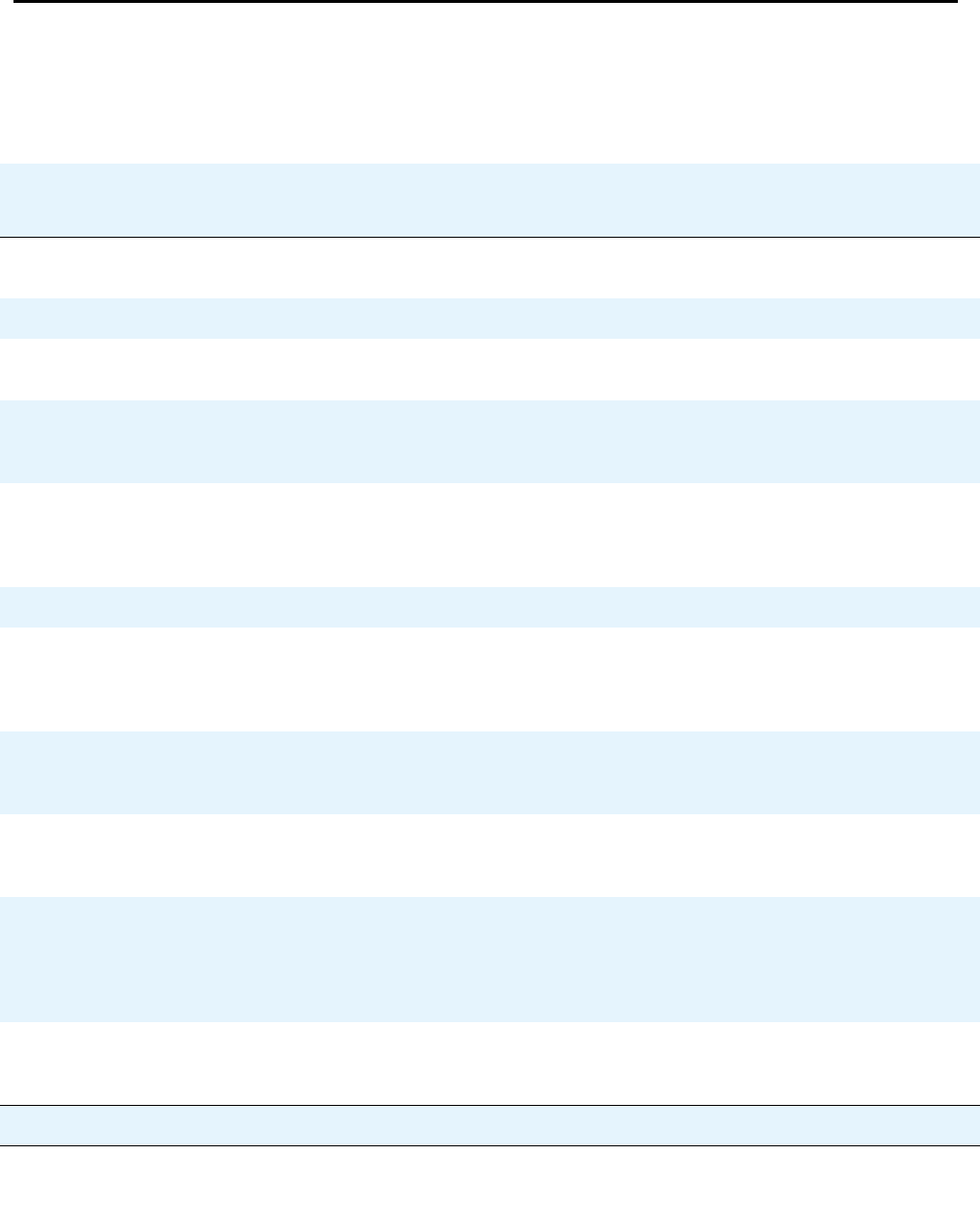
Configuring IPSec VPN
586 Administration for the Avaya G450 Media Gateway
Summary of VPN commands
For more information about these commands, see Avaya G450 CLI Reference, 03-300437.
Table 135: VPN CLI commands
Root level command First level
command Second level
command Description
clear crypto
isakmp Flush a specific ISAKMP SA or all
the ISAKMP SAs
clear crypto sa Clear all or specific IPSec SAs
clear crypto sa
counters Clear the crypto SA counters
crypto ipsec
nat-transparency
udp-encapsulation
Re-enable NAT Traversal if it was
disabled
crypto ipsec
transform-set Enter the IKE phase 2 (IPSec)
transform-set context and create or
edit IPSec parameters for the VPN
tunnel
mode Set security-association lifetime
set pfs Specify whether each IKE phase 2
negotiation will employ PFS and, if
yes, which Diffie-Hellman group to
employ
set security-
association
lifetime
Set the IKE phase 2 (IPSec) SA
lifetime
crypto isakmp
invalid-spi-
recovery
Enable invalid SPI recovery
(default setting)
crypto isakmp nat
keepalive Re-enable NAT Traversal
keepalive if it was disabled, and
configure the keepalive interval.
This command keeps the NAT
devices tables updated.
crypto isakmp
peer Enter the crypto ISAKMP peer
context and create or edit an
ISAKMP peer
1 of 5

Summary of VPN commands
Issue 1 January 2008 587
continuous-
channel Enable continuous-channel IKE,
which keeps the IKE phase1
session always up and running,
even if there is no traffic
description Enter a description for the ISAKMP
peer
initiate mode Specify which IKE Phase-1 mode
to use when communicating with
the peer: aggressive or none
isakmp-
policy Set the ISAKMP policy for the
ISAKMP peer
keepalive Enable DPD keepalives that check
whether the remote peer is up
keepalive-
track Bind an object tracker to a remote
VPN peer or to an interface, to
check whether the remote peer or
the interface is up
pre-shared-
key Configure the IKE pre-shared key
self-
identity Set the identity of this device
suggest-key Generate a random string which
you can use as a pre-shared key
for IKE. You must use the same
key on both peers.
crypto isakmp
peer-group Enter the crypto ISAKMP
peer-group context and create or
edit an ISAKMP peer group
description Enter a description for the ISAKMP
peer group
set peer Add a peer to the peer-group
crypto isakmp
policy Enter the crypto ISAKMP policy
context and create or edit IKE
Phase 1 parameters
authentication Set the authentication of ISAKMP
policy to pre-shared secret
Table 135: VPN CLI commands (continued)
Root level command First level
command Second level
command Description
2 of 5

Configuring IPSec VPN
588 Administration for the Avaya G450 Media Gateway
description Enter a description for the ISAKMP
policy
encryption Set the encryption algorithm for an
ISAKMP policy
group Set the Diffie-Hellman group for an
ISAKMP policy
hash Set the hash method for an
ISAKMP policy
lifetime Set the lifetime of the ISAKMP SA
in seconds
crypto isakmp
suggest-key Generate a random string which
you can use as a pre-shared key
for IKE. You must use the same
key on both peers.
crypto map Enter crypto map context and
create or edit a crypto map
continuous-
channel In a crypto ISAKMP peer context,
enable continuous-channel IKE,
which keeps the IKE phase1
session always up and running,
even if there is no traffic
description Enter a description for the crypto
map
set dscp Set the DSCP value in the
tunneled packet
set peer Attach a peer to a crypto map
set peer-group Attach a peer-group to a crypto
map
set
transform-set Configure the transform-set
interface
(fastethernet|
dialer|serial|
vlan)
Enter the FastEthernet,
Dialer, Serial, or VLAN
interface context
Table 135: VPN CLI commands (continued)
Root level command First level
command Second level
command Description
3 of 5

Summary of VPN commands
Issue 1 January 2008 589
crypto ipsec
df-bit Set the Don’t-Fragment bit to clear
mode or copy mode
crypto ipsec
minimal-pmtu Set the minimal PMTU value that
can be applied to an SA when the
G450 participates in PMTUD for
the tunnel pertaining to that SA
ip
crypto-group Activate a crypto list in the context
of the interface on which the crypto
list is activated
ip crypto-list Enter crypto list context and create
or edit a crypto list
ip-rule Enter ip-rule context and create or
modify a specific rule
description Enter a description for the ip-rule in
the ip crypto list
destination-
ip Specify the destination IP address
of packets to which the current rule
applies
protect
crypto map Protect traffic that matches this
rule by applying the IPSec
processing configured by the
specific crypto map
source-ip Indicate that the current rule
applies to packets from the
specified source IP address
local-address Set the local IP address for the
IPSec tunnels derived from this
crypto list
show crypto ipsec
sa Display the IPSec SA database
and related runtime, statistical, and
configuration information
show crypto ipsec
transform-set Display the configuration for the
specified transform-set or all
transform-sets
show crypto
isakmp peer Display crypto ISAKMP peer
configuration
Table 135: VPN CLI commands (continued)
Root level command First level
command Second level
command Description
4 of 5

Configuring IPSec VPN
590 Administration for the Avaya G450 Media Gateway
show crypto
isakmp peer-group Display crypto ISAKMP peer-group
configuration
show crypto
isakmp policy Display ISAKMP policy
configuration
show crypto
isakmp sa Display the ISAKMP SA database
status
show crypto map Display all or specific crypto map
configurations
show ip
active-lists Display information about a
specific policy list or all lists
show ip
crypto-list Display all or specific crypto list
configurations
Table 135: VPN CLI commands (continued)
Root level command First level
command Second level
command Description
5 of 5

Issue 1 January 2008 591
Chapter 20: Configuring policy
Policy lists enable you to control the ingress and egress of traffic to a router or port. You can use
policies to manage security, determine packet priority through an interface, implement quality of
service, or determine routing for a specific application or user. Each policy list consists of a set
of rules determining the behavior of a packet entering or leaving the interface on which the list is
applied.
Types of policy lists
There are various policy lists on the G450, including access control lists, QoS lists, and Policy
based routing.
Access control lists
Access lists have the following parts:
●Global rules. A set of rules that are executed before the list is evaluated
●Rule list. A list of filtering rules and actions for the G450 to take when a packet matches
the rule. Match actions on this list are pointers to the composite operation table.
●Actions (composite operation table). A table that describes actions to be performed
when a packet matches a rule. The table includes pre-defined actions, such as permit and
deny. You can configure more complex rules. See Composite operations on page 605.
Access control list rule specifications
You can use access control lists to control which packets are authorized to pass through an
interface. When a packet matches a rule on the access control list, the rule specifies whether
the G450:
●Accepts the packet or drops the packet
●Sends an ICMP error reply if it drops the packet
●Sends an SNMP trap if it drops the packet
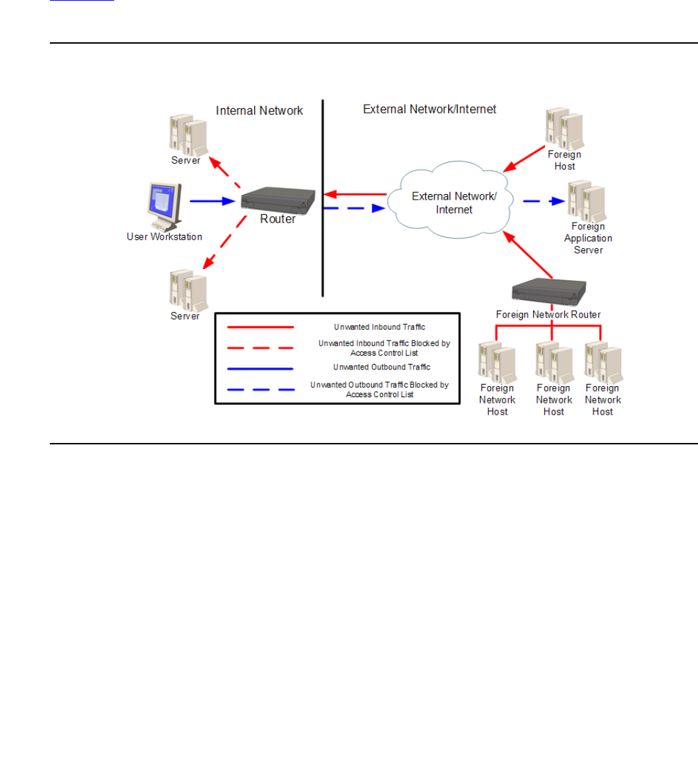
Configuring policy
592 Administration for the Avaya G450 Media Gateway
Network security using access control lists
The primary use of access control lists is to act as a component of network security. You can
use access control lists to determine which applications, networks, and users can access hosts
on your network. Also, you can restrict internal users from accessing specific sites or
applications outside the network. Access control lists can be based on permitting or denying
specific values or groups of IP addresses, protocols, ports, IP fragments, or DSCP values.
Figure 51 illustrates how access control lists are used to control traffic into and out of your
network.
Figure 51: Network security using access control lists

Types of policy lists
Issue 1 January 2008 593
QoS lists
You can use QoS lists to change the DSCP and Ethernet IEEE 802.1p CoS fields in packets.
Changing these fields adjusts the priority of packets meeting the criteria of the QoS list. DSCP
values are mapped to a CoS value. Rules can be created determining the priority behavior of
either individual DSCP values or CoS values, and can be based on specific values or groups of
IP addresses, protocols, ports, IP fragments, or DSCP values. When a packet matches a rule
on the QoS list, the G450 sets one or both of the QoS fields in the packet. The following table
shows these QoS fields:
Each QoS list also includes a DSCP table. The DSCP table enables you to set one or both of
the QoS fields in a packet, based on the previous value of the DSCP field in the packet.
QoS lists have the following parts:
●Rule list. A list of filtering rules and actions for the G450 to take when a packet matches
the rule. Match actions on this list are pointers to the composite operation table.
●Actions (composite operation table). A table that describes actions to be performed
when a packet matches a rule. The table includes pre-defined actions, such as permit and
deny. You can configure more complex rules. Refer to Composite operations on page 605.
●DSCP map. A table that contains DSCP code points and match action pairs. Match
actions are pointers to the composite operation table. Refer to DSCP table on page 608.
Policy-based routing
You can use policy-based routing to determine the routing path a packet takes based on the
type of packet, or the packet’s source or destination IP addresses, or its DSCP field. This
enables you to route different types of traffic over different routes or interfaces. For example,
you use policy-based routing to route voice traffic over a WAN interface and data traffic over the
Internet. Policy-based routing is implemented by means of policy-based routing (PBR) lists.
PBR lists are similar in many respects to access control lists and QoS lists. However, since
there are also some key differences, policy-based routing is explained in a separate chapter.
Refer to Configuring policy-based routing on page 619.
Table 136: QoS fields
Layer QoS field Allowed values
2 802.1p 0–7
3DSCP 0–63
Configuring policy
594 Administration for the Avaya G450 Media Gateway
Managing policy lists
You can manage policy lists on the Avaya G450 Media Gateway with CLI commands. You can
also manage policy lists throughout your network with Avaya QoS Manager. Avaya QoS
Manager is part of Avaya Integrated Management. Figure 52 illustrates the operation of policy
lists on the Avaya G450 Media Gateway:
Figure 52: Policy lists
Defining policy lists
You can create and edit policy lists, and define the list identification attributes. You can also
delete an unnecessary policy list.
Creating and editing a policy list
To create or edit a policy list, you must enter the context of the list. If the list already exists, you
can edit the list from the list context. If the list does not exist, entering the list context creates the
list.
To create or edit an access control list, enter ip access-control-list followed by a list
number in the range 300-399. The G450 includes one pre-configured access control list. The
pre-configured access control list is list number 300.
For example, to create access control list 301, enter the following command:
ip access-control-list 301

Defining policy lists
Issue 1 January 2008 595
To create or edit a QoS list, enter ip qos-list followed by a list number in the range
400-499. The G450 includes one pre-configured QoS list. The pre-configured QoS list is list
number 400.
For example, to create a new QoS list 401, enter the following command:
You can create a new policy list based on an existing list by using the ip policy-list-copy
command, followed by the name of the list from which you want to copy. The source and
destination lists must be of the same type. For example, you cannot copy an access control list
to a QoS list.
The following example creates a new access control list, number 340, based on access control
list 330. You can then enter the context of access control list 340 to modify it.
Once you have entered the list context, you can perform the following actions:
●Configure rules. See Defining rules on page 599
●Configure composite operations. See Composite operations on page 605
●Configure DSCP mapping (QoS lists only). See DSCP table on page 608
Defining list identification attributes
The policy list attributes including name, owner, and cookie, are used by Avaya QoS Manager
software to identify policy lists.
1. Enter the context of the policy list in which you want to define the attribute.
2. Enter one of the following commands, followed by a text string or integer:
-
name. Defines a list name (text string). The default value is owner.
-
owner. Defines a list owner (text string). The default value is list#<listnumber>.
-
cookie. Defines a list cookie (integer). The Avaya QoS Manager uses the cookie
attribute internally. Normally, you should not change this attribute.
To set a policy list attribute to its default setting, use the no form of the appropriate command.
For example, to set a list to its default name, use the command no name.
To view the attributes, use the show list command in the context of the list.
ip qos-list 401
G450-001(super)# ip policy-list-copy 330 340
Done!

Configuring policy
596 Administration for the Avaya G450 Media Gateway
Default actions
When no rule matches a packet, the G450 applies the default action for the list. The following
table shows the default action for each type of policy list:
Deleting a policy list
To delete an access control list, enter no ip access-control-list followed by the number
of the list you want to delete. To delete a QoS list, enter no ip qos-list followed by the
number of the list you want to delete.
Attaching policy lists to an interface
Attached to each interface on the Avaya G450 Media Gateway are policy lists, including the
ingress access control list, ingress QoS list, egress access control list, and egress QoS list.
Note:
Note: You can also attach PBR lists to certain interfaces, but PBR lists are not attached
to any interface by default.
Packets entering the interface
When a packet enters the G450 through an interface, the G450 applies the policy lists in the
following order:
1. Apply the ingress access control list.
2. If the ingress access control list does not drop the packet:
a. Apply the ingress QoS list.
b. Apply the PBR list (if any).
The packet enters the G450 through the interface.
List Default action
Access control list Accept all packets
QoS list No change to the priority or DSCP
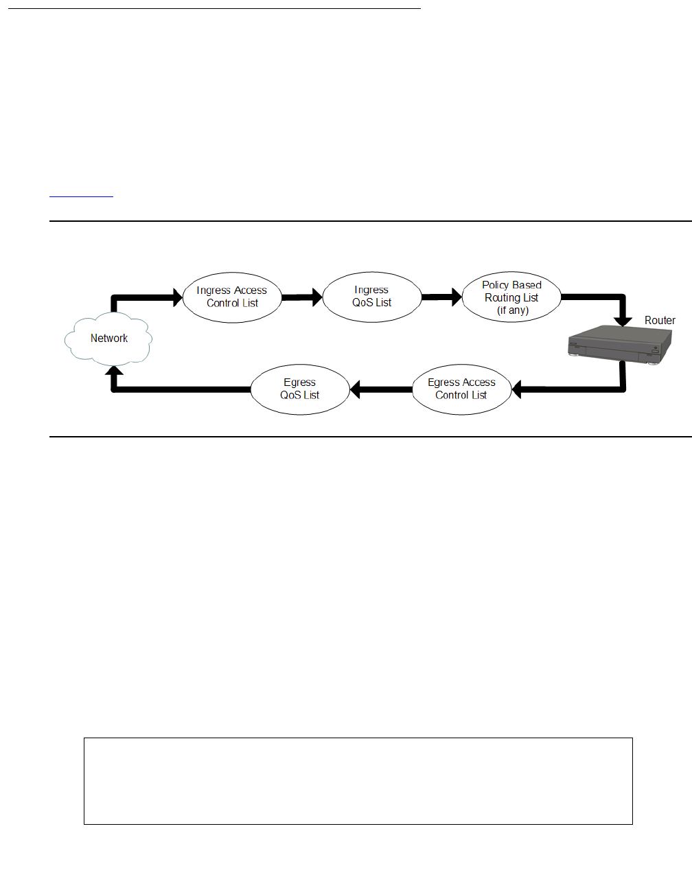
Attaching policy lists to an interface
Issue 1 January 2008 597
Packets exiting the interface
When a packet exits the G450 through an interface, the G450 applies the policy lists in the
following order:
1. Apply the egress access control list.
2. If the egress access control list does not drop the packet, apply the egress QoS list.
The packet exits the G450 through the interface.
Figure 53 illustrates the order in which the G450 applies policy lists to packets.
Figure 53: Applying Policy Lists to Packets
You can configure which policy lists are attached to each interface. You can choose the ingress
access control list and the egress access control list from among the access control lists that
are configured on the G450. You can choose the ingress QoS list and the egress QoS list from
among the QoS lists that are configured on the G450.
To attach an access control list to an interface as its ingress access control list, enter the
interface context and enter ip access-group list number in. To attach an access
control list to an interface as its egress access control list, enter the interface context and enter
ip access-group list number out.
To attach a QoS list to an interface as its ingress QoS list, enter the interface context and enter
ip qos-group list number in. To attach an access control list to an interface as its
egress QoS list, enter the interface context and enter ip qos-group list number out.
For example, the following sequence of commands attach policy lists to the VLAN 2 interface.
Access control list 301 becomes the ingress access control list for VLAN 2. QoS list 401
becomes the egress QoS list for VLAN 2.
G450-001# interface vlan 2
G450-001(if:VLAN 2)# ip access-group 301 in
Done!
G450-001(if:VLAN 2)# ip qos-group 401 out
Done!

Configuring policy
598 Administration for the Avaya G450 Media Gateway
To remove a list from an interface, use the no form of the appropriate command.
For example, if the ingress access control list for the VLAN 1 interface is list number 302, you
can remove the list from the interface by entering the following commands:
Note:
Note: You cannot change or delete a default list. You cannot change or delete any list
when it is attached to an interface. In order to change or delete a list that is
attached to an interface, you must first remove the list from the interface. You can
then change or delete the list. After changing the list, you can reattach the list to
the interface.
Device-wide policy lists
You can attach a policy list (other than a policy-based routing list) to every interface on the G450
using one command. To do this, attach a list to the Loopback 1 interface. For more information,
see Attaching policy lists to an interface on page 596.
Note:
Note: If you attach a policy list to a Loopback interface other than Loopback 1, the
policy list has no effect.
When you attach a policy list to the Loopback 1 interface, thereby creating a device-wide policy
list, and you also attach policy lists to specific interfaces, the G450 applies the lists in the
following order:
●Incoming packets:
a. Apply the ingress policy lists that are attached to the interface
b. Apply the device-wide ingress policy lists
●Outgoing packets:
a. Apply the device-wide egress policy lists
b. Apply the egress policy lists that are attached to the interface
G450-001(super)# interface vlan 1
G450-001(super-if:VLAN 1)# no ip access-group in
Done!

Defining global rules
Issue 1 January 2008 599
Defining global rules
In an access control list, you can define global rules for packets that contain IP fragments and IP
options. These rules apply to all packets. This is in contrast to individual rules, which apply to
packets that match certain defined criteria. See Defining rules on page 599.
The G450 applies global rules before applying individual rules.
1. Enter the context of the access control list in which you want to define the rule.
2. Enter one of the following commands, followed by the name of a composite command:
-
ip-fragments-in. Applies to incoming packets that contain IP fragments
-
ip-option-in. Applies to incoming packets that contain IP options
The composite command can be any command defined in the composite operation list. These
commands are case-sensitive. To view the composite operation list for the access control list
you are working with, use the command show composite-operation in the context of the
access control list.
The following example defines a rule in access control list 301 that denies access to all
incoming packets that contain IP fragments:
Defining rules
You can configure policy rules to match packets based on one or more of the following criteria:
●Source IP address, or a range of addresses
●Destination IP address, or a range of addresses
●IP protocol, such as TCP, UDP, ICMP, or IGMP
●Source TCP or UDP port or a range of ports
●Destination TCP or UDP port or a range of ports
●ICMP type and code
●Fragment
●DSCP
G450-001(super)# ip access-control-list 301
G450-001(super/ACL 301)# ip-fragments-in Deny
Done!

Configuring policy
600 Administration for the Avaya G450 Media Gateway
Use IP wildcards to specify a range of source or destination IP addresses. The zero bits in the
wildcard correspond to bits in the IP address that remain fixed. The one bits in the wildcard
correspond to bits in the IP address that can vary. Note that this is the opposite of how bits are
used in a subnet mask.
For access control lists, you can require the packet to be part of an established TCP session. If
the packet is a request for a new TCP session, the packet does not match the rule. You can also
specify whether an access control list accepts packets that have an IP option field.
Editing and creating rules
To create or edit a policy rule, you must enter the context of the rule. If the rule already exists,
you can edit the rule from the rule context. If the rule does not exist, entering the rule context
creates the rule.
1. Enter the context of the list in which you want to create or edit a rule.
2. Enter ip-rule followed by the number of the rule you want to create or edit. For example,
to create rule 1, enter ip-rule 1.
You can use the description command in the rule context to add a description of the rule.
This description is used in the AccessViolation Policy trap to identify and describe the IP rule in
which the trap was caused.
To view the existing rules in a list, enter the list’s context and then enter ip show-rule. Each
list starts with a default rule. Each new rule has the same default parameters as the default rule.
The default rule appears as follows:
This rule permits all packets.
Policy lists rule criteria
Rules work in the following ways, depending on the type of list and the type of information in the
packet:
●Layer 4 rules in an access control list with a Permit operation are applied to non-initial
fragments
G450-001(super-ACL 301)# show ip-rule
Index Protocol IP Wildcard Port Operation
DSCP Fragment rule
----- -------- --- ---------------- --------------- ------------ --------------
Deflt Any Src Any Any Permit
Any Dst Any Any No
Defining rules
Issue 1 January 2008 601
●Layer 4 rules in an access control list with a Deny operation are not applied to non-initial
fragments, and the device continues checking the next IP rule. This is to prevent cases in
which fragments that belong to other L4 sessions may be blocked by the other L4 session
which is blocked.
●Layer 3 rules apply to non-initial fragments
●Layer 3 rules that include the fragment criteria do not apply to initial fragments or
non-fragment packets
●Layer 3 rules that do not include the fragment criteria apply to initial fragments and
non-fragment packets
●Layer 4 rules apply to initial fragments and non-fragment packets
●Layer 3 and Layer 4 rules in QoS and policy-based routing lists apply to non-initial
fragments
IP protocol
To specify the IP protocol to which the rule applies, enter ip-protocol followed by the name
of an IP protocol. If you want the rule to apply to all protocols, use any with the command. If you
want the rule to apply to all protocols except for one, use the no form of the command, followed
by the name of the protocol to which you do not want the rule to apply.
For example, the following command specifies the UDP protocol for rule 1 in QoS list 401:
The following command specifies any IP protocol except IGMP for rule 3 in access control
list 302:
Source and destination IP address
To specify a range of source and destination IP addresses to which the rule applies, use the
commands source-ip and destination-ip, followed by the IP range criteria. The IP range
criteria can be one of the following:
●A range. Type two IP addresses to set a range of IP addresses to which the rule applies
●A single address. Type host, followed by an IP address, to set a single IP address to
which the rule applies
●A wildcard. Type host, followed by an IP address using wildcards, to set a range of IP
addresses to which the rule applies
●All addresses. Type any to apply the rule to all IP addresses
Use the no form of the appropriate command to specify that the rule does not apply to the IP
address or addresses defined by the command.
G450-001(QoS 401/rule 1)# ip-protocol udp
G450-001(ACL 302/ip rule 3)# no ip-protocol igmp

Configuring policy
602 Administration for the Avaya G450 Media Gateway
For example, the following command specifies a source IP address of 10.10.10.20 for rule 1 in
access control list 301:
The following command allows any destination IP address for rule 3 in QoS list 404:
The following command specifies a source IP address in the range 10.10.0.0 through
10.10.255.255 for rule 1 in access control list 301:
The following command specifies a source IP address outside the range 64.236.24.0 through
64.236.24.255 for rule 7 in access control list 308:
The following command specifies a source IP address in the range 64.<any>.24.<any> for rule
6 in access control list 350:
Source and destination port range
To specify a range of source and destination ports to which the rule applies, use the following
commands, followed by either port name or port number range criteria:
●tcp source-port. The rule applies to TCP packets from ports that match the defined
criteria
●tcp destination-port. The rule applies to TCP packets to ports that match the
defined criteria
●udp source-port. The rule applies to UDP packets from ports that match the defined
criteria
●udp destination-port. The rule applies to UDP packets to ports that match the
defined criteria
This command also sets the IP protocol parameter to TCP or UDP.
Port name or number range criteria
●A range. Type range, followed by two port numbers, to set a range of port numbers to
which the rule applies
●Equal. Type eq, followed by a port name or number, to set a port name or port number to
which the rule applies
G450-001(ACL 301/ip rule 1)# source-ip host 10.10.10.20
G450-001(QoS 404/rule 3)# destination-ip any
G450-001(ACL 301/ip rule 1)# source-ip 10.10.0.0 0.0.255.255
G450-001(ACL 308/ip rule 7)# no source-ip 64.236.24.0 0.0.0.255
G450-001(ACL 350/ip rule 6)# source-ip 64.*.24.*

Defining rules
Issue 1 January 2008 603
●Greater than. Type gt, followed by a port name or port number, to apply the rule to all
ports with a name or number greater than the specified name or number
●Less than. Type lt, followed by a port name or port number, to apply the rule to all ports
with a name or number less than the specified name or number
●All. Type any to apply the rule to all port names and port numbers
Use the no form of the appropriate command to specify that the rule does not apply to the ports
defined by the command.
For example, the following command specifies a source TCP port named telnet for rule 1 in
access control list 301:
The following command specifies any destination UDP port less than 1024 for rule 3 in QoS list
404:
The following command specifies any destination TCP port in the range 5000 through 5010 for
rule 1 in access control list 301:
The following command specifies any source TCP port except a port named http for rule 7 in
access control list 304:
ICMP type and code
To apply the rule to a specific type of ICMP packet, use the icmp command. This command
sets the IP protocol parameter to ICMP, and specifies an ICMP type and code to which the rule
applies. You can specify the ICMP type and code by integer or text string, as shown in the
examples below. To apply the rule to all ICMP packets except the specified type and code, use
the no form of this command.
For example, the following command specifies an ICMP echo reply packet for rule 1 in QoS
list 401:
The following command specifies any ICMP packet except type 1 code 2 for rule 5 in access
control list 321:
G450-001(ACL 301/ip rule 1)# tcp source-port eq telnet
G450-001(QoS 404/rule 3)# udp destination-port lt 1024
G450-001(ACL 301/ip rule 1)# tcp destination-port range 5000 5010
G450-001(ACL 304/ip rule 7)# no tcp source-port eq http
G450-001(QoS 401/rule 1)# icmp Echo-Reply
G450-001(ACL 321/ip rule 5)# no icmp 1 2

Configuring policy
604 Administration for the Avaya G450 Media Gateway
TCP establish bit (access control lists only)
In access control lists, you can use the tcp established command to specify that the rule
only applies to packets that are part of an established TCP session (a session in with the TCP
ACK or RST flag is set). Use the no form of this command to specify that the rule applies to all
TCP packets. In either case, the command also sets the IP protocol parameter to TCP.
For example, the following command specifies that rule 6 in access control list 301 only
matches packets that are part of an established TCP session:
Fragments
Enter fragment to apply the rule to non-initial fragments. You cannot use the fragment
command in a rule that includes UDP or TCP source or destination ports.
DSCP
Enter dscp, followed by a DSCP value (from 0 to 63), to apply the rule to all packets with the
specified DSCP value. Use the no form of the command to remove the rule from the list.
For example, the following command specifies that rule 5 in access control list 301 only
matches packets in which the DSCP value is set to 56:
Composite Operation
For instructions on assigning a composite operation to an ip rule, see Adding composite
operation to an ip rule on page 607.
G450-001(ACL 301/ip rule 6)# tcp established
G450-001(super-ACL 301/ip rule 5)# fragment
Done!
G450-001(super-ACL 301/ip rule 5)#
G450-001(ACL 301/ip rule 5)# dscp 56

Composite operations
Issue 1 January 2008 605
Composite operations
A composite operation is a set of operations that the G450 can perform when a rule matches a
packet. Every rule in a policy list has an operation field that specifies a composite operation.
The operation field determines how the G450 handles a packet when the rule matches the
packet.
There are different composite operations for access control list rules and QoS list rules. For
each type of list, the G450 includes a pre-configured list of composite operations. You cannot
change or delete pre-configured composite operations. You can define additional composite
operations.
Pre-configured composite operations for access control lists
Table 137 lists the pre-configured entries in the composite operation table for rules in an access
control list:
Each column represents the following:
●No. A number identifying the operation
●Name. A name identifying the operation. Use this name to attach the operation to a rule.
●Access. Determines whether the operation forwards (forward) or drops (deny) the packet
●Notify. Determines whether the operation causes the G450 to send a trap when it drops a
packet
●Reset Connection. Determines whether the operation causes the G450 to reset the
connection when it drops a packet
Table 137: Pre-configured access control list composite operations
No Name Access Notify Reset Connection
0 Permit forward no trap no reset
1Deny deny no trap no reset
2 Deny-Notify deny trap all no reset
3Deny-Rst deny no trap reset
4 Deny-Notify-Rst deny trap all reset

Configuring policy
606 Administration for the Avaya G450 Media Gateway
Pre-configured composite operations for QoS lists
Table 138 lists the pre-configured entries in the composite operation table for rules in a QoS list:
Each column represents the following:
●No. A number identifying the operation
●Name. A name identifying the operation. Use this name to attach the operation to a rule.
●CoS. The operation sets the Ethernet IEEE 802.1p CoS field in the packet to the
value listed in this column
●DSCP. The operation sets the DSCP field in the packet to the value listed in this column
●Trust. Determines how to treat packets that have been tagged by the originator or other
network devices. If the composite operation is set to Trust-DSCP, the packet’s CoS tag is
set to 0 before the QoS list rules and DSCP map are executed. If the composite operation
is set to CoSX, the DSCP map is ignored, but the QoS list rules are executed on the
Ethernet IEEE 802.1p CoS field. (For example, the composite operation CoS3
changes the CoS field to 3.) If the composite operation is set to Trust-DSCP-CoS, the
operation uses the greater of the CoS or the DSCP value. If the composite operation is set
to No Change, the operation makes no change to the packet’s QoS tags.
Table 138: Pre-configured QoS list composite operations
No Name CoS DSCP Trust
0 CoS0 cos0 no change No
1CoS1 cos1 no change No
2 CoS2 cos2 no change No
3CoS3 cos3 no change No
4 CoS4 cos4 no change No
5CoS5 cos5 no change No
6 CoS6 cos6 no change No
7CoS7 cos7 no change No
9 No-Change no change no change No
10 Trust-DSCP - - DSCP
11 Trust-DSCP-CoS - - DSCP and CoS

Composite operations
Issue 1 January 2008 607
Configuring composite operations
You can configure additional composite operations for QoS lists. You can also edit composite
operations that you configured. You cannot edit pre-configured composite operations.
Note:
Note: You cannot configure additional composite operations for access control lists,
since all possible composite operations are pre-configured.
1. Enter the context of a QoS list.
2. Enter composite-operation followed by an index number. The number must be 12 or
higher, since numbers 1 through 11 are assigned to pre-configured lists.
3. Use one or more of the following commands to set the parameters of the composite
operation:
-
dscp. Determines the value to which the rule resets the packet’s DSCP field. To ignore
the DSCP field, use the argument no change, or enter no dscp.
-
cos. Determines the value to which the rule resets the packet’s CoS field. To ignore
the CoS field, use the argument no change, or enter no cos.
4. Enter name, followed by a text string, to assign a name to the composite operation. You
must assign a name to the composite operation, because when you attach the composite
operation to a rule, you use the name, not the index number, to identify the composite
operation.
Adding composite operation to an ip rule
You can add or delete composite operations to or from an IP rule by using the
[no] composite-operation command, followed by the name of the composite operation
you want to add or delete, in the context of the rule. See Composite operation example on
page 608 for an example.

Configuring policy
608 Administration for the Avaya G450 Media Gateway
Composite operation example
The following commands create a new composite operation called dscp5 and assign the new
composite operation to rule 3 in QoS list 402. If the packet matches a rule, the G450 changes
the value of the DSCP field in the packet to 5.
DSCP table
DSCP is a standards-defined method for determining packet priority through an interface, either
into or out of a router.
There are three ways you can use the DSCP field:
●Classifier. Select a packet based on the contents of some portions of the packet header
and apply behavioral policies based on service characteristic defined by the DSCP value
●Marker. Set the DSCP field based on the traffic profile, as determined by the defined rules
●Metering. Check compliance to traffic profile using filtering functions
A DSCP value can be mapped to a Class of Service (CoS). Then, for a CoS, rules can be
applied to determine priority behavior for packets meeting the criteria for the entire CoS.
Multiple DSCP values can be mapped to a single CoS. Rules can also be applied to individual
DSCP values.
The default value of DSCP in a packet is 0, which is defined as “best-effort.” You can determine
a higher priority for a traffic type by changing the DSCP value of the packet using a QoS rule or
composite operation.
Each QoS list includes a DSCP table. A DSCP lists each possible DSCP value, from 0 to 63.
For each value, the list specifies a composite operation. See Pre-configured composite
operations for QoS lists on page 606.
G450-001# ip qos-list 402
G450-001(QoS 402)# composite-operation 12
G450-001(QoS 402/cot 12)# name dscp5
Done!
G450-001(QoS 402/cot 12)# dscp 5
Done!
G450-001(QoS 402/cot 12)# cos no-change
Done!
G450-001(QoS 402/cot 12)# exit
G450-001(QoS 402)# ip-rule 3
G450-001(QoS 402/rule 3)# composite-operation dscp5
Done!

DSCP table
Issue 1 January 2008 609
QoS rules on the list take precedence over the DSCP table. If a QoS rule other than the default
matches the packet, the G450 does not apply the DSCP table to the packet. The G450 applies
only the operation specified in the QoS rule.
Changing an entry in the DSCP table
1. Enter the context of a QoS list.
2. Enter dscp-table followed by the number of the DSCP value for which you want to
change its composite operation.
3. Enter composite-operation followed by the name of the composite operation you
want to execute for packets with the specified DSCP value.
The following commands specify the pre-configured composite operation CoS5 for DSCP table
entry 33 in QoS list 401. Every packet with DSCP equal to 33 is assigned CoS priority 5.
The following commands create a new composite operation called dscp5 and assign the new
composite operation to DSCP table entry 7 in QoS list 402. Every packet with DSCP equal to 7
is assigned a new DSCP value of 5.
Composite operation dscp5 changes the mapping of packets entering the router with a DSCP
values of 7. DSCP value 5 is most likely to be mapped to a different CoS, making these packets
subject to a different set of behavioral rules.
G450-001# ip qos-list 401
G450-001(QoS 401)# dscp-table 33
G450-001(QoS 401/dscp 33)# composite-operation CoS5
Done!
G450-001(super)# ip qos-list 402
G450-001(super/QoS 402)# composite-operation 12
G450-001(super/QoS 402/CompOp 12)# name dscp5
Done!
G450-001(super/QoS 402/CompOp 12)# dscp 5
Done!
G450-001(super/QoS 402/CompOp 12)# cos No-Change
Done!
G450-001(super/QoS 402/CompOp 12)# exit
G450-001(super/QoS 402)# dscp-table 7
G450-001(super/QoS 402/dscp 7)# composite-operation dscp5
Done!

Configuring policy
610 Administration for the Avaya G450 Media Gateway
Displaying and testing policy lists
To verify access control lists, QoS lists, and policy-based routing (PBR) lists, you can view the
configuration of the lists. You can also test the effect of the lists on simulated IP packets.
Displaying policy lists
To view information about policy lists and their components, use the following commands. Many
of these commands produce different results in different contexts.
●In general context:
-
show ip access-control-list. Displays a list of all configured access control
lists, with their list numbers and owners
-
show ip access-control-list list number detailed. Displays all the
parameters of the specified access control list
-
show ip qos-list. Displays a list of all configured QoS lists, with their list numbers
and owners
-
show ip qos-list detailed. Displays all the parameters of the specified QoS list
●In ip access-control-list context:
-
show composite-operation. Displays a list of all composite operations configured
for the list
-
show ip-rule. Displays a list of all rules configured for the list
-
show list. displays the parameters of the current list, including its rules
●In ip access-control-list/ip-rule context:
-
show composite-operation. Displays the parameters of the composite operation
assigned to the current rule
-
show ip-rule. Displays the parameters of the current rule
●In ip qos-list context:
-
show composite-operation. Displays a list of all composite operations configured
for the list
-
show dscp-table. Displays the current list’s DSCP table
-
show ip-rule. Displays a list of all rules configured for the list
-
show list. Displays the parameters of the current list, including its rules

Displaying and testing policy lists
Issue 1 January 2008 611
●In ip qos-list/ip-rule context:
-
show composite-operation. Displays the parameters of the composite operation
assigned to the current rule
-
show dscp-table. Displays the current list’s DSCP table
-
show ip-rule. Displays the parameters of the current rule
●In ip qos-list/dscp-table context:
-
show dscp-table. Displays the parameters of the current DSCP table entry
●In ip qos-list/composite-operation context:
-
show composite-operation. Displays the parameters of the current composite
operation
Simulating packets
Use the ip simulate command in the context of an interface to test a policy list. The
command tests the effect of the policy list on a simulated IP packet in the interface. You must
specify the number of a policy list, the direction of the packet (in or out), and a source and
destination IP address. You may also specify other parameters. For a full list of parameters, see
Avaya G450 CLI Reference, 03-602056.
For example, the following command simulates the effect of applying QoS list number 401 to a
packet entering the G450 through interface VLAN 2:
The simulated packet has the following properties:
●CoS priority is 1
●DSCP is 46
●source IP address is 10.1.1.1
●destination IP address is 10.2.2.2
●IP protocol is TCP
●source TCP port is 1182
●destination TCP port is 20
G450-001(if:VLAN 2)# ip simulate 401 in CoS1 dscp46 10.1.1.1
10.2.2.2 tcp 1182 20
Configuring policy
612 Administration for the Avaya G450 Media Gateway
When you use the ip simulate command, the G450 displays the effect of the policy rules on
the simulated packet. For example:
Summary of access control list commands
For more information about these commands, see Avaya G450 CLI Reference, 03-300437.
G450-001(super-if:VLAN 2)# ip simulate 401 in CoS1 dscp46 10.1.1.1
10.2.2.2 tcp 1182 20
Rule match for simulated packet is the default rule
Composite action for simulated packet is CoS6
New priority value is fwd6
Dscp value is not changed
Table 139: Access control list CLI commands
Root level
command Command Command Description
interface
{dialer|
serial|
loopback|
fastethernet|
tunnel|vlan}
Enter the Dialer, Serial,
Loopback, FastEthernet,
Tunnel or VLAN interface
configuration context
ip access-group Activate a specific Access
Control list, for a specific
direction, on the current interface
ip simulate Test the action of a policy on a
simulated packet
show ip
access-control-
list
Display the attributes of a
specific access control list or of
all access control lists on the
current interface
ip
access-control
-list
Enter configuration mode for the
specified policy access control
list, and create the list if it does
not exist
cookie Set the cookie for the current list
1 of 3

Summary of access control list commands
Issue 1 January 2008 613
ip-fragments-in Specify the action taken on
incoming IP fragmentation
packets for the current access
control list
ip-option-in Specify the action taken on
incoming packets carrying an IP
option for the current access
control list
ip-rule Enter configuration mode for a
specified policy rule or, if the rule
doesn’t exist, create it and enter
its configuration mode
composite-
operation Assign the specified composite
operation to the current rule
destination-ip Apply the current rule to packets
with the specified destination IP
address
dscp Apply the current rule to packets
with the specified DSCP value
fragment Apply the current rule for
non-initial fragments only
icmp Apply the current rule to a
specific type of ICMP packet
ip-protocol Apply the current rule to packets
with the specified IP protocol
show composite-
operation Display the parameters of the
composite operation assigned to
the current rule
show ip-rule Display the attributes of the
current rule
source-ip Apply the current rule to packets
from the specified source IP
address
tcp
destination-port Apply the current rule to TCP
packets with the specified
destination port
Table 139: Access control list CLI commands (continued)
Root level
command Command Command Description
2 of 3

Configuring policy
614 Administration for the Avaya G450 Media Gateway
tcp established Apply the current rule only to
packets that are part of an
established TCP session
tcp source-port Apply the current rule to TCP
packets from ports with specified
source port
udp
destination-port Apply the rule to UDP packets
with the specified destination
port
udp source-port Apply the rule to UDP packets
from the specified source port
name Assign a name to the current list
owner Specify the owner of the current
list
show composite-
operation Display the composite operations
configured for the list
show ip-rule Display the rules configured for
the current list attributes of a
specific rule
show list Display the attributes of the
current list, including its rules
ip
policy-list-
copy
Copy an existing policy list to a
new list
show ip
access-control
-list
Display the attributes of a
specific access control list or of
all access control lists
Table 139: Access control list CLI commands (continued)
Root level
command Command Command Description
3 of 3
Summary of QoS list commands
Issue 1 January 2008 615
Summary of QoS list commands
For more information about these commands, see Avaya G450 CLI Reference, 03-300437.
Table 140: QoS list CLI commands
Root level
command Command Command Description
interface
{dialer|
serial|
loopback|
fastethernet
|tunnel|
vlan}
Enter the Dialer, Serial,
Loopback, FastEthernet,
Tunnel, or VLAN interface
configuration context
ip qos-group Activate a specific QoS list, for a
specific direction, on the current
interface
ip simulate Test the action of a policy on a
simulated packet
show ip qos-list Display the attributes of a specific
QoS list or all QoS lists for the
current interface
ip
policy-list-
copy
Copy an existing policy list to a
new list
ip qos-list Enter configuration mode for the
specified QoS list, and create the
list if it does not exist
composite-operation Enter the configuration mode for
one of the current list’s composite
operations
cos Set the CoS priority value for the
current composite operation
dscp Set the DSCP value for the
current composite operation
name Assign a name to the current
composite operation
1 of 3

Configuring policy
616 Administration for the Avaya G450 Media Gateway
show
composite-
operation
Display the attributes of the
current composite operation
cookie Set the cookie for the current list
dscp-table Enter the DSCP table entry
context for a particular DSCP
value for the current QoS list
composite-
operation Specify the composite operation to
execute for packets with the
specified DSCP value
name Assign a name to the current
DSCP table entry
show
dscp-table Display the parameters of the
current DSCP table entry
ip-rule Enter configuration mode for a
specified policy rule or, if the rule
does not exist, create it and enter
its configuration mode
composite-
operation Assign the specified composite
operation to the current rule
destination-
ip Apply the current rule to packets
with the specified destination IP
address
dscp Apply the current rule to packets
with the specified DSCP value
fragment Apply the current rule for
non-initial fragments only
icmp Apply the current rule to a specific
type of ICMP packet
ip-protocol Apply the current rule to packets
with the specified IP protocol
show
composite-
operation
Display the parameters of the
composite operation assigned to
the current rule
Table 140: QoS list CLI commands (continued)
Root level
command Command Command Description
2 of 3

Summary of QoS list commands
Issue 1 January 2008 617
show
dscp-table Display the current list’s DSCP
table
show ip-rule Display the attributes of the
current rule
source-ip Apply the current rule to packets
from the specified source IP
address
tcp
destination-
port
Apply the current rule to TCP
packets with the specified
destination port
tcp
source-port Apply the current rule to TCP
packets from ports with specified
source port
udp
destination-
port
Apply the rule to UDP packets with
the specified destination port
udp
source-port Apply the rule to UDP packets
from the specified source port
name Assign a name to the current list
owner Specify the owner of the current
list
pre-classification Specify which priority tag the
current QoS list uses for data
flows
show
composite-operation Display all composite operations
configured for the list
show dscp-table Display the current list’s DSCP
table
show ip-rule Display the rules configured for
the current list attributes of a
specific rule
show list Display the attributes of the
current list, including its rules
show ip
qos-list Display the attributes of a specific
QoS list or all QoS lists
Table 140: QoS list CLI commands (continued)
Root level
command Command Command Description
3 of 3

Configuring policy
618 Administration for the Avaya G450 Media Gateway

Issue 1 January 2008 619
Chapter 21: Configuring policy-based
routing
Policy-based routing enables you to configure a routing scheme based on traffic’s source IP
address, destination IP address, IP protocol, and other characteristics. You can use
policy-based routing (PBR) lists to determine the routing of packets that match the rules defined
in the list. Each PBR list includes a set of rules, and each rule includes a next hop list. Each next
hop list contains up to 20 next hop destinations to which the G450 sends packets that match the
rule. A destination can be either an IP address or an interface.
Policy-based routing takes place only when the packet enters the interface, not when it leaves.
Policy-based routing takes place after the packet is processed by the Ingress Access Control
List and the Ingress QoS list. Thus, the PBR list evaluates the packet after the packet’s DSCP
field has been modified by the Ingress QoS List. See Figure 53.
Note:
Note: The Loopback 1 interface is an exception to this rule. On the Loopback 1
interface, PBR lists are applied when the packet leaves the interface. This
enables the PBR list to handle packets sent by the G450 device itself, as
explained below.
Note:
Note: ICMP keepalive provides the interface with the ability to determine whether a next
hop is or is not available. See ICMP keepalive on page 292.
Policy-based routing only operates on routed packets. Packets traveling within the same subnet
are not routed, and are, therefore, not affected by policy-based routing.
The Loopback interface is a logical interface which handles traffic that is sent to and from the
G450 itself. This includes ping packets to or from the G450, as well as telnet, FTP, DHCP Relay,
TFTP, HTTP, NTP, SNMP, H.248, and other types of traffic. The Loopback interface is also used
for traffic to and from analog and DCP phones connected to the device via IP phone entities.
The Loopback interface is always up. You should attach a PBR list to the Loopback interface if
you want to route specific packets generated by the G450 to a specific next-hop.
Unlike the case with other interfaces, PBR lists on the Loopback interface are applied to
packets when they leave the G450, rather than when they enter.
Certain types of packets are not considered router packets (on the Loopback interface only),
and are, therefore, not affected by policy-based routing. These include RIP, OSPF, VRRP, GRE,
and keepalive packets. On the other hand, packets using SNMP, Telnet, Bootp, ICMP, FTP,
SCP, TFTP, HTTP, NTP, and H.248 protocols are considered routed packets, and are, therefore,
affected by policy-based routing on the Loopback interface.
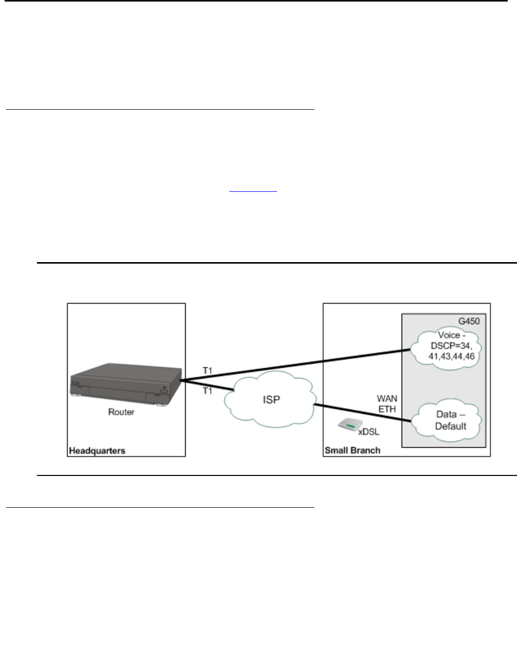
Configuring policy-based routing
620 Administration for the Avaya G450 Media Gateway
Applications
The most common application for policy-based routing is to provide for separate routing of voice
and data traffic. It can also be used as a means to provide backup routes for defined traffic
types.
Separate routing of voice and data traffic
Although there are many possible applications for policy-based routing, the most common
application is to create separate routing for voice and data traffic.
For example, the application shown in Figure 54 uses the DSCP field to identify VoIP control
packets (DSCP = 34, 41), VoIP Bearer RESV packets (DSCP = 43, 44), and VoIP Bearer
packets (DSCP = 46). Policy-based routing sends these packets over the T1 WAN line, and
sends other packets over the Internet. This saves bandwidth on the more expensive Serial
interface.
Figure 54: Policy-based routing – Voice/Data division by DSCP
Backup
You can utilize policy-based routing to define backup routes for defined classes of traffic. If the
first route on the next hop list fails, the packets are routed to a subsequent hop. When
necessary, you can use the NULL interface to drop packets when the primary next hop fails. For
example, voice packets are usually sent over a WAN line, and not the Internet. You can
configure a PBR list to drop voice packets when the WAN line is down.

Configuring policy-based routing
Issue 1 January 2008 621
Configuring policy-based routing
For a full example of a policy-based routing configuration, see Application example on
page 628.
1. Define PBR lists.
●In general context, enter ip pbr-list followed by a list number in the range
800-899. For example:
●To assign a name to the list, use the name command, followed by a text string, in the
PBR list context. The default name is list #<list number>. For example:
●To assign an owner to the list, use the owner command, followed by a text string, in
the PBR list context. The default owner is other. For example:
2. Define PBR rules.
In the PBR list context, enter ip-rule, followed by the number of the rule, to define a rule
for the PBR list. Repeat this command to define additional rules. A rule contains: (i) criteria
that is matched against the packet, and (ii) a next hop list. When a packet matches the
criteria specified in the rule, the rule’s next hop list determines how the packet is routed.
Each PBR list can have up to 1,500 rules. The first rule that matches the packet
determines the packet’s routing.
It is important to include a destination address, or range of addresses, in PBR rules to
better classify the traffic to be routed. For an illustration, see Application example on
page 628.
Note:
Note: It is recommended to leave a gap between rule numbers, in order to leave room
for inserting additional rules at a later time. For example, ip-rule 10, ip-rule 20,
ip-rule 30.
G450-001(super)# ip pbr-list 802
G450-001(super-PBR 802)#
G450-001(super-PBR 802)# name "voice"
Done!
G450-001(super-PBR 802)#
G450-001(super-PBR 802)# owner "tom"
Done!
G450-001(super-PBR 802)#

Configuring policy-based routing
622 Administration for the Avaya G450 Media Gateway
The following example creates rule 1, which routes packets going to IP address
149.49.43.210 with a DSCP value of 34 according to next hop list 1. The next step
explains how to define a next hop list. For additional details about PBR rules, see PBR
rules on page 624.
Note:
Note: Rules do not include a default next hop list. Thus, if you do not include a next hop
list in the rule, the packet is routed according to destination-based routing, that is,
the ordinary routing that would apply without policy-based routing.
3. Define next hop lists.
Enter exit twice to return to general context. In general context, define all the next hop
lists that you have used in PBR rules.
Note:
Note: You can also perform this step before defining PBR lists and rules.
Enter ip next-hop-list, followed by the number of the list, to define a next hop list. In
the next hop list context, use the following commands to define the next hops in the list:
●Enter next-hop-ip, followed by the index number of the entry in the next hop list, to
define an IP address as a next hop. You can optionally apply tracking to monitor the
route.
●Enter next-hop-interface, followed by the index number of the entry in the next
hop list, to define an interface as a next hop. You can optionally apply tracking to
monitor the route.
You can also use the name command to assign a name to the next hop list.
Note:
Note: You cannot use a FastEthernet Interface as an entry on a next hop list unless the
interface was previously configured to use PPPoE encapsulation, or a GRE
tunnel, or was configured as a DHCP client. See Configuring PPPoE on
page 259, Configuring GRE tunneling on page 456, and Configuring DHCP
client on page 199.
A next hop list can include the value NULL0. When the next hop is NULL0, the G450 drops
the packet. However, you cannot apply tracking to NULL0.
G450-001(super-PBR 802)# ip-rule 1
G450-001(super-PBR 802/ip rule 1)# next-hop list 1
Done!
G450-001(super-PBR 802/ip rule 1)# destination-ip host 149.49.43.210
Done!
G450-001(super-PBR 802/ip rule 1)# dscp 43
Done!
G450-001(super-PBR 802/ip rule 1)#

Configuring policy-based routing
Issue 1 January 2008 623
The following example creates next hop list 1, named “Data to HQ”, with three entries:
●The first entry is IP address 172.16.1.221. Object tracker 3 is applied to monitor the
route. For details about configuring the object tracker see Object tracking
configuration on page 299.
●The second entry is Serial interface 3/1:1
●The third entry is NULL, which means the packet is dropped
For additional details about next hop lists, see Next hop lists on page 625.
This example demonstrates a case where the data traffic is sent over a WAN FastEthernet
Interface through the Internet. When the track detects that this next hop is not valid, traffic
is routed over the Serial interface.
4. Apply the PBR list to an interface.
Enter exit to return to general context. From general context, enter the interface to which
you want to apply the PBR list. In the interface context, enter ip pbr-group, followed by
the number of the PBR list, to attach the list to the interface. The list will be applied to
packets entering the interface.
The following example applies PBR list 802 to VLAN 2.
5. Apply the PBR list to the Loopback interface.
The following example applies PBR list 802 to the Loopback interface.
6. Enter copy running-config startup-config. This saves the new policy-based
routing configuration in the startup configuration file.
G450-001(super)# ip next-hop-list 1
G450-001(super-next hop list 1)#name "Data_to_HQ"
Done!
G450-001(super-next hop list 1)#next-hop-ip 1 172.16.1.221 track 3
Done!
G450-001(super-next hop list 1)#next-hop-interface 2 Serial 3/1:1
Done!
G450-001(super-next hop list 1)#next-hop-interface 3 Null0
Done!
G450-001(super-next hop list 1)#
G450-001(super)# interface vlan 2
G450-001(super-if:VLAN 2)# ip pbr-group 802
Done!
G450-001(super-if:VLAN 2)#
G450-001(super)# interface Loopback 1
G450-001(super-if:Loopback 1)# ip pbr-group 802
Done!
G450-001(super-if:Loopback 1)# exit
G450-001(super)#

Configuring policy-based routing
624 Administration for the Avaya G450 Media Gateway
PBR rules
Each PBR list can have up to 1,500 rules. The first rule that matches the packet specifies the
next hop list for the packet. If no rule matches the packet, the packet is routed according to the
default rule.
You can configure policy rules to match packets based on one or more of the following criteria:
●Source IP address, or a range of addresses
●Destination IP address or a range of addresses
●IP protocol, such as TCP, UDP, ICMP, IGMP
●Source TCP or UDP port or a range of ports
●Destination TCP or UDP port or a range of ports
●ICMP type and code
●Fragments
●DSCP field
Note:
Note: The fragment criteria is used for non-initial fragments only. You cannot specify
TCP/UDP ports or ICMP code/type for a rule when using the fragment
command.
Use IP wildcards to specify a range of source or destination IP addresses. The zero bits in the
wildcard correspond to bits in the IP address that remain fixed. The one bits in the wildcard
correspond to bits in the IP address that can vary. Note that this is the opposite of how bits are
used in a subnet mask.
Note:
Note: When you use destination and source ports in a PBR rule, policy-based routing
does not catch fragments.
Note:
Note: It is recommended to leave a gap between rule numbers, in order to leave room
for inserting additional rules at a later time. For example, ip-rule 10, ip-rule 20,
ip-rule 30.

Next hop lists
Issue 1 January 2008 625
Modifying rules
To modify a policy-based routing rule, you must enter the context of the rule and redefine the
rule criteria.
1. Enter the context of the PBR list to which the rule belongs.
2. Enter ip-rule followed by the number of the rule you want to modify. For example, to
create rule 1, enter ip-rule 1.
To view the rules that belong to a PBR list, enter the list’s context and then enter show
ip-rule.
PBR rule criteria
The rule criteria for PBR rules are largely the same as the rule criteria for other policy list rules.
Refer to Policy lists rule criteria on page 600 for an explanation of the rule criteria, including
explanations and examples of the commands used to set the criteria.
Unlike other policy lists, PBR lists do not use composite operations. Thus, there is no
composite-operation command in the context of a PBR rule. Instead, PBR lists use next
hop lists. For an explanation of next hop lists, see Next hop lists on page 625.
Enter next-hop list, followed by the list number of a next hop list, to specify a next hop list
for the G450 to apply to packets that match the rule. You can specify Destination Based Routing
instead of a next hop list, in which case the G450 applies destination-based routing to a packet
when the packet matches the rule.
If the next hop list specified in the rule does not exist, the G450 applies destination-based
routing to packets that match the rule.
Next hop lists
PBR rules include a next hop list. When the rule matches a packet, the G450 routes the packet
according to the specified next hop list.
Each next hop list can include up to 20 entries. An entry in a next hop list can be either an IP
address or an interface. The G450 attempts to route the packet to the first available destination
on the next hop list. If every destination on the list is unavailable, the G450 routes the packet
according to destination-based routing.

Configuring policy-based routing
626 Administration for the Avaya G450 Media Gateway
Modifying next hop lists
To modify a next hop list, you must enter the context of the next hop list. To enter a next hop list
context, enter ip next-hop-list followed by the number of the list you want to edit. For
example, to modify next hop list 1, enter ip next-hop-list 1.
To show the next hops in an existing list, enter the context of the next hop list and enter show
next-hop.
Adding entries to a next hop list
1. Enter the context of the next hop list.
2. Use one of the following commands:
-
To enter an IP address as a next hop, enter next-hop-ip, followed by the index
number of the entry and the IP address. You can optionally apply tracking to monitor
the route. For example, the command next-hop-ip 2 149.49.200.2 track 3
sets the IP address 149.49.200.2 as the second entry on the next hop list and applies
object tracker 3 to monitor the route.
-
To enter an interface as a next hop, enter next-hop-interface, followed by the
index number of the entry and the name of the interface. You can optionally apply
tracking to monitor the route, except for the NULL0. For example, the command
next-hop-interface 3 serial 4/1:1.1 sets Serial 4/1:1.1 as the third entry
on the next hop list.
Deleting an entry from a next hop list
1. Enter the context of the next hop list.
2. Use one of the following commands:
-
To delete an IP address, enter no next-hop-ip, followed by the index number of the
entry you want to delete. For example, the command no next-hop-ip 2 deletes
the second entry from the next hop list.
-
To delete an interface, enter no next-hop-interface, followed by the index
number of the entry you want to delete. For example, the command no
next-hop-interface 3 deletes the third entry from the next hop list.
Canceling tracking and keeping the next hop
1. Enter the context of the next hop list.
2. Use the next-hop-ip or next-hop-interface command again, without the track
keyword.

Editing and deleting PBR lists
Issue 1 January 2008 627
Changing the object tracker and keeping the next hop
1. Enter the context of the next hop list.
2. Use the next-hop-ip or next-hop-interface command again, with the track
keyword followed by the new track index.
Editing and deleting PBR lists
You cannot delete or modify a PBR list when it is attached to an interface. In order to delete or
modify a PBR list, you must first remove the list from the interface. You can then delete or
modify the list. After modifying the list, you can reattach the list to the interface.
To remove a list from an interface, use the no form of the ip pbr-group command in the
interface context. The following example removes the PBR list from the VLAN 2 interface.
To modify a PBR list, enter ip pbr-list, followed by the number of the list you want to
modify, to enter the list context. Redefine the parameters of the list.
To delete a PBR list, enter exit to return to general context and enter no ip pbr-list
followed by the number of the list you want to delete.
Displaying PBR lists
To view information about PBR lists and their components, use the following commands. Many
of these commands produce different results in different contexts.
●In general context:
-
show ip active-pbr-lists. Displays details about a specified PBR list, or about
all active PBR lists, according to the interfaces on which the lists are active
-
show ip pbr-list. Displays a list of all configured PBR lists, with their list numbers
and names and their owners
-
show ip pbr-list list number. Displays the list number and name of the
specified PBR list
-
show ip pbr-list all detailed. Displays all the parameters of all configured
PBR lists
G450-001(super)# interface vlan 1
G450-001(super-if:VLAN 1)# no ip pbr-group
Done!
G450-001(super-if:VLAN 1)#

Configuring policy-based routing
628 Administration for the Avaya G450 Media Gateway
-
show ip pbr-list list number detailed. Displays all the parameters of the
specified PBR list
-
show ip active-lists. Displays a list of each G450 interface to which a PBR list
is attached, along with the number and name of the PBR list
-
show ip active-lists list number. Displays a list of each G450 interface to
which the specified PBR list is attached, along with the number and name of the PBR
list
-
show ip next-hop-list all. Displays the number and name of all next hop lists
-
show ip next-hop-list list number. Displays the number and name of the
specified next hop list
●In PBR list context:
-
show list. Displays all the parameters of the current PBR list
-
show ip-rule. Displays the parameters of all rules configured for the current list
-
show ip-rule rule number. Displays the parameters of the specified rule
●In next hop list context:
-
show next-hop. Displays the next hop entries in the current next hop list and their
current status
Application example
The following example creates a policy-based routing scheme in which:
●Voice traffic is routed over a Serial interface. If the interface is down, the traffic is dropped.
●Data traffic is routed over a GRE tunnel. If the tunnel is down, the traffic is routed over the
Serial interface. If both interfaces are down, the traffic is dropped.
Figure 55 illustrates the sample application described below.
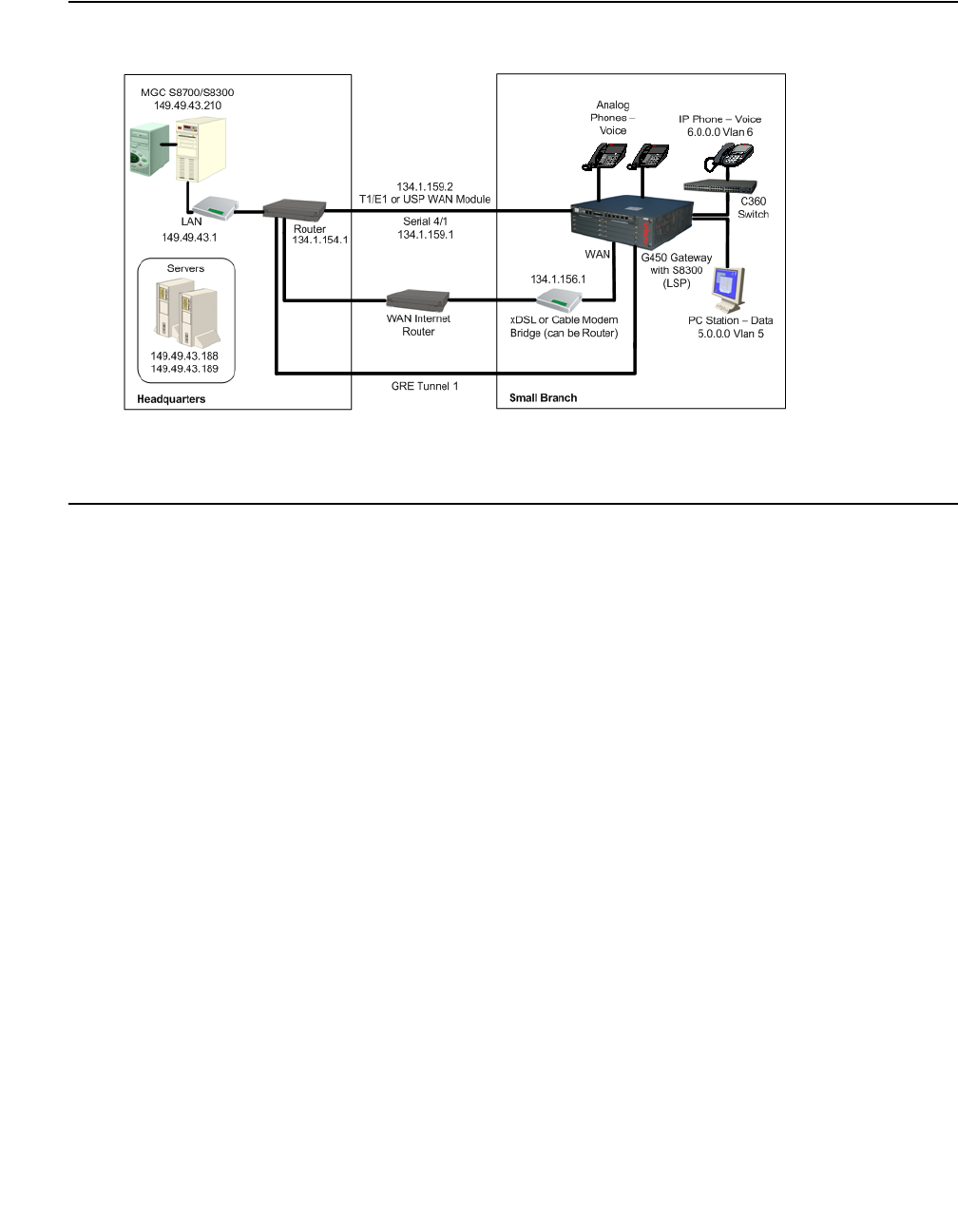
Application example
Issue 1 January 2008 629
Figure 55: Sample policy-based routing application
This example includes a voice VLAN (6) and a data VLAN (5). The PMI is on VLAN 6. The G450
is managed by a remote Media Gateway Controller (MGC) with the IP address 149.49.43.210.
The G450 also includes a local S8300 in LSP mode.
IP phones are located on the same subnet as the PMI. Therefore, there is no routing between
the PMI and the IP phones.
In this example, the object of policy-based routing is to route all voice traffic over the E1/T1 line,
which is more expensive but provides the superior QoS necessary for voice traffic. Remaining
traffic is to be routed over the more inexpensive Internet connection.
It is assumed that the IP phones on VLAN 6 establish connections with other IP phones on the
same subnet, sending signalling packets to the MGC, and bearer packets directly to other IP
phones or to the G450.
The policy-based routing configuring starts with PBR list 801. This list requires all voice packets
addressed to the MGC (149.49.43.210) with DSCP values that indicate voice transmission (34,
41, 43, 44, and 46) to be routed according to next hop list 1. This list directs packets to the
T1/E1 interface (Serial 4/1). If that interface is down, the packets are dropped.
In this example, it is important to include the destination IP address in each rule. This is
because without the destination address, calls from IP phones on VLAN 6 to a Softphone on
VLAN 5 will be routed by the PBR list to the E1/T1 line, rather than being sent directly to
VLAN 5 via the G450.

Configuring policy-based routing
630 Administration for the Avaya G450 Media Gateway
Configuration for the sample policy-based routing application
G450-001(super)# ip pbr-list 801
G450-001(super-PBR 801)# name "Voice"
Done!
G450-001(super-PBR 801)# ip-rule 1
G450-001(super-PBR 801/ip rule 1)# next-hop list 1
Done!
G450-001(super-PBR 801/ip rule 1)# destination-ip 149.49.123.0 0.0.0.255
Done!
G450-001(super-PBR 801/ip rule 1)# dscp 34
Done!
G450-001(super-PBR 801/ip rule 1)# exit
G450-001(super-PBR 801)# ip-rule 10
G450-001(super-PBR 801/ip rule 10)# next-hop list 1
Done!
G450-001(super-PBR 801/ip rule 10)# destination-ip 149.49.123.0 0.0.0.255
Done!
G450-001(super-PBR 801/ip rule 10)# dscp 41
Done!
G450-001(super-PBR 801/ip rule 10)# exit
Done!
G450-001(super-PBR 801/ip rule 20)# destination-ip 149.49.123.0 0.0.0.255
Done!
G450-001(super-PBR 801/ip rule 20)# dscp 43
Done!
G450-001(super-PBR 801/ip rule 20)# exit
G450-001(super-PBR 801)# ip-rule 30
G450-001(super-PBR 801/ip rule 30)# next-hop list 1
Done!
G450-001(super-PBR 801/ip rule 30)# destination-ip 149.49.123.0 0.0.0.255
Done!
G450-001(super-PBR 801/ip rule 30)# dscp 44
Done!
G450-001(super-PBR 801/ip rule 30)# exit
G450-001(super-PBR 801)# ip-rule 40
G450-001(super-PBR 801/ip rule 40)# next-hop list 1
Done!
G450-001(super-PBR 801/ip rule 40)# destination-ip 149.49.123.0 0.0.0.255
Done!
G450-001(super-PBR 801/ip rule 40)# dscp 46
Done!
G450-001(super-PBR 801/ip rule 40)# exit
G450-001(super-PBR 801)# exit
G450-001(super)#

Application example
Issue 1 January 2008 631
The next group of commands configures next hop list 1, which was included in the rules
configured above. Next hop list 1 sends packets that match the rule in which it is included to the
E1/T1 line (Serial interface 4/1). If that interface is not available, the next hop list requires the
packet to be dropped (Null0). This is because the QoS on the Internet interface is not adequate
for voice packets. It would also be possible to include one or more backup interfaces in this next
hop list.
The next set of commands applies the PBR list to the voice VLAN (6).
The next set of commands applies the PBR list to the Loopback interface. This is necessary to
ensure that voice packets generated by the G450 itself are routed via the E1/T1 line. The
Loopback interface is a logical interface that is always up. Packets sent from the G450, such as
signaling packets, are sent via the Loopback interface. In this example, applying PBR list 801 to
the Loopback interface ensures that signaling packets originating from voice traffic are sent via
the T1/E1 line.
G450-001(super)# ip next-hop-list 1
G450-001(super-next hop list 1)#name "Voice-To_HQ"
Done!
G450-001(super-next hop list 1)#next-hop-interface 1 Serial 4/1
Done!
G450-001(super-next hop list 1)#next-hop-interface 2 Null0
Done!
G450-001(super-next hop list 1)#exit
G450-001(super)#
G450-001(super)# interface vlan 6
G450-001(super-if:VLAN 6)# ip pbr-group 801
Done!
G450-001(super-if:VLAN 6)# exit
G450-001(super)#
G450-001(super)# interface Loopback 1
G450-001(super-if:Loopback 1)# ip pbr-group 801
Done!
G450-001(super-if:Loopback 1)# exit
G450-001(super)#

Configuring policy-based routing
632 Administration for the Avaya G450 Media Gateway
The next set of commands defines a new PBR list (802). This list will be applied to the data
interface (VLAN 5). The purpose of this is to route data traffic through interfaces other than the
E1/T1 interface, so that this traffic will not interface with voice traffic.
The next set of commands creates next hop list 2. This next hop list routes traffic to the GRE
tunnel (Tunnel 1). If the GRE tunnel is not available, then the next hop list checks the next entry
on the list and routes the traffic to the E1/T1 interface (Serial 4/1). If neither interface is
available, the traffic is dropped. This allows data traffic to use the E1/T1 interface, but only when
the GRE tunnel is not available. Alternatively, the list can be configured without the E1/T1
interface, preventing data traffic from using the E1/T1 interface at all.
Finally, the next set of commands applies the PBR list to the data VLAN (5).
In this example you can add a track on GRE Tunnel 1 in order to detect whether this next hop is
valid or not (for more information on object tracking, refer to Object tracking on page 298). Note
that the GRE tunnel itself has keepalive and can detect the status of the interface and,
therefore, modify the next hop status.
G450-001(super)# ip pbr-list 802
G450-001(super-PBR 802)# name "Data_To_HQ"
Done!
G450-001(super-PBR 802)# ip-rule 1
G450-001(super-PBR 802/ip rule 1)# next-hop list 2
Done!
G450-001(super-PBR 802/ip rule 1)# ip-protocol tcp
Done!
G450-001(super-PBR 802/ip rule 1)# destination-ip host 149.49.43.189
Done!
G450-001(super-PBR 802/ip rule 1)# exit
G450-001(super-PBR 802)# exit
G450-001(super)# ip next-hop-list 2
G450-001(super-next hop list 2)#name "Data-To_HQ"
Done!
G450-001(super-next hop list 2)#next-hop-interface 1 Tunnel 1
Done!
G450-001(super-next hop list 2)#next-hop-interface 2 Serial 4/1
Done!
G450-001(super-next hop list 2)#next-hop-interface 3 Null0
Done!
G450-001(super-next hop list 2)#exit
G450-001(super)#
G450-001(super)# interface vlan 5
G450-001(super-if:VLAN 6)# ip pbr-group 802
Done!
G450-001(super-if:VLAN 6)# exit
G450-001(super)#
Summary of policy-based routing commands
Issue 1 January 2008 633
Simulating packets in PBR
Policy-based routing supports the ip simulate command for testing policies. Refer to
Simulating packets on page 611.
Summary of policy-based routing commands
For more information about these commands, see Avaya G450 CLI Reference, 03-300437.
Table 141: Policy-based routing CLI commands
Root level
command First level
command Second level
command Description
ip
next-hop-list Enter the context of the specified
next hop list. If the list does not exist,
it is created.
next-hop-
interface Add the specified interface to the
next hop path for this next-hop list
next-hop-ip Add the specified ip address to the
next hop path for this next-hop list
show next-hop Display the next-hop entries in the
current list
interface Enter the interface configuration
mode for a Dialer, Serial,
Loopback, Fast Ethernet,
Tunnel or VLAN interface
ip pbr-group Apply the specified PBR list to the
current interface. The PBR list is
applied to ingress packets only.
ip pbr-list Enter the context of the specified
PBR list. If the list does not exist, it is
created.
cookie Set the cookie for the current list
ip-rule Enter configuration mode for the
specified rule. If the specified rule
does not exist, the system creates it
and enters its configuration mode.
1 of 3

Configuring policy-based routing
634 Administration for the Avaya G450 Media Gateway
destination-ip Specify the destination IP address of
packets to which the current rule
applies
dscp Specify the DSCP value that is set by
the current policy operation
fragment Apply the current rule for non-initial
fragments only
icmp Apply the current rule to a specific
type of ICMP packet
ip-protocol Apply the current rule to packets with
the specified IP protocol
next-hop Specify the next-hop policy to use
when the current rule is applied
show ip
next-hop-list Display the details of the next-hop list
or of all next-hop lists
show ip-rule Display the attributes of a specific
rule or all rules
source-ip Apply the current rule to packets from
the specified source IP address
tcp
destination-
port
Apply the current rule to TCP packets
with the specified destination port
tcp
source-port Apply the current rule to TCP packets
from ports with specified source port
udp
destination-
port
Apply the rule to UDP packets with
the specified destination port
udp
source-port Apply the rule to UDP packets from
the specified source port
name Assign a name to the specified list or
operation
owner Specify the owner of the current list
show ip-rule Display the attributes of a specific
rule or all rules
Table 141: Policy-based routing CLI commands (continued)
Root level
command First level
command Second level
command Description
2 of 3

Summary of policy-based routing commands
Issue 1 January 2008 635
show list Display information about the
specified list
show ip
active-lists Display information about a specific
policy list or all lists
show ip
active-pbr-
lists
Display details about a specific PBR
list or all PBR lists
show ip
pbr-list Display information about the
specified PBR list
Table 141: Policy-based routing CLI commands (continued)
Root level
command First level
command Second level
command Description
3 of 3

Configuring policy-based routing
636 Administration for the Avaya G450 Media Gateway

Issue 1 January 2008 637
Chapter 22: Setting synchronization
If the Avaya G450 Media Gateway contains an MM710 T1/E1 media module, it is advisable to
define the MM710 as the primary synchronization source for the G450. In so doing, clock
synchronization signals from the Central Office (CO) are used by the MM710 to synchronize all
operations of the G450. If no MM710 is present, it is not necessary to set synchronization.
Enter set sync interface primary|secondary mmID [portID] to define a potential
stratum clock source (T1/E1 Media Module, ISDN-BRI), where:
●mmID is the Media Module ID of an MM stratum clock source of the form vn, where n is the
MM slot number
●portID is the port number for an ISDN clock source candidate. The port ID consists of the
slot number of the media module and the number of the port. You can set more than one
port. For example, v2 1, 3, 5-8.
Note:
Note: The port ID parameter only applies if the source is a BRI module.
By setting the clock source to primary, normal failover will occur. The identity of the current
synchronization source is not stored in persistent storage. Persistent storage is used to
preserve the parameters set by this command.
Note:
Note: Setting the source to secondary overrides normal failover, generates a trap, and
asserts a fault. Thus, it is only recommended to set the clock source to secondary
for testing purposes.
To determine which reference source is the active source, use the set sync source
primary|secondary command. If you choose secondary, the secondary source becomes
active, and the primary source goes on standby. In addition, fallback to the primary source does
not occur even when the primary source becomes available.
If neither primary nor secondary sources are identified, the local clock becomes the active
source.
The following example sets the MM710 media module located in slot 2 of the G450 chassis as
the primary clock synchronization source for the Avaya G450 Media Gateway.
set sync interface primary v2
set sync source primary

Setting synchronization
638 Administration for the Avaya G450 Media Gateway
If the Avaya G450 Media Gateway includes a second MM710 media module, enter the following
additional command:
If, for any reason, the primary MM710 media module cannot function as the clock
synchronization source, the system uses the MM710 media module located in slot 3 of the
Avaya G450 Media Gateway chassis as the clock synchronization source. If neither MM710
media module can function as the clock synchronization source, the system defaults to the local
clock running on the S8300 Server.
To disassociate an interface previously specified as the primary or secondary clock
synchronization source, enter clear sync interface primary or clear sync
interface secondary.
To enable or disable automatic failover and failback between designated primary and secondary
synchronization sources, enter set sync switching enable or set sync switching
disable.
Synchronization status
The yellow ACT LED on the front of the MM710 media module displays the synchronization
status of that module.
●If the yellow ACT LED is solidly on or off, it has not been defined as a synchronization
source. If it is on, one or more channels is active. If it is an ISDN facility, the D-channel
counts as an active channel and causes the yellow ACT LED to be on.
●When the MM710 is operating as a clock synchronization source, the yellow ACT LED
indicates that the MM710 is the clock synchronization source by flashing at three second
intervals, as follows:
●The yellow ACT LED is on for 2.8 seconds and off for 200 milliseconds if the MM710
media module has been specified as a clock synchronization source and is receiving a
signal that meets the minimum requirements for the interface
●The yellow ACT LED is on for 200 milliseconds and off for 2.8 seconds if the MM710
media module has been specified as a synchronization source and is not receiving a
signal, or is receiving a signal that does not meet the minimum requirements for the
interface
set sync interface secondary v3
set sync source secondary

Synchronization status
Issue 1 January 2008 639
Displaying synchronization status
Enter show sync timing to display the status of the primary, secondary, and local clock
sources. The status can be Active, Standby, or Not Configured. The status is Not
Configured when a source has not been defined, for example, when there are no T1 cards
installed.
Summary of synchronization commands
For more information about these commands, see Avaya G450 CLI Reference, 03-300437.
Table 142: Synchronization CLI commands
Command Description
clear sync
interface Disassociate a previously specified interface as the primary or
secondary clock synchronization source
set sync
interface Define the specified module and port as a potential source for clock
synchronization for the media gateway
set sync source Specify which clock source is the active clock source. The identity of
the current synchronization source is not stored in persistent
storage.
set sync
switching Toggle automatic sync source switching
show sync timing Display the status of the primary, secondary, and local clock sources

Setting synchronization
640 Administration for the Avaya G450 Media Gateway
Issue 1 January 2008 641
Appendix A: Traps and MIBs
This appendix contains a list of all G450 traps and all MIBs.
G450 traps
Name Parameters
(MIB variables) Class Msg
Facility Severity Trap Name/
Mnemonic Format Description
coldStart STD Boot Warning coldStart Agent Up with
Possible Changes
(coldStart Trap)
enterprise:$E ($e)
args($#):$*
A coldStart trap indicates
that the entity sending the
protocol is reinitializing
itself in such a way as to
potentially cause the
alteration of either the
agent's configuration or
the entity's
implementation.
warmStart STD Boot Warning warmStart Agent Up with No
Changes
(warmStart Trap)
enterprise:$E ($e)
args($#):$*
A warmStart trap
indicates that the entity
sending the protocol is
reinitializing itself in such
a way as to keep both the
agent configuration and
the entity's
implementation intact.
LinkUp ifIndex,
ifAdminStatus,
ifOperStatus
STD System Warning LinkUp Agent Interface Up
(linkUp Trap)
enterprise:$E ($e)
on interface $1
A linkUp trap indicates
that the entity sending the
protocol recognizes that
one of the communication
links represented in the
agent's configuration has
come up.
The data passed with the
event is
1) The name and value of
the ifIndex instance for
the affected interface.
The name of the interface
can be retrieved via an
snmpget
of.1.3.6.1.2.1.2.2.1.2.INS
T, where INST is the
instance returned with the
trap.
1 of 9

Traps and MIBs
642 Administration for the Avaya G450 Media Gateway
linkDown ifIndex,
ifAdminStatus,
ifOperStatus
STD System Warning linkDown Agent Interface
Down (linkDown
Trap)
enterprise:$E ($e)
on interface $1
A linkDown trap indicates
that the entity that is
sending the protocol
recognizes a failure in
one of the communication
links represented in the
agent's configuration.
The data passed with the
event is
1) The name and value of
the ifIndex instance for
the affected interface.
The name of the interface
can be retrieved via an
snmpget
of.1.3.6.1.2.1.2.2.1.2.INS
T, where INST is the
instance returned with the
trap.
SNMP_Authen_
Failure P330 SECURITY Notification authentic
Failure Incorrect
Community Name
(authentication
Failure Trap)
enterprise:$E ($e)
args($#):$*
An authentication failure
trap indicates that the
protocol is not properly
authenticated.
risingAlarm alarmIndex,
alarmVariable,
alarmSample
Type,
alarmValue,
alarmRising
Threshold
RMON THRES
HOLD Warning rising
Alarm Rising Alarm: $2
exceeded
threshold $5; value
= $4. (Sample type
= $3; alarm index
= $1)
The SNMP trap that is
generated when an alarm
entry crosses its rising
threshold and generates
an event that is
configured for sending
SNMP traps
fallingAlarm alarmIndex,
alarmVariable,
alarmSample
Type,
alarmValue,
alarmRising
Threshold,
alarmFalling
Threshold
RMON THRES
HOLD Warning falling
Alarm Falling Alarm: $2
fell below
threshold $5; value
= $4. (Sample type
= $3; alarm index
= $1)
The SNMP trap that is
generated when an alarm
entry crosses its falling
threshold and generates
an event that is
configured for sending
SNMP traps
deleteSW
Redundancy
Trap
soft
Redundancy
Status
P330 SWITCH
FABRIC Info deleteSWRedu
ndancyTrap Software
Redundancy $1
definition deleted
The trap notifies the
manager of the deletion
of the specified
redundant link, which is
identified by the
softRedundancyId. It is
enabled/disabled by
chLntAgConfigChangeTr
aps.
Name Parameters
(MIB variables) Class Msg
Facility Severity Trap Name/
Mnemonic Format Description
2 of 9

G450 traps
Issue 1 January 2008 643
createSW
Redundancy
Trap
soft
Redundancy
Status
P330 SWITCH
FABRIC Info createSWRedu
ndancyTrap Software
Redundancy $1
definition created
The trap is generated on
the creation of the
redundant links for the
specified ports. It gives
the logical name of the
redundant link the
identification of the main
and secondary ports and
the status of the link. The
softRedundancyId
defines the instances of
the above- mentioned
variables. The trap is
enabled/disabled by
chLntAgConfigChangeTr
aps.
lseIntPortCAMLa
stChange
Trap
lseIntPortCAML
astChange P330 SWITCH
FABRIC Info lseIntPort
CAMLast
Change
Trap
CAM Change at
$1 This trap reports of the
occurred configuration
changes. It is
enabled/disabled by
chLntAgCAMChangeTra
ps.
duplicateIP
Trap ipNetToMediaPh
ysAddress,
ipNetToMediaNe
tAddress
P330 ROUTER Warning duplicateIPTrap Duplicate IP
address $2
detected; MAC
address $1
This trap reports to the
Management station on
Duplicate IP
identification. CRP
identify the new IP on the
network. If it similar to
one of its IP interfaces,
the CRP will issue a
SNMP trap, containing
the MAC of the intruder.
lntPolicy
ChangeEvent ipPolicy
Activation
EntID, ipPolicy
ActivationList,
ipPolicy
Activationif
Index, ipPolicy
ActivationSub
Context
P330 POLICY Info lntPolicyChang
eEvent Module $1 - Active
policy list changed
to $2
The trap reports a change
in the active list specific
for a policy-enabled box
or module.
Name Parameters
(MIB variables) Class Msg
Facility Severity Trap Name/
Mnemonic Format Description
3 of 9

Traps and MIBs
644 Administration for the Avaya G450 Media Gateway
lntPolicy
AccessControlVi
olationFlt
ipPolicy
AccessControl
ViolationEnt
ID,
ipPolicy
AccessControlVi
olationSrc
Addr,
ipPolicy
AccessControl
ViolationDst
Addr,
ipPolicy
AccessControl
Violation
Protocol,
ipPolicy
AccessControl
Violation
L4SrcPort,
ipPolicy
AccessControl
ViolationL4DstP
ort,
ipPolicy
AccessControlVi
olation
Established,
ipPolicyRuleID,
ipPolicyRule
ListID,
ipPolicy
AccessControlVi
olationIf
Index,
ipPolicy
AccessControl
ViolationSub
Ctxt,
ipPolicy
AccessControl
ViolationTime
P330 POLICY Warning lntPolicy
Access
Control
ViolationFlt
IP PolicyAccess
Control violation,
if-index$9
ip-protocol=$4
src-ip=$2
dst-ip=$3
src-port=$5
dst-port=$6
rule-id=$8
rule-list=$$9
This trap reports to the
Management station on
IP PolicyAccess Control
violation. The trap
includes in its varbind
information about the slot
where the event
occurred. The id of the
rule that was violated in
the current rules table,
and the quintuplet that
identifies the faulty
packet. A management
application would display
this trap and the relevant
information in a log entry.
This trap will not be sent
at intervals smaller than
one minute for identical
information in the
varbinds list variables.
DormantPort
Fault genPortSWRdF
ault,
genPortGroup
Id,
genPortId
P330 SWITCH
FABRIC Warning Dormant
PortFault Dormant Port
Connection Lost
on Module $2 Port
$3;
This trap reports the loss
of connection on a
dormant port.
DormantPort
Ok genPortSWRdF
ault,
genPortGroup
Id,
genPortId
P330 SWITCH
FABRIC Notification Dormant
PortOk Dormant Port
Connection
Returned to
Normal on Module
$2 Port $3;
This trap reports the
return of connection on a
dormant port.
InlinePwrFlt genGroup
FaultMask,
genGroupId,
genGroup
BUPSActivity
Status
P330 POE Error InlinePwr
Flt Module $2 Inline
Power Supply
failure
This trap reports the
failure of an inline power
supply.
InlinePwrFltOK genGroup
FaultMask,
genGroupId,
genGroup
BUPSActivity
Status
P330 POE Notification InlinePwr
FltOK Module $2 Inline
Power Supply
failure was cleared
This trap reports the
correction of a failure on
an inline power supply.
Name Parameters
(MIB variables) Class Msg
Facility Severity Trap Name/
Mnemonic Format Description
4 of 9

G450 traps
Issue 1 January 2008 645
WanPhysical
AlarmOn ifIndex,
ifAdminStatus,
ifOperStatus,
ifName,
ifAlias,
dsx1Line
Status
WAN WAN Critical Wan
Physical
AlarmOn
Cable Problem on
port $4 An E1/T1/serial cable
was disconnected.
wanPhysical
AlarmOff ifIndex,
ifAdminStatus,
ifOperStatus,
ifName,
ifAlias,
dsx1Line
Status
WAN WAN Notification wan
Physical
AlarmOff
Cable Problem on
port $4 was
cleared
An E1/T1/serial cable
was reconnected.
wanLocal
AlarmOn ifIndex,
ifAdminStatus,
ifOperStatus,
ifName,
ifAlias,
dsx1Line
Status
WAN WAN Error wanLocal
AlarmOn Local Alarm on
interface $4 Local alarms, such as
LOS.
wanLocal
AlarmOff ifIndex,
ifAdminStatus,
ifOperStatus,
ifName,
ifAlias,
dsx1Line
Status
WAN WAN Notification wanLocal
AlarmOff Local Alarm on
interface $4 was
cleared
Local alarms, such as
LOS, was cleared.
wanRemote
AlarmOn ifIndex,
ifAdminStatus,
ifOperStatus,
ifName,
ifAlias,
dsx1Line
Status
WAN WAN Error wan
Remote
AlarmOn
Remote Alarm on
interface $4 Remote alarms, such as
AIS.
wanRemote
AlarmOff ifIndex,
ifAdminStatus,
ifOperStatus,
ifName,
ifAlias,
dsx1Line
Status
WAN WAN Notification wan
Remote
AlarmOff
Remote Alarm on
interface $4 was
cleared
Remote alarms, such as
AIS, was cleared.
wanMinor
AlarmOn ifIndex,
ifAdminStatus,
ifOperStatus,
ifName,
ifAlias,
dsx1Line
Status
WAN WAN Warning wanMinor
AlarmOn Minor Alarm on
interface $4 Low BER.
wanMinorAlarm
Off ifIndex,
ifAdminStatus,
ifOperStatus,
ifName,
ifAlias,
dsx1Line
Status
WAN WAN Notification wanMinor
AlarmOff Minor Alarm on
interface $4 was
cleared
Normal BER.
Name Parameters
(MIB variables) Class Msg
Facility Severity Trap Name/
Mnemonic Format Description
5 of 9

Traps and MIBs
646 Administration for the Avaya G450 Media Gateway
AvEntFanFlt entPhysical
Index,
entPhysical
Descr,
entPhySensorVa
lue, avEntPhy
SensorLo
Warning
AVAYA-E
NTITY TEMP AvEntFan
Flt Fan $2 is Faulty This trap reports a faulty
fan.
AvEntFanOk entPhysical
Index,
entPhysical
Descr,
entPhySensor
Value, avEntPhy
SensorLo
Warning
AVAYA-E
NTITY TEMP Notification AvEntFanOk Fan $2 is OK This trap reports the
return to function of a
faulty fan.
avEnt48vPwr
Flt entPhysical
Index,
entPhysical
Descr,
entPhySensor
Value, avEntPhy
SensorHi
Warning,
avEntPhy
SensorLo
Warningent
Physical
ParentRelPos
AVAYA-E
NTITY SUPPLY avEnt48v
PwrFlt 48V power supply
Fault This trap reports a
problem with a 48V
power supply.
avEnt5vPwrFlt entPhysical
Index,
entPhysical
Descr,
entPhySensor
Value, avEntPhy
SensorHi
Warning,
avEntPhy
SensorLo
Warningent
Physical
ParentRelPos
AVAYA-E
NTITY SUPPLY avEnt5v
PwrFlt 5V power supply
Fault This trap reports a
problem with a 5V power
supply.
avEnt3300mv
PwrFlt entPhysical
Index,
entPhysical
Descr,
entPhySensor
Value, avEntPhy
SensorHi
Warning,
avEntPhy
SensorLo
Warningent
Physical
ParentRelPos
AVAYA-E
NTITY SUPPLY avEnt3300mv
PwrFlt 3.3V (3300mv)
power supply Fault This trap reports a
problem with a 3.3V
power supply.
Name Parameters
(MIB variables) Class Msg
Facility Severity Trap Name/
Mnemonic Format Description
6 of 9

G450 traps
Issue 1 January 2008 647
avEnt2500mv
PwrFlt entPhysical
Index,
entPhysical
Descr,
entPhySensor
Value, avEntPhy
SensorHi
Warning,
avEntPhy
SensorLo
Warningent
Physical
ParentRelPos
AVAYA-E
NTITY SUPPLY avEnt2500mv
PwrFlt 2.5V (2500mv)
power supply Fault This trap reports a
problem with a 2.5V
power supply.
avEnt1800mv
PwrFlt entPhysical
Index,
entPhysical
Descr,
entPhySensor
Value, avEntPhy
SensorHi
Warning,
avEntPhy
SensorLo
Warningent
Physical
ParentRelPos
AVAYA-E
NTITY SUPPLY avEnt1800mv
PwrFlt 1.8V (1800mv)
power supply Fault This trap reports a
problem with a 1.8V
power supply.
avEnt1600mv
PwrFlt entPhysical
Index,
entPhysical
Descr,
entPhySensor
Value, avEntPhy
SensorHi
Warning,
avEntPhy
SensorLo
Warningent
Physical
ParentRelPos
AVAYA-E
NTITY SUPPLY avEnt1600mv
PwrFlt 1.6V (1600mv)
power supply Fault This trap reports a
problem with a 1.6V
power supply.
avEnt48vPwr
FltOk entPhysical
Index,
entPhysical
Descr,
entPhySensor
Value, avEntPhy
SensorHi
Warning,
avEntPhy
SensorLo
Warningent
Physical
ParentRelPos
AVAYA-E
NTITY SUPPLY Notification avEnt48v
PwrFltOk 48V power supply
Fault Cleared This trap reports the
correction of a problem
with a 48V power supply.
Name Parameters
(MIB variables) Class Msg
Facility Severity Trap Name/
Mnemonic Format Description
7 of 9

Traps and MIBs
648 Administration for the Avaya G450 Media Gateway
avEnt5vPwrFltOk entPhysical
Index,
entPhysical
Descr,
entPhySensor
Value, avEntPhy
SensorHi
Warning,
avEntPhy
SensorLo
Warningent
Physical
ParentRelPos
AVAYA-E
NTITY SUPPLY Notification avEnt5v
PwrFltOk 5V power supply
Fault Cleared This trap reports the
correction of a problem
with a 5V power supply.
avEnt3300mv
PwrFltOk entPhysical
Index,
entPhysical
Descr,
entPhySensor
Value, avEntPhy
SensorHi
Warning,
avEntPhy
SensorLo
Warningent
Physical
ParentRelPos
AVAYA-E
NTITY SUPPLY Notification avEnt3300mv
PwrFlt
Ok
3.3V (3300mv)
power supply Fault
Cleared
This trap reports the
correction of a problem
with a 3.3V power supply.
avEnt2500mv
PwrFltOk entPhysical
Index,
entPhysical
Descr,
entPhySensor
Value, avEntPhy
SensorHi
Warning,
avEntPhy
SensorLo
Warningent
Physical
ParentRelPos
AVAYA-E
NTITY SUPPLY Notification avEnt2500mvP
wrFlt
Ok
2.5V (2500mv)
power supply Fault
Cleared
This trap reports the
correction of a problem
with a 2.5V power supply.
avEnt1800mv
PwrFltOk entPhysical
Index,
entPhysical
Descr,
entPhySensor
Value, avEntPhy
SensorHi
Warning,
avEntPhy
SensorLo
Warningent
Physical
ParentRelPos
AVAYA-E
NTITY SUPPLY Notification avEnt1800mvP
wrFlt
Ok
1.8V (1800mv)
power supply Fault
Cleared
This trap reports the
correction of a problem
with a 1.8V power supply.
Name Parameters
(MIB variables) Class Msg
Facility Severity Trap Name/
Mnemonic Format Description
8 of 9
G450 MIB files
Issue 1 January 2008 649
G450 MIB files
avEnt1600mv
PwrFltOk entPhysical
Index,
entPhysical
Descr,
entPhySensor
Value, avEntPhy
SensorHi
Warning,
avEntPhy
SensorLo
Warningent
Physical
ParentRelPos
AVAYA-E
NTITY SUPPLY Notification avEnt1600mv
PwrFlt
Ok
1.6V (1600mv)
power supply Fault
Cleared
This trap reports the
correction of a problem
with a 1.6V power supply.
avEntAmbient
TempFlt entPhysical
Index,
entPhysical
Descr,
entPhySensor
Value, avEntPhy
SensorHi
Warning,
entPhysical
ParentRelPos
AVAYA-E
NTITY TEMP avEnt
Ambient
TempFlt
Ambient
Temperature fault
($3)
This trap reports that the
ambient temperature in
the device is not within
the acceptable
temperature range for the
device.
avEntAmbient
TempOk entPhysical
Index,
entPhysical
Descr,
entPhySensor
Value, avEntPhy
SensorHi
Warning,
entPhysical
ParentRelPos
AVAYA-
ENTITY TEMP Notification avEnt
Ambient
TempOk
Ambient
Temperature fault
($3) cleared
This trap reports that the
ambient temperature in
the device has returned
to the acceptable range
for the device.
Name Parameters
(MIB variables) Class Msg
Facility Severity Trap Name/
Mnemonic Format Description
9 of 9
MIB File MIB Module Supported by G450
Load.MIB LOAD-MIB
RFC1315-MIB.my RFC1315-MIB
Q-BRIDGE-MIB.my Q-BRIDGE-MIB
ENTITY-MIB.my ENTITY-MIB
IP-FORWARD-MIB.my IP-FORWARD-MIB
VRRP-MIB.my VRRP-MIB
1 of 3

Traps and MIBs
650 Administration for the Avaya G450 Media Gateway
UTILIZATION-MANAGEMENT-MIB.my UTILIZATION-MANAGEMENT-MIB
ENTITY-SENSOR-MIB.my ENTITY-SENSOR-MIB
RSTP-MIB.my RSTP-MIB
APPLIC-MIB.MY APPLIC-MIB
DS1-MIB.my DS1-MIB
PPP-IP-NCP-MIB.my PPP-IP-NCP-MIB
RFC1213-MIB.my RFC1213-MIB
AVAYA-ENTITY-MIB.MY AVAYA-ENTITY-MIB
Rnd.MIB RND-MIB
XSWITCH-MIB.MY XSWITCH-MIB
CROUTE-MIB.MY CROUTE-MIB
RS-232-MIB.my RS-232-MIB
RIPv2-MIB.my RIPv2-MIB
IF-MIB.my IF-MIB
DS0BUNDLE-MIB.my DS0BUNDLE-MIB
RFC1406-MIB.my RFC1406-MIB
DS0-MIB.my DS0-MIB
POLICY-MIB.MY POLICY-MIB
BRIDGE-MIB.my BRIDGE-MIB
CONFIG-MIB.MY CONFIG-MIB
G700-MG-MIB.MY G700-MG-MIB
FRAME-RELAY-DTE-MIB.my FRAME-RELAY-DTE-MIB
IP-MIB.my IP-MIB
Load12.MIB LOAD-MIB
PPP-LCP-MIB.my PPP-LCP-MIB
WAN-MIB.MY WAN-MIB
MIB File MIB Module Supported by G450
2 of 3

G450 MIB files
Issue 1 January 2008 651
MIB files in the Load.MIB file
The following table provides a list of the MIBs in the Load.MIB file that are supported by the
G450 and their OIDs:
SNMPv2-MIB.my SNMPv2-MIB
USM-MIB.my USM-MIB
VACM-MIB.my VACM-MIB
OSPF-MIB.my OSPF-MIB
Tunnel-MIB.my TUNNEL-MIB
MIB File MIB Module Supported by G450
3 of 3
Object OID
genOpModuleId 1.3.6.1.4.1.1751.2.53.1.2.1.1
genOpIndex 1.3.6.1.4.1.1751.2.53.1.2.1.2
genOpRunningState 1.3.6.1.4.1.1751.2.53.1.2.1.3
genOpSourceIndex 1.3.6.1.4.1.1751.2.53.1.2.1.4
genOpDestIndex 1.3.6.1.4.1.1751.2.53.1.2.1.5
genOpServerIP 1.3.6.1.4.1.1751.2.53.1.2.1.6
genOpUserName 1.3.6.1.4.1.1751.2.53.1.2.1.7
genOpPassword 1.3.6.1.4.1.1751.2.53.1.2.1.8
genOpProtocolType 1.3.6.1.4.1.1751.2.53.1.2.1.9
genOpFileName 1.3.6.1.4.1.1751.2.53.1.2.1.10
genOpRunningStateDisplay 1.3.6.1.4.1.1751.2.53.1.2.1.11
genOpLastFailureIndex 1.3.6.1.4.1.1751.2.53.1.2.1.12
genOpLastFailureDisplay 1.3.6.1.4.1.1751.2.53.1.2.1.13
genOpLastWarningDisplay 1.3.6.1.4.1.1751.2.53.1.2.1.14
1 of 2

Traps and MIBs
652 Administration for the Avaya G450 Media Gateway
MIB files in the RFC1315-MIB.my file
The following table provides a list of the MIBs in the RFC1315-MIB.my file that are supported by
the G450 and their OIDs:
genOpErrorLogIndex 1.3.6.1.4.1.1751.2.53.1.2.1.15
genOpResetSupported 1.3.6.1.4.1.1751.2.53.1.2.1.16
genOpEnableReset 1.3.6.1.4.1.1751.2.53.1.2.1.17
genOpNextBootImageIndex 1.3.6.1.4.1.1751.2.53.1.2.1.18
genOpLastBootImageIndex 1.3.6.1.4.1.1751.2.53.1.2.1.19
genOpFileSystemType 1.3.6.1.4.1.1751.2.53.1.2.1.20
genOpReportSpecificFlags 1.3.6.1.4.1.1751.2.53.1.2.1.21
genOpOctetsReceived 1.3.6.1.4.1.1751.2.53.1.2.1.22
genAppFileId 1.3.6.1.4.1.1751.2.53.2.1.1.1
genAppFileName 1.3.6.1.4.1.1751.2.53.2.1.1.2
genAppFileType 1.3.6.‘1.4.1.1751.2.53.2.1.1.3
genAppFileDescription 1.3.6.1.4.1.1751.2.53.2.1.1.4
genAppFileSize 1.3.6.1.4.1.1751.2.53.2.1.1.5
genAppFileVersionNumber 1.3.6.1.4.1.1751.2.53.2.1.1.6
genAppFileLocation 1.3.6.1.4.1.1751.2.53.2.1.1.7
genAppFileDateStamp 1.3.6.1.4.1.1751.2.53.2.1.1.8
genAppFileRowStatus 1.3.6.1.4.1.1751.2.53.2.1.1.9
Object OID
2 of 2
Object OID
frDlcmiIfIndex 1.3.6.1.2.1.10.32.1.1.1
frDlcmiState 1.3.6.1.2.1.10.32.1.1.2
1 of 3

G450 MIB files
Issue 1 January 2008 653
frDlcmiAddress 1.3.6.1.2.1.10.32.1.1.3
frDlcmiAddressLen 1.3.6.1.2.1.10.32.1.1.4
frDlcmiPollingInterval 1.3.6.1.2.1.10.32.1.1.5
frDlcmiFullEnquiryInterval 1.3.6.1.2.1.10.32.1.1.6
frDlcmiErrorThreshold 1.3.6.1.2.1.10.32.1.1.7
frDlcmiMonitoredEvents 1.3.6.1.2.1.10.32.1.1.8
frDlcmiMaxSupportedVCs 1.3.6.1.2.1.10.32.1.1.9
frDlcmiMulticast 1.3.6.1.2.1.10.32.1.1.10
frCircuitIfIndex 1.3.6.1.2.1.10.32.2.1.1
frCircuitDlci 1.3.6.1.2.1.10.32.2.1.2
frCircuitState 1.3.6.1.2.1.10.32.2.1.3
frCircuitReceivedFECNs 1.3.6.1.2.1.10.32.2.1.4
frCircuitReceivedBECNs 1.3.6.1.2.1.10.32.2.1.5
frCircuitSentFrames 1.3.6.1.2.1.10.32.2.1.6
frCircuitSentOctets 1.3.6.1.2.1.10.32.2.1.7
frCircuitReceivedFrames 1.3.6.1.2.1.10.32.2.1.8
frCircuitReceivedOctets 1.3.6.1.2.1.10.32.2.1.9
frCircuitCreationTime 1.3.6.1.2.1.10.32.2.1.10
frCircuitLastTimeChange 1.3.6.1.2.1.10.32.2.1.11
frCircuitCommittedBurst 1.3.6.1.2.1.10.32.2.1.12
frCircuitExcessBurst 1.3.6.1.2.1.10.32.2.1.13
frCircuitThroughput 1.3.6.1.2.1.10.32.2.1.14
frErrIfIndex 1.3.6.1.2.1.10.32.3.1.1
frErrType 1.3.6.1.2.1.10.32.3.1.2
frErrData 1.3.6.1.2.1.10.32.3.1.3
Object OID
2 of 3

Traps and MIBs
654 Administration for the Avaya G450 Media Gateway
MIB files in the Q-BRIDGE-MIB.my file
The following table provides a list of the MIBs in the Q-BRIDGE-MIB.my file that are supported
by the G450 and their OIDs:
frErrTime 1.3.6.1.2.1.10.32.3.1.4
frTrapState 1.3.6.1.2.1.10.32.4.1
Object OID
3 of 3
Object OID
dot1qVlanVersionNumber 1.3.6.1.2.1.17.7.1.1.1
dot1qMaxVlanId 1.3.6.1.2.1.17.7.1.1.2
dot1qMaxSupportedVlans 1.3.6.1.2.1.17.7.1.1.3
dot1qNumVlans 1.3.6.1.2.1.17.7.1.1.4
dot1qGvrpStatus 1.3.6.1.2.1.17.7.1.1.5
dot1qVlanTimeMark 1.3.6.1.2.1.17.7.1.4.2.1.1
dot1qVlanIndex 1.3.6.1.2.1.17.7.1.4.2.1.2
dot1qVlanFdbId 1.3.6.1.2.1.17.7.1.4.2.1.3
dot1qVlanCurrentEgressPorts 1.3.6.1.2.1.17.7.1.4.2.1.4
dot1qVlanCurrentUntaggedPorts 1.3.6.1.2.1.17.7.1.4.2.1.5
dot1qVlanStatus 1.3.6.1.2.1.17.7.1.4.2.1.6
dot1qVlanCreationTime 1.3.6.1.2.1.17.7.1.4.2.1.7
dot1qVlanStaticName 1.3.6.1.2.1.17.7.1.4.3.1.1
dot1qVlanStaticEgressPorts 1.3.6.1.2.1.17.7.1.4.3.1.2
dot1qVlanForbiddenEgressPorts 1.3.6.1.2.1.17.7.1.4.3.1.3
dot1qVlanStaticUntaggedPorts 1.3.6.1.2.1.17.7.1.4.3.1.4
dot1qVlanStaticRowStatus 1.3.6.1.2.1.17.7.1.4.3.1.5
dot1qNextFreeLocalVlanIndex 1.3.6.1.2.1.17.7.1.4.4

G450 MIB files
Issue 1 January 2008 655
MIB files in the ENTITY-MIB.my file
The following table provides a list of the MIBs in the ENTITY-MIB.my file that are supported by
the G450 and their OIDs:
dot1qPvid 1.3.6.1.2.1.17.7.1.4.5.1.1
dot1qPortAcceptableFrameTypes 1.3.6.1.2.1.17.7.1.4.5.1.2
dot1qPortIngressFiltering 1.3.6.1.2.1.17.7.1.4.5.1.3
dot1qPortGvrpStatus 1.3.6.1.2.1.17.7.1.4.5.1.4
dot1qPortGvrpFailedRegistrations 1.3.6.1.2.1.17.7.1.4.5.1.5
dot1qPortGvrpLastPduOrigin 1.3.6.1.2.1.17.7.1.4.5.1.6
Object OID
Object OID
entPhysicalIndex 1.3.6.1.2.1.47.1.1.1.1.1
entPhysicalDescr 1.3.6.1.2.1.47.1.1.1.1.2
entPhysicalVendorType 1.3.6.1.2.1.47.1.1.1.1.3
entPhysicalContainedIn 1.3.6.1.2.1.47.1.1.1.1.4
entPhysicalClass 1.3.6.1.2.1.47.1.1.1.1.5
entPhysicalParentRelPos 1.3.6.1.2.1.47.1.1.1.1.6
entPhysicalName 1.3.6.1.2.1.47.1.1.1.1.7
entPhysicalHardwareRev 1.3.6.1.2.1.47.1.1.1.1.8
entPhysicalFirmwareRev 1.3.6.1.2.1.47.1.1.1.1.9
entPhysicalSoftwareRev 1.3.6.1.2.1.47.1.1.1.1.10
entPhysicalSerialNum 1.3.6.1.2.1.47.1.1.1.1.11
entPhysicalMfgName 1.3.6.1.2.1.47.1.1.1.1.12
entPhysicalModelName 1.3.6.1.2.1.47.1.1.1.1.13
entPhysicalAlias 1.3.6.1.2.1.47.1.1.1.1.14
1 of 2

Traps and MIBs
656 Administration for the Avaya G450 Media Gateway
MIB files in the IP-FORWARD-MIB.my file
The following table provides a list of the MIBs in the IP-FORWARD-MIB.my file that are
supported by the G450 and their OIDs:
entPhysicalAssetID 1.3.6.1.2.1.47.1.1.1.1.15
entPhysicalIsFRU 1.3.6.1.2.1.47.1.1.1.1.16
Object OID
2 of 2
Object OID
ipCidrRouteNumber 1.3.6.1.2.1.4.24.3
ipCidrRouteDest 1.3.6.1.2.1.4.24.4.1.1
ipCidrRouteMask 1.3.6.1.2.1.4.24.4.1.2
ipCidrRouteTos 1.3.6.1.2.1.4.24.4.1.3
ipCidrRouteNextHop 1.3.6.1.2.1.4.24.4.1.4
ipCidrRouteIfIndex 1.3.6.1.2.1.4.24.4.1.5
ipCidrRouteType 1.3.6.1.2.1.4.24.4.1.6
ipCidrRouteProto 1.3.6.1.2.1.4.24.4.1.7
ipCidrRouteAge 1.3.6.1.2.1.4.24.4.1.8
ipCidrRouteInfo 1.3.6.1.2.1.4.24.4.1.9
ipCidrRouteNextHopAS 1.3.6.1.2.1.4.24.4.1.10
ipCidrRouteMetric1 1.3.6.1.2.1.4.24.4.1.11
ipCidrRouteMetric2 1.3.6.1.2.1.4.24.4.1.12
ipCidrRouteMetric3 1.3.6.1.2.1.4.24.4.1.13
ipCidrRouteMetric4 1.3.6.1.2.1.4.24.4.1.14
ipCidrRouteMetric5 1.3.6.1.2.1.4.24.4.1.15
ipCidrRouteStatus 1.3.6.1.2.1.4.24.4.1.16

G450 MIB files
Issue 1 January 2008 657
MIB files in the VRRP-MIB.my file
The following table provides a list of the MIBs in the VRRP-MIB.my file that are supported by the
G450 and their OIDs:
Object OID
vrrpNodeVersion 1.3.6.1.2.1.68.1.1.1
vrrpOperVrId 1.3.6.1.2.1.68.1.1.3.1.1
vrrpOperVirtualMacAddr 1.3.6.1.2.1.68.1.1.3.1.2
vrrpOperState 1.3.6.1.2.1.68.1.1.3.1.3
vrrpOperAdminState 1.3.6.1.2.1.68.1.1.3.1.4
vrrpOperPriority 1.3.6.1.2.1.68.1.1.3.1.5
vrrpOperIpAddrCount 1.3.6.1.2.1.68.1.1.3.1.6
vrrpOperMasterIpAddr 1.3.6.1.2.1.68.1.1.3.1.7
vrrpOperPrimaryIpAddr 1.3.6.1.2.1.68.1.1.3.1.8
vrrpOperAuthType 1.3.6.1.2.1.68.1.1.3.1.9
vrrpOperAuthKey 1.3.6.1.2.1.68.1.1.3.1.10
vrrpOperAdvertisementInterval 1.3.6.1.2.1.68.1.1.3.1.11
vrrpOperPreemptMode 1.3.6.1.2.1.68.1.1.3.1.12
vrrpOperVirtualRouterUpTime 1.3.6.1.2.1.68.1.1.3.1.13
vrrpOperProtocol 1.3.6.1.2.1.68.1.1.3.1.14
vrrpOperRowStatus 1.3.6.1.2.1.68.1.1.3.1.15
vrrpAssoIpAddr 1.3.6.1.2.1.68.1.1.4.1.1
vrrpAssoIpAddrRowStatus 1.3.6.1.2.1.68.1.1.4.1.2

Traps and MIBs
658 Administration for the Avaya G450 Media Gateway
MIB files in the UTILIZATION-MANAGEMENT-MIB.my file
The following table provides a list of the MIBs in the UTILIZATION-MANAGEMENT-MIB.my file
that are supported by the G450 and their OIDs:
Object OID
genCpuIndex 1.3.6.1.4.1.6889.2.1.11.1.1.1.1.1
genCpuUtilizationEnableMonitoring 1.3.6.1.4.1.6889.2.1.11.1.1.1.1.2
genCpuUtilizationEnableEventGeneration 1.3.6.1.4.1.6889.2.1.11.1.1.1.1.3
genCpuUtilizationHighThreshold 1.3.6.1.4.1.6889.2.1.11.1.1.1.1.4
genCpuAverageUtilization 1.3.6.1.4.1.6889.2.1.11.1.1.1.1.5
genCpuCurrentUtilization 1.3.6.1.4.1.6889.2.1.11.1.1.1.1.6
genCpuUtilizationHistorySampleIndex 1.3.6.1.4.1.6889.2.1.11.1.1.2.1.1
genCpuHistoryUtilization 1.3.6.1.4.1.6889.2.1.11.1.1.2.1.2
genMemUtilizationTotalRAM 1.3.6.1.4.1.6889.2.1.11.1.2.1
genMemUtilizationOperationalImage 1.3.6.1.4.1.6889.2.1.11.1.2.2
genMemUtilizationDynAllocMemUsed 1.3.6.1.4.1.6889.2.1.11.1.2.3.1
genMemUtilizationDynAllocMemMaxUsed 1.3.6.1.4.1.6889.2.1.11.1.2.3.2
genMemUtilizationDynAllocMemAvailable 1.3.6.1.4.1.6889.2.1.11.1.2.3.3
genMemUtilizationAllocationFailures 1.3.6.1.4.1.6889.2.1.11.1.2.4
genMemUtilizationID 1.3.6.1.4.1.6889.2.1.11.1.2.6.1.1
genMemUtilizationPhyRam 1.3.6.1.4.1.6889.2.1.11.1.2.6.1.2
genMemUtilizationPercentUsed 1.3.6.1.4.1.6889.2.1.11.1.2.6.1.3

G450 MIB files
Issue 1 January 2008 659
MIB files in the ENTITY-SENSOR-MIB.my file
The following table provides a list of the MIBs in the ENTITY-SENSOR-MIB.my file that are
supported by the G450 and their OIDs:
MIB files in the RSTP-MIB.my file
The following table provides a list of the MIBs in the RSTP-MIB.my file that are supported by the
G450 and their OIDs:
Object OID
entPhySensorType 1.3.6.1.2.1.99.1.1.1.1
entPhySensorScale 1.3.6.1.2.1.99.1.1.1.2
entPhySensorPrecision 1.3.6.1.2.1.99.1.1.1.3
entPhySensorValue 1.3.6.1.2.1.99.1.1.1.4
entPhySensorOperStatus 1.3.6.1.2.1.99.1.1.1.5
entPhySensorUnitsDisplay 1.3.6.1.2.1.99.1.1.1.6
entPhySensorValueTimeStamp 1.3.6.1.2.1.99.1.1.1.7
entPhySensorValueUpdateRate 1.3.6.1.2.1.99.1.1.1.8
Object OID
dot1dStpVersion 1.3.6.1.2.1.17.2.16
dot1dStpTxHoldCount 1.3.6.1.2.1.17.2.17
dot1dStpPathCostDefault 1.3.6.1.2.1.17.2.18
dot1dStpPortProtocolMigration 1.3.6.1.2.1.17.2.19.1.1
dot1dStpPortAdminEdgePort 1.3.6.1.2.1.17.2.19.1.2
dot1dStpPortOperEdgePort 1.3.6.1.2.1.17.2.19.1.3
dot1dStpPortAdminPointToPoint 1.3.6.1.2.1.17.2.19.1.4
1 of 2

Traps and MIBs
660 Administration for the Avaya G450 Media Gateway
MIB files in the APPLIC-MIB.my file
The following table provides a list of the MIBs in the APPLIC-MIB.my file that are supported by
the G450 and their OIDs:
MIB files in the DS1-MIB.my file
The following table provides a list of the MIBs in the DS1-MIB.my file that are supported by the
G450 and their OIDs:
dot1dStpPortOperPointToPoint 1.3.6.1.2.1.17.2.19.1.5
dot1dStpPortAdminPathCost 1.3.6.1.2.1.17.2.19.1.6
Object OID
2 of 2
Object OID
lseIntPortGroupId 1.3.6.1.4.1.81.19.1.2.1.1.1
lseIntPortId 1.3.6.1.4.1.81.19.1.2.1.1.2
lseIntPortCAMLastChange 1.3.6.1.4.1.81.19.1.2.1.1.39
lseIntPortMACAddGroupId 1.3.6.1.4.1.81.19.1.2.2.1.1.1
lseIntPortMACAddPortId 1.3.6.1.4.1.81.19.1.2.2.1.1.2
lseIntPortMACAddLAId 1.3.6.1.4.1.81.19.1.2.2.1.1.3
lseIntPortMACAddList 1.3.6.1.4.1.81.19.1.2.2.1.1.4
Object OID
dsx1LineIndex 1.3.6.1.2.1.10.18.6.1.1
dsx1IfIndex 1.3.6.1.2.1.10.18.6.1.2
dsx1TimeElapsed 1.3.6.1.2.1.10.18.6.1.3
dsx1ValidIntervals 1.3.6.1.2.1.10.18.6.1.4
1 of 3

G450 MIB files
Issue 1 January 2008 661
dsx1LineType 1.3.6.1.2.1.10.18.6.1.5
dsx1LineCoding 1.3.6.1.2.1.10.18.6.1.6
dsx1SendCode 1.3.6.1.2.1.10.18.6.1.7
dsx1CircuitIdentifier 1.3.6.1.2.1.10.18.6.1.8
dsx1LoopbackConfig 1.3.6.1.2.1.10.18.6.1.9
dsx1LineStatus 1.3.6.1.2.1.10.18.6.1.10
dsx1SignalMode 1.3.6.1.2.1.10.18.6.1.11
dsx1TransmitClockSource 1.3.6.1.2.1.10.18.6.1.12
dsx1Fdl 1.3.6.1.2.1.10.18.6.1.13
dsx1InvalidIntervals 1.3.6.1.2.1.10.18.6.1.14
dsx1LineLength 1.3.6.1.2.1.10.18.6.1.15
dsx1LineStatusLastChange 1.3.6.1.2.1.10.18.6.1.16
dsx1LineStatusChangeTrapEnable 1.3.6.1.2.1.10.18.6.1.17
dsx1LoopbackStatus 1.3.6.1.2.1.10.18.6.1.18
dsx1Ds1ChannelNumber 1.3.6.1.2.1.10.18.6.1.19
dsx1Channelization 1.3.6.1.2.1.10.18.6.1.20
dsx1CurrentIndex 1.3.6.1.2.1.10.18.7.1.1
dsx1CurrentESs 1.3.6.1.2.1.10.18.7.1.2
dsx1CurrentSESs 1.3.6.1.2.1.10.18.7.1.3
dsx1CurrentSEFSs 1.3.6.1.2.1.10.18.7.1.4
dsx1CurrentUASs 1.3.6.1.2.1.10.18.7.1.5
dsx1CurrentCSSs 1.3.6.1.2.1.10.18.7.1.6
dsx1CurrentPCVs 1.3.6.1.2.1.10.18.7.1.7
dsx1CurrentLESs 1.3.6.1.2.1.10.18.7.1.8
dsx1CurrentBESs 1.3.6.1.2.1.10.18.7.1.9
dsx1CurrentDMs 1.3.6.1.2.1.10.18.7.1.10
Object OID
2 of 3

Traps and MIBs
662 Administration for the Avaya G450 Media Gateway
dsx1CurrentLCVs 1.3.6.1.2.1.10.18.7.1.11
dsx1IntervalIndex 1.3.6.1.2.1.10.18.8.1.1
dsx1IntervalNumber 1.3.6.1.2.1.10.18.8.1.2
dsx1IntervalESs 1.3.6.1.2.1.10.18.8.1.3
dsx1IntervalSESs 1.3.6.1.2.1.10.18.8.1.4
dsx1IntervalSEFSs 1.3.6.1.2.1.10.18.8.1.5
dsx1IntervalUASs 1.3.6.1.2.1.10.18.8.1.6
dsx1IntervalCSSs 1.3.6.1.2.1.10.18.8.1.7
dsx1IntervalPCVs 1.3.6.1.2.1.10.18.8.1.8
dsx1IntervalLESs 1.3.6.1.2.1.10.18.8.1.9
dsx1IntervalBESs 1.3.6.1.2.1.10.18.8.1.10
dsx1IntervalDMs 1.3.6.1.2.1.10.18.8.1.11
dsx1IntervalLCVs 1.3.6.1.2.1.10.18.8.1.12
dsx1IntervalValidData 1.3.6.1.2.1.10.18.8.1.13
dsx1TotalIndex 1.3.6.1.2.1.10.18.9.1.1
dsx1TotalESs 1.3.6.1.2.1.10.18.9.1.2
dsx1TotalSESs 1.3.6.1.2.1.10.18.9.1.3
dsx1TotalSEFSs 1.3.6.1.2.1.10.18.9.1.4
dsx1TotalUASs 1.3.6.1.2.1.10.18.9.1.5
dsx1TotalCSSs 1.3.6.1.2.1.10.18.9.1.6
dsx1TotalPCVs 1.3.6.1.2.1.10.18.9.1.7
dsx1TotalLESs 1.3.6.1.2.1.10.18.9.1.8
dsx1TotalBESs 1.3.6.1.2.1.10.18.9.1.9
dsx1TotalDMs 1.3.6.1.2.1.10.18.9.1.10
dsx1TotalLCVs 1.3.6.1.2.1.10.18.9.1.11
Object OID
3 of 3

G450 MIB files
Issue 1 January 2008 663
MIB files in the PPP-IP-NCP-MIB.my file
The following table provides a list of the MIBs in the PPP-IP-NCP-MIB.my file that are supported
by the G450 and their OIDs:
Object OID
pppIpOperStatus 1.3.6.1.2.1.10.23.3.1.1.1
pppIpLocalToRemoteCompressionProtocol 1.3.6.1.2.1.10.23.3.1.1.2
pppIpRemoteToLocalCompressionProtocol 1.3.6.1.2.1.10.23.3.1.1.3
pppIpRemoteMaxSlotId 1.3.6.1.2.1.10.23.3.1.1.4
pppIpLocalMaxSlotId 1.3.6.1.2.1.10.23.3.1.1.5
pppIpConfigAdminStatus 1.3.6.1.2.1.10.23.3.2.1.1
pppIpConfigCompression 1.3.6.1.2.1.10.23.3.2.1.2

Traps and MIBs
664 Administration for the Avaya G450 Media Gateway
MIB files in the RFC1213-MIB.my file
The following table provides a list of the MIBs in the RFC1213-MIB.my file that are supported by
the G450 and their OIDs:
Object OID
sysDescr 1.3.6.1.2.1.1.1
sysObjectID 1.3.6.1.2.1.1.2
sysUpTime 1.3.6.1.2.1.1.3
sysContact 1.3.6.1.2.1.1.4
sysName 1.3.6.1.2.1.1.5
sysLocation 1.3.6.1.2.1.1.6
sysServices 1.3.6.1.2.1.1.7
ifNumber 1.3.6.1.2.1.2.1
ifIndex 1.3.6.1.2.1.2.2.1.1
ifDescr 1.3.6.1.2.1.2.2.1.2
ifType 1.3.6.1.2.1.2.2.1.3
ifMtu 1.3.6.1.2.1.2.2.1.4
ifSpeed 1.3.6.1.2.1.2.2.1.5
ifPhysAddress 1.3.6.1.2.1.2.2.1.6
ifAdminStatus 1.3.6.1.2.1.2.2.1.7
ifOperStatus 1.3.6.1.2.1.2.2.1.8
ifLastChange 1.3.6.1.2.1.2.2.1.9
ifInOctets 1.3.6.1.2.1.2.2.1.10
ifInUcastPkts 1.3.6.1.2.1.2.2.1.11
ifInNUcastPkts 1.3.6.1.2.1.2.2.1.12
ifInDiscards 1.3.6.1.2.1.2.2.1.13
ifInErrors 1.3.6.1.2.1.2.2.1.14
1 of 4

G450 MIB files
Issue 1 January 2008 665
ifInUnknownProtos 1.3.6.1.2.1.2.2.1.15
ifOutOctets 1.3.6.1.2.1.2.2.1.16
ifOutUcastPkts 1.3.6.1.2.1.2.2.1.17
ifOutNUcastPkts 1.3.6.1.2.1.2.2.1.18
ifOutDiscards 1.3.6.1.2.1.2.2.1.19
ifOutErrors 1.3.6.1.2.1.2.2.1.20
ifOutQLen 1.3.6.1.2.1.2.2.1.21
ifSpecific 1.3.6.1.2.1.2.2.1.22
ipForwarding 1.3.6.1.2.1.4.1
ipDefaultTTL 1.3.6.1.2.1.4.2
ipInReceives 1.3.6.1.2.1.4.3
ipInHdrErrors 1.3.6.1.2.1.4.4
ipInAddrErrors 1.3.6.1.2.1.4.5
ipForwDatagrams 1.3.6.1.2.1.4.6
ipInUnknownProtos 1.3.6.1.2.1.4.7
ipInDiscards 1.3.6.1.2.1.4.8
ipInDelivers 1.3.6.1.2.1.4.9
ipOutRequests 1.3.6.1.2.1.4.10
ipOutDiscards 1.3.6.1.2.1.4.11
ipOutNoRoutes 1.3.6.1.2.1.4.12
ipReasmTimeout 1.3.6.1.2.1.4.13
ipReasmReqds 1.3.6.1.2.1.4.14
ipReasmOKs 1.3.6.1.2.1.4.15
ipReasmFails 1.3.6.1.2.1.4.16
ipFragOKs 1.3.6.1.2.1.4.17
ipFragFails 1.3.6.1.2.1.4.18
Object OID
2 of 4

Traps and MIBs
666 Administration for the Avaya G450 Media Gateway
ipFragCreates 1.3.6.1.2.1.4.19
ipAdEntAddr 1.3.6.1.2.1.4.20.1.1
ipAdEntIfIndex 1.3.6.1.2.1.4.20.1.2
ipAdEntNetMask 1.3.6.1.2.1.4.20.1.3
ipAdEntBcastAddr 1.3.6.1.2.1.4.20.1.4
ipAdEntReasmMaxSize 1.3.6.1.2.1.4.20.1.5
ipRouteDest 1.3.6.1.2.1.4.21.1.1
ipRouteIfIndex 1.3.6.1.2.1.4.21.1.2
ipRouteMetric1 1.3.6.1.2.1.4.21.1.3
ipRouteMetric2 1.3.6.1.2.1.4.21.1.4
ipRouteMetric3 1.3.6.1.2.1.4.21.1.5
ipRouteMetric4 1.3.6.1.2.1.4.21.1.6
ipRouteNextHop 1.3.6.1.2.1.4.21.1.7
ipRouteType 1.3.6.1.2.1.4.21.1.8
ipRouteProto 1.3.6.1.2.1.4.21.1.9
ipRouteAge 1.3.6.1.2.1.4.21.1.10
ipRouteMask 1.3.6.1.2.1.4.21.1.11
ipRouteMetric5 1.3.6.1.2.1.4.21.1.12
ipRouteInfo 1.3.6.1.2.1.4.21.1.13
ipNetToMediaIfIndex 1.3.6.1.2.1.4.22.1.1
ipNetToMediaPhysAddress 1.3.6.1.2.1.4.22.1.2
ipNetToMediaNetAddress 1.3.6.1.2.1.4.22.1.3
ipNetToMediaType 1.3.6.1.2.1.4.22.1.4
ipRoutingDiscards 1.3.6.1.2.1.4.23
snmpInPkts 1.3.6.1.2.1.11.1
snmpOutPkts 1.3.6.1.2.1.11.2
Object OID
3 of 4

G450 MIB files
Issue 1 January 2008 667
snmpInBadVersions 1.3.6.1.2.1.11.3
snmpInBadCommunityNames 1.3.6.1.2.1.11.4
snmpInBadCommunityUses 1.3.6.1.2.1.11.5
snmpInASNParseErrs 1.3.6.1.2.1.11.6
snmpInTooBigs 1.3.6.1.2.1.11.8
snmpInNoSuchNames 1.3.6.1.2.1.11.9
snmpInBadValues 1.3.6.1.2.1.11.10
snmpInReadOnlys 1.3.6.1.2.1.11.11
snmpInGenErrs 1.3.6.1.2.1.11.12
snmpInTotalReqVars 1.3.6.1.2.1.11.13
snmpInTotalSetVars 1.3.6.1.2.1.11.14
snmpInGetRequests 1.3.6.1.2.1.11.15
snmpInGetNexts 1.3.6.1.2.1.11.16
snmpInSetRequests 1.3.6.1.2.1.11.17
snmpInGetResponses 1.3.6.1.2.1.11.18
snmpInTraps 1.3.6.1.2.1.11.19
snmpOutTooBigs 1.3.6.1.2.1.11.20
snmpOutNoSuchNames 1.3.6.1.2.1.11.21
snmpOutBadValues 1.3.6.1.2.1.11.22
snmpOutGenErrs 1.3.6.1.2.1.11.24
snmpOutGetRequests 1.3.6.1.2.1.11.25
snmpOutGetNexts 1.3.6.1.2.1.11.26
snmpOutSetRequests 1.3.6.1.2.1.11.27
snmpOutGetResponses 1.3.6.1.2.1.11.28
snmpOutTraps 1.3.6.1.2.1.11.29
snmpEnableAuthenTraps 1.3.6.1.2.1.11.30
Object OID
4 of 4

Traps and MIBs
668 Administration for the Avaya G450 Media Gateway
MIB files in the AVAYA-ENTITY-MIB.my file
The following table provides a list of the MIBs in the AVAYA-ENTITY-MIB.my file that are
supported by the G450 and their OIDs:
MIB files in the Rnd-MIB.my file
The following table provides a list of the MIBs in the Rnd.MIB file that are supported by the
G450 and their OIDs:
Object OID
avEntPhySensorHiShutdown 1.3.6.1.4.1.6889.2.1.99.1.1.1
avEntPhySensorHiWarning 1.3.6.1.4.1.6889.2.1.99.1.1.2
avEntPhySensorHiWarningClear 1.3.6.1.4.1.6889.2.1.99.1.1.3
avEntPhySensorLoWarningClear 1.3.6.1.4.1.6889.2.1.99.1.1.4
avEntPhySensorLoWarning 1.3.6.1.4.1.6889.2.1.99.1.1.5
avEntPhySensorLoShutdown 1.3.6.1.4.1.6889.2.1.99.1.1.6
avEntPhySensorEventSupportMask 1.3.6.1.4.1.6889.2.1.99.1.1.7
Object OID
genGroupHWVersion 1.3.6.1.4.1.81.8.1.1.24
genGroupConfigurationSymbol 1.3.6.1.4.1.81.8.1.1.21
genGroupHWStatus 1.3.6.1.4.1.81.8.1.1.17

G450 MIB files
Issue 1 January 2008 669
MIB files in the XSWITCH-MIB.my file
The following table provides a list of the MIBs in the XSWITCH-MIB.my file that are supported
by the G450 and their OIDs:
Object OID
scGenPortGroupId 1.3.6.1.4.1.81.28.1.4.1.1.1
scGenPortId 1.3.6.1.4.1.81.28.1.4.1.1.2
scGenPortVLAN 1.3.6.1.4.1.81.28.1.4.1.1.3
scGenPortPriority 1.3.6.1.4.1.81.28.1.4.1.1.4
scGenPortSetDefaults 1.3.6.1.4.1.81.28.1.4.1.1.5
scGenPortLinkAggregationNumber 1.3.6.1.4.1.81.28.1.4.1.1.9
scGenPortGenericTrap 1.3.6.1.4.1.81.28.1.4.1.1.15
scGenPortLagCapability 1.3.6.1.4.1.81.28.1.4.1.1.20
scGenPortCapability 1.3.6.1.4.1.81.28.1.4.1.1.21
scGenSwitchId 1.3.6.1.4.1.81.28.1.5.1.1.1
scGenSwitchSTA 1.3.6.1.4.1.81.28.1.5.1.1.13
scEthPortGroupId 1.3.6.1.4.1.81.28.2.1.1.1.1
scEthPortId 1.3.6.1.4.1.81.28.2.1.1.1.2
scEthPortFunctionalStatus 1.3.6.1.4.1.81.28.2.1.1.1.27
scEthPortMode 1.3.6.1.4.1.81.28.2.1.1.1.28
scEthPortSpeed 1.3.6.1.4.1.81.28.2.1.1.1.29
scEthPortAutoNegotiation 1.3.6.1.4.1.81.28.2.1.1.1.30
scEthPortAutoNegotiationStatus 1.3.6.1.4.1.81.28.2.1.1.1.31
scEthPortPauseCapabilities 1.3.6.1.4.1.81.28.2.1.1.1.44
scEthPortFlowControl 1.3.6.1.4.1.81.28.2.1.1.1.47

Traps and MIBs
670 Administration for the Avaya G450 Media Gateway
MIB files in the CROUTE-MIB.my file
The following table provides a list of the MIBs in the CROUTE-MIB.my file that are supported by
the G450 and their OIDs:
Object OID
ipGlobalsBOOTPRelayStatus 1.3.6.1.4.1.81.31.1.1.1
ipGlobalsICMPErrMsgEnable 1.3.6.1.4.1.81.31.1.1.2
ipGlobalsARPInactiveTimeout 1.3.6.1.4.1.81.31.1.1.3
ipGlobalsPrimaryManagementIPAddress 1.3.6.1.4.1.81.31.1.1.4
ipGlobalsNextPrimaryManagementIPAddress 1.3.6.1.4.1.81.31.1.1.5
ipInterfaceAddr 1.3.6.1.4.1.81.31.1.2.1.1
ipInterfaceNetMask 1.3.6.1.4.1.81.31.1.2.1.2
ipInterfaceLowerIfAlias 1.3.6.1.4.1.81.31.1.2.1.3
ipInterfaceType 1.3.6.1.4.1.81.31.1.2.1.4
ipInterfaceForwardIpBroadcast 1.3.6.1.4.1.81.31.1.2.1.5
ipInterfaceBroadcastAddr 1.3.6.1.4.1.81.31.1.2.1.6
ipInterfaceProxyArp 1.3.6.1.4.1.81.31.1.2.1.7
ipInterfaceStatus 1.3.6.1.4.1.81.31.1.2.1.8
ipInterfaceMainRouterAddr 1.3.6.1.4.1.81.31.1.2.1.9
ipInterfaceARPServerStatus 1.3.6.1.4.1.81.31.1.2.1.10
ipInterfaceName 1.3.6.1.4.1.81.31.1.2.1.11
ipInterfaceNetbiosRebroadcast 1.3.6.1.4.1.81.31.1.2.1.12
ipInterfaceIcmpRedirects 1.3.6.1.4.1.81.31.1.2.1.13
ipInterfaceOperStatus 1.3.6.1.4.1.81.31.1.2.1.14
ipInterfaceDhcpRelay 1.3.6.1.4.1.81.31.1.2.1.15
ripGlobalsRIPEnable 1.3.6.1.4.1.81.31.1.3.1
ripGlobalsLeakOSPFIntoRIP 1.3.6.1.4.1.81.31.1.3.2
1 of 4

G450 MIB files
Issue 1 January 2008 671
ripGlobalsLeakStaticIntoRIP 1.3.6.1.4.1.81.31.1.3.3
ripGlobalsPeriodicUpdateTimer 1.3.6.1.4.1.81.31.1.3.4
ripGlobalsPeriodicInvalidRouteTimer 1.3.6.1.4.1.81.31.1.3.5
ripGlobalsDefaultExportMetric 1.3.6.1.4.1.81.31.1.3.6
ripInterfaceAddr 1.3.6.1.4.1.81.31.1.4.1.1
ripInterfaceMetric 1.3.6.1.4.1.81.31.1.4.1.2
ripInterfaceSplitHorizon 1.3.6.1.4.1.81.31.1.4.1.3
ripInterfaceAcceptDefaultRoute 1.3.6.1.4.1.81.31.1.4.1.4
ripInterfaceSendDefaultRoute 1.3.6.1.4.1.81.31.1.4.1.5
ripInterfaceState 1.3.6.1.4.1.81.31.1.4.1.6
ripInterfaceSendMode 1.3.6.1.4.1.81.31.1.4.1.7
ripInterfaceVersion 1.3.6.1.4.1.81.31.1.4.1.8
ospfGlobalsLeakRIPIntoOSPF 1.3.6.1.4.1.81.31.1.5.1
ospfGlobalsLeakStaticIntoOSPF 1.3.6.1.4.1.81.31.1.5.2
ospfGlobalsLeakDirectIntoOSPF 1.3.6.1.4.1.81.31.1.5.3
ospfGlobalsDefaultExportMetric 1.3.6.1.4.1.81.31.1.5.4
relayVlIndex 1.3.6.1.4.1.81.31.1.6.1.1
relayVlPrimaryServerAddr 1.3.6.1.4.1.81.31.1.6.1.2
relayVlSeconderyServerAddr 1.3.6.1.4.1.81.31.1.6.1.3
relayVlStatus 1.3.6.1.4.1.81.31.1.6.1.4
relayVlRelayAddr 1.3.6.1.4.1.81.31.1.6.1.5
ipRedundancyStatus 1.3.6.1.4.1.81.31.1.9.1
ipRedundancyTimeout 1.3.6.1.4.1.81.31.1.9.2
ipRedundancyPollingInterval 1.3.6.1.4.1.81.31.1.9.3
ipShortcutARPServerStatus 1.3.6.1.4.1.81.31.1.10.1
distributionListRoutingProtocol 1.3.6.1.4.1.81.31.1.12.1.1
Object OID
2 of 4

Traps and MIBs
672 Administration for the Avaya G450 Media Gateway
distributionListDirection 1.3.6.1.4.1.81.31.1.12.1.2
distributionListIfIndex 1.3.6.1.4.1.81.31.1.12.1.3
distributionListRouteProtocol 1.3.6.1.4.1.81.31.1.12.1.4
distributionListProtocolSpecific1 1.3.6.1.4.1.81.31.1.12.1.5
distributionListProtocolSpecific2 1.3.6.1.4.1.81.31.1.12.1.6
distributionListProtocolSpecific3 1.3.6.1.4.1.81.31.1.12.1.7
distributionListProtocolSpecific4 1.3.6.1.4.1.81.31.1.12.1.8
distributionListProtocolSpecific5 1.3.6.1.4.1.81.31.1.12.1.9
distributionListAccessListNumber 1.3.6.1.4.1.81.31.1.12.1.10
distributionListEntryStatus 1.3.6.1.4.1.81.31.1.12.1.11
ipVRRPAdminStatus 1.3.6.1.4.1.81.31.1.14.1
iphcIfIndex 1.3.6.1.4.1.81.31.1.15.1.1.1
iphcControlTcpAdminStatus 1.3.6.1.4.1.81.31.1.15.1.1.2
iphcTcpSessions 1.3.6.1.4.1.81.31.1.15.1.1.3
iphcNegotiatedTcpSessions 1.3.6.1.4.1.81.31.1.15.1.1.4
iphcControlRtpAdminStatus 1.3.6.1.4.1.81.31.1.15.1.1.5
iphcRtpSessions 1.3.6.1.4.1.81.31.1.15.1.1.6
iphcNegotiatedRtpSessions 1.3.6.1.4.1.81.31.1.15.1.1.7
iphcControlNonTcpAdminStatus 1.3.6.1.4.1.81.31.1.15.1.1.8
iphcNonTcpSessions 1.3.6.1.4.1.81.31.1.15.1.1.9
iphcNegotiatedNonTcpSessions 1.3.6.1.4.1.81.31.1.15.1.1.10
iphcMaxPeriod 1.3.6.1.4.1.81.31.1.15.1.1.11
iphcMaxTime 1.3.6.1.4.1.81.31.1.15.1.1.12
iphcControRtpMinPortNumber 1.3.6.1.4.1.81.31.1.15.1.1.13
iphcControRtpMaxPortNumber 1.3.6.1.4.1.81.31.1.15.1.1.14
iphcControlRtpCompressionRatio 1.3.6.1.4.1.81.31.1.15.1.1.15
Object OID
3 of 4

G450 MIB files
Issue 1 January 2008 673
MIB files in the RS-232-MIB.my file
The following table provides a list of the MIBs in the RS-232-MIB.my file that are supported by
the G450 and their OIDs:
iphcControlNonTcpMode 1.3.6.1.4.1.81.31.1.15.1.1.16
ospfXtndIfIpAddress 1.3.6.1.4.1.81.31.1.16.1.1
ospfXtndIfAddressLessIf 1.3.6.1.4.1.81.31.1.16.1.2
ospfXtndIfPassiveMode 1.3.6.1.4.1.81.31.1.16.1.3
vlConfIndex 1.3.6.1.4.1.81.31.3.1.1.1
vlConfAlias 1.3.6.1.4.1.81.31.3.1.1.2
vlConfStatus 1.3.6.1.4.1.81.31.3.1.1.3
Object OID
4 of 4
Object OID
rs232Number 1.3.6.1.2.1.10.33.1
rs232PortIndex 1.3.6.1.2.1.10.33.2.1.1
rs232PortType 1.3.6.1.2.1.10.33.2.1.2
rs232PortInSigNumber 1.3.6.1.2.1.10.33.2.1.3
rs232PortOutSigNumber 1.3.6.1.2.1.10.33.2.1.4
rs232PortInSpeed 1.3.6.1.2.1.10.33.2.1.5
rs232PortOutSpeed 1.3.6.1.2.1.10.33.2.1.6
rs232PortInFlowType 1.3.6.1.2.1.10.33.2.1.7
rs232PortOutFlowType 1.3.6.1.2.1.10.33.2.1.8
rs232SyncPortIndex 1.3.6.1.2.1.10.33.4.1.1
rs232SyncPortClockSource 1.3.6.1.2.1.10.33.4.1.2
rs232SyncPortFrameCheckErrs 1.3.6.1.2.1.10.33.4.1.3
1 of 2

Traps and MIBs
674 Administration for the Avaya G450 Media Gateway
rs232SyncPortTransmitUnderrunErrs 1.3.6.1.2.1.10.33.4.1.4
rs232SyncPortReceiveOverrunErrs 1.3.6.1.2.1.10.33.4.1.5
rs232SyncPortInterruptedFrames 1.3.6.1.2.1.10.33.4.1.6
rs232SyncPortAbortedFrames 1.3.6.1.2.1.10.33.4.1.7
rs232SyncPortRole 1.3.6.1.2.1.10.33.4.1.8
rs232SyncPortEncoding 1.3.6.1.2.1.10.33.4.1.9
rs232SyncPortRTSControl 1.3.6.1.2.1.10.33.4.1.10
rs232SyncPortRTSCTSDelay 1.3.6.1.2.1.10.33.4.1.11
rs232SyncPortMode 1.3.6.1.2.1.10.33.4.1.12
rs232SyncPortIdlePattern 1.3.6.1.2.1.10.33.4.1.13
rs232SyncPortMinFlags 1.3.6.1.2.1.10.33.4.1.14
rs232InSigPortIndex 1.3.6.1.2.1.10.33.5.1.1
rs232InSigName 1.3.6.1.2.1.10.33.5.1.2
rs232InSigState 1.3.6.1.2.1.10.33.5.1.3
rs232InSigChanges 1.3.6.1.2.1.10.33.5.1.4
rs232OutSigPortIndex 1.3.6.1.2.1.10.33.6.1.1
rs232OutSigName 1.3.6.1.2.1.10.33.6.1.2
rs232OutSigState 1.3.6.1.2.1.10.33.6.1.3
rs232OutSigChanges 1.3.6.1.2.1.10.33.6.1.4
Object OID
2 of 2

G450 MIB files
Issue 1 January 2008 675
MIB files in the RIPv2-MIB.my file
The following table provides a list of the MIBs in the RIPv2-MIB.my file that are supported by the
G450 and their OIDs:
Object OID
rip2GlobalRouteChanges 1.3.6.1.2.1.23.1.1
rip2GlobalQueries 1.3.6.1.2.1.23.1.2
rip2IfStatAddress 1.3.6.1.2.1.23.2.1.1
rip2IfStatRcvBadPackets 1.3.6.1.2.1.23.2.1.2
rip2IfStatRcvBadRoutes 1.3.6.1.2.1.23.2.1.3
rip2IfStatSentUpdates 1.3.6.1.2.1.23.2.1.4
rip2IfStatStatus 1.3.6.1.2.1.23.2.1.5
rip2IfConfAddress 1.3.6.1.2.1.23.3.1.1
rip2IfConfDomain 1.3.6.1.2.1.23.3.1.2
rip2IfConfAuthType 1.3.6.1.2.1.23.3.1.3
rip2IfConfAuthKey 1.3.6.1.2.1.23.3.1.4
rip2IfConfSend 1.3.6.1.2.1.23.3.1.5
rip2IfConfReceive 1.3.6.1.2.1.23.3.1.6
rip2IfConfDefaultMetric 1.3.6.1.2.1.23.3.1.7
rip2IfConfStatus 1.3.6.1.2.1.23.3.1.8
rip2IfConfSrcAddress 1.3.6.1.2.1.23.3.1.9

Traps and MIBs
676 Administration for the Avaya G450 Media Gateway
MIB files in the IF-MIB.my file
The following table provides a list of the MIBs in the IF-MIB.my file that are supported by the
G450 and their OIDs:
Object OID
ifNumber 1.3.6.1.2.1.2.1
ifIndex 1.3.6.1.2.1.2.2.1.1
ifDescr 1.3.6.1.2.1.2.2.1.2
ifType 1.3.6.1.2.1.2.2.1.3
ifMtu 1.3.6.1.2.1.2.2.1.4
ifSpeed 1.3.6.1.2.1.2.2.1.5
ifPhysAddress 1.3.6.1.2.1.2.2.1.6
ifAdminStatus 1.3.6.1.2.1.2.2.1.7
ifOperStatus 1.3.6.1.2.1.2.2.1.8
ifLastChange 1.3.6.1.2.1.2.2.1.9
ifInOctets 1.3.6.1.2.1.2.2.1.10
ifInUcastPkts 1.3.6.1.2.1.2.2.1.11
ifInNUcastPkts 1.3.6.1.2.1.2.2.1.12
ifInDiscards 1.3.6.1.2.1.2.2.1.13
ifInErrors 1.3.6.1.2.1.2.2.1.14
ifInUnknownProtos 1.3.6.1.2.1.2.2.1.15
ifOutOctets 1.3.6.1.2.1.2.2.1.16
ifOutUcastPkts 1.3.6.1.2.1.2.2.1.17
ifOutNUcastPkts 1.3.6.1.2.1.2.2.1.18
ifOutDiscards 1.3.6.1.2.1.2.2.1.19
ifOutErrors 1.3.6.1.2.1.2.2.1.20
ifOutQLen 1.3.6.1.2.1.2.2.1.21
1 of 2

G450 MIB files
Issue 1 January 2008 677
ifSpecific 1.3.6.1.2.1.2.2.1.22
ifName 1.3.6.1.2.1.31.1.1.1.1
ifInMulticastPkts 1.3.6.1.2.1.31.1.1.1.2
ifInBroadcastPkts 1.3.6.1.2.1.31.1.1.1.3
ifOutMulticastPkts 1.3.6.1.2.1.31.1.1.1.4
ifOutBroadcastPkts 1.3.6.1.2.1.31.1.1.1.5
ifHCInOctets 1.3.6.1.2.1.31.1.1.1.6
ifHCInUcastPkts 1.3.6.1.2.1.31.1.1.1.7
ifHCInMulticastPkts 1.3.6.1.2.1.31.1.1.1.8
ifHCInBroadcastPkts 1.3.6.1.2.1.31.1.1.1.9
ifHCOutOctets 1.3.6.1.2.1.31.1.1.1.10
ifHCOutUcastPkts 1.3.6.1.2.1.31.1.1.1.11
ifHCOutMulticastPkts 1.3.6.1.2.1.31.1.1.1.12
ifHCOutBroadcastPkts 1.3.6.1.2.1.31.1.1.1.13
ifLinkUpDownTrapEnable 1.3.6.1.2.1.31.1.1.1.14
ifHighSpeed 1.3.6.1.2.1.31.1.1.1.15
ifPromiscuousMode 1.3.6.1.2.1.31.1.1.1.16
ifConnectorPresent 1.3.6.1.2.1.31.1.1.1.17
ifAlias 1.3.6.1.2.1.31.1.1.1.18
ifCounterDiscontinuityTime 1.3.6.1.2.1.31.1.1.1.19
Object OID
2 of 2

Traps and MIBs
678 Administration for the Avaya G450 Media Gateway
MIB files in the DS0BUNDLE-MIB.my file
The following table provides a list of the MIBs in the DS0BUNDLE-MIB.my file that are
supported by the G450 and their OIDs:
MIB files in the RFC1406-MIB.my file
The following table provides a list of the MIBs in the RFC1406-MIB.my file that are supported by
the G450 and their OIDs:
Object OID
dsx0BundleIndex 1.3.6.1.2.1.10.82.3.1.1
dsx0BundleIfIndex 1.3.6.1.2.1.10.82.3.1.2
dsx0BundleCircuitIdentifier 1.3.6.1.2.1.10.82.3.1.3
dsx0BundleRowStatus 1.3.6.1.2.1.10.82.3.1.4
Object OID
dsx1LineIndex 1.3.6.1.2.1.10.18.6.1.1
dsx1IfIndex 1.3.6.1.2.1.10.18.6.1.2
dsx1TimeElapsed 1.3.6.1.2.1.10.18.6.1.3
dsx1ValidIntervals 1.3.6.1.2.1.10.18.6.1.4
dsx1LineType 1.3.6.1.2.1.10.18.6.1.5
dsx1LineCoding 1.3.6.1.2.1.10.18.6.1.6
dsx1SendCode 1.3.6.1.2.1.10.18.6.1.7
dsx1CircuitIdentifier 1.3.6.1.2.1.10.18.6.1.8
dsx1LoopbackConfig 1.3.6.1.2.1.10.18.6.1.9
dsx1LineStatus 1.3.6.1.2.1.10.18.6.1.10
dsx1SignalMode 1.3.6.1.2.1.10.18.6.1.11
dsx1TransmitClockSource 1.3.6.1.2.1.10.18.6.1.12
1 of 3

G450 MIB files
Issue 1 January 2008 679
dsx1Fdl 1.3.6.1.2.1.10.18.6.1.13
dsx1CurrentIndex 1.3.6.1.2.1.10.18.7.1.1
dsx1CurrentESs 1.3.6.1.2.1.10.18.7.1.2
dsx1CurrentSESs 1.3.6.1.2.1.10.18.7.1.3
dsx1CurrentSEFSs 1.3.6.1.2.1.10.18.7.1.4
dsx1CurrentUASs 1.3.6.1.2.1.10.18.7.1.5
dsx1CurrentCSSs 1.3.6.1.2.1.10.18.7.1.6
dsx1CurrentPCVs 1.3.6.1.2.1.10.18.7.1.7
dsx1CurrentLESs 1.3.6.1.2.1.10.18.7.1.8
dsx1CurrentBESs 1.3.6.1.2.1.10.18.7.1.9
dsx1CurrentDMs 1.3.6.1.2.1.10.18.7.1.10
dsx1CurrentLCVs 1.3.6.1.2.1.10.18.7.1.11
dsx1IntervalIndex 1.3.6.1.2.1.10.18.8.1.1
dsx1IntervalNumber 1.3.6.1.2.1.10.18.8.1.2
dsx1IntervalESs 1.3.6.1.2.1.10.18.8.1.3
dsx1IntervalSESs 1.3.6.1.2.1.10.18.8.1.4
dsx1IntervalSEFSs 1.3.6.1.2.1.10.18.8.1.5
dsx1IntervalUASs 1.3.6.1.2.1.10.18.8.1.6
dsx1IntervalCSSs 1.3.6.1.2.1.10.18.8.1.7
dsx1IntervalPCVs 1.3.6.1.2.1.10.18.8.1.8
dsx1IntervalLESs 1.3.6.1.2.1.10.18.8.1.9
dsx1IntervalBESs 1.3.6.1.2.1.10.18.8.1.10
dsx1IntervalDMs 1.3.6.1.2.1.10.18.8.1.11
dsx1IntervalLCVs 1.3.6.1.2.1.10.18.8.1.12
dsx1TotalIndex 1.3.6.1.2.1.10.18.9.1.1
dsx1TotalESs 1.3.6.1.2.1.10.18.9.1.2
Object OID
2 of 3

Traps and MIBs
680 Administration for the Avaya G450 Media Gateway
MIB files in the DS0-MIB.my file
The following table provides a list of the MIBs in the DS0-MIB.my file that are supported by the
G450 and their OIDs:
dsx1TotalSESs 1.3.6.1.2.1.10.18.9.1.3
dsx1TotalSEFSs 1.3.6.1.2.1.10.18.9.1.4
dsx1TotalUASs 1.3.6.1.2.1.10.18.9.1.5
dsx1TotalCSSs 1.3.6.1.2.1.10.18.9.1.6
dsx1TotalPCVs 1.3.6.1.2.1.10.18.9.1.7
dsx1TotalLESs 1.3.6.1.2.1.10.18.9.1.8
dsx1TotalBESs 1.3.6.1.2.1.10.18.9.1.9
dsx1TotalDMs 1.3.6.1.2.1.10.18.9.1.10
dsx1TotalLCVs 1.3.6.1.2.1.10.18.9.1.11
Object OID
3 of 3
Object OID
dsx0Ds0ChannelNumber 1.3.6.1.2.1.10.81.1.1.1
dsx0RobbedBitSignalling 1.3.6.1.2.1.10.81.1.1.2
dsx0CircuitIdentifier 1.3.6.1.2.1.10.81.1.1.3
dsx0IdleCode 1.3.6.1.2.1.10.81.1.1.4
dsx0SeizedCode 1.3.6.1.2.1.10.81.1.1.5
dsx0ReceivedCode 1.3.6.1.2.1.10.81.1.1.6
dsx0TransmitCodesEnable 1.3.6.1.2.1.10.81.1.1.7
dsx0Ds0BundleMappedIfIndex 1.3.6.1.2.1.10.81.1.1.8
dsx0ChanMappedIfIndex 1.3.6.1.2.1.10.81.3.1.1

G450 MIB files
Issue 1 January 2008 681
MIB files in the POLICY-MIB.my file
The following table provides a list of the MIBs in the POLICY-MIB.MY file that are supported by
the G450 and their OIDs:
Object OID
ipPolicyListSlot 1.3.6.1.4.1.81.36.1.1.1
ipPolicyListID 1.3.6.1.4.1.81.36.1.1.2
ipPolicyListName 1.3.6.1.4.1.81.36.1.1.3
ipPolicyListValidityStatus 1.3.6.1.4.1.81.36.1.1.4
ipPolicyListChecksum 1.3.6.1.4.1.81.36.1.1.5
ipPolicyListRowStatus 1.3.6.1.4.1.81.36.1.1.6
ipPolicyListDefaultOperation 1.3.6.1.4.1.81.36.1.1.7
ipPolicyListCookie 1.3.6.1.4.1.81.36.1.1.8
ipPolicyListTrackChanges 1.3.6.1.4.1.81.36.1.1.9
ipPolicyListOwner 1.3.6.1.4.1.81.36.1.1.10
ipPolicyListErrMsg 1.3.6.1.4.1.81.36.1.1.11
ipPolicyListTrustedFields 1.3.6.1.4.1.81.36.1.1.12
ipPolicyListScope 1.3.6.1.4.1.81.36.1.1.13
ipPolicyListIpOptionOperation 1.3.6.1.4.1.81.36.1.1.14
ipPolicyListIpFragmentationOperation 1.3.6.1.4.1.81.36.1.1.15
ipPolicyListType 1.3.6.1.4.1.81.36.1.1.16
ipPolicyListEtherTypeDefaultOperation 1.3.6.1.4.1.81.36.1.1.17
ipPolicyRuleSlot 1.3.6.1.4.1.81.36.2.1.1
ipPolicyRuleListID 1.3.6.1.4.1.81.36.2.1.2
ipPolicyRuleID 1.3.6.1.4.1.81.36.2.1.3
ipPolicyRuleSrcAddr 1.3.6.1.4.1.81.36.2.1.4
ipPolicyRuleSrcAddrWild 1.3.6.1.4.1.81.36.2.1.5
1 of 7

Traps and MIBs
682 Administration for the Avaya G450 Media Gateway
ipPolicyRuleDstAddr 1.3.6.1.4.1.81.36.2.1.6
ipPolicyRuleDstAddrWild 1.3.6.1.4.1.81.36.2.1.7
ipPolicyRuleProtocol 1.3.6.1.4.1.81.36.2.1.8
ipPolicyRuleL4SrcPortMin 1.3.6.1.4.1.81.36.2.1.9
ipPolicyRuleL4SrcPortMax 1.3.6.1.4.1.81.36.2.1.10
ipPolicyRuleL4DestPortMin 1.3.6.1.4.1.81.36.2.1.11
ipPolicyRuleL4DestPortMax 1.3.6.1.4.1.81.36.2.1.12
ipPolicyRuleEstablished 1.3.6.1.4.1.81.36.2.1.13
ipPolicyRuleOperation 1.3.6.1.4.1.81.36.2.1.14
ipPolicyRuleApplicabilityPrecedence 1.3.6.1.4.1.81.36.2.1.15
ipPolicyRuleApplicabilityStatus 1.3.6.1.4.1.81.36.2.1.16
ipPolicyRuleApplicabilityType 1.3.6.1.4.1.81.36.2.1.17
ipPolicyRuleErrMsg 1.3.6.1.4.1.81.36.2.1.18
ipPolicyRuleStatus 1.3.6.1.4.1.81.36.2.1.19
ipPolicyRuleDSCPOperation 1.3.6.1.4.1.81.36.2.1.20
ipPolicyRuleDSCPFilter 1.3.6.1.4.1.81.36.2.1.21
ipPolicyRuleDSCPFilterWild 1.3.6.1.4.1.81.36.2.1.22
ipPolicyRuleIcmpTypeCode 1.3.6.1.4.1.81.36.2.1.23
ipPolicyRuleSrcAddrNot 1.3.6.1.4.1.81.36.2.1.24
ipPolicyRuleDstAddrNot 1.3.6.1.4.1.81.36.2.1.25
ipPolicyRuleProtocolNot 1.3.6.1.4.1.81.36.2.1.26
ipPolicyRuleL4SrcPortNot 1.3.6.1.4.1.81.36.2.1.27
ipPolicyRuleL4DestPortNot 1.3.6.1.4.1.81.36.2.1.28
ipPolicyRuleIcmpTypeCodeNot 1.3.6.1.4.1.81.36.2.1.29
ipPolicyRuleSrcPolicyUserGroupName 1.3.6.1.4.1.81.36.2.1.30
ipPolicyRuleDstPolicyUserGroupName 1.3.6.1.4.1.81.36.2.1.31
Object OID
2 of 7

G450 MIB files
Issue 1 January 2008 683
ipPolicyControlSlot 1.3.6.1.4.1.81.36.3.1.1
ipPolicyControlActiveGeneralList 1.3.6.1.4.1.81.36.3.1.2
ipPolicyControlAllowedPolicyManagers 1.3.6.1.4.1.81.36.3.1.3
ipPolicyControlCurrentChecksum 1.3.6.1.4.1.81.36.3.1.4
ipPolicyControlMinimalPolicyManagmentVersion 1.3.6.1.4.1.81.36.3.1.5
ipPolicyControlMaximalPolicyManagmentVersion 1.3.6.1.4.1.81.36.3.1.6
ipPolicyControlMIBversion 1.3.6.1.4.1.81.36.3.1.7
ipPolicyDiffServSlot 1.3.6.1.4.1.81.36.4.1.1
ipPolicyDiffServDSCP 1.3.6.1.4.1.81.36.4.1.2
ipPolicyDiffServOperation 1.3.6.1.4.1.81.36.4.1.3
ipPolicyDiffServName 1.3.6.1.4.1.81.36.4.1.4
ipPolicyDiffServAggIndex 1.3.6.1.4.1.81.36.4.1.5
ipPolicyDiffServApplicabilityPrecedence 1.3.6.1.4.1.81.36.4.1.6
ipPolicyDiffServApplicabilityStatus 1.3.6.1.4.1.81.36.4.1.7
ipPolicyDiffServApplicabilityType 1.3.6.1.4.1.81.36.4.1.8
ipPolicyDiffServErrMsg 1.3.6.1.4.1.81.36.4.1.9
ipPolicyQuerySlot 1.3.6.1.4.1.81.36.5.1.1
ipPolicyQueryListID 1.3.6.1.4.1.81.36.5.1.2
ipPolicyQuerySrcAddr 1.3.6.1.4.1.81.36.5.1.3
ipPolicyQueryDstAddr 1.3.6.1.4.1.81.36.5.1.4
ipPolicyQueryProtocol 1.3.6.1.4.1.81.36.5.1.5
ipPolicyQueryL4SrcPort 1.3.6.1.4.1.81.36.5.1.6
ipPolicyQueryL4DestPort 1.3.6.1.4.1.81.36.5.1.7
ipPolicyQueryEstablished 1.3.6.1.4.1.81.36.5.1.8
ipPolicyQueryDSCP 1.3.6.1.4.1.81.36.5.1.9
ipPolicyQueryOperation 1.3.6.1.4.1.81.36.5.1.10
Object OID
3 of 7

Traps and MIBs
684 Administration for the Avaya G450 Media Gateway
ipPolicyQueryRuleID 1.3.6.1.4.1.81.36.5.1.11
ipPolicyQueryDSCPOperation 1.3.6.1.4.1.81.36.5.1.12
ipPolicyQueryPriority 1.3.6.1.4.1.81.36.5.1.13
ipPolicyQueryIfIndex 1.3.6.1.4.1.81.36.5.1.14
ipPolicyQuerySubContext 1.3.6.1.4.1.81.36.5.1.15
ipPolicyQueryEtherTypeType 1.3.6.1.4.1.81.36.5.1.16
ipPolicyQueryEtherTypeTrafficType 1.3.6.1.4.1.81.36.5.1.17
ipPolicyQueryIcmpTypeCode 1.3.6.1.4.1.81.36.5.1.18
ipPolicyDiffServControlSlot 1.3.6.1.4.1.81.36.6.1.1
ipPolicyDiffServControlChecksum 1.3.6.1.4.1.81.36.6.1.2
ipPolicyDiffServControlTrustedFields 1.3.6.1.4.1.81.36.6.1.3
ipPolicyDiffServControlValidityStatus 1.3.6.1.4.1.81.36.6.1.4
ipPolicyDiffServControlErrMsg 1.3.6.1.4.1.81.36.6.1.5
ipPolicyAccessControlViolationEntID 1.3.6.1.4.1.81.36.7.1.1
ipPolicyAccessControlViolationSrcAddr 1.3.6.1.4.1.81.36.7.1.2
ipPolicyAccessControlViolationDstAddr 1.3.6.1.4.1.81.36.7.1.3
ipPolicyAccessControlViolationProtocol 1.3.6.1.4.1.81.36.7.1.4
ipPolicyAccessControlViolationL4SrcPort 1.3.6.1.4.1.81.36.7.1.5
ipPolicyAccessControlViolationL4DstPort 1.3.6.1.4.1.81.36.7.1.6
ipPolicyAccessControlViolationEstablished 1.3.6.1.4.1.81.36.7.1.7
ipPolicyAccessControlViolationDSCP 1.3.6.1.4.1.81.36.7.1.8
ipPolicyAccessControlViolationIfIndex 1.3.6.1.4.1.81.36.7.1.9
ipPolicyAccessControlViolationSubCtxt 1.3.6.1.4.1.81.36.7.1.10
ipPolicyAccessControlViolationTime 1.3.6.1.4.1.81.36.7.1.11
ipPolicyAccessControlViolationRuleType 1.3.6.1.4.1.81.36.7.1.12
ipPolicyCompositeOpEntID 1.3.6.1.4.1.81.36.8.1.1
Object OID
4 of 7

G450 MIB files
Issue 1 January 2008 685
ipPolicyCompositeOpListID 1.3.6.1.4.1.81.36.8.1.2
ipPolicyCompositeOpID 1.3.6.1.4.1.81.36.8.1.3
ipPolicyCompositeOpName 1.3.6.1.4.1.81.36.8.1.4
ipPolicyCompositeOp802priority 1.3.6.1.4.1.81.36.8.1.5
ipPolicyCompositeOpAccess 1.3.6.1.4.1.81.36.8.1.6
ipPolicyCompositeOpDscp 1.3.6.1.4.1.81.36.8.1.7
ipPolicyCompositeOpRSGQualityClass 1.3.6.1.4.1.81.36.8.1.8
ipPolicyCompositeOpNotify 1.3.6.1.4.1.81.36.8.1.9
ipPolicyCompositeOpRowStatus 1.3.6.1.4.1.81.36.8.1.10
ipPolicyCompositeOpErrorReply 1.3.6.1.4.1.81.36.8.1.11
ipPolicyCompositeOpKeepsState 1.3.6.1.4.1.81.36.8.1.12
ipPolicyDSCPmapEntID 1.3.6.1.4.1.81.36.9.1.1
ipPolicyDSCPmapListID 1.3.6.1.4.1.81.36.9.1.2
ipPolicyDSCPmapDSCP 1.3.6.1.4.1.81.36.9.1.3
ipPolicyDSCPmapOperation 1.3.6.1.4.1.81.36.9.1.4
ipPolicyDSCPmapName 1.3.6.1.4.1.81.36.9.1.5
ipPolicyDSCPmapApplicabilityPrecedence 1.3.6.1.4.1.81.36.9.1.6
ipPolicyDSCPmapApplicabilityStatus 1.3.6.1.4.1.81.36.9.1.7
ipPolicyDSCPmapApplicabilityType 1.3.6.1.4.1.81.36.9.1.8
ipPolicyDSCPmapErrMsg 1.3.6.1.4.1.81.36.9.1.9
ipPolicyActivationEntID 1.3.6.1.4.1.81.36.10.1.1
ipPolicyActivationifIndex 1.3.6.1.4.1.81.36.10.1.2
ipPolicyActivationSubContext 1.3.6.1.4.1.81.36.10.1.3
ipPolicyActivationSubContextName 1.3.6.1.4.1.81.36.10.1.4
ipPolicyActivationList 1.3.6.1.4.1.81.36.10.1.5
ipPolicyActivationAclList 1.3.6.1.4.1.81.36.10.1.6
Object OID
5 of 7

Traps and MIBs
686 Administration for the Avaya G450 Media Gateway
ipPolicyActivationQoSList 1.3.6.1.4.1.81.36.10.1.7
ipPolicyActivationSourceNatList 1.3.6.1.4.1.81.36.10.1.8
ipPolicyActivationDestinationNatList 1.3.6.1.4.1.81.36.10.1.9
ipPolicyActivationAntiSpoofignList 1.3.6.1.4.1.81.36.10.1.10
ipPolicyActivationPBRList
ipPolicyValidListEntID 1.3.6.1.4.1.81.36.11.1.1.1
ipPolicyValidListIfIndex 1.3.6.1.4.1.81.36.11.1.1.2
ipPolicyValidListSubContext 1.3.6.1.4.1.81.36.11.1.1.3
ipPolicyValidListListID 1.3.6.1.4.1.81.36.11.1.1.4
ipPolicyValidListStatus 1.3.6.1.4.1.81.36.11.1.1.5
ipPolicyValidListErrMsg 1.3.6.1.4.1.81.36.11.1.1.6
ipPolicyValidListIpOption 1.3.6.1.4.1.81.36.11.1.1.7
ipPolicyValidListIpFragmentation 1.3.6.1.4.1.81.36.11.1.1.8
ipPolicyValidRuleEntID 1.3.6.1.4.1.81.36.11.2.1.1
ipPolicyValidRuleIfIndex 1.3.6.1.4.1.81.36.11.2.1.2
ipPolicyValidRuleSubContext 1.3.6.1.4.1.81.36.11.2.1.3
ipPolicyValidRuleListID 1.3.6.1.4.1.81.36.11.2.1.4
ipPolicyValidRuleRuleID 1.3.6.1.4.1.81.36.11.2.1.5
ipPolicyValidRuleStatus 1.3.6.1.4.1.81.36.11.2.1.6
ipPolicyValidRuleApplicabilityType 1.3.6.1.4.1.81.36.11.2.1.7
ipPolicyValidRuleErrMsg 1.3.6.1.4.1.81.36.11.2.1.8
ipPolicyValidDSCPEntID 1.3.6.1.4.1.81.36.11.3.1.1
ipPolicyValidDSCPIfIndex 1.3.6.1.4.1.81.36.11.3.1.2
ipPolicyValidDSCPSubContext 1.3.6.1.4.1.81.36.11.3.1.3
ipPolicyValidDSCPListID 1.3.6.1.4.1.81.36.11.3.1.4
ipPolicyValidDSCPvalue 1.3.6.1.4.1.81.36.11.3.1.5
Object OID
6 of 7

G450 MIB files
Issue 1 January 2008 687
MIB files in the BRIDGE-MIB.my file
The following table provides a list of the MIBs in the BRIDGE-MIB.my file that are supported by
the G450 and their OIDs:
ipPolicyValidDSCPStatus 1.3.6.1.4.1.81.36.11.3.1.6
ipPolicyValidDSCPApplicabilityType 1.3.6.1.4.1.81.36.11.3.1.7
ipPolicyValidDSCPErrMsg 1.3.6.1.4.1.81.36.11.3.1.8
Object OID
7 of 7
Object OID
dot1dBaseBridgeAddress 1.3.6.1.2.1.17.1.1
dot1dBaseNumPorts 1.3.6.1.2.1.17.1.2
dot1dBaseType 1.3.6.1.2.1.17.1.3
dot1dBasePort 1.3.6.1.2.1.17.1.4.1.1
dot1dBasePortIfIndex 1.3.6.1.2.1.17.1.4.1.2
dot1dBasePortCircuit 1.3.6.1.2.1.17.1.4.1.3
dot1dBasePortDelayExceededDiscards 1.3.6.1.2.1.17.1.4.1.4
dot1dBasePortMtuExceededDiscards 1.3.6.1.2.1.17.1.4.1.5
dot1dStpProtocolSpecification 1.3.6.1.2.1.17.2.1
dot1dStpPriority 1.3.6.1.2.1.17.2.2
dot1dStpTimeSinceTopologyChange 1.3.6.1.2.1.17.2.3
dot1dStpTopChanges 1.3.6.1.2.1.17.2.4
dot1dStpDesignatedRoot 1.3.6.1.2.1.17.2.5
dot1dStpRootCost 1.3.6.1.2.1.17.2.6
dot1dStpRootPort 1.3.6.1.2.1.17.2.7
dot1dStpMaxAge 1.3.6.1.2.1.17.2.8
1 of 2

Traps and MIBs
688 Administration for the Avaya G450 Media Gateway
dot1dStpHelloTime 1.3.6.1.2.1.17.2.9
dot1dStpHoldTime 1.3.6.1.2.1.17.2.10
dot1dStpForwardDelay 1.3.6.1.2.1.17.2.11
dot1dStpBridgeMaxAge 1.3.6.1.2.1.17.2.12
dot1dStpBridgeHelloTime 1.3.6.1.2.1.17.2.13
dot1dStpBridgeForwardDelay 1.3.6.1.2.1.17.2.14
dot1dStpPort 1.3.6.1.2.1.17.2.15.1.1
dot1dStpPortPriority 1.3.6.1.2.1.17.2.15.1.2
dot1dStpPortState 1.3.6.1.2.1.17.2.15.1.3
dot1dStpPortEnable 1.3.6.1.2.1.17.2.15.1.4
dot1dStpPortPathCost 1.3.6.1.2.1.17.2.15.1.5
dot1dStpPortDesignatedRoot 1.3.6.1.2.1.17.2.15.1.6
dot1dStpPortDesignatedCost 1.3.6.1.2.1.17.2.15.1.7
dot1dStpPortDesignatedBridge 1.3.6.1.2.1.17.2.15.1.8
dot1dStpPortDesignatedPort 1.3.6.1.2.1.17.2.15.1.9
dot1dStpPortForwardTransitions 1.3.6.1.2.1.17.2.15.1.10
dot1dTpAgingTime 1.3.6.1.2.1.17.4.2
dot1dTpFdbAddress 1.3.6.1.2.1.17.4.3.1.1
dot1dTpFdbPort 1.3.6.1.2.1.17.4.3.1.2
dot1dTpFdbStatus 1.3.6.1.2.1.17.4.3.1.3
Object OID
2 of 2

G450 MIB files
Issue 1 January 2008 689
MIB files in the CONFIG-MIB.my file
The following table provides a list of the MIBs in the CONFIG-MIB.MY file that are supported by
the G450 and their OIDs:
Object OID
chHWType 1.3.6.1.4.1.81.7.1
chNumberOfSlots 1.3.6.1.4.1.81.7.2
chReset 1.3.6.1.4.1.81.7.7
chLntAgMaxNmbOfMngrs 1.3.6.1.4.1.81.7.9.3.1
chLntAgPermMngrId 1.3.6.1.4.1.81.7.9.3.2.1.1
chLntAgPermMngrAddr 1.3.6.1.4.1.81.7.9.3.2.1.2
chLntAgMngrTraps 1.3.6.1.4.1.81.7.9.3.2.1.3
chLntAgTrapsPermMngrId 1.3.6.1.4.1.81.7.9.3.7.1.1
chLntAgTrapsId 1.3.6.1.4.1.81.7.9.3.7.1.2
chLntAgTrapsEnableFlag 1.3.6.1.4.1.81.7.9.3.7.1.3
chLntAgMaxTrapsNumber 1.3.6.1.4.1.81.7.9.3.100
chGroupList 1.3.6.1.4.1.81.7.18
chLogFileGroupId 1.3.6.1.4.1.81.7.22.1.1
chLogFileIndex 1.3.6.1.4.1.81.7.22.1.2
chLogFileName 1.3.6.1.4.1.81.7.22.1.3
chLogFileAbsoluteTime 1.3.6.1.4.1.81.7.22.1.4
chLogFileMessage 1.3.6.1.4.1.81.7.22.1.5
chLogFileEncryptedMessage 1.3.6.1.4.1.81.7.22.1.6
genGroupId 1.3.6.1.4.1.81.8.1.1.1
genGroupSWVersion 1.3.6.1.4.1.81.8.1.1.2
genGroupKernelVersion 1.3.6.1.4.1.81.8.1.1.3
genGroupType 1.3.6.1.4.1.81.8.1.1.4
1 of 4

Traps and MIBs
690 Administration for the Avaya G450 Media Gateway
genGroupDescr 1.3.6.1.4.1.81.8.1.1.5
genGroupNumberOfPorts 1.3.6.1.4.1.81.8.1.1.6
genGroupNumberOfIntPorts 1.3.6.1.4.1.81.8.1.1.7
genGroupReset 1.3.6.1.4.1.81.8.1.1.8
genGroupAutoMan 1.3.6.1.4.1.81.8.1.1.9
genGroupFullConfig 1.3.6.1.4.1.81.8.1.1.10
genGroupRedun12 1.3.6.1.4.1.81.8.1.1.11
genGroupRedun34 1.3.6.1.4.1.81.8.1.1.12
genGroupStandAloneMode 1.3.6.1.4.1.81.8.1.1.14
genGroupInterProcCommStatus 1.3.6.1.4.1.81.8.1.1.15
genGroupCommStatus 1.3.6.1.4.1.81.8.1.1.16
genGroupHWStatus 1.3.6.1.4.1.81.8.1.1.17
genGroupSupplyVoltageFault 1.3.6.1.4.1.81.8.1.1.18
genGroupIntTemp 1.3.6.1.4.1.81.8.1.1.19
genGroupSpecificOID 1.3.6.1.4.1.81.8.1.1.20
genGroupConfigurationSymbol 1.3.6.1.4.1.81.8.1.1.21
genGroupLastChange 1.3.6.1.4.1.81.8.1.1.22
genGroupRedunRecovery 1.3.6.1.4.1.81.8.1.1.23
genGroupHWVersion 1.3.6.1.4.1.81.8.1.1.24
genGroupHeight 1.3.6.1.4.1.81.8.1.1.25
genGroupWidth 1.3.6.1.4.1.81.8.1.1.26
genGroupIntrusionControl 1.3.6.1.4.1.81.8.1.1.27
genGroupThresholdStatus 1.3.6.1.4.1.81.8.1.1.28
genGroupEavesdropping 1.3.6.1.4.1.81.8.1.1.29
genGroupMainSWVersion 1.3.6.1.4.1.81.8.1.1.30
genGroupMPSActivityStatus 1.3.6.1.4.1.81.8.1.1.31
Object OID
2 of 4

G450 MIB files
Issue 1 January 2008 691
genGroupBUPSActivityStatus 1.3.6.1.4.1.81.8.1.1.32
genGroupPrepareCounters 1.3.6.1.4.1.81.8.1.1.33
genGroupPortLastChange 1.3.6.1.4.1.81.8.1.1.34
genGroupIntPortLastChange 1.3.6.1.4.1.81.8.1.1.35
genGroupFaultMask 1.3.6.1.4.1.81.8.1.1.36
genGroupTypeName 1.3.6.1.4.1.81.8.1.1.37
genGroupAgentSlot 1.3.6.1.4.1.81.8.1.1.38
genGroupMngType 1.3.6.1.4.1.81.8.1.1.39
genGroupNumberOfLogicalPorts 1.3.6.1.4.1.81.8.1.1.40
genGroupNumberOfInterfaces 1.3.6.1.4.1.81.8.1.1.41
genGroupCascadUpStatus 1.3.6.1.4.1.81.8.1.1.42
genGroupCascadDownStatus 1.3.6.1.4.1.81.8.1.1.43
genGroupSTARootPortID 1.3.6.1.4.1.81.8.1.1.44
genGroupCopyPortInstruction 1.3.6.1.4.1.81.8.1.1.45
genGroupLicenseKey 1.3.6.1.4.1.81.8.1.1.46
genGroupLogFileClear 1.3.6.1.4.1.81.8.1.1.47
genGroupBootVersion 1.3.6.1.4.1.81.8.1.1.48
genGroupResetLastStamp 1.3.6.1.4.1.81.8.1.1.49
genGroupSerialNumber 1.3.6.1.4.1.81.8.1.1.50
genGroupShowModuleInformation 1.3.6.1.4.1.81.8.1.1.51
genGroupCascadingUpFault 1.3.6.1.4.1.81.8.1.1.52
genGroupCascadingDownFault 1.3.6.1.4.1.81.8.1.1.53
genGroupPortClassificationMask 1.3.6.1.4.1.81.8.1.1.54
genGroupPSUType 1.3.6.1.4.1.81.8.1.1.55
genGroupPolicyType 1.3.6.1.4.1.81.8.1.1.56
genPortGroupId 1.3.6.1.4.1.81.9.1.1.1
Object OID
3 of 4

Traps and MIBs
692 Administration for the Avaya G450 Media Gateway
genPortId 1.3.6.1.4.1.81.9.1.1.2
genPortFunctionality 1.3.6.1.4.1.81.9.1.1.3
genPortType 1.3.6.1.4.1.81.9.1.1.4
genPortDescr 1.3.6.1.4.1.81.9.1.1.5
genPortAdminStatus 1.3.6.1.4.1.81.9.1.1.10
genPortFaultMask 1.3.6.1.4.1.81.9.1.1.14
genPortSWRdFault 1.3.6.1.4.1.81.9.1.1.15
genPortVLANMode 1.3.6.1.4.1.81.9.1.1.19
genPortAdminPermission 1.3.6.1.4.1.81.9.1.1.20
genPortName 1.3.6.1.4.1.81.9.1.1.21
genPortClassification 1.3.6.1.4.1.81.9.1.1.22
genPortVLANBindingMode 1.3.6.1.4.1.81.9.1.1.23
softRedundancyId 1.3.6.1.4.1.81.11.1.1.1
softRedundancyName 1.3.6.1.4.1.81.11.1.1.2
softRedundancyGroupId1 1.3.6.1.4.1.81.11.1.1.3
softRedundancyPortId1 1.3.6.1.4.1.81.11.1.1.4
softRedundancyGroupId2 1.3.6.1.4.1.81.11.1.1.5
softRedundancyPortId2 1.3.6.1.4.1.81.11.1.1.6
softRedundancyStatus 1.3.6.1.4.1.81.11.1.1.7
softRedundancyGlobalStatus 1.3.6.1.4.1.81.11.2
softRedundancyMinTimeBetweenSwitchOvers 1.3.6.1.4.1.81.11.4
softRedundancySwitchBackInterval 1.3.6.1.4.1.81.11.5
Object OID
4 of 4

G450 MIB files
Issue 1 January 2008 693
MIB files in the G700-MG-MIB.my file
The following table provides a list of the MIBs in the G700-MG-MIB.MY file that are supported
by the G450 and their OIDs:
Object OID
cmgHWType 1.3.6.1.4.1.6889.2.9.1.1.1
cmgModelNumber 1.3.6.1.4.1.6889.2.9.1.1.2
cmgDescription 1.3.6.1.4.1.6889.2.9.1.1.3
cmgSerialNumber 1.3.6.1.4.1.6889.2.9.1.1.4
cmgHWVintage 1.3.6.1.4.1.6889.2.9.1.1.5
cmgHWSuffix 1.3.6.1.4.1.6889.2.9.1.1.6
cmgStackPosition 1.3.6.1.4.1.6889.2.9.1.1.7
cmgModuleList 1.3.6.1.4.1.6889.2.9.1.1.8
cmgReset 1.3.6.1.4.1.6889.2.9.1.1.9
cmgHardwareFaultMask 1.3.6.1.4.1.6889.2.9.1.1.10.12
cmgHardwareStatusMask 1.3.6.1.4.1.6889.2.9.1.1.10.13
cmgModuleSlot 1.3.6.1.4.1.6889.2.9.1.1.11.1.1.1
cmgModuleType 1.3.6.1.4.1.6889.2.9.1.1.11.1.1.2
cmgModuleDescription 1.3.6.1.4.1.6889.2.9.1.1.11.1.1.3
cmgModuleName 1.3.6.1.4.1.6889.2.9.1.1.11.1.1.4
cmgModuleSerialNumber 1.3.6.1.4.1.6889.2.9.1.1.11.1.1.5
cmgModuleHWVintage 1.3.6.1.4.1.6889.2.9.1.1.11.1.1.6
cmgModuleHWSuffix 1.3.6.1.4.1.6889.2.9.1.1.11.1.1.7
cmgModuleFWVersion 1.3.6.1.4.1.6889.2.9.1.1.11.1.1.8
cmgModuleNumberOfPorts 1.3.6.1.4.1.6889.2.9.1.1.11.1.1.9
cmgModuleFaultMask 1.3.6.1.4.1.6889.2.9.1.1.11.1.1.10
cmgModuleStatusMask 1.3.6.1.4.1.6889.2.9.1.1.11.1.1.11
cmgModuleReset 1.3.6.1.4.1.6889.2.9.1.1.11.1.1.12
cmgModuleNumberOfChannels 1.3.6.1.4.1.6889.2.9.1.1.11.1.1.13
1 of 5

Traps and MIBs
694 Administration for the Avaya G450 Media Gateway
cmgGatewayNumber 1.3.6.1.4.1.6889.2.9.1.2.1.1
cmgMACAddress 1.3.6.1.4.1.6889.2.9.1.2.1.2
cmgFWVersion 1.3.6.1.4.1.6889.2.9.1.2.1.3
cmgCurrentIpAddress 1.3.6.1.4.1.6889.2.9.1.2.1.4
cmgMgpFaultMask 1.3.6.1.4.1.6889.2.9.1.2.1.15
cmgQosControl 1.3.6.1.4.1.6889.2.9.1.2.2.1
cmgRemoteSigDscp 1.3.6.1.4.1.6889.2.9.1.2.2.2
cmgRemoteSig802Priority 1.3.6.1.4.1.6889.2.9.1.2.2.3
cmgLocalSigDscp 1.3.6.1.4.1.6889.2.9.1.2.2.4
cmgLocalSig802Priority 1.3.6.1.4.1.6889.2.9.1.2.2.5
cmgStatic802Vlan 1.3.6.1.4.1.6889.2.9.1.2.2.6
cmgCurrent802Vlan 1.3.6.1.4.1.6889.2.9.1.2.2.7
cmgPrimaryClockSource 1.3.6.1.4.1.6889.2.9.1.2.3.1
cmgSecondaryClockSource 1.3.6.1.4.1.6889.2.9.1.2.3.2
cmgActiveClockSource 1.3.6.1.4.1.6889.2.9.1.2.3.3
cmgRegistrationState 1.3.6.1.4.1.6889.2.9.1.3.1
cmgActiveControllerAddress 1.3.6.1.4.1.6889.2.9.1.3.2
cmgH248LinkStatus 1.3.6.1.4.1.6889.2.9.1.3.3
cmgH248LinkErrorCode 1.3.6.1.4.1.6889.2.9.1.3.4
cmgUseDhcpForMgcList 1.3.6.1.4.1.6889.2.9.1.3.5
cmgStaticControllerHosts 1.3.6.1.4.1.6889.2.9.1.3.6
cmgDhcpControllerHosts 1.3.6.1.4.1.6889.2.9.1.3.7
cmgPrimarySearchTime
cmgTotalSearchTime
cmgTransitionPoint
cmgVoipEngineUseDhcp 1.3.6.1.4.1.6889.2.9.1.4.1
cmgVoipQosControl 1.3.6.1.4.1.6889.2.9.1.4.2
cmgVoipRemoteBbeDscp 1.3.6.1.4.1.6889.2.9.1.4.3.1.1
Object OID
2 of 5

G450 MIB files
Issue 1 January 2008 695
cmgVoipRemoteEfDscp 1.3.6.1.4.1.6889.2.9.1.4.3.1.2
cmgVoipRemote802Priority 1.3.6.1.4.1.6889.2.9.1.4.3.1.3
cmgVoipRemoteMinRtpPort 1.3.6.1.4.1.6889.2.9.1.4.3.1.4
cmgVoipRemoteMaxRtpPort 1.3.6.1.4.1.6889.2.9.1.4.3.1.5
cmgVoipRemoteRtcpEnabled 1.3.6.1.4.1.6889.2.9.1.4.3.2.1
cmgVoipRemoteRtcpMonitorIpAddress 1.3.6.1.4.1.6889.2.9.1.4.3.2.2
cmgVoipRemoteRtcpMonitorPort 1.3.6.1.4.1.6889.2.9.1.4.3.2.3
cmgVoipRemoteRtcpReportPeriod 1.3.6.1.4.1.6889.2.9.1.4.3.2.4
cmgVoipRemoteRsvpEnabled 1.3.6.1.4.1.6889.2.9.1.4.3.3.1
cmgVoipRemoteRetryOnFailure 1.3.6.1.4.1.6889.2.9.1.4.3.3.2
cmgVoipRemoteRetryDelay 1.3.6.1.4.1.6889.2.9.1.4.3.3.3
cmgVoipRemoteRsvpProfile 1.3.6.1.4.1.6889.2.9.1.4.3.3.4
cmgVoipLocalBbeDscp 1.3.6.1.4.1.6889.2.9.1.4.4.1.1
cmgVoipLocalEfDscp 1.3.6.1.4.1.6889.2.9.1.4.4.1.2
cmgVoipLocal802Priority 1.3.6.1.4.1.6889.2.9.1.4.4.1.3
cmgVoipLocalMinRtpPort 1.3.6.1.4.1.6889.2.9.1.4.4.1.4
cmgVoipLocalMaxRtpPort 1.3.6.1.4.1.6889.2.9.1.4.4.1.5
cmgVoipLocalRtcpEnabled 1.3.6.1.4.1.6889.2.9.1.4.4.2.1
cmgVoipLocalRtcpMonitorIpAddress 1.3.6.1.4.1.6889.2.9.1.4.4.2.2
cmgVoipLocalRtcpMonitorPort 1.3.6.1.4.1.6889.2.9.1.4.4.2.3
cmgVoipLocalRtcpReportPeriod 1.3.6.1.4.1.6889.2.9.1.4.4.2.4
cmgVoipLocalRsvpEnabled 1.3.6.1.4.1.6889.2.9.1.4.4.3.1
cmgVoipLocalRetryOnFailure 1.3.6.1.4.1.6889.2.9.1.4.4.3.2
cmgVoipLocalRetryDelay 1.3.6.1.4.1.6889.2.9.1.4.4.3.3
cmgVoipLocalRsvpProfile 1.3.6.1.4.1.6889.2.9.1.4.4.3.4
cmgVoipSlot 1.3.6.1.4.1.6889.2.9.1.4.5.1.1
cmgVoipMACAddress 1.3.6.1.4.1.6889.2.9.1.4.5.1.2
cmgVoipStaticIpAddress 1.3.6.1.4.1.6889.2.9.1.4.5.1.3
Object OID
3 of 5

Traps and MIBs
696 Administration for the Avaya G450 Media Gateway
cmgVoipCurrentIpAddress 1.3.6.1.4.1.6889.2.9.1.4.5.1.4
cmgVoipJitterBufferSize 1.3.6.1.4.1.6889.2.9.1.4.5.1.5
cmgVoipTotalChannels 1.3.6.1.4.1.6889.2.9.1.4.5.1.6
cmgVoipChannelsInUse 1.3.6.1.4.1.6889.2.9.1.4.5.1.7
cmgVoipAverageOccupancy 1.3.6.1.4.1.6889.2.9.1.4.5.1.8
cmgVoipHyperactivity 1.3.6.1.4.1.6889.2.9.1.4.5.1.9
cmgVoipAdminState 1.3.6.1.4.1.6889.2.9.1.4.5.1.10
cmgVoipDspFWVersion 1.3.6.1.4.1.6889.2.9.1.4.5.1.11
cmgVoipDspStatus 1.3.6.1.4.1.6889.2.9.1.4.5.1.12
cmgVoipEngineReset 1.3.6.1.4.1.6889.2.9.1.4.5.1.13
cmgVoipFaultMask 1.3.6.1.4.1.6889.2.9.1.4.5.1.14
cmgCcModule 1.3.6.1.4.1.6889.2.9.1.6.1.1.1
cmgCcPort 1.3.6.1.4.1.6889.2.9.1.6.1.1.2
cmgCcRelay 1.3.6.1.4.1.6889.2.9.1.6.1.1.3
cmgCcAdminState 1.3.6.1.4.1.6889.2.9.1.6.1.1.4
cmgCcPulseDuration 1.3.6.1.4.1.6889.2.9.1.6.1.1.5
cmgCcStatus 1.3.6.1.4.1.6889.2.9.1.6.1.1.6
cmgTrapManagerAddress
cmgTrapManagerControl
cmgTrapManagerMask
cmgTrapManagerRowStatus
cmgEtrModule 1.3.6.1.4.1.6889.2.9.1.7.1.1.1
cmgEtrAdminState 1.3.6.1.4.1.6889.2.9.1.7.1.1.2
cmgEtrNumberOfPairs 1.3.6.1.4.1.6889.2.9.1.7.1.1.3
cmgEtrStatus 1.3.6.1.4.1.6889.2.9.1.7.1.1.4
cmgEtrCurrentLoopDetect 1.3.6.1.4.1.6889.2.9.1.7.1.1.5
cmgDynCacStatus 1.3.6.1.4.1.6889.2.9.1.8.1
Object OID
4 of 5

G450 MIB files
Issue 1 January 2008 697
MIB files in the FRAME-RELAY-DTE-MIB.my file
The following table provides a list of the MIBs in the FRAME-RELAY-DTE-MIB.my file that are
supported by the G450 and their OIDs:
cmgDynCacRBBL 1.3.6.1.4.1.6889.2.9.1.8.2
cmgDynCacLastUpdate 1.3.6.1.4.1.6889.2.9.1.8.3
Object OID
5 of 5
Object OID
frDlcmiIfIndex 1.3.6.1.2.1.10.32.1.1.1
frDlcmiState 1.3.6.1.2.1.10.32.1.1.2
frDlcmiAddress 1.3.6.1.2.1.10.32.1.1.3
frDlcmiAddressLen 1.3.6.1.2.1.10.32.1.1.4
frDlcmiPollingInterval 1.3.6.1.2.1.10.32.1.1.5
frDlcmiFullEnquiryInterval 1.3.6.1.2.1.10.32.1.1.6
frDlcmiErrorThreshold 1.3.6.1.2.1.10.32.1.1.7
frDlcmiMonitoredEvents 1.3.6.1.2.1.10.32.1.1.8
frDlcmiMaxSupportedVCs 1.3.6.1.2.1.10.32.1.1.9
frDlcmiMulticast 1.3.6.1.2.1.10.32.1.1.10
frDlcmiStatus 1.3.6.1.2.1.10.32.1.1.11
frDlcmiRowStatus 1.3.6.1.2.1.10.32.1.1.12
frCircuitIfIndex 1.3.6.1.2.1.10.32.2.1.1
frCircuitDlci 1.3.6.1.2.1.10.32.2.1.2
frCircuitState 1.3.6.1.2.1.10.32.2.1.3
frCircuitReceivedFECNs 1.3.6.1.2.1.10.32.2.1.4
frCircuitReceivedBECNs 1.3.6.1.2.1.10.32.2.1.5
1 of 2

Traps and MIBs
698 Administration for the Avaya G450 Media Gateway
frCircuitSentFrames 1.3.6.1.2.1.10.32.2.1.6
frCircuitSentOctets 1.3.6.1.2.1.10.32.2.1.7
frCircuitReceivedFrames 1.3.6.1.2.1.10.32.2.1.8
frCircuitReceivedOctets 1.3.6.1.2.1.10.32.2.1.9
frCircuitCreationTime 1.3.6.1.2.1.10.32.2.1.10
frCircuitLastTimeChange 1.3.6.1.2.1.10.32.2.1.11
frCircuitCommittedBurst 1.3.6.1.2.1.10.32.2.1.12
frCircuitExcessBurst 1.3.6.1.2.1.10.32.2.1.13
frCircuitThroughput 1.3.6.1.2.1.10.32.2.1.14
frCircuitMulticast 1.3.6.1.2.1.10.32.2.1.15
frCircuitType 1.3.6.1.2.1.10.32.2.1.16
frCircuitDiscards 1.3.6.1.2.1.10.32.2.1.17
frCircuitReceivedDEs 1.3.6.1.2.1.10.32.2.1.18
frCircuitSentDEs 1.3.6.1.2.1.10.32.2.1.19
frCircuitLogicalIfIndex 1.3.6.1.2.1.10.32.2.1.20
frCircuitRowStatus 1.3.6.1.2.1.10.32.2.1.21
frErrIfIndex 1.3.6.1.2.1.10.32.3.1.1
frErrType 1.3.6.1.2.1.10.32.3.1.2
frErrData 1.3.6.1.2.1.10.32.3.1.3
frErrTime 1.3.6.1.2.1.10.32.3.1.4
frErrFaults 1.3.6.1.2.1.10.32.3.1.5
frErrFaultTime 1.3.6.1.2.1.10.32.3.1.6
frTrapState 1.3.6.1.2.1.10.32.4.1
frTrapMaxRate 1.3.6.1.2.1.10.32.4.2
Object OID
2 of 2

G450 MIB files
Issue 1 January 2008 699
MIB files in the IP-MIB.my file
The following table provides a list of the MIBs in the IP-MIB.my file that are supported by the
G450 and their OIDs:
Object OID
ipForwarding 1.3.6.1.2.1.4.1
ipDefaultTTL 1.3.6.1.2.1.4.2
ipInReceives 1.3.6.1.2.1.4.3
ipInHdrErrors 1.3.6.1.2.1.4.4
ipInAddrErrors 1.3.6.1.2.1.4.5
ipForwDatagrams 1.3.6.1.2.1.4.6
ipInUnknownProtos 1.3.6.1.2.1.4.7
ipInDiscards 1.3.6.1.2.1.4.8
ipInDelivers 1.3.6.1.2.1.4.9
ipOutRequests 1.3.6.1.2.1.4.10
ipOutDiscards 1.3.6.1.2.1.4.11
ipOutNoRoutes 1.3.6.1.2.1.4.12
ipReasmTimeout 1.3.6.1.2.1.4.13
ipReasmReqds 1.3.6.1.2.1.4.14
ipReasmOKs 1.3.6.1.2.1.4.15
ipReasmFails 1.3.6.1.2.1.4.16
ipFragOKs 1.3.6.1.2.1.4.17
ipFragFails 1.3.6.1.2.1.4.18
ipFragCreates 1.3.6.1.2.1.4.19
ipAdEntAddr 1.3.6.1.2.1.4.20.1.1
ipAdEntIfIndex 1.3.6.1.2.1.4.20.1.2
ipAdEntNetMask 1.3.6.1.2.1.4.20.1.3
1 of 2

Traps and MIBs
700 Administration for the Avaya G450 Media Gateway
MIB files in the Load12-MIB.my file
The following table provides a list of the MIBs in the Load12-MIB.my file that are supported by
the G450 and their OIDs:
ipAdEntBcastAddr 1.3.6.1.2.1.4.20.1.4
ipAdEntReasmMaxSize 1.3.6.1.2.1.4.20.1.5
ipNetToMediaIfIndex 1.3.6.1.2.1.4.22.1.1
ipNetToMediaPhysAddress 1.3.6.1.2.1.4.22.1.2
ipNetToMediaNetAddress 1.3.6.1.2.1.4.22.1.3
ipNetToMediaType 1.3.6.1.2.1.4.22.1.4
ipRoutingDiscards 1.3.6.1.2.1.4.23
Object OID
2 of 2
Object OID
genOpModuleId 1.3.6.1.4.1.1751.2.53.1.2.1.1
genOpIndex 1.3.6.1.4.1.1751.2.53.1.2.1.2
genOpRunningState 1.3.6.1.4.1.1751.2.53.1.2.1.3
genOpSourceIndex 1.3.6.1.4.1.1751.2.53.1.2.1.4
genOpDestIndex 1.3.6.1.4.1.1751.2.53.1.2.1.5
genOpServerIP 1.3.6.1.4.1.1751.2.53.1.2.1.6
genOpUserName 1.3.6.1.4.1.1751.2.53.1.2.1.7
genOpPassword 1.3.6.1.4.1.1751.2.53.1.2.1.8
genOpProtocolType 1.3.6.1.4.1.1751.2.53.1.2.1.9
genOpFileName 1.3.6.1.4.1.1751.2.53.1.2.1.10
genOpRunningStateDisplay 1.3.6.1.4.1.1751.2.53.1.2.1.11
genOpLastFailureIndex 1.3.6.1.4.1.1751.2.53.1.2.1.12
1 of 2

G450 MIB files
Issue 1 January 2008 701
genOpLastFailureDisplay 1.3.6.1.4.1.1751.2.53.1.2.1.13
genOpLastWarningDisplay 1.3.6.1.4.1.1751.2.53.1.2.1.14
genOpErrorLogIndex 1.3.6.1.4.1.1751.2.53.1.2.1.15
genOpResetSupported 1.3.6.1.4.1.1751.2.53.1.2.1.16
genOpEnableReset 1.3.6.1.4.1.1751.2.53.1.2.1.17
genOpNextBootImageIndex 1.3.6.1.4.1.1751.2.53.1.2.1.18
genOpLastBootImageIndex 1.3.6.1.4.1.1751.2.53.1.2.1.19
genOpFileSystemType 1.3.6.1.4.1.1751.2.53.1.2.1.20
genOpReportSpecificFlags 1.3.6.1.4.1.1751.2.53.1.2.1.21
genOpOctetsReceived 1.3.6.1.4.1.1751.2.53.1.2.1.22
genAppFileId 1.3.6.1.4.1.1751.2.53.2.1.1.1
genAppFileName 1.3.6.1.4.1.1751.2.53.2.1.1.2
genAppFileType 1.3.6.1.4.1.1751.2.53.2.1.1.3
genAppFileDescription 1.3.6.1.4.1.1751.2.53.2.1.1.4
genAppFileSize 1.3.6.1.4.1.1751.2.53.2.1.1.5
genAppFileVersionNumber 1.3.6.1.4.1.1751.2.53.2.1.1.6
genAppFileLocation 1.3.6.1.4.1.1751.2.53.2.1.1.7
genAppFileDateStamp 1.3.6.1.4.1.1751.2.53.2.1.1.8
genAppFileRowStatus 1.3.6.1.4.1.1751.2.53.2.1.1.9
Object OID
2 of 2

Traps and MIBs
702 Administration for the Avaya G450 Media Gateway
MIB files in the PPP-LCP-MIB.my file
The following table provides a list of the MIBs in the PPP-LCP-MIB.my file that are supported by
the G450 and their OIDs:
Object OID
pppLinkStatusPhysicalIndex 1.3.6.1.2.1.10.23.1.1.1.1.1
pppLinkStatusBadAddresses 1.3.6.1.2.1.10.23.1.1.1.1.2
pppLinkStatusBadControls 1.3.6.1.2.1.10.23.1.1.1.1.3
pppLinkStatusPacketTooLongs 1.3.6.1.2.1.10.23.1.1.1.1.4
pppLinkStatusBadFCSs 1.3.6.1.2.1.10.23.1.1.1.1.5
pppLinkStatusLocalMRU 1.3.6.1.2.1.10.23.1.1.1.1.6
pppLinkStatusRemoteMRU 1.3.6.1.2.1.10.23.1.1.1.1.7
pppLinkStatusLocalToPeerACCMap 1.3.6.1.2.1.10.23.1.1.1.1.8
pppLinkStatusPeerToLocalACCMap 1.3.6.1.2.1.10.23.1.1.1.1.9
pppLinkStatusLocalToRemoteACCompression 1.3.6.1.2.1.10.23.1.1.1.1.12
pppLinkStatusRemoteToLocalACCompression 1.3.6.1.2.1.10.23.1.1.1.1.13
pppLinkStatusTransmitFcsSize 1.3.6.1.2.1.10.23.1.1.1.1.14
pppLinkStatusReceiveFcsSize 1.3.6.1.2.1.10.23.1.1.1.1.15
pppLinkConfigInitialMRU 1.3.6.1.2.1.10.23.1.1.2.1.1
pppLinkConfigReceiveACCMap 1.3.6.1.2.1.10.23.1.1.2.1.2
pppLinkConfigTransmitACCMap 1.3.6.1.2.1.10.23.1.1.2.1.3
pppLinkConfigMagicNumber 1.3.6.1.2.1.10.23.1.1.2.1.4
pppLinkConfigFcsSize 1.3.6.1.2.1.10.23.1.1.2.1.5

G450 MIB files
Issue 1 January 2008 703
MIB files in the WAN-MIB.my file
The following table provides a list of the MIBs in the WAN-MIB.my file that are supported by the
G450 and their OIDs:
Object OID
ds0BundleMemmbersList 1.3.6.1.4.1.6889.2.1.6.1.1.2.1.1
ds0BundleSpeedFactor 1.3.6.1.4.1.6889.2.1.6.1.1.2.1.2
ds1DeviceMode 1.3.6.1.4.1.6889.2.1.6.2.1.1
ifTableXtndIndex 1.3.6.1.4.1.6889.2.1.6.2.2.1.1.1
ifTableXtndPeerAddress 1.3.6.1.4.1.6889.2.1.6.2.2.1.1.2
ifTableXtndVoIPQueue 1.3.6.1.4.1.6889.2.1.6.2.2.1.1.3
ifTableXtndCableLength 1.3.6.1.4.1.6889.2.1.6.2.2.1.1.4
ifTableXtndGain 1.3.6.1.4.1.6889.2.1.6.2.2.1.1.5
ifTableXtndDescription 1.3.6.1.4.1.6889.2.1.6.2.2.1.1.6
ifTableXtndKeepAlive 1.3.6.1.4.1.6889.2.1.6.2.2.1.1.7
ifTableXtndMtu 1.3.6.1.4.1.6889.2.1.6.2.2.1.1.8
ifTableXtndInvertTxClock 1.3.6.1.4.1.6889.2.1.6.2.2.1.1.9
ifTableXtndDTELoopback 1.3.6.1.4.1.6889.2.1.6.2.2.1.1.10
ifTableXtndIgnoreDCD 1.3.6.1.4.1.6889.2.1.6.2.2.1.1.11
ifTableXtndIdleChars 1.3.6.1.4.1.6889.2.1.6.2.2.1.1.12
ifTableXtndBandwidth 1.3.6.1.4.1.6889.2.1.6.2.2.1.1.13
ifTableXtndEncapsulation 1.3.6.1.4.1.6889.2.1.6.2.2.1.1.14
ifTableXtndOperStatus 1.3.6.1.4.1.6889.2.1.6.2.2.1.1.15
ifTableXtndBackupCapabilities 1.3.6.1.4.1.6889.2.1.6.2.2.1.1.16
ifTableXtndBackupIf 1.3.6.1.4.1.6889.2.1.6.2.2.1.1.17
ifTableXtndBackupEnableDelay 1.3.6.1.4.1.6889.2.1.6.2.2.1.1.18
ifTableXtndBackupDisableDelay 1.3.6.1.4.1.6889.2.1.6.2.2.1.1.19
1 of 2

Traps and MIBs
704 Administration for the Avaya G450 Media Gateway
ifTableXtndPrimaryIf 1.3.6.1.4.1.6889.2.1.6.2.2.1.1.20
ifTableXtndCarrierDelay 1.3.6.1.4.1.6889.2.1.6.2.2.1.1.21
ifTableXtndDtrRestartDelay 1.3.6.1.4.1.6889.2.1.6.2.2.1.1.22
ifTableXtndDtrPulseTime 1.3.6.1.4.1.6889.2.1.6.2.2.1.1.23
ifTableXtndLoadInterval 1.3.6.1.4.1.6889.2.1.6.2.2.1.1.24
ifTableXtndInputRate 1.3.6.1.4.1.6889.2.1.6.2.2.1.1.25
ifTableXtndOutputRate 1.3.6.1.4.1.6889.2.1.6.2.2.1.1.26
ifTableXtndInputLoad 1.3.6.1.4.1.6889.2.1.6.2.2.1.1.27
ifTableXtndOutputLoad 1.3.6.1.4.1.6889.2.1.6.2.2.1.1.28
ifTableXtndReliability 1.3.6.1.4.1.6889.2.1.6.2.2.1.1.29
ifTableXtndCacBBL 1.3.6.1.4.1.6889.2.1.6.2.2.1.1.31
ifTableXtndCacPriority 1.3.6.1.4.1.6889.2.1.6.2.2.1.1.32
ifTableXtndCacifStatus 1.3.6.1.4.1.6889.2.1.6.2.2.1.1.33
frDlcmiXtndIndex 1.3.6.1.4.1.6889.2.1.6.2.4.1.1.1
frDlcmiXtndLMIAutoSense 1.3.6.1.4.1.6889.2.1.6.2.4.1.1.2
frStaticCircuitSubIfIndex 1.3.6.1.4.1.6889.2.1.6.2.4.2.1.1
frStaticCircuitDLCI 1.3.6.1.4.1.6889.2.1.6.2.4.2.1.2
frStaticCircuitDLCIrole 1.3.6.1.4.1.6889.2.1.6.2.4.2.1.3
frStaticCircuitStatus 1.3.6.1.4.1.6889.2.1.6.2.4.2.1.4
frSubIfDlcmiIndex 1.3.6.1.4.1.6889.2.1.6.2.4.3.1.1
frSubIfSubIndex 1.3.6.1.4.1.6889.2.1.6.2.4.3.1.2
frSubIfType 1.3.6.1.4.1.6889.2.1.6.2.4.3.1.3
frSubIfStatus 1.3.6.1.4.1.6889.2.1.6.2.4.3.1.4
Object OID
2 of 2

G450 MIB files
Issue 1 January 2008 705
MIB files in the SNMPv2-MIB.my file
The following table provides a list of the MIBs in the SNMPv2-MIB.my file that are supported by
the G450 and their OIDs:
Object OID
sysDescr 1.3.6.1.2.1.1.1
sysObjectID 1.3.6.1.2.1.1.2
sysUpTime 1.3.6.1.2.1.1.3
sysContact 1.3.6.1.2.1.1.4
sysName 1.3.6.1.2.1.1.5
sysLocation 1.3.6.1.2.1.1.6
sysServices 1.3.6.1.2.1.1.7
snmpInPkts 1.3.6.1.2.1.11.1
snmpInBadVersions 1.3.6.1.2.1.11.3
snmpInBadCommunityNames 1.3.6.1.2.1.11.4
snmpInBadCommunityUses 1.3.6.1.2.1.11.5
snmpInASNParseErrs 1.3.6.1.2.1.11.6
snmpEnableAuthenTraps 1.3.6.1.2.1.11.30
snmpOutPkts 1.3.6.1.2.1.11.2
snmpInTooBigs 1.3.6.1.2.1.11.8
snmpInNoSuchNames 1.3.6.1.2.1.11.9
snmpInBadValues 1.3.6.1.2.1.11.10
snmpInReadOnlys 1.3.6.1.2.1.11.11
snmpInGenErrs 1.3.6.1.2.1.11.12
snmpInTotalReqVars 1.3.6.1.2.1.11.13
snmpInTotalSetVars 1.3.6.1.2.1.11.14
snmpInGetRequests 1.3.6.1.2.1.11.15
1 of 2

Traps and MIBs
706 Administration for the Avaya G450 Media Gateway
MIB files in the OSPF-MIB.my file
The following table provides a list of the MIBs in the OSPF-MIB.my file that are supported by the
G450 and their OIDs:
snmpInGetNexts 1.3.6.1.2.1.11.16
snmpInSetRequests 1.3.6.1.2.1.11.17
snmpInGetResponses 1.3.6.1.2.1.11.18
snmpInTraps 1.3.6.1.2.1.11.19
snmpOutTooBigs 1.3.6.1.2.1.11.20
snmpOutNoSuchNames 1.3.6.1.2.1.11.21
snmpOutBadValues 1.3.6.1.2.1.11.22
snmpOutGenErrs 1.3.6.1.2.1.11.24
snmpOutGetRequests 1.3.6.1.2.1.11.25
snmpOutGetNexts 1.3.6.1.2.1.11.26
snmpOutSetRequests 1.3.6.1.2.1.11.27
snmpOutGetResponses 1.3.6.1.2.1.11.28
snmpOutTraps 1.3.6.1.2.1.11.29
Object OID
2 of 2
Object OID
ospfRouterId 1.3.6.1.2.1.14.1.1
ospfAdminStat 1.3.6.1.2.1.14.1.2
ospfVersionNumber 1.3.6.1.2.1.14.1.3
ospfAreaBdrRtrStatus 1.3.6.1.2.1.14.1.4
ospfASBdrRtrStatus 1.3.6.1.2.1.14.1.5
ospfExternLsaCount 1.3.6.1.2.1.14.1.6
1 of 4

G450 MIB files
Issue 1 January 2008 707
ospfExternLsaCksumSum 1.3.6.1.2.1.14.1.7
ospfTOSSupport 1.3.6.1.2.1.14.1.8
ospfOriginateNewLsas 1.3.6.1.2.1.14.1.9
ospfRxNewLsas 1.3.6.1.2.1.14.1.10
ospfExtLsdbLimit 1.3.6.1.2.1.14.1.11
ospfMulticastExtensions 1.3.6.1.2.1.14.1.12
ospfExitOverflowInterval 1.3.6.1.2.1.14.1.13
ospfDemandExtensions 1.3.6.1.2.1.14.1.14
ospfAreaId 1.3.6.1.2.1.14.2.1.1
ospfAuthType 1.3.6.1.2.1.14.2.1.2
ospfImportAsExtern 1.3.6.1.2.1.14.2.1.3
ospfSpfRuns 1.3.6.1.2.1.14.2.1.4
ospfAreaBdrRtrCount 1.3.6.1.2.1.14.2.1.5
ospfAsBdrRtrCount 1.3.6.1.2.1.14.2.1.6
ospfAreaLsaCount 1.3.6.1.2.1.14.2.1.7
ospfAreaLsaCksumSum 1.3.6.1.2.1.14.2.1.8
ospfAreaSummary 1.3.6.1.2.1.14.2.1.9
ospfAreaStatus 1.3.6.1.2.1.14.2.1.10
ospfLsdbAreaId 1.3.6.1.2.1.14.4.1.1
ospfLsdbType 1.3.6.1.2.1.14.4.1.2
ospfLsdbLsid 1.3.6.1.2.1.14.4.1.3
ospfLsdbRouterId 1.3.6.1.2.1.14.4.1.4
ospfLsdbSequence 1.3.6.1.2.1.14.4.1.5
ospfLsdbAge 1.3.6.1.2.1.14.4.1.6
ospfLsdbChecksum 1.3.6.1.2.1.14.4.1.7
ospfLsdbAdvertisement 1.3.6.1.2.1.14.4.1.8
Object OID
2 of 4

Traps and MIBs
708 Administration for the Avaya G450 Media Gateway
ospfIfIpAddress 1.3.6.1.2.1.14.7.1.1
ospfAddressLessIf 1.3.6.1.2.1.14.7.1.2
ospfIfAreaId 1.3.6.1.2.1.14.7.1.3
ospfIfType 1.3.6.1.2.1.14.7.1.4
ospfIfAdminStat 1.3.6.1.2.1.14.7.1.5
ospfIfRtrPriority 1.3.6.1.2.1.14.7.1.6
ospfIfTransitDelay 1.3.6.1.2.1.14.7.1.7
ospfIfRetransInterval 1.3.6.1.2.1.14.7.1.8
ospfIfHelloInterval 1.3.6.1.2.1.14.7.1.9
ospfIfRtrDeadInterval 1.3.6.1.2.1.14.7.1.10
ospfIfPollInterval 1.3.6.1.2.1.14.7.1.11
ospfIfState 1.3.6.1.2.1.14.7.1.12
ospfIfDesignatedRouter 1.3.6.1.2.1.14.7.1.13
ospfIfBackupDesignatedRouter 1.3.6.1.2.1.14.7.1.14
ospfIfEvents 1.3.6.1.2.1.14.7.1.15
ospfIfAuthKey 1.3.6.1.2.1.14.7.1.16
ospfIfStatus 1.3.6.1.2.1.14.7.1.17
ospfIfMulticastForwarding 1.3.6.1.2.1.14.7.1.18
ospfIfDemand 1.3.6.1.2.1.14.7.1.19
ospfIfAuthType 1.3.6.1.2.1.14.7.1.20
ospfIfMetricIpAddress 1.3.6.1.2.1.14.8.1.1
ospfIfMetricAddressLessIf 1.3.6.1.2.1.14.8.1.2
ospfIfMetricTOS 1.3.6.1.2.1.14.8.1.3
ospfIfMetricValue 1.3.6.1.2.1.14.8.1.4
ospfIfMetricStatus 1.3.6.1.2.1.14.8.1.5
ospfNbrIpAddr 1.3.6.1.2.1.14.10.1.1
Object OID
3 of 4

G450 MIB files
Issue 1 January 2008 709
MIB files in the TUNNEL-MIB.my file
The following table provides a list of the MIBs in the TUNNEL-MIB.my file that are supported by
the G450 and their OIDs:
ospfNbrAddressLessIndex 1.3.6.1.2.1.14.10.1.2
ospfNbrRtrId 1.3.6.1.2.1.14.10.1.3
ospfNbrOptions 1.3.6.1.2.1.14.10.1.4
ospfNbrPriority 1.3.6.1.2.1.14.10.1.5
ospfNbrState 1.3.6.1.2.1.14.10.1.6
ospfNbrEvents 1.3.6.1.2.1.14.10.1.7
ospfNbrLsRetransQLen 1.3.6.1.2.1.14.10.1.8
ospfNbmaNbrStatus 1.3.6.1.2.1.14.10.1.9
ospfNbmaNbrPermanence 1.3.6.1.2.1.14.10.1.10
ospfNbrHelloSuppressed 1.3.6.1.2.1.14.10.1.11
ospfExtLsdbType 1.3.6.1.2.1.14.12.1.1
ospfExtLsdbLsid 1.3.6.1.2.1.14.12.1.2
ospfExtLsdbRouterId 1.3.6.1.2.1.14.12.1.3
ospfExtLsdbSequence 1.3.6.1.2.1.14.12.1.4
ospfExtLsdbAge 1.3.6.1.2.1.14.12.1.5
ospfExtLsdbChecksum 1.3.6.1.2.1.14.12.1.6
ospfExtLsdbAdvertisement 1.3.6.1.2.1.14.12.1.7
Object OID
4 of 4
Object OID
tunnelIfLocalAddress 1.3.6.1.2.1.10.131.1.1.1.1.1
tunnelIfRemoteAddress 1.3.6.1.2.1.10.131.1.1.1.1.2
1 of 2

Traps and MIBs
710 Administration for the Avaya G450 Media Gateway
tunnelIfEncapsMethod 1.3.6.1.2.1.10.131.1.1.1.1.3
tunnelIfTOS 1.3.6.1.2.1.10.131.1.1.1.1.4
tunnelIfHopLimit 1.3.6.1.2.1.10.131.1.1.1.1.5
tunnelConfigLocalAddress 1.3.6.1.2.1.10.131.1.1.2.1.1
tunnelConfigRemoteAddress 1.3.6.1.2.1.10.131.1.1.2.1.2
tunnelConfigEncapsMethod 1.3.6.1.2.1.10.131.1.1.2.1.3
tunnelConfigID 1.3.6.1.2.1.10.131.1.1.2.1.4
tunnelConfigStatus 1.3.6.1.2.1.10.131.1.1.2.1.5
ipTunnelIfIndex 1.3.6.1.4.1.81.31.8.1.1.1
ipTunnelIfChecksum 1.3.6.1.4.1.81.31.8.1.1.2
ipTunnelIfKey 1.3.6.1.4.1.81.31.8.1.1.3
ipTunnelIfkeyMode 1.3.6.1.4.1.81.31.8.1.1.4
ipTunnelIfAgingTimer 1.3.6.1.4.1.81.31.8.1.1.5
ipTunnelIfMTUDiscovery 1.3.6.1.4.1.81.31.8.1.1.6
ipTunnelIfMTU 1.3.6.1.4.1.81.31.8.1.1.7
ipTunnelIfKeepaliveRate 1.3.6.1.4.1.81.31.8.1.1.8
ipTunnelIfKeepaliveRetries 1.3.6.1.4.1.81.31.8.1.1.9
Object OID
2 of 2

Issue 1 January 2008 711
Index
Index
A
Access control list
CLI commands . . . . . . . . . . . . . . . . . 612
Access control lists, see Policy . . . . . . . . . . . 591
Access Security Gateway (ASG) authentication . . . 55
Accessing
Avaya Communication Manager . . . . . . . . . 53
Avaya IW . . . . . . . . . . . . . . . . . . . 48
GIW . . . . . . . . . . . . . . . . . . . . . . 51
MGC. . . . . . . . . . . . . . . . . . . . . . 53
PIM . . . . . . . . . . . . . . . . . . . . . . 52
via modem . . . . . . . . . . . . . . . . . . . 46
via S8300 . . . . . . . . . . . . . . . . . . . 48
Administrator login, configuring in IW . . . . . . . . 49
Announcement files
CLI commands . . . . . . . . . . . . . . . . . 350
managing and transferring using SCP . . . . . . 347
ARP table
adding entries . . . . . . . . . . . . . . . . . 484
CLI commands . . . . . . . . . . . . . . . . . 484
configuration . . . . . . . . . . . . . . . . . . 484
deleting dynamic entries . . . . . . . . . . . . 484
description . . . . . . . . . . . . . . . . . . . 482
dynamic entries. . . . . . . . . . . . . . . . . 483
removing entries . . . . . . . . . . . . . . . . 484
static entries . . . . . . . . . . . . . . . . . . 482
ASG authentication . . . . . . . . . . . . . . . . 55
ASG commands . . . . . . . . . . . . . . . . . . 60
Authenticating
Service logins . . . . . . . . . . . . . . . . . 55
Auto Fallback in SLS . . . . . . . . . . . . . . . . 118
autoneg . . . . . . . . . . . . . . . . . . . . . . 198
Auto-negotiation
Fast Ethernet port . . . . . . . . . . . . . . . 197
flowcontrol advertisement . . . . . . . . . . . . 194
Autonomous System Boundary Router . . . . . . . 493
Avaya Communication Manager
accessing . . . . . . . . . . . . . . . . . . . 53
configuring for SLS . . . . . . . . . . . . . . . 133
functions . . . . . . . . . . . . . . . . . . . . 53
Avaya IW
accessing . . . . . . . . . . . . . . . . . . . 48
administrator login, configuring . . . . . . . . . 49
configuration using . . . . . . . . . . . . . . . 48
description . . . . . . . . . . . . . . . . . . . 48
laptop configuration for . . . . . . . . . . . . . 48
Avaya Services
authenticating logins with ASG . . . . . . . . . . 55
Avaya Site Administration . . . . . . . . . . . . . . 53
Avaya Voice Announcement Manager (VAM). . . . 347
B
Backing up the gateway
via the gateway USB port . . . . . . . . . . . 106
Backup interfaces
CLI commands . . . . . . . . . . . . . . . . 270
configuring . . . . . . . . . . . . . . . . . . 268
defining through policy-based routing . . . . . . 620
dynamic bandwidth reporting. . . . . . . . . . 296
GRE tunnels as . . . . . . . . . . . . . . . . 457
limitations. . . . . . . . . . . . . . . . . . . 269
modem dial backup, see Modem dial backup
overview . . . . . . . . . . . . . . . . . . . 197
Backup service . . . . . . . . . . . . . . . . . . 325
Bandwidth
displaying. . . . . . . . . . . . . . . . . . . 297
dynamic reporting . . . . . . . . . . . . . . . 296
manual adjustment . . . . . . . . . . . . . . 493
reducing via header compression. . . . . . . . 225
setting maximum . . . . . . . . . . . . . . . 297
used to calculate Cost . . . . . . . . . . . . . 493
Basic
LAN deployment . . . . . . . . . . . . . . . . 31
BOOTP
configuration . . . . . . . . . . . . . . . . . 469
description . . . . . . . . . . . . . . . . . . 467
BOOTstrap Protocol
see BOOTP
BPDU . . . . . . . . . . . . . . . . . . . . . . 363
Bridge Protocol Data Units
see BPDU
Bridges
direct handshaking . . . . . . . . . . . . . . 363
loops . . . . . . . . . . . . . . . . . . . . . 362
Broadcast address . . . . . . . . . . . . . . . . 445
Broadcast relay
CLI commands . . . . . . . . . . . . . . . . 481
description . . . . . . . . . . . . . . . . . . 480
directed broadcast forwarding . . . . . . . . . 480
NetBIOS rebroadcast . . . . . . . . . . . . . 481
C
CAC-BL . . . . . . . . . . . . . . . . . . . . . 296

712 Administration for the Avaya G450 Media Gateway
Index
Call admission control, see Dynamic CAC
CAM table. . . . . . . . . . . . . . . . . . . . . 354
CDR, SLS information . . . . . . . . . . . . . . . 130
Challenge Handshake Authentication Protocol . 240, 242
Channel Groups
creating . . . . . . . . . . . . . . . . . . . . 251
illustration . . . . . . . . . . . . . . . . . . . 246
mapping . . . . . . . . . . . . . . . . . . . . 250
CHAP . . . . . . . . . . . . . . . . . . . . 240, 242
CIR . . . . . . . . . . . . . . . . . . . . . . . . 316
CLIaccessing from local network . . . . . . . . . . 45
accessing from remote location . . . . . . . . . 46
accessing with modem . . . . . . . . . . . . . 46
contexts . . . . . . . . . . . . . . . . . . . . 44
listing files . . . . . . . . . . . . . . . . . . . 116
managing configuration files . . . . . . . . . . . 113
managing firmware banks . . . . . . . . . . . . 99
online help . . . . . . . . . . . . . . . . . . . 44
remote access with S8300 Server . . . . . . . . 48
upgrading firmware using FTP/TFTP . . . . . . . 100
using to configure the system . . . . . . . . . . 39
viewing device status . . . . . . . . . . . . . . 95
CNA test plugs
CLI commands . . . . . . . . . . . . . . . . . 441
configuration example. . . . . . . . . . . . . . 439
configuring for registration. . . . . . . . . . . . 437
functionality . . . . . . . . . . . . . . . . . . 436
overview . . . . . . . . . . . . . . . . . . . . 436
Codec. . . . . . . . . . . . . . . . . . . . . . . 232
Commands
access-control-list . . . . . . . . . . . . . . . 282
add nfas-interface . . . . . . . . . . . . 180, 189
add port . . . . . . . . . . . . . . . . . 174, 190
area . . . . . . . . . . . . . . . . . . . 493, 496
arp. . . . . . . . . . . . . . . . . . . . 482, 484
arp timeout . . . . . . . . . . . . . . . . . . . 484
async mode interactive . . . . . . . . . . 242, 243
async mode terminal . . . . . . . . . . . 242, 243
async modem-init-string. . . . . . . . 239, 242, 243
async reset-modem. . . . . . . . . . 239, 242, 243
async-limit-string . . . . . . . . . . . . . . . . 241
async-reset-modem. . . . . . . . . . . . . . . 241
authentication . . . . . . . . . . . . . . . . . 587
autoneg . . . . . . . . . . . . . . . . . . . . 197
backup config usb . . . . . . . . . . . . 106, 112
backup delay . . . . . . . . . . . . . . . 269, 270
backup interface . . . . . . 270, 277, 278, 283, 292
bandwidth . . . . . . . . . . . 255, 256, 493, 495
bc out . . . . . . . . . . . . . . . . . . . . . 317
be out . . . . . . . . . . . . . . . . . . . . . 317
bootfile. . . . . . . . . . . . . . . . . . 474, 478
bri . . . . . . . . . . . . . . . . . . 159, 171, 184
cable length long . . . . . . . . . . . . . . . . 253
cable length short. . . . . . . . . . . . . . . . 253
cablelength long. . . . . . . . . . . . . . . . 249
cablelength short . . . . . . . . . . . . . . . 249
capture buffer mode . . . . . . . . . . . . . . 424
capture buffer-mode . . . . . . . . . . . . . . 432
capture buffer-size. . . . . . . . . . . . . . . 432
capture filter-group . . . . . . . . . .423, 425, 432
capture interface . . . . . . . . . . .415, 424, 432
capture ipsec . . . . . . . . . . . . . . . . . 432
capture max-frame-size . . . . . . . . . . 424, 432
capture start . . . . . . . . . . . . . . . 425, 432
capture stop . . . . . . . . . . . . . . . 426, 432
capture-service . . . . . . . . . . . . . . 415, 432
channel-group. . . . . . . . . . . . . . . 250, 253
cir out . . . . . . . . . . . . . . . . . . . . 317
class-identifier. . . . . . . . . . . . . . . 474, 479
clear arp-cache . . . . . . . . . . . . . . . . 484
clear attendant . . . . . . . . . . . . . . . . 185
clear bri. . . . . . . . . . . . . . . . . . 171, 185
clear capture-buffer . . . . . . . . . . . . 424, 432
clear counter . . . . . . . . . . . . . . . . . 441
clear counters. . . . . . . . . . . . . . . . . 441
clear crypto isakmp . . . . . . . . . . . . 528, 586
clear crypto sa . . . . . . . . . . . . . . 528, 586
clear crypto sa counters . . . . . . . . . . 528, 586
clear dial-pattern . . . . . . . . . . . . . 181, 185
clear ds1 . . . . . . . . . . . . . . . . . 166, 185
clear dynamic-trap-manager . . . . . . . . . . 339
clear extension . . . . . . . . . . . . . . 163, 185
clear fac . . . . . . . . . . . . . . . . . . . 185
clear fragment. . . . . . . . . . . . . . . . . 503
clear frame-relay counters . . . . . . . . . . . 265
clear incoming-routing . . . . . . . . . . . . . 185
clear ip dhcp-client statistics . . . . . .203, 204, 205
clear ip dhcp-server binding . . . . . . . . 474, 478
clear ip dhcp-server statistics. . . . . . . . 474, 478
clear ip domain statistics . . . . . . . . . . . . . 94
clear ip route . . . . . . . . . . . . . . . 455, 456
clear ip rtp header-compression . . . . . . 228, 231
clear ip tcp header-compression . . . . . . 228, 231
clear logging file. . . . . . . . . . . . . . 213, 222
clear logging server . . . . . . . . . . . . . . .211
clear mgc list . . . . . . . . . . . . . . . . 86, 88
clear port mirror . . . . . . . . . . . . . . 361, 362
clear port static-vlan . . . . . . . . . . . . 354, 357
clear radius authentication server. . . . . . . . . 66
clear rmon statistics . . . . . . . . . . . . 372, 374
clear sig-group . . . . . . . . . . . . . . 180, 185
clear slot-config . . . . . . . . . . . . . . . . 185
clear ssh-client known-hosts . . . . . . . . . . . 64
clear station. . . . . . . . . . . . . . . . . . 185
clear survivable-config . . . . . . . . . . . . . 185
clear sync interface . . . . . . . . . . . . 638, 639
clear tac . . . . . . . . . . . . . . . . . . . 190
clear tcp syn-cookies counters . . . . . . . . . . 71
clear trunk-group . . . . . . . . . . . . . 173, 185

Issue 1 January 2008 713
Index
clear vlan . . . . . . . . . . . . . . 353, 354, 357
client identifier . . . . . . . . . . . . . . . . . 472
client identifiers . . . . . . . . . . . . . . . . . 478
clock source . . . . . . . . . . . . . . . 249, 253
cna-testplug . . . . . . . . . . . . . . . 437, 441
cna-testplug-service . . . . . . . . . . . 438, 441
composite-operation
access control list . . . . . . . . . . . . . . 613
DSCP table . . . . . . . . . . . . . . 609, 616
IP rule configuration . . . . . . . . . . . . . 607
MSS configuration . . . . . . . . . . . . .75, 78
packet sniffing. . . . . . . . . . . . . . . . 433
QoS list . . . . . . . . . . . . . . 607, 615, 616
continuous-channel . . . . . 517, 520, 539, 587, 588
controller . . . . . . . . . . . . . . . . . 249, 253
control-port. . . . . . . . . . . . . . . . 438, 441
cookie
access control list . . . . . . . . . . . . . . 612
capture list . . . . . . . . . . . . . . 416, 433
policy based routing . . . . . . . . . . . . . 633
policy list . . . . . . . . . . . . . . . . . . 595
QoS list . . . . . . . . . . . . . . . . . . . 616
copy announcement-file ftp . . . . . . 104, 347, 350
copy announcement-file scp . . . . . . 104, 347, 350
copy announcement-file usb. . . 102, 104, 348, 350
copy auth-file ftp . . . . . . . . . . . . 57, 60, 104
copy auth-file scp . . . . . . . . . . . . 57, 60, 104
copy auth-file tftp . . . . . . . . . . . . . . .57, 60
copy auth-file usb. . . . . . . . . .57, 60, 102, 104
copy capture-file ftp . . . . . . . . . . 104, 428, 432
copy capture-file scp . . . . . . . . . 104, 428, 432
copy capture-file tftp . . . . . . . . . . . 428, 433
copy capture-file usb . . . . . . 102, 104, 428, 433
copy cdr-file ftp . . . . . . . . . . . . . . . . . 104
copy cdr-file scp . . . . . . . . . . . . . . . . 104
copy cdr-file usb . . . . . . . . . . . . . 102, 104
copy dhcp-binding ftp . . . . . . . . . . . . . . 104
copy dhcp-binding scp . . . . . . . . . . . . . 104
copy dhcp-binding usb . . . . . . . . . . 102, 104
copy file usb . . . . . . . . . . . . . . . . . . 102
copy ftp announcement-file . . . . . . . . 348, 350
copy ftp auth-file . . . . . . . . . . . . . . .57, 60
copy ftp EW_archive . . . . . . . . . . . 100, 104
copy ftp license-file . . . . . . . . . . . . . . . 510
copy ftp module . . . . . . . . . . . . . 100, 104
copy ftp startup-config . . . . . . . . . . .114, 115
copy ftp SW_imageA . . . . . . . . . . . 100, 104
copy ftp sw_imageA . . . . . . . . . . . 108, 112
copy ftp SW_imageB . . . . . . . . . . . . . . 104
copy ftp sw_imageB . . . . . . . . . . . . . . 100
copy license-file usb . . . . . . . . . . . 102, 104
copy phone-script usb. . . . . . . . . . . 102, 104
copy running-config ftp . . . . . . . . . . .114, 115
copy running-config scp . . . . . . . . . . .114, 115
copy running-config startup-config . . . . . . .69, 70
copy running-config tftp . . . . . . . . . . .114, 115
copy scp announcement-file . . . . . . . . 347, 350
copy scp auth-file . . . . . . . . . . . . . . 57, 60
copy scp license-file . . . . . . . . . . . . . . 510
copy scp startup-config . . . . . . . . . . 114, 115
copy startup-config ftp . . . . . . . . . . . 114, 115
copy startup-config scp . . . . . . . . . . 114, 115
copy startup-config tftp. . . . . . . . . . . 114, 115
copy startup-config usb . . . . . 102, 104, 114, 115
copy syslog-file usb . . . . . . . . . . . . 102, 104
copy tftp auth-file . . . . . . . . . . . . . . 57, 60
copy tftp EW_archive . . . . . . . . . . . 100, 104
copy tftp license-file . . . . . . . . . . . . . . 510
copy tftp module. . . . . . . . . . . . . . . . 104
copy tftp startup-config. . . . . . . . . . . 114, 115
copy tftp SW_imageA . . . . . . . . . . . 100, 104
copy tftp sw_imageA . . . . . . . . . . . 108, 112
copy tftp SW_imageB . . . . . . . . . . . 100, 104
copy usb . . . . . . . . . . . . . . . . . . . 101
copy usb announcement-file . . . . . .104, 348, 350
copy usb auth-file . . . . . . . . . . . . 57, 60, 104
copy usb EW_archive . . . . . . . . . . . . . 104
copy usb license-file . . . . . . . . . . . . . . 104
copy usb modules . . . . . . . . . . . . . . . 104
copy usb phone-image. . . . . . . . . . . . . 104
copy usb phone-script . . . . . . . . . . . . . 104
copy usb startup-config . . . . . . . . 105, 114, 115
copy usb SW_image. . . . . . . . . . . . . . 105
cos . . . . . . . . . . . . . . . . . . . . 607, 615
crypto ipsec df-bit . . . . . . . . . . . . . 526, 589
crypto ipsec minimal pmtu . . . . . . . . . . . 526
crypto ipsec minimal-pmtu . . . . . . . . . . . 589
crypto ipsec nat-transparency udp-encapsulation 525
crypto ipsec transform-set . . . . . . .513, 568, 576
crypto isakmp invalid-spi-recovery . . . . . 524, 586
crypto isakmp nat keepalive . . . . . . . . 525, 586
crypto isakmp peer . . . . . . . 514, 568, 576, 586
crypto isakmp peer-group . . . . . . .518, 576, 587
crypto isakmp policy . . . . . . . . . .568, 576, 587
crypto isakmp suggest-key . . . . . . . . . . . 588
crypto ispec nat-transparency udp-encapsulation 586
crypto ispec transform-set . . . . . . . . . . . 586
crypto key generate . . . . . . . . . . . . . 62, 63
crypto map . . . . . . . . . . . 519, 568, 576, 588
crypto-group . . . . . . . . . . . . . . . . . 526
cyrpto isakmp policy . . . . . . . . . . . . . . 512
default-metric . . . . . 489, 491, 493, 496, 497, 498
default-router . . . . . . . . . . . . . . . . . 473
default-routers . . . . . . . . . . . . . . . . 478
description
crypto list rule . . . . . . . . . . . . . 521, 589
crypto map. . . . . . . . . . . . . . . 519, 588
DNS servers list . . . . . . . . . . . . . 90, 95
ISAKMP peer . . . . . . . . . . . . . 515, 587
ISAKMP peer-group . . . . . . . . . . 518, 587
ISAKMP policy . . . . . . . . . . . . . 512, 588
object tracker . . . . . . . . . . . . . 302, 315

714 Administration for the Avaya G450 Media Gateway
Index
policy rule . . . . . . . . . . . . . . . . . . 600
track list. . . . . . . . . . . . . . . . . . . 303
destination-ip
access control list . . . . . . . . . . . . . . 613
crypto list rule . . . . . . . . . . . . . 521, 589
MSS configuration . . . . . . . . . . . . .75, 78
packet sniffing. . . . . . . . . . . . . 418, 433
policy based routing . . . . . . . . . . . . . 634
policy list . . . . . . . . . . . . . . . . . . 601
QoS list . . . . . . . . . . . . . . . . . . . 616
dialer modem-interface . . . . . . . . . . 283, 291
dialer order. . . . . . . . . . . . . . . . 275, 291
dialer persistent . . . . . . . . . . . . . 275, 291
dialer persistent delay. . . . . . . . . 275, 282, 291
dialer persistent initial delay . . . . . . 275, 282, 291
dialer persistent max-attempts . . . . . . . 275, 291
dialer persistent re-enable. . . . . . . . . 275, 291
dialer string. . . . . . . . . . . . . . 274, 283, 291
dialer wait-for-ipcp . . . . . . . . . . . . 276, 291
dial-pattern . . . . . . . . . . . . . . 160, 181, 185
dir . . . . . . . . . . . . . . . . . . 105, 112, 116
disconnect ssh . . . . . . . . . . . . . . . .62, 63
distribution list . . . . . . . . . . . . . . . . . 488
distribution-list . . . . . . . . . . . . . . 489, 491
dns-server . . . . . . . . . . . . . . . . 473, 478
domain-name. . . . . . . . . . . . . . . 473, 478
dos-classification . . . . . . . . . . . . . . .75, 78
ds1 . . . . . . . . . . . . . . . . . . . 159, 186
dscp
access control list . . . . . . . . . . . . . . 613
object tracking. . . . . . . . . . . . . 300, 315
packet sniffing. . . . . . . . . . . . . 418, 433
policy based routing . . . . . . . . . . . . . 634
policy lists. . . . . . . . . . . . . . . . . . 604
QoS list . . . . . . . . . . . . . . 607, 615, 616
dscp-table . . . . . . . . . . . . . . . . 609, 616
ds-mode . . . . . . . . . . . . . . . . . 249, 253
duplex . . . . . . . . . . . . . . . . . . . . . 197
dynamic-cac . . . . . . . . . . . . . . . 297, 298
encapsulation . . . . . . . . . 257, 258, 263, 265
encapsulation pppoe . . . . . . . . . . . 259, 262
encryption . . . . . . . . . . . . . . . . 512, 588
end-ip-addr. . . . . . . . . . . . . . . . 472, 479
erase announcement-file . . . . . . . . . 348, 350
erase auth-file . . . . . . . . . . . . . . . .56, 60
exit . . . . . . . . . . . . . . . . . . . . . . 80
fail-retries . . . . . . . . . . . . . . . . 301, 315
fair-queue-limit . . . . . . . . . . . . . . 234, 235
fair-voip-queue . . . . . . . . . . . . . . 234, 235
fdl . . . . . . . . . . . . . . . . . . . . . . . 253
fragment
access control list . . . . . . . . . . . 604, 613
fragmentation . . . . . . . . . . . . . . . . 503
frame relay . . . . . . . . . . . . . . 317, 318
packet sniffing. . . . . . . . . . . . . 421, 433
policy based routing . . . . . . . . . . . . 634
QoS list . . . . . . . . . . . . . . . . . . 616
fragment chain . . . . . . . . . . . . . . . . 503
fragment size . . . . . . . . . . . . . . . . . 503
fragment timeout . . . . . . . . . . . . . . . 503
frame-relay class-dlci . . . . . . . . . . . . . 265
frame-relay interface-dlci. . . . . . . . . . 264, 265
frame-relay lmi-n391dte . . . . . . . . . . 263, 265
frame-relay lmi-n392dte . . . . . . . . . . 263, 265
frame-relay lmi-n393dte . . . . . . . . . . 263, 266
frame-relay lmi-type . . . . . . . . . . . . 263, 266
frame-relay priority-dlci-group . . . . .264, 266, 318
frame-relay traffic-shaping . . . . 263, 266, 316, 317
framing . . . . . . . . . . . . . . . . . . 249, 253
frequency . . . . . . . . . . . . . . . . . 300, 315
group . . . . . . . . . . . . . . . . . . . 512, 588
hash . . . . . . . . . . . . . . . . . . . 512, 588
help . . . . . . . . . . . . . . . . . . . . . . 44
hostname . . . . . . . . . . . . . . . . . . 62, 63
icc-vlan . . . . . . . . . . . . . . . . . . 353, 357
icmp . . . . . . . . . 421, 433, 603, 613, 616, 634
idle character . . . . . . . . . . . . . . . . . 254
idle-character . . . . . . . . . . . . . . . . . 256
ignore dcd . . . . . . . . . . . . . . . . 255, 256
incoming-routing . . . . . . . . . . .160, 182, 187
initiate mode . . . . . . . . . . . . . . . 516, 587
interface . . . . . . . . . . . . . . . . 79, 80, 292
interface console . . . . . . . . 242, 243, 283, 446
interface dialer . . . . . . . . . 274, 282, 291, 446
interface fastethernet
DHCP and BOOTP relay . . . . . . . . . . 469
DHCP client . . . . . . . . . . . . . . 200, 204
interface configuration . . . . . . . . . . . 447
PPPoE . . . . . . . . . . . . . . . . . . 259
WAN Ethernet port . . . . . . . . . . . 196, 198
interface Loopback . . . . . . . . . . . . . . 282
interface loopback . . . . . . . . . . . . . . . 447
interface Serial . . . . . . . . . . . . . . . . 250
interface serial
E1/T1 ports . . . . . . . . . . . . . . . . 253
frame relay . . . . . . . . . . . .263, 264, 265
frame relay traffic shaping . . . . . . . . . 317
interface configuration . . . . . . . . . . . 447
PPP . . . . . . . . . . . . . . . . . . 257, 258
USP port . . . . . . . . . . . . . . . 254, 256
interface tunnel . . . . . . . . . . . .447, 462, 466
interface usb-modem . . . . . . . . .239, 241, 448
interface vlan . . . . . . . . . . 351, 354, 357, 448
invert txclock . . . . . . . . . . . . . . . 255, 256
ip access group . . . . . . . . . . . . . . . . 597
ip access-control-list . . . . . . 75, 78, 524, 594, 612
ip access-group . . . . . . . . . . . .283, 537, 612
ip address
console port . . . . . . . . . . . . . . 242, 243
dialer interface . . . . . . . . . . . . . 274, 291

Issue 1 January 2008 715
Index
E1/T1 ports . . . . . . . . . . . . . . 251, 254
frame relay . . . . . . . . . . . . . . 264, 266
interface configuration . . . . . . . . . . 79, 445
PPP . . . . . . . . . . . . . . . . . 257, 258
PPPoE . . . . . . . . . . . . . . . . 260, 262
USB port . . . . . . . . . . . . . . . 239, 241
USP port . . . . . . . . . . . . . . . . . . 256
ip address dhcp . . . . . . . . . . . 92, 201, 204
ip address negotiated . . . . 260, 262, 274, 291, 537
ip admin-state . . . . . . . . . . . . 445, 447, 448
ip bootp-dhcp network . . . . . . . . . . . . . 469
ip bootp-dhcp relay . . . . . . . . . . . . . . . 469
ip bootp-dhcp server . . . . . . . . . . . . . . 469
ip broadcast-address . . . . . . . . . 445, 447, 448
ip capture-list . . . . . . . . . . . . . . . 416, 433
ip crypto list . . . . . . . . . . . . . . . . . . 520
ip crypto-group . . . . . . . . . . . . 523, 539, 589
ip crypto-list . . . . . . . . . . . . . . . . . . 589
ip default-gateway . . . . . . . . 82, 292, 455, 456
ip default-gateway dialer . . . . . . . . . . . . 277
ip dhcp activate pool . . . . . . . . . . . 472, 478
ip dhcp client client-id . . . . . . . . . . . 200, 204
ip dhcp client hostname . . . . . . . . . . 200, 204
ip dhcp client lease . . . . . . . . . . . . 200, 204
ip dhcp client request . . . . . . . . . 200, 204, 568
ip dhcp client route track . . . . . . . . . 201, 204
ip dhcp ping packets . . . . . . . . . . . 474, 478
ip dhcp ping timeout . . . . . . . . . . . 474, 478
ip dhcp pool . . . . . . . . . . . . . . . . . . 472
ip dhcp pools . . . . . . . . . . . . . . . . . . 478
ip dhcp-server . . . . . . . . . . . . . . 472, 480
ip directed-broadcast . . . . . . . . . . . 480, 481
ip distribution access-default-action . . . . 488, 490
ip distribution access-list . . . . . . . . . 488, 490
ip distribution access-list-cookie . . . . . . . . . 490
ip distribution access-list-copy . . . . . . . . . . 490
ip distribution access-list-name . . . . . . . . . 490
ip distribution access-list-owner . . . . . . . . . 490
ip domain list . . . . . . . . . . . . . . . . .91, 95
ip domain lookup . . . . . . . . . . . . . . .91, 95
ip domain name-server-list . . . . . . . . . .90, 95
ip domain retry . . . . . . . . . . . . . . . .91, 95
ip domain timeout. . . . . . . . . . . . . . . . 95
ip icmp-errors. . . . . . . . . . . . . . . . . . 486
ip max-arp-entries . . . . . . . . . . . . . . . 484
ip netbios-rebroadcast . . . . . . . . . . . . . 481
ip netmask-format . . . . . . . . . . . . 455, 456
ip next-hop-list . . . . . . . . . . . . 622, 626, 633
ip ospf authentication . . . . . . . . . . . 493, 495
ip ospf authentication-key . . . . . . . . . 493, 495
ip ospf cost. . . . . . . . . . . . . . 493, 494, 495
ip ospf dead-interval . . . . . . . . . . . 494, 495
ip ospf hello-interval. . . . . . . . . . . . 494, 495
ip ospf message-digest-key . . . . . . . . 494, 495
ip ospf network point-to-multipoint . . . 248, 494, 495
ip ospf priority . . . . . . . . . . . . . . . 494, 495
ip ospf router-id . . . . . . . . . . . . . . 494, 496
ip pbr-group. . . . . . . . . . . . . . . . 623, 633
ip pbr-list . . . . . . . . . . . . . . .621, 627, 633
IP peer address . . . . . . . . . . . . . . 240, 243
ip peer address . . . . . . . . . . . . . . 241, 243
ip policy-list-copy . . . . . . . . 523, 595, 614, 615
ip proxy-arp . . . . . . . . . . . . . . . . . . 485
ip qos-group . . . . . . . . . . . . . . . 597, 615
ip qos-list . . . . . . . . . . . . . . . . . 594, 615
ip redirects . . . . . . . . . . . . . . . . 455, 456
ip rip authentication key . . . . . . . . . . . . 489
ip rip authentication mode . . . . . . . . . . . 489
ip rip authentications key. . . . . . . . . . . . 491
ip rip authentications mode. . . . . . . . . . . 491
ip rip default-route-mode . . . . . . . . . . 489, 491
ip rip poison-reverse. . . . . . . . . .488, 489, 491
ip rip rip-version . . . . . . . . . . . . . . 489, 491
ip rip send-receive-mode. . . . . . . . . . 489, 491
ip rip split-horizon . . . . . . . . . . .487, 489, 491
ip route . . . . . . . . . . .452, 453, 454, 455, 456
ip routing . . . . . . . . . . . . . . . . . 443, 456
ip rtp compression-connections. . . . . . . 227, 229
ip rtp header-compression . . . . . . .228, 229, 230
ip rtp max-period . . . . . . . . . . . . . 227, 229
ip rtp max-time . . . . . . . . . . . . . . 227, 229
ip rtp non-tcp-mode . . . . . . . . . . . . 227, 229
ip rtp port-range . . . . . . . . . . . . . . 227, 229
ip rule . . . . . . . . . . . . . . . . . . . . 600
ip show rule . . . . . . . . . . . . . . . . . . 600
ip simulate . . . . . . . . . . . . . .611, 612, 615
ip snmp. . . . . . . . . . . . . . . . . . . . 336
ip ssh. . . . . . . . . . . . . . . . . . . . 62, 63
ip tcp compression-connections . 227, 229, 230, 231
ip tcp header-compression . . . . . . .228, 230, 231
ip telnet . . . . . . . . . . . . . . . . . . . 67, 68
ip telnet-client . . . . . . . . . . . . . . . . 67, 68
ip telnet-services . . . . . . . . . . . . . . . . 68
ip unnumbered . . . . . . . . . . . .274, 283, 449
ip vrrp . . . . . . . . . . . . . . . . . . 500, 501
ip vrrp address . . . . . . . . . . . . . . 500, 501
ip vrrp auth-key . . . . . . . . . . . . . . 500, 501
ip vrrp override addr owner. . . . . . . . . 500, 501
ip vrrp preempt . . . . . . . . . . . . . . 500, 501
ip vrrp primary. . . . . . . . . . . . . . . 501, 502
ip vrrp priority . . . . . . . . . . . . . . . 501, 502
ip vrrp timer . . . . . . . . . . . . . . . . 501, 502
ip-fragments-in . . . . . . . . . . . . . . 599, 613
ip-option-in . . . . . . . . . . . . . . . . 599, 613
ip-protocol
access control list . . . . . . . . . . . . . 613
MSS configuration . . . . . . . . . . . . 75, 78
packet sniffing . . . . . . . . . . . . . 418, 433
policy based routing . . . . . . . . . . . . 634
policy list . . . . . . . . . . . . . . . . . 601

716 Administration for the Avaya G450 Media Gateway
Index
QoS list . . . . . . . . . . . . . . . . . . . 616
ip-rule
access control list . . . . . . . . . . . . . . 613
crypto list . . . . . . . . . . . . . . . . . . 521
MSS configuration . . . . . . . . . . . . .75, 78
packet sniffing. . . . . . . . . . . . . 416, 433
policy based routing . . . . . . . . 621, 625, 633
QoS list . . . . . . . . . . . . . . . . . . . 616
VPN . . . . . . . . . . . . . . . . . . . . 589
isakmp policy. . . . . . . . . . . . . . . . . . 515
isakmp-policy. . . . . . . . . . . . . . . . . . 587
keepalive. . . . . 257, 258, 460, 462, 466, 517, 587
keepalive-icmp . . . . . . . . . . . . . . 294, 295
keepalive-icmp failure-retries . . . . . . . 294, 295
keepalive-icmp interval . . . . . . . . . . 294, 295
keepalive-icmp source-address . . . . . . 294, 295
keepalive-icmp success-retries . . . . . . 294, 295
keepalive-icmp timeout . . . . . . . . . . 294, 296
keepalive-track . . . . . . . 197, 261, 262, 517, 587
key config-key password-encryption . . . 69, 111, 112
lease. . . . . . . . . . . . . . . . . 472, 473, 479
lifetime . . . . . . . . . . . . . . . . . . 512, 588
linecode . . . . . . . . . . . . . . . . . 249, 253
load-interval . . . . . . . . . . . . . . . . 79, 243
local-address . . . . . . . . . . . . . . . 521, 589
login authentication . . . . . . . . . . . . . . . 58
login authentication local-craft-password . . . .58, 60
login authentication lockout . . . . . . . . . .58, 60
login authentication response-time . . . . . . .58, 60
login authentication services-logins . . . . . . . 61
loopback . . . . . . . . . . . . . . . . . 252, 253
loopback remote . . . . . . . . . . . . . . . . 253
map-class frame-relay . . . . . . . . . . . . . 317
mode . . . . . . . . . . . . . . . . . . 514, 586
mtu . . . . . . . . . . . . . . . . . . . 260, 262
name
access control list . . . . . . . . . . . . . . 614
crypto list . . . . . . . . . . . . . . . . . . 521
DHCP option . . . . . . . . . . . . . 473, 479
DHCP server . . . . . . . . . . . . . 472, 479
DHCP vendor specific option . . . . . . 474, 479
packet sniffing. . . . . . . . . . . . . 416, 434
policy based routing . . . . . . . . 621, 622, 634
policy list . . . . . . . . . . . . . . . . . . 595
QoS list . . . . . . . . . . . 607, 615, 616, 617
name server . . . . . . . . . . . . . . . . . . 90
name-server . . . . . . . . . . . . . . . . . . 95
network . . . . . . . . . . . . . . . 490, 494, 496
next-hop . . . . . . . . . . . . . . . 300, 315, 625
next-hop (policy-based routing) . . . . . . . . . 634
next-hop-interface . . . . . . . . . . 622, 626, 633
next-hop-ip . . . . . . . . . . . . . . . . 626, 633
next-hop-list . . . . . . . . . . . . . . . . . . 622
next-server . . . . . . . . . . . . . . . . 474, 479
nrzi-encoding. . . . . . . . . . . . . . . 255, 256
nslookup . . . . . . . . . . . . . . . . . . .93, 95
object. . . . . . . . . . . . . . . . . . . 303, 315
option . . . . . . . . . . . . . . . . . . 473, 479
owner
access control list . . . . . . . . . . . . . 614
packet sniffing . . . . . . . . . . . . . 416, 434
policy based routing . . . . . . . . . . 621, 634
policy list . . . . . . . . . . . . . . . . . 595
QoS list . . . . . . . . . . . . . . . . . . 617
passive-interface . . . . . . . . . . . . . . . 494
passive-interfaces . . . . . . . . . . . . . . . 496
ping . . . . . . . . . . . . . . . . . . . . . 267
pmi . . . . . . . . . . . . . . . . . . . . . 80, 81
ppp authentication
ASG authentication. . . . . . . . . . . . 58, 61
console port . . . . . . . . . . . . . . 242, 244
USB port . . . . . . . . . . . . . . . 240, 241
ppp chap hostname . . . . . . . 260, 262, 276, 282
ppp chap password . . . . . . . . . .260, 262, 276
ppp chap refuse . . . . . . . . . . . . . . 260, 262
ppp chap-secret . . . . . . . . . 240, 241, 242, 244
ppp ipcp dns request . . 92, 95, 261, 262, 292, 568
ppp pap refuse . . . . . . . . . . . . . . 261, 262
ppp pap sent username . . . . . . . . . . . . 262
ppp pap sent-username . . . . . . . . . . . . 276
ppp pap-sent username . . . . . . . . . . . . 260
ppp time authentication . . . . . . . . . . 241, 244
ppp timeout authentication . . . . . . . . . 240, 243
ppp timeout ncp . . . . . . . . . . . . . . 257, 258
ppp timeout retry . . . . . . . . . . . . . 257, 258
pppoe-client persistent delay . . . . . . . . 260, 262
pppoe-client persistent max-attempts . . . . 260, 263
pppoe-client service-name . . . . . . . . . 260, 263
pppoe-client wait-for-ipcp . . . . . . . . . 260, 263
pre-shared-key . . . . . . . . . . . . . . 515, 587
priority-queue . . . . . . . . . . 234, 235, 236, 237
protect crypto-map . . . . . . . . . . . . 522, 589
queue-limit . . . . . . . . . . . . . . . . 236, 237
redistribute . . . . . . 490, 491, 494, 496, 497, 498
release dhcp . . . . . . . . . . . . . . . 202, 204
remove nfas-interface . . . . . . . . . . . . . 189
remove port . . . . . . . . . . . . . . . . . . 190
rename announcement-file. . . . . . . . . 348, 350
renew dhcp . . . . . . . . . . . . . . . . 202, 204
reset . . . . . . . . . . . . . . . . . . . . . . 80
restore . . . . . . . . . . . . . . . . . . 111, 112
restore usb . . . . . . . . . . . . . .102, 108, 113
rmon alarm . . . . . . . . . . . . . . . . 372, 374
rmon event . . . . . . . . . . . . . . . . 372, 374
rmon history. . . . . . . . . . . . . . . . 372, 374
router ospf . . . . . . . . .283, 292, 494, 496, 498
router rip . . . . . . . . . . . . . . .490, 491, 498
router vrrp . . . . . . . . . . . . . . . . 501, 502
rtp-echo-port . . . . . . . . . . . . . . . 438, 441
rtp-stat clear . . . . . . . . . . . . . . . 379, 412
rtp-stat event-threshold . . . . . . . . . . 379, 412
rtp-stat fault . . . . . . . . . . . . . . . . 383, 412

Issue 1 January 2008 717
Index
rtp-stat min-stat-win. . . . . . . . . . . . 382, 412
rtp-stat qos-trap . . . . . . . . . . . . . 383, 412
rtp-stat qos-trap-rate-limit . . . . . . . . . 384, 413
rtp-stat service . . . . . . . . . . . . . . . . . 413
rtp-stat thresholds . . . . . . . . . . . . 379, 413
rtp-stat-service . . . . . . . . . . . . . . . . . 379
rtp-test-port. . . . . . . . . . . . . . . . 438, 441
rtr . . . . . . . . . . . . . . . . . . . . 300, 314
rtr-schedule . . . . . . . . . . . . . . . 302, 315
running-config startup-config . . . . . . . . . . 40
safe-removal usb . . . . . . . . . . . . . . . . 113
scheduler . . . . . . . . . . . . . . . . 437, 441
self-identity. . . . . . . . . . . . . . . . 516, 587
server-name . . . . . . . . . . . . . . . 474, 479
session . . . . . . . . . . . . . . . . . . .87, 88
session mgc . . . . . . . . . . . . . . . . . . 428
set associated-signaling. . . . . . . . . . 180, 189
set attendant . . . . . . . . . . . . . . . 161, 187
set bearer-capability (bri) . . . . . . . . . 171, 184
set bearer-capability (ds1). . . . . . . . . 169, 186
set bit-rate . . . . . . . . . . . . . . . . 166, 186
set boot bank. . . . . . . . . . . . . . . . 99, 105
set cbc . . . . . . . . . . . . . . . . . . . . . 190
set cbc-parameter . . . . . . . . . . . . . . . 190
set cbc-service-feature . . . . . . . . . . . . . 190
set channel-numbering . . . . . . . . . . . . . 186
set channel-preferences. . . . . . . . . . 177, 190
set codeset-display . . . . . . . . . . . . 177, 190
set codeset-national . . . . . . . . . . . 177, 190
set connect. . . . . . . . . . . . . . . . 167, 186
set contact-closure admin . . . . . . . . . 344, 345
set contact-closure pulse-duration . . . . . 344, 345
set cor . . . . . . . . . . . . . . . . . . . . . 189
set country-protocol (bri) . . . . . . . . . 171, 184
set country-protocol (ds1) . . . . . . . 167, 168, 186
set date-format . . . . . . . . . . . . 160, 161, 187
set delete-digits (dial-pattern) . . . . . . . 182, 186
set delete-digits (incoming-routing). . . . . 183, 187
set deny . . . . . . . . . . . . . . . . . 182, 186
set dial . . . . . . . . . . . . . . . . . . 174, 190
set digit-handling . . . . . . . . . . . . . 178, 190
set digits . . . . . . . . . . . . . . . . . 177, 191
set digit-treatment . . . . . . . . . . . . 177, 191
set directory-number-a . . . . . . . . . . 172, 184
set directory-number-b . . . . . . . . . . 172, 184
set dscp . . . . . . . . . . . . . . . . . 520, 588
set endpoint-init . . . . . . . . . . . . . 172, 184
set etr . . . . . . . . . . . . . . . . . . 325, 326
set expansion-module. . . . . . . . . . . 165, 189
set fac . . . . . . . . . . . . . . . . . . . . . 187
set icc-monitoring. . . . . . . . . . . . . . .87, 88
set incoming-destination . . . . . . . . . 179, 191
set incoming-dialtone . . . . . . . . . . . 179, 191
set insert-digits (dial-pattern) . . . . . . . 182, 186
set insert-digits (incoming-routing) . . . . . 183, 187
set interface (bri) . . . . . . . . . . . . . 171, 184
set interface (ds1) . . . . . . . . . . . . . 167, 186
set interface-companding (bri) . . . . . . . 171, 184
set interface-companding (ds1). . . . . . . 170, 186
set ip-codec-set . . . . . . . . . . . . . . 160, 187
set japan-disconnect. . . . . . . . . . . . 178, 191
set layer 1-stable . . . . . . . . . . . . . 172, 184
set length . . . . . . . . . . . . . . . . . 183, 187
set lldp re-init-delay . . . . . . . . . . . . 207, 208
set lldp system-control . . . . . . . . . . . 206, 208
set lldp tx-delay . . . . . . . . . . . . . . 207, 208
set lldp tx-hold-multiplier . . . . . . . . . . 207, 208
set lldp tx-interval . . . . . . . . . . . . . 207, 208
set logging file. . . . . . . . . . . . . . . 217, 222
set logging file condition . . . . . . . . . . . . 217
set logging file disable . . . . . . . . . . . . . 213
set logging file enable . . . . . . . . . . . . . 213
set logging server . . . . . . . . . . .210, 222, 223
set logging server access level . . . . . . . . . 223
set logging server access-level . . . . . . . . . .211
set logging server condition . . . . . . . . 217, 223
set logging server disable . . . . . . . . . . . .211
set logging server enable . . . . . . . . . . . 210
set logging server facility. . . . . . . . . . 210, 223
set logging session . . . . . . . . . . . . . . 223
dialer interface . . . . . . . . . . . . . 284, 292
DNS resolver . . . . . . . . . . . . . . . . 94
object tracking . . . . . . . . . . . . . . . 305
session log . . . . . . . . . . . . . . . . 215
VPN. . . . . . . . . . . . . . . . . . . . 528
set logging session condition. . . . . . . . . . 217
set logging session condition dhcpc . . . . . . 203
set logging session disable. . . . . . . . . . . 215
set logging session enable . . . . . . . . . . . 203
set long-timer . . . . . . . . . . . . . . . 170, 186
set match-pattern . . . . . . . . . . . . . 183, 187
set max-ip-registrations . . . . . . . . . . 160, 188
set max-length . . . . . . . . . . . . . . 182, 186
set mediaserver . . . . . . . . . . . . . . . 87, 88
set mgc list . . . . . . . . . . . . . . . 84, 86, 88
set min-length . . . . . . . . . . . . . . . 182, 186
set mss-notification rate . . . . . . . . . . . 73, 78
set name (bri) . . . . . . . . . . . . . . . 171, 184
set name (ds1) . . . . . . . . . . . . . . 166, 187
set name (station) . . . . . . . . . . . . . 165, 189
set name (trunk-group) . . . . . . . . . . 177, 191
set numbering-format . . . . . . . . . . . 178, 191
set password . . . . . . . . . . . . . . . 165, 189
set peer. . . . . . . . . . . . . 518, 519, 587, 588
set peer group . . . . . . . . . . . . . . . . 519
set peer-group . . . . . . . . . . . . . . . . 588
set pfs . . . . . . . . . . . . . . . . . . 513, 586
set pim-lockout . . . . . . . . . . . .160, 162, 188
set port . . . . . . . . . . . . . . . . . . 164, 189
set port auto-negotiation-flowcontrol-advertisement194,
195

718 Administration for the Avaya G450 Media Gateway
Index
set port classification . . . . . . . . . . . 369, 370
set port disable . . . . . . . . . . . . . . . . . 194
set port duplex . . . . . . . . . . . . . . 194, 195
set port edge admin state . . . . 194, 195, 364, 368
set port flowcontrol . . . . . . . . . . . . 194, 196
set port level . . . . . . . . . . . . . . . 195, 196
set port lldp. . . . . . . . . . . . . . . . 206, 208
set port lldp tlv . . . . . . . . . . . . . . 207, 208
set port mirror . . . . . . . . . . . . . . 361, 362
set port name. . . . . . . . . . . . . . . 195, 196
set port negotiation . . . . . . . . . . . . 195, 196
set port point-to-point admin status 195, 196, 365, 368
set port redundancy. . . . . . . . . . . . 359, 360
set port redundancy enable|disable . . . . 359, 360
set port redundancy-intervals . . . . . 358, 359, 360
set port spantree . . . . . . . . . . . . . 365, 368
set port spantree cost . . . . . . . . . . . 365, 368
set port spantree force-protocol-migration . 365, 368
set port spantree priority . . . . . . . . . 365, 368
set port speed . . . . . . . . . . . . . . . . . 196
set port static-vlan . . . . . . . . . . . . 354, 357
set port trap . . . . . . . . . . . . . . . 333, 335
set port vlan . . . . . . . . . . . . . . . 354, 357
set port vlan-binding-mode . . . . . . . . 354, 357
set primary-dchannel . . . . . . . . . . . 180, 189
set protocol-version . . . . . . . . . . . . 168, 187
set qos bearer . . . . . . . . . . . . . . 232, 233
set qos control . . . . . . . . . . . . . . 232, 233
set qos rsvp . . . . . . . . . . . . . . . . . . 233
set qos rtcp. . . . . . . . . . . . . . . . 232, 233
set qos signal. . . . . . . . . . . . . . . 232, 233
set radius authentication . . . . . . . . . 64, 65, 66
set radius authentication retry-number . . . . .65, 66
set radius authentication retry-time. . . . . . .65, 66
set radius authentication secret . . . . . . . .64, 66
set radius authentication server . . . . . . . .65, 66
set radius authentication udp-port . . . . . . .65, 66
set reset-times . . . . . . . . . . . . . . . .86, 88
set security-association lifetime . . . . . . . . . 586
set security-association lifetime kilobytes . . . . . 513
set security-association lifetime seconds . . . . . 513
set send-name . . . . . . . . . . . . . . 178, 191
set send-number . . . . . . . . . . . . . 178, 191
set side (bri) . . . . . . . . . . . . . . . 171, 184
set side (ds1). . . . . . . . . . . . . . . 167, 187
set signaling-mode . . . . . . . . . . . . 166, 187
set slot-config . . . . . . . . . . . . . . 160, 188
set sls . . . . . . . . . . . . . . . . 143, 162, 184
set snmp community . . . . . . . . . . . 336, 337
set snmp retries . . . . . . . . . . . . . 336, 337
set snmp timeout . . . . . . . . . . . . . 336, 337
set snmp trap. . . . . . . . . . . . . . . . . . 335
set snmp trap disable auth . . . . . . . . . . . 333
set snmp trap disable frame-relay . . . . . . . . 333
set snmp trap enable auth. . . . . . . . . . . . 333
set snmp trap enable frame-relay. . . . . . . . 333
set spantree default-path-cost . . . . . . . 365, 368
set spantree enable/disable . . . . . . . . 365, 368
set spantree forward-delay . . . . . . . . . 365, 368
set spantree hello-time. . . . . . . . . . . 366, 368
set spantree max-age . . . . . . . . . . . 366, 368
set spantree priority . . . . . . . . . . . . 366, 368
set spantree tx-hold-account . . . . . . . . . . 366
set spantree tx-hold-count . . . . . . . . . . . 368
set spantree version . . . . . . . . . . . . 366, 368
set spid-a . . . . . . . . . . . . . . . . . 172, 184
set spid-b . . . . . . . . . . . . . . . . . 172, 185
set supervision . . . . . . . . . . . . . . 176, 191
set swhook-flash . . . . . . . . . . . . . 165, 189
set sync interface . . . . . . . . . . . . . . . 639
set sync source . . . . . . . . . . . . . . 637, 639
set sync switching . . . . . . . . . . . . . 638, 639
set system contact. . . . . . . . . . . . . . . . 81
set system location . . . . . . . . . . . . . . . 81
set system name . . . . . . . . . . . . . . . . 81
set tac . . . . . . . . . . . . . . . . . . 174, 191
set tei-assignment . . . . . . . . . . . . . 171, 185
set terminal recovery password. . . . . . . . . . 67
set tgnum . . . . . . . . . . . . . . . . . 182, 186
set transform-set . . . . . . . . . . . . . 519, 588
set trunk . . . . . . . . . . . . . . . . . 354, 357
set trunk-destination . . . . . . . . . . . . 165, 189
set trunk-group-chan-select . . . . . . . . 180, 189
set trunk-hunt . . . . . . . . . . . . . . . 179, 191
set type (dial-pattern) . . . . . . . . . . . 181, 186
set type (station) . . . . . . . . . . . . . 163, 190
set utilization cpu . . . . . . . . . . . . . . 96, 97
set vlan . . . . . . . . . . . . . . . .351, 354, 357
setting buffer-size . . . . . . . . . . . . . . . 424
show (bri) . . . . . . . . . . . . . . . . . 172, 185
show (dial-pattern). . . . . . . . . . . . . 182, 186
show (ds1) . . . . . . . . . . . . . . . . 170, 187
show (incoming-routing) . . . . . . . . . . 183, 187
show (sig-group) . . . . . . . . . . . . . 181, 189
show (station) . . . . . . . . . . . . . . . 166, 190
show (trunk-group) . . . . . . . . . . . . 179, 191
show announcement-file . . . . . . . . . . . . 350
show announcements-files . . . . . . . . . . . 348
show attendant . . . . . . . . . . . . . . . . 188
show auth-file info . . . . . . . . . . . . 56, 59, 61
show auth-file status. . . . . . . . . . . . . . . 61
show backup status . . . . . . . . . . . . . . .113
show boot bank . . . . . . . . . . . . . . .99, 105
show bri . . . . . . . . . . . . . . . . . . . 188
show cam vlan . . . . . . . . . . . . . . 354, 357
show capture . . . . . . . . . . . . . . . 426, 434
show capture-buffer hex . . . . . . . . . . 426, 434
show capture-dummy-headers . . . . . . . . . 430
show cna testplug . . . . . . . . . . . . . 438, 441
show composite-operation

Issue 1 January 2008 719
Index
access control list . . . . . . . . . 599, 613, 614
policy list . . . . . . . . . . . . . . . . . . 610
QoS list . . . . . . . . . . . . . . . . 616, 617
show contact-closure . . . . . . . . . . . . . . 345
show controller . . . . . . . . . . . . . . . . . 267
show controllers . . . . . . . . . . . 249, 254, 266
show controllers remote . . . . . . . . . . . . . 254
show crypto ipsec sa . . . . . . . . . . . 524, 589
show crypto ipsec transform-set . . . . . . 527, 589
show crypto isakmp peer . . . . . . . . . 527, 589
show crypto isakmp peer-group . . . . . . 527, 590
show crypto isakmp policy. . . . . . . . . 527, 590
show crypto isakmp sa . . . . . . . . . . 527, 590
show crypto ispsec sa. . . . . . . . . . . . . . 527
show crypto map . . . . . . . . . . . . . 527, 590
show date-format . . . . . . . . . . . . . . . . 188
show dial-pattern . . . . . . . . . . . . . . . . 188
show download announcement-file status . 349, 350
show download license-file status . . . . . . . . 510
show download software status . . . . . . 102, 105
show download status . . . . . . . . . . .114, 115
show ds1. . . . . . . . . . . . . . . . . . . . 188
show dscp-table . . . . . . . . . . . 610, 616, 617
show ds-mode . . . . . . . . . . . . . . . . . 249
show dynamic-cac . . . . . . . . . . . . 297, 298
show etr . . . . . . . . . . . . . . . . . . . . 326
show extension . . . . . . . . . . . . . . . . . 188
show fac . . . . . . . . . . . . . . . . . . . . 188
show faults . . . . . . . . . . . . . . . . . .95, 97
show fragment . . . . . . . . . . . . . . . . . 503
show frame-relay fragment . . . . . . . . 266, 267
show frame-relay lmi . . . . . . . . . . . 266, 267
show frame-relay map . . . . . . . . . . 266, 268
show frame-relay pvc . . . . . . . . . . . 266, 268
show frame-relay traffic . . . . . . . . . . 266, 268
show icc-monitoring. . . . . . . . . . . . . .87, 88
show icc-vlan. . . . . . . . . . . . . . . 353, 357
show image version. . . . 95, 97, 99, 105, 108, 113
show incoming-routing . . . . . . . . . . . . . 188
show interface . . . . . . . . . . . . . . . . . 241
show interfaces
dialer interface . . . . . . . . . . 274, 276, 292
frame relay . . . . . . . . . . . . 263, 265, 266
GRE tunnel . . . . . . . . . . . . . . 464, 466
interface status . . . . . . . . . . . . . . . 434
PPP . . . . . . . . . . . . . . . . . 257, 258
unnumbered IP interface . . . . . . . . . . . 449
VLANs . . . . . . . . . . . . . . . . 354, 358
WAN configuration. . . . . . . . . . . 266, 268
show interfaces usb-modem. . . . . . . . . . . 240
show ip access-control-list. . . . . . . 610, 612, 614
show ip active-lists . . . . . . . 527, 590, 628, 635
show ip active-pbr-lists . . . . . . . . . . . . . 635
show ip arp. . . . . . . . . . . . . . . . 484, 485
show ip capture-list . . . . . . . . . . . . 423, 434
show ip crypto-list. . . . . . . . . . . . . . . . 527
show ip crypto-lists . . . . . . . . . . . . . . 590
show ip dhcp-client . . . . . . . 201, 203, 204, 205
show ip dhcp-client statistics . . . . . . . . 203, 204
show ip dhcp-pool . . . . . . . . . . . . . 477, 479
show ip dhcp-server bindings . . . . . . . 477, 480
show ip dhcp-server statistics . . . . . . . 477, 480
show ip distribution access-lists . . . . . . . . 492
show ip domain . . . . . . . . . . . . . . . 93, 95
show ip domain statistics. . . . . . . . . . . 93, 95
show ip icmp . . . . . . . . . . . . . . . . . 486
show ip interface . . . . . . . . . . . . . . . 267
show ip interface brief . . . . . . . . . . . . . 448
show ip interfaces . . . . . . . . . . . . . . . 268
show ip next-hop-list all . . . . . . . . . . . . 628
show ip ospf . . . . . . . . . . . . . . . 494, 496
show ip ospf database . . . . . . . . . . . 494, 496
show ip ospf interface . . . . . . . . . . . 494, 496
show ip ospf neighbor . . . . . . . . . . . 494, 496
show ip ospf protocols . . . . . . . . . . . . . 496
show ip pbr-list . . . . . . . . . . . . . . 627, 635
show ip protocols . . . . . . . . . . . . . 492, 495
show ip qos-list . . . . . . . . . . . . . . 610, 615
show ip reverse-arp . . . . . . . . . . . . 484, 485
show ip route . . . . . . . . . . . . . . . 455, 456
show ip route best-match . . . . . . . . . 455, 456
show ip route static . . . . . . . . . . . . 455, 456
show ip route summary . . . . . . . . . . 455, 456
show ip route track-table . . . . . . . . . . . . 455
show ip rtp header-compression . . . . . . 229, 231
show ip rtp header-compression brief . . . . . . 229
show ip ssh . . . . . . . . . . . . . . . . . 62, 63
show ip tcp header-compression . . . . . . 229, 231
show ip tcp header-compression brief. . . . 229, 231
show ip telnet . . . . . . . . . . . . . . . . . . 68
show ip track-table . . . . . . . . . . . . . . 456
show ip vrrp. . . . . . . . . . . . . . . . 501, 502
show ip-codec-set . . . . . . . . . . . . . . . 188
show ip-next-hop-list. . . . . . . . . . . . . . 634
show ip-qos-list . . . . . . . . . . . . . . . . 617
show ip-rule
access control list . . . . . . . . . . . 613, 614
policy based routing . . . . . . . .625, 628, 634
policy list . . . . . . . . . . . . . . . . . 610
QoS list . . . . . . . . . . . . . . . . . . 617
show keepalive-icmp . . . . . . . . . . . 294, 296
show last-pim-update . . . . . . . . . . . . . 188
show license status . . . . . . . . . . . . . . 510
show list . . . . . . . 595, 610, 614, 617, 628, 635
show lldp . . . . . . . . . . . . . . . . . 207, 208
show lldp config . . . . . . . . . . . . . . 207, 208
show logging file condition . . . . . . . . . 214, 223
show logging file content. . . . . . . .213, 217, 223
show logging server condition . . . . . . . 212, 223
show logging session condition. . . . . . . 216, 223
show login authentication . . . . . . . . . . 59, 61
show map-class frame-relay . . . . . . . . 266, 268

720 Administration for the Avaya G450 Media Gateway
Index
show max-ip-registration . . . . . . . . . . . . 188
show mediaserver . . . . . . . . . . . . . . . 88
show mg list_config . . . . . . . . . . . . . .96, 97
show mgc . . . . . . . . . . . . . . 85, 88, 95, 97
show mgc list. . . . . . . . . . . . . . . . .85, 88
show mm . . . . . . . . . . . . . . . . . . . 95
show module . . . . . . . . . . . . . . . . .96, 97
show mss-notification rate. . . . . . . . . . . . 78
show next-hop . . . . . . . . . . . . 626, 628, 633
show pim-lockout . . . . . . . . . . . . . . . . 188
show pmi. . . . . . . . . . . . . . . . . . .80, 81
show point-to-point status . . . . . . . . . . . . 369
show port auto-negotiation-flowcontrol-advertisement .
194, 196
show port classification . . . . . . . . . . 369, 370
show port edge state . . . . . . . . . 194, 364, 368
show port edge status. . . . . . . . . . . . . . 196
show port flowcontrol . . . . . . . . . . . 194, 196
show port lldp config . . . . . . . . . . . 207, 208
show port lldp vlan-name config . . . . . . 207, 208
show port mirror . . . . . . . . . . . . . 361, 362
show port point-to-point status . . . . . . . . . . 365
show port redundancy . . . . . . . . . . 359, 360
show port trap . . . . . . . . . . . . . . 333, 335
show port vlan-binding . . . . . . . . . . . . . 354
show port vlan-binding-mode . . . . . . . . . . 358
show ppp authentication . . . . . . . . . 241, 244
show protocol . . . . . . . . . . . . . . . .68, 94
show protocols . . . . . . . . . . . . . . . . . 95
show qos-rtcp . . . . . . . . . . . . . . 232, 233
show queue . . . . . . . . . . . . . . . 234, 235
show queueing . . . . . . . . . 234, 235, 236, 237
show radius authentication . . . . . . . . . .65, 66
show recovery . . . . . . . . . . . . . . . .86, 88
show restart-log . . . . . . . . . . . . . . .96, 97
show restore status . . . . . . . . . . . . .102, 111
show rmon alarm . . . . . . . . . . . . . 372, 374
show rmon event . . . . . . . . . . . . . 372, 374
show rmon history . . . . . . . . . . . . 372, 374
show rmon statistics . . . . . . . . . . . 372, 374
show rtp-stat config . . . . . . . . . . . . 380, 413
show rtp-stat detailed . . . . . . . . . . . 386, 413
show rtp-stat sessions . . . . . . . . . . 385, 413
show rtp-stat summary . . . . . . . . . . 384, 413
show rtp-stat thresholds. . . . . . . . . . 377, 413
show rtp-stat traceroute . . . . . . . . . . 398, 413
show rtr configuration . . . . . . . . . . . 304, 315
show rtr operational-state . . . . . . . . . 304, 315
show running-config . . . . . . . . . . . . . . 267
show sig-group . . . . . . . . . . . . . . . . . 188
show slot-config . . . . . . . . . . . . . . . . 188
show sls . . . . . . . . . . . . . . . . . . . . 184
show snmp. . . . . . . . 72, 78, 333, 335, 337, 383
show snmp engineID . . . . . . . . . . . . . . 337
show snmp group. . . . . . . . . . . . . . . . 337
show snmp retries . . . . . . . . . . . . 337, 338
show snmp timeout . . . . . . . . . . . . 337, 338
show snmp user. . . . . . . . . . . . . . 337, 338
show snmp userToGroup . . . . . . . . . . . 337
show snmp usertogroup . . . . . . . . . . . . 338
show snmp view. . . . . . . . . . . . . . 336, 338
show spantree . . . . . . . . . . . . . . 366, 369
show startup-config . . . . . . . . . . . . . . 267
show station . . . . . . . . . . . . . . . . . 188
show sync timing . . . . . . . . . . . . . . . 639
show system . . . . . . . . . .82, 96, 97, 105, 113
show tcp syn-cookies . . . . . . . . . . . . . . 71
show temp . . . . . . . . . . . . . . . . . 96, 97
show timeout . . . . . . . . . . . . . . . . 96, 97
show track . . . . . . . . . . . . . . . . 304, 315
show traffic-shape . . . . . . . . . . . . . 267, 268
show trunk . . . . . . . . . . . . . . . . 354, 358
show trunk-group . . . . . . . . . . . . . . . 189
show upload announcement-file status . . . 349, 350
show upload auth-file status . . . . . . . . . 57, 61
show upload status . . . . . . . . . . . . 428, 434
show username . . . . . . . . . . . . . . . . . 59
show utilization . . . . . . . . . . . . . . . 96, 97
show vlan. . . . . . . . . . . . . . .353, 354, 358
show voltages. . . . . . . . . . . . . . . . 96, 97
shutdown
CNA test plug . . . . . . . . . . . . . 438, 441
console port . . . . . . . . . . . . . . 243, 244
PPPoE . . . . . . . . . . . . . . . . 261, 263
USB port . . . . . . . . . . . . . . . 240, 241
WAN port . . . . . . . . . . . . . . . . . 198
sig-group . . . . . . . . . . . . . . .159, 180, 189
sls . . . . . . . . . . . . . . . . . .159, 160, 184
snmp trap link-status . . . . . . . . . . . 334, 335
snmp-server community . . . . . . . . . . 336, 338
snmp-server dynamic-trap-manager 72, 78, 338, 339,
383
snmp-server enable notification . . . . . . . . 335
snmp-server enable notifications . . . . . . . . 333
snmp-server engineID . . . . . . . . . . . 336, 338
snmp-server group . . . . . . . . 72, 78, 336, 338
snmp-server host . . . . . . . 72, 78, 333, 336, 382
snmp-server informs. . . . . . . . . . . . 333, 336
snmp-server remote-user . . . . . . . . . 336, 338
snmp-server user . . . . . . . 72, 78, 330, 336, 338
snmp-server view . . . . . . . . . . .332, 336, 338
source-address . . . . . . . . . . . . . . 301, 315
source-ip
access control list . . . . . . . . . . . . . 613
crypto list rule . . . . . . . . . . . . . 521, 589
packet sniffing . . . . . . . . . . . . . 418, 433
policy based routing . . . . . . . . . . . . 634
policy list . . . . . . . . . . . . . . . . . 601
QoS list . . . . . . . . . . . . . . . . . . 617
speed . . . . . . . . . . . . . 198, 240, 242, 244
USB port . . . . . . . . . . . . . . . . . 241
start-ip-addr. . . . . . . . . . . . . . . . 472, 479

Issue 1 January 2008 721
Index
station . . . . . . . . . . . . . . . . 159, 163, 189
subnet-mask . . . . . . . . . . . . . 472, 473, 479
success-retries . . . . . . . . . . . . . . 301, 315
suggest-key . . . . . . . . . . . . . . . 516, 587
tcp destination-port . . 419, 433, 602, 613, 617, 634
tcp established . . . . . . . . . . . . . . 604, 614
tcp source-port . . . . 419, 433, 602, 614, 617, 634
tcp syn-cookies . . . . . . . . . . . . . . . .70, 71
telnet . . . . . . . . . . . . . . . . . . . .48, 68
test led. . . . . . . . . . . . . . . . . . . .96, 97
test-rate-limit . . . . . . . . . . . . . . . 438, 441
threshold count . . . . . . . . . . . . . . 303, 315
timeout absolute . . . . . . . . . . . 240, 243, 244
timers basic . . . . . . . . . . . . . . . 490, 491
timers spf . . . . . . . . . . . . . . . . 495, 496
traceroute . . . . . . . . . . . . . . . . 455, 456
track . . . . . . . . . . . . . . . . . . . 303, 315
track rtr . . . . . . . . . . . . . . . . . . . . 302
traffic-shape rate . . . . . . . . . . . . . . . . 197
transmitter-delay . . . . . . . . . . . . . 254, 256
trunk-group. . . . . . . . . . . . . . . . 159, 190
tunnel checksum . . . . . . . . . . . . . 463, 466
tunnel destination . . . . . . . . . . . . . 462, 466
tunnel dscp. . . . . . . . . . . . . . . . 463, 466
tunnel key . . . . . . . . . . . . . . . . 463, 466
tunnel path-mtu-discovery . . . . . . . . . 461, 466
tunnel source. . . . . . . . . . . . . . . 462, 466
tunnel ttl . . . . . . . . . . . . . . . . . 463, 466
type . . . . . . . . . . . . . . . . . . . 300, 314
udp destination-port. . 419, 434, 602, 614, 617, 634
udp source-port. . . . 419, 434, 602, 614, 617, 634
username . . . . . . . . . . . . . . . . . . . 54
value. . . . . . . . . . . . . . . . . 473, 474, 479
vendor-specific-option. . . . . . . . . . . 474, 479
voip-queue . . . . . . . . . . . 234, 235, 236, 237
voip-queue-delay . . . . . . . . . . . 234, 236, 237
wait-interval . . . . . . . . . . . . . . . 301, 315
Committed Burst size . . . . . . . . . . . . . . . 316
Composite operations
adding to IP rule . . . . . . . . . . . . . . . . 607
configuring . . . . . . . . . . . . . . . . . . . 607
deleting from IP rule . . . . . . . . . . . . . . 607
example . . . . . . . . . . . . . . . . . . . . 608
pre-configured for access control lists . . . . . . 605
Computer, connecting to fixed router port . . . . . . 193
Configuration
defining an interface . . . . . . . . . . . . . . 79
DHCP client . . . . . . . . . . . . . . . . . . 200
dynamic trap manager . . . . . . . . . . . . . 338
ethernet ports . . . . . . . . . . . . . . . . . 193
header compression . . . . . . . . . . . . . . 225
LLDP . . . . . . . . . . . . . . . . . . . . . 206
managing configuration files . . . . . . . . . . . 113
MGC list . . . . . . . . . . . . . . . . . . . . 84
modem. . . . . . . . . . . . . . . . . . . . . 239
primary management interface . . . . . . . . . . 80
RTCP . . . . . . . . . . . . . . . . . . . . 225
RTP . . . . . . . . . . . . . . . . . . . . . 225
running configuration . . . . . . . . . . . . . . 40
saving configuration changes . . . . . . . . . . 40
startup . . . . . . . . . . . . . . . . . . . . 267
startup configuration . . . . . . . . . . . . . . . 40
switching . . . . . . . . . . . . . . . . . . . 351
using Avaya IW . . . . . . . . . . . . . . . . . 48
using GIW . . . . . . . . . . . . . . . . . . . 51
using the CLI . . . . . . . . . . . . . . . . . . 39
WAN ethernet port. . . . . . . . . . . . . . . 196
Configuration file
CLI commands . . . . . . . . . . . . . . . . .115
Console device
configuring console port for use with . . . . . . 242
configuring console port to detect. . . . . . . . 242
Console port
assigning IP address . . . . . . . . . . . . . 242
associating with Dialer interface . . . . . . . . 283
CLI commands . . . . . . . . . . . . . . . . 243
configuring for modem use . . . . . . . . . . . . 47
configuring for telnet access . . . . . . . . . . 242
configuring for use with console device . . . . . 242
configuring for use with modem . . . . . . . . 244
configuring to detect console device . . . . . . 242
configuring to detect modem . . . . . . . . . . 242
connecting modem . . . . . . . . . . . . . . . 47
default settings . . . . . . . . . . . . . . . . 244
description . . . . . . . . . . . . . . . . . . 242
disconnecting sessions . . . . . . . . . . . . 243
entering interface context . . . . . . . . . . . 242
GIW configuration via . . . . . . . . . . . . . . 51
resetting connected modems. . . . . . . . . . 242
setting authentication method . . . . . . . . . 242
setting load calculation intervals . . . . . . . . 243
setting PPP timeout disconnects . . . . . . . . 243
Contact closure
activating when access code dialed. . . . . . . 344
closure modes . . . . . . . . . . . . . . . . 344
configuring software . . . . . . . . . . . . . . 344
deactivating manually . . . . . . . . . . . . . 344
displaying status . . . . . . . . . . . . . . . 345
overview . . . . . . . . . . . . . . . . . . . 343
relay control methods . . . . . . . . . . . . . 343
setting manually. . . . . . . . . . . . . . . . 344
setting pulse duration . . . . . . . . . . . . . 344
using in SLS mode . . . . . . . . . . . . . . 129
Contact closure configuration
CLI commands . . . . . . . . . . . . . . . . 345
Contexts . . . . . . . . . . . . . . . . . . . . . . 44
Continuous channel in VPN . . . . . . . . . . . . 539
Controller
configuring mode . . . . . . . . . . . . . . . 249
displaying configuration . . . . . . . . . . . . 249

722 Administration for the Avaya G450 Media Gateway
Index
entering context . . . . . . . . . . . . . . . . 249
Cost . . . . . . . . . . . . . . . . . . . . . . . 493
Crypto list
configuring . . . . . . . . . . . . . . . . . . . 520
deactivating . . . . . . . . . . . . . . . . . . 523
crypto list
overview . . . . . . . . . . . . . . . . . . . . 506
Crypto map
configuring . . . . . . . . . . . . . . . . . . . 519
overview . . . . . . . . . . . . . . . . . . . . 506
D
Data Link Connection Identifier
see DLCI
Default gateway
CLI commands . . . . . . . . . . . . . . . . . 82
defining . . . . . . . . . . . . . . . . . . 82, 455
removing . . . . . . . . . . . . . . . . . . . . 455
DeMilitarized Zone
see DMZ
Denial of Service reporting . . . . . . . . . . . . . 71
Deployments
basic. . . . . . . . . . . . . . . . . . . . . . 31
introduction. . . . . . . . . . . . . . . . . . . 31
overview . . . . . . . . . . . . . . . . . . . . 31
port redundancy . . . . . . . . . . . . . . .32, 33
STP . . . . . . . . . . . . . . . . . . . . . . 34
STP and switch redundancy . . . . . . . . . . . 35
switch redundancy . . . . . . . . . . . . . . . 33
Device status
CLI commands . . . . . . . . . . . . . . . . . 97
viewing. . . . . . . . . . . . . . . . . . . . . 95
DHCP
BOOTP relay . . . . . . . . . . . . . . . . . . 468
configuration . . . . . . . . . . . . . . . . . . 469
description . . . . . . . . . . . . . . . . . . . 467
DHCP and BOOTP relay
CLI commands . . . . . . . . . . . . . . . . . 469
DHCP client
applications . . . . . . . . . . . . . . . . . . 199
CLI commands . . . . . . . . . . . . . . . . . 204
CLI logging
enabling . . . . . . . . . . . . . . . . . . 203
setting logging session conditions . . . . . . 203
viewing . . . . . . . . . . . . . . . . . . . 203
configuring . . . . . . . . . . . . . . . . . . . 200
determining DHCP option requests . . . . . . . 200
displaying configuration . . . . . . . . . . . . . 203
displaying parameters. . . . . . . . . . . . . . 201
enabling . . . . . . . . . . . . . . . . . . . . 201
lease
releasing . . . . . . . . . . . . . . . . . . 202
renewing . . . . . . . . . . . . . . . . . . 202
maintaining. . . . . . . . . . . . . . . . . . . 203
overview . . . . . . . . . . . . . . . . . . . 199
setting the client identifier . . . . . . . . . . . 200
setting the client lease . . . . . . . . . . . . . 200
setting the hostname . . . . . . . . . . . . . 200
DHCP options . . . . . . . . . . . . . . . . . . 473
DHCP server
CLI commands . . . . . . . . . . . . . . . . 478
configuration examples . . . . . . . . . . . . 475
configuring DHCP options . . . . . . . . . . . 473
configuring vendor-specific options . . . . . . . 474
overview . . . . . . . . . . . . . . . . . . . 470
typical application . . . . . . . . . . . . . . . 471
Diagnosing
and monitoring the network . . . . . . . . . . 371
Dial On Demand Routing (DDR) . . . . . . . . . . 272
Dialer interface
activating with object tracking . . . . . . . . . 279
as backup for Loopback interface. . . . . . . . 272
as backup for WAN interface . . . . . . . . . . 272
assigning access control list to . . . . . . . . . 283
assigning to Console port . . . . . . . . . . . 283
authentication method . . . . . . . . . . . . . 276
CHAP authentication . . . . . . . . . . . . . 276
CLI commands . . . . . . . . . . . . . . . . 291
configuring . . . . . . . . . . . . . . . . . . 274
configuring as backup . . . . . . . . . . . . . 277
configuring backup routing . . . . . . . . . . . 277
dynamic IP . . . . . . . . . . . . . . . . . . 279
dynamic routing . . . . . . . . . . . . . . . . 272
giving priority to VoIP . . . . . . . . . . . . . 271
logging . . . . . . . . . . . . . . . . . . . . 284
setting IP address . . . . . . . . . . . . . . . 274
static routing . . . . . . . . . . . . . . . . . 272
unnumbered IP . . . . . . . . . . . .272, 279, 448
verifying connection . . . . . . . . . . . . . . 276
Dialer strings . . . . . . . . . . . . . . . . . . . 274
Directed broadcast forwarding. . . . . . . . . . . 480
Discard routes . . . . . . . . . . . . . . . . . . 454
Distribution access lists . . . . . . . . . . . . . . 488
DLCI
configuring for frame relay sub-interface . . . . 264
OSPF mapping . . . . . . . . . . . . . . . . 318
Priority
see Priority DLCI
DMZ . . . . . . . . . . . . . . . . . . . . . . . 444
DNS resolver
clearing counters . . . . . . . . . . . . . . . . 94
CLI commands . . . . . . . . . . . . . . . . . 94
configuration example . . . . . . . . . . . . . . 93
features. . . . . . . . . . . . . . . . . . . . . 89
maintaining . . . . . . . . . . . . . . . . . . . 93
overview . . . . . . . . . . . . . . . . . . . . 88
showing information . . . . . . . . . . . . . . . 93
typical application . . . . . . . . . . . . . . . . 89
when not necessary . . . . . . . . . . . . . . . 91

Issue 1 January 2008 723
Index
DNS servers
requesting list of DNS servers during a PPP/IPCP
session . . . . . . . . . . . . . . . . . . . . 261
requesting list of DNS servers from a DHCP server200
DoS reporting . . . . . . . . . . . . . . . . . . . 71
DSA . . . . . . . . . . . . . . . . . . . . . . . 61
DSCP
as access control list rule criteria. . . . . . . . . 604
as policy-based routing rule criteria . . . . . . . 604
as QoS list rule criteria . . . . . . . . . . . . . 604
in GRE header . . . . . . . . . . . . . . . . . 463
in RTR probes . . . . . . . . . . . . . . . . . 300
in VPN packets . . . . . . . . . . . . . . . . . 520
routing based on . . . . . . . . . . . . . . . . 620
DSCP table, see Policy. . . . . . . . . . . . . . . 608
duplex. . . . . . . . . . . . . . . . . . . . . . . 198
Duplex, configuring duplex type. . . . . . . . . . . 194
Dynamic CAC
and modem dial backup. . . . . . . . . . 271, 278
CLI commands . . . . . . . . . . . . . . . . . 298
configuration . . . . . . . . . . . . . . . . . . 297
description . . . . . . . . . . . . . . . . . . . 296
Dynamic Host Configuration Protocol
see DHCP
Dynamic IP
configuring . . . . . . . . . . . . . . . . . . . 537
Dialer interface . . . . . . . . . . . . . . . . . 279
overview . . . . . . . . . . . . . . . . . . . . 536
Dynamic routes
deleting . . . . . . . . . . . . . . . . . . . . 455
redistributing . . . . . . . . . . . . . . . . . . 497
Dynamic trap manager
CLI commands . . . . . . . . . . . . . . . . . 339
configuring . . . . . . . . . . . . . . . . . . . 338
E
E1/T1 lines
CLI commands . . . . . . . . . . . . . . . . . 253
connecting to WAN media module . . . . . . . . 245
default settings . . . . . . . . . . . . . . . . . 251
E1/T1 ports . . . . . . . . . . . . . . . . . . . . 249
ECMP. . . . . . . . . . . . . . . . . . . . . . . 493
Emergency Transfer Relay
see ETR
Encrypting gateway secrets. . . . . . . . . . . . . 68
Ethernet ports
CLI commands . . . . . . . . . . . . . . . . . 195
configuration . . . . . . . . . . . . . . . . . . 193
configuring duplex type . . . . . . . . . . . . . 194
configuring link negotiation protocol . . . . . . . 195
configuring switch port . . . . . . . . . . . . . 194
connecting devices to . . . . . . . . . . . . . . 193
list of. . . . . . . . . . . . . . . . . . . . . . 193
port redundancy . . . . . . . . . . . . . . . . 358
setting flowcontrol advertisements . . . . . . . 194
WAN Ethernet port
see WAN Ethernet port
ETR
CLI commands . . . . . . . . . . . . . . . . 326
description . . . . . . . . . . . . . . . . . . 325
displaying status . . . . . . . . . . . . . . . 326
LED . . . . . . . . . . . . . . . . . . . . . 325
manual activation . . . . . . . . . . . . . . . 325
setting state. . . . . . . . . . . . . . . . . . 325
Excess Burst size. . . . . . . . . . . . . . . . . 316
F
Fair VoIP queue . . . . . . . . . . . . . . . . . 234
Fast Ethernet interface
configuring PPPoE . . . . . . . . . . . . . . 258
Fast Ethernet port . . . . . . . . . . . . . . . . 294
auto-negotiation . . . . . . . . . . . . . . . . 197
configuring duplex type . . . . . . . . . . . . 197
configuring interface . . . . . . . . . . . . . . 196
configuring port speed . . . . . . . . . . . . . 197
firewall connected . . . . . . . . . . . . . . . 444
VPN connected . . . . . . . . . . . . . . . . 444
FastEthernet Interface
described . . . . . . . . . . . . . . . . . . . 444
FastEthernet interface
checking status . . . . . . . . . . . . . . . . 292
dynamic bandwidth reporting. . . . . . . . . . 296
ICMP keepalive . . . . . . . . . . . . . . . . 292
Features . . . . . . . . . . . . . . . . . . . . . . 28
File transfer, see FTP or TFTP . . . . . . . . . . . 98
FIPS
adding next hops . . . . . . . . . . . . . . . 453
disabling modem dial backup. . . . . . . . . . 279
next hops static routes. . . . . . . . . . . . . 452
Firewall . . . . . . . . . . . . . . . . . . . . . 444
Firmware
CLI commands . . . . . . . . . . . . . . . . 104
firmware bank defaults. . . . . . . . . . . . . . 99
firmware banks . . . . . . . . . . . . . . . . . 41
load with ASB button . . . . . . . . . . . . . . 99
managing firmware banks . . . . . . . . . . . . 99
redundancy . . . . . . . . . . . . . . . . . . . 99
upgrade overview . . . . . . . . . . . . . . . . 98
upgrading using FTP/TFTP . . . . . . . . . . 100
upgrading using USB mass storage device . . . 101
uploading files from the gateway . . . . . . . . 102
version control . . . . . . . . . . . . . . . . . 41
Fixed analog trunk port . . . . . . . . . . . . . . 325
Flowcontrol advertisement . . . . . . . . . . . . 194
Fragmentation
as map class parameter . . . . . . . . . . . . 316
CLI commands . . . . . . . . . . . . . . . . 503
configuration . . . . . . . . . . . . . . . . . 503

724 Administration for the Avaya G450 Media Gateway
Index
description . . . . . . . . . . . . . . . . . . . 502
GRE tunneling . . . . . . . . . . . . . . . . . 461
reassembly. . . . . . . . . . . . . . . . . . . 503
Frame relay . . . . . . . . . . . . . . . . . . . . 245
displaying configuration . . . . . . . . . . . . . 266
enabling traffic shaping . . . . . . . . . . . . . 316
Frame relay encapsulation
CLI commands . . . . . . . . . . . . . . . . . 265
down status . . . . . . . . . . . . . . . . . . 269
encapsulation types. . . . . . . . . . . . . . . 263
establishing Layer 3 interface . . . . . . . . . . 453
IETF . . . . . . . . . . . . . . . . . . . . . . 263
illustration . . . . . . . . . . . . . . . . . . . 247
non-IETF. . . . . . . . . . . . . . . . . . . . 263
supported features . . . . . . . . . . . . . . . 316
supported on Serial interfaces . . . . . . . 246, 445
Frame relay traffic shaping
CLI commands . . . . . . . . . . . . . . . . . 317
configuring within map classes . . . . . . . . . 316
description . . . . . . . . . . . . . . . . . . . 316
displaying configuration . . . . . . . . . . . . . 267
enabling . . . . . . . . . . . . . . . . . . . . 316
FRF.12 fragmentation
configuring within map classes . . . . . . . . . 316
description . . . . . . . . . . . . . . . . . . . 316
FTP. . . . . . . . . . . . . . . . . . . . . . . . 98
G
General context . . . . . . . . . . . . . . . . . . 44
Generic Routing Encapsulation, see GRE tunneling
Gigabit Ethernet port
location . . . . . . . . . . . . . . . . . . . . 193
port redundancy . . . . . . . . . . . . . . . . 358
GIW
accessing . . . . . . . . . . . . . . . . . . . 51
configuration using . . . . . . . . . . . . . . . 51
description . . . . . . . . . . . . . . . . . . . 51
installation on laptop . . . . . . . . . . . . . . 51
GRE tunneling
adding checksum . . . . . . . . . . . . . . . . 463
adding ID keys . . . . . . . . . . . . . . . . . 463
applications . . . . . . . . . . . . . . . . . . 457
as next hop. . . . . . . . . . . . . . . . . . . 625
assigning DSCP . . . . . . . . . . . . . . . . 463
assigning TTL . . . . . . . . . . . . . . . . . 463
checking tunnel status . . . . . . . . . . 460, 462
CLI commands . . . . . . . . . . . . . . . . . 466
compared to VPN. . . . . . . . . . . . . . . . 456
displaying tunnel information . . . . . . . . . . 464
dynamic bandwidth reporting . . . . . . . . . . 296
dynamic MTU discovery. . . . . . . . . . . . . 461
optional features . . . . . . . . . . . . . . . . 460
overview . . . . . . . . . . . . . . . . . 444, 456
preventing recursive routing . . . . . . . . . . . 458
routing packets to tunnel . . . . . . . . . . . . 457
Guide
downloading from website . . . . . . . . . . . . 23
latest version, downloading . . . . . . . . . . . 23
H
Header compression
clearing rtp header compression statistics. . . . 231
clearing tcp header compression statistics . . . 231
decompression . . . . . . . . . . . . . . . . 226
IPCH method - RTP and TCP header compression
CLI commands. . . . . . . . . . . . . . . 228
disabling. . . . . . . . . . . . . . . . . . 228
enabling . . . . . . . . . . . . . . . . . . 228
overview. . . . . . . . . . . . . . . . . . 226
IPHC method - RTP and TCP header compression
configuring UDP ports range . . . . . . . . 227
methods . . . . . . . . . . . . . . . . . . . 226
overview . . . . . . . . . . . . . . . . . . . 225
showing rtp header compression statistics . . . 231
showing tcp header compression statistics . . . 231
supported methods per interface type. . . . . . 226
transmission rate . . . . . . . . . . . . . . . 226
Van Jacobson Method - TCP header compression
CLI commands. . . . . . . . . . . . . . . 231
configuring. . . . . . . . . . . . . . . . . 229
disabling. . . . . . . . . . . . . . . . . . 230
enabling . . . . . . . . . . . . . . . . . . 230
overview. . . . . . . . . . . . . . . . . . 226
Hello packets. . . . . . . . . . . . . . . . . . . 494
Help
CLI . . . . . . . . . . . . . . . . . . . . . . . 44
commands . . . . . . . . . . . . . . . . . . . 44
High Preference static routes . . . . . . . . . . . 452
I
ICC-VLAN . . . . . . . . . . . . . . . . . . . . 353
ICMP errors . . . . . . . . . . . . . . . . . . . 486
CLI commands . . . . . . . . . . . . . . . . 486
ICMP keepalive . . . . . . . . . . . . . . . . . 292
and policy-based routing . . . . . . . . . . . . 619
CLI commands . . . . . . . . . . . . . . . . 295
IGAR . . . . . . . . . . . . . . . . . .271, 278, 296
IKEphase 1. . . . . . . . . . . . . . . . . . . . 505
phase 2. . . . . . . . . . . . . . . . . . . . 505
Ingress Access Control List . . . . . . . . . . . . 619
Ingress QoS List . . . . . . . . . . . . . . . . . 619
Interface configuration
CLI commands . . . . . . . . . . . . . . . . 446
Interface status
CLI commands . . . . . . . . . . . . . . . . 435
Interfaces

Issue 1 January 2008 725
Index
adjusting bandwidth. . . . . . . . . . . . . . . 493
administrative status . . . . . . . . . . . . . . 198
applying PBR lists . . . . . . . . . . . . . . . 623
assigning Cost . . . . . . . . . . . . . . . . . 493
assigning IP addresses . . . . . . . . . . . . . 79
authentication . . . . . . . . . . . . . . . . . 489
backup. . . . . . . . . . . . . . . . . . . . . 197
configuration . . . . . . . . . . . . . . . . . . 443
configuration examples . . . . . . . . . . . . . 446
defining . . . . . . . . . . . . . . . . . . . . 79
disabling . . . . . . . . . . . . . . . . . . . . 452
displaying information . . . . . . . . . . . . . . 267
displaying status . . . . . . . . . . . . . . . . 434
duplex type. . . . . . . . . . . . . . . . . . . 197
dynamic bandwidth reporting . . . . . . . . . . 296
fastethernet . . . . . . . . . . . . . . . . . . 444
frame relay . . . . . . . . . . . . . . . . . . . 263
GRE tunnel, see GRE tunneling
IP see IP interfaces
Layer 2. . . . . . . . . . . . . . . . . . 444, 452
Layer 3. . . . . . . . . . . . . . . . . . . . . 453
logical . . . . . . . . . . . . . . . . . . . . . 445
Loopback . . . . . . . . . . . . . . 444, 619, 623
metrics. . . . . . . . . . . . . . . . . . . . . 494
network type . . . . . . . . . . . . . . . . . . 494
physical . . . . . . . . . . . . . . . . . . . . 444
priority . . . . . . . . . . . . . . . . . . . . . 494
Serial . . . . . . . . . . . . . . . . . . . . . 445
see Serial interfaces
setting administrative state . . . . . . . . . . . 445
setting load calculation intervals . . . . . . . . . 79
speed . . . . . . . . . . . . . . . . . . . . . 198
switching . . . . . . . . . . . . . . . . . 444, 445
testing configuration . . . . . . . . . . . . . . 266
updating broadcast address . . . . . . . . . . . 445
USP WAN . . . . . . . . . . . . . . . . . . . 444
virtual . . . . . . . . . . . . . . . . . . 246, 444
WAN. . . . . . . . . . . . . . . . . . . . . . 444
Inter-Gateway Alternate Routing, see IGAR
Internet Key Exchange (IKE) . . . . . . . . . . . . 505
IP address
assigning to USB port. . . . . . . . . . . . . . 38
defining . . . . . . . . . . . . . . . . . . . . 445
obtaining via DHCP . . . . . . . . . . . . . . . 199
obtaining via PPP/IPCP negotiation . . . . . . . 260
storing in ARP table. . . . . . . . . . . . . . . 482
ip domain timeout . . . . . . . . . . . . . . . . . 91
IP interfaces . . . . . . . . . . . . . . . . . . . . 445
IP Security, see VPN
IP unnumbered interface configuration
CLI commands . . . . . . . . . . . . . . . . . 450
IPSec VPN, see VPN
ISAKMP
peer-group configuration . . . . . . . . . . . . 518
policies . . . . . . . . . . . . . . . . . . . . 512
VPN peer configuration . . . . . . . . . . . . 514
K
keepalive
configuring on PPP WAN line . . . . . . . . . 257
keepalive ICMP, see ICMP keepalive
Keepalive, GRE tunnel . . . . . . . . . . . . . . 460
keepalive-track . . . . . . . . . . . . . . . . . . 198
configuring in VPN. . . . . . . . . . . . . . . 517
configuring on PPPoE interface . . . . . . . . 261
L
LAN . . . . . . . . . . . . . . . . . . . . . . . 444
Layer 2 interfaces . . . . . . . . . . . . . . . . 452
Layer 2 logical interfaces . . . . . . . . . . . . . 445
Layer 2 virtual interfaces . . . . . . . . . . . . . 444
Layer 3 interfaces . . . . . . . . . . . . . . . . 453
LEDs, ETR. . . . . . . . . . . . . . . . . . . . 325
Link Layer Discovery Protocol, see LLDP . . . . . 205
Link-state algorithm. . . . . . . . . . . . . . . . 492
Listing files . . . . . . . . . . . . . . . . . . . . .116
CLI commands . . . . . . . . . . . . . . . . .116
LLDP
802.1 TLVs (optional) . . . . . . . . . . . . . 206
CLI commands . . . . . . . . . . . . . . . . 208
configuration . . . . . . . . . . . . . . . . . 206
enabling . . . . . . . . . . . . . . . . . . . 206
mandatory TLVs. . . . . . . . . . . . . . . . 206
optional TLVs . . . . . . . . . . . . . . . . . 206
overview . . . . . . . . . . . . . . . . . . . 205
setting additional TLVs. . . . . . . . . . . . . 207
setting port status . . . . . . . . . . . . . . . 206
supported ports . . . . . . . . . . . . . . . . 207
supported TLVs . . . . . . . . . . . . . . . . 206
verify advertisements . . . . . . . . . . . . . 207
LMI parameters . . . . . . . . . . . . . . . . . 263
Load balancing
ECMP . . . . . . . . . . . . . . . . . . . . 493
VRRP . . . . . . . . . . . . . . . . . . . . 498
Local Management Interface
see LMI parameters . . . . . . . . . . . . . . 263
Log file
see Logging
Logging
CLI commands . . . . . . . . . . . . . . . . 222
configuring log file . . . . . . . . . . . . . . . 213
configuring session log . . . . . . . . . . . . 215
configuring Syslog server . . . . . . . . . . . 210
default severity levels . . . . . . . . . . . . . 218
defining filters . . . . . . . . . . . . . . . . . 217
deleting log file . . . . . . . . . . . . . . . . 213
deleting Syslog server . . . . . . . . . . . . . .211

726 Administration for the Avaya G450 Media Gateway
Index
Dialer interface . . . . . . . . . . . . . . . . . 284
disabling log file . . . . . . . . . . . . . . . . 213
disabling session log . . . . . . . . . . . . . . 215
disabling Syslog server . . . . . . . . . . . . . 211
displaying log file contents. . . . . . . . . . . . 213
displaying Syslog server status . . . . . . . . . 212
enabling log file. . . . . . . . . . . . . . . . . 213
enabling session log . . . . . . . . . . . . . . 215
enabling Syslog server . . . . . . . . . . . . . 210
filtering by application . . . . . . . . . . . . . . 219
introduction. . . . . . . . . . . . . . . . . . . 209
limiting Syslog access. . . . . . . . . . . . . . 211
log file . . . . . . . . . . . . . . . . . . . . . 209
log file example. . . . . . . . . . . . . . . . . 221
log file filter contents . . . . . . . . . . . . . . 217
log file message format . . . . . . . . . . . . . 215
modem dial backup . . . . . . . . . . . . . . . 284
object trackers . . . . . . . . . . . . . . . . . 305
object tracking . . . . . . . . . . . . . . . . . 305
overview . . . . . . . . . . . . . . . . . . . . 209
RTR . . . . . . . . . . . . . . . . . . . . . . 305
saving settings . . . . . . . . . . . . . . . . . 209
session log . . . . . . . . . . . . . . . . 209, 215
session log example . . . . . . . . . . . . . . 222
session log message format . . . . . . . . . . . 216
setting filters . . . . . . . . . . . . . . . . . . 217
sinks. . . . . . . . . . . . . . . . . . . . . . 209
specifying Syslog output facility . . . . . . . . . 210
Syslog default settings . . . . . . . . . . . . . 212
Syslog server. . . . . . . . . . . . . . . . . . 209
Syslog server example . . . . . . . . . . . . . 220
Syslog server message format. . . . . . . . . . 212
VPN . . . . . . . . . . . . . . . . . . . . . . 528
Logging session, see Logging
Logical interfaces . . . . . . . . . . . . . . . . . 445
Loopback interface. . . . . . . . . 272, 444, 619, 623
Loops
defined. . . . . . . . . . . . . . . . . . . . . 362
preventing in GRE tunneling. . . . . . . . . . . 458
preventing in RIP . . . . . . . . . . . . . . . . 487
Low preference static routes . . . . . . . . . . . . 452
M
MAC addresses, storing in ARP table . . . . . . . . 482
Managed Security Services, see MSS
Map classes
applying to all configured Permanent Virtual Channels
316
default . . . . . . . . . . . . . . . . . . . . . 316
number that can be configured . . . . . . . . . 316
parameters. . . . . . . . . . . . . . . . . . . 316
Master Configuration Key
CLI commands . . . . . . . . . . . . . . . . . 71
configuring . . . . . . . . . . . . . . . . . . . 69
MCG
CLI commands . . . . . . . . . . . . . . . . . 88
MCK (Master Configuration Key) . . . . . . . . . . 68
Media modules . . . . . . . . . . . . . . . . . . . 28
adding, using a USB mass storage device . . . .111
MM340 . . . . . . . . . . . . . . . .248, 249, 444
MM342 . . . . . . . . . . . . . . . .248, 254, 444
upgrading, using a USB mass storage device . . .111
USP WAN, see MM342 media module
WAN . . . . . . . . . . . . . . . . . . . . . 248
Metrics. . . . . . . . . . . . . . . . . . . . . . 497
MGC
accessing. . . . . . . . . . . . . . . . . . . . 53
accessing the registered MGC . . . . . . . . . . 87
auto fallback to primary . . . . . . . . . . . . . 83
changing the list . . . . . . . . . . . . . . . . . 86
checking connectivity with . . . . . . . . . . . 272
clearing the list . . . . . . . . . . . . . . . . . 86
displaying the list . . . . . . . . . . . . . . . . 85
monitoring the ICC . . . . . . . . . . . . . . . 87
monitoring the LSP . . . . . . . . . . . . . . . 87
overview . . . . . . . . . . . . . . . . . . . . 82
reporting bandwidth to . . . . . . . . . . . . . 296
running Avaya Communication Manager . . . . . 53
setting reset times . . . . . . . . . . . . . . . . 86
setting the list . . . . . . . . . . . . . . . . . . 84
MGC list
SLS entry . . . . . . . . . . . . . . . . . . . 123
MM340 media module
configuring . . . . . . . . . . . . . . . . . . 249
E1/T1 WAN interface . . . . . . . . . . . . . 444
MM342 media module
configuring . . . . . . . . . . . . . . . . . . 254
USP WAN interface . . . . . . . . . . . . . . 444
Modem
configuring . . . . . . . . . . . . . . . . . . 239
configuring console port for use with . . . . . . 244
configuring console port to detect. . . . . . . . 242
configuring type on console port . . . . . . . . 242
connecting to Console port. . . . . . . . . . . . 47
connecting to S8300 Server . . . . . . . . . . . 48
connecting to USB port . . . . . . . . . . . . . 46
connecting via USB modem . . . . . . . . . . . 48
dial backup, see Modem dial backup
displaying USB modem status . . . . . . . . . 240
serial . . . . . . . . . . . . . . . . . . . . . 242
USB . . . . . . . . . . . . . . . . . . . . . 239
Modem dial backup
activating with object tracking . . . . . . . . . 279
and dynamic CAC . . . . . . . . . . . . . 271, 278
as backup interface . . . . . . . . . . . . . . 272
authentication method . . . . . . . . . . . . . 276
bandwidth available for . . . . . . . . . . . . 271
CHAP authentication . . . . . . . . . . . . . 276
configuration example . . . . . . . . . . . . . 279

Issue 1 January 2008 727
Index
configuring backup routing . . . . . . . . . . . 277
entering dialer strings . . . . . . . . . . . . . . 274
feature interactions . . . . . . . . . . . . . . . 278
FIPS and. . . . . . . . . . . . . . . . . . . . 279
logging. . . . . . . . . . . . . . . . . . . . . 284
overview . . . . . . . . . . . . . . . . . . . . 271
policy lists and . . . . . . . . . . . . . . . . . 271
prerequisites . . . . . . . . . . . . . . . . . . 273
RAS configuration . . . . . . . . . . . . . . . 273
typical installations . . . . . . . . . . . . . . . 273
using VPN . . . . . . . . . . . . . . . . . . . 271
Weighted Fair Queuing and . . . . . . . . . . . 271
Monitoring applications
configuring . . . . . . . . . . . . . . . . . . . 371
MSS
CLI commands . . . . . . . . . . . . . . . . . 78
configuring . . . . . . . . . . . . . . . . . . . 72
example . . . . . . . . . . . . . . . . . . . . 77
Overview. . . . . . . . . . . . . . . . . . . . 71
predefined DoS classes . . . . . . . . . . . . . 74
reporting mechanism . . . . . . . . . . . . . . 72
user-defined DoS classes . . . . . . . . . . . . 75
Multipoint topology support . . . . . . . . . . . . . 248
N
NAT Traversal
configuring . . . . . . . . . . . . . . . . . . . 524
overview . . . . . . . . . . . . . . . . . . . . 524
Nested tunneling. . . . . . . . . . . . . . . . . . 458
NetBIOS . . . . . . . . . . . . . . . . . . . . . 481
Network monitoring
applications . . . . . . . . . . . . . . . . . . 371
Next hop lists
applying to policy-based routing rules . . . . . . 625
backup routes . . . . . . . . . . . . . . . . . 620
editing . . . . . . . . . . . . . . . . . . . . . 626
entries . . . . . . . . . . . . . . . . . . . . . 625
overview . . . . . . . . . . . . . . . . . . . . 625
Next hops, see FIPS . . . . . . . . . . . . . . . . 452
O
Object tracking
activating Dialer interface . . . . . . . . . . . . 279
applying to DHCP client . . . . . . . . . . . . . 201
applying to PBR next-hops . . . . . . . . . . . 622
applying to static routes . . . . . . . . . . . . . 452
backup for the FastEthernet interface . . . . . . 309
CLI commands . . . . . . . . . . . . . . . . . 314
configuration . . . . . . . . . . . . . . . . . . 299
configuration workflow . . . . . . . . . . . . . 304
enabling logging . . . . . . . . . . . . . . . . 305
interface backup via policy-based routing. . . . . 312
maintenance . . . . . . . . . . . . . . . . . . 304
object tracker configuration . . . . . . . . . . 302
overview . . . . . . . . . . . . . . . . . . . 298
RTR configuration . . . . . . . . . . . . . . . 300
showing routes with tracking . . . . . . . . . . 455
verifying MGC connectivity . . . . . . . . . . . 272
viewing log messages . . . . . . . . . . . . . 305
VPN failover . . . . . . . . . . . . . . . . . 309
Open Shortest Path First protocol
see OSPF
OSPF
advertising static routes . . . . . . . . . . . . 452
CLI commands . . . . . . . . . . . . . . . . 495
compared to RIP . . . . . . . . . . . . . 486, 492
configuration . . . . . . . . . . . . . . . . . 493
default metric . . . . . . . . . . . . . . . . . 497
description . . . . . . . . . . . . . . . . . . 492
displaying information . . . . . . . . . . . . . 494
DLCI mapping. . . . . . . . . . . . . . . . . 318
dynamic Cost . . . . . . . . . . . . . . . . . 493
enabling on network . . . . . . . . . . . . . . 494
enabling on system . . . . . . . . . . . . . . 494
interface authentication password . . . . . . . 493
interface authentication type . . . . . . . . . . 493
limitations. . . . . . . . . . . . . . . . . . . 493
metrics . . . . . . . . . . . . . . . . . . . . 493
modem dial backup and . . . . . . . . . . . . 273
priority . . . . . . . . . . . . . . . . . . . . 494
redistributing routing information . . . . . . . . 494
shortest-path-first algorithm . . . . . . . . . . 492
suppressing updates . . . . . . . . . . . . . 494
using with RIP. . . . . . . . . . . . . . . . . 497
OSPF Autonomous System Boundary Router . . . 493
P
Packet sniffing
analyzing capture file . . . . . . . . . . . . . 429
analyzing captured packets . . . . . . . . . . 426
applying a capture-list . . . . . . . . . . . . . 423
applying rules to an address range . . . . . . . 418
applying rules to packets with DSCP values. . . 418
applying rules to packets with ip protocols. . . . 418
capture list examples . . . . . . . . . . . . . 422
clearing the capture buffer . . . . . . . . . . . 424
CLI commands . . . . . . . . . . . . . . . . 432
configuring . . . . . . . . . . . . . . . . . . 415
creating capture-list . . . . . . . . . . . . . . 416
defining rule criteria . . . . . . . . . . . . . . 416
disabling . . . . . . . . . . . . . . . . . . . 415
enabling . . . . . . . . . . . . . . . . . . . 415
enabling the service . . . . . . . . . . . . . . 425
excepting protocols from rules . . . . . . . . . 418
excluding ICMP type and code . . . . . . . . . 421
identifying the interface . . . . . . . . . . . . 430
information, viewing . . . . . . . . . . . . . . 426

728 Administration for the Avaya G450 Media Gateway
Index
overview . . . . . . . . . . . . . . . . . . . . 413
packets captured . . . . . . . . . . . . . . . . 414
reducing the size of the capture file . . . . . . . 424
rule criteria commands . . . . . . . . . . . . . 417
scp file upload limit . . . . . . . . . . . . . . . 428
service, starting. . . . . . . . . . . . . . . . . 425
service, stopping . . . . . . . . . . . . . . . . 426
setting buffers . . . . . . . . . . . . . . . . . 424
setting capture list context. . . . . . . . . . . . 416
setting capture list parameters . . . . . . . . . . 416
setting max frame size . . . . . . . . . . . . . 424
settings . . . . . . . . . . . . . . . . . . . . 424
simulating packets . . . . . . . . . . . . . . . 431
specifying bugger size . . . . . . . . . . . . . 424
specifying capture actions . . . . . . . . . . . . 416
specifying ICMP type and code . . . . . . . . . 421
specifying interfaces . . . . . . . . . . . . . . 415
streams that can be captured . . . . . . . . . . 414
streams that cannot be captured . . . . . . . . . 414
streams with conditional capture requirements . . 414
uploading capture file . . . . . . . . . . . . . . 427
uploading capture files to remote servers or USB storage
device . . . . . . . . . . . . . . . . . . . . 428
uploading capture files to the S8300 . . . . . . . 428
viewing the capture-list . . . . . . . . . . . . . 423
viewing, captured packet hex dump . . . . . . . 426
Packets, simulating, see Policy . . . . . . . . . . . 611
Password Authentication Protocol. . . . . . . 240, 242
Passwords
changing . . . . . . . . . . . . . . . . . . . . 54
managing . . . . . . . . . . . . . . . . . . . 54
overview . . . . . . . . . . . . . . . . . . . . 53
recovery password . . . . . . . . . . . . . . . 67
PBR lists
attaching to interface . . . . . . . . . . . . . . 623
attaching to Loopback interface . . . . . . 619, 623
CLI commands . . . . . . . . . . . . . . . . . 633
deleting . . . . . . . . . . . . . . . . . . . . 627
editing rules . . . . . . . . . . . . . . . . . . 625
modifying . . . . . . . . . . . . . . . . . . . 627
name . . . . . . . . . . . . . . . . . . . . . 621
rule criteria . . . . . . . . . . . . . . . . . . . 624
rules . . . . . . . . . . . . . . . . . . . 621, 624
Permanent routes . . . . . . . . . . . . . . . . . 454
Phones supported in SLS mode . . . . . . . . . . 119
PIM
accessing . . . . . . . . . . . . . . . . . . . 52
description . . . . . . . . . . . . . . . . . . . 52
SLS configuration. . . . . . . . . . . . . . . . 138
Ping. . . . . . . . . . . . . . . . . . . . . . . . 267
PMI
CLI commands . . . . . . . . . . . . . . . . . 81
configuration . . . . . . . . . . . . . . . . . . 80
entering the interface context . . . . . . . . . . 80
explanation. . . . . . . . . . . . . . . . . . . 80
resetting the interface . . . . . . . . . . . . . . 80
setting location information. . . . . . . . . . . . 81
setting system contact information . . . . . . . . 81
setting the system name . . . . . . . . . . . . . 81
showing the PMI . . . . . . . . . . . . . . . . 80
Point to Multi-Point topology. . . . . . . . . . . . 248
Point-to-Point frame relay . . . . . . . . . . . 245, 248
Poison-reverse . . . . . . . . . . . . . . . . 488, 489
Policy
access control lists . . . . . . . . . . . . . . 591
attaching policy list to interface at IACL . . . . . 597
attaching policy lists to an interface . . . . . . . 596
attaching QoS list to interface at ingress QoS list 597
changing DSCP table entries. . . . . . . . . . 609
configuring composite operations. . . . . . . . 607
copy list. . . . . . . . . . . . . . . . . . . . 595
create access control lost . . . . . . . . . . . 594
create QoS list . . . . . . . . . . . . . . . . 594
creating policy lists . . . . . . . . . . . . . . 594
creating rules . . . . . . . . . . . . . . . . . 600
default actions . . . . . . . . . . . . . . . . 596
defining global rules . . . . . . . . . . . . . . 599
defining list identification attributes . . . . . . . 595
defining policy lists . . . . . . . . . . . . . . 594
deleting a policy list . . . . . . . . . . . . . . 596
deleting a QoS list . . . . . . . . . . . . . . . 596
destination port range . . . . . . . . . . . . . 602
device wide policy lists. . . . . . . . . . . . . 598
displaying access control lists . . . . . . . . . 599
displaying composite operation lists . . . . . . 599
displaying ip rules . . . . . . . . . . . . . . . 600
displaying policy lists in access control list context 610
displaying policy lists in DSCP table context. . . .611
displaying policy lists in general context. . . . . 610
displaying policy lists in QoS list context . . . . 610
displaying policy lists in QoS list rule context . . 610
DSCP as rule criteria . . . . . . . . . . . . . 604
DSCP default value . . . . . . . . . . . . . . 608
DSCP methods . . . . . . . . . . . . . . . . 608
DSCP table . . . . . . . . . . . . . . . . . . 608
edit access control list . . . . . . . . . . . . . 594
editing policy lists . . . . . . . . . . . . . . . 594
editing rules. . . . . . . . . . . . . . . . . . 600
example composite operation . . . . . . . . . 608
fragments. . . . . . . . . . . . . . . . . . . 604
ICMP code . . . . . . . . . . . . . . . . . . 603
ICMP type . . . . . . . . . . . . . . . . . . 603
managing policy lists . . . . . . . . . . . . . 594
mapping DSCP to a CoS. . . . . . . . . . . . 608
modem dial backup and . . . . . . . . . . . . 271
network security with access control lists . . . . 592
overview . . . . . . . . . . . . . . . . . . . 591
policy lists and loopback interfaces . . . . . . . 598
policy-based routing, see Policy-based routing
precongifured composite operations . . . . . . 605
precongifured for QoS lists . . . . . . . . . . . 606

Issue 1 January 2008 729
Index
QoS fields . . . . . . . . . . . . . . . . . . . 593
QoS list . . . . . . . . . . . . . . . . . . . . 594
QoS list parts. . . . . . . . . . . . . . . . . . 593
QoS lists . . . . . . . . . . . . . . . . . . . . 593
rule criteria . . . . . . . . . . . . . . . . . . . 599
sequence of device-wide policy list application . . 598
sequence of policy list application . . . . . . . . 596
simulated packet properties . . . . . . . . . . . 611
simulating packets . . . . . . . . . . . . . . . 611
source port range. . . . . . . . . . . . . . . . 602
specifying a destination ip address. . . . . . . . 601
specifying a source ip address. . . . . . . . . . 601
specifying an ip protocol. . . . . . . . . . . . . 601
specifying operations . . . . . . . . . . . . . . 604
TCP, establish bit. . . . . . . . . . . . . . . . 604
testing policy lists . . . . . . . . . . . . . . . . 610
using ip wildcards. . . . . . . . . . . . . . . . 599
Policy-based routing
applications . . . . . . . . . . . . . . . . . . 620
applying object tracking to next-hops. . . . . . . 622
attaching list to interface . . . . . . . . . . . . 623
based on DSCP . . . . . . . . . . . . . . . . 620
cancelling object tracking on next-hops. . . . . . 626
changing the object tracker on a next-hop . . . . 626
defining next hop lists . . . . . . . . . . . . . . 622
distinguishing between voice and data . . . . . . 620
object tracking and . . . . . . . . . . . . . . . 312
overview . . . . . . . . . . . . . . . . . . . . 619
packets not considered router packets . . . . . . 619
PBR lists, see PBR lists
routing to GRE tunnel . . . . . . . . . . . . . . 457
rules . . . . . . . . . . . . . . . . . . . . . . 624
saving the configuration . . . . . . . . . . . . . 623
used to define backup routes . . . . . . . . . . 620
VoIP . . . . . . . . . . . . . . . . . . . . . . 620
Port classification
CLI commands . . . . . . . . . . . . . . . . . 370
Port classification, see Ports . . . . . . . . . . . . 369
Port mirroring
CLI commands . . . . . . . . . . . . . . . . . 362
configuration . . . . . . . . . . . . . . . . . . 361
description . . . . . . . . . . . . . . . . . . . 361
Port redundancy
CLI commands . . . . . . . . . . . . . . . . . 360
configuration . . . . . . . . . . . . . . . . . . 359
disabling . . . . . . . . . . . . . . . . . . . . 359
displaying information . . . . . . . . . . . . . . 359
enabling . . . . . . . . . . . . . . . . . . . . 359
LAN deployment . . . . . . . . . . . . . . .32, 33
secondary port activation . . . . . . . . . . . . 358
setting redundancy-intervals. . . . . . . . . . . 359
switchback . . . . . . . . . . . . . . . . . . . 359
Ports
alternate . . . . . . . . . . . . . . . . . . . . 363
analog line . . . . . . . . . . . . . . . . . . . 325
assigning static VLANs . . . . . . . . . . . . 354
backup . . . . . . . . . . . . . . . . . . . . 363
classification . . . . . . . . . . . . . . . . . 369
configuring administrative state. . . . . . . . . 194
configuring E1 port . . . . . . . . . . . . . . 249
configuring name . . . . . . . . . . . . . . . 195
configuring T1 port . . . . . . . . . . . . . . 249
configuring VLAN tagging mode . . . . . . . . 354
disabling . . . . . . . . . . . . . . . . . . . 194
displaying VLAN binding mode information . . . 354
Fast Ethernet, see Fast Ethernet port
FastEthernet
see Fast Ethernet port
managing connection type . . . . . . . . . . . 195
mirroring, see Port mirroring
opening traffic . . . . . . . . . . . . . . . . . 363
roles in RSTP . . . . . . . . . . . . . . . . . 363
setting priority level . . . . . . . . . . . . . . 195
setting send/receive mode . . . . . . . . . . . 194
USP, see USP ports
PPP
as default WAN protocol . . . . . . . . . . . . 249
CLI commands . . . . . . . . . . . . . . . . 258
configuring on WAN line . . . . . . . . . . . . 257
connection . . . . . . . . . . . . . . . . . 46, 47
establishing Layer 3 interface . . . . . . . . . 453
over channeled and fractional E1/T1 . . . . . . 245
over USP . . . . . . . . . . . . . . . . . . . 245
supported on Serial interfaces . . . . . . . 246, 445
PPP over Ethernet, see PPPoE
PPP/IPCP address negotiation . . . . . . . . . . 260
PPPoE. . . . . . . . . . . . . . . . . . . . . . 245
authentication . . . . . . . . . . . . . . . . . 260
CLI commands . . . . . . . . . . . . . . . . 262
description . . . . . . . . . . . . . . . . . . 258
shutting down client . . . . . . . . . . . . . . 261
Priority DLCI
applying map classes . . . . . . . . . . . . . 316
CLI commands . . . . . . . . . . . . . . . . 319
configuring . . . . . . . . . . . . . . . . 264, 318
description . . . . . . . . . . . . . . . . . . 318
Priority queueing
CLI commands . . . . . . . . . . . . . . . . 237
Priority Queuing . . . . . . . . . . . . . . . . . 235
Priority queuing
general . . . . . . . . . . . . . . . . . . . . 316
Priority VoIP queuing . . . . . . . . . . . . . . . 234
Privilege levels
changing . . . . . . . . . . . . . . . . . . . . 54
description . . . . . . . . . . . . . . . . . . . 54
Provisioning and Installation Manager, see PIM
Proxy ARP . . . . . . . . . . . . . . . . . . . . 485
CLI commands . . . . . . . . . . . . . . . . 485
PTMP, see Point to Multi-Point topology

730 Administration for the Avaya G450 Media Gateway
Index
Q
QoS
analyzing fault and clear trap output . . . . . . . 396
CLI commands . . . . . . . . . . . . . . . . . 233
configuration . . . . . . . . . . . . . . . . . . 232
displaying parameters. . . . . . . . . . . . . . 232
fair packet scheduling . . . . . . . . . . . . . . 234
fault and clear traps. . . . . . . . . . . . . . . 383
metrics for RTP statistics application . . . . . . . 377
policy, see Policy
Priority DLCI
see Priority DLCI
Priority Queuing . . . . . . . . . . . . . . . . 235
queue sizes for VoIP traffic . . . . . . . . . . . 232
resolving conflicts. . . . . . . . . . . . . . . . 232
SNMP traps . . . . . . . . . . . . . . . . . . 382
traps in messages file. . . . . . . . . . . . . . 393
traps, viewing. . . . . . . . . . . . . . . . . . 392
VoIP Queuing . . . . . . . . . . . . . . . . . 235
Weighted Fair VoIP Queuing . . . . . . . 234, 245
QoS list
CLI commands . . . . . . . . . . . . . . . . . 615
Queues
fair packet scheduling . . . . . . . . . . . . . . 234
Priority . . . . . . . . . . . . . . . . . . . . . 235
Priority Queuing . . . . . . . . . . . . . . . . 235
VoIP . . . . . . . . . . . . . . . . . . . . . . 235
VoIP Queuing . . . . . . . . . . . . . . . . . 235
Weighted Fair VoIP Queuing . . . . . . . 234, 245
R
RADIUS authentication. . . . . . . . . . . . . .53, 64
RAS
dialer strings for modem dial backup . . . . . . . 283
modem dial backup and. . . . . . . . . . . . . 271
modem dial backup configuration options. . . . . 273
modem dial backup prerequisites . . . . . . . . 273
serving multiple branch offices. . . . . . . . . . 273
Recovery password . . . . . . . . . . . . . . . . 67
CLI commands . . . . . . . . . . . . . . . . . 67
Remote Access Server, see RAS
Remote services logins. . . . . . . . . . . . . . . 55
Restoring the gateway
via the gateway USB port . . . . . . . . . . . . 108
RIP
advertising static routes . . . . . . . . . . . . . 452
authentication type . . . . . . . . . . . . . . . 489
CLI commands . . . . . . . . . . . . . . . . . 490
compared to OSPF . . . . . . . . . . . . . . . 492
configuration . . . . . . . . . . . . . . . . . . 489
default metric. . . . . . . . . . . . . . . . . . 497
description . . . . . . . . . . . . . . . . . . . 486
distribution access lists . . . . . . . . . . . . 488
enabling . . . . . . . . . . . . . . . . . . . 490
learning default route . . . . . . . . . . . . . 489
limitations. . . . . . . . . . . . . . . . . . . 489
poison-reverse . . . . . . . . . . . . . . . . 488
preventing loops. . . . . . . . . . . . . . . . 487
redistributing routing information . . . . . . . . 490
RIPv1 . . . . . . . . . . . . . . . . . . . . 487
RIPv2 . . . . . . . . . . . . . . . . . . . . 487
setting timers . . . . . . . . . . . . . . . . . 490
specifying networks . . . . . . . . . . . . . . 490
specifying version . . . . . . . . . . . . . . . 489
split-horizon. . . . . . . . . . . . . . . . . . 487
using with OSPF . . . . . . . . . . . . . . . 497
versions supported . . . . . . . . . . . . . . 486
RMON
agent . . . . . . . . . . . . . . . . . . . . . 371
clearing statistics . . . . . . . . . . . . . . . 372
CLI commands . . . . . . . . . . . . . . 372, 374
creating a history entry. . . . . . . . . . . . . 372
creating an alarm entry . . . . . . . . . . . . 372
creating an event entry . . . . . . . . . . . . 372
displaying alarm entries . . . . . . . . . . . . 372
displaying event entries . . . . . . . . . . . . 372
displaying history entries. . . . . . . . . . . . 372
displaying statistics . . . . . . . . . . . . . . 372
overview . . . . . . . . . . . . . . . . . . . 371
Route redistribution. . . . . . . . . . . . . . . . 486
CLI commands . . . . . . . . . . . . . . . . 498
configuration . . . . . . . . . . . . . . . . . 497
description . . . . . . . . . . . . . . . . . . 497
metric translation . . . . . . . . . . . . . . . 497
metrics . . . . . . . . . . . . . . . . . . . . 497
Router
backup . . . . . . . . . . . . . . . . . . . . 498
computing path . . . . . . . . . . . . . . . . 492
configuration commands . . . . . .63, 64, 66, 68, 69
configuring BOOTP . . . . . . . . . . . . . . 467
configuring broadcast relay . . . . . . . . . . 480
configuring DHCP . . . . . . . . . . . . . . . 467
configuring unnumbered ip addresses . . . . . 449
connecting to fixed router port . . . . . . . . . 193
defining default gateway . . . . . . . . . . . . 455
determining shortest path . . . . . . . . . . . 493
disabling . . . . . . . . . . . . . . . . . . . 443
displaying interfaces . . . . . . . . . . . . . . 449
enabling . . . . . . . . . . . . . . . . . . . 443
enabling RIP . . . . . . . . . . . . . . . . . 490
features. . . . . . . . . . . . . . . . . . . . 443
fragmentation
see Fragmentation
hello packets . . . . . . . . . . . . . . . . . 494
ID . . . . . . . . . . . . . . . . . . . . . . 494
interfaces . . . . . . . . . . . . . . . . . . . 444
load balancing . . . . . . . . . . . . . . . . 498

Issue 1 January 2008 731
Index
OSPF Autonomous System Boundary . . . . . . 493
overview . . . . . . . . . . . . . . . . . . . . 443
redundancy . . . . . . . . . . . . . . . . . . 498
RIP
see RIP
setting the borrowed ip interface . . . . . . . . . 449
unnumbered ip interfaces in table . . . . . . . . 449
virtual . . . . . . . . . . . . . . . . . . 498, 500
Router port, connecting to . . . . . . . . . . . . . 193
Routes
displaying . . . . . . . . . . . . . . . . . . . 455
distribution policy rules . . . . . . . . . . . . . 489
dynamic, displaying . . . . . . . . . . . . . . . 455
metrics. . . . . . . . . . . . . . . . . . . . . 489
setting route preference . . . . . . . . . . . . . 458
static, displaying . . . . . . . . . . . . . . . . 455
tracing . . . . . . . . . . . . . . . . . . . . . 455
Routing
policy based, see Policy. . . . . . . . . . . . . 593
Routing Information Protocol
see RIP
Routing table
CLI commands . . . . . . . . . . . . . . . . . 456
configuration . . . . . . . . . . . . . . . . . . 455
deleting dynamic entries . . . . . . . . . . . . 455
deleting static routes . . . . . . . . . . . . . . 452
description . . . . . . . . . . . . . . . . . . . 451
displaying for destination address . . . . . . . . 455
displaying information . . . . . . . . . . . . . . 455
RSA authentication . . . . . . . . . . . . . . . . 61
RSTP
designating ports as edge ports . . . . . . . . . 364
displaying port point-to-point status . . . . . . . 365
displaying the port edge state . . . . . . . . . . 364
fast network convergence . . . . . . . . . . . . 364
features . . . . . . . . . . . . . . . . . . . . 363
manually configure uplink and backbone ports . . 364
role of ports . . . . . . . . . . . . . . . . . . 363
setting port-to-port admin status . . . . . . . . . 365
RSVP . . . . . . . . . . . . . . . . . . . . . . . 233
RTCP . . . . . . . . . . . . . . . . . . . . . . . 225
RTP
configuring . . . . . . . . . . . . . . . . . . . 225
overview . . . . . . . . . . . . . . . . . . . . 374
statistics application functionality. . . . . . . . . 375
viewing configuration thresholds . . . . . . . . . 376
RTP header compression, see Header compression
RTP session data . . . . . . . . . . . . . . . . . 374
RTP statistics
CLI commands . . . . . . . . . . . . . . . . . 412
RTP statistics application
configuration and output examples. . . . . . . . 399
configuring . . . . . . . . . . . . . . . . . . . 375
configuring additional trap destinations . . . . . . 382
configuring fault and clear traps . . . . . . . . . 383
configuring QoS traps . . . . . . . . . . . . . 382
configuring thresholds . . . . . . . . . . . . . 378
display session information . . . . . . . . . . 386
displaying VoIP engine RTP statistics. . . . . . 384
enabling . . . . . . . . . . . . . . . . . . . 379
enabling traps . . . . . . . . . . . . . . . . . 383
modifying the statistics window . . . . . . . . . 382
QoS metric thresholds . . . . . . . . . . . . . 376
QoS metrics. . . . . . . . . . . . . . . . . . 377
resetting . . . . . . . . . . . . . . . . . . . 379
sample network . . . . . . . . . . . . . . . . 399
setting QoS event thresholds. . . . . . . . . . 379
setting QoS indicator thresholds . . . . . . . . 379
setting the trap rate limiter . . . . . . . . . . . 384
statistics summary report output . . . . . . . . 384
viewing configuration . . . . . . . . . . . . . 380
viewing QoS traps in messages file . . . . . . . 393
RTR, see Object tracking
S
S8300 Server
accessing gateway via. . . . . . . . . . . . . . 48
connecting modem . . . . . . . . . . . . . . . 48
remote connection to . . . . . . . . . . . . . . 48
Saving configuration changes commands . . . . . . 40
SCP . . . . . . . . . . . . . . . . . . . . . . . . 63
transferring announcement files using . . . . . 347
Security
DoS attack detection . . . . . . . . . . . . . . 71
overview . . . . . . . . . . . . . . . . . . . . 53
special features . . . . . . . . . . . . . . . . . 66
VLANs . . . . . . . . . . . . . . . . . . . . 353
Security Associations (SAs) . . . . . . . . . . . . 505
Serial interfaces . . . . . . . . . . . . . . . . . 445
configuring encapsulation . . . . . . . . . . . 251
default encapsulation . . . . . . . . . . . . . 251
dynamic bandwidth reporting. . . . . . . . . . 296
entering context . . . . . . . . . . . . . . 250, 254
Session log, see Logging
Setting synchronization, see Synchronization. . . . 637
show ip ospf commands . . . . . . . . . . . . . 494
shutdown
WAN port . . . . . . . . . . . . . . . . . . . 198
SLS
Avaya phones supported in SLS . . . . . . . . .119
call processing not supported by SLS. . . . . . 121
call processing supported by SLS . . . . . . . 120
capabilities . . . . . . . . . . . . . . . . . . .117
capacities by gateway model. . . . . . . . . . 145
CDR log . . . . . . . . . . . . . . . . . . . 130
CLI command hierarchy . . . . . . . . . . . . 184
configuring . . . . . . . . . . . . . . . . . . 132
configuring Avaya Communication Manager for SLS133
disabling . . . . . . . . . . . . . . . . . . . 143

732 Administration for the Avaya G450 Media Gateway
Index
enabling . . . . . . . . . . . . . . . . . . . . 143
entry in MGC list . . . . . . . . . . . . . . . . 123
features . . . . . . . . . . . . . . . . . . . . 118
interaction with
call transfer . . . . . . . . . . . . . . . . . 127
contact closure . . . . . . . . . . . . . . . 129
Direct Inward Dialing. . . . . . . . . . . . . 125
Hold feature. . . . . . . . . . . . . . . . . 126
multiple call appearances . . . . . . . . . . 125
shared administrative identity with softphone . 130
introduction. . . . . . . . . . . . . . . . . . . 117
logging. . . . . . . . . . . . . . . . . . . . . 130
manual CLI configuration
administering BRI parameters . . . . . . . . 171
administering dial-pattern parameters . . . . . 181
administering DS1 parameters . . . . . . . . 166
administering incoming-routing parameters . . 182
administering signaling-group parameters . . . 180
administering station parameters . . . . . . . 163
administering trunk-group parameters. . . . . 173
command sub-contexts . . . . . . . . . . . 159
commands hierarchy. . . . . . . . . . . . . 184
instructions . . . . . . . . . . . . . . . . . 160
introduction . . . . . . . . . . . . . . . . . 144
preparing SLS data set . . . . . . . . . . . 144
prerequisites . . . . . . . . . . . . . . . . 144
PIM configuration . . . . . . . . . . . . . . . . 138
preparing SLS data set . . . . . . . . . . . . . 144
analog stations data . . . . . . . . . . . . . 145
ARS dial patterns data . . . . . . . . . . . . 157
DCP stations data . . . . . . . . . . . . . . 146
DS1 trunks data . . . . . . . . . . . . . . . 152
FAC data . . . . . . . . . . . . . . . . . . 155
incoming call handling data. . . . . . . . . . 158
IP stations data . . . . . . . . . . . . . . . 148
ISDN-BRI trunks data . . . . . . . . . . . . 154
signaling groups data . . . . . . . . . . . . 153
system parameters data . . . . . . . . . . . 156
provisioning data . . . . . . . . . . . . . . . . 122
states . . . . . . . . . . . . . . . . . . . . . 123
registered . . . . . . . . . . . . . . . . . . 124
setup . . . . . . . . . . . . . . . . . . . . 124
teardown . . . . . . . . . . . . . . . . . . 124
unregistered. . . . . . . . . . . . . . . . . 123
supported functionality . . . . . . . . . . . . . 120
SNMP
adding an OID to a view. . . . . . . . . . . . . 336
agent-manager communication methods . . . . . 327
changing user parameters. . . . . . . . . . . . 330
configuration examples . . . . . . . . . . . . . 340
configuring traps . . . . . . . . . . . . . . . . 333
creating a community . . . . . . . . . . . . . . 336
creating a remote user . . . . . . . . . . . . . 336
creating OID lists . . . . . . . . . . . . . . . . 332
creating user groups . . . . . . . . . . . . . . 332
creating users . . . . . . . . . . . . . . . . . 330
default security name, read . . . . . . . . . . 329
default security name, write . . . . . . . . . . 329
defining the SNMPv3 notification host. . . . . . 333
deleting an OID from a view . . . . . . . . . . 336
disabling authentication failure traps . . . . . . 333
disabling link-up/down notifications/traps . . . . 333
disabling link-up/down traps on an interface . . . 334
displaying a list of views . . . . . . . . . . . . 336
displaying group lists . . . . . . . . . . . . . 337
displaying information . . . . . . . . . . . . . 333
displaying notification receiver list . . . . . . . 337
displaying the engine ID . . . . . . . . . . . . 337
displaying user lists . . . . . . . . . . . . . . 337
displaying users and group mapping . . . . . . 337
DoS alerts . . . . . . . . . . . . . . . . . . . 72
enabling access . . . . . . . . . . . . . . . . 336
enabling authentication failure traps . . . . . . 333
enabling frame relay traps . . . . . . . . . . . 333
enabling link-up/down notifications/traps . . . . 333
enabling link-up/down traps on an interface . . . 334
enabling traps and notifications. . . . . . . . . 333
mapping user groups to views . . . . . . . . . 331
MSS notifications . . . . . . . . . . . . . . . . 72
overview . . . . . . . . . . . . . . . . . . . 327
potential agent residences . . . . . . . . . . . 327
predefined user groups . . . . . . . . . . . . 331
QoS . . . . . . . . . . . . . . . . . . . . . 382
removing a group . . . . . . . . . . . . . . . 336
required information for creating views . . . . . 332
setting a group . . . . . . . . . . . . . . . . 336
setting dynamic trap manager parameters . . . 338
setting SNMPv3 timeout notifications . . . . . . 333
setting the engine ID. . . . . . . . . . . . . . 336
snmp-server community . . . . . . . . . . . . 336
user groups . . . . . . . . . . . . . . . . . . 331
user-based security model (USM) . . . . . . . 330
USM security levels . . . . . . . . . . . . . . 330
version 1 . . . . . . . . . . . . . . . . . . . 329
version 2 . . . . . . . . . . . . . . . . . . . 329
version 3 . . . . . . . . . . . . . . . . . . . 329
versions . . . . . . . . . . . . . . . . . . . 328
views . . . . . . . . . . . . . . . . . . . . . 332
SNMP access configuration
CLI commands . . . . . . . . . . . . . . . . 337
SNMP trap configuration
CLI commands . . . . . . . . . . . . . . . . 335
Software, see Firmware. . . . . . . . . . . . . . . 41
Spanning tree
CLI commands . . . . . . . . . . . . . . . . 368
configuration . . . . . . . . . . . . . . . . . 365
configuring . . . . . . . . . . . . . . . . . . 362
disabling . . . . . . . . . . . . . . . . . 363, 365
displaying spanning tree information . . . . . . 366
enabling . . . . . . . . . . . . . . . . . . . 365

Issue 1 January 2008 733
Index
forcing port to send hello packet . . . . . . . . . 365
setting bridge priority for STP . . . . . . . . . . 366
setting default path cost version . . . . . . . . . 365
setting hello time . . . . . . . . . . . . . . . . 366
setting message storage time . . . . . . . . . . 366
setting port cost . . . . . . . . . . . . . . . . 365
setting port spanning tree priority . . . . . . . . 365
setting protocol version . . . . . . . . . . . . . 366
setting the forward delay . . . . . . . . . . . . 365
speed . . . . . . . . . . . . . . . . . . . . . . . 198
Split-horizon . . . . . . . . . . . . . . . . . 487, 489
SSH
configuration . . . . . . . . . . . . . . . . . . 62
overview . . . . . . . . . . . . . . . . . . . . 61
Standard Local Survivability, see SLS
Static routes
advertising . . . . . . . . . . . . . . . . . . . 452
applying object tracking . . . . . . . . . . . . . 452
configuring next hops . . . . . . . . . . . . . . 452
deleting . . . . . . . . . . . . . . . . . 452, 453
description . . . . . . . . . . . . . . . . . . . 452
discard route . . . . . . . . . . . . . . . . . . 454
displaying . . . . . . . . . . . . . . . . . . . 455
dropping packets to . . . . . . . . . . . . . . . 454
establishing . . . . . . . . . . . . . . . . . . 455
High Preference . . . . . . . . . . . . . . . . 452
inactive . . . . . . . . . . . . . . . . . . . . 452
IP addressed next hops . . . . . . . . . . . . . 453
load-balancing . . . . . . . . . . . . . . . . . 452
Low Preference. . . . . . . . . . . . . . . . . 452
permanent . . . . . . . . . . . . . . . . . . . 454
redistributing to RIP and OSPF . . . . . . . . . 497
removing . . . . . . . . . . . . . . . . . . . . 455
types. . . . . . . . . . . . . . . . . . . . . . 452
via interface . . . . . . . . . . . . . . . . . . 453
STP
LAN deployment . . . . . . . . . . . . . . .34, 35
Survivability
auto fallback to primary MGC . . . . . . . . . . 83
configuring the MGC list. . . . . . . . . . . . . 84
connection preserving migration . . . . . . . . . 84
ELS . . . . . . . . . . . . . . . . . . . . . . 83
enhanced local survivability, see ELS . . . . . . 83
MGC list . . . . . . . . . . . . . . . . . . . . 83
modem dial-backup . . . . . . . . . . . . . . . 84
options. . . . . . . . . . . . . . . . . . . . . 83
overview . . . . . . . . . . . . . . . . . . . . 83
setting reset times . . . . . . . . . . . . . . . 86
SLS, see SLS
Switch
connecting to fixed router port . . . . . . . . . . 193
displaying configuration . . . . . . . . . . . . . 267
displaying VLAN tagging information . . . . . . . 354
displaying VLANs. . . . . . . . . . . . . . . . 354
interface . . . . . . . . . . . . . . . . . 444, 445
Switch ports
configuring . . . . . . . . . . . . . . . . . . 194
location . . . . . . . . . . . . . . . . . . . . 193
Switch redundancy
LAN deployment . . . . . . . . . . . . . . 33, 35
Switchback. . . . . . . . . . . . . . . . . . . . 359
Switching
configuring . . . . . . . . . . . . . . . . . . 351
interface . . . . . . . . . . . . . . . . . 444, 445
SYN attacks protection, see SYN cookies
SYN cookies
attack notification . . . . . . . . . . . . . . . . 71
clearing counters . . . . . . . . . . . . . . . . 71
configuring . . . . . . . . . . . . . . . . . . . 70
introduction . . . . . . . . . . . . . . . . . . . 69
overview . . . . . . . . . . . . . . . . . . . . 69
statistics . . . . . . . . . . . . . . . . . . . . 71
strategies employed . . . . . . . . . . . . . . . 70
SYN flood attack protection, see SYN cookies
Synchronization
CLI commands . . . . . . . . . . . . . . . . 639
disassociating specified primary or secondary clock
source . . . . . . . . . . . . . . . . . . . 638
displaying synchronization timing . . . . . . . . 639
LED status . . . . . . . . . . . . . . . . . . 638
overview . . . . . . . . . . . . . . . . . . . 637
setting the sync source . . . . . . . . . . . . 637
toggling sync source switching . . . . . . . . . 638
Syslog server
see Logging
T
Target environment . . . . . . . . . . . . . . . . . 27
TCP header compression, see Header compression
TCP/IP connection . . . . . . . . . . . . . . . 46, 47
Telnet
accessing console port . . . . . . . . . . . . 242
accessing gateway via. . . . . . . . . . . . 46, 47
accessing S8300 via. . . . . . . . . . . . . . . 48
enabling and disabling access . . . . . . . . . . 67
TFTP . . . . . . . . . . . . . . . . . . . . . . . 98
Time slots, mapping . . . . . . . . . . . . . . . 250
TLVs
802.1 (optional) . . . . . . . . . . . . . . . . 206
mandatory . . . . . . . . . . . . . . . . . . 206
optional . . . . . . . . . . . . . . . . . . . . 206
supported. . . . . . . . . . . . . . . . . . . 206
Tools
for monitoring . . . . . . . . . . . . . . . . . 371
VMON . . . . . . . . . . . . . . . . . . . . 374
Traffic marking . . . . . . . . . . . . . . . . . . 316
Traffic shaping
activating on frame relay interface . . . . . . . 263
displaying configuration . . . . . . . . . . . . 267

734 Administration for the Avaya G450 Media Gateway
Index
DLCI. . . . . . . . . . . . . . . . . . . . . . 264
enabling on frame relay interface . . . . . . . . 316
per Virtual Channel . . . . . . . . . . . . . . . 316
WAN Ethernet port . . . . . . . . . . . . . . . 197
traffic-shape rate. . . . . . . . . . . . . . . . . . 198
Transform-sets
overview . . . . . . . . . . . . . . . . . . . . 506
VPN, defining. . . . . . . . . . . . . . . . . . 513
TRK port
see Fixed analog trunk port
TTL . . . . . . . . . . . . . . . . . . . . . . . . 463
U
UDP
header compression . . . . . . . . . . . . . . 226
probe packets . . . . . . . . . . . . . . . . . 455
Unframed E1 . . . . . . . . . . . . . . . . . . . 245
Unnumbered IP interface
configuring . . . . . . . . . . . . . . . . . . . 449
Dialer interface . . . . . . . . . . . . . . 272, 279
examples . . . . . . . . . . . . . . . . . . . 449
feature overview . . . . . . . . . . . . . . . . 448
in routing table . . . . . . . . . . . . . . . . . 449
USB mass storage device
backing up the gateway . . . . . . . . . . . . . 106
CLI commands . . . . . . . . . . . . . . . . . 112
overview . . . . . . . . . . . . . . . . . . . . 105
restoring the gateway . . . . . . . . . . . . . . 108
upgrading firmware . . . . . . . . . . . . . . . 101
upgrading media modules . . . . . . . . . . . . 111
USB port . . . . . . . . . . . . . . . . . . . . . 105
assigning IP address . . . . . . . . . . . . . . 38
changing the ip peer address . . . . . . . 240, 243
CLI commands . . . . . . . . . . . . . . . . . 241
configuring for modem use . . . . . . . . . . . 46
connecting modem . . . . . . . . . . . . . . . 46
default parameters . . . . . . . . . . . . . . . 239
description . . . . . . . . . . . . . . . . . . . 239
disconnecting USB sessions. . . . . . . . . . . 240
displaying USB-modem interface parameters. . . 240
enabling . . . . . . . . . . . . . . . . . . . . 239
resetting . . . . . . . . . . . . . . . . . . . . 239
resetting the USB modem . . . . . . . . . . . . 239
setting authentication method . . . . . . . . . . 240
setting ip address. . . . . . . . . . . . . . . . 239
setting PPP timeout disconnects. . . . . . . . . 240
setting the PPP baud rate . . . . . . . . . . . . 240
User authentication . . . . . . . . . . . . . . . . 53
SSH . . . . . . . . . . . . . . . . . . . . . . 61
Usernames
configuring . . . . . . . . . . . . . . . . . . . 54
managing . . . . . . . . . . . . . . . . . . . 54
overview . . . . . . . . . . . . . . . . . . . . 53
removing . . . . . . . . . . . . . . . . . . . . 54
USP ports
CLI commands . . . . . . . . . . . . . . . . 256
configuring . . . . . . . . . . . . . . . . . . 254
illustration. . . . . . . . . . . . . . . . . . . 247
USP WAN lines . . . . . . . . . . . . . . . . . 245
default settings . . . . . . . . . . . . . . . . 255
USP WAN media module, see MM342 media module 254
V
VAM . . . . . . . . . . . . . . . . . . . . . . . 347
via interface static routes . . . . . . . . . . . . . 453
Virtual Channels
applying map classes . . . . . . . . . . . . . 316
assigning by QoS level . . . . . . . . . . . . 318
described . . . . . . . . . . . . . . . . . . . 316
Virtual interface. . . . . . . . . . . . . . . . . . 444
Virtual Private Network
see VPN
Virtual Private Network, see VPN
Virtual router . . . . . . . . . . . . . . . . . 498, 500
Virtual Router Redundancy Protocol, see VRRP
Vlan 1 . . . . . . . . . . . . . . . . . . . . . . 444
VLANs
assigning static VLANs to ports. . . . . . . . . 354
binding modes . . . . . . . . . . . . . . . . 352
clearing the VLAN table . . . . . . . . . . . . 353
CLI commands . . . . . . . . . . . . . . . . 357
configuration examples . . . . . . . . . . . . 354
configuring . . . . . . . . . . . . . . . . . . 354
configuring tagging mode . . . . . . . . . . . 354
deleting the VLAN . . . . . . . . . . . . . . . 354
description . . . . . . . . . . . . . . . . . . 445
DHCP/BOOTP requests . . . . . . . . . . . . 468
displaying configuration and statistics. . . . . . 354
displaying the VLAN table . . . . . . . . . . . 353
dynamic bandwidth reporting. . . . . . . . . . 296
entering configuration mode . . . . . . . . . . 354
ICC-VLAN . . . . . . . . . . . . . . . . . . 353
ingress security . . . . . . . . . . . . . . . . 353
multi VLAN binding . . . . . . . . . . . . . . 352
multiple interfaces . . . . . . . . . . . . . . . 469
overview . . . . . . . . . . . . . . . . . . . 351
setting the VLAN . . . . . . . . . . . . . 351, 354
setting vlan 2 example . . . . . . . . . . . . . 353
switching interface. . . . . . . . . . . . . 444, 445
table . . . . . . . . . . . . . . . . . . . . . 353
tagging . . . . . . . . . . . . . . . . . . . . 351
VLMS . . . . . . . . . . . . . . . . . . . . . . 487
VMON, for troubleshooting QoS . . . . . . . . . . 374
VoIP
assigning to unique Virtual Channel . . . . . . 318
available transmission protocols . . . . . . . . 225
enabling queuing . . . . . . . . . . . . . . . 232
fair packet scheduling . . . . . . . . . . . . . 234

Issue 1 January 2008 735
Index
overview . . . . . . . . . . . . . . . . . . . . 225
PPP configuration example . . . . . . . . . . . 319
priority over Dialer interface . . . . . . . . . . . 271
queue delay . . . . . . . . . . . . . . . . . . 232
queue size . . . . . . . . . . . . . . . . . . . 232
routing based on . . . . . . . . . . . . . . . . 620
RSVP protocol . . . . . . . . . . . . . . . . . 233
VoIP queueing . . . . . . . . . . . . . . . . . 235
Weighted Fair VoIP Queuing . . . . . . . 234, 245
VoIP Queuing . . . . . . . . . . . . . . . . . . . 235
VPN . . . . . . . . . . . . . . . . . . . . 444, 456
activating. . . . . . . . . . . . . . . . . . . . 525
assigning an access control list . . . . . . . . . 524
basic parameters . . . . . . . . . . . . . . . . 511
clearing VPN data . . . . . . . . . . . . . . . 528
CLI commands . . . . . . . . . . . . . . . . . 586
commands summary . . . . . . . . . . . . . . 508
components and relationships . . . . . . . . . . 507
components overview . . . . . . . . . . . . . . 506
configuration
displaying . . . . . . . . . . . . . . . . . . 527
overview . . . . . . . . . . . . . . . . . . 511
procedure . . . . . . . . . . . . . . . . . . 510
continuous channel . . . . . . . . . . . . . . . 539
coordinating with the VPN peer . . . . . . . . . 511
crypto list
assigning to an interface . . . . . . . . . . . 525
configuring . . . . . . . . . . . . . . . . . 520
deactivating . . . . . . . . . . . . . . . . . 523
overview . . . . . . . . . . . . . . . . . . 506
crypto map
configuring . . . . . . . . . . . . . . . . . 519
overview . . . . . . . . . . . . . . . . . . 506
failover mechanisms . . . . . . . . . . . . . . 559
introduction. . . . . . . . . . . . . . . . . . . 505
ISAKMP policies
configuring . . . . . . . . . . . . . . . . . 512
overview . . . . . . . . . . . . . . . . . . 506
license file . . . . . . . . . . . . . . . . . . . 510
logging. . . . . . . . . . . . . . . . . . . . . 528
maintenance . . . . . . . . . . . . . . . . . . 527
modem dial backup and. . . . . . . . . . . . . 271
NAT Traversal . . . . . . . . . . . . . . . . . 524
object tracking for failover . . . . . . . . . . . . 309
peer
configuring . . . . . . . . . . . . . . . . . 514
overview . . . . . . . . . . . . . . . . . . 507
peer-group
configuring . . . . . . . . . . . . . . . . . 518
overview . . . . . . . . . . . . . . . . . . 507
show configuration . . . . . . . . . . . . . . . 527
show status . . . . . . . . . . . . . . . . . . 527
simple VPN topology . . . . . . . . . . . . . . 530
site-to-site configuration . . . . . . . . . . . . . 510
transform-sets
configuring. . . . . . . . . . . . . . . . . 513
overview. . . . . . . . . . . . . . . . . . 506
typical failover applications
failover using a peer-group . . . . . . . . . 575
failover using DNS . . . . . . . . . . . . . 567
failover using GRE . . . . . . . . . . . . . 560
failover using object-tracking . . . . . . . . 575
overview. . . . . . . . . . . . . . . . . . 559
typical installations
configuring dynamic IP . . . . . . . . . . . 537
enabling continuous channel . . . . . . . . 539
full or partial mesh . . . . . . . . . . . . . 540
full solution . . . . . . . . . . . . . . . . 552
hub and spokes installation . . . . . . . . . 530
VRRP
CLI commands . . . . . . . . . . . . . . . . 501
configuration . . . . . . . . . . . . . . . . . 500
configuration example . . . . . . . . . . . . . 499
description . . . . . . . . . . . . . . . . . . 498
W
WAN
backup interfaces . . . . . . . . . . . . . . . 270
checking interface status. . . . . . . . . . . . 292
default encapsulation . . . . . . . . . . . . . 257
default protocol . . . . . . . . . . . . . . . . 249
Dialer interface as backup . . . . . . . . . . . 272
dynamic bandwidth reporting. . . . . . . . . . 296
features. . . . . . . . . . . . . . . . . . . . 245
ICMP keepalive . . . . . . . . . . . . . . 292, 619
initial configuration. . . . . . . . . . . . . . . 248
interfaces . . . . . . . . . . . . . . . . . . . 444
overview . . . . . . . . . . . . . . . . . . . 245
PPP . . . . . . . . . . . . . . . . . . . . . 249
PPP configuration . . . . . . . . . . . . . . . 257
testing configuration . . . . . . . . . . . . . . 266
CLI commands. . . . . . . . . . . . . . . 267
WAN endpoint device
connecting to fixed router port . . . . . . . . . 193
WAN Ethernet port
backup interfaces . . . . . . . . . . . . . . . 197
binding interface to object tracker. . . . . . . . 197
configuring . . . . . . . . . . . . . . . . . . 196
traffic shaping . . . . . . . . . . . . . . . . . 197
WAN Ethernet ports
CLI commands . . . . . . . . . . . . . . . . 198
Weighted Fair VoIP Queuing . . . . . . .234, 245, 271
WFVQ
CLI commands . . . . . . . . . . . . . . . . 235
WFVQ, see Weighted Fair VoIP Queuing

736 Administration for the Avaya G450 Media Gateway
Index
