Lutron Integration Protocol GUIDE (040249) Maestro 040249
User Manual: maestro
Open the PDF directly: View PDF ![]() .
.
Page Count: 160 [warning: Documents this large are best viewed by clicking the View PDF Link!]

integration protocol
revision V 29 August 2017
Lutron

ii
Lutron integration protocol
Updates new to this release of the Lutron Integration Protocol
Revision Update: V
Global Changes
• Adjusted formatting of Set (#), Get (?), and Report (~) operations so they are shown the same way
consistently throughout the entire document
• Changed “/” to “or” to provide better clarity throughout the entire document
• Moved most of the footnote references to left column of tables throughout the entire document
Integrator’s Reference
• Added footnotes #4-5 to bottom of page . . . . . . . . . . . . . . . . . . . . . . . . . . . .10
• Added footnote #4 to bottom of page . . . . . . . . . . . . . . . . . . . . . . . . . . . . . . 11
QS Standalone
• Added footnotes #3-4 to bottom of page . . . . . . . . . . . . . . . . . . . . . . . . . . . .23
Temperature Controls
• Updated footnote #6 . . . . . . . . . . . . . . . . . . . . . . . . . . . . . . . . . . . . . . 142
• Deleted footnotes #7-8 and renumbered footnote #9 to #7 . . . . . . . . . . . . . . . . . . 142
• Added new footnote #8 to bottom of page . . . . . . . . . . . . . . . . . . . . . . . . . . . 142
• Added footnote #7 to bottom of page . . . . . . . . . . . . . . . . . . . . . . . . . . . . . 143
• Added second note to bottom of page . . . . . . . . . . . . . . . . . . . . . . . . . . . . . 144
Palladiom Thermostat
• Added footnote #2 to bottom of page . . . . . . . . . . . . . . . . . . . . . . . . . . . . . 146
QSE-IO
• Reordered parameters for action number 14 . . . . . . . . . . . . . . . . . . . . . . . . . . 151
• Reordered parameters for action number 1 . . . . . . . . . . . . . . . . . . . . . . . . . . 152
Customer Assistance
• Updated model number example to more recent product . . . . . . . . . . . . . . . . . . . 156
• Added phone number for Mexico . . . . . . . . . . . . . . . . . . . . . . . . . . . . . . . 156
Revisions to previous releases of the Lutron Integration Protocol
Revision Update: U
Temperature Controls . . . . . . . . . . . . . . . . . . . . . . . . . . . . . . . . . . . . . 141
• New model added: HQWT-T-HW . . . . . . . . . . . . . . . . . . . . . . . . . . . . . . . . 141
– Footnote added to the bottom of the page . . . . . . . . . . . . . . . . . . . . . . . . . . 141
– Added footnotes #4-9 to the bottom of the page . . . . . . . . . . . . . . . . . . . . . . . 142
– Action modified: Get (?) Call Status #9 . . . . . . . . . . . . . . . . . . . . . . . . . . . . 143
– Added footnotes #4-6 to the bottom of the page . . . . . . . . . . . . . . . . . . . . . . . 143
– Added operation: Set Heat setpoint to 18.5 C and cool setpoint to 21.5 C . . . . . . . . . . 144
– Added the last 3 queries in the table . . . . . . . . . . . . . . . . . . . . . . . . . . . . . 144
– Added the last 3 responses in the table . . . . . . . . . . . . . . . . . . . . . . . . . . . 144
– Footnote added to the bottom of the page . . . . . . . . . . . . . . . . . . . . . . . . . . 144
Revision Update: T
Integrator’s Reference . . . . . . . . . . . . . . . . . . . . . . . . . . . . . . . . . . . . .12
• Footnote #4 was added to the description “Partition Wall” in the Monitoring Type table . . . . .12
• Footnote #4 was added to the bottom of the page . . . . . . . . . . . . . . . . . . . . . . . . 12
Continued on next page…

iii
Lutron integration protocol
• “and HomeWorks” was added to Footnote #3 at the bottom of the page . . . . . . . . . . . .12
Revision Update: S
About Integration . . . . . . . . . . . . . . . . . . . . . . . . . . . . . . . . . . . . . . . . 1
• New explanation added: Inter-Message Delays . . . . . . . . . . . . . . . . . . . . . . . . . . 3
Integrator’s Reference . . . . . . . . . . . . . . . . . . . . . . . . . . . . . . . . . . . . . 4
• DEVICE: Command Summary (Action Numbers and Parameters) . . . . . . . . . . . . . . . . 6
– Actions added: Set or Get Active LED Level (#36); Set or Get Inactive LED Level (#37)
– “Applies only to Palladiom keypads” note added (note 7)
• DEVICE: Command Summary (HomeWorks QS Button Type and Integration Requirements) . . . 7
– “myRoom plus” added to title.
• HVAC: Command Summary - New pages added . . . . . . . . . . . . . . . . . . . . . . . . 10
HomeWorks QS System Overview
– Energi Savr Node QS was changed to HomeWorks QS in the index . . . . . . . . . . . . . . 46
myRoom plus
– New system section added. . . . . . . . . . . . . . . . . . . . . . . . . . . . . . . . . . . 60
GRAFIK Eye QS
• DEVICE Commands . . . . . . . . . . . . . . . . . . . . . . . . . . . . . . . . . . . . . . . 76
– “myRoom plus” was added to notes (note 1 and 5)
Energi Savr Node QS for Dali®
– “HomeWorks QS/myRoom Power Module for Dali®” was added to the page heading . . . . .78
– “HomeWorks QS/myRoom Power Module for Dali®” was added to the compatibility chart . . . 78
– “myRoom Lutron Designer” was added to note 2 under Component Numbers . . . . . . . . . 79
Energi Savr Node QS with EcoSystem
–
“HomeWorks QS/myRoom Power Module with EcoSystem” was added to the page heading
. . . 81
–
“HomeWorks QS/myRoom/Power Module/EcoSystem” was added to the Compatibility Chart
. .81
• DEVICE Commands . . . . . . . . . . . . . . . . . . . . . . . . . . . . . . . . . . . . . . . 82
– DEVICE Command Formats - “/myRoom plus” was added to note 1.
– DEVICE Command-specific fields: - “/myRoom plus” was added to note 3.
Energi Savr Node QS for 0-10 V/Softswitch/Phase Adaptive
– “HomeWorks QS/myRoom Power Module with 0-10 V/Softswitch/Phase Adaptive” was
added to the page heading . . . . . . . . . . . . . . . . . . . . . . . . . . . . . . . . . . . 84
• DEVICE Commands . . . . . . . . . . . . . . . . . . . . . . . . . . . . . . . . . . . . . . . 85
– DEVICE Command Formats - “/myRoom plus” was added to note 1.
– DEVICE Command-specific fields: - “/myRoom plus” was added to note 3.
Energi Savr Node QS for Motor Module
–
“HomeWorks QS/myRoom Power Module for Motor Module” was added to the page heading
. .87
– “HomeWorks QS/myRoom/Power Module for Motor Module” was added to the
Compatibility Chart . . . . . . . . . . . . . . . . . . . . . . . . . . . . . . . . . . . . . . . 87
Low-Capacity Switching/Phase-Adaptive DIN Power Module (1A/output)
– New product section added . . . . . . . . . . . . . . . . . . . . . . . . . . . . . . . . . .92
Palladiom Keypad
– New product section added . . . . . . . . . . . . . . . . . . . . . . . . . . . . . . . . . .95
HVAC Controller
• Model deleted: MWP-T-OHW-WH-A . . . . . . . . . . . . . . . . . . . . . . . . . . . . . . 141
• Model number changed: LR-HVAC-PLC1-CPN7120 to LR-HWLV-HVAC . . . . . . . . . . . 141
Palladiom Thermostat
– New product section added . . . . . . . . . . . . . . . . . . . . . . . . . . . . . . . . . 144

iv
Lutron integration protocol
About Integration
Integration Operations . . . . . . . . . . . . . . . 1
Operation Characters . . . . . . . . . . . . . . .1
Command Types . . . . . . . . . . . . . . . . . . 1
Command Structure . . . . . . . . . . . . . . . . 1
Command Termination . . . . . . . . . . . . . . . 1
Command and Control Examples . . . . . . . . .2
Integration Access Points . . . . . . . . . . . . .3
Command Rules and Formatting . . . . . . . . . . 3
Intermessage Delays . . . . . . . . . . . . . . . . 3
Integrator’s Reference
Compatibility Matrix . . . . . . . . . . . . . . . .4
Device Command Summary . . . . . . . . . . . . 5
Output Command Summary . . . . . . . . . . . . 8
Group Command Summary . . . . . . . . . . . .9
HVAC Command Summary . . . . . . . . . . . 10
Monitoring Command Summary . . . . . . . . . 12
Error Command Summary . . . . . . . . . . . . 13
Help Command Summary . . . . . . . . . . . . 14
System Command Summary . . . . . . . . . . . 15
QS Standalone
System Overview . . . . . . . . . . . . . . . . . 16
Integration Access Points . . . . . . . . . . . . 17
System Commands . . . . . . . . . . . . . . . 19
RadioRA 2
System Overview . . . . . . . . . . . . . . . . . 27
Integration Access Points . . . . . . . . . . . . 28
System Commands . . . . . . . . . . . . . . . 30
Quantum
System Overview . . . . . . . . . . . . . . . . . 34
Integration Access Points . . . . . . . . . . . . 35
System Commands . . . . . . . . . . . . . . . 37
HomeWorks QS
System Overview . . . . . . . . . . . . . . . . . 46
Integration Access Points . . . . . . . . . . . . 48
System Commands . . . . . . . . . . . . . . . 50
myRoom plus
System Overview . . . . . . . . . . . . . . . . . 60
Integration Access Points . . . . . . . . . . . . 62
System Commands . . . . . . . . . . . . . . . 64
Devices
GRAFIK Eye QS . . . . . . . . . . . . . . . . . 74
Energi Savr Node QS / DALI® . . . . . . . . . . . 78
HomeWorks QS /
myRoom Power Module / DALI® . . . . . . . . . 78
Energi Savr Node QS / EcoSystem . . . . . . . . 81
Energi Savr Node QS / EcoSystem (Int’l) . . . . . 81
HomeWorks QS /
myRoom Power Module / EcoSystem . . . . . . 81
Energi Savr Node QS / 0 –10 V/ Softswitch (Int’l) . 84
Energi Savr Node QS / Phase-Adaptive (Int’l) . . . 84
Energi Savr Node QS / 0 –10 V/ Softswitch . . . . 84
HomeWorks QS / myRoom Power Module /
0 –10 V/Softswitch / Phase-Adaptive . . . . . . . 84
Energi Savr Node QS/Motor Module (Int’l) . . . . 87
HomeWorks QS / myRoom Power Module /
Motor Module . . . . . . . . . . . . . . . . . . 87
Remote Power Module . . . . . . . . . . . . . . 90
Low-Capacity Switching DIN Power Module
(1A/output) . . . . . . . . . . . . . . . . . . . . 92
Low-Capacity Phase-Adaptive DIN Power
Module (1A/output) . . . . . . . . . . . . . . . . 92
Palladiom Keypad . . . . . . . . . . . . . . . . 95
Architrave Keypad . . . . . . . . . . . . . . . . 98
Signature Series Keypad . . . . . . . . . . . . .101
seeTouch Keypad . . . . . . . . . . . . . . . .104
seeTouch QS International Keypad . . . . . . . .107
Tabletop seeTouch Keypad . . . . . . . . . . . .110
Pico Wireless Control. . . . . . . . . . . . . . .113
Hybrid Keypad . . . . . . . . . . . . . . . . . .115
Dynamic Keypad . . . . . . . . . . . . . . . . .119
Wallbox Input Closure Interface. . . . . . . . . .121
Sivoia QS Shade . . . . . . . . . . . . . . . . .124
Sivoia QS Venetian Blind . . . . . . . . . . . . .127
Maestro Dimmer and Plug-In Module. . . . . . .130
Maestro Fan Speed Control . . . . . . . . . . .133
Visor Control Receiver . . . . . . . . . . . . . .135
Radio Powr Savr Sensor . . . . . . . . . . . . .139
Temperature Controls . . . . . . . . . . . . . .141
Palladiom Thermostat . . . . . . . . . . . . . .145
Wireless Temperature Sensor . . . . . . . . . .147
QSE-IO Control Interface . . . . . . . . . . . . .149
QS Sensor Module (QSM) . . . . . . . . . . . .153
Contact Information . . . . . . . . . . . . . . .156
Table of Contents

1
Lutron integration protocol
About Integration
Integration Operations
The Lutron integration protocol will allow third-party equipment, such as touch-screens, universal
remote controls, and software applications, to control and monitor devices in a Lutron lighting
control system.
The protocol supports three basic types of integration operations:
• Execute an action in the Lutron system
• Query the status of the Lutron system and Lutron devices
• Monitor responses from the Lutron system
Operation Characters
To help create and manage the different integration operations, three distinct operation characters
have been selected to begin each command. All protocol messages will start with one of the
following operation characters:
# Execute an action (e.g., turn a dimmer on/off)
? Query system information (e.g., determine on/off status of a dimmer)
~ Monitor responses from the system when requested or after a change has occurred (e.g., if
someone turns on a dimmer locally, a response command is sent out to indicate the change)
Note to Integrator: Operation characters are not used in any other location in the protocol
command string. Therefore, the driver can search for these characters to determine the start of a
new command string.
Command Types
Operation characters will be followed by command types. The two most common commands are:
OUTPUT and DEVICE. Other command types are available; see the Integrator’s Reference for a
summary.
• OUTPUT allows control and monitoring of device outputs such as dimmers and contact closure
outputs.
• DEVICE allows control and monitoring of device inputs such as button presses, releases, and
contact closure inputs.
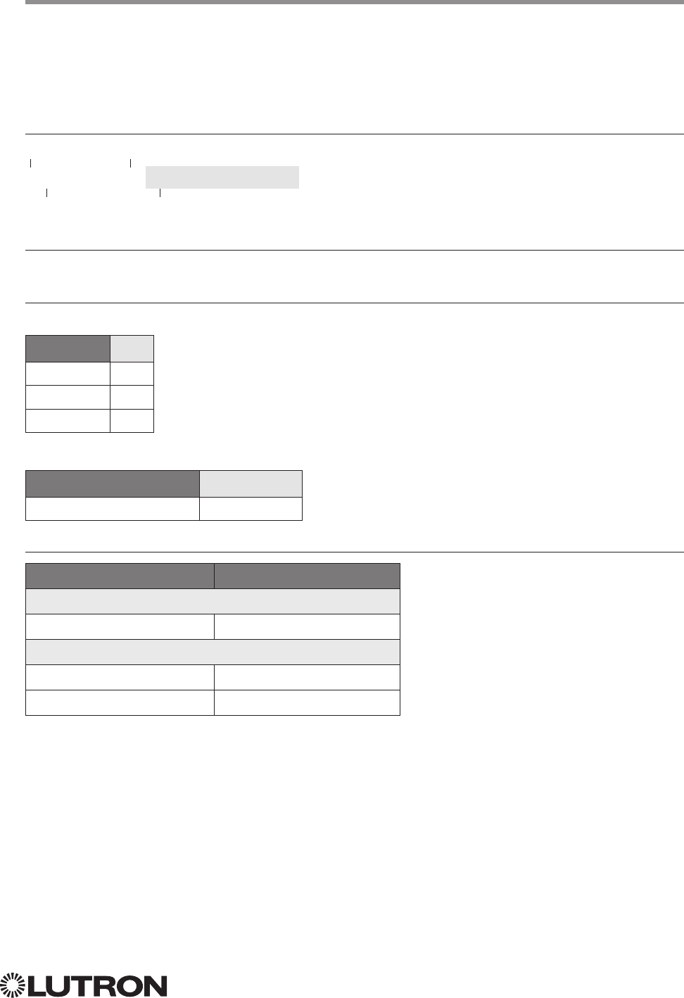
Command Structure
The protocol command structure is made up of three parts:
Command Integration ID Command-specific fields
1. The Command is made up of the operation character (#, ?, or ~) and the command type.
2. The Integration ID is assigned to each device in the system during system setup, providing a
unique user-assigned address for each system device.
3. The Command-specific fields contain additional information relevant to the type of command.
Details about what command-specific field data is supported can be found in the appropriate
device specific section of this integration protocol guide.
Command Termination
Each command is made up of fields, separated by commas, and terminated with a carriage return
(ASCII dec 13/hex 0D) and a line feed (ASCII dec 10/hex 0A). Throughout this document, carriage
return is shown as <CR> and line feed is shown as <LF>.
Continued on next page…
2
Lutron integration protocol
About Integration (continued)
Command and Control Examples
1) This command sets a dimmer (1) level to 75% with a 1 minute and 30 second fade time.
#OUTPUT,1,1,75,01:30<CR><LF>
Command Integration ID Command-specific fields
Action Number Level Fade Time
#OUTPUT 1 1 75 01:30
2) This command presses button number 1 of a keypad (2).
#DEVICE,2,4,3<CR><LF>
Command Integration ID Command-specific fields
Component Number Action Number
#DEVICE 2 4 3
Query Examples
3) This command requests the output level for a dimmer (3).
?OUTPUT,3,1<CR><LF>
Command Integration ID Command-specific fields
Action
?OUTPUT 3 1
Monitoring Examples
4) When a user makes a change to a dimmer locally, the following command response would be sent
out from the system or when requested by the command in Example 3 above. This command
response example shows the local dimmer (3) level was changed to 90%.
~OUTPUT,3,1,90.00<CR><LF>
Command Integration ID Command-specific fields
Action Level
~OUTPUT 3 1 90.00
3
Lutron integration protocol
About Integration (continued)
Integration Access Points
• Integration Access Points communicate with external systems using RS232, Ethernet or both.
The Lutron integration protocol will allow third-party equipment, such as touch-screens, keypads,
and software applications, to control and monitor devices in the Lutron lighting control system
through an Integration Access Point. For more information, check the page specific to the
Integration Access Point being used. An example of an Integration Access Point is the QS Network
Interface (QSE-CI-NWK-E). For a listing of all the available Integration Access Points supported
by a particular system, see the Integration Access Points section for that system in the table of
contents.
Command Rules and Formatting
• All commands are in ASCII characters
• Each command is made up of fields, separated by commas, and terminated with a carriage return
(<CR>, ASCII 13) and a new line (<LF>, ASCII 10)
• Letter case is ignored
• Spaces are ignored
• Leading zeros are ignored
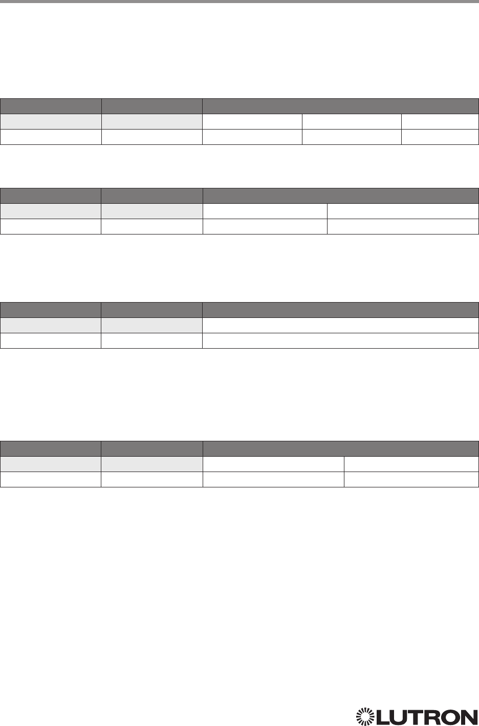
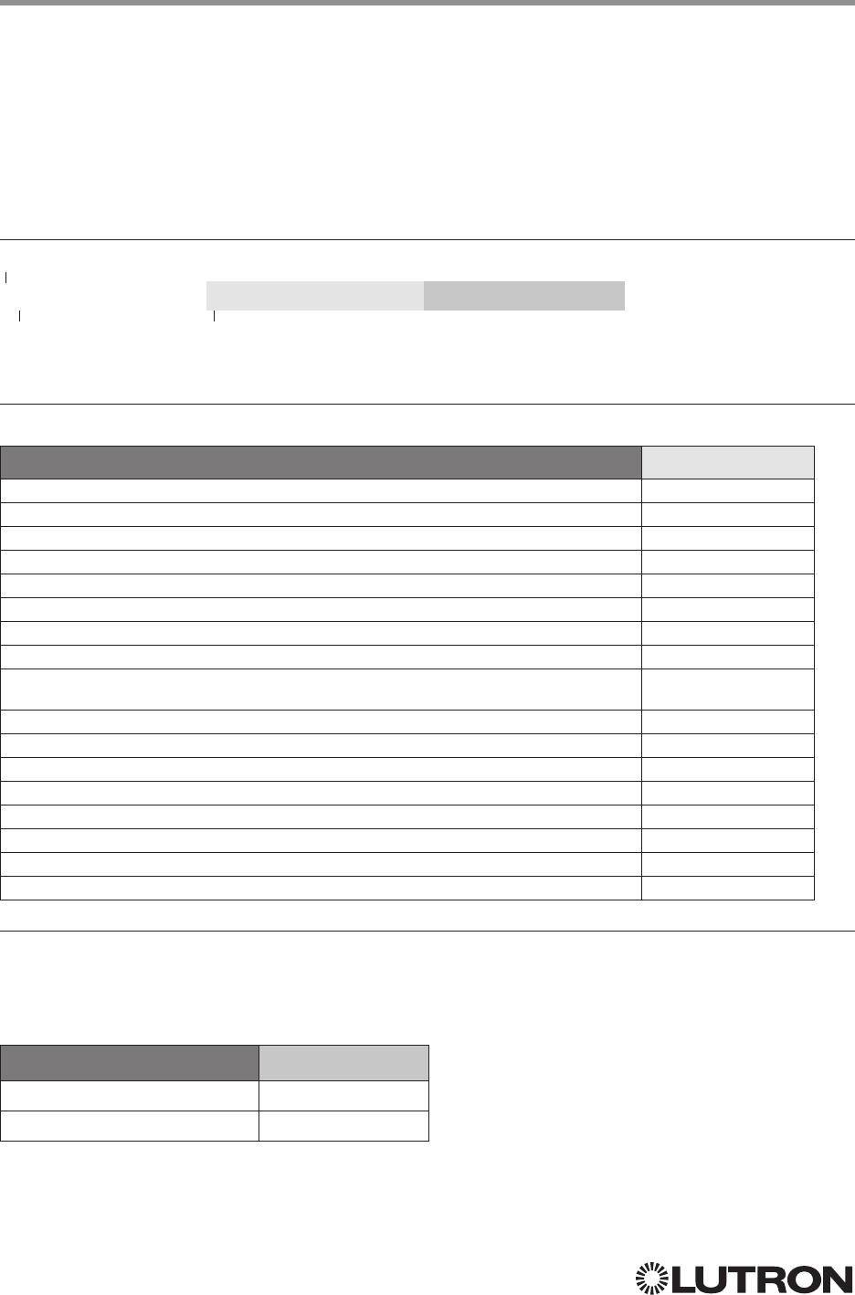
Inter-Message Delays
Inbound and outbound messages with the Integration Protocol will experience system delays
during normal operation. The following shows the minimum delays expected:
Command Type Minimum Inter-Message Delay
Command and Control: These commands start with “#” 100 ms
Query: These commands start with “?”11500 ms
NOTE
1. Integration systems should be designed to utilize Monitoring commands to maintain an up-to-date view of the current
system state.

4
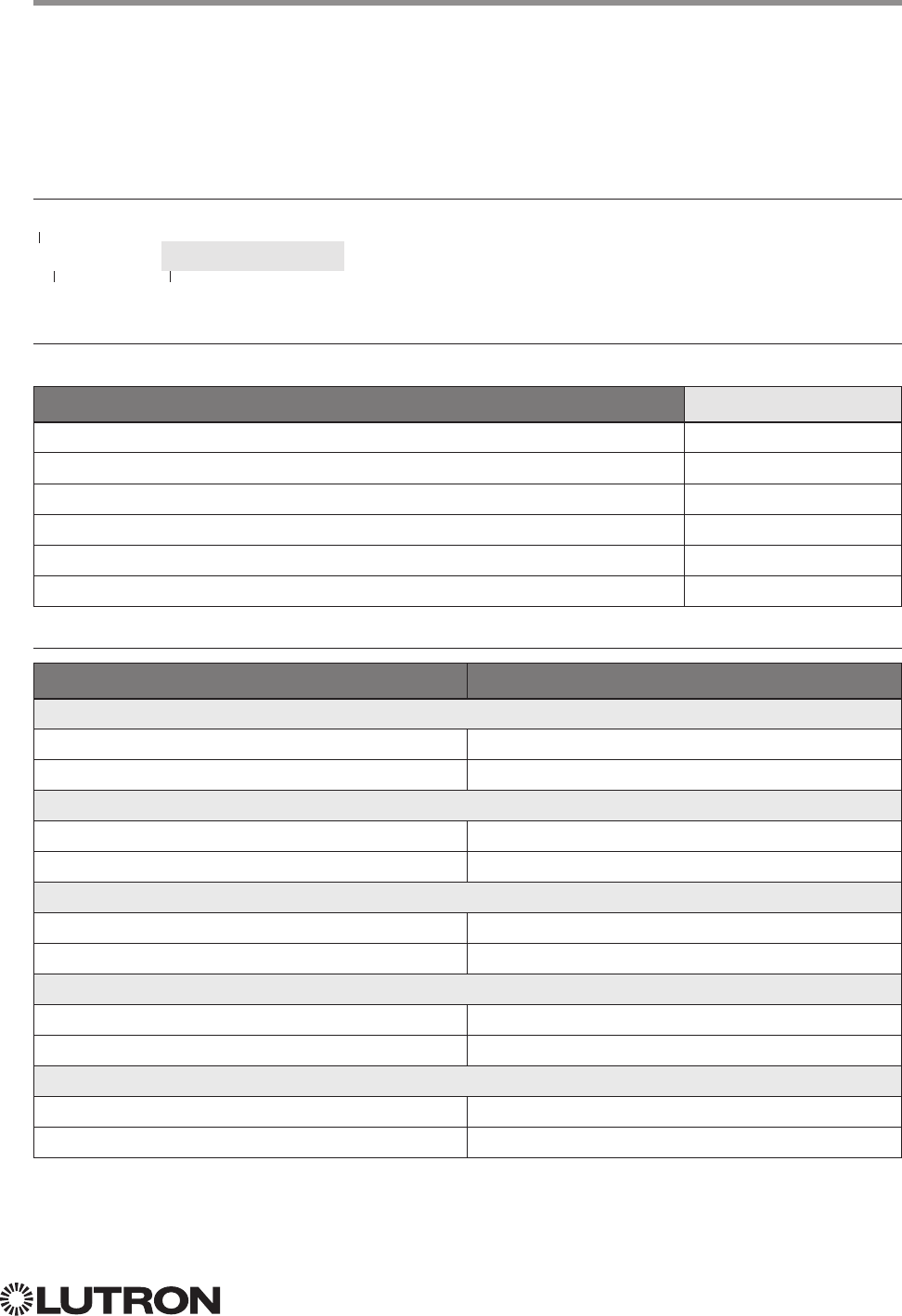
Integration Access Point Compatibility Matrix
QS Standalone Quantum RadioRA 2 HomeWorks QS myRoom plus
QS Network Interface
RadioRA 2 Main Repeater
HomeWorks QS Processor
myRoom (GCU-HOSP) Processor
Device Compatibility Matrix
QS Standalone Quantum RadioRA 2 HomeWorks QS myRoom plus
GRAFIK Eye QS
Energi Savr Node QS/DALI®
Energi Savr Node QS/
EcoSystem
Energi Savr Node QS/
EcoSystem (Int’l)
Energi Savr Node QS/0 –10 V/
Softswitch (Int’l)
Energi Savr Node QS/
Phase-Adaptive (Int’l)
Energi Savr Node QS/0 –10 V/
Softswitch
Energi Savr Node QS/
Motor Module (Int’l)
Remote Power Module
Low-Capacity Switching DIN
Power Module (1A/output)
Low-Capacity Phase-Adaptive
DIN Power Module (1A/output)
Palladiom Keypad
Palladiom Thermostat
Architrave Keypad
Signature Series Keypad
seeTouch Keypad
seeTouch QS Keypad (Int’l)
Tabletop seeTouch Keypad
Pico Wireless Control
Hybrid Keypad
Dynamic Keypad
Wallbox Input Closure Interface
Sivoia QS Shade
Sivoia QS Wireless Shade
Sivoia QS Venetian Blind
Sivoia QS Wireless Venetian Blind
Maestro Dimmer and Plug-In
Module
Maestro Fan Speed Control
Visor Control Receiver
Radio Powr Savr Sensor
HVAC Controller
Wireless Temperature Sensor
QS Input/Output Control Interface
QS Sensor Module
Lutron integration protocol
Integrator’s Reference
COMPATIBILITY MATRIX
5
Lutron integration protocol
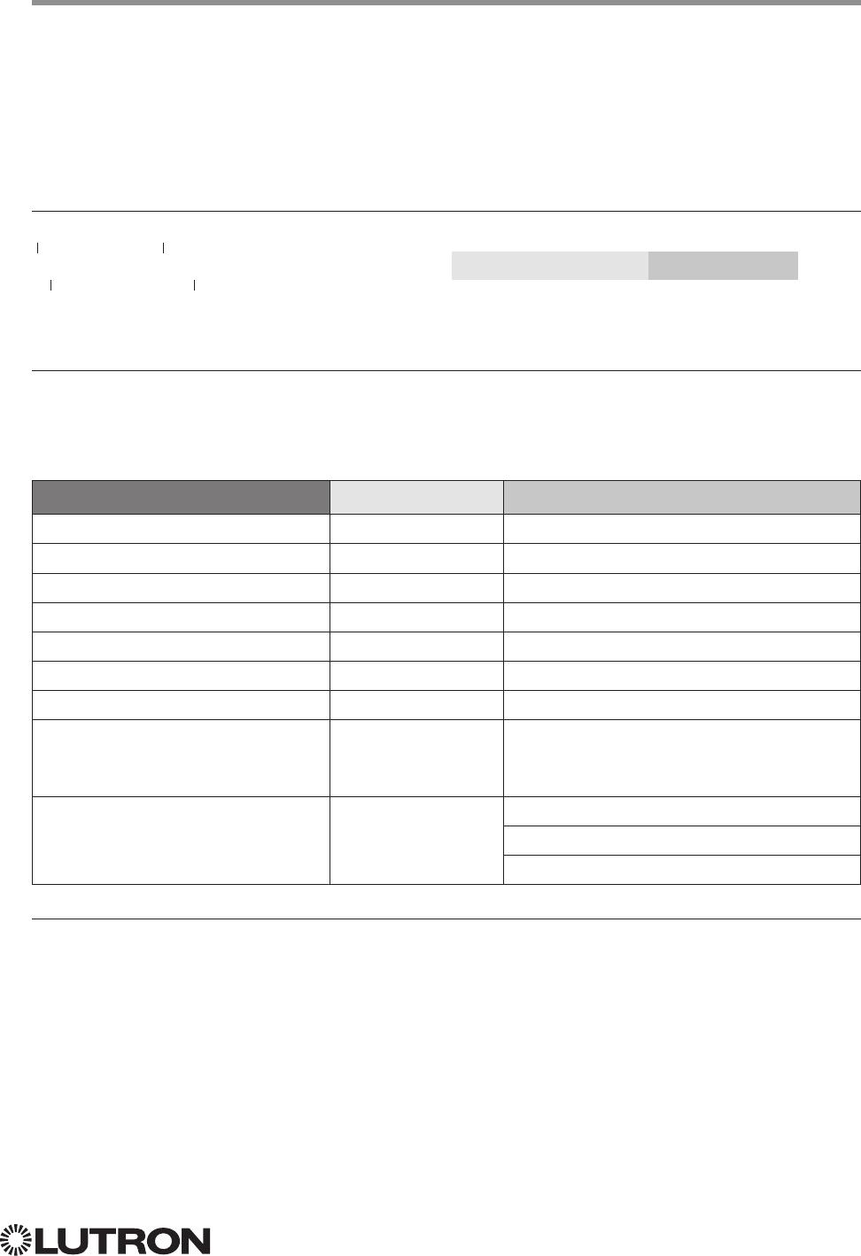
DEVICE Command-specific fields
Component Numbers:
Refer to device specific tables for lists of Component Numbers.
Action Numbers and Parameters:
Action Action Number Parameters
Set (#) Enable
11 None
Set (#) Disable
12 None
Set (#) Press, Close, or Occupied 3 None
Set (#) Release, Open, or Unoccupied 4 None
Set (#) Hold
25 None
Set (#) Multi-tap
26 None
Set (#) or Get (?) Current Scene
1,2 7 Scene
Set (#) or Get (?) LED State 9 0 = Off
1 = On
2 = Normal Flash2
3 = Rapid Flash2
Set (#) or Get (?) Light Level
314 0–100 or 0.00–100.00
SS.ss, SS, MM:SS, or HH:MM:SS
SS.ss, SS, MM:SS, or HH:MM:SS
NOTES
1. Quantum 2.7 and higher.
2. Not supported in RadioRA 2.
3. Not supported by Quantum.
DEVICE Command Formats
Use “DEVICE Command-specific fields” tables
to complete these command fields.
Operation
Command
Integration ID (example)
#DEVICE, 5, Component Number, Action Number, Parameters
Continued on next page…
Integrator’s Reference (continued)
DEVICE: Command Summary
Device integration commands allow the user to access components of the system such as a
physical device. The user can activate programming via button presses, releases, etc., as well as
monitor those same events as they occur in the system.

6
Lutron integration protocol
DEVICE Command-specific fields (continued)
Action Numbers and Parameters:
Action Action Number Parameters
Set (#) or Get (?) Zone Lock 1,2,3 15 0 = Off
1 = On
Set (#) or Get (?) Scene Lock 1,2,3 16 0 = Off
1 = On
Set (#) or Get (?) Sequence State 1,2,3 17 0 = Off
1 = Scenes 1– 4
2 = Scenes 5 –16
Set (#) Start Raising 3,4,5 18 None
Set (#) Start Lowering 3,4,5 19 None
Set (#) Stop Raising or Lowering 3,4,5 20 None
Get (?) battery status 22 1 = Normal, 2 = Low
Set (#) a custom lift and tilt level of venetian blinds
programmed to the phantom button 4,6 23 Lift level %
Tilt level %
Set (#) a custom lift level only of venetian blinds
programmed to the phantom button 4,6 24 Lift level %
Set (#) a custom tilt level only of venetian blinds
programmed to the phantom button 4,6 25 Tilt level %
Set (#) Hold or Release232 None
Set (#) GRAFIK Eye QS Timeclock state 34 0 = Disabled
1 = Enabled
Get (?) Query CCI state
835 None
Set (#) or Get (?) Active LED Level
736 0 –100%
Set (#) or Get (?) Inactive LED Level
737 0 –100%
NOTES
1. Not supported in HomeWorks QS.
2. Not supported in RadioRA 2.
3. Not supported by Quantum.
4. Use OUTPUT command with equivalent action number in RadioRA 2.
5. Use OUTPUT command with equivalent action number in HomeWorks QS.
6. Use SHADEGRP command with equivalent action number in HomeWorks QS.
7. Applies only to Palladiom keypads.
8. Requires NWK firmware 8.47 or newer for QS Standalone systems.
Integrator’s Reference (continued)
DEVICE: Command Summary (continued)
7
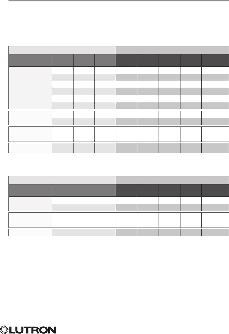
Lutron integration protocol
Programming Options Required Integration Action Numbers
Buttton Type Double
Tap Hold Cycle
Dim
Press
(3)
Release
(4)
Multi-Tap
(6)
Hold
(5)
Hold
Release (32)
Single-Action and
Toggle Buttons
———— — — —
— — —— —
—— — ——
— — —
— — —
—
Dual Action Buttons ——— — — —
— — — —
Master and Single
Scene Raise / Lower
Buttons
——— — — —
Open/Stop/Close/
Stop Buttons ———— — — —
Integrator’s Reference (continued)
DEVICE: Command Summary (continued)
HomeWorks / myRoom plus QS Button Types and Integration Requirements:
Refer to Lutron Designer software for setting up programming options.
RadioRA 2 Button Types and Integration Requirements:
Refer to RadioRA 2 Essentials / Inclusive software for setting up programming options.
Programming Options Required Integration Action Numbers
Buttton Type Scene Save
Enabled
Press
(3)
Release
(4)
Multi-Tap
(6)
Hold
(5)
Hold
Release (32)
Single-Action and
Toggle Buttons
—— — — —
— — —
Master and Single
Scene Raise / Lower
Buttons
— — — —
Shade Toggle Buttons — — — — —
Continued on next page…

8
OUTPUT Command-specific fields
Action Numbers and Parameters:
Action Action Number Parameters
Set (#) or Get (?) Zone Level 1 0–100 or
0.00–100.00
SS.ss
1, SS, MM:SS, or HH:MM:SS
Set (#) Start Raising 2 None
Set (#) Start Lowering 3 None
Set (#) Stop Raising or Lowering 4 None
Set (#) Start Flashing
25 SS.ss
1, SS, MM:SS, or HH:MM:SS
Set (#) Pulse Time 6 SS.ss
1, SS, MM:SS, or HH:MM:SS
Set (#) or Get (?) tilt level 3,4 9 Tilt Level
5 = 0 –1006 or 0.00–100.00
5,6
Fade
1 in: SS.ss
2, SS, MM:SS, or HH:MM:SS
Delay
3 in: SS.ss
2, SS, MM:SS, or HH:MM:SS
Set (#) or Get (?) lift & tilt level 410 Lift Level
5 = 0 –100 or 0.00 –100.00 5
Tilt Level
5 = 0 –100f or 0.00–100.00
5,6
Fade
1 in: SS.ss
2, SS, MM:SS, or HH:MM:SS
Delay
3 in: SS.ss
2, SS, MM:SS, or HH:MM:SS
Set (#)
Start Raising Tilt
4 11 None
Set (#)
Start Lowering Tilt
4 12 None
Set (#)
Stop Raising or Lowering Tilt
4 13 None
Set (#)
Start Raising Lift
4 14 None
Set (#)
Start Lowering Lift
4 15 None
Set (#)
Stop Raising or Lowering Lift
4 16 None
Set (#) DMX Color or Level Settings 7, 8 17 Color / level index: 0 – 255 / 0.00–100.00
Set (#) Motor Jog Raise 7, 9 18 None
Set (#) Motor Jog Lower 7, 9 19 None
Set (#) Motor 4-Stage Jog Raise 7, 9 20 None
Set (#) Motor 4-Stage Jog Lower 7, 9 21 None
NOTES
1. Fractions are rounded up to the closest 1/4 second.
2. To stop a dimmer from flashing, send it to a valid level (action 1).
3. The Delay time is optional. When not used, the system will use a zero-second delay. The minimum delay time is
0seconds. The maximum delay time is 4 hours.
4. Not supported in Quantum.
5. For switched outputs, any non-zero level results in on or closed, 0 results in off or open.
6. 50 for Horizontal Sheer Blinds.
7. Not supported in RadioRA 2.
8. Supported in Quantum version 2.2 and higher.
9. Supported in Quantum version 2.5 and higher.
Lutron integration protocol
OUTPUT Command Format
Use “OUTPUT Command-specific fields” tables
to complete these command fields.
Operation
Command
Integration ID (example)
#OUTPUT, 6, Action Number, Parameters
Integrator’s Reference (continued)
OUTPUT: Command Summary
Outputs are dimmers, CCOs, or other devices in a system that have a controllable output. All of
these devices will accept levels from 0% to 100% and 0.00% to 100.00% with a given fade and
delay time. These same commands can be monitored as they occur in the system.
9
Lutron integration protocol
Integrator’s Reference (continued)
GROUP1: Command Summary
The GROUP command is used to report the status of a group of occupancy sensors.
GROUP Command-specific fields
Action Numbers:
Action Action Number
Get (?) Occupancy Group State
3
GROUP Command Format
Use “GROUP Command-specific fields” tables
to complete these command fields.
Operation
Command
Integration ID (example)
?GROUP, 6, Action Number
Example GROUP Messages
Operation Command String
Query: ?GROUP, Integration ID, Action Number
What is Occ GROUP 1’s status? ?GROUP,1,3<CR><LF>
Response: ~ GROUP, Integration ID, Action Number, Parameters
Occ group 1 is occupied ~GROUP,1,3,3<CR><LF>
Occ group 1 is unknown ~GROUP,1,3,255<CR><LF>
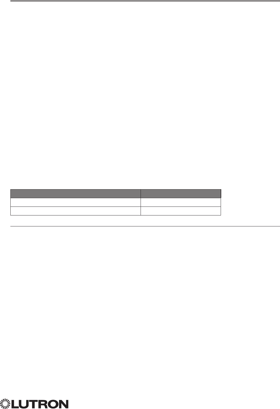
Occupancy States:
Description Value
Occupied 3
Unoccupied 4
Unknown 255
NOTE
1. Not supported in QS Standalone.
Continued on next page…

10
Lutron integration protocol
Integrator’s Reference (continued)
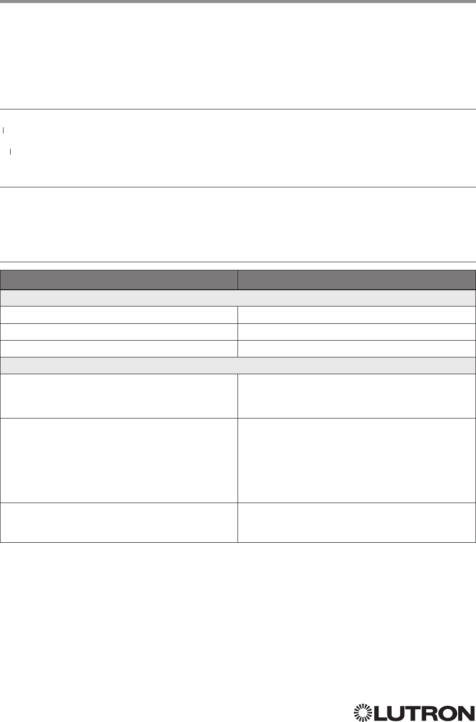
HVAC: Command Summary
HVAC Integration commands allow the user to access the HVAC components and features of the
system. The user can modify HVAC parameters like the operating mode, fan mode etc., as well as
monitor the changes to these parameters as they occur in the system.
HVAC Command Format
Use “HVAC Command-specific fields” tables
to complete these command fields.
Operation
Command
Integration ID (example)
#HVAC,21, Action Number, Parameters
HVAC Command-specific fields
Action Numbers and Parameters:
1
Action Action Number Parameters
Set (#) or Get (?) Current Temperature (°F) 5 1Temperature = 32–212 °F
Set (#) or Get (?) Heat and Cool
Setpoints (°F) 2, 4, 5 2Setpoint Heat (SPH) = 32–212 °F
Setpoint Cool (SPC) = 32–212 °F
Set (#) or Get (?) Operating Mode 3 Mode (1 = Off/Protect, 2 = Heat, 3 = Cool, 4 = Auto,
5 = Em.Heat, 7= Fan, 8 = Dry)
Set (#) or Get (?) Fan Mode 4 Mode (1 = Auto, 2 = On, 3 = Cycler, 4 = No Fan,
5 = High, 6 = Medium, 7 = Low, 8 = Top)
Set (#) or Get (?) Eco (Setback) Mode 5Mode (1 = Off, 2 = On)
Get (?) Eco Offset 6 Eco Offset = 1–11 °F
Set (#) or Get (?) Schedule Status 3 7
0 = Schedule Unavailable (Get “?” Only)
1 = Following Schedule (Set “#” or Get “?”)
2 = Permanent Hold (Set “#” or Get “?”)
3 = Temporary Hold (Get “?” only)
Get (?) Temperature Sensor
Connection Status 8
1 = All Sensors are Active
2 = Missing Sensor
3 = Wired Sensor Only
4 = No Sensor
Get (?) Schedule Event 9 Schedule # (1–7), Event # (1– 4), HH,MM, SPH, SPC
Get (?) Schedule Day Assignment 10 Schedule#(1–7), DD(Bitmap:Sunday(Bit 0) –
Saturday(Bit 6) 1–active day, 0– inactive day)
Get (?) System Mode 11
1 = Normal
2 = Away
3 = Green
Get (?) Heat and Cool Setpoints (°F) without
Eco Offset if applied 5 12 Setpoint Heat (SPH) = 32 – 212 °F
Setpoint Cool (SPC) = 32 – 212 °F
Get (?) Emergency Heat Available 13 1 = Not Available
2 = Available
NOTES
1. These commands are supported only for HomeWorks QS, RadioRA 2, myRoom Plus.
2. Changing the setpoint will turn Eco Mode off if it is currently on.
3. Schedule Unavailable –> Schedule not programmed or device needs date / time.
Following Schedule –> Running programmed schedule; set points from schedule.
Permanent Hold –> Schedule is not running; set points as adjusted.
Temporary Hold –> Running schedule; set points as adjusted. Returns to following schedule at next schedule event.
4. To leave a parameter unchanged, use “255” as the value for that parameter when ending the command.
5. Allow for reported temperature values to be zero padded, with up to 3 digits before the decimal point, and 2 digits after.
– Possible reported values of 5 °C: “005”, “05”, “5”, “005.”, “005.”, “5.”, “005.0”, “05.0”, “5.0”, “005.00”, “05.00”, “5.00”
– Possible reported values of 5.5 °C: “005.5”, “05.5”, “5.5”, “005.50”, “05.50”, “5.50”
– Possible reported values of 21 °C: “021”, “21”, “021.0”, “21.0, “021.00,” “21.00”
– Possible reported values of 21.5 °C: “021.5”, “21.5”, “021.50”, “21.50”

11
Lutron integration protocol
Integrator’s Reference (continued)
HVAC: Command Summary (continued)
HVAC Command-specific fields (continued)
Action Numbers and Parameters (continued):
Action Action Number Parameters
Set (#) or Get (?) Call Status 14
0 = None, Last was Heat
1 = Heat Stage 1
2 = Heat Stage 1 and 2
3 = Heat Stage 1, 2, and 3
4 = Heat Stage 3
5 = None, Last was Cool
6 = Cool Stage 1
7 = Cool Stage 1 and 2
8 = Off
9 = Emergency Heat
10 = Dry
Set (#) or Get (?) Current Temperature (°C)1, 4 15 Temperature = 0 –100 °C
Set (#) or Get (?) Heat and Cool Setpoints
(°C)2, 3, 4 16 Setpoint Heat (SPH) = 0 – 100 °C
Setpoint Cool (SPC) = 0 – 100 °C
Get (?) Heat and Cool Setpoints (°C) without
Eco Offset if applied2, 4 17 Setpoint Heat (SPH) = 0 – 100 °C
Setpoint Cool (SPC) = 0 – 100 °C
Set (#) or Get (?) Single Setpoint (°F) and
Drifts 3, 4 18 Single Setpoint =
32 – 212 °F
Negative Drift =
0 – 15 °F
Positive Drift =
0 – 15 °F
Set (#) or Get (?) Single Setpoint (°C) and
Drifts 3, 4 19 Single Setpoint =
0 – 100 °C
Negative Drift =
0 – 8 °C
Positive Drift =
0 – 8 °C
NOTES
1. HomeWorks QS software version 4.1 and higher.
2. Changing the setpoint will turn Eco Mode off if it is currently on.
3. To leave a parameter unchanged, use “255” as the value for that parameter when ending the command.
4. Allow for reported temperature values to be zero padded, with up to 3 digits before the decimal point, and 2 digits after.
– Possible reported values of 5 °C: “005”, “05”, “5”, “005.”, “005.”, “5.”, “005.0”, “05.0”, “5.0”, “005.00”, “05.00”, “5.00”
– Possible reported values of 5.5 °C: “005.5”, “05.5”, “5.5”, “005.50”, “05.50”, “5.50”
– Possible reported values of 21 °C: “021”, “21”, “021.0”, “21.0, “021.00,” “21.00”
– Possible reported values of 21.5 °C: “021.5”, “21.5”, “021.50”, “21.50”
12
Lutron integration protocol
MONITORING Command-specific fields
Monitoring Type:
Description Monitoring Type
Set (#) or Get (?) Diagnostic Monitoring 1
Set (#) or Get (?) Event Monitoring 2
Set (#) or Get (?) Button Monitoring 3
Set (#) or Get (?) LED Monitoring14
Set (#) or Get (?) Zone Monitoring 5
Set (#) or Get (?) Occupancy 6
Set (#) or Get (?) Scene # 8
Set (#) or Get (?) System Variable 10
Set (#) or Get (?) Reply State (if disabled, all messages FROM the integration access
point will cease)
11
Set (#) or Get (?) Prompt State (if disabled, the prompt will not be printed to the terminal) 12
Set (#) or Get (?) Venetian Tilt214
Set (#) or Get (?) Sequence Monitoring
116
Set (#) or Get (?) HVAC Monitoring
1,2 17
Set (#) or Get (?) Mode Monitoring
1,2 18
Set (#) or Get (?) Shade Group Monitoring
323
Set (#) or Get (?) Partition Wall
3,4 24
Set (#) or Get (?) State of All Monitoring (except Reply and Prompt) 255
NOTES
1. Not supported in QS Standalone.
2. Not compatible with Quantum.
3. Not supported in RadioRA 2 and HomeWorks QS.
4. Not supported via QSE-CI-NWK-E in Quantum.
Action Numbers:
Action Action Number
Enable 1
Disable 2
MONITORING Command Formats
Use “MONITORING Command-specific fields” tables
to complete these command fields.
Operation
Command
#MONITORING, Monitoring Type, Action Number
Integrator’s Reference (continued)
MONITORING: Command Summary
Monitoring allows the user to configure what types of messages the system will report.
Note to Integrator: The default values of these are set in the programming database and restored
whenever the integration port is logged in. The user can temporarily change those settings to hide
or show information as desired.
13
Lutron integration protocol
ERROR Command Formats
Refer to “ERROR Command-specific fields” table
Operation
Command
~ERROR, Error Number
ERROR Command-specific fields
Error Numbers:
Description Error Number
Report (~) Parameter count mismatch 1
Report (~) Object does not exist 2
Report (~) Invalid action number 3
Report (~) Parameter data out of range 4
Report (~) Parameter data malformed 5
Report (~) Unsupported Command 6
Example ERROR Messages
Operation Command String
Parameter count mismatch: Too many or too few parameters for the specified action
Too many parameters when activating scene #AREA,2,6,1,1,1,1,1<CR><LF>
Parameter count mismatch. ~ERROR,1<CR><LF>
Object does not exist: The Integration ID or serial number entered does not map to a known part of the system
Send command to an ID that is not valid #OUTPUT,1234,1,100.00<CR><LF>
Object does not exist ~ERROR,2<CR><LF>
Invalid Action: The action does not exist for this command
Send invalid action (4321) to Area 2 #AREA,2,4321<CR><LF>
Invalid action number ~ERROR,3<CR><LF>
Parameter data out of range: The parameter data is out of range for this action
Send Output 11 to 120% #OUTPUT,11,1,120.00<CR><LF>
Parameter data out of range ~ERROR,4<CR><LF>
Parameter data malformed: The parameter data given was not formatted properly
Set Time to 12:23:24:25 #SYSTEM,1,12:23:24:25<CR><LF>
Invalid action number ~ERROR,5<CR><LF>
Integrator’s Reference (continued)
ERROR: Command Summary
Integration Access Points will respond with an error if an invalid command is received. See the
table below for explanations of different errors.
Continued on next page…
14
Lutron integration protocol
HELP Command Formats
Example HELP Messages
Operation Command String
Query: ?HELP, Command Name, Action Number
What are all the supported Integration Commands? ?HELP<CR><LF>
What actions are available for #OUTPUT? ?HELP,#OUTPUT<CR><LF>
How is “Raise” used for #OUTPUT? ?HELP,#OUTPUT,2<CR><LF>
Response: ~HELP, Help Information
The list of all Integration Commands. #OUTPUT,?OUTPUT,#DEVICE,?DEVICE,#AREA,
?AREA,#TIMECLOCK,?TIMECLOCK,#SYSTEM,
?SYSTEM,#MONITORING,?MONITORING,
<CR><LF>
The help information for the #OUTPUT command. ~HELP, #OUTPUT requires action<1–6><CR><LF>
1 = Set Level / Position
2 = Start Raising
3 = Start Lowering
4 = Stop Raising / Lowering
6 = Pulse
USAGE: #OUTPUT, <ID>, <action>,<CR><LF>
The help information for the “Raise” action (#OUTPUT). ~HELP, #OUTPUT, <action=2> start raising
output level<CR><LF>
USAGE: #OUTPUT, <ID>, <action=2><CR><LF>
Operation
Command
?HELP, Command Name
2, Action Number
3
Integrator’s Reference (continued)
HELP1: Command Summary
HELP Command for a specific Command Name provides command-name specific usage
information.
NOTES
1. HELP not supported in QS Standalone.
2. The “Command Name” parameter is optional. If not entered, a list of all the supported Integration Commands will be
printed. If a supported command name is entered, the corresponding actions will be listed.
3. The “Action” parameter is optional. When a valid action number is entered (i.e. it is supported by the corresponding
“Command Name”), the help information for that particular action will be displayed.
15
Lutron integration protocol
SYSTEM Command Formats
SYSTEM Command-specific fields
Action Numbers and Parameters:
Action Action Number Parameters
Set (#) or Get (?) Time
11 Time in: SS.ss, SS, MM:SS, or HH:MM:SS
Set (#) or Get (?) Date 2 Date in MM/DD/YYYY
Set (#) or Get (?) Latitude
and Longitude
4Latitude = –90.00 to +90.00 degrees
Longitude = –180.00 to +180.00 degrees
Set (#) or Get (?) Time
Zone
25Hours = –12 to 12
Minutes = 0 to 59
Get (?) Sunset 6 None
Get (?) Sunrise 7 None
Get (?) OS Rev 8 None
Set (#) Load Shed
311 0 = Disabled
1 = Enabled
NOTES
1. The system time must be entered in 24 hour format.
2. The Time Zone is referenced to GMT.
3. Load Shed commands available only on Quantum version 2.0 and higher.
Example SYSTEM Messages
Operation Command String
Execute: #SYSTEM, Action Number, Parameters
Set time to 5:45 PM. #SYSTEM,1,17:45<CR><LF>
Set date to June 1, 2009. #SYSTEM,2,06/01/2009<CR><LF>
Query: ?SYSTEM, Action Number
What is the system time? ?SYSTEM,1<CR><LF>
What is the system date? ?SYSTEM,2<CR><LF>
Response: ~SYSTEM, Action Number, Parameters
The system time is 11:05 AM. ~SYSTEM,1,11:05:00<CR><LF>
The system date is July 3, 2009. ~SYSTEM,2,07/03/2009<CR><LF>
Use “SYSTEM Command-specific fields” tables to
complete these command fields.
Operation
Command
#SYSTEM, Action Number, Parameters
Integrator’s Reference (continued)
SYSTEM1: Command Summary
SYSTEM Command provides support for location, device and system specific information
(e.g., Date, Time, Software Version Numbers).
NOTE
1. Not supported in QS Standalone.

16
Lutron integration protocol
QS Standalone
System Overview
The QS family of products delivers scalable lighting and shading solutions for residential and
commercial applications. At the center of the QS system are the GRAFIK Eye QS control units,
Energi Savr Node control units, and Sivoia QS shades and drapes, providing direct control of
electric and natural light. QS system devices communicate over the highly flexible QS link; the
link allows for daisy-chain or t-tap wiring configurations. All QS system devices communicate
without the need for interfaces, and addressing is automatic, eliminating the need to set DIP
switches. In addition, QS keypads are configurable in the field to control lights, shades, lights +
shades, or third-party devices. The QS system can be easily integrated with other systems through
contact-closure input /output, DMX output, or Ethernet/RS232.
QS System Device Compatibility Index
QS Standalone
GRAFIK Eye QS
Energi Savr Node QS/DALI®
Energi Savr Node QS/EcoSystem
Energi Savr Node QS/EcoSystem (Int’l)
Energi Savr Node QS/0 –10 V/Softswitch (Int’l)
Energi Savr Node QS/Phase-Adaptive (Int’l)
Energi Savr Node QS/0 –10 V/Softswitch
Energi Savr Node QS/Motor Module (Int’l)
Architrave Keypad
Signature Series Keypad
seeTouch Keypad
seeTouch QS Keypad (Int’l)
Pico Wireless Control
Wallbox Input Closure Interface
Sivoia QS Shade
Sivoia QS Wireless Shade
Sivoia QS Venetian Blind
Sivoia QS Wireless Venetian Blind
QS Input/Output Control Interface
QS Sensor Module
17
Lutron integration protocol
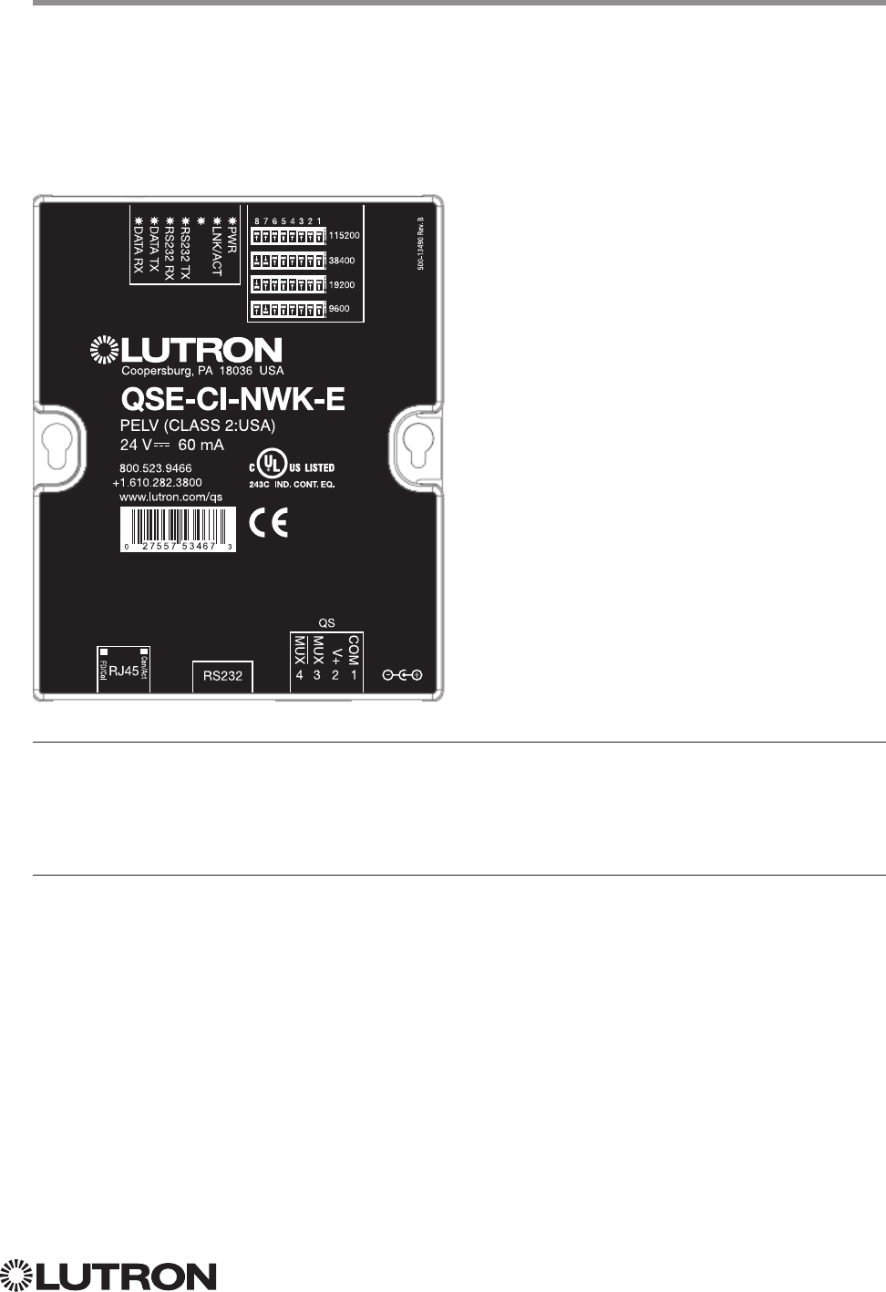
Why Integrate with a QSE-CI-NWK-E?
• Integrates a QS lighting control system with a PC or other digital equipment that supports RS232
or Ethernet TCP/IP connection.
• Allows monitor and control of system devices. For example, the QSE-CI-NWK-E can be used to
simulate button presses, report button presses, control light levels, and monitor light levels.
Supported Commands
• MONITORING specifies what type of messages the system will report
• ETHERNET modifies the Ethernet configurations of the QSE-CI-NWK-E
• RESET restarts the QSE-CI-NWK-E or restores it to factory defaults
• INTEGRATION ID assigns IDs to devices, so that they may be referred to in a more logical fashion
• DETAILS returns information about a QS device
• ERROR reports syntax errors in an integration string command or query
• PROGRAMMING allows user to program Phantom Buttons on the NWK supported in version 8.0
or higher
• DEVICE used to activate Phantom Buttons on the NWK
• OUTPUT used to control outputs of a Device
• “Programming” and “Device” commands require version 8.0 or higher of the NWK software
QS Standalone (continued)
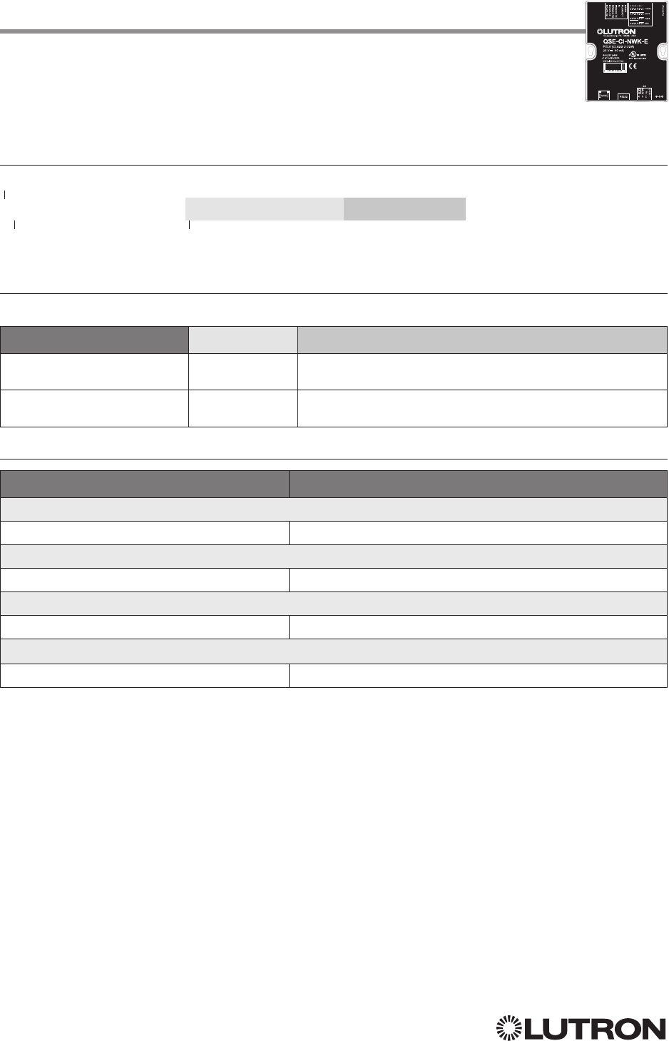
Integration Access Points
Network Interface
Model: QSE-CI-NWK-E
Continued on next page…

18
Lutron integration protocol
Connection Information
Provides an RS232 and Ethernet connection to communicate with external equipment.
Communication is through either RS232 or Ethernet, but not both simultaneously.
RS232
The RS232 connection has the following communication settings:
• Baud Rate 9600/19200/38400/115200 (set via dipswitch on unit)
• 8 data bits
• No parity bit
• 1 stop bit
• No flow control
Ethernet
Configuring the control interface to communicate over a network takes not only knowledge
of the QS system, but of networking as well. Installers with limited networking knowledge are
advised to contact a networking professional before attempting to connect a QSE-CI-NWK-E
through a network. The information below will help an installer communicate the QSE-CI-NWK-E
configurations to a network professional.
The installer will make any necessary changes to the control interface using the Lutron DeviceIP or
PC software tool and the network professional can make any necessary changes to the networking
equipment.
Single Ethernet Port
• IEEE® 802.3 Auto-Sensing 10BaseT / 100BaseTX
• Supports MDI/MDIX auto-crossover (no crossover cable needed).
• Female 8P8C “Computer RJ-45” socket
• Green “Connect” LED, Amber “Activity” LED
• Use Cat 5 cabling or better
TCP / IP Settings
• IP Address: <static default = 192.168.250.1>
• Subnet Mask: <static default = 255.255.255.0>
• Gateway: <static default = 0.0.0.0>
Protocols Used for Integration
• TELNET
Telnet Server
• Used by third party equipment (i.e. touch screen)
• Limited to transferring ASCII characters
• Telnet Port number is 23
• Login #1: nwk
• Login #2: nwk2
QS Standalone (continued)
Integration Access Points (continued)
19
Lutron integration protocol
ETHERNET Command Formats
ETHERNET Command-specific fields
Configuration Numbers:
Description Configuration Number Parameters
Set (#) or Get (?) IP Address 0 Address (XXX.XXX.XXX.XXX)
Set (#) or Get (?) Gateway
Address
1 Address (XXX.XXX.XXX.XXX)
Set (#) or Get (?) Subnet Mask 2 Address (XXX.XXX.XXX.XXX)
Set (#) or Get (?) Login Info 3 User (0 = All users; 1 = User 1; 2 = User 2),
Old Login,
New Login
Example ETHERNET Commands
Operation Command String
Execute: #ETHERNET, Configuration Number, Parameters
Set IP Address to 192.168.250.1 #ETHERNET,0,192.168.250.1<CR><LF>
Set Gateway Address to 10.2.4.1 #ETHERNET,1,10.2.4.1<CR><LF>
Query: ?ETHERNET, Configuration Number, Parameters
What is the IP Address? ?ETHERNET,0<CR><LF>
What is the Login Information for user 1? ?ETHERNET,3,1<CR><LF>
What is the Login Information for ALL users? (Note: 0 = ALL) ?ETHERNET,3,0<CR><LF>
Response: ~DEVICE, Integration ID, Configuration Number, Parameters
The IP Address is 192.168.250.1 ~ETHERNET,0=,192.168.250.1<CR><LF>
QS Standalone (continued)
System Commands
ETHERNET Commands
Use “ETHERNET Command-specific fields” tables
to complete these command fields.
Operation
Command
#ETHERNET, Configuration Number, Parameters
Continued on next page…
20
Lutron integration protocol
INTEGRATION ID Command Formats
INTEGRATION ID Command-specific fields
Action Numbers and Parameters:
Description Action Number Parameters
Set (#) or Get (?) Integration ID for
a Serial Number
1Serial Number = 8 character HEX serial number of the device
Integration ID = The integration ID to be assigned.
Set (#) Change Integration ID 2 Current Integration ID, New Integration ID
Note: An error will be reported if the new Integration ID is the
same as an existing Integration ID in the system.
Get (?) Info from ID 3 Integration ID
Note: If this field is left blank, all integration IDs will be printed.
Set (#) or Get (?) Output
Integration ID
4 Serial Number, Component Number, Integration ID
Example INTEGRATION ID Commands
Operation Command String
Execute: #INTEGRATIONID, Action Number, Parameters
Set the Integration ID for a serial number #INTEGRATIONID,1,1234ABCD,kitchen dimmer<CR><LF>
Response: ~INTEGRATIONID, Action Number, Parameters
Set the Integration ID for a serial number ~INTEGRATIONID,1,1234ABCD,kitchen dimmer<CR><LF>
Execute: ?INTEGRATIONID, Action Number, Parameters
Get the Integration ID for a serial number ?INTEGRATIONID,1,5678EFEF<CR><LF>
Response: ~INTEGRATIONID, Action Number, Parameters
Get the Integration ID for a serial number ~INTEGRATIONID,1,5678EFEF,living room keypad<CR><LF>
Execute: #INTEGRATIONID, Action Number, Parameters
Change the Integration ID #INTEGRATIONID,2,diningroomlights1,diningroomaccents<CR><LF>
Response: ~INTEGRATIONID, Action Number, Parameters
Change the Integration ID ~INTEGRATIONID,2,diningroomlights1,diningroomaccents<CR><LF>
Execute: ?INTEGRATIONID, Action Number, Parameters
Get information about an Integration ID
command
?INTEGRATIONID,3,livingroomkeypad<CR><LF>
Response: ~INTEGRATIONID, Action Number, Parameters
Get information about an Integration ID command ~INTEGRATIONID,3,livingroomkeypad,DEVICE,5678EFEF<CR><LF>
QS Standalone (continued)
System Commands (continued)
INTEGRATION ID Commands
Use “INTEGRATIONID Command-specific fields” tables
to complete these command fields.
Operation
Command
#INTEGRATIONID, Action Number, Parameters
21
Lutron integration protocol
Example DETAILS String
Operation Command String
Query: ?DETAILS, ID
Get details of the device with serial ID number 00AC123D ?DETAILS,00AC123D<CR><LF>
Response: ~DETAILS, Serial Number, Name, Family, Model, Software Rev., Boot Software Rev.
The device with serial ID number 00AC123D has the
following information:
Name = GRAFIK Eye 1
Product Family = GRAFIK Eye
Product Model = QSG
Software Revision = 1.70
Boot Code Software Revision = 2
~DETAILS,SN:00AC123D,IntegrationID:GRAFIKEye1,Famil
y:GRAFIK_Eye(2),Product:QSG(1),CODE:1.70,Boot:2.1,H
W:1.1<CR><LF>
DETAILS Command Formats
Operation
Command
?DETAILS, ID
1
QS Standalone (continued)
System Commands (continued)
DETAILS String
NOTE
1. Device ID may be entered as the serial ID number or the Integration ID. Use ALL_DEVICES or FFFFFFFF to query all
devices on the link.
Continued on next page…
22
Lutron integration protocol
RESET Command Formats
RESET Command-specific fields
Action Numbers:
Action Action Number
Set (#) restart the device 0
Set (#) restore to factory defaults 1
Set (#) restore to factory defaults (does not affect the
IP address, Gateway address, subnet mask settings)
2
Example RESET Commands
Operation Command String
Execute: #RESET, Action Number
Restart the NWK #RESET,0<CR><LF>
Restore NWK to factory defaults #RESET,1<CR><LF>
Use “RESET Command-specific fields” tables
to complete these command fields.
Operation
Command
#RESET, Action Number
QS Standalone (continued)
System Commands (continued)
RESET Commands
23
Lutron integration protocol
QS Standalone (continued)
System Commands (continued)
PROGRAMMING Commands
PROGRAMMING Command-specific fields
Action Numbers and Parameters:
Description Action Number Parameters
Set (#) add programming to a phantom button 1 a) Integration ID – The Integration ID of the device
b) Component Number – Always ‘0’ for Shade
c) Level – The level to which the shade being
programmed will go on activation of this button
d) Fade – The time the zone takes to reach the
level specified (maximum 4 hours)1
e) Delay – The time until the Shade/Zone begins
to change (maximum 4 hours)
Set (#) add scene programming to a phantom
button
2 a) Integration ID
b) Component Number (GRAFIK Eye QS Scene
controller, Energi Savr Node area
2)
c) Scene Number
Set (#) clear programming from a phantom
button
3
3 None
Set (#) configure Stop-If-Moving functionality
440 = Stop-If-Moving Off
1 = Stop-If-Moving On
Set (#) add programming to a phantom button
(Venetian blind, lift and tilt levels)
5 a) Venetian Integration ID
b) Component Number (always 0)
c) Lift level
d) Tilt level
Set (#) add programming to a phantom button
(Venetian blind, tilt only)
6 a) Venetian Integration ID
b) Component Number (always 0)
c) Tilt level
Set (#) add programming to a phantom button
(Venetian blind, lift only)
7 a) Venetian Integration ID
b) Component Number (always 0)
c) Lift level
NOTES
A maximum of 500 programming assignments can be made in the QSE-CI-NWK-E.
1. Not available for Shades.
2. If a device’s Zone is already assigned to the button, you cannot program a Scene for that button. If a Scene is already
programmed for this button for a device, you cannot program another Zone for this button.
3. Use button number 0 to clear programming from all buttons.
4. Use button number 0 to configure Stop-If-Moving functionality on all buttons.
PROGRAMMING Command Formats
Integration ID or Serial # of
the QSE-CI-NWK being used
Use “PROGRAMMING Command-specific fields” tables
to complete these command fields.
Operation
Phantom Button Number
(can be 1–100)
Command
#PROGRAMMING, 1, Button Number, Action Number, Parameters
Continued on next page…
24
Lutron integration protocol
QS Standalone (continued)
System Commands (continued)
PROGRAMMING Commands (continued)
Example PROGRAMMING Commands
For a system of one shade (Integration ID “living room sheer”), one Venetian blind (“kitchen
venetian”), and one QSE-CI-NWK (Integration ID “1”), the following examples show how
programming can be done.
Operation Command String
Add shade at 100% to phantom button 1 #PROGRAMMING,1,1,1,living room sheer,0,100<CR><LF>
Response Received ~PROGRAMMING,1,1,1,living room sheer,0,100<CR><LF>
Add Venetian blind at 0% lift and 50% tilt to phantom
button 2
#PROGRAMMING,1,2,5,kitchen venetian,0,0,50<CR><LF>
Response Received ~PROGRAMMING,1,2,5,kitchen venetian,0,0,50<CR><LF>
Add Venetian blind at 75% tilt to phantom button 3 #PROGRAMMING,1,3,6,kitchen venetian,0,75<CR><LF>
Response Received ~PROGRAMMING,1,3,6,kitchen venetian,0,75<CR><LF>
Add Venetian blind at 15% lift to phantom button 4 #PROGRAMMING,1,4,7,kitchen venetian,0,15<CR><LF>
Response Received ~PROGRAMMING,1,4,7,kitchen venetian,0,15<CR><LF>
Add shade at 50% to phantom button 2 #PROGRAMMING,1,2,1,dining room blackout,0,50<CR><LF>
Response Received ~PROGRAMMING,1,2,1,dining room blackout,0,50<CR><LF>
Turn On Stop-If-Moving for phantom button 5 #PROGRAMMING,1,5,4,1<CR><LF>
Response Received ~PROGRAMMING,1,5,4,1<CR><LF>
Clear programming from all the phantom buttons #PROGRAMMING,1,0,3<CR><LF>
Response Received Repeat command to clear all phantom button programming
Repeat command to clear all phantom button
programming
#PROGRAMMING,1,0,3<CR><LF>
Response Received ~PROGRAMMING,1,0,3<CR><LF>
Clear programming from phantom button 6 #PROGRAMMING,1,6,3<CR><LF>
Response Received ~PROGRAMMING,1,6,3<CR><LF>
25
Lutron integration protocol
PROGRAMING Command Formats
PROGRAMMING Command-specific fields
Action Numbers and Parameters:
Description Action Number Parameters
Get (?) display programming of a specific phantom
button
1None None
Get (?) display Stop-If-Moving configuration of a
specific phantom button
24 None
Example PROGRAMMING Commands
The following examples show how to verify the programming of the phantom buttons of a
QSE-CI-NWK-E with an Integration ID of “1.”
Operation Command String
Display programming of phantom button 1 ?PROGRAMMING,1,1<CR><LF>
Display programming of all phantom buttons ?PROGRAMMING,1<CR><LF>
Display Stop-If-Moving configuration of phantom button 5 ?PROGRAMMING,1,5,4<CR><LF>
Display Stop-If-Moving configuration of all phantom buttons ?PROGRAMMING,1,0,4<CR><LF>
NOTES
1. To display programming of all phantom buttons, leave the button number field blank.
2. To display Stop-If-Moving configuration of all phantom buttons, use button number 0.
Operation
Command
?PROGRAMMING, 1, Button Number, Action Number
Integration ID or Serial # of
the QSE-CI-NWK being used
Use “PROGRAMMING Command-specific fields” tables
to complete these command fields.
Phantom Button Number
(can be 1–100)
QS Standalone (continued)
System Commands (continued)
PROGRAMMING Commands (continued)
Continued on next page…
26
Lutron integration protocol
QS Standalone (continued)
System Commands (continued)
DEVICE Commands
DEVICE Command Formats
DEVICE Command-specific fields
Action Numbers and Parameters:
Description Action Number Parameters
Set (#) activate the phantom button preset 3 None
Set (#) a custom level of the shades, lighting zones
programmed to the phantom button
114 Level: The level the shades will go to
1
Set (#) Start Raising Shades
218 None
Set (#) Start Lowering Shades
219 None
Set (#) Stop Raising or Lowering Shades 20 None
Set (#) a custom lift and tilt level of venetian blinds pro-
grammed to the phantom button
123 Lift level %
Tilt level %
Set (#) a custom lift level only of venetian blinds pro-
grammed to the phantom button
124 Lift level %
Set (#) a custom tilt level only of venetian blinds pro-
grammed to the phantom button
125 Tilt level %
NOTES
1. Specifying a custom level above will not affect the preset level programmed for the phantom button.
2. For Venetian blinds, the Raise & Lower Actions will affect either the lift or the tilt based on how the phantom button was
programmed. If #PROGRAMMING Action 5 is used (affecting both lift and tilt levels), then the Raise & Lower Actions will
affect the tilt.
Example DEVICE Commands
The following examples show how we can activate phantom buttons on a link with a
QSE-CI-NWK-E whose Integration ID is “1.”
Operation Command String
Activate Preset on phantom button 1 #DEVICE,1,1,3<CR> <LF>
Set the level of all shades programmed to phantom button 2 to 50% #DEVICE,1,2,14,50<CR><LF>
Set all venetian blinds programmed to phantom button 3 to a lift level of
50% and tilt level of 25%
#DEVICE,1,3,23,50,25<CR><LF>
Set all venetian blinds programmed to phantom button 4 to a lift level of 50% #DEVICE,1,4,24,50<CR><LF>
Set all venetian blinds programmed to phantom button 5 to a tilt level of 25% #DEVICE,1,5,25,25<CR><LF>
Raise the shades and venetian blinds programmed to phantom button 6 #DEVICE,1,6,18<CR><LF>
Lower shades and venetian blinds programmed to phantom button 7 #DEVICE,1,7,19<CR><LF>
Stop shades and venetian blinds programmed to phantom button 8 #DEVICE,1,8,20<CR><LF>
Operation
Command
Integration ID or Serial # of
the QSE-CI-NWK being used
Use “DEVICE Command-specific fields” tables
to complete these command fields.
Phantom Button Number
(can be 1–100)
#DEVICE, 1, Button Number, Action Number, Parameters

27
Lutron integration protocol
RadioRA 2
System Overview
RadioRA 2 is a wireless multi-room control system for lights and shades. The system is made up
of repeaters, dimmers, keypads, and other devices. The Lutron proven, patented RF technology
ensures reliable performance. With the RadioRA 2 system, you can: create the right ambience for
varied activities, easily monitor and control your lights, reduce energy usage, and increase safety in
and around your home.
RadioRA 2 System Device Compatibility Index
RadioRA 2
GRAFIK Eye QS
seeTouch Keypad
Tabletop seeTouch Keypad
Pico Wireless Control
Hybrid Keypad
Sivoia QS Shade
Sivoia QS WirelessShade
Sivoia QS Venetian Blind
Sivoia QS Wireless Venetian Blind
Maestro Dimmer and Plug-In Module
Maestro Fan Speed Control
Visor Control Receiver
Radio Powr Savr Sensor
HVAC Controller
Wireless Temperature Sensor
Continued on next page…
28
Lutron integration protocol
Setup
Wired
RF
Communication
Repeater Status
13 4
2
M
Main Repeater
Power Repeater Link
COM
9 V
1
N / C
MUX
MUX
234
AddTest
Integrate
Program / Integrate
RS232 Ethernet
USB
Why Integrate with a RadioRA 2 Main Repeater?
• Integrates a RadioRA 2 lighting control system with a PC or other digital equipment that supports
RS232 or Ethernet TCP/IP communication.
• Allows monitoring and control of system devices. For example, the Main Repeater can be used to
simulate button presses, report button presses, monitor LEDs, and control light levels of dimmers.
Integration Capabilities
• 100 “virtual” programmable buttons with LEDs (use DEVICE command)
• Monitoring of changes to other system devices (use MONITORING command)
Additional Commands
• MONITORING commands are used to program what types of messages the system will report
RadioRA 2 (continued)
Integration Access Points
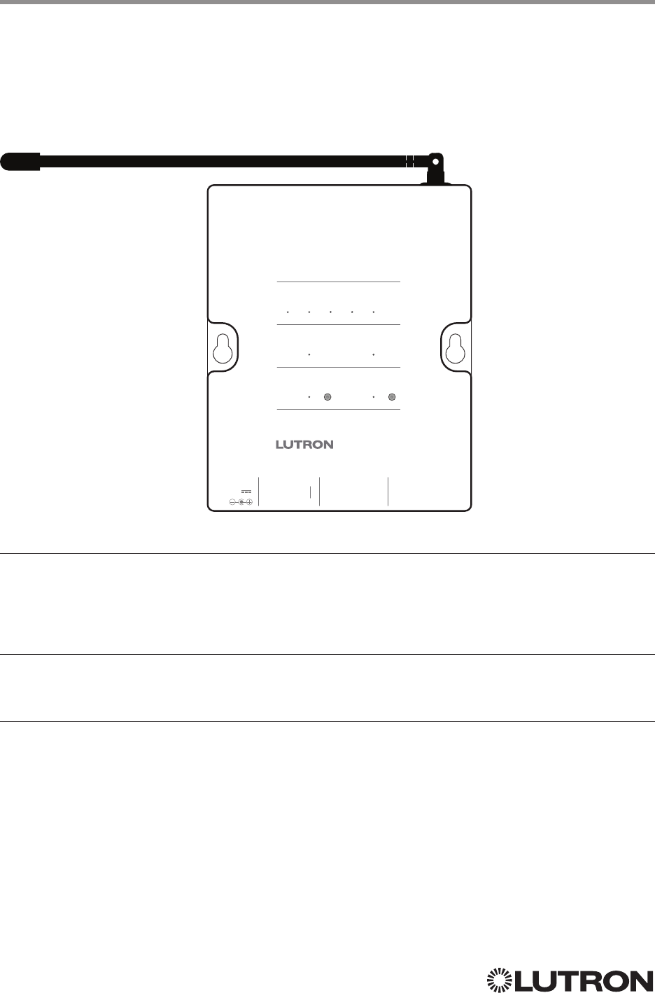
Main Repeater
Model: RR-MAIN-REP-WH, RRK-MAIN-REP-WH

29
Lutron integration protocol
Setup
Wired
RF
Communication
Repeater Status
13 4
2
M
Main Repeater
Power Repeater Link
COM
9 V
1
N / C
MUX
MUX
234
AddTest
Integrate
Program / Integrate
RS232 Ethernet
USB
RadioRA 2 (continued)
Integration Access Points (continued)
Connection Information
Provides an RS232 and Ethernet connection to communicate with external equipment.
RS232
The RS232 connection has the following communication settings:
• Baud Rate 9600
• 8 data bits
• No parity bit
• 1 stop bit
• No flow control
Ethernet
Configuring the control interface to communicate over a network takes not only knowledge of
the RadioRA 2 system, but of networking as well. Installers with limited networking knowledge
are advised to contact a networking professional before attempting to connect a control interface
through a network. The information below will help an installer communicate the control interface
configurations to a network professional.
The installer will make any necessary changes to the control interface using the Lutron DeviceIP or
RadioRA 2 PC software tool and the network professional can make any necessary changes to the
networking equipment.
Single Ethernet Port
• IEEE® 802.3 Auto-Sensing 10BaseT / 100BaseTX
• Supports MDI/MDIX auto-crossover (no crossover cable needed).
• Female 8P8C “Computer RJ-45” socket
• Green “Connect” LED, Amber “Activity” LED
• Use Cat 5 cabling or better
TCP / IP Settings
• DHCP (dynamic) or static configuration <factory default = DHCP>
• IP Address: <static default = 192.168.1.50 or dynamic configuration>
• Subnet Mask: <static default = 255.255.255.0 or dynamic configuration>
• Gateway: <static default = 0.0.0.0 or dynamic configuration>
Protocols Used for Integration
• TELNET
Telnet Server
• Inclusive Software will allow up to a total of 10 additional logins
• Used by software and/or third party equipment (e.g., touch screen)
• Limited to transferring ASCII characters
• Login: lutron
• Password: integration
Notes:
– Up to four additional login and password values can be defined in the RadioRA 2 PC software.
– Only one connection per login / password is allowed at a time.
UDP Multicast Messaging
• Used by the RadioRA 2 PC software during device configuration and system programming
• There are no user modifiable settings for UDP messaging
Continued on next page…
30
Lutron integration protocol
DEVICE Command Formats
DEVICE Command-specific fields
Component Numbers:
Component Component Number Available Actions
Button 1–100 1–100 Press, Release
LED 1–100 101–200 Set or Get LED state
Action Numbers and Parameters:
Action Action Number Parameters
Set (#) Press 3 None
Set (#) Release 4 None
Set (#) or Get (?) LED State 9 0 = Off
1 = On
Example DEVICE Commands
Operation Command String
Execute: #DEVICE, Integration ID, Component Number, Action Number, Parameters
Press Button 1. #DEVICE,4,1,3<CR><LF>
Release Button 1 #DEVICE,4,1,4<CR><LF>
Turn On LED 1. #DEVICE,4,101,9<CR><LF>
Query: ?DEVICE, Integration ID, Component Number, Action Number
What is the state of LED 1? ?DEVICE,4,101,9<CR><LF>
Response: ~DEVICE, Integration ID, Component Number, Action Number, Parameters
LED 1 is On. ~DEVICE,4,101,9,1<CR><LF>
Setup
Wired
RF
Communication
Repeater Status
13 4
2
M
Main Repeater
Power Repeater Link
COM
9 V
1
N / C
MUX
MUX
234
AddTest
Integrate
Program / Integrate
RS232 Ethernet
USB
RadioRA 2 (continued)
System Commands
DEVICE Commands
Use “DEVICE Command-specific fields” tables
to complete these command fields.
Operation
Command
Integration ID (example)
#DEVICE, 1, Component Number, Action Number, Parameters
31
Lutron integration protocol
RadioRA 2 (continued)
System Commands (continued)
GROUP Commands
Setup
Wired
RF
Communication
Repeater Status
13 4
2
M
Main Repeater
Power Repeater Link
COM
9 V
1
N / C
MUX
MUX
234
AddTest
Integrate
Program / Integrate
RS232 Ethernet
USB
GROUP Command-specific fields
Action Numbers:
Action Action Number
Get (?) Occupancy Group State
3
GROUP Command Format
Use “GROUP Command-specific fields” tables
to complete these command fields.
Operation
Command
Integration ID (example)
?GROUP, 6, Action Number
Example GROUP Messages
Operation Command String
Query: ?GROUP, Integration ID, Action Number
What is Occ GROUP 1’s status? ?GROUP,1,3<CR><LF>
Response: ~ GROUP, Integration ID, Action Number, Parameters
Occ group 1 is occupied ~GROUP,1,3,3<CR><LF>
Occ group 1 is unknown ~GROUP,1,3,255<CR><LF>
Occupancy States:
Description Value
Occupied 3
Unoccupied 4
Unknown 255
Continued on next page…
32
Lutron integration protocol
MONITORING Command Formats
MONITORING Command-specific fields
Monitoring Type:
Description Monitoring Type
Set (#) or Get (?) Diagnostic Monitoring 1
Set (#) or Get (?) Button Monitoring (if enabled, button actions will be reported) 3
Set (#) or Get (?) LED Monitoring (if enabled, LED states will be reported) 4
Set (#) or Get (?) Zone Monitoring (if enabled, zone levels will be reported, i.e. dimmer,
shade, contact closure output level)
5
Set (#) or Get (?) Reply State (if disabled, all messages FROM the integration access
point will cease)
11
Set (#) or Get (?) Prompt State (if disabled, the prompt will not be printed to the terminal) 12
Set (#) or Get (?) State of All Monitoring (except Reply and Prompt) 255
Action Numbers:
Action Action Number
Enable 1
Disable 2
Example MONITORING Commands
Operation Command String
Execute: #MONITORING, Monitoring Type, Action Number
Disable Diagnostic Monitoring. #MONITORING,1,2<CR><LF>
Enable Event Monitoring. #MONITORING,2,1<CR><LF>
Query: ?MONITORING, Monitoring Type
Is Diagnostic Monitoring disabled? ?MONITORING,1<CR><LF>
Response: ~MONITORING, Monitoring Type, Action Number
Diagnostic Monitoring is disabled. ~MONITORING,1,2<CR><LF>
Setup
Wired
RF
Communication
Repeater Status
13 4
2
M
Main Repeater
Power Repeater Link
COM
9 V
1
N / C
MUX
MUX
234
AddTest
Integrate
Program / Integrate
RS232 Ethernet
USB
RadioRA 2 (continued)
System Commands (continued)
MONITORING Commands
Use “MONITORING Command-specific fields”
tables to complete these command fields.
Operation
Command
#MONITORING, Monitoring Type, Action Number
33
Lutron integration protocol
Setup
Wired
RF
Communication
Repeater Status
13 4
2
M
Main Repeater
Power Repeater Link
COM
9 V
1
N / C
MUX
MUX
234
AddTest
Integrate
Program / Integrate
RS232 Ethernet
USB
RadioRA 2 (continued)
System Commands (continued)
TIMECLOCK Commands
TIMECLOCK Command Formats
TIMECLOCK Command-specific fields
Action Numbers and Parameters:
Action Action Number Parameters
Set (#) Current Timeclock
Mode
11 Mode
Get (?) Current Timeclock
Mode
1 None
Get (?) Sunrise Time 2 None
Get (?) Sunset Time 3 None
Get (?) Day’s Schedule 4 None
Set (#) Execute Indexed
Event
5Index of the event to test. The index number of the first event
is 1; the second event is 2, and so on.
Set (#) Indexed Event as
Enabled or Disabled
6 Event Index, Enable State (1 = Enable, 2 = Disable)
NOTE
1. In order to set the Timeclock Mode, the “mode” settings must first be determined using the ?help,#timeclock,1 command.
Example TIMECLOCK Messages
Operation Command String
Execute: #TIMECLOCK, Integration ID, Action Number, Parameters
Execute the 3rd event of the time clock. #TIMECLOCK,4,5,3<CR><LF>
Query: ?TIMECLOCK, Integration ID, Action Number
What is the sunrise time? ?TIMECLOCK,4,2<CR><LF>
Response: ~TIMECLOCK, Integration ID, Action Number, Parameters
The time the sun rises. ~TIMECLOCK,4,2,05:32<CR><LF>
Use “TIMECLOCK Command-specific fields” tables
to complete these command fields.
Operation
Command
#TIMECLOCK, 4, Action Number, Parameters
Integration ID (example)

34
Lutron integration protocol
Quantum
System Overview
The Quantum system is the Lutron premier commercial lighting control system. It allows the control
and monitoring of individual devices and outputs as well as allowing control of entire areas, shade
groups or other portions of the system. The Quantum system includes QS devices such as the
GRAFIK Eye QS and Sivoia QS shades as well as Lutron EcoSystem ballasts and GRAFIK dimming
panels. When integrating with a Quantum system the integrator gets additional access to portions
of a the system not available when using products in stand-alone mode, particularly the ability to
activate scenes on an area-by-area basis and to control the position of and activate presets on
entire groups of shades at once.
Quantum System Device Compatibility Index
Quantum
GRAFIK Eye QS
Energi Savr Node QS/DALI®
Energi Savr Node QS/EcoSystem
Energi Savr Node QS/EcoSystem (Int’l)
Energi Savr Node QS/0 –10 V/Softswitch (Int’l)
Energi Savr Node QS/Phase-Adaptive (Int’l)
Energi Savr Node QS/0 –10 V/Softswitch
Remote Power Module
Palladiom Keypad
Architrave Keypad
Signature Series Keypad
seeTouch Keypad
seeTouch QS Keypad (Int’l)
Pico Wireless Control
Wallbox Input Closure Interface
Sivoia QS Shade
Sivoia QS Wireless Shade
QS Input/Output Control Interface
Why Integrate with a Quantum System
• Compatible with Quantum system version 1.7 or higher
• Gain access to system-only information
• Activate System Area scenes
• Set levels for System Outputs
• Activate System Shade Group presets
• View and modify parameters of a Quantum system, such as time, date, time zone, etc.
Command Types
Operation characters will be followed by command types:
• AREA allows control of an area in the Quantum system. Scenes can be activated, occupancy
monitored etc.
• SHADEGRP allows control of shade groups in the Quantum system. Shade Groups are collections
of shades that operate in unison
• OUTPUT allows control and monitoring of a Quantum system output group such as a lighting zone
or closure output.
• SYSTEM allows setting and controlling system parameters and variables *
• HELP displays usage information for the supported commands and their corresponding actions
• INTEGRATION ID allows querying integration IDs of devices in the system
* Load Shed commands available only on Quantum version 2.0 and higher.
Continued on next page…

35
Lutron integration protocol
Why Integrate with a QSE-CI-NWK-E?
• Integrates a QS lighting control system with a PC or other digital equipment that supports RS232
or Ethernet TCP/IP connection.
• Allows monitor and control of system devices. For example, the QSE-CI-NWK-E can be used to
simulate button presses, report button presses, monitor LEDs, and control light levels.
Additional Commands
• MONITORING specifies what type of messages the system will report
• ETHERNET modifies the Ethernet configurations of the QSE-CI-NWK-E
• RESET restarts the QSE-CI-NWK-E or restores it to factory defaults
• INTEGRATION ID assigns IDs to devices, so that they may be referred to in a more logical fashion
• DETAILS returns information about a QS device
• ERROR reports syntax errors in an integration string command or query
Quantum (continued)
Integration Access Points
Network Interface
Model: QSE-CI-NWK-E

36
Lutron integration protocol
Quantum (continued)
Integration Access Points (continued)
Connection Information
Provides an RS232 and Ethernet connection to communicate with external equipment.
RS232
The RS232 connection has the following communication settings:
• Baud Rate 9600/19200/38400/115200 (set via dipswitch on unit)
• 8 data bits
• No parity bit
• 1 stop bit
• No flow control
Ethernet
Configuring the control interface to communicate over a network takes not only knowledge of
the Quantum system, but of networking as well. Installers with limited networking knowledge are
advised to contact a networking professional before attempting to connect a QSE-CI-NWK-E
through a network. The information below will help an installer communicate the QSE-CI-NWK-E
configurations to a network professional.
The installer will make any necessary changes to the control interface using the Lutron DeviceIP or
Quantum PC software tool and the network professional can make any necessary changes to the
networking equipment.
Single Ethernet Port
• IEEE® 802.3 Auto-Sensing 10BaseT / 100BaseTX
• Supports MDI/MDIX auto-crossover (no crossover cable needed).
• Female 8P8C “Computer RJ-45” socket
• Green “Connect” LED, Amber “Activity” LED
• Use Cat 5 cabling or better
TCP / IP Settings
• IP Address: <static default = 192.168.250.1>
• Subnet Mask: <static default = 255.255.255.0>
• Gateway: <static default = 0.0.0.0>
Protocols Used for Integration
• TELNET
Telnet Server
• Used by third party equipment (e.g., touch screen)
• Limited to transferring ASCII characters
• Telnet Port number is 23
• Login #1: nwk
• Login #2: nwk2
Continued on next page…

37
Lutron integration protocol
ETHERNET Command Formats
ETHERNET Command-specific fields
Configuration Numbers:
Description Configuration Number Parameters
Set (#) or Get (?) IP Address 0 IP Address (XXX.XXX.XXX.XXX)
Set (#) or Get (?) Gateway Ad-
dress
1 IP Address (XXX.XXX.XXX.XXX)
Set (#) or Get (?) Subnet Mask 2 IP Address (XXX.XXX.XXX.XXX)
Set (#) or Get (?) Login Info 3 User (1 or 2),
Old Login,
New Login
Example ETHERNET Commands
Operation Command String
Execute: #ETHERNET, Configuration Number, Parameters
Set IP Address to 192.168.250.1 #ETHERNET,0,192.168.250.1<CR><LF>
Set Gateway Address to 10.2.4.1 #ETHERNET,1,10.2.4.1<CR><LF>
Query: ?ETHERNET, Configuration Number, Parameters
What is the IP Address? ?ETHERNET,0<CR><LF>
What is the Login Information for user 1? ?ETHERNET,3,1<CR><LF>
What is the Login Information for ALL users? ?ETHERNET,3,0<CR><LF> (Note: 0 = ALL)
Response: ~ETHERNET, Integration ID, Configuration Number, Parameters
The IP Address is 192.168.250.1 ~ETHERNET,0,192.168.250.1<CR><LF>
Quantum (continued)
System Commands
ETHERNET Commands
Use “ETHERNET Command-specific fields” tables
to complete these command fields.
Operation
Command
#ETHERNET, Configuration Number, Parameters
38
Lutron integration protocol
INTEGRATION ID Command Formats
INTEGRATION ID Command-specific fields
Action Numbers and Parameters:
Description Action Number Parameters
Get (?) Integration ID for a Serial
Number
1 Serial Number: 8 character HEX serial number of the device;
Integration ID: The integration ID to be assigned.
Get (?) Info from ID 3 Integration ID = The Integration ID that information is desired for.
Note: If this field is left blank, all integration IDs will be printed.
Example INTEGRATION ID Commands
Operation Command String
Execute: ?INTEGRATIONID, Action Number, Parameters
Get the Integration ID for a serial number ?INTEGRATIONID,1,5678EFEF<CR><LF>
Response: ~INTEGRATIONID, Action Number, Parameters
Get the Integration ID for a serial number ~INTEGRATIONID,1,5678EFEF,1<CR><LF>
Execute: ?INTEGRATIONID, Action Number, Parameters
Get information about an Integration ID command ?INTEGRATIONID,3,1<CR><LF>
Response: ~INTEGRATIONID, Action Number, Parameters
Get information about an Integration ID command ~INTEGRATIONID,3,1,DEVICE,5678EFEF<CR><LF>
Quantum (continued)
System Commands (continued)
INTEGRATION ID Commands
Use “INTEGRATIONID Command-specific fields” tables
to complete these command fields.
Operation
Command
?INTEGRATIONID, Action Number, Parameters
Continued on next page…

39
Lutron integration protocol
RESET Command Formats
RESET Command-specific fields
Action Numbers:
Action Action Number
Set (#) restart the device 0
Set (#) restore to factory defaults 1
Example RESET Commands
Operation Command String
Execute: #RESET, Action Number
Restart the NWK #RESET,0<CR><LF>
Restore NWK to factory defaults #RESET,1<CR><LF>
Use “RESET Command-specific fields” tables
to complete these command fields.
Operation
Command
#RESET, Action Number
Quantum (continued)
System Commands (continued)
RESET Commands
40
Lutron integration protocol
AREA Command Formats
AREA Command-specific fields
Action Numbers and Parameters:
Action Action Number Parameters
Set (#) Area Level 1 Level
1 = 0 –100 or 0.00 –100.00
Fade
2 in: SS.ss
3, SS, MM:SS, or HH:MM:SS
Delay
2 in: SS.ss
3, SS, MM:SS, or HH:MM:SS
Set (#) Start Raising
42 None
Set (#) Start Lowering
43 None
Set (#) Stop Raising or Lowering 4 None
Set (#) or Get (?) Current Scene 6 Scene Number
5 = 0 –326
Set (#) or Get (?) Daylighting Mode 7 1 = Active
2 = Inactive
Get (?) Occupancy State 8 1 = Unknown
2 = Inactive
3 = Occupied
4 = Unoccupied
Set (#) or Get (?) Occupancy Mode 9 1 = Occupancy and Vacancy 7
2 = Vacancy 7
3 = Not Applicable 8
4 = Inactive
Set (#) or Get (?) Occupied Level or Scene 12 Level
= 0–100; 200–232 for Scene Number = 0 – 32
Set (#) or Get (?) Unoccupied Level or Scene 13 Level
= 0–100; 200–232 for Scene Number = 0 – 32
Set (#) or Get (?) Hyperion Shadow Sensor
Override State926 0 = Disable
1 = Enable
2 = Mixed (Get Only)
Set (#) or Get (?) Hyperion Brightness Sensor
Override State927 0 = Disable
1 = Enable
2 = Mixed (Get Only)
NOTES
1. The Level is accepted as a percentage.
2. The Fade and Delay time are optional. When not used, the system will use a one-second fade time with zero-second
delay. The minimum fade and delay time is 0 seconds. The maximum fade and delay time is 4 hours.
3. Fractional seconds “SS.ss” will be rounded down to the nearest quarter-second. For example, if a fade time is specified
as 1.45 seconds a value of 1.25 seconds will be used.
4. When a Raise/Lower command is issued, the area’s level will continue to go towards high end/low end until a Stop
command is received.
5. Scene 0 is the Off Scene.
6. Scenes 17 – 32 available only on Slider.
7. If After Hours is used in an area, setting the area’s Occupancy Mode to “Occupancy and Vacancy” or “Vacancy” will
activate After Hours.
8. The area will report “Not Applicable” as its Occupancy Mode if the area does not have occupancy sensors and if After
Hours is not used.
9. Quantum 2.7 and higher.
Quantum (continued)
System Commands (continued)
AREA Commands
Use “AREA Command-specific fields” tables
to complete these command fields.
Operation
Command
Integration ID (example)
#AREA
1, 2, 2, Action Number, Parameters
NOTES
1. AREA can be used to control only those areas of a Quantum system that have been assigned to a particular integration
access point. Please refer to the Q-Design software (Integration Tab) or Quantum Integration Report for details of what
areas are available for control and monitoring.
2. AREA commands cannot be sent to areas that contain other areas, such as a floor or an entire building.
Continued on next page…
41
Lutron integration protocol
Example AREA Messages
Operation Command String
Execute: #AREA, Integration ID, Action Number, Parameters
Set area level to 75% (Fade = 4 sec, Delay = 2 sec) #AREA,2,1,70,4,2<CR><LF>
Lower Area #AREA,2,3<CR><LF>
Query: ?AREA, Integration ID, Action Number
Is the area occupied? ?AREA,2,8<CR><LF>
What is the current active scene? ?AREA,2,6<CR><LF>
Response: ~AREA, Integration ID, Action Number, Parameters
The area is currently occupied ~AREA,2,8,3<CR><LF>
Area Scene 2 is currently active ~AREA,2,6,2<CR><LF>
Quantum (continued)
System Commands (continued)
AREA Commands (continued)
42
Lutron integration protocol
SHADEGRP Command Formats
SHADEGRP Command-specific fields
Action Numbers and Parameters:
Action Action Number Parameters
Set (#) Shade Group Level 1 Level
1 = 0 –100 or 0.00 –100.00
Delay
2 in: SS.ss
3, SS, MM:SS, or HH:MM:SS
Set (#) Start Raising
42 None
Set (#) Start Lowering
43 None
Set (#) Stop Raising or
Lowering
4 None
Set (#) or Get (?) Current
Preset
6Preset Number
5 = 0 –30
NOTES
1. The Level is accepted as a percentage, where 100% is fully open and 0% is fully closed.
2. The Delay time is optional. When not used, the system will use a zero-second delay. The minimum delay time is
0seconds. The maximum delay time is 4 hours.
3. Fractional seconds “SS.ss” will be rounded down to the nearest quarter second. For example, if a delay time is specified
as 1.45 seconds a value of 1.25 seconds will be used.
4. When a Raise / Lower command is issued, the shade group’s level will continue to go towards open / close until a Stop
command is received.
5. Preset 0 is the Open Preset and Preset 30 is the Closed Preset.
Example SHADEGRP Messages
Operation Command String
Execute: #SHADEGRP, Integration ID, Action Number, Parameters
Set shade group to 70% (Delay = 2 sec) #SHADEGRP,2,1,70,2<CR><LF>
Lower shade group. #SHADEGRP,2,3<CR><LF>
Query: ?SHADEGRP, Integration ID, Action Number
What is the current active preset? ?SHADEGRP,2,6<CR><LF>
Response: ~SHADEGRP, Integration ID, Action Number, Parameters
Shade group Preset 2 is currently active. ~SHADEGRP,2,6,2<CR><LF>
Quantum (continued)
System Commands (continued)
SHADEGRP Commands
Use “SHADEGRP Command-specific fields” tables
to complete these command fields.
Operation
Command
Integration ID (example)
#SHADEGRP
1, 2, Action Number, Parameters
NOTE
1. SHADEGRP can be used to control only those shade groups of a Quantum system that have been assigned to a
particular integration access point. Please refer to the Q-Design software (Integration Tab) or Quantum Integration Report
for details of what shade groups are available for control and monitoring.
Continued on next page…
43
Lutron integration protocol
OUTPUT Command Format
OUTPUT Command-specific fields
Action Numbers and Parameters:
Action Action Number Parameters
Set (#) or Get (?) Output Level 1 Level
1 = 0 –100 or 0.00 –100.00
Fade
2 in: SS.ss
3, SS, MM:SS, or HH:MM:SS
Delay
2 in: SS.ss
3, SS, MM:SS, or HH:MM:SS
Set (#) Start Raising
42 None
Set (#) Start Lowering
43 None
Set (#) Stop Raising or Lowering
44 None
Set (#) Pulse Time 6 Pulse
5 time in: SS.ss
3, SS, MM:SS, or HH:MM:SS, or
Delay
2 in: SS.ss
3, SS, MM:SS, or HH:MM:SS
Set (#) DMX Color or Level Settings 6 17 Color / level index: 0 – 255
0.00–100.00 5
Set (#) Motor Jog Raise 6, 7 18 None
Set (#) Motor Jog Lower 6, 7 19 None
Set (#) Motor 4-Stage Jog Raise 6, 7 20 None
Set (#) Motor 4-Stage Jog Lower 6, 7 21 None
NOTES
1. The Level is taken as a percentage.
2. The Fade and Delay time are optional. When not used, the system will use a one-second fade time with zero-second
delay. The minimum fade and delay time is 0 seconds. The maximum fade and delay time is 4 hours. For shade outputs,
the Fade parameter has no effect (since shades have fixed speeds) but it is required when specifying an optional delay.
3. Fractional seconds “SS.ss” will be rounded down to the nearest quarter second. For example, if a fade time is specified
as 1.45 seconds a value of 1.25 seconds will be used.
4. When a Raise / Lower command is issued, the output’s level will continue to go towards high end / low end until a Stop
command is received.
5. The default time is one second.
6. Not supported in RadioRA 2.
7. Quantum 2.5 and up.
Quantum (continued)
System Commands (continued)
OUTPUT Commands
Use “OUTPUT Command-specific fields” tables
to complete these command fields.
Operation
Command
Integration ID (example)
#OUTPUT
1, 2, Action Number, Parameters
NOTE
1. OUTPUT commands can be used to control system lighting zones, contact closed outputs and AC Motor Loads.

44
Lutron integration protocol
Example OUTPUT Messages
Operation Command String
Execute: #OUTPUT, Integration ID, Action Number, Parameters
Set output level to 70% (Fade = 4 sec, Delay = 2 sec) #OUTPUT,2,1,70,4,2<CR><LF>
Raise Output #OUTPUT,2,2<CR><LF>
Query: ?OUTPUT, Integration ID
What is the current output level? ?OUTPUT,2<CR><LF>
Response: ~OUTPUT, Integration ID, Action Number, Parameters 1
Output level is set to 48%. ~OUTPUT,2,1,48<CR><LF>
NOTE
1. The Fade and Delay time are optional. When not used, the system will use a one-second fade time with zero-second
delay. The minimum fade and delay time is 0 seconds. The maximum fade and delay time is 4 hours. For shade outputs,
the Fade parameter has no effect (since shades have fixed speeds) but it is required when specifying an optional delay.
Quantum (continued)
System Commands (continued)
OUTPUT Commands (continued)
Continued on next page…
45
Lutron integration protocol
Quantum (continued)
System Commands (continued)
SYSVAR Commands
1
SYSVAR Command Formats
Use “SYSVAR Command-specific fields” tables
to complete these command fields.
Operation
Command
SYSVAR Command-specific fields
Action Numbers and Parameters:
Action Action Number Parameters
Set (#) or Get (?) the state
of a given variable
1 State number
Example SYSVAR Messages
Operation Command String
Execute: #SYSVAR, Integration ID, Action Number, Parameters
Set the variable state to the third state #SYSVAR,2,1,3<CR><LF>
Query: ?SYSVAR, Integration ID, Action Number
What is the state of the variable? ?SYSVAR,2,1<CR><LF>
Response: ~SYSVAR, Integration ID, Action Number, Parameters
The variable is in the third state. ~SYSVAR,2,1,3<CR><LF>
#SYSVAR,2,Action Number, Parameters
NOTE
1. SYSVAR Commands available only on Quantum version 2.5 or higher.

46
Lutron integration protocol
HomeWorks QS
System Overview
The HomeWorks QS system is Lutron’s premier total home control system. It allows control and
monitoring of lights, shades, HVAC, sensors, and appliances. The HomeWorks QS system includes
QS devices, RF devices, and power panels that provide solutions for new construction and retrofit
projects of any size.
HomeWorks QS System Device Compatibility Index
HomeWorks QS
GRAFIK Eye QS
HomeWorks QS / DALI®
HomeWorks QS / EcoSystem
HomeWorks QS / 0 –10 V/Softswitch
HomeWorks QS / Phase-Adaptive
HomeWorks QS / Motor Module
Remote Power Module
Low-Capacity Switching DIN Power Module (1A / output)
Low-Capacity Phase-Adaptive DIN Power Module (1A /output)
Palladiom Keypad
Architrave Keypad
Signature Series Keypad
seeTouch Keypad
seeTouch QS Keypad (Int’l)
Tabletop seeTouch Keypad
Pico Wireless Control
Hybrid Keypad
Dynamic Keypad
Wallbox Input Closure Interface
Sivoia QS Shade
Sivoia QS Wireless Shade
Sivoia QS Venetian Blind
Sivoia QS Wireless Venetian Blind
Maestro Dimmer and Plug-In Module
Maestro Fan Speed Control
Visor Control Receiver
Radio Powr Savr Sensor
HVAC Controller
Wireless Temperature Sensor
QS Input/Output Control Interface
Continued on next page…

47
Lutron integration protocol
HomeWorks QS (continued)
System Overview (continued)
Command Types
The following is a list of supported command types. Details on certain device-specific types (e.g.,
DEVICE, HVAC) are located in the individual device section of this manual.
Operation characters will be followed by command types.
• DEVICE allows control and monitoring of device inputs such as button presses and contact
closure inputs
• OUTPUT allows control and monitoring of device outputs such as dimmers and contact closure
outputs
• SHADEGRP allows control of shades in the HomeWorks QS system. Shade groups are collections
of shades that operate in unison
• MONITORING specifies the type of messages that the system will report
• HVAC allows control and monitoring of Lutron HVAC equipment
• TIMECLOCK allows control (enable/disable) and monitoring of system timeclocks
• SYSVAR allows control and monitoring of system variables
• AREA allows control and monitoring of an area (e.g., activating area Scenes, monitoring
occupancy)
• ERROR displays responses to invalid commands
• HELP displays usage information for the supported commands and their corresponding actions
• SYSTEM allows setting and controlling system parameters and variables
• ETHERNET modifies the Ethernet configuration of the HomeWorks QS processor
• INTEGRATIONID gets information of the integration id or serial number of a device
• RESET resets the HomeWorks QS processor
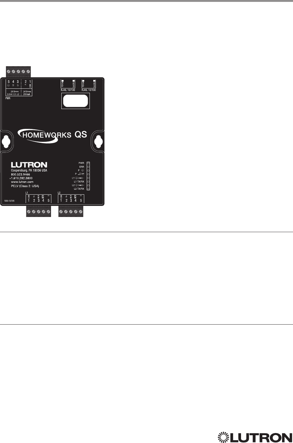
48
Lutron integration protocol
Why Integrate with a HomeWorks QS Processor?
• Integrating with a HomeWorks QS Processor provides integration over Ethernet without the need
for additional equipment or interfaces.
• RS-232 integration can also be accomplished using third party Ethernet to RS-232 adapters.
• Integrating directly with the HomeWorks QS Processor also provides the greatest bandwidth port
into the HomeWorks QS system.
• Integration IDs are automatically generated by the HomeWorks QS software application (e.g., for
devices, outputs, shadegroups, timeclocks). Integration IDs can be removed to reduce processing
and traffic of unwanted messages.
• Phantom Keypads allow for integration functionality to be organized on various virtual keypads that
have unlimited buttons and do not count towards link device count limits.
Integration Capabilities
• Control and monitoring of output devices such as dimmers, the GRAFIK Eye, shades and contact closure
outputs
• Control and monitoring of physical or phantom keypad buttons and button status LEDs
• Control and monitoring of Lutron HVAC equipment
• Control and monitoring of individual timeclocks
• Control and monitoring of state variables
• Monitoring of occupancy sensors
• Control and monitoring of areas to activate scenes and monitor occupancy
HomeWorks QS (continued)
Integration Access Points
HomeWorks QS Processor
Model: HQP6-2
Continued on next page…

49
Lutron integration protocol
HomeWorks QS (continued)
Integration Access Points (continued)
Connection Information
Ethernet
Configuring the HomeWorks QS processor to communicate over a network takes not only
knowledge of the HomeWorks QS system, but of networking as well. Installers with limited
networking knowledge are advised to contact a networking professional before attempting to
connect a HomeWorks QS processor through a network.
The installer will make any necessary configuration changes to the HomeWorks QS processor
using the HomeWorks QS Design Software Application and the network professional can make
any necessary changes to the networking equipment.
Dual Ethernet Port
• IEEE® 802.3 Auto-Sensing 10BaseT / 100BaseTX
• Supports MDI/MDIX auto-crossover (no crossover cable needed).
• Female 8P8C “Computer RJ-45” socket
• Green “Connect” LED, Amber “Activity” LED
• Use Cat 5 cabling or better
• 2 Port 10/100 Ethernet Switch
TCP / IP Settings
• IP Address: Address at which the processor can be reached for integration. In most instances
when integrating to a processor, DHCP should be disabled and a static IP address should be
assigned to prevent the processor from changing IP addresses.
• Subnet Mask: In conjunction with the IP address, it defines the subnet on which the processor
communicates. Processors will be able to integrate only with devices on the same subnet.
• Gateway: Used in instances where the processor needs to communicate to the internet. Should be
set to the IP address of the device on the network connected directly to the internet—typically, the
home router.
Protocols Used for Integration
• TELNET
Telnet Server
• Used by third party equipment (e.g., touch screen)
• Used by Lutron mobile devices (e.g., iPad and iPhone)
• Limited to transferring ASCII characters
• Telnet Port number is 23
• Logins: Defined in the HomeWorks QS software application
RS232
The HomeWorks QS Processor does not have native support for RS232. An Ethernet to RS232
adapter can be used and configured to provide RS232 integration directly from the Processor if
needed.
iPhone and iPad are trademarks of Apple, Inc., registered in the U.S. and other countries.

50
Lutron integration protocol
OUTPUT Command Format
OUTPUT Command-specific fields
Action Numbers and Parameters:
Action Action Number Parameters
Set (#) or Get (?) Output Level 1 Level
1 = 0 –100 or 0.00 –100.00
Fade
2 in: SS.ss
3, SS, MM:SS, or HH:MM:SS
Delay
2 in: SS.ss
3, SS, MM:SS, or HH:MM:SS
Set (#) Start Raising
42 None
Set (#) Start Lowering
43 None
Set (#) Stop Raising or Lowering
44 None
Set (#) or Get (?) Flash Frequency 5 Fade
2 in: SS.ss
3, SS, MM:SS, or HH:MM:SS
Delay
2 in: SS.ss
3, SS, MM:SS, or HH:MM:SS
Set (#) Pulse Time 6 Pulse
5 time in: SS.ss
3, SS, MM:SS, or HH:MM:SS,
or Delay
2 in: SS.ss
3, SS, MM:SS, or HH:MM:SS
Set (#) Tilt Level 9 Tilt level in % = 0.00–100
6
Fade
2 in: SS.ss
3, SS, MM:SS, or HH:MM:SS
Delay
2 in: SS.ss
3, SS, MM:SS, or HH:MM:SS
Set (#) Lift and Tilt Levels 10 Lift
1 = 0 –100 or 0.00 –100.00
Tilt
1 = 0 –1006 or 0.00–100.006
Fade
2 in: SS.ss
3, SS, MM:SS, or HH:MM:SS
Delay
2 in: SS.ss
3, SS, MM:SS, or HH:MM:SS
Set (#) Start Raising Tilt 11 None
Set (#) Start Lowering Tilt 12 None
Set (#) Stop Raising or Lowering Tilt 13 None
Set (#) Start Raising Lift 14 None
Set (#) Start Lowering Lift 15 None
Set (#) Stop Raising or Lowering Lift 16 None
Get (?) Horizontal Sheer Shade Region 28 Regions: 0 = Lift, 1 = Tilt
NOTES
1. The Level/Lift/Tilt is taken as a percentage.
2. The Fade and Delay time are optional. When not used, the system will use a one-second fade time with zero-second
delay. The minimum fade and delay time is 0 seconds. The maximum fade and delay time is 4 hours. For shade outputs,
the Fade parameter has no effect (since shades have fixed speeds) but it is required when specifying an optional delay.
3. Fractional seconds “SS.ss” will be rounded down to the nearest quarter second. For example, if a fade time is specified
as 1.45 seconds a value of 1.25 seconds will be used.
4. When a Raise / Lower command is issued, the output’s level will continue to go towards high end / low end until a Stop
command is received.
5. The default time is one second.
6. 50 for Horizontal Sheer Blinds.
HomeWorks QS (continued)
System Commands
OUTPUT Commands
Use “OUTPUT Command-specific fields” tables
to complete these command fields.
Operation
Command
Integration ID (example)
#OUTPUT
1, 2, Action Number, Parameters
NOTE
1. OUTPUT commands can be used to control system lighting zones, individual shades, and contact closed outputs.
Continued on next page…

51
Lutron integration protocol
Example OUTPUT Messages
Operation Command String
Execute: #OUTPUT, Integration ID, Action Number, Parameters
Set output level to 70% (Fade = 4 sec, Delay = 2 sec) #OUTPUT,2,1,70,4,2<CR><LF>
Raise Output #OUTPUT,2,2<CR><LF>
Query: ?OUTPUT, Integration ID
What is the current output level? ?OUTPUT,2<CR><LF>
Response
1: ~OUTPUT, Integration ID, Action Number, Parameters
Output level is set to 48%. ~OUTPUT,2,1,48<CR><LF>
NOTE
1. The Fade and Delay time are optional. When not used, the system will use a one-second fade time with zero-second
delay. The minimum fade and delay time is 0 seconds. The maximum fade and delay time is 4 hours. For shade outputs,
the Fade parameter has no effect (since shades have fixed speeds) but it is required when specifying an optional delay.
HomeWorks QS (continued)
System Commands (continued)
OUTPUT Commands (continued)

52
Lutron integration protocol
SHADEGRP Command Formats
SHADEGRP Command-specific fields
Action Numbers and Parameters:
Action Action Number Parameters
Set (#) or Get (?) Shade Group Level 1 Level
1 = 0 –100 or 0.00 –100.00
Delay
1 in: SS.ss
2, SS, MM:SS, or HH:MM:SS
Set (#) Start Raising
32 None
Set (#) Start Lowering
33 None
Set (#) Stop Raising or Lowering 4 None
Set (#) or Get (?) Current Preset 6 Preset Number
4 = 0 –30
Set (#) Tilt Level 14 Level
5 = 0 –100 6 or 0.00–100.00
6
Fade
1 in: SS.ss
2, SS, MM:SS, or HH:MM:SS
Delay
1 in: SS.ss
2, SS, MM:SS, or HH:MM:SS
Set (#) Lift and Tilt Levels 15 Lift
5 = 0 –100 or 0.00 –100.00
Tilt
5 = 0 –100 6 or 0.00–100.00
6
Fade
1 in: SS.ss
2, SS, MM:SS, or HH:MM:SS
Delay
1 in: SS.ss
2, SS, MM:SS, or HH:MM:SS
Set (#) Start Raising Tilt
316 None
Set (#) Start Lowering Tilt
317 None
Set (#) Stop Raising or Lowering Tilt
318 None
Set (#) Start Raising Lift
319 None
Set (#) Start Lowering Lift
320 None
Set (#) Stop Raising or Lowering Lift
321 None
Get (?) Horizontal Sheer Shade Region 28 Lift = 0
Tilt = 1
NOTES
1. The Fade and Delay time are optional. For shades, the Fade parameter has no effect (since shades have fixed speeds)
but it is required when specifying an optional delay. When not used, the system will use a zero-second delay. The
minimum fade and delay time is 0 seconds. The maximum fade and delay time is 4 hours.
2. Fractional seconds “SS.ss” will be rounded down to the nearest quarter second. For example, if a delay time is specified
as 1.45 seconds, a value of 1.25 seconds will be used.
3. When a Raise / Lower command is issued, the shade group’s level will continue to go towards open / close until a Stop
command is received.
4. Preset 0 is the Open Preset and Preset 30 is the Closed Preset.
5. The Level is accepted as a percentage, where 100% is fully open and 0% is fully closed.
6. 50 for Horizontal Sheer Blinds.
HomeWorks QS (continued)
System Commands (continued)
SHADEGRP Commands
Use “SHADEGRP Command-specific fields” tables
to complete these command fields.
Operation
Command
Integration ID (example)
#SHADEGRP, 2, Action Number, Parameters
Continued on next page…

53
Lutron integration protocol
Example SHADEGRP Messages
Operation Command String
Execute: #SHADEGRP, Integration ID, Action Number, Parameters
Set shade group to 70% (Delay = 2 sec). #SHADEGRP,2,1,70,2<CR><LF>
Lower shade group. #SHADEGRP,2,3<CR><LF>
Query: ?SHADEGRP, Integration ID, Action Number
What is the current active preset? ?SHADEGRP,2,6<CR><LF>
Response: ~SHADEGRP, Integration ID, Action Number, Parameters
Shade group Preset 2 is currently active. ~SHADEGRP,2,6,2<CR><LF>
HomeWorks QS (continued)
System Commands (continued)
SHADEGRP Commands (continued)

54
Lutron integration protocol
HomeWorks QS (continued)
System Commands (continued)
TIMECLOCK Commands
TIMECLOCK Command Formats
TIMECLOCK Command-specific fields
Action Numbers and Parameters:
Action Action Number Parameters
Get (?) Sunrise Time 2 None
Get (?) Sunset Time 3 None
Get (?) Day’s Schedule 4 None
Set (#) Execute Indexed
Event
5Index of the event to execute. The index number of the first
event is 1; the second event is 2, and so on.
Set (#) Indexed Event as
Enabled or Disabled
6 Event Index, Enable State (1 = Enable, 2 = Disable)
Example TIMECLOCK Messages
Operation Command String
Execute: #TIMECLOCK, Integration ID, Action Number, Parameters
Execute the 3rd event of the timeclock. #TIMECLOCK,2,5,3<CR><LF>
Query: ?TIMECLOCK, Integration ID, Action Number
What is the sunrise time? ?TIMECLOCK,2,2<CR><LF>
Response: ~TIMECLOCK, Integration ID, Action Number, Parameters
The time the sun rises. ~TIMECLOCK,2,2,05:32<CR><LF>
Use “TIMECLOCK Command-specific fields” tables
to complete these command fields.
Operation
Command
#TIMECLOCK,2,Action Number, Parameters
Continued on next page…

55
Lutron integration protocol
HomeWorks QS (continued)
System Commands (continued)
SYSVAR Commands
SYSVAR Command Formats
SYSVAR Command-specific fields
Action Numbers and Parameters:
Action Action Number Parameters
Set (#) or Get (?) the state
of a given variable
1 State number
Example SYSVAR Messages
Operation Command String
Execute: #SYSVAR, Integration ID, Action Number, Parameters
Set the variable state to the third state. #SYSVAR,2,1,3<CR><LF>
Query: ?SYSVAR, Integration ID, Action Number
What is the state of the variable? ?SYSVAR,2,1<CR><LF>
Response: ~SYSVAR, Integration ID, Action Number, Parameters
The variable is in the third state. ~SYSVAR,2,1,3<CR><LF>
Use “SYSVAR Command-specific fields” tables
to complete these command fields.
Operation
Command
#SYSVAR,2,Action Number, Parameters
56
Lutron integration protocol
HomeWorks QS (continued)
System Commands (continued)
AREA Commands
AREA Command Formats
AREA Command-specific fields
Action Numbers and Parameters:
Action Action Number Parameters
Get (?) Occupancy State 8 3 = Occupied
4 = Unoccupied
Example AREA Messages
Operation Command String
Execute: #AREA, Integration ID, Action Number, Parameters
Set area level to 75% (Fade = 4 sec, Delay = 2 sec) #AREA,2,1,70,4,2<CR><LF>
Lower Area. #AREA,2,3<CR><LF>
Query: ?AREA, Integration ID, Action Number
Is the area occupied? ?AREA,2,8<CR><LF>
What is the current active scene? ?AREA,2,6<CR><LF>
Response: ~AREA, Integration ID, Action Number, Parameters
The area is currently occupied. ~AREA,2,8,3<CR><LF>
Area Scene 2 is currently active. ~AREA,2,6,2<CR><LF>
Use “AREA Command-specific fields” tables
to complete these command fields.
Operation
Command
Integration ID (example)
?AREA
1, 2, Action Number, Parameters
NOTE
1. AREA commands cannot be sent to areas that contain other areas, such as a floor or an entire building.
Continued on next page…
57
Lutron integration protocol
ETHERNET Command-specific fields
Configuration Number and Parameters:
Description Configuration Number Parameters
Set (#) or Get (?) IP Address 0 IP Address (XXX.XXX.XXX.XXX)
Set (#) or Get (?) Gateway
Address
1 IP Address (XXX.XXX.XXX.XXX)
Set (#) or Get (?) Subnet Mask 2 IP Address (XXX.XXX.XXX.XXX)
Get (?) DHCP 4 None
Set (#) or Get (?) Multicast
Address
5IP Address (XXX.XXX.XXX.XXX)
Example ETHERNET Commands
Operation Command String
Execute: #ETHERNET, Configuration Number, Parameters
Set IP Address to 192.168.250.1 #ETHERNET,0,192.168.250.1<CR><LF>
Set Gateway Address to 10.2.4.1 #ETHERNET,1,10.2.4.1<CR><LF>
Query: ?ETHERNET, Configuration Number, Parameters
What is the IP Address? ?ETHERNET,0<CR><LF>
Response: ~DEVICE, Integration ID, Configuration Number, Parameters
The IP Address is 192.168.250.1 ~ETHERNET,0=,192.168.250.1<CR><LF>
HomeWorks QS (continued)
System Commands (continued)
ETHERNET Commands
ETHERNET Command Formats
Use “ETHERNET Command-specific fields” tables
to complete these command fields.
Operation
Command
#ETHERNET, Configuration Number, Parameters

58
Lutron integration protocol
INTEGRATION ID Command-specific fields
Action Numbers and Parameters:
Description Action Number Parameters
Get (?) Integration ID for a Serial
Number
11 Serial Number = 8 character HEX serial number of the device
Get (?) Info from ID
13 Integration ID
Note: If this field is left blank, all integration IDs will be printed.
Example INTEGRATION ID Commands
Operation Command String
Query: ?INTEGRATIONID, Action Number, Parameters
Get the Integration ID for a serial number ?INTEGRATIONID,1,5678EFEF<CR><LF>
Response: ~INTEGRATIONID, Action Number, Parameters
Get the Integration ID for a serial number ~INTEGRATIONID,1,5678EFEF,1<CR><LF>
Query: ?INTEGRATIONID, Action Number, Parameters
Get information about an Integration ID
command
?INTEGRATIONID,3,1<CR><LF>
Response: ~INTEGRATIONID, Action Number, Parameters
Get information about an Integration ID
command
~INTEGRATIONID,3,1,DEVICE,5678EFEF<CR><LF>
HomeWorks QS (continued)
System Commands (continued)
INTEGRATION ID Commands
INTEGRATION ID Command Formats
Use “INTEGRATIONID Command-specific fields” tables
to complete these command fields.
Operation
Command
?INTEGRATIONID, Action Number, Parameters
Continued on next page…
NOTE
1. Refer to the integration report generated by the Lutron Designer Tool to identify the integration IDs for devices.
59
Lutron integration protocol
RESET Command Formats
RESET Command-specific fields
Action Numbers:
Action Action Number
Set (#) reset the HomeWorks QS processor 0
Example RESET Commands
Operation Command String
Execute: #RESET, Action Number
Reset the HomeWorks QS processor #RESET,0<CR><LF>
Use “RESET Command-specific fields” tables
to complete these command fields.
Operation
Command
#RESET, Action Number
HomeWorks QS (continued)
System Commands (continued)
RESET Commands

60
Lutron integration protocol
myRoom plus
System Overview
The myRoom plus system is a guestroom management system for light, temperature, and shade
control that integrates with property management systems (PMS) and building managements
systems (BMS). The myRoom plus system provides increased energy savings through automatic
lighting and HVAC adjustments and enhanced by shade control. The myRoom plus system uses
occupied/unoccupied and sold/unsold information for guest presence detection and additional
HVAC setbacks. It offers hotel guests privacy or a view; a single button press closes or opens
shades and integrates with BMS to control and monitor.
myRoom plus System Device Compatibility Index
myRoom plus
HomeWorks QS / DALI®
HomeWorks QS / EcoSystem
HomeWorks QS / 0 –10 V/Softswitch
HomeWorks QS / Phase-Adaptive
HomeWorks QS / Motor Module
Low-Capacity Switching DIN Power Module (1A/output)
Low-Capacity Phase-Adaptive DIN Power Module (1A/output)
Palladiom Keypad
Palladiom Thermostat
Architrave Keypad
Signature Series Keypad
seeTouch Keypad
seeTouch QS Keypad (Int’l)
Tabletop seeTouch Keypad
Pico Wireless Control
Hybrid Keypad
Dynamic Keypad
Wallbox Input Closure Interface
Sivoia QS Shade
Sivoia QS Wireless Shade
Sivoia QS Venetian Blind
Sivoia QS Wireless Venetian Blind
Maestro Dimmer and Plug-In Module
Maestro Fan Speed Control
Visor Control Receiver
Radio Powr Savr Sensor
HVAC Controller
QS Input/Output Control Interface
QS Sensor Module
Continued on next page…

61
Lutron integration protocol
myRoom plus (continued)
System Overview (continued)
Command Types
The following is a list of supported command types. Details on certain device-specific types (e.g.,
DEVICE, HVAC) are located in the individual device section of this manual.
Operation characters will be followed by command types.
• DEVICE allows control and monitoring of device inputs such as button presses and contact
closure inputs
• OUTPUT allows control and monitoring of device outputs such as dimmers and contact closure
outputs
• SHADEGRP allows control of shades in the myRoom plus system. Shade groups are collections
of shades that operate in unison
• MONITORING specifies the type of messages that the system will report
• HVAC allows control and monitoring of Lutron HVAC equipment
• TIMECLOCK allows control (enable/disable) and monitoring of system timeclocks
• SYSVAR allows control and monitoring of system variables
• AREA allows control and monitoring of an area (e.g., activating area Scenes, monitoring
occupancy)
• ERROR displays responses to invalid commands
• HELP displays usage information for the supported commands and their corresponding actions
• SYSTEM allows setting and controlling system parameters and variables
• ETHERNET modifies the Ethernet configuration of the myRoom plus processor
• INTEGRATIONID gets information of the integration id or serial number of a device
• RESET resets the myRoom plus processor
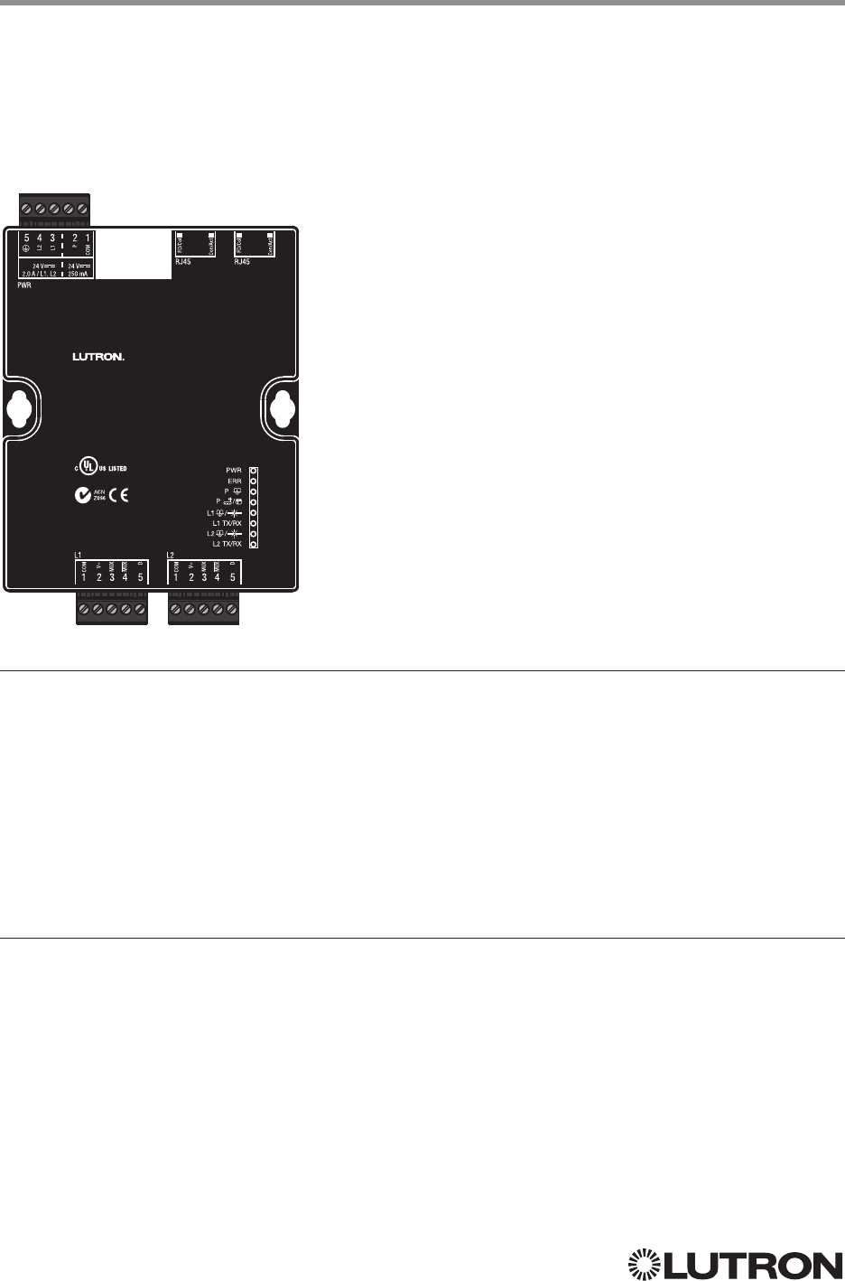
62
Lutron integration protocol
Assembled in U.S.A.
50015757 Rev. A
GCU-HOSP
Guestroom Control Unit
+ 44.(0)20.7680.4481
+ 1.800.523.9466
lutron.com
243C IND. CONT. EQ.
IEC PELV / NEC Class 2
®
Why Integrate with a myRoom Processor?
• Integrating with a myRoom Processor provides integration over Ethernet without the need for
additional equipment or interfaces.
• RS-232 integration can also be accomplished using third party Ethernet to RS-232 adapters.
• Integrating directly with the myRoom Processor also provides the greatest bandwidth port into the
myRoom plus system.
• Integration IDs are automatically generated by the myRoom plus software application (e.g., for
devices, outputs, shadegroups, timeclocks). Integration IDs can be removed to reduce processing
and traffic of unwanted messages.
• Phantom Keypads allow for integration functionality to be organized on various virtual keypads that
have unlimited buttons and do not count towards link device count limits.
Integration Capabilities
• Control and monitoring of output devices such as dimmers, the GRAFIK Eye, shades and contact closure
outputs
• Control and monitoring of physical or phantom keypad buttons and button status LEDs
• Control and monitoring of Lutron HVAC equipment
• Control and monitoring of individual timeclocks
• Control and monitoring of state variables
• Monitoring of occupancy sensors
• Control and monitoring of areas to activate scenes and monitor occupancy
myRoom plus (continued)
Integration Access Points
myRoom Processor
Model: GCU-HOSP
Continued on next page…

63
Lutron integration protocol
myRoom plus (continued)
Integration Access Points (continued)
Connection Information
Ethernet
Configuring the myRoom processor to communicate over a network takes not only knowledge of
the myRoom plus system, but of networking as well. Installers with limited networking knowledge
are advised to contact a networking professional before attempting to connect a myRoom
processor through a network.
The installer will make any necessary configuration changes to the myRoom processor using the
myRoom plus Design Software Application and the network professional can make any necessary
changes to the networking equipment.
Dual Ethernet Port
• IEEE® 802.3 Auto-Sensing 10BaseT / 100BaseTX
• Supports MDI/MDIX auto-crossover (no crossover cable needed).
• Female 8P8C “Computer RJ-45” socket
• Green “Connect” LED, Amber “Activity” LED
• Use Cat 5 cabling or better
• 2 Port 10/100 Ethernet Switch
TCP / IP Settings
• IP Address: Address at which the processor can be reached for integration. In most instances
when integrating to a processor, DHCP should be disabled and a static IP address should be
assigned to prevent the processor from changing IP addresses.
• Subnet Mask: In conjunction with the IP address, it defines the subnet on which the processor
communicates. Processors will be able to integrate only with devices on the same subnet.
• Gateway: Used in instances where the processor needs to communicate to the internet. Should be
set to the IP address of the device on the network connected directly to the internet.
Protocols Used for Integration
• TELNET
Telnet Server
• Used by third party equipment (e.g., touch screen)
• Used by Lutron mobile devices (e.g., iPad and iPhone)
• Limited to transferring ASCII characters
• Telnet Port number is 23
• Logins: Defined in the myRoom plus software application
RS232
The myRoom Processor does not have native support for RS232. An Ethernet to RS232 adapter
can be used and configured to provide RS232 integration directly from the Processor if needed.
Assembled in U.S.A.
50015757 Rev. A
GCU-HOSP
Guestroom Control Unit
+ 44.(0)20.7680.4481
+ 1.800.523.9466
lutron.com
243C IND. CONT. EQ.
IEC PELV/NEC Class 2
®

64
Lutron integration protocol
OUTPUT Command Format
OUTPUT Command-specific fields
Action Numbers and Parameters:
Action Action Number Parameters
Set (#) or Get (?) Output Level 1 Level
1 = 0 –100 or 0.00 –100.00
Fade
2 in: SS.ss
3, SS, MM:SS, or HH:MM:SS
Delay
2 in: SS.ss
3, SS, MM:SS, or HH:MM:SS
Set (#) Start Raising
42 None
Set (#) Start Lowering
43 None
Set (#) Stop Raising or Lowering
44 None
Set (#) or Get (?) Flash Frequency 5 Fade
2 in: SS.ss
3, SS, MM:SS, or HH:MM:SS
Delay
2 in: SS.ss
3, SS, MM:SS, or HH:MM:SS
Set (#) CCO Pulse Time 6 Pulse
5 time in: SS.ss
3, SS, MM:SS, or HH:MM:SS,
or Delay
2 in: SS.ss
3, SS, MM:SS, or HH:MM:SS
Set (#) Tilt Level 9 Tilt level in % = 0.00–100
6
Fade
2 in: SS.ss
3, SS, MM:SS, or HH:MM:SS
Delay
2 in: SS.ss
3, SS, MM:SS, or HH:MM:SS
Set (#) Lift and Tilt Levels 10 Lift
1 = 0 –100 or 0.00 –100.00
Tilt
1 = 0 –1006 or 0.00–100.006
Fade
2 in: SS.ss
3, SS, MM:SS, or HH:MM:SS
Delay
2 in: SS.ss
3, SS, MM:SS, or HH:MM:SS
Set (#) Start Raising Tilt 11 None
Set (#) Start Lowering Tilt 12 None
Set (#) Stop Raising or Lowering Tilt 13 None
Set (#) Start Raising Lift 14 None
Set (#) Start Lowering Lift 15 None
Set (#) Stop Raising or Lowring Lift 16 None
Get (?) Horizontal Sheer Shade Region 28 Regions: 0 = Lift, 1 = Tilt
NOTES
1. The Level/Lift/Tilt is taken as a percentage.
2. The Fade and Delay time are optional. When not used, the system will use a one-second fade time with zero-second
delay. The minimum fade and delay time is 0 seconds. The maximum fade and delay time is 4 hours. For shade outputs,
the Fade parameter has no effect (since shades have fixed speeds) but it is required when specifying an optional delay.
3. Fractional seconds “SS.ss” will be rounded down to the nearest quarter second. For example, if a fade time is specified
as 1.45 seconds a value of 1.25 seconds will be used.
4. When a Raise / Lower command is issued, the output’s level will continue to go towards high end / low end until a Stop
command is received.
5. The default time is one second.
6. 50 for Horizontal Sheer Blinds.
myRoom plus (continued)
System Commands
OUTPUT Commands
Use “OUTPUT Command-specific fields” tables
to complete these command fields.
Operation
Command
Integration ID (example)
#OUTPUT
1, 2, Action Number, Parameters
NOTE
1. OUTPUT commands can be used to control system lighting zones, individual shades, and contact closed outputs.
Assembled in U.S.A.
50015757 Rev. A
GCU-HOSP
Guestroom Control Unit
+ 44.(0)20.7680.4481
+ 1.800.523.9466
lutron.com
243C IND. CONT. EQ.
IEC PELV/NEC Class 2
®
Continued on next page…

65
Lutron integration protocol
Example OUTPUT Messages
Operation Command String
Execute: #OUTPUT, Integration ID, Action Number, Parameters
Set output level to 70% (Fade = 4 sec, Delay = 2 sec) #OUTPUT,2,1,70,4,2<CR><LF>
Raise Output #OUTPUT,2,2<CR><LF>
Query: ?OUTPUT, Integration ID
What is the current output level? ?OUTPUT,2<CR><LF>
Response
1: ~OUTPUT, Integration ID, Action Number, Parameters
Output level is set to 48%. ~OUTPUT,2,1,48<CR><LF>
NOTE
1. The Fade and Delay time are optional. When not used, the system will use a one-second fade time with zero-second
delay. The minimum fade and delay time is 0 seconds. The maximum fade and delay time is 4 hours. For shade outputs,
the Fade parameter has no effect (since shades have fixed speeds) but it is required when specifying an optional delay.
myRoom plus (continued)
System Commands (continued)
OUTPUT Commands (continued)
Assembled in U.S.A.
50015757 Rev. A
GCU-HOSP
Guestroom Control Unit
+ 44.(0)20.7680.4481
+ 1.800.523.9466
lutron.com
243C IND. CONT. EQ.
IEC PELV/NEC Class 2
®

66
Lutron integration protocol
SHADEGRP Command Formats
SHADEGRP Command-specific fields
Action Numbers and Parameters:
Action Action Number Parameters
Set (#) or Get (?) Shade Group Level 1 Level
1 = 0 –100 or 0.00 –100.00
Delay
1 in: SS.ss
2, SS, MM:SS, or HH:MM:SS
Set (#) Start Raising
32 None
Set (#) Start Lowering
33 None
Set (#) Stop Raising or Lowering 4 None
Set (#) or Get (?) Current Preset 6 Preset Number
4 = 0 –30
Set (#) Tilt Level 14 Level
5 = 0 –100 6 or 0.00–100.00
6
Fade
1 in: SS.ss
2, SS, MM:SS, or HH:MM:SS
Delay
1 in: SS.ss
2, SS, MM:SS, or HH:MM:SS
Set (#) Lift and Tilt Levels 15 Lift
5 = 0 –100 or 0.00 –100.00
Tilt
5 = 0 –100 6 or 0.00–100.00
6
Fade
1 in: SS.ss
2, SS, MM:SS, or HH:MM:SS
Delay
1 in: SS.ss
2, SS, MM:SS, or HH:MM:SS
Set (#) Start Raising Tilt
316 None
Set (#) Start Lowering Tilt
317 None
Set (#) Stop Raising or Lowering Tilt
318 None
Set (#) Start Raising Lift
319 None
Set (#) Start Lowering Lift
320 None
Set (#) Stop Raising or Lowering Lift
321 None
Get (?) Horizontal Sheer Shade Region 28 Lift = 0
Tilt = 1
NOTES
1. The Fade and Delay time are optional. For shades, the Fade parameter has no effect (since shades have fixed speeds)
but it is required when specifying an optional delay. When not used, the system will use a zero-second delay. The
minimum fade and delay time is 0 seconds. The maximum fade and delay time is 4 hours.
2. Fractional seconds “SS.ss” will be rounded down to the nearest quarter second. For example, if a delay time is specified
as 1.45 seconds, a value of 1.25 seconds will be used.
3. When a Raise / Lower command is issued, the shade group’s level will continue to go towards open / close until a Stop
command is received.
4. Preset 0 is the Open Preset and Preset 30 is the Closed Preset.
5. The Level is accepted as a percentage, where 100% is fully open and 0% is fully closed.
6. 50 for Horizontal Sheer Blinds.
myRoom plus (continued)
System Commands (continued)
SHADEGRP Commands
Use “SHADEGRP Command-specific fields” tables
to complete these command fields.
Operation
Command
Integration ID (example)
#SHADEGRP, 2, Action Number, Parameters
Continued on next page…
Assembled in U.S.A.
50015757 Rev. A
GCU-HOSP
Guestroom Control Unit
+ 44.(0)20.7680.4481
+ 1.800.523.9466
lutron.com
243C IND. CONT. EQ.
IEC PELV/NEC Class 2
®
67
Lutron integration protocol
Example SHADEGRP Messages
Operation Command String
Execute: #SHADEGRP, Integration ID, Action Number, Parameters
Set shade group to 70% (Delay = 2 sec). #SHADEGRP,2,1,70,2<CR><LF>
Lower shade group. #SHADEGRP,2,3<CR><LF>
Query: ?SHADEGRP, Integration ID, Action Number
What is the current active preset? ?SHADEGRP,2,6<CR><LF>
Response: ~SHADEGRP, Integration ID, Action Number, Parameters
Shade group Preset 2 is currently active. ~SHADEGRP,2,6,2<CR><LF>
myRoom plus (continued)
System Commands (continued)
SHADEGRP Commands (continued)
Assembled in U.S.A.
50015757 Rev. A
GCU-HOSP
Guestroom Control Unit
+ 44.(0)20.7680.4481
+ 1.800.523.9466
lutron.com
243C IND. CONT. EQ.
IEC PELV/NEC Class 2
®
68
Lutron integration protocol
myRoom plus (continued)
System Commands (continued)
TIMECLOCK Commands
TIMECLOCK Command Formats
TIMECLOCK Command-specific fields
Action Numbers and Parameters:
Action Action Number Parameters
Get (?) Sunrise Time 2 None
Get (?) Sunset Time 3 None
Get (?) Day’s Schedule 4 None
Set (#) Execute Indexed
Event
5Index of the event to test. The index number of the first event
is 1; the second event is 2, and so on.
Set (#) Indexed Event as
Enabled or Disabled
6 Event Index, Enable State (1 = Enable, 2 = Disable)
Example TIMECLOCK Messages
Operation Command String
Execute: #TIMECLOCK, Integration ID, Action Number, Parameters
Execute the 3rd event of the timeclock. #TIMECLOCK,2,5,3<CR><LF>
Query: ?TIMECLOCK, Integration ID, Action Number
What is the sunrise time? ?TIMECLOCK,2,2<CR><LF>
Response: ~TIMECLOCK, Integration ID, Action Number, Parameters
The time the sun rises. ~TIMECLOCK,2,2,05:32<CR><LF>
Continued on next page…
Assembled in U.S.A.
50015757 Rev. A
GCU-HOSP
Guestroom Control Unit
+ 44.(0)20.7680.4481
+ 1.800.523.9466
lutron.com
243C IND. CONT. EQ.
IEC PELV/NEC Class 2
®
Use “TIMECLOCK Command-specific fields” tables
to complete these command fields.
Operation
Command
#TIMECLOCK, 2, Action Number, Parameters
Integration ID (example)

69
Lutron integration protocol
myRoom plus (continued)
System Commands (continued)
SYSVAR Commands
SYSVAR Command Formats
SYSVAR Command-specific fields
Action Numbers and Parameters:
Action Action Number Parameters
Set (#) or Get (?) the state
of a given variable
1 State number
Example SYSVAR Messages
Operation Command String
Execute: #SYSVAR, Integration ID, Action Number, Parameters
Set the variable state to the third state. #SYSVAR,2,1,3<CR><LF>
Query: ?SYSVAR, Integration ID, Action Number
What is the state of the variable? ?SYSVAR,2,1<CR><LF>
Response: ~SYSVAR, Integration ID, Action Number, Parameters
The variable is in the third state. ~SYSVAR,2,1,3<CR><LF>
Assembled in U.S.A.
50015757 Rev. A
GCU-HOSP
Guestroom Control Unit
+ 44.(0)20.7680.4481
+ 1.800.523.9466
lutron.com
243C IND. CONT. EQ.
IEC PELV/NEC Class 2
®
Use “SYSVAR Command-specific fields” tables
to complete these command fields.
Operation
Command
Integration ID (example)
#SYSVAR, 2, Action Number, Parameters
70
Lutron integration protocol
myRoom plus (continued)
System Commands (continued)
AREA Commands
AREA Command Formats
AREA Command-specific fields
Action Numbers and Parameters:
Action Action Number Parameters
Get (?) Occupancy State
183 = Occupied
4 = Unoccupied
Use “AREA Command-specific fields” tables
to complete these command fields.
Operation
Command
Integration ID (example)
?AREA
1, 2, Action Number, Parameters
Continued on next page…
Assembled in U.S.A.
50015757 Rev. A
GCU-HOSP
Guestroom Control Unit
+ 44.(0)20.7680.4481
+ 1.800.523.9466
lutron.com
243C IND. CONT. EQ.
IEC PELV/NEC Class 2
®
NOTE
1. This is not for Guest Presence Detection of the room.
NOTE
1. AREA commands cannot be sent to areas that contain other areas, such as a room that has multiple areas within it
(e.g., bedroom, bathroom).
Example AREA Messages
Operation Command String
Execute: #AREA, Integration ID, Action Number, Parameters
Set area level to 75% (Fade = 4 sec, Delay = 2 sec) #AREA,2,1,70,4,2<CR><LF>
Lower Area. #AREA,2,3<CR><LF>
Query: ?AREA, Integration ID, Action Number
Is the area occupied? ?AREA,2,8<CR><LF>
What is the current active scene? ?AREA,2,6<CR><LF>
Response: ~AREA, Integration ID, Action Number, Parameters
The area is currently occupied. ~AREA,2,8,3<CR><LF>
Area Scene 2 is currently active. ~AREA,2,6,2<CR><LF>

71
Lutron integration protocol
ETHERNET Command-specific fields
Configuration Number and Parameters:
Description Configuration Number Parameters
Set (#) or Get (?) IP Address 0 IP Address (XXX.XXX.XXX.XXX)
Set (#) or Get (?) Gateway
Address
1 IP Address (XXX.XXX.XXX.XXX)
Set (#) or Get (?) Subnet Mask 2 IP Address (XXX.XXX.XXX.XXX)
Get (?) DHCP 4 None
Set (#) or Get (?) Multicast
Address
5IP Address (XXX.XXX.XXX.XXX)
Example ETHERNET Commands
Operation Command String
Execute: #ETHERNET, Configuration Number, Parameters
Set IP Address to 192.168.250.1 #ETHERNET,0,192.168.250.1<CR><LF>
Set Gateway Address to 10.2.4.1 #ETHERNET,1,10.2.4.1<CR><LF>
Query: ?ETHERNET, Configuration Number, Parameters
What is the IP Address? ?ETHERNET,0<CR><LF>
Response: ~DEVICE, Integration ID, Configuration Number, Parameters
The IP Address is 192.168.250.1 ~ETHERNET,0=,192.168.250.1<CR><LF>
myRoom plus (continued)
System Commands (continued)
ETHERNET Commands
ETHERNET Command Formats
Use “ETHERNET Command-specific fields” tables
to complete these command fields.
Operation
Command
#ETHERNET, Configuration Number, Parameters
Assembled in U.S.A.
50015757 Rev. A
GCU-HOSP
Guestroom Control Unit
+ 44.(0)20.7680.4481
+ 1.800.523.9466
lutron.com
243C IND. CONT. EQ.
IEC PELV/NEC Class 2
®
72
Lutron integration protocol
INTEGRATION ID Command-specific fields
Action Numbers and Parameters:
Description Action Number Parameters
Get (?) Integration ID for a Serial
Number
11 Serial Number = 8 character HEX serial number of the device
Get (?) Info from ID
13 Integration ID
Note: If this field is left blank, all integration IDs will be printed.
Example INTEGRATION ID Commands
Operation Command String
Query: ?INTEGRATIONID, Action Number, Parameters
Get the Integration ID for a serial number ?INTEGRATIONID,1,5678EFEF<CR><LF>
Response: ~INTEGRATIONID, Action Number, Parameters
Get the Integration ID for a serial number ~INTEGRATIONID,1,5678EFEF,1<CR><LF>
Query: ?INTEGRATIONID, Action Number, Parameters
Get information about an Integration ID
command
?INTEGRATIONID,3,1<CR><LF>
Response: ~INTEGRATIONID, Action Number, Parameters
Get information about an Integration ID
command
~INTEGRATIONID,3,1,DEVICE,5678EFEF<CR><LF>
myRoom plus (continued)
System Commands (continued)
INTEGRATION ID Commands
INTEGRATION ID Command Formats
Use “INTEGRATIONID Command-specific fields” tables
to complete these command fields.
Operation
Command
?INTEGRATIONID, Action Number, Parameters
Continued on next page…
Assembled in U.S.A.
50015757 Rev. A
GCU-HOSP
Guestroom Control Unit
+ 44.(0)20.7680.4481
+ 1.800.523.9466
lutron.com
243C IND. CONT. EQ.
IEC PELV/NEC Class 2
®
NOTE
1. Refer to the integration report generated by the Lutron Designer Tool to identify the integration IDs for devices.

73
Lutron integration protocol
RESET Command Formats
RESET Command-specific fields
Action Numbers:
Action Action Number
Set (#) Resets the GCU-HOSP 0
Example RESET Commands
Operation Command String
Execute: #RESET, Action Number
Reset the GCU-HOSP #RESET,0<CR><LF>
Use “RESET Command-specific fields” tables
to complete these command fields.
Operation
Command
#RESET, Action Number
myRoom plus (continued)
System Commands (continued)
RESET Commands
Assembled in U.S.A.
50015757 Rev. A
GCU-HOSP
Guestroom Control Unit
+ 44.(0)20.7680.4481
+ 1.800.523.9466
lutron.com
243C IND. CONT. EQ.
IEC PELV/NEC Class 2
®
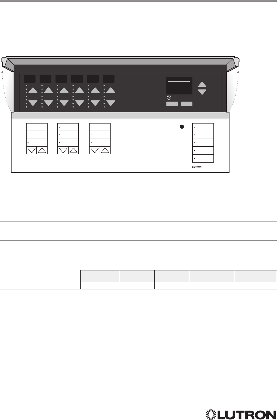
74
Lutron integration protocol
Why Integrate with a GRAFIK Eye QS unit?
• Control individual lights and scenes
• Query current scene and light levels
• Control LEDs of unprogrammed buttons
Integration Capabilities
• 16 scenes and up to 24 controllable outputs (output count depends on model)
Supported Command Types
• DEVICE allows control and monitoring of buttons, LEDs and scenes
• OUTPUT allows control and monitoring of the dimmer device output
Compatibility
QS Standalone Quantum RadioRA 2 HomeWorks QS myRoom plus
GRAFIK Eye QS Main Unit
123456 Scene 1
OK
Fade Time
03 Seconds
GRAFIK Eye QS
Main Unit
Models: QSGR-, QSG RJ-, QSGRK-, QSGRM-, QSGRN-, QSGRQ-
Continued on next page…
75
Lutron integration protocol
GRAFIK Eye QS (continued)
DEVICE Commands
DEVICE Command Formats
DEVICE Command-specific fields
Component Numbers:
Component Component Number Available Actions
Zone 1 Controller – Zone 24 Controller 1–24 Raise, Lower, Stop, Set Light Level
Scene 1 Button 70 Press, Release (Scenes Activate on “Press”)
Scene 2 Button 71 Press, Release (Scenes Activate on “Press”)
Scene 3 Button 76 Press, Release (Scenes Activate on “Press”)
Scene 4 Button 77 Press, Release (Scenes Activate on “Press”)
Scene Off Button 83 Press, Release
Shade Column 1 Open 38 Press, Release (Shades React on “Release”)
Shade Column 1 Preset 1 39 Press, Release (Shades React on “Release”)
Shade Column 1 Close 40 Press, Release (Shades React on “Release”)
Shade Column 1 Lower 41 Press, Release (Shades React on “Release”)
Shade Column 1 Raise 47 Press, Release (Shades React on “Release”)
Shade Column 2 Open 44 Press, Release (Shades React on “Release”)
Shade Column 2 Preset 1 45 Press, Release (Shades React on “Release”)
Shade Column 2 Close 46 Press, Release (Shades React on “Release”)
Shade Column 2 Lower 52 Press, Release (Shades React on “Release”)
Shade Column 2 Raise 53 Press, Release (Shades React on “Release”)
Shade Column 3 Open 50 Press, Release (Shades React on “Release”)
Shade Column 3 Preset 1 51 Press, Release (Shades React on “Release”)
Shade Column 3 Close 56 Press, Release (Shades React on “Release”)
Shade Column 3 Lower 57 Press, Release (Shades React on “Release”)
Shade Column 3 Raise 58 Press, Release (Shades React on “Release”)
Scene Controller 141
Set Current Scene, Set Zone Lock,
Set Scene Lock, Set Sequence State,
Raise, Lower, Stop, Scene Save
Scene 1 LED1201 Get (?) LED state
Scene 2 LED1210 Get (?) LED state
Scene 3 LED1219 Get (?) LED state
Scene 4 LED1228 Get (?) LED state
Scene Off LED1237 Get (?) LED state
Local CCI 163 Report (~) Occupied, Report (~) Unoccupied
Timeclock Controller 166 Enable/Disable, Query Status
Wireless Occupancy Sensor 1 – 30 500 – 529 Report (~) Occupied, Report (~) Unoccupied
EcoSystem Ballast Occupancy Sensor 1 – 64 700 – 763 Report (~) Occupied, Report (~) Unoccupied
NOTE
1. Not supported in QS Standalone.
123456 Scene 1
OK
Fade Time
03 Seconds
Use “DEVICE Command-specific fields” tables
to complete these command fields.
Operation
Command
Integration ID (example)
#DEVICE, 5, Component Number, Action Number, Parameters
76
Lutron integration protocol
DEVICE Command-specific fields (continued)
Component Numbers (continued):
Component Component Number Available Actions
Shade Column 1 Open LED1174 Get (?) LED state
Shade Column 1 Preset 1 LED1175 Get (?) LED state
Shade Column 1 Close LED1211 Get (?) LED state
Shade Column 2 Open LED1183 Get (?) LED state
Shade Column 2 Preset 1 LED1184 Get (?) LED state
Shade Column 2 Close LED1220 Get (?) LED state
Shade Column 3 Open LED1192 Get (?) LED state
Shade Column 3 Preset 1 LED1193 Get (?) LED state
Shade Column 3 Close LED1229 Get (?) LED state
NOTE
1. Not supported in QS Standalone.
Action Numbers and Parameters:
Action Action Number Parameters
Set (#) Press or Occupied 3 None
Set (#) Release or Unoccupied 4 None
Set (#) Current Scene
1,2 7 Scene
Set (#) or Get (?) LED State
390 = Off
1 = On
2 = Normal-Flash: 1 flash every second
2
3 = Rapid-Flash: 10 flashes every second
2
Set (#) Scene Save 12 Scene
Set (#) or Get (?) Light Level
4,5 14 Level = 0 –100 or 0.00 –100.00
Fade
6 in: SS.ss
7, SS, MM:SS, or HH:MM:SSJ79 (QS
Standalone fade: maximum 4 hours)
Delay
6 in: SS.ss
7, SS, MM:SS, or HH:MM:SS (QS Standalone
delay: maximum 4 hours)
Set (#) Zone Lock
815 0 = Off; 1 = On
Set (#) Scene Lock
816 0 = Off; 1 = On
Set (#) Sequence State
817 0 = Off
1 = Sequence through Scenes 1–4
2 = Sequence through Scenes 5–16
Set (#) Start Raising
4,5 18 None
Set (#) Start Lowering
4,5 19 None
Set (#) Stop Raising or Lowering
4,5 20 None
Set (#) or Get (?) Timeclock State 34 0 = Disabled
1 = Enabled
NOTES
The number of zone controllers available matches the number of zones a particular model supports.
1. Not supported in HomeWorks QS / myRoom plus.
2. Not supported in RadioRA 2.
3. Quantum or HomeWorks only. “Set” is for unprogrammed buttons and buttons with LED logic ‘Defined by Integration.’
4. Use OUTPUT command with equivalent command in RadioRA 2.
5. Use OUTPUT command with equivalent command in HomeWorks QS / myRoom plus.
6. The Fade and Delay time are optional. When not used, the system will use a one-second fade time with zero-second delay.
7. Fractional seconds “SS.ss” will be rounded down to the nearest quarter second. For example, if a fade time is specified
as 1.31 seconds a value of 1.25 seconds will be used.
8. QS Standalone only.
GRAFIK Eye QS (continued)
DEVICE Commands (continued)
123456 Scene 1
OK
Fade Time
03 Seconds
Continued on next page…
77
Lutron integration protocol 123456 Scene 1
OK
Fade Time
03 Seconds
GRAFIK Eye QS (continued)
OUTPUT Commands
OUTPUT Command-specific fields
Action Numbers and Parameters:
Action Action Number Parameters
Set (#) or Get (?) Zone Level 1 Level = 0 –100 or 0.00 –100.00
Fade
1 in: SS.ss
2, SS, MM:SS, or HH:MM:SS
(QSStandalone fade: maximum 4 hours)
Delay
1 in: SS.ss
2, SS, MM:SS, or HH:MM:SS
(QSStandalone delay: maximum 4 hours)
Set (#) Start Raising 2 None
Set (#) Start Lowering 3 None
Set (#)
Stop Raising or Lowering
4 None
NOTES
1. The Fade and Delay time are optional. When not used, the system will use a one-second fade time with zero-second delay.
2. Fractional seconds “SS.ss” will be rounded down to the nearest quarter sec. For example, if a fade time is specified as
1.31 seconds a value of 1.25 seconds will be used.
Example OUTPUT Commands
Operation Command String
Execute: #OUTPUT, Integration ID, Action Number, Parameters
Set dimmer to 75% with a 1 min 30 sec fade. #OUTPUT,1,1,75,01:30<CR><LF>
Start Raising zone level. #OUTPUT,1,2<CR><LF>
Stop Raising / Lowering zone level. #OUTPUT,1,4<CR><LF>
Query: ?OUTPUT, Integration ID, Action Number
What is the state of the output? ?OUTPUT,1,1<CR><LF>
Response
1: ~OUTPUT, Integration ID, Action Number, Parameters
Output level is set to 90%. ~OUTPUT,1,1,90.00<CR><LF>
NOTE
1. The system will report the target level of a dimmer while it is fading from one level to another.
The actual level is not transmitted while dimming between levels.
Example: If the “Over Sink” (Integration ID-1) dimmer is at 20% and is then commanded to go to 100% by sending
#OUTPUT,1,1,100, the response from the system will be ~OUTPUT,1,1,100.00
OUTPUT Command Format
Use “OUTPUT Command-specific fields” tables
to complete these command fields.
Operation
Command
Integration ID (example)
#OUTPUT, 1, Action Number, Parameters
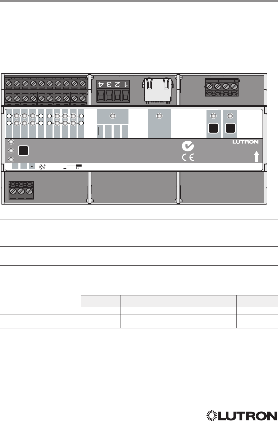
78
Lutron integration protocol
Why Integrate with an Energi Savr Node (ESN) unit?
• Control individual zones and scenes in an area
• Query current scene and light levels
Integration Capabilities
• Up to 32 areas with 16 scenes per area. Up to 32 zones across the two DALI® buses
Supported Command Types
• DEVICE allows control and monitoring of zone levels and area scenes
• OUTPUT allows control and monitoring of the dimmer device output
Compatibility
QS Standalone Quantum RadioRA 2 HomeWorks QS myRoom plus
Energi Savr Node QS / DALI®
HomeWorks QS / myRoom Power
Module / DALI®
Energi Savr Node QS for DALI®
HomeWorks QS / myRoom Power Module for DALI®
QS Model: QSNE-2DAL-D
HomeWorks QS / myRoom Model: LQSE-2DAL-D
QSNE-2DAL-D
V
D E
Test
Power
Hi Temp
Ethernet DALI 1 DALI 2
IR
Photo
Com
20 V
20 V
Com
MUX
MUX
24 V
COM
Occ
IR
Photo
Occ
Energi Savr Node QS
QSNE-2DAL-D
230 V~ 50/60 Hz 100 mA
www.lutron.com
+44.(0)20.7680.4481
L N
1 1 2 2
33 4 4
QS
8 mm
0,5 N∙m
N1771
Z096
Continued on next page…
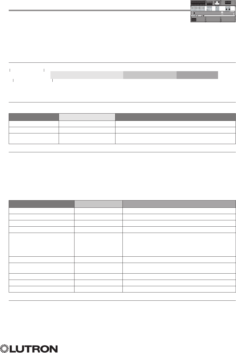
79
Lutron integration protocol
Energi Savr Node QS for DALI®
HomeWorks QS / myRoom
Power Module for DALI® (continued)
DEVICE Commands
iPhone and iPod Touch are trademarks of Apple, Inc., registered in the U.S. and other countries.
V
D E
Test
Power
Hi Temp
Ethernet DALI 1 DALI 2
IR
Photo
Com
20 V
20 V
Com
MUX
MUX
24 V
COM
Occ
IR
Photo
Occ
Energi Savr Node QS
QSNE-2DAL-D
230 V~ 50/60 Hz 100 mA
www.lutron.com
+44.(0)20.7680.4481
L N
1 1 2 2
33 4 4
QS
8 mm
0,5 N∙m
N1771
Z096
DEVICE Command Formats
Use “DEVICE Command-specific fields” tables
to complete these command fields.
Operation
Command
Integration ID (example)
#DEVICE, 5, Component Number, Action Number, Parameters
DEVICE Command-specific fields
Component Numbers:
Component Component Number Available Actions
Zone 1–Zone 32
1, 2, 3 301– 332 Set or Get Light Level, Raise, Lower, Stop
Area 1–Area 32
1, 3 401– 432 Set or Get Scene, Set Light Level, Raise, Lower, Stop
Occupancy Sensors 1–4 151–154 Report (~) Occupied
Report (~) Unoccupied
NOTES
1. Zones and areas are created and configured using the Lutron ESN Configuration Tool on an iPhone or iPod Touch mobile
device, the Quantum Q-Design Tool, the HomeWorks QS Lutron Designer, or the myRoom Lutron Designer. Only those
areas and zones that have been configured using one of these tools are accessible through integration.
2. Assigned zones can be given an individual Integration ID and controlled using the #OUTPUT command. For more details
on setting the output Integration ID of a zone component, see the Integration Access Point section of the system that
contains the ESN.
3. When the ESN is part of a Quantum system, then the #AREA and #OUTPUT commands found in the Quantum “System
Commands” section of this integration document should be used.
Action Numbers and Parameters:
Action Action Number Parameters
Report (~) Occupied 3 None
Report (~) Unoccupied 4 None
Set (#) or Get (?) Current Scene 7 Scene
Set (#) Scene Save112 Scene
Set (#) or Get (?) Light Level 14 Level = 0–100 or 0.00 –100.00
Fade
2 in: SS.ss
3, SS, MM:SS, or HH:MM:SS
(QSStandalone fade: maximum 90 seconds)
Delay
2 in: SS.ss
3, SS, MM:SS, or HH:MM:SS
(QSStandalone delay: maximum 4 hours)
Set (#) Scene Lock
416 0 = Off; 1 = On
Set (#) Sequence State
417 0 = Off; 1 = Sequence through Scenes 1– 4;
2 = Sequence through Scenes 5–16
Set (#) Start Raising 18 None
Set (#) Start Lowering 19 None
Set (#) Stop Raising or Lowering 20 None
NOTES
1. Available only with Energi Savr Node firmware > 6.x.
2. The Fade and Delay time are optional. When not used, the system will use a one-second fade time with zero-second delay.
3. Fractional seconds “SS.ss” will be rounded down to the nearest quarter-second. For example, if a fade time is specified
as 1.31 seconds, a value of 1.25 seconds will be used.
4. QS Standalone only.
80
Lutron integration protocol
Energi Savr Node QS for DALI®
HomeWorks QS / myRoom
Power Module for DALI® (continued)
OUTPUT Commands
OUTPUT Command Format
OUTPUT Command-specific fields
Action Numbers and Parameters:
Action Action Number Parameters
Set (#) or Get (?) Zone Level 1 Level = 0–100 or 0.00–100.00
Fade
1 in: SS.ss
2, SS, MM:SS, or HH:MM:SS
(QSStandalone fade: maximum 90 seconds)
Delay
1 in: SS.ss
2, SS, MM:SS, or HH:MM:SS
(QSStandalone delay: maximum 4 hours)
Set (#) Start Raising 2 None
Set (#) Start Lowering 3 None
Set (#)
Stop Raising or Lowering
4 None
NOTES
1. The Fade and Delay time are optional. When not used, the system will use a one-second fade time with zero-second delay.
2. Fractional seconds “SS.ss” will be rounded down to the nearest quarter second. For example, if a fade time is specified
as 1.31 seconds a value of 1.25 seconds will be used.
Example OUTPUT Commands
Operation Command String
Execute: #OUTPUT, Integration ID, Action Number, Parameters
Set dimmer to 75% with a 1 min 30 sec fade. #OUTPUT,1,1,75,01:30<CR><LF>
Start Raising zone level. #OUTPUT,1,2<CR><LF>
Stop Raising / Lowering zone level. #OUTPUT,1,4<CR><LF>
Query: ?OUTPUT, Integration ID, Action Number
What is the state of the output? ?OUTPUT,1,1<CR><LF>
Response
1: ~OUTPUT, Integration ID, Action Number, Parameters
Output level is set to 90%. ~OUTPUT,1,1,90.00<CR><LF>
NOTE
1. The system will report the target level of a dimmer while it is fading from one level to another.
The actual level is not transmitted while dimming between levels.
Example: If the “Over Sink” (Integration ID -1) dimmer is at 20% and is then commanded to go to 100% by sending
#OUTPUT,1,1,100, the response from the system will be ~OUTPUT,1,1,100.00
V
D E
Test
Power
Hi Temp
Ethernet DALI 1 DALI 2
IR
Photo
Com
20 V
20 V
Com
MUX
MUX
24 V
COM
Occ
IR
Photo
Occ
Energi Savr Node QS
QSNE-2DAL-D
230 V~ 50/60 Hz 100 mA
www.lutron.com
+44.(0)20.7680.4481
L N
1 1 2 2
33 4 4
QS
8 mm
0,5 N∙m
N1771
Z096
Use “OUTPUT Command-specific fields” tables
to complete these command fields.
Operation
Command
Integration ID (example)
#OUTPUT, 1, Action Number, Parameters
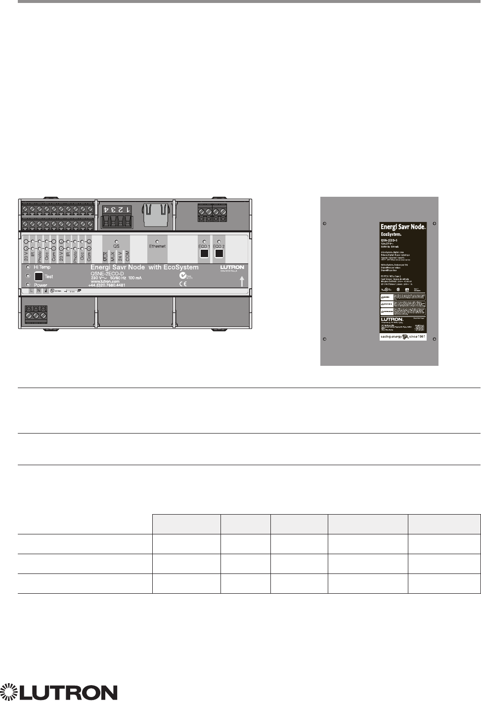
81
Lutron integration protocol
Why Integrate with an Energi Savr Node unit?
• Control individual zones and scenes in an area
• Query current scene and light levels
Integration Capabilities
• Up to 100 areas with 16 scenes per area. Up to 100 zones across the two EcoSystem loops
Supported Command Types
• DEVICE allows control and monitoring of zone levels and area scenes
• OUTPUT allows control and monitoring of the dimmer device output
Compatibility
QS Standalone Quantum RadioRA 2 HomeWorks QS myRoom plus
Energi Savr Node QS /
EcoSystem
Energi Savr Node QS /
EcoSystem (Int’l)
HomeWorks QS / myRoom Power
Module / EcoSystem
Energi Savr Node QS with EcoSystem
Model: QSN-2ECO-S
Energi Savr Node QS with EcoSystem (International)
QS Model: QSNE-2ECO-D
HomeWorks QS / myRoom Power Module
with EcoSystem
HomeWorks QS / myRoom Model: LQSE-2ECO-D
QSNE-2ECO-D QSN-2ECO-S
82
Lutron integration protocol
Energi Savr Node QS with EcoSystem
HomeWorks QS / myRoom Power Module
with EcoSystem (continued)
DEVICE Commands
1
DEVICE Command Formats
iPhone and iPod Touch are trademarks of Apple, Inc., registered in the U.S. and other countries.
Use “DEVICE Command-specific fields” tables
to complete these command fields.
Operation
Command
Integration ID (example)
#DEVICE, 5, Component Number, Action Number, Parameters
DEVICE Command-specific fields
Component Numbers:
Component Component Number Available Actions
Occupancy Sensors 1 – 4 136 – 139 Report (~) Occupied, Report (~) Unoccupied
Loop 1 Ballast Occupancy Sensors 140 – 203 Report (~) Occupied, Report (~) Unoccupied
Loop 2 Ballast Occupancy Sensors 204 – 267 Report (~) Occupied, Report (~) Unoccupied
Zone 1–Zone 100
1, 2, 3 1001–1100 Set or Get Light Level, Raise, Lower, Stop
Area 1–Area 100
1, 3 1201–1300 Set or Get Scene, Set Light Level, Raise, Lower, Stop
NOTES
1. Zones and areas are created and configured using the Lutron ESN Configuration Tool on an iPhone or iPod Touch mobile
device, the Quantum Q-Design Tool, the HomeWorks QS Lutron Designer, or the myRoom Lutron Designer. Only those
areas and zones that have been configured using one of these tools are accessible through integration.
2. Assigned zones can be given an individual Integration ID and controlled using the #OUTPUT command. For more details
on setting the output Integration ID of a zone component, see the Integration Access Point section of the system that
contains the ESN.
3. When the ESN is part of a Quantum, HomeWorks QS or myRoom plus system, the #AREA and #OUTPUT commands
found in the Quantum “System Commands” section of this integration document should be used.
Action Numbers and Parameters:
Action Action Number Parameters
Report (~) Occupied 3 None
Report (~) Unoccupied 4 None
Set (#) or Get (?) Current Scene 7 Scene
Set (#) Scene Save112 Scene
Set (#) or Get (?) Light Level 14 Level = 0 –100 or 0.00–100.00
Fade
2 in: SS.ss
3, SS, MM:SS, or HH:MM:SS
Delay
2 in: SS.ss
3, SS, MM:SS, or HH:MM:SS
Set (#) Scene Lock
416 0 = Off; 1 = On
Set (#) Sequence State
417 0 = Off; 1 = Sequence through Scenes 1– 4;
2 = Sequence through Scenes 5–16
Set (#) Start Raising 18 None
Set (#) Start Lowering 19 None
Set (#) Stop
Raising or Lowering
20 None
NOTES
1. Available only with Energi Savr Node Firmware > 6.x.
2. The Fade and Delay time are optional. When not used, the system will use a one-second fade time with zero-second delay.
3. Fractional seconds “SS.ss” will be rounded down to the nearest quarter second. For example, if a fade time is specified
as 1.31 seconds, a value of 1.25 seconds will be used.
4. QS Standalone only.
NOTE
1. Not Supported in HomeWorks QS / myRoom plus.
Continued on next page…
83
Lutron integration protocol
OUTPUT Command Format
OUTPUT Command-specific fields
Action Numbers and Parameters:
Action Action Number Parameters
Set (#) or Get (?) Zone Level 1 Level = 0–100 or 0.00–100.00
Fade
1 in: SS.ss
2, SS, MM:SS, or HH:MM:SS
(QSStandalone fade: maximum 2 hours)
Delay
1 in: SS.ss
2, SS, MM:SS, or HH:MM:SS
(QSStandalone delay: maximum 4 hours)
Set (#) Start Raising 2 None
Set (#) Start Lowering 3 None
Set (#)
Stop Raising or Lowering
4 None
NOTES
1. The Fade and Delay time are optional. When not used, the system will use a one-second fade time with zero-second delay.
2. Fractional seconds “SS.ss” will be rounded down to the nearest quarter second. For example, if a fade time is specified
as 1.31 seconds a value of 1.25 seconds will be used.
Example OUTPUT Commands
Operation Command String
Execute: #OUTPUT, Integration ID, Action Number, Parameters
Set dimmer to 75% with a 1 min 30 sec fade. #OUTPUT,1,1,75,01:30<CR><LF>
Start Raising zone level. #OUTPUT,1,2<CR><LF>
Stop Raising / Lowering zone level. #OUTPUT,1,4<CR><LF>
Query: ?OUTPUT, Integration ID, Action Number
What is the state of the output? ?OUTPUT,1,1<CR><LF>
Response1: ~OUTPUT, Integration ID, Action Number, Parameters
Output level is set to 90%. ~OUTPUT,1,1,90.00<CR><LF>
NOTE
1. The system will report the target level of a dimmer while it is fading from one level to another.
The actual level is not transmitted while dimming between levels.
Example: If the “Over Sink” (Integration ID-1) dimmer is at 20% and is then commanded to go to 100% by sending
#OUTPUT,1,1,100, the response from the system will be ~OUTPUT,1,1,100.00
Energi Savr Node QS with EcoSystem
HomeWorks QS / myRoom Power Module
with EcoSystem (continued)
OUTPUT Commands
Use “OUTPUT Command-specific fields” tables
to complete these command fields.
Operation
Command
Integration ID (example)
#OUTPUT, 1, Action Number, Parameters
84
Lutron integration protocol
Why Integrate with an Energi Savr Node unit?
• Control individual zones and scenes in an area
• Query current scene and light levels
Integration Capabilities
• Four areas with 16 scenes per area. Four zones on four independent outputs
Supported Command Types
• DEVICE allows control and monitoring of zone levels and area scenes
• OUTPUT allows control and monitoring of the dimmer device output
Compatibility QS Standalone Quantum RadioRA 2 HomeWorks QS myRoom plus
Energi Savr Node QS/0 –10 V/
Softswitch (Int’l)
Energi Savr Node QS/
Phase-Adaptive (Int’l)
Energi Savr Node QS/0 –10 V/
Softswitch
HomeWorks QS Power
Module /0 –10 V/Softswitch/ Phase
Adaptive
Energi Savr Node QS
for 0 –10 V/Softswitch (International)
QS Models (QSNE-): 4T10-D, 4S10-D
Energi Savr Node QS
for Phase Adaptive (International)
QS Model: QSNE-4A-D
Energi Savr Node QS
for 0 –10 V/Softswitch
Models (QSN-): 4T16-S, 4S16-S
HomeWorks QS / myRoom Power Module
for 0 –10 V/Softswitch / Phase Adaptive
0-10 V / Switching Models (LQSE-): 4T10-D, 4S10-D
Phase Adaptive Models: LQSE-4A-D
QSN-4T16-S
QSNE-4A-D
H
M
L
QSNE-4A-D
DIN Rail Power Module
230 V~ 50 / 60 Hz 10 A www.lutron.com +44.(0)20.7702.0657
Input
S1 S2 S3 S4 CCI
SwitchOccPhotoIR
Type
500 W Max 800 W Max 500 W Max 500 W Max
Zone 2Zone 1 Zone 3 Zone 4
Input
Hi Temp
Prog
Power
Opt1
Opt2
Opt3
Def
Option
QSNE-4T10-D
Continued on next page…
85
Lutron integration protocol
Energi Savr Node QS
0 –10 V/Softswitch/Phase-Adaptive
HomeWorks QS / myRoom Power Module
for 0 –10 V/Softswitch (continued)
DEVICE Commands
1
DEVICE Command Formats
iPhone and iPod Touch are trademarks of Apple, Inc., registered in the U.S. and other countries.
H
M
L
QSNE-4A-D
DIN Rail Power Module
230 V~ 50 / 60 Hz 10 A www.lutron.com +44.(0)20.7702.0657
Input
S1 S2 S3 S4 CCI
SwitchOccPhotoIR
Type
500 W Max 800 W Max 500 W Max 500 W Max
Zone 2Zone 1 Zone 3 Zone 4
Input
Hi Temp
Prog
Power
Opt1
Opt2
Opt3
Def
Option
Use “DEVICE Command-specific fields” tables
to complete these command fields.
Operation
Command
Integration ID (example)
#DEVICE, 5, Component Number, Action Number, Parameters
DEVICE Command-specific fields
Component Numbers:
Component Component Number Available Actions
Zone 1 – Zone 4 1, 2, 3 5 – 8 Set or Get Light Level, Raise, Lower, Stop
Area 1 – Area 4 1, 3 10 –13 Set or Get Scene, Set Light Level, Raise, Lower, Stop
Occupancy Sensor 1 – 4 34 – 37 Report (~) Occupied, Report (~) Unoccupied
Occupancy Sensor 1 – 2 34 – 35 Report (~) Occupied, Report (~) Unoccupied
NOTES
1. Zones and areas are created and configured using the Lutron ESN Configuration Tool on an iPhone or iPod Touch mobile
device, the Quantum Q-Design Tool, the HomeWorks QS Lutron Designer, or the myRoom Lutron Designer. Only those
areas and zones that have been configured using one of these tools are accessible through integration.
2. Assigned zones can be given an individual Integration ID and controlled using the #OUTPUT command. For more details
on setting the output Integration ID of a zone component, see the Integration Access Point section of the system that
contains the ESN.
3. When the ESN is part of a Quantum, HomeWorks QS or myRoom plus system, the #AREA and #OUTPUT commands
found in the Quantum “System Commands” section of this integration document should be used.
Action Numbers and Parameters:
Action Action Number Parameters
Report (~) Occupied 3 None
Report (~) Unoccupied 4 None
Set (#) or Get (?) Current Scene
17 Scene
Set (#) Scene Save212 Scene
Set (#) or Get (?) Light Level 14 Level = 0 –100 or 0.00 –100.00
Fade
3 in: SS.ss
4, SS, MM:SS, or HH:MM:SS
Delay
3 in: SS.ss
4, SS, MM:SS, or HH:MM:SS
Set (#) Scene Lock
116 0 = Off; 1 = On
Set (#) Sequence State
117 0 = Off; 1 = Sequence through Scenes 1– 4;
2 = Sequence through Scenes 5–16
Set (#) Start Raising 18 None
Set (#) Start Lowering 19 None
Set (#) Stop Raising or Lowering 20 None
NOTES
1. QS Standalone only.
2. Available only with Energi Savr Node Firmware > 6.x.
3. The Fade and Delay time are optional. When not used, the system will use a one-second fade time with zero-second delay.
4. Fractional seconds “SS.ss” will be rounded down to the nearest quarter-second. For example, if a fade time is specified
as 1.31 seconds, a value of 1.25 seconds will be used.
NOTE
1. Not Supported in HomeWorks QS / myRoom plus.
86
Lutron integration protocol H
M
L
QSNE-4A-D
DIN Rail Power Module
230 V~ 50 / 60 Hz 10 A www.lutron.com +44.(0)20.7702.0657
Input
S1 S2 S3 S4 CCI
SwitchOccPhotoIR
Type
500 W Max 800 W Max 500 W Max 500 W Max
Zone 2Zone 1 Zone 3 Zone 4
Input
Hi Temp
Prog
Power
Opt1
Opt2
Opt3
Def
Option
OUTPUT Command Format
OUTPUT Command-specific fields
Action Numbers and Parameters:
Action Action Number Parameters
Set (#) or Get (?) Zone Level 1 Level = 0–100 or 0.00 –100.00
Fade
1 in: SS.ss
2, SS, MM:SS, or HH:MM:SS
(QSStandalone fade: maximum 4 hours)
Delay
1 in: SS.ss
2, SS, MM:SS, or HH:MM:SS
(QSStandalone delay: maximum 4 hours)
Set (#) Start Raising 2 None
Set (#) Start Lowering 3 None
Set (#)
Stop Raising or Lowering
4 None
NOTES
1. The Fade and Delay time are optional. When not used, the system will use a one-second fade time with zero-second delay.
2. Fractional seconds “SS.ss” will be rounded down to the nearest quarter second. For example, if a fade time is specified
as 1.31 seconds a value of 1.25 seconds will be used.
Example OUTPUT Commands
Operation Command String
Execute: #OUTPUT, Integration ID, Action Number, Parameters
Set dimmer to 75% with a 1 min 30 sec fade. #OUTPUT,1,1,75,01:30<CR><LF>
Start Raising zone level. #OUTPUT,1,2<CR><LF>
Stop Raising / Lowering zone level. #OUTPUT,1,4<CR><LF>
Query: ?OUTPUT, Integration ID, Action Number
What is the state of the output? ?OUTPUT,1,1<CR><LF>
Response1: ~OUTPUT, Integration ID, Action Number, Parameters
Output level is set to 90%. ~OUTPUT,1,1,90.00<CR><LF>
NOTE
1. The system will report the target level of a dimmer while it is fading from one level to another.
The actual level is not transmitted while dimming between levels.
Example: If the “Over Sink” (Integration ID-1) dimmer is at 20% and is then commanded to go to 100% by sending
#OUTPUT,1,1,100, the response from the system will be ~OUTPUT,1,1,100.00
Energi Savr Node QS
0 –10 V/Softswitch/Phase-Adaptive
HomeWorks QS / myRoom Power Module
for 0 –10 V/Softswitch (continued)
OUTPUT Commands
Operation
Use “OUTPUT Command-specific fields” tables
to complete these command fields.
Command
Integration ID (example)
#OUTPUT, 1, Action Number, Parameters
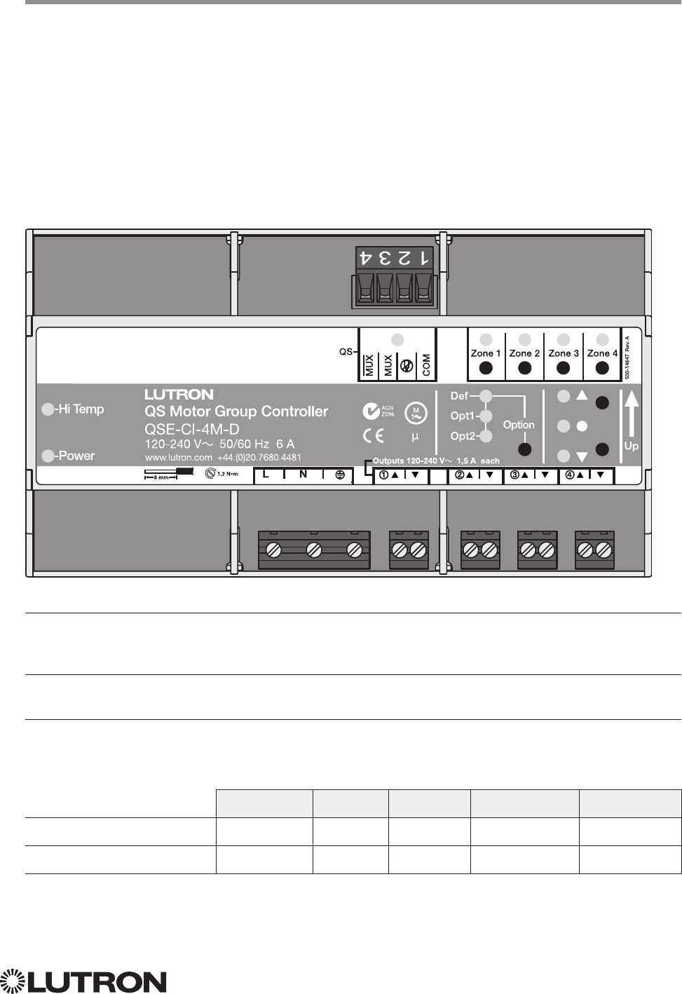
87
Lutron integration protocol
Why Integrate with an Energi Savr Node?
• Allows control and monitoring of the direction and remaining travel time of the four high-voltage
outputs.
Integration Capabilities
• Up to 4 zones
Supported Command Types
• DEVICE allows control and monitoring of zone levels
• OUTPUT allows control and monitoring of the device outputs
Compatibility
QS Standalone Quantum RadioRA 2 HomeWorks QS myRoom plus
Energi Savr Node QS /
Motor Module (Int’l)
HomeWorks QS / myRoom Power
Module for Motor Module
Energi Savr Node QS
for Motor Module (International)
QS Model: QSE-CI-4M-D
HomeWorks QS / myRoom Power Module
for Motor Module
HomeWorks QS / myRoom Model: LQSE-4M-D
LQSE-CI-4M-D
88
Lutron integration protocol
DEVICE Command-specific fields
Component Numbers:
Component Component Number Available Actions
Zone 1 – Zone 41,2 1 – 4 Set or Get Light Level, Raise, Lower, Stop
NOTES
1. Assigned zones can be given an individual Integration ID and controlled using the #OUTPUT command. For more details
on setting the output Integration ID of a zone component, see the Integration Access Point section of the system that
contains the QS Motor Module.
2. When the QS Motor Module is part of a Quantum system, then the commands found in the Quantum “System
Commands” section of this integration document should be used.
Action Numbers and Parameters:
Action Action Number Parameters
Set (#) Light Level 14 Level = 0 –100 or 0.00–100.001
Fade
2 in: Always use 0
Delay
3 in: SS.ss
4, SS, MM:SS, or HH:MM:SS
Set (#) Start Raising 18 None
Set (#) Start Lowering 19 None
Set (#) Stop Raising or Lowering 20 None
NOTES
1. Setting the level to 0% will cause the output to travel in the Closed direction; setting the level to 100% will cause the
output to travel in the Open direction; setting any level from 1 – 99% will be ignored by the output. Querying its level will
report 0 or 100%, based on the last direction it moved.
2. Fade is not available for Motor Loads because they move at a constant rate. The parameter must be entered, but is
ignored.
3. The delay time is optional. When not used, the system will use a zero-second delay.
4. Fractional seconds “SS.ss” will be rounded down to the nearest quarter-second. For example, if a fade time is specified
as 1.31 seconds, a value of 1.25 seconds will be used.
DEVICE Command Format
Use “DEVICE Command-specific fields” tables
to complete these command fields.
Operation
Command
Integration ID (example)
#DEVICE, 5, Component Number, Action Number, Parameters
Energi Savr Node QS
for Motor Module (International)
HomeWorks QS / myRoom Power Module
for Motor Module (continued)
DEVICE Commands
Continued on next page…
89
Lutron integration protocol
OUTPUT Command-specific fields
Action Numbers and Parameters:
Action Action Number Parameters
Set (#) or Get (?) Zone Level 1 Level = 0 or 100.001
Fade
2 in: SS.ss
3, SS, MM:SS, or HH:MM:SS
Delay
4 in: SS.ss
3, SS, MM:SS, or HH:MM:SS
Set (#) Start Raising 2 None
Set (#) Start Lowering 3 None
Set (#) Stop Raising or Lowering 4 None
Report (~) Travel Time Remaining517 Travel time in seconds: 0 – 255
Set (#) Motor Jog Raise618 None
Set (#) Motor Jog Lower619 None
Set (#) Motor 4-Stage Jog Raise620 None
Set (#) Motor 4-Stage Jog Lower621 None
NOTES
1. Setting the level to 0% will cause the output to travel in the Closed direction; setting the level to 100% will cause the
output to travel in the Open direction; setting any level from 1 – 99% will be ignored by the output. Querying its level will
report 0 or 100%, based on the last direction it moved.
2. Fade is not available for Shades because they move at a constant rate. The parameter must be entered, but is ignored.
3. Fractional seconds “SS.ss” will be rounded down to the nearest quarter-second. For example, if a delay time is specified
as 1.45 seconds, a value of 1.25 seconds will be used.
4. The delay time is optional. When not used, the system will use a zero-second delay. The minimum delay time is 0.25
seconds; the maximum delay time is 4 hours.
5. If the travel time of a motor is greater than 255 seconds, the unit will report 255 until the travel time drops below that
value.
6. Not supported in QS Standalone.
OUTPUT Command Format
Energi Savr Node QS
for Motor Module (International)
HomeWorks QS / myRoom Power Module
for Motor Module (continued)
OUTPUT Commands
Operation
Use “OUTPUT Command-specific fields” tables
to complete these command fields.
Command
Integration ID (example)
#OUTPUT, 3, Action Number, Parameters
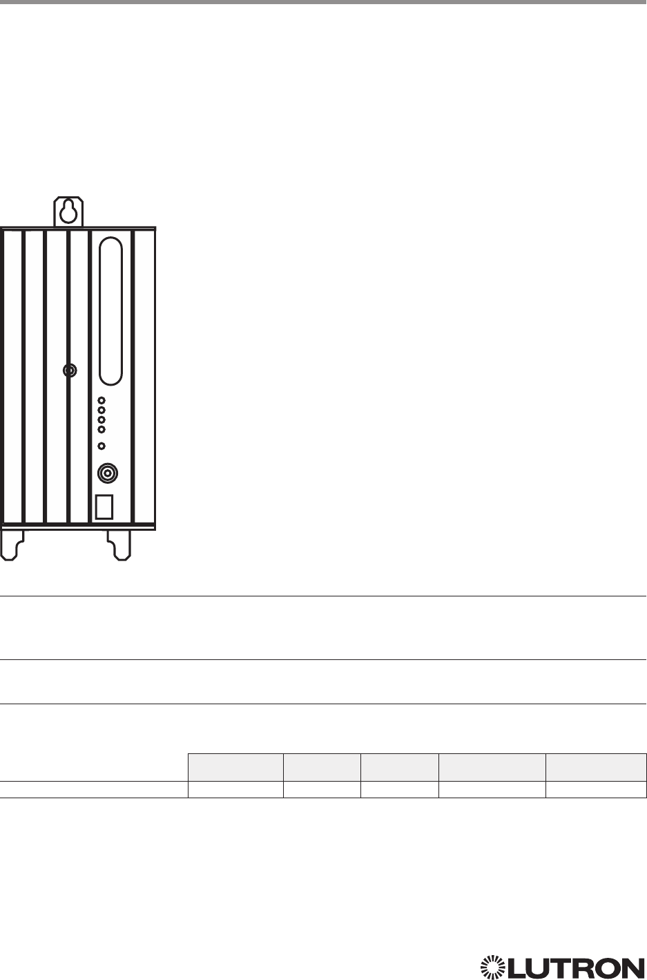
90
Lutron integration protocol
Why Integrate with a Remote Power Module?
• Control individual zones and scenes in an area
• Query current scene and light levels
Integration Capabilities
• Up to four zones on each remote power module
Supported Command Types
• OUTPUT allows control and monitoring of the control zone output
Compatibility
QS Standalone Quantum RadioRA 2 HomeWorks QS myRoom plus
Remote Power Module
Remote Power Module
Adaptive Phase Control Model: HW-RPM-4A
Phase Control Model: HW-RPM-4U
Quiet Fan Speed Control Model: HW-RPM-4FSQ
3-Wire Motor Control Model: HW-RPM-4M
Relay Switching Model: HW-RPM-4R
HW-RPM-4A
Continued on next page…
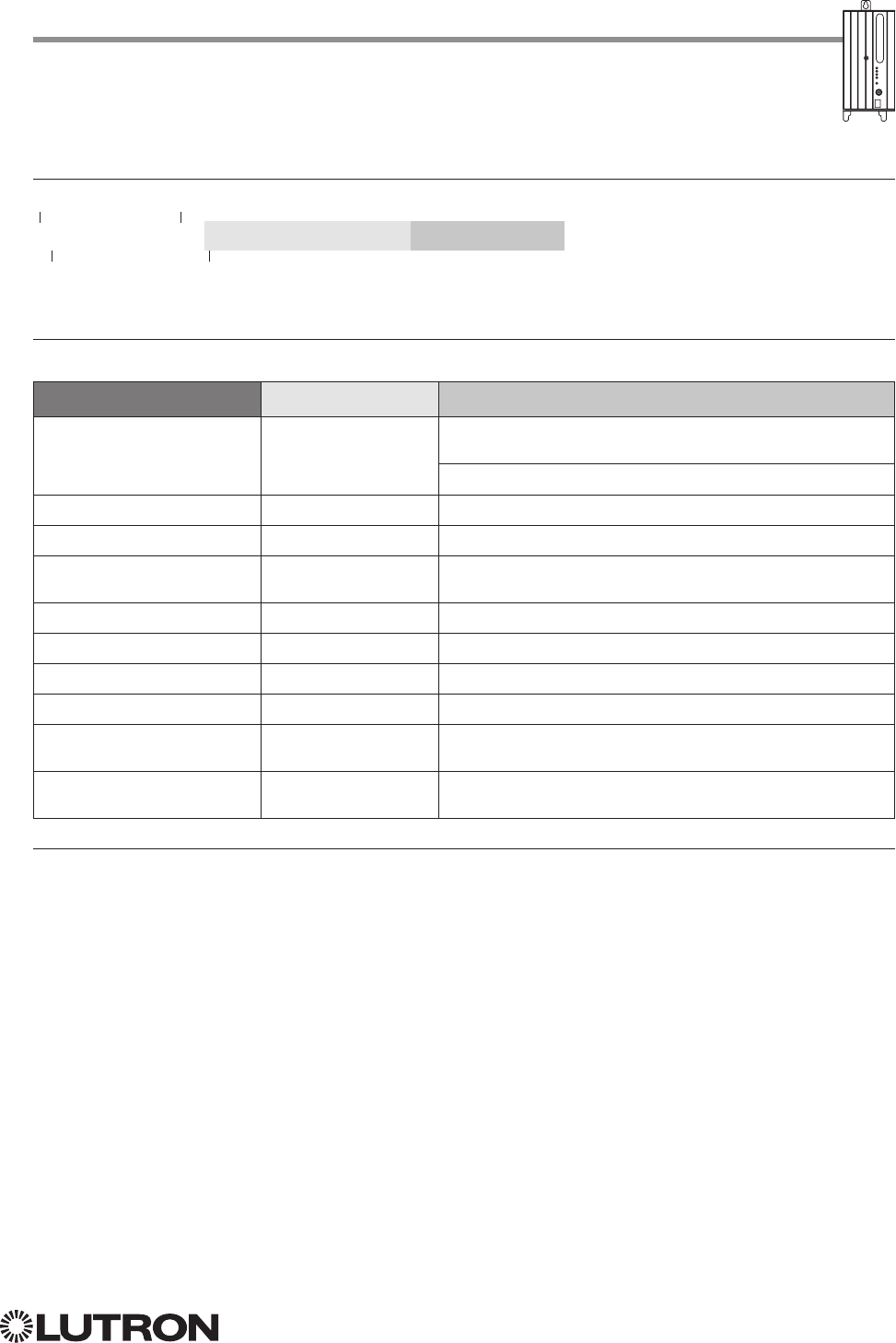
91
Lutron integration protocol
OUTPUT Command-specific fields
Action Numbers and Parameters:
Action Action Number Parameters
Set (#) or Get (?) Zone Level 1 0–100 or
0.00–100.00
SS.ss
1, SS, MM:SS, or HH:MM:SS
Set (#) Start Raising 2 None
Set (#) Stop Lowering 3 None
Set (#) Stop
Raising or
Lowering
4 None
Set (#) Flashing
25 SS.ss
1, SS, MM:SS, or HH:MM:SS
Set (#) Pulse Time 6 SS.ss
1, SS, MM:SS, or HH:MM:SS
Set (#) Motor Jog Raise 18 None
Set (#) Motor Jog Lower 19 None
Set (#) Motor 4-Stage Jog
Raise
20 None
Set (#) Motor 4-Stage Jog
Lower
21 None
NOTES
1. Fractions are rounded up to the closest ¼ second.
2. To stop a dimmer from flashing, send it to a valid level (action 1).
OUTPUT Command Format
Use “OUTPUT Command-specific fields” tables
to complete these command fields.
Operation
Command
Integration ID (example)
#OUTPUT, 6, Action Number, Parameters
Remote Power Module (continued)
OUTPUT Commands
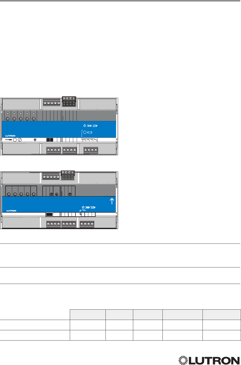
92
Lutron integration protocol
Why Integrate with a Low Capacity DIN Power Module?
• Control individual zones and scenes in an area
• Query current scene and light levels
Integration Capabilities
• Four areas with 16 scenes per area. Four zones on four independent outputs
Supported Command Types
• DEVICE allows control and monitoring of zone levels and area scenes
• OUTPUT allows control and monitoring of the dimmer device output
Compatibility
QS Standalone Quantum RadioRA 2 HomeWorks QS myRoom plus
Low-Capacity Switching DIN
Power Module (1A/output)
Low-Capacity Phase-Adaptive
DIN Power Module (1A/output)
Low-Capacity Switching DIN Power Module
(1A/output)
myRoom plus Model: MQSE-4S1-D
HomeWorks QS Model: LQSE-4S1-D
Low-Capacity Phase Adaptive DIN Power Module
(1A/output)
myRoom plus Model: MQSE-4A1-D
HomeWorks QS Model: LQSE-4A1-D
MQSE-4S1-D
LQSE-4A1-D
myRoom
MQSE-4S1-D
100
-
240 V~ 50
/
60 Hz 4 A
+1.610.282.3800
lutron.com
1 2 3 4
CCI COM
CCO N.O.
CCO COM
24 V
COM
CCI
CCO N.C.
MUX
MUX
Zn. 1Prog. Zn. 2 Zn. 3 Zn. 4
100
-
240 V~ 1 A
120
-
240 V~ 1 AX, 1 FLA
/
6 LRA
IEC PELV
/
NECR Class 2
24 V- 132 mA
4,4 in-lb
0,5 N
•
m
65
/
75 °C
Cu Al
NN NNNN
M
LL
HomeWorks QS
LQSE-4A1-D
120
-
240 V~ 50
/
60 Hz 4 A
+1.610.282.3800
lutron.com
COM
MUX
MUX
Zn. 1Prog. Zn. 2Zn. 3Zn. 4
NNNN
120
-
240 V~ 1 A
DL1DL2 DL3DL4
CCI COM
CCI
N
L
Continued on next page…
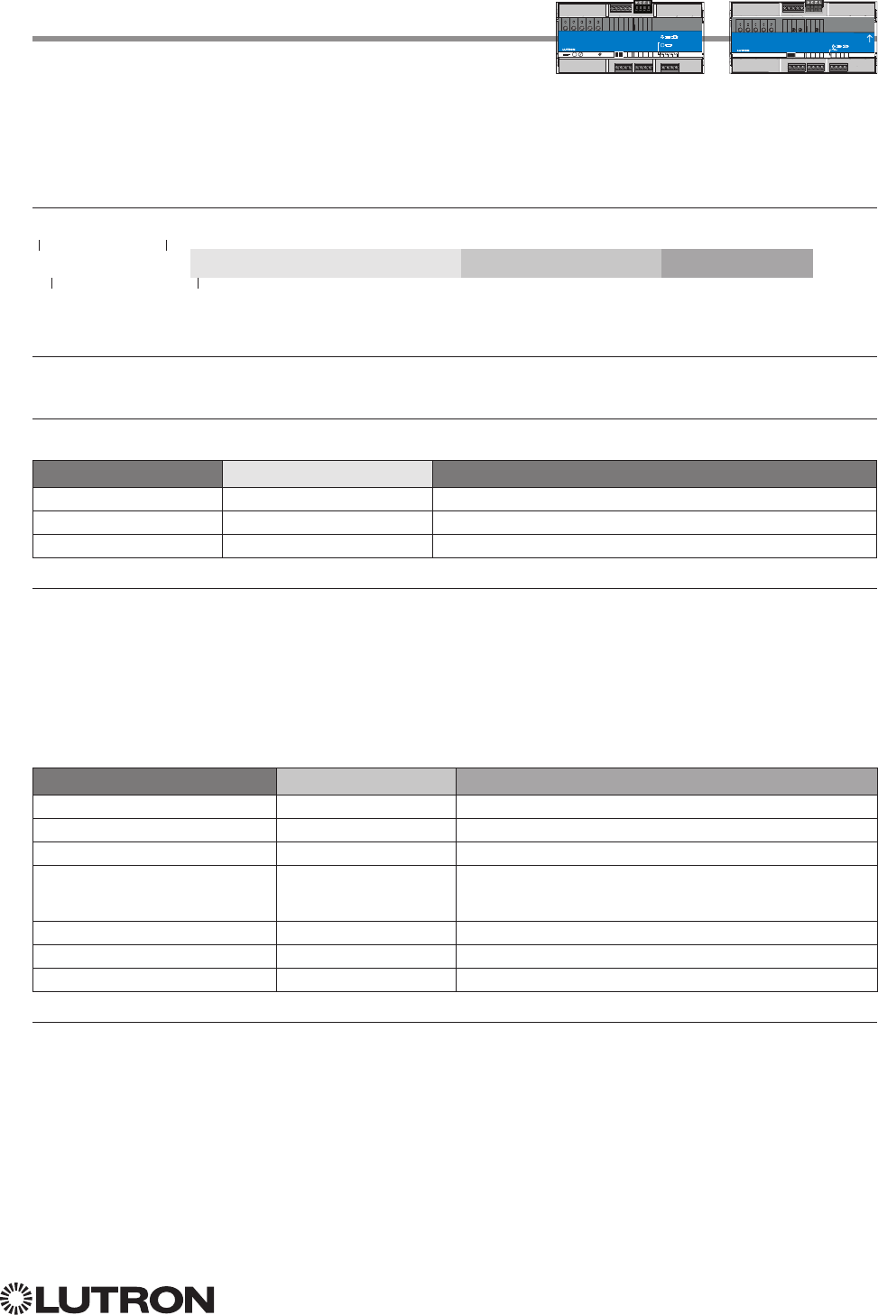
93
Lutron integration protocol
Low-Capacity Switching/Phase-Adaptive
DIN Power Module (1A/output) (continued)
DEVICE Commands
1
DEVICE Command Formats
iPhone and iPod Touch are trademarks of Apple, Inc., registered in the U.S. and other countries.
Use “DEVICE Command-specific fields” tables
to complete these command fields.
Operation
Command
Integration ID (example)
#DEVICE, 5, Component Number, Action Number, Parameters
DEVICE Command-specific fields
Component Numbers:
Component Component Number Available Actions
Zone 1 – Zone 4 1, 2, 3 5 – 8 Set or Get Light Level, Raise, Lower, Stop
Area 1 – Area 4 2, 3 10 –13 Set or Get Scene, Set Light Level, Raise, Lower, Stop
Contact Closure Input 26 Report Open, Report Closed
NOTES
1. Zones and areas are created and configured using the HomeWorks QS Lutron Designer, or the myRoom Lutron
Designer. Only those areas and zones that have been configured using one of these tools are accessible through
integration.
2. Assigned zones can be given an individual Integration ID and controlled using the #OUTPUT command. For more details
on setting the output Integration ID of a zone component, see the Integration Access Point section of the system that
contains the ESN.
3. When the ESN is part of a HomeWorks or myRoom system, then the #AREA and #OUTPUT commands found in the
Quantum “System Commands” section of this integration document should be used.
Action Numbers and Parameters:
Action Action Number Parameters
Report (~) Occupied or Closed
13 None
Report (~) Unoccupied or Open
14 None
Set (#) or Get (?) Current Scene 7 Scene
Set (#) or Get (?) Light Level 14 Level = 0–100 or 0.00 –100.00
Fade
2 in: SS.ss
3, SS, MM:SS, or HH:MM:SS
Delay
2 in: SS.ss
3, SS, MM:SS, or HH:MM:SS
Set (#) Start Raising 18 None
Set (#) Start Lowering 19 None
Set (#) Stop Raising or Lowering 20 None
NOTES
1. MQSE-4S1-D only
2. The Fade and Delay time are optional. When not used, the system will use a one-second fade time with zero-second delay.
3. Fractional seconds “SS.ss” will be rounded down to the nearest quarter-second. For example, if a fade time is specified
as 1.31 seconds, a value of 1.25 seconds will be used.
NOTE
1. Not Supported in HomeWorks QS / myRoom plus.
myRoom
MQSE-4S1-D
100
-
240 V~ 50
/
60 Hz 4 A
+1.610.282.3800
lutron.com
1 2 3 4
CCI COM
CCO N.O.
CCO COM
24 V
COM
CCI
CCO N.C.
MUX
MUX
Zn. 1Prog. Zn. 2 Zn. 3 Zn. 4
100
-
240 V~ 1 A
120
-
240 V~ 1 AX, 1 FLA
/
6 LRA
IEC PELV
/
NECR Class 2
24 V- 132 mA
4,4 in-lb
0,5 N
•
m
65
/
75 °C
Cu Al
NN NNNN
M
LL
HomeWorks QS
LQSE-4A1-D
120
-
240 V~ 50
/
60 Hz 4 A
+1.610.282.3800
lutron.com
COM
MUX
MUX
Zn. 1Prog. Zn. 2Zn. 3Zn. 4
NNNN
120
-
240 V~ 1 A
DL1DL2 DL3DL4
CCI COM
CCI
N
L
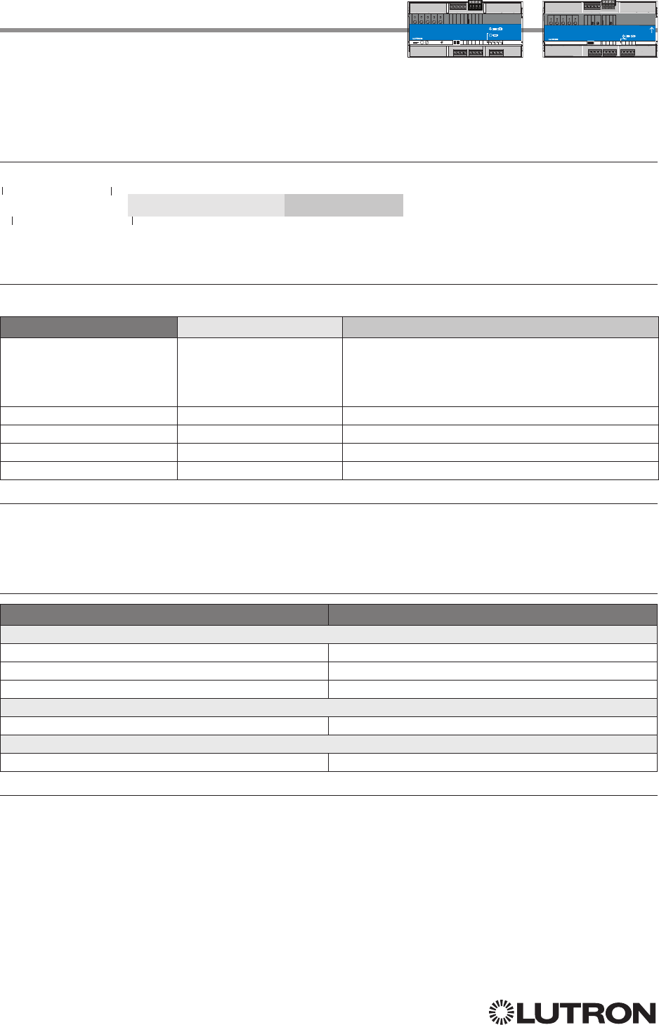
94
Lutron integration protocol
OUTPUT Command Format
OUTPUT Command-specific fields
Action Numbers and Parameters:
Action Action Number Parameters
Set (#) or Get (?) Zone Level
Set (#) or Get (?) CCO State
1
1Level = 0 –100 or 0.00 –100.00
Fade
2 in: SS.ss
3, SS, MM:SS, or HH:MM:SS
maximum 4 hours
Delay
2 in: SS.ss
3, SS, MM:SS, or HH:MM:SS
maximum 4 hours
Set (#) Start Raising 2 None
Set (#) Start Lowering 3 None
Set (#)
Stop Raising or Lowering
4 None
Set (#)
Pulse CCO
1
6 None
NOTES
1. Low-capacity switching only.
2. The Fade and Delay time are optional. When not used, the system will use a one-second fade time with zero-second delay.
3. Fractional seconds “SS.ss” will be rounded down to the nearest quarter second. For example, if a fade time is specified
as 1.31 seconds a value of 1.25 seconds will be used.
Example OUTPUT Commands
Operation Command String
Execute: #OUTPUT, Integration ID, Action Number, Parameters
Set dimmer to 75% with a 1 min 30 sec fade. #OUTPUT,1,1,75,01:30<CR><LF>
Start Raising zone level. #OUTPUT,1,2<CR><LF>
Stop Raising / Lowering zone level. #OUTPUT,1,4<CR><LF>
Query: ?OUTPUT, Integration ID, Action Number
What is the state of the output? ?OUTPUT,1,1<CR><LF>
Response1: ~OUTPUT, Integration ID, Action Number, Parameters
Output level is set to 90%. ~OUTPUT,1,1,90.00<CR><LF>
NOTE
1. The system will report the target level of a dimmer while it is fading from one level to another.
The actual level is not transmitted while dimming between levels.
Example: If the “Over Sink” (Integration ID-1) dimmer is at 20% and is then commanded to go to 100% by sending
#OUTPUT,1,1,100, the response from the system will be ~OUTPUT,1,1,100.00
Low-Capacity Switching/Phase-Adaptive
DIN Power Module (1A/output) (continued)
OUTPUT Commands
Operation
Use “OUTPUT Command-specific fields” tables
to complete these command fields.
Command
Integration ID (example)
#OUTPUT, 1, Action Number, Parameters
myRoom
MQSE-4S1-D
100
-
240 V~ 50
/
60 Hz 4 A
+1.610.282.3800
lutron.com
1 2 3 4
CCI COM
CCO N.O.
CCO COM
24 V
COM
CCI
CCO N.C.
MUX
MUX
Zn. 1Prog. Zn. 2 Zn. 3 Zn. 4
100
-
240 V~ 1 A
120
-
240 V~ 1 AX, 1 FLA
/
6 LRA
IEC PELV
/
NECR Class 2
24 V- 132 mA
4,4 in-lb
0,5 N
•
m
65
/
75 °C
Cu Al
NN NNNN
M
LL
HomeWorks QS
LQSE-4A1-D
120
-
240 V~ 50
/
60 Hz 4 A
+1.610.282.3800
lutron.com
COM
MUX
MUX
Zn. 1Prog. Zn. 2Zn. 3Zn. 4
NNNN
120
-
240 V~ 1 A
DL1DL2 DL3DL4
CCI COM
CCI
N
L
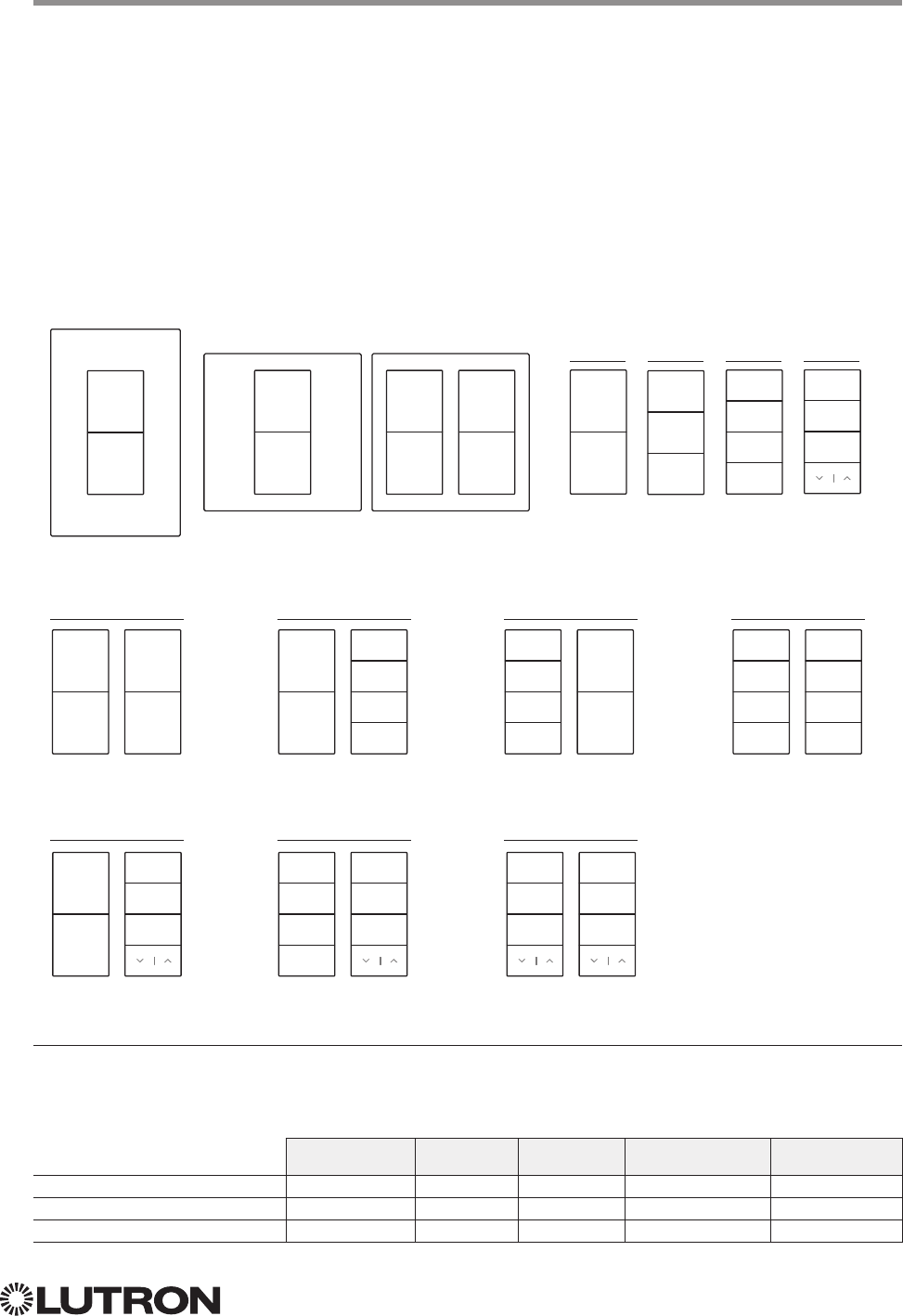
95
Lutron integration protocol
Why Integrate with a Palladiom Keypad?
• Simulate a button press
• Control LEDs of unprogrammed buttons
Compatibility
Palladiom Keypads QS Standalone Quantum RadioRA 2 HomeWorks QS myRoom plus
QS Model
HomeWorks QS Model
myRoomT Model
Palladiom Keypad
QS Models (QWP-): U-2W, U-3W, U-4W, U-RW,
S-2W, S-3W, S-4W, S-RW, S-22W, S-24W, S-42W, S-44W, S-2RW, S-4RW, S-RRW,
B-2W, B-3W, B-4W, B-RW, B-22W, B-24W, B-42W, B-44W, B-2RW, B-4RW, B-RRW.
HomeWorks QS Models (HQWT-): U-P2W, U-P3W, U-P4W, U-PRW,
S-P2W, S-P3W, S-P4W, S-PRW, S-P22W, S-P24W, S-P42W, S-P44W, S-P2RW, S-P4RW, S-PRRW,
B-P2W, B-P3W, B-P4W, B-PRW, B-P22W, B-P24W, B-P42W, B-P44W, B-P2RW, B-P4RW, B-PRRW.
myRoom Models (MWP-): U-2W, U-3W, U-4W, U-RW,
S-2W, S-3W, S-4W, S-RW, S-22W, S-24W, S-42W, S-44W, S-2RW, S-4RW, S-RRW,
B-2W, B-3W, B-4W, B-RW, B-22W, B-24W, B-42W, B-44W, B-2RW, B-4RW, B-RRW.
22W
button
5
button
8
button
1
button
4
24W
button
5
button
8
button
1
button
3
button
2
button
4
42W
button
1
button
4
button
5
button
7
button
6
button
8
44W
button
5
button
7
button
6
button
8
button
1
button
3
button
2
button
4
2W
button
1
button
4
3W
button
1
button
2
button
4
4W
button
1
button
3
button
2
button
4
U.S. Style Faceplate
Square Style Faceplates RW
button
1
button
3
button
2
2RW
button
5
button
8
button
1
button
3
button
2
4RW
button
5
button
7
button
6
button
8
button
1
button
3
button
2
RRW
button
1
button
3
button
2
button
5
button
7
button
6
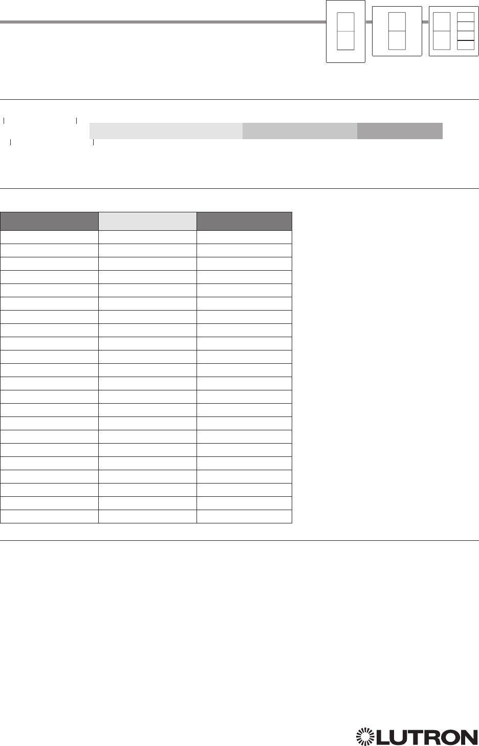
96
Lutron integration protocol
Scene 1
Scene 2
Scene 3
Palladiom Keypad (continued)
DEVICE Commands
DEVICE Command Formats
DEVICE Command-specific fields
Component Numbers:
Component Component Number Available Actions
Column 1, Button 1 1 Press, Release
Column 1, Button 2 2 Press, Release
Column 1, Button 3 3 Press, Release
Column 1, Button 4 4 Press, Release
Column 2, Button 1 5 Press, Release
Column 2, Button 2 6 Press, Release
Column 2, Button 3 7 Press, Release
Column 2, Button 4 8 Press, Release
Column 1, Lower 16 Press, Release
Column 1, Raise 17 Press, Release
Column 2, Lower 18 Press, Release
Column 2, Raise 19 Press, Release
Column 1, LED 1 81 Set or Get LED state
Column 1, LED 2 82 Set or Get LED state
Column 1, LED 3 83 Set or Get LED state
Column 1, LED 4 84 Set or Get LED state
Column 2, LED 1 85 Set or Get LED state
Column 2, LED 2 86 Set or Get LED state
Column 2, LED 3 87 Set or Get LED state
Column 2, LED 4 88 Set or Get LED state
Active LED Intensity189 Set or Get LED state
Inactive LED Intensity1113 Set or Get LED state
NOTE
1. LED intensity can be set only when the DBM sensor is disabled.
Use “DEVICE Command-specific fields” tables
to complete these command fields.
Operation
Command
Integration ID (example)
#DEVICE, 2, Component Number, Action Number, Parameters
Continued on next page…
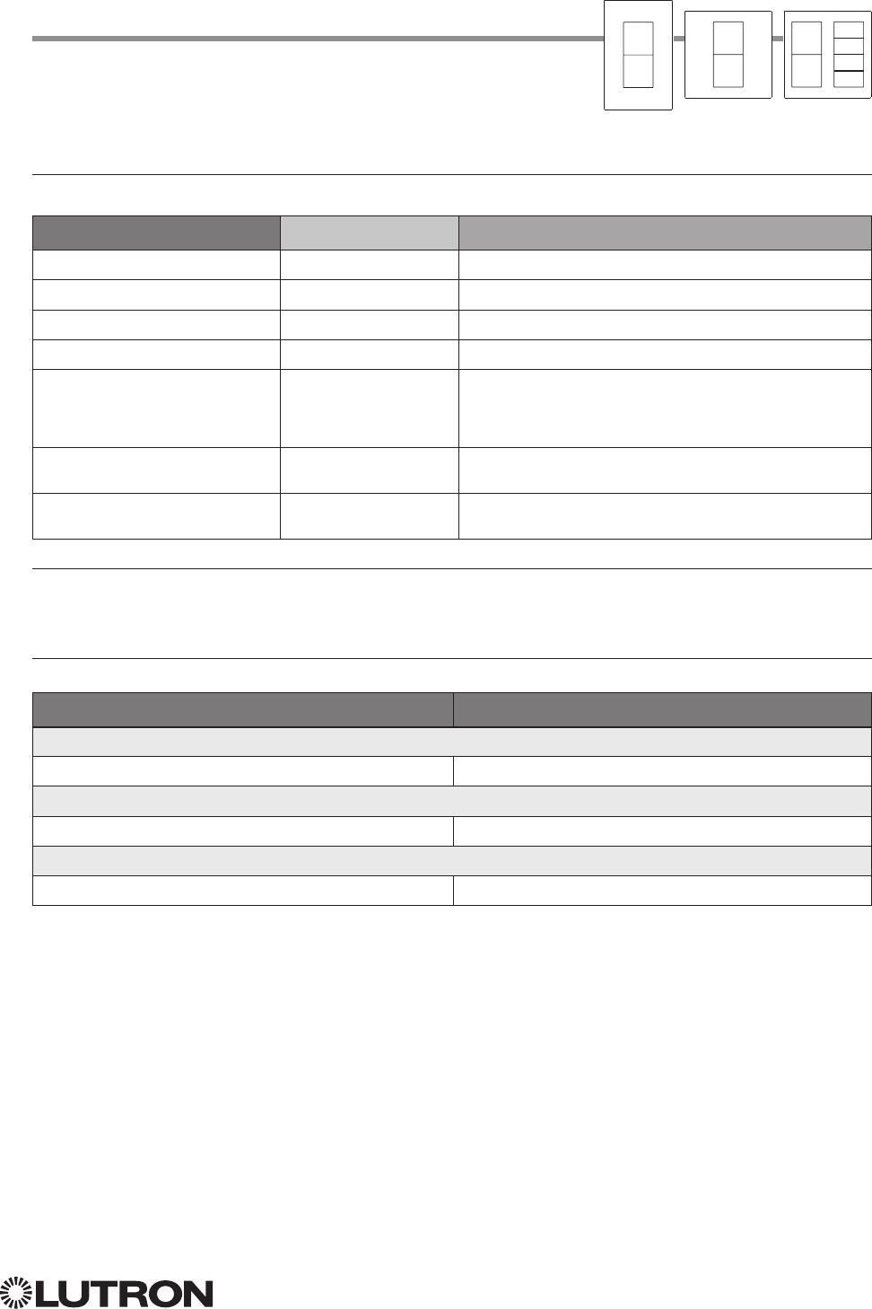
97
Lutron integration protocol
Palladiom Keypad (continued)
DEVICE Commands (continued)
DEVICE Command-specific fields (continued)
Action Numbers and Parameters:
Action Action Number Parameters
Set (#) Press 3 None
Set (#) Release 4 None
Set (#) Hold 5 None
Set (#) Multi-tap 6 None
Set (#) or Get (?) LED State
190 = Off
1 = On
2 = Normal-Flash: 1 flash every second
1
3 = Rapid-Flash: 10 flashes every second
1
Set (#) or Get (?) Active LED
Level
1,2 36 0 –100
Set (#) or Get (?) Inactive LED
Level
1,2 37 0 –100
NOTES
1. “Set” is for unprogrammed buttons and buttons with LED logic ‘Defined by Integration.’
2. LED intensity can be set only when the DBM sensor is disabled.
Example DEVICE Commands
Examples presume keypad has been assigned Integration ID 2.
Operation Command String
Execute: #DEVICE, Integration ID, Component Number, Action Number, Parameters
Set Active LED to 50 #DEVICE,2,89,36,50<CR><LF>
Query: ?DEVICE, Integration ID, Component Number, Action Number
What is the Inactive LED Level? ?DEVICE,2,113,37<CR><LF>
Response: ~DEVICE, Integration ID, Component Number, Action Number, Parameters
Inactive LED Level is 75% ~DEVICE,2,113,37,75<CR><LF>
Scene 1
Scene 2
Scene 3
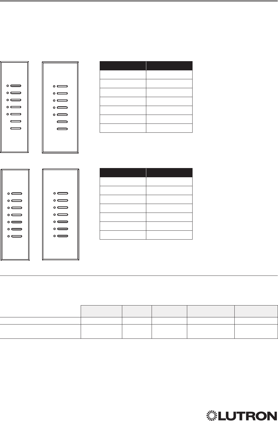
98
Lutron integration protocol
Why Integrate with an Architrave Keypad?
• Simulate a button press
• Control LEDs of unprogrammed buttons
Compatibility
Architrave Keypads QS Standalone Quantum RadioRA 2 HomeWorks QS myRoom plus
QS Model
HomeWorks QS /
myRoom Model
Architrave Keypad
QS Models (QSWAS-) with Faceplate / Button Kit Models (KP5-, KP7-): DN, KP7
HomeWorks QS / myRoom Models (HQWA-) with Faceplate / Button Kit Models (KP5-, KP7-): DN, KP7
KP5-DN KP5-DW
KP7-DN KP7-DW
QS HomeWorks QS
Button 1 Button 1
Button 2 Button 2
Button 3 Button 3
Button 4 Button 4
Button 5 Button 5
Button 6 Button 6
Button 7 Button 7
QS HomeWorks QS
Button 1 Button 1
Button 2 Button 2
Button 3 Button 3
Button 4 Button 4
Button 5 Button 5
Raise Button 6
Lower Button 7
Continued on next page…
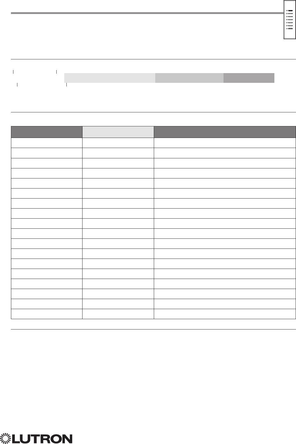
99
Lutron integration protocol
Architrave Keypad (continued)
DEVICE Commands
DEVICE Command Formats
DEVICE Command-specific fields
Component Numbers:
Component Component Number Available Actions
Button 1 1 Press, Release, Multi Tap, Hold, Hold Release
Button 2 2 Press, Release, Multi Tap, Hold, Hold Release
Button 3 3 Press, Release, Multi Tap, Hold, Hold Release
Button 4 4 Press, Release, Multi Tap, Hold, Hold Release
Button 5 5 Press, Release, Multi Tap, Hold, Hold Release
Button 6 6 Press, Release, Multi Tap, Hold, Hold Release
Button 7 7 Press, Release, Multi Tap, Hold, Hold Release
Lower 18 Press, Release, Multi Tap, Hold, Hold Release
Raise 19 Press, Release, Multi Tap, Hold, Hold Release
CCI 1 25 Press, Release
CCI 2 26 Press, Release
LED 1
181 Set or Get LED state
LED 2
182 Set or Get LED state
LED 3
183 Set or Get LED state
LED 4
184 Set or Get LED state
LED 5
185 Set or Get LED state
LED 6
186 Set or Get LED state
LED 7
187 Set or Get LED state
NOTE
1. Available only on units in a Quantum, HomeWorks, or myRoom Plus systems.
Use “DEVICE Command-specific fields” tables
to complete these command fields.
Operation
Command
Integration ID (example)
#DEVICE, 2, Component Number, Action Number, Parameters
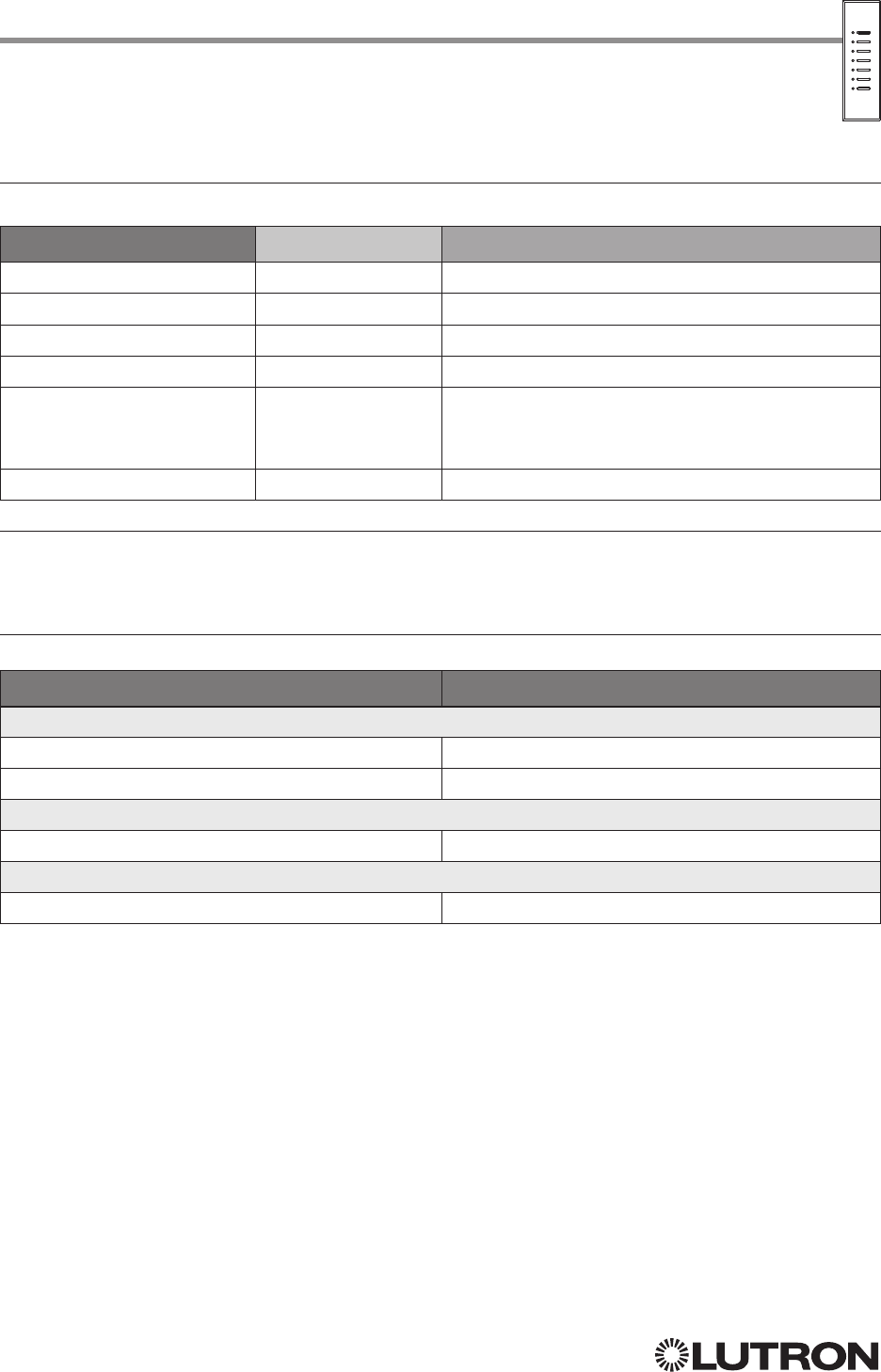
100
Lutron integration protocol
Architrave Keypad (continued)
DEVICE Commands (continued)
DEVICE Command-specific fields (continued)
Action Numbers and Parameters:
Action Action Number Parameters
Set (#) Press or CCI Close 3 None
Set (#) Release or CCI Open 4 None
Set (#) Hold 5 None
Set (#) Multi-tap 6 None
Set (#) or Get (?) LED State
190 = Off
1 = On
2 = Normal-Flash: 1 flash every second
2
3 = Rapid-Flash: 10 flashes every second
2
Set (#) Hold Release
232 None
NOTES
1. Quantum, HomeWorks or myRoom plus only. “Set” is for unprogrammed buttons and buttons with LED logic ‘Defined by
Integration.’
2. Available only on units in a Quantum or HomeWorks system.
Example DEVICE Commands
Examples presume keypad has been assigned Integration ID 2.
Operation Command String
Execute: #DEVICE, Integration ID, Component Number, Action Number, Parameters
Press Button 1. #DEVICE,2,1,3<CR><LF>
Turn On LED 5. #DEVICE,2,85,9,1<CR><LF>
Query: ?DEVICE, Integration ID, Component Number, Action Number
What is the state of LED 1? ?DEVICE,2,81,9<CR><LF>
Response: ~DEVICE, Integration ID, Component Number, Action Number, Parameters
LED 1 is On. ~DEVICE,2,81,9,1<CR><LF>
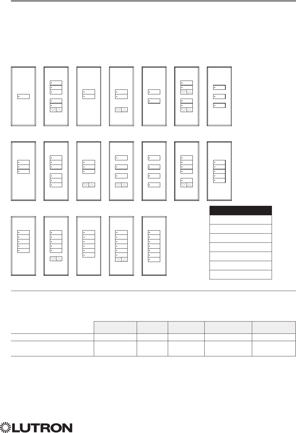
101
Lutron integration protocol
Why Integrate with a Signature Series Keypad?
• Simulate a button press
• Control LEDs of unprogrammed buttons
Compatibility
Signature Series Keypads QS Standalone Quantum RadioRA 2 HomeWorks QS myRoom plus
QS Model
HomeWorks QS /
myRoom Model
Signature Series Keypad
QS Models (QSWAS-): 1B, 1RLD, 2B, 2BRL, 2RLD, 3B, 3BD, 3BRL, 5B, 5BRL, 7B
HomeWorks QS / myRoom Models (HQWAS-B, HQWAS-G) with Faceplate / Button Kit Models (LFS-W):
1B, 1RLD, 2BS, 2RLD, 3BS, 3BD, 3BSRL, 4BS, 4S, 5B, 5BRL, 6B, 6BRL, 7B
1B
3B
5BT
1RLD
3BD
5BRL
2B
3BRL
6B
2BRL
3BSRL
6BRL
2BS
4BS
7B
2RLD
4S
3BS
5B
1
2
3
4
5
6
7
4
1
2
3
5
6
3
4
3
4
3
5
1
2
5
6
2
4
6
2
3
4
1
2
3
5
6
7
2
3
4
1
3
5
1
3
5
7
1
2
3
4
6
2
3
4
5
6
1
2
3
4
5
1
2
3
4
5
1
2
3
4
5
6
1
2
3
4
5
6
Configuration
Button 1
Button 2
Button 3 or Raise/Lower
Button 4
Button 5
Button 6
Button 7 or Raise/Lower

102
Lutron integration protocol
Signature Series Keypad (continued)
DEVICE Commands
DEVICE Command Formats
DEVICE Command-specific fields
Component Numbers:
Component Component Number Available Actions
Button 1 1 Press, Release, Multi Tap, Hold, Hold Release
Button 2 2 Press, Release, Multi Tap, Hold, Hold Release
Button 3 3 Press, Release, Multi Tap, Hold, Hold Release
Button 4 4 Press, Release, Multi Tap, Hold, Hold Release
Button 5 5 Press, Release, Multi Tap, Hold, Hold Release
Button 6 6 Press, Release, Multi Tap, Hold, Hold Release
Button 7 7 Press, Release, Multi Tap, Hold, Hold Release
Button Top Lower 16 Press, Release, Multi Tap, Hold, Hold Release
Button Top Raise 17 Press, Release, Multi Tap, Hold, Hold Release
Button Bottom Lower 18 Press, Release, Multi Tap, Hold, Hold Release
Button Bottom Raise 19 Press, Release, Multi Tap, Hold, Hold Release
CCI 1 25 Press, Release
CCI 2 26 Press, Release
LED 1
181 Set or Get LED state
LED 2
182 Set or Get LED state
LED 3
183 Set or Get LED state
LED 4
184 Set or Get LED state
LED 5
185 Set or Get LED state
LED 6
186 Set or Get LED state
LED 7
187 Set or Get LED state
NOTE
1. Available only on units in a Quantum, HomeWorks, or myRoom systems.
Use “DEVICE Command-specific fields” tables
to complete these command fields.
Operation
Command
Integration ID (example)
#DEVICE, 2, Component Number, Action Number, Parameters
Continued on next page…
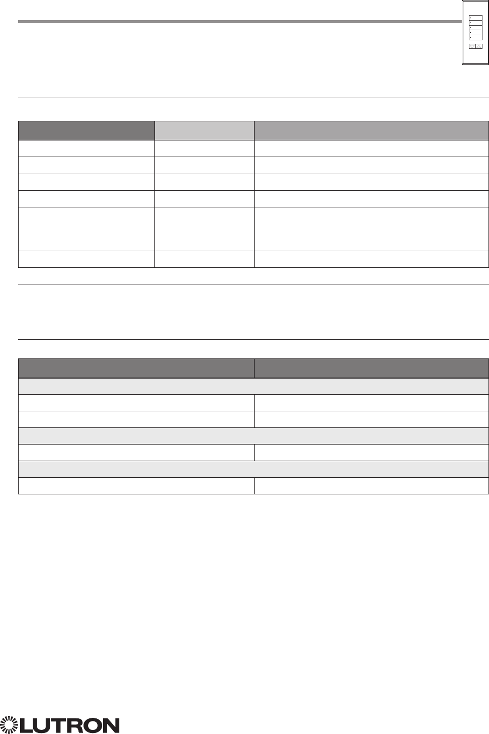
103
Lutron integration protocol
Signature Series Keypad (continued)
DEVICE Commands (continued)
DEVICE Command-specific fields (continued)
Action Numbers and Parameters:
Action Action Number Parameters
Set (#) Press 3 None
Set (#) Release 4 None
Set (#) Hold 5 None
Set (#) Multi-tap 6 None
Set (#) or Get (?) LED State
190 = Off
1 = On
2 = Normal-Flash: 1 flash every second
3 = Rapid-Flash: 10 flashes every second
Set (#) Hold Release
232 None
NOTES
1. Quantum, HomeWorks or myRoom plus only. “Set” is for unprogrammed buttons and buttons with LED logic ‘Defined by
Integration.’
2. Available only on units in a Quantum or HomeWorks system.
Example DEVICE Commands
Examples presume keypad has been assigned Integration ID 2.
Operation Command String
Execute: #DEVICE, Integration ID, Component Number, Action Number, Parameters
Press Button 1. #DEVICE,2,1,3<CR><LF>
Turn On LED 5. #DEVICE,2,85,9,1<CR><LF>
Query: ?DEVICE, Integration ID, Component Number, Action Number
What is the state of LED 1? ?DEVICE,2,81,9<CR><LF>
Response: ~DEVICE, Integration ID, Component Number, Action Number, Parameters
LED 1 is On. ~DEVICE,2,81,9,1<CR><LF>
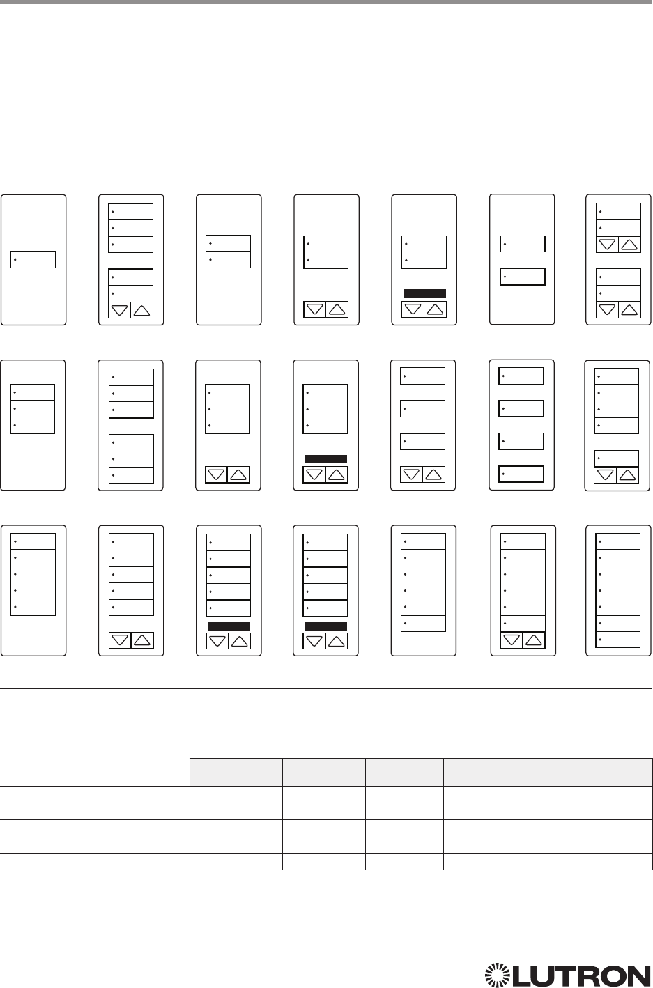
104
Lutron integration protocol
Why Integrate with a seeTouch Keypad?
• Simulate a button press
• Control LEDs of unprogrammed buttons
Compatibility
seeTouch Keypads QS Standalone Quantum RadioRA 2 HomeWorks QS myRoom plus
QS Model
RadioRA 2 Model
HomeWorks QS /
myRoom Model
Clear Connect Device Model
seeTouch Keypad
QS Models (QSWS2-): 1B, 1RLD, 2B, 2BRL, 2BRLIR, 2RLD, 3B, 3BD, 3BRL, 3BRLIR, 5B, 5BRL, 5BRLIR, 7B
RadioRA 2 Models (RRD-W): 1RLD, 2RLD, 3BD, 3BRL, 3BSRL, 4S, 5BRL, 5BRLIR, 6BRL, 7B
HomeWorks QS / myRoom Models (HQRD-W, HQWD-W, HQWA-W, HQRA-W, HQWAS-W):
1B, 1RLD, 2BS, 2RLD, 3BS, 3BD, 3BSRL, 4BS, 4S, 5B, 5BRL, 5BIR, 6B, 6BRL, 7B
Clear Connect Device Models (CCD-W): 6BRL
1B
3B
5B
1RLD
3BD
5BRL
2B
3BRL
5BRLIR
2BRL
3BRLIR
5BIR
2BRLIR
3BSRL
6B
2BS
4BS
6BRL
2RLD
4S
7B
button
1
button
2
button
3
button
4
button
5
button
6
button
7
button
4
button
2
button
3
button
4
button
1
button
2
button
3
button
5
button
6
button
7
button
2
button
3
button
4
button
2
button
3
button
4
button
1
button
3
button
5
button
1
button
3
button
5
button
7
button
1
button
2
button
3
button
4
button
6
button
1
button
2
button
3
button
4
button
5
button
1
button
2
button
3
button
4
button
5
button
1
button
2
button
3
button
4
button
5
button
1
button
2
button
3
button
4
button
5
button
1
button
2
button
3
button
4
button
5
button
6
button
1
button
2
button
3
button
4
button
5
button
6
button
1
button
2
button
3
button
5
button
6
button
3
button
4
button
3
button
4
button
3
button
4
button
3
button
5
button
1
button
2
button
5
button
6
Continued on next page…
105
Lutron integration protocol
seeTouch Keypad (continued)
DEVICE Commands
DEVICE Command Formats
DEVICE Command-specific fields
Component Numbers:
Component Component Number Available Actions
Button 1 1 Press, Release
Button 2 2 Press, Release
Button 3 3 Press, Release
Button 4 4 Press, Release
Button 5 5 Press, Release
Button 6 6 Press, Release
Button 7 7 Press, Release
Button Top Lower 16 Press, Release
Button Top Raise 17 Press, Release
Button Bottom Lower 18 Press, Release
Button Bottom Raise 19 Press, Release
CCI 1 25 Press, Release
CCI 2 26 Press, Release
LED 1
181 Set or Get LED state
LED 2
182 Set or Get LED state
LED 3
183 Set or Get LED state
LED 4
184 Set or Get LED state
LED 5
185 Set or Get LED state
LED 6
186 Set or Get LED state
LED 7
187 Set or Get LED state
NOTE
1. Available only on units in a Quantum, HomeWorks, or myRoom plus system.
Use “DEVICE Command-specific fields” tables
to complete these command fields.
Operation
Command
Integration ID (example)
#DEVICE, 2, Component Number, Action Number, Parameters
106
Lutron integration protocol
seeTouch Keypad (continued)
DEVICE Commands (continued)
DEVICE Command-specific fields (continued)
Action Numbers and Parameters:
Action Action Number Parameters
Set (#) Press or CCI Close 3 None
Set (#) Release or CCI Open 4 None
Set (#) Hold 5 None
Set (#) Multi-tap 6 None
Set (#) or Get (?) LED State
1,2 90 = Off
1 = On
2 = Normal-Flash: 1 flash every second
1
3 = Rapid-Flash: 10 flashes every second
1
NOTES
1. Available only on units in a Quantum, HomeWorks, or myRoom plus system.
2. Quantum, HomeWorks, or myRoom only. “Set” is for unprogrammed buttons and buttons with LED logic
‘Defined by Integration.’
Example DEVICE Commands
Examples presume keypad has been assigned Integration ID 2.
Operation Command String
Execute: #DEVICE, Integration ID, Component Number, Action Number, Parameters
Press Button 1. #DEVICE,2,1,3<CR><LF>
Turn On LED 5. #DEVICE,2,85,9,1<CR><LF>
Query: ?DEVICE, Integration ID, Component Number, Action Number
What is the state of LED 1? ?DEVICE,2,81,9<CR><LF>
Response: ~DEVICE, Integration ID, Component Number, Action Number, Parameters
LED 1 is On. ~DEVICE,2,81,9,1<CR><LF>
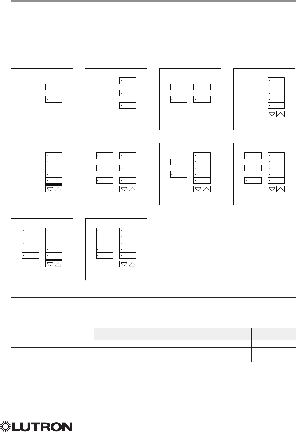
107
Lutron integration protocol
Why Integrate with a seeTouch QS Keypad?
• Simulate a button press
• Control LEDs of unprogrammed buttons
Compatibility
seeTouch QS Keypads (Int’l) QS Standalone Quantum RadioRA 2 HomeWorks QS myRoom plus
QS Model
HomeWorks QS /
myRoom Model
seeTouch QS Keypad (International)
QS Models (QSWE-): 2B, 3B, 4B, 5BRL, 5BRLIR, 6BRL, 7BRL, 8BRL, 8BRLIR, 10BRL
HomeWorks QS / myRoom Models (HWQIS-NB-NONE) with Faceplate / Button Kit Models (LFS-W):
2B, 3B, 4B, 5BRL, 5BRLIR, 6BRL, 7BRL, 8BRL, 8BRLIR, 10BRL
2B
5BRLIR
8BRLIR
3B
6BRL
10BRL
4B
7BRL
5BRL
8BRL
button
6
button
7
button
8
button
9
button
10
button
1
button
2
button
3
button
4
button
5
Lower Raise
button
6
button
7
button
8
button
9
button
10
button
1
button
3
button
5
Lower Raise
button
6
button
7
button
8
button
9
button
10
Lower Raise
button
6
button
8
button
10
button
1
button
3
button
5
Lower Raise
button
6
button
7
button
8
button
9
button
10
button
2
button
4
Lower Raise
button
7
button
9
button
6
button
8
button
10
button
7
button
9
button
2
button
4
button
6
button
7
button
8
button
9
button
10
button
1
button
3
button
5
Lower Raise
button
6
button
7
button
8
button
9
button
10
Lower Raise

108
Lutron integration protocol
seeTouch QS Keypad (International) (continued)
DEVICE Commands
DEVICE Command Formats
DEVICE Command-specific fields
Component Numbers:
Component Component Number Available Actions
Button 1 1 Press, Release, Multi Tap, Hold, Hold Release
Button 2 2 Press, Release, Multi Tap, Hold, Hold Release
Button 3 3 Press, Release, Multi Tap, Hold, Hold Release
Button 4 4 Press, Release, Multi Tap, Hold, Hold Release
Button 5 5 Press, Release, Multi Tap, Hold, Hold Release
Button 6 6 Press, Release, Multi Tap, Hold, Hold Release
Button 7 7 Press, Release, Multi Tap, Hold, Hold Release
Button 8 8 Press, Release, Multi Tap, Hold, Hold Release
Button 9 9 Press, Release, Multi Tap, Hold, Hold Release
Button 10 10 Press, Release, Multi Tap, Hold, Hold Release
Lower 18 Press, Release, Multi Tap, Hold, Hold Release
Raise 19 Press, Release, Multi Tap, Hold, Hold Release
CCI 1 25 Press, Release
CCI 2 26 Press, Release
LED 1181 Set or Get LED state
LED 2182 Set or Get LED state
LED 3183 Set or Get LED state
LED 4184 Set or Get LED state
LED 5185 Set or Get LED state
LED 6186 Set or Get LED state
LED 7187 Set or Get LED state
LED 8188 Set or Get LED state
LED 9189 Set or Get LED state
LED 10190 Set or Get LED state
NOTE
1. Not supported in QS Standalone.
Use “DEVICE Command-specific fields” tables
to complete these command fields.
Operation
Command
Integration ID (example)
#DEVICE, 2, Component Number, Action Number, Parameters
Continued on next page…
109
Lutron integration protocol
seeTouch QS Keypad (International) (continued)
DEVICE Commands (continued)
DEVICE Command-specific fields (continued)
Action Numbers and Parameters:
Action Action Number Parameters
Set (#) Press or CCI Close 3 None
Set (#) Release or CCI Open 4 None
Set (#) Hold 5 None
Set (#) Multi-tap 6 None
Set (#) or Get (?) LED State
190 = Off
1 = On
2 = Normal-Flash: 1 flash every sec
3 = Rapid-Flash: 10 flashes every sec
Set (#) Hold Release232 None
NOTES
1. “Set” is for unprogrammed buttons and buttons with LED logic ‘Defined by Integration.’
2. Not supported in QS Standalone.
Example DEVICE Commands
Examples presume keypad has been assigned Integration ID 2.
Operation Command String
Execute: #DEVICE, Integration ID, Component Number, Action Number, Parameters
Press Button 1. #DEVICE,2,1,3<CR><LF>
Turn On LED 5. #DEVICE,2,85,9,1<CR><LF>
Query: ?DEVICE, Integration ID, Component Number, Action Number
What is the state of LED 1? ?DEVICE,2,81,9<CR><LF>
Response: ~DEVICE, Integration ID, Component Number, Action Number, Parameters
LED 1 is On. ~DEVICE,2,81,9,1<CR><LF>
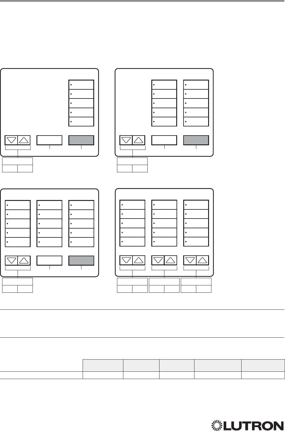
110
Lutron integration protocol
Why Integrate with a Tabletop seeTouch Keypad?
• Simulate a button press
• Control LEDs of unprogrammed buttons
Additional Commands
• None
Compatibility
QS Standalone Quantum RadioRA 2 HomeWorks QS myRoom plus
Tabletop seeTouch Keypad
Tabletop seeTouch Keypad
RadioRA 2 Models (RR-): T 5RL, T10RL, T15RL
HomeWorks QS Models (HQR-, HQK-, HQQ-, HQM-, HQN-):
T5RL, T10RL, T15RL, T5CRL, T10CRL, T15CRL
T5-RL T10-RL
T15-RL T15-CRL
button 11
button 12
button 13
button 14
button 15
button 11
button 12
button 13
button 14
button 15
button 6
button 7
button 8
button 9
button 10
button 6
button 7
button 8
button 9
button 10
button 6
button 7
button 8
button 9
button 10
button 1
button 2
button 3
button 4
button 5
button 1
button 2
button 3
button 4
button 5
button 1
button 2
button 3
button 4
button 5
button 1
button 2
button 3
button 4
button 5
Column 3
Lower Raise
Column 3
Lower Raise
Column 3
Lower Raise
Column 3
Lower Raise
Column 2
Lower Raise
Column 1
Lower Raise
button 17
All ON
button 17
All ON
button 17
All ON
button 16
All OFF
button 16
All OFF
button 16
All OFF
Continued on next page…

111
Lutron integration protocol
Tabletop seeTouch Keypad (continued)
DEVICE Commands
DEVICE Command Formats
DEVICE Command-specific fields
Component Numbers:
Component Component Number Available Actions
Button 1 1 Press, Release
Button 2 2 Press, Release
Button 3 3 Press, Release
Button 4 4 Press, Release
Button 5 5 Press, Release
Button 6 6 Press, Release
Button 7 7 Press, Release
Button 8 8 Press, Release
Button 9 9 Press, Release
Button 10 10 Press, Release
Button 11 11 Press, Release
Button 12 12 Press, Release
Button 13 13 Press, Release
Button 14 14 Press, Release
Button 15 15 Press, Release
Button 16 16 Press, Release
Button 17 17 Press, Release
Column 1: Lower 20 Press, Release
Column 1: Raise 21 Press, Release
Column 2: Lower 22 Press, Release
Column 2: Raise 23 Press, Release
Column 3: Lower 24 Press, Release
Column 3: Raise 25 Press, Release
Use “DEVICE Command-specific fields” tables
to complete these command fields.
Operation
Command
Integration ID (example)
#DEVICE, 3, Component Number, Action Number, Parameters
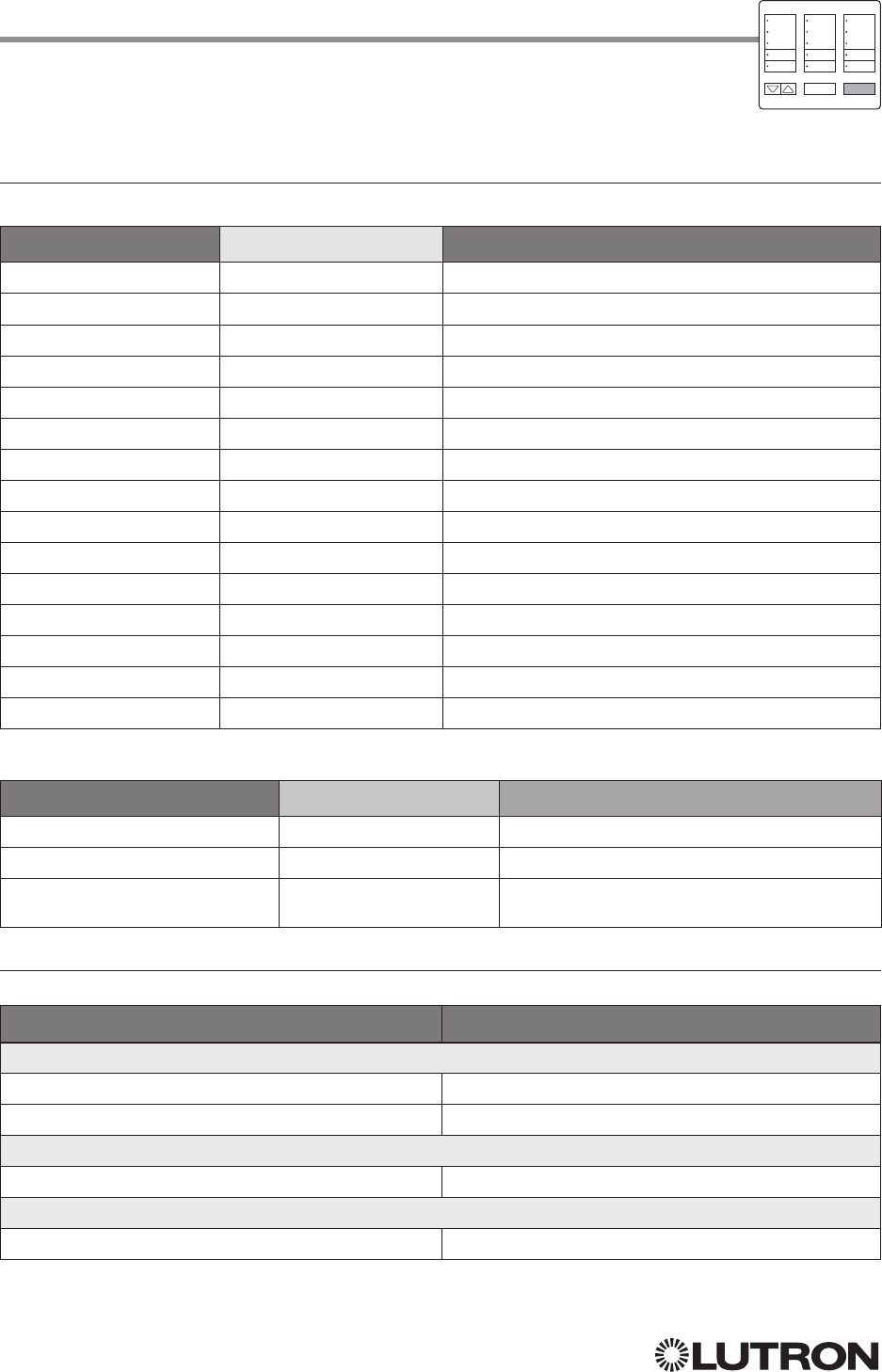
112
Lutron integration protocol
Tabletop seeTouch Keypad (continued)
DEVICE Commands (continued)
DEVICE Command-specific fields (continued)
Component Numbers (continued):
Component Component Number Available Actions
LED 1 81 Set or Get LED state
LED 2 82 Set or Get LED state
LED 3 83 Set or Get LED state
LED 4 84 Set or Get LED state
LED 5 85 Set or Get LED state
LED 6 86 Set or Get LED state
LED 7 87 Set or Get LED state
LED 8 88 Set or Get LED state
LED 9 89 Set or Get LED state
LED 10 90 Set or Get LED state
LED 11 91 Set or Get LED state
LED 12 92 Set or Get LED state
LED 13 93 Set or Get LED state
LED 14 94 Set or Get LED state
LED 15 95 Set or Get LED state
Action Numbers and Parameters:
Action Action Number Parameters
Set (#) Press 3 None
Set (#) Release 4 None
Set (#) or Get (?) LED State
Set is for unprogrammed LEDs only
90 = Off
1 = On
Example DEVICE Commands
Examples presume keypad has been assigned Integration ID 3.
Operation Command String
Execute: #DEVICE, Integration ID, Component Number, Action Number, Parameters
Press Button 1. #DEVICE,3,1,3<CR><LF>
Turn On LED 1. #DEVICE,3,81,9,1<CR><LF>
Query: ?DEVICE, Integration ID, Component Number, Action Number
What is the state of LED 1? ?DEVICE,3,81,9<CR><LF>
Response: ~DEVICE, Integration ID, Component Number, Action Number, Parameters
LED 1 is On. ~DEVICE,3,81,9,1<CR><LF>
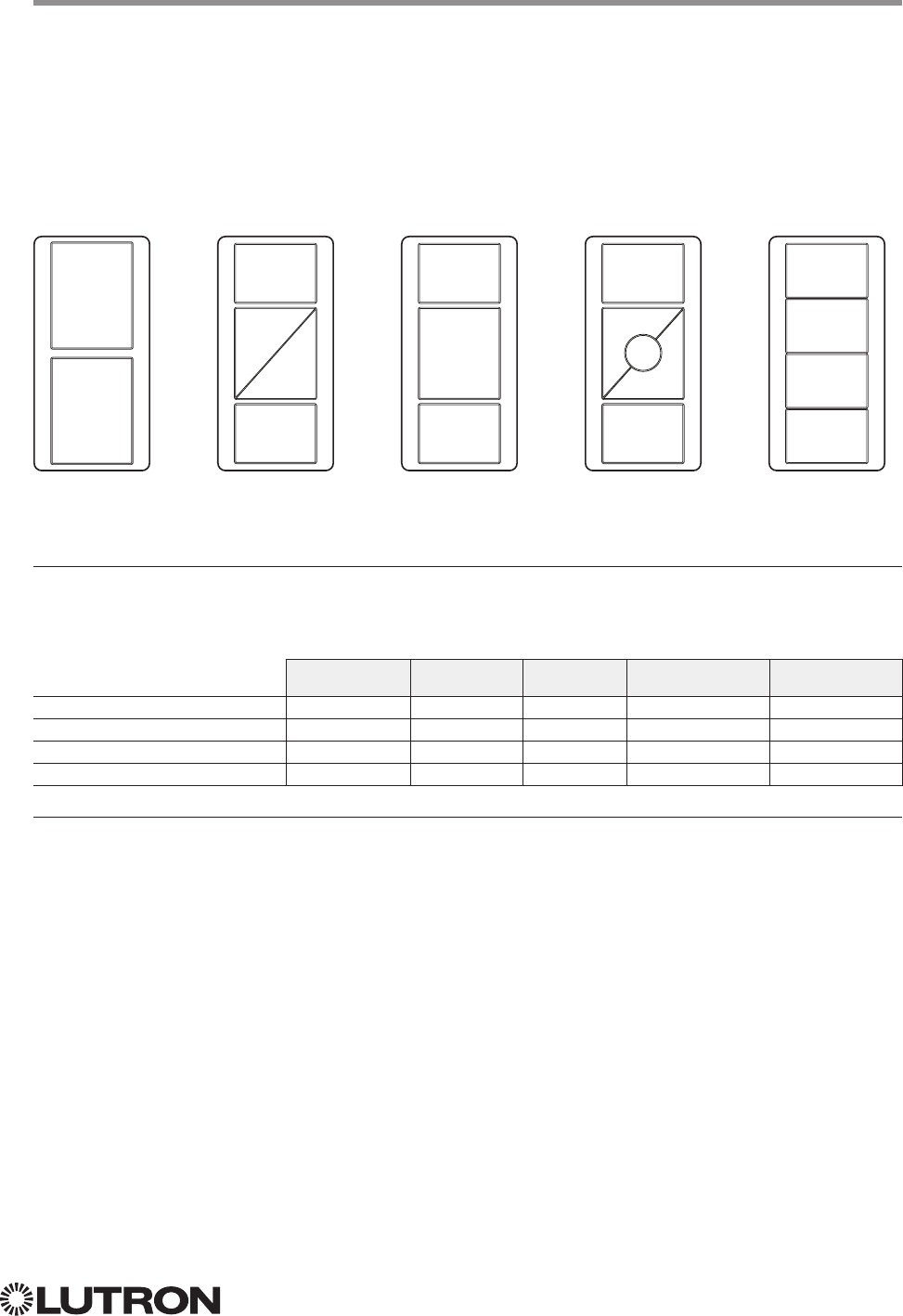
113
Lutron integration protocol
Why Integrate with a Pico Wireless Control?
• Simulate a button press
• Monitor button presses
Compatibility
QS Standalone Quantum RadioRA 2 HomeWorks QS myRoom plus
QS Model 12
RadioRA 2 Model
Pico PJ- Model 12,3
Pico PJ2- Model 12,3
NOTES
1. In QS Standalone systems, the Pico is integrated through its associated QSM. Refer to the QS Sensor Module (QSM)
section.
2. Can be used only when associated to a QSM.
3. PJ2-4B is supported only on QSM software version 7.28 and higher.
Pico Wireless Control
CURRENT Models: PJ-2B, PJ-2BRL, PJ-3B, PJ-3BRL, PJ2-2B, PJ2-2BRL, PJ2-3B, PJ2-3BRL, PJ2-4B
LEGACY Models:
QS Models (QSR4P-, QSR8P-, QSRKP-, QSRMP-): 2, 2R, 3R
RadioRA 2 Models (RRD- P): 3BRL-L, 3BRL-S
2B 2BRL 3B 3BRL 4B
Button 1
Button 1
Button 2
Button 3
Button 1 Button 1 Button 1
Button 2
Button 3
Button 4
Button
Raise
Button
Raise
Button
2
Button
Lower Button
Lower
Button 3 Button 3
Button 3
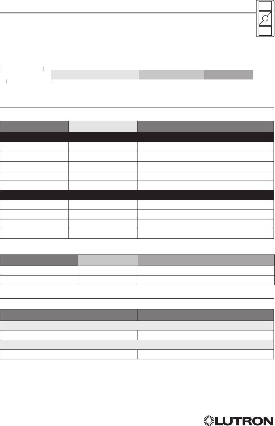
114
Lutron integration protocol
Pico Wireless Control (continued)
DEVICE Commands
DEVICE Command Formats
DEVICE Command-specific fields
Component Numbers:
Component Component Number Available Actions
For all Legacy models and all Current models except for PJ2-4B
Button 1 2 Press, Release
Button 2 3 Press, Release
Button 3 4 Press, Release
Button Raise 5 Press, Release
Button Lower 6 Press, Release
For PJ2-4B model only
Button 1 8 Press, Release
Button 2 9 Press, Release
Button 3 10 Press, Release
Button 4 11 Press, Release
Action Numbers and Parameters:
Action Action Number Parameters
Set (#) Press 3 None
Set (#) Release 4 None
Example DEVICE Commands
Examples presume Pico control has been assigned Integration ID 2.
Operation Command String
Execute: #DEVICE, Integration ID, Component Number, Action Number, Parameters
Press Button 1 (on a non-4B model). #DEVICE,2,2,3<CR><LF>
Response: ~DEVICE, Integration ID, Component Number, Action Number, Parameters
Button 1 was pressed. ~DEVICE,2,2,3<CR><LF>
Use “DEVICE Command-specific fields” tables
to complete these command fields.
Operation
Command
Integration ID (example)
#DEVICE, 2, Component Number, Action Number, Parameters
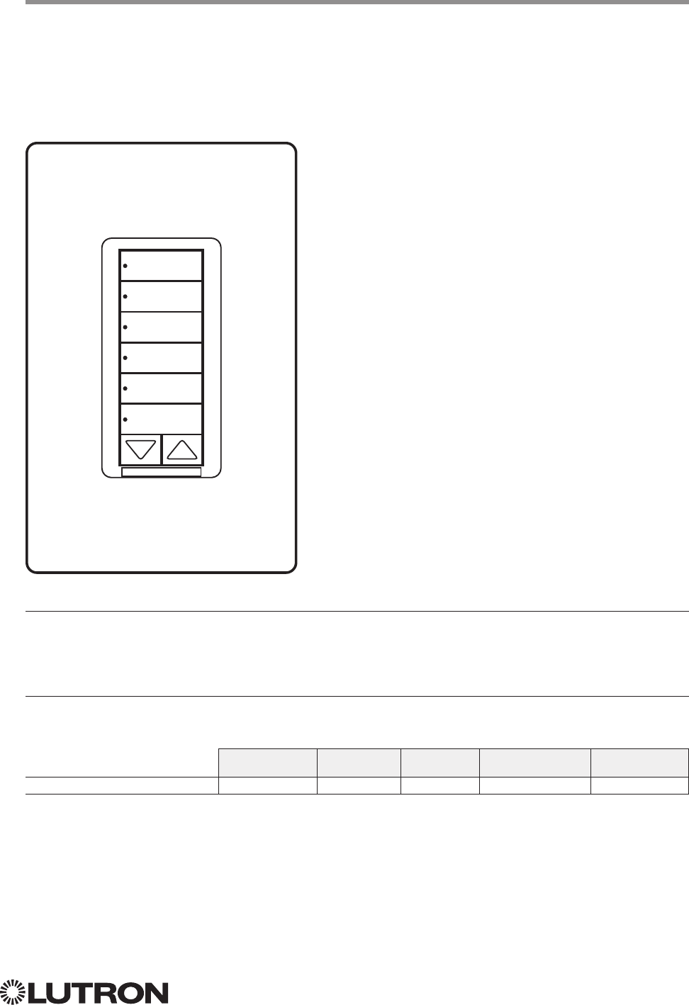
115
Lutron integration protocol
Hybrid Keypad
RadioRA 2 Models (RRD-H): 1RLD, 2RLD, 3BSRL, 4S, 5BRL, 6BRL
HomeWorks QS Models (HQRD-H): 1RLD, 2RLD, 3BSRL, 4S, 5BRL, 6BRL
Why Integrate with a Hybrid Keypad?
• Turn On to specific light level or Off
• Raise / Lower light level
• Query current light level
Additional Commands
• None
Compatibility
QS Standalone Quantum RadioRA 2 HomeWorks QS myRoom plus
Hybrid Keypad
H6BRL
116
Lutron integration protocol
Hybrid Keypad (continued)
OUTPUT Commands
OUTPUT Command Format
OUTPUT Command-specific fields
Action Numbers and Parameters:
Action Action Number Parameters
Set (#) or Get (?) Zone Level 1 Level = 0 –100 or 0.00 –100.00
Fade
1 in: SS.ss
2, SS, MM:SS, or HH:MM:SS
Delay
1 in: SS.ss
2, SS, MM:SS, or HH:MM:SS
Set (#) Start Raising 2 None
Set (#) Start Lowering 3 None
Set (#)
Stop Raising or
Lowering
4 None
Set (#) Start Flashing
3, 4, 5 5 Fade
1 in: SS.ss
2, SS, MM:SS, or HH:MM:SS
Delay
1 in: SS.ss
2, SS, MM:SS, or HH:MM:SS
NOTES
1. The Fade and Delay time are optional. When not used, the system will use a one-second fade time with zero-second delay.
2. Fractional seconds “SS.ss” will be rounded down to the nearest quarter second. For example, if a fade time is specified
as 1.31 seconds a value of 1.25 seconds will be used.
3. The system will not report a level while the output is flashing, it will instead report that it is flashing.
4. Default flash every second, unless fade time is specified (flash period is 2× fade time).
5. To stop a dimmer from flashing, send it to a valid level.
Example OUTPUT Commands
Examples presume dimmer has been assigned Integration ID 1.
Operation Command String
Execute: #OUTPUT, Integration ID, Action Number, Parameters
Set dimmer to 75% with a 1 min 30 sec fade. #OUTPUT,1,1,75,01:30<CR><LF>
Start Raising dimmer level. #OUTPUT,1,2<CR><LF>
Stop Raising / Lowering dimmer level. #OUTPUT,1,4<CR><LF>
Start Flashing a dimmer. #OUTPUT,1,5<CR><LF>
Start Flashing a dimmer once every 2 seconds. #OUTPUT,1,5,1<CR><LF>
Query: ?OUTPUT, Integration ID, Action Number
What is the state of the output? ?OUTPUT,1,1<CR><LF>
Response
1, 2: ~OUTPUT, Integration ID, Action Number, Parameters
Output level is set to 90%. ~OUTPUT,1,1,90.00<CR><LF>
NOTES
1. The system will report the target level of a dimmer while it is fading from one level to another.
The actual level is not transmitted while dimming between levels.
Example: If the “Over Sink” (1) dimmer is at 20% and is then commanded to go to 100% by sending
#OUTPUT,1,1,100,
the response from the system will be ~OUTPUT,1,1,100.00
2. The system will not report a level while the output is flashing, it will instead report that it is flashing.
Use “OUTPUT Command-specific fields” tables
to complete these command fields.
Operation
Command
Integration ID (example)
#OUTPUT, 1, Action Number, Parameters
Continued on next page…

117
Lutron integration protocol
Hybrid Keypad (continued)
DEVICE Commands
DEVICE Command-specific fields
Component Numbers:
Component Component Number Available Actions
Button 1 1 Press, Release
Button 2 2 Press, Release
Button 3 3 Press, Release
Button 4 4 Press, Release
Button 5 5 Press, Release
Button 6 6 Press, Release
Button 7 7 Press, Release
Button Top Lower 16 Press, Release
Button Top Raise 17 Press, Release
Button Bottom Lower 18 Press, Release
Button Bottom Raise 19 Press, Release
LED 1 81 Set or Get LED state
LED 2 82 Set or Get LED state
LED 3 83 Set or Get LED state
LED 4 84 Set or Get LED state
LED 5 85 Set or Get LED state
LED 6 86 Set or Get LED state
LED 7 87 Set or Get LED state
DEVICE Command Formats
Use “DEVICE Command-specific fields” tables
to complete these command fields.
Operation
Command
Integration ID (example)
#DEVICE, 2, Component Number, Action Number, Parameters
118
Lutron integration protocol
Hybrid Keypad (continued)
DEVICE Commands (continued)
DEVICE Command-specific fields (continued)
Action Numbers and Parameters:
Action Action Number Parameters
Set (#) Press 3 None
Set (#) Release 4 None
Set (#) or Get (?) LED State 9 0 = Off
1 = On
2 = Normal-Flash: 1 flash every second
1
3 = Rapid-Flash: 10 flashes every second
1
NOTE
1. “Set” is for LEDs on unprogrammed buttons and buttons with LED logic ‘Defined by Integration.’
Example DEVICE Commands
Examples presume keypad has been assigned Integration ID 2.
Operation Command String
Execute: #DEVICE, Integration ID, Component Number, Action Number, Parameters
Press Button 1. #DEVICE,2,1,3<CR><LF>
Turn On LED 5. #DEVICE,2,85,9,1<CR><LF>
Query: ?DEVICE, Integration ID, Component Number, Action Number
What is the state of LED 1? ?DEVICE,2,81,9<CR><LF>
Response: ~DEVICE, Integration ID, Component Number, Action Number, Parameters
LED 1 is On. ~DEVICE,2,81,9,1<CR><LF>
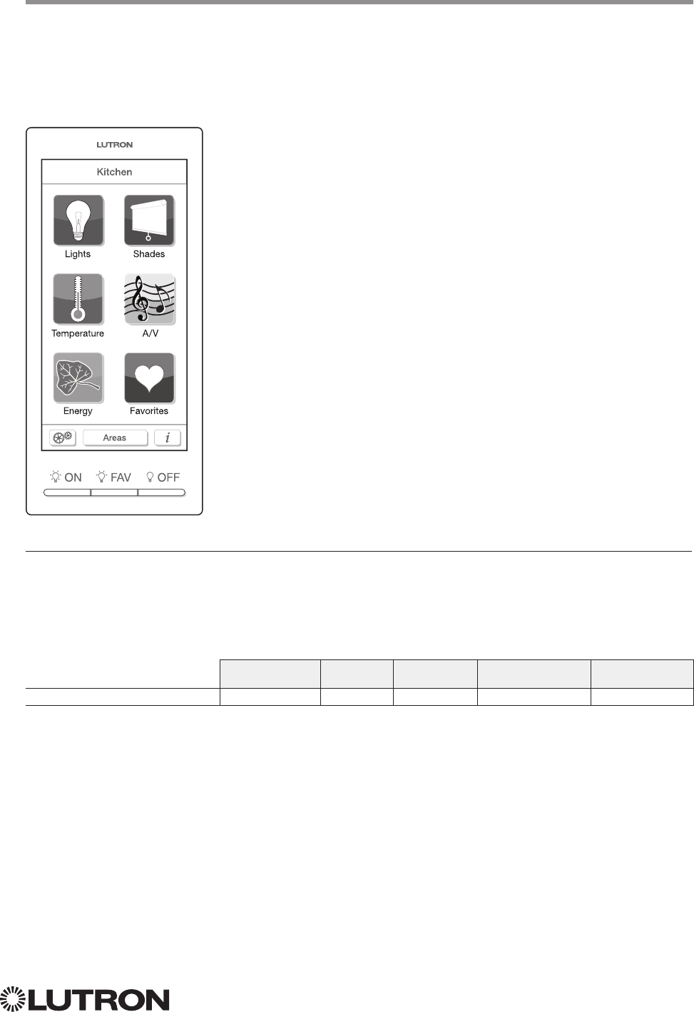
119
Lutron integration protocol
Why Integrate with a Dynamic Keypad?
• Recognize a button press / release in order to control a third party device from the Dynamic Keypad’s
user interface
• Simulate a button press
• Control LEDs of unprogrammed buttons
Compatibility
QS Standalone Quantum RadioRA 2 HomeWorks QS myRoom plus
Dynamic Keypad
Dynamic Keypad
Model: HQ-J-DK420
HQ-J-DK420
120
Lutron integration protocol
Dynamic Keypad (continued)
DEVICE Commands
DEVICE Command Formats
DEVICE Command-specific fields
Component Numbers:
Component Component Number Available Actions
Button 1 (left hard button) 1 Press, Release
Button 2 (middle hard button) 2 Press, Release
Button 3 (right hard button) 3 Press, Release
Button N 1 N Press, Release
LED M 1 M Set or Get LED state
NOTE
1. Component Numbers for the various pages of buttons and LEDs for a Dynamic Keypad are generated by the
HomeWorks QS or myRoom Software.
Action Numbers and Parameters:
Action Action Number Parameters
Set (#) Press 3 None
Set (#) Release 4 None
Set (#) Hold 5 None
Set (#) Multi-tap 6 None
Set (#) or Get (?) LED State 9 0 = Off
1 = On
2 = Normal-Flash
3 = Rapid-Flash
Example DEVICE Commands
Examples presume the Dynamic Keypad has been assigned Integration ID 23.
Operation Command String
Execute: #DEVICE, Integration ID, Component Number, Action Number, Parameters
Press Button 118. #DEVICE,23,118,3<CR><LF>
Turn On LED 566. #DEVICE,23,566,9,1<CR><LF>
Query: ?DEVICE, Integration ID, Component Number, Action Number
What is the state of LED 566? ?DEVICE,23,566,9<CR><LF>
Response: ~DEVICE, Integration ID, Component Number, Action Number, Parameters
LED 1 is On. ~DEVICE,23,566,9,1<CR><LF>
Use “DEVICE Command-specific fields” tables
to complete these command fields.
Operation
Command
Integration ID (example)
#DEVICE, 2, Component Number, Action Number, Parameters
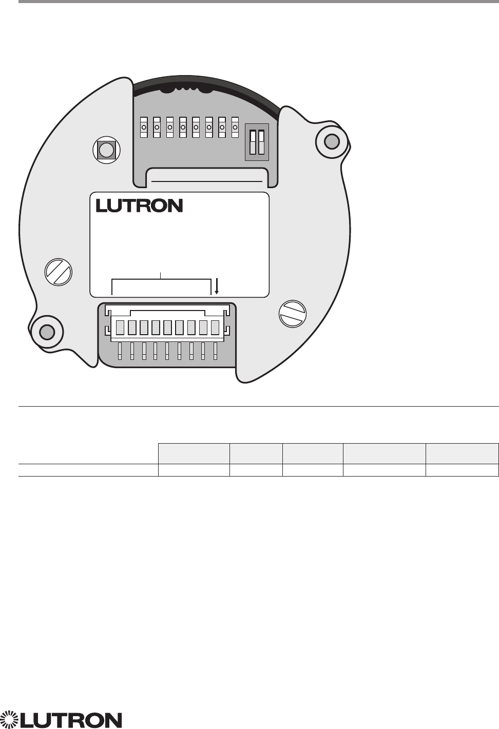
121
Lutron integration protocol
Why Integrate with a Wallbox Input Closure Interface?
• Simulate a button press
Compatibility
QS Standalone Quantum RadioRA 2 HomeWorks QS myRoom plus
Wallbox Input Closure Interface
Wallbox Input Closure Interface
Model: QSE-CI-WCI
ON
12
1 2 3 4 5 6 7 8
1 2 3 4 5 6 7 8
COM
QSE-CI-WCI
INPUTS
ENTRADA
ENTRÉES

122
Lutron integration protocol
Wallbox Input Closure Interface (continued)
DEVICE Commands
DEVICE Command Formats
DEVICE Command-specific fields
Component Numbers:
Component Component Number Available Actions
Button 1 1 Press, Release, Multi Tap, Hold, Hold Release
Button 2 2 Press, Release, Multi Tap, Hold, Hold Release
Button 3 3 Press, Release, Multi Tap, Hold, Hold Release
Button 4 4 Press, Release, Multi Tap, Hold, Hold Release
Button 5 5 Press, Release, Multi Tap, Hold, Hold Release
Button 6 6 Press, Release, Multi Tap, Hold, Hold Release
Button 7 7 Press, Release, Multi Tap, Hold, Hold Release
Button 8 8 Press, Release, Multi Tap, Hold, Hold Release
LED 1181 Set or Get LED state
LED 2182 Set or Get LED state
LED 3183 Set or Get LED state
LED 4184 Set or Get LED state
LED 5185 Set or Get LED state
LED 6186 Set or Get LED state
LED 7187 Set or Get LED state
LED 8188 Set or Get LED state
NOTE
1. Available only on units in a Quantum, HomeWorks, or myRoom plus system.
Use “DEVICE Command-specific fields” tables
to complete these command fields.
Operation
Command
Integration ID (example)
#DEVICE, 2, Component Number, Action Number, Parameters
ON
12
1 2 3 4 5 6 7 8
1 2 3 4 5 6 7 8
COM
QSE-CI-WCI
INPUTS
ENTRADA
ENTRÉES
Continued on next page…
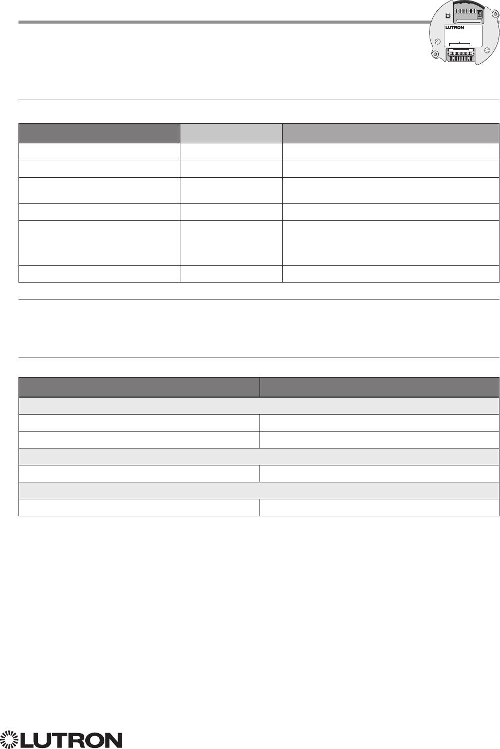
123
Lutron integration protocol
Wallbox Input Closure Interface (continued)
DEVICE Commands (continued)
DEVICE Command-specific fields (continued)
Action Numbers and Parameters:
Action Action Number Parameters
Set (#) Press 3 None
Set (#) Release 4 None
Set (#) Hold (only if input mode is
Momentary)
5 None
Set (#) Multi-tap 6 None
Set (#) or Get (?) LED State
190 = Off
1 = On
2 = Normal-Flash: 1 flash every second
2
3 = Rapid-Flash: 10 flashes every second
2
Set (#) Hold Release232 None
NOTES
1. Quantum, HomeWorks, or myRoom plus only. “Set” is for unprogrammed buttons and buttons with LED logic ‘Defined
by Integration.’
2. Available only on units in a Quantum, HomeWorks, or myRoom plus system.
Example DEVICE Commands
Examples presume keypad has been assigned Integration ID 2.
Operation Command String
Execute: #DEVICE, Integration ID, Component Number, Action Number, Parameters
Press Button 1. #DEVICE,2,1,3<CR><LF>
Turn On LED 5. #DEVICE,2,85,9,1<CR><LF>
Query: ?DEVICE, Integration ID, Component Number, Action Number
What is the state of LED 1? ?DEVICE,2,81,9<CR><LF>
Response: ~DEVICE, Integration ID, Component Number, Action Number, Parameters
LED 1 is On. ~DEVICE,2,81,9,1<CR><LF>
ON
12
1 2 3 4 5 6 7 8
1 2 3 4 5 6 7 8
COM
QSE-CI-WCI
INPUTS
ENTRADA
ENTRÉES
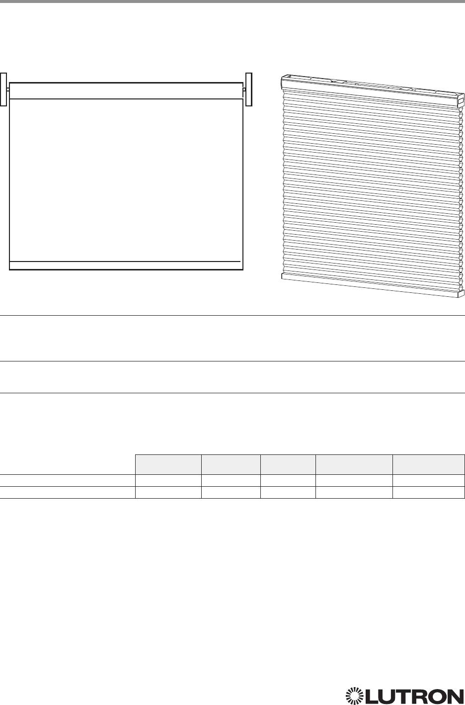
124
Lutron integration protocol
Sivoia QS Shade
Sivoia QS Wireless Shade
Why Integrate with a Sivoia QS Shade?
• Set shades to a specific level
• Query current level
Integration Capabilities
• One controllable output (use OUTPUT command)
Supported Command Types
• OUTPUT allows control and monitoring of the shade output
• SHADEGRP allows control of shade groups in a Quantum or HomeWorks QS system. Shade
Groups are collections of shades that operate in unison.
Compatibility
QS Standalone Quantum RadioRA 2 HomeWorks QS myRoom plus
Sivoia QS Shade
Sivoia QS Wireless Shade
Includes all roller, cellular, and drapery styles
Continued on next page…
125
Lutron integration protocol
Sivoia QS Shade (continued)
OUTPUT Commands
OUTPUT Command Format
OUTPUT Command-specific fields
Action Numbers and Parameters:
Action Action Number Parameters
Set (#) or Get (?) Zone Level 1 Level
1 = 0 –100 or 0.00 –100.00 2
Fade
3 in: SS.ss
4, SS, MM:SS, or HH:MM:SS
Delay
5 in: SS.ss
4, SS, MM:SS, or HH:MM:SS
Set (#) Start Raising 2 None
Set (#) Start Lowering 3 None
Set (#)
Stop Raising or
Lowering
4 None
NOTES
1. For shades, a level of 0 (or 0.00) equals closed, and a level of 100 (or 100.00) equals full open.
2. 0% = Closed; 100% = Open
3. Fade is not available for shades since they move at a constant rate. The parameter must be entered but is ignored.
4. Fractional seconds “SS.ss” will be rounded down to the nearest quarter second. For example, if a delay time is specified
as 1.45 seconds a value of 1.25 seconds will be used.
5. The Delay time is optional. When not used, the system will use a zero-second delay. The minimum delay time is
0.25seconds. The maximum delay time is 4 hours. Not supported in QS Standalone.
Example OUTPUT Messages
Examples presume shade has been assigned Integration ID 1.
Operation Command String
Execute: #OUTPUT, Integration ID, Action Number, Parameters
Set shade to 75% with a 1 min 30 sec delay. #OUTPUT,1,1,75,0,1:30<CR><LF>
Start Raising shade level. #OUTPUT,1,2<CR><LF>
Stop Raising / Lowering shade level. #OUTPUT,1,4<CR><LF>
Query: ?OUTPUT, Integration ID, Action Number
What is the state of the output? ?OUTPUT,1,1<CR><LF>
Response
1: ~OUTPUT, Integration ID, Action Number, Parameters
Output level is set to 90%. ~OUTPUT,1,1,90.00<CR><LF>
NOTE
1. The system will report the target level of a shade. The actual level is not transmitted while they are moving.
Example: If the Living Room Blackouts (Integration ID 1) are at 20% and are commanded to go to 100% by sending
#OUTPUT,1,1,100, the response from the system will be ~OUTPUT,1,1,100.00
Use “OUTPUT Command-specific fields” tables
to complete these command fields.
Operation
Command
Integration ID (example)
#OUTPUT, 1, Action Number, Parameters

126
Lutron integration protocol
SHADEGRP Command Formats
SHADEGRP Command-specific fields
Action Numbers and Parameters:
Action Action Number Parameters
Set (#) or Get (?) Shade
Group Level
11 Level
2 = 0 –100 or 0.00 –100.00
Delay
2 in: SS.ss
3, SS, MM:SS, or HH:MM:SS
Set (#) Start Raising
42 None
Set (#) Start Lowering
43 None
Set (#) Stop Raising or
Lowering
4 None
Set (#) or Get (?)
Current Preset
6Preset Number
5 = 0 –30
Set (#) Tilt Level 14 Level
6 = 0 –100 or 0.00 –100.00
Fade
2 in: SS.ss
3, SS, MM:SS, or HH:MM:SS
Delay
2 in: SS.ss
3, SS, MM:SS, or HH:MM:SS
Set (#) Lift and Tilt Levels 15 Lift
6 = 0 –100 or 0.00 –100.00
Tilt
6 = 0 –100 or 0.00 –100.00
Fade
2 in: SS.ss
3, SS, MM:SS, or HH:MM:SS
Delay
2 in: SS.ss
3, SS, MM:SS, or HH:MM:SS
Set (#) Start Raising Tilt
416 None
Set (#) Start Lowering Tilt
417 None
Set (#) Stop Raising or
Lowering Tilt
418 None
Set (#) Start Raising Lift
419 None
Set (#) Start Lowering Lift
420 None
Set (#) Stop Raising or
Lowering Lift
421 None
NOTES
1. Get (?) Shade Group Level (action number 1).
2. The Fade and Delay time are optional. For shades, the Fade parameter has no effect (since shades have fixed speeds)
but it is required when specifying an optional delay. When not used, the system will use a zero-second delay. The
minimum fade and delay time is 0 seconds. The maximum fade and delay time is 4 hours.
3. Fractional seconds “SS.ss” will be rounded down to the nearest quarter second. For example, if a delay time is specified
as 1.45 seconds, a value of 1.25 seconds will be used.
4. When a Raise / Lower command is issued, the shade group’s level will continue to go towards open / close until a Stop
command is received.
5. Preset 0 is the Open Preset and Preset 30 is the Closed Preset.
6. The Level is accepted as a percentage, where 100% is fully open and 0% is fully closed.
Use “SHADEGRP Command-specific fields” tables
to complete these command fields.
Operation
Command
Integration ID (example)
#SHADEGRP, 2, Action Number, Parameters
Sivoia QS Shade (continued)
OUTPUT Commands (continued)
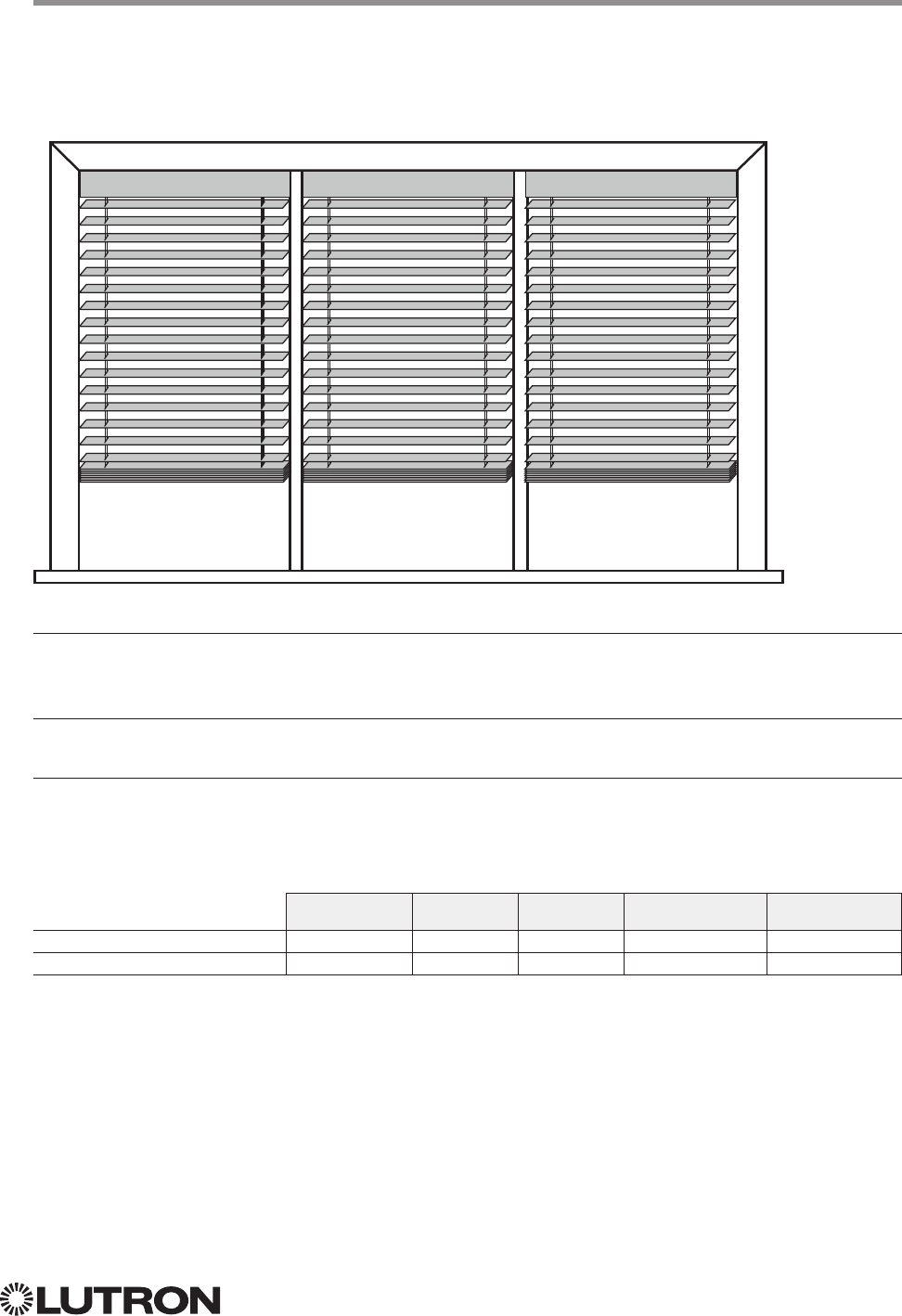
127
Lutron integration protocol
Sivoia QS Venetian Blind
Sivoia QS Wireless Venetian Blind
Why Integrate with a Sivoia QS Venetian Blind?
• Set Venetian blind tilt, lift to specific levels
• Query current tilt, lift levels
Integration Capabilities
• One controllable output (use OUTPUT command)
Supported Command Types
• OUTPUT allows control and monitoring of the Venetian blind output
• SHADEGRP allows control of shade groups in a HomeWorks QS system.
Shade Groups are collections of shades that operate in unison
Compatibility
QS Standalone Quantum RadioRA 2 HomeWorks QS myRoom plus
Sivoia QS Venetian Blind
Sivoia QS Wireless Venetian Blind
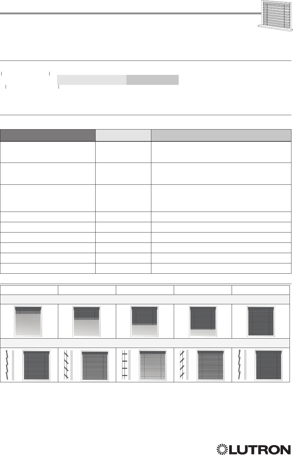
128
Lutron integration protocol
Sivoia QS Venetian Blind (continued)
OUTPUT Commands
OUTPUT Command Format
OUTPUT Command-specific fields
Action Numbers and Parameters:
Action Action Number Parameters
Set (#) or Get (?) Lift Level 1 Lift Level
1 = 0 –100 or 0.00 –100.00
Fade
2 in: SS.ss
3, SS, MM:SS, or HH:MM:SS
Delay
4 in: SS.ss
3, SS, MM:SS, or HH:MM:SS
Set (#) or Get (?) Tilt Level 9 Tilt Level
1 = 0 –100 or 0.00 –100.00
Fade
2 in: SS.ss
3, SS, MM:SS, or HH:MM:SS
Delay
4 in: SS.ss
3, SS, MM:SS, or HH:MM:SS
Set (#) or Get (?) Lift and Tilt Levels 10 Lift Level
1 = 0 –100 or 0.00 –100.00
Tilt Level
1 = 0 –100 or 0.00 –100.00
Fade
2 in: SS.ss
3, SS, MM:SS, or HH:MM:SS
Delay
4 in: SS.ss
3, SS, MM:SS, or HH:MM:SS
Set (#) Start Raising Tilt 11 None
Set (#) Start Lowering Tilt 12 None
Set (#) Stop Raising or Lowering Tilt 13 None
Set (#) Start Raising Lift 14 None
Set (#) Start Lowering Lift 15 None
Set (#) Stop Raising or Lowering
Lift
16 None
NOTES
1.
2.
Fade is not available for blinds since they move at a constant rate. The parameter must be entered but is ignored.
3. Fractional seconds “SS.ss” will be rounded down to the nearest quarter second. For example, if a delay time is specified
as 1.45 seconds, a value of 1.25 seconds will be used.
4. The Delay time is optional. When not used, the system will use a zero-second delay. The minimum delay time is
0.25seconds. The maximum delay time is 4 hours. Not supported in QS Standalone.
Use “OUTPUT Command-specific fields” tables
to complete these command fields.
Operation
Command
Integration ID (example)
#OUTPUT, 1, Action Number, Parameters
100% 75% 50% 25% 0%
Lift
Tilt
Continued on next page…
129
Lutron integration protocol
Sivoia QS Venetian Blind (continued)
OUTPUT Commands (continued)
Example OUTPUT Messages
Examples presume shade has been assigned Integration ID 1.
Operation Command String
Execute: #OUTPUT, Integration ID, Action Number, Parameters
Set Venetian blind to lift 0%, tilt 50% #OUTPUT,1,10,0,50<CR><LF>
Start raising Venetian tilt. #OUTPUT,1,11<CR><LF>
Stop raising Venetian tilt. #OUTPUT,1,13<CR><LF>
Query: ?OUTPUT, Integration ID, Action Number
What is the state of the Venetian lift and tilt? ?OUTPUT,1,10<CR><LF>
Response
1: ~OUTPUT, Integration ID, Action Number, Parameters
Venetian lift level is 0%, tilt level 50%. ~OUTPUT,1,10,0.00,50.00<CR><LF>
NOTE
1. The system will report the target lift level and target tilt level of a Venetian blind. The actual levels are not transmitted
while it is moving. Example: If the Kitchen Venetian (Integration ID 1) is set at 25% lift and 75% tilt, and is
commanded to go to 100% lift and 50% tilt by sending #OUTPUT,1,10,100,50, the response from the system will be
~OUTPUT,1,10,100.00,50.00
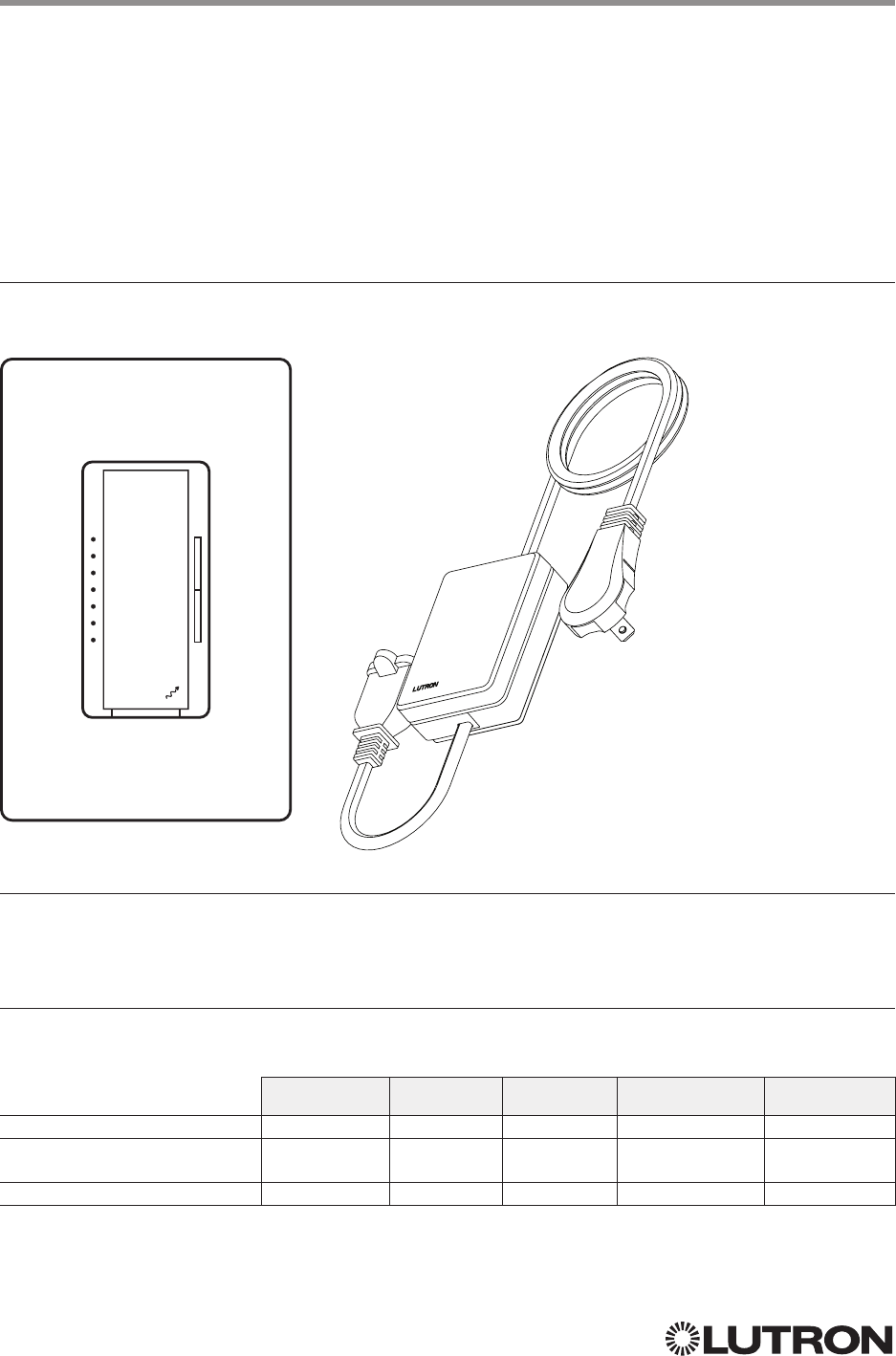
130
Lutron integration protocol
Maestro Dimmer and Plug-In Module
RadioRA 2 Models (RRD-): 6D, 6NA, 8ANS, 8S-DV, 10D, 10ND, F6AN-DV, 3LD
RadioRA 2 Models (RR-): 3PD, 15APS
HomeWorks QS / myRoom plus Models (HQRD-, HQRA): 6D, 6ND, 10D, 10ND, 6NA, F6AN-DV, 8ANS, 8S-DV
HomeWorks QS / myRoom plus Models (HWD-, HWA-): 6D, 6ND, 10D, 10ND, 5NE
1, 8ANS
HomeWorks QS / myRoom plus Models (HQR-): 3PD-1, 15APS-1, 3LD
Clear Connect Device Models (CCD-W): 6D, 6NA, F6AN-DV, 15APS-1
Why Integrate with a Maestro Dimmer or Plug-In Module?
• Turn On to specific light level or Off
• Raise / Lower light level
• Query current light level
Additional Commands
• None
Compatibility
QS Standalone Quantum RadioRA 2 HomeWorks QS myRoom plus
RadioRA 2 Model
HomeWorks QS /
myRoom plus Models
Clear Connect Device Model
6D 3PD
LUTRON
NOTE
1. 5NE is not available in architectural style
Continued on next page…
131
Lutron integration protocol
Maestro Dimmer (continued)
OUTPUT Commands
OUTPUT Command Format
OUTPUT Command-specific fields
Action Numbers and Parameters:
Action Action Number Parameters
Set (#) or Get (?) Zone Level 1 Level = 0 –100 or 0.00 –100.00
Fade
1 in: SS.ss
2, SS, MM:SS, or HH:MM:SS
Delay
1 in: SS.ss
2, SS, MM:SS, or HH:MM:SS
Set (#) Start Raising 2 None
Set (#) Start Lowering 3 None
Set (#)
Stop Raising or
Lowering
4 None
Set (#) Start Flashing
3, 4, 5 5 Fade
1 in: SS.ss
2, SS, MM:SS, or HH:MM:SS
Delay
1 in: SS.ss
2, SS, MM:SS, or HH:MM:SS
NOTES
1. The Fade and Delay time are optional. When not used, the system will use a one-second fade time with zero-second delay.
2. Fractional seconds “SS.ss” will be rounded down to the nearest quarter second. For example, if a fade time is specified
as 1.31 seconds a value of 1.25 seconds will be used.
3. The system will not report a level while the output is flashing, it will instead report that it is flashing.
4. Default flash every second, unless fade time is specified (flash period is 2× fade time).
5. To stop a dimmer from flashing, send it to a valid level.
Example OUTPUT Commands
Examples presume dimmer has been assigned Integration ID 1.
Operation Command String
Execute: #OUTPUT, Integration ID, Action Number, Parameters
Set dimmer to 75% with a 1 min 30 sec fade. #OUTPUT,1,1,75,01:30<CR><LF>
Start Raising dimmer level. #OUTPUT,1,2<CR><LF>
Stop Raising / Lowering dimmer level. #OUTPUT,1,4<CR><LF>
Query: ?OUTPUT, Integration ID, Action Number
What is the state of the output? ?OUTPUT,1,1<CR><LF>
Response
1: ~OUTPUT, Integration ID, Action Number, Parameters
Output level is set to 90%. ~OUTPUT,1,1,90.00<CR><LF>
NOTE
1. The system will report the target level of a dimmer while it is fading from one level to another.
The actual level is not transmitted while dimming between levels.
Example: If the “Over Sink” (1) dimmer is at 20% and is then commanded to go to 100% by sending
#OUTPUT,1,1,100,
the response from the system will be ~OUTPUT,1,1,100.00
Use “OUTPUT Command-specific fields” tables
to complete these command fields.
Operation
Command
Integration ID (example)
#OUTPUT, 1, Action Number, Parameters
LUTRON
132
Lutron integration protocol
LUTRON
Maestro Dimmer (continued)
DEVICE Commands
DEVICE Command Format
DEVICE Command-specific fields
Component Numbers:
Component Component Number Available Actions
Maestro Tap Switch 6 Press, Release, Double Tap, Hold
Action Numbers and Parameters:
Action Action Number Parameters
Set (#) Press 3 None
Set (#) Release 4 None
Set (#) Hold 5 None
Set (#) Double Tap 6 None
Example OUTPUT Commands
Examples presume dimmer has been assigned Integration ID 2.
Operation Command String
Execute: #DEVICE, Integration ID, Component Number, Action Number, Parameters
Press Button 1. #DEVICE,2,1,3,<CR><LF>
Use “OUTPUT Command-specific fields” tables
to complete these command fields.
Operation
Command
Integration ID (example)
#DEVICE
1, 2, Component Number, Action Number, Parameters
NOTE
1. Supported only in HomeWorks QS 4.0 or higher.
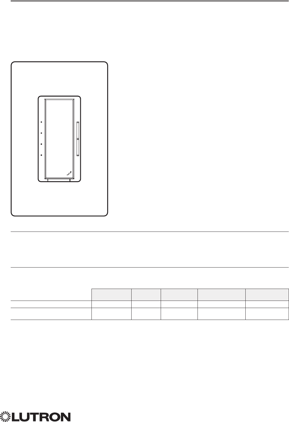
133
Lutron integration protocol
Maestro Fan Speed Control
RadioRA 2 Models (RRD-): 2ANF
HomeWorks QS / myRoom Models (HQRD-, HQRA-, HWD-, HWA-): 2ANF
Why Integrate with a Maestro Fan Speed Control?
• Turn On to specific speed (High, Medium-High, Medium, Low, or Off)
• Raise / Lower fan speed
• Query current speed
Additional Commands
• None
Compatibility
QS Standalone Quantum RadioRA 2 HomeWorks QS myRoom plus
RadioRA 2 Fan Speed Control
HomeWorks QS / myRoom Fan
Speed Control
2ANF
LUTRON
LUTRON
134
Lutron integration protocol
Maestro Fan Speed Control (continued)
OUTPUT Commands
OUTPUT Command Format
OUTPUT Command-specific fields
Action Numbers and Parameters:
Action Action Number Parameters
Set (#) or Get (?) Zone Level 1 Levels:
0 = Off
1– 25% = Low
26 –50% = Medium
56 –75% = Medium High
76 –100% = High
Example OUTPUT Commands
Examples presume dimmer has been assigned Integration ID 1.
Operation Command String
Execute: #OUTPUT, Integration ID, Action Number, Parameters
Set fan speed to Medium High. #OUTPUT,1,1,75<CR><LF>
Query: ?OUTPUT, Integration ID, Action Number
What is the state of the output? ?OUTPUT,1,1<CR><LF>
Response: ~OUTPUT, Integration ID, Action Number, Parameters
Output level is set to High. ~OUTPUT,1,1,100.00<CR><LF>
Use “OUTPUT Command-specific fields” tables
to complete these command fields.
Operation
Command
Integration ID (example)
#OUTPUT
1, 1, Action Number, Parameters
NOTE
1. Supported only in HomeWorks QS 4.0 or higher and RadioRA 2 6.0 or higher.
LUTRON
LUTRON
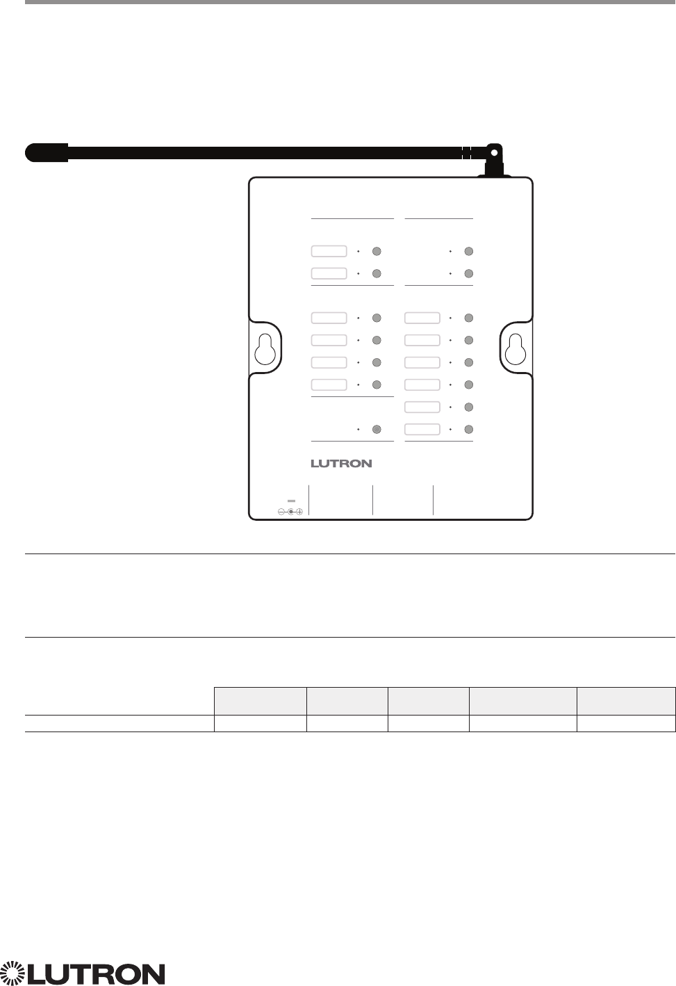
135
Lutron integration protocol
Visor Control Receiver
RadioRA 2 Model: RR-VCRX
HomeWorks QS / myRoom Model: HQR-VCRX
Why Integrate with a Visor Control Receiver?
• Simulate a keypad press or contact closure inputs
• Control LEDs of unprogrammed buttons
• Control contact closure outputs
Additional Commands
• None
Compatibility
QS Standalone Quantum RadioRA 2 HomeWorks QS myRoom plus
Visor Control Receiver
RR-VCRX
Visor Control Receiver
Learn
Visor Transmitter
Keypad
Outputs
Flash
Full
Security Input
Inputs
1 2
Power
9V
Inputs
C
Full
1 C 2 C
Outputs
3 C
4
C
Flash
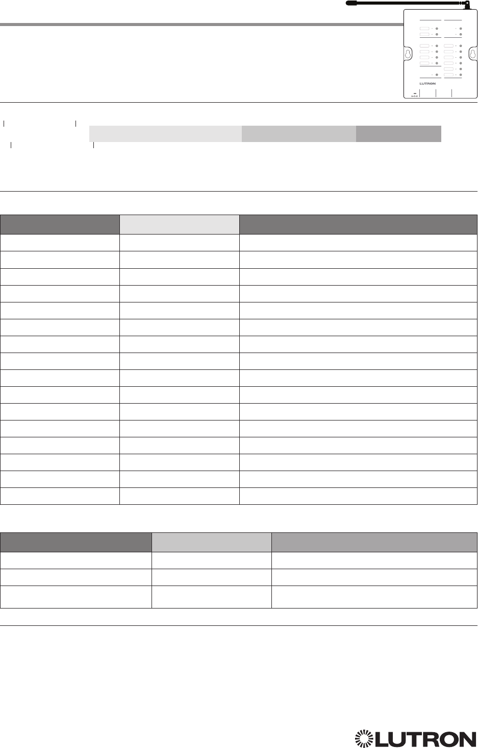
136
Lutron integration protocol
Visor Control Receiver (continued)
DEVICE Commands
DEVICE Command Formats
DEVICE Command-specific fields
Component Numbers:
Component Component Number Available Actions
Scene 1 1 Press, Release
Scene 2 2 Press, Release
Scene 3 3 Press, Release
Scene 4 4 Press, Release
Scene 5 5 Press, Release
Scene 6 6 Press, Release
Full / Security 30 Open Input, Close Input
Security Flash 31 Open Input, Close Input
Input 1 32 Open Input, Close Input
Input 2 33 Open Input, Close Input
LED Scene 1 81 Set or Get LED state
LED Scene 2 82 Set or Get LED state
LED Scene 3 83 Set or Get LED state
LED Scene 4 84 Set or Get LED state
LED Scene 5 85 Set or Get LED state
LED Scene 6 86 Set or Get LED state
Action Numbers and Parameters:
Action Action Number Parameters
Set (#) Press or Input Close 3 None
Set (#) Release or Input Open 4 None
Set (#) or Get (?) LED State
190 = Off; 1 = On
NOTES
1. Valid for Scene LEDs only.
Use “DEVICE Command-specific fields” tables
to complete these command fields.
Operation
Command
Integration ID (example)
#DEVICE, 5, Component Number, Action Number, Parameters
Visor Control Receiver
Learn
Visor Transmitter
Keypad
Outputs
Flash
Full
Security Input
Inputs
1 2
Power
9V
Inputs
C
Full
1 C 2 C
Outputs
3 C
4
C
Flash
Continued on next page…
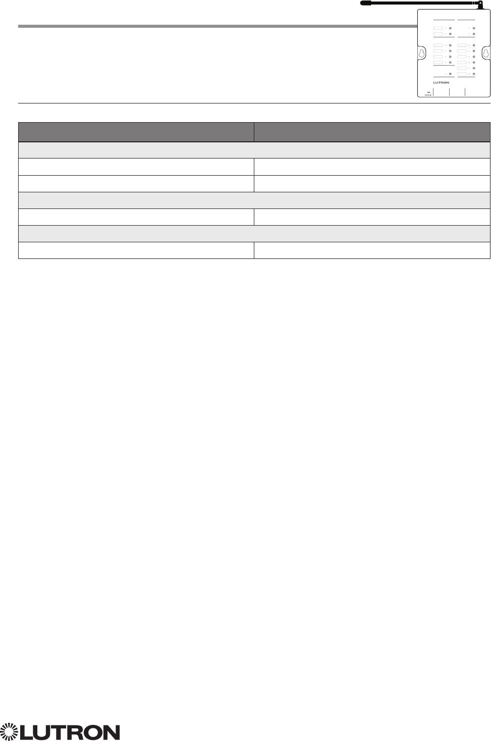
137
Lutron integration protocol
Example DEVICE Commands
Examples presume Visor Control Receiver has been assigned Integration ID 5.
Operation Command String
Execute: #DEVICE, Integration ID, Component Number, Action Number, Parameters
Press Scene 1. #DEVICE,5,1,3<CR><LF>
Turn On Scene 1 LED. #DEVICE,5,9,81,1<CR><LF>
Query: ?DEVICE, Integration ID, Component Number, Action Number
What is the state of LED 1? ?DEVICE,5,9,81<CR><LF>
Response: ~DEVICE, Integration ID, Component Number, Action Number, Parameters
LED 1 is On. ~DEVICE,5,9,81,1<CR><LF>
Visor Control Receiver (continued)
DEVICE Commands (continued)
Visor Control Receiver
Learn
Visor Transmitter
Keypad
Outputs
Flash
Full
Security Input
Inputs
1 2
Power
9V
Inputs
C
Full
1 C 2 C
Outputs
3 C
4
C
Flash
138
Lutron integration protocol
Visor Control Receiver (continued)
OUTPUT Commands
OUTPUT Command Format
OUTPUT Command-specific fields
Action Numbers and Parameters:
Action Action Number Parameters
Set (#) or Get (?) Output State 1 Level
1 = 0 –100 or 0.00 –100.00
Set (#) CCO Pulse Time 6 Pulse
2 time in: SS.ss
3, SS, MM:SS, or HH:MM:SS, or
Delay
4 in: SS.ss
3, SS, MM:SS, or HH:MM:SS
NOTES
1. Any level greater than 0 will close the output. When level is equal to 0 the output will open.
2. The default time is one second.
3. Fractional seconds “SS.ss” will be rounded down to the nearest quarter second. For example, if a fade time is specified
as 1.45 seconds a value of 1.25 seconds will be used.
4. The Fade and Delay time are optional. When not used, the system will use a one-second fade time with zero-second
delay. The minimum fade and delay time is 0 seconds. The maximum fade and delay time is 4 hours. For shade outputs,
the Fade parameter has no effect (since shades have fixed speeds) but it is required when specifying an optional delay.
Example OUTPUT Messages
Examples presume CCO has been assigned Integration ID 21.
Operation Command String
Set: #OUTPUT, Integration ID, Action Number, Parameters
Set output to open. #OUTPUT,21,1,0<CR><LF>
Set output to close. #OUTPUT,21,1,1<CR><LF>
Query
1: ?OUTPUT, Integration ID, Action Number
What is the state of the output? ?OUTPUT,21,1<CR><LF>
Response
2: ~OUTPUT, Integration ID, Action Number
Output state is closed. ~OUTPUT,21,1,100.00<CR><LF>
NOTES
1. Momentary outputs should not be queried.
2. The system will report the target level of outputs. Any level greater than 0 means that the output is closed.
Use “OUTPUT Command-specific fields” tables
to complete the parameter field.
Action number is always
1 for visor control outputs
Operation
Command
Integration ID (example)
#OUTPUT,21, Action Number, Parameters
Visor Control Receiver
Learn
Visor Transmitter
Keypad
Outputs
Flash
Full
Security Input
Inputs
1 2
Power
9V
Inputs
C
Full
1 C 2 C
Outputs
3 C
4
C
Flash
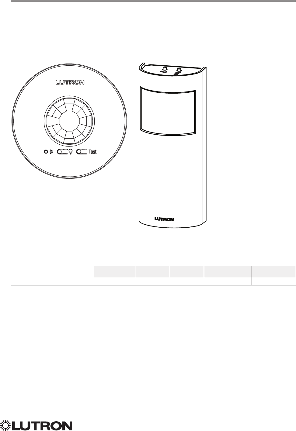
139
Lutron integration protocol
Why Integrate with a Radio Powr Savr Sensor?
• Monitor occupied, unoccupied status of a single sensor
Compatibility
QS Standalone Quantum RadioRA 2 HomeWorks QS myRoom plus
Radio Powr Savr Sensor
Radio Powr Savr Sensor
CURRENT Models (LRF2-, CCD-): OCR2B, VCR2B, OKLB, OHLB, OWLB, VKLB, VHLB, VWLB
LEGACY Models (LRF2-): OCRB, VCRB
LRF2-OCR2B LRF2-OKLB
140
Lutron integration protocol
Radio Powr Savr Sensor (continued)
DEVICE Commands
DEVICE Command Formats
~DEVICE, 19, 2, Action Number
Occupied state component
is always 2 for sensors
Operation
Command
Integration ID (example)
DEVICE Command-specific fields
Component Numbers:
Component Component Number Available Actions
Occupied State 2 Occupied, Unoccupied
Action Numbers:
Action Action Number
Report (~) Occupied 3
Report (~) Unoccupied 4
Example DEVICE Commands
Examples presume sensor has been assigned Integration ID 19.
Operation Command String
Response: ~DEVICE, Integration ID, Component Number, Action Number, Parameters
Radio Powr Savr 19 went occupied. ~DEVICE,19,2,3<CR><LF>
Radio Powr Savr 19 went unoccupied. ~DEVICE,19,2,4<CR><LF>

141
Lutron integration protocol
Why Integrate with an HVAC Controller?
• Get current temperature
• Set or get heat setpoints and cool setpoints
• Set or get operating mode, fan mode and Eco Mode1
• Get connection status to the temperature sensor
• Get schedule information and hold schedules
Supported Command Types
• HVAC allows control and monitoring of the HVAC Controller
Compatibility
QS Standalone Quantum RadioRA 2 HomeWorks QS myRoom plus
LR-HVAC-1-WH; LR-HWLV-HVAC
LR-HVAC-230-S
HQWT-T-HW
Temperature Controls
RadioRA 2 Models: LR-HVAC-1-WH, LR-HWLV-HVAC
HomeWorks QS Models: LR-HVAC-1-WH, LR-HWLV-HVAC, LR-HVAC-230-S, HQWT-T-HW
myRoom Model: LR-HVAC-230-S
LR-HVAC-1-WH
LR-HVAC-230-S
LR-HWLV-HVAC
1 HQWT-T-HW does not support Eco Mode
HQWT-T-HW
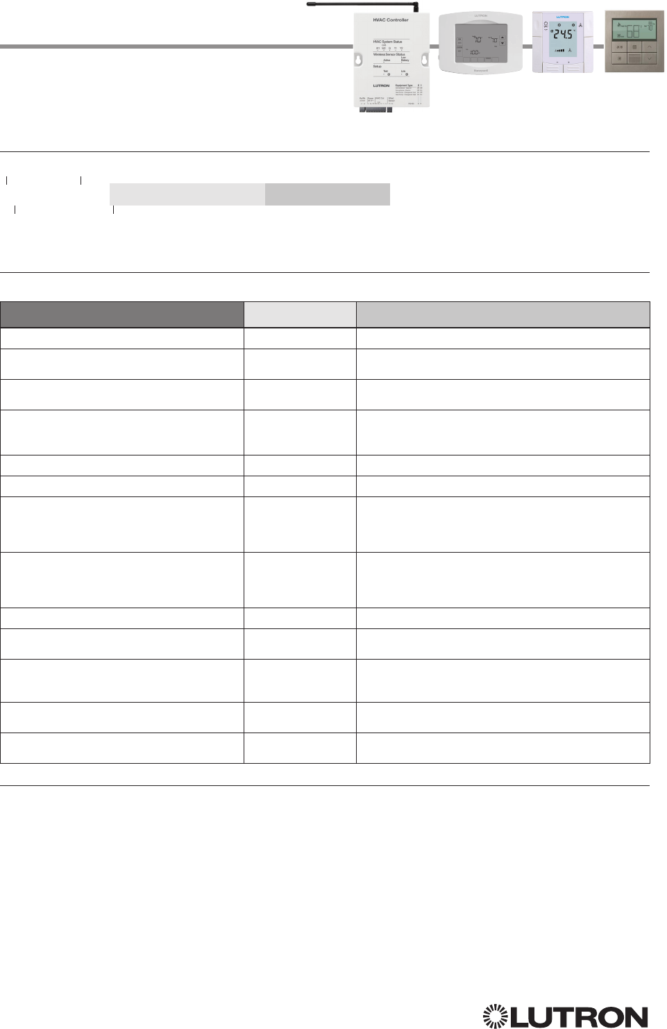
142
Lutron integration protocol
HVAC Command-specific fields
Action Numbers and Parameters:
Action Action Number Parameters
Set (#) or Get (?) Current Temperature (°F) 8 1Temperature = 32–212 °F
Set (#) or Get (?) Heat and Cool
Setpoints (°F)1, 2, 5, 8 2Setpoint Heat (SPH) = 32–212 °F
Setpoint Cool (SPC) = 32–212 °F
Set (#) or Get (?) Operating Mode63Mode (1 = Off/Protect, 2 = Heat, 3 = Cool, 4 = Auto,
5 =Em. Heat/Auxiliary Only, 7= Fan, 8 = Dry)
Set (#) or Get (?) Fan Mode 64Mode (1 = Auto, 2 = On, 3 = Cycler, 4 = No Fan,
5 = High, 6 = Medium, 7 = Low, 8 = Top)
Set (#) or Get (?) Eco (Setback) Mode45Mode (1 = Off, 2 = On)
Get (?) Eco Offset46Eco Offset = 1–11 °F
Set (#) or Get (?) Schedule Status
37
0 = Schedule Unavailable, Get (?) only
1 = Following Schedule, Set (#) or Get (?)
2 = Permanent Hold, Set (#) or Get (?)
3 = Temporary Hold 6, Get (?) only
Get (?) Temperature Sensor Connection
Status 68
1 = All Sensors are Active
2 = Missing Sensor
3 = Wired Sensor Only
4 = No Sensor
Get (?) Schedule Event 9 Schedule # (1–7), Event # (1– 4), HH,MM, SPH, SPC
Get (?) Schedule Day Assignment 10 Schedule#(1–7), DD(Bitmap:Sunday(Bit 0) –
Saturday(Bit 6) 1–active day, 0– inactive day)
Get (?) System Mode 11
1 = Normal
2 = Away
3 = Green
Get (?) Heat and Cool Setpoints (°F) without
Eco Offset if applied4, 8 12 Setpoint Heat (SPH) = 32 – 212 °F
Setpoint Cool (SPC) = 32 – 212 °F
Get (?) Emergency Heat Available 13 1 = Not Available
2 = Available
NOTES
1. Changing the setpoint will turn Eco Mode off if it is currently on.
2. To leave a parameter unchanged, use “255” as the value for that parameter when sending the command.
3. Schedule Unavailable –> Schedule not programmed or device needs date / time.
Following Schedule –> Running programmed schedule; set points from schedule.
Permanent Hold –> Schedule is not running; set points as adjusted.
Temporary Hold –> Running schedule; set points as adjusted. Returns to following schedule at next schedule event.
4. HQWT-T-HW does not support Eco Mode.
5. For the HQWT-T-HW, this range depends on the programming in the database. The setpoint range is 40-113 °F
(5-45 °C).
6. HQWT-T-HW does not support this integration feature.
7. If the thermostat is setup to use Fahrenheit, it is recommended to use Fahrenheit Integration command set. If it is setup
to use Celsius, it is recommended to use the Celsius Integration command set.
8. Allow for reported temperature values to be zero padded, with up to 3 digits before the decimal point, and 2 digits after.
– Possible reported values of 5 °C: “005”, “05”, “5”, “005.”, “005.”, “5.”, “005.0”, “05.0”, “5.0”, “005.00”, “05.00”, “5.00”
– Possible reported values of 5.5 °C: “005.5”, “05.5”, “5.5”, “005.50”, “05.50”, “5.50”
– Possible reported values of 21 °C: “021”, “21”, “021.0”, “21.0, “021.00,” “21.00”
– Possible reported values of 21.5 °C: “021.5”, “21.5”, “021.50”, “21.50”
Temperature Controls (continued)
HVAC Commands
HVAC Command Format
Use “HVAC Command-specific fields” tables
to complete these command fields.
Operation
Command
Integration ID (example)
#HVAC,21, Action Number, Parameters
Continued on next page…
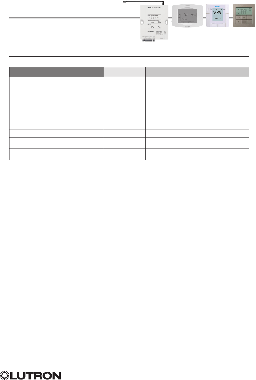
143
Lutron integration protocol
HVAC Command-specific fields (continued)
Action Numbers and Parameters (continued):
Action Action Number Parameters
Set (#) or Get (?) Call Status 14
0 = None, Last was Heat
1 = Heat Stage 1
2 = Heat Stage 1 and 2
3 = Heat Stage 1, 2, and 3
4 = Heat Stage 3
5 = None, Last was Cool
6 = Cool Stage 1
7 = Cool Stage 1 and 2
8 = Off
9 = Emergency Heat/Auxiliary Only
10 = Dry
Set (#) or Get (?) Current Temperature (°C)1, 7 15 Temperature = 0 –100 °C
Set (#) or Get (?) Heat and Cool Setpoints
(°C)2, 3, 5, 7 16 Setpoint Heat (SPH) = 0 – 100 °C
Setpoint Cool (SPC) = 0 – 100 °C
Get (?) Heat and Cool Setpoints (°C) without
Eco Offset if applied2, 4, 7 17 Setpoint Heat (SPH) = 0 –100 °C
Setpoint Cool (SPC) = 0 – 100 °C
NOTES
1. HomeWorks QS software version 4.1 and higher.
2. Changing the setpoint will turn Eco Mode off if it is currently on.
3. To leave a parameter unchanged, use “255” as the value for that parameter when sending the command.
4. HQWT-T-HW does not support Eco Mode.
5. For the HQWT-T-HW, this range depends on the programming in the database. The heat/cool setpoints increase or
decrease in increments of 0.5 °C.
6. If the thermostat is setup to use Fahrenheit, it is recommended to use Fahrenheit Integration command set. If it is setup
to use Celsius, it is recommended to use the Celsius Integration command set.
7. Allow for reported temperature values to be zero padded, with up to 3 digits before the decimal point, and 2 digits after.
– Possible reported values of 5 °C: “005”, “05”, “5”, “005.”, “005.”, “5.”, “005.0”, “05.0”, “5.0”, “005.00”, “05.00”, “5.00”
– Possible reported values of 5.5 °C: “005.5”, “05.5”, “5.5”, “005.50”, “05.50”, “5.50”
– Possible reported values of 21 °C: “021”, “21”, “021.0”, “21.0, “021.00,” “21.00”
– Possible reported values of 21.5 °C: “021.5”, “21.5”, “021.50”, “21.50”
Temperature Controls (continued)
HVAC Commands (continued)
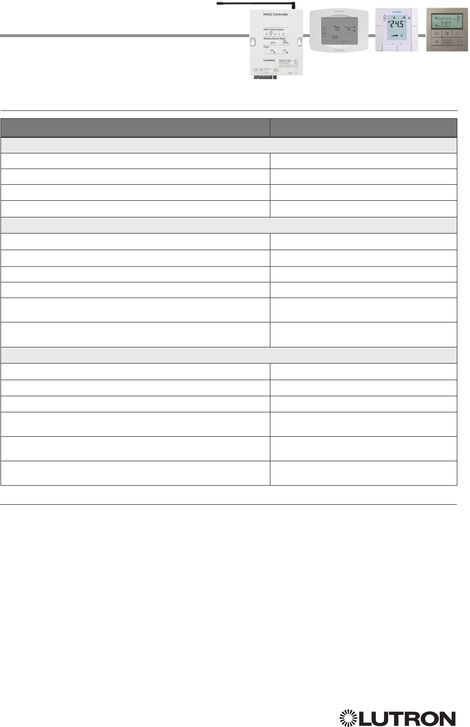
144
Lutron integration protocol
Temperature Controls (continued)
HVAC Commands (continued)
Example HVAC Commands
Operation Command String
Execute: #HVAC, Integration ID, Action Number, Parameters
Set heat setpoint to 68 °F and cool setpoint to 72 °F. #HVAC,1,2,68,72<CR><LF>
Set system mode to cool. #HVAC,1,3,3<CR><LF>
Turn Eco mode on. #HVAC,1,5,2<CR><LF>
Set heat setpoint to 18.5 C and cool setpoint to 21.5 C #HVAC,21,16,18.5,21.5<CR><LF>
Query: ?HVAC, Integration ID, Action Number
What is the current temperature? ?HVAC,1,1<CR><LF>
What is are the settings for Schedule 1, Event 2? ?HVAC,1,9,1,2<CR><LF>
What days are running Schedule 1? ?HVAC,1,10,1<CR><LF>
What are the current heat and cool setpoints in Celsius? ?HVAC,21,16<CR><LF>
What are the current heat and cool setpoints in Fahrenheit if the
Celsius values are 18.5 °C and 21.5 °C respectively?
?HVAC,21,2<CR><LF>
What are the current heat and cool setpoints in Fahrenheit if the
Celsius values are 10 °C and 20 °C respectively?
?HVAC,21,2<CR><LF>
Response: ~HVAC, Integration ID, Action Number, Parameters
Current Temperature is 70 °F. ~HVAC,1,1,70<CR><LF>
Schedule 1, Event 2 starts at 8:00 am with SPH=65,SPC=78 ~HVAC,1,9,1,2,08,00,65,78<CR><LF>
Schedule 1 is being run on Monday and Tuesday. ~HVAC,1,10,1,06<CR><LF>
Current heat and cool setpoints in Celsius are 18.5 °C and 21.5 °C
respectively.
~HVAC,21,16,18.5,21.5<CR><LF>
Current heat and cool setpoints in Fahrenheit are 65.3 °F and 70.7 °F
respectively.
~HVAC,21,2,65.3,70.7<CR><LF>
Current heat and cool setpoints in Fahrenheit are 50 °F and 68 °F
respectively.
~HVAC,21,2,50,68<CR><LF>
NOTES
• If the thermostat is setup to use Fahrenheit, it is recommended to use Fahrenheit Integration command set. If it is setup
to use Celsius, it is recommended to use the Celsius Integration command set.
• Allow for reported temperature values to be zero padded, with up to 3 digits before the decimal point, and 2 digits after.
– Possible reported values of 5 °C: “005”, “05”, “5”, “005.”, “005.”, “5.”, “005.0”, “05.0”, “5.0”, “005.00”, “05.00”, “5.00”
– Possible reported values of 5.5 °C: “005.5”, “05.5”, “5.5”, “005.50”, “05.50”, “5.50”
– Possible reported values of 21 °C: “021”, “21”, “021.0”, “21.0, “021.00,” “21.00”
– Possible reported values of 21.5 °C: “021.5”, “21.5”, “021.50”, “21.50”
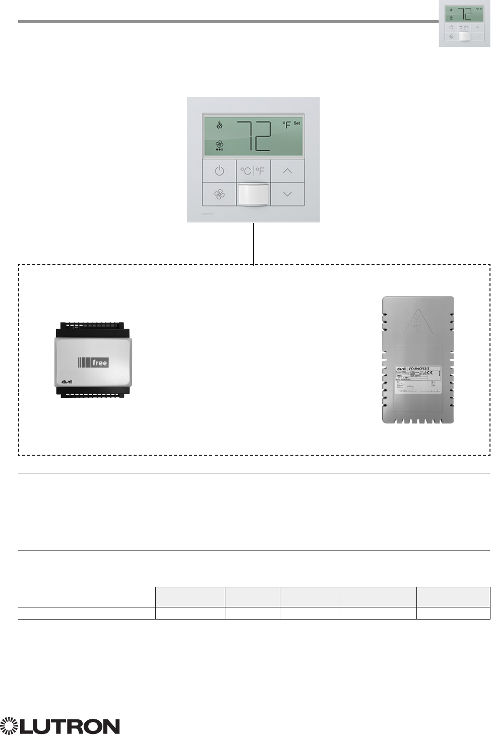
145
Lutron integration protocol
Why Integrate with a Palladiom Thermostat?
• Get current temperature
• Set or get single setpoint
• Set or get operating mode and fan mode
• Set or get positive or negative drifts
Supported Command Types
• HVAC allows control and monitoring of the Palladiom Thermostat and HVAC Controller
Compatibility
QS Standalone Quantum RadioRA 2 HomeWorks QS myRoom plus
MWP-T-OWH
1 Requires myRoom 10.0 or newer
Palladiom Thermostat
1
myRoom Model: MWP-T-OHW
MWP-T-OHW
SMC5300020401
SMC5500050407
FCABACPSS002
OR
HVAC Controller Required
HVAC Controller
Communication Link
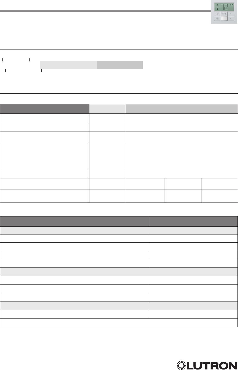
146
Lutron integration protocol
HVAC Command-specific fields
Action Numbers and Parameters:
Action Action Number Parameters
Set (#) or Get (?) Current Temperature (°F) 2 1Temperature = 32–104 °F
Set (#) or Get (?) Operating Mode 3 Mode (1 = Off, 4 = Auto)
Set (#) or Get (?) Fan Mode 4 Mode (1 = Auto, 4 = No Fan, 5 = High, 6 = Medium,
7 = Low)
Set (#) or Get (?) Call Status 14
0 = None, Last was Heat
1 = Heat Stage 1
5 = None, Last was Cool
6 = Cool Stage 1
8 = Off
Set (#) or Get (?) Current Temperature (°C) 15 Temperature = 0 –40 °C
Set (#) or Get (?) Single Setpoint (°F) and
Drifts
1, 2 18 Single Setpoint =
50 – 90 °F
Negative Drift =
0 – 15 °F
Positive Drift =
0 – 15 °F
Set (#) or Get (?) Single Setpoint (°C) and
Drifts
1, 2 19 Single Setpoint =
10 – 32 °C
Negative Drift =
0 – 8 °C
Positive Drift =
0 – 8 °C
Example HVAC Commands
Operation Command String
Execute: #HVAC, Integration ID, Action Number, Parameters
Set Single Setpoint to 75 °F, Positive Drift to 2 °F and Negative Drift to 1 °F. #HVAC,21,18,75,1,2<CR><LF>
Set System Operating Mode to “Auto”. #HVAC,21,3,4<CR><LF>
Set Fan Mode to “Medium”. #HVAC,21,4,6<CR><LF>
Set Single Setpoint to 20 °C and leave the Drifts unaffected #HVAC,21,19,20,255,255<CR><LF>
Query: ?HVAC, Integration ID, Action Number
What is the Current Temperature? ?HVAC,21,1<CR><LF>
What is the Current Operating Mode? ?HVAC,21,3<CR><LF>
What is the Current HVAC Call Status? ?HVAC,21,14<CR><LF>
Response: ~HVAC, Integration ID, Action Number, Parameters
Current Temperature is 70 °F. ~HVAC,21,1,70<CR><LF>
Current Operating Mode is “Off”. ~HVAC,21,3,1<CR><LF>
1. To leave a parameter unchanged, use “255” as the value for that parameter when sending the command.
2. Allow for reported temperature values to be zero padded, with up to 3 digits before the decimal point, and 2 digits after.
– Possible reported values of 5 °C: “005”, “05”, “5”, “005.”, “005.”, “5.”, “005.0”, “05.0”, “5.0”, “005.00”, “05.00”, “5.00”
– Possible reported values of 5.5 °C: “005.5”, “05.5”, “5.5”, “005.50”, “05.50”, “5.50”
– Possible reported values of 21 °C: “021”, “21”, “021.0”, “21.0, “021.00,” “21.00”
– Possible reported values of 21.5 °C: “021.5”, “21.5”, “021.50”, “21.50”
Palladiom Thermostat (continued)
HVAC Commands
HVAC Command Format
Use “HVAC Command-specific fields” tables
to complete these command fields.
Operation
Command
Integration ID (example)
#HVAC,21, Action Number, Parameters
147
Lutron integration protocol
Why Integrate with a Wireless Temperature Sensor?
• Get battery status
Note: To get current temperature, see HVAC Controller section.
Additional Commands
• None
Compatibility
QS Standalone Quantum RadioRA 2 HomeWorks QS myRoom plus
Wireless Temperature Sensor
Wireless Temperature Sensor
Model: LRF2-TWRB
Test
Link
Continued on next page…
148
Lutron integration protocol
Wireless Temperature Sensor (continued)
DEVICE Commands
DEVICE Command Formats
DEVICE Command-specific fields
Component Numbers:
Component Component Number Available Actions
Battery Status 1 Get battery status
Action Numbers and Parameters:
Action Action Number Parameters
Get (?) battery status 22 1 = Normal, 2 = Low
Example DEVICE Messages
Operation Command String
Query: ?DEVICE, Integration ID, Component Number, Action Number
What is the Temperature Sensor’s Battery Status? ?DEVICE,1,1,22<CR><LF>
Response: ~DEVICE, Integration ID, Component Number, Action Number, Parameters
Temperature Sensor’s Battery is Low. ~DEVICE,1,1,22,2<CR><LF>
Test
Link
Use “DEVICE Command-specific fields” tables
to complete these command fields.
Operation
Command
Integration ID (example)
?DEVICE, 1, Component Number, Action Number, Parameters
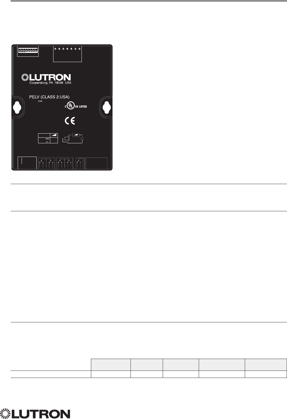
149
Lutron integration protocol
Why Integrate with a QSE-IO?
• Know the state of the Contact Closure Inputs (CCIs).
• Control the state of the Contact Closure Outputs (CCOs).
Integration Capabilities
5 Contact Closure Inputs (CCIs) and 5 Contact Closure Outputs. The QSE-IO mode of operation is specified
by its DIP switch configuration.
• CCI and CCO states can be polled in any DIP configuration.
• CCI events can be monitored through integration in any DIP configuration.
• CCI events (closures or openings of CCIs) can be ‘spoofed’ (faked) through integration in DIP configurations
where momentary CCIs are specified.
• CCO events can be monitored through integration in any DIP configuration.
• The CCO state logic is typically tied to the states of the CCIs or other devices on the QS link and thus, CCO
events cannot be generated through integration in most DIP configurations; the exceptions are the output
DIP configurations (e.g., Shade Output, Zone Control Output) and the Integration DIP configuration that
allows full monitoring of CCIs and control of CCOs through integration.
• Occupancy events can be monitored through integration when the QSE-IO is in an Occupancy DIP
configuration.
Supported Command Types
• DEVICE allows monitoring of CCI and CCO events and polling of CCI/CCO states and in certain QSE-IO DIP
configurations, allows ‘spoofing’ of CCI events and generation of CCO events.
• OUTPUT (in certain output-oriented QSE-IO DIP configurations) allows control and monitoring of the CCOs.
Compatibility
QS Standalone Quantum RadioRA 2 HomeWorks QS myRoom plus
QSE-IO
QSE-IO
Model: QSE-IO
CCI1
CCI 2
CCI 3
CCI 4
COM
CCI 5
V
0-24 V 1 A
0-24 V ½ A
R
O
N
CCO 1 NC
CCO 1 NO
CCO 2 NC
CCO 2 NO
1-2 COM
CCO 3 NC
CCO 4 NO
CCO 3 NO
CCO 4 NC
3-4 COM
CCO 5 NC
5 COM
CCO 5 NO
V
R
MUX
COM
V+
MUX
CCO 1
CCO 2
CCO 3
CCO 4
CCO 5
STAT
QS
800.523.9466
+
1.610.282.3800
www.lutron.com/qs
QSE-IO
24 V 100 mA
243C IND. CONT. EQ.
8 7 6 5 4 3 2 1
4 3 2 1
Continued on next page…

150
Lutron integration protocol
QSE-IO (continued)
DEVICE Commands
DEVICE Command Formats
DEVICE Command-specific fields
Component Numbers:
Component Component Number Available Actions
CCI 1 1 Report (~) closure/opening1
Poll (?) status
2
Spoof (#) closure/opening
3
CCI 2 2 Report (~) closure/opening1
Poll (?) status
2
Spoof (#)closure/opening
3
CCI 3 3 Report (~) closure/opening1
Poll (?) status
2
Spoof (#)closure/opening
3
CCI 4 4 Report (~) closure/opening1
Poll (?) status
2
Spoof (#)closure/opening
3
CCI 5 5 Report (~) closure/opening1
Poll (?) status
2
Spoof (#)closure/opening
3
CCO 1 11 Report (~) closure/opening
4
Poll (?) status
2
Generate (#) closure/opening
3
CCO 2 12 Report (~) closure/opening
4
Poll (?) status
2
Generate (#) closure/opening
3
CCO 3 13 Report (~) closure/opening
4
Poll (?) status
2
Generate (#) closure/opening
3
CCO 4 14 Report (~) closure/opening
4
Poll (?) status
2
Generate (#) closure/opening
3
CCO 5 15 Report (~) closure/opening
4
Poll (?) status
2
Generate (#) closure/opening
3
Occupancy Sensor 1 41 Report (~) occupied/unoccupied
3,5
Occupancy Sensor 2 42 Report (~) occupied/unoccupied
3,5
Occupancy Sensor 3 43 Report (~) occupied/unoccupied
3,5
Occupancy Sensor 4 44 Report (~) occupied/unoccupied
3,5
Occupancy Sensor 5 45 Report (~) occupied/unoccupied
3,5
NOTES
1. Monitoring type 2 must be enabled (see QSE-CI-NWK-E #MONITORING section)
2. Not available in Quantum
3. Feature supported in only some QSE-IO DIP configurations
4. Monitoring type 5 must be enabled (see QSE-CI-NWK-E #MONITORING section)
5. Monitoring type 6 must be enabled (see QSE-CI-NWK-E #MONITORING section)
Use “DEVICE Command-specific fields” tables
to complete these command fields.
Operation
Command
Integration ID (example)
#DEVICE, 5, Component Number, Action Number, Parameters
CCI 1
CCI 2
CCI 3
CCI 4
COM
CCI 5
V
0-24 V 1 A
0-24 V ½ A
R
O
N
CCO 1 NC
CCO 1 NO
CCO 2 NC
CCO 2 NO
1-2 COM
CCO 3 NC
CCO 4 NO
CCO 3 NO
CCO 4 NC
3-4 COM
CCO 5 NC
5 COM
CCO 5 NO
V
R
MUX
COM
V+
MUX
CCO 1
CCO 2
CCO 3
CCO 4
CCO 5
STAT
QS
800.523.9466
+
1.610.282.3800
www.lutron.com/qs
QSE-IO
24 V 100 mA
®
243C IND. CONT. EQ.
8 7 6 5 4 3 2 1
4 3 2 1
151
Lutron integration protocol
QSE-IO (continued)
DEVICE Commands (continued)
DEVICE Command-specific fields (continued)
Action Numbers and Parameters:
Action Action Number Parameters
Set (#) Closure
Report (~) Closure or Occupied
13 None
Set (#) Opening
Report (~) Opening or Unoccupied
14 None
Set (#) CCO State
1, 2 14 Level (0 = Open, 100 = Close)
Get (?) CCO State
2None
Report (~) CCO State Level (0 = Open, 100 = Close)
Get (?) CCI State
2,3 35 None
NOTES
1. Feature supported in only some QSE-IO DIP configurations. See QSE-IO installation instructions at www.lutron.com
2. Not available in Quantum
3. Requires NWK firmware 8.47 or newer for QS Standalone systems.
CCI 1
CCI 2
CCI 3
CCI 4
COM
CCI 5
V
0-24 V 1 A
0-24 V ½ A
R
O
N
CCO 1 NC
CCO 1 NO
CCO 2 NC
CCO 2 NO
1-2 COM
CCO 3 NC
CCO 4 NO
CCO 3 NO
CCO 4 NC
3-4 COM
CCO 5 NC
5 COM
CCO 5 NO
V
R
MUX
COM
V+
MUX
CCO 1
CCO 2
CCO 3
CCO 4
CCO 5
STAT
QS
800.523.9466
+
1.610.282.3800
www.lutron.com/qs
QSE-IO
24 V 100 mA
®
243C IND. CONT. EQ.
8 7 6 5 4 3 2 1
4 3 2 1
Continued on next page…

152
Lutron integration protocol
QSE-IO (continued)
OUTPUT Commands
OUTPUT Command Formats
OUTPUT Command-specific fields
Action Numbers and Parameters:
Action Action Number Parameters
Set (#) CCO state
1,
21Level (0 = Open, 100 = Close)
Get (?) CCO state None
Report (~) CCO state Level (0 = Open, 100 = Close)
NOTES
1. Feature supported in only some QSE-IO DIP configurations. See QSE-IO installation instructions at www.lutron.com
2. Not available in Quantum
Use “OUTPUT Command-specific fields” tables
to complete these command fields.
Operation
Command
Integration ID (example)
#OUTPUT, 1, Action Number, Parameters
CCI 1
CCI 2
CCI 3
CCI 4
COM
CCI 5
V
0-24 V 1 A
0-24 V ½ A
R
O
N
CCO 1 NC
CCO 1 NO
CCO 2 NC
CCO 2 NO
1-2 COM
CCO 3 NC
CCO 4 NO
CCO 3 NO
CCO 4 NC
3-4 COM
CCO 5 NC
5 COM
CCO 5 NO
V
R
MUX
COM
V+
MUX
CCO 1
CCO 2
CCO 3
CCO 4
CCO 5
STAT
QS
800.523.9466
+
1.610.282.3800
www.lutron.com/qs
QSE-IO
24 V 100 mA
®
243C IND. CONT. EQ.
8 7 6 5 4 3 2 1
4 3 2 1
153
Lutron integration protocol
QS Sensor Module
Models: QSMX-, QSM2-, QSM3-, QSM4-, QSM5-, QSM6-, QSM7-
Why Integrate with a QS Sensor Module?
• View occupancy events that occur.
Integration Capabilities
• Can view occupancy events for up to 14 sensors.
• Can view Pico button Press/Release Events.
Compatibility
QS Standalone Quantum RadioRA 2 HomeWorks QS myRoom plus
QS Sensor Module
Continued on next page…
154
Lutron integration protocol
QS Sensor Module (continued)
DEVICE Commands
DEVICE Command Formats
DEVICE Command-specific fields
Component Numbers:
Component Component Number Available Actions
Wired Occupancy sensors 1 – 4 Occupied, Unoccupied
Wireless Occupancy sensors 1 – 10 5 – 14 Occupied, Unoccupied
Pico 1 Buttons1,2 61 – 65 Press, Release
Pico 2 Buttons1,2 82 – 86 Press, Release
Pico 3 Buttons1,2 103 – 107 Press, Release
Pico 4 Buttons1,2 124 – 128 Press, Release
Pico 5 Buttons1,2 145 – 149 Press, Release
Pico 6 Buttons1,2 166 – 170 Press, Release
Pico 7 Buttons1,2 187 – 191 Press, Release
Pico 8 Buttons1,2 208 – 212 Press, Release
Pico 9 Buttons1,2 229 – 233 Press, Release
Pico 10 Buttons1,2 250 – 254 Press, Release
NOTES
1. All models except PJ2-4B: Pico button order (Top, Favorite, Bottom, Raise, Lower) dictates Component Number (see
Pico 1 example, below):
Pico 1 Button Sample Component Number
Top 61
Favorite 62
Bottom 63
Raise 64
Lower 65
2. Model PJ2-4B* only: Pico button order is 1, 2, 3, 4 and component mapping will be as below:
Pico 1 Button Sample Component Number
1 61
2 64
3 65
4 63
* Model PJ2-4B is supported only on QSM software version 7.28 and higher.
Use “DEVICE Command-specific fields” tables
to complete these command fields.
Operation
Command
Integration ID (example)
#DEVICE, 19, Component Number, Action Number, Parameters
155
Lutron integration protocol
QS Sensor Module (continued)
DEVICE Commands (continued)
DEVICE Command-specific fields (continued)
Action Numbers and Parameters:
Action Action Number Parameters
Report (~) Occupied or Button Press 3 None
Report (~) Unoccupied or Button Release 4 None
Example DEVICE Commands
Examples presume QSM has been assigned integration ID QSMID.
Operation Command String
Response: ~DEVICE, Integration ID, Component Number, Action Number
Wired Occupancy Sensor 1 transitions to Occupied ~DEVICE,QSMID,1,3<CR><LF>
Wired Occupancy Sensor 1 transitions to Unoccupied ~DEVICE,QSMID,1,4<CR><LF>
Wireless Occupancy Sensor 1 transitions to Occupied ~DEVICE,QSMID,5,3<CR><LF>
Wireless Occupancy Sensor 1 transitions to Unoccupied ~DEVICE,QSMID,5,4<CR><LF>
Pico 1 Favorite button press ~DEVICE,QSMID,62,3<CR><LF>

Customer Assistance
If you have questions concerning the installation or operation of
this product, call Lutron Customer Assistance.
Please provide the exact model number when calling.
Model number can be found on the product packaging.
Example: MWP-T-OHW-SN-A
U.S.A., Canada, and the Caribbean: 1.844.LUTRON1 (588.7661)
Mexico +1.888.235.2910
Other countries call: +1.610.282.3800
Fax: +1.610.282.1243
Visit us on the web at www.lutron.com/support
Lutron Electronics Co., Inc.
7200 Suter Road
Coopersburg, PA 18036 USA
)Lutron, Lutron, Clear Connect, EcoSystem, GRAFIK Eye, HomeWorks, Maestro, Palladiom, Pico, Quantum, RadioRA,
seeTouch, Sivoia, and Softswitch are trademarks of Lutron Electronics Co., Inc., registered in the U.S. and other
countries.
Architrave, Energi Savr Node, GRAFIK, Hyperion, myRoom, Q-Design, Radio Powr Savr, and Signature Series are
trademarks of Lutron Electronics Co., Inc.
IEEE is a registered trademark of the Institute of Electrical and Electronics Engineers, Inc., (IEEE). This publication is not
endorsed or approved by the IEEE.
DALI is a registered trademark of ZVEI - Zentralverband Elektrotechnik-und
Elektronikindustrie e.V.
This publication is not endorsed or approved by Apple, Inc.
© 2014 – 2017 Lutron Electronics Co., Inc.
P/N 040249 Rev. V 08/2017
