Operator's Manual, Chain Hoists, 7700 E, ET 04615308_ed2 04615308 Ed2
User Manual: 04615308_ed2 Ingersoll Rand
Open the PDF directly: View PDF ![]() .
.
Page Count: 28
- CHAIN HOISTS
- Operator’s Manual
- Save These Instructions
- MODEL IDENTIFICATION
- INSTALLATION
- AIR AND LUBE REQUIREMENTS
- OPERATION
- INSPECTION AND MAINTENANCE
- REMOVAL AND INSTALLATION OF LOAD CHAIN
- DISASSEMBLY AND REASSEMBLY
- SPARK-RESISTANT HOIST SECTION
- ACCESSORIES SECTION
- TROUBLE SHOOTING
- SERVICE KITS
- SERIES 7700 HOIST CHAIN BASKET INSTALLATION
- NOTES
- NOTES
Form 04615308
Edition 2
September 2005
CHAIN HOISTS
Series 7700-E & 7700-ET
Operator’s Manual
Save These Instructions
2Form 04615308-Edition 2
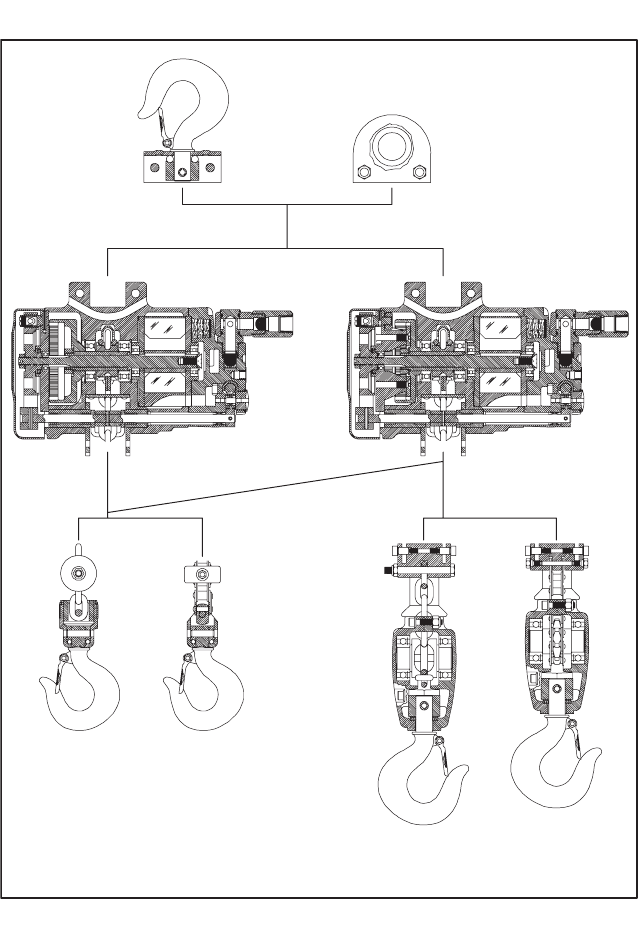
MODEL IDENTIFICATION
For spark-resistant models, see spark-resistant hoist section, see page 20.
Furnished with trolley adapter assembly (assembly number 47717 for 1/4 and 1/2 ton models; assembly number 47716 for 1 ton
models) for mounting manually operated trolley to hoist. Trolley must be ordered separately; see page 21.
INSTALLATION
WARNING
THE HOlSTlNG EQUIPMENT SHOWN AND DESCRIBED
IN THIS MANUAL SHALL NOT BE USED TO LIFT OR
TRANSPORT HUMAN CARGO.
The hoist shall be installed only in locations that will permit
the operator to stand free of the load at all times.
Your ARO hoist is completely lubricated and load tested
before being shipped from the factory. To place in service:
HOOK SUSPENDED MODELS:
Select an overhead support capable of safely supporting
combined weight of hoist and its capacity load. Hang hoist,
being certain the upper hook is firmly seated in the center of
the hook saddle and that the safety latch is properly closed.
The use of a secondary safety cable is recommended, see
page 21.
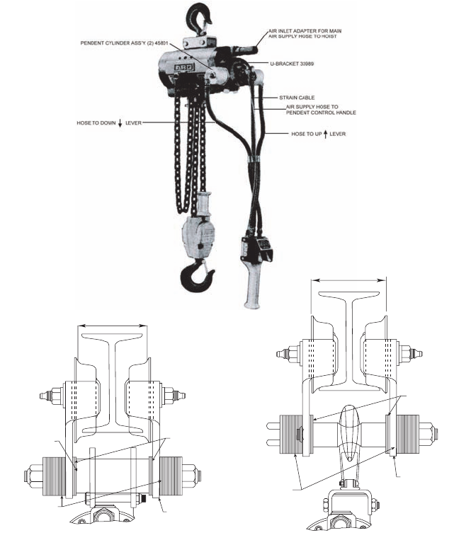
TROLLEY SUSPENDED MODELS:
The trolley side plates must be spaced so the trolley wheels
will properly engage the beam on which the trolley will be
operated. Adjustment for various beam sizes is
accomplished by arrangement of the spacer washers on the
shaft which connects the trolley side plates. The hoist can be
suspended from the trolley by using trolley adapter
(part number 47717 for 1/4 and 1/2 ton hoist models, part
number 47716 for 1 ton hoist models) or by attaching the
upper hook directly to shaft (figure 1). Use of the trolley
adapter is recommended.
The distance between the outside edges of the trolley wheels
should be approximately 1/2” greater than the width of the
beam flange. The number of spacer washers used to space
side plates out must be the same on each side of the shaft
(or trolley adapter) and the remaining spacers must be
equally distributed on the shaft outside the trolley side plates
at each side between the side plates and lock nuts,
(see figure 1). When installing the trolley on the beam, be
certain side plates are vertical.
Assemble trolley adapter to hoist housing. Determine the
number of spacer washers needed to properly space side
plates for beam to be used, and assemble shaft to trolley
adapter. Assemble spacer washers, side plate, spacer
washers and nut to one side of shaft. Position trolley and
hoist on beam and assemble spacer washers, side plate,
spacer washers and nut to other side of shaft. Tighten nuts
securely. The lock nuts must properly engage shaft extending
all the way thru the nut; see page 21 for trolley and adapter.
The trolley wheels should be positioned as close as possible
to the edge of the beam flange. Operate the trolley over the
entire length of the beam track and observe operation. If it
appears the trolley side plates can be moved closer together
and freedom of movement maintained, remove an equal
number of spacer washers from between the side plates and
MODEL NUMBER UPPER MOUNTING TYPE CONTROL TYPE LOAD CHAIN
400# 800# 1600#
7719-E 7700-E 7725-E 34921 HOOK ASSEMBLY PULL CHAIN ROLLER
7719-ET 7700-ET 7725-ET TROLLEY ADAPTER PULL CHAIN ROLLER
7720-E 7708-E 7732-E 34921 HOOK ASSEMBLY PENDENT ROLLER
7720-ET 7708-ET 7732-ET TROLLEY ADAPTER PENDENT ROLLER
MODEL NUMBER UPPER MOUNTING TYPE CONTROL TYPE LOAD CHAIN
1/4 TON 1/2 TON 1 TON
7717-E 7750-E 7775-E 34921 HOOK ASSEMBLY PULL CHAIN LINK
7717-ET 7750-ET 7775-ET TROLLEY ADAPTER PULL CHAIN LINK
7718-E 7756-E 7776-E 34921 HOOK ASSEMBLY PENDENT LINK
7718-ET 7756-ET 7776-ET TROLLEY ADAPTER PENDENT LINK
EXTRA-FAST DESCENT HOISTS
MODEL NUMBER UPPER MOUNTING TYPE CONTROL TYPE LOAD CHAIN
400# 800# 1600#
7706-E 7730-E 34921 HOOK ASSEMBLY PULL CHAIN ROLLER
7706-ET 7730-ET TROLLEY ADAPTER PULL CHAIN ROLLER
7710-E 7734-E 34921 HOOK ASSEMBLY PENDENT ROLLER
7710-ET 7734-ET TROLLEY ADAPTER PENDENT ROLLER
MODEL NUMBER UPPER MOUNTING TYPE CONTROL TYPE LOAD CHAIN
1/4 TON 1/2 TON 1 TON
7754-E 7777-E 34921 HOOK ASSEMBLY PULL CHAIN LINK
7754-ET 7777-ET TROLLEY ADAPTER PULL CHAIN LINK
7758-E 7778-E 34921 HOOK ASSEMBLY PENDENT LINK
7758-ET 7778-ET TROLLEY ADAPTER PENDENT LINK
Form 04615308-Edition 2 3
trolley adapter at each side and assemble these spacers to
the outside of the side plates between the side plate and lock
nuts.
The beam on which the trolley is to be used must safely
support the combined weight of the hoist, trolley and capacity
load. Minimum turning radius of the trolley is 24” for 1/4 and
1/2 ton models; 36” for 1 ton models.
Connect hoist to nearest air source using a minimum 1/2” i.d.
air hose assembly. Sufficient air hose must be provided to
reach the farthest point of travel of the trolley.
ARO model 7703 hose trolley assemblies are recommended
to keep air hose elevated and in line with the hoist,
see page 24.
WIDTH OF BEAM FLANGE
PLUS 1/2" (13 mm)
EQUAL NO.
OF SPACERS
EQUAL NO.
OF SPACERS
TROLLEY ADAPTER
SIDE PLATES MUST
BE VERTICAL
TROLLEY ADAPTER MOUNTING
WIDTH OF BEAM FLANGE
PLUS 1/2" (13 mm)
EQUAL NO.
OF SPACERS
EQUAL NO.
OF SPACERS
SIDE PLATES MUST
BE VERTICAL
HOOK TO TROLLEY MOUNTING
FIGURE 1
4Form 04615308-Edition 2
AIR AND LUBE REQUIREMENTS
AIR PRESSURE of 90 p.s.i.g. (6 bar) at the air inlet of the
hoist is required for maximum motor efficiency. If necessary,
an air regulator should be installed to maintain this pressure
when hoist is in operation.
FILTERED AND OILED AIR will allow the hoist to operate
more efficiently and yield a longer life to operating parts and
mechanisms. A line filter capable of filtering particles larger
than 50 microns should be used with a line oiler.
FILTER-REGULATOR-LUBRICATOR (F-R-L) assembly
model 128241-300 is recommended for use with each hoist.
The capacity of this F-R-L is adequate to provide clean
(40 micron) oiled and regulated air for the hoist. The F-R-L
must be installed on the stationary air line, in that order, with
the lubricator nearest to the hoist.
LOAD CHAIN LUBRICATION - Chain should be lubricated
periodically with heavy “EP” Gear Oil. Occasional cleaning of
the chain under normal operation conditions will tend to
reduce wear and prolong chain and pocketwheel
(or sprocket) life. To properly clean, remove chain from hoist
(see page 7) and wash in an oil solvent. Lubricate chain.
Under highly contaminated operating conditions, the load
chain should be cleaned and relubricated with greater
frequency to remove grit, sand and other contaminants.
OIL RESERVOIR in head should be filled with spindle oil
(29665) after each 40 hours of operation.
INJECT GREASE (33153), 2 to 3 strokes, thru grease fitting
in hoist housing to provide lubrication for gearing, and thru
fittings of trolley wheels a minimum of every 160 hours of
operation.
LOWER BLOCK ASSEMBLY should be lubricated at any
time the lower block is disassembled either for inspection or
for maintenance or for chain replacement. See pages 16 and
17 for lubrication instructions.
RECOMMENDED HOSE SIZE - 1/2” (13 mm) nominal inside
diameter.
RECOMMENDED LUBRICANTS: Spindle Oil 29665,1 qt.
(.9 liter) container for oiler and air inlet; Grease 33153,5 lb.
(2.3 kg) can for gears, lower block and bearings; “O” Ring
Lubricant 36460 4 oz. (113 g) tube for lubrication and
installation of “O” rings.
OPERATION
OPERATE HOIST CAUTIOUSLY to become familiar with the
performance of the hoist. Hoist shall be operated from a
position that will not be hazardous to the operator. Abrupt
operation, resulting from “jerking” of controls, should be
avoided.
The rate of lift or descent of any ARO chain hoist can be
governed manually by the operator, Both the pull chain and
pendant controls provide unlimited variation between full
speed and the slowest “INCHING” movement. This is
accomplished by movement of pull chain handles or pendant
control levers. Pulling down on pull chain control as far as
possible or depressing pendant control levers fully will result
in maximum hoist speed.
On pendant control models, the control handle is supported
by a strain cable to prevent stress on hoses.
BEFORE STARTING TO LIFT, ensure chain is properly
seated in the sprockets (or pocketwheel). Do not lift or move
load more than a few desinches until load is well balanced in
sling or lifting device. Care shall be taken in hoisting to
ensure that chain is not kinked or twisted and load does not
contact any obstruction Be certain hoist is centered over load
to prevent danger of load swinging when lifted. Side or end
pulling should always be avoided. Take up slack chain
carefully to avoid overstress caused by jerking load when
lifting. Be certain that safety latch on load hook is properly
closed. On 1 ton link chain models to avoid jamming of chain
in lower block, allow only sufficient slack in chain to permit
attaching hook to load.
DO NOT wrap the hoist chain around the load. The load shall
be attached to the hook by means of slings or other approved
devices and shall be properly seated in the saddle of the
hook.
The maximum lift rate of a hoist is constant, provided that air
pressure and load are also constant. The maximum descent
rate of a hoist, with the exception of spark-resistant models
(see spark-resistant hoist section), can be varied within fixed
limits by means of regulating valves located on the underside
of the head housing.
Hoists are shipped from the factory with regulator valves
pre-set for rate of descent and fastest rate of lift. If a faster
rate of descent is desired, turn regulator valve clockwise by
small increments while testing with desired or rated load
attached. If a slower rate of lift is desired, turn regulator valve
counterclockwise by small increments while testing with
desired or rated load.
The operator shall test the brakes each time a load
approaching the rated load is handled by raising the load just
enough to clear the floor, or supports, and checking for
proper brake action and lift continued only if brake is
functioning properly.
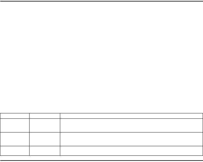
PART NUMBER WHERE USED DESCRIPTION
29665 AIR MOTOR
A HIGH QUALITY LIGHT TURBINE OR SPINDLE OIL. RUST INHIBITED, WITH
VISCOSITY OF 100-150 S.U.S. AT 100° F. OIL IS COMPATIBLE WITH
POLYCARBONATE TYPE AIR LINE LUBRICATOR BOWLS.
33153 GEARS &
BEARINGS
A HIGH QUALITY “EP” EXTREME PRESSURE ANTI-FRICTION BEARING AND GEAR
GREASE, NLGI NO. 1. FREE OF CORROSIVE MATTER AND FILLERS, WITH A
VISCOSITY OF APPROXIMATELY 750 S.U.S. AT 100° F.
36460 “O” RINGS &
LIP TYPE SEALS A STRINGY LUBRICANT FOR RUBBER SEALS, WITH GOOD ADHESIVE QUALITIES.
Form 04615308-Edition 2 5
CAUTION
DO NOT OPERATE HOIST WITHOUT CHAIN STOP
ATTACHED PROPERLY TO HOIST LOAD CHAIN. DO NOT
USE CHAIN STOP AS A LIMIT SWITCH (to stop hoist
when operating in the “up” mode). The chain stop
function is to keep the lower hook components (lower
block on 1 ton models) from striking control arm (37719)
should an over-run condition ever occur.
DO NOT EXCEED RATED LOAD CAPACITY OF HOIST.
DO NOT OPERATE HOIST OVER PEOPLE.
WARNING
DO NOT USE HOIST FOR HUMAN TRANSPORT.
DO NOT LEAVE LOAD SUSPENDED FOR EXTENDED OR
UNATTENDED PERIODS.
INSURE LOAD CHAIN IS HANGING PROPERLY AND IS
FREE OF TWISTS, LOOPS OR KINKS.
WARNING
MAXIMUM LOWERING SPEED WITH RATED CAPACITY
LOAD IS VERY HIGH. ADJUST WITH CARE.
Safe and efficient operation of your ARO hoist can be
attained by observing proper operating, inspection and
maintenance procedures. Allow only competent and qualified
people to operate hoist and subject each hoist to a regular
inspection and maintenance procedure. The qualified hoist
operator must be carefully instructed in the safe operation of
the hoist, including a study of the manufacturer’s literature,
and must thoroughly understand proper methods of hitching
loads. The operator should have a good attitude regarding
safety.
To aid in better understanding of proper and safe use of
hoists: the publication “Overhead Hoists”, ANSI B30.
16-1981, can be purchased from the American Standards
Institute, Inc., 1430 Broadway, N.Y., N.Y. 10018.
INSPECTION AND MAINTENANCE
INSPECTION
ARO recognizes the need for periodic inspection of hoist
components as an important step in preventive maintenance.
The type of application for a hoist varies so greatly, it is
impractical to recommend an exact time-table for inspection
of the hoist, Where hoist is subjected to continuous operation
with capacity loads, it is recommended the unit be inspected
daily to weekly. If the application is less demanding, the unit
should be inspected weekly to monthly. In general, the
frequency of inspection should be determined by the severity
of the application.
The user of a hoist should be guided by any existing federal,
state or local regulations governing the use, testing or
inspection of the hoist.
The following points and areas are recommended for
inspection:
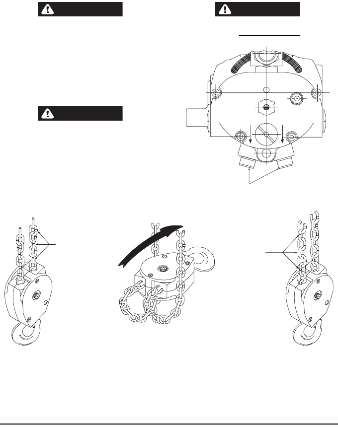
X
DN
UP
REGULATOR VALVE
FIGURE 2
WRONG
RIGHT
APPEARANCE OF TWISTED
CHAIN - ALTERNATING LINKS
DO NOT FORM A STRAIGHT
LINE
USE EXTREME CAUTION TO INSURE LOWER HOOK
ASS'Y. HAS NOT BEEN FLIPPED THRU CHAIN
RESULTING IN TWISTING OF CHAIN
APPEARANCE OF CHAIN THAT
HAS NOT BEEN TWISTED -
ALTERNATING LINKS FORM A
STRAIGHT LINE
FIGURE 3
6Form 04615308-Edition 2
LOAD CHAIN AND ANCHORS
a. Visually check for nicked, gouged, twisted, bent,
corroded, rusted, worn or broken links. Check ends of
chain where chain is anchored to hoist frame and where
chain is fastened to lower hook. Check anchores and
pins.
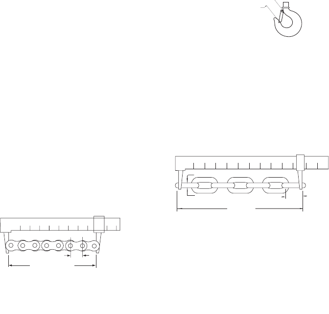
b. Check chain elongation with a vernier caliper as shown in
figure 4. IT IS NOT INFERRED that a chain is safe prior
to the occurence of elongation of the chain. It is inferred
ONLY, that when said elongation is evident, the chain
must be replaced. Other factors, such as those
mentioned as a visual check, may render chain unsafe
long before replacement due to elongation is necessary.
NOTE: New chain should never be used on a worn
pocketwheel. Replace chain and pocketwheel as a pair,
Chain should also be replaced when replacing brake
shoes.
GEARS, BEARINGS AND SPROCKET
a. Check condition of teeth on gears and motor shaft pinion.
b. Check condition of sprocket teeth or pockets of
pocketwheel.
c. Check condition of bearings.
d. Replace any worn or damaged parts.
BRAKE
a. Check brake linings and components,
b. Check brake operation.
NOTE: When replacement of brake shoes is indicated,
they must be replaced as a pair. Also replace chain at
this time.
THROTTLE VALVE HEAD AND GEARS
a. Check condition of valve body, valves and “O” rings on
valves.
b. Check condition of gear teeth and bearings.
c. Replace any worn or damaged parts.
HOOKS AND SUSPENSION
a. Check upper and lower hooks and component parts for
bent, worn, cracked, broken or otherwise damaged parts.
b. On trolley suspended models, check conditions of trolley
parts, trolley adapter and component parts. Replace any
damaged parts.
AIR MOTOR
a. Check end faces of rotor for roughness and blade slots
for wear or burrs, A new blade should slide in and out of
slots without binding.
b. Check blades for wear, warpage or other damage.
c. Check cylinder bore diameter for rough circular grooves
from scoring. A badly scored cylinder cannot be restored
by honing since it will only enlarge bore diameter,
widening seal point between rotor and cylinder, hindering
free exhaust of air and result in loss of speed and power.
d. Check end plates for wear or scoring. Check bearings.
e. Replace any excessively worn or damaged parts.
GENERAL MAINTENANCE
AIR HOISTS are made of precision parts and should be
handled with reasonable care when servicing. Excessive
pressure exerted by a holding device may cause distortion of
a part. Apply pressure evenly when disassembling (or
assembling) parts which have a press fit. When removing or
installing bearings, apply pressure to the bearing race that
will be press fit to the mating part; if this is not practiced,
Brinelling of the bearing races may occur making
replacement necessary. It is important that the correct tools
and fixtures are used when servicing this air hoist.
DISASSEMBLY should be done on a clean work bench with
a clean cloth spread to prevent the loss of small parts. After
disassembly is completed, all parts should be thoroughly
washed in a clean solvent, blown dry with air and inspected
for wear levels, abuse and contamination. Double sealed or
shielded bearings should never be placed in solvent unless a
good method of relubricating the bearing is available. Open
bearings may be washed but should not be allowed to spin
while being blown dry. When REPLACEMENT PARTS are
necessary, consult drawing containing part.
BEFORE REASSEMBLING, lubricate parts where required.
Use 33153 grease, or equivalent, in bearings. Use 36460
lubricant for “O” ring assembly. When assembling “O” rings or
parts adjacent “O” rings, care must be exercised to prevent
damage to the rubber sealing surfaces. A small amount of
grease will usually hold steel balls and other small parts in
place while assembling.
WHEN ORDERING PARTS, be sure to list PART NUMBER,
PART NAME and MODEL NUMBER OF HOIST. USE ONLY
GENUINE ARO REPLACEMENT PARTS.
(16 mm) .625 PITCH
4.755 NEW CHAIN
(120.7 mm)
VERNIER CALIPER
IF VISUAL CHECK REVEALS NO DEFECTS, PROCEED AS FOLLOWS:
LAY USED CHAIN ON FLAT SURFACE AND MEASURE OVER EIGHT (8) ROLLS, WHILE
CHAIN IS PULLED TAUT, AS SHOWN. MEASUREMENT SHOULD BE TAKEN ON PORTION
OF CHAIN WHICH HAS MOST PASSED OVER THE SPROCKET.
IF MEASUREMENT TAKEN IS 4.810 INCHES OR MORE. CHAIN SHOULD BE REPLACED.
(122 mm)
FIGURE 4
CORRECT
HOOK OPENING
1-1/8" (29 mm) ON 1/4 & 1/2 TON MODELS
(LOWER HOOKS).
1-1/4" (32 mm) ON UPPER & 1-TON
(LOWER HOOKS)
VERNIER CALIPER
5.250 NEW CHAIN
IF VISUAL CHECK REVEALS NO DEFECTS, PROCEED AS FOLLOWS:
LAY USED CHAIN ON FLAT SURFACE AND MEASURE BETWEEN SEVEN (7) LINKS AS
SHOWN. MEASUREMENT SHOULD BE TAKEN ON PORTION OF CHAIN WHICH HAS
MOST PASSED OVER THE POCKET WHEEL.
IF MEASUREMENT TAKEN IS 5.355 OR MORE. CHAIN SHOULD BE REPLACED.
1/4
(6 mm) (19 mm) .750 PITCH
(133 mm)
(136 mm)
FIGURE 4
Form 04615308-Edition 2 7
REMOVAL AND INSTALLATION OF LOAD CHAIN
REMOVAL
LINK CHAIN HOISTS - A new chain should never be used on
a worn pocketwheel. Replace chain and pocket-wheel as a
pair. To remove chain; disconnect end of load chain from
anchor lug on housing by removing screw (Y157-51) and
washer (Y13-4-C). NOTE: Models employing a chain basket,
remove chain stop from end of chain. Chain can be pulled
thru housing by hand while holding brake open, by pulling (or
pushing) on control arm (either end). On 1 ton models,
disconnect opposite end of load chain from anchor bracket
(41624) by removing nut (Y109-524) and bolt (41625).
Remove chain stop and lower hook assembly.
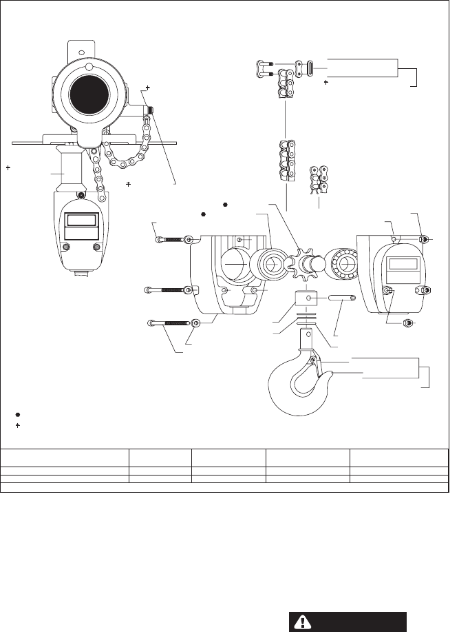
ROLLER CHAIN MODELS - Disconnect end of load chain
from anchor block (44686) by removing connecting link
(33363). NOTE: Models employing a chain basket, remove
chain stop (ring) from end of chain. Chain can be pulled thru
housing by hand while holding brake open, by pulling (or
pushing) on control arm (either end). On 1 ton models,
disconnect opposite end of load chain from anchor bracket
(37579) by removing bolt (37580) and anchor pin (34316).
Remove chain stop and lower hook assembly.
INSTALLATION
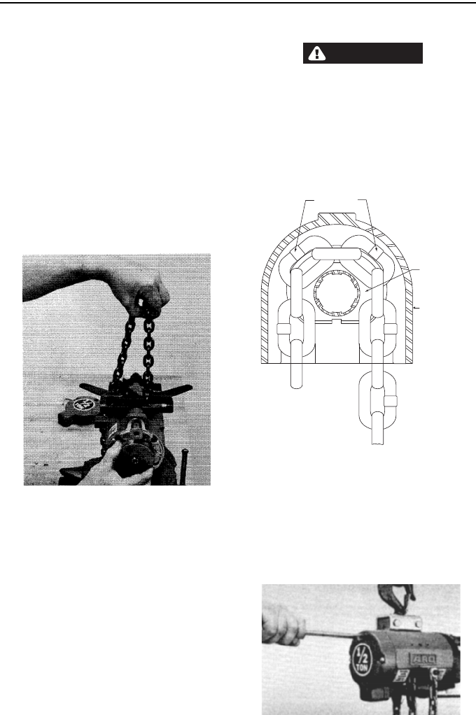
LINK CHAIN MODELS - Position hoist in a vise or other
suitable holding device (figure 5) and remove housing cap,
brake spring and brake shoes, Turn brake wheel by hand to
rotate pocketwheel while carefully feeding chain thru chain
guide and around pocketwheel. Pull sufficient chain thru
housing to allow end link of chain to be attached to anchor
lug on housing.
IMPORTANT NOTICE: The link chain must be positioned
around the pocketwheel so the weld on the standing
links of chain face outward from pocketwheel (figure 5).
ALSO, the end link of chain must be fed over
pocketwheel so it will be positioned properly to permit
attaching chain to anchor lug on housing without
twisting of chain (figure 16).
WARNING
DO NOT attempt to feed chain over pocketwheel or
sprocket by air power as chain will be pulled thru at a
very fast rate.
ROLLER CHAIN MODELS - Remove housing cap, brake
spring and brake shoes. Turn brake wheel by hand to rotate
sproket while carefully feeding chain thru guide and around
sproket. Pull sufficient chain thru housing to allow end link of
chain to be attached to anchor block and anchor lug on
housing.
To assemble chain to lower block on 1-TON models, see
page 16 and 17.
BRAKE ADJUSTMENT
To adjust brake, insert screwdriver thru hole in housing cap.
Turn screw (37701) counterclockwise to tighten brake,
clockwise to loosen brake.
Brake adjustment should be made with air turned on and with
rated load attached to lower hook. Operate hoist to raise load
applying slight pressure to pendent control. If load starts to
lower before it is raised by motor, tighten brake until no
slippage is evident. Cure should be taken not to tighten brake
more than necessary to hold load. If brake is too tight, it will
cause erratic hoist control.
INSTALLING LOAD CHAIN FIGURE 5
POCKET WHEEL
CHAIN GUIDE
CHAIN WELD
FIGURE 5
FIGURE 6
8Form 04615308-Edition 2
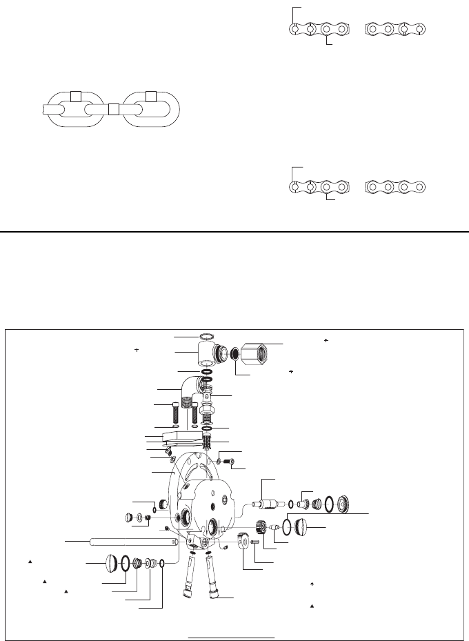
DISASSEMBLY AND REASSEMBLY
To minimize the possibility of ports damage and for
convenience, the steps for disassembly or reassembly listed
on the following pages are recommended.
REMOVAL OF HOIST
a. Lower and disconnect load from hoist.
b. Shut off air at source and operate hoist control to bleed
air from hoist and line.
c. Disconnect air hose at inlet swivel (on pendent control
models, remove pendent control hoses also) and remove
hoist from overhead suspension,
d. If chain basket is being used, remove from hoist.
e. Drain oil from reservoir in head.
f. Remove trolley from hoist housing.
g. Place hoist upside-down in vise and clamp on upper
mounting on housing.
h. If hoist is to be completely disassembled, it is
recommended the load chain be removed. For removal of
chain, see page 7.
HEAD SECTION
a. Remove roll pin (Y178-56) from gear (34022) and control
rod (34021). NOTE: If head assembly is not to be
disassembled, control rod may be removed with head,
thereby making it unnecessary to re-time gear (34022)
with throttle valves (see “Timing of Head” figure 7). To
remove control rod with head, remove roll pin (Y178-55)
from control arm (37719), remove roll pin (Y178-60) from
brake block (34029) and remove brake block.
b. Remove screws (Y154-54) and washers (Y14-10).
c. Remove head assembly from housing.
BRAKE AND GEARING SECTION
a. Remove screws (Y19-113-C) and housing cap assembly.
b. Slide brake spring (33281) part way off brake shoes
(33387 or 33387-1) and remove spring with brake spring
spreader (33541). This will release brake shoes and steel
balls (Y16-10).
c. Place a pin thru hole in brake wheel (33376) to keep from
turning and remove nut (Y12-106) and washer
(Y117-616). Remove brake wheel.
d. Remove roll pin (Y178-60) from brake block (34029) and
remove brake block from control rod (34021).
e. Remove screws (Y99-41) and washers (30997) and
remove gearing assembly.
MOTOR SECTION
a. After removal of head assembly, housing cap, nut
(Y12-106) and washer (Y117-616); motor assembly may
be removed from housing.
HOUSING SECTION
a. Follow disassembly procedures as outlined in head
section, brake and gearing section and motor section.
For further disassembly of sections, see pages 10 thru 19.
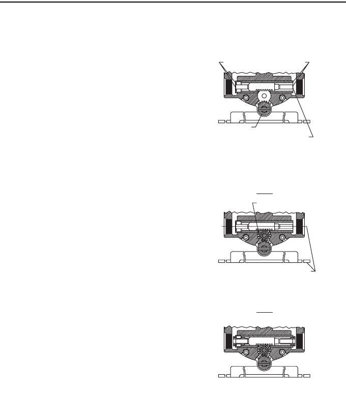
STEP 2
STEP 3
POSITION POWER UNIT SO YOU ARE FACING END WITH AIR INLET.
WITH VALVE PARTS AND GEAR (34030) REMOVED, PLACE VALVE BODY IN VALVE
OPENING. INSERT FINGER IN EACH END OF VALVE OPENING AND ALIGN ENDS OF
VALVE BODY WITH ENDS OF BUSHING. NOTE: VALVE BODY MUST BE INSTALLED WITH
IDENTIFICATION MARK AS SHOWN.
POSITION CONTROL ARM PARALLEL WITH OPENING.
DROP GEAR (34030) INTO PLACE AND SECURE WITH SHAFT (34025) AND LOC
K
SCREW.
ENDS OF VALVE BODY FLUSH WITH BUSHING.
GEAR 34022
IDENTIFICATION MARK ‘‘X” ON END OF VALVE BODY.
CONTROL ARM PARALLEL WITH OPENING.
GEAR 34030
A
SSEMBLE BALANCE OF VALVE PARTS.
"TIMING OF HEAD"
STEP-1
FIGURE 7
Form 04615308-Edition 2 9
400 LB. & 1/4 TON 800 & 1600 LB.
1/2 & 1 TON
800 LB. & 1/2 TON
LINK CHAIN ROLLER CHAIN
400 & 800 LB.
1/4 & 1/2 TON
LOWER BLOCK
LINK CHAIN
LOWER BLOCK
ROLLER CHAIN
1600 LB. & 1 TON
TYPICAL CROSS SECTION
- E - ET
FIGURE 8
10 Form 04615308-Edition 2
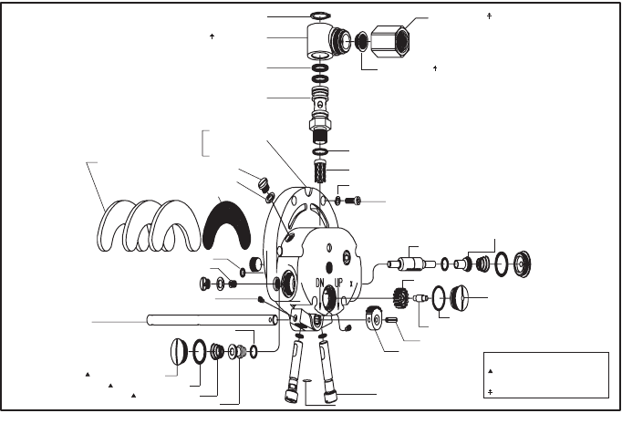
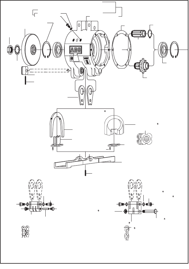
HEAD SECTION
DISASSEMBLY
a. Remove head from housing as outlined on page 8.
b. Remove lock screw (34024), gear (34030) and shaft
(34025).
c. Remove valve caps (34026), “O” rings (Y325-116) and
springs (38966).
d. Valves (33703) and (46079) with “O” rings (Y330-12) and
valve body (37704) may now be removed from either end
of head housing.
e. Swivel assembly may be disassembled while mounted to
head or removed from head. To disassemble, remove
retaining ring (Y145-28), pull off swivel (46839) exposing
“O” rings (Y325-115) and swivel body (33314).
f. To remove oilite casting (33190), remove oil screw
(30747) and washer (31389) on side of head. Insert
screwdriver into opening and remove oilite costing.
g. Muffler fillers (34028) and screen (33672) are exposed
after removal of head from housing and may be removed.
h. To remove regulator valve (41595), remove set screws
(41598) and pull valves from housing.
REASSEMBLY
a. Assemble screen (33672) and fillers (34028) to head.
Assuming other hoist components are assembled to
housing, assemble head to housing with gasket (41623).
Secure with washers (Y14-10) and screws (Y154-54).
b. Assemble “O” rings (Y325-17) and (Y325-115) and
screen (46072) to swivel body and assemble to head.
Assemble swivel to swivel body and secure with retaining
ring (Y145-28). Assemble screen (31648) and adapter
(46211) to swivel.
c. Assemble oilite casting (33190), screw (30747) with
washer (31389) and regulator valves (41595) with “O”
rings (Y325-11) to head.
NOTE: Assemble valves to head with slot in valve
positioned to accept set screw. Secure valves with set
screws (41598). After complete assembly of hoist,
loosen set screw and adjust valve for desired rate of lift
and descent. See pages 4 and 5.
d. With gear (34022) and control rod assembled to housing,
assemble valve parts as shown in figure 7, page 8.
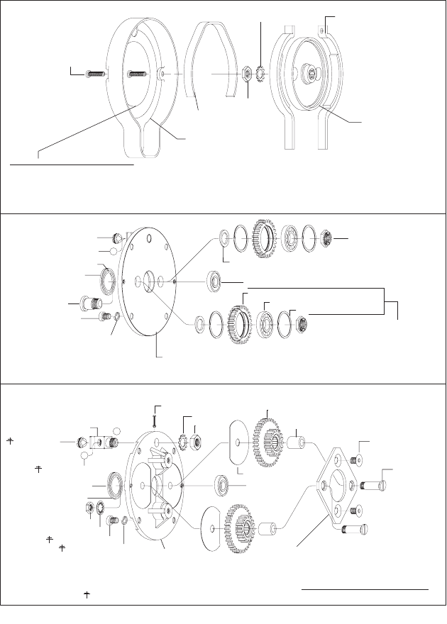
BRAKE AND GEARING SECTION
DISASSEMBLY
a. Remove housing cap, brake spring, brake wheel and
components as outlined on page 8.
b. On 1/4 ton models, remove nuts (38910), releasing gear
and bearing assemblies.
c. On 1/2 and 1 ton models, remove screws (Y194-44), nuts
(33368), washers (Y1-516) and bolts (33369), releasing
support ring and gear assemblies.
d. Bearing (36546) and grease seal (37706) should be
removed only for replacement.
REASSEMBLY
NOTE: lubricate gears and bearings liberally with ARO
33153 grease when assembling.
a. Assemble grease seal (37706) and bearing (36546) to
end plate, if removed.
b. On 1/4 ton models, assemble bearings (32325) and
retaining rings (38908) to idler gears (38905) and secure
to end plate with screws (38907) and nuts (38910).
ADAPTER 46211
RETAINING RING Y145-28
SWIVEL 46839
"O" RING (2) Y325-115
SWIVEL BODY 33314
INCLUDES PIPE
PLUG (3) Y227-3
(NOT SHOWN)
46071 HEAD
FILLER 34028 (3)
WASHER (2) 31389
SCREEN 33672
OIL SCREW (2) 30747
OLITE CASTING 33190
SET SCREW (2) 41598
* CONTROL ROD 34021
* "O" RING Y325-9
VALVE CAP (2) 34026
"O" RING (2) Y330-12
"O" RING (2) Y325-116
SPRING (2) 38966
LIFT VALVE 46079
VALVE BODY (2) 41595
"O" RING (2) Y325-11
ROLL PIN Y178-56
GEAR 34022
SHAFT 34025
"O" RING Y325-19
LOCK SCREW 34024
GEAR 34030
VALVE BODY 37704
VALVE 37703
CAP SCREW (6) Y154-54 *
LOCK WASHER (6) Y14-10 *
SCREEN 46072
"O" RING 7325-17
SCREEN 31648
*NOT INCLUDED IN HEAD ASS'Y
NOT USED WITH PENDENT
CONTROL MODELS
INCLUDED IN SWIVEL KIT 46840
FIGURE 9
Form 04615308-Edition 2 11
c. On 1/2 and 1 ton models, assemble wear plates (45909),
gear assemblies and bushings to end plate and secure
with support ring, screws (Y194-44), bolts (33369),
washers (Y1-516) and nuts (33368).
d. Assemble end plate to housing and secure with washers
(30997) and screws (Y99-41).
e. Assemble brake wheel (33376) to splined end of motor
spindle and secure with washer (Y117416) and nut
(Y12-106).
f. Assemble steel balls (Y 16-10) and screw (37701) into
bracket. Position brake shoes (33387 or 33387-1) over
brake wheel and assemble brake spring (33281) over
shoes, using brake spring spreader (33541).
g. Assemble housing cap over brake and secure with
screws (Y19-113-C). See “Brake Adjustment”, page 7.
SCREW (2) Y19-113C
CAPACITY LABEL
45672-1 (1/4 TON)
45672-2 (1/2 TON)
45672-3 (1 TON)
46097-2 (1500 lbs.)
46097-3 (400 lbs.)
46097-4 (800 lbs.)
46097-5 (1000 lbs.)
46097-6 (1600 lbs.)
HOUSING CAP 45667
BRAKE SPRING 33281
NUT Y12-106
WASHER- Y117-616 BRAKE SHOE (2)
33387- ROLLER CHAIN MODELS
33387-1- LINK CHAIN MODELS
BRAKE WHEEL 33376
* SCREW 37701
SPACER (2) 38906
BEARING 36546
IDLER GEAR 38905
BEARING 32325
RETAINING RING (2) 38908
NUT (2) 36910
* BALL(2) Y16-10
LIP OF SEAL THIS SIDE
INCLUDED WITH 38911
END PLATE
SEAL 37706
* SCREW (2) 38907
* SCREW (4) Y99-41
* WASHER (4) 30997
END PLATE 38911
INCLUDES BRACKET 38904-1 AND
ROLL PIN Y178-43, NOT SHOWN. GEARING ASSEMBLY 41618 (1/4 TON)
GEAR & BEARING ASS'Y. (2) 38912
* NOT INCLUDED WITH GEARING ASS'Y.
ROLL PIN Y178-21
WASHER Y117-616 GEAR & BEARING ASS'Y. 37763
WEAR PLATE (2) 45909
BEARING 36546
BUSHING (2) 37709
SCREW (2) Y194-44
BOLT (2) 33369
SUPPORT RING 45911
NUT Y11-6
BRACKET 37702-1
SCREW 37701
BALL (2) Y16-10
* SEAL 37706
WASHER (4) 30997 END PLATE 45913
SCREW (4) Y99-41
WASHER (2) Y1-516
NUT (2) 33368
LIP OF SEAL THIS SIDE
* INCLUDED WITH 45913 END PLATE
NOT INCLUDED WITH GEARING ASS'Y.
GEARING ASSEMBLY 45912 (1/2 8.1 TON
FIGURE 10
12 Form 04615308-Edition 2
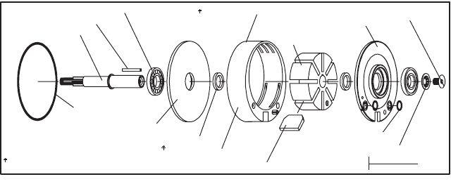
MOTOR SECTION
DISASSEMBLY
a. Remove motor from housing as outlined on page 8.
b. Remove screw (Y200-59) and washer (33274). Motor will
now come apart.
REASSEMBLY
a. Assemble bearings (33235) and spacers (33272) into
end plates.
NOTE: Bearings (33235) are paired flush face bearings,
shielded on one side. The open or unshielded side must
be installed facing the end plate. Lubricate bearings with
33153 grease when assembling.
b. Assemble end plate (33284) together with bearing and
spacer on large end of spindle shaft (33373) and slide up
to boss on shaft.
c. Assemble key (33277) into groove in spindle and
assemble rotor with groove aligned with key on spindle.
d. Assemble cylinder over rotor to end plate and assemble
blades (43067) to rotor.
e. Assemble end plate (46074) together with spacer and
bearing. Secure with washer (33274) and screw (Y200-
59). Hold spindle in a suitable holding device, being
careful not to damage splines or threads on end of
spindle.
f. Assemble “O” rings (Y325-12) into end plate.
g. Assemble motor with “O” ring (Y325-154) into housing.
HOUSING SECTION
DISASSEMBLY
a. Remove plate (33318) on link chain models; remove
chain stripper (33319) on roller chain models.
b. Place brass or wood block in sprocket cavity to prevent
turning of sprocket shaft and remove nut (33280), washer
(Y1-966) and gear.
c. Remove retaining ring (Y147-18) from “motor end” of
housing.
d. Sprocket shaft and bearing (33236) may now be removed
thru “motor end” of housing.
e. Remove chain guide (35861) and pocketwheel (37571)
on link chain models. On roller chain models., to remove
chain guide (34991), remove cap screws (Y154-54) and
washers (Y14-10) from housing.
f. Remove retaining ring (Y147-18) and bearing (33236)
from “brake end” of housing.
REASSEMBLY
LINK CHAIN MODELS -
a. Insert pocketwheel (37571) into chain guide (35861) and
place in housing. NOTE: Pocketwheel must be installed
with 1.250 diameter counterbore facing away from “brake
end” of housing. Secure plate (33318) to housing with
sems fasteners (33330).
b. Assemble bearing (33236) and retaining ring (Y147-18)
into “brake end” of housing.
c. Assemble retaining ring (Y145-28) into groove in shaft
(34985) and assemble bearing (33236) on end of shaft
with retaining ring.
d. Assemble shaft, with bearing and retaining ring thru
opening at “motor end” of housing. Insert shaft thru
pocketwheel and thru bearing in “brake end” of housing.
Assemble retaining ring (Y147-18) into housing.
e. Assemble gear (33374) to shaft and secure with washer
(Y1-966) and nut (33280).
f. Assemble brake block (34029) to control rod (34021) and
secure with roll pin (Y178-60).
g. Assemble hangers (37585) and control arm (37719) to
housing
(NOTE: Assemble control arm in housing with arms for
mounting control chains pointing towards air inlet) and
insert control rod thru housing, hangers and control
arm. Secure control rod and arm with roll pin (Y178-55).
h. On 1 ton models, assemble anchor bracket (41624) to
hangers (37585) and secure with washers (37587) and
anchor bolts (37586).
i. For installation of load chain, see page 7.
ROLLER CHAIN MODELS -
a. Insert chain guide (34991) into housing and secure with
washers (Y14-10) and cap screws (Y154-54).
b. Assemble bearings (33236) and retaining ring (Y147-18)
into “brake end” of housing.
c. Assemble bearing (33236) on sprocket (33375) and
assemble into housing thru “motor end” with threaded
end of sprocket thru bearing in “brake end” of housing.
d. Assemble gear (33374) to shaft and secure with washer
(Y1-966) and nut (33280).
e. Secure chain stripper (33319) to housing with sems
fasteners (33330).
f. Assemble brake block (34029) to control rod (34021) and
secure with roll pin (Y178-60).
INCLUDES Y178-73 ROLL PIN
NOT INCLUDED IN MOTOR ASSEMBLY
33277 KEY
33373 SPINDLE
33235 BEARING (PAIRED)
Y325 154 ‘‘O” RING
33284 END PLAT E
33272 SPACER (2)
34541 CYLINDER
CYLINDER 34032 (STANDARD DESCENT)
(EXTRA - FAST DESCENT)
43067 BLADE (8)
Y325-12 "O" RING (2)
33274 WASHER
43068 ROTOR
46074 END PLATE
Y200-59 SCREW
TORQUE TO 90-110 IN. LBS.
MOTOR ASS'Y. 46072-STANDARD
46077-EXTRA-FAST
*
*
*
FIGURE 11
Form 04615308-Edition 2 13
g. Assemble hangers (37585) and control arm (37719) to
housing
(NOTE: Assemble control arm in housing with arms for
mounting control chains pointed towards air inlet) and
insert control rod thru housing, hangers and control
arm. Secure control rod and arm with roll pin (Y178-55).
h. On 1 ton models, assemble anchor bracket (37579) to
hangers (37585) and secure with washers (37587) and
anchor bolts (37586).
i. For installation of load chain, see page 7.
NUT 33280
GEAR 38903 (1/4 TON)
CAP SCREW (2) Y154-54
WASHER (2) Y14-10
USED WITH ROLLER CHAIN MODELS ONLY
HOUSING 44677 INCLUDES
NAMEPLATE 45675
DRIVE SCREW (4) Y60-43
WARNING LABEL 43640
GREASE FITTING 35631
33374 (1/2 & 1 TON)
GASKET 41623 RETAINING RING Y145-28
BEARING (2) 33236
RETAINING RING (2) Y147-18
WASHER Y1-966
BRAKE BLOCK 34029
ROLL PIN Y178-60
HANGER (2) 37585
CHAIN GUIDE 34991
CHAIN STRIPPER 33319
(ROLLER CHAIN HOIST)
FASTENER (4) 33330
FASTENER (4) 33330
CHAIN GUIDE 35861
PLATE 33318
CONTROL ARM 37719
WASHER (2) 37587
BOLT 41625
NUT Y109-524
ANCHOR BRACKET 41624
(LINK CHAIN HOIST)
USED WITH 1-TON MODELS ONLY
(ROLLER CHAIN HOIST)
USED WITH 1-TON MODELS ONLY
ANCHOR BOLT (2) 37586
WASHER (2) 37587
ANCHOR BOLT (2) 37586
BRACKET BOLT (2) 37580
ANCHOR PIN 34316
ANCHOR BRACKET 37579
ROLL PIN Y178-55
POCKET WHEEL 37571
(LINK CHAIN HOIST)
SPROCKET 33375
(ROLLER CHAIN HOIST)
(LINK CHAIN HOIST)
SHAFT 34985
CHAIN GUIDE (2) PART NO. 34992-1
FOR MODELS 7712-EL AND 7714-EL.
CAPACITY LABEL
(NOT SHOWN)
46067-1
46067-2
46067-3
44198-2
44198-4
44198-9
44198-13
44198-14
250 Kg (550 lbs.)
500 Kg (1100 lbs.)
1000 Kg (2200 lbs.)
400 lbs.
1000 lbs.
1500 lbs.
800 lbs.
1600 lbs.
*
*
*
*
*
*
FIGURE 12
14 Form 04615308-Edition 2
UPPER HOOK SECTION
DISASSEMBLY
a. To remove upper hook assembly from housing, remove
nuts (Y109-624) and bolts (41599).
b. To disassemble hook assembly, drive out roll pin
(Yl78-122) from collar (34321).
c. Removing collar will release steel balls and bracket from
hook and latch assembly.
REASSEMBLY
a. To assemble steel balls to collar, apply a liberal amount of
grease in groove of collar and place steel balls into
groove.
b. Place bracket in a holding device with flanges down.
Insert hook thru bracket and slip collar with steel balls
over end of hook. Secure with roll pin.
c. Assemble to housing and secure with bolts and nuts.
NOTE: Assemble roll pin with split side pointing directly
UP or DOWN. Insure safety latch is properly assembled
to hook.
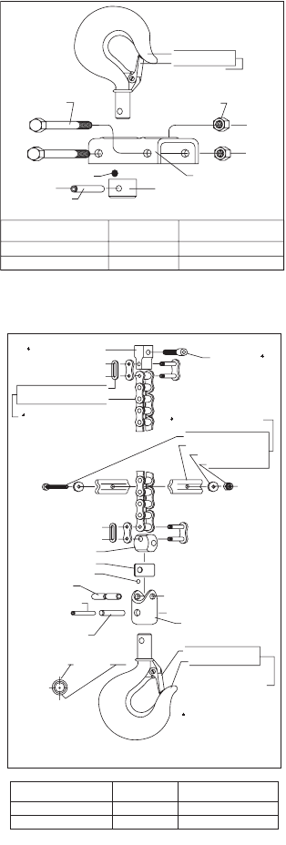
LOWER HOOK SECTION
400# & 800# ROLLER CHAIN MODELS
DISASSEMBLY
a. Remove connecting link (33363). Remove pin (36260),
releasing connector (36259).
b. To disconnect hook from bucket swivel (35009), drive out
roll pins (Y178-114 and Y178-77), releasing collar
(35010) and steel balls (Y16-6).
REASSEMBLY
a. Assemble steel balls (Yl6-6) to collar (35010), applying a
liberal amount of grease in groove of collar to hold steel
balls in place and also for lubrication.
b. Place bucket swivel (35009) in holding device with
opening for collar pointing down. Place hook and latch
assembly thru swivel and slip collar with steel balls over
end of hook and secure with roll pins (Yl78-114 and
Y178-77).
c. Assemble connector (36259) to bucket swivel (35009)
and secure with pin (36260). Assemble chain to
connector and secure with connecting link.
NOTE: Install roll pins with slots vertical, one UP and one
DOWN, figure 14 Insure safety latch is properly
assembled to hook.
UPPER HOOK
ASSEMBLY
HOOK & LATCH
ASSEMBLY HOOK ONLY
34921 (STANDARD)
35113 (SPARK-RESISTANT
34337 34342 (STEEL)
34649 (BRONZE)34651
ROLL PIN Y178-122
INSTALL WITH SPLIT SIDE
EITHER UP OR DOWN
BALL (11) Y16-10
* NOT INCLUDED WITH
UPPER HOOK ASSY.
* BOLT (2) (41599
BRACKET 34341
* NUT (2) Y109-624
HOOK (SEE TABLE)
SAFETY LATCH 35023
HOOK ASSY.
(SEE TABLE)
COLLAR 34321
FIGURE 13
CONNECTING LINK (2) 33363
ROLLER CHAIN 33362-
ROLLER CHAIN ASS'Y. 33364-11
SEE PAGES 20 & 21 FOR
SPARK-RESISTANT LOAD CHAIN.
ANCHOR BLOCK 44686
SCREW Y157-51
CHAIN STOP ASS'Y. 33382
SCREW Y133-113-C
CHAIN STOP (2) 33379
WASHER (2) F15-34-C
STOP NUT Y115-10
CONNECTOR 36259
COLLAR 35010
BALL (13) Y16-6
PIN 36260
ROLL PIN Y178-77
ROLL PIN Y178-114
ASSEMBLE ROLL PINS WITH SLOTS
VERTICAL, ONE UP AND ONE DOWN.
BUCKET SWIVEL 35009
SAFETY LATCH 35023
HOOK (SEE TABLE)
HOOK ASSEMBLY
(SEE TABLE)
NOT INCLUDED WITH LOWER
HOOK ASSEMBLY.
LOWER HOOK ASSEMBLY - ROLLER CHAIN
FIGURE 14
LOWER HOOK
ASSEMBLY
HOOK & LATCH
ASSEMBLY HOOK ONLY
33381-1 (STANDARD)
34655-1 (SPARK-RESISTANT
35005 35006 (STEEL)
35008 (BRONZE)35007
FIGURE 14
Form 04615308-Edition 2 15
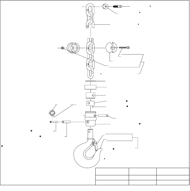
LOWER HOOK SECTION
1/4 AND 1/2 TON LINK CHAIN MODELS
DISASSEMBLY
a. Remove snap ring (35016) and sleeve (35017). Drive out
pin (35018), releasing chain and connector (34989).
b. To disconnect hook from bucket swivel (35019), drive out
roll pins (Y178-114 and Y178-77), releasing collar
(35010) and steel balls (Y16-6).
REASSEMBLY
a. Assemble steel balls (Y16-6) to collar (35010), applying a
liberal amount of grease in groove of collar to hold steel
balls in place and also to lubricate balls.
b. Place bucket swivel (35019) in a suitable holding device
with opening for collar pointing down. Place hook and
latch assembly thru bucket swivel and slip collar with
steel balls over end of hook and secure with roll pins
(Yl78-114 and Y178-77).
c. Place bucket swivel in holding device with hook down.
Insert connector (34989) in proper position in swivel,
place snap ring (35016) and sleeve (35017) over end of
chain. Place chain in connector and secure chain and
connector to swivel with pin (35018).
d. Slip sleeve (35017) over end of swivel and secure with
snap ring (35016).
NOTE: Install roll pins with slots vertical - one UP and
one DOWN. Ensure safety latch is properly assembled to
hook.
ROLL PIN Y178-77
ROLL PIN Y178-114
ASSEMBLE ROLL PINS WITH SLOTS
VERTICAL, ONE UP AND ONE DOWN.
BUCKET SWIVEL 35019
PIN 35018
SAFETY LATCH 35023
HOOK (SEE TABLE)
HOOK ASSEMBLY
(SEE TABLE)
NOT INCLUDED WITH LOWER
HOOK ASSEMBLY.
SCREW Y157-51
LOWER HOOK
ASSEMBLY
HOOK & LATCH
ASSEMBLY HOOK ONLY
35014 (STANDARD)
35012 (SPARK-RESISTANT
35005 35006 (STEEL)
35008 (BRONZE)35007
THESE PARTS INCLUDED IN LOWER HOOK ASSEMBLY
46564 (WITH STEEL HOOK) OR 46565 (WITH BRONZE
HOOK).
LOWER HOOK ASSEMBLY - LINK CHAIN
BALL (13) Y16-6
COLLAR 35010
CONNECTOR 34989
SLEEVE 35017
SNAP RING 35016
SCREW Y19-113-C
CHAIN STOP (2) 34994
STOP NUT Y109-324
CHAIN STOP ASSEMBLY 34981
WASHER Y13-4-C
LINK CHAIN 37708-11
SEE PAGES 20 & 21 FOR
SPARK-RESISTANT LOAD CHAIN
FIGURE 15
16 Form 04615308-Edition 2
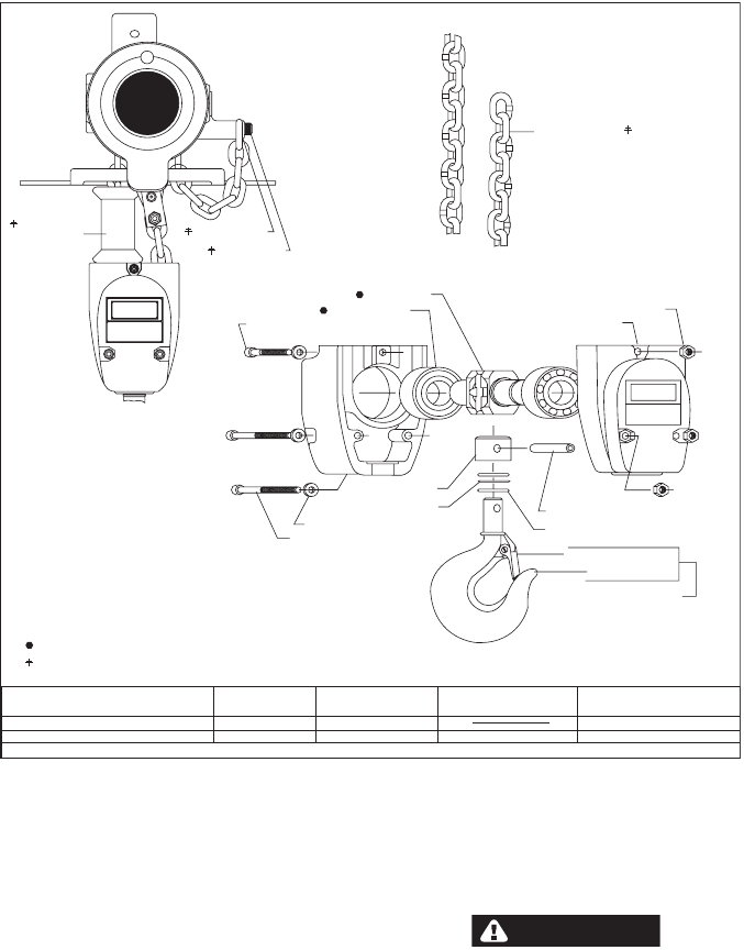
1 TON LINK CHAIN MODELS
DISASSEMBLY
a. Remove screw (Y99-43) and two (2) screws (Y99-47),
lock washers (Y14-416) and nuts (Y107-4-Z).
b. Pull shroud apart releasing hook and components.
Bearings (42406) are pressed on shaft of sheave
(45364).
c. To remove thrust bearing from hook shank, remove roll
pin (Y178-122) and sleeve (45368).
REASSEMBLY
a. Lubricate thrust bearing liberally with grease 33153 or
equivalent and assemble to shank of hook. Assemble
sleeve (45368) to hook and secure with roll pin
(Y178-122). NOTE: Assemble roll pin to hook with split
side vertical with hook (either up or down).
b. Pack bearings (42406) with grease 33153 and assemble
to sheave with shielded side going on shaft first (shielded
side towards sheave).
c. Assemble sheave and hook into one half of shroud,
insuring thrust bearing and race are properly seated in
shroud.
d. Feed load chain around sheave.
CAUTION
Insure chain is not twisted and that welded side of links
face away from sheave - see figure 5 and inset above.
e. Assemble other half of shroud and secure shroud with
screws, washers and nuts as shown, tightening securely.
CAUTION
DO NOT
TWIST
OR JAM
CHAIN
1
TON
1 TON
LINK CHAIN 37708-22
SEE PAGES 20 & 21 FOR SPARK-
RESISTANT LOAD CHAIN.
NUT (3) Y107-4-Z
SHROUD (2) 45362-1
ROLL PIN Y178-122
*
THRUST RACE (2) 45373
SAFETY LATCH 35023
HOOK (SEE TABLE)
HOOK ASSEMBLY (SEE TABLE)
SLEEVE 45368
THRUST BEARING 42089
WASHER (3) Y14-416
SCREW (2) Y99-47
SHEEVE 45364
BEARING (2) 42406
SCREW Y99-43
CAUTION: DO NOT ATTEMPT TO DISASSEMBLE LOWER BLOCK
WITH LOAD SUSPENDED FROM HOIST - LOWER LOAD AND REMOVE
EVERYTHING ATTACHED TO HOOK.
ASSEMBLE ROLL PIN WITH SPLIT SIDE EITHER UP OR DOWN.
SHEAVE AND BEARING ASSEMBLE 45705.
NOT INCLUDED IN LOWER BLOCK ASSEMBLY.
CHAIN
STOP 37666 WASHER Y13-4-C
SCREW Y157-51
*
LOWER BLOCK
ASSEMBLY
HOOK
ASSEMBLY SHROUD CAPACITY LABEL HOOK
45707 (STANDARD)
45709 (SPARK-RESISTANT
** INCLUDED WITH 45378 SHROUD
45367 45362-1 (2)
45378 (2) ** 45280 (1500 #)
45366 (STEEL)
45371 (BRONZE)45372
FIGURE 16
Form 04615308-Edition 2 17
1600# ROLLER CHAIN MODELS
DISASSEMBLY
a. Remove screws (Y99-43) and two (2) screws (Y99-47),
lock washers (Y14-416) and nuts (Y107-4-Z).
b. Pull shroud apart, releasing hook and components.
Bearings (42406) are pressed on shaft of sprocket
(45365).
c. To remove thrust bearing from hook shank, remove roll
pin (Y178-122) and sleeve (45368).
REASSEMBLY
a. Lubricate thrust bearing liberally with ARO 33153 grease,
or equivalent, and assemble to shank of hook. Assemble
sleeve (45368) to hook and secure with roll pin
(Y178-122).
NOTE: Assemble roll pin to hook with split side vertical
with hook (either up or down).
b. Pack bearings (42406) with ARO 33153 grease and
assemble to sprocket, with shielded side going on shaft
first (shielded side towards sprocket).
c. Assemble sprocket and hook into one half of shroud,
insuring thrust bearing and race are properly seated in
shroud.
d. Feed load chain around sprocket.
CAUTION
Insure chain is not twisted.
e. Assemble other half of shroud and secure shroud with
screws, washers and nuts as shown, tightening securely.
SEE PAGES 20 & 21 FOR SPARK-
RESISTANT LOAD CHAIN.
CAUTION: DO NOT ATTEMPT TO DISASSEMBLE LOWER BLOCK
WITH LOAD SUSPENDED FROM HOIST - LOWER LOAD AND REMOVE
EVERYTHING ATTACHED TO HOOK.
ASSEMBLE ROLL PIN WITH SPLIT SIDE EITHER UP OR DOWN.
SHEAVE AND BEARING ASSEMBLE 45706.
NOT INCLUDED IN LOWER BLOCK ASSEMBLY.
CHAIN
STOP 37666
SCREW Y157-51
CAUTION
DO NOT
TWIST
OR JAM
CHAIN
NUT (3) Y107-4-Z
SHROUD (2) 45363-1
ROLL PIN Y178-122 *
THRUST RACE (2) 45373
SAFETY LATCH 35023
HOOK (SEE TABLE)
HOOK ASSEMBLY (SEE TABLE)
SLEEVE 45368
THRUST BEARING 42089
WASHER (3) Y14-416
SCREW (2) Y99-47
SHEEVE 45364
BEARING (2) 42406
SCREW Y99-43
*
LOWER BLOCK
ASSEMBLY
HOOK
ASSEMBLY SHROUD CAPACITY LABEL** HOOK
45708 (STANDARD)
45710 (SPARK-RESISTANT
** INCLUDED WITH 45379 ( ) SHROUD
45367 45379-2 (2) 39592-2 (1600#)
45379-1 (2) 39592-1 (1000#)
45366 (STEEL)
45371 (BRONZE)45372
CONNECTING LINK 33363
ROLLER CHAIN 34331-11
ROLLER CHAIN 34332-22 ASS'Y.
ANCHOR BLOCK 44686
FIGURE 17
18 Form 04615308-Edition 2
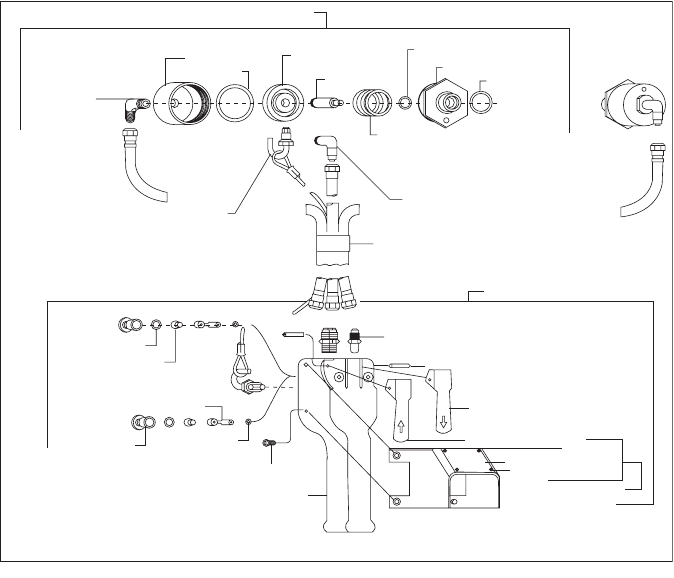
CONTROLS SECTION
PENDENT CONTROL 3-HOSE SYSTEM
DISASSEMBLY
a. To remove from hoist, shut off air and disconnect hoses
from cylinder assemblies and from head.
b. Remove “U” bracket (33989) from head, releasing cable.
c. To disassemble cylinders, unscrew and remove from
head.
d. Remove adapter (41067) releasing spring, piston, piston
rod and “O” ring.
e. To disassemble control handle, remove screws (37511)
with “O” rings (Y325-111), releasing spring (32858) and
valve (34757) with “O” rings (Y325-6).
REASSEMBLY
1. Assemble “O” ring (Y325-13) into adapter (41067).
2. Assemble piston rod (45799) and “O” ring (Y325-222) to
piston (41066) and assemble with spring (33981) into
cylinder (41064-1). Secure with adapter (41067).
3. Assemble with “O” ring (Y325116) to hoist.
4. To reassemble control handle, reverse disassembly
procedure.
ASSEMBLY OF CONTROLS TO HOIST
On pendent control models, control hoses must be attached
to cylinder on head as follows: Facing air inlet of hoist, the
hose to “DOWN” lever of control must be connected to
cylinder on left hand side of head. Hose to “UP” side of
control must be connected to right hand side of the head.
ELBOW Y54-23
CYLINDER 41064-1
CYLINDER ASS'Y. (2) 45801
PISTON 41066
SPRING 33981
ELBOW Y54-23
HOSE ASS'Y. 43103-6
"O" RING Y325-13
ADAPTER 41067
"O" RING Y325-118
PISTON ROD 45799
"O" RING Y326-222
U-BRACKET (2) 33989
"O" RING Y325-111
SPRING (2) 32858
CONNECTOR (3) Y54-2
HANDLE ASS'Y. 43102
SCREW (4) Y61-85-C
"O" RING (2) Y325-8
SCREW (2) 37511
VALVE (2) 34757
HANDLE 43122
ROLL PIN (2) Y178-58
LEVER (DOWN) 45616-1
LEVER (UP) 45616-2
WARNING PLATE 44197
GUARD ASS'Y. 44312
GUARD 40848
RIVET (4) 45119
PENDENT CONTROL ASSEMBLY 46094-6
FIGURE 18
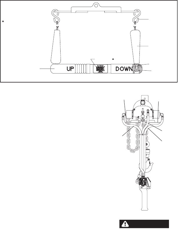
Form 04615308-Edition 2 19
On pull chain control models, control chains must be installed
as follows: Facing air inlet end of hoist (with hoist in an
upright position), chain attached to “UP” end of control
handle must be attached to right end of control arm. Chain
attached to “DOWN” end of control handle must be attached
to left end of control arm.
PENDENT CONTROL
3-HOSE SYSTEM
THE HOIST WILL ALWAYS CEASE OPERATION WHEN
OPERATOR RELEASES THE PENDENT CONTROL. IF
ANY HOSE (AIR INLET OR PENDENT CONTROL HOSES)
SHOULD BECOME CUT OR RUPTURED - 1) RELEASE
PENDENT CONTROL. 2) SHUT OFF AIR SUPPLY AND
REPLACE HOSE.
TO OPERATE HOIST IF HOSE SHOULD RUPTURE, BE
GUIDED BY THE FOLLOWING:
AIR INLET HOSE CUT OR RUPTURED:
TO LOWER LOAD - Load may be lowered by manually
operating control arm. Pull down on control arm at “3”. See
WARNING note below.
IF HOSE “W” IS CUT OR RUPTURED
TO LOWER LOAD - Load may be lowered by manually
operating control arm. Pull down on control arm at “B”. See
WARNING note below.
IF HOSE “X” IS CUT OR RUPTURED:
TO LOWER LOAD - Load may be lowered by depressing
“DOWN” lever of pendent control.
IF HOSE “Y” IS CUT OR RUPTURED:
TO LOWER LOAD - Load may be lowered by manually
operating control arm. Pull down on control arm at “B”. See
WARNING note below.
TO RAISE LOAD - Load may be raised by depressing “UP”
lever of pendent control.
WARNING
Exercise care when operating control arm to lower load
as load will be lowered at a very fast rate.
INCLUDED WITH 44806 CONTROL
HANDLE
CONTROL HANDLE 44806
CHAIN (2) 37657-5
HANDLE (2) 33268
"S" HOOK (2) 37659
ANCHOR (2) 37723
40004-5 PULL CHAIN CONTROL ASSEMBLY
LABEL 44596
FIGURE 19
‘‘A”
‘‘B”
‘‘W”
‘‘X”
‘‘Y”
FIGURE 20
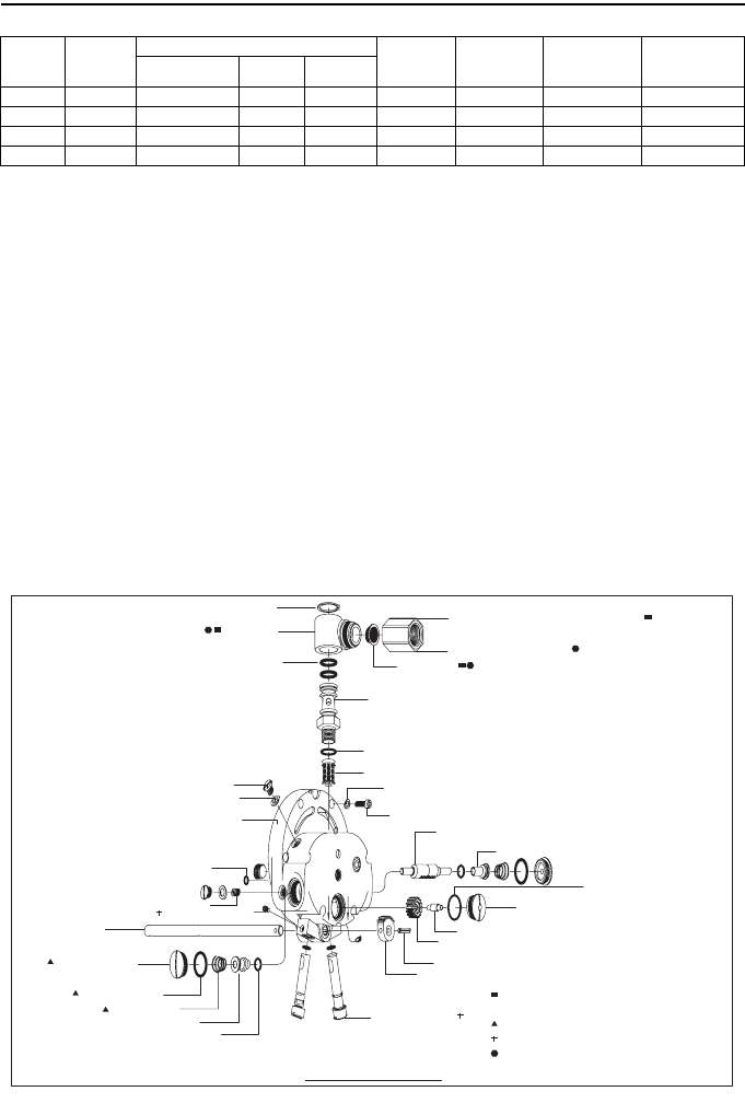
20 Form 04615308-Edition 2
SPARK-RESISTANT HOIST SECTION
NOTE: For models with trolley adapter in place of upper hook, add the letter “T” to model number. Example - 7712-ET or-
ELT would be supplied with trolley adapter in place of upper hook.
The hoists listed in the chart above are furnished with load
chain made of stainless steel. The top and bottom hooks of
these hoists are bronze, with snaps.
Other components of the 400 lb. capacity spark-resistant
hoists are comparable to the standard 1/2 ton models, and
the 1000 lb. capacity spark-resistant hoist components are
comparable to the standard 1 ton models, but the rates of lift
and descent are modified. All rates of lift and descent
outlined here are maximum of 90 p.s.i. The 400 lb. capacity,
stainless roller chain hoists have a rate of lift and descent of
approximately 40 feet per minute. The 550 lb. capacity,
stainless steel link chain hoists have a rate of lift of 50 feet
per minute and 70 feet per minute on descent. The 1000 lb.
capacity hoists have a rate of lift and descent at
approximately 10 feet per minute. The 1500 lb. capacity
hoists have a rate of lift and descent at approximately I6 feet
per minute.
SPECIAL NOTE: Spark-resistant models are shipped from
the factory with valves (41595) pre-set for maximum rates of
lift and descent and are secured by set screws (41627-1). DO
NOT ADJUST OR REMOVE VALVES (41595) on these
models. If head assembly is replaced for service, valves
(41595) must be adjusted for the following rates of lift and
descent.
400 LB. and 550 LB. CAPACITY HOISTS - Rate of lift with
maximum throttle opening with a 500 lb. load shall be:
Roller chain models - 40 ft/min. maximum.
Link chain models - 50 ft/min. maximum.
Rate of descent with maximum throttle opening and a 500 lb.
load shall not exceed:
Roller chain models - 40 ft/min.
Link chain models - 70 ft/min.
1000 LB. CAPACITY HOIST - Rate of lift and descent with
maximum throttle opening with 1200 lb. load shall not exceed
10 ft/min.
1500 LB. CAPACITY HOIST - Rate of lift and descent with
maximum throttle opening with a 1500 lb. load shall not
exceed 16 ft./min.
Air inlet adapter (46212) must be used with the 1000 lb.
capacity hoists.
MODELS
Hook
Mounting
CAPAClTY
(lbs)
LOAD CHAIN
HOOKS CONTROLS
MAX. LIFT
RATE AT
90 P.S.I.
MAX. DESCENT
RATE AT 90
P. S . I .
TYPE NUMBER LIFT
7712-E 400 Stainless, Roller 34043-11 10’ (3.0 m) Bronze Pull Chain 40 F.P.M. 40 F.P.M.
7712-EL 550 Stainless, Link 39489-11 10’ (3.0 m) Bronze Pull Chain 50 F.P.M. 70 F.P.M.
7714-E 1000 Stainless, Roller 35109-22 10’ (3.0 m) Bronze Pull Chain 10 F.P.M. 10 F.P.M.
7714-EL 1500 Stainless, Link 39489-22 10’ (3.0 m) Bronze Pull Chain 16 F.P.M. 16 F.P.M.
UPDN
X
OIL
ADAPTER 46211 (MODELS 7712-E, 7712-EL, 7714-EL)
ADAPTER 46212 (MODEL 7714-E)
SCREEN 31648
SCREEN 46072
LOCK WASHER (6) Y14-10
CAP SCREW (6) Y154-54
VALVE BODY 37704
"O" RING Y325-19
LOCK SCREW 34024
SHAFT 34025
GEAR 34030
ROLL PIN Y178-56
GEAR 34022
VALVE BODY (2) 41595
"O" RING (2) Y330-12
LIFT VALVE 46079
SPRING (2) 38966
"O" RING (2) Y325-116
VALVE CAP (2) 34026
CONTROL ROD 34021
SET SCREW (2) 41627-1
OILITE CASTING 33190
"O" RING Y325-9
WASHER (2) 31389
HEAD 46071
INCLUDES PIPE
PLUG (3) Y227-3
(NOT SHOWN)
OIL SCREW (2) 30747
SWIVEL BODY 33314
"O" RING (2) Y325-115
SWIVEL 46839
RETAINING RING Y145-28
VALVE 37703
"O" RING Y325-17
*
*
*
*
*
*
*
INCLUDED IN SWIVEL KIT 46840
NOT INCLUDED IN HEAD ASS'Y.
NOT USED WITH PENDENT CONTROL MODELS
SEE SPECIAL NOTE ABOVE
INCLUDED IN SWIVEL KIT 46841
46078 HEAD ASSEMBLY
*
*
*
NOT SHOWN "O" RING (2) Y325-11
FIGURE 21
Form 04615308-Edition 2 21
LOAD CHAIN
STAINLESS STEEL LINK CHAIN 39489-( )
FOR 250 kg (550 lb.) AND 1500 lb. CAPACITY HOIST
Dash number indicates exact length in feet. For 550 lb.
capacity hoists, order lift footage and add one extra foot for
assembly. For 1500 lb. capacity hoists, order twice the lift
footage and two extra feet for assembly and specify by
corresponding dash number.
Example: 39489-10, the dash 10 indicates 10 feet of chain.
STAINLESS STEEL ROLLER CHAIN 34043-( )
FOR 400 lb. CAPACITY HOIST
Dash number indicates exact length in feet.
Example: 34043-10, the dash 10 indicates 10 feet of chain.
When ordering, figure desired lift footage, add one extra foot
for assembly and specify by corresponding dash number.
Part number 34043-( ) includes two (2) connecting links
(34042).
STAINLESS STEEL ROLLER CHAIN 35109-( )
FOR 1000 lb. CAPACITY HOIST
Dash number indicates exact length in feet.
Example: 35109-20, the dash 20 indicates 20 feet of chain.
When ordering, figure twice the desired lift footage, add two
extra feet for assembly and specify by corresponding dash
number. Part number 35109-( ) includes one (1) connecting
link (34042).
ACCESSORIES SECTION
PIPED EXHAUST
Exhaust from the air motor normally escapes into the room
atmosphere, however, exhaust can be piped out of the room.
The hoist can be furnished, at extra cost, with a modified
head for piped exhaust. An exhaust hose, 1/2” (12 mm)
diameter recommended, can then be attached to this outlet
and air can be ventec at any remote point. Piped exhaust is
highly desirable in applications involving food processing,
chemicals or other processes where atmospheric purity must
be maintained. It is also preferred for its low noise level
characteristics.
When ordering, specify model number and add “with piped
exhaust”.
34042 (2) CONN. LINK
34041-( ) CHAIN
34042 (2) CONN. LINK
35107-( ) CHAIN
UPDN
X
OIL
ADAPTER 46211
SCREEN 31648
SCREEN 46072
LOCK WASHER (6) Y14-10
CAP SCREW (6) Y154-54
VALVE BODY 37704
"O" RING Y325-19
LOCK SCREW 34024
SHAFT 34025
GEAR 34030
ROLL PIN Y178-56
GEAR 34022
VALVE BODY (2) 41595
"O" RING (2) Y330-12
LIFT VALVE 46079
SPRING (2) 38966
"O" RING (2) Y325-116
VALVE CAP (2) 34026
CONTROL ROD 34021
SET SCREW (2) 41598
OILITE CASTING 33190
"O" RING Y325-9
WASHER (2) 31389
HEAD 46095
OIL SCREW (2) 30747
SWIVEL BODY 33314
"O" RING (2) Y325-115
ELBOW Y43-4-C
SCREW (2) Y99-51
WASHER (2) Y79-516
ADAPTER PLATE 37439
GASKET 37440
SWIVEL 46839
RETAINING RING Y145-28
VALVE 37703
"O" RING Y325-17
*
*
*
*
*
**
**
INCLUDED IN SWIVEL KIT 46840
NOT INCLUDED IN HEAD ASS'Y.
NOT USED WITH PENDENT CONTROL MODELS
INCLUDES PIPE PLUG (3) Y227-3
(NOT SHOWN)
46098-1 HEAD ASSEMBLY
22 Form 04615308-Edition 2
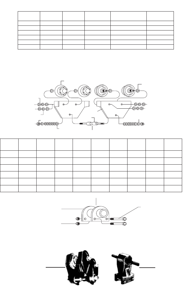
WASHER (26)
(1/8" THICK)
SHAFT NUT (2) SHAFT
TROLLEY WHEEL (4)
SPACER (8)
WASHER (2)
(1/16" THICK)
SIDE PLATE (2)
WHEEL NUT (4)
WHEEL WASHER (4)
NAMEPLATE 44081-1 (NOT SHOWN)
MODEL NO. TROLLEY
WHEEL SIDE PLATE SPACER (8) WHEEL
NUT
WHEEL
WASHER SHAFT
1/16"
SHAFT 1/8" SHAFT
WASHER SHAFT NUT
7702
7761-BC 41008-1 41009-1 Y13-8 Y12-108 Y14-816 41010 41012 41013 41011
7702-FT 45375 41009 Y13-8 Y12-108 Y14-816 41010 41012 41013 41011
7727 41015 41016 41022 Y12-112 Y14-750 41017 41021 41020 41018
7762-BC 41015-1 41016-1 41022 Y12-112 Y14-750 41017 41021 41020 41018
7727-FT 45376 41016 41022 Y12-112 Y14-750 41017 41021 41020 41018
41008 41009 Y13-8 Y12-108 Y14-816 41010 41012 41013 41011
BOLT (2) 47715
ADAPTER 47714 (1/4 & 1/2 TON)
ADAPTER 47713 (1 TON)
NUT (2) Y109 - 624
47717 1/4 AND 1/2 - TON TROLLEY ADAPTER ASSEMBLY
47716 1 - TON TROLLEY ADAPTER ASSEMBLY
ACCESSORIES
SECTION
MODEL NO. CAP. (LBS.) TYPE
BEAM
BEAM
SIZE
FLANGE
WIDTH
MINIMUM
TURNING RADIUS
7702 1/2 - TON L-BEAM 4" TO 10" 2.660" TO 4.660" 24 INCHES
1/2 - TON L-BEAM 4" TO 10" 2.660" TO 4.660" 24 INCHES
1/2 - TON H-BEAM 4" TO 10" 2.660" TO 4.990" 24 INCHES
1 - TON L-BEAM 5" TO 12" 3.000" TO 5.250" 36 INCHES
1 - TON L-BEAM 5" TO 12" 3.000" TO 5.250" 36 INCHES
1 - TON H-BEAM 5" TO 12" 2.600" TO 4.900" 36 INCHES
7761-BC *
7702-FT **
7727
7762-BC *
7727-FT **
* SPARK-RESISTANT MODEL, EQUIPPED WITH BERYLLIUM COPPER TREAD WHEELS.
** FLAT TREAD WHEEL MODEL FOR USE WITH "H" TYPE BEAMS.
*** SIDE PLATES ON SPARK-RESISTANT MODELS ARE EUIPPED WITH SKID BRACKETS (44618-2)
AND MOUNTED TO PLATES WITH RIVETS (Y193-33), NOT SHOWN.
NO. 41938 DUAL SWIVEL TROLLEY ADAPTER, FOR 1/4-TON AND
1/2-TON HOISTS, MAY BE USED WITH TROLLEY NO. 7702-( )
AND 7761-( )
41938 DUAL SWIVEL
ADAPTER
7702 TROLLEY
Form 04615308-Edition 2 23
TROUBLE SHOOTING
HOIST WILL NOT OPERATE - CHECK FOR:
1. Excessive Load
2. Sufficient air pressure.
3. Clogged air intake screen.
4. Clogged valves.
5. Proper brake adjustment.
6. Proper installation of Roll Pin in Control Rod and Gear
(34022).
UNABLE TO REGULATE HOIST SPEED BY
CONTROLS CHECK FOR:
1. Proper brake adjustment.
HOIST WILL NOT HOLD LOAD IN SUSPENSION -
CHECK FOR:
1. Excessive load.
2. Worn or oily brake linings.
3. Proper brake adjustment.
4. Proper timing of gears in head.
HOIST LOSES POWER - CHECK FOR:
1. Sufficient air pressure.
2. Clogged air intake screen.
3. Clogged muffler screen or filler.
HOIST LIFTING OR LOWERING SPEED DIFFERS
FROM RATED SPEED AT FULL LOAD - CHECK
FOR:
1. Proper timing of gears in Head.
HOIST CONTROL LEVER WILL NOT RETURN TO
HORIZONTAL POSITION - CHECK FOR:
1. Bent control rod.
2. Binding of control rod.
3. Proper brake adjustment.
4. Lack of lubrication in pendent control cylinders.
5. Proper timing of gears In head.
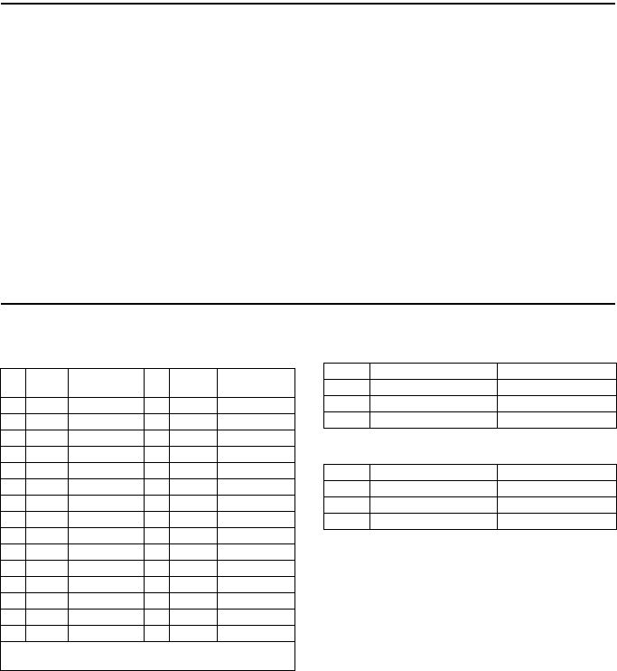
SERVICE KITS
SERVICE KIT NO. 41329-1
(FOR LINK CHAIN HOISTS)
CONSISTING OF:
SERVICE KIT NO. 41335
CONSISTING OF
SERVICE KIT NO. 41336
CONSISTING OF
QTY PART
NO. DESCRIPTION QTY PART
NO. DESCRIPTION
1 33274 Lockwasher 2 33236 Bearing
1 33387-2 Brake Shoe Kit 4 33330 Screw
3 34028 Filler 1 Y117-616 Washer
1 35023 Safety Latch 1 46072 Screen
1 41623 Gasket 1 31648 Screen
1 41795 Motor Oil 1 Y325-9 “O” Ring
2 41799 Gear Lube 1 Y145-28 Retainer Ring
8 43067 Blade 2 Y325-11 “O” Ring
1 Y1-966 Washer 2 Y325-12 “O” Ring
1 33281 Spring 1 Y325-17 “O” Ring
1 Y200-59 Screw 1 Y325-19 “O” Ring
1 Y12-106 Nut 2 Y325-115 “O” Ring
1 37706 Seal 2 Y325-116 “O” Ring
1 33235 Bearing 1 Y325-154 “O” Ring
1 Y147-18 Ring
DOES NOT INCLUDE CHAIN, POCKET WHEEL OR
SPROCKET
QTY. PART NO. DESCRIPTION
1 33375 Sprocket Wheel
1 34991 Chain Guide
4 33330 Fasteners
QTY. PART NO. DESCRIPTION
1 37571 Pocket Wheel
1 35861 Chain Guide
4 33330 Fasteners
24 Form 04615308-Edition 2
BULLARD SNAP HOOKS
HOSE-CARRIER TROLLEYS
MODEL - 7703
Recommended when hoist is trolley-mounted. Adjustable
clamp fits hose in sizes up to 1-1/4” o.d. can be mounted on
the same beam that carries the hoist trolley. Use on L-beams
from 3” to 10” high, having minimum width of 2-3/8” and
maximum width of 53/32”. For best results, use one trolley at
each 8’ hose interval.
Brake Spring Spreader
NO.33541
Specifically designed for hoist brake spring. Develops strong
leverage for spreading brake band open when removal is
required for service or maintenance.
35205-1 Lower Hook Assembly for 1/4 and 1/2 Ton
ROLLER CHAIN only. Includes Bucket Swivel,
Steel Balls, Collar, Roll Pins, Connector and Pin.
35206 Lower Hook Assembly for 1/4 and 1/2 Ton LINK
CHAIN only. Includes Bucket Swivel, Steel Balls,
Collar, Roll Pins, Connector, Pin, Sleeve and
Snap Ring.
35203 Upper Hook Assembly for 1/4, 1/2 and 1-Ton Link
and Roller Chain. Includes Mounting Bracket,
Bearing, Sleeve and Roll Pin.
45934 Lower Hook and Block Assembly for 1-Ton LINK
CHAIN only. Includes Sheave Assembly,
Shroud’s and all necessary components for
attaching to load chain.
45935 Lower Hook and Block Assembly for 1-Ton
ROLLER CHAIN only. Includes Sprocket
Assembly, Shroud’s and all necessary
components for attaching to load chain.
45374 Lower Hook (with latch) Only for 1-Ton LINK and
ROLLER CHAIN. (Same hook as furnished with
45934 and 45935 assemblies).
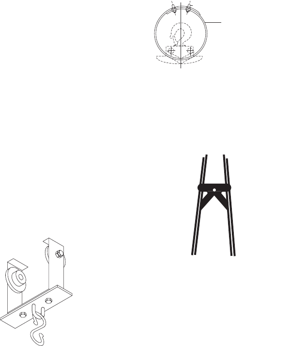
43230 RESTRAINING CABLE
(1/4" DIA x 2 FT. LONG)
43232 CLAMP (2)
43231 RESTRAINING CABLE ASS'Y.
FOR USE AS AN ADDED SAFETY PRECAUTION IN HOIST
SUSPENSION. INSERT CABLE THRU HOLE PROVIDED IN HOUSING
A
S SHOWN AND AROUND L-BEAM (OR OTHER OVERHEAD
SUPPORT CAPABLE OF SAFELY SUPPORTING COMBINED WEIGHT
OF HOIST AND ITS CAPACITY LOAD).
Form 04615308-Edition 2 25
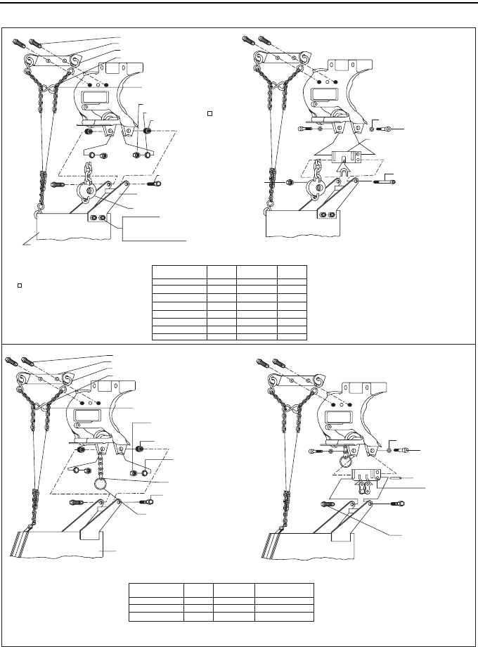
SERIES 7700 HOIST CHAIN BASKET INSTALLATION
BOLT (2) Y6-61-C
BRACKET 34706
"S" HOOK (4) 37659
NUT (2) Y109-524 *
NUT (2) Y109-524*
BOLT 41625 *
WASHER (2) Y14-516 *
SPACER (2) 37594 *
SCREW (2) Y5-54-C *
BRACKET ASSEMBLY 37598
CHAIN STOP ASS'Y 34961
BOLT (4) Y6-41-C
NUT (4) Y12-104-C
LOCK WASHER (4) Y14-416
FLAT WASHER (4) Y13-4-C
SASH CHAIN (2)-37657-000-G
NOTE: ATTACH "S" HOOK TO FOURTH
LINK FROM TOP AND CLOSE ENDS.
CHAIN BASKET-SEE TABLE BELOW
1/4 & 1/2 TON LINK CHAIN MODELS
NOT INCLUDED WITH MODELS 43554-( )
NOTE: WHEN MOUNTING BASKET TO HOIST,
REMOVE CHAIN END ATTACHMENT FROM
HOIST AND ASSEMBLE CHAIN STOP (34981)
WITH BOLT THRU SECOND LINK FROM END.
NOTE: ON 1- TON MODELS, BASKET IS ATTACHED
TO ANCHOR BRACKET, PARTS MARKED * ARE NOT
USED.
CHAIN BASKET
ASSEMBLY NUMBER
CHAIN
CAPACITY
BASKET
MATERIAL
CHAIN BASKET
NUMBER
37653-16
37653-32
37653-64
37653-80
37653-100
43554-1
43554-2
43554-3
36384-1
34384-2
36384-3
36384-7
36384-10
43440-1
43440-2
43440-3
STEEL
STEEL
STEEL
STEEL
STEEL
CANVAS
CANVAS
CANVAS
20'
32'
56'
80'
100'
20'
32'
64'
ANCHOR BRACKET 41624 *
BOLT (2) 37586
WASHER (2) 37587 *
1-TON LINK CHAIN MODELS
CHAIN BASKET
ASSEMBLY NUMBER
CHAIN
CAPACITY SASH CHAIN
CHAIN BASKET
NUMBER
37654
37655
37656
37660
37661
37658
37657-000-F
37657-000-G
37657-000-J
10'
16'
40'
BOLT (2) Y6-61-C
BRACKET 34706
"S" HOOK (4) 37659
NUT (2) Y109-524 *
CONNECTING LINK 33363
CHAIN BASKET - SEE TABLE BELOW
WASHER (2) Y14-516 *
SPACER (2) 37594 *
SCREW (2) Y5-54-C *
SASH CHAIN (2)-SEE TABLE BELOW
NOTE: ATTACH "S" HOOK TO FOURTH
LINK FROM TOP AND CLOSE ENDS.
1/4 & 1/2 TON ROLLER CHAIN MODELS 1-TON ROLLER CHAIN MODELS
BOLT (2) 37580 *
BRACKET 37579 *
PIN 34316 *
BOLT (2) 37586 *
WASHER (2) 37587 *
NOTE: ON 1-TON MODELS, BASKET IS ATTACHED TO
ANCHOR BRACKET. PARTS MARKED * ARE NOT USED.
* STANDARD 1-TON HOIST PARTS.
NOTE: CHAIN STOP (RING) 34711 IS ASSEMBLED TO END OF LOAD CHAIN AND CHAIN STOP ASSEMBLY 33382
(USED WITH 1/4 AND 1/2 TON MODELS) IS REMOVED. CHAIN STOP 33382 IS TOO WIDE TO FIT CHAIN BASKET.
CHAIN STOP 34711

26 Form 04615308-Edition 2
NOTES

Form 04615308-Edition 2 27
NOTES

www.irtools.com
© 2005 Ingersoll-Rand Company
